Internals Training Guide - HP e3000 MPE/iX Computer Systems
439
Internals Training Guide HP e3000 MPE/iX Computer Systems Edition 1 Manufacturing Part Number: 30216-90316 E0101 U.S.A. January 2001
-
Upload
khangminh22 -
Category
Documents
-
view
1 -
download
0
Transcript of Internals Training Guide - HP e3000 MPE/iX Computer Systems

Internals Training Guide
HP e3000 MPE/iX Computer Systems
Edition 1
Manufacturing Part Number: 30216-90316E0101
U.S.A. January 2001

NoticeThe information contained in this document is subject to changewithout notice.
Hewlett-Packard makes no warranty of any kind with regard to thismaterial, including, but not limited to, the implied warranties ofmerchantability or fitness for a particular purpose. Hewlett-Packardshall not be liable for errors contained herein or for direct, indirect,special, incidental or consequential damages in connection with thefurnishing or use of this material.
Hewlett-Packard assumes no responsibility for the use or reliability ofits software on equipment that is not furnished by Hewlett-Packard.
This document contains proprietary information which is protected bycopyright. All rights reserved. Reproduction, adaptation, or translationwithout prior written permission is prohibited, except as allowed underthe copyright laws.
Restricted Rights LegendUse, duplication, or disclosure by the U.S. Government is subject torestrictions as set forth in subparagraph (c) (1) (ii) of the Rights inTechnical Data and Computer Software clause at DFARS 252.227-7013.Rights for non-DOD U.S. Government Departments and Agencies areas set forth in FAR 52.227-19 (c) (1,2).
AcknowledgmentsUNIX is a registered trademark of The Open Group.
Hewlett-Packard Company3000 Hanover StreetPalo Alto, CA 94304 U.S.A.
© Copyright 2001 by Hewlett-Packard Company
2

Contents
1. Hardware Overview Monitor and I/O Services
2. PCISCSI Device Adapter Manager (DAM)Internals Training . . . . . . . . . . . . . . . . . . . . . . . . . . . . . . . . . . . . . . . . . . . . . . . . . . . . . . . . . . . 38Additional References . . . . . . . . . . . . . . . . . . . . . . . . . . . . . . . . . . . . . . . . . . . . . . . . . . . . . . . . 40
Introduction. . . . . . . . . . . . . . . . . . . . . . . . . . . . . . . . . . . . . . . . . . . . . . . . . . . . . . . . . . . . . . . 40PCI Based SCSI Interface Cards . . . . . . . . . . . . . . . . . . . . . . . . . . . . . . . . . . . . . . . . . . . . 40
PCISCSI DAM. . . . . . . . . . . . . . . . . . . . . . . . . . . . . . . . . . . . . . . . . . . . . . . . . . . . . . . . . . . . . 41PCISCSI DAM in 3 Layers . . . . . . . . . . . . . . . . . . . . . . . . . . . . . . . . . . . . . . . . . . . . . . . . . . . 41Best of HP-UX and MPE/iX . . . . . . . . . . . . . . . . . . . . . . . . . . . . . . . . . . . . . . . . . . . . . . . . . . 42Port Data Area (PDA) . . . . . . . . . . . . . . . . . . . . . . . . . . . . . . . . . . . . . . . . . . . . . . . . . . . . . . . 45
Port Sub-Qs & Pending Qs . . . . . . . . . . . . . . . . . . . . . . . . . . . . . . . . . . . . . . . . . . . . . . . . . 51Higher Manager Info . . . . . . . . . . . . . . . . . . . . . . . . . . . . . . . . . . . . . . . . . . . . . . . . . . . . . . . 53Req Table . . . . . . . . . . . . . . . . . . . . . . . . . . . . . . . . . . . . . . . . . . . . . . . . . . . . . . . . . . . . . . . . . 54Upper/Lower DAM Interface Layer . . . . . . . . . . . . . . . . . . . . . . . . . . . . . . . . . . . . . . . . . . . . 56
Mappings between Upper and Lower Data . . . . . . . . . . . . . . . . . . . . . . . . . . . . . . . . . . . . 56Auxiliary Data Area (ADA) . . . . . . . . . . . . . . . . . . . . . . . . . . . . . . . . . . . . . . . . . . . . . . . . . . 60
Lower DAM data structures/resources. . . . . . . . . . . . . . . . . . . . . . . . . . . . . . . . . . . . . . . . 60Upper DAM resources . . . . . . . . . . . . . . . . . . . . . . . . . . . . . . . . . . . . . . . . . . . . . . . . . . . . 60
Upper DAM I/O Specific Structures. . . . . . . . . . . . . . . . . . . . . . . . . . . . . . . . . . . . . . . . . . . . 61Interface layer I/O Specific Structures. . . . . . . . . . . . . . . . . . . . . . . . . . . . . . . . . . . . . . . . . . 61SelectQ. . . . . . . . . . . . . . . . . . . . . . . . . . . . . . . . . . . . . . . . . . . . . . . . . . . . . . . . . . . . . . . . . . . 69
Pending I/O requests . . . . . . . . . . . . . . . . . . . . . . . . . . . . . . . . . . . . . . . . . . . . . . . . . . . . . . 69BUS Specific . . . . . . . . . . . . . . . . . . . . . . . . . . . . . . . . . . . . . . . . . . . . . . . . . . . . . . . . . . . . . . 70
ISC Structure. . . . . . . . . . . . . . . . . . . . . . . . . . . . . . . . . . . . . . . . . . . . . . . . . . . . . . . . . . . . 71LISC Structure . . . . . . . . . . . . . . . . . . . . . . . . . . . . . . . . . . . . . . . . . . . . . . . . . . . . . . . . . . 71BUSP Structure. . . . . . . . . . . . . . . . . . . . . . . . . . . . . . . . . . . . . . . . . . . . . . . . . . . . . . . . . . 71LBP Structure . . . . . . . . . . . . . . . . . . . . . . . . . . . . . . . . . . . . . . . . . . . . . . . . . . . . . . . . . . . 71Target Specific . . . . . . . . . . . . . . . . . . . . . . . . . . . . . . . . . . . . . . . . . . . . . . . . . . . . . . . . . . . 73
I/O Specific. . . . . . . . . . . . . . . . . . . . . . . . . . . . . . . . . . . . . . . . . . . . . . . . . . . . . . . . . . . . . . . . 75DSP, LBP, LbpToScratch & LSP. . . . . . . . . . . . . . . . . . . . . . . . . . . . . . . . . . . . . . . . . . . . . . . 76
DSPS . . . . . . . . . . . . . . . . . . . . . . . . . . . . . . . . . . . . . . . . . . . . . . . . . . . . . . . . . . . . . . . . . . 76Symbios Card & SCSI Script . . . . . . . . . . . . . . . . . . . . . . . . . . . . . . . . . . . . . . . . . . . . . . . . . 79
SYMBIOS card- SCSI bus autosensing . . . . . . . . . . . . . . . . . . . . . . . . . . . . . . . . . . . . . . . 79SCSI Script (no firmware) . . . . . . . . . . . . . . . . . . . . . . . . . . . . . . . . . . . . . . . . . . . . . . . . . . 79
Do_Bind & Init . . . . . . . . . . . . . . . . . . . . . . . . . . . . . . . . . . . . . . . . . . . . . . . . . . . . . . . . . . . . 82Bind to lower mgr . . . . . . . . . . . . . . . . . . . . . . . . . . . . . . . . . . . . . . . . . . . . . . . . . . . . . . . . 82Init upper DAM data structures. . . . . . . . . . . . . . . . . . . . . . . . . . . . . . . . . . . . . . . . . . . . . 82Allocate and init lower DAM data structures . . . . . . . . . . . . . . . . . . . . . . . . . . . . . . . . . . 82
Device Manager Bind . . . . . . . . . . . . . . . . . . . . . . . . . . . . . . . . . . . . . . . . . . . . . . . . . . . . . . . 90Data Class Conversion to IOVEC. . . . . . . . . . . . . . . . . . . . . . . . . . . . . . . . . . . . . . . . . . . . . . 95Starting an I/O . . . . . . . . . . . . . . . . . . . . . . . . . . . . . . . . . . . . . . . . . . . . . . . . . . . . . . . . . . . 113Mapped Qtag . . . . . . . . . . . . . . . . . . . . . . . . . . . . . . . . . . . . . . . . . . . . . . . . . . . . . . . . . . . . . 120First I/O . . . . . . . . . . . . . . . . . . . . . . . . . . . . . . . . . . . . . . . . . . . . . . . . . . . . . . . . . . . . . . . . . 121SCSI Script and Patching . . . . . . . . . . . . . . . . . . . . . . . . . . . . . . . . . . . . . . . . . . . . . . . . . . . 123Interrupts . . . . . . . . . . . . . . . . . . . . . . . . . . . . . . . . . . . . . . . . . . . . . . . . . . . . . . . . . . . . . . . 125
Typical Interrupts . . . . . . . . . . . . . . . . . . . . . . . . . . . . . . . . . . . . . . . . . . . . . . . . . . . . . . . 125I/O Completion . . . . . . . . . . . . . . . . . . . . . . . . . . . . . . . . . . . . . . . . . . . . . . . . . . . . . . . . . . . 129
Multiple Interrupts to Complete an I/O . . . . . . . . . . . . . . . . . . . . . . . . . . . . . . . . . . . . . . 129
3
Contents
Multiple I/Os on the SCSI bus. . . . . . . . . . . . . . . . . . . . . . . . . . . . . . . . . . . . . . . . . . . . . . . .133I/O aborts. . . . . . . . . . . . . . . . . . . . . . . . . . . . . . . . . . . . . . . . . . . . . . . . . . . . . . . . . . . . . . .134Abort I/Os in any state in DAM . . . . . . . . . . . . . . . . . . . . . . . . . . . . . . . . . . . . . . . . . . . . .134
Timers . . . . . . . . . . . . . . . . . . . . . . . . . . . . . . . . . . . . . . . . . . . . . . . . . . . . . . . . . . . . . . . . . . .142Abort request timer . . . . . . . . . . . . . . . . . . . . . . . . . . . . . . . . . . . . . . . . . . . . . . . . . . . . . .142Poweron Timer . . . . . . . . . . . . . . . . . . . . . . . . . . . . . . . . . . . . . . . . . . . . . . . . . . . . . . . . . .142
Situation Escalation. . . . . . . . . . . . . . . . . . . . . . . . . . . . . . . . . . . . . . . . . . . . . . . . . . . . . . . .147Poweron (reset) . . . . . . . . . . . . . . . . . . . . . . . . . . . . . . . . . . . . . . . . . . . . . . . . . . . . . . . . . . . .150C-isms . . . . . . . . . . . . . . . . . . . . . . . . . . . . . . . . . . . . . . . . . . . . . . . . . . . . . . . . . . . . . . . . . . .158LLIO Msg Log. . . . . . . . . . . . . . . . . . . . . . . . . . . . . . . . . . . . . . . . . . . . . . . . . . . . . . . . . . . . .162Console Log. . . . . . . . . . . . . . . . . . . . . . . . . . . . . . . . . . . . . . . . . . . . . . . . . . . . . . . . . . . . . . .163Lower DAM Procedure Number List. . . . . . . . . . . . . . . . . . . . . . . . . . . . . . . . . . . . . . . . . . .168
Lower DAM Error Number List. . . . . . . . . . . . . . . . . . . . . . . . . . . . . . . . . . . . . . . . . . . . .171Lower DAM Error Mappings . . . . . . . . . . . . . . . . . . . . . . . . . . . . . . . . . . . . . . . . . . . . . . . . .173Hardware Log . . . . . . . . . . . . . . . . . . . . . . . . . . . . . . . . . . . . . . . . . . . . . . . . . . . . . . . . . . . . .175Card Maintenance . . . . . . . . . . . . . . . . . . . . . . . . . . . . . . . . . . . . . . . . . . . . . . . . . . . . . . . . .180Logtool. . . . . . . . . . . . . . . . . . . . . . . . . . . . . . . . . . . . . . . . . . . . . . . . . . . . . . . . . . . . . . . . . . .181Mesa . . . . . . . . . . . . . . . . . . . . . . . . . . . . . . . . . . . . . . . . . . . . . . . . . . . . . . . . . . . . . . . . . . . .182Case 1: Fail to Bind . . . . . . . . . . . . . . . . . . . . . . . . . . . . . . . . . . . . . . . . . . . . . . . . . . . . . . . .184
Case 2: Finding I/Os . . . . . . . . . . . . . . . . . . . . . . . . . . . . . . . . . . . . . . . . . . . . . . . . . . . . . .186The search is over! . . . . . . . . . . . . . . . . . . . . . . . . . . . . . . . . . . . . . . . . . . . . . . . . . . . . . . . . .217
3. Memory Holes
4. PCI Console DriverPCI Console Driver . . . . . . . . . . . . . . . . . . . . . . . . . . . . . . . . . . . . . . . . . . . . . . . . . . . . . . . . . .246
Introduction — Multi-function core I/O card . . . . . . . . . . . . . . . . . . . . . . . . . . . . . . . . . . . .246Guardian Service Processor . . . . . . . . . . . . . . . . . . . . . . . . . . . . . . . . . . . . . . . . . . . . . . . .246Serial Ports . . . . . . . . . . . . . . . . . . . . . . . . . . . . . . . . . . . . . . . . . . . . . . . . . . . . . . . . . . . . .247The GSP LAN . . . . . . . . . . . . . . . . . . . . . . . . . . . . . . . . . . . . . . . . . . . . . . . . . . . . . . . . . . .247External SCSI . . . . . . . . . . . . . . . . . . . . . . . . . . . . . . . . . . . . . . . . . . . . . . . . . . . . . . . . . . .247SCSI (ULTRA). . . . . . . . . . . . . . . . . . . . . . . . . . . . . . . . . . . . . . . . . . . . . . . . . . . . . . . . . . .24710/100Base-TX LAN . . . . . . . . . . . . . . . . . . . . . . . . . . . . . . . . . . . . . . . . . . . . . . . . . . . . . .247
ASCII Terminal Connectivity . . . . . . . . . . . . . . . . . . . . . . . . . . . . . . . . . . . . . . . . . . . . . . . .248GSP LAN Access. . . . . . . . . . . . . . . . . . . . . . . . . . . . . . . . . . . . . . . . . . . . . . . . . . . . . . . . . . .249GSP Features . . . . . . . . . . . . . . . . . . . . . . . . . . . . . . . . . . . . . . . . . . . . . . . . . . . . . . . . . . . . .250
Console Mirroring . . . . . . . . . . . . . . . . . . . . . . . . . . . . . . . . . . . . . . . . . . . . . . . . . . . . . . . .250Password Protected Access. . . . . . . . . . . . . . . . . . . . . . . . . . . . . . . . . . . . . . . . . . . . . . . . .250Session ldevs . . . . . . . . . . . . . . . . . . . . . . . . . . . . . . . . . . . . . . . . . . . . . . . . . . . . . . . . . . . .251Remote Power Up/Down. . . . . . . . . . . . . . . . . . . . . . . . . . . . . . . . . . . . . . . . . . . . . . . . . . .251GSP Firware Upgrade . . . . . . . . . . . . . . . . . . . . . . . . . . . . . . . . . . . . . . . . . . . . . . . . . . . .251Secure Web Console . . . . . . . . . . . . . . . . . . . . . . . . . . . . . . . . . . . . . . . . . . . . . . . . . . . . . .251
Background — Project Considerations . . . . . . . . . . . . . . . . . . . . . . . . . . . . . . . . . . . . . . . . .252Design Criteria . . . . . . . . . . . . . . . . . . . . . . . . . . . . . . . . . . . . . . . . . . . . . . . . . . . . . . . . . . .253Functionality . . . . . . . . . . . . . . . . . . . . . . . . . . . . . . . . . . . . . . . . . . . . . . . . . . . . . . . . . . . . .255
Local, remote, UPS ports . . . . . . . . . . . . . . . . . . . . . . . . . . . . . . . . . . . . . . . . . . . . . . . . . .255Two additional card ports. . . . . . . . . . . . . . . . . . . . . . . . . . . . . . . . . . . . . . . . . . . . . . . . . .255Unsupported Functionality . . . . . . . . . . . . . . . . . . . . . . . . . . . . . . . . . . . . . . . . . . . . . . . .256
4

Contents
Console Architecture. . . . . . . . . . . . . . . . . . . . . . . . . . . . . . . . . . . . . . . . . . . . . . . . . . . . . . . 257Core I/O 1, Tosca Card . . . . . . . . . . . . . . . . . . . . . . . . . . . . . . . . . . . . . . . . . . . . . . . . . . . 257Core I/O 2, Maestro Card . . . . . . . . . . . . . . . . . . . . . . . . . . . . . . . . . . . . . . . . . . . . . . . . . 259
Configuration. . . . . . . . . . . . . . . . . . . . . . . . . . . . . . . . . . . . . . . . . . . . . . . . . . . . . . . . . . . . . 260GSP Commands . . . . . . . . . . . . . . . . . . . . . . . . . . . . . . . . . . . . . . . . . . . . . . . . . . . . . . . . 260
Security Options (SO) . . . . . . . . . . . . . . . . . . . . . . . . . . . . . . . . . . . . . . . . . . . . . . . . . . 261Power Control and Status(PC, PS): . . . . . . . . . . . . . . . . . . . . . . . . . . . . . . . . . . . . . . . 262Paging Parameters (PG): . . . . . . . . . . . . . . . . . . . . . . . . . . . . . . . . . . . . . . . . . . . . . . . 262Upgrade the GSP Firmware (XU) . . . . . . . . . . . . . . . . . . . . . . . . . . . . . . . . . . . . . . . . 262
Console and GSP LAN . . . . . . . . . . . . . . . . . . . . . . . . . . . . . . . . . . . . . . . . . . . . . . . . . . . . . 263Modem Protocols . . . . . . . . . . . . . . . . . . . . . . . . . . . . . . . . . . . . . . . . . . . . . . . . . . . . . . . . 263Default Parameters . . . . . . . . . . . . . . . . . . . . . . . . . . . . . . . . . . . . . . . . . . . . . . . . . . . . . . 263
Console ldevs . . . . . . . . . . . . . . . . . . . . . . . . . . . . . . . . . . . . . . . . . . . . . . . . . . . . . . . . . . . . . 265Support and Diagnostics. . . . . . . . . . . . . . . . . . . . . . . . . . . . . . . . . . . . . . . . . . . . . . . . . . . . 266Troubleshooting. . . . . . . . . . . . . . . . . . . . . . . . . . . . . . . . . . . . . . . . . . . . . . . . . . . . . . . . . . . 268Additional Comments . . . . . . . . . . . . . . . . . . . . . . . . . . . . . . . . . . . . . . . . . . . . . . . . . . . . . . 270
5. PCI Networking Generic TopicsOther Networking Changes Made. . . . . . . . . . . . . . . . . . . . . . . . . . . . . . . . . . . . . . . . . . . . . . 271
6. PCI 100Base-TSection 1: Detail of Product Features and Limitations . . . . . . . . . . . . . . . . . . . . . . . . . . . . . 276Section 2 — Configuration Changes in 7.0 . . . . . . . . . . . . . . . . . . . . . . . . . . . . . . . . . . . . . . . 281Section 3: Tools & Diagnostics . . . . . . . . . . . . . . . . . . . . . . . . . . . . . . . . . . . . . . . . . . . . . . . . . 289Section 4: Documentation . . . . . . . . . . . . . . . . . . . . . . . . . . . . . . . . . . . . . . . . . . . . . . . . . . . . 299Section 5: Troubleshooting Techniques and Examples . . . . . . . . . . . . . . . . . . . . . . . . . . . . . 302
7. PCI Sync MUX
8. OS macro changes in MPE/iX 7.0
9. Support Tools Changed in MPE/iX 7.0Support Tools Changed in MPE/iX 7.0 . . . . . . . . . . . . . . . . . . . . . . . . . . . . . . . . . . . . . . . . . . 372
CONLOG.PUBXL . . . . . . . . . . . . . . . . . . . . . . . . . . . . . . . . . . . . . . . . . . . . . . . . . . . . . . . . . 372DSTUSE . . . . . . . . . . . . . . . . . . . . . . . . . . . . . . . . . . . . . . . . . . . . . . . . . . . . . . . . . . . . . . . . 372DUMPCUT . . . . . . . . . . . . . . . . . . . . . . . . . . . . . . . . . . . . . . . . . . . . . . . . . . . . . . . . . . . . . . 372FMTIOERR.PRVXL . . . . . . . . . . . . . . . . . . . . . . . . . . . . . . . . . . . . . . . . . . . . . . . . . . . . . . . 372KSCHKIX.PRVXL. . . . . . . . . . . . . . . . . . . . . . . . . . . . . . . . . . . . . . . . . . . . . . . . . . . . . . . . . 372LNKSUMM.PUBXL . . . . . . . . . . . . . . . . . . . . . . . . . . . . . . . . . . . . . . . . . . . . . . . . . . . . . . . 372LOGFIX . . . . . . . . . . . . . . . . . . . . . . . . . . . . . . . . . . . . . . . . . . . . . . . . . . . . . . . . . . . . . . . . . 372MVTDUMP.PRVXL. . . . . . . . . . . . . . . . . . . . . . . . . . . . . . . . . . . . . . . . . . . . . . . . . . . . . . . . 373NETMAC.PUBXL . . . . . . . . . . . . . . . . . . . . . . . . . . . . . . . . . . . . . . . . . . . . . . . . . . . . . . . . . 373NEWMACS.PUBXL . . . . . . . . . . . . . . . . . . . . . . . . . . . . . . . . . . . . . . . . . . . . . . . . . . . . . . . 373SCANCB.PRVXL. . . . . . . . . . . . . . . . . . . . . . . . . . . . . . . . . . . . . . . . . . . . . . . . . . . . . . . . . . 373SECRTCKX.PUBXL . . . . . . . . . . . . . . . . . . . . . . . . . . . . . . . . . . . . . . . . . . . . . . . . . . . . . . . 373SHOWCLKS.PUBXL . . . . . . . . . . . . . . . . . . . . . . . . . . . . . . . . . . . . . . . . . . . . . . . . . . . . . . 374SYSLOG. . . . . . . . . . . . . . . . . . . . . . . . . . . . . . . . . . . . . . . . . . . . . . . . . . . . . . . . . . . . . . . . . 374TAPESCAN . . . . . . . . . . . . . . . . . . . . . . . . . . . . . . . . . . . . . . . . . . . . . . . . . . . . . . . . . . . . . . 374
5
Contents
TBLMON . . . . . . . . . . . . . . . . . . . . . . . . . . . . . . . . . . . . . . . . . . . . . . . . . . . . . . . . . . . . . . . .374TCPIP.PUBXL . . . . . . . . . . . . . . . . . . . . . . . . . . . . . . . . . . . . . . . . . . . . . . . . . . . . . . . . . . . .374UNDEDLOK.PRVXL . . . . . . . . . . . . . . . . . . . . . . . . . . . . . . . . . . . . . . . . . . . . . . . . . . . . . . .374
A. PCISCSI Device Adapter Manager (DAM)
B. Monitor and I/O ServicesN-Class and A-Class Configuration Files. . . . . . . . . . . . . . . . . . . . . . . . . . . . . . . . . . . . . . . . .387New and Changed Procedures . . . . . . . . . . . . . . . . . . . . . . . . . . . . . . . . . . . . . . . . . . . . . . . . .390
Function — io_get_sysmap_info . . . . . . . . . . . . . . . . . . . . . . . . . . . . . . . . . . . . . . . . . . . . . .390Calling Convention. . . . . . . . . . . . . . . . . . . . . . . . . . . . . . . . . . . . . . . . . . . . . . . . . . . . . . . . .390Data Returned . . . . . . . . . . . . . . . . . . . . . . . . . . . . . . . . . . . . . . . . . . . . . . . . . . . . . . . . . . . .391Procedure — io_info . . . . . . . . . . . . . . . . . . . . . . . . . . . . . . . . . . . . . . . . . . . . . . . . . . . . . . . .392Calling Sequence . . . . . . . . . . . . . . . . . . . . . . . . . . . . . . . . . . . . . . . . . . . . . . . . . . . . . . . . . .392Data Returned . . . . . . . . . . . . . . . . . . . . . . . . . . . . . . . . . . . . . . . . . . . . . . . . . . . . . . . . . . . .392Procedure — io_get_pci_info . . . . . . . . . . . . . . . . . . . . . . . . . . . . . . . . . . . . . . . . . . . . . . . . .395Calling Convention . . . . . . . . . . . . . . . . . . . . . . . . . . . . . . . . . . . . . . . . . . . . . . . . . . . . . . . .395Data Returned . . . . . . . . . . . . . . . . . . . . . . . . . . . . . . . . . . . . . . . . . . . . . . . . . . . . . . . . . . . .395
HSYSMAP File From 6.0 . . . . . . . . . . . . . . . . . . . . . . . . . . . . . . . . . . . . . . . . . . . . . . . . . . . . .400HSYSMAP File From 7.0 . . . . . . . . . . . . . . . . . . . . . . . . . . . . . . . . . . . . . . . . . . . . . . . . . . . . .408DIOPPT File from 6.0 . . . . . . . . . . . . . . . . . . . . . . . . . . . . . . . . . . . . . . . . . . . . . . . . . . . . . . . .425DIOPPT File From 7.0. . . . . . . . . . . . . . . . . . . . . . . . . . . . . . . . . . . . . . . . . . . . . . . . . . . . . . . .428
C. Hardware OverviewIOSAPIC Interrupt Handling Tutorial/IS . . . . . . . . . . . . . . . . . . . . . . . . . . . . . . . . . . . . . . . .433
Overview . . . . . . . . . . . . . . . . . . . . . . . . . . . . . . . . . . . . . . . . . . . . . . . . . . . . . . . . . . . . . . . . .433High-Level Flow. . . . . . . . . . . . . . . . . . . . . . . . . . . . . . . . . . . . . . . . . . . . . . . . . . . . . . . . . . . . .434Module Detail. . . . . . . . . . . . . . . . . . . . . . . . . . . . . . . . . . . . . . . . . . . . . . . . . . . . . . . . . . . . . . .435
Questions . . . . . . . . . . . . . . . . . . . . . . . . . . . . . . . . . . . . . . . . . . . . . . . . . . . . . . . . . . . . . . . .439
6

1 Hardware Overview Monitor andI/O Services
Figure 1-1 Slide 1
for internal use only
hp e3000
7.0 fieldtraining
MPE/ iX
Release 7.0
Monitor and I/O ServicesHardware Overview
7

Hardware Overview Monitor and I/O Services
Figure 1-2 Slide 2
Slide 2 Speaker Notes
Picture of front panel of N4000 AKA Prelude.
Note that the power switch is actually a standby switch. The GSP isstill active.
In order to fully power-down the system or do a full reset, you mustdisconnect the power.
for internal use only
hp e3000
7.0 fieldtraining
N4000
Add picture of Prelude
FaultRun AttnDisc A
Disc BRemote
Power
PowerSwitch
8 Chapter 1

Hardware Overview Monitor and I/O Services
Figure 1-3 Slide 3
Slide 3 Speaker Notes
These are the versions of the N4000 that will be shipping at firstrelease.
The 220 Mhz and 330 Mhz are software-throttled versions.
Maximum memory will be 2GB at first release, increased to 16MB onfuture releases.
Minimum memory on 440 Mhz will be 1 Gb per processor.
for internal use only
hp e3000
7.0 fieldtraining
N4000 Configurations
Model # Proc MinMem
MaxMem
A4000-100-22 1220mhz
512Mb
2Gb (16Gb)
A4000-100-33 1330mhz
512Mb
2Gb (16Gb)
A4000-100-44 1440mhz
1Gb 2Gb (16Gb)
A4000-200-44 2440mhz
2Gb 2Gb (16Gb)
Chapter 1 9
Hardware Overview Monitor and I/O Services
Figure 1-4 Slide 4
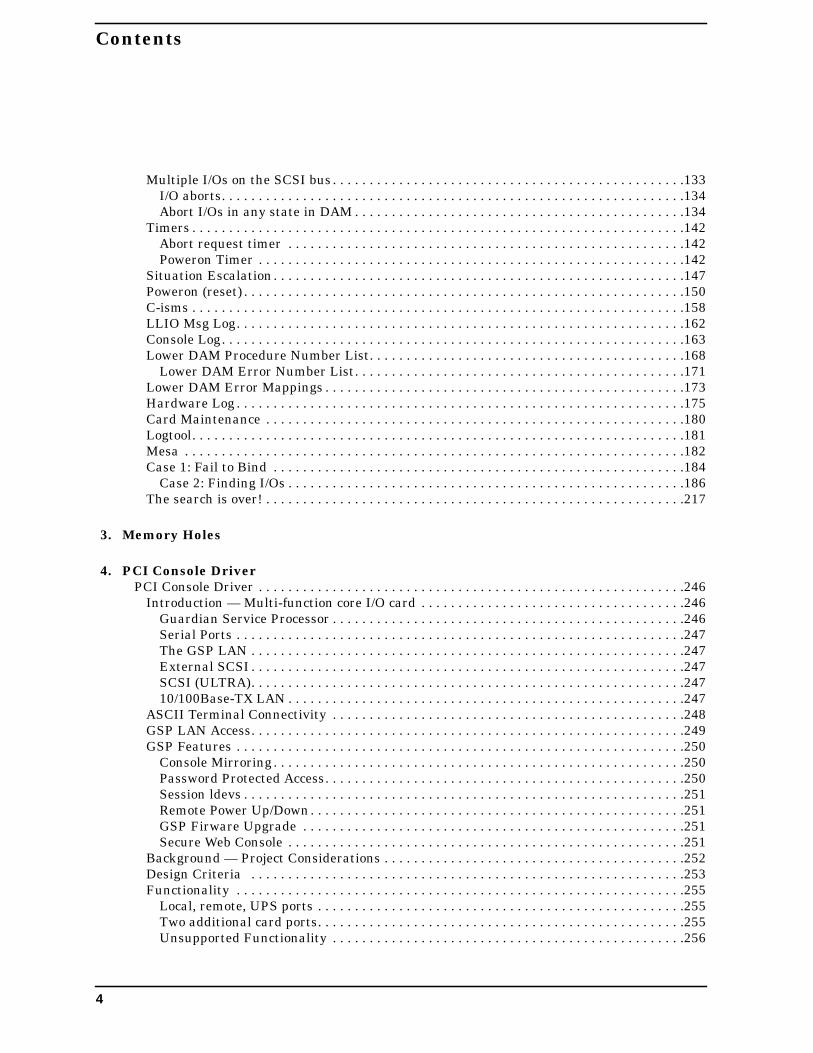
Slide 4 Speaker Notes
Because minimum memory on these processors will be 1Gb perprocessor, these models will need to wait until the first releaserestriction of 2Gb is removed.
for internal use only
hp e3000
7.0 fieldtraining
N4000 Configurations
Model # Proc MinMem
MaxMem
A4000-300-44 3440mhz
3Gb (16Gb)
A4000-400-44 4440mhz
4Gb (16Gb)
A4000-300-55 3550mhz
3Gb (16Gb)
A4000-400-55 4550mhz
4Gb (16Gb)
10 Chapter 1

Hardware Overview Monitor and I/O Services
Figure 1-5 Slide 5
Slide 5 Speaker Notes
Here is a picture of the inside of a N4000. Processors are finned unitstoward the top of the picture. Memory is along the right hand side.
for internal use only
hp e3000
7.0 fieldtraining
N4000
Add picture of back of Prelude
Chapter 1 11

Hardware Overview Monitor and I/O Services
Figure 1-6 Slide 6
Slide 6 Speaker Notes
Note the three power plugs at the bottom center. At least two of thethree must be connected, the third is a redundant supply.
Open slots on left and right sides are the I/O slots for PCI cards.
Two disk drives directly under the Serial/UPS connector. The N4000supports hot swap disks, but MPE does not.
for internal use only
hp e3000
7.0 fieldtraining
N4000
Add picture on inside of Prelude
FiberChannel
RemoteConsole
LocalConsole
LANConsole
Serial/UPS
10/100BT
Ultra 2SCSI
12 Chapter 1

Hardware Overview Monitor and I/O Services
Figure 1-7 Slide 7
Slide 7 Speaker Notes
In this diagram: Bus converter is the DEW chip, the system bus isMerced, and the IO controller is Ike.
MPE will initially ship with 8500 chips with upgrades as the 8x00family of chips becomes available.
for internal use only
hp e3000
7.0 fieldtraining
Ultra2 SCSI port - Independent of internal disks10/100Base-TX portRS-232 port
Service Processorsystem management ports
10Base-TX LAN console portRemote serial console (modem) portLocal serial console port
Hot Plug PCITwin Turbo slots
Ultra SCSI bus 1
Optional internal hot-plugdisks
Ultra SCSI bus 0
SystemBus 0
PA-8600CPU
PA-8600CPU
Memory Carriers 8 DIMM Slots per Carrier
ò Up to 8 high-performance CPUsò PA-8600 @ 550MHz, orò PA-8500 @ 360MHz & 440MHzò Fully symmetricalmultiprocessingò 1.5MB on chip I/D cache perCPU
PA-8600CPU
PA-8600CPU
PA-8600CPU
PA-8600CPU
PA-8600CPU
PA-8600CPU
SystemBus 1
System speeds and feeds
System bus bandwidth 4.3GB/sMemory bus bandwidth 8.5GB/sI/O bandwidth total 6.4GB/sCPU to Memory Latency 105ns
Hot- plugPCITurboslots
Hot-plugPCITwin Turboslots
Very LowLatencyMemory
Controller
IntegratedMultifunction
Core I/O
BusConverter
BusConverter
BusConverter
BusConverter
I/O C
ontr
olle
r I/O C
ontroller
Chapter 1 13

Hardware Overview Monitor and I/O Services
Figure 1-8 Slide 8
Slide 8 Speaker Notes
MPE will be using the same IO core card as UNIX.
Support will not be available for 10/100BT on the core IO card at firstrelease. It will require a separate 10/100BT card, supplied with thesystem.
• The blocks labeled IO Controller are known as Ike chips
• The blocks labeled 2X PCI or 4X PCI are know as Elroy chips
• The buses connecting Ike to Elroy is known as Rope.
Note that the 4X PCI slots require two ropes.
for internal use only
hp e3000
7.0 fieldtraining I/O Subsystem
Ultra2 SCSI port10/100BaseT portRS-232 port
LAN Console portRemote console (modem) portLocal serial console port
Ultra SCSI bus 1
Optional internalHot-Plug disks
Ultra SCSI bus 0
System Bus 0
I/O speeds and feeds
All I/0 slots support 66 MHz x 64 bit PCI busTwin-Turbo slots use two I/O channelsTurbo slots use a single I/O channel
Single I/O Channel 266MB/sTwin I/O Channel 532MB/sI/O bandwidth total 6.4GB/s
IntegratedMultifunction
Core I/O
4X PCITwin Channel
4X PCITwin Channel
4X PCITwin Channel
4X PCITwin Channel
4X PCITwin Channel
4X PCITwin Channel
TwinTurbo
TwinTurbo
Twin
Turbo
TwinTurbo
TwinTurbo
TwinTurbo
System Bus 1
All Hot-Plug
SingleChannel
SingleChannel
MemoryController
Service Processorsystem mgmt. ports
Turbo
Turbo
4X PCITwin Channel
4X PCITwin Channel
4X PCITwin Channel
4X PCITwin Channel
2X PCISingle Channel
2X PCI
TwinTurboTwinTurboTwinTurbo
TwinTurbo
Single Channel
All Hot-Plug
I/O C
ontrollerI/O C
ontr
olle
r
14 Chapter 1

Hardware Overview Monitor and I/O Services
Figure 1-9 Slide 9
Slide 9 Speaker Notes
This diagram brings the last two diagrams into a total picture.
for internal use only
hp e3000
7.0 fieldtraining
N4000
Add block diagram of prelude
Chapter 1 15

Hardware Overview Monitor and I/O Services
Figure 1-10 Slide 10
Slide 10 Speaker Notes
Front panel of A400 or A500 - aka Crescendo
When the front bezel is removed, the two internal disks will be foundbehind the HP logo.
for internal use only
hp e3000
7.0 fieldtraining
A400/500Discs
Run Attn
Fault
Remote
Power
16 Chapter 1

Hardware Overview Monitor and I/O Services
Figure 1-11 Slide 11
Slide 11 Speaker Notes
All A400/500 models are software throttled.
Max memory will be 2Gb on first release, increasing to 8Gb on futurereleases.
for internal use only
hp e3000
7.0 fieldtraining
A400/500 Configurations
Model # Proc MinMem
MaxMem
A400-100-11 1110mhz
128Mb
2Gb (8Gb)
A500-100-14 1140mhz
512Mb
2Gb (8Gb)
A500-200-14 2140mhz
512Mb
2Gb (8Gb)
Chapter 1 17

Hardware Overview Monitor and I/O Services
Figure 1-12 Slide 12
Slide 12 Speaker Notes
Interior of A400/500.
• Processors are the assemblies in the center of the chassis.
• Memory are the vertical boards in the upper right.
• PCI cards mount under sheet metal in upper left of chassis.
• Disks are under the sheet metal in the lower left.
• Power supplies are under the large label in the lower right.
for internal use only
hp e3000
7.0 fieldtraining
A400/500
18 Chapter 1

Hardware Overview Monitor and I/O Services
Figure 1-13 Slide 13
Slide 13 Speaker Notes
This is back of the A400/500
Note that both Single-Ended and Ultra 2 SCSI connectors.
As with the N4000, the power switch is really a standby switch whichleaves the GSP active.
for internal use only
hp e3000
7.0 fieldtraining
A400/500
PowerSwitch
Ultra 2SCSI
SESCSI
10/100BT LANConsole
ConsoleUPS
Chapter 1 19

Hardware Overview Monitor and I/O Services
Figure 1-14 Slide 14
Slide 14 Speaker Notes
Here is a block diagram of the A400/500.
No merced bus. Astro does conversion from Runway to Ropes.
Two PCI slots driven from one Elroy (shared slot).
for internal use only
hp e3000
7.0 fieldtraining
20 Chapter 1

Hardware Overview Monitor and I/O Services
Figure 1-15 Slide 15
Slide 15 Speaker Notes
These processors can be accessed via a telnet session over a LANconnected to the LAN console connection. The customer system mayrequire login and password.
You will also get to a similar screen from system power-on.
for internal use only
hp e3000
7.0 fieldtraining
Remote Console Access$ telnet csysas2Trying...Connected to csysas2.cup.hp.com.Escape character is '^]'.Local flow control off
Service Processor login: <cr>Service Processor password: <cr>
Welcome to HP Guardian Service Processor
9000/800/N4000-36 System Name: csysas2
Chapter 1 21
Hardware Overview Monitor and I/O Services
Figure 1-16 Slide 16
Slide 16 Speaker Notes
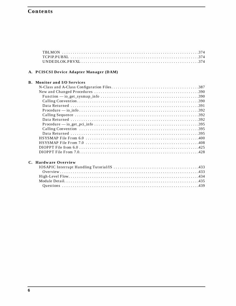
This is the GSP prompt. This is the point from which you will do RS orTC, as well as any of the other commands listed here and on the nextcouple of slides.
for internal use only
hp e3000
7.0 fieldtraining
GSP Prompt
GSP Host Name: csysas2GSP>he
HE
Firmware Revision X.17.02 Apr 28 1999,18:06:22
AC : Alert Display ConfigurationAR : Configure the Automatic System RestartCA : Configure local and remote consoleparametersCE : Log a chassis code in the GSP chassis codehistory bufferCL : Display the history of the ConsoleZCTGNAYOR : Clear GSP NVM at your own riskCO : Return to Console Mode
22 Chapter 1

Hardware Overview Monitor and I/O Services
Figure 1-17 Slide 17
Figure 1-18 Slide 18
for internal use only
hp e3000
7.0 fieldtraining
GSP Prompt
GSP Host Name: csysas2GSP>he
HE
Firmware Revision X.17.02 Apr 28 1999,18:06:22
AC : Alert Display ConfigurationAR : Configure the Automatic System RestartCA : Configure local and remote consoleparametersCE : Log a chassis code in the GSP chassis codehistory bufferCL : Display the history of the ConsoleZCTGNAYOR : Clear GSP NVM at your own riskCO : Return to Console Mode
for internal use only
hp e3000
7.0 fieldtraining
GSP PromptQMM : Quit the manufacturing modeRP : Reset password configurationRS : System reset through RST signalSE : Activate a system session on local orremote portSL : Display SPU status logsSO : Configure security options and accesscontrolSS : Display the status of the system processorsTC : System reset through INIT signalTE : Sends a message to other terminalsVFP : Activates Alert Log Display (all portsexcept internal port)VT : View Trace bufferWHO : Display a list of GSP connected usersXD : GSP Diagnostics and ResetXU : Upgrade the GSP FirmwareSDM : Set Display Mode (hex or text)
Chapter 1 23
Hardware Overview Monitor and I/O Services
Figure 1-19 Slide 19
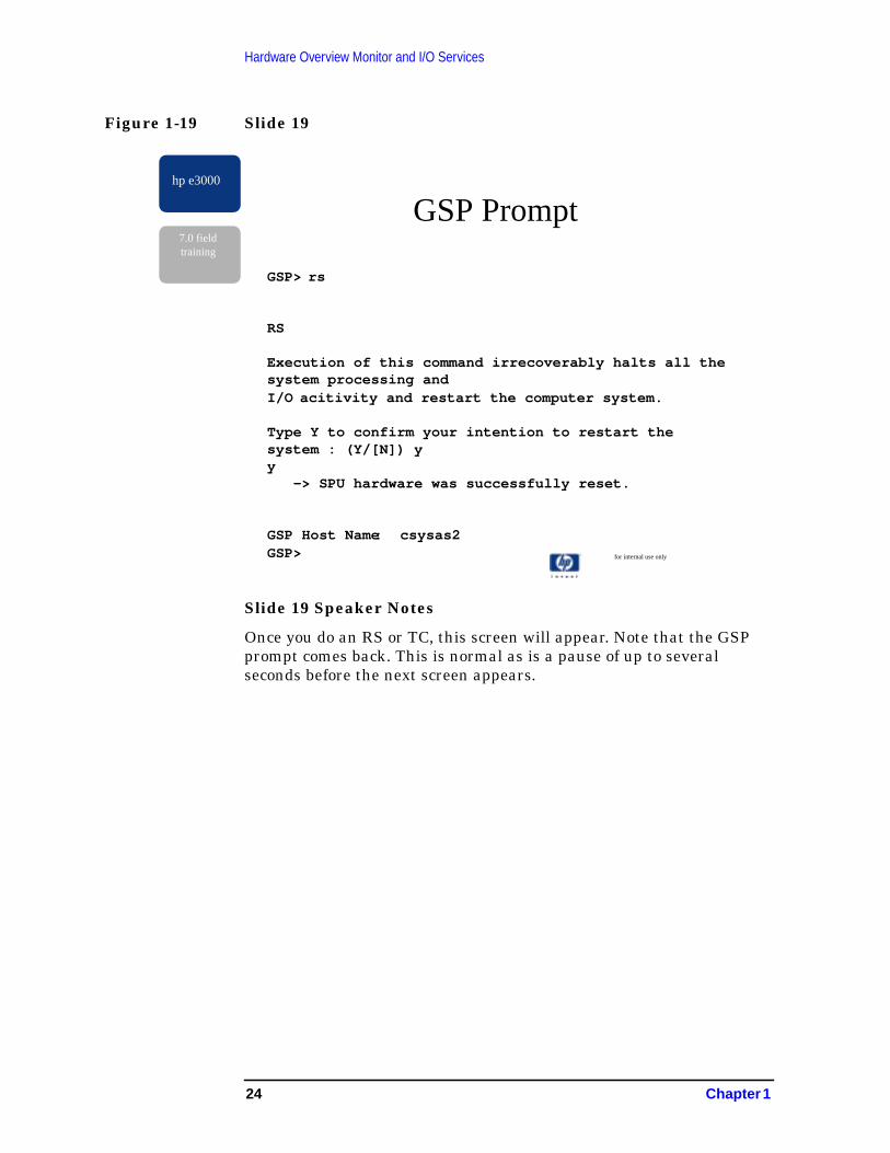
Slide 19 Speaker Notes
Once you do an RS or TC, this screen will appear. Note that the GSPprompt comes back. This is normal as is a pause of up to severalseconds before the next screen appears.
for internal use only
hp e3000
7.0 fieldtraining
GSP Prompt
GSP> rs
RS
Execution of this command irrecoverably halts all thesystem processing andI/O acitivity and restart the computer system.
Type Y to confirm your intention to restart thesystem : (Y/[N]) yy -> SPU hardware was successfully reset.
GSP Host Name: csysas2GSP>
24 Chapter 1

Hardware Overview Monitor and I/O Services
Figure 1-20 Slide 20
Slide 20 Speaker Notes
Following the pause mentioned on the previous slide, this screen willappear. The four digit numbers in the right column are equivalent tothe hex display on current processors. A large number of these statuslines will appear on the screen as PDC goes through its self-test.
for internal use only
hp e3000
7.0 fieldtraining
GSP Prompt
********** VIRTUAL FRONT PANEL **********System Boot detected*****************************************platform config 602Fprocessor slave rendezvous 10C7processor slave rendezvous 10C7processor slave rendezvous 10C7processor test 1012processor test 1010processor test 1010...
Chapter 1 25
Hardware Overview Monitor and I/O Services
Figure 1-21 Slide 21
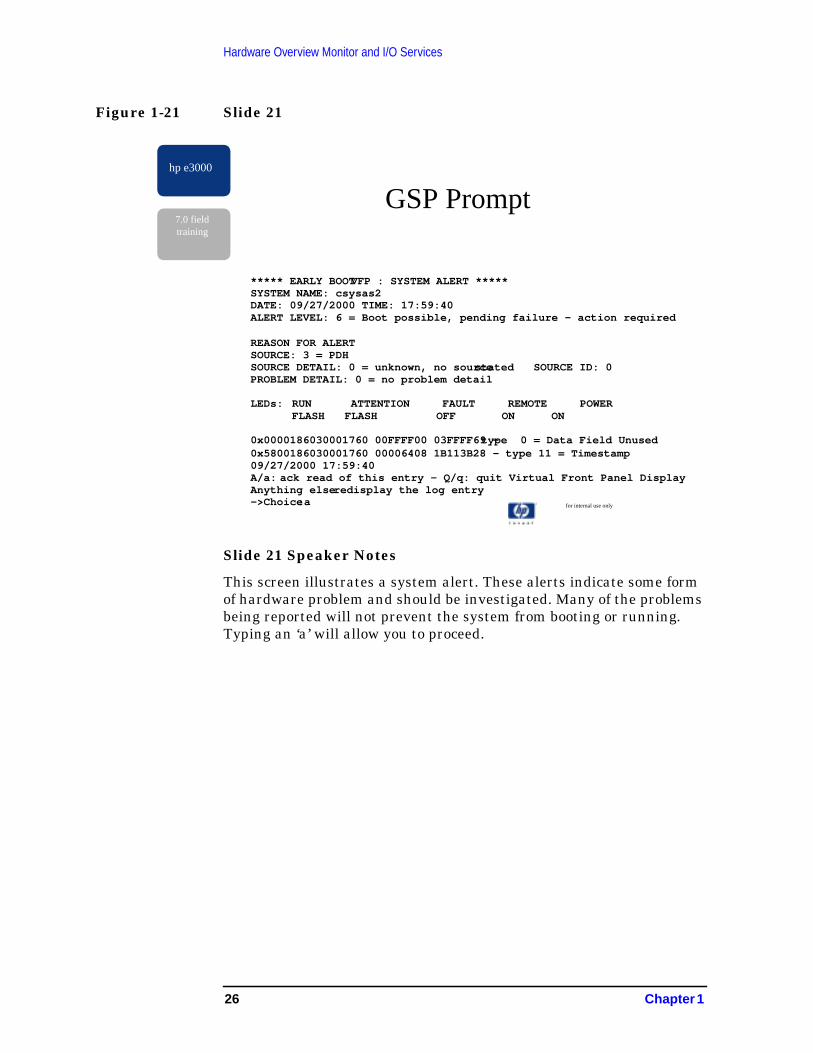
Slide 21 Speaker Notes
This screen illustrates a system alert. These alerts indicate some formof hardware problem and should be investigated. Many of the problemsbeing reported will not prevent the system from booting or running.Typing an ‘a’ will allow you to proceed.
for internal use only
hp e3000
7.0 fieldtraining
GSP Prompt
***** EARLY BOOT VFP : SYSTEM ALERT *****SYSTEM NAME: csysas2DATE: 09/27/2000 TIME: 17:59:40ALERT LEVEL: 6 = Boot possible, pending failure - action required
REASON FOR ALERTSOURCE: 3 = PDHSOURCE DETAIL: 0 = unknown, no source stated SOURCE ID: 0PROBLEM DETAIL: 0 = no problem detail
LEDs: RUN ATTENTION FAULT REMOTE POWERFLASH FLASH OFF ON ON
0x0000186030001760 00FFFF00 03FFFF69 - type 0 = Data Field Unused0x5800186030001760 00006408 1B113B28 - type 11 = Timestamp09/27/2000 17:59:40A/a: ack read of this entry - Q/q: quit Virtual Front Panel DisplayAnything elseredisplay the log entry->Choice :a
26 Chapter 1
Hardware Overview Monitor and I/O Services
Figure 1-22 Slide 22
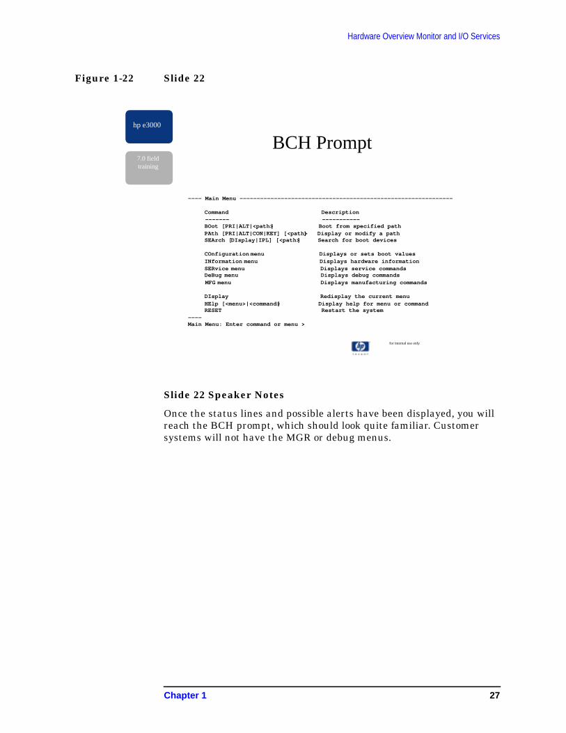
Slide 22 Speaker Notes
Once the status lines and possible alerts have been displayed, you willreach the BCH prompt, which should look quite familiar. Customersystems will not have the MGR or debug menus.
for internal use only
hp e3000
7.0 fieldtraining
BCH Prompt
---- Main Menu --------------------------------------------------------------
Command Description ------- -----------
BOot [PRI|ALT|<path> ] Boot from specified pathPAth [PRI|ALT|CON|KEY] [<path> ] Display or modify a pathSEArch [DIsplay|IPL] [<path> ] Search for boot devices
COnfiguration menu Displays or sets boot valuesINformation menu Displays hardware informationSERvice menu Displays service commandsDeBug menu Displays debug commands
MFG menu Displays manufacturing commands
DIsplay Redisplay the current menuHElp [<menu>|<command> ] Display help for menu or commandRESET Restart the system
----Main Menu: Enter command or menu >
Chapter 1 27

Hardware Overview Monitor and I/O Services
Figure 1-23 Slide 23
Slide 23 Speaker Notes
This screen illustrates additional messages you will see on the screenfollowing the START command. As the system scans the PCI buses, anactivity indicator is placed on the screen for each possible module onthe bus.
+ indicates a PCI card is present
* indicates a multi-function PCI card is present
. indicates an empty or non-existent slot
for internal use only
hp e3000
7.0 fieldtraining
System Boot
ISL> startnorecoveryMPE/iX launch facility
Scanning PCI BUS 0 ++* ..++..........................Scanning PCI BUS 8 + ...............................Scanning PCI BUS 10 ................................Scanning PCI BUS 20 + ...............................Scanning PCI BUS 28 ................................Scanning PCI BUS 40 ................................Scanning PCI BUS 50 + ...............................Scanning PCI BUS60 ..
28 Chapter 1

Hardware Overview Monitor and I/O Services
Figure 1-24 Slide 24
Slide 24 Speaker Notes
The path is formed from left to right. Each slash indicates a busconverter of some type.
The first digit indicates the address of the Ike (0 or 1) or the Astro(always 0)
The second digit indicates the attached Elroy. This number goes up by 2for twin turbo slots.
The third digit indicates the PCI device attached to the Elroy. This istypically 0. The exceptions are the core I/O card and the shared slot onA400/500.
The fourth digit is the PCI function number.
The fifth digit is the SCSI target.
The sixth digit is the SCSI LAN
NOTE The mapping of these paths to the physical I/O slots is arbitrary. Youmust refer to the labels. Do not try to determine a slot number bycounting.
for internal use only
hp e3000
7.0 fieldtraining Path
0/0/2/0.6.0
ST39103LC - Disc Drive
PseudoA5150A - PCI_SCSI_MGR
PCI_DEVICE - PCI_DEVICE_MGR
PAT_PCI_BC - PCI_ELROY_MGR
PAT_IOA_BC - PCI_IKE_MGR
Chapter 1 29
Hardware Overview Monitor and I/O Services
Figure 1-25 Slide 25
Slide 25 Speaker Notes
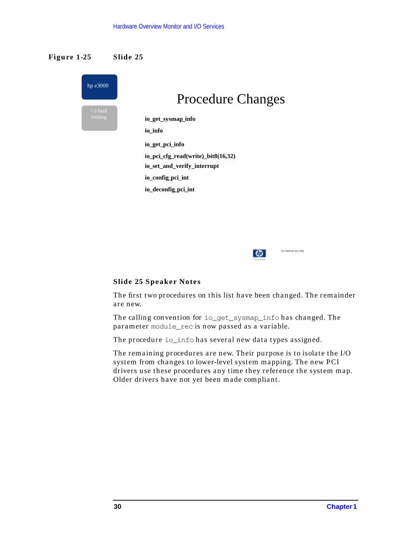
The first two procedures on this list have been changed. The remainderare new.
The calling convention for io_get_sysmap_info has changed. Theparameter module_rec is now passed as a variable.
The procedure io_info has several new data types assigned.
The remaining procedures are new. Their purpose is to isolate the I/Osystem from changes to lower-level system mapping. The new PCIdrivers use these procedures any time they reference the system map.Older drivers have not yet been made compliant.
for internal use only
hp e3000
7.0 fieldtraining
Procedure Changesio_get_sysmap_info
io_info
io_get_pci_info
io_pci_cfg_read(write)_bit8(16,32)
io_set_and_verify_interrupt
io_config_pci_int
io_deconfig_pci_int
30 Chapter 1
Hardware Overview Monitor and I/O Services
Figure 1-26 Slide 26
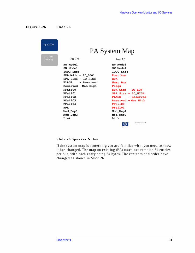
Slide 26 Speaker Notes
If the system map is something you are familiar with, you need to knowit has changed. The map on existing (PA) machines remains 64 entriesper bus, with each entry being 64 bytes. The contents and order havechanged as shown in Slide 26.
for internal use only
hp e3000
7.0 fieldtraining
PA System MapPre 7.0 Post 7.0
HW ModelSW ModelIODC infoSPA Addr - IO_LOWSPA Size - IO_HIGHFLAGS - ReservedReserved - Mem HighPFail00PFail01PFail02PFail03PFail04HPAMod_Dep1Mod_Dep2Link
HW ModelSW ModelIODC infoPort NumHPANext BusFlagsSPA Addr - IO_LOWSPA Size - IO_HIGHFLAGS - ReservedReserved - Mem HighPFail00PFail01Mod_Dep1Mod_Dep2Link
Chapter 1 31

Hardware Overview Monitor and I/O Services
Figure 1-27 Slide 27
Slide 27 Speaker Notes
The system map for the N4000 and A400/500 has changedsubstantially. The record structure has grown mush larger than theoriginal 64 bytes. The full definition can be found in the listings in thisdocument. There are many possible variations depending on the typesof bus converters and cards connected. The other difference is thatthere is no longer an entry per possible slot location, as in the old map.Now there is one entry per actual device/bus converter. The pointersNext Bus and Next Entry are the navigation mechanisms for this newbus, rather than the indexing schemes used previously.
for internal use only
hp e3000
7.0 fieldtraining
PAT System Map
HW ModelSW ModelIODC InfoModule NumberHPANext BusFlagsArchDep InfoNext Entry
32 Chapter 1

Hardware Overview Monitor and I/O Services
Figure 1-28 Slide 28
Slide 28 Speaker Notes
The Physical Path Table has had additional entries added. The originaltable is shown in the first column. The second column contains newentries dealing with Mesa diagnostics. The final column containsentries added to support PCI buses. The full definitions for the old andnew PPT entries are in this document.
for internal use only
hp e3000
7.0 fieldtraining
Physical Path Table
per_mgr_entryptper_port_numper_pdaper_pathper_mgr_nameper_hw_prod_numper_mgr_priorityper_config_stateper_autoconfigedper_made_residentper_creation_optper_mgr_cntper_da_classper_obj_classper_child_ptrper_sibling_ptrper_alt_path_ptrper_eimper_ada_size
per_tokenper_hw_typeper_stateper_parent_ptrper_device_id_info
per_mgr_pfaper_mgr_subsys_numper_interrupt_hintsper_pci_dino_pathper_mgr_hw_model_revper_mgr_sw_model_revper_mgr_module_typeper_mgr_hw_flagsper_mgr_pa
Chapter 1 33
Hardware Overview Monitor and I/O Services
Figure 1-29 Slide 29
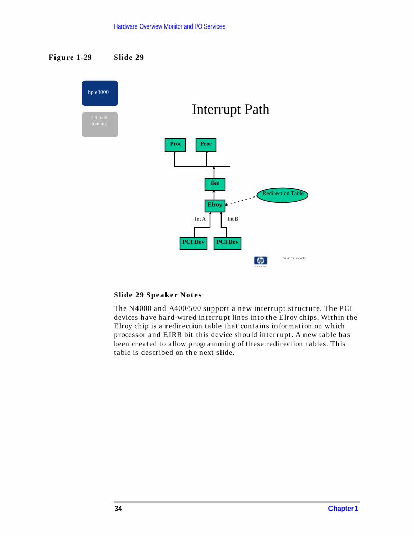
Slide 29 Speaker Notes
The N4000 and A400/500 support a new interrupt structure. The PCIdevices have hard-wired interrupt lines into the Elroy chips. Within theElroy chip is a redirection table that contains information on whichprocessor and EIRR bit this device should interrupt. A new table hasbeen created to allow programming of these redirection tables. Thistable is described on the next slide.
for internal use only
hp e3000
7.0 fieldtraining
Interrupt Path
Proc
Ike
Proc
Elroy
PCI Dev PCI Dev
Int A Int B
Redirection Table
34 Chapter 1

Hardware Overview Monitor and I/O Services
Figure 1-30 Slide 30
Slide 30 Speaker Notes
There is a pointer at IVA-514 which points to the IOSAPIC table. Thisis the table from which the Elroy redirection table programming takeplace. There is one entry for each Elroy. Each Elroy entry contains anentry for each of the possible eight interrupt lines on the Elroy. Withineach of these entries is the information needed to program the Elroy.This includes the CPU number, the EIRR bit, mode information for theElroy regarding type of interrupt (edge trigger, level polarity, etc.), thenumber of devices connected to this interrupt pin, and a list ofconnected devices.
For additional information on Monitor and I/O Services, refer toAppendix B , “Monitor and I/O Services,” and Appendix C , “HardwareOverview.”
for internal use only
hp e3000
7.0 fieldtraining
IOSAPIC Table
Elroy1
Elroy2
Elroy3
Elroy4
IVA-514
mon_iosapic
int 1
int 8
CPU No
EIRR
Elroy mode
Num Devices
ConnectedDev’s
Chapter 1 35

Hardware Overview Monitor and I/O Services
36 Chapter 1
2 PCISCSI Device AdapterManager (DAM)
Figure 2-1 Slide 1
for internal use only
hp e3000
PCISCSI Device AdapterManager (DAM)
Internals Training
37
PCISCSI Device Adapter Manager (DAM)Internals Training
Internals Training
• Training Objective:
The PCISCSI DAM Internals Training class is intended to teach driverdata structures, and driver processes such that an MPE/iX field supportor factory lab engineer can diagnose and maintain the PCISCSI DAMcode.
• Audience:
The material presented contains low_level code examples anddetailed data structures explanations. This is more that a field supportengineer requires in order to isolate the problem to the PCISCSI DAM.The instructor may skip over portions of the training material andcustomize the course to the audience’s needs. The entire training courseshould me made familiar for factory lab engineers.
Additional information is located in System Tables (31900-90017) andAppendix A , “PCISCSI Device Adapter Manager (DAM),” of thismanual.
Apologies in advance for the overwhelming amount of material.
38 Chapter 2
PCISCSI Device Adapter Manager (DAM)Internals Training
Figure 2-2 Slide 2
Figure 2-3 Slide 3
hp e3000
7.0 fieldtraining
Class Content
· Introduction
· Additional References
· Internal Data Structures
· DAM Processes
· DAM logs
· System Diagnostics
· Troubleshooting
hp e3000
7.0 fieldtraining
Additional References
· “PCISCSI Lower DAM Data Types -Explanations/Examples”
· “Console Log - Example”
· “Logs and Data Structures for a Good System -Example”
Chapter 2 39

PCISCSI Device Adapter Manager (DAM)Additional References
Additional References“PCISCSI Lower DAM Data Types - Explanations/Examples”
located at http://csy.cup.hp.com/division/index.htm
Figure 2-4 Slide 4
Introduction
New! PCI based SCSI Interface Cards
New! PCISCSI DAM
PCSISCSI DAM in 3 layers
PCI Based SCSI Interface Cards
A new set of PCI-based SCSI interface cards are being introduced withthe new N-class high-performance computing systems. These cards areOEM from SYMBIOS company and deliver state-of-the-art interfacehardware and SCSI bus protocols. Customers will experience adramatic increase in throughput when these cards are configured withnew LVD (low-voltage differential) 10,000 RPM disk systems.SYMBIOS cards are auto-sensing for the particular bus and offerself-protection should a bus mis-configuration occur by shutting off its
hp e3000
7.0 fieldtraining
Introduction
· New! PCI-based SCSI Interface Cards
· New! PCSISCSI DAM (Device Adapter Manager)
· PCISCSI DAM in 3 Layers
· Upper DAM: interface with higher managers (e.g.device drivers)
· Interface Layer: interface between upper and lowerDAM (data mappings, function call sequences)
· Lower DAM: Process I/O requests to the SCSI bus.Manage SCSI bus and DMA data transfers
40 Chapter 2

PCISCSI Device Adapter Manager (DAM)Additional References
interface drivers. The SYMBIOS LVD interface card is especiallyversatile with its ability to auto-sense and support either wide-dataLVD, wide-data SE, and narrow-data SE. The four cards beingintroduced are:
• A5149A (LVD single port)
• A5150A (LVD dual port)
• A4800A (HVD single port)
• A5159A (HVD dual port)
PCISCSI DAM
A new interface manager PCISCSI DAM has been created that willsupport these new cards in all the various configurations. The PCISCSIDAM contains a large portion of the HP-UX c720 scsi interface driverhas the hardware driver to control the SCSI bus and process I/Otransactions. The decision to port HP-UX c720 scsi driver was to takeadvantage of the proven interface driver code and deliver this modulesooner to customers.
PCISCSI DAM in 3 Layers
Porting of HP-UX c720 scsi driver to MPE/iX posed several engineeringchallenges such as sharing “C” data structure with MPE’s MODCALOperating System and even getting the code to compile and executereliably. In the end, an interface to MPE/iX I/O subsytem for HP-UXc720 scsi driver was done with a three layer DAM architecture:
Upper DAM: interface with higher managers (e.g., device drivers)
Interface Layer: interface between upper and lower DAM (datamappings, function call sequences).
Lower DAM: Process I/O requests to the SCSI bus. Manage SCSI busand DMA data transfers.
Upper DAM provides all the standard interface functions tocommunicate with other I/O drivers in the I/O subsystem. Suchfunctions include binding, configuration, ports interface, LLIOmessages handling and logging.
Interface layer maps data from upper to lower dam data structures andcalls functions to perform the desired lower DAM functions.
Lower DAM operates the interface hardware via card registermanipulations and SCSI scripts. The DAM code sets up DMAoperations to transfer data from host memory to local FIFO buffers andthen works with the target device to transfer data to and from thedevice. Exception conditions such as unexpected phase changes on theSCSI bus are also handled by the lower DAM code.
Chapter 2 41
PCISCSI Device Adapter Manager (DAM)Additional References
Figure 2-5 Slide 5
Best of HP-UX and MPE/iX
HP-UX — Support of multiple SCSI bus interface cards for SE, LVD,HVD devices.
MPE/iX — Robust device drivers, and modular I/O subsystem,
PCISCSI team was offered an opportunity to look at MPE/iX andHP-UX to find the best interface driver for the new N-class computerplatform. Investigations were launched looking for a new driversolution and it considered: 1) HP-UX driver porting code, 2) writing adriver from scratch, or 3) a hybrid of MPE and HP-UX. The decision fora hybrid solution gave the team on-going flexibility to take the best ofOperating Systems to create new driver.
HP-UX driver code has been released and proven itself to support thenew interface cards in high performance capacities. The efficiency of “C”code to do low-level interactions with card registers makes “C” the rightlanguage choice.
MPE/iX I/O subsystem is robust in device classes it support, modular inseparating device drivers and interface drivers, and flexible througharchitected ports interfaces. A new interface driver, PCISCSI DAM,could utilize existing.
MPE/iX device drivers by providing the architected interface to the I/Osubsystem. The engine operating the hardware could be HP-UXleveraged and be compatible with MPE/iX.
hp e3000
7.0 fieldtraining
Introduction Cont’d
· Best of HP-UX and MPE/iX
· MPE/iX robust device drivers and modular I/Osubsystem
42 Chapter 2

PCISCSI Device Adapter Manager (DAM)Additional References
Figure 2-6 Slide 6
hp e3000
7.0 fieldtraining
Upper DAM Internal Data Structures[overview]
· Upper DAM bedsheet
· Port Data Area (PDA)
· Port Sub-Qs and Pending Qs
· Higher Mgr info (pciscsi_tgt_table)
· Request table (pciscsi_req_table)
Chapter 2 43

PCISCSI Device Adapter Manager (DAM)Additional References
Figure 2-7 Slide 7
hp e3000
7.0 fieldtraining
Upper DAM Bedsheet
44 Chapter 2

PCISCSI Device Adapter Manager (DAM)Additional References
Figure 2-8 Slide 8
Port Data Area (PDA)
Local logs
Managers state
Operational Info
Pending Queues and active requests table
Each MPE/iX I/O driver contains a private data area called the PortData Area. No other driver or manager has access to this area.PCISCSI DAM does not share data with other instances of the PCISCSIDAM nor any I/O modules except through the use of LLIO messagesand the ports interface.
Port Data Area contains various items for operation of the DAM ingeneral and specific to upper DAM. All trace logs for the upper andlower DAM are kept at the PDA’s end. Manager state and operationalinformation is available in the PDA. Active and pending I/O requestmanagement items are also here.
Read the PDA and comments following:
hp e3000
7.0 fieldtraining
Port Data Area (PDA)
· Local logs
· Managers state
· Operational Info
· Pending Qs and active requests table
Chapter 2 45

PCISCSI Device Adapter Manager (DAM)Additional References
{--------------------------------------------------------------------------}
{ Mgr States }
{--------------------------------------------------------------------------}
CONST
Initialize_Handlers = 0; { Initialize message handlers }
Init_Dam = 1; { Init DAM data areas and interfacehardware }
Bind_Lower_Mgr = 2; { Bind to lower manager }
Ready_For_Io = 3; { Ready to do I/O }
Power_On_Reset = 4; { Poweron reset }
Mgr_Broken = 5; { Mgr broken. Can only perform config(eg. unbind) }
Unbind_Lower_Mgr = 6; { Unbind from lower manager }
PCISCSI_PDA_TYPE = RECORD
{-----------------------------------------------------------------------------}
{==== DAM LOGS POINTERS ====}
{-----------------------------------------------------------------------------}
num_log_tables : integer; { The number of logs the DAM has}
msg_log_table_addr : localanyptr; { Pointer to LLIO Msg log table }
hw_log_table_addr : localanyptr; { Pointer to hardware log table }
console_log_table_addr : localanyptr; { Pointer to console msgs log table }
version_date : pac44; { PCISCSI compile string }
{-----------------------------------------------------------------------------}
{==== MANAGER STATE AND PORT INFORMATION (subQ and associated data areas) ====}
{-----------------------------------------------------------------------------}
mgr_state : bit8; { Dobinding, Initializing, Normal_Io,}
{ Unbinding: used to tell us which msgs }
{ are valid to receive in a given state }
my_port : port_num_type; { My port number }
aux_data_ptr : localanyptr; { Pointer to the auxiliary data area }
my_enabled_subqs : set_of_32; { My enabled subqueues as of the lasttime I exited }
{-----------------------------------------------------------------------------}
{==== SCSI CDBs AREA ====}
{-----------------------------------------------------------------------------}
tur_cdb : packed array [1..Group_1_Cdb_Len] of char;
46 Chapter 2
PCISCSI Device Adapter Manager (DAM)Additional References
{ Take advantage of the PDA initially }
{ created with all zeroes }
{-----------------------------------------------------------------------------}
{==== LOWER MANAGER INFO ====}
{-----------------------------------------------------------------------------}
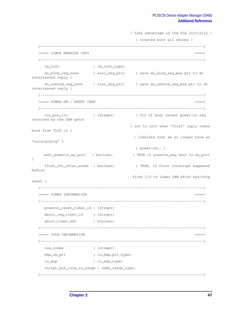
lm_info : lm_info_type;
do_bind_req_save : scsi_msg_ptr; { save do_bind_req_msg ptr to dointerleaved reply }
do_unbind_req_save : scsi_msg_ptr; { save do_unbind_req_msg ptr to dointerleaved reply }
{-----------------------------------------------------------------------------}
{==== POWER-ON / RESET CARD ====}
{-----------------------------------------------------------------------------}
cur_pon_trn : integer; { Trn of most recent power-on reqreceived by the DAM gets}
{ set to zero when "final" reply comesback from TLIH to }
{ indicate that we no longer have an"outstanding" }
{ power-on). }
sent_poweron_my_port : boolean; { TRUE if poweron_msg sent to my_port}
first_int_after_reset : boolean; { TRUE, if first interrupt happenedbefore
first I/O to lower DAM after bus/chipreset }
{-----------------------------------------------------------------------------}
{==== TIMER INFORMATION ====}
{-----------------------------------------------------------------------------}
poweron_reset_timer_id : integer;
abort_req_timer_id : integer;
abort_timer_set : boolean;
{-----------------------------------------------------------------------------}
{==== IOVA INFORMATION ====}
{-----------------------------------------------------------------------------}
ioa_index : integer;
map_cb_ptr : io_map_ptr_type;
io_map : io_map_type;
script_buf_iova_io_range : addr_range_type;
{-----------------------------------------------------------------------------}
Chapter 2 47
PCISCSI Device Adapter Manager (DAM)Additional References
{==== STATIC INFORMATION (about I/O hardware and DAM info.) ====}
{-----------------------------------------------------------------------------}
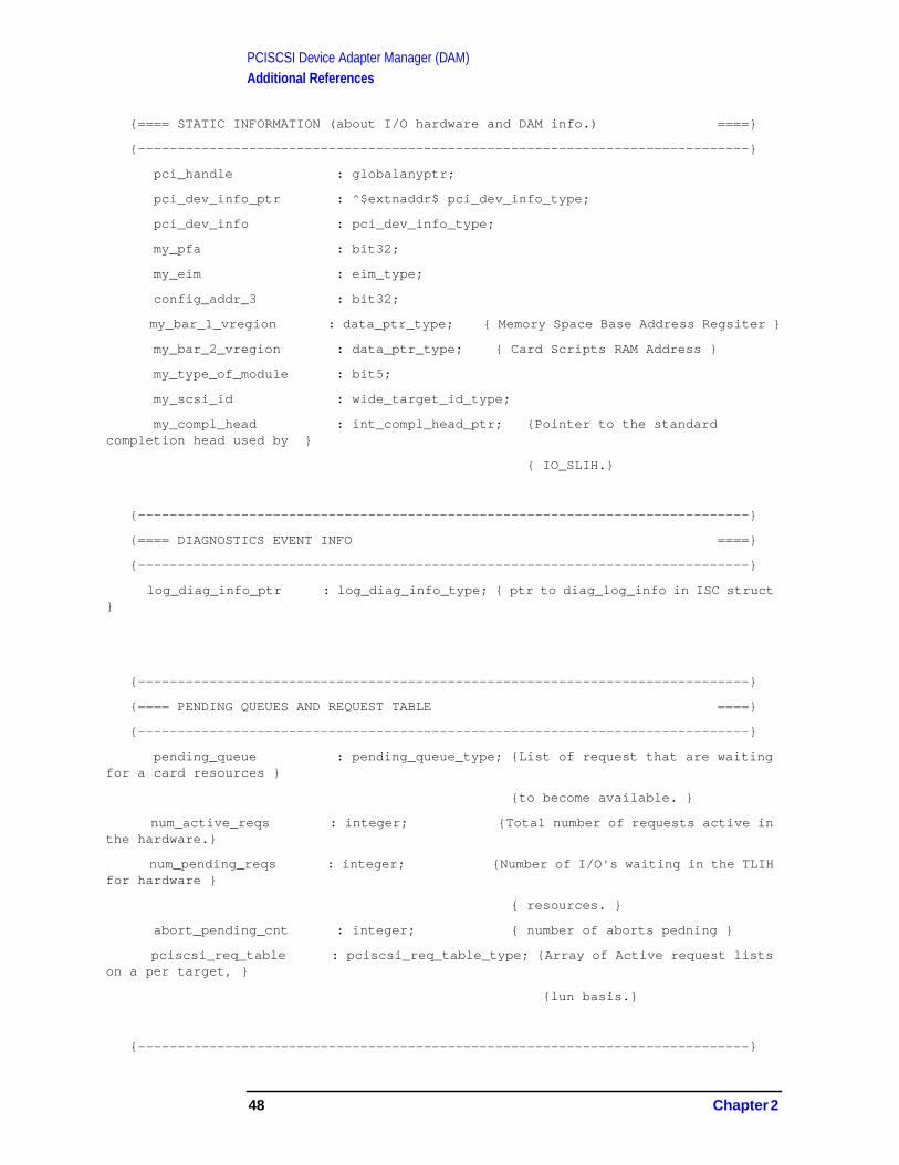
pci_handle : globalanyptr;
pci_dev_info_ptr : ^$extnaddr$ pci_dev_info_type;
pci_dev_info : pci_dev_info_type;
my_pfa : bit32;
my_eim : eim_type;
config_addr_3 : bit32;
my_bar_1_vregion : data_ptr_type; { Memory Space Base Address Regsiter }
my_bar_2_vregion : data_ptr_type; { Card Scripts RAM Address }
my_type_of_module : bit5;
my_scsi_id : wide_target_id_type;
my_compl_head : int_compl_head_ptr; {Pointer to the standardcompletion head used by }
{ IO_SLIH.}
{-----------------------------------------------------------------------------}
{==== DIAGNOSTICS EVENT INFO ====}
{-----------------------------------------------------------------------------}
log_diag_info_ptr : log_diag_info_type; { ptr to diag_log_info in ISC struct}
{-----------------------------------------------------------------------------}
{==== PENDING QUEUES AND REQUEST TABLE ====}
{-----------------------------------------------------------------------------}
pending_queue : pending_queue_type; {List of request that are waitingfor a card resources }
{to become available. }
num_active_reqs : integer; {Total number of requests active inthe hardware.}
num_pending_reqs : integer; {Number of I/O's waiting in the TLIHfor hardware }
{ resources. }
abort_pending_cnt : integer; { number of aborts pedning }
pciscsi_req_table : pciscsi_req_table_type; {Array of Active request listson a per target, }
{lun basis.}
{-----------------------------------------------------------------------------}
48 Chapter 2
PCISCSI Device Adapter Manager (DAM)Additional References
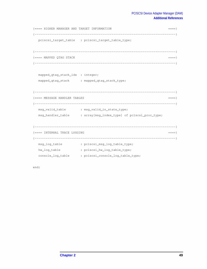
{==== HIGHER MANAGER AND TARGET INFORMATION ====}
{-----------------------------------------------------------------------------}
pciscsi_target_table : pciscsi_target_table_type;
{-----------------------------------------------------------------------------}
{==== MAPPED QTAG STACK ====}
{-----------------------------------------------------------------------------}
mapped_qtag_stack_idx : integer;
mapped_qtag_stack : mapped_qtag_stack_type;
{-----------------------------------------------------------------------------}
{==== MESSAGE HANDLER TABLES ====}
{-----------------------------------------------------------------------------}
msg_valid_table : msg_valid_in_state_type;
msg_handler_table : array[msg_index_type] of pciscsi_proc_type;
{-----------------------------------------------------------------------------}
{==== INTERNAL TRACE LOGGING ====}
{-----------------------------------------------------------------------------}
msg_log_table : pciscsi_msg_log_table_type;
hw_log_table : pciscsi_hw_log_table_type;
console_log_table : pciscsi_console_log_table_type;
end;
Chapter 2 49

PCISCSI Device Adapter Manager (DAM)Additional References
Figure 2-9 Slide 9
hp e3000
7.0 fieldtraining
Port Sub-Qs & Pending Qs
· Port Subqueues
· Pending queues
50 Chapter 2

PCISCSI Device Adapter Manager (DAM)Additional References
Port Sub-Qs & Pending Qs
Port Subqueues
Pending queues
A small set of port subqueues are used to interface with other I/Omodules. Subqueues 0 thru 2 are architected for specific usage. Suchas power_on (reset), configuration and I/O abort requests. Subqueues 3thru 5 have defined usage specific to this module. Timer pop messagesare sent to subqueue “3”. Interrupt messages from the third levelinterrupt handler are sent to subqueue “4”. All SCSI I/O requests aresent to subqueue “5”.
{ Architected Subqueues. }
Power_On_Subqueue = 0;
Config_Subqueue = 1;
Abort_Subqueue = 1;
Diagnostics_Subqueue = 2;
{ Other subqueues. }
Timer_Event_Subqueue = 3;
Tlih_Subqueue = 4;
Scsi_Request_Subqueue = 5;
Requests to the PCISCSI DAM may at some point stop on an internalpending queue. Poweron requests are processed then saved on thePoweron_reset pending_queue until the end of the Poweron (reset)sequence. Abort_req pending_queue have I/O requests queued forsending to the lower DAM to be aborted. Pending_resourcespending_queue contain new requests waiting to be allocated resourcesand started in the lower DAM.
pending_queue_name = (Poweron_Reset,
Abort_Req,
Pending_Resources);
Chapter 2 51

PCISCSI Device Adapter Manager (DAM)Additional References
Figure 2-10 Slide 10
hp e3000
7.0 fieldtraining
Higher Mgr Info
· Higher Mgr Binding Info
52 Chapter 2

PCISCSI Device Adapter Manager (DAM)Additional References
Higher Manager Info
Higher Manager Binding Info
During the configuration bind process, manager info is exchangedbetween the PCISCSI DAM and device managers. The higher managerinfo is used during none-I/O data transfer activities such power_on(reset), and device aen_polling .
pciscsi_target_table_type = array [ wide_target_id_type, lun_type] ofpciscsi_target_entry_type;
pciscsi_target_entry_type = RECORD
hm_info : hm_info_type; { Higher manager info }
aen_info : aen_info_type; { AEN buffer info }
end;
hm_info_type = RECORD
hm_port_num : port_num_type; { Port number of uppermanager }
hm_subsys : shortint; { Subsystem number of uppermanager }
hm_event_subqueue : io_subq_type; { Subqueue into which wesend events }
hm_poweron_reset : boolean; { While true flush requestswith pfail-aborted }
{ status }
hm_bound : boolean; { Higher manager is boundor not }
end;
aen_info_type = RECORD
aen_enabled : boolean; { True: Aen is enabled forthis DM }
active_aen_buf : bit1; { Index indicating whichaen_buf is currently }
{ active }
aen_buf_length : bit8; { Size of each aen buffer }
aen_buf : aen_buf_array; { Array of two aen buffers }
end;
Chapter 2 53

PCISCSI Device Adapter Manager (DAM)Additional References
Figure 2-11 Slide 11
Req Table
Active I/O Request Table
Active I/O requests from device managers are kept in thepciscsi_req_table . The pciscsi_req_entry is a single record thatcontains information about I/O request such as: target_id /lun , the I/Oindentifier, mapped_qtag , pointer to the original LLIO msg, ptr to theio_data structure given the lower DAM to perform the I/O.
The pciscsi_req_entry can move from the pciscsi_req_tableto/from a pending_queue while in the DAM. Local PCISCSI DAMservices in the upper DAM moves the request and maintains thelinklist head information.
hp e3000
7.0 fieldtraining
Req Table
· Active I/O Request Table
54 Chapter 2
PCISCSI Device Adapter Manager (DAM)Additional References
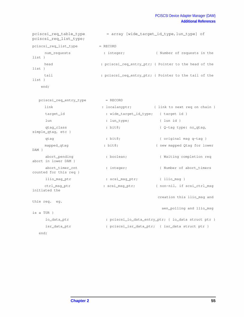
pciscsi_req_table_type = array [wide_target_id_type,lun_type] ofpciscsi_req_list_type;
pciscsi_req_list_type = RECORD
num_requests : integer; { Number of requests in thelist }
head : pciscsi_req_entry_ptr; { Pointer to the head of thelist }
tail : pciscsi_req_entry_ptr; { Pointer to the tail of thelist }
end;
pciscsi_req_entry_type = RECORD
link : localanyptr; { link to next req on chain }
target_id : wide_target_id_type; { target id }
lun : lun_type; { lun id }
qtag_class : bit8; { Q-tag type: no_qtag,simple_qtag, etc }
qtag : bit8; { original msg q-tag }
mapped_qtag : bit8; { new mapped Qtag for lowerDAM }
abort_pending : boolean; { Waiting completion reqabort in lower DAM }
abort_timer_cnt : integer; { Number of abort_timerscounted for this req }
llio_msg_ptr : scsi_msg_ptr; { llio_msg }
ctrl_msg_ptr : scsi_msg_ptr; { non-nil, if scsi_ctrl_msginitiated the
creation this llio_msg andthie req. eg.
aen_polling and llio_msgis a TUR }
io_data_ptr : pciscsi_io_data_entry_ptr; { io_data struct ptr }
isr_data_ptr : pciscsi_isr_data_ptr; { isr_data struct ptr }
end;
Chapter 2 55

PCISCSI Device Adapter Manager (DAM)Additional References
Figure 2-12 Slide 12
Upper/Lower DAM Interface Layer
Mappings between Upper and Lower Data
Lower DAM Function Calls Sequence
The interface layer glues the upper and lower DAM data components bymapping data from upper DAM MODCAL structure types to lowerDAM “C” structure types. The interface layer mappings can occur viavariable declarations or explicit assignment statements.
Data Mappings via variable declarations
struct isc_table_type *isc = io_data_ptr->isc_ptr->isc; /* ptr to isc */
struct c720_isc *lisc = io_data_ptr->isc_ptr->iscx; /* ptr to c720_isc */
struct scsi_bus *busp = (void *)isc->if_drv_data; /* ptr to scsi_bus */
struct c720_bus *lbp = busp->if_bus; /* ptr to c720_bus */
struct buf *bp = io_data_ptr->buf_ptr; /* ptr to buf */
struct scb *scb = io_data_ptr->scb_ptr->scb; /* ptr to scb */
hp e3000
7.0 fieldtraining
Interface Layer Data Mappings
· Preserve lower DAM HP-UX C720_SCSI datastructures
· Mappings between Upper and Lower Data
· c720 Interface Functionality
· Bus Initialization
· Starting IOs
· Interrupt Handling
· Abort Requests
56 Chapter 2

PCISCSI Device Adapter Manager (DAM)Additional References
struct c720_scb *lsp = io_data_ptr->scb_ptr->scbx; /* ptr to c720_scb */
struct scsi_tgt *tp = io_data_ptr->tgt_ptr->tgt; /* ptr to scsi_tgt */
struct c720_tgt *ltp = io_data_ptr->tgt_ptr->tgtx; /* ptr to c720_tgt */
struct scsi_lun *lp = io_data_ptr->lun_ptr; /* ptr to scsi_lun */
ubit8 tgt_id = io_data_ptr->tgt_id; /* target id */
ubit8 lun_id = io_data_ptr->lun_id; /* lun ID */
dev_t dev = (tgt_id<<12) | (lun_id<<8);
Data Mappings via assignment statements
bp->b_scb = (long)scb;
scb->if_scb = lsp; /* ptr to c720_scb */
scb->lp = lp; /* ptr to scsi_lun */
if (busp->tgt[tgt_id] == NULL)
More assignments to create linkages for “init target” structures
/*********************************************************************/
/* init target */
/*********************************************************************/
busp->tgt[tgt_id] = tp; /* ptr to scsi_tgt */
tp->if_tgt = ltp; /* ptr to c720_tgt */
tp->tgt_id = tgt_id; /* tgt ID from UD */
tp->sdtr_period = &((ubit8 *) &busp->isc->tgt_sdtr_period)[tgt_id];
tp->sdtr_done = (void *) &busp->isc->tgt_sdtr_done;
tp->wdtr_done = (void *) &busp->isc->tgt_wdtr_done;
tp->wdtr_width = (void *) &busp->isc->tgt_wdtr_width;
tp->bus = busp; /* ptr to scsi_bus */
c720_if_tgt_open(tp, dev); /* open target */
/*********************************************************************/
/* init target/lun relationship */
/*********************************************************************/
tp->lun[lun_id] = lp; /* ptr to scsi_lun */
lp->lun_id = lun_id; /* lun ID from UD */
lp->tgt = tp; /* ptr to scsi_tgt */
The interface layer calls a sequence of lower DAM functions on behalf ofthe upper DAM to perform specific actions. A sequence of lower DAMfunction calls in the interface layer exists for:
• lower DAM initialization after poweron or reset
• queueing and starting new I/O requests
Chapter 2 57

PCISCSI Device Adapter Manager (DAM)Additional References
• locating and aborting I/O requests
• servicing of hardware interrupts
• logging transactions and event information
58 Chapter 2
PCISCSI Device Adapter Manager (DAM)Additional References
Figure 2-13 Slide 13
hp e3000
7.0 fieldtraining
Lower DAM Internal Data Structures[overview]
· Lower DAM Structures (ADA)
· Lower DAM bedsheet
· Select Q
· SCSI Bus specific (ISC, LISC, BUSP,LBP)
· Target specific (LP, TP, LTP)
· I/O specific (BP, SCB, LSP)
· DSP, LBP LbpScratchToLsp & LSP
· Symbios Card and SCSI Script
Chapter 2 59

PCISCSI Device Adapter Manager (DAM)Additional References
Figure 2-14 Slide 14
Auxiliary Data Area (ADA)
Lower DAM data structures/resources
Dam processes: init_data , io_data , abort_data , isr_data
Card interface: isc, lisc, busp, …..
I/O
Upper DAM resources
Request entry pool
The PCSCSI DAM auxiliary data area contains all the structures forthe lower DAM and also interface layer structures when data ismapped between lower and upper DAM data structures.
The interface layer data structures:
• init_data — lower DAM initialization data
• io_data — all items to start and complete an I/O to the lower DAM
• abort_data — I/O request information to abort an active I/O
hp e3000
7.0 fieldtraining
Auxiliary Data Area (ADA)
· Lower DAM data structures/resources
· Dam processes: init_data, io_data, abort_data,isr_data
· Card interface: isc, lisc, busp, …..
· Target
· I/O
· Upper DAM resources
· Request entry pool
60 Chapter 2

PCISCSI Device Adapter Manager (DAM)Additional References
• isr_data — interrupt service routine data on who interrupted andwhy
Lower DAM exclusive structures for operation of SCSI bus and devicesare:
• Isc — bus information
• C720_isc — bus information
• Scsi_bus — bus information
• C720_bus — bus information
• Scsi_tgt_array — array of scsi_tgt structures, one per eachtarget
• C720_tgt_array — array of c720_tgt structures, one per eachtarget/lun pair
• Scsi_lun_array — array of scsi_lun structures, one per eachtarget
• Script_buf — SCSI scripts area, one SCSI SCRIPT per each I/Orequest
Upper DAM I/O Specific Structures
Pciscsi_req_entry_pool — Pool of pciscsi_req_entry to maintainI/O requests
Interface layer I/O Specific Structures
Io_data_pool — Pool of io_data to perform I/O requests
pciscsi_init_data_type = RECORD
{** pointer components ********}
pci_isc_ptr : pci_isc_ptr_type; { ptr to isc }
pci_bus_ptr : pci_bus_ptr_type; { ptr to scsi_bus/c720_bus struct }
{** isc components ************}
chip_id : bit32; { Symbios chip identification }
card_ptr : globalanyptr; { Ptr to base of cards operatingregister set }
bus_type : bit8; { PCI Bus 0x55 }
hpux_eim : bit32; { 0x00 }
pci_handle : globalanyptr; { Handle use to talk to PCI Services}
{ bit 1 -> 7 not defined }
Chapter 2 61
PCISCSI Device Adapter Manager (DAM)Additional References
{** SCSI bus mode and id *******}
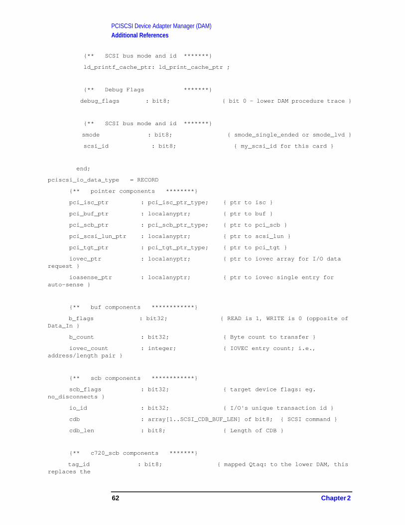
ld_printf_cache_ptr: ld_print_cache_ptr ;
{** Debug Flags *******}
debug_flags : bit8; { bi t 0 - lower DAM procedure trace }
{** SCSI bus mode and id *******}
smode : bit8; { smode_single_ended or smode_lvd }
scsi_id : bit8; { my_scsi_id for this card }
end;
pciscsi_io_data_type = RECORD
{** pointer components ********}
pci_isc_ptr : pci_isc_ptr_type; { ptr to isc }
pci_buf_ptr : localanyptr; { ptr to buf }
pci_scb_ptr : pci_scb_ptr_type; { ptr to pci_scb }
pci_scsi_lun_ptr : localanyptr; { ptr to scsi_lun }
pci_tgt_ptr : pci_tgt_ptr_type; { ptr to pci_tgt }
iovec_ptr : localanyptr; { ptr to iovec array for I/O datarequest }
ioasense_ptr : localanyptr; { ptr to iovec single entry forauto-sense }
{** buf components ************}
b_flags : bit32; { READ is 1, WRITE is 0 (opposite ofData_In }
b_count : bit32; { Byte count to transfer }
iovec_count : integer; { IOVEC entry count; i.e.,address/length pair }
{** scb components ************}
scb_flags : bit32; { target device flags: eg.no_disconnects }
io_id : bit32; { I/O's unique transaction id }
cdb : array[1..SCSI_CDB_BUF_LEN] of bit8; { SCSI command }
cdb_len : bit8; { Length of CDB }
{** c720_scb components *******}
tag_id : bit8; { mapped Qtaq: to the lower DAM, thisreplaces the
62 Chapter 2

PCISCSI Device Adapter Manager (DAM)Additional References
original request's Q-tag to ensureall Q-tags for
all targets do not have duplicateQ-tag values sent
to the lower DAM. NOTE: mappedqtag is the lower
DAM's index to tables in the lowerDAM }
{** scsi_tgt components ********}
tgt_id : bit8; { scsi target id }
{** scsi_lun components ********}
lun_id : bit8; { lun id for tgt }
l_tag : bit32; { "1" if tagged I/O, and "0" if not(s/b be a boolean) }
{** c720_tgt components ********}
filler : array [1..5] of integer; { expanson for lower DAM }
{//////////////////////////////////////////////////////////////////////}
{ Upper portion of io_data maps to corresponding structure in lower }
{ DAM. Bottom portion of io_data are buffer areas for I/O completion }
{ and only known to lower DAM via pointers in upper portion of io_data }
{//////////////////////////////////////////////////////////////////////}
{----------------------------------}
{** IOASENSE RESOURCE ********}
ioasense : iovec_type; {* only one IOVEC entry needed versus an IOVECarray *}
{----------------------------------}
{** IOVEC RESOURCE ********}
iovec : iovec_type;
{----------------------------------}
{** SCB RESOURCE ********}
scb : scb_type;
Chapter 2 63

PCISCSI Device Adapter Manager (DAM)Additional References
{----------------------------------}
{** C720_SCB RESOURCE ********}
c720_scb : c720_scb_type;
end;
pciscsi_io_data_entry_type = RECORD
link : localanyptr;
body : pciscsi_io_data_type;
end;
pciscsi_abort_data_type = RECORD
{** pointer components ********}
pci_isc_ptr : pci_isc_ptr_type; { ptr to isc }
pci_buf_ptr : localanyptr; { ptr to buf }
{** abort components ********}
abort_io : bit8; { abort_single_io }
end;
pciscsi_isr_data_type = record
{** pointer components *********}
pci_isc_ptr : pci_isc_ptr_type; { ptr to isc }
{** isr_data components ********}
tgt_id : bit8; { TGT id }
lun_id : bit8; { LUN id }
tag_id : bit8; { UD's mapped qtag }
scsi_status : bit8; { SCSI status byte }
req_sense_status : bit8; { Request sense status byte }
data_xfer_cnt : bit32; { Actual IO length }
asense_xfer_cnt : bit32; { Sense data length }
filler : array [1..5] of integer;
end;
PCISCSI_ADA_TYPE = record
{-----------------------------------------------------------------------------}
{==== LOWER DAM DATA STRUCTURES ====}
64 Chapter 2

PCISCSI Device Adapter Manager (DAM)Additional References
{-----------------------------------------------------------------------------}
{-----------------------------------------------------}
{** CARD INTERFACE STRUCTS **}
{-----------------------------------------------------}
{-----------------------------------------------------}
{ ***** ISC MUST remain the first item ***** }
{ ***** in the ada. The isc is the ***** }
{ ***** same ptr as the aux_data_ptr. MUST use***** }
{ ***** aux_data_ptr to access structures when ***** }
{ ***** executing lower DAM code. ***** }
{-----------------------------------------------------}
isc : array [1..ISC_TABLE_SIZE] of bit32; { ISC must remainfirst item. }
{ see NOTE previousline }
c720_isc : array [1..C720_ISC_SIZE] of bit32;
scsi_bus : array [1..SCSI_BUS_SIZE] of bit32;
c720_bus : array [1..C720_BUS_SIZE] of bit32;
{-----------------------------------------------------}
{** PDA POINTER **}
{-----------------------------------------------------}
port_data_ptr : localanyptr;
{-----------------------------------------------------}
{** STRUCTS PASSING POINTERS **}
{ }
{ Following items have pointers that point to }
{ structs the lower DAM will use to perform actions. }
{-----------------------------------------------------}
pci_isc : pci_isc_type;
pci_bus : pci_bus_type;
pci_scb : pci_scb_type;
pci_tgt : pci_tgt_type;
{-----------------------------------------------------}
Chapter 2 65

PCISCSI Device Adapter Manager (DAM)Additional References
{** UPPER/LOWER DAM INTERFACE STRUCTS (non I/O) **}
{-----------------------------------------------------}
abort_data : pciscsi_abort_data_type; { lower DAM single I/O abortdata }
init_data : pciscsi_init_data_type; { lower DAM initialization data}
isr_data : pciscsi_isr_data_type; { lower DAM interrupt servicereturn data }
disable_chip_data : pciscsi_disable_chip_data_type; { lower DAM disablechip data }
{-----------------------------------------------------}
{** TARGET STRUCTS **}
{-----------------------------------------------------}
scsi_tgt_array : array [wide_target_id_type] of scsi_tgt_type;
c720_tgt_array : array [wide_target_id_type] of c720_tgt_type;
scsi_lun_array : array [wide_target_id_type,
lun_type] of scsi_lun_type;
{-----------------------------------------------------}
{-----------------------------------------------------}
{** Upper DAM - PCI REQ ENTRY POOL **}
{-----------------------------------------------------}
pciscsi_req_pool_hdr : pciscsi_pool_hdr_type;
pciscsi_req_entry_pool : array [1..MAX_REQ_ENTRIES] of
pciscsi_req_entry_type;
{-----------------------------------------------------}
{** IO_DATA RESOURCE POOL **}
{-----------------------------------------------------}
io_data_pool_hdr : pciscsi_pool_hdr_type;
io_data_pool : array [1..MAX_IO_REQUESTS] of
pciscsi_io_data_entry_type;
{-----------------------------------------------------}
{** CARD PROGRAMING SCRIPTS BUFFERS **}
{-----------------------------------------------------}
66 Chapter 2
PCISCSI Device Adapter Manager (DAM)Additional References
script_buf_base_va : buf_va_type;
script_buf_max_va : buf_va_type;
script_buf_base_iova : bit32;
script_buf_resource : buf_va_type;
script_buf_max_resource : buf_va_type;
{/////////////////////////////////////////////////////}
{***** script buf MUST be page aligned *****}
{ The script_buf structure MUST be page aligned }
{ use the following fill statement to make sure }
{ the offset is xxxxx000 }
{/////////////////////////////////////////////////////}
filler : array [1..2389] of bit8;
script_buf : array [1..MAX_SCRIPTS_BUF] of script_buf_type;
{-----------------------------------------------------}
{ Lower DAM Print Cache }
{-----------------------------------------------------}
ld_print_cache : ld_print_cache_type;
end;
Chapter 2 67

PCISCSI Device Adapter Manager (DAM)Additional References
Figure 2-15 Slide 15
hp e3000
7.0 fieldtraining
Lower DAM Bedsheet
68 Chapter 2
PCISCSI Device Adapter Manager (DAM)Additional References
Figure 2-16 Slide 16
SelectQ
Pending I/O requests
Re-queued requests for special action (e.g., auto-request sense)
Selectq is a doubly linked list of BP structures for I/Os pending and tobe started on the target device. A request is removed from the head ofthe queue via busp->selectq->bp->av_forw . New pending requestsare added to the end of queue via busp->selecteq->av_back .
Exception, if an I/O did not complete with good status and auto-requestsense is to be done, this request is added to the head to selectq to beserviced at the earliest time.
Requests added to the selectq are initiated by the upper DAM by callingpci_c720_if_start and passing io_data which contains all theresources and information needed to start the I/O request.
hp e3000
7.0 fieldtraining
Select Q
· Pending I/O requests
· Re-queued requests for special action (eg. auto-request sense)
Chapter 2 69

PCISCSI Device Adapter Manager (DAM)Additional References
Figure 2-17 Slide 17
BUS Specific
ISC — Interface specific parameters (card_type , bus_type , MPE/iXlogging area,…)
LISC — ISC extension, bus state, card RAM ptr, all targets’ WDTR,SDTR info)
BUSP — SCSI bus request process items
LBP — Current I/O: card registers, I/O interrupt and completionpointers, Nexus_Table
The SCSI bus interface management is allocated a set of structures tocontain information about the bus and current activities on the SCSIBUS. The structures and items and items of interest:
hp e3000
7.0 fieldtraining
Bus Specific
· ISC - Interface specific parameters (card_type,bus_type, MPE i/X logging area)
· LISC - ISC extension, bus state, card RAM ptr, alltargets’ WDTR, SDTR info)
· BUSP - SCSI bus request process items
· LBP - Current I/O: card registers, I/O interrupt andcompletion pointers, Nexus_Table
70 Chapter 2
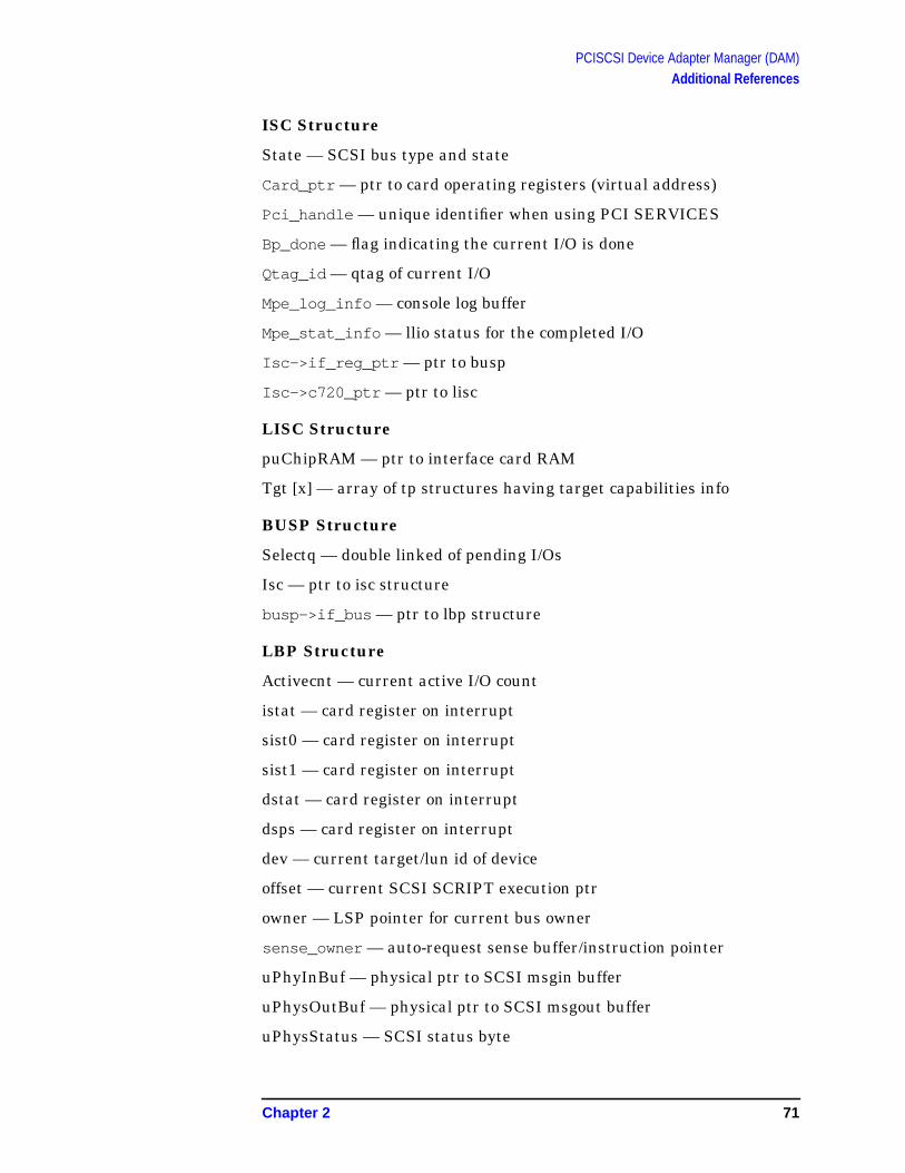
PCISCSI Device Adapter Manager (DAM)Additional References
ISC Structure
State — SCSI bus type and state
Card_ptr — ptr to card operating registers (virtual address)
Pci_handle — unique identifier when using PCI SERVICES
Bp_done — flag indicating the current I/O is done
Qtag_id — qtag of current I/O
Mpe_log_info — console log buffer
Mpe_stat_info — llio status for the completed I/O
Isc->if_reg_ptr — ptr to busp
Isc->c720_ptr — ptr to lisc
LISC Structure
puChipRAM — ptr to interface card RAM
Tgt [x] — array of tp structures having target capabilities info
BUSP Structure
Selectq — double linked of pending I/Os
Isc — ptr to isc structure
busp->if_bus — ptr to lbp structure
LBP Structure
Activecnt — current active I/O count
istat — card register on interrupt
sist0 — card register on interrupt
sist1 — card register on interrupt
dstat — card register on interrupt
dsps — card register on interrupt
dev — current target/lun id of device
offset — current SCSI SCRIPT execution ptr
owner — LSP pointer for current bus owner
sense_owner — auto-request sense buffer/instruction pointer
uPhyInBuf — physical ptr to SCSI msgin buffer
uPhysOutBuf — physical ptr to SCSI msgout buffer
uPhysStatus — SCSI status byte
Chapter 2 71

PCISCSI Device Adapter Manager (DAM)Additional References
uPhyScript — ptr to beginning of SCSI SCRIPT
isrPutMsgOut — code ptr for SCSI msgout
isrMsgRejected — code ptr for SCSI msg reject
isrSelectMsgOut — code ptr for SCSI msgout
isrSelectMsgOutIn — code ptr for SCSI msgin
NexusTable — array of lsp pointers for all active requests. Indexed bymapped qtag
lbp->busp — ptr to busp structure
72 Chapter 2

PCISCSI Device Adapter Manager (DAM)Additional References
Figure 2-18 Slide 18
Target Specific
TP — Target information
LP — Target’s LUN information
LTP — Lun/Target information
The management of each device is allocated a set of structures tocontain information about the device so I/Os are done within thedevices capabilities. The structures and items in items of interest:
lun_id — id of the LUN
retry_cnt — how many times the I/O is retried before it has failed
tgt_id — if of the target device
sdtr_period — the SDTR (synchronous data transfer) value
wdtr_width — the WDTR (wide data transfer) value
lp->tgt — ptr to tp structure
lp->if_lun — ptr to lsp structure
tp->if_tgt — tr to ltp structure
hp e3000
7.0 fieldtraining
Target Specific
· TP - Target information
· LP - Target’s LUN information
· LTP - Lun/Target information
Chapter 2 73
PCISCSI Device Adapter Manager (DAM)Additional References
Figure 2-19 Slide 19
hp e3000
7.0 fieldtraining
I/O Specific
· BP - I/O request info
· SCB - BP extension, additional I/O request info
· LSP - SCSI Script patching info, data transfer pointers
74 Chapter 2

PCISCSI Device Adapter Manager (DAM)Additional References
I/O Specific
BP — I/O request info
SCB — BP extension, additional I/O request info
LSP — SCSI Script patching info, data transfer pointers
Each I/O request is allocated a set of structures to contain all theinformation to complete the I/O. This includes instructions for theinterface card for DMA setup and SCSI bus management, and SCSICDB (Command Data Block) device commands sent directly to thedevice. Some items of intereset from these structures are:
b_bcount — total to be transferred
b_resid — remaining to transfer
cdb — device command (e.g., read, write, inquiry)
sense_status — SCSI command status
sense_bytes — additional SCSI command status bytes
puJumpDest — ptr to data transfer jump table
puScript — ptr to SCSI SCRIPT
puActivePtr — current dta buffer ptr
puDataDone — ptr to I/O completion code
bp->b_s2 — ptr to scb structure
scb->if_scb — ptr to lsp structure
lsp->bp — ptr to bp structure
lsp->scb — ptr to lsp structure
Chapter 2 75

PCISCSI Device Adapter Manager (DAM)Additional References
Figure 2-20 Slide 20
DSP, LBP, LbpToScratch & LSP
How the host software finds itself when the hardware interrupt.
(scratchA register) — Target id and LUN of target interrupting
DSPS
LBP — Nexus Table pointer to LSPs for active I/Os
LbpScratchToLsp — Code that obtains LSP pointer based on scratchregister
LSP — I/O specific information for this current nexus
The PCISCSI DAM and devices supporting multiple concurrent I/O cangenerate a high volume of I/O traffic on the SCSI bus. This is good forperformance but makes managing I/Os a very difficult situation. Thelower DAM implementation manages the numerous I/Os partly inhardware and software. The SCSI SCRIPT executing on the interfacehardware builds device information into the “SCRATCHA” registerprior to interrupting the host. For tagged I/O, only the tag is supplied,for untagged I/O, the target id/LUN information is provided.
hp e3000
7.0 fieldtraining
DSP, LBP, LbpScratchToLsp & LSP
· How the host software finds itself when the hardwareinterrupts
· DSP (scratch register) - Target id and LUN of targetinterrupting
· LBP - Nexus Table pointer to LSPs for active I/Os
· LbpScratchToLsp - Code that obtains LSP pointerbased on scratch register
· LSP - I/O specific information for this current nexus
76 Chapter 2
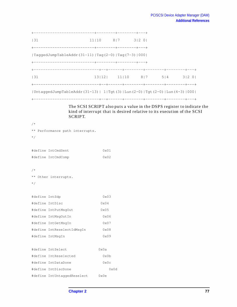
PCISCSI Device Adapter Manager (DAM)Additional References
+--------------------------+--------+--------+---+
|31 11|10 8|7 3|2 0|
+--------------------------+--------+--------+---+
|TaggedJumpTableAddr(31-11)|Tag(2-0)|Tag(7-3)|000|
+--------------------------+--------+--------+---+
+----------------------------+--+------+--------+--------+--------+---+
|31 13|12| 11|10 8|7 5|4 3|2 0|
+----------------------------+--+------+--------+--------+--------+---+
|UntaggedJumpTableAddr(31-13)| 1|Tgt(3)|Lun(2-0)|Tgt(2-0)|Lun(4-3)|000|
+----------------------------+--+------+--------+--------+--------+---+
The SCSI SCRIPT also puts a value in the DSPS register to indicate thekind of interrupt that is desired relative to its execution of the SCSISCRIPT.
/*
** Performance path interrupts.
*/
#define IntCmdSent 0x01
#define IntCmdComp 0x02
/*
** Other interrupts.
*/
#define IntSdp 0x03
#define IntDisc 0x04
#define IntPutMsgOut 0x05
#define IntMsgOutIn 0x06
#define IntGetMsgIn 0x07
#define IntReselectIdMsgIn 0x08
#define IntMsgIn 0x09
#define IntSelect 0x0a
#define IntReselected 0x0b
#define IntDataDone 0x0c
#define IntDiscDone 0x0d
#define IntUntaggedReselect 0x0e
Chapter 2 77

PCISCSI Device Adapter Manager (DAM)Additional References
#define IntBusClose 0x0f
#define IntGood 0x10
#define IntAbortDone 0x11
#define IntSdtrMsg 0x12
#define IntWdtrMsg 0x13
#define IntExtMsgLenIn 0x14
#define IntError 0xff
PCISCSI DAM receives an interrupt message from the third levelinterrupt handler and begins probing the card registers for informationon the interrupt. Using the SCRATCHA register, the functionLbpScratchToLsp scans the NEXUS TABLE and does a lookup for theLSP structure associated with this I/O. The LSP has an I/O completionptr, data structure ptrs and various other items concerning this I/O.Adding in the DSPS register (interrupt code), the lower DAM can movethe I/O onto its next phase of completion by patching a new SCSISCRIPT for the interface hardware to execute.
Several interrupts will occur to process the I/O each time evaluatingthe scratchA and DSPS registers followed by patching a new SCSISCRIPT. This continues until the device says the I/O is complete or anexception condition occurs with the device or interface card.
78 Chapter 2

PCISCSI Device Adapter Manager (DAM)Additional References
Figure 2-21 Slide 21
Symbios Card & SCSI Script
SYMBIOS card- SCSI bus autosensing
SCSI Script (no firmware)
All the PCI SCSI cards supported by PCISCSI DAM are manufacturedby the SYMBIOS company. The cards have automatic features such asSCSI bus detection (i.e., SE, HVD, LVD, narrow-data-bus,wide-data-bus) SCSI bus auto-termination, self-timers and local RAMfor executing SCSI SCRIPTS. Each card has a monolothic chip thatcontains the PCI BUS interface, SCSI BUS interface, DMA engine, I/Oprocessor, registers and local RAM. No firmware is used for the cardsoperation. A program called the SCSI SCRIPT is used to control thecards action. PCISCSI DAM customizes this program by patching theSCSI SCRIPT for each I/O with the appropriate data address and datalength.
hp e3000
7.0 fieldtraining
Symbios Card & SCSI Script
· SYMBIOS card- SCSI bus autosensing
· SCSI Script (no firmware)
Chapter 2 79

PCISCSI Device Adapter Manager (DAM)Additional References
This table has the product ids and vendor ids for these cards.
{---------------------------------------------------------------------------------}
{ A4800A Single ported HVD card - SYM53C875 chip }
{ A5159A Dual ported HVD card - SYM53C876 chip }
{---------------------------------------------------------------------------------}
SYM53C875_876_DEVICE_ID = hex ('000f');
{---------------------------------------------------------------------------------}
{ A5149A Single ported LVD card - SYM53C895 chip }
{---------------------------------------------------------------------------------}
SYM53C895_DEVICE_ID = hex ('000c');
{---------------------------------------------------------------------------------}
{ A5150A Dual ported LVD card - SYM53C896 chip }
{---------------------------------------------------------------------------------}
SYM53C896_DEVICE_ID = hex ('000b');
80 Chapter 2

PCISCSI Device Adapter Manager (DAM)Additional References
Figure 2-22 Slide 22
Figure 2-23 Slide 23
hp e3000
7.0 fieldtraining
DAM Processes[overview]
· Do_Bind and Init
· Device Manager Bind
· Data Class Conversion to IOVEC
· Port SubQ to Internal Q
· Starting an I/O
· First I/O
· SCSI Script Patching
· Interrupts
hp e3000
7.0 fieldtraining
DAM Processes continued
· I/O Completion
· Multi- I/Os
· I/Os on the bus
· I/O aborts
· Timers
· Situation Escalation
· Poweron (reset)
Chapter 2 81

PCISCSI Device Adapter Manager (DAM)Additional References
Figure 2-24 Slide 24
Do_Bind & Init
Bind to lower mgr
Init upper DAM data structures
Allocate and init lower DAM data structures
The I/O configurator orchestrates the configuration of the I/Osubsystem during boot time. Each driver beginning with the hardwareinterface driver, DAM, receives a do_bind request to bind to a lowermanager (if one is present), and to perform its internal initialization inprepartion to doing I/O. The PCISCSI DAM perform the do_bind andexit its code execution several times during this process to: 1) bind withthe lower manager and 2) wait for hardware initialization. Followingcode snippets shows this do_bind sequence and highlights when theDAM exits code execution.
hp e3000
7.0 fieldtraining
Do_Bind & Init
· Bind to lower mgr
· Init upper DAM data structures
· Allocate and init lower DAM data structures
82 Chapter 2

PCISCSI Device Adapter Manager (DAM)Additional References
Receiving the do_bind starts some preliminary actions and theninitiates a bind request to the lower mgr.
[[ PCISCSI DAM starts execution ]]
procedure PCISCSI_DO_BIND_REQ_MSG
Close subqueues except for poweron and config
Save do_bind info from I/O configurator in PDA
PCISCSI_BIND_TO_LOWER_MGR ( )
{--------------------------------------------------------------------------}
{ Send reply for do_bind_req }
{--------------------------------------------------------------------------}
PCISCSI_BS_REPLY( )
Bind request to lower manager built and sent
procedure PCISCSI_BIND_TO_LOWER_MGR
{--------------------------------------------------------------------------}
{ Get new message frame }
{--------------------------------------------------------------------------}
PCISCSI_GET_FRAME( msg^.do_bind_req.lm_port_num,
my_msg,
status,
pda,
0
);
{--------------------------------------------------------------------------}
{ Build the BIND REQ message to be sent to the lower MGR }
{--------------------------------------------------------------------------}
WITH my_msg^ DO
BEGIN { of with }
msg_header.msg_descriptor := Bind_Req_Msg;
msg_header.message_id := msg^.msg_header.message_id;
msg_header.transaction_num := msg^.msg_header.transaction_num;
msg_header.from_port := my_port;
Chapter 2 83
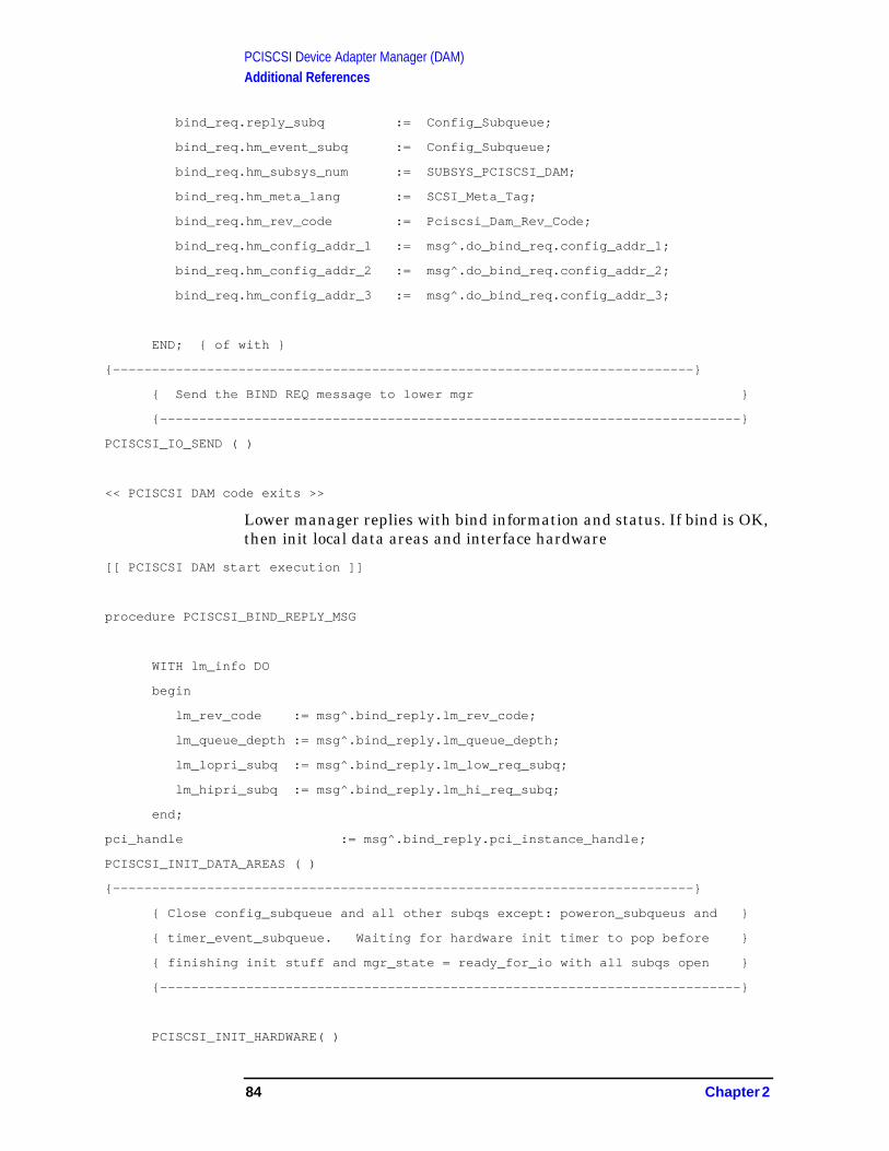
PCISCSI Device Adapter Manager (DAM)Additional References
bind_req.reply_subq := Config_Subqueue;
bind_req.hm_event_subq := Config_Subqueue;
bind_req.hm_subsys_num := SUBSYS_PCISCSI_DAM;
bind_req.hm_meta_lang := SCSI_Meta_Tag;
bind_req.hm_rev_code := Pciscsi_Dam_Rev_Code;
bind_req.hm_config_addr_1 := msg^.do_bind_req.config_addr_1;
bind_req.hm_config_addr_2 := msg^.do_bind_req.config_addr_2;
bind_req.hm_config_addr_3 := msg^.do_bind_req.config_addr_3;
END; { of with }
{--------------------------------------------------------------------------}
{ Send the BIND REQ message to lower mgr }
{--------------------------------------------------------------------------}
PCISCSI_IO_SEND ( )
<< PCISCSI DAM code exits >>
Lower manager replies with bind information and status. If bind is OK,then init local data areas and interface hardware
[[ PCISCSI DAM start execution ]]
procedure PCISCSI_BIND_REPLY_MSG
WITH lm_info DO
begin
lm_rev_code := msg^.bind_reply.lm_rev_code;
lm_queue_depth := msg^.bind_reply.lm_queue_depth;
lm_lopri_subq := msg^.bind_reply.lm_low_req_subq;
lm_hipri_subq := msg^.bind_reply.lm_hi_req_subq;
end;
pci_handle := msg^.bind_reply.pci_instance_handle;
PCISCSI_INIT_DATA_AREAS ( )
{--------------------------------------------------------------------------}
{ Close config_subqueue and all other subqs except: poweron_subqueus and }
{ timer_event_subqueue. Waiting for hardware init timer to pop before }
{ finishing init stuff and mgr_state = ready_for_io with all subqs open }
{--------------------------------------------------------------------------}
PCISCSI_INIT_HARDWARE( )
84 Chapter 2

PCISCSI Device Adapter Manager (DAM)Additional References
Part of hardware init is to init the lower DAM by providing ptrs to areasin the aux data area, items to direct dam general operations. Once thedam has finished the init and hardware reset, a 5 second timer is set toallow settling of interface and SCSI bus devices prior to the first I/O.
procedure PCISCSI_INIT_HARDWARE
{--------------------------------------------------------------------------}
{ Setup structure pointers and items for lower DAM h/w init }
{--------------------------------------------------------------------------}
init_data.pci_isc_ptr := addr ( pci_isc );
init_data.pci_isc_ptr^.isc_ptr := addr ( isc );
init_data.pci_isc_ptr^.c720_isc_ptr := addr ( c720_isc );
init_data.pci_bus_ptr := addr ( pci_bus );
init_data.pci_bus_ptr^.scsi_bus_ptr := addr ( scsi_bus );
init_data.pci_bus_ptr^.c720_bus_ptr := addr ( c720_bus );
init_data.ld_printf_cache_ptr := addr ( ld_print_cache );
init_data.card_ptr := my_bar_1_vregion.data_ptr;
init_data.bus_type := PCI_BUS_ID;
init_data.hpux_eim := 0; { zero, EIM not used }
init_data.pci_handle := pci_handle;
init_data.scsi_id := CARD_SCSI_ID; {* id = 7 *}
init_data.debug_flags := hex ('00000001');
{--------------------------------------------------------------------------}
{ Init lower DAM data areas }
{--------------------------------------------------------------------------}
PCISCSI_INIT_LOWER_DAM_DATA_AREAS ( pda,
ada
);
{--------------------------------------------------------------------------}
{ Call lower DAM procedure to Initialize the hardware }
{--------------------------------------------------------------------------}
PCI_C720_INIT ( init_data,
status );
Chapter 2 85

PCISCSI Device Adapter Manager (DAM)Additional References
{--------------------------------------------------------------------------}
{ Set poweron_reset timer and wait for hardware to settle down }
{--------------------------------------------------------------------------}
IO_RESET_TIMER ( POWERON_RESET_TIMER_INTERVAL,
poweron_reset_timer_id,
status
The lower DAM performs several steps to initialize and they areoutlined as follows:
switch to interface
pci_c720_init
integrate/merge init_data to:
isc, c720_isc, isc->if_isc = c720_isc, busp, lisc,
c720_pci_attach ()
switch to lower dam
c720_pci_attach (ISC,…)
Init task, PCI service config reg calls
complete init tasks
switch to interface
setup
c720_int ()
Switch to lower dam
c720_init ()
Init task
c720_reset_chip ()
c720_read_cfg_unint(n)_isc
c720_write_cfg_unit(n)_isc
ktimeout ()
switch to interface
setup
isc ->if_drv_data = scsi_bus
init field in scsi_bus
86 Chapter 2
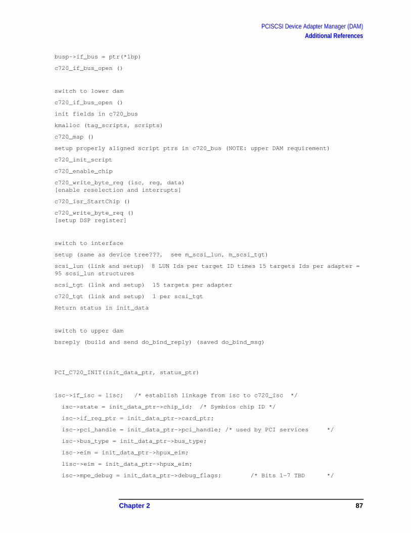
PCISCSI Device Adapter Manager (DAM)Additional References
busp->if_bus = ptr(*lbp)
c720_if_bus_open ()
switch to lower dam
c720_if_bus_open ()
init fields in c720_bus
kmalloc (tag_scripts, scripts)
c720_map ()
setup properly aligned script ptrs in c720_bus (NOTE: upper DAM requirement)
c720_init_script
c720_enable_chip
c720_write_byte_reg (isc, reg, data)[enable reselection and interrupts]
c720_isr_StartChip ()
c720_write_byte_req ()[setup DSP register]
switch to interface
setup (same as device tree???, see m_scsi_lun, m_scsi_tgt)
scsi_lun (link and setup) 8 LUN Ids per target ID times 15 targets Ids per adapter =95 scsi_lun structures
scsi_tgt (link and setup) 15 targets per adapter
c720_tgt (link and setup) 1 per scsi_tgt
Return status in init_data
switch to upper dam
bsreply (build and send do_bind_reply) (saved do_bind_msg)
PCI_C720_INIT(init_data_ptr, status_ptr)
isc->if_isc = lisc; /* establish linkage from isc to c720_isc */
isc->state = init_data_ptr->chip_id; /* Symbios chip ID */
isc->if_reg_ptr = init_data_ptr->card_ptr;
isc->pci_handle = init_data_ptr->pci_handle; /* used by PCI services */
isc->bus_type = init_data_ptr->bus_type;
isc->eim = init_data_ptr->hpux_eim;
lisc->eim = init_data_ptr->hpux_eim;
isc->mpe_debug = init_data_ptr->debug_flags; /* Bits 1-7 TBD */
Chapter 2 87
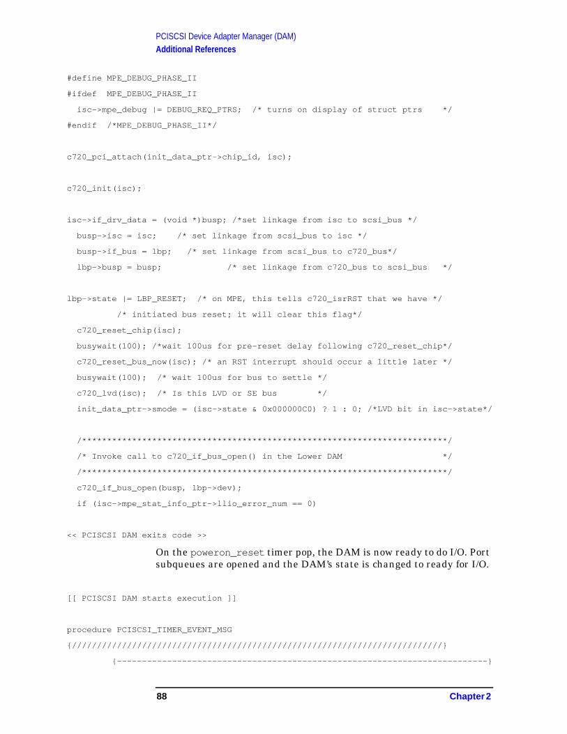
PCISCSI Device Adapter Manager (DAM)Additional References
#define MPE_DEBUG_PHASE_II
#ifdef MPE_DEBUG_PHASE_II
isc->mpe_debug |= DEBUG_REQ_PTRS; /* turns on display of struct ptrs */
#endif /*MPE_DEBUG_PHASE_II*/
c720_pci_attach(init_data_ptr->chip_id, isc);
c720_init(isc);
isc->if_drv_data = (void *)busp; /*set linkage from isc to scsi_bus */
busp->isc = isc; /* set linkage from scsi_bus to isc */
busp->if_bus = lbp; /* set linkage from scsi_bus to c720_bus*/
lbp->busp = busp; /* set linkage from c720_bus to scsi_bus */
lbp->state |= LBP_RESET; /* on MPE, this tells c720_isrRST that we have */
/* initiated bus reset; it will clear this flag*/
c720_reset_chip(isc);
busywait(100); /*wait 100us for pre-reset delay following c720_reset_chip*/
c720_reset_bus_now(isc); /* an RST interrupt should occur a little later */
busywait(100); /* wait 100us for bus to settle */
c720_lvd(isc); /* Is this LVD or SE bus */
init_data_ptr->smode = (isc->state & 0x000000C0) ? 1 : 0; /*LVD bit in isc->state*/
/*************************************************************************/
/* Invoke call to c720_if_bus_open() in the Lower DAM */
/*************************************************************************/
c720_if_bus_open(busp, lbp->dev);
if (isc->mpe_stat_info_ptr->llio_error_num == 0)
<< PCISCSI DAM exits code >>
On the poweron_reset timer pop, the DAM is now ready to do I/O. Portsubqueues are opened and the DAM’s state is changed to ready for I/O.
[[ PCISCSI DAM starts execution ]]
procedure PCISCSI_TIMER_EVENT_MSG
{//////////////////////////////////////////////////////////////////////////}
{--------------------------------------------------------------------------}
88 Chapter 2

PCISCSI Device Adapter Manager (DAM)Additional References
{--------------------------------------------------------------------------}
POWERON_RESET_TIMER_TRN :
begin
{--------------------------------------------------------------------------}
{ This poweron_reset timer is to allow interface hardware, SCSI bus and}
{ targets to settle down before beginning poweron sequence with highermgrs}
{ }
{ Put DAM in mode to start processing requests again.}
{--------------------------------------------------------------------------}
subqs_on :=[Pciscsi_Min_Known_Subq..Pciscsi_Max_Known_Subq];
mgr_state := Ready_For_Io;
<< PCISCSI DAM exits code >>
Chapter 2 89
PCISCSI Device Adapter Manager (DAM)Additional References
Figure 2-25 Slide 25
Device Manager Bind
PCISCSI DAM supports several models of PCI SCSI interface cardswith differing SCSI bus electrical signaling (HVD, LVD, SE), andnumerous classes of SCSI devices (e.g., Tape, disks, MO in all capacitiesand data bus width flavors). However, each of the various MPE/iXdevice managers still only support a certain class of device. Forexample, singled-ended/narrow disc drives use the SCSIDISC devicemanager. Differential/wide (aka fast-wide) disc drives use theSDARRAY device manager. And both of these mangers are able to bindto the PCISCSI DAM. For performance reasons and device managerlegacy reasons, the two managers in will not be able to bindsimultaneously to the DAM. Also, crossing device managers with deviceclasses (e.g., SCSIDISC device manager with differential/wide devices),can cause a large I/O performance degradation.
The DAM checks for combinations of device managers and bus types toensure an optimal configuration is done as a result of the bind request.If the configuration is not optimal, the bind will fail with appropriatestatus of “incompatible_subsys .”
The bind process also validates other aspects of the device manager
hp e3000
7.0 fieldtraining
Device Manager Bind
· During the configuration bind process, manager info isexchanged between the PCISCSI DAM and devicemanagers. The higher manager info is used duringnone-I/O data transfer activities such power_on (reset),and device aen_polling
90 Chapter 2
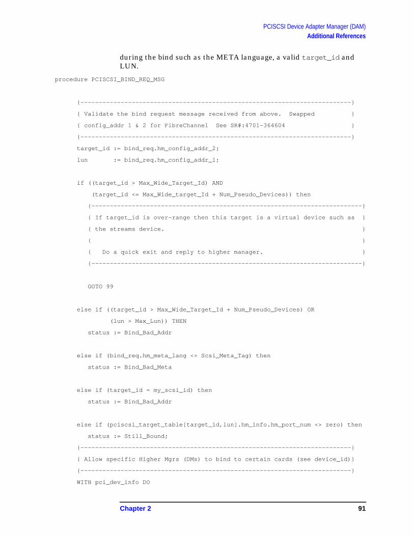
PCISCSI Device Adapter Manager (DAM)Additional References
during the bind such as the META language, a valid target_id andLUN.
procedure PCISCSI_BIND_REQ_MSG
{--------------------------------------------------------------------------}
{ Validate the bind request message received from above. Swapped }
{ config_addr 1 & 2 for FibreChannel See SR#:4701-364604 }
{--------------------------------------------------------------------------}
target_id := bind_req.hm_config_addr_2;
lun := bind_req.hm_config_addr_1;
if ((target_id > Max_Wide_Target_Id) AND
(target_id <= Max_Wide_target_Id + Num_Pseudo_Devices)) then
{--------------------------------------------------------------------------}
{ If target_id is over-range then this target is a virtual device such as }
{ the streams device. }
{ }
{ Do a quick exit and reply to higher manager. }
{--------------------------------------------------------------------------}
GOTO 99
else if ((target_id > Max_Wide_Target_Id + Num_Pseudo_Devices) OR
(lun > Max_Lun)) THEN
status := Bind_Bad_Addr
else if (bind_req.hm_meta_lang <> Scsi_Meta_Tag) then
status := Bind_Bad_Meta
else if (target_id = my_scsi_id) then
status := Bind_Bad_Addr
else if (pciscsi_target_table[target_id,lun].hm_info.hm_port_num <> zero) then
status := Still_Bound;
{--------------------------------------------------------------------------}
{ Allow specific Higher Mgrs (DMs) to bind to certain cards (see device_id)}
{--------------------------------------------------------------------------}
WITH pci_dev_info DO
Chapter 2 91

PCISCSI Device Adapter Manager (DAM)Additional References
begin
IF (( device_id = SYM53C895_DEVICE_ID ) OR
( device_id = SYM53C896_DEVICE_ID )) THEN
IF ( ada^.init_data.smode = SMODE_SINGLE_ENDED ) THEN
{--------------------------------------------}
{ SINGLE-ENDED SCSI BUS }
{--------------------------------------------}
{--------------------------------------------}
{--------------------------------------------}
{*** Valid Higher Mgr for this SCSI Bus ***}
{--------------------------------------------}
CASE bind_req.hm_subsys_num OF
Subsys_Scsi_Tape_Dm,
Subsys_Scsi_Tape2_Dm,
Subsys_Scsi_Ddm, { Scsi Disk Device mgr }
Subsys_Autochg_Dm,
Subsys_Magneto_Dm,
Subsys_Hep_Printer_Dm : { do nothing } ;
OTHERWISE
status := Incompatible_Subsys;
goto 99;
end { case }
ELSE
{--------------------------------------------}
{ Low-Voltage SCSI Bus }
{--------------------------------------------}
{--------------------------------------------}
{--------------------------------------------}
{*** Valid Higher Mgr for this SCSI Bus ***}
{--------------------------------------------}
CASE bind_req.hm_subsys_num OF
Subsys_Magneto_Dm,
92 Chapter 2

PCISCSI Device Adapter Manager (DAM)Additional References
Subsys_disk_And_Array_Dm: { do nothing } ;
OTHERWISE
status := Incompatible_Subsys;
goto 99;
end; { case }
{--------------------------------------------}
{ High-Voltage Diff SCSI bus }
{--------------------------------------------}
{--------------------------------------------}
IF ( device_id = SYM53C875_876_DEVICE_ID ) THEN
{--------------------------------------------}
{*** Valid Higher Mgr for this SCSI Bus ***}
{--------------------------------------------}
CASE bind_req.hm_subsys_num OF
Subsys_disk_And_Array_Dm,
Subsys_Scsi_Tape2_Dm,
Subsys_Magneto_Dm,
Subsys_Autochg_Dm: { do nothing } ;
OTHERWISE
status := Incompatible_Subsys;
goto 99;
end; { case }
end; { with pci_dev_info }
{--------------------------------------------------------------------------}
{ Save higher mgr binding information in the pciscsi_target_table }
{--------------------------------------------------------------------------}
with pciscsi_target_table[target_id,lun].hm_info do
begin
hm_port_num := msg_header.from_port;
hm_subsys := bind_req.hm_subsys_num;
Chapter 2 93

PCISCSI Device Adapter Manager (DAM)Additional References
hm_event_subqueue := bind_req.hm_event_subq;
hm_poweron_reset := FALSE;
hm_bound := FALSE;
end;
WITH pciscsi_target_table [target_id, lun].aen_info DO
begin
aen_enabled := FALSE;
active_aen_buf := zero;
aen_buf [zero] := nil;
aen_buf [one] := nil;
end;
99:
PCISCSI_BS_REPLY( pda,
msg,
status,
nil, { req }
subqs_on
);
94 Chapter 2

PCISCSI Device Adapter Manager (DAM)Additional References
Figure 2-26 Slide 26
Data Class Conversion to IOVEC
All data classes mapped to common IOVEC structure
Data Classes
Virtual Buffer,
Virtual Block,
Pquad Blocks,
Scatter Gather Lists
IOVA for 32-bit drivers on a 64-bit O.S
Data class conversion of MPE/iX data transfer is necessary toaccommodate the single native data class of IOVEC for the lower DAM.An IOVEC is a list of paired address pointers and data lengths for asingle transaction. For example, a list could contain six entries for asingle six page MIB request. The data lengths in each IOVEC entry arerestricted to a single full or partial page as part of the IOVA project to
hp e3000
7.0 fieldtraining
Data Class Conversion to IOVEC
· All data classes mapped to common IOVEC structure
· Data Classes
· Virtual Buffer,
· Virtual Block,
· Pquad Blocks,
· Scatter Gather Lists
· IOVA for 32-bit drivers on a 64-bit O.S
Chapter 2 95

PCISCSI Device Adapter Manager (DAM)Additional References
support 32-bit cards on a 64-bit host platform. (see IOVA internalstraining).
MPE/iX supports multiple data classes: 1) with/without head databuffer chains (e.g. data class: PQUADS), 2) single monolithic buffers(e.g. data class: virtual buffer) or 3) linked buffers (e.g. data class:virtual blocks). Each of these structures is converted to IOVEC viaprocedure pciscsi_build_iovec . The IOVEC array ptr is passed tothe lower DAM via IO_DATA structure.
For each kind of data class, Pciscsi_build_iovec traverses the databuffers and passes one buffer at a time to procedurePciscsi_vergion_to_iovec for conversion to the address/length pairsin IOVEC. A single IOVEC list is created for the I/O transactionregardless of the number of data buffers in the original request. Thelower DAM setups the hardware DMAs (Direct Memory Access) drivenby the IOVEC list.
procedure PCISCSI_BUILD_IOVEC
with io_data_ptr^.body do
begin
{xxxxxxxxxxxxxxxxxxxxxxxxxxxxxxxxxxxxxxxxxxxxxxxxxxxxxxxxxxxxxxxxxxxxxxxxxx}
{--------------------------------------------------------------------------}
{ Build IOVEC for auto req sense buffer }
{--------------------------------------------------------------------------}
{xxxxxxxxxxxxxxxxxxxxxxxxxxxxxxxxxxxxxxxxxxxxxxxxxxxxxxxxxxxxxxxxxxxxxxxxxx}
PCISCSI_VREGION_TO_IOVEC ( pda,
ada,
globalanyptr (status_ptr),
status_len,
ioasense,
iovec_idx,
status
);
IF ( status.is_ok <> ALL_OK ) THEN
GOTO 99;
end;
96 Chapter 2
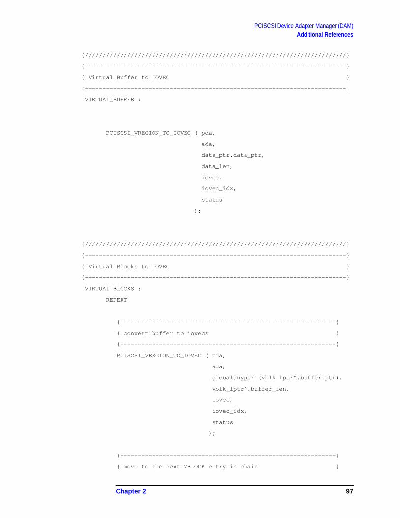
PCISCSI Device Adapter Manager (DAM)Additional References
{//////////////////////////////////////////////////////////////////////////}
{--------------------------------------------------------------------------}
{ Virtual Buffer to IOVEC }
{--------------------------------------------------------------------------}
VIRTUAL_BUFFER :
PCISCSI_VREGION_TO_IOVEC ( pda,
ada,
data_ptr.data_ptr,
data_len,
iovec,
iovec_idx,
status
);
{//////////////////////////////////////////////////////////////////////////}
{--------------------------------------------------------------------------}
{ Virtual Blocks to IOVEC }
{--------------------------------------------------------------------------}
VIRTUAL_BLOCKS :
REPEAT
{-------------------------------------------------------------}
{ convert buffer to iovecs }
{-------------------------------------------------------------}
PCISCSI_VREGION_TO_IOVEC ( pda,
ada,
globalanyptr (vblk_lptr^.buffer_ptr),
vblk_lptr^.buffer_len,
iovec,
iovec_idx,
status
);
{-------------------------------------------------------------}
{ move to the next VBLOCK entry in chain }
Chapter 2 97

PCISCSI Device Adapter Manager (DAM)Additional References
{-------------------------------------------------------------}
if (vblk_lptr^.next_ptr <> nil) then
begin
vblk_lptr := vblk_lptr^.next_ptr;
iovec_idx := iovec_idx + 1;
end
else
chain_end := TRUE;
UNTIL (chain_end);
{//////////////////////////////////////////////////////////////////////////}
{--------------------------------------------------------------------------}
{ Page Blocks to IOVEC }
{--------------------------------------------------------------------------}
PAGE_BLOCKS :
status := Unexpected_Data_Class;
PCISCSI_NOTIFY_DIAG ( pda,
msg,
status.error_num,
status.proc_num
);
{//////////////////////////////////////////////////////////////////////////}
{--------------------------------------------------------------------------}
{ Pquad Blocks to IOVEC }
{--------------------------------------------------------------------------}
PQUAD_BLOCKS :
REPEAT
n := n + 1;
LOAD_VIRT_ADDR (pquad_lptr^.address, {* physical buffer address *}
va_type (buffer_lptr));
98 Chapter 2

PCISCSI Device Adapter Manager (DAM)Additional References
{-------------------------------------------------------------}
{ flush_dc_range only on data write. Physical address in }
{ pquad during data read may not be mapped to a virtual }
{ address until the successful read. }
{-------------------------------------------------------------}
IF (data_direction = data_out) then
{* DC flush buffer for this PQUAD *}
FLUSH_DC_RANGE (buffer_lptr, {* virtual buffer addr *}
pquad_lptr^.count); {* bytes in buffer to DC flush*}
host_range.len := pquad_lptr^.count; {* bytes in buffer *}
host_range.host_addr := va_type (buffer_lptr);
host_range.phys_addr := pquad_lptr^.address; {* buffer physicaladdress *}
MAP_TO_IOVA_RANGE ( ioa_index,
[IOA_CONTIGUOUS], { hints }
zero, { host_range type, not supported}
host_range, { request for addr range }
io_range, { IOVA (io_addr) to use }
map_cb_ptr,
status,
); { alloc_scheme }
IF ( status.is_ok <> ALL_OK ) THEN
begin
status := Map_To_Iova_Failed;
goto 99;
end;
iovec[n].buf_iova := io_range.io_addr.iova;
iovec[n].buf_len := io_range.len;
{-------------------------------------------------------------}
Chapter 2 99

PCISCSI Device Adapter Manager (DAM)Additional References
{ move to the next PQUAD entry in chain }
{-------------------------------------------------------------}
if (pquad_link_type(pquad_lptr^.link).end_of_chain <> EOC) then
{* convert link to virtual *}
LOAD_VIRT_ADDR (pquad_lptr^.link,
va_type(pquad_lptr))
else
chain_end := TRUE;
UNTIL (chain_end);
sync_caches;
iovec_count := n; {* number of IOVEC entries *}
end;
{//////////////////////////////////////////////////////////////////////////}
{--------------------------------------------------------------------------}
{ Scatter Gather List to IOVEC }
{--------------------------------------------------------------------------}
SCATTER_GATHER_LIST :
with msg^.scsi_io_req do
REPEAT
n := n + 1;
LOAD_VIRT_ADDR_64 (loc_sgl^.sgl_entries[n].sgl_data_phys_addr,
va_type (buffer_lptr));
IF (data_direction = data_out) then
{* DC flush buffer for this SGL entry *}
FLUSH_DC_RANGE (buffer_lptr, {* virtual buffer addr *}
loc_sgl^.sgl_entries[n].sgl_byte_count);
host_range.len := loc_sgl^.sgl_entries[n].sgl_byte_count;
100 Chapter 2

PCISCSI Device Adapter Manager (DAM)Additional References
{ bytes in buffer }
host_range.host_addr := va_type (buffer_lptr); {virt addr }
host_range.phys_addr :=loc_sgl^.sgl_entries[n].sgl_data_phys_addr; { phys addr }
MAP_TO_IOVA_RANGE ( ioa_index,
[IOA_CONTIGUOUS], { hints }
zero, { host_range type, notsupported }
host_range, { request for addr range }
io_range, { IOVA (io_addr) to use }
map_cb_ptr,
status,
); { alloc_scheme }
IF ( status.is_ok <> ALL_OK ) THEN
begin
status := Map_To_Iova_Failed;
goto 99;
end;
iovec[n+1].buf_iova := io_range.io_addr.iova;
iovec[n+1].buf_len := io_range.len;
UNTIL (n+1 = loc_sgl^.sgl_header.sgl_num_entries);
iovec_count := n+1; {* number of IOVEC entries *}
{* sync caches *}
sync_caches;
end;
procedure PCISCSI_VREGION_TO_IOVEC
{--------------------------------------------------------------------------}
{ Setup for vreglet to iovec conversion. Calculate for number of }
{ iovec entries needed for this vreglet }
{--------------------------------------------------------------------------}
Chapter 2 101

PCISCSI Device Adapter Manager (DAM)Additional References
next_vreglet_ptr := vregion_ptr;
next_vreglet_ptr := addtopointer(next_vreglet_ptr,
PAGE_SIZE);
num_iovecs_left := (va_type (next_vreglet_ptr).page_offset +
vregion_len + (PAGE_SIZE - 1)) DIV PAGE_SIZE;
{//////////////////////////////////////////////////////////////////////////}
{--------------------------------------------------------------------------}
{ BUILD FIRST IOVEC ENTRY - for partial or full physical page }
{ ======================= }
{--------------------------------------------------------------------------}
{--------------------------------------------------------------------------}
{ Build FIRST iovec entry from vregion_ptr (ie. from beginning vregion_ptr)}
{ to first 4k page boundary). }
{--------------------------------------------------------------------------}
IF (num_iovecs_left = 0) THEN
iovec[iovec_idx].buf_len := vregion_len {* vregion is less than one page insize *}
ELSE
iovec[iovec_idx].buf_len := PAGE_SIZE - va_type(vregion_ptr).page_offset;{*vregion spans pages *}
{* MAP_TO_IOVA_RANGE replaces: iovec[iovec_idx].buf_ptr :=load_phys_addr(vregion_ptr); *}
host_range.len := iovec[iovec_idx].buf_len;
host_range.host_addr := va_type (vregion_ptr);
host_range.phys_addr := load_phys_addr_64_x (vregion_ptr);
{--------------------------------------------------------------------------}
{ Map to IOVA }
{--------------------------------------------------------------------------}
102 Chapter 2
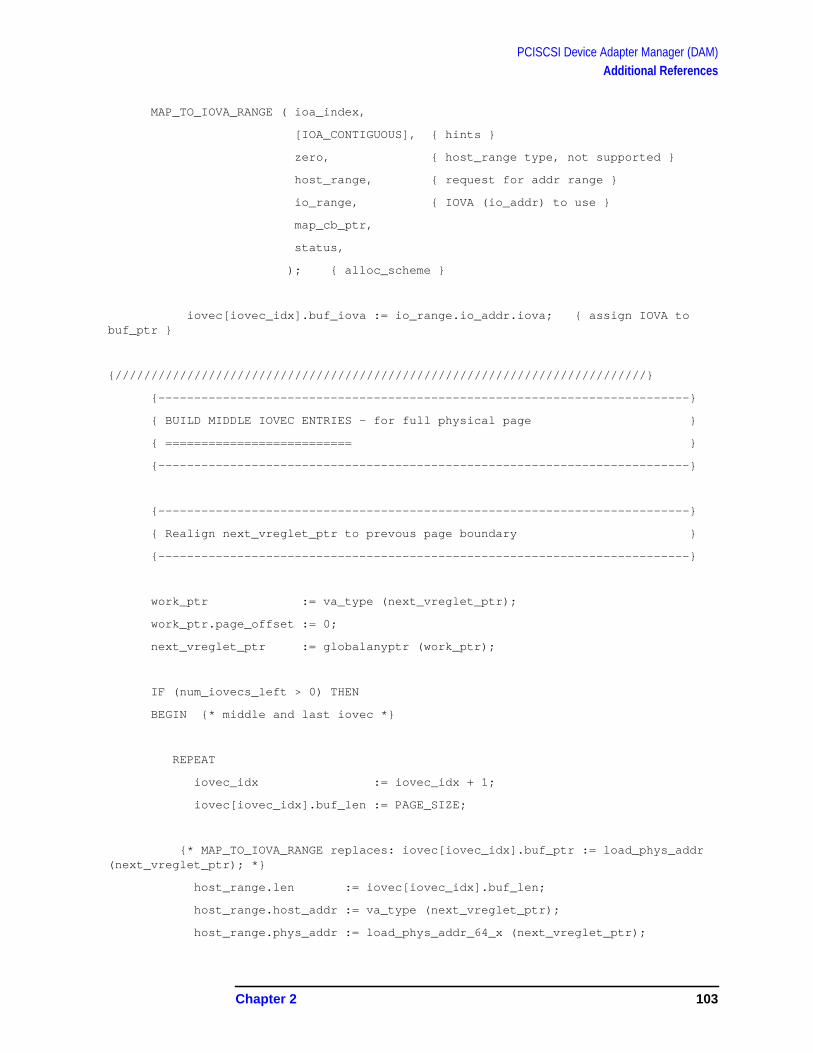
PCISCSI Device Adapter Manager (DAM)Additional References
MAP_TO_IOVA_RANGE ( ioa_index,
[IOA_CONTIGUOUS], { hints }
zero, { host_range type, not supported }
host_range, { request for addr range }
io_range, { IOVA (io_addr) to use }
map_cb_ptr,
status,
); { alloc_scheme }
iovec[iovec_idx].buf_iova := io_range.io_addr.iova; { assign IOVA tobuf_ptr }
{//////////////////////////////////////////////////////////////////////////}
{--------------------------------------------------------------------------}
{ BUILD MIDDLE IOVEC ENTRIES - for full physical page }
{ ========================== }
{--------------------------------------------------------------------------}
{--------------------------------------------------------------------------}
{ Realign next_vreglet_ptr to prevous page boundary }
{--------------------------------------------------------------------------}
work_ptr := va_type (next_vreglet_ptr);
work_ptr.page_offset := 0;
next_vreglet_ptr := globalanyptr (work_ptr);
IF (num_iovecs_left > 0) THEN
BEGIN {* middle and last iovec *}
REPEAT
iovec_idx := iovec_idx + 1;
iovec[iovec_idx].buf_len := PAGE_SIZE;
{* MAP_TO_IOVA_RANGE replaces: iovec[iovec_idx].buf_ptr := load_phys_addr(next_vreglet_ptr); *}
host_range.len := iovec[iovec_idx].buf_len;
host_range.host_addr := va_type (next_vreglet_ptr);
host_range.phys_addr := load_phys_addr_64_x (next_vreglet_ptr);
Chapter 2 103

PCISCSI Device Adapter Manager (DAM)Additional References
{--------------------------------------------------------------------------}
{ Map to IOVA }
{--------------------------------------------------------------------------}
MAP_TO_IOVA_RANGE ( ioa_index,
[IOA_CONTIGUOUS], { hints }
zero, { host_range type, not supported }
host_range, { request for addr range }
io_range, { IOVA (io_addr) to use }
map_cb_ptr,
status,
); { alloc_scheme }
{//////////////////////////////////////////////////////////////////////////}
{--------------------------------------------------------------------------}
{ BUILD LAST IOVEC ENTRY - partial or full physical page }
{ ====================== }
{--------------------------------------------------------------------------}
{--------------------------------------------------------------------------}
{ Build last iovec entry (ie. redo last iovec count) }
{--------------------------------------------------------------------------}
work_ptr := va_type(addtopointer (globalanyptr(vregion_ptr),
vregion_len));
IF (work_ptr.Page_offset = 0) THEN
iovec[iovec_idx].buf_len := PAGE_SIZE
ELSE
iovec[iovec_idx].buf_len := work_ptr.page_offset;
END; {* middle and last iovec *}
{--------------------------------------------------------------------------}
{ Flush virtual buffer and sync caches }
{--------------------------------------------------------------------------}
flush_dc_range (globalanyptr(vregion_ptr),
vregion_len);
sync_caches;
104 Chapter 2

PCISCSI Device Adapter Manager (DAM)Additional References
Figure 2-27 Slide 27
Port SubQ to Internal Pending_queue
Batch process from port SubQ
Requests processed with immediate actions and deferred actions
A performance enhancement was engineered in the PCISCSI DAM thatprocesses all I/Os requests from the port subqueues before the DAMexits. Most other I/O managers process only one request (even if morerequests are in the port subqueues) from the port, exits the code, thenwakes up again to process another single request, exits the code,wakes up, etc. etc.
The PCISCSI DAM processes I/O requests from the port subqueues toits internal queues and determines what request should be acted onfirst or to defer action until a later point in this DAM’s executioninstance. All requests will be processed from the internal queues beforethe code exits.
hp e3000
7.0 fieldtraining
Port SubQ to Internal Q
· Batch process from port SubQ
· Results of immediate actions and deferred actions
Chapter 2 105

PCISCSI Device Adapter Manager (DAM)Additional References
procedure PCI_SCSI_DAM
{--------------------------------------------------------------------------}
{////////// //////////}
{ Process all llio_msgs from port subqueues to internal queues before }
{ starting any internal processes to complete I/O requests. }
{--------------------------------------------------------------------------}
REPEAT
{--------------------------------------------------------------------------}
{ Log the message in the PDA (tracing information for debugging). }
{--------------------------------------------------------------------------}
PCISCSI_DO_MSG_LOG ( pda,
msg,
Received_By_Dam
);
{--------------------------------------------------------------------------}
{ Go to the appropriate message handler based on msg_descriptor and }
{ mgr_state. }
{--------------------------------------------------------------------------}
msg_handler := PCISCSI_GET_MSG_HANDLER( mgr_state,
msg^.msg_header.msg_descriptor,
pda,
status
);
if (status.is_ok = Llio_Ok) then
Call( Msg_Handler,
pda,
ada,
msg,
msg_length,
subqueue,
subqs_on
)
106 Chapter 2
PCISCSI Device Adapter Manager (DAM)Additional References
{--------------------------------------------------------------------------}
{ Get next msg from port subqueue}
{--------------------------------------------------------------------------}
IO_RETRIEVE_MSG ( my_port,
subqs_on, { subqueues to retrieve from }
found_subq, { first subqueue a msg was found on }
retrieved_msg, { msg ptr }
retrieved_status
);
UNTIL ( retrieved_status.is_ok <> ALL_OK );
{--------------------------------------------------------------------------}
{ Start internal process to complete I/O requests}
{--------------------------------------------------------------------------}
PCISCSI_TRY_START_IO ( pda,
ada,
subqs_on
);
The procedure naming convention in PCSICSI DAM is to add “_msg” toall procedures that are message handlers. The msg_handlers areexecuted in the “CALL” within the manager’s outer code blockpci_scsi_dam (see above). Pciscsi_io_req_msg andpciscsi_ctrl_req_msg are examples of two message handlers. Thefirst handler merely obtains a “req” (i.e. request entry structure), copiescomponents of the LLIO message into the req and queues the req ontothe pending_resources queue.
Pciscsi_ctrl_req_msg is primarily a DAM specific message whichresults in immediate action and reply to the higher mgr. Additionalactions are done when a AE_POLLING message is received to test thepresence/condition of the device via a TUR (Test Unit Ready) SCSIcommand.
Chapter 2 107

PCISCSI Device Adapter Manager (DAM)Additional References
procedure PCISCSI_IO_REQ_MSG
PCISCSI_GET_REQ_ENTRY ( ada,
req,
subqs_on,
status
);
req^.llio_msg_ptr := msg;
req^.target_id := msg^.scsi_io_req.target_id;
req^.lun := msg^.scsi_io_req.lun;
req^.qtag := msg^.scsi_io_req.q_tag;
req^.qtag_class := msg^.scsi_io_req.q_tag_message;
PCISCSI_PUT_ON_PENDING_QUEUE ( pda,
Pending_Resources,
req,
status
);
procedure PCISCSI_CTRL_REQ_MSG
Case scsi_ctrl_req.ctrl_func of
{+++++++++++++++++}
RESET_NEXUS,
RESET_LUN,
CLEAR_QUEUE,
ABORT_QUEUE:
begin
status := Not_Implemented;
quick_reply := TRUE;
end;
108 Chapter 2

PCISCSI Device Adapter Manager (DAM)Additional References
{+++++++++++++++++}
ENABLE_AEN:
begin
pciscsi_target_table [target_id, lun].aen_info.aen_enabled := TRUE;
quick_reply := TRUE;
end;
{+++++++++++++++++}
DISABLE_AEN:
begin
pciscsi_target_table [target_id, lun].aen_info.aen_enabled := FALSE;
quick_reply := TRUE;
end;
{+++++++++++++++++}
INITIATE_AE_POLLING,
TAGGED_AE_POLLING:
with ada^ do
{--------------------------------------------------------------------------}
{ The ctrl_reply is sent just before sending the scsi_event (even if we}
{ don't send an event), in PCISCSI_BS_REPLY, so that the DM can triggerthe}
{ opening of its input subqueues based on the receipt of the ctrl reply}
{ from the DAM. (Otherwise the DM could unintentionally end up with two}
{ I/Os queued to a device that doesn't support tagged queuing).}
{--------------------------------------------------------------------------}
{--------------------------------------------------------------------------}
{ No tlih mechanism instead, send a TUR msg to device via a new scsi req}
{ msg. }
{--------------------------------------------------------------------------}
Chapter 2 109

PCISCSI Device Adapter Manager (DAM)Additional References
PCISCSI_GET_REQ_ENTRY ( ada,
req,
subqs_on,
status
);
PCISCSI_GET_FRAME( my_port,
tur_msg,
status,
pda,
zero
);
WITH tur_msg^.msg_header DO
begin
msg_descriptor := scsi_io_req_msg;
message_id := msg^.msg_header.message_id;
transaction_num := msg^.msg_header.transaction_num;
from_port := my_port;
end;
tur_msg^.scsi_io_req.target_id := msg^.scsi_ctrl_req.target_id;
tur_msg^.scsi_io_req.lun := msg^.scsi_ctrl_req.lun;
with tur_msg^.scsi_io_req, pciscsi_target_table [target_id,lun].aen_info do
begin
{--------------------------------------------------------------------------}
{ NOTE: Queue tagged aen polling not supported}
{--------------------------------------------------------------------------}
q_tag_message := NO_QUEUE_TAG;
q_tag := ZERO;
cmd_ptr := Addr(tur_cdb);
110 Chapter 2

PCISCSI Device Adapter Manager (DAM)Additional References
cmd_len := 6;
data_ptr.data_ptr := NIL;
data_len := 0;
data_class := virtual_buffer;
data_direction := data_in;
allow_disconnect := TRUE;
status_ptr := aen_buf[active_aen_buf];
status_len := aen_buf_length;
end;
req^.llio_msg_ptr := tur_msg; {* newly created TUR msg *}
req^.target_id := msg^.scsi_ctrl_req.target_id;
req^.lun := msg^.scsi_ctrl_req.lun;
req^.ctrl_msg_ptr := msg; {* save scsi_ctrl_msg for laterreply *}
PCISCSI_PUT_ON_PENDING_QUEUE ( pda,
Pending_Resources,
req,
status
);
{+++++++++++++++++}
RELEASE_RECOVERY:
begin
status := Not_Implemented;
end;
{+++++++++++++++++}
SET_AEN_BUFFERS:
begin
with pciscsi_target_table [target_id, lun].aen_info do
begin
quick_reply := TRUE;
Chapter 2 111

PCISCSI Device Adapter Manager (DAM)Additional References
aen_buf_length := {msg^.} scsi_ctrl_req.aen_buf_length;
aen_buf[0] := scsi_ctrl_req.aen_primary_buf;
aen_buf[1] := scsi_ctrl_req.aen_secondary_buf;
active_aen_buf := 0;
end;
end;
{+++++++++++++++++}
SET_QUEUE_DEPTH:
begin
quick_reply := TRUE;
end;
112 Chapter 2
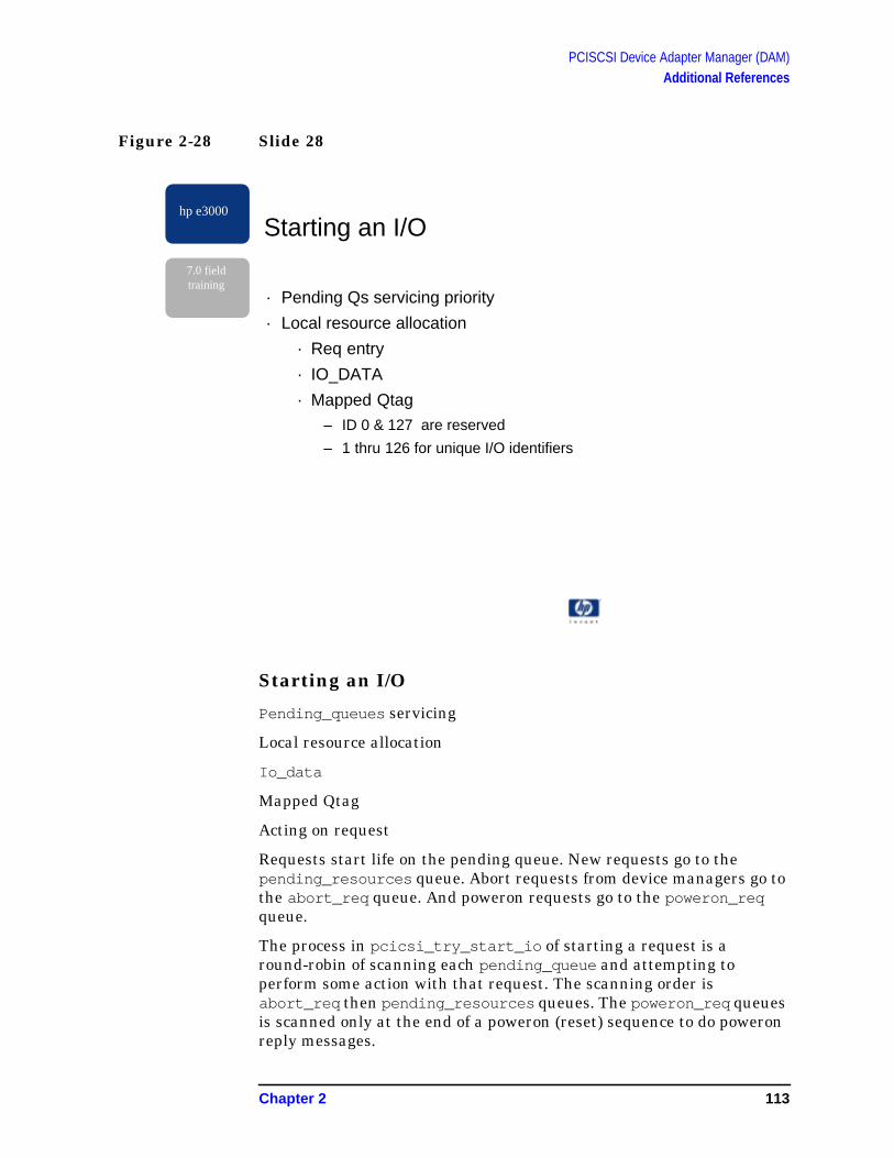
PCISCSI Device Adapter Manager (DAM)Additional References
Figure 2-28 Slide 28
Starting an I/O
Pending_queues servicing
Local resource allocation
Io_data
Mapped Qtag
Acting on request
Requests start life on the pending queue. New requests go to thepending_resources queue. Abort requests from device managers go tothe abort_req queue. And poweron requests go to the poweron_reqqueue.
The process in pcicsi_try_start_io of starting a request is around-robin of scanning each pending_queue and attempting toperform some action with that request. The scanning order isabort_req then pending_resources queues. The poweron_req queuesis scanned only at the end of a poweron (reset) sequence to do poweronreply messages.
hp e3000
7.0 fieldtraining
Starting an I/O
· Pending Qs servicing priority
· Local resource allocation
· Req entry
· IO_DATA
· Mapped Qtag
– ID 0 & 127 are reserved
– 1 thru 126 for unique I/O identifiers
Chapter 2 113

PCISCSI Device Adapter Manager (DAM)Additional References
procedure PCISCSI_TRY_START_IO
{--------------------------------------------------------------------------}
{ ABORT_REQ pending queue: }
{ Start each request in the Abort_Req queue }
{--------------------------------------------------------------------------}
REPEAT
PCISCSI_GET_NEXT_FROM_PENDING_QUEUE ( pda,
Abort_Req,
REMOVE_REQ, {* remove_action *}
req,
get_status
);
IF ( get_status.is_ok = ALL_OK ) THEN
begin
PCISCSI_ABORT_REQ ( pda,
ada,
req,
subqs_on,
status
);
UNTIL (get_status.is_ok <> ALL_OK );
{--------------------------------------------------------------------------}
{ PENDING_RESOURCE pending queue: }
{ Try to start first and subsequent request in the Pending_Resources }
{ queue }
{--------------------------------------------------------------------------}
IF ( pending_queue [Pending_Resources].head <> NIL ) THEN
begin
curr_req := pending_queue [Pending_Resources].head;
114 Chapter 2

PCISCSI Device Adapter Manager (DAM)Additional References
REPEAT
{--------------------------------------------------------------------------}
{ SNOOP req on pending queue first and try to get resources. If all}
{ necessary resources are acquired then remove from pending_resources}
{ queue and start the I/O. }
{--------------------------------------------------------------------------}
PCISCSI_GET_RESOURCES ( pda,
ada,
curr_req,
resource_status
)
IF ( resource_status.is_ok <> ALL_OK ) THEN
{--------------------------------------------------------------------------}
{ Check the next req on the pending queue}
{--------------------------------------------------------------------------}
curr_req := curr_req^.link
ELSE
begin
{--------------------------------------------------------------------------}
{ SNOOPed req and also acquired resources, so remove req from queue}
{ pending_resources and start the I/O}
{ OR }
{ Reply to curr_req with powerfail_abort status. Remove req frompending }
{ queue and then bs_reply }
{--------------------------------------------------------------------------}
Chapter 2 115

PCISCSI Device Adapter Manager (DAM)Additional References
my_msgid := curr_req^.llio_msg_ptr^.msg_header.message_id;
my_trn := curr_req^.llio_msg_ptr^.msg_header.transaction_num;
{--------------------------------------------------------------------------}
{ Move curr_req ptr to the next req on pending queue}
{--------------------------------------------------------------------------}
curr_req := curr_req^.link;
PCISCSI_REMOVE_FROM_PENDING_QUEUE ( pda,
Pending_Resources,
Msgid_Trn,
REMOVE_REQ, {* remove_action *}
my_msgid,
my_trn,
req,
get_status
);
IF ( status.is_ok = ALL_OK ) THEN
PCISCSI_START_IO ( pda,
ada,
req,
status
);
IF (status.is_ok = ALL_OK ) THEN
{--------------------------------------------------------------------------}
{ Successful start of I/O then place req in active request table}
{--------------------------------------------------------------------------}
PCISCSI_PUT_IN_REQ_TABLE ( pda,
116 Chapter 2

PCISCSI Device Adapter Manager (DAM)Additional References
req,
status
)
ELSE
{--------------------------------------------------------------------------}
{ Failed to start I/O. Reply to higher manager with status}
{--------------------------------------------------------------------------}
PCISCSI_BS_REPLY ( pda,
NIL, { msg }
status,
req,
subqs_on
);
end;
UNTIL (curr_req = nil );
When an I/O request on the pending_resources is selected andresources are allocated, the request is passed to pciscsi_start_io tosetup the associated io_data structure and then call pci_c720_if_startto start the I/O request in the lower DAM.
procedure PCISCSI_START_IO
{--------------------------------------------------------------------------}
{ Convert data [class] type to IOVEC data type for the lower DAM. IOVEC }
{ is an array of data ptrs and data lengths like MPE SGL data type. }
{--------------------------------------------------------------------------}
PCISCSI_BUILD_IOVEC (pda,
ada,
req,
status
);
with ada^, io_data_ptr^.body do
Chapter 2 117

PCISCSI Device Adapter Manager (DAM)Additional References
begin
{--------------------------------------------------------------------------}
{ Setup io_data strucuture for lower DAM to start the I/O }
{--------------------------------------------------------------------------}
pci_isc_ptr := addr ( pci_isc );
pci_isc_ptr^.isc_ptr := addr ( isc );
pci_isc_ptr^.c720_isc_ptr := addr ( c720_isc );
pci_buf_ptr := addr ( buf );
pci_scb_ptr := addr ( pci_scb );
pci_scb_ptr^.scb_ptr := addr ( scb );
pci_scb_ptr^.c720_scb_ptr := addr ( c720_scb );
pci_scsi_lun_ptr := addr ( scsi_lun_array[target_id, lun] );
pci_tgt_ptr := addr ( pci_tgt );
pci_tgt_ptr^.scsi_tgt_ptr := addr ( scsi_tgt_array [target_id] );
pci_tgt_ptr^.c720_tgt_ptr := addr ( c720_tgt_array [target_id] );
{--------------------------------------------------------------------------}
{ IOVEC chain for user buffer (iovec_ptr) and sense buffer (ioasense_ptr) }
{ setup in when PCISCSI_BUILD_IOVEC is called }
{--------------------------------------------------------------------------}
iovec_ptr := addr ( iovec );
ioasense_ptr := addr ( ioasense );
WITH llio_msg_ptr^.scsi_io_req DO
begin
if (data_direction = data_in) then
begin
b_flags := hex ('00000001'); { read data }
IF ( allow_disconnect ) THEN
scb_flags := hex ('00000001')
{ 0x00000001 - sctl_read }
ELSE
scb_flags := hex ('00000009');
{ 0x00000001 - sctl_read }
118 Chapter 2

PCISCSI Device Adapter Manager (DAM)Additional References
{ 0x00000008 - no disconnects }
end
else
begin
b_flags := hex ('00000000'); { write data }
IF ( allow_disconnect ) THEN
scb_flags := hex ('00000000')
ELSE
scb_flags := hex ('00000008');
{ 0x00000008 - no disconnects }
end;
b_count := data_len;
io_id := llio_msg_ptr^.msg_header.transaction_num;
cdb_cmd.data_ptr := cmd_ptr;
for n := 1 to cmd_len do
cdb_len := cmd_len;
lun_id := lun;
tgt_id := target_id;
tag_id := mapped_qtag;
IF ( q_tag_message <> No_Queue_Tag ) THEN
l_tag := TAGGED_IO {* This a tagged I/O req *}
ELSE
l_tag := UNTAGGED_IO; {* This is not *}
end; { with llio_msg_ptr }
end; { with io_data_ptr }
{--------------------------------------------------------------------------}
{ Flush sense buffer prior to possibly using it. }
{--------------------------------------------------------------------------}
with llio_msg_ptr^ DO
begin
PURGE_DC_RANGE ( scsi_io_req.status_ptr,
Chapter 2 119

PCISCSI Device Adapter Manager (DAM)Additional References
scsi_io_req.status_len {* flush length from io_data *}
);
SYNC_CACHES;
end;
{--------------------------------------------------------------------------}
{ Call lower DAM to start I/O }
{--------------------------------------------------------------------------}
PCI_C720_IF_START ( io_data_ptr^.body,
status
);
Mapped Qtag
Tagged and untagged I/O get assigned a mapped qtag
1 thru 126 for unique I/O indentifiers
ID 0 & 127 are reserved
All I/Os to the lower DAM must be uniquely identified by the use of amapped qtag. This tag also acts as an index to arrays for I/O associateddata structures, ptrs, etc. These tags must also be unique across all I/Osfor all devices on a SCSI bus.
MPE/iX I/O subsystem device drivers have the ability to locally assigntheir own qtag to track I/Os. However, duplicate qtags could be sent tothe DAM from independent device mgrs and cause lower DAM I/Oconfusion. As a service to the lower DAM, the upper DAM saves thedevice manager’s qtag in the pciscsi_req_entry structure and thenassigns a new unique mapped qtag that will be passed to the lowerDAM as the qtag. This mapped qtag will also be passed to the device asthe “qtag” part of a SCSI tagged I/O transaction.
Mapped qtag Ids “0” and “127” are reserved for the lower DAM. Mappedqtag ids “1” through “126” are all available for I/O transaction usage.
120 Chapter 2

PCISCSI Device Adapter Manager (DAM)Additional References
Figure 2-29 Slide 29
First I/O
Data setup
Negotiate with device for SDTR and WDTR
The lower dam initializes device specific structures during the first I/Oto that device. Also, an exchange of device capabilities is done usingSDTR (Synchronous Data Transfer) and WDTR (Wide Data Transfer)to determine if the device can communicate in narrow (8-bits) or wide(16-bits) or do synchronous handshaking during data transfers.
The following is pseudo code for an I/O when the upper DAM callspci_c720_start.
pci_c720_if_start (io_data_ptr, isc_ptr, m_bp_ptr, iovec_ptr, status_ptr)
switch to interface
pci_c720_if_start (io_data_ptr, isc_ptr, m_bp_ptr, m_lun_tgt_ptr, iovec_ptr,isc=>status)
bp ->b_scb = scb
scb->if_scb = lsp
hp e3000
7.0 fieldtraining
First I/O
· Negotiate with device for SDTR and WDTR
· DM specifiable
Chapter 2 121
PCISCSI Device Adapter Manager (DAM)Additional References
scb->lp = lp
lp->tgt = tp
lp->lun_id = lun_id
tp->tgt_id = tgt_id
lsp->iovec = iovec
lsp->chain_cnt = iovec_cnt
Setup scb (from io_data)
Setup bp (from io_data)
Setup tp (from io_data)
Setup lp (from io_data)
Setup lsp (from io_data)
queue request (bp) to busp->select_q
C720_if_start (isc,…)
switch to Lower Dam
c720_if_start(isc,…)
c720_start (isc, …)
c720_DataSetup ()
c720_BMALLOC () [ensure proper mapping of BM scripts]
loop through iovec to setup scripts mapping
setup other script maps, using c720_scb fields
NOTE: {{ scratch=TgtLunToScratch (tgt_id, lun_id) }} send to card to indicate I/Oowner
c720_write_byte_reg ( )
set SIGP (in ISTAT, card register) , signal to card to start I/O
switch to interface
return status
switch to upper dam
if (status = io_started) then /* set timer */ io_rest_timer (watchdog_timer) /* wait for interrupt */ else
122 Chapter 2

PCISCSI Device Adapter Manager (DAM)Additional References
Figure 2-30 Slide 30
SCSI Script and Patching
No card firmware
Card scripting language
Patching to suit next program
The PCISCSI cards from SYMBIOS are a new generation of interfacethat have no firmware. Instead, a general purpose language called SCSISCRIPT is download to the card and interpreted by the card tomanipulate registers, control the SCSI bus, perform DMA from localFIFO buffers.
The SCSI SCRIPTS start with un-defined data transfer lengths anddata transfer ptrs. The host code (PCISCSI lower DAM) patches theseareas in the script with the relevant I/O data lengths and data ptrs andthen downloads the SCSI SCRIPT to the card for execution. Forexample, line 302 “MOVE 1, 0” will be patched with a physical addressto the host memory on where the SCSI msg-in data should be stored.
hp e3000
7.0 fieldtraining
SCSI Script Patching
· No firmware
· Card scripting language
· Patching to suit next program
Chapter 2 123

PCISCSI Device Adapter Manager (DAM)Additional References
295
296 ENTRY PtTag
297 00000140: PtTag:
298
299 ; The MOVE destination ispatched to be lbp->PhysInBuf->msgin.
300 ; The instruction is patchedonce on bus open and never again.
301
302 00000140: 0F000001 00000000 MOVE 1, 0, WHEN MSG_IN
303 00000148: 6A340000 00000000 MOVE SFBR TO SCRATCHA0
304 00000150: 78350800 00000000 MOVE 0x08 TO SCRATCHA1
305
306 ENTRY DoNextPhaseClrAck
307 00000158: DoNextPhaseClrAck:
308
309 00000158: 60000040 00000000 CLEAR ACK
310 00000160: 80080000 00000080 JUMP DoNextPhase
124 Chapter 2

PCISCSI Device Adapter Manager (DAM)Additional References
Figure 2-31 Slide 31
Interrupts
Type-A card requiring host assistance to complete I/O.
Target device directs the I/O progress and host SCSI Script programcreated to continue the I/O.
Typical Interrupts
All the PCISCSI interface cards are type-a cards requiring hostsoftware intervention to process the I/O data transfer to the device.These cards interrupt the host often for such events as: 1) deviceselection on the SCSI bus, 2) data transfer complete, 3) device statusafter data transfer, 4) devices exception or out of SCSI bus phaseconditions.
A complex list of IF_THEN_ELSE and SWITCH statements in thelower DAM initiate actions in response to the interrupts for whateverthe card and/or device may need to continue the I/O.
hp e3000
7.0 fieldtraining
Interrupts
· Type-A card requiring host assistance to complete I/O
· Target device directs the I/O progress and host SCSIScript program created to continue the I/O
· Typical interrupts
· after device selection
· after data transfer DMA
· bus exceptions
· device exceptions
Chapter 2 125
PCISCSI Device Adapter Manager (DAM)Additional References
BIG NOTE: At the beginning of the I/O request on the SCSI bus, thehost will select a device for an I/O transaction. From then on, the devicecontrols the entire transaction until the I/Os completion. This includesdata transfer to or from the device, changing of SCSI bus phases duringthe transaction, completing the transaction with status and releasingand re-obtaining the SCSI bus should data not be immediatelyavailable from the device’s media.
When the DAM is woke because of an interrupt, various registers arequeried to determine the host’s action on how to continue the I/O. A keyregister is the DSPS register which contains a passed value from theSCSI SCRIPT to indicate the kind of interrupt. The DAM’s hardwarelog contains DSPS values during the I/O transaction. The DSPS valuesdefinitions are:
DPSP REGISTER VALUES:
Performance path interrupts.
IntCmdSent 0x01
IntCmdComp 0x02
Other interrupts.
IntSdp 0x03
IntDisc 0x04
IntPutMsgOut 0x05
IntMsgOutIn 0x06
IntGetMsgIn 0x07
IntReselectIdMsgIn 0x08
IntMsgIn 0x09
IntSelect 0x0a
IntReselected 0x0b
IntDataDone 0x0c
IntDiscDone 0x0d
IntUntaggedReselect 0x0e
IntBusClose 0x0f
IntGood 0x10
Another register, the “scratchA” register contains the device ID or qtagid that is associated with this interrupt. The SCSI SCRIPT puts thedevice ID or qtag id in the scratch register prior to interrupting thehost. Look closely at the 2 scratch register examples for the two forms ofthe scratch register: one way for untagged I/O and another for taggedI/O.
126 Chapter 2
PCISCSI Device Adapter Manager (DAM)Additional References
Untagged SCRATCH
Tagged SCRATCH
The upper DAM calls pci_c720_isr upon receiving an interrupt messageto awake the lower DAM to respond to the hardware’s request for hostintervention. Following is pseudo code of the lower DAM’s actions inresponse to an interrupt:
pci_c720_isr (isc_ptr, isr_data)
switch to interface
pci_c720_isr (isr0_data, isc_ptr)
*lisc = (struct c720_isc *)isc->if_isc
c720_isr ()
switch to lower dam
c720_isr (isc, lisc, status)
setup busp, pa_regs
if c720_ReadByteReg (…ISTAT…) [pending DMA or SCSI interrupt]
c720_isrGuts
c720_isrGuts_NOT_ISTAT_SIP()
c720_ReadByteReg(SIST0/SIST1 regs ) [status registers]
c720_ReadByteReg(DSTAT reg)
c720_ReadByteReg(DSPS reg)
c720_ReadByteReg(SCRATCH reg)
obtain lsp ptr to c720_scb via LbpScratchToLsp ( SCRATCH A register )
Combine all interrupt bits into “intstat”
C720_FLUSH-CACHE()
DSPS “+” instat to select service routine
-- if “IntGood”
31 16 15 12 11 10 8 7 5 4 0
Don’t Care 0001 Tgt (Bit 3) 000 Tgt (bits 2–0 Lun
31 16 15 12 11 10 8 7 0
Don’t care 0000 1 000 Tag
Chapter 2 127

PCISCSI Device Adapter Manager (DAM)Additional References
---- c720_isr_CmdComp ()
------ extract status byte stored by chip
---------- etc. etc. etc.
-- else /* not IntGood */
---- c720_isrEscape () [s/w and h/w trap]
lisc->cbfns = bp <> null (signifies I/O completion)
c720_call_cbfns (……,bp) [complete request]
scsi_fast_cbfn(bp, scb,….)
-- scb or bp indicates errors
---- io_break
else biodone (bp)
bp->io_status = scb->cdb_status ???
switch to interface
complete isr_data
Tgt_id
Lun_id
Io_status
switch to upper dam
build and send scsi_io_reply ( saved scsi_io_reg msg)pci_release_io_data_structs
pci_release_to_pool (io_data)
128 Chapter 2
PCISCSI Device Adapter Manager (DAM)Additional References
Figure 2-32 Slide 32
I/O Completion
Multiple Interrupts to Complete an I/O
ISR Status’ procnum indicates I/O completion or continuation.
Several interrupts occur from the interface card to process andcomplete an I/O. The last interrupt response from the lower DAMcontains the completion status of the I/O which will be sent back to thedevice mgr for action or I/O completion at its level.
The upper DAM calls pci_c720_isr for each card interrupt and the lowerDAM interrogates the card, performs some action and responds withone of several statuses. If the procnum in the status is positive, then theI/O has completed with good or bad to the device mgr. Otherwise, theupper DAM has no further interest in the interrupt and can continuedoing the next I/O requests.
hp e3000
7.0 fieldtraining
I/O Completion
· I/O specific resources released
· I/O specific log entries complete
· Reply to requesting DM
Chapter 2 129

PCISCSI Device Adapter Manager (DAM)Additional References
A majority of the interrupts are ignored by the upper DAM because:
• the interrupt message was not originated by this card and wasreceived as part of sharing an interrupt bit,
• this interrupt is requesting host software to continue the I/Osprogress,
• this interrupt is part of the lower DAM reset sequence to indicatethe card has reset.
130 Chapter 2

PCISCSI Device Adapter Manager (DAM)Additional References
Figure 2-33 Slide 33
{--------------------------------------------------------------------------}
{ Call the lower DAM to find who and why we are interrupted }
{--------------------------------------------------------------------------}
PCI_C720_ISR ( ada^.isr_data,
status
);
{//////////////////////////////////////////////////////////////////////////}
{--------------------------------------------------------------------------}
{ I/O was completed with SCSI STATUS of: GOOD, or CHECK CONDTION }
{--------------------------------------------------------------------------}
IF ( status.proc_num >= 0 ) THEN
begin
hp e3000
7.0 fieldtraining
Multiple I/Os on the SCSI Bus
· Multi-I/Os active to the target device
· Multi-I/O for each target device using Q-tags
· Multi-target and multi-Lun on bus
Chapter 2 131

PCISCSI Device Adapter Manager (DAM)Additional References
{--------------------------------------------------------------------------}
{ Get req associated with this tid/lun/qtag }
{--------------------------------------------------------------------------}
PCISCSI_REMOVE_FROM_REQ_TABLE ( pda,
pciscsi_req_table [tgt_id, lun_id],
MAPPED_QTAG,
REMOVE_REQ, {* remove_action *}
tag_id, { search item1 : mapped_qtag }
zero, { search item2 }
req,
my_status
);
PCISCSI_REMOVE_FROM_PENDING_QUEUE ( pda,
Abort_Req,
MAPPED_QTAG,
REMOVE_REQ, {* remove_action *}
tag_id, { search item1 :mapped_qtag }
zero, { search item2 }
req,
my_status
);
req^.isr_data_ptr := addr ( ada^.isr_data );
PCISCSI_BS_REPLY ( pda,
nil, { msg }
status,
req,
subqs_on
);
end
ELSE
132 Chapter 2

PCISCSI Device Adapter Manager (DAM)Additional References
{//////////////////////////////////////////////////////////////////////////}
{--------------------------------------------------------------------------}
{ I/O was not completed or interrupt was NOT caused by this interface card }
{ In all cases, exit tlih processing now }
{--------------------------------------------------------------------------}
begin
IF ( status.error_num = BROADCAST_INTERRUPT_NOT_OURS ) THEN
{* Interrupt was not originated by our card. *}
{* Exit manager. *}
ELSE
IF ( status.error_num = TRANSACTION_CONTINUE ) THEN
{* Expect another interrupt to complete transaction. *}
{* Exit manager. *}
ELSE
IF ( status.error_num = LDIO_BUS_RESET_INITIATED ) THEN
{* Interrupt is part of bus reset sequence *}
{* Exit manager. *}
Multiple I/Os on the SCSI bus
Multi-I/Os active to the target device
Multi-I/O for each target device using Q-tags
Multi-target and multi-Lun on same SCSI bus
PCISCSI DAM, SCSI SCRIPTS and interface hardware as a teamsupports multi-I/O and multiple devices on a single SCSI bus. Thesedevices can all be target id addressable or target id/LUN addressable ora combination of both on the same bus.
Through the use of q-tagged I/O, each device can have multiple activeI/Os on the bus concurrently. This allows for better I/O throughputresulting in better system performance. Today, the device managerdetermines the number of concurrent I/Os per device it manages (ex.Scsi_disk_and_array_dm does 8 concurrent I/Os per device,scsi_disc and the tape DMs only do 1 concurrent I/O per device). ThePCISCSI DAM has an architectual limitation of 126 concurrent I/Os forall the devices on the SCSI bus
Chapter 2 133
PCISCSI Device Adapter Manager (DAM)Additional References
Figure 2-34 Slide 34
I/O aborts
Abort I/Os in any state in DAM
Check Port and Pending Qs
Check SelectQ
Check for Active I/O on the hardware
The device manager may abort I/Os sent to the DAM either: 1) on itsown because the I/O is taking too long to complete or 2) on behalf of ahigher manager that wants its I/Os aborted. The DAM must respond tothe abort request by completing the I/O with status. However, the I/Orequest could be in one of many states and or locations within the DAMand must be located before the abort action can occur.
The following code shows the search mechanism used to find the I/Orequest beginning with the port subqueue followed by upper DAMstructures searched:
hp e3000
7.0 fieldtraining
I/O aborts
· Abort I/Os in any state in DAM
· Check Port and Pending Qs
· Check SelectQ
· Active on the hardware
134 Chapter 2

PCISCSI Device Adapter Manager (DAM)Additional References
procedure PCISCSI_ABORT_EVENT_MSG
{--------------------------------------------------------------------------}
{ Check to see if the request to be aborted is on one of the DAM's }
{ input subqueues. }
{--------------------------------------------------------------------------}
IO_FIND_MSG( my_port,
Scsi_Request_Subqueue,
Msgid_And_Trn,
AddToPointer( msg, 2 ),
[Search_And_Dequeue],
my_msg,
my_status
);
{--------------------------------------------------------------------------}
{ If found in the DAM's input subqueues then send a reply with }
{ "Llio_Aborted" status, otherwise forward the abort event to DAM's }
{ internal queues. }
{--------------------------------------------------------------------------}
if (found) then
begin
status := Aborted_Req;
goto 99;
end;
{--------------------------------------------------------------------------}
{ Search pending_resources pending queue for this req }
{--------------------------------------------------------------------------}
PCISCSI_REMOVE_FROM_PENDING_QUEUE ( pda,
Pending_Resources,
msgid_trn,
REMOVE_REQ, {* remove_action *}
msg_header.message_id,
msg_header.transaction_num,
req,
my_status
Chapter 2 135
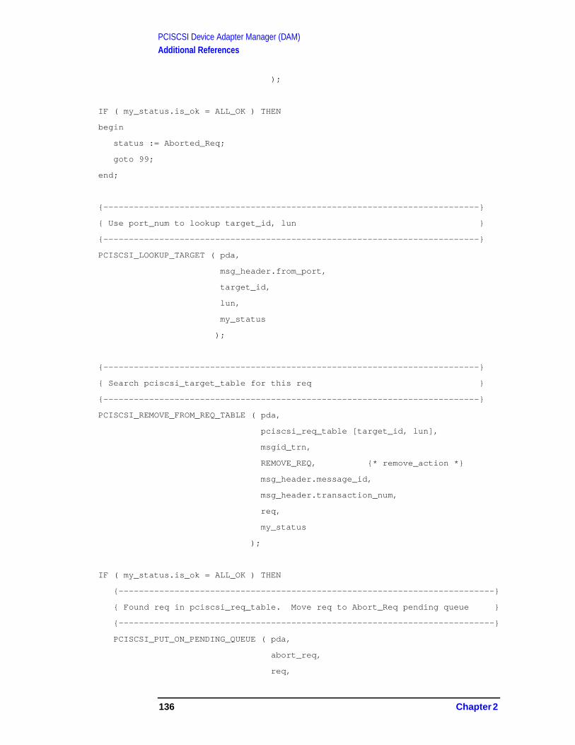
PCISCSI Device Adapter Manager (DAM)Additional References
);
IF ( my_status.is_ok = ALL_OK ) THEN
begin
status := Aborted_Req;
goto 99;
end;
{--------------------------------------------------------------------------}
{ Use port_num to lookup target_id, lun }
{--------------------------------------------------------------------------}
PCISCSI_LOOKUP_TARGET ( pda,
msg_header.from_port,
target_id,
lun,
my_status
);
{--------------------------------------------------------------------------}
{ Search pciscsi_target_table for this req }
{--------------------------------------------------------------------------}
PCISCSI_REMOVE_FROM_REQ_TABLE ( pda,
pciscsi_req_table [target_id, lun],
msgid_trn,
REMOVE_REQ, {* remove_action *}
msg_header.message_id,
msg_header.transaction_num,
req,
my_status
);
IF ( my_status.is_ok = ALL_OK ) THEN
{--------------------------------------------------------------------------}
{ Found req in pciscsi_req_table. Move req to Abort_Req pending queue }
{--------------------------------------------------------------------------}
PCISCSI_PUT_ON_PENDING_QUEUE ( pda,
abort_req,
req,
136 Chapter 2

PCISCSI Device Adapter Manager (DAM)Additional References
my_status
)
If the I/O request to abort is active in the lower DAM and hardware, theupper DAM will remove the request from the pciscsi_req_table ,place it in the abort_req pending_queue . Pciscsi_try_start_ioregularly scans its pending queues for new requests to process and theabort pending_queue is scanned first. Any requests on the abort_reqqueue will be processed by executing pciscsi_abort_req which inturns calls pci_c720_abort for the lower DAM to locate and abort therequest.
The lower DAM has several ways to reply to the upper DAM concerningthe abort request (via pci_c720_abort):
• the request was aborted from the selectq,
• the request is active on the hardware and will be aborted there,
• the request could not be located in any lower DAM data structureand thus cannot be aborted.
procedure PCISCSI_ABORT_REQ
WITH ada^ DO
begin
WITH abort_data DO
begin
pci_isc_ptr := addr ( pci_isc );
pci_isc_ptr^.isc_ptr := addr ( isc );
pci_isc_ptr^.c720_isc_ptr := addr ( c720_isc );
pci_buf_ptr := req^.io_data_ptr^.body.pci_buf_ptr;
abort_io := ABORT_SINGLE_IO;
end;
PCI_C720_ABORT ( abort_data,
status
);
CASE status.error_num of
{--------------------------------------------------------------------------}
{ Request was aborted from lower DAM SELECTQ ( not active on hardware }
{--------------------------------------------------------------------------}
Chapter 2 137

PCISCSI Device Adapter Manager (DAM)Additional References
PCISCSI_ABORTED_FROM_SELECTQ :
begin
reply_status := aborted_req;
PCISCSI_BS_REPLY ( pda,
nil, { msg }
reply_status,
req,
subqs_on
);
end;
{--------------------------------------------------------------------------}
{ Request is active on the interface card }
{--------------------------------------------------------------------------}
PCISCSI_ACTIVE_ON_HARDWARE :
begin
req^.abort_pending := TRUE;
abort_pending_cnt := abort_pending_cnt + 1;
{--------------------------------------------------------------------------}
{ Cannot reply to request at this time. }
{ Put req in request_table until I/O completes from lower DAM }
{--------------------------------------------------------------------------}
PCISCSI_PUT_IN_REQ_TABLE ( pda,
req,
status
);
IF ( NOT abort_timer_set ) THEN
begin
IO_RESET_TIMER( ABORT_REQ_TIMER_INTERVAL,
pda^.abort_req_timer_id,
status
138 Chapter 2

PCISCSI Device Adapter Manager (DAM)Additional References
);
abort_timer_set := TRUE;
end;
end;
PCISCSI_UNABLE_TO_LOCATE_REQUEST :
begin
{--------------------------------------------------------------------------}
{ Upper DAM believes request is in lower DAM, however, lower DAM cannot}
{ locate request per information in abort_data. Upper and lower DAM are}
{ have lost a request and are now out of sync. Do poweron_reset and }
{ recover from this situation. }
{--------------------------------------------------------------------------}
{--------------------------------------------------------------------------}
{ Cannot reply to request at this time. }
{ Put req in request_table for later poweron_abort reply }
{--------------------------------------------------------------------------}
PCISCSI_PUT_IN_REQ_TABLE ( pda,
req,
status
);
PCISCSI_SEND_POWERON_MY_PORT ( ada {* ada, not pda *}
);
end;
The interface layer initially manages the abort sequence for the lowerDAM by checking the selectq and NEXUS TABLE for the desiredrequest. If request is not in either place then call c720_abort and havethe lower DAM abort the request that is active on the hardware.
Chapter 2 139

PCISCSI Device Adapter Manager (DAM)Additional References
PCI_C720_ABORT(abort_data_ptr, status_ptr)
/*************************************************************************/
/* Check the selectQ first. If the I/O request is still on the selectQ, */
/* it will be dequeued, and we will return status to the UD indicating */
/* that the I/O has been aborted. */
/*************************************************************************/
if (c720_dequeue_bp(lbp->busp, bp))
{
/*
** I/O has been removed from the selectQ, and thus aborted.
** Inform the UD of this.
*/
C720_MPE_STAT_ERRNUM_PUT(isc, PN_pci_c720_abort, LLIO_ABORTED, LSP_NULL);
C720_MPE_LLIO_STAT_GEN(isc, status_ptr, LSP_NULL);
C720_MPE_STAT_PROCID_PUT(isc, PN_pci_c720_abort); /* add trailer PN */
C720_MPE_STAT_PROCID_DUMP(isc, status_ptr); /*conditional log to console*/
return;
}
/*************************************************************************/
/* If not on the selectQ, the I/O better be active and match ownership. */
/* Otherwise, the result will be a power on reset by the UD. */
/*************************************************************************/
if (lbp->NexusTable[scb->tag] == NULL || lbp->NexusTable[scb->tag] != lsp)
{
/*
** I/O is not active or ours according to the LD. Oops!
** Inform the UD of this error.
*/
C720_MPE_STAT_ERRNUM_PUT(isc, PN_pci_c720_abort, LLIO_ABORTED, LSP_NULL);
return;
}
/*************************************************************************/
/* If not on the selectQ, the I/O better be active and match ownership. */
/* Otherwise, the result will be a power on reset by the UD. */
/*************************************************************************/
140 Chapter 2
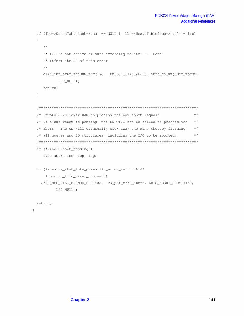
PCISCSI Device Adapter Manager (DAM)Additional References
if (lbp->NexusTable[scb->tag] == NULL || lbp->NexusTable[scb->tag] != lsp)
{
/*
** I/O is not active or ours according to the LD. Oops!
** Inform the UD of this error.
*/
C720_MPE_STAT_ERRNUM_PUT(isc, -PN_pci_c720_abort, LDIO_IO_REQ_NOT_FOUND,
LSP_NULL);
return;
}
/*************************************************************************/
/* Invoke C720 Lower DAM to process the new abort request. */
/* If a bus reset is pending, the LD will not be called to process the */
/* abort. The UD will eventually blow away the ADA, thereby flushing */
/* all queues and LD structures, including the I/O to be aborted. */
/*************************************************************************/
if (!(isc->reset_pending))
c720_abort(isc, lbp, lsp);
if (isc->mpe_stat_info_ptr->llio_error_num == 0 &&
lsp->mpe_llio_error_num == 0)
C720_MPE_STAT_ERRNUM_PUT(isc, -PN_pci_c720_abort, LDIO_ABORT_SUBMITTED,
LSP_NULL);
return;
}
Chapter 2 141

PCISCSI Device Adapter Manager (DAM)Additional References
Figure 2-35 Slide 35
Timers
Abort request timer
Poweron Timer
PCISCSI DAM has only 2 timers and they are used only in exceptionsituations. The abort timer limits the lower DAM’s response time to anI/O abort request. The poweron timer holds off any requests to lowerDAM and card interface hardware to let everything settle down after areset was initiated.
No heartbeat timer is used to ensure the forward progress of I/Os in theDAM. The device manager is responsible for I/O progress and itsheartbeat timer cause the generation of an I/O abort request after atime period with no I/O response.
hp e3000
7.0 fieldtraining
Timers
· Abort request timer
· Poweron timer
142 Chapter 2

PCISCSI Device Adapter Manager (DAM)Additional References
ABORT TIMER.
The abort timer is a 1 second timer that can be set several times foreach abort request. After a series of 5 abort timer pops and theMAX_ABORT_TIMER_CNT exceeded for the request, this code willinitiate a DAM poweron request to reset the DAM due a lack ofresponse from the lower DAM on the I/O abort request.
{//////////////////////////////////////////////////////////////////////////}
{--------------------------------------------------------------------------}
{--------------------------------------------------------------------------}
ABORT_REQ_TIMER_TRN :
begin
{--------------------------------------------------------------------------}
{ Look at each request in the req_table and check for abort_pending}
{ and increment abort_timer_cnt. }
{--------------------------------------------------------------------------}
FOR target_id := MIN_TARGET_ID to MAX_WIDE_TARGET_ID DO
FOR lun := MIN_LUN to MAX_LUN DO
WITH pciscsi_req_table [target_id, lun] DO
IF ( head <> NIL ) THEN
begin
curr_req := head;
{-----------------------------------------------}
{ Check all reqs on the request list }
{-----------------------------------------------}
REPEAT
WITH curr_req^ DO
IF ( abort_pending ) THEN
IF ( abort_timer_cnt >= MAX_ABORT_TIMER_CNT ) THEN
abort_wait_exceeded := TRUE
ELSE
abort_timer_cnt := abort_timer_cnt + 1;
Chapter 2 143

PCISCSI Device Adapter Manager (DAM)Additional References
curr_req := curr_req^.link;
UNTIL (( curr_req = NIL ) OR abort_wait_exceeded );
end;
IF ( abort_wait_exceeded ) THEN
begin
IF ( NOT sent_poweron_my_port ) THEN
{-------------------------------------------------}
{ Escalating to poweron_reset because I/O was not }
{ aborted in time allotted. }
{-------------------------------------------------}
PCISCSI_SEND_POWERON_MY_PORT ( ada
);
end
ELSE
begin
IO_RESET_TIMER( ABORT_REQ_TIMER_INTERVAL,
pda^.abort_req_timer_id,
my_status
);
abort_timer_set := TRUE;
end;
end; { if abort_pending }
end;
144 Chapter 2

PCISCSI Device Adapter Manager (DAM)Additional References
POWERON TIMER.
During a poweron (reset) of the DAM, the card interface andperipherals are reset and require a few seconds to recover and be readyto start new I/O requests. The current 5 second poweron timer is setduring the hardware init sequence and no I/O requests are processedduring this period. After the timer pops, the port subqueues are openedand the DAM start is made “ready_for_io ”. The pweron requests onthe poweron_reset queue are processed with rely msgs having goodstatus.
{//////////////////////////////////////////////////////////////////////////}
{--------------------------------------------------------------------------}
{--------------------------------------------------------------------------}
POWERON_RESET_TIMER_TRN :
begin
{--------------------------------------------------------------------------}
{ This poweron_reset timer is to allow interface hardware, SCSI bus and}
{ targets to settle down before begining poweron sequence with highermgrs }
{ }
{ Put DAM in mode to start processing requests again.}
{--------------------------------------------------------------------------}
subqs_on :=[Pciscsi_Min_Known_Subq..Pciscsi_Max_Known_Subq];
mgr_state := Ready_For_Io;
{--------------------------------------------------------------------------}
{ Reply to msgs on power_reset pending queue}
{--------------------------------------------------------------------------}
REPEAT
PCISCSI_GET_NEXT_FROM_PENDING_QUEUE ( pda,
poweron_reset,
Chapter 2 145

PCISCSI Device Adapter Manager (DAM)Additional References
REMOVE_REQ, {*remove_action *}
req,
my_status
);
IF ( my_status.is_ok = ALL_OK ) THEN
begin
status.is_ok := ALL_OK; { good status for poweron_reply_msg }
PCISCSI_BS_REPLY ( pda,
nil, { msg }
status,
req,
subqs_on
);
end;
UNTIL ( my_status.is_ok <> ALL_OK );
146 Chapter 2

PCISCSI Device Adapter Manager (DAM)Additional References
Figure 2-36 Slide 36
Situation Escalation
Data structures inconsistency (e.g., NIL or bad pointers)
Call c720_isr_escape
Strange device behaviors, hardware defects or SCSI cabling problemscan cause unexpected events with the lower DAM unable to recovergracefully. At key points in the lower DAM code, c720_isr_escaperoutines are called to enable situation escalation and recover from thisunexpected event. C720_isr_escape logs the event, the relevant registerinformation, and then calls pciscsi_send_poweron_my_port to causethe DAM to reset itself.
C720_isr_escape is the native HP-UX mechanism to escalate a problemsituation. Some example situations include:
hp e3000
7.0 fieldtraining
Situation Escalation
· Data structures inconsistency (eg. NIL or bad pointers)
· Call c720_isrEscape
Chapter 2 147

PCISCSI Device Adapter Manager (DAM)Additional References
/*
** Driver bug. The code assumes that this cannot occur
** even though the NCR manual does not say that it won't.
*/
c720_isrEscape(isc, lbp, lsp, "DSTAT_DFE is clear on DSTAT_SIR");
/*
** Driver bug or hardware problem.
*/
c720_isrEscape(isc, lbp, lsp, "Unhandled script interrupt");
c720_isrEscape(isc, lbp, lsp, "First party detected bus hang (HTH)");
c720_isrEscape(isc, lbp, lsp, "GEN timer popped");
/*
** Driver bug or hardware problem.
*/
c720_isrEscape(isc, lbp, lsp, "Unhandled interrupt");
c720_isr_escape proceeds to do logging and sending the powering msgvia pciscsi_send_poweron_my_port .
/*
** Reset the bus, but first dump some critical registers to dmesg.
** This function can only be used when the chip is NOT running due to the
** register accesses. If the bus needs to be reset while the chip is
** running, one must call c720_reset_bus directly.
*/
c720_isrEscape(isc, lbp, lsp, msg)
if (lbp->offset == -1 || (lbp->state & LBP_CHIP_ACCESS_OKAY))
{
c720_isrDumpState(isc, lbp, lsp, msg);
}
else
{
c720_DumpState(isc, lbp, lsp, msg);
}
if (c720_panic_on_escape)
148 Chapter 2
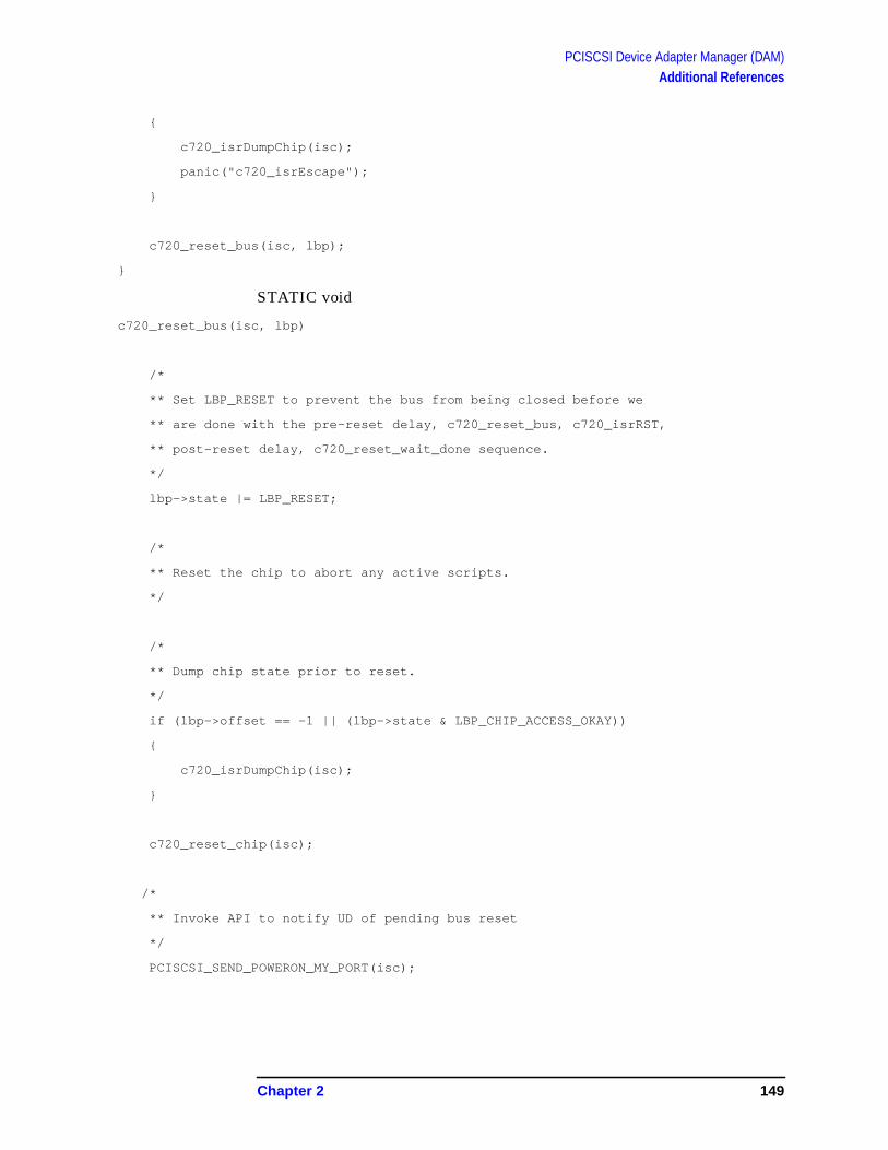
PCISCSI Device Adapter Manager (DAM)Additional References
{
c720_isrDumpChip(isc);
panic("c720_isrEscape");
}
c720_reset_bus(isc, lbp);
}
STATIC void
c720_reset_bus(isc, lbp)
/*
** Set LBP_RESET to prevent the bus from being closed before we
** are done with the pre-reset delay, c720_reset_bus, c720_isrRST,
** post-reset delay, c720_reset_wait_done sequence.
*/
lbp->state |= LBP_RESET;
/*
** Reset the chip to abort any active scripts.
*/
/*
** Dump chip state prior to reset.
*/
if (lbp->offset == -1 || (lbp->state & LBP_CHIP_ACCESS_OKAY))
{
c720_isrDumpChip(isc);
}
c720_reset_chip(isc);
/*
** Invoke API to notify UD of pending bus reset
*/
PCISCSI_SEND_POWERON_MY_PORT(isc);
Chapter 2 149

PCISCSI Device Adapter Manager (DAM)Additional References
Figure 2-37 Slide 37
Poweron (reset)
All I/Os aborted with Powerfail status
Lower and Upper DAM reinitialized
Upper managers acknowledge DAM Poweron (reset)
Upper managers re-start I/O requests
Poweron (reset) can occur to the DAM for 2 reasons: the I/Oconfigurator needs to reset the DAM for configuration reasons or 2) theDAM needs to recover from a situation neither the upper or lower DAMcan recover from else-wise. Poweron (reset) is the only situationescalation method the DAM has once a serious situation has beendetected.
Poweron can be initiated by either the upper or lower DAM in thefollowing situations:
1. Lower DAM can experience nil data pointers during device exceptionconditions and will call c720_isrEscape to begin the situationescalation. (c720_isrEscape calls C720_reset_bus and finally
hp e3000
7.0 fieldtraining
Poweron (reset)
· All I/O aborted with Powerfail status
· Lower and Upper DAM reinitialized
· Upper managers acknowledge DAM Poweron (reset)
· Upper managers restart I/O requests
150 Chapter 2

PCISCSI Device Adapter Manager (DAM)Additional References
pciscsi_send_poweron_my_port to do mgr poweron reset).
c720_reset_bus(isc, lbp)
/*
** Set LBP_RESET to prevent the bus from being closed before we
** are done with the pre-reset delay, c720_reset_bus, c720_isrRST,
** post-reset delay, c720_reset_wait_done sequence.
*/
lbp->state |= LBP_RESET;
/*
** Reset the chip to abort any active scripts.
*/
/*
** Dump chip state prior to reset.
*/
if (lbp->offset == -1 || (lbp->state & LBP_CHIP_ACCESS_OKAY))
{
c720_isrDumpChip(isc);
}
c720_reset_chip(isc);
/*
** Invoke API to notify UD of pending bus reset
*/
PCISCSI_SEND_POWERON_MY_PORT(isc);
2. Upper DAM to do situation escalation when the requested I/O toabort could not be located in the lower DAM; either in the selectq(pending start), NexusTable (active I/O), or ISC/LBP (current SCSIbus owner).
{--------------------------------------------------------------------------}
{ Invoke lower DAM procedure to abort the request }
{--------------------------------------------------------------------------}
PCI_C720_ABORT ( abort_data,
status
Chapter 2 151

PCISCSI Device Adapter Manager (DAM)Additional References
);
CASE status.error_num of
PCISCSI_UNABLE_TO_LOCATE_REQUEST :
begin
{--------------------------------------------------------------------------}
{ Upper DAM believes request is in lower DAM, however, lower DAM cannot}
{ locate request per information in abort_data. Upper and lower DAM}
{ have lost a request and are now out of sync. Do poweron_reset and}
{ recover from this situation. }
{--------------------------------------------------------------------------}
{--------------------------------------------------------------------------}
{ Cannot reply to request at this time.}
{ Put req in request_table for later poweron_abort reply}
{--------------------------------------------------------------------------}
PCISCSI_PUT_IN_REQ_TABLE ( )
PCISCSI_SEND_POWERON_MY_PORT ( ada {* ada, not pda *}
);
end;
3. Upper DAM to do situation escalation when the abort does notcomplete (with good or bad status) after the Lower DAM indicatesthe I/O is active on the hardware.
{//////////////////////////////////////////////////////////////////////////}
{--------------------------------------------------------------------------}
{--------------------------------------------------------------------------}
ABORT_REQ_TIMER_TRN :
152 Chapter 2

PCISCSI Device Adapter Manager (DAM)Additional References
begin
IF ( abort_pending_cnt > 0 ) THEN {* still have an abort_pending *}
begin
{--------------------------------------------------------------------------}
{ Look at each request in the req_table and check for abort_pending}
{ and increment abort_timer_cnt.}
{--------------------------------------------------------------------------}
FOR target_id := MIN_TARGET_ID to MAX_WIDE_TARGET_ID DO
FOR lun := MIN_LUN to MAX_LUN DO
WITH pciscsi_req_table [target_id, lun] DO
IF ( head <> NIL ) THEN
begin
curr_req := head;
{-----------------------------------------------}
{ Check all reqs on the request list }
{-----------------------------------------------}
REPEAT
WITH curr_req^ DO
IF ( abort_pending ) THEN
IF ( abort_timer_cnt >= MAX_ABORT_TIMER_CNT )
THEN
abort_wait_exceeded := TRUE
ELSE
abort_timer_cnt := abort_timer_cnt + 1;
curr_req := curr_req^.link;
UNTIL (( curr_req = NIL ) OR abort_wait_exceeded );
end;
IF ( abort_wait_exceeded ) THEN
Chapter 2 153

PCISCSI Device Adapter Manager (DAM)Additional References
begin
IF ( NOT sent_poweron_my_port ) THEN
{-------------------------------------------------}
{ Escalating to poweron_reset because I/O was not }
{ aborted in time allotted. }
{-------------------------------------------------}
PCISCSI_SEND_POWERON_MY_PORT ( ada
);
The poweron reset is started by a POWERON msg being sent to theport by either the upper and lower DAM by calling procedurePCISCSI_SEND_POWERON_MY_PORT.
procedure PCISCSI_SEND_POWERON_MY_PORT
sent_poweron_my_port := TRUE;
PCISCSI_GET_FRAME ( my_port,
poweron_msg,
status,
pda,
0
);
WITH poweron_msg^.msg_header DO
begin
msg_descriptor := power_on_req_msg;
message_id := Subsys_Pciscsi_Dam;
transaction_num := Pciscsi_Dam_Rev_Code;
from_port := my_port;
end;
PCISCSI_IO_SEND ( my_port,
power_on_subqueue,
poweron_msg,
sizeof (scsi_msg_type, power_on_req_msg),
pda,
status,
Sent_By_Dam
);
154 Chapter 2

PCISCSI Device Adapter Manager (DAM)Additional References
The power_on message is serviced immediately from subqueue 0 aheadof any other requests. The upper DAM closes the subqueues to stopprocessing of new requests followed by flushing all current I/Os withpowerfail status. The upper DAM then begins the DAM reset orre-initialization process.
procedure PCISCSI_POWERON_REQ_MSG
begin { of with }
mgr_state := power_on_reset;
subqs_on := [power_on_subqueue,
config_subqueue,
timer_event_subqueue,
tlih_subqueue ];
{--------------------------------------------------------------------------}
{ Put power_on msg onto poweron_reset queue for later reply after DAM }
{ poweron sequence has compeleted. }
{--------------------------------------------------------------------------}
PCISCSI_GET_REQ_ENTRY ( req, ...)
req^.llio_msg_ptr := msg;
PCISCSI_PUT_ON_PENDING_QUEUE ( pda,
poweron_reset,
req,
status
);
{--------------------------------------------------------------------------}
{ Flush all requests in the DAM both in the pending queues and req_table }
{--------------------------------------------------------------------------}
flush_status := Powerfail_Aborted;
PCISCSI_FLUSH_ALL_REQS ( pda,
flush_status,
Chapter 2 155

PCISCSI Device Adapter Manager (DAM)Additional References
subqs_on
);
{--------------------------------------------------------------------------}
{ Re-init lower DAM data areas and interface hardware }
{--------------------------------------------------------------------------}
PCISCSI_INIT_HARDWARE ( )
{--------------------------------------------------------------------------}
{ Send power-on requests to each of the bound higher managers and set }
{ hm_poweron_reset flag to true. }
{--------------------------------------------------------------------------}
for target_id := MIN_TARGET_ID to MAX_WIDE_TARGET_ID do
for lun := MIN_LUN to MAX_LUN do
with pciscsi_target_table [target_id, lun].hm_info DO
if (hm_port_num <> nil_port_num) then
begin
{--------------------------------------------------------------------------}
{ Set flag to flush requests for this DM with Llio_Powerfail_Aborted}
{ status until a power-on reply msg is received from this DM.}
{--------------------------------------------------------------------------}
hm_poweron_reset := TRUE;
{--------------------------------------------------------------------------}
{ Build and send a power-on request to the higher manager.}
{--------------------------------------------------------------------------}
PCISCSI_GET_FRAME ( )
with power_on_msg^.msg_header do
begin
msg_descriptor := Power_On_Req_Msg;
message_id := (target_id*16)+lun;
transaction_num := cur_pon_trn;
from_port := my_port;
{--------------------------------------------------------------------------}
156 Chapter 2
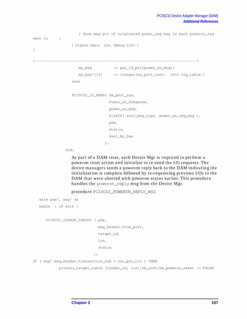
PCISCSI Device Adapter Manager (DAM)Additional References
{ Save msg ptr of originated power_req msg in each poweron_reqsent to }
{ higher mgrs. (ie. debug info )}
{--------------------------------------------------------------------------}
my_msg := pai_14_ptr(power_on_msg);
my_msg^[13] := integer(hm_port_num); {For log_table.}
end;
PCISCSI_IO_SEND( hm_port_num,
Power_On_Subqueue,
power_on_msg,
SizeOf( scsi_msg_type, power_on_req_msg ),
pda,
status,
Sent_By_Dam
);
end;
As part of a DAM reset, each Device Mgr is required to perform apoweron reset action and initialize to re-send the I/O requests. Thedevice managers sends a poweron reply back to the DAM indicating theinitialization is complete followed by re-requesting previous I/Os to theDAM that were aborted with poweron status earlier. This procedurehandles the poweron_reply msg from the Device Mgr.
procedure PCISCSI_POWERON_REPLY_MSG
with pda^, msg^ do
begin { of with }
PCISCSI_LOOKUP_TARGET ( pda,
msg_header.from_port,
target_id,
lun,
status
);
IF ( msg^.msg_header.transaction_num = cur_pon_trn ) THEN
pciscsi_target_table [target_id, lun].hm_info.hm_poweron_reset := FALSE
Chapter 2 157

PCISCSI Device Adapter Manager (DAM)Additional References
Figure 2-38 Slide 38
C-isms
HP-UX code and hardware memory mapping in same SID (space ID)
Convert long <=> short virtual pointers
Callable procedure names in NL are upper case (#define UPPER lower)
Elimination of global variables
Creation of stub routines for c720 calling convention
The I/O drivers in HP-UX are placed in the same SID (space ID) aswhere the hardware is mapped. Accessing card registers using virtualaddressing can be done with short pointers. In MPE/iX, the I/O driversand the mapped hardware are in different SIDs and long pointervirtual addressing is used. The HP-UX ported code was changed byreplacing virtual short pointers with long pointers anytime cardregisters or card RAM area was to be accessed.
The upper and lower DAMs call each other’s procedures to initiateactions and exchange data. MODCAL compilation and/or linkingupshifts the procedure names for the upper DAM for all imported andexported procedures. Lower DAM “C” code exports and imports
hp e3000
7.0 fieldtraining
C-isms
· HP-UX code and hardware memory mapping in sameSID (space ID)
· Convert long <=> short virtual pointers
· Callable procedure names in NL are upper case(#define UPPER lower)
· Elimination of global variables
· Creation of stub routines for c720 calling convention
158 Chapter 2
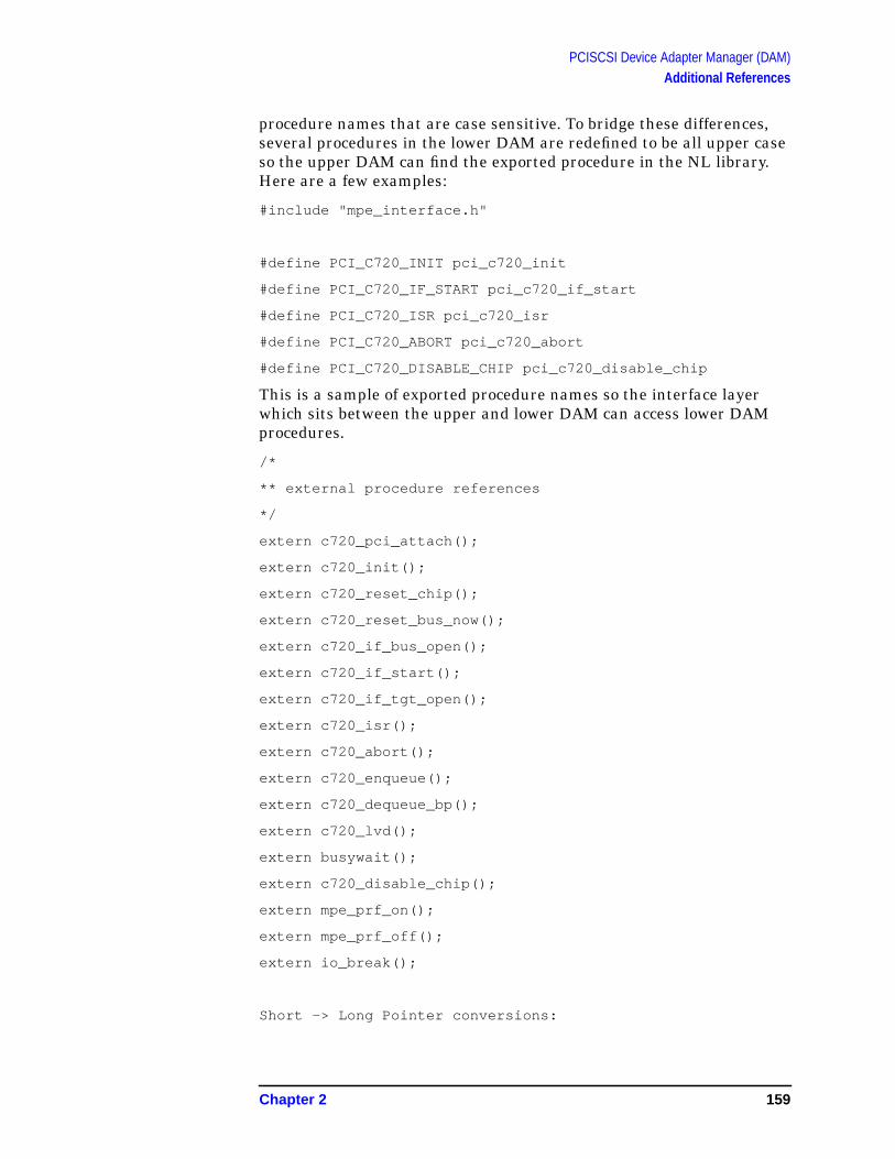
PCISCSI Device Adapter Manager (DAM)Additional References
procedure names that are case sensitive. To bridge these differences,several procedures in the lower DAM are redefined to be all upper caseso the upper DAM can find the exported procedure in the NL library.Here are a few examples:
#include "mpe_interface.h"
#define PCI_C720_INIT pci_c720_init
#define PCI_C720_IF_START pci_c720_if_start
#define PCI_C720_ISR pci_c720_isr
#define PCI_C720_ABORT pci_c720_abort
#define PCI_C720_DISABLE_CHIP pci_c720_disable_chip
This is a sample of exported procedure names so the interface layerwhich sits between the upper and lower DAM can access lower DAMprocedures.
/*
** external procedure references
*/
extern c720_pci_attach();
extern c720_init();
extern c720_reset_chip();
extern c720_reset_bus_now();
extern c720_if_bus_open();
extern c720_if_start();
extern c720_if_tgt_open();
extern c720_isr();
extern c720_abort();
extern c720_enqueue();
extern c720_dequeue_bp();
extern c720_lvd();
extern busywait();
extern c720_disable_chip();
extern mpe_prf_on();
extern mpe_prf_off();
extern io_break();
Short -> Long Pointer conversions:
Chapter 2 159

PCISCSI Device Adapter Manager (DAM)Additional References
#define C720_PHYS(ptr, addr) ((ptr32_t)((ptr)->uPhysScript \
+ ((uintptr64_t)(addr) \
-(uintptr64_t)(ptr)->puScript)))
#else /*MPE_PORT*/
#define C720_PHYS(ptr, addr) ((ptr32_t)((ptr)->uPhysScript \
+ (uintptr_t)(addr) \
-(uintptr_t)(ptr)->puScript))
#endif /*MPE_PORT*/
160 Chapter 2

PCISCSI Device Adapter Manager (DAM)Additional References
Figure 2-39 Slide 39
hp e3000
7.0 fieldtraining
DAM Logs[overview]
· LLIO msg log
· Log of LLIO msgs received and sent
· Console log
· Lower DAM console printf messages
· Hardware log
· Card registers log per I/O
Chapter 2 161
PCISCSI Device Adapter Manager (DAM)Additional References
Figure 2-40 Slide 40
LLIO Msg Log|-------------------------------------------------------------------------|| cl| timestamp || message header ||scsi-io-req-msg || as| || || || || || || || ||------------------------------------------------------------------------------|| rest-of scsi-io-req-msg ||msg || || || || || || || ||ptr ||-------------------------------------------------------------------------|
LLIO message log records all LLIO messages received and sent byDAM. A single log contains the messages from all the device managersin chronological order. Following is a sample log:
[[ 9201, 9202, 9929 msg samples ]]
hp e3000
7.0 fieldtraining
LLIO Msg Log
· |------------------------------------------------------------------------------|| cl| timestamp || message header ||scsi-io-req-msg || as| || || || || || || || ||------------------------------------------------------------------------------|| rest-of scsi-io-req-msg ||msg || || || || || || || ||ptr ||------------------------------------------------------------------------------|
162 Chapter 2

PCISCSI Device Adapter Manager (DAM)Additional References
Figure 2-41 Slide 41
Console Log
83fef31c: "...u" "..#0" "...." ">>>>" "C720" "_MPE" "_STA" "T_PR”83fef33c: "OCID" "_DUM" "P: T" "gt/L" "un: " "ff/f" "f St" "atus”83fef35c: ": 00" "0000" "00 ." "PNs:" ": 02" " 03 " "08 0" "b 07”83fef37c: " 09 " "04 2" "e 07" " 0a " "07 0" "a 2e" " 07 " "07 0"
The console log began life as a tool to help bring-up the new DAM code.Configuration and status information would be displayed on the consoleas I/Os were processed. When an exception condition occurred, variousdumps of information like register sets and data structures would bedisplayed on the console. The console output has now been directed to a“console log” to aid in debugging problems.
The console output produces trace information on the sequence ofprocedure execution. This procedure trace list appears as a sequence ofnumbers preceded by “PNs” This is an example “PNs:: 14 15 16 30 41 4336 14” The procedure numbers can be translated to procedure namesusing the chart in the next slide.
This sample console log has captured various steps in completing an I/Orequest:
Enqueuing an IO:
hp e3000
7.0 fieldtraining
Console Log
· 83fef31c: "...u" "..#0" "...." ">>>>" "C720" "_MPE" "_STA" "T_PR”83fef33c: "OCID" "_DUM" "P: T" " gt/L" "un: " "ff/f" "f St" "atus”83fef35c: ": 00" "0000" "00 ." " PNs:" ": 02" " 03 " "08 0" "b 07”83fef37c: " 09 " "04 2" "e 07" " 0a " "07 0" "a 2e" " 07 " "07 0”
· dv console+40 2010 s 20
VIRT $b.85ce4c30 "..#\u.......LD PTRS> io_data:85d03768, TLQ:05/00/01 bp:85d03fac scb:85d0412c/85d04238 tp:85ce6fd4/85ce6341 lp:85cefb04 "VIRT $b.85ce4cb0 "..#\u.......C720_MPE_LLIO_STAT_GEN: isc= 85ce6000, status_ ptr
= 81d8fc84, value= 00000000 "
Chapter 2 163

PCISCSI Device Adapter Manager (DAM)Additional References
VIRT $b.81cfd89c"............>>>>C720_MPE_STAT_PROCID_DUMP: Tgt/Lun: 00/00 Status:00000000 .PNs:: 0c 0d 0e 0c.. "
0c – PCI_C720_IF_START
0d – c720_if_start
0e – c720_DataSetup
0c – PCI_C720_IF_START
VIRT $b.81cfce9c "......z.....>>>>C720_MPE_STAT_PROCID_DUMP: Tgt/Lun: 00/00 Status:02ec03b7 .PNs:: 14 15 16 30 41 43 36 14.. "
14 – PCI_C720_ISR
15 – c720_isr
16 – c720_isrGuts
30 – c720_isrMA
41 – c720_isrUpdateDataPtr
43 – c720_isrSaveDataPtr
36 – c720_StartChip
14 – PCI_C720_ISR
Good Status IO Complete Example:
VIRT $b.81cfcf9c ".......@....>>>>C720_MPE_STAT_PROCID_DUMP: Tgt/Lun: 00/00 Status:00000000 .PNs:: 14 15 16 18 36 37 39 3a 3c 45 46 14.."
14 – PCI_C720_ISR
15 – c720_isr
16 – c720_isrGuts
18 – c720_isrCompComplete
36 – c720_StartChip
37 – c720_done
39 – c720_cleanup
3a – c720_DataCleanup
3c – c720_Deactivate
45 – c720_call_cbfns
46 – scsi_fast_cbfn
14 – PCI_C720_ISR
Bus Initialization: (PCI_C720_INIT)
Following c720_pci_attach:
164 Chapter 2

PCISCSI Device Adapter Manager (DAM)Additional References
VIRT $b.81cfce9c "....l.HP....c720_pci_attach -- command: 0x0000..
VIRT $b.81cfcf1c "....p.......PCI Vendor ID: 1000..
VIRT $b.81cfcf9c "....p.+.....PCI Device ID: 000f..
VIRT $b.81cfd01c "....rk......PCI Rev ID: 14..
VIRT $b.81cfd09c "....rk......MACNTL Chip Type: 07..
VIRT $b.81cfd11c "....rk. ....CTEST3 Chip Revision Level: 05..
VIRT $b.81cfd19c "....rl......GPREG: 07..
VIRT$b.81cfd21c"....rl......pci_c720_pci_attach:UDSCID=07;chipSCID=07.."
c720_init (no console log entries)
c720_reset_chip: (No console log entries)
c720_reset_bus_now:
VIRT $b.81cfd29c "......e.......SCSI: Resetting SCSI -- lbolt: 0, bus: 0..
c720_lvd: (No console log entries).
c720_if_bus_open: (No console log entries)
After c720_if_bus_open:
......>.....>>>>C720_MPE_STAT_PROCID_DUMP: Tgt/Lun: ff/ff Status"
VIRT $b.81cfd2dc ": 00000000 .PNs:: 02 03 08 0b 07 09 04 2e 07 0a 07 0a..
02 – pci_c720_init
03 – c720_pci_attach
08 – pci_read_cfg_uint16_isc
0b – pci_write_ctg_uint16_isc
07 – pci_read_cfg_uint8_isc
09 – pic_read_cfg_uint32_isc
04 – c720_init
2e – c720_reset_chip
07 – pci_read_cfg_uint8_isc
0a - pci_write_cfg_uint8_isc
07 – pci_read_cfg_uint8_isc
0a - pci_write_cfg_uint8_isc
Chapter 2 165

PCISCSI Device Adapter Manager (DAM)Additional References
....[g ......SCSI: Resetting SCSI -- lbolt: 0, bus: 0.. "
VIRT $b.81cfd35c "
.....t5.....>>>>C720_MPE_STAT_PROCID_DUMP: Tgt/Lun: ff/ff Status"
VIRT $b.81cfd3dc ": 00000000 .PNs:: ff 2e 07 07 05 06 13 36 02..
ff – indicates continuation of initialization.
07 – pci_read_cfg_uint8_isc
07 – pci_read_cfg_uint8_isc
05 – c720_if_bus_open
06 – c720_init_script
13 – c720_check_xdtr_parms
36 – c720_isrStartChip
02 – PCI_C720_INIT (exit indicator)
First interrupt following initialization:
VIRT $b.81cfd39c ".....w......>>>>C720_MPE_STAT_PROCID_DUMP: Tgt/Lun: ff/ff Status:01cc03b7 .PNs:: 14 15 16 34 2e 07 07 06 13 13 36 0d 14.."
Start of first IO:
VIRT $b.81cfd41c ".....3\ ....LD PTRS> io_data:81d2243c, Tgt:00/00 bp:81d22c80
scb:81d22e00/81d22f0c tp:81d05c98/81d06598 lp:81d06618 "
VIRT $b.81cfd49c ".....4......>>>>C720_MPE_STAT_PROCID_DUMP: Tgt/Lun: 00/00 Status:00000000 .PNs:: 0c 12 13 0d 0e 0f 11 0c..
First Interrupt:
VIRT $b.81cfd51c "...... `....>>>>C720_MPE_STAT_PROCID_DUMP: Tgt/Lun: 00/00 Status:02ec03b7 .PNs:: 14 15 16 20 21 36 14..
Second interrupt: (01 Extended Msg for Wide Negotiation)
VIRT $b.81cfd59c "....c..@....>>>>C720_MPE_STAT_PROCID_DUMP: Tgt/Lun: 00/00 Status:02ec03b7 .PNs:: 14 15 16 22 1c 13 21 36 14..
Third interrupt: (02,03)
VIRT $b.81cfd61c ".....h.@....>>>>C720_MPE_STAT_PROCID_DUMP: Tgt/Lun: 00/00 Status:02ec03b7 .PNs:: 14 15 16 22 21 36 14..
Fourth interrupt: (01 => 2**1 or 2 bytes wide)
VIRT $b.81cfd69c "............>>>>C720_MPE_STAT_PROCID_DUMP: Tgt/Lun: 00/00 Status:02ec03b7 .PNs:: 14 15 16 22 1c 13 1e 36 14..
Fifth interrupt:
VIRT $b.81cfd71c "....... ....>>>>C720_MPE_STAT_PROCID_DUMP: Tgt/Lun: 00/00 Status:02ec03b7 .PNs:: 14 15 16 20 21 36 14..
166 Chapter 2
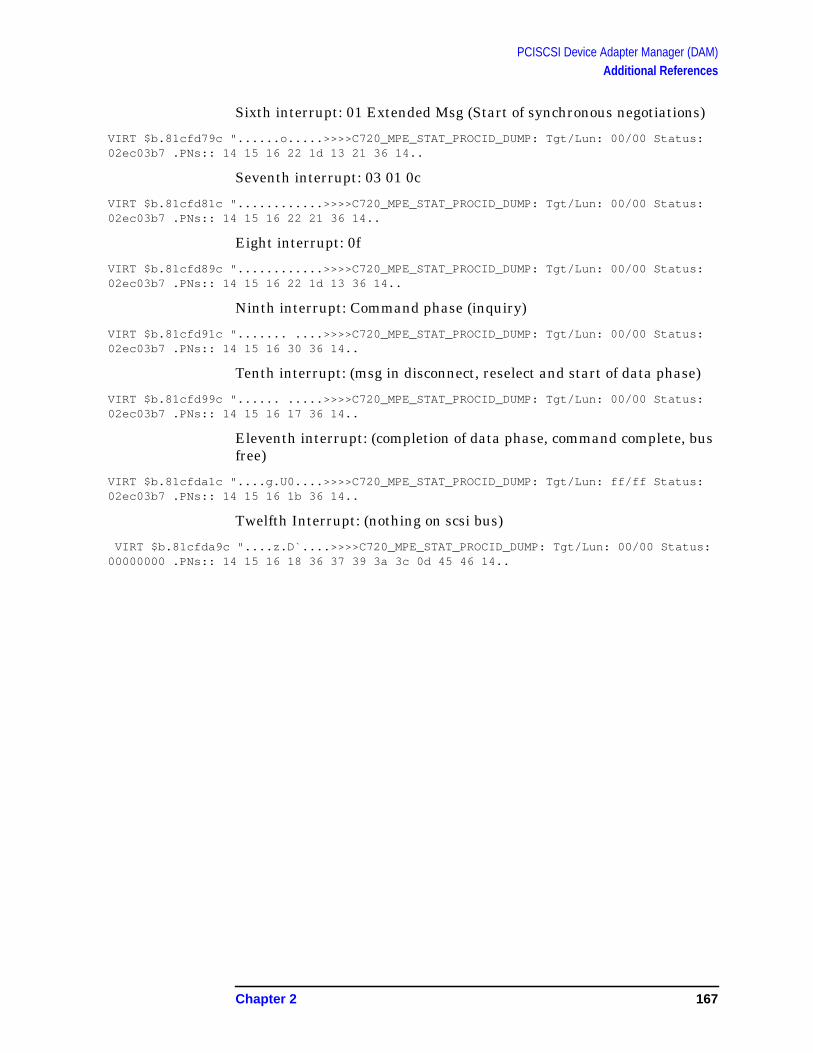
PCISCSI Device Adapter Manager (DAM)Additional References
Sixth interrupt: 01 Extended Msg (Start of synchronous negotiations)
VIRT $b.81cfd79c "......o.....>>>>C720_MPE_STAT_PROCID_DUMP: Tgt/Lun: 00/00 Status:02ec03b7 .PNs:: 14 15 16 22 1d 13 21 36 14..
Seventh interrupt: 03 01 0c
VIRT $b.81cfd81c "............>>>>C720_MPE_STAT_PROCID_DUMP: Tgt/Lun: 00/00 Status:02ec03b7 .PNs:: 14 15 16 22 21 36 14..
Eight interrupt: 0f
VIRT $b.81cfd89c "............>>>>C720_MPE_STAT_PROCID_DUMP: Tgt/Lun: 00/00 Status:02ec03b7 .PNs:: 14 15 16 22 1d 13 36 14..
Ninth interrupt: Command phase (inquiry)
VIRT $b.81cfd91c "....... ....>>>>C720_MPE_STAT_PROCID_DUMP: Tgt/Lun: 00/00 Status:02ec03b7 .PNs:: 14 15 16 30 36 14..
Tenth interrupt: (msg in disconnect, reselect and start of data phase)
VIRT $b.81cfd99c "...... .....>>>>C720_MPE_STAT_PROCID_DUMP: Tgt/Lun: 00/00 Status:02ec03b7 .PNs:: 14 15 16 17 36 14..
Eleventh interrupt: (completion of data phase, command complete, busfree)
VIRT $b.81cfda1c "....g.U0....>>>>C720_MPE_STAT_PROCID_DUMP: Tgt/Lun: ff/ff Status:02ec03b7 .PNs:: 14 15 16 1b 36 14..
Twelfth Interrupt: (nothing on scsi bus)
VIRT $b.81cfda9c "....z.D`....>>>>C720_MPE_STAT_PROCID_DUMP: Tgt/Lun: 00/00 Status:00000000 .PNs:: 14 15 16 18 36 37 39 3a 3c 0d 45 46 14..
Chapter 2 167

PCISCSI Device Adapter Manager (DAM)Additional References
Figure 2-42 Slide 42
Lower DAM Procedure Number List
The console log mentioned in the previous slide contains lists ofprocedures sequences that were executed to complete an I/O. This listtranslates those procedure numbers into procedures names.
#define PN_pci_c720_init 2
#define PN_c720_pci_attach 3
#define PN_c720_init 4
#define PN_c720_if_bus_open 5
#define PN_c720_init_script 6
#define PN_pci_read_cfg_uint8_isc 7
#define PN_pci_read_cfg_uint16_isc 8
#define PN_pci_read_cfg_uint32_isc 9
#define PN_pci_write_cfg_uint8_isc 10
#define PN_pci_write_cfg_uint16_isc 11
hp e3000
7.0 fieldtraining
Lower DAM Procedure Number List
· Reference hmpestat.cc72intr.official (1-74)
· Pseudo PNs
/* Pseudo PN numbers used to indicate when c720_start sets SIGP *//* Note: a qtag_id will immediately following a pseudo PN in a PN list*/#define PN_c720_start_set_SIGP1 0x97#define PN_c720_start_set_SIGP2 0x98#define PN_c720_start_set_SIGP3 0x99
168 Chapter 2
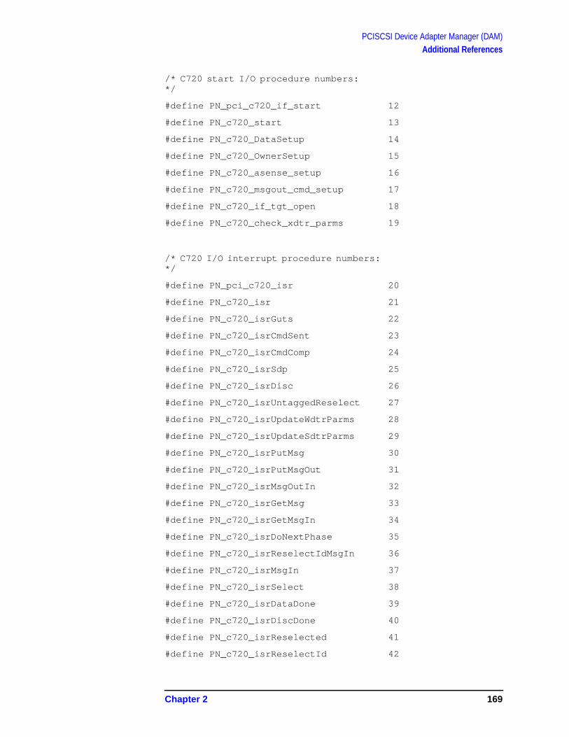
PCISCSI Device Adapter Manager (DAM)Additional References
/* C720 start I/O procedure numbers:*/
#define PN_pci_c720_if_start 12
#define PN_c720_start 13
#define PN_c720_DataSetup 14
#define PN_c720_OwnerSetup 15
#define PN_c720_asense_setup 16
#define PN_c720_msgout_cmd_setup 17
#define PN_c720_if_tgt_open 18
#define PN_c720_check_xdtr_parms 19
/* C720 I/O interrupt procedure numbers:*/
#define PN_pci_c720_isr 20
#define PN_c720_isr 21
#define PN_c720_isrGuts 22
#define PN_c720_isrCmdSent 23
#define PN_c720_isrCmdComp 24
#define PN_c720_isrSdp 25
#define PN_c720_isrDisc 26
#define PN_c720_isrUntaggedReselect 27
#define PN_c720_isrUpdateWdtrParms 28
#define PN_c720_isrUpdateSdtrParms 29
#define PN_c720_isrPutMsg 30
#define PN_c720_isrPutMsgOut 31
#define PN_c720_isrMsgOutIn 32
#define PN_c720_isrGetMsg 33
#define PN_c720_isrGetMsgIn 34
#define PN_c720_isrDoNextPhase 35
#define PN_c720_isrReselectIdMsgIn 36
#define PN_c720_isrMsgIn 37
#define PN_c720_isrSelect 38
#define PN_c720_isrDataDone 39
#define PN_c720_isrDiscDone 40
#define PN_c720_isrReselected 41
#define PN_c720_isrReselectId 42
Chapter 2 169
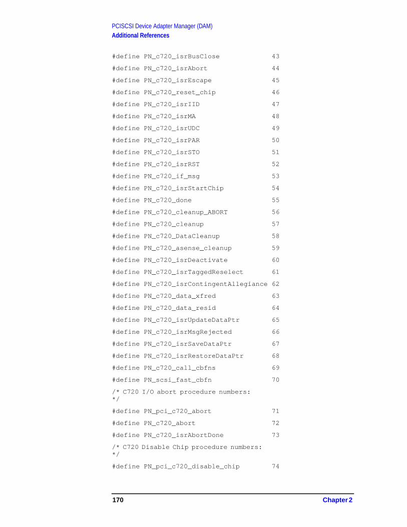
PCISCSI Device Adapter Manager (DAM)Additional References
#define PN_c720_isrBusClose 43
#define PN_c720_isrAbort 44
#define PN_c720_isrEscape 45
#define PN_c720_reset_chip 46
#define PN_c720_isrIID 47
#define PN_c720_isrMA 48
#define PN_c720_isrUDC 49
#define PN_c720_isrPAR 50
#define PN_c720_isrSTO 51
#define PN_c720_isrRST 52
#define PN_c720_if_msg 53
#define PN_c720_isrStartChip 54
#define PN_c720_done 55
#define PN_c720_cleanup_ABORT 56
#define PN_c720_cleanup 57
#define PN_c720_DataCleanup 58
#define PN_c720_asense_cleanup 59
#define PN_c720_isrDeactivate 60
#define PN_c720_isrTaggedReselect 61
#define PN_c720_isrContingentAllegiance 62
#define PN_c720_data_xfred 63
#define PN_c720_data_resid 64
#define PN_c720_isrUpdateDataPtr 65
#define PN_c720_isrMsgRejected 66
#define PN_c720_isrSaveDataPtr 67
#define PN_c720_isrRestoreDataPtr 68
#define PN_c720_call_cbfns 69
#define PN_scsi_fast_cbfn 70
/* C720 I/O abort procedure numbers:*/
#define PN_pci_c720_abort 71
#define PN_c720_abort 72
#define PN_c720_isrAbortDone 73
/* C720 Disable Chip procedure numbers:*/
#define PN_pci_c720_disable_chip 74
170 Chapter 2

PCISCSI Device Adapter Manager (DAM)Additional References
Figure 2-43 Slide 43
Lower DAM Error Number List
This list shows the PCISCSI DAM specific error numbers. These LDIO(Lower Dam I/O) error numbers will appear in the LLIO statusreturned to device mgrs. General LLIO error numbers listed here mayalso be used in the status.
/* LLIO General Warnings */
#define LLIO_NORMAL 0 /* LD has completed I/O */
#define LLIO_OK 0 /* LD has completed I/O */
#define LLIO_NORMAL_STATUS 9 /* I/O has a check condition */
/* LLIO General Errors */
#define LLIO_ABORTED -1 /* the I/O has been aborted */
#define LLIO_SW_PROBLEM -7 /* Ultimate non-specific stat */
#define LLIO_DEV_POWER_ON -33 /* Dev Power on from Bus Reset */
#define LLIO_DATA_OVERRUN -38 /* Data lose due to xfer error */
#define LLIO_PARITY_ERROR -48 /* Data Parity Error */
#define LLIO_CHANNEL_TIMEOUT -41 /* Channel Timeout failure */
#define LLIO_HW_PROBLEM -44 /* General hardware problem */
hp e3000
7.0 fieldtraining
Lower DAM Error Number List
· Contained in hmpestat.cc72intr.official
· LLIO error partial list
· LDIO errors
· LDIO -> LLIO mapping
Chapter 2 171

PCISCSI Device Adapter Manager (DAM)Additional References
/* LDIO Specific Warnings */
#define LDIO_OK_REQ 0 /* LD has processed request */
#define LDIO_OK_NOT_OURS 1 /* the interrupt is not ours */
#define LDIO_OK_IO_INCOMPLETE 2 /* LD has not yet completed I/O */
#define LDIO_ABORT_SUBMITTED 10 /* I/O abort submitted by LD */
/* LDIO Specific Errors */
#define LDIO_IO_REQ_NOT_FOUND -50 /* LD could not find IO request */
#define LDIO_REQ_UNSUPPORTED -51 /* function not supported by LD */
#define LDIO_PCI_SVC_ERR -52 /* MPE/iX PCI Services error */
#define LDIO_UNDEFINED_ERR -53 /* see C720_MPE_STAT_ERRNUM_GET */
#define LDIO_PHASE_MM_SSTATX_ILF -54 /* isrMA: SSTATX_ILF on phase mismatch*/
#define LDIO_MISSING_IWR -55 /* isrMA: missing ignore_wide_residue*/
#define LDIO_DATA_OVERRUN -56 /* isrMA: Data Overrun detected */
#define LDIO_PHASE_MISMATCH1 -57 /* isrMA: unhandled phase mismatch */
#define LDIO_PHASE_MISMATCH2 -58 /* isrMA: unhandled phase mismatch */
#define LDIO_PHASE_MISMATCH3 -59 /* isrMA: unhandled phase mismatch */
#define LDIO_UNHANDLED_MSG_REJECT -60 /* isrMA: unhandled phase mismatch */
#define LDIO_ATN_IGNORED -61 /* isrMA: target ignored ATN for now*/
#define LDIO_BUS_OPEN_ERR -62 /* c720_if_bus_open err (unlikely) */
#define LDIO_BUS_RESET -63 /* LD-detected bus reset */
#define LDIO_MEM_MAP_ERR -64 /* NULL card_ptr from UD */
#define LDIO_PARITY_ERR -65 /* I/O parity error detected */
#define LDIO_UNEXPECTED_DATA_PHASE -66 /* c720_isrIID detected error */
#define LDIO_ILLEGAL_INSTRUCTION -67 /* c720_isrIID detected error */
#define LDIO_CHANNEL_TIMEOUT -68 /* c720_isrSTO detected error */
#define LDIO_IO_BUSY -69 /* S_BUSY on normal I/O */
#define LDIO_IO_INCOMPLETE -70 /* incomplete I/O detected */
#define LDIO_NULL_MEM_ADDR -71 /* NULL returned by UD mem alloc */
#define LDIO_NOT_PAGE_ALIGNED -72 /* UD mem alloc addr not page align */
#define LDIO_TAG_ID_RANGE_ERR -73 /* TAG ID out of range (0-126) */
#define LDIO_TGT_ID_RANGE_ERR -74 /* TGT ID out of range (0-15) */
#define LDIO_LUN_ID_RANGE_ERR -75 /* LUN ID out of range (0-7) */
#define LDIO_ABORTED -76 /* LD completed I/O abort */
#define LDIO_PCI_BUS_FAULT -77 /* PCI BUS Fault detected */
#define LDIO_IID_WAIT_DISCONNECT -78 /* IID on WAIT DISCONNECT detected */
#define LDIO_DEV_POWER_ON -79 /* Device Power On detected */
172 Chapter 2

PCISCSI Device Adapter Manager (DAM)Additional References
#define LDIO_DIRECTION_MISMATCH -80 /* isrMA: data direction mismatch */
#define LDIO_HOST_BUS_PARITY -81 /* isrGuts: Host Bus Parity error */
#define LDIO_PHASE_MM_SSTATX -82 /* isrMA: invalid OLF/ORF settings */
#define LDIO_VA_TO_IOVA_ERR -83 /* c720_map: UD call returned -1 */
#define LDIO_ERROR_ON_IO -99 /* LD detected error on I/O */
Lower DAM Error Mappings
Since some of the LDIO errors generated by the Lower DAM may beconfusing higher level managers, the Lower DAM utilizes an errormapping table as follows:
/****************************************************************************/
/* LDIO to LLIO Mappings */
/* ---- -- ---- -------- */
static ubit8 LDIO_LLIO_map[] =
{
/* LDIO Errors LLIO Errors */
/* ---- ------ ---- ------ */
LDIO_IO_REQ_NOT_FOUND /* 0xCE */, LDIO_IO_REQ_NOT_FOUND /* 0xCE */,
LDIO_REQ_UNSUPPORTED /* 0xCD */, LDIO_REQ_UNSUPPORTED /* 0xCD */,
LDIO_PCI_SVC_ERR /* 0xCC */, LDIO_PCI_SVC_ERR /* 0xCC */,
LDIO_UNDEFINED_ERR /* 0xCB */, LLIO_SW_PROBLEM /* 0xF9 */,
LDIO_PHASE_MM_SSTATX_ILF /* 0xCA */, LLIO_HW_PROBLEM /* 0xD4 */,
LDIO_MISSING_IWR /* 0xC9 */, LLIO_HW_PROBLEM /* 0xD4 */,
LDIO_DATA_OVERRUN /* 0xC8 */, LLIO_DATA_OVERRUN /* 0xDA */,
LDIO_PHASE_MISMATCH1 /* 0xC7 */, LLIO_HW_PROBLEM /* 0xD4 */,
LDIO_PHASE_MISMATCH2 /* 0xC6 */, LLIO_HW_PROBLEM /* 0xD4 */,
LDIO_PHASE_MISMATCH3 /* 0xC5 */, LLIO_HW_PROBLEM /* 0xD4 */,
LDIO_UNHANDLED_MSG_REJECT /* 0xC4 */, LLIO_HW_PROBLEM /* 0xD4 */,
LDIO_ATN_IGNORED /* 0xC3 */, LLIO_HW_PROBLEM /* 0xD4 */,
LDIO_BUS_OPEN_ERR /* 0xC2 */, LDIO_BUS_OPEN_ERR /* 0xC2 */,
LDIO_BUS_RESET_INITIATED /* 0xC1 */, LDIO_BUS_RESET_INITIATED /* 0xC1 */,
LDIO_MEM_MAP_ERR /* 0xC0 */, LDIO_MEM_MAP_ERR /* 0xC0 */,
LDIO_PARITY_ERR /* 0xBF */, LLIO_PARITY_ERROR /* 0xD0 */,
LDIO_UNEXPECTED_DATA_PHASE/* 0xBE */, LLIO_HW_PROBLEM /* 0xD4 */,
LDIO_ILLEGAL_INSTRUCTION /* 0xBD */, LLIO_HW_PROBLEM /* 0xD4 */,
LDIO_CHANNEL_TIMEOUT /* 0xBC */, LLIO_CHANNEL_TIMEOUT /* 0xD7 */,
Chapter 2 173

PCISCSI Device Adapter Manager (DAM)Additional References
LDIO_IO_BUSY /* 0xBB */, LLIO_HW_PROBLEM /* 0xD4 */,
LDIO_IO_INCOMPLETE /* 0xBA */, LLIO_HW_PROBLEM /* 0xD4 */,
LDIO_NULL_MEM_ADDR /* 0xB9 */, LDIO_NULL_MEM_ADDR /* 0xB9 */,
LDIO_NOT_PAGE_ALIGNED /* 0xB8 */, LDIO_NOT_PAGE_ALIGNED /* 0xB8 */,
LDIO_TAG_ID_RANGE_ERR /* 0xB7 */, LDIO_TAG_ID_RANGE_ERR /* 0xB7 */,
LDIO_TGT_ID_RANGE_ERR /* 0xB6 */, LDIO_TGT_ID_RANGE_ERR /* 0xB6 */,
LDIO_LUN_ID_RANGE_ERR /* 0xB5 */, LDIO_LUN_ID_RANGE_ERR /* 0xB5 */,
LDIO_ABORTED /* 0xB4 */, LLIO_ABORTED /* 0xFF */,
LDIO_PCI_BUS_FAULT /* 0xB3 */, LLIO_HW_PROBLEM /* 0xD4 */,
LDIO_IID_WAIT_DISCONNECT /* 0xB2 */, LLIO_HW_PROBLEM /* 0xD4 */,
LDIO_DEV_POWER_ON /* 0xB1 */, LLIO_DEV_POWER_ON /* 0xDF */,
LDIO_DIRECTION_MISMATCH /* 0xB0 */, LDIO_DIRECTION_MISMATCH /* 0xB0 */,
LDIO_HOST_BUS_PARITY /* 0xAF */, LLIO_HW_PROBLEM /* 0xD4 */,
LDIO_PHASE_MM_SSTATX /* 0xAE */, LLIO_HW_PROBLEM /* 0xD4 */,
LDIO_VA_TO_IOVA_ERR /* 0xAD */, LLIO_SW_PROBLEM /* 0xF9 */,
LDIO_RST_INT_DETECTED /* 0xAC */, LDIO_RST_INT_DETECTED /* 0xAC */,
0x7F /* This must be the last entry */
};
/* */
174 Chapter 2
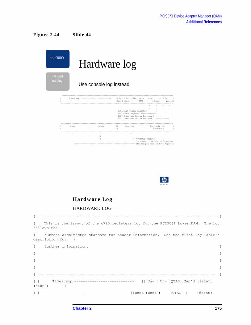
PCISCSI Device Adapter Manager (DAM)Additional References
Figure 2-44 Slide 44
Hardware Log
HARDWARE LOG
{===================================================================================}
{ This is the layout of the c720 registers log for the PCISCSI Lower DAM. The logfollows the }
{ current architected standard for header information. See the first log Table'sdescription for }
{ further information. }
{ }
{ }
{ }
{ -------------------------------------------------------------------------------- }
{ | Timestamp --------------------------> || Un- : Un- :QTAG :Map'd||istat::sist0: | }
{ | || ||used :used : :QTAG || :dstat:
hp e3000
7.0 fieldtraining
--------------------------------------------------------------------------------------------------
| Timestamp --------------------------> || Un- : Un- :QTAG :Map'd||istat: :sist0: || || ||used :used : :QTAG || :dstat: :sist1| -------------------------------------------------------------------------------------------------- ^ ^ ^ ^ | | | | Interrupt Status Register - | | | DMA Status Register ------------- | | SCSI Interrupt Status Register 0 ------ | SCSI Interrupt Status Register 1 ------------
--------------------------------------------------------------------------------------------------| dsps || intstat || scratcha || Available for || || || || expansion | ------------------------------------------------------------------------------------------------- ^ ^ ^ | | | | | --- Owership mapping | ------------------------------ Interrupt Processing Information ------------------------------------------------------ DMA Scripts Pointer Save Register
· Use console log instead
Hardware log
Chapter 2 175
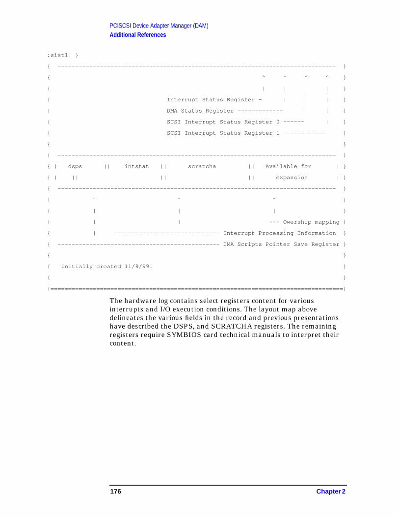
PCISCSI Device Adapter Manager (DAM)Additional References
:sist1| }
{ ------------------------------------------------------------------------------- }
{ ^ ^ ^ ^ }
{ | | | | }
{ Interrupt Status Register - | | | }
{ DMA Status Register ------------- | | }
{ SCSI Interrupt Status Register 0 ------ | }
{ SCSI Interrupt Status Register 1 ------------ }
{ }
{ ------------------------------------------------------------------------------- }
{ | dsps || intstat || scratcha || Available for | }
{ | || || || expansion | }
{ ------------------------------------------------------------------------------- }
{ ^ ^ ^ }
{ | | | }
{ | | --- Owership mapping }
{ | ------------------------------ Interrupt Processing Information }
{ ---------------------------------------------- DMA Scripts Pointer Save Register }
{ }
{ Initially created 11/9/99. }
{ }
{===================================================================================}
The hardware log contains select registers content for variousinterrupts and I/O execution conditions. The layout map abovedelineates the various fields in the record and previous presentationshave described the DSPS, and SCRATCHA registers. The remainingregisters require SYMBIOS card technical manuals to interpret theircontent.
176 Chapter 2

PCISCSI Device Adapter Manager (DAM)Additional References
QTAGs STATs DSPS INSTAT SCRATCH
85fa9d9c:00a100a2 00200100 00432380 01010100 00000000 00000000 00000000 00000000
85fa9dbc:00000000 00000000 00000000 00000000 00000000 00000000 00000000 00000000
85fa9ddc:05cb2c02 be313020 000000ff 02800210 00000000 00000002 ff000000 00000000
85fa9dfc:05cb2c02 c2902780 00000001 29840000 00000006 00040000 ff001000 52657365
85fa9e1c:05cb2c02 c290bee0 00000001 29840000 00000007 00040000 ff001000 52657365
85fa9e3c:05cb2c02 c2916090 00000001 29840000 00000007 00040000 ff001000 52657365
85fa9e5c:05cb2c02 c291ee10 00000001 29840000 00000007 00040000 ff001000 52657365
85fa9e7c:05cb2c02 c2932910 00000001 29840000 00000006 00040000 ff001000 52657365
85fa9e9c:05cb2c02 c293b500 00000001 29840000 00000007 00040000 ff001000 52657365
85fa9ebc:05cb2c02 c2945580 00000001 29840000 00000007 00040000 ff001000 52657365
85fa9edc:05cb2c02 c294e2c0 00000001 29840000 00000007 00040000 ff001000 52657365
85fa9efc:05cb2c02 c295b3a0 00000001 2a80c010 c0081581 00000080 ff001000 52657365
85fa9f1c:05cb2c02 c2966180 00000001 09840000 00000001 00040000 ff001000 52657365
85fa9f3c:05cb2c02 c29d6750 000000ff 09840000 0000000e 00040000 ff000000 52657365
85fa9f5c:05cb2c02 c29e89f0 00000001 01840000 00000010 00040000 ff001000 52657365
85fa9f7c:05cb2c02 c29fa930 00000001 09840000 00000001 00040000 ff001000 52657365
85fa9f9c:05cb2c02 c2a05df0 00000001 01840000 00000002 00040000 ff001000 52657365
85fa9fbc:05cb2c02 c2a259a0 00000001 29840000 00000006 00040000 ff001000 52657365
85fa9fdc:05cb2c02 c2a2e570 00000001 29840000 00000007 00040000 ff001000 52657365
85fa9ffc:05cb2c02 c2a389b0 00000001 29840000 00000007 00040000 ff001000 52657365
85faa01c:05cb2c02 c2a417d0 00000001 29840000 00000007 00040000 ff001000 52657365
85faa03c:05cb2c02 c2a54c20 00000001 29840000 00000006 00040000 ff001000 52657365
85faa05c:05cb2c02 c2a5d680 00000001 29840000 00000007 00040000 ff001000 52657365
85faa07c:05cb2c02 c2a67210 00000001 29840000 00000007 00040000 ff001000 52657365
85faa09c:05cb2c02 c2a6ff70 00000001 29840000 00000007 00040000 ff001000 52657365
85faa0bc:05cb2c02 c2a7c7f0 00000001 2a80c000 c0081581 00000080 ff001000 52657365
85faa0dc:05cb2c02 c2a86880 00000001 09840000 00000001 00040000 ff001000 52657365
85faa0fc:05cb2c02 c2abf340 00000001 0a808000 07716780 00000080 ff001000 52657365
85faa11c:05cb2c02 c2acaa60 00000001 01840000 00000010 00040000 ff801000 52657365
85faa13c:05cb2c02 f7108800 00000001 09840000 00000001 00040000 ff801000 52657365
85faa15c:05cb2c02 f71f6070 00000001 01840000 00000010 00040000 ff801000 52657365
85faa17c:05cb2c02 f7214fa0 00000001 29840000 00000006 00040000 ff801000 52657365
85faa19c:05cb2c02 f721db70 00000001 29840000 00000007 00040000 ff801000 52657365
85faa1bc:05cb2c02 f7228080 00000001 29840000 00000007 00040000 ff801000 52657365
85faa1dc:05cb2c02 f7230ea0 00000001 29840000 00000007 00040000 ff801000 52657365
85faa1fc:05cb2c02 f72441e0 00000001 29840000 00000006 00040000 ff801000 52657365
85faa21c:05cb2c02 f724cf70 00000001 29840000 00000007 00040000 ff801000 52657365
Chapter 2 177

PCISCSI Device Adapter Manager (DAM)Additional References
85faa23c:05cb2c02 f7256d20 00000001 29840000 00000007 00040000 ff801000 52657365
85faa25c:05cb2c02 f725fba0 00000001 29840000 00000007 00040000 ff801000 52657365
85faa27c:05cb2c02 f726c240 00000001 2a80c000 c0081581 00000080 ff801000 52657365
; INT instruction DSPS values.
ABSOLUTE IntCmdSent = 0x01 ; selection resource is free
ABSOLUTE IntCmdComp = 0x02 ; Command Complete
ABSOLUTE IntSdp = 0x03
ABSOLUTE IntDisc = 0x04 ; Disconnect with implied restore needed
ABSOLUTE IntPutMsgOut = 0x05 ; WDTR and SDTR negotiation
ABSOLUTE IntMsgOutIn = 0x06 ; WDTR and SDTR negotiation
ABSOLUTE IntGetMsgIn = 0x07 ; WDTR and SDTR negotiation
ABSOLUTE IntReselectIdMsgIn = 0x08
ABSOLUTE IntMsgIn = 0x09 ; Restore Pointers
ABSOLUTE IntSelect = 0x0a
ABSOLUTE IntReselected = 0x0b
ABSOLUTE IntDataDone = 0x0c
ABSOLUTE IntDiscDone = 0x0d
ABSOLUTE IntUntaggedReselect = 0x0e
ABSOLUTE IntGood = 0x10
ABSOLUTE IntAbortDone = 0x11
ABSOLUTE IntError = 0xff
Variable Type location Description
ISTAT bit8 Lbp Interrupt Status Register (14)
DSTAT bit8 Lbp DMA Status Register(0C)
DSPS bit8 Lbp DMA Scripts Pointer Save (B0–B3)
SIST0 bit8 Lbp SCSI Interrupt Status 0 (42)
SIST1 bit8 Lbp SCSI Interrupt Status 1(43)
Intstat Ubit32 Local variable Interrupt processing information.
SCRATCHA Ubit32 Local variable Maps ownership via lsp (34 –37)
178 Chapter 2

PCISCSI Device Adapter Manager (DAM)Additional References
Figure 2-45 Slide 45
Figure 2-46 Slide 46
hp e3000
7.0 fieldtraining
System Diagnostics[overview]
· Card Maintenance
· Diagnostics Tools
· Logtool
· Mesa
hp e3000
7.0 fieldtraining
Card Maintenance
· No firmware download
· No hardware probing
· No hardware resets
Chapter 2 179

PCISCSI Device Adapter Manager (DAM)Additional References
Card Maintenance
No firmware download
No hardware probing
No hardware resets
All the PCI SCSI cards for the N-class platform operate by followingcustom programs called SCSI SCRIPTS and don’t rely on firmware.Updates to card operation are done through the PCISCSI DAMpatching the SCSI SCRIPT. There is no firmware J
Previous interface cards and diagnostics could use a diagnostics LLIOmessage to probe card registers for operational status or initiate actionssuch as self-test after locking the manager. No such interface exists inthe PCISCSI DAM driver and the MESA diagnostic will not attemptsuch actions.
There is no way via software to cause a card reset outside of the nativePCISCSI DAM doing this. If the card appears to be hung, the systemmust reset the bus.
180 Chapter 2

PCISCSI Device Adapter Manager (DAM)Additional References
Figure 2-47 Slide 47
Logtool
[[ logtool output sample]]
hp e3000
7.0 fieldtraining
Logtool
Chapter 2 181

PCISCSI Device Adapter Manager (DAM)Additional References
Figure 2-48 Slide 48
Mesa
[[ mesa error log sample]]
hp e3000
7.0 fieldtraining
Mesa
182 Chapter 2

PCISCSI Device Adapter Manager (DAM)Additional References
Figure 2-49 Slide 49
hp e3000
7.0 fieldtraining
Troubleshooting[overview]
· case 1: fail to bind
· case 2: finding I/O
Chapter 2 183

PCISCSI Device Adapter Manager (DAM)Additional References
Figure 2-50 Slide 50
Case 1: Fail to Bind
Card type and bus type matters
Matrix of higher mgrs to card/bus type
The SYMBIOS cards for the N-class platform have the same ultra-highdensity cable connector. Misconnecting cables to the wrong card orconnecting devices of the wrong SCSI bus type (SE, LVD, HVD) areeasy mismakes. The SYMBIOS LVD cards can sense the SCSI bus typeand switch between LVD and SE bus electrical characteristics. Theproblem is made worse when all LVD devices are connected to an LVDSCSI bus but one of the devices is really an SE device. The LVD cardwill switch the SCSI bus to SE stay in this mode.
To assist the customer and field in these situations, the followingmatrix has been encoded into the upper DAM’s bind routine. When aconfiguration not in the matrix is detected, the LLIO status will be“IMCOMPATIBLE SUBSYS”
Device ID: SYM53C895 OR SYM53C896
Bus Mode:Single-ended (SE)
hp e3000
7.0 fieldtraining
Case 1: Fail to Bind
· Matrix of higher mgrs to bus type
184 Chapter 2

PCISCSI Device Adapter Manager (DAM)Additional References
Device Managers:Subsys_Scsi_Tape_Dm
Subsys_Scsi_Tape2_Dm
Subsys_Scsi_Ddm
Subsys_Autochg_Dm,
Subsys_Magneto_Dm,
Subsys_Hep_Printer_Dm
Device ID: SYM53C895 OR SYM53C896
Bus Mode:Low-Voltage Differential (LVD)
Device Managers: Subsys_Magneto_Dm,
Subsys_disk_And_Array_Dm
Chapter 2 185

PCISCSI Device Adapter Manager (DAM)Additional References
Figure 2-51 Slide 51
Case 2: Finding I/Os
For desired LDEV, use IO_PPT entries to locate device mgr and DAMmgr port info
Check the device mgr’s port subqueues for the request
Check device mgr’s LLIO msg log for the request
Check DAM mgr’s port subqueues for the request
Check DAM mgr’s LLIO msg log for request
Determining the DAM’s condition/status
System hangs are often root caused as a lost I/O possibly due to anon-responding device. The first tact might be to power cycle the deviceor replace it. This case study will, instead, track down a pair of I/Osand determine their condition/status.
The quest for the I/Os will start with the memory manager andrequests to LDEV #68 not completing and may be hung in the I/Osubsystem. The I/O needs be tracked down and their status obtained inorder to determine if the cause is in software or hardware.
hp e3000
7.0 fieldtraining
Case 2: Finding I/Os
· For desired LDEV, use IO_PPT entries to locate devicemgr and
· DAM mgr port info
· Check the device mgr’s port subqueues for the request
· Check device mgr’s LLIO msg log for the request
· Check DAM mgr’s port subqueues for the request
· Check DAM mgr’s LLIO msg log for request
· Determining the DAM’s condition/status
186 Chapter 2

PCISCSI Device Adapter Manager (DAM)Additional References
The exercise will use DEBUG and symbols formatting to illustrate amethod of locating the I/Os. The search will start with the memorymanager and its active I/O list. The following list shows that 5 I/Os toLDEV #68 are active. Picking 2 of them (see hightlight) these I/Os willbe tracked for their current status/condition.
$163 ($76) nmdat >mm_active_io
Memory Manager Active I/O List
------------------------------
W
r
i
t Num PIN/ Req MIB
e Ldev Sector Status Base VA Pages Msg Pri State Pointer
- ---- ------ --------- ------------- ----- --------- ----- ------- ---------
w 68 $109420 ALL OK $e9.0 $6 $0 $80 In Prog $d20112d0
Phys Addr : $46508000 Virt Addr : $e9.0
Phys Addr : $49d3a000 Virt Addr : $e9.1000
Phys Addr : $3ab4c000 Virt Addr : $e9.2000
Phys Addr : $3ab4d000 Virt Addr : $e9.3000
Phys Addr : $3c552000 Virt Addr : $e9.4000
Phys Addr : $1faec000 Virt Addr : $e9.5000
--------------------------------------------------------------
w 68 $37a0 ALL OK $119.22c000 $1 $0 $33ff In Prog $d2036ad0
Phys Addr : $4420f000 Virt Addr : $119.22c000
--------------------------------------------------------------
w 69 $105330 ALL OK $3d4.0 $6 $0 $80 In Prog $d2057cd0
Phys Addr : $d7b6000 Virt Addr : $3d4.0
Phys Addr : $35746000 Virt Addr : $3d4.1000
Phys Addr : $53bed000 Virt Addr : $3d4.2000
Phys Addr : $1728f000 Virt Addr : $3d4.3000
Phys Addr : $563d6000 Virt Addr : $3d4.4000
Phys Addr : $522ff000 Virt Addr : $3d4.5000
--------------------------------------------------------------
w 68 $109360 ALL OK $725.0 $6 $0 $80 In Prog $d206add0
Phys Addr : $33be6000 Virt Addr : $725.0
Phys Addr : $40691000 Virt Addr : $725.1000
Chapter 2 187

PCISCSI Device Adapter Manager (DAM)Additional References
Phys Addr : $4eeaf000 Virt Addr : $725.2000
Phys Addr : $1354f000 Virt Addr : $725.3000
Phys Addr : $48176000 Virt Addr : $725.4000
Phys Addr : $3c3db000 Virt Addr : $725.5000
--------------------------------------------------------------
w 68 $1093c0 ALL OK $318.0 $6 $0 $80 In Prog $d206ec50
Phys Addr : $2b679000 Virt Addr : $318.0
Phys Addr : $319da000 Virt Addr : $318.1000
Phys Addr : $52b31000 Virt Addr : $318.2000
Phys Addr : $26848000 Virt Addr : $318.3000
Phys Addr : $67b2c000 Virt Addr : $318.4000
Phys Addr : $38df2000 Virt Addr : $318.5000
$164 ($76) nmdat >
Using io_disc_info , the port numbers and PDA pointers will beobtained for LDEV #68’s DM and DAM.
$162 ($76) nmdat > io_disc_info
LDEV-TYPE STATUS VOLUME (VOLUME SET - GEN)
----------- ------------ ---------------------------
61-000000 MASTER MASTER (PVOL61-0)
69-000000 MASTER MASTER (PVOL69-0)
54-000000 MASTER MASTER (PVOL54-0)
62-000000 MASTER MASTER (PVOL62-0)
55-000000 MASTER MASTER (PVOL55-0)
63-000000 MASTER MASTER (PVOL63-0)
56-000000 MASTER MASTER (PVOL56-0)
64-000000 MASTER MASTER (PVOL64-0)
57-000000 MASTER MASTER (PVOL57-0)
65-000000 MASTER MASTER (PVOL65-0)
50-000000 MASTER MASTER (PVOL50-0)
58-000000 MASTER MASTER (PVOL58-0)
66-000000 MASTER MASTER (PVOL66-0)
51-000000 MASTER MASTER (PVOL51-0)
59-000000 MASTER MASTER (PVOL59-0)
67-000000 MASTER MASTER (PVOL67-0)
52-000000 MASTER MASTER (PVOL52-0)
1-000000 MASTER MEMBER1 (MPEXL_SYSTEM_VOLUME_SET-0)
188 Chapter 2

PCISCSI Device Adapter Manager (DAM)Additional References
60-000000 MASTER MASTER (PVOL60-0)
68-000000 MASTER MASTER (PVOL68-0)
53-000000 MASTER MASTER (PVOL53-0)
LDEV# TYPE LDM Port LDM PDA DM Port DM PDA
----- ---- -------- ------- ------- ------
61 IO_DISC ffffff5b b.82416700 ffffff5c b.8280ba40
69 IO_DISC ffffff53 b.8241c200 ffffff54 b.8281f240
54 IO_DISC ffffff67 b.824122c0 ffffff68 b.827fd040
62 IO_DISC ffffff51 b.8241d8c0 ffffff52 b.82824040
55 IO_DISC ffffff65 b.82413980 ffffff66 b.82801e40
63 IO_DISC ffffff4f b.8241ef80 ffffff50 b.82828e40
56 IO_DISC ffffff73 b.82409a40 ffffff74 b.827dfc40
64 IO_DISC ffffff4d b.82420640 ffffff4e b.8282dc40
57 IO_DISC ffffff71 b.8240b100 ffffff72 b.827e4a40
65 IO_DISC ffffff4b b.82421d00 ffffff4c b.82832a40
50 IO_DISC ffffff77 b.82406cc0 ffffff78 b.827d6040
58 IO_DISC ffffff6f b.8240c7c0 ffffff70 b.827e9840
66 IO_DISC ffffff59 b.82417dc0 ffffff5a b.82810840
51 IO_DISC ffffff75 b.82408380 ffffff76 b.827dae40
59 IO_DISC ffffff6d b.8240de80 ffffff6e b.827ee640
67 IO_DISC ffffff57 b.82419480 ffffff58 b.82815640
52 IO_DISC ffffff6b b.8240f540 ffffff6c b.827f3440
1 IO_DISC ffffffc3 b.824011c0 ffffffc4 b.827d1240
60 IO_DISC ffffff5d b.82415040 ffffff5e b.82806c40
68 IO_DISC ffffff55 b.8241ab40 ffffff56 b.8281a440
53 IO_DISC ffffff69 b.82410c00 ffffff6a b.827f8240
PATH MANAGER NAME PORT # PDA PTR PRI ENV
---- ------------ ------ ------- --- ---
1/8/0/0.1.0 SCSI_DISK_AND_ARRAY_Dffffff5c 8280ba40 8
1/8/0/0.13.0 SCSI_DISK_AND_ARRAY_Dffffff54 8281f240 8
0/12/0/0.8.0 SCSI_DISK_AND_ARRAY_Dffffff68 827fd040 8
1/8/0/0.2.0 SCSI_DISK_AND_ARRAY_Dffffff52 82824040 8
0/12/0/0.9.0 SCSI_DISK_AND_ARRAY_Dffffff66 82801e40 8
1/8/0/0.3.0 SCSI_DISK_AND_ARRAY_Dffffff50 82828e40 8
0/12/0/0.10.0 SCSI_DISK_AND_ARRAY_Dffffff74 827dfc40 8
Chapter 2 189

PCISCSI Device Adapter Manager (DAM)Additional References
1/8/0/0.8.0 SCSI_DISK_AND_ARRAY_Dffffff4e 8282dc40 8
0/12/0/0.11.0 SCSI_DISK_AND_ARRAY_Dffffff72 827e4a40 8
1/8/0/0.9.0 SCSI_DISK_AND_ARRAY_Dffffff4c 82832a40 8
0/12/0/0.0.0 SCSI_DISK_AND_ARRAY_Dffffff78 827d6040 8
0/12/0/0.12.0 SCSI_DISK_AND_ARRAY_Dffffff70 827e9840 8
1/8/0/0.10.0 SCSI_DISK_AND_ARRAY_Dffffff5a 82810840 8
0/12/0/0.1.0 SCSI_DISK_AND_ARRAY_Dffffff76 827dae40 8
0/12/0/0.13.0 SCSI_DISK_AND_ARRAY_Dffffff6e 827ee640 8
1/8/0/0.11.0 SCSI_DISK_AND_ARRAY_Dffffff58 82815640 8
0/12/0/0.2.0 SCSI_DISK_AND_ARRAY_Dffffff6c 827f3440 8
0/0/2/0.6.0 SCSI_DISK_AND_ARRAY_Dffffffc4 827d1240 5
1/8/0/0.0.0 SCSI_DISK_AND_ARRAY_Dffffff5e 82806c40 8
1/8/0/0.12.0 SCSI_DISK_AND_ARRAY_Dffffff56 8281a440 8
0/12/0/0.3.0 SCSI_DISK_AND_ARRAY_Dffffff6a 827f8240 8
164 ($76) nmdat > io_ppt
PATH PDA PTR CHILD PTR SIBLING PTR ALT PATH PTR
---- ------- --------- ----------- ------------
1 $85fff200 $a.d0c02e58 $a.d0c04610 $0.0
1/8 $86c1a200 $a.d0c02f60 $a.d0c02c48 $0.0
1/8/0 $86c1d200 $a.d0c03068 $0.0 $0.0
1/8/0/0 $86c1e200 $a.d0c03170 $0.0 $0.0
1/8/0/0.0 $00000000 $a.d0c03278 $a.d0c03380 $0.0
1/8/0/0.0.0 $82806c40 $0.0 $0.0 $0.0
1/8/0/0.1 $00000000 $a.d0c03488 $a.d0c03dd0 $0.0
1/8/0/0.1.0 $8280ba40 $0.0 $0.0 $0.0
1/8/0/0.2 $00000000 $a.d0c03ed8 $a.d0c03fe0 $0.0
1/8/0/0.2.0 $82824040 $0.0 $0.0 $0.0
1/8/0/0.3 $00000000 $a.d0c040e8 $a.d0c041f0 $0.0
1/8/0/0.3.0 $82828e40 $0.0 $0.0 $0.0
1/8/0/0.8 $00000000 $a.d0c042f8 $a.d0c04400 $0.0
1/8/0/0.8.0 $8282dc40 $0.0 $0.0 $0.0
1/8/0/0.9 $00000000 $a.d0c04508 $a.d0c03590 $0.0
1/8/0/0.9.0 $82832a40 $0.0 $0.0 $0.0
1/8/0/0.10 $00000000 $a.d0c03698 $a.d0c037a0 $0.0
190 Chapter 2

PCISCSI Device Adapter Manager (DAM)Additional References
1/8/0/0.10.0$82810840 $0.0 $0.0 $0.0
1/8/0/0.11 $00000000 $a.d0c038a8 $a.d0c039b0 $0.0
1/8/0/0.11.0$82815640 $0.0 $0.0 $0.0
1/8/0/0.12 $00000000 $a.d0c03ab8 $a.d0c03bc0 $0.0
1/8/0/0.12.0$8281a440 $0.0 $0.0 $0.0
1/8/0/0.13 $00000000 $a.d0c03cc8 $0.0 $0.0
1/8/0/0.13.0$8281f240 $0.0 $0.0 $0.0
1/10 $86c16200 $a.d0c02d50 $0.0 $0.0
1/10/0 $86c19200 $0.0 $0.0 $0.0
~0 $88ac2000 $0.0 $a.d0c04718 $0.0
~99 $88af3000 $0.0 $0.0 $0.0
The DM port will be checked first to ensure the requests are not held ina subqueue. Ë All subqueues are open and no requests waiting in anysubqueue.
$165 ($76) nmdat > port_info ffffff56
Information for Port : $ffffff56
Port Type : Message Port
Port is PFP : FALSE
Purge Pending : FALSE
Access Count : $0
Owner Pin : $7ffd (Not owned by a process)
Ports PFP Port : $ffffffe5
Global Port Desc : $800c8650
Freeze Desc : $00000000
Subqueue Information
Highest Subqueue # : $1f
Enabled Subq Mask : $ffffffff
NonEmpty Subq Mask : $00000000
Number of Messages : $0
Server Information
Server Type : Procedure Server
Server Invoked : FALSE
Chapter 2 191

PCISCSI Device Adapter Manager (DAM)Additional References
Queued to PFP : FALSE
PFP Priority : $10
Deferred : FALSE
Message Threshold : $1
Server Procedure : ?scsi_disk_and_array_dm
Server Data Area : $b.8281a440
Message Pool Information
Use Count : $33
Message Size : $48
Pool Desc Ptr : $8124e000
$166 ($76) nmdat >
Look now within the DM scsi_disc_array_dm to see if the I/Os areactive and sent to the DAM. Ë The linkage_array elementlkclass_mm_io indicates I/Os are active and have been sent to theDAM. Following the head_ and tail_ req_ptrs 4 I/Os are active and thenum_active_reqs (see further down in the pda) confirms this.
The active requests are held in the DM’s req_tbl and the reqs beingchased are at index “3” and “9”
$15b ($76) nmdat > fv dm 'sda_port_data_type'
RECORD
NUM_LOG_TABLES : 1
SDA_LOG_TABLE_ADDR : 8281afa8
DM_VERSION_COMP_CODE : '@(#) SDArray/C0316+NIKE 1/5/96 '#M#J'
'
SDA_STATE : SDA_READY_FOR_IO_STATE
DEVICE_IS_ONLINE : TRUE
DEVICE_IS_RESERVED : FALSE
VOLUME_IS_ACCESSIBLE : TRUE
SCSI_III_META : FALSE
ADDRESSING_METHOD : PERIPHERAL
SDA_AVR_STATE : SDA_AVR_CLEAR
SDA_AUTODIAG_ON : FALSE
SDA_ERRORLOG_ON : TRUE
SDA_MAX_RETRIES : 5
192 Chapter 2

PCISCSI Device Adapter Manager (DAM)Additional References
MSG_SUBQ_NUM : 3
MSG_INDEX_NUM : SCSI_REPLY_MSG_INDEX
MSG_PROC_ARRAY :
[ DO_BIND_MSG_PROC_INDEX ]: 5cb7c8.0
[ DO_UNBIND_MSG_PROC_INDEX ]: 5cbbe8.0
. . . . .
[ UNKNOWN_ACTION_PROC_INDEX ]: 5c8b8c.0
[ DEVICE_BROKEN_PROC_INDEX ]: 5c8c00.0
DAM_DESCRIPTION :
DAM_PORT_NUM : ffffff5f
DAM_REV_CODE : 100
DAM_QUEUE_DEPTH : 8
DAM_LOPRI_SUBQ : 5
DAM_HIPRI_SUBQ : 5
LDM_DESCRIPTION :
LDM_PORT_NUM : ffffff55
SUBSYSTEM_ID : 6f
EVENT_SUBQUEUE : 1
LDEV : 44
DEV_PRODUCT_ID : 'ST39103LC '
MY_PORT : ffffff56
MY_TARGET_ADDR : c
MY_UNIT_ADDR : 0
LOGICAL_BLOCK_SIZE : 200
LIF_SECTORS_PER_BLOCK : 2
LOGICAL_BLOCK_LIMIT : 10f5947
LIF_SECTOR_LIMIT : 21eb28f
DEVICE_IS_ARRAY : FALSE
RAID_LEVEL : 0
FILLER : 0
PRODUCT_ID_PAC :
PROC_ID : 'ST391'
LINKAGE_ARRAY :
[ LKCLASS_IDENTIFY_SEQ ]:
HEAD_REQ_PTR : 0
TAIL_REQ_PTR : 0
[ LKCLASS_BIND_UNBIND_SEQ ]:
HEAD_REQ_PTR : 0
Chapter 2 193
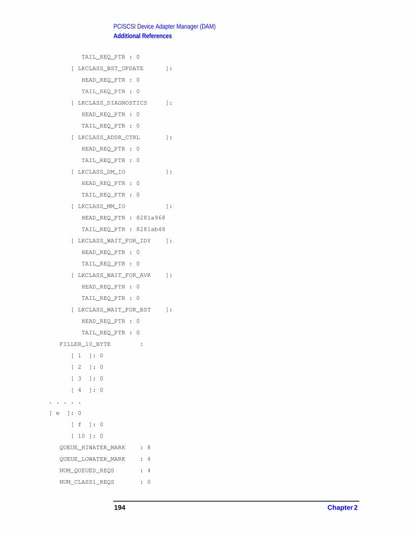
PCISCSI Device Adapter Manager (DAM)Additional References
TAIL_REQ_PTR : 0
[ LKCLASS_BST_UPDATE ]:
HEAD_REQ_PTR : 0
TAIL_REQ_PTR : 0
[ LKCLASS_DIAGNOSTICS ]:
HEAD_REQ_PTR : 0
TAIL_REQ_PTR : 0
[ LKCLASS_ADDR_CTRL ]:
HEAD_REQ_PTR : 0
TAIL_REQ_PTR : 0
[ LKCLASS_DM_IO ]:
HEAD_REQ_PTR : 0
TAIL_REQ_PTR : 0
[ LKCLASS_MM_IO ]:
HEAD_REQ_PTR : 8281a968
TAIL_REQ_PTR : 8281ab48
[ LKCLASS_WAIT_FOR_IDY ]:
HEAD_REQ_PTR : 0
TAIL_REQ_PTR : 0
[ LKCLASS_WAIT_FOR_AVR ]:
HEAD_REQ_PTR : 0
TAIL_REQ_PTR : 0
[ LKCLASS_WAIT_FOR_BST ]:
HEAD_REQ_PTR : 0
TAIL_REQ_PTR : 0
FILLER_10_BYTE :
[ 1 ]: 0
[ 2 ]: 0
[ 3 ]: 0
[ 4 ]: 0
. . . . .
[ e ]: 0
[ f ]: 0
[ 10 ]: 0
QUEUE_HIWATER_MARK : 8
QUEUE_LOWATER_MARK : 4
NUM_QUEUED_REQS : 4
NUM_CLASS1_REQS : 0
194 Chapter 2

PCISCSI Device Adapter Manager (DAM)Additional References
NUM_ACTIVE_REQS : 4
WATCHDOG_TIMER_ID : 360023
ROTATING_POLL_TIMER : 0
LOCKER_FROM_PORT : 0
LOCKER_EVENT_PORT : 0
LOCKER_EVENT_SUBQ : 0
LOCKER_LOCK_EVENT : 0
LAST_HW_STATUS :
SCSI_STATUS_BYTE :
RESERVED_1 : 0
STATUS_INFO : 0
RESERVED_2 : 0
SCSI_SENSE :
SENSE_FIELDS :
VALID : FALSE
ERROR_CODE : 0
SEGMENT_NUMBER : 0
FILEMARK : FALSE
. . . . .
MI_START_TIME : 72133d62a5d0f40
MI_LAST_TIME : 72133d62a5d0f40
AUX_DATA_PTR : 86cbb000
REQUEST_TBL_HDR :
FREE_HEAD_PTR : 8281ae68
FREE_TAIL_PTR : 8281adc8
NUM_FREE_ENTRIES : 8
MAX_TBL_ENTRIES : c
. . . . .
[ 3 ]:
NEXT_REQ : 8281ad28
PREV_REQ : 0
REQ_STATE : ST_ACTIVE_REQUEST
ABORT_BY_USER : FALSE
REQUEST_BY_DIAG : FALSE
RESTART_IDY_SEQ : FALSE
LKCLASS_QUEUE : LKCLASS_MM_IO
LKCLASS_HOME_QUEUE : LKCLASS_MM_IO
Chapter 2 195

PCISCSI Device Adapter Manager (DAM)Additional References
RETRY_COUNT : 0
TIMER_COUNTDOWN : 3
TIMER_RESET_COUNT : 3
FRAME_PTR : b.81263e78
SCSI_CMD_PTR : 86cbd080
SCSI_CMD_LEN : a
SENSE_PTR : 86cbc600
DATA_PTR :
DATA_PTR : a.d206ae50
DATA_CLASS : 3
DATA_DIRECTION : 1
ALLOW_DISCONNECT : TRUE
DATA_LEN : 6000
DATA_XFERED_CNT : 0
TYPE_OF_QTAG : 20
ROTATING_QTAG_PARM : 3
FIXED_REQ_INDEX : 3
MSG_REQ :
MSG_HEADER :
MSG_DESCRIPTOR : 195
MESSAGE_ID : 0
TRANSACTION_NUM : d206add0
FROM_PORT : 0
DM_IO_REQ :
REPLY_SUBQ : 1
DATA_CLASS : 1
DATA_PTR :
DATA_PTR : a.d0ea1908
DATA_LEN : 800
FUNC :
IO_FUNC_TAG : 13
W_BYTE_OFFSET : 0
COMPLETION_STATUS :
IS_OK : 0
REQ_FUNC : FN_MIB_IO
BST_BAD_BLOCK : 0
MIB_IS_SINGLE : TRUE
196 Chapter 2
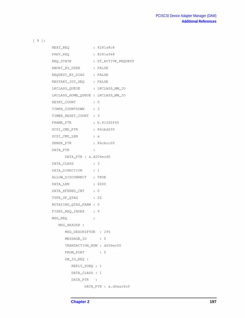
PCISCSI Device Adapter Manager (DAM)Additional References
[ 9 ]:
NEXT_REQ : 8281a8c8
PREV_REQ : 8281a968
REQ_STATE : ST_ACTIVE_REQUEST
ABORT_BY_USER : FALSE
REQUEST_BY_DIAG : FALSE
RESTART_IDY_SEQ : FALSE
LKCLASS_QUEUE : LKCLASS_MM_IO
LKCLASS_HOME_QUEUE : LKCLASS_MM_IO
RETRY_COUNT : 0
TIMER_COUNTDOWN : 3
TIMER_RESET_COUNT : 3
FRAME_PTR : b.81260f60
SCSI_CMD_PTR : 86cbd200
SCSI_CMD_LEN : a
SENSE_PTR : 86cbcc00
DATA_PTR :
DATA_PTR : a.d206ecd0
DATA_CLASS : 3
DATA_DIRECTION : 1
ALLOW_DISCONNECT : TRUE
DATA_LEN : 6000
DATA_XFERED_CNT : 0
TYPE_OF_QTAG : 20
ROTATING_QTAG_PARM : 0
FIXED_REQ_INDEX : 9
MSG_REQ :
MSG_HEADER :
MSG_DESCRIPTOR : 195
MESSAGE_ID : 0
TRANSACTION_NUM : d206ec50
FROM_PORT : 0
DM_IO_REQ :
REPLY_SUBQ : 1
DATA_CLASS : 1
DATA_PTR :
DATA_PTR : a.d0ea18c0
Chapter 2 197
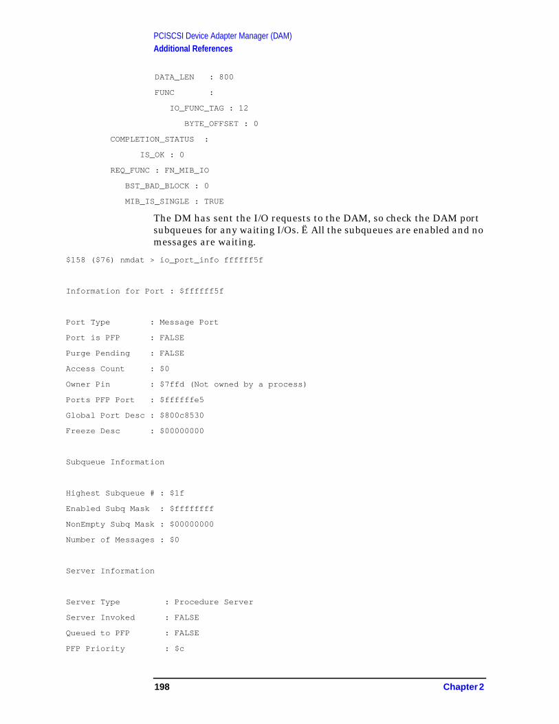
PCISCSI Device Adapter Manager (DAM)Additional References
DATA_LEN : 800
FUNC :
IO_FUNC_TAG : 12
BYTE_OFFSET : 0
COMPLETION_STATUS :
IS_OK : 0
REQ_FUNC : FN_MIB_IO
BST_BAD_BLOCK : 0
MIB_IS_SINGLE : TRUE
The DM has sent the I/O requests to the DAM, so check the DAM portsubqueues for any waiting I/Os. Ë All the subqueues are enabled and nomessages are waiting.
$158 ($76) nmdat > io_port_info ffffff5f
Information for Port : $ffffff5f
Port Type : Message Port
Port is PFP : FALSE
Purge Pending : FALSE
Access Count : $0
Owner Pin : $7ffd (Not owned by a process)
Ports PFP Port : $ffffffe5
Global Port Desc : $800c8530
Freeze Desc : $00000000
Subqueue Information
Highest Subqueue # : $1f
Enabled Subq Mask : $ffffffff
NonEmpty Subq Mask : $00000000
Number of Messages : $0
Server Information
Server Type : Procedure Server
Server Invoked : FALSE
Queued to PFP : FALSE
PFP Priority : $c
198 Chapter 2

PCISCSI Device Adapter Manager (DAM)Additional References
Deferred : FALSE
Message Threshold : $1
Server Procedure : ?pci_scsi_dam
Server Data Area : $b.86c1e200
Message Pool Information
Use Count : $33
Message Size : $48
Pool Desc Ptr : $8124e000
$159 ($76) nmdat >
So far, the I/Os have made it into the DAM and may be active on thehardware. Two places in the upper DAM and two places in the lowerDAM need be checked now. The DAM’s PDA pending_queue(s) showno requests pending and num_active_reqs indicates 5 reqs are activein the lower DAM. The active req information is kept in thepciscsi_req_table and using index of [target_id , lun] or [$c, $0] forLDEV #68, 4 active I/O requests are indicated.
$16b ($76) nmdat > fv dam "pciscsi_pda_type”
RECORD
NUM_LOG_TABLES : 3
MSG_LOG_TABLE_ADDR : 86c1fd5c
HW_LOG_TABLE_ADDR : 86c23d9c
CONSOLE_LOG_TABLE_ADDR : 86c25ddc
VERSION_DATE : '@(#) PCI_SCSI_DAM/C.16.01 ver.2f 02/06/00'#M#J'
'
MGR_STATE : 3
MY_PORT : ffffff5f
AUX_DATA_PTR : 86c2e000
MY_ENABLED_SUBQS : [ 0, 1, 2, 3, 4, 5, 6, 7, 8, 9, a, b, c, d, e, f
, 10, 11, 12, 13, 14, 15, 16, 17, 18, 19, 1a,
1b, 1c, 1d, 1e, 1f]
TUR_CDB : $0$0$0$0$0$0$0$0$0$0
LM_INFO :
LM_PORT_NUM : ffffff60
LM_BOUND : TRUE
LM_REV_CODE : e0000
Chapter 2 199
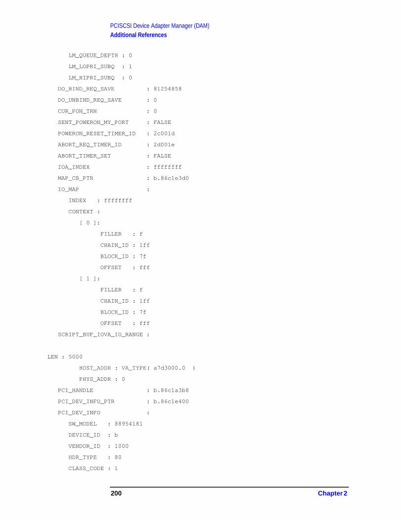
PCISCSI Device Adapter Manager (DAM)Additional References
LM_QUEUE_DEPTH : 0
LM_LOPRI_SUBQ : 1
LM_HIPRI_SUBQ : 0
DO_BIND_REQ_SAVE : 81254858
DO_UNBIND_REQ_SAVE : 0
CUR_PON_TRN : 0
SENT_POWERON_MY_PORT : FALSE
POWERON_RESET_TIMER_ID : 2c001d
ABORT_REQ_TIMER_ID : 2d001e
ABORT_TIMER_SET : FALSE
IOA_INDEX : ffffffff
MAP_CB_PTR : b.86c1e3d0
IO_MAP :
INDEX : ffffffff
CONTEXT :
[ 0 ]:
FILLER : f
CHAIN_ID : 1ff
BLOCK_ID : 7f
OFFSET : fff
[ 1 ]:
FILLER : f
CHAIN_ID : 1ff
BLOCK_ID : 7f
OFFSET : fff
SCRIPT_BUF_IOVA_IO_RANGE :
LEN : 5000
HOST_ADDR : VA_TYPE( a7d3000.0 )
PHYS_ADDR : 0
PCI_HANDLE : b.86c1a3b8
PCI_DEV_INFO_PTR : b.86c1e400
PCI_DEV_INFO :
SW_MODEL : 88954181
DEVICE_ID : b
VENDOR_ID : 1000
HDR_TYPE : 80
CLASS_CODE : 1
200 Chapter 2
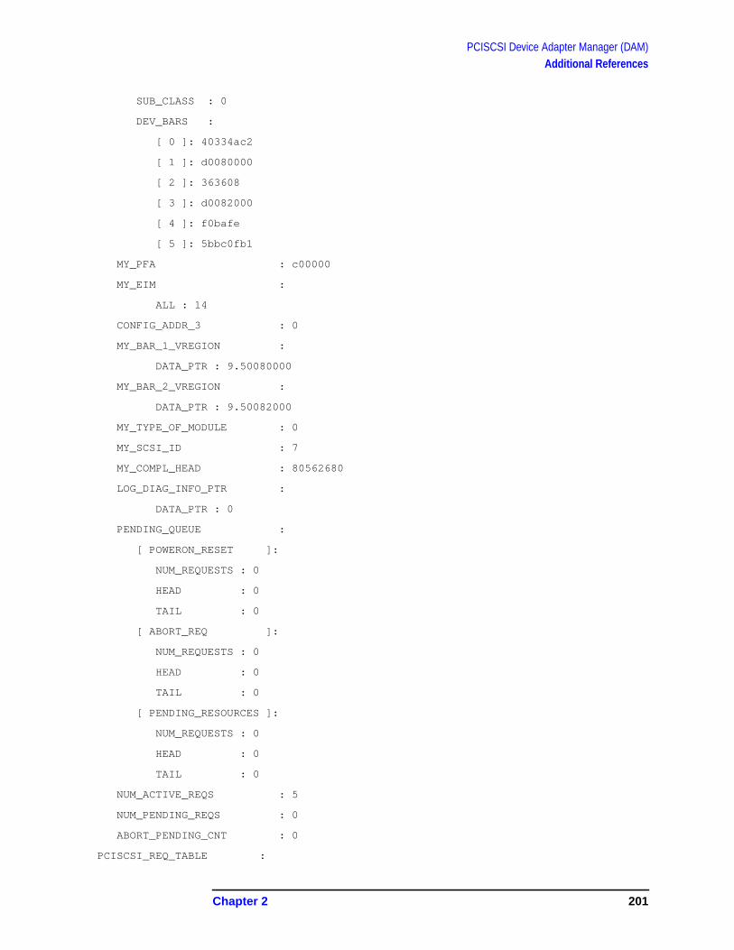
PCISCSI Device Adapter Manager (DAM)Additional References
SUB_CLASS : 0
DEV_BARS :
[ 0 ]: 40334ac2
[ 1 ]: d0080000
[ 2 ]: 363608
[ 3 ]: d0082000
[ 4 ]: f0bafe
[ 5 ]: 5bbc0fb1
MY_PFA : c00000
MY_EIM :
ALL : 14
CONFIG_ADDR_3 : 0
MY_BAR_1_VREGION :
DATA_PTR : 9.50080000
MY_BAR_2_VREGION :
DATA_PTR : 9.50082000
MY_TYPE_OF_MODULE : 0
MY_SCSI_ID : 7
MY_COMPL_HEAD : 80562680
LOG_DIAG_INFO_PTR :
DATA_PTR : 0
PENDING_QUEUE :
[ POWERON_RESET ]:
NUM_REQUESTS : 0
HEAD : 0
TAIL : 0
[ ABORT_REQ ]:
NUM_REQUESTS : 0
HEAD : 0
TAIL : 0
[ PENDING_RESOURCES ]:
NUM_REQUESTS : 0
HEAD : 0
TAIL : 0
NUM_ACTIVE_REQS : 5
NUM_PENDING_REQS : 0
ABORT_PENDING_CNT : 0
PCISCSI_REQ_TABLE :
Chapter 2 201

PCISCSI Device Adapter Manager (DAM)Additional References
[ 0 ]:
[ 0 ]:
NUM_REQUESTS : 0
HEAD : 0
TAIL : 0
[ 1 ]:
NUM_REQUESTS : 0
HEAD : 0
TAIL : 0
[ 2 ]:
. . . . .
[ c ]:
[ 0 ]:
NUM_REQUESTS : 4
HEAD : 86c4a1a8
TAIL : 86c4a068
[ 1 ]:
NUM_REQUESTS : 0
HEAD : 0
TAIL : 0
[ 2 ]:
NUM_REQUESTS : 0
HEAD : 0
TAIL : 0
. . . . .
[ d ]:
[ 0 ]:
NUM_REQUESTS : 1
HEAD : 86c49e88
TAIL : 86c49e88
[ 1 ]:
NUM_REQUESTS : 0
HEAD : 0
TAIL : 0
. . . . .
PCISCSI_TARGET_TABLE :
202 Chapter 2

PCISCSI Device Adapter Manager (DAM)Additional References
[ 0 ]:
[ 0 ]:
HM_INFO :
HM_PORT_NUM : ffffff5e
HM_SUBSYS : 384
HM_EVENT_SUBQUEUE : 3
HM_POWERON_RESET : FALSE
HM_BOUND : FALSE
AEN_INFO :
AEN_ENABLED : TRUE
ACTIVE_AEN_BUF : 0
AEN_BUF_LENGTH : fc
AEN_BUF :
[ 0 ]: b.86cb0200
[ 1 ]: b.86cb0300
[ 1 ]:
HM_INFO :
HM_PORT_NUM : 0
HM_SUBSYS : 0
HM_EVENT_SUBQUEUE : 0
HM_POWERON_RESET : FALSE
HM_BOUND : FALSE
AEN_INFO :
AEN_ENABLED : FALSE
ACTIVE_AEN_BUF : 0
AEN_BUF_LENGTH : 0
AEN_BUF :
[ 0 ]: 0.0
[ 1 ]: 0.0
. . . . .
MAPPED_QTAG_STACK_IDX : 5
MAPPED_QTAG_STACK :
[ 1 ]: 0
[ 2 ]: 0
[ 3 ]: 0
[ 4 ]: 0
[ 5 ]: 0
[ 6 ]: 23
Chapter 2 203
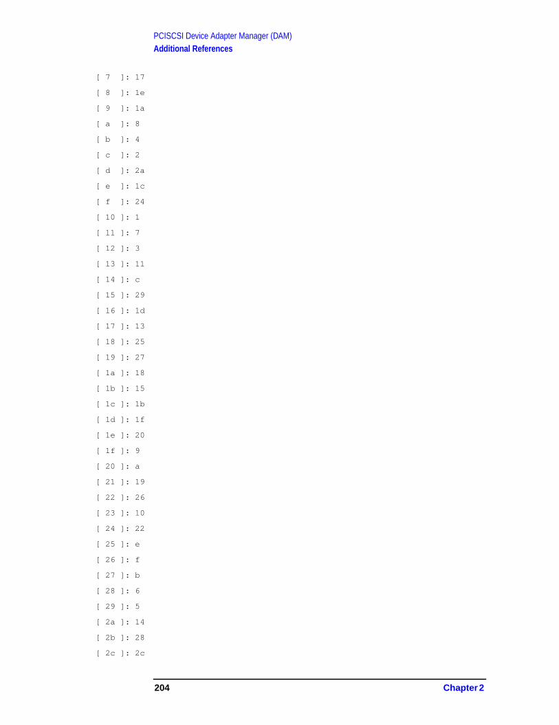
PCISCSI Device Adapter Manager (DAM)Additional References
[ 7 ]: 17
[ 8 ]: 1e
[ 9 ]: 1a
[ a ]: 8
[ b ]: 4
[ c ]: 2
[ d ]: 2a
[ e ]: 1c
[ f ]: 24
[ 10 ]: 1
[ 11 ]: 7
[ 12 ]: 3
[ 13 ]: 11
[ 14 ]: c
[ 15 ]: 29
[ 16 ]: 1d
[ 17 ]: 13
[ 18 ]: 25
[ 19 ]: 27
[ 1a ]: 18
[ 1b ]: 15
[ 1c ]: 1b
[ 1d ]: 1f
[ 1e ]: 20
[ 1f ]: 9
[ 20 ]: a
[ 21 ]: 19
[ 22 ]: 26
[ 23 ]: 10
[ 24 ]: 22
[ 25 ]: e
[ 26 ]: f
[ 27 ]: b
[ 28 ]: 6
[ 29 ]: 5
[ 2a ]: 14
[ 2b ]: 28
[ 2c ]: 2c
204 Chapter 2

PCISCSI Device Adapter Manager (DAM)Additional References
[ 2d ]: 2d
[ 2e ]: 2e
[ 2f ]: 2f
[ 30 ]: 30
[ 31 ]: 31
[ 32 ]: 32
. . . . .
Poking thru this pciscsi_req_table chain, the 2 reqs we have beenchasing are listed and have assigned mapped_qtag values “d” and “12”.To confirm these are the right requests, llio_msg_ptr should point tothe original request sent by the DM initiated by the MIB request. Sofar, so good.
$16f ($76) nmdat > fv 86c4a1a8 "pciscsi_req_entry_type"
RECORD
LINK : 86c49e28
TARGET_ID : c
LUN : 0
QTAG_CLASS : 20
QTAG : 33
MAPPED_QTAG : d
ABORT_PENDING : FALSE
ABORT_TIMER_CNT : 0
LLIO_MSG_PTR : 81263e78
CTRL_MSG_PTR : 0
IO_DATA_PTR : 86c54228
ISR_DATA_PTR : 0
END
$170 ($76) nmdat >
$170 ($76) nmdat > dv 81263e78,10
VIRT $b.81263e78 $ 026c0003 d206add0 ffffff56 030c0000
VIRT $b.81263e88 $ 203351c0 86cbd080 0000000a 0000000a
VIRT $b.81263e98 $ d206ae50 00006000 03010100 86cbc600
VIRT $b.81263ea8 $ 000000fc 00000000 00000000 00000000
$171 ($76) nmdat >
$171 ($76) nmdat > fv 86c49e28 "pciscsi_req_entry_type"
Chapter 2 205

PCISCSI Device Adapter Manager (DAM)Additional References
RECORD
LINK : 86c49f28
TARGET_ID : c
LUN : 0
QTAG_CLASS : 20
QTAG : 9
MAPPED_QTAG : 12
ABORT_PENDING : FALSE
ABORT_TIMER_CNT : 0
LLIO_MSG_PTR : 81260f60
CTRL_MSG_PTR : 0
IO_DATA_PTR : 86c57d4c
ISR_DATA_PTR : 0
END
$172 ($76) nmdat > dv 81260f60,10
VIRT $b.81260f60 $ 026c0009 d206ec50 ffffff56 030c0000
VIRT $b.81260f70 $ 20095880 86cbd200 0000000a 0000000a
VIRT $b.81260f80 $ d206ecd0 00006000 03010150 86cbcc00
VIRT $b.81260f90 $ 000000fc 00000000 00000000 00000000
$173 ($76) nmdat >
Before the chase proceeds, a quick look at the DAM llio_msg_log willbe done to ensure the I/O is not completing upward from the LowerDAM. The highlighted log entries shows the start of the I/Os chasingwith msg_id “026c” and no completion entries have been made withmsg_id “026d”. So, the I/Os are still active in the lower DAM.
DAM LLIO MSG LOG
86c20adc:002133d6 29ade3c0 02950070 00000089 ffffff5f 00000000 85e56cc0 067b9a00
86c20afc:00004000 00000000 80440000 0000000b 00000000 fffffffc 800c7190 81263f28
86c20b1c:002133d6 29ae7a40 99299929 0c120000 812525a0 00000000 d2000000 4184bc98
86c20b3c:d0964000 41849990 41847d28 41847920 00000001 00000000 00000001 81d854a0
86c20b5c:012133d6 29ae85f0 026d0001 d2068ad0 ffffff5f 00000000 0000f140 00006000
86c20b7c:00000000 0000000a d2068b50 00006000 03010100 86cbc400 000000fc 8125b340
86c20b9c:002133d6 29afb0a0 02950070 00000089 ffffff5f 00000000 00000000 0000000b
86c20bbc:86c0e200 0600000a 85e56180 00000002 00000054 8600e800 000000fc 81261118
86c20bdc:002133d6 29b02420 99299929 0c0d0000 812525a0 00000000 d2000000 81d8547c
86c20bfc:81d85498 41849900 41847d01 85f0f340 00000001 00000000 00000001 81d854a0
206 Chapter 2

PCISCSI Device Adapter Manager (DAM)Additional References
86c20c1c:012133d6 29b02a10 026d0007 d201d0d0 ffffff5f 00000000 000051c0 00006000
86c20c3c:00000000 0000000a d201d150 00006000 03010150 86cbca00 000000fc 81254f90
86c20c5c:002133d6 29c12ec0 026c0003 d206add0 ffffff56 030c0000 203351c0 86cbd080
86c20c7c:0800000a 0000000a d206ae50 00006000 03010100 86cbc600 000000fc 81263e78
86c20c9c:002133d6 29c19240 99010003 d206add0 81d855fc 81d85618 d206add0 00000003
86c20cbc:00000000 00000002 86c1e464 86c1e340 0000000a 81d85690 81d85590 81d856a0
86c20cdc:002133d6 29c2f9b0 02950070 00000089 ffffff5f 00020000 00008f80 85f0f38c
86c20cfc:00000006 00000000 00000000 00000000 0000017d 85fa1600 00000040 81264240
86c20d1c:002133d6 29c35330 99299929 000d0000 81d855fc 02ec03b7 d206add0 00000003
86c20d3c:81d85614 81d85614 86c4a1a8 86c1e340 0000000b 81d855a4 85f1f000 81d85620
86c20d5c:002133d6 29fc09b0 026c0009 d206ec50 ffffff56 030c0000 20095880 86cbd200
86c20d7c:0800000a 0000000a d206ecd0 00006000 03010150 86cbcc00 000000fc 81260f60
86c20d9c:002133d6 29fc88b0 99010009 d206ec50 81d855fc 81d85618 d206ec50 00000009
86c20dbc:00000000 00000002 86c1e464 86c1e340 d04fcdc0 81d85690 81d85590 81d856a0
86c20ddc:002133d6 29fe3930 02950070 00000089 ffffff5f 00020000 00000016 85f0f38c
86c20dfc:00000006 00000000 00000000 00000000 00000176 85fa15c0 00000040 81260930
86c20e1c:002133d6 29fe9cd0 99299929 000d0000 81d855fc 02ec03b7 d206ec50 00000009
86c20e3c:81d85614 81d85614 86c49e28 86c1e340 0000000b 81d855a4 85f1f000 81d85620
86c20e5c:002133d6 2a1cb9c0 026c0004 d2040d50 ffffff56 030c0000 20140000 86cbd0c0
86c20e7c:0000000a 0000000a d2040dd0 00010000 03010101 86cbc700 000000fc 81251db8
86c20e9c:002133d6 2a1d6930 99010004 d2040d50 81d855fc 81d85618 d2040d50 00000004
86c20ebc:00000000 00000002 86c1e464 86c1e340 d04fcdc0 81d85690 81d85590 81d856a0
86c20edc:002133d6 2a1f0cf0 02950070 00000089 ffffff5f 00020000 0000fc80 85f0f38c
86c20efc:00000006 00000000 00000000 00000000 00000156 85fa15c0 00000040 8125e678
86c20f1c:002133d6 2a1f7000 99299929 000d0000 81d855fc 02ec03b7 d2040d50 00000004
86c20f3c:81d85614 81d85614 86c4a368 86c1e340 0000000b 81d855a4 85f1f000 81d85620
86c20f5c:002133d6 2a1fc320 026c000a d20464d0 ffffff56 030c0000 202a3d80 86cbd240
86c20f7c:0000000a 0000000a d2046550 00003000 03010145 86cbcd00 000000fc 81255510
86c20f9c:002133d6 2a201310 9901000a d20464d0 81d855fc 81d85618 d20464d0 0000000a
86c20fbc:00000000 00000002 86c1e464 86c1e340 d04fcdc0 81d85690 81d85590 81d856a0
86c20fdc:002133d6 2a214930 02950070 00000089 ffffff5f 00000000 02000000 0000000b
86c20ffc:86cb9200 0000000a d206f950 00002000 03010100 86cb9e00 000000fc 81255b98
86c2101c:002133d6 2a21a070 99299929 000d0000 81d855fc 02ec03b7 d20464d0 0000000a
86c2103c:81d85614 81d85614 86c4a028 86c1e340 0000000b 81d855a4 85f1f000 81d85620
86c2105c:002133d6 2a2a8c80 02950070 00000089 ffffff5f 00000000 00000000 0000000b
86c2107c:86cb0300 0000000a d204a8d0 00003000 03010100 86cb0600 000000fc 81258008
86c2109c:002133d6 2a2b2e30 99299929 0c2b0000 81255510 00000000 d2000000 00000082
86c210bc:d0964000 00000004 41847d28 41847920 00000001 00000000 00000001 81d854a0
Chapter 2 207

PCISCSI Device Adapter Manager (DAM)Additional References
86c210dc:012133d6 2a2b3c10 026d0005 d20414d0 ffffff5f 00000000 00000016 00010000
86c210fc:00000000 0000000a d2041550 00010000 03010100 86cbc800 000000fc 81251d08
86c2111c:002133d6 2a2c4f40 02950070 00000089 ffffff5f 000b0000 00000000 0000000b
86c2113c:85ffd200 0000000a d201ddd0 00010000 03010100 85ffdd00 000000fc 81256e80
86c2115c:002133d6 2a2cc470 99299929 0c210000 81255510 00000000 d2000000 81d8547c
86c2117c:81d85498 00000000 41847d01 85f0f340 00000001 00000000 00000001 81d854a0
86c2119c:012133d6 2a2ccbc0 026d000c d20306d0 ffffff5f 00000000 00004f80 00004000
86c211bc:00000000 0000000a d2030750 00004000 03010100 86cbcf00 000000fc 812525a0
86c211dc:002133d6 2a44a510 026c0002 d20112d0 ffffff56 030c0000 20024b00 86cbd040
86c211fc:0800000a 0000000a d2011350 00006000 03010150 86cbc500 000000fc 8125bd90
86c2121c:002133d6 2a450930 99010002 d20112d0 81d855fc 81d85618 d20112d0 00000002
86c2123c:00000000 00000002 86c1e464 86c1e340 0000000a 81d85690 81d85590 81d856a0
86c2125c:002133d6 2a467220 02950070 00000089 ffffff5f 00010000 00003d80 86c1e38c
86c2127c:00000006 00000000 00000000 00000000 00000100 86cb3200 000000fc 81263fd8
86c2129c:002133d6 2a46cde0 99299929 00210000 81d855fc 02ec03b7 d20112d0 00000002
86c212bc:81d85614 81d85614 86c49f28 86c1e340 0000000b 81d855a4 85f1f000 81d85620
86c212dc:002133d6 2a5d3290 026c0006 d2036ad0 ffffff56 030c0000 20360016 86cbd140
86c212fc:0000000a 0000000a d2036b50 00001000 03010101 86cbc900 000000fc 812601f8
86c2131c:002133d6 2a5d88e0 99010006 d2036ad0 81d855fc 81d85618 d2036ad0 00000006
86c2133c:00000000 00000002 86c1e464 86c1e340 d04fcdc0 81d85690 81d85590 81d856a0
86c2135c:002133d6 2a5f17f0 02950070 00000089 ffffff5f 00000000 02000000 0000000b
86c2137c:86cb6200 0000000a d2043850 00010000 03010100 86cb6400 000000fc 81263b60
86c2139c:002133d6 2a5f79c0 99299929 00210000 81d855fc 02ec03b7 d2036ad0 00000006
86c213bc:81d85614 81d85614 86c4a068 86c1e340 0000000b 81d855a4 85f1f000 81d85620
86c213dc:002133d6 2a60f0a0 026c0008 d2057cd0 ffffff54 030d0000 20080000 86cc01c0
86c213fc:0800000a 0000000a d2057d50 00006000 03010100 86cbfb00 000000fc 8125bb28
86c2141c:002133d6 2a616f80 99010008 d2057cd0 81d855fc 81d85618 d2057cd0 00000008
86c2143c:00000000 00000002 86c1e464 86c1e340 d04fcdc0 81d85690 81d85590 81d856a0
86c2145c:002133d6 2a62ccc0 02950070 00000089 ffffff5f 000a0000 00000000 0000000b
86c2147c:85ffa200 0000000a d2015e50 0000f000 03010150 85ffa900 000000fc 8125a6e0
86c2149c:002133d6 2a6328c0 99299929 00210000 81d855fc 02ec03b7 d2057cd0 00000008
86c214bc:81d85614 81d85614 86c49e88 86c1e340 0000000b 81d855a4 85f1f000 81d85620
86c214dc:002133d6 2a6ffab0 02950070 00000089 ffffff5f 0000000b 85e55640 067b9a00
86c214fc:00004000 00000000 00000001 20001000 00000001 42001000 00000005 81251b50
86c2151c:002133d6 2a709950 99299929 0c170000 8125bb28 00000000 d2000000 00000001
86c2153c:d0964000 00000001 8401d000 8401d280 8401d0c0 00000000 00000001 81d854a0
86c2155c:012133d6 2a70ac90 026d0004 d2040d50 ffffff5f 00000000 00000000 00010000
86c2157c:00000000 0000000a d2040dd0 00010000 03010101 86cbc700 000000fc 81251db8
208 Chapter 2

PCISCSI Device Adapter Manager (DAM)Additional References
86c2159c:002133d6 2a71a810 02950070 00000089 ffffff5f 00000000 00000000 0000000b
86c215bc:86c14300 0000000a d206b850 00003000 03010150 86c14a00 000000fc 812541d0
86c215dc:002133d6 2a7221b0 99299929 0c230000 8125bb28 00000000 d2000000 81d8547c
86c215fc:81d85498 00000000 8401d001 85f0f340 8401d0c0 00000000 00000001 81d854a0
86c2161c:012133d6 2a722a40 026d000a d20464d0 ffffff5f 00000000 00003d80 00003000
86c2163c:00000000 0000000a d2046550 00003000 03010145 86cbcd00 000000fc 81255510
Looking at the PCISCSI DAM bedsheets, the ISC structures containsthe pointers linking to other lower DAM structures. The busp->selectqcontains I/Os waiting to be started. To find busp structure to check theselecteq, a few steps need to be done. The PDA’s aux_data_ptr and theisc ptr are the same and an offset off from the isc ptr will be the buspptr.
AUX_DATA_PTR IS SAME AS ISC PTR
$169 ($76) nmdat > fv dam "pciscsi_pda_type.aux_data_ptr"
86c2e000
The first bytes of the ISC contains version information about the lower DAM.
$16b ($76) nmdat > dv aux_ptr, 20,s
VIRT $b.86c2e000 "c720 Lower DAM 02/23/00 11:15 PST Disconnects, Tagged I/O.
.............?...?.............................................P..."
Using symbols in debug, the value of busp ptr in the isc can be obtained.However, debug upshifts symbols and “C” procedure names in the NLare case sensitive. The Debug feature to upshift symbol names must beturned off.
$16e ($76) nmdat > fv aux_ptr "isc_table_type"
Expected either a TYPE or CONST definition as path specification. (error #5560
)
$171 ($76) nmdat > env sympath_upshift FALSE
Now, the busp pointer can be seen using symbols
BUSP PTR
$166 ($76) nmdat > fv aux_ptr "isc_table_type.if_drv_data"
86c2e398
Chapter 2 209
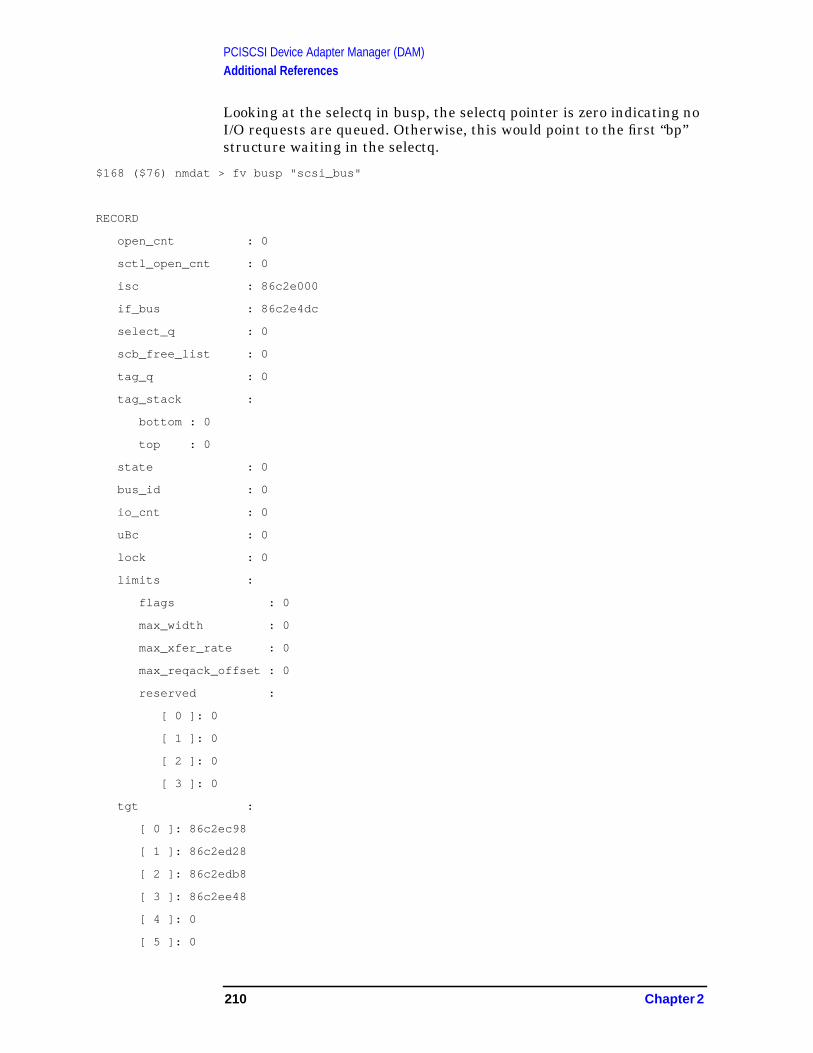
PCISCSI Device Adapter Manager (DAM)Additional References
Looking at the selectq in busp, the selectq pointer is zero indicating noI/O requests are queued. Otherwise, this would point to the first “bp”structure waiting in the selectq.
$168 ($76) nmdat > fv busp "scsi_bus"
RECORD
open_cnt : 0
sctl_open_cnt : 0
isc : 86c2e000
if_bus : 86c2e4dc
select_q : 0
scb_free_list : 0
tag_q : 0
tag_stack :
bottom : 0
top : 0
state : 0
bus_id : 0
io_cnt : 0
uBc : 0
lock : 0
limits :
flags : 0
max_width : 0
max_xfer_rate : 0
max_reqack_offset : 0
reserved :
[ 0 ]: 0
[ 1 ]: 0
[ 2 ]: 0
[ 3 ]: 0
tgt :
[ 0 ]: 86c2ec98
[ 1 ]: 86c2ed28
[ 2 ]: 86c2edb8
[ 3 ]: 86c2ee48
[ 4 ]: 0
[ 5 ]: 0
210 Chapter 2

PCISCSI Device Adapter Manager (DAM)Additional References
[ 6 ]: 0
[ 7 ]: 0
[ 8 ]: 86c2f118
[ 9 ]: 86c2f1a8
[ a ]: 86c2f238
[ b ]: 86c2f2c8
[ c ]: 86c2f358
[ d ]: 86c2f3e8
[ e ]: 0
[ f ]: 0
The last stop in the chase of the I/O requests is check the NEXUSTABLE in lbp for active requests. Get the lbp pointer frombusp->if_bus.
$169 ($76) nmdat > fv busp "scsi_bus.if_bus"
86c2e4dc
LBP NEXUS TABLE has 5 entries scattered in the table indexed by themapped_qtag value in pciscsi_req_entry and assigned by the upperDAM. Mapped qtag value of “d” and “12” are the active I/O requestswe’ve been looking for. Being in the NEXUS TABLE indicates therequests are active on the hardware making progress to completing therequest. The NEXUS TABLE is an array of LSP pointers one for eachI/O request. The LSP structure contains various items to complete theI/O and also current I/O status. So look at each LSP for the desired I/Os.
$16f ($76) nmdat > fv lbp "c720_bus"
RECORD
sense_buf :
[ 0 ]: 0
[ 1 ]: 0
[ 2 ]: 0
[ 3 ]: 0
[ 4 ]: 0
. . . . .
[ fd ]: 0
[ fe ]: 0
[ ff ]: 0
state : 40
ActiveCnt : 5
Chapter 2 211

PCISCSI Device Adapter Manager (DAM)Additional References
istat : 1
sist0 : 0
sist1 : 0
dstat : 84
dsps : 10
bus_ticks : 1f4
pre_reset_ticks : 64
post_reset_ticks : 1f4
timer_ticks : 64
asense_ticks : 5dc
dev : ff00ffff
offset : f0
nominalOffset : f0
reset_wait_cnt : 0
busp : 86c2e398
owner : 0
sense_owner : 0
puSenseScript : 9.500824c0
uSensePhysScript : d00824c0
pInBuf : 9.50082580
uPhysInBuf : d0082580
pOutBuf : 9.50082500
uPhysOutBuf : d0082500
pTiptoeBuf : 9.50082540
uPhysTiptoeBuf : d0082540
puStatus : 9.500825c0
uPhysStatus : d00825c0
puNotDD : 9.50082600
puPhysNotDD : d0082600
puScript : 9.50082000
uPhysScript : d0082000
uJumpTable : 9.50082000
uPhysJumpTable : d0082000
uUntaggedJumpTable : 86ca9000
uPhysUntaggedJumpTable : a7d3000
isrPutMsgOut : 0
isrMsgOutIn : 0
isrMsgRejected : 0
212 Chapter 2

PCISCSI Device Adapter Manager (DAM)Additional References
argMsgRejected : 0
isrSelectMsgOut : d9a5b4
isrSelectMsgOutIn : d99388
isrSelectMsgRejected : d9cd78
argGetMsgIn : 0
isrGetMsgIn : d9a7dc
NexusTable :
[ 0 ]: 0
[ 1 ]: 0
[ 2 ]: 0
[ 3 ]: 0
[ 4 ]: 0
[ 5 ]: 0
[ 6 ]: 0
[ 7 ]: 0
[ 8 ]: 0
[ 9 ]: 0
[ a ]: 0
[ b ]: 0
[ c ]: 0
[ d ]: 86c54cfc
[ e ]: 0
[ f ]: 0
[ 10 ]: 0
[ 11 ]: 0
[ 12 ]: 86c58820
[ 13 ]: 0
[ 14 ]: 0
[ 15 ]: 0
[ 16 ]: 86c5b770
[ 17 ]: 0
[ 18 ]: 0
[ 19 ]: 0
[ 1a ]: 0
[ 1b ]: 0
[ 1c ]: 0
[ 1d ]: 0
[ 1e ]: 0
Chapter 2 213

PCISCSI Device Adapter Manager (DAM)Additional References
[ 1f ]: 0
[ 20 ]: 0
[ 21 ]: 86c6398c
[ 22 ]: 0
[ 23 ]: 0
[ 24 ]: 0
[ 25 ]: 0
[ 26 ]: 0
[ 27 ]: 0
[ 28 ]: 0
[ 29 ]: 0
[ 2a ]: 0
[ 2b ]: 86c6afd4
[ 2c ]: 0
[ 2d ]: 0
[ 2e ]: 0
[ 2f ]: 0
[ 30 ]: 0
[ 31 ]: 0
[ 32 ]: 0
[ 33 ]: 0
[ 34 ]: 0
[ 35 ]: 0
[ 36 ]: 0
[ 37 ]: 0
[ 38 ]: 0
[ 39 ]: 0
[ 3a ]: 0
[ 3b ]: 0
[ 3c ]: 0
The lsp has a state of “5”. The LSP STATE BITS (see chart following)indicates this I/O was pre_setup and it is currently active.
$171 ($76) nmdat > fv 86c54cfc "c720_scb"
RECORD
state : 5
bm_size : 40
bm_align : 800000
214 Chapter 2

PCISCSI Device Adapter Manager (DAM)Additional References
lbolt_at_start : 0
lbolt_at_timeout : 0
bp : 86c54a70
scb : 86c54bf0
puJumpDest : 9.50082d0c
puScript : b.86caa040
uPhysScript : a7d4040
puActivePtr : b.86caa040
uActiveAdjust : 0
puSavedPtr : b.86caa040
uSavedAdjust : 0
puPeakPtr : b.86caa040
uPeakAdjust : 0
puDataDone : b.86caa070
bp_dma_parms :
dma_parms :
channel : ffffffff
dma_options : 0
flags : 10
key : 0
num_entries : 0
buflet_key : 0
chain_ptr : 86c54680
chain_count : 6
chain_index : 0
drv_routine : 0
drv_arg : 0
transfer_size : 0
addr : 0
spaddr : 0
count : 0
merge_dma_parms : 0
mpe_llio_proc_num : 0
mpe_llio_error_num : 0
END
$172 ($76) nmdat >
Chapter 2 215

PCISCSI Device Adapter Manager (DAM)Additional References
LSP STATE BITS
#define LSP_PRE_SETUP 0x0001
#define LSP_BUS_CLOSE 0x0002
#define LSP_ACTIVE 0x0004
#define LSP_ABORT 0x0008
#define LSP_ASENSE 0x0010
#define LSP_HUMOR 0x0020
#define LSP_BDR 0x0040
#define LSP_THIRD_PARTY 0x0080
#define LSP_HANG_DETECTOR 0x0100
#define LSP_REQ_TIMEOUT 0x0200
#define LSP_INVALID_REQ 0x0400
#define LSP_IWR 0x0800
#define LSP_MEMORY_ALLOC_FAILED 0x1000
#define LSP_C720_BMALLOC_FAILED 0x2000
This second request also has a state value of “5”
$172 ($76) nmdat > fv 86c58820 "c720_scb"
RECORD
state : 5
bm_size : 40
bm_align : 800000
lbolt_at_start : 0
lbolt_at_timeout : 0
bp : 86c58594
scb : 86c58714
puJumpDest : 9.50082a14
puScript : b.86caa140
uPhysScript : a7d4140
puActivePtr : b.86caa140
uActiveAdjust : 0
puSavedPtr : b.86caa140
uSavedAdjust : 0
puPeakPtr : b.86caa140
216 Chapter 2

PCISCSI Device Adapter Manager (DAM)Additional References
uPeakAdjust : 0
puDataDone : b.86caa170
bp_dma_parms :
dma_parms :
channel : ffffffff
dma_options : 0
flags : 10
key : 0
num_entries : 0
buflet_key : 0
chain_ptr : 86c581a4
chain_count : 6
chain_index : 0
drv_routine : 0
drv_arg : 0
transfer_size : 0
addr : 0
spaddr : 0
count : 0
merge_dma_parms : 0
mpe_llio_proc_num : 0
mpe_llio_error_num : 0
END
$173 ($76) nmdat >
The search is over!
The I/Os are active on the hardware and appear to be making progress.Until the hardware completes the I/O or the DM aborts the I/O becauseits taking too long to complete, the I/O subsystem will continue to holdthe I/O for completion.
Chapter 2 217

PCISCSI Device Adapter Manager (DAM)Additional References
Figure 2-52 Slide 53
For additional information, refer to the System Tables (31900-90017)and Appendix A , “PCISCSI Device Adapter Manager (DAM).”
hp e3000
7.0 fieldtraining
Finding I/Os cont’d
· Locating the I/O in the upper DAM
· Locating the I/O in the lower DAM
· Determining the I/O’s condition/status
· Determining the target’s condition/status
218 Chapter 2

3 Memory Holes
Figure 3-1 Slide 1
Speaker Notes 1:
Unlike the hawk machines PAT machines do not have memoryoverlapping the io addresses so no memory can reside between 2 to 4 gbon a prelude and no memory between 3.75 to 4 gb on a crescendo.
Other holes are created, during initialization (system reset) by thePDC, processor dependent code, when it assigns the addresses tomemory.
for internal use only
hp e3000
7.0 fieldtraining
Memory holes
· Efficient support of noncontiguous memory on PAT platforms
– page table space
– performance
· Prelude
memory hole at 2-4 gb + others
io addresses spread over 2 gb range
· Crescendo
memory hole at 3.75 to 4gb + others
io addresses spread over 250 mb
219

Memory Holes
Figure 3-2 Slide 2
Speaker Notes 2:
The important concept here is the physical page number is the same asthe ipdir index. It is easy to go from a physical address to its ipdir andvice versa. They are used interchangeably (sloppily) in the memorymanager code.
The existing memory code with slight changes can be used for PATmachines but would waste a lot of memory (ipdir entries) keeping trackof pages that do not exist (in holes).
This is because the number of ipdir entries is determined not by thesize of memory but the highest memory location. Entries can be createdthat will never be used.
On the PAT platform the io addresses are not contiguous like theirpredecessors. IO addresses are spread through a 2 gb range on aprelude and a 256 mb range on a crescendo. Without the memory holechanges, ipdir entries are created for the whole range.
for internal use only
hp e3000
7.0 fieldtraining
‘PAGE TABLE’ IPDIR
· Review of IPDIR on non PAT platforms· array
· on entry per page
· positive indices for memory
· negative indices for io
· physical page number =
· current algorithms waste space by creating entries inhole regions
220 Chapter 3

Memory Holes
Figure 3-3 Slide 3
Speaker Notes 3:
The io portion of the ipdir is now separate. A new data structure calledthe io_ipdir holds the io entries. Like the memory ipdir, it is made upof an array of ipdir entries.
We will see later how the memory hole code eliminates the holes fromthe ipdir and greatly reduces the number of io ipdir entries.
We will also see how we handled the new problem of not being able touse the physical page number (ppn) and ipdir entry indexinterchangeably.
for internal use only
hp e3000
7.0 fieldtraining
PAT platforms
· IPDIR on PAT
· designed by Ed Olander
· two arrays
· on entry per page
· separate io_ipdir for io
· physical page number <> IPDIR index
Chapter 3 221
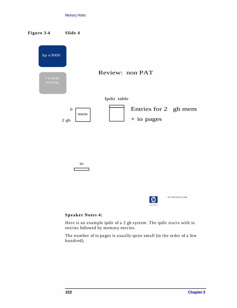
Memory Holes
Figure 3-4 Slide 4
Speaker Notes 4:
Here is an example ipdir of a 2 gb system. The ipdir starts with ioentries followed by memory entries.
The number of io pages is usually quite small (in the order of a fewhundred).
for internal use only
hp e3000
7.0 fieldtraining
Ipdir table
0
2 gb
mem
io
Entries for 2 gb mem
+ io pages
Review: non PAT
222 Chapter 3

Memory Holes
Figure 3-5 Slide 5
Speaker Notes 5:
Lots of space was wasted in the io part of the ipdir without the memoryholes code.
Using the old algorithm for building the ipdir, the io part of the ipdirexpands greatly to track 2 gb of io pages. In bytes the io part of the ipdiralone is 32 mb. Of the 2 gb, 512 k pages, typically just a few hundredwill be active.
for internal use only
hp e3000
7.0 fieldtraining
Ipdir table
io
mem
0
2 gb
Entries for 4 gb
PRELUDE with 2 gb
Chapter 3 223

Memory Holes
Figure 3-6 Slide 6
Speaker Notes 6:
With the old algorithm a 5 gb prelude system has an ipdir that supports2 gb of io and 12 gb of memory.
“I” has two memory holes, one from 2 to 4 gb, and another from 5 to 10gb.
Though the ipdir has entries for 14 gb of address space, entries foralmost 9 gb are unused.
for internal use only
hp e3000
7.0 fieldtraining
Ipdir table
io
mem
0
4 gb
hole
2 gb
mem
mem
10 gb
12 gb
hole
5 gb
Entries for 14 gb
Only need entriesfor a little morethan 5 gb
PRELUDE with 5 gb
224 Chapter 3

Memory Holes
Figure 3-7 Slide 7
Speaker Notes 7:
The memory holes code goal is to reduce space wasted by unused ipdirentries. It also increases the flexibility of where the memory can beplaced something the os has no control over.
The unused io entries are reduced and the unused memory entries areeliminated. The memory hole code also separates the io entries from thememory entries and created an io_ipdir .
Two of the new memory hole data structures are shown here: thesegment table to map a physical address segment to an ipdir segmentand the io_ipdir that contain entries for io pages.
for internal use only
hp e3000
7.0 fieldtraining
Ipdir table
io
mem
0
4 gb
hole
2 gb
mem
mem
10 gb
12 gb
hole
5 gb
Entries for 5 gb
PRELUDE with 5 gb
IO Ipdir table
Note: IO has its ownipdir table
S
E
G
M
E
N
T
T
B
L
Chapter 3 225

Memory Holes
Figure 3-8 Slide 8
Speaker Notes 8:
The real physical segment table is used to map a memory ipdir segmentto a physical address segment.
It is not used for io ipdir entries.
for internal use only
hp e3000
7.0 fieldtraining
Ipdir table
io
mem
0
4 gb
hole
2 gb
mem
mem
10 gb
12 gb
hole
5 gb
PRELUDE with 5 gb
IO Ipdir table
S
E
G
M
E
N
T
T
B
L
R
P
S
E
G
T
B
L
Physicalmemorysegment
226 Chapter 3
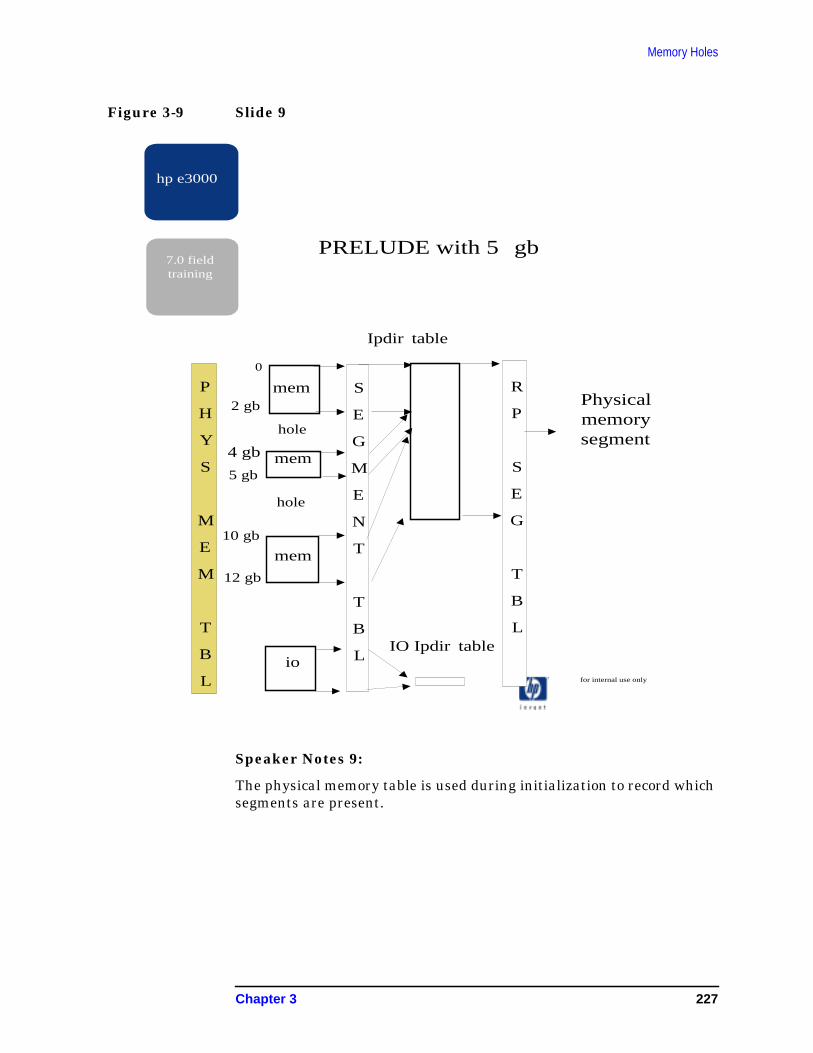
Memory Holes
Figure 3-9 Slide 9
Speaker Notes 9:
The physical memory table is used during initialization to record whichsegments are present.
for internal use only
hp e3000
7.0 fieldtraining
Ipdir table
io
mem
0
4 gb
hole
2 gb
mem
mem
10 gb
12 gb
hole
5 gb
PRELUDE with 5 gb
IO Ipdir table
S
E
G
M
E
N
T
T
B
L
R
P
S
E
G
T
B
L
Physicalmemorysegment
P
H
Y
S
M
E
M
T
B
L
Chapter 3 227
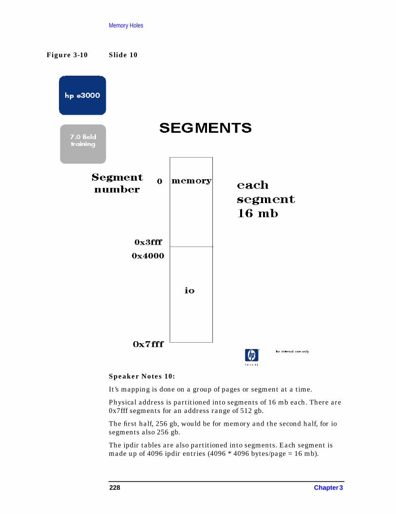
Memory Holes
Figure 3-10 Slide 10
Speaker Notes 10:
It’s mapping is done on a group of pages or segment at a time.
Physical address is partitioned into segments of 16 mb each. There are0x7fff segments for an address range of 512 gb.
The first half, 256 gb, would be for memory and the second half, for iosegments also 256 gb.
The ipdir tables are also partitioned into segments. Each segment ismade up of 4096 ipdir entries (4096 * 4096 bytes/page = 16 mb).
228 Chapter 3
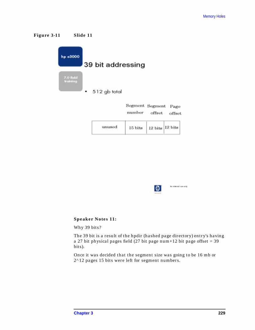
Memory Holes
Figure 3-11 Slide 11
Speaker Notes 11:
Why 39 bits?
The 39 bit is a result of the hpdir (hashed page directory) entry's havinga 27 bit physical pages field (27 bit page num+12 bit page offset = 39bits).
Once it was decided that the segment size was going to be 16 mb or2^12 pages 15 bits were left for segment numbers.
Chapter 3 229

Memory Holes
Figure 3-12 Slide 12
Speaker Notes 12:
This table is used to map a physical page segment to an ipdir segment.
Each entry consist of an ipdir table pointer and an ipdir segmentnumber.
ipdir_tlb pointer to the beginning of an ipdir segment
ipdir_idx_seg segment number of the ipdir segment
iva_mem_seg_tbl_vba in the IVA points to the table Slide 13
230 Chapter 3
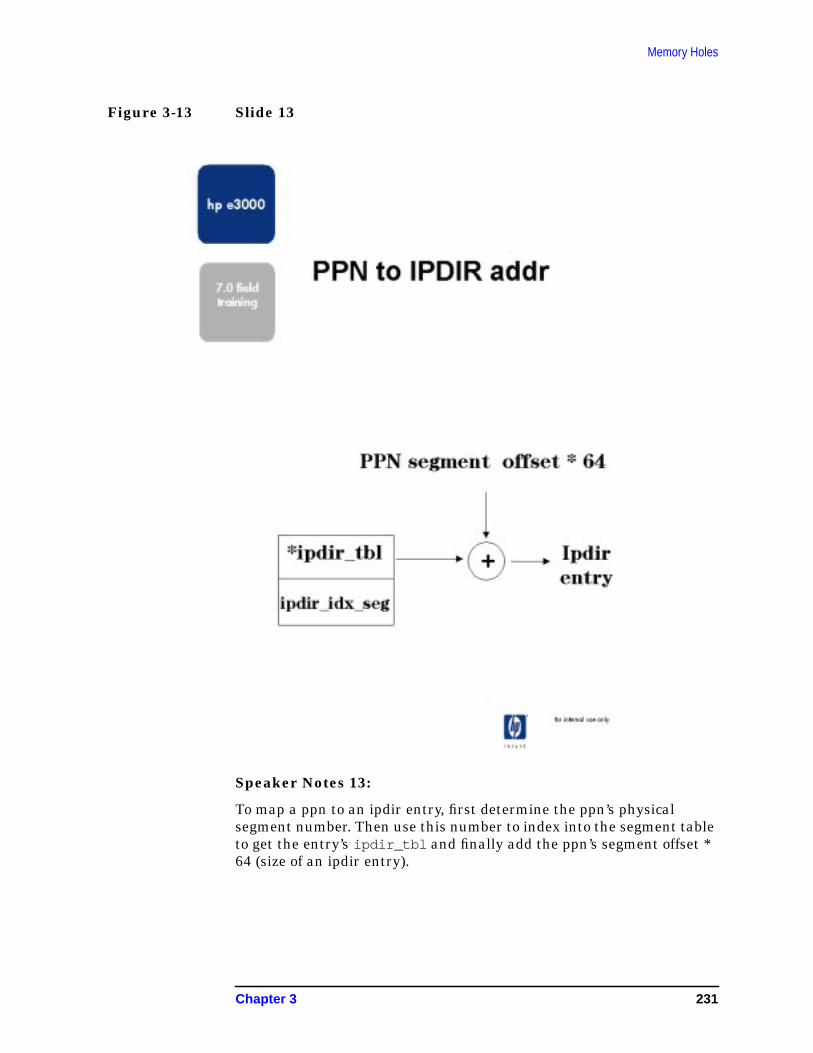
Memory Holes
Figure 3-13 Slide 13
Speaker Notes 13:
To map a ppn to an ipdir entry, first determine the ppn’s physicalsegment number. Then use this number to index into the segment tableto get the entry’s ipdir_tbl and finally add the ppn’s segment offset *64 (size of an ipdir entry).
Chapter 3 231

Memory Holes
Figure 3-14 Slide 14
Speaker Notes 14:
To map a ppn to an ipdir entry index, first determine the ppn’s physicalsegment number. Then use it to index into the segment table to get theentry's ipdir_idx_seg . Finally, multiply that by 4096 (number ofpages per segment) and add the ppn’s segment offset.
232 Chapter 3

Memory Holes
Figure 3-15 Slide 15
Speaker Notes 15:
This table maps a memory ipdir segment number to a physical segmentnumber.
To go from a particular memory ipdir entry to a physical page number,first determine the memory ipdir segment number. Then use thatnumber to index into the real page segment table to get the physicalsegment. Finally multiply the physical segment by 4096 (pages in asegment) and add the memory ipdir entry’s segment offset.
iva_real_page_seg_vba in the IVA points to the table.
Chapter 3 233

Memory Holes
Figure 3-16 Slide 16
Speaker Notes 16:
This is a bit array containing information on whether a particularsegment is present or not. It is only used during initialization of thememory manager.
iva_phys_mem_tbl_vba in the IVA points to the table
234 Chapter 3

Memory Holes
Figure 3-17 Slide 17
Speaker Notes 17:
New code that determines which segments are present, builds thephysical memory segment table, the segment table, the real physicalsegment and the io_ipdir tables can be found in alaunch.asmlnch andcpatmap.asmmon.
Changes to existing file were confined to the groups memmgt, genesisand asmmon. Most of the changes involved adding code to map an ipdirindex to a ppn or to map a ppn to an ipdir index because the index andthe page number can no longer be used interchangeably.
for internal use only
hp e3000
7.0 fieldtraining
Code Changes
· Declarations
· dmmsptyp.memmgt
· hmh.asmmon
· New Initialization Code
alaunch.asmlnch
· cpatmap.asmmon
· amminit.amemdir
· Others changes
memmgt, genesis, asmmon
Chapter 3 235

Memory Holes
Figure 3-18 Slide 18
Speaker Notes 18:
This is just a list of files that were changed.
for internal use only
hp e3000
7.0 fieldtraining
Changes by group
· Groups
· asmlnch
– alaunch
· asmmon
– ahpdir,atlb,hptmacro.hrealst,htlbmiss,hmh,cpatmap
· genesis
– dlocal
· memmgt
– dmmsptyp,easmmem
– xmmcontg, xmmcreat,xmmdgnew,xmmgate,
– xmmgenis,xmmio,xmmline,xmmpdir,xmmuser,
– xmmvis
236 Chapter 3

Memory Holes
Figure 3-19 Slide 19
Speaker Notes 19:
Examples: load_virt_addr_64 is a procedure that takes a 64 bitphysical address and returns its virtual address. It does this by callingMM_PPN_TO_IPDIR_VBA to get the ipdir entry address associated withthe physical address so it can read the virtual address stored in theipdir entry.
get_ipdir_index takes a virtual address and returns its ipdir index.The procedure finds the hpdir entry for the virtual address, extracts theppn from the hpdir and calls MM_PPN_TO_IPDIR_IDX.
for internal use only
hp e3000
7.0 fieldtraining
Macros in hpdirmac.asmmem
Physical address number -> ipdir entry
· MM_PPN_TO_IPDIR_VBAused in:
procedure load_virt_addr_64procedure add_io_page
· MM_PPN_TO_IPDIR_IDXused in:
function get_ipdir_index
procedure add_resident_page
Chapter 3 237

Memory Holes
Figure 3-20 Slide 20
Speaker Notes 20:
An example of why we need to do this is memory manager code thatneeds to get a free page frame. It’ll search through the ipdir table to geta free entry but it also needs the ppn associated with the ipdir entrybefore it can use it.
ipdir_idx_to_ppn is a function that takes an ipdir index and returnsits ppn.
for internal use only
hp e3000
7.0 fieldtraining
More Macros
Ipdir entry index -> physical page number
· MM_IPDIR_IDX_TO_PPN
used in:
function ipdir_to_idx_ppn procedure update_hpdir_address_word procedure insert_in_hpdir
238 Chapter 3

Memory Holes
Figure 3-21 Slide 21
Speaker Notes 21:
The information for the following slides was dumped from a preludewith 5 gb of memory installed.
The table starts at 0xef9000 and shows the first 128 segments, 2 gb,are present. Then another 64 segments, 1 gb, at 4 gb and finally 128segments, 2 gb, at 10 gb.
for internal use only
hp e3000
7.0 fieldtraining
Physical Memory Table
($2e) nmdebug > dz ef9000,30
REAL $00ef9000 $ ffffffff ffffffff ffffffff ffffffff
REAL $00ef9010 $ 00000000 00000000 00000000 00000000
REAL $00ef9020 $ ffffffff ffffffff 00000000 00000000
REAL $00ef9030 $ 00000000 00000000 00000000 00000000
REAL $00ef9040 $ 00000000 00000000 00000000 00000000
REAL $00ef9050 $ ffffffff ffffffff ffffffff ffffffff
REAL $00ef9060 $ 00000000 00000000 00000000 00000000
REAL $00ef9070 $ 00000000 00000000 00000000 00000000
REAL $00ef9080 $ 00000000 00000000 00000000 00000000
@ 0, 2gb
@ 4gb, 1 gb
@10gb, 2 gb
Chapter 3 239
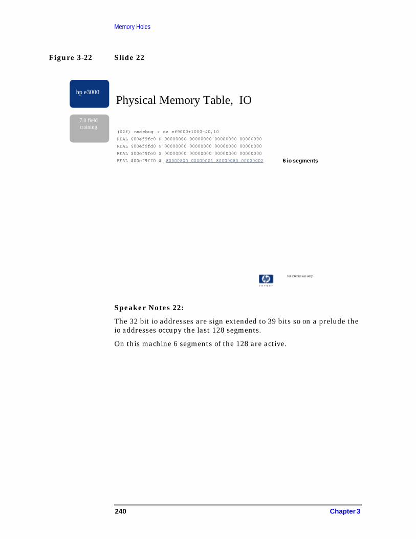
Memory Holes
Figure 3-22 Slide 22
Speaker Notes 22:
The 32 bit io addresses are sign extended to 39 bits so on a prelude theio addresses occupy the last 128 segments.
On this machine 6 segments of the 128 are active.
for internal use only
hp e3000
7.0 fieldtraining
Physical Memory Table, IO
($2f) nmdebug > dz ef9000+1000-40,10
REAL $00ef9fc0 $ 00000000 00000000 00000000 00000000
REAL $00ef9fd0 $ 00000000 00000000 00000000 00000000
REAL $00ef9fe0 $ 00000000 00000000 00000000 00000000
REAL $00ef9ff0 $ 80000800 00000001 80000080 00000002 6 io segments
240 Chapter 3

Memory Holes
Figure 3-23 Slide 23
Speaker Notes 23:
This slide shows the ipdir pointer/ipdir segment pairs in the segmenttable.
Notice that the ipdir pointers increases by 0x40000 , the size of an ipdirsegment (4096 64 bit entries per segment) and the ipdir indicesincreases by one in successive entries.
for internal use only
hp e3000
7.0 fieldtraining
Segment Table
($2e) nmdebug > dz 95e0000,20
REAL $095e0000 $ 09640000 00000000 09680000 00000001
REAL $095e0010 $ 096c0000 00000002 09700000 00000003
REAL $095e0020 $ 09740000 00000004 09780000 00000005
REAL $095e0030 $ 097c0000 00000006 09800000 00000007
REAL $095e0040 $ 09840000 00000008 09880000 00000009
REAL $095e0050 $ 098c0000 0000000a 09900000 0000000b
REAL $095e0060 $ 09940000 0000000c 09980000 0000000d
REAL $095e0070 $ 099c0000 0000000e 09a00000 0000000f
Ipdirpointer/ ipdirsegmentpair
Chapter 3 241
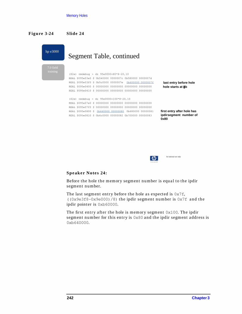
Memory Holes
Figure 3-24 Slide 24
Speaker Notes 24:
Before the hole the memory segment number is equal to the ipdirsegment number.
The last segment entry before the hole as expected is 0x7f ,((0x9e3f8-0x9e000)/8) the ipdir segment number is 0x7f and theipdir pointer is 0xb60000 .
The first entry after the hole is memory segment 0x100 . The ipdirsegment number for this entry is 0x80 and the ipdir segment address is0xb640000 .
for internal use only
hp e3000
7.0 fieldtraining
Segment Table, continued
($2e) nmdebug > dz 95e0000+80*8-20,10
REAL $095e03e0 $ 0b540000 0000007c 0b580000 0000007d
REAL $095e03f0 $ 0b5c0000 0000007e 0b600000 0000007f
REAL $095e0400 $ 00000000 00000000 00000000 00000000
REAL $095e0410 $ 00000000 00000000 00000000 00000000
($2e) nmdebug > dz 95e0000+100*8-20,10
REAL $095e07e0 $ 00000000 00000000 00000000 00000000
REAL $095e07f0 $ 00000000 00000000 00000000 00000000
REAL $095e0800 $ 0b640000 00000080 0b680000 00000081
REAL $095e0810 $ 0b6c0000 00000082 0b700000 00000083
last entry before hole
first entry after hole hasipdirsegment number of0x80
hole starts at 2gb
242 Chapter 3

Memory Holes
Figure 3-25 Slide 25
Speaker Notes 25:
Remember this table is indexed by ipdir segment numbers and mapsthe ipdir segment to a physical memory segment.
The last ipdir segment of the first 2 gb of memory is ipdir segment 0x7f(0x80*16mb=2gb) contain 0x7f . The next entry contain 0x100 or 4 gb(0x100*16mb=4gb) indicating ipdir segment 0x80 maps to 4 gb.
For additional information refer to
for internal use only
hp e3000
7.0 fieldtraining
Real Physical Segment Table
($2e) nmdebug > dz 9620000,20
REAL $09620000 $ 00000000 00000001 00000002 00000003
REAL $09620010 $ 00000004 00000005 00000006 00000007
REAL $09620020 $ 00000008 00000009 0000000a 0000000b
REAL $09620030 $ 0000000c 0000000d 0000000e 0000000f
REAL $09620040 $ 00000010 00000011 00000012 00000013
REAL $09620050 $ 00000014 00000015 00000016 00000017
REAL $09620060 $ 00000018 00000019 0000001a 0000001b
REAL $09620070 $ 0000001c 0000001d 0000001e 0000001f
($2e) nmdebug > dz 9620000+4*80-20,10
REAL $096201e0 $ 00000078 00000079 0000007a 0000007b
REAL $096201f0 $ 0000007c 0000007d 0000007e 0000007f
REAL $09620200 $ 00000100 00000101 00000102 00000103
REAL $09620210 $ 00000104 00000105 00000106 00000107
Ipdirsegment 0x80 hasphysical address of 4gb
Chapter 3 243

Memory Holes
Figure 3-26 Slide 26
Speaker Notes 26:
How much did we save in the 5 gb example?
Keep the following in mind: each 1 mb of hole eliminated the ipdir isreduced by 16 kb, each 1 gb of hole eliminated the ipdir is reduced by 16mb and each ipdir segment is 256 kb (4096 entries/segment * 64bytes/entry).
Entries for 7 gb (12-5gb) of memory pages were eliminated giving areducing the memory ipdir by 112 mb.
The number ipdir entries require for io was reduced from 2 gb to 96mb(6*16 mb) of io pages. The saving for io is 30.5 mb (32 mb - 1.5 mb).
The io area on a crescendo is 256 mb, smaller than on a prelude so theipdir reductions will be less. Within the io space only 8 segments of 16possible segments can be active. This is a minimum savings of 2 mb.
for internal use only
hp e3000
7.0 fieldtraining
Summary of IPDIR reduction
· Memory
· 16 mb saved per 1 gb of hole
· 112 mb saved for the 5 gb example
· IO
· memory saved depends on configuration
· typical for prelude, > 28 mb
· our example had six segment, 30.5 mb
· crescendo minimum saving is 2 mb
244 Chapter 3
4 PCI Console Driver
Figure 4-1 Contents
ForInternal Use Only
Page 1
hp e3000
7.0 FieldTraining
MPE/iX PCI Console DriverCONTENTS
• Introduction
• Background
• Functionality
• Core I/O Architecture
• Configuration
• Support and Diagnostics
• Troubleshooting
• Additional Comments
245
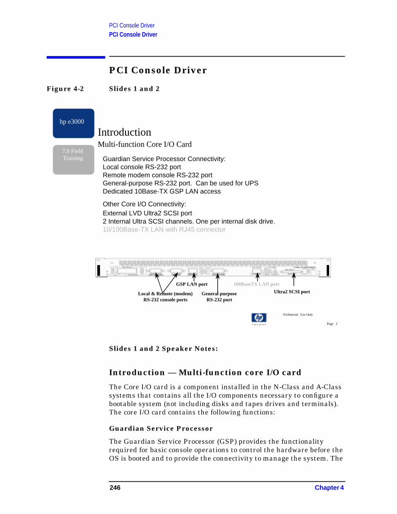
PCI Console DriverPCI Console Driver
PCI Console Driver
Figure 4-2 Slides 1 and 2
Slides 1 and 2 Speaker Notes:
Introduction — Multi-function core I/O card
The Core I/O card is a component installed in the N-Class and A-Classsystems that contains all the I/O components necessary to configure abootable system (not including disks and tapes drives and terminals).The core I/O card contains the following functions:
Guardian Service Processor
The Guardian Service Processor (GSP) provides the functionalityrequired for basic console operations to control the hardware before theOS is booted and to provide the connectivity to manage the system. The
ForInternal Use Only
Page 2
hp e3000
7.0 FieldTraining
IntroductionMulti-function Core I/O Card
Guardian Service Processor Connectivity:Local console RS-232 portRemote modem console RS-232 portGeneral-purpose RS-232 port. Can be used for UPSDedicated 10Base-TX GSP LAN access
Other Core I/O Connectivity:External LVD Ultra2 SCSI port2 Internal Ultra SCSI channels. One per internal disk drive.10/100Base-TX LAN with RJ45 connector
Local & Remote (modem)RS-232 console ports
GSP LAN port
General purposeRS-232 port
100BaseTX LAN port
Ultra2 SCSI port
246 Chapter 4
PCI Console DriverPCI Console Driver
functions supported by the GSP are similar in nature to those providedby the Access Port (AP) interface on previous platforms. For example,display selftest chassis codes, execute boot commands, determineinstalled hardware, etc.
Serial Ports
The three external serial ports perform the same general purposes ason previous platforms.
1. Local console provides direct connect for a C1099A terminal.
2. Remote console port provides a modem capable port for remotesupport access. It is not recommended for this port to be used forgeneral user dial-in access.
3. The third serial port is intended for use to connect to a UPS. Theconsole driver will not allow a user to logon to this port. Thisbehavior is the same as on previous platforms.
The GSP LAN
This port provides a 10Base-TX connection into the GSP. When a logonis established to the GSP, that logon can be used to perform almost allconsole functions that are available on the local and remote consoleports such as startup and shutdown of the system. More on it’s featureslater.
External SCSI
Connection is implemented as a single Ultra2 (LVD) channel forexternal connections to the N-Class system.
SCSI (ULTRA)
A dual (two) channel SCSI connection is provided for disks internal tothe N-Class system. Both of the channels are Wide Ultra Single Ended(WUSE) channels. The supported maximum transfer rate is 40MB/sec.
10/100Base-TX LAN
Capable of providing full 10/100Base-TX connectivity for generalsystem network access. BUT, this port will not be supported on firstrelease. A new Core I/O card in development may contain a Gigabit portin place of this port. MPE will not have a Gigabit driver ready when thecore I/O card is revved, therefore customers would see a loss offunctionality if we supported 10/100BT on this port if they happen tohave a system with an older card that was then updated. If schedulesallow, MPE will ship with the new Core I/O card from day one. (doubtfulat this time.)
This presentation focuses only on the Serial console ports and GSPLAN port. And a high level look at the GSP functions.
Chapter 4 247

PCI Console DriverPCI Console Driver
Figure 4-3 Slide 3
Slide 3 Speaker Notes:
ASCII Terminal Connectivity
The local and remote terminals are connected to the system in a wayvery similar to the current platforms. The supported modem is theMulti-Tech model MT5634ZBA (HP Part No: 0960-1074). We arefollowing the configuration and hardware installation procedures in usefor the HP9000 platforms.
ForInternal Use Only
Page 3
hp e3000
7.0 FieldTraining
IntroductionASCII Terminal connectivity
RS-232 3M cable(P/N 24542G)
25-pinmale
9-pin female
VT100terminal
orVT100
Emulator
Remote console via External Modem
VT100terminal
orVT100
Emulator
9-pin female
25-pinmale
Modem
Modem
Cable depends onmodem type
Local console using ASCII terminal
248 Chapter 4

PCI Console DriverPCI Console Driver
Figure 4-4 Slide 4
Slide 4 Speaker Notes:
GSP LAN Access
This port provides an independent LAN connection to the Core I/O card.This port has its own IP node and telnet server. When enabled, aconnection is established to the port via telnet from any telnet client.The GSP provides a user and password protected logon. This is not asecure telnet connection.
Once a user is logged on to the GSP, they have the capability to performalmost all of the same console tasks that are available from the localconsole. This includes full startup and shutdown capability, remotepower on/off control configure and control most GSP operations. Thesystem can be fully managed via a connection to this port. This physicalLAN connection to this port is completely independent from the generalsystem LAN.
A new core I/O card due to be released early next year (2001), will alsoprovide Secure Web Console functionality through this port. This SWCis similar to that offered as a standalone product (Product numberJ3591A).
ForInternal Use Only
Page 4
hp e3000
7.0 FieldTraining
IntroductionGSP LAN Access
Related Products· HP’s Central Web Console - manage hundreds of HP servers from acentral console or browser (uses remote serial port).
10baseTX Console LAN
LAN console solution
N-Class Core I/O
N-Class’s integrated GuardianService Processor utilizes an internaltelnet server, providing consoleaccess via a simple LAN connectionand telnet session.
Telnet$ Standard UNIX telnet sessions support.$ Connection over Management LAN$ Secure password protection for console access
Chapter 4 249

PCI Console DriverPCI Console Driver
Figure 4-5 Slide 5
Slide 5 Speaker Notes:
GSP Features
The GSP provides the functionality to locally and remotely manage thesystem console functions.
Console Mirroring
When enabled, and a user connects to the remote port and/or GSP LANport, the GSP will mirror all console activity to all connected users.There is always one user that has the ability to enter commands. Allother connected users will see a message telling them they don’t havewrite access. Write access can be obtained by entering the characters^Ecf (Ctrl-E cf)
Password Protected Access
All access to the GSP can be protected by username and passwordprotection.
ForInternal Use Only
Page 5
hp e3000
7.0 FieldTraining
IntroductionGSP Features
Console mirroring between local and remote consolesConsole mirroring between local and GSP LANPassword protected console accessSession access through separate LdevsRemote power-up and power-down controlProcess and display system alert codesGSP firmware upgrade through GSP LAN portSecure Web Console (Core I/O 2)Write access on mirrored console obtained with ^Ecf.
GSP LAN port
General purposeRS-232 port or UPS
100BaseT LAN port
Ultra2 SCSI portLocal & Remote (modem)RS-232 Console ports
250 Chapter 4
PCI Console DriverPCI Console Driver
Session ldevs
Both the local and remote serial ports can create sessions on separateldevs. For example, if remote console access is disabled then a userwould log on to ldev 21, if that ldev was configured in Sysgen andNMMGR when they connected to the system. In this case, no GSPaccess is available. If remote console is enabled and the user ismirroring the console on the remote port, the GSP command ‘SE’ willsuspend console mirroring and establish a connection to ldev21, ifconfigured.
Remote Power Up/Down
From the GSP interface, the user can power up or down the system.This feature is available unless the front panel switch is turned off. Thefunction behaves almost like the user turned off the front panel switch.
GSP features for each class of GSP user.
Users of the GSP are categorized into two sets of capabilities.
A console Operator can use the system’s console, manage the systemwhen a problem occurs (rebooting it...), diagnose system failuresthrough GSP logs and allow a pre-configured remote console to connect.This is the usual set of capabilities required to operate and manage asystem.
A console Administrator is allowed to set up the GSP configuration inorder to allow correct system operation and management. This mainlyincludes configuring login/password and access control and systemmonitoring features. Once this is configured the system can be fullyoperated and managed with the Operator capability only.GSP firmwareupgrade
A console Operator can use the system’s console, manage the systemwhen a problem occurs (rebooting it...), diagnose system failuresthrough GSP logs and allow a pre-configured remote console to connect.This is the usual set of capabilities required to operate and manage asystem.
GSP Firware Upgrade
From the local console, the GSP firmware can be upgraded from aremote server via the GSP LAN port.
Secure Web Console
Integrated into the A-Class(????). will be available on N-Class whenCore I/O 2 is released.
Chapter 4 251

PCI Console DriverPCI Console Driver
Figure 4-6 Slide 6
Slide 6 Speaker Notes:
Background — Project Considerations
The Console DAM is the module that handles the I/O card specific taskssuch as setting the baud rate, reading and writing data directly to thecard. The N-class and A-Class systems are based on a PCI I/O busarchitecture. Therefore we need a driver that can talk to a PCI device.
The main goal was to maintain the console functionality that iscurrently needed to manage the HP e3000 systems. As time allows weare also trying to take advantage of new console support features. Mostof the new GSP feature we get for free because they don’t require anyadditional driver software to be able to use them.
We do have the issue that most of the N-Class development to date wasdone with only HP-UX in mind. This becomes apparent in the onlinehelp and other documentation of the N-class systems. There are manyreferences to HP-UX when a description a task is described. HP-UXwas only planning to support the VT100 terminals but the HP e3000requires a HPTerm or HP700/92 type terminal behavior. The C1099Aterminal has both a HPTerm and VTxxx mode of operation.
ForInternal Use Only
Page 6
hp e3000
7.0 FieldTraining
BackgroundProject Considerations
b A new console driver is a required component for N and A class.+ Change in I/O architecture between current platforms and N-class+ Current systems uses NIO bus, N-Class uses PCI bus for I/O
b Need to maintain current user and support functionality.
b Opportunistic support of console new features.
b Core I/O card supports a 10 BT GSP LAN connection:+ No additional driver code needed to support this functionality.
b GPS development is mostly driven by HP-UX.
252 Chapter 4

PCI Console DriverPCI Console Driver
Figure 4-7 Slide 7
Slide 7 Speaker Notes:
Design Criteria
The purpose of this project was to develop a Device Access Managerthat would support the N-Class and A-Class serial ports on the Core I/Ocard. This driver works directly with the PCI device on the I/O buss.
We also wanted to minimize the changes to the other two modulesneeded to run the console, the TIO_TLDM (Terminal I/O Logical DeviceManager) and Console DM (CDM). No changes were required toTIO_TLDM and moderate changes were needed to CDM.
On MPE systems the console DAM is bound to and communicates withCDM above. The console is initialized in a very early part of the bootcycle of MPE. Most OS facilities are not yet started. Therefore, theconsole modules must be coded so that it does some tasks that normallywould be done by other modules. In the case of the CDM, it was coded sothat it assumed it was always working with the current NIOThinLAN/Console driver. CDM also contained some code that used a
ForInternal Use Only
Page 7
hp e3000
7.0 FieldTraining
BackgroundDesign Criteria
b New PCI Console DAM to support Core I/O serial ports
b Moderate changes needed to Console DM (CDM)
b Minor changes needed to NIO LAN/Console DAM
b Utilized the existing DAM/DM interface used by NIO LAN/Console.
b Leverage as much as possible from NIO DAM and HP-UX Asio0 DAM.
Chapter 4 253

PCI Console DriverPCI Console Driver
command format that was very specific to the NIO console card. Tomake CDM work with both the NIO and new PCI drivers, we need tomove these card specific operations to the NIO DAM and make othercode able to work with either DAM. In some cases, we made the codemore generic and set the proper PDA values at configure time. In otherplaces, CDM determines the proper behavior when sending data to thelower manager.
To further minimize changes, we re-utilized the existing DAM/DMinterface almost intact. The main impact of this is the PCI DAM isresponding to card command codes that are defined for the NIO card.The NIO card is a ‘smart’ card and the NIO DAM simply passed mostcodes directly to the card without looking at them. The PCI card is a‘dumb’ card so the driver must perform the appropriate action when thecommand arrives.
The driver startup, message and read/write event handling are stronglyleveraged from the NIO DAM. The lower level PCI operations arestrongly leveraged from the HP-UX Asio0 DAM that runs on theHP-UX N-Class systems.
254 Chapter 4
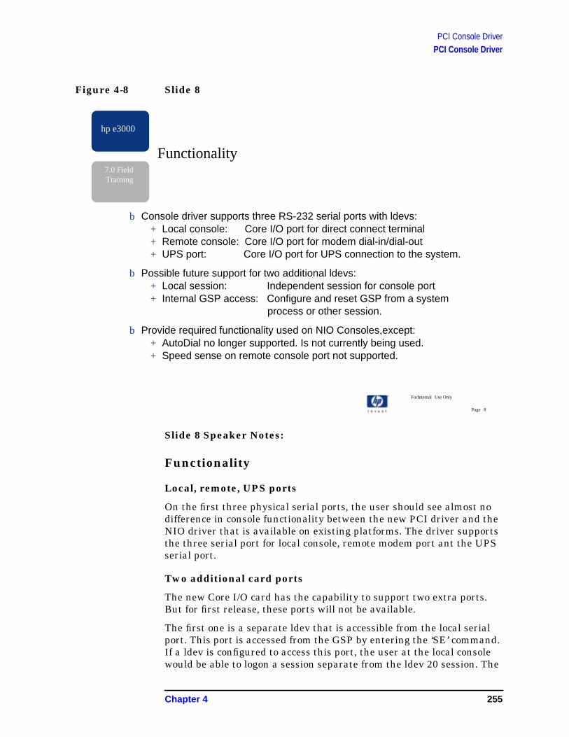
PCI Console DriverPCI Console Driver
Figure 4-8 Slide 8
Slide 8 Speaker Notes:
Functionality
Local, remote, UPS ports
On the first three physical serial ports, the user should see almost nodifference in console functionality between the new PCI driver and theNIO driver that is available on existing platforms. The driver supportsthe three serial port for local console, remote modem port ant the UPSserial port.
Two additional card ports
The new Core I/O card has the capability to support two extra ports.But for first release, these ports will not be available.
The first one is a separate ldev that is accessible from the local serialport. This port is accessed from the GSP by entering the ‘SE’ command.If a ldev is configured to access this port, the user at the local consolewould be able to logon a session separate from the ldev 20 session. The
ForInternal Use Only
Page 8
hp e3000
7.0 FieldTraining
Functionality
b Console driver supports three RS-232 serial ports with ldevs:+ Local console: Core I/O port for direct connect terminal+ Remote console: Core I/O port for modem dial-in/dial-out+ UPS port: Core I/O port for UPS connection to the system.
b Possible future support for two additional ldevs:+ Local session: Independent session for console port+ Internal GSP access: Configure and reset GSP from a system process or other session.
b Provide required functionality used on NIO Consoles,except:+ AutoDial no longer supported. Is not currently being used.+ Speed sense on remote console port not supported.
Chapter 4 255
PCI Console DriverPCI Console Driver
user would not see any console messages. The console messages wouldbe placed in a history buffer that could be displayed later when the localsession is terminated.
The second extra port is used for internal access to the GSP. This portalways has GSP administrator capability and has the added ability toreset all configurations to the default values. To use this port, anapplication will need to be developed that can act like the HP-UX “cu”command or Kermit application to open the port and providebi-directional data path between the port and the user’s session.
Unsupported Functionality
There are two console features that are no longer supported on theN-class systems.
AutoDial: This driver does not support outgoing AutoDial. This featurewas part of the NIO card firmware and at one time in the past,Predictive support was the only known product using autodial toinitiate calls. Predictive is no longer using this method to initiate calls.Instead Predictive is sending all the necessary modem commands viathe normal write path.
Speed Sense: This was also a built in feature of the NIO card. Wechose to not implement this because: a) it was difficult to do in thedriver; b) there is a limited need to have this on the console.
256 Chapter 4

PCI Console DriverPCI Console Driver
Figure 4-9 Slide 9
Slide 9 Speaker Notes:
Console Architecture
Core I/O 1, Tosca Card
The Core I/O card currently being shipped with the N-Class systems iscode named Tosca. The console and GSP interface on the card is codenamed DIVA. The diagram on this slide depicts the various data pathsfrom the external serial and GSP LAN ports to the devices accessed onthe PCI buss. In this diagram you see that there are two separate PCIdevices connected to the buss. Each PCI device requires a separateinstance of the PCI driver to be created. The first DIVA contains theinterface to the local console, remote session and UPS paths. Thesecond DIVA contains the interface to the local session and internalGSP paths.
ForInternal Use Only
Page 9
hp e3000
7.0 FieldTraining
Console ArchitectureCore I/O 1, Tosca Card
Legend:System Console I/OMirrored Console I/OLocal session modeRemote session modeUPS port pathInternal GPS access
PCI Bus
LocalSerialport
RemoteSerialport
UPSserialport
10BTLANConsole
PCI device
Uart 2Uart 1Uart 0
PCI deviceUnusedUartUart 1Uart 0
ConsolePath
UPSPath
RemotesessionPath
InternalGSPPath
LocalSessionPath
PCI Console Driver0/0/4/0
PCI Console Driver0/0/5/0
GSP
Core I/O Console
b Two PCI (DIVA) devices defined.
b Remote/Local session mode accessed with the ‘SE’ command.
b Internal GSP and Local Session paths may be used on future release.
Chapter 4 257

PCI Console DriverPCI Console Driver
If a ldev is configured for these paths, the local session is accessed fromthe local console port with the GSP ‘SE’ command. When in localsession mode, the user cannot access the GSP. The user can return tothe GSP or console mode by logging off the session.
The remote session path is accessed from the remote serial port. Ifremote console access is disabled then the user is connected to theremote session path when a connection is established to the serialmodem port. In this mode, the user can not access the GSP interface.
258 Chapter 4

PCI Console DriverPCI Console Driver
Figure 4-10 Slide 10
Slide 10 Speaker Notes:
Core I/O 2, Maestro Card
From the console perspective, this card is very similar to Core I/O 1except that there is only one PCI device defined. All 5 console paths areconfigured on this one device and there is only one instance of the PCIdriver. The driver is designed to recognize the card and configure thedevices accordingly.
ForInternal Use Only
Page 10
hp e3000
7.0 FieldTraining
Console ArchitectureCore I/O 2, Maestro Card
Legend:System Console I/OMirrored Console I/OLocal session modeRemote session modeUPS port pathInternal GPS access
b One PCI (DIVA) device defined.
b Remote/Local session mode accessed with the ‘SE’ command.
b Internal GSP and Local Session paths may be used on future release.
PCI Bus
LocalSerialport
RemoteSerialport
UPSserialport
10BTLANConsole
PCI device
Uart 2Uart 1Uart 0 Uart 4Uart 3
ConsolePath
UPSPath
RemotesessionPath
InternalConsolePath
LocalSessionPath
PCI Console Driver0/0/4/1
GSP
Chapter 4 259

PCI Console DriverPCI Console Driver
Figure 4-11 Slide 11
Slide 11 Speaker Notes:
Configuration
GSP Commands
The purpose and function of many of the GSP commands are similar tothe Access Port commands on previous platforms. This slide is roughlyorganized by the commands that are the same, those that changed, newcommands and help. There is extensive online help text.
ForInternal Use Only
Page 11
hp e3000
7.0 FieldTraining
b Many commands similar to AP commands on previous platforms (TC, RS, MS, CO, SE)b Changed commands:
+ Enable and Disable remote/LAN access (CA, DI, ER, EL)+ Other Configuration commands (AC, AR, CA, IT)
b New commands:+ LAN Configuration and status (LC) (LS)+ Upgrade GSP firmware (XU)+ Remote Power Control and Status (PC, PS)+ Security Options (SO)+ History and chassis code buffering (CL, SL)+ Display of front panel LEDs state and console users. (VFP, WHO)
b Extensive online help (HE)
ConfigurationGSP Commands
260 Chapter 4

PCI Console DriverPCI Console Driver
Here is a GSP command summary:
==== GSP Help ============================================(Administrator)===
AC : Alert display Configuration PC : Remote Power Control
AR : Automatic System Restart config. PG : PaGing parameter setup
CA : Configure Asynch/serial ports PS : Power management module Status
CL : Console Log- view console history RS : Reset System through RST signal
CO : COnsole- return to console mode SDM : Set Display Mode (hex or text)
CSP : Connect to remote Service Proc. SE : SEssion- log into the system
DC : Default Configuration SL : Show Logs (chassis code buffer)
DI : DIsconnect remote or LAN console SO : Security Options & access control
EL : Enable/disable LAN access SS : System Status of proc. modules
ER : Enable/disable Remote/modem TC : Reset via Transfer of Control
HE : Display HElp for menu or command TE : TEll- send a msg. to other users
IT : Inactivity Timeout settings VFP : Virtual Front Panel display
LC : LAN Configuration WHO : Display connected GSP users
LS : LAN Status XD : Diagnostics and/or Reset of GSP
MR : Modem Reset XU : Upgrade the GSP Firmware
MS : Modem Status
Details of selected commands:
Security Options (SO) : This command is used to configure GSPusers and passwords. The default configuration is no users areconfigured. All connections to the GSP have administrator capability.
The first user configured is created as administrator Once created,several console mirroring rules will come into play. For example if anadministrator is logged on, then an operator capable user can’t logontill the administrator disconnects. It also appears that if anadministrator is connected via the GSP LAN port, no access (not even^B) is allowed on the local console until the administrator disconnects.
If the administrator password is lost, then the user config in the GSPmust be cleared via the rear panel reset button. If the internal GSPpath were available, then the users could also be reset via this port.
GSP users can be configured for DIAL-BACK access. This means thatwhen that user logs on to the GSP, the GSP will hang up and dial thatuser back at a configured phone number.
Extra note: If the user access is set to “single” then the user is onlyallowed to logon once. The GSP admin must take action to re-enable theuser.
Chapter 4 261
PCI Console DriverPCI Console Driver
Power Control and Status(PC, PS): PC — Allow the user to switchsystem power ON or OFF. This is almost like turning the system poweroff at the front panel switch. This will work as long as the real frontpanel switch is left in the ‘ON’ position.
Paging Parameters (PG): This feature is able to generate a pagingmessage based on the chassis codes that arrive in the GSP. Thisrequires a modem to be connected to the remote port and to be properlyconfigured. On receipt of the appropriate level of alert, the GSP will diala configured number to send an alpha-numeric page. Part of thealpha-numeric pager message is the string configured in this command,describing the alert level that caused the page.
Upgrade the GSP Firmware (XU) : The upgrade is performed usingftp over the GSP LAN. The command provides a dialog that contains adefault IP address and anonymous ftp logon to a server where theupgrade files reside. The user can override this location if the files havebeen copied to a more local server. This command can only be run fromthe local or internal ports.
262 Chapter 4

PCI Console DriverPCI Console Driver
Figure 4-12 Slide 12
Slide 12 Speaker Notes:
Console and GSP LAN
Modem Protocols
CCITT Mode — In this protocol the driver waits for RI before raisingDTR. It also requires the modem to assert DSR, RTS and DCD before aconnection is established.
Bell Mode — This is sometimes called Bell simple protocol. The driverraises DTR when it can accept a connection. The connection is validwhen the driver sees DCD from the modem.
Default Parameters
No change in the methods to configure the ports in Sysgen andNMMGR, except that V.22 mode not supported on N-Class.
The local and remote session paths must be configured for a modemprotocol. The GSP uses the ‘drop of modem line’ commands to the cardto detect session termination.
ForInternal Use Only
Page 12
hp e3000
7.0 FieldTraining
b Remote modem supports Bell and CCITT.
b Default parameters for serial ports configured in GSP.+ Configured in NMMGR and Sysgen same as before.+ The config in GSP must match NMMGR parameters.+ Modem protocol required for GSP ‘SE’ command to work.
b Configure LAN console port as independent node:+ IP, GSP Host name, Gateway and Subnet mask.
b GSP LAN port can NOT be used for general system access.
b User name and password protected. Not a secure telnet connection.
ConfigurationConsole and GSP LAN
Chapter 4 263
PCI Console DriverPCI Console Driver
The parameters configured for the GSP LAN are all normal for a telnetcapable node.
As stated before, the logon to the GSP can be protected by a user nameand password.
264 Chapter 4

PCI Console DriverPCI Console Driver
Figure 4-13 Slide 13
Slide 13 Speaker Notes:
Console ldevs
This slide shows the details of the I/O paths used by the console and anexample of the PCI driver path configuration and the console ldev. Notethe two new ID’s for these entries.
ForInternal Use Only
Page 13
hp e3000
7.0 FieldTraining
b I/O paths for Core I/O 1+ 0/0/4/0.0 - console; Ldev 20+ 0/0/4/0.1 - remote session+ 0/0/4/0.2 - UPS+ 0/0/5/0.0 - Internal GSP+ 0/0/5/0.1 - local session
ConfigurationConsole ldevs
b I/O paths for Core I/O 2+ 0/0/4/1.0 - console; Ldev 20+ 0/0/4/1.1 - remote session+ 0/0/4/1.2 - UPS+ 0/0/4/1.3 - Internal GSP+ 0/0/4/1.4 - local session
PATH: 0/0/4/0 LDEV: ID: PCI_CONSOLE TYPE: DAPMGR: PCI_CONSOLE_DAM PMGRPRI: 6LMGR: MAXIOS: 0
PATH: 0/0/4/0.0 LDEV: 20 ID: C1099A TYPE: TERMPMGR: CDM_CONSOLE_DM PMGRPRI: 9LMGR: TIO_TLDM MAXIOS: 0
Chapter 4 265

PCI Console DriverPCI Console Driver
Figure 4-14 Slide 14
Slide 14 Speaker Notes:
Support and Diagnostics
This driver, as all current link products do, by default generates loggingand trace areas in the PDA. The formats used are the same as thoseused by the ThinLAN/Console driver. There are some tag fields andentry variants that are different to account for the driver differences.
In order to aid looking at the PDA, the symbol file for this module hasbeen linked with the DTS som: SYMDTS.DTC0000.TELESUP. Thiswas chosen because the TIO_TLDM is already there and apparently theCDM does not have a symbol file available (hmm, enhancement req?).Maybe it would be welcomed if the TIO_TLDM, CDM and PciDAM wererecombined in a new symbol file. TIO_TLDM is now only used on theconsole ports (I think).
ForInternal Use Only
Page 14
hp e3000
7.0 FieldTraining
Support and Diagnostics
b Internal area for tracing and logging in DAM PDA.
b Same logging and tracing formats as used by Lancelot.
b Symbol file linked into SYMDTS.DTC0000.TELESUP file.
b Can’t log to NMLG log files because of Link architecture issues.
b No macros planned at this time. If deemed critical this could be revisited.
266 Chapter 4

PCI Console DriverPCI Console Driver
Unfortunately, this driver is not able to log to the NMLGxxxx files. Thisis because the driver is started at such an early time that the loggingfacilities are not available. This driver also does not have the ModuleConfigurator that other links do. The MC is the module that startslogging if configured. We are discussing some non-conventionalmethods that could be used to allow NMLG logging but not sure howhelpful it will be for the field.
At this time we don’t have the macros that are comparable to theThinLAN macros. If this is deemed critical, then this could be revisited.We would leverage the ThinLAN macros to allow the PDA trace andlogging areas to be formatted.
Chapter 4 267

PCI Console DriverPCI Console Driver
Figure 4-15 Slide 15
Slide 15 Speaker Notes:
Troubleshooting
The console is more difficult to debug that most other modules becauseany action taken on the console, assuming that it is alive, will affect thedata in the PDA. Also with any problem that prevents the console fromoperating it is possible to hang the system. This means that if theconsole is non-responsive, the only option may be a system dump.
If networking is up, it may be possible to access the system from anetwork connection and use debug to look at the PDA. This is where themacros would be handy to dump the trace and logging.
The trace and logging areas in the pda are in these pda structures. Thisslide lists the offset of the logging and trace areas from the start of thePDA.
ForInternal Use Only
Page 15
hp e3000
7.0 FieldTraining
Troubleshooting
b Any activity on console affects PDA data.
b If console is non-responsive, System dump may be the only option.
b If network connection possible, then debug is used to look at PDA
+ Trace & logging areas in pdapcd_pda_type.t_pda_sw_tracebuf x200.0 @ 384.0
pcd_pda_type.ph_internal_logging x6B0.0 @ 818.0
b PCI DAM does all of the work for card control. PDA contains all relevant card data.
268 Chapter 4

PCI Console DriverPCI Console Driver
There are other areas in the PDA that contain all the data relevant tothe operation of the card including the value of all the registers on thecard. The detail of the logging and trace formats in the PDA is beyondthe scope of this course.
Chapter 4 269
PCI Console DriverPCI Console Driver
Figure 4-16 Slide 16
Slide 16 Speaker Notes:
Additional Comments
This slide has some general comments that give a some highlights ofother aspects of the driver that may be of interest.
ForInternal Use Only
Page 16
hp e3000
7.0 FieldTraining
Additional Comments
b Some inconsistencies in CDM were addressed. Not sure if it fixed any bugs.
b PCI code is much simpler than NIO LAN driver. It is now solely focused on serial I/O and doesn’t have to handle LAN or FDDI traffic.
b Driver must handle flow control and modem protocols.
270 Chapter 4

5 PCI Networking Generic Topics
Other Networking Changes Made
Figure 5-1 Slide A
Slide A Speaker Notes:
At this point we still need to discuss a number of other miscellaneouschanges that did not properly fit into the earlier categories.
Certain internal changes are seen as being too low-level for thisaudience, and are thus omitted. These include: True linktypes,Nslopenlink, Link Common details, linktype abstraction details, SDIread-write reconvergence, bilingual transports, print_linkstate ,LAN and LINKCONTROL structure changes, load_virt_addr_64calls, Plnkutil, and Bmgr enhancements.
for internal use only
hp e3000
7.0 fieldtraining
Other 7.0 Networking Changes
· PCI Bus Support in MPE Networking
· PCI Bus Visibility
271
PCI Networking Generic TopicsOther Networking Changes Made
Figure 5-2 Slide B
Slide B Speaker Notes:
To add PCI bus support to MPE Networking, we had the choice of“forking” the O/S, i.e. creating one OS supporting only PCI, and anothersupporting only HP-PB, or merging PCI support in, creating a singleOS. We chose to merge, so the same version of the software can drivelinks on different types of busses, depending on the platform.
Enhancements to LSS (Link Support Services) and MPE IO Serviceswere key to multi-bus support in MPE Networking. MPE now seessame-type adapters (like 100Base-T) on different bus types, as differentlinktypes. So MPE now sees more linktypes than before.
When new linktypes are added, MPE networking always has to changeto support them. New internal services now make it easier forsubsystems to collectively group various linktypes by technology, andtreat them similarly, regardless of bus type. These same services arealso expected to simplify future addition of new linktypes.
for internal use only
hp e3000
7.0 fieldtraining
PCI Bus Support in MPE Networking
· Same version of MPE now supports multiple bus types:no need to “fork” the OS (7.0 and beyond).
· Bus type internally translates to linktype.
· New internal services group linktypes by technology, sotransports can treat them similarly, regardless of bustype.
272 Chapter 5
PCI Networking Generic TopicsOther Networking Changes Made
Figure 5-3 Slice C
Slide C Speaker Notes:
Most users and administrators don’t want to know bus type to configureand manage a network link. However, support personnel still need toknow the bus type to properly diagnose any trouble.
MPE Networking’s knowledge of bus types is therefore madetransparent (“generic”) at the NMMGR configuration level and at thetransport level (NS/ DTS/ Streams transport level). This means youconfigure a 100Base-T adapter the same, regardless of bus type.
Bus type does become visible at the maintenance level (Logging config,LINKCONTROL, NMDUMP, NMMAINT), appearing in all the displaysas either “PCI” or “HP-PB” (i.e. NIO).
Drivers for new bus types have new subsystem numbers. This means toreport the version of the PCI 100Base-T driver, you need to specify thesubsystem number of that driver (78), not that for the HP-PB driver(77). A nice new NMMAINT feature is “;PARM= -1,” which will print alist of known subsystem numbers. Another nice new feature is thateach subsystem’s number prints with its version output.
for internal use only
hp e3000
7.0 fieldtraining
PCI Bus Visibility
· Bus type is transparent at configuration level, bus visible atthe maintenance level
· Each link driver has its own NMS and MPE subsystemnumbers, depending on bus type
· Log screens, Selection menus, and LINKCONTROL andNNMAINT version outputs now indicate HP-PB or PCI foreach link. For example …
· NMMaint: PCI 100Bast-T Fast Ethernet driver ------overall version = A.00.70
· LINKCONTROL:Linkname: TSLINK Linktype: PCI100BT Linkstate: Connected
Chapter 5 273

PCI Networking Generic TopicsOther Networking Changes Made
Note that NMMAINT is now a native-mode program, which affects theway you use the other unsupported entry points, such as “shutdown.”They must now be passed in the INFO= string.
Having separate subsystem numbers, that if the link does not start, itwill still be possible to tell which type of link was having trouble. Thiscan be done through console logging, LINKCONTROL output, and/ordecoded error status values. Status value decoding requires NS ErrorMessage Manual changes, which won’t be available at first release.
274 Chapter 5

6 PCI 100Base-T
Figure 6-1 Slide 1A
for internal use only
hp e3000
7.0 fieldtraining
PCI 100Base-T Field Training Topics
· Section1: Product Features and Limitations
· Section 2: Configuration changes in 7.0
· Section 3: Tools & Diagnostics
· Section 4: Documentation
· Section 5: Troubleshooting Techniques & Examples
275

PCI 100Base-TSection 1: Detail of Product Features and Limitations
Section 1: Detail of Product Features andLimitations
Figure 6-2 Slide 1-1
Figure 6-3 Slide 1-2
for internal use only
hp e3000
7.0 fieldtraining
PCI 100 Base-T(Adapter Card and Driver)
for internal use only
hp e3000
7.0 fieldtraining
What is the PCI 100Base-T LinkProduct?
· LAN connectivity solution for PCI-bus based HP e3000systems
· Provides the same interface to all LAN network stacks(e.g., NS TCP/IP, DTC) as exists on HP-PB systems
· Software component bundled with FOS
· PCI 100Base-T add-on adapter card (A5230A) must beordered separately.
· PCI equivalent to HP-PB 100Base-T Fast Ethernet linkproduct (B5427BA)
276 Chapter 6

PCI 100Base-TSection 1: Detail of Product Features and Limitations
Slide 1-2, Speaker Notes:
This slide explains the purpose of the new PCI 100Base-T link product.
The new class of HP e3000 systems has PCI-bus based hardwarearchitecture, so new drivers must be developed to support newPCI-based peripheral devices, including a new LAN card.
PCI 100Base-T encompasses the new software driver and new add-onadapter card that are required to provide LAN connectivity for the newsystem architecture. It is a distinct and separate product from HP-PB100Base-T Fast Ethernet, which runs only on HP-PB platforms.
From a customer perspective, there is no major difference in how thenetworking subsystems will operate compared to HP-PB HP e3000systems. Customers currently using various network software products(such as NS TCP/IP, DTC Terminal I/O, and Streams/iX products andapplications) will run their applications the same as they do on HP-PBsystems, only they will now run over the PCI 100Base-T link product.This approach is fundamental to the HP e3000 PCI design philosophy:the underlying hardware/architecture changes should not impact upperlayer software products or customer applications, and should beessentially transparent.
The software component for the new PCI 100Base-T link product willbe bundled into FOS (MPE/iX 7.0 and later). The customer only needsto order the hardware (100Base-T adapter add-on card) for theirsystem. This should simplify ordering and installation.
Chapter 6 277

PCI 100Base-TSection 1: Detail of Product Features and Limitations
Figure 6-4 Slide 1-3
Slide 1-3 Speaker Notes:
The PCI 100Base-T adapter card is a single-port, add-on card(controlled by a DEC 21143 LAN controller chip). This is a relativelysimple “dumb” card, which does not require firmware downloads andhas no on-board memory.
This particular LAN card was chosen for the new HP e3000 platforms,in part, because it is also supported by HP-UX on their N-class servers(PCI bus-based architecture). This means that the card had beenproven to work on the new PCI bus-based hardware architecture, andwe also gained some leverage in developing the software on MPE/iX todrive the card.
The card is capable of supporting both 10-Mbps and 100-Mbps speeds,which can be configured in NMCONFIG. Therefore, there is no need fora separate 10Base-T adapter card.
for internal use only
hp e3000
7.0 fieldtraining
Features of the PCI 100Base-TAdd-On Adapter Card
· Single-port card
· Can support 10M bps or 100M bps speeds(configurable), no need for separate 10Base-T link
· “Dumb” card with no on-board memory ordownloadable firmware
· Same adapter card is supported by HP-UX on theN-Class servers
278 Chapter 6
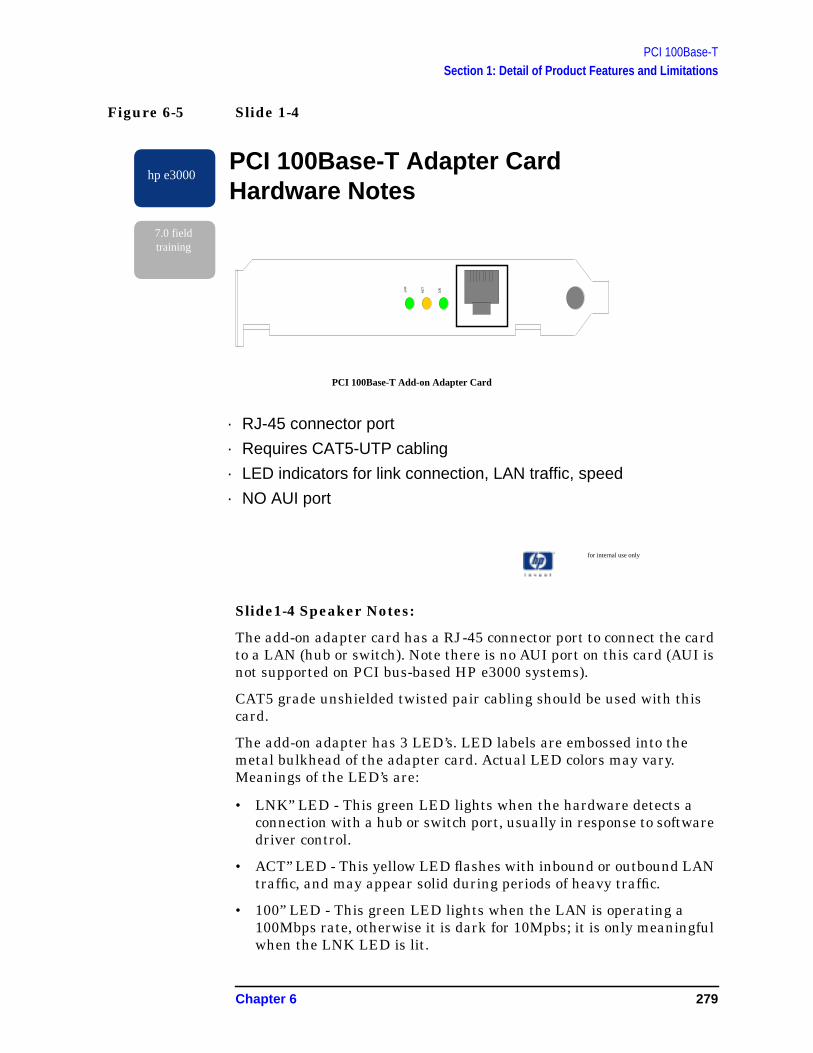
PCI 100Base-TSection 1: Detail of Product Features and Limitations
Figure 6-5 Slide 1-4
Slide1-4 Speaker Notes:
The add-on adapter card has a RJ-45 connector port to connect the cardto a LAN (hub or switch). Note there is no AUI port on this card (AUI isnot supported on PCI bus-based HP e3000 systems).
CAT5 grade unshielded twisted pair cabling should be used with thiscard.
The add-on adapter has 3 LED’s. LED labels are embossed into themetal bulkhead of the adapter card. Actual LED colors may vary.Meanings of the LED’s are:
• LNK” LED - This green LED lights when the hardware detects aconnection with a hub or switch port, usually in response to softwaredriver control.
• ACT” LED - This yellow LED flashes with inbound or outbound LANtraffic, and may appear solid during periods of heavy traffic.
• 100” LED - This green LED lights when the LAN is operating a100Mbps rate, otherwise it is dark for 10Mpbs; it is only meaningfulwhen the LNK LED is lit.
for internal use only
hp e3000
7.0 fieldtraining
PCI 100Base-T Adapter CardHardware Notes
· RJ-45 connector port
· Requires CAT5-UTP cabling
· LED indicators for link connection, LAN traffic, speed
· NO AUI port
LNK
AC
T
100
PCI 100Base-T Add-on Adapter Card
Chapter 6 279

PCI 100Base-TSection 1: Detail of Product Features and Limitations
Figure 6-6 Slide 1-5
Slide 1-5 Speaker Notes:
There has been no standardized performance testing completed yet forthe MPE/iX N-class systems. Early indications are that the PCI100BT-link throughput has increased noticeably over that of HP-PB100BT links. Under certain limited load conditions, we have seenincreases of up to 2x the throughput previously seen under similarconditions on HP-PB systems. *** This is preliminary data for HPInternal Use only. ***
N-class systems will support up to 4 separate 100BT links (4single-port 100BT cards). (The smaller A-class HP3000 systems willsupport less; limits are still being defined).
The Core I/O card (part of the “base” hardware for every PCI HP e3000system) contains a LAN connector port, but this LAN port is notcurrently supported. Only the add-on adapter card (ordered separately)can be used for LAN connections.
The N-class and A-class HP e3000 systems include support of UniversalPower Supply (UPS) “backup” power. This has essentially replaced theneed for traditional MPE/iX power fail recovery, which will no longerexist on the new PCI HP e3000 platforms.
for internal use only
hp e3000
7.0 fieldtraining
Miscellaneous Notes
· PCI 100Bast-T expects significant performanceimprovement over HP-PB 100Base-T Fast Ethernet Link
· Each N-Class HP e3000 system can support up to 4 single-port 100BT cards
· LAN connection on Core I/O card no support until MPE/iXRelease 7.0 Express 1
· UPS is supported (replaces “old” powerfail recovery)
280 Chapter 6

PCI 100Base-TSection 2 — Configuration Changes in 7.0
Section 2 — Configuration Changes in 7.0
Figure 6-7 Slide 2-1
Slide 2-1 Speaker Notes:
A number of general NMMGR configuration changes impact 100Base-Tin 7.0.
Most of the configuration is the same as for HP-PB 100Base-T. Thereare some specific differences.
The next few slides give the details.
for internal use only
hp e3000
7.0 fieldtraining
100Base-T Configuration in NMMGR
· All NS LAN network interface (NI) types are collapsedinto one “LAN.”
· Usually you must change the default 100Base-T linkscreen settings.
· On PCI platforms, DTS screen must specify “BT100” asthe linktype.
· New logging configuration screens for PCI 100Base-Tlink (subsystem 78).
Chapter 6 281

PCI 100Base-TSection 2 — Configuration Changes in 7.0
Figure 6-8 Slide 2-2
Slide 2-2 Speaker Notes:
NS collapses all LAN NI types into a single NI type. Therefore a PCI100Base-T link will now be configured under a “LAN” NI, not a “100BT”NI. Both the 100Base-T and 100VG-802.3 NI types are removed. Thisalso means it is now simpler to migrate the underlying linktype for anNI without having to delete and reenter the NI’s entire configuration:just select a different linkname. NMMGRVER will perform the LAN NIconversion when run.
As shown in this slide, the first Guided Config screen changes for 7.0 toreflect the collapse.
As usual, it is always recommended that Guided Config be used to dothe initial NS creation of any new NI.
for internal useonly
hp e3000
7.0 fieldtraining
NMMGR/3000 (B.07.00) # 42 Network Transport Configuration
Enter the information required; then press the desired function key.
Command:
Config - To create or modify a network
Network Enter a network interface: [TSLAN ]
Enter a network type: [1 ] 1 = LAN 2 = Pt-Pt
3 = X.25
5 = Gateway Half
6 = Token Ring
7 = FDDI
Then press the Config Network key.
Modify - To modify default logging configuration:
Logging Press the Modify Logging key (note that logging is
created with defaults when the first network type
is configured).
File: NMCONFIG.PUB.SYS
Config Modify List Help Prior
Network Logging Networks Screen
282 Chapter 6

PCI 100Base-TSection 2 — Configuration Changes in 7.0
Figure 6-9 Slide 2-3
Slide 2-3 Speaker Notes:
The Guided Config screen for LAN changes to require a link typespecification. For a 100Base-T link, specify “BT100”. This replaceshaving a separate NI type.
After creating the NI, you will usually need to change the link settingsto match your network. The next two slides discuss this.
To form the I/O path field for a 100Base-T adapter on PCI platforms,begin with the path printed on the slot where the adapter is installed(“1/10” in this example), and add “/0/0.” This is the rule for 100Base-T,but SMUX paths use a different formation.
Although PCI platforms impose a deeper I/O bus converter tree, the OSprovides a new service, which the new PCI driver subsystems call toestablish the underlying bus components if not already configured. Thiscontinues the practice of Sysgen not being required for networkconfiguration or diagnostics. Currently, this feature is only provided onPCI links.
IMPORTANT: Never specify the path “0/0/0/0”, the 100Base-T port onsome Core I/O boards; this port is not supported. (Repeat)
for internal use only
hp e3000
7.0 fldtraining
NMMGR/3000 (B.07.00) # 41 LAN Configuration Data: Y
Fill in the required information; then press the Save Data key.
Command:
Node name (First 50 chars) [NODE.DOM1.DOM2.ORG ]
Network Interface (NI) name [TSLAN ]
IP address [111.222.333.444 ]
IP subnet mask [255.255.248.000] (optional)
Proxy node [N] (Y/N)
Link name [TSLINK ]
Link type [BT100 ] (LAN, VG100LAN, BT100)
Physical path of LANIC [ 1/10/0/0 ]
Enable Ethernet? [Y] (Y/N)
Enable IEEE802.3? [Y] (Y/N)
Press Neighbor Gateways to configure neighbor gateways, if any.
If done configuring, press the Validate Netxport key.
Type "open" on the command line and press enter to configure the directory.
File: NMCONFIG.PUB.SYS
List Delete Read Neighbor Validate Save Help Prior
Nis NI Other NI Gateways Netxport Data Screen
Chapter 6 283

PCI 100Base-TSection 2 — Configuration Changes in 7.0
Figure 6-10 Slide 2-4
Slide 2-4 Speaker Notes:
This slide shows what the complete 100Base-T link configurationscreen looks like. It is accessible from NS-Unguided-Link. It is alsoaccessible from the DTS screen, through the “Tune Link” softkey. Youwill need to visit this screen to adjust your 100Base-T default linksettings.
The trace fields should be used only for debugging startup problems,and you would almost never change the factory-address fields.
Besides having the proper path, the fields highlighted in blue are themost important, and are discussed on the next slide.
for internal use only
hp e3000
7.0 fieldtraining
NMMGR/3000 (B.07.00) #306 100BaseT Link Configuration Data: Y
When Data Flag is "N", press "Save Data" to create the data record.
Command:
Path: LINK.TSLINK
Physical path of device adapter [1/10/0/ 0 ]
Use factory-configured local station address? [Y] (Y/N)
Local station address [FF-FF-FF-FF-FF-FF] (Hex)
When auto-negotiation is enabled, the system can only
properly configure the link if the hub also auto-negotiates.
Use auto-negotiation to determine link settings? [N] (Y/N)
If 'N' : Link speed [10 ] (100 or 10 MBits/sec)
Full Duplex mode [N] (Y/N; N=Half)
Trace at startup? [N] (Y/N) Note : Trace reduces
Trace filename [ ] performance.
File: NMCONFIG.PUB.SYS
Save Help Prior
Data Screen
284 Chapter 6

PCI 100Base-TSection 2 — Configuration Changes in 7.0
Figure 6-11 Slide 2-5
Slide 2-5 Speaker Notes:
The MOST IMPORTANT aspect of setting up 100Base-T is to makesure the link settings match the hub/switch port you are connected to.The default is auto-negotiation, so you WILL need to change thesettings before using the link.
If settings are changed in NMMGR, the link must be fully stopped andrestarted to pick up the changes.
The flow of questions on this slide shows how you should be thinkingwhen setting the 100Base-T link configuration
If connecting to a port that is set for auto-negotiation, set auto=Yes, andchances are the speed and duplex chosen will be 100/Full. Data switchports (not hub) usually support this.
If connecting into an existing 10Base-T ThinLAN network, chances areyou need to set auto=No, speed=10, full duplex=No.
If connecting to a 100Base-T hub (not switch), chances are you need toset auto=No, speed=100, full duplex=No.
If there is any doubt auto-negotiation is working right, configure boththe link and the port for the best available, often 100/Full.
The combination of 10/full is rarely used.
for internal use only
hp e3000
7.0 fieldtraining
100Base-T Link Configuration SettingMUST Match Data Switch Settings· After Guided Config, visit the LINK screen (or in DTS, hit
[Tune Link])…
· [Open Config] [NS] [ UnGuided Config] [ Go To Link] [linkname ] [Modify]
· Use auto-negotiation to determine link settings?(default=Yes)
· Q. Does the data switch support auto negotiation, and is itenabled for the port?
· A: If Yes, Accect the default [ Y ]
· If No, Change to no [ N ] then, according to hub portsetting:
– Set Link Speed = [ 10] or [100]
– Set Full Duplex mode = [ Y ] or [ N ]
· Hit [ Save Data ] softkey
Chapter 6 285

PCI 100Base-TSection 2 — Configuration Changes in 7.0
Figure 6-12 Slide 2-6
Slide 2-6 Speaker Notes:
The NI screen also changes, removing 100BT and 100VG8023 LANtypes as choices for “Add.” Use the LAN type to configure a 100Base-TNI.
To minimize confusion, the NI display screen now displays theunderlying link type along with each NI’s name and NI type. LAN NI’ssupporting 100Base-T will display NI Type = “LAN” and Link Type =“BT100.”
Note the screen only shows 10 NI’s instead of 15. The system nowsupports 48 NI’s instead of 12, so you will need to use those Next Page/Prev Page keys if you have more than 10 NI’s.
This screen appears within Unguided Config, and also in the GuidedConfig “List NIs” screen.
for internal use only
hp e3000
7.0 fieldtraining
NMMGR/3000 (B.07.00) # 112 Network Interface Configuration
Enter the name of an item then press the desired function key.
Command:
Path: NETXPORT.NI
GATEHALF, LAN , LOOP,
Network interface name [ TSLAN ] Type [ ] ROUTER, X.25, TOKEN,
New name (for rename) [ ] FDDI
Configured Network Interfaces
NI Name NI Type Link Type NI Name NI Type Link Type
[LOOP ] [LOOP ] [ ] [TSLAN ] [LAN ] [BT100 ]
[ ] [ ] [ ] [ ] [ ] [ ]
[ ] [ ] [ ] [ ] [ ] [ ]
[ ] [ ] [ ] [ ] [ ] [ ]
[ ] [ ] [ ] [ ] [ ] [ ]
File: NMCONFIG.PUB.SYS
Next Prev Rename Help Prior
Page Page Screen
286 Chapter 6
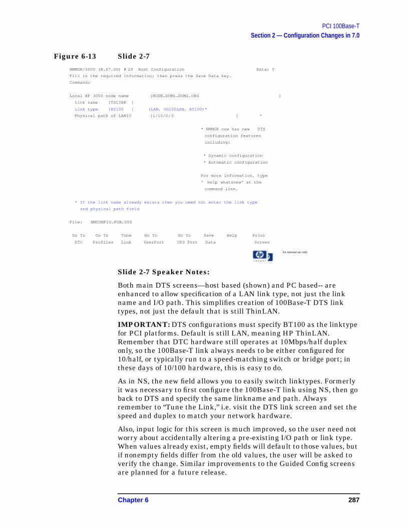
PCI 100Base-TSection 2 — Configuration Changes in 7.0
Figure 6-13 Slide 2-7
Slide 2-7 Speaker Notes:
Both main DTS screens—host based (shown) and PC based-- areenhanced to allow specification of a LAN link type, not just the linkname and I/O path. This simplifies creation of 100Base-T DTS linktypes, not just the default that is still ThinLAN.
IMPORTANT: DTS configurations must specify BT100 as the linktypefor PCI platforms. Default is still LAN, meaning HP ThinLAN.Remember that DTC hardware still operates at 10Mbps/half duplexonly, so the 100Base-T link always needs to be either configured for10/half, or typically run to a speed-matching switch or bridge port; inthese days of 10/100 hardware, this is easy to do.
As in NS, the new field allows you to easily switch linktypes. Formerlyit was necessary to first configure the 100Base-T link using NS, then goback to DTS and specify the same linkname and path. Alwaysremember to “Tune the Link,” i.e. visit the DTS link screen and set thespeed and duplex to match your network hardware.
Also, input logic for this screen is much improved, so the user need notworry about accidentally altering a pre-existing I/O path or link type.When values already exist, empty fields will default to those values, butif nonempty fields differ from the old values, the user will be asked toverify the change. Similar improvements to the Guided Config screensare planned for a future release.
for internal use only
hp e3000
7.0 fieldtraining
NMMGR/3000 (B.07.00) # 29 Host Configuration Data: Y
Fill in the required information; then press the Save Data key.
Command:
Local HP 3000 node name [NODE.DOM1.DOM2.ORG ]
Link name [TSLINK ]
Link type [BT100 ] (LAN, VG100LAN, BT100)*
Physical path of LANIC [1/10/0/ 0 ] *
* NMMGR now has new DTS
configuration features
including:
* Dynamic configuration
* Automatic configuration
For more information, type
" help whatsnew" at the
command line.
* If the link name already exists then you need not enter the link type
and physical path field
File: NMCONFIG.PUB.SYS
Go To Go To Tune Go To Go To Save Help Prior
DTC Profiles Link UserPort UPS Port Data Screen
Chapter 6 287
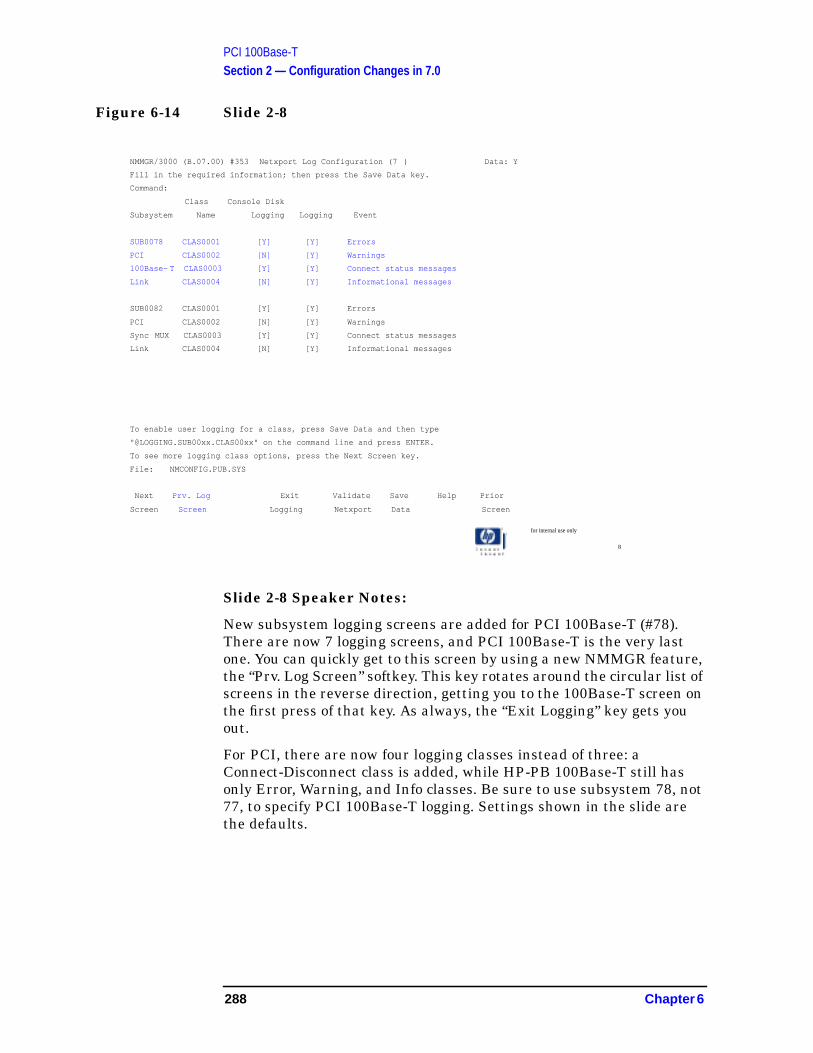
PCI 100Base-TSection 2 — Configuration Changes in 7.0
Figure 6-14 Slide 2-8
Slide 2-8 Speaker Notes:
New subsystem logging screens are added for PCI 100Base-T (#78).There are now 7 logging screens, and PCI 100Base-T is the very lastone. You can quickly get to this screen by using a new NMMGR feature,the “Prv. Log Screen” softkey. This key rotates around the circular list ofscreens in the reverse direction, getting you to the 100Base-T screen onthe first press of that key. As always, the “Exit Logging” key gets youout.
For PCI, there are now four logging classes instead of three: aConnect-Disconnect class is added, while HP-PB 100Base-T still hasonly Error, Warning, and Info classes. Be sure to use subsystem 78, not77, to specify PCI 100Base-T logging. Settings shown in the slide arethe defaults.
for internal use only
8
hp e3000
7.0 fieldtraining
NMMGR/3000 (B.07.00) #353 Netxport Log Configuration (7 ) Data: Y
Fill in the required information; then press the Save Data key.
Command:
Class Console Disk
Subsystem Name Logging Logging Event
SUB0078 CLAS0001 [Y] [Y] Errors
PCI CLAS0002 [N] [Y] Warnings
100Base- T CLAS0003 [Y] [Y] Connect status messages
Link CLAS0004 [N] [Y] Informational messages
SUB0082 CLAS0001 [Y] [Y] Errors
PCI CLAS0002 [N] [Y] Warnings
Sync MUX CLAS0003 [Y] [Y] Connect status messages
Link CLAS0004 [N] [Y] Informational messages
To enable user logging for a class, press Save Data and then type
"@LOGGING.SUB00xx.CLAS00xx" on the command line and press ENTER.
To see more logging class options, press the Next Screen key.
File: NMCONFIG.PUB.SYS
Next Prv. Log Exit Validate Save Help Prior
Screen Screen Logging Netxport Data Screen
288 Chapter 6

PCI 100Base-TSection 3: Tools & Diagnostics
Section 3: Tools & Diagnostics
Figure 6-15 Slide 3-1
Slide 3-1 Speaker Notes:
This slide lists all the diagnostic tools that will be covered in thetraining.
for internal use only
hp e3000
7.0 fieldtraining
Diagnostic Tools
· NMMAINT
· DAT/Debug Macros
· NMDUMP Trace Formatter
· NMDUMP Log Formatter
· LINKCONTROL
· Mesa Diagnostics
· Tools that won’t be updated for MR
Chapter 6 289

PCI 100Base-TSection 3: Tools & Diagnostics
Figure 6-16 Slide 3-2
Slide 3-2 Speaker Notes:
NMMAINT,78 also reports the version number of LinkCommon(LNK_NL_VERS), which is a set of shared services used by 100BT.
for internal use only
hp e3000
7.0 fieldtraining
NMMAINT,78
· Reports the NL & XL version numbers of the 100BT driver
· Reports the 100BT catalog file (NMCAT78): nmmaint,78NMS Maintenance Utility 32098-90014 B.00.11 (C) Hewlett-Packard Co. 1984
WED, AUG 30, 2000, 11:37 AMDatacom products build version: N.68.03
Subsystem version Ids:Subsystem Number: 78PCI 100Base-T Fast Ethernet driver -----module versions:
NL procedure: PCI_100BT_NL-VERS Version:A0070000XL procedure: PCI-100BT_XL_VERS Version:A0070000Catalog file: NMCAT78.NET.SYS Version:A0070000NL procedure: LNK_NL_VERS Version:A0070000
PCI 100Base-T Fast Ethernet driver ----- overal version =A.00.70
290 Chapter 6

PCI 100Base-TSection 3: Tools & Diagnostics
Figure 6-17 Slide 3-3
Slide 3-3 Speaker Notes:
Using DAT macros, the user can analyze PCI 100BT data structures indifferent modes (on-line, system dump, Rembug, driver dump).Examples include pbtnetdmpopen and pbtfmtdvrtrace.
Datacomm Link macros in TELESUP have been extended to addselections for the new PCI 100Base-T links, and the menu selectionvalue for “all” changes from “9” to “99” to leave room for future links.Different macros are required for PCI 100Base-T and HP-PB100VG-BT.
for internal use only
hp e3000
7.0 fieldtraining
DAT/Debug Macros
· All PCI 100Base-T macros begin with PBT* (similar toHp-PB 100VG-BT macros, which begin with VG*)
· New macros for PCIPBTSETPTRSPBTSETSYMSPBTSETUPPBTNETDMPOPENPBTNETDMPCLOSEPRTSUMDMPOPEN
PBTFMTDVRTRACEPBTFMTISRTRACEPBTFMTINTTRACEPBTT_FMTTRACEBUF
NOTE: HP-PB 100VG-BT macros cannot be usedto debug a PCI 100BT driver.
Chapter 6 291

PCI 100Base-TSection 3: Tools & Diagnostics
Figure 6-18 Slide 3-4
Slide 3-4 Speaker Notes:
From within the NMDUMP program, this utility gives the user theability to format trace records recorded to the disk by the 100BT driver(and WAN SDLC and LAPB drivers). Tracing can be turned on in theNMCONFIG file or through the :linkcontrol command.
The trace content looks significantly different between the PCI100Base-T and HP-PB 100VG/BT driver because the trace content isdriver specific. Details of the trace content are beyond the scope of thistraining as it would require in-depth training of the 100BT softwaredriver.
for internal use only
hp e3000
7.0 fieldtraining
NMDUMT Trace Formatter
· No significant user interface changes made for PCI
· Trace content specific to the new 100Base-T driver
· Use subsys78 for PCI 100Base-T
292 Chapter 6
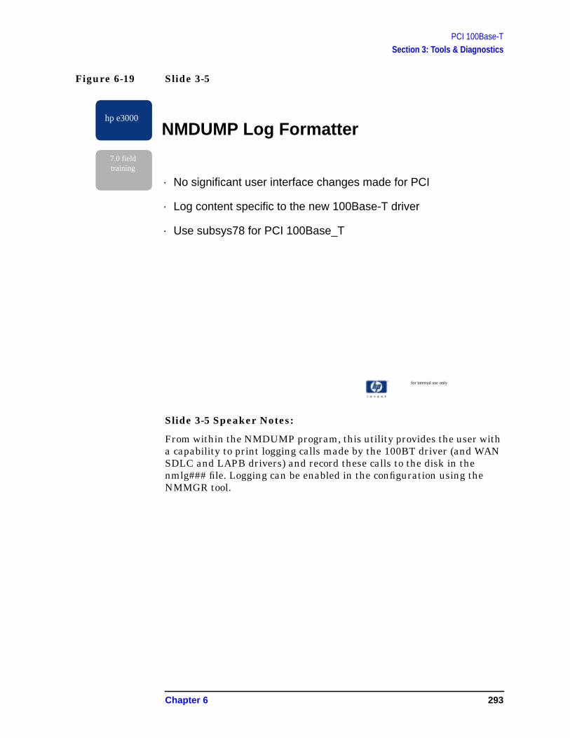
PCI 100Base-TSection 3: Tools & Diagnostics
Figure 6-19 Slide 3-5
Slide 3-5 Speaker Notes:
From within the NMDUMP program, this utility provides the user witha capability to print logging calls made by the 100BT driver (and WANSDLC and LAPB drivers) and record these calls to the disk in thenmlg### file. Logging can be enabled in the configuration using theNMMGR tool.
for internal use only
hp e3000
7.0 fieldtraining
NMDUMP Log Formatter
· No significant user interface changes made for PCI
· Log content specific to the new 100Base-T driver
· Use subsys78 for PCI 100Base_T
Chapter 6 293

PCI 100Base-TSection 3: Tools & Diagnostics
Figure 6-20 Slide 3-6
Slide 3-6 Speaker Notes:
Linkcontrol <command> is either trace or status
The Trace command turns tracing on/off
The Status command has several sub-options:
All prints configuration and statistics information
Link prints the linkname, linktype and linkstate
Config prints the driver's configuration information(e.g. driver path, MAC address, multicast addresses,etc.)
Statistics prints driver statistics
Diagstats prints driver's configuration information,driver statistics and driver diagnostic statistics (forinternal use only)
Reset prints the current statistics and then tells thedriver to reset the statistics & diagnostic statisticsvalues
for internal use only
hp e3000
7.0 fieldtraining
Linkcontrol
· :Linkcontrol [linkname] [; <command>]
· Trace· On
· Off
· Status· =a[ll]
· =l[ink]
· =c[onfiguration]
· =s[tatistics]
· =d[iagstats]
· =r[eset]
294 Chapter 6
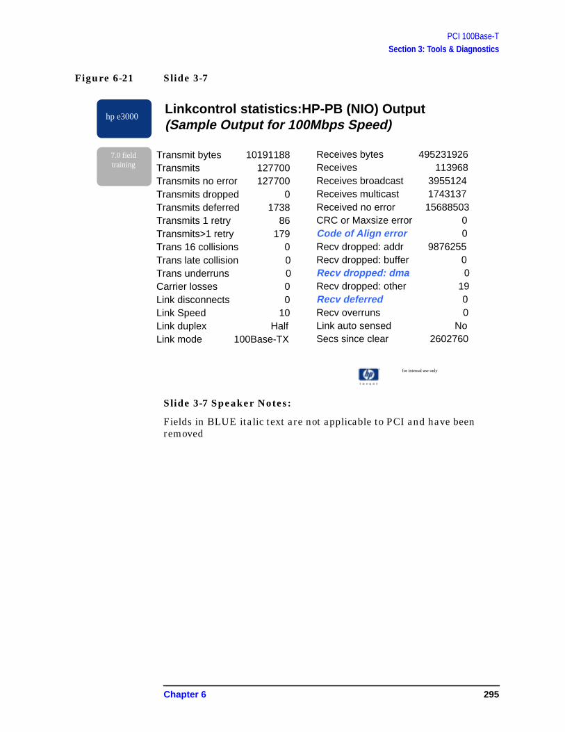
PCI 100Base-TSection 3: Tools & Diagnostics
Figure 6-21 Slide 3-7
Slide 3-7 Speaker Notes:
Fields in BLUE italic text are not applicable to PCI and have beenremoved
for internal use only
hp e3000
7.0 fieldtraining
Linkcontrol statistics:HP-PB (NIO) Output(Sample Output for 100Mbps Speed)
Transmit bytes 10191188Transmits 127700Transmits no error 127700Transmits dropped 0Transmits deferred 1738Transmits 1 retry 86Transmits>1 retry 179Trans 16 collisions 0Trans late collision 0Trans underruns 0Carrier losses 0Link disconnects 0Link Speed 10Link duplex HalfLink mode 100Base-TX
Receives bytes 495231926Receives 113968Receives broadcast 3955124Receives multicast 1743137Received no error 15688503CRC or Maxsize error 0Code of Align error 0Recv dropped: addr 9876255Recv dropped: buffer 0Recv dropped: dma 0Recv dropped: other 19Recv deferred 0Recv overruns 0Link auto sensed NoSecs since clear 2602760
Chapter 6 295
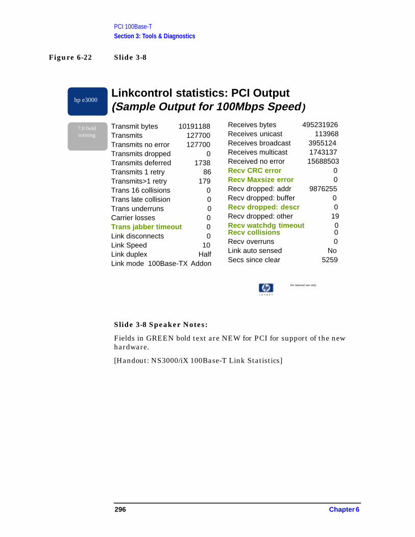
PCI 100Base-TSection 3: Tools & Diagnostics
Figure 6-22 Slide 3-8
Slide 3-8 Speaker Notes:
Fields in GREEN bold text are NEW for PCI for support of the newhardware.
[Handout: NS3000/iX 100Base-T Link Statistics]
for internal use only
hp e3000
7.0 fieldtraining
Linkcontrol statistics: PCI Output(Sample Output for 100Mbps Speed )
Transmit bytes 10191188Transmits 127700Transmits no error 127700Transmits dropped 0Transmits deferred 1738Transmits 1 retry 86Transmits>1 retry 179Trans 16 collisions 0Trans late collision 0Trans underruns 0Carrier losses 0Trans jabber timeout 0Link disconnects 0Link Speed 10Link duplex HalfLink mode 100Base-TX Addon
Receives bytes 495231926Receives unicast 113968Receives broadcast 3955124Receives multicast 1743137Received no error 15688503Recv CRC error 0Recv Maxsize error 0Recv dropped: addr 9876255Recv dropped: buffer 0Recv dropped: descr 0Recv dropped: other 19Recv watchdg timeout 0Recv collisions 0Recv overruns 0Link auto sensed NoSecs since clear 5259
296 Chapter 6
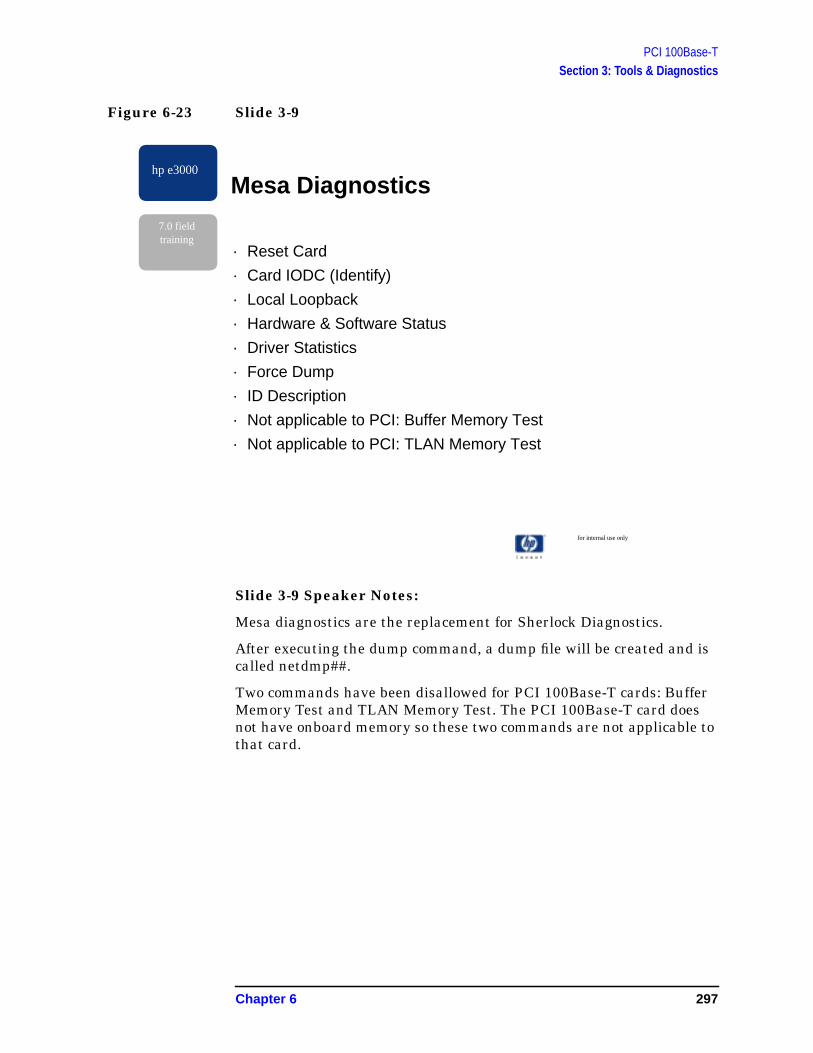
PCI 100Base-TSection 3: Tools & Diagnostics
Figure 6-23 Slide 3-9
Slide 3-9 Speaker Notes:
Mesa diagnostics are the replacement for Sherlock Diagnostics.
After executing the dump command, a dump file will be created and iscalled netdmp##.
Two commands have been disallowed for PCI 100Base-T cards: BufferMemory Test and TLAN Memory Test. The PCI 100Base-T card doesnot have onboard memory so these two commands are not applicable tothat card.
for internal use only
hp e3000
7.0 fieldtraining
Mesa Diagnostics
· Reset Card
· Card IODC (Identify)
· Local Loopback
· Hardware & Software Status
· Driver Statistics
· Force Dump
· ID Description
· Not applicable to PCI: Buffer Memory Test
· Not applicable to PCI: TLAN Memory Test
Chapter 6 297

PCI 100Base-TSection 3: Tools & Diagnostics
Figure 6-24 Slide 3-10
Slide 3-10 Speaker Notes:
Ndmpsum extracts the minimum critical information from a driverdump (netdmp##) in order to analyze a fatal error. This tool will not beavailable for PCI 100BT driver dumps for MR. It may be updated in afuture (Express) release.
Due to resource constraints, tools were implemented based on theresults of a priority ranking survey by WTEC and CPE engineers. Alltools ranked in the “must” category will be available for MR. Only toolsranked at the lowest priorities will be updated after MR.
for internal use only
hp e3000
7.0 fieldtraining
Tools that will not be updated for MR
· NDMPSUM
298 Chapter 6

PCI 100Base-TSection 4: Documentation
Section 4: Documentation
Figure 6-25 Slide 4-1
Slide 4-1 Speaker Notes:
This slide lists the topics that will be covered with regards todocumentation for 7.0.
nfor internal use only
hp e3000
7.0 fieldtraining
Documentation
· What’s being updated/created for MR
· What’s being updated/created after MR
Chapter 6 299
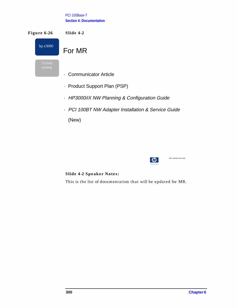
PCI 100Base-TSection 4: Documentation
Figure 6-26 Slide 4-2
Slide 4-2 Speaker Notes:
This is the list of documentation that will be updated for MR.
nfor internal use only
hp e3000
7.0 fieldtraining
For MR
· Communicator Article
· Product Support Plan (PSP)
· HP3000/iX NW Planning & Configuration Guide
· PCI 100BT NW Adapter Installation & Service Guide
(New)
300 Chapter 6

PCI 100Base-TSection 4: Documentation
Figure 6-27 Slide 5-3
Slide 4-3 Speaker Notes:
This is the list of documentation that will be updated after MR (afterFCS).
The NS3000/iX Error Message Manual contains cause/action text foreach error message produced by the 100BT driver (and WAN SDLC andLAPB drivers). The user can refer to this manual to look up the causeand the action to be taken when the 100BT driver produces an error.This manual will not be updated in time for MR.
The NS3000 Operations and Maintenance Manual contains, amongother topics, a description of the statistics produced by the:linkcontrolcommand. These descriptions will not be updated by MR time, howeverthe handout NS3000/iX 100Base-T Link Statistics (made available inthe previous section of this training) covers this information.
The Using the Node Management Services (NMS) Utilities manualcontains information on the NMS utilities and will not be updated byMR time.
Due to resource constraints, manuals were implemented based on theresults of a priority ranking survey by WTEC and CPE engineers. Allmanuals ranked in the “must” category will be available for MR. Onlymanuals ranked at the lowest priorities will be updated after MR.
nfor internal use only
hp e3000
7.0 fieldtraining
Post-MR
· NS3000/iX Error Message Manual, cause/action text
· NS3000 Operations and Maintenance Manual
· Using the Node Management (NMS) Utilities
Chapter 6 301

PCI 100Base-TSection 5: Troubleshooting Techniques and Examples
Section 5: Troubleshooting Techniques andExamples
Figure 6-28 Slide 5-1
Slide 5-1 Speaker Notes
In this section we talk about troubleshooting problems with a PCI100BT link.
If problems occur, there are going to be a range of problems that arefield solvable, either over the phone or onsite, and another range whichare going to require extra work.
The field solvable problems are typically of the installation, hookup,and configuration variety. This slide summarizes the types of problemsthat fall into this category.
Each summarized item is covered in more detail on a separate slide fortroubleshooting reference.
In all discussions, any discussion of a “hub” applies equally if a dataswitch is being used instead.
for internal use only
hp e3000
7.0 fieldtraining
Installation or Field-Solvable100BT Problems· Fails to start, error from the transport occurs
Check I/O path. Enable logging. Check versions, status, andadapter card.
· Starts, but after 30 seconds, receives a warning “did not connectwithin time allowed.”
Try substituting a working connection. Check hubconfiguration, power, cabling.
· “LNK” LED does not go on when the cable is plugged in.Start the network link software.
· Starts and connects, but transport connections cannot beestablished.
Verify matching host-hub speed/duplex. Check NS pathresolution, gateways.
· Sort-of works, but with extremely poor throughput or responsetimes
Verify matching host-hub speed/duplex. Check cabling,network design.
· Configuration was changed, but the old settings are still in effectStop and restart all network link software using the link.
302 Chapter 6
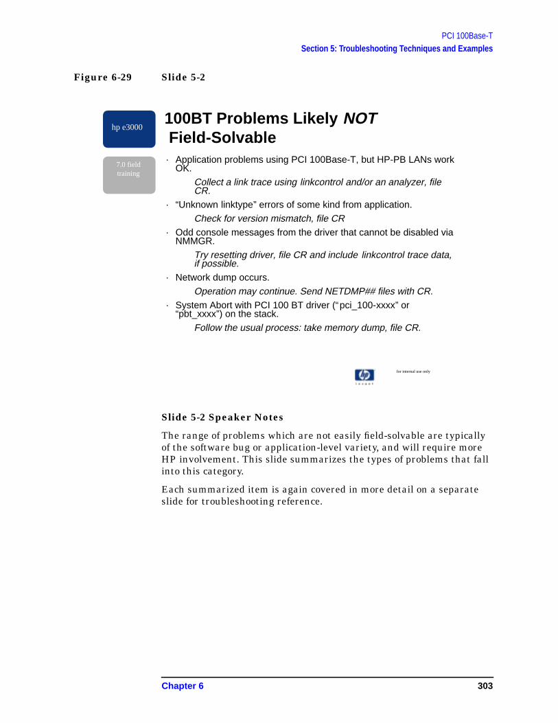
PCI 100Base-TSection 5: Troubleshooting Techniques and Examples
Figure 6-29 Slide 5-2
Slide 5-2 Speaker Notes
The range of problems which are not easily field-solvable are typicallyof the software bug or application-level variety, and will require moreHP involvement. This slide summarizes the types of problems that fallinto this category.
Each summarized item is again covered in more detail on a separateslide for troubleshooting reference.
for internal use only
hp e3000
7.0 fieldtraining
100BT Problems Likely NOT Field-Solvable· Application problems using PCI 100Base-T, but HP-PB LANs work
OK.
Collect a link trace using linkcontrol and/or an analyzer, fileCR.
· “Unknown linktype” errors of some kind from application.
Check for version mismatch, file CR· Odd console messages from the driver that cannot be disabled via
NMMGR.
Try resetting driver, file CR and include linkcontrol trace data,if possible.
· Network dump occurs.
Operation may continue. Send NETDMP## files with CR.· System Abort with PCI 100 BT driver (“pci_100-xxxx” or
“pbt_xxxx”) on the stack.
Follow the usual process: take memory dump, file CR.
Chapter 6 303

PCI 100Base-TSection 5: Troubleshooting Techniques and Examples
Figure 6-30 Slide 5-3
for internal use only
hp e3000
7.0 fieldtraining
Symptom: Fails to Start, Error fromthe Transport Occurs
ACTIONS:
· Check that the proper I/O path was specified in NMMGR.
· Make sure NMMGRVER has been run.
· More driver logging may help. Enable all console loggingfor Sybsys #78 in NMMGR and retry. Collect the log files
· “Parm” value from NS Class-2 error location #42 gives HPvaluable status detail for startup problems.
· Verify the adapter being used is an adapter support onMPE
· If the errors sound like faulty hardware, try replacing theadapter.
· Activate the “trace at startup” option in NMMGR 100BT linkscreen and retry. Collect the trace file.
304 Chapter 6

PCI 100Base-TSection 5: Troubleshooting Techniques and Examples
Slide 5-3 Speaker Notes
First let’s talk about the problems which are easier to solve. If the linkwon’t even start, you’re checking configuration and installation levelinformation, and collecting what tidbits of error information you can,all using tools designed for this purpose.
Remember that I/O paths on PCI systems are longer than on mostHP-PB platforms. For PCI 100BT, be sure to use the slot’s path followedby “/0/0”.
If NMCONFIG came from a supported older release, make sureNMMGRVER has been run.
Default logging configuration should display errors and connects on theconsole, but additional startup logging is available if “Info” logging isenabled, and this may be useful in a startup-troubleshooting situation.Enable all console logging for Subsys #78 in NMMGR, retry the start,and analyze the log messages.
Most common symptom is a Class-2 error from NS location #42; herethe “parm” gives an 8-digit hex value that needs to be decoded to be ofuse. It’s typically a status from the driver. Until error information isready for the NS Error Messages manual, you must rely on the Lab orWTEC to decode any errors. Although HP-PB 100BT data is in themanual, the PCI 100BT values are different.
MPE currently supports only one model of PCI add-on adapter, aspreviously discussed, and does not support the Core I/O 100BT port.
If all this does not lead to a solution, activate the “trace at startup”option in the NMMGR 100BT link screen, retry the start, do:SWITCHNMLOG, then send log and trace files to HP-CSY.
Chapter 6 305
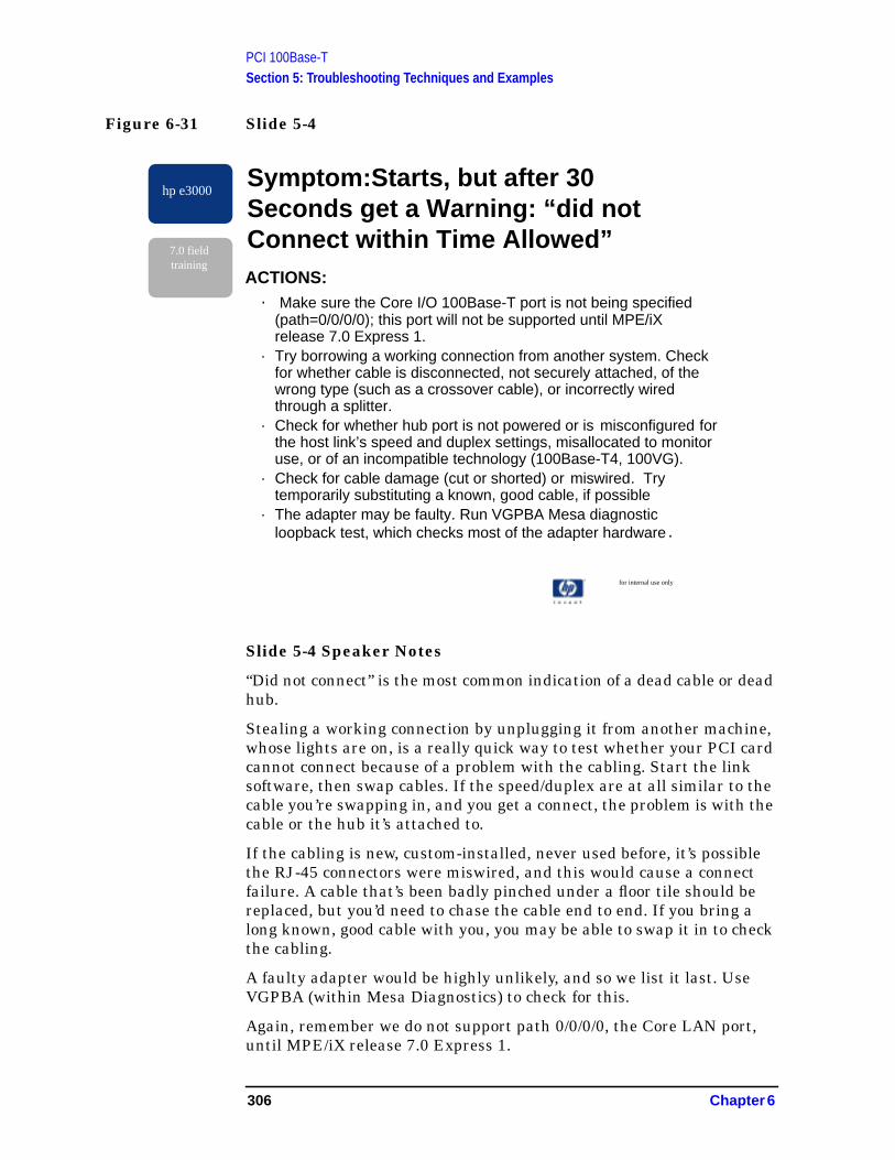
PCI 100Base-TSection 5: Troubleshooting Techniques and Examples
Figure 6-31 Slide 5-4
Slide 5-4 Speaker Notes
“Did not connect” is the most common indication of a dead cable or deadhub.
Stealing a working connection by unplugging it from another machine,whose lights are on, is a really quick way to test whether your PCI cardcannot connect because of a problem with the cabling. Start the linksoftware, then swap cables. If the speed/duplex are at all similar to thecable you’re swapping in, and you get a connect, the problem is with thecable or the hub it’s attached to.
If the cabling is new, custom-installed, never used before, it’s possiblethe RJ-45 connectors were miswired, and this would cause a connectfailure. A cable that’s been badly pinched under a floor tile should bereplaced, but you’d need to chase the cable end to end. If you bring along known, good cable with you, you may be able to swap it in to checkthe cabling.
A faulty adapter would be highly unlikely, and so we list it last. UseVGPBA (within Mesa Diagnostics) to check for this.
Again, remember we do not support path 0/0/0/0, the Core LAN port,until MPE/iX release 7.0 Express 1.
for internal use only
hp e3000
7.0 fieldtraining
Symptom:Starts, but after 30Seconds get a Warning: “did notConnect within Time Allowed”ACTIONS:
· Make sure the Core I/O 100Base-T port is not being specified(path=0/0/0/0); this port will not be supported until MPE/iXrelease 7.0 Express 1.
· Try borrowing a working connection from another system. Checkfor whether cable is disconnected, not securely attached, of thewrong type (such as a crossover cable), or incorrectly wiredthrough a splitter.
· Check for whether hub port is not powered or is misconfigured forthe host link’s speed and duplex settings, misallocated to monitoruse, or of an incompatible technology (100Base-T4, 100VG).
· Check for cable damage (cut or shorted) or miswired. Trytemporarily substituting a known, good cable, if possible
· The adapter may be faulty. Run VGPBA Mesa diagnosticloopback test, which checks most of the adapter hardware .
306 Chapter 6

PCI 100Base-TSection 5: Troubleshooting Techniques and Examples
Figure 6-32 Slide 5-5
Slide 5-5 Speaker Notes
Since the 100BT adapter contains no processor, the LNK LED isnormally only lit under software control. If the software link driver hasnot been started, the LED will probably be dark. Start the link usingthe appropriate NS, DTS, and/or Streams mechanism.
Having the LED come on doesn’t guarantee the host-hub speed andduplex settings are properly matched: the LED is not a definitiveindication, it’s just a general indication that the cabling has at leastsome continuity. If you still cannot connect, go through the earliersteps.
for internal use only
hp e3000
7.0 fieldtraining
Symptom: “LNK” LED does not goon when the Cable is plugged inACTIONS:
· The LNK LED is normally only lit under software control;start the link.
· If the LED still does not come on, see the “did not connect”actions.
· It ma be possible for the LNK LED to light when the driveris not running.
Chapter 6 307
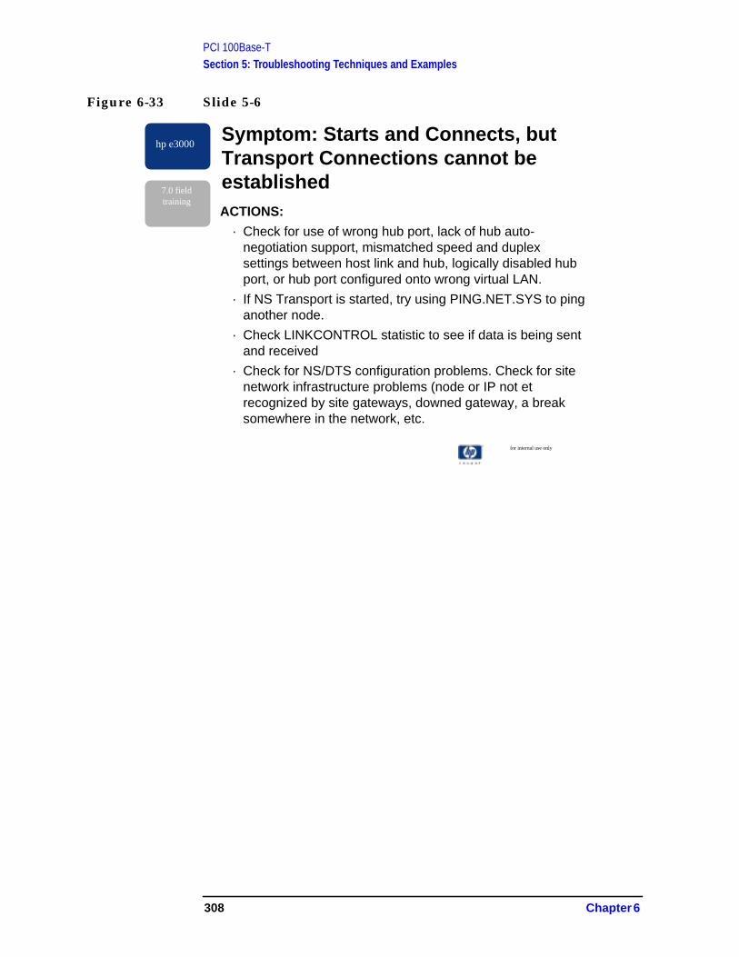
PCI 100Base-TSection 5: Troubleshooting Techniques and Examples
Figure 6-33 Slide 5-6
for internal use only
hp e3000
7.0 fieldtraining
Symptom: Starts and Connects, butTransport Connections cannot beestablishedACTIONS:
· Check for use of wrong hub port, lack of hub auto-negotiation support, mismatched speed and duplexsettings between host link and hub, logically disabled hubport, or hub port configured onto wrong virtual LAN.
· If NS Transport is started, try using PING.NET.SYS to pinganother node.
· Check LINKCONTROL statistic to see if data is being sentand received
· Check for NS/DTS configuration problems. Check for sitenetwork infrastructure problems (node or IP not etrecognized by site gateways, downed gateway, a breaksomewhere in the network, etc.
308 Chapter 6
PCI 100Base-TSection 5: Troubleshooting Techniques and Examples
Slide 5-6 Speaker Notes
Forgetting to change the default NMMGR setting of auto-negotiation =Yes is the most common cause of not being able to talk to remote hostson a fresh installation. This is the case even if a link connect wassuccessfully established.
If NS is being used, you should suspect NS configuration next,especially the RESVLCNF.NET file, NMCONFIG search path inNETXPORT.GLOBAL (type. 1-2-0), gateway configurations, andnetwork directory. Don’t forget that the site’s network infrastructuremay need to be told to recognize a new IP address and nodename.
Other general NS configuration items can also cause this, such as:
• NS Services not starting,
• missing default gateway,
• wrong GLOBAL search path,
• missing RESLVCNF file,
• wrong IP address or subnet mask,
• wrong domain name or nodename, etc.,
• node or IP not yet recognized by site gateways,
• a downed gateway or break someplace in the network.
Chapter 6 309
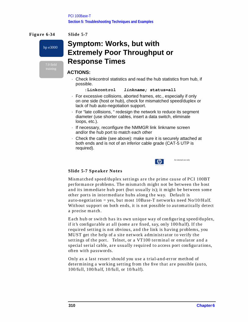
PCI 100Base-TSection 5: Troubleshooting Techniques and Examples
Figure 6-34 Slide 5-7
Slide 5-7 Speaker Notes
Mismatched speed/duplex settings are the prime cause of PCI 100BTperformance problems. The mismatch might not be between the hostand its immediate hub port (but usually is); it might be between someother ports in intermediate hubs along the way. Default isauto-negotiation = yes, but most 10Base-T networks need No/10/Half.Without support on both ends, it is not possible to automatically detecta precise match.
Each hub or switch has its own unique way of configuring speed/duplex,if it’s configurable at all (some are fixed, say, only 100/half). If therequired setting is not obvious, and the link is having problems, youMUST get the help of a site network administrator to verify thesettings of the port. Telnet, or a VT100 terminal or emulator and aspecial serial cable, are usually required to access port configurations,often with passwords.
Only as a last resort should you use a trial-and-error method ofdetermining a working setting from the five that are possible (auto,100/full, 100/half, 10/full, or 10/half).
for internal use only
hp e3000
7.0 fieldtraining
Symptom: Works, but withExtremely Poor Throughput orResponse TimesACTIONS:
· Check linkcontrol statistics and read the hub statistics from hub, ifpossible.
:Linkcontrol linkname; status=all
· For excessive collisions, aborted frames, etc., especially if onlyon one side (host or hub), check for mismatched speed/duplex orlack of hub auto-negotiation support.
· For “late collisions, “ redesign the network to reduce its segmentdiameter (use shorter cables, insert a data switch, eliminateloops, etc.).
· If necessary, reconfigure the NMMGR link linkname screenand/or the hub port to match each other
· Check the cable (see above): make sure it is securely attached atboth ends and is not of an inferior cable grade (CAT-5 UTP isrequired).
310 Chapter 6

PCI 100Base-TSection 5: Troubleshooting Techniques and Examples
Figure 6-35 Slide 5-8
Slide 5-8 Speaker Notes
The software link driver reads configuration settings only at the firststartup. It must be fully closed before another startup can be used toupdate the settings.
If DTS is running over the link, simply stopping NS won’t be enough toclose the link. You need to use :DTCCNTRL or reboot the system.Remember to validate DTS in NMMGR if you’ve changed settings,before a reboot.
for internal use only
hp e3000
7.0 fieldtraining
Symptom: Configuration waschanged, but the Old Settings arestill in effectACTIONS:
· Type :NETCONTROLSTOP to shut down the link, thentype :LINKCONTROL@
· If the link still shows as active, probably DTS is also usingit. Use :DTCCNTRL option 4 to shutdown DTS, thenoption 5 to restart it; or stop and restart the system
· Then use :NETCONTROL to restart the link. The newsettings should now be in effect.
Chapter 6 311
PCI 100Base-TSection 5: Troubleshooting Techniques and Examples
Figure 6-36 Slide 5-9
for internal use only
hp e3000
7.0 fieldtraining
Symptom: Application Problemsusing PCI 100Base-T, but HP-PBLANS work OKACTIONS:
· Collect any error details, including how to reproduce theproblem.
· If possible, temporarily move the nodes onto a quietnetwork, activate link tracing, then reproduce the problem
:linkcontrol linkname ; trace=on,partial,12
:linkcontrol linkname ; trace=off
· There is a high potential for trace data loss due to the highlink speed.
· If trace data loss occurs, use a LAN protocol analyzerinstrument to trace the problem. Include formatted tracedata with the CR.
· If the problem does not appear to be in the application, filea CR. Route CRs to CHART product “MPENW.100BT.”
312 Chapter 6
PCI 100Base-TSection 5: Troubleshooting Techniques and Examples
Slide 5-9 Speaker Notes
Now we’re past the problems that are easily solvable, and are dealingwith some more difficult problems. If the link has come up andconnected, but isn’t working properly, this can be difficult to diagnose.
An application problem might result in an error message, a hang, orsimply incorrect results.
Depending on the problem and the support contract, troubleshootingmight be beyond the scope of normal HP support.
Link trace is a great tool for debugging startup problems, but once thelink really gets going, no file system is able to keep up with it, sorecording trace data becomes a problem. There is a high potential fortrace data loss due to high-speed link, compatibility-mode OS tracinginfrastructure, and limited file size. If the application problem can beduplicated on a quiet network after only a few protocol exchanges, thereis a better chance for success with tracing.
Format the trace to an ASCII file and then browse the file. HP may alsorequire traces from a working HP-PB system (100BT, 100VG, orThinLAN).
A line analyzer instrument would be the tool of choice if the problemcannot be captured another way. If trace data loss occurs, use a LANprotocol analyzer to trace the problem. Make sure your instrument canbe used with the site’s LAN (speed/ duplex etc.) before going onsite.Include formatted trace data in any CR filed (don’t assume the lab canhandle a raw analyzer data file).
Chapter 6 313

PCI 100Base-TSection 5: Troubleshooting Techniques and Examples
Figure 6-37 Slide 5-10
Slide 5-10 Speaker Notes
It is the intent that PCI 100BT work with everything HP-PB 100BTworks with, but if something was missed, trouble will occur. It isdifficult to predict what the specific error symptom might be, but if it’sany sort of error message relating to an “unknown linktype” this wouldbe a good clue that something was missed. File a CR.
for internal use only
hp e3000
7.0 fieldtraining
Symptom: “Unknown Linktype”errors of some kind fromApplicationACTIONS:
· Check for old or mismatched software revisions. RunNMMAINT to check versions
:nmmaint, 78
· If this is not the problem, file a CR. Route CRs to CHARTproduct “MPENW.100BT.”
314 Chapter 6

PCI 100Base-TSection 5: Troubleshooting Techniques and Examples
Figure 6-38 Slide 5-11
Slide 5-11 Speaker Notes
First release of the driver still has numerous “print statements” in it.These messages should not occur in normal operation unless somethingvery strange is happening. File a CR.
Note that “:Linkcontrol linkname; status=reset” does not perform thissame function as a reset from Mesa Diagnostics' VGPBA.
All printouts will be removed in a future revision of the link softwaredriver.
for internal use only
hp e3000
7.0 fieldtraining
Symptom: Odd Console Messagesfrom the Driver that cannot bedisabled via NMMGRACTIONS:
· A few unlikely errors, if detected, print messages directly tothe system console; driver operation may or may notcontinue
· Try using the Mesa Diagnostics VGPBA “reset” function torestore normal driver operation.
· Try stopping and restarting the link.
· File a CR. Route CRs to CHART product“MPE.NW.100BT.” If possible, include a Linkcontrol linktrace of the problem with the CR.
Chapter 6 315

PCI 100Base-TSection 5: Troubleshooting Techniques and Examples
Figure 6-39 Slide 5-12
for internal use only
hp e3000
7.0 fieldtraining
Symptom: Network Dump OccursACTIONS:
· Driver should resume automatically up to 12 times.However, dumps should never occur. Send allNETDMP##.PUB.SYS files to HP-CSY.
· File a CR. Route CRs to CHART product“MPE.NW.100BT.”
316 Chapter 6

PCI 100Base-TSection 5: Troubleshooting Techniques and Examples
Slide 5-12 Speaker Notes
The link driver software is able to take a snapshot of itself in the eventof a serious failure, for analysis by the lab. These snapshots are dumpedinto NETDMPnn.PUB.SYS files, then the driver attempts to auto-resetitself and continue.
These serious failures should not be occurring, so send the files in witha CR.
Incidentally, additional Network Dump Processes will start up at boottime. This is normal. Each link type supporting driver-error dumps nowhas its own dump module, a dependency-reduction change. Therefore atboot time, instead of seeing a single [NETWORK_DUMP_PROCESS]startup message, it will be normal to at least 4 dump process startupmessages.
The NDMPSUM tool is designed to help the field compare differentNETDMP files to see if they are probably of the same problem or not. Itmay not support PCI linktypes by MR time.
Analyzing NETDMP files is generally a job for the lab, since all the datastructures are driver specific, and some special addressing techniquesare required. PCI 100BT provides some DAT macros to aid in opening aNETDMP file for analysis, but getting DAT to let you do this instead ofopening a system memory dump is tricky.
Chapter 6 317

PCI 100Base-TSection 5: Troubleshooting Techniques and Examples
Figure 6-40 Slide 5-13
Slide 5-13 Speaker Notes
As with any Sysabort you should take a system memory dump.Subsystem Dump does not support MPE networking.
Just because link driver software procedure names are on the stack,doesn’t necessarily mean the driver did or didn’t cause a problem. Butanalysis will be aided if the CR states what is happening near the top ofthe stack.
Fortunately PCI 100BT data structures are designed to simplifydebugging, and the driver collects a lot of information at runtime to aidproblem analysis.
for internal use only
hp e3000
7.0 fieldtraining
Symptom: System Abort with PCI100BT Driver (“pci_100_xxxx” or“pbt_xxxx” Procedure) on the Stack
ACTIONS:
· Take a memory dump and use the usual support process.Route CRs to CHART product “MPE.NW.100BT.”
318 Chapter 6

7 PCI Sync MUX
Figure 7-1 Slide 1
for internal use only
hp e3000
7.0 fieldtraining
PCI Sync MUX Field Training Topics
· Section1: Detail of Product Features and Limitations
· Section 2: Configuration changes in 7.0
· Section 3: Tools & Diagnostics
· Section 4: Documentation
· Section 5: Troubleshooting Techniques & Examples
319

PCI Sync MUX
Figure 7-2 Slide 2
for internal use only
hp e3000
7.0 fieldtraining
PCI WAN Sync MUX (Adapter Cardand Driver)
The WAN Sync MUX product is a combination ofhardware, firmware protocol modules and the hostdriver.
320 Chapter 7

PCI Sync MUX
Figure 7-3 Slide 3
Slide 3 Speaker Notes:
In choosing the WAN Sync MUX adapter card we would support onPCI-bus based HP e3000 systems, we decided to support the same cardas HP-UX. (HP-UX uses other Cards also). This gave us leverage indeveloping the software to drive the card, and assured us that the cardhad been proven to work on the new hardware architecture.
The PCI WAN Sync MUX does require firmware downloads and hasreal on-board processor and memory. The level-2 protocols (SDLC andLAPB) will be running on the card. This will simplifies the driver’soperations.
This slide explains the purpose of the new PCI WAN Sync MUX linkproduct.
The new class of HP e3000 systems has PCI-bus based hardwarearchitecture. New drivers must be developed to support new PCI-basedperipheral devices, including a new WAN Sync MUX card.
for internal use only
hp e3000
7.0 fieldtraining
What is the PCI WAN Sync MUX linkproduct?
· WAN connectivity solution for PCI-bus based HP e3000systems
· IBM (SNA) connectivity solution for PCI-bus basedHP e3000 systems
· Provides the same interface to LAN/WAN network stacks (e.g.,NS TCP/IP) as exists on HP-PB systems.
· Provides the same interface to SNA network stacks (e.g., IMF,APPC, NRJE, etc.)
· Software component bundled with FOS and SUBSYS.
· PCI WAN Sync Mux add-on adapter card (Z7340A) must beordered separately.
· PCI equivalent to HP-PB PSI link product (A5563A)
Chapter 7 321

PCI Sync MUX
PCI WAN Sync MUX encompasses the new software driver and newadd-on adapter card that are required to provide WAN and IBMconnectivity for the new system architecture.
It is a distinct and separate product from HP-PB PSI, which isincompatible with the new architecture.
From a customer perspective, there is no major difference in how thenetworking subsystems will operate compared to HP-PB HP e3000systems. The change to the underlying hardware architecture will bebasically transparent. Customers currently using NS TCP/IP, and SNAproducts and applications will run their applications the same as theydo on HP-PB (using PSI hardware) systems, only they will now run overthe PCI WAN MUX LAPB and SDLC links respectively.
This approach is fundamental to the HP e3000 PCI design philosophy:the underlying hardware/architecture changes should not impact upperlayer software products or customer applications, and should beessentially transparent.
NOTE Please note that Bi-Sync/RJE is not supported on Sync MUX, unlikePSI.
The software component for the new PCI WAN Sync MUX link productwill be bundled into FOS (MPE/iX 7.0 and later) and SUBSYS. Thecustomer needs to order the hardware (Sync MUX adapter add-on card)and software (LAP-B or SDLC) separately for their system. This issame as HP-PB PSI.
322 Chapter 7

PCI Sync MUX
Figure 7-4 Slide 4
Slide 4 Speaker Notes:
The PCI WAN Sync MUX adapter card is a multi-port, add-on. This isan “Intelligent” card, which does require firmware downloads and hason-board memory.
This particular WAN card was chosen for the new HP e3000 platformsin part because it is supported by HP-UX on their N-class servers (PCIbus-based architecture). This means that the card had been proven towork on the new PCI bus-based hardware architecture, and we alsogained some leverage in developing the software on MPE/iX to drive thecard.
Since this is an “Intelligent” card with protocols running on the card,this makes the driver design as simple.
The card is capable of supporting up to 2 Mbps speeds, which can beconfigured in NMCONFIG.
for internal use only
hp e3000
7.0 fieldtraining
Features of the PCI WAN Sync MUXAdd-on Adapter Card
· Multi-port card (8 ports).
· Can support multiple WAN protocols such asHDLC-NRM (SDLC), HDLC-LAPB (and X.25),HDLC-LAP-D (ISDN), Frame Relay, etc.
· “Intelligent” card with on-board memory anddownloadable firmware
· Protocols will be running on the card.
· Can support running of multiple protocols on differentports at the same time.
· Same adapter card is supported by HP-UX on theirN-Class servers.
Chapter 7 323

PCI Sync MUX
Figure 7-5 Slide 5
for internal use only
hp e3000
7.0 fieldtraining
PCI WAN Sync MUX Adapter CardHardware notes:
• RS-232c interface support
• V.35 Interface Support
• LED indicator for Self test
324 Chapter 7

PCI Sync MUX
Figure 7-6 Slide 6
Slides 5 and 6 Speaker Notes:
The multiplexer (MUX) installs as an I/O interface card in theHP e3000 computer. The MUX is a one-half length PCI card, whichsupports eight synchronous ports at speeds up to 128 kbps on RS-232and V.35 ports, 2 Mbps on RS-449 and X.21 ports (not supported).
The MUX connects to the interchange panel by a 160-conductor cable,three meters in length (as shown in Slide-1). The cable has maleconnectors on each end. The 8 ports will be there on the interchangePANEL and can be configured for different protocol accordingly.
Two-meter octopus cables with a 160-conductor connector on one endand right RS-232 or V.35 female connectors on the other end are alsoavailable for connecting the MUX. The below figure shows the MUXcard with an octopus cable.
for internal use only
hp e3000
7.0 fieldtraining
Table 2-1 MUX Card LED Display Interpretation
LED Display MeaningLED flashes red for aboutSeven seconds, then turnsgreen.
This is normal functioning.
LED mains red or remainsoff.
There is a problem with theMUX card.
The LED turns orangeinstead of green.
This means that at least oneof the ports is down but thesystem can still be used.Run diagnostic software todetermine the problem.
Chapter 7 325

PCI Sync MUX
326 Chapter 7
PCI Sync MUX
Figure 7-7 Slide 7
Slide 7 Speaker Notes:
There will be no Auto Dial Support for the first release. Efforts arebeing made to support Auto Dial for the future releases.
There will be no Bi-Sync/RJE support on Sync MUX. There will bemajor enhancement to support Bi-Sync on Sync MUX.
Even though MUX supports LAPB (X.25 level 2), Host based X.25 is notsupported and will be supported through DTCs. To support host basedX.25 we need to implement X.25 level-3 protocol on the host, which isanother major enhancement.
N-class systems will support up to 4 separate Sync MUX cards persystem.
(The smaller A-class HP e3000 systems will support less; limits are stillbeing defined).
The N-class and A-class HP e3000 systems include support of UniversalPower Supply (UPS) “backup” power. This has essentially replaced theneed for traditional MPE/iX power fail recovery, which will no longerexist on the new PCI HP e3000 platforms.
for internal use only
hp e3000
7.0 fieldtraining
Miscellaneous Notes
· Supports RS-232 and V.35 interfaces.
· Supports speeds up to 2Mbps.
· Bi-Sync/RJE is not supported.
· AutoDial is not supported for the first release.
· Host-based X.25 is not supported (it will be supportedon DTCs).
· Each N-Class HP e3000 system can support up to 2(?)Sync MUX cards.
Chapter 7 327
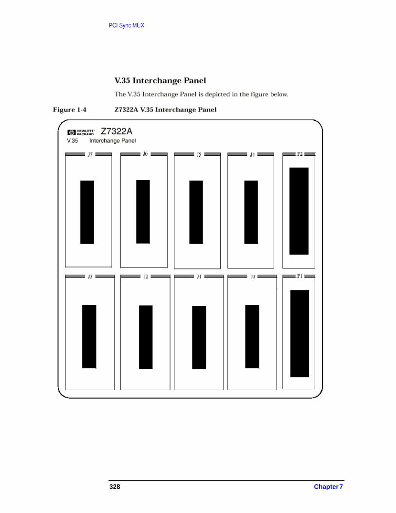
PCI Sync MUX
328 Chapter 7
PCI Sync MUX
Figure 7-8 Slide 8
Slide 8 Speaker Notes:
Most of the configuration is the same as for HP-PB 100Base-T. Thereare some specific differences.
The next few slides give the details.
for internal use only
hp e3000
7.0 fieldtraining
PCI WAN Sync MUX Configurationin NMMGR
· On PCI platforms, both NS and SNA must specify thecardport along with the physical path.
· On PCI platforms, NS screen must specify “LAPBMUX”as the linktype
· On PCI platforms, SNA screen must specify“SDLCMUX” as the linktype
· On PCI platforms: LAPBMUX doesn’t support localmode type 11 (HP to HP).
· New logging configuration screens for PCI WAN SyncMUX link (Subsystem 82).
Chapter 7 329

PCI Sync MUX
Figure 7-9 Slide 9
Slide 9 Speaker Notes:
This is the first Guided Config screen to configure a Point to Point NI.Point to Point NI now supports two kinds of Link type, one is the oldPSI link type and the other is the New LAPBMUX link type. Toconfigure the New LAPBMUX link type, enter a NI name and choosethe “network type” of 2. Then click the “Config Network” softkey.
for internal use only
hp e3000
7.0 fieldtraining
for internal use only
330 Chapter 7

PCI Sync MUX
Figure 7-10 Slide 10
Slide 10 Speaker Notes:
This is the screen through which you can configure the New LAPBMUXlink type. This is the screen used to configure the PSI LAPB link also. Anew field as “Card Type” has been introduced. For configuring the newLAPBMUX link, enter “LAPBMUX” in the “Card Type” field. ForLAPBMUX link you need to enter the Card port number along with thephysical path.
To form the I/O path field for Sync MUX adapter on PCI platforms,begin with the path printed on the slot where the adapter is installed(“1/10” in this example), and add “0/1.cardport#.” If the physical path ofthe card is 1/10/0/1 and if you are using the port-2 of the card as LAPBport, then you should enter 1/10/0/1.2 as the physical path as shownabove.
This applies to both LAPBMUX and SDLCMUX configuration.
for internal use only
hp e3000
7.0 fieldtraining
for internal use only
Chapter 7 331

PCI Sync MUX
Figure 7-11 Slide 11
Slide 11 Speaker Notes:
The NI Selection screen changes to display the link type. Point to PointNI’s supporting LAPBMUX link type will display the NI type =“ROUTER” and Link Type = “LAPBMUX.” This screen appears withinUnguided Config and also in the Guided Config “List NIs” screen.
for internal use only
hp e3000
7.0 fieldtraining
for internal use only
332 Chapter 7

PCI Sync MUX
Figure 7-12 Slide 12
Slide 12 Speaker Notes:
This is the first Unguided Screen to configure the new LAPBMUX linktype. For this you need to choose a Link name and to enter the “Type”as “LAPBMUX.” Then click the “Add” softkey button.
for internal use only
hp e3000
7.0 fieldtraining
for internal use only
Chapter 7 333
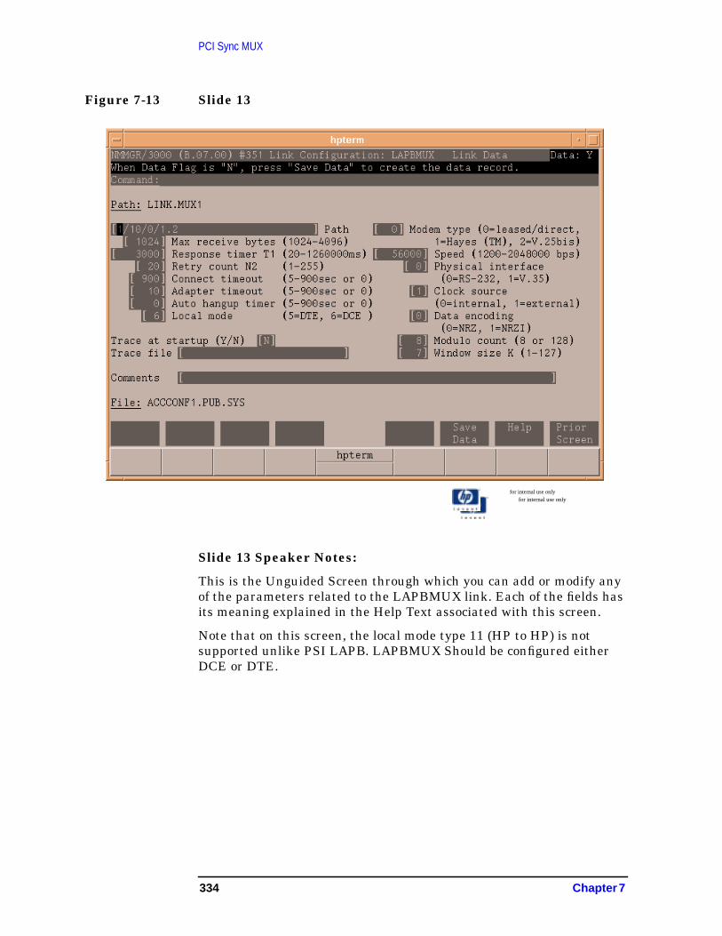
PCI Sync MUX
Figure 7-13 Slide 13
Slide 13 Speaker Notes:
This is the Unguided Screen through which you can add or modify anyof the parameters related to the LAPBMUX link. Each of the fields hasits meaning explained in the Help Text associated with this screen.
Note that on this screen, the local mode type 11 (HP to HP) is notsupported unlike PSI LAPB. LAPBMUX Should be configured eitherDCE or DTE.
for internal use only
hp e3000
7.0 fieldtraining
for internal use only
334 Chapter 7
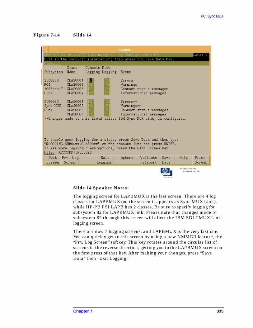
PCI Sync MUX
Figure 7-14 Slide 14
Slide 14 Speaker Notes:
The logging screen for LAPBMUX is the last screen. There are 4 logclasses for LAPBMUX (on the screen it appears as Sync MUX Link),while HP-PB PSI LAPB has 2 classes. Be sure to specify logging forsubsystem 82 for LAPBMUX link. Please note that changes made tosubsystem 82 through this screen will affect the IBM SDLCMUX Linklogging screen.
There are now 7 logging screens, and LAPBMUX is the very last one.You can quickly get to this screen by using a new NMMGR feature, the“Prv. Log Screen” softkey. This key rotates around the circular list ofscreens in the reverse direction, getting you to the LAPBMUX screen onthe first press of that key. After making your changes, press “SaveData” then “Exit Logging.”
for internal use only
hp e3000
7.0 fieldtraining
for internal use only
Chapter 7 335

PCI Sync MUX
Figure 7-15 Slide 15
Slide 15 Speaker Notes:
This is the main IBM configuration screen. You need to click therespective Softkeys to do the required configuration. If you want toconfigure an IBM SNANODE, then click the Softkey “Go ToSNANODE” to configure a new SNANODE or to update an existing one.
for internal use only
hp e3000
7.0 fieldtraining
for internal use only
336 Chapter 7

PCI Sync MUX
Figure 7-16 Slide 16
Slide 16 Speaker Notes:
This is the IBM SNA Node Configuration screen. Here a new linktypeof SDLCMUX has been added. To add this new link type, enter“SDLCMUX” in the “Link Type” field and click on the “Go ToLINKDATA” softkey.
for internal use only
hp e3000
7.0 fieldtraining
for internal use only
Chapter 7 337

PCI Sync MUX
Figure 7-17 Slide 17
Slide 17 Speaker Notes:
This is the screen through which you can add or modify theconfiguration data related to a SDLCMUX link. Enter the datacorrespond to various fields on the screen and then click the “SaveData” screen to add a new link or to modify an existing link.
for internal use only
hp e3000
7.0 fieldtraining
for internal use only
338 Chapter 7

PCI Sync MUX
Figure 7-18 Slide 18
Slide 18 Speaker Notes:
This is the logging screen for the SDLCMUX link type (it appears asSync MUX Link on the screen). There are 4 classes for SDLCMUX,while SDLC PSI HPPB still has 2 classes. Be sure to specify logging forsubsystem 82 for SDLCMUX. Please note that any changes made tosubsystem 82 through this screen will affect t7.0 PCI WAN Sync MUXField Training
for internal use only
hp e3000
7.0 fieldtraining
for internal use only
Chapter 7 339

PCI Sync MUX
Figure 7-19 Slide 19
Slide 19 Speaker Notes:
This slide lists all the diagnostic tools that will be covered in thetraining.
for internal use only
hp e3000
7.0 fieldtraining
Diagnostic Tools
· NMMAINT
· DAT/Debug Macros
· NMDUMP Trace Formatter
· NMDUMP Log Formatting
· LINKCONTROL
· Tools that won’t be updated for MR
340 Chapter 7

PCI Sync MUX
Figure 7-20 Slide 20
for internal use only
hp e3000
7.0 fieldtraining
NMMAINT,82
· Reports the NL & XL version numbers of the WANSync MUX driver
· Reports the NL version number of the LAPB module
· Reports the NL version number of the SDLC module
· Reports the WAN Sync MUX catalog file (NMCAT82)
· Reports the version of Sync MUX Download(MUXDWN00.NET.SYS)
Chapter 7 341

PCI Sync MUX
Figure 7-21 Slide 21
Slide 20 and 21 Speaker Notes:
NMMAINT,82 also reports the version number of Link Common(LNK_NL_VERS), which is a set of shared services used by WAN SyncMUX.
for internal use only
hp e3000
7.0 fieldtraining
CSYPREL8:nmmaint,82NMS Maintenance Utility 32098-20014 B.00.11 (C)Hewlett-Packard Co 1984
THU,SEP 14, 2000 10:24 AMDatacom products build version: N.68.03
Subsystem version IDs
Subsystem Number: 82PCI WAN Sync MUX Driver -----module versions:
NL procedure: WAN_SMUX_NL_VERS Version: A0070002NL procedure: MUX_LAPB_NL_VERS Version: A0070000NL procedure: MUX_SDLC_NL_VERS Version: A0070000XL procedure: WAN_SMUX_XL_VERS Version: A0070000Catalog file: NMCAT82.NET.SYS Version: A0070000Download: MUXDWN00.NET.SET Version: A0070000NL procedure: LNK_NL_VERS Version: A0070004
PCI WAN Sync MUX Driver ----- overall version - A.00.70
342 Chapter 7

PCI Sync MUX
Figure 7-22 Slide 22
Slide 22 Speaker Notes:
Using DAT macros, the user can analyze WAN Sync MUX datastructures in different modes (on-line, system dump, Rembug, driverdump). Examples include accnetdmpopen and accfmtdvrtrace.
Datacomm Link macros in TELESUP have been extended to addselections for the new WAN Sync MUX, and the menu selection valuefor “all” changes from “9” to “99” to leave room for future links.
for internal use only
hp e3000
7.0 fieldtraining
DAT/Debug Macros
· All WAN Sync MUX macros begin with ACC*
· New macros for PCIACCSETPTRSACCSETSYMSACCSETUPACCNETDMPOPENACCNETDMPCLOSEACCSUMDMPOPEN
ACCFMTDVRTRACEACCFMTALLTRACEACCT_FMTTRACEBUF
NOTE: HP_PB WAN macros cannot be used to debuga PCI WAN Sync MUX driver.
Chapter 7 343

PCI Sync MUX
Figure 7-23 Slide 23
Slide 23 Speaker Notes:
From within the NMDUMP program, this utility gives the user theability to format trace records recorded to the disk by the WAN SyncMUX (includes WAN SDLC and LAPB drivers). Tracing can be turnedon in the NMCONFIG file or through the :linkcontrol command.
for internal use only
hp e3000
7.0 fieldtraining
NMDUMP Trace Formatter
· No significant user interface changes made for PCI
· Trace content specific to the new WAN Sync MUXdriver
· Use subsys 82 for WAN Sync MUX
344 Chapter 7

PCI Sync MUX
Figure 7-24 Slide 24
Slide 24 Speaker Notes:
From within the NMDUMP, this utility provides the user with acapability to print logging calls made by the WAN Sync MUX driver(includes WAN SDLC and LAPB drivers) and record these calls to thedisk in the nmlg### file. Logging can be enabled in the configurationusing the NMMGR tool.
for internal use only
hp e3000
7.0 fieldtraining
NMDUMP Log Formatting
· No significant user interface changes made for PCI
· Some new options
· Log content specific to the new WAN Sync MUX
· Use subsys82 for WAN Sync MUX
Chapter 7 345

PCI Sync MUX
Figure 7-25 Slide 25
Slide 25 Speaker Notes:
Linkcontrol <command> is either trace or status
The Trace command turns tracing on/off
The Status command has several sub-options:
All prints configuration and statistics information
Link prints the linkname, linktype and linkstate
Config prints the driver configuration information (e.g.driver path, MAC address, multicast addresses, etc.)
Statistics prints driver statistics
Diagstats prints driver configuration information,driver statistics and driver diagnostic statistics (forinternal use only)
Reset prints the current statistics and then tells thedriver to reset the statistics & diagnostic statisticsvalues
for internal use only
hp e3000
7.0 fieldtraining
Linkcontrol
:Linkcontrol [linkname]
[; <command>]· Trace
· On
· Off
· Status
· =a[ll]
· =l[ink]
· =c[onfiguration]
· =s[tatistics]
· =d[iagstats]
· =r[eset]
346 Chapter 7

PCI Sync MUX
Figure 7-26 Slide 26
Slide 26 Speaker Notes:
This is in a preliminary stage of development. There is not enoughinformation on its development to discuss at this time.
for internal use only
hp e3000
7.0 fieldtraining
for internal use only
Linkcontrol Statistics:PCI Output
MICKEYS:linkcontrol @; status=dLinkname:PLAPLNK4 Linktype: LAPBMUX Linkstate: CONNECTING LEVEL 2Physical Path 1/10/0/1.4Phone NumberModulo Count 8 Cable Type Modem eliminatorLocal Mode DCE Buffer Size 1028 bytesLAPB Parm K 7 Connect Timeout 900 secLAPB Parm T1 300 sec Local Timeout 60 secLAPB Parm N2 20 Transmission Speed 56000 bps
Connect Duration 1:16:18 Tracing OFFData BytesSent 3817 Data Bytes Rcvd 5990Overhead BytesSent 888 Overhead Bytes Rcvd 564Total FramesSent 148 Total Frames Rcvd 94Data FramesSent 70 Data Frames Rcvd 70Aborted FramesSent 0 Aborted Frames Rcvd 0 Statistics Resets 0Pda Pointer A.D6B80300Write Subqueue Closes 0 Receives Without Buffers 0Transmit Underruns 0 Buffer Starvations 5Power Failures 0 Receive Timeouts 0Total DriverTimeouts 2553 Connect Timeouts 0Level 2 Connects 1 Total Bytes Hardware Trace 131948Level 2 Disconnects 1 Total Bytes Software Trace 410164Trace BuffersLost 0 Trace Buffer Send Attempts 0Driver MessagesSent 94 Driver Messages Received 5525DriverInterrupts 2881 Driver MessagesDequeued 0
Chapter 7 347

PCI Sync MUX
Figure 7-27 Slide 27
for internal use only
hp e3000
7.0 fieldtraining
Linkname:PCI44 Linktype: LAPBLinkstate CONNECTING LEVEL 1
Pysical Path 56/44Phone NumberModule Count 8 Cable Type: Modem eliminatorLocal Node DCE Buffer Size: 1028 bytesLAPB Parm K 7 Connect Timeout: 900 SecLAPB Parm T1 300 sec Local Timeout: 60 secLAPB Parm N2 20 Transmission Speed: 56000 bps
Connect Duration 0:05:47 Tracing: OFFData Bytes Sent 85695 Data Bytes Rcvd: 728928Overhead Bytes Sent 20664 Overhead Bytes Rcvd: 10056Total Frames Sent 3444 Total Frames Rcvd: 1676Data Frames Sent 1243 Data Frames Rcvd: 1246Aborted Frames Sent 0 Aborted Frames Rcvd: 152DST Losses 52 Oversized Frames Rcvd: 0CTS Carrier Losses 0 Receive Overruns: 0DCD Carrier Losses 4733 CRC Errors: 0 Statistics Resets: 2
348 Chapter 7

PCI Sync MUX
Figure 7-28 Slide 28
Slide 27 and 28 Speaker Notes:
There are NEW fields for PCI for support of the new hardware.
for internal use only
hp e3000
7.0 fieldtraining
Total Frames Sent: 3444 Total Frames Rcvd: 1676 I frames: 1243 I frames: 1246
RR frames: 1465 RR frames: 362 RNR frames: 0 RNR frames: 25 REF frames: 0 REJ frames 0 DISC frames: 210 DISC frames: 14
DM frames: 0 DM frames: 0 FRMR frames: 0 FRMR frames: 0
SABM frames: 489 SABM frames: 23 UA frames: 37 UA frames: 6
PdsPointer A.D6B80300Write Subqueue Closes 4 Receives Without Buffers 0Transmit Underruns 0 Buffer Starvations 125Power Failures 0 Receive Timeouts 0Total Driver Timeouts 37545 Connect Timeouts 0Level 2 Connects 26 Total Bytes HW Trace 2166184Level 2 Disconnects 36 Total Bytes SW Trace 6075388Trace Buffers Lost 0 Trace Buffer Send Attempts 0Driver Messages Sent 1494 Driver Messages Received 80015Driver Interrupts 40977 Driver Messages Dequeued 0
Chapter 7 349

PCI Sync MUX
Figure 7-29 Slide 29
Slide 29 Speaker Notes:
Ndmpsum extracts the minimum critical information from a driverdump (netdmp##) in order to analyze a fatal error. This tool will not beavailable for PCI Sync MUX driver dumps for MR. It may be updated ina future (Express) release.
The LAPBMUX link logging also.
There are now 4 IBM logging screens and SDLCMUX is the last one.You can quickly get to this screen by using a new NMMGR feature, the“Prev Log Screen” softkey. This key rotates around the circular list ofscreens in the reverse direction, getting you to the SDLCMUX screenon the first press of that key. After making your changes, press “SaveData” and then “Exit Logging.”
for internal use only
hp e3000
7.0 fieldtraining
Tools that won’t be updated for MR
· NDMPSUM
350 Chapter 7

PCI Sync MUX
Figure 7-30 Slide 30
Slide 30 Speaker Notes:
This slide lists the topics that will be covered with regards todocumentation for 7.0.
for internal use only
hp e3000
7.0 fieldtraining
Documentation
· What is being updated/created for MR
· What is being updated/created after MR
Chapter 7 351

PCI Sync MUX
Figure 7-31 Slide 31
Slide 31 Speaker Notes:
This is the list of documentation that will be updated for MR.
for internal use only
hp e3000
7.0 fieldtraining
For MR
· Communicator Article
· Product Support Plan (PSP)
· HP e3000/iX NW Planning & ConfigurationGuide
· PCI Sync MUX NW Adapter Installation &Service Guide (NEW)
352 Chapter 7

PCI Sync MUX
Figure 7-32 Slide 32
Slide 32 Speaker Notes:
This is the list of documentation that will be updated after MR (afterFCS).
The NS 3000/iX Error Message Manual contains cause/action text foreach error message produced by the 100BT driver (and WAN SDLC andLAPB drivers). The user can refer to this manual to look up the causeand the action to be taken when the 100BT driver produces an error.This manual will not be updated by MR time.
The NS 3000 Operations and Maintenance Manual contains, amongother topics, a description of the statistics produced by the :linkcontrolcommand. These descriptions will not be updated by MR time, howeverthe handout NS 3000/iX Sync MUX Link Statistics (made availablein the previous section of this training) covers this information.
The Using the Node Management Services (NMS) Utilities manualcontains information on the NMS utilities and will not be updated byMR time.
Due to resource constraints, manuals were implemented based on theresults of a priority ranking survey by WTEC and CPE engineers. Allmanuals ranked in the “must” category will be available for MR. Onlymanuals ranked at the lowest priorities will be updated after MR.
for internal use only
hp e3000
7.0 fieldtraining
POST-MR
· NS3000/iX Error Message Manual,cause/action text
· NS3000 Operations and Maintenance Manual
· Using the Node Management Services (NMS)Utilities
Chapter 7 353

PCI Sync MUX
Figure 7-33 Slide 33
Slide 33 Speaker Notes:
In this section we talk about troubleshooting problems with a PCI WANlink (SDLC or LAPB).
There is a range of potential problems that are field solvable. There isanother group of problems that will require extra work to solve andmore HP involvement.
The field solvable problems are typically of the installation, hookup,and configuration variety. This slide summarizes the types of problemsthat fall into this category.
Each summarized item is covered in more detail on a separate slide fortroubleshooting reference.
for internal use only
hp e3000
7.0 fieldtraining
Installation or Field-Solvable WANproblems· Fails to start, error from the transport occurs.
Check I/O path. Enable logging. Check versions, status,adapter card.
· “Self test” LED does not go green on the boot.May be faulty card, fist try rebooting after hard RESET. Ifthe problem occurs again, try replacing the adapter card.
· Starts, but after 30 seconds, gets a warning “did not connectwith time allowed.”
Try substituting a working connection. Check configuration,power, cabling.
· Starts and connects, but transport connections cannot beestablished.
Check NS path resolution, gateways in case for LAPB link· Configuration was changed, but the old settings are still in
effectStop and restart all network link software using the link.
354 Chapter 7

PCI Sync MUX
Figure 7-34 Slide 34
Slide 34 Speaker Notes
The range of problems which are not easily field solvable are typically ofthe software-bug or application-level variety, and will require more HPinvolvement. This slide summarizes the types of problems that fall intothis category.
Each summarized item is again covered in more detail on a separateslide for troubleshooting reference.
for internal use only
hp e3000
7.0 fieldtraining
WAN Sync MUX Problems Likelynot Field-Solvable· Application problems using PCI WAN Sync MUX, but HP-PB
PSIs worked OK.Collect a link trace using Linkcontrol and/or an analyzer.File CR
· “Unknown linktype” errors of some kind from applicationCheck for version mismatch. File CR
· Odd console messages from the driver which cannot bedisabled via NMMGR
Try resetting driver. File CR & include Linkcontrol tracedata is possible.
· Network dump occurs.Operation may continue. Send NETDMP## files with CR
· System Abort with PCI WAN Sync MUX driver (“pacc_xxxx”or “acc_xxxx” or “nacc_xxxx”) on the stack
Follow the usual process: take memory dump, file CR
Chapter 7 355
PCI Sync MUX
Figure 7-35 Slide 35
for internal use only
hp e3000
7.0 fieldtraining
Symptom: Fails to start, error fromthe Transport occurs
Actions :
· Check that the proper I/O path was specified in NMMGR.
· Make sure NMMGRVER has been run.
· More driver logging may help. Enable all console loggingfor Subsys #82 in NMMGR and retry. Collect the log file.
· “Parm” value from NS Class-2 error location #42 gives HPvaluable status detail for startup problems.
· Verify the adapter being used is an adapter supported onMPE.
· If the errors sound like faulty hardware, try replacing theadapter.
· Activate the “trace at startup” option in NMMGR LAPBMUXlink screen and retry. Collect the trace tile.
· For SNA: activate the “trace at startup” option in NMMGRSDLCMUX screen.
356 Chapter 7
PCI Sync MUX
Slide 35 Speaker Notes
First, we will focus on the problems that are easier to solve. If the linkwon’t start check configuration and installation level information. Thencollect what tidbits of error information you can, by using toolsdesigned for this purpose.
Remember that I/O paths on PCI systems are longer than on mostHP-PB platforms. For PCI WAN Sync MUX, be sure to use the slot’spath followed by “/0/1.” And also specify the port number along with thepath. If the path 1/10/0/1, and the port number used is 4, then youshould enter the path as 1/10/0/1.4 in NMMGR.
If NMCONFIG came from a supported older release, make sureNMMGRVER has been run.
Default logging configuration should display errors and connects on theconsole, but additional startup logging is available if “Info” logging isenabled. This may be useful in a startup troubleshooting situation.Enable all console logging for Subsys #82 in NMMGR, retry the start,and analyze the log messages.
Most common symptom is a Class-2 error from NS location #42. The“parm” gives an 8-digit hex value that needs to be decoded to be of use.It’s typically a status from the driver. Until error information is readyfor the NS Error Messages manual, you must rely on the Lab or WTECto decode any errors.
If all this does not lead to a solution, activate the “trace at startup”option in the NMMGR LAPBMUX (for NS) or SDLCMUX (for IBM) linkscreen, retry the start, do :SWITCHNMLOG, then send log and tracefiles to HP-CSY.
Chapter 7 357
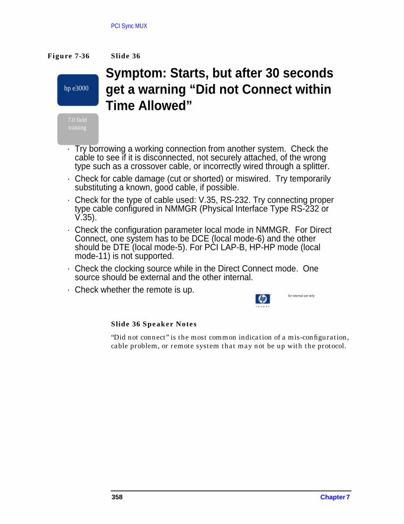
PCI Sync MUX
Figure 7-36 Slide 36
Slide 36 Speaker Notes
“Did not connect” is the most common indication of a mis-configuration,cable problem, or remote system that may not be up with the protocol.
for internal use only
hp e3000
7.0 fieldtraining
Symptom: Starts, but after 30 secondsget a warning “Did not Connect withinTime Allowed”
· Try borrowing a working connection from another system. Check thecable to see if it is disconnected, not securely attached, of the wrongtype such as a crossover cable, or incorrectly wired through a splitter.
· Check for cable damage (cut or shorted) or miswired. Try temporarilysubstituting a known, good cable, if possible.
· Check for the type of cable used: V.35, RS-232. Try connecting propertype cable configured in NMMGR (Physical Interface Type RS-232 orV.35).
· Check the configuration parameter local mode in NMMGR. For DirectConnect, one system has to be DCE (local mode-6) and the othershould be DTE (local mode-5). For PCI LAP-B, HP-HP mode (localmode-11) is not supported.
· Check the clocking source while in the Direct Connect mode. Onesource should be external and the other internal.
· Check whether the remote is up.
358 Chapter 7

PCI Sync MUX
Figure 7-37 Slide 37
Slide 37 Speaker Notes
If NS is being used, you should suspect NS configuration next,especially the RESVLCNF.NET file, NMCONFIG search path inNETXPORT.GLOBAL (typ. 1-2-0), gateway configurations, and networkdirectory. Don’t forget that the site’s network infrastructure may needto be told to recognize a new IP address and nodename.
Other general NS configuration items can also cause this, such as NSServices not starting, missing default gateway, wrong GLOBAL searchpath, missing RESLVCNF file, wrong IP address, or subnet mask,wrong domain name or nodename. Node or IP not yet recognized by sitegateways, or a downed gateway or break someplace in the network.
For SNA: There might be configuration problems such as LUconfigurations, IMF configurations etc.
for internal use only
hp e3000
7.0 fieldtraining
Symptom: Starts and connects, butTransport Connections cannot beestablished
· If NS Transport is started, try using PING.NET to ping another node.
· Check LINKCONTROL statistics to see if data is being sent andreceived.
· Check for NS/SNA configuration problems.
· Check for site network infrastructure problems (node or IP not yetrecognized by site gateways, downed gateway, a break somewhere inthe network, etc.).
· Remote system may be active with the protocol.
Chapter 7 359
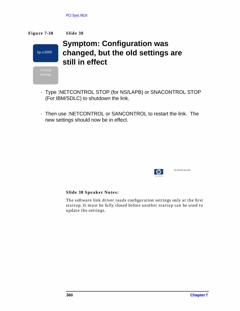
PCI Sync MUX
Figure 7-38 Slide 38
Slide 38 Speaker Notes:
The software link driver reads configuration settings only at the firststartup. It must be fully closed before another startup can be used toupdate the settings.
for internal use only
hp e3000
7.0 fieldtraining
Symptom: Configuration waschanged, but the old settings arestill in effect
· Type :NETCONTROL STOP (for NS/LAPB) or SNACONTROL STOP(For IBM/SDLC) to shutdown the link.
· Then use :NETCONTROL or SANCONTROL to restart the link. Thenew settings should now be in effect.
360 Chapter 7

PCI Sync MUX
Figure 7-39 Slide 39
Slide 39 Speaker Notes
Now we’re past the problems that are easily solvable and are dealingwith some more difficult problems. If the link has come up andconnected, but isn’t working properly, this can be difficult to diagnose.
An application problem might result in an error message, a hang, orsimply incorrect results.
Depending on the problem and the support contract, troubleshootingmight be beyond the scope of normal HP support.
Link trace is a great tool for debugging startup problems, but once thelink really gets going, no file system is able to keep up with it, sorecording trace data becomes a problem. There is a high potential fortrace data loss due to high-speed link, compatibility-mode OS tracinginfrastructure, and limited file size. If the application problem can beduplicated on a quiet network after only a few protocol exchanges, thereis a better chance for success with tracing.
for internal use only
hp e3000
7.0 fieldtraining
Symptom: Application problemsusing PCI WASN Sync MUX, butHP-PB PSIs work OK
· Collect any error details, including how to reproduce the problem
· If possible, temporarily move the nodes onto a quiet network, activate linktracing, the reproduce the problem.
:linkcontrol linkname;
trace=on, partial, 12 :linkcontrol
linkname; trace=off
· If trace data loss occurs, use a WAN protocol analyzer (or InternetAdvisor) instrument to trace the problem. Include formatted trace datawith the CR.
· If the problem does not appear to be in the application, file a CR. RouteCR’s to CHART product “MPE.NW.SDLC” or “MPE.NW.LAPB” based onthe link used.
Chapter 7 361
PCI Sync MUX
Format the trace to an ASCII file, then browse the file. HP may alsorequire traces from a working HP-PB system (PSI SDLC or PSI-LAPB).
A protocol analyzer instrument would be the tool of choice if theproblem cannot be captured another way. If trace data loss occurs, use aInternet Advisor to trace the problem. Include formatted trace data inany CR filed (don’t assume the lab can handle a raw analyzer data file).
362 Chapter 7
PCI Sync MUX
Figure 7-40 Slide 40
Slide 40 Speaker Notes
It is the intent that PCI WAN Sync MUX work with everything HP-PBPSI works with, but if something was missed, trouble will occur. It isdifficult to predict the type of specific error symptom. If you receive anerror message relating to an “unknown linktype,” this is a good cluethat something was missed. File a CR.
for internal use only
hp e3000
7.0 fieldtraining
Symptom: “Unknown Link Type” errorsof some kind from application
Actions:
· Check for old or mismatched software revisions. RunNMMAINT to check versions. :nmmaint, 82
· If this is not the problem, file a CR. Route CRs toCHART product “MPE.NW.SDLC” or “MPE.NW.LAPB”based on the links used.
Chapter 7 363

PCI Sync MUX
Figure 7-41 Slide 41
Slide 41 Speaker Notes
The first release of the driver still has numerous “print statements” init. These messages should not occur in normal operation unlesssomething very strange is happening. File a CR.
All printouts will be removed in a future revision of the link softwaredriver.
for internal use only
hp e3000
7.0 fieldtraining
Symptom: Odd console messagesfrom the driver which cannot disabledvia NMMGR
ACTIONS:
· A few unlikely errors, if detected, print messages directly to thesystem console; driver operation may or may not continue
· Try stopping and restarting the link
· File a CR. Route CRs to CHART product “MPE.NW.SDLC” or“MPE.NW.LAPB.” If possible, include a Linkcontrol link trace ofthe problem.
364 Chapter 7

PCI Sync MUX
Figure 7-42
Slide 42 Speaker Notes
The link driver software is able to take a snapshot of itself in the eventof a serious failure for analysis by the lab. These snapshots are dumpedinto NETDMPnn.PUB.SYS files, then the driver attempts to auto-resetitself and continue.
These serious failures should not be occurring, so send the files in witha CR.
Incidentally, additional Network Dump Processes will start up at boottime. This is normal. Each link type supporting driver-error dumps nowhas its own dump module, and a dependency-reduction change.Therefore at boot time, instead of seeing a single[NETWORK_DUMP_PROCESS] startup message, it will be normalthrough at least four dump process startup messages.
The NDMPSUM tool is designed to help the field compare differentNETDMP files to determine if they are having the same problem or not.It may not support PCI linktypes by MR time.
for internal use only
hp e3000
7.0 fieldtraining
Symptom: Network Dump Occurs
ACTIONS:
· Driver should resume automatically up to 12 times.However, dumps should never occur. Send allNETDMP##.PUB.SYS files to HP-CSY.
· File a CR. Route CRs to CHART product“MPE.NW.SDLC” or “MPE.NW.LAPB” based on thelinktype used.
Chapter 7 365

PCI Sync MUX
Analyzing NETDMP files is generally a job for the lab, since all the datastructures are driver specific, and some special addressing techniquesare required. PCI WAN Sync MUX provides some DAT macros to aid inopening a NETDMP file for analysis, but getting DAT to let you do thisinstead of opening a system memory dump is tricky.
366 Chapter 7

PCI Sync MUX
Figure 7-43 Slide 43
Slide 43 Speaker Notes
Any Sysabort you should take a system memory dump. SubsystemDump does not support MPE networking.
Just because link driver software procedure names are on the stack,doesn’t necessarily mean the driver did or didn’t cause a problem. Butanalysis will be aided if the CR states what is happening near the top ofthe stack.
Fortunately PCI WAN Sync MUX data structures are designed tosimplify debugging. The driver collects a lot of information at runtimeto aid problem analysis.
for internal use only
hp e3000
7.0 fieldtraining
Symptom: System abort with PCIWAN Sync MUX Driver (“add_xxxx”or “pacc_xxxx” or “nacc_xxxx”procedure on the stack
· Take a memory dump and use the usual supportprocess: route CRs to CHART product“MPE.NW.SDLC” or “MPE.NW.LAPB” based on the linkused.
Chapter 7 367

PCI Sync MUX
368 Chapter 7

8 OS macro changes in MPE/iX 7.0
By Paulose K Arackal, Commercial Systems Division and Alan Tyson,MPE/iX WTEC.
Several macros have been updated and added in MPE/iX 7.0. Thisarticle outlines some of the changes and additions made in this release.
fs_closed_files
This is a new macro which displays information about the files whichare on the file system’s least recently used (LRU) list.
fs_file_accessors
Given the address of a plfd, gdpd or gufd, this new macro will displaydetails of all of the processes which have the file opened.
fs_mvt_ldev_list
This macro, used by fs_dstat and others, has been improved toperform much faster than it did on the 6.5 release. The fixes in thisversion of the macro correspond to those which were in the 6.5 patchMPELX47.
fs_open_files
Now takes an option pin number as a parameter.
fs_volume_list
This macro has been enhanced so that the columns of informationdisplayed line up correctly.
io_ios_diag_log
This macro now displays timestamps as date and time rather than inticks. It will also display the text associated with the errors if available.
mi_lookup_pin
This macro has been around for a very long time and is available inKmine. It is now available in the standard os macro set. It will take apin number and search the measurement interface tables in order to tryand find out the program associated with the pin and the job/sessionthat ran it.
objcl_name
This macro, which takes a virtual address and displays the object class(in words) has been enhanced to work with more object classes.
pm_libraries
This macro has been enhanced to display the names of libraries whichhave HFS filenames and also to display the virtual address into whichthe libraries are mapped.
369

OS macro changes in MPE/iX 7.0
ui_discfree
Displays disk free space information, rather like discfree C output.
370 Chapter 8
9 Support Tools Changed inMPE/iX 7.0
By Alan Tyson, MPE/iX WTEC.
Product HP35071, formally known as NARC Support Tools, is nowmanaged by the MPE/iX WTEC. This product is a series of tools thathave been written by and are supported by numerous individuals in theHPe3000 support and lab community.
This article is to highlight the existence of these tools and to give a briefsummary of some of the tools available. Since these utilities are alldelivered on the FOS, they are available on all customer systemsrunning MPE/iX 7.0. Further details of these and additional tools canbe found by following the Tools link on the MPE/iX WTEC web site athttp://wtec.cup.hp.com/~mpeix/.
371

Support Tools Changed in MPE/iX 7.0Support Tools Changed in MPE/iX 7.0
Support Tools Changed in MPE/iX 7.0
CONLOG.PUBXL
This is a CI command file that will display the console messages from asystem logfile. Its output is very concise and saves you having to runlogtool and examine its verbose output. There is also another commandfile called CONLOGD which allows a date range to be specified.
DSTUSE
This program examines the usage of CM DST’s on the system and triesto categorize them according to what they are being used for. Thisprogram is “hidden” and needs to be extracted from its archive. See thewebsite for details on how to do this.
DUMPCUT
This program will reduce the size of a copy of a dump-to-disk memorydump file, freeing up the disk space beyond the end of the dump itself.This file is “hidden” too, see the web page on how to extract it.
FMTIOERR.PRVXL
This program will take I/O error statuses and convert them into errormessages.
KSCHKIX.PRVXL
Checks the integrity of NM Ksam files (not yet updated for KSAM64).
LNKSUMM.PUBXL
Accepts as input the output from the NMDUMP trace formattingutility. From this it summarizes all the packets from the trace into oneline per packet. It is especially useful for obtaining a snapshotoverview of network traffic on a link.
LOGFIX
Fixes problems in the system logging KSO structure (KSO #248) andalso perform maintenance on LOG#### logfiles that can potentiallycause problems because they are in the way. See the program’s webpage for further details.
372 Chapter 9

Support Tools Changed in MPE/iX 7.0Support Tools Changed in MPE/iX 7.0
MVTDUMP.PRVXL
An improved DSTAT. It is a Mounted Volume Table formatter with adisplay similar to DSTAT. It is intended to be used to help gatherinformation in cases where a disc volume will not mount. In that case itgives more detailed STATE information than DSTAT and it also printsthe HPE_STATUS indicating why the volume did not mount.
NETMAC.PUBXL
This file contains numerous networking macros which are documentedat the web sitehttp://wtec.cup.hp.com/~netmpe/technical/net_macros/net_macros.htm. These need to be loaded after loading the OS, Serial i/o, NStransport, Common services and arpa macros.
NEWMACS.PUBXL
This file contains some dat/debug macros which have recently beencreated by folks in the support organization. They are:
port_num_messages displays a list of ports which havemessages queued
dzall displays all of real memory
list_log displays system logfiles in a dump
io_mirror_errors gives you the reason for mirrored disksbecoming disabled
listfile allows contents of directories to bedisplayed.
These macros should be loaded after performing a macstart and loadingthe OS macros.
SCANCB.PRVXL
Produces a summary of the most relevant information from a DBDC fileproduced as a result of an Allbase/SQL program aborting. It can processan individual file or a set of files.
SECRTCKX.PUBXL
Program to analyze MPE log files for items relating to security. Eventsreported include File Close for any files that are Deleted,Consolelogging of certain commands and logon attempts,File open,CM Fileclose,Change Group,Process Initiation for PM programs executed or forany program.
Chapter 9 373

Support Tools Changed in MPE/iX 7.0Support Tools Changed in MPE/iX 7.0
SHOWCLKS.PUBXL
Displays the values for GMT (retrieved from Processor DependentCode), the MPE software time (obtained with the CALENDAR andCLOCK intrinsics) and the GMT offset, which is the difference betweenthe two.
SYSLOG
Allows system logging to be changed online. This program is “hidden”,see the web page on how to get it.
TAPESCAN
Displays information about the sizes of each block of data on a tape.
TBLMON
Displays information about the usage of certain system tables.
TCPIP.PUBXL
Accepts as input the output from the NMDUMP trace formattingutility. From this it organizes the inbound and outbound TCP datapackets from the trace into their corresponding TCP connections, andsummarizes this data to the user, per TCP connection, one line per TCPdata packet.
UNDEDLOK.PRVXL
Allows an HP support engineer to break a TurboIMAGE deadlockwithout having to reboot the system. UNDEDLOK/iX breaks aTurboIMAGE deadlock by taking the lock(s) away from a specified PINand calling DBUNLOCK.
374 Chapter 9

A PCISCSI Device AdapterManager (DAM)
Figure A-1 Slide 53
For those folks that intimately understand SCSI bus protocol, anannotated SCSI bus trace with console log PN lists (procedure numberlists) is provided below. The intention is to understand what the SCSIbus and device are doing based on information in the console log fromthe Lower DAM.
PN_pci_c720_isr15 - PN_c720_isr16 - PN_c720_isrGuts26 - PN_c720_isrSelect13 - PN_c720_check_xdtr_parms36 - PN_c720_isrStartChip14 - PN_pci_c720_isr-71 00C0 Msgout Atn Identify Disconnect, Logical=0 -4.679 ms-70 0001 Msgout Atn Extended Message -4.678 ms-69 0002 Msgout Atn 02H bytes follow -2.743 ms-68 0003 Msgout Atn Wide Data Transfer 16 bits -2.724 ms-67 0001 Msgout 01H -2.706 ms
hp e3000
7.0 fieldtraining
Appendix A: SCSI Bus TraceAnnotated
· PN_pci_c720_ isr15 - PN_c720_ isr16 - PN_c720_ isrGuts26 - PN_c720_ isrSelect13 - PN_c720_check_ xdtr_parms36 - PN_c720_ isrStartChip14 - PN_ pci_c720_ isr-71 00C0 Msgout Atn Identify Disconnect, Logical=0-4.679 ms-70 0001 Msgout Atn Extended Message-4.678 ms-69 0002 Msgout Atn 02H bytes follow-2.743 ms-68 0003 Msgout Atn Wide Data Transfer 16 bits-2.724 ms-67 0001 Msgout 01H-2.706 ms
375

PCISCSI Device Adapter Manager (DAM)
INIT DATA start
02 - PN_pci_c720_init
03 - PN_c720_pci_attach
08 - PN_pci_read_cfg_uint16
0b - PN_pci_write_cfg_uint16_isc
07 - PN_pci_read_cfg_uint8
09 - PN_pci_read_cfg_uint32_isc
04 - PN_c720_init
2e - PN_c720_reset_chip
07 - PN_pci_read_cfg_uint8
0a - PN_pci_write_cfg_uint8
07 - PN_pci_read_cfg_uint8
0a - PN_pci_write_cfg_uint8
etc.
ff
2e - PN_c720_reset_chip
07 - PN_pci_read_cfg_uint8
07 - PN_pci_read_cfg_uint8
05 - PN_c720_if_bus_open
06 - PN_c720_init_scri
13 - PN_c720_check_xdtr_parms
36 - PN_c720_isrStartChip
02 - PN_pci_c720_init
14 - PN_pci_c720_isr
15 - PN_c720_isr
16 - PN_c720_isrGuts
34 - PN_c720_isrRST
2e - PN_c720_reset_chip
07 - PN_pci_read_cfg_uint8_isc
07 - PN_pci_read_cfg_uint8_isc
06 - PN_c720_init_script
13 - PN_c720_check_xdtr_parms
13 - PN_c720_check_xdtr_parms
376 Appendix A

PCISCSI Device Adapter Manager (DAM)
36 - PN_c720_isrStartChip
0d - PN_c720_start
14 - PN_pci_c720_isr
IO DATA start
0c - PN_pci_c720_if_start
12 – PN_c720_if_tgt_open
13 - PN_c720_check_xdtr_parms
0d - PN_c720_start
0e - PN_c720_DataSetup
0f - PN_c720_OwnerSetup
11 - PN_pci_write_cfg_uint16_isc
0c - PN_pci_c720_if_start
-73 0080 Arbitrate ID=07 -4.779 ms
-72 0081 Select Atn ID=00 -4.777 ms
14 - PN_pci_c720_isr
15 - PN_c720_isr
16 - PN_c720_isrGuts
26 - PN_c720_isrSelect
13 - PN_c720_check_xdtr_parms
36 - PN_c720_isrStartChip
14 - PN_pci_c720_isr
-71 00C0 Msgout Atn Identify Disconnect, Logical=0 -4.679 ms
-70 0001 Msgout Atn Extended Message -4.678 ms
-69 0002 Msgout Atn 02H bytes follow -2.743 ms
-68 0003 Msgout Atn Wide Data Transfer 16 bits -2.724 ms
-67 0001 Msgout 01H -2.706 ms
14 - PN_pci_c720_isr
15 - PN_c720_isr
16 - PN_c720_isrGuts
20 - PN_c720_isrMsgOutIn
Appendix A 377

PCISCSI Device Adapter Manager (DAM)
21 - PN_c720_isrGetMsg
36 - PN_c720_isrStartChip
14 - PN_pci_c720_isr
-66 0001 Msg_in Extended Message -2.553 ms
14 - PN_pci_c720_isr
15 - PN_c720_isr
16 - PN_c720_isrGuts
22 - PN_c720_isrGetMsgIn
1c - PN_c720_isrUpdateWdtrParms
13 - PN_c720_check_xdtr_parms
21 - PN_c720_isrGetMsg
36 - PN_c720_isrStartChip
14 - PN_pci_c720_isr
-65 0002 Msg_in 02H bytes follow -2.478 ms
14 - PN_pci_c720_isr
15 - PN_c720_isr
16 - PN_c720_isrGuts
22 - PN_c720_isrGetMsgIn
21 - PN_c720_isrGetMsg
36 - PN_c720_isrStartChip
14 - PN_pci_c720_isr
-64 0003 Msg_in Wide Data Transfer 16 bits -2.467 ms
-63 0001 Msg_in Atn 01H -2.395 ms
14 - PN_pci_c720_isr
15 - PN_c720_isr
16 - PN_c720_isrGuts
22 - PN_c720_isrGetMsgIn
1c - PN_c720_isrUpdateWdtrParms
378 Appendix A

PCISCSI Device Adapter Manager (DAM)
13 - PN_c720_check_xdtr_parms
1e - PN_c720_isrPutMsg
36 - PN_c720_isrStartChip
14 - PN_pci_c720_isr
-62 0001 Msgout Atn Extended Message -2.379 ms
-61 0003 Msgout Atn 03H bytes follow -2.362 ms
-60 0001 Msgout Atn Sync Xfer Req Period=2EH Offset=1FH -2.343 ms
-59 002E Msgout Atn 2EH -2.324 ms
-58 001F Msgout 1FH -2.306 ms
14 - PN_pci_c720_isr
15 - PN_c720_isr
16 - PN_c720_isrGuts
20 - PN_c720_isrMsgOutIn
21 - PN_c720_isrGetMsg
36 - PN_c720_isrStartChip
14 - PN_pci_c720_isr
-57 0001 Msg_in Extended Message -2.142 ms
14 - PN_pci_c720_isr
15 - PN_c720_isr
16 - PN_c720_isrGuts
22 - PN_c720_isrGetMsgIn
1d - PN_c720_isrUpdateSdtrParms
13 - PN_c720_check_xdtr_parms
21 - PN_c720_isrGetMsg
36 - PN_c720_isrStartChip
14 - PN_pci_c720_isr
-56 0003 Msg_in 03H bytes follow -2.068 ms
14 - PN_pci_c720_isr
Appendix A 379

PCISCSI Device Adapter Manager (DAM)
15 - PN_c720_isr
16 - PN_c720_isrGuts
22 - PN_c720_isrGetMsgIn
21 - PN_c720_isrGetMsg
36 - PN_c720_isrStartChip
14 - PN_pci_c720_isr
-55 0001 Msg_in Sync Xfer Req Period=2EH Offset=0FH -2.056 ms
-54 002E Msg_in 2EH -2.046 ms
-53 000F Msg_in 0FH -1.978 ms
14 - PN_pci_c720_isr
15 - PN_c720_isr
16 - PN_c720_isrGuts
22 - PN_c720_isrGetMsgIn
1d - PN_c720_isrUpdateSdtrParms
13 - PN_c720_check_xdtr_parms
36 - PN_c720_isrStartChip
14 - PN_pci_c720_isr
14 - PN_pci_c720_isr
15 - PN_c720_isr
16 - PN_c720_isrGuts
30 - PN_c720_isrMA
36 - PN_c720_isrStartChip
14 - PN_pci_c720_isr
-52 0008 Commd Read -1.860 ms
-51 0000 Commd Lu=0 Logical Block Addr=000001H -1.859 ms
-50 0000 Commd -1.859 ms
-49 0001 Commd -1.859 ms
-48 0008 Commd Transfer Length=08H -1.858 ms
-47 0000 Commd
380 Appendix A
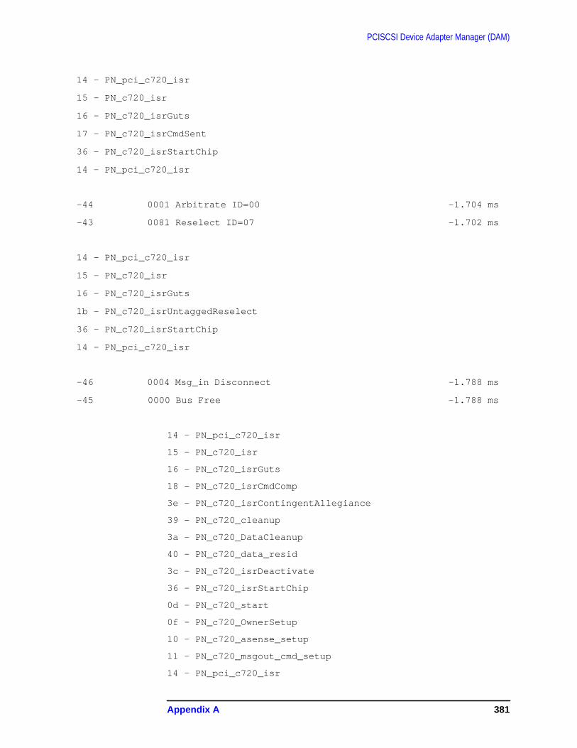
PCISCSI Device Adapter Manager (DAM)
14 - PN_pci_c720_isr
15 - PN_c720_isr
16 - PN_c720_isrGuts
17 - PN_c720_isrCmdSent
36 - PN_c720_isrStartChip
14 - PN_pci_c720_isr
-44 0001 Arbitrate ID=00 -1.704 ms
-43 0081 Reselect ID=07 -1.702 ms
14 - PN_pci_c720_isr
15 - PN_c720_isr
16 - PN_c720_isrGuts
1b - PN_c720_isrUntaggedReselect
36 - PN_c720_isrStartChip
14 - PN_pci_c720_isr
-46 0004 Msg_in Disconnect -1.788 ms
-45 0000 Bus Free -1.788 ms
14 - PN_pci_c720_isr
15 - PN_c720_isr
16 - PN_c720_isrGuts
18 - PN_c720_isrCmdComp
3e - PN_c720_isrContingentAllegiance
39 - PN_c720_cleanup
3a - PN_c720_DataCleanup
40 - PN_c720_data_resid
3c - PN_c720_isrDeactivate
36 - PN_c720_isrStartChip
0d - PN_c720_start
0f - PN_c720_OwnerSetup
10 - PN_c720_asense_setup
11 - PN_c720_msgout_cmd_setup
14 - PN_pci_c720_isr
Appendix A 381

PCISCSI Device Adapter Manager (DAM)
-36 00C0 Msgout Atn Identify Disconnect, Logical=0 -1.577 ms
-35 0001 Msgout Atn Extended Message -1.576 ms
-34 0002 Msgout Atn 02H bytes follow -1.487 ms
-33 0003 Msgout Atn Wide Data Transfer 16 bits -1.468 ms
-32 0001 Msgout 01H -1.450 ms
14 - PN_pci_c720_isr
15 - PN_c720_isr
16 - PN_c720_isrGuts
20 - PN_c720_isrMsgOutIn
21 - PN_c720_isrGetMsg
36 - PN_c720_isrStartChip
14 - PN_pci_c720_isr
-31 0001 Msg_in Extended Message -1.309 ms
14 - PN_pci_c720_isr
15 - PN_c720_isr
16 - PN_c720_isrGuts
22 - PN_c720_isrGetMsgIn
1c - PN_c720_isrUpdateWdtrParms
1d - PN_c720_isrUpdateSdtrParms
13 - PN_c720_check_xdtr_parms
13 - PN_c720_check_xdtr_parms
21 - PN_c720_isrGetMsg
36 - PN_c720_isrStartChip
14 - PN_pci_c720_isr
-30 0002 Msg_in 02H bytes follow -1.232 ms
14 - PN_pci_c720_isr
15 - PN_c720_isr
16 - PN_c720_isrGuts
382 Appendix A

PCISCSI Device Adapter Manager (DAM)
22 - PN_c720_isrGetMsgIn
21 - PN_c720_isrGetMsg
36 - PN_c720_isrStartChip
14 - PN_pci_c720_isr
-29 0003 Msg_in Wide Data Transfer 16 bits -1.222 ms
-28 0001 Msg_in Atn 01H -1.153 ms
14 - PN_pci_c720_isr
15 - PN_c720_isr
16 - PN_c720_isrGuts
22 - PN_c720_isrGetMsgIn
1c - PN_c720_isrUpdateWdtrParms
13 - PN_c720_check_xdtr_parms
1e - PN_c720_isrPutMsg
36 - PN_c720_isrStartChip
14 - PN_pci_c720_isr
-27 0001 Msgout Atn Extended Message -1.137 ms
-26 0003 Msgout Atn 03H bytes follow -1.119 ms
-25 0001 Msgout Atn Sync Xfer Req Period=2EH Offset=1FH -1.101 ms
-24 002E Msgout Atn 2EH -1.082 ms
-23 001F Msgout 1FH -1.064 ms
14 - PN_pci_c720_isr
15 - PN_c720_isr
16 - PN_c720_isrGuts
20 - PN_c720_isrMsgOutIn
21 - PN_c720_isrGetMsg
36 - PN_c720_isrStartChip
14 - PN_pci_c720_isr
-22 0001 Msg_in Extended Message -905.630 us
Appendix A 383
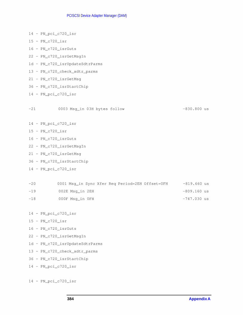
PCISCSI Device Adapter Manager (DAM)
14 - PN_pci_c720_isr
15 - PN_c720_isr
16 - PN_c720_isrGuts
22 - PN_c720_isrGetMsgIn
1d - PN_c720_isrUpdateSdtrParms
13 - PN_c720_check_xdtr_parms
21 - PN_c720_isrGetMsg
36 - PN_c720_isrStartChip
14 - PN_pci_c720_isr
-21 0003 Msg_in 03H bytes follow -830.800 us
14 - PN_pci_c720_isr
15 - PN_c720_isr
16 - PN_c720_isrGuts
22 - PN_c720_isrGetMsgIn
21 - PN_c720_isrGetMsg
36 - PN_c720_isrStartChip
14 - PN_pci_c720_isr
-20 0001 Msg_in Sync Xfer Req Period=2EH Offset=0FH -819.660 us
-19 002E Msg_in 2EH -809.160 us
-18 000F Msg_in 0FH -747.030 us
14 - PN_pci_c720_isr
15 - PN_c720_isr
16 - PN_c720_isrGuts
22 - PN_c720_isrGetMsgIn
1d - PN_c720_isrUpdateSdtrParms
13 - PN_c720_check_xdtr_parms
36 - PN_c720_isrStartChip
14 - PN_pci_c720_isr
14 - PN_pci_c720_isr
384 Appendix A
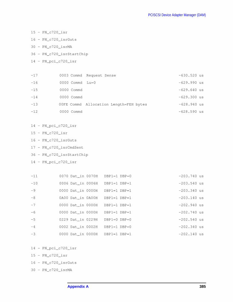
PCISCSI Device Adapter Manager (DAM)
15 - PN_c720_isr
16 - PN_c720_isrGuts
30 - PN_c720_isrMA
36 - PN_c720_isrStartChip
14 - PN_pci_c720_isr
-17 0003 Commd Request Sense -630.520 us
-16 0000 Commd Lu=0 -629.990 us
-15 0000 Commd -629.640 us
-14 0000 Commd -629.300 us
-13 00FE Commd Allocation Length=FEH bytes -628.940 us
-12 0000 Commd -628.590 us
14 - PN_pci_c720_isr
15 - PN_c720_isr
16 - PN_c720_isrGuts
17 - PN_c720_isrCmdSent
36 - PN_c720_isrStartChip
14 - PN_pci_c720_isr
-11 0070 Dat_in 0070H DBP1=1 DBP=0 -203.740 us
-10 0006 Dat_in 0006H DBP1=1 DBP=1 -203.540 us
-9 0000 Dat_in 0000H DBP1=1 DBP=1 -203.340 us
-8 0A00 Dat_in 0A00H DBP1=1 DBP=1 -203.140 us
-7 0000 Dat_in 0000H DBP1=1 DBP=1 -202.940 us
-6 0000 Dat_in 0000H DBP1=1 DBP=1 -202.740 us
-5 0229 Dat_in 0229H DBP1=0 DBP=0 -202.540 us
-4 0002 Dat_in 0002H DBP1=1 DBP=0 -202.340 us
-3 0000 Dat_in 0000H DBP1=1 DBP=1 -202.140 us
14 - PN_pci_c720_isr
15 - PN_c720_isr
16 - PN_c720_isrGuts
30 - PN_c720_isrMA
Appendix A 385
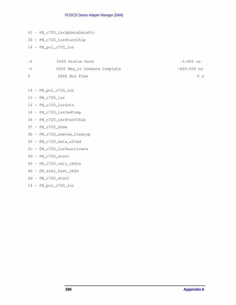
PCISCSI Device Adapter Manager (DAM)
41 - PN_c720_isrUpdateDataPtr
36 - PN_c720_isrStartChip
14 - PN_pci_c720_isr
-2 0000 Status Good -3.650 us
-1 0000 Msg_in Command Complete -820.000 ns
0 0000 Bus Free 0 s
14 - PN_pci_c720_isr
15 - PN_c720_isr
16 - PN_c720_isrGuts
18 - PN_c720_isrCmdComp
36 - PN_c720_isrStartChip
37 - PN_c720_done
3b - PN_c720_asense_cleanup
3f - PN_c720_data_xfred
3c - PN_c720_isrDeactivate
0d - PN_c720_start
45 - PN_c720_call_cbfns
46 - PN_scsi_fast_cbfn
0d - PN_c720_start
14 - PN_pci_c720_isr
386 Appendix A

B Monitor and I/O Services
Refer to Chapter 1 , “Hardware Overview Monitor and I/O Services,” foradditional information.
N-Class and A-ClassConfiguration Files
{** CONFNCL1--This is for a PRELUDE w/internal disk(s) **}
{** $Header: CONFNCL1 $ **}
permyes on
show all
{** Start for I/O configuration commands. **}
io
{** The following configuration statements assume that they **}
{** are modifying an "empty" set of configuration files. **}
{** Establish the standard set of I/O paths leading to devices. **}
apath 0 PAT_IOA_BC
apath 0/0 PAT_PCI_BC PCI_ELROY_MGR
apath 0/0/0 PCI_DEVICE PCI_DEVICE_MGR
apath 0/0/1 PCI_DEVICE PCI_DEVICE_MGR
apath 0/0/1/0 A5150A PCI_SCSI_DAM
apath 0/0/1/0.6 PSEUDO
apath 0/0/1/0.16 PSEUDO
apath 0/0/1/0.17 PSEUDO
apath 0/0/2 PCI_DEVICE PCI_DEVICE_MGR
apath 0/0/2/0 A5150A PCI_SCSI_DAM
apath 0/0/2/1 A5150A PCI_SCSI_DAM
apath 0/0/2/0.6 PSEUDO
387

Monitor and I/O ServicesN-Class and A-Class Configuration Files
apath 0/0/2/1.6 PSEUDO
apath 0/0/4 PCI_DEVICE PCI_DEVICE_MGR
apath 0/0/4/0 PCI_CONSOLE PCI_CONSOLE_DAM
adev 1 0/0/2/0.6.0 ST39103LC class=(DISC,SPOOL)
adev 2 0/0/2/1.6.0 ST39103LC class=(DISC,SPOOL)
adev 6 0/0/1/0.16.0 LP_PP_ID class=(LP,PP) &
mode=none
adev 7 0/0/1/0.6.0 HPC1553A class=(TAPE,TAPE2,ddump,tape1)
adev 10 0/0/1/0.17.0 JOBTAPE_ID class=(JOB,JOBTAPE) &
outdev=(LP) mode=(JOB,DATA) rsize=128
adev 20 0/0/4/0.0 C1099A class=(CONSOLE,TERM)
{** CONFACL1--This is for a CRESCENDO w/internal disk(s) **}
{** $Header: CONFACL1 $ **}
permyes on
show all
{** Start for I/O configuration commands. **}
io
{** The following configuration statements assume that they **}
{** are modifying an "empty" set of configuration files. **}
{** Establish the standard set of I/O paths leading to devices. **}
apath 0 PAT_IOA_BC
apath 0/0 PAT_PCI_BC PCI_ELROY_MGR
apath 0/0/0 PCI_DEVICE PCI_DEVICE_MGR
apath 0/0/1 PCI_DEVICE PCI_DEVICE_MGR
apath 0/0/1/0 A5150A PCI_SCSI_DAM
apath 0/0/1/1 A5150A PCI_SCSI_DAM
apath 0/0/1/1.15 PSEUDO
apath 0/0/2 PCI_DEVICE PCI_DEVICE_MGR
apath 0/0/2/0 A5150A PCI_SCSI_DAM
apath 0/0/2/0.6 PSEUDO
apath 0/0/2/0.16 PSEUDO
388 Appendix B
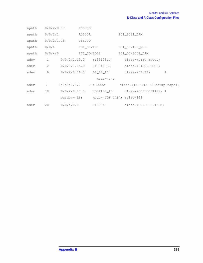
Monitor and I/O ServicesN-Class and A-Class Configuration Files
apath 0/0/2/0.17 PSEUDO
apath 0/0/2/1 A5150A PCI_SCSI_DAM
apath 0/0/2/1.15 PSEUDO
apath 0/0/4 PCI_DEVICE PCI_DEVICE_MGR
apath 0/0/4/0 PCI_CONSOLE PCI_CONSOLE_DAM
adev 1 0/0/2/1.15.0 ST39103LC class=(DISC,SPOOL)
adev 2 0/0/1/1.15.0 ST39103LC class=(DISC,SPOOL)
adev 6 0/0/2/0.16.0 LP_PP_ID class=(LP,PP) &
mode=none
adev 7 0/0/2/0.6.0 HPC1553A class=(TAPE,TAPE2,ddump,tape1)
adev 10 0/0/2/0.17.0 JOBTAPE_ID class=(JOB,JOBTAPE) &
outdev=(LP) mode=(JOB,DATA) rsize=128
adev 20 0/0/4/0.0 C1099A class=(CONSOLE,TERM)
Appendix B 389
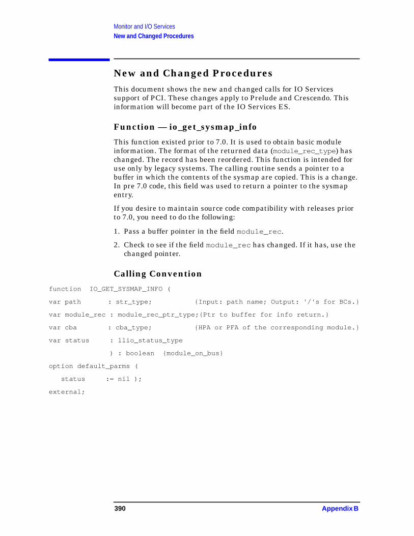
Monitor and I/O ServicesNew and Changed Procedures
New and Changed ProceduresThis document shows the new and changed calls for IO Servicessupport of PCI. These changes apply to Prelude and Crescendo. Thisinformation will become part of the IO Services ES.
Function — io_get_sysmap_info
This function existed prior to 7.0. It is used to obtain basic moduleinformation. The format of the returned data (module_rec_type ) haschanged. The record has been reordered. This function is intended foruse only by legacy systems. The calling routine sends a pointer to abuffer in which the contents of the sysmap are copied. This is a change.In pre 7.0 code, this field was used to return a pointer to the sysmapentry.
If you desire to maintain source code compatibility with releases priorto 7.0, you need to do the following:
1. Pass a buffer pointer in the field module_rec .
2. Check to see if the field module_rec has changed. If it has, use thechanged pointer.
Calling Convention
function IO_GET_SYSMAP_INFO (
var path : str_type; {Input: path name; Output: '/'s for BCs.}
var module_rec : module_rec_ptr_type;{Ptr to buffer for info return.}
var cba : cba_type; {HPA or PFA of the corresponding module.}
var status : llio_status_type
) : boolean {module_on_bus}
option default_parms (
status := nil );
external;
390 Appendix B

Monitor and I/O ServicesNew and Changed Procedures
Data Returned
module_rec_type = packed record
hw_model_rev : hw_model_rev_type;
spa_capability : spa_capability_type;
type_of_module : type_of_module_type;
sw_model_rev : sw_model_rev_type;
iodc_rev : bit8;
iodc_dep : bit8;
iodc_reserved : bit16;
hpa : hpa_type;
port_num : port_num_type;
next_bus : integer;
flags : flags_type;
spa : spa_info_type;
{ filler : array [1..2] of integer;
} filler1 : integer;
filler2 : integer;
module_specific1 : integer; {Bus converters only}
module_specific2 : integer; { " " I " }
CASE module_type of
Tp_Bcport, Tp_Multi:
(hpa_of_attached_bus : hpa_type );
Tp_Memory:
(mem_space_used : bit32 );
end;
{ Define the bus_type to be bit32, plenty to chew on..}
io_bus_type_unknown = 0;
io_bus_type_pci = 1;
io_bus_type_pci_32 = 2;
io_bus_type_pci_64 = 3;
io_bus_type_hsc = 4;
io_bus_type_hppb = 5; {including 'NIO'}
io_bus_type_cio = 6;
Appendix B 391

Monitor and I/O ServicesNew and Changed Procedures
Procedure — io_info
Use this procedure to obtain information regarding modules for both PAand PAT systems.
Calling Sequence
procedure IO_INFO
(
path : str_type; { Path on which to obtain information. }
item : io_item_type; { Item being returned from I/O system. }
var info : io_info_type; { Where the item info is returned. }
var status : llio_status_type { Resultant status. }
The following items have been added to the existing io_item_type :
io_info_pfa = 14; { PCI Function Address }
io_info_mgr_sw_model = 15; { "software model" }
io_info_pci_dev_info = 16; { PCI device info }
io_info_pci_ppb_info = 17; { PCI bridge info }
io_info_mgr_hw_model_rev = 18; { "hardware model" }
io_info_mgr_type_module = 19; { "mod type" }
io_info_mgr_attached_bus = 20; { NOT SUPPORTED yet }
io_info_mgr_module_info = 21; { "module info" }
io_info_bus_type = 22; { "bus type" }
Data Returned
Data structures for these new items are as follows:
io_info_pfa : (pfa : bit32 );
io_info_mgr_sw_model : (sw_model : bit32 );
io_info_pci_dev_info : (dev_info : pci_dev_info_type );
io_info_pci_ppb_info : (ppb_info : pci_ppb_info_type );
io_info_mgr_hw_model_rev: (hw_model_rev : bit16 );
io_info_mgr_type_module : (module_type : bit8 );
io_info_mgr_attached_bus: (attached_bus_hpa: bit32 );
io_info_bus_type : (bus_type : bit32 );
pci_dev_info_type = record
sw_model : bit32; {Software Model }
392 Appendix B

Monitor and I/O ServicesNew and Changed Procedures
device_id : bit16; {Device ID }
vendor_id : bit16; {Vendor ID }
status_reg : bit16; {Status Register }
command : bit16; {Command Register }
class_code : bit8; {Dev Class Code }
sub_class : bit8; {Dev Sub-Class }
prog_intf : bit8; {Programmable Itf }
revision_id : bit8; {Revision ID }
bist : bit8; {Built In Selftest}
hdr_type : bit8; {Header Type }
latency : bit8; {Latency Timer }
cache_size : bit8; {Cache Line Size }
dev_bars : array [0..NUM_DEV_BARS-1] of bit32; {base addrregisters}
cardbus_ptr : bit32;
subsys_id : bit16; {Subsystem ID }
subsys_vid : bit16; {Subsystem Vendor }
rom_address : bit32; {ROM base addre }
reserved1 : bit32;
reserved2 : bit32;
max_lat : bit8; {Max Latency Reg }
min_grant : bit8; {Min Grant Reg }
int_pin : bit8; {Interrupt Pin }
int_line : bit8; {Interrupt Line }
end;
pci_ppb_info_type = record
sw_model : bit32; {Software Model }
device_id : bit16; {Device ID }
vendor_id : bit16; {Vendor ID }
status_reg : bit16; {Status Register }
command : bit16; {Command Register }
class_code : bit8; {Dev Class Code }
sub_class : bit8; {Dev Sub-Class }
Appendix B 393
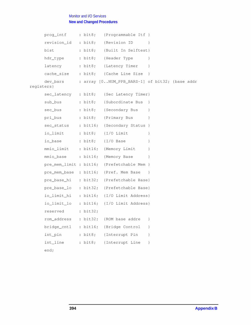
Monitor and I/O ServicesNew and Changed Procedures
prog_intf : bit8; {Programmable Itf }
revision_id : bit8; {Revision ID }
bist : bit8; {Built In Selftest}
hdr_type : bit8; {Header Type }
latency : bit8; {Latency Timer }
cache_size : bit8; {Cache Line Size }
dev_bars : array [0..NUM_PPB_BARS-1] of bit32; {base addrregisters}
sec_latency : bit8; {Sec Latency Timer}
sub_bus : bit8; {Subordinate Bus }
sec_bus : bit8; {Secondary Bus }
pri_bus : bit8; {Primary Bus }
sec_status : bit16; {Secondary Status }
io_limit : bit8; {I/O Limit }
io_base : bit8; {I/O Base }
mmio_limit : bit16; {Memory Limit }
mmio_base : bit16; {Memory Base }
pre_mem_limit : bit16; {Prefetchable Mem }
pre_mem_base : bit16; {Pref. Mem Base }
pre_base_hi : bit32; {Prefetchable Base}
pre_base_lo : bit32; {Prefetchable Base}
io_limit_hi : bit16; {I/O Limit Address}
io_limit_lo : bit16; {I/O Limit Address}
reserved : bit32;
rom_address : bit32; {ROM base addre }
bridge_cntl : bit16; {Bridge Control }
int_pin : bit8; {Interrupt Pin }
int_line : bit8; {Interrupt Line }
end;
394 Appendix B

Monitor and I/O ServicesNew and Changed Procedures
Procedure — io_get_pci_info
Use this procedure to obtain information about PCI modules.
Calling Convention
procedure io_get_pci_info (pfa : bit32;
item : bit8;
info : globalanyptr;
var status : llio_status_type);
external;
Data Returned
This procedure uses the same types and data structures and io)info.
The following procedures are used to directly read and write pci registers.
procedure io_pci_cfg_read_bit8 (pci_handle : globalanyptr;
register : bit32;
var data : bit8;
var status : llio_status_type;
swap : boolean)
option default_parms (swap := true);
external;
------------------------------------------------------------------
procedure io_pci_cfg_read_bit16 (pci_handle : globalanyptr;
register : bit32;
var data : bit16;
var status : llio_status_type;
swap : boolean)
option default_parms (swap := true);
external;
-----------------------------------------------------------------
procedure io_pci_cfg_read_bit32 (pci_handle : globalanyptr;
register : bit32;
var data : bit32;
var status : llio_status_type;
swap : boolean)
Appendix B 395

Monitor and I/O ServicesNew and Changed Procedures
option default_parms (swap := true);
external;
-----------------------------------------------------------------
procedure io_pci_cfg_write_bit8 (pci_handle : globalanyptr;
register : bit32;
data : bit8;
var status : llio_status_type;
swap : boolean)
option default_parms (swap := true);
external;
----------------------------------------------------------------
procedure io_pci_cfg_write_bit16 (pci_handle : globalanyptr;
register : bit32;
data : bit16;
var status : llio_status_type;
swap : boolean)
option default_parms (swap := true);
external;
---------------------------------------------------------------
procedure io_pci_cfg_write_bit32 (pci_handle : globalanyptr;
register : bit32;
data : bit32;
var status : llio_status_type;
swap : boolean)
option default_parms (swap := true);
external;
---------------------------------------------------------------
procedure io_pci_mem_read_bit8 (pci_handle : globalanyptr;
io_mem_addr : bit32;
var data : bit8;
var status : llio_status_type;
swap : boolean)
option default_parms (swap := true);
external;
396 Appendix B
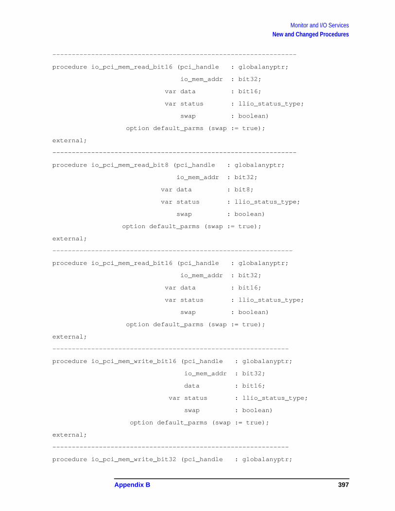
Monitor and I/O ServicesNew and Changed Procedures
---------------------------------------------------------------
procedure io_pci_mem_read_bit16 (pci_handle : globalanyptr;
io_mem_addr : bit32;
var data : bit16;
var status : llio_status_type;
swap : boolean)
option default_parms (swap := true);
external;
---------------------------------------------------------------
procedure io_pci_mem_read_bit8 (pci_handle : globalanyptr;
io_mem_addr : bit32;
var data : bit8;
var status : llio_status_type;
swap : boolean)
option default_parms (swap := true);
external;
--------------------------------------------------------------
procedure io_pci_mem_read_bit16 (pci_handle : globalanyptr;
io_mem_addr : bit32;
var data : bit16;
var status : llio_status_type;
swap : boolean)
option default_parms (swap := true);
external;
-------------------------------------------------------------
procedure io_pci_mem_write_bit16 (pci_handle : globalanyptr;
io_mem_addr : bit32;
data : bit16;
var status : llio_status_type;
swap : boolean)
option default_parms (swap := true);
external;
-------------------------------------------------------------
procedure io_pci_mem_write_bit32 (pci_handle : globalanyptr;
Appendix B 397

Monitor and I/O ServicesNew and Changed Procedures
io_mem_addr : bit32;
data : bit32;
var status : llio_status_type;
swap : boolean)
option default_parms (swap := true);
external;
-------------------------------------------------------------
function swap32 (value : bit32) : bit32;
external;
-------------------------------------------------------------
function swap16 (value : bit16) : bit16;
external;
------------------------------------------------------------
Procedure IO_SET_AND_VERIFY_INTERRUPT( pfa : bit32;
processor : localanyptr;
eir_bit : localanyptr;
status : localanyptr);
External;
-----------------------------------------------------------
procedure io_config_pci_int ( pfa : bit32;
eim : eim_type;
compl_head_info :
var compl_head : int_compl_head_ptr;
var status : llio_status_type);
external;
-----------------------------------------------------------
procedure io_deconfig_pci_int ( eim : eim_type;
compl_head : int_compl_head_ptr;
var status : llio_status_type);
external;
-----------------------------------------------------------\
procedure IO_CONFIG_INT (
eir_bit : eir_bit_type;
compl_head_info : int_config_info_type;
398 Appendix B

Monitor and I/O ServicesNew and Changed Procedures
var compl_head : int_compl_head_ptr;
var status : llio_status_type;
hpa : bit32; {Only required right now for Type-A}
var compl_head_iova : bit32 {Only required for Type-B}
)
option default_parms (
hpa := 0,
compl_head_iova := nil );
external;
Appendix B 399

Monitor and I/O ServicesHSYSMAP File From 6.0
HSYSMAP File From 6.0/* $Revision: 1.17.2.2 $ */
/* File hsysmap.asmmon.official
Contains definitions related to system map */
#define MODULE_TYPE 3
#define SPA_TYPE 2
#define MOD_ID_BASE 0
#define SW_ID_BASE 4
#define UNIQ_ID_BASE 8
#define IODC_REV 8
#define IODC_DEP 9
#define SPA_ADDR 12
#define SPA_SIZE 16
#define MAP_CONFIG 20
#define MAP_CF_CNFG 0
#define MAP_CF_NO_HW 1
#define MAP_CF_BROKEN 2
#define MAP_RESVD2 24
#define IO_LOW 12
#define IO_HIGH 16
#define MEM_LOW 52 /* moved from 20 */
#define MEM_HIGH 24
#define PWFAIL_INFO0 28
#define PWFAIL_INFO1 32
#define PWFAIL_INFO2 36
#define PWFAIL_INFO3 40
#define PWFAIL_INFO4 44
#define PWFAIL_INFO5 48
#define PWFAIL_INFO6 52
400 Appendix B

Monitor and I/O ServicesHSYSMAP File From 6.0
#define PWFAIL_INFO7 56
#define ACT_MEM_SIZE 60
#define BC_LINK 60
#define MAP_ENT_SIZE 64
#define PWFAIL_PLAB0 28
#define PWFAIL_PLAB1 32
#define PWFAIL_DATA0 36
#define PWFAIL_DATA1 40
#define PWFAIL_PORT 44
#define PWFAIL_HPA 48
#define PWFAIL_MODS1 52
#define PWFAIL_MODS2 56
/********************************************************************
The following are constant definitions of IODC_TYPE. See section
13 of the IO/ACD. (page 13-6 of version 0.95) for details.
********************************************************************/
#define TP_NPROC 0 /* Native Processor */
#define TP_MEMORY 1 /* Memory */
#define TP_B_DMA 2 /* Type-B DMA I/O */
#define TP_B_DIRECT 3 /* Obsolete [reserved] */
#define TP_A_DMA 4 /* Type-A DMA I/O */
#define TP_A_DIRECT 5 /* Type-A Direct I/O */
#define TP_OTHER 6 /* Obsolete [reserved] */
#define TP_BCPORT 7 /* Bus converter port */
#define TP_CIO 8 /* HP-CIO adapter */
#define TP_CONSOLE 9 /* Console */
#define TP_FPROC 10 /* Foreign I/O module */
#define TP_BA 11 /* Bus adapter */
#define TP_IOA 12 /* U2 Bus converter port */
/* 13-30 reserved for future types */
#define TP_NONE 31 /* Faulty module */
Appendix B 401

Monitor and I/O ServicesHSYSMAP File From 6.0
/****************************************************************
The following are the architecture revision levels as defined
by the PDC_MODEL string definition in the IO ACD.
*****************************************************************/
#define ARCH_REV_1_0 0 /* PA RISC 1.0 */
#define ARCH_REV_1_1 4 /* PA RISC 1.1 */
#define ARCH_REV_2_0 8 /* PA RISC 2.0 */
/*********************************************************************
The following table lists the hardware (HVERS) and software (SVERS)
version numbers. These numbers reflect values found in PDC_MODEL
call. Appendix B of the IO-ACD has complete listing of these values.
**********************************************************************/
#define INDIGO_HVERS 0x0040 /* Model 930 */
#define FIREFOX_HVERS 0x0080 /* Model 925 */
#define TOP_GUN_HVERS 0x00a0 /* Model 935 */
#define SHOGUN_845_HVERS 0x00b0
#define CHEETAH_O_HVERS 0x00c0 /* Model 950 */
#define SHOGUN_949_HVERS 0x00f0 /* Model 949 */
#define CHEETAH_HVERS 0x0800 /* Model 950S */
#define PN10_HVERS 0x0810 /* Model 955 */
#define PN10C_HVERS 0x0820 /* Model 960 */
#define PANTHER_HVERS 0x0830 /* Model 980 */
#define BURGANDY_HVERS 0x1000
#define SILVER_L_HVERS 0x1010 /* Model 922 */
#define SILVER_H_HVERS 0x1020 /* Model 932 */
#define CHIMERA_HVERS 0x1810 /* Model 990/992 */
#define TNT_HVERS 0x1820 /* Model 991/995 */
#define TNT_120_HVERS 0x1830 /* Model Nitro */
#define NOVA_S_HVERS 0x280 /* Model 957 (old firmware) */
#define NOVA_L_HVERS 0x2800 /* Model 957 */
#define NOVA_H_HVERS 0x2810 /* Model 967 */
402 Appendix B
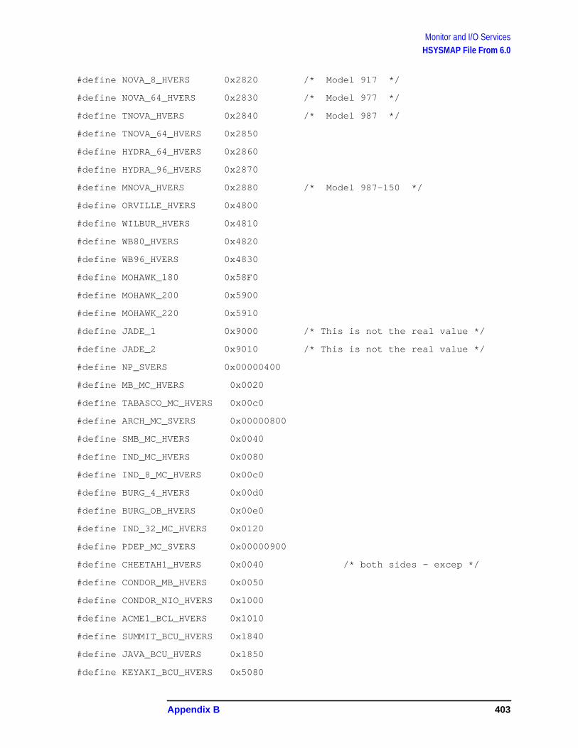
Monitor and I/O ServicesHSYSMAP File From 6.0
#define NOVA_8_HVERS 0x2820 /* Model 917 */
#define NOVA_64_HVERS 0x2830 /* Model 977 */
#define TNOVA_HVERS 0x2840 /* Model 987 */
#define TNOVA_64_HVERS 0x2850
#define HYDRA_64_HVERS 0x2860
#define HYDRA_96_HVERS 0x2870
#define MNOVA_HVERS 0x2880 /* Model 987-150 */
#define ORVILLE_HVERS 0x4800
#define WILBUR_HVERS 0x4810
#define WB80_HVERS 0x4820
#define WB96_HVERS 0x4830
#define MOHAWK_180 0x58F0
#define MOHAWK_200 0x5900
#define MOHAWK_220 0x5910
#define JADE_1 0x9000 /* This is not the real value */
#define JADE_2 0x9010 /* This is not the real value */
#define NP_SVERS 0x00000400
#define MB_MC_HVERS 0x0020
#define TABASCO_MC_HVERS 0x00c0
#define ARCH_MC_SVERS 0x00000800
#define SMB_MC_HVERS 0x0040
#define IND_MC_HVERS 0x0080
#define IND_8_MC_HVERS 0x00c0
#define BURG_4_HVERS 0x00d0
#define BURG_OB_HVERS 0x00e0
#define IND_32_MC_HVERS 0x0120
#define PDEP_MC_SVERS 0x00000900
#define CHEETAH1_HVERS 0x0040 /* both sides - excep */
#define CONDOR_MB_HVERS 0x0050
#define CONDOR_NIO_HVERS 0x1000
#define ACME1_BCL_HVERS 0x1010
#define SUMMIT_BCU_HVERS 0x1840
#define JAVA_BCU_HVERS 0x1850
#define KEYAKI_BCU_HVERS 0x5080
Appendix B 403

Monitor and I/O ServicesHSYSMAP File From 6.0
#define U2_BCU_HVERS 0x5800
#define BC1_SVERS 0x00000c00
#define IOA_SVERS 0x00000b00
#define VCIO_HVERS 0x0040 /* vlsi */
#define SCIO_HVERS 0x0050 /* silverfox */
#define DCIO_HVERS 0x0080 /* ttl */
#define CIO_SVERS 0x00001000
#define NIO_FL_SVERS 0x00004100
#define LAN_RDB_MIURA_SVERS 0x00005200
#define LAN_RDB_MIURA_HVERS 0x0040
#define LAN_RDB_DIABLO_SVERS 0x00006000
#define LAN_RDB_DIABLO_HVERS 0x0140
#define LAN_RDB_COUNTACH_SVERS 0x00006000
#define LAN_RDB_COUNTACH_HVERS 0x0540
#define PAR_IO_HVERS 0x0040
#define PAR_IO_SVERS 0x00001800
#define PAR_RDB_HVERS 0x0040
#define PAR_RDB_SVERS 0x00001900
#define PAR_NIO_SVERS NIO_GPIO_SVERS
#define PAR_NIO2_SVERS NIO_GPIO2_SVERS
#define PAR_OLD_HVERS 0xeb60
#define PAR_OLD_SVERS 0x08000240
#define CHEETAH_CONS_SVERS 0x00001c00
#define CHEETAH_CONS_HVERS 0x0040
#define PSI_SVERS 0x00002000
#define MBTRNSIT_SVERS 0x00002100
404 Appendix B
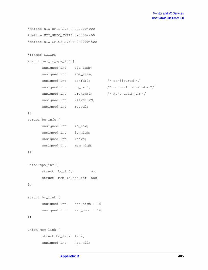
Monitor and I/O ServicesHSYSMAP File From 6.0
#define NIO_HPIB_SVERS 0x00004000
#define NIO_GPIO_SVERS 0x00004400
#define NIO_GPIO2_SVERS 0x00004500
#ifndef LOCORE
struct mem_io_spa_inf {
unsigned int spa_addr;
unsigned int spa_size;
unsigned int confd:1; /* configured */
unsigned int no_hw:1; /* no real hw exists */
unsigned int broken:1; /* He's dead jim */
unsigned int resvd1:29;
unsigned int resvd2;
};
struct bc_info {
unsigned int io_low;
unsigned int io_high;
unsigned int resvd;
unsigned int mem_high;
};
union spa_inf {
struct bc_info bc;
struct mem_io_spa_inf nbc;
};
struct bc_link {
unsigned int hpa_high : 16;
unsigned int rec_num : 16;
};
union mem_link {
struct bc_link link;
unsigned int hpa_all;
Appendix B 405

Monitor and I/O ServicesHSYSMAP File From 6.0
unsigned int act_mem;
};
struct bus_map {
unsigned int hw_model : 16;
unsigned int io : 1;
unsigned int resvd1 : 2;
unsigned int spa_shft : 5;
unsigned int more : 1;
unsigned int word : 1;
unsigned int resvd2 : 1;
unsigned int mod_type : 5;
unsigned int sw_model : 32;
unsigned int iodc_rev : 8;
unsigned int iodc_dep : 8;
unsigned int resvd3 : 16;
union spa_inf spa;
unsigned int pfail00;
unsigned int pfail01;
unsigned int pfail02;
unsigned int pfail03;
unsigned int pfail04;
unsigned int hpa;
unsigned int mod_dep1; /* mem_low for bc/monarch */
/* primary for memory */
unsigned int mod_dep2;
union mem_link link;
};
#define mem_low mod_dep1
struct path_type {
unsigned int len;
unsigned char data[32];
};
406 Appendix B

Monitor and I/O ServicesHSYSMAP File From 6.0
struct pdc_path {
unsigned int flags:8; /* boot flags */
unsigned char bc[6]; /* bus converter slots */
unsigned int pm:8; /* physical module */
unsigned int module[6]; /* logical module, etc. */
};
#endif ! LOCORE
Appendix B 407

Monitor and I/O ServicesHSYSMAP File From 7.0
HSYSMAP File From 7.0/* $Revision: 1.19.2.2 $ */
/* File hsysmap.asmmon.official
Contains definitions related to system map */
/* Marcia: change includes to be qualified */
#ifndef LOCORE
#include "hinttyps.asmmon.official"
#include "hpci.asmmon.official"
#endif
#define MODULE_TYPE 3
#define SPA_TYPE 2
#define MOD_ID_BASE 0
#define SW_ID_BASE 4
#define UNIQ_ID_BASE 8
#define IODC_REV 8
#define IODC_DEP 9
#define NEXT_BUS 20
#define MAP_CONFIG 24 /*flags*/
#define MAP_CF_CNFG 0
#define MAP_CF_NO_HW 1
#define MAP_CF_BROKEN 2
#define SPA_ADDR 28
#define SPA_SIZE 32
#define MAP_RESVD1 36
#define MAP_RESVD2 40
#define IO_LOW 28
#define IO_HIGH 32
#define MEM_HIGH 40
408 Appendix B
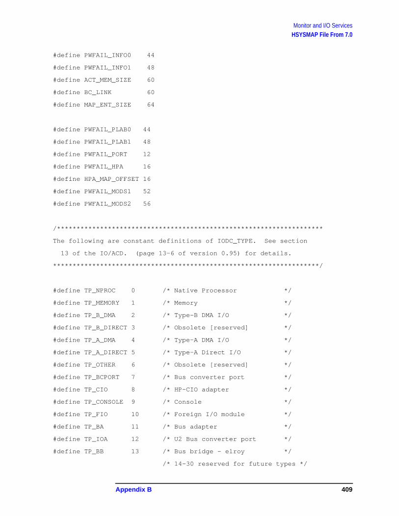
Monitor and I/O ServicesHSYSMAP File From 7.0
#define PWFAIL_INFO0 44
#define PWFAIL_INFO1 48
#define ACT_MEM_SIZE 60
#define BC_LINK 60
#define MAP_ENT_SIZE 64
#define PWFAIL_PLAB0 44
#define PWFAIL_PLAB1 48
#define PWFAIL_PORT 12
#define PWFAIL_HPA 16
#define HPA_MAP_OFFSET 16
#define PWFAIL_MODS1 52
#define PWFAIL_MODS2 56
/********************************************************************
The following are constant definitions of IODC_TYPE. See section
13 of the IO/ACD. (page 13-6 of version 0.95) for details.
********************************************************************/
#define TP_NPROC 0 /* Native Processor */
#define TP_MEMORY 1 /* Memory */
#define TP_B_DMA 2 /* Type-B DMA I/O */
#define TP_B_DIRECT 3 /* Obsolete [reserved] */
#define TP_A_DMA 4 /* Type-A DMA I/O */
#define TP_A_DIRECT 5 /* Type-A Direct I/O */
#define TP_OTHER 6 /* Obsolete [reserved] */
#define TP_BCPORT 7 /* Bus converter port */
#define TP_CIO 8 /* HP-CIO adapter */
#define TP_CONSOLE 9 /* Console */
#define TP_FIO 10 /* Foreign I/O module */
#define TP_BA 11 /* Bus adapter */
#define TP_IOA 12 /* U2 Bus converter port */
#define TP_BB 13 /* Bus bridge - elroy */
/* 14-30 reserved for future types */
Appendix B 409
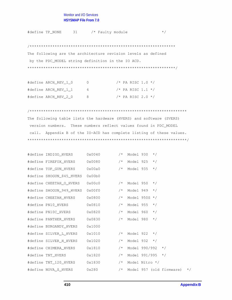
Monitor and I/O ServicesHSYSMAP File From 7.0
#define TP_NONE 31 /* Faulty module */
/****************************************************************
The following are the architecture revision levels as defined
by the PDC_MODEL string definition in the IO ACD.
*****************************************************************/
#define ARCH_REV_1_0 0 /* PA RISC 1.0 */
#define ARCH_REV_1_1 4 /* PA RISC 1.1 */
#define ARCH_REV_2_0 8 /* PA RISC 2.0 */
/*********************************************************************
The following table lists the hardware (HVERS) and software (SVERS)
version numbers. These numbers reflect values found in PDC_MODEL
call. Appendix B of the IO-ACD has complete listing of these values.
**********************************************************************/
#define INDIGO_HVERS 0x0040 /* Model 930 */
#define FIREFOX_HVERS 0x0080 /* Model 925 */
#define TOP_GUN_HVERS 0x00a0 /* Model 935 */
#define SHOGUN_845_HVERS 0x00b0
#define CHEETAH_O_HVERS 0x00c0 /* Model 950 */
#define SHOGUN_949_HVERS 0x00f0 /* Model 949 */
#define CHEETAH_HVERS 0x0800 /* Model 950S */
#define PN10_HVERS 0x0810 /* Model 955 */
#define PN10C_HVERS 0x0820 /* Model 960 */
#define PANTHER_HVERS 0x0830 /* Model 980 */
#define BURGANDY_HVERS 0x1000
#define SILVER_L_HVERS 0x1010 /* Model 922 */
#define SILVER_H_HVERS 0x1020 /* Model 932 */
#define CHIMERA_HVERS 0x1810 /* Model 990/992 */
#define TNT_HVERS 0x1820 /* Model 991/995 */
#define TNT_120_HVERS 0x1830 /* Model Nitro */
#define NOVA_S_HVERS 0x280 /* Model 957 (old firmware) */
410 Appendix B

Monitor and I/O ServicesHSYSMAP File From 7.0
#define NOVA_L_HVERS 0x2800 /* Model 957 */
#define NOVA_H_HVERS 0x2810 /* Model 967 */
#define NOVA_8_HVERS 0x2820 /* Model 917 */
#define NOVA_64_HVERS 0x2830 /* Model 977 */
#define TNOVA_HVERS 0x2840 /* Model 987 */
#define TNOVA_64_HVERS 0x2850
#define HYDRA_64_HVERS 0x2860
#define HYDRA_96_HVERS 0x2870
#define MNOVA_HVERS 0x2880 /* Model 987-150 */
#define ORVILLE_HVERS 0x4800
#define WILBUR_HVERS 0x4810
#define WB80_HVERS 0x4820
#define WB96_HVERS 0x4830
#define MOHAWK_180 0x58F0
#define MOHAWK_200 0x5900
#define MOHAWK_220 0x5910
#define JADE_1 0x9000 /* This is not the real value */
#define JADE_2 0x9010 /* This is not the real value */
#define NP_SVERS 0x00000400
#define MB_MC_HVERS 0x0020
#define TABASCO_MC_HVERS 0x00c0
#define ARCH_MC_SVERS 0x00000800
#define SMB_MC_HVERS 0x0040
#define IND_MC_HVERS 0x0080
#define IND_8_MC_HVERS 0x00c0
#define BURG_4_HVERS 0x00d0
#define BURG_OB_HVERS 0x00e0
#define IND_32_MC_HVERS 0x0120
#define PDEP_MC_SVERS 0x00000900
#define CHEETAH1_HVERS 0x0040 /* both sides - excep */
#define CONDOR_MB_HVERS 0x0050
Appendix B 411

Monitor and I/O ServicesHSYSMAP File From 7.0
#define CONDOR_NIO_HVERS 0x1000
#define ACME1_BCL_HVERS 0x1010
#define SUMMIT_BCU_HVERS 0x1840
#define JAVA_BCU_HVERS 0x1850
#define KEYAKI_BCU_HVERS 0x5080
#define U2_BCU_HVERS 0x5800
#define BC1_SVERS 0x00000c00
#define IOA_SVERS 0x00000b00
#define VCIO_HVERS 0x0040 /* vlsi */
#define SCIO_HVERS 0x0050 /* silverfox */
#define DCIO_HVERS 0x0080 /* ttl */
#define CIO_SVERS 0x00001000
#define NIO_FL_SVERS 0x00004100
#define LAN_RDB_MIURA_SVERS 0x00005200
#define LAN_RDB_MIURA_HVERS 0x0040
#define LAN_RDB_DIABLO_SVERS 0x00006000
#define LAN_RDB_DIABLO_HVERS 0x0140
#define LAN_RDB_COUNTACH_SVERS 0x00006000
#define LAN_RDB_COUNTACH_HVERS 0x0540
#define PAR_IO_HVERS 0x0040
#define PAR_IO_SVERS 0x00001800
#define PAR_RDB_HVERS 0x0040
#define PAR_RDB_SVERS 0x00001900
#define PAR_NIO_SVERS NIO_GPIO_SVERS
#define PAR_NIO2_SVERS NIO_GPIO2_SVERS
#define PAR_OLD_HVERS 0xeb60
412 Appendix B

Monitor and I/O ServicesHSYSMAP File From 7.0
#define PAR_OLD_SVERS 0x08000240
#define CHEETAH_CONS_SVERS 0x00001c00
#define CHEETAH_CONS_HVERS 0x0040
#define PSI_SVERS 0x00002000
#define MBTRNSIT_SVERS 0x00002100
#define NIO_HPIB_SVERS 0x00004000
#define NIO_GPIO_SVERS 0x00004400
#define NIO_GPIO2_SVERS 0x00004500
#define PA_PLATFORM 0
#define PAT_PLATFORM 1
#define PA_CENTRAL_BUS 0xfff80000
#ifndef LOCORE
/*********************************************************************
*** Common Module Declarations ***
**********************************************************************/
/* flags.arch_type defines */
#define PA_DEV 0
#define PAT_DEV 1
#define PCI_DEV 2
#define PCI_BRG 3
typedef struct flags_inf {
unsigned int confd:1; /* Mod configured */
unsigned int no_hw:1; /* No h/w in slot */
unsigned int broken:1; /* h/w is broken */
unsigned int arch_type:4; /* PA,PAT,PCI,PPB mod */
unsigned int directed_mmio:1; /* has directed no distributed sp */
Appendix B 413

Monitor and I/O ServicesHSYSMAP File From 7.0
unsigned int filler:24;
} flags_inf_t;
/*********************************************************************
*** PA Module Declarations ***
**********************************************************************/
#define SPA pa.spa /* short-hand. The code became unreadable. */
#define LINK pa.link
#define MOD_DEP1 pa.mod_dep1
#define MOD_DEP2 pa.mod_dep2
#define PA_NUM_BUS_ENTRIES 64
#define PA_SIZE_BUS_ENT sizeof(struct pa_bus_map)
struct mem_io_spa_inf {
unsigned int spa_addr;
unsigned int spa_size;
unsigned int resvd1;
unsigned int resvd2;
};
struct bc_info {
unsigned int io_low;
unsigned int io_high;
unsigned int resvd;
unsigned int mem_high;
};
union spa_inf {
struct bc_info bc;
struct mem_io_spa_inf nbc;
};
414 Appendix B
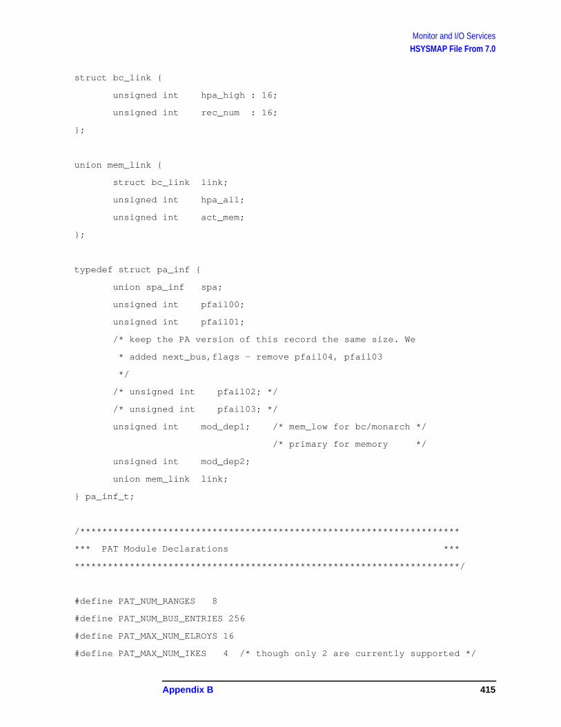
Monitor and I/O ServicesHSYSMAP File From 7.0
struct bc_link {
unsigned int hpa_high : 16;
unsigned int rec_num : 16;
};
union mem_link {
struct bc_link link;
unsigned int hpa_all;
unsigned int act_mem;
};
typedef struct pa_inf {
union spa_inf spa;
unsigned int pfail00;
unsigned int pfail01;
/* keep the PA version of this record the same size. We
* added next_bus,flags - remove pfail04, pfail03
*/
/* unsigned int pfail02; */
/* unsigned int pfail03; */
unsigned int mod_dep1; /* mem_low for bc/monarch */
/* primary for memory */
unsigned int mod_dep2;
union mem_link link;
} pa_inf_t;
/*********************************************************************
*** PAT Module Declarations ***
**********************************************************************/
#define PAT_NUM_RANGES 8
#define PAT_NUM_BUS_ENTRIES 256
#define PAT_MAX_NUM_ELROYS 16
#define PAT_MAX_NUM_IKES 4 /* though only 2 are currently supported */
Appendix B 415

Monitor and I/O ServicesHSYSMAP File From 7.0
#define PAT_NUM_DIR_RANGES 4 /* Number of directed ranges supported by IKE*/
/* Module specific information returned by PDC_PAT_CELL */
typedef struct pat_addr_range {
ulonglong_t type; /* addr range type (LMMIO,...) */
ulonglong_t ia64_start; /* ia64 view */
ulonglong_t ia64_end;
ulonglong_t pa_start; /* pa view */
ulonglong_t pa_end;
} pat_addr_range_t;
typedef enum pat_range_index {
LMMIO_TYPE = 0,
GMMIO_TYPE = 1,
ELMMIO_TYPE = 2,
NPIOP_TYPE = 3,
PIOP_TYPE = 4,
LMMIO1_TYPE = 5, /* IKE_KLUDGE */
NUM_RANGE_TYPES = 6
} pat_range_index_t;
#ifdef IKE_KLUDGE
#define MAX_LMMIO_RANGES 2
#endif
typedef struct pat_range_info {
ulonglong_t start; /* ia64 view - starting address of range */
ulonglong_t end; /* end of range */
ulonglong_t next; /* next address to assign */
ulonglong_t pa_start; /* pa view */
ulonglong_t pa_end;
} pat_range_info_t;
416 Appendix B
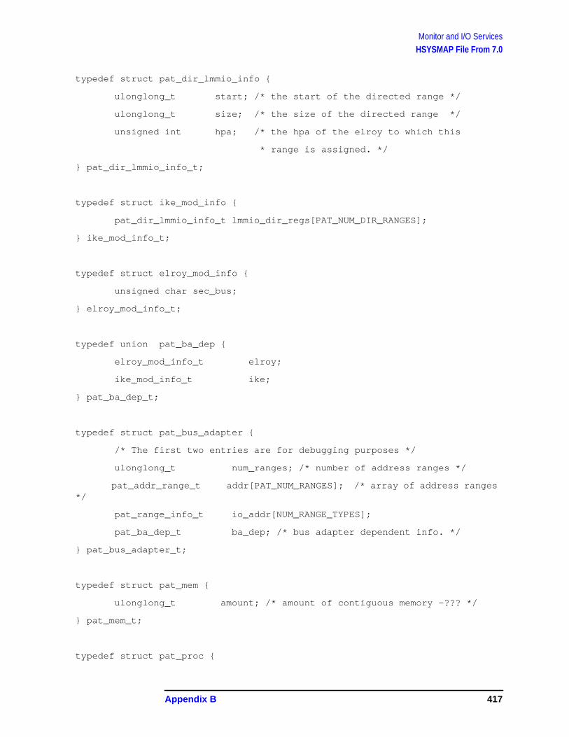
Monitor and I/O ServicesHSYSMAP File From 7.0
typedef struct pat_dir_lmmio_info {
ulonglong_t start; /* the start of the directed range */
ulonglong_t size; /* the size of the directed range */
unsigned int hpa; /* the hpa of the elroy to which this
* range is assigned. */
} pat_dir_lmmio_info_t;
typedef struct ike_mod_info {
pat_dir_lmmio_info_t lmmio_dir_regs[PAT_NUM_DIR_RANGES];
} ike_mod_info_t;
typedef struct elroy_mod_info {
unsigned char sec_bus;
} elroy_mod_info_t;
typedef union pat_ba_dep {
elroy_mod_info_t elroy;
ike_mod_info_t ike;
} pat_ba_dep_t;
typedef struct pat_bus_adapter {
/* The first two entries are for debugging purposes */
ulonglong_t num_ranges; /* number of address ranges */
pat_addr_range_t addr[PAT_NUM_RANGES]; /* array of address ranges*/
pat_range_info_t io_addr[NUM_RANGE_TYPES];
pat_ba_dep_t ba_dep; /* bus adapter dependent info. */
} pat_bus_adapter_t;
typedef struct pat_mem {
ulonglong_t amount; /* amount of contiguous memory -??? */
} pat_mem_t;
typedef struct pat_proc {
Appendix B 417

Monitor and I/O ServicesHSYSMAP File From 7.0
ulonglong_t id_eid; /* processor LID register format */
} pat_proc_t;
typedef union pat_mod_dep {
pat_proc_t proc; /* processor */
pat_mem_t mem; /* memory */
pat_bus_adapter_t ba; /* local or system bus adapter */
} pat_mod_dep_t;
typedef struct pat_inf {
ulonglong_t cba; /* IA64 view of conf base addr */
ulonglong_t mod_info; /* module information - PAT_CELL */
ulonglong_t mod_location; /* module location */
ulonglong_t hw_path; /* what does this look like PATH */
pat_mod_dep_t mod; /* module specific info */
} pat_inf_t;
typedef union arch_dep_inf {
pa_inf_t pa;
pat_inf_t pat;
pci_mod_t pci;
pci_brg_t pci_bd;
} arch_dep_inf_t;
/**********************************************************************
*** System Map Structure ***
**********************************************************************/
/* The Iodc information in this map must not be rearraged or moved.
* Code in CMAP assumes that the iodc info is at the beginning
* of the structure and adheres to the format of data returned
* by PDC_IODC
*/
418 Appendix B

Monitor and I/O ServicesHSYSMAP File From 7.0
/* Warning: if you change the beginning of this record you must
* change the beginning of pa_bus_map. These two structures must
* match!!!!!!!!! Yuk. Marcia Fix.
*/
/* On PA boxes the bus is a contiguous array of entries. On PAT
* boxes it is a linked list of pointers. It was too large as
* a contiguous array. Sat could not load in 16MB.
*/
struct bus_map {
unsigned int hw_model : 16;
unsigned int io : 1;
unsigned int resvd1 : 2;
unsigned int spa_shft : 5;
unsigned int more : 1;
unsigned int word : 1;
unsigned int resvd2 : 1;
unsigned int mod_type : 5;
unsigned int sw_model : 32;
unsigned int iodc_rev : 8;
unsigned int iodc_dep : 8;
unsigned int resvd3 : 16;
unsigned int module_num; /* see comment Dont move !!! */
unsigned int hpa;
struct bus_map *next_bus; /* ptr next bus */
flags_inf_t flags; /* configured, broken,... */
arch_dep_inf_t arch; /* PA, PAT, PCI mod info */
struct bus_map *next_ent; /* PAT, PCI next entry ptr */
};
typedef struct bus_map *bus_map_ptr_t;
/* #ifndef NO_LONG_PTR */
Appendix B 419

Monitor and I/O ServicesHSYSMAP File From 7.0
#ifndef JUNK_JMS
typedef struct bus_map ^bus_map_lptr_t;
#endif
/* WARNING: old CMAP code assumes that it can read in 16 bytes of
* IODC directly into this structure w/o clobbering the HPA. The
* hpa has been set up before the IODC has been called in
* mb_fill_bus. However, port_num has not. YUK.
*/
/* On old PA boxes we cannot affort to have the entry expand to
* the size it will be on PAT boxes. Therefore, we have a separate
* bus structure for pa_bus_map. The separate entry is purely
* to get the size correct.
* MARCIA fix: The beginning of the structures pa_bus_map and
* bus_map must be the same in order for the search routines
* to work independent of the box type. Therefore, WARNING
* can't change one without changing the other.
*/
struct pa_bus_map {
unsigned int hw_model : 16;
unsigned int io : 1;
unsigned int resvd1 : 2;
unsigned int spa_shft : 5;
unsigned int more : 1;
unsigned int word : 1;
unsigned int resvd2 : 1;
unsigned int mod_type : 5;
unsigned int sw_model : 32;
unsigned int iodc_rev : 8;
unsigned int iodc_dep : 8;
unsigned int resvd3 : 16;
unsigned int port_num; /* Dont move !!! - see comment below */
420 Appendix B

Monitor and I/O ServicesHSYSMAP File From 7.0
unsigned int hpa;
unsigned int next_bus; /* rec number of next bus */
flags_inf_t flags; /* configured, broken,... */
pa_inf_t pa;
};
/*
* Useful "short-cut" Defines for accessing fields in system map
*/
#define BA_INFO(map) map->arch.pat.mod.ba
#define IKE_INFO(map) map->arch.pat.mod.ba.ba_dep.ike
#define ELROY_INFO(map) map->arch.pat.mod.ba.ba_dep.elroy
#define PCI_INFO(map) map->arch.pci
#define PCI_BRG_INFO(map) map->arch.pci_bd
/* No one seems to set no_hw - set in mb_fill ??? */
#define MOD_IN_USE(map) (map->mod_type != TP_NONE)
#define MOD_PCI_DEV(map) \
(MOD_IN_USE(map) && map->flags.arch_type == PCI_DEV)
#define MOD_PPB(map) \
(MOD_IN_USE(map) && map->flags.arch_type == PCI_BRG)
#define PPB_BAR_ADDR(map,j) map->arch.pci_bd.bar[j].addr
#define PCI_BAR_ADDR(map,j) map->arch.pci.bar[j].addr
#define BAR_ADDR(map,j) \
(MOD_PPB(map) ? PPB_BAR_ADDR(map,j) : PCI_BAR_ADDR(map,j))
#define PPB_BAR_IN_USE(map,j) map->arch.pci_bd.bar[j].in_use
#define PCI_BAR_IN_USE(map,j) map->arch.pci.bar[j].in_use
#define BAR_IN_USE(map,j) \
(MOD_PPB(map) ? PPB_BAR_IN_USE(map,j) : PCI_BAR_IN_USE(map,j))
Appendix B 421

Monitor and I/O ServicesHSYSMAP File From 7.0
#define PPB_BAR_SPA_TYPE(map,j) map->arch.pci_bd.bar[j].type
#define PCI_BAR_SPA_TYPE(map,j) map->arch.pci.bar[j].type
#define BAR_SPA_TYPE(map,j) \
(MOD_PPB(map) ? PPB_BAR_SPA_TYPE(map,j) : PCI_BAR_SPA_TYPE(map,j))
#define PPB_BAR_MEM_SPACE_TYPE(map,j) map->arch.pci_bd.bar[j].mem_space
#define PCI_BAR_MEM_SPACE_TYPE(map,j) map->arch.pci.bar[j].mem_space
#define BAR_MEM_SPACE_TYPE(map,j) \
(MOD_PPB(map) ? PPB_BAR_MEM_SPACE_TYPE(map,j) :PCI_BAR_MEM_SPACE_TYPE(map,j))
#define PPB_BAR_SIZE(map,j) map->arch.pci_bd.bar[j].size
#define PCI_BAR_SIZE(map,j) map->arch.pci.bar[j].size
#define BAR_SIZE(map,j) \
(MOD_PPB(map) ? PPB_BAR_SIZE(map,j) : PCI_BAR_SIZE(map,j))
#define MAX_MODULE_NUM \
((get_platform_type() == PAT_PLATFORM) ? \
PAT_NUM_BUS_ENTRIES : PA_NUM_BUS_ENTRIES)
#define SIZE_MAP_REC \
((get_platform_type() == PAT_PLATFORM) ? \
sizeof(struct bus_map): sizeof(struct pa_bus_map))
#define PA_GET_NEXT_BUS_INDEX(map) \
(PA_NUM_BUS_ENTRIES * ((struct pa_bus_map ^)(map))->LINK.link.rec_num)
/* Get the map index, this works for PA. Assumes a long pointer */
#define PA_LONG_GET_MAP_INDEX(map, map_start) \
((struct pa_bus_map ^)map - (struct pa_bus_map ^)map_start)
#define NIL_MAP_INDEX -1
422 Appendix B

Monitor and I/O ServicesHSYSMAP File From 7.0
/**********************************************************************
*** Error Returns for MAP Access routines ***
**********************************************************************/
#define sysmap_invalid_path -10
#define sysmap_nonexistant_dev -11
/**********************************************************************
*** CEC Structure Definitions for Map Procedures ***
**********************************************************************/
/* *** Cell Structure *** */
/* For Prelude this is a dummy structure which is not part of the overall
* Map structure. For HD, there will be Protection domains and cells which
* will each have their own system map. (Possibly)
*/
typedef struct cell_info {
ulonglong_t cell_location;
} cell_info_t;
/**** Additional Ike declarations ****/
/* Ike info: This structure is used to accumlate information about
* Ikes, during the first pass through the bus. It contains a pointer
* to the IKEs in the map. This structure is used on the second
* pass to hook the ELROYs to their IKEs.
*/
typedef struct ike_info {
struct bus_map *map; /* Ikes map entry */
struct bus_map *start; /* first bus entry for the Elroys */
struct bus_map *next; /* next bus entry for Elroy */
Appendix B 423

Monitor and I/O ServicesHSYSMAP File From 7.0
} ike_info_t;
typedef struct ba_range {
ulonglong_t start; /* first address in range */
ulonglong_t size; /* size of range */
} ba_range_t;
#define mem_low MOD_DEP1
/**********************************************************************
*** Miscellaneous declarations for Map Procedures ***
**********************************************************************/
struct path_type {
unsigned int len;
unsigned char data[32];
};
struct pdc_path {
unsigned int flags:8; /* boot flags */
unsigned char bc[6]; /* bus converter slots */
unsigned int pm:8; /* physical module */
unsigned int module[6]; /* logical module, etc. */
};
struct addrs {
unsigned int map_start;
unsigned int rpdirx_start;
unsigned int iva_start;
unsigned int free_mem;
unsigned int no_io_pg;
unsigned int no_mem_pg;
unsigned int resvd[6];
};
#endif /* ! LOCORE */
424 Appendix B

Monitor and I/O ServicesDIOPPT File from 6.0
DIOPPT File from 6.0$title 'DIOPPT.IOSERV -- Physical Path Table Definitions'$
$page$
{----------------------------------------------------------------------}
{ This file is only used by the Sherlock Diagnostics IO_MAP module? }
{ Does anyone in MXO use it? How about BND? }
{----------------------------------------------------------------------}
const
Iop_Path_Exists = 0;
Iop_No_Parent = 1;
Iop_Add_To_Sibling = 2;
Iop_Add_To_Parent = 3;
type
ppt_entry_ptr_type = ^ $extnaddr$ ppt_entry_rec;
ppt_entry_shptr_type = ^ ppt_entry_rec;
ppt_entry_rec = record
per_mgr_entrypt : llio_manager_proc; {The address of the I/O Managerprocedure outer block.}
per_port_num : port_num_type; {The I/O Manager's portnumber.}
per_pda : localanyptr; {Ptr to the Port Data Area ofthis manager.}
per_path : str_type; {Hardware path to the physicalhardware.}
per_mgr_name : str_type; {Procedure Name of the I/Omanager.}
per_hw_prod_num : str_type; {The HP (or ?) product numberof the hardware component.}
{ represented by this entry.}
per_mgr_priority : bit8; {The manager's ICS executionpriority.}
per_config_state : bit8; {Mgr_Nonexistent .. Unbound --manager's configuration state.}
Appendix B 425
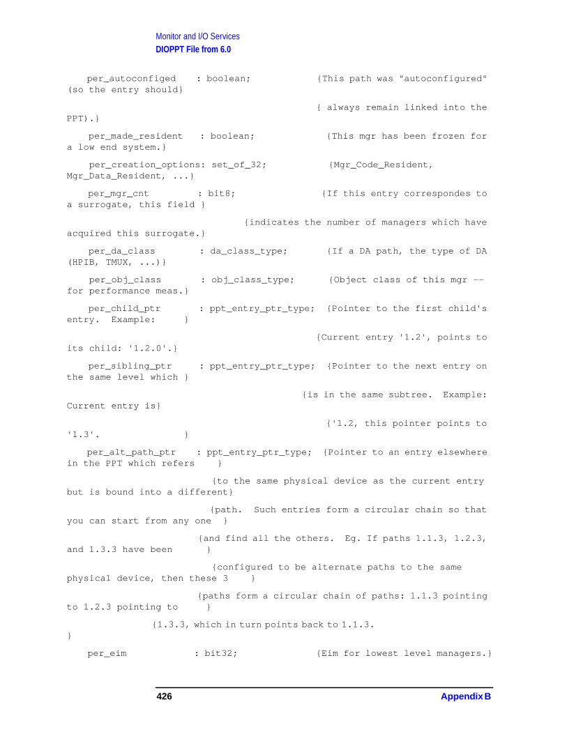
Monitor and I/O ServicesDIOPPT File from 6.0
per_autoconfiged : boolean; {This path was "autoconfigured"(so the entry should}
{ always remain linked into thePPT).}
per_made_resident : boolean; {This mgr has been frozen fora low end system.}
per_creation_options: set_of_32; {Mgr_Code_Resident,Mgr_Data_Resident, ...}
per_mgr_cnt : bit8; {If this entry correspondes toa surrogate, this field }
{indicates the number of managers which haveacquired this surrogate.}
per_da_class : da_class_type; {If a DA path, the type of DA(HPIB, TMUX, ...)}
per_obj_class : obj_class_type; {Object class of this mgr --for performance meas.}
per_child_ptr : ppt_entry_ptr_type; {Pointer to the first child'sentry. Example: }
{Current entry '1.2', points toits child: '1.2.0'.}
per_sibling_ptr : ppt_entry_ptr_type; {Pointer to the next entry onthe same level which }
{is in the same subtree. Example:Current entry is}
{'1.2, this pointer points to'1.3'. }
per_alt_path_ptr : ppt_entry_ptr_type; {Pointer to an entry elsewherein the PPT which refers }
{to the same physical device as the current entrybut is bound into a different}
{path. Such entries form a circular chain so thatyou can start from any one }
{and find all the others. Eg. If paths 1.1.3, 1.2.3,and 1.3.3 have been }
{configured to be alternate paths to the samephysical device, then these 3 }
{paths form a circular chain of paths: 1.1.3 pointingto 1.2.3 pointing to }
{1.3.3, which in turn points back to 1.1.3.}
per_eim : bit32; {Eim for lowest level managers.}
426 Appendix B

Monitor and I/O ServicesDIOPPT File from 6.0
per_ada_size : bit32; {Size of the manager's aux dataarea.}
end;
type
ppt_header_rec = record
table_hdr : ios_table_hdr_type;
phr_config_sema : semaphore_rec; {Serialization of IO_CONFIG andIO_UNCONFIG.}
phr_allocated_list: ppt_entry_rec; {Head of the allocated list ofentries (root of the tree).}
filler : array[1..8] of bit8;
{ Start the boot paths at +100H }
console_path : str_type; {Actual boot paths as figured out byPRIMIO_CONFIG.}
disc_path : str_type; {Note: if the path.len = 0 then itmeans that PRIMIO_CONFIG hasn't}
tape_path : str_type; { been called to configure this bootdevice yet. }
blues_port_num : port_num_type; {Port # for Blues.}
tbit_trap_counter : integer;
blues_tbit_log_msg: globalanyptr; {Msg which get sent to BLUES port.}
filler1 : array[hex('17c')..hex('17f')] of bit8;
{ Body starts at +180H }
end;
type
ppt_ptr_type = ^$extnaddr$PPT_HEADER_REC;
ppt_shptr_type = ^ppt_header_rec;
Appendix B 427
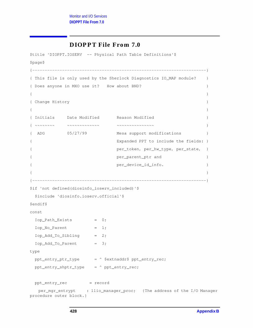
Monitor and I/O ServicesDIOPPT File From 7.0
DIOPPT File From 7.0$title 'DIOPPT.IOSERV -- Physical Path Table Definitions'$
$page$
{----------------------------------------------------------------------}
{ This file is only used by the Sherlock Diagnostics IO_MAP module? }
{ Does anyone in MXO use it? How about BND? }
{ }
{ Change History }
{ }
{ Initials Date Modified Reason Modified }
{ ~~~~~~~~ ~~~~~~~~~~~~~ ~~~~~~~~~~~~~~~ }
{ ADG 05/27/99 Mesa support modifications }
{ Expanded PPT to include the fields: }
{ per_token, per_hw_type, per_state, }
{ per_parent_ptr and }
{ per_device_id_info. }
{ }
{----------------------------------------------------------------------}
$if 'not defined(diosinfo_ioserv_included)'$
$include 'diosinfo.ioserv.official'$
$endif$
const
Iop_Path_Exists = 0;
Iop_No_Parent = 1;
Iop_Add_To_Sibling = 2;
Iop_Add_To_Parent = 3;
type
ppt_entry_ptr_type = ^ $extnaddr$ ppt_entry_rec;
ppt_entry_shptr_type = ^ ppt_entry_rec;
ppt_entry_rec = record
per_mgr_entrypt : llio_manager_proc; {The address of the I/O Managerprocedure outer block.}
428 Appendix B
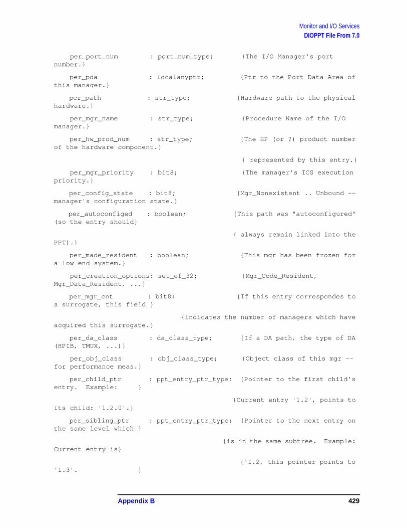
Monitor and I/O ServicesDIOPPT File From 7.0
per_port_num : port_num_type; {The I/O Manager's portnumber.}
per_pda : localanyptr; {Ptr to the Port Data Area ofthis manager.}
per_path : str_type; {Hardware path to the physicalhardware.}
per_mgr_name : str_type; {Procedure Name of the I/Omanager.}
per_hw_prod_num : str_type; {The HP (or ?) product numberof the hardware component.}
{ represented by this entry.}
per_mgr_priority : bit8; {The manager's ICS executionpriority.}
per_config_state : bit8; {Mgr_Nonexistent .. Unbound --manager's configuration state.}
per_autoconfiged : boolean; {This path was "autoconfigured"(so the entry should}
{ always remain linked into thePPT).}
per_made_resident : boolean; {This mgr has been frozen fora low end system.}
per_creation_options: set_of_32; {Mgr_Code_Resident,Mgr_Data_Resident, ...}
per_mgr_cnt : bit8; {If this entry correspondes toa surrogate, this field }
{indicates the number of managers which haveacquired this surrogate.}
per_da_class : da_class_type; {If a DA path, the type of DA(HPIB, TMUX, ...)}
per_obj_class : obj_class_type; {Object class of this mgr --for performance meas.}
per_child_ptr : ppt_entry_ptr_type; {Pointer to the first child'sentry. Example: }
{Current entry '1.2', points toits child: '1.2.0'.}
per_sibling_ptr : ppt_entry_ptr_type; {Pointer to the next entry onthe same level which }
{is in the same subtree. Example:Current entry is}
{'1.2, this pointer points to'1.3'. }
Appendix B 429
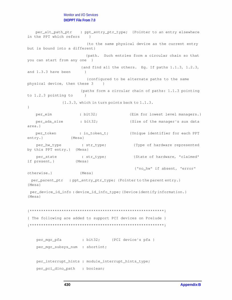
Monitor and I/O ServicesDIOPPT File From 7.0
per_alt_path_ptr : ppt_entry_ptr_type; {Pointer to an entry elsewherein the PPT which refers }
{to the same physical device as the current entrybut is bound into a different}
{path. Such entries form a circular chain so thatyou can start from any one }
{and find all the others. Eg. If paths 1.1.3, 1.2.3,and 1.3.3 have been }
{configured to be alternate paths to the samephysical device, then these 3 }
{paths form a circular chain of paths: 1.1.3 pointingto 1.2.3 pointing to }
{1.3.3, which in turn points back to 1.1.3.}
per_eim : bit32; {Eim for lowest level managers.}
per_ada_size : bit32; {Size of the manager's aux dataarea.}
per_token : io_token_t; {Unique identifier for each PPTentry.} {Mesa}
per_hw_type : str_type; {Type of hardware representedby this PPT entry.} {Mesa}
per_state : str_type; {State of hardware, "claimed"if present,} {Mesa}
{"no_hw" if absent, "error"otherwise.} {Mesa}
per_parent_ptr : ppt_entry_ptr_type; {Pointer to the parent entry.}{Mesa}
per_device_id_info : device_id_info_type; {Device identify information.}{Mesa}
{***********************************************************}
{ The following are added to support PCI devices on Prelude }
{***********************************************************}
per_mgr_pfa : bit32; {PCI device's pfa }
per_mgr_subsys_num : shortint;
per_interrupt_hints : module_interrupt_hints_type;
per_pci_dino_path : boolean;
430 Appendix B

Monitor and I/O ServicesDIOPPT File From 7.0
{************************************************************}
{ These are generic attributes of the module in SYSMAP }
{************************************************************}
per_mgr_module_on_bus : boolean;
per_mgr_hw_model_rev : hw_model_rev_type;
per_mgr_sw_model_rev : sw_model_rev_type;
per_mgr_module_type : type_of_module_type;
per_mgr_hw_flags : flags_type;
per_mgr_pa : pa_info_type;
end;
type
ppt_header_rec = record
table_hdr : ios_table_hdr_type;
phr_config_sema : semaphore_rec; {Serialization of IO_CONFIG andIO_UNCONFIG.}
phr_allocated_list: ppt_entry_rec; {Head of the allocated list ofentries (root of the tree).}
filler : array[1..8] of bit8;
{ Start the boot paths at +100H }
console_path : str_type; {Actual boot paths as figured out byPRIMIO_CONFIG.}
disc_path : str_type; {Note: if the path.len = 0 then itmeans that PRIMIO_CONFIG hasn't}
tape_path : str_type; { been called to configure this bootdevice yet. }
blues_port_num : port_num_type; {Port # for Blues.}
tbit_trap_counter : integer;
blues_tbit_log_msg: globalanyptr; {Msg which get sent to BLUES port.}
filler1 : array[hex('17c')..hex('17f')] of bit8;
{ Body starts at +180H }
end;
Appendix B 431

Monitor and I/O ServicesDIOPPT File From 7.0
type
ppt_ptr_type = ^$extnaddr$PPT_HEADER_REC;
ppt_shptr_type = ^ppt_header_rec;
432 Appendix B
C Hardware Overview
Refer to Chapter 1 , “Hardware Overview Monitor and I/O Services,” foradditional information.
IOSAPIC Interrupt HandlingTutorial/IS
OverviewThe current platform refresh project for CSY’s HP e3000 computerimplements the MPE operating system on Prelude hardware. ThePrelude design is called “PAT” (Precision Architecture on Tahoe.) It iscomprised of a PA (Precision Architecture) processor (e.g., PCX-W) withits Runway bus converted by a DEW (Device to Enable the PCX-Wprocessor) bus converter to the Merced bus (IA-64 (Intel Architecture64-bit), an early phase of which is code-named “Tahoe.”) The Mercedbus has an Ike bus converter that connects to the Elroy PCI busmanager. The PCI bus in turn supports buses such as SCSI, to whichcan be attached peripheral devices such as disk and tape.
The focus of this spec is IOSAPIC. “APIC” stands for “AdvancedProgrammable Interrupt Controller,” a facility in Intel processors of thex86 family. The “S” stands for “Streamlined,” since systems like Preludehave to support only a subset of the APIC found in PCs. The “IO”denotes the I/O subsystem part of SAPIC that in Prelude is part ofElroy, as distinguished from the IOSAPIC “local unit” that is theprocessor part.
The main function of IOSAPIC is to convert and route the interruptsignals such as PCI INTA# to the processor(s) for final disposition.
433

Hardware OverviewHigh-Level Flow
High-Level FlowDuring early boot, the pdc interrupt routing table is retrieved via apdc_access_pat call and leveraged into a more detailed iosapic tablethat supports routing by device to a specific interrupt priority within aspecific processor. As devices are configured the drivers providecriticality and frequency hints to get the interrupt load balanced acrossthe available processors with appropriate priority. Here's the flow forthe initial setup:
launch (alaunch.asmlnch) (first code in start, loaded by isl)pat_setup_interrupts (cpatintr.asmmon) (set up interrupts for pat box)
pat_get_intr_routing_table (cpatintr.asmmon) (get interrupt routing table via pdc)pat_setup_iosapic (cpatintr.asmmon) (build iosapic table)
pat_init_iosapic_tbl (cpatintr.asmmon) (align, initialize iosapic table)set_iosapic_ptr (cmon.asmmon) (set pointer to iosapic table in iva-minus area)
After launch passes control to genesis and the I/O configuration isunderway, the iosapic table gets updated. The interrupt hints areretrieved from the drivers and passed to the iosapic routines to updatethe iosapic table. Here's the high-level flow:
. . . .do_io_config (xconfig.ioserv) (main functionality of io_config)
pick_pfa_eim (xeim.ioserv) (use criticality/freq to select cpu & eir)io_set_and_verify_interrupt (cpatintr.asmmon) (set iosapic cpu & eir)
pat_get_proc_id_eid (cmon.asmmon) (get cpu id_eid from cpu index)pat_write_iosapic_entry (cpatintr.asmmon) (update iosapic register)
io_write_reg32_w (hpat.asmmon) (swap & store (wide) 32 bits to io space)io_read_reg32_w (hpat.asmmon) (load & swap (wide) 32 bits from io space)
434 Appendix C

Hardware OverviewModule Detail
Module DetailIn this section you find the calling sequence for the iosapic functionsmentioned in the flow above, along with the main data structures thesefunctions deal with, and example data from a live system. The sourcefile is noted for easy reference.
int *pat_setup_interrupts(mem_buf) (cpatintr.asmmon)int *mem_buf;
* Function: This procedure sets up interrupts on a pat box. It gets the* interrupt routing table, sets up data structures for all the* I/O SAPICs in the system.* Input: mem_buf - address of free memory to build tables* Return: address of free memory after interrupt structures
int *pat_get_intr_routing_table(mem_buf, status) (cpatintr.asmmon)int *mem_buf; int *status;
* Function: Calls pdc to get the interrupt routing table* Inputs:
* mem_buf: Address of mem buffer for routing table* status : Pointer to status word* Output:* status : Pointer to status word* Return: Pointer to first free mem past the routing table
Here’s the target structure for the pdc interrupt routing table data. It’sput in the next available memory in the globals being set up by launch,just ahead of the iosapic table.
typedef struct intr_tbl_entry { (hintr.asmmon)/* Entry Type 139 identifies an I/O SAPIC interrupt entry */uint8_t entry_type;uint8_t entry_length; /* entry length in bytes */uint8_t intr_type; /* 0 => vectored all other values resvd */unsigned int resvd:4; /* Reserved field *//*
* Polarity of SAPIC I/O input signals:* 00 = Reserved* 01 = Active high* 10 = Reserved* 11 = Active low*/
unsigned int po:2;/* Trigger mode of SAPIC I/O input signals
* 00 = Reserved* 01 = Edge-triggered* 10 = Reserved* 11 = Level-triggered
*/
unsigned int el:2;unsigned int resvd1:1; /* Reserved field */unsigned int srcdev_no:5; /* Identifies dev that triggered intr *//* PCI Interrupt signal *//* 0x0 => INT_A# */
Appendix C 435

Hardware OverviewModule Detail
/* 0x1 => INT_B# *//* 0x2 => INT_C# *//* 0x3 => INT_D# */
unsigned int srcbus_irq:2;/* Bus no from which the intr originated */
uint8_t srcbus_id;uint8_t srcseg_id; /* Unique id across protection domains */
/* Identifies segment of PCI buses *//* Identifies INTINn pin to which signal is connected */
uint8_t dest_iosapic_intin;/* I/O SAPIC (Elroy) to which signal is connected */
ulonglong_t dest_iosapic;} intr_tbl_entry_t;
typedef struct intr_tbl {uint32_t num_entries; /* Num of entries in the table */uint32_t table_size; /* #entries * size of entry */
/* Pointer to the first entry in the table */intr_tbl_entry_t *intr_routing_tbl;
} intr_tbl_t;
The pointer to the iosapic table is in the iva-negative area. Backing offfrom this point gets you to the beginning of the pdc interrupt routingdata that is used to build the iosapic table. Here’s the raw data:
$192 ($0) nmrembug > dz iva-514 /*get the iva_sapic_ptr from iva-negative*/REAL $00231aec $ 00fc43f0
$1aa ($0) nmrembug > dz 00fc43f0-4*100,110,b /*back up to find the start of */
/*the pdc interrupt routing data*/
REAL $00fc3ff0 $ 00000000 00000000 00000000 00000000 .... .... .... ....REAL $00fc4000 $ 0000003e 000003e0 00fc4010 000025f8 ...> .... ..@. ..%.REAL $00fc4010 $ 8b10000f 00000000 ffffffff bffe0800 .... .... .... ....REAL $00fc4020 $ 8b10000f 04000001 ffffffff bffe0800 .... .... .... ....REAL $00fc4030 $ 8b10000f 08000002 ffffffff bffe0800 .... .... .... ....REAL $00fc4040 $ 8b10000f 09000003 ffffffff bffe0800 .... .... .... ....REAL $00fc4050 $ 8b10000f 10000004 ffffffff bffe0800 .... .... .... ....REAL $00fc4060 $ 8b10000f 14000005 ffffffff bffe0800 .... .... .... ....REAL $00fc4070 $ 8b10000f 00080000 ffffffff bffe2800 .... .... .... ..(.REAL $00fc4080 $ 8b10000f 01080001 ffffffff bffe2800 .... .... .... ..(.......
REAL $00fc43c0 $ 8b10000f 01e00001 ffffffff fecf8800 .... .... .... ....REAL $00fc43d0 $ 8b10000f 02e00002 ffffffff fecf8800 .... .... .... ....REAL $00fc43e0 $ 8b10000f 03e00003 ffffffff fecf8800 .... .... .... ....REAL $00fc43f0 $ ffffffff bffe0800 1b010501 00000000 .... .... .... ....
Here’s the “formatted” data:
typedef struct intr_tbl_entry {uint8_t entry_type; = 8b = #139 = iosapic entryuint8_t entry_length; = 10 = #16uint8_t intr_type; = 00 = vectoredunsigned int resvd:4; = 00unsigned int po:2; = f = 11 = active lowunsigned int el:2; = f = 11 = level-triggered
436 Appendix C

Hardware OverviewModule Detail
unsigned int resvd1:1; = 0unsigned int srcdev_no:5; = 04 = b00000100 = b00001 = dev #1unsigned int srcbus_irq:2; = 04 = b00000100 = b00 = INTA#uint8_t srcbus_id; = 00uint8_t srcseg_id; = 00uint8_t dest_iosapic_intin;= 01ulonglong_t dest_iosapic; = ffffffff bffe0800
} intr_tbl_entry_t;
typedef struct intr_tbl {uint32_t num_entries; = 3e = #62uint32_t table_size; = 3e0 = #992 = 3e*10
intr_tbl_entry_t *intr_routing_tbl = 00fc4010 = start of pdc routing data
Leveraging the pdc interrupt routing data, the pat_setup_iosapicfunction builds the iosapic table:
int *pat_setup_iosapic(free_mem, tbl_ptr) (cpatintr.asmmon)int *free_mem;intr_tbl_t *tbl_ptr;
* Function: This procedure sets up the all the IO SAPICs on the system* Currently only Elroys have io sapics. This procedure reads the* intr routing table that has already been set up by* pat_get_intr_routing_table and creates a table with one entry* for every io sapic redirection table on the system.** Input: free_mem - address of free memory to build tables* intr_table - address of the interrupt routing table** Return: address of free memory after interrupt structures*
typedef struct iosapic_entry {uint16_t dest_id_eid;unsigned int res4:16;unsigned int res3:15;unsigned int mask:1; /* 0-> not masked, 1->masked */unsigned int trig_mode:1; /* Trigger mode, 0->edge, 1->level */unsigned int res2:1;unsigned int intr_po:1; /* Input pin polarity *//* 0-> high, 1-> low */unsigned int del_stat:1; /* Delivery Status, 0->idle *//* 1-> Send Pending */unsigned int res1:1;unsigned int del_mode:3; /* Mode of delivery of Intr *//*
* 000 -> Fixed* 001 -> Fixed w/hint* 010 -> PMI* 011 -> reserved* 100 -> NMI* 101 -> INIT* 110 -> reserved* 111 -> ExtINT
Appendix C 437
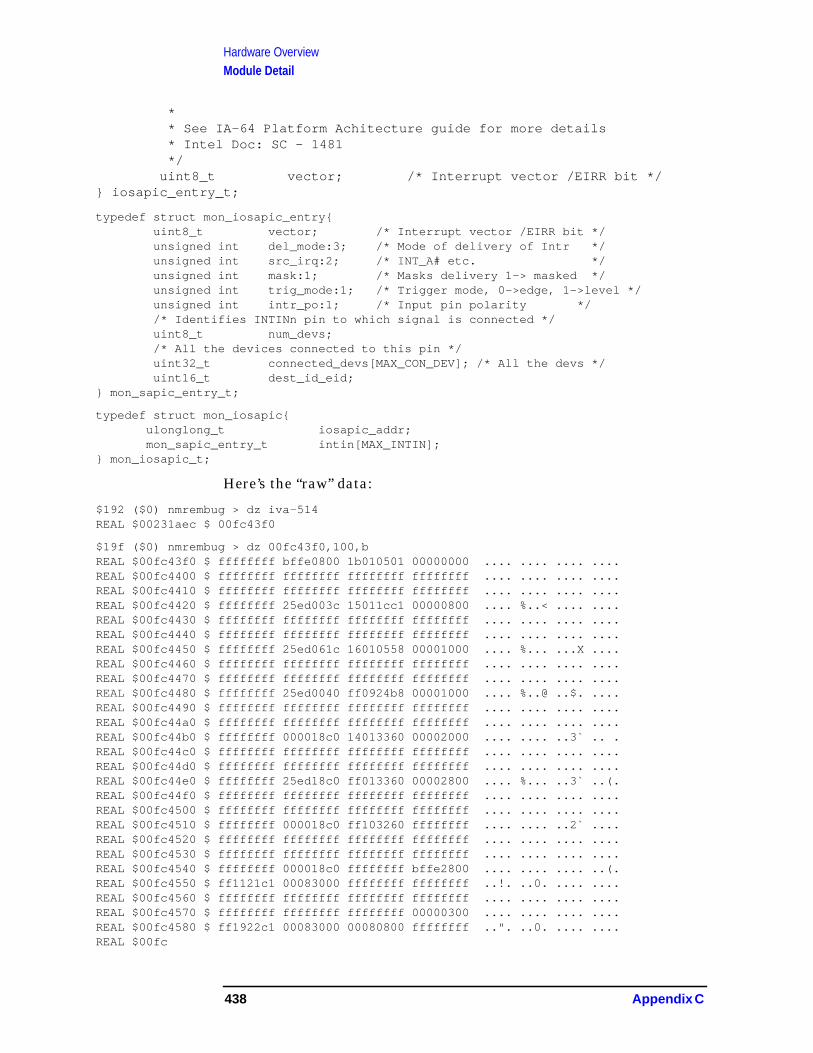
Hardware OverviewModule Detail
** See IA-64 Platform Achitecture guide for more details* Intel Doc: SC - 1481*/
uint8_t vector; /* Interrupt vector /EIRR bit */} iosapic_entry_t;
typedef struct mon_iosapic_entry{uint8_t vector; /* Interrupt vector /EIRR bit */unsigned int del_mode:3; /* Mode of delivery of Intr */unsigned int src_irq:2; /* INT_A# etc. */unsigned int mask:1; /* Masks delivery 1-> masked */unsigned int trig_mode:1; /* Trigger mode, 0->edge, 1->level */unsigned int intr_po:1; /* Input pin polarity *//* Identifies INTINn pin to which signal is connected */uint8_t num_devs;/* All the devices connected to this pin */uint32_t connected_devs[MAX_CON_DEV]; /* All the devs */uint16_t dest_id_eid;
} mon_sapic_entry_t;
typedef struct mon_iosapic{ulonglong_t iosapic_addr;mon_sapic_entry_t intin[MAX_INTIN];
} mon_iosapic_t;
Here’s the “raw” data:
$192 ($0) nmrembug > dz iva-514REAL $00231aec $ 00fc43f0
$19f ($0) nmrembug > dz 00fc43f0,100,bREAL $00fc43f0 $ ffffffff bffe0800 1b010501 00000000 .... .... .... ....REAL $00fc4400 $ ffffffff ffffffff ffffffff ffffffff .... .... .... ....REAL $00fc4410 $ ffffffff ffffffff ffffffff ffffffff .... .... .... ....REAL $00fc4420 $ ffffffff 25ed003c 15011cc1 00000800 .... %..< .... ....REAL $00fc4430 $ ffffffff ffffffff ffffffff ffffffff .... .... .... ....REAL $00fc4440 $ ffffffff ffffffff ffffffff ffffffff .... .... .... ....REAL $00fc4450 $ ffffffff 25ed061c 16010558 00001000 .... %... ...X ....REAL $00fc4460 $ ffffffff ffffffff ffffffff ffffffff .... .... .... ....REAL $00fc4470 $ ffffffff ffffffff ffffffff ffffffff .... .... .... ....REAL $00fc4480 $ ffffffff 25ed0040 ff0924b8 00001000 .... %..@ ..$. ....REAL $00fc4490 $ ffffffff ffffffff ffffffff ffffffff .... .... .... ....REAL $00fc44a0 $ ffffffff ffffffff ffffffff ffffffff .... .... .... ....REAL $00fc44b0 $ ffffffff 000018c0 14013360 00002000 .... .... ..3` .. .REAL $00fc44c0 $ ffffffff ffffffff ffffffff ffffffff .... .... .... ....REAL $00fc44d0 $ ffffffff ffffffff ffffffff ffffffff .... .... .... ....REAL $00fc44e0 $ ffffffff 25ed18c0 ff013360 00002800 .... %... ..3` ..(.REAL $00fc44f0 $ ffffffff ffffffff ffffffff ffffffff .... .... .... ....REAL $00fc4500 $ ffffffff ffffffff ffffffff ffffffff .... .... .... ....REAL $00fc4510 $ ffffffff 000018c0 ff103260 ffffffff .... .... ..2` ....REAL $00fc4520 $ ffffffff ffffffff ffffffff ffffffff .... .... .... ....REAL $00fc4530 $ ffffffff ffffffff ffffffff ffffffff .... .... .... ....REAL $00fc4540 $ ffffffff 000018c0 ffffffff bffe2800 .... .... .... ..(.REAL $00fc4550 $ ff1121c1 00083000 ffffffff ffffffff ..!. ..0. .... ....REAL $00fc4560 $ ffffffff ffffffff ffffffff ffffffff .... .... .... ....REAL $00fc4570 $ ffffffff ffffffff ffffffff 00000300 .... .... .... ....REAL $00fc4580 $ ff1922c1 00083000 00080800 ffffffff ..". ..0. .... ....REAL $00fc
438 Appendix C

Hardware OverviewModule Detail
Here’s the “formatted” data:
typedef struct mon_iosapic_entry{uint8_t vector; = 1b = #27 **** NB: this seems out of range:
high demand critical: 6- 9 eir bitslow demand critical: 10-13high non-critical: 14-17
low non-critical: 18-23
*** Mahesh, please*** advise
unsigned int del_mode:3; = b000 = [add text]unsigned int src_irq:2; = b00 = INT_A#unsigned int mask:1; = b0 = not maskedunsigned int trig_mode:1; = b0 = edge [????]unsigned int intr_po:1; = b1 = [add text]uint8_t num_devs; = 5 [????]/* All the devices connected to this pin */uint32_t connected_devs[MAX_CON_DEV]; max = 10 [????]
uint16_t dest_id_eid; = 25ed [????]} mon_sapic_entry_t;
typedef struct mon_iosapic{ulonglong_t iosapic_addr; = ffffffff bffe0800 = target iosapicmon_sapic_entry_t intin[MAX_INTIN]; : 7 interrupt input lines
} mon_iosapic_t;
Questions
1. Where are the specs for the data that comes frompdc_io_get_pci_routing_table ?
2. Are PCI INTE#, INTF#, INTG# supported?
3. Is the device count in mon_iosapic_entry correct?
4. Is the vector eir correct?
5. Should we have an example interrupt life cycle, going from (e.g., thedisk drive thru scsi, pci, elroy, processor iva, through the 3 levels ofinterrupt handler to the dam?),
Appendix C 439


![[2] Silabus Bahasa Arab Kls IX](https://static.fdokumen.com/doc/165x107/631ae90e68e6f36d0304449d/2-silabus-bahasa-arab-kls-ix.jpg)