Interchangeable metal transfer phenomenon in GMA welding: Features, mechanisms, classification
9
(This is a sample cover image for this issue. The actual cover is not yet available at this time.) This article appeared in a journal published by Elsevier. The attached copy is furnished to the author for internal non-commercial research and education use, including for instruction at the authors institution and sharing with colleagues. Other uses, including reproduction and distribution, or selling or licensing copies, or posting to personal, institutional or third party websites are prohibited. In most cases authors are permitted to post their version of the article (e.g. in Word or Tex form) to their personal website or institutional repository. Authors requiring further information regarding Elsevier’s archiving and manuscript policies are encouraged to visit: http://www.elsevier.com/copyright
-
Upload
independent -
Category
Documents
-
view
4 -
download
0
Transcript of Interchangeable metal transfer phenomenon in GMA welding: Features, mechanisms, classification

(This is a sample cover image for this issue. The actual cover is not yet available at this time.)
This article appeared in a journal published by Elsevier. The attachedcopy is furnished to the author for internal non-commercial researchand education use, including for instruction at the authors institution
and sharing with colleagues.
Other uses, including reproduction and distribution, or selling orlicensing copies, or posting to personal, institutional or third party
websites are prohibited.
In most cases authors are permitted to post their version of thearticle (e.g. in Word or Tex form) to their personal website orinstitutional repository. Authors requiring further information
regarding Elsevier’s archiving and manuscript policies areencouraged to visit:
http://www.elsevier.com/copyright

Author's personal copy
Journal of Materials Processing Technology 212 (2012) 1406– 1413
Contents lists available at SciVerse ScienceDirect
Journal of Materials Processing Technology
journa l h omepa g e: www.elsev ier .com/ locate / jmatprotec
A scientific application oriented classification for metal transfer modes in GMAwelding
Américo Scotti a,∗, Vladimir Ponomareva, William Lucasb
a Federal University of Uberlandia, Faculty of Mechanical Engineering, 38400-902 Uberlândia, MG, Brazilb The Welding Institute, TWI Ltd, Cambridge, CB21 6AL, UK
a r t i c l e i n f o
Article history:Received 11 November 2011Received in revised form 29 January 2012Accepted 30 January 2012Available online xxx
Keywords:WeldingGMAWMIG/MAGMetal transfer
a b s t r a c t
In this work, metal transfer in solid wire GMA welding was studied. Several experiments with differentcombinations of gas-wire-parameters were carried out to observe metal transfer and to characterizethe various transfer modes. A laser shadograph system with synchronized electrical signals and highspeed filming were used. New modes were observed and their particular characteristics described forcompleteness. A classification for metal transfer, oriented to scientific personnel (researchers, scholarsand students), is proposed, in which the modes are independent of the type of shielding gas or weldingpower source.
© 2012 Elsevier B.V. All rights reserved.
1. Introduction
One of the most characteristic phenomena of gas metal arc weld-ing (GMAW or MIG/MAG) is molten droplets transferring acrossthe arc from the wire electrode to the liquid weld pool. Differenttransfer behavior, referred to as “droplet transfer mode”, can beobserved Influenced by, e.g., growth time, dimension and detach-ment frequency. The main parameters affecting droplet generationmay be considered to be wire composition and diameter, shield-ing gas composition and electrical polarity, as well as arc lengthand welding current level. This, in turn, may be on-line controlledto improve process features. Controlled metal transfer modes havebeen a significant development in the last decade, due to enhancedpower source control features using the welding parameters togenerate unique types of droplet transfer.
Acknowledging the importance of this subject, researchersworldwide, and in particular members of the International Instituteof Welding (IIW), strove for a logical classification. The first classifi-cation (IIW, 1976), established more than 30 years ago, is still usedby several researchers. Despite its merit, this classification neitherencompasses recent controlled transfer types nor the metal transfermodes recognizable only when applying sophisticated measure-ment technologies.
During the last decade, some leading researchers have con-tributed to the elaboration of a more comprehensive classification.
∗ Corresponding author. Tel.: +55 34 3239 4483; fax: +55 34 3239 4206.E-mail addresses: [email protected], [email protected] (A. Scotti).
Norrish (2003) proposed to extend the above mentioned classifica-tion adding two more groups of modes namely Controlled TransferModes and Extended Operating Modes. He also proposed to con-sider the transfer modes mentioned in the former classification asthe Natural Transfer Modes. Norrish’s intention was to encompasstransfers modes that happen in novel processes. However Lucaset al. (2005) suggested confining the classification to Natural andControlled Transfer Modes. In addition, these authors proposed anextra fixed alphabetic label for each “fundamental” metal trans-fer mode (A – short-circuiting, B – globular, C – pulsed, D – sprayand E – rotating), furnishing those labels with superscripts N and C,depending whether the metal transfer is natural or it is generatedby a control system (e.g., Ac is a controlled short-circuiting trans-fer). Iordachescu and Quintino (2008) proposed a similar approachusing alphanumeric labels (A, B1, B2, C1, C2 and C3). In spite of agood intention, both labeling approaches look somewhat confus-ing. Izutani et al. (2006) presented a comprehensive descriptionof the metal transfer modes, yet partially polemic, and suggestedsome improvements for the classification in force.
From those works, it is clear to have in the welding communitytwo approaches. Some authors look to simplify the classification,while the others strive for a more comprehensive and detailed, i.e.,towards a more “scientific” one. The first approach is focused onallowing the broadest welding community to apply the classifica-tion for practical situations, aiming mainly to meet industrial needs,while not covering the entire range of metal transfer modes. Thelatter approach strives to cover the intricate physical aspects ofmetal transfer. Although both approaches may be equally justified,the IIW, as reported by Norrish (2009), has adopted the simplified
0924-0136/$ – see front matter © 2012 Elsevier B.V. All rights reserved.doi:10.1016/j.jmatprotec.2012.01.021

Author's personal copy
A. Scotti et al. / Journal of Materials Processing Technology 212 (2012) 1406– 1413 1407
classification, which does not always meet researchers’ require-ments, in particular when describing complex process interactions.For example, two different transfer modes in which the dropletsare transferred by different mechanisms, yet using similar weldingparameters, would have the same classification under the ‘simpli-fied’ classification. This classification also neglects cyclical changesin transfer modes. Thus, the initial objective of this work was tocarry out a detailed study of metal transfer in GMA welding withthe intention of identifying all types of metal transfer, includingthe novel Controlled Transfer Modes produced by the new powersources. The final intention is a ‘scientific application oriented’ clas-sification in order that all types of metal transfer can be classified.
2. Experimental procedures
A series of experiments was carried out with the aim of repro-ducing parameters that would lead to differing types of metaltransfer in GMA welding. Different types of metal transfer wereproduced by varying the composition of the shielding gas and wire,as well as the current and voltage levels.
The main methodological approach was a system for metaltransfer visualization, as used by Lin et al. (2001), among others.The objective was to achieve a shadow projected by the variouselements (contact tube, electrode, drops, weld pool and plate) onthe lens of a camera, a technique known as backlighting. The exper-imental rig was set in accordance with Fig. 1. A high-speed digitalcamera working at 2000 fps and a 632.2 nm He–Ne laser were used.To enable the arc to be also seen, optical filters of different inten-sity were employed. Balsamo et al. (2000) synchronized the electricsignals with the film frames to correlate the variations in voltageand current with the formation and detachment of the drops.
3. Observation of the metal transfer characteristics
3.1. The natural metal transfer modes
Modes such as “short-circuit”, “globular” and “spray”, occur asa function of the set electrical parameters, i.e., current and voltage.The modes and variations of these modes, e.g., contact and freeflight transfer, are listed in Table 1. The physical forces affectingnatural GMA welding droplet transfer are not to be dealt with indetail in this work, but, for the sake of completeness to define theirphysical character, they are also listed in Table 1. It is common to allmodes in Table 1 to occur “naturally”, that is, they are not forced byadditional electrical parameter or wire feeding control. However,more than one single transfer mode may be referred to either as“contact” or “free flight” category.
Heald et al. (1994) showed that the groups, and respective trans-fer modes, are related to welding process parameters and shieldinggas types, usually represented through diagrams, which are oftenreferred to as “transfer mode maps”. Scotti (2000) presented differ-ent versions for them, having similar content, yet using differentapproaches, as illustrated in Fig. 2. Welding voltage (Ua) plottedagainst current (Iw) is the most conventional way of represent-ing a transfer map. A second version would use “arc length” (La),or, more precisely, the “arc gap extension”, instead of voltage,since arc gap is considered to describe the influence on transferbehavior more realistically. As there is a proportional relationshipbetween “Ua” or “La” and “Iw”, the drawings can take slight differ-ences in shape. The fields for “Repelled globular” and “Explosive”modes are not shown in the maps, because they are overlapped bythe globular and spray projected fields. It is also widely acceptedthat these modes are governed by shielding gas and filler wiregrades, rather than by welding current and voltage (arc length). Itis also important to mention intercession areas, existing between
adjacent transfer mode fields (transition areas) and characterizedby eventual transfer instabilities.
To be classified as a pure short-circuiting mode, there must bea contact (short-circuit) between the droplet under formation andthe pool before drop detachment. During the short-circuit periods,the arc extinguishes. As shown in Fig. 3, a liquid metal bridge isformed and then grows as the droplet is sucked into the moltenpool (by surface tension). As the short-circuit current at this stage isnot very pronounced, there is insufficient electromagnetic force toconstrict (pinch effect) the metal bridge. Then, owing to a reducedelectrical resistance in the bridging, the current increases progres-sively, heating the wire by Joule effect (absence of anodic heatingat this moment). The bridge is necked out by the combined effectof the surface tension and the progressive electromagnetic forces(pinch effect), the latter as a consequence of the increased currentat the final stage.
Although there is an equilibrium between the wire melting rateand its feeding speed during the short-circuiting mode, just afterthe end of the short-circuit, the first parameter becomes higherthan the latter one (due to the still increased post short-circuit cur-rent), leading to a limited increase of the arc length. At this point,there is also an accelerated formation of a new droplet at the tipof the electrode wire. As the current subsequently falls, the rate ofthe wire melting matches the wire feed speed during the follow-ing few milliseconds. Afterwards, as the current intensity becomessmaller, the wire feeding rate exceeds the wire melting rate, causingthe wire to gradually approach the weld pool.
As a characteristic of metal transfer, it is important to point outthat, during the end of the “open arc period”, there is a continuous,yet slow, droplet approach towards the weld pool (the melting rateat this period is low and so is the droplet formation speed). Anotherinherent phenomenon is an oscillation of both the droplet and theweld pool, leading to arc length variations (from 1 to 2 mm). If thisdroplet-pool oscillation (each at its own frequencies, according todifferent molten masses, viscosity, etc.) is towards each other, con-sistent short-circuit conditions take place. On the other hand, if theoscillations are chaotically out of phase, slight contacts betweenthe wire electrode and the weld pool may occur, a phenomenoncalled “incidental short-circuiting”. No metal transfer, but spattergeneration may result.
Bridging transfer, also belonging to the “contact transfer group”,happens when the wire is subject to only low short-circuit currentduring the contact drop-pool. The surface tension becomes the driv-ing force for metal transfer, reducing the importance of the pincheffect on droplet detachment. Neither droplet repulsion (low pooland droplet oscillation) nor spatter generation is observed withbridging transfer and smooth weld pool behavior leads to a uniformbead appearance. Usually generated with a constant current powersource characteristic and/or very high inductance levels, this trans-fer mode has a restricted range of parameters (arc voltage, weldingcurrent and welding speed). However, once set, the transfer modecan be properly used for, e.g., joining thin sheet metals.
The forced short-circuiting transfer mode, is characterized byparameter settings for a short arc with a very high wire feedspeed (over 10–12 m/min), to produce a welding current as high as250–350 A. As the transfer is governed by a strong electromagnetic(pinch) force, the droplets are of small size (no time to reach largervolume) with a high transfer rate minimizing the surface tensioneffect. There is a high level of spatter.
Globular metal transfer is encountered when operating the weld-ing process with low to moderate current and moderate to highvoltage (i.e., extended arc lengths), thereby avoiding short-circuits.Large droplets, reaching diameters of 1.5–3 times the wire diame-ter, and very low droplet transfer rates, in the order of 1–10 dropletsper second, characterize this transfer mode. Being retained at thewire tip during its growth by surface tension and vapor jet reaction

Author's personal copy
1408 A. Scotti et al. / Journal of Materials Processing Technology 212 (2012) 1406– 1413
Fig. 1. Details of the optical laser system used for metal transfer visualization. 1, light source (laser); 2, neutral filters; 3, divergent lens; 4, convergent lens; 5, protectionglass; 6, band-pass and neutral filters; 7, high-speed video camera; 8, monitor; 9, image recording unit; 10, computer; 11, current hall probe.
Fig. 2. Schematic maps of the main natural metal transfer modes occurring in GMA welding as a function of the welding current (Iw), represented by either the weldingvoltage setting (on the left) or by the arc length (on the right).

Author's personal copy
A. Scotti et al. / Journal of Materials Processing Technology 212 (2012) 1406– 1413 1409
Table 1GMA welding natural metal transfer modes.
Group of modes Transfer mode Appearance Main governing force (effect)
Contact transferShort-circuiting Surface tension and electromagnetic pinch effect
Bridging Surface tension
Forced short-circuiting Strongly pronounced electromagnetic pinch effect
Free-flight transfer
Globular Gravitational force
Repelled globular Gravitational force and repelling forces
Projected spray Electromagnetic force
Streaming spray Electromagnetic force
Rotating spray Electromagnetic force
Explosive Electromagnetic force and chemical reactions
(*) This sequence of photographs was kindly provided by Fronius, through Mr. Stephan Egerland and Mr. Josef Artelsmair.
force, the droplet is detached finally when gravity and aerodynamicforces exceed the former (a critical droplet diameter is reached).Electromagnetic forces are negligible due to the lower current.When the droplet starts growing, the neck formed at the inter-face between the wire end and the droplet presents a larger areathan the arc coupling area (due to the lower current), which alsomakes the pinch effect act backwards. As the droplet grows, theneck elongates up to a point in which the arc coupling area over-comes the neck area, when the pinch effect now helps the transfer.Thus, the electromagnetic force, even on a small scale, contributesto droplet growth. This helps to explain why the droplet size doesnot change very much inside the operational current envelope forglobular transfer. Droplet size, shape and behavior depend on theshielding gas type, filler material diameter and composition andthe welding current level.
“Repelled globular” droplet detachment may arise from globulartransfer when applying certain welding conditions (some types ofshielding gas, DCEN polarity, etc.). The arc spots become constricted
and concentrated underneath the droplet, creating repulsive forces(the pinch effect acting backwards and the metal vaporization reac-tion). It is believed that excessive vapor can also be formed in thepool by some shielding gases (especially CO2 rich gases). The largedroplet formed just over the weld pool results in a high pressureacting on the droplet due to a small escape area. The forces repel thedroplet from the wire axis, causing it to grow further and towardsone side. Droplet transfer occurs when gravity and aerodynamicforces exceed the repelling arc forces.
Based on the dominant nature of gravitational forces, the glob-ular transfer modes, both pure and repelled, are known to havevery limited suitability for welding in positions other than the flat.When welding, e.g., in the vertical position, some droplets are sim-ply lost, since their mass and volume impede a proper transferfrom the wire to the weld pool. As in short-circuit transfer, thewire feed and fusion rate are approximately the same. But, duringthe droplet growing phase, the arc length becomes progressivelysmaller and (when using constant voltage power source and most

Author's personal copy
1410 A. Scotti et al. / Journal of Materials Processing Technology 212 (2012) 1406– 1413
Fig. 3. Typical traces of arc length (La), arc voltage (Ua) and welding current (Iw) during GMAW short-circuiting transfer.
shielding gases) the current increases proportionally. The fusionrate increases more than the wire feed speed (not as much as inshort-circuit, since, in this case, the current rise is less) and thedrop grows in all directions, including up the wire. It means thatat first the electrode does not approach the welding pool but thedroplet does. When detachment starts (necking due to gravity force,the current gradually reduces (in response to the higher electricalresistance), making the fusion rate smaller than the wire feed rate.With necking, the slight pinch effect assists the gravity force toovercome the surface tension retaining action and to detach thedroplet.
Projected spray is characterized by small droplets (close to theelectrode diameter) transferring from the electrode tip to the weldpool at a rate of hundreds per second, without short-circuiting thepool. Very regular, yet high, heat transfer to the pool is obtained andno significant amounts of spatter are observed. However, projectedspray transfer can only be used in the flat position, because of thelarge volume of the molten metal in the weld pool. A prerequisitefor projected spray is both high voltage (long arc) and moderate tohigh current, the latter to exceed the so-called “transition current”.This threshold is dependent on a great number of parameters, suchas filler material, shielding gas composition and electrode exten-sion/diameter. Below the “transition current” and with moderateto high voltage, the transfer is globular. If the current is set abovethe transition current, the spherical droplets become progressivelysmaller, correspondingly increasing the transfer rate (characteris-tically, fine droplets at high rates, with high momentum rate, asdemonstrated by Scotti and Rodrigues, 2009). The wire electrodetip becomes a little bit pointed. The radial, compressing, fractionof the electromagnetic force increases dramatically, subjecting thedroplet to a strong pinch effect, limiting its volume and size andallowing only a small droplet to be formed. There is very little oscil-lation of current and the equilibrium of wire feed rate and fusion
rate is acceptable. At this level of current, the balance of forcesacting in the metal transfer is not only based on the static equi-librium theory, but also upon a combination of forces explained bythe pinch instability, as proposed by Allum (1985). Kim and Eager(1991) found that the static force balance theory would give morerealistic representation of the globular metal transfer phenomenonif the effect of dynamics of droplet motion at the electrode tip istaken into consideration. In addition, they state that the pinch insta-bility theory is unable to explain the metal transfer at globular andspray projected transfer mode, but the droplet size at the streamingtransfer is thought to be determined by the pinch instability.
With a further increase of the welding current, projected spraytransforms into “streaming spray” transfer. In addition to greaterheat produced in the electrode tip, the anodic area needs, to someextent, to increase due to higher current arriving the wire end(the arc climbs the wire surface). As a result, a wire volume abovethe arc-wire coupling is heated enough to become plastic, result-ing in the “tapered” shape of the electrode end. Hence, the wireend changes into an almost molten stream towards the weld pool,forming a conic shaped metal column. At the tip, very fine dropletsare formed and detached. Electromagnetic forces (acting predom-inantly in accordance with the pinch instability phenomenon),mentioned in the “projected spray” section, are taken as the govern-ing phenomenon in the metal transfer, leading to a smaller dropletdiameter and higher transfer frequency than with projected spray.As long as this tapered end does not touch the pool, there is nospatter. Welding in positions other than the flat one becomes evenmore difficult.
Beyond “streaming spray”, the “rotating spray” transfer modetakes place, attainable by a further increase in the current level.The wire electrode tapering effect is more pronounced withoverheating, resulting in an extended metal filament. Strong elec-tromagnetic forces, caused by the excessively high welding current

Author's personal copy
A. Scotti et al. / Journal of Materials Processing Technology 212 (2012) 1406– 1413 1411
applied, move the column away from its straight line of flow.The combination of asymmetric radial forces and azimuthal forcesresults in a spiral motion of the column. The droplets (extremelyfine) are detached from the tip of the rotational filament in tangen-tial direction, producing a lot of spatter.
It has been observed that, under some circumstances (certaingas and wire compositions), droplets attached to the electrode tipcan eject material in an explosive manner in which small dropletsare expelled from the molten part of the electrode tip and trans-ferred to the weld pool. This is thought to be due to chemicalreactions (gas–metal) inside the droplet. This transfer mode isnamed Explosive transfer and is usually accompanied by consider-able amount of fine spatter.
3.2. Modes resulting from controlling the transfer
Special welding applications (e.g., joining thin sheet metals,welding in the vertical position or requiring low spatter) highlightthe physical limitations of “natural” transfer modes. These limi-tations can be overcome by using advanced welding equipment,which allows automatic adjustment and control of the transfer. Theresulting transfers can be categorized as “controlled metal transfer”,but they are in effect natural modes obtained deliberately, eitherthrough programming parameter changes or through adaptive con-trol as a response to a parameter variation. The most commonexamples of controlled metal transfer modes are the “pulsed trans-fer” and the “controlled contact transfer”.
Commercially applied since the 1960s, the “pulsed transfermode” is a very well-known approach to control the droplets. Inpulsed transfer a long arc length is used and the welding currentis cyclically pulsed from a low value (base current), sufficient,however, to maintain the arc, to a high value (pulse current) andsufficient to form and detach a droplet (a spray-like transfer). Fora given pulse current, pulse time is precisely required to lead toone drop detached per pulse, as explained by Kim and Eagar (1993)among others. Ueyama et al. (2005) describe a special pulse modevariant, designated AC (Alternating Current) or VP (Variable Polar-ity) MIG/MAG welding. During DCEN polarity, a droplet forms onthe end of the wire. The droplet is forced across the arc when thecurrent switches to DCEP polarity. Nascimento et al. (2008) explainthat the transfer is controlled by the parameter settings at bothpolarities. Another special controlled pulse mode is double pulsedMIG/MAG welding, in which the high frequency pulsing currentcontrols metal transfer but superimposed low frequency or ther-mal pulsation is used to control the weld pool (similar to pulsedGTAW).
Controlled contact transfer modes may be considered as a meansof improving the regularity of the droplet to weld pool contactswhich occur under natural short-circuiting transfer. By reducingthe randomness of natural transfer, a “softer” droplet detach-ment (no spatter and improved weld pool controllability, due tohigher thermal regularity), is achieved. To achieve this aim, manyresearchers, like for instance Stava (1993), suggest to use adaptivecontrol systems for modulating current (control of the voltage sig-nal level throughout each contact stage), while Pickin and Young(2006), similar to other specialists, added wire feeding variations toassist in the breaking of the molten metal bridge breaking. Brandedcommercial names, such as STTTM, CMTTM, RMDTM, FastRootTM, etc.are related to controlled metal transfer techniques.
The controlled metal transfer modes might be sub-classified inaccordance with the main parameter (parameters) subjected toadaptive control, as follows:
• Spray transfer controlled by pulsed current (DC and AC) (the cur-rent is automatically adjusted by the machine using an algorithmto form the appropriate pulse and base periods);
• Contact transfer controlled by current (the current is controlledduring and/or before the short-circuit stage);
• Contact transfer controlled by current and wire feeding (not onlycurrent, but also the feeding of the wire, forward and backwards,is controlled during and/or before the short-circuit stage).
3.3. Modes that happen in an interchangeable way
Ponomarev et al. (2002) show that there is a pattern of trans-fer which is not widely commented on in the current literature,most likely because the related transfers are difficult to be iden-tified using ordinary laboratory techniques. Moreover, they areeasily confused with temporary transfer instability during a set-ting at a transition operational envelope between two adjacentnatural modes. For certain welding conditions, two or more trans-fer natural-like modes happen in a periodic sequence (without anyinterference of the operator and/or a control system), such as inter-changing of modes. One important characteristic of this transfer isthat the following mode is a consequence of the previous one (thevariation of current, electrode temperature and/or plasma statusdue to a transfer mode gives rise to conditions for the followingmode to take place). For instance:
• Short-circuiting-projected spray;• Short-circuiting-streaming spray;• Globular-projected spray;• Globular-streaming spray;• Globular-short-circuiting-streaming spray-globular;• Others.
Though the instances of these transfer modes may occurbetween periods of natural modes, they should not be confusedwith a transition transfer mode, because they are characterized byother fundamentals, such as sequential periodic repeatability (i.e.,it is not a phenomenon of occasional natural instability betweentwo modes). This interchangeable metal transfer mode takes placeif, and only if, all necessary conditions are present, i.e., a combi-nation of current, arc length, material and diameter of the wire,shielding gas, contact-tube to work distance (CTWD) and favorabledynamics (inductance) of the power source. In other words, if thereare no favorable conditions between two natural modes, this modeof metal transfer will never happen.
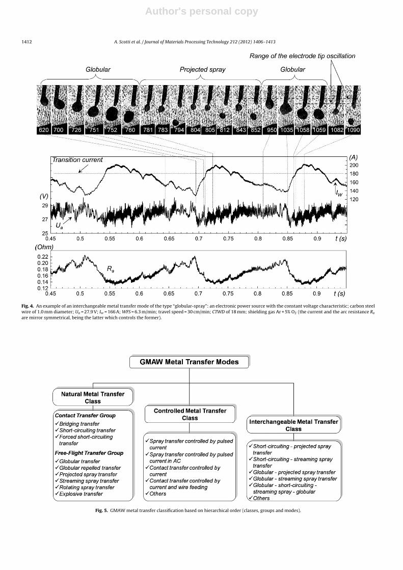
For instance, if the welding current exceeds the globular-spraytransition current level, there may be a change in the Natural Trans-fer Mode (short-circuiting or globular to projected spray or evenstreaming spray). Shortly thereafter, this current decreases and thetransfer mode type coherently returns to the previous one, initi-ating a new cycle. An example of interchangeable metal transfermode is shown in Fig. 4.
4. A scientific application oriented metal transferclassification
First of all, it is important to state the terminology used in thiswork for this classification:
• Mode (metal transfer mode) defines a characteristic behavior ofa drop under transference in GMA welding, e.g., “globular” mode(large drops traveling from the wire tip to the weld pool) or theso-called “spray” mode (small droplets traveling consecutivelyfrom the wire tip to the weld pool).
• Group (group of modes) stands for a number of modes that havesimilar characteristics.
Author's personal copy
1412 A. Scotti et al. / Journal of Materials Processing Technology 212 (2012) 1406– 1413
Fig. 4. An example of an interchangeable metal transfer mode of the type “globular-spray”: an electronic power source with the constant voltage characteristic; carbon steelwire of 1.0 mm diameter; Ua = 27.9 V; Iw = 166 A; WFS = 6.3 m/min; travel speed = 30 cm/min; CTWD of 18 mm; shielding gas Ar + 5% O2 (the current and the arc resistance Ra
are mirror symmetrical, being the latter which controls the former).
Fig. 5. GMAW metal transfer classification based on hierarchical order (classes, groups and modes).

Author's personal copy
A. Scotti et al. / Journal of Materials Processing Technology 212 (2012) 1406– 1413 1413
• Class (class of modes) is the highest hierarchical (parental) group-ing of modes. A class of mode can be formed by one or moregroups.
Members of the IIW have reached a consensus on a simplemetal transfer classification which has two classes, namely “NaturalMetal Transfer” and the “Controlled Metal Transfer”. In the scientificapplication oriented classification, a third “Interchangeable MetalTransfer” class is included to cover those modes which have period-ical changes in the transfer mode provoked by changes in weldingparameters (an “autophagic” behavior). The classification orientedto scientific users is summarized in Fig. 5.
The characteristics of the three classes of metal transfer modesare as follows:
The ‘Natural Metal Transfer’ class contains those modes thatoccur without any further adaptive welding parameter control (e.g.,arc voltage, welding current, wire feed speed, inductance). Hence,droplet transfer is primarily affected by a resultant physical bal-ance of forces acting upon the droplet. Two different groups can befound within the natural metal transfer class. The first is governedby “contact” droplet transfer, while the second shows a “free-flight”droplet transfer to the weld pool.
The “Controlled Metal Transfer” class consists of “improved”natural modes, for getting better process characteristics, such asspatter minimization, weld geometry control, heat input stabiliza-tion and so forth. Hence, the balance of transfer governing forcesstill prevails but the forces are controlled and/or modified deliber-ately.
The “Interchangeable Metal Transfer” describes a class of modesthat occur with two or more Natural Transfer Modes happening ina periodic repetitive sequence, one following the other, as a conse-quence of the previous one. There is no operator or adaptive controlsystem interference.
5. Conclusions
The proposed scientific application oriented classification formetal transfer modes satisfies the demand for having a system-atic method to describe all metal transfer types in GMA welding,including the novel or not easily observed ones.
The terminology for the modes is short and self-describing.The categorization in metal transfer mode, group of modes and
classes of modes avoids specific applications or commercial namessince it is based on global characteristics of the metal transfer andon the phenomena taking place.
Unambiguously, this classification facilitates the communica-tion between Researchers and Academics, yet useful for Engineersin the field.
Acknowledgements
The authors would like to thank the Brazilian agencies forresearch and development (CNPq and Fapemig) which have pro-vided the financial backing for the specialized equipment used inthis work.
References
Allum, C.J., 1985. Metal transfer in arc welding as a varicose instability. II. Devel-opment of model for arc welding. J. Phys. D: Appl. Phys. 18, 1447–1468,http://iopscience.iop.org/0022-3727/18/7/030.
Balsamo, P.S.S., Vilarinho, L.O., Vilela, M., Scotti, A., 2000. Development of anexperimental technique for studying metal transfer in welding: synchronisedshadowgraphy. Int. J. Join. Mater. 12 (1), 1–12, ISSN 0905-6866.
Heald, P.R., Madigan, R.B., Siewert, T.A., Liu, S., 1994. Mapping the droplet transfermodes for an ER100S-1 GMAW electrode. Weld. J. 73 (2), 38s–44s.
International Institute of Welding, 1976. Classification of Metal Transfer, IIW Doc.XII-636-76.
Iordachescu, D., Quintino, L., 2008. Steps towards a new classification of metaltransfer in gas metal arc welding. J. Mater. Process. Technol. 202 (1–3),391–397.
Izutani, S., Shimizu, H., Suzuki, K., Koshiishi, F., 2006. Observation and Classificationof Droplet Transfer in Gas Metal Arc Welding, IIW Doc. 212-1090-06.
Kim, J.A., Eager, N.M., 1991. Analysis of metal transfer in gas metal arc welding. Weld.J. 70 (6), 91–99.
Kim, Y.S., Eagar, T.W., 1993. Metal transfer in pulsed current gas metal arc welding.Weld. J. 72 (7), 279s–287s.
Lin, Q., Li, X., Simpson, S.W., 2001. Metal transfer measurements in gas metalarc welding. J. Phys. D: Appl. Phys. 34 (3), 347–353, doi:10.1088/0022-3727/34/3/3172000.
Lucas, W., Iordachescu, D., Ponomarev, V., 2005. Classification of Metal TransferModes in GMAW, IIW Doc. XII-1859-05.
Nascimento, A.S., Fernandes, D.B., Mota, C.A.M., Vilarinho, L.O., 2008. Methodol-ogy for determination of parameters for welding MIG with variable polarity.Soldagem Insp. 13 (2), 97–104 (in Portuguese).
Norrish, J., 2003. A Review of Metal Transfer Classification in Arc Welding, IIW Doc.XII-1769-03.
Norrish, J.,2009. Process control and automation developments in welding.In: 8th Int. Conf. on Trends in Welding Research. ASM, pp. 17–24,doi:10.1361/cp2008twr017.
Pickin, C.G., Young, K., 2006. Evaluation of cold metal transfer (CMT) process forwelding aluminum alloy. Sci. Technol. Weld. Join. 11 (5), 583–585.
Ponomarev, V., Scotti, A., Miranda, H.C., Costa, A.V., 2002. Influence of the PowerSource Dynamic Characteristics on the Metal Transfer Mixed Mode, IIW Doc.212-1014-02.
Scotti, A., 2000. Mapping the transfer modes for stainless steel GMAW. J. Sci. Technol.Weld. Join. 5 (4), 227–234, ISSN 1362-1718.
Scotti, A., Rodrigues, C.E.A.L., 2009. Determination of momentum as a mean of quan-tifying the mechanical energy delivered by droplets during MIG/MAG welding.Eur. Phys. J. Appl. Phys. 45 (1), p. 11201, 1–8, doi:10.1051/epjap:2008196, ISSN:1286-0042; e-ISSN: 1286-0050.
Stava, E.K., 1993. The surface-tension-transfer power source: a new low-spatter arcwelding machine. Weld. J. 72 (1), 25–29.
Ueyama, T., Tong, H., Harada, S., Passmore, R., Ushio, M., 2005. AC pulsed GMAWimproves sheet metal joining. Weld. J. 84 (2), 40–46.