Interactive Architecture #2
53
iA #2 episode publishers Rotterdam 2008
Transcript of Interactive Architecture #2

iA#2
episode publishersRotterdam 2008
2
> content
> page 4 introduction / editorialKas Oosterhuis
> page 10 researchArchitectural Parametric Design and Mass CustomizationKas Oosterhuis, Sander Boer>page 22 researchPowerlinesIlona Lénárd> page 30 researchMuscle Body Interactive ArchitectureMax Cohen de Lara, Hans Hubers> page 36 researchiWEB and ProtoSpaceKas Oosterhuis, Christian Friedrich, Tomasz Jaskiewicz, Dieter Vandoren, Marthijn Pool, Xin Xia
> page 56 education798 Multi Player Design GameKas Oosterhuis, Tomasz Jaskiewicz> page 64 educationDigital MuseumHan Feng
> page 74 workshopForm Follows EnergyPatrick Teuffel, Hans Hubers
> page 82 dialogueThe Embodied Universe in Pulse +Krisztina de Châtel, Kas Oosterhuis, Ilona Lénárd
> page 92 linked
> page 100 contributors
4
closer to each other then they were before, when they were physically close, but with their backs turned to each other, looking outside the windows. Now, we had the experience of looking towards the essential inner kernel of the faculty. We were living in a swarm. What kind of organization of the new faculty would support this kind of empathic swarm behaviour?
The digital facultyAll people were rescued but not their books, their personal memories, and their works of art. All these were claimed by the fire. But everything that was digital was rescued, the back-up tapes which were stored outside the faculty were OK, and all digital files of staff and students could be recovered safely. Had this fire occurred ten years earlier, it would have paralyzed the people, now it activated many people to continue immediately with augmented energy.
The 24-hour facultyOpening hours of the faculty are limited. There was not much activity during the evenings, and on the weekends it was completely closed. I always wondered, why? Both staff and students work almost continuously on their ideas and projects. The bad plumbing job probably revealed itself during the weekend, but there was no-one to witness it. The new faculty must be a 24-hour faculty; the designer’s mind never sleeps. I receive approximately fifty emails per day from my Hyperbody staff, some of them posted very late at night. The work always goes on.
The adaptive facultyAfter my thesis project in 1980, I came back twenty years later to invent the Chair of Interactive Architecture. In those twenty years, virtually nothing had changed in the building, as if it had been asleep for that many years. Only during the last year were serious attempts at a real change made by the Dean: finally we had good coffee and more comfortable furniture. Finally, imagination took over the faculty, but its efforts
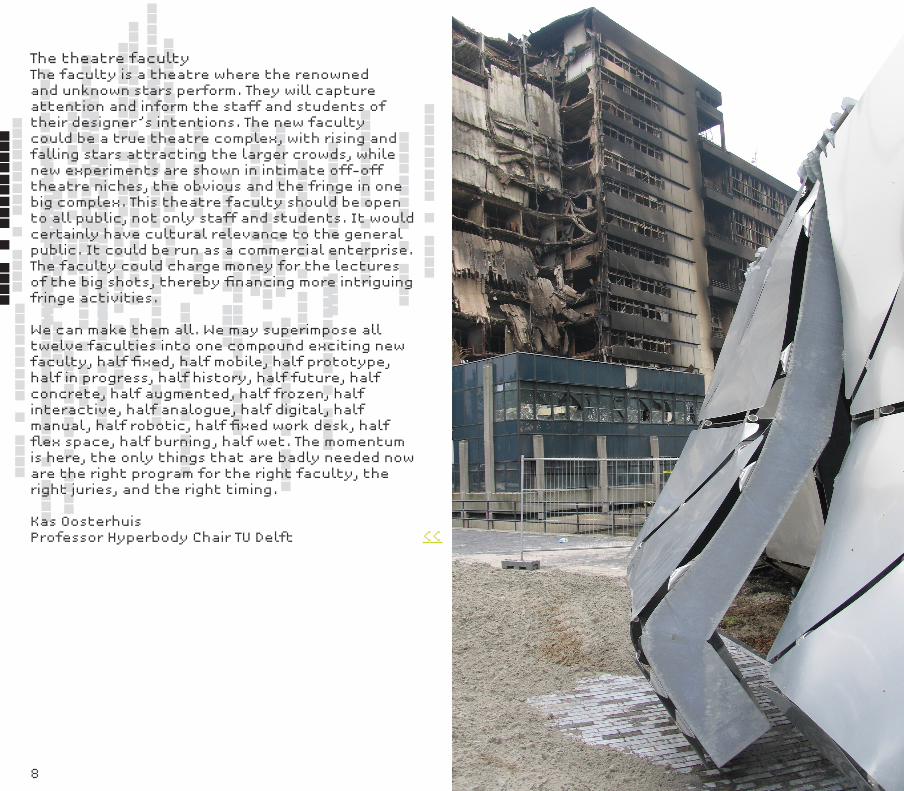
IntroductionIn Delft, we will remember 5/13, rather then 9/11. The day the faculty of architecture burnt. The day that chaos theory was applied in real life. Water leaking from a coffee machine, setting fire, and eventually burning down the complete faculty building. All was lost, except digital data, which was stored on the BK server’s back-up tapes. And miraculously the iWEB survived. I took a picture of the iWEB after the fire; it looked like a scene from a new Star Wars movie, titled The Battle of the Theories. Swarm Architecture beats Architecture-As-We-Know-It. To begin an open discussion for possibilities for the new faculty, I have put together scenarios for twelve possible faculties.
The burning faculty‘Architektur Muss brennen’, stated Wolfgang Prix in 1968 when the student revolution was unleashed. At exactly that time, the faculty was built, and forty years later, it took fire literally. But the Coop Himmelb(l)au statement is more relevant now then ever. How can we make architecture relevant and actual? What kind of faculty would stimulate that?
The swarm facultyThe complete staff and all three thousand students spread over the city, hosted by other faculties, in tents, in apartments in the city, in private offices. The faculty swarmed out and yet was connected via the Internet and mobile phones. In a sense, many people were mentally
> introduction / editorial
>>___
6
were stranded in the fire. We need an adaptive, flexible faculty, a faculty that allows itself to be reinvented every seven years of architecture generation.
The mobile facultyWe need a faculty that is open to the world outside the faculty. Staff and students have been too much encapsulated by the solid structure of the faculty. Imagine a faculty where 50% of the structure is fixed, while the other 50% is located in mobile units, either motorized or erected in places around the country. (Naturally all mobile units must equipped for wireless communication.) We must see the factories, the building sites, the political rallies, settle in the Vinex locations for a while, travel the highways, and explore the networks. We must come closer to the design offices, plug-in to other faculties, or find a place on the beach. In these places, we can continue to work on our projects and design and discuss with any one.
The laboratory faculty Staff and students must go the factories, but the factory must also come to the faculty. The production machines inform us of what can be made. Staff and students must know what the machines are capable of: with them, there is much more possible then is actually used. In general, a machine-user (computer) only uses a few of all available commands. The same is true for the machines in the workshops; their potential is far greater then us generally known. Knowing the potential stimulates the imagination of the designer. Think of the IO (Industrial Design Engineering) Central Hall at the TU Delft campus, but imagine it covering the whole site.
The robotic facultyNow the faculty has 3D milling machines and machines for model making in general. We can learn from the ETH in Zurich where they have installed robotic equipment to build prototypes on 1:1 scale. Their robots are generic, they are equipped
to assemble complex brickwork as well. Using robotic equipment includes old materials but opens the way for experimenting with new materials as well. New robotic technology does not replace traditional technology, but adds another layer of intelligence to it - it is inclusive.
The 1:1 prototype factoryStaff and students should focus on building 1:1 prototypes. This is the fastest and most reliable way to understand the full potential of building. There should be yearly contests to build a 1:1 prototype, similar to the Stylos pavilion, but more related to CNC (computer numberical control) production methods using robotic equipment.
The augmented facultyThe faculty must be emotionally linked to leading faculties worldwide. We need to experience on a daily basis what they do at the ETH, at MIT, Harvard, La Sapienza, snf and TU/e. We could place webcams and install augmented reality interfaces, not to see our faculty being taken down, but to see what is built up at all other faculties. We can embed the interfaces in the furniture, in the lounge spaces. There should be a permanent, real-time connection to talk, communicate, retrieve information, and send information in the augmented, networked swarm of faculties. Augmented reality does not replace physical reality, it adds another layer of intelligence to it. It is nothing to be afraid of.
The sustainable facultySustainability will continue to be a major issue. Sustainability is greatly facilitated by new technologies like wireless connections, CNC (computer numerical control) production methods, and C2C (cradle to cradle) concepts. Each of these new technologies require less energy and they are virtually waste-free. All production is controlled and waste will be recycled and/or function as food/fuel/futter for other processes. Sustainable C2C and CNC production will be exercised in the Prototype Factory. >>___
8
The theatre facultyThe faculty is a theatre where the renowned and unknown stars perform. They will capture attention and inform the staff and students of their designer’s intentions. The new faculty could be a true theatre complex, with rising and falling stars attracting the larger crowds, while new experiments are shown in intimate off-off theatre niches, the obvious and the fringe in one big complex. This theatre faculty should be open to all public, not only staff and students. It would certainly have cultural relevance to the general public. It could be run as a commercial enterprise. The faculty could charge money for the lectures of the big shots, thereby financing more intriguing fringe activities.
We can make them all. We may superimpose all twelve faculties into one compound exciting new faculty, half fixed, half mobile, half prototype, half in progress, half history, half future, half concrete, half augmented, half frozen, half interactive, half analogue, half digital, half manual, half robotic, half fixed work desk, half flex space, half burning, half wet. The momentum is here, the only things that are badly needed now are the right program for the right faculty, the right juries, and the right timing.
Kas OosterhuisProfessor Hyperbody Chair TU Delft <<___
10
parametric design
Architec-tural para-metric de-sign and mass cus-tomization
> research
Architectural Parametric Design and Mass
Customization
Kas Oosterhuis
Sander Boer
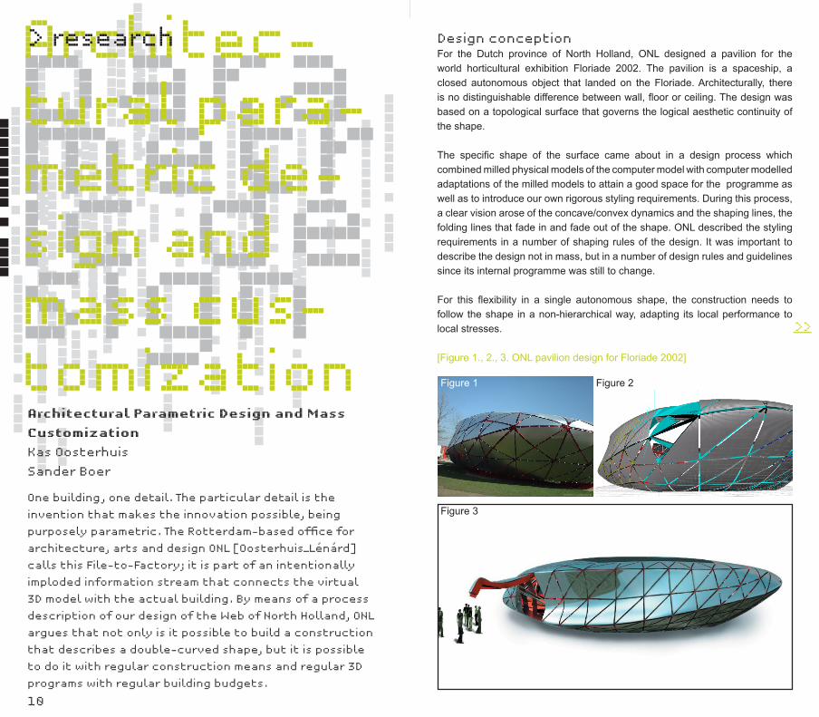
Design conceptionFor the Dutch province of North Holland, ONL designed a pavilion for the world horticultural exhibition Floriade 2002. The pavilion is a spaceship, a closed autonomous object that landed on the Floriade. Architecturally, there is no distinguishable difference between wall, floor or ceiling. The design was based on a topological surface that governs the logical aesthetic continuity of the shape.
The specific shape of the surface came about in a design process which combined milled physical models of the computer model with computer modelled adaptations of the milled models to attain a good space for the programme as well as to introduce our own rigorous styling requirements. During this process, a clear vision arose of the concave/convex dynamics and the shaping lines, the folding lines that fade in and fade out of the shape. ONL described the styling requirements in a number of shaping rules of the design. It was important to describe the design not in mass, but in a number of design rules and guidelines since its internal programme was still to change.
For this flexibility in a single autonomous shape, the construction needs to follow the shape in a non-hierarchical way, adapting its local performance to local stresses.
[Figure 1., 2., 3. ONL pavilion design for Floriade 2002]
One building, one detail. The particular detail is the
invention that makes the innovation possible, being
purposely parametric. The Rotterdam-based office for
architecture, arts and design ONL [Oosterhuis_Lénárd]
calls this File-to-Factory; it is part of an intentionally
imploded information stream that connects the virtual
3D model with the actual building. By means of a process
description of our design of the Web of North Holland, ONL
argues that not only is it possible to build a construction
that describes a double-curved shape, but it is possible
to do it with regular construction means and regular 3D
programs with regular building budgets.
>>___
Figure 1 Figure 2
Figure 3
12
> research Inventing a double curved constructionIn architecture, irregular surfaces can be bothersome to build and strategies to build them are often based on layers. For example, a crude approximation of a shape is constructed in steel and with a number of cladding layers, this crude approximation can be smoothed. Creating a low-res construction for a high-res shape obviously lacks control over the shape and it is costly for it needs multiple layers of construction, secondary construction and cladding. A more precise method is the creation of customized molds for every segment of the building, however, this concentrates the effort primarily on the cladding; a construction is still needed, making the whole very expensive. Another strategy is projecting one or more regular grids over the shape, like one would slice a loaf of bread. Although this approach results in perfectly manageable constructive ribs that can be manufactured relatively easily, it is only viable for tube-like constructions. Projection is inherently flawed for closed irregular surfaces because in its projection vector, it introduces a form of anisotropy in its construction. This means the building construction favours a certain direction over others.
It was decided that the building in question was to be built only once: creating molds was out of the question. The shape ONL wanted to end up with needed to be present in the main construction. With the introduction of the construction grid based on an icosahedron, ONL dedicated itself to an approach that was linked directly to a NURBS surface. ONL decided to create a construction that would be capable of describing this irregular surface directly and be isotropic. To do this, ONL added vectors to the construction grid that were oriented perpendicular to the surface called normal-lines. These lines were used to orient the construction detail.
However, a challenge was presented when creating a constructive connection between two non-parallel lines. Using a tubular construction was considered, but soon proved too costly. A novel idea struck home when ONL realized that it could use folded plates. The idea is simple, when one needs to connect two points with a construction, one could use a simple flat plate, but when one also needs to make a transition from one initial orientation to the next, one can fold the plate over a diagonal. The innovation of this idea might not be immediately apparent, but this simple idea allowed ONL to create a construction that describes a truly double-curved surface.
First, when connecting two points and their respective orientations, one folds the plate. In doing so one effectively creates two triangles each in their respective planes, joined at the diagonal. The top triangle is described by the diagonal, one of the two orientations and a line connecting the two points of the point-grid on the surface. This line can be straight, creating a construction that is polygonal, but, since it connects two points that are positioned on a surface, this connecting line can also follow the surface one-to-one. >>___
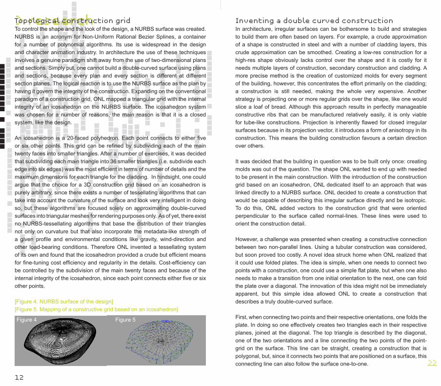
Topological construction gridTo control the shape and the look of the design, a NURBS surface was created. NURBS is an acronym for Non-Uniform Rational Bezier Splines, a container for a number of polynomial algorithms. Its use is widespread in the design and character animation industry. In architecture the use of these techniques involves a genuine paradigm shift away from the use of two-dimensional plans and sections. Simply put, one cannot build a double-curved surface using plans and sections, because every plan and every section is different at different section planes. The logical reaction is to use the NURBS surface as the plan by having it govern the integrity of the construction. Expanding on the conventional paradigm of a construction grid, ONL mapped a triangular grid with the internal integrity of an icosahedron on the NURBS surface. The icosahedron system was chosen for a number of reasons, the main reason is that it is a closed system, like the design.
An icosahedron is a 20-faced polyhedron. Each point connects to either five or six other points. This grid can be refined by subdividing each of the main twenty faces into smaller triangles. After a number of exercises, it was decided that subdividing each main triangle into 36 smaller triangles (i.e. subdivide each edge into six edges) was the most efficient in terms of number of details and the maximum dimensions for each triangle for the cladding. In hindsight, one could argue that the choice for a 3D construction grid based on an icosahedron is purely arbitrary, since there exists a number of tessellating algorithms that can take into account the curvature of the surface and look very intelligent in doing so, but these algorithms are focused solely on approximating double-curved surfaces into triangular meshes for rendering purposes only. As of yet, there exist no NURBS-tessellating algorithms that base the distribution of their triangles not only on curvature but that also incorporate the metadata-like strength of a given profile and environmental conditions like gravity, wind-direction and other load-bearing conditions. Therefore ONL invented a tessellating system of its own and found that the icosahedron provided a crude but efficient means for fine-tuning cost efficiency and regularity in the details. Cost-efficiency can be controlled by the subdivision of the main twenty faces and because of the internal integrity of the icosahedron, since each point connects either five or six other points.
[Figure 4. NURBS surface of the design] [Figure 5. Mapping of a constructive grid based on an icosahedron]
Figure 4 Figure 5
14
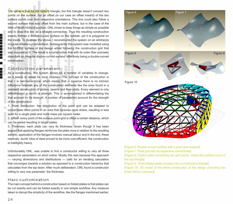
> researchThe same is true for the bottom triangle, but this triangle doesn’t connect two points on the surface, but an offset (in our case an offset inward) of the two surface points over their respective orientations. This line could also follow a second surface that was offset from the main surface, but in the case of the Web of North Holland pavilion, ONL chose to keep things as simple as possible and to draw this line as a straight connection. Thus the resulting construction exactly follows a double-curved surface on the outside, yet it is polygonal on the inside. To illustrate the above, I reconstructed the system on an arbitraryly irregular double-curved surface: Subsequently this system was modelled using the NURBS surface of the design whilst following the construction grid that was mapped on it. The result is a construction that with its outer fiber precisely describes an irregular double-curved surface, effectively being a double-curved construction.
Construction parameters As a construction, this system allows for a number of variables to change, as it needs to adapt for local stresses. The concept of the construction is that it is non-hierarchical, which means that in essence there is no intrinsic difference between any of the construction elements like the ones found in a standard construction of girders, beams and floor-joists. Every element is only differentiated in terms of strength. This is accomplished in differentiating the that account for its strength. A number of parameters account for the strength of the construction: 1. Point distribution: the distribution of the point grid can be adapted to concentrate more points in an area that receives more stress, resulting in less span for a single plate and more mass per square meter.2. Offset: every point of the surface point-grid is offset a certain distance, which can be varied resulting in larger plates.3. Thickness: each plate can vary its thickness, (even though it has been argued that applying flanges reinforces the plate more in relation to the resulting weight), application of the flanges involves manual labour and in the end, these relatively ‘dumb’ kilos of steel proved to be more cost-efficient; the construction is intelligibly heavy.
Unfortunately ONL, was unable to find a constructor willing to vary all three respective parameters on short notice. Mostly this was because this approach — varying dimensions and distributions — calls for an iterating calculation that converges towards a solution as opposed to a construction hierarchy that calculates from the top down. After much deliberation, ONL found a constructor willing to vary one parameter: the thickness.
Mass customization The main concept behind a construction based on folded plates is that plates can be cut exactly and can be folded exactly in one simple workflow. Any measure taken to disrupt the simplicity of the workflow, like the flanges mentioned earlier,
Figure 6 Figure 7
Figure 8 Figure 9
Figure 10
[Figure 6. Double-curved surface with a point grid mapped] [Figure 7. Point grid with its respective normal-lines] [Figure 8. Folded plate connecting two grid points, notice the surface curve of the top triangle] [Figure 9. Three folded plates connect into a constructive triangle] [Figure 10. 3D model of the entire construction of the design (including two small interior volumes)]
16
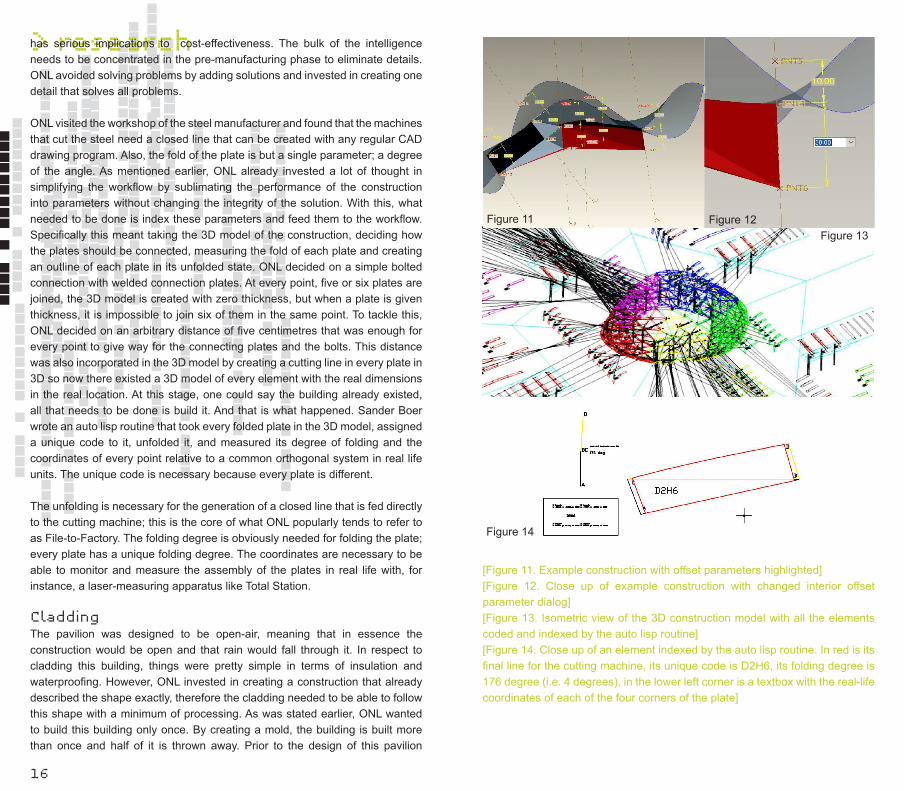
> researchhas serious implications to cost-effectiveness. The bulk of the intelligence needs to be concentrated in the pre-manufacturing phase to eliminate details. ONL avoided solving problems by adding solutions and invested in creating one detail that solves all problems. ONL visited the workshop of the steel manufacturer and found that the machines that cut the steel need a closed line that can be created with any regular CAD drawing program. Also, the fold of the plate is but a single parameter; a degree of the angle. As mentioned earlier, ONL already invested a lot of thought in simplifying the workflow by sublimating the performance of the construction into parameters without changing the integrity of the solution. With this, what needed to be done is index these parameters and feed them to the workflow. Specifically this meant taking the 3D model of the construction, deciding how the plates should be connected, measuring the fold of each plate and creating an outline of each plate in its unfolded state. ONL decided on a simple bolted connection with welded connection plates. At every point, five or six plates are joined, the 3D model is created with zero thickness, but when a plate is given thickness, it is impossible to join six of them in the same point. To tackle this, ONL decided on an arbitrary distance of five centimetres that was enough for every point to give way for the connecting plates and the bolts. This distance was also incorporated in the 3D model by creating a cutting line in every plate in 3D so now there existed a 3D model of every element with the real dimensions in the real location. At this stage, one could say the building already existed, all that needs to be done is build it. And that is what happened. Sander Boer wrote an auto lisp routine that took every folded plate in the 3D model, assigned a unique code to it, unfolded it, and measured its degree of folding and the coordinates of every point relative to a common orthogonal system in real life units. The unique code is necessary because every plate is different.
The unfolding is necessary for the generation of a closed line that is fed directly to the cutting machine; this is the core of what ONL popularly tends to refer to as File-to-Factory. The folding degree is obviously needed for folding the plate; every plate has a unique folding degree. The coordinates are necessary to be able to monitor and measure the assembly of the plates in real life with, for instance, a laser-measuring apparatus like Total Station. CladdingThe pavilion was designed to be open-air, meaning that in essence the construction would be open and that rain would fall through it. In respect to cladding this building, things were pretty simple in terms of insulation and waterproofing. However, ONL invested in creating a construction that already described the shape exactly, therefore the cladding needed to be able to follow this shape with a minimum of processing. As was stated earlier, ONL wanted to build this building only once. By creating a mold, the building is built more than once and half of it is thrown away. Prior to the design of this pavilion
Figure 11 Figure 12Figure 13
Figure 14
[Figure 11. Example construction with offset parameters highlighted] [Figure 12. Close up of example construction with changed interior offset parameter dialog][Figure 13. Isometric view of the 3D construction model with all the elements coded and indexed by the auto lisp routine] [Figure 14. Close up of an element indexed by the auto lisp routine. In red is its final line for the cutting machine, its unique code is D2H6, its folding degree is 176 degree (i.e. 4 degrees), in the lower left corner is a textbox with the real-life coordinates of each of the four corners of the plate]
18
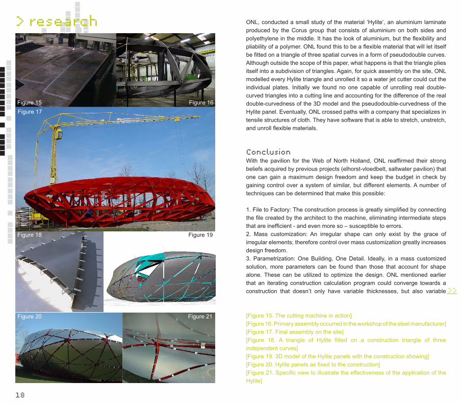
> research ONL, conducted a small study of the material ‘Hylite’, an aluminium laminate produced by the Corus group that consists of aluminium on both sides and polyethylene in the middle. It has the look of aluminium, but the flexibility and pliability of a polymer. ONL found this to be a flexible material that will let itself be fitted on a triangle of three spatial curves in a form of pseudodouble curves. Although outside the scope of this paper, what happens is that the triangle plies itself into a subdivision of triangles. Again, for quick assembly on the site, ONL modelled every Hylite triangle and unrolled it so a water jet cutter could cut the individual plates. Initially we found no one capable of unrolling real double-curved triangles into a cutting line and accounting for the difference of the real double-curvedness of the 3D model and the pseudodouble-curvedness of the Hylite panel. Eventually, ONL crossed paths with a company that specializes in tensile structures of cloth. They have software that is able to stretch, unstretch, and unroll flexible materials.
ConclusionWith the pavilion for the Web of North Holland, ONL reaffirmed their strong beliefs acquired by previous projects (elhorst-vloedbelt, saltwater pavilion) that one can gain a maximum design freedom and keep the budget in check by gaining control over a system of similar, but different elements. A number of techniques can be determined that make this possible:
1. File to Factory: The construction process is greatly simplified by connecting the file created by the architect to the machine, eliminating intermediate steps that are inefficient - and even more so – susceptible to errors.2. Mass customization: An irregular shape can only exist by the grace of irregular elements; therefore control over mass customization greatly increases design freedom. 3. Parametrization: One Building, One Detail. Ideally, in a mass customized solution, more parameters can be found than those that account for shape alone. These can be utilized to optimize the design. ONL mentioned earlier that an iterating construction calculation program could converge towards a construction that doesn’t only have variable thicknesses, but also variable
> research
Figure 15 Figure 16Figure 17
Figure 18 Figure 19
Figure 20 Figure 21
>>___
[Figure 15. The cutting machine in action][Figure 16. Primary assembly occurred in the workshop of the steel manufacturer] [Figure 17. Final assembly on the site] [Figure 18. A triangle of Hylite fitted on a construction triangle of three independent curves] [Figure 19. 3D model of the Hylite panels with the construction showing] [Figure 20. Hylite panels as fixed to the construction] [Figure 21. Specific view to illustrate the effectiveness of the application of the Hylite]

20
heights and an optimal point distribution. Similarly, in a design process, parameters can change in accordance to design requirements and iterative scripts can be written to accommodate very specific demands.4. Design control hierarchy: In this specific pavilion, the shape is described in a single NURBS surface, essentially all that follows will refer to this surface. A NURBS surface is created using NURBS lines, keeping this creation link intact yields control on a higher level, by changing the line, the surface changes and the entire system changes. Primarily for designers this notion is paramount. 5. Body Styling: These techniques give the architect/designer full freedom to shape the volume of the building, to propose styled creases and smooth transitions of creases disappearing into the surface of the overall body.
In the meantime, ONL now has two projects in the production phase that have been designed with the above in mind: the Cockpit building and the Acoustic Barrier. The Cockpit building is part of a fluid design of the Acoustic Barrier. To accommodate the transition from the one to the other, the design control hierarchy proved to be essential, Both projects share the same outlines, but differ in construction principle. Construction is based on the streamlined File-to-Factory process described earlier.
Figure 23
Figure 24
<<___
[Figure 22. Screengrab of the soundbarrier/cockpit 3D model, the cockpit building is the bulge in the middle] [Figure 23. Rendering of the cockpit building, notice the fluid transition between the acoustic barrier (dark) and the building itself] [Figure 24. Screengrab of the soundbarrier construction, this construction is generated by the steel constructor (Meijers Staalbouw bv.) based on geometry we provided]
[Copyright images: All images are copyrighted by ONL, except for figures 13 and 14; courtesy of Berry van Heerens, Meijers Staalbouw bv.]
> research
Figure 22
22
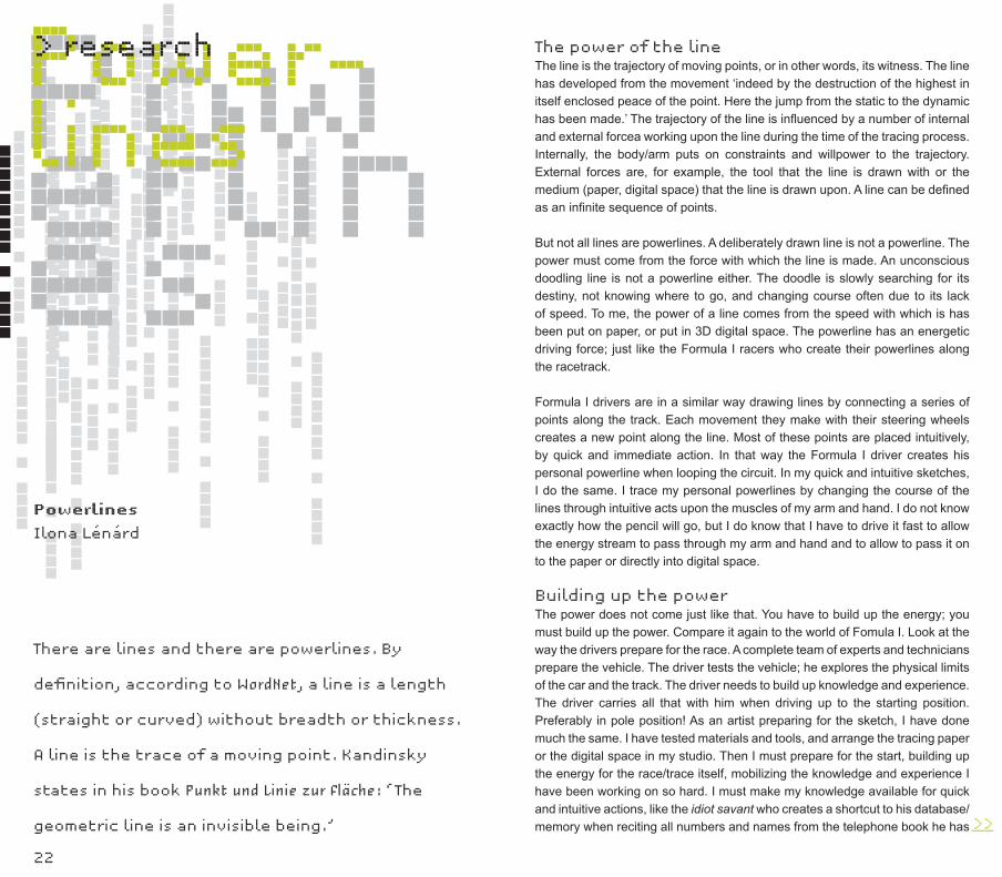
PowerlinesPower-lines> research
Powerlines
Ilona Lénárd
The power of the lineThe line is the trajectory of moving points, or in other words, its witness. The line has developed from the movement ‘indeed by the destruction of the highest in itself enclosed peace of the point. Here the jump from the static to the dynamic has been made.’ The trajectory of the line is influenced by a number of internal and external forcea working upon the line during the time of the tracing process. Internally, the body/arm puts on constraints and willpower to the trajectory. External forces are, for example, the tool that the line is drawn with or the medium (paper, digital space) that the line is drawn upon. A line can be defined as an infinite sequence of points.
But not all lines are powerlines. A deliberately drawn line is not a powerline. The power must come from the force with which the line is made. An unconscious doodling line is not a powerline either. The doodle is slowly searching for its destiny, not knowing where to go, and changing course often due to its lack of speed. To me, the power of a line comes from the speed with which is has been put on paper, or put in 3D digital space. The powerline has an energetic driving force; just like the Formula I racers who create their powerlines along the racetrack.
Formula I drivers are in a similar way drawing lines by connecting a series of points along the track. Each movement they make with their steering wheels creates a new point along the line. Most of these points are placed intuitively, by quick and immediate action. In that way the Formula I driver creates his personal powerline when looping the circuit. In my quick and intuitive sketches, I do the same. I trace my personal powerlines by changing the course of the lines through intuitive acts upon the muscles of my arm and hand. I do not know exactly how the pencil will go, but I do know that I have to drive it fast to allow the energy stream to pass through my arm and hand and to allow to pass it on to the paper or directly into digital space.
Building up the powerThe power does not come just like that. You have to build up the energy; you must build up the power. Compare it again to the world of Fomula I. Look at the way the drivers prepare for the race. A complete team of experts and technicians prepare the vehicle. The driver tests the vehicle; he explores the physical limits of the car and the track. The driver needs to build up knowledge and experience. The driver carries all that with him when driving up to the starting position. Preferably in pole position! As an artist preparing for the sketch, I have done much the same. I have tested materials and tools, and arrange the tracing paper or the digital space in my studio. Then I must prepare for the start, building up the energy for the race/trace itself, mobilizing the knowledge and experience I have been working on so hard. I must make my knowledge available for quick and intuitive actions, like the idiot savant who creates a shortcut to his database/memory when reciting all numbers and names from the telephone book he has
There are lines and there are powerlines. By
definition, according to WordNet, a line is a length
(straight or curved) without breadth or thickness.
A line is the trace of a moving point. Kandinsky
states in his book Punkt und Linie zur Fläche: ‘The
geometric line is an invisible being.’ >>___
24
> research
been reading before. I must be prepared to build a shortcut to my knowledge when drawing the powerline. This is called concentration, excluding disturbing influences, peeling off reality to focus on the potential power of the line.
Unleashing the powerGo to the start. On your marks [pole position]. And there you go. I have lift off. All systems go. I unleash the power. The graphite rushes over the paper like the rubber tires mark the asphalt. Speed is essential for unleashing the power. It only takes one or two seconds to make a quick and intuitive sketch. The speed of the sketch is by far faster then the time-consuming thinking process of the brain. There is no time for deliberate action. I rely completely on my intuition, on my trained ability to connect as directly as possible to my experience, to my knowledge base. Unleashing the power is letting the information flow freely from my body through my arm and hand to the paper. Unleashing the power is becoming the idiot savant. The Formula I driver.
IntuitionBut just like the idiot savant, I have no conscious understanding of what the names and numbers in the telephone book mean when connecting directly to the data. Each one of us is a potential idiot savant, if we only know how to get in touch with the power within ourselves. The connections have been prepared before the process of fast and powerful action, but when executing the actual sketch I have no conscious communication with my brain. It is one-way information flow. This is intuition. According to Worldnet 2.0, intuition is the ‘instinctive knowing without the use of rational processes’. Intuition is knowing. Intuition is doing without thinking. The process of thinking is way too slow to keep up with the information flowing through shortcut body and brain circuitry instigated by the liberation of intuition. Intuition unfolds in the present; it never comes from the past. Intuition is by definition actual. According to Buckminster Fuller, intuition is insight and sensitivity to the environment and the self. In that sense the person following his or her intuition is bridging the self with the environment, (s)he creates a shortcut between the individual person and the surrounding world.
Speed and frictionThe speed of intuition is awesome. It is comparable to the calculation speed of the computer. In the late 1980s, I started realizing that the computer is the perfect tool† for executing and monitoring my fast and intuitive sketches. The calculation speed of the computer keeps pace with the speed of the information flowing through the shortcut to the brain created by the idiot savant in me. The
Figure 1
Figure 2
Figure 3-a
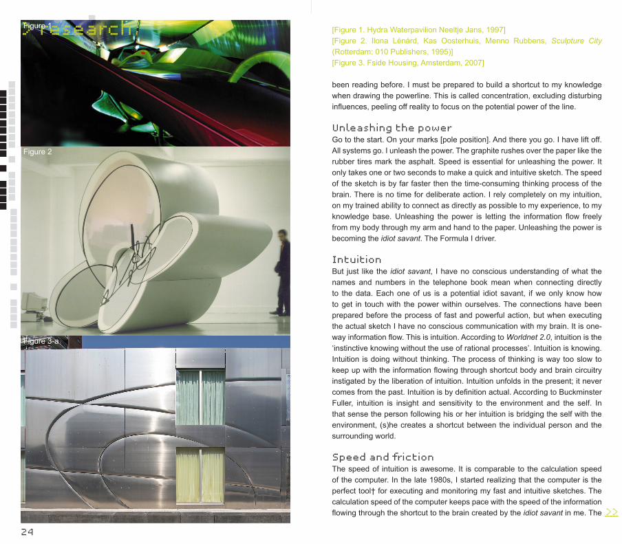
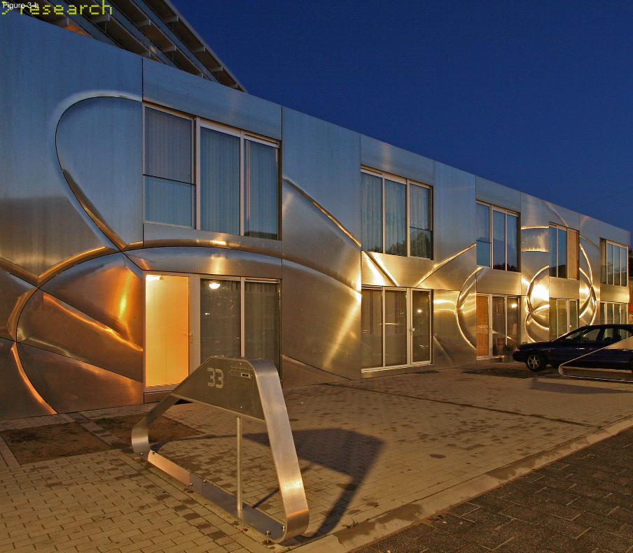
[Figure 1. Hydra Waterpavilion Neeltje Jans, 1997] [Figure 2. Ilona Lénárd, Kas Oosterhuis, Menno Rubbens, Sculpture City (Rotterdam: 010 Publishers, 1995)][Figure 3. Fside Housing, Amsterdam, 2007]
>>___
26
> researchFigure 3-b
28
> research
Figure 6
Figure 5
Figure 4 computer calculates the positions of the 3D pointer in my hand in real time, and registers seemingly effortless the sequence of coordinates. The computer is my personal idiot savant, allowing me to connect in real time to the data created by my arm movements, steered by my intuition. Speed executed in an environment causes friction. When making fast and intuitive hand drawn sketches, the speed of the sketch causes friction in my arm, and I experience the physical constraints of my arm movements. I have a limited degree of freedom to move and rotate my arm and hands, and I have a limited reach of one-and-a-half meters without displacing myself during the action. And there is friction between the tip of my pen and the paper, causing the graphite to leave bits of material on the paper. Looking into the greater details of the traces left on the paper, the worn down graphite witnesses the power and the intuitive intentions of the maker. When making fast and intuitive sketches using the mouse of the computer or the 3D digitizer, I still have the physical constraints of my arm movements, but now the curves are traced in 3D digital space, which is virtually endless. The 3D trajectories are immediately registered in weightless space, and I am free to travel through the 3D witness of my arm movements. There is hardly any friction in digital space. The friction in digital space is caused by other tools and resides in the subsequent transformations of the sketch. The friction is in the software and in the ability of the operators to choose the sequence of commands in computer programs.
3D sketches are the genes for new constructsHaving developed sufficiently good computer skills, digital sketches can be translated directly into formative forces working upon 3D models for sculptures and buildings. Here, we have discovered another shortcut: the hot link from file to factory. We have discovered that the 3D sketch can be literally made, literally transformed into tangible matter. The file to factory process allows us to declare the 3D trajectories of the intuitive sketches to be genes for further construction. Searching the Web for the meaning of a gene, we find that a gene is the unit of heredity. A gene contains hereditary information encoded in the form of DNA and is located at a specific position on a chromosome in a cell’s nucleus. Each individual has a unique sequence of genes, or genetic code. Here we regard projects (sculptures, buildings) as the individuals. The 3D sketches contain the hereditary information for the development of the evolutionary 3D model eventually leading to the exact execution (reproduction) of the data into tangible matter. Installations, sculptures and buildings are organized information and matter. The 3D sketch constitutes an important sequence of informative genes, cooperating with thousands of other genes making up the newly constructed individual installation, sculpture or building. Powerlines are internal genetic forces.
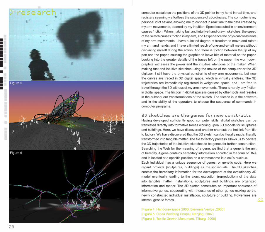
[Figure 4. Handdrawspace 2000, Biennale Venice ,2000][Figure 5. Cipea Wedding Chapel, Nanjing, 2007][Figure 6. Textile Growth Monument, Tilburg, 2006]
<<___

30
Mus-cle-Body
MuscleBody Interactive Archi-tecture
> research
Muscle Body Interactive Architecture
Max Cohen de Lara
Hans Hubers
In April 2005, Hyperbody presented MuscleBody.
MuscleBody is a fully kinetic and interactive
architecture that is a full-scale prototype of an
interior space. It forms the latest prototype in
an ongoing research into a fully programmable
and interactive architecture, of which the first
build version was on show at the Centre Pompidou
in Paris during the Non-Standard Architecture
exhibition from December 2003 until March 2004.
For this first prototype, ONL used Festo industrial muscles that could contract and relax, which allowed for the installation to change its shape. The installation was a pneumatic soft volume, wrapped in a mesh of tensile Festo muscles. Orchestrated motions of the individual muscles changed the length, the height and the width and thus the overall shape of the prototype by varying the pressure pumped into the 94 muscles. The muscles were programmed with a swarm behaviour allowing this ‘animal’ to bend and taper in all directions. Sensors imbedded in the skin of the installation allowed for information to be subtracted from its environment. The behaviour of the people that moved around the installation and investigated it with their hands served as the input to which it reacted by contracting and relaxing different groups of muscles, therefore altering its shape.
For the development of the latest prototype, a group of five students worked together intensively during a period of eight weeks to design and build an interactive interior space. During this process, the group was not only responsible for the design and the construction of the space, but they also had to get familiar with the hardware and software necessary for the interactivity. Another important aspect of the project was contacting different companies that would provide the needed materials for building the prototype. What distinguishes the MuscleBody from previous prototypes is that it for the first time is an interior space. The group was asked to develop an interior space that was to be large enough for at least one adult person to freely move around in. This gave Hyperbody the opportunity to go beyond the interactive object and move further towards an interactive architecture.
The MuscleBody is an architectural body that consists of a double curved continuous skin that incorporates all its architectural properties and makes no categorical distinctions such as floor, wall, ceiling and door. One can enter the inside space by passing through a cut in the skin, which opens itself when the skin is touched from the outside. Once inside the people who have entered are completely encapsulated by the MuscleBody of which its skin also continues above their heads and beneath their feat. The absence of these categorical elements breaks down the linear connection between an element and its use. This leads to more dynamic interaction because behaviours are not predetermined but instead have to develop over time.
The structure of the MuscleBody is based on a single, spiralling tube that is bent in three dimensions. The material properties of the tube (which is normally used as water piping), allow for both the needed flexibility and stiffness of the structure. Material research formed an important part in developing this structure and for the project in general. The MuscleBody uses the same industrial muscles that were used in all the previously developed prototypes. Because these can only deliver contracting forces, a secondary structure is needed to counter the movements of the muscles. >>___

32
> research
Figure 4
Figure 3Figure 2
Figure 1Figure 5
Figure 6
[Figure 1. Students using game software to program the interactive behaviour of the MuscleBody] [Figure 2. Sensors are placed in the skin of the MuscleBody to extract information from the behaviour of the people who enter the interior space] [Figure 3. Detail of the interior space of the MuscleBody][Figure 4. A student interacting with the MuscleBody by triggering the motion sensors integrated in its skin][Figure 5. Students testing the tubular construction and layout of the MuscleBody’s artificial muscles] [Figure 6. Final configuration of the MuscleBody as seen from the outside.

34
> researchA number of scale models were built-using PVC-tubing to test different configurations. This gave the group the opportunity to study their structural properties, the possible deformations and the quality of the interior space. Further tests were made to determine the material of the tube and its diameter that would provide the needed stiffness and flexibility. Mock-ups were built by connecting an industrial muscle to different tube-samples to study the behaviour of the tube when the muscle was activated.
The final configuration is an 80-metre long spiralling tubular structure, into which a total of 26 industrial muscles are integrated that control the physical movements of the MuscleBody. By contracting and relaxing the muscles, which cause the tubular structure to bend in different directions, the MuscleBody dramatically changes its shape. The muscles never act alone but are activated in groups. This causes large areas of the skin to deform, which pulls towards, moves away or partly wraps around the persons inside. The skin is further composed of Lycra, a stretchable fabric normally used for sports clothing. Because the material is stretchable, it can easily adjust to the deformations of the structure. The translucency of the fabric varies according to the degree of stretching, allowing different degrees of light to pass through. The fabric is fitted in segments that are slightly offset to the tubular structure. The thin strips of light that occur between the tubing and the skin in combination with the altering translucency of the fabric itself result in a play of light when the MuscleBody is activated. There are also a number of speakers integrated into the skin from which sound is emitted consisting of several (sound)samples that are combined and transformed according to the behaviour of the players (the people that have entered the interior space). The more active the players become, the more dramatic the space deforms and the amount of sound that is emitted increases.
To activate the MuscleBody, information is subtracted from the behaviour of the players by a number of pressure and proximity sensors that are imbedded in the skin. The pressure sensors are activated when touched. The proximity sensors give information as to how close a person is positioned to the sensor. The different sensors combine to make it possible to track the positions and movements of the players. The information received by the sensors is transferred to the computer of the MuscleBody in real time, meaning that the numerical input changes as soon as the movements of the players change. The game-software Virtools is used for organizing the dynamic relations between the input received by the sensors and the output consisting of the behaviour of the muscles and the generated sound. The use of game-software is especially appropriate for the development of interactive architecture because a game is primarily based on interaction. In a computer game, for instance, a player is constantly acting and reacting to what is happening on his or her screen by communicating with a controller, such as a joystick. In the interactive architecture of the MuscleBody, the screen is extended to an entire environment. The use of a joystick as an
interface for communicating becomes obsolete as the whole body of the player takes over its role. One can move around the same as in any other space, only here the architecture is constantly aware of these movements and able to react to them. The students received intensive software training and were given access to scripts used for previous prototypes that act as an open source database for new projects. By organizing the information flow and interpreting the input in terms of generated movements and sound by MuscleBody, meaning is given to the information.
The interaction between MuscleBody and its players causes the MuscleBody to change its shape, its degrees of transparency and the sound that it generates. In contrast to static architecture, the behaviour of the MuscleBody develops in co-evolution with the behaviour of its players. The exact configuration of the interior space keeps developing over time. The information feedback loop results in a continuous play between the architectural body and the human body.
We expect architecture to become more and more interactive. Will it be like MuscleBody?
[MuscleBody is a project of Hyperbody, directed by Prof. Ir. Kas Oosterhuis. Students: Susan O. Driscoll, Agnes Lahaye, Guido Lammerink, Thijs Welman, Koki Hirakawa; Coordinator: Ir. Hans Hubers; Teachers: Architecture: Ir. Max Cohen de Lara, Construction: Ir. Gerrie Hobbelman, Virtools: Sven Blokker]
<<___
iWEBandProtoSpace
iWEB andProtoSpace
36
> research
iWEB and ProtoSpace
Kas Oosterhuis
Christian Friedrich
Tomasz Jaskiewicz
Dieter Vandoren
Marthijn Pool
Xin Xia
The iWEB is a vehicle for trans-disciplinary research,
education and design as developed by Hyperbody.
The iWEB hosts the virtually augmented transaction
space ime.
iWEBlog: The multiple identity of the iWEB
Kas Oosterhuis
Two years ago, we had an exhibition of the work of ONL [Oosterhuis_Lénárd] in the hall of the Faculty of Architecture at the Delft University of Technology. We showed a project called the iWEB as well as the original models of the TT Monument. I had a discussion with one of my colleagues, Prof. Leen van Duin, who stated that the iWEB was art, not architecture. Before we can say anything meaningful on the subject of this opinion, we need definitions. What is the definition of art, and what is the definition of architecture? Since not everyone would agree to the same definition, I have to work with my own definition.
Art is art when the maker has the intention to make art. That explains why Duchamps is art, and why Mondrian is art, even though many of their contemporary citizens questioned it. But above all it explains why there are many unknown artists, while only a few artists are acknowledged as such by the art world. Architecture is architecture when the maker intends to make architecture. This presupposition explains why El Lissitsky is architecture, why Nicholas Schöffer, as an artist, could propose architecture, and above all why the iWEB is architecture, among other things.
In 1994, Ilona Lénárd and I initiated an event called Sculpture City, which included the Sculpture City Exhibition with 1:20 scale models, inkjetplots and virtual reality environments, the Sculpture City Workshop with some twenty invited international artists and architects, the Sculpture City book with CDROM, and a lecture series. Back then, we claimed that sculpture could consist of a building, and that the building can be a sculpture at the same time. Today, almost fourteen years later, in 2008, we claim it again. The iWEB is a sculpture which allows it to function as a building (in this case as the ProtoSpace Laboratory), and it is a building which can be appreciated as a sculpture, as a piece of art if Prof. van Duin wishes to maintain that position.
But I think that Van Duin’s statement implied that it can only be one thing at a time. We, as ONL and Hyperbody, see it from two points of view of the same time. Being art does not contradict being architecture. If you want to see it as art, fine with us, we support that idea. If you see it as a building, perfect, that’s what we want it to be also. It is even more then that, from the user’s point of view, it is an interaction place, a transaction place, a studio for negotiations between designers and the world around them. The action taking place in the interior matters just as much as the looks of the exterior. >>___
> research
38
Besides being a piece of architecture I would also claim that it is a construct. Purely from a construction engineering point of view, the iWEB is pure construction. The construction is fully exposed, and yet is has nothing to do with the once popular high-tech movement. It simply is construction. Even more I claim that the iWEB is decoration as well. The tessellation of the construction, the patterns of the cladding panels and their brackets, are in synch with the architecture. Thus the iWEB can be identified as a piece of art, a piece of architecture, an installation, a construct, and a decoration.
The iWEB has been widely published in books and magazines on art and architecture, in magazines and books on interactive architecture, in engineering journals and books on construction. It has been recognized by all theses different fields of knowledge and expertise as something valuable. Therefore the iWEB is neither art, nor architecture: it has a multiple identity, and is has been welcomed in a variety of professional fields. From the designer’s point of view, we intended the iWEB to have a multiple identity.
ProtoSpace SoftwareKas Oosterhuis
Christian Friedrich
Tomasz Jaskiewicz
Dieter Vandoren
ProtoSpace, an initiative of Prof. Kas Oosterhuis, is a development of Hyperbody. It has been planned as a revolutionary design environment for architectural, urban planning, and other disciplines. In the beginning of 2007 ProtoSpace, was introduced to the iWEB pavilion. The primary aim of ProtoSpace is to intensify the professional dialogue between different experts in a project team and to bring the entire design process to a new level of complexity and performance, thus increasing the quality of obtained design results achievable within a much shorter design timeframe.
ProtoSpace software allows experts to use their professional software tools while sharing and exchanging in real-time project data with other design team members. By sharing the project data amongst each other, changes by one expert are immediately visible in other experts’ views, thus allowing for the professional dialogue to take place in real-time also on the design tool level.
ProtoSpace software includes modules for: (real-time) connections between the professional software tools of the users; interface mapping; design versioning; process modelling; conceptual diagramming and semantic modelling of the design. For ProtoSpace software, a generic solution developed by Hyperbody is implemented. This solution, the XiGraph, allows for realization of the various ProtoSpace modules on an inter-compatible, extensible basis. ProtoSpace software consists of three main parts: the ProtoSpace protocol, specially developed design applications, and the integration of interfaces. The ProtoSpace protocol allows experts to use their professional software tools while sharing and exchanging in real-time project data with other design team >>___
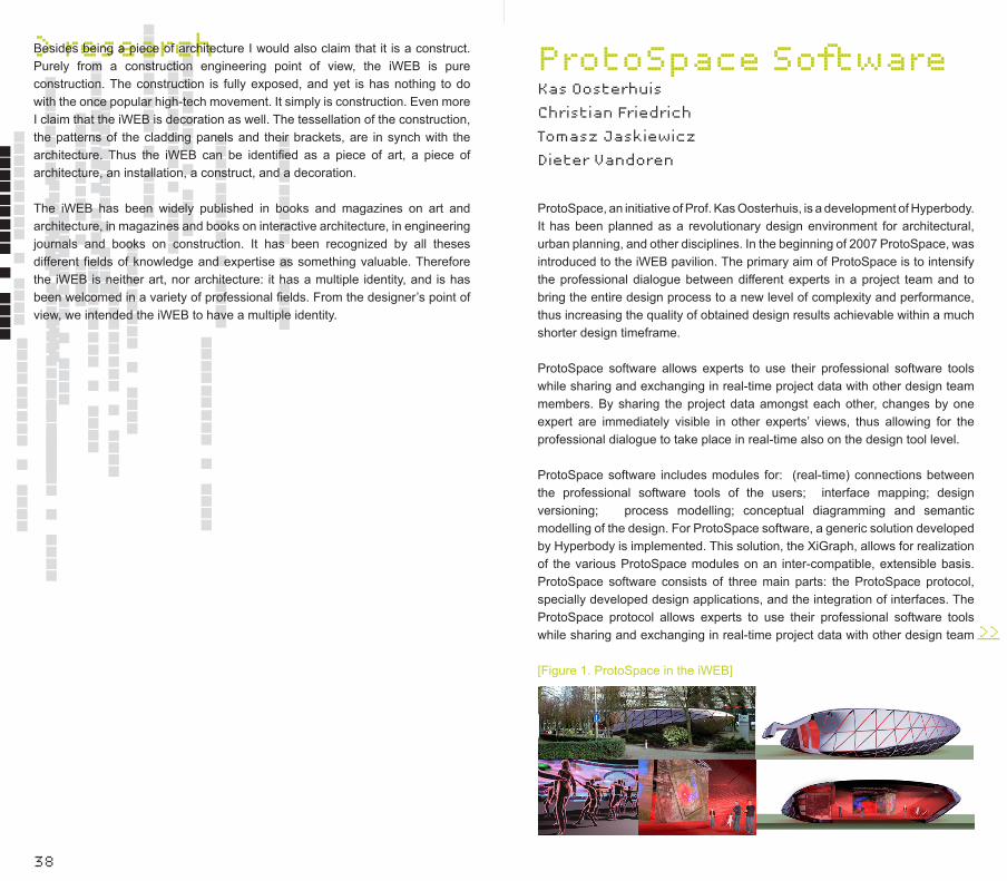
[Figure 1. ProtoSpace in the iWEB]
> research
40
members. By sharing the project data amongst each other, changes by one expert are immediately visible in other experts’ views, thus allowing for the professional dialogue to take place in real-time, even on the design tool level. The combination of shared computational models integrated into specialist applications, with the collaborative actions, evaluation, and feedback of a team of human players, allows for deeper insights into the design than solitary software solutions or group discussions alone can provide. Design alternatives can be more thoroughly studied as real-time design exploration comes within reach. At the same time, the design process becomes more transparent and traceable. In addition, by designing in ProtoSpace software, the team builds a shared computational model of the design, which binds the specialized models of their individual tools together. This shared model could be used as a basis for project communication even outside ProtoSpace design sessions.
Development historyThe original ProtoSpace concept focused on creating an immersive virtual reality environment and a parametric design system, supported by intuitive hands-free interfaces. For prototyping of the software system, the Virtools [note 1] software development toolkit was adopted and used. Extensive work on the subject of collaborative design in VR spaces was carried out by PhD researcher and group coordinator Hans Hubers in his COLADIVIR and COLAB [note 2] projects. Master of Science students covered ProtoSpace related problems in their study research [note 3]. In parallel and as an extension to these efforts, a series of demonstration projects was initiated to design and verify the functionality of the ProtoSpace system in practice.
The first demo, ProtoSpace Demo 1.1, was aimed at creating a working software application, that would allow for parametric design of architectural objects. These, in turn, would be fully performed in the virtual 3D environment. The placement of objects and tweaking of parameters would then be enacted in collaboration with various professionals coming from different fields of expertise. The idea behind initiating the follow-up, ProtoSpace Demo 1.2, was to create a design tool complimentary to the previous one. The core idea of the design application was to support the design process by providing designers with an environment filled with elements virtually equipped with autonomous behaviours, thus allowing emerging self organization of the whole system.
Another focus of the project was research on interface solutions that would allow multi-user interaction within a software application, displayed on one large projection screen. ProtoSpace Demo 1.3 was initiated to continue the research on interfaces to be used with the ProtoSpace system. New developments included PDA-based Menus, wireless keyboards, pressure pads, RFID Identification, environmental sensors, speech recognition, custom controllers and passive stereo projection. With the ProtoSpace Demo 1.4 project, the whole system was further tested on a real-life case, and the development of the
swarm-based design tool was continued. This project resulted in the definition of a ProtoSpace system architecture, testing proposed solutions, and developing a software tool prototype for urban scale, swarm-based design.
The iWEB ProtoSpace environment has five main screens set up in a pentagonal shape, which relate to the icosahedral topology of the iWEB structure. The main screens can be used from the inside, e.g. for a group discussion over the project displayed on a 360 degree 3D environment, or from the outside, for individual applications used by five specialists or stakeholders involved in the project. Surround sound, ambient lighting, and various sensors are also integrated into iWEB. The users can freely move around the space, and use wireless gamepads and other interfaces for navigating the ProtoSpace environment and generating designs.
Interfaces Interface strategies for collaborative designProtoSpace is a spatially open environment not obstructed by office desks and desktop computers, providing a space suitable for teamwork. PC workstations are hidden behind the scenes and the only visible system components are the interface devices. The main displays of ProtoSpace are five large projection screens and a multi-channel audio system surrounding the work area. A range of wireless devices is available as input devices, with varying characteristics to fulfill specific tasks, complemented by a range of sensors monitoring the activity and environmental factors inside the space. The interfaces for controlling the system and its various tools are not a given fact as they are with standard desktop PCs (small display, mouse, and keyboard). In ProtoSpace, large screens replace small computer displays and the workspace remains open, giving its users an optimal freedom of movement. Wireless controllers and motion tracking technologies replace desktop input devices like the keyboard and mouse. A large portion of the development of ProtoSpace consists of creating these custom interfaces, which aim at giving the users the most natural and unconstrained controls over the system.
Interaction processorThe interface layer of the ProtoSpace environment is set up as an independent user-interface processing system on an Apple PowerMac G5 computer, named the ProtoSpace interaction processor. All user-interface devices will be connected to the interaction processor, not to the PC workstations running the design tools themselves. The interaction processor interprets all incoming user-interface data and routes it to the according design tool running on a different workstation as UDP messages over Ethernet. This routing is dynamic which means that one interface device input can be routed to different functions in an application or to different applications/workstations according to changing user needs. For example: a user holds one wireless gamepad controller and switches between different applications running on different workstations. >>___
> research
42
User interface technologiesA wide range of interface types has been tested, including (optical) motion tracking, speech recognition, wireless controllers, and various custom controllers. Below is an overview of the currently developed/applied interfaces and technologies:1) Wireless gamepads: Logitech Wingman Cordless game controllers are used as generic and intuitive controllers to navigate and perform basic operations in virtual 3D environments.2) PDA-based GUI: PDAs connected to the system over Wi-Fi serve as dynamic GUIs (graphical user interfaces) fully dependent on the state of the system and display controls according to the user’s current activity.3) Wireless keyboards: Miniature Bluetooth keyboards provide alphanumeric input to the system from any location in the project environment.4) Optical motion tracking: Max/MSP/Jitter [note 4] applications analyze the real-time input of Firewire digital cameras. The movements in the design space are monitored to provide the system with information on activity and positions of users. Different tracking modes have been tested: general motion tracking without identification, tracking of specific objects/persons (with IR and coloured LED tagging) and more. 5) Pressure Sensitive Floor Pressure pads cover the floor for position tracking of users.6) RFID identification and pairing of controllers: All wireless controller devices have been tagged with RFID chips and each of the five displays has an embedded RFID reader antenna. By approaching a screen with a tagged controller device the system links the controller to the application displayed on that screen. The interaction processor system then routes the input of the
Figure 2
Figure 3
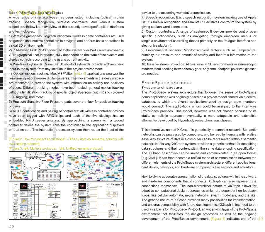
[Figure 2. How to connect applications? – The system as semantic network with overlapping subsets] [Figure 3. left: Multiple protocols, right: Unified, generic protocol]
device to the according workstation/application.7) Speech recognition: Basic speech recognition system making use of Apple OS X’s built-in recognition and Max/MSP. Facilitates control of the system by giving spoken word commands.8) Custom controllers: A range of custom-built devices provide control over specific functionalities, such as navigating through on-screen menus or tangible environment controlling (based primarily on the Phidgets interface and electronics platform).9) Environmental sensors: Monitor ambient factors such as temperature, humidity, air pressure and amount of activity and feed this information to the system.10) Passive stereo projection: Allows viewing 3D environments in stereoscopic mode without needing to wear heavy gear, only small-footprint polarized glasses are needed.
ProtoSpace protocolSystem architectureThe ProtoSpace system architecture that followed the series of ProtoSpace demo applications was originally based on a project model shared via a central database, to which the diverse applications used by design team members would connect. The applications in turn could be assigned to the interfaces ProtoSpace provides. This model, however, was not chosen because of its static, centralistic approach; eventually, a more adaptable and extensible alternative developed by Hyperbody researchers was chosen.
This alternative, named XiGraph, is generically a semantic network. Semantic networks can be processed by computers, and be read by humans with relative ease. Any structure of data in a computer can be represented within a semantic network. In this way, XiGraph system provides a generic method for describing data structures and their content within the same data encoding specification. The XiGraph description can be saved and communicated in an open format (e.g. XML). It can then become a unified mode of communication between the different elements of the ProtoSpace system architecture, different applications, hard drives, networks, and hardware components like sensors and actuators.
Next to giving adequate representation of the data structures within the software and hardware components that it connects, XiGraph can also represent the connections themselves. The non-hierarchical nature of XiGraph allows for adaptive computational design approaches which are dependent on feedback loops, like cellular automata, neural networks, swarm modellers, and the like. The generic nature of XiGraph provides many possibilities for implementation, and ensures compatibility with future developments. XiGraph is intended to be used as a basis for ProtoSpace Protocol, an underlying layer of the ProtoSpace environment that facilitates the design processes as well as the ongoing development of the ProtoSpace environment. [Figure 3] indicates one of the >>___

> research
44
advantages of such a protocol. Instead of handling several disconnected and incompatible protocols for data storage, interface handling and application connections, a common layer simplifies the setup and makes it possible to make tools for handling the entire environment. These tools support the handling of (real-time) connections between the professional software tools of the users, interface mapping, design versioning, process modelling, conceptual diagramming, and semantic modeling of the design.
Within this ProtoSpace Protocol, XiGraph is intended to run in instances, which can be standalone tools or plug-ins to existing applications. Currently, the communication between XiGraph instances is realized via a MySQL database. The next step is to provide XiGraph with a network solution that lets XiGraph instances connect directly with each other. A possible solution to this could be communication of XiGraph via the Verse [note 5] library. The XiGraph specification itself was first researched in Virtools, an environment for rapid application development. The Virtools model is currently being rebuilt as a C++ library that will eventually be used by programmers to let applications communicate in a XiGraph network. This library will be made available as open-source code as soon as it reaches a defined state.
Application integrationVia connections to the XiGraph protocol, existing applications can be integrated into the ProtoSpace system. Inside XiGraph, these connections represent the entities and functionalities present within the applications as XiGraph structures. There are several ways in which such connections can be achieved:- build custom plug-ins to applications when an API (Application Programming Interface) or entire SDK (Software Development Kit) makes this possible;- connect to the programs from the outside via automation interfaces like Microsoft COM (Component Object Model) or the Microsoft. NET Framework;- connect from or to a database or application that already has XiGraph connections.In the current implementation, custom-made plug-ins for Virtools were built to connect to MySQL databases, MS Office, the structural analysis program Oasys GSA [note 6], and AutoCAD. 3D Studio Max is currently connected to the XiGraph protocol via an extension scripted in Maxscript that can exchange data with a MySQL database, which in its turn is directly accessible from the graph. Though at first sight this setup seems to be overly complex, it rather illustrates the complexity, which a common protocol like XiGraph removes. To end-users, exchanging information between applications becomes easier through a simplified interface. ‘Get’ and ’send’ buttons let users send information to applications running on other ProtoSpace screens. A ‘live’ switch can make the exchange run in real-time if the applications allow for it.
System toolFor the handling of ProtoSpace design environments, four applications are
being built on top of the ProtoSpace protocol, as visualizations and editors of the XiGraph adapt to specific tasks. These applications are designed for handling the ProtoSpace environment during design processes (Process modeler), connecting applications (Application connector), connecting interfaces to applications (interaction modeler), and versioning of design alternatives (design evolver).
[Figure 4. left: Process Modeler, right: Design Evolver][Figure 5. left: Application Connector, right: Interface Mapper]
>>___
Figure 4
Figure 5
Process modeller The Process Modeler tool is intended for handling the ProtoSpace environment itself, as it has to change in configuration according to the stage of a design session. The configuration of the entire system, which consists of interface connections, ambient interface configurations, managing applications and other aspects of the ProtoSpace system itself, can be stored as a state. Then various states can be scheduled on a design session timeline and will be called up accordingly. The process modeller could also contain a task list, notes, and timers/alarms with relation to the design session.
Design evolverThe design evolver is a tool for handling the evolution of the design itself.
Application connector The Application connector is a tool for connecting entities in one application to those in another application. For example, the geometric description provided
> research
46
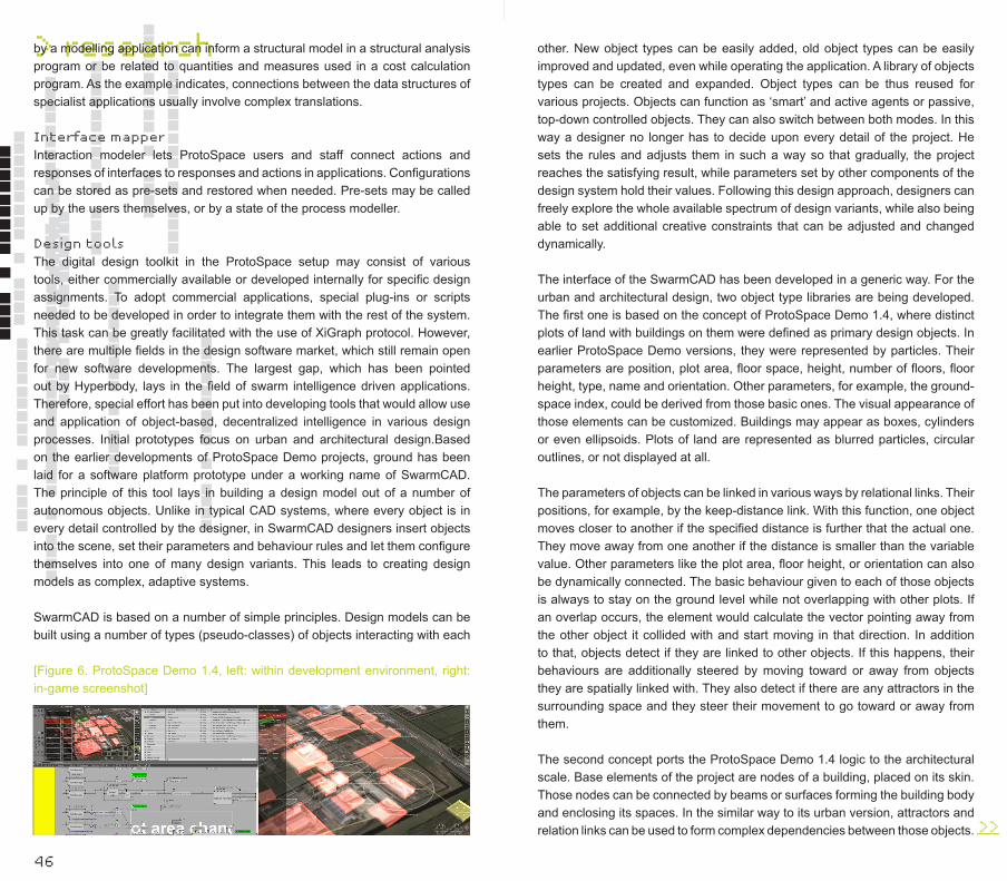
by a modelling application can inform a structural model in a structural analysis program or be related to quantities and measures used in a cost calculation program. As the example indicates, connections between the data structures of specialist applications usually involve complex translations.
Interface mapperInteraction modeler lets ProtoSpace users and staff connect actions and responses of interfaces to responses and actions in applications. Configurations can be stored as pre-sets and restored when needed. Pre-sets may be called up by the users themselves, or by a state of the process modeller.
Design toolsThe digital design toolkit in the ProtoSpace setup may consist of various tools, either commercially available or developed internally for specific design assignments. To adopt commercial applications, special plug-ins or scripts needed to be developed in order to integrate them with the rest of the system. This task can be greatly facilitated with the use of XiGraph protocol. However, there are multiple fields in the design software market, which still remain open for new software developments. The largest gap, which has been pointed out by Hyperbody, lays in the field of swarm intelligence driven applications. Therefore, special effort has been put into developing tools that would allow use and application of object-based, decentralized intelligence in various design processes. Initial prototypes focus on urban and architectural design.Based on the earlier developments of ProtoSpace Demo projects, ground has been laid for a software platform prototype under a working name of SwarmCAD. The principle of this tool lays in building a design model out of a number of autonomous objects. Unlike in typical CAD systems, where every object is in every detail controlled by the designer, in SwarmCAD designers insert objects into the scene, set their parameters and behaviour rules and let them configure themselves into one of many design variants. This leads to creating design models as complex, adaptive systems.
SwarmCAD is based on a number of simple principles. Design models can be built using a number of types (pseudo-classes) of objects interacting with each
[Figure 6. ProtoSpace Demo 1.4, left: within development environment, right: in-game screenshot]
other. New object types can be easily added, old object types can be easily improved and updated, even while operating the application. A library of objects types can be created and expanded. Object types can be thus reused for various projects. Objects can function as ‘smart’ and active agents or passive, top-down controlled objects. They can also switch between both modes. In this way a designer no longer has to decide upon every detail of the project. He sets the rules and adjusts them in such a way so that gradually, the project reaches the satisfying result, while parameters set by other components of the design system hold their values. Following this design approach, designers can freely explore the whole available spectrum of design variants, while also being able to set additional creative constraints that can be adjusted and changed dynamically.
The interface of the SwarmCAD has been developed in a generic way. For the urban and architectural design, two object type libraries are being developed. The first one is based on the concept of ProtoSpace Demo 1.4, where distinct plots of land with buildings on them were defined as primary design objects. In earlier ProtoSpace Demo versions, they were represented by particles. Their parameters are position, plot area, floor space, height, number of floors, floor height, type, name and orientation. Other parameters, for example, the ground-space index, could be derived from those basic ones. The visual appearance of those elements can be customized. Buildings may appear as boxes, cylinders or even ellipsoids. Plots of land are represented as blurred particles, circular outlines, or not displayed at all.
The parameters of objects can be linked in various ways by relational links. Their positions, for example, by the keep-distance link. With this function, one object moves closer to another if the specified distance is further that the actual one. They move away from one another if the distance is smaller than the variable value. Other parameters like the plot area, floor height, or orientation can also be dynamically connected. The basic behaviour given to each of those objects is always to stay on the ground level while not overlapping with other plots. If an overlap occurs, the element would calculate the vector pointing away from the other object it collided with and start moving in that direction. In addition to that, objects detect if they are linked to other objects. If this happens, their behaviours are additionally steered by moving toward or away from objects they are spatially linked with. They also detect if there are any attractors in the surrounding space and they steer their movement to go toward or away from them.
The second concept ports the ProtoSpace Demo 1.4 logic to the architectural scale. Base elements of the project are nodes of a building, placed on its skin. Those nodes can be connected by beams or surfaces forming the building body and enclosing its spaces. In the similar way to its urban version, attractors and relation links can be used to form complex dependencies between those objects. >>___
> research
48
System also allows for the use of dynamically adjustable structural objects similar to physical actuators. In this way, kinetic properties of architectural constructs can be designed and tested.
Those two design object libraries will serve the first two case study projects of the ProtoSpace: one dealing with urban design, the other with an adaptable high-rise structure. Following a long preliminary development trajectory, ProtoSpace is now being installed in the iWEB. The results of the development - the ProtoSpace protocol, design tools, application connections, and interfaces - are promising. The next step is to add more remote application control possibilities for controlling the system from any screen, and to switch from quick-and-dirty standard connections to the ProtoSpace protocol, which is more open to future developments. In the near future, the system will be applied in real-world design cases, from which Hyperbody expects great leaps for the further development of ProtoSpace.
Notes1. Virtools, A Dassault Systèmes Company, www.virtools.com2. Hans Hubers: ’COLAB’, in: Kas Oosterhuis, Lukas Feireiss (eds), Game Set and Match II. On Computer Games, Advanced Geometries and Digital Technologies (Rotterdam: episode publishers, 2006) 560-5673. e.g. the projects described in: Tomasz Jaskiewicz, ‘Designing a Hyperbody of a Train Station Design Lab’, in: Kas Oosterhuis, Lukas Feireiss (eds), Game Set and Match II. On Computer Games, Advanced Geometries and Digital Technologies (Rotterdam: episode publishers, 2006) 46-51 and Tomasz Jaskiewicz, ‘Paracity - A Digital Urban Design Process’, in: Kas Oosterhuis, Lukas Feireiss (eds), Game Set and Match II. On Computer Games, Advanced Geometries and Digital Technologies (Rotterdam: episode publishers, 2006) 296-3044. Max/MSP, www.cycling74.com/products/maxmsp5. verse.blender.org/, www.uni-verse.org/6. Oasys GSA is developed by Arup, www.oasys-software.com/products/structural/gsa/
>>___
Interior skinMarthijn Pool
The former Web of North Holland Pavilion has landed on its new and second bearing ground, the campus of Delft University of Technology. Its former functionality, as a semi open-air pavilion, is different from its current usage, which incorporates new users and climatic demands. The purpose of the iWEB is to host the interfaculty design lab. The body of the structure must provide permanent protection from external climatic influences as well as internal refurbishments in order to functionally operate as the Hyperbody physical platform for interactive design development strategies and implementations.
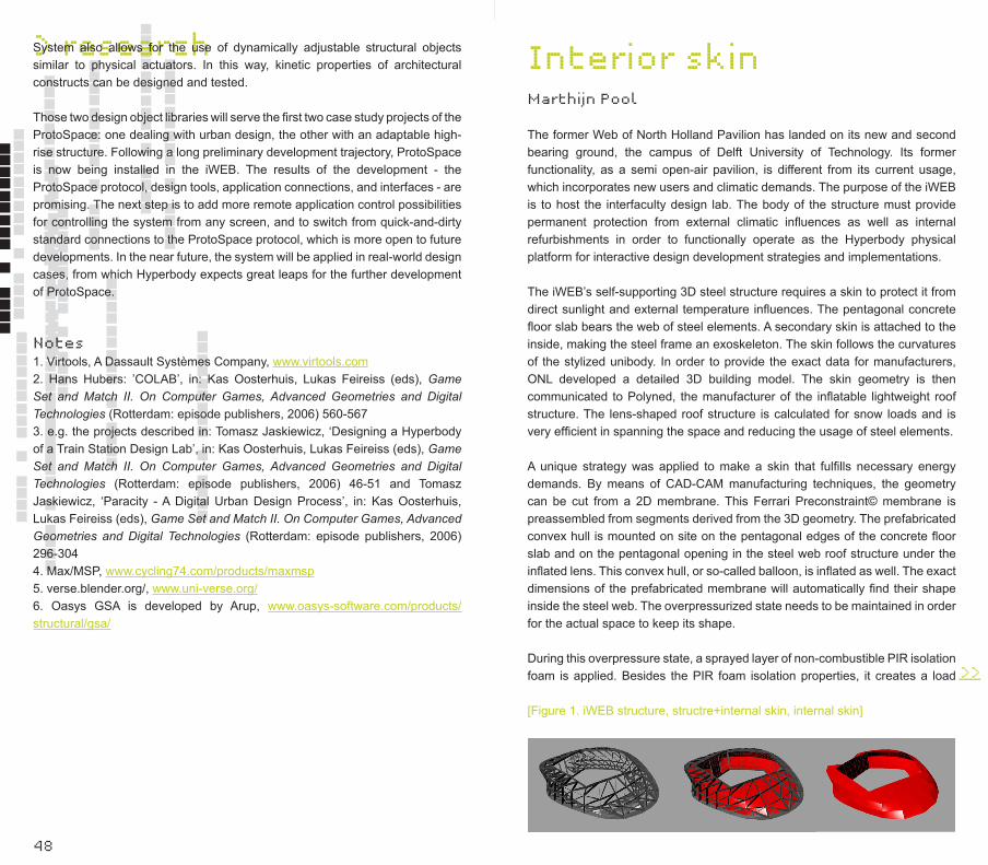
The iWEB’s self-supporting 3D steel structure requires a skin to protect it from direct sunlight and external temperature influences. The pentagonal concrete floor slab bears the web of steel elements. A secondary skin is attached to the inside, making the steel frame an exoskeleton. The skin follows the curvatures of the stylized unibody. In order to provide the exact data for manufacturers, ONL developed a detailed 3D building model. The skin geometry is then communicated to Polyned, the manufacturer of the inflatable lightweight roof structure. The lens-shaped roof structure is calculated for snow loads and is very efficient in spanning the space and reducing the usage of steel elements.
A unique strategy was applied to make a skin that fulfills necessary energy demands. By means of CAD-CAM manufacturing techniques, the geometry can be cut from a 2D membrane. This Ferrari Preconstraint© membrane is preassembled from segments derived from the 3D geometry. The prefabricated convex hull is mounted on site on the pentagonal edges of the concrete floor slab and on the pentagonal opening in the steel web roof structure under the inflated lens. This convex hull, or so-called balloon, is inflated as well. The exact dimensions of the prefabricated membrane will automatically find their shape inside the steel web. The overpressurized state needs to be maintained in order for the actual space to keep its shape.
During this overpressure state, a sprayed layer of non-combustible PIR isolation foam is applied. Besides the PIR foam isolation properties, it creates a load
[Figure 1. iWEB structure, structre+internal skin, internal skin]

> research
50
bearing shell. As soon as the entire internal skin is applied with an 8-10cm thick foam layer, the space no longer has to be over pressurized and the monolithic foam layer becomes part of the constructive skin. A final polyurea coating is applied onto the PIR foam to make it walkable and easy to clean.
The internal skin creates a unique spatial experience since the floor smoothly merges into the wall and the wall into the ceiling, making a cornerless radial space. This creates a spatial effect that gives the space its unique character. Without the common tectonics of a floor, wall, and ceiling, the interior space is a continuum where horizontal merges into vertical and vice versa. The landscape invites the user to explore and experience the body, which is not unlike making a trip into a new universe. Installations, such as sensors, ventilation, and LED lighting are integrated in the interior skin. The actual ProtoSpace will be different each time any user triggers and activates it.
[Figure 3. LED+ventilation integrated in skin, installation concept][Figure 4. atmospheric LED lighting, 360 degrees projection space]
The closed envelope of the skeleton, together with the skin, wraps the sensory and explorative experience from the outside world. Since the functionality asks for an interior, which is fully controllable, direct sunlight is kept out. Instead, RGB LEDs have been integrated all around the iWEB’s interior skin. By projecting the light onto the white fabric of the inflatable roof, this skylight reflector equally spreads the light in the space available. To prevent direct external influence, a small number of windows is oriented in the cantilevering part of the structure.
Figure 3
Figure 4
[Figure 2. steel web, inflated membrane, PIR foam, Polyurea coating]
> research
>>___
This creates a minimal visual connection to the surrounding environment, but enough for the visitor to have an idea of the weather outside. By integrating LED lights in the outer skin, the interior activity can be communicated to the exterior. These LED lights are programmed to output commands, which relate to the interior presence and activity. During nighttime hours, the building’s skin will communicate a compilation of past events stored in the memory of its commander.
Figure 2
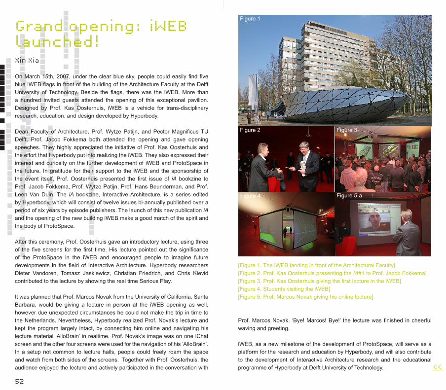
52
Grand opening: iWEB launched!Xin Xia
On March 15th, 2007, under the clear blue sky, people could easily find five blue iWEB flags in front of the building of the Architecture Faculty at the Delft University of Technology. Beside the flags, there was the iWEB. More than a hundred invited guests attended the opening of this exceptional pavilion. Designed by Prof. Kas Oosterhuis, iWEB is a vehicle for trans-disciplinary research, education, and design developed by Hyperbody.
Dean Faculty of Architecture, Prof. Wytze Patijn, and Pector Magnificus TU Delft, Prof. Jacob Fokkema both attended the opening and gave opening speeches. They highly appreciated the initiative of Prof. Kas Oosterhuis and the effort that Hyperbody put into realizing the iWEB. They also expressed their interest and curiosity on the further development of iWEB and ProtoSpace in the future. In gratitude for their support to the iWEB and the sponsorship of the event itself, Prof. Oosterhuis presented the first issue of iA bookzine to Prof. Jacob Fokkema, Prof. Wytze Patijn, Prof. Hans Beunderman, and Prof. Leen Van Duin. The iA bookzine, Interactive Architecture, is a series edited by Hyperbody, which will consist of twelve issues bi-annually published over a period of six years by episode publishers. The launch of this new publication iA and the opening of the new building iWEB make a good match of the spirit and the body of ProtoSpace.
After this ceremony, Prof. Oosterhuis gave an introductory lecture, using three of the five screens for the first time. His lecture pointed out the significance of the ProtoSpace in the iWEB and encouraged people to imagine future developments in the field of Interactive Architecture. Hyperbody researchers Dieter Vandoren, Tomasz Jaskiewicz, Christian Friedrich, and Chris Kievid contributed to the lecture by showing the real time Serious Play.
It was planned that Prof. Marcos Novak from the University of California, Santa Barbara, would be giving a lecture in person at the iWEB opening as well, however due unexpected circumstances he could not make the trip in time to the Netherlands. Nevertheless, Hyperbody realized Prof. Novak’s lecture and kept the program largely intact, by connecting him online and navigating his lecture material ‘AlloBrain’ in realtime. Prof. Novak’s image was on one iChat screen and the other four screens were used for the navigation of his ‘AlloBrain’. In a setup not common to lecture halls, people could freely roam the space and watch from both sides of the screens. Together with Prof. Oosterhuis, the audience enjoyed the lecture and actively participated in the conversation with
[Figure 1. The iWEB landing in front of the Architectural Faculty][Figure 2. Prof. Kas Oosterhuis presenting the IA#1 to Prof. Jacob Fokkema][Figure 3. Prof. Kas Oosterhuis giving the first lecture in the iWEB][Figure 4. Students visiting the iWEB][Figure 5. Prof. Marcos Novak giving his online lecture]
Prof. Marcos Novak. ‘Bye! Marcos! Bye!’ the lecture was finished in cheerful waving and greeting.
iWEB, as a new milestone of the development of ProtoSpace, will serve as a platform for the research and education by Hyperbody, and will also contribute to the development of Interactive Architecture research and the educational programme of Hyperbody at Delft University of Technology.
Figure 5-aFigure 4
Figure 3Figure 2
Figure 1
<<___
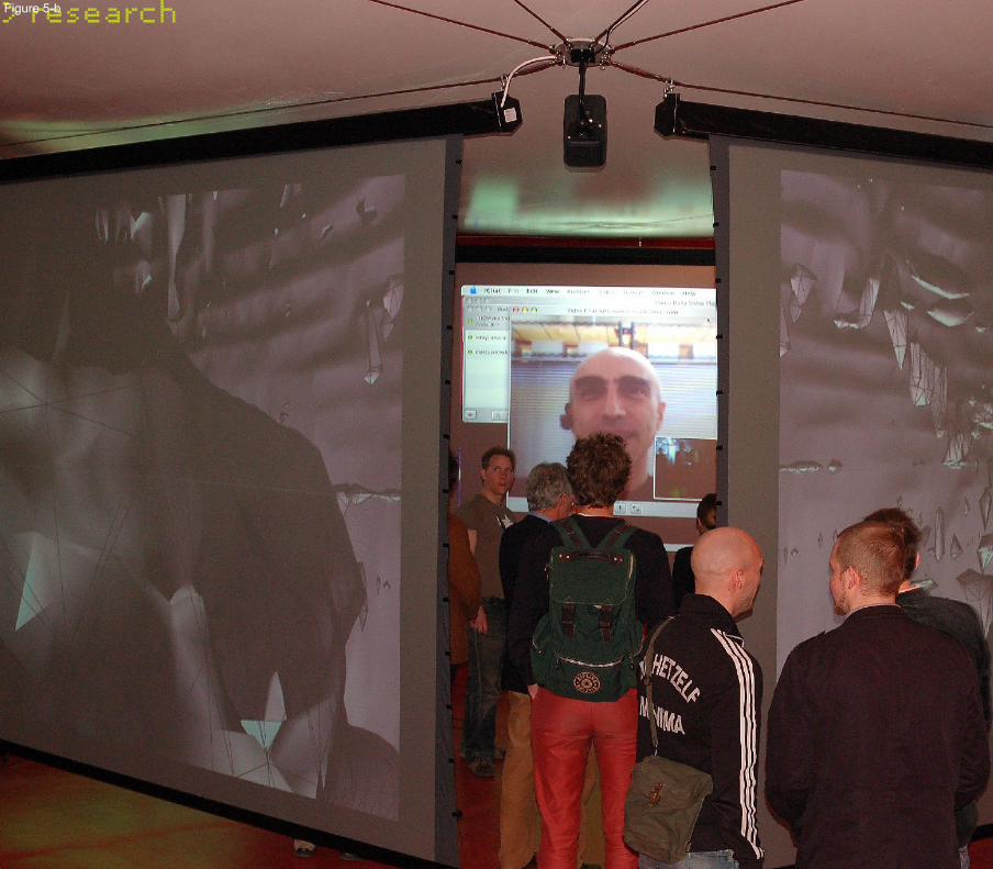
54
> researchFigure 5-b
56
Multiplay-er design game
798 Multiplayer design game
> education
798 Multi Player Design Game
Kas Oosterhuis
Tomasz Jaskiewicz
In the second semester of 2003, a group of
ten Master of Science Architecture students
started their research semester in the E-Motive
Architecture studio, an educational program of the
Hyperbody. The design assignment was a relatively
common one – to design a train station. The path
that they were required to follow to accomplish
that task, however, was highly innovative.
’A multiplayer game is a video game in which more than one person can play the same game at the same time. (…) In multiplayer games, players either all compete against each other, or team up to achieve a common goal such as defeating an enemy that can consist of either computer or human players. Usually multiplayer games either use computer networking to allow players to play together or require the players to gather around a single game system to play.’ - From Wikipedia – the free encyclopedia, www.wikipedia.org
Designing architecture is serious play. The goal of the game is to create a great building. It is a game where designers need to play according to the rules of physics, economy, and society. It is by its nature a multiplayer game where many specialists need to work together to increase their prospects of winning. It is impossible to imagine designing contemporary architecture without computers. They have enormously accelerated many parts of design processes and opened up astounding new possibilities that have never been imaginable before. Parametric architecture, interactive architecture, mass customization, and file-to-factory production: all these would not be possible without the use of digital technologies. Ironically, common use of computers has also drawn designers away from meeting tables and caught them in a single-player working mode. When we design, we are now confined to our screens and keyboards. We exchange information only when we stop designing.
The single-player way of working in our digital workspaces makes cooperation between different specialists in the design process one of the most serious bottlenecks in project development. Each party involved in the design has to wait for the work of other parties to be finished in order to continue with their own tasks. Thus it is absolutely impossible to verify all design variants or scenarios. If it already takes weeks to fully work out one alternative, it would simply stretch the entire process into eternity if we were to investigate hundreds or thousands of design variations. As a result, designs are often optimized from the point of view of only one specialist, while others follow the dominant party, providing solutions for just one, very specific case. In this way the whole range of design options that could be worth exploring is not even brought to consideration. The design process not only takes way too much time, it also doesn’t allow us to investigate all possible design alternatives. In this context, a new design method paradigm shift involving a change from single player to multiplayer design becomes an absolute necessity. Not only to speed up the design process, but more importantly, it should allow the exploration of the whole possible spectrum of design alternatives.
Hyperbody has performed extensive research on this topic. The ProtoSpace Lab, which will be hosted in the iWEB pavilion at the university campus, will become a new kind of environment for multiplayer design. The research of Hyperbody aims to use real time data exchange for serious play in architectural >>___

58
> educationdesign. Various sub-projects of ProtoSpace have explored different ways of employing this concept. ProtoSpace 1.1 looked at designing with many simultaneous views on one software application, the COLAB project investigated collaborating over internet, ProtoSpace 1.2 and 1.3 researched the implication of interfaces that do not constrain our movement and communication abilities while working in a group, and the latest ProtoSpace 1.4 project and the Graph protocol have managed to dynamically connect various applications used by different specialists all working on one project. All these shows that multiplayer design is technically possible and within our reach. We intend to definitely prove these convictions by a series of case study projects that will run in the final ProtoSpace setup.
However, more important than all the technical issues associated with making things work, is the whole new way of designing that it invokes. Computers let us play together in real time. In a multiplayer game, the exchange of information happens instantly, many cycles per second. What will happen if design information gets exchanged immediately between different designers? We couldn’t wait any longer to see what implications such a radical change in design methodology would have. Thus, before the professional projects start in ProtoSpace, we have established a multiplayer design setup with much simpler means for our MSc3 students in their design studio. The leading idea for the student project was to guide students in such a way that they would cooperate in an ambitious ‘top-down’ master-planning scheme, but at the same time consisting of many concurrently ‘bottom-up’ designed subparts. Designing those parts should happen in parallel to each of the others, with each part instantaneously negotiating with and mutually affecting its neighbours.
A group of twenty-three students joined our design semester in September 2006. The given design site was not a usual two-dimensional plot, but a large three-dimensional urban body. Each student was assigned to one of the twenty-three interlocking pieces of the 3D puzzle. When put together, all pieces would form a giant sphere of 8,000,000 m3. This spatial boundary has been located in the middle of the 751 Factory in Beijing, the eastern part of the 798 Art District. The sphere, partly submerged underground, would stand on small feet, with a 20,000 m2 base. The rest of the 751 area has been divided among the group of five students from the collaborating South-East University of Nanjing. Their work proceeded in parallel to the progress of Delft students. Their designs, however, have been made from a more conventional, two-dimensional starting point.
Each of the students was encouraged to be creative and innovative. They were allowed to develop any proposal as long as they would obey the following rules of the master plan:1. Program is mixed use development of 1,000,000 m2 of built-up area.2. Contained in a virtual sphere of 8,000,000 m3 leaving 25% open space for
bringing light into the large urban body.3. We provide the students with a 3D puzzle of as many interlocking parts as there are students.4. Each 3D plot communicates and negotiates only with its immediate neighbours.5. Each piece of the 3D puzzle has a specific program of requirements (housing, offices, commercial, cultural, educational, leisure).6. Location will be right in the heart of the 751 site.7. Each plot administrates its data input, data processing, data output, and communicates the parameters in a dynamic database with its immediate neighbours.8. Each plot has to structurally support itself and communicates data of structural loads with its immediate neighbours.9. The sphere must produce energy--as much energy as it consumes.
The rules are derived from the concept of swarm behaviour. In a swarm, each member of the swarm exclusively communicates with its immediate neighbour. The shape of the swarm is not imposed by any of these swarming members, there is no leader nor do they have an awareness of the whole. The shape of the swarm is the balanced result of the bi-directional interactions between the acting members and of exterior climatic conditions that impose constraints upon the size and direction of the swarm. In the 798 master plan, the students are the bottom-up communicating swarm members and the tutors represent the top-down control.
The students from the South-East University working on the 751 area around the sphere were asked to approach their designs more conventionally. Their task was to react to the developments within the sphere and to provide facilities for that development while accomplishing their particular design goals and acting as an intermediate zone between the sphere and the rest of the 798/751 area and Beijing. >>___
Figure 1 Figure 2
[Figure 1. Interactive viewer of the design site] [Figure 2. Position of the sphere in the 798 art district]
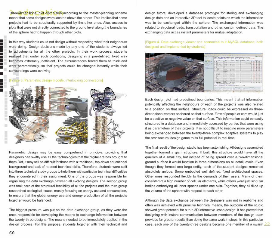
60
> educationThree-dimensional plot distribution according to the master-planning scheme meant that some designs were located above the others. This implies that some projects had to be structurally supported by the other ones. Also, access to plots that were not directly connected to the ground level along the boundaries of the sphere had to happen through other plots.
In this way students could not design without respecting what their neighbours were doing. Design decisions made by any one of the students always led to adjustments for all the other projects. In their work process, students realized that under such conditions, designing in a pre-defined, fixed way becomes extremely inefficient. The circumstances forced them to think and work parametrically, so that projects could be changed instantly while their surroundings were evolving.
[Figure 3. Parametric design models, interlocking connections]
Parametric design may be easy comprehend in principle, providing that designers can swiftly use all the technologies that the digital era has brought to them. Yet, it may still be difficult for those with a traditional, top-down educational background and lack of needed technical skills. Therefore, students were split into three technical study groups to help them with particular technical difficulties they encountered in their assignment. One of the groups was responsible for organising the data exchange between all evolving designs. The second group was took care of the structural feasibility of all the projects and the third group researched ecological issues, mostly focusing on energy use and consumption, to ensure that the global energy use and energy production of all the projects together would be balanced.
The biggest pressure was put on the data exchange group, as they were the ones responsible for developing the means to exchange information between the twenty-three designs. The means needed to be immediately applied in the design process. For this purpose, students together with their technical and
design tutors, developed a database prototype for storing and exchanging design data and an interactive 3D tool to locate points on which the information was to be exchanged within the sphere. The exchanged information was related to structural loads, transportation and other, custom defined data. The exchanging data act as instant parameters for mutual adaptation.
[Figure 4. Data exchange viewer and connected to it MySQL database, both designed and implemented by students]
>>___
Each design plot had predefined boundaries. This meant that all information potentially affecting the neighbours of each of the projects was also related to a position on that surface. Structural loads could be expressed as three-dimensional vectors anchored on that surface. Flow of people or cars would just be a positive or negative value on that surface. This information could be easily structured in a database and immediately accessed by parties that were using it as parameters of their projects. It is not difficult to imagine more parameters being exchanged between the twenty-three complex adaptive systems to play the architectural design game to its full potential in real time.
The final result of the design studio has been astonishing. All designs assembled together formed a giant structure. If built, this structure would have all the qualities of a small city, but instead of being spread over a two-dimensional ground surface it would function in three dimensions on all detail levels. Even though they formed one large entity, each of the student designs remained absolutely unique. Some embodied well defined, fixed architectural spaces. Other ones responded flexibly to the demands of their users. Many of them consisted of a high number of cellular elements, while others were just singular bodies embodying all inner spaces under one skin. Together, they all filled up the volume of the sphere with respect to each other.
Although the data exchange between the designers was not in real-time and often was achieved with primitive technical means, the outcome of the studio showed great potential for a true 3D interactive urban design. It has proved that designing with instant communication between members of the design team provides far greater results than doing the same work in steps. In this particular case, each one of the twenty-three designs became one member of a swarm
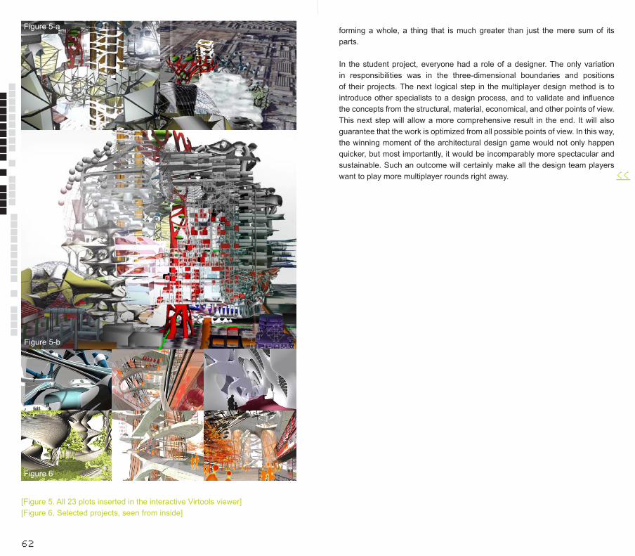
[Figure 5. All 23 plots inserted in the interactive Virtools viewer][Figure 6. Selected projects, seen from inside]
62
> education
Figure 5-b
Figure 6
> educationFigure 5-a forming a whole, a thing that is much greater than just the mere sum of its parts.
In the student project, everyone had a role of a designer. The only variation in responsibilities was in the three-dimensional boundaries and positions of their projects. The next logical step in the multiplayer design method is to introduce other specialists to a design process, and to validate and influence the concepts from the structural, material, economical, and other points of view. This next step will allow a more comprehensive result in the end. It will also guarantee that the work is optimized from all possible points of view. In this way, the winning moment of the architectural design game would not only happen quicker, but most importantly, it would be incomparably more spectacular and sustainable. Such an outcome will certainly make all the design team players want to play more multiplayer rounds right away. <<___
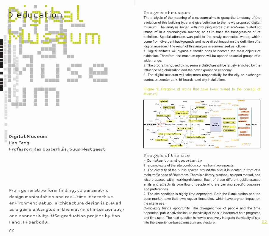
64
Dig-ital Museum
Digital Museum
Han Feng
Professor: Kas Oosterhuis, Guus Westgeest
DigitalMuseum> education
From generative form finding, to parametric
design manipulation and real-time interactive
environment setup, architecture design is played
as a game entangled in the matrix of intentionality
and connectivity. MSc graduation project by Han
Feng, Hyperbody.
Analysis of museumThe analysis of the meaning of a museum aims to grasp the tendency of the evolution of this building type and give definition to the newly proposed digital museum. The analysis began with grouping words that are/were related to ‘museum’ in a chronological manner, so as to trace the transgression of its definition. Special attention was paid to the newly connected words, which come from divergent backgrounds and have direct impact on the definition of a ‘digital museum.’ The result of this analysis is summarized as follows: 1. Digital artifacts will bypass authentic ones to become the main objects of exhibition. Therefore, the museum space will be opened to social groups of a wider range. 2. The programs housed by museum architecture will be largely enriched by the influence of globalization and the new experience economy.3. The digital museum will take more responsibility for the city as exchange centre, encounter park, billboards, and city installations.
[Figure 1. Chronicle of words that have been related to the concept of Museum]
Analysis of the site- Complexity and opportunityThe complexity of the site condition comes from two aspects:1. The diversity of the public spaces around the site: it is located in front of a main traffic node of Rotterdam. There is a library, a school, an open market, and leisure spaces within walking distance. Each of these different public spaces emits and attracts its own flow of people who are carrying specific purposes and preferences.2. The site condition is highly time dependent. Both the Blaak station and the open market have their own regular timetables, which have a great impact on the site in use.Complexity brings opportunity. The divergent flow of people and the time dependent public activities insure the vitality of the site in terms of both programs and time span. The next question is how to creatively integrate the vitality of site into the experience-based museum architecture. >>___
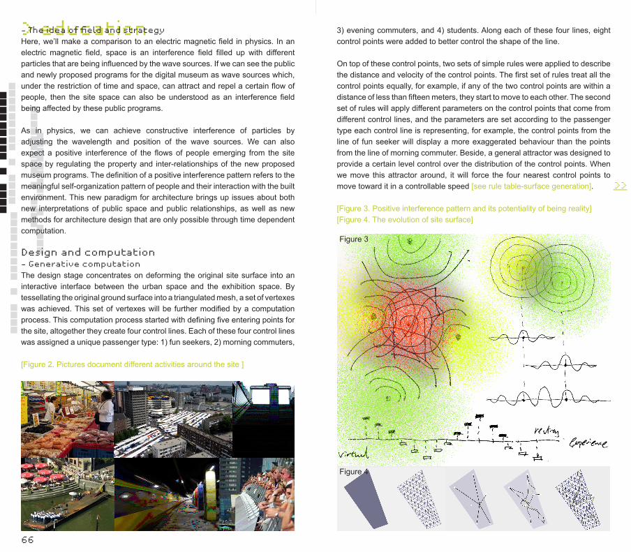
66
> education- The idea of field and strategyHere, we’ll make a comparison to an electric magnetic field in physics. In an electric magnetic field, space is an interference field filled up with different particles that are being influenced by the wave sources. If we can see the public and newly proposed programs for the digital museum as wave sources which, under the restriction of time and space, can attract and repel a certain flow of people, then the site space can also be understood as an interference field being affected by these public programs.
As in physics, we can achieve constructive interference of particles by adjusting the wavelength and position of the wave sources. We can also expect a positive interference of the flows of people emerging from the site space by regulating the property and inter-relationships of the new proposed museum programs. The definition of a positive interference pattern refers to the meaningful self-organization pattern of people and their interaction with the built environment. This new paradigm for architecture brings up issues about both new interpretations of public space and public relationships, as well as new methods for architecture design that are only possible through time dependent computation.
Design and computation- Generative computationThe design stage concentrates on deforming the original site surface into an interactive interface between the urban space and the exhibition space. By tessellating the original ground surface into a triangulated mesh, a set of vertexes was achieved. This set of vertexes will be further modified by a computation process. This computation process started with defining five entering points for the site, altogether they create four control lines. Each of these four control lines was assigned a unique passenger type: 1) fun seekers, 2) morning commuters,
[Figure 2. Pictures document different activities around the site ]
Figure 3
3) evening commuters, and 4) students. Along each of these four lines, eight control points were added to better control the shape of the line.
On top of these control points, two sets of simple rules were applied to describe the distance and velocity of the control points. The first set of rules treat all the control points equally, for example, if any of the two control points are within a distance of less than fifteen meters, they start to move to each other. The second set of rules will apply different parameters on the control points that come from different control lines, and the parameters are set according to the passenger type each control line is representing, for example, the control points from the line of fun seeker will display a more exaggerated behaviour than the points from the line of morning commuter. Beside, a general attractor was designed to provide a certain level control over the distribution of the control points. When we move this attractor around, it will force the four nearest control points to move toward it in a controllable speed [see rule table-surface generation].
Figure 4
>>___
[Figure 3. Positive interference pattern and its potentiality of being reality][Figure 4. The evolution of site surface]
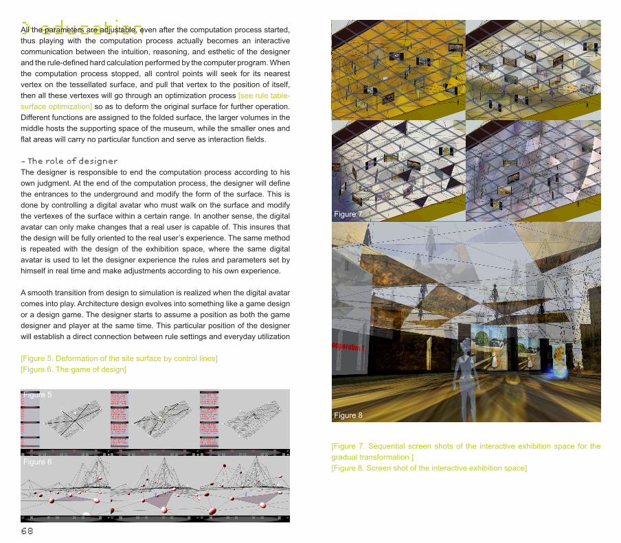
> education
68
All the parameters are adjustable, even after the computation process started, thus playing with the computation process actually becomes an interactive communication between the intuition, reasoning, and esthetic of the designer and the rule-defined hard calculation performed by the computer program. When the computation process stopped, all control points will seek for its nearest vertex on the tessellated surface, and pull that vertex to the position of itself, then all these vertexes will go through an optimization process [see rule table-surface optimization] so as to deform the original surface for further operation. Different functions are assigned to the folded surface, the larger volumes in the middle hosts the supporting space of the museum, while the smaller ones and flat areas will carry no particular function and serve as interaction fields.
- The role of designerThe designer is responsible to end the computation process according to his own judgment. At the end of the computation process, the designer will define the entrances to the underground and modify the form of the surface. This is done by controlling a digital avatar who must walk on the surface and modify the vertexes of the surface within a certain range. In another sense, the digital avatar can only make changes that a real user is capable of. This insures that the design will be fully oriented to the real user’s experience. The same method is repeated with the design of the exhibition space, where the same digital avatar is used to let the designer experience the rules and parameters set by himself in real time and make adjustments according to his own experience.
A smooth transition from design to simulation is realized when the digital avatar comes into play. Architecture design evolves into something like a game design or a design game. The designer starts to assume a position as both the game designer and player at the same time. This particular position of the designer will establish a direct connection between rule settings and everyday utilization
Figure 5
Figure 6
[Figure 5. Deformation of the site surface by control lines][Figure 6. The game of design]
Figure 8
Figure 7
[Figure 7. Sequential screen shots of the interactive exhibition space for the gradual transformation ][Figure 8. Screen shot of the interactive exhibition space]
Figure 7
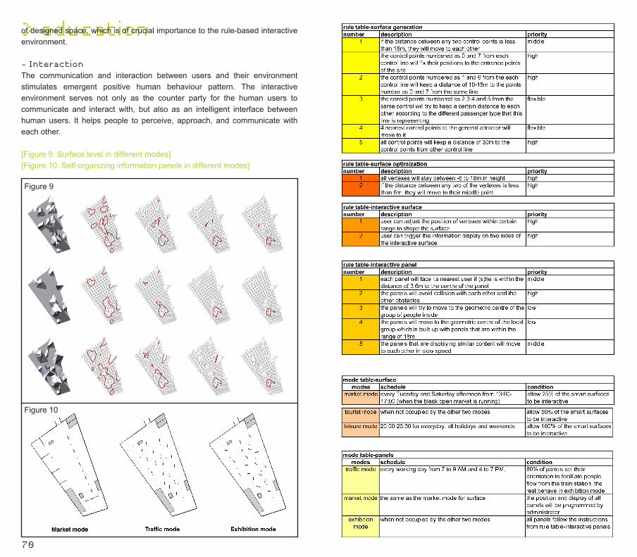
> education
70
of designed space, which is of crucial importance to the rule-based interactive environment.
- InteractionThe communication and interaction between users and their environment stimulates emergent positive human behaviour pattern. The interactive environment serves not only as the counter party for the human users to communicate and interact with, but also as an intelligent interface between human users. It helps people to perceive, approach, and communicate with each other.
Figure 9
Figure 10
[Figure 9. Surface level in different modes][Figure 10. Self-organizing information panels in different modes]

72
> educationThe interactive environment in this project is composed of interactive surfaces and the exhibition panel system. On the surface level, users can control the vertexes to modify the surface as they want/need. Their contact with the triangulated glass panels will trigger a double-sided information display which will provide them the information they requested, and at the same time manifest the position and movement of this user to the users in the exhibition space. As in the exhibition space, users can control the position and content of several information panels to alter the space for different purposes. The instant position and vector speed of a single user and the center of multiple users will be detected and reacted by the information panels. Also, people who have requested similar content on different panels will be gradually guided to each other by the movement of their panels [see the rule table-interactive panel]. The notion of grouped users further complicates the relationship between user and his or her environment. Being an open system, the constitution of the user group will be constantly influenced by the surrounding activities in time. This changing condition of user groups can only be properly accommodated by running alternative rule sets. These rule sets will be described as modes in this project.
- The modesThe different modes for the surface level and exhibition space are derived from the site analysis. For the surface level, there is a market mode, tourist mode, and leisure mode. They differ from each other by the proportion of activated surface area [see mode table-surface]. This limitation is set to insure a balance between space requirement of massive flow of people and the flexibility of the surface under different circumstances. For the exhibition space, the modes are set as market mode, traffic mode, and exhibition mode [see mode table-panels]. The information panels exhibit different behaviour according to the different modes they are in. Together, these modes make sure that the exhibition space can adapt itself to different expectations through time while continuing to add valuable experiences to the flow of people passing by.
ConclusionIn the end, this is a project about building up relations between people and their immediately updated environments, between people and people. These relations interweave to sum up a complex system, for which the linear cause and effect starts to lose its significance. A paradigm shift is manifested here that sees the world as a dynamic system built upon simple rules with all its components communicating with each other. One direct consequence derived from this paradigm shift is that to precisely locate or describe something becomes extremely difficult. As for the word ‘web’ and for the word ‘museum,’ the meaning emerges only through a time dependent synthesis of all sub-connections. As for the behaviour of a single information panel, the instant movement is only understandable by examining all the overlapping rules and the entire environment situation that it cares about. A new kind of space is constructed
within this paradigm shift, which displays such extreme vitality that a whole new method to describe and manipulate it becomes necessary. This necessity brings new questions to architecture, which have never been discussed before. Would it be feasible to introduce the methods like statistic mathematics and fuzzy logic to architecture? Would it be helpful to learn from quantum mechanics, which is known for its achievement of working with uncertainty? These are just a few of the questions that this project has inspired. <<___
74
Form Follows Energy
Patrick Teuffel
Hans Hubers
Patrick Teuffel is a German structural engineer who
did his doctorate at the University of Stuttgart
under the chair of Prof. Dr.-Ing Werner Sobek. His
doctorate was titled ‘Designing Adaptive Systems’
[Ilek 2007]. He now leads his own office, Teuffel
Engineering Consultants, in Stuttgart and he is
Senior Lecturer (Architectural Engineering) at the
University of Leeds [Teuffel 2007].
Form fol-lows ener-gy
Form follows energy
> workshop This workshop was conducted on the 6th of October 2006. Participants in the workshop include: Hans Hubers, Christina Ann Rangel, Christian Mack, Jędrzej Kolesiński, Roman Krajger, Sema Alagam Aslan, and Tomas Lapka. Hans Hubers wrote this article on the basis of the reports that some students made about the workshop. Christina Ann Rangel’s report was taken as the basis, because it was the most complete and well written. Additions were taken from reports of the other students and additional sources.
Until recently, the geometry and topology of buildings was found experimentally or calculated mathematically. But the most important role always played the ‘dead weight’ as a fixed unit. Patrick Teuffel belongs to a group of engineers that is developing types of structures, which have a variable geometry and stiffness in order to minimize their weight. Adaptive systems always try to force the structure’s tension to the maximum to control the deformations and oscillations. Damps to reduce oscillations are already used, especially to protect high-rise buildings against earthquakes in Japan. The challenge now is to search for ways to imply these techniques (into hulls of buildings, for example) to make them react to their changing environment or interior. The adaptation is achieved by the use of elements that are variable in size and stiffness.
Modern architecture is not just about designing brand-new forms, formerly never seen, but also about searching for new principles in developement
and searching for progressive materials. Today’s trend is to develop structures, that are adaptible to all designers‘ demands, very light, cost effective on one hand, but on the other hand strong enough to carry all neccessary forces – temporary or permanent. We do not have to look only to the future to find new materials, we can also see inspiration in the past, as Patrick Teuffel does. Very simple structures, like the post for electric lines by Schuchov, can be an example of timeless structures. The technician-designer‘s approach of B. Fuller to architecture is also very well known. From such structures, it is only a short step to inspiration by aerospace-engineering.
Lightweight structures often follow natural systems (e.g. cobwebs), save energy, and are deployable. Principle fields to study for lightweight structures are materials, structures, and systems. Lightweight structures have a low density and high strength or stiffness. We discussed the possibilities of using new materials that will be responsive to our needs. Lightweight materials include foils, fabrics, nets, ropes and rods made of synthetic, metallic and natural materials e. g. tents, pneumatics, cable nets, grid shells, tree columns and hybrid systems, for permanent and temporary applications and for stationary, convertible, and mobile utilizations.
A number of emerging technologies were discussed at the workshop, such as:- Smart materials. Here we talk about short term and long-term >>___
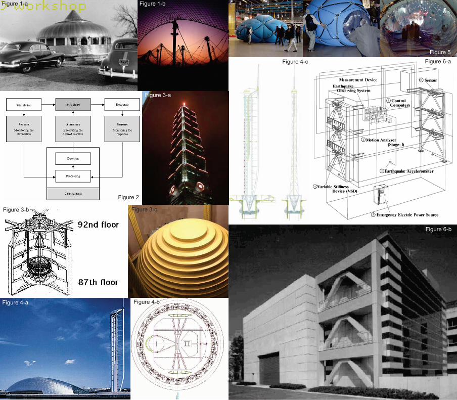
76
> workshopFigure 1-a
Figure 3-cFigure 3-b
Figure 3-a
Figure 2
Figure 1-b
Figure 4-a Figure 4-b
Figure 4-cFigure 5
Figure 6-b
Figure 6-aFigure 5
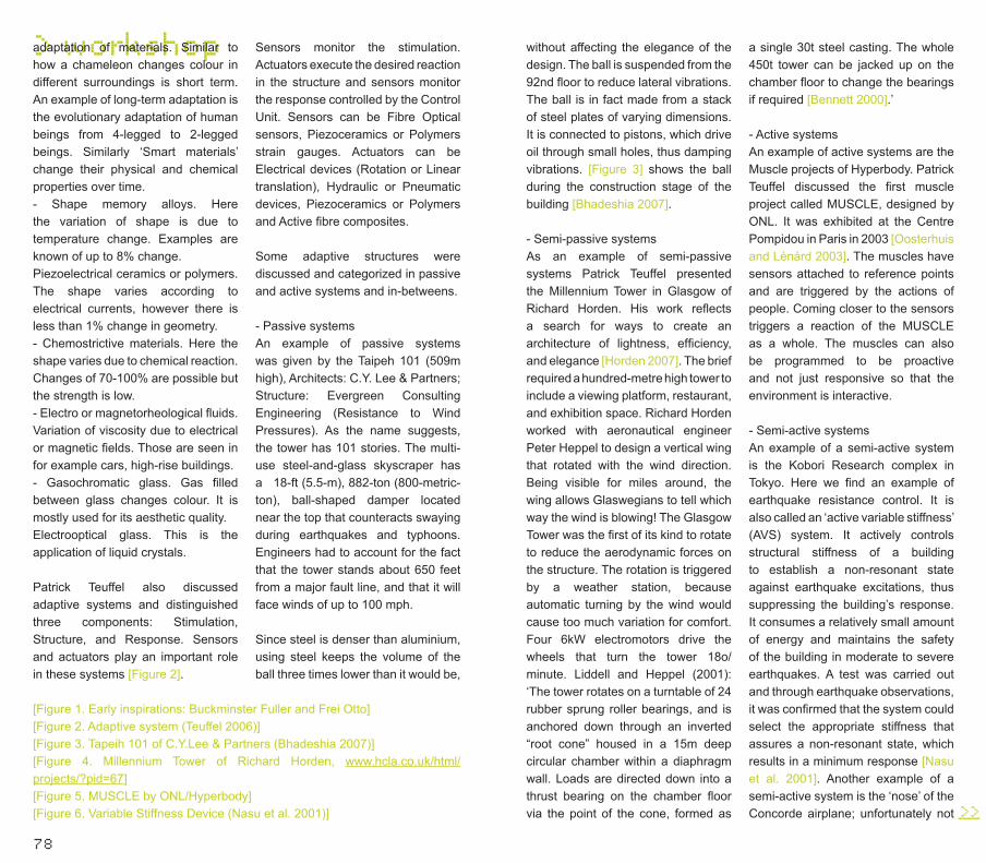
78
> workshopadaptation of materials. Similar to how a chameleon changes colour in different surroundings is short term. An example of long-term adaptation is the evolutionary adaptation of human beings from 4-legged to 2-legged beings. Similarly ‘Smart materials’ change their physical and chemical properties over time.- Shape memory alloys. Here the variation of shape is due to temperature change. Examples are known of up to 8% change.Piezoelectrical ceramics or polymers. The shape varies according to electrical currents, however there is less than 1% change in geometry.- Chemostrictive materials. Here the shape varies due to chemical reaction. Changes of 70-100% are possible but the strength is low.- Electro or magnetorheological fluids. Variation of viscosity due to electrical or magnetic fields. Those are seen in for example cars, high-rise buildings.- Gasochromatic glass. Gas filled between glass changes colour. It is mostly used for its aesthetic quality.Electrooptical glass. This is the application of liquid crystals.
Patrick Teuffel also discussed adaptive systems and distinguished three components: Stimulation, Structure, and Response. Sensors and actuators play an important role in these systems [Figure 2].
Sensors monitor the stimulation. Actuators execute the desired reaction in the structure and sensors monitor the response controlled by the Control Unit. Sensors can be Fibre Optical sensors, Piezoceramics or Polymers strain gauges. Actuators can be Electrical devices (Rotation or Linear translation), Hydraulic or Pneumatic devices, Piezoceramics or Polymers and Active fibre composites.
Some adaptive structures were discussed and categorized in passive and active systems and in-betweens.
- Passive systemsAn example of passive systems was given by the Taipeh 101 (509m high), Architects: C.Y. Lee & Partners; Structure: Evergreen Consulting Engineering (Resistance to Wind Pressures). As the name suggests, the tower has 101 stories. The multi-use steel-and-glass skyscraper has a 18-ft (5.5-m), 882-ton (800-metric-ton), ball-shaped damper located near the top that counteracts swaying during earthquakes and typhoons. Engineers had to account for the fact that the tower stands about 650 feet from a major fault line, and that it will face winds of up to 100 mph.
Since steel is denser than aluminium, using steel keeps the volume of the ball three times lower than it would be,
[Figure 1. Early inspirations: Buckminster Fuller and Frei Otto][Figure 2. Adaptive system (Teuffel 2006)][Figure 3. Tapeih 101 of C.Y.Lee & Partners (Bhadeshia 2007)][Figure 4. Millennium Tower of Richard Horden, www.hcla.co.uk/html/projects/?pid=67][Figure 5. MUSCLE by ONL/Hyperbody][Figure 6. Variable Stiffness Device (Nasu et al. 2001)]
without affecting the elegance of the design. The ball is suspended from the 92nd floor to reduce lateral vibrations. The ball is in fact made from a stack of steel plates of varying dimensions. It is connected to pistons, which drive oil through small holes, thus damping vibrations. [Figure 3] shows the ball during the construction stage of the building [Bhadeshia 2007].
- Semi-passive systemsAs an example of semi-passive systems Patrick Teuffel presented the Millennium Tower in Glasgow of Richard Horden. His work reflects a search for ways to create an architecture of lightness, efficiency, and elegance [Horden 2007]. The brief required a hundred-metre high tower to include a viewing platform, restaurant, and exhibition space. Richard Horden worked with aeronautical engineer Peter Heppel to design a vertical wing that rotated with the wind direction. Being visible for miles around, the wing allows Glaswegians to tell which way the wind is blowing! The Glasgow Tower was the first of its kind to rotate to reduce the aerodynamic forces on the structure. The rotation is triggered by a weather station, because automatic turning by the wind would cause too much variation for comfort. Four 6kW electromotors drive the wheels that turn the tower 18o/minute. Liddell and Heppel (2001): ‘The tower rotates on a turntable of 24 rubber sprung roller bearings, and is anchored down through an inverted “root cone” housed in a 15m deep circular chamber within a diaphragm wall. Loads are directed down into a thrust bearing on the chamber floor via the point of the cone, formed as
a single 30t steel casting. The whole 450t tower can be jacked up on the chamber floor to change the bearings if required [Bennett 2000].’
- Active systemsAn example of active systems are the Muscle projects of Hyperbody. Patrick Teuffel discussed the first muscle project called MUSCLE, designed by ONL. It was exhibited at the Centre Pompidou in Paris in 2003 [Oosterhuis and Lénárd 2003]. The muscles have sensors attached to reference points and are triggered by the actions of people. Coming closer to the sensors triggers a reaction of the MUSCLE as a whole. The muscles can also be programmed to be proactive and not just responsive so that the environment is interactive.
- Semi-active systemsAn example of a semi-active system is the Kobori Research complex in Tokyo. Here we find an example of earthquake resistance control. It is also called an ‘active variable stiffness’ (AVS) system. It actively controls structural stiffness of a building to establish a non-resonant state against earthquake excitations, thus suppressing the building’s response. It consumes a relatively small amount of energy and maintains the safety of the building in moderate to severe earthquakes. A test was carried out and through earthquake observations, it was confirmed that the system could select the appropriate stiffness that assures a non-resonant state, which results in a minimum response [Nasu et al. 2001]. Another example of a semi-active system is the ‘nose’ of the Concorde airplane; unfortunately not >>___
80
> workshopflying anymore.This workshop clearly indicated how, thanks to new technologies, lightweight structures can improve architectural design by reducing or eliminating structural constraints not only from an aesthetic but from a functional viewpoint as well. Design of Adaptive Systems is a multidisciplinary approach involving mechanics, manufacturing, sensors/actuators, ICT teams, and so on and hence it is important that architects engage and collaborate at the early design stages to work out design options.
For many students this workshop was a first meeting with these new developments, opportunities, and solutions. The most important criterion for evaluating their reports is that they show that the students learned something important. They certainly did with this workshop. Sema, our master student from Turkey, wrote:
‘There were both suggestions for the design phase (material selection, form finding process) and the construction phase (behaviours, systems, sensors, interaction with simulations…). The concept of “evolutionary adaptation” is a recent issue; with flexible structural system solutions with actuators, sensors, and stimulators (this she apparently didn’t quite get…). In the previous adaptation hypotheses, the behaviours of the structural system were much more restricted (e.g. flexible articulation of a bridge according to heat difference). In this case, the vision is completely different. There are more parameters which are taken into consideration and the whole system somehow becomes much more sensitive to the other stimulations via reaction and movement. Briefly this approach may open a window to more efficient energy preservation solutions.’
ReferencesBhadeshia, H.K.D.H., www.msm.cam.ac.uk/¬phase-trans/2005/¬t101/t101.html. Accessed 19-4-2007.Bennett, R., ‘Blowing in the wind’, in: New Civil Engineer (21 September 2000). Also available from ¬www.nceplus.co.uk/¬buro_happold/¬tower8/¬. Accessed 20-4-2007.Horden, R., www.umich.edu/~iinet/¬journal/vol4no1/¬horden.html. Accessed 19-4 2007.Ilek 2007., www.uni-stuttgart.de/ilek/¬home/english.html. Accessed 19-4-2007.Liddell, I. and P. Heppel, ‘Turning with the Wind’, in: Civil Engineering Magazine (July 2001. Also available from www.pubs.asce.org/¬ceonline/¬ceonline01/¬0107feat.html. Accessed 20-4-7.Nasu,T., T. Kobori, M. Takahashi, N. Niwa and K. Ogasawara, ‘Active variable stiff¬ness system with non-resonant control’ in: Earthquake Engineering and Structural Dynamics (2001); 30:1597–1614. Also available at www3.interscience.wiley.com/¬cgibin/¬fulltext/¬84504230/¬PDFSTART. Accessed 19-4-2007. Oosterhuis, K. and I. Lénárd, ‘Vers une architecture é-motive’, in: Architecturesnon standard (Paris: Editions du Centre Pompidou, 2003) pp. 150-162.Teuffel, P., ‘Utilization of Advances in Material and Computer Sciences for Building Structures’. in: Game Set and Match II. On Computer Games, Advanced Geometries, and Digital Technologies, Kas Oosterhuis, Lucas Feireiss (eds) (Rotterdam: episode publishers, 2006) 264 -271.Teuffel, P., ¬www.patrick-teuffel.com/¬302E.HTM. Accessed 19-4-2007. <<___
82
DIALOGUE >
84
Dialogue
Bodily movements in time and space. Can natural physics,
swarms of birds, traffic, architecture and dance be
connected in one universal concept of real time motion?
Over the years the Hungarian-born choreographer
Krisztina de Châtel has made more than fifty
choreographies and two dance films. The performances,
which are often set in unusual (outdoor) locations,
combine dance, music and visual art. Ilona Lénárd and
Kas Oosterhuis went to see the Pulse + (2007) dance piece
in the Orgelpark in Amsterdam and later went to visit
Dansgroep Krisztina de Châtel in Amsterdam to find out.
The Em-bodied Uni-verse in Pulse + by Krisztina de Châtel
> dialogue
The Embodied Universe in Pulse +
Krisztina de Châtel
Kas Oosterhuis
Ilona Lénárd
Bodily movements in time and space in natural physics. Suppose that what is usually labelled as atoms we see as bodies. How would that change our universal worldview? How would that change the way we experience the world as we live in it? How would that change the way we experience swarms, traffic, architecture and dance?
The notion of an atom as a body implies that one ‘atom’(erroneously referred to as undividable and elementary) actually might be seen as something very complex, as a body composed of many different interacting elements. Natural physics already has broken the atom down into quarks and many other constituting elements. A fundamental question, which rises here is: can we speak of matter in the physical sense at all? Perhaps we should consider seeing atoms as ephemeral phase transitions in force fields instead. This matter will be discussed in greater detail in iA#3. If atoms are considered as complex adaptive systems in themselves, then parallels can be drawn with other complex adaptive systems like traffic, swarms and dance. The bodies are different in nature, but they all act and interact with other bodies of their kind.
How does architecture fit into this picture? It doesn’t take much imagination to fit urban design into this picture, but we will have to rethink architecture before we can fit it into the universal concept as well. First, architecture needs to be positioned as a complex set of related components building up a bigger whole, well integrated so as to become a body, a body building1. A body of architecture is obviously dividable, interacting with other bodies as a complex adaptive
The bodies are different in nature, but they all act and interact with other bodies of their kind.
system. Bodies adapt to changing circumstances in real time. Would atoms do this too? And does dance?
Krisztina de Châtel refers to her dancers as birds. Birds performing a series of ritual movements. Birds as members of a swarm, following a set of rules, precisely given by the choreographer. Would the architect ever refer to the building components as birds, associated to perform a ritual relationship? From Wikipedia: ‘A ritual may be performed at regular intervals, or on specific occasions, or at the discretion of individuals or communities. It may be performed by a single individual, by a group, or by the entire community; in arbitrary places, or in places especially reserved for it; either in public, in >>___

86
> dialogueprivate, or before specific people’. Yes, but indeed only if the building would actually perform in real time. And again following Wikipedia: ‘In any case, an essential feature of a ritual is that the actions and their symbolism are not arbitrarily chosen by the performers, nor dictated by logic or necessity, but are, at least in part, prescribed and imposed upon the performers by some external source’. This means that both architecture and dance may be defined as unfolding ritual relationships, informed by an external force, and formed by an internal drive at regular intervals.
The individual dancers follow the exact instructions as set by de Châtel. She invents her instructions intuitively, born from rotational movements along the vertical spine of the body. De Châtel speaks of tornados, spiral movements and crossings between spiral movements. The notion of the spine of the body has been a crucial concept in all of her work. This is an intriguing concept. It makes you think of whirlpool movements in the pool of stars in the Milky Way, the stars representing the movements along the spine. There is something very fundamental in her approach. All matter in the Universe seems to organize itself following similar logic: spiral movements along an axis. The axis forms by self-organization of the particles, which are in their turn subject to an external force. Again, one could speak of a complex adaptive system, open to information from outside the system, and internally organized, applying real time swarm behaviour.
De Châtel speaks of a play of attractive and repelling forces, orchestrating the movements of the members of the dance group, elementary, universal. The dancers are building relations in real time. This relates directly to the natural physics of the atoms. A complex choreography2 of attracting and repelling forces unfolds between the elementary elements (the dancers). Each dancer is an almost
Dance is closer to natural physics than any other form of art.
mechanistic body communicating with the other ‘mechabodies’ to form repetitive but evolving patterns in space. Dance is closer to natural physics than any other form of art. Would it be imaginable that dance choreographies may form the inspiration to natural physicists to allow their scientific work to be seen as a more complex world, not broken down into bare atoms but broken down into complex atomic bodies whose movements are as complex as the motion of the dancers? Surely de Châtel’s dance pieces inspire us to think along these lines.De Châtel told us that at the
beginning of her career she was inspired by mechanical movements, the gestures of machines. One can still see that fascination in one of her latest dance pieces Pulse +. Mechanical bodies have an internal rhythm; they are thought to have a frame rate. The notion of frame rate comes from game design where the environments run in real time, and where the dynamic relations between the objects are recalculating themselves and jump from frame to frame at a rate of say 50-100 frames per second. The sequence of instances feels like a smooth continuous form of life, but in fact it is a series of explicit scenes. In the unfolding >>___
[Figure 1. Choreographic drawing III]

88
> dialogueof the scene, the players execute their scripts, they execute their tasks as given by their instructor (the game designer, the choreographer). Machines perform such tasks also, but mostly less complex and more limited in scope. To be inspired by mechanistic movements indicates the choreographer’s desire to be elementary. De Châtel’s philosophy of choreography certainly seems to support that attitude.De Châtel tells her dancers to count, which has become second nature for them. They go from scene to scene through many in-between frames; they use the muscular souplesse of their trained bodies to make the transitions look smooth and continuous. And it seems that it never stops. Each individual has characteristic movements, and these movements evolve in time. The gestures, especially of their arms, are sometimes purely individually executed, and sometimes organized in groups. Organized linearly as to form a procession, organized centrifugally as to explode, organized centripetally as to implode. The universe of gestures of de Châtel feels essential and elementary, but not undividable.
[Figure 2.choreographic drawing IV]
One of her most elementary gestures comes from the bottom up, twists around the spiral column of the body, and sweeps out into space. De Châtel says they make space by their gestures, they write trajectories in space. It is the strong-arm movement cut into space. Intuitively, de Châtel develops many of her choreographies from this elementary bodily twist, which stems from deep within the body, from the region of the belly button [think yoga]. It finds its way up rotating around the vertical spine, gains speed and then accelerates with great strength out of the body. This incorporated whirlpool movement has universal dimensions.
What exactly informs the dancers to move, what makes them tick?
Why does the Milky Way form huge spirals? Why does water goes down the sink in a spiral movement? Why are so many architects these days fascinated by the twisted skyscraper (of which we have seen now hundreds of examples around the globe)? It seems that when otherwise evenly distributed particles are set into motion in a limited and constrained area, they spontaneously organize themselves in a spiral movement. That seems to be their only way to keep on moving in within their constrained boundary conditions.
De Châtel is literally moved by the strong syncopic motion of the contemporary music of the Hungarian composer György Ligeti. In Pulse + she selected piano pieces and pieces for the organ. These pieces created a fascinating sound massage framing the atmosphere for the dancers who were dressed in inventively black Arabic fashion by Aziz. Knowing that the Turks have dominated Hungary for 150 years, the modern Arabic fits de Châtel’s internal drive for the elementary, which she shares with Ligeti. De Châtel says that she typically listens to music before she imagines the basic gestures of a new choreography.
Naturally, a dance piece makes a temporary universe, like any piece of music. It is time-based art; the performance has an explicit beginning and an explicit end. From an evolutionary point of view it is intriguing to observe that many conceptual ideas, detailed design, collaborative efforts involving many disciplines, transport of people and matter, preparation of the location, design of dresses, exercising the bodily movements and many more, converge in that moment when the actual dance piece takes place. In this respect, it makes sense to question what exactly informs the dancers to move, what makes them tick? Many instruction sessions have preceded the performance, where >>___
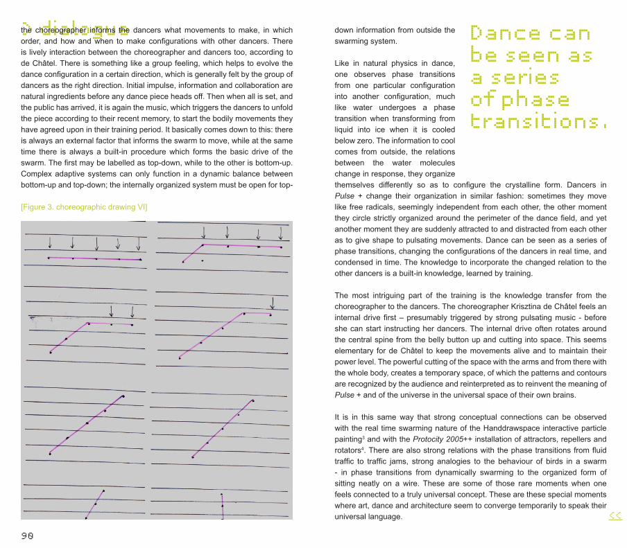
90
> dialoguethe choreographer informs the dancers what movements to make, in which order, and how and when to make configurations with other dancers. There is lively interaction between the choreographer and dancers too, according to de Châtel. There is something like a group feeling, which helps to evolve the dance configuration in a certain direction, which is generally felt by the group of dancers as the right direction. Initial impulse, information and collaboration are natural ingredients before any dance piece heads off. Then when all is set, and the public has arrived, it is again the music, which triggers the dancers to unfold the piece according to their recent memory, to start the bodily movements they have agreed upon in their training period. It basically comes down to this: there is always an external factor that informs the swarm to move, while at the same time there is always a built-in procedure which forms the basic drive of the swarm. The first may be labelled as top-down, while to the other is bottom-up. Complex adaptive systems can only function in a dynamic balance between bottom-up and top-down; the internally organized system must be open for top-
[Figure 3. choreographic drawing VI]
down information from outside the swarming system.
Like in natural physics in dance, one observes phase transitions from one particular configuration into another configuration, much like water undergoes a phase transition when transforming from liquid into ice when it is cooled below zero. The information to cool comes from outside, the relations between the water molecules change in response, they organize
<<___
Dance can be seen as a series of phase transitions.
themselves differently so as to configure the crystalline form. Dancers in Pulse + change their organization in similar fashion: sometimes they move like free radicals, seemingly independent from each other, the other moment they circle strictly organized around the perimeter of the dance field, and yet another moment they are suddenly attracted to and distracted from each other as to give shape to pulsating movements. Dance can be seen as a series of phase transitions, changing the configurations of the dancers in real time, and condensed in time. The knowledge to incorporate the changed relation to the other dancers is a built-in knowledge, learned by training.
The most intriguing part of the training is the knowledge transfer from the choreographer to the dancers. The choreographer Krisztina de Châtel feels an internal drive first – presumably triggered by strong pulsating music - before she can start instructing her dancers. The internal drive often rotates around the central spine from the belly button up and cutting into space. This seems elementary for de Châtel to keep the movements alive and to maintain their power level. The powerful cutting of the space with the arms and from there with the whole body, creates a temporary space, of which the patterns and contours are recognized by the audience and reinterpreted as to reinvent the meaning of Pulse + and of the universe in the universal space of their own brains.
It is in this same way that strong conceptual connections can be observed with the real time swarming nature of the Handdrawspace interactive particle painting3 and with the Protocity 2005++ installation of attractors, repellers and rotators4. There are also strong relations with the phase transitions from fluid traffic to traffic jams, strong analogies to the behaviour of birds in a swarm - in phase transitions from dynamically swarming to the organized form of sitting neatly on a wire. These are some of those rare moments when one feels connected to a truly universal concept. These are these special moments where art, dance and architecture seem to converge temporarily to speak their universal language.
92
> linked
Other institutes that are working on interaction
Harvard GSD, USA | Technology and Design (MSc) www.gsd.harvard.edu/academic/mdes/technology_design.htmProgram description: This study area positions technology as an enabler of design and as a tool to broaden design inquiry, and highlights emerging fields and innovations impacting design research and the practice of design. Five specific areas of design technology and innovation are covered in these courses.Course setting & description: - Advanced Materials and Systems;- Design Computation;- Environmental Technology;- Product Development;- Digital Design and Manufacturing.
Architecture Association, UK | Emergent Technology and Design (MSc) www.aaschool.ac.uk/graduate/et.shtm and also www.emtechlog.netProgram description: The Emergent Technologies + Design programme is focused upon the relationship of new technologies to design. It is
open to graduates in architecture and engineering who are interested in architectural design that proceeds from innovative technologies, and who wish to develop design research skills in the context of new production paradigms. The programme offers MA and MArch degrees, and is structured in two phases.Course setting & description: - Emergence and Design;- Design and Technology;- Core Studio.
University of Pennsylvania, USA | NLSO (MSc) www.nso.penndesign.netProgram description: The NLSO, Non-Linear Systems Organization, is directed by renowned designer Cecil Balmond of Arup, to explore how architecture can learn from mathematics and the sciences-non-linear, algorithmic and complex-in the design of material structures across an open-ended range of scales and materials.
Bartlett School of Architecture, UK | Adaptive Architecture and Computation (MSc) www.bartlett.ucl.ac.uk/graduate/programmes/msc_be/aac_overview.htm
_______ Program description: The MSc Adaptive Architecture and Computation replaces the MSc Virtual Environments that Bartlett taught MSc in the field of digital design. It draws on the unique multidisciplinary milieu at the Bartlett School of Graduate Studies to bring together designers and programmers in the pursuit of enhanced architectural product and process.Course setting & description: - Digital Space and Society;- Computing for Emergent Architecture 1 & 2;- Generative Space, Form and Behaviour.
Columbia GSAPP, USA | Algorithmic Morphology (MSc) www.arch.columbia.edu/gsap/65244///?data=true!work!current_coursework.php?semester=2006-09-01!65244Program description: In tandem with the development of the digital computer, and often feeding off the potential offered through advances in computational speed, has been the development of axiomatic theories of biological development. A similar relationship between ideas of rule-based generative morphology and the evolution of computational methods can be seen in architectural practices. As the computer was introduced to the field of architecture as a design tool, the idea of a rule-based architectural strategy was explored at length through the design science work of Christopher Alexander, Phillip Steadman, Lionel March and William Mitchell.Course setting & description:- Geometric and Positioning System;
- Intelligence and Awareness;- Repetition: Iteration;- Repetition: Recursion.
MIT, USA | Computation Group (BSc, MSc, PhD) http://architecture.mit.edu/computation.htmlProgram description: Students centred in Computation take subjects and do research in theory and applications of computation and computer technology including computer graphics, digital modelling and rendering, generative design, CAD/CAM and rapid prototyping technologies, remote collaborative design, and the design process. Past students have also taken design studios and subjects in other discipline areas as a means to explore and develop their interests. SMArchS students are encouraged to define their own agendas in collaboration with their advisors.Course setting & description (MSc): - Introduction to Shape Grammars I;- Geometric Modelling;- Inquiry into Computation & Design.Course setting and description (BSc):- Computational Design I: Theory & Applications.Course setting and description (PhD):- Advanced Projects in Digital Media;- Proseminar in Computation;- PhD Forum in Computation;- Workshop in Computation - Design Without Boundaries;- Workshop in Computation-Design Explorers.
MIT, USA | Digital Design Fabrication Group (BSc, MSc) http://ddf.mit.edu/courses/index.htmlProgram description: Students >>___
94
learn various aspects of advanced computing from curved surface modelling to parametric modelling and computer programming. Advanced computational learning will lead to advanced applications in digital fabrication, ultimately leading to research topics and projects. Courses are focused on teaching design process in architecture using digital fabrication. Students use three to seven rapid prototyping and CAD CAM machines in any given course.Course Setting & Description (BSc, MSc): - Introduction to Design Computing;- Architectural Construction and Computation;- Digital Design Fabrication;- Digital Design Fabrication workshop.
Princeton University, USA | Computing and Imaging in Architecture (MSc) www.princeton.edu/~soa/Program description: This course will investigate how traditional modes of architectural representation are transformed by their displacement into the digital realm. Students will be introduced to fundamental moves, workflows and novel conceptual frameworks that are particular to digital practice. The platform for this seminar/workshop will be high-end digital modelling and animation software outputting to printers, plotters, laser cutters and CNC milling machines. Students will be asked to design and produce digitally based projects in ways unique to the specific technology. Lectures will focus on how working digitally influences our conception and interpretation of architecture.
ETH Zurich, Switzerland | CAAD (BSc, MSc) http://caad.arch.ethz.ch/RMIT, Melbourne | SIAL (MSc, BSc) www.sial.rmit.edu.au/Program description: The Spatial Information Architecture Laboratory (SIAL) is a facility for innovation in transdisciplinary design research and education. It embraces a broad range of investigative modes, involving both highly speculative and industry linked projects. SIAL is concerned with the integration of technical, theoretical and social concerns as part of its innovation agenda. High-end computing, modelling and communication tools associated with disparate disciplines are combined with traditional production techniques.Course setting and description (MSc):- Parametric Design;- Installation and Exhibitions;- Design and Computation;- Visualization of Complex SystemCourse setting and description (BSc):- Architectural Composition - Emergence and Vitality.
UCLA, USA | MSc, BScwww.aud.ucla.edu/Program description: UCLA is unique in providing both the intellectual and the technical resources needed to explore fully a wide range of issues in design and computation. The impact of the computer on the manufacturing process, on environmental and sustainable design, and on new techniques of visualization, from CAD to virtual reality, is our focus. Advanced courses explore special topics in computer-aided design,
software development, new modes of manufacture, the use of CNC (computer numerically controlled) milling in the development of building elements, and rapid prototyping. Our expertise in emerging digital technologies and our commitment to understanding these developments in relation to design has permitted UCLA to taking a leading role in defining the next phase of architecture’s technological evolution.Course setting and description (MSc): - Programming Computer Applications in Architecture and Urban Design;- User Interaction Techniques in Design.Course setting and description (BSc):- Digital Technology.
Parallel research and education groups
Blue-c (ETH)http://blue-c.ethz.ch/Blue-c is a new generation immersive projection and 3D video acquisition environment for virtual design and collaboration. It combines simultaneous acquisition of multiple live video streams with advanced 3D projection technology in a CAVE™-like environment, creating the impression of total immersion.
AI Lab (MIT)www.csail.mit.edu/index.phpThe primary mission of CSAIL is research in both computation and artificial intelligence, broadly construed. It is organized into four broad research areas:
- Systems covers all aspects of the building of both hardware and software computational systems;- Language, Learning, Vision and Graphics includes work on the sorts of things that all people manage to do effortlessly, both emulating those abilities, and simulating their appearance;- Physical, Biological and Social Systems might also be called ‘complete adaptive systems’, and it covers work from robotics, to molecular biology, to semantic systems, to computational models of politics; - Theory looks at the fundamental mathematical underpinnings of all aspects of computer science and artificial intelligence.
Media Lab (MIT)www.media.mit.eduThe Media Laboratory vision of ‘enabling technology for learning and expression by people and machines’ emphasizes technologies that improve the quality of life in the digital age, and that assist people in constructing their own tools for expression. The Lab advocates a process that includes both imagination and realization, criticism and reflection.
Media Lab (University of Art and Desisgn Helsinki)http://mlab.uiah.fi The mission of the Media Lab is to explore, discover and comprehend the new digital technology and its impact in society; to find and exploit the possibilities it opens to communication, interaction and expression; and to evaluate,
<<___
>>___
96
understand and deal with the challenges it poses to design and creative production.Algorithmic Architecture (Columbia)www.arch.columbia.edu/Instructor: Rory O’Neill and Cory ClarkeIn this seminar, students will explore rule-based systems for generating architectural form, designing ‘genetic material’ that the computer can process to create new architectural morphologies. Using scripting languages available in 3d packages (i.e. Maya Embedded Language (MEL) and 3dMaxScript, Cinema4d COFFEE) students can go beyond the mouse, transcending the factory-set limitations of current 3D software. By working with code it is possible to create intelligent form using methods analogous to those through which intelligent life evolves: emergent behaviour and self-organizing systems.
SIAL (RMIT-Melbourne)www.sial.rmit.edu.au/The Spatial Information Architecture Laboratory (SIAL) is a facility for innovation in transdisciplinary design research and education. It embraces a broad range of investigative modes, involving both highly speculative and industry linked projects. SIAL is concerned with the integration of technical, theoretical and social concerns as part of its innovation agenda. High-end computing, modelling and communication tools associated with disparate disciplines are combined with traditional production techniques. Researchers are engaged in a wide variety of
projects that collaboratively disturb artificial distinctions between the physical and virtual, digital and analogue, scientific and artistic, instrumental and philosophical.
Wolfram Researchwww.wolfram.comFounded by Stephen Wolfram in 1987, Wolfram Research is one of the world’s most respected software companies - as well as a powerhouse of scientific and technical innovation. As pioneers in computational science and the computational paradigm, we have pursued a long-term vision to develop the science, technology, and tools to make computation an ever-more-potent force in today’s and tomorrow’s world.www.wolfram.com/products/mathematica/newin6/About the features of the newest version of Wolfram’s Mathematica 6.0, which is now called ‘global computing environment’.www.wolfram.com/products/mathematica/newin6/content/DynamicInteractivity/About new real-time interaction.www.wolfram.com/products/mathematica/newin6/content/LanguageForDataIntegration/About data integration language, dynamic graphical input, built-in game-pad and human interface device support and 3D printing and scanning support.www.wolfram.com/products/player/About a free Mathematica Player.
More links
www.house.propositions.org.ukThe Reconfigurable House is an
<<___
environment constructed from thousands of low-tech components that can be ‘rewired’ by visitors. The project is a critique of ubiquitous computing ‘smart homes’, which are based on the idea that technology should be invisible to prevent DIY.
www.haque.co.ukHaque Design + Research specializes in the design and research of interactive architecture systems. Architecture is no longer considered something static and immutable; instead it is seen as dynamic, responsive and conversant. Their projects explore some of this territory.
www.we-make-money-not-art.comIt shows the intersection between art, design and technology.
www.socialfiction.orgThis site is dedicated to continue the exploration of Psychogeography through software. They list their interest through the following keywords: cartographic sadism, gabber avant-gardism, experimental knowledge, DIY urbanism, autonomous spacetravel, gymnosophistic delight, disco socialism, peripatetic hedonism.
www.interactivearchitecture.org (www.ruairiglynn.co.uk and www.bartlett.ucl.ac.uk: Bartlett School of Architecture)The Interactive Architecture website explores emerging practices within architecture that aim to merge digital technologies & virtual spaces with tangible and physical spatial experiences. Instead of defining
a fixed architectural product, it is architecture in constant flux best-suited to protyping and semi-perminant installations. It is maintained by Ruairi Glynn.
www.visualcomplexity.com/This site intends to be a unified resource space for anyone interested in the visualization of complex networks. The project’s main goal is to leverage a critical understanding of different visualization methods, across a series of disciplines, as diverse as biology, social networks or the World Wide Web.
http://house.propositions.org.ukThis site is about Reconfigurable House, Usman Haque and Adam Somlai-Fischer. The Reconfigurable House is an environment constructed from thousands of low tech components that can be ‘rewired’ by visitors. The project is a critique of ubiquitous computing ‘smart homes’, which are based on the idea that technology should be invisible to prevent DIY. In contrast to such homes, which are not able to adapt structurally over time, the many sensors and actuators of Reconfigurable House can be reconnected endlessly as people change their minds so that the House can take on completely new behaviours.
www.lab-au.com/v1/dexia//2006/touch/home.phpTouch is a project by the Belgian digital design and art lab, LAb [au], Laboratory for Architecture and Urbanism. The project turns the 4200 windows of the 145m high Dexia >>___
98
Tower in Brussels into an immense display. Instead of considering this infrastructure as a flat screen (surface) displaying pre-rendered video loops, the project is working on the architectural characteristics of the tower and its urban context. The characteristics of the building - orientation, volume, scale - are used as parameters to set up a spatial, temporal and luminous concept, which moreover allows people to directly interact with the tower. At the bottom of the tower a station is mounted where people can interact either individually or collectively with the visual and luminous display through a multi-touch screen. Static (touch) as dynamic input (gesture) is recognized to generate an elementary graphical language of points, lines and surfaces combined with physical behaviours (growth, weight) taking a monochromatic colour palette (background) combined with black and white (graphical elements).
www.urbanxml.com‘Tracking the Selfless Blogging Revolution’: online datafeeds for the ubiquitously networked society...
http://rhizome.orgThis is an online platform for the global new media art community. It supports the creation, presentation, discussion and preservation of contemporary art that uses new technologies in significant ways. http://futurefeeder.comThis website collects articles and projects vaguely related to the future of technology, design and architecture. It provides rich and
up-to-date information in many fields that is interesting for architects from the new generation, such as AI, biology, Internet, computing theory, fabrication technology and programming. In its subcategory ‘Quantum Issues in Architecture’, some interesting links are listed. This site also publishes the Online Journal of Architecture and Computation, which collects high quality scientific papers concerning the above-mentioned topics. www.complexification.net/An open source website for processing, this site exhibits inspiring computer generated graphics. Holding a Bachelor of Science degree in computer science, the author, Jared Tarbell shows his talent in graphic and creativity in visualizing theories from computer science. The topics covered in his work includes: Lorenz Attractor (in his work of Deep Lorenz), Swarm behaviour (in Happy Place), Genetic algorithm (in Bone Piles and Offspring), Fractal geometry (in Trema Disk), Network and Connections (in Node Garden series). etc. Besides, in his work of City Traveller and Cubic Attractor, the trajectories of a series of moving cities and their inhabitants are traced and overlapped, which not only provides an interesting graphical product, but also provides a provoking simulation of one possibility for the future. www.theverymany.net/This site is a territory for design and research via Rhino. Marc Fornes, the founder of the site, scripts his own tools in Rhino, which help to generate
precise 3D parametric models aimed at architecture design. The author tested many interesting topics in his homemade tools, such as the game of life, surface tessellation, voronoi objects, fractal geometry, complexity, vector field. Those divergent topics made his works more than a pure form-finding process, but a deep exploration into the possibilities provided by scripting technique for architecture design. The author also shares some tips and scripts on this site. www.mediaarchitecture.orgThis site is dealing with the implications of new display technology on architecture and city planning. It collects outstanding media facade projects and tracks new technological developments especially in the field of LED. The contributing editors and authors are experts in the areas of architecture, architecture theory, media design, and LED displays.
www.ds.arch.tue.nl/GeneralThis site is the home of the Design Systems group of the Technical University of Eindhoven, the Netherlands, directed by Prof. Bauke de Vries. This group has a lot of experience in Virtual Reality and developed the DeskCave. The website has many links to conferences in the domain of CAD.
www.theswapmeet-forum.com/This is a forum for finding answers to questions concerning Virtools. <<___
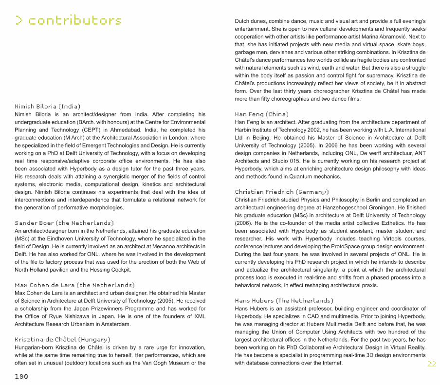
100
Nimish Biloria (India)Nimish Biloria is an architect/designer from India. After completing his undergraduate education (BArch. with honours) at the Centre for Environmental Planning and Technology (CEPT) in Ahmedabad, India, he completed his graduate education (M Arch) at the Architectural Association in London, where he specialized in the field of Emergent Technologies and Design. He is currently working on a PhD at Delft University of Technology, with a focus on developing real time responsive/adaptive corporate office environments. He has also been associated with Hyperbody as a design tutor for the past three years. His research deals with attaining a synergistic merger of the fields of control systems, electronic media, computational design, kinetics and architectural design. Nimish Biloria continues his experiments that deal with the idea of interconnections and interdependence that formulate a relational network for the generation of performative morphologies.
Sander Boer (the Netherlands)An architect/designer born in the Netherlands, attained his graduate education (MSc) at the Eindhoven University of Technology, where he specialized in the field of Design. He is currently involved as an architect at Mecanoo architects in Delft. He has also worked for ONL. where he was involved in the development of the file to factory process that was used for the erection of both the Web of North Holland pavilion and the Hessing Cockpit.
Max Cohen de Lara (the Netherlands) Max Cohen de Lara is an architect and urban designer. He obtained his Master of Science in Architecture at Delft University of Technology (2005). He received a scholarship from the Japan Prizewinners Programme and has worked for the Office of Ryue Nishizawa in Japan. He is one of the founders of XML Architecture Research Urbanism in Amsterdam.
Krisztina de Châtel (Hungary)Hungarian-born Krisztina de Châtel is driven by a rare urge for innovation, while at the same time remaining true to herself. Her performances, which are often set in unusual (outdoor) locations such as the Van Gogh Museum or the
> contributors Dutch dunes, combine dance, music and visual art and provide a full evening’s entertainment. She is open to new cultural developments and frequently seeks cooperation with other artists like performance artist Marina Abramović. Next to that, she has initiated projects with new media and virtual space, skate boys, garbage men, dervishes and various other striking combinations. In Krisztina de Châtel’s dance performances two worlds collide as fragile bodies are confronted with natural elements such as wind, earth and water. But there is also a struggle within the body itself as passion and control fight for supremacy. Krisztina de Châtel’s productions increasingly reflect her views of society, be it in abstract form. Over the last thirty years choreographer Krisztina de Châtel has made more than fifty choreographies and two dance films.
Han Feng (China)Han Feng is an architect. After graduating from the architecture department of Harbin Institute of Technology 2002, he has been working with L.A. International Ltd in Beijing. He obtained his Master of Science in Architecture at Delft University of Technology (2005). In 2006 he has been working with several design companies in Netherlands, including ONL, De werff architectuur, ANT Architects and Studio 015. He is currently working on his research project at Hyperbody, which aims at enriching architecture design philosophy with ideas and methods found in Quantum mechanics.
Christian Friedrich (Germany)Christian Friedrich studied Physics and Philosophy in Berlin and completed an architectural engineering degree at Hanzehogeschool Groningen. He finished his graduate education (MSc) in architecture at Delft University of Technology (2006). He is the co-founder of the media artist collective Ezthetics. He has been associated with Hyperbody as student assistant, master student and researcher. His work with Hyperbody includes teaching Virtools courses, conference lectures and developing the ProtoSpace group design environment. During the last four years, he was involved in several projects of ONL. He is currently developing his PhD research project in which he intends to describe and actualize the architectural singularity: a point at which the architectural process loop is executed in real-time and shifts from a phased process into a behavioral network, in effect reshaping architectural praxis.
Hans Hubers (The Netherlands)Hans Hubers is an assistant professor, building engineer and coordinator of Hyperbody. He specializes in CAD and multimedia. Prior to joining Hyperbody, he was managing director at Hubers Multimedia Delft and before that, he was managing the Union of Computer Using Architects with two hundred of the largest architectural offices in the Netherlands. For the past two years, he has been working on his PhD Collaborative Architectural Design in Virtual Reality. He has become a specialist in programming real-time 3D design environments with database connections over the Internet. >>___

102
Tomasz Jaskiewicz (Poland)Tomas Jaskiewicz is an architect and urban designer. He graduated as an architect, with a specialization in urbanism, at the Technical University of Gdansk. He obtained his Master of Science in Architecture at Delft University of Technology (2005). His working experience includes projects with bAR architects and Prof. Jacek Krenz design studio. Since 2001, he has been in close cooperation with diaade, and ar+di, a dialogic design research lab in Gdansk. In 2003, he joined Hyperbody, first as a student assistant, and eventually as an associate researcher. In January 2007, he started a PhD thesis, which he has titled ‘Complex Systems in Interactive Architecture’. Since 2005, he has been working as an architect and project manager with ONL [Oosterhuis_Lénárd].
Ilona Lénárd (Hungary)Ilona Lénárd is the co-director of ONL[Oosterhuis_Lénárd] design studio, an innovative design studio, internationally known for integrating digital techniques into the design process and in the production process [artificial intuition, mass-customization, file to factory process]. In 2005 the ONLNUT (Nanjijng University of Technology) joint office was founded, Nanjijng, China. Ilona Lénárd is a certified actress educated in Budapest and a certified sculptor trained at the Willem de Kooning Academy in Rotterdam.
Kas Oosterhuis (The Netherlands)Born in 1951 in Amersfoort Kas Oosterhuis studied architecture at the Delft University of Technology. In 1987-1988 he taught as unit master at the AA in London and worked/lived one year in the former studio of Theo van Doesburg in Paris together with visual artist Ilona Lénárd. Their design studio is in 2004 renamed into ONL [Oosterhuis_Lénárd. As from 2007 Oosterhuis is a registered architect in Hungary, executing as General Designer the CET project. Since 2000, Oosterhuis has been appointed professor of digital design methods at the Delft University of Technology and he is currently leading a staff of twenty researchers at Hyperbody, the knowledge centre for Non-Standard and Interactive Architecture. Oosterhuis is Director of the ProtoSpace Laboratory in the iWEB pavilion, located in front of the Faculty of Architecture. He is member of the Dutch Building Information Council and has been a Member of the Board of Witte de With Center of Contemporary Art in Rotterdam and of the VCA (Computerusers Architectural Offices) until 1989. He has been the co-founder of the Attila Foundation, responsible for the groundbreaking Sculpture City event in 1994 and the ParaSite weblounge in 1996. He has lectured worldwide at numerous universities, academies and international conferences since 1990. Oosterhuis has initiated two GameSetandMatch (GSM) conferences at the Delft University of Technology on the subjects’ multiplayer game design, file to factory design and build methods and open source communication in the evolutionary development of the 3D reference model. Award winning building designs include the Saltwaterpavilion at Neeltje Jans (Gold Award 1997 for innovative recreational projects, Zeeuwse Architectuurprijs 1998, nomination
Mies van der Rohe Award 1998), the Garbagetransferstation Elhorst/Vloedbelt in Zenderen (Business Week/Architectural Record Award 1998, OCE-BNA Award for Industrial Architecture 1996, Aluminium Design Award 1997) and the Hessing Cockpit in Acoustic Barrier in Utrecht (National Steel Award 2006, Glass Award 2006, Dutch Design Award for Public Space 2006, nomination Mies van der Rohe Award 2008, nomination Golden Pyramid 2006).
Marthijn Pool (the Netherlands)Marthijn Pool has received his Master of Science in Architecture at Delft University of Technology (2005). On the basis of programming and parametric modelling, a design tool was developed to propose a synthesis on the integration of Infrastructure and Architecture on a high-density integration of static and dynamic space. After studying he is tutoring Master students at the University of Delft. He has been working at ONL from begin 2006. On the architectural level his focus lies in the field of building 3-D parametric models in early design stages. As an architect/ engineer he has contributed to the realization of F-Zuid Housing project, iWeb Reasearch&DesignLab and he has been the responsible project architect for the Berlin Landscape Lounge, ONL-Philips Transitions II and is currently leading the Kaiserslautern Landmark.
Dieter Vandoren (Belgium)Dieter Vandoren is an interactive technology developer, media artist and musician. He has a Digital Communication degree from the Hogeschool Utrecht. He held a researcher position at Hyperbody and was involved with ONL as developer. He is currently pursuing his media arts work (interactive installations and performances), music projects, teaching and the direction of cultural centre De Fabriek in Rotterdam.
Guus Westgeest (The Netherlands)Guus Westgeest studied at the Technical High School Bouwkunde Haarlem and Delft University of Technology at the Faculty of Architecture. In 1974 he started his own office Architectenbureau Guus Westgeest bv. Now he works as assistant professor at the Faculty of Architecture, Delft University of Technology.
Xin Xia (China)Xin Xia studied at the Nanjing Arts Institute for Decorative Art Design. In 2000, she moved to the Netherlands for postgraduate studies, where she completed master’s degrees at both the Dutch Art Institute (Visual Art) and Amsterdam University (Film and Television Studies). Her practice was mainly in painting and installation. Her research was focused on Cognitive Film Theory and Contemporary Video Art Installations. She was involved with ONL [Oosterhuis_Lénárd] on art projects and publicity. In 2005 she joined Hyperbody as a researcher and she is working on book editing, publicity and events organizing. <<___

104
This publication has been made possible with the generous support of Delft University of Technology, Faculty of Architecture, the Netherlands.
Organization and supervisionHyperbodyDirector Prof. Ir. Kas OosterhuisFaculty of ArchitectureDelft University of Technologywww.hyperbody.bk.tudelft.nl
EditorsKas Oosterhuis, Xin Xia
Copy editing and proofreadingEleonoor Jap Sam, Christopher Nicolson
Image editingXin Xia
Graphic design conceptDanielle van Steenbergen, Rotterdam
DTP, graphic design Xin Xia i.c.w. Danielle van Steenbergen
Printing and bindingXXXXXXXX
Publisherepisode publishers, Rotterdamwww.episode-publishers.nl
© 2008 Delft University of Technology, the authors,
the photographers and episode publishers
ISBN 978-90-5973-062-5