
ABSTRACTION LEVEL TAXONOMY OF PROGRAMMING LANGUAGE FRAMEWORKS
Upload
khangminh22Category
view
1download
0
Interactive 3D Face Stylization Using Sculptural Abstraction
Jan Jachnik1 Dan B Goldman2 Linjie Luo2 Andrew J. Davison1
1Imperial College London2Adobe Research
(a) Input mesh (b) Input segmented (c) Abstracted mesh (d) Deformed abstracted mesh (e) Output mesh
Figure 1: We transform a scanned input mesh into a stylized output emphasizing anatomy and characteristic features. The input is segmentedinto nearly planar regions via alignment with a template model. The angular definition of the segmented mesh is enhanced in a highlycontrollable optimization which generates smooth full resolution output interactively.
Abstract
Sculptors often deviate from geometric accuracy in order to en-hance the appearance of their sculpture. These subtle stylizationsmay emphasize anatomy, draw the viewer’s focus to characteristicfeatures of the subject, or symbolize textures that might not be ac-curately reproduced in a particular sculptural medium, while stillretaining fidelity to the unique proportions of an individual. In thiswork we demonstrate an interactive system for enhancing face ge-ometry using a class of stylizations based on visual decompositioninto abstract semantic regions, which we call sculptural abstrac-tion. We propose an interactive two-scale optimization frameworkfor stylization based on sculptural abstraction, allowing real-timeadjustment of both global and local parameters. We demonstratethis system’s effectiveness in enhancing physical 3D prints of scansfrom various sources.
1 Introduction
The technology required for a “3D fax” that can scan the shapesof household objects of various sizes, transmit them electronically,and reprint facsimiles of those objects at a distant location, is nowavailable at a price feasible for many households. In addition to util-itarian uses such as printing missing or broken parts for householdobjects, 3D scanning and printing tools are also being employedfor more personal items such as figurines of family and friends1.Although the market for such tools is nascent, we suggest that giventhe appropriate tools and low enough pricing in the future, we mightbe just as likely to send our relatives a 3D printed figure of a familyvacation as we would a framed photograph: Just as photographydemocratized 2D imagery by unchaining it from the painter’s hand,3D scanning and printing may democratize 3D representations bydecoupling them from the sculptor’s hand.
Thus far, research on 3D scanning and printing has rightly focusedon geometric accuracy. However, 3D printed human figures of-
1 e.g., www.shapify.me, www.shapeways.com/tutorials/shapeme,www.fablitec.com
ten appear lifeless, particularly when generated with commodityscanning and printing. We propose that creative applications ofthese technologies require further exploration of sculptural styl-ization, which we define to be when a 3D model deviates fromgeometric accuracy in a manner analogous in many ways to thatof non-photorealistic rendering for 2D imagery. Sculptural styliza-tion could be either for purely aesthetic purposes; or to improvethe recognizability of the subject by emphasizing characteristic fea-tures [Winnemöller et al. 2006]; or to fit the limitations or require-ments of a given sculpting medium; or simply to imitate historicallypopular styles of sculpture. Well known sculptors consistently ex-aggerate away from geometric accuracy in order to achieve somecombination of these aims (a preliminary analysis of how sculptedbusts deviate from real human geometry is provided in Section 3.1).
As described in subsequent sections, one important class of styliza-tions first decomposes a model into masses, planes or other compo-nents. These decompositions could be purely geometric, but areoften based on higher-level object semantics or a knowledge ofunderlying anatomy. We use the term sculptural abstractions todescribe these semantically-based decompositions, using the wordabstraction in the sense of isolating essential qualities.
In this paper we propose an interactive approach to stylization ofhuman faces, founded on a specific sculptural abstraction used byartists called the planes of the head — regions of the surface of theface which, although not literally planar, may be grouped togetherby geometric consistency or separated by underlying anatomy. Wegeneralize this concept to scans of other objects beyond simplyfaces, and refer to the general concept as sculptor’s planes. Ourmethod’s stylizations emphasize the contrast between these formsby accentuating the angles between them and making the regionswithin them more planar. We imagine an expert sculptor whofirst studies his subject and identifies these sculptor’s planes, thenproduces a rough, low-detail model in which the surface anglesbetween planes are exaggerated and deviations within planes aresmoothed, and finally introduces fine details of the surface.
Our system, using a 3D scan of the subject as its input, supports
arX
iv:1
502.
0195
4v1
[cs
.GR
] 6
Feb
201
5

an amateur digital sculptor in several stages: First, the sculptor’splanes are automatically identified — either by aligning a scan toa generic, pre-segmented head model, or by automatic geometryanalysis; and the scan is then simplified to an abstracted mesh us-ing the given segmentation. Second, we construct and optimizean energy function to balance the exaggeration of angles of thisabstracted mesh with preservation of the original form and somekey individual facial characteristics. The sculptor can adjust boththe global scale and local scale of exaggeration as well as fidelityto the facial characteristics. Finally, we map the resulting deforma-tion back to the original full resolution scan, and the sculptor canlocally adjust the the amount of detail to include from the originalscan, as well as the smoothness between sculptors planes. The lasttwo stages are performed continuously at interactive frame rates,providing detailed user control of both global and local parameters.
Our contributions include an algorithmic analysis of stylizationbased on sculptural abstraction, and an interactive system to em-ulate these techniques under real-time user control of intuitive pa-rameters. We show that our approach permits a wide array of bothsubtle and exaggerated stylizations on both faces and other mod-els, and illustrate qualitative improvement over previous geometrydeformations applied to faces.
2 Related Work
The non-photorealistic rendering literature features a long historyof transforming photographs and 3D models into artistic depic-tions. In particular, Gao et al. [2013] used an abstracted modelsimilar to the planes of the head for 2D stylization and exaggera-tion. Winnemoller et al. [2006] demonstrated that certain types ofabstraction improve human memory tasks, including facial recog-nition and scene recall. We hypothesize that sculptural abstractioncan play a similar role for 3D shape. Furthermore, many papersin NPR explore the depiction of 3D scenes to improve shape un-derstanding. Hertzmann and Zorin developed a hatching techniqueto emphasize aspects of curved surfaces that are otherwise hard toperceive [Hertzmann and Zorin 2000]. Cole et al. [2008] analyzedwhere people draw lines when representing 3D surfaces, whichmight be similar to the features that sculptors exaggerate.
We are unaware of previous work that defines the broader notionof sculptural abstraction in 3D geometry. However, the idea of3D collage [Gal et al. 2007] seems to fall within this scope, as itattempts to represent the gestalt of a given 3D shape by aggregatingseveral smaller 3D primitives. Bhat et al. [2004] also applied amethod similar to image analogies [Hertzmann et al. 2001] in thecontext of 3D geometry. This method applied a learned geomet-ric texture to an entire model rather than local deformations basedon existing geometry, and thus could be used as a complement toour sculptural abstraction in order to reproduce the surface textureimposed by various real-world sculpting tools.
Other existing methods for automatic non-metric mesh enhance-ment take approaches which have predictable and global effects.Blanz and Vetter [1999] fitted a parametric 3D model built from alarge family of faces to a new scan, and could create caricatures byshifting the parameters away from the mean face. This results ina global linear deformation, in contrast to our nonlinear template-driven deformation. PriMo [Botsch et al. 2006] is another defor-mation strategy that has been used to demonstrate caricature, bymodeling polygons as prisms of finite thickness and constructingan energy function to increase angles between them. This resem-bles our exaggeration energy term, but although our system can beused for stylizations such as caricature — e.g.exaggeration of keyindividual features — we characterize our goal of abstraction assharpening visual contrast and form without modifying key indi-
Figure 2: Left: A scan acquired using KinectFusion. Right: Thesame scan after sculpting by Gio Nakpil. Note exaggerated featuressuch as cheekbones, temples, jawline, chin, and sides of the nose.
vidual features. This distinction is explored in detail in Section 4.2,in which we propose Lanteri constraints for maintaining fidelity tothese features.
Various signal processing techniques exist for meshes which canexaggerate features. The simplest is the 3D equivalent of theunsharp mask, where a 3D shape is enhanced by smoothing itsnormals and then exaggerating their angles in the opposite direc-tion [Yagou et al. 2003]. Eigensatz et al. [2008] operate in thecurvature domain, but do not process meshes in real time. Morerecently, anisotropic smoothing and exaggeration have been imple-mented in graphics hardware [Chuang and Kazhdan 2011]. Al-though these methods can produce some results similar to ours, theydon’t offer simple local control.
Some previous works have explored automated abstraction ofshapes [Mehra et al. 2009] and shape collections [Yumer and Kara2012] into semantic groupings, though they do not demonstratestylizations based on these groupings. Similarly, Lee et al. [2000]decomposed geometry into a base mesh plus displacements not un-like our two-scale decomposition, but their model is not suitable fordeformation because it associates each high-resolution vertex withonly one base polygon.
3 Background
In order to learn what techniques sculptors use in their abstrac-tion, we interviewed two accomplished professionals: Gio Nakpil, asculptor who works both in physical and digital sculpture, includingwork for Industrial Light and Magic and Valve; and Mike Magrath,an instructor at Seattle’s Gage Academy of Art. Although manytechniques are particular to specific styles, we narrowed our focusto abstraction techniques for human busts that span multiple styles.
Two common points of reference between the sculptors emerged:First, both sculptors mentally and visually decompose a subjectinto component masses or forms at a variety of scales — startingfrom larger groupings such as the forehead, and working down tosmaller details like the sides of the nose and the folds of the eyelid.And second, in the case of human faces this decomposition is oftendescribed in terms of planes of the head, as defined in Section 1.
Nakpil emphasized the role of highlight and shadow in sculptingtechnique2, noting that sculptors view their work under a range oflighting conditions and from many angles to understand and controlthe shapes and relationships of those highlights and shadows. Since
2 In this context, highlight and shadow refer to the broad artistic definitionof regions brighter or darker than the mean, not only specular highlightsand cast shadows.
2

Figure 3: Left: Examples of planar decompositions in painting andsculpture, c©John Asaro 1976, excerpted with permission. Right: Avariation of the Planes of the Head entitled Memorized, intendedfor student memorization.
sculptures are typically lit from above, sculptors may tilt surfacestoward the horizontal, exaggerating the contrast between highlightsand shadows. Figure 2 shows a scan we provided to Nakpil along-side his sculptural interpretation using ZBrush.
Magrath made special note of the exaggeration of “soft” and “hard”forms. This nomenclature refers to the distinction between angu-lar regions with rapidly alternating high and low curvature (e.g.,the bridge of a nose) versus rounded, uniform medium-curvatureregions (e.g., the forehead). He characterized his abstraction tech-nique as “making the hard forms harder, and the soft forms softer.”
The notion of planes of the head permeates literature about sculpt-ing, and dates back at least to the turn of the 19th century, when thesculptor Edouard Lanteri (whom Rodin described as “Dear Mas-ter” [Lanteri 1911]) wrote a seminal textbook. Although much ofhis work describes technical methods for ensuring metric accuracy,he also suggests a methodical approach to exaggerating these planesand their junctions using side lighting to reveal them more clearlyto the sculptor:
When these divisions of form have been obtained in theirproper drawing by studying each separately, the work mayappear a little hard. Then it becomes necessary to work bycolour — that is to say, by the comparative values of the half-tints, in simplifying or accentuating the surfaces or planeswhich divide these forms. [Lanteri 1985]
The concept of planes of the head was further formalized in the late20th century, most notably by John Asaro, an instructor at Art Cen-ter College in Pasadena, California [Asaro 1976]. Asaro hypoth-esized that decompositions of facial form into masses and planeshave been used by painters and sculptors since antiquity, and pro-posed planar decompositions for works by Cassatt, Rodin, Degas,Rubens, Vermeer, Michelangelo and many others. As an aid to stu-dents of sculpting and painting, Asaro developed a set of canonicalbusts which exaggerate the planes to their logical extreme, reducinga human head to a nearly polygonal object (see Figure 3).
While sculptors use these planes to exaggerate certain forms,Lanteri’s writing also makes it clear that certain aspects of humananatomy and individual facial characteristics are perceptually rel-evant, and must not be perturbed by these stylizations. He writesvoluminously about using calipers to ensure that certain distances,ratios, and angles are preserved in a sculpture of a given model.Here is one such passage:
From the tip of the nose measure the distance to the mostprojecting part of the chin, i.e. the subcutaneous mentaleminence... To make sure of the correctness of the previ-ous measure, you now take the distance from the ear to themental eminence (see Fig. 40) in your calipers, and if thismeasure, taken from both ears of course, coincides with thepreviously fixed point on the chin, your measure runs a fairchance of being correct. If it is not, you have to... retakeboth measures, until they agree. [Lanteri 1985]
Additional measurements proposed by Lanteri appear in AppendixA. We make use of these in our algorithm to preserve the facialcharacteristics of the subjects during stylization.
We hypothesize that the planes of the head perform a similar func-tion to lines in 2D illustration: Artists abstract detail that isn’t im-portant and emphasize features that do matter for recognition andunderstandability. Although we may not yet know exactly whatfeatures are perceived as important for emphasis in 3D, we chooseto follow methods employed by professional sculptors because it isreasonable to assume they relate to perceptual importance.
Thus the challenge of sculptural abstraction is to enhance or exag-gerate visual contrast between sculptor’s planes, while simultane-ously preserving certain critical global geometric relationships. Al-though it may seem these goals are fundamentally incompatible, inthe sections that follow we demonstrate a system that accomplishesthis automatically, interactively and under flexible user control.
3.1 Analysis of scans of humans vs. sculptures
We observed informally that, in spite of some sculptors’ focus ongeometric fidelity, some features in realistic classical and modernsculptures appear exaggerated. This is hard to detect when compar-ing people directly to sculptures, because their reflectance qualitiesdiffer so drastically. However, these differences become more ap-parent when people and sculptures are scanned. Perhaps most crit-ically for our application, 3D prints of scanned faces often appearflat and lifeless.
An ideal analysis of sculptural stylization would require extensivedata collection of existing sculptures and comparisons to humanscans of the individual models being sculpted. In the absenceof such a dataset, we performed an informal comparison of thedepth of the eye sockets between six scans of humans – four fromKinectFusion [Newcombe et al. 2011] and two using the methodof Beeler et al. [2010] – and five scans of sculptures – three ofRodin’s “Burghers of Calais”3, and two busts from the MIT CSAIL3D Model Database4. First, a number of feature points on the mod-els were identified and manually labeled. Then, we measured thedepth of the eye sockets using four separate scale-invariant mea-sures: Measure A takes the distance from the midpoint of the innercorners of the eye to the plane formed by the midpoint of each eye-brow and the tip of the chin, normalized using the distance betweenthe points at the base of the ears. Measure B is the same as measureA, but using the outer corners of the eyes. Measure C takes thedistance from the midpoint of the inner corners of the eye to theplane formed by the saddle point at the bridge of the nose and thecorners of the mouth, also normalized using the distance betweenthe ears. Measure D is the same as C, but using the outer corners ofthe eyes. Each measure was aggregated across human and sculptedscans using both the mean and the median. A summary of the re-sults can be found in Table 1.
3 http://www.stanford.edu/~qianyizh/projects/scenedata.
html4 http://people.csail.mit.edu/tmertens/textransfer/data/
3

A B C D
MeanHuman 0.069 0.134 0.094 0.157Sculpt 0.112 0.177 0.131 0.193% Increase 63.1 32.5 39.3 23.1
MedianHuman 0.065 0.127 0.091 0.156Sculpt 0.091 0.169 0.127 0.183% Increase 40.2 33.5 40.4 17.4
Table 1: Measures of the depth of the eye sockets on scans ofhumans vs. sculptures.
For each aggregate measure, the sculpted scans had significantlydeeper eye sockets than the human scans. Note that all fiducialpoints were identified by hand, the quality and resolution of thescans varies significantly, and the measures we propose are some-what ad hoc. Furthermore, the size of the sample is much too smallto draw concrete conclusions. Nonetheless we see a strong sugges-tion that sculptors such as Rodin routinely exaggerated features offacial anatomy such as the depth of eye sockets.
4 Approach
Our goal is to allow a user to interactively stylize an input facemodel guided by sculptural abstraction principles. Our system firstcomputes an abstracted mesh from the input face model. The ab-stracted mesh needs to convey both high-level abstract elements ofthe input mesh and semantically meaningful facial features. To thisend, we use a Planes of the Head model as our template to guideour abstracted mesh generation. The abstracted mesh serves asthe sculptural abstraction framework for the subsequent stylizationsteps, and is divided into meaningful regions corresponding to theplanes from the template model.
The subsequent sculptural stylization optimization and stylizationtransfer phases of our system run at real-time rates and are designedfor interactive use by a user in control of global and/or local pa-rameter settings. We stylize the abstracted mesh by minimizing anenergy function with several terms of various purposes: to exagger-ate angles between different regions; to enforce flatness within eachsegment; to regularize the stylization towards the original shape;and to enforce Lanteri constraints that preserve geometric measure-ments characteristic of a person’s identity. The transfer of thesestylizations back to the input mesh produces real-time full resolu-tion results for inspection and further adjustment. The amount ofsmoothing can be controlled here both globally and locally; and theinteractive display of the full resolution deformed mesh is crucialin permitting fine user control over subtle deformations.
4.1 Abstracted Mesh Generation
We first generate the abstracted mesh MC that captures locallymeaningful sculptural abstractions from the input mesh M . Forgeneral 3D models, we find that Variational Shape Approximation(VSA) [Cohen-Steiner et al. 2004] often derives plausible geomet-ric abstractions from the input mesh by grouping faces of similarnormals into contiguous regions. However for human faces, due toour heightened perceptions, VSA can cause noticeable artifacts be-cause it does not preserve semantically meaningful segmentationsand salient features such as eyes and lips.
Thus, we employ a semantically segmented human head templateto generate the abstracted meshes from human face models. Morespecifically, we use the Planes of the Head model (Figure 3) be-cause it takes into account both the principles of sculptural abstrac-tion and facial semantics. To acquire the 3D template, we scanneda Planes of the Head model using KinectFusion [Newcombe et al.2011] and manually segmented the model into sculptor’s planes
Figure 4: Planes of the Head: Memorized scan and segmentation.
(a) (b) (c)
Figure 5: The segmentation of the template model is transferred tothe input mesh using nonrigid alignment.
(shown with colored segments in Figure 4). For each novel inputmesh M we transfer the segmentation by non-rigidly aligning M tothe template, using the method of Li et al. [2009], and taking thenearest vertices as correspondences (Figure 5b).
The transferred segmentation divides M into K regions {Rr}Kr=1
(K = 32). We generate the abstracted mesh MC by approximatingeach sculptor’s plane with a small number of triangles. We fol-low the approach of Cohen-Steiner et al. [2004]: anchor verticesare placed along the borders between sculptor’s planes and a con-strained Delaunay triangulation is used to fill the regions. Note thatour algorithm only uses the anchor vertices on the boundaries be-tween regions, the triangulation is used for visualization purposes.
4.2 Abstracted Mesh Stylization
After we compute the abstracted mesh MC for the input mesh M ,we build up a stylization framework on the abstracted mesh in orderto eventually transfer the stylization to the input mesh (Sec. 4.3).The stylization framework includes both exaggeration of the anglesbetween the regions and planarization of the features within eachregion. Here we introduce a few definitions to facilitate our formu-lation of the stylization framework.
We first define the sculptor’s plane πr approximating each region Rrby the normal nr and centroid cr. cr is computed as the weightedaverage of the centroids of all the triangles within Rr and nr asthe average of the triangle normals weighted by the triangle areaswithin Rr:
nr =∑t∈Rr
Atnt∣∣∑t∈RrAtnt
∣∣ . (1)
Since Atnt = vt1 × vt2 + vt2 × vt3 + vt3 × vt1 where vt1, vt2, vt3 arethe vertices of triangle t, all the terms with respect to the internaledges in Eqn. 1 cancel out given that vi × v j = −v j × vi. Thus weonly need to include the terms with respect to each boundary edgee = (ve1, ve2) ∈ ∂Ri:
nr =∑e∈∂Rr
ve1 × ve2∣∣∑e∈∂Rrve1 × ve2
∣∣ . (2)
4
To facilitate the stylization transfer in (Sec. 4.3), we define an affinetransformation Tr for each Rr as follows:
Tr = TrrT
pr , (3)
where Trr defines the rigid transformation implied by the change of
nr to n′r and cr to c′r in the stylization optimization in this section:
Trr = [R(nr,n′r) | c′r − R(nr,n′r)cr] , (4)
where R(nr,n′r) is the rotation matrix to transform nr to n′r. Thiscan be derived from Rodrigues’ formula to compute the rotationmatrix based on the axis nr × n′r and angle cos−1(nr · n′r).
The planarization transformation Tpr scales the affine space in the
nr direction relative to cr:
Tpr (µ) =
[I3 − µnrn>r | µ(nr · cr)nr
], (5)
where µ is a user-defined variable which determines the amount ofplanarization and I3 is the 3x3 identity matrix. If a point p is at adistance d from the plane then Tp
r (µ)p will be a distance (1− µ)dfrom the plane πr.
Note that we can derive all the quantities mentioned above fromvertex positions. Our optimization in the following will be formu-lated in terms of vertex positions directly or indirectly.
Energy formulation
We pose the stylization of our abstracted mesh as an energy min-imization problem. We consider two types of energies in our for-mulation. The stylization energy exaggerates the angles betweenadjacent regions while keeping the regions themselves roughly pla-nar; and the regularization energy keeps the solution close to theoriginal abstracted mesh and the Lanteri constraints as suggestedby Lanteri [1985]. The total energy to be minimized is the sum ofall stylization and regularization energies:
E = Estyle + Ereg . (6)
Stylization energy
The stylization energy consists of two terms for exaggeration be-tween adjacent regions Ri and R j and planarization within eachregion:
Estyle = λd ∑Ri∼R j
wi, jni · n j + λ f ∑r
∑v∈Rr
(nr · (cr − v))2 . (7)
Here, Ri ∼ R j means that region Ri shares a boundary with regionR j. Weights wi, j scale the amount of exaggeration between Ri andR j. λd (d for dihedral) controls the overall amount of exaggerationwhile λ f controls how flat the regions should be.
The weights wi, j are set as the boundary length between Ri andR j normalized by the average boundary length. We find that thisweighting scheme ensures that each edge’s deformation is weightedapproximately according to its visual impact on the final model.Our system allows the user to alter these weights by specifying ascale factor si, j such that: wi, j ← si, jwi, j.
We can transform the dot product between unit normal vectorsni · n j into an energy with a sum of squares form to facilitate theuse of efficient solvers such as Levenberg-Marquardt:
ni · n j =12‖ni + n j‖2 − 1 . (8)
Regularization energy
The regularization energy Ereg includes the following terms:
Ereg = Earea + Eedge + Evertex + Enormal + ELanteri. (9)
The edge and area terms are as follows:
Earea = λa
K
∑i=1
(1− A(Rr)
A0(Rr)
)2
(10)
Eedge = λe ∑e∈MC
(1− |e||e0|
)2
(11)
where A(Rr) is the area of Rr. |e| is the length of edge e and the sumonly includes edges on the borders between regions. The super-script “0” denotes the initial value. By using ratios with the initialvalue we make the terms scale invariant.
The vertex and normal terms are simple L2 error metrics:
Evertex =λv
2|e|2 ∑v∈VC
‖v− v0‖2 (12)
Enormal =λn
2
K
∑i=1
∥∥nr − n0r
∥∥2(13)
where |e| is the mean edge length of the mesh used to make thevertex term scale invariant.
All of these regularization terms are needed to avoid various degen-eracies of the energy function and maintain closeness to the originalmesh, but the results are not critically affected by their weights. Weused constant values of λv, λn, λe, and λa (given in Section 5) for allresults shown in this paper.
Lanteri constraints
Based on the writings of Edouard Lanteri, we posit that certain rela-tive measurements on the face are critical to maintain the individual“personality” of the model (Figure 6). We thus consider three typesof Lanteri constraints to formulate the Lanteri energy ELanteri. Anabsolute position constraint (Eq. 14a) ensures that certain points ofinterest remain at their original positions, a relative position con-straint (Eq. 14b) ensures that the relative position of two pointsremains the same, and a relative distance constraint (Eq. 14c) en-sures a constant distance between two points during stylization. Theenergy is formulated as a sum of term of the following form:
∑p
λv
2|e|2‖T(p)p− p‖2 (14a)
∑p1,p2
λv
2‖(T(p1)p1 − T(p2)p2)− (p1 − p2)‖2
‖p1 − p2‖2 (14b)
∑p1,p2
λv
2(‖T(p1)p1 − T(p2)p2‖ − ‖p1 − p2‖)2
‖p1 − p2‖2 (14c)
T(p) transforms p based on its closest regions’ affine transforma-tion (Sec. 4.3). The specific feature points used to formulate theseconstraints are given in Appendix A.
Energy minimization
To find the minimum of Equation 6 the energy is written as a func-tion of the vertex positions and minimized using the Levenberg-Marquardt method in Ceres Solver [Agarwal et al. ]. The verticeson the open boundary of the mesh are kept constant during the op-timization. Standard thresholds on function tolerance and gradienttolerance are used to determine convergence.
4.3 Stylization Transfer
To transfer stylization of the abstracted mesh back onto the inputmesh, we need to ensure smooth transitions between different re-
5
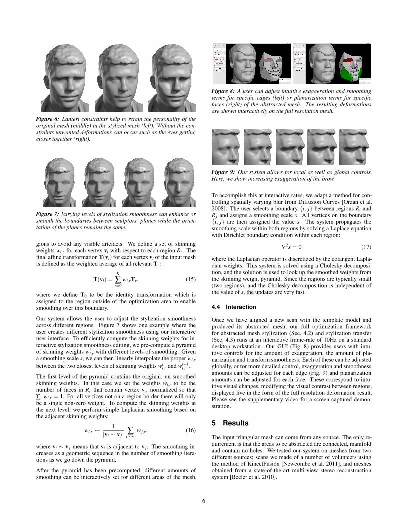
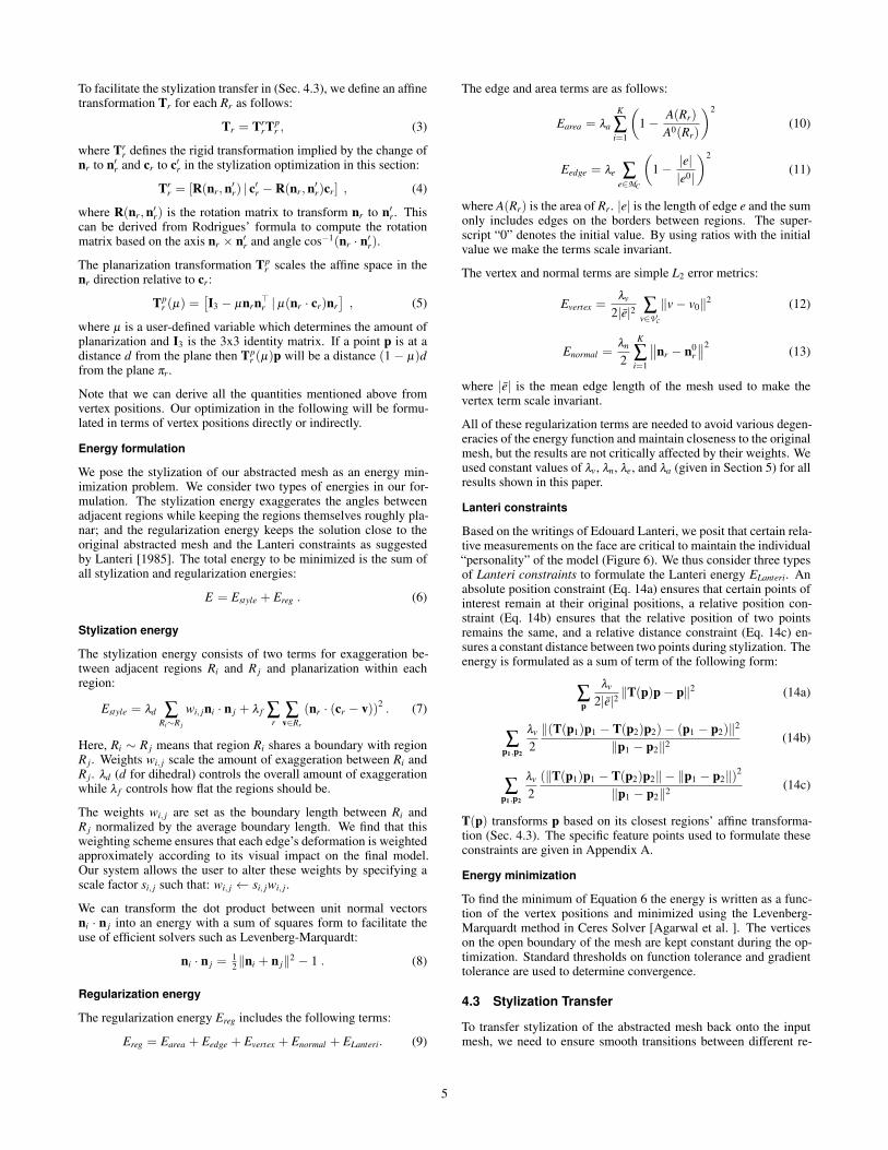
Figure 6: Lanteri constraints help to retain the personality of theoriginal mesh (middle) in the stylized mesh (left). Without the con-straints unwanted deformations can occur such as the eyes gettingcloser together (right).
Figure 7: Varying levels of stylization smoothness can enhance orsmooth the boundaries between sculptors’ planes while the orien-tation of the planes remains the same.
gions to avoid any visible artefacts. We define a set of skinningweights wi,r for each vertex vi with respect to each region Rr. Thefinal affine transformation T(vi) for each vertex vi of the input meshis defined as the weighted average of all relevant Tr:
T(vi) =K
∑r=0
wi,rTr, (15)
where we define T0 to be the identity transformation which isassigned to the region outside of the optimization area to enablesmoothing over this boundary.
Our system allows the user to adjust the stylization smoothnessacross different regions. Figure 7 shows one example where theuser creates different stylization smoothness using our interactiveuser interface. To efficiently compute the skinning weights for in-teractive stylization smoothness editing, we pre-compute a pyramidof skinning weights wl
i,r with different levels of smoothing. Givena smoothing scale s, we can then linearly interpolate the proper wi,r
between the two closest levels of skinning weights wli,r and wl+1
i,r .
The first level of the pyramid contains the original, un-smoothedskinning weights. In this case we set the weights wi,r to be thenumber of faces in Rr that contain vertex vi, normalized so that∑r wi,r = 1. For all vertices not on a region border there will onlybe a single non-zero weight. To compute the skinning weights atthe next level, we perform simple Laplacian smoothing based onthe adjacent skinning weights:
wi,r ←1
|vi ∼ v j| ∑vi∼v j
w j,r, (16)
where vi ∼ v j means that vi is adjacent to v j. The smoothing in-creases as a geometric sequence in the number of smoothing itera-tions as we go down the pyramid.
After the pyramid has been precomputed, different amounts ofsmoothing can be interactively set for different areas of the mesh.
Figure 8: A user can adjust intuitive exaggeration and smoothingterms for specific edges (left) or planarization terms for specificfaces (right) of the abstracted mesh. The resulting deformationsare shown interactively on the full resolution mesh.
Figure 9: Our system allows for local as well as global controls.Here, we show increasing exaggeration of the brow.
To accomplish this at interactive rates, we adapt a method for con-trolling spatially varying blur from Diffusion Curves [Orzan et al.2008]: The user selects a boundary {i, j} between regions Ri andR j and assigns a smoothing scale s. All vertices on the boundary{i, j} are then assigned the value s. The system propagates thesmoothing scale within both regions by solving a Laplace equationwith Dirichlet boundary condition within each region:
∇2s = 0 (17)
where the Laplacian operator is discretized by the cotangent Lapla-cian weights. This system is solved using a Cholesky decomposi-tion, and the solution is used to look up the smoothed weights fromthe skinning weight pyramid. Since the regions are typically small(two regions), and the Cholesky decomposition is independent ofthe value of s, the updates are very fast.
4.4 Interaction
Once we have aligned a new scan with the template model andproduced its abstracted mesh, our full optimization frameworkfor abstracted mesh stylization (Sec. 4.2) and stylization transfer(Sec. 4.3) runs at an interactive frame-rate of 10Hz on a standarddesktop workstation. Our GUI (Fig. 8) provides users with intu-itive controls for the amount of exaggeration, the amount of pla-narization and transform smoothness. Each of these can be adjustedglobally, or for more detailed control, exaggeration and smoothnessamounts can be adjusted for each edge (Fig. 9) and planarizationamounts can be adjusted for each face. These correspond to intu-itive visual changes, modifying the visual contrast between regions,displayed live in the form of the full resolution deformation result.Please see the supplementary video for a screen-captured demon-stration.
5 Results
The input triangular mesh can come from any source. The only re-quirement is that the areas to be abstracted are connected, manifoldand contain no holes. We tested our system on meshes from twodifferent sources; scans we made of a number of volunteers usingthe method of KinectFusion [Newcombe et al. 2011], and meshesobtained from a state-of-the-art multi-view stereo reconstructionsystem [Beeler et al. 2010].
6

λd = 0.5 λd = 1.0 λd = 1.6 λd = 2.3
Figure 10: Increasing amounts of stylization, from left to right. Weintentionally push the exaggeration too far to demonstrate how theLanteri constraints keep salient features in correct positions.
Figure 11: Increasing planarization (left to right)
Figure 12: 3D printed busts — original (left) vs. stylized (right).
The deformations produced by our method typically enhancecheekbones, deepen eye sockets, and emphasize the brows, chinand lips (see Figure 15). This approach is especially effective forthe KinectFusion scans, which are sometimes lifeless and hard torecognize due to their lower fidelity. Further, materials used in 3Dprinting can be more translucent than skin, giving a blank look toprinted busts. Our method gives such busts stronger definition byaccentuating facial features, often making them more recognizable(see Figure 12). Our method can also be applied to models otherthan faces by using VSA for abstraction. In this case, the modelsare often thinned, and concavities become more pronounced (seeFigure 13). The deformations shown in these figures are subtle,by design, and may be hard to see clearly in the printed paper.We direct the reader to view the electronic version, and especiallyto our supplementary video, which demonstrates the abstractionsmore clearly by cutting rapidly between inputs and outputs.
For the stylization of the abstracted mesh (Section 4.2), the opti-mization is performed over a small number (n < 100) of vertices onthe coarse mesh, and thus takes only a fraction of a second, regard-less of the input scan resolution. The stylization transfer step (Sec-tion 4.3) works with the full resolution mesh, but since only locallinear solves and linear operations are required, both steps togethercan be run interactively. For an input mesh with 30k vertices oursystem runs at 10Hz on a Linux laptop, including all rendering, withroom for further optimisation. For one of the Beeler et al.meshescontaining 375k vertices the system runs at about 2Hz. Currentlythe system runs entirely on the CPU, however, the stylization trans-fer step would be well suited to GPU acceleration.
Most of the weight parameters described in Sections 4.2 and 4.3 areheld constant for all examples in this paper: λa = 10 and λe = 4,
Figure 13: Original mesh (left), segmentation (middle), and styl-ized mesh (right). Note the emphasis of facial features on thebunny5and sharper definition of the eye sockets on the lion6.
Figure 14: A style can be transferred to other meshes by using thesame set of weights.
λv = 60, λn = 1, and λ f = 1. The default exaggeration weightsyield pleasing results with the user just specifying 0 ≤ λd < 3to control the overall amount of deformation. However, the usercan customize the output by specifying per-edge exaggeration andsmoothing weights and per-face planarization weights.
A video and a selection of the results (including original, seg-mented, abstacted and stylized meshes) are made available on ourproject webpage: http://wp.doc.ic.ac.uk/robotvision/project/face-stylization/
6 Discussion and Conclusion
Experts in sculpture will note that both the approach and algorithmwe have chosen are both oversimplifications of a sculpting process.Our interpretation of the planes of the head, inspired by Lanteri andAsaro, is only one abstraction used by sculptors, and our algorithmis only one possible implementation of this abstraction. We hopeand expect that future researchers will explore alternate interpreta-tions and methods with us. We expect that much further insight will
5 Source: Stanford University Computer Graphics Laboratory6 Copyright purita, licensed under CC BY-NC 3.0. Source: http://www.thingiverse.com/thing:215420
7
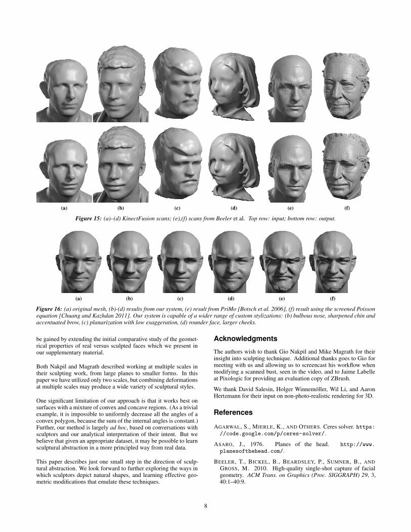
(a) (b) (c) (d) (e) (f)
Figure 15: (a)–(d) KinectFusion scans; (e),(f) scans from Beeler et al. Top row: input; bottom row: output.
(a) (b) (c) (d) (e) (f)
Figure 16: (a) original mesh, (b)-(d) results from our system, (e) result from PriMo [Botsch et al. 2006], (f) result using the screened Poissonequation [Chuang and Kazhdan 2011]. Our system is capable of a wider range of custom stylizations: (b) bulbous nose, sharpened chin andaccentuated brow, (c) planarization with low exaggeration, (d) rounder face, larger cheeks.
be gained by extending the initial comparative study of the geomet-rical properties of real versus sculpted faces which we present inour supplementary material.
Both Nakpil and Magrath described working at multiple scales intheir sculpting work, from large planes to smaller forms. In thispaper we have utilized only two scales, but combining deformationsat multiple scales may produce a wide variety of sculptural styles.
One significant limitation of our approach is that it works best onsurfaces with a mixture of convex and concave regions. (As a trivialexample, it is impossible to uniformly decrease all the angles of aconvex polygon, because the sum of the internal angles is constant.)Further, our method is largely ad hoc, based on conversations withsculptors and our analytical interpretation of their intent. But webelieve that given an appropriate dataset, it may be possible to learnsculptural abstraction in a more principled way from real data.
This paper describes just one small step in the direction of sculp-tural abstraction. We look forward to further exploring the ways inwhich sculptors depict natural shapes, and learning effective geo-metric modifications that emulate these techniques.
Acknowledgments
The authors wish to thank Gio Nakpil and Mike Magrath for theirinsight into sculpting technique. Additional thanks goes to Gio formeeting with us and allowing us to screencast his workflow whenmodifying a scanned bust, seen in the video, and to Jaime Labelleat Pixologic for providing an evaluation copy of ZBrush.
We thank David Salesin, Holger Winnemöller, Wil Li, and AaronHertzmann for their input on non-photo-realistic rendering for 3D.
References
AGARWAL, S., MIERLE, K., AND OTHERS. Ceres solver. https://code.google.com/p/ceres-solver/.
ASARO, J., 1976. Planes of the head. http://www.planesofthehead.com/.
BEELER, T., BICKEL, B., BEARDSLEY, P., SUMNER, B., ANDGROSS, M. 2010. High-quality single-shot capture of facialgeometry. ACM Trans. on Graphics (Proc. SIGGRAPH) 29, 3,40:1–40:9.
8
Page Passage Constraint15 “...with your calipers measure the distance from corner to corner of the mouth,
and set this distance off on your horizontal line.”distance between mouth corners
19 “measure with calipers the length of the nose” distance from bridge to tip of nose43–44 “calculate or measure (from the place where you fixed the articulation of ster-
num and collar-bone) the height of the chin...”absolute position of chin tip
48 “Measure on your model the distance from the notch of the ear to the mostprojecting part of the nose-tip (Fig. 38) (take this measure on both sides, foryou will frequently find that the distance on right and left side varies)”
absolute position of nose tip
50 “...the distance from the chin to the eyebrows... by describing an arc on themodel, in order to find out if the eyebrows are of the same height on eitherside...”
distance from chin to each eyebrow (2)
53 “...model the upper jaw, marking at once the two corners of the mouth, wellobserving their relation to the size of the nostrils.”
distance from each corner of mouth tosame side of nose (2)
58–59 “A careful measurement from inner corner to inner corner...” distance between inner corners of eyes
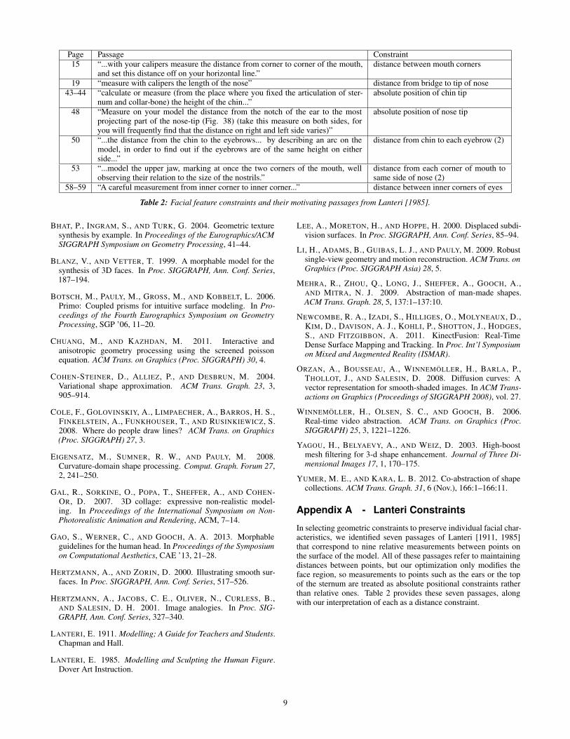
Table 2: Facial feature constraints and their motivating passages from Lanteri [1985].
BHAT, P., INGRAM, S., AND TURK, G. 2004. Geometric texturesynthesis by example. In Proceedings of the Eurographics/ACMSIGGRAPH Symposium on Geometry Processing, 41–44.
BLANZ, V., AND VETTER, T. 1999. A morphable model for thesynthesis of 3D faces. In Proc. SIGGRAPH, Ann. Conf. Series,187–194.
BOTSCH, M., PAULY, M., GROSS, M., AND KOBBELT, L. 2006.Primo: Coupled prisms for intuitive surface modeling. In Pro-ceedings of the Fourth Eurographics Symposium on GeometryProcessing, SGP ’06, 11–20.
CHUANG, M., AND KAZHDAN, M. 2011. Interactive andanisotropic geometry processing using the screened poissonequation. ACM Trans. on Graphics (Proc. SIGGRAPH) 30, 4.
COHEN-STEINER, D., ALLIEZ, P., AND DESBRUN, M. 2004.Variational shape approximation. ACM Trans. Graph. 23, 3,905–914.
COLE, F., GOLOVINSKIY, A., LIMPAECHER, A., BARROS, H. S.,FINKELSTEIN, A., FUNKHOUSER, T., AND RUSINKIEWICZ, S.2008. Where do people draw lines? ACM Trans. on Graphics(Proc. SIGGRAPH) 27, 3.
EIGENSATZ, M., SUMNER, R. W., AND PAULY, M. 2008.Curvature-domain shape processing. Comput. Graph. Forum 27,2, 241–250.
GAL, R., SORKINE, O., POPA, T., SHEFFER, A., AND COHEN-OR, D. 2007. 3D collage: expressive non-realistic model-ing. In Proceedings of the International Symposium on Non-Photorealistic Animation and Rendering, ACM, 7–14.
GAO, S., WERNER, C., AND GOOCH, A. A. 2013. Morphableguidelines for the human head. In Proceedings of the Symposiumon Computational Aesthetics, CAE ’13, 21–28.
HERTZMANN, A., AND ZORIN, D. 2000. Illustrating smooth sur-faces. In Proc. SIGGRAPH, Ann. Conf. Series, 517–526.
HERTZMANN, A., JACOBS, C. E., OLIVER, N., CURLESS, B.,AND SALESIN, D. H. 2001. Image analogies. In Proc. SIG-GRAPH, Ann. Conf. Series, 327–340.
LANTERI, E. 1911. Modelling; A Guide for Teachers and Students.Chapman and Hall.
LANTERI, E. 1985. Modelling and Sculpting the Human Figure.Dover Art Instruction.
LEE, A., MORETON, H., AND HOPPE, H. 2000. Displaced subdi-vision surfaces. In Proc. SIGGRAPH, Ann. Conf. Series, 85–94.
LI, H., ADAMS, B., GUIBAS, L. J., AND PAULY, M. 2009. Robustsingle-view geometry and motion reconstruction. ACM Trans. onGraphics (Proc. SIGGRAPH Asia) 28, 5.
MEHRA, R., ZHOU, Q., LONG, J., SHEFFER, A., GOOCH, A.,AND MITRA, N. J. 2009. Abstraction of man-made shapes.ACM Trans. Graph. 28, 5, 137:1–137:10.
NEWCOMBE, R. A., IZADI, S., HILLIGES, O., MOLYNEAUX, D.,KIM, D., DAVISON, A. J., KOHLI, P., SHOTTON, J., HODGES,S., AND FITZGIBBON, A. 2011. KinectFusion: Real-TimeDense Surface Mapping and Tracking. In Proc. Int’l Symposiumon Mixed and Augmented Reality (ISMAR).
ORZAN, A., BOUSSEAU, A., WINNEMÖLLER, H., BARLA, P.,THOLLOT, J., AND SALESIN, D. 2008. Diffusion curves: Avector representation for smooth-shaded images. In ACM Trans-actions on Graphics (Proceedings of SIGGRAPH 2008), vol. 27.
WINNEMÖLLER, H., OLSEN, S. C., AND GOOCH, B. 2006.Real-time video abstraction. ACM Trans. on Graphics (Proc.SIGGRAPH) 25, 3, 1221–1226.
YAGOU, H., BELYAEVY, A., AND WEIZ, D. 2003. High-boostmesh filtering for 3-d shape enhancement. Journal of Three Di-mensional Images 17, 1, 170–175.
YUMER, M. E., AND KARA, L. B. 2012. Co-abstraction of shapecollections. ACM Trans. Graph. 31, 6 (Nov.), 166:1–166:11.
Appendix A - Lanteri Constraints
In selecting geometric constraints to preserve individual facial char-acteristics, we identified seven passages of Lanteri [1911, 1985]that correspond to nine relative measurements between points onthe surface of the model. All of these passages refer to maintainingdistances between points, but our optimization only modifies theface region, so measurements to points such as the ears or the topof the sternum are treated as absolute positional constraints ratherthan relative ones. Table 2 provides these seven passages, alongwith our interpretation of each as a distance constraint.
9
Copyright © 2022 FDOKUMEN