Intelligent Mobility - Autonomous Outdoor Robotics at the DFKI
7
Künstl Intell DOI 10.1007/s13218-011-0089-8 PROJEKT Intelligent Mobility Autonomous Outdoor Robotics at the DFKI Sylvain Joyeux · Jakob Schwendner · Frank Kirchner · Ajish Babu · Felix Grimminger · Janosch Machowinski · Patrick Paranhos · Christopher Gaudig © Springer-Verlag 2011 Abstract Robotic systems for outdoor applications can play an important role in the future. Tasks like exploration, surveillance or search and rescue missions benefit greatly from increased autonomy of the available systems. Outdoor environments and their high complexity pose a special chal- lenge for existing autonomous behaviour technologies in robots. Some of these challenges in the area of navigation, plan management and sensor integration are investigated in the Intelligent Mobility (iMoby) project at the DFKI. An in- troduction to the project goals and the current achievements is given. Further, an outlook towards the end of the project and beyond is provided. 1 Introduction That we use machines to perform the work required to main- tain our way of life has become an accepted reality nowa- days. Robots can support humans by performing tasks that are dirty, dangerous or mundane. Designing robotic systems becomes more challenging with complex environments, and mobile robotic systems have thus a stronger research back- ing for indoor applications. Many real world applications re- quire highly mobile systems which can cope with complex and changing outdoor environments. The Intelligent Mobil- ity project at the Robotics Innovation Center (RIC) at the German Research Center for Artificial Intelligence (DFKI) is aimed at developing technologies to improve the availabil- ity and quality of autonomous outdoor robots. The work is S. Joyeux · J. Schwendner ( ) · F. Kirchner · A. Babu · F. Grimminger · J. Machowinski · P. Paranhos · C. Gaudig DFKI–Robotics Innovation Center, Robert-Hooke-Str. 5, 28359 Bremen, Germany e-mail: [email protected] Fig. 1 The Asguard v3 platform was developed in the course of the In- telligent Mobility project. It has mechanical properties similar to those of the Asguard v2 and includes additional sensors. The sensor suite includes a laser range finder, stereo camera, inertial measurement unit and a differential GPS for verification performed on the Asguard v3 robot (see Fig. 1), which is a leg-wheel hybrid system. A summary of the research goals, achievements so far and applications is given in this article. 1.1 Motivation The main motivation of the Intelligent Mobility project is to investigate new concepts for robust autonomous navigation in outdoor environments. This has led to the definition of three main research axes. First, since the advent of SLAM (Simultaneous Locali- sation and Mapping), the principal trend in robotic research focusing on autonomous navigation is to see the robot as an exteroceptive sensor pack (camera(s), 3D laser scanner, etc.) on wheels. The robot is only used as a way to move cameras and other exteroceptive sensors around. The focus of our project is to use the valuable information that is orig- inated in the robot body itself. This information is mostly
Transcript of Intelligent Mobility - Autonomous Outdoor Robotics at the DFKI

Künstl IntellDOI 10.1007/s13218-011-0089-8
P RO J E K T
Intelligent Mobility
Autonomous Outdoor Robotics at the DFKI
Sylvain Joyeux · Jakob Schwendner · Frank Kirchner ·Ajish Babu · Felix Grimminger · Janosch Machowinski ·Patrick Paranhos · Christopher Gaudig
© Springer-Verlag 2011
Abstract Robotic systems for outdoor applications canplay an important role in the future. Tasks like exploration,surveillance or search and rescue missions benefit greatlyfrom increased autonomy of the available systems. Outdoorenvironments and their high complexity pose a special chal-lenge for existing autonomous behaviour technologies inrobots. Some of these challenges in the area of navigation,plan management and sensor integration are investigated inthe Intelligent Mobility (iMoby) project at the DFKI. An in-troduction to the project goals and the current achievementsis given. Further, an outlook towards the end of the projectand beyond is provided.
1 Introduction
That we use machines to perform the work required to main-tain our way of life has become an accepted reality nowa-days. Robots can support humans by performing tasks thatare dirty, dangerous or mundane. Designing robotic systemsbecomes more challenging with complex environments, andmobile robotic systems have thus a stronger research back-ing for indoor applications. Many real world applications re-quire highly mobile systems which can cope with complexand changing outdoor environments. The Intelligent Mobil-ity project at the Robotics Innovation Center (RIC) at theGerman Research Center for Artificial Intelligence (DFKI)is aimed at developing technologies to improve the availabil-ity and quality of autonomous outdoor robots. The work is
S. Joyeux · J. Schwendner (�) · F. Kirchner · A. Babu ·F. Grimminger · J. Machowinski · P. Paranhos · C. GaudigDFKI–Robotics Innovation Center, Robert-Hooke-Str. 5, 28359Bremen, Germanye-mail: [email protected]
Fig. 1 The Asguard v3 platform was developed in the course of the In-telligent Mobility project. It has mechanical properties similar to thoseof the Asguard v2 and includes additional sensors. The sensor suiteincludes a laser range finder, stereo camera, inertial measurement unitand a differential GPS for verification
performed on the Asguard v3 robot (see Fig. 1), which is aleg-wheel hybrid system. A summary of the research goals,achievements so far and applications is given in this article.
1.1 Motivation
The main motivation of the Intelligent Mobility project is toinvestigate new concepts for robust autonomous navigationin outdoor environments. This has led to the definition ofthree main research axes.
First, since the advent of SLAM (Simultaneous Locali-sation and Mapping), the principal trend in robotic researchfocusing on autonomous navigation is to see the robot asan exteroceptive sensor pack (camera(s), 3D laser scanner,etc.) on wheels. The robot is only used as a way to movecameras and other exteroceptive sensors around. The focusof our project is to use the valuable information that is orig-inated in the robot body itself. This information is mostly

Künstl Intell
used for measuring the odometry, but has the potential toimprove localisation and mapping and increase the overallnavigation robustness. This main idea is obviously related tothe field of “embodied cognition”, and we therefore coinedthe term “embodied SLAM” (or eSLAM) for the localisa-tion and mapping part of the project.
Second, to enable the development of eSLAM, one alsohas to look at the challenges it poses for the hardware plat-form itself. For eSLAM to work as we envisioned it, it isindeed critical to gather useful information from the hard-ware.
Finally, instead of trying to improve localisation, map-ping and planning algorithms so as to make them “perfect”,one can instead try to use “the right tool for the job” atall times. In other words, we investigate how to achieve ro-bustness and performance by having the system always pickthe combination of control behaviour, sensor processing anddecision-making tools that are best adapted to the currentsituation.
The three research topics that have therefore been identi-fied in the project are:
eSLAM takes care of building an environment representa-tion that integrates both exteroceptive and embodied infor-mation.
The platform should be designed as to produce enough in-formation to augment SLAM and navigation algorithms.
Plan management offers the framework needed to reasonabout the ability to opportunistically switch between theavailable navigation modes and apply these changes.
1.2 Related Work
There are two main forms of locomotion for autonomousoutdoor systems. Wheeled systems perform well in envi-ronments that contain roads or other flat surfaces. Leggedsystems are more complex, but can excel wheeled systemswhen it comes to unstructured terrain [2]. Leg-wheel hybridsystems first developed at the ESA A&R group [8] can com-bine some of the advantages of both domains. The Asguardsystem used in this project was developed at the DFKI [5]and provides enhanced locomotion capabilities while main-taining mechanical simplicity. Also, the environment inter-action information of the Asguard is rich enough to performsome ground contact modelling like the one used in [4] forlocalisation.
In general, there is very little work on using embodieddata for localisation and mapping tasks (see [12]). The workdescribed by Chitta et al. [4] uses a ground contact model forquadrupeds and evaluates a particle filter based localisationapproach on the LittleDog robot. Spenneberg and Kirchner[13] have hinted at using proprioceptive terrain classifica-tion for localisation and mapping tasks. Wurm et al. [15]
have employed vibration data to differentiate between vari-ous substrate types in order to perform unsupervised learn-ing of different terrain types using a laser range finder.
Runtime adaptation of robot behaviour is traditionally astrong point in behaviour-based architectures. To integratethis behaviour-based adaptation with plan-based control inhybrid architectures, plan-based executives have been de-signed (IDEA [10] and T-REX [9]). However, these exec-utives can only react to errors reported by the behaviourlayer, but fail to represent and benefit from the availability ofchoices that were foreseen at planning time. Moreover, theycan only reason on behaviour-reported status—mainly suc-cess/failure reports—and therefore fail to benefit from morefine-grained situation assessment.
2 Preliminary Results
This section presents the preliminary results in the outlinedfields of interest. All parts presented in this paper are, in theircurrent state, integrated on the Asguard platform, and can beused for autonomous navigation in known maps (Fig. 3).
2.1 Platform
The most important data that the eSLAM algorithm needs iscontact information, force information and geometric con-figuration. We investigated the integration of sensors into thewheels that would allow the measurement of force and con-tact (Fig. 2). Moreover, for mechanical reasons, an elasticpart is placed between the motor and the wheel. By mea-suring the compression of that piece, it is also possible toestimate the torque applied to the wheel by the motor. Thisinformation will be used in eSLAM through terrain classifi-cation, and in diagnostics for fault tolerance.
2.2 Localisation and Mapping
The primary research subject in the area of navigation isthe application of embodied sensor data for localisation andmapping tasks. Embodied data on its own is unlikely to besufficient to perform navigation in any real world scenario.Thus, a number of different and complementing technolo-gies have been developed so far. This paper will present twoof them: a rather traditional ICP matching method and a lo-calization method based on embodied data.
The Asguard v3 is equipped with a Hokuyo LRX-30 laserrange finder and a stereo camera setup, both on a tiltablesensor head. Classically, robots with tilting laser range find-ers stop periodically to acquire full 3D images using thetilt unit (see e.g. [11]). To avoid these stops, we use infor-mation on the robot’s movement and pose to generate localscans, which are then matched into a known 3D map using

Künstl Intell
Fig. 2 A pressure sensitive foot is being developed in the project, thatuses the Hall effect to measure the deformation of the flexible structure,so that the contact forces can be estimated
an ICP algorithm [3]. The local scans are generated by for-ward projecting the position of the laser scanner using theodometry information and the orientation we get from theIMU. Since the odometry is prone to position and orienta-tion drift, these local scans are likely to be a distorted repre-sentation of the environment. For localisation purposes, itis important to keep these scans small enough to preventlarge distortions and maintain a sufficient position updaterate. On the other side, scans that are too small resulted in adecreased localisation performance due to bad ICP matches.It was found that around 20 scan lines, spaced around 2 cmto 3 cm apart performed well in the tested environments.Tests have so far been performed on the DFKI test track,which is 70 m × 5 m, and contains obstacles of varioussizes. It also includes a change in elevation of around 2 m.An a-priori map of the track was generated using the sen-sor and tilt unit from the robot fixed on a tripod. Around20 individual scans were manually matched off-line, and thematches subsequently improved by running the ICP algo-rithm pair-wise on the scans. The resulting 3D point-cloudwas finally sub-sampled to approximately 900 k points, withan average spacing of 5 cm. Even for situations with a lot ofslip, the ICP based localisation method performs robustlyand is, in combination with a Kalman filter, able to estimatethe robot’s pose to within 0.2 m 95% of the time (Fig. 3).All calculations required for this approach were performedon-board, using a Core 2 Duo processor at 1.5 GHz. For atraveling speed of 0.6 m/s the ICP task was taking around50% load average on one of the cores.
The other complementary approach for localisation thathas been investigated uses embodied data [12], instead of vi-sual data, to perform the localisation within the known map.The employed method applies a particle filter to representthe posterior pose distribution (similar to [4]) and performsupdates of the particle weights using inertial sensor data and
Fig. 3 Representation of the robot’s internal data model during a navi-gation run on the DFKI test track, from real data. The green zone is thepart of the terrain that has already been seen. The local model (red) isused to match the a-priori model (white) for localisation purposes. Fur-ther along this run (bottom-right in the image), the robot encounters abridge (black). As it is a feature that is easy to recognise in the robot’s2D laser scanner, the supervision layer switches the modality to a cor-ridor servoing behaviour which is more robust and less CPU-intensivethan the global navigation behaviour used normally
joint angle readings. The pose distribution is sampled in the2D pose space (2D position and yaw angle). The projectionstep uses a simple skid steering odometry model as well asthe change of yaw from the IMU. Absolute yaw readingsfrom the IMU proved to be unreliable due to variations inthe magnetic field readings of up to 30°. The update of theparticle weights is performed using a probabilistic foot con-tact model, which uses a forward kinematic model of therobot with the joint angle readings and the IMU’s orientationreading to estimate the foot positions. The resulting contactpoint candidates are evaluated with regard to how well theyfit the environment for the particular pose of the particle.The particles weight is updated accordingly. Unlike the ICPbased approach, this method uses a grid based representa-tion of the environment. For the test track, a 80 m by 12 mmap with a grid size of 5 cm was used. In order to repre-sent uncertainties, as well as structures like tubes or gates,multi level surface maps [14] have been applied. So far wewere able to show that this method can improve localisa-tion over simple odometry, especially for feature rich terrain(see Fig. 4). Current work is being undertaken, to make theapproach scalable to very large terrains (square km), and in-vestigate how it is affecting the mapping aspect in a SLAMscenario.
2.3 Online Software Adaptation
In the frame of the Intelligent Mobility project, a way to rep-resent which choices are available to the system and whateffect these choices have on the navigation also seemed crit-ical to us. We therefore developed a path representation and
Künstl Intell
Fig. 4 Comparison oflocalisation usingdead-reckoning (red) andlocalisation using embodiedsensor data (green). The run wasperformed on the DFKI testtrack over a distance of around70 m
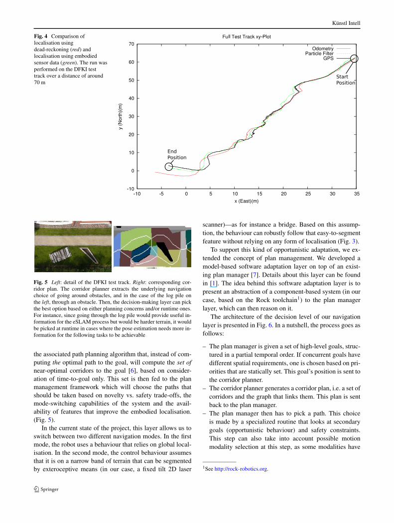
Fig. 5 Left: detail of the DFKI test track. Right: corresponding cor-ridor plan. The corridor planner extracts the underlying navigationchoice of going around obstacles, and in the case of the log pile onthe left, through an obstacle. Then, the decision-making layer can pickthe best option based on either planning concerns and/or runtime ones.For instance, since going through the log pile would provide useful in-formation for the eSLAM process but would be harder terrain, it wouldbe picked at runtime in cases where the pose estimation needs more in-formation for the following tasks to be achievable
the associated path planning algorithm that, instead of com-puting the optimal path to the goal, will compute the set ofnear-optimal corridors to the goal [6], based on consider-ation of time-to-goal only. This set is then fed to the planmanagement framework which will choose the paths thatshould be taken based on novelty vs. safety trade-offs, themode-switching capabilities of the system and the avail-ability of features that improve the embodied localisation.(Fig. 5).
In the current state of the project, this layer allows us toswitch between two different navigation modes. In the firstmode, the robot uses a behaviour that relies on global local-isation. In the second mode, the control behaviour assumesthat it is on a narrow band of terrain that can be segmentedby exteroceptive means (in our case, a fixed tilt 2D laser
scanner)—as for instance a bridge. Based on this assump-tion, the behaviour can robustly follow that easy-to-segmentfeature without relying on any form of localisation (Fig. 3).
To support this kind of opportunistic adaptation, we ex-tended the concept of plan management. We developed amodel-based software adaptation layer on top of an exist-ing plan manager [7]. Details about this layer can be foundin [1]. The idea behind this software adaptation layer is topresent an abstraction of a component-based system (in ourcase, based on the Rock toolchain1) to the plan managerlayer, which can then reason on it.
The architecture of the decision level of our navigationlayer is presented in Fig. 6. In a nutshell, the process goes asfollows:
– The plan manager is given a set of high-level goals, struc-tured in a partial temporal order. If concurrent goals havedifferent spatial requirements, one is chosen based on pri-orities that are statically set. This goal’s position is sent tothe corridor planner.
– The corridor planner generates a corridor plan, i.e. a set ofcorridors and the graph that links them. This plan is sentback to the plan manager.
– The plan manager then has to pick a path. This choiceis made by a specialized routine that looks at secondarygoals (opportunistic behaviour) and safety constraints.This step can also take into account possible motionmodality selection at this step, as some modalities have
1See http://rock-robotics.org.

Künstl Intell
Fig. 6 Diagram detailing the high-level navigation architecture in theproject. Detailed explanations are given in Sect. 2.3
less stringent requirements on the other subsystems (e.g.localization) than others.
– Motion modalities are selected. They get deployed, i.e.the system is configured according to the modality’s defi-nition, when the corresponding corridor(s) is(are) entered.This is done through the software adaptation layer men-tioned earlier.
One very important aspect of this architecture is that thefinal plan contains the links between the high-level goals, thecorridors and the selected modalities. It is therefore straight-forward to monitor the effect of failures during execution.Moreover, the use of a corridor data structure allows us tomonitor the effect of localization uncertainties. Indeed, onecan use the localization uncertainty to estimate the probabil-ity of having the system within the specified corridor bound-aries (i.e. within the desired constraints), and react if thatprobability gets low.
Finally, the architecture does not forbid to delay path andmodality selection until execution time (i.e. until the systemneeds to make these choices). This will allow, in the future,to select modalities based on criteria as for instance local-ization quality at a particular point in the navigation. In ad-dition, it allows for online fault handling by plan repairs: itallows to detect faults, pause execution of the current tasks,repair the plan and then either resume the execution if pos-sible, or replan if needed. We believe that this strategy willallow to overcome the problem of plan stability, i.e. the factthat replanning often produces a very different plan than theexisting one, forcing the system to redo all decisions alreadymade on the old plan, as for instance renegotiation in caseof multi-robot systems.
The performance of the implemented system on our robot(Core 2 Duo @ 1.5 GHz) is as follows. The corridor plan-
Fig. 7 The technologies developed in the Intelligent Mobility projectcould be used to improve the capabilities of future lunar or planetaryexploration missions
ner requires 150 ms to plan on a 80 × 100 grid, crossing thegrid in its longest dimension. Note that the algorithm spendsmost of its time extracting the corridor skeleton, which de-pends only on the length of the final path, not on the actualmap size. Moreover, we are confident that the current imple-mentation can be improved to show at least a twofold im-provement in performance. The plan manager requires 2%CPU on average for execution monitoring. Component layeradaptation requires 200 ms. The modality selection is morea proof of concept right now: it is using rule-based choicesand its performance impact is therefore negligible.
3 Conclusion and Further Work
This paper aims at combining two important aspects of mo-bility. On the one hand, the kinematic construction of thesystem enables the robot to surpass even highly complex en-vironments without any intelligence. On the other hand, ontop of this low-level kinematic intelligence—built into theconstruction of the system—we have implemented a higherlevel of intelligence that incorporates maps of the environ-ment, the ability to build plans on how to navigate from A toB and a first attempt to localise itself. This way the systemcombines mechanical and algorithmic aspects of mobility.This combination should enable the robot to be used in awide field of applications. Ranging from search and rescueoperations, surveillance of large areas—such as in industrialcomplex surveillance or power plant supervision—all theway to planetary, especially lunar exploration (see Fig. 7).What all these applications have in common is the fact thatthe robot traverses a wide variety of different terrains andsubstrates, which have an impact on the robot’s mobility.This seems to be a problem at first sight but at second sight

Künstl Intell
we might be able to turn it into an advantage using the em-bodied SLAM approach that we have proposed here.
It has been mentioned before that the embodied SLAMapproach aims to incorporate the data that comes from therobot’s internal sensors like wheel encoders, power mea-surements on the wheels and the deformation of the struc-ture of the system, as well as vibration, etc., and tries to fusethese different sensor modalities into a coherent signal thatdescribes more precisely the state of the robot and the stateof the environment.
In upcoming research activities we will have to go an-other step further. We will be using the proprioceptive sig-nals and augment that data with behaviour data that comesfrom the robot’s low-level control reacting on the challengesof the environment. E.g., a robot that is driving over a pileof rocks will usually have to initiate certain locomotion andmovement behaviours that reflect the fact that the robot ispassing through very difficult terrain. This data together withthe proprioceptive direct signals can be used to achieve a se-mantic annotation of the environment and can be used to de-scribe the environment in a more coherent and precise way,thereby providing a bias for a set of state descriptors used inthe eSLAM algorithm.
Acknowledgements The work presented here is part of the Project“Intelligent Mobility”, which is funded by the Federal Ministry forEconomics and Technology (BMWI) through the German SpaceAgency (DLR) grant number 50 RA 0907.
References
1. Albiez J, Joyeux S, Hildebrandt M (2010) Adaptive AUV missionmanagement in under-informed situations. In: Proceedings of theIEEE/MTS OCEANS 2010 conference
2. Bartsch S, Birnschein T, Cordes F, Kuehn D, Kampmann P, Hill-jegerdes J, Planthaber S, Römmermann M, Kirchner F (2010)Spaceclimber: developement of a six-legged climbing robot forspace exploration. In: Proceedings for the joint conference of ISR2010 and ROBOTIK 2010
3. Besl P, McKay N (1992) A method for registration of 3-D shapes.In: IEEE Transactions on pattern analysis and machine intelli-gence, pp 239–256
4. Chitta S, Vemaza P, Geykhman R, Lee D (2007) Proprioceptivelocalilzatilon for a quadrupedal robot on known terrain. In: IEEEinternational conference on robotics and automation
5. Eich M, Grimminger F, Bosse S, Spenneberg D, Kirchner F (2008)Asguard: a hybrid legged wheel security and sar-robot using bio-inspired locomotion for rough terrain. In: IARP/EURON work-shop on robotics for risky interventions and environmental surveil-lance, online-proceedings
6. Joyeux S, Kirchner F (2009) Leaving choices open in plan-ner/planner integration. In: ICAPS workshop on planning and planexecution for real-world systems
7. Joyeux S, Kirchner F, Lacroix S (2010) Managing plans: inte-grating deliberation and reactive execution schemes. Robot AutonSyst
8. Martin-Alvarez A, de Peuter W, Hillebrand J, Putz P, Matthys-sen A, de Weerd J (1996) Walking robots for planetary explorationmissions. In: WAC’96, second world automation congress, Mont-pellier, France, May 27–30, 1996
9. McGann C, Py F, Rajan K, Thomas H, Henthorn R, Mcewen R(2008) A deliberative architecture for AUV control. In: IEEE in-ternational conference on robotics and automation
10. Muscettola N, Dorais G, Levinson C, Plaunt C (2002) IDEA: plan-ning at the core of autonomous reactive agents. In: InternationalNASA workshop on planning and scheduling for space
11. Nuchter A, Lingemann K, Hertzberg J, Surmann H (2005)Heuristic-based laser scan matching for outdoor 6D SLAM. Lec-ture notes in computer science, vol 3698, p 304
12. Schwendner J, Kirchner F (2010) eSLAM—self localisation andmapping using embodied data. KI, Künstl Intell 24
13. Spenneberg D, Kirchner F (2005) Embodied categorization of spa-tial environments on the basis of proprioceptive data. In: Proceed-ings of the international symposium on adaptive motion in animalsand machines
14. Triebel R, Pfaff P, Burgard W (2006) Multi-level surface maps foroutdoor terrain mapping and loop closing. In: 2006 IEEE/RSJ in-ternational conference on intelligent robots and systems, pp 2276–2282
15. Wurm K, Kummerle R, Stachniss C, Burgard W (2009) Improvingrobot navigation in structured outdoor environments by identify-ing vegetation from laser data. In: IEEE/RSJ international confer-ence on intelligent robots and systems
Sylvain Joyeux received his PhDon multi-robot architectures atLAAS/CNRS in 2007. Since then,he his working at the DFKI RoboticsInnovation Center in Bremen. Hisfocus stayed on achieving auton-omy and long-lived systems throughsystem reconfiguration, more par-ticularly on solutions that use planmanagement. He leads the Intelli-gent Mobility project since its startin 2009.
Jakob Schwendner received aBEng in Computing from the CityUniversity, London. He also com-pleted a MSc in Advanced Tech-nologies in Electronics at the Bris-tol Robotics Lab, University of theWest of England. Since 2007 heis employed as a researcher at theDFKI Robotics Innovation Center,where he is pursuing his PhD onthe subject of embodied localisa-tion and mapping. Further researchinterests are state estimation, robotautonomy and mobility as well asembedded systems design.

Künstl Intell
Frank Kirchner is Professor at theUniversity of Bremen and, at thesame time, Director of the RoboticsInnovation Center and speaker ofthe Bremen location of the GermanResearch Center for Artificial Intel-ligence (DFKI). He was Senior Sci-entist and Tenure Track AssistantProfessor at the Dept. for ElectricalEngineering at Northeastern Uni-versity in Boston, MA. Among oth-ers, he is founding member of IEEERobotics and Automation’s Techni-cal Committee on Space Roboticsand is on the board of the GMT
Gesellschaft für Maritime Technik, Hamburg, Germany. His main re-search interests are in the field of autonomous intelligent robots inreal-world applications.
Ajish Babu received his Mastersdegree in Mechatronics Engineeringfrom Hamburg University of Tech-nology, Hamburg, in 2007. He iscurrently working as a researcher atthe DFKI Robotics Innovation Cen-ter with focus on robot dynamicsand control.
Felix Grimminger received a Mas-ters Degree in Mechatronics at TheKarlsruhe University of AppliedSciences in 2002. From 2003 to2006 he worked for Boston Dynam-ics contributing to the mechanicaland hydraulic design of the BigDogrobot. Since 2007 he is employedas a robotics engineer at the DFKIRobotics Innovation Center in Bre-men and works on the mechanicaldesign of the Asguard robots. Hismain professional interest is the de-sign and construction of highly mo-bile robotic platforms.
Janosch Machowinski received hisDiplom in Computer Science fromthe University of Bremen. Since2009 he is employed as a researcherat the DFKI Robotics InnovationCenter. His main research interestare in software architecture, motionplanning and embedded system de-sign.
Patrick Paranhos received a BEngin Control and Automation fromthe PUC-Rio University, Rio deJaneiro. He also completed a MScin Applied Mechanics at PUC-Rioon the subject of position estima-tion. He had 2 years of experience asa researcher for Petrobras Researchcenter on a hybrid robot for envi-ronmental inspection of the Ama-zon rainforest. Since 2010 he is em-ployed as a researcher at the DFKIRobotics Innovation Center, wherehis major work line is position esti-mation for outdoor and underwaterrobots.
Christopher Gaudig received aDipl.-Ing. in Computer Engineer-ing from the Technische UniversitätIlmenau, Germany. Since 2010 heis employed as a researcher at theDFKI Robotics Innovation Centerwhere he is working on image ac-quisition and vision-based terrainclassification. Further research in-terests include visual odometry, ex-ploration strategies and underwaterrobotics.