Intelligent control of a stepping motor drive using an adaptive neuro-fuzzy inference system
11
Applied Soft Computing 3 (2003) 209–219 Intelligent control of a stepping motor drive using a hybrid neuro-fuzzy ANFIS approach Leocundo Aguilar, Patricia Melin ∗ , Oscar Castillo Department of Computer Science, Tijuana Institute of Technology, P.O. Box 4207, Chula Vista, CA 91909, USA Received 14 January 2003; received in revised form 5 March 2003; accepted 16 April 2003 Abstract Stepping motors are widely used in robotics and in the numerical control of machine tools where they have to perform high-precision positioning operations. However, the variations of the mechanical configuration of the drive, which are common to these two applications, can lead to a loss of synchronism for high stepping rates. Moreover, the classical open-loop speed control is weak and a closed-loop control becomes necessary. In this paper, fuzzy logic is applied to control the speed of a stepping motor drive with feedback. A neuro-fuzzy hybrid approach is used to design the fuzzy rule base of the intelligent system for control. In particular, we used the adaptive neuro-fuzzy inference system (ANFIS) methodology to build a Sugeno fuzzy model for controlling the stepping motor drive. An advanced test bed is used in order to evaluate the tracking properties and the robustness capacities of the fuzzy logic controller. © 2003 Elsevier B.V. All rights reserved. Keywords: Intelligent control; Neuro-fuzzy approach; ANFIS method; Stepping motor 1. Introduction Stepping motors can be viewed as electric motors without commutators [8]. Typically, all windings in the motor are part of the stator, and the rotor is either a permanent magnet or, in the case of variable reluc- tance motors, a toothed block of some magnetically soft material. All of the commutation must be handled externally by the motor controller, and typically, the motors and controllers are designed so that the motor may be held in any fixed position as well as being ro- tated one way or the other. Most stepping motors can be stepped at audio frequencies, allowing them to spin ∗ Corresponding author. Tel.: +1-52-664-623-6318; fax: +1-52-664-623-6318. E-mail address: [email protected] (P. Melin). quite quickly, and with an appropriate controller, they may be started and stopped “on a dime” at controlled orientations. For some applications, there is a choice between using servomotors and stepping motors. Both types of motors offer similar opportunities for precise po- sitioning, but they differ in a number of ways. Ser- vomotors require analog feedback control systems of some type. Typically, this involves a potentiometer to provide feedback about the rotor position, and some mix of circuitry to drive a current through the motor inversely proportional to the difference between the desired position and the current position. In making a choice between stepping motors and servomotors, a number of issues must be considered; which of these will matter depends on the application. For example, the repeatability of positioning done with a stepping 1568-4946/$ – see front matter © 2003 Elsevier B.V. All rights reserved. doi:10.1016/S1568-4946(03)00035-8
Transcript of Intelligent control of a stepping motor drive using an adaptive neuro-fuzzy inference system
Applied Soft Computing 3 (2003) 209–219
Intelligent control of a stepping motor drive using ahybrid neuro-fuzzy ANFIS approach
Leocundo Aguilar, Patricia Melin∗, Oscar CastilloDepartment of Computer Science, Tijuana Institute of Technology, P.O. Box 4207,
Chula Vista, CA 91909, USA
Received 14 January 2003; received in revised form 5 March 2003; accepted 16 April 2003
Abstract
Stepping motors are widely used in robotics and in the numerical control of machine tools where they have to performhigh-precision positioning operations. However, the variations of the mechanical configuration of the drive, which are commonto these two applications, can lead to a loss of synchronism for high stepping rates. Moreover, the classical open-loop speedcontrol is weak and a closed-loop control becomes necessary. In this paper, fuzzy logic is applied to control the speed of astepping motor drive with feedback. A neuro-fuzzy hybrid approach is used to design the fuzzy rule base of the intelligentsystem for control. In particular, we used the adaptive neuro-fuzzy inference system (ANFIS) methodology to build a Sugenofuzzy model for controlling the stepping motor drive. An advanced test bed is used in order to evaluate the tracking propertiesand the robustness capacities of the fuzzy logic controller.© 2003 Elsevier B.V. All rights reserved.
Keywords: Intelligent control; Neuro-fuzzy approach; ANFIS method; Stepping motor
1. Introduction
Stepping motors can be viewed as electric motorswithout commutators[8]. Typically, all windings inthe motor are part of the stator, and the rotor is eithera permanent magnet or, in the case of variable reluc-tance motors, a toothed block of some magneticallysoft material. All of the commutation must be handledexternally by the motor controller, and typically, themotors and controllers are designed so that the motormay be held in any fixed position as well as being ro-tated one way or the other. Most stepping motors canbe stepped at audio frequencies, allowing them to spin
∗ Corresponding author. Tel.:+1-52-664-623-6318;fax: +1-52-664-623-6318.E-mail address: [email protected] (P. Melin).
quite quickly, and with an appropriate controller, theymay be started and stopped “on a dime” at controlledorientations.
For some applications, there is a choice betweenusing servomotors and stepping motors. Both typesof motors offer similar opportunities for precise po-sitioning, but they differ in a number of ways. Ser-vomotors require analog feedback control systems ofsome type. Typically, this involves a potentiometer toprovide feedback about the rotor position, and somemix of circuitry to drive a current through the motorinversely proportional to the difference between thedesired position and the current position. In makinga choice between stepping motors and servomotors, anumber of issues must be considered; which of thesewill matter depends on the application. For example,the repeatability of positioning done with a stepping
1568-4946/$ – see front matter © 2003 Elsevier B.V. All rights reserved.doi:10.1016/S1568-4946(03)00035-8
210 L. Aguilar et al. / Applied Soft Computing 3 (2003) 209–219
motor depends on the geometry of the motor rotor,while the repeatability of positioning done with aservomotor generally depends on the stability of thepotentiometer and other analog components in thefeedback circuit. Stepping motors can be used insimple open-loop control systems; these are generallyadequate for systems that operate at low accelera-tions with static loads, but closed-loop control maybe essential for high accelerations, particularly if theyinvolve variable loads[1]. If a stepping motor in anopen-loop control system is overtorqued, all knowl-edge of rotor position is lost and the system mustbe reinitialized; servomotors are not subject to thisproblem.
In this paper, the application of fuzzy logic is pro-posed to control the speed of a stepping motor drive.The closed-loop control scheme entails in incorporat-ing engineering knowledge into the automatic con-trol system by using the intuition and experience ofthe designer. This strategy was proposed by Zadeh[17–20], to describe complicated systems, which arehard to analyze using traditional mathematics. Indeed,Mamdani [10] was the first to report on the appli-cation of fuzzy logic to control a small laboratorysteam engine. The success of this study led manyscientists to attempt to control industrial processessuch as chemical reactors, automatic trains, or nu-clear reactors using fuzzy algorithms. The results ofthese experiments, showed that, fuzzy controllers per-form better, or at least as well as, classical controllers.Moreover, this technique offers the advantage of re-quiring only a simple mathematical model to formu-late the algorithm, which can easily be implementedby a digital computer. These features are appreciatedfor non-linear processes for which there is no reli-able model and complex systems where the modelis useless due to the large number of equations in-volved[3]. Additionally, fuzzy logic is used more fre-quently for the control of electrical machines such asdirect current or induction motors[9]. Nevertheless,the main problem with fuzzy logic is that there is nosystematic procedure for the design of a fuzzy con-troller. For this reason, we propose in this paper theuse of the adaptive neuro-fuzzy inference system (AN-FIS) methodology[7] to adapt the parameters of thefuzzy system for control[2,4]. We use this neuro-fuzzyapproach to train the controller with real data about theproblem.
2. Basic concepts of stepping motors
Stepping motors come in two varieties,permanentmagnet andvariable reluctance (there are alsohybridmotors, which are indistinguishable from permanentmagnet motors from the controller’s point of view).You can distinguish between the two varieties with anohmmeter.
Variable reluctance motors usually have three(sometimes four) windings, with a common return,while permanent magnet motors usually have twoindependent windings, with or without center taps.Center-tapped windings are used in unipolar perma-nent magnet motors[8]. Stepping motors come in awide range of angular resolution. The coarsest mo-tors typically turn 90◦ per step, while high resolutionpermanent magnet motors are commonly able to han-dle 1.8 or even 0.72◦ per step. With an appropriatecontroller, most permanent magnet and hybrid motorscan be run in half-steps, and some controllers canhandle smaller fractional steps or micro-steps.
2.1. Variable reluctance motors
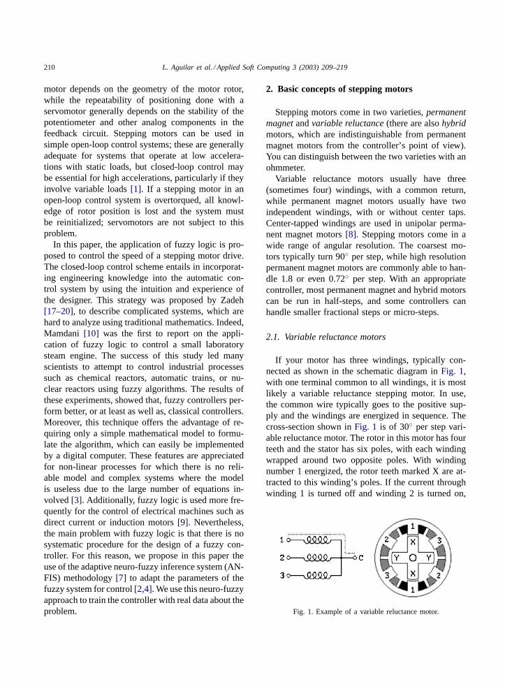
If your motor has three windings, typically con-nected as shown in the schematic diagram inFig. 1,with one terminal common to all windings, it is mostlikely a variable reluctance stepping motor. In use,the common wire typically goes to the positive sup-ply and the windings are energized in sequence. Thecross-section shown inFig. 1 is of 30◦ per step vari-able reluctance motor. The rotor in this motor has fourteeth and the stator has six poles, with each windingwrapped around two opposite poles. With windingnumber 1 energized, the rotor teeth marked X are at-tracted to this winding’s poles. If the current throughwinding 1 is turned off and winding 2 is turned on,
Fig. 1. Example of a variable reluctance motor.
L. Aguilar et al. / Applied Soft Computing 3 (2003) 209–219 211
the rotor will rotate 30◦ clockwise so that the polesmarked Y line up with the poles marked 2. There arealso variable reluctance stepping motors with four andfive windings, requiring five or six wires. The prin-ciple for driving these motors is the same as that forthe three winding variety, but it becomes important towork out the correct order to energize the windings tomake the motor step nicely. The motor geometry il-lustrated inFig. 1, giving 30◦ per step, uses the fewestnumber of rotor teeth and stator poles that performssatisfactorily. Using more motor poles and more rotorteeth allows construction of motors with smaller stepangle.
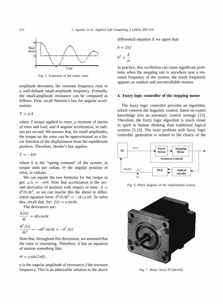
2.2. Unipolar motors
Unipolar stepping motors, both permanent magnetand hybrid stepping motors with five or six wires areusually wired as shown in the schematic inFig. 2, witha center tap on each of two windings.
In use, the center taps of the windings are typicallywired to the positive supply, and the two ends of eachwinding are alternately grounded to reverse the direc-tion of the field provided by that winding. The motorcross-section shown inFig. 2 is of a 30◦ per step per-manent magnet or hybrid motor.
For higher angular resolutions, the rotor must haveproportionally more poles. The 30◦ per step motorin the figure is one of the most common permanentmagnet motor designs, although 15 and 7.5◦ per stepmotors are widely available.
2.3. Bipolar motors
Bipolar permanent magnet and hybrid motors areconstructed with exactly the same mechanism as isused on unipolar motors, but the two windings arewired more simply, with no center taps.
Fig. 2. Example of a unipolar motor.
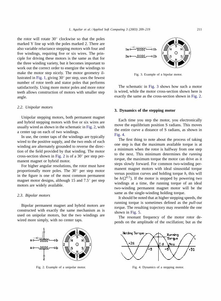
Fig. 3. Example of a bipolar motor.
The schematic inFig. 3 shows how such a motoris wired, while the motor cross-section shown here isexactly the same as the cross-section shown inFig. 2.
3. Dynamics of the stepping motor
Each time you step the motor, you electronicallymove the equilibrium position S radians. This movesthe entire curve a distance of S radians, as shown inFig. 4.
The first thing to note about the process of takingone step is that the maximum available torque is ata minimum when the rotor is halfway from one stepto the next. This minimum determines therunningtorque, the maximum torque the motor can drive as itsteps slowly forward. For common two-winding per-manent magnet motors with ideal sinusoidal torqueversus position curves and holding torqueh, this willbe h/(20.5). If the motor is stepped by powering twowindings at a time, the running torque of an idealtwo-winding permanent magnet motor will be thesame as the single-winding holding torque.
It should be noted that at higher stepping speeds, therunning torque is sometimes defined as thepull-outtorque. The resulting trajectory may resemble the oneshown inFig. 5.
The resonant frequency of the motor rotor de-pends on the amplitude of the oscillation; but as the
Fig. 4. Dynamics of a stepping motor.
212 L. Aguilar et al. / Applied Soft Computing 3 (2003) 209–219
Fig. 5. Trajectory of the motor rotor.
amplitude decreases, the resonant frequency rises toa well-defined small-amplitude frequency. Formally,the small-amplitude resonance can be computed asfollows. First, recall Newton’s law for angular accel-eration:
T = µA
whereT torque applied to rotor,µ moment of inertiaof rotor and load, andA angular acceleration, in radi-ans per second. We assume that, for small amplitudes,the torque on the rotor can be approximated as a lin-ear function of the displacement from the equilibriumposition. Therefore, Hooke’s law applies:
T = −kΘ
where k is the “spring constant” of the system, intorque units per radian,Θ the angular position ofrotor, in radians.
We can equate the two formulas for the torque toget: µA = −kΘ. Note that acceleration is the sec-ond derivative of position with respect to time:A =d2Θ/dt2, so we can rewrite this the above in differ-ential equation form: d2Θ/dt2 = −(k/µ)Θ. To solvethis, recall that, for:f(t) = a sinbt.
The derivatives are:
df(t)
dt= ab cosbt
d2f(t)
dt2= −ab2 sinbt = −b2f(t)
Note that, throughout this discussion, we assumed thatthe rotor is resonating. Therefore, it has an equationof motion something like:
Θ = a sin(2πft)
a is the angular amplitude of resonance;f the resonantfrequency. This is an admissible solution to the above
differential equation if we agree that:
b = 2πf
b2 = k
µ
In practice, this oscillation can cause significant prob-lems when the stepping rate is anywhere near a res-onant frequency of the system; the result frequentlyappears as random and uncontrollable motion.
4. Fuzzy logic controller of the stepping motor
The fuzzy logic controller provides an algorithm,which converts the linguistic control, based on expertknowledge into an automatic control strategy[13].Therefore, the fuzzy logic algorithm is much closerin spirit to human thinking than traditional logicalsystems[5,14]. The main problem with fuzzy logiccontroller generation is related to the choice of the
u(t)
Y(nTs)
Ts
System to Control
Power Driver
Stepping Motor
PLD Optical encoder
PC
Fig. 6. Block diagram of the experimental system.
Fig. 7. Motor Vexta PV266-01E.
L. Aguilar et al. / Applied Soft Computing 3 (2003) 209–219 213
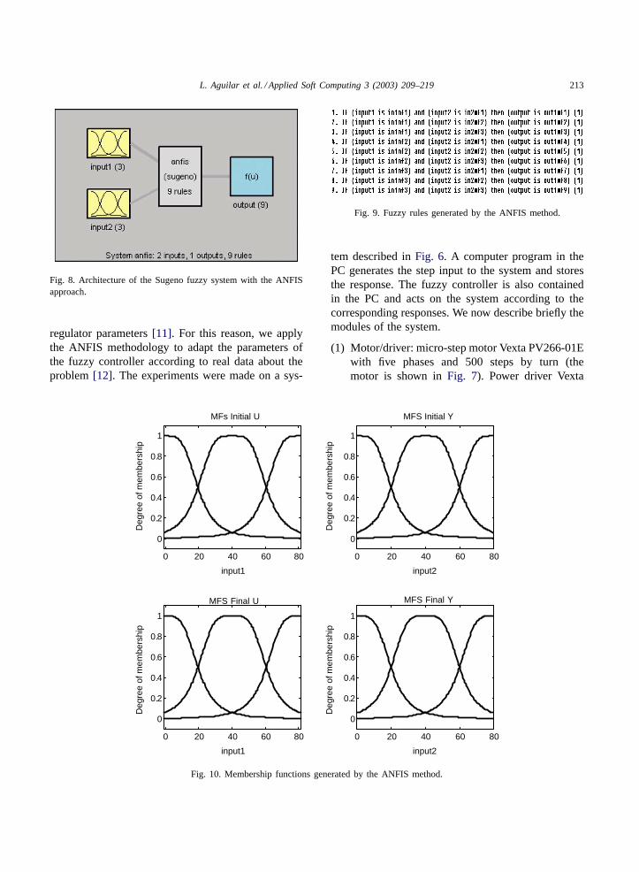
Fig. 8. Architecture of the Sugeno fuzzy system with the ANFISapproach.
regulator parameters [11]. For this reason, we applythe ANFIS methodology to adapt the parameters ofthe fuzzy controller according to real data about theproblem [12]. The experiments were made on a sys-
0 20 40 60 80
0
0.2
0.4
0.6
0.8
1
input1
Deg
ree
of m
embe
rshi
p
Deg
ree
of m
embe
rshi
p
MFs Initial U
0 20 40 60 80
0
0.2
0.4
0.6
0.8
1
input2
MFS Initial Y
Deg
ree
of m
embe
rshi
p
Deg
ree
of m
embe
rshi
p
input1 input2
0 20 40 60 80
0
0.2
0.4
0.6
0.8
1
MFS Final U
0 20 40 60 80
0
0.2
0.4
0.6
0.8
1
MFS Final Y
Fig. 10. Membership functions generated by the ANFIS method.
Fig. 9. Fuzzy rules generated by the ANFIS method.
tem described in Fig. 6. A computer program in thePC generates the step input to the system and storesthe response. The fuzzy controller is also containedin the PC and acts on the system according to thecorresponding responses. We now describe briefly themodules of the system.
(1) Motor/driver: micro-step motor Vexta PV266-01Ewith five phases and 500 steps by turn (themotor is shown in Fig. 7). Power driver Vexta
214 L. Aguilar et al. / Applied Soft Computing 3 (2003) 209–219
DFR1514A with multi-resolution (minimum: 500steps by turn; maximum: 125,000 steps by turn).
(2) Encoder: optical encoder Bourns of 40,000 stepsby turn. This encoder generates two square signalswith 90◦ difference. With these signals the mag-nitude of motor movement is determined. Weuse the programmable logic device (PLD) of Al-tera (EP5032) to determine the movement of themotor.
(3) Data acquisition card: PCL-818 of Advantechwith eight analog inputs and two analog outputs(12 bits), 16 digital inputs, 16 digital outputs. Thesampling time used is 0.25 ms.
(4) Computer/software: Pentium III with 733 MHz.We design a small real time kernel in C languagefor control and data acquisition, and the fuzzy con-troller was programmed in MATLAB [15].
The linguistic control rules are established consider-ing the dynamic behavior of the stepping motor driveand analyzing the error and its variation. These con-trol rules are expressed as follows.
If Error is LP and Change Error is LPthen Speed = p1 × Error + q1 × Change Error+ r1
If Error is LP and Change Error is MPthen Speed = p2 × Error + q2 × Change Error+ r2, . . .
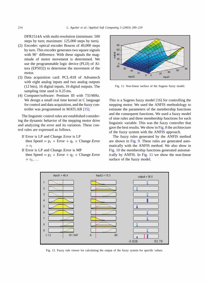
Fig. 12. Fuzzy rule viewer for calculating the output of the fuzzy system for specific values.
Fig. 11. Non-linear surface of the Sugeno fuzzy model.
This is a Sugeno fuzzy model [16] for controlling thestepping motor. We used the ANFIS methodology toestimate the parameters of the membership functionsand the consequent functions. We used a fuzzy modelof nine rules and three membership functions for eachlinguistic variable. This was the fuzzy controller thatgave the best results. We show in Fig. 8 the architectureof the fuzzy system with the ANFIS approach.
The fuzzy rules generated by the ANFIS methodare shown in Fig. 9. These rules are generated auto-matically with the ANFIS method. We also show inFig. 10 the membership functions generated automat-ically by ANFIS. In Fig. 11 we show the non-linearsurface of the fuzzy model.
L. Aguilar et al. / Applied Soft Computing 3 (2003) 209–219 215
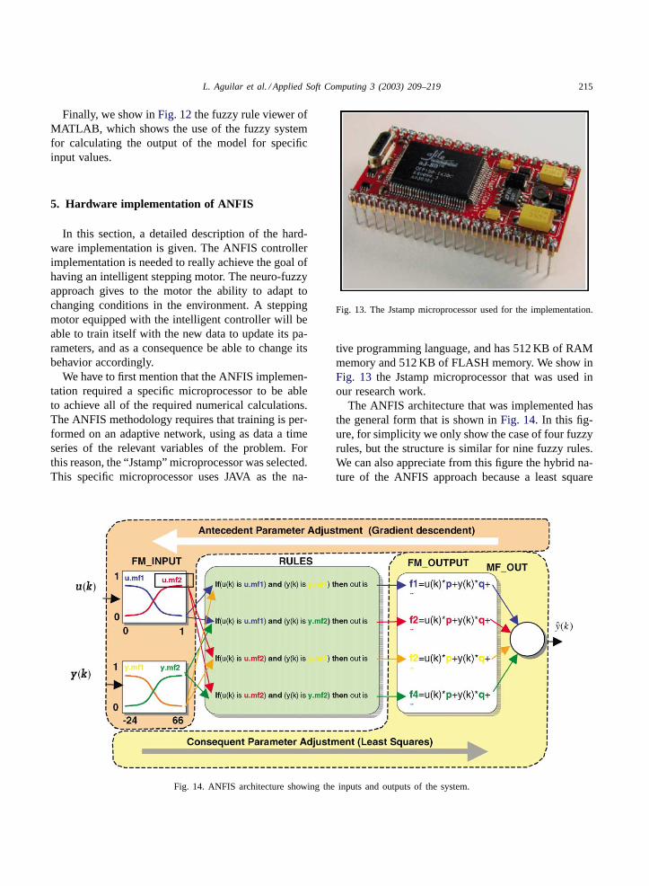
Finally, we show in Fig. 12 the fuzzy rule viewer ofMATLAB, which shows the use of the fuzzy systemfor calculating the output of the model for specificinput values.
5. Hardware implementation of ANFIS
In this section, a detailed description of the hard-ware implementation is given. The ANFIS controllerimplementation is needed to really achieve the goal ofhaving an intelligent stepping motor. The neuro-fuzzyapproach gives to the motor the ability to adapt tochanging conditions in the environment. A steppingmotor equipped with the intelligent controller will beable to train itself with the new data to update its pa-rameters, and as a consequence be able to change itsbehavior accordingly.
We have to first mention that the ANFIS implemen-tation required a specific microprocessor to be ableto achieve all of the required numerical calculations.The ANFIS methodology requires that training is per-formed on an adaptive network, using as data a timeseries of the relevant variables of the problem. Forthis reason, the “Jstamp” microprocessor was selected.This specific microprocessor uses JAVA as the na-
Fig. 14. ANFIS architecture showing the inputs and outputs of the system.
Fig. 13. The Jstamp microprocessor used for the implementation.
tive programming language, and has 512 KB of RAMmemory and 512 KB of FLASH memory. We show inFig. 13 the Jstamp microprocessor that was used inour research work.
The ANFIS architecture that was implemented hasthe general form that is shown in Fig. 14. In this fig-ure, for simplicity we only show the case of four fuzzyrules, but the structure is similar for nine fuzzy rules.We can also appreciate from this figure the hybrid na-ture of the ANFIS approach because a least square
216 L. Aguilar et al. / Applied Soft Computing 3 (2003) 209–219
Fig. 15. Block diagram showing the connections of the micro-controller.
0 50 100 150 200 250 300 350 400-10
0
10
20
30
40
50
60
70
80
90
Samples
Out
put
Stepping Motor (Input-Output)
Input Output
Fig. 16. Response of the stepping motor to a sequence of step input signals.
L. Aguilar et al. / Applied Soft Computing 3 (2003) 209–219 217
method is used in the forward direction and the back-propagation algorithm is used in the backward direc-tion. These methods were implemented in the JAVAlanguage and then they were downloaded to the Js-tamp microprocessor to obtain the controller.
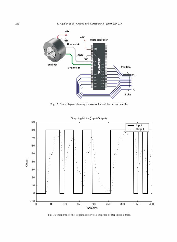
We also used a micro-controller for detecting theposition of the encoder. The specific type of the micro-controller is the SX28 from the Ubicom company. TheSX28 is a micro-controller based on Flash memoryand with RISC type architecture. We show in Fig. 15the block diagram of the connections for detectingthe position of the encoder.
6. Experimental results
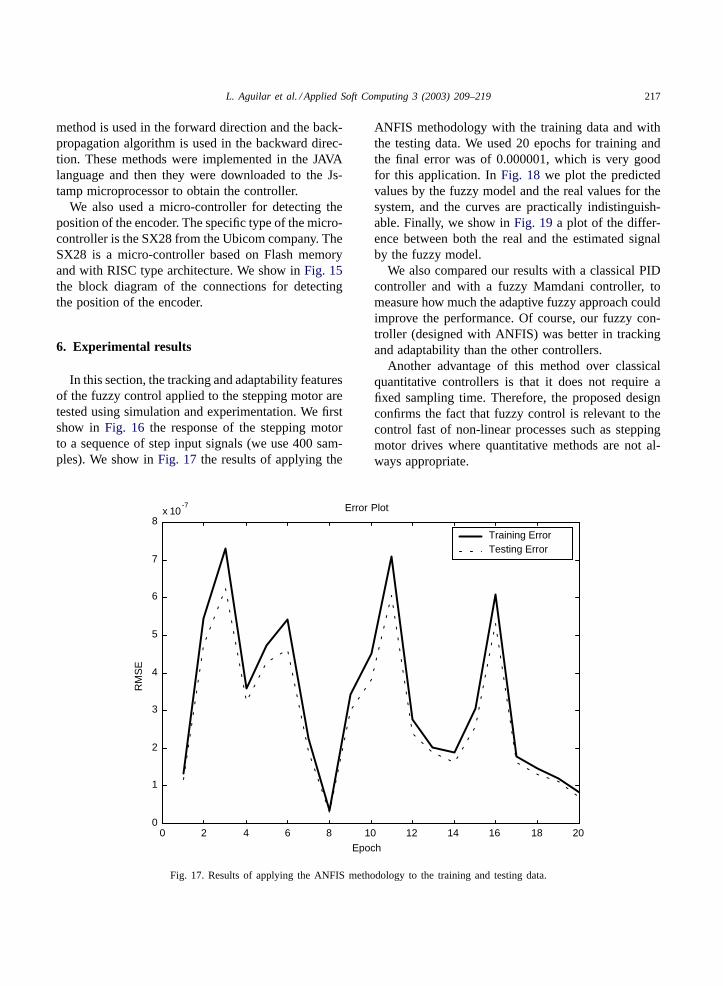
In this section, the tracking and adaptability featuresof the fuzzy control applied to the stepping motor aretested using simulation and experimentation. We firstshow in Fig. 16 the response of the stepping motorto a sequence of step input signals (we use 400 sam-ples). We show in Fig. 17 the results of applying the
0 2 4 6 8 10 12 14 16 18 200
1
2
3
4
5
6
7
8x 10
-7 Error Plot
Epoch
RM
SE
Training ErrorTesting Error
Fig. 17. Results of applying the ANFIS methodology to the training and testing data.
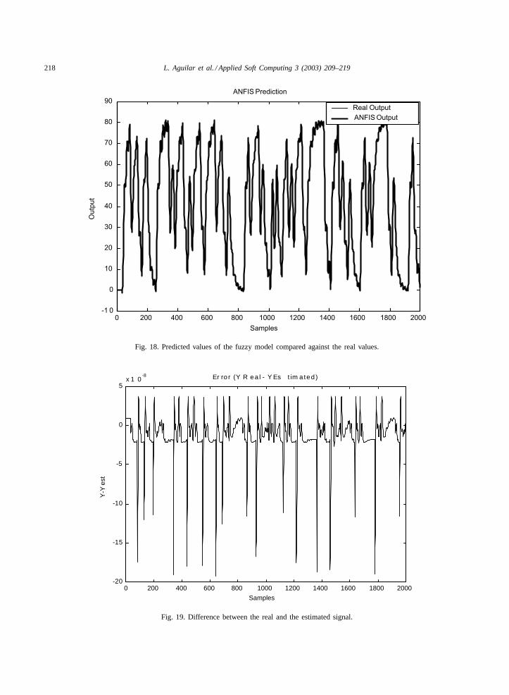
ANFIS methodology with the training data and withthe testing data. We used 20 epochs for training andthe final error was of 0.000001, which is very goodfor this application. In Fig. 18 we plot the predictedvalues by the fuzzy model and the real values for thesystem, and the curves are practically indistinguish-able. Finally, we show in Fig. 19 a plot of the differ-ence between both the real and the estimated signalby the fuzzy model.
We also compared our results with a classical PIDcontroller and with a fuzzy Mamdani controller, tomeasure how much the adaptive fuzzy approach couldimprove the performance. Of course, our fuzzy con-troller (designed with ANFIS) was better in trackingand adaptability than the other controllers.
Another advantage of this method over classicalquantitative controllers is that it does not require afixed sampling time. Therefore, the proposed designconfirms the fact that fuzzy control is relevant to thecontrol fast of non-linear processes such as steppingmotor drives where quantitative methods are not al-ways appropriate.
218 L. Aguilar et al. / Applied Soft Computing 3 (2003) 209–219
0 200 400 600 800 1000 1200 1400 1600 1800 2000-1 0
0
10
20
30
40
50
60
70
80
90 ANFIS Prediction
Samples
Out
put
Real Output ANFIS Output
Fig. 18. Predicted values of the fuzzy model compared against the real values.
0 200 400 600 800 1000 1200 1400 1600 1800 2000-20
-15
-10
-5
0
5x 1 0
-8 Er ro r (Y R ea l - Y Es t im a ted)
Samples
Y-Y
est
Fig. 19. Difference between the real and the estimated signal.
L. Aguilar et al. / Applied Soft Computing 3 (2003) 209–219 219
7. Conclusions
In this paper, the feasibility of fuzzy control for step-ping motor drives has been proved and illustrated bysimulation and experimentation. The best parametersfor the fuzzy controller were determined by using theANFIS methodology and also by using simulations ofthe stepping motor dynamics. An experimental systemwas used to validate experimentally the tracking abilityand the insensibility to plant parameter changes. Thefuzzy controller presented very interesting trackingfeatures and was able to respond to different dynamicconditions. Also, the fuzzy control computation is veryinexpensive, and this regulator could be used for thecontrol of machine tools and robotics manipulators [6]without significantly increasing the cost of the drive.
The only extra cost is for the optical encoder.Another advantage of this method over classicalquantitative controllers is that it does not require afixed sampling time. Therefore, the proposed designconfirms the fact that fuzzy control is relevant tothe control fast of non-linear processes such as step-ping motor drives where quantitative methods are notalways appropriate.
Acknowledgements
We would like to thank the Research Grant Com-mittee of COSNET and CONACYT for the financialsupport for performing this research work. We wouldalso like to thank the Department of Computer Sci-ence of Tijuana Institute of Technology for the timeand resources given to this project.
References
[1] F. Betin, D. Pinchon, G.A. Capolino, Fuzzy logic applied tospeed control of a motor drive, IEEE Trans. Ind. Electron.47 (2000) 610–622.
[2] O. Castillo, P. Melin, A new fuzzy-fractal-genetic method forautomated mathematical modelling and simulation of robotic
dynamic systems, in: Proceedings of FUZZ’98, Anchorage,Alaska, vol. 2, 1998, pp. 1182–1187.
[3] O. Castillo, P. Melin, Automated mathematical modelling,simulation and behavior identification of robotic dynamicsystems using a fuzzy-fractal-genetic approach, J. RoboticsAutonomous Syst. 28 (1) 19–30.
[4] O. Castillo, P. Melin, Soft Computing for Controlof Non-Linear Dynamical Systems, Springer, Heidelberg,Germany, 2001.
[5] O. Castillo, P. Melin, A hybrid fuzzy-fractal approach fortime series analysis and plant monitoring, Int. J. Intell. Syst.17 (8) (2002) 751–765.
[6] K.S. Fu, R.C. Gonzalez, C.S.G. Lee, Robotics: Control,Sensing, Vision and Intelligence, McGraw-Hill, New York,1987.
[7] J.S.R. Jang, C.T. Sun, E. Mizutani, Neuro-Fuzzy and SoftComputing, Prentice-Hall, Englewood Cliffs, NJ, 1997.
[8] T. Kenjo, A. Sugawara, Stepping Motors, Oxford SciencePublications, Oxford, 1994.
[9] Y.F. Li, C.C. Lau, Developments of fuzzy algorithms forservo systems, IEEE Control Syst. Mag. 9 (1989) 65–72.
[10] E.H. Mamdani, Application of fuzzy algorithms for controlof a simple dynamic plant, Proc. IEEE 121 (1974) 1585–1588.
[11] P. Melin, O. Castillo, A new method for adaptivemodel-based control of non-linear dynamic plants using aneuro-fuzzy-fractal approach, Soft Comput. J. 5 (2) (2001)171–177.
[12] P. Melin, O. Castillo, Intelligent control of complexelectrochemical systems with a neuro-fuzzy-genetic approach,IEEE Trans. Ind. Electron. 48 (5) (2001) 951–955.
[13] P. Melin, O. Castillo, Modelling, Simulation and Control ofNon-Linear Dynamical Systems, Taylor & Francis, London,2002.
[14] P. Melin, O. Castillo, Adaptive model-based control ofnon-linear dynamical systems with a neuro-fuzzy-geneticapproach, Int. J. Smart Eng. Syst. Design 4 (1) (2002) 41–47.
[15] S. Nakamura, Numerical Analysis and Graphic Visualizationwith MATLAB, Prentice-Hall, Englewood Cliffs, NJ, 1997.
[16] M. Sugeno, G.T. Kang, Structure identification of fuzzymodel, Fuzzy Sets Syst. 28 (1988) 15–33.
[17] L.A. Zadeh, Fuzzy sets, Inform. Control 8 (1965) 338–353.[18] L.A. Zadeh, Quantitative fuzzy semantics, Inform. Sci. 3
(1971) 159–176.[19] L.A. Zadeh, Outline of a new approach to the analysis of
complex systems and decision processes, IEEE Trans. Syst.Man Cybernetics 3 (1) (1973) 28–44.
[20] L.A. Zadeh, The concept of a linguistic variable and itsapplication to approximate reasoning, Inform. Sci. 8 (1975)43–80.