Integration of MAC/GMC into CalculiX, an open source finite ...
10
Integration of MAC/GMC into CalculiX, an open source finite element code Francisco A. Yapor Genao * Western Michigan University, Kalamazoo, MI, 49008, USA Evan J. Pineda † NASA Glenn Research Center, Cleveland, OH, 44135, USA Brett A. Bednarcyk ‡ NASA Glenn Research Center, Cleveland, OH, 44135, USA Peter A. Gustafson § Western Michigan University, Kalamazoo, MI, 49008, USA An analysis framework is presented that makes available multiscale analysis of composite structures using the open-source FEA solver package CalculiX CrunchiX (CCX). At the center of this framework is the coupling of the Finite Element Analysis - Micromechanics Analy- sis Code (FEAMAC) library from NASA’s Micromechanics Analysis Code with Generalized Method of Cells (MAC/GMC) to allow micromechanics analysis. The results show that the pro- posed coupling can be used with appropriate care for multiscale FEA simulations of composite materials. The largest error reported in this validation was in a four-point bend test specimen with an error of less than 1 % difference in the maximum deflection of the beam. I. Introduction T use of composite materials continues to grow in the engineering practice. Their use in the aerospace industry is extensive and attractive given their tailoring capabilities and specific properties. Accurate predictions of macro-scale failure and the lifecycle of these composite materials are of critical importance to structural designs; however, the failure mechanisms are dependent on the micro-scale phenomenon. The Generalized Method of Cells (GMC) is a semi-analytical micromechanics theory that is computationally efficient and provides acceptably accurate displacement and stress fields at at scales of interest. As such, it is suitable for multiscale applications [1]. For a review of multiscale methods to predict mechanical and thermo-mechanical responses of composites, the reader is directed to Kanouté et al. [2], Aboudi et al. [3], and Dvorak [4]. The Micromechanics Analysis Code with Generalized Method of Cells (MAC/GMC) is based on the GMC theory, developed at NASA Glenn Research Center and available free of charge to United States persons. A multiscale coupling procedure, the Finite Element Analysis - Micromechanics Analysis Code (FEAMAC), was developed by Bednarcyk and Arnold [5] to couple the commercially available Abaqus Finite Element Analysis (FEA) package, through a set of user-defined Fortran subroutines linked with a compiled Fortran library of MAC/GMC, to perform micromechanics calculations for the FEA model. Currently, this limits the use of FEAMAC to users of a single commercial FEA package and hinders broader use of FEAMAC by the composites community. For example, the current academic teaching license for Abaqus does not permit the use of user-defined subroutines or compiling and linking Fortran libraries. This restriction makes it difficult for academic users to study, implement, and test recently developed models or investigate a particular problem. Research-level open-source codes have become an attractive option in academic research given their ability to allow the user to modify the behavior of the software to address particular needs. The present study aims to link an open-source finite element package to the MAC/GMC code. This coupling supports the use and growth of the audience who can utilize multiscale analysis for composite materials and structures. * Graduate student, Mechanical and Aerospace Engineering, [email protected], and AIAA Member † Aerospace Research Engineer, Multiscale and Multiphysics Modeling Branch, [email protected], and AIAA Member ‡ Materials Research Engineer, Multiscale and Multiphysics Modeling Branch, [email protected] , and AIAA Associate Fellow § Associate Professor, Mechanical and Aerospace Engineering, [email protected], and AIAA Member 1
-
Upload
khangminh22 -
Category
Documents
-
view
4 -
download
0
Transcript of Integration of MAC/GMC into CalculiX, an open source finite ...

Integration of MAC/GMC into CalculiX, an open source finiteelement code
Francisco A. Yapor Genao ∗
Western Michigan University, Kalamazoo, MI, 49008, USA
Evan J. Pineda †
NASA Glenn Research Center, Cleveland, OH, 44135, USA
Brett A. Bednarcyk ‡
NASA Glenn Research Center, Cleveland, OH, 44135, USA
Peter A. Gustafson §
Western Michigan University, Kalamazoo, MI, 49008, USA
An analysis framework is presented that makes available multiscale analysis of compositestructures using the open-source FEA solver package CalculiX CrunchiX (CCX). At the centerof this framework is the coupling of the Finite Element Analysis - Micromechanics Analy-sis Code (FEAMAC) library from NASA’s Micromechanics Analysis Code with GeneralizedMethod of Cells (MAC/GMC) to allow micromechanics analysis. The results show that the pro-posed coupling can be used with appropriate care for multiscale FEA simulations of compositematerials. The largest error reported in this validation was in a four-point bend test specimenwith an error of less than 1 % difference in the maximum deflection of the beam.
I. Introduction
The use of composite materials continues to grow in the engineering practice. Their use in the aerospace industryis extensive and attractive given their tailoring capabilities and specific properties.Accurate predictions of macro-scale failure and the lifecycle of these composite materials are of critical importance
to structural designs; however, the failure mechanisms are dependent on the micro-scale phenomenon. The GeneralizedMethod of Cells (GMC) is a semi-analytical micromechanics theory that is computationally efficient and providesacceptably accurate displacement and stress fields at at scales of interest. As such, it is suitable for multiscale applications[1]. For a review of multiscale methods to predict mechanical and thermo-mechanical responses of composites, thereader is directed to Kanouté et al. [2], Aboudi et al. [3], and Dvorak [4].
The Micromechanics Analysis Code with Generalized Method of Cells (MAC/GMC) is based on the GMC theory,developed at NASA Glenn Research Center and available free of charge to United States persons. A multiscale couplingprocedure, the Finite Element Analysis - Micromechanics Analysis Code (FEAMAC), was developed by Bednarcykand Arnold [5] to couple the commercially available Abaqus Finite Element Analysis (FEA) package, through a set ofuser-defined Fortran subroutines linked with a compiled Fortran library of MAC/GMC, to perform micromechanicscalculations for the FEA model. Currently, this limits the use of FEAMAC to users of a single commercial FEA packageand hinders broader use of FEAMAC by the composites community. For example, the current academic teachinglicense for Abaqus does not permit the use of user-defined subroutines or compiling and linking Fortran libraries. Thisrestriction makes it difficult for academic users to study, implement, and test recently developed models or investigate aparticular problem. Research-level open-source codes have become an attractive option in academic research given theirability to allow the user to modify the behavior of the software to address particular needs.
The present study aims to link an open-source finite element package to the MAC/GMC code. This couplingsupports the use and growth of the audience who can utilize multiscale analysis for composite materials and structures.
∗Graduate student, Mechanical and Aerospace Engineering, [email protected], and AIAA Member†Aerospace Research Engineer, Multiscale and Multiphysics Modeling Branch, [email protected], and AIAA Member‡Materials Research Engineer, Multiscale and Multiphysics Modeling Branch, [email protected] , and AIAA Associate Fellow§Associate Professor, Mechanical and Aerospace Engineering, [email protected], and AIAA Member
1

There are many open-source FEA packages available in the open domain that can be used for this purpose. The FEApackage CalculiX was selected given the similarities on the input file format with the commercial code Abaqus [6].
II. MethodologyThe principle of execution mirrors that of FEAMAC with Abaqus in this new implementation with CalculiX
CrunchiX (CCX). The MAC/GMC code will operate as a nonlinear constitutive model within the CalculiX CrunchiXsimulation, representing a heterogeneous composite material for which the response is evaluated at the integration pointswithin the finite elements of the macroscopic or structural-level FEA model. The CalculiX CrunchiX user-definedmaterial (UMAT) subroutine provides current strains, incremental strains, stresses, and solution-dependent variables(SDVs) at the integration points to MAC/GMC through subroutine calls to the linked FEAMAC library. MAC/GMCperforms the repeating unit cell (RUC)-level micromechanics analysis by calculating the local fields within the RUC(including local damage and nonlinearity of the constituents), and returning a new homogenized state of stress andmaterial stiffness at the integration point as described by Bednarcyk and Arnold [5]. After this process is completed forall the elements containing the GMC material, the process proceeds with forming and solving the global finite elementequations iteratively.
Along with FEAMAC distribution package, several validation examples are provided to the end-users as part of thedocumentation. Three mechanical, i.e. no thermal loading, example problems were selected to validate the integrationof FEAMAC into CCX by comparing the results to those provided as reference values from the coupling with FEAMACand Abaqus.
III. Validation
A. Problem 1: Unit cubes in uniaxial stress
1. DescriptionThis problem involves two unit cubes connected along the x-axis to emulate a simple uniaxial loading condition
along the x-axis. The cubes are in the form of linear 3D-solid continuum elements (C3D8), fully integrated, as describedby Dhondt [7]. The material assigned to both elements is the same MAC/GMC material, a 33% volume fiber fractionSilicon Carbide-Titanium (SiC/Ti) metal-matrix composite. The material properties and models are specified in theinput file for the MAC/GMC simulation. The filename for the MAC/GMC input file must be specified as the name ofthe material for the CCX input file, CCX pass the material filename information to the linked FEAMAC library for themicromechanics analysis. In the MAC/GMC input file, the SiC/Ti is modeled using a 2 × 2 GMC doubly-periodicRUC, as described and adapted from Bednarcyk and Arnold [5]. The orientation of the RUC GMC material is shown inFigure 1 (right), where the x1 axis (into the page) is the direction of the fiber reinforcement, and is aligned to the x axisof the global FEA model. Other material orientations can be analyzed by using the keyword *ORIENTATION in theCCX input file, this allows the user to specify a local axes system to be used for defining material properties [7]. Allintegration points in both elements have their material constitutive response described by this MAC/GMC material. Theviscoplastic material response of the Titanium matrix was modeled via the Generalized Viscoplasticity with PotentialStructure (GVIPS) constitutive model within MAC/GMC given its numerical efficiency and predictive capabilities whencompared to other commonly used viscoplastic models (e.g., Bodner-Partom model) as mentioned by Arnold et al. [8].The SiC fiber was modeled using linear elastic and isotropic model. The elastic material properties of both materials, atroom temperature, are shown in Table 1.
Material E (GPa) ν
SiC Fibers 393.0 0.250Ti Matrix* 114.1 0.365
Table 1 Elastic properties of RUC materials
where E denotes the elastic modulus and ν the Poisson’s ratio. * The GVIPS constitutive model requires otherparameters. See Bednarcyk and Arnold [5] for details.
2

Fig. 1 FEA model (left) and GMC materials (right)
2. Boundary and loading conditionsThe model is 2 inches long in the direction of applied load, and 1 inch in the other two directions. Figure 1 shows
the node numbering and arrows pointing the directions of the displacement. For the homogeneous boundary conditions:1) Zero displacement in the x-direction for nodes 1, 2, 3, and 4.2) Zero displacement in the y-direction for nodes 3 and 9.3) Zero displacement in the z-direction for node 9.
For the applied displacement:1) A total displacement of +0.03 inches in x-direction for nodes 9, 10, 11, and 12.
The applied displacement of 0.03 inches corresponds to an applied strain of 0.015 in the composite. This problemwas verified to be identical to a stand-alone MAC/GMC problem in which a strain of 0.015 is applied directly to thecomposite using the same MAC/GMC material. The displacement is applied in a single quasi-static step with a totalof 150 seconds, with 2 seconds per increment, for a global strain rate of 1.0 × 10⁻⁴/second. Longitudinal (RUC fiberx1-axis is aligned with the loading x-axis) and transverse (RUC fiber x1 axis is normal to the loading x-axis) materialorientations were considered in separate CCX executions, using the keyword *ORIENTATION in the CCX input files.
3. ResultsLongitudinal and transverse stress-strain curves are shown in Figure 2a. The curves labeled "CCX" are plotted from
the CCX simulation at the integration point 1 of element 1. All integration points were numerically identical given theuniform state of stress that results from this loading condition. Since the problem simulates uniform stress and strainthroughout the FEM model, results should be identical to a strain-controlled stand-alone MAC/GMC problem of theSiC/Ti composite.
The percent error is plotted in Figure 2b for both material orientations. The experimental measure (e) is thesimulation from the CCX run and the reference method (r) is the results from the FEAMAC with Abaqus. The error isthen calculated as: error % = (e/r − 1) × 100. Note that the error is in the order of 5.0 × 10⁻⁵, which is attributed tonumerical round-off of the different solvers and convergence tolerances used in both FEA packages.
The RUC-level equivalent plastic strain is plotted in Figure 3a. The values were numerically identical to thosereported in the documentation and also compared to the strain-controlled stand-alone MAC/GMC.
Figure 3b provides the contour plots of the uniform von Mises stress field in the longitudinal and transverse directionsof the MAC/GMC material at the end of the simulation (i.e., same strain point 0.015). This supports the plot fromFigure 2a, with the longitudinal stress at 399.6 ksi versus the transverse stress at 232.2 ksi.
3

(a) Stress-strain curves (b) Error in stress
Fig. 2 Stress vs. strain in both material orientations
(a) Equivalent plastic strain in RUC (b) Contour plots of von Mises stress
Fig. 3 Equivalent plastic strain and contour of von Mises stress plots
B. Problem 2: Tensile specimen in uniaxial tension
1. DescriptionThis second problem involves the analysis of a tensile test specimen subjected to displacement controlled loading
from Bednarcyk and Arnold [9]. The specimen geometry is shown in Figure 4a, and the quarter-symmetry simplificationand finite element mesh model, consisting of 432 C3D8 elements, are shown in Figures 4b and 5 respectively. TheMAC/GMC material is again a 33% volume fraction SiC/Ti composite with a 2 × 2 GMC doubly-periodic RUC. Allelements and integration points use the MAC/GMC material to provide the constitutive response.
Tensile specimens, like the one shown in Figure 4a, are useful in testing given their simplicity and also can provide atypical material response in the gauge section where the strain is typically measured (via strain gauge, extensometer,
4
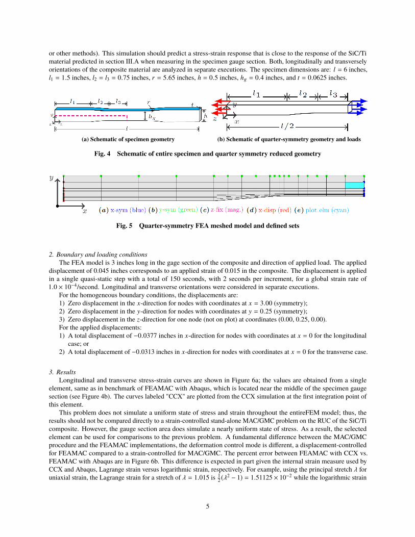
or other methods). This simulation should predict a stress-strain response that is close to the response of the SiC/Timaterial predicted in section III.A when measuring in the specimen gauge section. Both, longitudinally and transverselyorientations of the composite material are analyzed in separate executions. The specimen dimensions are: l = 6 inches,l1 = 1.5 inches, l2 = l3 = 0.75 inches, r = 5.65 inches, h = 0.5 inches, hg = 0.4 inches, and t = 0.0625 inches.
(a) Schematic of specimen geometry (b) Schematic of quarter-symmetry geometry and loads
Fig. 4 Schematic of entire specimen and quarter symmetry reduced geometry
Fig. 5 Quarter-symmetry FEA meshed model and defined sets
2. Boundary and loading conditionsThe FEA model is 3 inches long in the gage section of the composite and direction of applied load. The applied
displacement of 0.045 inches corresponds to an applied strain of 0.015 in the composite. The displacement is appliedin a single quasi-static step with a total of 150 seconds, with 2 seconds per increment, for a global strain rate of1.0 × 10−4/second. Longitudinal and transverse orientations were considered in separate executions.
For the homogeneous boundary conditions, the displacements are:1) Zero displacement in the x-direction for nodes with coordinates at x = 3.00 (symmetry);2) Zero displacement in the y-direction for nodes with coordinates at y = 0.25 (symmetry);3) Zero displacement in the z-direction for one node (not on plot) at coordinates (0.00, 0.25, 0.00).For the applied displacements:1) A total displacement of −0.0377 inches in x-direction for nodes with coordinates at x = 0 for the longitudinal
case; or2) A total displacement of −0.0313 inches in x-direction for nodes with coordinates at x = 0 for the transverse case.
3. ResultsLongitudinal and transverse stress-strain curves are shown in Figure 6a; the values are obtained from a single
element, same as in benchmark of FEAMAC with Abaqus, which is located near the middle of the specimen gaugesection (see Figure 4b). The curves labeled "CCX" are plotted from the CCX simulation at the first integration point ofthis element.
This problem does not simulate a uniform state of stress and strain throughout the entireFEM model; thus, theresults should not be compared directly to a strain-controlled stand-alone MAC/GMC problem on the RUC of the SiC/Ticomposite. However, the gauge section area does simulate a nearly uniform state of stress. As a result, the selectedelement can be used for comparisons to the previous problem. A fundamental difference between the MAC/GMCprocedure and the FEAMAC implementations, the deformation control mode is different, a displacement-controlledfor FEAMAC compared to a strain-controlled for MAC/GMC. The percent error between FEAMAC with CCX vs.FEAMAC with Abaqus are in Figure 6b. This difference is expected in part given the internal strain measure used byCCX and Abaqus, Lagrange strain versus logarithmic strain, respectively. For example, using the principal stretch λ foruniaxial strain, the Lagrange strain for a stretch of λ = 1.015 is 1
2 (λ2 − 1) = 1.51125 × 10⁻² while the logarithmic strain
5

is ln(λ) = 1.48886 × 10⁻² which generates an error of 1.50375 × 10⁻² using the logarithmic strain as the referencemethod since it is used by FEAMAC with Abaqus. This approximately is in the order of magnitudes shown in Figure 6b.
The von Mises stress field contour plots in the longitudinal and transverse directions of the MAC/GMC materialare shown in Figure 7, which is taken at the end of the simulation (i.e., same strain point 0.015). These figures alsoshow that, while the fields are close to constant in the middle of the gauge section, the concentrations arise in the gaugetransition region.
(a) Stress-strain curves (b) Error in stress
Fig. 6 Stress-strain in both material orientations
Fig. 7 Contour plot of von Mises stress
6

C. Problem 3: Four-point bend specimen
1. DescriptionThe third problem involves the analysis of a composite beam specimen under the conditions of a four-point flexural
test. The geometry of the beam specimen is shown in Figure 8a, and the quarter-symmetry FEA mesh, consistingof 2142 C3D8 elements, is shown in Figure 8b. The MAC/GMC material is again a SiC/Ti composite with a 2 × 2GMC doubly-periodic RUC. However, this time, the fiber volume fraction is at 25% instead of 33% as in the previousproblems. The RUC orientation remains unchanged, the only change is to the volume fraction in the MAC input file.All elements and integration points use the MAC/GMC material to provide the constitutive response.
Given the rectangular cross-section of the specimen, an analytical solution for the midspan deflection of the four-pointflexural specimen is readily available from Euler-Bernoulli’s beam theory, assuming a constant (homogenized) flexuralrigidity. The midspan deflection, vmidspan, is given by:
vmidspan = −Pa
24EI
(3l2 − 4a2
)(1)
where, P is the applied load, E is the effective modulus of the specimen along the length of the specimen, I themoment of inertia, l is the length of the specimen, and a is the distance between the applied load and the supports ora = (ls − lp)/2. The specimen dimensions are (all in millimeters): l = 50, ls = 40, lp = 20, h = 3, and t = 4.
(a) Schematic of specimen geometry (b) Quarter-symmetry FEA meshed model and defined sets
Fig. 8 Schematic of entire specimen and quarter symmetry reduced FEA model
2. Boundary and loading conditionsSimilarly, as in the previous examples, longitudinal and transverse cases were considered in separate executions. For
the homogeneous boundary conditions, the displacements are:1) Zero displacement in the x-direction for nodes with coordinates at x = 0.00 (symmetry);2) Zero displacement in the y-direction for nodes 1401 and 1716 with coordinates at (20,−1.5,0) and (20,−1.5,2.0)
(supports);3) Zero displacement in the z-direction for nodes with coordinates at z = 0.00 (symmetry).For the applied load P, the keyword *DLOAD in CCX is used. This keyword allows the specification of distributed
loads, in this case, a constant pressure loading on element faces. The face that is normal to y-direction of two elements,highlighted in red in Figure 8 (b), is selected:
1) Total pressure of 2500 MPa on elements located at (10,3, z) for longitudinal case; Or2) Total pressure of 1400 MPa for transverse case (same elements).
This distributed pressure on the top surface of these two elements over a total area of 0.2 mm × 2 mm × 2 = 0.8 mm2.The last multiple of two is due to the symmetry of the model. The equivalent force load corresponding to the appliedpressure is then 0.8 mm2 × P, or 2000 N and 1120 N for the longitudinal and transverse case, respectively.
Note that the MAC/GMC input file has material properties in ksi units, while the CCX input file is in length units ofmillimeters and pressure units of MPa. To address this, the keyword *CONVERT has been used in the MAC/GMC inputfile with a specified conversion factor of 6.895 MPa/ksi. This will cause the MAC/GMC stress and stiffness components,which are in ksi, to be multiplied before they are passed back to CCX. As a result, the CCX-level results will be in unitsof MPa, while the MAC/GMC-level results remain in ksi units.
7
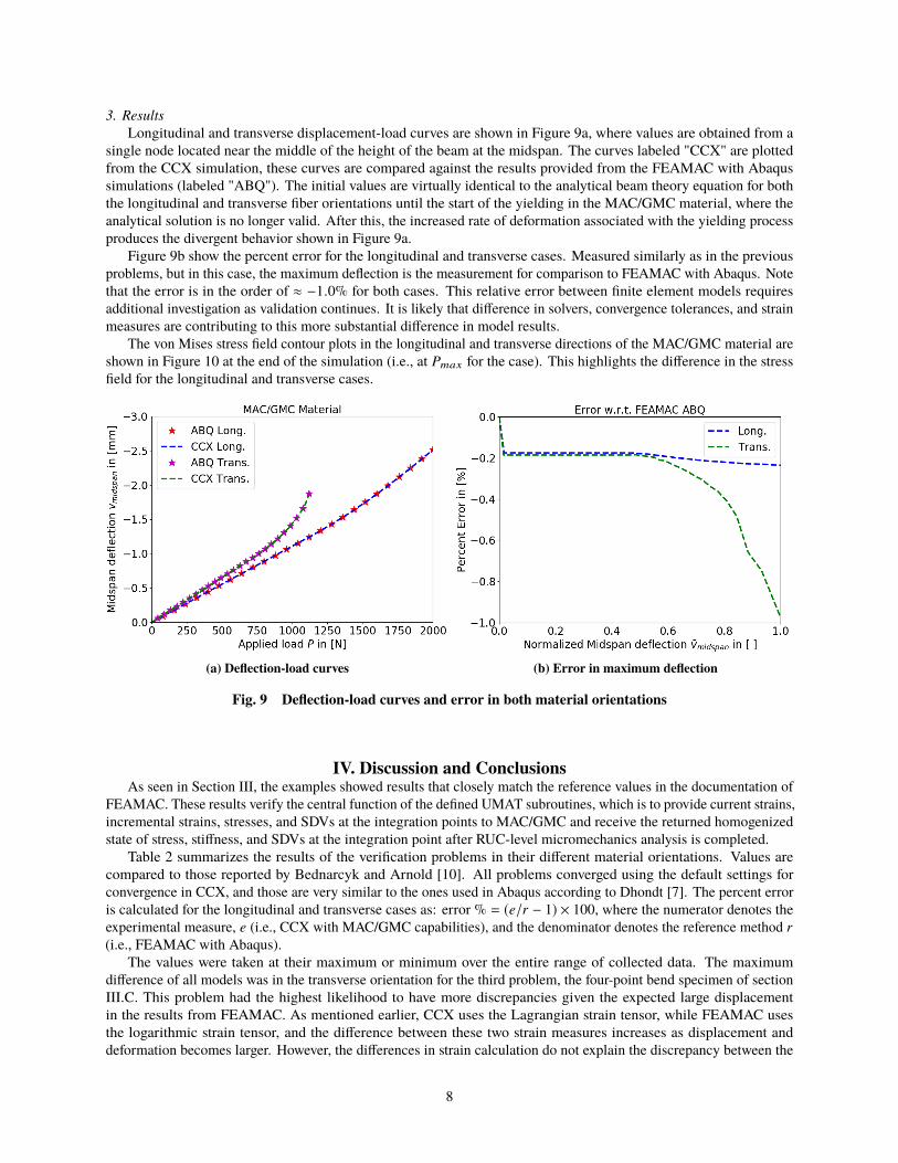
3. ResultsLongitudinal and transverse displacement-load curves are shown in Figure 9a, where values are obtained from a
single node located near the middle of the height of the beam at the midspan. The curves labeled "CCX" are plottedfrom the CCX simulation, these curves are compared against the results provided from the FEAMAC with Abaqussimulations (labeled "ABQ"). The initial values are virtually identical to the analytical beam theory equation for boththe longitudinal and transverse fiber orientations until the start of the yielding in the MAC/GMC material, where theanalytical solution is no longer valid. After this, the increased rate of deformation associated with the yielding processproduces the divergent behavior shown in Figure 9a.
Figure 9b show the percent error for the longitudinal and transverse cases. Measured similarly as in the previousproblems, but in this case, the maximum deflection is the measurement for comparison to FEAMAC with Abaqus. Notethat the error is in the order of ≈ −1.0% for both cases. This relative error between finite element models requiresadditional investigation as validation continues. It is likely that difference in solvers, convergence tolerances, and strainmeasures are contributing to this more substantial difference in model results.
The von Mises stress field contour plots in the longitudinal and transverse directions of the MAC/GMC material areshown in Figure 10 at the end of the simulation (i.e., at Pmax for the case). This highlights the difference in the stressfield for the longitudinal and transverse cases.
(a) Deflection-load curves (b) Error in maximum deflection
Fig. 9 Deflection-load curves and error in both material orientations
IV. Discussion and ConclusionsAs seen in Section III, the examples showed results that closely match the reference values in the documentation of
FEAMAC. These results verify the central function of the defined UMAT subroutines, which is to provide current strains,incremental strains, stresses, and SDVs at the integration points to MAC/GMC and receive the returned homogenizedstate of stress, stiffness, and SDVs at the integration point after RUC-level micromechanics analysis is completed.
Table 2 summarizes the results of the verification problems in their different material orientations. Values arecompared to those reported by Bednarcyk and Arnold [10]. All problems converged using the default settings forconvergence in CCX, and those are very similar to the ones used in Abaqus according to Dhondt [7]. The percent erroris calculated for the longitudinal and transverse cases as: error % = (e/r − 1) × 100, where the numerator denotes theexperimental measure, e (i.e., CCX with MAC/GMC capabilities), and the denominator denotes the reference method r(i.e., FEAMAC with Abaqus).
The values were taken at their maximum or minimum over the entire range of collected data. The maximumdifference of all models was in the transverse orientation for the third problem, the four-point bend specimen of sectionIII.C. This problem had the highest likelihood to have more discrepancies given the expected large displacementin the results from FEAMAC. As mentioned earlier, CCX uses the Lagrangian strain tensor, while FEAMAC usesthe logarithmic strain tensor, and the difference between these two strain measures increases as displacement anddeformation becomes larger. However, the differences in strain calculation do not explain the discrepancy between the
8

Fig. 10 Contour plots of von Mises stress
two finite element models identified in section III.C. Nevertheless, both models compare favorably to the analyticalsolution with errors of less than 1% throughout the linear material response. It is likely that differing solvers andconvergence tolerances contributed to the difference in model results. The relative error between finite element modelsrequires additional investigation as validation continues.
Problem L/T Measure FEAMAC CCX + MAC error %
1 L Stress 3.9963E+2 3.9963E+2 3.9763E-51 T Stress 2.3219E+2 2.3219E+2 5.7596E-52 L Stress 3.9945E+2 3.9946E+2 5.8237E-32 T Stress 2.3384E+2 2.3395E+2 4.9821E-23 L Displacement -2.5184E+0 -2.5125E+0 -2.3545E-13 T Displacement -1.8780E+0 -1.8597E+0 -9.7397E-1
Table 2 Summary of validation results
where, L/T denotes the orientation of the MAC/GMC material, longitudinal (L) or transverse (T). Measure denotes thephysical quantity used to evaluate the implementation.
These results show that the proposed coupling of CCX and FEAMAC can be used with appropriate care formultiscale FEA simulation of composite materials. This work is the first step to support the use of the MAC/GMC codefor multiscale analysis of composite materials and structures using an open-source FEA package, CalculiX CrunchiX(CCX). Some of the limitations of the presented coupling are the following:
1) Thermo-mechanical analysis: this capability is available in FEAMAC with Abaqus and CCX is capable ofhandling thermo-mechanical analysis. However, implementing this coupling with FEAMAC requires significantwork on the CCX distribution to introduce a variable and user-definable coefficient of thermal expansion (CTE),which is not yet implemented.
2) Other MAC/GMC modules: The development-level MAC/GMC library only included the necessary modules forbenchmarking. There are other modules that were not loaded for this development version, for example modulesfor different doubly-periodic MAC/GMC RUCs architectures and also for the triply-periodic MAC/GMC RUCs.Equally important is the module for access to the user-definable MAC/GMC RUC capabilities.
The software used in this study are shown in Table 3. While other dependent software libraries may be required,
9

these other dependencies were managed using operating system package manager.
Analysis Tool VersionCalculiX CrunchiX (CCX) 2.14CalculiX GraphiX (CGX) 2.14
GNU Compiler Collection (GCC) 8.2.1Python 3.6.0(a) Analysis tools
Required Library Version
SPOOLES (CCX) 2.2ARPACK (CCX) 1.0FEAMAC (CCX) 4z-3_9 (dev)OpenGL (CGX) 3.1-8OpenGLU (CGX) 3.1-8(b) Key libraries for functionality
Table 3 Software used in this development work
AcknowledgmentsGratitude is extended to Dr. Guido Dhondt, Klaus Wittig, and all contributors to the CalculiX base code. To the
Ministry of Higher Education, Science, and Technology (MESCYT) from the Dominican Republic for their financialsupport of one of the authors. Also, to Tad Kollar from the Advanced Computational Concepts Laboratory and to therest of the team at NASA Glenn Research Center in the Materials and Structures Division for their support with theessential parts of this work. Lastly, to NASA’s Transformational Tools and Technologies (TTT) project for their supportfor this work.
References[1] Arnold, S. M., Bednarcyk, B. A., Wilt, T. E., and Trowbridge, D., “Micromechanics analysis code with generalized method of
cells MAC/GMC: user guide - version 3,” NASA Technical Reports Server, 1999. URL https://ntrs.nasa.gov/search.jsp?R=19990032036.
[2] Kanouté, P., Boso, D. P., Chaboche, J. L., and Schrefler, B. A., “Multiscale methods for composites: a review,” Archivesof Computational Methods in Engineering, Vol. 16, No. 1, 2009, pp. 31–75. doi:10.1007/s11831-008-9028-8, URLhttps://link.springer.com/content/pdf/10.1007%2Fs11831-008-9028-8.pdf.
[3] Aboudi, J., Arnold, S. M., and Bednarcyk, B. A., Micromechanics of composite materials: a generalized multiscale analysisapproach, Butterworth-Heinemann, 2013. URL https://books.google.com/books?id=jKJ2VqSwu08C.
[4] Dvorak, G. J., “Transformation field analysis of inelastic composite materials,” Proceedings: Mathematical and PhysicalSciences, Vol. 437, No. 1900, 1992, pp. 311–327. URL http://www.jstor.org/stable/52200.
[5] Bednarcyk, B. A., and Arnold, S. M., “A framework for performing multiscale stochastic progressive failure analysis ofcomposite structures,” techreport, National Aeronautics and Space Administration, 2007. URL https://ntrs.nasa.gov/archive/nasa/casi.ntrs.nasa.gov/20070019696.pdf.
[6] Dhondt, G., and Wittig, K., “CalculixX: A Free Software Three-Dimensional Structural Finite Element Program,” Web page,1998. URL http://www.calculix.de/, accessed 2018-09-23.
[7] Dhondt, G., “CalculiX CrunchiX User’s manual version 2.14,” Web page, 2018. URL http://www.dhondt.de/ccx_2.14.pdf, accessed 2018-09-27.
[8] Arnold, S. M., Saleeb, A. F., and Castelli, M. G., “A fully associative, nonlinear kinematic, unified viscoplastic model fortitanium-based matrices,” NASA Technical Reports Server, 1994. URL https://ntrs.nasa.gov/archive/nasa/casi.ntrs.nasa.gov/19940029452.pdf.
[9] Bednarcyk, B. A., and Arnold, S. M., “A multiscale, nonlinear, modeling framework enabling the design and analysis ofcomposite materials and structures,” NASA Technical Reports Server, 2012. URL https://ntrs.nasa.gov/archive/nasa/casi.ntrs.nasa.gov/20120014088.pdf.
[10] Bednarcyk, B. A., and Arnold, S. M., “MAC/GMC 4.0 User’s Manual: Example Problem Manual - Volume 3,” techreport,National Aeronautics and Space Administration, 2002. URL https://ntrs.nasa.gov/archive/nasa/casi.ntrs.nasa.gov/20030015411.pdf.
10