INTEGRATED GAS DYNAMIC AND THERMODYNAMIC COMPUTATIONAL MODELING OF MULTICYLINDER 4-STROKE SPARK...
18
INTEGRATED GAS DYNAMIC AND THERMODYNAMIC COMPUTATIONAL MODELING OF MULTICYLINDER 4-STROKE SPARK IGNITION ENGINE USING GASOLINE AS A FUEL by Jeevan V. TIRKEY, Hari N. GUPTA, and Shailendra K. SHUKLA Original scientific paper UDC: 621.43.05:517.95 DOI: 10.2298/TSCI0903113T This paper presents a computational tool for the evaluation of engine performance and exhaust emissions for four stroke multi-cylinder spark ignition engine which uses gasoline as a fuel. Gas dynamics flow in multi-cylinder intake and exhaust sys- tems are modeled by using one-dimensional unsteady compressible flow equations. The hyperbolic partial differential equations are transferred into a set of ordinary differential equations by using method of characteristics and solved by finite differ- ence method. Compatibility relationships between local fluid velocity and sonic ve- locity are expressed in terms of Riemann variables, which are constant along the position characteristics. The equations are solved numerically by using rectangu- lar grid in the flow direction and time. In this model nitric oxide concentration is predicted by using the rate kinetic model in the power cycle and along the exhaust pipes. Carbon monoxide is computed under chemical equilibrium condition and then empirical adjustment is made for kinetic behaviors based upon experimental results. A good agreement is obtained in the comparison of computed and experi- mental results of instantaneous cylinder pressure, manifold pressure and tempera- ture, and nitric oxide and carbon monoxide emissions level. Key words: computer simulation, method of characteristics, Riemann variables, non-homentropic, rate kinetics, exhaust species Introduction In recent years, the internal combustion engine powered vehicles have come under heavy attack due to environment pollution through exhaust emissions of mainly the oxides of ni- trogen (NO x ), carbon monoxide (CO), and unburned hydrocarbons (HC). It has a deleterious ef- fect on human beings and plants. So to achieve a clean environment, better understanding and modifications of the combustion process are necessary. At the same time, the fluid dynamic pro- cess is much important for determining the overall performance of internal combustion engine throughout its operating range. In this respect computerized simulation techniques have been tried in recent years to study the various parameters of engine performance and exhaust pollutant emissions, rather than performing the experiments by using a real engine. Abd Alla [1] has offered simulation modeling for single cylinder engine, which pro- vides the correlation of heat release rate formula to predict the cylinder pressure that can be used to find indicated power and other performances for engine. Kodah et al. [2], constructed a theo- retical model to predict the cylinder’s gas pressure, temperature, and rate of heat release. Raine THERMAL SCIENCE: Vol. 13 (2009), No. 3, pp. 113-130 113
Transcript of INTEGRATED GAS DYNAMIC AND THERMODYNAMIC COMPUTATIONAL MODELING OF MULTICYLINDER 4-STROKE SPARK...
INTEGRATED GAS DYNAMIC AND THERMODYNAMICCOMPUTATIONAL MODELING OF MULTICYLINDER 4-STROKE
SPARK IGNITION ENGINE USING GASOLINE AS A FUEL
by
Jeevan V. TIRKEY, Hari N. GUPTA, and Shailendra K. SHUKLA
Orig i nal sci en tific pa perUDC: 621.43.05:517.95
DOI: 10.2298/TSCI0903113T
This pa per pres ents a com pu ta tional tool for the eval u a tion of en gine per for manceand ex haust emis sions for four stroke multi-cyl in der spark ig ni tion en gine whichuses gas o line as a fuel. Gas dy nam ics flow in multi-cyl in der in take and ex haust sys -tems are mod eled by us ing one-di men sional un steady com press ible flow equa tions.The hy per bolic par tial dif fer en tial equa tions are trans ferred into a set of or di narydif fer en tial equa tions by us ing method of char ac ter is tics and solved by fi nite dif fer -ence method. Com pat i bil ity re la tion ships be tween lo cal fluid ve loc ity and sonic ve -loc ity are ex pressed in terms of Riemann vari ables, which are con stant along thepo si tion char ac ter is tics. The equa tions are solved nu mer i cally by us ing rect an gu -lar grid in the flow di rec tion and time. In this model ni tric ox ide con cen tra tion ispre dicted by us ing the rate ki netic model in the power cy cle and along the ex haustpipes. Car bon mon ox ide is com puted un der chem i cal equi lib rium con di tion andthen em pir i cal ad just ment is made for ki netic be hav iors based upon ex per i men talre sults. A good agree ment is ob tained in the com par i son of com puted and ex per i -men tal re sults of in stan ta neous cyl in der pres sure, man i fold pres sure and tem per a -ture, and ni tric oxide and car bon monoxide emis sions level.
Key words: computer simulation, method of characteristics, Riemann variables,non-homentropic, rate kinetics, exhaust species
In tro duc tion
In re cent years, the in ter nal com bus tion en gine pow ered ve hi cles have come un derheavy at tack due to en vi ron ment pol lu tion through ex haust emis sions of mainly the ox ides of ni -tro gen (NOx), car bon mon ox ide (CO), and un burned hy dro car bons (HC). It has a del e te ri ous ef -fect on hu man be ings and plants. So to achieve a clean en vi ron ment, better un der stand ing andmod i fi ca tions of the com bus tion pro cess are nec es sary. At the same time, the fluid dy namic pro -cess is much im por tant for de ter min ing the over all per for mance of in ter nal com bus tion en ginethrough out its op er at ing range.
In this re spect com put er ized sim u la tion tech niques have been tried in re cent years tostudy the var i ous pa ram e ters of en gine per for mance and ex haust pol lut ant emis sions, rather than per form ing the ex per i ments by us ing a real en gine.
Abd Alla [1] has of fered sim u la tion mod el ing for sin gle cyl in der en gine, which pro -vides the cor re la tion of heat re lease rate for mula to pre dict the cyl in der pres sure that can be usedto find in di cated power and other per for mances for en gine. Kodah et al. [2], con structed a the o -ret i cal model to pre dict the cyl in der’s gas pres sure, tem per a ture, and rate of heat re lease. Raine
THERMAL SCIENCE: Vol. 13 (2009), No. 3, pp. 113-130 113

et al. [3] have sim u lated and ver i fied the re sult with mea sured val ues from sin gle cyl in der en -gine by us ing “power gas” as a fuel. The power gas is a syn thetic fuel con sisted mainly of car bon mon ox ide and hy dro gen. The “power gas” fuel en gine emits higher CO2 and low CO in com par -i son to com pressed nat u ral gas (CNG) and gas o line. Gas o line fuel op er ated en gine pro videshigher vol u met ric ef fi ciency in com par i son to CNG and “power gas” fuel. In this con nec tionBayraktar [4] pre sented a math e mat i cal SI en gine cy cle and com bus tion model and dis cussedthat liq uid pe tro leum gas (LPG) fu eled en gine gives neg a tive ef fect on en gine per for mance, fuel econ omy, and en gine struc tural el e ments, when it is used at the same fuel-air equiv a lence ra tioas gas o line. How ever, it has pos i tive ef fects on ob nox ious ex haust emis sions such as CO andNO. Kultar et al. [5] sim u lated and con firmed with ex per i men tal val ues for sin gle cyl in der en -gine that, ef fi ciency de creases more at part throt tle con di tion in com par i son to wide open throt -tle (WOT). Par tially open throt tle valve leads to in crease in pump ing loss, re sult ing re duc tion ofpres sure loop in p-v di a gram. Ad ams et al. [6] an a lyzed and tested with the vari able com pres sion ra tio en gine and sug gested that sig nif i cant sav ing in fuel con sump tion can be at tained by vary -ing the com pres sion ra tio as a func tion of load and en gine speed in com par i son to an en gine with a con stant com pres sion ra tio.
It has been stud ied [5, 7-9] that, if a gas o line or al ter na tive fu eled en gine can be run ona very lean air fuel mix ture, the com bus tion pro cess will be come more com plete, and the level of ex haust emis sions of CO, HC, and NOx will be sig nif i cantly re duced. How ever, it is nor mallynot pos si ble to run a con ven tional carburetted en gine on such a lean mix ture, be cause a nor malcar bu re ttor pro duces a wet, non-ho mog e nous mix ture and the fuel is un evenly dis trib uted be -tween the in let man i fold branches. Thus in multi cylin der en gine, some cyl in ders re ceive a muchleaner mix ture than oth ers, and mis fir ing oc curs in the lean cyl in ders if the over all mix ture is be -yond a cer tain limit.
Kesgin [9] stud ied about in take and ex haust pipe size as well as in let and ex haust valve of a sta tion ary nat u ral gas en gine per for mance. The ef fect of pipe elon ga tion and T junc tion inex haust pipe of fers an im prove ment po ten tial of the en gine ef fi ciency, but this is lim ited be -cause of the com pact ness of en gine size. The in take and ex haust man i fold sys tems de ter mine the en gine op er a tion be hav ior in steady and tran sient modes, the en gine per for mance and the en gine emis sions re gard ing ex haust gas and sound.
In con tin u a tion of the pro cess un der taken, zero and quasi di men sional mod el ing havebeen de vel oped [9-14] for sin gle cyl in der en gine to sim u late four stroke cy cle of a spark ig ni tion en gine fu eled with fuel as gas o line, eth a nol, hy dro gen, LPG, and their mix ture. The study hasbeen per formed to in ves ti gate com bus tion cy cle, pol lu tion emis sion and per for mance for var i -ous en gine geo met ric op er a tional con di tion and fuel.
Most prac ti cal stim u la tion of in take and ex haust man i fold are based on one di men -sional com press ible flow equa tions and ideal gas be hav ior. The clas sic method to at tempt tosolve the one di men sional un steady gov ern ing equa tion is through the use of method of char ac -ter is tic (MOC) and fi nite dif fer ence method (FDM) [9, 15-17].
Re gard ing this re cent view there is a lack of ex per i men tal ver i fi ca tion on multi cylin -der en gine in clud ing gas dy namic ef fect in in let and ex haust man i folds. In this pa per at tempt ismade to in ves ti gate the multi cylin der (4 cylinders) SI en gine’s com bus tion pro cess, cy cle per -for mance at var i ous op er at ing con di tions, and en gine man i fold’s gas ex change sys tem.
For prac ti cal and re li able eval u a tion, a quasi di men sional SI en gine cy cle com putersim u la tion model has been de vel oped, in clud ing in take and ex haust man i fold sys tem. In thismodel com press ible char ac ter is tic of flow is an a lyzed by ap ply ing MOC model on rel e vant base of gas dy namic, ther mo dy namic, and chem i cal ki netic. With this tech nique hy per bolic par tialdif fer en tial equa tions are trans formed into or di nary dif fer en tial equa tions that ap ply on char ac -
114 Tirkey, J. V., Gupta, H. N., Shukla, S. K.: Integrated Gas Dynamic and Thermodynamic ...
ter is tic lines. The trans formed equa tions are solved by FDM us ing in ter po la tion onto a rect an gu -lar grid.
To check the re li abil ity of the pres ent model, com par i sons of re sults with ex per i men tal work that have been pre sented.
Fi nally, the man i fold gas dy namic ef fects on in take and ex haust ports pres sure, pipeline pres sure, and tem per a ture are ex plored. The fur ther ap pli ca tion of this model is to use al ter -na tive fuel en gine, ex am in ing the ef fect of en gine de sign and op er at ing pa ram e ters.
Power cy cle cal cu la tion
Power cy cle oc curs when both in let and ex haust valves are closed. It con sists of thefol low ing pro cesses:– com pres sion, – ig ni tion and prop a ga tion of flame front, and– ex pan sion: (1) two zone, (2) full prod ucts.
Com pres sion. The com pres sion pro cess starts at the trapped con di tion. The state of the gas at this point is de rived us ing a per fect mix ing model for the in duced fresh charge and re sid -ual from the pre vi ous cy cle. Re ac tions are ne glected dur ing com pres sion and a per fect gas mix -ture is as sumed.
First law of ther mo dy nam ics to the cyl in der charge and equa tion of state gives the re la -tions:
d
d
d
d
d
dv v
p R
C
Q p V R
C Va a a=
æ
èç
ö
ø÷ - +
æ
èçç
ö
ø÷÷
é
ëê
ù
ûú1
1(1)
For un burned mix ture de noted by suf fix “m”:
d
d
d
d
d
dm
m
TT
V
V
p
p
a a a= +
æ
èç
ö
ø÷
1 1(2)
Con vec tive heat trans fer from the gas to wall is cal cu lated by us ing Annand’s equa tion [10-12].
q
Fa
k
DT T c T Tb= - + -
qm w m w(Re) ( ) ( )4 4 (3)
where kq is the ther mal con duc tiv ity (= cpm/0.7), and a, b, and c are con stants (a = 0.4, b = 0.7,c = 4.3·10–9).
Re vers ible work done by re cip ro cat ing pis ton is:
d
d
d
d
Wp
V
a a= (4)
As the com pres sion pro cess con tin ues the vari ables are in cre mented by fol low ingequa tion and solved by the fourth or der Runge-Kutta method:
X XX
n+ = +1 n
d
daaD (5)
where “X” is any vari able.
Ig ni tion. The lam i nar flame speed for gas o line at pres sure, tem per a ture, and equiv a -lence ra tio which oc curs in en gine have been cal cu lated by us ing the cor re la tion of Metghalchiand Keck’s [4, 11, 17],
THERMAL SCIENCE: Vol. 13 (2009), No. 3, pp. 113-130 115
Lam i nar flame speed (SL), is:
S ST
T
p
pL us
u
us us
=æ
èçç
ö
ø÷÷
æ
èçç
ö
ø÷÷
a b
[cm/s] (6a)
where the ref er ence pres sure and tem per a ture are pus = 1 atm, and Tus = 300 K, re spec tively. Sus is the burn ing ve loc ity at pus and Tus. a and b as well as Sus, are func tions of F and are given by[17]: S us
3.51
cm/s
= 2.4 0.271
= - -
- = -
305 549 121
0
2. . ( . ) [ ]
, .
F
Fa b 357 014 2 77+ . .F(6b)
The first value of prod uct tem per a ture and pres sure is guessed by fol low ing ex pres -sions de vel oped by Annand [18]:
Tp = Tm + 2500.0 Ffi for F £ 1.0 (7a)
Tp = Tm + 2500.0 Ffi – 700(F – 1.0)fi for F > 1.0 (7b)
This first prod uct tem per a ture (Tp) is cal cu lated by bal anc ing the spe cific in ter nal en -ergy of prod uct at the guessed tem per a ture with that of un burned mix ture at cur rent un burnedtem per a ture us ing an it er a tive tech nique.
The tur bu lent flame front speed (Sp) is cal cu lated by [11, 12]:
S S Ff
X
T L
u
b
u
bb
=
-é
ëê
ù
ûú +
r
r
r
r1 1
(8)
where, flame fac tor Ff = 1 + 0.00018 RPM, and Xb is burned mass frac tion [2, 12].Mass burn ing rate is cal cu lated by [11, 12, 17]:
d
db
f u T
m
tA S= r (9)
Flame front ar eas are cal cu lated on the ba sis of geo met ri cal model. The flame front ra -dius (R) and de lay pe riod (Dq) are cal cu lated by the re la tion ships [11, 12, 18]:
RS
RPM
RPM
S
V= =
DD
p
qqT
T
cyl
6
6 00001,
. (10a, b)
In or der to ini ti ate the two zones (burned & un burned) a fi nite prod uct vol ume Vp == 10–3 ´ cyl in der vol ume, is as sumed.
For two zone cal cu la tion [18] a three se quen tial steps are adopted which are de picted in fig. 1.
In pro cess A (fig. 1), it is as sumed that cyl in der con tent (un burned m mix ture) un der -goes com pres sion (V1 to V2) with heat loss dQm (com bus tion is not ini ti ated).
The con di tion at the end of this pro cess be comes:
¢ =æ
èçç
ö
ø÷÷ -T T
V
V
Q
mc
R
C
m mm
v
m
vm
m
d1
1
2
(11)
¢ =¢
pp V T
V T1 1
2 1
m
m
(12)
116 Tirkey, J. V., Gupta, H. N., Shukla, S. K.: Integrated Gas Dynamic and Thermodynamic ...

In pro cess B (fig. 1), the as sump tion is that the flame nu cleus is formed by con stantspe cific vol ume com bus tion, which re sults in a high pres sure and tem per a ture in the prod ucts re -gion. Dur ing the pro cess T’m and p’ are kept fixed.
Tem per a ture of the prod uct in the flame nuclease ( ¢¢Tp) and pres sure in the flame ker nelcan be cal cu lated as:
¢¢ =¢¢
¢¢p
R T
R Tp
p p
m m
(13)
and the mass of prod uct is:m
r
Vmp =
2
3
3
2
p(14)
where m is the to tal mass trapped in the cyl in der. Mass of the mix ture re main ing af ter pro cess Bis:
m m mm p2= - (15)
To tal in ter nal en ergyU mu m u m u= ¢ = ¢ + ¢¢m m m p p2
(16)
Pro cess C (fig. 1) – pressure equal iza tion, equating the to tal in ter nal en ergy be fore andaf ter pro cess C:
m u m u m u m um m p p m m p p2 2 2 2¢ + ¢¢ = + (17)
For re vers ible adi a batic pro cess hold:
T
T
p
p
k
km
mm
m
2 2
1
¢=
¢
æ
èç
ö
ø÷
-
(18)
andT
T
p
p
k
k
p
pp
p
2 2
1
¢=
¢¢
æ
èç
ö
ø÷
-
(19)
alsop
p
p
p
p
p
p
p
R t
R t2 2 2
¢¢=
¢
¢
¢¢=
¢
¢
¢¢m m
p p
(20)
Us ing eqs. (17, (18), and (20) the fol low ing re la tion is ob tained:
y – 1 = A(1 – Bya) (21)
where y = Tm2/ ¢Tm, and a = [km/(km – 1)][(kp – 1)/kp]
THERMAL SCIENCE: Vol. 13 (2009), No. 3, pp. 113-130 117
Fig ure 1
Am c T
m c TB
R T
R T
k
k
=¢¢
¢=
¢
¢¢
æ
è
çç
ö
ø
÷÷
-
p v p
m v m
m m
p p
p
m
p
p
2
1
,
The eq. (21) can be solved for y with an it er a tive tech nique.Ex pan sion with two zones. In this model charges are con sid ered ho mo ge neous, pres -
sure is uni form through out the cyl in der, vol ume oc cu pied by the flame re ac tion zone is neg li gi -ble, burned gas is at full ther mo dy namic equi lib rium ex cept for the NOx, and there is no heattrans fer be tween burned and un burned zones. The tem per a ture and pres sure of the burned andun burned mix ture can be ob tained by ap ply ing the first law of ther mo dy nam ics, en ergy equa -tion, flame speed, and the ge om e try of the burned zone in re la tion to the com bus tion cham ber[12, 18]:
d
d
d
d
d
dm m
m p m p
m
m m
T V
m c
P
m c
Q
a a a= +
1(22)
d
d
d
d
d
d
dp
p p
p p m m p m m
pm
T p
m R
V R T
p
R T
p
m R V
pca a a= - -
æ
èçç
ö
ø÷÷
-p R
pc
Q V p
pd
d
d
d
dm
p
m
ma a a
- +é
ëêê
ù
ûúú
(23)
d
d
d
d
v
pp m v p
m
pm
m
p
p
c
Rp
Vu u c T
R
RT
a
a
=
+æ
è
çç
ö
ø
÷÷
+ - - -æ
è
çç
1 ( )ö
ø
÷÷
é
ëêê
ù
ûúú
+
+ -æ
è
çç
ö
ø
÷÷
-
d
d
d
p
v
p
v
p
m
p
mm
m
p
m
m
c
c
c
R
R
c
dQ
a
a
d
d
v
p
m
pm
v
pm
v
p
p
m
m
m
p
Q
c
c
R
RV
c
cV
c
RV
a
- -
(24)
The vari ables are in cre mented by the Runge-Kutta method. The o ret i cally com bus tionshould ter mi nate when Vm ® 0. In our nu mer i cal so lu tion, it is as sumed to ter mi nate at the be -gin ning of the time step where we find that the cur rent value of Vm is just neg a tive.
Once the com bus tion is com plete the vari ables are or ga nized to cal cu late for singezone only. The Runge-Kutta method is used. Heat trans fer rate is cal cu lated by Annand’s equa -tion.
Gas ex change
The gas ex change pe riod is the du ra tion be tween open ing of the ex haust valve andclos ing of the in let valve, when ei ther one or both valves are open. A ho mo ge neous mix ture isas sumed for the re sid ual gases mix ing with the fresh charge. The gas ex change cal cu la tions arecar ried out with the av er age gas prop er ties of the re sult ing mix ture.
By ap ply ing the first law of ther mo dy nam ics, the en ergy equa tion for the gas ex change pe riod is [18, 19]:
d & & ( ) & &Q Wt
m u m he m hi- = + -d d dc c e 0 i 0
¶(25)
Stag na tion enthalpy h0 = a02 /(k – 1) and in ter nal en ergy mcuc = pcVc/(k – 1) af ter re ar -
rang ing the eq. (25) be comes:
118 Tirkey, J. V., Gupta, H. N., Shukla, S. K.: Integrated Gas Dynamic and Thermodynamic ...
V
k
p k
kp
V a
k
m a
k
i ec
c
c c
cc
c
i
i
e
d
d
d
d
d
d
d
-= -
-+
--
-1 1 1 10 0
2 2
a a a
m Qe
d
d
da a+ (26)
The mass bal ance in the cyl in der is:
d
d
d
d
d
dc i cm m m
a a a= - (27)
( ) ( )m mcm
nc ncd
d+ = +1
aaD (28)
( ) ( )p pcp
nc ncd
d+ = +1
aaD (29)
( )Tp V
Rmn
n
cc c
c+
+
=æ
èçç
ö
ø÷÷1
1
(30)
Pipe cal cu la tions
The par tial dif fer en tial equa tions for 1-D non-steady flow of a per fect gas in a ductwith grad ual area change, wall fric tion, heat trans fer, and en tropy changes are [15, 16, 18]:
– con ti nu ity
rr
rr
t
u
xu
x
u
F
F
x+ + + =
d
d0 (31)
– mo men tum
u
tu
u
x
p
x
f
D
u u
u+ + + =
1 4
20
2
r(32)
where
f
u
=t
r
w
1
22
– en ergy equation:
p
tu
p
xa
ta u
p
xk q u
f
D
u u
u+ - - - - +
æ
è
çç
ö
ø
÷2 22
14
2
rr( )
÷= 0 (33)
where
akp2 =r
The method of char ac ter is tics is ap plied to solve these equa tions. Us ing the Riemannvari ables, the char ac ter is tic so lu tions of these equa tions are [18]:
(a) l char ac ter is tics
l = +-
Ak
U1
2(34)
– di rec tion con di tiond
d
X
ZU A= + (35)
– com pat i bil ity con di tion
d d dl = +-
Ak
U1
2(36)
THERMAL SCIENCE: Vol. 13 (2009), No. 3, pp. 113-130 119
Tak ing non-di men sional pa ram e ter as:
Aa
aU
u
aA
a
aZ
a t
x= = = =
ref refa
A
ref
ref
ref
, , ,
d d dd
dd
aa
ref
ref
l = +-
--
-
--
A
AA
k
Aq
x
aZ
k AU
F
F
XZ
k
( )1
2
1
2
1
2
2
3
2 1 12fx
DU
U
Uk
U
AZref d- -é
ëêù
ûú( ) (37)
(b) b char ac ter is tics
b = --
Ak
U1
2(38)
– di rec tion con di tiond
d
X
ZU A= - (39)
– com pat i bil ity con di tiond d db = -
-A
kU
1
2(40)
d d dd
dd
aa
ref
ref
b = +-
--
+
+-
A
AA
k
Aq
x
aZ
k AU
F
F
XZ
k
( ) ( )1
2
1
2
2
3
1
22 1 12æ
èç
ö
ø÷ + -é
ëêù
ûúf
x
DU
U
Uk
U
AZref d( ) (41)
In eqs. (37) and (41), the first term is the change in dl (or db) due to en tropy change,the sec ond term is due to heat trans fer, the third term is due to area changes and the fourth term is due to fric tion.
(c) Path line char ac ter is tics
– di rec tion con di tiond
d
X
XU
k= =
-
-
l b
1(42)
– com pat i bil ity con di tion
d daa ref
ref
refAk A
A
qx
a
fx
DU Z=
-+
æ
è
çç
ö
ø
÷÷
1
2
22 3
3 (43)
The lo cal Riemann vari ables, l and b, and the en tropy level Aa give the pres sure, tem -per a ture, and ve loc ity of the fluid at a point. The fol low ing re la tion ships are used:
A Uk
=+
=-
-
l b l b
2 1,
Con sid er ing these re la tion ships and isentropic pro cess eq. (43) be comes,
d aa ref
ref3
refA kA qx
a
fx
D k= -
++
-
-
æ
è
çç
ö
ø
÷2 12
12
3
( )( )l b
l b
÷dZ (44)
120 Tirkey, J. V., Gupta, H. N., Shukla, S. K.: Integrated Gas Dynamic and Thermodynamic ...

Equa tion (44) gives the change in en tropy level of the gas par ti cles along path lines.The re la tion ship be tween the pres sure and the speed of sound is given by:
p
p
a
a
A
A
k
k
k
k
ref A a
=æ
èçç
ö
ø÷÷ =
æ
èçç
ö
ø÷÷
- -
2
1
2
1(45)
Heat trans fer in pipes
The Reynolds anal ogy for heat trans fer could be used with the method of char ac ter is tic to cal cu late ap prox i mately the rate of heat trans fer be tween an ex haust pipe wall and a gas un derun steady flow con di tions [18].
Heat trans fer co ef fi cient (h) of Reynold’s anal ogy:
hf
c u=2
p r (46)
and the heat trans fer rate is:
qfuc T T
D=
-2 p w g( )(47)
Us ing this re la tion and cp = [k/(k – 1)]R, the heat trans fer term for the char ac ter is tic:
( )( )
dl heat transferref
ref
d=-k qx
a AZ
1
2
12
3(48)
and for the path line char ac ter is tic:
( ) ( )dA kA
AU
x
D
fR
aT T Z
refa heat transfer
a
ref
w g d= -2 2
(49)
Nu mer i cal so lu tion on non-homentropic equa tions
For the right and left run ning char ac ter is tics [18], lI and lII sym bols are used re spec -tively.
If X is taken pos i tive form the left to the right
lI = l, lII = b
and if X is pos i tive from the right to the left
lI = b, lII= l
Us ing these no ta tions, and A = (l + b)/2; and U = (l – b)/(k – 1)a gen eral com pat i bil ity equa tion can be ex pressed as:
d d dd
aa
ref
ref
ll b
l b
l b l b=
++
-
+-
+ -
2
1
4
12
3AA
k qx
aZ
F
F( ) ( )( )
dd
ref
XZ
kf
x
D k
-
-- -
-
-
--
-
+
é
ëê
ù
û
1
22
11
22( )
( )
( )l b l b
l b
l b
l b ú dZ (50)
We de fine the ends of the duct as odd and even num bers, then if the nom i nal slope ofthe char ac ter is tics is in the odd to even end di rec tion l = lI and b = lII in (eq. 43).
THERMAL SCIENCE: Vol. 13 (2009), No. 3, pp. 113-130 121

If the nom i nal slope of a char ac ter is tics is in the even to odd end di rec tion, then
b = lI, l = lII in (eq. 43)
In line with this con ven tion pipes are num bered 1-2, 3-4, etc., in fig 2.
For path line char ac ter is tics, the re quired l and bat a path line can be cal cu lated by us -ing lin ear in ter po la tion be tween the val ues at the two mesh points on ei ther side of the path line.The com pat i bil ity equa tion is used which gives the change in en tropy dAak
as:
dl b
l bA
k A qx
a
fx
D ka
a
k k
ref
ref
ref k kk
k=-
++
-
-
æ
è
1
2
4 2
12 3
3
( )çç
ö
ø
÷÷DZ (51)
Spe cies for ma tion
It is con sid ered that there are 12 spe cies pres ent in the com bus tion prod uct in the cyl in -der and in the ex haust. These are H2O, H2, OH, H, N2, NO, N, CO2, CO, O2, O, and Ar. Thesespe cies could reach equi lib rium con di tion if suf fi cient time is al lowed for the re ac tions to takeplace un der a cer tain state [17, 18, 20].
122 Tirkey, J. V., Gupta, H. N., Shukla, S. K.: Integrated Gas Dynamic and Thermodynamic ...
Fig ure 2. The pipe and pipe end numbers for com pu ta tional anal y sis
Cri te rion for chem i cal equi lib rium can be ex pressed by Gibbs func tion as:
(dG)T,p = 0
the spe cific Gibbs func tion is ex pressed as:
g T
RTa T b T
cT
dT
eT k
( )( ln )= - - - - - -g g
g g gg1
2 3 42 3 4 (52)
where ag, bg, cg, dg, eg, and kg are con stants. Their val ues are ob tained from ref er ence [17, 18,20].
Con sid er ing the equi lib rium equa tion of re ac tion used by Vickland et al. [17, 18]:
uaA + ubB º ucC + udD (53)
The equi lib rium con stant Kp is ob tained by:
KX X
X Xp
c d
a b
c d a bp
c d
a b
= + - -
u u
u uu u u u (54)
where u is the stoichiometric co ef fi cient, X – the mo lar frac tion, and p – the to tal pres sure.The equi lib rium con stants for all chem i cal equi lib rium equa tions are ob tained by us -
ing the fol low ing re la tion:
ln( ) ( )
Kg T
RT
g T
RTp
reactant product
=é
ëêù
ûú-
é
ëêù
ûú
ìåå u u
íî
üýþ
-DH
RT0 (55)
NO for ma tion
It is ob served that the for ma tion of NO and CO in the cyl in der and in the ex haust is notin equi lib rium. The rate ki net ics of NO is con sid ered in the pres ent work. The seven gov ern ingequa tions for NO for ma tion are con sid ered on the the ory de vel oped by Lavoie et al. [11, 17, 18].
The first equa tion is:
N + NO º N2 + O (56)
For the eq. (56):
11 1 2
V
d
tV K Kf
dNO N NO N Ob[( ) ] [ ][ ] [ ][ ]= - - (57)
where K1f = for ward rate con stant (K1f = 3.1·1010e–160/T), K1b = back ward rate con stant, V = vol -ume of burned gas, and K1b is ob tained by us ing the re la tion:
K1f[N]e[NO]e = K1b[N2]e[O]e = R1 (58)
The fol low ing rate equa tion for NO is ob tained [15]:
12 1
1 1
2 1
1
2 3
6
6
4 5 7
V
d
tV
R
R
R R
R
R
R R R
dNO e
e
[( ) ] ( )= -
++
+
++ +
æ
a
aè
çççç
ö
ø
÷÷÷÷
(59)
where ae = [NO]/[NO]e and “e”‘rep re sents the equi lib rium con di tion.
THERMAL SCIENCE: Vol. 13 (2009), No. 3, pp. 113-130 123
CO for ma tion
The for ma tion of car bon mon ox ide in side the cyl in der is as sumed to be at equi lib riumcon di tion up to the peak value. Af ter that the con cen tra tion of CO is as sumed to lie be tweenpeak equi lib rium and cur rent equi lib rium value, be cause at lower tem per a ture dur ing ex pan sionpro cess, the ac tual chem i cal re ac tion rates for the for ma tion of CO lag be hind the equi lib riumvalue lead ing to a higher value than ob tained at equi lib rium [18, 22]. A mul ti pli ca tion fac torcalled COFAC is in tro duced to ob tain the cor rect value at the ex haust.
The fol low ing re la tion is used for the com pu ta tion work:
XCO= XCOeq + COFAC(XCOmax – XCOeq) (60)
where XCO = con cen tra tion of cor rected CO, XCOeq = con cen tra tion of CO at equi lib rium,XCOmax = max i mum value of CO con cen tra tion at equi lib rium con di tion, and COFAC = scalefac tor lies be tween 0 and 1; 0 means the in stan ta neous equi lib rium value of CO, and 1 means CO is frozen at the peak value.
Pre sen ta tion and dis cus sion of re sults
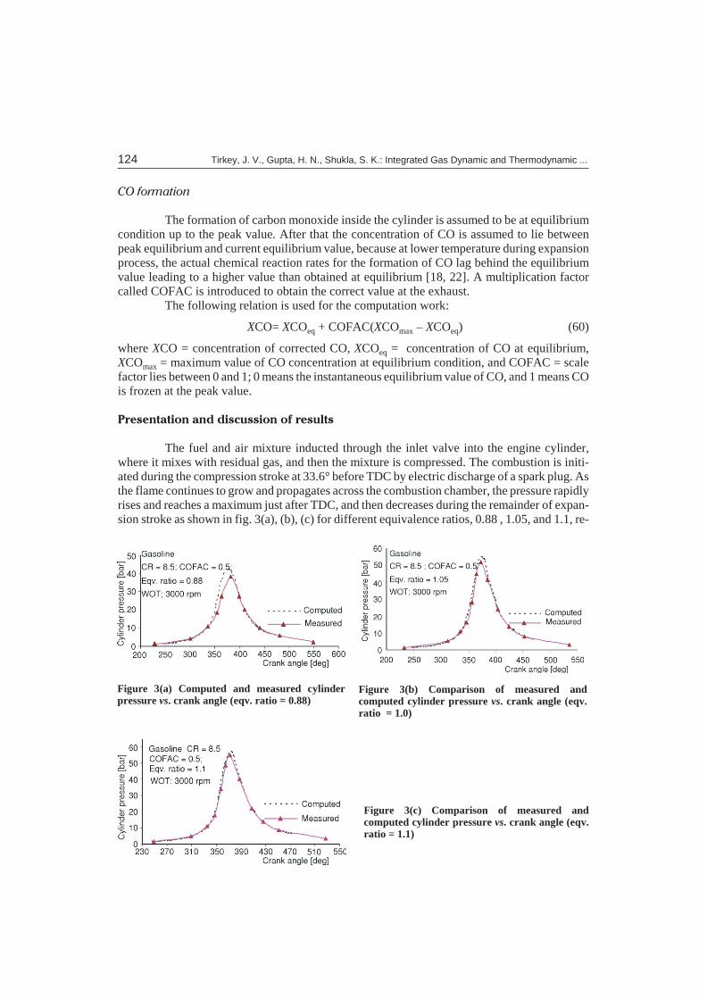
The fuel and air mix ture in ducted through the in let valve into the en gine cyl in der,where it mixes with re sid ual gas, and then the mix ture is com pressed. The com bus tion is ini ti -ated dur ing the com pres sion stroke at 33.6° be fore TDC by elec tric dis charge of a spark plug. As the flame con tin ues to grow and prop a gates across the com bus tion cham ber, the pres sure rap idly rises and reaches a max i mum just af ter TDC, and then de creases dur ing the re main der of ex pan -sion stroke as shown in fig. 3(a), (b), (c) for dif fer ent equiv a lence ra tios, 0.88 , 1.05, and 1.1, re -
124 Tirkey, J. V., Gupta, H. N., Shukla, S. K.: Integrated Gas Dynamic and Thermodynamic ...
Figure 3(a) Computed and measured cylinderpressure vs. crank angle (eqv. ratio = 0.88)
Figure 3(b) Comparison of measured andcomputed cylinder pressure vs. crank angle (eqv.ratio = 1.0)
Figure 3(c) Comparison of measured andcomputed cylinder pressure vs. crank angle (eqv.ratio = 1.1)
spec tively. As in fig ures, the pre dicted re sults have been val i dated by com par i son with ex per i -men tal re sults ob tained from Vauxhall Vic tor 2000cc, four cyl in ders, four stroke SI en gine. Thetech ni cal data for the en gine are given in tab. 1.
Re fer ring to fig. 3(a), (b), and (c) the com puted curves fol low the ex per i men tal cyl in -der pres sure curves, but the mea sured and com puted peak pres sures are slightly dif fer ent.
The dis crep ancy of the peak pres sure is caused by the cy cle to cy cle dis per sion, and isdue to non-ho mo ge ne ity of fuel mix ture and sup ply in the cyl in der in ac tual case, but the o ret i calcal cu la tions are based on con stant ho mo ge neous mix ture sup ply at ev ery cy cle. A great deal ofex per i men tal re search work [21, 23] has been done on cy clic dis per sion. An other ma jor sourceof cy cle to cy cle vari a tion is due to the vari a tion in the spher i cal burn ing area pro duced by vari a -tion in the po si tion of the wall con tact flame cen ter and vari a tion in the lam i nar flame speed atthe spark and fluc tu a tion in the first eddy burn [24, 25].
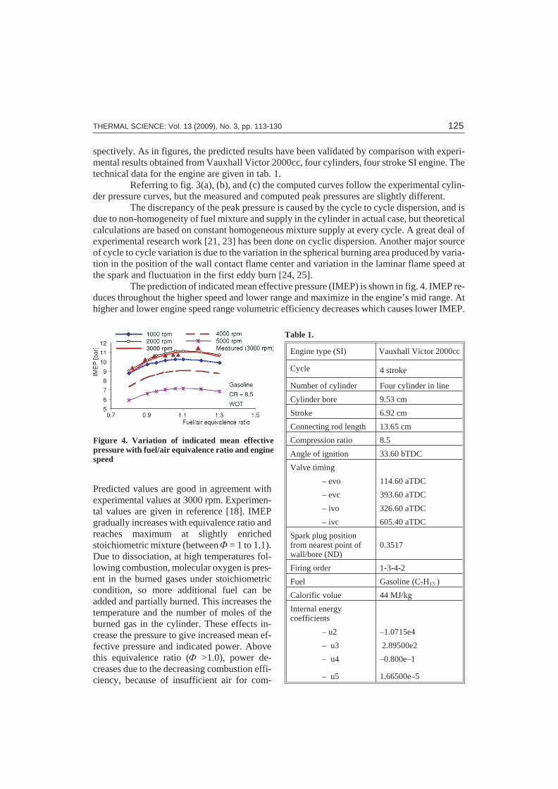
The pre dic tion of in di cated mean ef fec tive pres sure (IMEP) is shown in fig. 4. IMEP re -duces through out the higher speed and lower range and max i mize in the en gine’s mid range. Athigher and lower en gine speed range vol u met ric ef fi ciency de creases which causes lower IMEP.
Pre dicted val ues are good in agree ment withex per i men tal val ues at 3000 rpm. Ex per i men -tal val ues are given in ref er ence [18]. IMEPgrad u ally in creases with equiv a lence ra tio and reaches max i mum at slightly en richedstoichiometric mix ture (be tween F = 1 to 1.1). Due to dis so ci a tion, at high tem per a tures fol -low ing com bus tion, mo lec u lar ox y gen is pres -ent in the burned gases un der stoichiometriccon di tion, so more ad di tional fuel can beadded and par tially burned. This in creases thetem per a ture and the num ber of moles of theburned gas in the cyl in der. These ef fects in -crease the pres sure to give in creased mean ef -fec tive pressure and in di cated power. Abovethis equiv a lence ra tio (F >1.0), power de -creases due to the de creas ing com bus tion ef fi -ciency, be cause of in suf fi cient air for com -
THERMAL SCIENCE: Vol. 13 (2009), No. 3, pp. 113-130 125
Ta ble 1.
En gine type (SI) Vauxhall Vic tor 2000cc
Cy cle 4 stroke
Number of cyl in der Four cyl in der in line
Cyl in der bore 9.53 cm
Stroke 6.92 cm
Con nect ing rod length 13.65 cm
Com pres sion ra tio 8.5
An gle of ig ni tion 33.60 bTDC
Valve tim ing
– evo 114.60 aTDC
– evc 393.60 aTDC
– ivo 326.60 aTDC
– ivc 605.40 aTDC
Spark plug po si tionfrom near est point ofwall/bore (ND)
0.3517
Fir ing or der 1-3-4-2
Fuel Gas o line (C7H13 )
Cal o rific volue 44 MJ/kg
In ter nal en ergycoefficients
– u2 –1.0715e4
– u3 2.89500e2
– u4 –0.800e–1
– u5 1.66500e–5
Figure 4. Variation of indicated mean effectivepressure with fuel/air equivalence ratio and enginespeed
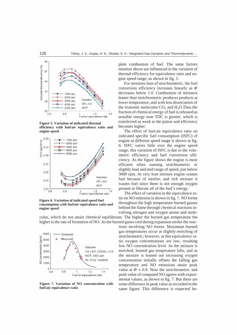
plete com bus tion of fuel. The same fac torsmen tion above are in flu enced in the vari a tion ofther mal ef fi ciency for equiv a lence ra tio and en -gine speed range, as shown in fig. 5.
For mix tures lean of stoichiometric, the fuelcon ver sion ef fi ciency in creases lin early as Fde creases be low 1.0. Com bus tion of mix turesleaner than stoichiometric pro duces prod ucts atlower tem per a ture, and with less dis so ci a tion of the triatomic mol e cules CO2 and H2O.Thus thefrac tion of chem i cal en ergy of fuel is re leased as sen si ble en ergy near TDC is greater, which istrans ferred as work to the pis ton and ef fi ciencybe comes higher.
The ef fect of fuel-air equiv a lence ra tio onin di cated spe cific fuel con sump tion (ISFC) ofen gine at dif fer ent speed range is shown in fig.6. ISFC var ies lit tle over the en gine speedrange; this vari a tion of ISFC is due to the vol u -met ric ef fi ciency and fuel con ver sion ef fi -ciency. As the fig ure shows the en gine is mostef fi cient when run ning stoichiometric orslightly lean and mid range of speed, just be low3000 rpm. At very lean mix ture en gine wastesfuel be cause of mis fire, and rich mix ture itwastes fuel since there is not enough ox y genpres ent to lib er ate all of the fuel’s en ergy.
The ef fect of vari a tion in the equiv a lence ra -tio on NO emis sion is shown in fig. 7. NO forms through out the high tem per a ture burned gas sesbe hind the flame through chem i cal re ac tions in -volv ing ni tro gen and ox y gen at oms and mol e -
cules, which do not at tain chem i cal equi lib rium. The higher the burned gas tem per a ture thehigher is the rate of for ma tion of NO. As the burned gases cool dur ing ex pan sion stroke the re ac -
tions in volv ing NO freeze. Max i mum burnedgas tem per a tures oc cur at slightly en rich ing ofstoichiometric; how ever, at this equiv a lence ra -tio ox y gen con cen tra tions are low, re sult inglow NO con cen tra tion level. As the mix ture isen riched, burned gas tem per a ture falls, and asthe mix ture is leaned out in creas ing ox y gencon cen tra tion ini tially off sets the fall ing gastem per a ture and NO emis sions at tain peakvalue at F » 0.9. Near the stoichiometric andpeak value of com puted NO agrees with ex per i -men tal val ues, as shown in fig. 7. But there aresome dif fer ence in peak value as re corded in the same fig ure. This dif fer ence is ex pected be -
126 Tirkey, J. V., Gupta, H. N., Shukla, S. K.: Integrated Gas Dynamic and Thermodynamic ...
Figure 5. Variation of indicated thermalefficiency with fuel/air equivalence ratio andengine speed
Figure 6. Variation of indicated speed fuelconsumption with fuel/air equivalence ratio andengine speed
Figure 7. Variation of NO concentration withfuel/air equivalence ratio
cause the com puted re sults are ob tained with the as sump tion of con stant ho mo ge neous mix turesup ply.
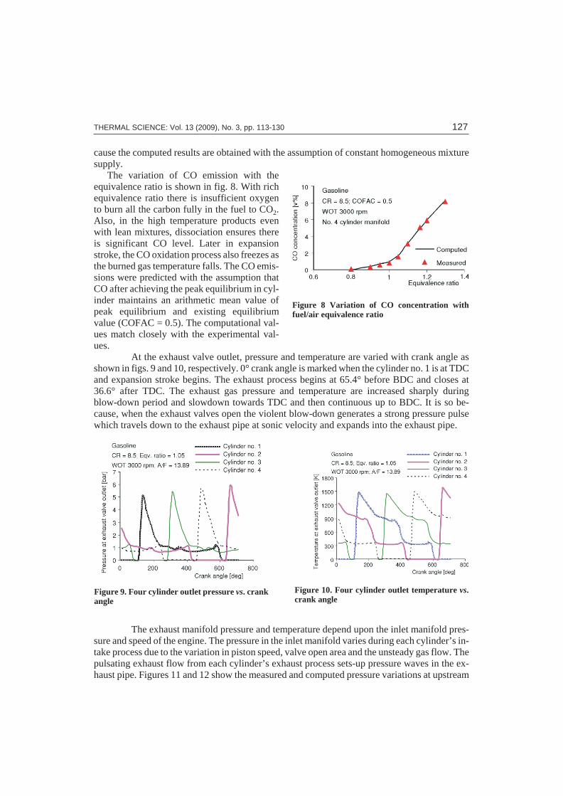
The vari a tion of CO emis sion with theequiv a lence ra tio is shown in fig. 8. With richequiv a lence ra tio there is in suf fi cient ox y gento burn all the car bon fully in the fuel to CO2.Also, in the high tem per a ture prod ucts evenwith lean mix tures, dis so ci a tion en sures thereis sig nif i cant CO level. Later in ex pan sionstroke, the CO ox i da tion pro cess also freezes as the burned gas tem per a ture falls. The CO emis -sions were pre dicted with the as sump tion thatCO af ter achiev ing the peak equi lib rium in cyl -in der main tains an arith me tic mean value ofpeak equi lib rium and ex ist ing equi lib riumvalue (COFAC = 0.5). The com pu ta tional val -ues match closely with the ex per i men tal val -ues.
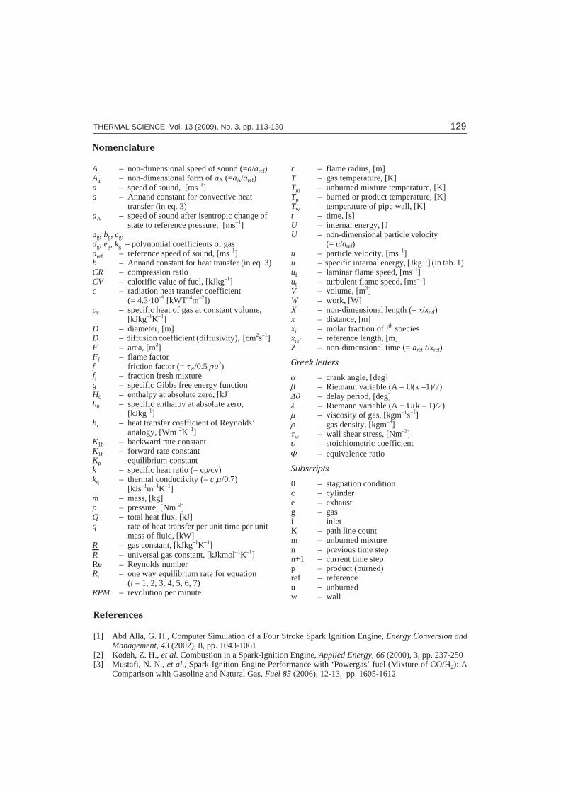
At the ex haust valve out let, pres sure and tem per a ture are var ied with crank an gle asshown in figs. 9 and 10, re spec tively. 0° crank an gle is marked when the cyl in der no. 1 is at TDCand ex pan sion stroke be gins. The ex haust pro cess be gins at 65.4° be fore BDC and closes at36.6° af ter TDC. The ex haust gas pres sure and tem per a ture are in creased sharply dur ingblow-down pe riod and slow down to wards TDC and then con tin u ous up to BDC. It is so be -cause, when the ex haust valves open the vi o lent blow-down gen er ates a strong pres sure pulsewhich trav els down to the ex haust pipe at sonic ve loc ity and ex pands into the ex haust pipe.
The ex haust man i fold pres sure and tem per a ture de pend upon the in let man i fold pres -sure and speed of the en gine. The pres sure in the in let man i fold var ies dur ing each cyl in der’s in -take pro cess due to the vari a tion in pis ton speed, valve open area and the un steady gas flow. Thepul sat ing ex haust flow from each cyl in der’s ex haust pro cess sets-up pres sure waves in the ex -haust pipe. Fig ures 11 and 12 show the mea sured and com puted pres sure vari a tions at up stream
THERMAL SCIENCE: Vol. 13 (2009), No. 3, pp. 113-130 127
Figure 8 Variation of CO concentration withfuel/air equivalence ratio
Figure 10. Four cylinder outlet temperature vs.crank angle
Figure 9. Four cylinder outlet pressure vs. crankangle

and down stream of pipe no. VII, re spec tively.The two re sults are in agree ment. Fig ure 13shows the com puted re sults of tem per a turevari a tion at up stream and down stream of pipeno. VII.
As the pres sure and tem per a ture di a gramsare ob tained in a four cyl in der en gine ex haustsys tem, the four pri mary pulses are as so ci atedwith the ex haust sys tem blow down. The tim ing of the pulses fol lows the fir ing or der of the cyl -in ders and the phas ing is due to the rel a tive po -si tion of one cyl in der to an other.
Con clu sions
A com puter sim u la tion tech nique has been de vel oped to model the gas dy nam ics phe -nom ena which oc cur in the in take and ex haust man i folds of multi-cyl in der spark ig ni tion en -gines. The ex haust sys tem has a crit i cal ef fect on the charg ing and gas ex change pro cess andhence on the over all per for mance of the en gine. This arises from the cy cle of events dur ing theex haust and re charg ing phases when the ex haust pipe and in duc tion man i fold are both open tothe cyl in der at the same time. In the de vel op ment of in ter nal com bus tion en gine at ten tion isdrawn to the pres sure phe nom ena oc cur ring in the ex haust pipe.
Ex haust pulses af fect the en gine per for mance both in tim ing of the pulse and over alllength of the pipe. The in flu ence of the pres sure pulses on the charg ing pro cess af fects the over allper for mance of the en gine. Ex haust sys tem should be de signed to en hance the en gine per for mance.
The the o ret i cal re sults ob tained from the pres ent model and ex per i men tal re sults ob -tained from a four cyl in der, four stroke Vauxhal-Vic tor 2000cc petrol en gine have con firmedthe re li abil ity and ac cu racy of the pres ent model for pre dict ing the per for mance of SI en ginerun ning on gas o line fuel.
The pres ent model can be used to ex am ine the ef fect of fuel type, en gine ge om e try, and op er a tion pa ram e ters on com bus tion cy cle and en gine per for mance. The only change re quiredin the model to al low for other fuel is to use dif fer ent in ter nal en er gies of re ac tion and ther mo dy -nam ics data for the fuel. In ad di tion, for mu la tions for the flame speed are required for differentfuels.
128 Tirkey, J. V., Gupta, H. N., Shukla, S. K.: Integrated Gas Dynamic and Thermodynamic ...
Figure 11. Comparison of computed andmeasured pressure at upstream pipe no. VII
Figure 13. Temperature at upstream anddownstream of pipe no. VII end vs. crank angle
Figure 12. Comparison of computed andmeasured pressure at downstream pipe no. VII
Ref er ences
[1] Abd Alla, G. H., Com puter Sim u la tion of a Four Stroke Spark Ig ni tion En gine, En ergy Con ver sion andMan age ment, 43 (2002), 8, pp. 1043-1061
[2] Kodah, Z. H., et al. Com bus tion in a Spark-Ig ni tion En gine, Ap plied En ergy, 66 (2000), 3, pp. 237-250[3] Mustafi, N. N., et al., Spark-Ig ni tion En gine Per for mance with ‘Powergas’ fuel (Mix ture of CO/H2): A
Com par i son with Gas o line and Nat u ral Gas, Fuel 85 (2006), 12-13, pp. 1605-1612
THERMAL SCIENCE: Vol. 13 (2009), No. 3, pp. 113-130 129
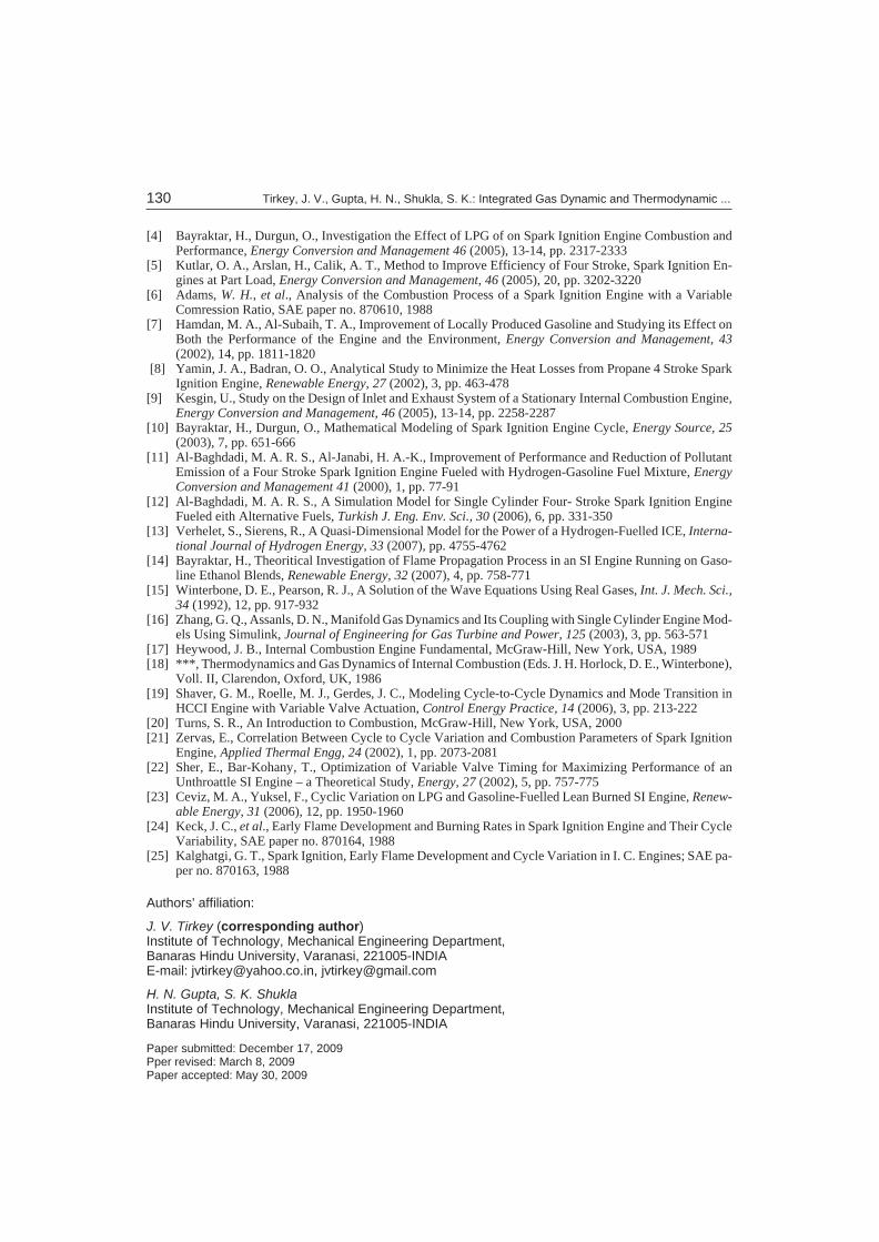
No men cla ture
A – non-dimensional speed of sound (=a/aref)Aa – non-dimensional form of aA (=aA/aref) a – speed of sound, [ms–1]a – Annand constant for convective heat
– transfer (in eq. 3)aA – speed of sound after isentropic change of
– state to reference pressure, [ms–1]ag, bg, cg, dg, eg, kg – polynomial coefficients of gasaref – reference speed of sound, [ms–1]b – Annand constant for heat transfer (in eq. 3)CR – compression ratioCV – calorific value of fuel, [kJkg–1]c – radiation heat transfer coefficient
– (= 4.3·10–9 [kWT–4m–2])cv – specific heat of gas at constant volume,
– [kJkg–1K–1]D – diameter, [m]D – diffusion coefficient (diffusivity), [cm2s–1] F – area, [m2]Ff – flame factorf – friction factor (= tw/0.5 ru2)fi – fraction fresh mixtureg – specific Gibbs free energy functionH0 – enthalpy at absolute zero, [kJ]h0 – specific enthalpy at absolute zero,
– [kJkg–1]hr – heat transfer coefficient of Reynolds’
– analogy, [Wm–2K–1]K1b – backward rate constantK1f – forward rate constant Kp – equilibrium constant k – specific heat ratio (= cp/cv)kq – thermal conductivity (= cpm/0.7)
– [kJs–1m–1K–1] m – mass, [kg]p – pressure, [Nm–2]Q – total heat flux, [kJ]q – rate of heat transfer per unit time per unit
– mass of fluid, [kW]R – gas constant, [kJkg–1K–1]R – universal gas constant, [kJkmol–1K–1]Re – Reynolds number Ri – one way equilibrium rate for equation
– (i = 1, 2, 3, 4, 5, 6, 7)RPM – revolution per minute
r – flame radius, [m]T – gas temperature, [K] Tm – unburned mixture temperature, [K] Tp – burned or product temperature, [K]Tw – temperature of pipe wall, [K] t – time, [s]U – internal energy, [J]U – non-dimensional particle velocity
– (= u/aref)u – particle velocity, [ms–1] u – specific internal energy, [Jkg–1] (in tab. 1)uf – laminar flame speed, [ms–1]ut – turbulent flame speed, [ms–1]V – volume, [m3]W – work, [W]X – non-dimensional length (= x/xref)x – distance, [m]xi – molar fraction of ith speciesxref – reference length, [m]Z – non-dimensional time (= aref.t/xref)
Greek let ters
a – crank angle, [deg]b – Riemann variable (A – U(k –1)/2) Dq – delay period, [deg]l – Riemann variable (A + U(k – 1)/2) m – viscosity of gas, [kgm–1s–1]r – gas density, [kgm–3]tw – wall shear stress, [Nm–2]u – stoichiometric coefficientF – equivalence ratio
Sub scripts
0 – stagnation condition c – cylinder e – exhaust g – gas i – inlet K – path line count m – unburned mixturen – previous time step n+1 – current time step p – product (burned)ref – reference u – unburned w – wall
[4] Bayraktar, H., Durgun, O., In ves ti ga tion the Ef fect of LPG of on Spark Ig ni tion En gine Com bus tion andPer for mance, En ergy Con ver sion and Man age ment 46 (2005), 13-14, pp. 2317-2333
[5] Kutlar, O. A., Arslan, H., Calik, A. T., Method to Im prove Ef fi ciency of Four Stroke, Spark Ig ni tion En -gines at Part Load, En ergy Con ver sion and Man age ment, 46 (2005), 20, pp. 3202-3220
[6] Ad ams, W. H., et al., Anal y sis of the Com bus tion Pro cess of a Spark Ig ni tion En gine with a Vari ableComression Ra tio, SAE pa per no. 870610, 1988
[7] Hamdan, M. A., Al-Subaih, T. A., Im prove ment of Lo cally Pro duced Gas o line and Study ing its Ef fect onBoth the Per for mance of the En gine and the En vi ron ment, En ergy Con ver sion and Man age ment, 43(2002), 14, pp. 1811-1820
[8] Yamin, J. A., Badran, O. O., An a lyt i cal Study to Min i mize the Heat Losses from Pro pane 4 Stroke SparkIg ni tion En gine, Re new able En ergy, 27 (2002), 3, pp. 463-478
[9] Kesgin, U., Study on the De sign of In let and Ex haust Sys tem of a Sta tion ary In ter nal Com bus tion En gine,En ergy Con ver sion and Man age ment, 46 (2005), 13-14, pp. 2258-2287
[10] Bayraktar, H., Durgun, O., Math e mat i cal Mod el ing of Spark Ig ni tion En gine Cy cle, En ergy Source, 25(2003), 7, pp. 651-666
[11] Al-Baghdadi, M. A. R. S., Al-Janabi, H. A.-K., Im prove ment of Per for mance and Re duc tion of Pol lut antEmis sion of a Four Stroke Spark Ig ni tion En gine Fu eled with Hy dro gen-Gas o line Fuel Mix ture, En ergyCon ver sion and Man age ment 41 (2000), 1, pp. 77-91
[12] Al-Baghdadi, M. A. R. S., A Sim u la tion Model for Sin gle Cyl in der Four- Stroke Spark Ig ni tion En gineFu eled eith Al ter na tive Fu els, Turk ish J. Eng. Env. Sci., 30 (2006), 6, pp. 331-350
[13] Verhelet, S., Sierens, R., A Quasi-Di men sional Model for the Power of a Hy dro gen-Fu elled ICE, In ter na -tional Jour nal of Hy dro gen En ergy, 33 (2007), pp. 4755-4762
[14] Bayraktar, H., Theoritical In ves ti ga tion of Flame Prop a ga tion Pro cess in an SI En gine Run ning on Gas o -line Eth a nol Blends, Re new able En ergy, 32 (2007), 4, pp. 758-771
[15] Winterbone, D. E., Pearson, R. J., A So lu tion of the Wave Equa tions Us ing Real Gases, Int. J. Mech. Sci.,34 (1992), 12, pp. 917-932
[16] Zhang, G. Q., Assanls, D. N., Man i fold Gas Dy nam ics and Its Cou pling with Sin gle Cyl in der En gine Mod -els Us ing Simulink, Jour nal of En gi neer ing for Gas Tur bine and Power, 125 (2003), 3, pp. 563-571
[17] Hey wood, J. B., In ter nal Com bus tion En gine Fun da men tal, McGraw-Hill, New York, USA, 1989[18] ***, Ther mo dy nam ics and Gas Dy nam ics of In ter nal Com bus tion (Eds. J. H. Horlock, D. E., Winterbone),
Voll. II, Clarendon, Ox ford, UK, 1986[19] Shaver, G. M., Roelle, M. J., Gerdes, J. C., Mod el ing Cy cle-to-Cy cle Dy nam ics and Mode Tran si tion in
HCCI En gine with Vari able Valve Ac tu a tion, Con trol En ergy Prac tice, 14 (2006), 3, pp. 213-222[20] Turns, S. R., An In tro duc tion to Com bus tion, McGraw-Hill, New York, USA, 2000[21] Zervas, E., Cor re la tion Be tween Cy cle to Cy cle Vari a tion and Com bus tion Pa ram e ters of Spark Ig ni tion
En gine, Ap plied Ther mal Engg, 24 (2002), 1, pp. 2073-2081[22] Sher, E., Bar-Kohany, T., Op ti mi za tion of Vari able Valve Tim ing for Max i miz ing Per for mance of an
Unthroattle SI En gine – a The o ret i cal Study, En ergy, 27 (2002), 5, pp. 757-775[23] Ceviz, M. A., Yuksel, F., Cy clic Vari a tion on LPG and Gas o line-Fu elled Lean Burned SI En gine, Re new -
able En ergy, 31 (2006), 12, pp. 1950-1960[24] Keck, J. C., et al., Early Flame De vel op ment and Burn ing Rates in Spark Ig ni tion En gine and Their Cy cle
Vari abil ity, SAE pa per no. 870164, 1988[25] Kalghatgi, G. T., Spark Ig ni tion, Early Flame De vel op ment and Cy cle Vari a tion in I. C. En gines; SAE pa -
per no. 870163, 1988
Authors' affiliation:
J. V. Tirkey (corresponding author)Institute of Technology, Mechanical Engineering Department,Banaras Hindu University, Varanasi, 221005-INDIAE-mail: [email protected], [email protected]
H. N. Gupta, S. K. ShuklaInstitute of Technology, Mechanical Engineering Department,Banaras Hindu University, Varanasi, 221005-INDIA
Paper submitted: December 17, 2009Pper revised: March 8, 2009Paper accepted: May 30, 2009
130 Tirkey, J. V., Gupta, H. N., Shukla, S. K.: Integrated Gas Dynamic and Thermodynamic ...