Instructions manual - Dynapac
283
Instructions manual Operating & Maintenance High capacity planer PL2000F (Engine stage IIIA / T3) Diesel engine CumminsQSX15-C600 PIN: 10000905EHC006777 Original instructions. Reservation for changes Printed in China
-
Upload
khangminh22 -
Category
Documents
-
view
0 -
download
0
Transcript of Instructions manual - Dynapac

Instructions manualOperating & Maintenance
High capacity planerPL2000F (Engine stage IIIA / T3)
Diesel engineCumminsQSX15-C600
PIN: 10000905EHC006777
Original instructions.
Reservation for changesPrinted in China


Contents
1
4812313240.pdf
Contents
Instruction ............................................................................................................................................. 1
The machine ........................................................................................................................................ 1
Intended use ........................................................................................................................................ 2
Warning symbols ................................................................................................................................. 2
General ................................................................................................................................................ 3
Safety – General instructions .............................................................................................................. 5
Safety – when operating ...................................................................................................................... 7
Risk zones on the machine .................................................................................................................. 7
Slopes (Tip over risk) ........................................................................................................................... 8
Safety devices ..................................................................................................................................... 9
Conveyor ............................................................................................................................................. 9
Roof (Option) ....................................................................................................................................... 9
Emergency stop button ..................................................................................................................... 10
Horn .................................................................................................................................................. 11
Headlights, Indicators rotary beacons ............................................................................................... 12
Hazard warning lights on side panels ................................................................................................ 13
Reverse lights and folding warning signs .......................................................................................... 13
Traction unit supports ....................................................................................................................... 14
Steel retaining cables ........................................................................................................................ 15
Retaining hook of scraper flap ........................................................................................................... 16
Limit switch of scraper flap ............................................................................................................... 16
Scraper flap safeguard ...................................................................................................................... 16
Exit ladders, grab bars and guardrails ............................................................................................... 17
Side shield......................................................................................................................................... 17
Special instructions ........................................................................................................................... 19
Standard lubricants and other recommended oil and fluids ............................................................ 19
High ambient temperatures, above +40°C (104°F) ........................................................................... 19
Lower ambient temperature – Freeze risk ....................................................................................... 19

Contents
2
4812313240.pdf
Temperatures ................................................................................................................................. 19
High pressure cleaning .................................................................................................................. 20
Fire fighting .................................................................................................................................... 20
Battery handling ............................................................................................................................. 20
Jumping starting (24V) ................................................................................................................... 21
Technical specifications........................................................................................................................ 23
Vibrations – Operator station ............................................................................................................. 23
Noise level ......................................................................................................................................... 23
Dimensions ....................................................................................................................................... 24
Weights ............................................................................................................................................. 26
Performance data .............................................................................................................................. 26
Loading system ................................................................................................................................. 27
Engine (T3) ........................................................................................................................................ 27
Travel drive ....................................................................................................................................... 27
Hydraulic system ............................................................................................................................... 28
Water system..................................................................................................................................... 28
Compressed air system ..................................................................................................................... 28
Electrical system ............................................................................................................................... 28
Tightening torques ............................................................................................................................ 29
Machine description .............................................................................................................................. 31
Descriptions of assemblies and functions ......................................................................................... 31
Machine description .......................................................................................................................... 43
Identification .................................................................................................................................. 43
Machine plate ................................................................................................................................. 43
Explanation of 17PIN serial number ................................................................................................ 44
Decals ............................................................................................................................................... 45
Safety decals .................................................................................................................................. 48
Info decals ..................................................................................................................................... 52
Instruments/Controls ......................................................................................................................... 53
Control panel ................................................................................................................................. 53

Contents
3
4812313240.pdf
Switch panel .................................................................................................................................. 55
Main console – left & right ............................................................................................................ 55
Control lever panel ....................................................................................................................... 69
RH/LH – Ergo control .................................................................................................................... 71
Ground plate panel ....................................................................................................................... 74
Front left Front right ..................................................................................................................... 74
Rear left & Rear right .................................................................................................................... 77
Screen structure for setting and display options ............................................................................ 80
Description of error codes (of page 703), dialog boxes ................................................................... 97
Electrical system ............................................................................................................................. 115
Fuses, boxes ................................................................................................................................ 115
Relay, machine ............................................................................................................................. 116
Driver’s seat on left/right ................................................................................................................. 117
Battery’s main switch ...................................................................................................................... 118
Batteries ...................................................................................................................................... 118
Tilt display ....................................................................................................................................... 119
Lock and Unlock the ground panel cover ......................................................................................... 120
Folding ladder ................................................................................................................................. 121
Guardrail ......................................................................................................................................... 122
Transport position for ladder and guardrails ................................................................................... 123
Hydraulic folding roof operation ...................................................................................................... 124
Hydraulic hood operations .............................................................................................................. 125
Throttle valves for deployment speed of hood and roof ................................................................... 126
Manual pump, hood and roof ........................................................................................................ 126
Water system................................................................................................................................... 127
High pressure cleaner ..................................................................................................................... 128
Filling pump for water tank .............................................................................................................. 129
Water filling (pressure fill) connection for water tank ....................................................................... 130
Changeover for separate circuits of rear strut towers ...................................................................... 131
Milling depth display ....................................................................................................................... 132
Contents
4
4812313240.pdf
Milling drum operation check .......................................................................................................... 132
Interlock on scraper flap .................................................................................................................. 133
Retaining hook of scraper flap ......................................................................................................... 133
Limit switch of scraper flap ............................................................................................................. 134
Traction unit supports ..................................................................................................................... 135
Support brackets ............................................................................................................................. 135
“Scraper flap function changeover” valve ....................................................................................... 136
“Discharge conveyor function changeover” valve ........................................................................... 136
Monitoring camera ........................................................................................................................... 137
Compressed air system (O) ............................................................................................................. 138
Storage area and protective flaps .................................................................................................... 139
Plumb fixture ................................................................................................................................... 140
Swivel-mounted warning sign .......................................................................................................... 141
Tool holder ...................................................................................................................................... 141
Typical wear marks on tool holder ................................................................................................ 142
Typical wear marks on bits ........................................................................................................... 143
Bits holder replacement ............................................................................................................... 144
Bits replacement .......................................................................................................................... 147
Replacing the holder box ............................................................................................................. 148
Leveling unit .................................................................................................................................... 149
Matric type ................................................................................................................................... 149
Operating the Dynapac Leveling System ...................................................................................... 150
Setting the contrast .................................................................................................................. 150
Symbols and displays in the working window .............................................................................. 151
Sensor selection .......................................................................................................................... 152
Operating with the Cross-Slope sensor ........................................................................................ 154
Zero adjustment ........................................................................................................................... 156
Sensitivity setting ........................................................................................................................ 158
Changing the measurement units ................................................................................................. 160
System languages ........................................................................................................................ 161

Contents
5
4812313240.pdf
Operation ............................................................................................................................................ 163
Before starting................................................................................................................................. 163
Preparing for operation ................................................................................................................ 163
Devices and aids .......................................................................................................................... 163
Before starting work ..................................................................................................................... 164
Starting the machine .................................................................................................................... 165
External starting (starting aid) ...................................................................................................... 167
Allowing engine to “warm up” ...................................................................................................... 168
Driving the machine ..................................................................................................................... 169
Milling (preparation) ..................................................................................................................... 170
Parking the machine .................................................................................................................... 174
Long-term parking .............................................................................................................................. 175
Long-term parking ........................................................................................................................... 175
Battery............................................................................................................................................. 175
Engine ............................................................................................................................................. 175
Hoods, tarpaulin .............................................................................................................................. 175
Fuel tank ......................................................................................................................................... 175
Hydraulic reservoir .......................................................................................................................... 175
Watering system .............................................................................................................................. 176
Water pump ..................................................................................................................................... 176
Miscellaneous ..................................................................................................................................... 177
Transport......................................................................................................................................... 177
Safety regulations for transport .................................................................................................... 177
Fix points ..................................................................................................................................... 179
Transport on trailers ........................................................................................................................ 181
Hydraulically foldable discharge conveyor ...................................................................................... 187
Folding in discharge conveyor ..................................................................................................... 187
Folding out discharge conveyor ................................................................................................... 188
Load by crane .................................................................................................................................. 189
Towing/Retriving ............................................................................................................................. 190

Contents
6
4812313240.pdf
Short distance towing when the engine is inoperative ..................................................................... 191
Towing the planer ............................................................................................................................ 192
Lifting the conveyor ......................................................................................................................... 193
Securing before parking up ............................................................................................................. 194
Operating instructions – Summary ...................................................................................................... 195
Preventive maintenance ...................................................................................................................... 197
Maintenance – Lubricants and symbols .............................................................................................. 199
Maintenance – Lubricants and symbols ........................................................................................... 199
Fluid volumes .................................................................................................................................. 199
Maintenance ...................................................................................................................................... 201
Notes regarding safety for maintenance .......................................................................................... 201
Liability exclusion in case of use of non-original spare or wear parts as well as incorrect operating
materials ......................................................................................................................................... 202
Maintenance intervals ...................................................................................................................... 202
Engine drive unit ............................................................................................................................. 215
Fuel tank ......................................................................................................................................... 215
Cleaning tank and system ............................................................................................................... 216
Diesel engine ................................................................................................................................... 216
Engine oil drainage point ................................................................................................................. 217
Oil filter ........................................................................................................................................... 218
Fuel filter ......................................................................................................................................... 218
Fuel filter water separator ................................................................................................................ 219
Air filter ........................................................................................................................................... 219
Cooler ............................................................................................................................................. 220
Coolant filter .................................................................................................................................... 220
Cooler ............................................................................................................................................. 221
Drive belt ......................................................................................................................................... 221
Valve clearance ............................................................................................................................... 222
Engine brackets, left/right ................................................................................................................ 222
Connecting screws, pump distribution transmission/engine............................................................ 223

Contents
7
4812313240.pdf
Hydraulic system ............................................................................................................................. 224
Hydraulic oil tank ............................................................................................................................. 224
Hydraulic oil drainage valve ............................................................................................................. 224
High-pressure hydraulic filter .......................................................................................................... 225
Return hydraulic filter ...................................................................................................................... 226
Pump distribution transmission ....................................................................................................... 227
Oil level check ................................................................................................................................. 227
Oil cooler ......................................................................................................................................... 228
Bleeder ............................................................................................................................................ 229
Oil cooler ......................................................................................................................................... 229
Hydraulic hoses ............................................................................................................................... 230
Hydraulic unit for roof and hood activation ...................................................................................... 230
Oil level check ................................................................................................................................. 230
Traction units .................................................................................................................................. 231
Planetary gear – oil level check ....................................................................................................... 231
Oil change ....................................................................................................................................... 231
Chain tension .................................................................................................................................. 232
Bottom plate .................................................................................................................................... 233
Rubber pad ...................................................................................................................................... 233
Steering system sliding parts, steering arms, stop ring and scraper ................................................ 234
Retaining device for track rod and steering cylinder bolts ............................................................... 235
Belt drive ......................................................................................................................................... 235
Clutch “DESCH” Type ..................................................................................................................... 236
Milling drum gear box ...................................................................................................................... 237
Oil level check ................................................................................................................................. 237
Oil change ....................................................................................................................................... 238
Milling drum .................................................................................................................................... 239
Draining coolant .............................................................................................................................. 239
Checking fluid level/adding fluid ...................................................................................................... 240
Scrapers and supporting wear bar (moldboard) ............................................................................... 240

Contents
8
4812313240.pdf
Runners on the side boards ............................................................................................................. 241
Sliding shoe runners ....................................................................................................................... 242
Drum flap limit switch ...................................................................................................................... 243
Milling drum housing fastening bolts ............................................................................................... 243
Loading equipment .......................................................................................................................... 244
Belt tension ..................................................................................................................................... 244
Drum holder .................................................................................................................................... 245
Steel cords ...................................................................................................................................... 245
Funnel rubber of transfer point and sealing rubbers/guides ............................................................ 246
Water system................................................................................................................................... 247
Water tank ....................................................................................................................................... 247
Feed pump ...................................................................................................................................... 249
Water filter ....................................................................................................................................... 250
Water pump – Check oil level ........................................................................................................... 251
Water pump – Drain oil .................................................................................................................... 251
Spray nozzles .................................................................................................................................. 252
Power supply................................................................................................................................... 253
Batteries .......................................................................................................................................... 253
Compressed air system ................................................................................................................... 254
Maintenance unit and compressed air system ................................................................................. 254
Leveling system .............................................................................................................................. 255
Sensor, controllers, connection cables ............................................................................................ 255
Brake system................................................................................................................................... 255
Emergency stop button ................................................................................................................... 256
Lubrication points ......................................................................................................................... 257
Traction unit .................................................................................................................................... 257
Chassis legs .................................................................................................................................... 257
Steering cylinder ............................................................................................................................. 257
Floating pin ..................................................................................................................................... 257
Milling section ................................................................................................................................. 258
Contents
9
4812313240.pdf
Belt tensioner .................................................................................................................................. 258
Clutch bearing type “DESCH” .......................................................................................................... 258
Scraper hydraulic cylinder ............................................................................................................... 259
Milling drum bearing ........................................................................................................................ 259
Discharge conveyor ......................................................................................................................... 260
Tail roller pedestal bearing .............................................................................................................. 260
Driver roller tension bearing ............................................................................................................ 260
Springs, joints and bolts .................................................................................................................. 260
Primary conveyor ............................................................................................................................ 261
Drive roller tension bearing ............................................................................................................. 261
Inspection ....................................................................................................................................... 262
General visual inspection ................................................................................................................ 262
Inspection by an expert ................................................................................................................... 262
Disposal ............................................................................................................................................ 264
Appendix ............................................................................................................................................... 1
Appendix 1: Engine Fault Code ........................................................................................................... 1

Introduction
1
4812313240.pdf 2017-12-1
Introduction
The machine Dynapac PL2000F is a high performance cold milling
machine for removing asphalt and concrete in a
controlled manner. The track driven machine has a high
capacities discharge conveyor. The milling drum is
driven by heavy duty belts.
As a result of its high milling performance, we would
recommend that this cold planer is used in particular
when carrying out extensive redevelopment work on
large and spacious roads, such as motorways, urban
and country roads, car parks, airports etc.
The PL2000F satisfies very stringent requirements in
terms of its reliability, economic viability and
environmental responsibility. Technical modifications, attachments and
conversations:
The machine may only be operated with the extension
parts, optional equipment and accessories, protection
and safety devices authorized by the manufacturer as
well as the setting values specified by the
manufacturer. The manufacturer is not liable for
damage resulting from unauthorized changes to the
assemblies, their removal or their replacement with
other, non-intended components or taking them
completely or partially out of operation.
The attachment or installation of additional devices,
which are used to intervene in the function of the cold
planer or with which its function are supplemented, is
only permitted with the written approval of the
manufacturer. If necessary, approval should be sought
from the local authorities.

Introduction
2
4812313240.pdf 2017-12-1
Intended use PL2000F is mainly intended to be used for roadworks:
to partially or completely remove asphalt,
asphalt based and/or cement layers
to remove distortions in the forms of track
grooves, lateral bulges, lateral warps
to recreate a proper surface
to implement roughing up and striping work For this, the underlying base layer must be robust
enough to withstand movement of the cold planer.
The transport of outsiders is expressly forbidden, as
using the cold planer as a traction mechanism or lifting
device.
The intended usage also includes compliance with
operating, transport, maintenance and repair
conditions specified in the operating instructions.
The machine is not designed for any type of usage not
described in the intended usage section. The
manufacturer is not liable for such instances of use.
The operator alone bears all risks for such usage.
When in doubt, contact the manufacturer.
Warning symbols
WARNING ! Marks a danger or a hazardous
procedure that can result in life threatening or
serious injury if the warning is ignored
CAUTION ! Marks a danger or hazardous procedure
that can result in damage to the machine or property
if the warning is ignored

Introduction
3
4812313240.pdf 2017-12-1
General
This manual contains instructions for machine safety,
operation, transport and maintenance.
The machine must be correctly maintained for top
performance level.
The machine should be kept clean so that any
leakages, loose bolts and loose connections are
discovered at as early as possible.
Inspect the machine every day, before starting.
Inspect the entire machine so that any leakages or
other faults are detected.
Check the ground under the machine. Leakages are
more easily detected on the ground than on the
machine itself.
THINK ENVIRONMENT ! Do not release oil, fuel and
other environmentally hazardous substances into the
environment. Always send used filters, drain oil and
fuel remnants to environmentally correct disposal.
This manual contains instructions for periodic
maintenance normally carried out by the operator.
Additional instructions for the engine can be found in
the manufacturer’s engine manual.

Introduction
4
4812313240.pdf 2017-12-1

Safety - General instructions
5
4812313240.pdf 2017-12-1
Safety - General instructions
(Also read the safety manual)
1. Read the entire manual before starting the machine and before
carrying out any maintenance. Do not remove the manual from the machine. Replace the instruction manual if lost, damaged or unreadable.
2. The safety manual supplied with the machine must be read by
all planer operators. Always follow the safety instructions. Do not remove the manual from the machine.
3. Only trained and/or experienced operators should be allowed
to drive the planer. It is prohibited to take passengers on the planer.
4. Never use the planer if it is in need of adjustment or repair.
5. Only climb up or down from the planer when it is stationary. Use
the intended grips and rails. Always use the three-point grip (both feet and one hand, or one foot and both hands) when mounting or dismounting from the machine. Never jump down from the machine.
6. Drive carefully on sharp bends.
7. Avoid driving across slopes. Drive straight up or straight down the
slope.
8. Make sure that the underlying surface is sufficiently stable.
9. Make sure that there are no obstacles in the direction of
travel, on the ground, in front of or behind the planer, or overhead.
10. Drive particularly carefully on uneven ground.
11. Use the safety equipment provided.
12. Keep the planer clean. Immediately remove any dirt or grease
from the operator platform. Keep all signs and labels clean and fully legible. Replace damaged plates and labels.
13. Safety measures before refueling:
- Shut off the engine - Do not smoke - No naked flame in the vicinity of the machine - Ground the filling device nozzle to the tank to avoid sparks

Safety - General instructions
6
4812313240.pdf 2017-12-1
14. Hearing protection is recommended if the noise level exceeds
80 dB(A). The noise level can vary depending on the equipment on the machine and the surface the machine is being used on.
15. Do not make any changes or modifications to the planer, this could put safety at risk. Changes may only be made following the written approval of Dynapac.
16. Avoid using the planer before the hydraulic fluid has reached its normal working temperature. Braking distances can be longer than normal when the fluid is cold. See instructions in the STOP section.
17. For your own safety,
always wear: - a helmet - work shoes with steel toecaps - hearing protection - breathing protection while milling, if necessary - reflective clothing/high visibility vest - work gloves - eye protection, if necessary
18. Ensure sufficient ventilation (extraction of air by fan) where
the engine is run poorly ventilated spaces.
Safety - General instructions
7
4812313240.pdf 2017-12-1
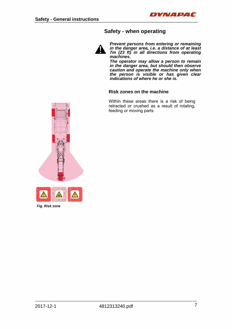
Safety - when operating Prevent persons from entering or remaining in the danger area, i.e. a distance of at least 7m (23 ft) in all directions from operating machines. The operator may allow a person to remain in the danger area, but should then observe caution and operate the machine only when the person is visible or has given clear indications of where he or she is.
Fig. Risk zone
Risk zones on the machine Within these areas there is a risk of being retracted or crushed as a result of rotating, feeding or moving parts

Safety - General instructions
8
4812313240.pdf 2017-12-1
Slopes (Tip over risk) Bear in mind that loose ground, and conveyor movements changes the center of gravity and can cause the machine to tip over on slopes lower than specified. Follow the stated recommendations for maximum permitted angle in the picture. Safety cannot be guaranteed when the max. permitted angle of inclination is exceeded. Before operating your vehicle in an inclined position (gradient, slope, lateral inclination) which is above the specified limit valve, please consult the customer service department for your vehicle! Where possible, avoid driving across slopes. Drive instead straight up and down sloping ground Before operating your vehicle in an inclined position (gradient, slope, lateral inclination) which is above the specified limit valve, please consult the customer service department for your vehicle!
Maximum permitted angle
of inclination 34% (19°)
Maximum permitted angle of
inclination 17% (10°)
Fig. Operating on slopes
19°
10°

Safety - General instructions
9
4812313240.pdf 2017-12-1
Safety devices The machine can only be safely operated if the control and safety devices are functioning perfectly and if the protective equipment is fitted correctly. Conveyor The machine must not be transported with material on the conveyor. The weight for the conveyor is specified on the unit rating plate. The operator must make sure that nobody is in the working area while the machine is in use. Risk of body and crush injuries. The conveyor has rotating parts. Risk of being retracted. Rotating conveyor The conveyor must be returned to its transport position after it has been used. The overall length of the machine is changed when the conveyor is fitted. Roof (Option) Risk of squeeze risk and crush injuries.

Safety - General instructions
10
4812313240.pdf 2017-12-1
Emergency stop button - On the left/right console - One the left/right ergo box - On the four ground control panels The engine, drives and steering system are shut down when the emergency stop button is pressed. Any counter measures required (Diverting, lifting the discharge conveyor etc.) are then no longer available! Risk of accident! The emergency stop button must not usually be used to shut down the engine and should only be pressed in an emergency or for test purposes.

Safety - General instructions
11
4812313240.pdf 2017-12-1
Horn - On the left/right console - One the left/right ergo box - On the four ground control panels Before starting to operate the machine and moving the conveyor units, the horn knob and/or the horn button should be pressed to issue a warning signal.

Safety - General instructions
12
4812313240.pdf 2017-12-1
Headlights, indicators rotary beacons Lights for illuminating different operating areas and for indicating danger areas and/or dangerous situations are located at various machine positions. Several contacts, to which headlights can be connected, can be found around the machine. The headlights, indicators and rotary beacons can be activated using the appropriate switches on the upper control panel. The function of the headlights and warning lamps should be checked on a daily basis before starting work. The headlights can be simply removed and should be taken off from easily accessible points and safely stored once work is complete. Headlight contacts which are not used should be protected using rubber caps.

Safety - General instructions
13
4812313240.pdf 2017-12-1
Hazard warning lights on side panels One hazard warning light can be found above the side panel on both the left and right-hand sides of machine. The hazard warning lights are operated as soon as the side panels are raised. Reverse lights and folding warning signs The reverse lights illuminate the danger area behind the machine. A warning sign can be folded out on the right-hand side of the machine and is used e.g. to warn any traffic behind the machine. A reflective decal is fitted to the other side of the back of the machine. The machine is also fitted with an acoustic reverse warning device which sounds as soon as the machine starts to reverse

Safety - General instructions
14
4812313240.pdf 2017-12-1
Traction unit supports One separable traction unit support can be found on every traction unit as a safety measure. The complete traction unit support is used for retaining purposes during maintenance and repair work. In order to achieve a lower transport height, the upper section of the separable support is used on the trailer during transport. The full length of traction unit supports should be inserted during all maintenance and repair work. Under vehicle as well as when parking for long periods of time. If the machine is lowered unintentionally, wedge-shaped supports advance automatically into the recesses provided in the locating plates and therefore prevent the machine from being lowered further.

Safety - General instructions
15
4812313240.pdf 2017-12-1
Steel retaining ropes The steel ropes hold the discharge conveyor and should be regularly checked for damage. If damage is found, the steel ropes should be replaced immediately.
Fig. Steel retaining cables

Safety - General instructions
16
4812313240.pdf 2017-12-1
Retaining hook of scraper flap When open the scraper flap, the retaining hook must be inserted to prevent the flap falling down. Limit switch of scraper flap The switch is pressed when raising the scraper, ensure the machine, milling drum drive and the rear tower cannot be actuated. Scraper flap safeguard One safeguard for the scraper flap is located on the left side of the rear drum box. The safeguard must be released before the scraper flap can be opened.

Safety - General instructions
17
4812313240.pdf 2017-12-1
Exit ladders, grab bars and guardrails The ladders on both sides of the machines are fitted with slip-free covers. Grab bars and guardrails are also provided. Climbing up and down the ladders during travel and travelling on the ladders themselves is prohibited. Side shield A side shield is fitted to both sides of the milling drum housing on the machine. These shields can be lifted by pressing the appropriate buttons on the controls.
Fig. Exit ladders, grab bars, guardrails
Fig. Side shield

Safety - General instructions
18
4812313240.pdf 2017-12-1

Special instructions
19
4812313240.pdf 2017-12-1
Special instructions
Standard lubricants and other recommended oils and fluids Before leaving the factory, the systems and components are filled with the oils and fluids specified in the lubricant specification. These are suitable for ambient temperatures in the range -15°C to +40°C (5°F - 105°F). The maximum temperature for biological hydraulic fluid is +35°C (95°F). Higher ambient temperatures, above +40°C (104°F) For operation of the machine at higher ambient temperatures, however maximum +50°C (122°F), the following recommendations apply: The diesel engine can be run at this temperature using normal oil. However, the following fluids must be used for other components: Hydraulic system - mineral oil Shell Tellus T100 or similar. Lower ambient temperature - Freeze risk Make sure that the watering system is empty/drained of water (sprinkler, hoses, tank/s) or that anti-freeze has been added, to prevent the system freezing. Temperatures The temperature limits apply to standard versions of planers. Planers equipped with additional equipment, such as noise suppression, may need to be more carefully monitored in the higher temperature ranges.

Special instructions
20
4812313240.pdf 2017-12-1
High pressure cleaning Do not spray directly onto electrical components. Do not use high pressure cleaning for dashboard/display. The Electrical Drive Control and the computer box may not be washed with high pressure cleaning and not at all with water. Clean them with a dry wiper. Detergent that can destroy electrical parts, or which is conductive, must not be used. Place a plastic bag over the fuel filler cap and secure with a rubber band. This is to avoid high pressure water entering the vent hole in the filler cap. This could cause malfunctions, such as the blocking of filters. Never aim the water jet directly at the fuel tank cap. This is particularly important when using a high-pressure cleaner. Fire fighting If the machine catches fire, use an ABC-class powder fire extinguisher. A BE-class carbon dioxide fire extinguisher can also be used. Battery handling When removing batteries, always disconnect the negative cable first. When fitting batteries, always connect the positive cable first. Dispose of old batteries in an environmentally friendly way. Batteries contain toxic lead. Do not use a quick-charger for charging the battery. This may shorten battery life.

Special instructions
21
4812313240.pdf 2017-12-1
Jump starting (24V) Do not connect the negative cable to the negative terminal on the dead battery. A spark can ignite the oxy-hydrogen gas formed around the battery. Check that the battery used for jump starting has the same voltage as the dead battery. Turn the ignition and all power consuming equipment off. Switch off the engine on the machine which is providing jump start power. Jump leads must have 24V. First connect the jump start battery's positive terminal (1) to the flat battery's positive terminal (2).Then connect the jump start battery's negative terminal (3) to, for example, a bolt (4) or the lifting eye on the machine with the flat battery. Start the engine on the power providing machine. Let it run for a while. Now try to start the other machine. Disconnect the cables in the reverse order. Starting gas is not to be used!
Fig. Jump starting

Special instructions
22
4812313240.pdf 2017-12-1
Technical specifications
23
4812313240.pdf 2017-12-1
Technical specifications
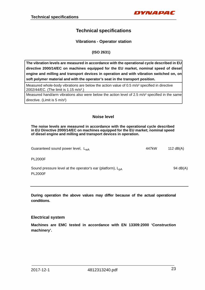
Vibrations - Operator station
(ISO 2631)
The vibration levels are measured in accordance with the operational cycle described in EU
directive 2000/14/EC on machines equipped for the EU market, nominal speed of diesel
engine and milling and transport devices in operation and with vibration switched on, on
soft polymer material and with the operator’s seat in the transport position.
Measured whole-body vibrations are below the action value of 0.5 m/s² specified in directive 2002/44/EC. (The limit is 1.15 m/s².) Measured hand/arm vibrations also were below the action level of 2.5 m/s² specified in the same
directive. (Limit is 5 m/s²)
Noise level The noise levels are measured in accordance with the operational cycle described in EU Directive 2000/14/EC on machines equipped for the EU market; nominal speed of diesel engine and milling and transport devices in operation.
Guaranteed sound power level, LwA 447kW 112 dB(A)
PL2000F
Sound pressure level at the operator's ear (platform), LpA 94 dB(A)
PL2000F
During operation the above values may differ because of the actual operational
conditions.
Electrical system
Machines are EMC tested in accordance with EN 13309:2000 ‘Construction
machinery’.

Technical specifications
24
4812313240.pdf 2017-12-1
Dimensions

Technical specifications
25
4812313240.pdf 2017-12-1
Designation PL2000F Standard
A Machine length with max. paving height 14110 mm
B Machine length with discharge conveyor at transport height 15310 mm
C Max. paving height 5670 mm
D Transport height of discharge conveyor any mm
E Machine length without discharge conveyor 8645 mm
F Height without (with lowered) weather protecting sun roof 3100 mm
G Height with weather protecting sun roof 3940 mm
H Drive unit height 690 mm
I Drive unit length 1905 mm
J Length of drive unit suspension to start of drive unit 935 mm
K Distance between suspension of front drive unit - milling drum
2900
mm
L Distance between suspension of rear drive unit - milling drum
2100
mm
M Length of drive unit suspension to end of drive unit 955 mm
N Distance between suspension of front drive unit - rear drive unit
5000
mm
O Total distance between the drive units (incl. drive units)
6890
mm
P Machine length with discharge conveyor folded in 12010 mm
Q Transport height with discharge conveyor folded in 1660-3865 mm
R Track width, outer front drive units 1890 mm
S Chain width 310 m
T Tract width, outer rear drive units 1680 mm
U Machine width 2550 mm
V Max. steering lock turn, front drive units 30 degr.
W Max. steering lock turn, rear drive units 30 degr.
X Turning radius 2065 mm
Y Max. swash angle, discharge conveyor to the right 55 degr.
Z Max. swash angle, discharge conveyor to the left 55 degr.

Technical specifications
26
4812313240.pdf 2017-12-1
*CE weight: water and fuel tank half filled, driver and tools on board
Performance data
Transportation speed 0 - 5 km/h
Operating speed 0 - 40 m/min
Milling width 2010
Milling depth 0 - 320
Max. slope 10 degr.
Line spacing 15
Cutting diameter 1100
Cutting speed 4.8 - 6.0
Number of milling tools 162
mm
mm
mm
mm
items
m/s
Weights
(Hydraulic Foldable discharge conveyor)
Operating weight CE* 33.3 t
Transport weight 31 t
Operating weight
(with full tank)
35
t
Discharge conveyor 2.2 t
Max axle load, front 21 t
Max axle load, rear 14 t

Technical specifications
27
4812313240.pdf 2017-12-1
Loading system
Belt width, primary conveyor 850 mm
Belt width, discharge conveyor 800 mm
Belt speed, primary conveyor 0-4 m/s
Belt speed, discharge conveyor 0-5 m/s
Loading capacity (theoretical) 470 m3/h
Engine (T3)
Make/type Cummins QSX 15-C600
Version 6-cylinder diesel engine (water-cooled)
Power (in accordance with DIN 6270)
447 kW / 607 PS / 600 hp (at 2100 rpm)
Capacity 15 L
Fuel consumption, full load Fuel consumption, 2/3 load
120 L/h 80 L/h
Fuel tank filling volume approx. 1100 L
Travel drive
Input Hydrostatic input, continuously variable
Drive units 4 individually driven tracks, each with
26 PU plates
Steering system - Hydraulic steering Steering variants
- only at front - only at rear - front and rear - crab steering

Technical specifications
28
4812313240.pdf 2017-12-1
Hydraulic system
Pressure creation Hydro pumps via transfer box (directly flange-mounted on engine)
Pressure distribution
Separate hydraulic circuits, e.g. for: - loading and discharge conveyor, - cylinder functions - clutch, belt tensioner - fan, filling equipment, water system
Hydraulic oil tank - filling volume approx. 270 L
Water systemFilling pump 6 - 12 m3/h
High pressure cleaner 80 - 120 bar
Water spray 5 - 10 bar
Water tank - filling volume approx. 3400 L
Water filling interval 2 - 3 h
Nozzle
Lower conveyor 4
Unit Dust suction 2
Milling drum 12
Compressed air system 03 ecnamrofreP m3/h
Compressed air reservoir 20 L
Permissible working pressure 6.5 bar
Electrical system
On-board voltage 24V
Batteries 2X12V 165 Min CCA 950A
Generator 24V / 100 A

Technical specifications
29
4812313240.pdf 2017-12-1
Tightening torque
Tightening torque in Nm (lbf.ft) for oiled or dry bolts tightened with a torque wrench.
Maximum torque for shaft screws with metric ISO coarse-pitch thread
8.8
10.9
12.9
Bias force Torque Bias force Torque Bias force Torque
M3 2250 1.3 3150 1.9 3800 2.
M4 3900 2.9 5450 4.1 6550 4.
M5 6350 6.0 8950 8.5 10700 1
M6 9000 10 12600 14 15100 1
M8 16500 25 23200 35 27900 4
M10 26200 49 36900 69 44300 8
M12 38300 86 54000 120 64500 145
M14 52500 135 74000 190 88500 230
M16 73000 210 102000 295 123000 355
M18 88000 290 124000 405 148000 485
M20 114000 410 160000 580 192000 690
M22 141000 550 199000 780 239000 930
M24 164000 710 230000 1000 276000 1200
M27 215000 1050 302000 1500 363000 1800
M30 262000 1450 368000 2000 442000 2400

Technical specifications
30
4812313240.pdf 2017-12-1

Machine description
31
4812313240.pdf 2017-12-1
Descriptions of assemblies and functions
10 1 14
2
7 9 4 5 8
15 16 17 6
12 18
3 13 11

Machine description
32
4812313240.pdf 2017-12-1
Item Designation
1 Frame
2 Weather protecting roof
3 Control panel
4 Ground control panels
5 Belt drive (milling drum drive)
6 Milling box (be consistent)
7 Track systems
8 Strut towers
9 Primary conveyor
10 Discharge conveyor
11 Water tank
12 Foldable ladder
13 Guardrails
14 Storage area
15 Radiator grille
16 Connection for external water filling (filling under pressure)
17 Swivel-mounted warning sign
18 Plumbline fixture

Machine description
33
4812313240.pdf 2017-12-1
Frame and assembly: Robust,
distortion-resistant steel welded design with
useful brackets for supporting the assemblies,
units, attachments and tanks. All parts can be
easily accessed for maintenance and repair work.
Operator’s control station: Operator’s control
station is located in the central part of the
machine and can be reached via two ladders.
Two ergonomic seats ensure that the planer can
be conveniently operated from both sides and that
the operator has a good overview of and can
monitor the milling process. The control station
has an innovative sliding system that enhances
the visibility of the operator. The full station can
slide 400mm on both sides of the frame.
The cold planer can be fitted with a weather
protecting sun roof (can be folded in) and all-round
panels as an option. During transport, the roof
can be folded forwards hydraulically and secured
on the water tank.
Controls at operator’s control station: An
operating panel, the position of which can be
easily adjusted, can be locked on the right and left
and contains all operating and control elements
required. If necessary, the machine operator can
move this into any other position required, even
beyond the edge of the machine. The securely
arranged controls are obviously marked for all
applications.
Steering and feed are simultaneously controlled
using a drive lever, designed as a joystick. A
second joystick controls the position of the
discharge conveyor and its speed (controlled in a
gradual manner).
A LC display integrated in the operating panel
rapidly and comprehensively informs the

Machine description
34
4812313240.pdf 2017-12-1
machinist of the present operating modes as well
as any setting and maintenance work required on
the machine.
All machine settings, including the milling depth
and slope control, can be simply programmed
and modified by means of a perforated keypad
with internationally comprehensible symbols.
Space has been left for the installation of a
camera display for observing the planer track and
the dead space. This equipment is optionally
available and can be installed with four video
cameras.
The main control panel, the ground control panels
and access to all important switching and
connection points can be covered.
Ground control panels: The operating panels
housed here are located on both sides of the
planer, in front of and behind the milling drum box.
They contain duplicates of the main controls of the
operator’s control station with override functions
so that the milling process can be monitored,
corrected and interrupted from this point. One digital controller for the milling depth and one
for the slope position are attached next to the rear
operating panels on the left and right sides.
Dynapac CAN-BUS data communication
system: The tried and tested state-of-the-art
electronic PLC (Programmable Logic Control)
monitors all control functions of the cold planer.
Signals processed by microprocessors are safely
transferred by an efficient CAN-BUS system (Data
Information System) and displayed as information
on the LC display. Possible function deviations
Machine description
35
4812313240.pdf 2017-12-1
and errors are noted and can be corrected
immediately.
Engine: The machine is fitted with a powerful
6-cylinder Cummins turbo diesel engine which
effortlessly covers the power requirements of the
large planer. This engine has electronic engine
management which also automatically adapts it to
the extreme operating and environmental
conditions and therefore keeps its torque stable.
The engine cover is noise-insulated as standard
so that operating staff and the surrounding area
are subjected to minimum levels of noise. It’s
complying with US EPA T3, EU stage IIIA and
China stage III exhaust standard.
Milling box: The milling section consists of the
mechanical milling drum drive, the milling drum
housing, the milling drum, the moldboard, the
sliding shoe and the side boards.
All these elements are precisely tuned to one
another and their designs adapted so that high
performance milling is assured with low levels of
milling tool wear, as is very good retrieval,
granulation and transport of the milled product, an
exact milling pattern with cleaner milling edges is
produced and the processed area is kept clean
and free of milling product which has not been
retrieved.
- The mechanical milling drum is driven by the
diesel engine via a hydraulic separating
clutch, belt pulleys and a high efficient poly-V
belt on a planetary gear directly connected
with the drum body. This guarantees a
low-loss transfer of power intercepts load
impact and has a long service life. The drive
is fitted with an automatic belt tensioning
fixture. The hydraulically selectable 3-pulley
dry-plate clutch and the two-stage planetary

Machine description
36
4812313240.pdf 2017-12-1
gear are configured specially for the milling
drum drives and finely tuned to the engine
rating of the machine.
- Material is removed by the process of upwilling – if the machine is moving from left
to right, the drum will rotate anti-clockwise.
The professional milling tool arrangement and
equipping with the best milling tools ensures
rapid and clean milling as well as high milling
tool downtimes
The milling drum housing seals off the milling drums to the left and right through the side boards, the sliding shoe to the front, the moldboard to the rear, in all milling depths and therefore ensures optimum material pickup and a clean milling surface.
The side shields are fitted with replaceable,
zero-wear hard metal plates to increase their
service life.
Traction system, steering system, brakes
- Traction system
Four large track units, suspended on the strut
towers, hydrostatically driven and fitted with
sensor-monitored anti-slip control are equipped
with slip-free plastic pads. They provide excellent
traction when cornering and in all working
positions.
The speed limits required can be set beforehand
using the button provided or can be changed during
operations. The control lever of the travel drive then
allows the speed to be gradually adjusted in this
driving range for both forwards and reverse travel.

Machine description
37
4812313240.pdf 2017-12-1
When overloaded, the machine feed is
automatically reduced using limit load control.
- Steering system
The machine has fully-tracked steering. When used
in conjunction with a pre-selection button, the
control lever allows the machine to be driven in four
different steering variations and the speed to be
changed at the same time:
- only front steered
- only rear steered
- coordinated front and rear-steered
- driving in crab steering
- Brakes: The machine brake consists of:
- the auto-inhibit of the hydrostatic drive
- the hydraulic spring accumulator brakes
integrated in the gears of all four drive units.
The machine brakes when the control lever is
swiveled back from the maximum position to
neutral. The accumulator or spring brakes are
activated both in the neutral position (during
machine “stop”) and when the engine is shut down
and they act as parking brakes.
During a towing procedure, the spring accumulator
brakes can be hydraulically disengaged by a
manual pump.
- Strut tower: The strut towers are secured to the
vehicle frame. The cold planer is lowered and
raised in a controlled manner into the position
required via these towers. Milling drum, connected
to mainframe, moves depending on the strut tower
movement. The strut tower movement can be
controlled manually or by the levelling system.

Machine description
38
4812313240.pdf 2017-12-1
The height of the strut tower is adjusted using an
integrated hydraulic cylinder which is activated by
proportional valves.
The milling depth and slope are set by means of the
two front columns. The height of each of the front
strut towers can be adjusted individually. The two
rear columns operate in tandem and therefore
adapt themselves to the appropriate machine
position. For service purposes, the rear strut towers
can also be changed over to individual adjustment
mode.
The strut tower make a large lifting height possible
so that the space required between the machine
and ground is always provided during difficult
manoeuvres such as loading.
Levelling equipment: The leveling equipment
consists of a digital controller and control display
which can be connected with combination of a tilt
sensor and various height sensors.
The leveling equipment controls the cylinders of the
front drive unit legs.
The milling depth and lateral slope required are
pre-selected and compliance is automatically
maintained with them during milling as the distance
defined to a reference surface is continually
compared and corrected.
The automatic operation can be briefly bridged and
replaced by manual control.

Machine description
39
4812313240.pdf 2017-12-1
Water system: Water spray system is need to cool
the bits and minimize dust during milling operation.
Spray bars consists of nozzles that can be easily
replaced.
- Water high pressure cleaner (optional):
The cold planer can optionally be fitted with a high
pressure cleaner that consists of high pressure
pump, water lance and a tube reeling device.
Water refilling system (optional): Water filling port
is mounted at the back of the milling machine.
It can also be filled from the platform through
opening the side of the water tank.
Loading unit: The cold planer is designed as a
front loader. The primary conveyor located under
the machine receives the milled material. The
discharge conveyor conveys if away from the cut,
mostly on to a truck.

Machine description
40
4812313240.pdf 2017-12-1
The speed of the conveyors can be adjusted using
the control levers. It can be run in both directions.
The discharge conveyor can swing up, down, left &
right.
It comes with a cover and can be folded for
transport. Here, the speed of the discharge
conveyor can be gradually adjusted from zero to
maximum when in operation. The speed of the
lower conveyor automatically changes in proportion
to the speed adjustment of the discharge conveyor.
All belt changes can be simply and rapidly
performed.
The lower conveyor is positioned on a sliding shoe
to protect it from wear. This shoe also serves as a
compression device and prevents lumps from
breaking up on the milling surface.
Hydraulic system: The diesel engine drives the
hydraulic pumps for all planers via attached
distribution gear and its auxiliary drive shafts.
The following ensure that the entire hydraulic
system is kept perfectly clean:

Machine description
41
4812313240.pdf 2017-12-1
- a large return suction filter, fitted in the hydraulic
oil tank, for the drive circuits of the traction unit,
loading belt, fan and water system as well as for the
drives of the cylinder adjustment functions;
- two pressure filters, fitted in front of the milling
drum housing, on the right under the machine and
easily accessible from the outside. In the drive
circuit for height adjustment and steering, these are
switched between the load-sensing adjustment
pump and the hydraulic control blocks.
Electrical system: 24 volt system with two cold
start high power batteries engaged sequentially.
The power supply can be interrupted to
ground/earth by the battery’s main switch.
Air pressure system (optional): Compressor
driven directly by the engine with compressed air
reservoir of 20l/6.3 bar. There is a connection point
with a rapid release clutch for external consumers
(e.g. pneumatic milling tool driver or rotary
screwdriver) in the rear section under the machine.

Machine description
42
4812313240.pdf 2017-12-1
Optional equipment:
1. Fold roof
2. Dust suction system
3. Option weight
4. Air pressure system
5. Fine drum 2m
6. High pressure water
7. Water refilling pump
8. Basic leveling system
9. Additional slope sensor
10. Advance leveling system
11. Tools and wears
12. Rotated light
13. Option 12V
14. Fire extinguisher
15. First-aid kit
16. Tool box assembly
17. Drum kit 2000F / 2000 / 15 / KPF301
18. Drum kit 2000F / 2000 / 15 / BMS15L

Machine description
43
4812313240.pdf 2017-12-1
Machine description
Identification
The machine PIN (1) is punched on the front right
side of the frame.
Machine plate
The machine plate (2) is fixed to the right hand inner
front side of the machine.
The plate gives the name and address of the
manufacturer, type of machine, PIN (serial number),
operating weight, engine power, axle weight
front/rear, and year of manufacture.
Please state the machine's PIN when ordering
spares.
2
1
Fig. 1. PIN
2. Machine plate

Machine description
44
4812313240.pdf 2017-12-1
Explanation of 17PIN serial number
A= Manufacturer B= Family/Model C= Check letter D= No coding E= Production unit F= Serial number

Machine description
45
4812313240.pdf 2017-12-1
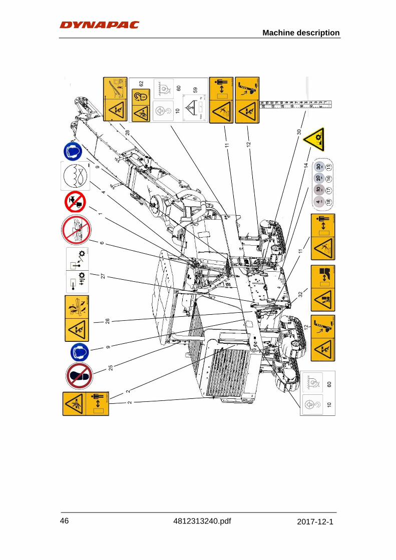
Decals
Machine description
46
4812313240.pdf 2017-12-1

Machine description
47
4812313240.pdf 2017-12-1

Machine description
48
4812313240.pdf 2017-12-1
Safety decals Always make sure that all safety decals are completely legible, and remove dirt or order new decals if they have become illegible. Use the part number specified on each decal. 4700903832 Warning – Belt rotation. Keep your hands at a safe distance from the danger zone. 4700903424 Warning - Hot surfaces. Keep your hands at a safe distance from the danger zone. 4700903459 Warning - Instruction manual The operator must read the safety, operation and maintenance instructions before operating the machine. 4812248523 Warning – Risk of crushing of the whole body. Maintain a safe distance from the crush zone.

Machine description
49
4812313240.pdf 2017-12-1
4812248460 Warning – Risk of crushing of whole body-attach support Maintain a safe distance from the crush zone. D956052009 Warning – “Battery charging” Maintain a safe distance. D956052003 Warning – “Battery charging” Prohibit to spray with water. 4812248496 Warning – Risk of hitting of feet Maintain a safe distance from the danger zone.

Machine description
50
4812313240.pdf 2017-12-1
4812248833 Warning – Electrical hazard decal Danger of electric shock. Maintain a safety distance. 4812248835 Warning – Crush of whole body conveyor Maintain a safe distance from the crush zone. 4812248836 Warning – Crush of whole body conveyor Maintain a safe distance from the crush zone. 4812248469 Warning – Crawler Maintain a safe distance from the crush zone. 4812248472 Warning – Crush of whole body Maintain a safe distance from the crush zone.

Machine description
51
4812313240.pdf 2017-12-1
4812248474 Warning – Crush of whole body Maintain a safe distance from the crush zone. 4812248495 Caution – Close the guard Maintain a safe distance from the crush zone. 4812248494 Caution – Do not climb Do not climb when the vehicle is moving. 4812248466 Caution – Do not step Do not step decal. Maintain a safe distance from the danger zone. 4812017008 Warning – Engine ECU protection Do not disconnect battery switch before 100 seconds after stopping the machine.

Machine description
52
4812313240.pdf 2017-12-1
Info labels
Handbook compartment Battery voltage Master switch
Diesel fuel Water Hydraulic fluid level
Fixing point Lifting plate Lift point
Hearing protection Milling depth Coolant
Sound effect level

Machine description
53
4812313240.pdf 2017-12-1
Instruments/Controls Control panel
Two operating stations, one on the left and the other on the right, are provided on
the platform. It consists of a main panel with display and ergo box. The left or the right
operators’ station could be activated depending on the working situations.

Machine description
54
4812313240.pdf 2017-12-1
Pos. Designation Brief description
1 Control lever discharge
conveyor
Controls the following functions of the discharge
conveyor „Swivel“, „Raise“, „Lower“. It also
provides infinitely variable control for the conveyor
speed.
2 Control lever for travel
drive
Is used after system is unlocked for the purposes
of driving, steering and braking.
In conjunction with the appropriate activated
automatic function, when the lever is swiveled
out, the leveling unit, water spray and cooling
system and the appropriate loading belt is
activated or de-activated in neutral position.
3 Switching table
Consists of an appropriately labeled keypad with
pre- defined push buttons for all work and
inspection functions. The operating status of the
main functions is displayed by means of LEDs.
The system also includes:
- ignition lock
- rotary switch for work lighting and warning lamps
- EMERGENCY STOP impact switch
4 Display indicator
Used in conjunction with the menu bar to display
actual statuses, changes in setting values and to
provide information about malfunctions
5 Steer mode selector
Steering mode is controlled by the dual-axis
control lever.
- Push the control lever forward, the front drive
units are swiveled to the straight-forward position.
- Pull it backward, the rear drive units are
swiveled to the straight-forward position.
- Turn it to the left, the rear drive units are
swiveled to the right and the planer turns to the
left.
- Turn it to the right, the rear drive units are
swiveled to the left and the planer turns to the
right.
6 Securing handle
To release and secure the operating panel when
moving the operating panel beyond the outer
edge of the machine.
The operating panel can only be adjusted if the
machine is stationary.

Machine description
55
4812313240.pdf 2017-12-1
Switch panel Main console – left & right

Machine description
56
4812313240.pdf 2017-12-1
Pos. Designation Symbol Brief description
1 Ignition lock
Insert the key and turn it to the right, the vehicle is
supplied with power. When resetting, the vehicle
is powered off and the engine stop working.
2 Emergency
stop
Press in emergencies (people in danger, risk of
collision etc.)!
- The engine, drive units and steering are
disengaged whenever the EMERGENCY STOP
button is pressed.
No movement, e.g. of the lower conveyor, is then
possible! Risk of accident!
- Seven emergency stops are located on the
left/right console, ergo box and four ground plate
control boxes respectively. Any of it being
pressed shall be indicated in the display.
- To restart the engine, all EMERGENCY STOP
buttons must be in the upright position.
3
Engine
start/stop
engine
Start engine by pressing the switch when the
ignition lock is switched on (Safety condition is
required, refer to the module description). LED
indicates activation.
The display will show the reason for unsuccessful
start of engine. Press the switch to stop engine
when it is in operation.
4 Service mode
At the touch of the button, the system enters into
the service mode, LED lights up, exits by
pressing it again.
The button/mode function is activated only when
the engine is started and the planer is in
stationary.
In service mode:
- The engine speed value can be set directly by
using button 24 & 25.
- The planer stays in braking mode, and the
travelling function is deactivated.
- Both of the side boards can stay in any position.

Machine description
57
4812313240.pdf 2017-12-1

Machine description
58
4812313240.pdf 2017-12-1
Pos. Designation Symbol Short description
5 Moving to the
left-platform
At the touch of the button, the platform moves to
the left, and the indicating light is switched on.
6 Moving to the
right-platform
At the touch of the button, the platform moves to
the right, and the indicating light is switched on.
7 Driving light
For switching on the driving lighting (driving light,
rear lights, control panel lighting and width lamp).
8 Working light
For switching on the working lighting (working
lights, rear lights, control panel light).
The activated function is confirmed by LED.
9 Warning
lights switch
For switching on the warning lights (hazard
warning flashers).
The activated function is confirmed by LED.
10 Dust
extraction
For actuating the function of dust extraction.
LED indicates activation.

Machine description
59
4812313240.pdf 2017-12-1

Machine description
60
4812313240.pdf 2017-12-1
Pos. Designation Symbol Brief description
11 Console
selector
The switch is located on the left and right
console respectively. When pressed, the LED
lights up, and the corresponding console enters
into controlling mode, all switches in it are
available, while the others are unavailable. The
LED lighted below indicates which console is
activated. And only one can be worked at a time.
12 ECO mode
At the touch of the button, the planer enters into
ECO mode, and LED lights on. Exit and enter
other mode by pressing switch 13 or 14.
The engine speed can be set in the display in
ECO mode.
When in ECO mode, engine speed value will be
within the scope of 1700 – 2100 rpm.
This engine speed will be activated when the
drum is on and the machine is moving forward.
13 Milling drum
speed set 1
The engine speed is 1900rpm by pressing this
button by pressing the button; meanwhile the
indicating light is switched on.
This engine speed will be activated when the
drum is on and the machine is moving forward.
14 Milling drum
speed set 2
The default setting is gear II, engine speed 2100
rpm when ignition.
This engine speed will be activated when the
drum is on and the machine is moving forward.

Machine description
61
4812313240.pdf 2017-12-1

Machine description
62
4812313240.pdf 2017-12-1
Pos. Designation Symbol Brief description
15 Water pump
switch
For switching on the water pump.
LED indicates activation.
16 Water refilling
To activate the water refilling pump. The LED will
be lighted once this function is activated.
17 Unfolding
conveyor
While the button is being pressed, the conveyor
continues being unfolded..
Release the button to stop unfolding.
18 Folding
conveyor
While the button is being pressed, the conveyor
continues being folded.
Release the button to stop folding.

Machine description
63
4812313240.pdf 2017-12-1

Machine description
64
4812313240.pdf 2017-12-1
Pos. Designation Symbol Brief description
19
Reversing
mode lower
conveyor
switch
At the touch of the button, the direction of the
lower conveyor is switched over to the reversing
mode, And it stops when released. The engaged
function is confirmed by LED.
This button function is available only when the
conveyor is stopped.
The reversing speed is 40% of the Max. speed of
conveyor.
20
Reversing
mode
discharger
conveyor
At the touch of the button, the direction of the
discharge conveyor is switched over to the
reversing mode, And it stops when released.
The engaged function is confirmed by LED.
This button function is available only when the
conveyor is stopped.
The reversing speed is 40% of the Max. speed of
conveyor.
21 Horn
For switching on the horn.

Machine description
65
4812313240.pdf 2017-12-1

Machine description
66
4812313240.pdf 2017-12-1
Pos. Designation Symbol Brief description
22 Position
diodes
Indicate the present position of the front and
rear drive units.
24
Engine speed
adjustment
(+)
Increase the engine speed by pressing this
button when the machine is in transport mode
or service mode, keep pressing, the engine
speed will increase continuously; adjust range
is 1000-2100 rpm.
25 Engine speed
adjustment (-)
Decrease the engine speed by pressing this
button when the machine is in transport mode
or service mode, keep pressing, the engine
speed will decrease continuously, adjust range
is 1000-2100 rpm.

Machine description
67
4812313240.pdf 2017-12-1

Machine description
68
4812313240.pdf 2017-12-1
Pos. Designation Symbol Brief description
26 Milling drum
At the touch of the button, the milling drum starts
working, and stops when it is released. The
activated function is confirmed by LED.
The milling drum drive can only be engaged at
idle speed
27 Automatic
mode
At the touch of the button, the system enters into
automatic control mode.
After the conveyor and water pump functions are
running in auto mode, press the conveyor or
water pump manual button, LED flashes and auto
function stops.
Press conveyor or water pump manual button
again, auto function is ON again.
28 Set-up button
As an aid for start of milling. When stationary,
lowers the machine to the preselected milling
depth at the touch of the button. The activated
function is confirmed by LED. Press the button
again to exit from this mode and stops lowering.
29
Moving
forward
indication of
loader
At the touch of the button, the forward indicating
light of loader is switched on.
30
Stop
indication of
loader
At the touch of the button, the stop indicating light
of loader is switched on.
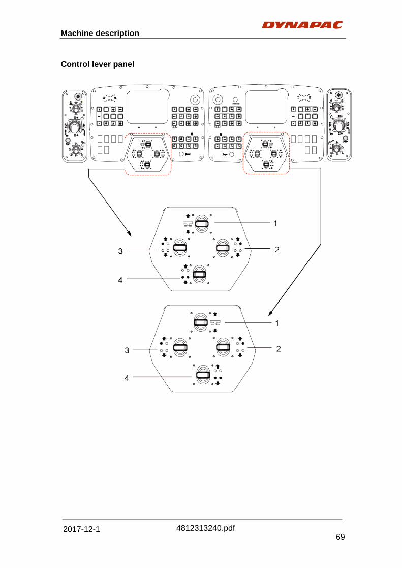
Machine description
69
4812313240.pdf 2017-12-1
Control lever panel

Machine description
70
4812313240.pdf 2017-12-1
Pos. Designation Symbol Brief description
1 Raising/lowering
the vehicle
While the control lever is being pulled
upward/downward, all four strut tower
cylinders are extended/retracted and the
vehicle is raised/lowered continuously
until they reach their upper/lower limit
position.
2
Raising/lowering
front right side
of vehicle
While the control lever is being pulled
upward/downward, the front right strut
tower cylinder is extended/retracted and
the body of vehicle is raised/lowered
continuously until it reaches its
upper/lower limit position.
This function is related to the leveling
control system. When the leveling system
of planer is in auto mode, operate the
control lever, it will be switched to manual
mode in which the cylinder is controlled
by the operator. When the control lever is
released (in the neutral position), it will be
automatically shifted to auto mode again.
3
Raising/lowering
front left side of
vehicle
While the control lever is being pulled
upward/downward, the front left strut
tower is extended/retracted and the body
of vehicle is raised/lowered continuously
until it reaches its upper/lower limit
position.
This function is related to the leveling
control system. When the leveling system
of planer is in auto mode, operate the
control lever, it will be switched to manual
mode in which the cylinder is controlled
by the operator. When the control lever is
released (in the neutral position), it will be
automatically shifted to auto mode again.
4 Raising/lowering
rear of vehicle
While the control lever is being pulled
upward/downward, the rear strut towers
are extended/retracted and the rear of the
vehicle is raised/lowered continuously
until they/it reaches its upper/lower limit
position.

Machine description
71
4812313240.pdf 2017-12-1
LH / RH – Ergo control

Machine description
72
4812313240.pdf 2017-12-1
Pos. Designation Symbol Brief description
1 Emergency
stop
Press in emergencies (people in danger, risk
of collision etc. )!
- The engine, drive units and steering are
disengaged whenever the EMERGENCY
STOP button is pressed.
No movement, e.g. of the lower conveyor, is
then possible! Risk of accident!
- Seven emergency stops are located on the
left/right console, ergo box and four ground
plate control boxes respectively. Any of it
being pressed shall be indicated in the
display.
- To restart the engine, all EMERGENCY
STOP buttons must be in the upright
position.
2 Control lever
for steering
Steering mode is controlled by the dual-axis
control lever.
- Push the control lever forward, the front
drive units are swiveled to the
straight-forward position.
- Pull it backward, the rear drive units are
swiveled to the straight-forward position.
- Turn it to the left, the rear drive units are
swiveled to the right and the planer turns to
the left.
- Turn it to the right, the rear drive units are
swiveled to the left and the planer turns to
the right.
- Rotate the knob clockwise, the planer is
switched to crab steering mode, the steering
angle of rear drive will follow the front ones in
positive direction. LED on the right is
activated. Any movement of control lever will
make the planer exit from this mode.
- Rotate the knob anticlockwise, the planer is
switched to all steering mode, the steering
angle of the rear units will follow the front
one in negative direction, LED on the left is
activated. Any movement of the control lever
will make the planer exit from this mode.

Machine description
73
4812313240.pdf 2017-12-1
Pos. Designation Symbol Brief description
3
Control lever
for travel
drive and
steering
The driving and steering direction are
controlled by the dual-axis control lever.
- Turn the control lever to the left, the
vehicle is swiveled to the left (the selection
of steering mode is required, and it
defaults to front drive units steering. The
rear drive units are required to follow in
positive and negative directive when it is in
crab steering or all steering mode. )
- Turn it to the right, the planer is swiveled
to the right.
- Push it forward, the planer moves
forward.
- Pull it backward, the planer moves
backward. If this function is engaged, the
milling drum is deactivated.
- The top button is used for electrically
locking/unlocking the drive units.
4 Horn
For switching on the horn.
5
Control lever
for discharge
conveyor
The direction of the discharge conveyor is
controlled by the dual-axis control lever.
- Turn the control lever to the left, the
discharge conveyor is swiveled to the left.
- Turn it to the right, the conveyor is
swiveled to the right.
- Push it forward, the conveyor is lowered.
- Pull it backward, the conveyor is raised.
- Rotate the knob clockwise, the speed of
discharge conveyor is increased.
- Rotate the knob anticlockwise, the speed
is decreased.
- Press the button on the control lever, the
conveyor starts to work.

Machine description
74
4812313240.pdf 2017-12-1
Ground plate panel Front left & Front right
Pos. Designation Symbol Brief description
1 Emergency
stop
Press in emergencies (people in danger, risk of
collision etc.)!
- The engine, drive units and steering are
disengaged whenever the EMERGENCY STOP
button is pressed.
No movement, e.g. of the lower conveyor, is then
possible! Risk of accident!
- Seven emergency stops are located on the
left/right console, ergo box and four remote
control boxes respectively. Any of it being
pressed shall be indicated in the display.
- To restart the engine, all EMERGENCY STOP
buttons must be in the upright position.
2 Horn
For switching on the horn.

Machine description
75
4812313240.pdf 2017-12-1
Pos. Designation Symbol Brief description
3
Reversing
mode-discharge
conveyor
At the touch of the button, the direction of the
discharge conveyor is switched over to the
reversing mode, And it stops when released.
The engaged function is confirmed by LED.
This button function is available only when the
conveyor is stopped.
The reversing speed is 40% of the Max. speed
of conveyor.
4
Reversing
mode-lower
conveyor
At the touch of the button, the direction of the
lower conveyor is switched over to the
reversing mode, And it stops when released.
The engaged function is confirmed by LED.
This button function is available only when the
conveyor is stopped.
The reversing speed is 40% of the Max. speed
of conveyor.
5 Water system
The function of water sprinkling or high
pressure cleaner is activated by holding down
the upper/lower position of switch.
The engaged function is confirmed by LED.
6 Raising/lowering
sliding shoe
The lower conveyor is raised/lowered by
pressing the upper/lower position of the switch.
Activated function is confirmed by LED.
7 Floating switch
for sliding shoe
The lower conveyor is in floating state by
pressing the upper position of the switch. And it
is locked by pressing the lower position.
It defaults to locking state when the system is
powered on.

Machine description
76
4812313240.pdf 2017-12-1
Pos. Designation Symbol Brief description
8 Water pump
For switching on the water pump.
10 Conveyor
For actuating and stopping the both conveyors.
11 Direction
change
By pressing up, front trackers turn to left position;
Pressing down, front trackers turn to right
position. Hold to run.
12 Mid-position
and run
By pressing, the front trackers can go to the
mid-position. Hold to run.

Machine description
77
4812313240.pdf 2017-12-1
Rear left & Rear right
Pos. Designation Symbol Brief description
1 Emergency
stop
Press in emergencies (people in danger, risk of
collision etc.)!
- The engine, drive units and steering are
disengaged whenever the EMERGENCY STOP
button is pressed.
No movement, e.g. of the lower conveyor, is then
possible! Risk of accident!
- Seven emergency stops are located on the
left/right console, ergo box and four remote
control boxes respectively. Any of it being
pressed shall be indicated in the display.
- To restart the engine, all EMERGENCY STOP
buttons must be in the upright position.
2 Horn
For switching on the horn.

Machine description
78
4812313240.pdf 2017-12-1
Pos. Designation Symbol Brief description
3
Raising/lowering
front left side of
vehicle
While the joystick is being pulled
upward/downward, the front left strut tower is
extended/retracted and the body of vehicle is
raised/lowered continuously until it reaches its
upper/lower limit position.
This function is related to the leveling control
system. When the leveling system of planer is
in auto mode, operate the joystick, it will be
switched to manual mode in which the cylinder
is controlled by the operator. When the joystick
is released (in the neutral position), it will be
automatically shifted to auto mode again.
4
Raising/lowering
front right side
of vehicle
While the joystick is being pulled
upward/downward, the front right strut tower
cylinder is extended/retracted and the body of
vehicle is raised/lowered continuously until it
reaches its upper/lower limit position.
This function is related to the leveling control
system. When the leveling system of planer is
in auto mode, operate the joystick, it will be
switched to manual mode in which the cylinder
is controlled by the operator. When the joystick
is released (in the neutral position), it will be
automatically shifted to auto mode again.
5 Raising/lowering
rear of vehicle
While the joystick is being pulled
upward/downward, the rear strut towers are
extended/retracted and the rear of the vehicle
is raised/lowered continuously until they/it
reaches its upper/lower limit position.
6
Floating switch
for scraper
blade
The scraper blade is in floating position by
pressing the upper position of the switch, while
it is locked by pressing the lower position.
It is defaults to locking state when the system is
supplied with power.
7 Raising/lowering
scraper blade
While the upper position of the button is being
pressed, the scraper blade continues being
raised until it reaches to its upper limit position.
While the lower position of the button is being
pressed, the scraper blade continues being
lowered until it reaches to its lower limit
position.

Machine description
79
4812313240.pdf 2017-12-1
Pos. Designation Symbol Brief description
8 Raising left
side board
While the button is being pressed, the left side
board is being raised.
11 Direction
change
By pressing up, front trackers turn to left position;
Pressing down, front trackers turn to right
position. Hold to run.
12 Mid-position
and run
By pressing, the front trackers can go to the
mid-position. Hold to run.

Machine description
80
4812313240.pdf 2017-12-1
Screen structure for setting and display options The following graphics can be used to clarify the setup of the screen structure and
to simplify operation or the procedure to be following during various setting and
display operations (see the CAD drawing attached.)

Machine description
81
4812313240.pdf 2017-12-1

Machine description
82
4812313240.pdf 2017-12-1
Operation, displays and setting options in
the menu
Welcome Screen
The system gets electricity once the key
switch is turned on. Welcome screen appears
in the display, and then the main screen is
showed 3 seconds later , meanwhile, all LEDs
on the control table are lighted for 3 seconds,
the state of vehicle is indicated normally.
Rotate encoder A to switch different menu
screen, the focus change in proper order that
is the same as the rotation direction of
encoder A. The chosen item from Action
menu “I” will be highlighted, while the
remaining is in dark color. Press button B for
entering.
Action menu is including the following items:
‐ Main
‐ Engine information
‐ Engine warning
‐ Leveling
‐ Adjustment
‐ Electrical screen
‐ Hydraulic
‐ Fan information
‐ Calibration
‐ Warning screen
‐ System information
Press button C-G to execute corresponding
function that shown from Action menu.
Display: Show the information details
of the selected “Action” through
Action Menu by pressing button B
I

Machine description
83
4812313240.pdf 2017-12-1
The following main parameters are indicated in the main screen:
1. The actual milling depth of the left hand side in cm (inch in British system),
resolution ratio of 0.1cm and measuring range of 99.9cm.
2. The actual milling depth of the right hand side in cm (inch in British system),
resolution ratio of 0.1cm and measuring range of 99.9cm.
3. The system alarm, driving direction and high/low speed are displayed
respectively in three indication box:
1
2
6
4
7
5
8
11
Main screen - information and warning
messages
Following the welcome screen, the system
enters into the main screen automatically in
three seconds later.
9
10

Machine description
84
4812313240.pdf 2017-12-1
4. The actual torque load of engine is shown in percentage.
5. The level of water tank is indicated by instrument graphics.
6. The level of diesel oil is indicated by instrument graphics.
7. The engine alarm information is shown at the right corner of display.
Mainly include:
Engine fault alarm Lit effect
Engine warning alarm Lit effect
Engine regeneration Lit effect
Engine regeneration prohibition Lit effect
High post-processing temperature of engine Lit effect
Low DEF liquid level of engine Lit effect
1st BOX: Display status: Alarm display OR Normal display
2nd BOX: Drive Forward mode OR Neutral position OR Reverse
mode
4. The engine speed in rpm is shown on the left side of display (instrument graph).
5. The actual driving speed is shown on the right side of tachometer, with the
measuring range of 99, and unit of m/min (feet in British system). The maximum
setting speed is displayed under the meter of actual travelling speed, with the
unit of m/min (feet in British system). During the transport runs, the display
shows actual road speed in km/h (mile in British system). The maximum
achievable road speed goes out at this time.
6. The total distance travelled by the machine since delivery is indicated at bottom
right of the display (the value, with the unit of km, cannot be reset to zero), and
the measuring range is 99999, recalculate from 0 when it overflows.
7. The total distance travelled in milling mode is shown below the total mileage
(recalculate when it is cleared to zero).Callout the main screen, press button G
for more than three seconds and then reset mileage. And it is recorded only
when the plan is in low speed working mode (turtle), the milling drum is turned
on and the automatic state is valid. The measuring range is 99999, and
recalculates from zero after it overflows.
8. The actual torque load of engine is shown in percentage.
9. The level of water tank is indicated by instrument graphics.
10. The level of diesel oil is indicated by instrument graphics.

Machine description
85
4812313240.pdf 2017-12-1
11. Engine alarm display, when an alarm appears the right symbol will light.
Engine fault alarm
Engine warning alarm
Engine regeneration
Engine regeneration prohibition
High post-processing temperature of engine
Low DEF liquid level of engine

Machine description
86
4812313240.pdf 2017-12-1
A: Action selection (Button B)
B: Activate ECO (Select through Button C on the display)
The engine speed in ECO mode is increased/decreased by rotating knob A
clockwise/anticlockwise. The information is readable through display page J (See
display page J information in below) The step pitch is 50rpm. Press button B to
enter and save, the focus frame turns into green.
The range of engine speed in ECO mode is from 1700rpm to 2200rpm.
C: Deactivate ECO (Select through Button D on the display)
E: Enforce engine regenerate, For T4f engine ONLY (Select through Button E on the
display)
F: Forbid engine regenerate, For T4f engine ONLY (Select through Button F on the
display)
G: Back to Home Page (Main interface)
J: Information that appear on the screen, including:
- Real time engine speed (rpm)
- Power voltage (v)
- Water temperature (°C)
Engine screen (Page 101)
This screen is used to set the engine speed in ECO mode and indicates whether the
machine is in ECO mode or not.
K
A
B
C
E
F
G
J

Machine description
87
4812313240.pdf 2017-12-1
- Oil pressure (bar)
- Working hours (h)
- The engine’s value and parameters displayed in this screen are come from
J939.
K: Alarm → Symbol message refer to main screen. Six alarm light signals are
displayed in this screen, with the same state as home page.

Machine description
88
4812313240.pdf 2017-12-1
Engine warning screen (Page 102)
This screen is used for displaying the engine
SPN fault code.
This screen has 3 different states:
1st state: Green interface – The display shows
“ENGINE OK”, which indicates no fault code.
2nd state: Yellow interface - The display shows
“ENGINE WARNING!”, which indicates that the
engine goes wrong. The temporary operation
function of the machine can be executed. This
issue is required to be addressed as soon as
possible to prevent further damage.
3rd state: Red interface - The display shows
“STOP ENGINE”, which indicates that the
malfunction of the guide engine has reached to
the extent of automatically shutting down, or stop
engine to prevent from further damage.
Press button B to see the next fault code.
Press button G to return to the main screen.
The fault conditions can be determined by
explanation of a number of alarm codes
contained in the alarm information screen
See appendix 1 for specific SPN fault code.
Fig. Engine warning screen
- SPN+FMI: Fault code
- OC: Frequency

Machine description
89
4812313240.pdf 2017-12-1
Leveling, setting leveling value
The setting value and actual measured value
of leveling system are displayed in this screen.
The actual travelling speed of planer displayed
at the upper position of the screen.
1. Indicates actual measured value of leveling system.
2. Indicates the setting value of leveling system.
3. Button on the display. Select corresponding button for each specific action.
4. Action menu, corresponding button on the display (3) which controls selecting
each action.
Press Button B to change the value from left to right.
The setting depth of left side is increased by 0.1 cm at each press of button D
, and it is decreased by 0.1cm at each press of button E . Press and
hold for continuous change.
Inputting focus (red frame) switches from left to right in turn at each press of
button B .
Press button C to switch ground plate control mode with the same side of
inputting point (in red frame), gray means turn off, and green means
activation. The display of depth is shown in percentage when the ground plate
control mode is activated.
Press button G to return to the main interface.
3
2
1
4
B
C
D
E
F
G

Machine description
90
4812313240.pdf 2017-12-1
Adjustment screen (Page 301)
The number of console (the machine is
standard-equipped with two consoles, and
only choosing the right side one is available);
the adjustment of discharge conveyor
(mechanical folding or hydraulic folding); unit
of display data (metric or British system) and
parameters of conveyor, water pump and
other working devices. Red frame indicates
the current setting.
1. Button on the display. Select corresponding button for each specific action.
2. Action menu, corresponding button on the display (1) which controls selecting
each action.
Press button C to set the number of consoles, rotate knob
A (see Knob A location from Welcome screen description) to select single or
double one, press B to enter and save, the focus frame changes from red to
green.
Press button D to set up the fold of conveyor, Rotate knob A to
select mechanical or hydraulic mode, press button B to enter and save and
the focus frame change from red to green.
Press button E to set display unit, rotate knob A to select metric or
British system, press button B to enter and save, the focus frame changes
from red to green.
Press button F to enter into page 302 to set parameter of working devices.
Press button G to return to the main screen.
12
B
C
D
E
F
G

Machine description
91
4812313240.pdf 2017-12-1
(Page 302)
Press button D to set parameters of
working device in page 301.
It is required to select parameters needed to
be changed first.
The red frame indicates the focus point, press
button D to move to the next parameter
box.
1. Button on the display. Select corresponding button for each specific action.
2. Action menu, corresponding button on the display (1) which controls selecting
each action.
And then rotate knob A (see Knob A location from Welcome screen description)
to change the corresponding parameters, the step pitch is 1%.
Press button B to enter and save, and the focus frame changes from red
into green.
The parameters in the conveyor from top to bottom are in the following order:
- forward speed percentage;
- reverse speed percentage;
- delay time percentage of control handle back to neutral position.
The parameter of water pump:
- water volume control percentage;
- delay time percentage of control handle back to neutral position.
The pressures are of sliding shoe and scraper and side plates respectively.
Press button G to return to page 301.
3. Information screen, show action selection result from the information screen.
Electrical screen (Page 401)
The upper part of screen displays the double
circuit voltage of potentiometer in X-axis and
Y-axis of control handle on the right arm control
box of the machine.
The lower part of screen displays the
potentiometer voltage in X-axis and Y-axis of
steering handle of right drive unit on the right
control box of the machine.
12
B
C
D
E
F
G
3
B
C
D
E
F
G

Machine description
92
4812313240.pdf 2017-12-1
Press button B to enter into the next electrical screen in page 401, and press
button G to return to the main screen.
(Page 402)
The left side of this screen displays the
dual-circuit voltage of potentiometer of the
strut tower lifting lever on the left control
box.
The right side of this screen displays the
dual-circuit voltage of the strut tower lifting
lever on the right control box.
Press button B to enter into the next electrical screen in page 403, pre button C to
switch back to the previous one and press button G to return to the main interface.
(Page 403)
The left side of this screen displays the
dual-circuit voltage of potentiometer of the
strut tower lifting lever on the left control
box.
The right side of this screen displays the
dual-circuit voltage of the strut tower lifting
lever on the right control box.
Press button B to enter into the next electrical screen in page 403, pre button C
to switch back to the previous one and press button G to return to the main
interface.
(Page 404)
The left upper part of this screen displays
voltage of steering angle sensor of rear
and front units in sequence.
The right upper part displays rollover
prevention horizon sensor signal voltage.
B
C
D
E
F
G
B
C
D
E
F
G
B
C
D
E
F
G

Machine description
93
4812313240.pdf 2017-12-1
This screen displays the speed of four hydraulic motors of the driving system in rmp.
Press button C to switch back to the previous electrical page and press button G
to return to the main interface.
Hydraulic screen (Page 501)
The signal value of each pressure sensor of
the hydraulic system is displayed in
sequence in this screen, which is not for
changing but for monitoring.
The value is displayed as the following
order:
‐ Pressure of driving system
‐ Pressure of discharge conveyor
‐ Lower conveyor pressure.
‐ Oil temperature of hydraulic system
Press button G to return to the main interface.
(Page 601)
Input password to enter this screen.
No change in the page if the password is
not correct, press button G to return to
the main screen.
Shift into the calibration screen (BODAS
Service) if the password is correct.
Warning Screen (page 701)
Press button B to check current fault.
Press button D to check non-current
fault, and press button G to return to
the main screen.
B
C
D
E
F
G
B
C
D
E
F
G
B
C
D
E
F
G

Machine description
94
4812313240.pdf 2017-12-1
Key to component and status symbols
Warning Symbol Action Oil temperature
Allow engine to heat up at slightly
raised idle speed.
Oil pressure
Switch off engine immediately!
Check engine oil level. If necessary,
carry out a visual inspection for signs of
leakage.
Coolant water level
Switch off engine immediately!
Top up coolant. If necessary, carry
out a visual inspection for signs of
leakage.
When hot, the system is
pressurized!
Risk of scalding!
Coolant temperature
Switch off engine immediately!
Check coolant water level.
If necessary, carry out a visual
inspection for signs of leakage. When hot, the system is
pressurized!
Risk of scalding! Coolant pressure
Switch off engine immediately!
Check coolant water level.
If necessary, carry out a visual
inspection for signs of leakage.
When hot, the system is
pressurized!
Risk of scalding! Air temperature
Check inlet air line
Air pressure
Check air outlet line

Machine description
95
4812313240.pdf 2017-12-1
Designation Symbol Action Engine speed
Reduce engine speed
(possible coasting mode)
Engine stop solenoid
Check wiring on stop solenoid. If
necessary, call Service.
Fuel temperature
If necessary, top up fuel tank or carry
out visual inspection for signs of
leakage. Check fuel return line.
Injector nozzles
Call Service!
Battery (under voltage)
Check generator, drive belts.
If necessary, call Service.

Machine description
96
4812313240.pdf 2017-12-1
Press button B , the next alarm is displayed automatically, press button G
to return to the main screen.
See appendix for specific warning information.
Press button D under page 701
to enter into the non-current fault
warning screen (Page 703).
The previously appeared and stored
warning information shows in
sequence automatically after entering
this interface.
Press button B , the next alarm appears automatically; press button D to
clear all stored warning information.
Press button G to return to the main screen.
B
C
D
E
F
G
B
C
D
E
F
G
Press button B under page 701 to
enter into the current fault warning screen
(page 702).
The current system alarm is showed in
sequence automatically after entering this
interface.
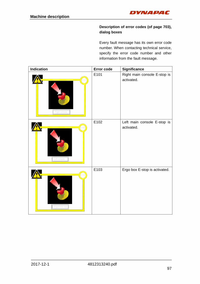
Machine description
97
4812313240.pdf 2017-12-1
Description of error codes (of page 703),
dialog boxes
Every fault message has its own error code
number. When contacting technical service,
specify the error code number and other
information from the fault message.
Indication Error code Significance
E101 Right main console E-stop is
activated.
E102 Left main console E-stop is
activated.
E103 Ergo box E-stop is activated.
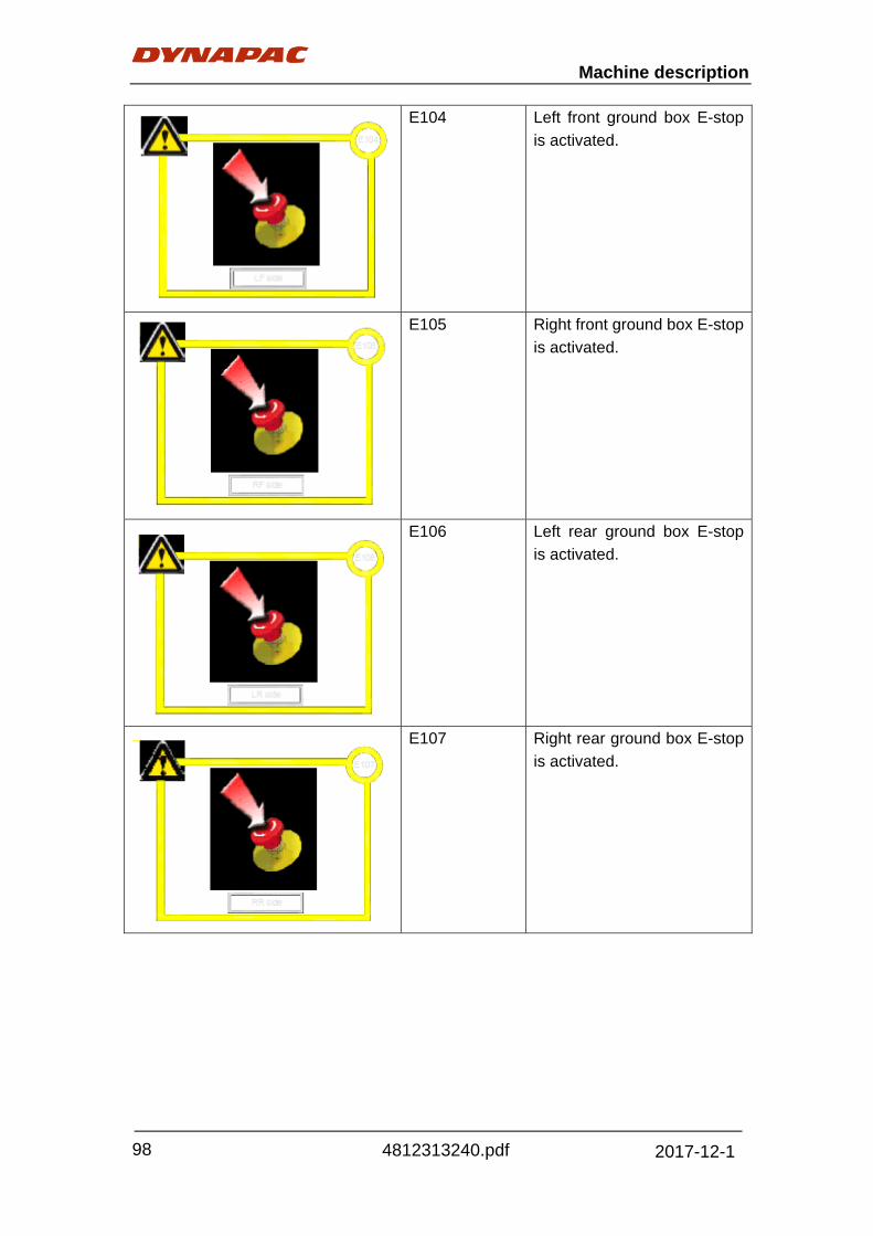
Machine description
98
4812313240.pdf 2017-12-1
E104 Left front ground box E-stop
is activated.
E105 Right front ground box E-stop
is activated.
E106 Left rear ground box E-stop
is activated.
E107 Right rear ground box E-stop
is activated.

Machine description
99
4812313240.pdf 2017-12-1
E108 Low voltage.
E109 CAN connection error
between main controller and
the engine.
E110 CAN connection error
between main controller and
the consoles.
E111 CAN connection error
between the main controller
and the display.

Machine description
100
4812313240.pdf 2017-12-1
E112 CAN connection error
between A3 and A4.
E113 CAN connection error
between A3 and A8.
E114 Leveling system error
E115 Propelling control lever error

Machine description
101
4812313240.pdf 2017-12-1
E116 Rear steering control lever
error
E117 Four strut towers control
lever error- Right side
E118 Left front strut tower control
lever error- Right side
E119 Right front strut tower control
lever error- Right side
E120 Rear strut towers control
lever error- Right side

Machine description
102
4812313240.pdf 2017-12-1
E121 Four strut towers control
lever error- Left side
E122 Left front strut tower control
lever error- Left side
E123 Right front strut tower control
lever error- Left side
E124 Rear strut towers control
lever error- Left side
E125 Slop sensor error

Machine description
103
4812313240.pdf 2017-12-1
E126 Front steering sensor error
E127 Rear steering sensor error
E128 Left front motor speed sensor
error
E129 Right front motor speed
sensor error
E130 Left rear motor speed sensor
error

Machine description
104
4812313240.pdf 2017-12-1
E131 Right rear motor speed
sensor error
E132 Fuel level sensor error
E133 Hydraulic oil temperature
high
E134 Hydraulic oil level low
E135 High pressures hydraulic oil
filter block

Machine description
105
4812313240.pdf 2017-12-1
E136 Low pressures hydraulic oil
filter block
E137 Water level low
E138 Discharge conveyor
pressures high (Option)
E139 Lower conveyor pressure
high (Option)
E140 Propelling system pressure
high

Machine description
106
4812313240.pdf 2017-12-1
E141 Tilt too much
E149 Calibration values error
E150 A3 controller error
E151 A4 controller error
E152 A8 controller error

Machine description
107
4812313240.pdf 2017-12-1
E153 Milling drum clutch error
E154 Milling drum belt tension
error
E155 Parking valve error
E156 Propelling pump error
E157 Left rear motor error

Machine description
108
4812313240.pdf 2017-12-1
E158 Left front motor erro
E159 Right rear motor error
E160 Right front motor error
E161 Front steering valve error
E162 Rear steering valve error

Machine description
109
4812313240.pdf 2017-12-1
E163 Rear strut tower valve error
E164 Discharge conveyor error
E165 Lower conveyor error

Machine description
110
4812313240.pdf 2017-12-1
Key to component and status symbols
Designation Symbol Action
Hydraulic oil temperature
Allow the hydraulic oil to cool
down.
Check the hydraulic oil level. Check
radiator for signs of contamination.
Hydraulic oil level
Top up hydraulic oil.
If necessary, carry out a visual
inspection for signs of leakage.
Hydraulic filter
(pressure filter)
Replacing filter elements
Hydraulic filter
(return flow filter)
Replacing filter element
Display set-up and system information
screen (Page 801)
This screen indicates the version number
of the three controllers, two displays and
left and right consoles in the electrical
system.
Press button B to set brightness and contrast of display (D13 system graphics is
applied).
Press button G to return to the main screen.
B
C
D
E
F
G

Machine description
111
4812313240.pdf 2017-12-1
Key to function and component symbols Meaning Display mode
- A: Front traction units, right steering
movement
- B: Front traction units, left steering
movement
- C: Rear traction units, right steering
movement
- D: Rear traction units, left steering
movement
A B C D
- A: Traction unit / rear right travel drive
- B: Traction unit / front left travel drive
- C: Traction unit / front right travel drive
- D: Traction unit / rear left travel drive
- A: Rear drive unit steering angle recording
- B: Front drive unit steering angle recording
A B
- A: Raising rear traction units
- B: Lowering rear traction units
- C: Raising front left traction unit
- D: Lowering front left traction unit
- E: Raising front right traction unit
- F: Lowering front right traction unit
- A: Raising discharge conveyor
- B: Lowering discharge conveyor
- C: Swivel discharge conveyor to left
- D: Swivel discharge conveyor to right
Hydraulically folding discharge conveyor (O)
- A: Belt tensioner
- B: Locking mechanism
- C: Folding-in function
- D: Folding-out function

Machine description
112
4812313240.pdf 2017-12-1
Meaning Display
- A: Forwards drive for discharge conveyor
- B: Reverse drive for discharge conveyor
- C: Forwards drive for lower conveyor
- D: Reverse drive for lower conveyor
- A: Raising left side board
- B: Lowering right side board
A B
- A: Raising sliding shoe
- B: Lowering sliding shoe
- C: Applying load to sliding shoes
- D: Sliding shoe floating position
- E: Sliding shoe stop valve
- A: Raising scraper blade
- B: Lowering scraper blade
- C: Applying load to scraper blade
- D: Scraper blade floating position
- E: Scraper blade stop valve
- A: Travel drive, right-hand operating
panel - drive axle - B: Travel drive, right-hand operating
panel - steering axle
- C: Travel drive, left-hand operating
panel - drive axle
- D: Travel drive, left-hand operating
panel - steering axle
- A: Control lever for discharge conveyor,
right-hand operating panel: Swivel
discharge conveyor - B: Control lever for discharge conveyor,
right-hand operating panel: Raise/lower
discharge conveyor - A: Control lever for discharge conveyor, left-
hand operating panel: Swivel discharge
conveyor - B: Control lever for discharge conveyor, left-
hand operating panel: Raise/lower
discharge conveyor

Machine description
113
4812313240.pdf 2017-12-1
Meaning Symbol
- A: Travel drive, forwards - B: Travel drive, reverse
- A: Travel drive brake function
A - A: Starter relay
A - A: Engine-stop-relay
A - A: High-pressure cleaner
A
- A: Spraying system high-pressure pump
proportioning valve
A
- A: Fuel pump
A
- A: Spray valve
A

Machine description
114
4812313240.pdf 2017-12-1
- A: Clutch for milling drum drive
A
- A: Belt tensioner
A
- A: Tilt sensor
- Tilt outside range or measurements or
- Senor defective
A

Machine description
115
4812313240.pdf 2017-12-1
FB1 Intake Air Heater Fuse=150A Fuse box FB2 Charging Fuse=100A Fuse box FB3 Main Fuse=100A Fuse box FB4 Electrical motor=60A Fuse box F1 Engine ECM Fuse=30A Junction Box F2 DEF Supply Heater Fuse=15A Junction Box F3 Line Heater Fuse=15A Junction Box F4 E-stop to relay=10A Junction Box F5 Engine Diagnosit Plug Fuse=10A Junction Box F6 E-stop to controller=3A Junction Box F7 Right console=20A Junction Box F8 Left console=20A Junction Box F9 Roof switch=10A Junction Box F10 A3 controller power1=5A Junction Box F11 A3 controller power2=30A Junction Box F12 A4 controller power1=5A Junction Box F13 A4 controller power2=30A Junction Box F14 A8 controller power1=5A Junction Box F15 A8 controller power2=30A Junction Box F16 Engine ECN key switch =5A Junction Box F17 After treatment=20A Junction Box F18 Slop CAN sensor=10A Junction Box F19 Travel motor sensors=3A Junction Box F20 A3 controller enable=1A Junction Box F21 Left rear control panel=10A Junction Box F22 Scraper switch=1A Junction Box F23 Right rear control panel=10A Junction Box F24 A4 controller enable=1A Junction Box F25 Horn relay=10A Junction Box F26 Left front control panel=10A Junction Box F27 Right front control panel=10A Junction Box
Electrical system
Fuses, machine The figure shows the different positions of the
fuses. The table below gives the amperage
and function of the fuses. All fuses are flat pin
fuses.
Fuses boxes

Machine description
116
4812313240.pdf 2017-12-1
F28 A8 controller enable=1A Junction Box F29 Pressure sensors=10A Junction Box F30 Null Junction Box F31 Conveyor position switches=10A Junction Box F32 Fan motor speed sensor=3A Junction Box F33 Lightings=40A Junction Box F34 Traffic lights=20A Junction Box F35 Rotation beacon=10A Junction Box F36 Horns=20A Junction Box F37 Back lights=20A Junction Box F38 Levelling control power1=10A Junction Box F39 Levelling control power2=10A Junction Box F40 Left cable sensor=10A Junction Box F41 Slope sensor=10A Junction Box F42 Right cable sensor=10A Junction Box F43 12 VDC output=20A Junction Box F44 Null Junction Box F45 Levelling display=10A Junction Box F46 T3 Engine ECM power1=10A Junction Box F47 T3 Engine ECM power2=10A Junction Box
K0 Starter relay K14 E-stop relay for electrical pump
K2 DEF supply module heater relay K15 Electrical pump relay
K4 Engine protection relay K16 E-stop relay for controllers
K5 Intake air heater relay K17 Backward relay
K6 E-stop relay for engine K18 Walter high pressure relay
K7 Left leveling relay 1 K19 Traffic lights relay
K8 Left leveling relay 2 K20 Working lamps relay
K9 Right leveling relay 1 K21 Flashing relay
K10 Right leveling relay 2 K33 DEF heater relay 1
K11 Fuel relay (engine power switch) K34 DEF heater relay 2
K12 Horn relay K35 DEF heater relay 3
K13 Power switch relay
Fig. Relays
Relay, machine
Relays

Machine description
117
4812313240.pdf 2017-12-1
Driver’s seat on left/ right
A driver’s seat can be found on both the left
and right. The seat should be set to the
driver’s requirements before work is started.
- Pull out lever (1) and (2), to adjust seat
position.
- After set the seat position, lock the seat
position by locking lever (2).
Risk of accident! If possible, always
select the operator’s control station on the
nearside, i.e. further away from oncoming
traffic.
Always ensure that the operating
panel and driver’s seat are correctly
locked into place.
Fig. 1. Lever
2. Locking lever
1
2

Machine description
118
4812313240.pdf 2017-12-1
Battery’s main switch
The battery’s main switch can be found under
the right-hand grid plate. It separates the
power supply from the battery for main fuse.
To deactivate the master switch, turn to the
right and remove.
Cover aperture with protective cap (2).
Do not lose the removed master switch
because otherwise you will not be able to start
the machine.
For the specifications governing all fuses,
refer to Chapter “Maintenance”.
Batteries
Behind the maintenance flap, two batteries of
the 24 volt system can be found on both the
left and right behind the driver’s seat.
For the specification, refer to ”Technical
data.”.
For maintenance, refer to Chapter
“Maintenance”.
Only undertake external starting in
accordance with the instructions (refer to
section “Starting machine, external starting”
(starting aid))”.
Fig. 1. Main switch
2. Cap
Fig. Batteries
2
1

Machine description
119
4812313240.pdf 2017-12-1
1
2
Tilt display
A tilt display (1) can be found in the center of
the front panel in the operator’s control
station.
The tilt display is used to provide a visual
estimate of the size of the machine’s present
tilt.
- The indicator ball in the sight glass shows
the machine tilt on the scale fitted below the
sight glass.
A warning message is displayed on the
operating panel once the tilt exceeds 10% (O
13 %).
In certain situations, when the
machine tilt exceeds 10%, there is a risk of
tipping! Risk of accident!
Fig. 1. Tilt display
2. Indicator

Machine description
120
4812313240.pdf 2017-12-1
Lock and Unlock the ground panel cover
When using the ground panel to control
machine, the operator need unlock the cover
first, follow up below actions to do this
operation:
1, Insert the key, rotate the key as direction 1
shows;
2, pull down the cover as direction 2 shows;
3, put the cover in the accessory box/rear tool
box;
4, pull in the cover and lock the key after finish
the milling work.
Attention: Do not rotate the cover after unlock
the key

Machine description
121
4812313240.pdf 2017-12-1
Folding ladder
A robust ladder with slip-free steps can be
found on both the left and right.
The ladder can be folded up on both sides of
the machine.
- By gripping a rung or the slip-free step,
push the ladder upwards the ladder will fold in
as moving up.
- To fold out, pull the ladder down the
ladder will fold out as moving down.
Danger of crushing! Do not reach into the joint
area during the folding process as there is a
risk that fingers and hands will be crushed.
Never climb up/down ladders on the
machine during travel. Hold tight when
climbing up and down ladders.
Fig. Ladder

Machine description
122
4812313240.pdf 2017-12-1
Guardrail
There is one guardrail on both the left and
right between the ladders and operator’s
control stations.
The guardrails must be set up as required and
once the operator’s control station has been
entered.
Each of the guardrails consists of one outer
section (1) and two inner sections (2).
- Regarding the front guardrail, both outer
section and inner section can be adjusted;
regarding the rear guardrail, only the inner
section can be adjusted.
The diagram shown here indicates the
different situations in which the guardrail
should be set up.
- (A) Close guardrail
- (B) Open guardrail to enter and exit from
the operator’s control station.
- (C) Inner section of front guardrail fold out
– the operator stand out of the operator
platform when the platform is in the middle
position.
Danger of crushing! Do not reach into
the joint area during the folding process
as there is a risk that fingers and hands
will be crushed.
Fig. 1. Outer section
2. Inner section
(A)
(B)
(C)
2
1
2

Machine description
123
4812313240.pdf 2017-12-1
Transport position for ladder and
guardrails
To reduce the machine width for transport and
as an additional safety measure when parking
in public places
- Swivel the guardrails in front of the
slip-free step.
- Fold up the ladder on both sides of the
machine.
Fig. Ladder and guardrail

Machine description
124
4812313240.pdf 2017-12-1
Hydraulic folding roof operation
The hydraulically folded roof (1) is locked to
the rear suspension of the left and right-hand
side of the machine by a lock pin (2).
The key-operated switch (4) for actuating the
folding roof and hood hydraulics can be found
to the left of the belt drive’s protective box.
The roof can be raised and lowered without
the drive engine having to be started.
- Pull out the lock pin (2).
- Check that the changeover valve (3) (under
the compensation tank behind the
maintenance flap) is in position (A).
- To lower the roof, turn the key-operated
switch (4) to the left until the roof has lowered
to its minimum level.
Risk of crushing! Ensure that no one reaches
into the joint areas or the areas into which the
roof is to be lowered during the folding
process as there is a risk that fingers and
hands will be crushed.
- To raise the roof again, turn the
key-operated switch (4) to the right until
the roof has risen to its maximum height.
- Insert pin (2) on both sides of the machine.
Fig. 1. Roof
2. Pin
3. Valve
4. Switch
1
2

Machine description
125
4812313240.pdf 2017-12-1
Hydraulic hood operations
The machine’s engine hood (1) can be
opened and closed hydraulically and provides
good access to the various monitoring and
maintenance points.
The key-operated switch (2) for actuating the
folding roof and hood hydraulics can be found
to the left of the belt drive’s protective box.
The hood can be raised and lowered without
the drive engine having to be started.
- Check that the changeover valve (3)
(under the compensation tank behind the
maintenance flap) is in position (B),
- Turn key-operated switch (2) to the left
until the hood is opened to its maxi- mum
level.
- To lock in this open position, slide the
slotted detent sleeves (4) on both sides
over the joint.
Risk of crushing! Ensure that no one
reaches into the joint areas or the areas
into which the roof is to be lowered during
the folding process as there is a risk that
fingers and hands will be crushed.
- In order to close the hood again, the two
detent sleeves (4) have first to be sild
away from the joints.
- Turn key-operated switch (2) to the right
until the hood is fully closed.
Fig. 1. Engine hood
2. Switch 3. Valve 4. Sleeve
2
1

Machine description
126
4812313240.pdf 2017-12-1
4
3
2
1
Throttle valves for deployment speed of
hood and roof
The hydraulic unit for hood and roof operation
can be found behind the maintenance flap of
the operator’s control station.
The unit has two throttle valves for setting the
speed for raising and lowering the roof.
Throttle valve (1):
Turn adjustment button clockwise = slower
speed for lowering roof
Turn adjustment button anticlockwise = faster
speed for lowering roof
Throttle valve (2):
Turn adjustment button clockwise = slower
speed for raising roof
Turn adjustment button anticlockwise = faster
speed for raising roof
Manual pump, hood and roof
A manual pump can be used to lift and lower
roof and engine hood if battery power failure.
The way to lift roof and engine hood with
manual pump:
1. Use one thin rod to push “valve A” (1) to
the end
2. Operate manual pump lever (3) until roof
or engine hood lift to the top
3. Release “valve A” (1)
The way to lower roof and engine hood is
same with the way of lift, the only different is
push “Valve B” (2)
Fig. 1. Throttle valve
2. Throttle valve
3. Screw threading dowel
4. Pump lever
1
3
2
Fig. 1. Valve A
2. Valve B
3. Manual pump lever

Machine description
127
4812313240.pdf 2017-12-1
Water system
The water system on the machine comprises
the following elements:
- Diaphragm water pump (1): used in the water spraying system to produce pressure, 8
bar
- High pressure pump (2): used in the high pressure cleaner system to produce pressure,
80 bar
- Water filter (3): used in the water spray system
- Water filter (4): used in the high pressure cleaner system
- Pressure gauge (5) for water spray system
- Pressure gauge (6) for high pressure cleaner system
Tank water supply shut-off valve (7) and (8):
used to shut off the water from the water tank,
e.g. for maintenance work
Fig. Water system
1. Water pump
2. High pressure pump
3. Water filter
4. Water filter
5. Pressure gauge
6. Pressure gauge
7. Shut-off valve
8. Shut-off valve
7
3
1
8
6
2
4
5

Machine description
128
4812313240.pdf 2017-12-1
2
3
High pressure cleaner
The hose reel (1) of the high pressure cleaner can be found on the top of accessory box at the rear of the machine. The spray pistol (2) is locked in its detent by a cotter pin (3). - Remove cotter pin. - Remove spray pistol from bracket. - Pull hose out of fixture until you hear a
click. When released, the hose automatically engages here. ‐ The hose will automatically roll back
up again if pulled and released again. ‐ The high-pressure jet is started by
pressing the trigger (4). (Only if the high pressure cleaner function is activated.)
When cleaning heavily
contaminated areas, note that particles of dirt may be flung in all directions. Danger of accidents.
When cleaning, never direct water
jet of high pressure cleaner towards electrical components such as sensors, connection boxes, operating panels, electric distributors etc.!
Fig. High pressure cleaner
1. Hose reel
2. Spray pistol
3. Cotter pin
4. Trigger
1
3
2
4

Machine description
129
4812313240.pdf 2017-12-1
Filling pump for water tank
The filling pump for the water tank is located
at the front left of the machine.
To fill the water tank:
- Unscrew seal cap (1) (if necessary use
wrench)
- Attach suction line and tighten
- Start filling process by pressing switch (2).
- Switch off filling pump as soon as the level
water required is reached in the water
tank (monitor using the LCD display on
the operating panel.)
An overflow can be found on the underside of
the machine. Excess water flows out through
this if overfilled.
Ensure that the water is not too heavily
contaminated because this may result in
lengthy filter changes and cleaning work in
the tank.
Fig. 1. Seal cap 1
Fig. 2. Switch
2

Machine description
130
4812313240.pdf 2017-12-1
Water filling (pressure fill) connection for
water tank
The connection for the water tank’s pressure
fill can be found on the left rear underside of
the machine.
To fill the water tank:
- Open lock cock.
- Unscrew seal cap (if necessary use
wrench)
- Attach pressure pipe and tighten
- Signal to the operator of the external filling
pump that the filling process can be
started.
Switch the filling pump as soon as the level of
water required in the water tank is reached
(monitor using LCD display on the operating
panel).
- Close the lock cock again before
removing the filling hose.
- An overflow can be found on the
underside of the machine. Excess water
flows out through this if overfilled.
Fig. Connection

Machine description
131
4812313240.pdf 2017-12-1
2
3
Changeover for separate circuits of rear
strut towers
For some maintenance and repair work, the
rear strut towers will have to be individually
operated. The joint hydraulic circuit will have to be separated in such instances. The changeover equipment is located in front
of the right strut tower under the engine hood. To separately operate the strut towers:
- Raise machine to the height required and support.
- Remove retaining pin (1) and grip.
- Turn changeover lever (2) anticlockwise
until the second detent bore (3) is under
the retaining pin (1).
- Allow retaining pin to engage.
- The traction unit legs can now move
separately using the traction unit buttons
on the rear side control panels.
Once maintenance and/or repair work is
complete, turn the changeover valve back to
its original position so that the traction unit legs
are moved together again.
Fig. 1. Retaining pin
2. Lever
3. Detent bore
1

Machine description
132
4812313240.pdf 2017-12-1
Milling depth display
One milling depth display, indicating cm
and/or inches, is located on both sides of the
milling housing. This provides additional
visual assistance in addition to the leveling
equipment.
- The upper edge of the side shield serves
as a reference and indicates the depth of
the engaged milling drum on the display
(1).
Milling drum operational check
Several control marks can be found on both
side shields and, depending on the grating
depth, indicate the extent to which the milling
drum is engaged.
The control marks are used as assistance, e.g.
if milling is to be conducted as close as
possible to an obstacle (e.g. drain cover).
- Control marks are available for the
following milling depths: 4 cm (1), 10 cm (2),
20 cm (3), 30 cm (4).
‐ The slots in the side shield under the
marks are used as a reference line and
indicate the minimum possible distance
between the milling drum and obstacle at
which no damage will be caused.
Fig. 1.Milling depth display
Fig. Depth
1. 4 cm
2. 10 cm
3. 20 cm
4. 30 cm
1 2 3 4
1

Machine description
133
4812313240.pdf 2017-12-1
1
2
34
Fig. 1. Bolt
2. Detent bore
3. Handle
4. Interlock
Fig. Retaining hook
Interlock on scraper flap
One interlock for the scraper flap can be
found on either side of the back of the drum
box.
The interlock must be released before the
scraper flap can be opened.
When interlocked, the bolt (1) is in the detent
bore (2).
Unlocking procedure:
‐ Use handle (3) to rotate interlock bolt upwards and slide towards the center of
the vehicle, via the sliding interlock (4).
‐ Rotate the bolt downwards so that the handle lies on the inner side of the sliding
interlock (4).
Retaining hook of scraper flap
The retaining hook for the scraper flap can be
found on the right-hand side of the machine.
When the scraper flap is opened, this
automatically engages in the retaining hook.
The limit switch is also activated.
Only open the scraper flap once the
milling drum drive and the travel drive have
been switched off.
Refer to limit switch of scraper flap.
Unlocking procedure:
- Use the appropriate controls to open the
scraper flap so wide that the retaining
hook is disengaged.
- Swivel retaining hook upwards.
- Use appropriate controls to close the
scraper flap completely.

Machine description
134
4812313240.pdf 2017-12-1
Limit switch of scraper flap
The limit switch can be found behind the
milling drum housing on the frame of the
left-hand side of the machine.
The limit switch serves as a safety measure
and is actuated as soon as the scraper flap is
opened.
Once the switch has been actuated, as an
additional safety measure, the clutch and belt
tensioner of the milling drum drive cannot be
actuated and the machine cannot be
operated.
For safety purposes, always ensure that
the limit switch Is functioning correctly.

Machine description
135
4812313240.pdf 2017-12-1
1
2
3
4
2
1
3
Traction unit supports
One separable traction unit support can be
found as a safety measure on every traction
unit.
The complete traction unit support is used for
retaining purposes during maintenance and
repair work.
In order to achieve a lower transport height,
the upper section of the separable support is
used on the trailer during transport.
The full length of the traction unit
supports should be placed under the machine
during all maintenance and repair work.
If the machine is lowered unintentionally,
wedge-shaped supports advance
automatically into the recesses provided in
the locating plates and therefore prevent the
machine from being lowered further.
- Extend traction units to their maximum
limit position.
- Remove complete supports (1) from the
retaining tabs (2) and swivel down.
- If necessary, dismantle lower section (3)
of support. Remove spring cotter pin (4) for
this purpose.
- Ensure that the support is above the
hollow of the support plate.
- For transport purposes and before starting
work, return the supports to the retaining tabs.
Support brackets
If the lower sections of the traction unit
support have to be dismantled, there is a
storage space inside traction units for them.
To prevent loss, always place the dismantled
lower sections of the traction unit support (1)
and corresponding cotter spring pins (2) in the
support brackets (3) provided for this purpose.
Fig. 1. Traction unit support
2. Spring pin
3. Support bracket
Fig. 1. Supports
2. Retaining tabs
3. Lower section
4. Cotter pin

Machine description
136
4812313240.pdf 2017-12-1
“Scraper flap function changeover” valve
The valve for the raise and lower scraper flap /
swivel scraper flap function changeover (1)
can be found above the frame on the
right-hand side of the machine behind the
milling drum box.
- Switch position (1): raise/lower scraper flap.
- Switch position (2): swivel scraper flap
(open / close).
Switch position (1) should only be selected for
the working site, switch position (2) is used for
maintenance and repair work.
Observe safety precautions when the
scraper flap is open.
“Discharge conveyor function
changeover” valve
The valve for changing over between
discharge conveyor in operating
position/discharge conveyor in floating
position function can be found on the left-hand
side of the machine, in the front section of the
inside of the frame.
- Switch position (1): discharge conveyor in
operating position.
- Switch position (2): discharge conveyor or
in floating position (transport position).
- Switch position (1) is for the working site
and should be selected for transport tasks
during which the discharge conveyor is
rigidly placed on the trailer, ie. No swivel
movement.
- Switch position (2) should be selected for
transport tasks during which the discharge
conveyor is flexible mounted, e.g. placed
on a support fixture on the tractor machine
of the trailer.
12
Fig. Switch position 1, 2
Fig. Switch position 1, 2
1
2

Machine description
137
4812313240.pdf 2017-12-1
Monitoring camera
Six video cameras are fitted to the machine to
observe the area of the milling track in front of
the front drive unit, the area of the sliding
shoe in front of the milling drum housing, the
area of the scraper f lap beh ind the milling
drum housing, the area of the rear track
during reverse, the area of the top of
discharge conveyor and the area of the top of
the rear hood.
Fig. Camera

Machine description
138
4812313240.pdf 2017-12-1
Compressed air system (O)
The compressed air tank and connected
maintenance unit can be found behind the
storage room flap on the left-hand side of the
machine.
There is a maintenance unit on the
compressed air tank. This unit separates water
from the air and enriches the airflow with a fine
veil of oil and therefore ensures that the
components connected have a longer service
life. The air pressure required can be set on
the pressure reducer (1).
- The pressure level set is indicated on the
pressure gauge (2).
- Various compressed air tools (e.g. the
pneumatic milling tool driver) can be connected
to the quick connector (3).
The compressed air coupling is accessible from
outside and can be found on the rear of the
storage area cabinet.
When using the compressed air tools,
ensure that the oiler (4) is filled with oil under
pressure.
Fig. 1. Pressure reducer
2. Pressure gauge
3. Quick connector
4. Oiler
1 2 3 4

Machine description
139
4812313240.pdf 2017-12-1
Storage area and protective flaps
The section of storage area and protective
flap which covers the operating side panels
and the levelling device (1) can be folded for
operations.
- Open latch (2) and raise flap
- Press the two flap sections together so
that both bracket sections are pressed
into one another.
To close the flap, proceed in reverse order.
Risk of crushing! Ensure that no one
reaches into the joint areas during the folding
process as there is a risk that fingers and
hands will be crushed.
Fig. 1. Leveling device
2. Latch
1
2

Machine description
140
4812313240.pdf 2017-12-1
3 4 2
1
Plumb fixture
The part of the lockable storage area and
protective flap which covers the operating side
panels and leveling device (1) can be turned
down for operations.
The plumb line fixture can be used to work
along one particular longitudinal mark which
is at a specified distance from the machine.
The machine should then be controlled
ensuring that the suspended plumb line (1)
is above the mark.
‐ To set the handle to the mark, unfasten
wing screw (2), move the pipe into the
position required and re-tighten the wing
screw correctly.
‐ To remove the plumb line fixtures,
unfasten wing screw (3) and pull the
fixture out of the bracket.
‐ If the plumb line fixture is not used for
some time, the chain can be used to hang
the plumb line in the bracket.
Fig. 1. Plumb line
2. Screw
3. Screw

Machine description
141
4812313240.pdf 2017-12-1
1
Swivel-mounted warning sign
The swivel-mounted warning sign is located
on the rear of the machine, on the right.
The sign should be swiveled out if this side of
the machine is on the offside, closest to
passing traffic or if the machine is driven on
public highways.
‐ Slightly raise the warning sign so that the
detent pin no longer reaches into the bore.
‐ Swivel the sign through 90° and lower into
the detent bore.
To transport the machine, fold in the
warning sign. Danger of accidents, very
wide vehicle.
Tool holder
A console (1) is fitted on each of the inner
sides of the rear traction units. These can be
used to store bit boxes or tool boxes.
During operation, the parts needed can be
safely transported in this location.
During maintenance work, these areas
provide better access to tools.
Fig. 1. Console

Machine description
142
4812313240.pdf 2017-12-1
Typical wear marks on tool holder
New bit box
Strong wear of contact surfaces of
bit - replace as soon as possible
Strong wear of hole for bit - replace as
soon as possible
Strong wear of flank - replace immediately
To check and replace bits and bit boxes, the following safety measures are to be
met and enforced:
- Apply traction unit supports.
- Open and secure the drum flap.
- Lift the side boards and secure them.
- Ensure that the drive engine cannot be started.
If a pneumatic driver is used, heed the required safety measurement!

Machine description
143
4812313240.pdf 2017-12-1
The condition of the milling bits and bit boxes is to be checked several
times a day. Worn or damaged bits and boxes must be replaced immediately.
The machine capacity can be fully exploited only with perfect milling tools.
Typical wear marks on bits
New bit
Worn bit - replace as soon as possible
Washed-out bit - replace as soon as possible
Asymmetrically worn bit - replace immediately
Worn bit - replace immediately
Broken-off bit - replace immediately
Broken-off bit - replace immediately

Machine description
144
4812313240.pdf 2017-12-1
Bits holder replacement
- Remove the used holder system.
- Cut off along the middle of the welding seam, the marked ( ) pins / dowel pins
and the contact areas must remain undamaged the old welding seams have to be
removed completely.
- Position and weld on the new holder
system (1).
The welding area must be metallically
bright and dry.
The milling drum itself should be at room
temperature during welding.

Machine description
145
4812313240.pdf 2017-12-1
- Remove the old screw and replace it
by the new coated screw (2).
Locking torque is 200 Nm.
The torque wrench with the plug tool
must be set to 120Nm.
The screw has to be inserted dry and
free of oil and grease.
Don’t reuse it!
Drive in the changeable holder tightly
into the cone of the basic holder with a
copper hammer.
Then tighten the screw (2) again with the
required locking torque.
Danger of injury from flaking-off
pieces of metal.

Machine description
146
4812313240.pdf 2017-12-1
Observe the required safety measures during dismantling and welding!
- Remove the screw (a).
- Disassemble the changeable holder
(b):
With hammer blows on the side of
the changeable holder alternatively
from LH / RH.
- Clean the basic holder and check it
for damage.
Inner cone free of dirt
and grease
Make surfaces free
of dirt.

Machine description
147
4812313240.pdf 2017-12-1
Bits replacement
Dismantling the bits
‐ Position the bit extractor in the hole at the rear
of the bit box, and drive out worn and
damaged bit by hitting with a hammer.
Optionally, a pneumatically operated hammer that
can be driven using the compressed air system of
the machine is available.
Mounting the bits
‐ Drive the new bit into the bit box with a copper,
brass or hard plastic hammer.
Do not use a steel hammer to drive the bits
into the holders, this can lead to the destruction of
the top of the bit.
Danger of injury from flaking-off pieces
of metal.
After mounting the bit ensure that the milling
bit can be turned. Stuck bits wear out
asymmetrically and quickly.

Machine description
148
4812313240.pdf 2017-12-1
Replacing the holder box The bit holders, which are arranged on the milling drum In a spiral shape, are welded
so solidly and reliably with the drum that they are torn off extremely rarely and in
extreme situations (for example, forgotten steel rails in the milling surface).
Each bit on one side of the milling drum (the right or left spiral, as seen from the middle
of the drum) has a counterpart bit on the other side that is in the same position, but
shifted by a few centimeters.
Use this bit to determine the specifications:
- height to bit tip
- distance between bit tip and drum edge.
- Smooth the break point.
- Position, attach, align and weld the bit holder.
The process always occurs with an inserted milling bit!
Ensure that you distinguish between the left and the right bit holder.
Observe the required safety measures during dismantling and welding! The lateral cutters are normally not welded directly to the milling drum body, but rather to
a distance piece welded to the milling drum. The place where the break should occur
lies between the cutter and the distance piece so that the distance piece remaining on
the cylinder serves as a positioning guide for the new weld if a tear does occur.
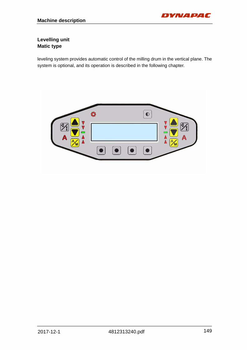
Machine description
149
4812313240.pdf 2017-12-1
Levelling unit Matic type leveling system provides automatic control of the milling drum in the vertical plane. The
system is optional, and its operation is described in the following chapter.

Machine description
150
4812313240.pdf 2017-12-1
Operating the Dynapac Levelling System Setting the contrast The contrast of the graphic display can be adjusted at the control panel to achieve
easy viewing, also in poor lighting conditions.
1) To do so press the contrast key in the right hand corner above the display.
As long as the key is held down, the contrast is increased starting from the previously
set value.
When the maximum value is reached, the process reverses and the contrast values
start to reduce automatically.
When the minimum value is reached, the process reverses again and the contrast
values start to increase again.
When the key is released, the contrast value at the point of release is
saved.
Cross slope Sonic‐ski Ground
350 3.26
4.00
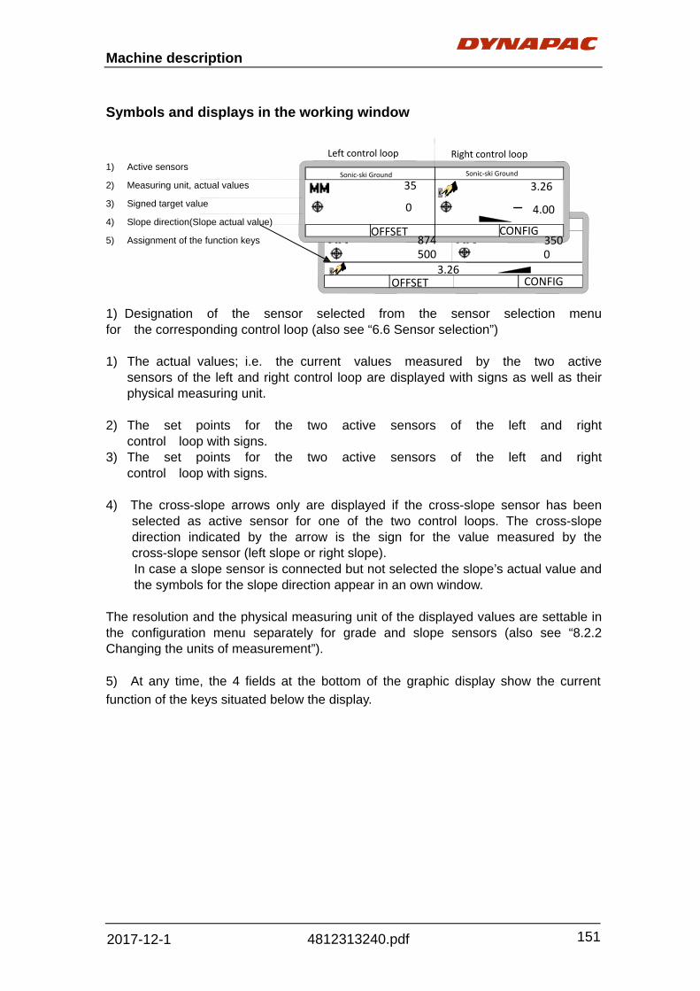
Machine description
151
4812313240.pdf 2017-12-1
Symbols and displays in the working window 1) Active sensors
2) Measuring unit, actual values
3) Signed target value
4) Slope direction(Slope actual value)
5) Assignment of the function keys
1) Designation of the sensor selected from the sensor selection menu for the corresponding control loop (also see “6.6 Sensor selection”)
1) The actual values; i.e. the current values measured by the two active
sensors of the left and right control loop are displayed with signs as well as their physical measuring unit.
2) The set points for the two active sensors of the left and right
control loop with signs. 3) The set points for the two active sensors of the left and right
control loop with signs. 4) The cross-slope arrows only are displayed if the cross-slope sensor has been
selected as active sensor for one of the two control loops. The cross-slope direction indicated by the arrow is the sign for the value measured by the cross-slope sensor (left slope or right slope). In case a slope sensor is connected but not selected the slope’s actual value and the symbols for the slope direction appear in an own window.
The resolution and the physical measuring unit of the displayed values are settable in the configuration menu separately for grade and slope sensors (also see “8.2.2 Changing the units of measurement”). 5) At any time, the 4 fields at the bottom of the graphic display show the current
function of the keys situated below the display.
35 3.26
4.00
Sonic‐ski Ground
Right control loop Left control loop
Sonic‐ski Ground
0
874 350 500 0
3.26 CONFIG
CONFIG
OFFSET
OFFSET
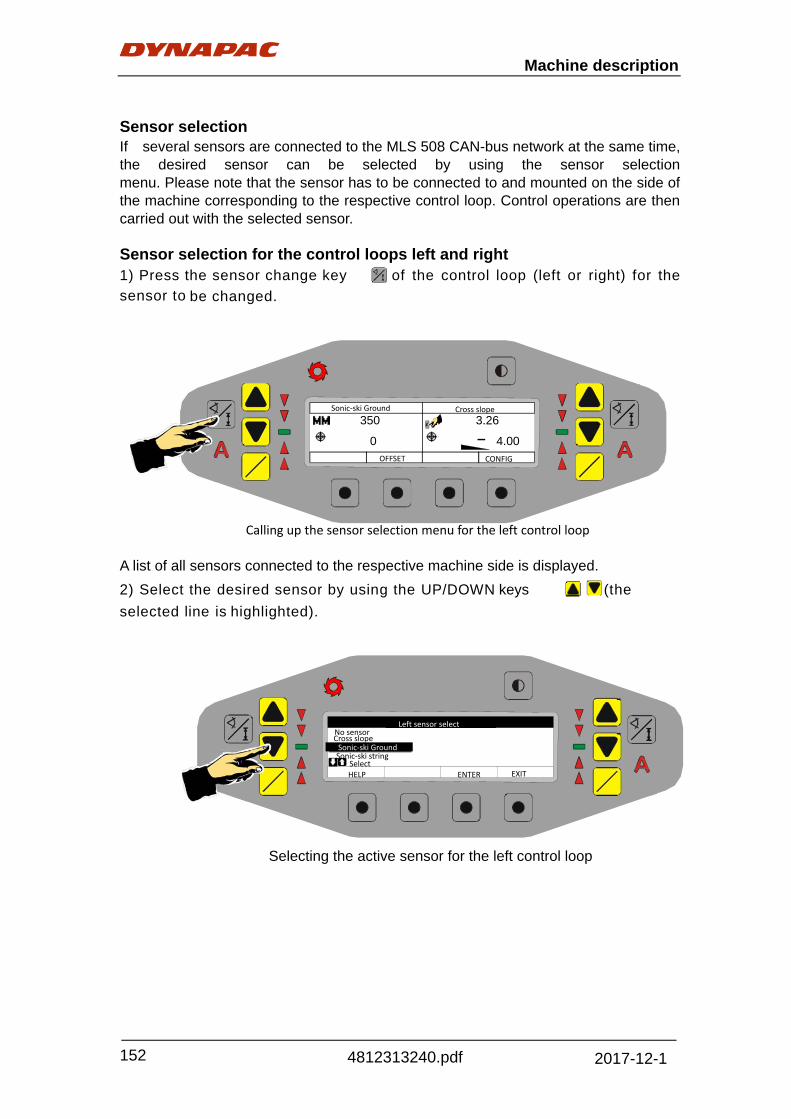
Machine description
152
4812313240.pdf 2017-12-1
Sensor selection If several sensors are connected to the MLS 508 CAN-bus network at the same time, the desired sensor can be selected by using the sensor selection menu. Please note that the sensor has to be connected to and mounted on the side of the machine corresponding to the respective control loop. Control operations are then carried out with the selected sensor. Sensor selection for the control loops left and right 1) Press the sensor change key of the control loop (left or right) for the sensor to be changed.
350 3.26
0 4.00
A list of all sensors connected to the respective machine side is displayed.
2) Select the desired sensor by using the UP/DOW N keys (the
selected line is highlighted).
Sonic‐ski Ground Cross slope
OFFSET CONFIG
Calling up the sensor selection menu for the left control loop
Selecting the active sensor for the left control loop
Sonic‐ski Ground
Left sensor select
Cross slope No sensor
Select
HELP ENTER EXIT
Sonic‐ski string

Machine description
153
4812313240.pdf 2017-12-1
4) Press the function key F3 (Enter) to save the selection or press the
function key F4 (Exit) to exit without making any changes. After either key is
pressed, the software returns to the working window.
Left sensor select
No sensor Cross slope
Sonic‐ski string Select
Sonic ski ground
Proceed in analogy with the above explanations when changing the
sensor for the right machine side.
Saving the selection and returning to the working window

Machine description
154
4812313240.pdf 2017-12-1
Cross Slope 3D3.26
4.00
OFFSET
Cross Slope 3D3.26
4.00
OFFSET
Operating with the Cross-Slope sensor
The Cross-Slope sensor has been selected for one of the two sides with the help
of the sensor change key (also see “6.6 Sensor selection”). The other side is
controlled manually or by means of a grade sensor.
1) If the automatic light of the
side selected for cross-slope
operation lights up, switch this
control loop to manual mode by
pressing the corresponding A/M key (manual = automatic light off).
2) Enter the desired s e t
point f o r the milling drum’s
slope angle taking account of
the sign by using the UP/DOW
N keys of the corresponding loop.
By briefly and simultaneously pressing the UP and DOWN keys 0.0% is set as set point.
If you hold down both keys until the display jumps from 0.0% to “Set”, the current milling drum’s slope will be adopted as set point.

Machine description
155
4812313240.pdf 2017-12-1
If the control in automatic mode works too sluggishly or is too unstable, the sensitivity
settings of the Cross-Slope sensor should be changed accordingly.
See section “1.6 Sensitivity settings” in the configuration menu.
3) Now switch the controller to automatic
mode (automatic = automatic light on) by
pressing the corresponding A/M key.
The “RAISE” or “LOWER” valve light first
indicates that an existing deviation is being
controlled out. The controller of the MLS508
then automatically holds the milling drum at
the set slope, even if it is moved in height
(manually or by the other side’s control
loop).
With the UP/DOW N keys the set point for
the milling drum’s slope angle can also be
adjusted in automatic mode.
The controller of the MLS 508
automatically moves the milling drum
to the new value and holds it in that
position.

Machine description
156
4812313240.pdf 2017-12-1
Zero adjustment Before describing operations with the various grade sensors, the term “zero
adjustment” has to be defined.
For every new application or after mounting or remounting a grade
sensor, the current value measured by the sensor has to be adjusted to zero.
In doing so, the current mounting level of the grade sensor above the reference is
saved in the system and a clear reference value is provided for all future set points at
the same time.
We call this procedure zero adjustment.
Procedure:
1) Move the milling drum’s bottom edge manually to the adjustment level; i.e. to the
level relevant to your day’s work (scratching).
2) Position the grade sensor(s) above the reference. Please consider the individual
specifications of the various sensors when doing so.
If you are working with laser receivers, move them with the help of the integrated
positioning aid so that the laser beam hits the middle of the receiver.
When the milling drum and the sensor(s) are set at the adjustment level, proceed as
follows in order to carry out the zero adjustment:
3) From the sensor selection menu, select the grade sensor to be
adjusted for the respective control loop.
4) Simultaneously press the UP key and the DOW N key of the respective control loop
and hold both keys down until the display first shows “Set” and then, after approx.
another two seconds, “0.0”.
The zero adjustment only is effective if the respective control loop is in manual mode.
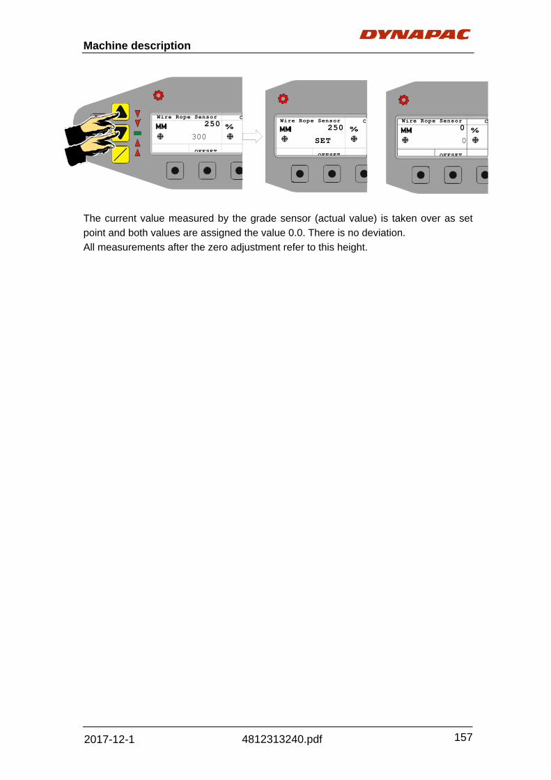
Machine description
157
4812313240.pdf 2017-12-1
Wire Rope Sensor C250
SET
OFFSET
Wire Rope Sensor C250
300
OFFSET
Wire Rope Sensor C0
0
OFFSET
The current value measured by the grade sensor (actual value) is taken over as set
point and both values are assigned the value 0.0. There is no deviation.
All measurements after the zero adjustment refer to this height.

Machine description
158
4812313240.pdf 2017-12-1
Sensitivity settings
The most varied influences (e.g. the machine size and motorization, the size of the
hydraulics, the subsoil condition or the sensing reference or, simply, just the selection of
a different type of sensor) may require adjusting the sensitivity settings of the MLS 508
control system in manual and automatic mode.
The control sensitivity is an indicator for how quickly and drastically the system reacts to
a control deviation.
The operator can set the sensitivity of each sensor type individually by assigning values
between 1 and 100.
Meaning of the values:
1 = very insensitive;
100 = very sensitive;
If the MLS 508 works too unstable on one side in automatic mode,
the sensitivity of the corresponding control loop should be reduced.
If the system operates too slowly, however, the sensitivity of the
corresponding control loop should be increased.
The sensitivity settings are stored separately for each sensor type and each control
loop.
This means that two different sensor types (e.g. a Sonic-Ski in ground sensing mode
and a Cross-Slope sensor) on the left control loop may have or will have different
sensitivity settings. In case the operator switches back and forth between those two
sensor types during operation, the stored sensitivity setting belonging to each sensor
will automatically be reloaded.
However, this also means that the same sensor (e.g. a Sonic-Ski in ground sensing
mode) may have different sensitivity settings when it is selected for both, the left and
the right control loop.

Machine description
159
4812313240.pdf 2017-12-1
Setting the sensor sensitivity:
1) From the working window switch to the menu item Configuration menu and then
to the parameter Sensitivity.
2) Call up the parameter Sensitivity and set the desired values for the active
sensors.
86 79
Change value Change value HELP SAVE CANCEL
3) Save the set value(s) and return to the working window.
Please note: If the same type of sensor is chosen for both the left and the right control
loop of the MLS 508 (e.g. the system operates with Sonic-Ski sensors in ground
sensing mode on the left side as well as on the right side), you will be asked during the
storing process whether a change in the sensitivity settings of one sensor shall
automatically bring about the same change in the sensitivity settings of the identical
sensor on the other side.
SENSITIVITY
Set Sensitivity for both side?
Change value
HELP ENTER CANCEL
Sensitivity
Y

Machine description
160
4812313240.pdf 2017-12-1
Changing the measurement units
In this menu item, the country-specific physical measurement unit and the resolution of
the displayed sensor values for grade and slope can be preset.
Setting the measurement unit of the grade sensors:
1) From the working window switch to the parameter Change grade units via the menu
items Configuration menu, User settings and Change units.
2) Call up the parameter Change Grade Units and select the desired measurement
units as well as the resolution for all measured values of the grade sensors.
GRADE UNITS
3) Save the selection and return to the working window.
0.1 CM(centimeter)

Machine description
161
4812313240.pdf 2017-12-1
System languages
To enable the operator to also take full advantage of the graphic navigation menu with
comprehensible texts and symbols in other languages the system language can be set
for universal use.
English, French and German have already been installed ex works
and can be selected immediately. Please contact your dealer referring the
implementation of other languages.
Setting the language: 1) From the working window switch to the parameter Language via the menu items
Configuration menu and Special functions.
2) Call up the parameter Language and set the desired system language.
LANGUAGE
3) Save the selection and return to the working window.

Machine description
162
4812313240.pdf 2017-12-1

Operation
163
4812313240.pdf 2017-12-1
Fig. 1. Shut-off valve
2. Filter housing
3. Hose
1
2
3
Operation
Before starting
Preparing for operation
To protect the water system from corrosion and frost, it is filled with around 5-7litres of antifreeze in the factory.
Before first starting up the machine, this must be
drained off, collected and disposed of in an
environmentally sound way under due
consideration of local rulings.
- Close shut-off valve (1).
- Unscrew filter housing (2) and drain.
- Open hoses on pumps (3) and run empty.
Observe safety measures (gloves, protective
goggles etc.)
Devices and aids
To prevent delays and to ensure a problem-free
flow of work, before starting work, operators
should check whether all the devices and aids
required for smooth operation are available.
A sufficient quantity of lubrication agents and fuel
substances, tools, spare milling tools and other
spare parts required as well as items of clothing
for personal safety (protective clothing, reflective
jackets, gloves, ear protection) should be
available.

Operation
164
4812313240.pdf 2017-12-1
Before starting work
- Read safety instructions.
- Check personal protective equipment.
- The parts and equipment removed for safe
keeping should be fitted again in accordance
with the appropriate instructions.
- Walk around the machine to check for damage
and leaks to ensure that the machine can be
safely started.
Conduct checks in accordance with “Checklist for
machine operator”
See the check list for machine operator from
Appendix II.

Operation
165
4812313240.pdf 2017-12-1
1
Starting the machine
The following should be done before the diesel
engine can be started and the machine can be
operated.
‐ Daily machine maintenance
Check the operating hours counter to determine
whether further maintenance work should be
conducted.
‐ Check the safety and protection equipment.
Check the position of the lever for changing over
the discharge conveyor.
If necessary, move the lever into the operation
position (1).
If necessary:
‐ Align and secure folding roof.
‐ Fold up ladder and secure,
‐ Set up control panel (driver’s seat, operating
panel, guardrails).
‐ Switch on battery’s main switch.(2)
Fig. 1. Operation position
2. Main switch
2

Operation
166
4812313240.pdf 2017-12-1
‐ Insert ignition key lock in position”0”. ‐ Switch ignition on (pos.1). Start screen appears on the display, position indicator of main operating panel light up.
‐ The start screen (4) is displayed while, the on-board computer is booting up.
‐ Once the booting procedure is complete, the main screen (5) appears on the display.
‐ Press the start button (6). See button function description from “Machine
description” chapter.
Press the horn button before starting.
The machine cannot be started if the control lever and function keys are not in position 0 or if one of the emergency stop button is pressed. ((7) shown on display).
If the engine does not start straightway,
continue starting for a maximum of 20 seconds without a break, then wait 1 minute.
‐ Press the button to start the planer. ‐ Use the display to check the operating and
setting values, correct if necessary. ‐ Allow the machine to warm up if
necessary.
6
4
5
7
Fig. 4. Start screen;
5. Main screen; 6. Start/stop button;

Operation
167
4812313240.pdf 2017-12-1
6
4
External starting (starting aid)
If the batteries are flat and the starter is not
running, the engine can be started using an
external source of power.
The following are suitable as sources of power.
- Another vehicle with a 24V system;
- Additional 24V battery;
- Starting aid, 20V/100A.
Normal charge devices and rapid charge.
Devices are not suitable as starting aids.
To externally start the engine;
- Use appropriate to connect up source of
power.
Check correct polarity! Always connect the
negative cable last and remove it first.
- Insert ignition lock in position “0”.
- Switch on ignition (pos.1).
Start screen (4) appears on display.
Position diodes of main operating panel light up.
- The start screen (4) is displayed while the
on-board computers is booting up.
- Once the booting procedure is complete the
main screen (5) appear on the display.
- Press the start button (6).
- Press the button to start the planer. Once the engine is running:
- Disconnect external source of power.
When using starter aid spray, note the engine’s
Operating instructions.
See main screen information from “Machine
description” section.
5
Fig. 4. Start screen;
5. Main screen;
6. Start/stop button;

Operation
168
4812313240.pdf 2017-12-1
Allowing engine to “warm up”
To keep excessive wear and increased load of
individual assemblies to a minimum, the engine
should always, but especially at low outside
temperatures (<10°C), warm up for approx. 5
minutes at idle speed and without any load.
The optimum operating values of a warm machine
are:
- engine: 60 - 110°C coolant temperature,
2.4 - 2.8 bar oil pressure at idle speed.
- hydraulic system: 45 - 85°C hydraulic oil
temperature.
The temperatures and pressure levels can be
called up from the info screen 2 and 3.
Before the milling procedure is started, all
hydraulic function elements on the machine
should be moved several times.
See main screen information from “Machine
description” section.

Operation
169
4812313240.pdf 2017-12-1
Driving the machine
- Smoothly raise the machine by pressing
button (1) or buttons (2), (4) until the distance
required between the machine and ground
has been reached.
- Never fully raise the machine for driving
purposes!
- Risk of tipping!
- Slightly raise sliding shoe by pressing button
(32).
- Slightly raised scraper board by pressing
button (35).
- Check whether all other position diodes of the
main operating panel are switched to „0“, if
necessary, press button to change over.
Always engage the warning lights (rotary
beacons and hazard flasher) and unfold the
warning sign when moving the machine!
- Slide unlocking switch of right-hand control
lever forwards and at the same time side the
control lever in the direction of travel required until
the machine starts to move.
- The unlocking switch can be released as soon
as the machine moves.
In an emergency, press the emergency
stop button or one of the emergency stop
buttons on the side operating units.
See button function description from “Machine
description” chapter.
32 35
3
1 2 4
Fig. Switch panel, ergo control
panel

Operation
170
4812313240.pdf 2017-12-1
Milling (preparation)
- Drive the machine to the milling section and
lower manually as far as possible (side boards are
lowered, milling drum does not quite touch the
ground)
‐ Correct start position with the help of the
reference points on sideboards for various
milling depth (4,10,20,30 cm)
Example: Milling starts
Once the milling drum has been inserted to the
milling depth of cm required, exactly on the rear
dimension mark.
‐ Switch the A/M button of the digital controller
of the levelling system („AUTO“ function
lights up).
‐ Set milling depth and / or slope on levelling
display. (Precondition: the zero and/or actual
value calibration has already been conducted).
Please refer to the description of levelling
system from “Machine description” Chapter.
- Lower the machine, by pressing the joystick (4)
of the control lever panel, via the rear strut
towers until the base-plates of the side boards
touch the ground in the rear area.
4

Operation
171
4812313240.pdf 2017-12-1
Activate the AUTO function from the main
operation panel.
See more instructions from chapter
“Machine description – Switch panel, Main
console, left & right, RH/LH ergo control,
Front/Rear ground plate control”
The floating function of the scraper, sliding shoe,
the auto function of discharge and primary
conveyor, water spray equipment can also be
activated or deactivated from the lower control
panels.
28
10 8
5
Fig. Switch panel, ergo control panel

Operation
172
4812313240.pdf 2017-12-1
Once all the preparations for milling are complete,
the machine is ready for milling, the automatic
levelling device is activated from the main control
panel and the machine is lowered to the depth
required while at a standstill.
- Release control lever (3) by pressing slide
switch and gently slide forwards out of central
point (within dead band range).
- At the same time, use the function key (4) of
the control lever panel control down so that
the machine dips into a horizontal position
and in its final position is tilted slightly more at
the rear than at the front.
This milling position should be retained during the
entire milling process, even if the milling depth is
changed via the digital controller.
- Set the max. milling speed required by
pressing button (24) or (25).
The machine starts to move:
- Depending on the setting, the speed display
lights up.
The speed reached is shown on the display.
Other settings can also be made on the leveling
equipment.
4 24 25
3
Fig. Switch panel, ergo control
panel

Operation
173
4812313240.pdf 2017-12-1
Stop the machine and raise at the end of the
milling track:
Depending on the milling depth, the end of the cut
will be at the height of the reference point marked
on the side boards:
-To remove the milled material from the conveyor
belts, let the lower and discharge conveyors run
on as is necessary.
The run-on times can be set in the lower and
discharge conveyor menu.
- Smoothly raise the machine by operating
joystick (1) or button (2), (4) of the main
control panel.
- Pressing button (7), (8), (9) of the rear
side ground plate control until the distance
required between the machine and ground is
reached.
Never fully raise the machine for driving purposes!
Risk of tipping!
- Slightly raise sliding shoe by pressing button
(32).
- Slightly raise scraper board by pressing button
(34).
- Set both front and rear tracker back to neutral
position.
See button function description from “Machine
description” chapter.
7 8 9
24 32 34 25 1 2 4
Fig. Switch panel, ground plate
control

Operation
174
4812313240.pdf 2017-12-1
Parking the machine
Before parking the machine, read the operating
hours counter and check whether any
maintenance work is to be conducted.
When parking the machine on publicly accessible
land, secure it to ensure that unauthorized
persons and children cannot do any damage to
the machine.
The machine should be parked on even ground;
the discharge conveyor lowered and, if possible,
swiveled into a safe area.
‐ Lower scraper, sliding shoe and side boards.
‐ Remove ignition key and master switch and
take them with you – do not leave them,
hidden “in the machine”
- Fit cover to operating panel and lock.
- Close protective covers of the side control
elements and lock.
- Fold up ladder on the right-hand side of the
machine.
- Close guardrail.
- Safely store loose components and
accessories such as removable spotlights or
parts of the levelling equipment.
- Deploy folding roof, remove key.
- Close all bottom lids, hoods and storage
rooms.
- Fold out full length of traction unit supports so
that the vehicle cannot be lowered should
attempts be made to do so.
See main screen information from “Machine
description” section.
Long-term parking
175
4812313240.pdf 2017-12-1
Long-term parking The following instructions should be followed when long term parking (more than one month). Before using the planer again attend to the items marked with a “below”. Wash the machine and touch up the paint finish to avoid rusting. Treat exposed parts with anti-rust agent, lubricate the machine thoroughly and apply grease to unpainted surfaces. Battery *Remove the battery from the machine, clean, grease the cable connectors (terminals) and trickle charge the battery once a month. The battery is otherwise maintenance free. Engine *See the manufacturer’s instructions in the engine manual. Hoods, tarpaulin *Lower the instrument cover over the instrument panel. *Cover the entire planer with a tarpaulin. A gap must be left between the tarpaulin and the ground. *If possible, store the planer indoors and ideally in a building where the temperature is constant. If the machine is stationary for over 6 months to 1 year the following items must also be attended to. *Drain off the engine oil and fill the diesel engine with an approved conservation oil. Fuel tank Fill the fuel tank completely full to prevent condensation. Hydraulic reservoir Fill the hydraulic reservoir to the uppermost level mark. (see under the heading ‘Every 10 hours of operation.’)

Long-term parking
176
4812313240.pdf 2017-12-1
Watering system *Empty the water tank and all hoses of water. Empty the filter housing and the water pump. Undo all sprinkler nozzles. See maintenance sections for “Watering system - draining”.
Water pump It is important to comply with the recommendations
for lay-offs in the operator’s manual of the machine
into which the pump is incorporated
For the pump itself, at the end of pumping
operations, it’s essential to flush out internal circuit
by pumping clean water. After this, open the intake
circuit to the air and leave the pump in operation
until the internal circuit is completely empty.
Following this simple procedure at the end of every
operating session will prevent the retention inside
the pump of products which are often corrosive and
may damage tis hydraulic circuit in the long-term.
If the pump is laid off during the winter in locations
with severe weather conditions, its very important to
flush out the internal circuit a described above and
then draw diluted automotive anti-freeze into the
pump. Then take care to discharge the liquid from
the system and the pump in particular.
The drain plug as picture.

Miscellaneous
177
4812313240.pdf 2017-12-1
Transport
Safety regulations for transport
There is a risk of accident if the machine is
prepared incorrectly and transportation is
conducted incorrectly.
Prepare the machine ensuring that all
components are secured and cannot come loose.
Dismantle all protruding and removable
components and/or fit them so that they do not
represent a hazard!
The weather protecting sun roof should be
deployed and appropriately fastened during
transport.
Lower all of the machine down to the upper
section of the separated traction unit supports.
When in this position, the milling tool tips of the
milling drum are approx. 1 cm above the ground.
If a wooden support is fitted, the milling drum can
rest gently on this.
The discharge conveyor should also be moved
into its floating position if necessary.
The machine should be fastened onto the
attachment points provided for this purpose and
fixed to the transporter in accordance with the
relevant regulations.
Ensure that the transport vehicle is authorized for
transport of this type and that the maximum
transport load is not exceeded.
Store all components which are not permanently
connected to the machine in the boxes and
storage areas provided.
Close all panels and check that they are securely
fastened.

Miscellaneous
178
4812313240.pdf 2017-12-1
Use the cover to secure the main control panel,
close the side operating units.
When loading via ramps, there is a risk that
the machine will slip, tilt or overturn.
Drive carefully! Keep people away from the
danger area!
The following applies in addition to the above
during transport on public roads:
The machine driver must have a valid driving
license for this type of vehicle.
The operating panel must be on the side facing
oncoming traffic and be secured in place.
The headlights must be set in accordance with the
relevant regulations.
When driving on public roads, if necessary,
another person must guide the machine driver
especially at crossroads and side-road junctions.
Note the load bearing capacity of vaults and
bridges as well as the permissible trans- port
height and width.

Miscellaneous
179
4812313240.pdf 2017-12-1
Fix points
Fig. Fix points

Miscellaneous
180
4812313240.pdf 2017-12-1
There are two fix points (1) on each side of the
machine frame, at the front and back.
The machine should be fastened to these points
during transport on the transport vehicle.
The machine is to be fixed to the transporter using
sufficiently sized shackles (chains) and secured
so that it cannot tilt, slide or fall off.
Attention: when working, be sure that the
front lifting point is as state A.
The lifting weight of the machine is
shown on the lifting plate on the right front
frame and the left rear frame.
Stand well clear of the hoisted machine!
Make sure that the lifting hooks are properly
secured.
The machine must be held in a horizontal
position when lifted!

Miscellaneous
181
4812313240.pdf 2017-12-1
Transport on trailers
When transporting the machine on trailers, the load
dimensions and weights should be taken into
account when selecting and using appropriate
tractor vehicles and transporters in accordance with
the road traffic and registration authorities.
Approach ramps and tracks of the trailer should be
coated with a slip-free material. There must be
sufficient possible attachment points on the trailer.
Approach ramps and trailers must be upright during
loading to prevent the machine from sliding or tilting
sideways.
Always keep approach and transport areas free of
contaminations, such as clay, grease or oil.
If necessary, use winches to secure the machine
when driving on.
The machine should be cleaned before being
loaded.
The machine should be parked and secured as
follows:
Position the machine on the transporter ensuring
that the transport height, width and loaded
distribution correspond to the relevant regulations

Miscellaneous
182
4812313240.pdf 2017-12-1
Activities and preventive measures:
- In order to achieve a lower transport height, the
machine is evenly lowered down to the upper
section of the separated traction unit supports.
When in this position, the milling tool tips of the
milling drums are just (approx.1cm) above the
ground and can if necessary be gently rested on a
wooden supporting if fitted.
- Sliding shoe and scraper plate are raised slightly,
- Weather protecting sun roofs, ladders, operating
equipment should be folded in or removed.
- The parking brake is engaged and the engine
switched off.
- do not leave any insecure components on the
machine or the load surface.
When transporting machines with a foldable
discharge conveyor, this is placed on the front
locating surface of the transporter and if
necessary secured separately.
- Securely fix the machine to the four fix points
provided on the transporter.
Fig. Transport the foldable conveyor

Miscellaneous
183
4812313240.pdf 2017-12-1
1-14 = single lashings, i.e. one lashing with two parts, one head on the machine,
another head on the platform.
The lashings' permitted distance interval in meters
1, 6,7,12: Single lashings, LC at least 6 tonnes (60 KN)
2-5, 8-11: Single lashings, LC at least 8 tonnes (80 KN)
13, 14: Single lashings, LC at least 1 tonnes (10 KN)
L1/L6 L2 L3 L4 L14
1.0-1.5 1.0-1.5 1.0-1.5 1.0-1.5 0.5-1.5
Load carrier-The machine must always be reversed up the ramp with the rear end
pointing in the direction of travel of the transport vehicle.
- When loaded, the planer is not centered laterally on the platform, refer fig 1
dimension, d1=d2=145mm+50mm
-The steering angle of the front wheels must be zero.
-The drive motor of wheel/track should be locked.
- Lower the machine until the milling drum is just above the ground (approx. 5 cm), or
if wooden supports are used the drum should rest lightly against them.
- Lower the rear scraper, front guard and left/right shields to the lowest position.
- Lower the roof to its lowest position. Extruding control equipment must be retracted,
or removed.
- The parking brake is applied and in good working condition and stop the engine.
- If the conveyor belt is mounted, place it on its support and lash it as per fig. 1
-Chock all machine wheels/tracks, strongly recommend non-slip mat under
wheel/track to increase the friction factor.
- The contact surfaces must be clean, wet or dry, and free from frost, ice and snow.
- The lashing mounts on the load carrier have LC/MSL at least 10 tonnes.
Secure PL2000F for transporting. (The instructions also apply to machine without
conveyor.)
Direct of travel
Fig.1
Table.1

Miscellaneous
184
4812313240.pdf 2017-12-1
Lashings
- The lashings 1-14 comprise a lashing strap or chain with a permitted load (LC/MSL)
of at least in table 1.
-The lashings are re-tightened as required, the lashing preload should follow the
lashing supplier instruction.
- Each of lashings 1-14 is a single lashing. One end on the machine, another end on
the platform.
- Lashings in the same direction are placed in different lashing mounts on the trailer.
- The lashing hooks must not lose grip if the lashings become slack.
- The lashings are protected against sharp edges and corners.
- The lashings are located symmetrically in pairs on the right and left sides.
Make sure that the lashing equipment, e.g.
chains, blocks and attachments in the transport
vehicle, are approved and have the requisite
breaking strain for the mode of transport. The
lashing must be held tensioned during the entire
transport.

Miscellaneous
185
4812313240.pdf 2017-12-1
2 1 If the support for the discharge conveyor or
the locating surface for the folded in discharge
conveyor is placed on the frame of the towing
machine, the swivel hydraulic of the discharge
conveyor must be changed over to the floating
position once parts have been placed on this
frame.
In order to do this, the lever provided for this
purpose must be moved out of its operating
position (1) into the transport position (2)!
Risk of accident! If the locating surface is
not on the towing machine, but on the trailer, the
swivel hydraulics must always be shifted into the
operating positon!
When transporting the machine on different forms
of transport, such as by rail or ship, proceed as
described in the appropriate valid transport and
loading system.
Lever into operation position: when the discharge
conveyor is rigidly placed on the trailer or has to
be held. In other words, when the unit is not
subject to swivel movement;
Lever into transport position: when the discharge
conveyor is flexibly mounted on a support fixture
on the tractor machine of the trailer. In other
words, when the unit is subject to swivel
movement.
Fig. Transport position

Miscellaneous
186
4812313240.pdf 2017-12-1
Normal on-road travel
The machine is not intended for normal on-road
travel and is not equipped for such circumstances.
It should be used within enclosed building sites.
If the machine’s loading or unloading area is
outside an enclosed building site or if the machine
has to propel itself from one section of the
roadworks to another, the machine must be
dual-manned for safety reasons. All safety
measures (cordoning off) required for this should
be implemented.
If a machine has to be parked on a public
highway, it should be cordoned off in accordance
with the relevant regulations and secured to
prevent the machine from rolling away, tilting or
swiveling.
If the machine components protrude into another
lane of traffic during milling or maneuvering, this
should be briefly cordoned off until the hazard has
passed.
The rotary beacons and hazard flasher are
permanently activated during milling and
transport, the warning signs on the machine are
permanently folded down.
If necessary, the machine should always be used
on the nearside, away from oncoming traffic.
For relocation or during journeys required over a
long distance (distance>1km), the machine
should be transported on its transporter for
technical and safety reasons

Miscellaneous
187
4812313240.pdf 2017-12-1
Hydraulically foldable discharge conveyor
Folding in the discharge conveyor
The machine’s transport length can be
significantly reduced in a few simple steps by
using hydraulic foldable discharge conveyor.
To fold the discharge conveyor, various
preconditions must be checked and/or satisfied.
Machine has been moved out of its milling track
and is therefore on as level a base as possible.
Discharge conveyor is in its working position.
Milling drum is not activated.
- Loading and discharge conveyors are not
being operated.
Steps required for folding process:
1. Firstly raise machine as far forward as
possible over traction unit legs then lower as
far as possible to the rear.
2. Ensure that the distance between the bit of
milling drum and the ground is more than
150mm.
3. While the Button (18) is being pressed, the
conveyor continues being folded in until the
button is released.
4. Once the discharge conveyor is folded in
completely, release Button (18) to finish this
process.
See button function description from “Machine
description” chapter.
18 17
Fig. Switch panel;
Foldable conveyor

Miscellaneous
188
4812313240.pdf 2017-12-1
Folding out the discharge conveyor
To fold out, proceed as for the folding in process
but in reverse.
The following should be noted:
1. Firstly raise machine as far forward as
possible over traction unit legs then lower as
far as possible to the rear.
2. Ensure that the distance between the bit of
milling drum and the ground is more than
150mm.
3. While the Button (17) is being pressed, the
conveyor continues being folded out until the
button is released.
4. Once the discharge conveyor is folded out
completely, release Button (17) to finish this
process.
When pushbutton is pressed, the discharge
conveyor begins to fold. The pushbutton must be
held down during the entire folding process.
Ensure that there is no one in the machine’s
danger area.
The folding process is complete once the belt is
correctly re-tensioned (visual inspection).
See button function description from “Machine
description” chapter.
18 17
Fig. Switch panel;
Foldable conveyor

Miscellaneous
189
4812313240.pdf 2017-12-1
Load by crane
In the event of break down, should it no longer be
possible for the machine to be towed or if it cannot
be loaded in any other way, there is also the
possibility of raising it by crane.
Use lifting tackle with sufficient load bearing
capacity.
(For weights and dimensions, refer to Chapter B).
Ensure that the steel cables, shackles and
crosshead are large enough.
For attachment points (1,2) are provided on the
machine frame for loading the vehicle using lifting
gear.
- Secure vehicle wherever it is parked up.
- Move discharge conveyor into operating
position.
- Weather protecting sun roof may be
deployed.
- Safely store loose components and
accessories, such as removable spotlights or
leveling equipment parts.
- Check fix point A and B, attach lifting gear to
four attachment points (1,2).
During transport, ensure that the machine is
always horizontal! Ensure that there is nobody in
the danger area.
Risk of accident! When loading by crane,
the swivel hydraulics of the discharge conveyor
must always be moved into their operating
position (1) because otherwise the machine may
e.g. swivel outwards accident tally if on a slight
incline.
Fig. Load by crane
1
Fig. 1. Position of
discharge conveyor
swivel hydraulics

Miscellaneous
190
4812313240.pdf 2017-12-1
Towing/Retrieving
The planer can be moved up to 300 meters using
the instructions below.
Short distance towing with the engine running
Activate the parking brake, and temporarily
stop the engine. Chock the wheels to prevent the
planer from moving.
Open the two foot boards on the platform and
found the propel system by-pass ball valve (1)
which handle should be in line with pipeline to put
the system in by-pass mode.
By-pass mode means that A and B sides on the
pump are freely connected to the pressure side.
This function enables a machine to be moved
without the drive shaft rotating.
Start the engine and allow it to idle.
Unlock the control lever and place the
Forward/Reverse lever in the forward or reverse
position to release the parking brake.
The planer can now be towed and can also be
steered if the steering system is otherwise
functioning.
After towing, disengage the by-pass mode by turn
the handle of by-pass ball valves (1) to make it
vertical to the pipeline.
The machine must not be moved at a speed
higher than 0.5 km/h, and no more than 300
meters. Otherwise there is a risk of damaging the
drives. Make sure to reset the towing valves (by
turning them three turns clockwise) after towing.
Fig. Propel system
1. By-pass ball valve
1

Miscellaneous
191
4812313240.pdf 2017-12-1
Short distance towing when the engine is
inoperative
Chock the wheels to prevent the planer
from moving when the brakes are hydraulically
disengaged.
Open the two foot boards on the platform and
found the propel system by-pass ball valve (1)
which handle should be in line with pipeline to
put the system in working mode. (by-pass valve
(1) in vertical position is By Pass Mode)
By-pass mode means that A and B sides on the
pump are freely connected to the pressure side.
This function enables a machine to be moved
without the drive shaft rotating.
Manual brake release:
- Release the nut (4) of the towing valve; screw
the adjusting screw (3) to the lowest position.
- Press the pump handle (5) until the brake
pressure was released completely. (About
3bar).
- Rotate the towing valve (1) from horizontal
position to vertical position.
- After finishing towing the planer, set the valve
to original position.
The planer can now be towed.
After towing, it is important to reset the towing
valve (1) and the brake release to working mode.
Disengage the by-pass mode by turn back the ball
valve handle (1) to horizontal position and turn
back the adjusting screw (3).
The machine must not be moved at a speed
higher than 0.5 km/h, and no more than 300
meters. Otherwise there is a risk of damaging the
drives. Make sure to reset the towing valves (by
turning them three turns clockwise) after towing.
Fig. Propel system
1. By-pass ball valve
1
Fig. Brake release pump
position
2
Fig. 3. Screw
4. Nut
5. Pump handle
6. Towing valve

Miscellaneous
192
4812313240.pdf 2017-12-1
Towing the planer
When towing/retrieving, the planer must be
tied by the towing vehicle. A towing bar must be
used on the fix point of the planer.
The planer must be towed slowly, max. 0.5
km/h and only towed short distances, max. 300 m.
When towing/retrieving a machine, the towing
device must be connected to both holes.
Towing/retrieving in only 1 of the eyes is
prohibited!
The pulling force must act longitudinally on the
machine as shown in the figure.
Maximum gross pulling force 200 kN.
Fig. Towing

Miscellaneous
193
4812313240.pdf 2017-12-1
Lifting the conveyor
Refer to the fig1, there are lifting holes on the
conveyor head, middle section and support legs.
Lifting equipment such as chains, steel
wires, straps and lifting hooks must be
dimensioned in accordance with the relevant
safety regulations for lifting equipment. They
must be strong enough to hold the 3ton weight
of conveyor.
Lifting conveyor vertical to avoid it tip over!
Stand well clear of the lifted conveyor! Make sure
that the lifting hooks are properly secured.
Please Note the weight of the conveyor
from the data plate.
Fig1. Conveyor

Miscellaneous
194
4812313240.pdf 2017-12-1
3
1
Secure before parking up
When parking on publicly accessible areas, the
machine should be secured to ensure that
unauthorized persons and children cannot cause
any damage to it.
The machine should be parked on level ground;
the discharge conveyor lowered and, if possible,
swiveled into a safe area.
‐ Lower scraper, sliding shoe and side boards.
‐ Remove ignition key (1) and master switch (2)
and take them with you- do not leave them
“hidden” in the machine.
‐ Fit cover (3) onto operating panel and lock.
‐ Fold up the ladder on both sides of the
machine and swivel the guardrails in front of
the slip-free step (4).
‐ Safety store loose components and
accessories such as removable spotlights or
leveling equipment parts.
‐ Deploy folding roof, remove key.
‐ Lock all bottom lids, hoods and storage
rooms.
‐ Fold out full length of traction unit supports so
that the vehicle cannot be lowered should
attempts be made to do so.
Fig. 1. Ignition key
2. Master switch
3. Cover
4. Slip-free step
4
2

Operating instructions
195
4812313240.pdf 2017-12-1
Operating instructions – Summary
1. Follow the SAFETY INSTRUCTIONS specified in the Safety Manual.
2. Make sure that all instructions in the MAINTENANCE are followed.
3. Turn the master switch to the ON position.
4. Check that all switches are in position 0 and the Forward/Reverse control is in
neutral.
5. Start the engine and allow it to warm up.
6. Set the gear position switch in the required position.
7. Adjust the engine RPM to the desired position.
8. Set the travel speed to the desired position.
9. Check that the milling drum clears the ground, at least 10cm. Raise the
machine if necessary.
10. Drive the planer. Operate the forward/reverse lever with care.
11. Check the brakes. Remember that the braking distance will be longer if
the hydraulic fluid is cold.
12. IN AN EMERGENCY:
- Press the emergency stop
- Hold the handrails firmly
- Brace yourself for a sudden stop
13. When parking:
- Set the forward/reverse control in NEUTRAL.
14. When lifting: - Refer to the relevant section in the Instruction Manual
15. When towing: - Refer to the relevant section in the Instruction Manual.
16. When transporting: - Refer to the relevant section in the Instruction Manual.
17. Retrieval: - Refer to the relevant section in the Instruction Manual.

Operating instructions
196
4812313240.pdf 2017-12-1

Preventive maintenance
197
4812313240.pdf 2017-12-1
Preventive maintenance
Complete maintenance is necessary for the
machine to function satisfactorily and at the
lowest possible cost.
The maintenance section includes the periodic
maintenance that must be carried out on the
machine.
The recommended maintenance intervals
assume that the machine is used in a normal
environment and working conditions.
Acceptance and delivery inspection
The machine is tested and adjusted before it
leaves the factory.
On arrival, before delivery to the customer,
delivery inspection must be conducted as per the
check list in the warranty document.
Any transport damage must be immediately
reported to the transport company.
Warranty
The warranty is only valid if the stipulated
delivery inspection and the separate service
inspection have been completed as per the
warranty document, and when the machine has
been registered for starting under the warranty.
The warranty is not valid if damage has been
caused by inadequate service, incorrect use of
the machine, the use of lubricants and hydraulic
fluids other than those specified in the manual, or
if any other adjustments have been made without
the requisite authorization.

Preventive maintenance
198
4812313240.pdf 2017-12-1

Maintenance – Lubricants and symbols
199
4812313240.pdf 2017-12-1
Maintenance – Lubricants and symbols
DYNAPAC
Only the listed lubricants or commercial products with corresponding qualities may be used. Use only containers that are clean on both the inside and the outside to add oil or fuel. Observe the filling amounts! Using the incorrect oil/lubricant leads to increased wear and machine breakdowns
Fluid volumes
PL2000F
Fuel tank 1100L
Engine oil 55L
Hydraulic fluid tank 370L
Water tank 3400L
Pump distribution transmission 12L
Planetary gear, milling drum 16L
Coolant, engine 105L
Coolant, milling drum 420L
Urea 20Kg
Grease 1 Kg

Maintenance – Lubricants and symbols
200
4812313240.pdf 2017-12-1

Maintenance schedule
201
4812313240.pdf 2017-12-1
Maintenance
1 Notes regarding safety for maintenance During all maintenance work, the regulations regarding health, work and fire protection are to be heeded. The necessary protective equipment is to be worn continuously. If not described otherwise, maintenance work must only be carried out with the engine stopped (heed the notes regarding checking and replacing milling bits and milling bit holders!). Maintenance work must only be carried out on even and stable surfaces. When working in closed areas, exhaust fumes must be vented to the outside. Provide sufficient ventilation. Before beginning maintenance work, secure the machine against inadvertent starting, rolling away or lowering by: - putting the drive lever into the neutral central position and putting the
machine feed into the “zero” position using the selection switch. - removing the ignition key and the main switch - positioning the sign “DO NOT START” on the control panel so that it is
clearly visible. - when working under the machine, position all traction unit supports and
wear a hardhat. - If required, use chocks to prevent the drive units from rolling away.
In addition, pay attention to the following when replacing the milling bit and the milling bit holder. - if the pneumatic bit extractor is used, the drive engine must only run at
idling speed. The milling drum drive must be switched off. - The drum flap is locked in the open position. - The limit switch of the drum flap is functioning. - The belt tightened must be retracted and the clutch must be deactivated. If safety and protective devices must be removed for maintenance, they must be properly reinstalled again before putting the machine back into operation. Do not use easily flammable materials during cleaning. Always keep steps and other areas where persons can stand free of lubricants and slip-proof. When using the installed high-pressure cleaner or a stem sprayer to hose down electric parts, do not expose any electronic modules, insulators or ventilators to the direct water jet; cover these items if possible.

202
Maintenance schedule
4812313240.pdf 2017-12-1
Avoid electrical soldering work on the machine; this can lead to damage of the electronic and hydraulic modules! However, if exceptional electrical soldering work on the machine should become necessary, the following is to be heeded before beginning work: - the ignition is turned off - the power circuit is interrupted - the electrical devices are disconnected from the power supply - the ground terminal of the solderer is placed as closely as possible to the
point to be soldered.
During all work on the electrical installation, always remove the mass cable from the battery. Only use fuse inserts of the stipulated amperage. 2 Liability exclusion in case of use of non-original spare or wear parts
as well as incorrect operating materials. For maintenance and repair work, only the wear and spare parts allowed by the manufacturer are permitted to be used and are to be installed by experts. Consult the manufacturer in case of doubt. Only those materials that are described in these operating instructions are to be used as lubricating and operating materials. In the case of non-compliance with these regulations, liability of the manufacturer for resulting damage is excluded. 3 Maintenance intervals The manufacturer is adding more and more maintenance-free modules to the machine construction. The number of lubrication points described in the following can therefore deviate from the number of lubrication points that actually exist on the machine. The maintenance intervals and the degree of maintenance for the drive engine are not completely presented in the following. They are to be executed according to the engine manufacturer following the enclosed operating and maintenance instructions.
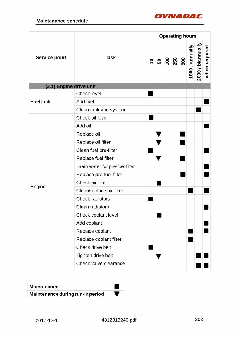
Maintenance schedule
203
4812313240.pdf 2017-12-1
Maintenance
Maintenance during run-in period
Service point
Task
Operating hours
10
50
10
0
25
0
50
0
10
00
/ a
nn
ua
lly
20
00 /
bia
nn
ual
ly
wh
en r
eq
uir
ed
(3.1) Engine drive unit Fuel tank
Check level
Add fuel
Clean tank and system
Engine
Check oil level
Add oil
Replace oil
Replace oil filter
Clean fuel pre-filter
Replace fuel filter
Drain water for pre-fuel filter
Replace pre-fuel filter
Check air filter
Clean/replace air filter
Check radiators
Clean radiators
Check coolant level
Add coolant
Replace coolant
Replace coolant filter
Check drive belt
Tighten drive belt
Check valve clearance

204
Maintenance schedule
4812313240.pdf 2017-12-1
Service point
Task
Operating hours
10
50
10
0
25
0
50
0
10
00
/ a
nn
ua
lly
20
00 /
bia
nn
ual
ly
wh
en r
eq
uir
ed
(3.1) Engine drive unit
Engine
Check engine brackets
Tighten engine brackets
Check screw connections between pump distribution transmission and engine
Tighten screw connections between pump distribution transmission and engine
Maintenance
Maintenance during run-in period

Maintenance schedule
205
4812313240.pdf 2017-12-1
Service point
Task
Operating hours
10
50
10
0
25
0
50
0
10
00
/ a
nn
ua
lly
20
00 /
bia
nn
ual
ly
wh
en r
eq
uir
ed
(3.2) Hydraulic system Hydraulic oil tank
Check oil level
Add oil
Replace oil
High-pressure hydraulic filter
Check maintenance display
Replace filter element
Suction/return hydraulic filter
Check maintenance display
Replace filter element
Pump distribution transmission
Check oil level
Add oil
Replace oil
Check aerator
Oil cooler
Carry out visual check
Clean radiators
Hydraulic hoses
Carry out visual check
Replace hoses
Hydraulic unit for roof and hood activation
Check oil level
Add oil
Replace oil
Maintenance
Maintenance during run-in period

206
Maintenance schedule
4812313240.pdf 2017-12-1
Service point
Task
Operating hours
10
50
10
0
25
0
50
0
10
00
/ a
nn
ua
lly
20
00 /
bia
nn
ual
ly
wh
en r
eq
uir
ed
(3.3) Traction units, chassis legs and steering system
Planetary gear
Check oil level
Add oil
Replace oil
Check visible, noglued nuts and screws; tighten if necessary
Traction unit
Check chain tension
Adjust chain tension
Check condition of bottom plates
Replace bottom plates
Retaining device for track rod and steering cylinder bolts
Check attachment
Steering system sliding parts, steering arms, stop ring and scraper
Visual check (attachment, wear)
Secure / replace components
Replace steering system sliding parts
Maintenance
Maintenance during run-in period

Maintenance schedule
207
4812313240.pdf 2017-12-1
Service point
Task
Operating hours
10
50
10
0
25
0
50
0
10
00
/ a
nn
ua
lly
20
00 /
bia
nn
ual
ly
wh
en r
eq
uir
ed
(3.4) Milling section
Milling bit, bit boxes
Check condition
Replace bits / bit boxes
Belt drive
Check condition
Replace belt
Clutch "DESCH" TYPE
Check friction lining wear
Replace friction lining
Drum transmission
Check oil level
Add oil
Replace oil
Check visible, nonglued nuts and screws; tighten if necessary
Milling drum
Check fluid level
Add coolant
Please note the different maintenance instructions for the different clutch types! You can refer to the type plate on the clutch to determine which type is appropriate for your machine!
Maintenance
Maintenance during run-in period
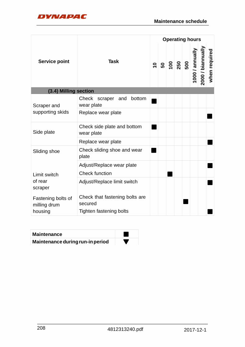
208
Maintenance schedule
4812313240.pdf 2017-12-1
Service point
Task
Operating hours
10
50
10
0
25
0
50
0
10
00
/ a
nn
ua
lly
20
00 /
bia
nn
ual
ly
wh
en r
eq
uir
ed
(3.4) Milling section
Scraper and supporting skids
Check scraper and bottom wear plate
Replace wear plate
Side plate
Check side plate and bottom wear plate
Replace wear plate
Sliding shoe Check sliding shoe and wear plate
Adjust/Replace wear plate
Limit switch of rear scraper
Check function
Adjust/Replace limit switch
Fastening bolts of milling drum housing
Check that fastening bolts are secured
Tighten fastening bolts
Maintenance
Maintenance during run-in period

Maintenance schedule
209
4812313240.pdf 2017-12-1
Service point
Task
Operating hours
10
50
10
0
25
0
50
0
10
00
/ a
nn
ua
lly
20
00 /
bia
nn
ual
ly
wh
en r
eq
uir
ed
(3.5) Loading equipment Conveyor belt
Check belt tension/sag
Adjust belt tension/sag
Check wear condition
Replace conveyor belt
Conveyor roller
Check condition
Replace rolls
Funnel rubber of transfer points and sealing rubber
Check wear condition
Replace funnel rubber / sealing rubber
Maintenance
Maintenance during run-in period

210
Maintenance schedule
4812313240.pdf 2017-12-1
Service point
Task
Operating hours
10
50
10
0
25
0
50
0
10
00
/ a
nn
ua
lly
20
00 /
bia
nn
ual
ly
wh
en r
eq
uir
ed
(3.6) Water system Water tank
Check level
Add water
Clean tank
Filling pump
Replace oil
Drain water Water filter
Check water filter
Replace both filter elements
Drain water
Spraying water pump
Check oil level
Replace oil
Inspect mounting
Inspect connection of pump to power source
Inspect pipes and connections
Check inflation pressure, if installed pressure accumulator
Drain water
Spray nozzle Check and clean spray noozle
Cleaning water pump
Check oil level
Replace oil
Inspect mounting
Inspect connection of pump to power source
Inspect pipes and connections
Drain water
Maintenance
Maintenance during run-in period

Maintenance schedule
211
4812313240.pdf 2017-12-1
Service point
Task
Operating hours
10
50
10
0
25
0
50
0
10
00
/ a
nn
ua
lly
20
00 /
bia
nn
ual
ly
wh
en r
eq
uir
ed
(3.7) Power supply
Batteries Replace
(3.8) Pneumatic system Maintenance unit
Check oil level
Add oil
Drain water
(3.9) Levelling device
Sensors, controllers, connecting cable
Check condition
Clean or replace
(3.10) Brake system Brake system
Check brake function
Check brake pressure
Check manual brake pump
(3.11) Miscellaneous
Emergency-stop button
Check function
Replace button
Maintenance
Maintenance during run-in period

212
Maintenance schedule
4812313240.pdf 2017-12-1
Please note the different maintenance instructions for the different clutch
types! You can refer to the type plate on the clutch to determine which type is appropriate for your machine!
Service point
Task
Operating hours
10
50
10
0
25
05
00
10
00
/ a
nn
ua
lly
20
00 /
bia
nn
ual
ly
wh
en r
eq
uir
ed
(4.0) Lubrication points
Drive unit
Lubricate support legs (grease nipple))/
Check lubrication of sliding sur- faces
Lubricate steering cylinder (grease nipple)
Lubricate floating pin (grease nipple)
Milling section
Lubricate belt tensioner (grease nipple)
Lubricate hydraulic cylinder of rear scraper (grease nipple)
Milling drum bearing
Lubricate
"DESCH TYPE" clutch bearing (grease nipple)
Maintenance
Maintenance during run-in period

Maintenance schedule
213
4812313240.pdf 2017-12-1
Service point
Task
Operating hours
10
50
10
0
25
0
50
0
10
00
/ a
nn
ua
lly
20
00 /
bia
nn
ual
ly
wh
en r
eq
uir
ed
(4.0) Lubrication points
Discharge conveyor, standard (fixed)
Lubricate pedestal bearing for tail roller (grease nipple)
Lubricate tension bearing for drive roller (grease nipple)
Discharge conveyor (foldable)
Lubricate pedestal bearing for tail roller (grease nipple)
Lubricate tension bearing for drive roller (grease nipple)
Lubricate flange bolts
Lubricate springs, joints and bolts in joint area
Maintenance
Maintenance during run-in period

214
Maintenance schedule
4812313240.pdf 2017-12-1
Service point
Task
Operating hours
10
50
10
0
25
0
50
0
10
00
/ a
nn
ua
lly
20
00 /
bia
nn
ual
ly
wh
en r
eq
uir
ed
(5.0) Inspections
General visual inspection
Inspection by an expert
Maintenance
Maintenance during run-in period
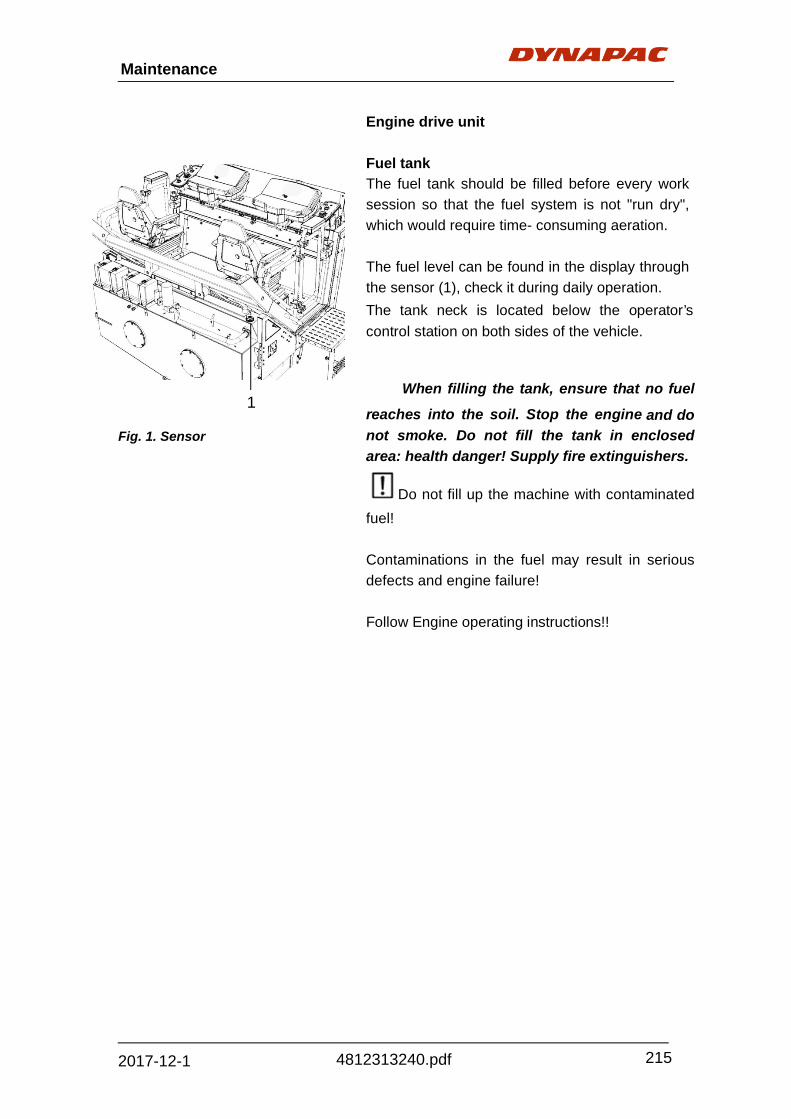
Maintenance
215
4812313240.pdf 2017-12-1
1
Fig. 1. Sensor
Engine drive unit
Fuel tank
The fuel tank should be filled before every work
session so that the fuel system is not "run dry",
which would require time- consuming aeration.
The fuel level can be found in the display through
the sensor (1), check it during daily operation.
The tank neck is located below the operator’s
control station on both sides of the vehicle.
When filling the tank, ensure that no fuel
reaches into the soil. Stop the engine and do
not smoke. Do not fill the tank in enclosed
area: health danger! Supply fire extinguishers.
Do not fill up the machine with contaminated
fuel!
Contaminations in the fuel may result in serious
defects and engine failure!
Follow Engine operating instructions!!

216
Maintenance
4812313240.pdf 2017-12-1
Cleaning tank and system
For maintenance and repair work, it may be
necessary for the fuel to be drained off.
The drainage point for this diesel tank is in the
rear section of the machine underside.
‐ Unscrew seal cap (1).
‐ Move lever (2) and drain off the volume of fuel
required into a suitable container.
‐ Use lever (2) to close drain and correctly refit
seal cap (1).
Dispose of the fuel drained off properly.
Diesel engine
The oil level in the engine should be tested
before each start with the dipstick.
Check the oil only when the machine is at a
standstill!
The dipstick can be found behind the maintenance
flap of the operator’s control panel.
Too much oil in the engine damages the seals;
too little oil leads to overheating and destruction of
the engine.
The filler neck for engine oil can be found behind the
maintenance flap of the operator’s control panel.
Follow Engine operating instructions!
Fig. 1. Seal cap
2. Lever
Fig. Diesel engine

Maintenance
217
4812313240.pdf 2017-12-1
Engine oil drainage point
The drainage point for the engine and gear oil is in
the rear section of the machine underside.
The stopcock (2) has three switch positions:
-Closed (2A)
-Drain for engine oil (2B)
-Drain for pump distribution transmission (2C)
Danger of scalding due to hot oil.
Collect used oil in a suitable container and
dispose of property.
Leave engine to warm up slightly for oil change.
Unscrew seal cap (1) and open stop cock (2) in
position (2B). After draining, close the stopcock in
position (2A), fit the seal cap (1) with a new seal
and screw back on.
Add new oil using the filler (behind the left
maintenance hatch of the driver’s platform).
Check the level using the dipstick (behind the
middle hatch of the driver’s platform). Before checking with the dipstick, wait a moment;
the added oil must first flow into the oil pan.
Follow Engine operating instructions!
Fig. 1. Seal cap
2. Stopcock

218
Maintenance
4812313240.pdf 2017-12-1
Oil filter
The oil filter can be found in the rear section of the
engine compartment and is accessible once the
engine hood has been opened.
Loosen the filter and clean the contact surface.
Slightly lubricate the seal of the new filter and fill the
filter with oil before installing it. Tighten by hand.
Dispose of used filters properly.
After replacing the oil filter, keep an eye on
the seals and the oil pressure display.
Follow Engine operating instructions!
Fuel filter
The fuel filter can be found behind the
maintenance flap of the operator’s control panel.
Dismantle the connection on the underside of the
filter, loosen the filter and clean the contact
surfaces.
Add fuel to the new filter with the new seal and
tighten by hand.
Install the connection on the underside of the filter
with new seals.
Dispose of used filters properly.
After replacing the filter, keep an eye on the
seals.
Follow engine operating instructions!!
Fig. Oil filter
Fig. Fuel filter

Maintenance
219
4812313240.pdf 2017-12-1
Fuel filter water separator
Drain the water separator every day or when
engine electronics error messages appear.
Collect fuel-water mixture in a suitable container
and dispose of properly.
There is a drain valve (1) on the underside of the
filter cartridge.
Disconnect engine electrics plug (2) and screw on
drain valve (1) until the neck can be pulled out.
Drain off fluid until only clear fuel runs out.
Then slide the neck back again and close drain
valve until hand tight.
Follow Engine operating instructions!!
Air filter
The air filter can be found in the rear section of the
engine compartment and is accessible once the
engine hood has been opened.
In order to reach the filter element, the wing bolt
(2) must be loosened and the locking lid of the
filter casing removed.
After removal, replace the outer filter element by a
new one or clean it with compressed air.
The inner filter element must be replaced if it is
dirty. It cannot be cleaned.
Follow Engine operating instructions!!
Fig. Air filter

220
Maintenance
4812313240.pdf 2017-12-1
Cooler
Check the coolant level daily before starting
work.
Replace the coolant at least once per year.
The filler neck of the coolant compensation tank
can be found behind the maintenance flap of the
operator’s control panel.
The system is under pressure when it is
hot. When it is opened, there is danger of
scalding!
Also check the radiators daily for dirt; if necessary,
clean with suitable methods.
Collect used coolant in a suitable container
and dispose of properly.
Follow engine operating instructions!!
Coolant filter
The coolant filter can be found in the rear section
of the engine compartment and is accessible once
the engine hood has been opened.
The system is under pressure when it is
hot. When it is opened, there is danger of
scalding! Let the engine cool before replacing
the filter.
Close the locking valve (1) of the coolant filter,
loosen the filter and clean the contact surface.
Slightly lubricate the seal of the new filter before
installing it. Tighten by hand. Open the locking
valve again.
After replacing the filter, keep an eye on the
seals.
Dispose of used filters properly.
Follow Engine operating instructions!!
Fig. Coolant filter
Fig. Cooler

Maintenance
221
4812313240.pdf 2017-12-1
Cooler
Check the radiators of the cooler daily for
soiling and leakage.
The water cooler is located at the rear of the
machine, behind the cooler grill.
The cooler grill can be swiveled upward after
opening the lock.
In case of especially strong soiling, it is good idea to
first spray the cooler with a suitable dirt solvent and
to then sprays the dirt off with a water jet
Drive belt
Visually check the drive belt daily for
damage.
For maintenance of the drive belt:
See Engine operating instructions.
The protective grid must be removed before
undertaking maintenance work on the drive belt!.
Fig. Drive belt
Fig. Cooler

222
Maintenance
4812313240.pdf 2017-12-1
Valve clearance
To check and adjust the valve clearance: see
Engine operating instructions.
Engine brackets, left/right
The connecting screws of the engine
brackets (on the left (1) and on the right (2), (3))
should be checked regularly to ensure that they
are secure. Switch off engine when checking.
If the screws have come loose, these must be
tightened immediately to the torque required.
Fig. Valve
1
2
3
Fig. Engine bracket

Maintenance
223
4812313240.pdf 2017-12-1
Connecting screws, pump distribution
transmission/ engine
All connecting screws (1) around the clutch
bell housing between the engine and pump
distribution transmission should be checked
regularly to ensure that they are secure. Switch off
engine when checking.
If the screws have come loose, these must
immediately be individually dis- mantled, secured
with screw cement and re-inserted using the
torque required.
Centa coupling
If you have to replace the Centa coupling
fitted between the engine and pump distribution
transmission, you MUST note that these parts are
fitted without the use of oil and grease!
When replacing the Centa coupling, please
contact the Dynapac service team. They will
discuss the process with you.
Fig. Coupling
Fig. Connecting screws
1

224
Maintenance
4812313240.pdf 2017-12-1
1
2
Hydraulic system
Hydraulic oil tank
Use a dipstick (1) to check the oil level every
day. Dust and dirt should be regularly removed from
the oil tank vent. Change the hydraulic oil every
1000 operating hours, but at least every year.
The hydraulic tank can be found in the left section
of the engine compartment and is accessible once
the engine hood has been opened.
To top up hydraulic oil, open protective cap (2) and
fill with new oil using a funnel.
Ensure that no impurities enter the tank.
Avoid skin contact with hydraulic oil.
Use only recommended hydraulic oils.
Hydraulic oil drainage valve
The drainage point for hydraulic oil is in the rear
section of the machine underside.
In order to empty the hydraulic oil, first remove
the cap (1) of the drainage valve and then install
the drainage hose.
By switching lever (2), drain the oil and collect it in
a suitable container.
After draining, screw the cap back onto the
drainage valve.
Add new oil using the filling opening of the
hydraulic oil tank.
Check the oil level using the display.
Collect used oil in a suitable container and
dispose of property.
Wear protective clothing when draining
hot oil. Danger to health if oil contacts skin.
Fig. 1. Dipstick
2. Protective cap
Fig. 1. Cap
2. Lever

Maintenance
225
4812313240.pdf 2017-12-1
High-pressure hydraulic filter
Replace filter cartridges once the maintenance
indicator (1) is red.
The filters should be checked 10 operating hours
after repairs on the hydraulic system and replaced if
necessary!
Always replace the filter elements in pairs!
The filter can be found in the rear section of the
engine compartment and are accessible once the
engine hood has been opened.
Loosen the filter pot with a hexagonal key and
unscrew it by hand.
After unscrewing the filter pot, empty the
separated dirt into a used oil container. Remove
the filter element and put it into a container for
recycling (danger of pollution!). Wash out the
casing, replace the O-rings and apply lubrication.
Screw the filter casing with the new filter element
back on and tighten securely.
The red mark on the maintenance indicator (1) is
reset automatically.
Wear protective clothing when working with hot
oil.
Danger to health if oil contacts skin.
Never clean a filter and then re-use it!
Always use new filters.
Fig. High-pressure hydraulic
filter
1. Indicator

226
Maintenance
4812313240.pdf 2017-12-1
Return hydraulic filter
Replace the filter element according to the
soiling display, but at least once a year!
The return hydraulic filter can be found on the
hydraulic oil tank in the left section of the engine
compartment and is accessible once the engine
hood has been opened.
- Remove the fastening screws of the filter top and
remove the lid of the filter casing.
- Pull the entire filter insert from the casing.
- Pull the intermediate plate (1) and the dirt
collection dish (2) from the used filter element.
- Clean the dirt collection dish.
- Insert the intermediate plate and the dirt
collection dish on to the new filter element and
insert it into the filter casing.
- Slightly lubricate the O-ring of the casing cover
and install using the four fastening screws.
Wear protective clothing when working
with hot oil. Danger to health if oil contacts
skin..
Never clean a filter and then re-use it!
Always use new filters.
Dispose of used filters properly.
1
2
Fig. 1. Intermediate plate
2. Dirt collection dish

Maintenance
227
4812313240.pdf 2017-12-1
Pump distribution transmission
Oil level check
The pump distribution transmission can be found in
the left section of the engine compartment and is
accessible once the engine hood has been opened.
The dipstick (1) can be found on the left on the
transmission housing.
The oil level should be between the "MAX" and
"MIN" marks.
Top up oil if necessary.
The oil filling screw (2) is located on the
upper side of the transmission.
- Unscrew the screw; use a funnel to fill with the
appropriate oil.
- Use dipstick (1) to check that the oil level is
correct.
- Close the inspection screw again correctly.
Ensure cleanliness!
Fig. 1. Dipstick
2. Oil filling screw

228
Maintenance
4812313240.pdf 2017-12-1
Oil cooler
The drainage point for the gear and engine oil is in
the rear section of the machine underside.
The stopcock (2) has three switch positions:
- Closed (2A)
- Drain for engine oil(2B)
- Drain for pump distribution transmission(2C)
Collect used oil in a suitable container and
dispose of properly.
- Unscrew seal cap (1) and open stopcock (2) in
position (2C). After draining, close the
stopcock in position (2A), fit the seal cap (1)
with a new seal and screw back on.
- Add new oil via the unscrewed filling screw.
Continue to do so until the oil level reaches
the bottom edge of the opening and some oil
runs out.
- Reseal inspection screw and oil fill screw
correctly.
Ensure cleanliness!
Check the oil lever again after running for
15 minutes, top up oil if necessary.
Wear protective clothing when working with
hot oil. Danger to health if oil contacts skin
Fig. 1. Seal cap
2. Stopcock

Maintenance
229
4812313240.pdf 2017-12-1
Bleeder
The bleeder can be found on the housing of the
pump distribution transmission.
The functioning of the bleeder must be ensured.
If soiling has occurred, the ventilator should be
cleaned.
Oil cooler
Check the radiators of the cooler daily for soiling and leakage. The oil cooler is located at the rear of the machine, behind the cooler grill (to the left of the water cooler). The cooler grill can be swiveled upward after opening the lock using a square key.
In the case of especially strong soiling, it is a good idea to first spray the cooler with a suitable dirt solvent and to then sprays the dirt off with a water jet.
Fig. Bleeder
Fig. Oil cooler

230
Maintenance
4812313240.pdf 2017-12-1
21
1
Hydraulic hoses
All hydraulic hoses on the machine should also be
replaced by the interval specified!
Old hoses become porous and can burst!
Risk of accident!
A number punched into the connection provides
information about the date of manufacture (1) and
the highest permitted pressure for this hose (2).
Never install aged hoses; observe the permitted
pressure.
Hydraulic unit for roof and hood activation
Oil level check
The hydraulic unit can be found in the engine
compartment on the right.
There is a dipstick (1) on the oil reservoir for the oil
level check.
Hydraulic oil is topped up through the dipstick
opening using a funnel until the necessary height
is reached. Screw the dipstick back in to seal the
oil reservoir.
Maintain cleanliness when filling with oil!
Avoid contact with skin!
DHH09/00 225BAR
Fig. Hydraulic hoses
Fig. Dipstick

Maintenance
231
4812313240.pdf 2017-12-1
1
2
1
Traction units
Planetary gear – oil level check
To check the oil level and while adding oil, the
locking screw for the oil level check (1) must be in
the 9 o’clock position.
The oil level should reach the lower edge of the
hole for the locking screw.
Add oil using the opened filling screw until some
oil exits the hole of the locking screw.
When adding oil, ensure cleanliness.
Oil Change
To drain oil, the drainage screw (2) should be in
the 6 o’clock position and the filling screw (1)
should be in the 9 o’clock position.
Do not change oil when the engine is cold,
but rather directly after the transmission has
stopped.
This ensures that solid particles do not settle.
Wear protective clothing when working
with hot oil. Danger to health if oil contacts
skin.
- Unscrew the oil drainage screw (2), collect
draining oil.
- Remove the filling screw (1).
- After the oil is completely drained, properly
screw in the drainage screw (2) again.
- Add oil using the opened filling screw until
some oil exits the hole of the locking screw.
- Properly screw the filling screw (2) back in.
Collect used oil in a suitable container and
dispose of properly.
When adding oil, ensure cleanliness.
Fig. 1. Oil level check
Fig. 1. Filling screw
2. Draining screw

232
Maintenance
4812313240.pdf 2017-12-1
Chain tension
The chain tension of the drives is to be
tested daily and adapted to the given use and
roadway conditions.
The chain sag should be 0-7mm (depending on
the use conditions) between the chain and the
framework of the drive, measured in the drive
middle.
After adjusting the chain tension, drive the
machine a few meters and check the sag again.
Elevated wear on chain parts and supports
due to chain tension that us too low or too high.
Note: special settings are available; pressure
range is 28-80bar.
Fig. Chain tension

Maintenance
233
4812313240.pdf 2017-12-1
Bottom plate
The condition of the bottom plates of the
drives is to be tested daily.
Damaged and worn bottom plates should be
replaced immediately.
Each bottom plate is connected with the contact
surface of the chain link by four fastening screws.
- Hold the square nut with a fork wrench fork
wrench, loosen the fastening bolts in the trough of
the bottom plate using a socket wrench and
dismantle.
The bottom plates and fastening bolts should
always be replaced together.
- Install the new bottom plate in the same
manner; tighten the bolts with the required torque.
Problem-free bottom plates also ensure that the
machine will drive straight ahead with no
problems.
Rubber pad
Each rubber pad is connected with bottom plates
by four fastening screws.
Damaged and worn rubber pads should be
replaced immediately.
Install the new rubber pad in the same manner,
tighten the bolts with the required torque.
Fig. Bottom plate

234
Maintenance
4812313240.pdf 2017-12-1
2 2 3
4
4
4
Steering system sliding parts, steering arms,
stop ring and scraper
Check steering arms (1), two-section stop ring (2)
and scraper (3) for correct function, clearance,
perfect attachment and excess wear.
If these components are attached or
function insufficiently, subsequent excess wear
will allow dirt to penetrate and will result in
possible failure and/or deterioration of
straight-ahead travel!
- Two-section stop ring (2) of steering arms (1) is
joined to vehicle frame by means of 10
cemented in screws (2a). If this screw
connection has come loose, the entire screw
connection should be cemented back in and
tightened to the specified tightening torque.
- Worn or loosened pipe scraper (3) should be
replaced or tightened immediately.
Replacing sliding shoes
- Remove both cylindrical screws (4) (2 screws
per sliding parts!).
The screws are cemented in!
- Use an appropriate object to extract loosened
outer grooved scraper (4a) out of groove.
- Screw one of the two previously re- leased
cylindrical screws (4) from be- low into the sliding
piece in the groove.
- Use the screw to pull sliding piece (4b) out of
groove.
Replace scraper from outer groove, sliding piece,
springs and scraper from inner groove.
Parts are installed in reverse order. Ensure
correct installation position.
Cement in screws and note tightening
torques!
1
4
Fig. 1. Steering arm
2. Stop ring
3. Scraper
4. Screw

Maintenance
235
4812313240.pdf 2017-12-1
Retaining device for track rod and steering
cylinder bolts
Check that retaining bolts of retaining plates on
track rods and on cylinder bolts are secured
correctly.
If necessary, retighten screws.
Belt drive
The condition of the belts of the milling drive
is to be tested daily.
Damaged and worn belts should be replaced
immediately.
Material particles are to be removed from the
grooves of the V-belt!
The belts are always to be replaced in pairs.
The belt drive is located in the protective box on
the left side of the machine.
Ensure that the drive engine cannot be
started!
If the belt tensioner is relaxed, the belts can easily
be taken from the belt discs.
The belts are arranged in the following order:
5-fold belt, 4-fold belt, 5-fold belt.
The condition of the belt discs is also to be
tested. If the flank wear on the belt discs is too
high, they must be replaced immediately.
Fig. Retaining device for track
rod and steering cylinder bolts
Fig. Belt drive

236
Maintenance
4812313240.pdf 2017-12-1
1
2
Clutch ”DESCH” Type
Worn friction lining should be replaced
immediately.
The clutch is located behind the belt disc in the
protective box on the left side of the machine.
Ensure that the drive engine cannot be
started!
The inspection cover (1) of the clutch casing must
be removed to carry out the inspection.
- Remove the four locking screws (2) of an
accessible inspection cover (1).
- Remove the inspection cover.
- Through the open inspection opening, check the
distance between pistons and cylinders with a
measuring instrument.
A distance (X) between pistons and cylinders
with the clutch activated amounts to 6 mm in
new condition; the wear limit is 12 mm (Y).
- After the inspection, lock the inspection cover
again properly.
Fig. 1. Inspection cover
2. Locking screws

Maintenance
237
4812313240.pdf 2017-12-1
Milling drum gear box
Oil level check
To check the oil level and while adding oil, the lock
screw for the oil check (1) must be in the 9 o’clock
position.
- Lower the machine on to the service
supports.
- Lift the side board and secure it.
- Ensure that the drive engine cannot be
started.
- Turn the milling drum until the mark (1) on the
drum is in the 9 o'clock position
- Remove the Allen screw (2) and the screw
protection (3).
- Remove the inspection screw.
The oil level should reach the lower edge of the
hole for the locking screw.
- Fill oil using the open filling screw until some
oil exits the hole of the locking screw.
- Properly reinstall the inspection screw,
screw protection (3) and Allen screw.
When adding oil, ensure cleanliness.
Fig. 1. Drum
2. Allen screw
3. Screw protection

238
Maintenance
4812313240.pdf 2017-12-1
Oil change
To drain oil, the drainage screw (2) should be in
the 6 o’clock position and 2 the filling screw (1)
should be in the 9 o’clock position.
Do not change oil when the engine is cold,
but rather directly after the transmission has
stopped.
This ensures that solid particles do not settle.
Wear protective clothing when working with
hot oil. Danger to health if oil contacts skin.
- Lower the machine on to the service
supports.
- Lift the side board and secure it.
- Ensure that the drive engine cannot be
started.
- Turn the milling drum until the mark (3) on the
drum is in the desired position.
- Remove the Allen screw (4) and screw sleeve
(5) on the drainage and inspection screw.
- Remove the inspection screw (2).
- Remove the oil drainage screw (1) and collect
draining oil.
- After all the oil has drained, properly screw
the drainage screw (1) back in.
- Fill oil using the open inspection screw until
some oil exits the hole.
- Properly reinstall the inspection screw (2).
- Properly reinstall the Allen screw (4) and
screw sleeve (5) on the drainage and inspection
screw.
Collect used oil in a suitable container and
dispose of properly.
When adding oil, ensure cleanliness.
Fig. 1. Filling screw
2. Drainage screw
3. Drum
4. Allen screw
5. Screw sleeve

Maintenance
239
4812313240.pdf 2017-12-1
Milling drum
The coolant must be replenished when necessary,
depending on operating conditions.
Freezing water in the milling drum can
destroy the component; use the stipulated
coolant.
There are two drainage and filling/in section
screws (1) positioned opposite to each other on
the milling drum.
Draining coolant
- Lower the machine on to the service
supports.
- Open and secure the drum flap.
- Ensure that the drive engine cannot be
started.
- Turn the milling drum until one of the drainage
screws points downwards.
- Unscrew the drainage screw and collect
coolant in a suitable container.
The milling cylinder is filled with approx.420 liters
of coolant.
- After the fluid is completely drained, properly
tighten the drainage screw again.
Fig. 1. Section screw
Fig. 1. Coolant level

240
Maintenance
4812313240.pdf 2017-12-1
Checking fluid level / adding fluid - Lower the machine on to the service supports.
- Open and secure the drum flap.
- Ensure that the drive engine cannot be started.
- Turn the milling drum until the inspection and
filling screw lies at an angle of approx. 25°.
- Remove the inspection screw.
The liquid level should reach the bottom edge of the
hole for the locking screw.
- Add coolant if necessary.
- Properly tighten the filling and inspection screw
again.
Scrapers and supporting wear bar
(moldboard)
If too much material remains in the milling lane,
the parts are also to be tested.
The scrapers (1) ensure that hardly any removed
material remains in the milled track and
consequently guarantees problem free material
removal.
The supporting wear bar (2) prevents the scrapers
from digging themselves into the milling plane.
Both parts, which are installed on the entire length
of the moldboard, are equipped with hard metal
strips that wear out with time.
- Lower the machine on to the service supports.
- Lift the side boards and secure them.
- Ensure that the drive engine cannot be started.
- Open the moldboard and take appropriate
safety measures.
- Remove the worn scraper (1) and supporting
wear bar (2) by loosening the two hex screws.
- Clean the contact surface, properly install the
new parts and mount at the required height using
the oval holes.
Note that the outer scrapers have different
dimensions than the inner scrapers!
Fig. 1. Scraper

Maintenance
241
4812313240.pdf 2017-12-1
Runners on the side boards
The runners of the side boards continuously slide
over the asphalt during milling operation and are
thus subjected to an elevated degree of wear. If the
material of the runner becomes too thin, it must be
replaced.
In the case of divided runners, the relevant element
is to be replaced.
Check the runners on both side boards
regularly and replace if necessary.
- Lower the machine on to the service supports.
- Lift the side board and secure it.
- Ensure that the drive engine cannot be started.
- Remove the worn runner by loosening the hex
screws along the length of the part.
- Clean the contact surface and properly install the
new parts (it may also be necessary to replace the
fastening screws since these can also wear).
Fig. Side board

242
Maintenance
4812313240.pdf 2017-12-1
Sliding shoe runners
The runners of the sliding shoe continuously slide
over the asphalt that has not yet been removed
during milling operation and are thus subjected to
an elevated degree of wear.
The runners exert downward pressure and
prevent bigger parts from being ripped out.
If the hard metal plate of the runners becomes too
thin, this must be replaced.
In order to reduce overall wear, there is an
adjustable runner on each outer side.
Check the runners on the sliding shoe
regularly and replace and/or readjust if necessary.
- Lower the machine on to the service supports.
- Lift the sliding shoe and secure it in the
uppermost position.
- Ensure that the drive engine cannot be started.
Depending on the operating
circumstances, the adjustable runners can be
installed at a distance of 0-10mm below the
permanent runners.
When removing concrete, e.g. a significantly
lower distance should be set than is the case for
asphalt work.
- If necessary, remove the worn hard metal
plates of the permanent runners; ensure that the
contact surface is level.
- First attach the new parts, then weld them on
properly.
- To install the adjustable runner, loosen
fastening bolts (1) and lock nuts (2).
- Use adjusting screw (3) to set height distance
to permanent runner (4). If the distance has to be
reduced, the runner can be pushed up.
- Retighten fastening bolts (1) and lock nuts (2)
correctly.
Observe the required safety measures
during dismantling and welding!
0-10mm
4
3 2
1
Fig. 1. Fastening bolt
2. Lock nuts
2. Adjusting screw
4. Permanent runner
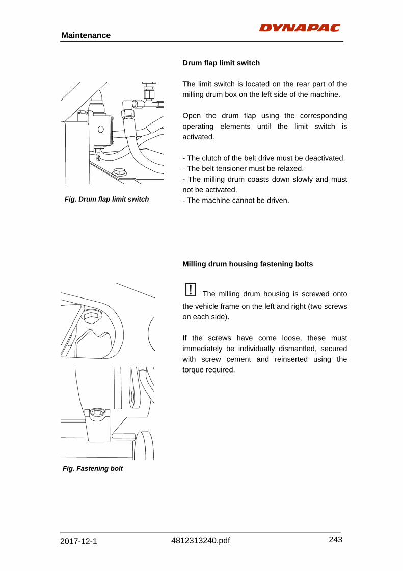
Maintenance
243
4812313240.pdf 2017-12-1
Drum flap limit switch
The limit switch is located on the rear part of the
milling drum box on the left side of the machine.
Open the drum flap using the corresponding
operating elements until the limit switch is
activated.
- The clutch of the belt drive must be deactivated.
- The belt tensioner must be relaxed.
- The milling drum coasts down slowly and must
not be activated.
- The machine cannot be driven.
Milling drum housing fastening bolts
The milling drum housing is screwed onto
the vehicle frame on the left and right (two screws
on each side).
If the screws have come loose, these must
immediately be individually dismantled, secured
with screw cement and reinserted using the
torque required.
Fig. Drum flap limit switch
Fig. Fastening bolt

244
Maintenance
4812313240.pdf 2017-12-1
Loading equipment
Belt tension
The belt tension of the loading belt and the
discharge conveyor is to be checked daily. If the
belt sags too far, the tension must be increased.
In the first weeks of operation, the belt will stretch
excessively (permanent and elastic stretching).
Therefore, it is necessary to tighten the belt
repeatedly during this time.
The sag of the belt of the primary conveyor should
be somewhat greater than the sag of the
discharge conveyor.
To increase the tension:
- Loosen the lock nuts (1) on both sides of the
tightening equipment.
- Increase the tension evenly on both sides
using a fork wrench on the adjusting nuts (2).
- Tighten the lock nuts (1) again after the
adjustment.
The tension setting of the loading belt and the
discharge conveyor is basically the same.
If the belt runs asymmetrically, tighten the right
spindle or loosen the left spindle if the belt runs
towards the right or vice-versa.
. Fig. 1. Lock nuts
2. Adjusting nuts
1 2
Also visually check the belts, conveyor belt
rollers and support rings for damage or wear
controls.
Worn support rings can be replaced in sets.
Regularly remove material encrustations on
the rollers.
Regularly check the screwed connections.
During all work on the loading and
discharge conveyors, ensure that the belt
drive cannot be started!

Maintenance
245
4812313240.pdf 2017-12-1
Drum holder
As a result of high loading levels, clearance in the
seat of the holder (2) for the shaft end of the roller
(1) may increase over time.
Steel cords
The condition of the hold and catch cords (steel
cords) as well as the shackles of the discharge
conveyor is to be tested daily.
Damaged steel cords and shackles must be
replaced immediately.
Tearing steel cords represent a great danger
for persons and machinery。
Release the tension of damaged steel cords and
shackles on the discharge conveyor and replace
them.
During all work on the primary and discharge
conveyors, ensure that the belt drive cannot be
started.
Fig. 1. Roller
2. Holder
Fig. Steel cords
2
1

246
Maintenance
4812313240.pdf 2017-12-1
Funnel rubber of transfer point and sealing
rubbers / guides
On the primary and discharge conveyors, different
rubber parts are provided to guarantee
problem-free material removal. These rubber
parts should be visually checked for damage
weekly:
- scraper rubber (1)
- lateral seal (2)
- lateral guide of primary conveyor (3)
- discharge funnel (4)
- primary funnel (5)
- lateral guide of discharge conveyor (6)
All rubber parts are installed with screw
connections and can be easily removed when
required.
- Remove the fastening screws and the
damaged part.
- Properly mount the new part and tighten the
fastening screws.
Fig. 1. Scraper rubber
2. Lateral seal
3. Lateral guide for primary
conveyor
4. Discharge funnel
5. Primary funnel
6. Lateral guide for
discharge conveyor

Maintenance
247
4812313240.pdf 2017-12-1
Water system
Water tank
The filling level of the water tank should be tested
before each start. If necessary, the tank must be
refilled.
Check the water level of the water tank several
times a day using water level indicators located on
the sides of the tank.
The water tank should preferably be cleaned
when it is empty.
If the machine is not in continuous operation, the
water should be replaced once per year.
- Fully drain the tank by opening the drain valve
(1) on the underside of the machine.
- To drain out all the residue, open the two outlet
points (2) on the left and right of the machine
underside.
Opening (3) serves as an overflow if the tank is
overfilled.
The cover of water tank can be unscrewed out.
- With the high-pressure cleaner, spray the
inside of the empty tank.
If necessary, a person can climb through the
opened lid into the tank in order to execute
cleaning work.
- The loosened sediments run out through the
opened drainage valve.
- After cleaning, close the drainage valve and
the locking lid of the water tank again.
Fig. 1. Valve
2. Outlet points
3. Port
2
3

248
Maintenance
4812313240.pdf 2017-12-1
During cleaning work in the interior of the
tank, a second person must always oversee
the person in the tank!
If the tank must be entered, a ladder is to
be placed against the machine and secured
accordingly.
Wet machine surfaces are slippery! Risk of
accident!
The water in the tank is service water, not
drinking water!
In case of frost, completely empty the water
tank using the drainage valve, leave the valve
open, loosen the connection hoses and let them
run empty. Remove the caps of the water filling
openings.

Maintenance
249
4812313240.pdf 2017-12-1
Feed pump
Drain water
When the temperature is below freezing, the
water in the pump must be drained since freezing
water can destroy the pump.
Replace oil
The feed pump is located on the left forefront of
the machine.
- Remove the oil drainage screw (1) and collect
draining oil.
- Remove the filling screw (2).
- After all the oil has drained, properly screw
the drainage screw (1) back in.
- Fill the stipulated quantity of new oil via the
opened filling cover.
- Properly screw the filling screw (2) back in.
Wear protective clothing when working
with hot oil. Danger to health if oil contacts
skin.
Collect used oil in a suitable container
and dispose of properly.
When adding oil, ensure cleanliness.
When the temperature is below freezing, the
water in the pump must be drained since freezing
water can destroy the pump.
- Remove the drainage screw (3) and let the
water drain completely.
- Properly screw the drainage screw (1) back in.
Fig. 1. Drainage screw
2. Filling screw
3. Drainage screw

250
Maintenance
4812313240.pdf 2017-12-1
Water filter
Check the filter element at the end of work every
day and according to the soiling display!
The machine accessories include a second set of
water filters which makes daily replacement
possible without delay.
One water filter is under the frame, in front of the
milling drum housing on the right side of the
machine, the other one is located nearby the
conveyor suspension
The filter can also be replaced if the water tank is
not empty.
- Close stopcock (1) (lever in horizontal
position).
- Use the wrench provided in on-board took kit
to loosen both filters housings (2) and unscrew by
hand.
- Remove filter elements, if necessary rinse out
housing and insert new/ cleaned filter.
- Clean the contact surface of the discharge
and primary parts of the casing and check seal.
- Screw both filter housing on by hand and
tighten slightly with wrench.
Check for leaks after replacing the filter!
The removed filter elements can be cleaned and if
necessary rinsed with a high pressure cleaner.
Once the machine has next been used, the
cleaned filter set can therefore be used to replace
the other filter set.
The filter casing must be emptied completely in
the case of frost in order to protect the casing from
damage.
- Close stopcock (1)
- Use the wrench provided in on-board tool kit
to loosen both filter housings (2), unscrew by
hand and shake out any water found.
Refit emptied filter casings correctly.
Fig. 1. Stopcock 2. Filter housing
Fig. 1. Stopcock 2. Filter housing

Maintenance
251
4812313240.pdf 2017-12-1
Water pump – Check oil level Check oil level, oil level should between Min. and Max. - If oil level lower than Min., please fill
specified oil. - If oil level over Max., please drain some oil
out until the level keep between Min. and Max. (Fill about 0.8kg).
Water pump – Drain oil - Release the pressure from accumulator
(1). - Unscrew the plug (2), and remove
accumulator. - Unscrew the drain plug and drain oil from
water pump.
Be careful to handle the oil that drains from water pump in case of adding pollution to environment.
- Fill oil for water pump according to reverse step of draining oil.
After filling oil, please run the pump for a
while and check again if oil is enough.
Fig. 1. Accumulator
2. Plug
1
2
Fig. Water pump

252
Maintenance
4812313240.pdf 2017-12-1
Fig. Spray nozzle
Spray nozzles
The spray nozzles are located on the milling drum cabinet and are secured against twisting by guides. To check and clean them, the nozzles can be removed from the guides through the gaps in the milling drum cabinet. - Pull the hose with the nozzle out of the holder. - Clean the nozzle with a wire brush. If necessary, remove or replace the nozzle to be cleaned. - Properly reinstall the nozzle and insert it into the guide. In case of frost, the feed hoses must be pulled with the nozzles from the mounts and emptied completely in order to protect them from damage. - Pull the hoses with the nozzles out of the holders, drain them and let them hang down. - Before re-commissioning, properly remount the hoses.

Maintenance
253
4812313240.pdf 2017-12-1
Power supply
Batteries
‐ Behind the maintenance flap, two batteries of
the 24 volt system can be found on both the
left and right behind the driver’s seat.
‐
‐ The batteries are maintenance–free.
‐
‐ The pole terminals must be free of oxide and
be protected with special pole grease.
The gas formed in the battery is
explosive. Avoid naked flames and sparks.
When removing the batteries, always
remove the negative pole first; ensure that the
battery poles are not short-circuited.
The battery contains corrosive and
poisonous sulphuric acid. Wear goggles and
absolutely avoid skin contact!
Fig. Batteries

254
Maintenance
4812313240.pdf 2017-12-1
Compressed air system
Maintenance unit and compressed air system
A maintenance unit that separates the
water from the air and enriches the air- flow with a
fine oil mist, thus providing for a longer lifetime of
the parts, is located on the compressed air tank.
Check the filling level of the oiler (1) every 50
operating hours and replenish if necessary.
Drain any water that has formed into the water
separator (2).
Also drain any condensation that has formed in
the compressed air tank.
The compressed air tank and connected
maintenance unit can be found behind the storage
room flap on the left-hand side of the machine.
- Unscrew the oil reservoir (1) by hand and
replenish the stipulated oil up to the mark ”max“;
then properly screw the oil reservoir in again.
- Drain any water that has formed in the water
separator (2) by opening the valve (3); close the
valve again properly as soon as the water has
completely drained.
- Drain any water that has formed in the
compressed air tank by pulling the valve eyelet
(4). Drain water only when the drive engine is not
running. The escaping air drives the water from
the tank. Hold the valve open until no more water
exits.
Fig. 1. Oiler
2. Water separator
3. Valve
4. Valve eyelet
3 2 4 1

Maintenance
255
4812313240.pdf 2017-12-1
Levelling system
Sensors, displays, connection cables
The sensors, displays and connection cables of
the levelling equipment should be checked daily in
order to guarantee an interruption-free and
precise work flow. Damaged parts, such as cables
and cords, should be replaced immediately to
avoid breakdowns of the levelling equipment and
consequent unnecessary delays.
The equipment and sensors should also be
cleaned.
Brake system
Check if the brake is normal every day.
Check the brake pressure, which should be about
25 bar – 30 bar.
Check if manual brake pump can release brake,
every 500h.

256
Maintenance
4812313240.pdf 2017-12-1
Emergency stop button
For your own safety, the safety of other persons
and the safety of the machine, the function of all
the emergency stop buttons located on the
machine should be tested daily.
Defective emergency stop buttons must be
replaced immediately. Emergency stop buttons
are located
- on the discharge control panel (on both upper
control panels)
- on all lower control panels
See more details in “Machine description”
Chapter.
The engine, drives and steering system are
shut down when the emergency stop button is
pressed. Any countermeasures required
(diverting, lifting the discharge conveyor etc.) are
then no longer available! Risk of accident!

Maintenance
257
4812313240.pdf 2017-12-1
Lubrication points
Traction unit
Chassis legs
A grease nipple is located on each chassis leg.
Add grease with a grease gun until grease flows
out of the front and rear guide grooves.
The sliding surfaces in the guide
grooves must always be covered by a film of
grease!
Steering cylinder
A grease nipple is located on each bearing point
of the steering cylinder.
Add 3 loads of grease with a grease gun.
Floating pin
A grease nipple is located on each traction unit on
the floating pin.
Add 5 loads of grease with a grease gun.
Fig. Lubrication point
Fig. Lubrication point
Fig. Lubrication point

258
Maintenance
4812313240.pdf 2017-12-1
Milling section
Belt tensioner
A grease nipple is located on the bearing point on
the belt tensioner of the milling drum
transmission.
Add 3 loads of grease with a grease gun.
Clutch bearing Type “DESCH”
The grease nipple for the clutch bearing is located
behind the belt disc.
- Turn the belt disc until one of the holes is in the
upper most position; then push the hose of the
grease gun through the hole onto the grease
nipple.
Add 3-5 loads of grease with a grease gun.
Fig. Lubrication point
Fig. Lubrication point

Maintenance
259
4812313240.pdf 2017-12-1
Scraper hydraulic cylinder
A grease nipple is located on each bearing point
(top and bottom) of the hydraulic cylinder on the
drum flap.
Add 3 loads of grease with a grease gun.
Milling drum bearing
Each time the drum is replaced, the condition of
the bearing must be checked and the bearing
must be filled with fresh grease!
- Lower side board until the screw plug (1) is
visible
- Remove screw plug
Use a grease gun to add approx. 500ccm of
grease.
- Refit screw plug and protective cover.
Fig. Lubrication point
1
Fig.1. Screw plug
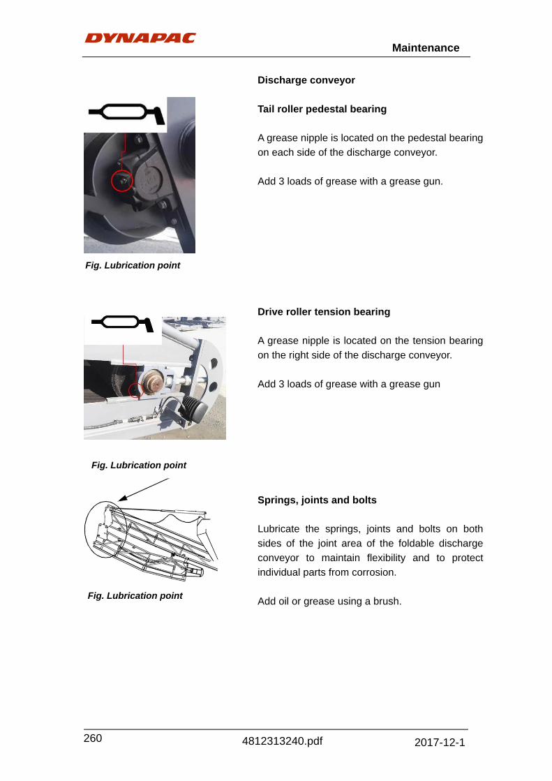
260
Maintenance
4812313240.pdf 2017-12-1
Discharge conveyor
Tail roller pedestal bearing
A grease nipple is located on the pedestal bearing
on each side of the discharge conveyor.
Add 3 loads of grease with a grease gun.
Drive roller tension bearing
A grease nipple is located on the tension bearing
on the right side of the discharge conveyor.
Add 3 loads of grease with a grease gun
Springs, joints and bolts
Lubricate the springs, joints and bolts on both
sides of the joint area of the foldable discharge
conveyor to maintain flexibility and to protect
individual parts from corrosion.
Add oil or grease using a brush.
Fig. Lubrication point
Fig. Lubrication point
Fig. Lubrication point

Maintenance
261
4812313240.pdf 2017-12-1
Primary conveyor
Tail roller pedestal bearing
A grease nipple is located on the pedestal bearing
on each side of the primary conveyor.
Add 4 loads of grease with a grease gun.
Drive roller tension bearing
A grease nipple is located on the tension bearing
on the right side of the primary conveyor.
Add 3 loads of grease with a grease gun.
Fig. Lubrication point
Fig. Lubrication point

262
Maintenance
4812313240.pdf 2017-12-1
Inspection
General visual inspection
The daily routine includes walking around the
machine with the following inspections:
- damage to parts or operating elements?
- leaks in engine, hydraulic system, transmission,
etc.?
- all fastening points OK?
Eliminate problems immediately in order to
avoid damage, accidents and pollution!
Inspection by an expert
The operational condition of the cold planer must
be inspected by an expert:
- as necessary (according to use conditions and
operational circumstances),
- but at least once per year.

Maintenance
263
4812313240.pdf 2017-12-1

264
Disposal
4812313240.pdf 2017-12-1
Disposal
Correctly sorted disposal must be carried out after replacing wear and spare parts and after the machine has been withdraw from service (scrapped). The materials must be sorted correctly according to metal, plastic, electronic scrap, various operating substances etc. Any oil greasy parts (hydraulic hoses, lube pipes etc.) must be treated separated. Electric devices, accessories and packaging should be recycled in an environment–friend manner. Always observe the local regulations.

Appendix
1
4812313240.pdf 2017-12-1
Appendix 1: Engine Fault Code
111 (Red) S25412
62912
Engine Control Module – Critical internalfailure
X
115 (Red) P1902
1902
Engine Speed/Position Sensor Circuit - lostboth of two signals from themagnetic pickup sensor
X
121 (Yellow) P19010
19010
Engine Speed/Position Sensor Circuit - lostone of two signals from the magnetic pickupsensor
X
122 (Yellow) P1023
1023
Intake Manifold Pressure Sensor #1Circuit - shorted high
X
123 (Yellow) P1024
1024
Intake Manifold Pressure Sensor #1Circuit - shorted low
X
131 (Red) P0913
0913
Accelerator Pedal Position SensorCircuit - shorted high
X
132 (Red) P0914
0914
Accelerator Pedal Position SensorCircuit - shorted low
X
133 (Red) P0293
9743
Remote Accelerator Pedal PositionSensor Circuit - shorted high
X
134 (Red) P0294
9744
Remote Accelerator Pedal PositionSensor Circuit - shorted low
X
135 (Yellow) P1003
1003
Engine Oil Pressure Sensor Circuit - shortedhigh
X
141 (Yellow) P1004
1004
Engine Oil Pressure Sensor Circuit - shortedlow
X
143 (Yellow) P1001
10018
Engine Oil Pressure Low – Warning X
144 (Yellow) P1103
1103
Engine Coolant Temperature SensorCircuit - shorted high
X
145 (Yellow) P1104
1104
Engine Coolant Temperature SensorCircuit - shorted low
X
147 (Red) P0918
0918
Accelerator Pedal Position SensorCircuit - low frequency
X
148 (Red) P0918
0918
Accelerator Pedal Position SensorCircuit - high frequency
X
FAULT CODE(LAMP)
SID(S)PID(P)FMI
SPNFMI DESCRIPTION
QSX
15

Appendix
2
4812313240.pdf 2017-12-1
151 (Red) P1100
1100
Engine Coolant Temperature High – Critical X
153 (Yellow) P1053
1053
Intake Manifold Temperature Sensor#1 Circuit - shorted high
X
154 (Yellow) P1054
1054
Intake Manifold Temperature Sensor#1 Circuit - shorted low
X
155 (Red) P1050
1050
Intake Manifold Temperature #1 High -Critical
X
187 (Yellow) S2324
6204
Sensor Supply Voltage #2 Circuit - shortedlow
X
211 (None) S21611
148431
Additional OEM/Vehicle DiagnosticCodes have been logged. Check otherECM's for DTC's.
X
212 (Yellow) P1753
1753
Engine Oil Temperature Sensor Circuit- shorted high
X
213 (Yellow) P1754
1754
Engine Oil Temperature Sensor Circuit- shorted low
X
214 (Red) P1750
1750
Engine Oil Temperature High - Critical X
219Maint.
P171
138017
Low Oil Level in the Centinel makeup oil tank X
221 (Yellow) P1083
1083
Ambient Air Pressure Sensor Circuit –shorted high
X
222 (Yellow) P1084
1084
Ambient Air Pressure Sensor Circuit –shorted low
X
223 (Yellow) S0854
12654
Engine Oil Burn Valve Solenoid Circuit– shorted low
X
227 (Yellow) S2323
6203
Sensor Supply Voltage #2 Circuit - shortedhigh
X
234 (Red) P1900
1900
Engine Speed High – Critical X
235 (Red) P1111
1111
Engine Coolant Level Low - Critical X
241 (Yellow) P0842
0842
Vehicle Speed Sensor Circuit - data incorrect X
242 (Yellow) P08410
08410
Vehicle Speed Sensor Circuit - tamperinghas been detected
X
FAULT CODE(LAMP)
SID(S)PID(P)FMI
SPNFMI DESCRIPTION
QSX
15

Appendix
3
4812313240.pdf 2017-12-1
245 (Yellow) S0334
6474
Fan Clutch Circuit - shorted low X
254 (Red) S0174
6324
Fuel Shutoff Valve Circuit - shorted low X
255 (Yellow) S0173
6323
Fuel Shutoff Valve Circuit - shorted high X
259 (Red) S0177
6327
Fuel Shutoff Valve - stuck open X
284 (Yellow) S2214
10434
Engine Speed/Position Sensor #1(Crankshaft) Supply Voltage Circuit -shorted low
X
285 (Yellow) S2319
6399
SAE J1939 Multiplexing PGN TimeoutError
X
286 (Yellow) S23113
63913
SAE J1939 Multiplexing ConfigurationError
X
287 (Red) P0912
9119
SAE J1939 Multiplexing AcceleratorPedal Sensor System Error
X
288 (Red) P0292
97419
SAE J1939 Multiplexing RemoteThrottle Data Error
X
293 (Yellow) S1543
10833
Auxiliary Temperature Sensor Input # 1Circuit – shorted high
X
294 (Yellow) S1544
10834
Auxiliary Temperature Sensor Input # 1Circuit – shorted low
X
295 (Yellow) P1082
1082
Ambient Air Pressure Sensor Circuit - dataincorrect
X
297 (Yellow) P2233
10843
Auxiliary Pressure Sensor Input # 2Circuit – shorted high
X
298 (Yellow) P2234
10844
Auxiliary Pressure Sensor Input # 2Circuit – shorted low
X
299 (Yellow) S11711
138431
Engine Shutdown Commanded byJ1939
X
311 (Yellow) S0016
6516
Injector Solenoid Valve Cylinder #1Circuit – grounded circuit
X
312 (Yellow) S0056
6556
Injector Solenoid Valve Cylinder #5Circuit – grounded circuit
X
313 (Yellow) S0036
6536
Injector Solenoid Valve Cylinder #3Circuit – grounded circuit
X
FAULT CODE(LAMP)
SID(S)PID(P)FMI
SPNFMI DESCRIPTION
QSX
15

Appendix
4
4812313240.pdf 2017-12-1
314 (Yellow) S0066
6566
Injector Solenoid Valve Cylinder #6Circuit - grounded circuit
X
315 (Yellow) S0026
6526
Injector Solenoid Valve Cylinder #2Circuit – grounded circuit
X
319Maint.
P2512
2512
Real Time Clock - Power Interrupt X
341 (Yellow) S2532
6302
Engine Control Module – data lost X
343 (Yellow) S25412
62912
Engine Control Module - Warning internalhardware failure
X
346 (Yellow) S25312
63012
Engine Control Module - WarningSoftware error
X
349 (Yellow) P1910
19116
Transmission Output Shaft (Tailshaft) SpeedHigh – Warning
X
352 (Yellow) S2324
10794
Sensor Supply Voltage #1 Circuit - shortedlow
X
378 (Yellow) S0185
6335
Fueling Actuator #1 Circuit - open circuit X
379 (Yellow) S0186
6336
Fueling Actuator #1 Circuit - grounded circuit X
386 (Yellow) S2323
10793
Sensor Supply Voltage #1 Circuit - shortedhigh
X
387 (Yellow) S2213
10433
Accelerator Pedal Position SensorSupply Voltage Circuit - shorted high
X
394 (Yellow) S0205
6355
Timing Actuator #1 Circuit - open circuit X
395 (Yellow) S0206
6356
Timing Actuator #1 Circuit - grounded circuit X
396 (Yellow) S0835
12445
Fueling Actuator #2 Circuit - open circuit X
397 (Yellow) S0836
12446
Fueling Actuator #2 Circuit - grounded circuit X
398 (Yellow) S0845
12455
Timing Actuator #2 Circuit - open circuit X
399 (Yellow) S0846
12456
Timing Actuator #2 Circuit - grounded circuit X
FAULT CODE(LAMP)
SID(S)PID(P)FMI
SPNFMI DESCRIPTION
QSX
15

Appendix
5
4812313240.pdf 2017-12-1
415 (Red) P1001
1001
Engine Oil Pressure Low – Critical X
418WIF / Maint.
P0970
09715
Water in Fuel Indicator High – MaintenanceX
422 (Yellow) P1112
1112
Engine Coolant Level Sensor Circuit - dataincorrect
X
426 (None) S2312
6392
SAE J1939 datalink - cannot transmit X
428 (Yellow) P0973
973
Water in Fuel Sensor Circuit - shorted high X
429 (Yellow) P0974
0974
Water in Fuel Sensor Circuit - shorted low X
431 (Yellow) S2302
5582
Accelerator Pedal Idle ValidationCircuit - data incorrect
X
432 (Red) S23013
55813
Accelerator Pedal Idle ValidationCircuit - out of calibration
X
433 (Yellow) P1022
1022
Intake Manifold Pressure SensorCircuit - data incorrect
X
434 (Yellow) S2512
6272
Power Lost without Ignition Off X
435 (Yellow) P1002
1002
Engine Oil Pressure Sensor Circuit - dataincorrect
X
441 (Yellow) P1681
16818
Battery #1 Voltage Low - Warning X
442 (Yellow) P1680
16816
Battery #1 Voltage High - Warning X
443 (Yellow) S2214
10434
Accelerator Pedal Position SensorSupply Voltage Circuit - shorted low
X
449 (Yellow) P0940
09416
Fuel Pressure High - Warning X
451 (Yellow) P1573
1573
Injector Metering Rail #1 PressureSensor Circuit - shorted high
X
452 (Yellow) P1574
1574
Injector Metering Rail #1 PressureSensor Circuit - shorted low
X
466 (Yellow) S0324
11884
Turbocharger #1 Wastegate ControlCircuit - shorted low
X
FAULT CODE(LAMP)
SID(S)PID(P)FMI
SPNFMI DESCRIPTION
QSX
15

Appendix
6
4812313240.pdf 2017-12-1
482 (Yellow) P0941
09418
Fuel Pressure Low - Warning X
483 (Yellow) P1293
13493
Injector Metering Rail #2 PressureSensor Circuit - shorted high
X
484 (Yellow) P1294
13494
Injector Metering Rail #2 PressureSensor Circuit - shorted low
X
485 (Yellow) P1290
134916
Injector Metering Rail #2 Pressure High- Warning
X
486 (Yellow) P1291
134918
Injector Metering Rail #2 Pressure Low- Warning
X
489 (Yellow) P1911
19118
Transmission Output Shaft (Tailshaft) SpeedLow – Warning
X
496 (Yellow) S22111
104311
Engine Speed/Position Sensor #2(Camshaft) Supply Voltage
X
527 (Yellow) P1543
7023
Auxiliary Input/Output #2 Circuit - shorted high X
528 (Yellow) P0932
0932
OEM Alternate torque validation switch- data incorrect
X
529 (Yellow) S0513
7033
Auxiliary Input/Output #3 Circuit - shorted high X
546 (Yellow) P0943
943
Fuel Delivery Pressure Sensor Circuit -shorted high
X
547 (Yellow) P0944
944
Fuel Delivery Pressure Sensor Circuit-shorted low
X
551 (Yellow) S2304
5584
Accelerator Pedal Idle ValidationCircuit - shorted low
X
553 (Yellow) P1570
15716
Injector Metering Rail #1 Pressure High- warning level
X
581 (Yellow) P0153
13813
Fuel Supply Pump Inlet PressureSensor Circuit - shorted high
X
582 (Yellow) P0154
13814
Fuel Supply Pump Inlet PressureSensor Circuit – shorted low
X
583 (Yellow) P0151
138118
Fuel Supply Pump Inlet Pressure Low -warning level
X
595 (Yellow) P1030
10316
Turbocharger #1 Speed High - warning level X
FAULT CODE(LAMP)
SID(S)PID(P)FMI
SPNFMI DESCRIPTION
QSX
15

Appendix
7
4812313240.pdf 2017-12-1
596 (Yellow) P1670
16716
Electrical Charging System VoltageHigh - warning level
X
597 (Yellow) P1671
16718
Electrical Charging System VoltageLow - Warning Level
X
598 (Red) P1671
1671
Electrical Charging System VoltageLow - Critical Level
X
611 (None) S15111
138331
Engine Hot Shutdown X
753 (None) S0642
7232
Engine Speed/Position #2 - Cam sync error X
755 (Yellow) P1577
1577
Injector Metering Rail #1 PressureMalfunction
X
758 (Yellow) P1297
13497
Injector Metering Rail #2 PressureMalfunction
X
951 (None) P1662
1662
Cylinder Power Imbalance between cylinders X
FAULT CODE(LAMP)
SID(S)PID(P)FMI
SPNFMI DESCRIPTION
QSX
15

Dynapac (China) Compaction & Paving Equipment Co., Ltd. No. 38, Quanwang Road, WuQing High Tech Industrial Park,
301700, Tianjin, China
www.dynapac.com