Instructions for Use - MONTERIS® MINI-BOLT
18
MONTERIS ® MINI-BOLT AXiiiS-CMB & Accessories Instructions for Use
-
Upload
khangminh22 -
Category
Documents
-
view
0 -
download
0
Transcript of Instructions for Use - MONTERIS® MINI-BOLT

MONTERIS® MINI-BOLT AXiiiS-CMB & Accessories
Instructions for Use

Monteris® Mini-Bolt, AXiiiS-CMB and Accessories Instructions for Use 80347 Rev H – May 2020
Page 1
MONTERIS® MINI-BOLT AXiiiS-CMB & Accessories
INSTRUCTIONS FOR USE
CAUTION – Federal (U.S.A.) law restricts this device to sale by or on the order of a physician. Carefully read all instructions prior to use. Observe all warnings and cautions noted in these directions. Failure to do so may result in patient complications.
Table of Contents 1 Device Description ................................................................................................... 2 2 Indications for Use ................................................................................................... 5 3 Contraindications .................................................................................................... 5 4 Warnings, Cautions, and General Safety Requirements ......................................... 6 5 MRI Conditional Status ............................................................................................ 7 6 Directions for Use .................................................................................................... 9 7 Troubleshooting .................................................................................................... 15 8 Cleaning, Disinfection, Sterilization and Inspection .............................................. 15 9 Operating Conditions............................................................................................. 17 10 Storage Conditions ................................................................................................ 17 11 Contact Information .............................................................................................. 17

Monteris® Mini-Bolt, AXiiiS-CMB and Accessories Instructions for Use 80347 Rev H – May 2020
Page 2
1 Device Description
1.1 Mini-Bolt The Monteris® Mini-Bolt and AXiiiS-CMB are identical products and referred to as Mini-Bolt throughout these instructions. The Mini-Bolt is a disposable, rigid skull fixation device designed to provide a stable platform to deliver neurosurgical devices or instruments.
The Mini-Bolt is offered in two configurations to accept an instrument or device with an outer diameter (OD) of 2.2 mm or 3.3 mm. Both configurations have an OD of 4.5 mm.
The Mini-Bolt is provided in a non-sterile plastic pouch and is supplied with a either a plug or a cap to provide temporary closure of the inner lumen of the Mini-Bolt (Figure 1).
Figure 1: Mini-Bolt with plug (left); Mini-Bolt with cap (right)
Refer to the NeuroBlate® System Instructions for Use (IFU) for use of the Mini-Bolt with the NeuroBlate® Robotic Probe Driver.
A 4.5 mm diameter twist drill is not included but is required to create an on-trajectory opening in the skull to accept the Mini-Bolt.
1.2 Accessories and Adapters The Mini-Bolt Host and Insert Adapters (Figure 2) are reusable, stainless steel bushings designed to enable on-trajectory deployment of the Mini-Bolt into the skull. The adapters allow the use of various stereotactic frames or image-guided surgery (IGS) articulated arm systems to place the Mini-Bolt along an intended trajectory. They are provided non-sterile in a plastic pouch and can be re-used.

Monteris® Mini-Bolt, AXiiiS-CMB and Accessories Instructions for Use 80347 Rev H – May 2020
Page 3
Figure 2: Accessory adapter components unassembled – host adapter (left) and insert adapters (right)
For a stereotactic frame or robotic device, the proper Host Adapter is inserted into the respective frame’s Instrument Guide. All Host Adapters can receive the Insert Adapters as shown in Figure 3.
Figure 3: Insert adapters as assembled with CRW and Leksell host adapters Additional reusable accessories are required for on-trajectory deployment into the skull (Figure 4). There are two different accessory kits for the 2.2 mm and 3.3 mm Mini-Bolt. Both kits include a 4.5 mm ID Insert Adapter, which accepts a 4.5 mm instrument such as a drill bit, and a 4.5 mm outer diameter (OD) Clearance Mandrel to assess for complete skull trephination. The kits also include a Stereotactic Driver and T-Handle which attaches to the Driver. The Stereotactic Driver shaft has the same 8 mm OD as the Insert Adapters allowing for trajectory guidance through the Host Adapters or articulated arm systems during deployment of the Mini-Bolt into the skull. The tip of the Stereotactic Driver differs in OD depending on the internal diameter (ID) of the desired Mini-Bolt. A 2.2 mm or 3.3 mm Alignment Mandrel and 2.2 mm or 3.3 mm ID Host Adapter are also provided in the respective kits. A titanium Removal Tool is also included to allow for removal of the Mini-Bolt within the MRI environment. Additional Insert Adapters are available for purchase separate from the accessory kits for specialized use. A 3.4 mm ID adapter is available for use with a 3.4 mm OD instrument and a longer, 10mm length 4.5 mm ID adapter with a tapered (trumpet-style) distal end.

Monteris® Mini-Bolt, AXiiiS-CMB and Accessories Instructions for Use 80347 Rev H – May 2020
Page 4
Figure 4: Mini-Bolt Accessories. (1) 2.2mm or 3.3mm Stereotactic Driver (2) Mini-Bolt Removal Tool for MRI (3) 4.5mm Clearance Mandrel (4) 2.2 or 3.3 Alignment Mandrel (5) 4.5mm ID Depth Stop (6) Driver T-Handle (7)
2.2mm or 3.3mm Insert Adapter (8) 4.5mm Insert Adapter
1.3 Catalog Numbers
Table 1: Mini-Bolt and Accessories Catalog Numbers
Catalog Number
Description MRI Status
CMB033 (Disposable)
3.3 Mini-Bolt Assembly includes: • 4.5 mm OD Mini-Bolt for 3.3 mm Instruments • Mini-Bolt Plug or Cap
CMB033-AA (Reusable)
3.3 Mini-Bolt Accessory Kit, Includes: • T-Handle and 3.3 mm Stereotactic Driver • Insert Adapter for 4.5 mm Instrument • 4.5 mm ID Depth Stop • Insert Adapter for 3.3 mm Alignment Mandrel • Sterilization Tray with Dividers
• 4.5 mm Clearance Mandrel • 3.3 mm Alignment Mandrel • Mini-Bolt Removal Tool for MRI
CMB033-UP (Reusable)
3.3 Accessories Upgrade Kit, Includes: • 3.3 mm Stereotactic Driver • Insert Adapter for 3.3 mm Alignment Mandrel

Monteris® Mini-Bolt, AXiiiS-CMB and Accessories Instructions for Use 80347 Rev H – May 2020
Page 5
2 Indications for Use The Mini-Bolt is a disposable device intended to provide placement and skull fixation of neurosurgical instruments or devices with an outer diameter (OD) of 3.3 mm or 2.2 mm.
3 Contraindications None
• 3.3 mm Alignment Mandrel
CMB022 (Disposable)
2.2 Mini-Bolt Assembly includes: • 4.5 mm OD Bolt for 2.2 mm Instruments • Mini-Bolt Plug or Cap
CMB022-AA (Reusable)
2.2 Monteris Mini-Bolt Accessory Kit, Includes: • T-Handle and 2.2 mm Stereotactic Driver • Insert Adapter for 4.5 mm Instrument • 4.5 mm ID Depth Stop • Insert Adapter for 2.2 mm Alignment Mandrel • Sterilization Tray with Dividers
• 4.5 mm Clearance Mandrel • 2.2 mm Alignment Mandrel • Mini-Bolt Removal Tool for MRI
CMB022-UP (Reusable)
2.2 Accessories Upgrade Kit, Includes: • 2.2 mm Stereotactic Driver • Insert Adapter for 2.2 mm Alignment Mandrel • 2.2 mm Alignment Mandrel
Additional Reusable Accessories CMB-CW Accessory Host Adapter for CRW Stereotactic Frame
CMB-LK Accessory Host Adapter for Leksell Stereotactic Frame
CMB-RR Accessory Host Adapter for Rosa Robot
CMB-MA Accessory Host Adapter for Autoguide System
CMB-TA Trumpet Insert Adapter 4.5 mm ID
CMB-34 Insert Adapter 3.4 mm ID
CMB022-SD 6 mm Specialized Driver for 2.2 Mini-Bolt with Insert Adapter
CMB-SD 6 mm Specialized Driver for 3.3 Mini-Bolt with Insert Adapter
CMB-TR Mini-Bolt Sterilization Tray with Dividers
Monteris® Mini-Bolt, AXiiiS-CMB and Accessories Instructions for Use 80347 Rev H – May 2020
Page 6
4 Warnings, Cautions, and General Safety Requirements
The following are warnings, cautions, and safety requirements that apply to the Mini-Bolt assembly and accessories; consult the device specific instructions for all devices used in conjunction with the Mini-Bolt for warnings specific to those devices.
4.1 Identification Labels
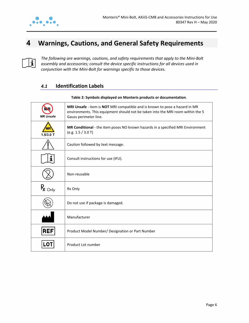
Table 2: Symbols displayed on Monteris products or documentation.
MRI Unsafe - item is NOT MRI compatible and is known to pose a hazard in MR environments. This equipment should not be taken into the MRI room within the 5 Gauss perimeter line.
MR Conditional - the item poses NO known hazards in a specified MRI Environment (e.g. 1.5 / 3.0 T)
Caution followed by text message.
Consult instructions for use (IFU).
Non-reusable
Rx Only
Do not use if package is damaged.
Manufacturer
Product Model Number/ Designation or Part Number
Product Lot number

Monteris® Mini-Bolt, AXiiiS-CMB and Accessories Instructions for Use 80347 Rev H – May 2020
Page 7
4.2 Warnings and Cautions
WARNING:
• The Mini-Bolt and accessories are to be used only by trained physicians. • Perform systematic validation of the image-guided surgery (IGS) system used in
conjunction with the Mini-Bolt according to the IGS system manufacturer guidelines to ensure system accuracy and efficacy. Error magnitudes can vary for different IGS systems. If the IGS system is not validated prior to performing the surgical procedure, there is a greater potential for trajectory and depth error.
• Image-guided surgery (IGS) system compatibility and accessories – Verify the compatibility of the image-guided surgery (IGS) system and accessories before use with the Mini-Bolt.
• Assess the boney skull anatomy for previously resected bone flaps or diseased or damaged bone prior to Mini-Bolt attachment and use caution if attaching to these areas.
• With the exception of the Mini-Bolt Removal Tool for MRI, Alignment Mandrel and Clearance Mandrel, the rest of the Mini-Bolt Accessories have not been evaluated for MR compatibility. They are therefore considered MR Unsafe and should not be subjected to MRI.
CAUTION:
• Exercise caution if using accessories not supplied by Monteris Medical. Failure to do so may result in improper performance and/or damage to the device with the potential to cause harm.
• Do not attempt to use the Mini-Bolt before thoroughly reading the Instructions for Use.
5 MRI Conditional Status
5.1 Mini-Bolt Assembly Non-clinical testing has demonstrated that the Mini-Bolt components are MR Conditional. The following guidelines should be followed:
• Static magnetic field of 1.5/3.0 Tesla
• Scan in “Normal Operating Mode” only with a maximum whole-body-averaged specific absorption rate (SAR) of 2 W/kg.
• Use only whole-body transmitting coils, no local transmitting coils are allowed, local receiving coils can be used.
5.2 Mini-Bolt Accessories See component list for specific component MR designations in Table 1.

Monteris® Mini-Bolt, AXiiiS-CMB and Accessories Instructions for Use 80347 Rev H – May 2020
Page 8
The Stereotactic Driver, T-Handle for the Stereotactic Driver, Insert Adapters and Depth Stop in the Accessory Kits should be considered MRI unsafe.
Non-clinical testing has demonstrated that the Clearance Mandrel, Alignment Mandrel and Mini-Bolt Removal Tool for MRI in the Accessory Kits are MR Conditional. For the accessories with an MRI status of "MR Conditional", the following guidelines should be followed:
• Static magnetic field of 1.5/3.0 T
• These devices pose no danger due to magnetically induced forces; however, they should not remain within the MRI environment during imaging or scanning.

Monteris® Mini-Bolt, AXiiiS-CMB and Accessories Instructions for Use 80347 Rev H – May 2020
Page 9
6 Directions for Use 6.1 Sterilization Thoroughly clean and steam sterilize the Mini-Bolt and accessories prior to use. Follow the sterilization procedures at the healthcare facility for steam sterilization. General guidelines are provided in Section 8 below.
WARNING: To prevent loss of attachment stability in bone, do not reuse the Mini-Bolt as patient injury may result.
6.2 Trajectory Alignment and Attachment to Skull Refer to the stereotactic or IGS system manufacturer’s IFU for trajectory alignment.
• Use the appropriate surgical planning software for the stereotactic or IGS system when guiding the trajectory of Mini-Bolt on previously loaded MRI and or CT scans.
WARNING: To prevent patient injury, assess the skull anatomy prior to attachment. Use caution when attaching to resection bone flaps or to diseased or damaged bone. Ensure a minimum skull thickness of 5 mm exists at the at the Mini-Bolt attachment point.
• Assess the desired trajectory for proper stack-up clearance of devices placed by the Mini-Bolt within the MRI bore.
WARNING: To prevent potential patient injury, avoid trajectories perpendicular to the MRI bore which can lead to collisions with devices placed by the Mini-Bolt.
• Perform surgical prep and sterile draping of patient’s head per standard practice of the healthcare facility.
• Examine the skull for any previously installed cranial plating, mesh or cranial hardware.
WARNING: Do not affix the Mini-Bolt over previously installed cranial plating, mesh or other cranial hardware to avoid patient injury.

Monteris® Mini-Bolt, AXiiiS-CMB and Accessories Instructions for Use 80347 Rev H – May 2020
Page 10
Figure 5: Angle of Mini-Bolt relative to the skull needed to avoid patient injury
WARNING: To ensure proper attachment of the Mini-Bolt to the skull and to avoid patient injury do not exceed an angle of 40° from perpendicular to the skull as shown in Figure 5 above.
• Identify and mark the planned entry point on the scalp which intersects the optimal surgical trajectory to the predetermined target in the brain.
• Ensure adequate clearance for the Mini-Bolt exists between the aiming device and the head to allow placement.
• Create a scalp incision at the desired entry location.
• Create a 4.5 mm diameter twist drill hole at the entry location in the skull, oriented along the desired trajectory, and through the 4.5 mm Insert Adapter.
Ensure the drill hole is complete and through both tables of the skull (Figure 6).
Note: A non-skiving 3.2 mm twist-drill is recommended for creating a pilot hole through the outer table of the skull. Complete trephination though the inner table of the skull should be completed by using a 4.5 mm drill bit with a flat or less aggressive (pointed) flute design at the tip.

Monteris® Mini-Bolt, AXiiiS-CMB and Accessories Instructions for Use 80347 Rev H – May 2020
Page 11
WARNING: Incomplete drilling through both tables of the skull may prevent stable anchoring of the Mini-Bolt or cause interference with instruments and lead to patient injury. l
Figure 6: Incomplete Drilling with a Pointed Drill Bit (left); Complete Drilling (right)
• Insert the flat, non-beveled end of the 4.5 mm Clearance Mandrel through the 4.5 mm Insert Adapter and extend through the created twist drill hole to the Dura (Figure 7).
• Confirm a clear path for placement of the Mini-Bolt is created through both the outer and inner tables.
• If there is any noted resistance in passing the Clearance Mandrel through the skull to the Dura, complete the drilling process or use a cutting instrument to de-burr the inner skull table.
Figure 7: Incomplete Drilling (left); Clearance Mandrel with Complete Drilling (right)

Monteris® Mini-Bolt, AXiiiS-CMB and Accessories Instructions for Use 80347 Rev H – May 2020
Page 12
• Insert the Stereotactic Driver shaft into the T-Handle while pressing on the end of the handle (Figure 8).
• Insert the Stereotactic Driver into the proximal end of the Mini-Bolt. Ensure the Driver is fully seated into the Mini-Bolt. Insert the Driver and Mini-Bolt through the Host Adapter or directly into the stereotactic guide device and (Figure 7).
Figure 8: T-Handle and Stereotactic Driver Inserted into Mini-Bolt and placed through Stereotactic Guide: CRW
Frame (left); VarioGuide Arm (right).
• Thread the Mini-Bolt into the skull opening.
• Rotate the Stereotactic Driver with the T-handle clockwise until the Mini-Bolt is fully seated and engaged to the skull inner table. Ten full turns will place the threads 8 mm into the skull (see Table 3).
Table 3: Chart to Calculate Mini-Bolt Depth in Skull Based on Number of 360° Driver Turns
Number of Turns Depth into Skull
4 3.2mm 5 4.0mm 6 4.8mm 7 5.6mm 8 6.4mm 9 7.2mm
10 8.0mm 11 8.8mm 12 9.6mm 13 10.4mm 14 11.2mm 15 12.0mm

Monteris® Mini-Bolt, AXiiiS-CMB and Accessories Instructions for Use 80347 Rev H – May 2020
Page 13
• Manually check the stability of attachment into the skull before proceeding.
WARNING: Exercise care, over-tightening the Mini-Bolt may cause stripping of the bone channel at attachment. Use only enough force to assure stable attachment to avoid patient injury.
• Remove the Stereotactic Driver from the Mini-Bolt.
• Place the Mini-Bolt cap onto the Mini-Bolt to temporarily close the open channel to the brain as needed.
Remove the Mini-Bolt cap before performing the intended neurosurgical procedure. • Place additional Mini-Bolts as needed for multiple trajectories.
• See section 6.3 for measurements of the Mini-Bolt and accessories to determine proper depth settings for the delivered instrument or device.
Refer to the stereotactic or IGS system manufacturer’s IFU to properly calculate instrument or device depth to the intended target.
• See section 6.4 for the next steps to performing a NeuroBlate® System Procedure.
CAUTION: When using Mini-Bolt with the Robotic Probe Driver (RPD), the minimum spacing necessary to place an additional Mini-Bolts is 11 mm center to center (Figure 8). Inadequate spacing between Mini-Bolts may interfere with attachment of the RPD.
• At the end of the procedure, remove (unscrew) the Mini-Bolt from the skull using the Stereotactic Driver and T-handle outside of the MRI environment. If necessary, the Mini-Bolt can be removed inside the MRI environment using the Removal Tool for MRI.
6.3 Mini-Bolt and Accessory Adapter Dimensions (mm)
Figure 9: Measurements of the Mini-Bolt

Monteris® Mini-Bolt, AXiiiS-CMB and Accessories Instructions for Use 80347 Rev H – May 2020
Page 14
Figure 10: Measurements of the Host Adapters and Insert Adapters
6.4 Using Mini-Bolt for NeuroBlate® System Procedures Refer to the NeuroBlate® System’s Instructions for Use to determine appropriate depth settings for delivery of a laser probe via the Mini-Bolt.
WARNING: MRI artifact can extend from the distal end of the Mini-Bolt (at the inner table of the skull) into brain tissue by as much as 13 mm for 1.5 T, and 18 mm for 3.0 T systems. If thermal imaging is required within these ranges, the user should proceed with extreme caution to ensure safe laser energy delivery. The amount of thermal data pixel dropout at shallow depths should be evaluated prior to laser energy delivery. To prevent patient injury, the user should not deliver laser energy into tissue that cannot be properly evaluated with thermal imaging.
• MR imaging should be used to confirm any manual linear instrument adjustments after initial delivery into the brain.
• To attach the Robotic Probe Driver (RPD) to the Mini-Bolt, slide the stem over the Mini-Bolt and tighten the thumbscrew (Figure 11).
WARNING: Ensure the Locking Collar Adaptor notch is properly aligned with the RPD Follower and the thumbscrew is adequately tightened to avoid patient injury or death.

Monteris® Mini-Bolt, AXiiiS-CMB and Accessories Instructions for Use 80347 Rev H – May 2020
Page 15
Figure 11: Attaching the Robotic Probe Driver (RPD) to the Mini-Bolt
7 Troubleshooting Contact Monteris Customer Support for specific advice regarding troubleshooting:
• Monteris Toll Free Customer Support: 1-866-799-7655 Callers may choose to be connected directly to a Technical Services Representative, to leave a message requesting service or product sales, or be connected to the Monteris Medical operator.
• Monteris Email Reporting System: [email protected] Contact Monteris via email to request service, make product improvement suggestions, report system issues, or register complaints.
8 Cleaning, Disinfection, Sterilization and Inspection • Prior to use, sterilize the Mini-Bolt and Accessories. The following parameters have been
validated for effective sterilization using moist heat:
o 4-minute, 132° C pre-vacuum cycle, 30-minute dry time
o 18-minute, 134° C pre-vacuum cycle, 30-minute dry time
WARNING: Proper sterilization of the Mini-Bolt assembly and accessories must be done prior to use to prevent patient injury.
WARNING: To prevent patient injury do not reuse the Mini-Bolt.
• After use, the Mini-Bolt Accessory components should be cleaned using a manual or automated process that is equivalent to or exceeds the following validated parameters:
Monteris® Mini-Bolt, AXiiiS-CMB and Accessories Instructions for Use 80347 Rev H – May 2020
Page 16
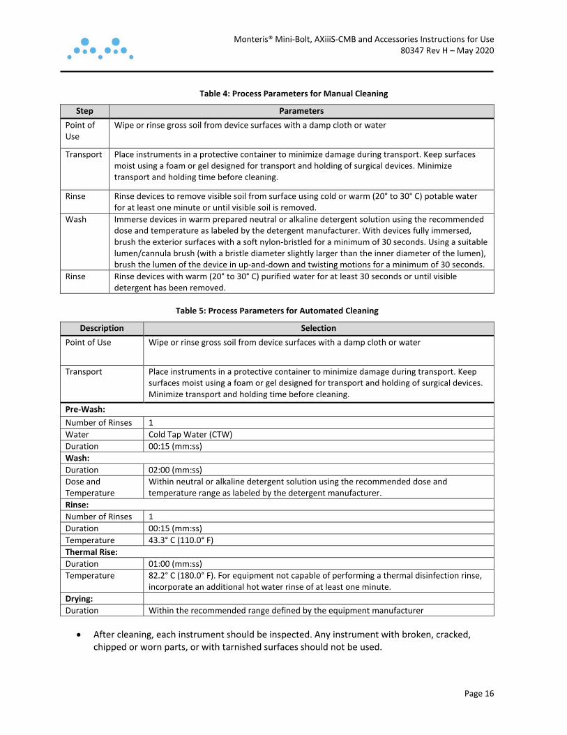
Table 4: Process Parameters for Manual Cleaning
Step Parameters Point of Use
Wipe or rinse gross soil from device surfaces with a damp cloth or water
Transport Place instruments in a protective container to minimize damage during transport. Keep surfaces moist using a foam or gel designed for transport and holding of surgical devices. Minimize transport and holding time before cleaning.
Rinse Rinse devices to remove visible soil from surface using cold or warm (20° to 30° C) potable water for at least one minute or until visible soil is removed.
Wash Immerse devices in warm prepared neutral or alkaline detergent solution using the recommended dose and temperature as labeled by the detergent manufacturer. With devices fully immersed, brush the exterior surfaces with a soft nylon-bristled for a minimum of 30 seconds. Using a suitable lumen/cannula brush (with a bristle diameter slightly larger than the inner diameter of the lumen), brush the lumen of the device in up-and-down and twisting motions for a minimum of 30 seconds.
Rinse Rinse devices with warm (20° to 30° C) purified water for at least 30 seconds or until visible detergent has been removed.
Table 5: Process Parameters for Automated Cleaning
Description Selection Point of Use Wipe or rinse gross soil from device surfaces with a damp cloth or water
Transport Place instruments in a protective container to minimize damage during transport. Keep surfaces moist using a foam or gel designed for transport and holding of surgical devices. Minimize transport and holding time before cleaning.
Pre-Wash: Number of Rinses 1 Water Cold Tap Water (CTW) Duration 00:15 (mm:ss) Wash: Duration 02:00 (mm:ss) Dose and Temperature
Within neutral or alkaline detergent solution using the recommended dose and temperature range as labeled by the detergent manufacturer.
Rinse: Number of Rinses 1 Duration 00:15 (mm:ss) Temperature 43.3° C (110.0° F) Thermal Rise: Duration 01:00 (mm:ss) Temperature 82.2° C (180.0° F). For equipment not capable of performing a thermal disinfection rinse,
incorporate an additional hot water rinse of at least one minute. Drying: Duration Within the recommended range defined by the equipment manufacturer
• After cleaning, each instrument should be inspected. Any instrument with broken, cracked, chipped or worn parts, or with tarnished surfaces should not be used.

Monteris® Mini-Bolt, AXiiiS-CMB and Accessories Instructions for Use 80347 Rev H – May 2020
Page 17
9 Operating Conditions • Temperature: 15°C (59°F) to 30°C (86°F)
• Relative Humidity: < 70%
10 Storage Conditions • Temperature: 10°C (50°F) to 40°C (104°F)
• Relative Humidity: < 60%
11 Contact Information
11.1 Distributed by:
11.2 Manufactured by: Monteris Medical Corp. 14755 27th Ave N Suite C Plymouth, MN 55447 (763) 253-4710 / (866) 799-7655 [email protected]
Monteris Medical Corp. 14755 27th Ave N Suite C Plymouth, MN 55447 (763) 253-4710 / (866) 799-7655 www.monteris.com


![Panaeolus cinctulus [Bolt.] Saccardo et Panaeolus ... - DUMAS](https://static.fdokumen.com/doc/165x107/631dbceb3969c5af13078f6d/panaeolus-cinctulus-bolt-saccardo-et-panaeolus-dumas.jpg)