Instruction manual VITO - Impexron GMBH
40
Instruction manual VITO
-
Upload
khangminh22 -
Category
Documents
-
view
0 -
download
0
Transcript of Instruction manual VITO - Impexron GMBH

Instruction manualVITO


____________________________________________________________________________________
Instruction manual VITO Page 1
Instruction manual VITO April 2009 Part no.: 4416.655 Revision 3
Enraf B.V. P.O. Box 812 2600 AV Delft Netherlands Tel. : +31 15 2701100 Fax : +31 15 2701111 E-mail : [email protected] Website : http://www.honeywell.com/ps

Preface ___________________________________________________________________________
Instruction manual VITO Page 2
Copyright 2006 - 2009 Enraf B.V. All rights reserved Reproduction in any form without the prior consent of Enraf B.V. is not allowed. This manual is for information only. The contents, descriptions and specifications are subject to change without notice. Enraf B.V. accepts no responsibility for any errors that may appear in this manual. The warranty terms and conditions applicable in the country of purchase in respect to Enraf B.V. products are available from your supplier. Please retain them with your proof of purchase.
Preface ___________________________________________________________________________
Instruction manual VITO Page 3
Preface This manual is intended for technicians involved with the commissioning and service of the Honeywell Enraf instruments. A description preceding the technical procedures gives the technical information necessary to understand its functioning. It is recommended to read this description prior to performing any of the procedures. Safety an prevention of damage Refer to the chapter Safety in the instruction manual of the applicable instrument (servo/radar gauge or indicator) for detailed safety instructions. “Warnings”, “Cautions”, and Notes have been used throughout this manual to bring special matters to the immediate attention of the reader.
• A Warning concerns danger to the safety of the technician or user; • A Caution draws attention to an action which may damage the equipment; • A Note points out a statement deserving more emphasis than the general text, but does not deserve a
“Warning” or a “Caution”. The sequence of steps in a procedure may also be important from the point of view of personal safety and prevention of damage; it is therefore advised not to change the sequence of procedure steps or alter a procedure. Legal aspects The commissioning and trouble shooting to the instrument may only be conducted by qualified engineers, trained by Honeywell Enraf and with knowledge of safety regulations for working in hazardous areas. The information in this manual is the copyright property of Enraf B.V., Netherlands. Enraf B.V. disclaims any responsibility for personal injury or damage to equipment caused by :
• Deviation from any of the prescribed procedures; • Execution of activities that are not prescribed; • Neglect of the general safety precautions for handling tools and use of electricity.
EC declaration of conformity The Honeywell Enraf instrument is in conformity with the protection requirements of EC Council Directive 89/336/EC. Refer to EC declaration of conformity delivered with the instrument or to the installation guide of the instrument. Additional information Please do not hesitate to contact Honeywell Enraf or its representative if you require any additional information.

Table of Contents ___________________________________________________________________________
Instruction manual VITO Page 4
Table of contents
Preface...................................................................................................................................... 3
1 Average temperature measurement with Vito temperature probes ............................. 6
1.1 Introduction................................................................................................................................................. 6
1.2 Commissioning of average temperature measurement ......................................................................... 7
1.2.1 Average temperature settings .................................................................................................................. 7
1.2.2 Additional temperature settings for 877 FDI........................................................................................... 11
1.3 Operation................................................................................................................................................... 12
1.3.1 Display.................................................................................................................................................... 12
1.3.2 Data items .............................................................................................................................................. 12
1.4.1 Temperature error request (item EM) ................................................................................................ 13
1.4.2 Temperature status request (Item MQ).................................................................................................. 13
2 Average temperature measurement with MRT............................................................. 14
2.1 General ...................................................................................................................................................... 14
2.2 Operating principle................................................................................................................................... 14
2.3 Commissioning......................................................................................................................................... 14
2.3.1 Format critical items ............................................................................................................................... 14
2.3.2 Temperature related settings ................................................................................................................. 15
2.3.3 Additional settings for and 877 FDI ........................................................................................................ 16
2.3.4 Data items .............................................................................................................................................. 17
2.4 Error codes................................................................................................................................................ 18
2.4.1 Temperature error HCU/HPI (item EM).................................................................................................. 18
2.4.2 Temperature status request (item MQ) .................................................................................................. 18
3 Average temperature measurement with RTD............................................................. 19
4.1 General ...................................................................................................................................................... 19
3.2 Operating principle................................................................................................................................... 19
3.3 Commissioning......................................................................................................................................... 19
3.3.1 Format critical items ............................................................................................................................... 19
3.3.2 Temperature related settings ................................................................................................................. 20
3.3.3 Additional settings for and 877 FDI ........................................................................................................ 21
3.3.4 Data items .............................................................................................................................................. 22
3.4 Error codes................................................................................................................................................ 22
3.4.1 Temperature error (item EM).................................................................................................................. 22
3.4.2 Temperature status request (item MQ) .................................................................................................. 23
4 Water bottom measurement .......................................................................................... 24
4.1 Introduction............................................................................................................................................... 24
4.1.1 Water probe versions ............................................................................................................................. 24
4.1.2 Principle of measurement....................................................................................................................... 25
4.2 Commissioning measurements .............................................................................................................. 25

Table of Contents ___________________________________________________________________________
Instruction manual VITO Page 5
4.2.1 Commissioning measurements with roof suspended probes ................................................................ 25
4.2.2 Commissioning measurements for side mounted probes...................................................................... 27
4.2.3 Water probe settings .............................................................................................................................. 28
4.3 Operation................................................................................................................................................... 29
4.3.1 Display.................................................................................................................................................... 29
4.3.2 Water above / below probe warning....................................................................................................... 29
4.3.3 Data items .............................................................................................................................................. 29
4.4 Troubleshooting ....................................................................................................................................... 30
4.4.1 Water error request (item EW) ............................................................................................................... 30
4.4.2 HART communication errors.................................................................................................................. 30
4.4.3 Water level (ullage) status bytes ............................................................................................................ 30
4.4.4 Water bottom pointer (items VP and VV) ............................................................................................... 31
Appendix A ASCII table.................................................................................................... 32
Appendix B Configuration procedure for 765/766/768 VITO water probe .................... 33
Appendix C Part numbers ................................................................................................ 34
Appendix D Related documents....................................................................................... 35

Average temperature measurement with MTT’s ___________________________________________________________________________
Instruction manual VITO Page 6
1 Average temperature measurement with Vito temperature probes
1.1 Introduction Honeywell Enraf’s portfolio for average temperature measurement consists from the following probes:
- 764 VITO temperature probe (MTT 16); - 766 VITO water and temperature probe (MTT 16); - 767 VITO temperature probe (MTT 9) - 768 VITO water and temperature probe (MTT 9)
The measuring range (MK) of a probe is defined as the distance from the reference element / Pt100, which is always positioned at 1m from the bottom of the probe, to the position of the highest element. Refer to figure 1.1 & 1.2.
1. The VITO MTT 764C probe comprises 16 measuring elements and has its lowest element positioned at 1m from the bottom of the probe. Its 16 elements are subsequently equally divided from the reference resistor up to the highest element.
2. The VITO MTT 764D probe comprises 16 measuring elements and has its lowest element positioned at
the bottom of the probe. The remaining 15 elements are subsequently equally divided from the reference resistor up to the highest element.
3. The VITO MTT 766C probe comprises a water probe & 16 measuring elements and has its lowest element positioned at 1m from the bottom of the probe. Its 16 elements are subsequently equally divided from the reference resistor up to the highest element.
4. The VITO MTT 766D probe comprises a water probe & 16 measuring elements and has its lowest
element positioned at the bottom of the probe. Its remaining 15 elements are subsequently equally divided from the reference resistor up to the highest element.
5. The VITO LT 767C probe comprises 9 measuring elements and has its lowest element positioned at 1m
from the bottom of the probe. Its 9 elements are subsequently equally divided over the from the reference resistor up to the highest element.
6. The VITO LT 767D probe comprises 9 measuring elements and has its lowest element positioned at the
bottom of the probe. The remaining 8 elements are subsequently equally divided over the from the reference resistor up to the highest element.
7. The VITO LT 768C probe comprises a water probe & 9 measuring elements and has its lowest element
positioned at the 1m from the bottom of the probe. Its 9 elements are subsequently equally divided from the reference resistor up to the highest element.
8. The VITO LT 768D probe comprises a water probe & 9 measuring elements and has its lowest element
positioned at the bottom of the probe. The remaining 8 elements are subsequently equally divided from the reference resistor up to the highest element.

Average temperature measurement with MTT’s ___________________________________________________________________________
Instruction manual VITO Page 7
1.2 Commissioning of average temperature measurement The wiring sequence of all blue thermocouple wires is only measured once at start-up and the information is stored in the memory. The time required to complete all thermocouples measurements after powering up the instrument is approximately 2 minutes. The commissioning of the optional average temperature part should be performed after the basic commissioning of the level gauge or indicator.
1.2.1 Average temperature settings Before programming the temperature data, the sensitive length and the offset of the temperature probe must be known. The sensitive probe-length is equal to the total probe length minus spacing for installation (700mm) and minus 1m in case of version C. Standard, the measuring ranges are:
• For C version probes (model code ……C<ol><he>): overall length – 1700mm. • For D version probes (model code ……D<ol><he>): overall length – 700mm.
Other (smaller) measuring ranges (sensitive lengths) are possible: check on identification label of the VITO probe (or MTT) for the positioning of the highest element (last 4 digits; units: cm). The offset is the distance from the lowest element to the tank’s zero point (datum plate). The 764/767 VITO temperature sensor and 766/768 water and temperature sensor can have the lowest element on different places. This is identified on the instrument label:
• …..764 C <ol><he> lowest element at 1 m from bottom of probe; • …..764 D <ol><he> lowest element at 0.065 m from lower end of probe; • …..766 C <ol><he> lowest element at 1 m from bottom of probe; depends on WaterProbe • …..766 D <ol><he> lowest element at 0.065 m from lower end of probe; • …..767 C <ol><he> lowest element at 1 m from bottom of probe; • …..767 D <ol><he> lowest element at 0.065 m from lower end of probe; • …..768 C <ol><he> lowest element at 1 m from bottom of probe; depends on WaterProbe • …..768 D <ol><he> lowest element at 0.065 m from lower end of probe;
Note: In the model code given above a dot ‘.’ Represents any character, the notation <ol> means: overall length (4 positions) and the notation <he> means: position of highest element (4 positions).
The position of the lowest element can also be verified by requesting the VITO device type & s/w version by means of items VP and VV, provided you know if a 764, 766, 767 or VITO 768 sensor is connected. Refer to the table below how to obtain data with the temperature pointer items:
Item VP Item VV sensor model code
VP=03.10 VV: 764 C VV: 764 D VV: 767 C VV: 767 D
…. 764 C <ol><he> …. 764 D <ol><he> …. 767 C <ol><he> …. 767 D <ol><he>
VP=03.10 VV: 766 C VV: 766 D VV: 768 C VV: 768 D
.A..766 C <ol><he>
.A..766 D <ol><he>
.A..768 C <ol><he>
.A..768 D <ol><he>

Average temperature measurement with MTT’s ___________________________________________________________________________
Instruction manual VITO Page 8
Figure 1.1 Tank and temperature probe data

Average temperature measurement with MTT’s ___________________________________________________________________________
Instruction manual VITO Page 9
Figure 1.2 Tank and temperature probe data
Average temperature measurement with MTT’s ___________________________________________________________________________
Instruction manual VITO Page 10
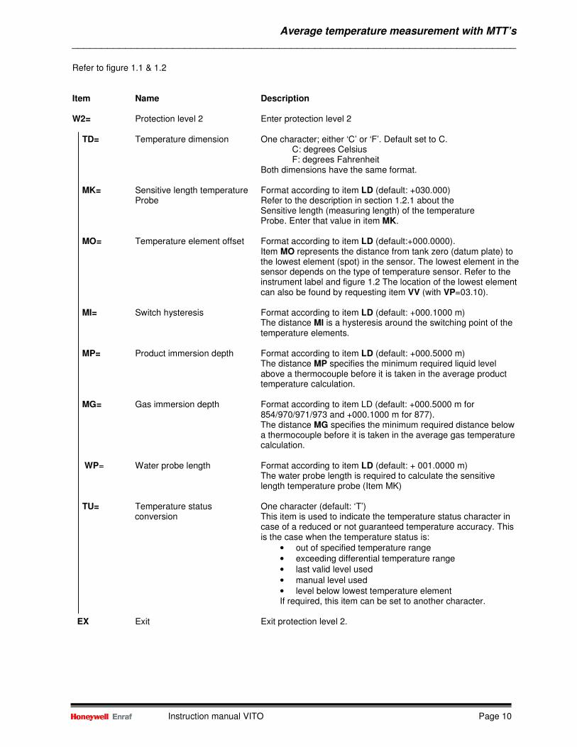
Refer to figure 1.1 & 1.2 Item Name Description W2= Protection level 2 Enter protection level 2 TD= Temperature dimension One character; either ‘C’ or ‘F’. Default set to C. C: degrees Celsius F: degrees Fahrenheit Both dimensions have the same format. MK= Sensitive length temperature Format according to item LD (default: +030.000) Probe Refer to the description in section 1.2.1 about the
Sensitive length (measuring length) of the temperature Probe. Enter that value in item MK.
MO= Temperature element offset Format according to item LD (default:+000.0000).
Item MO represents the distance from tank zero (datum plate) to the lowest element (spot) in the sensor. The lowest element in the sensor depends on the type of temperature sensor. Refer to the instrument label and figure 1.2 The location of the lowest element can also be found by requesting item VV (with VP=03.10).
MI= Switch hysteresis Format according to item LD (default: +000.1000 m)
The distance MI is a hysteresis around the switching point of the temperature elements.
MP= Product immersion depth Format according to item LD (default: +000.5000 m)
The distance MP specifies the minimum required liquid level above a thermocouple before it is taken in the average product temperature calculation.
MG= Gas immersion depth Format according to item LD (default: +000.5000 m for 854/970/971/973 and +000.1000 m for 877).
The distance MG specifies the minimum required distance below a thermocouple before it is taken in the average gas temperature calculation.
WP= Water probe length Format according to item LD (default: + 001.0000 m) The water probe length is required to calculate the sensitive length temperature probe (Item MK) TU= Temperature status One character (default: ‘T’)
conversion This item is used to indicate the temperature status character in case of a reduced or not guaranteed temperature accuracy. This is the case when the temperature status is:
• out of specified temperature range • exceeding differential temperature range • last valid level used • manual level used • level below lowest temperature element If required, this item can be set to another character.
EX Exit Exit protection level 2.

Average temperature measurement with MTT’s ___________________________________________________________________________
Instruction manual VITO Page 11
With all “D” version temperature probes it is thereby possible to exclude the lowest spot element from the average temperature calculation. This can be done by setting the first position in item MW to ‘F’. In fact, with item MW any spot temperature element (or more spots) can be disabled from average temperature calculation. Item Name Description W2= Protection level 2 Enter protection level 2 MW= MTT wiring connection Sixteen hexa-decimal characters; default: 0000000000000000 When one (or more) of the elements must be disabled from average temperature calculation, set the desired position to ‘F’ For instance, to disable lowest spot element: MW=F000000000000000 Note: When entering item MW with the Portable Enraf Terminal, the display will be cleared after entering the 15
th character.
Continue with entering the last character and press return. All 16 entered characters will be repeated at the top line of the PET. EX Exit Exit protection level 2
1.2.2 Additional temperature settings for 877 FDI Item Name Description W2= Protection level 2 Enter protection level 2 TF= Temperature source One ASCII character; either ‘I’ or ‘E’. this item selects if there is Selection a temperature measurement inside the indicator (internal) or to be fetched from the Enraf field bus (external). I: Internal E: External EX Exit Exit protection level 2

Average temperature measurement with MTT’s ___________________________________________________________________________
Instruction manual VITO Page 12
1.3 Operation
1.3.1 Display For operation of the display and the information on it (if applicable), refer tot the instruction manual of the related level gauge or indicator. Below, only an overview is given which display formats gives information about the average temperature measurement.
Display format Displayed information
A Product level and average product temperature C Average gas temperature and status D Average product temperature and status
1.3.2 Data items The table below lists a number of data items. They contain measured data, verification data and error data. The verification data can be used to check the results of certain steps in the measuring sequence. The temperature status indicates the validity of the measured data. The error data provides low level error information about the temperature measurement (refer to section 1.4).
Item
Description
AG AP MQ MU U0 – UF V0 - VF
Measured/ Average gas temperature Calculated data Average product temperature Temperature status request (refer to section 2.4.2) Measured test resistance (floating point format);
Must be: 166.5 Ω ± 0.03% Calculated spot positions (see below) Spot temperatures (see below)
RW Thermocouple wiring connection sequence EM FH F0
Diagnostic data Error request (refer to section 2.4.1). Fatal errors Last fatal error
Item V0 is the temperature of the lowest spot element. The calculated spot position item U0 corresponds with item V0. Refer to figure 2.2 to locate the lowest spot (L) with each particular temperature probe model.

Average temperature measurement with MTT’s ___________________________________________________________________________
Instruction manual VITO Page 13
1.4 Troubleshooting
1.4.1 Temperature error request (item EM) This item helps you configuring correctly by the most recent temperature error encountered by the option board. xxoo no error, value at initialisation xx11 no reply on initial HART commands communication error. Check connection level gauge – 762 VITO interface, or change 762 VITO interface or option board. xx50 Pt100 (or spot 0) error Brown wire connected to CN1 A-1 (or orange wire connected to CN2B-1) not connected . xx51 spot 1 (or Pt100) error Blue wire to CN2B-1 (or brown wire to CN1A-1) not connected xx52 Spot 2 error Blue wire to CN2A-2 not connected xx64 Spot 14 error Blue wire to CN5A-2 not connected xx65 Spot 15 error Yellow wire to CN5A-1 not connected xx70 Sub-system error Data from 762 VITO not valid. Reset instrument; if error persist, replace 762 VITO interface xx71 Wrong probe connection Thermocouple wires of VITO sensor connected wrongly (blue and yellow wires) xx77 Wrong Pt100 connection Brown and red wires of VITO sensor connected wrongly xx80 Rtest error Measurement on test resistor failed. Reset instrument; if error persist replace 762 VITO xx84 Standard deviation too large EMC influence (check cable shields) or defective 762 VITO interface xx92 No data available Communication error between 762 VITO interface and level gauge. Check wiring; replace 762 VITO interface or option board. xx98 No temperature sources found No VITO temperature probe (and no RTD) connected xx: 22 for MPU emulation With error codes xx50 to xx65, connector numbers are mentioned 24 for HPU emulation Refer to installation guide 762 VITO interface 764,765,766, 767 or 768 VITO 30 for HCU emulation Temperature and/or water bottom probe for location of these connectors.
1.4.2 Temperature status request (Item MQ) Temperature status request item contains four status bytes (Byte 0, Byte 1, Byte 2, Byte 3) of the option board. For decoding, refer to the ASCII table in appendix A. Status byte 0: Contains the characters ‘0’ ÷ ‘F’, indicating the highest immersed spot element of the temperature probe. At start up: ‘I’. Status byte 1: Status byte 2: Bit 0: General temperature fail Bit 0: Last valid level used 1: Fail in average product temperature 1: Manual level used 2: Fail in average gas temperature 2: Level time out 3: Level exceeds lowest spot element 3: Device not calibrated 4: Level exceeds highest spot element 4: Exceeding differential temp, range 5: Spot element fail (one or more spots defect) 5: Out of specified temperature range 6: 1 6: 1 7: 0 7: 0 Status byte 3: Bit 0: No previous store command 1-5: 0 6: 1 7: 0
Note: Only the bits which are set to ‘1’ have an active status.

Average temperature measurement with MRT ___________________________________________________________________________
Instruction manual VITO Page 14
2 Average temperature measurement with MRT 2.1 General The 762 VITO MRT temperature selector is used for interfacing an Multiple Resistance Thermometer (MRT). This unit is basically a solid state electronic element selector, containing all hardware necessary for selecting and measuring an MRT with up to 13 temperature elements with one spot element.
2.2 Operating principle Since most liquids, stored in storage tanks, are not homogeneous in temperature, an average temperature measurement over the entire liquid column is required. A Multiple Resistance Thermometer can provide this true average temperature measurement. An MRT comprises a number of resistance elements of different lengths, all starting near the tank bottom. To measure the average product temperature, the longest fully immersed element is automatically selected and its temperature measured. The average gas temperature is calculated by measuring the temperature of the longest resistance thermometer element and subtracting the contribution of the average product temperature. The operational board located in the 854 level gauge, 877 FDI or 97x radar, selects the longest immersed element for the average product temperature calculation.
2.3 Commissioning
The commissioning of the optional board should be performed after the basic commissioning of the level gauge, radar gauge or indicator. The items mentioned in this section resides under protection level 2.
2.3.1 Format critical items When the temperature dimension and/or the decimal separator has to be changed, it should be done at the start of the commissioning. Item Name Description TD Temperature dimension One ASCII character, either “C” or “F”
• C: degrees Centigrade • F: degrees Fahrenheit
Both dimensions have the same format: sign XXX sep XX Where: Sign: + or – X : digit Sep: decimal separator (“.” Or “,”)
DP Decimal separator One ASCII character; either “.” (point) or “,” (comma). If the instrument is equipped with an XPU 2 board, all related
items are automatically converted. With an XPU board, all items depending on the temperature, level, density and pressure format have to be re-programmed with the correct decimal separator.

Average temperature measurement with MRT ___________________________________________________________________________
Instruction manual VITO Page 15
2.3.2 Temperature related settings Item Name Description J0 - JD MRT element position. J0 through JD represent the distance from the end of the probe
(nearest to tank zero level) to the MRT element if selected by item [MJ].
MJ Multi temperature distribution This item determines whether fixed element positions are taken
(=F=default) or configurable element positions (=T) via ithe items J0 .. JD. The fixed element positions are described at item U0 .. UD.
MT Element type Three ASCII characters (C3 C2 C1). Selects the element type connected to the 762 VITO MRT, with its characteristics. C3 R refers to an MRT without spot element Q refers to an MRT with spot element
C2 C1 CB Rth = 90.2935 + T x 0.38826 (-100 ÷ +280 °C) CN Rth = 90.4778 + T x 0.38090 (-100 ÷ +280 °C) CS Rth = 90.5000 + T x 0.38730 (-100 ÷ +280 °C) MN Number of elements Two ASCII digits. This item specifies the number of elements
from the MRT, inclusive the spot element. The maximum number of elements is 13.
Refer to figure 2.1
Figure 2.1 MRT definition

Average temperature measurement with MRT ___________________________________________________________________________
Instruction manual VITO Page 16
Item Name Description MO Temperature element offset Format according to item LD. The offset represents the distance form the tank zero level to the lowest position of the MRT. Note: Incase of ullage measurement, distance MO is taken from The upper reference point. MI Switch hysteresis Format according to item LD.The distance MI is a hysteresis around the switching point of the temperature elements. MP Product immersion depth Format according to item LD.The distance MP specifies the
minimum required liquid level above a element before it is selected for the average product temperature calculation
MG Gas immersion depth Format according to item LD.The distance MG specifies the minimum required distance before the resistance value of the longest element is taken in the average gas temperature calculation TU Temperature status conversion One character (default: ‘T’)
This item is used to indicate the temperature status character incase of a reduced or not guaranteed temperature accuracy. This is the case when the temperature status is:
• out of specified temperature range • exceeding differential temperature range • last valid level used • manual level used • level below lowest temperature element
2.3.3 Additional settings for and 877 FDI Item Name Description TF= Temperature source One ASCII character; either ‘I’ or ‘E’. this item selects if there is Selection a temperature measurement inside the indicator (internal) or to be fetched from the Enraf field bus (external). I: Internal E: External

Average temperature measurement with MRT ___________________________________________________________________________
Instruction manual VITO Page 17
2.3.4 Data items There are of number of data items for the measured temperature, checks and status information. These data items are: Item Name Description AP Average product temperature This item contains the average product temperature, calculated from the longest immersed element. It is preceded by four status bytes from item MQ. AG Average gas temperature This item contains the average gas temperature, calculated from the longest element reduced with the average product temperature influence. It is preceded by four status bytes from Item MQ. MQ Temperature status request This item contains four bytes with temperature status information. For description of the status, refer to chapter 2.2 MU Test resistance The measured test resistance in floating point format
The value should be 166,5 ohm ± 0.03%
U0 ÷÷÷÷ UD Calculated element Format according to item LD. These items gives the position of each element with respect to the lowest part of the MRT. U0 : position of 1
st element (0.25 m or 0.65 m or [J0])
U1 : position of 2nd
element (0.65 m or 1.25 m or [J1]) U2 : position of 3
th element (1.25 m or 1.95 m or [J2])
U3 : position of 4th element (1.95 m or 2.85 m or [J3])
U4 : position of 5th element (2.85 m or 4.15 m or [J4])
U5 : position of 6th element (4.15 m or 5.65 m or [J5])
U6 : position of 7th element (5.65 m or 7.35 m or [J6])
U7 : position of 8th element (7.35 m or 9.25 m or [J7])
U8 : position of 9th element (9.25 m or 11.65 m or [J8])
U9 : position of 10th element (11.65 m or 14.65 m or [J9])
UA : position of 11th element (14.65 m or 18.45 m or [JA])
UB : position of 12th element (18.55 m or 22.95 m or [JB])
UC : position of 13th element (22.95 m or 29.65 m or [JC])
UD : position of 14th element (29.65 m or [JD])
V0 ÷÷÷÷ VD Element temperatures Format according to item TD. These 14 items contains the temperature of each element. V0 : temperature of 1
st element
V1 : temperature of 2nd
element
VD : temperature of 14th element YP Stored average prod. Temp. Format according to item TD. Stored product temperature, copied from item AP, after an ST command was given.

Average temperature measurement with MRT ___________________________________________________________________________
Instruction manual VITO Page 18
2.4 Error codes 2.4.1 Temperature error HCU/HPI (item EM) This item helps you configuring correctly by showing the most recent temperature error encountered by the option board. xx00 no error xx70 sub-system error. Check or replace VITO xx50 Element 1 detected absent xx72 not supported element type. Check item MT xx51 Element 2 detected absent xx73 wrong element configuration. Check item MN xx52 Element 3 detected absent xx80 R test error (out of limits) xx53 Element 4 detected absent xx81 R cable error (out of limits) xx54 Element 5 detected absent xx84 standard deviation too high xx55 Element 6 detected absent xx91 Wrong J0 .. JD setting. Check these items. xx56 Element 7 detected absent xx92 no data available. Check wiring or connection with VITO xx57 Element 8 detected absent xx58 Element 9 detected absent xx59 Element 10 detected absent xx60 Element 11 detected absent xx61 Element 12 detected absent xx62 Element 13 detected absent xx63 Element 14 detected absent
xx22 for MPU emulation xx24 for HPU emulation xx30 for HCU emulation
2.4.2 Temperature status request (item MQ) Four bytes status information (B0 B1B2 B3) with the following meaning: Status byte 0:
Contains the characters ‘0’ ÷ 'D', indicating the highest immersed element of the MRT. At start up this is: ‘I’. Status byte 1: Status byte 2: Bit 0: general temperature fail bit 0: last valid level used 1: fail in average product temperature 1: manual level used 2: fail in average gas temperature 2: 0 3: level exceeds lowest element 3: 0 4: level exceeds highest element 4: 0 5: element fail (one or more elements defect) 5: 0 6: 1 6: 1 7: 0 7: 0 Status byte 3: Bit 0: no previous store command for decoding of the status bytes, refer to the 1: alternative (lower) element selected ASCII table in appendix A 2÷5: 0 6: 1 7: 0 Note: Only the bits which are set to ‘1’ have an active status.

Average temperature measurement with RTD ___________________________________________________________________________
Instruction manual VITO Page 19
3 Average temperature measurement with RTD 4.1 General The 762 VITO MRT can be used for interfacing with 1 through 3 RTD spots which are in a 3 wire connection or 1 through 14 RTD's as a probe with each RTD in a 2 common wire (ground and cable) connection.
3.2 Operating principle The RTD elements below the product level will determine the average product temperature, in respect to product immersion depth and hysteresis mechanisms and to actual valid level, last valid level or manual level. The RTD elements above the product level will determine the average gas temperature, in respect to gas immersion depth and hysteresis mechanisms and to actual valid level, last valid level or manual level.
3.3 Commissioning The commissioning of the optional board should be performed after the basic commissioning of the level gauge, radar gauge or indicator. The items mentioned in this section resides under protection level 2.
3.3.1 Format critical items When the temperature dimension and/or the decimal separator has to be changed, it should be done at the start of the commissioning. Item Name Description W2= Protection level 2 Enter protection level 2 TD Temperature dimension One ASCII character, either “C” or “F”
• C: degrees Centigrade • F: degrees Fahrenheit
Both dimensions have the same format: sign XXX sep XX Where: Sign: + or – X : digit Sep: decimal separator (“.” Or “,”)
EX Exit Exit protection level 2

Average temperature measurement with RTD ___________________________________________________________________________
Instruction manual VITO Page 20
3.3.2 Temperature related settings
Item Name Description W2= Protection level 2 Enter protection level 2 MT Element type Three ASCII characters (C3 C2 C1). Selects the element type Connected to the 762 VITO MRT C3 S refers to a RTD spot element
C2 C1 PL Pt100 large (-200 ÷ +250 °C) MN Number of elements Two ASCII digits. This item specifies the number of elements
of the RTD, 1 through 3 means RTD spot in a 3 wire connection. 4 through 14 means a multi RTD probe.
MO Temperature element offset Format according to item LD. The offset represents the distance
from the tank zero level to the lowest position of the multi RTD probe.
In case of the RTD spots this item should be left at 0. Note: Incase of ullage measurement, distance MO is taken from The upper reference point. J0 - JD RTD element position. In case of the RTD spots J0 through J2 represent the distance
from tank zero level to the RTD spot. In case of a multi RTD probe J0 through JD represent the distance from the end of the probe (nearest to tank zero level) to the RTD element.

Average temperature measurement with RTD ___________________________________________________________________________
Instruction manual VITO Page 21
Item Name Description MI Switch hysteresis Format according to item LD.The distance MI is a hysteresis around the switching point of the temperature elements. MP Product immersion depth Format according to item LD.The distance MP specifies the
minimum required liquid level above a element before it is selected for the average product temperature calculation
MG Gas immersion depth Format according to item LD.The distance MG specifies the minimum required distance before the resistance value of the longest element is taken in the average gas temperature calculation TU Temperature status conversion One character (default: ‘T’)
This item is used to indicate the temperature status character incase of a reduced or not guaranteed temperature accuracy. This is the case when the temperature status is:
• out of specified temperature range • last valid level used • manual level used • level below lowest temperature element • If required, this item can be set to another character.
EX Exit Exit protection level 2
3.3.3 Additional settings for and 877 FDI Item Name Description W2= Protection level 2 Enter protection level 2 TF= Temperature source One ASCII character; either ‘I’ or ‘E’. this item selects if there is Selection a temperature measurement inside the indicator (internal) or to be fetched from the Enraf field bus (external). I: Internal E: External EX Exit Exit protection level 2

Average temperature measurement with RTD ___________________________________________________________________________
Instruction manual VITO Page 22
3.3.4 Data items There are of number of data items for the measured temperature, checks and status information. These data items are: Item Name Description AP Average product temperature This item contains the average product temperature, calculated by averaging the immersed elements. It is preceded by four status bytes from item MQ. AG Average gas temperature This item contains the average gas temperature, calculated
by averaging the not immersed elements. It is preceded by four status bytes from Item MQ.
MQ Temperature status request This item contains four bytes with temperature status information. For description of the status, refer to chapter 4.4.2 MU Test resistance The measured test resistance in floating point format
The value should be 166,5 ohm ± 0.03%
U0 ÷ UD Calculated element position Format according to item LD. These items gives the position of each element. U0 = lowest element position.
V0 ÷ VD Element temperatures Format according to item TD. These 14 items contains the temperature of each element. V0 = lowest element temperature. YP Stored average prod. Temp. Format according to item TD. Stored product temperature, copied from item AP, after an ST command was given.
3.4 Error codes
3.4.1 Temperature error (item EM) This item helps you configuring correctly by showing the most recent temperature error encountered by the option board. xx00 no error xx70 sub-system error. Check or replace VITO xx50 Element 1 detected absent xx72 not supported element type. Check item MT xx51 Element 2 detected absent xx73 wrong element configuration. Check item MN xx52 Element 3 detected absent xx80 R test error (out of limits) xx53 Element 4 detected absent xx81 R cable error (out of limits) xx54 Element 5 detected absent xx84 standard deviation too high xx55 Element 6 detected absent xx91 Wrong J0 .. JD setting. Check these items. xx56 Element 7 detected absent xx92 no data available. Check wiring or connection with VITO xx57 Element 8 detected absent xx58 Element 9 detected absent xx59 Element 10 detected absent xx60 Element 11 detected absent xx61 Element 12 detected absent xx62 Element 13 detected absent xx63 Element 14 detected absent xx = 22 for MPU emulation xx = 24 for HPU emulation xx = 30 for HCU emulation

Average temperature measurement with RTD ___________________________________________________________________________
Instruction manual VITO Page 23
3.4.2 Temperature status request (item MQ) Four bytes status information (B0 B1B2 B3) with the following meaning: Status byte 0:
Contains the characters ‘0’ ÷ 'D', indicating the highest immersed element of the RTD. At start up this is: ‘I’. Status byte 1: Status byte 2: Bit 0: general temperature fail bit 0: last valid level used 1: fail in average product temperature 1: manual level used 2: fail in average gas temperature 2: 0 3: level exceeds lowest element 3: 0 4: level exceeds highest element 4: 0 5: element fail (one or more elements defect) 5: 0 6: 1 6: 1 7: 0 7: 0 Status byte 3: Bit 0: no previous store command for decoding of the status bytes, refer to the 1: alternative (lower) element selected ASCII table in appendix A
2÷5: 0 6: 1 7: 0 Note: Only the bits which are set to ‘1’ have an active status.

Water bottom measurement ___________________________________________________________________________
Instruction manual VITO Page 24
4 Water bottom measurement
4.1 Introduction The water bottom probe is based on a capacitive measurement principle. The probe is one plate of the capacitor and earthed, electrically conducting parts as water and the tank shell, is the other plate. A change in water level is detected by the water bottom probe as a change in capacitance.
4.1.1 Water probe versions There are four different water probe versions which can be interfaced:
• The 765 VITO water probe; • The 766 VITO water and temperature probe; • The external HART
water bottom probe • The 768 VITO water and temperature probe
The 765 VITO water probe, the 766 VITO water and temperature probe and the 768 VITO water and temperature probe are connected to the 762 VITO interface, which is connected to the HCU board or ICU-HPI board. The external water bottom probe is connected to HART input 2 (same input where pressure transmitters are connected).
Figure 4.1 VITO water probes, Side mounted water probe Refer to figure 4.1
A) 765 VITO water probe Can be delivered in three sensitive lengths for the water measurement: 0.5m, 1.0m, 1.5m and 2.0m.
B) 766 VITO MTT water and temperature probe There is one sensitive length for the water measurement: 0.5m, 1.0m, 1.5m and 2.0m.
C) 768 VITO LT water and temperature probe There is one sensitive length for the water measurement: 0.5m.
D) Side mounted water probe

Water bottom measurement ___________________________________________________________________________
Instruction manual VITO Page 25
4.1.2 Principle of measurement When correctly calibrated, the capacitance value given in PV LRV (primary Variable Lower Range Value) is the capacitance measured by the probe when no water is present (sensitive part of probe completely immersed in product). The capacitance value given in PV URV (Primary Variable Upper Range Value) is the capacitance measured by the probe when the sensitive part of probe completely immersed in water. Note: The 765, 766 and 768 VITO water probes uses items VR an VT to store the minimum and maximum capacitance values. The measured capacitance by the water probe has a linear function with the water level. Hence, the water level is calculated as: Water level = PV – PV LRV x sensitive length probe + water probe bottom position PV URV – PV LRV Where: PV = the measured capacitance by the water probe; with VITO water sensor, item MX is used PV LRV = the minimum capacitance (0% water); with VITO water probe, item VR is used PV URV = the maximum capacitance (100% water); with VITO water probe, item VT is used Or, LW = MX – VR x WP + WB VT – VR
If LW > WS otherwise LW = 0
Where: LW = water level WP = water probe length WB = water probe bottom position WS = alarm hysteresis
4.2 Commissioning measurements The purpose of these calibration measurements is to determine the water probe offset and a control measurement for the water level. With these measurements the product level is used as a horizontal line between the point where the tank zero point is located and the point where the water probe is installed.
4.2.1 Commissioning measurements with roof suspended probes If the commissioning takes place directly after installation, the measurements at the probe position in figure 4.2 have already been made if the instructions are followed from the installation guide. Otherwise, that measurement should be made now, by partly removing the probe to enable a measuring tape to be lowered from the nozzle. The following values are obtained:
• Nozzle height • Product level at water probe location • Water level at water probe location
From these measurements, calculate the ‘ullage’ value ‘A’: A= nozzle height – product level at water probe location The next step is to fetch the product level with respect to the tank zero point. This can be done in several ways:
• Read the level from the level gauge if that has recently been checked (calibrated);

Water bottom measurement ___________________________________________________________________________
Instruction manual VITO Page 26
• Take a manual ‘innage’ measurement to the datum plate of the tank; • Take a manual ‘ullage’ measurement from the Upper Reference Point and calculate the level by; level =
URP – ‘ullage’.
Figure 4.2 Calibration measurements for water probe If the commissioning takes place directly after installation, the measurements at the probe position in figure 4.2 have already been made if the instructions are followed from the installation guide. Otherwise, that measurement should be made now, by partly removing the probe to enable a measuring tape to be lowered from the nozzle. The following values are obtained:
• Nozzle height • Product level at water probe location • Water level at water probe location
From these measurements, calculate the ‘ullage’ value ‘A’: A= nozzle height – product level at water probe location The next step is to fetch the product level with respect to the tank zero point. This can be done in several ways:
• Read the level from the level gauge if that has recently been checked (calibrated); • Take a manual ‘innage’ measurement to the datum plate of the tank; • Take a manual ‘ullage’ measurement from the Upper Reference Point and calculate the level by; level =
URP – ‘ullage’. Refer to figure 4.2 At the bottom part of the probe there is an inactive metal part with a height of 25mm (1”). That is represented as distance ‘B’. The offset, which had to be programmed in item WB, can be found from: WB = (A + product level at reference point) – (Nozzle height – B) Note: If WB is a negative figure then it is possible to have a negative water level reading. Calibrating the water probe Refer to Appendix B for information about calibrating the water probe. Where the water dip is mentioned, please refer to the measured water level at the probe position as described before.

Water bottom measurement ___________________________________________________________________________
Instruction manual VITO Page 27
4.2.2 Commissioning measurements for side mounted probes
Figure 4.3 Calibration measurements for side mounted probe From the probe installation must be known:
• Active length of probe • Total length of probe • Angle of installation (α) • Height ‘H’ of nozzle
The water probe length (WP) can be calculated as:
WP = active length of probe x cos (α) Offset (WB) can be calculated as:
WB = H – (total length x cos (α)) When the water bottom measurement has no relation to the tank zero, the offset WB can be used as water probe bottom position. If the water bottom measurement is related to the tank zero, then the water probe bottom position (WB) can be determined when the probe is immersed in some water. The reading of the probe is taken; item LW. A manual water dip is taken from the tank zero point (datum plate); note this value as ‘W’. Calculate the water probe bottom position WB as: WB = W – LW Calibrating the water probe Refer to appendix B for information about calibrating the water probe. Where is mentioned the water dip, refer to the measured water level at the probe position as described above.

Water bottom measurement ___________________________________________________________________________
Instruction manual VITO Page 28
4.2.3 Water probe settings Item Name Description W2= Protection level 2 Enter protection level 2 WB= Water probe bottom position Format according to item LD (default: + 000.0000 m) This item gives the offset to the water probe zero point in Relation. With the tank zero point. Refer to sections 4.2.1 and 4.2.2 how to obtain this offset value. WP= Water probe length Format according to item LD (default: + 001.0000 m) The water probe length (together with the water probe Bottom position) is required to calculate the water level. WF= Water level field communication One character: ‘s’ or ‘D’. Only valid with 854 level gauges.
This item selects from which source the water level is measured and transmitted in the level record (B-record) to the system.
S: from the water probe (VITO water sensor or side mounted water probe)
D: from water dip (displacer) Select ‘S; for 854 the gauges (default: D).
WH= Water high alarm Format according to item LD (default: +000.0000 m) With this item a water high alarm set point can be given. When active, the water high alarm condition is signalled on the Instrument display in display format K (if display is available).
The water alarm information is also transmitted in the water level record (M-record).
WS= Water alarm hysteresis Format according to item LD (default: + 000.0100 m). The water alarm hysteresis prevents the water alarm to be Switched on and off when the water level is around the water High or water low alarm set point. EX Exit Exit protection level Water probe length : The 766 VITO water and temperature probe has one length for the water measurement; the other water probes can have different lengths. The actual water probe length can be found from the identification code of the probe. The table below gives an overview:
765 VITO
water probe
766 VITO MTT
water and temperature probe
768 VITO LT
water and temperature probe
Side mounted water probe
0.485 m 0.985 m 1.985 m
0.485 m 0.985 m 1.985 m
0.485 m Not required to Specify in item WP
Active length x cos (α) (refer to section 4.2.2)

Water bottom measurement ___________________________________________________________________________
Instruction manual VITO Page 29
4.3 Operation
4.3.1 Display For operation of the display and the information on it, refer to the instruction manual of the applicable level gauge or 877 FDI. Below, only an overview is given which display format gives information about the water bottom measurement.
Display format Displayed information
K Water level and status
4.3.2 Water above / below probe warning Automatically a warning is given when the water level is too low or too high for the probe to measure correctly.
• The water above probe status (AP) is displayed and signalled in the water level record when the water level is within 1% of the probe length (item WP) from the top of the water probe.
• The water below probe status (BP) is displayed and signalled in the water level record when the water level is within 1% of the probe length (item WP) from the bottom of the water probe.
Around these warnings there is a hysteresis of ½% of the probe length (item WP).
4.3.3 Data items Below, a summary is given of the available data items and error codes. There is one operational command with the water bottom measurement.
Item
Description
LW LH N4 PV MX
Measured / Water level, preceded by two status bytes (refer to section 4.4.3) Calculated data Water ullage, preceded by two status bytes (refer to section 4.4.3) Serial number external water probe Measured capacitance from side mounted water probe Measured capacitance from 765/766/768 VITO water probe
VV Verification data Refer to description at section 4.4.4 EW HE FH H0
Diagnostic data Error water request (refer to section 4.4.1) HART communication errors (refer to section 4.4.3) Fatal HCU/ICU_HPI errors Last fatal HCU/ICU_HPI error
Operational command: SR Stop HART request (used with HART communicator).

Water bottom measurement ___________________________________________________________________________
Instruction manual VITO Page 30
4.4 Troubleshooting
4.4.1 Water error request (item EW) Data item EW contains the most recent error code concerning the water probe measurement, encountered by the optional HCU/ICU_HPI board. Item EW with external water bottom probe (Side mounted water probe): xx00 No error, value at initialisation xx11 No reply on initial HART commands Check connection level gauge – water probe; check if HART device address of water probe is 4; change water probe electronics, or HCU/ICU_HPI board xx35 Wrong dimension Dimension of PV should be: m (metres) or mm (millimetres) xx40 Device malfunction Defective water probe (electronics) xx98 No water sources found No water probe connected
Item EW with 765, 766 and 768 VITO water probe: xx00 No error, value at initialisation xx01 Ctest error Either defective 762 VITO interface or defective (leaking) water probe xx02 Linearity error Should be within 1% of the test capacitance, if too large, change 762 VITO interface xx03 No water probe available Measured capacitance is >4000 pF; check water probe wiring (green wire and coax Cable) to 762 VITO interface terminals xx04 Sub system error Defective 762 VITO interface xx05 Capacitance too low Measured capacitance <50pF; check water probe wiring or change 765/766/768 VITO probe xx06 Capacitance too high Measured capacitance >3000pF;check water probe wiring or change 765/766/768 VITO
probe xx07 Capacitance shortcut Either water probe error or internal 762 VITO interface error xx11 No reply on initial HART commands Communication error. Check connection level gauge – 762 VITO interface, or change 762 VITO interface or HCU/ICU_HPI board xx79 Not calibrated check items VR and VT (set to zero or are equal to each other) xx98 No water sources found No water probe connected
xx: 24 for HPU emulation; 28 for HSU emulation; 30 for HCU emulation
4.4.2 HART communication errors Item HE contains four counters. The first three counters are used by pressure transmitters (if present). The last counter contains the number of times the external water probe is detected absent. The external water probe is considered to be absent after three consecutive requests, or after receiving three incorrect/invalid answer records. Default value item HE 000:000:000:000
4.4.3 Water level (ullage) status bytes The water level and ullage, items LW and LH, are constructed as follows: s 0s 1IIIIIIIII IIIIIIIII : water level (or ullage) value; format according the level dimension LD. s 0s 1 : two status bytes, bit coded; containing the following information: status byte s0 status byte s1 bit 0: general probe fail bit 0: water probe (0=present; 1= absent) 1: low water alarm 1: 0 (not used) 2: high water alarm 2: 0 (not used) 3: water below probe warning 3: 0 (not used) 4: water above probe warning 4: 0 (not used) 5: 0 5: 0 6: 1 6: 1 7: 0 7: 0
Note: Only the bits which are to set to ‘1’ have an active status.

Water bottom measurement ___________________________________________________________________________
Instruction manual VITO Page 31
4.4.4 Water bottom pointer (items VP and VV) By means of the value pointer (item VP) a vector can be loaded to the HCU or ICU_HPI option board. Next with item VV, the selected data is returned. Item VP consists of 4 positions, in the middle separated by a ‘.’ Or ‘,’; v w , x y (or v w, x y). the values for the value pointer are listed in the table together with the obtained data. v w
,
x y
Selected data
Example/dimension
0 0
,
0 0
HCU/ICU_HPI emulation & Function
VV=HCU HCAOMTWTPR
Emulation: MPU, HSU, HPU, HCU Function: HC: HART channel installed AO: analog output ST: spot temperature MT: VITO average temperature WS: external water bottom probe WT: VITO water bottom probe PR: pressure transmitters MR: VITO average temperature MRT
0 0 0 0 0 0 0 3 0 3 0 3 0 3 0 3 0 3 0 4 0 4
, , , , , , , , , , ,
0 1 0 2 0 3 0 1 0 9 1 0 1 1 1 2 2 0 0 0 0 1
Configuration boot code Sales code option: C boot code: 0A J 2E W 1A X 12 Y 3F HCU/ICU_HPI hardware version Boot code software version Error counters HART addresses 3.4 and 5 Detected HART device addresses external water probe has HART address 4 and 762 VITO-T and VITO-R has HART address 5) VITO-LT has HART address 6) See 1.2.1 Average temperature settings Real active functions of VITO interface (refer to description of VP=03,10) Actual executed HART commands from 762 VITO interface Averaging constant 762 VITO interface (floating point format)
Ctest from 762 VITO interface (floating point format)
Clinearity form 762 VITO interface (floating point format)
VV=HCU CONF 1G: 3F VV= HW VERSION: 00 VV= BOOTSW VERS:01 VV= 0000:0000:0013 VV=----5---------------
Item Name Description VP= Water bottom value pointer Water bottom value pointer; format: 2 digits, separator, Digits (refer to table above). Example: VP=04.00: value pointer loaded to request the Measured test capacitor. VV Water bottom pointer value Water bottom pointer value. This item holds the value requested by item VP (refer to table above)

Appendix ___________________________________________________________________________
Instruction manual VITO Page 32
Appendix A ASCII table
HEX MSB 0 1 2 3 4 5 6 7
BIT 654 654 654 654 654 654 654 654
LSB 3 2 1 0 000 001 010 011 100 101 110 111
0 0 0 0 0 NUL DLE SP 0 @ P ‘ p
1 0 0 0 1 SOH DC1 ! 1 A Q a q
2 0 0 1 0 STX DC2 “ 2 B R b r
3 0 0 1 1 ETX DC3 # 3 C S c s
4 0 1 0 0 EOT DC4 $ 4 D T d t
5 0 1 0 1 ENQ NAK % 5 E U e u
6 0 1 1 0 ACK SYN & 6 F V f v
7 0 1 1 1 BEL ETB ‘ 7 G W g w
8 1 0 0 0 BS CAN ( 8 H X h x
9 1 0 0 1 HT EM ) 9 I Y i y
A 1 0 1 0 LF SUB * : J Z j z
B 1 0 1 1 VT ESC + ; K [ k
C 1 1 0 0 FF FS ‘ < L \ l l
D 1 1 0 1 CR GS - = M ] m
E 1 1 1 0 SO RS . > N ^ n ~
F 1 1 1 1 SI US / ? O - o DEL

Appendix ___________________________________________________________________________
Instruction manual VITO Page 33
Appendix B Configuration procedure for 765/766/768 VITO water probe Make sure the VITO water (temperature) probe is installed properly (refer to installation guide VITO) Check by means of a hand dip the water level. If there is no water found, or the water level is below the sensitive part of the VITO water probe, the measured capacitance is used as the value for item VR. If there is water found within the sensitive part of the VITO, an interpolation is applied on the measured capacitance to find the capacitance value at zero water level. Refer to figure: manual measurement of water level. The interpolation of the capacitance value is done as follows:
Water level – 25 mm – offset % water = x 100% sensitive length Example:
125 – 25 - 0 % water = x 100 = 20%
500
Manual measurement of water level To calculate the value for item VR (minimum capacitance), the actual measured capacitance (item MX) and the maximum capacitance (item V) should be known These two values can be read by the PET or via the service program from the instrument. The minimum capacitance value is then calculated as follows: Example: VT – MX 1000 – 840 VR = VT - x 100 VR = 1000 - x 100 = 800 pF 100 - %water 100 - 20 Proceed as follows: Apply power to the instrument to which the 762 VITO interface is connected and wait for approximately 2 minutes. Item Name Description MX Actual measured capacitance Read the actual measured capacitance (floating point format). W1= Protection level 2 Enter protection level 2 VT Maximum capacitance Read the maximum capacitance (floating point format). VR Minimum capacitance Program the minimum capacitance; Either the value from item MX or the calculated minimum Capacitance value (floating point format). EX Exit Exit protection level

Appendix ___________________________________________________________________________
Instruction manual VITO Page 34
Appendix C Part numbers
For VITO family:
Refer to figure: 762 VITO interface
Item Description Part no.
1 Protective cover over HART terminals 0186.901
2a Printed circuit board 762 VITO MTT Interface
0762.950
2b Printed circuit board 762 VITO MRT Interface
0762.960
2c Printed circuit board 762 VITO LT Interface
0762.970
3 O-ring, 190.18 x 2.62, NBR70 2132.991
4 Cover 762 VITO interface 0186.798
762 VITO interface

Appendix ___________________________________________________________________________
Instruction manual VITO Page 35
Appendix D Related documents Instruction manual series 854 ATG level gauge Instruction manual series 854 XTG level gauge Instruction manual 990 SmartRadar Flexline Instruction manual 877 Field Display & Interface Instruction manual 97x SmartRadar series Instruction manual HIMS /HTG and vapour pressure (P3) measurement Installation guide 762 VITO interface & 764, 765, 766, 767 or 768 VITO temperature and/or water bottom probes Installation guide 864 MTT Multi Thermo sensor Thermometer


Honeywell Enraf
Delftechpark 39
2628 XJ Delft
The Netherlands
Tel: +31 (0)15-2701 100
Email: [email protected]
www.honeywell.com/ps
4416655 - Revision 3April 2009© 2009 Honeywell International Inc.