Instruction Manual Turbolap - joke Technology
12
Surface Technology Oberflächentechnik Instruction Manual Turbolap Hand-filing machines TLL 03 + 07 + 12 · TLS 03 + 07 + 12 Order No: 0 750 700-704 · 0 750 709
-
Upload
khangminh22 -
Category
Documents
-
view
0 -
download
0
Transcript of Instruction Manual Turbolap - joke Technology

Surface TechnologyOberflächentechnik
Instruction ManualTurbolap
Hand-filing machinesTLL 03 + 07 + 12 · TLS 03 + 07 + 12
Order No: 0 750 700-704 · 0 750 709

Surface TechnologyOberflächentechnikSurface TechnologyOberflächentechnik
2
Surface TechnologyOberflächentechnik
i
!
2
List of contents 1 List of contents Page 02 2 Tips on using the manual Page 02 3 Safety instructions Page 03 4 Warranty/Identification Page 04 5 Device overview Page 05 6 Technical data Page 07 7 Operation Page 08 8 Troubleshooting Page 14 9 Care and maintenance Page 1510 Telefax form Page 16
Tips on using the manual
Congratulation on the purchase of this device. Please pay attention to the operating instructions,to be able to use the handpiece effectively - about all - safety.
The symbols used in the manual have the following meaning:
Working and operating processes which must be observed to the letter to exclude any risk to persons.
The illustrations and diagrams are numbered in sequence within each chapter. Some of these illustrationshave keys. References to illustrations within the text e. g. (5.1/2) have the following meaning:
5.1 = Figure 5.12 = Position 2 in the key to the figure.
Please feel free to call our customer service department at any time should you encounter tech-nical problems which are not dealt with in this manual:Telephone: 0 22 04 / 8 39 - 0Telefax: 0 22 04 / 8 39 - 60Internet: www.joke.de
Working and operating processes which must be observed to the letter to avoid any damage to the device.
Technical information to which the device operator must give special attention.
1

Surface TechnologyOberflächentechnikSurface TechnologyOberflächentechnik
3
3 Safety instructions
This device has been built according to the latest technical standards and generally accepted safety regulations. Nevertheless, it can constitute a hazard to the device itself or other equip-ment during use.
1. Only use the device if in perfect working order and for its intended purpose. You must always pay attention to the instruction manual and safety instructions therein and be aware of the risks! Repair any faults which could affect the device’s safety immediately by yourself or have these repaired. The unit is designed exclusively for grinding, milling and polishing with the tools listed and approved in the joke catalogue. Any other use will be deemed to be contrary to its intended purpose. The manufacturer cannot be held liable for any resulting damages. The risk is borne solely by the user. Correct use also includes compliance with the instruction manual and an observation of the care and maintenance conditions.
2. Keep the instruction manual handy at the device’s place of use.
3. Pay attention to and observe generally applicable statutory and otherwise binding regu- lations relating to accident prevention and environmental protection in addition to the information provided in the instruction manual!
4. All personnel commissioned to work on or with the device must have read this instruc- tion manual, and particularly the safety instructions chapter, before starting work. This applies especially for personnel who only work with the device occasionally.
5. Stop the device immediately should you notice changes to the device or its operating behaviour that are relevant to its safety. Have these remedied before restarting work.
6. Do not carry out any modifications, additions or conversions to the device! This also applies to the installation and adjustment of safety equipment.
7. Spare parts must meet the technical requirements specified by the manufacturer. This can only be guaranteed with original joke spare parts.
8. Any work on/with the device may only be carried out by qualified, appropriately trained and authorised personnel. Pay attention to minimum statutory age limits!
9. Wear safety goggles when working with the handpiece.
10. Personnel undergoing training or in a general apprenticeship should only be allowed to work with the machine under the constant supervi¬sion of an experienced operator!
11. Restrain from any type of work that could jeopardise your safety.
12. The device may only be used if all protective and safety equipment is in place and in proper working order.

Surface TechnologyOberflächentechnikSurface TechnologyOberflächentechnik
4
13. Do not leave the device unattended when switched on!
14. Stop and secure the device immediately in the event of malfunctions! Faults must be remedied at once.
15. The construction of the filing handpiece is designed for an air pressure of 6 bars. If the device is operated with a higher air pressure, undesirable vibrations may occur that do not necessarily damage the device, but place stress on the user. The air pressure should not exceed 6 bars; otherwise damage can no longer be ruled out.
16. Use a pressure control valve that can be adjusted to 6 bars.
17. Check all lines for condensation and contamination before starting work. The com pressed air should be dry, clean and non-oiled. It is advisable to install a filter upstream.
18. The compressed air filing machine is generally not earthed. Take care in case of contact with other current sources.
19. The compressed air filing machine is not to be used near explosive substances/gases.
20. Accumulated compressed air may result in damage to the filing machine.
21. Long hair or loose clothing may become entangled or drawn into the filing machine.
22. Beware of the beating air hose.

Surface TechnologyOberflächentechnikSurface TechnologyOberflächentechnik
5
Warranty
joke Technology GmbH warrant the correct manufacture of every joke product which is delivered in accordance with the terms of contract and supply.
This warranty does not cover damages caused by normal wear and tear, incorrect handling, negligent use, the fitting of non-original spare parts, inadequate care and/or a failure to comply with this technical manual. .
The device may only be used by appropriately trained and commissioned personnel. If it is not, all warranty claims will be forfeited according to the terms of delivery.
Device identification
The serial number is to be found on the grip sleeve.
Waste disposal
Ensure that the device is properly disposed of and is on no account committed to the domestic waste.
4
Owing to its active vibration damping, the filing handpiece is an innovative device. Minute natural vibrations provide excellent properties for precision work that rule out fatigue even during pro-longed working processes. If the following simple instructions for use of the device are followed, we guarantee a long service life under optimum working conditions.
Warranty claims shall be void if the filing handpiece is opened.
Surface TechnologyOberflächentechnikSurface TechnologyOberflächentechnik
6
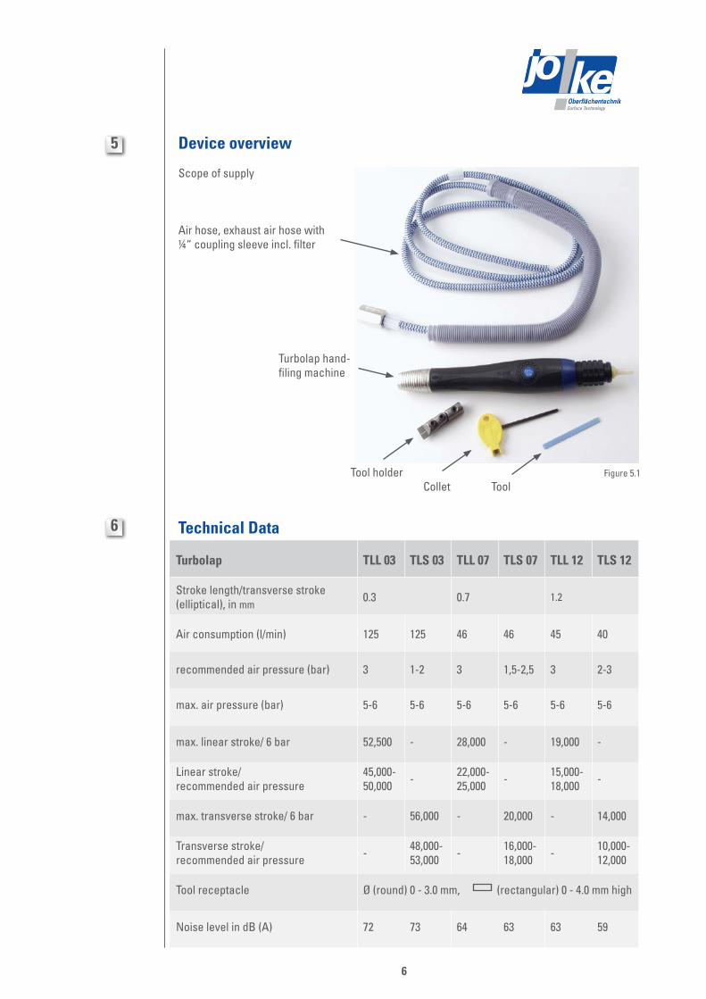
ToolColletTool holder
Air hose, exhaust air hose with ¼“ coupling sleeve incl. filter
Turbolap hand-filing machine
5 Device overview
Scope of supply
Figure 5.1
Technical Data6
Turbolap TLL 03 TLS 03 TLL 07 TLS 07 TLL 12 TLS 12
Stroke length/transverse stroke (elliptical), in mm
0.3 0.7 1.2
Air consumption (l/min) 125 125 46 46 45 40
recommended air pressure (bar) 3 1-2 3 1,5-2,5 3 2-3
max. air pressure (bar) 5-6 5-6 5-6 5-6 5-6 5-6
max. linear stroke/ 6 bar 52,500 - 28,000 - 19,000 -
Linear stroke/recommended air pressure
45,000-50,000 - 22,000-
25,000 - 15,000-18,000 -
max. transverse stroke/ 6 bar - 56,000 - 20,000 - 14,000
Transverse stroke/ recommended air pressure - 48,000-
53,000 - 16,000-18,000 - 10,000-
12,000
Tool receptacle Ø (round) 0 - 3.0 mm, (rectangular) 0 - 4.0 mm high
Noise level in dB (A) 72 73 64 63 63 59

Surface TechnologyOberflächentechnikSurface TechnologyOberflächentechnik
7
area that can be worked
Scope of supply: tool holder, collet, supply air hose 1.5 m, exhaust air hose, connecting sleeve ¼“ incl. filter
Turbolap TLS: the tool operates elliptically (area marked in orange), depending on stroke length.
Turbolap TLL: the tool operates linearly(area marked in orange), depending on stroke length.
toolTLS TLL
7 Operation / Use / Care
Notes on operation • The recommended air pressure for operating the filing handpiece is indicated in chapter 6. An increased air pressure may result in damage to the filing handpiece. • The spindle must be treated particularly carefully during the working process and when at a standstill. Under no circumstances must the spindle be knocked, as the components vital to operation will be damaged as a result. • Pay attention to the permitted cutting speeds and the tool manufacturer’s guidelines before using the tools. • Check that the tool is firmly seated and safely tighten.
Check the maintenance unit regularly. If condensation water and dirt are present, drain off the condensation water and clean the filter (refer to care/maintenance section).i
Wear goggles, protective gloves and hearing protection!!
Filing:The filing handpiece is excellent in combination with a wide selection of tools for precision and deburring work on all steels and non-ferrous alloys. It offers the optimum prerequisites for use in mould building during deburring, grinding and polishing tasks. Tools with a shaft diameter of 3.1 mm and less can be easily clamped. This is possible up to a height of 4.0 mm with flat tools.
Pay attention to proper handling of the device. Do not put any pressure on the tools. The tools should only be guided over the surfaces.Correct clamping of the tools is indispensable. Do not use any distorted or worn files.
Futher technical data:Air consumption: ¼“ female thread (FT)Dimensions in mm: Ø 28 x 218

Surface TechnologyOberflächentechnikSurface TechnologyOberflächentechnik
8
11
12
13
Connecting the filing handpiece
1. Connect the air supply hose of the pneumatic filing handpiece to the maintenance unit.
2. Set a pressure of 6 bars on the maintenance unit. The hand-filing machine is ready for operation.3. Insert the tool in the collet and tighten with the Allen key supplied.4. The device is switched On and Off by operating the rotary knob.
Oiled compressed air must NOT be used in order to guarantee optimum function.i
Tool receptacles
• The linear and transverse stroke hand-filing machines are only intended for manual use.• The tool receptacle is designed such as to accommodate tools with a round shaft Ø of up to 3.1 mm and flat tools of up to 4.0 mm high.
Changing the tool
Use the Allen key. Insert tools depending on their dimensions and position as desired. Tighten the clamping claw and check that the tools are firmly seated.
Usable, reliable tools can be found in the current joke catalogue.i
Maintenance unit and air connection
The maintenance unit must consist of the following functional units: • Water and dirt separator • Pressure gauge
The compressed air needed to drive the compressed air filing machine must be supplied by means of a maintenance unit.
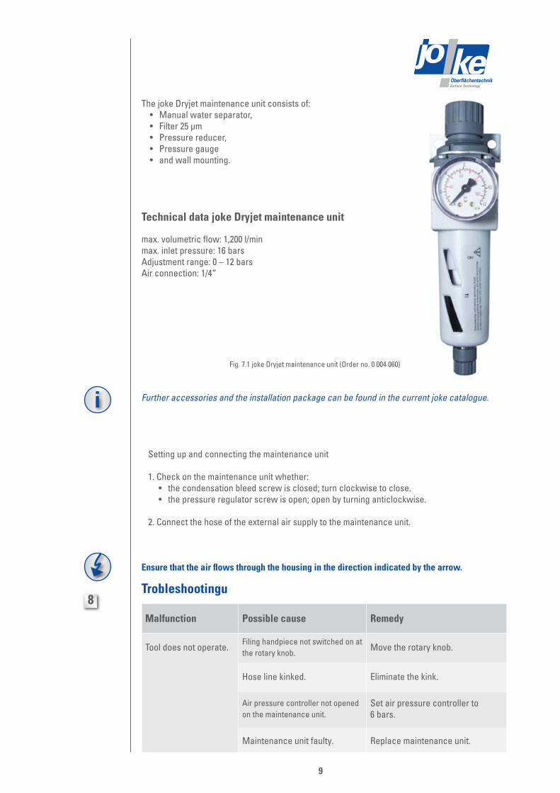
Optimum function of the compressed air filing machine is guaranteed by using the joke Dryjet maintenance unit (order no. 0 004 060). Further accessories and the installation package can be found in the current joke catalogue.
i
Surface TechnologyOberflächentechnikSurface TechnologyOberflächentechnik
9
The joke Dryjet maintenance unit consists of: • Manual water separator, • Filter 25 µm • Pressure reducer, • Pressure gauge • and wall mounting.
Technical data joke Dryjet maintenance unit
max. volumetric flow: 1,200 l/minmax. inlet pressure: 16 barsAdjustment range: 0 – 12 barsAir connection: 1/4“
Further accessories and the installation package can be found in the current joke catalogue.i
Fig. 7.1 joke Dryjet maintenance unit (Order no. 0 004 060)
Setting up and connecting the maintenance unit
1. Check on the maintenance unit whether: • the condensation bleed screw is closed; turn clockwise to close. • the pressure regulator screw is open; open by turning anticlockwise.
2. Connect the hose of the external air supply to the maintenance unit.
Ensure that the air flows through the housing in the direction indicated by the arrow.
Trobleshootingu8
Malfunction Possible cause Remedy
Tool does not operate.Filing handpiece not switched on at the rotary knob.
Move the rotary knob.
Hose line kinked. Eliminate the kink.
Air pressure controller not opened on the maintenance unit.
Set air pressure controller to 6 bars.
Maintenance unit faulty. Replace maintenance unit.

Surface TechnologyOberflächentechnikSurface TechnologyOberflächentechnik
10
Care9
Clean the linear or transverse stroke hand-filing machine if required with a soft brush/paintbrush or a dry cloth.
Maintenance The linear or transverse stroke hand-filing machines are maintenance-free.Bleeding condensate from the air filter of the maintenance unit:
1. Render the maintenance unit free of pressure using a ¼“ ball cock. We recommend a ball cock from the current joke catalogue, which is to be mounted laterally.2. The condensation must be bled off through the drain valve before the maximum filling level is reached. The bleed screw is to be turned clockwise (~90°) and pushed upwards.3. Screw out the air filter and replace or clean it.
Take care that the filter socket and the loose seal are reinstalled with their position unchanged.
4. Screw in the condensate reservoir and perform a functional test. After draining or replacing the filter, loosen the bleed screw and rotate the latter anticlockwise (~90°).5. Supply the maintenance unit with pressure.
Fig. 9.1 joke Dryjet maintenance unit (Order no. 0 004 060)
Condensate reservoir
Filter
Water separator withcondensate bleed screw

Surface TechnologyOberflächentechnikSurface TechnologyOberflächentechnik
11
Surface TechnologyOberflächentechnik
Turbolap TLL 03 Order no. 0 750 702
Turbolap TLL 07 Order no. 0 750 700
Turbolap TLL 12 Order no. 0 750 701
Turbolap TLS 03 Order no. 0 750 709
Turbolap TLS 07 Order no. 0 750 704
Turbolap TLS 12 Order no. 0 750 703
Maintenance unit joke Oiljet Order no. 0 004 060
To
joke Technology GmbHService-department Fax: 0 22 04 / 8 39 - 60
Sender: Company Name/Department
Customer-no.
Street
Post code/town Please send us the spare parts drawing with parts list for the following devices:
as a printout (see above for address, per fax, as a pdf file to my email address.

Surface TechnologyOberflächentechnik
joke Technology GmbHAsselborner Weg 14 -16
D-51429 Bergisch GladbachTel. +49 (0) 22 04 / 8 39-0
Fax +49 (0) 22 04 / 8 39-60Mail [email protected] www.joke.de
© Copyright joke Technology GmbH • Juli 2013 • Changes due to technical progress, errors and printing errors reserved • Reproduction, also partial, only with prior written permission.
Brilliant solutions for perfect surfaces
Surface TechnologyOberflächentechnik