INSTRUCTION MANUAL AQ F213 – Feeder Protection IED
420
INSTRUCTION MANUAL AQ F213 – Feeder Protection IED
-
Upload
khangminh22 -
Category
Documents
-
view
2 -
download
0
Transcript of INSTRUCTION MANUAL AQ F213 – Feeder Protection IED

INSTRUCTION MANUAL
AQ F213 – Feeder Protection IED

Instruction manual –AQ F213 Feeder Protection IED 2 (420)
Revision 1.00
Date 7.12.2015
Changes - The first revision for AQ-F213 IED.
Revision 1.01
Date 30.8.2016
Changes - Added password set up guide (previously only in AQtivate user
guide)
Revision 1.02
Date 10.2.2017
Changes - Order code updated
Revision 1.03
Date 27.2.2017
Changes - Order code updated
- Technical data revised according to ordering code

Instruction manual –AQ F213 Feeder Protection IED 3 (420)
Read these instructions carefully and inspect the equipment to become familiar with it
before trying to install, operate, service or maintain it.
Electrical equipment should be installed, operated, serviced, and maintained only by
qualified personnel. Local safety regulations should be followed. No responsibility is
assumed by Arcteq for any consequences arising out of the use of this material.
We reserve right to changes without further notice.

Instruction manual –AQ F213 Feeder Protection IED 4 (420)
TABLE OF CONTENTS
1 ABBREVIATIONS ............................................................................................................. 8
2 GENERAL ......................................................................................................................... 9
3 IED USER INTERFACE .................................................................................................. 10
3.1 AQ 200 series local panel structure...................................................................... 10
3.1.1 Basic configuration ..................................................................................... 10
3.1.2 Navigation in main configuration menus ...................................................... 12
3.1.3 User level configuration .............................................................................. 39
4 FUNCTIONS OF AQ-F213 FEEDER PROTECTION IED ................................................ 40
4.1 Measurements ..................................................................................................... 42
4.1.1 Current measurement and scaling .............................................................. 42
4.1.2 Voltage measurement and scaling .............................................................. 54
4.1.3 Frequency tracking and sampling ............................................................... 63
4.1.4 Power and energy calculation ..................................................................... 66
4.2 Protection functions ............................................................................................. 75
4.2.1 General properties of a protection function ................................................. 75
4.2.2 Non-directional over current I> (50/51) ........................................................ 90
4.2.3 Non-directional earth fault I0> (50N/51N) .................................................... 97
4.2.4 Directional over current IDir> (67) ............................................................. 103
4.2.5 Directional earth fault I0Dir> (67N) ............................................................ 112
4.2.6 Current unbalance I2> (46) ....................................................................... 122
4.2.7 Harmonic over current IH> (50H/51H/68H) ............................................... 129
4.2.8 Circuit breaker failure protection (CBFP) (50BF) ....................................... 138
4.2.9 Restricted earth fault / cable end differential (REF) I0D> (87N) ................. 152
4.2.10 Thermal overload protection for feeders TF> (49F) .................................... 160
4.2.11 Over voltage U> (59) ................................................................................ 178
4.2.12 Under voltage U< (27)............................................................................... 185
4.2.13 Sequence voltage U1/U2>/< (59P/27P/47) ............................................... 193
4.2.14 Neutral voltage U0> (59N) ........................................................................ 203
4.2.15 Over- and under frequency f>/< (81O/81U) ............................................... 211
4.2.16 Rate-of-change of frequency protection df/dt (81R) .................................. 216
4.2.17 Over power P> (32O) ................................................................................ 222
4.2.18 Under power P< (32U) .............................................................................. 226
4.2.19 Reverse power Pr (32R) ........................................................................... 232
4.2.20 Vector jump Z< (78) .................................................................................. 237
4.2.21 Arc fault protection IArc>/I0Arc>(50Arc/50NArc) ....................................... 242

Instruction manual –AQ F213 Feeder Protection IED 5 (420)
4.3 Control functions ................................................................................................ 250
4.3.1 Setting group selection (SGS) ................................................................... 250
4.3.2 Object control and monitoring (OBJ) ......................................................... 258
4.3.3 Indicator object monitoring (CIN) ............................................................... 267
4.3.4 Programmable control switch .................................................................... 269
4.3.5 Auto-reclosing 0 1 (79) ......................................................................... 269
4.3.6 Cold load pick-up (CLPU) ......................................................................... 300
4.3.7 Switch on to fault (SOTF) .......................................................................... 308
4.4 Monitoring functions ........................................................................................... 311
4.4.1 Current transformer supervision (CTS) ..................................................... 311
4.4.2 Voltage transformer supervision (60) ........................................................ 321
4.4.3 Disturbance recorder (DR) ........................................................................ 324
4.4.4 Measurement recorder .............................................................................. 336
4.4.5 Circuit breaker wear -monitor (CBW) ........................................................ 337
4.4.6 Total harmonic distortion monitor (THD) ................................................... 343
4.4.7 Fault locator .............................................................................................. 348
5 SYSTEM INTEGRATION .............................................................................................. 352
5.1 Communication protocols ................................................................................... 352
5.1.1 NTP .......................................................................................................... 352
5.1.2 ModbusTCP and ModbusRTU .................................................................. 353
5.1.3 ModbusIO ................................................................................................. 354
5.1.4 IEC 61850 ................................................................................................. 355
5.1.5 GOOSE .................................................................................................... 359
5.1.6 IEC 103 ..................................................................................................... 360
5.1.7 DNP3 ........................................................................................................ 361
5.1.8 IEC 101 / 104 ............................................................................................ 361
5.1.9 SPA protocol ............................................................................................. 362
5.2 General IO analog fault registers ....................................................................... 362
6 CONSTRUCTION AND INSTALLATION ....................................................................... 363
6.1 CPU, IO and Power supply module .................................................................... 366
6.1.1 Scanning cycle of the digital input ............................................................. 367

Instruction manual –AQ F213 Feeder Protection IED 6 (420)
6.2 Current measurement module ............................................................................ 367
6.3 3 Voltage channel measurement module ........................................................... 368
6.4 Digital input module DI8 ..................................................................................... 369
6.5 Digital output module DO5 ................................................................................. 370
6.6 Arc protection module (option) ........................................................................... 372
6.7 RTD & mA input module (option) ....................................................................... 373
6.8 Serial RS232 & Serial fiber module (option) ....................................................... 375
6.9 Double LC 100 Mb Ethernet module (option) ..................................................... 376
6.10 RJ-45 & 4 digital input module ........................................................................... 377
6.11 Installation and dimensions ................................................................................ 378
7 APPLICATIONS ............................................................................................................ 381
7.1 2LN+U0 connection example ............................................................................. 381
7.2 3-phase, 3-wire ARON input connection example .............................................. 381
7.3 Trip circuit supervision ....................................................................................... 383
7.3.1 Trip circuit open coil supervision with one digital input and connected trip
output .............................................................................................................. 383
7.3.2 Trip circuit open coil supervision with one digital input and connected and
latched trip output ............................................................................................ 385
8 TECHNICAL DATA ....................................................................................................... 387
8.1 Connections ....................................................................................................... 387
8.1.1 Measurements .......................................................................................... 387
8.1.2 Auxiliary voltage ........................................................................................ 389
8.1.3 Binary inputs ............................................................................................. 390
8.1.4 Binary outputs ........................................................................................... 390
8.1.5 Arc protection card (Option) ...................................................................... 391
8.1.6 Communication ports ................................................................................ 392
8.2 Protection functions ........................................................................................... 393
8.2.1 Current protection functions ...................................................................... 393
8.2.2 Voltage protection functions ...................................................................... 401
8.2.3 Power protection functions ........................................................................ 405
8.2.4 Frequency protection functions ................................................................. 406
8.2.5 Arc protection function .............................................................................. 408
8.3 Control functions ............................................................................................... 409
8.4 Monitoring functions ........................................................................................... 412
8.5 Tests and environmental .................................................................................... 416
8.5.1 Electrical environment compatibility .......................................................... 416
8.5.2 Physical environment compatibility ........................................................... 417
8.5.3 Casing and package ................................................................................. 417

Instruction manual –AQ F213 Feeder Protection IED 7 (420)
9 ORDERING INFORMATION ......................................................................................... 418
10 REFERENCE INFORMATION ...................................................................................... 420

Instruction manual –AQ F213 Feeder Protection IED 8 (420)
1 ABBREVIATIONS
CB – Circuit breaker
CBFP – Circuit breaker failure protection
CT – Current transformer
CPU – Central processing unit
EMC – Electromagnetic compatibility
HMI – Human machine interface
HW – Hardware
IED – Intelligent electronic device
IO – Input output
LED – Light emitting diode
LV – Low voltage
MV – Medium voltage
NC – Normally closed
NO – Normally open
RMS – Root mean square
SF – System failure
TMS – Time multiplier setting
TRMS – True root mean square
VAC – Voltage alternating current
VDC – Voltage direct current
SW – Software
uP - Microprocessor

Instruction manual –AQ F213 Feeder Protection IED 9 (420)
2 GENERAL
The AQ-F213 Feeder Protection IED is a member of the AQ-200 product line. The AQ-200
protection product line in respect of hardware and software is a modular concept. The
hardware modules are assembled and configured according to the application IO
requirements and the software determines the available functions. This manual describes
the specific application of the AQ-F213 Feeder Protection IED. For other AQ-200 series
products please consult corresponding device manuals.

Instruction manual –AQ F213 Feeder Protection IED 10 (420)
3 IED USER INTERFACE
AQ 200 series IED user interface section is divided into hardware- and software user
interface sections. Software interface is divided into local panel configuration and
programming by using AQtivate 200 freeware software suite.
3.1 AQ 200 SERIES LOCAL PANEL STRUCTURE
AQ 200 series IED have multiple LEDs, control buttons and local RJ-45 Ethernet port for
configuration on front as a default. On rear each unit is equipped with RS-485 serial
interface and RJ-45 Ethernet interface options as a standard. See list below.
• 4 default LEDs for free configuration: Power,
Error, Start and Trip.
• 16 freely configurable LEDs with programmable legend texts.
• 3 object control buttons: Choose the controllable object with Ctrl –button, control breaker with 0- and I push buttons.
• L/R push button for local remote control.
• 7 Navigation buttons for IED local programming and a button for password activation.
• RJ-45 Ethernet port for IED configuration.
Figure 3.1-1 AQ-200 series IED local panel structure.
3.1.1 BASIC CONFIGURATION
IED user interface is divided into 5 quick displays. The displays are Events, Favorites,
Mimic, LEDs and Clock. Default quick display is the mimic view and it is possible to glance
through these menus by pressing arrows left and right. Please note that the available quick
display carousel views might be different if user has changed it with AQtivate setting tools
Carousel Designer. Home button transfers the user between quick display carousel and
main configuration menus. Main configuration menus are General, Protection, Control,

Instruction manual –AQ F213 Feeder Protection IED 11 (420)
Communication, Measurements and Monitoring. Available menus vary depending on IED
type. You can choose the main menu by using the four arrow keys and press enter.
Figure 3.1.1-2 AQ-200 series IED basic navigation.
Cancel key takes you one step back or holding it down for 3 seconds takes
you back to general –menu .Cancel key is also used for alarm LEDs reset.
• Padlock button takes user to password menu where it is possible to enter
different user levels (user, operator, configurator and super user).

Instruction manual –AQ F213 Feeder Protection IED 12 (420)
3.1.2 NAVIGATION IN MAIN CONFIGURATION MENUS
All the settings in AQ-200 series IEDs have been divided into main configuration menus.
Main configuration menus are presented below. Available menus may vary according to
IED type.
Figure 3.1.2-3 AQ-200 series IED main configuration menus.

Instruction manual –AQ F213 Feeder Protection IED 13 (420)
3.1.2.1 GENERAL MENU
General menu “ ” includes Device Info- and Function Comments sub-menus.
DEVICE INFO
• Set name and location of the device. • Serial number and SW version of the IED.
• Hardware configuration (order code).
• Source for time synchronization, Internal or
External (internal as default).
• Enable stage forcing (disabled / enabled). When forcing is disabled after using every forced output will restore. Forcing is done individually in info menu of each stage.
• Language selection, all available languages
here (English as default).
• Clear devices events.
• LCD contrast level and setting 0…255 (120 as default).
• Reset latched signals
• Protection/Control/Monitor profile: Displays the status of enabled functions.
Figure 3.1.2.1-4 AQ-200 series IED Device Info sub-menu.

Instruction manual –AQ F213 Feeder Protection IED 14 (420)
3.1.2.2 PROTECTION MENU
Protection menu includes Stage activation sub-menu and sub-menus for different
protection functions like Overcurrent, Earthfault, Seq. and balance and Supporting. Valid
protection functions vary according IED type.
Figure 3.1.2.2-5 AQ-200 series IED Protection menu view. Protection stages vary
according IED type.
Stage activation

Instruction manual –AQ F213 Feeder Protection IED 15 (420)
• Activation of different protection stages is
done in Stage activation –sub menu. Each protection stage and supporting function is disabled as standard.
• Activated menus will appear below the stage
specific sub-menu for example I> appears below Current –module, U< appears below Voltage-module etc.
Figure 3.1.2.2-6 AQ-200 series IED Stage activation sub- menu.
EXAMPLE PROTECTION STAGE
Figure 3.1.2.2-7 AQ-200 series IED stage navigation and modification.
Each protection stage and supportive function has five stage menus Info, Settings,
Registers, IO and Events.

Instruction manual –AQ F213 Feeder Protection IED 16 (420)
INFO-menu
• Function is activated and disabled in Stage
activation menu. It is possible to disable function in Info menu as well.
• Function condition indicates whether the
stages condition is Normal, Start or Trip.
• Measured amplitude can be Peak-to-peak, TRMS or RMS. As a default it is set as RMS. Available measured amplitudes vary.
• Under Characteristic graphs-title you can open graphs related to the protection function.
• Info view has calculator for function starts,
trips and blockings. It is possible to clear calculators by choosing Clear statistics and Clear.
• Measurements display measurements
relevant for the function.
• Active setting group and its settings are all visible in Info menu. Other setting groups can be set in the SETTINGS-menu.
Figure 3.1.2.2-8 Info menu indicates all the details listed below certain protection stage or
function.

Instruction manual –AQ F213 Feeder Protection IED 17 (420)
SETTINGS-menu
Figure 3.1.2.2-9 All group specific settings are done individually in Settings menu.
Stage settings vary according different protection functions. With factory settings only one
group of eight is activated. To enable more groups go to Control menu and select Setting
Groups.

Instruction manual –AQ F213 Feeder Protection IED 18 (420)
REGISTERS-menu
Figure 3.1.2.2-10 AQ-200 series IED stage information is divided into two sections.
Specific fault data of IEDs is stored in operation log under the register. Each of these 12
logs includes pre-fault current, fault current, time stamp and active group during the
triggering. Operation log can be cleared by choosing Clear registers Clear.
Events generated by the specific stage can be checked by going to Stage event register.
General events cannot be cleared.

Instruction manual –AQ F213 Feeder Protection IED 19 (420)
IO-matrix
Figure 3.1.2.2-11 AQ-200 series IED stage information is divided into two sections.
Starting and tripping signals of protection stages are connected to physical outputs in Direct
Output Control menu. It is possible to connect to output relay or to start- trip- or user
configurable LED. In case when stage is internally blocked (DI or other signal) it is possible
to configure an output to indicate that stage is blocked. Connection to outputs can be either
latched |x| or non-latched x.
Stage blocking is done in Blocking Input Control menu. Blocking can be done by using
digital inputs, logical inputs or outputs, stage start- trip- or blocked information or by using
object status information.

Instruction manual –AQ F213 Feeder Protection IED 20 (420)
EVENTS-mask
Figure 3.1.2.2-12 Protection stage related events are masked on and off individually under
EventsEvent mask.
Events are masked off as default. It is possible to activate desired events by masking them
|x|. Only masked events appear to event list. Events cannot be cleared.
3.1.2.3 CONTROL MENU
Control menu “ ” includes Controls Enabled sub-menu and sub-menus for different
control functions like Setting Groups, Objects, Control Functions and Device IO. Valid
control functions vary according IED type.
Figure 3.1.2.3-13 AQ-200 series IED Control menu view. Functions vary according IED
type.

Instruction manual –AQ F213 Feeder Protection IED 21 (420)
CONTROLS ENABLED
• Activation of different control functions is
done in Controls Enabled –sub menu. Each control function is disabled as standard. Active functions will appear below Control Functions –sub menu.
• Activated objects will appear below Objects –
sub menu. Each object is disabled as standard.
Figure 3.1.2.3-14 AQ-200 series IED Controls Enabled sub- menu.
SETTING GROUPS
• Active setting group displays the current
active setting group 1…8. • It is possible to activate desired setting group
by setting the force SG. While doing this Force SG change has to be enabled.
• In Used setting groups menus it is possible
to activate setting groups between 1 and 1…8 (default only 1 group is active).
• Select local control for different setting
groups from SG Local Select. Digital inputs, Logical inputs or outputs, stage starting- tripping- or blocking, RTDs and object status information can be used.
• Event masking for setting groups (masks are
off as default). Only masked events appear to event list. Events cannot be cleared.
Figure 3.1.2.3-15 Setting Groups menu displays all the information related to group
changing.
Setting group 1 has the highest and group 8 the lowest priority. Setting groups can be
controlled with steady signal or pulses.

Instruction manual –AQ F213 Feeder Protection IED 22 (420)
Figure 3.1.2.3-16 Group changing with pulse control only or with pulses and static signal.
OBJECTS
Figure 3.1.2.3-17 AQ-200 series IED object controlling.
Each activated object is visible in Objects-menu. As default all objects are disabled. Each
active object has four setting menus, settings, application control, registers and events.

Instruction manual –AQ F213 Feeder Protection IED 23 (420)
• Control access may be set to Local- or
Remote control (local as default). When local control is enabled it is not possible to control object trough bus and vice versa.
• Type name of the object. As default objects are named as Object1…5.
• Select type of the object between grounding
disconnector, motor controlled disconnector, circuit breaker, and withdraw able circuit breaker (circuit breaker as default).
• Object status can be between Bad, Closed,
Open and Intermediate. Intermediate is the phase between open and closed where both status inputs are equal to zero (0). When both status inputs of the object are one (1) the status of the object is Bad.
• Object withdraw status could be Bad, Cart In,
Cart Out or Intermediate. Intermediate is the phase between open and closed where both status inputs are equal to zero (0). When both status inputs of the cart are one (1) the withdrawn status is Bad.
• Additional status information gives feedback
from the object whether the opening and closing is allowed or blocked, whether the object is ready or the synchronization status is ok.
• Activate Use Synchrocheck or Use Object Ready. Closing the object is forbidden if sides are out of sync or object is not ready to be closed.
Figure 3.1.2.3-18 Info menu indicates all the details listed below certain protection stage or
function.
• Settings-menu also includes statistics for open- and closed requests. Stats can be cleared
by choosing Clear statistics Clear.
• Object has Open- and Close inputs and withdrawable object has In- and Out inputs. Object
Ready- and external Synchrocheck permission have status inputs as well. Digital inputs,
Logical inputs or outputs, stage starting- tripping- or blocking, RTDs and object status
information can be used to indicate the status.

Instruction manual –AQ F213 Feeder Protection IED 24 (420)
• Object open- and close signals of an object are connected to physical output relays.
• Separate timeouts for objects are set in Settings menu. Synchronization wait- and Object
Ready wait timeouts are settable between 0.02…500.00 s (default 200ms, step 20ms). If
time expires the controlling of object fails. Same time settings apply with Maximum close-
and open command pulse lengths. Control Termination Timeout is set to 10 seconds as
default. After the set delay if the controlled object does not respond accordingly the
procedure is terminated and there will be fail message.
• Access level for MIMIC control is selected between User, Operator, Configurator and
Super user. To control MIMIC the terms of user access level (password) has to be fulfilled.
As default the access level is set to Configurator.
• For object local and remote controlling digital inputs can be used. Remote controlling via
bus is configured in protocol level.
Figure 3.1.2.3-19 Object output- and block signal setting.
Object statuses can be connected directly to physical outputs in Signal Connections menu
which is sub-menu to APP CONTR menu. It is possible to connect to output relay or to start-

Instruction manual –AQ F213 Feeder Protection IED 25 (420)
trip- or user configurable LED. Connection to outputs can be either latched |x| or non-latched
x.
Object blocking is done in Blocking Input Control menu. Blocking can be done by using
digital inputs, logical inputs or outputs, stage start- trip- or blocked information or by using
object status information.
• Check chapter 3.1.2.2 for more information
about registers and events.
Figure 3.1.2.3-20 Object registers and events.
CONTROL FUNCTIONS
Figure 3.1.2.3-21 AQ-200 series IED stage navigation and modification.

Instruction manual –AQ F213 Feeder Protection IED 26 (420)
Each enabled control function is listed below Control Functions menu. Every function
includes same sub-menus as protections stages including Info, Settings, Registers, IO and
Events. For further information concerning these sub-menus see chapter 3.1.2.2.
DEVICE IO
• Device IO menu has sub-menus for Binary Inputs, Binary Outputs, LEDs, Logic signals and for general Device IO matrix.
• Binary inputs, Logic
Outputs, protection stage status signals (start, trip & blocked etc.) and object status signals can be connected to output relay or to start- trip- or user configurable LEDs in Device IO matrix.
Figure 3.1.2.3-22 AQ-200 series ID Device IO menu.
Figure 3.1.2.3-23 AQ-200 series IED Binary Inputs menu.
All settings related to binary inputs can be found under the Binary Inputs menu. Binary
inputs Settings menu includes polarity selection for the input (normal open or normal
closed), activation (16…200 VAC/DC, step 0.1V) and release (10…200 VAC/DC, step 0.1V)
threshold voltage for each available input and activation delay (0…1800 s, step 1ms). Binary
input statuses can be check from corresponding menu. For more information related to
event masking see chapter 3.1.2.2.

Instruction manual –AQ F213 Feeder Protection IED 27 (420)
Digital input activation and release threshold follows the measured peak value. Activation
time of input is between 5-10 milliseconds. Activation delay is configurable. Release time
with DC is between 5-10 milliseconds. Release time with AC is less than 25 milliseconds.
Figure 3.1.2.3-24 AQ-200 series IED Binary Outputs menu.
Polarity of binary outputs is configured between normal open (NO) and normal closed (NC)
in Binary Outputs menu. As default polarity is normal open. Operation delay of output
contact is around 5 milliseconds.
Description text for Binary output is configured in Binary Output Descriptions menu. Name
change affects to Matrixes and input –or output selection lists. Names have to be configured
online or updated to the IED via setting file.
NOTE! Normal closed signal goes to default position (normal open) in case the relay loses
the auxiliary voltage or during System full reset. Normally closed output signal does not
open during Communication- or protections reset.

Instruction manual –AQ F213 Feeder Protection IED 28 (420)
Figure 3.1.2.3-25 Object output- and block signal setting.
LED Settings menu has two sub-menus LED Description Settings and LED Color Settings.
In LED Description Settings menu the label text of the LED can be modified. This label is
visible in LEDs quick displays and matrixes. LED color can be chosen between green and
yellow in LED Color Settings menu. As default the color is green.

Instruction manual –AQ F213 Feeder Protection IED 29 (420)
Figure 3.1.2.3-26 AQ-200 series IED Binary Outputs menu.
Binary inputs, Logic Outputs, protection stage status signals (start, trip & blocked etc.) and
object status signals can be connected to output relay or to start- trip- or user configurable
LEDs in Device IO matrix IO Matrix. Connections can be made as latched |x| or non-
latched x. Non-latched output is dis-activated immediately when triggering signal is
disabled. Latched signal stays active until the triggering signal dis-activates and latched
function is cleared.
Clearing latched signals is committed at the mimic display by pressing cancel key “ ”.
• Programmable control switches (PCS) are switches that can be used to control signals in mimic view. These signals can be used in various situations (controlling logic program, function blocking etc.)
• You can give each switch
a name and set access level to determine who can control the switch.
Figure 3.1.2.3-27 AQ-200 series Programmable Control Switch.

Instruction manual –AQ F213 Feeder Protection IED 30 (420)
• 32 logical input signal status bits. Status is either 0 or 1.
• 32 quality bits of logical
input signals (GOOSE). Status is either 0 or 1. 1 stands for bad/invalid quality.
• 32 logical output signal
status bits. Status is either 0 or 1.
Figure 3.1.2.3-28 AQ-200 series IED Logical signals.
Logical signals are mainly used for control purposes via IEC-61850 and GOOSE or other
protocols with similar purpose. Logical Inputs Quality bit checks the condition of logical
input. Logical Outputs can be used when building programmable logic. Activating logic gate
won’t make event but when logical output is connected to the logic gate it is possible to
create an event of the gate activation. Logical inputs and outputs have on and off events
those can be masked on (off as default). For more information related to event masking see
chapter 3.1.2.2.
Note! System integration chapter gives more details of use of the logical signals generally.
3.1.2.4 COMMUNICATION MENU
Communication menu includes Connections and Protocols sub-menus. AQ-200
series IEDs can be configured through rear Ethernet by using Aqtivate 200 setting and
configuration software suite. IP address of the IED can be checked from the Connections
menu. AQ-200 series IEDs support following communication protocols: SNTP, IEC61850,
ModbusTCP, ModbusRTU, IEC103 and ModbusIO as a standard. It is also possible to have
additional protocols with special extra communication interface modules.

Instruction manual –AQ F213 Feeder Protection IED 31 (420)
CONNECTIONS-menu
• IP address of the IED is user settable.
Default IP-address varies from device to another.
• Network subnet mask is entered here.
• Gateway is configured only when
communicating with IEDs in separate subnet.
• Bitrate of the RS-485 serial communication interface is 9600 bps as standard but can be changed to 19200 or 38400 bps in case the external device supports faster speed.
• Databits, parity and stopbits can be set
according the connected external devices.
• As default the IED does not have any serial protocol activated (None) but IEC103, ModbusIO and Modbus RTU can be used for communication.
Figure 3.1.2.4-29 AQ-200 series IED Connections sub- menu.
Note! When communicating with IED via front Ethernet port the IP address is always
192.168.66.9.
• SNTP protocol is used for time
synchronization over Ethernet. It can be used at the same time with ModbusTCP and IEC61850 protocols.
• ModbusTCP can be used at the same time
with other Ethernet based protocols like SNTP and IEC61850.
• ModbusRTU / IEC103 / ModbusIO
configuration menus. ModbusRTU like other serial protocols can be used only one at the time over one physical serial communication interface.
Figure 3.1.2.4-30 AQ-200 series IED Protocols sub- menu.

Instruction manual –AQ F213 Feeder Protection IED 32 (420)
See more detailed information about communications options in chapter System integration.
3.1.2.5 MEASUREMENT MENU
Measurement menu includes sub-menus for Transformers, Frequency, Current
Measurement, Voltage measurement and Phasors depending of the IED type. Ratio of used
current and voltage transformers is defined in Transformers sub-menu. System nominal
frequency is specified in Frequency sub-menu. Other sub-menus menus under
Measurement menu are mainly for monitoring purposes.
TRANSFORMERS
• Phase CT scaling, Residual I01- and Residual I02 CT scaling determines the ratio of used transformers.
• According to IED type it is
possible to have voltage transformer scaling and other similar in transformers menu.
• Some IEDs like S214 won’t
necessarily have CTs or VTs at all.
Figure 3.1.2.5-31 AQ-200 series IED current- and voltage transformer ratio is set in
Transformers sub-menu.
Among ratio settings the nominal values are determined in Transformers menu as well.
Sometimes it is possible that due wiring the polarity has to be changed because of mistake
or other similar reason. In AQ-200 series IEDs it is possible to individually invert polarity of
each phase current. Transformers menu also displays more information like scaling factors
for CTs and per unit values.

Instruction manual –AQ F213 Feeder Protection IED 33 (420)
FREQUENCY
• Sampling mode is fixed as standard and System nominal frequency should be set to desired level. In case the Sampling mode is set as tracking the IED will use measured frequency value as system nominal frequency.
• Frequency has three
reference measuring points. The order of reference point can be changed.
Figure 3.1.2.5-32 AQ-200 series IED Frequency settings menu.
CURRENT AND VOLTAGE MEASUREMENT
Figure 3.1.2.5-33 AQ-200 series IED Measurement menu.
Measurement menu includes sub-menus for different Current- and Voltage measurements.
Individual measurements can be found for each phase- or phase- to phase measurement.
Sub-menus are divided into four groups which are Per-Unit, Primary, Secondary and Phase
Angle.
Per-unit group has values for fundamental component, TRMS, amplitude- and power THD
and peak- to peak values. Primary group has values for fundamental component and TRMS
and same applies with Secondary group. Phase Angle group displays the angle of each
measured component.

Instruction manual –AQ F213 Feeder Protection IED 34 (420)
Figure 3.1.2.5-34 AQ-200 series IED Sequence components.
Sequence components including positive, negative and neutral components are calculated
for both voltage and current. Sequence sub-menu is divided into four groups which are Per-
Unit, Primary, Secondary and Phase Angle. Each group has calculation for positive,
negative and neutral sequence components.
Figure 3.1.2.5-35 AQ-200 series IED Harmonics view.
Harmonics menu displays voltage and current harmonics from fundamental component up
to 31th harmonic. It is possible to select whether each component is displayed as Absolute-
or Percentage and as primary or secondary amps or per unit values.

Instruction manual –AQ F213 Feeder Protection IED 35 (420)
PHASORS
Figure 3.1.2.5-36 AQ-200 series IED Phasors sub-menu.
Measurement Phasors have vector displays for voltage and currents. Also calculated
components have own vector displays. Vectors can be seen in own display and additionally
per unit values of measured or calculated components along with secondary and primary
amplitudes are shown. Phasors are handy when it comes to solving incorrect wiring issues.
3.1.2.6 MONITORING MENU
Monitoring menu includes Monitoring Enabled, Monitoring Functions, Disturbance
REC and Device Diagnostics sub-menus. Valid Monitor functions vary according IED type.
Figure 3.1.2.6-37 AQ-200 series IED Monitoring menu view. Monitor functions vary
according IED type.

Instruction manual –AQ F213 Feeder Protection IED 36 (420)
MONITORS ENABLED
• Activation of different monitor functions is
done in Monitors Enabled sub-menu. Each Monitoring function is disabled as standard.
• Activated menus will appear in the Monitor
functions sub-menu.
Figure 3.1.2.6-38 AQ-200 series IED Monitors Enabled sub- menu.
MONITOR FUNCTIONS
• Monitor functions vary according IED type.
Figure 3.1.2.6-39 AQ-200 series IED function modification.
Configuring monitor functions is very similar to configuring protection stages. See chapter 3.1.2.2
for more information.

Instruction manual –AQ F213 Feeder Protection IED 37 (420)
DISTURBANCE REC
• Manual Trigger triggers the recording
instantly once when used. • It is possible to clear the latest, oldest or
every stored recording at once.
• Maximum length of recording depends of the amount chosen channels and sample rate. Maximum amount of recording depend of amount of channels, sample rate and length of the file.
• Amount of recording in memory can be
checked.
• Nothing is triggering the recorder as standard. It is possible to choose binary input, logical input or output, start-, trip- or block signal of stage, object position and many other signals to trigger the recorder.
• Recording length is settable between
0.1…1800 seconds.
• Recording mode is either First in First out or Keep Olds. Sample rate of analogue channels is 8/16/32/62 samples per cycle. Digital channel sample rate is fixed 5 ms. Pre triggering time is selectable between 5…95%.
Figure 3.1.2.6-40 Setting disturbance recorder.
AQ-200 series IED is capable to record nine analogue channels. Every measured current
or voltage signal can be selected to be recorded.
Auto. Get recordings uploads recordings automatically to FTP folder. Due this any FTP
client can read recordings from the IED memory.
Digital channels include primary and secondary amplitudes and currents, calculated signals,
TRMS values, sequence components, inputs and outputs and much more.

Instruction manual –AQ F213 Feeder Protection IED 38 (420)
DEVICE DIAGNOSTICS
• AQ-200 series IED Device Diagnostics gives
detailed feedback of the IED condition generally and whether option cards are installed correctly without problems.
• In case anything abnormal is noticed in Device diagnostics menu and it cannot be reset please contact closest representative or manufacturer.
Figure 3.1.2.6-41 Self diagnostics sub-menu.

Instruction manual –AQ F213 Feeder Protection IED 39 (420)
3.1.3 USER LEVEL CONFIGURATION
As a factory default IEDs come without user level settings activated. In order to activate
different user levels click the IED HMI lock button and set the desired passwords for different
user levels.
NOTE: Passwords can be set only at local HMI.
In the HMI the user level currently in use is indicated in the upper right corner with stars.
Different user levels and the indicators are:
SUPERUSER (***) = full access including configurations
CONFIGURATOR (**) = access to all settings
OPERATOR (*) = access to limited settings and control
USER ( - ) = view only
You can set a new password for the user level by selecting the key icon next to the user
level. After this you can lock the user level by pressing return key while the lock is selected.
If you need to change the password you can select the key icon again and give a new
password. Please note that in order to do this the user level must be unlocked.

Instruction manual –AQ F213 Feeder Protection IED 40 (420)
4 FUNCTIONS OF AQ-F213 FEEDER PROTECTION IED
This chapter presents the functions of AQ-F213 Feeder Protection relay with each function
package. AQ-F213 includes following functions and amounts of instances of the functions.
Table 4-1 Protection functions of AQ-F213
Function package
Name IEC ANSI Description A B C D E
NOC(4) I> 50/51 Overcurrent protection (4 stages)
NEF(4) I0> 50N/51N Earth fault protection (4 stages)
CUB(4)
I2> 46/46R/46L
Negative sequence overcurrent /
phase current reversal /
unbalance protection (4 stages)
HOC(4) Ih>
Ih>>
Ih>>>
Ih>>>>
50h/51h/68h
Detection and blocking or tripping
from selectable 2nd, 3rd, 4th, 5th
or 7th harmonic. Phase currents
and residual currents separate
stages. (4 stages)
DOC(4) IDir> 67
Directional overcurrent protection
(4 stages)
DEF(4) I0Dir> 67N
Directional residual overcurrent
protection (4 stages)
CBF(1) CBFP 50BF/52BF Breaker failure protection
REF(1)
I0d> 87N
Low or high impedance restricted
earth fault, cable end differential
protection
TOLF1 TF> 49L
Feeder thermal overload
protection
OV(4) U>
U>>
U>>>
U>>>>
59 Overvoltage protection (4 stages)
UV(4) U<
U<<
U<<<
U<<<<
27 Undervoltage protections (4
stages)
NOV(4) U0>
U0>>
U0>>>
U0>>>>
59N Neutral voltage protection (4
stages)
FRQV1
f>,f>>,f>>>,f>>>>
f<,f<<,f<<<,f<<<< 81O/81U Frequency protection (8 stages)
VUB(4) U1&U2>/<_1
U1&U2>/<_2
U1&U2>/<_3
U1&U2>/<_4
59P/27P/47 Sequence voltage protection (4
stages)
OPW(1) P> 32O Over power

Instruction manual –AQ F213 Feeder Protection IED 41 (420)
UPW(1) P< 32U Under power
RPW(1) Pr 32R Reverse power
ROCOF1
df/dt >/< (1…8)
81R
Rate of change of frequency (8
stages)
IMP(1) Z< 78 Vector Jump
IEF(1) I0Int> 67NT Intermittent earth fault
ARC(1) IArc>/I0Arc> 50Arc/50NArc Arc protection (Option)
Table 4-2 Control functions of AQ-F213
Function package
Name IEC ANSI Description A B C D E
SG - - Set group settings
OBJ - - Object control
AR 0 1 79 Autoreclosing function
CLP CLPU - Cold load pick-up
SOF SOTF - Switch on to fault logic
SYN ΔV/Δa/Δf 25 Synchrocheck function
Table 4-3 Monitoring functions of AQ-F213
Function package
Name IEC ANSI Description A B C D E
CTS - - Current transformer supervision
VTS - 60 Fuse failure
DR - - Disturbance recorder
CBW - - Circuit breaker wear monitor
THD - - Total harmonic distortion
FLOC - 21FL Fault locator

Instruction manual –AQ F213 Feeder Protection IED 42 (420)
Table 4-4 Measurement functions of AQ-F213
Function package
Measurement function A B C D E
Currents (IL1,IL2,IL3,I01,I02)
Voltages (U1,U2,U3)
Power (P,Q,S & PF)
Energy (E+, E-, Eq+, Eq-)
Voltage and current harmonics
4.1 MEASUREMENTS
4.1.1 CURRENT MEASUREMENT AND SCALING
In AQ-2xx series current measurement module (CT-module) is used for measuring the
currents from current transformers and processing the measured currents to measurement
database and for use of measurement- and protection functions. For the measurements to
be correct it is essential to understand the concept of the AQ-2xx series IEDs current
measurements.
- PRI
o Primary current, the current
which flows in the primary circuit
and through primary side of the
current transformer.
- SEC
o Secondary current, the current
which the current transformer
transforms according to its ratios.
This current is measured by the
protection IED.
- NOM
o Nominal primary current of the
load. Load in this means can be
any electrical apparatus which
produces or consumes electricity
and has rated value for when it is
producing or consuming
electricity in its rated conditions.
Figure 4.1.1-1 Current measurement terminology in AQ-2xx platform

Instruction manual –AQ F213 Feeder Protection IED 43 (420)
For the measurements to be correct it needs to be made sure that the measurement signals
are connected to correct inputs, current direction is connected correctly and the scaling is
set correctly.
For the scaling relay calculates scaling factors based onto the set CT primary, secondary
and nominal current values. Relay measures secondary current which in this case mean
the current output from the current transformer which is installed into the primary circuit of
the application. In order the relay to “know” primary and per unit values it needs to be told
the current transformer rated primary and secondary currents. In case of motor or any
specific electrical apparatus protection the relay needs to be told also the motors nominal
current in order that the settings can be per unitized to apparatus nominal not to CT nominal
(This is not absolutely mandatory, in some relays it is still needed to calculate correct
settings manually. Setting the relay nominal current makes the motor protection a lot easier
and straight forward. In modern protection IED like AQ-2xx series devices this scaling
calculation is done internally after the current transformer primary, secondary and motor
nominal currents are given). Also in the AQ-2xx series feeder protection IEDs the scaling
can be set according to protected object nominal current.
Normally the primary current ratings for phase current transformers are 10A, 12.5A, 15A,
20A, 25A, 30A, 40A, 50A, 60A and 75A and their decimal multiples, while normal secondary
current ratings are 1 and 5A. For AQ-2xx series devices also other, non-standard ratings
can be directly connected since the scaling settings are flexible in large ranges. For ring
core current transformers the ratings may be different. Ring core current transformers are
commonly used for sensitive earth fault protection and their rated secondary may be as low
as 0.2 A in some cases.
In following chapter is given example for the scaling of the relay measurements to the
example current transformers and system load.
4.1.1.1 CT SCALING EXAMPLE
The connection of CTs to the IED measurement inputs and the ratings of the current
transformers and load nominal current are as in following figure.

Instruction manual –AQ F213 Feeder Protection IED 44 (420)
Figure 4.1.1.1-2 Example connection.
Initial data of the connection and the ratings are presented in following table.
Table 4.1.1.1-5 Initial data from example connection.
Phase current CT:
CT primary 100A
CT secondary 5A
Ring core CT in Input I02:
I0CT primary 10A
I0CT secondary 1A
Load nominal 36A
Phase currents are connected to summing “Holmgren” connection into the I01
residual input.
Phase current CT secondary currents starpoint is towards the line.
For the scaling of the currents to per unit values for the protections selection needs to be
made now if the protected object nominal current or the CT primary value should be the
base for per unitizing.
If the per unit scaling is wanted to be according to the CT values then “Scale meas to In” is
set to “CT nom p.u.” As presented in the figure below.

Instruction manual –AQ F213 Feeder Protection IED 45 (420)
Figure 4.1.1.1-3 Phase current transformer scalings to CT nominal.
After the settings are input to the IED, scaling factors are also calculated and displayed for
the user. Scaling factor P/S tells the CT primary to secondary ratio, CT scaling factor to
NOM tells the scaling factor to nominal current (in this case it should be 1 since the selected
nominal current is the phase CT nominal). Per unit scaling factors to primary and secondary
values are also shown. In this case the scaling factors are directly the set primary and
secondary currents of the set CT.
If the settings would be wanted to be scaled to load nominal then the selection “Scale meas
to In” would be set to “Object In p.u.”
Figure 4.1.1.1-4 Phase current transformer scalings to protected object nominal current.

Instruction manual –AQ F213 Feeder Protection IED 46 (420)
When measurement scaling is made to the protected object nominal current, the object
nominal current needs also to be set into the “Nominal current In” input. The differences in
the used scaling factors can now be seen. Primary to secondary ratio is directly the ratio of
the set CT ratios, CT scaling factor to nominal is now the set CT primary to nominal current
ratio, per unit scalings to primary is changed now to nominal current and the secondary per
unit factor is calculated accordingly to the given ratio of CT primary to object nominal
current.
If coarse residual current (I01) is wanted to be used for CT sum (Holmgren) input then it
should be set to phase current CT ratings 100/5A.
Figure 4.1.1.1-5 Residual current I01 scaling to summing connection.
For the sensitive residual current (I02) measurement is set directly 10/1A rated currents.
Figure 4.1.1.1-6 Residual current I02 scaling to ring core CT input.
If the scaling was made to CT primary or to object nominal current the measurements will
look as follows with nominal current feeding:
Figure 4.1.1.1-7 Scalings to CT nominal.

Instruction manual –AQ F213 Feeder Protection IED 47 (420)
Figure 4.1.1.1-8 Scalings to protected object nominal current.
As seen from the examples the primary and secondary currents will be displayed as actual
values so the scaling selection does not have effect to that. Only effect is now that the per
unit system in the relay is scaled to either transformer nominal or the protected object
nominal and this makes the settings input for the protected object straight forward.
4.1.1.2 TROUBLESHOOTING
It is possible that for some reason the measured currents may not be as expected. For
these cases following checks may be helpful.
Problem Check / Resolution
Measured current amplitude in all phases does not
match for what is injected.
Scaling settings may be wrong, check from
Measurement, Transformers, Phase CT scaling that
the settings match for what is expected. Also check
that the scaling measurement to In is set accordingly
either to “Object In“or CT nominal. If working with
CT:s, if possible check the actual ratings from the CT:s
as well, since in some cases the actual CT:s may have
been changed from the original plan for some reason.
Measured current amplitude does not match for one
measured phase or calculated I0 is measured when
there should not be any.
Check wiring connections from injection device or CTs
to the IED. NOTE: If working with CTs which are in
energized system extreme caution should be practiced
when checking connections. Opened CT secondary
circuit may generate dangerously high voltages.
“Buzzing” sound from connector can indicate open
circuit.
Measured current amplitudes are all ok and equal but
the angles are strange.
Phase unbalance protection trips immediately when it
is activated.
Earth fault protection trips immediately when it is
activated.
Phase currents are connected into the measurement
module, but the order or polarity of one or all phases is
incorrect.
Go to Measurement, Phasors and check the current
Phasors diagram.
When all is correctly connected the diagram should
look as below with symmetric feeding:
In following rows few most common cases are
presented

Instruction manual –AQ F213 Feeder Protection IED 48 (420)
Phase polarity problems are easy to find since the vector diagram points out the opposite polarity in the wrongly
connected phase.
Phase L1 (A) polarity incorrect.
Measurements:
Phase currents Sequence currents
IL1: 1.00 xIn / 0.00 deg
IL2: 1.00 xIn / 60.00 deg
IL3: 1.00 xIn / 300.00 deg
I1: 0.33 xIn / 180.00 deg
I2: 0.67 xIn / 0.00 deg
I0Calc: 0.67 xIn / 0.00 deg
Resolution:
- Change wires to opposite in CT module connectors 1
– 2
- Or from the Transformers, Phase CT scaling select
IL1 polarity to “Invert”.
Phase L2 (B) polarity incorrect.
Measurements:
Phase currents Sequence currents
IL1: 1.00 xIn / 0.00 deg
IL2: 1.00 xIn / 60.00 deg
IL3: 1.00 xIn / 120.00 deg
I1: 0.33 xIn / 0.00 deg
I2: 0.67 xIn / -60.00 deg
I0Calc: 0.67 xIn / 60.00 deg
Resolution:
- Change wires to opposite in CT module connectors 3
– 4
- Or from the Transformers, Phase CT scaling select
IL2 polarity to “Invert”.
Phase L3 (C) polarity incorrect.
Measurements:
Phase currents Sequence currents
IL1: 1.00 xIn / 0.00 deg
IL2: 1.00 xIn / 240.00 deg
IL3: 1.00 xIn / 300.00 deg
I1: 0.33 xIn / 0.00 deg
I2: 0.67 xIn / 60.00 deg
I0Calc: 0.67 xIn / -60.00 deg
Resolution:
- Change wires to opposite in CT module connectors 5
– 6
- Or from the Transformers, Phase CT scaling select
IL3 polarity to “Invert”.
Network rotation / mixed phases problem might be difficult to find since the measurement result shall always be
the same in the relay. If two phases are mixed together the network rotation shall always look like IL1-IL3-IL2 and
the measured negative sequence current shall be always 1.00 per unit if this is the case.
Phase L1 (A) and L2 (B) switch place (network rotation
wrong).
Measurements:
Phase currents Sequence currents
IL1: 1.00 xIn / 0.00 deg
IL2: 1.00 xIn / 120.00 deg
IL3: 1.00 xIn / 240.00 deg
I1: 0.00 xIn / 0.00 deg
I2: 1.00 xIn / 0.00 deg
I0Calc: 0.00 xIn / 0.00 deg
Resolution:
- Change wires to opposite in CT module connectors 1
- 3

Instruction manual –AQ F213 Feeder Protection IED 49 (420)
Phase L2 (B) and L3 (C) switch place (network rotation
wrong).
Measurements:
Phase currents Sequence currents
IL1: 1.00 xIn / 0.00 deg
IL2: 1.00 xIn / 120.00 deg
IL3: 1.00 xIn / 240.00 deg
I1: 0.00 xIn / 0.00 deg
I2: 1.00 xIn / 0.00 deg
I0Calc: 0.00 xIn / 0.00 deg
Resolution:
- Change wires to opposite in CT module connectors 3
- 5
Phase L3 (C) and L1 (A) switch place (network rotation
wrong).
Measurements:
Phase currents Sequence currents
IL1: 1.00 xIn / 0.00 deg
IL2: 1.00 xIn / 120.00 deg
IL3: 1.00 xIn / 240.00 deg
I1: 0.00 xIn / 0.00 deg
I2: 1.00 xIn / 0.00 deg
I0Calc: 0.00 xIn / 0.00 deg
Resolution:
- Change wires to opposite in CT module connectors 1
- 5
4.1.1.3 SETTINGS
Table 4.1.1.3-6 Settings of the Phase CT scaling in AQ-2xx.
Name Range Step Default Description
Scale meas to In 0:CT nom p.u.
1:Object In p.u.
- 0:CT nom p.u. Selection of the IED per unit system
scaling reference, either the set phase
current CT primary or protected object
nominal current.
Phase CT primary 1…5000.0 A 0.1A 100.0A Rated primary current of the CT in
amperes.
Phase CT secondary 0.2…10.0 A 0.1A 5.0A Rated secondary current of the CT in
amperes.
Nominal current In 1…5000A 0.01A 100.00A Protected object nominal current in
amperes. (This setting is visible if “Scale
meas to In” setting is set to “Object In
p.u.”)
IL1 Polarity 0:-
1:Invert
- 0:- IL1 (first current) measurement channel
polarity (direction) selection. Default
setting is that positive current flow is from
connector 1 to connector 2 and the
secondary currents starpoint is towards
line.
IL2 Polarity 0:-
1:Invert
- 0:- IL2 (second current) measurement
channel polarity (direction) selection.
Default setting is that positive current flow
is from connector 3 to connector 4 and
the secondary currents starpoint is
towards line.
IL3 Polarity 0:-
1:Invert
- 0:- IL3 (third current) measurement channel
polarity (direction) selection. Default
setting is that positive current flow is from
connector 5 to connector 6 and the

Instruction manual –AQ F213 Feeder Protection IED 50 (420)
secondary currents starpoint is towards
line.
CT scaling factor P/S - - - IED feedback value, this is the calculated
scaling factor for primary /secondary
current ratio
CT scaling factor
NOM
- - - IED feedback value, this is the calculated
ratio in between of set primary and
nominal currents.
Ipu scaling primary - - - IED feedback value, scaling factor from
p.u. value to primary current.
Ipu scaling
secondary
- - - IED feedback value, scaling factor from
p.u. value to secondary current.
Table 4.1.1.3-7 Settings of the residual I01 CT scaling in AQ-2xx.
Name Range Step Default Description
I01 CT primary 1…5000.0 A 0.1A 100.0A Rated primary current of the CT in
amperes.
I01 CT secondary 0.2…10.0 A 0.1A 5.0A Rated secondary current of the CT in
amperes.
I01 Polarity 0:-
1:Invert
- 0:- I01 (coarse residual) measurement
channel polarity (direction) selection.
Default setting is that positive current flow
is from connector 7 to connector 8.
CT scaling factor P/S - - - IED feedback value, this is the calculated
scaling factor for primary /secondary
current ratio
Table 4.1.1.3-8 Settings of the residual I02 CT scaling in AQ-2xx.
Name Range Step Default Description
I02 CT primary 1…5000.0 A 0.1A 100.0A Rated primary current of the CT in
amperes.
I02 CT secondary 0.1…10.0 A 0.1A 5.0A Rated secondary current of the CT in
amperes.
I02 Polarity 0:-
1:Invert
- 0:- I02 (fine residual) measurement channel
polarity (direction) selection. Default
setting is that positive current flow is from
connector 9 to connector 10.
CT scaling factor P/S - - - IED feedback value, this is the calculated
scaling factor for primary /secondary
current ratio
4.1.1.4 MEASUREMENTS
Following measurements are available from the measured current channels.
Table 4.1.1.4-9 Per unit phase current measurements in AQ-2xx.
Name Range Step Description
Phase current ILx 0.00…1250.0 xIn 0.01xIn Per unit measurement from each phase
current channel fundamental frequency
RMS current.

Instruction manual –AQ F213 Feeder Protection IED 51 (420)
Phase current ILx TRMS 0.00…1250.0 xIn 0.01xIn Per unit measurement from each current
channel TRMS current including
harmonics up to 31st.
Peak to peak current ILx 0.00…500.0 xIn 0.01xIn Per unit measurement peak to peak
current from each phase current
measurement channel.
Table 4.1.1.4-10 Primary phase current measurements in AQ-2xx.
Name Range Step Description
Primary Phase current
ILx
0.00…1000000.0A 0.01A Primary measurement from each phase
current channel fundamental frequency
RMS current.
Phase current ILx TRMS
pri
0.00…1000000.0A 0.01A Primary measurement from each current
channel TRMS current including
harmonics up to 31st.
Table 4.1.1.4-11 Secondary phase current measurements in AQ-2xx.
Name Range Step Description
Secondary Phase current
ILx
0.00…300.0A 0.01A Secondary measurement from each
phase current channel fundamental
frequency RMS current.
Phase current ILx TRMS
sec
0.00…300.0A 0.01A Secondary measurement from each
current channel TRMS current including
harmonics up to 31st.
Table 4.1.1.4-12 Phase current angles measurements in AQ-2xx.
Name Range Step Description
Phase angle ILx 0.00…360.00 deg 0.01deg Phase angle measurement of the three
phase current inputs.
Table 4.1.1.4-13 Per unit residual current measurements in AQ-2xx.
Name Range Step Description
Residual current I01 0.00…1250.0 xIn 0.01xIn Per unit measurement from residual
current channel I01 fundamental
frequency RMS current.
Residual current I02 0.00…1250.0 xIn 0.01xIn Per unit measurement from residual
current channel I02 fundamental
frequency RMS current.
Calculated I0 0.00…1250.0 xIn 0.01xIn Per unit measurement from calculated I0
current fundamental frequency RMS
current.
Phase current I01 TRMS 0.00…1250.0 xIn 0.01xIn Per unit measurement from I01 residual
current channel TRMS current including
harmonics up to 31st.
Phase current I02 TRMS 0.00…1250.0 xIn 0.01xIn Per unit measurement from I02 residual
current channel TRMS current including
harmonics up to 31st.
Peak to peak current I01 0.00…500.0 xIn 0.01xIn Per unit measurement peak to peak
current from I01 residual current
measurement channel.
Peak to peak current I02 0.00…500.0 xIn 0.01xIn Per unit measurement peak to peak
current from I02 residual current
measurement channel.

Instruction manual –AQ F213 Feeder Protection IED 52 (420)
Table 4.1.1.4-14 Primary residual current measurements in AQ-2xx.
Name Range Step Description
Primary residual current
I01
0.00…1000000.0A 0.01A Primary measurement from residual
current channel I01 fundamental
frequency RMS current.
Primary residual current
I02
0.00…1000000.0A 0.01A Primary measurement from residual
current channel I02 fundamental
frequency RMS current.
Primary calculated I0 0.00…1000000.0A 0.01A Primary measurement from calculated I0
fundamental frequency RMS current.
Residual current I01
TRMS pri
0.00…1000000.0A 0.01A Primary measurement from residual
current channel I01 TRMS current
including harmonics up to 31st.
Residual current I02
TRMS pri
0.00…1000000.0A 0.01A Primary measurement from residual
current channel I02 TRMS current
including harmonics up to 31st.
Table 4.1.1.4-15 Primary residual current measurements in AQ-2xx.
Name Range Step Description
Secondary residual
current I01
0.00…300.0A 0.01A Secondary measurement from residual
current channel I01 fundamental
frequency RMS current.
Secondary residual
current I02
0.00…300.0A 0.01A Secondary measurement from residual
current channel I02 fundamental
frequency RMS current.
Secondary calculated I0 0.00…300.0A 0.01A Secondary measurement from calculated
I0 fundamental frequency RMS current.
Residual current I01
TRMS sec
0.00…300.0A 0.01A Secondary measurement from residual
current channel I01 TRMS current
including harmonics up to 31st.
Residual current I02
TRMS sec
0.00…300.0A 0.01A Secondary measurement from residual
current channel I02 TRMS current
including harmonics up to 31st.
Table 4.1.1.4-16 Residual current angles measurements in AQ-2xx.
Name Range Step Description
Residual current angle
I01
0.00…360.00 deg 0.01deg Residual current angle measurement of
the I01 current input.
Residual current angle
I02
0.00…360.00 deg 0.01deg Residual current angle measurement of
the I02 current input.
Calculated I0 phase
angle
0.00…360.00 deg 0.01deg Calculated residual current angle
measurement.
Table 4.1.1.4-17 Per unit sequence current measurements in AQ-2xx.
Name Range Step Description
Positive sequence
current
0.00…1250.0 xIn 0.01xIn Per unit measurement from calculated
positive sequence current
Negative sequence
current
0.00…1250.0 xIn 0.01xIn Per unit measurement from calculated
negative sequence current
Zero sequence current 0.00…1250.0 xIn 0.01xIn Per unit measurement from calculated
zero sequence current

Instruction manual –AQ F213 Feeder Protection IED 53 (420)
Table 4.1.1.4-18 Primary sequence current measurements in AQ-2xx.
Name Range Step Description
Primary Positive
sequence current
0.00…1000000.0A 0.01A Primary measurement from calculated
positive sequence current
Primary Negative
sequence current
0.00…1000000.0A 0.01A Primary measurement from calculated
negative sequence current
Primary Zero sequence
current
0.00…1000000.0A 0.01A Primary measurement from calculated
zero sequence current
Table 4.1.1.4-19 Secondary sequence current measurements in AQ-2xx.
Name Range Step Description
Secondary Positive
sequence current
0.00…300.0A 0.01A Secondary measurement from calculated
positive sequence current
Secondary Negative
sequence current
0.00…300.0A 0.01A Secondary measurement from calculated
negative sequence current
Secondary Zero
sequence current
0.00…300.0A 0.01A Secondary measurement from calculated
zero sequence current
Table 4.1.1.4-20 Sequence current angle measurements in AQ-2xx.
Name Range Step Description
Positive sequence
current angle
0.00…360.0deg 0.01deg Calculated positive sequence current
angle
Negative sequence
current angle
0.00…360.0deg 0.01deg Calculated negative sequence current
angle
Zero sequence current
angle
0.00…360.0deg 0.01deg Calculated zero sequence current angle
Table 4.1.1.4-21 Harmonic current measurements in AQ-2xx.
Name Range Step Description
IL1 Harmonics
IL1 fund…IL1 31harm
0.00…1000000.0
A
0.01A Per unit, primary and secondary
harmonics per component for
current input IL1
IL2 Harmonics
IL2 fund…IL2 31harm
0.00…1000000.0
A
0.01A Per unit, primary and secondary
harmonics per component for
current input IL2
IL3 Harmonics
IL3 fund…IL3 31harm
0.00…1000000.0
A
0.01A Per unit, primary and secondary
harmonics per component for
current input IL3
I01 Harmonics
I01 fund…I01 31harm
0.00…1000000.0
A
0.01A Per unit, primary and secondary
harmonics per component for
current input I01
I02 Harmonics
I02 fund…I02 31harm
0.00…1000000.0
A
0.01A Per unit, primary and secondary
harmonics per component for
current input I02

Instruction manual –AQ F213 Feeder Protection IED 54 (420)
4.1.2 VOLTAGE MEASUREMENT AND SCALING
NOTE: Voltage measurements are available only in function packages B, C, D & E.
In AQ-2xx series voltage measurement module (VT-module) is used for measuring the
voltages from voltage transformers and processing the measured voltages to measurement
database and for use of measurement- and protection functions. For the measurements to
be correct it is essential to understand the concept of the AQ-2xx series IEDs voltage
measurements.
- PRI
o Primary voltage, the voltage
which flows in the primary circuit
and through primary side of the
voltage transformer.
- SEC
o Secondary voltage, the voltage
which the voltage transformer
transforms according to the ratio.
This voltage is measured by the
protection IED.
Figure 4.1.2-9 Voltage measurement terminology in AQ-2xx platform
For the measurements to be correct there is need to make sure that the measurement
signals are connected to correct inputs and direction of voltages is connected correctly and
the scaling is set correctly.
For the scaling the relay calculates scaling factors based into the set VT primary and
secondary voltage values. Relay measures secondary voltages which in this case mean the
voltage outputs from the voltage transformer that is installed into the primary circuit of the
application. Voltage can be measured up to 250V system directly as well. In order the relay
to “know” primary and per unit values it needs to be set the voltage transformer rated
primary and secondary voltages. Modern protection IED like AQ-2xx series devices the
scaling calculation is done internally after the voltage transformer primary and secondary
voltages are given).
Normally the primary line to line voltage rating for voltage transformers between 400V and
600kV while normally secondary voltage ratings are 100-120V. For AQ-2xx series devices
also other, non-standard ratings can be directly connected since the scaling settings are
flexible in large ranges.
In following chapter is given example for the scaling of the relay measurements to the
example voltage transformers.

Instruction manual –AQ F213 Feeder Protection IED 55 (420)
4.1.2.1 VT SCALING EXAMPLE
The connection of VTs to the IED measurement inputs and the ratings of the voltage
transformers are as in following figure. In figure below line to neutral voltages are connected
among with zero sequence voltage. Other connection possibilities are presented in this
chapter.
Figure 4.1.2.1-10 Example connection with two line to neutral voltages and zero sequence
voltage connected. 2LN mode has to be selected.
Initial data of the connection and the ratings are presented in following table.
Table 4.1.2.1-22 Initial data of previous example connection.
Phase voltage VT:
VT primary 20000V
VT secondary 100V
Zero sequence voltage VT:
U4 VT primary 20000V
U4 VT secondary 100V
Zero sequence voltage is connected similar way with Line to neutral voltages
(+U0).
In case of incorrect wiring all polarities can be switched individually by 180
degrees in IED.
Protection may be based on line to line –or line to earth voltages. This selection is completed
in each protection stage menu separately.
Voltage protection is based on nominal voltage. If 20000V is set to be the nominal voltage
this equals 100% setting in voltage based protection functions. 120% trip setting in

Instruction manual –AQ F213 Feeder Protection IED 56 (420)
overvoltage stage equals to 24000V on primary level so 20% increase in this case would
be 4000V.
Figure 4.1.2.1-11 Voltage may be based on line to line voltage or line to neutral voltage.
This selection is completed in “Measured magnitude” –menu under each voltage protection
stage separately.
After the settings are input to the IED scaling factors are also calculated and displayed for
the user. Scaling factor P/S tells the VT primary to secondary ratio. Per unit scaling factors
to primary and secondary values are also shown.
Triggering of voltage protection stage can be based on single, dual or all three fault loops.
Fault loops are either line to line or line to neutral according the “Measured magnitude”
setting.
Figure 4.1.2.1-12 Activation of one fault loop will trip the voltage protection stage as a
default.

Instruction manual –AQ F213 Feeder Protection IED 57 (420)
There are several different ways to use all four voltage channels. For further information
see different voltage measurement mode examples below:
• 2LN+U3
• 2LL+U3
• 3LN
See connection wirings for the measurement modes below:
Figure 4.1.2.1-13 Example connections for voltage line to neutral measurement. Three line-
to neutral voltages on the left and two on the right.

Instruction manual –AQ F213 Feeder Protection IED 58 (420)
Figure 4.1.2.1-14 Example connections for line to line voltage measurement.
In case two line to line voltages are measured the third one is calculated based on U12 and
U23 vectors. When measuring line to line voltages the line to neutral voltages can be
calculated if U0 is measured and known.
Voltage measurement channel U3 can be used for zero sequence voltage in voltage
measurement modes 2LN+U3 and 2LL+U3.
In the next figure is presented relay behavior when nominal voltage is injected to the relay
and the IED is measuring line to neutral voltages. Part of the available information from the
IED is presented as well:
Figure 4.1.2.1-15 Nominal voltage injection to the IED by using secondary test equipment.
Voltage transformer scaling is set to 20000:100 V. Voltage measurement mode is 3LN.
4.1.2.2 TROUBLESHOOTING
It is possible that for some reason the measured voltages may not be as expected. For
these cases following checks may be helpful.
Problem Check / Resolution
Measured voltage amplitude in all phases does not
match for what is injected.
Scaling settings or voltage measurement mode may be
wrong, check from Measurement Transformers
VT Module that the settings match for what is
expected.
Measured voltage amplitude does not match for one
measured phase or calculated U0 is measured
when there should not be any.
Wiring connections from injection device or VT:s to the
IED.
Measured voltage amplitudes are all ok and equal
but the angles are strange.
Voltage unbalance protection trips immediately
when it is activated.
Voltages are connected into the measurement module,
but the order or polarity of one or all phases is
incorrect.

Instruction manual –AQ F213 Feeder Protection IED 59 (420)
Earth fault protection trips immediately when it is
activated and voltage is calculated.
Go to Measurement Phasors and check the voltage
vector diagram.
When all is correctly connected the diagram should
look as below with symmetric feeding:
4.1.2.3 SETTINGS
Table 4.1.2.3-23 Settings of the VT scaling in AQ-2xx.
Name Range Step Default Description
Voltage meas mode 0:3LN
1:2LL+U3
2:2LN+U0
- 0:2LN+U3 Voltage wiring method to the IED.
Voltages are scaled according the set
voltage measurement mode.
U3 mode U0 or SS 0:NotUsed
1:U0
2:SS
- 0:NotUsed
Voltage channel U3 can be used to
measure zero sequence voltage U0 or
Synchro-check voltage SS. In case these
are not needed the default setting
“NotUsed” should be active. (Valid only in
2LL+U3 and 2LN+U3 mode)
PE Voltage
measurements
0:NotUsed
1:U0
-
VT primary 1…1000000.0 V 0.1V 20000.0V Rated primary voltage of the VT in volts.
VT secondary 0.2…120.0 V 0.1V 100.0V Rated secondary voltage of the VT in
volts.
U3 Res/SS VT
primary
1…1000000V 0.1V 20000.0V Primary nominal voltage of connected U0
–or SS VT. (Valid only in 2LL+U3 and
2LN+U3 mode)
U3 Res/SS VT
secondary
0.2…120V 0.1V 100.0V Secondary nominal voltage of connected
U0 –or SS VT. (Valid only in 2LL+U3 and
2LN+U3 mode)
U1 Polarity 0:-
1:Invert
- 0:- U1 (first voltage) measurement channel
polarity (direction) selection. Default
setting is that positive voltage flow is from
connector 1 to connector 2 and the
secondary voltage star point is towards
line.
U2 Polarity 0:-
1:Invert
- 0:- U2 (second voltage) measurement
channel polarity (direction) selection.
Default setting is that positive voltage flow
is from connector 1 to connector 2 and
the secondary voltage star point is
towards line.

Instruction manual –AQ F213 Feeder Protection IED 60 (420)
U3 Polarity 0:-
1:Invert
- 0:- U3 (third voltage) measurement channel
polarity (direction) selection. Default
setting is that positive voltage flow is from
connector 1 to connector 2 and the
secondary voltage star point is towards
line.
VT scaling factor P/S - - - IED feedback value, this is the calculated
scaling factor for primary /secondary
voltage ratio
VT scaling factor p.u.
Pri
- - - IED feedback value, scaling factor from
p.u. value to primary voltage.
VT scaling factor p.u.
Sec
- - - IED feedback value, scaling factor from
p.u. value to secondary voltage.
U3 VT scaling factor
P/S U0/SS
- - - IED feedback value, this is the calculated
scaling factor for primary /secondary
voltage ratio of voltage channel U3. (Valid
only in 2LL+U3 and 2LN+U3 mode)
U3 scaling factor p.u.
Pri
- - - IED voltage channel U3 feedback value,
scaling factor from p.u. value to primary
voltage. (Valid only in 2LL+U3 and
2LN+U3 mode)
U3 scaling factor p.u.
Sec
- - - IED voltage channel U3 feedback value,
scaling factor from p.u. value to
secondary voltage. (Valid only in 2LL+U3
and 2LN+U3 mode)
4.1.2.4 MEASUREMENTS
Following measurements are available from the measured voltage channels.
Table 4.1.2.4-24 Per unit voltage measurements in AQ-2xx.
Name Range Step Description
Ux Volt p.u. 0.00…500.0 xUn 0.01V Per unit measurement from each voltage
channel fundamental frequency RMS
voltage.
UxVolt TRMS p.u. 0.00…500.0 xUn 0.01V Per unit measurement from each voltage
channel TRMS voltage including
harmonics up to 31st.
Table 4.1.2.4-25 Secondary voltage measurements in AQ-2xx.
Name Range Step Description
Ux Volt sec 0.00…500.0 xUn 0.01V Secondary measurement from each
voltage channel fundamental frequency
RMS voltage.
UxVolt TRMS sec 0.00…500.0 xUn 0.01V Secondary measurement from each
voltage channel TRMS voltage including
harmonics up to 31st.

Instruction manual –AQ F213 Feeder Protection IED 61 (420)
Table 4.1.2.4-26 Voltage phase angle measurements in AQ-2xx.
Name Range Step Description
Ux Angle 0.00…360.00 deg 0.01deg Phase angle measurement of the four
voltage inputs.
Table 4.1.2.4-27 Per unit sequence voltage measurements in AQ-2xx.
Name Range Step Description
Pos.seq.Volt.p.u. 0.00…500.0 xUn 0.01xUn Per unit measurement from calculated
positive sequence voltage
Neg.seq.Volt.p.u. 0.00…500.0 xUn 0.01xUn Per unit measurement from calculated
negative sequence voltage
Zero.seq.Volt.p.u. 0.00…500.0 xUn 0.01xUn Per unit measurement from calculated
zero sequence voltage
U0 Calc.Volt p.u. 0.00…500.0 xUn 0.01xUn Per unit measurement from calculated
residual voltage
Table 4.1.2.4-28 Primary sequence voltage measurements in AQ-2xx.
Name Range Step Description
Pos.seq.Volt.pri 0.00…1000000.00 xUn 0.01V Primary measurement from calculated
positive sequence voltage
Neg.seq.Volt.pri 0.00…1000000.00 xUn 0.01V Primary measurement from calculated
negative sequence voltage
Zero.seq.Volt.pri 0.00…1000000.00 xUn 0.01V Primary measurement from calculated
zero sequence voltage
U0 Calc. pri 0.00…1000000.00 xUn 0.01V Primary measurement from calculated
residual voltage
Table 4.1.2.4-29 Secondary sequence voltage measurements in AQ-2xx.
Name Range Step Description
Pos.seq.Volt.sec 0.00…4800.0V 0.01V Secondary measurement from calculated
positive sequence voltage
Neg.seq.Volt.sec 0.00…4800.0V 0.01V Secondary measurement from calculated
negative sequence voltage
Zero.seq.Volt.sec 0.00…4800.0V 0.01V Secondary measurement from calculated
zero sequence voltage
U0 Calc. sec 0.00…4800.0V 0.01V Secondary measurement from calculated
residual voltage
Table 4.1.2.4-30 Sequence voltage angle measurements in AQ-2xx.
Name Range Step Description
Pos.seq.Volt.Angle 0.00…360.0deg 0.01deg Calculated positive sequence voltage
angle
Neg.seq.Volt.Angle 0.00…360.0deg 0.01deg Calculated negative sequence voltage
angle
Zero.seq.Volt.Angle 0.00…360.0deg 0.01deg Calculated zero sequence voltage angle

Instruction manual –AQ F213 Feeder Protection IED 62 (420)
Table 4.1.2.4-31 Primary voltage measurements in AQ-2xx.
Name Range Step Description
System volt UL12 mag 0.00…1000000.00V 0.01V Primary measured or calculated
fundamental frequency RMS line to line
UL12 voltage.
System volt UL23 mag 0.00…1000000.00V 0.01V Primary measured or calculated
fundamental frequency RMS line to line
UL23 voltage.
System volt UL31 mag 0.00…1000000.00V 0.01V Primary measured or calculated
fundamental frequency RMS line to line
UL31 voltage.
System volt UL1 mag 0.00…1000000.00V 0.01V Primary measured or calculated
fundamental frequency RMS line to
neutral UL1 voltage.
System volt UL2 mag 0.00…1000000.00V 0.01V Primary measured or calculated
fundamental frequency RMS line to
neutral UL2 voltage.
System volt UL3 mag 0.00…1000000.00V 0.01V Primary measured or calculated
fundamental frequency RMS line to
neutral UL3 voltage.
System volt U0 mag 0.00…1000000.00V 0.01V Primary measured or calculated
fundamental frequency RMS zero
sequence U0 voltage.
System volt U3 mag 0.00…1000000.00V 0.01V Primary measured fundamental frequency
RMS Synchro-check SS voltage. (Valid
only in 2LL+U3 and 2LN+U3 mode)
Table 4.1.2.4-32 Primary voltage angles in AQ-2xx.
Name Range Step Description
System volt UL12 ang 0.00…360.0deg 0.01deg Primary measured or calculated line to
line UL12 angle.
System volt UL23 ang 0.00…360.0deg 0.01deg Primary measured or calculated line to
line UL23 angle.
System volt UL31 ang 0.00…360.0deg 0.01deg Primary measured or calculated line to
line UL31 angle.
System volt UL1 ang 0.00…360.0deg 0.01deg Primary measured or calculated line to
neutral UL1 angle.
System volt UL2 ang 0.00…360.0deg 0.01deg Primary measured or calculated line to
neutral UL2 angle.
System volt UL3 ang 0.00…360.0deg 0.01deg Primary measured or calculated line to
neutral UL3 angle.
System volt U0 ang 0.00…360.0deg 0.01deg Primary measured or calculated zero
sequence U0 angle.
System volt U3 ang 0.00…360.0deg 0.01deg Primary measured Synchro-check SS
angle. (Valid only in 2LL+U3 and 2LN+U3
mode)

Instruction manual –AQ F213 Feeder Protection IED 63 (420)
Table 4.1.2.4-33 Harmonic voltage measurements in AQ-2xx.
Name Range Step Description
U1 Harmonics
U1 fund…U1 31harm
0.00…100000.0V 0.01V Selectable per unit, primary and
secondary harmonics per component for
voltage input U1
U2 Harmonics
U2 fund…U2 31harm
0.00…100000.0V 0.01V Selectable per unit, primary and
secondary harmonics per component for
voltage input U2
U3 Harmonics
U3 fund…U3 31harm
0.00…100000.0V 0.01V Selectable per unit, primary and
secondary harmonics per component for
voltage input U3
4.1.3 FREQUENCY TRACKING AND SAMPLING
NOTE: Frequency measurements are available only in function packages B, C, D & E of
AQ-F213 IED.
In AQ-2xx series the measurement sampling can be set to frequency tracking mode or fixed
user given frequency sampling mode. Benefit of the frequency tracking is that the
measurements are in given accuracy range even when the fundamental frequency of the
power system changes.
Measurement error with fixed 50Hz sampling
frequency when frequency changes. Constant
current of 5A, frequency sweep from 6 Hz to 75 Hz
Measurement error with frequency tracking when
frequency changes. Constant current of 5A, frequency
sweep from 6 Hz to 75 Hz
Figure 4.1.3-16 Frequency tracking effect when the fundamental frequency is changing
from 6 Hz to 75 Hz
As can be seen in the figure above the sampling frequency has major effect to the
measurement accuracy of the IED. If the sampling is not tracked to the system frequency it
can be seen that even a change from set 50Hz to measured system frequency 60Hz (most
common system frequencies) already gives measurement error of roughly over 5% in the

Instruction manual –AQ F213 Feeder Protection IED 64 (420)
measured phase currents. From the figure can also be seen that when the frequency is
tracked the measurement accuracy is about -0.2% - 0.1% error in the whole frequency
range when the sampling is adjusted according to the detected system frequency.
The system frequency independent measurement accuracy has been achieved in AQ-2xx
series devices by adjusting the samplerate of the measurement channels according to the
measured system frequency so that the FFT calculation has always whole power cycle in
the buffer. Further improvement for the achieved measurement accuracy is the Arcteq
patented method of calibrating of the analog channels against 8 system frequency points
for both, magnitude and angle. This frequency dependent correction compensates the used
measurement hardware frequency dependencies. These two mentioned methods
combined shall give the result of accurate system frequency independent measurement.
As can be noted generally that the frequency dependent sampling improves the
measurement accuracy significantly also there can be seen that the measurement hardware
is not linear considering the measured analog signal frequency. For this reason the
magnitude and angle measurements need to be calibrated against frequency. For this
purpose measured channels FFT result fundamental frequency component is corrected for
magnitude and angle errors by Arcteq AQ-2xx series patented calibration algorithms.
4.1.3.1 TROUBLESHOOTING
It is possible that for some reason the measured currents may not be as expected. For
these cases following checks may be helpful.
Problem Check / Resolution
Measured current or voltage amplitude is too low
compared to what it should be. Values are “jumping”
and are not stable.
Set system frequency may be wrong. Check the set
frequency and that it matches to your local system
frequency or change the measurement mode to
“Tracking” and the IED will adjust the frequency by
itself.
Frequency readings are wrong. In tracking mode frequency interpreted by the relay
may be wrong if there is no current/voltage injected to
the CT or VT. Check the frequency measurement
settings.
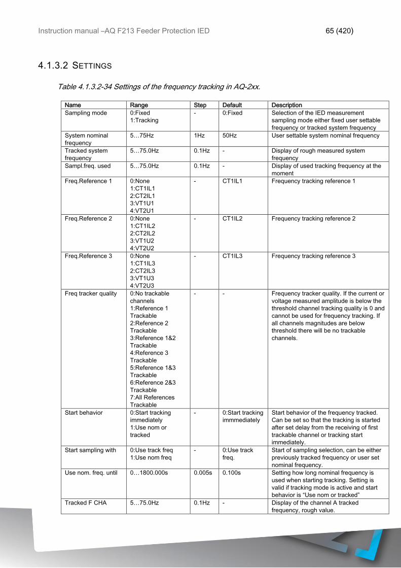
Instruction manual –AQ F213 Feeder Protection IED 65 (420)
4.1.3.2 SETTINGS
Table 4.1.3.2-34 Settings of the frequency tracking in AQ-2xx.
Name Range Step Default Description
Sampling mode 0:Fixed
1:Tracking
- 0:Fixed Selection of the IED measurement
sampling mode either fixed user settable
frequency or tracked system frequency
System nominal
frequency
5…75Hz 1Hz 50Hz User settable system nominal frequency
Tracked system
frequency
5…75.0Hz 0.1Hz -
Display of rough measured system
frequency
Sampl.freq. used 5…75.0Hz 0.1Hz - Display of used tracking frequency at the
moment
Freq.Reference 1 0:None
1:CT1IL1
2:CT2IL1
3:VT1U1
4:VT2U1
- CT1IL1 Frequency tracking reference 1
Freq.Reference 2 0:None
1:CT1IL2
2:CT2IL2
3:VT1U2
4:VT2U2
- CT1IL2 Frequency tracking reference 2
Freq.Reference 3 0:None
1:CT1IL3
2:CT2IL3
3:VT1U3
4:VT2U3
- CT1IL3 Frequency tracking reference 3
Freq tracker quality 0:No trackable
channels
1:Reference 1
Trackable
2:Reference 2
Trackable
3:Reference 1&2
Trackable
4:Reference 3
Trackable
5:Reference 1&3
Trackable
6:Reference 2&3
Trackable
7:All References
Trackable
- - Frequency tracker quality. If the current or
voltage measured amplitude is below the
threshold channel tracking quality is 0 and
cannot be used for frequency tracking. If
all channels magnitudes are below
threshold there will be no trackable
channels.
Start behavior 0:Start tracking
immediately
1:Use nom or
tracked
- 0:Start tracking
immmediately
Start behavior of the frequency tracked.
Can be set so that the tracking is started
after set delay from the receiving of first
trackable channel or tracking start
immediately.
Start sampling with 0:Use track freq
1:Use nom freq
- 0:Use track
freq.
Start of sampling selection, can be either
previously tracked frequency or user set
nominal frequency.
Use nom. freq. until 0…1800.000s 0.005s 0.100s Setting how long nominal frequency is
used when starting tracking. Setting is
valid if tracking mode is active and start
behavior is “Use nom or tracked”
Tracked F CHA 5…75.0Hz 0.1Hz - Display of the channel A tracked
frequency, rough value.

Instruction manual –AQ F213 Feeder Protection IED 66 (420)
Tracked F CHB 5…75.0Hz 0.1Hz - Display of the channel B tracked
frequency, rough value.
Tracked F CHC 5…75.0Hz 0.1Hz - Display of the channel C tracked
frequency, rough value.
4.1.4 POWER AND ENERGY CALCULATION
NOTE: Power measurements are available only in function packages B, C, D & E.
AQ-2xx series IEDs with both voltage –and current cards can calculate power and have
power based protection and monitoring functions depending on the IED type. When power
calculation is possible also the energy magnitudes are calculated.
Power is divided into three magnitudes, apparent power S, active power P and reactive
power Q. Energy measurement is calculating magnitude for active and reactive energy.
Energy can be flowing to forward (exported) or reverse (imported) direction.
LINE TO NEUTRAL VOLTAGES AVAILABLE
Power is calculated from line to neutral voltages and phase currents. In case line to line
voltages are connected the line to neutral voltages can be calculated based on measured
zero sequence voltage. In line to neutral mode and in line to line voltage measurement
mode when U0 is connected and measured the following equations apply for power
calculation:
Below is presented formula for three phase apparent power (S) calculation:
SL1 = UL1×IL1
SL2 = UL2×IL2
SL3 = UL3×IL3
S = SL1 + SL2 + SL3
Where,
UL1…UL3 = Line to neutral voltage
IL1…IL3 = Phase current
Below is presented formula for three phase active power (P) calculation:
PL1 = UL1×IL1 cos φ
PL2 = UL2×IL2 cos φ
PL3 = UL3×IL3 cos φ
P = PL1 + PL2 + PL3
Where,
UL1…UL3 = Line to neutral voltage

Instruction manual –AQ F213 Feeder Protection IED 67 (420)
IL1…IL3 = Phase current φ = Angle difference between voltage
and current

Instruction manual –AQ F213 Feeder Protection IED 68 (420)
Below is presented formula for three phase reactive power (Q) calculation:
QL1 = UL1×IL1 sin φ
QL2 = UL2×IL2 sin φ
QL3 = UL3×IL3 sin φ
Q = QL1 + QL2 + QL3
Where,
UL1…UL3 = Line to neutral voltage
IL1…IL3 = Phase current
φ = Angle difference between voltage
and current
Active power direction can be to forward or reverse direction. Active power direction can be
indicated simply by using Cos (φ). Cosine phi is calculated according the following formula:
3PH Cos(phi) = PS⁄
L1 Cos(phi) =PL1
SL1⁄
L2 Cos(phi) =PL2
SL2⁄
L3 Cos(phi) =PL3
SL3⁄
Direction of reactive power is divided in to four quadrants. Reactive power may be inductive
or capacitive on both forward and reverse direction. Reactive power quadrant can be
indicated simply by using Tan (φ) together with Cos (φ). Tangent phi is calculated according
the following formula:
3PH Tan(phi) = QP⁄
L1 Tan(phi) =QL1
PL1⁄
L2 Tan(phi) =QL2
PL2⁄
L3 Tan(phi) =QL3
PL3⁄

Instruction manual –AQ F213 Feeder Protection IED 69 (420)
ONLY LINE TO LINE VOLTAGES AVAILABLE
In case the line to line voltages are measured and zero sequence voltage is not measured
and known the three phase power calculation is based on Aaron’s theorem:
S = U23×IL1 cos(30) + U31×IL2 cos(30)
P = U23×IL1 cos(30-φ) + U31×IL2 cos(30 + φ)
Q = U23×IL1 + sin(30-φ) + U31×IL2 sin(30 + φ)
Cosine and tangent phi is calculated similar way with line to neutral mode.
4.1.4.1 TROUBLESHOOTING
Check troubleshooting section in chapters “Current measurement and scaling” and “Voltage
measurement and scaling”. Faulty power and energy measurement is normally related to
same issues (wiring errors, wrong voltage measurement mode, faulty frequency settings
etc.).
4.1.4.2 SETTINGS
Table 4.1.4.2-35 Power and Energy meas. settings in AQ-2xx.
Name Range Step Default Description
EP meas 3ph 0:Disabled
1:Enabled
- 0:Disabled Enable active energy measurement.
EQ meas 3ph 0:Disabled
1:Enabled
- 0:Disabled Enable reactive energy measurement.
E 3ph M or k 0:Mega
1:Kilo
- 0:Mega
Measured energy in kilo –or mega values.
PQ Quadrant
VA Quadrant
Reset 3ph Energies 0:-
1:Reset
- 0:-
Resets the memory of each 3 phase
energy calculator. Goes back to “-“ -state
automatically after reset.
EP meas per phase 0:Disabled
1:Enabled
- 0:Disabled
Enable active energy per phase
measurement.
EQ meas per phase 0:Disabled
1:Enabled
- 0:Disabled
Enable reactive energy per phase
measurement.
E 3ph M or k 0:Mega
1:Kilo
- 0:Mega
Measured energy per phase in kilo –or
mega values.
Reset E per phase 0:-
1:Reset
- 0:-
Resets the memory of each phase energy
calculator. Goes back to “-“ -state
automatically after reset.

Instruction manual –AQ F213 Feeder Protection IED 70 (420)
Table 4.1.4.2-36 Energy Dose Counter 1 settings in AQ-2xx.
Name Range Step Default Description
Energy dose
counter mode
0:Disabled
1:Activated
- 0:Disabled
Enable energy dose counters
generally.
DC 1…4 enable 0:Disabled
1:Enabled
- 0:Disabled
Enable energy dose counter
1…4 individually.
DC 1…4 Input
signal select
0:3PH.Fwd.Act.EP
1:3PH.Rev.Avt.EP
2:3PH.Fwd.Eact.EQ.CAP
3: 3PH.Fwd.Eact.EQ.IND
4: 3PH.Rev.Eact.EQ.CAP
5: 3PH.Rev.Eact.EQ.IND
- 0:3PH.Fwd.Act.EP
Choose forward or reverse
direction active or reactive
energy magnitudes.
DC 1…4 Input
signal
-1x10⁶…1x10⁶ 0.01 - Total amount of consumed
energy.
DC 1…4 Pulse
magnitude
0…1800 0.005 1 kW/Var Set pulse size. Energy pulse is
given every time when set
magnitude exceeds.
DC 1…4 Pulse
Length
0…1800 0.005 1 s Total length of control pulse.
Table 4.1.4.2-37 DC 1…4 Pulse out settings in AQ-2xx.
Name Range Step Default Description
DC 1…4 Pulse
out
OUT1…OUT5 (or more,
amount corresponds with
order code)
- None selected
Controlled physical outputs
selection.
4.1.4.3 POWER MEASUREMENTS
Following power calculations are available when voltage and current cards are available.
Table 4.1.4.3-38 Three phase power calculation in AQ-2xx.
Name Range Step Description
3PH Apparent power (S) -1x10⁶…1x10⁶ kVA 0.01kVA Total 3 phase apparent power
3PH Active power (P) -1x10⁶…1x10⁶ kW 0.01kW Total 3 phase active power
3PH Reactive power (Q) -1x10⁶…1x10⁶ kVar 0.01kVar Total 3 phase reactive power
3PH Tan(phi) -1x10⁶…1x10⁶ kVA 0.01 3 phase active power direction
3PH Cos(phi) -1x10⁶…1x10⁶ kVA 0.01 3 phase reactive power direction
Table 4.1.4.3-39 Phase L1 power calculation in AQ-2xx.
Name Range Step Description
L1 Apparent power (S) -1x10⁶…1x10⁶ kVA 0.01kVA Phase L1 apparent power
L1 Active power (P) -1x10⁶…1x10⁶ kW 0.01kW Phase L1 active power
L1 Reactive power (Q) -1x10⁶…1x10⁶ kVar 0.01kVar Phase L1 reactive power
L1 Tan(phi) -1x10⁶…1x10⁶ kVA 0.01 Phase L1 active power direction
L1 Cos(phi) -1x10⁶…1x10⁶ kVA 0.01 Phase L1 reactive power direction

Instruction manual –AQ F213 Feeder Protection IED 71 (420)
Table 4.1.4.3-40 Phase L2 power calculation in AQ-2xx.
Name Range Step Description
L2 Apparent power (S) -1x10⁶…1x10⁶ kVA 0.01kVA Phase L2 apparent power
L2 Active power (P) -1x10⁶…1x10⁶ kW 0.01kW Phase L2 active power
L2 Reactive power (Q) -1x10⁶…1x10⁶ kVar 0.01kVar Phase L2 reactive power
L2 Tan(phi) -1x10⁶…1x10⁶ kVA 0.01 Phase L2 active power direction
L2 Cos(phi) -1x10⁶…1x10⁶ kVA 0.01 Phase L2 reactive power direction
Table 4.1.4.3-41 Phase L3 power calculation in AQ-2xx.
Name Range Step Description
L3 Apparent power (S) -1x10⁶…1x10⁶ kVA 0.01kVA Phase L3 apparent power
L3 Active power (P) -1x10⁶…1x10⁶ kW 0.01kW Phase L3 active power
L3 Reactive power (Q) -1x10⁶…1x10⁶ kVar 0.01kVar Phase L3 reactive power
L3 Tan(phi) -1x10⁶…1x10⁶ kVA 0.01 Phase L3 active power direction
L3 Cos(phi) -1x10⁶…1x10⁶ kVA 0.01 Phase L3 reactive power direction
4.1.4.4 ENERGY MEASUREMENTS
Following energy calculations are available when voltage and current cards are available.
Table 4.1.4.4-42 Three phase energy calculation in AQ-2xx.
Name Range Step Description
Exp.Active Energy Mwh -1x10⁶…1x10⁶ MWh 0.01MWh Total exported active energy
Imp.Active Energy Mwh -1x10⁶…1x10⁶ MWh 0.01MWh Total imported active energy
Exp/Imp.Act.E balance
Mwh
-1x10⁶…1x10⁶ MWh 0.01MWh Sum of imported and exported
active energy
Exp.React.Cap.E.Mvarh -1x10⁶…1x10⁶ MVarh 0.01MVarh Total exported reactive capacitive
energy
Imp.React.Cap.E.Mvarh -1x10⁶…1x10⁶ MVarh 0.01MVarh Total imported reactive capacitive
energy
Exp/Imp
React.Cap.E.bal.MVarh
-1x10⁶…1x10⁶ MVarh 0.01MVarh Sum of imported and exported
reactive capacitive energy
Exp.React.Ind.E.Mvarh -1x10⁶…1x10⁶ MVarh 0.01MVarh Total exported reactive inductive
energy
Imp.React.Ind.E.Mvarh -1x10⁶…1x10⁶ MVarh 0.01MVarh Total imported reactive inductive
energy
Exp/Imp
React.Ind.E.bal.MVarh
-1x10⁶…1x10⁶ MVarh 0.01MVarh Sum of imported and exported
reactive inductive energy

Instruction manual –AQ F213 Feeder Protection IED 72 (420)
Table 4.1.4.4-43 Phase L1 energy calculation in AQ-2xx.
Name Range Step Description
L1 Exp.Active Energy Mwh -1x10⁶…1x10⁶ MWh 0.01MWh Phase L1 exported active energy
L1 Imp.Active Energy Mwh -1x10⁶…1x10⁶ MWh 0.01MWh Phase L1 imported active energy
L1 Exp/Imp.Act.E balance
Mwh
-1x10⁶…1x10⁶ MWh 0.01MWh Sum of imported and exported
phase L1 active energy
L1 Exp.React.Cap.E.Mvarh -1x10⁶…1x10⁶ MVarh 0.01MVarh Phase L1total exported reactive
capacitive energy
L1 Imp.React.Cap.E.Mvarh -1x10⁶…1x10⁶ MVarh 0.01MVarh Phase L1 total imported reactive
capacitive energy
L1 Exp/Imp
React.Cap.E.bal.MVarh
-1x10⁶…1x10⁶ MVarh 0.01MVarh Sum of imported and exported
phase L1 reactive capacitive
energy
L1 Exp.React.Ind.E.Mvarh -1x10⁶…1x10⁶ MVarh 0.01MVarh Phase L1 total exported reactive
inductive energy
L1 Imp.React.Ind.E.Mvarh -1x10⁶…1x10⁶ MVarh 0.01MVarh Phase L1 total imported reactive
inductive energy
L1 Exp/Imp
React.Ind.E.bal.MVarh
-1x10⁶…1x10⁶ MVarh 0.01MVarh Sum of imported and exported
phase L1 reactive inductive
energy
Table 4.1.4.4-44 Phase L2 energy calculation in AQ-2xx.
Name Range Step Description
L2 Exp.Active Energy Mwh -1x10⁶…1x10⁶ MWh 0.01MWh Phase L2 exported active energy
L2 Imp.Active Energy Mwh -1x10⁶…1x10⁶ MWh 0.01MWh Phase L2 imported active energy
L2 Exp/Imp.Act.E balance
Mwh
-1x10⁶…1x10⁶ MWh 0.01MWh Sum of imported and exported
phase L2 active energy
L2 Exp.React.Cap.E.Mvarh -1x10⁶…1x10⁶ MVarh 0.01MVarh Phase L2total exported reactive
capacitive energy
L2 Imp.React.Cap.E.Mvarh -1x10⁶…1x10⁶ MVarh 0.01MVarh Phase L2 total imported reactive
capacitive energy
L2 Exp/Imp
React.Cap.E.bal.MVarh
-1x10⁶…1x10⁶ MVarh 0.01MVarh Sum of imported and exported
phase L2 reactive capacitive
energy
L2 Exp.React.Ind.E.Mvarh -1x10⁶…1x10⁶ MVarh 0.01MVarh Phase L2 total exported reactive
inductive energy
L2 Imp.React.Ind.E.Mvarh -1x10⁶…1x10⁶ MVarh 0.01MVarh Phase L2 total imported reactive
inductive energy
L2 Exp/Imp
React.Ind.E.bal.MVarh
-1x10⁶…1x10⁶ MVarh 0.01MVarh Sum of imported and exported
phase L2 reactive inductive
energy

Instruction manual –AQ F213 Feeder Protection IED 73 (420)
Table 4.1.4.4-45 Phase L3 energy calculation in AQ-2xx.
Name Range Step Description
L3 Exp.Active Energy Mwh -1x10⁶…1x10⁶ MWh 0.01MWh Phase L3 exported active energy
L3 Imp.Active Energy Mwh -1x10⁶…1x10⁶ MWh 0.01MWh Phase L3 imported active energy
L3 Exp/Imp.Act.E balance
Mwh
-1x10⁶…1x10⁶ MWh 0.01MWh Sum of imported and exported
phase L3 active energy
L3 Exp.React.Cap.E.Mvarh -1x10⁶…1x10⁶ MVarh 0.01MVarh Phase L3total exported reactive
capacitive energy
L3 Imp.React.Cap.E.Mvarh -1x10⁶…1x10⁶ MVarh 0.01MVarh Phase L3 total imported reactive
capacitive energy
L3 Exp/Imp
React.Cap.E.bal.MVarh
-1x10⁶…1x10⁶ MVarh 0.01MVarh Sum of imported and exported
phase L3 reactive capacitive
energy
L3 Exp.React.Ind.E.Mvarh -1x10⁶…1x10⁶ MVarh 0.01MVarh Phase L3 total exported reactive
inductive energy
L3 Imp.React.Ind.E.Mvarh -1x10⁶…1x10⁶ MVarh 0.01MVarh Phase L3 total imported reactive
inductive energy
L3 Exp/Imp
React.Ind.E.bal.MVarh
-1x10⁶…1x10⁶ MVarh 0.01MVarh Sum of imported and exported
phase L3 reactive inductive
energy
4.1.4.5 CALCULATION EXAMPLES
Example for power calculation is represented here. Both wiring methods line to line –and
line to neutral are checked with same signal injection. Voltage scaling is set to 20000:100V
and current scaling is set to 1000:5A.
Voltages (Line to neutral):
VA=40.825V, 45.00°
VB=61.481V, -159.90°
VC=97.742V, 126.21°
Currents:
IL1=2.500V, 0.00°
IL2=2.500V, -120.00°
IL3=2.500V, 120.00°
SL1 = UL1×IL1 = 40.825V×2.5A = 102 VA (secondary) 4.08 MVA (primary)
PL1 = UL1×IL1 cos φ = 40.825V×2.5A cos(45°-0°) = 72.2 W (secondary) 2.89 MW (primary)
QL1 = UL1×IL1 sin φ = 40.825V×2.5A sin(45°-0°) = 72.2 W (secondary) 2.89 MVar (primary)
L1 Tan(phi) =QL1
PL1⁄ = 2.89
2.89⁄ = 1.00 L1 Cos(phi) =PL1
SL1⁄ = 2.89
4.08⁄ = 0.71

Instruction manual –AQ F213 Feeder Protection IED 74 (420)
Name k# Name k# Name k# Name M#
L1 (S) 4.08 L2 (S) 6.15 L3 (S) 9.77 3PH (S) 20.00
L1 (P) 2.89 L2 (P) 4.72 L3 (P) 9.71 3PH (P) 17.32
L1 (Q) 2.89 L2 (Q) -3.94 L3 (Q) 1.06 3PH (Q) 0.01
L1 Tanφ 1.00 L2 Tanφ -0.83 L3 Tanφ 0.11 3PH Tanφ 0.00
L1 Cosφ 0.71 L2 Cosφ 0.77 L3 Cosφ 0.99 3PH Cosφ 0.87
Voltages (Line to line):
VA=100.00V, 30.00°
VB=100.00V, -90.00°
Currents:
IL1=2.500V, 0.00°
IL2=2.500V, -120.00°
IL3=2.500V, 120.00°
S = U12×IL1 + U23×IL2
S = 100×2.5 + 100×2.5 = 500 VA (secondary)20.00 MVA (primary)
P = U12×IL1 cos(-φ) + U23×IL2 cos(φ)
P = 100×2.5 cos -(30°-0°) + 100×2.5 cos(270°-240°) = 433W(sec)17.32 MW(pri)
Q = U12×IL1 + sin(-φ) + U23×IL2 sin(φ)
Q = 100×2.5 + sin -(30°-0°) + 100×2.5 sin(270°-240°) = 0 Var(sec)0 MVar(pri)
3PH Tan(phi) =Q
P⁄ = 0.0117.32⁄ = 0.00 3PH Cos(phi) = P
S⁄ = 17.3220.00⁄ = 0.87
Name M#
3PH (S) 20.00
3PH (P) 17.32
3PH (Q) 0.00
3PH Tanφ 0.00
3PH Cosφ 0.87

Instruction manual –AQ F213 Feeder Protection IED 75 (420)
4.2 PROTECTION FUNCTIONS
4.2.1 GENERAL PROPERTIES OF A PROTECTION FUNCTION
In following flowchart is described the basic structure of any protection function. Basic
structure is composed of the analog measurement values comparison to the pick-up values
and operating time characteristics.

Instruction manual –AQ F213 Feeder Protection IED 76 (420)
Protection function is run in a completely digital environment with protection CPU
microprocessor which also processes the analog signals transferred to digital form.
Figure 4.2.1-17 Principle diagram of AQ-2xx protection relay platform.
In following chapters are presented the common functionalities of protection functions. If in
some protection function is deviation of this basic structure the difference is described in
the corresponding chapter of the manual.
4.2.1.1 PICK-UP CHARACTERISTICS
Pick-up of the function is controlled by Xset setting parameter, which defines the maximum
allowed measured magnitude in per unit, absolute or percentage value before action from
the function. The function constantly calculates the ratio in between of the user set pick-up
parameter and measured magnitude (Im). Reset ratio of 97 % is inbuilt in the function and
is always related to the Xset value. If function pick-up characteristics vary from this
described, it is defined in the function part of the manual.

Instruction manual –AQ F213 Feeder Protection IED 77 (420)
Figure 4.2.1.1-18 Pick up and reset characteristics of the function.
The pick-up activation of the function is not directly equal to start-signal generation of the
function. Start signal is allowed if blocking condition is not active.
Figure 4.2.1.1-19 Measurement range in relation to the nominal current.

Instruction manual –AQ F213 Feeder Protection IED 78 (420)
The “In” magnitude refers to user set nominal current which can be in range of 0.2…10A,
typically 0.2A, 1A or 5A. With its own current measurement card the IED will measure
secondary currents from 0.001A up to 250A. To this relation the pick-up setting in secondary
amperes will vary.
4.2.1.2 FUNCTION BLOCKING
In the blocking element the block signal is checked in the beginning of each program cycle.
Blocking signal is received from the blocking matrix for the function dedicated input. If the
blocking signal is not activated when the pick-up element activates, a START signal is
generated and the function proceeds to the time characteristics calculation.
If blocking signal is active when pick-up element activates a BLOCKED signal will be
generated and the function shall not process the situation further. If START function has
been activated before blocking signal it will reset and the release time characteristics are
processed as in case of when pick-up signal is reset.
From blocking of the function a HMI display event as well as time stamped blocking event
with information of the startup current values and fault type is issued.
Blocking signal can be tested also in the commissioning phase of the stage by software
switch signal when relay common and global testing mode is activated.
User settable variables are binary signals from the system. Blocking signal needs to reach
the IED minimum of 5 ms before the set operating delay has passed for blocking to be active
in time.
4.2.1.3 OPERATING TIME CHARACTERISTICS FOR TRIP AND RESET
The operating timers’ behavior of the function can be set for trip signal and also for the
release of the function in case the pick-up element is reset before the trip time has been
reached. There are three basic operating modes available for the function. Instant operation
gives the trip signal with no additional time delay simultaneously with start signal. Definite
time operation (DT) will give trip signal with user given time delay regardless of the
measured current as long as the current is above the Iset value and thus pick-up element
is active (independent time characteristics). Inverse definite minimum time (IDMT) will give
the trip signal in time which is in relation of the set pick-up current Iset and measured current
Im (dependent time characteristics). For the IDMT operation is available IEC and
IEEE/ANSI standard characteristics as well as user settable parameters.
In the table below are presented the setting parameters for the function time characteristics.

Instruction manual –AQ F213 Feeder Protection IED 79 (420)
Table 4-46 Operating time characteristics setting parameters (general).
Name Range Step Default Description
Delay Type DT
IDMT
- DT Selection of the delay type time counter.
Selection possibilities are dependent
(IDMT, Inverse Definite Minimum Time)
and independent (DT, Definite Time)
characteristics.
Definite operating
time delay
0.000…1800.000 s 0.005 s 0.040 s Definite time operating delay. Setting is
active and visible when Delay Type is
selected to DT.
When set to 0.000 s the stage operates as
instant (PIOC, 50) stage without added
delay. When the parameter is set to 0.005
– 1800 s the stage operates as
independent delayed (PTOC, 51).
Delay curve series IEC
IEEE
- IEC Setting is active and visible when Delay
Type is selected to IDMT.
Delay curve series for IDMT operation
following either IEC or IEEE/ANSI
standard defined characteristics.
Delay
characteristics
IEC
NI
EI
VI
LTI
Param
- NI Setting is active and visible when Delay
Type is selected to IDMT.
IEC standard delay characteristics.
Normally Inverse, Extremely Inverse, Very
Inverse and Long Time Inverse
characteristics. Param selection allows the
tuning of the constants A and B which
allows setting of characteristics following
the same formula as the IEC curves
mentioned here.
Delay
characteristics
IEEE
ANSI NI
ANSI VI
ANSI EI
ANSI LI
IEEE MI
IEEE VI
IEEE EI
Param
- LTI Setting is active and visible when Delay
Type is selected to IDMT.
IEEE and ANSI standard delay
characteristics. ANSI: Normal Inverse,
Very Inverse, Extremely inverse, Long
time inverse characteristics. IEEE:
Moderately Inverse, Very Inverse,
Extremely Inverse characteristics. Param
selection allows the tuning of the
constants A, B and C which allows setting
of characteristics following the same
formula as the IEEE curves mentioned
here.
Time dial setting k 0.01…25.00 s 0.01 s 0.05 s Setting is active and visible when Delay
Type is selected to IDMT.
Time dial / multiplier setting for IDMT
characteristics.
A 0.0000…250.0000 0.0001 0.0860 Setting is active and visible when Delay
Type is selected to IDMT.
Constant A for IEC/IEEE characteristics.
B 0.0000…5.0000 0.0001 0.1850 Setting is active and visible when Delay
Type is selected to IDMT.
Constant B for IEC/IEEE characteristics.
C 0.0000…250.0000 0.0001 0.0200 Setting is active and visible when Delay
Type is selected to IDMT.
Constant C for IEEE characteristics.

Instruction manual –AQ F213 Feeder Protection IED 80 (420)
Table 4-47 Inverse operating time formulas.
IEC IEEE/ANSI
1
B
set
m
I
I
kAt
B
I
I
Akt
C
set
m 1
t = Operating delay (s) k = Time dial setting Im = Measured maximum current Iset = Pick up setting A = Operating characteristics constant B = Operating characteristics constant
t = Operating delay (s) k = Time dial setting Im = Measured maximum current Iset = Pick up setting A = Operating characteristics constant B = Operating characteristics constant C = Operating characteristics constant
Standard delays IEC constants Type A B Normally Inverse (NI) 0,14 0,02 Extremely Inverse (EI) 80 2 Very Inverse (VI) 13,5 1 Long Time Inverse (LTI) 120 1
Standard delays ANSI constants Type A B C Normally Inverse (NI) 8,934 0,1797 2,094 Very Inverse (VI) 3,922 0,0982 2 Extremely Inverse (EI) 5,64 0,02434 2 Long Time Inverse (LTI) 5,614 2,186 1
Standard delays IEEE constants
Type A B C Moderately Inverse (MI) 0,0515 0,114 0,02 Very Inverse (VI) 19,61 0,491 2 Extremely Inverse (EI) 28,2 0,1217 2

Instruction manual –AQ F213 Feeder Protection IED 81 (420)
Figure 4.2.1.3-20. Definite time operating characteristics.

Instruction manual –AQ F213 Feeder Protection IED 82 (420)
Figure 4.2.1.3-21. IEC predefined characteristics NI, VI, LTI and EI

Instruction manual –AQ F213 Feeder Protection IED 83 (420)
Figure 4.2.1.3-22. IEEE ANSI predefined characteristics EI, LTI, NI and VI

Instruction manual –AQ F213 Feeder Protection IED 84 (420)
Figure 4.2.1.3-23. IEEE predefined characteristics EI, MI and VI

Instruction manual –AQ F213 Feeder Protection IED 85 (420)
Figure 4.2.1.3-24. Parameters A, B and C effect to the characteristics.

Instruction manual –AQ F213 Feeder Protection IED 86 (420)
4.2.1.4 NON-STANDARD DELAY CHARACTERISTICS
Additionally to previously mentioned delay characteristics some functions include also delay
characteristics that deviate from the norm. These functions are Overcurrent stages,
Residual overcurrent stages, Directional overcurrent stages and Directional residual
overcurrent stages. The setting parameters and their ranges are documented in the function
blocks respective chapters.
RI-type characteristic is used to get time grading with mechanical relays.
Equation 1: RI-type characteristic is used to get time grading with mechanical relays
t[s] =k
0.339-0.236*I >
I
t = operating time
k = time multiplier
I = measured current
I> = pick-up value
Equation 2: RD-type characteristic is a characteristic mostly used in earth-fault protection
which grants selective tripping even in non-directional protection.
t[s] = 5.8-1.35*loge
I
k*I >
t = operating time
k = time multiplier
I = measured current
I> = pick-up value

Instruction manual –AQ F213 Feeder Protection IED 87 (420)
Table 4-48 Reset time characteristics setting parameters.
Release Time
delay
0.000…150.000 s 0.005 s 0.06 s Resetting time. Time allowed in between
of pick-ups if the pick-up has not lead into
trip operation. During this time the start
signal is held on for the timers if delayed
pick-up release is active.
Delayed Pick-up
release
No
Yes
- Yes
Resetting characteristics selection either
time delayed or instant after pick-up
element is released. If activated the start
signal is reset after set release time delay.
Time calc reset
after release time
No
Yes
- Yes Operating timer resetting characteristics
selection. When active the operating time
counter is reset after set release time if
pick-up element is not activated during this
time. When disabled the operating time
counter is reset directly after the pick-up
element reset.
Continue time
calculation during
release time
No
Yes
- No Time calculation characteristics selection.
If activated the operating time counter is
continuing until set release time even the
pick-up element is reset.
In following figures are presented the behavior of the stage in different release time
configurations.
Figure 4.2.1.4-25. No delayed pick-up release.

Instruction manual –AQ F213 Feeder Protection IED 88 (420)
Figure 4.2.1.4-26. Delayed pick-up release, delay counter is reset at signal drop-off.
Figure 4.2.1.4-27. Delayed pick-up release, delay counter value is held during the release
time.

Instruction manual –AQ F213 Feeder Protection IED 89 (420)
Figure 4.2.1.4-28. Delayed pick-up release, delay counter value is decreasing during the
release time.
Resetting characteristics can be set according to the application. Default setting is delayed
with 60 ms and the time calculation is held during the release time.
When using the release delay option where the operating time counter is calculating the
operating time during the release time, function will not trip if the input signal is not activated
again during the release time counting.
4.2.1.5 STAGE FORCING
In AQ-2xx series relays it is possible to test the logic and the operation of the protection
system of the relay by controlling the state of the protection functions by hand without
injecting any current into the relay. To enable stage forcing set the Enable stage forcing to
Enabled in General menu. After this it is possible to control the status of a protection function
(Normal, Start, Trip, Blocked etc.) in the Info page of the function.
NOTE: When Stage forcing is enabled protection functions will change state only by user
input, injected currents/voltages don’t affect the behavior of the relay. To ensure normal
operation of the relay after testing disable stage forcing in the General menu.

Instruction manual –AQ F213 Feeder Protection IED 90 (420)
4.2.2 NON-DIRECTIONAL OVER CURRENT I> (50/51)
This function is included in all function packages of AQ-F213.
Overcurrent function (NOC) is used for non-directional instant- and time delayed
overcurrent/short circuit protection for various applications including feeder, filter and
machine applications of utilities and industry. The number of available instances of the
function depends of the IED model. Function measures constantly phase current
magnitudes which on the operating decisions are based. Monitored phase current
magnitudes can be selected fundamental component RMS, TRMS values (including
harmonics up to 32nd) or peak-to-peak values. Blocking signal and setting group selection
controls the operating characteristics of the function during normal operation.
Outputs of the function are Start Trip and Blocked signals. Setting parameters are static
inputs for the function which are changed only by user input in the setup phase of the
function. Non directional overcurrent function utilizes total of eight separate setting groups
which can be selected from one common source.
The function can be operating on instant or time delayed mode. In time delayed mode the
operation can be selected for definite time or IDMT. For IDMT operation IEC and ANSI
standard time delays are supported as well as custom parameters. Function includes CT
saturation checking which allows the function to start and operate accurately also in case
of CT saturation condition.
The operational logic consists of input magnitude processing, input magnitude selection,
saturation check, threshold comparator, block signal check, time delay characteristics and
output processing. The basic design of the protection function is 3-pole operation.
Inputs for the function are the operating mode selections, setting parameters and measured
and pre-processed current magnitudes and binary input signals. Function outputs START,
TRIP and BLOCKED signals which can be used for direct IO controlling and also for user
logic programming. The function registers its operation into 12 last time-stamped registers
and also generates general time stamped ON/OFF events to the common event buffer from
each of the three output signal. In instant operating mode the function outputs START and
TRIP events simultaneously with equivalent time stamp. Time stamp resolution is 1ms.
Function provides also cumulative counters for START, TRIP and BLOCKED events.
In the following figure is presented the simplified function block diagram of the NOC function.

Instruction manual –AQ F213 Feeder Protection IED 91 (420)
Figure 4.2.2-29 Simplified function block diagram of the NOC function.
4.2.2.1 MEASURED INPUT VALUES
Function block uses analog current measurement values. Function block always utilizes
peak-to-peak measurement from samples and by user selection the monitored magnitude
can be either fundamental frequency RMS values, True RMS values from the whole
harmonic specter of 32 components or peak to peak values. -20ms averaged value of the
selected magnitude is used for pre-fault data registering.
Table 4.2.2.1-49 Analogic magnitudes used by the NOC function.
Signal Description Time base
IL1PP Peak-to-peak measurement of phase L1/A current 5 ms
IL2PP Peak-to-peak measurement of phase L2/B current 5 ms
IL3PP Peak-to-peak measurement of phase L3/C current 5 ms
IL1RMS Fundamental RMS measurement of phase L1/A current 5 ms
IL2RMS Fundamental RMS measurement of phase L2/B current 5 ms
IL3RMS Fundamental RMS measurement of phase L3/C current 5 ms
IL1TRMS TRMS measurement of phase L1/A current 5 ms
IL2TRMS TRMS measurement of phase L2/B current 5 ms
IL3TRMS TRMS measurement of phase L3/C current 5 ms
Selection of the used AI channel is made with a setting parameter. In all possible input
channel variations pre-fault condition is presented with 20 ms averaged history value from
-20 ms of Start or Trip event.

Instruction manual –AQ F213 Feeder Protection IED 92 (420)
4.2.2.2 PICK-UP CHARACTERISTICS
Pick-up of the NOC function is controlled by Iset setting parameter, which defines the
maximum allowed measured current before action from the function. The function
constantly calculates the ratio in between of the Iset and measured magnitude (Im) per all
three phases. Reset ratio of 97 % is inbuilt in the function and is always related to the Iset
value. The setting value is common for all measured phases and single-, dual- or all phases
Im exceed of the Iset value will cause pick-up operation of the function.
Table 4.2.2.2-50 Pick-up characteristics setting
Name Description Range Step Default
Iset Pick-up setting 0.10 … 40.00 x In 0.01 x In 1.20 x In
The pick-up activation of the function is not directly equal to start-signal generation of the
function. Start signal is allowed if blocking condition is not active.
4.2.2.3 FUNCTION BLOCKING
In the blocking element the block signal is checked in the beginning of each program cycle.
Blocking signal is received from the blocking matrix for the function dedicated input. If the
blocking signal is not activated when the pick-up element activates, a START signal is
generated and the function proceeds to the time characteristics calculation.
If blocking signal is active when pick-up element activates a BLOCKED signal will be
generated and the function shall not process the situation further. If START function has
been activated before blocking signal it will reset and the release time characteristics are
processed as in case of when pick-up signal is reset.
From blocking of the function a HMI display event as well as time stamped blocking event
with information of the startup current values and fault type is issued.
Blocking signal can be tested also in the commissioning phase of the stage by software
switch signal when relay common and global testing mode is activated.
User settable variables are binary signals from the system. Blocking signal needs to reach
the IED minimum of 5 ms before the set operating delay has passed for blocking to be active
in time.

Instruction manual –AQ F213 Feeder Protection IED 93 (420)
4.2.2.4 OPERATING TIME CHARACTERISTICS FOR TRIP AND RESET
The operating timers’ behavior of the function can be set for trip signal and also for the
release of the function in case the pick-up element is reset before the trip time has been
reached. There are three basic operating modes available for the function. Instant operation
gives the trip signal with no additional time delay simultaneously with start signal. Definite
time operation (DT) will give trip signal with user given time delay regardless of the
measured current as long as the current is above the Iset value and thus pick-up element
is active (independent time characteristics). Inverse definite minimum time (IDMT) will give
the trip signal in time which is in relation of the set pick-up current Iset and measured current
Im (dependent time characteristics). For the IDMT operation is available IEC and
IEEE/ANSI standard characteristics as well as user settable parameters.
In the following table are presented the setting parameters for the function time
characteristics.
Table 4.2.2.4-51 Operating time characteristics setting parameters.
Name Range Step Default Description
Delay Type DT
IDMT
- DT Selection of the delay type time counter.
Selection possibilities are dependent
(IDMT, Inverse Definite Minimum Time)
and independent (DT, Definite Time)
characteristics.
Definite operating
time delay
0.000…1800.000 s 0.005 s 0.040 s Definite time operating delay. Setting is
active and visible when Delay Type is
selected to DT.
When set to 0.000 s the stage operates as
instant (PIOC, 50) stage without added
delay. When the parameter is set to 0.005
– 1800 s the stage operates as
independent delayed (PTOC, 51).

Instruction manual –AQ F213 Feeder Protection IED 94 (420)
Delay curve series IEC
IEEE
Non standard
- IEC Setting is active and visible when Delay
Type is selected to IDMT.
Delay curve series for IDMT operation
following either IEC or IEEE/ANSI
standard defined characteristics.
Non-standard characteristics include RI
and RD type characteristics
Delay
characteristics
IEC
NI
EI
VI
LTI
Param
- NI Setting is active and visible when Delay
Type is selected to IDMT.
IEC standard delay characteristics.
Normally Inverse, Extremely Inverse, Very
Inverse and Long Time Inverse
characteristics. Param selection allows the
tuning of the constants A and B which
allows setting of characteristics following
the same formula as the IEC curves
mentioned here.
Delay
characteristics
IEEE
ANSI NI
ANSI VI
ANSI EI
ANSI LI
IEEE MI
IEEE VI
IEEE EI
Param
- LTI Setting is active and visible when Delay
Type is selected to IDMT.
IEEE and ANSI standard delay
characteristics. ANSI: Normal Inverse,
Very Inverse, Extremely inverse, Long
time inverse characteristics. IEEE:
Moderately Inverse, Very Inverse,
Extremely Inverse characteristics. Param
selection allows the tuning of the
constants A, B and C which allows setting
of characteristics following the same
formula as the IEEE curves mentioned
here.
Non-standard
characteristic
RI-type
RD-type
- RI-type Selection of the non-standard
characteristic. See the formulas from
chapter 4.2.1. General properties of a
protection function.
Time dial setting k 0.01…25.00 s 0.01 s 0.05 s Setting is active and visible when Delay
Type is selected to IDMT or non-standard
characteristic.
Time dial / multiplier setting for IDMT
characteristics or non-standard
characteristic.
A 0.0000…250.0000 0.0001 0.0860 Setting is active and visible when Delay
Type is selected to IDMT.
Constant A for IEC/IEEE characteristics.
B 0.0000…5.0000 0.0001 0.1850 Setting is active and visible when Delay
Type is selected to IDMT.
Constant B for IEC/IEEE characteristics.
C 0.0000…250.0000 0.0001 0.0200 Setting is active and visible when Delay
Type is selected to IDMT.
Constant C for IEEE characteristics.
Table 4.2.2.4-52 Reset time characteristics setting parameters.
Release Time
delay
0.000…150.000 s 0.005 s 0.06 s Resetting time. Time allowed in between
of pick-ups if the pick-up has not lead into
trip operation. During this time the start
signal is held on for the timers if delayed
pick-up release is active.
Delayed Pick-up
release
No
Yes
- Yes
Resetting characteristics selection either
time delayed or instant after pick-up
element is released. If activated the start
signal is reset after set release time delay.

Instruction manual –AQ F213 Feeder Protection IED 95 (420)
Time calc reset
after release time
No
Yes
- Yes Operating timer resetting characteristics
selection. When active the operating time
counter is reset after set release time if
pick-up element is not activated during this
time. When disabled the operating time
counter is reset directly after the pick-up
element reset.
Continue time
calculation during
release time
No
Yes
- No Time calculation characteristics selection.
If activated the operating time counter is
continuing until set release time even the
pick-up element is reset.
Resetting characteristics can be set according to the application. Default setting is delayed
with 60 ms and the time calculation is held during the release time.
When using the release delay option where the operating time counter is calculating the
operating time during the release time, function will not trip if the input signal is not activated
again during the release time counting.
4.2.2.5 EVENTS AND REGISTERS
The NOC function generates events and registers from the status changes of start, trip and
blocked. To main event buffer is possible to select status “On” or “Off” messages. The NOC
function offers four independent instances which events are segregated for each instance
operation.
In the function is available 12 last registers where the triggering event of the function (start,
trip or blocked) is recorded with time stamp and process data values.

Instruction manual –AQ F213 Feeder Protection IED 96 (420)
Table 4.2.2.5-53. Event codes of the NOC function instances 1 – 4.
Event
Number
Event
channel Event block name
Event
Code Description
Event
Type
1280 20 NOC1 0 Start ON 1
1281 20 NOC1 1 Start OFF 0
1282 20 NOC1 2 Trip ON 1
1283 20 NOC1 3 Trip OFF 0
1284 20 NOC1 4 Block ON 1
1285 20 NOC1 5 Block OFF 0
1344 21 NOC2 0 Start ON 1
1345 21 NOC2 1 Start OFF 0
1346 21 NOC2 2 Trip ON 1
1347 21 NOC2 3 Trip OFF 0
1348 21 NOC2 4 Block ON 1
1349 21 NOC2 5 Block OFF 0
1408 22 NOC3 0 Start ON 1
1409 22 NOC3 1 Start OFF 0
1410 22 NOC3 2 Trip ON 1
1411 22 NOC3 3 Trip OFF 0
1412 22 NOC3 4 Block ON 1
1413 22 NOC3 5 Block OFF 0
1472 23 NOC4 0 Start ON 1
1473 23 NOC4 1 Start OFF 0
1474 23 NOC4 2 Trip ON 1
1475 23 NOC4 3 Trip OFF 0
1476 23 NOC4 4 Block ON 1
1477 23 NOC4 5 Block OFF 0
In the register of the NOC function is recorded start, trip or blocked “On” event process data.
In the table below is presented the structure of NOC function register content. This
information is available in 12 last recorded events for all provided instances separately.
Table 4.2.2.5-54. Register content.
Date & Time Event
code
Fault
type
Trigger
current
Fault
current
Prefault
current
Trip time
remaining
Used
SG
dd.mm.yyyy
hh:mm:ss.mss
1280-
1477
Descr.
L1-G…
L1-L2-
L3
Start
average
current
Trip
-20 ms
averages
Start
-200 ms
averages
0 ms -
1800 s
1 - 8

Instruction manual –AQ F213 Feeder Protection IED 97 (420)
4.2.3 NON-DIRECTIONAL EARTH FAULT I0> (50N/51N)
This function is included in all function packages of AQ-F213.
Non directional earth fault function (NEF) is used for instant- and time delayed earth fault
protection for various applications including feeder, filter and machine applications of utilities
and industry. The number of available instances of the function depends of the IED model.
Function measures constantly selected neutral current magnitudes which on the operating
decisions are based. Monitored phase current magnitudes can be selected fundamental
component RMS, TRMS values (including harmonics up to 32nd) or peak-to-peak values of
residual current measurement inputs I01 and I02 or from phase current measurements
calculated zero sequence current I0Calc. Blocking signal and setting group selection
controls the operating characteristics of the function during normal operation.
Outputs of the function are Start Trip and Blocked signals. Setting parameters are static
inputs for the function which are changed only by user input in the setup phase of the
function. Non directional overcurrent function utilizes total of eight separate setting groups
which can be selected from one common source.
The function can be operating on instant or time delayed mode. In time delayed mode the
operation can be selected for definite time or IDMT. For IDMT operation IEC and ANSI
standard time delays are supported as well as custom parameters. Function includes
saturation checking which allows the function to start and operate accurately also in case
of CT saturation condition.
The operational logic consists of input magnitude processing, input magnitude selection,
saturation check, threshold comparator, block signal check, time delay characteristics and
output processing.
Inputs for the function are the operating mode selections, setting parameters and measured
and pre-processed current magnitudes and binary input signals. Function outputs START,
TRIP and BLOCKED signals which can be used for direct IO controlling and also for user
logic programming. The function registers its operation into 12 last time-stamped registers
and also generates general time stamped ON/OFF events to the common event buffer from
each of the three output signal. In instant operating mode the function outputs START and
TRIP events simultaneously with equivalent time stamp. Time stamp resolution is 1ms.
Function provides also cumulative counters for START, TRIP and BLOCKED events.
In the following figure is presented the simplified function block diagram of the NEF function.

Instruction manual –AQ F213 Feeder Protection IED 98 (420)
Figure 4.2.3-30 Simplified function block diagram of the NEF function.
4.2.3.1 MEASURED INPUT VALUES
Function block uses analog current measurement values. Function block always utilizes
peak-to-peak measurement from samples and by user selection the monitored magnitude
can be either fundamental frequency RMS values, True RMS values from the whole
harmonic specter of 32 components or peak to peak values. -20ms averaged value of the
selected magnitude is used for pre-fault data registering.
Table 4.2.3.1-55 Analogic magnitudes used by the NEF function.
Signal Description Time base
I01PP Peak-to-peak measurement of coarse residual current
measurement input I01
5 ms
I01RMS Fundamental RMS measurement of coarse residual current
measurement input I01
5 ms
I01TRMS TRMS measurement of coarse residual current
measurement input I01
5 ms
I02PP Peak-to-peak measurement of sensitive residual current
measurement input I02
5 ms
I02RMS Fundamental RMS measurement of sensitive residual
current measurement input I02
5 ms
I02TRMS TRMS measurement of coarse sensitive current
measurement input I02
5 ms
I0Calc Fundamental RMS value of the calculated zero sequence
current from the three phase currents
5 ms
Selection of the used AI channel is made with a setting parameter. In all possible input
channel variations pre-fault condition is presented with 20 ms averaged history value from
-20 ms of Start or Trip event.

Instruction manual –AQ F213 Feeder Protection IED 99 (420)
4.2.3.2 PICK-UP CHARACTERISTICS
Pick-up of the NEF function is controlled by I0set setting parameter, which defines the
maximum allowed measured current before action from the function. The function
constantly calculates the ratio in between of the Iset and measured magnitude (Im) per all
three phases. Reset ratio of 97 % is inbuilt in the function and is always related to the Iset
value. The setting value is common for all measured phases and single-, dual- or all phases
Im exceed of the Iset value will cause pick-up operation of the function.
Table 4.2.3.2-56 Pick-up characteristics setting
Name Description Range Step Default
I0set Pick-up setting 0.005 … 40.00 x In 0.001 x In 1.20 x In
The pick-up activation of the function is not directly equal to start-signal generation of the
function. Start signal is allowed if blocking condition is not active.
4.2.3.3 FUNCTION BLOCKING
In the blocking element the block signal is checked in the beginning of each program cycle.
Blocking signal is received from the blocking matrix for the function dedicated input. If the
blocking signal is not activated when the pick-up element activates, a START signal is
generated and the function proceeds to the time characteristics calculation.
If blocking signal is active when pick-up element activates a BLOCKED signal will be
generated and the function shall not process the situation further. If START function has
been activated before blocking signal it will reset and the release time characteristics are
processed as in case of when pick-up signal is reset.
From blocking of the function a HMI display event as well as time stamped blocking event
with information of the startup current values and fault type is issued.
Blocking signal can be tested also in the commissioning phase of the stage by software
switch signal when relay common and global testing mode is activated.
User settable variables are binary signals from the system. Blocking signal needs to reach
the IED minimum of 5 ms before the set operating delay has passed for blocking to be active
in time.

Instruction manual –AQ F213 Feeder Protection IED 100 (420)
4.2.3.4 OPERATING TIME CHARACTERISTICS FOR TRIP AND RESET
The operating timers’ behavior of the function can be set for trip signal and also for the
release of the function in case the pick-up element is reset before the trip time has been
reached. There are three basic operating modes available for the function. Instant operation
gives the trip signal with no additional time delay simultaneously with start signal. Definite
time operation (DT) will give trip signal with user given time delay regardless of the
measured current as long as the current is above the Iset value and thus pick-up element
is active (independent time characteristics). Inverse definite minimum time (IDMT) will give
the trip signal in time which is in relation of the set pick-up current Iset and measured current
Im (dependent time characteristics). For the IDMT operation is available IEC and
IEEE/ANSI standard characteristics as well as user settable parameters.
In the following table are presented the setting parameters for the function time
characteristics.
Table 4.2.3.4-57 Operating time characteristics setting parameters.
Name Range Step Default Description
Delay Type DT
IDMT
- DT Selection of the delay type time counter.
Selection possibilities are dependent
(IDMT, Inverse Definite Minimum Time)
and independent (DT, Definite Time)
characteristics.
Definite operating
time delay
0.000…1800.000 s 0.005 s 0.040 s Definite time operating delay. Setting is
active and visible when Delay Type is
selected to DT.
When set to 0.000 s the stage operates as
instant (PIOC, 50) stage without added
delay. When the parameter is set to 0.005
– 1800 s the stage operates as
independent delayed (PTOC, 51).
Delay curve series IEC
IEEE
Non standard
- IEC Setting is active and visible when Delay
Type is selected to IDMT.
Delay curve series for IDMT operation
following either IEC or IEEE/ANSI
standard defined characteristics.
Non-standard characteristics include RI
and RD type characteristics
Delay
characteristics
IEC
NI
EI
VI
LTI
Param
- NI Setting is active and visible when Delay
Type is selected to IDMT.
IEC standard delay characteristics.
Normally Inverse, Extremely Inverse, Very
Inverse and Long Time Inverse
characteristics. Param selection allows the
tuning of the constants A and B which
allows setting of characteristics following
the same formula as the IEC curves
mentioned here.
Delay
characteristics
IEEE
ANSI NI
ANSI VI
ANSI EI
- LTI Setting is active and visible when Delay
Type is selected to IDMT.

Instruction manual –AQ F213 Feeder Protection IED 101 (420)
ANSI LI
IEEE MI
IEEE VI
IEEE EI
Param
IEEE and ANSI standard delay
characteristics. ANSI: Normal Inverse,
Very Inverse, Extremely inverse, Long
time inverse characteristics. IEEE:
Moderately Inverse, Very Inverse,
Extremely Inverse characteristics. Param
selection allows the tuning of the
constants A, B and C which allows setting
of characteristics following the same
formula as the IEEE curves mentioned
here.
Non-standard
characteristic
RI-type
RD-type
- RI-type Selection of the non-standard
characteristic. See the formulas from
chapter 4.2.1. General properties of a
protection function.
Time dial setting k 0.01…25.00 s 0.01 s 0.05 s Setting is active and visible when Delay
Type is selected to IDMT or non-standard
characteristic.
Time dial / multiplier setting for IDMT
characteristics or non-standard
characteristic.
A 0.0000…250.0000 0.0001 0.0860 Setting is active and visible when Delay
Type is selected to IDMT.
Constant A for IEC/IEEE characteristics.
B 0.0000…5.0000 0.0001 0.1850 Setting is active and visible when Delay
Type is selected to IDMT.
Constant B for IEC/IEEE characteristics.
C 0.0000…250.0000 0.0001 0.0200 Setting is active and visible when Delay
Type is selected to IDMT.
Constant C for IEEE characteristics.
Table 4.2.3.4-58 Reset time characteristics setting parameters.
Release Time
delay
0.000…150.000 s 0.005 s 0.06 s Resetting time. Time allowed in between
of pick-ups if the pick-up has not lead into
trip operation. During this time the start
signal is held on for the timers if delayed
pick-up release is active.
Delayed Pick-up
release
No
Yes
- Yes
Resetting characteristics selection either
time delayed or instant after pick-up
element is released. If activated the start
signal is reset after set release time delay.
Time calc reset
after release time
No
Yes
- Yes Operating timer resetting characteristics
selection. When active the operating time
counter is reset after set release time if
pick-up element is not activated during this
time. When disabled the operating time
counter is reset directly after the pick-up
element reset.
Continue time
calculation during
release time
No
Yes
- No Time calculation characteristics selection.
If activated the operating time counter is
continuing until set release time even the
pick-up element is reset.

Instruction manual –AQ F213 Feeder Protection IED 102 (420)
Resetting characteristics can be set according to the application. Default setting is delayed
with 60 ms and the time calculation is held during the release time.
When using the release delay option where the operating time counter is calculating the
operating time during the release time, function will not trip if the input signal is not activated
again during the release time counting.
4.2.3.5 EVENTS AND REGISTERS
The NEF function generates events and registers from the status changes of start, trip and
blocked. To main event buffer is possible to select status “On” or “Off” messages. The NEF
function offers four independent instances which events are segregated for each instance
operation.
In the function is available 12 last registers where the triggering event of the function (start,
trip or blocked) is recorded with time stamp and process data values.
Table 4.2.3.5-59. Event codes of the NEF-function instances 1 – 4.
In the register of the NEF function is recorded start, trip or blocked “On” event process data.
In the table below is presented the structure of NEF function register content. This
information is available in 12 last recorded events for all provided instances separately.
Event
Number
Event
channel Event block name
Event
Code Description
Event
Type
1664 26 NEF1 0 Start ON 1
1665 26 NEF1 1 Start OFF 0
1666 26 NEF1 2 Trip ON 1
1667 26 NEF1 3 Trip OFF 0
1668 26 NEF1 4 Block ON 1
1669 26 NEF1 5 Block OFF 0
1728 27 NEF2 0 Start ON 1
1729 27 NEF2 1 Start OFF 0
1730 27 NEF2 2 Trip ON 1
1731 27 NEF2 3 Trip OFF 0
1732 27 NEF2 4 Block ON 1
1733 27 NEF2 5 Block OFF 0
1792 28 NEF3 0 Start ON 1
1793 28 NEF3 1 Start OFF 0
1794 28 NEF3 2 Trip ON 1
1795 28 NEF3 3 Trip OFF 0
1796 28 NEF3 4 Block ON 1
1797 28 NEF3 5 Block OFF 0
1856 29 NEF4 0 Start ON 1
1857 29 NEF4 1 Start OFF 0
1858 29 NEF4 2 Trip ON 1
1859 29 NEF4 3 Trip OFF 0
1860 29 NEF4 4 Block ON 1
1861 29 NEF4 5 Block OFF 0

Instruction manual –AQ F213 Feeder Protection IED 103 (420)
Table 4.2.3.5-60. Register content.
Date & Time Event
code
Fault type Trigger
current
Fault
current
Prefault
current
Trip time
remaining
Used
SG
dd.mm.yyyy
hh:mm:ss.mss
1664-1861
Descr.
A-G-R…
C-G-F
Start
average
current
Trip
-20 ms
averages
Start
-200 ms
averages
0 ms -
1800 s
1 - 8
4.2.4 DIRECTIONAL OVER CURRENT IDIR> (67)
This function is included in function packages D & E of AQ-F213.
Directional overcurrent function (DOC) is used for directional instant- and time delayed
overcurrent/short circuit protection for various applications including feeder and machine
applications of utilities and industry. IED with both voltage and current protection module
may have four available instances of the function (IDir>, IDir>>, IDir>>>, IDir>>>>). Function
measures constantly phase current magnitudes which on the operating decisions are
based. Monitored phase current magnitudes can be selected fundamental component RMS,
TRMS values (including harmonics up to 31st) or peak-to-peak values. Blocking signal and
setting group selection controls the operating characteristics of the function during normal
operation.
Outputs of the function are Start Trip and Blocked signals. Setting parameters are static
inputs for the function which are changed only by user input in the setup phase of the
function. Directional overcurrent function utilizes total of eight separate setting groups which
can be selected from one common source.
The function can be operating on instant or time delayed mode. In time delayed mode the
operation can be selected for definite time or IDMT. For IDMT operation IEC and ANSI
standard time delays are supported as well as custom parameters. Function includes CT
saturation checking which allows the function to start and operate accurately also in case
of CT saturation condition.
The operational logic consists of input magnitude and angle processing, input magnitude
selection, saturation check, threshold comparator, block signal check, time delay
characteristics and output processing. The basic design of the protection function is 3-pole
operation.
Inputs for the function are the operating mode selections, setting parameters and measured
and pre-processed current magnitudes and binary input signals. Function outputs START,

Instruction manual –AQ F213 Feeder Protection IED 104 (420)
TRIP and BLOCKED signals which can be used for direct IO controlling and also for user
logic programming. The function registers its operation into 12 last time-stamped registers
and also generates general time stamped ON/OFF events to the common event buffer from
each of the three output signal. In instant operating mode the function outputs START and
TRIP events simultaneously with equivalent time stamp. Time stamp resolution is 1ms.
Function provides also cumulative counters for START, TRIP and BLOCKED events.
In the following figure is presented the simplified function block diagram of the DOC function.
Figure 4.2.4-31 Simplified function block diagram of the DOC function.
4.2.4.1 MEASURED INPUT VALUES
Function block uses analog current measurement values. Function block always utilizes
peak-to-peak measurement from samples and by user selection the monitored magnitude
can be either fundamental frequency RMS values, True RMS values from the whole
harmonic specter of 32 components or peak to peak values. -20ms averaged value of the
selected magnitude is used for pre-fault data registering.
Fault current angle is based on comparison of positive sequence voltage U1. If PSV is not
available (3LL and no U0) voltage angle is based on faulty phase line to line voltage. In
case voltage drops below 1V secondary during fault, voltage memory is used for 0.5
seconds. When 0.5 exceeds the reference angle of voltage is forced to 0°.

Instruction manual –AQ F213 Feeder Protection IED 105 (420)
Table 4.2.4.1-61 Analogic magnitudes used by the DOC function.
Signal Description Time base
IL1PP Peak-to-peak measurement of phase L1/A current 5 ms
IL2PP Peak-to-peak measurement of phase L2/B current 5 ms
IL3PP Peak-to-peak measurement of phase L3/C current 5 ms
IL1RMS Fundamental RMS measurement of phase L1/A current 5 ms
IL2RMS Fundamental RMS measurement of phase L2/B current 5 ms
IL3RMS Fundamental RMS measurement of phase L3/C current 5 ms
IL1TRMS TRMS measurement of phase L1/A current 5 ms
IL2TRMS TRMS measurement of phase L2/B current 5 ms
IL3TRMS TRMS measurement of phase L3/C current 5 ms
U1RMS Fundamental RMS measurement of voltage U1/V 5 ms
U2RMS Fundamental RMS measurement of voltage U2/V 5 ms
U3RMS Fundamental RMS measurement of voltage U3/V 5 ms
U4RMS Fundamental RMS measurement of voltage U4/V 5 ms
Selection of the used current AI channel is made with a setting parameter. In all possible
input channel variations pre-fault condition is presented with 20 ms averaged history value
from -20 ms of Start or Trip event.
4.2.4.2 REAL-TIME INFO DISPLAYED OF THE FUNCTION
The relays Info-page displays useful information in real time of the state of the protection
function either through relays HMI display or with AQtivate software when connection there
is a connection to relay and Live Edit-mode is activated.
Name Unit Description
Operating angle now Deg Positive sequence current angle in relation to positive
sequence voltage
Expected operating time s Displays the expected operating time in case a fault
occurs
Time remaining to trip s When the relay has picked up and is counting time
towards pick-up
Imeas/Iset at the moment Im/Iset Ratio between positive sequence current and the pick-
up value.
4.2.4.3 PICK-UP CHARACTERISTICS
Pick-up of the DOC function is controlled by Iset setting parameter, which defines the
maximum allowed measured current before action from the function. The function
constantly calculates the ratio in between of the Iset and measured magnitude (Im) per all
three phases. Reset ratio of 97 % is inbuilt in the function and is always related to the Iset

Instruction manual –AQ F213 Feeder Protection IED 106 (420)
value. The setting value is common for all measured phases and single-, dual- or all phases
Im exceed of the Iset value will cause pick-up operation of the function.
The fault has to be in the monitored direction as well to fulfill the terms to trip. Fault direction
can be set to forward or reverse. Tripping area is ±88° (176°) and reference angle is based
on calculated positive sequence voltage U1 angle. In case U1 voltage is not available and
only line to line voltages are measured the angle reference is based on healthy line to line
voltage and during short circuit to impedance calculation. If voltage drops below 1V
secondary the angle memory is used for 0.5 seconds. Angle memory forces the angle
reference to the value that was measured or calculated before the fault. Angle memory
captures the measured voltage angle 100 ms before the fault starts. After 0.5 seconds the
angle memory is not used anymore and reference voltage is forced to 0°. Inbuilt reset ratio
for the trip area angle is 2.
Table 4.2.4.3-62 Pick-up characteristics setting
Name Description Range Step Default
Iset Pick-up setting 0.10 … 40.00 x In 0.01 x In 1.20 x In
Angle Pick-up area ±45.0…90.0° 0.1° ±88°
The pick-up activation of the function is not directly equal to start-signal generation of the
function. Start signal is allowed if blocking condition is not active.
Figure 4.2.4-32 Angle tracking of DOC function (3LN or 3LL+U0 mode).
U1
I1
I1
U1

Instruction manual –AQ F213 Feeder Protection IED 107 (420)
Notice in picture above that tripping area is linked to the angle of positive sequence voltage
U1. Positive sequence current I1 angle is compared to U1 angle and in case the fault is in
correct direction it is possible to perform trip when amplitude of IL1, IL2 or IL3 increases above
the pick-up limit.
In case 3LL mode without U0 measurement is used in one phase fault situation voltage
reference comes from the healthy phase and current reference from faulty phase. In short
circuit the angle comes from impedance calculation.
4.2.4.4 FUNCTION BLOCKING
In the blocking element the block signal is checked in the beginning of each program cycle.
Blocking signal is received from the blocking matrix for the function dedicated input. If the
blocking signal is not activated when the pick-up element activates, a START signal is
generated and the function proceeds to the time characteristics calculation.
If blocking signal is active when pick-up element activates a BLOCKED signal will be
generated and the function shall not process the situation further. If START function has
been activated before blocking signal it will reset and the release time characteristics are
processed as in case of when pick-up signal is reset.
From blocking of the function a HMI display event as well as time stamped blocking event
with information of the startup current values and fault type is issued.
Blocking signal can be tested also in the commissioning phase of the stage by software
switch signal when relay common and global testing mode is activated.
User settable variables are binary signals from the system. Blocking signal needs to reach
the IED minimum of 5 ms before the set operating delay has passed for blocking to be active
in time.
4.2.4.5 OPERATING TIME CHARACTERISTICS FOR TRIP AND RESET
The operating timers’ behavior of the function can be set for trip signal and also for the
release of the function in case the pick-up element is reset before the trip time has been
reached. There are three basic operating modes available for the function. Instant operation
gives the trip signal with no additional time delay simultaneously with start signal. Definite
time operation (DT) will give trip signal with user given time delay regardless of the
measured current as long as the current is above the Iset value and thus pick-up element
is active (independent time characteristics). Inverse definite minimum time (IDMT) will give
the trip signal in time which is in relation of the set pick-up current Iset and measured current

Instruction manual –AQ F213 Feeder Protection IED 108 (420)
Im (dependent time characteristics). For the IDMT operation is available IEC and
IEEE/ANSI standard characteristics as well as user settable parameters.
In the following table are presented the setting parameters for the function time
characteristics.
Table 4.2.4.5-63 Operating time characteristics setting parameters.
Name Range Step Default Description
Delay Type DT
IDMT
- DT Selection of the delay type time counter.
Selection possibilities are dependent
(IDMT, Inverse Definite Minimum Time)
and independent (DT, Definite Time)
characteristics.
Definite operating
time delay
0.000…1800.000 s 0.005 s 0.040 s Definite time operating delay. Setting is
active and visible when Delay Type is
selected to DT.
When set to 0.000 s the stage operates as
instant (PIOC, 50) stage without added
delay. When the parameter is set to 0.005
– 1800 s the stage operates as
independent delayed (PTOC, 51).
Delay curve series IEC
IEEE
Non standard
- IEC Setting is active and visible when Delay
Type is selected to IDMT.
Delay curve series for IDMT operation
following either IEC or IEEE/ANSI
standard defined characteristics.
Non-standard characteristics include RI
and RD type characteristics

Instruction manual –AQ F213 Feeder Protection IED 109 (420)
Delay
characteristics
IEC
NI
EI
VI
LTI
Param
- NI Setting is active and visible when Delay
Type is selected to IDMT.
IEC standard delay characteristics.
Normally Inverse, Extremely Inverse, Very
Inverse and Long Time Inverse
characteristics. Param selection allows the
tuning of the constants A and B which
allows setting of characteristics following
the same formula as the IEC curves
mentioned here.
Delay
characteristics
IEEE
ANSI NI
ANSI VI
ANSI EI
ANSI LI
IEEE MI
IEEE VI
IEEE EI
Param
- LTI Setting is active and visible when Delay
Type is selected to IDMT.
IEEE and ANSI standard delay
characteristics. ANSI: Normal Inverse,
Very Inverse, Extremely inverse, Long
time inverse characteristics. IEEE:
Moderately Inverse, Very Inverse,
Extremely Inverse characteristics. Param
selection allows the tuning of the
constants A, B and C which allows setting
of characteristics following the same
formula as the IEEE curves mentioned
here.
Non-standard
characteristic
RI-type
RD-type
- RI-type Selection of the non-standard
characteristic. See the formulas from
chapter 4.2.1. General properties of a
protection function.
Time dial setting k 0.01…25.00 s 0.01 s 0.05 s Setting is active and visible when Delay
Type is selected to IDMT or non-standard
characteristic.
Time dial / multiplier setting for IDMT
characteristics or non-standard
characteristic.
A 0.0000…250.0000 0.0001 0.0860 Setting is active and visible when Delay
Type is selected to IDMT.
Constant A for IEC/IEEE characteristics.
B 0.0000…5.0000 0.0001 0.1850 Setting is active and visible when Delay
Type is selected to IDMT.
Constant B for IEC/IEEE characteristics.
C 0.0000…250.0000 0.0001 0.0200 Setting is active and visible when Delay
Type is selected to IDMT.
Constant C for IEEE characteristics.
Release Time
delay
0.000…150.000 s 0.005 s 0.06 s Resetting time. Time allowed in between
of pick-ups if the pick-up has not lead into
trip operation. During this time the start
signal is held on for the timers if delayed
pick-up release is active.
Delayed Pick-up
release
No
Yes
- Yes
Resetting characteristics selection either
time delayed or instant after pick-up
element is released. If activated the start
signal is reset after set release time delay.
Time calc reset
after release time
No
Yes
- Yes Operating timer resetting characteristics
selection. When active the operating time
counter is reset after set release time if
pick-up element is not activated during this
time. When disabled the operating time
counter is reset directly after the pick-up
element reset.

Instruction manual –AQ F213 Feeder Protection IED 110 (420)
Continue time
calculation during
release time
No
Yes
- No Time calculation characteristics selection.
If activated the operating time counter is
continuing until set release time even the
pick-up element is reset.
Resetting characteristics can be set according to the application. Default setting is delayed
with 60 ms and the time calculation is held during the release time.
When using the release delay option where the operating time counter is calculating the
operating time during the release time, function will not trip if the input signal is not activated
again during the release time counting.
4.2.4.6 EVENTS AND REGISTERS
The DOC function generates events and registers from the status changes of start, trip and
blocked. To main event buffer is possible to select status “On” or “Off” messages. The DOC
function offers four independent instances which events are segregated for each instance
operation.
In the function is available 12 last registers where the triggering event of the function (start,
trip or blocked) is recorded with time stamp and process data values.
Table 4.2.4.6-64. Event codes of the DOC function instances 1 – 4.
Event
Number
Event
channel Event block name
Event
Code Description
Event
Type
Alarm
Type
4800 75 DOC1 0 Start ON 1 0
4801 75 DOC1 1 Start OFF 0 0
4802 75 DOC1 2 Trip ON 1 1
4803 75 DOC1 3 Trip OFF 0 0
4804 75 DOC1 4 Block ON 1 0
4805 75 DOC1 5 Block OFF 0 0
4864 76 DOC2 0 Start ON 1 0
4865 76 DOC2 1 Start OFF 0 0
4866 76 DOC2 2 Trip ON 1 1
4867 76 DOC2 3 Trip OFF 0 0
4868 76 DOC2 4 Block ON 1 0
4869 76 DOC2 5 Block OFF 0 0
4928 77 DOC3 0 Start ON 1 0
4929 77 DOC3 1 Start OFF 0 0
4930 77 DOC3 2 Trip ON 1 1
4931 77 DOC3 3 Trip OFF 0 0
4932 77 DOC3 4 Block ON 1 0
4933 77 DOC3 5 Block OFF 0 0
4992 78 DOC4 0 Start ON 1 0
4993 78 DOC4 1 Start OFF 0 0
4994 78 DOC4 2 Trip ON 1 1
4995 78 DOC4 3 Trip OFF 0 0
4996 78 DOC4 4 Block ON 1 0
4997 78 DOC4 5 Block OFF 0 0

Instruction manual –AQ F213 Feeder Protection IED 111 (420)
In the register of the DOC function is recorded start, trip or blocked “On” event process data.
In the table below is presented the structure of DOC function register content. This
information is available in 12 last recorded events for all provided instances separately.
Table 4.2.4.6-65. Register content.
Date & Time dd.mm.yyyy hh:mm:ss.mss
Event code 4800-4997 Descr.
Fault type L1-G… L1-L2-L3
Trigger current Start average current
Fault current Trip -20 ms averages
Prefault current Start -200 ms averages
Trip time remaining 0 ms -1800 s
Used SG 1…8
Operating angle 0…250 deg
Reactance to fault 0…250 ohm
Distance to fault 0…250 km

Instruction manual –AQ F213 Feeder Protection IED 112 (420)
4.2.5 DIRECTIONAL EARTH FAULT I0DIR> (67N)
This function is included in function packages C, D & E of AQ-F213.
Directional earth fault function (DEF) is used for instant- and time delayed earth fault
protection for various applications including feeder and machine applications of utilities and
industry. IED with both voltage and current protection module may have four available
instances of the function (I0Dir>, I0Dir>>, I0Dir>>>, I0Dir>>>>). Function measures
constantly selected neutral current –or voltage magnitudes which on the operating decisions
are based. Monitored residual current magnitudes can be selected fundamental component
RMS, TRMS values (including harmonics up to 31st) or peak-to-peak values of residual
current measurement inputs I01 and I02 or from phase current measurements calculated
residual current I0Calc. Current angle is based compared to the angle of measured or
calculated zero sequence voltage. Also certain amount of zero sequence voltage has to be
present to activate the trip. Blocking signal and setting group selection controls the
operating characteristics of the function during normal operation.
Outputs of the function are Start Trip and Blocked signals. Setting parameters are static
inputs for the function which are changed only by user input in the setup phase of the
function. Directional earth fault function utilizes total of eight separate setting groups which
can be selected from one common source.
The function can be operating on instant or time delayed mode. In time delayed mode the
operation can be selected for definite time or IDMT. For IDMT operation IEC and ANSI
standard time delays are supported as well as custom parameters.
The operational logic consists of input magnitude processing, input magnitude selection,
threshold comparator, angle check, block signal check, time delay characteristics and
output processing.
Inputs for the function are the operating mode selections, setting parameters and measured
and pre-processed current magnitudes and binary input signals. Function outputs START,
TRIP and BLOCKED signals which can be used for direct IO controlling and also for user
logic programming. The function registers its operation into 12 last time-stamped registers
and also generates general time stamped ON/OFF events to the common event buffer from
each of the three output signal. In instant operating mode the function outputs START and
TRIP events simultaneously with equivalent time stamp. Time stamp resolution is 1ms.
Function provides also cumulative counters for START, TRIP and BLOCKED events.
In the following figure is presented the simplified function block diagram of the DEF function.

Instruction manual –AQ F213 Feeder Protection IED 113 (420)
Figure 4.2.5-33 Simplified function block diagram of the DEF function.
4.2.5.1 MEASURED INPUT VALUES
Function block uses analog current measurement values. Function block always utilizes
peak-to-peak measurement from samples and by user selection the monitored magnitude
can be either fundamental frequency RMS values, True RMS values from the whole
harmonic specter of 32 components or peak to peak values. -20ms averaged value of the
selected magnitude is used for pre-fault data registering.
Fault current angle is based on comparison of neutral voltage U0. Both I0 and U0 must be
above squelch limit to be able to detect the angle. Squelch limit for I0 current is 0.01 x In
and for voltage 0.01 x Un.
Table 4.2.5.1-66 Analogic magnitudes used by the DEF function.
Signal Description Time base
I01PP Peak-to-peak measurement of coarse residual current
measurement input I01
5 ms
I01RMS Fundamental RMS measurement of coarse residual current
measurement input I01
5 ms
I01TRMS TRMS measurement of coarse residual current
measurement input I01
5 ms

Instruction manual –AQ F213 Feeder Protection IED 114 (420)
I02PP Peak-to-peak measurement of sensitive residual current
measurement input I02
5 ms
I02RMS Fundamental RMS measurement of sensitive residual
current measurement input I02
5 ms
I02TRMS TRMS measurement of coarse sensitive current
measurement input I02
5 ms
I0Calc Fundamental RMS value of the calculated residual current
from the three phase currents
5 ms
U0RMS Fundamental RMS measurement of zero sequence voltage
measurement input U0
5 ms
U0Calc Fundamental RMS value of the calculated zero sequence
voltage from the three phase voltages
5 ms
Selection of the used AI channel is made with a setting parameter. In all possible input
channel variations pre-fault condition is presented with 20 ms averaged history value from
-20 ms of Start or Trip event.
4.2.5.2 PICK-UP CHARACTERISTICS
Pick-up of the DEF function is controlled by I0set setting parameter, which defines the
maximum allowed measured current, U0set setting parameter which defines the maximum
allowed measured voltage and checks the angle difference before action from the function.
The function constantly calculates the ratio in between of the Iset/Uset and measured
magnitudes (Im/Um). Reset ratio of 97 % is inbuilt in the function and is always related to
the I0set value (or U0set). Im exceed of the I0set value will cause pick-up operation of the
function.
Table 4.2.5.2-67 Pick-up characteristics setting
Name Description Range Step Default
I0set Pick-up setting 0.01 … 40.00 x In 0.001 x In 1.20 x In
U0set Pick-up setting 1…75 %Un 0.01 (%Un) 20 %Un
Grounding
type
Network
grounding
method
1. Unearthed
2. Petersen coil grounded
3. Grounded network
- Unearthed
Angle Trip area size
(Grounded
network)
±45.0…135.0° 0.1° ±88°
Angle offset Protection area
direction
(Grounded
network)
0.0…360.0° 0.1° 0.0°

Instruction manual –AQ F213 Feeder Protection IED 115 (420)
The pick-up activation of the function is not directly equal to start-signal generation of the
function. Start signal is allowed if blocking condition is not active.
UNEARTHED NETWORK
Figure 4.2.5.2-34 Angle tracking of DEF function. Unearthed network model.
When unearthed (capacitive) network mode is chosen the IED expects the fault current to
be lagging zero sequence voltage by 90 degrees. Healthy phases of healthy feeders
produce capacitive current during ground fault just like faulty feeder but current is floating
towards busbar and trough incoming transformer or grounding transformer to faulty feeder.
Healthy feeders do not trip since capacitive current is floating to opposite direction and
selective tripping can be ensured.
Amplitude of fault current depends of the capacitance of the network. The sources of
capacitive currents are the outgoing feeders. The bigger the network the greater the
capacitive current during fault is. Each outgoing feeder produces capacitance according the
zero sequence capacitive reactance of the line (ohms per kilometer). It is normal that in
cable networks fault currents are higher compared to overhead lines.
Resistance of the fault affects to the amount of voltage drop during the fault. In direct earth
fault the zero sequence voltage amplitude is equal to system line to earth voltage. In direct
earth fault the voltage of faulty phase drops close to zero and healthy phase voltages
increase to amplitude of line to line voltages.
U0
I0F2 current
I0F1 current

Instruction manual –AQ F213 Feeder Protection IED 116 (420)
PETERSEN COIL GROUNDED (COMPENSATED) NETWORK
There are many benefits with Petersen coil grounded network. Amount of automatic
reclosing is highly decreased and therefore maintenance of breakers is diminished. Arc
faults die on their own and cables and equipment suffer less damage. In emergency
situations line with earth fault can be used for certain time.
Figure 4.2.5.2-35 Angle tracking of DEF function. Petersen coil grounded network model.
When Petersen coil grounded (compensated) network mode is chosen the IED expects the
fault current to be opposite direction to zero sequence voltage. Healthy phases of healthy
feeders and faulty feeder produce capacitive current similar to unearthed network.
Inductance of Petersen coil is compensating the capacitive current and therefore residual
current in fault location is close to zero. Size of the inductance is chosen according the
prospective earth fault current of the network. Desired compensation grade is achieved
when k-factor is close to 1.0 and network is fully compensated. Network is over
compensated when k-factor is greater than one and under compensated if the factor is
smaller than one.
Inductance connected to the star point of incoming transformer or like in most cases to
grounding transformer compensates the capacitance of the network but due this the
capacitive fault current cannot be measured anymore. Fault detection is handled by
connecting a resistance on parallel with the inductance. This resistance concludes the
amplitude of fault current. In under –or over compensated situations the resistive component
during the fault does not change, therefore selective tripping is ensured even if the network
is bit under –or over compensated.
U0 I0F2 current
I0F1 current
Over
compensated
Under
compensated

Instruction manual –AQ F213 Feeder Protection IED 117 (420)
DIRECTLY OR SMALL IMPEDANCE GROUNDED NETWORK
Figure 4.2.5.2-36 Angle tracking of DEF function. Petersen coil grounded network model.
In directly grounded network the amplitude of single phase fault current is similar to
amplitude of short circuit current. Directly or small impedance grounded network schemes
are normal in transmission, distribution and in industry.
Phase angle setting of the trip area is adjustable as is the base direction of the area (angle
offset).
U0
I0F2 current
I0F1 current

Instruction manual –AQ F213 Feeder Protection IED 118 (420)
4.2.5.3 REAL-TIME INFO DISPLAYED OF THE FUNCTION
The relays Info-page displays useful information in real time of the state of the protection
function either through relays HMI display or with AQtivate software when connection there
is a connection to relay and Live Edit-mode is activated.
Name Unit Description
U0> Pick-up setting V Required residual voltage on the primary side for the
relay to trip.
Detected U0I0 angle (fi) Deg The angle in degrees between the monitored residual
voltage and current
I0 Magnitude xI0n Per-unit-value of the monitored residual current
I0 Wattmetric I0xCos(fi) xI0n
I0 Varmetric I0xSin(fi) xI0n
I0 direction now Undefined
Forward
Reverse
Detected direction of the residual current.
I0 meas / I0 set now xI0n Ratio between monitored residual current and pick-up
setting
U0 meas now %U0n The measured voltage in the chosen voltage channel.
Expected operating time s Displays the expected operating time in case a fault
occurs
Time remaining to trip s When the relay has picked up and is counting time
towards pick-up
4.2.5.4 FUNCTION BLOCKING
In the blocking element the block signal is checked in the beginning of each program cycle.
Blocking signal is received from the blocking matrix for the function dedicated input. If the
blocking signal is not activated when the pick-up element activates, a START signal is
generated and the function proceeds to the time characteristics calculation.
If blocking signal is active when pick-up element activates a BLOCKED signal will be
generated and the function shall not process the situation further. If START function has
been activated before blocking signal it will reset and the release time characteristics are
processed as in case of when pick-up signal is reset.
From blocking of the function a HMI display event as well as time stamped blocking event
with information of the startup current values and fault type is issued.
Blocking signal can be tested also in the commissioning phase of the stage by software
switch signal when relay common and global testing mode is activated.
User settable variables are binary signals from the system. Blocking signal needs to reach
the IED minimum of 5 ms before the set operating delay has passed for blocking to be active
in time.

Instruction manual –AQ F213 Feeder Protection IED 119 (420)
4.2.5.5 OPERATING TIME CHARACTERISTICS FOR TRIP AND RESET
The operating timers’ behavior of the function can be set for trip signal and also for the
release of the function in case the pick-up element is reset before the trip time has been
reached. There are three basic operating modes available for the function. Instant operation
gives the trip signal with no additional time delay simultaneously with start signal. Definite
time operation (DT) will give trip signal with user given time delay regardless of the
measured amplitude as long as the value is above the set value and thus pick-up element
is active (independent time characteristics). Inverse definite minimum time (IDMT) will give
the trip signal in time which is in relation of the set pick-up amplitude and measured
amplitude (dependent time characteristics). For the IDMT operation is available IEC and
IEEE/ANSI standard characteristics as well as user settable parameters.
In the following table are presented the setting parameters for the function time
characteristics.
Table 4.2.5.5-68 Operating time characteristics setting parameters.
Name Range Step Default Description
Delay Type DT
IDMT
- DT Selection of the delay type time counter.
Selection possibilities are dependent
(IDMT, Inverse Definite Minimum Time)
and independent (DT, Definite Time)
characteristics.
Definite operating
time delay
0.000…1800.000 s 0.005 s 0.040 s Definite time operating delay. Setting is
active and visible when Delay Type is
selected to DT.
When set to 0.000 s the stage operates as
instant (PIOC, 50) stage without added
delay. When the parameter is set to 0.005
– 1800 s the stage operates as
independent delayed (PTOC, 51).
Delay curve series IEC
IEEE
Non standard
- IEC Setting is active and visible when Delay
Type is selected to IDMT.
Delay curve series for IDMT operation
following either IEC or IEEE/ANSI
standard defined characteristics.
Non-standard characteristics include RI
and RD type characteristics
Delay
characteristics
IEC
NI
EI
VI
LTI
Param
- NI Setting is active and visible when Delay
Type is selected to IDMT.
IEC standard delay characteristics.
Normally Inverse, Extremely Inverse, Very
Inverse and Long Time Inverse
characteristics. Param selection allows the
tuning of the constants A and B which
allows setting of characteristics following
the same formula as the IEC curves
mentioned here.
Delay
characteristics
IEEE
ANSI NI
ANSI VI
ANSI EI
- LTI Setting is active and visible when Delay
Type is selected to IDMT.

Instruction manual –AQ F213 Feeder Protection IED 120 (420)
ANSI LI
IEEE MI
IEEE VI
IEEE EI
Param
IEEE and ANSI standard delay
characteristics. ANSI: Normal Inverse,
Very Inverse, Extremely inverse, Long
time inverse characteristics. IEEE:
Moderately Inverse, Very Inverse,
Extremely Inverse characteristics. Param
selection allows the tuning of the
constants A, B and C which allows setting
of characteristics following the same
formula as the IEEE curves mentioned
here.
Non-standard
characteristic
RI-type
RD-type
- RI-type Selection of the non-standard
characteristic. See the formulas from
chapter 4.2.1. General properties of a
protection function.
Time dial setting k 0.01…25.00 s 0.01 s 0.05 s Setting is active and visible when Delay
Type is selected to IDMT or non-standard
characteristic.
Time dial / multiplier setting for IDMT
characteristics or non-standard
characteristic.
A 0.0000…250.0000 0.0001 0.0860 Setting is active and visible when Delay
Type is selected to IDMT.
Constant A for IEC/IEEE characteristics.
B 0.0000…5.0000 0.0001 0.1850 Setting is active and visible when Delay
Type is selected to IDMT.
Constant B for IEC/IEEE characteristics.
C 0.0000…250.0000 0.0001 0.0200 Setting is active and visible when Delay
Type is selected to IDMT.
Constant C for IEEE characteristics.
Table 4.2.5.5-69 Reset time characteristics setting parameters.
Release Time
delay
0.000…150.000 s 0.005 s 0.06 s Resetting time. Time allowed in between
of pick-ups if the pick-up has not lead into
trip operation. During this time the start
signal is held on for the timers if delayed
pick-up release is active.
Delayed Pick-up
release
No
Yes
- Yes
Resetting characteristics selection either
time delayed or instant after pick-up
element is released. If activated the start
signal is reset after set release time delay.
Time calc reset
after release time
No
Yes
- Yes Operating timer resetting characteristics
selection. When active the operating time
counter is reset after set release time if
pick-up element is not activated during this
time. When disabled the operating time
counter is reset directly after the pick-up
element reset.
Continue time
calculation during
release time
No
Yes
- No Time calculation characteristics selection.
If activated the operating time counter is
continuing until set release time even the
pick-up element is reset.
Resetting characteristics can be set according to the application. Default setting is delayed
with 60 ms and the time calculation is held during the release time.

Instruction manual –AQ F213 Feeder Protection IED 121 (420)
When using the release delay option where the operating time counter is calculating the
operating time during the release time, function will not trip if the input signal is not activated
again during the release time counting.
4.2.5.6 EVENTS AND REGISTERS
The DEF function generates events and registers from the status changes of start, trip and
blocked. To main event buffer is possible to select status “On” or “Off” messages. The DEF
function offers four independent instances which events are segregated for each instance
operation.
In the function is available 12 last registers where the triggering event of the function (start,
trip or blocked) is recorded with time stamp and process data values.
Table 4.2.5.6-70. Event codes of the DEF-function instances 1 – 4.
In the register of the DEF function is recorded start, trip or blocked “On” event process data.
In the table below is presented the structure of DEF function register content. This
information is available in 12 last recorded events for all provided instances separately.
Event
Number
Event
channel Event block name
Event
Code Description
Event
Type
Alarm
Type
5184 81 DEF1 0 Start ON 1 0
5185 81 DEF1 1 Start OFF 0 0
5186 81 DEF1 2 Trip ON 1 1
5187 81 DEF1 3 Trip OFF 0 0
5188 81 DEF1 4 Block ON 1 0
5189 81 DEF1 5 Block OFF 0 0
5248 82 DEF2 0 Start ON 1 0
5249 82 DEF2 1 Start OFF 0 0
5250 82 DEF2 2 Trip ON 1 1
5251 82 DEF2 3 Trip OFF 0 0
5252 82 DEF2 4 Block ON 1 0
5253 82 DEF2 5 Block OFF 0 0
5312 83 DEF3 0 Start ON 1 0
5313 83 DEF3 1 Start OFF 0 0
5314 83 DEF3 2 Trip ON 1 1
5315 83 DEF3 3 Trip OFF 0 0
5316 83 DEF3 4 Block ON 1 0
5317 83 DEF3 5 Block OFF 0 0
5376 84 DEF4 0 Start ON 1 0
5377 84 DEF4 1 Start OFF 0 0
5378 84 DEF4 2 Trip ON 1 1
5379 84 DEF4 3 Trip OFF 0 0
5380 84 DEF4 4 Block ON 1 0
5381 84 DEF4 5 Block OFF 0 0

Instruction manual –AQ F213 Feeder Protection IED 122 (420)
Table 4.2.5.6-71. Register content.
Date & Time Event
code
Trigger
current
Fault
current
Prefault
current
Trip time
remaining
Used
SG
dd.mm.yyyy
hh:mm:ss.mss
5184-
5381
Descr.
Start
average
current
Trip
-20 ms
averages
Start
-200 ms
averages
0 ms -
1800 s
1 - 8
4.2.6 CURRENT UNBALANCE I2> (46)
This function is included in all function packages of AQ-F213.
Current unbalance function (CUB) is used for instant- and time delayed unbalanced network
protection and detection of broken conductor for various applications including feeder, filter
and machine applications of utilities and industry. The number of available instances of the
function depends of the IED model. Function measures constantly negative- and positive
sequence current magnitudes which on the operating decisions are based. In broken
conductor mode (I2/I1) phase current magnitudes are monitored also for minimum allowed
loading current.
Two possible operating modes are available, I2 mode which monitors negative sequence
current and I2/I1 mode, which monitors negative sequence current ratio to positive
sequence current. The used symmetrical component magnitudes are calculated in the relay
from the phase current inputs IL1, IL2 and IL3. Zero sequence current is also recorded into
the events as well as the angles of the positive, negative and zero sequence currents for
better verification of the fault cases. Blocking signal and setting group selection controls the
operating characteristics of the function during normal operation.
Outputs of the function are Start Trip and Blocked signals. Setting parameters are static
inputs for the function which are changed only by user input in the setup phase of the
function. Non directional unbalance function utilizes total of eight separate setting groups
which can be selected from one common source.
The function can be operating on instant or time delayed mode. In time delayed mode the
operation can be selected for definite time or IDMT. For IDMT operation IEC and ANSI
standard time delays are supported as well as custom parameters.
The operational logic consists of input magnitude processing, input magnitude selection,
threshold comparator, block signal check, time delay characteristics and output processing.
Inputs for the function are the operating mode selections, setting parameters and measured
and pre-processed current magnitudes and binary input signals. Function outputs START,

Instruction manual –AQ F213 Feeder Protection IED 123 (420)
TRIP and BLOCKED signals which can be used for direct IO controlling and also for user
logic programming. The function registers its operation into 12 last time-stamped registers
and also generates general time stamped ON/OFF events to the common event buffer from
each of the three output signal. In instant operating mode the function outputs START and
TRIP events simultaneously with equivalent time stamp. Time stamp resolution is 1ms.
Function provides also cumulative counters for START, TRIP and BLOCKED events.
In the following figure is presented the simplified function block diagram of the CUB function.
Figure 4.2.6-37 Simplified function block diagram of the CUB function.
4.2.6.1 MEASURED INPUT VALUES
Function block uses analog current measurement values. Function block utilizes calculated
positive and negative sequence currents. In broken conductor mode (I2/I1) also the phase
currents RMS value is used for the minimum current check. Zero sequence and the
component sequence angles are used for the fault registering and for fault analysis
processing. -20ms averaged value of the selected magnitude is used for pre-fault data
registering.
Table 4.2.6.1-72 Analogic magnitudes used by the CUB function.
Signal Description Time base
I1 Positive sequence current magnitude 5 ms
I2 Negative sequence current magnitude 5 ms
IZ Zero sequence current magnitude 5 ms
I1 ANG Positive sequence current angle 5 ms
I2 ANG Negative sequence current angle 5 ms
IZ ANG Zero sequence current angle 5 ms
IL1RMS Phase L1 (A) measured RMS current 5 ms

Instruction manual –AQ F213 Feeder Protection IED 124 (420)
IL2RMS Phase L2 (B) measured RMS current 5 ms
IL3RMS Phase L3 (C) measured RMS current 5 ms
Selection of the used AI channel is made with a setting parameter. In all possible input
channel variations pre-fault condition is presented with 20 ms averaged history value from
-20 ms of Start or Trip event.
4.2.6.2 PICK-UP CHARACTERISTICS
Pick-up of the CUB function is controlled by I2set or I2/I1set setting parameters, which
define the maximum allowed measured negative sequence current or negative/positive
sequence current ratio before action from the function. The function constantly calculates
the ratio in between of the Iset and measured magnitude (Im). Reset ratio of 97 % is inbuilt
in the function and is always related to the Ixset value. The reset ratio is common for both
of the modes.
Table 4.2.6.2-73 Pick-up characteristics setting
Name Description Range Step Default
I2set Pick-up setting for I2 0.005 … 40.00 x In 0.001 x In 1.20 x In
I2/I1set Pick-up setting for I2/I1 1…200 % 1 % 20 %
The pick-up activation of the function is not directly equal to start-signal generation of the
function. Start signal is allowed if blocking condition is not active.
4.2.6.3 FUNCTION BLOCKING
In the blocking element the block signal is checked in the beginning of each program cycle.
Blocking signal is received from the blocking matrix for the function dedicated input. If the
blocking signal is not activated when the pick-up element activates, a START signal is
generated and the function proceeds to the time characteristics calculation.
If blocking signal is active when pick-up element activates a BLOCKED signal will be
generated and the function shall not process the situation further. If START function has
been activated before blocking signal it will reset and the release time characteristics are
processed as in case of when pick-up signal is reset.
From blocking of the function a HMI display event as well as time stamped blocking event
with information of the startup current values and fault type is issued.

Instruction manual –AQ F213 Feeder Protection IED 125 (420)
Blocking signal can be tested also in the commissioning phase of the stage by software
switch signal when relay common and global testing mode is activated.
User settable variables are binary signals from the system. Blocking signal needs to reach
the IED minimum of 5 ms before the set operating delay has passed for blocking to be active
in time.
4.2.6.4 OPERATING TIME CHARACTERISTICS FOR TRIP AND RESET
The operating timers’ behavior of the function can be set for trip signal and also for the
release of the function in case the pick-up element is reset before the trip time has been
reached. There are three basic operating modes available for the function. Instant operation
gives the trip signal with no additional time delay simultaneously with start signal. Definite
time operation (DT) will give trip signal with user given time delay regardless of the
measured current as long as the current is above the Iset value and thus pick-up element
is active (independent time characteristics). Inverse definite minimum time (IDMT) will give
the trip signal in time which is in relation of the set pick-up current Iset and measured current
Im (dependent time characteristics). For the IDMT operation is available IEC and
IEEE/ANSI standard characteristics as well as user settable parameters.
Uniquely to current unbalance protection there is also “Curve1” delay available which
follows the formula below:
t =K1
(I2meas
IN)
2
-K22
t = Operating time
I2meas = Calculated negative sequence
IN = Nominal current
K1 = Constant K1 value (user settable delay multiplier)
K2 = Pick-up setting of the function.
In the following table are presented the setting parameters for the function time
characteristics.

Instruction manual –AQ F213 Feeder Protection IED 126 (420)
Figure 4-1 Operation characteristics curve for I2 > Curve1
Table 4.2.6.4-74 Operating time characteristics setting parameters.
Name Range Step Default Description
Delay Type DT
IDMT
- DT Selection of the delay type time counter.
Selection possibilities are dependent
(IDMT, Inverse Definite Minimum Time)
and independent (DT, Definite Time)
characteristics.
Definite operating
time delay
0.000…1800.000 s 0.005 s 0.040 s Definite time operating delay. Setting is
active and visible when Delay Type is
selected to DT.
When set to 0.000 s the stage operates as
instant (PIOC, 50) stage without added
delay. When the parameter is set to 0.005
– 1800 s the stage operates as
independent delayed (PTOC, 51).
Delay curve series IEC
IEEE
Curve1
- IEC Setting is active and visible when Delay
Type is selected to IDMT.
Delay curve series for IDMT operation
following either IEC or IEEE/Ansi standard
defined characteristics. Additionally and
uniquely to I2> protection also Curve1
series is available.

Instruction manual –AQ F213 Feeder Protection IED 127 (420)
Delay
characteristics
IEC
NI
EI
VI
LTI
Param
- NI Setting is active and visible when Delay
Type is selected to IDMT.
IEC standard delay characteristics.
Normally Inverse, Extremely Inverse, Very
Inverse and Long Time Inverse
characteristics. Param selection allows the
tuning of the constants A and B which
allows setting of characteristics following
the same formula as the IEC curves
mentioned here.
Delay
characteristics
IEEE
LTI
LTVI
LTEI
MI
VI
EI
STI
STEI
Param
- LTI Setting is active and visible when Delay
Type is selected to IDMT.
IEEE standard delay characteristics. Long
Time Inverse, Long Time Very Inverse,
Long Time Extremely Inverse, Moderately
Inverse, Very Inverse, Extremely Inverse,
Short Time Inverse, Short Time Extremely
Inverse characteristics. Param selection
allows the tuning of the constants A, B and
C which allows setting of characteristics
following the same formula as the IEEE
curves mentioned here.
Time dial setting k 0.01…25.00 s 0.01 s 0.05 s Setting is active and visible when Delay
Type is selected to IDMT.
Time dial / multiplier setting for IDMT
characteristics.
A 0.0000…250.0000 0.0001 0.0860 Setting is active and visible when Delay
Type is selected to IDMT.
Constant A for IEC/IEEE characteristics.
B 0.0000…5.0000 0.0001 0.1850 Setting is active and visible when Delay
Type is selected to IDMT.
Constant B for IEC/IEEE characteristics.
C 0.0000…250.0000 0.0001 0.0200 Setting is active and visible when Delay
Type is selected to IDMT.
Constant C for IEEE characteristics.
K 0.0000…250.0000 0.0001 0.0200 Setting is active and visible when selected
delay curve is Curve1.
Constant K for Curve1 characteristics.

Instruction manual –AQ F213 Feeder Protection IED 128 (420)
Table 4.2.6.4-75 Reset time characteristics setting parameters.
Release Time
delay
0.000…150.000 s 0.005 s 0.06 s Resetting time. Time allowed in between
of pick-ups if the pick-up has not lead into
trip operation. During this time the start
signal is held on for the timers if delayed
pick-up release is active.
Delayed Pick-up
release
No
Yes
- Yes
Resetting characteristics selection either
time delayed or instant after pick-up
element is released. If activated the start
signal is reset after set release time delay.
Time calc reset
after release time
No
Yes
- Yes Operating timer resetting characteristics
selection. When active the operating time
counter is reset after set release time if
pick-up element is not activated during this
time. When disabled the operating time
counter is reset directly after the pick-up
element reset.
Continue time
calculation during
release time
No
Yes
- No Time calculation characteristics selection.
If activated the operating time counter is
continuing until set release time even the
pick-up element is reset.
Resetting characteristics can be set according to the application. Default setting is delayed
with 60 ms and the time calculation is held during the release time.
When using the release delay option where the operating time counter is calculating the
operating time during the release time, function will not trip if the input signal is not activated
again during the release time counting.
4.2.6.5 EVENTS AND REGISTERS
The CUB function generates events and registers from the status changes of start, trip and
blocked. To main event buffer is possible to select status “On” or “Off” messages. The CUB
function offers four independent instances which events are segregated for each instance
operation. In the function is available 12 last registers where the triggering event of the
function (start, trip or blocked) is recorded with time stamp and process data values.

Instruction manual –AQ F213 Feeder Protection IED 129 (420)
Table 4.2.6.5-76. Event codes of the CUB-function instances 1 – 4.
In the register of the CUB function is recorded start, trip or blocked “On” event process data.
In the table below is presented the structure of CUB function register content. This
information is available in 12 last recorded events for all provided instances separately.
Table 4.2.6.5-77. Register content.
Date & Time Event
code
Fault type Trigger
current
Fault
current
Prefault
current
Fault
currents
Trip time
remaining
Used SG
dd.mm.yyyy
hh:mm:ss.mss
2048-
2245
Descr.
Unbalance Start
average
current
Trip
-20 ms
averages
Start
-200 ms
averages
I1,I2,IZ
mag. and
ang.
0 ms -
1800 s
1 – 8
Depends on the selected mode
4.2.7 HARMONIC OVER CURRENT IH> (50H/51H/68H)
This function is included in all function packages of AQ-F213.
Harmonic overcurrent function (HOC) is used for non-directional instant- and time delayed
harmonic overcurrent detection and clearing for various applications including feeder, filter
Event
Number
Event
channel Event block name
Event
Code Description
Event
Type
2048 32 CUB1 0 Start ON 1
2049 32 CUB1 1 Start OFF 0
2050 32 CUB1 2 Trip ON 1
2051 32 CUB1 3 Trip OFF 0
2052 32 CUB1 4 Block ON 1
2053 32 CUB1 5 Block OFF 0
2112 33 CUB2 0 Start ON 1
2113 33 CUB2 1 Start OFF 0
2114 33 CUB2 2 Trip ON 1
2115 33 CUB2 3 Trip OFF 0
2116 33 CUB2 4 Block ON 1
2117 33 CUB2 5 Block OFF 0
2176 34 CUB3 0 Start ON 1
2177 34 CUB3 1 Start OFF 0
2178 34 CUB3 2 Trip ON 1
2179 34 CUB3 3 Trip OFF 0
2180 34 CUB3 4 Block ON 1
2181 34 CUB3 5 Block OFF 0
2240 35 CUB4 0 Start ON 1
2241 35 CUB4 1 Start OFF 0
2242 35 CUB4 2 Trip ON 1
2243 35 CUB4 3 Trip OFF 0
2244 35 CUB4 4 Block ON 1
2245 35 CUB4 5 Block OFF 0

Instruction manual –AQ F213 Feeder Protection IED 130 (420)
and machine applications of utilities and industry. The number of available instances of the
function depends of the IED model. Function measures constantly selected measurement
channels selected harmonic component either on absolute value or relative to the
fundamental frequency component. Blocking signal and setting group selection controls the
operating characteristics of the function during normal operation.
Outputs of the function are Start Trip and Blocked signals. Setting parameters are static
inputs for the function which are changed only by user input in the setup phase of the
function. Non directional overcurrent function utilizes total of eight separate setting groups
which can be selected from one common source.
The function can be operating on instant or time delayed mode. If the stage is used in the
instant mode (e.g. set operating time delay is 0 s) for blocking purposes of other protection
stages either Start or Trip signal can be used. In time delayed mode the operation can be
selected for definite time or IDMT and the function Start signal can be used for blocking
other stages while in cases when the situation prolongs can Trip signal be used for other
actions as time delayed. For IDMT operation IEC and ANSI standard time delays are
supported as well as custom parameters.
The operational logic consists of input magnitude processing, input magnitude selection,
saturation check, threshold comparator, block signal check, time delay characteristics and
output processing. The basic design of the protection function is 3-pole operation.
Inputs for the function are the operating mode selections, setting parameters and measured
and pre-processed current magnitudes and binary input signals. Function outputs START,
TRIP and BLOCKED signals which can be used for direct IO controlling and also for user
logic programming. The function registers its operation into 12 last time-stamped registers
and also generates general time stamped ON/OFF events to the common event buffer from
each of the three output signal. In instant operating mode the function outputs START and
TRIP events simultaneously with equivalent time stamp. Time stamp resolution is 1ms.
Function provides also cumulative counters for START, TRIP and BLOCKED events.
In the following figure is presented the simplified function block diagram of the HOC function.

Instruction manual –AQ F213 Feeder Protection IED 131 (420)
Figure 4.2.7-38 Simplified function block diagram of the HOC function.
4.2.7.1 MEASURED INPUT VALUES
Function block uses analog current measurement values from the phase currents or
residual currents. For each measurement input the HOC function block utilizes the
fundamental frequency and harmonic components of the selected current input and by user
selection the monitored magnitude can be either per unit RMS values of the harmonic
component or harmonic component percentage content compared to fundamental
frequency RMS. -20ms averaged value of the selected magnitude is used for pre-fault data
registering.

Instruction manual –AQ F213 Feeder Protection IED 132 (420)
Table 4.2.7.1-78 Analogic magnitudes used by the HOC function.
Signal Description Time base
IL1FFT Magnitudes (rms) of phase L1/A current components:
Fundamental, 2nd harmonic, 3rd harmonic, 4th harmonic, 5th
harmonic 7th, harmonic 9th, harmonic 11th, harmonic 13th,
harmonic 15th, harmonic 17th, harmonic 19th harmonic current.
5 ms
IL2FFT Magnitudes (rms) of phase L2/B current components:
Fundamental, 2nd harmonic, 3rd harmonic, 4th harmonic, 5th
harmonic 7th, harmonic 9th, harmonic 11th, harmonic 13th,
harmonic 15th, harmonic 17th, harmonic 19th harmonic current.
5 ms
IL3FFT Magnitudes (rms) of phase L3/C current components:
Fundamental, 2nd harmonic, 3rd harmonic, 4th harmonic, 5th
harmonic 7th, harmonic 9th, harmonic 11th, harmonic 13th,
harmonic 15th, harmonic 17th, harmonic 19th harmonic current.
5 ms
I01FFT Magnitudes (rms) of residual I01 current components:
Fundamental, 2nd harmonic, 3rd harmonic, 4th harmonic, 5th
harmonic 7th, harmonic 9th, harmonic 11th, harmonic 13th,
harmonic 15th, harmonic 17th, harmonic 19th harmonic current.
5 ms
I02FFT Magnitudes (rms) of residual I02 current components:
Fundamental, 2nd harmonic, 3rd harmonic, 4th harmonic, 5th
harmonic 7th, harmonic 9th, harmonic 11th, harmonic 13th,
harmonic 15th, harmonic 17th, harmonic 19th harmonic current.
5 ms
Selection of the used AI channel and monitored harmonic as well as per unit monitoring or
percentage of fundamental monitoring is made with a setting parameter. In all possible input
channel variations pre-fault condition is presented with 20 ms averaged history value from
-20 ms of Start or Trip event.
4.2.7.2 OPERATING MODE AND INPUT SELECTION
The function can be set to monitor the ratio of the measured harmonic to the measured
fundamental component or directly the per unit value of the harmonic current. Also the user
needs to select the correct measurement input.

Instruction manual –AQ F213 Feeder Protection IED 133 (420)
Table 4.2.7.2-79 Operating mode selection settings of the HOC function
Name Range Step Default Description
Harmonic
selection
2nd harmonic
3rd harmonic
4th harmonic
5th harmonic
7th harmonic
9th harmonic
11th harmonic
13th harmonic
15th harmonic
17th harmonic
19th harmonic
- 2nd harmonic Selection of the monitored harmonic
component
Per unit or
percentage
x In
Ih/IL
- x In Selection of the monitored harmonic
mode. Either directly per unit x In or in
relation to the fundamental frequency
magnitude.
Measurement
input
IL1/IL2/IL3
I01
I02
- IL1/IL2/IL3 Selection of the measurement input
either phase currents or residual
currents inputs.
Each HOC function instance provides these same settings. Multiple instances of HOC can
be set to operate independently of each other.
4.2.7.3 PICK-UP CHARACTERISTICS
Pick-up of the HOC function is controlled by Ihset pu, Ih/IL (depends of the selected
operating mode) setting parameter, which defines the maximum allowed measured current
before action from the function. The function constantly calculates the ratio in between of
the Ihset pu or Ih/IL and measured magnitude (Im) per all three phases. Reset ratio of 97 %
is inbuilt in the function and is always related to the Ihset / Ih/IL value. The setting value is
common for all measured phases and single-, dual- or all phases Im exceed of the Iset
value will cause pick-up operation of the function.
Table 4.2.7.3-80 Pick-up characteristics setting
Name Range Step Default Description
Ihset pu 0.10 … 40.00 x In 0.01 x In 1.20 x In Pick-up setting
(per unit monitoring)
Ih/IL 1…4000 % 1 % 20 % Pick-up setting
(percentage monitoring)
The pick-up activation of the function is not directly equal to start-signal generation of the
function. Start signal is allowed if blocking condition is not active.

Instruction manual –AQ F213 Feeder Protection IED 134 (420)
4.2.7.4 FUNCTION BLOCKING
In the blocking element the block signal is checked in the beginning of each program cycle.
Blocking signal is received from the blocking matrix for the function dedicated input. If the
blocking signal is not activated when the pick-up element activates, a START signal is
generated and the function proceeds to the time characteristics calculation.
If blocking signal is active when pick-up element activates a BLOCKED signal will be
generated and the function shall not process the situation further. If START function has
been activated before blocking signal it will reset and the release time characteristics are
processed as in case of when pick-up signal is reset.
From blocking of the function a HMI display event as well as time stamped blocking event
with information of the startup current values and fault type is issued.
Blocking signal can be tested also in the commissioning phase of the stage by software
switch signal when relay common and global testing mode is activated.
User settable variables are binary signals from the system. Blocking signal needs to reach
the IED minimum of 5 ms before the set operating delay has passed for blocking to be active
in time.
4.2.7.5 OPERATING TIME CHARACTERISTICS FOR TRIP AND RESET
The operating timers’ behavior of the function can be set for trip signal and also for the
release of the function in case the pick-up element is reset before the trip time has been
reached. There are three basic operating modes available for the function. Instant operation
gives the trip signal with no additional time delay simultaneously with start signal. Definite
time operation (DT) will give trip signal with user given time delay regardless of the
measured current as long as the current is above the Iset value and thus pick-up element
is active (independent time characteristics). Inverse definite minimum time (IDMT) will give
the trip signal in time which is in relation of the set pick-up current Iset and measured current
Im (dependent time characteristics). For the IDMT operation is available IEC and
IEEE/ANSI standard characteristics as well as user settable parameters.
In the following table are presented the setting parameters for the function time
characteristics.

Instruction manual –AQ F213 Feeder Protection IED 135 (420)
Table 4.2.7.5-81 Operating time characteristics setting parameters.
Name Range Step Default Description
Delay Type DT
IDMT
- DT Selection of the delay type time counter.
Selection possibilities are dependent
(IDMT, Inverse Definite Minimum Time)
and independent (DT, Definite Time)
characteristics.
Definite operating
time delay
0.000…1800.000 s 0.005 s 0.040 s Definite time operating delay. Setting is
active and visible when Delay Type is
selected to DT.
When set to 0.000 s the stage operates as
instant (PIOC, 50) stage without added
delay. When the parameter is set to 0.005
– 1800 s the stage operates as
independent delayed (PTOC, 51).
Delay curve series IEC
IEEE
- IEC Setting is active and visible when Delay
Type is selected to IDMT.
Delay curve series for IDMT operation
following either IEC or IEEE/ANSI
standard defined characteristics.
Delay
characteristics
IEC
NI
EI
VI
LTI
Param
- NI Setting is active and visible when Delay
Type is selected to IDMT.
IEC standard delay characteristics.
Normally Inverse, Extremely Inverse, Very
Inverse and Long Time Inverse
characteristics. Param selection allows the
tuning of the constants A and B which
allows setting of characteristics following
the same formula as the IEC curves
mentioned here.
Delay
characteristics
IEEE
ANSI NI
ANSI VI
ANSI EI
ANSI LI
IEEE MI
IEEE VI
IEEE EI
Param
- LTI Setting is active and visible when Delay
Type is selected to IDMT.
IEEE and ANSI standard delay
characteristics. ANSI: Normal Inverse,
Very Inverse, Extremely inverse, Long
time inverse characteristics. IEEE:
Moderately Inverse, Very Inverse,
Extremely Inverse characteristics. Param
selection allows the tuning of the
constants A, B and C which allows setting
of characteristics following the same
formula as the IEEE curves mentioned
here.
Time dial setting k 0.01…25.00 s 0.01 s 0.05 s Setting is active and visible when Delay
Type is selected to IDMT.
Time dial / multiplier setting for IDMT
characteristics.
A 0.0000…250.0000 0.0001 0.0860 Setting is active and visible when Delay
Type is selected to IDMT.
Constant A for IEC/IEEE characteristics.
B 0.0000…5.0000 0.0001 0.1850 Setting is active and visible when Delay
Type is selected to IDMT.
Constant B for IEC/IEEE characteristics.
C 0.0000…250.0000 0.0001 0.0200 Setting is active and visible when Delay
Type is selected to IDMT.
Constant C for IEEE characteristics.

Instruction manual –AQ F213 Feeder Protection IED 136 (420)
Table 4.2.7.5-82 Reset time characteristics setting parameters.
Release Time
delay
0.000…150.000 s 0.005 s 0.06 s Resetting time. Time allowed in between
of pick-ups if the pick-up has not lead into
trip operation. During this time the start
signal is held on for the timers if delayed
pick-up release is active.
Delayed Pick-up
release
No
Yes
- Yes
Resetting characteristics selection either
time delayed or instant after pick-up
element is released. If activated the start
signal is reset after set release time delay.
Time calc reset
after release time
No
Yes
- Yes Operating timer resetting characteristics
selection. When active the operating time
counter is reset after set release time if
pick-up element is not activated during this
time. When disabled the operating time
counter is reset directly after the pick-up
element reset.
Continue time
calculation during
release time
No
Yes
- No Time calculation characteristics selection.
If activated the operating time counter is
continuing until set release time even the
pick-up element is reset.
Resetting characteristics can be set according to the application. Default setting is delayed
with 60 ms and the time calculation is held during the release time.
When using the release delay option where the operating time counter is calculating the
operating time during the release time, function will not trip if the input signal is not activated
again during the release time counting.
4.2.7.6 EVENTS AND REGISTERS
The HOC function generates events and registers from the status changes of start, trip and
blocked. To main event buffer is possible to select status “On” or “Off” messages. The HOC
function offers four independent instances which events are segregated for each instance
operation.
In the function is available 12 last registers where the triggering event of the function (start,
trip or blocked) is recorded with time stamp and process data values.

Instruction manual –AQ F213 Feeder Protection IED 137 (420)
Table 4.2.7.6-83. Event codes of the HOC function instances 1 – 4.
In the register of the HOC function is recorded start, trip or blocked “On” event process data.
In the table below is presented the structure of HOC function register content. This
information is available in 12 last recorded events for all provided instances separately.
Table 4.2.7.6-84. Register content.
Date & Time Event
code
Fault
type
Trigger
current
Fault
current
Prefault
current
Trip time
remaining
Used
SG
dd.mm.yyyy
hh:mm:ss.mss
2368-
2565
Descr.
L1-G…
L1-L2-
L3
Start
average
current
Trip
-20 ms
averages
Start
-200 ms
averages
0 ms -
1800 s
1 - 8
Depends of the selected measurement mode
When the measurement input is selected either I01 or I02, the register will include only this
measured input values. When the measurement input is selected to be IL1/IL2/IL3 all
phases measurement values are recorded event the harmonic is measured only in one
phase.
Event
Number
Event
channel Event block name
Event
Code Description
Event
Type
2368 37 HOC1 0 Start ON 1
2369 37 HOC1 1 Start OFF 0
2370 37 HOC1 2 Trip ON 1
2371 37 HOC1 3 Trip OFF 0
2372 37 HOC1 4 Block ON 1
2373 37 HOC1 5 Block OFF 0
2432 38 HOC2 0 Start ON 1
2433 38 HOC2 1 Start OFF 0
2434 38 HOC2 2 Trip ON 1
2435 38 HOC2 3 Trip OFF 0
2436 38 HOC2 4 Block ON 1
2437 38 HOC2 5 Block OFF 0
2496 39 HOC3 0 Start ON 1
2497 39 HOC3 1 Start OFF 0
2498 39 HOC3 2 Trip ON 1
2499 39 HOC3 3 Trip OFF 0
2500 39 HOC3 4 Block ON 1
2501 39 HOC3 5 Block OFF 0
2560 40 HOC4 0 Start ON 1
2561 40 HOC4 1 Start OFF 0
2562 40 HOC4 2 Trip ON 1
2563 40 HOC4 3 Trip OFF 0
2564 40 HOC4 4 Block ON 1
2565 40 HOC4 5 Block OFF 0

Instruction manual –AQ F213 Feeder Protection IED 138 (420)
4.2.8 CIRCUIT BREAKER FAILURE PROTECTION (CBFP) (50BF)
This function is included in all function packages of AQ-F213.
Circuit breaker failure protection (CBFP) function is used for monitoring the circuit breaker
operation after it has been tripped. CBFP function can be used for Retrip to the failing
breaker and if the Retrip fails the upstream breaker can be tripped by using CBFP output.
Retrip functionality can be disabled if the breaker does not have two open coils.
CBFP function can be triggered from overcurrent (phases and residual), digital output
monitor, digital signal or combination of these mentioned triggers.
In current dependent mode CBFP function constantly measures phase current magnitudes
and selected residual current. In signal dependent mode any of the IED binary signal can
be used for triggering the CBFP. In binary output dependent mode CBFP monitors selected
output relay control signal status. Blocking signal and setting group selection controls the
operating characteristics of the function during normal operation.
Outputs of the function are CBFP START, RETRIP, CBFP ACT and BLOCKED signals.
Setting parameters are static inputs for the function which are changed only by user input
in the setup phase of the function. CBFP function utilizes total of eight separate setting
groups which can be selected from one common source. Also the operating mode of the
CBFP can be changed by setting group selection.
The operational logic consists of input magnitude processing, threshold comparator, block
signal check, time delay characteristics and output processing.
Inputs for the function are setting parameters and measured and pre-processed current
magnitudes and binary input and output signals. Function output signals can be used for
direct IO controlling and also for user logic programming. The function registers its operation
into 12 last time-stamped registers and also generates general time stamped ON/OFF
events to the common event buffer from each of the two output signal. Time stamp
resolution is 1ms. Function provides also cumulative counters for RETRIP, CBFP, CBFP
START and BLOCKED events.
In the following figure is presented the simplified function block diagram of the CBFP
function.

Instruction manual –AQ F213 Feeder Protection IED 139 (420)
Figure 4.2.8-39 Simplified function block diagram of the CBFP function.
4.2.8.1 MEASURED INPUT VALUES
Function block uses analog current measurement values. Function uses always the
fundamental frequency magnitude of the current measurement input. For residual current
measurement I01, I02 or calculated I0 can be selected. -20ms averaged value of the
selected magnitude is used for pre-fault data registering.
Table 4.2.8.1-85 Analogic magnitudes used by the CBFP function.
Signal Description Time base
IL1RMS Fundamental RMS measurement of phase L1/A current 5 ms
IL2RMS Fundamental RMS measurement of phase L2/B current 5 ms
IL3RMS Fundamental RMS measurement of phase L3/C current 5 ms
I01RMS Fundamental RMS measurement of residual input I01 5 ms
I02RMS Fundamental RMS measurement of residual input I02 5 ms
I0Calc Calculated residual current from the phase current inputs 5 ms
DOIN Monitoring of the digital output relay status 5 ms
DIIN Monitoring of digital input status 5 ms
Selection of the used AI channel is made with a setting parameter. In all possible input
channel variations pre-fault condition is presented with 20 ms averaged history value from
-20 ms of Start or Trip event.

Instruction manual –AQ F213 Feeder Protection IED 140 (420)
Table 4.2.8.1-86 Operating mode and input signals selection
Name Range Step Default Description
I0Input Not in use
I01
I02
I0Calc
- Not in
use
Selection of the residual current
monitoring from the two separate
residual measurements I01 and I02 or
from phase currents calculated residual
current.
Actmode Current only
DO only
Signals only
Current and DO
Current or DO
Current and signals
Current or signals
Signals and DO
Signals or DO
Current or DO or signals
Current and DO and Signals
- Current
only
Operating mode selection. Mode can be
dependent of current measurement,
digital channel status or combination of
these.
4.2.8.2 PICK-UP CHARACTERISTICS
Current dependent pick-up and activation of the CBFP function is controlled by ISet and
I0set setting parameters, which defines the minimum allowed measured current before
action from the function. The function constantly calculates the ratio in between of the
setting values and measured magnitude (Im) per all three phases and selected residual
current input. Reset ratio of 97 % is inbuilt in the function and is always related to the setting
value. The setting value is common for all measured phases and single-, dual- or all phases
Im exceed of the Iset value will cause pick-up operation of the function.
Table 4.2.8.2-87 Pick-up characteristics setting
Name Range Step Default Description
Iset 0.10 … 40.00 x In 0.01 x In 1.20 x In Pick-up threshold for phase current
measurement. This setting limit defines the
upper limit for the phase current pick-up
element.
I0set 0.005 … 40.000 x
In
0.001 x In 1.200 x In Pick-up threshold for residual current
measurement. This setting limit defines the
upper limit for the phase current pick-up
element.
The pick-up activation of the function is not directly equal to start-signal generation of the
function. Start signal is allowed if blocking condition is not active. From binary signals the
activation of the pick-up is immediate when the monitored signal is activated.

Instruction manual –AQ F213 Feeder Protection IED 141 (420)
4.2.8.3 FUNCTION BLOCKING
In the blocking element the block signal is checked in the beginning of each program cycle.
Blocking signal is received from the blocking matrix for the function dedicated input. If the
blocking signal is not activated when the pick-up element activates, a START signal is
generated and the function proceeds to the time characteristics calculation.
If blocking signal is active when pick-up element activates a BLOCKED signal will be
generated and the function shall not process the situation further. If START function has
been activated before blocking signal it will reset and the release time characteristics are
processed as in case of when pick-up signal is reset.
From blocking of the function a HMI display event as well as time stamped blocking event
with information of the startup current values and fault type is issued.
Blocking signal can be tested also in the commissioning phase of the stage by software
switch signal when relay common and global testing mode is activated.
User settable variables are binary signals from the system. Blocking signal needs to reach
the IED minimum of 5 ms before the set operating delay has passed for blocking to be active
in time.
4.2.8.4 OPERATING TIME CHARACTERISTICS FOR ACTIVATION AND RESET
The operating timers’ behavior of the function is set depending of the application. Both of
the timers are started from the same pick-up signal, which means that in case Retrip is used
the time grading should be set so that the Retrip time added with expected operating time
and releasing time of the CBFP pick up conditions is shorter than the set CBFP time in order
to avoid unnecessary CBFP in cases when re tripping to another breaker coil clears the
fault. In the following table are presented the setting parameters for the function time
characteristics.

Instruction manual –AQ F213 Feeder Protection IED 142 (420)
Table 4.2.8.4-88 Operating time characteristics setting parameters.
Name Range Step Default Description
Retrip No
Yes
- Yes Retrip enabled or disabled. If Retrip is disabled the
output will not be visible and also the TRetr setting
parameter will not be available.
Retrip
time
delay
0.000…1800.000s 0.005s 0.100s Retrip start timer, this setting defines how long the
starting condition has to last before RETRIP signal is
activated.
CBFP 0.000…1800.000s 0.005s 0.200s CBFP start timer, this setting defines how long the
starting condition has to last before CBFP signal is
activated.
In following figures are presented few typical cases of CBFP situations.

Instruction manual –AQ F213 Feeder Protection IED 143 (420)
Figure 4.2.8.4-40 Into the IED is configured Trip, Retrip and CBFP.
In application where the circuit breaker has retrip / redundant trip coil available, retrip
functionality can be used. The trip signal is wired normally to the trip coil of the breaker from
the trip output of the IED. Retrip is wired in parallel from its own output contact in the IED to
the second tripping coil of the circuit breaker. CBFP signal to upstream is wired normally
from its output contact in the IED to the upstream / incomer breaker. In following are few
operational cases presented regarding to the different applications.

Instruction manual –AQ F213 Feeder Protection IED 144 (420)
Figure 4.2.8.4-41 Retrip and CBFP when selected criteria is current only.
In case when the current based protection activates so that either Iset and/or I0Sset
current threshold setting is exceeded the counters for retrip and CBFP start to calculate
the set operating time. The tripping of the primary protection stage is not monitored in this
configuration and if the current is not decreased under the setting limit first is issued retrip
and if the current is not decreased in time also CBFP will be issued to upstream breaker.
If the primary protection function clears the fault e.g. the circuit breaker operates normally
the counters for retrip and CBFP are reset immediately the current is measured below the
threshold settings.
Figure 4.2.8.4-42 Retrip and CBFP when selected criteria is current and DO.

Instruction manual –AQ F213 Feeder Protection IED 145 (420)
In case when the current based protection activates so that either Iset and/or I0Sset
current threshold setting are exceeded the counters for retrip and CBFP are halted until
the monitored output contact is controlled (primary protection operates). From the tripping
signal of the primary protection stage the counters for retrip and CBFP start to calculate
the set operating time. The tripping of the primary protection stage is constantly monitored
in this configuration and if the current is not decreased under the setting limit and the trip
signal from primary stage is not reset first is issued retrip and if the current is not
decreased in time also CBFP will be issued to upstream breaker. If the primary protection
function clears the fault e.g. the circuit breaker operates normally the counters for retrip
and CBFP are reset immediately the current is measured below the threshold settings or
the trip signal is reset. This configuration allows the CBFP to be controlled on current
based functions only and other function trips can be excluded from the CBFP functionality.
Figure 4.2.8.4-43 Retrip and CBFP when selected criteria is current or DO.
In case when the current based protection activates so that either Iset and/or I0Sset
current threshold setting is exceeding the counters for retrip and CBFP start to calculate
the set operating time. From the tripping signal of the primary protection stage the
counters for retrip and CBFP start to calculate the set operating time. The tripping of the
primary protection stage is constantly monitored in this configuration regardless of the
current status. The pick-up of CBFP is active until current is not decreased under the
setting limit or the trip signal from primary stage is not reset. In case if either of these
conditions are met until the timers set time first is issued retrip and if either of the
conditions is active also CBFP will be issued to upstream breaker. If the primary
protection function clears the fault e.g. the circuit breaker operates normally the counters
for retrip and CBFP are reset immediately the current is measured below the threshold

Instruction manual –AQ F213 Feeder Protection IED 146 (420)
settings and the trip signal is reset. This configuration allows the CBFP to be controlled on
current based functions with added security from the current monitoring of the CBFP
function and other function trips can be also included to the CBFP functionality.
Figure 4.2.8.4-44 Into the IED is configured Trip and CBFP.
Probably the most common application is the case where the circuit breaker trip coil is
controlled with the IED trip output and CBFP is controlled with one dedicated CBFP contact.
In following are few operational cases presented regarding to the different applications and
settings of the CBFP function.

Instruction manual –AQ F213 Feeder Protection IED 147 (420)
Figure 4.2.8.4-45 CBFP when selected criteria is current only.
In case when the current based protection activates so that either Iset and/or I0Sset
current threshold setting is exceeded, the counter for CBFP start to calculate the set
operating time. The tripping of the primary protection stage is not monitored in this
configuration and if the current is not decreased under the setting limit CBFP will be
issued to upstream breaker. If the primary protection function clears the fault e.g. the
circuit breaker operates normally the counter for CBFP are reset immediately the current
is measured below the threshold settings.
Figure 4.2.8.4-46 CBFP when selected criteria is current and DO.

Instruction manual –AQ F213 Feeder Protection IED 148 (420)
In case when the current based protection activates so that either Iset and/or I0Sset
current threshold setting are exceeded the counter for CBFP is halted until the monitored
output contact is controlled (primary protection operates). From the tripping signal of the
primary protection stage the counter for CBFP start to calculate the set operating time.
The tripping of the primary protection stage is constantly monitored in this configuration
and if the current is not decreased under the setting limit and the trip signal from primary
stage is not reset CBFP will be issued to upstream breaker. If the primary protection
function clears the fault e.g. the circuit breaker operates normally the counter for CBFP is
reset immediately the current is measured below the threshold settings or the trip signal is
reset. This configuration allows the CBFP to be controlled on current based functions only
and other function trips can be excluded from the CBFP functionality.
Figure 4.2.8.4-47 CBFP when selected criteria is current or DO.
The counter for CBFP starts to calculate the set operating time either from current
exceeding the setting limit or from the primary protection stage trip signal. The tripping of
the primary protection stage is constantly monitored in this configuration regardless of the
current status. The pick-up of CBFP is active until current is not decreased under the
setting limit or the trip signal from primary stage is not reset. In case if either of these
conditions are met until the timers set time first is issued retrip and if either of the
conditions is active also CBFP will be issued to upstream breaker. If the primary
protection function clears the fault e.g. the circuit breaker operates normally the counter
for CBFP is reset immediately the current is measured below the threshold settings and
the trip signal is reset. This configuration allows the CBFP to be controlled on current

Instruction manual –AQ F213 Feeder Protection IED 149 (420)
based functions with added security from the current monitoring of the CBFP function and
other function trips can be also included to the CBFP functionality.
Figure 4.2.8.4-48 IED is configured as dedicated CBFP unit.
In some applications dedicated circuit breaker protection unit is required. When the CBFP
function is configured to operate with DI signal it can be used in these applications. When
the IED is used for this purpose the tripping signal is wired to the IED digital input and the
IED:s own trip signal is used for CBFP purpose only. In this application the retrip and also
CBFP to upstream are also available for different types of requirements. Retrip signal can
be used for the section incomer breaker tripping and CBFP for the upstream breaker

Instruction manual –AQ F213 Feeder Protection IED 150 (420)
tripping. In this example no retripping is utilized and CBFP signal is used for the incomer
trip from the outgoing breaker trip signal. The trip signal can be transported in between of
the IED:s also by using GOOSE messages if so wanted.
Figure 4.2.8.4-49 Dedicated CBFP operation from binary input signal.
In this mode the CBFP operates from binary input signal only. Additionally also current and
output relay monitoring can be used. The counter for the CBFP is started when the digital
input is activated. If the counter is active until the time in the CBFP counter is used the IED
will issue CBFP command to the incomer breaker. In this application all of the outgoing
feeders IED:s tripping signals can be connected to one dedicated CBFP IED which operates
either on current based or all possible faults CBFP protection.
4.2.8.5 EVENTS AND REGISTERS
The CBFP function generates events and registers from the status changes of Retrip, CBFP
activated and blocked signals as well as from the internal pick-up comparators. To main
event buffer is possible to select status “On” or “Off” messages.
In the function is available 12 last registers where the triggering event of the function (Retrip,
CBFP activated or blocked) is recorded with time stamp and process data values.

Instruction manual –AQ F213 Feeder Protection IED 151 (420)
Table 4.2.8.5-89. Event codes of the CBFP function instance
In the register of the CBFP function is recorded activated, blocked etc. “On” event process
data. In the table below is presented the structure of CBFP function register content. This
information is available in 12 last recorded events for all provided instances separately.
Table 4.2.8.5-90. Register content.
Date & Time Event
code
Trigger
current
Time to
RETRact
Time to
CBFPact
Ftype Stype Used
SG
dd.mm.yyyy
hh:mm:ss.mss
2817-
2818
Descr.
Phase
and
residual
currents
on
trigger
time
Time
remaining
before
RETR is
active
Time
remaining
before
CBFP is
active
Monitored
current
status
code
Activated
start
triggers
1 - 8
Event
Number
Event
channel Event block name
Event
Code Description
Event
Type
2817 44 CBF1 1 Start ON 1
2818 44 CBF1 2 Start OFF 0
2819 44 CBF1 3 Retrip ON 1
2820 44 CBF1 4 Retrip OFF 0
2821 44 CBF1 5 CBFP ON 1
2822 44 CBF1 6 CBFP OFF 0
2823 44 CBF1 7 Block ON 1
2824 44 CBF1 8 Block OFF 0

Instruction manual –AQ F213 Feeder Protection IED 152 (420)
4.2.9 RESTRICTED EARTH FAULT / CABLE END DIFFERENTIAL (REF) I0D> (87N)
This function is included in all function packages of AQ-F213.
Restricted Earth Fault function (REF) is used for residual differential current measurement
for transformers and also this function can be used for Cable End Differential (CED)
functionality. Operating principle is low impedance differential protection with settable bias
characteristics where differential current is calculated in between of summed phase currents
and selected residual current input. In CED mode the function provides natural
measurement unbalance compensation in order to have higher operating sensitivity for
monitoring cable end faults.
REF function constantly monitors phase currents and selected residual current instant
values as well as calculated bias current and differential current magnitudes of.
Blocking signal and setting group selection controls the operating characteristics of the
function during normal operation.
Outputs of the function are REF Trip and Blocked signals. Setting parameters are static
inputs for the function which are changed only by user input in the setup phase of the
function. REF function utilizes total of eight separate setting groups which can be selected
from one common source. Also the operating mode of the REF can be changed by setting
group selection.
The operational logic consists of input magnitude processing, differential characteristic
comparator, block signal check and output processing.
Inputs for the function are setting parameters and measured and pre-processed current
magnitudes. Function output signals can be used for direct IO controlling and also for user
logic programming. The function registers its operation into 12 last time-stamped registers
and also generates general time stamped ON/OFF events to the common event buffer from
each of the two output signal. Time stamp resolution is 1ms. Function provides also
cumulative counters for REF Trip and BLOCKED events.
In the following figure is presented the simplified function block diagram of the REF
function.

Instruction manual –AQ F213 Feeder Protection IED 153 (420)
Figure 4.2.9-50 Simplified function block diagram of the REF function.
4.2.9.1 MEASURED INPUT VALUES
Function block uses analog current measurement values. Function uses the fundamental
frequency magnitude of the current measurement inputs and calculated residual current
with residual current measurement. For residual current measurement I01 or I02 can be
selected.
Table 4.2.9.1-91 Analogic magnitudes used by the REF function.
Signal Description Time base
IL1RMS Fundamental RMS measurement of phase L1/A current 5 ms
IL2RMS Fundamental RMS measurement of phase L2/B current 5 ms
IL3RMS Fundamental RMS measurement of phase L3/C current 5 ms
I01RMS Fundamental RMS measurement of residual input I01 5 ms
I02RMS Fundamental RMS measurement of residual input I02 5 ms
IL1Ang Fundamental angle of phase L1/A current 5 ms
IL2 Ang Fundamental angle of phase L2/B current 5 ms
IL3 Ang Fundamental angle of phase L3/C current 5 ms
I01 Ang Fundamental angle of residual input I01 5 ms
I02 Ang Fundamental angle of residual input I02 5 ms
Selection of the used residual current input AI channel is made with a setting parameter.

Instruction manual –AQ F213 Feeder Protection IED 154 (420)
Table 4.2.9.1-92 General settings of the REF stage (not SG selectable)
Name Range Step Default Description
I0d> mode 0: Disabled
1: Activated
- Disabled Selection of the function is activated or
disabled in the configuration. Default setting
0: Disabled (Not in use).
REF or Cable
end Diff
0: REF
1: CED
- REF Selection of the operating characteristics. If
selected REF the function operates with
normal accuracies and if selected CED the
natural unbalance created by the phase
current CT:s can be compensated for more
sensitive operation. Default setting is REF.
Comp. natural
unbal.
0:-
1:Comp
- - When activated in on line the currently
present calculated residual current will be
compensated to 0. This compensation does
not have effect otherwise than in CED
mode.
4.2.9.2 OPERATING CHARACTERISTICS
Current dependent pick-up and activation of the REF function is controlled by setting
parameters, which defines the used current calculating method and operating
characteristics.
Table 4.2.9.2-93 Pick-up characteristics setting (SG selectable)
Name Range Step Default Description
I0 Input 0: I01
1: I02
- I01 Selection of the used residual current
measurement input. Default setting is 0: I01
I0 Direction 0:Add
1:Subtract
- Add Differential current calculation mode. With
this selection the directions of the
calculated and measured residual currents
can be set to match the application. Default
setting is Add which means that I0calc +
I01 or I02 in through fault yields 0 of
differential current.
Bias current
calc
0: Residual current
1:Phase and I0 max
- Residual
current
Selection of bias current calculation. Either
maximum of all measured currents or
calculated residual current can be used for
the differential characteristics biasing.
Residual current mode is more sensitive
while max current more coarse. Default
setting is Residual current.
I0d> pick up 0.01…50.00%
(of In)
0.01% 10% Setting for basic sensitivity of the
differential characteristics.
Turnpoint 1 0.01…50.00xIn 0.01xIn 1.00xIn Setting for first turn point in the bias axe of
the differential characteristics.
Slope 1 0.01…150.00% 0.01% 10.00% Setting for the first slope of the differential
characteristics.
Turnpoint 1 0.01…50.00xIn 0.01xIn 3.00xIn Setting for second turn point in the bias axe
of the differential characteristics.
Slope 2 0.01…250.00% 0.01% 40.00% Setting for the second slope of the
differential characteristics.

Instruction manual –AQ F213 Feeder Protection IED 155 (420)
The pick-up activation of the function is not directly equal to trip-signal generation of the
function. Trip signal is allowed if blocking condition is not active.
In the following figure is presented the differential characteristics with default settings.
Figure 4.2.9.2-51 Differential characteristics for REF function with default settings.
Equations for the differential characteristics are as below:
Differential current (calculation is based into user selected inputs and direction):
IDiff+I01 = (IL1 + IL2 + IL3) + I01
IDiff-I01 = (IL1 + IL2 + IL3)-I01
IDiff+I02 = (IL1 + IL2 + IL3) + I02
IDiff-I02 = (IL1 + IL2 + IL3)-I02
Bias current (calculation is based into user selected mode):
IBias1 = (IL1 + IL2 + IL3)
IBias2I01 = MAX(|IL1|, |IL2|, |IL3|, |I01|)
IBias2I02 = MAX(|IL1|, |IL2|, |IL3|, |I02|)

Instruction manual –AQ F213 Feeder Protection IED 156 (420)
Characteristics settings are calculated as follows:
DiffBias<TP1 = I0d>Pick-up
DiffBias TP1…TP2 = SL1×(TP2-TP1) + I0d>Pick-up
DiffBias>TP2 = SL2×(Ix-TP2) + SL1×(TP2-TP1) + I0d>Pick-up
4.2.9.3 FUNCTION BLOCKING
In the blocking element the block signal is checked in the beginning of each program cycle.
Blocking signal is received from the blocking matrix for the function dedicated input. If the
blocking signal is not activated when the pick-up element activates, a Trip signal is
generated and the function proceeds to the time characteristics calculation.
If blocking signal is active when pick-up element activates a BLOCKED signal will be
generated and the function shall not process the situation further. If Trip function has been
activated before blocking signal it will reset and the release time characteristics are
processed as in case of when pick-up signal is reset.
From blocking of the function a HMI display event as well as time stamped blocking event
with information of the startup current values and fault type is issued.
Blocking signal can be tested also in the commissioning phase of the stage by software
switch signal when relay common and global testing mode is activated.
User settable variables are binary signals from the system. Blocking signal needs to reach
the IED minimum of 5 ms before the set operating delay has passed for blocking to be active
in time.
In following figures are presented typical applications for this function.

Instruction manual –AQ F213 Feeder Protection IED 157 (420)
Figure 4.2.9.3-52 Cable end differential with natural unbalance in the phase current
measurement.
When calculating the residual current from phase currents the natural unbalance may be in
total around 10% and still the used CT:s are in the promised 5P class (probably most
common CT accuracy class). When the current natural unbalance is compensated in this
same situation the differential settings may be set more sensitive and the natural unbalance
does not affect into the calculation.
Figure 4.2.9.3-53 Cable end differential when fault happens.
If in the cable end should occur any starting faults the cable end differential catches the
difference in between of the ingoing and outgoing residual currents and the resulting signal
can be used for alarming or tripping purpose for the feeder with failing cable end. The
sensitivity of the algorithm and settings can be freely user settable.
Restricted earth fault protection is normally used in Y winding of a power transformer. This
function is needed due to prevent the main differential protection from tripping in outside
protection area faults in some cases it has disabled or limited sensitivity to catch inside area
0.00
1.00
2.00
0 1 2 3 4 5 6 7
I D
iff
I Bias
Differential characteristicsCharacteristics
DIFF
0.00
1.00
2.00
0 1 2 3 4 5 6 7
I D
iff
I Bias
Differential characteristicsCharacteristics
DIFF

Instruction manual –AQ F213 Feeder Protection IED 158 (420)
earth faults. For this purpose restricted earth fault function is stabile since it monitors only
the side it is wired to and compares the calculated and measured residual currents. In case
of outside earth fault the circulating residual current in the faulty phase winding is not
causing tripping because the comparison of measured starpoint current and calculated
residual current differential is close to zero.
Figure 4.2.9.3-54 Restricted earth fault on outside of Y winding transformer.
If the fault is located inside of the transformer and thus inside of the protection area the REF
function catches the fault with high sensitivity since the measured residual current directions
are now opposite for the outside fault situation the measured differential current is high.
Figure 4.2.9.3-55 Restricted earth fault on inside of Y winding transformer.
0.00
1.00
2.00
0 1 2 3 4 5 6 7
I D
iff
I Bias
Differential characteristicsCharacteristics
DIFF
0.00
1.00
2.00
0 1 2 3 4 5 6 7
I D
iff
I Bias
Differential characteristicsCharacteristics
DIFF

Instruction manual –AQ F213 Feeder Protection IED 159 (420)
4.2.9.4 EVENTS AND REGISTERS
The REF function generates events and registers from the status changes of the Trip
activated and blocked signals. To main event buffer is possible to select status “On” or “Off”
messages.
In the function is available 12 last registers where the triggering event of the function (Trip
activated or blocked) is recorded with time stamp and process data values.
Table 4.2.9.4-94. Event codes of the REF function instance
In the register of the REF function is recorded activated, blocked etc. “On” event process
data. In the table below is presented the structure of REF function register content. This
information is available in 12 last recorded events for all provided instances separately.
Table 4.2.9.4-95. Register content.
Date & Time Event
code
Trigger currents Trigger currents Residual
currents
Used SG
dd.mm.yyyy
hh:mm:ss.mss
4224-
4227
Descr.
Biascurrent trig
Diffcurrent trig
Characteristics
diff trig
Biascurrent max
Diffcurrent max
Characteristics diff
max
I0Calc
I0 meas
1 - 8
Event
Number
Event
channel Event block name
Event
Code Description
Event
Type
4224 66 REF1 0 REF Trip On 1
4225 66 REF1 1 REF Trip Off 0
4226 66 REF1 2 REF Block On 1
4227 66 REF1 3 REF Block Off 0

Instruction manual –AQ F213 Feeder Protection IED 160 (420)
4.2.10 THERMAL OVERLOAD PROTECTION FOR FEEDERS TF> (49F)
This function is included in all function packages of AQ-F213.
Thermal overload function for feeder (TOLF) is used for cables and overhead lines thermal
capacity monitoring and protection. Also this function can be used for any single time
constant application like inductor chokes, certain types of transformers and any other static
units which don’t have active cooling in addition to the cables and overhead lines.
TOLF function constantly monitors phase TRMS currents (including harmonics up to 31st)
instant values and calculates the set thermal replica status in 5 ms cycles. TOLF function
includes total memory function of the load-current conditions according to IEC 60255-8
TOLF function is based into thermal replica, which represents the protected object or cable
thermal loading in relation to the current going through the object. Thermal replica includes
the calculated thermal capacity used in the “memory” since it is integral function which tells
apart this function from normal overcurrent function operating principle for the overload
protection applications.
Thermal image for the TOLF function is calculated according to equation described below:
θt% = ((θt-1- (IMAX
IN×kSF×kAMB
)2
×e-tτ) + (
IMAX
IN×kSF×kAMB
)2
) ×100%
, where
t% = Thermal image status in percent of the maximum thermal capacity available
t-1 = Thermal image status in previous calculation cycle (the memory of the function)
IMAX = Measured maximum of the three TRMS phase currents
IN = Current for the 100 % thermal capacity to be used (pick-up current in p.u., with this
current tmax will be achieved in time x 5)
kSF = Loading factor (service factor) coefficient, maximum allowed load current in per unit
value depend of the protected object or cable/line installation
kAMB = Temperature correction factor either from linear approximation or settable 10 point
thermal capacity curve.
= Thermal time constant of the protected object (in minutes)
e = Euler’s number
t = Calculation time step in seconds (for AQ 2xx IED:s 0.005s)
The basic operating principle of the thermal replica is based into that the nominal
temperature rise is achieved when the protected object is loaded with nominal load in

Instruction manual –AQ F213 Feeder Protection IED 161 (420)
nominal ambient temperature. When the object is loaded with nominal load for time equal
its heating constant tau (), 63% of the nominal thermal capacity is used. When the loading
continues until five times this given constant the used thermal capacity indefinitely
approaches to 100% but never exceeds it. With a single time constant model cooling of the
object follows this same behavior reversible to the heating when the current feeding is
completely zero.
Figure 4.2.10-56 Thermal image calculation with nominal conditions, example.
This described behavior is based into that assumption that the monitored object, whether
cable, line or electrical device has a homogenous body which is generating and dissipating
heat with a rate which is proportional to temperature rise caused by current squared. This
usually is the case with cables and objects while overhead lines heat dissipation is
dependent of current weather conditions. Weather conditions considering the prevailing
conditions in the thermal replica are compensated with ambient temperature coefficient
which is constantly calculated and changing when using RTD sensor for the measurement.
When the ambient temperature of the protected object is stable it can be set manually (e.g.
in case of ground dug cables).

Instruction manual –AQ F213 Feeder Protection IED 162 (420)
Ambient temperature compensation takes into account the set minimum and maximum
temperature and load capacity of the protected object and measured or set ambient
temperature. The calculated coefficient is linear correction factor which is presented with
following formulas:
tAmb<tmin= kmin
tAmb<tref= (
1-kmin
tref-tmin×(tAMB-tmin)) + kmin
tAmb>tref= (
kmax-1
tmax-tref×(tAMB-tref)) + 1.0
tAmb>tmax= kmax
tamb = Measured (set) ambient temperature (can be set in ̊C or ̊F)
tmax = Maximum temperature (can be set in ̊C or ̊F) for the protected object
kmax = Ambient temperature correction factor for the maximum temperature
tmin = Minimum temperature (can be set in ̊C or ̊F) for the protected object
kmin = Ambient temperature correction factor for the minimum temperature
tref = Ambient temperature reference (can be set in ̊C or ̊F, the temperature in which the
given manufacturer presumptions apply and the temperature correction factor is 1.0)
Figure 4.2.10-57 Ambient temperature coefficient calculation examples when reference
temperature is +15 C with 3 point linear approximation and settable correction curve.

Instruction manual –AQ F213 Feeder Protection IED 163 (420)
This mentioned ambient temperature coefficient relates to nominal temperature reference.
By default is used +15 C (ground dug cables) which gives coefficient value of 1.00 for the
thermal replica.
Settable thermal capacity curve uses linear interpolation for ambient temperature correction
with maximum 10 pairs of temperature – correction factor pairs.
Figure 4.2.10-58 Example of the ground temperature and correction coefficient.
In the manufacturer given data the temperature coefficient may be informed as in figure
above.
Figure 4.2.10-59 Settings of the TOLF function ambient temperature coefficient curve.
Temperature and coefficient pairs are set to the TOLF function settable curve.

Instruction manual –AQ F213 Feeder Protection IED 164 (420)
The correction coefficient curve for
ambient temperature is shown in the
figure.
The reference temperature for ground
dug cables usually is 15 ̊ C which
gives correction coefficient of 1.00
which can referred as nominal
temperature in this case.
The curve does not need to be set as
many points as there is available.
Minimum setting is two pairs and the
result will be straight line.
Figure 4.2.10-60 Set correction curve for ambient temperature.
For the cables this ambient temperature correction is just one correction parameter. For the
non-changing corrections are used kSF correction factor which calculation is explained in
following part. To calculate the correction factors for the cable or overhead installation, there
is need to consult the technical specification for the initial data of the cable used. This
information is usually provided by the cable manufacturer.
For cable the initial data may be as follows (example data from Prysmian cables datasheet).

Instruction manual –AQ F213 Feeder Protection IED 165 (420)
Figure 4.2.10-61 Initial data of the cable temperature characteristics and current ratings
with different installations and copper or aluminium conductors.
Based into the given data can be seen the currents which in given installation and
construction methods will achieve the given temperature in given standard conditions.
Cable current and where it is installed are the most important parameters for setting the
thermal image to work properly. In addition to this current carrying capacity table also
manufacturer should provide additional data for fine tune the thermal image. In addition to
the ampere-temperature values equally important information is the continuous current
capacity presumptions (e.g. in which conditions the given values apply). In following figure
the presumptions are given for example to Prysmian cables.

Instruction manual –AQ F213 Feeder Protection IED 166 (420)
Figure 4.2.10-62 General presumptions of the high voltage cables.
If the installation conditions vary from the presumption conditions, manufacturers may give
additional information of how the current carrying capacity should be corrected in order to
match changed conditions.

Instruction manual –AQ F213 Feeder Protection IED 167 (420)
Figure 4.2.10-63 Correction coefficients for the current carrying capacity given by the
manufacturer (Prysmian).
As an example of the kSF (service factor, current carrying capacity) factor importance let’s
calculate cable installation with correct k factor and without setting it to correct value.

Instruction manual –AQ F213 Feeder Protection IED 168 (420)
Initial data for the set-up of the thermal image:
500 mm2 cross sectional 66 kV copper cable is installed into ground. Its 1s permissible short
circuit current is 71.4 kA and its insulation is XLPE. The cables screen circuit is open and
the laying of the cable is flat. Its current carrying capacity is 575A in 65 ̊C and 680A in 90 ̊
C. Reference temperature for ground installation is 15 ̊C.
First let’s calculate estimate of the time constantfrom the known 1s short circuit current
related to In. (If manufacturer has not informed the time constant it can be estimated from
given short circuit withstandability current, which is usually 1s value). TOLF function uses
this same method for estimating the heating time constant.
τCable =1s
60s× (
I1s
IN)
2
=1s
60s× (
71400A
680A)
2
= 183.75 min
Rest of the settings are found from the initial data for the cable:
In = 680 A, Tmax = 90 ̊C, Tamb = 15 ̊C, Tref = 15 ̊C and kSF = 1.0
As can be noted from the
results, when the cable
has been loaded with
stable current for time
which is five times of the
time constant end
temperature of 68.35 ̊C
is reached. This
represents 71 % of the
thermal capacity used.
According to the data
sheet with this current
temperature should be
around 65 ̊C and can be
seen that the model is
now 3 degrees
overprotecting.
Figure 4.2.10-64 Thermal image response with nominal load when the installation is
according to the presumptions.

Instruction manual –AQ F213 Feeder Protection IED 169 (420)
With maximum allowed
load the end temperature
89 ̊C has been reached
with thermal capacity
99.6% used. From this
result can be noted that
the thermal image
matches perfectly into
the expectations.
Cable alarm from the
overheating could be set
securely
Figure 4.2.10-65 Thermal image response with maximum load when the installation is
according to the presumptions.
When comparing the result to fully tuned model in the application let’s include all of the
installation correction factors to the image.
500 mm2 cross sectional 66 kV copper cable is installed with no adjacent cables (k=1) into
dry gravel and clay (k=0.85) ground in depth of 1.5 meter (k=0.95). Cable 1s permissible
short circuit current is 71.4 kA and its insulation is XLPE. The cables screen circuit is open
and the laying of the cable is flat. Its current carrying capacity is 575A in 65 ̊C and 680A in
90 ̊C. Reference temperature for ground installation is 15 ̊C. Cable thermal time constant
is 183.8 min.
From these given initial data also the kSF correction factor can be calculated by multiplying
them together (k factor related information in red color):
kSF = 1×0.85×0.95 = 0.81

Instruction manual –AQ F213 Feeder Protection IED 170 (420)
so the settings would be then In = 680 A, Tmax = 90 ̊C, Tamb = 15 ̊C, Tref = 15 ̊C and
kSF = 0.81
Now when trying to load the
cable with the given nominal
current can be seen that the
actual cable current carrying
capacity is much lower than in
presumption conditions. Normal
loading current can now get the
cable too warm and endanger its
withstandability. If in this case
the kSF factor would not been set
the thermal image would show
about 68 ̊C temperature when it
in reality would be 96 ̊C.
Figure 4.2.10-66 Thermal image response with nominal currents and fine tuned kSF
correction factor.
When the installation conditions
vary from the presumption
conditions like in this example,
the current carrying capacity of
the cable had been reduced so
that 90 ̊ C temperature is
achieved already with 550A
current instead of the initial data
given current of 680A.
Figure 4.2.10-67 Thermal response with kSF factor correctly set.

Instruction manual –AQ F213 Feeder Protection IED 171 (420)
4.2.10.1 THERMAL OVERLOAD FUNCTION IO
Blocking signal and setting group selection controls the operating characteristics of the
function during normal operation.
Outputs of the function are TOLF Trip and Blocked signals. Setting parameters are static
inputs for the function which are changed only by user input in the setup phase of the
function. TOLF function utilizes total of eight separate setting groups which can be selected
from one common source. Also the operating mode of the TOLF can be changed by setting
group selection.
The operational logic consists of input magnitude processing, thermal replica, comparator,
block signal check and output processing.
Inputs for the function are setting parameters and measured and pre-processed current
magnitudes. Function output signals can be used for direct IO controlling and also for user
logic programming. The function registers its operation into 12 last time-stamped registers
and also generates general time stamped ON/OFF events to the common event buffer from
each of the two output signal. Time stamp resolution is 1ms. Function provides also
cumulative counters for TOLF Trip, Alarm 1, Alarm 2, Inhibit and BLOCKED events.
In the following figure is presented the simplified function block diagram of the TOLF
function.
Figure 4.2.10.1-68 Simplified function block diagram of the TOLF function.

Instruction manual –AQ F213 Feeder Protection IED 172 (420)
4.2.10.2 MEASURED INPUT VALUE
Function block uses analog current measurement values. Function uses the fundamental
frequency magnitude of the current measurement inputs and calculated residual current
with residual current measurement. For residual current measurement I01 or I02 can be
selected.
Table 4.2.10.2-96 Analogic magnitudes used by the TOLF function.
Signal Description Time base
IL1RMS Fundamental TRMS measurement of phase L1/A current 5 ms
IL2RMS Fundamental TRMS measurement of phase L2/B current 5 ms
IL3RMS Fundamental TRMS measurement of phase L3/C current 5 ms
RTD Temperature measurement for the ambient correction 5 ms
Table 4.2.10.2-97 General settings of the TOLF stage (not SG selectable)
Name Range Step Default Description
TF> mode 0: Disabled
1: Activated
- 0:Disabled Selection of the function is activated or
disabled in the configuration. Default
setting 0:Disabled (Not in use).
Temp C or F deg 0: C
1: F
- 0:C Selection whether the temperature values
of the thermal image and RTD
compensation are shown in Celsius or
Fahrenheit degrees.
Table 4.2.10.2-98 Thermal replica settings.
Name Range Step Default Description
IN thermal cap current 0.10…40.00
xIn
0.01 xIn
1.00 xIn
Current for the 100 % thermal
capacity to be used (pick-up
current in p.u., with this current tmax
will be achieved in time x 5).
Default setting is 1.00 xIn.
Set or estimate tau (t const) 0: Set
1: Estimate
- 0:Set Selection of the timeconstant
setting. If selection is “Set” then tau
(t const) setting is available and the
used time constant can be set
there. If the setting is “Estimate”,
cable initial data parameters are
visible. Default setting is “Set”.
tau (t const) 0.1…500.0 min 0.1 min 10.0 min Time constant setting. This time
constant is used for heating and
cooling of the protected object.
Setting is visible if Set or estimate
tau setting is selected to “Set”.
Max.Perm.OC.Current(norm
ik1s)
1…1000000 A 1 A 75000 A Maximum rated short circuit current
of the protected object (cable).
Usually this value is presented as 1
second value. Setting is visible if
Set or estimate tau setting is
selected to “Estimate”.

Instruction manual –AQ F213 Feeder Protection IED 173 (420)
Max. OC. time (norm 1s) 0.1…5 s 0.1 s 1.0 s Time of the maximum rated short
circuit current (usually 1 second) of
the protected object. Setting is
visible if Set or estimate tau setting
is selected to “Estimate”.
Rated nominal current 1…1000000 A 1 A 700 A Rated nominal current in primary
value of the protected object in
nominal rated conditions. Setting is
visible if Set or estimate tau setting
is selected to “Estimate”.
Estimated tau 0…1800 min 0.005
min
191.3 min
(from
defaults)
Estimation result which is used for
thermal replica time constant. After
the previous three required
parameters are set the IED will
calculate this value. This value is
visible if Set or estimate tau setting
is selected to “Estimate”.
kSF (service factor) 0.01…5.00 0.01 1.00 Service factor which corrects the
maximum allowed current value
according to installation etc.
conditions which vary from the
presumption conditions.
Cold Reset default theta
0.0…150.0% 0.1% 60.0% Thermal image status in the restart
of the function / IED in percentage
of used thermal capacity of the
protected object. Default setting is
60% of thermal capacity used.

Instruction manual –AQ F213 Feeder Protection IED 174 (420)
Table 4.2.10.2-99 Environmental settings
Name Range Step Default Description
Object max temp (tmax =
100%)
0…500 deg 1 deg 90 Maximum allowed temperature for
the protected object. Default setting
is +90 degrees and it suits for
Celsius range and for PEX
insulated cables
Ambient temp sel 0: Manual set
1: RTD
- 0:Manual
set
Selection whether fixed or
measured ambient temperature
should be used for the thermal
image biasing.
Man.Amb.Temp.Set 0…500 deg 1 deg 15 deg Manual fixed ambient temperature
setting for the thermal image
biasing. For underground cables
commonly is used 15 degrees
Celsius. Setting is visible if Ambient
temp sel is set to “Manual set”.
RTD Amb.Temp.Read 0…500 deg 1 deg 15 deg RTD ambient temperature reading
for the thermal image biasing.
Setting is visible if Ambient temp sel
is set to “RTD”.
Ambient lin. or curve 0:Linear est.
1:Set curve
- 0:Linear
est
Selection of ambient temperature
correction either by internally
calculated compensation based into
end temperatures or user settable
curve. Default setting is 0:Linear
corr, which means internally
calculated correction for ambient
temperature.
Temp.reference (tref)
kamb=1.0
-60…500 deg 1 deg 15 deg Temperature reference setting. In
this temperature manufacturer
presumptions apply and the thermal
correction factor is 1.00 (rated
temperature). For ground dug
cables this is usually 15 ̊C and in
air 25 ̊C.
Setting is visible if Ambient lin. or
curve is set to “Linear est.”
Max ambient temp 0…500 deg 1 deg 45 deg Maximum ambient temperature
setting. If measured temperature is
more than maximum set
temperature the set correction
factor for maximum temperature
shall be used. Setting is visible if
Ambient lin. or curve is set to
“Linear est.”
k at max amb temp 0.01…5.00 xIn 0.01 xIn 1.00 xIn Temperature correction factor for
maximum ambient temperature
setting. Setting is visible if Ambient
lin. or curve is set to “Linear est.”
Min ambient temp -60…500 deg 1 deg 0 deg Minimum ambient temperature
setting. If measured temperature is
less than minimum set temperature
the set correction factor for
minimum temperature shall be
used. Setting is visible if Ambient
lin. or curve is set to “Linear est.”
k at min amb temp 0.01…5.00 xIn 0.01 xIn 1.00 xIn Temperature correction factor for
minimum ambient temperature

Instruction manual –AQ F213 Feeder Protection IED 175 (420)
setting. Setting is visible if Ambient
lin. or curve is set to “Linear est.”
Amb.Temp.ref1...10 -50.0…500.0
deg
0.1 deg 15 deg Temperature reference points for
the user settable ambient
temperature coefficient curve.
Setting is visible if Ambient lin. or
curve is set to “Set curve”.
Amb.Temp.k1...k10 0.01…5.00 1.00 0.01 Coefficient value for the
temperature reference point.
Coefficient and temperature
reference points must be set as
pairs. Setting is visible if Ambient
lin. or curve is set to “Set curve”.
Add curvepoint 3…10 0:Not used
1:Used
- 0:Not
used
Selection whether the curve
temperature / coefficient pair is in
use. Minimum amount is two pairs
to be set for the temperature /
coefficient curve and maximum is
ten pairs. If measured temperature
is less than set minimum
temperature reference or more than
maximum set temperature
reference the used temperature
coefficient shall be the first or last
value in the set curve. Setting is
visible if Ambient lin. or curve is set
to “Set curve”.
4.2.10.3 OPERATION CHARACTERISTICS
The operating characteristic of the TOLF function is completely controlled by the thermal
image. From the thermal image calculated thermal capacity used value can be set IO
controls with Alarm 1, Alarm 2, Inhibit and Trip signals.
Table 4.2.10.3-100 Pick-up characteristics setting (SG selectable)
Name Range Step Default Description
Enable TF>
Alarm 1
0: Disabled
1:Enabled
- 0:Disabled
Enabling / Disabling of the Alarm 1 signal
and IO
TF> Alarm 1
level
0.0…150.0 % 0.1% 40% Alarm 1 activation threshold. Default setting
is 40%.
Enable TF>
Alarm 2
0: Disabled
1:Enabled
- 0:Disabled
Enabling / Disabling of the Alarm 2 signal
and IO
TF> Alarm 2
level
0.0…150.0 % 0.1% 40% Alarm 2 activation threshold. Default setting
is 40%.
Enable TF>
Rest Inhibit
0: Disabled
1:Enabled
- 0:Disabled
Enabling / Disabling of the Inhibit signal and
IO
TF> Inhibit
level
0.0…150.0 % 0.1% 80% Inhibit activation threshold. Default setting
is 80%.
Enable TF>
Trip
0: Disabled
1:Enabled
- 0:Disabled
Enabling / Disabling of the Inhibit signal and
IO
TF> Trip
level
0.0…150.0 % 0.1% 100% Inhibit activation threshold. Default setting
is 80%.

Instruction manual –AQ F213 Feeder Protection IED 176 (420)
TF> Trip
delay
0.000…3600.000 s 0.005s 0.000s Trip signal additional delay. This delay will
prolong the trip signal generation for the set
time. Default setting is 0.000s which will not
give added time delay for the trip signal.
The pick-up activation of the IO is direct for all other signals except TRIP signal which has
also blocking check before the trip signal is generated.
4.2.10.4 FUNCTION BLOCKING
In the blocking element the block signal is checked in the beginning of each program cycle.
Blocking signal is received from the blocking matrix for the function dedicated input. If the
blocking signal is not activated when the pick-up element activates, a Trip signal is
generated and the function proceeds to the time characteristics calculation.
If blocking signal is active when pick-up element activates a BLOCKED signal will be
generated and the function shall not process the situation further. If Trip function has been
activated before blocking signal it will reset and the release time characteristics are
processed as in case of when pick-up signal is reset.
From blocking of the function a HMI display event as well as time stamped blocking event
with information of the startup current values and fault type is issued.
Blocking signal can be tested also in the commissioning phase of the stage by software
switch signal when relay common and global testing mode is activated.
User settable variables are binary signals from the system. Blocking signal needs to reach
the IED minimum of 5 ms before the set operating delay has passed for blocking to be active
in time.
4.2.10.5 MEASUREMENTS AND INDICATIONS OF THE FUNCTION
TOLF function outputs measured process data from following magnitudes:
Table 4.2.10.5-101 General status codes
Name Range Description
TF> Condition 0: Normal
1: Alarm1 On
2: Alarm2 On
3: Inhibit On
4: Trip On
5: Blocked
TOLF function operating condition at the moment considering binary
IO signal status. When the status is “Normal” no outputs are
controlled.
Thermal status 0: Light / No load
1: High overload
2: Overloading
TOLF function thermal image status. When the measured current is
below 1 % of nominal status “Light / No load” will be shown, when the
measured current is below trip limit status “Load normal” will be

Instruction manual –AQ F213 Feeder Protection IED 177 (420)
3: Load normal shown, when the measured current is over pick-up limit but under 2
xIn status “Overloading” will be shown and when measured current is
over 2 xIn status “High overload” will be shown.
Table 4.2.10.5-102 Measurements
Name Range Description / values
Currents 0: Primary A
1: Secondary A
2: Per unit
Active phase current measurement from IL1(A), IL2(B) and
IL3(C) phases in given scalings.
Thermal Image 0:Thermal image calc. - TF> Trip expect mode: No trip expected / Trip expected
- TF> time to 100% theta: Time to reach 100% thermal cap
- TF> reference T curr.: Reference / pick-up value (IEQ)
- TF> Active meas curr.: Measured max TRMS current at the
moment
- TF> T est.with act curr.: Estimate of used thermal capacity
with current at the moment
- TF> T at the moment: Thermal capacity used at the moment
1: Temp estimates - TF> Used k for amb.temp: Ambient correction factor at the
moment
- TF> Max.Temp.Rise All: Maximum temperature rise allowed
- TF> Temp.Rise atm: Calculated temperature rise at the
moment
- TF> Hot Spot estimate: Estimated hot spot temperature
including the ambient temperature
- TF> Hot Spot Max. All: Maximum allowed temperature for
the object
2: Timing status - TF> Trip delay remaining: Time to reach 100% theta
- TF> Trip time to rel.: Time to theta to reach under trip limit
when cooling
- TF> Alarm 1 time to rel.: Time to theta to reach under Alarm
1 limit when cooling
- TF> Alarm 2 time to rel.: Time to theta to reach under Alarm
2 limit when cooling
- TF> Inhibit time to rel.: Time to theta to reach under Inhibit
limit when cooling
Table 4.2.10.5-103 Counters
Name Description / values
Alarm1 inits Times the TOLF function has activated the Alarm 1 output
Alarm2 inits Times the TOLF function has activated the Alarm 2 output
Restart inhibits Times the TOLF function has activated the Restart inhibit output
Trips Times the TOLF function has tripped
Trips Blocked Times the TOLF function trips has been blocked
4.2.10.6 EVENTS AND REGISTERS
The TOLF function generates events and registers from the status changes of the Trip
activated and blocked signals. To main event buffer is possible to select status “On” or “Off”
messages.

Instruction manual –AQ F213 Feeder Protection IED 178 (420)
In the function is available 12 last registers where the triggering event of the function (Trip
activated or blocked) is recorded with time stamp and process data values.
Table 4.2.10.6-104. Event codes of the TOLF function instance
In the register of the TOLF function is recorded activated, blocked etc. “On” event process
data. In the table below is presented the structure of TOLF function register content. This
information is available in 12 last recorded events for all provided instances separately.
Table 4.2.10.6-105. Register content.
Date & Time Event
code
Time to
reach 100%
theta
Ref. T
current
Active
meas
current
T at the
moment
Max
temp
rise
allowed
Temp
rise at
the
moment
Hot Spot
estimate
Hot
spot
max
all.
Trip
delay
rem
Used
SG
dd.mm.yyyy
hh:mm:ss.mss
4288-
4297
Descr.
seconds xIn xIn % deg deg deg deg s 1 – 8
4.2.11 OVER VOLTAGE U> (59)
This function is included in function packages D & E of AQ-F213.
Overvoltage function (OV) is used for instant- and time delayed overvoltage protection for
various applications including feeder, filter and machine applications of utilities and industry.
Each IED with voltage protection module has four available instances of the function (U>,
U>>, U>>>, U>>>>). Function measures constantly phase voltage magnitudes or line- to
line voltage magnitudes. Overvoltage protection is based to line- to line fundamental
frequency component or to line- to neutral fundamental frequency component if so chosen.
If protection is based to line- to line voltage, during earth fault in isolated or compensated
networks the overvoltage protection is not affected. Blocking signal and setting group
selection controls the operating characteristics of the function during normal operation.
Outputs of the function are Start Trip and Blocked signals. Setting parameters are static
inputs for the function which are changed only by user input in the setup phase of the
Event
Number
Event
channel Event block name
Event
Code Description
4288 67 TOLF1 0 Alarm1 On
4289 67 TOLF1 1 Alarm1 Off
4290 67 TOLF1 2 Alarm2 On
4291 67 TOLF1 3 Alarm2 Off
4292 67 TOLF1 4 Inhibit On
4293 67 TOLF1 5 Inhibit Off
4294 67 TOLF1 6 Trip On
4295 67 TOLF1 7 Trip Off
4296 67 TOLF1 8 Block On
4297 67 TOLF1 9 Block Off

Instruction manual –AQ F213 Feeder Protection IED 179 (420)
function. Overvoltage function utilizes total of eight separate setting groups which can be
selected from one common source.
The function can be operating on instant or time delayed mode. In time delayed mode the
operation can be selected for definite time or IDMT.
The operational logic consists of input magnitude processing, input magnitude selection,
threshold comparator, block signal check, time delay characteristics and output processing.
Inputs for the function are the operating mode selections, setting parameters and measured
and pre-processed voltage magnitudes and binary input signals. Function outputs START,
TRIP and BLOCKED signals which can be used for direct IO controlling and also for user
logic programming. The function registers its operation into 12 last time-stamped registers
and also generates general time stamped ON/OFF events to the common event buffer from
each of the three output signal. In instant operating mode the function outputs START and
TRIP events simultaneously with equivalent time stamp. Time stamp resolution is 1ms.
Function provides also cumulative counters for START, TRIP and BLOCKED events.
In the following figure is presented the simplified function block diagram of the OV function.
Figure 4.2.11-69 Simplified function block diagram of the OV function.
4.2.11.1 MEASURED INPUT VALUES
For the function block is used analog voltage measurement values. Function block utilizes
always peak-to-peak measurement from samples and the monitored magnitude is
fundamental frequency RMS values. -20 ms averaged value is used for the pre-fault data.

Instruction manual –AQ F213 Feeder Protection IED 180 (420)
Table 4-106 Analogic magnitudes used by the OV function.
Signal Description Time base
UL12RMS Fundamental RMS measurement of voltage UL12/V 5 ms
UL23RMS Fundamental RMS measurement of voltage UL23/V 5 ms
UL31RMS Fundamental RMS measurement of voltage UL31/V 5 ms
UL1RMS Fundamental RMS measurement of voltage UL1/V 5 ms
UL2RMS Fundamental RMS measurement of voltage UL2/V 5 ms
UL3RMS Fundamental RMS measurement of voltage UL3/V 5 ms
Table 4-107 Measured magnitude selection setting.
Name Description Range Step Default
Measured magnitude Selection of P-P or
P-E voltages
0: P-P Voltages
1: P-E Voltages
- 0: P-P Voltages
Selection of the used AI channel is made with a setting parameter. In all possible input
channel variations pre-fault condition is presented with 20 ms averaged history value from
-20 ms of Start or Trip event.
4.2.11.2 PICK-UP CHARACTERISTICS
Pick-up of the OV function is controlled by Uset setting parameter, which defines the
maximum allowed measured voltage before action from the function. The function
constantly calculates the ratio in between of the Uset and measured magnitude (Um) per
all three voltages. Reset ratio of 97 % is inbuilt in the function and is always related to the
Uset value. The setting value is common for all measured amplitudes and single-, dual- or
each voltages Um exceed above the Uset value will cause pick-up operation of the function.
Table 4-108 Pick-up characteristics setting
Name Description Range Step Default
Operation
mode
Pick-up criteria
selection
0: All faults
1: P-P faults
2: Only 3P faults
- 0:All faults
Uset Pick-up setting 50.00 … 150.00 % Un 0.1 V 120 % Un
The pick-up activation of the function is not directly equal to start-signal generation of the
function. Start signal is allowed if blocking condition is not active.

Instruction manual –AQ F213 Feeder Protection IED 181 (420)
4.2.11.3 REAL-TIME INFO DISPLAYED OF THE FUNCTION
The relays Info-page displays useful information in real time of the state of the protection
function either through relays HMI display or with AQtivate software when connection there
is a connection to relay and Live Edit-mode is activated.
Name Unit Description
U< Pick-up setting V Primary voltage required for tripping. The displayed
pick-up voltage level depends on the pick-up setting
and the voltage transformer settings.
Expected operating time s Displays the expected operating time in case a fault
occurs
Time remaining to trip s When the relay has picked up and is counting time
towards pick-up
Umeas/Uset at the moment Um/Uset Ratio between measured voltage and the pick-up value.
4.2.11.4 FUNCTION BLOCKING
In the blocking element the block signal is checked in the beginning of each program cycle.
Blocking signal is received from the blocking matrix for the function dedicated input. If the
blocking signal is not activated when the pick-up element activates, a START signal is
generated and the function proceeds to the time characteristics calculation.
If blocking signal is active when pick-up element activates a BLOCKED signal will be
generated and the function shall not process the situation further. If START function has
been activated before blocking signal it will reset and the release time characteristics are
processed as in case of when pick-up signal is reset.
From blocking of the function a HMI display event as well as time stamped blocking event
with information of the startup voltage values and fault type is issued.
Blocking signal can be tested also in the commissioning phase of the stage by software
switch signal when relay common and global testing mode is activated.
User settable variables are binary signals from the system. Blocking signal needs to reach
the IED minimum of 5 ms before the set operating delay has passed for blocking to be active
in time.
4.2.11.5 OPERATING TIME CHARACTERISTICS FOR TRIP AND RESET
The operating timers’ behavior of the function can be set for trip signal and also for the
release of the function in case the pick-up element is reset before the trip time has been
reached. There are three basic operating modes available for the function. Instant operation

Instruction manual –AQ F213 Feeder Protection IED 182 (420)
gives the trip signal with no additional time delay simultaneously with start signal. Definite
time operation (DT) will give trip signal with user given time delay regardless of the
measured voltage as long as the voltage is above the Uset value and thus pick-up element
is active (independent time characteristics). Inverse definite minimum time (IDMT) will give
the trip signal in time which is in relation of the set pick-up voltage Uset and measured
voltage Um (dependent time characteristics).
In the following table are presented the setting parameters for the function time
characteristics.
Table 4-109 Operating time characteristics setting parameters.
Name Range Step Default Description
Delay Type DT
IDMT
- DT Selection of the delay type time counter.
Selection possibilities are dependent
(IDMT, Inverse Definite Minimum Time)
and independent (DT, Definite Time)
characteristics.
Definite operating
time delay
0.000…1800.000 s 0.005 s 0.040 s Definite time operating delay. Setting is
active and visible when Delay Type is
selected to DT.
When set to 0.000 s the stage operates as
instant (PIOC, 50) stage without added
delay. When the parameter is set to 0.005
– 1800 s the stage operates as
independent delayed (PTOC, 51).
Time dial setting k 0.01…60.00 s 0.01 s 0.05 s Setting is active and visible when Delay
Type is selected to IDMT.
Time dial / multiplier setting for IDMT
characteristics.
IDMT Multiplier 0.01…25.00 s 0.01 s 1.00 Setting is active and visible when Delay
Type is selected to IDMT.
IDMT time multiplier in the Um/Uset
power.

Instruction manual –AQ F213 Feeder Protection IED 183 (420)
Table 4-110 Reset time characteristics setting parameters.
Release Time
delay
0.000…150.000 s 0.005 s 0.06 s Resetting time. Time allowed in between
of pick-ups if the pick-up has not lead into
trip operation. During this time the start
signal is held on for the timers if delayed
pick-up release is active.
Delayed Pick-up
release
No
Yes
- Yes
Resetting characteristics selection either
time delayed or instant after pick-up
element is released. If activated the start
signal is reset after set release time delay.
Time calc reset
after release time
No
Yes
- Yes Operating timer resetting characteristics
selection. When active the operating time
counter is reset after set release time if
pick-up element is not activated during this
time. When disabled the operating time
counter is reset directly after the pick-up
element reset.
Continue time
calculation during
release time
No
Yes
- No Time calculation characteristics selection.
If activated the operating time counter is
continuing until set release time even the
pick-up element is reset.
Resetting characteristics can be set according to the application. Default setting is delayed
with 60 ms and the time calculation is held during the release time.
When using the release delay option where the operating time counter is calculating the
operating time during the release time, function will not trip if the input signal is not activated
again during the release time counting.
4.2.11.6 EVENTS AND REGISTERS
The OV function generates events and registers from the status changes of start, trip and
blocked. To main event buffer is possible to select status “On” or “Off” messages. The OV
function offers four independent instances which events are segregated for each instance
operation.
In the function is available 12 last registers where the triggering event of the function (start,
trip or blocked) is recorded with time stamp and process data values.

Instruction manual –AQ F213 Feeder Protection IED 184 (420)
Table 4-111. Event codes of the OV function instance 1 – 4.
In the register of the OV function is recorded start, trip or blocked “On” event process data.
In the table below is presented the structure of OV function register content. This information
is available in 12 last recorded events for all provided instances separately.
Table 4-112. Register content.
Date & Time Event
code
Fault
type
Trigger
voltage
Fault
voltage
Prefault
voltage
Trip time
remaining
Used
SG
dd.mm.yyyy
hh:mm:ss.mss
5440-
5637
Descr.
L1-…
L1-L2-
L3
Start
average
voltage
Trip
-20 ms
averages
Start
-200 ms
averages
0 ms -
1800 s
1 - 8
Event
Number
Event
channel Event block name
Event
Code Description
Event
Type
5440 85 OV1 0 Start ON 1
5441 85 OV1 1 Start OFF 0
5442 85 OV1 2 Trip ON 1
5443 85 OV1 3 Trip OFF 0
5444 85 OV1 4 Block ON 1
5445 85 OV1 5 Block OFF 0
5504 86 OV2 0 Start ON 1
5505 86 OV2 1 Start OFF 0
5506 86 OV2 2 Trip ON 1
5507 86 OV2 3 Trip OFF 0
5508 86 OV2 4 Block ON 1
5509 86 OV2 5 Block OFF 0
5568 87 OV3 0 Start ON 1
5569 87 OV3 1 Start OFF 0
5570 87 OV3 2 Trip ON 1
5571 87 OV3 3 Trip OFF 0
5572 87 OV3 4 Block ON 1
5573 87 OV3 5 Block OFF 0
5632 88 OV4 0 Start ON 1
5633 88 OV4 1 Start OFF 0
5634 88 OV4 2 Trip ON 1
5635 88 OV4 3 Trip OFF 0
5636 88 OV4 4 Block ON 1
5637 88 OV4 5 Block OFF 0

Instruction manual –AQ F213 Feeder Protection IED 185 (420)
4.2.12 UNDER VOLTAGE U< (27)
This function is included in function packages D & E of AQ-F213.
Undervoltage function (UV) is used for instant- and time delayed undervoltage protection
for various applications including feeder, filter and machine applications of utilities and
industry. Each IED with voltage protection module has four available instances of the
function (U<, U<<, U<<<, U<<<<). Function measures constantly phase voltage- or line to
line voltage magnitudes. Function measures constantly phase voltage magnitudes or line-
to line voltage magnitudes. Undervoltage protection is based to line- to line fundamental
frequency component or line- to neutral fundamental frequency component if so chosen. If
protection is based to line- to line voltage, during earth fault in isolated or compensated
networks the undervoltage protection is not affected. Undervoltage protection stage has two
blocking instances, internal blocking based on voltage measurement and low voltage or
external blocking during for example VT fuse failure. Blocking signal and setting group
selection controls the operating characteristics of the function during normal operation.
Outputs of the function are Start Trip and Blocked signals. Setting parameters are static
inputs for the function which are changed only by user input in the setup phase of the
function. Undervoltage function utilizes total of eight separate setting groups which can be
selected from one common source.
The function can operate on instant or time delayed mode. In time delayed mode the
operation can be selected for definite time or IDMT.
The operational logic consists of input magnitude processing, input magnitude selection,
threshold comparator, two block signal check, time delay characteristics and output
processing.
Inputs for the function are the operating mode selections, setting parameters and measured
and pre-processed voltage magnitudes and binary input signals. Function outputs START,
TRIP and BLOCKED signals which can be used for direct IO controlling and also for user
logic programming. The function registers its operation into 12 last time-stamped registers
and also generates general time stamped ON/OFF events to the common event buffer from
each of the three output signal. In instant operating mode the function outputs START and
TRIP events simultaneously with equivalent time stamp. Time stamp resolution is 1ms.
Function provides also cumulative counters for START, TRIP and BLOCKED events.
In the following figure is presented the simplified function block diagram of the UV function.

Instruction manual –AQ F213 Feeder Protection IED 186 (420)
Figure 4.2.12-70 Simplified function block diagram of the UV function.
4.2.12.1 MEASURED INPUT VALUES
Analog voltage measurement values are used for the function block. Function block utilizes
always peak-to-peak measurement from samples and the monitored magnitude is
fundamental frequency RMS values. -20ms averaged value of the selected magnitude is
used for pre-fault data registering.
Table 4.2.12.1-113 Analogic magnitudes used by the UV function.
Signal Description Time base
U1RMS Fundamental RMS measurement of voltage U1/V 5 ms
U2RMS Fundamental RMS measurement of voltage U2/V 5 ms
U3RMS Fundamental RMS measurement of voltage U3/V 5 ms
Selection of the used AI channel is made with a setting parameter. In all possible input
channel variations pre-fault condition is presented with 20 ms averaged history value from
-20 ms of Start or Trip event.
4.2.12.2 PICK-UP CHARACTERISTICS
Pick-up of the UV function is controlled by Uset setting parameter, which defines the
minimum allowed measured voltage before action from the function. The function constantly
calculates the ratio in between of the Uset and measured magnitude (Um) per all three
voltages. Reset ratio of 103 % is inbuilt in the function and is always related to the Uset
value. The setting value is common for all measured amplitudes and single-, dual- or each
voltage Um decrease below the Uset value will cause pick-up operation of the function.

Instruction manual –AQ F213 Feeder Protection IED 187 (420)
Table 4.2.12.2-114 Pick-up characteristics setting
Name Description Range Step Default
Uset Pick-up
setting
20.00 … 120.00 % Un 0.01 % Un 60 % Un
U Block
setting
Block setting.
If set to zero
blocking is not
in
use.Operation
explained in
the next
chapter.
0.00 … 100.00 % Un 0.01 % Un 10 % Un
The pick-up activation of the function is not directly equal to start-signal generation of the
function. Start signal is allowed if blocking condition is not active.
4.2.12.3 USING BLOCK SETTING TO PREVENT NUISANCE TRIPS
To prevent the relay from tripping in a situation where the network is de-energized it is
advised to use the Block setting parameter. When the measured voltage drops below the
set value relay will not give a tripping signal. If the measured voltage has dropped below

Instruction manual –AQ F213 Feeder Protection IED 188 (420)
the Block setting the blocking will persist until all of the line voltages have risen over the U<
pick-up setting. Please see the image for a visualization of this function.
Figure 4.2.12-71 Block setting operation example. If Block setting is set to zero blocking is
not in use.
4.2.12.4 REAL-TIME INFO DISPLAYED OF THE FUNCTION
The relays Info-page displays useful information in real time of the state of the protection
function either through relays HMI display or with AQtivate software when connection there
is a connection to relay and Live Edit-mode is activated.
Name Unit Description
U< Pick-up setting V Primary voltage required for tripping. The displayed
pick-up voltage level depends on the pick-up setting
and the voltage transformer settings.
Expected operating time s Displays the expected operating time in case a fault
occurs
Time remaining to trip s When the relay has picked up and is counting time
towards pick-up
Umeas/Uset at the moment Um/Uset Ratio between measured voltage and the pick-up value.
4.2.12.5 FUNCTION BLOCKING
In the blocking element the block signal is checked in the beginning of each program cycle.
Blocking signal is received from the blocking matrix for the function dedicated input. If the
blocking signal is not activated when the pick-up element activates, a START signal is
generated and the function proceeds to the time characteristics calculation.

Instruction manual –AQ F213 Feeder Protection IED 189 (420)
If blocking signal is active when pick-up element activates a BLOCKED signal will be
generated and the function shall not process the situation further. If START function has
been activated before blocking signal it will reset and the release time characteristics are
processed as in case of when pick-up signal is reset.
From blocking of the function a HMI display event as well as time stamped blocking event
with information of the startup voltage values and fault type is issued.
Blocking signal can be tested also in the commissioning phase of the stage by software
switch signal when relay common and global testing mode is activated.
User settable variables are binary signals from the system. Blocking signal needs to reach
the IED minimum of 5 ms before the set operating delay has passed for blocking to be active
in time.
4.2.12.6 OPERATING TIME CHARACTERISTICS FOR TRIP AND RESET
The operating timers’ behavior of the function can be set for trip signal and also for the
release of the function in case the pick-up element is reset before the trip time has been
reached. There are three basic operating modes available for the function. Instant operation
gives the trip signal with no additional time delay simultaneously with start signal. Definite
time operation (DT) will give trip signal with user given time delay regardless of the
measured voltage as long as the voltage is below the Uset value and thus pick-up element
is active (independent time characteristics). Inverse definite minimum time (IDMT) will give
the trip signal in time which is in relation of the set pick-up voltage Uset and measured
voltage Um (dependent time characteristics).
In the following table are presented the setting parameters for the function time
characteristics.

Instruction manual –AQ F213 Feeder Protection IED 190 (420)
Table 4.2.12.6-115 Operating time characteristics setting parameters.
Name Range Step Default Description
Delay Type DT
IDMT
- DT Selection of the delay type time counter.
Selection possibilities are dependent
(IDMT, Inverse Definite Minimum Time)
and independent (DT, Definite Time)
characteristics.
Definite operating
time delay
0.000…1800.000 s 0.005 s 0.040 s Definite time operating delay. Setting is
active and visible when Delay Type is
selected to DT.
When set to 0.000 s the stage operates as
instant (PIOC, 50) stage without added
delay. When the parameter is set to 0.005
– 1800 s the stage operates as
independent delayed (PTOC, 51).
Time dial setting k 0.01…60.00 s 0.01 s 0.05 s Setting is active and visible when Delay
Type is selected to IDMT.
Time dial / multiplier setting for IDMT
characteristics.
IDMT Multiplier 0.01…25.00 s 0.01 s 1.00 Setting is active and visible when Delay
Type is selected to IDMT.
IDMT time multiplier in the Um/Uset
power.
Table 4.2.12.6-116 Reset time characteristics setting parameters.
Release Time
delay
0.000…150.000 s 0.005 s 0.06 s Resetting time. Time allowed in between
of pick-ups if the pick-up has not lead into
trip operation. During this time the start
signal is held on for the timers if delayed
pick-up release is active.
Delayed Pick-up
release
No
Yes
- Yes
Resetting characteristics selection either
time delayed or instant after pick-up
element is released. If activated the start
signal is reset after set release time delay.
Time calc reset
after release time
No
Yes
- Yes Operating timer resetting characteristics
selection. When active the operating time
counter is reset after set release time if
pick-up element is not activated during this
time. When disabled the operating time
counter is reset directly after the pick-up
element reset.
Continue time
calculation during
release time
No
Yes
- No Time calculation characteristics selection.
If activated the operating time counter is
continuing until set release time even the
pick-up element is reset.
Resetting characteristics can be set according to the application. Default setting is delayed
with 60 ms and the time calculation is held during the release time.

Instruction manual –AQ F213 Feeder Protection IED 191 (420)
When using the release delay option where the operating time counter is calculating the
operating time during the release time, function will not trip if the input signal is not activated
again during the release time counting.

Instruction manual –AQ F213 Feeder Protection IED 192 (420)
4.2.12.7 EVENTS AND REGISTERS
The UV function generates events and registers from the status changes of start, trip and
blocked. To main event buffer is possible to select status “On” or “Off” messages. The UV
function offers four independent instances which events are segregated for each instance
operation.
In the function is available 12 last registers where the triggering event of the function (start,
trip or blocked) is recorded with time stamp and process data values.
Table 4.2.12.7-117. Event codes of the UV function instance 1 – 4.
In the register of the UV function is recorded start, trip or blocked “On” event process data.
In the table below is presented the structure of UV function register content. This information
is available in 12 last recorded events for all provided instances separately.
Table 4.2.12.7-118. Register content.
Date & Time Event
code
Fault type Pretrig
voltage
Fault
voltage
Prefault
voltage
Trip time
remaining
Used
SG
dd.mm.yyyy
hh:mm:ss.mss
5696-
5893
Descr.
A … A-B-C
Start
average
voltage
Trip
-20 ms
averages
Start
-200 ms
averages
0 ms -
1800 s
1 - 8
Event
Number
Event
channel Event block name
Event
Code Description
Event
Type
Alarm
Type
5696 89 UV1 0 Start ON 1 0
5697 89 UV1 1 Start OFF 0 0
5698 89 UV1 2 Trip ON 1 1
5699 89 UV1 3 Trip OFF 0 0
5700 89 UV1 4 Block ON 1 0
5701 89 UV1 5 Block OFF 0 0
5760 90 UV2 0 Start ON 1 0
5761 90 UV2 1 Start OFF 0 0
5762 90 UV2 2 Trip ON 1 1
5763 90 UV2 3 Trip OFF 0 0
5764 90 UV2 4 Block ON 1 0
5765 90 UV2 5 Block OFF 0 0
5824 91 UV3 0 Start ON 1 0
5825 91 UV3 1 Start OFF 0 0
5826 91 UV3 2 Trip ON 1 1
5827 91 UV3 3 Trip OFF 0 0
5828 91 UV3 4 Block ON 1 0
5829 91 UV3 5 Block OFF 0 0
5888 92 UV4 0 Start ON 1 0
5889 92 UV4 1 Start OFF 0 0
5890 92 UV4 2 Trip ON 1 1
5891 92 UV4 3 Trip OFF 0 0
5892 92 UV4 4 Block ON 1 0
5893 92 UV4 5 Block OFF 0 0

Instruction manual –AQ F213 Feeder Protection IED 193 (420)
4.2.13 SEQUENCE VOLTAGE U1/U2>/< (59P/27P/47)
This function is included in function package E of AQ-F213.
Sequence voltage function (VUB) is used for instant- and time delayed voltage protection
for various feeder, machine, utility and industry applications. It is has positive- and negative
sequence over- and under voltage protection built in. Each IED with voltage protection
module has four available instances of the function. Function measures constantly
fundamental frequency components of phase to earth voltage magnitudes or line- to line
and neutral voltage magnitudes to calculate the positive or negative sequence voltage.
Used voltage is user selected. VUB protection is based on system line- to line voltage level.
Protection stages can be set to protect against under- or overvoltage. Blocking signal and
setting group selection controls the operating characteristics of the function during normal
operation.
4.2.13.1 POSITIVE SEQUENCE VOLTAGE CALCULATION
Below is presented the formula for symmetric component calculation and therefore to VUB
positive sequence calculation.
U1 = 13⁄ (UL1 + aUL2 + a2UL3)
a = 1∠120°
a2 = 1∠240°
UL1…3 = Line to neutral voltages

Instruction manual –AQ F213 Feeder Protection IED 194 (420)
See positive sequence calculation examples below.
Normal situation.
Earth fault in isolated network.
Close distance short circuit between phases 1 and 3.
Figure 4.2.13-72 Positive sequence component vector examples.
4.2.13.2 NEGATIVE SEQUENCE CALCULATION
Below is presented the formula for symmetric component calculation and therefore to NSV
calculation.
U2 = 13⁄ (UL1 + a2UL2 + aUL3)
a = 1∠120°
a2 = 1∠240°
UL1
UL3
UL2
UL1
Swapped 120 degrees
Swapped 240 degrees
UL2 UL3 U1
Vector sum divided by three
UL1
UL3
UL2
UL1
Swapped 120 degrees Swapped
240 degrees
UL2
UL3 U1
Vector sum divided by three
UL1
UL3
UL2
UL1
Swapped 120 degrees
Swapped 240 degrees
UL2
UL3
U1 Vector sum divided by three

Instruction manual –AQ F213 Feeder Protection IED 195 (420)
UL1…3 = Line to neutral voltages
See negative sequence calculation examples below.
Figure 4.2.13-73 Negative sequence component vector examples.
Outputs of the function are Start Trip and Blocked signals. Blocking can be executed by
using external block signal or by using low voltage block function integrated to the stage.
Setting parameters are static inputs for the function which are changed only by user input
in the setup phase of the function. Positive sequence voltage function utilizes total of eight
separate setting groups which can be selected from one common source.
The function can be operating on instant or time delayed mode. In time delayed mode the
operation can be selected for definite time or IDMT.

Instruction manual –AQ F213 Feeder Protection IED 196 (420)
The operational logic consists of input magnitude processing, input magnitude selection,
threshold comparator, block signal check, time delay characteristics and output processing.
Inputs for the function are the operating mode selections, setting parameters and measured
and pre-processed voltage magnitudes and binary input signals. Function outputs START,
TRIP and BLOCKED signals which can be used for direct IO controlling and also for user
logic programming. The function registers its operation into 12 last time-stamped registers
and also generates general time stamped ON/OFF events to the common event buffer from
each of the three output signal. In instant operating mode the function outputs START and
TRIP events simultaneously with equivalent time stamp. Time stamp resolution is 1ms.
Function provides also cumulative counters for START, TRIP and BLOCKED events.
In the following figure is presented the simplified function block diagram of the positive
sequence protection.
Figure 4.2.13-74 Simplified function block diagram of the sequence voltage function.
4.2.13.3 MEASURED INPUT VALUES
The function block uses analog voltage measurement values. Function block utilizes always
fundamental frequency RMS values. -20 ms averaged value of the selected magnitude is
used for the pre-fault data registering.
Table 4.2.13.3-119 Analogic magnitudes used by the VUB function.
Signal Description Time base
U1RMS Fundamental RMS measurement of voltage U1/V 5 ms
U2RMS Fundamental RMS measurement of voltage U2/V 5 ms
U3RMS Fundamental RMS measurement of voltage U3/V 5 ms
In fundamental frequency RMS value the pre-fault condition is presented with 20 ms
averaged history value from -20 ms of Start or Trip event.

Instruction manual –AQ F213 Feeder Protection IED 197 (420)
4.2.13.4 PICK-UP CHARACTERISTICS
Pick-up of the VUB function is controlled by Uset setting parameter, which defines the
maximum or minimum allowed calculated U1 or U2 voltage before action from the function.
The function constantly calculates the ratio in between of the Uset and calculated U1 or U2
magnitude (Uc). The monitored voltage is chosen with the parameter in the INFO-page with
the parameter Measured magnitude.
Name Description Range Default
Measured
magnitude
Decision which
calculated
voltage is
supervised
U1 Pos seq.Volt
U2 Neg seq.Volt
U1 Pos
seq.Volt
Reset ratio of 97 % in over voltage applications is inbuilt in the function and is always related
to the Uset value. Reset ratio of 103 % in under voltage applications is inbuilt in the function
and is always related to the Uset value. When Uc exceed/decrease above/below the Uset
value will cause pick-up operation of the function.
Table 4.2.13.4-120 Pick-up characteristics setting
Name Description Range Step Default
Pick-up
terms
Decision if the
function will pick-up
when the monitored
voltage is under or
over the set pick-up
value.
Over >
Under<
- Over>
Uset Pick-up setting 5.00…150.00 % Un 0.01%Un 105%Un
Ublk Under voltage
blocking (visible when
Pick-up term is
Under<
0.00…80.00 % Un 0.01%Un 5%Un
The pick-up activation of the function is not directly equal to start-signal generation of the
function. Start signal is allowed if blocking condition is not active.
4.2.13.5 USING BLOCK SETTING TO PREVENT NUISANCE TRIPS
In case “Under <” is the chosen tripping condition to prevent the relay from tripping in a
situation where the network is de-energized it is advised to use the Under block setting Ublk

Instruction manual –AQ F213 Feeder Protection IED 198 (420)
parameter. When the measured voltage drops below the set value relay will not give a
tripping signal. If the measured voltage has dropped below the Under block setting Ublk the
blocking will persist until all of the line voltages have risen over the U< pick-up setting.
Please see the image for a visualization of this function. If block level is set to zero, blocking
is not in use.
Figure 4.2.13-75 Block setting operation example. If Block setting is set to zero blocking is
not in use.
4.2.13.6 REAL-TIME INFO DISPLAYED OF THE FUNCTION
The relays Info-page displays useful information in real time of the state of the protection
function either through relays HMI display or with AQtivate software when connection there
is a connection to relay and Live Edit-mode is activated.
Name Unit Description
U1/2 >/< Pick-up setting V Primary voltage required for tripping. The displayed
pick-up voltage level depends on the pick-up setting
and the voltage transformer settings.
Expected operating time s Displays the expected operating time in case a fault
occurs
Time remaining to trip s When the relay has picked up and is counting time
towards pick-up
Umeas/Uset at the moment Um/Uset Ratio between measured voltage and the pick-up value.

Instruction manual –AQ F213 Feeder Protection IED 199 (420)
4.2.13.7 FUNCTION BLOCKING
In the blocking element the block signal is checked in the beginning of each program cycle.
Blocking signal is received from the blocking matrix for the function dedicated input. If the
blocking signal is not activated when the pick-up element activates, a START signal is
generated and the function proceeds to the time characteristics calculation.
If blocking signal is active when pick-up element activates a BLOCKED signal will be
generated and the function shall not process the situation further. If START function has
been activated before blocking signal it will reset and the release time characteristics are
processed as in case of when pick-up signal is reset.
From blocking of the function a HMI display event as well as time stamped blocking event
with information of the startup voltage values and fault type is issued.
Blocking signal can be tested also in the commissioning phase of the stage by software
switch signal when relay common and global testing mode is activated.
User settable variables are binary signals from the system. Blocking signal needs to reach
the IED minimum of 5 ms before the set operating delay has passed for blocking to be active
in time.
4.2.13.8 OPERATING TIME CHARACTERISTICS FOR TRIP AND RESET
The operating timers’ behavior of the function can be set for trip signal and also for the
release of the function in case the pick-up element is reset before the trip time has been
reached. There are three basic operating modes available for the function. Instant operation
gives the trip signal with no additional time delay simultaneously with start signal. Definite
time operation (DT) will give trip signal with user given time delay regardless of the
calculated sequence voltage as long as the voltage is above/below the Uset value and thus
pick-up element is active (independent time characteristics). Inverse definite minimum time
(IDMT) will give the trip signal in time which is in relation of the set pick-up voltage Uset and
calculated voltage Uc (dependent time characteristics).
In the following table are presented the setting parameters for the function time
characteristics.

Instruction manual –AQ F213 Feeder Protection IED 200 (420)
Table 4.2.13.8-121 Operating time characteristics setting parameters.
Name Range Step Default Description
Delay Type DT
IDMT
- DT Selection of the delay type time counter.
Selection possibilities are dependent (IDMT,
Inverse Definite Minimum Time) and
independent (DT, Definite Time)
characteristics.
Definite operating
time delay
0.000…1800.000 s 0.005 s 0.040 s Definite time operating delay. Setting is
active and visible when Delay Type is
selected to DT.
When set to 0.000 s the stage operates as
instant (PIOC, 50) stage without added delay.
When the parameter is set to 0.005 – 1800 s
the stage operates as independent delayed
(PTOC, 51).
Delay curve series IEC
IEEE
- IEC Setting is active and visible when Delay Type
is selected to IDMT.
Delay curve series for IDMT operation
following either IEC or IEEE/ANSI standard
defined characteristics.
Delay
characteristics
IEC
NI
EI
VI
LTI
Param
- NI Setting is active and visible when Delay Type
is selected to IDMT.
IEC standard delay characteristics. Normally
Inverse, Extremely Inverse, Very Inverse and
Long Time Inverse characteristics. Param
selection allows the tuning of the constants A
and B which allows setting of characteristics
following the same formula as the IEC curves
mentioned here.
Delay
characteristics
IEEE
ANSI NI
ANSI VI
ANSI EI
ANSI LI
IEEE MI
IEEE VI
IEEE EI
Param
- LTI Setting is active and visible when Delay Type
is selected to IDMT.
IEEE and ANSI standard delay
characteristics. ANSI: Normal Inverse, Very
Inverse, Extremely inverse, Long time
inverse characteristics. IEEE: Moderately
Inverse, Very Inverse, Extremely Inverse
characteristics. Param selection allows the
tuning of the constants A, B and C which
allows setting of characteristics following the
same formula as the IEEE curves mentioned
here.
Time dial setting k 0.01…25.00 s 0.01 s 0.05 s Setting is active and visible when Delay Type
is selected to IDMT.
Time dial / multiplier setting for IDMT
characteristics.
A 0.0000…250.0000 0.0001 0.0860 Setting is active and visible when Delay Type
is selected to IDMT.
Constant A for IEC/IEEE characteristics.
B 0.0000…5.0000 0.0001 0.1850 Setting is active and visible when Delay Type
is selected to IDMT.
Constant B for IEC/IEEE characteristics.
C 0.0000…250.0000 0.0001 0.0200 Setting is active and visible when Delay Type
is selected to IDMT.
Constant C for IEEE characteristics.

Instruction manual –AQ F213 Feeder Protection IED 201 (420)
Table 4.2.13.8-122 Reset time characteristics setting parameters.
Release Time
delay
0.000…150.000 s 0.005 s 0.06 s Resetting time. Time allowed in between
of pick-ups if the pick-up has not lead into
trip operation. During this time the start
signal is held on for the timers if delayed
pick-up release is active.
Delayed Pick-up
release
No
Yes
- Yes
Resetting characteristics selection either
time delayed or instant after pick-up
element is released. If activated the start
signal is reset after set release time delay.
Time calc reset
after release time
No
Yes
- Yes Operating timer resetting characteristics
selection. When active the operating time
counter is reset after set release time if
pick-up element is not activated during this
time. When disabled the operating time
counter is reset directly after the pick-up
element reset.
Continue time
calculation during
release time
No
Yes
- No Time calculation characteristics selection.
If activated the operating time counter is
continuing until set release time even the
pick-up element is reset.
Resetting characteristics can be set according to the application. Default setting is delayed
with 60 ms and the time calculation is held during the release time.
When using the release delay option where the operating time counter is calculating the
operating time during the release time, function will not trip if the input signal is not activated
again during the release time counting.
4.2.13.9 EVENTS AND REGISTERS
The VUB function generates events and registers from the status changes of start, trip and
blocked. To main event buffer is possible to select status “On” or “Off” messages. The VUB
function offers four independent instances which events are segregated for each instance
operation.
In the function is available 12 last registers where the triggering event of the function (start,
trip or blocked) is recorded with time stamp and process data values.

Instruction manual –AQ F213 Feeder Protection IED 202 (420)
Table 4.2.13.9-123. Event codes of the VUB function instance 1 – 4.
In the register of the VUB function is recorded start, trip or blocked “On” event process data.
In the table below is presented the structure of VUB function register content. This
information is available in 12 last recorded events for all provided instances separately.
Table 4.2.13.9-124. Register content.
Date & Time Event
code
Fault
type
Trigger
voltage
Fault
voltage
Prefault
voltage
Trip time
remaining
Used
SG
dd.mm.yyyy
hh:mm:ss.mss
1280-
1477
Descr.
Start
average
voltage
Trip
-20 ms
averages
Start
-200 ms
averages
0 ms -
1800 s
1 - 8
Event
Number
Event
channel Event block name
Event
Code Description
Event
Type
Alarm
Type
8320 130 VUB1 0 Start ON 1 0
8321 130 VUB1 1 Start OFF 0 0
8322 130 VUB1 2 Trip ON 1 1
8323 130 VUB1 3 Trip OFF 0 0
8324 130 VUB1 4 Block ON 1 0
8325 130 VUB1 5 Block OFF 0 0
8384 131 VUB2 0 Start ON 1 0
8385 131 VUB2 1 Start OFF 0 0
8386 131 VUB2 2 Trip ON 1 1
8387 131 VUB2 3 Trip OFF 0 0
8388 131 VUB2 4 Block ON 1 0
8389 131 VUB2 5 Block OFF 0 0
8448 132 VUB3 0 Start ON 1 0
8449 132 VUB3 1 Start OFF 0 0
8450 132 VUB3 2 Trip ON 1 1
8451 132 VUB3 3 Trip OFF 0 0
8452 132 VUB3 4 Block ON 1 0
8453 132 VUB3 5 Block OFF 0 0
8512 133 VUB4 0 Start ON 1 0
8513 133 VUB4 1 Start OFF 0 0
8514 133 VUB4 2 Trip ON 1 1
8515 133 VUB4 3 Trip OFF 0 0
8516 133 VUB4 4 Block ON 1 0
8517 133 VUB4 5 Block OFF 0 0

Instruction manual –AQ F213 Feeder Protection IED 203 (420)
4.2.14 NEUTRAL VOLTAGE U0> (59N)
This function is included in function packages C, D & E of AQ-F213.
Neutral overvoltage function (NOV) is used for non-directional instant- and time delayed
earth fault protection for various applications including feeder, filter and machine
applications of utilities and industry. Each IED with voltage protection module has four
available instances of the function (U0>, U0>>, U0>>>, U0>>>>).
NOV -function measures constantly phase to ground voltage magnitudes and calculates the
zero sequence component. Neutral overvoltage protection is scaled to line- to line
fundamental frequency component level. In case line to line voltage of system is 100 V
secondary the earth fault is 100% of Un when calculated zero sequence voltage reaches
100 √3⁄ V= 57.74 V.
Below is presented the formula for symmetric component calculation and therefore to zero
sequence voltage calculation.
U0 = 13⁄ (UL1 + UL2 + UL3)
UL1…3 = Line to neutral voltages

Instruction manual –AQ F213 Feeder Protection IED 204 (420)
See zero sequence calculation examples below.
Normal situation.
Earth fault in isolated network.
Close distance short circuit between phases 1 and 3.
Figure 4.2.14-76 Calculated zero sequence component vector examples.
NOV function is capable to use measured neutral voltage as well. In case line to line voltage
of system is 100 V secondary the earth fault is 100% of Un when measured neutral voltage
is 100 V. See picture below.
UL1
UL3
UL2
UL1
UL2
UL3
U0
Vector sum divided by three
UL1
UL3
UL2
UL1
UL2
UL3
U0
Vector sum divided by three
UL1
UL3
UL2 UL1
UL2
UL3 U0
Vector sum divided by three

Instruction manual –AQ F213 Feeder Protection IED 205 (420)
Figure 4.2.14-77 Measured neutral voltage example.
For monitored voltage magnitudes can be selected fundamental component RMS and
TRMS values (including harmonics up to 31st). Blocking signal and setting group selection
controls the operating characteristics of the function during normal operation.
Outputs of the function are Start Trip and Blocked signals. Setting parameters are static
inputs for the function which are changed only by user input in the setup phase of the
function. Neutral overvoltage function utilizes total of eight separate setting groups which
can be selected from one common source.
The function can be operating on instant or time delayed mode. In time delayed mode the
operation can be selected for definite time or IDMT. For IDMT operation IEC and ANSI
standard time delays are supported as well as custom parameters.
The operational logic consists of input magnitude processing, input magnitude selection,
threshold comparator, block signal check, time delay characteristics and output processing.
Inputs for the function are the operating mode selections, setting parameters and measured
and pre-processed voltage magnitudes and binary input signals. Function outputs START,
TRIP and BLOCKED signals which can be used for direct IO controlling and also for user
logic programming. The function registers its operation into 12 last time-stamped registers
and also generates general time stamped ON/OFF events to the common event buffer from
each of the three output signal. In instant operating mode the function outputs START and
TRIP events simultaneously with equivalent time stamp. Time stamp resolution is 1ms.
Function provides also cumulative counters for START, TRIP and BLOCKED events.
In the following figure is presented the simplified function block diagram of the NOV function.

Instruction manual –AQ F213 Feeder Protection IED 206 (420)
Figure 4.2.14-78 Simplified function block diagram of the NOV function.
4.2.14.1 MEASURED INPUT VALUES
Function block uses the analog voltage measurement values. Function block utilizes
fundamental frequency RMS values. -20ms averaged value of the selected magnitude is
used for pre-fault data registering.
Table 4.2.14.1-125 Analogic magnitude used by the NOV function.
Signal Description Time base
U0RMS Fundamental RMS measurement of voltage U0/V 5 ms
Selection of the used AI channel is made with a setting parameter. In all possible input
channel variations pre-fault condition is presented with 20 ms averaged history value from
-20 ms of Start or Trip event.

Instruction manual –AQ F213 Feeder Protection IED 207 (420)
4.2.14.2 REAL-TIME INFO DISPLAYED OF THE FUNCTION
The relays Info-page displays useful information in real time of the state of the protection
function either through relays HMI display or with AQtivate software when connection there
is a connection to relay and Live Edit-mode is activated.
Name Unit Description
U0> Pick-up setting V Primary voltage required for tripping. The displayed
pick-up voltage level depends on the chosen U0
measurement input selection, pick-up setting and the
voltage transformer settings.
Expected operating time s Displays the expected operating time in case a fault
occurs
Time remaining to trip s When the relay has picked up and is counting time
towards pick-up
Umeas/Uset at the moment Um/Uset Ratio between measured/calculated neutral voltage and
the pick-up value.
4.2.14.3 PICK-UP CHARACTERISTICS
Pick-up of the NOV function is controlled by Uset setting parameter, which defines the
maximum allowed measured voltage before action from the function. The function
constantly calculates the ratio in between of the Uset and measured magnitude (Um) per
all three voltages. Reset ratio of 97 % is inbuilt in the function and is always related to the
Uset value. The setting value is common for all measured amplitudes and single-, dual- or
each voltages Um exceed above the Uset value will cause pick-up operation of the function.
Table 4.2.14.3-126 Pick-up characteristics setting
Name Description Range Step Default
Pick-up setting
U0set>
Pick-up setting 1.00 … 99.00%Un 0.01% 20%Un
The pick-up activation of the function is not directly equal to start-signal generation of the
function. Start signal is allowed if blocking condition is not active.
4.2.14.4 FUNCTION BLOCKING
In the blocking element the block signal is checked at the beginning of each program cycle.
Blocking signal is received from the blocking matrix for the function dedicated input. If the
blocking signal is not activated when the pick-up element activates, a START signal is
generated and the function proceeds to the time characteristics calculation.

Instruction manual –AQ F213 Feeder Protection IED 208 (420)
If blocking signal is active when pick-up element activates a BLOCKED signal will be
generated and the function shall not process the situation further. If START function has
been activated before blocking signal it will reset and the release time characteristics are
processed as in case of when pick-up signal is reset.
From blocking of the function a HMI display event as well as time stamped blocking event
with information of the startup voltage values and fault type is issued.
Blocking signal can be tested also in the commissioning phase of the stage by software
switch signal when relay common and global testing mode is activated.
User settable variables are binary signals from the system. Blocking signal needs to reach
the IED minimum of 5 ms before the set operating delay has passed for blocking to be active
in time.
4.2.14.5 OPERATING TIME CHARACTERISTICS FOR TRIP AND RESET
The operating timers’ behavior of the function can be set for trip signal and also for the
release of the function in case the pick-up element is reset before the trip time has been
reached. There are three basic operating modes available for the function. Instant operation
gives the trip signal with no additional time delay simultaneously with start signal. Definite
time operation (DT) will give trip signal with user given time delay regardless of the
measured or calculated voltage as long as the voltage is above the Uset value and thus
pick-up element is active (independent time characteristics). Inverse definite minimum time
(IDMT) will give the trip signal in time which is in relation of the set pick-up voltage Uset and
measured voltage Um (dependent time characteristics). For the IDMT operation is available
IEC and IEEE/ANSI standard characteristics as well as user settable parameters.
In the following table are presented the setting parameters for the function time
characteristics.

Instruction manual –AQ F213 Feeder Protection IED 209 (420)
Table 4.2.14.5-127 Operating time characteristics setting parameters.
Name Range Step Default Description
Delay Type DT
IDMT
- DT Selection of the delay type time counter.
Selection possibilities are dependent
(IDMT, Inverse Definite Minimum Time)
and independent (DT, Definite Time)
characteristics.
Definite operating
time delay
0.000…1800.000 s 0.005 s 0.040 s Definite time operating delay. Setting is
active and visible when Delay Type is
selected to DT.
When set to 0.000 s the stage operates as
instant (PIOC, 50) stage without added
delay. When the parameter is set to 0.005
– 1800 s the stage operates as
independent delayed (PTOC, 51).
Time dial setting k 0.01…60.00 s 0.01 s 0.05 s Setting is active and visible when Delay
Type is selected to IDMT.
Time dial / multiplier setting for IDMT
characteristics.
IDMT Multiplier 0.01…25.00 s 0.01 s 1.00 Setting is active and visible when Delay
Type is selected to IDMT.
IDMT time multiplier in the Um/Uset
power.
Table 4.2.14.5-128 Reset time characteristics setting parameters.
Release Time
delay
0.000…150.000 s 0.005 s 0.06 s Resetting time. Time allowed in between
of pick-ups if the pick-up has not lead into
trip operation. During this time the start
signal is held on for the timers if delayed
pick-up release is active.
Delayed Pick-up
release
No
Yes
- Yes
Resetting characteristics selection either
time delayed or instant after pick-up
element is released. If activated the start
signal is reset after set release time delay.
Time calc reset
after release time
No
Yes
- Yes Operating timer resetting characteristics
selection. When active the operating time
counter is reset after set release time if
pick-up element is not activated during this
time. When disabled the operating time
counter is reset directly after the pick-up
element reset.
Continue time
calculation during
release time
No
Yes
- No Time calculation characteristics selection.
If activated the operating time counter is
continuing until set release time even the
pick-up element is reset.
Resetting characteristics can be set according to the application. Default setting is delayed
with 60 ms and the time calculation is held during the release time.

Instruction manual –AQ F213 Feeder Protection IED 210 (420)
When using the release delay option where the operating time counter is calculating the
operating time during the release time, function will not trip if the input signal is not activated
again during the release time counting.
4.2.14.6 EVENTS AND REGISTERS
The NOV function generates events and registers from the status changes of start, trip and
blocked. To main event buffer is possible to select status “On” or “Off” messages. The NOV
function offers four independent instances which events are segregated for each instance
operation.
In the function is available 12 last registers where the triggering event of the function (start,
trip or blocked) is recorded with time stamp and process data values.
Table 4.2.14.6-129. Event codes of the NOV function instance 1 – 4.
In the register of the NOV function is recorded start, trip or blocked “On” event process data.
In the table below is presented the structure of NOV function register content. This
information is available in 12 last recorded events for all provided instances separately.
Event
Number
Event
channel Event block name
Event
Code Description
Event
Type
Alarm
Type
5952 93 NOV1 0 Start ON 1 0
5953 93 NOV1 1 Start OFF 0 0
5954 93 NOV1 2 Trip ON 1 1
5955 93 NOV1 3 Trip OFF 0 0
5956 93 NOV1 4 Block ON 1 0
5957 93 NOV1 5 Block OFF 0 0
6016 94 NOV2 0 Start ON 1 0
6017 94 NOV2 1 Start OFF 0 0
6018 94 NOV2 2 Trip ON 1 1
6019 94 NOV2 3 Trip OFF 0 0
6020 94 NOV2 4 Block ON 1 0
6021 94 NOV2 5 Block OFF 0 0
6080 95 NOV3 0 Start ON 1 0
6081 95 NOV3 1 Start OFF 0 0
6082 95 NOV3 2 Trip ON 1 1
6083 95 NOV3 3 Trip OFF 0 0
6084 95 NOV3 4 Block ON 1 0
6085 95 NOV3 5 Block OFF 0 0
6144 96 NOV4 0 Start ON 1 0
6145 96 NOV4 1 Start OFF 0 0
6146 96 NOV4 2 Trip ON 1 1
6147 96 NOV4 3 Trip OFF 0 0
6148 96 NOV4 4 Block ON 1 0
6149 96 NOV4 5 Block OFF 0 0

Instruction manual –AQ F213 Feeder Protection IED 211 (420)
Table 4.2.14.6-130. Register content.
Date & Time Event
code
Fault
type
Trigger
voltage
Fault
voltage
Prefault
voltage
Trip time
remaining
Used
SG
dd.mm.yyyy
hh:mm:ss.mss
5952-
6149
Descr.
L1-G…
L1-L2-
L3
Start
average
voltage
Trip
-20 ms
averages
Start
-200 ms
averages
0 ms -
1800 s
1 - 8
4.2.15 OVER- AND UNDER FREQUENCY F>/< (81O/81U)
This function is included in function packages D & E of AQ-F213.
Frequency protection function can be used for both under frequency and over frequency
situations and it has four stages for both. Frequency protection can be applied to protect
feeder, bus, transformer, motor and generator applications. Difference between generated
power and load demand can cause the frequency to drop below or rise above the allowed
level. When the consumption is larger than the generated power the frequency may drop.
When more power is generated than is consumed over frequency can occur.
In generator applications too big load or malfunction in power controller can cause
frequency to decrease. Under frequency causes damage to turbine wings through vibration,
heating due to increased iron losses, dropped cooling effectivity and over magnetization in
step-up transformer. Over frequency protection prevents the generator from running too fast
which can cause damage to the generator turbine.
Under frequency and over frequency protection can be used as an indicator of accidental
island operation of distributed generation and some consumers since it is unlikely that the
consumed and generated power are the same. Over frequency is also often used to control
power generation to keep the system frequency consistent.
Activation and deactivation of each individual stage can be done inside the protection
function menus info-tab.
Outputs of the function are Start Trip and Blocked signals. Setting parameters are static
inputs for the function which are changed only by user input in the setup phase of the
function. Frequency protection utilizes total of eight separate setting groups which can be
selected from one common source.
The function can operate on instant or time delayed mode.
The operational logic consists of input magnitude processing, threshold comparator, two
block signal check, time delay characteristics and output processing.

Instruction manual –AQ F213 Feeder Protection IED 212 (420)
Inputs for the function are the operating mode selections, setting parameters and measured
and pre-processed frequency magnitudes and binary input signals. Function outputs
START, TRIP and BLOCKED signals which can be used for direct IO controlling and also
for user logic programming. The function registers its operation into 12 last time-stamped
registers and also generates general time stamped ON/OFF events to the common event
buffer from each of the three output signal. In instant operating mode the function outputs
START and TRIP events simultaneously with equivalent time stamp. Time stamp resolution
is 1ms. Function provides also cumulative counters for START, TRIP and BLOCKED
events.
In the following figure is presented the simplified function block diagram of the FRQV
function.
Figure 4.2.15-79 Simplified function block diagram of the FRQV function.
4.2.15.1 MEASURED INPUT VALUES
Frequency protection function compares measured frequency to pick-up setting given in
Hz. Source of measured frequency depends on the factory defined tracking reference which
can be checked from frequency tab behind measurements-menu.

Instruction manual –AQ F213 Feeder Protection IED 213 (420)
Table 4.2.15.1-131 Measurement magnitudes used by the FRQV function (depends on
factory defined)
Signals Description Time base
VT1 U1,U2,U3 L-N voltages of first voltage transformer 5 ms
VT2 U1,U2,U3 L-N voltages of second voltage transformer 5 ms
4.2.15.2 PICK-UP CHARACTERISTICS AND TIME DELAY
Pick-up of each stage of FRQV functions stage is controlled by fset>, fset>> etc. setting
parameter, which defines the maximum or minimum allowed measured frequency before
action from the function. The function constantly calculates the ratio in between of the pick-
up setting and measured frequency. Reset ratio of 97 % is inbuilt in the function and is
always related to the pick-up value.
Table 4.2.15.2-132 Pick-up characteristics setting
Name Description Range Step Default
fset>
fset>>
fset>>>
fset>>>>
Pick-up setting 10.00…80.00 0.01 Hz 51 Hz
fset<
fset<<
fset<<<
fset<<<<
Pick-up setting 5.00…75.00 0.01 Hz 49 Hz
The pick-up activation of the function is not directly equal to start-signal generation of the
function. Start signal is allowed if blocking condition is not active.
Definite time operation (DT) will give trip signal with user given time delay regardless of the
measured frequency as long as the frequency is above the fset> value or below the set
fset< value and thus pick-up element is active (independent time characteristics). In the
following table are presented the setting parameters for the function time characteristics.

Instruction manual –AQ F213 Feeder Protection IED 214 (420)
Table 4.2.15.2-133 Operating time characteristics setting parameters.
Name Range Step Default Description
Definite operating
time delay
0.000…1800.000 s 0.005 s 0.040 s Definite time operating delay. When set to
0.000 s the stage operates as instant
(PIOC, 50) stage without added delay.
When the parameter is set to 0.005 – 1800
s the stage operates as independent
delayed (PTOC, 51).
4.2.15.3 FUNCTION BLOCKING
In the blocking element the block signal is checked at the beginning of each program cycle.
Blocking signal is received from the blocking matrix for the function dedicated input. If the
blocking signal is not activated when the pick-up element activates, a START signal is
generated and the function proceeds to the time characteristics calculation.
If blocking signal is active when pick-up element activates a BLOCKED signal will be
generated and the function shall not process the situation further. If START function has
been activated before blocking signal it will reset and the release time characteristics are
processed as in case of when pick-up signal is reset.
From blocking of the function a HMI display event as well as time stamped blocking event
with information of the startup voltage values and fault type is issued.
Blocking signal can be tested also in the commissioning phase of the stage by software
switch signal when relay common and global testing mode is activated.
User settable variables are binary signals from the system. Blocking signal needs to reach
the IED minimum of 5 ms before the set operating delay has passed for blocking to be active
in time.
4.2.15.4 EVENTS
The FRQV function generates events and registers from the status changes of start, trip
and blocked. To main event buffer it’s possible to select status “On” or “Off” messages.
In the function is available 12 last registers where the triggering event of the function (start,
trip or blocked) is recorded with time stamp and process data values.

Instruction manual –AQ F213 Feeder Protection IED 215 (420)
Table 4.2.15.4-134. Event codes of the FRQV function.
In the table below is presented the structure of FSP function register content. This
information is available in 12 last recorded events.
Event
Number
Event
channel Event block name
Event
Code Description
Event
Type
Alarm
Type
6336 99 FRQV1 0 f> Start ON 1 0
6337 99 FRQV1 1 f> Start OFF 0 0
6338 99 FRQV1 2 f> Trip ON 1 1
6339 99 FRQV1 3 f> Trip OFF 0 0
6340 99 FRQV1 4 f>> Start ON 1 0
6341 99 FRQV1 5 f>> Start OFF 0 0
6342 99 FRQV1 6 f>> Trip ON 1 0
6343 99 FRQV1 7 f>> Trip OFF 0 0
6344 99 FRQV1 8 f>>> Start ON 1 1
6345 99 FRQV1 9 f>>> Start OFF 0 0
6346 99 FRQV1 10 f>>> Trip ON 1 0
6347 99 FRQV1 11 f>>> Trip OFF 0 0
6348 99 FRQV1 12 f>>>> Start ON 1 0
6349 99 FRQV1 13 f>>>> Start OFF 0 0
6350 99 FRQV1 14 f>>>> Trip ON 1 1
6351 99 FRQV1 15 f>>>> Trip OFF 0 0
6352 99 FRQV1 16 f< Start ON 1 0
6353 99 FRQV1 17 f< Start OFF 0 0
6354 99 FRQV1 18 f< Trip ON 1 0
6355 99 FRQV1 19 f< Trip OFF 0 0
6356 99 FRQV1 20 f<< Start ON 1 1
6357 99 FRQV1 21 f<< Start OFF 0 0
6358 99 FRQV1 22 f<< Trip ON 1 0
6359 99 FRQV1 23 f<< Trip OFF 0 0
6360 99 FRQV1 24 f<<< Start ON 1 0
6361 99 FRQV1 25 f<<< Start OFF 0 0
6362 99 FRQV1 26 f<<< Trip ON 1 1
6363 99 FRQV1 27 f<<< Trip OFF 0 0
6364 99 FRQV1 28 f<<<< Start ON 1 0
6365 99 FRQV1 29 f<<<< Start OFF 0 0
6366 99 FRQV1 30 f<<<< Trip ON 1 0
6367 99 FRQV1 31 f<<<< Trip OFF 0 0
6368 99 FRQV1 32 f> Block ON 1 0
6369 99 FRQV1 33 f> Block OFF 0 0
6370 99 FRQV1 34 f>> Block ON 1 0
6371 99 FRQV1 35 f>> Block OFF 0 0
6372 99 FRQV1 36 f>>> Block ON 1 0
6373 99 FRQV1 37 f>>> Block OFF 0 0
6374 99 FRQV1 38 f>>>> Block ON 1 0
6375 99 FRQV1 39 f>>>> Block OFF 0 0
6376 99 FRQV1 40 f< Block ON 1 0
6377 99 FRQV1 41 f< Block OFF 0 0
6378 99 FRQV1 42 f<< Block ON 1 0
6379 99 FRQV1 43 f<< Block OFF 0 0
6380 99 FRQV1 44 f<<< Block ON 1 0
6381 99 FRQV1 45 f<<< Block OFF 0 0
6382 99 FRQV1 46 f<<<< Block ON 1 0
6383 99 FRQV1 47 f<<<< Block OFF 0 0

Instruction manual –AQ F213 Feeder Protection IED 216 (420)
Table 4.2.15.4-135. Register content.
Date & Time Event
code
f Pretrig (Hz) f Fault (Hz) Setting group in
use
dd.mm.yyyy
hh:mm:ss.mss
6336-
6383
Descr.
Start –20ms
averages
Fault frequency Starts used at the
triggering moment
4.2.16 RATE-OF-CHANGE OF FREQUENCY PROTECTION DF/DT (81R)
This function is included in function package E of AQ-F213.
Rate of change of frequency (df/dt or ROCOF) is used to detect fast drops or increases of
frequency. If the load changes fast df/dt protection will detect and clear the frequency based
faults faster than conventional under- and over frequency protections. One of the most
common causes for the frequency to deviate from nominal value is unbalance between
generated power and the load demand. If the unbalance is big frequency will change rapidly.
Rate of change of frequency protection can also be applied to detect loss of mains situation.
Loss of mains is a situation where part of the network (incorporating generation) loses
connection with the rest of the system (i.e. islanded network). If the generator is not
disconnected from the network as well it can cause safety hazards. Generator can also be
automatically reconnected to the network which can cause damage to the generator and
the network.
Figure 4-2 Operation of df/dt function when the frequency starts but doesn’t trip.

Instruction manual –AQ F213 Feeder Protection IED 217 (420)
In the figure above is presented an example case of df/dt function operation when the
frequency is decreasing. If the flimit is activated df/dt doesn’t trip no matter how fast the
measured frequency changes if it’s over the f<limit or under f>limit. In the figure above when
the frequency decreases under the f<limit tripping of the function is allowed but change of
frequency isn’t yet fast enough for the df/dt function to trip. Later the frequency makes a fast
dip and as a result the change of the frequency is faster than the set pick-up value which
causes the relay to operate.
Activation and deactivation of each individual stage can be done inside the protection
function menus info-tab.
Outputs of the function are Start Trip and Blocked signals. Setting parameters are static
inputs for the function which are changed only by user input in the setup phase of the
function. Frequency protection utilizes total of eight separate setting groups which can be
selected from one common source.
The function can operate on instant or time delayed mode.
The operational logic consists of input magnitude processing, threshold comparator, two
block signal check, time delay characteristics and output processing.
Inputs for the function are the operating mode selections, setting parameters and measured
and pre-processed frequency magnitudes and binary input signals. Function outputs
START, TRIP and BLOCKED signals which can be used for direct IO controlling and also
for user logic programming. The function registers its operation into 12 last time-stamped
registers and also generates general time stamped ON/OFF events to the common event
buffer from each of the three output signal. In instant operating mode the function outputs
START and TRIP events simultaneously with equivalent time stamp. Time stamp resolution
is 1ms. Function provides also cumulative counters for START, TRIP and BLOCKED
events.
In the following figure is presented the simplified function block diagram of the ROCOF
function.

Instruction manual –AQ F213 Feeder Protection IED 218 (420)
Figure 4.2.16-80 Simplified function block diagram of the ROCOF function.
4.2.16.1 MEASURED INPUT VALUES
Rate of change of frequency protection function compares measured df/dt to pick-up setting
given in Hz/s. Source of measured frequency depends on the factory defined tracking
reference which can be checked from frequency tab behind measurements-menu.
Table 4.2.16.1-136 Measurement magnitudes used by the ROCOF function (depends on
factory definition)
Signals Description Time base
VT1 U1,U2,U3 L-N voltages of first voltage transformer 5 ms
VT2 U1,U2,U3 L-N voltages of second voltage transformer 5 ms
4.2.16.2 PICK-UP CHARACTERISTICS AND TIME DELAY
Pick-up of each stage of ROCOF functions stage is controlled by df/dt>/< (1) pick-up,
df/dt>/< (2) pick-up etc. setting parameter, which defines the maximum allowed change of
frequency before action from the function. The function constantly calculates the ratio in
between of the pick-up setting and measured df/dt. Reset ratio of 20mHz is inbuilt in the
function and is always related to the pick-up value. The f>/< limit value is used to block the
operation of the function near the nominal frequency.

Instruction manual –AQ F213 Feeder Protection IED 219 (420)
Table 4.2.16.2-137 Pick-up characteristics setting
Name Description Range Step Default
df/dt>/<(1…8)pick-up Pick-up setting 0.01 … 10.00 0.01Hz/s 0.2 Hz/s
df/dt>/<(1…8) f< limit f< limit 7.00…65.00 0.01Hz/s 49.95 Hz/s
df/dt>/<(1…8) f> limit f> limit 10.00…70.00 0.01Hz/s 51Hz/s
The pick-up activation of the function is not directly equal to start-signal generation of the
function. Start signal is allowed if blocking condition is not active.
Definite time operation (DT) will give trip signal with user given time delay regardless of the
measured frequency as long as the frequency is above the df/dt>/< pick-up value and thus
pick-up element is active (independent time characteristics). In the following table are
presented the setting parameters for the function time characteristics.
Table 4.2.16.2-138 Operating time characteristics setting parameters.
Name Range Step Default Description
Definite operating
time delay
0.000…1800.000 s 0.005 s 0.040 s Definite time operating delay. When set to
0.000 s the stage operates as instant
(PIOC, 50) stage without added delay.
When the parameter is set to 0.005 – 1800
s the stage operates as independent
delayed (PTOC, 51).
4.2.16.3 FUNCTION BLOCKING
In the blocking element the block signal is checked at the beginning of each program cycle.
Blocking signal is received from the blocking matrix for the function dedicated input. If the
blocking signal is not activated when the pick-up element activates, a START signal is
generated and the function proceeds to the time characteristics calculation.
If blocking signal is active when pick-up element activates a BLOCKED signal will be
generated and the function shall not process the situation further. If START function has
been activated before blocking signal it will reset and the release time characteristics are
processed as in case of when pick-up signal is reset.
From blocking of the function a HMI display event as well as time stamped blocking event
with information of the startup voltage values and fault type is issued.

Instruction manual –AQ F213 Feeder Protection IED 220 (420)
Blocking signal can be tested also in the commissioning phase of the stage by software
switch signal when relay common and global testing mode is activated.
User settable variables are binary signals from the system. Blocking signal needs to reach
the IED minimum of 5 ms before the set operating delay has passed for blocking to be active
in time.
4.2.16.4 EVENTS
The ROCOF function generates events and registers from the status changes of start, trip
and blocked. To main event buffer it’s possible to select status “On” or “Off” messages.
In the function is available 12 last registers where the triggering event of the function (start,
trip or blocked) is recorded with time stamp and process data values.

Instruction manual –AQ F213 Feeder Protection IED 221 (420)
Table 4.2.16.4-139. Event codes of the ROCOF function.
In the table below is presented the structure of FSP function register content. This
information is available in 12 last recorded events.
Table 4.2.16.4-140. Register content.
Date & Time Event
code
df/dt Pretrig
(Hz/s)
f Pretrig (Hz) df/dt Fault
(Hz/s)
f Fault (Hz) Setting group in
use
dd.mm.yyyy
hh:mm:ss.mss
6592-
6639
Descr.
Start –20ms
averages
Start –20ms
averages
Fault df/dt Fault frequency 1-8
Event
Number
Event
channel Event block name
Event
Code Description
Event
Type
Alarm
Type
6592 103 DFT1 0 df/dt </> (1) Start ON 1 0
6593 103 DFT1 1 df/dt </> (1) Start OFF 0 0
6594 103 DFT1 2 df/dt </> (1) Trip ON 1 1
6595 103 DFT1 3 df/dt </> (1) Trip OFF 0 0
6596 103 DFT1 4 df/dt </> (2) Start ON 1 0
6597 103 DFT1 5 df/dt </> (2) Start OFF 0 0
6598 103 DFT1 6 df/dt </> (2) Trip ON 1 0
6599 103 DFT1 7 df/dt </> (2) Trip OFF 0 0
6600 103 DFT1 8 df/dt </> (3) Start ON 1 1
6601 103 DFT1 9 df/dt </> (3) Start OFF 0 0
6602 103 DFT1 10 df/dt </> (3) Trip ON 1 0
6603 103 DFT1 11 df/dt </> (3) Trip OFF 0 0
6604 103 DFT1 12 df/dt </> (4) Start ON 1 0
6605 103 DFT1 13 df/dt </> (4) Start OFF 0 0
6606 103 DFT1 14 df/dt </> (4) Trip ON 1 1
6607 103 DFT1 15 df/dt </> (4) Trip OFF 0 0
6608 103 DFT1 16 df/dt </> (5) Start ON 1 0
6609 103 DFT1 17 df/dt </> (5) Start OFF 0 0
6610 103 DFT1 18 df/dt </> (5) Trip ON 1 0
6611 103 DFT1 19 df/dt </> (5) Trip OFF 0 0
6612 103 DFT1 20 df/dt </> (6) Start ON 1 1
6613 103 DFT1 21 df/dt </> (6) Start OFF 0 0
6614 103 DFT1 22 df/dt </> (6) Trip ON 1 0
6615 103 DFT1 23 df/dt </> (6) Trip OFF 0 0
6616 103 DFT1 24 df/dt </> (7) Start ON 1 0
6617 103 DFT1 25 df/dt </> (7) Start OFF 0 0
6618 103 DFT1 26 df/dt </> (7) Trip ON 1 1
6619 103 DFT1 27 df/dt </> (7) Trip OFF 0 0
6620 103 DFT1 28 df/dt </> (8) Start ON 1 0
6621 103 DFT1 29 df/dt </> (8) Start OFF 0 0
6622 103 DFT1 30 df/dt </> (8) Trip ON 1 0
6623 103 DFT1 31 df/dt </> (8) Trip OFF 0 0
6624 103 DFT1 32 df/dt </> (1) Block ON 1 0
6625 103 DFT1 33 df/dt </> (1) Block OFF 0 0
6626 103 DFT1 34 df/dt </> (2) Block ON 1 0
6627 103 DFT1 35 df/dt </> (2) Block OFF 0 0
6628 103 DFT1 36 df/dt </> (3) Block ON 1 0
6629 103 DFT1 37 df/dt </> (3) Block OFF 0 0
6630 103 DFT1 38 df/dt </> (4) Block ON 1 0
6631 103 DFT1 39 df/dt </> (4) Block OFF 0 0
6632 103 DFT1 40 df/dt </> (5) Block ON 1 0
6633 103 DFT1 41 df/dt </> (5) Block OFF 0 0
6634 103 DFT1 42 df/dt </> (6) Block ON 1 0
6635 103 DFT1 43 df/dt </> (6) Block OFF 0 0
6636 103 DFT1 44 df/dt </> (7) Block ON 1 0
6637 103 DFT1 45 df/dt </> (7) Block OFF 0 0
6638 103 DFT1 46 df/dt </> (8) Block ON 1 0
6639 103 DFT1 47 df/dt </> (8) Block OFF 0 0

Instruction manual –AQ F213 Feeder Protection IED 222 (420)
4.2.17 OVER POWER P> (32O)
This function is included in function package E of AQ-F213.
AQ-2xx series IEDs with both voltage –and current cards can have over power function
(POW), which is used for instant- and time delayed active over power protection. In
applications like feeder-, generator- and motor protection it is used to detect overload
situations by measuring three phase active power.
Below is presented formula for three phase active power (P) calculation when line to neutral
voltages are available:
PL1 = UL1×IL1 cos φ Where,
PL2 = UL2×IL2 cos φ UL1…UL3 = Line to neutral voltage
PL3 = UL3×IL3 cos φ IL1…IL3 = Phase current
P = PL1 + PL2 + PL3 φ = Angle difference between voltage and current
In case the line to line voltages are measured and zero sequence voltage is not measured
and known the three phase power calculation is based on Aaron’s theorem:
P = U23×IL1 cos(30-φ) + U31×IL2 cos(30 + φ)
Cosine and tangent phi is calculated similar way with line to neutral mode.
Outputs of the function are Start Trip and Blocked signals. Setting parameters are static
inputs for the function which are changed only by user input in the setup phase of the
function. Over power function utilizes total of eight separate setting groups which can be
selected from one common source.
The function can operate on instant or time delayed mode.
The operational logic consists of input magnitude processing, threshold comparator, two
block signal check, time delay characteristics and output processing.
Inputs for the function are the operating mode selections, setting parameters and measured
and pre-processed power magnitudes and binary input signals. Function outputs START,
TRIP and BLOCKED signals which can be used for direct IO controlling and also for user

Instruction manual –AQ F213 Feeder Protection IED 223 (420)
logic programming. The function registers its operation into 12 last time-stamped registers
and also generates general time stamped ON/OFF events to the common event buffer from
each of the three output signal. In instant operating mode the function outputs START and
TRIP events simultaneously with equivalent time stamp. Time stamp resolution is 1ms.
Function provides also cumulative counters for START, TRIP and BLOCKED events.
In the following figure is presented the simplified function block diagram of the OPW
function.
Figure 4.2.17-81 Simplified function block diagram of the OPW function.
4.2.17.1 MEASURED INPUT VALUES
Three phase active power value is used for the function block. For pre-fault data registering
is used -20ms averaged value.
Table 4.2.17.1-141 Measurement magnitudes used by the OPW function.
Signal Description Time base
3PH Active power (P) Total 3 phase active power 5 ms
4.2.17.2 PICK-UP CHARACTERISTICS
Pick-up of the OPW function is controlled by Pset> setting parameter, which defines the
maximum allowed measured three phase active power before action from the function. The
function constantly calculates the ratio in between of the Pset> and measured magnitude
(Pm). Reset ratio of 97 % is inbuilt in the function and is always related to the Pset> value.

Instruction manual –AQ F213 Feeder Protection IED 224 (420)
Table 4.2.17.2-142 Pick-up characteristics setting
Name Description Range Step Default
Pset> Pick-up setting 0.0 … 100000 kW 0.01 kV 100 kW
The pick-up activation of the function is not directly equal to start-signal generation of the
function. Start signal is allowed if blocking condition is not active.
4.2.17.3 FUNCTION BLOCKING
In the blocking element the block signal is checked at the beginning of each program cycle.
Blocking signal is received from the blocking matrix for the function dedicated input. If the
blocking signal is not activated when the pick-up element activates, a START signal is
generated and the function proceeds to the time characteristics calculation.
If blocking signal is active when pick-up element activates a BLOCKED signal will be
generated and the function shall not process the situation further. If START function has
been activated before blocking signal it will reset and the release time characteristics are
processed as in case of when pick-up signal is reset.
From blocking of the function a HMI display event as well as time stamped blocking event
with information of the startup voltage values and fault type is issued.
Blocking signal can be tested also in the commissioning phase of the stage by software
switch signal when relay common and global testing mode is activated.
User settable variables are binary signals from the system. Blocking signal needs to reach
the IED minimum of 5 ms before the set operating delay has passed for blocking to be active
in time.
4.2.17.4 OPERATING TIME CHARACTERISTICS FOR TRIP AND RESET
The operating timers’ behavior of the function can be set for trip signal and also for the
release of the function in case the pick-up element is reset before the trip time has been
reached. Instant operation gives the trip signal with no additional time delay simultaneously
with start signal. Definite time operation (DT) will give trip signal with user given time delay
regardless of the measured power as long as the power is above the Pset> value and thus
pick-up element is active (independent time characteristics). In the following table are
presented the setting parameters for the function time characteristics.

Instruction manual –AQ F213 Feeder Protection IED 225 (420)
Table 4.2.17.4-143 Operating time characteristics setting parameters.
Name Range Step Default Description
Definite operating
time delay
0.000…1800.000 s 0.005 s 0.040 s Definite time operating delay. When set to
0.000 s the stage operates as instant
(PIOC, 50) stage without added delay.
When the parameter is set to 0.005 – 1800
s the stage operates as independent
delayed (PTOC, 51).
Table 4.2.17.4-144 Reset time characteristics setting parameters.
Release Time
delay
0.000…150.000 s 0.005 s 0.06 s Resetting time. Time allowed in between
of pick-ups if the pick-up has not lead into
trip operation. During this time the start
signal is held on for the timers if delayed
pick-up release is active.
Delayed Pick-up
release
No
Yes
- Yes
Resetting characteristics selection either
time delayed or instant after pick-up
element is released. If activated the start
signal is reset after set release time delay.
Time calc reset
after release time
No
Yes
- Yes Operating timer resetting characteristics
selection. When active the operating time
counter is reset after set release time if
pick-up element is not activated during this
time. When disabled the operating time
counter is reset directly after the pick-up
element reset.
Continue time
calculation during
release time
No
Yes
- No Time calculation characteristics selection.
If activated the operating time counter is
continuing until set release time even the
pick-up element is reset.
Resetting characteristics can be set according to the application. Default setting is delayed
with 60 ms and the time calculation is held during the release time.
When using the release delay option where the operating time counter is calculating the
operating time during the release time, function will not trip if the input signal is not activated
again during the release time counting.
4.2.17.5 EVENTS AND REGISTERS
The OPW function generates events and registers from the status changes of start, trip and
blocked. To main event buffer is possible to select status “On” or “Off” messages. The OPW
function offers four independent instances which events are segregated for each instance
operation.

Instruction manual –AQ F213 Feeder Protection IED 226 (420)
In the function is available 12 last registers where the triggering event of the function (start,
trip or blocked) is recorded with time stamp and process data values.
Table 4.2.17.5-145. Event codes of the OPW function.
In the register of the OPW function is recorded start, trip or blocked “On” event process
data. In the table below is presented the structure of OPW function register content. This
information is available in 12 last recorded events for all provided instances separately.
Table 4.2.17.5-146. Register content.
Date & Time Event
code
Trigger
power
Fault
power
Prefault
power
Trip time
remaining
Used
SG
dd.mm.yyyy
hh:mm:ss.mss
4608-
4613
Descr.
Start
average
power
Trip
-20 ms
averages
Start
-200 ms
averages
0 ms -
1800 s
1 - 8
4.2.18 UNDER POWER P< (32U)
This function is included in function package E of AQ-F213.
AQ-2xx series IEDs with both voltage –and current cards can have under power function
(UPW), which is used for instant- and time delayed active under power protection. Under
power function detects loss-of-load conditions when there is no significant loss of current.
Event
Number
Event
channel Event block name
Event
Code Description
Event
Type
Alarm
Type
4608 72 OPW1 0 Start ON 1 0
4609 72 OPW1 1 Start OFF 0 0
4610 72 OPW1 2 Trip ON 1 1
4611 72 OPW1 3 Trip OFF 0 0
4612 72 OPW1 4 Block ON 1 0
4613 72 OPW1 5 Block OFF 0 0

Instruction manual –AQ F213 Feeder Protection IED 227 (420)
Below is presented formula for three phase active power (P) calculation when line-to-neutral
voltages are available:
PL1 = UL1×IL1 cos φ Where,
PL2 = UL2×IL2 cos φ UL1…UL3 = Line to neutral voltage
PL3 = UL3×IL3 cos φ IL1…IL3 = Phase current
P = PL1 + PL2 + PL3 φ = Angle difference between voltage and current
In case the line to line voltages are measured and zero sequence voltage is not measured
and known the three phase power calculation is based on Aaron’s theorem:
P = U23×IL1 cos(30-φ) + U31×IL2 cos(30 + φ)
Outputs of the function are Start Trip and Blocked signals. Setting parameters are static
inputs for the function which are changed only by user input in the setup phase of the
function. Under power function utilizes total of eight separate setting groups which can be
selected from one common source.
The operational logic consists of input magnitude processing, threshold comparator, two
block signal check, time delay characteristics and output processing.
Inputs for the function are the operating mode selections, setting parameters and measured
and pre-processed power magnitudes and binary input signals. Function outputs START,
TRIP and BLOCKED signals which can be used for direct IO controlling and also for user
logic programming. The function registers its operation into 12 last time-stamped registers
and also generates general time stamped ON/OFF events to the common event buffer from
each of the three output signal. In instant operating mode the function outputs START and
TRIP events simultaneously with equivalent time stamp. Time stamp resolution is 1ms.
Function provides also cumulative counters for START, TRIP and BLOCKED events.
In the following figure is presented the simplified function block diagram of the UPW
function.

Instruction manual –AQ F213 Feeder Protection IED 228 (420)
Figure 4.2.18-82 Simplified function block diagram of the UPW function.
4.2.18.1 MEASURED INPUT VALUES
Three phase active power value is used for the function block. -20ms averaged value is
used for pre-fault data registering.
Table 4.2.18.1-147 Measurement magnitudes used by the UPW function.
Signal Description Time base
3PH Active power (P) Total 3 phase active power 5 ms
4.2.18.2 PICK-UP CHARACTERISTICS
Pick-up of the UPW function is controlled by Pset< setting parameter, which defines the
maximum allowed measured three phase active power before action from the function. The
function constantly calculates the ratio in between of the Pset< and measured magnitude
(Pm). Reset ratio of 97 % is inbuilt in the function and is always related to the Pset< value.

Instruction manual –AQ F213 Feeder Protection IED 229 (420)
Figure 4.2.18-83 Activation and deactivation characteristics of the Under Power functions
Low Power Blocking.
To prevent accidental tripping before active power exceeds under powers pick-up setting,
low power block-setting can be used. LPB-signal deactivates when measured active power
exceeds pick-up settings reset value (1.03xPset).
Table 4.2.18.2-148 Pick-up characteristics setting
Name Description Range Step Default
Pset< Pick-up setting 0.0 … 100000 kW 0.01 kW 100 kW
Pset< Low power block 0.0 … 100000 kW 0.01 kW 50 kW
The pick-up activation of the function is not directly equal to start-signal generation of the
function. Start signal is allowed if blocking condition is not active.
4.2.18.3 FUNCTION BLOCKING
In the blocking element the block signal is checked at the beginning of each program cycle.
Blocking signal is received from the blocking matrix for the function dedicated input. If the
blocking signal is not activated when the pick-up element activates, a START signal is
generated and the function proceeds to the time characteristics calculation.

Instruction manual –AQ F213 Feeder Protection IED 230 (420)
If blocking signal is active when pick-up element activates a BLOCKED signal will be
generated and the function shall not process the situation further. If START function has
been activated before blocking signal it will reset and the release time characteristics are
processed as in case of when pick-up signal is reset.
From blocking of the function a HMI display event as well as time stamped blocking event
with information of the startup voltage values and fault type is issued.
Blocking signal can be tested also in the commissioning phase of the stage by software
switch signal when relay common and global testing mode is activated.
User settable variables are binary signals from the system. Blocking signal needs to reach
the IED minimum of 5 ms before the set operating delay has passed for blocking to be active
in time.
4.2.18.4 OPERATING TIME CHARACTERISTICS FOR TRIP AND RESET
The operating timers’ behavior of the function can be set for trip signal and also for the
release of the function in case the pick-up element is reset before the trip time has been
reached. Instant operation gives the trip signal with no additional time delay simultaneously
with start signal. Definite time operation (DT) will give trip signal with user given time delay
regardless of the measured power as long as the power is above the Pset> value and thus
pick-up element is active (independent time characteristics). In the following table are
presented the setting parameters for the function time characteristics.
Table 4.2.18.4-149 Operating time characteristics setting parameters.
Name Range Step Default Description
Definite operating
time delay
0.000…1800.000 s 0.005 s 0.040 s When set to 0.000 s the stage operates as
instant (PIOC, 50) stage without added
delay. When the parameter is set to 0.005
– 1800 s the stage operates as
independent delayed (PTOC, 51).

Instruction manual –AQ F213 Feeder Protection IED 231 (420)
Table 4.2.18.4-150 Reset time characteristics setting parameters.
Release Time
delay
0.000…150.000 s 0.005 s 0.06 s Resetting time. Time allowed in between
of pick-ups if the pick-up has not lead into
trip operation. During this time the start
signal is held on for the timers if delayed
pick-up release is active.
Delayed Pick-up
release
No
Yes
- Yes
Resetting characteristics selection either
time delayed or instant after pick-up
element is released. If activated the start
signal is reset after set release time delay.
Time calc reset
after release time
No
Yes
- Yes Operating timer resetting characteristics
selection. When active the operating time
counter is reset after set release time if
pick-up element is not activated during this
time. When disabled the operating time
counter is reset directly after the pick-up
element reset.
Continue time
calculation during
release time
No
Yes
- No Time calculation characteristics selection.
If activated the operating time counter is
continuing until set release time even the
pick-up element is reset.
Resetting characteristics can be set according to the application. Default setting is delayed
with 60 ms and the time calculation is held during the release time.
When using the release delay option where the operating time counter is calculating the
operating time during the release time, function will not trip if the input signal is not activated
again during the release time counting.
4.2.18.5 EVENTS AND REGISTERS
The UPW function generates events and registers from the status changes of start, trip and
blocked. To main event buffer is possible to select status “On” or “Off” messages. The UPW
function offers four independent instances which events are segregated for each instance
operation.
12 last registers are available in the function where the triggering event of the function (start,
trip or blocked) is recorded with time stamp and process data values.
Table 4.2.18.5-151. Event codes of the UPW function.
Event
Number
Event
channel Event block name
Event
Code Description
Event
Type
Alarm
Type
4672 73 UPW1 0 Start ON 1 0
4673 73 UPW1 1 Start OFF 0 0
4674 73 UPW1 2 Trip ON 1 1
4675 73 UPW1 3 Trip OFF 0 0
4676 73 UPW1 4 Block ON 1 0
4677 73 UPW1 5 Block OFF 0 0

Instruction manual –AQ F213 Feeder Protection IED 232 (420)
In the register of the UPW function is recorded start, trip or blocked “On” event process
data. In the table below is presented the structure of UPW function register content. This
information is available in 12 last recorded events for all provided instances separately.
Table 4.2.18.5-152. Register content.
Date & Time Event
code
Trigger
power
Fault
power
Prefault
power
Trip time
remaining
Used
SG
dd.mm.yyyy
hh:mm:ss.mss
4672-
4677
Descr.
Start
average
power
Trip
-20 ms
averages
Start
-200 ms
averages
0 ms -
1800 s
1 - 8
4.2.19 REVERSE POWER PR (32R)
This function is included in function package E of AQ-F213.
AQ-2xx series IEDs with both voltage –and current cards can have reverse power function
(RPW), which is used for instant- and time delayed active reverse power protection. In
generator protection applications reverse power protection function is used to prevent
damage in situations where synchronous generator is running like a motor when the
generator draws active power. Reverse power protection isn’t used to protect the generator
itself but to protect the generators turbine.
Below is presented formula for three phase active power (P) calculation when line to neutral
voltages are available:
PL1 = UL1×IL1 cos φ Where,
PL2 = UL2×IL2 cos φ UL1…UL3 = Line to neutral voltage
PL3 = UL3×IL3 cos φ IL1…IL3 = Phase current
P = PL1 + PL2 + PL3 φ = Angle difference between voltage and current
In case the line to line voltages are measured and zero sequence voltage is not measured
and known the three phase power calculation is based on Aaron’s theorem:
P = U23×IL1 cos(30-φ) + U31×IL2 cos(30 + φ)
Cosine and tangent phi is calculated similar way with line to neutral mode.
Outputs of the function are Start Trip and Blocked signals. Setting parameters are static
inputs for the function which are changed only by user input in the setup phase of the

Instruction manual –AQ F213 Feeder Protection IED 233 (420)
function. Reverse power function utilizes total of eight separate setting groups which can
be selected from one common source.
The function can operate on instant or time delayed mode.
The operational logic consists of input magnitude processing, threshold comparator, two
block signal check, time delay characteristics and output processing.
Inputs for the function are the operating mode selections, setting parameters and measured
and pre-processed power magnitudes and binary input signals. Function outputs START,
TRIP and BLOCKED signals which can be used for direct IO controlling and also for user
logic programming. The function registers its operation into 12 last time-stamped registers
and also generates general time stamped ON/OFF events to the common event buffer from
each of the three output signal. In instant operating mode the function outputs START and
TRIP events simultaneously with equivalent time stamp. Time stamp resolution is 1ms.
Function provides also cumulative counters for START, TRIP and BLOCKED events.
In the following figure is presented the simplified function block diagram of the RPW
function.
Figure 4.2.19-84 Simplified function block diagram of the RPW function.
4.2.19.1 MEASURED INPUT VALUES
Three phase active power value is used for the function block. For pre-fault data registering
is used -20ms averaged value.

Instruction manual –AQ F213 Feeder Protection IED 234 (420)
Table 4.2.19.1-153 Measurement magnitudes used by the RPW function.
Signal Description Time base
3PH Active power (P) Total 3 phase active power 5 ms
4.2.19.2 PICK-UP CHARACTERISTICS
Pick-up of the RPW function is controlled by Pset rev. setting parameter, which defines the
maximum allowed measured three phase active power before action from the function. The
function constantly calculates the ratio in between of the Pset rev. and measured magnitude
(Pm). Reset ratio of 97 % is inbuilt in the function and is always related to the Pset rev.
value.
Table 4.2.19.2-154 Pick-up characteristics setting
Name Description Range Step Default
Pset rev. Pick-up setting 0.0…100000 kW 0.01 kW 100 kW
The pick-up activation of the function is not directly equal to start-signal generation of the
function. Start signal is allowed if blocking condition is not active.
4.2.19.3 FUNCTION BLOCKING
In the blocking element the block signal is checked at the beginning of each program cycle.
Blocking signal is received from the blocking matrix for the function dedicated input. If the
blocking signal is not activated when the pick-up element activates, a START signal is
generated and the function proceeds to the time characteristics calculation.
If blocking signal is active when pick-up element activates a BLOCKED signal will be
generated and the function shall not process the situation further. If START function has
been activated before blocking signal it will reset and the release time characteristics are
processed as in case of when pick-up signal is reset.
From blocking of the function a HMI display event as well as time stamped blocking event
with information of the startup voltage values and fault type is issued.
Blocking signal can be tested also in the commissioning phase of the stage by software
switch signal when relay common and global testing mode is activated.

Instruction manual –AQ F213 Feeder Protection IED 235 (420)
User settable variables are binary signals from the system. Blocking signal needs to reach
the IED minimum of 5 ms before the set operating delay has passed for blocking to be active
in time.
4.2.19.4 OPERATING TIME CHARACTERISTICS FOR TRIP AND RESET
The operating timers’ behavior of the function can be set for trip signal and also for the
release of the function in case the pick-up element is reset before the trip time has been
reached. Instant operation gives the trip signal with no additional time delay simultaneously
with start signal. Definite time operation (DT) will give trip signal with user given time delay
regardless of the measured power as long as the power is above the Pset rev. value and
thus pick-up element is active (independent time characteristics). In the following table are
presented the setting parameters for the function time characteristics.
Table 4.2.19.4-155 Operating time characteristics setting parameters.
Name Range Step Default Description
Definite operating
time delay
0.000…1800.000 s 0.005 s 0.040 s Definite time operating delay. Setting is
active and visible when Delay Type is
selected to DT.
When set to 0.000 s the stage operates as
instant (PIOC, 50) stage without added
delay. When the parameter is set to 0.005
– 1800 s the stage operates as
independent delayed (PTOC, 51).
Table 4.2.19.4-156 Reset time characteristics setting parameters.
Release Time
delay
0.000…150.000 s 0.005 s 0.06 s Resetting time. Time allowed in between
of pick-ups if the pick-up has not lead into
trip operation. During this time the start
signal is held on for the timers if delayed
pick-up release is active.
Delayed Pick-up
release
No
Yes
- Yes
Resetting characteristics selection either
time delayed or instant after pick-up
element is released. If activated the start
signal is reset after set release time delay.
Time calc reset
after release time
No
Yes
- Yes Operating timer resetting characteristics
selection. When active the operating time
counter is reset after set release time if
pick-up element is not activated during this
time. When disabled the operating time
counter is reset directly after the pick-up
element reset.
Continue time
calculation during
release time
No
Yes
- No Time calculation characteristics selection.
If activated the operating time counter is
continuing until set release time even the
pick-up element is reset.

Instruction manual –AQ F213 Feeder Protection IED 236 (420)
Resetting characteristics can be set according to the application. Default setting is delayed
with 60 ms and the time calculation is held during the release time.
When using the release delay option where the operating time counter is calculating the
operating time during the release time, function will not trip if the input signal is not activated
again during the release time counting.
4.2.19.5 EVENTS AND REGISTERS
The RPW function generates events and registers from the status changes of start, trip and
blocked. To main event buffer is possible to select status “On” or “Off” messages. The RPW
function offers four independent instances which events are segregated for each instance
operation.
In the function is available 12 last registers where the triggering event of the function (start,
trip or blocked) is recorded with time stamp and process data values.
Table 4.2.19.5-157. Event codes of the RPW function.
In the register of the RPW function is recorded start, trip or blocked “On” event process
data. In the table below is presented the structure of RPW function register content. This
information is available in 12 last recorded events for all provided instances separately.
Table 4.2.19.5-158. Register content.
Date & Time Event
code
Trigger
power
Fault
power
Prefault
power
Trip time
remaining
Used
SG
dd.mm.yyyy
hh:mm:ss.mss
4736-
4741
Descr.
Start
average
power
Trip
-20 ms
averages
Start
-200 ms
averages
0 ms -
1800 s
1 - 8
Event
Number
Event
channel Event block name
Event
Code Description
Event
Type
Alarm
Type
4736 74 RPW1 0 Start ON 1 0
4737 74 RPW1 1 Start OFF 0 0
4738 74 RPW1 2 Trip ON 1 1
4739 74 RPW1 3 Trip OFF 0 0
4740 74 RPW1 4 Block ON 1 0
4741 74 RPW1 5 Block OFF 0 0

Instruction manual –AQ F213 Feeder Protection IED 237 (420)
4.2.20 VECTOR JUMP Z< (78)
This function is included in function package E of AQ-F213.
Distribution systems may include different kind of distributed power generation sources
such as wind farms and diesel/fuel generators. When a fault occurs in the distribution
system, it is usually detected and isolated by the protection system closest to the faulty
point, resulting in the shutdown of a part or whole electrical power system. The remaining
distributed generators try to deliver the power to the part of the distribution system that has
been disconnected from the grid, and in most cases an overload condition can be expected.
Under such overload condition, it is normal to have a drop in voltage and frequency. This
overload results in the final system disconnection of the islanding generator(s).
The disconnection depends in a great deal in the ratio between power
generation and demand of the islanded system. When any power is supplied to a load only
from distributed generators, due to the opening of the main switch, the situation is
called isolated island operation or islanded operation of the electrical distribution network.
The vector jump (or vector shift) protection is suitable to detect most islanding situation and
switch off the mains breaker in order to let the generator supply only loads under their rated
power value. Therefore overload won’t cause any mechanical stress to the generator
unit(s).
The vector jump relay should be issued ether on the mains side of the operated breaker or
the islanding generator side. Vector jump function (VJP) is used for instant tripping and has
only one operating instance VJP1. Vector jump function has algorithm which follows the
samples of chosen measured voltages (64samples/cycle). Used reference voltage can be
all or any phase- to phase or phase- to neutral voltage.
VJP outputs are Δα> Alarm, Trip and Blocked signals. Both alarm and trip signals do have
an individual pick-up setting. Blocking signal and setting group selection controls the
operating characteristics of the function during normal operation. Setting parameters are
static inputs for the function which are changed only by user input in the setup phase of the
function. Vector jump function utilizes total of eight separate setting groups which can be
selected from one common source.
The operational logic consists of input magnitude processing, input magnitude selection,
threshold comparator, two block signal checks (undervoltage block or stage external signal),
time delay characteristics and output processing.

Instruction manual –AQ F213 Feeder Protection IED 238 (420)
Inputs for the function are the available stages, setting parameters and measured and pre-
processed voltage magnitudes and binary input signals. Function outputs ALARM, TRIP
and BLOCKED signals can be used for direct IO controlling and also for user logic
programming. The function registers its operation into 12 last time-stamped registers and
also generates general time stamped ON/OFF events to the common event buffer from
each of the three output signals. When tripping, the function outputs ALARM and TRIP
events simultaneously with equivalent time stamp. Time stamp resolution is 1ms. Function
provides also cumulative counters for ALARM, TRIP and BLOCKED events.
In the following figure is presented the simplified function block diagram of the VJP function.
Figure 4.2.20-85 Simplified function block diagram of the VJP function.
4.2.20.1 MEASURED INPUT VALUES
Analog voltage measurement values are used for the function block. Function block utilizes
always complex measurement from samples. For the pre-fault data registering, -20 ms
averaged value of the selected magnitude is used.

Instruction manual –AQ F213 Feeder Protection IED 239 (420)
Table 4.2.20.1-159 Analogic magnitudes used by the VJP function.
Signal Description Time base
U1L-L Measured Line-to-Line voltage U1/V 5 ms
U2L-L Measured Line-to-Line voltage U2/V 5 ms
U3L-L Measured Line-to-Line voltage U3/V 5 ms
U1L-N Measured Line-to-Neutral voltage U1/V 5 ms
U2L-N Measured Line-to-Neutral voltage U2/V 5 ms
U3L-N Measured Line-to-Neutral voltage U3/V 5 ms
U4 Measured voltage U4/V 5 ms
Selection of the used AI channel is made with a setting parameter. In all possible input
channel variations pre-fault condition is presented with 20 ms averaged history value from
-20 ms of Alarm or Trip event.
4.2.20.2 PICK-UP CHARACTERISTICS
When a fault appears in the power system and some areas are disconnected, the remaining
generators connected to the network normally must supply the area which has been
disconnected from utility side supply and there is an instantaneous demand of power that
the generators must tackle. The excitation and the mechanical systems are not so quick to
deliver such huge demand of power even if there is enough reserve. The worst situation is
suffered by the rotors of the generator units. They suffer a torsion torque that can even
break it with the subsequent damage not only for the generator but for the entire power
plant too.
Figure 4.2.20-86 Generator islanding occurs.
In example case above, only phase-to-phase voltages L1-L2 and L3-L1 have been reduced
and the voltage L2-L3 remains the same. This means that the problem happened in phase

Instruction manual –AQ F213 Feeder Protection IED 240 (420)
L1 in the network. The voltage level is not reduced to zero or either the voltage in any phase
is totally lost. Phases without fault condition normally remain with the same value. On the
other hand, the frequency can sag as it can be seen in the figure below.
Pick-up of the VJP function alarm/trip is controlled by Δα setting parameter, which defines
the minimum allowed rapid measured voltage angle change before action from the function.
The function constantly calculates the ratio in between of the Δ α set and measured
magnitude (Δαm) per all selected voltages. VJP stage trip signal lasts for 20 milliseconds
and resets automatically after the time has passed. The setting value is common for all
measured amplitudes those are used.
Figure 4.2.20-87 Vector jump in the relay point of view.
Table 4.2.20.2-160 Pick-up characteristics setting
Name Description Range Step Default
Δα Pick-up
setting
0.05 … 30.00 deg 0.01 deg 5 deg
U Block
setting
Block setting.
If set to zero
blocking is not
in use.
Operation
explained in
the next
chapter.
0.00 … 100.00 % Un 0.01 % Un 10 % Un
The pick-up activation of the function is not directly equal to start –or trip signal generation
of the function. Start signal is allowed if blocking condition is not active.

Instruction manual –AQ F213 Feeder Protection IED 241 (420)
4.2.20.3 USING BLOCK SETTING TO PREVENT NUISANCE TRIPS
To prevent the relay from tripping in a situation where the network is de-energized it is
advised to use the Block setting parameter. When the measured voltage drops below the
set value relay will not give an alarm or trip signal. If the measured voltage has dropped
below the Block setting the blocking will persist until all of the line voltages have risen over
the U< pick-up setting. Please see the image for a visualization of this function.
Figure 4.2.20-88 Block setting operation example. If Block setting is set to zero blocking is
not in use.
4.2.20.4 FUNCTION BLOCKING
In the blocking element the block signal is checked in the beginning of each program cycle.
Blocking signal is received from the blocking matrix for the function dedicated input. If the
blocking signal is not activated when the pick-up element activates, an ALARM or TRIP
signal is generated.
If blocking signal is active when pick-up element activates a BLOCKED signal will be
generated and the function shall not process the situation further.
From blocking of the function a HMI display event as well as time stamped blocking event
with information of the startup voltage values and fault type is issued.
Blocking signal can be tested also in the commissioning phase of the stage by software
switch signal when relay common and global testing mode is activated.

Instruction manual –AQ F213 Feeder Protection IED 242 (420)
User settable variables are binary signals from the system. Blocking signal needs to reach
the IED minimum of 5 ms before the set operating delay has passed for blocking to be active
in time.
4.2.20.5 EVENTS AND REGISTERS
The VJP function generates events and registers from the status changes of start, trip and
blocked. To main event buffer is possible to select status “On” or “Off” messages.
In the function, there are 12 last registers available. The triggering event of the function
(alarm, trip or blocked) is recorded with time stamp and process data values.
Table 4.2.20.5-161. Event codes of the VJP function.
In the register of the VJP function, is recorded start, trip or blocked “On” event process data.
In the table below is presented the structure of VJP function register content. This
information is available in 12 last recorded events for all provided instances separately.
Table 4.2.20.5-162. Register content.
Date & Time Event
code
Fault type Trip da meas
/ dataset
Trip da meas
/ dataset
Used SG
dd.mm.yyyy
hh:mm:ss.mss
9920-
9925
Descr.
L1(2), L2(3),
L3(1) and U4
Trip angle
difference
Alarm angle
difference
1 - 8
4.2.21 ARC FAULT PROTECTION IARC>/I0ARC>(50ARC/50NARC)
This function is included in the IED if arc protection card has been ordered.
Arc faults occur because of insulation failure, incorrect operation of the protected device,
corrosion, overvoltage, dirt, moisture, incorrect wiring or even because of aging caused by
electric load. To minimize the effects of the arc fault it’s important to detect the arc as fast
as possible. Using arc sensors to detect arc faults is much faster than merely measuring
currents and voltages. In busbar protection using just the normal protection IEDs could be
too slow to disconnect arcs under safe time. For example when setting up overcurrent
Event
Number
Event
channel Event block name
Event
Code Description
Event
Type
Alarm
Type
9920 155 VJP1 0 Block On 1 0
9921 155 VJP1 1 Block Off 0 0
9922 155 VJP1 2 Trip On 1 1
9923 155 VJP1 3 Trip Off 0 0
9924 155 VJP1 4 Alarm On 1 0
9925 155 VJP1 5 Alarm Off 0 0

Instruction manual –AQ F213 Feeder Protection IED 243 (420)
protection relay controlling the feeder breakers operation time could be necessary to delay
for hundreds of milliseconds after sensing the fault to achieve selectivity. This delay can be
avoided by using arc protection. To extent the speed of arc protection operation arc
protection card has high speed output as well to give tripping signal faster.
Arc protection card has four sensor channels. Up to three arc point sensors may be
connected to each channel. Sensor channels support Arcteqs AQ-01 light and AQ-02
pressure and light sensor units. Optionally protection function can be applied with phase or
residual current condition. This means that the function will trip only if light and current
conditions are met. This feature can be enabled or disabled in the protection functions
settings menu.
Activation and deactivation of this stage can be done inside the protection functions menus
info-tab.
Outputs of the function are Trip and Blocked signals. Setting parameters are static inputs
for the function which are changed only by user input in the setup phase of the function. Arc
protection utilizes total of eight separate setting groups which can be selected from one
common source.
Table 4.2.20.5-163 Output signals of the arc protection function

Instruction manual –AQ F213 Feeder Protection IED 244 (420)
Outputs
Channel1 Light In
Channel2 Light In
Channel3 Light In
Channel4 Light In
Channel1 Pressure In
Channel2 Pressure In
Channel3 Pressure In
Channel4 Pressure In
ARC Binary input signal
I/I0 Arc> Ph.Curr.START
I/I0 Arc> Res.Curr.START
I/I0 Arc> Ph.Curr.BLOCKED
I/I0 Arc> Res.Curr.BLOCKED
I/I0 Arc> Zone1 TRIP
I/I0 Arc> Zone1 BLOCKED
I/I0 Arc> Zone2 TRIP
I/I0 Arc> Zone2 BLOCKED
I/I0 Arc> Zone3 TRIP
I/I0 Arc> Zone3 BLOCKED
I/I0 Arc> Zone4 TRIP
I/I0 Arc> Zone4 BLOCKED
The operational logic consists of input processing, threshold comparator, two block signal
check and output processing.
Inputs for the function are the operating mode selections, setting parameters and measured
and pre-processed power magnitudes and binary input signals. Function outputs TRIP,
BLOCKED, light sensing etc. signals can be used for direct IO controlling and also for user
logic programming. The function registers its operation into 12 last time-stamped registers
and also generates general time stamped ON/OFF events to the common event buffer from
each of the three output signal. Time stamp resolution is 1ms. Function provides also
cumulative counters for TRIP and BLOCKED events for each Zone.
4.2.21.1 EXAMPLE SCHEME SETTING
The following examples give a better understanding of setting up the arc protection function.
In the following cases AQ-101 models are used to extend the protection of Zone2 and to
protect each outgoing feeder (Zone3).

Instruction manual –AQ F213 Feeder Protection IED 245 (420)
Figure 4.2.21-89 Scheme IA1 single-line diagram with AQ-2xx series relays and AQ-101
arc protection relays.
To set the zones for the AQ-2xx models sensor channels start by enabling the protected
zones which in this case are Zones 1 and 2. Then define which sensor channels are sensing
which zones. In this case sensor channels S1 and S2 are protecting Zone 1. Enable Zone
1 Light 1 and Zone 1 Light 2. Sensor channel S3 deals with Zone 2. Enable Zone 2 Light 3.
High speed output contacts HSO1 and HSO2 have been set to send overcurrent and master
trip signals to the AQ-101 arc protection relays.
Next example is the same as in the first one but this time each outgoing feeder has AQ-2xx
protection relay instead of AQ-101 arc protection relay.

Instruction manual –AQ F213 Feeder Protection IED 246 (420)
Figure 4.2.21-90 Scheme IA1 single-line diagram with AQ-2xx series relays.
The relay supervising the incoming feeder settings are the same as in the first example.
The relays supervising the busbar and the outgoing feeder should be set up in the following
way. Since there are sensors connected to Zone 2 and 3 start by enabling Zone2 Enabled
and Zone3 Enabled. Sensors connected to S3 are in Zone 2. Enable Zone2 Light 3. Sensor
connected to S2 channel is in Zone 3. Enable Zone3 Light 2.
If any of the channels has pressure sensing sensor included do the enable pressure in same
way as with normal light sensor. If phase overcurrent or residual overcurrent current is
needed in tripping decision those can be enabled in the same way as enabling the light
sensors in the zone. When a current channel is enabled measured current needs to be over
the set current limit in addition to light sensing.

Instruction manual –AQ F213 Feeder Protection IED 247 (420)
4.2.21.2 MEASURED INPUT VALUES
Arc protection uses sample based per phase measurement. If required number of samples
is found over the setting limit current condition activates. It is possible to use either phase
currents or residual current in the tripping decision.
4.2.21.3 PICK-UP CHARACTERISTICS
Pick-up of each zone of ARC function is controlled by phase current pick-up setting, residual
current pick-up setting and the sensor channels (depending on which of these are activated
in the zone).
Table 4.2.21.3-164 Enabled Zone pick-up characteristics setting
Name Description
Phase current pick-up Phase current measurement pick-up value in per-
unit value.
I0 input selection Selection of the residual current channel between
I01 and I02
Res.current pick-up Residual current measurement pick-up value in
per-unit value.
Zone Ph. Curr Enabled Phase overcurrent allows the zone to trip when light
is detected
Zone Res.Curr Enabled Residual overcurrent allows the zone to trip when
light is detected
Zone Light 1 Enabled Light detected in sensor channel 1 trips the zone
Zone Light 2 Enabled Light detected in sensor channel 2 trips the zone
Zone Light 3 Enabled Light detected in sensor channel 3 trips the zone
Zone Light 4 Enabled Light detected in sensor channel 4 trips the zone
The pick-up activation of the function is not directly equal to trip-signal generation of the
function. Trip signal is allowed if blocking condition is not active.
4.2.21.4 FUNCTION BLOCKING
In the blocking element the block signal is checked at the beginning of each program cycle.
Blocking signal is received from the blocking matrix for the function dedicated input. If the
blocking signal is not activated when the pick-up element activates, a TRIP signal is
generated and the function proceeds to the time characteristics calculation.

Instruction manual –AQ F213 Feeder Protection IED 248 (420)
If blocking signal is active when pick-up element activates a BLOCKED signal will be
generated and the function shall not process the situation further. If TRIP function has been
activated before blocking signal it will reset and the release time characteristics are
processed as in case of when pick-up signal is reset.
From blocking of the function an HMI display event as well as time stamped blocking event
with information of the startup voltage values and fault type is issued.
Blocking signal can be tested also in the commissioning phase of the stage by software
switch signal when relay common and global testing mode is activated.
User settable variables are binary signals from the system. Blocking signal needs to reach
the IED minimum of 5 ms before the set operating delay has passed for blocking to be active
in time.
4.2.21.5 EVENTS
The ARC function generates events and registers from the status changes of start, trip and
blocked. To main event buffer it’s possible to select status “On” or “Off” messages.
In the function is available 12 last registers where the triggering event of the function (start,
trip or blocked) is recorded with time stamp and process data values.

Instruction manual –AQ F213 Feeder Protection IED 249 (420)
Table 4.2.21.5-165. Event codes of the ARC function.
In the table below is presented the structure of ARC function register content. This
information is available in 12 last recorded events.
Table 4.2.21.5-166. Register content.
Date & Time Event
code
Phase A
current
Phase B
current
Phase C
current
Residual
current
Active
sensors
SG in use
dd.mm.yyyy
hh:mm:ss.mss
4736-
4777
Descr.
Trip
-20 ms
averages
Trip
-20 ms
averages
Trip
-20 ms
averages
Trip
-20 ms
averages
1 - 4 1 - 8
Event
Number
Event
channel Event block name
Event
Code Description
Event
Type
Alarm
Type
4736 74 ARC1 0 Zone1 Trip On 1 0
4737 74 ARC1 1 Zone1 Trip Off 0 0
4738 74 ARC1 2 Zone1 Block On 1 0
4739 74 ARC1 3 Zone1 BlockOff 0 0
4740 74 ARC1 4 Zone2 Trip On 1 0
4741 74 ARC1 5 Zone2 Trip Off 0 0
4742 74 ARC1 6 Zone2 Block On 1 0
4743 74 ARC1 7 Zone2 BlockOff 0 0
4744 74 ARC1 8 Zone3 Trip On 1 1
4745 74 ARC1 9 Zone3 Trip Off 0 0
4746 74 ARC1 10 Zone3 Block On 1 1
4747 74 ARC1 11 Zone3 BlockOff 0 0
4748 74 ARC1 12 Zone4 Trip On 1 1
4749 74 ARC1 13 Zone4 Trip Off 0 0
4750 74 ARC1 14 Zone4 Block On 1 1
4751 74 ARC1 15 Zone4 BlockOff 0 0
4752 74 ARC1 16 Ph Current Blocked On 1 1
4753 74 ARC1 17 Ph Current Blocked Off 0 0
4754 74 ARC1 18 Ph Current Start On 1 1
4755 74 ARC1 19 Ph Current Start Off 0 0
4756 74 ARC1 20 Res Current Blocked On 1 1
4757 74 ARC1 21 Res Current Blocked Off 0 0
4758 74 ARC1 22 Res Current Start On 1 1
4759 74 ARC1 23 Res Current Start Off 0 0
4760 74 ARC1 24 Channel 1 Light On 1 0
4761 74 ARC1 25 Channel 1 Light Off 0 0
4762 74 ARC1 26 Channel 1 Pressure On 1 0
4763 74 ARC1 27 Channel 1 Pressure Off 0 0
4764 74 ARC1 28 Channel 2 Light On 1 0
4765 74 ARC1 29 Channel 2 Light Off 0 0
4766 74 ARC1 30 Channel 2 Pressure On 1 0
4767 74 ARC1 31 Channel 2 Pressure Off 0 0
4768 74 ARC1 32 Channel 3 Light On 1 0
4769 74 ARC1 33 Channel 3 Light Off 0 0
4770 74 ARC1 34 Channel 3 Pressure On 1 0
4771 74 ARC1 35 Channel 3 Pressure Off 0 0
4772 74 ARC1 36 Channel 4 Light On 1 0
4773 74 ARC1 37 Channel 4 Light Off 0 0
4774 74 ARC1 38 Channel 4 Pressure On 1 0
4775 74 ARC1 39 Channel 4 Pressure Off 0 0
4776 74 ARC1 40 DI Signal On 1 0
4777 74 ARC1 41 DI Signal Off 0 0

Instruction manual –AQ F213 Feeder Protection IED 250 (420)
4.3 CONTROL FUNCTIONS
4.3.1 SETTING GROUP SELECTION (SGS)
This function is included in all function packages of AQ-F213.
Eight (8) separate setting groups are available in in AQ-2xx series devices. Availability and
selection is controlled by SGS function block. By default only SG1 is active and thus the
selection logic is idle. When more than one setting group is enabled the setting group
selector logic shall take control of the setting group activations based into the user
programmed logic and conditions.
Setting group activation for use in the application is set in the SGS function block which
after all available functions enable corresponding setting groups. If setting group is not
activated but is tried to control on with SGS an event of failed setting group change is issued.
In the following figure is presented the simplified function block diagram of the SGS function.
Figure 4.3.1-91 Simplified function block diagram of the SGS function.
Setting group selection can be applied by activating the SGS_SG1…SG8 inputs by the
device internal logic or connected binary inputs. Also it is possible to force any of the setting
group on by enabling the Force SG and give the wanted setting group as number from the
communication bus or from local HMI. When force parameter is enabled the local device

Instruction manual –AQ F213 Feeder Protection IED 251 (420)
automatic control is overridden and full control of setting group is with user until the force
SG change is disabled again.
For the application controlled setting group switch and selection is available either pulse
controlled change or signal level change options. In the setting group controller block is
prioritized the setting groups so that if higher one is controlled simultaneously with lower
priority setting group the higher request shall be taken into use.
If the control is applied with steady state signals then lower priority setting group requests
will not be applied. If pulse control is applied for the setting group selection control of the
setting group has to be applied for all setting groups e.g. if setting group 2 is selected with
signal and when it is released the setting group 1 shall not be automatically selected and
the logic needs separate control to set the active setting group back to group 1.
Figure 4.2.21.5-92 Group changing with pulse control only or with pulses and static signal.
4.3.1.1 SETTINGS AND SIGNALS
Settings of the setting group control function includes the amount of available setting groups,
selection of force change enable and forced setting group selection. If the setting group is
forced to change it requires that the corresponding setting group is enabled and the force
change is activated. After this the setting group can be set from communications or from
HMI to any available group. In case if the setting group control is applied with steady state
signals right after force setting group parameter is released application shall take control of
the setting group selection.

Instruction manual –AQ F213 Feeder Protection IED 252 (420)
Table 4.3.1.1-167 Settings of the SGS function.
Name Range Step Default Description
Used setting
groups
0=SG1
1=SG1...2
2=SG1...3
3=SG1...4
4=SG1...5
5=SG1...6
6=SG1...7
7=SG1...8
1 0 Selection of activated setting groups in
the application. If setting group is enabled
it cannot be controlled to active. When
enabling new setting groups the activated
setting groups shall copy values from the
SG1. Default setting is that only SG1 is
active.
Force SG change
enabled
0=Disabled
1=Enabled
1 0 Setting of force setting group change
either enabled or disabled. This setting
has to be active before the setting group
can be changed remotely or from local
HMI. This parameter is overriding local
control of the setting groups and is not
time dependable which means that in
user activation this override shall be on
until it is disabled by user again.
Force SG change 0=none
1=SG1
2=SG2
3=SG3
4=SG4
5=SG5
6=SG6
7=SG7
8=SG8
1 0 Selection of override setting group. After
force SG change is enabled any of the
configured setting groups can be override
on to the device. This control is always
based into pulse operating mode and also
requires that the setting group selected is
specifically controlled to “On” after force
SG is disabled if there is no other controls
the last set SG shall remain active.

Instruction manual –AQ F213 Feeder Protection IED 253 (420)
Table 4.3.1.1-168. Signals of the SGS function
Name Range Step Default Description
Setting group 1 0=Not active
1=Active
1 0 Setting group 1 selection, highest priority
input for setting group control. Can be
controlled with pulse or steady state
signals. If steady state signal is applied no
other SG requests shall be processed.
Setting group 2 0=Not active
1=Active
1 0 Setting group 2 selection, second highest
priority input for setting group control. Can
be controlled with pulse or steady state
signals. If steady state signal is applied no
lower priority than SG1 requests shall be
processed.
Setting group 3 0=Not active
1=Active
1 0 Setting group 3 selection, third highest
priority input for setting group control. Can
be controlled with pulse or steady state
signals. If steady state signal is applied no
lower priority than SG1 and SG2 requests
shall be processed.
Setting group 4 0=Not active
1=Active
1 0 Setting group 4 selection, fourth highest
priority input for setting group control. Can
be controlled with pulse or steady state
signals. If steady state signal is applied no
lower priority than SG1,SG2 and SG3
requests shall be processed.
Setting group 5 0=Not active
1=Active
1 0 Setting group 6 selection, fourth lowest
priority input for setting group control. Can
be controlled with pulse or steady state
signals. If steady state signal is applied
SG6, SG7 and SG8 requests shall not be
processed.
Setting group 6 0=Not active
1=Active
1 0 Setting group 6 selection, third lowest
priority input for setting group control. Can
be controlled with pulse or steady state
signals. If steady state signal is applied
SG7 and SG8 requests shall not be
processed.
Setting group 7 0=Not active
1=Active
1 0 Setting group 7 selection, second lowest
priority input for setting group control. Can
be controlled with pulse or steady state
signals. If steady state signal is applied
only SG8 requests shall not be
processed.
Setting group 8 0=Not active
1=Active
1 0 Setting group 8 selection, lowest priority
input for setting group control. Can be
controlled with pulse or steady state
signals. If steady state signal is applied all
other SG requests shall be processed no
matter of this signal status.
Active SG 0…7 1 0 Active SG at the moment. This output
signal is used by all other functions.

Instruction manual –AQ F213 Feeder Protection IED 254 (420)
4.3.1.2 EVENTS
SG selection function block generates events from its controlling status and applied input
signals as well as unsuccessful control changes and enabled setting groups. For this
function is no register available.
Table 4.3.1.2-169. Event codes of the SGS function.
Event
Number
Event
channel Event block name
Event
Code Description
Event
Type
4160 65 SGS 0 SG2 Enabled 1
4161 65 SGS 1 SG2 Disabled 0
4162 65 SGS 2 SG3 Enabled 1
4163 65 SGS 3 SG3 Disabled 0
4164 65 SGS 4 SG4 Enabled 1
4165 65 SGS 5 SG4 Disabled 0
4166 65 SGS 6 SG5 Enabled 1
4167 65 SGS 7 SG5 Disabled 0
4168 65 SGS 8 SG6 Enabled 1
4169 65 SGS 9 SG6 Disabled 0
4170 65 SGS 10 SG7 Enabled 1
4171 65 SGS 11 SG7 Disabled 0
4172 65 SGS 12 SG8 Enabled 1
4173 65 SGS 13 SG8 Disabled 0
4174 65 SGS 14 SG1 Requested 1
4175 65 SGS 15 SG2 Requested 1
4176 65 SGS 16 SG3 Requested 1
4177 65 SGS 17 SG4 Requested 1
4178 65 SGS 18 SG5 Requested 1
4179 65 SGS 19 SG6 Requested 1
4180 65 SGS 20 SG7 Requested 1
4181 65 SGS 21 SG8 Requested 1
4182 65 SGS 22 Force Change SG Requested 1
4183 65 SGS 23 Change SG Requested 1
4184 65 SGS 24 Force Change SG On 1
4185 65 SGS 25 Force Change SG Off 0
4186 65 SGS 26 SG Req. Fail Not configured SG 1
4187 65 SGS 27 Force Req. Fail Force not On 1
4188 65 SGS 28 SG Req. Fail Lower priority Req. 1
4189 65 SGS 29 SG1 Active On 1
4190 65 SGS 30 SG1 Active Off 0
4191 65 SGS 31 SG2 Active On 1
4192 65 SGS 32 SG2 Active Off 0
4193 65 SGS 33 SG3 Active On 1
4194 65 SGS 34 SG3 Active Off 0
4195 65 SGS 35 SG4 Active On 1
4196 65 SGS 36 SG4 Active Off 0
4197 65 SGS 37 SG5 Active On 1
4198 65 SGS 38 SG5 Active Off 0
4199 65 SGS 39 SG6 Active On 1
4200 65 SGS 40 SG6 Active Off 0
4201 65 SGS 41 SG7 Active On 1
4202 65 SGS 42 SG7 Active Off 0
4203 65 SGS 43 SG8 Active On 1
4204 65 SGS 44 SG8 Active Off 0

Instruction manual –AQ F213 Feeder Protection IED 255 (420)
4.3.1.3 EXAMPLES OF SETTING GROUP CONTROL
In this chapter are presented some of most common applications for setting group changing
requirements.
In a Petersen coil compensated network is usually used directional sensitive earth fault
protection which characteristics is wanted to be controlled in between Varmetric and
Wattmetric based into if the Petersen coil is connected when the network is compensated
or is it open when the network is unearthed.
Figure 4.3.1.3-93 Setting group control with 1 wire connection from Petersen coil status.
By monitoring the state of the Petersen coil connection the setting group control can be
applied either with 1 wire or 2 wire connection depending of the application requirements.
In case of 1 wire connection is allowed the setting group change logic can be applied as in
the figure above. Petersen coil status on controls SG1 to be active and if the coil is
disconnected SG2 is active. With this practice if the wire is broken for some reason the
setting group would always be controlled to SG2.
With 2 wires connection when the Petersen coil state is monitored in both status more
security can be achieved. In addition to the direct connection below also additional logic can
be added to the control similarly to the 1 wire control. By that way single wire loss will not
effect to the correct setting group selection.

Instruction manual –AQ F213 Feeder Protection IED 256 (420)
Figure 4.3.1.3-94 Setting group control with 2 wire connection from Petersen coil status.
Figure 4.3.1.3-95 Setting group control with 2 wire connection from Petersen coil status
and additional logic.

Instruction manual –AQ F213 Feeder Protection IED 257 (420)
Application controlled setting group change can be applied also completely from the relays
internal logics. One example can be setting group change based into cold load pick up
function.
Figure 4.3.1.3-96 Example of fully application controlled setting group change with CLPU
function.
In this example the CLPU function output is used for the automatic setting group change.
Similarly to this application, any combination of the available signals in the relay database
can be programmed to be used for in the setting group selection logic.
As can be seen from these presented examples the setting group selection with application
control has to be built fully when using this approach for the setting group control. Setting
group will not change back to SG1 if it is not controlled back to SG1 by the application. This
explains the inverted signal “NOT” and use of logics in the SG control. Another approach
can be that the SG2 in these cases would be selected as primary SG while with “On” signal
would be controlled higher priority SG1. By this way after the automatic control is over SG
would return automatically to SG2.
Figure 4.3.1.3-97 Example of setting default SG constant signal.

Instruction manual –AQ F213 Feeder Protection IED 258 (420)
4.3.2 OBJECT CONTROL AND MONITORING (OBJ)
This function is included in all function packages of AQ-F213.
Object control and monitoring function takes care of circuit breaker and disconnector
controlling and status monitoring. Monitor and control is based into the statuses of the IED
binary inputs and outputs configured. In the relay the amount of controllable and monitored
objects is dependent of available IO. One controllable object requires minimum of 2 output
contacts. For status monitoring typically 2 binary inputs are utilized per monitored object.
Alternatively object status monitoring can be performed with single digital input using rising
and falling edge monitoring and logic virtual inputs.
Object can be controlled from local control, remote control and HMI mimic manually or by
software function automatically. For remote control from protocols the modes “Direct
Control” and “Select before Execute” are dealt in the protocol handling itself.
Object control consists of control logic, control monitor and output handler. In addition of
these main parts in the object control block can be added object related CBFP and object
wear monitor. For the basic version of the object control block these additional functions are
not included.
Outputs of the function are Object open and Object close control signals. In addition to these
output controls the function will report the monitored object status and applied operations.
Setting parameters are static inputs for the function which are changed only by user input
in the setup phase of the function.
Inputs for the function are binary status indications open and close control signals,
blockings, object ready and synchrocheck monitor signals. The function registers its
operation into 12 last time-stamped registers and also generates general time stamped
ON/OFF events to the common event buffer from each of the two output signal as well as
several operational event signals. Time stamp resolution is 1ms. Function provides also
cumulative counters for Open and Close act and Open / Close Failed events.
In the following figure is presented the simplified function block diagram of the OBJ function.

Instruction manual –AQ F213 Feeder Protection IED 259 (420)
Figure 4.3.2-98 Simplified function block diagram of the OBJ function.
4.3.2.1 INPUT SIGNALS FOR OBJECT STATUS MONITORING
For the function is used available hardware and software digital signal statuses and
command signals. The signals can be divided into Monitor, Command and Control signals
based into how they are dealt in the function. These input signals are also setting
parameters for the function. The amount of needed control and setting parameters depend
of the selected object type.

Instruction manual –AQ F213 Feeder Protection IED 260 (420)
Table 4.3.2.1-170 Monitor digital signal inputs used by the OBJ function.
Signal Range Description
Objectx Open
Input
DI1 … DIx
(SWx)
Link to the physical binary input. Monitored object OPEN status. “1” means active
open state of the monitored object. Position indication can be done among binary
inputs and protection stage signals by using IEC-61850, GOOSE or logical
signals.
Objectx Close
Input
DI1 … DIx
(SWx)
Link to the physical binary input. Monitored object CLOSE status. “1” means
active close state of the monitored object. Position indication can be done among
binary inputs and protection stage signals by using IEC-61850, GOOSE or logical
signals.
WD Object In DI1 … DIx
(SWx)
Link to the physical binary input. Monitored withdrawable object position IN. “1”
means that the withdrawable object cart is in. Position indication can be done
among binary inputs and protection stage signals by using IEC-61850, GOOSE or
logical signals.
WD Object Out DI1 … DIx
(SWx)
Link to the physical binary input. Monitored withdrawable object position OUT. “1”
means that the withdrawable object cart is pulled out. Position indication can be
done among binary inputs and protection stage signals by using IEC-61850,
GOOSE or logical signals.
Object Ready DI1 … DIx
(SWx)
Link to the physical binary input. Monitored object status.“1” means that the object
is ready and spring is charged for close command. Position indication can be
done among binary inputs and protection stage signals by using IEC-61850,
GOOSE or logical signals. Ready status can be set by application either “1” or “0”.
Syncrocheck
permission
DI1 … DIx
(SWx)
Link to the physical binary input or synchrocheck function.“1” means that the
synchrocheck conditions are met and object can be closed. Position indication
can be done among binary inputs and protection stage signals by using IEC-
61850, GOOSE or logical signals.
Open Block
Input
DI1 … DIx
(SWx)
Link to the physical or software binary input.“1” means that the opening of the
object is blocked. Position indication can be done among binary inputs and
protection stage signals by using IEC-61850, GOOSE or logical signals.
Close Block
Input
DI1 … DIx
(SWx)
Link to the physical or software binary input.“1” means that the closing of the
object is blocked. Position indication can be done among binary inputs and
protection stage signals by using IEC-61850, GOOSE or logical signals.
LOC / REM Pre-assigned IED Local / Remote switch status. Control of the object has to be applied in the
correct control location. In local status remote controls cannot override the open
or close commands.
Status change of the monitor signals will always cause recorded event also in the object
registers and object continuous status indications. Events can be enabled or disabled
according to the application requirements.

Instruction manual –AQ F213 Feeder Protection IED 261 (420)
Table 4.3.2.1-171 Command digital signal inputs used by the OBJ function.
Signal Range Description
Objectx Local
Close control
input
DI1 … DIx Local Close command from physical digital input for example from pushbutton.
Objectx Local
Open control
input
DI1 … DIx Local Open command from physical digital input for example from pushbutton.
Objectx
Remote Close
control input
DI1 … DIx Remote Close command from physical digital input for example from RTU.
Objectx
Remote Open
control input
DI1 … DIx Remote Open command from physical digital input for example from RTU.
Objectx
Remote Close
Signal
Pre-assigned Remote Close signal from communication protocols.
Objectx
Remote Open
Signal
Pre-assigned Remote Open signal from communication protocols.
Objectx Local
Close Signal
Pre-assigned Local Close signal from HMI, either select-execute from the mimic SLD or direct
from the local panel pushbutton.
Objectx Local
Open Signal
Pre-assigned Local Open signal from HMI either select-execute from the mimic SLD or direct
from the local panel pushbutton..
SW Open Input Configuration
assigned
Software controlled open signal. Can be from autoreclosing or user logic.
SW Close
Input
Configuration
assigned
Software controlled open signal. Can be from autoreclosing, synchroswitch or user
logic.
Command signal activations are logged in the function registers when applied. The
activation is logged also if the control is failed for any reason.
Table 4.3.2.1-172 Control digital signal outputs used by the OBJ function.
Signal Range Description
Close
command
OUT1…OUTx Physical close command pulse to output relay of the IED.
Open
command
OUT1…OUTx Physical open command pulse to output relay of the IED
4.3.2.2 SETTING PARAMETERS
For the definition of the object following parameters are provided. Based into these settings
the operation of the function will vary according to the type of the object. When Disconnector
(NC) is selected as object type only parameters to be set are the position indication inputs
and if withdrawable CB is selected, settings for WD cart, position indication of the CB, object
ready, use synchrocheck and control timings are available. The functionality of the selected
object is presented in the table below.

Instruction manual –AQ F213 Feeder Protection IED 262 (420)
Table 4.3.2.2-173 Object type selection
Object type Functionality Description
Withdrawable CB
Position indication
WD cart position
Control
Object ready
Use synchrocheck
Interlocks
Withdrawable circuit breaker monitor and control configuration.
Circuit Breaker
Position indication
Control
Object ready
Use synchrocheck
Interlocks
Circuit breaker monitor and control configuration.
Disconnector (MC)
Position indication
Control
Disconnector position monitoring and control of the disconnector
Disconnector (NC) Position indication Earthing switch position indication
In the following table are presented the setting parameters for withdrawable breaker
configuration (maximum set of parameters).
Table 4.3.2.2-174 Object setting parameters
Name Range Step Default Description
Object type Withdrawable CB
Circuit Breaker
Disconnector (MC)
Disconnector (NC)
- - User selection of object type. Selection defines the
amount of required binary inputs for the monitored
object. This affects into the HMI and also for the
monitoring of the CB, WD cart in or out and if object
ready is in use or just monitoring of status (E.switch).
Use
Synchrocheck
No
Yes
- No Selection if synchrocheck condition is in use for circuit
breaker close command.
Sync timeout 0.000…1800.000 s 0.02 s 0.200 s Setting for synchrocheck wait timeout. If the
synchrocheck permission is not received during this
set time the close command will be rejected with error
message. (visible only if Use Synchrocheck is “Yes”)
Use Object
ready
Ready High
Ready Low
Not in use
- Not in
use
Selection if object ready condition is in use for circuit
breaker close command. Selection can be either “1”
or “0” for object ready or not in use.
Ready timeout 0.000…1800.000 s 0.02 s 0.20 s Setting for ready wait timeout. If the object ready is
not received during this set time the close command
will be rejected with error message. (visible only if Use Object is either “High” or “Low”)
Max Close
pulse length
0.000…1800.000 s 0.02 s 0.20 s Maximum length for close pulse from the output relay
to the controlled object. If the object operates faster
than this set time the control pulse will be reset in the
time when the status is changed.
Max Open
pulse length
0.000…1800.000 s 0.02 s 0.20 s Maximum length for open pulse from the output relay
to the controlled object. If the object operates faster
than this set time the control pulse will be reset in the
time when the status is changed.
Control
termination
timeout
0.000…1800.000 s 0.02 s 10.00 s Control pulse termination timeout. If the object has not
changed it status in this given time the function will
issue error event and the control is ended. This
parameter is common for both open and close
commands.

Instruction manual –AQ F213 Feeder Protection IED 263 (420)
The pick-up activation of the function is not directly equal to start-signal generation of the
function. Start signal is allowed if blocking condition is not active.
4.3.2.3 BLOCKING AND INTERLOCKING
For each controllable object can be set interlocking and blocking conditions for open and
close separately. Blocking and interlocking can be based into other object statuses,
software function or binary input. For example interlocking can be set for object close based
into earthing disconnector position.
Figure 4.3.2.3-99 Example of interlock application. Closed earthing switch interlocks CB
close.
Blocking signal has to reach the function 5 ms before control command in order it is received
in time.
4.3.2.4 EVENTS AND REGISTERS
The OBJ function generates events and registers from the status changes of monitored
signals as well as control command fails and operations. To main event buffer is possible
to select status “On” or “Off” messages.
In the function is available 12 last registers where the triggering event of the function (CLPU
activated or blocked) is recorded with time stamp and process data values.

Instruction manual –AQ F213 Feeder Protection IED 264 (420)
Table 4.3.2.4-175. Event codes of the OBJ function instances 1 – 5.
Event
Numbe
r
Event
channel Event block name
Event
Code Description
Event
Type
2945 46 OBJ1 1 Object Intermediate 1
2946 46 OBJ1 2 Object Open 1
2947 46 OBJ1 3 Object Close 1
2948 46 OBJ1 4 Object Bad 1
2949 46 OBJ1 5 WD Intermediate 1
2950 46 OBJ1 6 WD Out 1
2951 46 OBJ1 7 WD in 1
2952 46 OBJ1 8 WD Bad 1
2953 46 OBJ1 9 Open Request On 1
2954 46 OBJ1 10 Open Fail 1
2955 46 OBJ1 11 Open Request Off 0
2956 46 OBJ1 12 Open Command On 1
2957 46 OBJ1 13 Open Command Off 0
2958 46 OBJ1 14 Close Request On 1
2959 46 OBJ1 15 Close Fail 1
2960 46 OBJ1 16 Close Request Off 0
2961 46 OBJ1 17 Close Command On 1
2962 46 OBJ1 18 Close Command Off 0
2963 46 OBJ1 19 Status Change On 1
2964 46 OBJ1 20 Status Change Off 0
3009 47 OBJ2 1 Object Intermediate 1
3010 47 OBJ2 2 Object Open 1
3011 47 OBJ2 3 Object Close 1
3012 47 OBJ2 4 Object Bad 1
3013 47 OBJ2 5 WD Intermediate 1
3014 47 OBJ2 6 WD Out 1
3015 47 OBJ2 7 WD in 1
3016 47 OBJ2 8 WD Bad 1
3017 47 OBJ2 9 Open Request On 1
3018 47 OBJ2 10 Open Fail 1
3019 47 OBJ2 11 Open Request Off 0
3020 47 OBJ2 12 Open Command On 1
3021 47 OBJ2 13 Open Command Off 0
3022 47 OBJ2 14 Close Request On 1
3023 47 OBJ2 15 Close Fail 1
3024 47 OBJ2 16 Close Request Off 0

Instruction manual –AQ F213 Feeder Protection IED 265 (420)
3025 47 OBJ2 17 Close Command On 1
3026 47 OBJ2 18 Close Command Off 0
3027 47 OBJ2 19 Status Change On 1
3028 47 OBJ2 20 Status Change Off 0
3073 48 OBJ3 1 Object Intermediate 1
3074 48 OBJ3 2 Object Open 1
3075 48 OBJ3 3 Object Close 1
3076 48 OBJ3 4 Object Bad 1
3077 48 OBJ3 5 WD Intermediate 1
3078 48 OBJ3 6 WD Out 1
3079 48 OBJ3 7 WD in 1
3080 48 OBJ3 8 WD Bad 1
3081 48 OBJ3 9 Open Request On 1
3082 48 OBJ3 10 Open Fail 1
3083 48 OBJ3 11 Open Request Off 0
3084 48 OBJ3 12 Open Command On 1
3085 48 OBJ3 13 Open Command Off 0
3086 48 OBJ3 14 Close Request On 1
3087 48 OBJ3 15 Close Fail 1
3088 48 OBJ3 16 Close Request Off 0
3089 48 OBJ3 17 Close Command On 1
3090 48 OBJ3 18 Close Command Off 0
3091 48 OBJ3 19 Status Change On 1
3092 48 OBJ3 20 Status Change Off 0
3137 49 OBJ4 1 Object Intermediate 1
3138 49 OBJ4 2 Object Open 1
3139 49 OBJ4 3 Object Close 1
3140 49 OBJ4 4 Object Bad 1
3141 49 OBJ4 5 WD Intermediate 1
3142 49 OBJ4 6 WD Out 1
3143 49 OBJ4 7 WD in 1
3144 49 OBJ4 8 WD Bad 1
3145 49 OBJ4 9 Open Request On 1
3146 49 OBJ4 10 Open Fail 1
3147 49 OBJ4 11 Open Request Off 0
3148 49 OBJ4 12 Open Command On 1
3149 49 OBJ4 13 Open Command Off 0
3150 49 OBJ4 14 Close Request On 1
3151 49 OBJ4 15 Close Fail 1
3152 49 OBJ4 16 Close Request Off 0
3153 49 OBJ4 17 Close Command On 1
3154 49 OBJ4 18 Close Command Off 0
3155 49 OBJ4 19 Status Change On 1
3156 49 OBJ4 20 Status Change Off 0

Instruction manual –AQ F213 Feeder Protection IED 266 (420)
3201 50 OBJ5 1 Object Intermediate 1
3202 50 OBJ5 2 Object Open 1
3203 50 OBJ5 3 Object Close 1
3204 50 OBJ5 4 Object Bad 1
3205 50 OBJ5 5 WD Intermediate 1
3206 50 OBJ5 6 WD Out 1
3207 50 OBJ5 7 WD in 1
3208 50 OBJ5 8 WD Bad 1
3209 50 OBJ5 9 Open Request On 1
3210 50 OBJ5 10 Open Fail 1
3211 50 OBJ5 11 Open Request Off 0
3212 50 OBJ5 12 Open Command On 1
3213 50 OBJ5 13 Open Command Off 0
3214 50 OBJ5 14 Close Request On 1
3215 50 OBJ5 15 Close Fail 1
3216 50 OBJ5 16 Close Request Off 0
3217 50 OBJ5 17 Close Command On 1
3218 50 OBJ5 18 Close Command Off 0
3219 50 OBJ5 19 Status Change On 1
3220 50 OBJ5 20 Status Change Off 0
In the register of the OBJ function is recorded statuses, commands etc. “On” event process
data. In the table below is presented the structure of OBJ function register content. This
information is available in 12 last recorded events for all provided instances separately.
Table 4.3.2.4-176. Register content.
Date & Time Event
code
Object
status
WDstatus Action Fails General
status
Timing
dd.mm.yyyy
hh:mm:ss.mss
2945-
3220
Descr.
Open
Close
Intermediate
Bad
In
Out
Intermediate
Bad
Requests Reasons
for failed
commands
Blockings
Ready
Synchro
ok
opening
and
closing
time

Instruction manual –AQ F213 Feeder Protection IED 267 (420)
Object registers are treated different from other registers seen in the IED. Following
example is from closing of the breaker when the breaker is not ready.
dd.mm.yyyy hh:mm:ss.mss ObjectOpen, WDIn, Close request from RemCloInput,Close pending due to:
Close wait for Ready, Open Allowed, Close Allowed, Object Not Ready
dd.mm.yyyy hh:mm:ss.mss ObjectOpen,WDIn,Open Allowed,Close Allowed,ObjectReady
dd.mm.yyyy hh:mm:ss.mss ObjectClosed,WDIn,Open Allowed,Close Allowed,ObjectReady,Obj
closetime:0.070s
Corresponding event list is as below
dd.mm.yyyy hh:mm:ss.mss CloseRequestOn
dd.mm.yyyy hh:mm:ss.mss CloseFail
dd.mm.yyyy hh:mm:ss.mss CloseRequestOff
dd.mm.yyyy hh:mm:ss.mss CloseCommandOn
dd.mm.yyyy hh:mm:ss.mss StatusChangedOn
dd.mm.yyyy hh:mm:ss.mss ObjectIntermediate
dd.mm.yyyy hh:mm:ss.mss ObjectClose
dd.mm.yyyy hh:mm:ss.mss CloseCommandOff
As can be seen the registers complement the event list information in cases when the
control has failed. The reason of failure can be seen directly from the registers
4.3.3 INDICATOR OBJECT MONITORING (CIN)
Indicator function takes care of circuit breaker and disconnector status monitoring. Indicator
function is only for indication purposes so it does not have any control functionality. For
circuit breaker/disconnector controlling use objects instead. Monitor is based into the
statuses of the configured IED binary inputs. In the relay the number of monitored indicators
is dependent of available IO. For status monitoring typically 2 binary inputs are utilized per
monitored indicator. Alternatively, indicator status monitoring can be performed with single
digital input using rising and falling edge monitoring and logic virtual inputs.
Outputs of the function are monitored indicator statuses Open/Close. Setting parameters
are static inputs for the function which are changed only by user input in the setup phase of
the function.
Inputs for the function are binary status indications. The function generates general time
stamped ON/OFF events to the common event buffer from each of the open, close, bad
and intermediate event signals. Time stamp resolution is 1ms.
In the following figure is presented the simplified function block diagram of the CIN function.

Instruction manual –AQ F213 Feeder Protection IED 268 (420)
4.3.3.1 INPUT SIGNALS FOR INDICATOR STATUS MONITORING
For the function is used available hardware and software digital signal statuses and
command signals. The signals can be divided into Monitor, Command and Control signals
based into how they are dealt in the function. These input signals are also setting
parameters for the function. The amount of needed control and setting parameters depend
of the selected indicator type.
Table 4.3.3.1-177 Monitor digital signal inputs used by the CIN function.
Signal Range Description
IndicatorX
Open Input
DI1 … DIx
(SWx)
Link to the physical binary input. Monitored indicator OPEN status. “1” means
active open state of the monitored indicator. Position indication can be done
among binary inputs and protection stage signals by using IEC-61850, GOOSE or
logical signals.
IndicatorX
Close Input
DI1 … DIx
(SWx)
Link to the physical binary input. Monitored indicator CLOSE status. “1” means
active close state of the monitored indicator. Position indication can be done
among binary inputs and protection stage signals by using IEC-61850, GOOSE or
logical signals.
Status change of the monitor signals will always cause recorded event also in the indicators
continuous status indications. Events can be enabled or disabled according to the
application requirements.
4.3.3.2 EVENTS AND REGISTERS
The indicator function generates events and registers from the status changes of monitored
signals. To main event buffer is possible to select status “On” or “Off” messages.

Instruction manual –AQ F213 Feeder Protection IED 269 (420)
Table 4.3.3.2-178. Event codes of the CIN function instances 1 – 5.
4.3.4 PROGRAMMABLE CONTROL SWITCH
Programmable Control Switch is a control function that controls its binary output signal
on/off. This output signal can be controlled locally from the IED mimic (appears as square
box) or remotely from RTU. Programmable Control Switches main purpose is to change
function properties by changing the setting group by other means or block/enable functions.
This binary signal can be also used for any other kind of purpose just like all other binary
signals.
Once Programmable Control Switch output has been activated (1) or disabled (0) it will
remain in this state until given a new control command to the opposite state. The switch
cannot be controlled by any “auxiliary” input like digital input or logic signals, only local mimic
control or remote RTU control are available.
4.3.5 AUTO-RECLOSING 0 1 (79)
This function is included in all function packages of AQ-F213.
Autoreclosing (AR) means coordinated de-energisation and energisation of transmission or
distribution overhead-line with purpose to clear permanent or semi-permanent cause of fault
from the line in order to restore supply automatically to the line.
Event
Number
Event
channel Event block name
Event
Code Description
Event
Type
Alarm
Type
6656 104 CIN1 0 Intermediate 1 0
6657 104 CIN1 1 Open 1 0
6658 104 CIN1 2 Close 1 0
6659 104 CIN1 3 Bad 1 0
6720 105 CIN2 0 Intermediate 1 0
6721 105 CIN2 1 Open 1 0
6722 105 CIN2 2 Close 1 0
6723 105 CIN2 3 Bad 1 0
6784 106 CIN3 0 Intermediate 1 0
6785 106 CIN3 1 Open 1 0
6786 106 CIN3 2 Close 1 0
6787 106 CIN3 3 Bad 1 0
6848 107 CIN4 0 Intermediate 1 0
6849 107 CIN4 1 Open 1 0
6850 107 CIN4 2 Close 1 0
6851 107 CIN4 3 Bad 1 0
6912 108 CIN5 0 Intermediate 1 0
6913 108 CIN5 1 Open 1 0
6914 108 CIN5 2 Close 1 0
6915 108 CIN5 3 Bad 1 0

Instruction manual –AQ F213 Feeder Protection IED 270 (420)
Autoreclosing can be used in overhead-line networks for clearing transient and semi-
permanent faults which present approximately 80-95% of all of the faults found in
transmission and distribution networks. Majority of this type of faults can be cleared with
high speed autoreclosing and the rest of the faults can be cleared with delayed
autoreclosing by de-energizing the faulty line for a longer period of time.
Only minority of the overhead line faults are permanent type which require maintenance or
repair in the actual fault location. Faults like lightning in the line, tree branch touching to the
overhead line, arc caused by animals or short circuits caused by objects touching to the
overhead lines are this type of transient and semi-permanent faults. If the fault is permanent
for example tree fall and leaning into the overhead line or broken insulator, autoreclosing
will not clear the fault and the faulty feeder shall be locked from closing until the cause of
the fault is repaired in the actual fault location. Also close short circuit faults should avoid
the autoreclosing to be even initiated in order to avoid unnecessary stress for the lines and
circuit breaker in cases when the fault cannot be cleared by autoreclosing the line. Similar
situations arise also in the mixed cable and overhead line networks since cable network
faults cannot be cleared by autoreclosing. In this category faults the autorecloser should be
aware of fault location before autoreclosing is applied to the faulty line.
4.3.5.1 AUTORECLOSING AS APPLICATION
The main principle of autoreclosing is to de-energize the faulty line and fault location so that
the cause of the fault can drop out from the line. When the line is energized and object
either touches or drops into the line, current will start to flow through the object either to the
ground or in between of the phases causing the surrounding air to heat and ionize and start
to operate as conductor in between of the energized phase(s) and (or) ground causing arc
to ignite.
When the breaker is opened either by command of autorecloser or protection function,
voltage in the line will be zero thus extinguishing the arc and letting the object which caused
the fault to drop from the line and by this way clearing the cause of the fault. Autorecloser
closes the breaker after set time (called Dead Time meaning the time which the line is not-
energized) and the supply is restored to the line. If the fault is not cleared by this first
autoreclosing cycle (called Shot) then more shots can be applied to the line.
If the fault was not cleared by the time autorecloser closes the breaker and second shot is
applied into the line there can be set either time delay (called Arcing time) in order to burn
the fault causing object from the line or normal protection operating times can be applied.
In autorecloser is selection also if the fault is not present when closing the breaker but
reappears soon after closing the breaker (called Discrimination time, Reclaim time),

Instruction manual –AQ F213 Feeder Protection IED 271 (420)
Autorecloser either arms another shot or gives final trip command and locks-out. In case
one shot is applied to the line and if it is not successfully clearing the fault autorecloser will
init final trip and will lock out the feeder closing also.
Whether single or multi-shot autoreclosing should be used is matter of the type of protection,
switchgear, circuit breaker, stability requirements, network type, consumer loads and also
local utility knowledge and practices of the network.
Typical autoreclosing scheme is not easy to define since in distribution and transmission
networks these mentioned parameters vary greatly thus affecting directly to the scheme
main parameters, how many shots and how long dead times should be set for the reclosing
scheme and also which protection functions should init the autorecloser.
Minimum times for the Dead Time setting is mostly dependent of the voltage level of the
protected network in order to give enough time for the air to de-ionize after the circuit
breaker is opened. For medium voltage 20 kV to 75 kV Dead Time of 200 ms should be
sufficient when for 110 kV requires about 300 ms and 400 kV requires 400-500 ms Dead
Time. This minimum time is not this straightforward to define since it is affected by other
parameters also like conductor spacing, wind speed, fault type, fault duration etc. The main
purpose of the Dead Time is to allow and give time for the fault location surrounding air to
return to isolating state before the line is re-energized and inhibit the arc from re-ignite due
to heated and ionized air. Also for lower voltage levels the breaker open-close-open cycle
capacity gives restrictions for the minimum Dead Time setting while with higher voltage
levels the de-ionizing time dictates the minimum Dead Time which makes possible a
successful autoreclosing.
In case of evolving faults like transient earth fault turns to multi-phase short circuit or
overcurrent fault different schemes can be built by setting the requests into different
priorities and behaviors. Autorecloser has five independent priority requests for reclosing
and one critical request which halt the recloser in any position it is running when the critical
request is received. REQ1 has the highest priority and REQ5 lowest.
4.3.5.2 AUTORECLOSING SCHEME IN RADIAL NETWORK
In typical medium voltage overhead network construction is radial type and does not cause
any additional requirements for the autoreclosing scheme in addition to the mentioned air
de-ionization time and the capacity of the circuit breaker which should be the dictating
magnitudes for the autoreclosing scheme. Also typically medium voltage overhead line
consists of only consumers and no power generation which leads to that the most stable
supply continuity is the main objective.

Instruction manual –AQ F213 Feeder Protection IED 272 (420)
Figure 4.3.5.2-100 Typical rural radial medium voltage network construction.
Typically rural radial medium voltage network consists of short cable connection from
substation to the overhead line and relatively long overhead line which typically ends to
consumer. The overhead line part can feed from basically any location residential, farming
etc. consumers which connect with 20 kV / 0.4 kV distribution transformers to the medium
voltage. Overhead line can have multiple branches and it usually in the countryside goes
through forest areas in between of the consumers. In longer lines is possible to isolate areas
of the overhead line with line disconnectors at least in branches.
In this type of application is normally used two shot (one high speed and one delayed)
autoreclosing which are started by earth fault protection or overcurrent protection. Short
circuit protection is used for interlocking of the autorecloser in case of clear short circuit fault
in the line.
Figure 4.3.5.2-101 Example of signals assignment for autoreclosing sequences

Instruction manual –AQ F213 Feeder Protection IED 273 (420)
Figure 4.3.5.2-102. Autoreclosing shot settings, two requests and two shots are initialized.
In this example for earth faults its own operating time settings are used and for overcurrent
time delay its set from autorecloser. Both fault types can initialize both of the shots with
different settings. If the fault evolves from earth fault AR2 to multi-phase fault, auto-recloser
will use AR1 settings for the reclosing. In this example the dead time in between of the first
and second shot is different due to need for give more time for the air to cool and de-ionize
in the case of overcurrent or multi-phase fault. If high set overcurrent stage activates in any
situation the autoreclosing sequence is ended. In this case final trip shall be issued and the
feeder closing will be locked by autorecloser. Closing of the breaker will require manual
reset of the autorecloser lock before attempting to close the breaker. Manual reset can be
applied from SCADA or locally from the HMI of the IED.
Following graphs present the principle signaling of the autorecloser in different cases
possible for this type of line. The graphs describe the available requests status, autorecloser
internal signal statuses, timer statuses, breaker controls from autorecloser and breaker
status signals.
Autorecloser operates closely with Object control and all of the breaker status and monitor
signals are forwarded from the selected Object to the autorecloser. Also circuit breaker
Open and Close signals are controlled through the dedicated Object. In cases if the breaker
cannot be closed due to it is not ready or closing is waiting for synchrocheck allowance the
wait state is forwarded to autorecloser so that it waits for Object to acknowledge either
successful closing or failure timeout. Similar situation can arise in circuit breaker open
command e.g. if the open is blocked due to SF6 gas leakage. In the failure
acknowledgements situations autorecloser is always put to lock-out state with requirement
for manual reset when the cause of the lock-out is cleared.

Instruction manual –AQ F213 Feeder Protection IED 274 (420)
4.3.5.3 AUTORECLOSING SEQUENCE FROM TRIP WITH TWO SHOT FAILURE
For this earth fault autoreclosing scheme directional earth fault protection Trip signal to
operate was set as REQ2 starter which was enabled to Shot1 and Shot2 with following
settings. One rapid shot followed by time delayed shot is set for this scheme.
Figure 4.3.5.3-103 Settings for earth fault reclosing with two shots.
When Trip signal is used for the autorecloser cycle init then no additional starting or
discrimination times are used since the protection stage takes care of the breaker opening
timings directly by its own operation. Autorecloser therefore only monitors the status of the
directional earth fault stage tripping before initiating request and shots.
Figure 4.3.5.3-104 Signal status graph of the permanent earth fault autoreclosing cycle.

Instruction manual –AQ F213 Feeder Protection IED 275 (420)
1. Earth fault is found in the protected line which causes directional earth fault protection
I0Dir> to start and calculate the operating time for the trip.
2. I0Dir> trips and gives open command to the breaker open coil. Autoreclosing REQ2 is
initiated and AR running, AR2 Requested and Shot1 Running signals are activated.
3. Circuit breaker is opened and I0Dir> Trip signal is released and simultaneously REQ2
signal for autorecloser is released. Recloser starts to calculate the Shot1 Dead Time for
closing the breaker.
4. Dead Time for Shot1 is exceeded and autorecloser sends close request for the Object
breaker, the close conditions are met and the breaker close command is sent to breaker
close coil.
5. Circuit Breaker is closed towards the fault which was not cleared by the Shot1 given
non-energized time and I0Dir> stage picks up and starts to calculate operating time for
trip. Close command is drop off after the breaker closed indication is received and the
autorecloser starts to calculate Reclaim time.
6. I0Dir> trips and gives REQ2 request for autorecloser, autorecloser is calculating
Reclaim Time for Shot1 and while during this time new request is received recloser will
jump to next available Shot for this request. Shot2 is next which is allowed for REQ2
input and Shot2 Running signal is set to active and Shot1 Running is drop off.
7. Circuit breaker is opened and I0Dir> Trip signal is released and simultaneously REQ2
signal for autorecloser is released. Recloser starts to calculate the Shot2 Dead Time for
closing the breaker.
8. Dead Time for Shot2 is exceeded and autorecloser sends close request for the Object
breaker, the close conditions are met and the breaker close command is sent to breaker
close coil.
9. Circuit breaker is closed towards the fault which was not cleared by the Shot2 given
non-energized time and I0Dir> stage picks up and starts to calculate operating time for
trip. Close command is drop off after the breaker closed indication is received and the
autorecloser starts to calculate Reclaim time.
10. I0Dir> trips and gives REQ2 request for autorecloser, autorecloser is calculating
Reclaim Time for Shot2 and while during this time new request is received recloser will
jump to next available Shot for this request. For this scheme is not anymore available
shots so autorecloser initializes Final Trip state and drops AR Running, Shot2 Running
and REQ2 Running signals. Autorecloser enters to Lock-out state preventing further
requests for reclosing.
11. Circuit breaker is opened and I0Dir> Trip signal is released. Simultaneously REQ2
signal is released and recloser is now in steady Lock-out state waiting for manual reset
from user and re-initialization by closing the breaker.

Instruction manual –AQ F213 Feeder Protection IED 276 (420)
4.3.5.4 AUTORECLOSING SEQUENCE FROM TRIP WITH TWO SHOT, HIGH SPEED
FAILS AND TIME DELAYED SUCCEEDS
The Scheme for autoreclosing starter and shots is the same than in the previous example
with same settings and signals. In this example fault persist for the high speed autoreclosing
but is cleared by time delayed autoreclosing.
Figure 4.3.5.4-105 Settings for earth fault reclosing with two shots.
This type of sequence represents 10-15% of all the faults in the medium voltage overhead
line network.
Figure 4.3.5.4-106 Signal status graph of the semi-permanent earth fault autoreclosing
cycle.

Instruction manual –AQ F213 Feeder Protection IED 277 (420)
1. Earth fault is found in the protected line which causes directional earth fault protection
I0Dir> to start and calculate the operating time for the trip.
2. I0Dir> trips and gives open command to the breaker open coil. Autoreclosing REQ2 is
initiated and AR running, AR2 Requested and Shot1 Running signals are activated.
3. Circuit breaker is opened and I0Dir> Trip signal is released and simultaneously REQ2
signal for autorecloser is released. Recloser starts to calculate the Shot1 Dead Time for
closing the breaker.
4. Dead Time for Shot1 is exceeded and autorecloser sends close request for the Object
breaker, the close conditions are met and the breaker close command is sent to breaker
close coil.
5. Circuit Breaker is closed towards the fault which was not cleared by the Shot1 given
non-energized time and I0Dir> stage picks up and starts to calculate operating time for
trip. Close command is drop off after the breaker closed indication is received and the
autorecloser starts to calculate Reclaim time.
6. I0Dir> trips and gives REQ2 request for autorecloser, autorecloser is calculating
Reclaim Time for Shot1 and while during this time new request is received recloser will
jump to next available Shot for this request. Shot2 is next which is allowed for REQ2
input and Shot2 Running signal is set to active and Shot1 Running is drop off.
7. Circuit breaker is opened and I0Dir> Trip signal is released and simultaneously REQ2
signal for autorecloser is released. Recloser starts to calculate the Shot2 Dead Time for
closing the breaker.
8. Dead Time for Shot2 is exceeded and autorecloser sends close request for the Object
breaker, the close conditions are met and the breaker close command is sent to breaker
close coil.
9. Circuit breaker is closed and since fault cleared by the Shot2 given non-energized time
no pick-ups are detected Close command is drop off after the breaker closed indication
is received and the autorecloser starts to calculate Reclaim time for Shot2.
10. Reclaim Time for Shot2 is exceeded and the reclosing cycle is ended. AR running,
Shot2 Running and REQ2 Running signals are reset and Reclaim Time for the
Autorecloser application starts. Difference in between of the autoreclosing and shot
specific reclaim times is that if fault is returning in shot specific reclaim time autorecloser
jumps to next shot. If a fault return after successful cycle and Autoreclosing reclaim time
is running recloser will go directly to final trip state and lock-out state. This behavior can
be controlled with settings. Both of these reclaim times can be set to 0 when they are
not needed. Autoreclosing will skip all timers set to 0.
11. Autoreclosing Reclaim Time is exceeded and Autorecloser is set to Ready state waiting
for next request.

Instruction manual –AQ F213 Feeder Protection IED 278 (420)
4.3.5.5 AUTORECLOSING SEQUENCE FROM TRIP WITH TWO SHOT, HIGH SPEED
SUCCEEDS
The Scheme for autoreclosing starter and shots is the same than in the previous examples
with same settings and signals. In this example fault is cleared by the high speed
autoreclosing.
Figure 4.3.5.5-107 Settings for earth fault reclosing with two shots.
This type of sequence represents 75-85% of all the faults in the medium voltage overhead
line network.
Figure 4.3.5.5-108 Signal status graph of the transient earth fault autoreclosing cycle.

Instruction manual –AQ F213 Feeder Protection IED 279 (420)
1. Earth fault is found in the protected line which causes directional earth fault protection
I0Dir> to start and calculate the operating time for the trip.
2. I0Dir> trips and gives open command to the breaker open coil. Autoreclosing REQ2 is
initiated and AR running, AR2 Requested and Shot1 Running signals are activated.
3. Circuit breaker is opened and I0Dir> Trip signal is released and simultaneously REQ2
signal for autorecloser is released. Recloser starts to calculate the Shot1 Dead Time for
closing the breaker.
4. Dead Time for Shot1 is exceeded and autorecloser sends close request for the Object
breaker, the close conditions are met and the breaker close command is sent to breaker
close coil.
5. Circuit breaker is closed and since fault cleared by the Shot1 given non-energized time
no pick-ups are detected Close command is drop off after the breaker closed indication
is received and the autorecloser starts to calculate Reclaim time for Shot1.
6. Reclaim Time for Shot1 is exceeded and the reclosing cycle is ended. AR running,
Shot1 Running and REQ2 Running signals are reset and Reclaim Time for the
Autorecloser application starts. Difference in between of the autoreclosing and shot
specific reclaim times is that if fault is returning in shot specific reclaim time autorecloser
jumps to next shot. If a fault return after successful cycle and Autoreclosing reclaim time
is running recloser will go directly to final trip state and lock-out state. This behavior can
be controlled with settings of the recloser. Both of these reclaim times can be set to 0
when they are not needed. Recloser function will skip all timers set to 0. Also is possible
to set the AR Reclaim not to be used after successful reclosing cycle.
7. Autoreclosing Reclaim Time is exceeded and Autorecloser is set to Ready state waiting
for next request.
4.3.5.6 AUTORECLOSING SEQUENCE FROM START WITH TWO SHOT FAILURE
For this overcurrent autoreclosing scheme was set non directional overcurrent protection
Start signal to operate as REQ1 starter which was enabled to Shot1 and Shot2 with
following settings. One rapid shot followed by time delayed shot are set for this scheme. In
this scheme the first start time is set to longer than in the unsuccessful reclose shots arcing
time if the fault persists then the allowed towards fault time is reduced.

Instruction manual –AQ F213 Feeder Protection IED 280 (420)
Figure 4.3.5.6-109 Settings for earth fault reclosing with two shots.
When Start signal is used for the autoreclosing the timings of the fault durations are taken
care by the autorecloser function and the starting / arcing times needs to be set accordingly.
The main operating time settings of the protection should be longer than the values set to
the autorecloser in order the state changes work properly for recloser.
Figure 4.3.5.6-110 Signal status graph of the permanent overcurrent autoreclosing cycle.
1. Overcurrent is found in the protected line which causes overcurrent protection I> to pick
up and activate REQ1 which causes the starting time calculating for the Shot 1. Shot 1
signal is activated simultaneously with corresponding starting time even the
autorecloser is still in not running mode.
2. Start time 500 ms for Shot 1 is elapsed and the autorecloser enters to running mode
and sends open command to the breaker.

Instruction manual –AQ F213 Feeder Protection IED 281 (420)
3. Circuit breaker is opened and I> Start signal is released and simultaneously REQ1
signal for autorecloser is released. Recloser starts to calculate the Shot1 Dead Time for
closing the breaker.
4. Dead Time for Shot1 is exceeded and autorecloser sends close request for the Object
breaker, the close conditions are met and the breaker close command is sent to breaker
close coil.
5. Circuit breaker is closed and since fault is not cleared by the Shot1 given non-energized
time, pick-up of I> is detected. Close command is drop off after the breaker closed
indication is received and the autorecloser starts to calculate Reclaim time for Shot1
simultaneously with the arcing time.
6. Arcing time for the Shot1 is exceeded which means that the fault is not cleared and the
recloser sends open command to the breaker. Recloser enters to the Shot2 state.
7. Circuit breaker opens and the Dead time calculation for Shot2 starts.
8. Shot2 Dead time calculation is finished and the recloser sends close command to the
breaker.
9. Dead Time for Shot2 is exceeded and autorecloser sends close request for the Object
breaker, the close conditions are met and the breaker close command is sent to breaker
close coil.
10. Circuit breaker is closed towards the fault which was not cleared by the Shot2 given
non-energized time and I> stage picks up and starts to calculate arcing time for final
trip. Close command is drop off after the breaker closed indication is received and the
autorecloser starts to calculate Reclaim time.
11. Arcing time is finished and REQ1 request is activated for autorecloser, autorecloser is
calculating Reclaim Time for Shot2 and while during this time new request is received
recloser will jump to next available Shot for this request. For this scheme is not anymore
available shots so autorecloser initializes Final Trip state and drops AR Running, Shot2
Running and REQ1 Running signals. Autorecloser enters to Lock-out state preventing
further requests for reclosing. Circuit breaker is opened and I> Start signal is released.
Simultaneously REQ1 signal is released and recloser is now in steady Lock-out state
waiting for manual reset from user and re-initialization by closing the breaker.
4.3.5.7 AUTORECLOSING SEQUENCE FROM START WITH TWO SHOT, HIGH SPEED
FAILS AND TIME DELAYED SUCCEEDS
The Scheme for autoreclosing starter and shots is the same than in the previous example
with same settings and signals. In this example fault persist for the high speed autoreclosing
but is cleared by time delayed autoreclosing.

Instruction manual –AQ F213 Feeder Protection IED 282 (420)
Figure 4.3.5.7-111 Settings for overcurrent reclosing with two shots.
This type of sequence represents 10-15% of all the faults in the medium voltage overhead
line network.
Figure 4.3.5.7-112 Signal status graph of the semi-permanent overcurrent autoreclosing
cycle.
1. Overcurrent is found in the protected line which causes overcurrent protection I> to pick
up and activate REQ1 which causes the starting time calculating for the Shot 1. Shot 1
signal is activated simultaneously with corresponding starting time even the
autorecloser is still in not running mode.
2. Start time 500 ms for Shot 1 is elapsed and the autorecloser enters to running mode
and sends open command to the breaker.

Instruction manual –AQ F213 Feeder Protection IED 283 (420)
3. Circuit breaker is opened and I> Start signal is released and simultaneously REQ1
signal for autorecloser is released. Recloser starts to calculate the Shot1 Dead Time for
closing the breaker.
4. Dead Time for Shot1 is exceeded and autorecloser sends close request for the Object
breaker, the close conditions are met and the breaker close command is sent to breaker
close coil.
5. Circuit breaker is closed and since fault is not cleared by the Shot1 given non-energized
time, pick-up of I> is detected. Close command is drop off after the breaker closed
indication is received and the autorecloser starts to calculate Reclaim time for Shot1
simultaneously with the arcing time.
6. Arcing time for the Shot1 is exceeded which means that the fault is not cleared and the
recloser sends open command to the breaker. Recloser enters to the Shot2 state.
7. Circuit breaker opens and the Dead time calculation for Shot2 starts.
8. Shot2 Dead time calculation is finished and the recloser sends close command to the
breaker.
9. Circuit breaker is closed and since fault cleared by the Shot2 given non-energized time,
no pick-ups are detected. Close command is drop off after the breaker closed indication
is received and the autorecloser starts to calculate Reclaim time for Shot2.
10. Reclaim Time for Shot2 is exceeded and the reclosing cycle is ended. AR running,
Shot2 Running and REQ1 Running signals are reset and Reclaim Time for the
Autorecloser application starts. Difference in between of the autoreclosing and shot
specific reclaim times is that if fault is returning in shot specific reclaim time autorecloser
jumps to next shot. If a fault return after successful cycle and Autoreclosing reclaim time
is running recloser will go directly to final trip state and lock-out state. This behavior can
be controlled with settings of the recloser. Both of these reclaim times can be set to 0
when they are not needed. Recloser function will skip all timers set to 0. Also is possible
to set the AR Reclaim not to be used after successful reclosing cycle.
11. Autoreclosing Reclaim Time is exceeded and Autorecloser is set to Ready state waiting
for next request.
4.3.5.8 AUTORECLOSING SEQUENCE FROM START WITH TWO SHOT, HIGH SPEED
SUCCEEDS
The Scheme for autoreclosing starter and shots is the same than in the previous examples
with same settings and signals. In this example fault is cleared by the high speed
autoreclosing.

Instruction manual –AQ F213 Feeder Protection IED 284 (420)
Figure 4.3.5.8-113 Settings for overcurrent reclosing with two shots.
This type of sequence represents 75-85% of all the faults in the medium voltage overhead
line network.
Figure 4.3.5.8-114 Signal status graph of the transient overcurrent autoreclosing cycle.
1. Overcurrent is found in the protected line which causes overcurrent protection I> to pick
up and activate REQ1 which causes the starting time calculating for the Shot 1. Shot 1
signal is activated simultaneously with corresponding starting time even the
autorecloser is still in not running mode.
2. Start time 500 ms for Shot 1 is elapsed and the autorecloser enters to running mode
and sends open command to the breaker.

Instruction manual –AQ F213 Feeder Protection IED 285 (420)
3. Circuit breaker is opened and I> Start signal is released and simultaneously REQ1
signal for autorecloser is released. Recloser starts to calculate the Shot1 Dead Time for
closing the breaker.
4. Dead Time for Shot1 is exceeded and autorecloser sends close request for the Object
breaker, the close conditions are met and the breaker close command is sent to breaker
close coil.
5. Circuit breaker is closed and since fault cleared by the Shot1 given non-energized time,
no pick-ups are detected. Close command is drop off after the breaker closed indication
is received and the autorecloser starts to calculate Reclaim time for Shot1.
6. Reclaim Time for Shot1 is exceeded and the reclosing cycle is ended. AR running,
Shot1 Running and REQ1 Running signals are reset and Reclaim Time for the
Autorecloser application starts. Difference in between of the autoreclosing and shot
specific reclaim times is that if fault is returning in shot specific reclaim time autorecloser
jumps to next shot. If a fault return after successful cycle and Autoreclosing reclaim time
is running recloser will go directly to final trip state and lock-out state. This behavior can
be controlled with settings of the recloser. Both of these reclaim times can be set to 0
when they are not needed. Recloser function will skip all timers set to 0. Also is possible
to set the AR Reclaim not to be used after successful reclosing cycle.
7. Autoreclosing Reclaim Time is exceeded and Autorecloser is set to Ready state waiting
for next request.
4.3.5.9 AUTORECLOSING IN MESHED OR RING NETWORKS
If the overhead line feeder has distributed power generation, which can arise even more
often in the future since renewable power sources become more common, typical
autoreclosing scheme cannot be applied directly. In this kind of autoreclosing schemes two
end autoreclosing has to be used so that the relays in both ends of the line operate as
master-follower autoreclosing in co-operation. If the reclosing is not applied so that the DG
power plant is disconnected prior to the breaker close command, firstly the reclosing will fail
since the DG power plant will keep the fault on during the dead time of the autorecloser and
also the closing of the breaker when the main grid has been disconnected from the DG
power plant will most probably cause problems for the DG power plant due to phase shift
of the DG power plant during the dead time.

Instruction manual –AQ F213 Feeder Protection IED 286 (420)
Figure 4.3.5.9-115 Autoreclosing with distributed generation in the line.
For this operation there needs to be communication link in between of the substation master
relay and 20 kV collector station incomer follower relay. When autoreclosing is initiated the
collector station breaker is opened until the autoreclosing cycle is completed. If the
autoreclosing is not successful from the 20 kV substation towards the collector station there
is no point to allow the closing of the collector station breaker either. In case the
autoreclosing cycle is successful after reclaim time the close permission for the collector
station can be given and the breaker should be closed with synchroswitch function.
After the collector station is disconnected the basic principles of autoreclosing can be
applied for the overhead line as described previously. This same principle should apply for
any ring or meshed network where in the same line power can be fed from more than one
direction. For typical consumer radial network this problem does not exist.
4.3.5.10 ARCING TIME AND DISCRIMINATION TIME
After the Dead time has elapsed and the breaker is closed by autorecloser, behavior of the
autorecloser can be set in various ways. Generally after breaker is closed Reclaim time
starts running and if during this Reclaim time new reclosing request occurs Autorecloser
shall continue to next state whether it would be next shot or in case all shots have been
used to Final Trip.
The entering to next state can be controlled by Arcing time and Discrimination time settings.
These settings are either or type which means that if Arcing time is selected Discrimination
time cannot be selected for same request and same shot simultaneously.

Instruction manual –AQ F213 Feeder Protection IED 287 (420)
Arcing time can be used for controlling the autoreclosing in cases protection function Start
signal is making the requests. In case if the request (start) activates during the Reclaim time
the Arcing time calculation starts and if fault persists autorecloser shall continue to next
stage. If Arcing time calculation starts but stops before the set time have been used then
Reclaim time calculation continues normally and when it is elapsed autorecloser shall return
to either General Reclaim time or into Ready mode and the shot is considered as
successful. Arcing time counter is not resetting from the request drop off during the Reclaim
time and every time the request is activated (e.g. protection function starts) the arcing time
counter is deducted by the time request is on. This means that the time set to Arcing time
parameter means cumulative time of start allowed in Reclaim time before decision is made
that the shot is failed or succeeded.
In case the autoreclosing is used in the time coordinated network protected by IDMT time
characteristics and the relays are old mechanical types which have also current dependent
release time the operation of the protection selectivity has to be guaranteed by allowing all
of the relays timing devices reset completely during the dead time so that the correct time
discrimination is maintained after reclosing to the fault. Time required for mechanical IDMT
relay to reset may be even 10 s in some cases. When short dead times are required the
relays should reset almost instantaneously so that the current dependent time grading
operates as expected. For these cases in the autorecloser is possible to set certain
discrimination time instead of arcing time, which starts simultaneously with reclaim time and
if during this discrimination time any new reclosing requests are made the recloser will halt
and let the protection devices operate based into their settings and does not interfere on
the operation of the protection functions or the breaker. This means also that further
reclosing are not made before the autorecloser is reset manually and the breaker shall
remain open until it is manually closed.
4.3.5.11 AUTORECLOSER IO
Main outputs of the autorecloser function are Object open and Object close control signals.
In addition to these output controls the function will report the recloser status information to
be used in the logics or LED indications as well as applied operations. Setting parameters
are static inputs for the function which are changed only by user input in the setup phase of
the function.
Inputs for the function are binary recloser request signals, blockings and controlling signals,
controlled object monitoring and status signals. The function registers its operation into 12
last time-stamped registers and also generates general time stamped ON/OFF events to
the common event buffer from each of the two output signal as well as several operational

Instruction manual –AQ F213 Feeder Protection IED 288 (420)
event signals. Time stamp resolution is 1ms. Function provides also cumulative counters
for each applied reclosing events and requests.
Autorecloser function can be divided into starter, shot selector state machine, sorter and
shot blocks which operate dynamically during the reclosing cycles based into the given
settings and input signals monitoring. Autorecloser behavior can be changed dynamically
even during the cycle based into programmed reclosing scheme and active requests.
In the Figure 4.2.2-29 is presented the simplified function block diagram of the AR function.
Figure 4.3.5.11-116 Simplified function block diagram of the AR function.
As can be seen in the function block diagram the autorecloser is tightly dependent of the
object function block status information and configuration. Therefore in order to use
autoreclosing the controlled object has to be configured before the autoreclosing can be
used. In AQ 2xx platform the object control block takes all control of the breaker operations
which means that for example synchrocheck, breaker status monitoring etc. breaker related
functionality is not taken separately in to account in the autorecloser function. Should any
of these fail in the circuit breaker opening or closing object control function will report the
event to autorecloser function which will do corresponding action.
In addition to the previously mentioned also manual control of the breaker whether open or
close during the autoreclosing cycle will always cause reset of autorecloser. For example if

Instruction manual –AQ F213 Feeder Protection IED 289 (420)
the breaker is closed manually during the Dead Time autorecloser will enter to general
reclaim mode and if the breaker is closed towards fault it will cause lock-out of autorecloser
function.
Autorecloser gives through information about its operations and statuses by on-line
indications, events, registered data and also output signals which can be configured to any
output or logical input in the device.
If network configuration is changed during the autoreclosing sequence the operation of the
autorecloser can be modified also correspondingly by switching setting group which
matches for the changed network situation.
4.3.5.12 INPUT SIGNALS FOR AUTORECLOSER CONTROL
For the function is used available hardware and software digital signal statuses and
command signals. The signals can be divided into Request, Command and Control signals
based into how they are dealt in the function. These input signals are also setting
parameters for the function. The amount of needed setting parameters depends of the
required autoreclosing scheme.
Table 4.3.5.12-179 AR input signals.
Signal Range Description
AR
spontaneous
blocking
Any binary
signal in the
IED
Input for dynamically block the autoreclosing. When input is activated
the recloser will halt its operation and refuses any further requests.
When signal is released recloser will continue its operation as were
before receiving this signal.
AR manual
reset
Any binary
signal in the
IED
Input for resetting the recloser manually in case it is locked due to final
trip or any other possible cause for locking.
AR Locking Any binary
signal in the
IED
Locking of the autorecloser so that it needs manual reset before its
operation is allowed to be set ready.
AR1 Request Any binary
signal in the
IED
Reclosing request 1, highest priority request which overrules all lower
priority requests for autoreclosing. When this request signal is activated
and other conditions for reclosing are met a shot will be applied.
AR2 Request Any binary
signal in the
IED
Reclosing request 2, second highest priority request which overrules all
lower priority requests for autoreclosing. When this request signal is
activated and other conditions for reclosing are met a shot will be
applied.
AR3 Request Any binary
signal in the
IED
Reclosing request 3, third highest priority request which overrules all
lower priority requests for autoreclosing. When this request signal is
activated and other conditions for reclosing are met a shot will be
applied.
AR4 Request Any binary
signal in the
IED
Reclosing request 4, fourth highest priority request which overrules all
lower priority requests for autoreclosing. When this request signal is
activated and other conditions for reclosing are met a shot will be
applied.

Instruction manual –AQ F213 Feeder Protection IED 290 (420)
AR5 Request Any binary
signal in the
IED
Reclosing request 5, lowest priority request which overrules all lower
priority requests for autoreclosing. When this request signal is activated
and other conditions for reclosing are met a shot will be applied.
Critical
Request
Any binary
signal in the
IED
Critical request for autoreclosing, if this signal is activated the
autorecloser shall go directly to locked state and trip the breaker directly
in the moment the request was received.
Status change of the input signals will always cause recorded event also in the object
registers and object continuous status indications. Events can be enabled or disabled
according to the application requirements.
4.3.5.13 OUTPUT SIGNALS OF AUTORECLOSER
Output functions of the autorecloser in this mean are indication signals only. The breaker
open and close commands are controlled by object function.
Table 4.3.5.13-180 AR output signals.
Signal Description
AR Running When autorecloser is in running mode this signal is activated. Signal can be
connected to any relay IO as well as into communication protocols.
AR1 Request On When autorecloser is executing shot requested by AR1 priority this signal is
activated. Signal can be connected to any relay IO as well as into communication
protocols.
AR2 Request On When autorecloser is executing shot requested by AR2 priority this signal is
activated. Signal can be connected to any relay IO as well as into communication
protocols.
AR3 Request On When autorecloser is executing shot requested by AR3 priority this signal is
activated. Signal can be connected to any relay IO as well as into communication
protocols.
AR4 Request On When autorecloser is executing shot requested by AR4 priority this signal is
activated. Signal can be connected to any relay IO as well as into communication
protocols.
AR5 Request On When autorecloser is executing shot requested by AR5 priority this signal is
activated. Signal can be connected to any relay IO as well as into communication
protocols.
Shot1 Running When autorecloser is executing Shot1 this signal is activated. Signal can be
connected to any relay IO as well as into communication protocols.
Shot2 Running When autorecloser is executing Shot2 this signal is activated. Signal can be
connected to any relay IO as well as into communication protocols.
Shot3 Running When autorecloser is executing Shot3 this signal is activated. Signal can be
connected to any relay IO as well as into communication protocols.
Shot4 Running When autorecloser is executing Shot4 this signal is activated. Signal can be
connected to any relay IO as well as into communication protocols.
Shot5 Running When autorecloser is executing Shot5 this signal is activated. Signal can be
connected to any relay IO as well as into communication protocols.
Final Trip When autorecloser has executed Final Trip command this signal is activated.
Signal can be connected to any relay IO as well as into communication protocols.
AR Locked When autorecloser is Locked mode this signal is activated. Signal can be
connected to any relay IO as well as into communication protocols.
AR Inhibit When autorecloser is in Inhibit mode this signal is activated. Signal can be
connected to any relay IO as well as into communication protocols.
AR Lockout delay On When autorecloser is calculating Lockout delay this signal is activated. Signal can
be connected to any relay IO as well as into communication protocols.
AR Arcing time On When autorecloser is calculating Arcing time this signal is activated. Signal can be
connected to any relay IO as well as into communication protocols.

Instruction manual –AQ F213 Feeder Protection IED 291 (420)
AR Reclaim time On When autorecloser is calculating Reclaim time this signal is activated. Signal can
be connected to any relay IO as well as into communication protocols.
Status change of the output signals will always cause recorded event also in the AR
registers and AR continuous status indications. Events can be enabled or disabled
according to the application requirements.
4.3.5.14 SETTING PARAMETERS
Autorecloser function has freely configurable settings for all areas of the function in order to
control the operation of the autoreclosing application to suit different kind of needs.
Operation of the autorecloser can be static or dynamic based into if setting groups are used.
In autorecloser are found basic settings and shot related settings. Basic settings control the
desired Object selection as well as general behavior of the autorecloser in different
operating schemes.
Table 4.3.5.14-181 Autorecloser basic settings.
Setting Range SG Description
AR Mode 0: Disabled
1: Enabled
No Selection of the Autorecloser Enabled / Disabled in
the configuration. Default value is Disabled.
AR Object 0: Object 1
1: Object 2
2: Object 3
3: Object 4
4: Object 5
8 Selection of the monitored / controlled breaker object.
This selection defines the Object the autorecloser
monitoring and control signals are issued. This
selection can be changed dynamically by setting
group selection in real time in the IED. Default setting
is Object 1.
AR Enabled in SG 0: Disabled
1: Enabled
8 Selection of the autoreclosing activation in current
setting group. It is possible to disable / enable
autoreclosing in each setting group independently.
This selection can be changed dynamically by setting
group selection in real time in the IED. Default setting
is Disabled.
Manual resetting 0: Required
1: Obj Close resets
8 Selection of the autorecloser resetting after locking
(final trip, error condition), can be set so that only
manual reset to resetting input of the function resets
autorecloser or general breaker close command from
any source resets the autorecloser. This selection
can be changed dynamically by setting group
selection in real time in the IED. Default setting is
Manual reset required.
General reclaim 0: Only shot reclaim
1: Shot reclaim and
general reclaim
8 Selections if autorecloser runs after successful
reclose (including shot reclaim time) the general
reclaim (object close reclaim time) in which if request
for autoreclosing is applied will direct the
autorecloser to locked state. If enabled this selection
will define the minimum time allowed in between of
autoreclosing cycles without changing the shot
specific reclaim times. This selection can be changed
dynamically by setting group selection in real time in
the IED. Default setting is Only shot reclaim.
Object close reclaim 0.000 … 1800.000s
by step of 0.005s
8 Setting for general/object close reclaim time. This
time starts when the object is manually closed or if
general reclaim time is selected after successful

Instruction manual –AQ F213 Feeder Protection IED 292 (420)
autoreclosing. If during this time autoreclosing
request is applied autorecloser will enter to locked
state preventing further reclosing attempts. This
selection can be changed dynamically by setting
group selection in real time in the IED. Default setting
is 10.000s.
Lockout time 0.000 … 1800.000s
by step of 0.005s
8 Setting of autorecloser lock-out after successful
reclosing. When set to 0.000 recloser enters directly
to ready state after successful reclosing. If this time is
running and new reclosing request is applied
autorecloser will enter to locked state preventing
further reclose attempts. This selection can be
changed dynamically by setting group selection in
real time in the IED. Default setting is 0.000s
(disabled)
Table 4.3.5.14-182 Autorecloser shot settings.
Setting Range SG Description
AR1,2,3,4,5 Shot
1,2,3,4,5
0: Disabled
1: Enabled
8 Shotx selection enabled / disabled for request ARx. If
disabled ARx request will skip Shot 1 and seek for next
enabled shot. If enabled ARx request will execute shot
according to Shot1 settings. This selection can be
changed dynamically by setting group selection in real
time in the IED.
AR1,2,3,4,5 Shot
1,2,3,4,5 Starting
delay
0.000…1800.000s
by step of 0.005
8 Shotx Starting Delay. This setting defines the minimum
time ARx request has to be active before entering to
Dead time delay counting. This setting is used only when
the ARx request is made from function Start signal. If set
with function Trip request to other than 0.000s value will
prevent autoreclosing from starting. When the shot is not
first one in all cases this setting should be set to 0.000s.
This selection can be changed dynamically by setting
group selection in real time in the IED. Default setting
0.000s.
AR1,2,3,4,5 Shot
1,2,3,4,5 DeadTime
delay
0.000…1800.000s
by step of 0.005
8 Shotx Dead Time delay. This setting defines the breaker
open time before autorecloser closes the breaker. Time
calculation starts from breaker open signal. This
selection can be changed dynamically by setting group
selection in real time in the IED. Default setting 0.000s.
AR1,2,3,4,5 Shot
1,2,3,4,5 Arc or
Discr.
0: Arcing
1: Discrimination
8 Shotx selection for the action after Dead Time in case
fault persists when the breaker is closed. Selection of
Arcing or Discrimination behavior depends of the
application. When arcing time is selected autorecloser
shall keep the breaker closed until Action time is spent
and with Discrimination time if during Action time new
request is activated recloser shall lock-out during the
Reclaim time. This selection can be changed
dynamically by setting group selection in real time in the
IED. Default setting is Arcing time.
AR1,2,3,4,5 Shot
1,2,3,4,5 Action
time
0.000…1800.000s
by step of 0.005
8 Shotx Action time setting after Dead Time and breaker is
closed. This setting defines maximum arcing time or
discrimination time when Reclaim time is running. When
set to 0.000s Arcing or Discrimination time is disabled in
the autoreclosing scheme. This selection can be
changed dynamically by setting group selection in real
time in the IED. Default setting 0.000s.

Instruction manual –AQ F213 Feeder Protection IED 293 (420)
Figure 4.3.5.14-117 Autorecloser shot setting parameters.
Autorecloser shot settings are grouped into corresponding rows where setting of each shot
is straightforward. From the settings can be seen how the reclosing cycle is executed by
each request row by row and which functions initiate requests and which shots and requests
are in use.
This setting example presents two shot autoreclosing. For example of the reading of the
settings AR1 request is started by I> Start signal and AR2 is started by I0Dir> Trip signal.
Timings for AR1 is 500ms starting time followed by 200ms Dead time which after 200ms
Arcing time and 10s Reclaim time for Shot 1. If Shot 1 fails follows 120s dead time, 200ms
Arcing time and 10s Reclaim time. If Shot 2 fails recloser shall init Final Trip. For AR2
request the reading of the settings is exactly the same, the values can be read from 2nd row
and if AR3,4,5 requests are activated, from the corresponding rows from left to right and
from up to down can be seen the autoreclosing schemes for each request.

Instruction manual –AQ F213 Feeder Protection IED 294 (420)
4.3.5.15 INHIBIT AND LOCKED STATES OF AUTORECLOSER FUNCTION
Autorecloser has several locked and inhibit states where reclosing for some given reason
cannot be allowed. When autorecloser function enters into the not ready state it will give
indication of the reason it cannot be in ready state in order to quickly rectify what is causing
the problem of the functions operation.
Inhibit reasons for autorecloser are following:
o AR is blocked (from Blocking input)
o AR is not enabled
o AR is calculating lock-out delay
o Object open or close is blocked
o Object status is not known
o General reclaim time is running
o AR is locked
When AR is in inhibit state it will recover to ready state when the reason for the inhibition is
removed.
Lock-out reasons for autorecloser are following:
o Lock down signal is init (from Lockdown input)
o Final Trip signal is given
o Object not ready failed in given time (from Object)
o Object no sync failed in given time (from Object)
o Object open timeout (from Object)
o Object close timeout (from Object)
o AR request init during General reclaim time
o AR request was not released during Dead Time
o Critical request init in any state of autoreclosing cycle
When AR is in Locked state it can be recovered only by user input either from manual reset
input or by closing the breaker manually. This depends of the configuration which way is
required to reset the autorecloser.

Instruction manual –AQ F213 Feeder Protection IED 295 (420)
4.3.5.16 DISPLAYING AUTO RECLOSER TIMERS IN MIMIC VIEW
It is possible to enable timers to display in mimic view. The timer will display the reclaim
time and dead time delay. To do this load the aqs file of the relay and enable AR timer value
in Tools Events and logs Alarm events. After this click Set-button.
4.3.5.17 EVENTS AND REGISTERS
The AR function generates events and registers from the status changes of monitored
signals as well as control command fails and operations. To main event buffer is possible
to select status “On” or “Off” messages.
In the function is available 12 last registers where the triggering event of the function is
recorded with time stamp and process data values.
Table 4.3.5.17-183. Event codes of the AR function.
Event Number
Event channel Event block name
Event Code Description
4032 63 AR1 0 AR Ready On
4033 63 AR1 1 AR Ready Off
4034 63 AR1 2 AR Locked Reset
4035 63 AR1 3 AR Reclosing request rejected On
4036 63 AR1 4 AR Reclosing request rejected Off
4037 63 AR1 5 AR Reclosing request On
4038 63 AR1 6 AR Reclosing request Off
4039 63 AR1 7 User Operated Obj AR halted and reset
4040 63 AR1 8 Object failure, AR locked
4041 63 AR1 9 Shot Failed
4042 63 AR1 10 AR cycle end due to Discr request
4043 63 AR1 11 AR Shot Clear

Instruction manual –AQ F213 Feeder Protection IED 296 (420)
4044 63 AR1 12 Object Close Request
4045 63 AR1 13 Object Open Request
4046 63 AR1 14 Inhibit condition On
4047 63 AR1 15 Inhibit condition Off
4048 63 AR1 16 Locking condition On
4049 63 AR1 17 Locking condition Off
4050 63 AR1 18 Reserved
4051 63 AR1 19 AR1 Request On
4052 63 AR1 20 AR1 Request Off
4053 63 AR1 21 AR2 Request On
4054 63 AR1 22 AR2 Request Off
4055 63 AR1 23 AR3 Request On
4056 63 AR1 24 AR3 Request Off
4057 63 AR1 25 AR4 Request On
4058 63 AR1 26 AR4 Request Off
4059 63 AR1 27 AR5 Request On
4060 63 AR1 28 AR5 Request Off
4061 63 AR1 29 Critical Request On
4062 63 AR1 30 Critical Request Off
4063 63 AR1 31 AR Running On
4064 63 AR1 32 AR Running Off
4065 63 AR1 33 Shot 1 Execute On
4066 63 AR1 34 Shot 1 Execute Off
4067 63 AR1 35 Shot 2 Execute On
4068 63 AR1 36 Shot 2 Execute Off
4069 63 AR1 37 Shot 3 Execute On
4070 63 AR1 38 Shot 3 Execute Off
4071 63 AR1 39 Shot 4 Execute On
4072 63 AR1 40 Shot 4 Execute Off
4073 63 AR1 41 Shot 5 Execute On
4074 63 AR1 42 Shot 5 Execute Off
4075 63 AR1 43 Seq Finished Final Trip Armed
4076 63 AR1 44 Final Trip Executed
4077 63 AR1 45 Lock Out Time On
4078 63 AR1 46 Lock Out Time Off
4079 63 AR1 47 General Reclaim time On
4080 63 AR1 48 General Reclaim time Off
4081 63 AR1 49 Shot Start Time On
4082 63 AR1 50 Shot Start Time Off
4083 63 AR1 51 Dead Time On
4084 63 AR1 52 Dead Time Off
4085 63 AR1 53 Arc Discr Time On
4086 63 AR1 54 Arc Discr Time Off
4087 63 AR1 55 Shot Reclaim Time On

Instruction manual –AQ F213 Feeder Protection IED 297 (420)
4088 63 AR1 56 Shot Reclaim Time Off
In the register of the OBJ function is recorded statuses, commands etc. “On” event process
data. In the table below is presented the structure of AR function register content. This
information is available in 12 last recorded events for all provided instances separately.
Table 4.3.5.17-184. Register content.
Date &
Time
Event
code
Timer
value
Used SG Inhibit
reason
on
Inhibit
reason
off
Locked
reason
on
Locked
reason
off
Status
code
Timer
on
AR registers are treated different from other registers seen in the IED. Following example
is part from autoreclosing sequence:
dd.mm.yyyy hh:mm:ss.mss AR Status:, AR is ready, AR is not running, AR2 Requested,
Executing Shot1
AR Timers:No timers running 0.000 s dd.mm.yyyy hh:mm:ss.mss AR Status:, AR is ready, AR is not running, Start time counting,
AR2 Requested, Executing Shot1
AR Timers:Start Delay 0.000 s
dd.mm.yyyy hh:mm:ss.mss AR Status:, AR is ready, AR is running, Start time counting,
AR2 Requested, Executing Shot1
AR Timers:Start Delay 0.000 s
dd.mm.yyyy hh:mm:ss.mss AR Status:, AR is ready, AR is running, Dead time counting, AR2
Requested, Executing Shot1
AR Timers:Dead Time 0.195 s
dd.mm.yyyy hh:mm:ss.mss AR Status:, AR is ready, AR is running, Dead time counting,
Reclaim time counting, AR2 Requested, Executing
Shot1
AR Timers:Dead Time -0.270 s
Corresponding event list is as below (including also Object and protection events):
dd.mm.yyyy hh:mm:ss.mss 1664 NEF1 Start ON
dd.mm.yyyy hh:mm:ss.mss 1666 NEF1 Trip ON
dd.mm.yyyy hh:mm:ss.mss 4065 AR1 Shot 1 Execute On
dd.mm.yyyy hh:mm:ss.mss 4037 AR1 AR Reclosing request On
dd.mm.yyyy hh:mm:ss.mss 4053 AR1 AR2 Request On
dd.mm.yyyy hh:mm:ss.mss 4081 AR1 Shot Start Time On
dd.mm.yyyy hh:mm:ss.mss 4045 AR1 Object Open Request
dd.mm.yyyy hh:mm:ss.mss 2944 OBJ1 Object Intermediate
dd.mm.yyyy hh:mm:ss.mss 2952 OBJ1 Open Request On
dd.mm.yyyy hh:mm:ss.mss 2955 OBJ1 Open Command On
dd.mm.yyyy hh:mm:ss.mss 4063 AR1 AR Running On
dd.mm.yyyy hh:mm:ss.mss 2954 OBJ1 Open Request Off
dd.mm.yyyy hh:mm:ss.mss 1665 NEF1 Start OFF
dd.mm.yyyy hh:mm:ss.mss 1667 NEF1 Trip OFF
dd.mm.yyyy hh:mm:ss.mss 4038 AR1 AR Reclosing request Off
dd.mm.yyyy hh:mm:ss.mss 2945 OBJ1 Object Open
dd.mm.yyyy hh:mm:ss.mss 2956 OBJ1 Open Command Off
dd.mm.yyyy hh:mm:ss.mss 4082 AR1 Shot Start Time Off
dd.mm.yyyy hh:mm:ss.mss 4083 AR1 Dead Time On
dd.mm.yyyy hh:mm:ss.mss 2963 OBJ1 Status Change Off
dd.mm.yyyy hh:mm:ss.mss 4044 AR1 Object Close Request
dd.mm.yyyy hh:mm:ss.mss 2957 OBJ1 Close Request On
dd.mm.yyyy hh:mm:ss.mss 2958 OBJ1 Close Fail
dd.mm.yyyy hh:mm:ss.mss 2959 OBJ1 Close Request Off
dd.mm.yyyy hh:mm:ss.mss 2960 OBJ1 Close Command On
dd.mm.yyyy hh:mm:ss.mss 2962 OBJ1 Status Change On
dd.mm.yyyy hh:mm:ss.mss 2944 OBJ1 Object Intermediate
dd.mm.yyyy hh:mm:ss.mss 2946 OBJ1 Object Close

Instruction manual –AQ F213 Feeder Protection IED 298 (420)
dd.mm.yyyy hh:mm:ss.mss 2961 OBJ1 Close Command Off
dd.mm.yyyy hh:mm:ss.mss 4087 AR1 Shot Reclaim Time On
As can be seen the registers complement the event list information in cases when the
control has something not expected behaviour. In this example can be seen that the Object
has had issues on closing command execution which has caused the Dead Time to be 270
ms longer than it has been set. From the Object registers can be verified the reason for this
behaviour.
dd.mm.yyyy hh:mm:ss.mss ObjectOpen,WDIn,Open Allowed,Close Allowed,ObjectReady,Sync
Ok,Obj opentime:0.025s
dd.mm.yyyy hh:mm:ss.mss ObjectOpen,WDIn,Object not ready for Close request,Open Allowed,
Close Allowed,Object Not Ready,Sync Ok
dd.mm.yyyy hh:mm:ss.mss ObjectOpen,WDIn,Close request from Autorecloser,Close pending
due to: Close wait for Ready,Open Allowed,Close Allowed,Object
Not Ready,Sync Ok
dd.mm.yyyy hh:mm:ss.mss ObjectOpen,WDIn,Open Allowed,Close Allowed,ObjectReady,Sync Ok
dd.mm.yyyy hh:mm:ss.mss ObjectClosed,WDIn,Open Allowed,Close Allowed,ObjectReady,Sync Ok
,Obj closetime:0.030s
In this case the reason was that the Object was not ready when it received the closing
request from autorecloser and had the request pending until the Object was ready to
execute the close command.
4.3.5.18 AUTORECLOSER OPERATION COUNTERS
Autorecloser function keeps statistical track of the operated autoreclosing cycles and
successful and failed shots.
Function records following counters
o Shot 1 started
o Shot 2 started
o Shot 3 started
o Shot 4 started
o Shot 5 started
o Shot 1 requested by AR1
o Shot 2 requested by AR1
o Shot 3 requested by AR1
o Shot 4 requested by AR1
o Shot 5 requested by AR1
o Shot 1 requested by AR2
o Shot 2 requested by AR2
o Shot 3 requested by AR2
o Shot 4 requested by AR2
o Shot 5 requested by AR2
o Shot 1 requested by AR3
o Shot 2 requested by AR3
o Shot 3 requested by AR3
o Shot 4 requested by AR3
o Shot 5 requested by AR3
o Shot 1 requested by AR4
o Shot 2 requested by AR4
o Shot 3 requested by AR4
o Shot 4 requested by AR4
o Shot 5 requested by AR4

Instruction manual –AQ F213 Feeder Protection IED 299 (420)
o Shot 1 requested by AR5
o Shot 2 requested by AR5
o Shot 3 requested by AR5
o Shot 4 requested by AR5
o Shot 5 requested by AR5
o Shots failed
o Final Trips
o Shots cleared
o AR started
The counters are cumulative and update automatically according to the operations of the
autorecloser function.

Instruction manual –AQ F213 Feeder Protection IED 300 (420)
4.3.6 COLD LOAD PICK-UP (CLPU)
This function is included in all function packages of AQ-F213.
Cold load pick-up function (CLPU) is used for detecting the so called “cold load” situations
which relate to the distribution feeder protection after service restoration in which loss of
load diversity has occurred. The characteristics of cold load situation will vary according to
the types of loads of individual feeders. This means that the CLPU stage needs to be set
according to the load type of the feeder it is monitoring specifically. For example in
residential areas where is possibly relatively lot of thermostat controlled apparatus, heating
or cooling machinery which normally run in asynchronous cycles. After power restoration
from longer shortage all of these devices demand full start-up power can cause the current
inrush to be significantly higher than the load current was before the shortage. In industrial
environment this kind of cases are not common since after an outage the restoration of
production process may take up to hours or even days which after the power consumption
will be in the level it was before power outage. It is also possible that in some areas of the
industrial network CLPU functionality may be useful also.
CLPU function measures constantly phase current magnitudes and magnitude changes
which on the operating decisions are based. Blocking signal and setting group selection
controls the operating characteristics of the function during normal operation.
Outputs of the function are CLPU act and Blocked signals. Setting parameters are static
inputs for the function which are changed only by user input in the setup phase of the
function. CLPU function utilizes total of eight separate setting groups which can be selected
from one common source.
The operational logic consists of input magnitude processing, threshold comparator, block
signal check, time delay characteristics and output processing.
Inputs for the function are setting parameters and measured and pre-processed current
magnitudes and binary input signals. Function outputs CLPU act and BLOCKED signals
which can be used for direct IO controlling and also for user logic programming. The function
registers its operation into 12 last time-stamped registers and also generates general time
stamped ON/OFF events to the common event buffer from each of the two output signal.
Time stamp resolution is 1ms. Function provides also cumulative counters for CLPU act
and BLOCKED events.
In the Figure 4.2.2-29 is presented the simplified function block diagram of the CLPU
function.

Instruction manual –AQ F213 Feeder Protection IED 301 (420)
Figure 4.3.6-118 Simplified function block diagram of the CLPU function.
4.3.6.1 MEASURED INPUT VALUES
Function block uses analog current measurement values. Function block always utilizes
peak-to-peak measurement from samples and by user selection the monitored magnitude
can be either fundamental frequency RMS values, True RMS values from the whole
harmonic specter of 32 components or peak to peak values. -20ms averaged value of the
selected magnitude is used for pre-fault data registering.
Table 4.3.6.1-185 Analogic magnitudes used by the CLPU function.
Signal Description Time base
IL1RMS Fundamental RMS measurement of phase L1/A current 5 ms
IL2RMS Fundamental RMS measurement of phase L2/B current 5 ms
IL3RMS Fundamental RMS measurement of phase L3/C current 5 ms
Selection of the used AI channel is made with a setting parameter. In all possible input
channel variations pre-fault condition is presented with 20 ms averaged history value from
-20 ms of Start or Trip event.
4.3.6.2 PICK-UP CHARACTERISTICS
Pick-up and activation of the CLPU function is controlled by ILow, IHigh and IOver setting
parameters, which defines the maximum and minimum allowed measured current before
action from the function. The function constantly calculates the ratio in between of the
setting values and measured magnitude (Im) per all three phases. Reset ratio of 97 % is

Instruction manual –AQ F213 Feeder Protection IED 302 (420)
inbuilt in the function and is always related to the setting value. The setting value is common
for all measured phases and single-, dual- or all phases Im exceed of the Iset value will
cause pick-up operation of the function.
Table 4.3.6.2-186 Pick-up characteristics setting
Name Range Step Default Description
ILow 0.10 … 40.00 x In 0.01 x In 0.20 x In Pick-up setting for low current detection. All
measured currents must be below this
setting in order the CLPU signal shall be
activated.
IHigh 0.10 … 40.00 x In 0.01 x In 1.20 x In Pick-up setting for high current detection.
Any measured current must exceed this
setting directly from the ILow condition in
order CLPU signal shall be activated.
IOver 0.10 … 40.00 x In 0.01 x In 2.00 x In Pick-up setting for over current detection. In
case this setting is exceeded by any
measured current the CLPU signal shall be
released immediately.
The pick-up activation of the function is not directly equal to start-signal generation of the
function. Start signal is allowed if blocking condition is not active.
4.3.6.3 FUNCTION BLOCKING
In the blocking element the block signal is checked in the beginning of each program cycle.
Blocking signal is received from the blocking matrix for the function dedicated input. If the
blocking signal is not activated when the pick-up element activates, a START signal is
generated and the function proceeds to the time characteristics calculation.
If blocking signal is active when pick-up element activates a BLOCKED signal will be
generated and the function shall not process the situation further. If START function has
been activated before blocking signal it will reset and the release time characteristics are
processed as in case of when pick-up signal is reset.
From blocking of the function a HMI display event as well as time stamped blocking event
with information of the startup current values and fault type is issued.
Blocking signal can be tested also in the commissioning phase of the stage by software
switch signal when relay common and global testing mode is activated.
User settable variables are binary signals from the system. Blocking signal needs to reach
the IED minimum of 5 ms before the set operating delay has passed for blocking to be active
in time.

Instruction manual –AQ F213 Feeder Protection IED 303 (420)
4.3.6.4 OPERATING TIME CHARACTERISTICS FOR ACTIVATION AND RESET
The operating timers’ behavior of the function can be set for activation and the cold load
pick up situation monitoring and release.
In the Table 4-46 are presented the setting parameters for the function time characteristics.
Table 4.3.6.4-187 Operating time characteristics setting parameters.
Name Range Step Default Description
Tset 0.000…1800.000s 0.005s 10.000s CLPU start timer, this setting defines how long the ILow
condition has to last before CLPU is activated.
Tmax 0.000…1800.000s 0.005s 30.000s CLPU max timer, this setting defines how long the
starting condition can last and the current is allowed to
be over IHigh.
Tmin 0.000…1800.000s 0.005s 0.040s CLPU min timer, this setting defines how long the
starting condition last for minimum time. In case if the
start up sequence includes more than one inrush
situation this parameter may be used to prolong the
CLPU time over the first inrush. Also this parameter
operates as “reclaim” time for the CLPU function in case
the inrush current is not immediately initiated in the start-
up sequence.
In following figures are presented few typical cases of CLPU situations.
Figure 4.3.6.4-119 Example of timers and pick-up parameters. Normal CLPU situation.
CLPU activates after current has been under ILow setting for time Tset . When current
exceed the IHigh setting the maximum allowed CLPU timer start to count until Tmax time.
In this example the pick-up current is cleared before the Tmax time. When the measured

Instruction manual –AQ F213 Feeder Protection IED 304 (420)
current is in between of ILow and IHigh the start-up condition is considered to be over. The
CLPU signal can be prolonged over this time by setting Tmin to higher value than 0.000s.
Figure 4.3.6.4-120 Example of timers and pick-up parameters. No CLPU pick up since too
short current low situation.
CLPU does not activate even current has been under ILow . The time setting Tset is not
exceed and therefore no CLPU signal is issued. If the CLPU is wanted to be activated in
shorter time or directly when the measured current is below the ILow setting the Tset
parameter can be set to lower value and even to 0.000s delay for immediate operation.
Figure 4.3.6.4-121 Example of timers and pick-up parameters. Activated CLPU instant
release due to overcurrent.
CLPU activates after current has been under ILow setting for time Tset . When current
exceed the IHigh setting the maximum allowed CLPU timer start to count until Tmax time.

Instruction manual –AQ F213 Feeder Protection IED 305 (420)
In this example the measured current is exceeding the IOver setting during the startup
situation and causes the CLPU signal immediate release.
Figure 4.3.6.4-122 Example of timers and pick-up parameters. Activated CLPU instant
release due to too long starting.
CLPU activates after current has been under ILow setting for time Tset . When current
exceed the IHigh setting the maximum allowed CLPU timer start to count until Tmax time.
In this example the measured current is over the set IHigh setting until Tmax time and
causes the release of the CLPU signal.
Figure 4.3.6.4-123 Example of timers and pick-up parameters. No inrush current detected
in the starting.

Instruction manual –AQ F213 Feeder Protection IED 306 (420)
CLPU activates after current has been under ILow setting for time Tset. When current
exceed the ILow setting but not IHigh the CLPU signal is active until the Tmin time. If no
inrush is noticed during the Tmin time the CLPU signal is released.
Figure 4.3.6.4-124 Example of timers and pick-up parameters. Inrush current is detected
during Tmin time.
CLPU activates after current has been under ILow setting for time Tset. When current
exceed the ILow setting but not IHigh the CLPU signal is active until the Tmin time. When
the current exceed the IHigh setting the Tmax timer is started. CLPU signal will stay active
until the Tmax time is used or the start-up is over and Tmin time is over.
4.3.6.5 EVENTS AND REGISTERS
The CLPU function generates events and registers from the status changes of CLPU
activated and blocked signals as well as from the internal pick-up comparators. To main
event buffer is possible to select status “On” or “Off” messages.
In the function is available 12 last registers where the triggering event of the function (CLPU
activated or blocked) is recorded with time stamp and process data values.

Instruction manual –AQ F213 Feeder Protection IED 307 (420)
Table 4.3.6.5-188. Event codes of the CLPU function instances 1 – 4.
In the register of the CLPU function is recorded activated, blocked etc. “On” event process
data. In the table below is presented the structure of CLPU function register content. This
information is available in 12 last recorded events for all provided instances separately.
Table 4.3.6.5-189. Register content.
Date & Time Event
code
Trigger
current
Time to
CLPUact
Act
CLPU
Starting
time
Recl
time
Used
SG
dd.mm.yyyy
hh:mm:ss.mss
2688-
2699
Descr.
Phase
currents
on
trigger
time
Time
remaining
befor
CLPU is
active
Time
CLPU
has
been
active
before
starting
recorded
starting
time
Reclaim
time
counter
1 - 8
Event
Number
Event
channel Event block name
Event
Code Description
Event
Type
2688 42 CLP1 0 LowStart ON 1
2689 42 CLP1 1 LowStart OFF 0
2690 42 CLP1 2 HighStart ON 1
2691 42 CLP1 3 HighStart OFF 0
2692 42 CLP1 4 LoadNormal ON 1
2693 42 CLP1 5 LoadNormal OFF 0
2694 42 CLP1 6 Overcurrent ON 1
2695 42 CLP1 7 Overcurrent OFF 0
2696 42 CLP1 8 CLPUActivated ON 1
2697 42 CLP1 9 CLPUActivated OFF 0
2698 42 CLP1 10 Block ON 1
2699 42 CLP1 11 Block OFF 0

Instruction manual –AQ F213 Feeder Protection IED 308 (420)
4.3.7 SWITCH ON TO FAULT (SOTF)
This function is included in all function packages of AQ-F213.
Switch on to fault (SOTF) function is used for speeding up the tripping in case if the
breaker is closed towards a fault or forgotten earthing in order to reduce the damage in
the fault- or problem location. Switch on to fault function can be used for controlling the
protection functions or it can be used directly to trip breaker if any connected protection
function starts during the set SOTF time. Operation of the SOTF function is instant after
the conditions SOTF active and any signal connected to SOF1_FCN input activates.
SOTF function inputs are Initiating, Blocking, Setting group selection and Function trigger
inputs. The function can be initiated from digital input or circuit breaker close command
connected to the Init input and the duration of the SOTF armed condition can be set by
setting parameter which can be changed if the application so requires by using the setting
group selector.
Outputs of the SOTF function are Blocked, Active and Trip signals as well as corresponding
events and registers when any of these mentioned signals activate.
In the following figure is presented the simplified function block diagram of the SOTF
function.
Figure 4.3.7-125 Simplified function block diagram of the SOTF function.

Instruction manual –AQ F213 Feeder Protection IED 309 (420)
4.3.7.1 INPUT SIGNALS
For the function block is not used analogic measurements. The operation is based fully into
binary signal status.
Table 4.3.7.1-190 Signal inputs used by the SOTF function.
Input Description
SOTF activate
input
Binary input for the function to arm and start calculate the SOTF time. Any binary
signal can be used to activate SOTF and start the calculation. Start of the function is
applied from rising edge of the signal.
Block input Input for blocking SOTF function. Any binary signal can be used to block SOTF
function from starting.
Function input Function input for SOTF activates SOTF instant trip if applied simultaneously when
the SOTF function is calculating SOTF time.
4.3.7.2 SETTINGS
Setting for the SOTF function is the active time after function is triggered. During this time
if any set signal to Function input activates SOTF trip will be activated.
Name Range Step Default Description
Release time
for SOTF
0.000…1800.000s 0.005 s 1.000 s SOTF active time after triggering.
4.3.7.3 FUNCTION BLOCKING
SOTF function can be blocked by activating BLOCK input. This will prevent the SOTF active
time from starting.
4.3.7.4 EVENTS AND REGISTERS
The SOTF function generates events and registers from the status changes of SOTF
activated, SOTF trip and blocked. To main event buffer is possible to select status “On” or
“Off” messages.
In the function is available 12 last registers where the triggering event of the function is
recorded with time stamp and process data values.

Instruction manual –AQ F213 Feeder Protection IED 310 (420)
Table 4.3.7.4-191. Event codes of the SOTF-function instance
In the register of the SOTF function is recorded activated “On” event process data. In the
table below is presented the structure of SOTF function register content. This information
is available in 12 last recorded events for all provided instances separately.
Table 4.3.7.4-192. Register content.
Date & Time Event
code
SG in
use
SOTF
remaining
time
SOTF
been
active time
Event
Number
Event
channel Event block name
Event
Code Description
Event
Type
3904 61 SOTF1 0 SOTF Start Request 1
3905 61 SOTF1 1 SOTF Active On 1
3906 61 SOTF1 2 SOTF Active Off 0
3907 61 SOTF1 3 SOTF Trip On 1
3908 61 SOTF1 4 SOTF Trip Off 0
3909 61 SOTF1 5 SOTF Blocked On 1

Instruction manual –AQ F213 Feeder Protection IED 311 (420)
4.4 MONITORING FUNCTIONS
4.4.1 CURRENT TRANSFORMER SUPERVISION (CTS)
This function is included in all function packages of AQ-F213.
Current transformer supervision (CTS) function is meant to be used for monitoring the CT:s,
wirings in between of the IED and IED CT inputs in case of malfunction or wire breaks.
Open CT circuit can generate dangerously high voltages into the CT secondary side as well
as cause not intended activation of current balance monitoring functions.
CTS function constantly monitors phase current instant values as well as key calculated
magnitudes of the phase currents. Also residual current circuit can be monitored if the
residual current is measured from dedicated residual current CT. Residual circuit monitoring
can be enabled or disabled by user selection.
Blocking signal and setting group selection controls the operating characteristics of the
function during normal operation.
Outputs of the function are CTS alarm and Blocked signals. Setting parameters are static
inputs for the function which are changed only by user input in the setup phase of the
function. CTS function utilizes total of eight separate setting groups which can be selected
from one common source. Also the operating mode of the CTS can be changed by setting
group selection.
The operational logic consists of input magnitude processing, threshold comparator, block
signal check, time delay characteristics and output processing.
For the CTS function alarm activation following conditions has to be met simultaneously:
- None of the three phase currents is over the set Iset Highlimit setting
- At least one of the three phase currents is over the Iset Lowlimit setting
- At least one of the three phase currents is under the Iset Lowlimit setting
- Three phase current calculated Min/Max ratio is under the Iset ratio setting
- Negative sequence / Positive sequence ratio is over the I1/I2 ratio setting
- Calculated (IL1̅̅ ̅̅ + IL2̅̅ ̅̅ + IL3̅̅ ̅̅ + I0̅) difference is over the Isum difference setting (optional)
- Above mentioned condition is met until the set TCTS time
Inputs for the function are setting parameters and measured and pre-processed current
magnitudes. Function output signals can be used for direct IO controlling and also for user
logic programming. The function registers its operation into 12 last time-stamped registers

Instruction manual –AQ F213 Feeder Protection IED 312 (420)
and also generates general time stamped ON/OFF events to the common event buffer from
each of the two output signal. Time stamp resolution is 1ms. Function provides also
cumulative counters for CTS alarm and BLOCKED events.
In the following figure is presented the simplified function block diagram of the CTS
function.
Figure 4.4.1-126 Simplified function block diagram of the CTS function.
4.4.1.1 MEASURED INPUT VALUES
Function block uses analog current measurement values. Function uses the fundamental
frequency magnitude of the current measurement inputs and calculated positive and
negative sequence currents. For residual current measurement can be selected: None, I01
fundamental component or I02 fundamental component.

Instruction manual –AQ F213 Feeder Protection IED 313 (420)
Table 4.4.1.1-193 Analogic magnitudes used by the CTS function.
Signal Description Time base
IL1RMS Fundamental RMS measurement of phase L1/A current 5 ms
IL2RMS Fundamental RMS measurement of phase L2/B current 5 ms
IL3RMS Fundamental RMS measurement of phase L3/C current 5 ms
I01RMS Fundamental RMS measurement of residual input I01 5 ms
I02RMS Fundamental RMS measurement of residual input I02 5 ms
I1 Phase currents positive sequence component 5 ms
I2 Phase currents negative sequence component 5 ms
IL1Ang Fundamental angle of phase L1/A current 5 ms
IL2 Ang Fundamental angle of phase L2/B current 5 ms
IL3 Ang Fundamental angle of phase L3/C current 5 ms
I01 Ang Fundamental angle of residual input I01 5 ms
I02 Ang Fundamental angle of residual input I02 5 ms
Selection of the used AI channel is made with a setting parameter. In all possible input
channel variations pre-fault condition is presented with 20 ms averaged history value from
-20 ms of Start or Trip event.
Table 4.4.1.1-194 Residual current input signals selection
Name Range Step Default Description
I0 Input 0: Not in use
1: I01
2: I02
- Not in
use
Selection of residual current measurement
input. In cases if the residual current is
measured with separate CT the residual
current circuit can be monitored also with
the CTS function. This does not apply
summing connection (Holmgren etc.) in
case of phase current CT summed to I01 or
I02 input use selection 0:Not in use.
4.4.1.2 PICK-UP CHARACTERISTICS
Current dependent pick-up and activation of the CTS function is controlled by ISet and I0set
setting parameters, which defines the minimum allowed measured current before action
from the function. The function constantly calculates the ratio in between of the setting
values and measured magnitude (Im) per all three phases and selected residual current
input. Reset ratio of 97 % is inbuilt in the function and is always related to the setting value.
The setting value is common for all measured phases and single-, dual- or all phases Im
exceed of the Iset value will cause pick-up operation of the function.

Instruction manual –AQ F213 Feeder Protection IED 314 (420)
Table 4.4.1.2-195 Pick-up characteristics setting
Name Range Step Default Description
Iset Highlimit 0.01 … 40.00 x In 0.01 x In 1.20 x In Pick-up threshold for phase current
measurement. This setting limit defines the
upper limit for the phase current pick-up
element. If this condition is met it is
considered as fault and the CTS is not
activated
Iset Lowlimit 0.01 … 40.00 x In 0.01 x In 0.10 x In Pick-up threshold for phase current
measurement. This setting limit defines the
lower limit for the phase current pick-up
element. If this condition is met it is
considered as one trigger for the CTS
activation.
Iset Ratio 0.01 … 100.00 % 0.01 % 10.00 % Pick-up ratio threshold for phase current
min and max values. This condition has to
be met in order CTS is activated.
I2/I1 ratio 0.01 … 100.00 % 0.01 % 49.00 % Pick-up ratio threshold for Negative
sequence / Positive sequence currents
calculated from the phase currents. This
condition has to be met in order CTS is
activated. In full single phasing fault when
one of the phases is completely lost the
ratio shall be 50%. Setting of 49% allows
0.01 xIn to flow in one phase when the two
other are 1.00 xIn
Isum
difference
0.01 … 40.00 x In 0.01 x In 0.10 x In Pick-up ratio threshold for calculated
residual phase current to measured
residual current. If the measurement circuit
is healthy the sum of these should be 0.
The pick-up activation of the function is not directly equal to start-signal generation of the
function. Start signal is allowed if blocking condition is not active. From binary signals the
activation of the pick-up is immediate when the monitored signal is activated.
4.4.1.3 FUNCTION BLOCKING
In the blocking element the block signal is checked in the beginning of each program cycle.
Blocking signal is received from the blocking matrix for the function dedicated input. If the
blocking signal is not activated when the pick-up element activates, a START signal is
generated and the function proceeds to the time characteristics calculation.
If blocking signal is active when pick-up element activates a BLOCKED signal will be
generated and the function shall not process the situation further. If START function has
been activated before blocking signal it will reset and the release time characteristics are
processed as in case of when pick-up signal is reset.
From blocking of the function a HMI display event as well as time stamped blocking event
with information of the startup current values and fault type is issued.

Instruction manual –AQ F213 Feeder Protection IED 315 (420)
Blocking signal can be tested also in the commissioning phase of the stage by software
switch signal when relay common and global testing mode is activated.
User settable variables are binary signals from the system. Blocking signal needs to reach
the IED minimum of 5 ms before the set operating delay has passed for blocking to be active
in time.
4.4.1.4 OPERATING TIME CHARACTERISTICS FOR ACTIVATION
The timer is started from the pick-up signal, when all of the pick-up conditions are met.
In the Table 4-46 are presented the setting parameters for the function time characteristics.
Table 4.4.1.4-196 Operating time characteristics setting parameters.
Name Range Step Default Description
Time Delay
for alarm
0.000…1800
.000s
0.005s 0.100s CTS alarm timer. In case the pick-up conditions are met
the timer shall count until the set alarming time which
after the CTS alarm signal is activated. This function has
immediate reset characteristics inbuilt which means that
if any of the pick-up conditions is lost during the time
calculation the timer is reset also instantly.
In following figures are presented few typical cases of CTS situations and setting effects.
Figure 4.4.1.4-127 System in case when all is working properly and no fault is present.

Instruction manual –AQ F213 Feeder Protection IED 316 (420)
Figure 4.4.1.4-128 System in case when secondary circuit fault is found in phase L1 wiring.
When fault is detected and all of the conditions are met the CTS timer will start counting. If
the situation continues until the set time has been spent CTS will issue alarm.
Figure 4.4.1.4-129 System in case when primary circuit fault is found in phase L1 wiring.
Distinction in between primary and secondary fault in this case is impossible. However the
situation meets the CTS conditions and as well as in the secondary circuit fault the CTS
will issue alarm if this state continues until the set time has been spent. This means that
the CTS do not supervise only the secondary circuit but also the primary circuit.

Instruction manual –AQ F213 Feeder Protection IED 317 (420)
Figure 4.4.1.4-130 System in case when there is no wiring fault and heavy unbalance.
If any of the phases is over the Iset Highlimit the operation of the CTS is not activated. This
behavior is applied in short circuit and earth faults also if the fault current exceeds the Iset
high setting.
Figure 4.4.1.4-131 System in case of low current and heavy unbalance.
If all of the measured phases magnitudes are below the Iset Lowlimit setting the CTS is not
activated even the unbalance and other conditions are met.
By adjusting the Iset Highlimit and Iset Lowlimit setting parameters according to the
application normal behavior, the operation of the CTS can be set to very sensitive for broken
circuit/conductor faults.

Instruction manual –AQ F213 Feeder Protection IED 318 (420)
Figure 4.4.1.4-132 System in normal situation when measuring also the residual current.
When the residual condition is added the sum current and residual current are compared
against each other and the wiring condition can be verified.
Figure 4.4.1.4-133 System in case when secondary phase current wiring is broken.
When phase current wire is broken all of the conditions are met in the CTS and alarm shall
be issued in case if the situation continues until the set alarming time is met.

Instruction manual –AQ F213 Feeder Protection IED 319 (420)
Figure 4.4.1.4-134 System in case when primary phase current wiring is broken.
In this case all other conditions are met except the residual difference which is now 0 x In
and thus indicate primary side fault.
Figure 4.4.1.4-135 System in case of primary side high impedance earth fault.
In case of high impedance earth fault the CTS will not activate if the measurement
conditions are met and the calculated and measured residual current difference is not

Instruction manual –AQ F213 Feeder Protection IED 320 (420)
reaching the limit. The setting Isum difference should be set according to the application to
reach maximum security and sensitivity for the network earthing.
4.4.1.5 EVENTS AND REGISTERS
The CTS function generates events and registers from the status changes of the ALARM
activated and blocked signals. To main event buffer is possible to select status “On” or “Off”
messages.
In the function is available 12 last registers where the triggering event of the function
(ALARM activated or blocked) is recorded with time stamp and process data values.
Table 4.4.1.5-197. Event codes of the CTS function instance
In the register of the CTS function is recorded activated, blocked etc. “On” event process
data. In the table below is presented the structure of CTS function register content. This
information is available in 12 last recorded events for all provided instances separately.
Table 4.4.1.5-198. Register content.
Date & Time Event
code
Trigger currents Time to
CTSact
Ftype Used
SG
dd.mm.yyyy
hh:mm:ss.mss
3329-
3332
Descr.
Phase and residual
currents
sequence currents
on trigger time
Time
remaining
before CTS
is active
Monitored
current status
code
1 - 8
Event
Number
Event
channel Event block name
Event
Code Description
Event
Type
3329 52 CTS1 1 Alarm On 1
3330 52 CTS1 2 Alarm Off 0
3331 52 CTS1 3 Block On 1
3332 52 CTS1 4 Block Off 0

Instruction manual –AQ F213 Feeder Protection IED 321 (420)
4.4.2 VOLTAGE TRANSFORMER SUPERVISION (60)
This function is included in function packages C, D & E of AQ-F213.
Voltage transformer supervision is used to detect errors in the secondary circuit of the
voltage transformer. This signal is mostly used as alarming function or to disable functions
that require adequate voltage measurement.
4.4.2.1 MEASURED INPUT VALUES
The function block uses analog voltage measurement values. Function uses the
fundamental frequency magnitude of the voltage measurement inputs and calculated
positive-, negative- and zero sequence currents.
Table 4.4.2.1-199 Analogic magnitudes used by the VTS function.
Signal Description Time base
UL12RMS Fundamental RMS measurement of voltage UL12/V 5 ms
UL23RMS Fundamental RMS measurement of voltage UL23/V 5 ms
UL31RMS Fundamental RMS measurement of voltage UL31/V 5 ms
UL1RMS Fundamental RMS measurement of voltage UL1/V 5 ms
UL2RMS Fundamental RMS measurement of voltage UL2/V 5 ms
UL3RMS Fundamental RMS measurement of voltage UL3/V 5 ms
U1P Positive sequence voltage 5 ms
U2N Negative sequence voltage 5 ms
UZ0 Zero sequence voltage 5 ms
UL12Ang Fundamental angle of UL12 voltage 5 ms
UL23Ang Fundamental angle of UL23 voltage 5 ms
UL31Ang Fundamental angle of UL31 voltage 5 ms
UL1Ang Fundamental angle of UL1 voltage 5 ms
UL2Ang Fundamental angle of UL2 voltage 5 ms
UL3Ang Fundamental angle of UL3 voltage 5 ms
Selection of the used AI channel is made with a setting parameter. In all possible input
channel variations pre-fault condition is presented with 20 ms averaged history value from
-20 ms of Start or Trip event.
4.4.2.2 PICK-UP CHARACTERISTICS
Voltage dependent pick-up and activation of the VTS function is controlled by Voltage low
pick-up and Voltage high detect setting parameters. If at least one measured voltage of the
three are under the set low value, VTS pick-up will activate. Also if at least two of the three
voltages are over high detect value VTS pick-up will activate. The function constantly

Instruction manual –AQ F213 Feeder Protection IED 322 (420)
calculates the ratio in between of the setting values and measured magnitude per all three
phases and selected residual current input.
Table 4.4.2.2-200 Pick-up characteristics setting
Name Range Step Default Description
Voltage low
pickup
0.00 … 0.50 x Un 0.01 x Un 0.05 x Un If at least one of the measured voltages are
under this set value the function will pick up
Voltage high
detect
0.01 … 40.00 x In 0.01 x In 0.10 x In If at least two of the measured voltages are
over this set value the function will pick up
Angle shift
limit
2.00 … 90.00 deg 0.10 deg 5.00 deg If the difference between the angle in
present time and -40ms before is greater
than the set value function will pick up
Line Fuse
fail check
No
Yes
- Yes Selection if the state of the line fuse will be
supervised. The supervised signal is
determined in IO Fuse-Failure Inputs
Bus Fuse fail
check
No
Yes
- Yes Selection if the state of the bus fuse will be
supervised. The supervised signal is
determined in IO Fuse-Failure Inputs
The pick-up activation of the function is not directly equal to start-signal generation of the
function. Start signal is allowed if blocking condition is not active. From binary signals the
activation of the pick-up is immediate when the monitored signal is activated.
Voltage transformer supervision can also report several different states of the measured
voltage. These can be seen in the INFO-page of the function in the relay HMI or in AQtivate.
Name Description
Bus dead No voltages
Bus Live VTS Ok All of the voltages are within the
set limits
Bus Live VTS Ok SEQ
Rev
All of the voltages are within the
set limits BUT the voltages are
in reversed sequence
Bus Live VTS Ok SEQ
Undef
Voltages are within the set limits
BUT sequence cannot be
defined.
Bus Live VTS problem Any of the VTS pick-up
conditions are valid!
4.4.2.3 FUNCTION BLOCKING
In the blocking element the block signal is checked in the beginning of each program cycle.
Blocking signal is received from the blocking matrix for the function dedicated input. If the
blocking signal is not activated when the pick-up element activates, a START signal is
generated and the function proceeds to the time characteristics calculation.
If blocking signal is active when pick-up element activates a BLOCKED signal will be
generated and the function shall not process the situation further. If START function has

Instruction manual –AQ F213 Feeder Protection IED 323 (420)
been activated before blocking signal it will reset and the release time characteristics are
processed as in case of when pick-up signal is reset.
From blocking of the function a HMI display event as well as time stamped blocking event
with information of the startup current values and fault type is issued.
Blocking signal can be tested also in the commissioning phase of the stage by software
switch signal when relay common and global testing mode is activated.
User settable variables are binary signals from the system. Blocking signal needs to reach
the IED minimum of 5 ms before the set operating delay has passed for blocking to be active
in time.
4.4.2.4 OPERATING TIME CHARACTERISTICS FOR ACTIVATION
The operating timers’ behavior of the function can be set for trip signal and also for the
release of the function in case the pick-up element is reset before the trip time has been
reached. There are three basic operating modes available for the function. Instant operation
gives the trip signal with no additional time delay simultaneously with start signal. Definite
time operation (DT) will give trip signal with user given time delay regardless of the
measured current as long as the voltage is in abnormal state and thus pick-up element is
active (independent time characteristics).
Table 4.4.2.4-201 Operating time characteristics setting parameters.
Name Range Step Default Description
Definite operating
time delay
0.000…1800.000 s 0.005 s 0.040 s Definite time operating delay. Setting is
active and visible when Delay Type is
selected to DT.
When set to 0.000 s the stage operates as
instant (PIOC, 50) stage without added
delay. When the parameter is set to 0.005
– 1800 s the stage operates as
independent delayed (PTOC, 51).
4.4.2.5 EVENTS AND REGISTERS
The VTS function generates events and registers from the status changes of the ALARM
activated and blocked signals. To main event buffer is possible to select status “On” or “Off”
messages.
In the function is available 12 last registers where the triggering event of the function
(ALARM activated or blocked) is recorded with time stamp and process data values.

Instruction manual –AQ F213 Feeder Protection IED 324 (420)
Table 4.4.2.5-202. Event codes of the VTS function instance
In the register of the VTS function is recorded activated, blocked etc. “On” event process
data. In the table below is presented the structure of VTS function register content. This
information is available in 12 last recorded events for all provided instances separately.
Table 4.4.2.5-203. Register content.
Date & Time Event
code
Volt 1,2,3 status System status Input
A,B,C
angle diff
Trip time
remaining
Used
SG
dd.mm.yyyy
hh:mm:ss.mss
3392-
3403
Descr.
0b=No Voltage;
1b=Voltage Ok;
2b=Low Voltage
0=BusDead;
1=BusLive VTSok
SeqOk;
2=BusLive VTSok
SeqRev;
3=BusLive VTSok
SeqUndef;
4=BusLive VTS
fault;
- - 1 - 8
4.4.3 Disturbance recorder (DR)
This function is included in all function packages of AQ-F213.
The disturbance recorder in AQ-2xx IED is a high capacity (60 Mbyte) and fully digital
recorder integrated to protection relay. Maximum sample rate of the recorder analog
channels is 64 samples per cycle. The recorder supports 32 digital channels simultaneously
with measured 9 analog channels.
The recorder provides great tool to analyze the performance of the power system in network
disturbance situations. Recorder output is in general comtrade format and it is compatible
Event
Number
Event
channel Event block name
Event
Code Description
Event
Type
Alarm
Type
3392 53 VTS1 0 Bus VT fail Start On 1 0
3393 53 VTS1 1 Bus VT fail Start Off 0 0
3394 53 VTS1 2 Bus VT fail Trip On 1 1
3395 53 VTS1 3 Bus VT fail Trip Off 0 0
3396 53 VTS1 4 Bus VT fail Block On 1 0
3397 53 VTS1 5 Bus VT fail Block Off 0 0
3398 53 VTS1 6 Line VT fail On 1 1
3399 53 VTS1 7 Line VT fail Off 0 0
3400 53 VTS1 8 Bus Fuse fail On 1 0
3401 53 VTS1 9 Bus Fuse fail Off 0 0
3402 53 VTS1 10 Line Fuse fail On 1 0
3403 53 VTS1 11 Line Fuse fail Off 0 0

Instruction manual –AQ F213 Feeder Protection IED 325 (420)
with most viewers and injection devices. Comtrade file is based on standard IEEE Std
C37.111-1999. Captured recordings can be injected as playback with secondary testing
tools those support comtrade file format. Playback of files might help to analyze the fault or
can be simply used in educational purposes.
4.4.3.1 ANALOG AND DIGITAL RECORDING CHANNELS
AQ-2xx IED supports up to 9 analog recording channels and 32 digital channels
simultaneously. Possible analog channels vary according the IED type. All analog channels
are presented below:
Table 4.4.3.1-204 Analogue recording channels can be chosen between channels
represented in table below.
Signal Description Sample rate
IL1 Phase current IL1 8/16/32/64 s/c
IL2 Phase current IL2 8/16/32/64 s/c
IL3 Phase current IL3 8/16/32/64 s/c
I01 Residual current I01 8/16/32/64 s/c
I02 Residual current I02 8/16/32/64 s/c
U1 Line to neutral UL1 or line to line voltage U12 8/16/32/64 s/c
U2 Line to neutral UL2 or line to line voltage U23 8/16/32/64 s/c
U3 Line to neutral UL3,line to line voltage U31, zero
sequence voltage U0 or synchrocheck voltage USS
8/16/32/64 s/c
U4 Zero sequence voltage U0 or synchrocheck voltage
USS
8/16/32/64 s/c

Instruction manual –AQ F213 Feeder Protection IED 326 (420)
Possible digital channels vary according the IED type. All digital channels are presented
below:
Table 4.4.3.1-205 Digital recording channels can be chosen between channels represented
in table below.
Signal Description Sample rate
Pri.Pha.curr.IL1 5ms
Pri.Pha.curr.IL2 5ms
Pri.Pha.curr.IL3 5ms
Pha.angle IL1 5ms
Pha.angle IL2 5ms
Pha.angle IL3 5ms
pu.Pha.curr.IL1 5ms
pu.Pha.curr.IL2 5ms
pu.Pha.curr.IL3 5ms
Sec.Pha.curr.IL1 5ms
Sec.Pha.curr.IL2 5ms
Sec.Pha.curr.IL3 5ms
Pri.Res.curr.I01 5ms
Res.curr.angle I01 5ms
pu.Res.curr.I01 5ms
Sec.Res.curr.I01 5ms
Pri.Res.curr.I02 5ms
Res.curr.angle I02 5ms
pu.Res.curr.I02 5ms
Sec.Res.curr.I02 5ms
Pri.calc.I0 5ms
Sec. calc.I0 5ms
pu.calc.I0 5ms
calc.I0 Pha.angle 5ms
Pha.curr.IL1 TRMS 5ms
Pha.curr.IL2 TRMS 5ms
Pha.curr.IL3 TRMS 5ms
Pha.curr.IL1 TRMS Sec 5ms
Pha.curr.IL2 TRMS Sec 5ms
Pha.curr.IL3 TRMS Sec 5ms
Pha.curr.IL1 TRMS Pri 5ms
Pha.curr.IL2 TRMS Pri 5ms
Pha.curr.IL3 TRMS Pri 5ms
pu.Pos.seq.curr. 5ms
pu.Neg.seq.curr. 5ms
pu.Zero.seq.curr. 5ms
Sec.Pos.seq.curr. 5ms
Sec.Neg.seq.curr. 5ms
Sec.Zero.seq.curr. 5ms

Instruction manual –AQ F213 Feeder Protection IED 327 (420)
Pri.Pos.seq.curr. 5ms
Pri.Neg.seq.curr. 5ms
Pri.Zero.seq.curr. 5ms
Pos.seq.curr.angle 5ms
Neg.seq.curr.angle 5ms
Zero.seq.curr.angle 5ms
Res.curr.I01 TRMS 5ms
Res.curr.I01 TRMS Sec 5ms
Res.curr.I01 TRMS Pri 5ms
Res.curr.I02 TRMS 5ms
Res.curr.I02 TRMS Sec 5ms
Res.curr.I02 TRMS Pri 5ms
Pha.L1 ampl. THD 5ms
Pha.L1 pow. THD 5ms
Pha.L2 ampl. THD 5ms
Pha.L2 pow. THD 5ms
Pha.L3 ampl. THD 5ms
Pha.L3 pow. THD 5ms
Pha.I01 ampl. THD 5ms
Pha.I01 pow. THD 5ms
Pha.I02 ampl. THD 5ms
Pha.I02 pow. THD 5ms
P-P curr.IL1 5ms
P-P curr.IL2 5ms
P-P curr.IL3 5ms
P-P curr.I01 5ms
P-P curr.I02 5ms
U1Volt p.u. 5ms
U1Volt pri 5ms
U1Volt sec 5ms
U2Volt p.u. 5ms
U2Volt pri 5ms
U2Volt sec 5ms
U3Volt p.u. 5ms
U3Volt pri 5ms
U3Volt sec 5ms
U4Volt p.u. 5ms
U4Volt pri 5ms
U4Volt sec 5ms
U1Volt TRMS p.u. 5ms
U1Volt TRMS pri 5ms
U1Volt TRMS sec 5ms
U2Volt TRMS p.u. 5ms
U2Volt TRMS pri 5ms
U2Volt TRMS sec 5ms
U3Volt TRMS p.u. 5ms

Instruction manual –AQ F213 Feeder Protection IED 328 (420)
U3Volt TRMS pri 5ms
U3Volt TRMS sec 5ms
U4Volt TRMS p.u. 5ms
U4Volt TRMS pri 5ms
U4Volt TRMS sec 5ms
Pos.seq.Volt.p.u 5ms
Pos.seq.Volt.pri 5ms
Pos.seq.Volt.sec 5ms
Neg.seq.Volt.p.u 5ms
Neg.seq.Volt.pri 5ms
Neg.seq.Volt.sec 5ms
Zero.seq.Volt.p.u 5ms
Zero.seq.Volt.pri 5ms
Zero.seq.Volt.sec 5ms
U1 Angle 5ms
U2 Angle 5ms
U3 Angle 5ms
U4 Angle 5ms
Pos.Seg.volt.Angle 5ms
Neg.Seg.volt.Angle 5ms
Zero.Seg.volt.Angle 5ms
System volt UL12 mag 5ms
System volt UL12 ang 5ms
System volt UL23 mag 5ms
System volt UL23 ang 5ms
System volt UL31 mag 5ms
System volt UL31 ang 5ms
System volt UL1 mag 5ms
System volt UL1 ang 5ms
System volt UL2 mag 5ms
System volt UL2 ang 5ms
System volt UL3mag 5ms
System volt UL3 ang 5ms
System volt U0 mag 5ms
System volt U0 ang 5ms
System volt U3 mag 5ms
System volt U3 ang 5ms
System volt U4 mag 5ms
System volt U4 ang 5ms
Tracked system frequency 5ms
Sampl.freq used 5ms
Tracked F CHA 5ms
Tracked F CHB 5ms
Tracked F CHC 5ms
DI1…Dix 5ms
Logical Output 1…32 5ms

Instruction manual –AQ F213 Feeder Protection IED 329 (420)
Logical Input 1…32 5ms
Internal Relay Fault active 5ms
Stage START signals 5ms
Stage TRIP signals 5ms
Stage BLOCKED signals 5ms
CTS ALARM 5ms
CTS BLOCKED 5ms
THDPH> START 5ms
THDPH> ALARM 5ms
THDI01> START 5ms
THDI01> ALARM 5ms
THDI02> START 5ms
THDI02> ALARM 5ms
THD> BLOCKED 5ms
CBW Alarm 1 act 5ms
CBW Alarm 2 act 5ms
SOTF Blocked 5ms
SOTF Active 5ms
SOTF Trip 5ms
PCS1…5 Switch Status 5ms
Object1…5 Status Open 5ms
Object1…5 Status Closed 5ms
Object1…5 Status Interm. 5ms
Object1…5 Status Bad 5ms
Object1…5 Open Command 5ms
Object1…5 Close Command 5ms
Object1…5 Open Request 5ms
Object1…5 Close Request 5ms
Object1…5 Not ready wait 5ms
Object1…5 No sync wait 5ms
Object1…5 Not ready fail 5ms
Object1…5 No sync fail 5ms
Object1…5 Open timeout 5ms
Object1…5 Close timeout 5ms
AR1…5 Request on 5ms
AR Running 5ms
AR Shot 1…5 Running 5ms
AR Sequence finished 5ms
AR Final Trip 5ms
ARC time on 5ms
Reclaim time on 5ms
AR Ready 5ms
AR Lockout after successful sequence 5ms
AR Operation Inhibit 5ms
AR Locked 5ms
OUT1…OUTx 5ms

Instruction manual –AQ F213 Feeder Protection IED 330 (420)
4.4.3.2 RECORDING SETTINGS AND TRIGGERING
Disturbance recorder can be triggered manually or automatically by using dedicated triggers.
Every signal listed in “Digital recording channels” –list can be selected to trig the recorder.
IED has no maximum limit for amount of recordings. Maximum amount is related to the size
of the recording. Amount of analog and digital channels together with sample rate and time
setting do affect to the recording size. For example in case that analogue channels IL1, IL2,
IL3, I01, UL1, UL2, UL3 and U0 are selected, sample rate is 64 s/c and recording length is
set to 1.0 seconds, the IED has memory for 623 recordings.
Table 4.4.3.2-206 Disturbance recorder setting table is presented below.
Name Range Step Default Description
Manual Trigger 0:-
1:Trig
- 0:Disabled Trig the disturbance recorder manually.
Clear all records 0:-
1:Clear
- 0:Disabled Clears all disturbance recordings.
Clear newest record 0:-
1:Clear
- 0:Mega
Clears the latest of stored recordings.
Clear oldest record 0:-
1:Clear
- - Clears the oldest stored recording.
Max amount of
recordings
0…232-1 1 - Maximum amount of recordings possible
to store in the memory of IED.
Max length of
recording
0…1800 s 0.001 - Maximum settable length of a single
recording,
Recordings in
memory
0…232-1 1 0
How many recordings stored in the
memory of IED.
Recorder trigger Enable by
checking the
box
- Unchecked
Enable triggers by checking the boxes.
Check “Digital recording channels” –list
for possible trigger inputs.
Recording length 0.1…1800 s 0.001 1.0 s
Measured energy per phase in kilo –or
mega values.
Recording mode 0:FIFO
1:KEEP OLDS
- 0:FIFO
First in first out replaces the oldest stored
recording by the latest one if the memory
is full.
Keep olds won’t accept new recordings
when the memory is full.
Analog channel
samples
0:8 s/c
1:16 s/c
2:32 s/c
3:64 s/c
- 3:64s/c Sample rate of the disturbance recorder.
Samples are saved from the measured
wave according the setting.
Digital channel
samples
Fixed 5ms - 5ms Fixed sample rate of the recorded digital
channels.
Pre triggering time 5…95% 1 20% Percentage of total recording length
before the triggering.
Analog Recording
CH1…8
0…8 freely
selectable
channels
- None selected Check available analog channels from the
“Analogue recording channels” –list for
possible recorder inputs.
Auto. get recordings 0:Disbaled
1:Enabled
- 0:Disbaled Transfer recordings to relay FTP directory
automatically to be fetched to SCADA
system via FTP client.
Rec.Digital Channels 0…32 freely
selectable
channels
- None selected Check available digital channels from the
“Digital recording channels” –list for
possible recorder inputs.

Instruction manual –AQ F213 Feeder Protection IED 331 (420)
Notice that disturbance recorder is not ready unless the “Max length of recording” is showing
some value other than zero. At least one trigger input has to be selected to “Recorder
Trigger” -menu to fulfill this term.
4.4.3.3 EVENTS
Disturbance recorder generates an event each time when it is triggered either manually or
by using dedicated signals. Event cannot be masked off.
4.4.3.4 APPLICATION EXAMPLE
In this chapter is presented an application example of setting and analyzing the disturbance
recorder. Configuration is done by using “AQtivate” –configuration and setting tool and
“AQviewer” is used for analyzing the recording. Registered users can download the latest
tools from the company website www.arcteq.fi.
In table “Disturbance recorder settings” the recorder is set as specified below.
1. Maximum amount of recordings and maximum length of recording is calculated
according the memory size and following settings: Recording length 1.0 second,
Analog channel samples 32s/c, Analog recording channel 1,2,3,4,6,7 and 8 are used
and Recorder digital channels is taking samples of tracked system frequency every
5ms.
2. First overcurrent stage trip (I> TRIP) activation will trigger the recorder.
3. Length of the recording is 1.0 seconds. Pre triggering time 20 percent affects to the
recording in a way that 200ms is recorded before “I> TRIP” and 800ms is recorder
after.
4. Sample of each recorder analog signal is taken 64 times in a cycle. With 50Hz
system frequency it means that sample is taken every 313µs. Digital channels are
tracked every 5 milliseconds.

Instruction manual –AQ F213 Feeder Protection IED 332 (420)
Table 4.4.3.4-207 Disturbance recorder settings.
When there is at least one recording in the memory of the IED the recording can be analyzed
by using AQviewer software.
First the recording has to be read from the memory of the IED by selecting Disturbance
Recorder Get DR-file. The file is stored to folder in PC hard disk drive. The location of
the folder is described in Tools Settings DR path.
AQ viewer is launched from Disturbance recorder menu as well.
4.4.3.5 HOW TO ESTIMATE THE MAX LENGTH OF TOTAL RECORDING TIME
When the disturbance recorder settings have been made and loaded into IED, disturbance
recorder function will display the total length of recording in seconds it is possible to record.
Though if needed it is also possible to confirm the length by using the following calculation.

Instruction manual –AQ F213 Feeder Protection IED 333 (420)
Please note that the following calculation assumes that DR doesn’t share the 64MB space
with any other files in the FTP.
16076647 samples
(fn*(AnCh + 1)*SR) + (200Hz*DiCh)
Where:
• fn is
• AnCh is the amount of recorded analog channels (which is then summed with 1
which stand for time stamp for each recorded sample)
• SR is the sample rate chosen by parameter (8,16,32 or 64 samples per cycle)
• 200Hz is the rate at which digital channels are always recorded (5ms)
• DiCh is the amount of digital channels recorded
• 16076647 is the amount of samples available in FTP if no other types of files are
saved.
As an example if nominal frequency is 50Hz and sample rate is 64s/c, all nine analog
channels are used and 2 digital channels are recorded the result is the following.
16076647 samples
(50Hz*(9 + 1)*64) + (200Hz*2)= 496s
Total sample reserve 16076647 is derived from the knowledge that one sample is always 4
bytes and the DR can use 64306588 bytes (total amount of bytes available divided by size
of one sample in bytes).
4.4.3.6 AQVIEWER
Disturbance recordings can be opened by choosing open folder icon or by going to File
Open. Recordings are packed comtrade files. Zip-file includes *.cfg and *.dat. AQviewer is
capable to open original packed zip files directly or comtrade files as they are as far as both
*.cfg and *.dat are located in same directory.

Instruction manual –AQ F213 Feeder Protection IED 334 (420)
Table 4.4.3.6-208 Open stored recordings.
1. As a default the default plotter is empty. Choose measured signals on the left to
move them to the plotter. In this example phase currents IL1, IL2 and IL3 are
selected.
2. To have another plotter choose blue plus key icon that can be found on top. Note,
“Add Plotter” -text appears when moving mouse cursor is on top of the icon. In this
example line to neutral voltages UL1, Ul2 and UL3 are selected and moved to the
right side. Confirm plotter by pressing OK –key.
Table 4.4.3.6-209 Add signals to plotters.
1. To remove plotters one at the time use red minus key icon “1” that can be found on
top. Note, “Remove Plotter” -text appears when moving mouse on top of the icon.
2. Add cursors to measure time. While staying on top of any plotter double click mouse
left to add cursor. It is possible to add 5 cursors simultaneously. To remove cursors
1
.
2
.

Instruction manual –AQ F213 Feeder Protection IED 335 (420)
choose icon “2” that can be found on top. Note, “Remove All Cursors” -text appears
when moving mouse on top of the icon.
3. Zoom in manually by going on top of any plotter and holding down mouse left. Move
mouse to create area how you want to zoom in. Zooming in and out is possible by
using vertical and horizontal + and – icons as well. It is possible to reset zooming by
pressing corresponding icon in the middle “3”.
Note! Zoom amplitude of individual plotters by holding down shift and scrolling
mouse wheel up and down. Scroll time by holding down Ctrl and scrolling mouse
wheel up and down.
4. Toggle between primary (P) and secondary (S) signals.
Table 4.4.3.6-210 Zooming and using AQviewer generally.
1
.
2
.
3
.
1
.
2
.
3
.
4
.

Instruction manual –AQ F213 Feeder Protection IED 336 (420)
4.4.4 MEASUREMENT RECORDER
This function is included in all function packages of AQ-F213.
Specific measurements can be recorded on a file by using the measurement recorder. In
the measurement recorder-dialog, the desired measurements to be recorded can be
selected by checking the checkboxes. A connection to a relay must be established via
AQtivate-software and live edit mode must be enabled, for the measurement recorder to be
able to activate. Navigate to measurement recorder through Tools > Measurement recorder.
Recording interval can be changed from the “Interval”-combo box. You have the option to
choose will the measurements be recorded in AQtivate or in the relay itself with Record in
dropdown box.
If you have chosen to record in AQtivate, AQtivate-software and live edit-mode needs to be
activated to record. Record file location can be changed by editing the “Path”-field. File
name can be changed from the “File Name”-field. Hitting the red “Record”-button will start
the recorder. Closing the measurement recorder-dialog will not stop the recording. To stop
the recording, blue “Stop”-button must be pressed.
If the measurements are recorder into the relay you just need to set the recording interval
and start the recording. AQtivate estimates the max recording time which depends on the
recording interval.

Instruction manual –AQ F213 Feeder Protection IED 337 (420)
4.4.5 CIRCUIT BREAKER WEAR -MONITOR (CBW)
This function is included in all function packages of AQ-F213.
Circuit breaker wear (CBW) function is used for monitoring the circuit breaker lifetime before
maintenance needs due to interrupting currents and mechanical wearing. CBW function
uses the circuit breaker manufacturer given data for the breaker operating cycles in relation
to the current breaker has operated. CBW function is integrated into the controllable object
function and can be enabled and set under object function. CBW function is independent
function and initializes as separate independent instance which has own events and
settings not related to the object it is linked to.
Figure 4.4.5-136 Example of the circuit breaker interrupting life operations.
Function is triggered from the circuit breaker open command output and it monitors the
three phase current values in the tripping/opening moment. The maximum interrupting life
operations value per each phase are calculated from these currents which is cumulatively
deducted from the starting value of the operations. It is possible to set up two separate
alarm levels which are activated when the interrupting life operations value is below the
setting limit.
Outputs of the function are Alarm 1 and Alarm 2 signals. Setting parameters are static inputs
for the function which are changed only by user input in the setup phase of the function.
Inputs for the function are setting parameters and measured and pre-processed current
magnitudes and binary output signals. Function output signals can be used for direct IO
controlling and also for user logic programming. The function registers its operation into 12

Instruction manual –AQ F213 Feeder Protection IED 338 (420)
last time-stamped registers and also generates general time stamped ON/OFF events to
the common event buffer from each of the two output signal. Time stamp resolution is 1ms.
Function provides also cumulative counters for Open operations, Alarm 1 and Alarm 2
events. Operations left for each phase can be monitored also in the function.
In the following figure is presented the simplified function block diagram of the CBW
function.
Figure 4.4.5-137 Simplified function block diagram of the CBW function.
4.4.5.1 MEASURED INPUT VALUES
Function block uses analog current measurement values. Function always uses the
fundamental frequency magnitude of the current measurement input.
Table 4.4.5.1-211 Analogic magnitudes used by the CBW function.
Signal Description Time base
IL1RMS Fundamental RMS measurement of phase L1/A current 5 ms
IL2RMS Fundamental RMS measurement of phase L2/B current 5 ms
IL3RMS Fundamental RMS measurement of phase L3/C current 5 ms
4.4.5.2 CIRCUIT BREAKER CHARACTERISTICS SETTINGS
The circuit breaker characteristics is set by two operating points where are defined the
maximum allowed breaking current of the breaker, nominal breaking current and
corresponding interrupts allowed. This data is provided by the circuit breaker manufacturer.

Instruction manual –AQ F213 Feeder Protection IED 339 (420)
Name Range Step Default Description
Current 1
(Inom)
0.00…100.00 kA 0.01 kA 1.00 kA Nominal operating current of the breaker
(rms)
Operations
(Inom)
0… 200000 Op 1 Op 50000 Op Interrupting life operations at rated current
(Close - Open)
Current 2
(Imax)
0.00…100.00 kA 0.01 kA 20.00 kA Rated short circuit breaking current (rms)
Operations
(Imax)
0… 200000 Op 1 Op 100 Op Interrupting life operations at rated breaking
current (Open)
4.4.5.3 PICK-UP CHARACTERISTICS FOR ALARM
For the alarm stages Alarm 1 and Alarm 2 can be set pick-up level for the remaining
operations left. The pick-up setting is common for all phases and the alarm stage shall pick-
up if any of the phases is below this setting.
Table 4.4.5.3-212 Pick-up characteristics setting
Name Range Step Default Description
Enable
Alarm 1
0: Disabled
1: Enabled
- Enabled Enable / Disable selection of the Alarm 1
stage
Alarm 1 Set 0 … 200000
operations
1 operation 1000 op Pick-up threshold for remaining operations.
When the remaining operations is below
this setting Alarm 1 signal is activated.
Enable
Alarm 2
0: Disabled
1: Enabled
- Enabled Enable / Disable selection of the Alarm 2
stage
Alarm 2 Set 0 … 200000
operations
1 operation 100 op Pick-up threshold for remaining operations.
When the remaining operations is below
this setting Alarm 2 signal is activated.
4.4.5.4 FUNCTION BLOCKING
For this function are no separate blocking procedures available. The function can be either
enabled or disabled and the Alarm 1 or Alarm 2 stages can be enabled or disabled.
4.4.5.5 EVENTS AND REGISTERS
The CBW function generates events and registers from the status changes of Retrip, CBW
activated and blocked signals as well as from the internal pick-up comparators. To main
event buffer is possible to select status “On” or “Off” messages.
In the function is available 12 last registers where the triggering event of the function is
recorded with time stamp and process data values.

Instruction manual –AQ F213 Feeder Protection IED 340 (420)
Table 4.4.5.5-213. Event codes of the CBW function instance
In the register of the CBW function is recorded activated “On” event process data. In the
table below is presented the structure of CBW function register content. This information is
available in 12 last recorded events for all provided instances separately.
Table 4.4.5.5-214. Register content.
Date & Time Event
code
Trigger
current
All.Op.ITrg Deduct.
Op
Op.Left
dd.mm.yyyy
hh:mm:ss.mss
3713-
3717
Descr.
Phase
currents
on
trigger
time
Allowed
operations
with
trigger
current
Deducted
operations
from the
cumulative
sum
Operations
left
Event
Number
Event
channel Event block name
Event
Code Description
Event
Type
3713 58 CBW1 1 CBWEAR1 Triggered 1
3714 58 CBW1 2 CBWEAR1 Alarm1 On 1
3715 58 CBW1 3 CBWEAR1 Alarm1 Off 0
3716 58 CBW1 4 CBWEAR1 Alarm2 On 1
3717 58 CBW1 5 CBWEAR1 Alarm2 Off 0

Instruction manual –AQ F213 Feeder Protection IED 341 (420)
4.4.5.6 SETTING EXAMPLE
Setting example: Tavrida ISM/TEL-24-16 / 800 – 057 circuit breaker

Instruction manual –AQ F213 Feeder Protection IED 342 (420)
Set the CBW stage as follows:
Parameter Value
Current 1 (Inom) 0.80 kA
Operation 1 (Inom) 30000 Op
Current 2 (Imax) 16.00 kA
Operations 2 (Imax) 100 Op
Enable Alarm 1 1: Enabled
Alarm 1 Set 1000
operations
Enable Alarm 2 1: Enabled
Alarm 2 Set 100 operations
With these settings Alarm 1 will be issued when any of the three phases cumulative
interruptions counter is below the set 1000 operations left and similarly when any of the
counters is below the set 100 operations left Alarm 2 will be issued.

Instruction manual –AQ F213 Feeder Protection IED 343 (420)
4.4.6 TOTAL HARMONIC DISTORTION MONITOR (THD)
This function is included in function package C, D & E of AQ-F213.
Total harmonic distortion monitor function (THD) is used for monitoring the current harmonic
content. THD is a measurement of the harmonic distortion present and is defined as the
ratio of the sum of powers of all harmonic components to the power of fundamental
frequency.
Harmonics can be caused by different sources in the electric networks like electric machine
drives, thyristor controls etc. Monitoring of the THD of the currents can be used to alarm in
case if the harmonic content rises too high in cases if either the electric quality requirement
exist in the protected unit or in cases if process generated harmonics needs to be monitored.
THD function measures constantly phase and residual current magnitudes and the
harmonic content of the monitored signals up to 31.st harmonic component. When the THD
function is activated the THD measurements are available for displays also. User has
possibility to set also the alarming limits for each measured channels if required by the
application.
THD of the measured signals can be selected either amplitude- or power ratio THD. The
difference is in the calculation formula:
Power THD ratio is the sum of harmonic components squared divided by the fundamental
component squared.
THDP =Ix2
2 + Ix32 + Ix4
2 … Ix312
Ix12
, where
I = measured current,
x= measurement input,
n = harmonic number
Amplitude THD (percentage) is otherwise similar in difference of that the result is square
root of the Power THD:
THDA = √Ix2
2 + Ix32 + Ix4
2 … Ix312
Ix12
, where
I = measured current,
x= measurement input,
n = harmonic number
Both of these mentioned ways to calculate THD exist, while power THD is known by IEEE
and IEC defines the amplitude ratio.
Blocking signal and setting group selection controls the operating characteristics of the
function during normal operation if the alarming is selected to be active.

Instruction manual –AQ F213 Feeder Protection IED 344 (420)
Outputs of the function are Start and Alarm act signals for phase current THD, I01 THD, I02
THD and Blocked signals. Setting parameters are static inputs for the function which are
changed only by user input in the setup phase of the function. THD function utilizes total of
eight separate setting groups which can be selected from one common source.
The operational logic consists of input magnitude processing, threshold comparator, block
signal check, time delay characteristics and output processing.
Inputs for the function are setting parameters and measured and pre-processed current
magnitudes and binary input signals. Function outputs THD Alarm act and BLOCKED
signals which can be used for direct IO controlling and also for user logic programming. The
function registers its operation into 12 last time-stamped registers and also generates
general time stamped ON/OFF events to the common event buffer from each of the two
output signal. Time stamp resolution is 1ms. Function provides also cumulative counters for
THD Start and Alarm act and BLOCKED events.
In the following figure is presented the simplified function block diagram of the THD function.
Figure 4.4.6-138 Simplified function block diagram of the THD function.
4.4.6.1 MEASURED INPUT VALUES
Function block uses analog current measurement values. Function block always utilizes
FFT measurement of whole harmonic specter of 32 components from each measured
current channel which from the THD is calculated either as amplitude or power ratio THD. -
20ms averaged value of the selected magnitude is used for pre-fault data registering.

Instruction manual –AQ F213 Feeder Protection IED 345 (420)
Table 4.4.6.1-215 Analogic magnitudes used by the THD function.
Signal Description Time base
IL1FFT Fundamental RMS measurement of phase L1/A current 5 ms
IL2FFT Fundamental RMS measurement of phase L2/B current 5 ms
IL3FFT Fundamental RMS measurement of phase L3/C current 5 ms
I01FFT Fundamental RMS measurement of residual I01 current 5 ms
I02FFT Fundamental RMS measurement of residual I02 current 5 ms
Selection of the THD calculation method is made with a setting parameter commonly for all
of the measurement channels.
4.4.6.2 PICK-UP CHARACTERISTICS
Pick-up and activation of the THD function alarm is controlled by IsetPh, IsetI01 and IsetI02
pick-up setting parameters, which defines the maximum allowed measured current THD
before action from the function. In order to have alarm signals activated from the function,
the corresponding pick-up element needs to be activated by the Enable PH, Enable I01 and
Enable I02 setting parameters. Each pick-up element can be activated individually. The
function constantly calculates the ratio in between of the setting values and measured
magnitude (Im) per all three phases. Reset ratio of 97 % is inbuilt in the function and is
always related to the setting value. The setting value is common for all measured phases
and single-, dual- or all phases Im exceed of the Iset value will cause pick-up operation of
the function.

Instruction manual –AQ F213 Feeder Protection IED 346 (420)
Table 4.4.6.2-216 Pick-up characteristics setting
Name Range Step Default Description
Enable PH On
Off
- Off Enable of the THD alarm function from
phase currents.
Enable I01 On
Off
- Off Enable of the THD alarm function from
residual current input I01.
Enable I02 On
Off
- Off Enable of the THD alarm function from
residual current input I02.
IsetPh 0.10 … 200.00 % 0.01 % 20.00 % Pick-up setting for THD alarm element from
the phase currents. The measured THD
value has to be over this setting on at least
one of the measured phases to activate the
alarm signal.
IsetI01 0.10 … 200.00 % 0.01 % 20.00 % Pick-up setting for THD alarm element from
the residual current I01. The measured
THD value has to be over this setting to
activate the alarm signal.
IsetI02 0.10 … 200.00 % 0.01 % 20.00 % Pick-up setting for THD alarm element from
the residual current I02. The measured
THD value has to be over this setting to
activate the alarm signal.
The pick-up activation of the function is not directly equal to start-signal generation of the
function. Start signal is allowed if blocking condition is not active.
4.4.6.3 FUNCTION BLOCKING
In the blocking element the block signal is checked in the beginning of each program cycle.
Blocking signal is received from the blocking matrix for the function dedicated input. If the
blocking signal is not activated when the pick-up element activates, a START signal is
generated and the function proceeds to the time characteristics calculation.
If blocking signal is active when pick-up element activates a BLOCKED signal will be
generated and the function shall not process the situation further. If START function has
been activated before blocking signal it will reset and the release time characteristics are
processed as in case of when pick-up signal is reset.
From blocking of the function a HMI display event as well as time stamped blocking event
with information of the startup current values and fault type is issued.
Blocking signal can be tested also in the commissioning phase of the stage by software
switch signal when relay common and global testing mode is activated.
User settable variables are binary signals from the system. Blocking signal needs to reach
the IED minimum of 5 ms before the set operating delay has passed for blocking to be active
in time.

Instruction manual –AQ F213 Feeder Protection IED 347 (420)
4.4.6.4 OPERATING TIME CHARACTERISTICS FOR ACTIVATION AND RESET
The operating timers’ behavior of the function can be set for activation and the cold load
pick up situation monitoring and release.
In the following table are presented the setting parameters for the function time
characteristics.
Table 4.4.6.4-217 Operating time characteristics setting parameters.
Name Range Step Default Description
Tpha 0.000…1800.000s 0.005s 10.000s Delay time setting for the alarm timer from the phase
currents measured THD.
TI01 0.000…1800.000s 0.005s 10.000s Delay time setting for the alarm timer from the residual
current I01 measured THD.
TI02 0.000…1800.000s 0.005s 10.000s Delay time setting for the alarm timer from the residual
current I02 measured THD.
4.4.6.5 EVENTS AND REGISTERS
The THD function generates events and registers from the status changes of the alarm
function when it is activated. Recorded signals are Start and Alarm signals per monitoring
element and common blocked signals. To main event buffer is possible to select status “On”
or “Off” messages.
In the function is available 12 last registers where the triggering event of the function (THD
start, alarm or blocked) is recorded with time stamp and process data values.

Instruction manual –AQ F213 Feeder Protection IED 348 (420)
Table 4.4.6.5-218. Event codes of the THD function
In the register of the THD function is recorded activated, blocked etc. “On” event process
data. In the table below is presented the structure of THD function register content. This
information is available in 12 last recorded events for all provided instances separately.
Table 4.4.6.5-219. Register content.
Date & Time Event
code
IL1
THD
IL2
THD
IL3
THD
I01
THD
I02
THD
Ph
Trem
I01
Trem
I02
Trem
Used
SG
dd.mm.yyyy
hh:mm:ss.mss
3521-
3534
Descr.
Measured THD values on the
trigger event.
Time left to Alarm on
the trigger event
1 - 8
4.4.7 FAULT LOCATOR
This function is included in function packages D & E of AQ-F213.
Fault locator is used for recording an estimated distance to the point where fault has
occurred. It is mostly used in directional overcurrent protection or distance protection
applications but can be also triggered by other protections as well. Function can be used if
three phase current and three phase voltage have been connected to the relay. In the
configuration the triggering signals, triggering current and reactance per km must be set.
Inputs for the function are the operating mode selections, setting parameters and measured
and pre-processed voltage and current magnitudes and binary input signals. The function
registers its operation into 12 last time-stamped registers and also generates general time
Event
Number
Event
channel Event block name
Event
Code Description
Event
Type
3521 55 THD1 1 THD Start Phase On 1
3522 55 THD1 2 THD Start Phase Off 0
3523 55 THD1 3 THD Start I01 On 1
3524 55 THD1 4 THD Start I01 Off 0
3525 55 THD1 5 THD Start I02 On 1
3526 55 THD1 6 THD Start I02 Off 0
3527 55 THD1 7 THD Alarm Phase On 1
3528 55 THD1 8 THD Alarm Phase Off 0
3529 55 THD1 9 THD Alarm I01 On 1
3530 55 THD1 10 THD Alarm I01 Off 0
3531 55 THD1 11 THD Alarm I02 On 1
3532 55 THD1 12 THD Alarm I02 Off 0
3533 55 THD1 13 Blocked On 1
3534 55 THD1 14 Blocked Off 0

Instruction manual –AQ F213 Feeder Protection IED 349 (420)
stamped ON/OFF events to the common event buffer from each of the three output signal.
Time stamp resolution is 1ms. Function provides also cumulative counter for fault locator
triggering events.
4.4.7.1 MEASURED INPUT VALUES
Function block uses analog current and voltage measurements and calculated phase-to-
phase loop impedances.
Table 4-220 Measurement magnitudes used by the FLX function
Signals Description Time base
VT1 U1,U2,U3 L-N voltages of first voltage transformer 5 ms
CT1 IL1,IL2,IL3 Measurement of phase L1/A, L2/B & L3/B
current
5 ms
4.4.7.2 FAULT LOCATOR TRIGGERING
For the fault locator to trig and record distance there are there are several conditions that
have to be met. The first thing when receiving a triggering signal function checks if the
calculation is blocked. Calculation blocking signals are determined by user set Block
calculation matrix. Then the function checks if phase to earth voltages are available. If
phase-to-earth voltages are not available fault locator can record only phase-to-phase
impedance loops. If phase-to-earth voltages are available phase-to-neutral impedance
loops can be recorded as well. Depending on measured phase currents at the moment of
receiving a triggering signal the recorded impedance loop is chosen from the available
options. See the tables below.

Instruction manual –AQ F213 Feeder Protection IED 350 (420)
Table 4-221 Pick-up characteristics setting
Name Description Range Step Default
Trigger
current>
Affects to the
decision which
impedance loop is
recorded or if
anything is recorded
at all. See table
below.
0.0xIn 0.1xIn 1xIn
Reactance
per km
Used to calculate the
distance to fault
0.000…5.000
ohm/km
0.001ohm/km 0.125oh
m/km
Table 4-222 Current conditions needed to trig impedance recording.
Currents over limit
P-E voltages available P-E Voltage not available
Recorded impedance Recorded impedance
IL1,IL2,IL3 XL12 XL12
IL1,IL2 XL12 XL12
IL2,IL3 XL23 XL23
IL1,IL3 XL31 XL31
IL1 XL1 No trig
IL2 XL2 No trig
IL3 XL3 No trig
If none of the current measurement requirements are fulfilled when the function receives a
triggering signal it will not record impedance.
4.4.7.3 FUNCTION BLOCKING
In the blocking element the block signal is checked at the beginning of each program cycle.
Blocking signal is received from the blocking matrix for the function dedicated input. If
blocking signal is active when pick-up element activates the function shall not process the
situation further.
From blocking of the function a HMI display event as well as time stamped blocking event
with information of the startup voltage values and fault type is issued.
Blocking signal can be tested also in the commissioning phase of the stage by software
switch signal when relay common and global testing mode is activated.

Instruction manual –AQ F213 Feeder Protection IED 351 (420)
User settable variables are binary signals from the system. Blocking signal needs to reach
the IED minimum of 5 ms before the set operating delay has passed for blocking to be active
in time.
4.4.7.4 EVENTS
The FLX function generates events and registers from the status changes of triggering and
calculation statuses. To main event buffer it’s possible to select status “On” or “Off”
messages.
12 latest registers where the triggering event of the function (start, trip or blocked) is
recorded with time stamp and process data values are available in the function.
Table 4-223. Event codes of the FLX function.
In the table below is presented the structure of FLX function register content. This
information is available in 12 last recorded events.
Table 4-224. Register content.
Date & Time Event
code
Fault
type
Fault
direction
Fault
reactance
Fault
Current
Fault
Current
Fault
distance
Setting
group in
use
dd.mm.yyyy
hh:mm:ss.mss
6336-
6383
Descr.
L1-L2;
L2-L3;
L3-L1;
L1-N;
L2-N;
L3-N;
L1-L2-L3
Not
detected;
Forward;
Reverse
In Ohms In per
unit
value
In
primary
value
In km SG 1-8
Event
Number
Event
channel Event block name
Event
Code Description
Event
Type
Alarm
Type
2752 43 FLX1 0 Flocator triggered On 1 0
2753 43 FLX1 1 Flocator triggered Off 0 0
2754 43 FLX1 2 Flocator Calculation On 1 0
2755 43 FLX1 3 Flocator Calculation Off 0 0
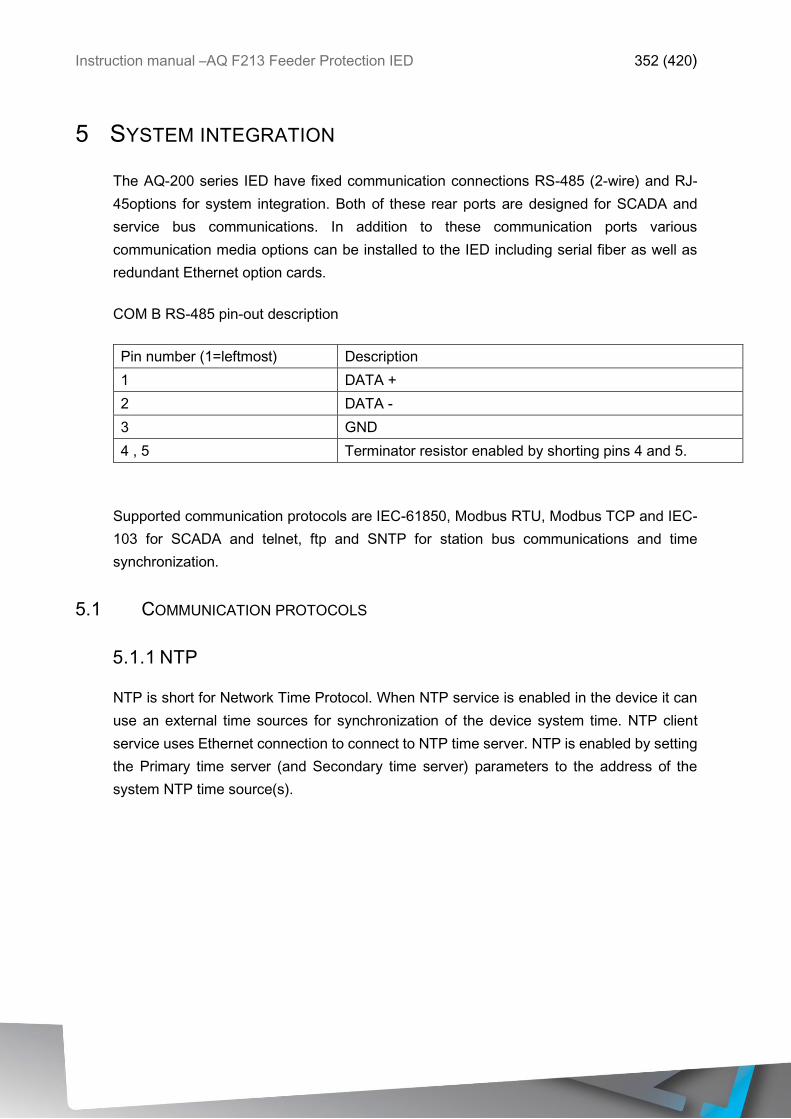
Instruction manual –AQ F213 Feeder Protection IED 352 (420)
5 SYSTEM INTEGRATION
The AQ-200 series IED have fixed communication connections RS-485 (2-wire) and RJ-
45options for system integration. Both of these rear ports are designed for SCADA and
service bus communications. In addition to these communication ports various
communication media options can be installed to the IED including serial fiber as well as
redundant Ethernet option cards.
COM B RS-485 pin-out description
Pin number (1=leftmost) Description
1 DATA +
2 DATA -
3 GND
4 , 5 Terminator resistor enabled by shorting pins 4 and 5.
Supported communication protocols are IEC-61850, Modbus RTU, Modbus TCP and IEC-
103 for SCADA and telnet, ftp and SNTP for station bus communications and time
synchronization.
5.1 COMMUNICATION PROTOCOLS
5.1.1 NTP
NTP is short for Network Time Protocol. When NTP service is enabled in the device it can
use an external time sources for synchronization of the device system time. NTP client
service uses Ethernet connection to connect to NTP time server. NTP is enabled by setting
the Primary time server (and Secondary time server) parameters to the address of the
system NTP time source(s).

Instruction manual –AQ F213 Feeder Protection IED 353 (420)
Parameter Range Description
Primary time server address [0.0.0.0 …
255.255.255.255]
Primary NTP server
address. 0.0.0.0 = service
not in use.
Secondary time server
address
[0.0.0.0 …
255.255.255.255]
Secondary/backup NTP
server address. 0.0.0.0 =
service not in use.
IP address [0.0.0.0 …
255.255.255.255]
The NTP Client IP
address.
NOTE: NTP Client IP has
to be different than relay
IP address.
Netmask [0.0.0.0 …
255.255.255.255]
NTP Client Netmask
Gateway [0.0.0.0 …
255.255.255.255]
NTP Client Gateway
NetworkStatus Messages:
Running
IP error
NM error
GW error
Displays the status or
possible errors of NTP
settings. These are errors
in the parameters
mentioned above.
NTP quality for events No sync
Synchronized
Shows the status of the
NTP time synchronization
at the moment. If other
time synchronization
method is used (external
serial), this indication isn’t
valid.
NOTE: a unique IP address needs to be reserved for NTP Client. Relay IP address cannot
be used.
To set the time zone of the relay connect to relay and then Commands Set time zone.
5.1.2 MODBUSTCP AND MODBUSRTU
The device supports both Modbus TCP and Modbus RTU communication. Modbus TCP
uses the Ethernet connection for communicating with Modbus TCP clients. Modbus RTU is
a serial protocol which can be selected for the available serial ports.

Instruction manual –AQ F213 Feeder Protection IED 354 (420)
Following Modbus function types are supported:
• Read Holding Register, 3
• Write Single Register, 6
• Write Multiple Registers, 16
• Read/Write Multiple Registers, 23
Following data can be accessed using both Modbus TCP and Modbus RTU
• Device measurements
• Device I/O
• Commands
• Events
• Time
NOTE: Modbus map of the relay is found in AQtivate software in Tools Modbus map
once the configuration file has been loaded.
Modbus TCP parameters can be found in following table.
Parameter Range Description
ModbusTCP enable [Disabled, Enabled] Enable setting for Modbus
TCP on Ethernet port.
IP port [0…65535] IP port used by Modbus
TCP. Standard and
default port is 502.
Modbus RTU parameters can be found in following table.
Parameter Range Description
Slave address [1…247] Modbus RTU slave
address for the unit.
5.1.3 MODBUSIO
ModbusIO can be selected for communication on available serial ports. ModbusIO is
actually a ModbusRTU master implementation dedicated for communication with serial
ModbusRTU slaves such as RTD inputs modules. Up to 3 ModbusRTU slaves can be
connected to the same bus polled by the ModbusIO implementation. These are named IO

Instruction manual –AQ F213 Feeder Protection IED 355 (420)
Module A … IO Module C. Each of the modules can be configured using parameters in the
following table.
Parameter Range Description
IO Module[A,B,C] address [0…247] Modbus unit address for
the IO Module. 0 = not in
use.
Module[A,B,C] type [ADAM-4018+] Type selection for module
Channels in use [Ch0…Ch7] Channel selection for the
module.
For each of the 8 channels of the IO module connected thermocouple can be selected.
T.C. type [+-20mA,Type J, Type K,
Type T, Type E, Type R,
Type S]
Thermocouple type
setting.
5.1.4 IEC 61850
Device models with IEC 61850 support, can have the IEC 61850 protocol enabled by the
user. IEC 61850 in Arcteq devices support the following services:
• Dataset, pre-defined datasets can be edited with IEC 61850 editor tool in Aqtivate.
• Report control block, both buffered and un-buffered reporting is supported.
• Control, ‘direct-with-normal-security’ control sequences are supported.
• GOOSE
• Time synchronization

Instruction manual –AQ F213 Feeder Protection IED 356 (420)
Currently used 61850 setup of the device can be viewed in the IEC61850 tool (Tools
IEC61850). For a list of available Logical Nodes in the Arcteq implementation browse the
61850 tree. See following picture:
Figure 5-1 IEC 61850 tool buttons.
The available functions in the IEC 61850 tool are:
1. Open an existing CID-file from the PC hard drive
2. Save the CID file into the aqs currently open (save the aqs file as well [File Save]
to keep the changes)
3. Save the CID file into the hard drive for later use.
4. Exports current CID file without private tags
5. Exports dataset info into a txt file that can be viewed in table format in tools like
Excel
6. Opens main configurations window
7. Opens data set editing window
8. Send the CID configuration to the relay (requires a connection to the relay)
9. Retrieves the default CID file from the relay.

Instruction manual –AQ F213 Feeder Protection IED 357 (420)
The main configurations dialog is opened by pressing 6th button. Important parameters are
here the IED Name and the IP settings. Also if GOOSE publisher service is to be used, the
parameters for GCB1 and GCB2 should be set. See following picture:
Figure 5-2 Main configuration window for basic settings and goose publishing.
The pre-defined, editable, datasets can be opened by pressing the 7th button. It is possible
to add and remove datasets with +/- buttons. When a dataset has been added it has to be
assigned to an RCB with RCB-button (opens a new window). It is possible to assign to Un-
buffered URCB’s or Buffered reporting BRCB’s. All of these datasets can be edited. By un-
checking both of the GOOSE publisher datasets GOOSE publisher service will be disabled.
See following picture.
Figure 5-3 DataSets window for adding/removing and editing datasets.
By marking a dataset and pressing the Edit button the dataset edit dialog is opened. See
following picture. In the edit dialog all currently configured entries of the dataset are visible.
If the red ‘-‘-button is pressed in the end of an entry row the entry will be removed from the

Instruction manual –AQ F213 Feeder Protection IED 358 (420)
dataset. If the green ‘±’-button is pressed a new dialog is opened were it is possible to edit
contents of the dataset. New entries can be added and old edited. It is recommended that
for URCB and BRCB datasets that data is selected on the doName, data object level, (see
example below). In this way all available information like; status, quality and time is always
sent in the report. Data can also be selected on daName, data attribute level, selecting each
individual data. This approach may be preferred for the GOOSE datasets.
Figure 5-4 Data can be also chosen in data attribute level.
For more information on IEC 61850 support, see the conformance statement documents.
IEC61850 general parameters visible in AQtivate and local HMI are described in the table
below.
Parameter Range Description
IEC61850 enable [Disabled, Enabled] Enable setting for IEC
61850 protocol.
IP port [0…65535] IP port used by IEC 61850
protocol. Standard and
default port is 102.
Measurements dead-
band
[0.01…10.00] Measurement data
reporting dead-band
setting.
GOOSE subscriber
enable
[Disabled, Enabled] Enable setting for
GOOSE subscriber.

Instruction manual –AQ F213 Feeder Protection IED 359 (420)
5.1.5 GOOSE
Both GOOSE publisher and subscriber are supported by the Arcteq implementation.
GOOSE subscriber is enabled by parameter setting (Communication Protocols
IEC61850 GOOSE subscriber enable) and GOOSE inputs are configured using HMI or
Aqtivate tool. For each of the Goose inputs there is also an input quality signal which can
also be used in the internal logic. If the input quality is low, (=0), then the quality is good.
Input quality can be bad for reasons like GOOSE timeout and configuration error. Logical
input signal states and quality can be viewed in the device under Device IO menu. For each
GOOSE input following parameters are available.
Parameter Range Description
In use [No, Yes] Setting to take input in to
use.
AppId [0…4294967295] Application ID which will
be matched with the
publishers GOOSE
control block.
ConfRev [0…4294967295] Configuration revision
which will be matched
with the publishers
GOOSE control block.
DataIdx [0…99] Data index of the value in
the matched published
frame which will be the
state of this input.
NextIdx is quality [No, Yes] If the “next” received input
is the quality bit of this
GOOSE Input choose
yes.
Goose publisher configuration is done using the IEC61850 editor started from AQtivate tools
menu. For GOOSE publishing service to start the GCB’s and GOOSE datasets must be
setup. GOOSE Control Blocks are visible by pressing 6th button in the IEC61850 tool. See
picture below. On the right side in the dialog the GCB’s are setup. The important
parameters are App ID which should be unique for the system. Also confRev parameter is

Instruction manual –AQ F213 Feeder Protection IED 360 (420)
checked by the receiving part. If VLAN switches are used to build sub-networks the VLAN
Priority and VLAN ID parameters must be set to match with the system specification.
Figure 5-5 Settings for both available GOOSE Publishing datasets.
GOOSE datasets defines the data which will be sent by the GOOSE publisher. Only binary
data and quality information for the binary signals can be sent by the GOOSE publisher.
The binary signals will be mapped to GOOSE input signals on the receiving side together
with the quality information for that binary signal. The quality information in the incoming
frame will be ORed with GOOSE reception timeout supervision information so that quality
information for each GOOSE input can be used in relay logic.
5.1.6 IEC 103
IEC 103 is short for international standard IEC 60870-5-103. Arcteq implements a
secondary station (slave). The IEC 103 protocol can be selected for the available serial
ports of the device. A master or primary station can communicate with the Arcteq device
and receive information by polling from the slave device. Disturbance recordings transfer is
not supported.

Instruction manual –AQ F213 Feeder Protection IED 361 (420)
NOTE: IEC103 map of the relay is found in AQtivate software in Tools IEC103 map once
the configuration file has been loaded.
IEC 103 parameters can be found in the following table.
Parameter Range Description
Slave address [1…254] IEC 103 slave address for
the unit.
Measurement interval [0…60000]ms Interval setting for the
measurements update.
5.1.7 DNP3
DNP3 is a protocol standard which is controlled by the DNP Users Group at www.dnp.org.
The implementation in the AQ2xx series of a DNP3 slave is compliant with DNP3 Subset
Definition Level 2, but contains also functionality of higher levels. For detailed information
see the DNP3 Device Profile document.
DNP3 parameters can be found in following table.
Parameter Range Description
Slave address [1…65519] DNP3 slave address for
the unit.
Master address [1…65519] DNP3 address setting for
allowed master.
Link layer timeout [0…60000]ms Timeout of link layer
Link layer retries [1…20] Number of link layer
retries
Application layer timeout [0…60000]ms Application layer timeout
Application layer
confirmation
[0=No,1=Yes] Application layer
confirmation enable.
Time sync request
interval
[0…60000]ms Request interval for
synchronization.
5.1.8 IEC 101 / 104
Standards IEC 60870-5-101 & IEC 60870-5-104 are closely related. Both are derived from
IEC 60870-5 standard. On the physical layer IEC 101 uses serial communication but IEC
104 uses Ethernet communication.

Instruction manual –AQ F213 Feeder Protection IED 362 (420)
The IEC 101/104 implementation in AQ2xx series works as a slave in unbalanced mode.
For more detailed information see the IEC101 Profile Checklist document.
IEC101/104 parameters can be found in following table.
Parameter Range Description
Link layer address [1…65535] Link layer address
Link layer address size [1…2] Link layer address size
ASDU address [1…65535] ASDU address
ASDU address size [1…2] ASDU address size
IO address size [1…2] IO address size
IEC104 server enable [0=No,1=Yes] IEC104 enable
IEC104 client IP Client IP address
5.1.9 SPA PROTOCOL
AQ-2xx relay can act as a SPA-slave. SPA can be selected as the communication protocol
into COM B port (in CPU module). If serial RS232 & serial fiber module is available in the
device SPA protocol can be activated for these channels (COM E or F). See the chapter for
construction and installation to see the connections for these modules.
SPAs data transfer rate is 9600bps but it can be also set to 19200bps or 38400bps. As a
slave the relay will send data on demand or by sequenced polling. Available data can be
measurements, circuit breaker states, function starts/trips etc. Full SPA signal map can be
found in AQtivate from ToolsSPA map. Please note that aqs file should be downloaded
from relay first.
The SPA EVENT addresses can be found in Tools Events and logs Event list. This
also requires to open an aqs configuration file of the relay first.
NOTE: SPA map of the relay is found in AQtivate software in Tools SPA map once the
configuration file has been loaded.
5.2 GENERAL IO ANALOG FAULT REGISTERS
In the menu in Communication General IO Analog fault register it is possible to set up
to 12 channels to record the measured value at the time of protection function start or trip.
These values can be read through possibly used communication protocol or locally from
this same menu.

Instruction manual –AQ F213 Feeder Protection IED 363 (420)
6 CONSTRUCTION AND INSTALLATION
AQ-F213 Feeder Protection IED is a member of modular and scalable AQ-2xx series and
includes three configurable modular add-on card slots. As a standard configuration in the
IED are included CPU, IO and Power supply module. In the figure below is presented non-
optioned model (AQ-F213-XX-AAA) and fully optioned model (AQ-F213-XX-BBC) of the
AQ-F213 Feeder Protection IED.
Figure 6-1 Modular construction of AQ-F213 Feeder Protection IED
AQ-F213 modular structure allows scalable solutions for different application requirements.
In any of the non-standard configured slot “C”, “E” and “F” can be ordered with any available
add-on module which can be binary IO module, integrated Arc –protection or any special
module provided. Only differentiating factor in the device scalability is considering the “E”
slot which supports also communication options.
In case add-on module is inserted to the IED the start-up scan will search of the modules
according to the type designation code, if the module location or content is differing from
the expected the IED will not take additional modules into account and will issue a
configuration error. For a field upgrade this means that the add-on module has to be ordered
from Arcteq Ltd. or representative who shall provide the add-on module with corresponding
unlocking code in order the device to be operating correctly after upgrading the hardware

Instruction manual –AQ F213 Feeder Protection IED 364 (420)
configuration. This means also that the module location cannot be changed without
updating the device configuration data, for this case also unlocking code is needed.
When IO module is inserted to the IED the module location shall effect to the naming of the
IO. The scanning order in the start-up sequence is CPU-module IO, slot C, slot E and slot
F. This means that the binary input channels DI1 and DI2 and also the binary output
channels OUT1, OUT2, OUT3, OUT4 and OUT5 are always located in the CPU-module. If
more IO is installed the location of each type of card will have effect on the found IO naming.
In following figure is presented the principle of the start-up hardware scan of the IED.
1. Scan: Start-up system, detect and self-test CPU-module,
voltages, comm. and IO. Find and assign DI1, DI2
OUT1, OUT2, OUT3, OUT4 and OUT5.
2. Scan: Find VTM&DI4 module with 3 voltage channels and 4
digital inputs DI3,DI4,DI5,DI6 (fixed for AQ-F213).
3. Scan: Scan Slot B, in case of AQ-F213 should be always
empty. If not empty then issue alarm.
4. Scan: Scan Slot C, if empty go to next slot. If found 8DI
module then reserve to this slot
DI7,DI8,DI9,DI10,DI11,DI12,DI13 and DI14. If found
DO5 module then reserve to this slot OUT6, OUT7,
OUT8, OUT9 and OUT10. Amount of IO is added If the
type designation code allows and if not match then
issue alarm as also if module is expected to be found
and is not there alarm will be issued.
5. Scan: Find CTM module 5 channels (fixed for AQ-F213).
6. Scan: Scan Slot E, if empty go to next slot. If found 8DI
module then reserve to this slot running number regard
if Slot C was empty or had other than Dix module then
DI7, DI8, DI9, DI10, DI11, DI12, DI13 and DI14 or if
Slot C has also DI8 module then DI15, DI16, DI17,
DI18, DI19, DI20, DI21 and DI22. If found DO5 module
then reserve to this slot OUT6, OUT7, OUT8, OUT9
and OUT10 or OUT11, OUT12, OUT13, OUT14 and
OUT15 with similar basis than for the inputs.
If found arc protection module, reserve sensor
channels S1, S2, S3, S4, high speed outputs HSO1,
HSO2 and binary input channel ArcBI to this slot.
7 Scan: Similar operation to Scan 6.
Figure 6-2 Hardware scanning and IO naming principle in AQ-F213 IED
In the previous example only IO add-on cards were described if installed into the option
module slots. If the slot has other module than IO they are treated similarly. For example in
case of added communication port the upper port of the communication module shall be in
minimum of Comm. port 3 etc. since in the CPU-module already exist Comm. ports 1 and
2. After communication port is detected it is added into the communication space in the IED
and corresponding settings are enabled for the IED.
In the example case of AQ-F213-XX-BBC all available binary input channels amount is
DI1…DI22, from which DI1 and DI2 are in the CPU module, DI3…DI6 are in the voltage

Instruction manual –AQ F213 Feeder Protection IED 365 (420)
measurement module and DI7…DI22 are in Slots C & E. All available binary output
channels are DO1…DO10, from which DO1-DO5 are in the CPU module and DO6-DO10
are in slot F. If the configuration should differ from this example the same principle is always
applied into the IED. Slot E has an arc protection module installed, which has sensor
modules S1,S2,S3 and S4, one binary input ArcBI and high speed outputs HSO1 and
HSO2.

Instruction manual –AQ F213 Feeder Protection IED 366 (420)
6.1 CPU, IO AND POWER SUPPLY MODULE
By default the AQ-2xx IED platform combination CPU, IO and Power supply module is
included in the AQ-2xx IED which includes two standard communication ports and basic
binary IO of the relay.
Connector Description
COM A : Communication port A, RJ-45. For Modbus TCP and station
bus communications.
COM B : Communication port B, RS-485. For Modbus RTU and IEC-
103 SCADA communications. Pin-out starting from the left:
1=DATA +, 2=DATA -, 3=GND, 4&5=Terminator resistor
enabled by shorting.
X1-1 Digital input 1, Settable digital input with pick-up and release
thresholds.
X1-2 Digital input 1 Ground
X1-3 Digital input 2, Settable digital input with pick-up and release
thresholds.
X1-4 Digital input 2 Ground
X1-5:6 Output relay 1, Normally open contact
X1-7:8 Output relay 2, Normally open contact
X1-9:10 Output relay 3, Normally open contact
X1-11:12 Output relay 4, Normally open contact
X1-13:14:15 Output relay 5, Changeover contact
X1-16:17:18 System Fault output relay, Changeover contact
X1-19:20 Power supply in, Either 85 – 265 VAC/DC (model H) or 18 –
75 DC (model L), Positive side (+) to pin X1:20
GND Relay grounding connector
- Binary inputs current consumption is 2 mA when activated
and the operating voltage range is from 0V to
24,110,220VAC/DC (depends on ordered CPU module
type). All binary inputs are scanned in 5 ms program cycle
and have software settable filtering and pick-up delay of
input signal and software settable NO/NC selection.
- Binary outputs control is settable from the software. As
standard binary outputs are controlled in 5 ms program
cycle. All output contacts are mechanical type. Rated
voltage of the NO/CO outputs is 250VAC/DC.
Figure 6.1-3 AQ-2xx Main processor module CPU, IO, communications and PSU with 2
digital inputs.
Auxiliary voltage shall be defined in the ordering code of the device, either A or B model
power supplies are available. Power supply minimum allowed bridging time for all voltage
levels is > 150 ms. Power supply maximum power consumption is 15 Wmax. Power supply

Instruction manual –AQ F213 Feeder Protection IED 367 (420)
allows DC ripple of <15 % and start-up time of power supply is < 5 ms. Further details refer
to the “Technical data” section of this document.
6.1.1 SCANNING CYCLE OF THE DIGITAL INPUT
Binary inputs are scanned in 5 millisecond cycle. This makes the state of input to be updated
between 0…5 milliseconds. When input is used internally in IED (group change or logic) it
takes additional 0…5 milliseconds to operate. So in theory when binary input is used for
group control or similar it takes 0…10 milliseconds to change the group. In practice the
delay is between 2…8 milliseconds about 95% of the time. In case the binary input is
connected directly to binary output (T1…Tx) it takes additional third 5 millisecond round.
When binary input is controlling internally binary output it takes 0…15 milliseconds in theory
and 2…13 milliseconds in practice. This delay excludes the mechanical delay of the relay.
6.2 CURRENT MEASUREMENT MODULE
AQ-2xx basic five channel current measure module includes three phase current
measurement inputs and also coarse and fine residual current inputs.
Connector Description
CTM 1-2 Phase current measurement for phase L1 (A)
CTM 3-4 Phase current measurement for phase L2 (B)
CTM 5-6 Phase current measurement for phase L3 (C)
CTM 7-8 Coarse residual current measurement I01
CTM 9-10 Fine residual current measurement I02
Figure 6.2-4 current measurement module
Current measurement module is connected to secondary side of conventional current
transformers (CTs). Nominal dimensioning current for the phase current inputs is 5 A. Input
nominal current can be scaled for secondary currents of 1…10 A. Secondary currents are
calibrated to nominal currents of 1A and 5A which provide ± 0.2% inaccuracy in range of
0,05 x In – In – 4 x In.

Instruction manual –AQ F213 Feeder Protection IED 368 (420)
Phase current input characteristics are as follows:
o Measurement range
▪ Phase currents 0…250 ARMS
▪ Coarse residual current 0…150ARMS
▪ Fine residual current 0…75ARMS
o Angle measurement accuracy less than ± 0.5 degrees with nominal current.
o Frequency measurement range of the phase current inputs is in range from 6 Hz to
1800 Hz with standard hardware.
o Quantization of the measurement signal is applied with 18 bit AD converters and the
sample rate of the signal shall be 64 samples / power cycle in system frequency
range of 6 Hz to 75 Hz.
For further details refer to the “Technical data” section of this document.
6.3 3 VOLTAGE CHANNEL MEASUREMENT MODULE
AQ-2xx three channel voltage measure module includes three freely configurable voltage
measurement inputs and four digital inputs.
Connector Description
SlotX 1-2-3 Configurable voltage measurement input U1
and U2
SlotX 4-5 Configurable voltage measurement input U3
SlotX 6 DIx + 3
SlotX 7 DIx + 4
SlotX 8 DIx + 5
SlotX 9 DIx + 6
SlotX 10 GND common ground for this module 3-6 DI
Figure 6.3-5 3 voltage measurement module

Instruction manual –AQ F213 Feeder Protection IED 369 (420)
Voltage measurement module is connected to secondary side of conventional voltage
transformers (VTs) or directly to low voltage systems secured by fuses. Nominal
dimensioning voltage can be 100…250 V. Voltages are calibrated in range of 0…240 V
which provide ± 0.2% inaccuracy in same range.
Voltage input characteristics are as follows:
o Measurement range
▪ Per channel 0…250 V
o Angle measurement accuracy less than ± 0.5 degrees within nominal range.
o Frequency measurement range of the voltage inputs is in range from 6 Hz to 1800
Hz with standard hardware.
o Quantization of the measurement signal is applied with 18 bit AD converters and the
sample rate of the signal shall be 64 samples / power cycle in system frequency
range of 6 Hz to 75 Hz.
For further details refer to the “Technical data” section of this document.
6.4 DIGITAL INPUT MODULE DI8
The DI8 module is an add-on module for additional eight (8) galvanic isolated binary inputs.
This module can be ordered directly as factory installed option or it can be field upgraded if
needed after the first installation of the AQ-200 series IED.
Connector Description
SlotX 1 DIx + 1
SlotX 2 DIx + 2
SlotX 3 DIx + 3
SlotX 4 DIx + 4
SlotX 5 GND common ground for this module 1-4 DI
SlotX 6 DIx + 5
SlotX 7 DIx + 6
SlotX 8 DIx + 7
SlotX 9 DIx + 8
SlotX 10 GND common ground for this module 5-8 DI
Figure 6.4-6 DI8 Binary input module for eight add-on binary inputs.

Instruction manual –AQ F213 Feeder Protection IED 370 (420)
Properties of this binary input module provided inputs are exactly the same than inputs in the
CPU-module.
Binary inputs have as standard current consumption of 2 mA when activated and the operating
voltage range is from 0V to 265VAC/DC with software settable activation/release threshold
and 1V resolution. All binary inputs are scanned in 5 ms program cycle and they have software
settable filtering and pick-up delay of input signal and software settable NO/NC selection.
Naming convention of the binary inputs provided by this module is presented in the chapter 6
Construction and installation.
For further details refer to the “Technical data” section of this document.
6.5 DIGITAL OUTPUT MODULE DO5
The DO5 module is an add-on module for additional five (5) binary outputs. This module
can be ordered directly as factory installed option or it can be field upgraded if needed after
the first installation of the AQ-200 series IED.
Connector Description
SlotX 1 OUTx + 1 first pole NO
SlotX 2 OUTx + 1 second pole NO
SlotX 3 OUTx + 2 first pole NO
SlotX 4 OUTx + 2 second pole NO
SlotX 5 OUTx + 3 first pole NO
SlotX 6 OUTx + 3 second pole NO
SlotX 7 OUTx + 4 first pole NO
SlotX 8 OUTx + 4 second pole NO
SlotX 9 OUTx + 5 first pole NO
SlotX 10 OUTx + 5 second pole NO
Figure 6.5-7 DO5 Binary output module for five add-on binary outputs.
Properties of this binary input module provided inputs are exactly the same than inputs in the
CPU-module.

Instruction manual –AQ F213 Feeder Protection IED 371 (420)
Binary outputs control can be settable from the software. As a standard binary outputs are
controlled in 5 ms program cycle. All output contacts are mechanical type. Rated voltage of
the NO/CO outputs is 250VAC/DC.
Naming convention of the binary outputs provided by this module is presented in the chapter
6 Construction and installation.
For further details refer to the “Technical data” section of this document.

Instruction manual –AQ F213 Feeder Protection IED 372 (420)
6.6 ARC PROTECTION MODULE (OPTION)
The arc protection module is an add-on module for four (4) light sensor channels. This module also
has two (2) high speed outputs and one (1) binary input. This module can be ordered directly as
factory installed option or it can be field upgraded if needed after the first installation of the AQ-200
series IED.
Connector Description
S1 Light sensor channels 1…4 with plus, sensor
and ground connectors. S2
S3
S4
SlotX 1 HSO2 + NO
SlotX 2 Common battery + for HSO
SlotX 3 HSO1 + NO
SlotX 4 Arc BI1 + pole
SlotX 5 Arc BI1 - pole
Figure 6.6-8 Arc protection module for four light sensors, two high speed outputs and one
binary input.
In case any of sensor channels S1…S4 is not connected correctly it won’t work. Each channel
can have up to three light sensors connected on parallel. It is up to the user how many
channels are used.
High speed outputs HSO1 and HSO2 operate only with DC supply. Battery plus (+) has to be
wired according the drawing and output 1 or 2 NO side is wired trough trip coil to battery minus
(-). High speed output voltage withstand is up to 250VDC. For further information see the
technical data chapter of the manual. High speed output operation time is less than 1ms.
Binary input rated voltage is 24 VDC. Threshold picks up at ≥16 VDC. Binary input can be
used for external light information or similar and can be used as a part of various ARC –
schemes. Notice that the delay of binary input lies between 5…10ms.

Instruction manual –AQ F213 Feeder Protection IED 373 (420)
BI and HSO1…2 are not visible in Device IO Binary Inputs or Binary Outputs -menus.
Binary input and high speed outputs are programmable only in Arc Matrix menu.
6.7 RTD & MA INPUT MODULE (OPTION)
The RTD/mA module is an add-on module for 8 RTD inputs. Each input supports 2-wire, 3-wire
and 4-wire RTDs and thermocouple sensors. Sensor type can be selected by software for two 4
channel groups.
• Supported RTD sensors: Pt100, Pt1000
• Supported Thermocouple: Type K, Type J, Type T and Type S
Two mA-input channels are available in the option card. If these are selected it will reduce total
amount of RTD channels to 6.
Connector
1:RTD1-1 2:RTD1-2/TC1-
3:RTD1-3/TC1+ 4:RTD1-4
5:RTD2-1 6:RTD2-2/TC2-
7:RTD2-3/TC2+ 8:RTD2-4
9:RTD3-1 10:RTD3-2/TC3-
11:RTD3-3/TC3+ 12:RTD3-4
13:RTD4-1 14:RTD4-2/TC4-
15:RTD4-3/TC4+ 16:RTD4-4
17:RTD5-1 18:RTD5-2/TC5-
19:RTD5-3/TC5+ 20:RTD5-4
21:RTD6-1 22:RTD6-2/TC6-
23:RTD6-3/TC6+ 24:RTD6-4
25:RTD7-1 26:RTD7-2 / TC7- / mAin1-
27:RTD7-3/TC7+ 28:RTD7-4 / mAin1+
29:RTD8-1 30:RTD8-2/TC8/mAin2-
31:RTD8-3/TC8+ 32:RTD8-4/mAin2+
Figure 6.7-9 RTD module with 8 RTD channels

Instruction manual –AQ F213 Feeder Protection IED 374 (420)
Figure 6-1 Connection of different sensor types

Instruction manual –AQ F213 Feeder Protection IED 375 (420)
6.8 SERIAL RS232 & SERIAL FIBER MODULE (OPTION)
Option card includes two serial communication interfaces. COM E is a serial fiber interface
with glass/plastic option. COM F is a RS-232 interface.
COM E Serial fiber
(GG/PP/GP/PG)
Serial based communications
COM F Pin1 GND
(for+24Vinput)
Optional external auxiliary voltage
for serial fiber
COM F Pin2 - Optional external auxiliary voltage
for serial fiber
COM F Pin3 - -
COM F Pin4 - -
COM F Pin5 RS-232 RTS Serial based communications
COM F Pin6 RS-232 GND Serial based communications
COM F Pin7 RS-232 TX Serial based communications
COM F Pin8 RS-232 RX Serial based communications
COM F Pin9 - -
COM F Pin10 +3.3V output
(spare)
Spare power source for external
equipment (45mA)
COM F Pin11 Clock sync input Clock synchronization input
COM F Pin12 Clock sync
GND
Clock synchronization input
Figure 6.8-10 AQ-2xx Serial RS232-card connectors

Instruction manual –AQ F213 Feeder Protection IED 376 (420)
6.9 DOUBLE LC 100 MB ETHERNET MODULE (OPTION)
Optional LC 100 MB Ethernet card supports HSR and PRP protocols according to IEC
61850 substation communication standard. Card has IEEE1588 (PIP) clock sync
functionality. Card has two PRP/HSR ports which are 100Mbit fiber ports and can be
configured to 100Mbit or 10 Mbit.
Connector Description
COM C : Communication port C, LC fiber connector
COM D : Communication port D, LC fiber connector
Figure 6.9-11 AQ-2xx LC 100 MB Ethernet card connectors

Instruction manual –AQ F213 Feeder Protection IED 377 (420)
6.10 RJ-45 & 4 DIGITAL INPUT MODULE
The RJ-45&DI4 module is an add-on module for additional RJ-45 port and four (4) galvanic
isolated binary inputs. This module can be ordered directly as factory installed option or it
can be field upgraded if needed after the first installation of the AQ-200 series IED.
Connector Description
COM G Communication port A, RJ-45. For Modbus
TCP and station bus communications.
SlotX 1 DIx + 1
SlotX 2 DIx + 2
SlotX 3 DIx + 3
SlotX 4 DIx + 4
SlotX 5 GND common ground for this module 1-4 DI
Figure 6.10-12 RJ-45 & 4 Binary input module for add-on binary inputs and RJ-45 port.
Properties of this binary input module provided inputs are exactly the same than inputs in the
CPU-module.
Binary inputs have as standard current consumption of 2 mA when activated and the operating
voltage range is from 0V to 265VAC/DC with software settable activation/release threshold
and 1V resolution. All binary inputs are scanned in 5 ms program cycle and they have software
settable filtering and pick-up delay of input signal and software settable NO/NC selection.
Naming convention of the binary inputs provided by this module is presented in the chapter 6
Construction and installation.
The RJ-45 port is an additional port to the one as a default in CPU card. It can be used e.g.
as a maintenance port.

Instruction manual –AQ F213 Feeder Protection IED 378 (420)
6.11 INSTALLATION AND DIMENSIONS
AQ-2xx IED can be installed either to standard 19” rack or cut-out to a switchgear panel
(Installation type of the device has to be defined by ordering option). When installing to rack,
the device will take ¼ of the rack width and total of four devices can be installed to same
rack in parallel. In below is described the device panel installation and cut-outs.
Figure 6.11-13 Dimensions of the AQ-2xx IED.

Instruction manual –AQ F213 Feeder Protection IED 379 (420)
Figure 6.11-14 Installation of the AQ-2xx IED

Instruction manual –AQ F213 Feeder Protection IED 380 (420)
Figure 6.11-15 Panel cut-out and spacing of the AQ-2xx IED.

Instruction manual –AQ F213 Feeder Protection IED 381 (420)
7 APPLICATIONS
7.1 2LN+U0 CONNECTION EXAMPLE
Connection example of outgoing feeder application with two lines to neutral voltages and zero
sequence voltage connected. Three phase currents and residual current are connected as well.
Figure 6.1.1-1 Voltage measurement mode is 2LN+U0.
7.2 3-PHASE, 3-WIRE ARON INPUT CONNECTION EXAMPLE
In this chapter is presented a connection example of an application with only two installed
protection CTs. Connection is suitable for both motor –and feeder protection applications.

Instruction manual –AQ F213 Feeder Protection IED 382 (420)
Figure 6.1.1-2 3-phase, 3-wire ARON input connection.
ARON input connection can measure load symmetrically despite the fact that one of the CTs is
missing from the installation. Normally the current transformer of phase two is without installed
CT since it is much more likely that external fault appears on line 1 or 3.
Fault between line 2 and ground cannot be detected when ARON input connection is used. For
detecting ground fault in phase two a cable core CT has to be used.

Instruction manual –AQ F213 Feeder Protection IED 383 (420)
7.3 TRIP CIRCUIT SUPERVISION
7.3.1 TRIP CIRCUIT OPEN COIL SUPERVISION WITH ONE DIGITAL INPUT AND
CONNECTED TRIP OUTPUT
Trip circuit supervision is used to monitor the wiring from auxiliary power supply trough IEDs
binary output and all the way to the open coil of the breaker. It is recommended to know that trip
circuit is on healthy state when the breaker is closed. Application scheme for trip circuit
supervision with one digital input is presented in figure below.
Figure 7.3.1-3 Trip circuit supervision by using one DI and non-latched trip output.
Notice that DI monitoring the circuit is used as normally closed. Same applies with the used alarm
relay (if used). In monitoring purposes and especially in trip circuit supervision it is recommended
to use closed contact in normal condition to confirm the condition of wiring. Active digital input
generates less than 2mA current to the circuit. Normally current this small is not able to make the
breaker open coil operate. While the trip relay is controlled and the circuit breaker is being opened
the digital input is shorted by the trip contact as long as the breaker opens. This normally takes
approximately 100ms if the relay is non-latched. Therefore t = 1.0 second activation delay should
be added to the digital input. Basically activation delay just a bit longer than the operation time of

Instruction manual –AQ F213 Feeder Protection IED 384 (420)
circuit breaker would be long enough. When CB failure protection is used it might be good to add
the CBFP operation time to the digital input activation time (tDI = tCB + tIEDrelease + tCBFP). See
attached picture below.
Figure 7.3.1-4 The digital input used for TCS needs to have normally closed polarity and
also 1.0 second activation delay to avoid nuisance alarms while CB is controlled open.
Non-latched outputs are seen in the output matrix as hollow circles. Latched contacts are painted.
See below presented figure.
Figure 7.3.1-5 IED trip contact used to open the circuit breaker has to be non-latched.
Non-latched trip output contact is a mandatory to have if Autorecloser is used in feeder
applications. TCS is generally easier and more reliable to build with non-latched output.
The open coil is energized only as long as the circuit breaker is opened and IED output releases.
This takes approximately 100ms depending of the size and type of the breaker. When the breaker
opens the auxiliary contacts will open the inductive circuit but the IED trip contact won’t open at
the same time. IEDs output relay contact will open in <50ms or after configured release delay due

Instruction manual –AQ F213 Feeder Protection IED 385 (420)
the breaker is open. This means that the open coil is energized for a short moment even the
breaker is already open. Coil could be energized even moment longer if circuit breaker failure
protection has to be used and incomer is performing the tripping.
7.3.2 TRIP CIRCUIT OPEN COIL SUPERVISION WITH ONE DIGITAL INPUT AND
CONNECTED AND LATCHED TRIP OUTPUT
The main difference between non-lathed and latched control in trip circuit supervision is that when
latched control is used it is not possible to monitor the trip circuit in open state due the digital input
is shorted by the trip output of the IED.
Figure 7.3.2-6 Trip circuit supervision by using one DI and latched output contact.
It is possible to monitor trip circuit with latched output contact but then monitoring the trip circuit
is possible only while the circuit breaker status is closed. Whenever the breaker is open the TCS
is blocked by an internal logic scheme. The disadvantage is that you don’t know whether the trip
circuit is intact or not when the breaker is closed again.
While the circuit breaker is in open position the TCS alarm is blocked by using following logic
scheme or similar. TCS alarm is giving whenever the breaker is closed and inverted digital input

Instruction manual –AQ F213 Feeder Protection IED 386 (420)
signal (CTS) activates. Normally closed digital input activates only when there is something wrong
in the trip circuit and the auxiliary power goes off. While the breaker is open the logic is blocked.
Logical output can be used in output matrix or in SCADA as pleased.
Figure 7.3.2-7 TCS block scheme when non-latched trip output is not used.

Instruction manual –AQ F213 Feeder Protection IED 387 (420)
8 TECHNICAL DATA
8.1 CONNECTIONS
8.1.1 MEASUREMENTS
Table 8.1.1-1 Current measurement module
Measurement channels / CT inputs Three phase currents, One coarse residual current, and One
sensitive residual current. Total of five separate CT inputs.
Phase current inputs (A,B,C)
- Rated current In
- Thermal withstand
- Frequency measurement range
- Current measurement range
- Current measurement inaccuracy
- Angle measurement inaccuracy
- Burden (50Hz/60Hz)
5A (configurable 0.2A…10A)
30A continuous
100A for 10s
500A for 1s
1250A for 0.01s
from 6Hz to 75Hz fundamental, up to 31st harmonic current
25mA…250A(rms)
0.005xIn…4xIn < ±0.5% or < ±15mA
4xIn…20xIn < ±0.5%
20xIn…50xIn < ±1.0%
< ±0.1 °
<0.1VA
Coarse residual current input (I01)
- Rated current In
- Thermal withstand
- Frequency measurement range
- Current measurement range
- Current measurement inaccuracy
- Angle measurement inaccuracy
- Burden (50Hz/60Hz)
1A (configurable 0.2A…10A)
25A continuous
100A for 10s
500A for 1s
1250A for 0.01s
from 6Hz to 75Hz fundamental, up to 31st harmonic current
2mA…150A(rms)
0.002xIn…10xIn < ±0.5% or < ±3mA
10xIn…150xIn < ±0.5%
< ±0.1 °
<0.1VA
Fine residual current input (I02)
- Rated current In
- Thermal withstand
- Frequency measurement range
- Current measurement range
0.2A (configurable 0.2A…10A)
25A continuous
100A for 10s
500A for 1s
1250A for 0.01s
from 6Hz to 75Hz fundamental, up to 31st harmonic current
0.4mA…75A(rms)

Instruction manual –AQ F213 Feeder Protection IED 388 (420)
- Current measurement inaccuracy
- Angle measurement inaccuracy
- Burden (50Hz/60Hz)
0.002xIn…25xIn < ±0.5% or < ±0.6mA
25xIn…375xIn < ±0.5%
< ±0.1 °
<0.1VA
Terminal block
- Solid or stranded wire
- Phoenix Contact FRONT 4H-6,35
Maximum wire diameter:
4 mm2
Table 8.1.1-2 Voltage measurement module
Measurement channels / VT inputs Total of three separate VT inputs.
Voltage inputs (U1, U2, U3)
Voltage measuring range
Thermal withstand
Frequency measurement range
Voltage measurement inaccuracy
Angle measurement inaccuracy
Burden (50Hz/60Hz)
0.01…250.00V (RMS)
300VRMS continuous
from 6Hz to 75Hz
0.01…250V < ±1%
< ±1.0 degrees
<0.02VA
Terminal block
Solid or stranded wire
Maximum wire diameter:
4 mm2

Instruction manual –AQ F213 Feeder Protection IED 389 (420)
Table 8.1.1-3 Frequency, power and energy measurement accuracy
Frequency measuring range
Inaccuracy
6…75 Hz fundamental, up to 31st harmonic current and
voltage
10 mHz
Power measurement P, Q, S
Inaccuracy
Frequency range 6…75 Hz
1 % of value or 3 VA of secondary
Energy measurement
Energy and power metering inaccuracy
Frequency range 6…75 Hz
IEC 62053-22 class 0.5 S (50/60Hz) as standard
8.1.2 AUXILIARY VOLTAGE
Table 8.1.2-4 Power supply model A
Rated auxiliary voltage 85…265V(AC/DC)
Power consumption < 7W
< 15W
Maximum permitted interrupt time < 150ms with 110VDC
DC ripple < 15 %
Terminal block
- Solid or stranded wire
- Phoenix Contact MSTB2,5-5,08
Maximum wire diameter:
2.5mm2
Table 8.1.2-5 Power supply model B
Rated auxiliary voltage 18…72VDC
Power consumption < 7W
< 15W
Maximum permitted interrupt time < 150ms with 110VDC
DC ripple < 15 %
Terminal block
- Solid or stranded wire
- Phoenix Contact MSTB2,5-5,08
Maximum wire diameter:
2.5mm2

Instruction manual –AQ F213 Feeder Protection IED 390 (420)
8.1.3 BINARY INPUTS
Table 8.1.3-6 Isolated binary inputs at CPU card DI1-DI2
Rated auxiliary voltage D: 24Vdc
E: 110Vdc
F: 220Vdc
Pick-up threshold <80% of the nominal
Scanning rate 5 ms
Pick-up delay Software settable: 0…1800s
Polarity Software settable: Normally On / Normally Off
Current drain 2 mA
Terminal block
- Solid or stranded wire
- Phoenix Contact MSTB2,5-5,08
Maximum wire diameter:
2.5mm2
Table 8.1.3-7 Isolated binary inputs with software settable threshold DI3-
Rated auxiliary voltage 5…265V(AC/DC)
Pick-up threshold
Release threshold
Software settable: 5…240V, by step of 1V
Software settable: 5…240V, by step of 1V
Scanning rate 5 ms
Pick-up delay Software settable: 0…1800s
Polarity Software settable: Normally On / Normally Off
Current drain 2 mA
Terminal block
- Solid or stranded wire
- Phoenix Contact MSTB2,5-5,08
Maximum wire diameter:
2.5mm2
8.1.4 BINARY OUTPUTS
Table 8.1.4-7 Normal Open binary outputs
Rated auxiliary voltage 265V(AC/DC)
Continuous carry 5A
Make and carry 0.5s
Make and carry 3s
30A
15A
Breaking capacity, DC (L/R = 40 ms)
at 48VDC
at 110 VDC
at 220 VDC
1A
0.4A
0.2A
Control rate 5 ms
Polarity Software settable: Normally On / Normally Off
Contact material
Terminal block
- Solid or stranded wire
- Phoenix Contact MSTB2,5-5,08
Maximum wire diameter:
2.5mm2

Instruction manual –AQ F213 Feeder Protection IED 391 (420)
Table 8.1.4-8 Change-Over binary outputs
Rated auxiliary voltage 265V(AC/DC)
Continuous carry 5A
Make and carry 0.5s
Make and carry 3s
30A
15A
Breaking capacity, DC (L/R = 40 ms)
at 48VDC
at 110 VDC
at 220 VDC
1A
0.4A
0.2A
Control rate 5 ms
Polarity Software settable: Normally On / Normally Off
Contact material
Terminal block
- Solid or stranded wire
- Phoenix Contact MSTB2,5-5,08
Maximum wire diameter:
2.5mm2
8.1.5 ARC PROTECTION CARD (OPTION)
Table 8.1.5-9 Normal Open binary outputs
Number of arc sensor channels 4
Operating time <15ms
Table 8.1.5-10 High Speed Outputs (HSO1…2)
Rated auxiliary voltage 250Vdc
Continuous carry 2A
Make and carry 0.5s
Make and carry 3s
15A
6A
Breaking capacity, DC (L/R = 40 ms) 1A / 110W
Control rate 5ms
Operation delay <1ms
Polarity Normally Off
Contact material Semiconductor
Terminal block
- Solid or stranded wire
- Phoenix Contact MSTB2,5-5,08
Maximum wire diameter:
2.5mm2

Instruction manual –AQ F213 Feeder Protection IED 392 (420)
Table 8.1.5-11 Binary input channel
Voltage withstand 265Vdc
Rated auxiliary voltage
Pick-up threshold
Release threshold
24Vdc
≥16Vdc
≤15Vdc
Scanning rate 5 ms
Operation delay
Polarity Normally Off
Current drain 3 mA
Terminal block
- Solid or stranded wire
- Phoenix Contact MSTB2,5-5,08
Maximum wire diameter:
2.5mm2
NOTE! Polarity has to be correct.
8.1.6 COMMUNICATION PORTS
Table 8.1.6-12 Front panel local communication port
Port media Copper Ethernet RJ-45
Number of ports 1pcs
Port protocols PC-protocols, FTP, Telnet
Data transfer rate 100 MB
System integration Cannot be used for system protocols, only for local
programming
Table 8.1.6-13 Rear panel system communication port A
Port media Copper Ethernet RJ-45
Number of ports 1pcs
Port protocols IEC61850, Modbus TCP, DNP 3.0, FTP, Telnet
Data transfer rate 100 MB
System integration Can be used for system protocols and for local programming
NOTE: IEC61850 function is included in function packages B, C, D & E of AQ-F213.
Table 8.1.6-14 Rear panel system communication port B
Port media Copper RS-485
Number of ports 1pcs
Port protocols Modbus RTU, DNP 3.0, IEC-103
Data transfer rate 65580 kB/s
System integration Can be used for system protocols

Instruction manual –AQ F213 Feeder Protection IED 393 (420)
8.2 PROTECTION FUNCTIONS
All specified operation times include mechanical trip contact delay.
8.2.1 CURRENT PROTECTION FUNCTIONS
OVERCURRENT (50/51) I>, I>>, I>>>, I>>>>
Input signals
Input magnitudes Phase current fundamental freq RMS
Phase current TRMS
Phase current peak-to-peak
Pick-up
Pick-up current setting 0.10…40.00 x In, setting step 0.01 x In
Inaccuracy
-Current
±0.5 %ISET or ±15 mA (0.10…4.0 x ISET)
Operation time
Definite time function operating time setting 0.00…1800.00 s, setting step 0.005 s
Inaccuracy
-Definite Time (Im/Iset ratio > 3)
-Definite Time (Im/Iset ratio 1.05…3)
±1.0 % or ±20 ms
±1.0 % or ±30 ms
IDMT operating time setting (ANSI / IEC) 0.02…1800.00 s, setting step 0.001 x parameter
IDMT setting parameters
k Time dial setting for IDMT
A IDMT Constant
B IDMT Constant
C IDMT Constant
0.01…25.00 step 0.01
0…250.0000 step 0.0001
0…5.0000 step 0.0001
0…250.0000 step 0.0001
Inaccuracy
-IDMT operating time
-IDMT minimum operating time; 20 ms
±1.5 % or ±20 ms
±20 ms
Instant operation time
Start time and instant operation time (trip):
(Im/Iset ratio > 3)
(Im/Iset ratio 1.05…3)
<35 ms (typical 25 ms)
<50 ms
Reset
Reset ratio 97 % of pick-up current setting
Reset time setting
Inaccuracy: Reset time
0.010 … 10.000 s, step 0.005 s
±1.0 % or ±35 ms
Instant reset time and start-up reset <50 ms
NOTE: I> function is included in all function packages of AQ-F213.

Instruction manual –AQ F213 Feeder Protection IED 394 (420)
EARTHFAULT (50N/51N) I0>, I0>>, I0>>>, I0>>>>
Input signals
Input magnitudes Residual current fundamental freq RMS
Residual current TRMS
Residual current peak-to-peak
Pick-up
Used magnitude Measured residual current I01 (1 A)
Measured residual current I02 (0.2 A)
Calculated residual current I0Calc (5 A)
Pick-up current setting 0.005…40.00 x In, setting step 0.001 x In
Inaccuracy
-Starting I01 (1 A)
-Starting I02 (0.2 A)
-Starting I0Calc (5 A)
±0.5 %I0SET or ±3 mA (0.005…10.0 x ISET)
±1.5 %I0SET or ±1.0 mA (0.005…25.0 x ISET)
±1.0 %I0SET or ±15 mA (0.005…4.0 x ISET)
Operating time
Definite time function operating time setting 0.00…1800.00 s, setting step 0.005 s
Inaccuracy
-Definite Time (Im/Iset ratio > 3)
-Definite Time (Im/Iset ratio 1.05…3)
±1.0 % or ±20 ms
±1.0 % or ±30 ms
IDMT operating time setting (ANSI / IEC) 0.02…1800.00 s, setting step 0.001 x parameter
IDMT setting parameters
k Time dial setting for IDMT
A IDMT Constant
B IDMT Constant
C IDMT Constant
0.01…25.00 step 0.01
0…250.0000 step 0.0001
0…5.0000 step 0.0001
0…250.0000 step 0.0001
Inaccuracy
-IDMT operating time
-IDMT minimum operating time; 20 ms
±1.5 % or ±20 ms
±20 ms
Instant operation time
Start time and instant operation time (trip):
(Im/Iset ratio > 3)
(Im/Iset ratio 1.05…3)
<35 ms (typical 25 ms)
<50 ms
Reset
Reset ratio 97 % of pick-up current setting
Reset time setting
Inaccuracy: Reset time
0.010 … 10.000 s, step 0.005 s
±1.0 % or ±35 ms
Instant reset time and start-up reset <50 ms
NOTE: I0> function is included in all function packages of AQ-F213.

Instruction manual –AQ F213 Feeder Protection IED 395 (420)
DIRECTIONAL OVERCURRENT (67) IDIR>, IDIR>>, IDIR>>>, IDIR>>>>
Input signals
Input magnitudes Phase current fundamental freq RMS
Phase current TRMS
Phase current peak-to-peak
P-P +U0 voltage fundamental frequency RMS
P-E voltage fundamental frequency RMS
Pick-up
Characteristic direction Forward (0°), Reverse (180°), Non-directional
Operating sector size (+/-) 1.00…180.00 deg, setting step 0.10 deg
Pick-up current setting 0.10…40.00 x In, setting step 0.01 x In
Inaccuracy
-Current
-U1/I1 angle (U > 15 V)
-U1/I1 angle (U = 1…15 V)
±0.5 %ISET or ±15 mA (0.10…4.0 x ISET)
±0.4 °
±3.0 °
Operation time
Definite time function operating time setting 0.00…1800.00 s, setting step 0.005 s
Inaccuracy
-Definite Time (Im/Iset ratio > 3)
-Definite Time (Im/Iset ratio 1.05…3)
±1.0 % or ±20 ms
±1.0 % or ±35 ms
IDMT operating time setting (ANSI / IEC) 0.02…1800.00 s, setting step 0.001 x parameter
IDMT setting parameters
k Time dial setting for IDMT
A IDMT Constant
B IDMT Constant
C IDMT Constant
0.01…25.00 step 0.01
0…250.0000 step 0.0001
0…5.0000 step 0.0001
0…250.0000 step 0.0001
Inaccuracy
-IDMT operating time
-IDMT minimum operating time; 20 ms
±1.5 % or ±20 ms
±20 ms
Instant operation time
Start time and instant operation time (trip):
(Im/Iset ratio > 3)
(Im/Iset ratio 1.05…3)
<35 ms (typical 25 ms)
<50 ms
Reset
Reset ratio
-Current
-U1/I1 angle
97 % of pick-up current setting
2.0 °
Reset time setting
Inaccuracy: Reset time
0.010 … 10.000 s, step 0.005 s
±1.0 % or ±50 ms
Instant reset time and start-up reset <50 ms
Note! Minimum voltage for direction solving is 1.0 V secondary. During three phase
short circuits the angle memory is active for 0.5 seconds in case the voltage
drops below 1.0 V.

Instruction manual –AQ F213 Feeder Protection IED 396 (420)
NOTE: Idir> function is included in function packages D & E of AQ-F213.
DIRECTIONAL EARTH FAULT (67N) I0DIR>, I0DIR>>, I0DIR>>>, I0DIR>>>>
Input signals
Input current magnitudes
Input voltage magnitude
Residual current fundamental freq RMS
Residual current TRMS
Residual current peak-to-peak
Zero sequence voltage fundamental freq RMS
Pick-up
Used current magnitude
Used voltage magnitude
Measured residual current I01 (1 A)
Measured residual current I02 (0.2 A)
Calculated residual current I0Calc (5 A)
Measured zero sequence voltage U0
Calculated zero sequence voltage U0
Characteristic direction Unearthed (Varmetric 90°)
Petersen coil GND (Wattmetric 180°)
Grounded (Adjustable sector)
When grounded mode is active
-Trip area center
-Trip area size (+/-)
0.00…360.00 deg, setting step 0.10 deg
45.00…135.00 deg, setting step 0.10 deg
Pick-up current setting
Pick-up voltage setting
0.005…40.00 x In, setting step 0.001 x In
1.00…50.00 % U0n, setting step 0.01 x In
Inaccuracy
-Starting I01 (1 A)
-Starting I02 (0.2 A)
-Starting I0Calc (5 A)
-Voltage U0 and U0Calc
-U0/I0 angle (U > 15 V)
-U0/I0 angle (U = 1…15 V)
±0.5 %I0SET or ±3 mA (0.005…10.0 x ISET)
±1.5 %I0SET or ±1.0 mA (0.005…25.0 x ISET)
±1.5 %I0SET or ±15 mA (0.005…4.0 x ISET)
±2.5 %U0SET
±0.1 ° (I0Calc ±1.0 °)
±1.0 °
Operation time
Definite time function operating time setting 0.00…1800.00 s, setting step 0.005 s
Inaccuracy
-Definite Time (Im/Iset ratio 1.05)
±1.0 % or ±30 ms
IDMT operating time setting (ANSI / IEC) 0.02…1800.00 s, setting step 0.001 x parameter
IDMT setting parameters
k Time dial setting for IDMT
A IDMT Constant
B IDMT Constant
C IDMT Constant
0.01…25.00 step 0.01
0…250.0000 step 0.0001
0…5.0000 step 0.0001
0…250.0000 step 0.0001
Inaccuracy
-IDMT operating time
-IDMT minimum operating time; 20 ms
±1.5 % or ±20 ms
±20 ms
Instant operation time
Start time and instant operation time (trip):
(Im/Iset ratio > 3)
(Im/Iset ratio 1.05…3)
<40 ms (typical 30 ms)
<50 ms

Instruction manual –AQ F213 Feeder Protection IED 397 (420)
Reset
Reset ratio
-Current and voltage
-U0/I0 angle
97 % of pick-up current and voltage setting
2.0 °
Reset time setting
Inaccuracy: Reset time
0.000 … 150.000 s, step 0.005 s
±1.0 % or ±40 ms
Instant reset time and start-up reset <50 ms
NOTE: I0dir> function is included in function packages C, D & E of AQ-F213.
UNBALANCE (46/46R/46L) I2>, I2>>, I2>>>, I2>>>>
Input signals
Input magnitudes Phase current fundamental freq RMS
Pick-up
Used magnitude Negative sequence component I2pu
Relative unbalance I2/I1
Pick-up setting 0.01…40.00 x In, setting step 0.01 x In (I2pu)
1.00…200.00 %, setting step 0.01 % (I2/I1)
Minimum phase current (least 1 phase above) 0.01…2.00 x In, setting step 0.01 x In
Inaccuracy
-Starting I2pu
-Starting I2/I1
±1.0 %I2SET or ±30 mA (0.10…4.0 x IN)
±1.0 %I2SET / %I1SET or ±30 mA (0.10…4.0 x IN)
Operating time
Definite time function operating time setting 0.00…1800.00 s, setting step 0.005 s
Inaccuracy
-Definite Time (Im/Iset ratio >1.05)
±1.0 % or ±30 ms
IDMT operating time setting (ANSI / IEC) 0.02…1800.00 s, setting step 0.001 x parameter
IDMT setting parameters
k Time dial setting for IDMT
A IDMT Constant
B IDMT Constant
C IDMT Constant
0.01…25.00 step 0.01
0…250.0000 step 0.0001
0…5.0000 step 0.0001
0…250.0000 step 0.0001
Inaccuracy
-IDMT operating time
-IDMT minimum operating time; 20 ms
±1.5 % or ±20 ms
±20 ms
Instant operation time
Start time and instant operation time (trip):
(Im/Iset ratio >1.05)
<50 ms
Reset
Reset ratio 97 % of pick-up setting
Reset time setting
Inaccuracy: Reset time
0.010 … 10.000 s, step 0.005 s
±1.0 % or ±35 ms
Instant reset time and start-up reset <50 ms

Instruction manual –AQ F213 Feeder Protection IED 398 (420)
NOTE: I2> function is included in all function packages of AQ-F213.
HARMONIC OC (50H/51H 68H) IH>, IH>>, IH>>>, IH>>>>
Input signals
Input magnitudes Phase current IL1/IL2/IL3 TRMS
Residual current I01 TRMS
Residual current I02 TRMS
Pick-up
Harmonic selection 2nd, 3rd, 4th, 5th, 7th, 9th, 11th, 13th, 15th, 17th or 19th
Used magnitude Harmonic per unit xIn
Harmonic relative Ih/IL
Pick-up setting 0.05…2.00 x In, setting step 0.01 x In (xIn)
5.00…200.00 %, setting step 0.01 % (Ih/IL)
Inaccuracy
-Starting xIn
-Starting Ih/IL
<0.02 xIn (2nd, 3rd, 5th)
<0.02 xIn tolerance to Ih (2nd, 3rd, 5th)
Operation time
Definite time function operating time setting 0.00…1800.00 s, setting step 0.005 s
Inaccuracy
-Definite Time (Im/Iset ratio >1.05)
±1.0 % or ±30 ms
IDMT operating time setting (ANSI / IEC) 0.02…1800.00 s, setting step 0.001 x parameter
IDMT setting parameters
k Time dial setting for IDMT
A IDMT Constant
B IDMT Constant
C IDMT Constant
0.01…25.00 step 0.01
0…250.0000 step 0.0001
0…5.0000 step 0.0001
0…250.0000 step 0.0001
Inaccuracy
-IDMT operating time
-IDMT minimum operating time; 20 ms
±1.5 % or ±20 ms
±20 ms
Instant operation time
Start time and instant operation time (trip):
(Im/Iset ratio >1.05)
<50 ms
Reset
Reset ratio 95 % of pick-up setting
Reset time setting
Inaccuracy: Reset time
0.010 … 10.000 s, step 0.005 s
±1.0 % or ±35 ms
Instant reset time and start-up reset <50 ms
HARMONICS GENERALLY: AMPLITUDE OF HARMONIC CONTENT HAS TO BE LEAST 0.02 X IN WHEN
RELATIVE (IH/IL) MODE IS USED.
BLOCKING: TO ACHIEVE FAST ACTIVATION FOR BLOCKING PURPOSE WITH HARMONIC OC STAGE
THE HARMONIC STAGE MAY ACTIVATE IF RAPID LOAD CHANGE OR FAULT SITUATION OCCUR.
INTENTIONAL ACTIVATION LASTS FOR ABOUT 20 MS IF HARMONIC COMPONENT IS NOT PRESENT.
HARMONIC STAGE STAYS ACTIVE IN CASE THE HARMONIC CONTENT IS ABOVE THE PICK-UP LIMIT.

Instruction manual –AQ F213 Feeder Protection IED 399 (420)
TRIPPING: WHEN USING HARMONIC OC STAGE FOR TRIPPING MAKE SURE THAT THE OPERATION
TIME IS SET TO 20 MS (DT) OR HIGHER TO AVOID NUISANCE TRIPPING DUE THE ABOVE MENTIONED
REASON.
NOTE: Ih> function is included in all function packages of AQ-F213.
BREAKER FAILURE (50BF) CBFP
Input signals
Input magnitudes Phase currents, I01, I02 I0Calc fundamental freq RMS
Digital input status, Digital output status
Pick-up
Pick-up current setting
-IL1…IL3
-I01, I02, I0Calc
0.10…40.00 x In, setting step 0.01 x In
0.005…40.00 x In, setting step 0.005 x In
Inaccuracy
-Starting phase current (5A)
-Starting I01 (1 A)
-Starting I02 (0.2 A)
-Starting I0Calc (5 A)
±0.5 %ISET or ±15 mA (0.10…4.0 x ISET)
±0.5 %I0SET or ±3 mA (0.005…10.0 x ISET)
±1.5 %I0SET or ±1.0 mA (0.005…25.0 x ISET)
±1.0 %I0SET or ±15 mA (0.005…4.0 x ISET)
Operation time
Definite time function operating time setting 0.00…1800.00 s, setting step 0.005 s
Inaccuracy
-Definite Time (Im/Iset ratio 1.05)
±1.0 % or ±50 ms
Reset
Reset ratio 97 % of pick-up current setting
Reset time <50 ms
NOTE: Breaker failure function is included in all function packages of AQ-F213.

Instruction manual –AQ F213 Feeder Protection IED 400 (420)
RESTRICTED EARTH FAULT / CABLE END DIFFERENTIAL (87N) I0D>
Input magnitudes Phase currents, I01, I02 fundamental frequency RMS
Calculated bias and residual differential currents
Operating modes Restricted earth fault
Cable end differential
Characteristics Biased differential with 3 settable sections and 2 slopes
Pick-up current sensitivity setting 0.01…50.00% (In), setting step 0.01 %
Slope 1 0.00…150.00%, setting step 0.01%
Slope 2 0.00…250.00%, setting step 0.01%
Start time Typically <14 ms
Reset time With current monitoring typically <14ms
Reset ratio 97 % for current measurement
Inaccuracy
- - Starting
- - Operating time
±3% of set pick-up value > 0.5 x In setting. 5 mA < 0.5 x In
setting
< 20 ms
NOTE: I0d> function is included in all function packages of AQ-F213.
THERMAL OVERLOAD (49L) TF>
Input current magnitude Phase current TRMS max (31 harmonic)
Time constants 1
Time constant value 0.0…500.00 min by step of 0.1 min
Service factor (max overloading) 0.01…5.00 by step of 0.01 x In
Thermal model biasing - Ambient temperature (Set -60.0 … 500.0 deg by step of 0.1
deg and RTD)
- Negative sequence current
Thermal replica temperature estimates - Selectable deg C or deg F
Outputs - Alarm 1 (0…150% by step of 1%)
- Alarm 2 (0…150% by step of 1%)
- Thermal Trip (0…150% by step of 1%)
Trip delay (0.000…3600.000s by step of 0.005s)
- Restart Inhibit (0…150% by step of 1%)
Inaccuracy
- Starting
- Operating time
±0.5% of set pick-up value
±5 % or ± 500ms
NOTE: TF> function is included in all function packages of AQ-F213.

Instruction manual –AQ F213 Feeder Protection IED 401 (420)
8.2.2 VOLTAGE PROTECTION FUNCTIONS
OVERVOLTAGE (59) U>, U>>, U>>>, U>>>>
Input signals
Input magnitudes P-P voltage fundamental frequency RMS
P-E voltage fundamental frequency RMS
Pick-up
Pick-up terms 1 voltage
2 voltages
3 voltages
Pick-up setting 50.00…150.00 %Un, setting step 0.01 %Un
Inaccuracy
-Voltage
±3.5 %USET
Operating time
Definite time function operating time setting 0.00…1800.00 s, setting step 0.005 s
Inaccuracy
-Definite Time (Um/Uset ratio 1.05)
±1.0 % or ±35 ms
IDMT operating time setting (ANSI / IEC) 0.02…1800.00 s, setting step 0.001 x parameter
IDMT setting parameters
k Time dial setting for IDMT
A IDMT Constant
B IDMT Constant
C IDMT Constant
0.01…25.00 step 0.01
0…250.0000 step 0.0001
0…5.0000 step 0.0001
0…250.0000 step 0.0001
Inaccuracy
-IDMT operating time
-IDMT minimum operating time; 20 ms
±1.5 % or ±20 ms
±20 ms
Instant operation time
Start time and instant operation time (trip):
-Um/Uset ratio 1.05
<50 ms
Reset
Reset ratio 97 % of pick-up voltage setting
Reset time setting
Inaccuracy: Reset time
0.010 … 10.000 s, step 0.005 s
±1.0 % or ±35 ms
Instant reset time and start-up reset <50 ms
NOTE: U> function is included in function packages D & E of AQ-F213.

Instruction manual –AQ F213 Feeder Protection IED 402 (420)
UNDER VOLTAGE (27) U<, U<<, U<<<, U<<<<
Input signals
Input magnitudes P-P voltage fundamental frequency RMS
P-E voltage fundamental frequency RMS
Pick-up
Pick-up terms 1 voltage
2 voltages
3 voltages
Pick-up setting 20.00…120.00 %Un, setting step 0.01 %Un
Inaccuracy
-Voltage
±3.5 %USET
Low voltage block
Pick-up setting 0.00…80.00 %Un, setting step 0.01 %Un
Inaccuracy
-Voltage
±3.5 % USET
Operation time
Definite time function operating time setting 0.00…1800.00 s, setting step 0.005 s
Inaccuracy
-Definite Time (Um/Uset ratio 1.05)
±1.0 % or ±35 ms
IDMT operating time setting (ANSI / IEC) 0.02…1800.00 s, setting step 0.001 x parameter
IDMT setting parameters
k Time dial setting for IDMT
A IDMT Constant
B IDMT Constant
C IDMT Constant
0.01…25.00 step 0.01
0…250.0000 step 0.0001
0…5.0000 step 0.0001
0…250.0000 step 0.0001
Inaccuracy
-IDMT operating time
-IDMT minimum operating time; 20 ms
±1.5 % or ±20 ms
±20 ms
Instant operation time
Start time and instant operation time (trip):
-Um/Uset ratio 1.05
<65 ms
Reset
Reset ratio 103 % of pick-up voltage setting
Reset time setting
Inaccuracy: Reset time
0.010 … 10.000 s, step 0.005 s
±1.0 % or ±35 ms
Instant reset time and start-up reset <50 ms
Note! -LV block is not in use when set to 0 %. Undervoltage is on trip stage if LV block
is disabled and IED is without voltage injection.
NOTE: U> function is included in function packages D & E of AQ-F213.

Instruction manual –AQ F213 Feeder Protection IED 403 (420)
NEUTRAL OVERVOLTAGE (59N) U0>, U0>>, U0>>>, U0>>>>
Input signals
Input magnitudes U0 voltage fundamental frequency RMS
Pick-up
Pick-up voltage setting 1.00…50.00 % U0n, setting step 0.01 x In
Inaccuracy
-Voltage U0
-Voltage U0Calc
±3.5 %U0SET or ±30 mV
±400 mV
Operation time
Definite time function operating time setting 0.00…1800.00 s, setting step 0.005 s
Inaccuracy
-Definite Time (U0m/U0set ratio 1.05)
±1.0 % or ±35 ms
IDMT operating time setting (ANSI / IEC) 0.02…1800.00 s, setting step 0.001 x parameter
IDMT setting parameters
k Time dial setting for IDMT
A IDMT Constant
B IDMT Constant
C IDMT Constant
0.01…25.00 step 0.01
0…250.0000 step 0.0001
0…5.0000 step 0.0001
0…250.0000 step 0.0001
Inaccuracy
-IDMT operating time
-IDMT minimum operating time; 20 ms
±1.5 % or ±20 ms
±20 ms
Instant operation time
Start time and instant operation time (trip):
-U0m/U0set ratio 1.05
<50 ms
Reset
Reset ratio 97 % of pick-up voltage setting
Reset time setting
Inaccuracy: Reset time
0.000 … 150.000 s, step 0.005 s
±1.0 % or ±35 ms
Instant reset time and start-up reset <50 ms
NOTE: U> function is included in function packages C, D & E of AQ-F213.

Instruction manual –AQ F213 Feeder Protection IED 404 (420)
POSITIVE/NEGATIVE SEQUENCE OVER/UNDERVOLTAGE (59/27/47)
U1&U2>/<
Input signals
Input magnitudes Phase voltage fundamental freq RMS
Positive sequence component calculated from line voltages
and neutral voltage fundamental freq RMS
Pick-up
System frequency operating range 6.00…75.00 Hz
Pick-up voltage setting 50.00…150.00 % Un, setting step 0.1V
Pick-up inaccuracy ±3% of set pick-up value
Operating time
Definite time function operating time setting 0.00…1800.00 s, setting step 0.005 s
Definite time inaccuracy ±0.5 % or ±10 ms
IDMT operating time setting (ANSI / IEC) 0.02…1800.00 s, setting step 0.001 x parameter
IDMT setting parameters
k Time dial setting for IDMT
A IDMT Constant
B IDMT Constant
C IDMT Constant
0.01…25.00 step 0.01
0…250.0000 step 0.0001
0…5.0000 step 0.0001
0…250.0000 step 0.0001
IDMT inaccuracy ±3 % or ±10 ms
Instant operating time Typically <20 ms
Start time Typically <14 ms
Reset
Reset time
Reset time setting
Settable, minimum typically <10 ms
0.010 … 10.000 s, step 0.005 s
Retardation time Typically <14 ms
Reset ratio 97 %
NOTE: U> function is included in function packages E of AQ-F213.

Instruction manual –AQ F213 Feeder Protection IED 405 (420)
8.2.3 POWER PROTECTION FUNCTIONS
POWER (32/37) P>, P<, PREV>
Input signals
Input magnitudes Phase current and voltage fundamental freq RMS
Pick-up
P>
PREV>
0.10…150000.00 kW, setting step 0.01 kW
-15000.00…-1.00 kW, setting step 0.01 kW
P<
Low Power block Pset<
0.00…150000.00 kW, setting step 0.01 kW
0.00…100000.00 kW, setting step 0.01 kW
Inaccuracy
-Active power
Typically <3.0 %PSET
Operation time
Definite time function operating time setting 0.00…1800.00 s, setting step 0.005 s
Inaccuracy
-Definite Time (Pm/Pset ratio 1.05)
±1.0 % or ±35 ms
Instant operation time
Start time and instant operation time (trip):
(Pm/Pset ratio 1.05)
<50 ms
Reset
Reset ratio 0.97/1.03 x Pset
Reset time setting
Inaccuracy: Reset time
0.000 … 150.000 s, step 0.005 s
±1.0 % or ±35 ms
Instant reset time and start-up reset <50 ms
Note! -Voltage measurement starts from 0.5V and current measurement from 50mA.
In case either or both is missing the power measurement is forced to 0kW. In
case the settings allow (low power block = 0 kW), the P< might be on trip state
during this condition. Trip is released when voltage and current is started to
measure.
-When low power block is set to zero it is not in use. Also power measurement
below 1.00 kW is forced to zero (P< blocked).
NOTE: Power protection functions are included in function package E of AQ-F213.

Instruction manual –AQ F213 Feeder Protection IED 406 (420)
8.2.4 FREQUENCY PROTECTION FUNCTIONS
FREQUENCY (81O/81U) F>/<, F>>/<<, F>>>/<<<, F>>>>/<<<<
Input signals
Sampling mode Fixed
Tracking
Freq reference1
Freq reference2
Freq reference3
CT1IL1, CT2IL1, VT1U1, VT2U1
CT1IL2, CT2IL2, VT1U2, VT2U2
CT1IL3, CT2IL3, VT1U3, VT2U3
Pick-up
f> pick-up setting
f< pick-up setting
10.00…70.00 Hz, setting step 0.01 Hz
7.00…65.00 Hz, setting step 0.01 Hz
Inaccuracy (sampling mode)
-Fixed
-Tracking
±15 mHz (50 / 60 Hz fixed frequency)
±15 mHz (U > 30 V secondary)
±20 mHz (I > 30 % of rated secondary)
Operation time
Definite time function operating time setting 0.00…1800.00 s, setting step 0.005 s
Inaccuracy
-Definite Time (Im/Iset ratio +/- 50mHz)
±1.5 % or ±50 ms (max step size 100mHz)
Instant operation time
Start time and instant operation time (trip):
(Im/Iset ratio +/- 50mHz) FIXED mode
(Im/Iset ratio +/- 50mHz) TRACKING mode
<70 ms (max step size 100mHz)
<2 cycles or <55 ms (max step size 100mHz)
Reset
Reset ratio 0.020 Hz
Instant reset time and start-up reset
(Im/Iset ratio +/- 50mHz) FIXED mode
(Im/Iset ratio +/- 50mHz) TRACKING mode
<110 ms (max step size 100mHz)
<2 cycles or <70 ms (max step size 100mHz)
Note! -Frequency is measured in 2 seconds after a signal is received.
-Fixed freq. mode: When fixed mode is used the system nominal frequency
should be set to 50 or 60 Hz.
-Tracked freq. mode: When tracked mode is used the system nominal frequency
can be anything between 7...75 Hz.
NOTE: Frequency protection functions are included in function packages D & E of AQ-
F213.

Instruction manual –AQ F213 Feeder Protection IED 407 (420)
RATE OF CHANGE OF FREQUENCY (81R) DF/DT>/< 1…8
Input signals
Sampling mode Fixed
Tracking
Freq reference1
Freq reference2
Freq reference3
CT1IL1, CT2IL1, VT1U1, VT2U1
CT1IL2, CT2IL2, VT1U2, VT2U2
CT1IL3, CT2IL3, VT1U3, VT2U3
Pick-up
Df/dt>/< pick-up setting
f> limit
f< limit
0.15…1.00 Hz/s, setting step 0.01 Hz
10.00…70.00 Hz, setting step 0.01 Hz
7.00…65.00 Hz, setting step 0.01 Hz
Inaccuracy
-df/dt
-frequency
±5.0 %ISET or ±20 mHz/s
±15 mHz (U > 30 V secondary)
±20 mHz (I > 30 % of rated secondary)
Operation time
Definite time function operating time setting 0.00…1800.00 s, setting step 0.005 s
Inaccuracy
-Definite Time (Im/Iset ratio +/- 50mHz)
±1.5 % or ±110 ms (max step size 100mHz)
Instant operation time
Start time and instant operation time (trip):
(fm/fset ratio +/-20mHz overreach)
(fm/fset ratio +/- 200mHz overreach)
<170 ms
<90 ms
Reset
Reset ratio (Frequency limit) 0.020 Hz
Instant reset time and start-up reset
(fm/fset ratio +/- 50mHz)
<2 cycles or <60 ms (max step size 100mHz)
Note! Frequency is measured 2 seconds after a signal is received.
NOTE: ROCOF function is included in function package E of AQ-F213.

Instruction manual –AQ F213 Feeder Protection IED 408 (420)
8.2.5 Arc protection function
ARC PROTECTION (50ARC/50NARC) IARC> I0ARC> (OPTION)
Input signals
Input magnitudes
Input arc point sensors
Sample based phase current measurement
Sample based residual current measurement
S1, S2, S3, S4 (pressure and light or light only)
System frequency operating range 6.00…75.00 Hz
Pick-up
Pick-up current setting (phase current)
Pick-up current setting (residual current)
Pick-up light intensity
0.50…40.00 x In, setting step 0.01 x In
0.10…40.00 x In, setting step 0.01 x In
8000, 25000 or 50000 Lux (sensor selectable in order code)
Starting inaccuracy ArcI> & ArcI0> ±3% of set pick-up value > 0.5 x In setting. 5 mA < 0.5 x In
setting
Point sensor detection radius 180 degrees
Operation time
Light only
-Semiconductor outputs HSO1 and HSO2
-Regular relay outputs
Typically 7 ms (3…12 ms)
Typically 11 ms (6.5…18 ms)
Light + current criteria (zone1…4)
-Semiconductor outputs HSO1 and HSO2
-Regular relay outputs
Typically 12 ms (6.5…17.5 ms)
Typically 17 ms (12.0…22.5 ms)
Arc BI only
-Semiconductor outputs HSO1 and HSO2
-Regular relay outputs
Typically 7 ms (2…12 ms)
Typically 12 ms (8…16.5 ms)
Reset
Reset ratio for current 97 %
Reset time <35 ms
Note! Arc sensor maximum cable length is 200 meters.
Arc protection function is included in all function packages of AQ-F213 if arc protection card
if the protection relay has arc protection card.

Instruction manual –AQ F213 Feeder Protection IED 409 (420)
8.3 Control functions
SET GROUP SETTINGS
Setting groups 8 independent control prioritized setting groups
Control scale Common for all installed functions which support setting
groups
Control mode
Local
Remote
Any digital signal available in the device
Force change overrule of local controls either from setting
tool, HMI or SCADA
Reaction time <5 ms from receiving the control signal
NOTE: Setting group function is included in all function packages of AQ-F213.
OBJECT CONTROL
Input signals Binary inputs
Software signals
GOOSE messages
Output signals Close command output
Open command output
Definite time function operating time setting for
all timers
0.00…1800.00 s, setting step 0.02 s
Inaccuracy
- - Definite Time operating time
±0.5 % or ±10 ms
NOTE: Object control function is included in all function packages of AQ-F213.

Instruction manual –AQ F213 Feeder Protection IED 410 (420)
AUTORECLOSING FUNCTION (79) 0 1
Input signals
Input signals Software signals (Protection, Logics, etc.)
GOOSE messages
Binary inputs
Requests
REQ1-5 5 priority request inputs, possibility to set parallel signals to
each request
Shots
1-5 shots 5 independently –or scheme controlled shots in each AR
request
Operation time
Operating time setting
-Lockout after successful AR
-Object close reclaim time
-AR shot starting delay
-AR shot dead time delay
-AR shot action time
-AR shot specific reclaim time
0.00…1800.00 s, setting step 0.005 s
Inaccuracy
-AR starting (From start signal of protection)
-AR starting (From trip signal of protection)
-Dead time
-Action time
±1.0 % or ±30 ms (AR delay)
Trip delay inaccuracy +15 ms (Protection + AR delay)
±1.0 % or ±30 ms (AR delay)
±1.0 % or ±30 ms (AR delay)
Instant starting time
Instant operation time: Protection activation delay + 15 ms (Protection + AR delay)
NOTE: Autoreclosing function is included in all function packages of AQ-F213.
COLD LOAD PICK-UP CLPU
Input magnitudes Phase current fundamental freq RMS
Pick-up current setting for all comparators 0.10…40.00 x In, setting step 0.01 x In
Definite time function operating time setting for
all timers
0.00…1800.00 s, setting step 0.005 s
Start time Typically <14 ms
Reset time Settable, minimum typically <10 ms
Reset time setting 0.010 … 10.000 s, step 0.005 s
Reset ratio 97 %
Inaccuracy
- - Starting
- - Definite Time operating time
±3% of set pick-up value > 0.5 x In setting. 5 mA < 0.5 x In
setting
±0.5 % or ±10 ms
Instant operating time, when Im/Iset ratio > 3 Typically <15 ms

Instruction manual –AQ F213 Feeder Protection IED 411 (420)
Instant operating time,
when Im/Iset ratio 1.05 < Im/Iset < 3
Typically <20 ms
NOTE: CLPU function is included in all function packages of AQ-F213.
SWITCH ON TO FAULT SOTF
Definite time function operating time setting for
activation time
0.000…1800.000 s, setting step 0.005 s
Inaccuracy
- - Starting
- - Definite Time operating time
±5 ms from received init signal.
±0.5 % or ±10 ms
NOTE: SOTF function is included in all function packages of AQ-F213.

Instruction manual –AQ F213 Feeder Protection IED 412 (420)
8.4 MONITORING FUNCTIONS
CURRENT TRANSFORMER SUPERVISION CTS
Input signals
Input magnitudes Phase current fundamental freq RMS
Residual current fundamental freq RMS (optional)
Pick-up
Pick-up current setting
-Iset Highlimit / Iset Lowlimit / Isum difference
-Iset ratio / I2/I1 ratio
0.10…40.00 x In, setting step 0.01 x In
0.01…100.00 %, setting step 0.01 %
Inaccuracy
-Starting IL1, IL2, IL3
-Starting I2/I1
-Starting I01 (1 A)
-Starting I02 (0.2 A)
±0.5 %ISET or ±15 mA (0.10…4.0 x ISET)
±1.0 %I2SET / I1SET or ±100 mA (0.10…4.0 x IN)
±0.5 %I0SET or ±3 mA (0.005…10.0 x ISET)
±1.5 %I0SET or ±1.0 mA (0.005…25.0 x ISET)
Time delay for alarm
Definite time function operating time setting 0.00…1800.00 s, setting step 0.005 s
Inaccuracy
-Definite Time (Im/Iset ratio > 1.05)
±1.0 % or ±40 ms
Instant operation time (alarm):
(Im/Iset ratio > 1.05)
<50 ms
Reset
Reset ratio 97 / 103 % of pick-up current setting
Reset time setting
Inaccuracy: Reset time
0.010 … 10.000 s, step 0.005 s
±1.0 % or ±35 ms
Instant reset time and start-up reset <50 ms
Current transformer supervision function is included in all function packages of AQ-F213.

Instruction manual –AQ F213 Feeder Protection IED 413 (420)
FUSE FAILURE (60) VTS
Input signals
Measured magnitudes P-P voltage fundamental frequency RMS
P-E voltage fundamental frequency RMS
Pickup
Pickup setting
-Voltage low pickup
-Voltage high pickup
-Angle shift limit
0.05…0.50 x Un, setting step 0.01 x Un
0.50…1.10 x Un, setting step 0.01 x Un
2.00…90.00 deg, setting step 0.10 deg
Inaccuracy
-Voltage
-U angle(U > 1 V)
±1.5 %USET
±1.5 °
External line/bus side pickup (optional) 0 1
Time delay for alarm
Definite time function operating time setting 0.00…1800.00 s, setting step 0.005 s
Inaccuracy
-Definite Time (Um/Uset ratio > 1.05 / 0.95)
±1.0 % or ±35 ms
Instant operation time (alarm):
(Um/Uset ratio > 1.05 / 0.95)
<50 ms
VTS MCB trip bus/line (external input) <50 ms
Reset
Reset ratio 97 / 103 % of pickup voltage setting
Reset time setting
Inaccuracy: Reset time
0.010 … 10.000 s, step 0.005 s
±1.0 % or ±35 ms
Instant reset time and start-up reset <50 ms
VTS MCB trip bus/line (external input) <50 ms
Note! -When turning on auxiliary power of IED the normal condition of stage has to be
fulfilled before tripping.
Fuse failure function is included in function packages C, D & E of AQ-F213.

Instruction manual –AQ F213 Feeder Protection IED 414 (420)
DISTURBANCE RECORDER
Sample rate 8, 16, 32 or 64 sample / cycle
Recording length 0.1…1800, setting step 0.001
Maximum length according chosen signals
Amount of recordings 0…1000, 60MB shared flash memory reserved
Maximum amount of recordings according chosen signals
and operation time setting combined
Recorder analogue channels 0…9 channels
Freely selectable
Recorder digital channels 0…96 channels
Freely selectable analogue and binary signals
5ms sample rate (FFT)
Disturbance recorder function is included in all function packages of AQ-F213.
CB WEAR
Breaker characteristics settings:
Nominal breaking current
Maximum breaking current
Operations with nominal current
Operations with maximum breaking current
0.00…100.00 kA by step of 0.001 kA
0.00…100.00 kA by step of 0.001 kA
0…200000 Operations by step of 1 Operation
0…200000 Operations by step of 1 Operation
Pick-up setting for Alarm 1 and Alarm 2 0…200000 operations, setting step 1 operation
Inaccuracy for current/operations counter
- - Current measurement element
- - Operation counter
0.1xIn > I < 2 xIn ±0.2% of measured current, rest 0.5%
±0.5% of operations deducted
CB Wear function is included in all function packages of AQ-F213.

Instruction manual –AQ F213 Feeder Protection IED 415 (420)
TOTAL HARMONIC DISTORTION
Input magnitudes Current measurement channels FFT result up to 31.st
harmonic component.
Operating mode Power THD
Amplitude THD
Pick-up setting for all comparators 0.10…200.00% , setting step 0.01%
Definite time function operating time setting for
all timers
0.00…1800.00 s, setting step 0.005 s
Start time Typically <20 ms
Reset time Typically <10 ms
Reset ratio 97 %
Inaccuracy
- - Starting
- - Definite Time operating time
±3% of set pick-up value > 0.5 x In setting. 5 mA < 0.5 x In
setting
±0.5 % or ±10 ms
Instant operating time, when Im/Iset ratio > 3
Instant operating time,
when Im/Iset ratio 1.05 < Im/Iset < 3
Typically <20ms
Typically <25 ms
THD function is included in function packages C, D & E of AQ-F213.
FAULT LOCATOR (21FL) X KM
Input signals
Input magnitudes Phase current fundamental freq RMS
Pick-up
Trigger current > 0.00…40.00 x In, setting step 0.01 x In
Inaccuracy
-Triggering
±0.5 %ISET or ±15 mA (0.10…4.0 x ISET)
Reactance
Reactance per kilometer 0.000…5.000 s, setting step 0.001 ohm/km
Inaccuracy
-Reactance
±5.0 % (Typically)
Operation
Activation From trip signal of any protection stage
Minimum operation time Least 0.040 s stage operation time required
Fault locator function is included in function packages D & E of AQ-F213.

Instruction manual –AQ F213 Feeder Protection IED 416 (420)
8.5 TESTS AND ENVIRONMENTAL
8.5.1 ELECTRICAL ENVIRONMENT COMPATIBILITY
Table 8.5.1-15 Disturbance tests
All tests CE approved and tested according to EN 50081-2,
EN 50082-2
Emission
Conducted (EN 55011 class A)
Emitted (EN 55011 class A)
0.15 - 30 MHz
30 - 1 000 MHz
Immunity
- Static discharge (ESD) (According to IEC244-
22-2 and EN61000-4-2, class III)
- Fast transients (EFT) (According to EN61000-
4-4, class III and IEC801-4, level 4)
- Surge (According to EN61000-4-5 [09/96],
level 4)
- RF electromagnetic field test (According. to
EN 61000-4-3, class III)
- Conducted RF field (According. to EN 61000-
4-6, class III)
Air discharge 15 kV
Contact discharge 8 kV
Power supply input 4kV, 5/50ns
other inputs and outputs 4kV, 5/50ns
Between wires 2 kV / 1.2/50µs
Between wire and earth 4 kV / 1.2/50µs
f = 80….1000 MHz 10V /m
f = 150 kHz….80 MHz 10V
Table 8.5.1-16 Voltage tests
Insulation test voltage acc- to IEC 60255-5 2 kV, 50Hz, 1min
Impulse test voltage acc- to IEC 60255-5 5 kV, 1.2/50us, 0.5J

Instruction manual –AQ F213 Feeder Protection IED 417 (420)
8.5.2 PHYSICAL ENVIRONMENT COMPATIBILITY
Table 8.5.2-17 Mechanical tests
Vibration test 2 ... 13.2 Hz ±3.5mm
13.2 ... 100Hz, ±1.0g
Shock/Bump test acc. to IEC 60255-21-2 20g, 1000 bumps/dir.
Table 8.5.2-18 Environmental tests
Damp Heat IEC 60068-2-30
Dry Heat IEC 60068-2-2
Cold Test IEC 60068-2-1
Table 8.5.2-19 Environmental conditions
Casing protection degree IP54 front
IP21 rear
Ambient service temperature range -35…+70°C
Transport and storage temperature range -40…+70°C
8.5.3 CASING AND PACKAGE
Table 8.5.3-20 Dimensions and weight
Device dimensions (W x H x D mm) Casing height 4U, width ¼ rack, depth 210 mm
Package dimensions (W x H x D mm) 230(w) x 120(h) x 210(d) mm
Weight Device 1.5kg
In package 2kg

Instruction manual –AQ F213 Feeder Protection IED 418 (420)
9 ORDERING INFORMATION
Table 9-1 Ordering codes of the AQ-F213 Feeder Protection IED
AQ - F 2 1 3 X - X X 0 X A D A - X X X
Model Slot C,E,F
F Feeder protection A None
B 8 Binary inputs
Device size C 5 Binary outputs **
1 1/4 of 19" rack D Arc protection *
F 2 x mA input - 8 x RTD input **
Analog measurement G RJ-45 & 4 Binary inputs
3 5 Current measurement channels and J Double LC 100Mb Ethernet (Redundant) *
3 voltage measurement channels L Serial RS232 - Serial fiber (PP) *
M Serial RS232 - Serial fiber (PG) *
Functionality package N Serial RS232 - Serial fiber (GP) *
A Basic O/C protection O Serial RS232 - Serial fiber (GG) *
B A + IEC61850 * One card at most per IED
C B + 67N, 59N, voltage measurements ** Two cards at most per IED
D C + 67, 59, 27, 81U, 81O, 21FL
E D + 47, 59P, 27P, 81R, 32, 78 Reserved for future use
A N/A
Mounting Binary inputs on power supply module
P Panel mounted D 2 Binary inputs, 24V nominal threshold
E 2 Binary inputs, 110V nominal threshold
Aux voltage F 2 Binary inputs, 220V nominal threshold
H 80...265 VAC/DC
L 18...72 VDC Reserved for future use
A N/A
Measurement accuracy
0 Power/Energy measurement accuracy class 0.5 Terminals
A Standard
B Ring lug terminals

Instruction manual –AQ F213 Feeder Protection IED 419 (420)
ACCESSORIES

Instruction manual –AQ F213 Feeder Protection IED 420 (420)
10 REFERENCE INFORMATION
Manufacturer information:
Arcteq Ltd. Finland
Visiting and postal address:
Wolffintie 36 F 12
65200 Vaasa, Finland
Contacts:
Phone, general and commercial issues (office hours GMT +2): +358 10 3221 370
Fax: +358 10 3221 389
url: www.arcteq.fi
email sales: [email protected]
email technical support: [email protected]