Instituto Tecnológico de Costa Rica - CORE
501
Instituto Tecnológico de Costa Rica Escuela de Ingeniera en Electrnica Unisys de Centroamérica “Diseño y ampliación de Comunicaciones” Informe de Proyecto de Graduación para optar por el grado de Bachiller en Ingeniería Electrónica Alvaro Abel Martínez Gutiérrez Cartago, 2000
-
Upload
khangminh22 -
Category
Documents
-
view
1 -
download
0
Transcript of Instituto Tecnológico de Costa Rica - CORE

Instituto Tecnológico de Costa Rica
Escuela de Ingeniería en Electrónica
Unisys de Centroamérica
“Diseño y ampliación de Comunicaciones”
Informe de Proyecto de Graduación para optar por el grado de Bachiller en Ingeniería Electrónica
Alvaro Abel Martínez Gutiérrez
Cartago, 2000

2
DEDICATORIA
Dedico este trabajo a mi madre. Eres tú quien me impulsó
y quien me mostró el camino para llegar a dónde hoy estoy...
gracias por estar allí siempre... gracias mamá.

3
AGRADECIMIENTO
Agradezco a los Ingenieros Ricardo Zamora y Carlos Elizondo por brindarme
la oportunidad, el apoyo y la ayuda para realizar mi Proyecto de Graduación en
Unisys de Centroamérica; agradezco a mis amig@s por brindarme su ayuda siempre
que la necesité.

4
Resumen
El objetivo principal de este informe es determinar las características
necesarias para realizar un enlace inalámbrico que permita unir al segmento
principal de la red de Unisys de Centroamérica con otro segmento de red que se
ubicará en un local en el que se desea establecer un Nuevo Centro Logístico. Este
enlace transmitirá tanto voz (Voz sobre IP) como datos.
El informe detalla las características del enlace que se desea realizar: ancho
de banda para voz, ancho de banda para datos, equipo de comunicaciones
necesario para la realización del enlace, actualizaciones de software (para el equipo
en existencia) necesarias para la realización del enlace y también detalla los
requerimientos del Nuevo Centro Logístico.
Palabras clave: VoIP; Voz sobre IP; Enlace Inalámbrico; Ancho de Banda; Equipo
Inalámbrico.

5
Abstract
The main objective of this inform is to determinate the characteristics needed
to make a wireless link that will allow to unite the main segment of the Unisys of
Centro America Network with another segment that is going to be located in a
warehouse where a New Logistic Center is going to be build. This link will transmit
voice (Voice over IP) and data.
The inform details the characteristics of the link that is going to be make: total
bandwidth, voice bandwidth, data bandwidth, communications equipment needed to
achieve the link, software upgrades for the existing equipment and also details the
New Logistic Center requirements.
Keywords: VoIP, Voice over IP, Wireless Link, Bandwidth, Wireless Equipment.
6
INDICE GENERAL RESUMEN................................................................................................................. 4 ABSTRACT................................................................................................................ 5
CAPÍTULO 1: INTRODUCCIÓN................................................................................11
1.1 DESCRIPCIÓN GENERAL ................................................................................... 12 1.2 DESCRIPCIÓN DEL PROBLEMA Y SU IMPORTANCIA ............................................... 13 1.3 OBJETIVO GENERAL......................................................................................... 14 1.4 OBJETIVOS ESPECÍFICOS.................................................................................. 15
CAPÍTULO 2: ANTECEDENTES...............................................................................17
2.1 ESTUDIO DEL PROBLEMA POR RESOLVER ........................................................... 18 2.2 REQUERIMIENTOS DE LA EMPRESA .................................................................... 20 2.3 SOLUCIÓN PROPUESTA..................................................................................... 23
CAPÍTULO 3: PROCEDIMIENTO METODOLÓGICO...................27
3.1 CAPACITACIÓN SOBRE LOS PRINCIPIOS BÁSICOS DE AMBIENTES EN REDES Y EQUIPO ACTIVO DE COMUNICACIONES ................................................................................... 28 3.2 DETERMINACIÓN DE LOS REQUERIMIENTOS DEL NUEVO CENTRO LOGÍSTICO........ 28 3.3 ESCOGER DIFERENTES MÉTODOS PARA DETERMINAR EL ANCHO DE BANDA PARA LA TRANSMISIÓN DE DATOS EN EL NUEVO ENLACE........................................................... 29 3.4 OBTENCIÓN DEL ANCHO DE BANDA NECESARIO PARA TRANSMITIR DATOS CON EL NUEVO ENLACE, A PARTIR DEL MÉTODO ÓPTIMO......................................................... 29 3.5 ESCOGER DIFERENTES MÉTODOS PARA DETERMINAR EL ANCHO DE BANDA PARA LA TRANSMISIÓN DE VOZ EN EL NUEVO ENLACE............................................................... 29 3.6 OBTENCIÓN DEL ANCHO DE BANDA NECESARIO PARA TRANSMITIR VOZ CON EL NUEVO ENLACE, A PARTIR DEL MÉTODO ÓPTIMO......................................................... 29 3.7 EVALUACIÓN DEL ANCHO DE BANDA ACTUAL ..................................................... 30 3.8 EVALUACIÓN DEL EQUIPO ACTUAL.................................................................... 30 3.9 SELECCIÓN DEL EQUIPO ACTIVO DE COMUNICACIONES....................................... 30 3.10 DISTRIBUCIÓN FÍSICA.................................................................................... 31
CAPÍTULO 4: DESCRIPCIÓN DEL HARDWARE UTILIZADO..............................................................................................................................................................................32
ROUTER CISCO SERIE 3600 .................................................................................... 33 PACKETEER (INTELLIGENT BANDWIDTH MAGANEMENT) .............................................. 41 SISTEMA GLOBAL DE POSICIONAMIENTO ................................................................... 43
CAPÍTULO 5: DESARROLLO DE SOFTWARE ......................................46
5.1 CONFIGURACIÓN DE VOZ SOBRE IP (VOIP) ........................................................ 47 5.1.1 Configurar la red para que soporte tráfico de voz en tiempo real ... 48 5.1.2 Dial peers .............................................................................................. 50
5.2 PROGRAMACIÓN DE LAS INTERFACES FXS EN LOS ROUTERS CISCO 3640............ 54

7
5.3 PROGRAMACIÓN DE LAS INTERFACES E&M EN LOS ROUTERS CISCO 3660........... 56 5.4 CONFIGURACIÓN DE LOS PUERTOS DE VOZ FXS ................................................. 58 5.5 CONFIGURACIÓN DE LOS PUERTOS DE VOZ E & M .............................................. 61 5.6 CONFIGURACIÓN DEL PUENTE INALÁMBRICO AIR � WGBR342R........................ 65
5.6.1 Configuración de la red de radio (Radio Network)............................ 70 5.6.2 Configuración del Puerto Ethernet (Ethernet) ................................... 71
CAPÍTULO 6: ANÁLISIS Y RESULTADOS ..................................................73
6.1 RESULTADOS DEL ESTUDIO DE ANCHO DE BANDA ................................................ 74 6.2 REQUERIMIENTOS DEL NUEVO CENTRO LOGÍSTICO............................................. 82
6.2.1 Requerimientos Físicos....................................................................... 83 6.2.2 Laboratorio de Pruebas....................................................................... 84 6.2.3 Segmentos de Red............................................................................... 85
CÁLCULO DE LA ALTURA DE LAS TORRES PARA REALIZAR EL ENLACE DESEADO ............. 85
CAPÍTULO 7: CONCLUSIONES Y RECOMENDACIONES......93
CONCLUSIONES ...................................................................................................... 94 RECOMENDACIONES................................................................................................ 95
BIBLIOGRAFÍA...............................................................................................................................96
ANEXOS....................................................................................................................................................97
ANEXO 1: COMANDOS DE CONFIGURACIÓN DE LOS PUERTOS DE VOZ. ....................... 100ANEXO 2: CONFIGURACIÓN DE VOIP EN LOS PUERTOS DE VOZ ................................ 121ANEXO 3: CONFIGURACIÓN DE LOS ROUTERS CISCO PARA QUE SOPORTEN VOIP ... ... 285ANEXO 4: GUÍA DE ANTENAS Y ACCESORIOS NECESARIOS EN LOS PUENTES INALÁMBRICOS DE LA SERIE AIRONET........................................................... .......... 293ANEXO 5: MANUAL DE USUARIO DE LOS PUENTES INALÁMBRICOS DE LA SERIE AIRONET 340 102 ............................................................................................................................293 ANEXO 6: ORGANIGRAMAS DE UNISYS LATINOAMÉRICA Y CARIBE ............................. 498

8
INDICE DE FIGURAS
FIGURA 2.1 DIAGRAMA FÍSICO DE LA RED INTERNA DE UNISYS DE CENTROAMÉRICA.......................................................................................21
FIGURA 2.2 DIAGRAMA FÍSICO DE LA RED INTERNA DE CLU ...................................22 FIGURA 2.3 DIAGRAMA FÍSICO DE LA SOLUCIÓN PLANTEADA ...................................25 FIGURA 2.4 DIAGRAMA FÍSICO DE LA SOLUCIÓN PROPUESTA (NUEVO CENTRO)........26 FIGURA 4.1 VISTA POSTERIOR DEL ROUTER CISCO 3660 ......................................36 FIGURA 4.2 VISTA POSTERIOR DEL ROUTER CISCO 3640 ......................................36 FIGURA 4.3 MÓDULO SERIAL DE UN PUERTO .........................................................37 FIGURA 4.4 MÓDULO SERIAL DE 4 PUERTOS .........................................................37 FIGURA 4.5 MÓDULO DE RED ETHERNET DE 4 PUERTOS ........................................37 FIGURA 4.6 MÓDULO DE RED ETHERNET DE 1 PUERTO..........................................37 FIGURA 4.7 TARJETA DE INTERFAZ DE VOZ FXS....................................................38 FIGURA 4.8 CONEXIÓN DE LA TARJETA FXS..........................................................38 FIGURA 4.9 TARJETA DE INTERFAZ DE VOZ FXO ...................................................39 FIGURA 4.10 CONEXIÓN DE LA TARJETA FXO ........................................................39 FIGURA 4.11 TARJETA DE INTERFAZ DE VOZ E & M................................................40 FIGURA 4.12 CONEXIÓN DE LA TARJETA E & M ....................................................40 FIGURA 4.13 VISTA FRONTAL DEL GPS MAGELLAN 300 .........................................45 FIGURA 5.1 RTP HEADER COMPRESSION ...........................................................50 FIGURA 5.2 SEGMENTOS DE LLAMADA VISTOS DESDE EL ROUTER EMISOR
(SOURCE) Y EL ROUTER DE DESTINO (DESTINATION).............................51 FIGURA 5.3 CONEXIÓN PUNTO A PUNTO EMPLEANDO PUENTES INALÁMBRICOS.........66 FIGURA 5.4 VISTA GENERAL DEL PUENTE DE LA SERIE AIRONET..............................67 FIGURA 5.5 PANTALLA INCIAL DE CONFIGURACIÓN DEL PUENTE AIRONET AIR-
WGB342R......................................................................................68 FIGURA 5.6 SUBMENÚ CONFIGURATION (PUENTE INALÁMBRICO).............................69 FIGURA 6.1 GRÁFICO DE LOS 10 PROTOCOLOS MÁS UTILIZADOS (PARA LOS DATOS
INBOUND) EN EL CLU DURANTE UN PERIODO DE 1 SEMANA (AL 02 DE OCTUBRE DE 2000)..........................................................................76
FIGURA 6.2 UTILIZACIÓN DEL ANCHO DE BANDA DEL ENLACE A CLU (DATOS INBOUND) DURANTE EL PERIODO DE UNA SEMANA (AL 02 DEOCTUBRE DE 2000).................................................................76
FIGURA 6.3 EFICIENCIA DE LA RED DE CLU (DATOS INBOUND) PARA UN PERIODO DE UNA SEMANA (AL 02 DE OCTUBRE DE 2000) .......................................77
FIGURA 6.4 GRÁFICO QUE MUESTRA LA UTILIZACIÓN DE ANCHO DE BANDA DEL PROTOCOLO HTTP (INBOUND) PARA EL ENLACE CLU PARA UN PERIODO DE UNA SEMANA (AL 02 DE OCTUBRE DE 2000).....................77

9
FIGURA 6.5 GRÁFICO QUE MUESTRA LA UTILIZACIÓN DE ANCHO DE BANDA DEL PROTOCOLO NETBIOS-IP (INBOUND) PARA EL ENLACE CLU PARA UN PERIODO DE UNA SEMANA (AL 02 DE OCTUBRE DE 2000).....................78
FIGURA 6.6 GRÁFICO QUE MUESTRA LA UTILIZACIÓN DE ANCHO DE BANDA DEL PROTOCOLO DCOM (INBOUND) PARA EL ENLACE CLU PARA UN PERIODO DE UNA SEMANA (AL 02 DE OCTUBRE DE 2000).......................78
FIGURA 6.7 GRÁFICO QUE MUESTRA LA UTILIZACIÓN DE ANCHO DE BANDA DEL PROTOCOLO FTP (INBOUND) PARA EL ENLACE CLU PARA UN PERIODO DE UNA SEMANA (AL 02 DE OCTUBRE DE 2000).....................................79
FIGURA 6.8 GRÁFICO DE LOS 10 PROTOCOLOS MÁS UTILIZADOS (PARA LOS DATOS OUTBOUND) EN EL CLU DURANTE UN PERIODO DE 1 SEMANA (AL 02 DE OCTUBRE DE 2000).............................................................79
FIGURA 6.9 UTILIZACIÓN DEL ANCHO DE BANDA DEL ENLACE A CLU (DATOS OUTBOUND) DURANTE EL PERIODO DE UNA SEMANA (AL 02 DEOCTUBRE DE 2000)..............................................................80
FIGURA 6.10 GRÁFICO DE LA EFICIENCIA DE LA RED DE CLU (PARA LOS DATOS OUTBOUND) PARA UN PERIODO DE UNA SEMANA (AL 02 DE OCTUBRE DE 2000) ...........................................................................................80
FIGURA 6.11 GRÁFICO QUE MUESTRA LA UTILIZACIÓN DE ANCHO DE BANDA DEL PROTOCOLO NETBIOS-IP/OUTSIDE (OUTBOUND) PARA EL ENLACE CLU PARA UN PERIODO DE UNA SEMANA (AL 02 DE OCTUBRE DE 2000) .81
FIGURA 6.12 GRÁFICO QUE MUESTRA LA UTILIZACIÓN DE ANCHO DE BANDA DEL PROTOCOLO HTTP (OUTBOUND) PARA EL ENLACE CLU PARA UN PERIODO DE UNA SEMANA (AL 02 DE OCTUBRE DE 2000).......................81
FIGURA 6.13 GRÁFICO QUE MUESTRA LA UTILIZACIÓN DE ANCHO DE BANDA DEL PROTOCOLO DCOM (OUTBOUND) PARA EL ENLACE CLU PARA UN PERIODO DE UNA SEMANA (AL 02 DE OCTUBRE DE 2000).......................82
FIGURA 6.14 GRÁFICO QUE MUESTRA LA UTILIZACIÓN DE ANCHO DE BANDA DEL PROTOCOLO NETBIOS-IP/INSIDE (OUTBOUND) PARA EL ENLACE CLU PARA UN PERIODO DE UNA SEMANA (AL 02 DE OCTUBRE DE 2000) ..................................................................82
FIGURA 6.15 DIAGRAMA DE LA UBICACIÓN DE LOS EDIFICIOS PARA REALIZAR EL ENLACE INALÁMBRICO .........................................................................89

10
INDICE DE TABLAS
TABLA 5.1 COMANDOS EMPLEADOS EN LA CONFIGURACIÓN DE VOZ SOBRE IP..................52 TABLA 5.2 ROUTER 3640 DIAL PEERS LOCALES.................................................................54 TABLA 5.3 ROUTER 3660 DIAL PEERS REMOTOS ..............................................................57 TABLA 5.4 DESCRIPCIÓN DE LOS COMANDOS NECESARIOS PARA CONFIGURAR LA
TARJETA DE INTERFAZ FXS..............................................................................59 TABLA 5.5 DESCRIPCIÓN DE LOS COMANDOS NECESARIOS PARA CONFIGURAR LA TARJETA
DE INTERFAZ E&M..........................................................................................62 Nota: Todas las tablas se realizaron en Microsoft Word

11
CAPÍTULO 1: INTRODUCCIÓN
12
1.1 Descripción General
Unisys de Centroamérica es una empresa que tiene como fin principal el
brindar servicios en el área de la informática y de las comunicaciones digitales.
Estos servicios se encuentran orientados hacia el área de los sistemas automáticos
que son empleados por compañías con bases de datos dinámicas.
El servicio que brinda la compañía comprende lo que se denomina
�soluciones completas�; ésto significa que con base en el proyecto que se esté
realizando, Unisys subcontrata los servicios de otras compañías que puede ofrecer
otro tipo de equipo que permitirá brindar la �solución completa� al cliente.
Además de brindar servicios prácticos, Unisys de Centroamérica también
brinda servicios de asesorías y evaluaciones de sistemas de redes actuales a las
compañías que así lo soliciten (la asesoría comprende una evaluación de la red así
como también un plan de acción).
La empresa tiene más de 40 años de prestar sus servicios. En ella laboran
110 empleados directos (propios de Unisys, en planilla) y 50 empleados por
contratos temporales. El Gerente General es el Ingeniero Jorge Villalobos.
En el área de ingeniería la empresa está constituida por dos grandes
divisiones, la división IS, o logística, que se encarga del desarrollo de proyectos y la
división GNS, que se encarga del servicio al cliente, diseño e instalación de redes.

13
El proyecto de graduación se realizará en la división GNS, específicamente en
implantación. Este departamento está formado por 4 ingenieros en las áreas de
sistemas y electrónica, y sus funciones están orientadas a lo que se llama Equipo de
Implantación, que como su nombre lo indica, consiste en la formación de grupos
coordinados de ingenieros para instalar, configurar, probar y monitorear los sistemas
que el equipo de diseño haya seleccionado y aprobado para ofrecer una solución a
un problema. El coordinador del departamento es el Ingeniero Ricardo Zamora, el
cual coordina además otros proyectos.
Para realizar los proyectos, el departamento cuenta con todo el equipo
necesario, desde materiales y equipo, y en casos necesarios se encarga de la
subcontratación de algunos elementos a otras compañías. Los organigramas de la
compañía se muestran en el Anexo 6.
1.2 Descripción del Problema y su importancia
El edificio principal de Unisys de Centroamérica se localiza en el Parque
Empresarial Fórum. En este edificio se encuentra el centro de cómputo y el centro de
comunicaciones de la empresa.
Este edificio se encuentra enlazado a un Centro Logístico, conocido como
CLU, que se encuentra en La Uruca. El enlace se realiza a través de líneas
telefónicas dedicadas, equipo Cisco y fibra óptica (para las conexiones internas) y
funciona con un ancho de banda de 64Kbits. Del mismo modo, el edificio principal
(de Fórum) se encuentra enlazado con Racsa, y desde Racsa se realiza un enlace
inalámbrico con el Centro de Comunicaciones Corporativo, ubicado en Minnesota,
Estados Unidos de América.
14
El ancho de banda actual con el que cuenta el edificio principal de Unisys es
de 384 Kbits. Dicho ancho de banda se encuentra distribuido de la siguiente forma:
! 8 canales de voz de 8Kb cada uno
! 1 canal de datos de 256 Kb para el enlace Fórum - Minnesota
! 64 Kb para el enlace con el Centro Logístico de la Uruca (este ancho de
banda es independiente del ancho de banda principal).
! Se desperdician 64 Kb debido a limitaciones del equipo que realiza la
multiplexación por división de tiempo.
Unisys ha planeado el alquiler de un local para la creación de un Nuevo
Centro Logístico que se ubicará muy cerca al edificio principal (poco menos de 1 Km
de distancia). Este Centro estará constituido por una bodega, laboratorios, oficinas
de ingenieros además del Centro de Servicio. Este nuevo Centro tendrá una función
similar al Centro Logístico de la Uruca.
1.3 Objetivo General
Realizar un estudio que permita determinar las características necesarias del
enlace inalámbrico que unirá al Edificio Central de Unisys de Centroamérica con un
nuevo Centro Logístico en un periodo de 15 semanas.

15
1.4 Objetivos Específicos
1. Realizar una capacitación sobre los principios básicos de ambientes de redes
(networking), tecnología y equipo activo de comunicaciones durante un
periodo de 7 semanas.
2. Determinar los requerimientos del nuevo Centro Logístico que se enlazará con
el Edificio Central de Unisys de Centroamérica de acuerdo con el equipo que
allí se utilizará en un periodo de 1 semana.
3. Escoger diferentes métodos que permitan determinar el ancho de banda
necesario para la transmisión de datos del nuevo Centro Logístico que se
enlazará con el Edificio Central de Unisys de Centroamérica en un periodo de
0.75 semanas.
4. Obtener el ancho de banda, a partir del método óptimo, necesario para la
transmisión de datos del nuevo Centro Logístico que se enlazará con el
Edificio Central de Unisys de Centroamérica en un periodo de 0.75 semanas.
5. Escoger diferentes métodos que permitan determinar el ancho de banda
necesario para la transmisión de voz del nuevo Centro Logístico que se
enlazará con el Edificio Central de Unisys de Centroamérica en un periodo de
0.75 semanas.
6. Obtener el ancho de banda, a partir del método óptimo, necesario para la
transmisión de voz del nuevo Centro Logístico que se enlazará con el Edificio
Central de Unisys de Centroamérica en un periodo de 0.75 semanas.

16
7. Evaluar si el ancho de banda actual del Edificio Central de Unisys de
Centroamérica es suficiente para realizar un enlace que permita la transmisión
de voz y datos entre el Edificio Central y el Nuevo Centro Logístico en un
periodo de 1 semana.
8. Determinar si el equipo de comunicaciones en existencia en el Edificio Central
de Unisys de Centroamérica permitirá realizar un enlace que permita la
transmisión de voz y datos entre el Edificio Central y el nuevo Centro Logístico
en un periodo de 1 semana.
9. Seleccionar el equipo activo de comunicaciones que se requerirá en el nuevo
Centro Logístico para unirlo, mediante un enlace inalámbrico que transmitirá
voz y datos, al Edificio Central de Unisys de Centroamérica en un periodo de
1 semana.
10. Determinar las características de la distribución física del equipo de
comunicaciones que se requerirá en el nuevo Centro Logístico para unirlo,
mediante un enlace inalámbrico que transmitirá voz y datos, al Edificio Central
de Unisys de Centroamérica en un periodo de 2 semanas.

17
CAPÍTULO 2: ANTECEDENTES

18
Básicamente, en proyecto en cuestión no presenta antecedentes. Como ya
se ha mencionado en el apartado anterior, el Nuevo Centro no se ha creado sino que
se espera que se apruebe el alquiler del local. Debido ha esto, no se ha realizado
ningún estudio que haya permitido determinar las características del enlace.
2.1 Estudio del problema por resolver
La solución proyectada consiste en realizar un enlace inalámbrico para unir al
edificio central de Unisys con el Nuevo Centro que se planea crear. Dicho enlace se
realizará a partir de las características que el estudio ha establecido.
El ancho de banda del enlace que se desea realizar no dependerá del ancho
de banda que utiliza el edificio principal (ya que el ancho de banda del enlace
completamente independiente del ancho de banda principal), además de que se
apoyará en el hardware en existencia en el edificio principal.
El estudiante fue el encargado de realizar un estudio que permitió determinar
las características que se necesitarán para el nuevo enlace: el ancho de banda total
que se requerirá, el ancho de banda para la transmisión de voz, el ancho de banda
para la transmisión de datos, determinar la posibilidad de ampliar el ancho de banda
del edificio central, determinar la posibilidad de actualizar el equipo de
comunicaciones en existencia en el edificio central, determinar el equipo activo de
comunicaciones que se requerirá en el nuevo Centro Logístico y la distribución
interna del mismo.
Dicho estudio servirá de base para realizar el enlace una vez que se haya
aprobado la construcción del nuevo Centro.

19
La figura 2.1 muestra un diagrama de interconexión de la red interna del
Edificio Principal de Unisys de Centroamérica. En este diagrama se puede observar
que la red emplea un total de 8 switches (los cuales se encuentran conectados en
cascada y las interfaces entre los mismos es de 1 Giga); estos switches representan
un total de 192 puertos, de los cuales se emplean 180.
El switch 7 se conecta al Router Cisco 3660 a través del puerto Ethernet. El
puerto Serial 0 del router se encuentra conectado al slot Pos 5D del Timeplex; el
puerto Serial 1 del router está conectado a la línea dedicada, de allí pasa al módem
del CLU (Centro Logístico de la Uruca). El diagrama de la conexión de la red del
CLU se puede observar en la figura 2.2.
El Timeplex es un Mainframe MicroLink / 2+ de 6 slots. Este equipo es el
encargado de realizar la multiplexación por división de tiempo (TDM) de la voz
(proveniente de la central telefónica que se encuentra conectada a los slots 2A, 2B,
3A y 3B del Timeplex; en la conexión de la central telefónica al Timeplex se
consumen 64 Kb del enlace total) y de los datos que le llegan por el Slot 5D. El slot
6A se encuentra conectado al módem que permite comunicarse con Racsa, a través
de líneas dedicadas, para realizar el enlace inalámbrico con Minnesota.
En CLU se cuenta con un Router Cisco 3640 (ver figura 4.2). Las estaciones
de trabajo (son 11) se conectan a 2 Hubs. Los Hubs se conectan al router a través
del puerto Ethernet del mismo; el módem con el que se realiza el enlace a Fórum se
conecta con el router a través del puerto Serial 0 del mismo (del router). El CLU no
cuenta con una central telefónica, sino con 6 números de teléfono independientes
proporcionados por el ICE.
20
Como se puede observar de las figuras 2.1 y 2.2, desde CLU hacia Fórum sólo se
puede transmitir datos, la configuración actual del equipo no permite la transmisión
de voz.
Desde el Edificio Principal de Unisys de Centroamérica se puede transmitir
voz y datos, hacia Minnesota, a través del enlace inalámbrico en existencia.
El estudio que se desarrolló tuvo como finalidad determinar las
especificaciones que permitirán lograr establecer un enlace inalámbrico entre el
nuevo Centro Logístico y el Edificio Principal. Dicho enlace debe soportar la
transmisión de datos (como se logra con el enlace actual hacia CLU), pero además
también debe permitir la transmisión de voz a través de la red en existencia.
2.2 Requerimientos de la empresa
Unisys de Centroamérica requirió de un informe en el que se detallarán las
características del enlace (ancho de banda de voz y datos) y los estudios realizados;
en dicho informe además se recomienda la clase de equipo de comunicaciones que
se empleará en el Centro Logístico para lograr el enlace y se presenta una propuesta
para la distribución física del Nuevo Centro Logístico.

SWITCH 0 SWITCH 1 SWITCH 2 SWITCH 7
ROUTER CISCO 3660
TIMEPLEX
URUCA (CLU)
MODEM RACSA
MODEM URUCA
CENTRAL TELEFONICA
ANTENA (ENLACE A MINNESOTA)
PUERTO ETHERNET
SERIAL 0
SERIAL
POS 2 (A,B)
POS 3 (A,B)
POS 5 (D)
POS 6 (A)
Visio 4.5
Figura 2.1 Diagrama físico de la red interna de Unisys de Centroamérica

MÓDEM U
ROUTER CISCO 3640
HUB 0
HUB 1
SERIAL 0
SERIAL 1
Visio 4.5
Figura 2.2 Diagrama físico de la red interna de CLU (Rea
22
RUCA
EDIFICIO UNISYS FÓRUM
lizado en Visio 4.5)
2.3 Solución propuesta
Se desea enlazar el nuevo Centro con el edificio principal de Unisys. Sin
embargo, dicho enlace se desea que sea inalámbrico. La ventaja de realizar un
enlace inalámbrico y no mediante líneas telefónicas ni líneas dedicadas es que se
logra aumentar la capacidad de manejo de datos del Centro puesto que no se
dependerá de líneas telefónicas además de modernizar los enlaces. El estudio
realizado determina las características del ancho de banda que se deberá emplear
para realizar este enlace además del equipo activo y de la distribución física del
centro.
Como ya se mencionó, el Centro no se ha creado aún, sino que se encuentra
como un proyecto por realizar. El estudio realizado sirve como base para que, una
vez que se haya aprobado el alquiler del local, se cuente con las especificaciones
necesarias para realizar el enlace.
La figura 2.3 muestra un diagrama de la solución planteada. Puede
observarse que la solución propuesta utiliza el equipo en existencia en Unisys de
Centroamérica, no se requiere de la adquisición de nuevo equipo (aparte de las
interfaces inalámbricas). Se puede observar que los cambios principales se realizan
el router.

24
Al router se conectará la central telefónica de Unisys de Centroamérica. Para
realizar esto, el router cuenta con un módulo de voz para red (Voice Network
Module); este módulo permite la conexión de una central telefónica al router (la
descripción detallada se realiza en el Capitulo 4); la interfaz serie del router mantiene
su configuración original (enlace con Minnesota) y al switch 7 se conecta la interfaz
inalámbrica para la realización del enlace (el bloque de interfaz inalámbrica
contendrá un puente inalámbrico Aironet AIR - WBR342R). La principal diferencia
que presenta el diagrama de la solución propuesta con el diagrama de la red actual,
es la eliminación del Timeplex (multiplexor) puesto que ahora el router asume las
funciones del multiplexor.
La figura 2.4 muestra un diagrama de la conexión de los equipos en el Nuevo
Centro Logístico. El principal bloque de este diagrama el Router Cisco 3640. Al
router se le conectará un teléfono además de una máquina de fax; ésto se puede
lograr ya que el router cuenta con un Voice Network Module que permitirá que se le
conecte el equipo mencionado (ver Capitulo 4).
El router mantiene su conexión con la red y se le agrega el bloque de interfaz
inalámbrica para la realización del enlace (el bloque de interfaz inalámbrica ya ha
sido especificado).
Además de las conexiones especificadas, se hace necesario reprogramar los
routers para que soporten la transmisión de voz sobre IP (VoIP).

SWITCH 0 SWITCH 1 SWITCH 2 SWITCH 7
ROUTER CISCO 3660
NUEVO EDIFICIO
MODEM RACSA
CENTRAL TELEFONICA
ANTENA (ENLACE A MINNESOTA)
PUERTO ETHERNET
SERIAL 0
VOICENETWORKMODULE
ANTENA (NUEVO CENTRO) ANTENA (FÓRUM)
INTERFAZ INALÁMBRICA
INTERFAZ INALÁMBRICA
Visio 4.5
Figura 2.3 Diagrama físico de la solución planteada

ROUTER CISCO 3640
HUB 0
HUB 1
SERIAL 0
INTERFAZ INALÁMBRICA
Teléfono Fax
VOICE NETWORKMODULE
ANTENA FÓANTENA (NUEVO CENTRO)
Visio 4.5
Figura 2.4 Diagrama físico de la solución propues
26
EDIFICIO UNISYS FÓRUMRUM
ta (Nuevo Centro)

27
CAPÍTULO 3: PROCEDIMIENTO METODOLÓGICO
28
A continuación se detallan cada uno de los pasos que conforma la
metodología:
3.1 Capacitación sobre los principios básicos de ambientes en redes y equipo activo de comunicaciones
En esta etapa se estudiaron conceptos generales sobre redes, el esquema de
capas OSI, las funciones de cada capa y su interacción; tecnologías de transmisión
de datos (ATM, Frame Relay), conceptos de transmisión de datos (paquetización y
conmutación de circuitos); herramientas de Calidad de Servicio (QoS); conceptos de
redes inalámbricas Esta etapa se realizo en Unisys, donde existe documentación al
respecto.
La capacitación también estuvo orientada a familiarizar al estudiante con el
equipo activo de comunicaciones en existencia en Unisys de Centroamérica, además
de poner al tanto al estudiante con la nueva tecnología en existencia en el área de
comunicaciones y redes. Esta actividad tuvo una duración de 6 semanas.
3.2 Determinación de los requerimientos del nuevo Centro Logístico
Consistió en la determinación, por parte del estudiante, en el tipo y clase de
equipo que albergará el nuevo Centro Logístico. Esto se hizo necesario para poder
determinar el ancho de banda requerido para realizar el enlace deseado. Esta
actividad tuvo una duración de 1 semana.

29
3.3 Escoger diferentes métodos para determinar el ancho de banda para la transmisión de datos en el nuevo enlace
Esta etapa consistió en la investigación y evaluación de diferentes métodos
que permitieran calcular, experimentalmente, el ancho de banda requerido para
lograr la transmisión de datos en el nuevo enlace. El método evaluado fue la
utilización del Packet Shaper, el cual es un administrador inteligente de ancho de
banda (ver Capitulo 4). Esta actividad tuvo una duración de 1 semana.
3.4 Obtención del ancho de banda necesario para transmitir datos con el nuevo enlace, a partir del método óptimo
Una vez que se comprendió el funcionamiento del Packet Shaper, se procedió
a conectarlo al enlace CLU con el fin de determinarla utilización del ancho de banda
en existencia en este enlace. Se dejo conectado el equipo por un periodo de una
semana con el fin de que recolectara datos acerca de la utilización del enlace.
3.5 Escoger diferentes métodos para determinar el ancho de banda para la transmisión de voz en el nuevo enlace
La explicación de este apartado coincide con la realizada para el punto 3.3
3.6 Obtención del ancho de banda necesario para transmitir voz con el nuevo enlace, a partir del método óptimo
Este punto coincide con la explicación realizada para el apartado 3.4

30
3.7 Evaluación del ancho de banda actual
Esta etapa consistió en un análisis del ancho de banda actual que emplea
Unisys de Centroamérica. A partir de los resultados experimentales obtenidos en los
pasos anteriores, se tuvieron bases para recomendar que se amplíe o que se
mantenga igual el ancho de banda actual de Unisys de Centroamérica. Esta
actividad tuvo una duración de 1 semana.
3.8 Evaluación del equipo actual
Esta etapa consistió en la evaluación del equipo actual con el que labora
Unisys de Centroamérica. Basado en los resultados experimentales obtenidos en
los pasos anteriores y en el ancho de banda actual con el que labora la empresa, se
recomendó mantener el equipo de comunicaciones como se encuentra en la
actualidad y se recomendó someterlo a actualización (software). Esta actividad tuvo
una duración de 1 semana.
3.9 Selección del equipo activo de comunicaciones
Esta etapa consistió en la determinación del equipo activo de comunicaciones
que se requerirá para realizar el enlace. Basado en los resultados experimentales
obtenidos en los pasos anteriores y en el ancho de banda actual con el que labora la
empresa, se recomendó el equipo de comunicaciones que se deberá emplear en el
nuevo Centro Logístico para lograr el nuevo enlace. Esta actividad tuvo una
duración de 1 semana.
31
3.10 Distribución física
Esta etapa consistió en la determinación de las características de la
distribución física (del equipo) que se requerirá en el Nuevo Centro Logístico. Las
características mencionadas comprenden los requerimientos del Nuevo Centro.
Esta actividad tuvo una duración de 2 semanas.

32
CAPÍTULO 4: DESCRIPCIÓN DEL HARDWARE UTILIZADO

33
Como ya se ha mencionado anteriormente, el estudio desarrollado ha
involucrado tres herramientas principales en lo que a hardware se refiere. A
continuación se dará una descripción más detallada de cada unas de estas
herramientas.
Router Cisco Serie 3600
Los Router Cisco de la serie 3600 son una plataforma modular multifuncional
que combina los servicios LAN � LAN, enrutamiento e integración de voz, vídeo y
datos en el mismo dispositivo. En esta serie se incluyen los modelos 3660, 3640 y
3620.
El Router Cisco 3660 (ver figura 4.1) tiene 6 slots para módulos mientras que
el 3640 cuenta con 4 (ver figura 4.2). Cada slot de módulo acepta una variedad de
tarjetas de interface de módulos de red que soportan, a su vez, una gran variedad de
tecnologías LAN y WAN. Este router cuenta con un módulos de 4 puertos seriales
(ver figura 4.4). Cuando se emplea el cable de transmisión serial adecuado, cada
puerto de este módulo puede proveer de las interfaces seriales EIA / TIA � 232, EIA /
TIA � 449, V.35, X.21, DTE / DCE, EIA � 530 DTE, NRZ / NRZI, en cualquier
combinación. El módulo serial permite tasa de datos sincrónicos de 8MB/seg en el
puerto 0, 4 MB/seg en los puertos 0 y 2, ó 4 MB/seg en los cuatro puertos
simultáneamente.
La serie 3600 ha sido provista de mayores herramientas para el manejo de
voz: voz sobre Frame Relay (VoFR), voz sobre ATM (Asinchronous Transfer Mode)
sobre las interfaces de voz digitales (E1 y T1), voz sobre IP (VoIP).

34
Para el manejo de la voz, se hace necesario que el router tenga instalado un
Voice Network Module. En este módulo, se instalan las diferentes clases de tarjetas
de interface de voz. Hay 3 tipos de estas tarjetas:
! FXS (Foreing Exchange Station): a este tipo de tarjeta (ver figura 4.7 y 4.8) se
le puede conectar directamente un teléfono, una máquina de fax o un
dispositivo similar. Esta interfaz provee el voltaje de repique, tono de marcado
y también en la estación. Para conectar el teléfono se debe emplear un cable
de teléfono estándar del tipo RJ �11. Esta tarjeta incluye dos puertos. El
router 3660 no cuenta con este tipo de interfaz; el router 3640 tiene 2 tarjetas
del tipo FXS instaladas.
! FXO (Foreing Exchange Office): esta tarjeta (ver figuras 4.9 y 4.10)
interconecta las llamadas locales a una oficina central (PSTN: Public
Switched Telephone Network) o a una PBX (central telefónica). Esta tarjeta
tiene puertos del tipo RJ � 11.
! E & M (RecEive & transMit): esta es una técnica de señalización para
interfaces de teléfono de dos o de cuatro cables. Este tipo de interfaz (ver
figuras 4.11 y 4.12) típicamente conecta llamadas remotas, realizadas desde
una red IP, a una central telefónica. Esta tarjeta tiene puertos de tipo RJ �
48C y no se debe conectar directamente a una línea telefónica. El router
3660 tiene instaladas 2 tarjetas de este tipo.

35
Del mismo modo, los router cuentan con módulos de red Ethernet (ver figura 4.5).
El router 3660 tiene un módulo de 4 puertos de red Ethernet, mientras que el router
3640 tiene un módulo de un puerto (ver figura 4.6). El puerto de Ethernet 0 puede
utilizar el conector AUI (Attachement Unit Interface) (DB � 15) o el conector 10BaseT
(RJ � 45) que se encuentra a la par. Sólo uno de estos conectores se puede activar
a la vez. Los puertos de Ethernet 1, 2 y 3 (en el módulo de 4 puertos) sólo utilizan
conectores 10BaseT; éstos puertos no proveen conectores AUI. En el puerto 0, el
módulo detecta automáticamente el tipo de conexión de red y no se requiere
seleccionar el tipo de medio cuando se configura el software. Si se conectan cables
en los conectores AUI y 10BaseT al mismo tiempo, se selecciona la conexión
10BaseT.
El router 3660 utiliza dos tipos de memoria (las cuales son reemplazables y
actualizables): memoria SDRAM y memoria FLASH. La memoria FLASH (puede
utilizar de 4 a 64 MB) es implementada con SIMMs, mientras que la memoria
SDRAM (puede utilizar de 16 a 256 MB) utiliza DIMMs. El router 3640 emplea
memoria FLASH (4 a 32 MB) y memoria DRAM (4 a 128 MB).
El router Cisco 3660 es el que se encuentra en existencia en Unisys de
Centroamérica, mientras que en CLU se encuentra un router Cisco 3640.

36
Figura 4.1 Vista posterior del Router Cisco 3660
Figura 4.2 Vista posterior del Router Cisco 3640

37
Figura 4.3 Módulo serial de un puerto
Figura 4.4 Módulo serial de 4 puertos
Figura 4.5 Módulo de red Ethernet de 4 puertos
Figura 4.6 Módulo de red Ethernet de 1 puerto

38
Figura 4.7 Tarjeta de Interfaz de voz FXS
Figura 4.8 Conexión de la tarjeta FXS

39
Figura 4.9 Tarjeta de Interfaz de voz FXO
Figura 4.10 Conexión de la tarjeta FXO

40
Figura 4.11 Tarjeta de Interfaz de voz E & M
Figura 4.12 Conexión de la Tarjeta E & M

41
Packeteer (Intelligent Bandwidth Maganement)
El Packetshaper es un dispositivo que, tal como su nombre lo indica, es un
administrador inteligente de ancho de banda. Este dispositivo se conecta entre el
router de acceso a la red y los servidores Web.
Una vez instalado, el Packetshaper se le asigna una dirección IP disponible
de las que emplee la red a la que se ha conectado, se configura con la dirección IP
del Router de la red así como del Gateway y se le asigna el ancho de banda total
que emplea la red. De este modo, el Packeteer logra identificar los protocolos de los
diferentes tipos de tráficos que se dan en la red (tanto entrantes � Inbound � como
los salientes � Outbound - de la red). El Packeteer realiza y almacena un muestreo
del ancho de banda que consume cada uno de los protocolos que emplea la red.
Del mismo modo, el Packeteer esta en la capacidad de generar gráficos de
la utilización del enlace (ancho de banda total) de la red, indicando picos y valores
promedios; puede generar gráficos acerca de la eficiencia de la red; gráficos del
consumo de ancho de banda de cada protocolo; gráficos de tiempos de respuesta;
gráficos de los protocolos más utilizados, etc. Del mismo modo, el Packeteer
permite asignar anchos de banda (fijos o expansibles sí existe ancho de banda
disponible) a los diferentes protocolos de la red; también se pueden asignar
prioridades de aplicaciones, valores máximos y mínimos de ancho de banda, etc.

42
Este equipo se instaló en el CLU con el fin de realizar un estudio acerca de
la utilización de los 64Kb del enlace entre el Edificio Principal de Unisys de
Centroamérica y CLU. El equipo se dejó conectado por un periodo de una semana,
al final de la cual se procedió a la revisión y estudio de los datos muestreados en ese
periodo de tiempo. Este estudio permitió determinar las aplicaciones que más ancho
de banda consumen en el enlace Unisys � CLU, también permitió determinar si el
ancho de banda del enlace es suficiente o si hay que aumentarlo. A partir de estos
resultados, se logró determinar un ancho de banda apropiado (tanto para la
transmisión de voz como para la transmisión de datos) del nuevo enlace que se
desea realizar.
Se puede obtener más información acerca de este dispositivo en la dirección
de internet www.packetshaper.com

43
Sistema Global de Posicionamiento
Un GPS (Global Position System) es un dispositivo que permite a un usuario,
desde cualquier punto de la tierra, determinar las coordenadas en las que se
encuentra con un alto grado de precisión. Los GPS utilizan un sistema de satélites
que les permiten determinar su ubicación en el globo terráqueo. A continuación se
realiza una explicación acerca del funcionamiento de los GPS.
! Triangulación: la idea general detrás del GPS es utilizar los satélites en el
espacio como puntos de referencia para ubicaciones aquí en la tierra. Esto
se logra mediante una muy, pero muy exacta, medición de la distancia hacia
al menos tres satélites, lo que permite "triangular" la posición en cualquier
parte de la tierra.
! Medición de distancias: el GPS calcula la distancia entre el satélite con el
que se está comunicando y él mismo. Esto lo hace midiendo el tiempo que
tarda una señal emitida por el satélite en llegar hasta el receptor de GPS.
Una vez obtenido el tiempo que tarda la señal en llegar, y sabiendo que en el
vacío cualquier onda electromagnética viaja a la velocidad de la luz, es posible
calcular la distancia a la que se encuentra el satélite. Para efectuar dicha
medición se asume que ambos, el receptor GPS y el satélite, están generando
el mismo Código Pseudo Aleatorio en exactamente el mismo momento.
Comparando cuanto retardo existe entre la llegada del Código Pseudo
Aleatorio proveniente del satélite y la generación del código del receptor GPS,
se puede determinar cuanto tiempo le llevó a dicha señal llegar hasta el
receptor. Multiplicando dicho tiempo de viaje por la velocidad de la luz y se
obtiene la distancia al satélite.
44
! Posicionamiento de satélites: La altura de 20.000 km (de la tierra a los
satélites) es en realidad un gran beneficio para este caso, porque algo que
está a esa altura está bien despejado de la atmósfera. Eso significa que
orbitará de manera regular y predecible mediante ecuaciones matemáticas
sencillas. La Fuerza Aérea de los EEUU colocó cada satélite de GPS en una
órbita muy precisa, de acuerdo al Plan Maestro de GPS. En tierra, todos los
receptores de GPS tienen un almanaque programado en sus computadoras
que les informan donde está cada satélite en el espacio, en cada momento.
Las órbitas básicas son muy exactas pero con el fin de mantenerlas así, los
satélites de GPS son monitoreados de manera constante por el Departamento
de Defensa.
Existen muchos modelos de GPS. Para las mediciones realizadas se utilizó un
GPS Magellan 300 (como el que se muestra en la figura 4.13).

45
Figura 4.13 Vista frontal del GPS Magellan 300

46
CAPÍTULO 5: DESARROLLO DE SOFTWARE

47
5.1 Configuración de voz sobre IP (VoIP)
Existen diferentes factores que deben tenerse en cuenta cuando se desea
transmitir voz sobre IP. Entre estos factores se pueden mencionar los siguientes:
! Delay: se refiere al tiempo que toma a los paquetes de voz viajar entre dos
puntos. Las redes de hoy día están diseñadas para minimizar este tiempo, sin
embargo siempre se debe esperar un retardo. El oído humano normalmente
acepta un delay no mayor de 150 ms, por lo que una conversación telefónica con
un delay mayor a los 150 ms puede volverse ininteligible.
! Jitter: se refiere a delays de diferente longitud. Este también es un factor que
puede producir que una conversación se vuelva ininteligible.
! Serialización: este es un término que describe lo que ocurre cuando un router
intenta enviar tanto voz como datos (en paquetes) fuera de una interfaz.
Generalmente, los paquetes de voz son muy pequeños (80 a 256 bytes) mientras
que los paquetes de datos son muy grandes (1500 a 18000 bytes). En enlaces
lentos (como conexiones WAN), paquetes grandes de datos pueden demorar
mucho tiempo en transmitirse; cuando estos paquetes se mezclan con paquetes
de voz más pequeños, el exceso de tiempo de transmisión puede producir delay
y jitter. Para eliminar esto se utiliza la fragmentación para reducir el tamaño de
los paquetes.

48
! Consumo de ancho de banda: conversaciones tradicionales consumen 64 Kb de
ancho de banda (equivalente en una red). Cuando se realiza este tráfico a través
de una red IP, este ancho de banda se puede comprimir y digitalizar (a través de
procesadores digitales de señales) hasta 5.3 Kb. Una vez que estos paquetes
son enviados a la red IP, los encabezados (IP/UDP/RTP) se agregan (alrededor
de 40 bytes por paquete de voz). Otras tecnologías como RTP Header
Compression pueden comprimir estos encabezados a 2 bytes (ver figura 5.1);
VAD (voice activity detection) no envía paquetes de voz a menos que la
conversación esté activa.
Existen una serie de pasos para configurar voz sobre IP en un router Cisco de la
serie 3600. Estos pasos son los siguientes:
5.1.1 Configurar la red para que soporte tráfico de voz en tiempo real
Esta configuración se logra a partir de la activación y configuración de diferentes
herramientas de calidad y servicio (QoS) (se detallan las herramientas que se
aconseja emplear para la realización del nuevo enlace):
! RSVP: debido a que los paquetes de voz son de longitud variable y se
transmiten por ráfagas, este protocolo que trocea los paquetes de datos grandes
y da prioridad a los paquetes de voz en el caso de que haya una congestión en el
router. Se aconseja la utilización de esta herramienta si la implementación de
voz es a pequeña escala, se busca la mejor calidad de voz, hay enlaces de alta
utilización o enlaces menores a 2 Mbps. Se aconseja la utilización de esta
herramienta en ambos routers (para realizar el nuevo enlace inalámbrico si el
ancho de banda es menor a los 2 Mbps).
Esta herramienta se puede programar mediante el comando
ip rsvp bandwidth [interfaz-kbps] [flujo-simple-kbps]

49
El valor interfaz se reemplaza con el máximo ancho de banda que se desea
reservar para el tráfico de voz; el valor flujo-simple indica el máximo ancho de
banda que puede consumir una sola conversación (este valor puede tener un
máximo de un 75% del valor interfaz. RSVP es la única herramienta de QoS que
se aconseja emplear para la realización del enlace inalámbrico deseado (si el
enlace logrado es menor a los 2 Mbps). Existen otras herramientas que sólo se
mencionarán, pero no se describirán pues no es necesario emplearlas para el
mencionado enlace:
! Multilink PPP: se emplea únicamente en interfaces multienlace.
! RTP Header Compression: se emplea para interfaces seriales (ver descripción
del apartado �consumo de ancho de banda� en la parte inicial de este capítulo).
Se aconseja emplear esta herramienta en enlaces lentos y si se necesita ahorrar
ancho de banda.
! Queuning: se emplea para definir prioridades a cierto tipo de tráfico. Se
aconseja emplear esta herramienta en redes con un ancho de banda
congestionado.

50
Figura 5.1 RTP Header Compression
5.1.2 Dial peers
Para entender el funcionamiento de VoIP, primero que todo se debe entender
lo que se denomina dial peers. Cada dial peers define las características de cada
�segmento de llamada�. Un segmento de llamada (call leg) es un segmento discreto
de una conexión en la que se transmite voz (ver figura 5.2); dicho segmento yace
entre dos puntos de la conexión. Cada uno de los segmentos de llamada, para una
conexión particular, tienen el mismo identificador (ID).
Como se observa en la figura 5.2, una llamada completa está compuesta de 4
segmentos de llamada (dos desde la perspectiva del emisor y dos desde la
perspectiva del destino). Los dial peers se emplean para colocar aplicar atributos a
los segmentos de llamada y para identificar el origen y el destino. Los atributos que
se aplican a los segmentos de llamada incluyen QoS (calidad y servicio), CODEC,
VAD y fax rate.

51
Figura 5.2 Segmentos de llamada vistos desde el router emisor (source) y el router de destino (destination).
Existen dos clases de dial peers:
! POTS (Plain Old Telephone Service): describe las características de una
conexión de red de telefonía tradicional. POTS peers apuntan a un puerto
particular de voz en un dispositivo de red para voz y permiten que las llamadas
entrantes sean recibidas por un dispositivo telefónico particular. Para
configurarlos, se requiere identificar al dial peer con un número único al que se
les denomina tags (son números enteros que abarcan un rango que va desde 1
hasta (231 � 1). Los tags en un router deben ser únicos, pero se pueden reutilizar
en otro router. ! VoIP: describe las características de una conexión de red de paquetes (en el
caso de Voz sobre IP, se trata de una red IP). VoIP apunta a un dispositivo
específico de voz sobre IP (puesto que asocia los números de teléfono de destino
con una dirección IP específica), de modo que las llamadas entrantes puedan ser
recibidas y las llamadas salientes puedan ser enviadas.

52
Se aconseja la creación de una tabla en la que se muestren los tags que se
empleen para los diferentes VoIP y POTS, además de incluír los números de
teléfono de destino y los atributos asignados.
La tabla 5.1 muestra una lista (y la descripción) de los comandos que se emplean
para configurar VoIP.
Tabla 5.1 Comandos empleados en la configuración de voz sobre IP
Comando Propósito
dial-peer voice número pots Entra al modo de configuración dial-peer para
configurar un POTS (número se reemplaza con
el tag asignado)
Destination-pattern cadena Define el número de teléfono asociado con el
POTS (cadena se reemplaza con el número
telefónico asociado al dial peer).
La cadena es el número telefónico especificado
de acuerdo con el estándar E.164
port número de puerto Asocia el dial peer con una interfaz de voz
específica.
dial-peer voice número voip Entra al modo de configuración dial-peer para
configurar un VoIP.
Ip precedence número Selecciona el nivel de precedencia para el tráfico de voz asociado con el dial peer.
- �número� es un valor entre 1 y 7; los números de 1 a 5 identifica clases para flujos IP; los números 6 y 7 se emplean para actualizaciones de red y enrutamiento de backbone. La precedencia es ascendente.
Este comando se debe emplear si no se ha habilitado RSVP y se desea dar mayor prioridad a los paquetes de voz.

53
req-qos [ best-effort | controlled-load |
guaranteed-delay ]
Continuación de la tabla 5.1
Especifica la calidad deseada de servicio.
Se aconseja emplear la opción controlled-load
(asegura preferencia a un tipo de tráfico en el
caso de que el ancho de banda se sature).
- best-effort: indica que no se reseva ancho
de banda
- guaranteed-dealy: indica que se mantiene
una tasa de datos mínima y se realiza
queueining si no se excede el valor de ancho
de banda reservado.
codec [ g711alaw | g711ulaw | g729r8 ] Coder � Decoder.
Determina cuanto ancho de banda emplea la
sesion de voz.
g729r8 (8000 bps) es el valor predeterminado (es
el más deseado); para redes con bajo ancho de
banda y con calidad de voz de muy alta
importancia, se debe emplear alguna de las otras
opciones. Así se logrará la mejor calidad de voz
pero se consumirá un mayor ancho de banda.
Las otras dos opciones tienen tasas de 64000
bps.
Vad Voice Activity Detection
Desactiva la transmisión de paquetes de silencio.
El valor predeterminado de este comando es
habilitado; si se requiere una mejor calidad de
voz, se debe deshabilitar vad pero se consumirá
más ancho de banda.

54
5.2 Programación de las interfaces FXS en los Routers Cisco 3640
! El primer paso paso para realizar la programación de voz sobre IP, del Router
Cisco 3640, es crear una tabla en la que se asignen los números de teléfono que
se desean utilizar con el router (estos números son asignados por el programador
y nunca por la compañía telefónica), el patrón de destino y de la asignación de
los dial peer pots.
Tabla 5.2 Router 3640 dial peers locales
Número de
teléfono
Destination Pattern Puerto de Voz
(Router) Dial peer
204 - 0000 506 � 2040000 1/0/0 001
. . 1/0/1 002
. . 1/1/0 003
204- 0003 506 � 2040003 1/1/1 004
Una vez realizada esta tabla, se pueden programar los números de teléfonos en
el router con la siguiente rutina de programación (se supone que el router se
llama 3640): 3640 global config
3640(config)# dial-peer voice 001 pots 3640(config-dial-peer)# dest-pat +5062040000 3640(config-dial-peer)# port 1/0/0 . . . 3640(config-dial-peer)# exit 3640(config)#
Se deben repetir las líneas 2 � 4 para programar cada puerto de voz en el
router.

55
Los números de teléfono se pueden asignar por extensiones (con la cantidad de
de dígitos deseada) o con la secuencia completa de siete números establecida
de acuerdo con el área del país (para que el número indique el área a la que se
está llamando). Esta asignación de números servirá de guía para saber a dónde
se está llamando; estos números no tienen nada que ver con los empleados por
las líneas telefónicas convencionales. Los números empleados en este
documento son a modo de ejemplo; no tienen que ser necesariamente los que
se utilicen en la programación real.
! Las centrales telefónicas (PBX), generalmente, están configuradas de modo que
un usuario puede realizar una llamada local (en la misma central telefónica)
marcando sólo una porción del número telefónico en vez del número completo.
En la telefonía sobre IP también se puede programar esta facilidad de acceso
mediante el comando num-exp (expansión de número). A continuación se
muestra un ejemplo de la utilización de este comando
Para expandir la extensión 0000 en el número completo incluída el código de
país, se debe escribir la siguiente línea al programar el router: 3640(config)# num-exp 0000 +5062040000
Para expandir 4141 en 506204-0000, se debe escribir: 3640(config)# num-exp 4141 +5062044141
Se pueden emplear periodos (..) en lugar de escribir los números completos:
3640(config)# num-exp .... +506204....
Este comando expande cualquier secuencia de números de 4 dígitos
precediéndole la secuencia 506204.

56
Para emplear extensiones de 5 números (que empiecen con el número 0), se
debe emplear el siguiente comando: 3640(config)# num-exp 0.... +1408555....
Este comando permite utilizar extensiones de cinco dígitos en lugar de cuatro.
Luego de realizar esta programación, se debe poder realizar llamadas entre los
teléfonos conectados al mismo router. El comando show num-exp permitirá
verificar si los datos programados son correctos.
! Para lograr la comunicación entre las extensiones telefónicas que se encuentran
conectadas al router 3640 y la central telefónica en el Edificio Principal de Unisys
en Fórum, se necesita programar al router 3640 asociándole un dial peer
remoto (voip) además de indicarle la dirección IP del router en Fórum (comando
session-target):
3640(config)# dial-peer voice 001 voip 3640(config-dial-peer)# dest-pat +506204.... 3640(config-dial-peer)# session-target ipv4:direcciónip.de.Unisys.Fórum
5.3 Programación de las interfaces E&M en los Routers Cisco 3660
! De modo similar a la programación del router 3640, al router 3660 se le debe
definir un dial peer local, un patrón de destino y el puerto que se está
empleando:
3660(config)# dial-peer voice 111 pots 3660(config-dial-peer)# dest-pat +506204.... 3660(config-dial-peer)# port 1/0/0
57
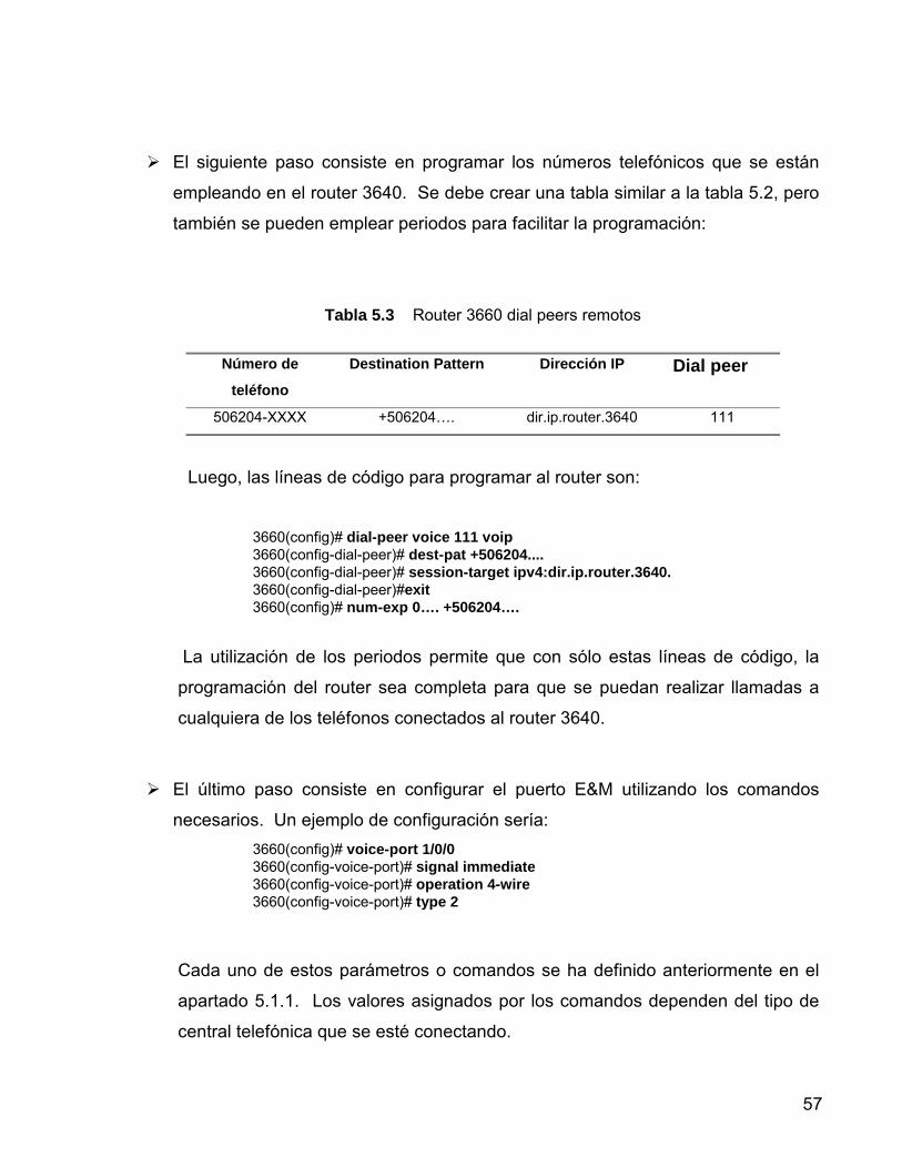
! El siguiente paso consiste en programar los números telefónicos que se están
empleando en el router 3640. Se debe crear una tabla similar a la tabla 5.2, pero
también se pueden emplear periodos para facilitar la programación:
Tabla 5.3 Router 3660 dial peers remotos
Número de
teléfono
Destination Pattern Dirección IP Dial peer
506204-XXXX +506204�. dir.ip.router.3640 111
Luego, las líneas de código para programar al router son:
3660(config)# dial-peer voice 111 voip 3660(config-dial-peer)# dest-pat +506204.... 3660(config-dial-peer)# session-target ipv4:dir.ip.router.3640. 3660(config-dial-peer)#exit 3660(config)# num-exp 0…. +506204….
La utilización de los periodos permite que con sólo estas líneas de código, la
programación del router sea completa para que se puedan realizar llamadas a
cualquiera de los teléfonos conectados al router 3640.
! El último paso consiste en configurar el puerto E&M utilizando los comandos
necesarios. Un ejemplo de configuración sería: 3660(config)# voice-port 1/0/0 3660(config-voice-port)# signal immediate 3660(config-voice-port)# operation 4-wire 3660(config-voice-port)# type 2
Cada uno de estos parámetros o comandos se ha definido anteriormente en el
apartado 5.1.1. Los valores asignados por los comandos dependen del tipo de
central telefónica que se esté conectando.

58
5.4 Configuración de los puertos de voz FXS
Generalmente, los valores de la configuración de los puertos de voz son
adecuados para el funcionamiento de las interfaces de voz del router (FXO, FXS,
E&M). Para cambiar la configuración de los puertos de voz, se hace necesario
realizar las siguientes tareas:
1. Identificar el puerto de voz (comando voice-port) y entrar al modo de
configuración de puerto de voz (comando configure terminal). 2. Configurar los siguientes parámetros:
! Tipo de señal (comando signal) ! Tono de llamada en progreso (comando cptone)
! Frecuencia de repique (comando ring frequency)
! Configurar uno o más parámetros opcionales:
• Modo de conexión PLAR (comando connection plar)
• Nivel de música (comando music-threshold)
• Descripción (comando description)
• Tono de fondo (comando comfort-noise)
Existen otros parámetros configurables en la interface FXS. Estos parámetros
son llamados de ajuste fino. Generalmente, los valores predeterminados de estos
parámetros son los adecuados para que la interface funcione correctamente luego
de configurar los parámetros principales. (estos parámetros de ajuste fino no se
detallan en este documento. Dichos parámetros y comandos relacionados se
muestran en el Anexo 3).
La Tabla 5.4 describe la sintaxis de los comandos que permiten configurar los
parámetros principales.

59
Tabla 5.4 Descripción de los comandos necesarios para configurar la tarjeta de interfaz
FXS
Comando Propósito voice-port No.slot / No.subunidad / puerto Identifica al puerto de voz que se desea
configurar.
configure terminal Entra al modo de configuración globlal.
signal { loop-start | ground-start } Selecciona el tipo de señal apropiado para
este tipo de interface.
loop-start: sólo un lado de la conexión
puede colgar.
ground-start: cualquiera de los lados de
la conexión puede empezar o terminar
una conversación.
Cptone country Selecciona el tono de llamada en
progreso apropiado para esta interfaz
(especifica una interfaz de voz analógica
regional, tono, timbrado y cadencia para
un puerto de voz específico). El valor
predeterminado es US (se puede
seleccionar otra región).
Ring frequency { 25 | 50 } Selecciona el valor de la frecuencia de
repique en Hz (25 ó 50).
connection plar cadena
Especifica la conexión para Private Line
Auto Ringdown (se asocia un peer
directamente con una interfaz; cuando se
descuelga la interfaz, el peer conecta el
segundo segmento de llamada con el
número de destino sin la necesidad de

60
Continuación de la tabla 5.4
que la persona que llama tenga que
marcar ningún número). La cadena
especifica el número de teléfono de
destino.
music threshold número Especifica el volumen de la música de
espera (en dB). Una entrada válida se
encuentra entre �70 y �30.
description cadena Agrega texto descriptivo acerca de esta
conexión de puerto de voz (permite
escribir de 1 a 255 caracteres).
comfort- noise Especifica que se generará música de
fondo.
61
5.5 Configuración de los puertos de voz E & M
Generalmente, los valores de la configuración de los puertos de voz E & M son
adecuados para el funcionamiento de la interfaz. Para cambiar la configuración de
los puertos de voz, se hace necesario realizar los siguientes tareas:
1. Identificar el puerto de voz (comando voice-port) y entrar al modo de
configuración de puerto de voz (comando configure terminal). 2. Configurar los siguientes parámetros:
! Tipo de dial (comando dial-type)
! Tipo de señal (comando signal) ! Tono de llamada en progreso (comando cptone)
! Operación (comando operation)
! Tipo (comando type)
! Impedancia (comando impedance)
! Configurar uno o más parámetros opcionales:
• Modo de conexión PLAR (comando connection plar)
• Nivel de música (comando music-threshold)
• Descripción (comando description)
• Tono de fondo (comando comfort-noise)
4. Existen otros parámetros configurables en la interface E&M. Estos
parámetros son llamados de ajuste fino. Generalmente, los valores
predeterminados de estos parámetros son los adecuados para que la interfaz
funcione correctamente luego de configurar los parámetros principales. (estos
parámetros de ajuste fino no se detallan en este documento. Dichos
parámetros y comandos relacionados se muestran en el Anexo 3).

62
La Tabla 5.5 describe la sintaxis de los comandos que permiten configurar los
parámetros principales.
Luego de configurar el puerto de voz, se necesita activar este puerto para
poder utilizarlo. De hecho, se aconseja apagar el puerto y luego volver a encenderlo
(ciclarlo). Para activar el puerto de voz se emplea el comando no shutdown (se
debe utilizar en el modo configuración).
Para ciclar el puerto se deben utilizar los siguientes comandos (en la
secuencia especificada):
! shutdown : desactiva el puerto de voz
! voice-port : se emplea con la misma sintaxis especificada anteriormente.
! no shutdown : activa el puerto de voz.
Tabla 5.5 Descripción de los comandos necesarios para configurar la tarjeta de interfaz
E&M
Comando Propósito voice-port No.slot / No.subunidad / puerto Identifica al puerto de voz que se
desea configurar.
configure terminal Entra al modo de configuración globlal.
signal { dtmf | pulse } Selecciona el tipo de señal apropiado
para la marcación externa (pulso o
tonos).
cptone country Ver descripción de la tabla 5.4
num-exp número1 número2 Define cómo expandir un set
específico de números en un patrón de
63
destino específico.
�número1� indica la extensión con la
que se desea establecer una
comunicación.
�número2� indica el número en que se
va a expandir la extensión marcada
para lograr la comunicación (el número
se especifica según el formato E.164).
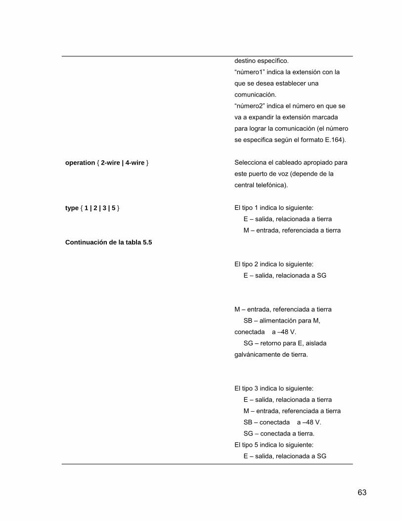
operation { 2-wire | 4-wire } Selecciona el cableado apropiado para
este puerto de voz (depende de la
central telefónica).
type { 1 | 2 | 3 | 5 }
Continuación de la tabla 5.5
El tipo 1 indica lo siguiente:
E � salida, relacionada a tierra
M � entrada, referenciada a tierra
El tipo 2 indica lo siguiente:
E � salida, relacionada a SG
M � entrada, referenciada a tierra
SB � alimentación para M,
conectada a �48 V.
SG � retorno para E, aislada
galvánicamente de tierra.
El tipo 3 indica lo siguiente:
E � salida, relacionada a tierra
M � entrada, referenciada a tierra
SB � conectada a �48 V.
SG � conectada a tierra.
El tipo 5 indica lo siguiente:
E � salida, relacionada a SG

64
M � entrada, referenciada a �48 V
Impedance { 600c | 600r| 900c | complex1 | complex2 } Especifica el valor de la impedancia
terminal. Este valor debe coincidir con
la especificación de la central
telefónica.
La �r� indica que es un valor real; la �c�
indica que es un valor complejo;
complex1 y complex2 indican Complex
1 y Complex 2 respectivamente.
connection plar cadena Ver descripción de la tabla 5.4
Continuación de la tabla 5.5
music threshold número
Especifica el volumen de la música de
espera (en dB). Una entrada válida se
encuentra entre �70 y �30.
description cadena
Agrega texto descriptivo acerca de
esta
conexión de puerto de voz.
comfort- noise Especifica que se generará música de
fondo.

65
5.6 Configuración del Puente Inalámbrico AIR – WGBR342R
El puente inalámbrico permitirá unir la red del Nuevo Centro Logístico con la
red del Edificio Principal de Unisys de Centroamérica (se requerirá de dos puentes,
uno en cada edificio). Este puente está en capacidad de transmitir la paqueteria
TCP/IP con un ancho de banda de hasta 11 Mbps. Como regla general, cuanto
mayor sea el ancho de banda del enlace, menor será el alcance de la señal del
puente (idealmente, la señal tiene un alcance de hasta 15 Km); del mismo modo, el
alcance de la señal del puente disminuirá en la misma proporción de la altura de la
antena que se utilice y se debe mantener �linea vista� entre las antenas de los
puentes (esto significa que se debe si se traza una línea recta imaginaria entre
ambas antenas, dicha línea debe estar libre de obstáculos).
Este puente emplea una encriptación de 128 bits (Same System Identifier �
SSID). Para que estos dispositivos se puedan comunicar entre sí, todos los equipos
deben utilizar el mismo SSID, sino, no se podrán comunicar entre ellos; la potencia
de la señal de salida es de 100 mW, permite la conexión de una antena externa y
emplea la técnica de Modulación DSSS (Direct Sequence Spread Spectrum), la cual
fue desarrollada inicialmente con propósitos militares y es una tecnología con muy
baja probabilidad de intercepción.

66
Como ya se mencionó, se utilizarán dos puentes: uno en el edificio en Fórum
y otro en el Nuevo Centro Logístico. El puente que se deberá instalar en el Edificio
en Fórum se utilizará como root (está conectado al segmento principal de red) y con
el otro puente (que estará en el Nuevo Centro Logístico) se realizará una conexión
de punto a punto (se enlazarán los dos segmentos de red). Un diagrama de
conexión punto a punto se muestra en la figura 5.3. Como se observa, mediante la
utilización de los puentes inalámbricos se logra la comunicación entre los dos
segmentos de red. Cada segmento de red accesa la información que necesita de su
respectivo servidor (a través de la red alambrada); sólo en el caso de que se
requiera el intercambio de información entre ambos segmentos de red, se emplea el
enlace inalámbrico.
Figura 5.3 Conexión punto a punto empleando puentes inalámbricos

67
La figura 5.4 muestra una vista general de los puentes de la serie Aironet.
Cada puente posee tres conectores de red (estos puentes se conectan directamente
al switch o al hub de la red): un conector 10BaseTm (cable twisted pair), 10Base5
(puerto AUI), 10Base2 (conector BNC -T). Además también tiene un conector para
la antena externa, un puerto RS-232 para la conexión de una consola externa (para
realizar la configuración), leds indicadores, botón de encendido/apagado y una
unidad de alimentación AC/DC.
Figura 5.4 Vista general del puente de la serie Aironet
En el Anexo 4 se muestran las instrucciones para la conexión de la antena
externa y protección contra rayos.
La configuración inicial del puente se debe realizar a través del puerto de
consola mediante un programa de comunicación serial (9600 bps, 1 start bit, 1 stop
bit, sin paridad, 8 bits datos y compatibilidad ANSI). Una vez que ya se ha instalado
el puente, se puede variar la configuración también mediante TELNET, SNMP ó
HTML (con Internet Explorer o Netscape Navigator) mediante su dirección IP.

68
Al realizar la configuración inicial mediante el puerto de consola, una vez que
se ha establecido la comunicación, se muestra la siguiente pantalla:
Figura 5.5 Pantalla incial de configuración del puente Aironet AIR-WGB342R
A continuación se realiza una breve descripción acerca de cada una de las
opciones del menú principal:
! Configuration: permite establecer los parámetros de Ethernet y de la
comunicación, estableciendo identificadores de red.
! Statistics: permite ver una variedad de información estadística del puente (datos
enviados y recibidos, errores generados, estatus normal del puente.
! Association: es una tabla que contiene la dirección de todos los nodos (que
emplean señales de RF) que se encuentran conectados a un nivel menor que el
del puente. Esta tabla permite ver dichas direcciones, borrar y quitar entradas
estáticas y permitir la detección automática de adiciones a la tabla.
! Filter: controla el filtrado de la paquetería; permite controlar el envío de
mensajes multicast bloqueando aquellos protocolos no empleados en la red RF
(Radio Frequency).
! Logs: guarda un archivo acerca todas las alarmas que ocurren en la unidad;
permite establecer niveles de alarma e imprimir el archivo antes mencionado.

69
! Diagnostics: permite realizar pruebas diagnóstico (de transmisión) entre la
unidad Aironet y algún otro nodo de la infraestructura para probar la calidad del
radio enlace. También permite descargar nuevas versiones del software del
puente.
! Privilege: permite establecer niveles de privilegio y passwords para accesar la
configuración del puente.
! Help: pantalla de ayuda de comandos, menús, etc.
La figura 5.6 muestra el menú que se despliega al seleccionar la opción
Configuration del menú principal. A continuación se realiza una descripción de la
configuración básica del puente. Sólo se describirán en detalle las configuraciones
Radio y Ethernet (ya que son básicas para lograr una configuración adecuada).
Figura 5.6 Submenú Configuration

70
5.6.1 Configuración de la red de radio (Radio Network)
Esta configuración se realiza seleccionando la opción Configuration del menú
principal y luego la opción Radio. Las configuraciones que se deben realizar son las
siguientes:
! Configurar SSID: es un valor de cadena que funciona como una palabra clave
que permitirá la comunicación entre el puente y los demás dispositivos deseados
(en este caso, el otro puente que se utilizará). En ambos se debe configurar la
misma SSID, en caso contrario, los dispositivos no se comunicarán entre ellos.
! Establecer la unidad Root: establece cual es el puente que estará conectado al
segmento principal de la red. El puente de Unisys � Fórum será el Root, al otro
puente se le debe asignar off en esta opción.
! Rates: establece el valor de la tasa de datos a la que se le permitirá a la unidad
enviar y recibir información (este valor se especifica en Mbps). La unidad
también podrá recibir información que venga a tasas menores que la
especificada. ! Basic_rates: se configura en el puente Root. Establece los diferentes valores
de velocidad que todos los nodos de la conexión inalámbrica deben soportar o no
se podrán asociar con el puente Root. El valor menor se emplea para transmitir
broadcast y paquetes de control. Si se emplea el valor menor se asegura que los
broadcasts y paquetes de control serán recibidos por todos los nodos, incluso los
más distantes. El valor más alto determina la máxima velocidad a la que se
puede transmitir un paquete de respuesta. Este parámetro no es tan crítico al
momento de la configuración, pues el puente Root sólo estará enviando
información a un solo nodo (en el Nuevo Centro)
71
! Frequency: establece la frecuencia que se empleará para realizar la transmisión
de los datos. Si se asigna el valor manualmente, se debe asignar uno de
acuerdo con las entidades reguladoras de la utilización del espectro radiofónico;
si se deja la opción en auto, la unidad verificará todas las frecuencias permitidas
y elegirá una que no se encuentre en uso. ! Distance: se debe establecer la distancia que debe recorrer el radio enlace.
Este parámetro sólo se debe configurar en el puente Root y permite establecer
valores aproximados de delay en la transmisión.
Esta es la configuración básica del radio enlace. Para revisar los demás
parámetros de configuración del radio enlace, se debe revisar el manual de usuario
del puente (este manual se encuentra en el Anexo 5).
5.6.2 Configuración del Puerto Ethernet (Ethernet)
La configuración del puerto Ethernet se realiza seleccionando Configuration del
menú principal y luego la opción Port. La configuración que se realiza comprende lo
siguiente:
! Active: establece el estado del puerto del puente. Si se deja en on, el puente
sigue enviando y recibiendo información por el puerto. Si se establece en off,
se le informa al software que deje de enviar paquetes al puerto y se deja de
revisar la existencia de actividad de ethernet. ! Size: permite incrementar el tamaño máximo de los frames que se transmiten
desde y hacia la estructura de ethernet. El valor típico se encuentra entre
1518 y 4096.

72
! Port: establece el puerto mediante el que el puente se conecta a la
estructura de ethernet. Con la opción Auto, el puente busca automáticamente
un cable en cualquiera de sus tres conectores. Asignación de Identificadores de Red (Ident)
Esta opción permite la configuración de diferentes parámetros entre los que
se pueden mencionar: dirección IP asignada al puente, dirección IP del router
principal, dirección IP del Gateway, máscara, DNS, dominio, etc.
Spanning Tree Protocol (STP)
No se realiza una descripción de esta opción puesto que éste es un protocolo
que se emplea si se están manejando múltiples puentes en un ambiente de LAN
extendida.
Configuración de Mobile IP (Mobile-IP) Este es un protocolo que permite moverse a través de diferenes sub-redes IP
mientras que se mantiene la misma dirección IP.

73
CAPÍTULO 6: ANÁLISIS Y RESULTADOS

74
6.1 Resultados del estudio de ancho de banda A continuación se muestran las gráficas que se obtuvieron de la utilización
del ancho de banda del enlace hacia CLU.
Las figuras 6.1 a 6.7 son gráficas obtenidas para los datos Inbound
(entrantes), mientras que las gráficas 6.8 a 6.14 son las obtenidas para los datos
Outbound (salientes).
La figura 6.2 muestra la utilización del enlace durante un periodo de una
semana. Puede observarse que la utilización del enlace se da prácticamente a un
100 % (64K) durante las horas del día (a pesar de que el valor promedio es bajo, los
picos de utilización son altos), mientras que durante las horas de la noche, el ancho
de banda se mantiene en un valor aproximado de 40 K (este valor se mantiene así
por la utilización del protocolo NETBIOS � IP, como se puede observar en la figura
6.5).
La figura 6.3 muestra un gráfico de la eficiencia de la red para los datos
Inbound. Puede observarse que la eficiencia se mantiene casi en un valor de un
100%. Esto significa que para el tráfico de datos que se maneja en el enlace CLU, el
ancho de banda es suficiente.
La figura 6.9 muestra la utilización del enlace durante un periodo de una
semana para los datos Outbound. Puede observarse que la utilización del enlace se
da prácticamente a un 100 % (64K) durante las horas del día (según los picos
observados), mientras que durante las horas de la noche, el ancho de banda se
mantiene en un valor aproximado de 5 K. Las siguientes figuras muestran las
gráficas de utilización del ancho de banda para los protocolos más empleados
durante la semana del muestreo.

75
La figura 6.10 muestra un gráfico de la eficiencia de la red para los datos
Outbound. Puede observarse que la eficiencia se mantiene casi en un valor de un
100%. Esto significa que para el tráfico de datos que se maneja en el enlace CLU, el
ancho de banda es suficiente.
Como ya se mencionó, la eficiencia de la red es muy alta, pero sólo para el
transporte de datos. Si se desea realizar el transporte de voz por IP y aumentar el
número de puntos de conexión, se debe ampliar este ancho de banda.
Si se realiza un enlace inalámbrico, el ancho de banda del enlace será de 11
Mbps (aproximadamente), por lo que el transporte de voz y de datos no tendrá
ningún problema. Si se realiza el enlace por medio de una línea dedicada, se
recomienda emplear un ancho de banda mínimo de 128 Kbps. Con este ancho de
banda se asegura que se pueda realizar tanto un tráfico de datos como el tráfico de
voz a través del enlace (línea dedicada).
Para ninguno de los dos casos (de enlace inalámbrico o de la utilización de
una línea dedicada), se hace necesario la ampliación del ancho de banda de Unisys
de Centroamérica (actualmente el ancho de banda es de 384 Kb). Esto es debido a
que con los 384 Kb se realiza en enlace con Minnesotta; el ancho de banda con el
que se realiza el enlace con la bodega (CLU) es completamente independiente del
ancho de banda principal.

76
Figura 6.1 Gráfico de los 10 protocolos más utilizados (para los datos Inbound) en el CLU durante un periodo de 1 semana (al 02 de Octubre de 2000)
Figura 6.2 Utilización del ancho de banda del enlace a CLU (datos Inbound) durante el periodo de una semana (al 02 deOctubre de 2000)

77
Figura 6.3 Eficiencia de la red de CLU (datos Inbound) para un periodo de una semana (al 02 de Octubre de 2000)
Figura 6.4 Gráfico que muestra la utilización de ancho de banda del protocolo HTTP (Inbound) para el
enlace CLU para un periodo de una semana (al 02 de Octubre de 2000)
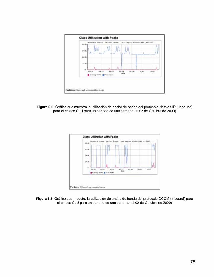
78
Figura 6.5 Gráfico que muestra la utilización de ancho de banda del protocolo Netbios-IP (Inbound) para el enlace CLU para un periodo de una semana (al 02 de Octubre de 2000)
Figura 6.6 Gráfico que muestra la utilización de ancho de banda del protocolo DCOM (Inbound) para
el enlace CLU para un periodo de una semana (al 02 de Octubre de 2000)
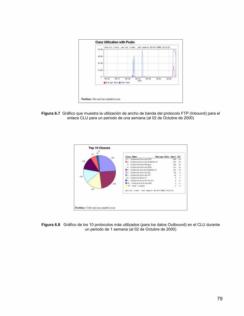
79
Figura 6.7 Gráfico que muestra la utilización de ancho de banda del protocolo FTP (Inbound) para el
enlace CLU para un periodo de una semana (al 02 de Octubre de 2000)
Figura 6.8 Gráfico de los 10 protocolos más utilizados (para los datos Outbound) en el CLU durante un periodo de 1 semana (al 02 de Octubre de 2000)

80
Figura 6.9 Utilización del ancho de banda del enlace a CLU (datos Outbound) durante el periodo de
una semana (al 02 deOctubre de 2000)
Figura 6.10 Gráfico de la eficiencia de la red de CLU (para los datos Outbound) para un periodo de
una semana (al 02 de Octubre de 2000)

81
Figura 6.11 Gráfico que muestra la utilización de ancho de banda del protocolo NETBIOS-IP/OUTSIDE (Outbound) para el enlace CLU para un periodo de una semana (al 02 de Octubre de
2000)
Figura 6.12 Gráfico que muestra la utilización de ancho de banda del protocolo HTTP (Outbound) para el enlace CLU para un periodo de una semana (al 02 de Octubre de 2000)

82
Figura 6.13 Gráfico que muestra la utilización de ancho de banda del protocolo DCOM (Outbound)
para el enlace CLU para un periodo de una semana (al 02 de Octubre de 2000)
Figura 6.14 Gráfico que muestra la utilización de ancho de banda del protocolo NETBIOS-IP/INSIDE (Outbound) para el enlace CLU para un periodo de una semana (al 02 de Octubre de 2000)
6.2 Requerimientos del Nuevo Centro Logístico
El local al que Unisys de Centroamérica desea trasladar el equipo que se
encuentra en CLU son Las Bodegas de Matra, las cuales son administradas por
Mabinsa (las bodegas se encuentran en Santa Ana).

83
Unisys de Centroamérica desea trasladar su equipo a la bodega No. 5. Dicha
bodega cuenta con un área de 350 m2 y 10 líneas telefónicas. El equipo que se
desea trasladar es todo el que se encuentra en CLU: computadores personales,
equipo en reparación, periféricos, material de bodega, etc.
Actualmente en CLU se emplean 11 computadores personales y existen un
total de 16 conexiones (las conexiones extra corresponden a los dispositivos
periféricos).
Los requerimientos básicos de la nueva bodega son los siguientes:
! Capacidad para albergar el equipo que se encuentra en existencia en CLU.
! Creación de un laboratorio de pruebas de equipo de redes.
! Aumento de los puntos de conexión.
! Capacidad de distinguir los diferentes segmentos de red.
6.2.1 Requerimientos Físicos
El nuevo local albergará el equipo en existencia en CLU. Este equipo
comprende los dispositivos periféricos, las computadoras personales, equipo en
reparación y equipo almacenado. Además de ésto, se desea aumentar la cantidad
de puntos de conexión.
84
Como ya se mencionó, actualmente en CLU se emplean 16 puntos de
conexión, 11 de los cuales corresponden a computadoras. Para el Nuevo Centro
Logístico se desea doblar la cantidad de puntos de conexión (tentativamente a 22
puntos). Cada punto de conexión deberá contar con su conexión de cable de red
UTP, su extensión telefónica (de una central telefónica) además de las conexiones
eléctricas necesarias.
Para realizar el enlace inalámbrico se ha seleccionado puentes inalámbricos
de la Serie Aironet. El modelo seleccionado corresponde al Aironet AIR �
WGBR342R. Se seleccionó este tipo de puente pues es el que presenta la mayor
potencia de salida (100 mW) y la mayor opción de seguridad (ID de 128 bits). En el
desarrollo de software se realiza una mayor descripción de este puente.
6.2.2 Laboratorio de Pruebas
Se desea que el Nuevo Centro cuente con un laboratorio de equipo de
comunicaciones. No se cuenta con una descripción específica acerca del equipo de
comunicaciones que albergará este laboratorio, sin embargo, se pueden mencionar
los siguientes: Routers, Hubs, Packeteers, equipo Nortel, equipo Cisco, etc.
Además del equipo de comunicaciones, el laboratorio deberá contar con, al
menos, 10 puntos de conexión (conexión a la red, conexiones eléctricas y
extensiones telefónicas) además de un mínimo de dos líneas telefónicas directas
(para la realización de pruebas). Los 10 puntos de conexión del laboratorio no se
deben contar entre los 22 puntos de conexión propios del Nuevo Centro.

85
6.2.3 Segmentos de Red
También se desea distinguir la localización física de las computadoras que
conforman la red de Unisys de Centroamérica; en otras palabras, se desea poder
diferenciar cuáles máquinas se encuentran en el Edificio de Fórum y cuales estarán
en el Nuevo Centro.
Para realizar esto no se requiere de ningún tipo de herramienta. El edificio en
Fórum cuenta con un Router propio, en CLU también se encuentra otro Router.
Puesto que cada Router cuenta con su dirección IP, el Router de Fórum define el
segmento de red de Fórum y el Router de CLU define al segmento de red de CLU.
Puesto que este Router será el mismo que se instalará en el Nuevo Centro, el
segmento de red del Nuevo Centro se podrá diferenciar del segmento de red de
Unisys en Fórum.
Cálculo de la altura de las torres para realizar el enlace deseado
La figura 6.15 muestra un diagrama de la ubicación de los edificios para la
realización del enlace inalámbrico.
El enlace se desea realizar entre el edificio de Unisys de Centroamérica y el
Nuevo Centro. Como se puede observar, entre ambas edificaciones se encuentran
los edificios de la compañía Procter & Gamble. El edificio de Unisys tiene una altura
total de 15 metros, el edificio más alto de Procter & Gamble tiene una altura de 25
metros y la bodega No.5 presenta una altura de 9 metros.

86
El edificio de Unisys se encuentra en el terreno más elevado, los edificios de
Procter & Gamble se encuentran en un desnivel aproximado de tres metros y el
nuevo local de Unisys se encuentra en un desnivel mucho mayor (como se puede
apreciar en el diagrama).
Con la ayuda de un GPS (Global Position System), se pudieron realizar las
medidas de las distancias entre los edificios, las alturas relativas de los terrenos en
los que están ubicados y la latitud y longitud en la que están ubicados. La distancia
existente entre el edificio de Unisys (9º 56� 37��N, 84º 11� 38��W) y los edificios de
Procter & Gamble (d1) medida fue de aproximadamente 225 metros; la distancia
entre los Edificios de Procter & Gamble (9º 56� 44��N, 84º 11� 39��W) y la bodega (d2)
es de aproximadamente 800 metros; la distancia entre el edificio de Unisys y la
bodega (dT) es de aproximadamente 980 metros. Sumando las distancias parciales
se observa que el valor obtenido es muy similar al valor de la distancia total, lo cual
demuestra que los tres edificios se encuentran prácticamente en la misma línea de
visión (existe una diferencia en la distancia sumada y la real de 45 metros, pero se
puede aproximar a una línea recta). Esto significa que para enlazar el edificio de
Unisys con la bodega (9º 57� 06��N, 84º 11� 25��W), se debe pasar por encima del los
edificios de Procter & Gamble.
Esto se puede realizar colocando las antenas, de los puentes inalámbricos, a
las alturas necesarias para pasar por encima de los edificios de P&G.
En el diagrama se observan una serie de abreviaturas que señalan diferentes
alturas. Esta es la descripción de dichas alturas (todas las alturas y distancias se
miden en metros):
87
hUNISYS : es la altura completa del edificio principal de Unisys incluida la torre que
se deberá construir.
hEXTRA : altura con la que se desea que la señal de RF pase por encima del edificio
de P&G. Este valor se debe asignar libremente.
hTP&G : altura del edificio de P&G más la hEXTRA.
hD1 : desnivel entre el terreno del edificio de Unisys y el terreno de los edificios de
P&G. Con el GPS se obtuvo un valor aproximado de 3 metros.
hTUNISYS : altura necesaria de la torre que se deberá instalar en el edificio de Unisys.
hD2: desnivel entre el terreno de los edificios de P&G y el terreno en el que se
encuentra la bodega. Con el GPS se midió un valor aproximado de 10 metros.
hTOTBOD : es la altura completa del edificio de la bodega incluida la torre que se
deberá construir.
hTBOD : es la altura de la torre que se deberá construir en la bodega. Este valor se
asigna según consideraciones de diseño.
∆h : es un valor de altura relativa entre hTOTBOD y hD2. Este valor podrá ser positivo
o negativo.
Ángulo θ: en un ángulo que se emplea con fines matemáticos y permite calcular
alturas necesarias en el diseño.
88
Para poder calcular la altura de las torres que se deben construir, el primer paso
consiste en asignar un valor deseado para hEXTRA. Una vez realizado esto, se debe
asignar un valor para la altura de la torre de la bodega (hTBOD).
Con estos valores, se puede calcular hTOTBOD:
hTOTBOD = 9m + hTBOD
Trazando una línea recta imaginaria (a cero grados de inclinación) entre la
punta de la torre hasta que corte al edificio de P&G o al terreno del mismo, se puede
calcular el valor de ∆h:
∆h = hD2 - hTOTBOD

Figura 6.15 Diagrama de la ubicación de los edificios para realizar el enlace inalám
89
brico (diagrama realizado en Paint)

Con el valor de deltah, los 25 metros de alto del edificio de P&G y hEXTRA se
puede calcular el valor equivalente de hTP&G:
hTP&G = ∆h + 25m + hEXTRA
De este modo, se forma un triángulo rectángulo imaginario que está formado
por la distancia d2 (eje X), la altura hTP&G y el segmento que une a hTP&G con hTBOD.
Con estos valores, se puede calcular el valor del ángulo θ:
θ = TAN-1 (hTP&G / d2)
Con el valor dT y con el valor de θ, se puede calcular la altura equivalente
hUNISYS:
hUNISYS = dT (TANθ)
Una vez obtenido este valor, se puede calcular el valor de la torre que se debe
construir en Fórum para colocar la antena del puente inalámbrico (y con la que se
logrará tener línea vista entre ambas antenas):
hTUNISYS = hUNISYS �15m - ∆h - hD1
Este valor de altura calculado es medido desde el suelo del edificio de Unisys.
Para tener una idea de los cálculos, suponiendo una hEXTRA de 2m y una altura de
hTBOD de 10 metros (32.8 pie), se obtiene una altura de hTUNISYS de 13.05 metros
(42.81 pie)1.
1 Las alturas se detallan en pie pues Cisco Systems especifica la longitud de los cables de bajas pérdidas en pie.

91
La altura de 13.05 metros de la torre de Unisys convertida en pie, representa
42.81 pie (por lo que se haría necesario emplear un mínimo de 100 pie de cable de
bajas pérdidas para la conexión de la antena al puente).
Se aconseja utilizar la antena AIR-ANT1949; esta antena presenta las
siguientes características:
! Ganancia de 13.5 dBi
! Alcance aproximado de 10.5 Km a 2 Mbps y de 3.3 Km a 11 Mbps
! Lóbulo de radiación ubicado a 30º H y 25º V
! Se utiliza en aplicaciones de alcance medio y direccionales.
Para el cable que unirá a la antena con el puente, se aconseja emplear un
cable de bajas pérdidas del tipo AIR-420-003346-100 el que presenta una
atenuación de 6.7 dBi por cada 100 pie de cable; las pérdidas totales se calculan a
partir de:
Pérdidas = 100 pie * ( 6.7 dBi / 100 pie) = 6.7 dBi.
Esto significa que para cuando la señal generada por el puente llegue a la
antena, habrá perdido 6.7 dBi de potencia.

92
Para el lado de la bodega, se debe emplear una antena del mismo tipo que la
que se aconseja utilizar en Unisys de Centroamérica. Se recomienda emplear es
mismo tipo de antena debido a que en radioenlaces se aconseja emplear antenas
direccionales; la antena direccional evita que se desperdicie potencia irradiando en
direcciones en las que no existe un receptor. Asumiendo que se empleará una torre
de 10 metros (32.8 pie), se aconseja emplear 75 pie de cable de bajas pérdidas del
tipo AIR-420-003346-075 (el que presenta pérdidas de 5.0d dBi por cada 75 pie de
cable). Las pérdidas producidas en este caso son menores:
Pérdidas = 75 pie * (5.0 dBi / 75pie) = 5.0 dBi.
Esto significa que para cuando la señal generada por el puente llegue a la
antena, habrá perdido 5.0 dBi de potencia.
Con estos valores de alturas, se puede lograr el enlace deseado. Se pueden
realizar otros cálculos basándose en las ecuaciones planteadas.
Los datos de distancias que se mencionan en este informe se obtuvieron con
un GPS. Para poder realizar cálculos más exactos, se recomienda realizar un
trabajo topográfico para calcular las distancias y las alturas de los terrenos con
mayor precisión.

93
CAPÍTULO 7: CONCLUSIONES Y RECOMENDACIONES

94
Conclusiones
La etapa de capacitación permitió adquirir conocimientos básicos sobre el
ambiente de redes, técnicas de transmisión de datos y equipo activo de
comunicaciones.
El Nuevo Centro Logístico albergará al mismo equipo en existencia en el Centro
Logístico de la Uruca (computadores personales, equipo de taller, equipo de bodega,
etc). El Nuevo Centro Logístico requerirá de la creación de un laboratorio de
pruebas (para equipo de comunicaciones). El Nuevo Centro además requerirá de la
duplicación de los puntos de conexión, en comparación con la cantidad que existen
en la Uruca).
La utilización del Packetshaper, al conectarlo al enlace Unisys Fórum � CLU,
permitió determinar la utilización de los 64 Kbits de este enlace. Una vez
determinada la utilización de dicho enlace, se pudo calcular los anchos el ancho de
banda necesario para la transmisión de voz y de datos en el nuevo enlace que se
desea realizar.
Si se realiza un enlace inalámbrico para la transmisión de voz y de datos, el
ancho de banda empleado estará entre los 2 Mbps y los 11 Mbps, por lo que no se
requiere de ninguna herramienta Qos (Calidad de servicio). Si se realiza el enlace a
través de una línea dedicada, el ancho de banda mínimo aconsejado es de 128
Kbits; además se sugiere la utilización de las herramientas de QoS. Este ancho de
banda es el total para el enlace, tanto como para voz como para datos. Las
herramientas de QoS administran dinámicamente este ancho de banda en el caso
de la transmisión de voz.

95
No se requiere que en Unisys de Centroamérica se amplíe el ancho de banda
(actualmente el mismo es de 384 Kbps). El nuevo enlace es independiente del
ancho de banda principal de Unisys.
Al Router Cisco de la serie 3660 que se emplea en Unisys de Centroamérica se
le deben programar herramientas QoS para que soporte el tráfico de voz. Ocurre lo
mismo con el Router Cisco de la serie 3640 en existencia en CLU.
Para realizar el enlace inalámbrico entre Unisys de Centroamérica y el Nuevo
Centro Logístico se recomienda emplear equipo inalámbrico de la serie Aironet 340,
además de las antenas y cable de bajas pérdidas.
Recomendaciones
Se recomienda la realización de un estudio topográfico para determinar las
distancias exactas entre los edificios de Unisys, Procter & Gamble y el Nuevo Centro,
a partir de ese estudio se pueden determinar las alturas exactas de los terrenos y la
dirección de cada edificio. Con estos datos más precisos y con las ecuaciones
planteadas se pueden calcular las alturas de las torres para la colocación de las
antenas.

96
BIBLIOGRAFÍA
Cisco 3600 Series Hardware Installation Guide, Cisco Systems, USA, 1999.
Cisco Network Modules Hardware Installation Guide (for Cisco 3600 Series and
Cisco 2600 Series Routers), Cisco Systems, USA, 1999.
Configuring Voice over IP for the Cisco 3600 Series, Cisco Systems, USA, 2000.
Configuring Voice Ports for the Cisco 3600 Series, Cisco Systems, USA, 2000.
GPS Magellan 300 User’s Guide, Magellan Corporation, USA, 1999.
PacketShaper Reference Guide, Versión 4.0, Packeteer Corporation, USA, 2000.
Software Configuration Guide (for Cisco 3600 Series and Cisco 2600 Series
Routers), Cisco Systems, USA, 1999.
Using the Cisco Aironet 340 Series Wireless Bridges, Cisco Systems, USA, 2000.

98
ANEXOS

99
Anexo 1: Comandos de configuración de los puertos de Voz.
El siguiente archivo presenta una descripción más detallada acerca de los
comandos necesarios para la configuración de los puertos de voz de los routers
Cisco.

96
ANEXOS

100
Anexo 1: Comandos de configuración de los puertos de Voz.
El siguiente archivo presenta una descripción más detallada acerca de los
comandos necesarios para la configuración de los puertos de voz de los routers
Cisco.

Configuring Voice Port 99
Configuring Voice Ports
This chapter describes how to configure voice ports for both the Cisco 3600 series (for Voice overIP) and for the Cisco MC3810 (for Voice over Frame Relay, Voice over ATM, and Voiceover HDLC). For a description of the voice port commands, refer to the “Voice Port Commands”chapter in theVoice, Video, and Home Applications Command Reference.
Voice Ports on the Cisco 3600 SeriesThe Cisco 3600 currently provides only analog voice ports for its implementation of Voice over IP.The type of signaling associated with these analog voice ports depend on the interface moduleinstalled into the device. The Cisco 3600 series router supports either a two-port or four-port voicenetwork module (VNM); VNMs can hold either two or four voice interface cards (VICs).
Each VIC is specific to a particular signaling type; therefore, VICs determine the type of signalingfor the voice ports on that particular VNM. This means that even though VNMs can hold multipleVICs, each VIC on a VNM must conform to the same signaling type. For more information aboutthe physical characteristics of VNMs and VICs or how to install them, refer to the installationdocument,Voice Network Module and Voice Interface Card Configuration Note, that came with yourVNM.
Voice ports on the Cisco 3600 series support three basic voice signaling types:
• FXO—Foreign Exchange Office interface. The FXO interface is an RJ-11 connector that allowsa connection to be directed at the PSTN’s central office (or to a standard PBX interface, if thelocal telecommunications authority permits). This interface is of value for off-premise extensionapplications.
• FXS—The Foreign Exchange Station interface. This interface is an RJ-11 connector that allowsconnection for basic telephone equipment, keysets, PBXs, and supplies ring, voltage, and dialtone.
• E&M—The “Ear and Mouth” interface (or “RecEive and TransMit”) interface. This interface isan RJ-48 connector that allows connection for PBX trunk lines (tie lines). It is a signalingtechnique for two-wire and four-wire telephone and trunk interfaces.
Configuring Voice Ports on the Cisco 3600 SeriesIn general, voice port commands define the characteristics associated with a particular voice portsignaling type. Under most circumstances, the default voice port command values are adequate toconfigure FXO and FXS ports to transport voice data over your existing IP network. Because of theinherent complexities involved with PBX networks, E&M ports might need specific voice portvalues configured, depending on the specifications of the devices in your telephony network.

Voice Ports for the Cisco 3600 Series Configuration Task List
VC-100 Voice, Video, and Home Applications Configuration Guide
Voice Ports for the Cisco 3600 Series Configuration Task ListPerform the following tasks to configure the voice ports on the Cisco 3600 series:
• Configuring FXO or FXS Voice Ports
• Fine-Tuning FXO and FXS Voice Ports
• Configuring E&M Voice Ports
• Fine-Tuning E&M Voice Ports
• Activating the Voice Port
Configuring FXO or FXS Voice PortsUnder most circumstances the default voice port values are adequate for both FXO and FXS voiceports. If you need to change the default configuration for these voice ports, perform the followingtasks. The first two tasks are required; the third task is optional.
1 Identify the voice port and enter the voice-port configuration mode.
2 Configure the following mandatory voice-port parameters:
(a) Dial type (FXO only)
(b) Signal type
(c) Call progress tone
(d) Ring frequency (FXS only)
(e) Ring number (FXO only)
3 Configure one or more of the following optional voice-port parameters:
(a) PLAR connection mode
(b) Music-threshold
(c) Description
(d) Comfort noise (if VAD is activated—VAD is a dial peer command)
To configure FXO and FXS voice ports, use the following commands beginning in privileged EXECmode:
Step Command Purpose
1 configure terminal Enter global configuration mode.
2 voice-port slot-number/subunit-number/port Identify the voice port you want to configure andenter voice-port configuration mode.
3 dial-type {dtmf | pulse} (For FXO ports only) Select the appropriate dialtype for out-dialing.
4 signal { loop-start | ground-start} Select the appropriate signal type for this interface.
5 cptonecountry Select the appropriate voice call progress tone forthis interface.
The default for this command isus. For a list ofsupported countries, refer to theVoice, Video, andHome Applications Command Reference.

Fine-Tuning FXO and FXS Voice Ports
Configuring Voice Ports VC-101
Validation TipsYou can check the validity of your voice-port configuration by performing the following tasks:
• Pick up the handset of an attached telephony device and check for a dial tone.
• If you have dial tone, check for DTMF detection. If the dial tone stops when you dial a digit, thenthe voice port is most likely configured properly.
• Use theshow voice-port command to verify that the data configured is correct.
Troubleshooting TipsIf you are having trouble connecting a call and you suspect the problem is associated with voice-portconfiguration, you can try to resolve the problem by performing the following tasks:
• Ping the associated IP address to confirm connectivity. If you cannot successfully ping yourdestination, refer to theNetwork Protocols Configuration Guide, Part 1.
• Use the show voice-port command to make sure that the port is enabled. If the port is offline, usetheno shutdown command.
• If you have configured E&M interfaces, make sure that the values pertaining to your specific PBXsetup, such as timing and/or type, are correct.
• Check to see if the voice network module has been correctly installed. For more information,refer to the installation document,Voice Network Module and Voice Interface CardConfiguration Note, that came with your voice network module.
Fine-Tuning FXO and FXS Voice PortsDepending on the specifics of your particular network, you may need to adjust voice parametersinvolving timing, input gain, and output attenuation for FXO or FXS voice ports. Collectively, thesecommands are referred to as voice-port tuning commands.
Note In most cases, the default values for voice-port tuning commands will be sufficient.
6 ring frequency {25 | 50} (For FXS ports only) Select the appropriate ringfrequency (in Hertz) specific to the equipmentattached to this voice port.
7 ring number number (For FXO ports only) Specify the maximum numberof rings to be detected before answering a call.
8 connection plarstring (Optional) Specify the private line auto ringdown(PLAR) connection, if this voice port is used for aPLAR connection. Thestring value specifies thedestination telephone number.
9 music-thresholdnumber (Optional) Specify the threshold (in decibels) foron-hold music. Valid entries are from –70 to –30.
10 description string (Optional) Attach descriptive text about thisvoice port connection.
11 comfort-noise (Optional) Specify that background noise will begenerated.
Step Command Purpose
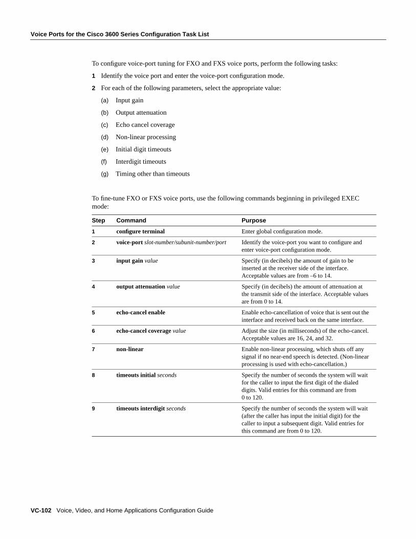
Voice Ports for the Cisco 3600 Series Configuration Task List
VC-102 Voice, Video, and Home Applications Configuration Guide
To configure voice-port tuning for FXO and FXS voice ports, perform the following tasks:
1 Identify the voice port and enter the voice-port configuration mode.
2 For each of the following parameters, select the appropriate value:
(a) Input gain
(b) Output attenuation
(c) Echo cancel coverage
(d) Non-linear processing
(e) Initial digit timeouts
(f) Interdigit timeouts
(g) Timing other than timeouts
To fine-tune FXO or FXS voice ports, use the following commands beginning in privileged EXECmode:
Step Command Purpose
1 configure terminal Enter global configuration mode.
2 voice-port slot-number/subunit-number/port Identify the voice-port you want to configure andenter voice-port configuration mode.
3 input gain value Specify (in decibels) the amount of gain to beinserted at the receiver side of the interface.Acceptable values are from –6 to 14.
4 output attenuation value Specify (in decibels) the amount of attenuation atthe transmit side of the interface. Acceptable valuesare from 0 to 14.
5 echo-cancel enable Enable echo-cancellation of voice that is sent out theinterface and received back on the same interface.
6 echo-cancel coveragevalue Adjust the size (in milliseconds) of the echo-cancel.Acceptable values are 16, 24, and 32.
7 non-linear Enable non-linear processing, which shuts off anysignal if no near-end speech is detected. (Non-linearprocessing is used with echo-cancellation.)
8 timeouts initial seconds Specify the number of seconds the system will waitfor the caller to input the first digit of the dialeddigits. Valid entries for this command are from0 to 120.
9 timeouts interdigit seconds Specify the number of seconds the system will wait(after the caller has input the initial digit) for thecaller to input a subsequent digit. Valid entries forthis command are from 0 to 120.
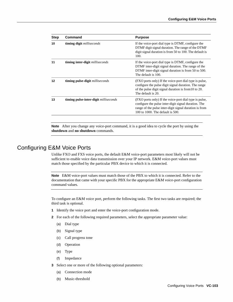
Configuring E&M Voice Ports
Configuring Voice Ports VC-103
Note After you change any voice-port command, it is a good idea to cycle the port by using theshutdown andno shutdown commands.
Configuring E&M Voice PortsUnlike FXO and FXS voice ports, the default E&M voice-port parameters most likely will not besufficient to enable voice data transmission over your IP network. E&M voice-port values mustmatch those specified by the particular PBX device to which it is connected.
Note E&M voice-port values must match those of the PBX to which it is connected. Refer to thedocumentation that came with your specific PBX for the appropriate E&M voice-port configurationcommand values.
To configure an E&M voice port, perform the following tasks. The first two tasks are required; thethird task is optional.
1 Identify the voice port and enter the voice-port configuration mode.
2 For each of the following required parameters, select the appropriate parameter value:
(a) Dial type
(b) Signal type
(c) Call progress tone
(d) Operation
(e) Type
(f) Impedance
3 Select one or more of the following optional parameters:
(a) Connection mode
(b) Music-threshold
10 timing digit milliseconds If the voice-port dial type is DTMF, configure theDTMF digit signal duration. The range of the DTMFdigit signal duration is from 50 to 100. The default is100.
11 timing inter-digit milliseconds If the voice-port dial type is DTMF, configure theDTMF inter-digit signal duration. The range of theDTMF inter-digit signal duration is from 50 to 500.The default is 100.
12 timing pulse-digit milliseconds (FXO ports only) If the voice-port dial type is pulse,configure the pulse digit signal duration. The rangeof the pulse digit signal duration is from10 to 20.The default is 20.
13 timing pulse-inter-digit milliseconds (FXO ports only) If the voice-port dial type is pulse,configure the pulse inter-digit signal duration. Therange of the pulse inter-digit signal duration is from100 to 1000. The default is 500.
Step Command Purpose

Voice Ports for the Cisco 3600 Series Configuration Task List
VC-104 Voice, Video, and Home Applications Configuration Guide
(c) Description
(d) Comfort tone (if VAD is activated)
To configure E&M voice ports, use the following commands beginning in privileged EXEC mode:
Step Command Purpose
1 configure terminal Enter global configuration mode.
2 voice-port slot-number/subunit-number/port Identify the voice port you want to configure andenter voice-port configuration mode.
3 dial-type {dtmf | pulse} Select the appropriate dial type for out-dialing.
4 signal {wink-start | immediate | delay-dial} Select the appropriate signal type for this interface.
5 cptone {australia | brazil | china | finland |france | germany | japan | northamerica |unitedkingdom}
Select the appropriate voice call progress tone forthis interface.
6 operation { 2-wire | 4-wire} Select the appropriate cabling scheme for this voiceport.
7 type { 1 | 2 | 3 | 5} Select the appropriate E&M interface type.
Type 1 indicates the following lead configuration:
E—output, relay to groundM—input, referenced to ground
Type 2 indicates the following lead configuration:
E—output, relay to SGM—input, referenced to groundSB—feed for M, connected to –48VSG—return for E, galvanically isolated fromground
Type 3 indicates the following lead configuration:
E—output, relay to groundM—input, referenced to groundSB—connected to –48VSG—connected to ground
Type 5 indicates the following lead configuration:
E—output, relay to groundM—input, referenced to –48V
8 impedance {600c | 600r | 900c | complex1 |complex2}
Specify a terminating impedance. This value mustmatch the specifications from the telephony systemto which this voice port is connected.
9 connection plarstring (Optional) Specify the private line auto ringdown(PLAR) connection, if this voice port is used for aPLAR connection. Thestring value specifies thedestination telephone number.
10 music-thresholdnumber (Optional) Specify the threshold (in decibels) foron-hold music. Valid entries are from –70 to –30.
11 description string (Optional) Attach descriptive text about thisvoice port connection.
12 comfort-noise (Optional) Specify that background noise will begenerated.

Fine-Tuning E&M Voice Ports
Configuring Voice Ports VC-105
Validation TipsYou can check the validity of your voice-port configuration by performing the following tasks:
• Pick up the handset of an attached telephony device and check for a dial tone.
• If you have dial tone, check for DTMF detection. If the dial tone stops when you dial a digit, thenthe voice port is most likely configured properly.
• Use theshow voice-port command to verify that the data configured is correct.
Troubleshooting TipsIf you are having trouble connecting a call and you suspect the problem is associated with voice-portconfiguration, you can try to resolve the problem by performing the following tasks:
• Ping the associated IP address to confirm connectivity. If you cannot successfully ping yourdestination, refer to theNetwork Protocols Configuration Guide, Part 1.
• Use theshow voice-port command to make sure that the port is enabled. If the port is offline,use theno shutdown command.
• If you have configured E&M interfaces, make sure that the values pertaining to your specific PBXsetup, such as timing and/or type, are correct.
• Check to see if the voice network module has been correctly installed. For more information,refer to the installation document that came with your voice network module.
Fine-Tuning E&M Voice PortsDepending on the specifics of your particular network, you may need to adjust voice parametersinvolving timing, input gain, and output attenuation for E&M voice ports. Collectively, thesecommands are referred to as voice-port tuning commands.
Note In most cases, the default values for voice-port tuning commands will be sufficient.
To configure voice-port tuning for E&M voice ports, perform the following tasks:
1 Identify the voice port and enter the voice-port configuration mode.
2 For each of the following parameters, select the appropriate value:
(a) Input gain
(b) Output attenuation
(c) Echo cancel coverage
(d) Non-linear processing
(e) Initial digit timeouts
(f) Interdigit timeouts
(g) Timing other than timeouts

Voice Ports for the Cisco 3600 Series Configuration Task List
VC-106 Voice, Video, and Home Applications Configuration Guide
To fine-tune E&M voice ports, use the following commands beginning in privileged EXEC mode:
Step Command Purpose
1 configure terminal Enter global configuration mode.
2 voice-port slot-number/subunit-number/port Identify the voice port you want to configure andenter voice-port configuration mode.
3 input gain value Specify (in decibels) the amount of gain to beinserted at the receiver side of the interface.Acceptable values are from –6 to 14.
4 output attenuation value Specify (in decibels) the amount of attenuation atthe transmit side of the interface. Acceptable valuesare from 0 to 14.
5 echo-cancel enable Enable echo-cancellation of voice that is sent out theinterface and received back on the same interface.
6 echo-cancel coveragevalue Adjust the size (in milliseconds) of the echo-cancel.Acceptable values are 16, 24, and 32.
7 non-linear Enable non-linear processing, which shuts off anysignal if no near-end speech is detected. (Non-linearprocessing is used with echo-cancellation.)
8 timeouts initial seconds Specify the number of seconds the system will waitfor the caller to input the first digit of the dialeddigits. Valid entries for this command are from0 to 120.
9 timeouts interdigit seconds Specify the number of seconds the system will wait(after the caller has input the initial digit) for thecaller to input a subsequent digit. Valid entries forthis command are from 0 to 120.
10 timing clear-wait milliseconds Specify the minimum amount of time between theinactive seizure signal and the call being cleared.Valid entries forclear-wait are from 200 to 2000milliseconds.
11 timing delay-duration milliseconds Specify the delay signal duration for delay dialsignaling. Valid entries fordelay-duration are from100 to 5000 milliseconds.
12 timing delay-start milliseconds Specify the minimum delay time from outgoingseizure to outdial address. Valid entries fordelay-start are from 20 to 2000 milliseconds.
13 timing dial-pulse min-delaymilliseconds Specify the time between generation of wink-likepulses. Valid entries fordial-pulse min-delayarefrom 0 to 5000 milliseconds.
14 timing digit milliseconds If the voice-port dial type is DTMF, configure theDTMF digit signal duration.Valid entries fordigitare from 50 to 100 milliseconds.
15 timing inter-digit milliseconds If the voice-port dial type is DTMF, specify theDTMF inter-digit duration. Valid entries forinter-digit are from 50 to 500 milliseconds.
16 timing pulse pulse-per-second If the voice-port dial type is pulse, specify the pulsedialing rate. Valid entries forpulseare from 10 to 20pulses per second.

Activating the Voice Port
Configuring Voice Ports VC-107
Note After you change any voice-port command, it is a good idea to cycle the port by using theshutdown andno shutdown commands.
Activating the Voice PortAfter you have configured the voice port, you need to activate the voice port to bring it online. In factit is a good idea to cycle the port—meaning to shut the port down and then bring it online again.
To activate a voice port, use the following commands in voice-port configuration mode:
To cycle a voice port, use the following command in voice-port configuration mode:
Note If you are not going to use a voice port, shut it down.
Voice Ports on the Cisco MC3810The Cisco MC3810 hardware features two models, each providing different configuration optionsfor voice ports:
• Six analog voice interfaces— The Cisco MC3810 version with the analog voice module (AVM)supports up to six analog voice personality modules (APMs) with each voice module supportinga single signaling type (see below). Each voice personality module maps to a single analog voiceport. The FXO, FXS, and E&M voice modules can be installed in any combination.
• One digital voice module (DVM)— The Cisco MC3810 version with the DVM provides supportfor up to 24 voice channels, one for each voice port. Depending on whether the controller is T1or E1, different DS0 voice channels are used. The DVM supports Channel Associated Signaling
17 timing pulse-inter-digit milliseconds If the voice-port dial type is pulse, specify the pulsedialing inter-digit timing. Valid entries forpulse-inter-digit are 100 to 1000 milliseconds.
18 timing wink-duration milliseconds Specify the maximum wink signal duration. Validentries forwink-duration are from 100 to 400milliseconds.
19 timing wink-wait milliseconds Specify the maximum wink-wait duration for a winkstart signal. Valid entries forwink-wait are from100 to 5000 milliseconds.
Command Purpose
no shutdown Activate the voice port.
Step Command Purpose
1 shutdown Deactivate the voice port.
2 voice-port slot-number/subunit-number/port Identify the voice port you want to activateand enter the voice-port configuration mode.
3 no shutdown Activate the voice port.
Step Command Purpose

Configuring Voice Ports on the Cisco MC3810
VC-108 Voice, Video, and Home Applications Configuration Guide
(CAS) for the following types: FXO, FXS, and E&M. For E&M signaling, the DVM alsosupports E1 Mercury Exchange Limited Channel Associated Signaling (MELCAS), a standardused primarily in the United Kingdom.
The Cisco MC3810 voice ports provide support for three basic voice signaling formats:
• FXO—The Foreign Exchange Office interface. This interface allows a connection to be directedto the PSTN’s central office. The FXO interface also allows a connection to be directed to astandard PBX interface if the local telecommunications authority permits. This interface is ofvalue for off-premise extension applications.
• FXS—The Foreign Exchange Station interface. This interface allows connection for basictelephone equipment and keysets, and supplies ring, voltage, and dial tone.
• E&M—The “Ear and Mouth” (or “RecEive and TransMit”) interface allows connection for PBXtrunk lines (tie lines). E&M is a signaling technique for two-wire and four-wire telephone andtrunk interfaces.
Configuring Voice Ports on the Cisco MC3810In general, voice-port commands define the characteristics associated with a particular voice-portsignaling type. Under most circumstances, the default voice-port command values are adequate toconfigure FXO and FXS ports to transport voice data using the Cisco MC3810. Because of theinherent complexities involved with PBX networks, E&M ports might need specific voice-portvalues configured, depending on the specifications of the devices in your telephony network.
Table 10 lists the valid slot and port numbers for the different voice interfaces.
Note The voice-port number designations start with 1. Unlike serial port interfaces and interfaceson other Cisco products, there is noport 0 for voice ports.
Voice Ports for the Cisco MC3810 Configuration Task ListPerform the following tasks to configure the voice ports on the Cisco MC3810:
• Configuring FXO or FXS Voice Ports
• Fine-Tuning FXO and FXS Voice Ports
• Configuring E&M Voice Ports
• Fine-Tuning E&M Voice Ports
Table 10 Voice Interface Slot and Port Number
Interface Type Slot Valid Port Numbers
Analog voice module (AVM) 1 1–6
Digital voice module (DVM) 1 Digital T1: 1–24
Digital E1: 1–15 and17–31
Multiflex Trunk (MFT) 0 Digital T1: 1–24
Digital E1: 1–15 and17–31

Configuring FXO or FXS Voice Ports
Configuring Voice Ports VC-109
• Activating the Voice Port
Configuring FXO or FXS Voice PortsUnder most circumstances the default voice-port values are adequate for both FXO and FXS voiceports. If you need to change the default configuration for these voice ports, perform the followingtasks. The first two tasks are required; the third task is optional.
1 Identify the voice port and enter the voice-port configuration mode.
2 Configure the following mandatory voice-port parameters:
(a) Connection
(b) Dial type
(c) Signal type
(d) CODEC
(e) Call progress tone
3 Configure one or more of the following optional voice-port parameters:
(a) Description
(b) VAD
(c) Comfort noise (if VAD is activated)
To configure FXO and FXS voice ports, use the following commands beginning in privileged EXECmode:
Step Command Purpose
1 voice-port slot/port Enter voice-port configuration mode. The slotnumber for analog voice ports on theCisco MC3810 is always 1. There is no port 0for voice ports.
2 connection{ plar | tie-line | plar-opx} string Configure the voice-port connection mode typeand the destination telephone number.
Theplar value is used for Private Line AutoRingdown (PLAR) connections. Thetie-linevalue is used for a tie-line connection to a PBX.Theplar-opx value is used for PLAROff-Premises eXtension, to allow the localvoice port to provide a local response beforethe remote voice port receives an answer.
3 dial-type { pulse | dtmf} Configure the voice-port dial-type. The defaultis dtmf (FXO only).
4 signal { loop-start | ground-start} Configure the signaling type for analog FXOand FXS voice ports. The default is loop-start.

Voice Ports for the Cisco MC3810 Configuration Task List
VC-110 Voice, Video, and Home Applications Configuration Guide
Validation TipsYou can check the validity of your voice-port configuration by performing the following tasks:
• Pick up the handset of an attached telephony device and check for a dial tone.
• If you have dial tone, check for DTMF detection. If the dial tone stops when you dial a digit, thenthe voice port is most likely configured properly.
• Use theshow voice port command to verify that the data configured is correct.
• Use theshow voice dsp command to verify the current status of all DSP voice channels.
• Use theshow voice call summary command to verify the call status for all voice ports.
5 codec {g729r8 | g729ar8 | g726r32 |g711alaw | g711ulaw}
Configure the voice-port compressionmode.The g729ar8 value is the default and isrecommended.
The g729ar8 compression mode can support amaximum of 24 simultaneously active on-netvoice calls while the g729r8 value can onlysupport a maximum of 12. The g729compression modes have a nominal data rate of8 kbps.
6 compand-type {u-law | a-law} Configure the companding standard used toconvert between analog and digital signals inPCM systems. This command applies to digitalvoice-ports only.
7 cptonecountry Configure the appropriate call progress tone forthe local region.
The default for this command isnorthamerica.For a list of supported countries, refer to theVoice, Video, and Home ApplicationsCommand Reference.
8 description string (Optional) Enter a string description for thevoice port. The string describes the voice portin displays. You can use the descriptioncommand to note the voice port’s location oruse.
9 vad (Optional) Enable voice activity detection(VAD).
10 voice confirmation-tone (Optional) If the voice port is configured forconnection plar-opx for Off-PremiseseXtension, disable the two-beep confirmationtone that a caller hears when picking up thehandset.
Step Command Purpose

Fine-Tuning FXO and FXS Voice Ports
Configuring Voice Ports VC-111
Troubleshooting TipsIf you are having trouble connecting a call and you suspect the problem is associated with voice-portconfiguration, you can try to resolve the problem by performing the following tasks:
• Ping the associated IP address to confirm connectivity. If you cannot successfully ping yourdestination, refer to theNetwork Protocols Configuration Guide, Part 1.
• Use theshow voice portcommand to make sure that the port is enabled. If the port is offline, usetheno shutdown command.
• Check the dial-peer configuration.
• Check the Frame Relay, ATM, or HDLC configuration.
• Check to see if the voice network module has been correctly installed. For more information,refer to theCisco MC3810 Multiservice Concentrator Hardware Installation Guide.
Fine-Tuning FXO and FXS Voice PortsDepending on the specifics of your particular network, you may need to adjust voice parametersinvolving timing, input gain and output attenuation for FXO or FXS voice ports. Collectively, thesecommands are referred to as voice-port tuning commands.
Note In most cases, the default values for voice-port tuning commands will be sufficient.
To configure voice-port tuning applicable for both FXO and FXS voice ports, perform the followingtasks:
1 Identify the voice port and enter the voice-port configuration mode.
2 For each of the following parameters, select the appropriate value:
(a) Input gain
(b) Output attenuation
(c) Echo cancel coverage
(d) Initial digit timeouts
(e) Interdigit timeouts
(f) Timing other than timeouts
(g) Impedance (FXO voice ports only)
(h) Ring number (FXO voice ports only)
(i) Ring frequency (FXS voice port only)
(j) Ring cadence (FXS voice port only)
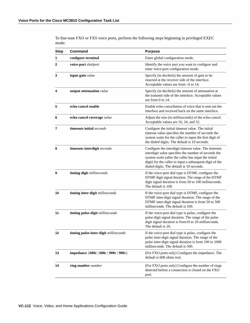
Voice Ports for the Cisco MC3810 Configuration Task List
VC-112 Voice, Video, and Home Applications Configuration Guide
To fine-tune FXO or FXS voice ports, perform the following steps beginning in privileged EXECmode:
Step Command Purpose
1 configure terminal Enter global configuration mode.
2 voice-port slot/port Identify the voice port you want to configure andenter voice-port configuration mode.
3 input gain value Specify (in decibels) the amount of gain to beinserted at the receiver side of the interface.Acceptable values are from –6 to 14.
4 output attenuation value Specify (in decibels) the amount of attenuation atthe transmit side of the interface. Acceptable valuesare from 0 to 14.
5 echo-cancel enable Enable echo-cancellation of voice that is sent out theinterface and received back on the same interface.
6 echo-cancel coveragevalue Adjust the size (in milliseconds) of the echo-cancel.Acceptable values are 16, 24, and 32.
7 timeouts initial seconds Configure the initial timeout value. The initialtimeout value specifies the number of seconds thesystem waits for the caller to input the first digit ofthe dialed digits. The default is 10 seconds.
8 timeouts interdigit seconds Configure the interdigit timeout value. The timeoutsinterdigit value specifies the number of seconds thesystem waits (after the caller has input the initialdigit) for the caller to input a subsequent digit of thedialed digits. The default is 10 seconds.
9 timing digit milliseconds If the voice-port dial type is DTMF, configure theDTMF digit signal duration. The range of the DTMFdigit signal duration is from 50 to 100 milliseconds.The default is 100.
10 timing inter-digit milliseconds If the voice-port dial type is DTMF, configure theDTMF inter-digit signal duration. The range of theDTMF inter-digit signal duration is from 50 to 500milliseconds. The default is 100.
11 timing pulse-digit milliseconds If the voice-port dial type is pulse, configure thepulse digit signal duration. The range of the pulsedigit signal duration is from10 to 20 milliseconds.The default is 20.
12 timing pulse-inter-digit milliseconds If the voice-port dial type is pulse, configure thepulse inter-digit signal duration. The range of thepulse inter-digit signal duration is from 100 to 1000milliseconds. The default is 500.
13 impedance {600r | 600c | 900r | 900c} (For FXO ports only) Configure the impedance. Thedefault is 600 ohms real.
14 ring number number (For FXO ports only) Configure the number of ringsdetected before a connection is closed on the FXOport.

Configuring E&M Voice Ports
Configuring Voice Ports VC-113
Note After you change any voice-port command, it is a good idea to cycle the port by using theshutdown andno shutdown commands.
Configuring E&M Voice PortsUnlike FXO and FXS voice ports, the default E&M voice-port parameters most likely will not besufficient to enable voice data transmission over your network.
Note E&M voice-port values must match those of the PBX to which it is connected. Refer to thedocumentation that came with your specific PBX for the appropriate E&M voice-port configurationcommand values.
To configure an E&M voice port on the Cisco MC3810, perform the following tasks. The first twotasks are required; the third task is optional.
1 Identify the voice port and enter the voice-port configuration mode.
2 Configure the appropriate value for each of the following required parameters:
(a) Connection
(b) Dial type
(c) Cabling scheme
(d) Interface type
(e) Signal type
(f) CODEC
(g) Call progress tone
3 Configure one or more of the following optional parameters:
(a) Description
(b) VAD
(c) Comfort noise (if VAD is activated)
15 ring frequency number (For FXS ports only) Specify the local ringfrequency for the FXS voice port. Thenumbervalueshould be set to either 20 or 30.
16 ring cadence [on1 | off1] [on2 | off2][on3 | off3] [on4 | off4] [on5 | off5] [on6 | off6]
(For FXS only) Specify the local ring cadence forthe FX voice port. Using this command, specify theon and off pulses for the ring. The ring cadencediffers depending on the local region. The units arein 100-millisecond units.
Step Command Purpose

Voice Ports for the Cisco MC3810 Configuration Task List
VC-114 Voice, Video, and Home Applications Configuration Guide
To configure E&M voice ports, use the following commands beginning in privileged EXEC mode:
Step Command Purpose
1 configure terminal Enter global configuration mode.
2 voice-port slot/port Identify the voice port you want to configure andenter voice-port configuration mode.
3 connection{ plar | tie-line | plar-opx} string Configure the voice-port connection mode type andthe destination telephone number.
Theplar value is used for Private Line AutoRingdown (PLAR) connections. Thetie-line valueis used for a tie-line connection to a PBX. Theplar-opx value is used for PLAR Off-PremiseseXtension, to allow the local voice port to provide alocal response before the remote voice port receivesan answer.
4 dial-type dtmf Select the appropriate dial type for out-dialing. ForE&M voice ports, the only available choice isDTMF.
5 operation { 2-wire | 4-wire} Select the appropriate cabling scheme for this voiceport.
6 type { 1 | 2 | 3 | 5} Select the appropriate E&M interface type.
Type 1 indicates the following lead configuration:
E—output, relay to groundM—input, referenced to ground
Type 2 indicates the following lead configuration:
E—output, relay to SGM—input, referenced to groundSB—feed for M, connected to –48VSG—return for E, galvanically isolated fromground
Type 3 indicates the following lead configuration:
E—output, relay to groundM—input, referenced to groundSB—connected to –48VSG—connected to ground
Type 5 indicates the following lead configuration:
E—output, relay to groundM—input, referenced to –48V.
7 signal { wink-start | immediate | delay-dial} Configure the signaling type for E&M voice ports.The default is wink-start.
8 codec {g729r8 | g729ar8} Configure the voice-port compression mode.Theg729ar8 value is the default and is recommended.
The g729ar8 compression mode can support amaximum of 24 simultaneously active on-net voicecalls while the g729r8 value can only support amaximum of 12. Both compression modes have anominal data rate of 8 kbps.
9 compand-type {u-law | a-law} Configure the companding standard used to convertbetween analog and digital signals in PCM systems.This command applies to digital voice-posts only.

Fine-Tuning E&M Voice Ports
Configuring Voice Ports VC-115
Validation TipsYou can check the validity of your voice-port configuration by performing the following tasks:
• Pick up the handset of an attached telephony device and check for a dial tone.
• If you have dial tone, check for DTMF detection. If the dial tone stops when you dial a digit, thenthe voice port is most likely configured properly.
• Use theshow voice port command to verify that the data configured is correct.
• Use theshow voice dsp command to verify the current status of all DSP voice channels.
• Use theshow voice call summary command to verify the call status for all voice ports.
Troubleshooting TipsIf you are having trouble connecting a call and you suspect the problem is associated with voice-portconfiguration, you can try to resolve the problem by performing the following tasks:
• Ping the associated IP address to confirm connectivity. If you cannot successfully ping yourdestination, refer to theNetwork Protocols Configuration Guide, Part 1.
• Use theshow voice portcommand to make sure that the port is enabled. If the port is offline, usetheno shutdown command.
• Make sure that the values pertaining to your specific PBX setup, such as timing and type, arecorrect.
• Check to see if the voice network module has been correctly installed. For more information,refer to the Cisco MC3810Multiservice Concentrator Hardware Installation Guide.
Fine-Tuning E&M Voice PortsDepending on the specifics of your particular network, you may need to adjust voice parametersinvolving timing, input gain and output attenuation for E&M voice ports. Collectively, thesecommands are referred to as voice-port tuning commands.
Note In most cases, the default values for voice-port tuning commands will be sufficient.
10 cptonecountry Configure the appropriate call progress tone for thelocal region.
The default for this command isnorthamerica. Fora list of supported countries, refer to theVoice,Video, and Home Applications Command Reference.
11 description string (Optional) Attach descriptive text about thisvoice port connection.
12 vad (Optional) Enable voice activity detection (VAD).
13 voice confirmation-tone (Optional) If the voice port is configured forconnection plar-opx for Off-Premises eXtension,disable the two-beep confirmation tone that a callerhears when picking up the handset.
Step Command Purpose
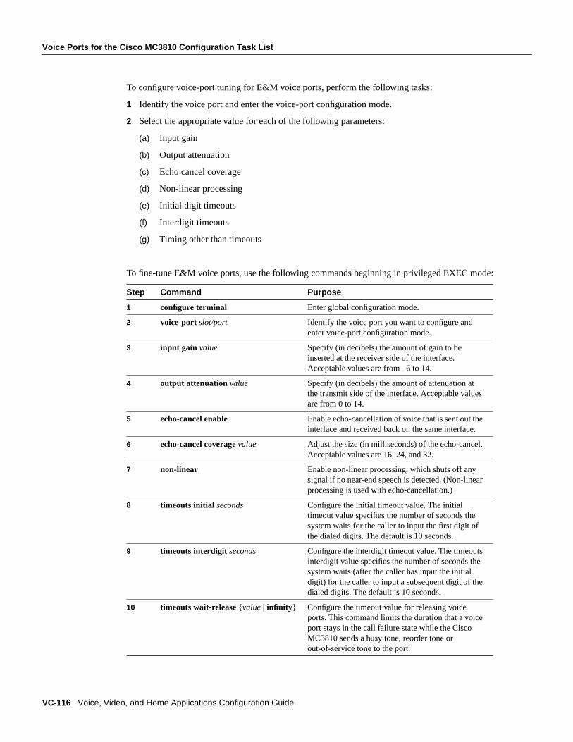
Voice Ports for the Cisco MC3810 Configuration Task List
VC-116 Voice, Video, and Home Applications Configuration Guide
To configure voice-port tuning for E&M voice ports, perform the following tasks:
1 Identify the voice port and enter the voice-port configuration mode.
2 Select the appropriate value for each of the following parameters:
(a) Input gain
(b) Output attenuation
(c) Echo cancel coverage
(d) Non-linear processing
(e) Initial digit timeouts
(f) Interdigit timeouts
(g) Timing other than timeouts
To fine-tune E&M voice ports, use the following commands beginning in privileged EXEC mode:
Step Command Purpose
1 configure terminal Enter global configuration mode.
2 voice-port slot/port Identify the voice port you want to configure andenter voice-port configuration mode.
3 input gain value Specify (in decibels) the amount of gain to beinserted at the receiver side of the interface.Acceptable values are from –6 to 14.
4 output attenuation value Specify (in decibels) the amount of attenuation atthe transmit side of the interface. Acceptable valuesare from 0 to 14.
5 echo-cancel enable Enable echo-cancellation of voice that is sent out theinterface and received back on the same interface.
6 echo-cancel coveragevalue Adjust the size (in milliseconds) of the echo-cancel.Acceptable values are 16, 24, and 32.
7 non-linear Enable non-linear processing, which shuts off anysignal if no near-end speech is detected. (Non-linearprocessing is used with echo-cancellation.)
8 timeouts initial seconds Configure the initial timeout value. The initialtimeout value specifies the number of seconds thesystem waits for the caller to input the first digit ofthe dialed digits. The default is 10 seconds.
9 timeouts interdigit seconds Configure the interdigit timeout value. The timeoutsinterdigit value specifies the number of seconds thesystem waits (after the caller has input the initialdigit) for the caller to input a subsequent digit of thedialed digits. The default is 10 seconds.
10 timeouts wait-release {value | infinity } Configure the timeout value for releasing voiceports. This command limits the duration that a voiceport stays in the call failure state while the CiscoMC3810 sends a busy tone, reorder tone orout-of-service tone to the port.
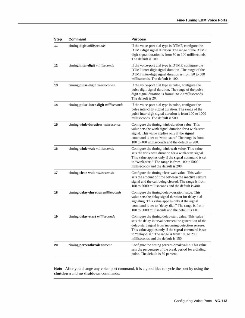
Fine-Tuning E&M Voice Ports
Configuring Voice Ports VC-113
Note After you change any voice-port command, it is a good idea to cycle the port by using theshutdown andno shutdown commands.
11 timing digit milliseconds If the voice-port dial type is DTMF, configure theDTMF digit signal duration. The range of the DTMFdigit signal duration is from 50 to 100 milliseconds.The default is 100.
12 timing inter-digit milliseconds If the voice-port dial type is DTMF, configure theDTMF inter-digit signal duration. The range of theDTMF inter-digit signal duration is from 50 to 500milliseconds. The default is 100.
13 timing pulse-digit milliseconds If the voice-port dial type is pulse, configure thepulse digit signal duration. The range of the pulsedigit signal duration is from10 to 20 milliseconds.The default is 20.
14 timing pulse-inter-digit milliseconds If the voice-port dial type is pulse, configure thepulse inter-digit signal duration. The range of thepulse inter-digit signal duration is from 100 to 1000milliseconds. The default is 500.
15 timing wink-duration milliseconds Configure the timing wink-duration value. Thisvalue sets the wink signal duration for a wink-startsignal. This value applies only if thesignalcommand is set to “wink-start.” The range is from100 to 400 milliseconds and the default is 200.
16 timing wink-wait milliseconds Configure the timing wink-wait value. This valuesets the wink wait duration for a wink-start signal.This value applies only if thesignalcommand is setto “wink-start.” The range is from 100 to 5000milliseconds and the default is 200.
17 timing clear-wait milliseconds Configure the timing clear-wait value. This valuesets the amount of time between the inactive seizuresignal and the call being cleared. The range is from100 to 2000 milliseconds and the default is 400.
18 timing delay-duration milliseconds Configure the timing delay-duration value. Thisvalue sets the delay signal duration for delay dialsignaling. This value applies only if thesignalcommand is set to “delay-dial.” The range is from100 to 5000 milliseonds and the default is 140.
19 timing delay-start milliseconds Configure the timing delay-start value. This valuesets the delay interval between the generation of thedelay-start signal from incoming detection seizure.This value applies only if thesignalcommand is setto “delay-dial.” The range is from 100 to 290milliseconds and the default is 150.
20 timing percentbreak percent Configure the timing percent-break value. This valuesets the percentage of the break period for a dialingpulse. The default is 50 percent.
Step Command Purpose

Voice Ports for the Cisco MC3810 Configuration Task List
VC-114 Voice, Video, and Home Applications Configuration Guide
Activating the Voice PortAfter you have configured the voice port, you need to activate the voice port to bring it online. In factit is a good idea to cycle the port—meaning to shut the port down and then bring it online again.
To activate a voice port, use the following command in voice-port configuration mode:
To cycle a voice port, use the following commands in voice-port configuration mode:
Note If you are not going to use a voice port, shut it down.
Command Purpose
no shutdown Activate the voice port.
Step Command Purpose
1 shutdown Deactivate the voice port.
2 voice-port slot-number/subunit-number/portorvoice-port slot/port
Identify the voice port you want to activateand enter the voice-port configuration mode.
3 no shutdown Activate the voice port.

121
Anexo 2: Configuración de VoIP en los puertos de voz
El siguiente archivo presenta una descripción más detallada acerca de los pasos
necesarios para programar los puertos de voz de los routers Cisco.
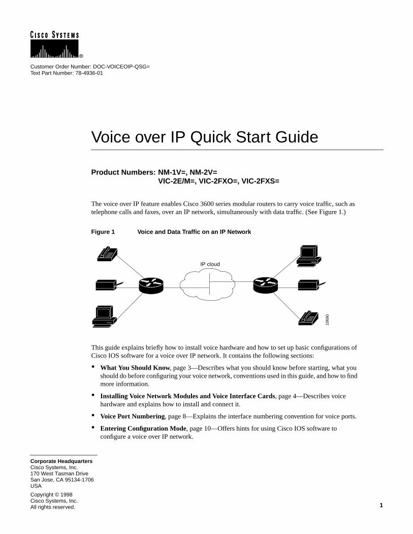
1Cisco Systems, Inc.All rights reserved.
170 West Tasman DriveSan Jose, CA 95134-1706USA
Cisco Systems, Inc.Corporate Headquarters
Copyright © 1998
Voice over IP Quick Start Guide
Product Numbers: NM-1V=, NM-2V=VIC-2E/M=, VIC-2FXO=, VIC-2FXS=
The voice over IP feature enables Cisco 3600 series modular routers to carry voice traffic, such astelephone calls and faxes, over an IP network, simultaneously with data traffic. (See Figure 1.)
Figure 1 Voice and Data Traffic on an IP Network
This guide explains briefly how to install voice hardware and how to set up basic configurations ofCisco IOS software for a voice over IP network. It contains the following sections:
• What You Should Know, page 3—Describes what you should know before starting, what youshould do before configuring your voice network, conventions used in this guide, and how to findmore information.
• Installing Voice Network Modules and Voice Interface Cards, page 4—Describes voicehardware and explains how to install and connect it.
• Voice Port Numbering, page 8—Explains the interface numbering convention for voice ports.
• Entering Configuration Mode, page 10—Offers hints for using Cisco IOS software toconfigure a voice over IP network.
IP cloud
1069
0
Customer Order Number: DOC-VOICEOIP-QSG=Text Part Number: 78-4936-01

2 Voice over IP Quick Start Guide
• Configuring the IP Network for Real-Time Voice Traffic, page 12—Describes how toconfigure the IP network to accommodate voice traffic.
• Configuring FXS Interfaces, page 16—Describes how to configure FXS voice interface cardsfor connecting a router to telephones, fax machines, and similar devices. This section alsointroduces the concepts of dial peers, which link voice ports or IP addresses with telephonenumbers, and number expansion, a shortcut to entering repeated voice-configuration commands.
• Configuring FXO Interfaces, page 24—Describes how to configure FXO voice interface cardsfor connecting a router to a telephone company central office.
• Configuring E&M Interfaces , page 26—Describes how to configure E&M voice interfacecards for connections between PBXs.
• Saving the Configuration, page 29—Explains how to save the configuration so it is availablethe next time you boot the router.
• List of Terms, page 30—Provides a list of terms and abbreviations used in this guide.
• Cisco Connection Online, page 32—Explains how to get service and support.

Voice over IP Quick Start Guide 3
What You Should Know
What You Should KnowThis guide is intended for data communications managers or telecommunications managers who areinstalling, configuring, or maintaining voice network modules and interface cards. It assumes thatyou already have a working IP LAN or WAN, or that you know how to set one up, and that you wantto add voice capability to it. It does not tell you how to design or install a LAN or WAN, assign IPaddresses, install routers and configure them for IP traffic, or perform other basic tasks. It alsoassumes that you are familiar with Cisco IOS software, and that you know how to configure therouters on your LAN or WAN for IP service.
For E&M installations, you should also be familiar with telephony concepts and PBX operation.
The “List of Terms” near the end of this guide provides a glossary of many terms and concepts usedby voice over IP. For further information on voice over IP features, refer to theVoiceNetwork Module and Voice Interface Card Configuration Note, theVoice over IP SoftwareConfiguration Guide, your router installation and configuration guide, theRegulatory Complianceand Safety Informationdocument for your router, and the Cisco IOS configuration guides andcommand references.
Document ConventionsIn this guide:
• Commands in the text are shown inboldface.
• Variables for which you supply values are initalics.
• Italics are also used for the titles of publications and for new words or concepts.
• Information the router displays on the console screen is inscreen font .
• Information that you enter at the console keyboard is inboldface screen font .
To Learn MoreCisco documentation and additional literature are available in a CD-ROM package, which ships withyour product. The Documentation CD-ROM, a member of the Cisco Connection Family, is updatedmonthly. Therefore, it might be more up to date than printed documentation. To order additionalcopies of the Documentation CD-ROM, contact your local sales representative or call customerservice. The CD-ROM package is available as a single package or as an annual subscription.
You can also read Cisco documentation on the World Wide Web at http://www.cisco.com,http://www-china.cisco.com, or http://www-europe.cisco.com. From here, you can submitcomments electronically. ClickFeedbackon the title bar, and then selectDocumentation. After youcomplete the form, clickSubmit to send it to Cisco. We appreciate your comments.
If you have questions or need help, refer to the section “Cisco Connection Online” at the end of thisguide for further information.

4 Voice over IP Quick Start Guide
Installing Voice Network Modules and Voice Interface Cards
Installing Voice Network Modules and Voice Interface CardsThe voice over IP feature for Cisco 3600 series routers uses two types of hardware:
• Voice network modules
• Voice interface cards (VICs)
Note To transmit voice calls over an IP LAN or WAN, you need (in addition to the voice hardware)at least one other network module or WAN interface card in the router to provide the connection tothe LAN or WAN. In most cases, this network module, or another network module or WAN interfacecard in the router, also serves to carry data traffic.
You should install and cable voice modules and VICs before performing the software configurationtasks explained later. If you need more detailed installation instructions, refer to theVoiceNetwork Module and Voice Interface Card Configuration Note.
Voice Network ModulesVoice network modules install in a slot in a Cisco 3600 series router, and convert telephone voicesignals into a form that can be transmitted over an IP network. The one-slot voice network moduleprovides one slot for a voice interface card. The two-slot voice network module provides two slotsfor voice interface cards. Figure 2 shows a two-slot voice network module.
Figure 2 Two-Slot Voice Network Module
Warning Be sure to observe all warnings and safety precautions in the configuration note.
Caution Network modules and voice interface cards do not support online insertion and removal(hot swap). To avoid equipment damage, before you insert a network module into a chassis slot, orinsert a voice interface card into a voice network module in the router chassis, you must turn OFFelectrical power and disconnect network cables.
VOICE2V
V0V1
EN
Slots for voice interface cards
1069
2
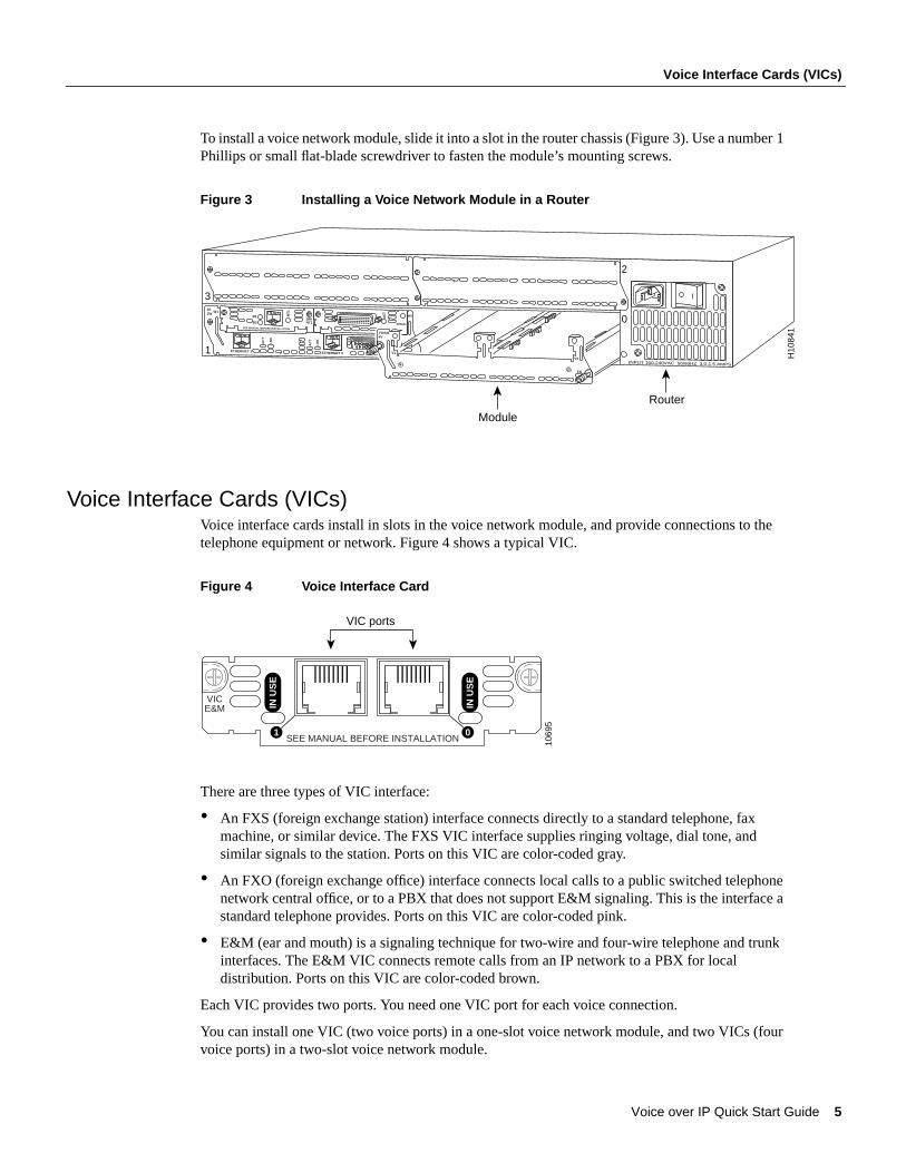
Voice over IP Quick Start Guide 5
Voice Interface Cards (VICs)
To install a voice network module, slide it into a slot in the router chassis (Figure 3). Use a number 1Phillips or small flat-blade screwdriver to fasten the module’s mounting screws.
Figure 3 Installing a Voice Network Module in a Router
Voice Interface Cards (VICs)Voice interface cards install in slots in the voice network module, and provide connections to thetelephone equipment or network. Figure 4 shows a typical VIC.
Figure 4 Voice Interface Card
There are three types of VIC interface:
• An FXS (foreign exchange station) interface connects directly to a standard telephone, faxmachine, or similar device. The FXS VIC interface supplies ringing voltage, dial tone, andsimilar signals to the station. Ports on this VIC are color-coded gray.
• An FXO (foreign exchange office) interface connects local calls to a public switched telephonenetwork central office, or to a PBX that does not support E&M signaling. This is the interface astandard telephone provides. Ports on this VIC are color-coded pink.
• E&M (ear and mouth) is a signaling technique for two-wire and four-wire telephone and trunkinterfaces. The E&M VIC connects remote calls from an IP network to a PBX for localdistribution. Ports on this VIC are color-coded brown.
Each VIC provides two ports. You need one VIC port for each voice connection.
You can install one VIC (two voice ports) in a one-slot voice network module, and two VICs (fourvoice ports) in a two-slot voice network module.
Module
Router
H10
841
INPUT 100-240VAC 50/60HZ 3.0-1.5 AMPS
2E2W W1
ETHERNET 1 ETHERNET 0
WO
AC
T
LN
K
AC
T
LN
K
AC
T
SERIAL
BRINT1
B1
B2
NT
1
2
0
3
1
SEE MANUAL BEFORE INSTALLATION
VOICE4V
V0
V1
EN
1069
5
SEE MANUAL BEFORE INSTALLATION
VICE&M IN
US
E
IN U
SE
1 0
VIC ports

6 Voice over IP Quick Start Guide
Installing Voice Network Modules and Voice Interface Cards
To install a VIC, slide it into a slot in the voice network module, as shown in Figure 5. Use anumber 1 Phillips or small flat-blade screwdriver to fasten the VIC’s mounting screws.
Figure 5 Installing a Voice Interface Card in a Voice Network Module
Router
H1
08
42
INPUT 100-240VAC 50/60HZ 3.0-1.5 AMPS
2E2W W1
ETHERNET 1 ETHERNET 0
WO
AC
T
LN
K
AC
T
LN
K
AC
T
SERIAL
BRINT1
B1
B2
NT
1
2
0
3
1
SEE MANUAL BEFORE INSTALLATION
VOICE4V
V0V1
EN
SEE MANUAL BEFORE INSTALLATION
VICFXO IN
US
E
IN U
SE
1 0
SEE MANUAL BEFORE INSTALLATION
VICFXO IN
US
E
IN U
SE
1 0
Module

Voice over IP Quick Start Guide 7
Connecting VICs to the Network
Connecting VICs to the NetworkFigure 6 shows how to connect VICs to the network:
• Use a standard RJ-11 modular telephone cable to connect FXS VIC ports (color-coded gray) toa telephone or fax machine.
• Use a standard RJ-11 modular telephone cable to connect FXO VIC ports (color-coded pink) tothe public switched telephone network, or to a PBX that does not support E&M signaling,through a telephone wall outlet.
• The E&M VIC uses an RJ-48S connector and cable. The cable wiring depends on the type ofconnection. See theVoice Network Module and Voice Interface Card Configuration Note fordetails.
Figure 6 Connecting VICs to the Network
When you are finished, reinstall any network interface cables you removed and turn ON power tothe router.
Checking the InstallationIf you installed an FXS VIC, connect a handset to the VIC port. When router power is on, you shouldbe able to hear dial tone when you lift the handset. Dial tone should stop after you dial a digit. If youhave trouble, use theshow voice portcommand to make sure that the VIC is installed correctly. Ifit is, try connecting a different handset to the VIC.
SEE MANUAL BEFORE INSTALLATION
IN U
SE
IN U
SE
1 0
SEE MANUAL BEFORE INSTALLATION
IN U
SE
IN U
SE
1 0
SEE MANUAL BEFORE INSTALLATION
IN U
SE
IN U
SE
1 0
PBX
FXS VIC
FXO VIC
E&M VIC
1069
1
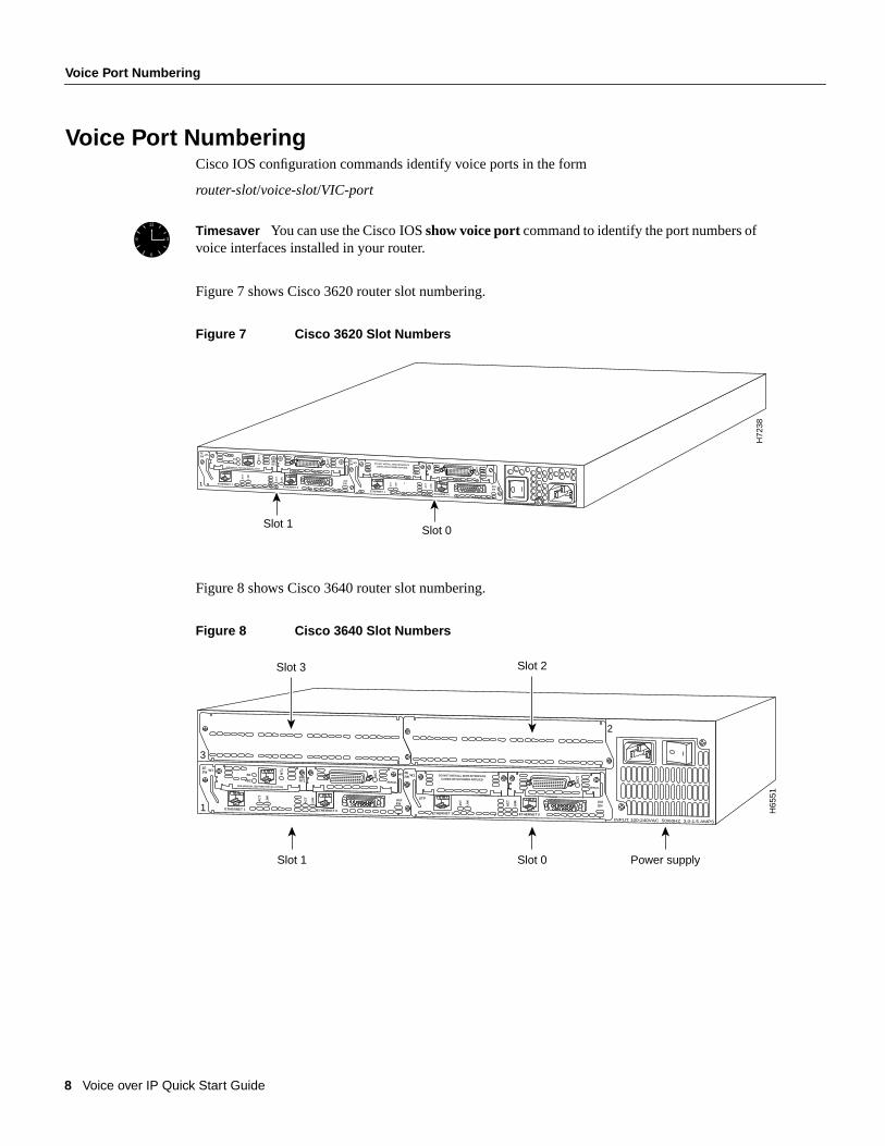
8 Voice over IP Quick Start Guide
Voice Port Numbering
Voice Port NumberingCisco IOS configuration commands identify voice ports in the form
router-slot/voice-slot/VIC-port
Figure 7 shows Cisco 3620 router slot numbering.
Figure 7 Cisco 3620 Slot Numbers
Figure 8 shows Cisco 3640 router slot numbering.
Figure 8 Cisco 3640 Slot Numbers
Timesaver You can use the Cisco IOSshow voice portcommand to identify the port numbers ofvoice interfaces installed in your router.
12
6
9 3
2E2W
W1
1 ETHERNET 1
ETH 1
ETHERNET 0
ENAUI
WO
AC
T
LN
K
AC
T
LN
K
AC
T
SERIAL
BRINT1
B1
B2
NT
1
2E2W W1
ETHERNET 0
AUIEN
AC
T
LN
K
AC
T
LN
K
DO NOT INSTALL WAN INTERFACECARDS WITH POWER APPLIED
AC
TSERIAL
SEE MANUAL BEFORE INSTALLATION
Slot 0
H72
38
Slot 1
0ETHERNET 1
Slot 0Slot 1 Power supply
Slot 3
H65
51
INPUT 100-240VAC 50/60HZ 3.0-1.5 AMPS
2E2W W1
ETHERNET 1 ETHERNET 0
ENAUI
WO
AC
T
LN
K
AC
T
LN
K
AC
T
SERIAL
BRINT1
B1
B2
NT
1
2
3
1
2E2W W1
STP
ETHERNET 0
AUIENA
CT
LN
K
AC
T
LN
K
DO NOT INSTALL WAN INTERFACECARDS WITH POWER APPLIED
Slot 2
AC
T
SERIALSEE MANUAL BEFORE INSTALLATION
ETHERNET 1

Voice over IP Quick Start Guide 9
Example
Figure 9 shows voice slot numbering.
Figure 9 Voice Slot Numbering
Figure 10 shows VIC port numbering.
Figure 10 VIC Port Numbering
ExampleSuppose you install a two-slot voice network module in the upper right slot of a Cisco 3640 router,and install two VICs in the module. Each VIC has two ports. From right to left, these ports wouldbe numbered 2/0/0, 2/0/1, 2/1/0, and 2/1/1.
VOICE2V
V0V1
EN
Voice slot 1 Voice slot 0
1069
3
1069
4
SEE MANUAL BEFORE INSTALLATION
VICE&M IN
US
E
IN U
SE
1 0
VIC port 1 VIC port 0

10 Voice over IP Quick Start Guide
Entering Configuration Mode
Entering Configuration ModeYou configure Cisco IOS software for voice over IP by typing commands on the command line. Thismethod of entering commands is called configuration mode.
Note Voice over IP commands require the IP Plus, Desktop Plus, or Enterprise Plus image,Cisco IOS Release 11.3(1)T or later.
To enter configuration mode, follow this procedure:
Step 1 Connect a console to the router. Configure the console for 9600 baud, 8 data bits, 1 stopbit, and no parity. Power up the router.
Step 2 If the current configuration is no longer valid (for instance, because you added aninterface), after about one minute you see the following prompt:
Would you like to enter the initial configuration dialog? [yes]:
Answerno. You now enter the normal operating mode of the router.
Note If the current configuration is valid, you enter the normal operating modeautomatically.
Step 3 After a few seconds, you see the user EXEC prompt (Router> ). Typeenable and thepassword to enter enable mode:
Router> enablePassword:
Configuration changes can be made only in enable mode. The prompt changes to theprivileged EXEC (enable) prompt (Router# ):
Router#
Step 4 Enter theconfig terminal command to enter configuration mode:
Router# config terminalRouter(config)#
The router enters global configuration mode, indicated by theRouter(config)# prompt.
Step 5 If you have not configured the router before, or want to change the configuration,configure global parameters, passwords, network management, and routing protocols. Inthis example, IP routing, AppleTalk routing, and IPX routing are all enabled:
Router(config)# ip routingRouter(config)# appletalk routingRouter(config)# ipx routing
For complete information about global configuration commands, and about configuringLAN and WAN interfaces on your router, refer to the Cisco IOS configuration guides andcommand references.

Voice over IP Quick Start Guide 11
Entering Configuration Mode
The rest of this guide explains how to configure Cisco IOS software for voice over IP traffic.
Remember that when you finish configuring the software, you must save the new configuration toNVRAM. This procedure is described in the section “Saving the Configuration” later in this guide.You may also want to save periodically during the configuration process.
Timesaver Voice configuration uses a number of new Cisco IOS commands. For completeinformation about these commands, see theVoice over IP Software Configuration Guide. You canalso enter a question mark after a command or partial command at theRouter(config)# promptto get help with syntax and arguments.
Timesaver At any point, you can see the current operating configuration, including changes youjust made, by entering theshow running-configcommand.
12
6
9 3
12
6
9 3

12 Voice over IP Quick Start Guide
Configuring the IP Network for Real-Time Voice Traffic
Configuring the IP Network for Real-Time Voice TrafficVoice traffic is much more sensitive to timing variations than data traffic. For good voiceperformance, you might need to configure your data network so voice packets are not lost or delayed.This section describes three important methods of improving quality of service, or QoS (the level ofnetwork performance needed for voice over IP connections):
• RSVP
• Multilink PPP interleaving
• RTP header compression
Cisco IOS software provides many other tools for ensuring QoS, such as custom queuing, priorityqueuing, weighted fair queuing, and IP precedence. For further information and more detailedexamples of QoS configuration, see theVoice over IP Software Configuration Guide.
Note QoS measures the level of network performance. It does not directly measure the quality ofthe voice signal.
Configuring voice over IP on a Frame Relay link involves special considerations. These arediscussed in the section “Configuring Frame Relay for Voice over IP.”
Do You Need QoS?On a relatively low-bandwidth connection, such as a PPP or HDLC serial link, you should considerusing methods to ensure QoS. If you have a high-bandwidth network, such as Ethernet or FastEthernet, and voice and data traffic together occupy only a small fraction of the bandwidth available,you may not need to provide QoS. (See Figure 11.) If you are not sure, you may want to try skippingthe following sections and continuing with “Configuring FXS Interfaces” later in this guide. Returnto this section if you need to improve the reliability of voice connections.
Figure 11 Bandwidth v. Quality of Service
Low bandwidth Need QoS
High bandwidthMay not need QoS 10
689
Voice over IP Quick Start Guide 13
Do You Need RSVP?
Do You Need RSVP?Resource Reservation Protocol (RSVP) enables routers to reserve enough bandwidth for reliableperformance. RSVP works well on PPP, HDLC, and similar serial line interfaces. It does not workwell on multiaccess LANs.
You should configure RSVP if you have a serial interface and any of the following:
• Links slower than 2 Mbps
• Links with high utilization
• Need for the best possible voice quality
Note If you configure multilink PPP interleaving, you can use theip rtp reserve command insteadof configuring RSVP. See the next section on “Do You Need Multilink PPP Interleaving?”
Configuring RSVPBy default, RSVP is disabled for compatibility with routers that do not implement it. To enableRSVP on an IP network, enter theip rsvp bandwidth command from interface configuration mode.The following example shows how to configure RSVP on serial interface 0/0:
Router> enablePassword:Router# configure terminalRouter(config)# interface serial 0/0Router(config-if)# ip rsvp bandwidth
The default maximum bandwidth is 75 percent of the bandwidth available on each interface.
RSVP must be enabled at each LAN or WAN interface that voice packets will travel across. Youmust also configure each remote dial peer to request an RSVP session, using thereq-qoscommand.See the section “Calling Between Routers” later in this guide.
Do You Need Multilink PPP Interleaving?On a dialer, ISDN PRI or BRI interface, or a virtual template, you can configure multilink PPPinterleaving, which helps to make sure that voice packets are transmitted without delay.
You should configure multilink PPP interleaving if you have one of these interfaces, and either ofthe following:
• Point-to-point connections using PPP encapsulation
• Links slower than 2 Mbps
Note Do not use multilink PPP on links faster than 2 Mbps.

14 Voice over IP Quick Start Guide
Configuring the IP Network for Real-Time Voice Traffic
Configuring Multilink PPP InterleavingTo configure multilink PPP and interleaving on a dialer, ISDN PRI, or ISDN BRI interface, or avirtual template, you must first configure multilink PPP and interleaving on the interface or templateby entering the following commands in interface configuration mode:
Router(config-if)# encapsulation pppRouter(config-if)# ppp multilinkRouter(config-if)# ppp multilink interleave
Optionally, configure a maximum fragment delay:
Router(config-if)# ppp multilink fragment-delay milliseconds
You can also reserve a special queue for real-time packet flows to specified destination UDP ports,allowing real-time traffic to have higher priority than other flows. This command is needed only ifyou have not configured RSVP:
Router(config-if)# ip rtp reserve lowest-UDP-port range-of-ports
For virtual templates only, apply the virtual template to the multilink bundle:
Router(config-if)# multilink virtual-template 1
Do You Need RTP Header Compression?RTP header compression on a PPP, HDLC, or similar serial interface compresses the packet headerto reduce network overhead.
You should configure RTP header compression on a serial interface if you have either of thefollowing:
• Links slower than 2 Mbps
• Need to save bandwidth
Note Do not use RTP header compression on links faster than 2 Mbps.
Configuring RTP Header CompressionEnable RTP header compression at both ends of the serial link by entering the following commandin interface configuration mode:
Router(config-if)# ip rtp header-compression

Voice over IP Quick Start Guide 15
Configuring Frame Relay for Voice over IP
Configuring Frame Relay for Voice over IPConfiguring voice over IP on a Frame Relay link involves certain special considerations to ensureacceptable voice quality. For Frame Relay links with slow output rates (64 kbps or less), where dataand voice are being transmitted over the same PVC, you should configure the following:
• Lower MTU size—Voice packets are generally small. If you decrease the MTU size to 300 bytes,large data packets can be broken up into smaller data packets that are more easily interleaved withvoice packets.
The following example configures an MTU size of 300 bytes over serial interface 0/0:
Router# interface serial 0/0Router(config-if)# mtu 300
• RSVP—Configure RSVP on the subinterfaces (which correspond to PVCs) to reserve bandwidthfor voice channels. See the section on “Do You Need RSVP?” earlier in this guide.
The following example configures RSVP over serial subinterface 0/0.1:
Router(config-if)# interface serial 0/0.1 point-to-pointRouter(config-if)# ip address 192.168.19.0 255.0.0.0Router(config-if)# ip rsvp bandwidth
• RTP header compression—Configure RTP header compression on the subinterfaces to minimizethe size of the voice packet. See the previous section on “Do You Need RTP HeaderCompression?”
The following command configures RTP header compression over the currently selectedsubinterface:
Router(config-if)# frame-relay ip rtp header-compression
• Traffic shaping—Use traffic shaping to control the outbound traffic rate; otherwise, voice packetsmight be discarded. In Cisco IOS Release 11.3, Frame Relay traffic shaping is not compatiblewith RSVP. Use generic traffic shaping instead, setting the CIR equal to the port speed. Doingthis prevents the router from exceeding the CIR rate, which could lead to frames being discarded.
The following command configures generic traffic shaping with a CIR of 32000 bps:
Router(config-if)# traffic-shape rate 32000
For further information and more detailed examples of Frame Relay configuration, see theVoiceover IP Software Configuration Guide.

16 Voice over IP Quick Start Guide
Configuring FXS Interfaces
Configuring FXS InterfacesThis section explains how to configure FXS VICs. Ports on this VIC connect directly to a standardtelephone, fax machine, or similar device.
Figure 12 shows a basic voice network. A small business uses a Cisco 3600 series router (namedWest) to provide telephone and fax connections among employees in its office. Figure 12 shows twoof these telephones, each connected to an FXS VIC port in the West router.
Figure 12 Basic Voice Network (West Router)
Note You can name your router by using thehostname command in global configuration mode.
Table 1 lists telephone numbers and voice ports for the West router. (For information about portnumbering, see the section on “Voice Port Numbering” earlier in this guide.)
Table 1 West Router Telephone Numbers and Voice Ports
Note Additional telephones and fax machines could be connected in this example, up to a total of12 if the router is a Cisco 3640 configured with three two-slot voice network modules. The modulein the remaining slot would provide interfaces for IP connectivity to the LAN or WAN and for datatraffic. To accommodate more than 12 voice devices, you would need to add more routers, or to usean E&M VIC and a local PBX, rather than connecting every telephone to its own FXS VIC.
Telephone Number Voice Port
408 555-3737 2/0/0
408 555-4141 2/0/1
408 555-3737
408 555-4141
FXS VIC2/0/0
FXS VIC2/0/1
West
IP cloud
1000
7

Voice over IP Quick Start Guide 17
Local Dial Peers
Local Dial PeersTo route a received voice call to the right destination, the router needs to know which telephonenumber belongs to each voice port. For instance, if a call comes in for 408 555-3737, the router needsto know that this telephone is connected to voice port 2/0/0 (as shown in Figure 12). In other words,the router needs to know the information in Table 1.
To hold this information, Cisco IOS software uses objects calleddial peers. A telephone number, avoice port, and other call parameters are tied together by associating them all with the same dial peer.Configuring dial peers is similar to configuring static IP routes—you are telling the router what pathto follow to route the call.
Dial peers are identified by numbers, but to avoid confusing these numbers with telephone numbers,they are usually referred to astags. Dial peer tags are integers that can range from 1 to 231 -1(2147483647), which should be enough for most purposes. Dial peers on the same router must haveunique tags, but you can reuse the tags on other routers.
Table 2 assigns each phone number-voice port pair on the West router a dial peer tag. Within theallowed range, you can choose any dial peer tag or any system that is convenient or makes sense toyou. This type of dial peer is called aPOTS dial peer or alocal dial peer. The term “POTS” (plainold telephone service) means that the dial peer associates a physical voice port with a local telephonedevice. (Another type of dial peer is explained in the section “Calling Between Routers.”)
Table 2 West Router Local Dial Peers
You should construct a table similar to Table 2 for your own routers, assigning your own telephonenumbers and dial peer tags.
Note The telephone numbers used in this guide are only examples, and are generally invalid forpublic use in the United States. When you configure your network, be sure to substitute your owntelephone numbers.
To configure the router with the information in the table, enter the following commands in globalconfiguration mode:
West(config)# dial-peer voice 401 potsWest(config-dial-peer)# dest-pat +14085553737West(config-dial-peer)# port 2/0/0West(config)# dial-peer voice 402 potsWest(config-dial-peer)# dest-pat +14085554141West(config-dial-peer)# port 2/0/1West(config-dial-peer)# exitWest(config)#
These commands are summarized in Figure 13.
Telephone Number Voice Port Dial Peer Tag
408 555-3737 2/0/0 401
408 555-4141 2/0/1 402

18 Voice over IP Quick Start Guide
Configuring FXS Interfaces
Figure 13 West Router Configured for Local Dial Peers
Thedial-peer command always takes the argumentvoice. The number following it is the dial peertag, andpots is the type of dial peer.
Cisco IOS software refers to a telephone number as adestination pattern, because it is thedestination for an incoming or outgoing call. Enter these numbers with thedestination-pattern(abbreviateddest-pat) command. A destination pattern always begins with a plus sign (+). It canalso include asterisks (*) and pound signs (#) from the telephone keypad, and commas (,) andperiods (.), which have special meaning. Parentheses ( () ), hyphens (-), slashes (/), and spaces ( ),which are often used to make telephone numbers easier for humans to read, are not allowed.
Notice that the commands in the examples append the prefix 1 (used in the United States to indicatea long-distance number) and an area code to the destination pattern. You may need to include similarcodes for your country if the voice over IP equipment needs to establish a connection to the PSTN.In other situations, you might be able to simplify configuration by omitting this information.
Note The Cisco IOS software does not check the validity of the telephone number. It accepts anystring of permitted characters as a valid number.
The business that owns the West router also has a branch office in the East. Figure 14 shows the Eastnetwork, and Table 3 lists phone numbers, voice ports, and dial peer tags for this office.
Figure 14 Basic Voice Network (East Router)
dial-peer voice 401 pots dest-pat +14085553737 port 2/0/0
dial-peer voice 402 pots dest-pat +14085554141 port 2/0/1
FXS VIC2/0/0
FXS VIC2/0/1
West
IP cloud
1000
8
919 958-8282
919 958-9595
FXS VIC3/1/0
FXS VIC3/1/1
East
IP cloud
1000
9

Voice over IP Quick Start Guide 19
Local Dial Peers
Table 3 East Router Local Dial Peers
The following commands configure local ports on the East Router:
East(config)# dial-peer voice 901 potsEast(config-dial-peer)# dest-pat +19199588282East(config-dial-peer)# port 3/1/0East(config)# dial-peer voice 902 potsEast(config-dial-peer)# dest-pat +19199589595East(config-dial-peer)# port 3/1/1East(config-dial-peer)# exitEast(config)#
These commands are summarized in Figure 15.
Figure 15 East Router Configured for Local Dial Peers
Checking the ConfigurationIf you configured your router following these examples, you should now be able to place callsbetween telephones connected to the same router. You can also use theshow dial-peer voicecommand to verify that the data you configured is correct.
Note Although placing calls directly between ports on the same router helps to verify yourconfiguration, it is not recommended for general telecommunications use.
Telephone Number Destination Pattern Voice Port Dial Peer Tag
919 958-8282 +19199588282 3/1/0 901
919 958-9595 +19199589595 3/1/1 902
Timesaver If the voice port is offline, use theno shutdown command from interfaceconfiguration mode to enable it.
dial-peer voice 901 pots dest-pat +19199588282 port 3/1/0
dial-peer voice 902 pots dest-pat +19199589595 port 3/1/1
FXS VIC3/1/0
FXS VIC 3/1/1
East
IP cloud10
010
12
6
9 3
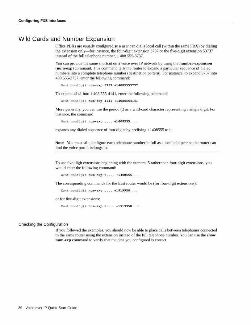
20 Voice over IP Quick Start Guide
Configuring FXS Interfaces
Wild Cards and Number ExpansionOffice PBXs are usually configured so a user can dial a local call (within the same PBX) by dialingthe extension only—for instance, the four-digit extension 3737 or the five-digit extension 53737instead of the full telephone number, 1 408 555-3737.
You can provide the same shortcut on a voice over IP network by using thenumber-expansion(num-exp) command. This command tells the router to expand a particular sequence of dialednumbers into a complete telephone number (destination pattern). For instance, to expand 3737 into408 555-3737, enter the following command:
West(config)# num-exp 3737 +14085553737
To expand 4141 into 1 408 555-4141, enter the following command:
West(config)# num-exp 4141 +14085554141
More generally, you can use the period (.) as a wild-card character representing a single digit. Forinstance, the command
West(config)# num-exp .... +1408555....
expands any dialed sequence of four digits by prefixing +1408555 to it.
Note You must still configure each telephone number in full as a local dial peer so the router canfind the voice port it belongs to.
To use five-digit extensions beginning with the numeral 5 rather than four-digit extensions, youwould enter the following command:
West(config)# num-exp 5.... +1408555....
The corresponding commands for the East router would be (for four-digit extensions):
East(config)# num-exp .... +1919958....
or for five-digit extensions:
East(config)# num-exp 8.... +1919958....
Checking the ConfigurationIf you followed the examples, you should now be able to place calls between telephones connectedto the same router using the extension instead of the full telephone number. You can use theshownum-exp command to verify that the data you configured is correct.
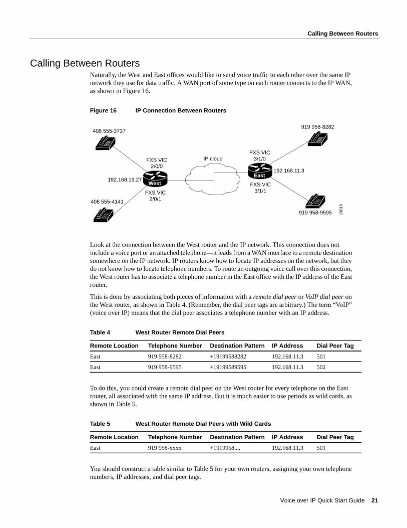
Voice over IP Quick Start Guide 21
Calling Between Routers
Calling Between RoutersNaturally, the West and East offices would like to send voice traffic to each other over the same IPnetwork they use for data traffic. A WAN port of some type on each router connects to the IP WAN,as shown in Figure 16.
Figure 16 IP Connection Between Routers
Look at the connection between the West router and the IP network. This connection does notinclude a voice port or an attached telephone—it leads from a WAN interface to a remote destinationsomewhere on the IP network. IP routers know how to locate IP addresses on the network, but theydo not know how to locate telephone numbers. To route an outgoing voice call over this connection,the West router has to associate a telephone number in the East office with the IP address of the Eastrouter.
This is done by associating both pieces of information with aremote dial peeror VoIP dial peeronthe West router, as shown in Table 4. (Remember, the dial peer tags are arbitrary.) The term “VoIP”(voice over IP) means that the dial peer associates a telephone number with an IP address.
Table 4 West Router Remote Dial Peers
To do this, you could create a remote dial peer on the West router for every telephone on the Eastrouter, all associated with the same IP address. But it is much easier to use periods as wild cards, asshown in Table 5.
Table 5 West Router Remote Dial Peers with Wild Cards
You should construct a table similar to Table 5 for your own routers, assigning your own telephonenumbers, IP addresses, and dial peer tags.
Remote Location Telephone Number Destination Pattern IP Address Dial Peer Tag
East 919 958-8282 +19199588282 192.168.11.3 501
East 919 958-9595 +19199589595 192.168.11.3 502
Remote Location Telephone Number Destination Pattern IP Address Dial Peer Tag
East 919 958-xxxx +1919958.... 192.168.11.3 501
408 555-3737
408 555-4141
FXS VIC2/0/0
FXS VIC2/0/1
West
IP cloud
919 958-8282
919 958-9595
FXS VIC3/1/0
FXS VIC3/1/1
East
1001
5
192.168.11.3
192.168.19.27

22 Voice over IP Quick Start Guide
Configuring FXS Interfaces
Note The IP addresses shown in this guide are reserved, and are meant only as examples. Whenyou configure your network, be sure to substitute your own IP addresses.
Now you need to enter only the following commands on the West router from global configurationmode:
West(config)# dial-peer voice 501 voipWest(config-dial-peer)# dest-pat +1919958....West(config-dial-peer)# session-target ipv4:192.168.11.3
Cisco IOS software calls the remote network thesession target. This command is followed by theIP address of the remote router. The prefixipv4 means IP version 4. Alternatively, you can use theprefixdns followed by the DNS name—for instance:
West(config-dial-peer)# session-target dns:voice.eastrouter.com
These commands are summarized in Figure 17.
Figure 17 West Router Configured for Remote Dial Peers
In general, you have to configure a dial peer on each router for every telephone number (or group ofwild cards) on every other router.
You can make things even easier by configuring number expansion for East router telephonenumbers on the West router:
West(config)# num-exp 8.... +1919958....
Now users can dial a five-digit extension beginning with 8 from a telephone on the West router toreach a telephone on the East router.
Now the West router is configured to send calls to the East router. Table 6 shows how to configurethe East router to send calls to the West router.
Table 6 East Router Remote Dial Peers with Wild Cards
Remote Location Telephone Number IP Address Dial Peer Tag
West 408 555-xxxx 192.168.19.27 801
919 958-xxxx
EastWest
IP cloud
1001
1
192.168.11.3
dial-peer voice 501 voip dest-pat +1919958…. session-target ipv4:192.168.11.3 num-exp 8…. +1919958….
Source Destination

Voice over IP Quick Start Guide 23
Calling Between Routers
To create this configuration, you would enter the following commands on the East router:
East(config)# num-exp 5.... +1408555....East(config)# dial-peer voice 801 voipEast(config-dial-peer)# dest-pat +1408555....East(config-dial-peer)# session-target ipv4:192.168.19.27
These commands are summarized in Figure 18.
Figure 18 East Router Configured for Remote Dial Peers
Requesting RSVPIf you configured RSVP on the WAN interface (see the section “Do You Need RSVP?” earlier in thisguide), then you must also configure each VoIP dial peer to request an RSVP session, using thereq-qos command:
West(config-dial-peer)# req-qos controlled-load
Otherwise no bandwidth is reserved for voice traffic. For further information about this command,see theVoice over IP Software Configuration Guide.
Other Routers on the NetworkIf the path between endpoints of a voice call travels through intermediate routers, you shouldconfigure those routers for VoIP traffic, as described in the section “Configuring the IP Network forReal-Time Voice Traffic” earlier in this guide.
You need to configure local or remote dial peers on an intermediate router only if that router also hasvoice devices attached.
Checking the ConfigurationAfter you configure remote dial peers (VoIP dial peers) on a router, you should be able to place callsfrom that router to telephones on the remote routers (using just the extension if you configurednumber expansion). If you have trouble, use theshow dial-peer voice command to verify that thedata you configured is correct, and ping the remote router to make sure you have connectivity.
408 555-xxxx
EastWest
IP cloud
1001
2
192.168.19.27
Destination Source
dial-peer voice 801 voip dest-pat +1408555…. session-target ipv:192.168.19.27

24 Voice over IP Quick Start Guide
Configuring FXO Interfaces
Configuring FXO InterfacesFXO interfaces provide a gateway from the VoIP network to the analog PSTN, or to a PBX that doesnot support E&M signaling, so users can reach telephones and fax machines outside the VoIPnetwork. Figure 19 shows a typical PSTN gateway attached to the West router.
Figure 19 FXO Gateway to PSTN
To create a local (POTS) dial peer for an FXS interface, as explained earlier, you enter the completetelephone number of the attached telephone as the destination pattern for incoming calls. When youcreate a local dial peer for an FXO interface, however, the destination pattern refers to outgoing calls,and you can include wild cards in it, because the PSTN performs the switching.
The VoIP feature can also remove digits that you don’t want to send to the PSTN. For instance,suppose you want to dial 9 to reach an outside line (that is, the analog PSTN). You would entercommands similar to these:
West(config)# dial-peer voice 201 potsWest(config-dial-peer)# dest-pat +9...........West(config-dial-peer)# port 1/0/0
Now, when you dial 9 followed by an 11-digit telephone number from a telephone attached to theWest router, your call is connected through voice port 1/0/0 to the PSTN. The router softwareautomatically removes the fixed part of the destination pattern—in this case, the digit 9—and sendsthe remaining 11 digits to the PSTN.
Note The fixed part of the destination pattern is removed only on calls sent to analog (FXO)interfaces. The entire number is always sent to digital (FXS and E&M) interfaces.
To enable East router users to make calls over the West router’s local PSTN, you could entercommands similar to these:
East(config)# dial-peer voice 701 voipEast(config-dial-peer)# dest-pat +7...........East(config-dial-peer)# session-target ipv4:192.168.19.27
West(config)# dial-peer voice 601 potsWest(config-dial-peer)# dest-pat +7...........West(config-dial-peer)# port 1/0/0
West
IP cloud
PSTNcloud
1001
3
FXO VIC1/0/0
Source
Destinationdial-peer voice 201 voip dest-pat +9……… port 1/0/0

Voice over IP Quick Start Guide 25
Checking the Configuration
The East router now sends all calls whose numbers begin with the special prefix 7 over the IPnetwork to the West router. (The entire number is sent, including the 7.) The West router removesthe 7 and passes the calls through its analog FXO gateway to the local PSTN.
Note In this example, West voice port 1/0/0 has two separate POTS dials peers associated with it.Dial peer 201 matches calls beginning with the digit 9, and handles PSTN calls originating from theWest router. Dial peer 601 matches calls beginning with the digit 7, and handles calls to the WestPSTN originating from the East router.
Checking the ConfigurationIf you configured your FXO interface according to this example, you should now be able to placeoutgoing calls over the PSTN. If you have trouble, use theshow voice portcommand to make surethat the VIC is installed correctly. Use theshow dial-peer voicecommand to make sure that the datayou configured is correct, and test the PSTN by connecting a handset directly to the PSTN outlet andplacing a call.

26 Voice over IP Quick Start Guide
Configuring E&M Interfaces
Configuring E&M InterfacesIf you have more than a few voice users at each location, then the cost of voice ports and routers, andthe effort needed to configure dial peers for all the combinations of origins and destinations,increases rapidly. In this situation, it may be more efficient to use a PBX at each location to switchlocal traffic and to direct incoming calls, and to connect the PBXs over an IP network using E&Mvoice interface cards.
The following example again shows a company with two offices, West and East. Now each officehas a PBX to operate its internal telephone network, while the IP network carries voice trafficbetween the offices. Figure 20 illustrates the topology of this connection. Each PBX connects to theIP router over an E&M interface connection.
Figure 20 Linking PBXs over the IP Network (Local Dial Peers)
Both PBXs in this example use E&M interface Type 2, with four-wire operation and immediate-startsignaling. The values you should use for your configuration depend on your PBX, and should beavailable from your telecommunications department or the PBX manufacturer. For moreinformation about E&M interface configuration commands, see the “Voice over IP Commands”chapter of theVoice over IP Software Configuration Guide.
In the following configuration, West users can dial 8 and a four-digit extension to reach telephonesin the East Office. East users can dial 5 and a four-digit extension to reach telephones in the Westoffice.
The West router is connected to the PBX over E&M port 3/0/0. That means that this port isassociated with local (POTS) dial peers for incoming calls. But you no longer need to associate everytelephone number with its own port. Instead, you can configure a local dial peer as if all the Westtelephones (represented by a wild-card destination pattern) are connected directly to this port, asshown in the following commands:
West(config)# dial-peer voice 111 potsWest(config-dial-peer)# dest-pat +1408555....West(config-dial-peer)# port 3/0/0
Remote (VoIP) dial peers for outgoing calls associate destination phone numbers on the East routerwith that router’s IP address, just as before (see Figure 21):
West(config)# dial-peer voice 121 voipWest(config-dial-peer)# dest-pat +1919958....West(config-dial-peer)# session-target ipv4:192.168.11.3West(config-dial-peer)# exitWest(config)#
1001
4
West East
408 555-xxxxE&M VIC
3/0/0 919 958-xxxx192.168.11.3
dial-peer voice 111 pots dest-pat +1408555…. port 3/0/0
PBX PBX
SourceDestination
IP cloud

Voice over IP Quick Start Guide 27
Configuring E&M Interfaces
Figure 21 Linking PBXs over the IP Network (Remote Dial Peers)
Now configure number expansion, so that numbers beginning with 8 (belonging to the East office)and sent by the West PBX to the West router are expanded into the full destination pattern:
West(config)# num-exp 8.... +1919958....
Note You do not need to configure number expansion for calls from one West telephone to anotherWest telephone, because the PBX switches those calls.
Finally, configure the E&M port similarly to any other network interface, using thevoice-portcommand from global configuration mode:
West(config)# voice-port 3/0/0West(config-voice-port)# signal immediateWest(config-voice-port)# operation 4-wireWest(config-voice-port)# type 2
Note Configure the PBX to pass all DTMF signals to the router.
Configuration for the East router is similar. The PBX for this router is connected to E&M port 2/0/1.The following commands configure a local dial peer for all East telephones:
East(config)# dial-peer voice 211 potsEast(config-dial-peer)# dest-pat +1919958....East(config-dial-peer)# port 2/0/1
These commands configure a remote dial peer for telephones on the West router:
East(config)# dial-peer voice 221 voipEast(config-dial-peer)# dest-pat +1408555....East(config-dial-peer)# session-target ipv4:192.168.19.27East(config-dial-peer)# exitEast(config)#
Configure number expansion, to make it easy for East users to dial numbers on the West router:
West(config)# num-exp 5.... +1408555....
1069
6
West East
408 555-xxxxE&M VIC
3/0/0 919 958-xxxx192.168.11.3
dial-peer voice 121 voip dest-pat +1919958…. session-target ipv4:192.168.11.3 num-exp 8…. +1919958….
PBX PBX
Source Destination
IP cloud
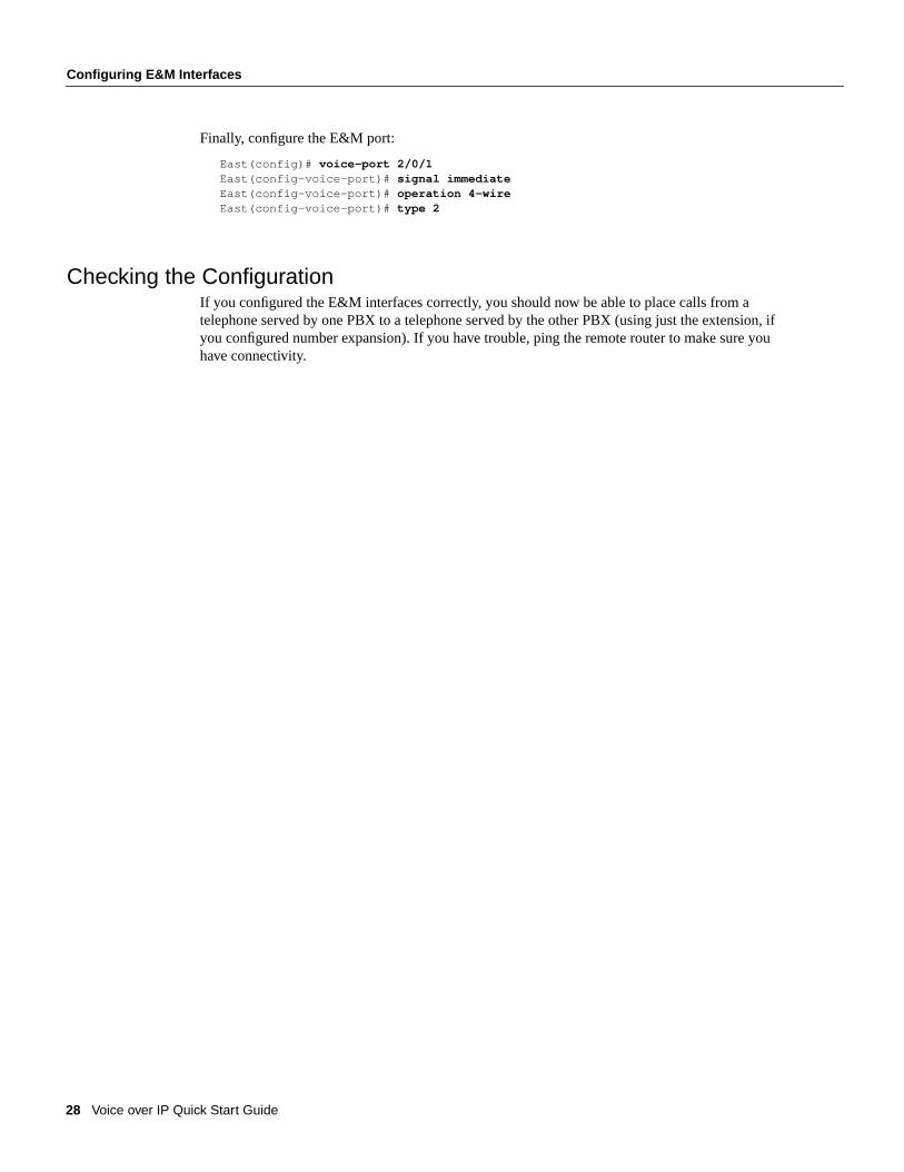
28 Voice over IP Quick Start Guide
Configuring E&M Interfaces
Finally, configure the E&M port:
East(config)# voice-port 2/0/1East(config-voice-port)# signal immediateEast(config-voice-port)# operation 4-wireEast(config-voice-port)# type 2
Checking the ConfigurationIf you configured the E&M interfaces correctly, you should now be able to place calls from atelephone served by one PBX to a telephone served by the other PBX (using just the extension, ifyou configured number expansion). If you have trouble, ping the remote router to make sure youhave connectivity.

Voice over IP Quick Start Guide 29
Saving the Configuration
Saving the ConfigurationWhen you finish router configuration, follow this procedure for each router to write the newconfiguration to NVRAM:
Step 1 Exit configuration mode and return to the enable prompt by pressingCtrl-Z . To see thecurrent operating configuration, including any changes you just made, enter theshowrunning-config command:
Router# show running-config
To see the configuration currently stored in NVRAM, enter theshow startup-configcommand at the enable prompt:
Router# show startup-config
Step 2 The results of theshow running-configandshow startup-configcommands differ fromeach other if you have made changes to the configuration, but have not yet written themto NVRAM. To write your changes to NVRAM, making them permanent, enter thecopy running-config startup-config command at the enable prompt:
Router# copy running-config startup-configBuilding configuration. . .[OK]Router#
The router is now configured to boot in the new configuration.
If you have questions or need help, see the last section, “Cisco Connection Online.”

30 Voice over IP Quick Start Guide
List of Terms
List of TermsThis section defines some of the terms and concepts used by voice over IP.
BRI—Basic Rate Interface.
call leg—a segment of a call path; for instance, between a telephone and a router, a router and anetwork, a router and a PBX, or a router and the PSTN. Each call leg corresponds to a dial peer.
CIR—committed information rate. The average rate of information transfer a subscriber (forexample, the network administrator) has stipulated for a Frame Relay PVC.
destination pattern—the pattern of numbers that identifies the destination of an incoming call; inother words, a phone number.
dial peer—a software object that ties together a voice port and a local telephone number (local dialpeeror POTS dial peer) or an IP address and a remote telephone number (remote dial peeror VoIPdial peer). Each dial peer corresponds to a call leg.
E&M —ear and mouth (or recEive and transMit), a signaling technique for two-wire and four-wireinterfaces between PSTN central offices or PBXs.
FXO—foreign exchange office, a type of VIC interface. The FXO VIC connects local calls to aPSTN central office or PBX over a standard RJ-11 modular telephone cable. This is the interface astandard telephone provides.
FXS—foreign exchange station, a type of VIC interface. The FXS VIC connects directly to astandard telephone, fax machine, or similar device over a standard RJ-11 modular telephone cable,and supplies ringing voltage, dial tone, and similar signals to it.
IPX—Internetwork Packet Exchange.
ISDN—Integrated Services Digital Network.
local dial peer—a software object that ties together a voice port and the telephone number of adevice attached to the port (also calledPOTS dial peer).
MTU —maximum transmission unit.
Multilink PPP —Multilink Point-to-Point Protocol, a method of splitting, recombining, andsequencing datagrams across multiple logical data links.
PBX—private branch exchange, a private telephone switching system.
POTS—plain old telephone service.
POTS dial peer—a software object that ties together a voice port and the telephone number of adevice attached to the port (also calledlocal dial peer).
PRI—Primary Rate Interface.
PSTN—public switched telephone network.
PVC—permanent virtual circuit.
QoS—quality of service, a measure of the level of performance needed for a particular application,such as a voice over IP connection.
remote dial peer—a software object that ties together an IP address and a telephone number at aremote site reached over the IP network (also calledVoIP dial peer).
RSVP—resource reservation protocol, a network protocol that enables routers to reserve thebandwidth necessary for reliable performance.
RTP—real-time transport protocol (RTP), a network protocol used to carry packetized audio andvideo traffic over an IP network.
Voice over IP Quick Start Guide 31
List of Terms
session target—a remote IP or DNS address specified as one end of a voice connection.
tag—a positive integer in the range 1 to 231 -1 (2147483647) used to identify a dial peer.
UDP—User Datagram Protocol.
VIC —voice interface card. VICs install in a slot in a voice network module, and provide theconnection to the telephone equipment or network. There are three types: FXS, FXO, and E&Minterface. Each VIC provides two ports of the same type.
voice network module—a network module that installs in a slot in a Cisco 3600 series router,converts telephone voice signals into a form that can be transmitted over an IP network, and providesone or two slots for voice interface cards.
VoIP—voice over IP, a feature that carries voice traffic, such as telephone calls and faxes, over anIP network, simultaneously with data traffic.
VoIP dial peer—a software object that ties together an IP address and a telephone number at aremote site reached over the IP network (also calledremote dial peer).

32 Voice over IP Quick Start Guide
Cisco Connection Online
Cisco Connection OnlineCisco Connection Online (CCO) is Cisco Systems’ primary, real-time support channel. Maintenancecustomers and partners can self-register on CCO to obtain additional information and services.
Available 24 hours a day, 7 days a week, CCO provides a wealth of standard and value-addedservices to Cisco’s customers and business partners. CCO services include product information,product documentation, software updates, release notes, technical tips, the Bug Navigator,configuration notes, brochures, descriptions of service offerings, and download access to public andauthorized files.
CCO serves a wide variety of users through two interfaces that are updated and enhancedsimultaneously: a character-based version and a multimedia version that resides on the World WideWeb (WWW). The character-based CCO supports Zmodem, Kermit, Xmodem, FTP, and Internete-mail, and it is excellent for quick access to information over lower bandwidths. The WWW versionof CCO provides richly formatted documents with photographs, figures, graphics, and video, as wellas hyperlinks to related information.
You can access CCO in the following ways:
• WWW: http://www.cisco.com
• WWW: http://www-europe.cisco.com
• WWW: http://www-china.cisco.com
• Telnet: cco.cisco.com
• Modem: From North America, 408 526-8070; from Europe, 33 1 64 46 40 82. Use thefollowing terminal settings: VT100 emulation; databits: 8; parity: none; stop bits: 1; andconnection rates up to 28.8 kbps.
For a copy of CCO’s Frequently Asked Questions (FAQ), contact [email protected]. Foradditional information, contact [email protected].
Note If you are a network administrator and need personal technical assistance with a Ciscoproduct that is under warranty or covered by a maintenance contract, contact Cisco’s TechnicalAssistance Center (TAC) at 800 553-2447, 408 526-7209, or [email protected]. To obtain generalinformation about Cisco Systems, Cisco products, or upgrades, contact 800 553-6387,408 526-7208, or [email protected].
Use this document in conjunction with your router installation and configuration guide, theRegulatory Compliance and Safety Information document for your router, theVoiceNetwork Module and Voice Interface Card Configuration Note, theVoice over IP Software Configuration Guide, and the Cisco IOS configuration guides and command references.
AccessPath, AtmDirector, the CCIE logo, CD-PAC, Centri, Centri Bronze, Centri Gold, Centri Security Manager, Centri Silver, the Cisco Capital logo, Cisco IOS, the Cisco IOS logo,CiscoLink, the Cisco NetWorkslogo, the Cisco Powered Network logo, the Cisco Press logo, ClickStart, ControlStream, Fast Step, FragmentFree, IGX, JumpStart, Kernel Proxy, LAN2LANEnterprise, LAN2LAN Remote Office, MGX, MICA, Natural Network Viewer, NetBeyond, NetRanger, NetSonar, Netsys Technologies,Packet, PIX, Point and Click Internetworking,Policy Builder, RouteStream, Secure Script, SMARTnet, StrataSphere, StrataSphere BILLder, StrataSphere Connection Manager, StrataSphere Modeler, StrataSphere Optimizer, Stratm,StreamView, SwitchProbe,The Cell, TrafficDirector, TransPath, VirtualStream, VlanDirector, Workgroup Director, Workgroup Stack, and XCI are trademarks; Empowering the InternetGeneration and The Network Works. No Excuses. are service marks; and BPX, Catalyst, Cisco, Cisco Systems, the Cisco Systems logo, EtherChannel, FastHub, FastPacket, ForeSight, IPX,LightStream, OptiClass, Phase/IP, StrataCom, and StrataView Plus are registered trademarks of Cisco Systems, Inc. in the U.S. and certain other countries. All other trademarks mentionedin this document are the property of their respective owners.
Copyright © 1998, Cisco Systems, Inc.All rights reserved. Printed in USA.9803R

154
Anexo 3: Configuración de los routers Cisco para que soporten VoIP Los siguientes tres archivos detallan los comandos necesarios para que los
routers Cisco soporten la transmisión de voz sobre IP. Los dos primeros archivos
detallan las herramientas QoS disponibles en los routers Cisco y el ajuste fino de la
tarjetas de módulo de voz. El último archivo detalla todos los comandos que se
pueden utilizar para la configuración de VoIP, (tanto en el router como en los puertos
de voz).
C H A P T E R
Configuring Voice over IP for the Cisco 3600 Series 2-1
2
Configuring Voice over IP for theCisco 3600 Series
This chapter explains how to configure Voice over IP (VoIP) on Cisco 3600 series routers andcontains the following sections:
• Introduction
• List of Terms
• Prerequisites Tasks
• How Voice over IP Handles a Typical Telephone Call
• Configuration Tasks
• Configure IP Networks for Real-Time Voice Traffic
— Configure RSVP for Voice
— Configure Multilink PPP with Interleaving
— Configure RTP Header Compression
— Configure Custom Queuing
— Configure Weighted Fair Queuing
• Configure Frame Relay for Voice over IP
• Configure Number Expansion
— Create a Number Expansion Table
— Configure Number Expansion
• Configure Dial Peers
— Create a Peer Configuration Table
— Configure POTS Peers
— Configure VoIP Peers
• Configure Voice Ports
— Configuring FXO or FXS Voice Ports
— Fine-Tune FXO and FXS Voice Ports
— Configure E&M Voice Ports
— Fine-Tune E&M Voice Ports

Introduction
Voice over IP for the Cisco 3600 Series Software Configuration Guide2-2
• Optimize Dial Peer and Network Interface Configurations
— Configure IP Precedence for Dial Peers
— Configure RSVP for Dial Peers
— Configure CODEC and VAD for Dial Peers
• Configure Voice over IP for Microsoft NetMeeting
All of these tasks are described in the following sections.
IntroductionVoice over IP (VoIP) enables a Cisco 3600 series router to carry voice traffic (for example, telephonecalls and faxes) over an IP network. Voice over IP is primarily a software feature; however, to usethis feature on a Cisco 3600 series router, you must install a Voice Network Module (VNM). TheVNM can hold either 2 or 4 Voice Interface Cards (VICs). Each VIC is specific to a particularsignaling type associated with a voice port; therefore, VICs determine the type of signaling for thevoice ports on that particular VNM. For more information about the physical characteristics of theVNM, as well as installing or configuring a VNM in your Cisco 3600 series router, refer to theVoiceNetwork Module and Voice Interface Card Configuration Note that came with your VNM.
Voice over IP offers the following benefits:
• Toll bypass
• Remote PBX presence over WANs
• Unified voice/data trunking
• POTS-Internet telephony gateways
List of TermsACOM —Term used in G.165, “General Characteristics of International Telephone Connections andInternational Telephone Circuits: Echo Cancellers.” ACOM is the combined loss achieved by theecho canceller, which is the sum of the Echo Return Loss, Echo Return Loss Enhancement, andnonlinear processing loss for the call.
Call leg—A logical connection between the router and either a telephony endpoint over a bearerchannel or another endpoint using a session protocol.
Channel Associated Signaling (CAS)—A form of signaling used on a T1 line. With CAS, asignaling element is dedicated to each channel in the T1 frame. This type of signaling is sometimescalled Robbed Bit Signaling (RBS) because a bit is taken out (or robbed) from the user’s data streamto provide signaling information to and from the switch.
CIR—Committed Information Rate. The average rate of information transfer a subscriber (forexample, the network administrator) has stipulated for a Frame Relay PVC.
CODEC—Coder-decoder compression scheme or technique. In Voice over IP, it specifies the voicecoder rate of speech for a dial peer.
Dial peer—An addressable call endpoint. In Voice over IP, there are two kinds of dial peers: POTSand VoIP.
DS0—A 64K channel on an E1 or T1 WAN interface.
DTMF —Dual tone multifrequency. Use of two simultaneous voice-band tones for dial (such astouch tone).

Configuring Voice over IP for the Cisco 3600 Series 2-3
Prerequisites Tasks
E&M —Stands for recEive and transMit (or Ear and Mouth). E&M is a trunking arrangementgenerally used for two-way switch-to-switch or switch-to-network connections. Cisco’s E&Minterface is an RJ-48 connector that allows connections to PBX trunk lines (tie lines).
FIFO—First-in, first-out. In data communication, FIFO refers to a buffering scheme where the firstbyte of data entering the buffer is the first byte retrieved by the CPU. In telephony, FIFO refers to aqueuing scheme where the first calls received are the first calls processed.
FXO—Foreign Exchange Office. An FXO interface connects to the PSTN’s central office and is theinterface offered on a standard telephone. Cisco’s FXO interface is an RJ-11 connector that allowsan analog connection to be directed at the PSTN’s central office. This interface is of value foroff-premise extension applications.
FXS—Foreign Exchange Station. An FXS interface connects directly to a standard telephone andsupplies ring, voltage, and dial tone. Cisco’s FXS interface is an RJ-11 connector that allowsconnections to basic telephone service equipment, keysets, and PBXs.
Multilink PPP —Multilink Point-to-Point Protocol. This protocol is a method of splitting,recombining, and sequencing datagrams across multiple logical data links.
PBX—Private Branch Exchange. Privately-owned central switching office.
PLAR—Private Line Auto Ringdown. This type of service results in a call attempt to someparticular remote endpoint when the local extension is taken off-key.
POTS—Plain Old Telephone Service. Basic telephone service supplying standard single linetelephones, telephone lines, and access to the public switched telephone network.
POTS dial peer—Dial peer connected via a traditional telephony network. POTS peers point to aparticular voice port on a voice network device.
PSTN—Public Switched Telephone Network. PSTN refers to the local telephone company.
PVC—Permanent Virtual Circuit.
QoS—Quality of Service, which refers to the measure of service quality provided to the user.
RSVP—Resource Reservation Protocol. This protocol supports the reservation of resources acrossan IP network.
Trunk —Service that allows quasi-transparent connections between two PBXes, a PBX and a localextension, or some other combination of telephony interfaces to be permanently conferencedtogether by the session application and signaling passed transparently through the IP network.
VoIP dial peer—Dial peer connected via a packet network; in the case of Voice over IP, this is anIP network. VoIP peers point to specific VoIP devices.
Prerequisites TasksBefore you can configure your Cisco 3600 series router to use Voice over IP, you must first:
• Establish a working IP network. For more information about configuring IP, refer to the“IP Overview,” “Configuring IP Addressing,” and “Configuring IP Services” chapters in theNetwork Protocols Configuration Guide, Part 1.
• Install the one-slot or two-slot (NM-1V/NM-2V) voice network module into the appropriate bayof your Cisco router. For more information about the physical characteristics of the voicenetwork module, or how to install it, refer to the installation documentation,Voice NetworkModule and Voice Interface Card Configuration Note, that came with your voice networkmodule.
• Complete your company’s dial plan.

How Voice over IP Handles a Typical Telephone Call
Voice over IP for the Cisco 3600 Series Software Configuration Guide2-4
• Establish a working telephony network based on your company’s dial plan.
• Integrate your dial plan and telephony network into your existing IP network topology. Mergingyour IP and telephony networks depends on your particular IP and telephony network topology.In general, we recommend the following suggestions:
— Use canonical numbers wherever possible. It is important to avoid situations wherenumbering systems are significantly different on different routers or access servers in yournetwork.
— Make routing and/or dialing transparent to the user—for example, avoid secondary dial tonesfrom secondary switches, where possible.
— Contact your PBX vendor for instructions about how to reconfigure the appropriate PBXinterfaces.
After you have analyzed your dial plan and decided how to integrate it into your existing IP network,you are ready to configure your network devices to support Voice over IP.
How Voice over IP Handles a Typical Telephone CallBefore configuring Voice over IP on your Cisco 3600 series router, it helps to understand whathappens at an application level when you place a call using Voice over IP. The general flow of atwo-party voice call using Voice over IP is as follows:
1 The user picks up the handset; this signals an off-hook condition to the signaling application partof Voice over IP in the Cisco 3600 series router.
2 The session application part of Voice over IP issues a dial tone and waits for the user to dial atelephone number.
3 The user dials the telephone number; those numbers are accumulated and stored by the sessionapplication.
4 After enough digits are accumulated to match a configured destination pattern, the telephonenumber is mapped to an IP host via the dial plan mapper. The IP host has a direct connection toeither the destination telephone number or a PBX that is responsible for completing the call tothe configured destination pattern.
5 The session application then runs the H.323 session protocol to establish a transmission and areception channel for each direction over the IP network. If the call is being handled by a PBX,the PBX forwards the call to the destination telephone. If RSVP has been configured, the RSVPreservations are put into effect to achieve the desired quality of service over the IP network.
6 The CODECs are enabled for both ends of the connection and the conversation proceeds usingRTP/UDP/IP as the protocol stack.
7 Any call-progress indications (or other signals that can be carried in-band) are cut through thevoice path as soon as end-to-end audio channel is established. Signaling that can be detected bythe voice ports (for example, in-band DTMF digits after the call setup is complete) is also trappedby the session application at either end of the connection and carried over the IP networkencapsulated in RTCP using the RTCP APP extension mechanism.
8 When either end of the call hangs up, the RSVP reservations are torn down (if RSVP is used) andthe session ends. Each end becomes idle, waiting for the next off-hook condition to triggeranother call setup.

Configuring Voice over IP for the Cisco 3600 Series 2-5
Configuration Tasks
Configuration TasksTo configure Voice over IP on the Cisco 3600 series, you need to perform the following steps:
Step 1 Configure your IP network to support real-time voice traffic. Fine-tuning your network toadequately support VoIP involves a series of protocols and features geared toward Qualityof Service (QoS). To configure your IP network for real-time voice traffic, you need totake into consideration the entire scope of your network, then select and configure theappropriate QoS tool or tools:
• RSVP
• Multilink PPP with Interleaving
• RTP Header Compression
• Custom Queuing
• Weighted Fair Queuing
Refer to “Configure IP Networks for Real-Time Voice Traffic” section for informationabout how to select and configure the appropriate QoS tools to optimize voice traffic onyour network.
Step 2 (Optional) If you plan to run Voice over IP over Frame Relay, you need to take certainfactors into consideration when configuring Voice over IP for it to run smoothly overFrame Relay. For example, a public Frame Relay cloud provides no guarantees for QoS.Refer to the “Configure Frame Relay for Voice over IP” section for information aboutdeploying Voice over IP over Frame Relay.
Step 3 Use thenum-expcommand to configure number expansion if your telephone network isconfigured so that you can reach a destination by dialing only a portion (an extensionnumber) of the full E.164 telephone number. Refer to the “Configure Number Expansion”section for information about number expansion.
Step 4 Use thedial-peer voice command to define dial peers and switch to the dial-peerconfiguration mode. Each dial peer defines the characteristics associated with a call leg.A call leg is a discrete segment of a call connection that lies between two points in theconnection. An end-to-end call is comprised of four call legs, two from the perspective ofthe source access server, and two from the perspective of the destination access server.Dial peers are used to apply attributes to call legs and to identify call origin anddestination. There are two different kinds of dial peers:
• POTS—dial peer describing the characteristics of a traditional telephony networkconnection. POTS peers point to a particular voice port on a voice network device. Tominimally configure a POTS dial peer, you need to configure the following twocharacteristics: associated telephone number and logical interface. Use thedestination-pattern command to associate a telephone number with a POTS peer.Use theport command to associate a specific logical interface with a POTS peers. Inaddition, you can specify direct inward dialing for a POTS peer by using thedirect-inward-dial command.
• VoIP—dial peer describing the characteristics of a packet network connection; in thecase of Voice over IP, this is an IP network. VoIP peers point to specific VoIP devices.To minimally configure a VoIP peer, you need to configure the following twocharacteristics: associated destination telephone number and a destination IP address.Use thedestination-pattern command to define the destination telephone numberassociated with a VoIP peer. Use thesession-targetcommand to specify a destinationIP address for a VoIP peer.

Configure IP Networks for Real-Time Voice Traffic
Voice over IP for the Cisco 3600 Series Software Configuration Guide2-6
In addition, you can use VoIP peers to define characteristics such as IP precedence,additional QoS parameters (when RSVP is configured), CODEC, and VAD. Use theip precedence command to define IP precedence. If you have configured RSVP, useeither thereq-qosor acc-qoscommand to configure QoS parameters. Use thecodeccommand to configure specific voice coder rates. Use thevad command to disablevoice activation detection and the transmission of silence packets.
Refer to the “Configure Dial Peers” section and the “Optimize Dial Peer and NetworkInterface Configurations” section for additional information about configuring dial peersand dial-peer characteristics.
Step 5 You need to configure your Cisco 3600 series router to support voice ports. In general,voice-port commands define the characteristics associated with a particular voice-portsignaling type. voice ports on the Cisco 3600 series support three basic voice signalingtypes:
— FXO—Foreign Exchange Office interface
— FXS—Foreign Exchange Station interface
— E&M—“RecEive and TransMit” interface or the “Ear and Mouth” interface
Under most circumstances, the default voice-port command values are adequate toconfigure FXO and FXS ports to transport voice data over your existing IP network.Because of the inherent complexities involved with PBX networks, E&M ports mightneed specific voice-port values configured, depending on the specifications of the devicesin your telephony network. For information about configuring voice ports, refer to the“Configuring Voice Ports” section.
Configure IP Networks for Real-Time Voice TrafficYou need to have a well-engineered network end-to-end when running delay-sensitive applicationssuch as VoIP. Fine-tuning your network to adequately support VoIP involves a series of protocols andfeatures geared toward Quality of Service (QoS). It is beyond the scope of this document to explainthe specific details relating to wide-scale QoS deployment. Cisco IOS software provides many toolsfor enabling QoS on your backbone, such as Random Early Detection (RED), Weighted RandomEarly Detection (WRED), Fancy Queuing (meaning custom, priority, or weighted fair queuing), andIP Precedence. To configure your IP network for real-time voice traffic, you need to take intoconsideration the entire scope of your network, then select the appropriate QoS tool or tools.
The important thing to remember is that QoS must be configured throughout your network—not juston the Cisco 3600 series devices running VoIP—to improve voice network performance. Not all QoStechniques are appropriate for all network routers. Edge routers and backbone routers in yournetwork do not necessarily perform the same operations; the QoS tasks they perform might differ aswell. To configure your IP network for real-time voice traffic, you need to take into consideration thefunctions of both edge and backbone routers in your network, then select the appropriate QoS toolor tools.
In general, edge routers perform the following QoS functions:
• Packet classification
• Admission control
• Bandwidth management
• Queuing

Configuring Voice over IP for the Cisco 3600 Series 2-7
Configure RSVP for Voice
In general, backbone routers perform the following QoS functions:
• High-speed switching and transport
• Congestion management
• Queue management
Scalable QoS solutions require cooperative edge and backbone functions.
Although not mandatory, some QoS tools have been identified as being valuable in fine-tuning yournetwork to support real-time voice traffic. To configure your IP network for QoS using these tools,perform one or more of the following tasks:
• Configure RSVP for Voice
• Configure Multilink PPP with Interleaving
• Configure RTP Header Compression
• Configure Custom Queuing
• Configure Weighted Fair Queuing
Each of these tasks is discussed in the following sections.
Configure RSVP for VoiceRSVP allows end systems to request a particular Quality of Service (QoS) from the network.Real-time voice traffic requires network consistency. Without consistent QoS, real-time traffic canexperience jitter, insufficient bandwidth, delay variations, or information loss. RSVP works inconjunction with current queuing mechanisms. It is up to the interface queuing mechanism (such asweighted fair queuing or weighted random early detection) to implement the reservation.
RSVP can be equated to a dynamic access list for packet flows.
You should configure RSVP to ensure QoS if the following conditions exist in your network:
• Small scale voice network implementation
• Slow links
• Links with high utilization
• Links less than 2 Mbps
• Need for the best possible voice quality
Enable RSVPTo minimally configure RSVP for voice traffic, you must enable RSVP on each interface wherepriority needs to be set.
By default, RSVP is disabled so that it is backward compatible with systems that do not implementRSVP. To enable RSVP on an interface, use the following command in interface configuration mode:
This command starts RSVP and sets the bandwidth and single-flow limits. The default maximumbandwidth is up to 75 percent of the bandwidth available on the interface. By default, the amountreservable by a flow can be up to the entire reservable bandwidth.
Command Purpose
ip rsvp bandwidth [interface-kbps] [single-flow-kbps] Enable RSVP for IP on an interface.
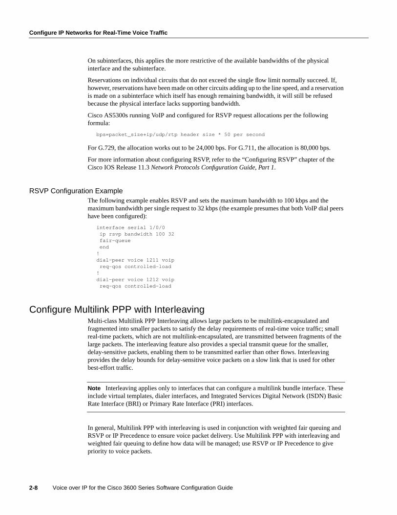
Configure IP Networks for Real-Time Voice Traffic
Voice over IP for the Cisco 3600 Series Software Configuration Guide2-8
On subinterfaces, this applies the more restrictive of the available bandwidths of the physicalinterface and the subinterface.
Reservations on individual circuits that do not exceed the single flow limit normally succeed. If,however, reservations have been made on other circuits adding up to the line speed, and a reservationis made on a subinterface which itself has enough remaining bandwidth, it will still be refusedbecause the physical interface lacks supporting bandwidth.
Cisco AS5300s running VoIP and configured for RSVP request allocations per the followingformula:
bps=packet_size+ip/udp/rtp header size * 50 per second
For G.729, the allocation works out to be 24,000 bps. For G.711, the allocation is 80,000 bps.
For more information about configuring RSVP, refer to the “Configuring RSVP” chapter of theCisco IOS Release 11.3Network Protocols Configuration Guide, Part 1.
RSVP Configuration ExampleThe following example enables RSVP and sets the maximum bandwidth to 100 kbps and themaximum bandwidth per single request to 32 kbps (the example presumes that both VoIP dial peershave been configured):
interface serial 1/0/0ip rsvp bandwidth 100 32fair-queueend
!dial-peer voice 1211 voip
req-qos controlled-load!dial-peer voice 1212 voip
req-qos controlled-load
Configure Multilink PPP with InterleavingMulti-class Multilink PPP Interleaving allows large packets to be multilink-encapsulated andfragmented into smaller packets to satisfy the delay requirements of real-time voice traffic; smallreal-time packets, which are not multilink-encapsulated, are transmitted between fragments of thelarge packets. The interleaving feature also provides a special transmit queue for the smaller,delay-sensitive packets, enabling them to be transmitted earlier than other flows. Interleavingprovides the delay bounds for delay-sensitive voice packets on a slow link that is used for otherbest-effort traffic.
Note Interleaving applies only to interfaces that can configure a multilink bundle interface. Theseinclude virtual templates, dialer interfaces, and Integrated Services Digital Network (ISDN) BasicRate Interface (BRI) or Primary Rate Interface (PRI) interfaces.
In general, Multilink PPP with interleaving is used in conjunction with weighted fair queuing andRSVP or IP Precedence to ensure voice packet delivery. Use Multilink PPP with interleaving andweighted fair queuing to define how data will be managed; use RSVP or IP Precedence to givepriority to voice packets.

Configuring Voice over IP for the Cisco 3600 Series 2-9
Configure Multilink PPP with Interleaving
You should configure Multilink PPP if the following conditions exist in your network:
• Point-to-point connection using PPP Encapsulation
• Slow links
Note Multilink PPP should not be used on links greater than 2 Mbps.
Multilink PPP support for interleaving can be configured on virtual templates, dialer interfaces, andISDN BRI or PRI interfaces. To configure interleaving, you need to complete the following tasks:
• Configure the dialer interface or virtual template, as defined in the relevant chapters of theCisco IOS Release 11.3Dial Solutions Configuration Guide.
• Configure Multilink PPP and interleaving on the interface or template.
To configure Multilink PPP and interleaving on a configured and operational interface or virtualinterface template, use the following commands in interface mode:
Note The ip rtp reserve command can be used instead of configuring RSVP. If you configureRSVP, this command is not required.
For more information about Multilink PPP, refer to the “Configuring Media-Independent PPP andMultilink PPP” chapter in the Cisco IOS Release 11.3Dial Solutions Configuration Guide.
Multilink PPP Configuration ExampleThe following example defines a virtual interface template that enables Multilink PPP withinterleaving and a maximum real-time traffic delay of 20 milliseconds, and then applies that virtualtemplate to the Multilink PPP bundle:
interface virtual-template 1ppp multilinkencapsulated pppppp multilink interleaveppp multilink fragment-delay 20ip rtp reserve 16384 100 64
multilink virtual-template 1
Step Command Purpose
1 ppp multilink Enable Multilink PPP.
2 ppp multilink interleave Enable real-time packet interleaving.
3 ppp multilink fragment-delay milliseconds Optionally, configure a maximum fragmentdelay.
4 ip rtp reserve lowest-UDP-portrange-of-ports [maximum-bandwidth]
Reserve a special queue for real-time packetflows to specified destination User DatagramProtocol (UDP) ports, allowing real-time trafficto have higher priority than other flows. This isonly applicable if you have not configuredRSVP.

Configure IP Networks for Real-Time Voice Traffic
Voice over IP for the Cisco 3600 Series Software Configuration Guide2-10
Configure RTP Header CompressionReal-Time Transport Protocol (RTP) is used for carrying packetized audio traffic over an IP network.RTP header compression compresses the IP/UDP/RTP header in an RTP data packet from 40 bytesto approximately 2 to 4 bytes (most of the time), as shown in Figure 2-1.
This compression feature is beneficial if you are running Voice over IP over slow links. Enablingcompression on both ends of a low-bandwidth serial link can greatly reduce the network overhead ifthere is a lot of RTP traffic on that slow link.
Typically, an RTP packet has a payload of approximately 20 to 160 bytes for audio applications thatuse compressed payloads. RTP header compression is especially beneficial when the RTP payloadsize is small (for example, compressed audio payloads between 20 and 50 bytes).
Figure 2-1 RTP Header Compression
You should configure RTP header compression if the following conditions exist in your network:
• Slow links
• Need to save bandwidth
Note RTP header compression should not be used on links greater than 2 Mbps.
Perform the following tasks to configure RTP header compression for Voice over IP. The first task isrequired; the second task is optional.
• Enable RTP Header Compression on a Serial Interface
• Change the Number of Header Compression Connections
Before RTP header compression:
20 bytes 8 bytes
20 to 160 bytes
12 bytes
IP
Header
UDP RTP Payload
After RTP header compression:
2 to 4 bytes
20 to 160 bytesIP/UDP/RTP header
Payload
1207
6
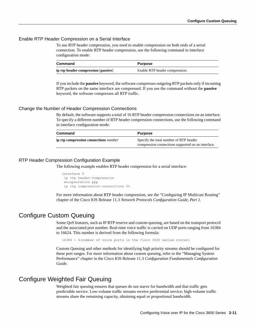
Configuring Voice over IP for the Cisco 3600 Series 2-11
Configure Custom Queuing
Enable RTP Header Compression on a Serial InterfaceTo use RTP header compression, you need to enable compression on both ends of a serialconnection. To enable RTP header compression, use the following command in interfaceconfiguration mode:
If you include thepassivekeyword, the software compresses outgoing RTP packets only if incomingRTP packets on the same interface are compressed. If you use the command without thepassivekeyword, the software compresses all RTP traffic.
Change the Number of Header Compression ConnectionsBy default, the software supports a total of 16 RTP header compression connections on an interface.To specify a different number of RTP header compression connections, use the following commandin interface configuration mode:
RTP Header Compression Configuration ExampleThe following example enables RTP header compression for a serial interface:
interface 0ip rtp header-compressionencapsulation pppip rtp compression-connections 25
For more information about RTP header compression, see the “Configuring IP Multicast Routing”chapter of the Cisco IOS Release 11.3Network Protocols Configuration Guide, Part 1.
Configure Custom QueuingSome QoS features, such as IP RTP reserve and custom queuing, are based on the transport protocoland the associated port number. Real-time voice traffic is carried on UDP ports ranging from 16384to 16624. This number is derived from the following formula:
16384 = 4(number of voice ports in the Cisco 3600 series router)
Custom Queuing and other methods for identifying high priority streams should be configured forthese port ranges. For more information about custom queuing, refer to the “Managing SystemPerformance” chapter in the Cisco IOS Release 11.3Configuration Fundamentals ConfigurationGuide.
Configure Weighted Fair QueuingWeighted fair queuing ensures that queues do not starve for bandwidth and that traffic getspredictable service. Low-volume traffic streams receive preferential service; high-volume trafficstreams share the remaining capacity, obtaining equal or proportional bandwidth.
Command Purpose
ip rtp header-compression [passive] Enable RTP header compression.
Command Purpose
ip rtp compression connectionsnumber Specify the total number of RTP headercompression connections supported on an interface.

Configure Frame Relay for Voice over IP
Voice over IP for the Cisco 3600 Series Software Configuration Guide2-12
In general, weighted fair queuing is used in conjunction with Multilink PPP with interleaving andRSVP or IP Precedence to ensure that voice packet delivery. Use weighted fair queuing withMultilink PPP to define how data will be managed; use RSVP or IP Precedence to give priority tovoice packets. For more information about weighted fair queuing, refer to the “Managing SystemPerformance” chapter in the Cisco IOS Release 11.3Configuration Fundamentals ConfigurationGuide.
Configure Frame Relay for Voice over IPYou need to take certain factors into consideration when configuring Voice over IP for it to runsmoothly over Frame Relay. A public Frame Relay cloud provides no guarantees for QoS. Forreal-time traffic to be transmitted in a timely manner, the data rate must not exceed the committedinformation rate (CIR) or there is the possibility that packets will be dropped. In addition, FrameRelay traffic shaping and RSVP are mutually exclusive. This is particularly important to rememberif multiple DLCIs are carried on a single interface.
For Frame Relay links with slow output rates (less than or equal to 64 kbps), where data and voiceare being transmitted over the same PVC, we recommend the following solutions:
• Separate DLCIs for voice and data—By providing a separate subinterface for voice and data, youcan use the appropriate QoS tool per line. For example, each DLCI would use 32 kbps of a64 kbps line.
— Apply adaptive traffic shaping to both DLCIs.
— Use RSVP or IP Precedence to prioritize voice traffic.
— Use compressed RTP to minimize voice packet size.
— Use weighted fair queuing to manage voice traffic.
• Lower MTU size—Voice packets are generally small. By lowering the MTU size (for example,to 300 bytes), large data packets can be broken up into smaller data packets that can more easilybe interwoven with voice packets.
Note Lowering the MTU size affects data throughput speed.
• CIR equal to line rate—Make sure that the data rate does not exceed the CIR. This isaccomplished through generic traffic shaping.
— Use RSVP or IP Precedence to prioritize voice traffic.
— Use compressed RTP to minimize voice packet header size.
• Traffic shaping—Use adaptive traffic shaping to throttle back the output rate based on the BECN.If the feedback from the switch is ignored, packets (both data and voice) might be discarded.Because the Frame Relay switch does not distinguish between voice and data packets, voicepackets could be discarded, which would result in a deterioration of voice quality.
— Use RSVP, compressed RTP, reduced MTU size, and adaptive traffic shaping based onBECN to hold data rate to CIR.
— Use generic traffic shaping to obtain a low interpacket wait time. For example, set Bc to 4000to obtain an interpacket wait of 125 ms.

Configuring Voice over IP for the Cisco 3600 Series 2-13
Frame Relay for Voice over IP Configuration Example
In Cisco IOS Release 11.3, Frame Relay Traffic Shaping is not compatible with RSVP. We suggestone of the following workarounds:
• Provision the Frame Relay PVC to have the CIR equal to the port speed.
• Use Generic Traffic Shaping with RSVP.
Frame Relay for Voice over IP Configuration ExampleFor Frame Relay, it is customary to configure a main interface and several subinterfaces, onesubinterface per PVC. The following example configures a Frame Relay main interface and asubinterface so that voice and data traffic can be successfully transported:
interface Serial0/0mtu 300no ip addressencapsulation frame-relayno ip route-cacheno ip mroute-cachefair-queue 64 256 1000frame-relay ip rtp header-compression
interface Serial0/0.1 point-to-pointmtu 300ip address 40.0.0.7 255.0.0.0ip rsvp bandwidth 48 48no ip route-cacheno ip mroute-cachebandwidth 64traffic-shape rate 32000 4000 4000frame-relay interface-dlci 16frame-relay ip rtp header-compression
In this configuration example, the main interface has been configured as follows:
• MTU size is 300 bytes.
• No IP address is associated with this serial interface. The IP address must be assigned for thesubinterface.
• Encapsulation method is Frame Relay.
• Fair-queuing is enabled.
• IP RTP header compression is enabled.
The subinterface has been configured as follows:
• MTU size is inherited from the main interface.
• IP address for the subinterface is specified.
• Bandwidth is set to 64 kbps.
• RSVP is enabled to use the default value, which is 75 percent of the configured bandwidth.
• Generic traffic shaping is enabled with 32 kbps CIR where Bc=4000 bits and Be=4000 bits.
• Frame Relay DLCI number is specified.
• IP RTP header compression is enabled.

Configure Number Expansion
Voice over IP for the Cisco 3600 Series Software Configuration Guide2-14
Note When traffic bursts over the CIR, output rate is held at the speed configured for the CIR (forexample, traffic will not go beyond 32 kbps if CIR is set to 32 kbps).
For more information about Frame Relay, refer to the “Configuring Frame Relay” chapter in theCisco IOS Release 11.3Wide-Area Networking Configuration Guide.
Configure Number ExpansionIn most corporate environments, the telephone network is configured so that you can reach adestination by dialing only a portion (an extension number) of the full E.164 telephone number.Voice over IP can be configured to recognize extension numbers and expand them into their fullE.164 dialed number by using two commands in tandem:destination-patternandnum-exp. Beforeyou configure these two commands, it is helpful to map individual telephone extensions with theirfull E.164 dialed numbers. This can be done easily by creating a number expansion table.
Create a Number Expansion TableIn Figure 2-2, a small company wants to use Voice over IP to integrate its telephony network withits existing IP network. The destination pattern (or expanded telephone number) associated withAccess Server 1 (located to the left of the IP cloud) is (408) 526-xxxx, where xxxx identifies theindividual dial peers by extension. The destination pattern (or expanded telephone number)associated with Access Server 2 (located to the right of the IP cloud) is (729) 422-xxxx.
Figure 2-2 Sample Voice over IP Network
Table 2-1 shows the number expansion table for this scenario.
408 555-1002
408 555-1001
408 555-1003
729 555-1000 729 555-1003
729 555-1001 729 555-1002
Cisco AS5300Router 1
WANWAN
T1 ISDN PRI
T1 ISDN PRI
10.1.1.110.1.1.2
IPcloud
Cisco AS5300Router 2
Voice port 0:DVoice port
0:D10
351
1:D

Configuring Voice over IP for the Cisco 3600 Series 2-15
Configure Number Expansion
Table 2-1 Sample Number Expansion Table
Note You can use the period symbol (.) to represent variables (such as extension numbers) in atelephone number.
The information included in this example needs to be configured on both Access Server 1 and AccessServer 2.
Configure Number ExpansionTo define how to expand an extension number into a particular destination pattern, use the followingcommand in global configuration mode:
You can verify the number expansion information by using the show num-exp command to verifythat you have mapped the telephone numbers correctly.
After you have configured dial peers and assigned destination patterns to them, you can verifynumber expansion information by using theshow dialplan number command to see how atelephone number maps to a dial peer.
Configure Dial PeersThe key point to understanding how Voice over IP functions is to understand dial peers. Each dialpeer defines the characteristics associated with a call leg, as shown in Figure 2-3 and Figure 2-4. Acall leg is a discrete segment of a call connection that lies between two points in the connection. Allof the call legs for a particular connection have the same connection ID.
There are two different kinds of dial peers:
• POTS—Dial peer describing the characteristics of a traditional telephony network connection.POTS peers point to a particular voice port on a voice network device.
• VoIP—Dial peer describing the characteristics of a packet network connection; in the case ofVoice over IP, this is an IP network. VoIP peers point to specific VoIP devices.
An end-to-end call is comprised of four call legs, two from the perspective of the source accessserver as shown in Figure 2-3, and two from the perspective of the destination access server as shownin Figure 2-4. A dial peer is associated with each one of these call legs. Dial peers are used to applyattributes to call legs and to identify call origin and destination. Attributes applied to a call leginclude QoS, CODEC, VAD, and fax rate.
Extension Destination Pattern Num-Exp Command Entry
5.... 40852..... num-exp 5.... 408525....
6.... 40852..... num-exp 6.... 408526....
7.... 40852..... num-exp 7.... 408527....
1... 729422.... num-exp 2.... 729422....
Command Purpose
num-exp extension-number extension-string Configure number expansion.

Configure Dial Peers
Voice over IP for the Cisco 3600 Series Software Configuration Guide2-16
Figure 2-3 Dial Peer Call Legs from the Perspective of the Source Router
Figure 2-4 Dial Peer Call Legs from the Perspective of the Destination Router
Inbound versus Outbound Dial PeersDial peers are used for both inbound and outbound call legs. It is important to remember that theseterms are defined from therouter’sperspective. An inbound call leg originatesoutsidethe router. Anoutbound call leg originatesfrom the router.
For inbound call legs, a dial peer might be associated to the calling number or the port designation.Outbound call legs always have a dial peer associated with them. The destination pattern is used toidentify the outbound dial peer. The call is associated with the outbound dial peer at setup time.
POTS peers associate a telephone number with a particular voice port so that incoming calls for thattelephone number can be received and outgoing calls can be placed. VoIP peers point to specificdevices (by associating destination telephone numbers with a specific IP address) so that incomingcalls can be received and outgoing calls can be placed. Both POTS and VoIP peers are needed toestablish Voice over IP connections.
Establishing communication using Voice over IP is similar to configuring an IP static route: you areestablishing a specific voice connection between two defined endpoints. As shown in Figure 2-5, foroutgoing calls (from the perspective of the POTS dial peer 1), the POTS dial peer establishes thesource (via the originating telephone number or voice port) of the call. The VoIP dial peer establishesthe destination by associating the destination telephone number with a specific IP address.
1035
3
IP cloud
DestinationSource
Call leg for POTSdial peer 1
Source router
Call leg for VoIPdial peer 2
1035
4
IP cloud
Destination router
Call leg for POTSdial peer 4
Call leg for VoIPdial peer 3
Destination Source

Configuring Voice over IP for the Cisco 3600 Series 2-17
Inbound versus Outbound Dial Peers
Figure 2-5 Outgoing Calls from the Perspective of POTS Dial Peer 1
To configure call connectivity between the source and destination as illustrated in Figure 2-5, enterthe following commands on router 10.1.2.2:
dial-peer voice 1 potsdestination-pattern 1408526....port 1/0/0
dial-peer voice 2 voipdestination-pattern 1310520....session target ipv4:10.1.1.2
In the previous configuration example, the last four digits in the VoIP dial peer’s destination patternwere replaced with wildcards. This means that from access server 10.1.2.2, calling any numberstring that begins with the digits “1310520” will result in a connection to access server 10.1.1.2. Thisimplies that access server 10.1.1.2 services all numbers beginning with those digits. From accessserver 10.1.1.2, calling any number string that begins with the digits “1408526” will result in aconnection to access server 10.1.2.2. This implies that access server 10.1.2.2 services all numbersbeginning with those digits. For more information about stripping and adding digits, see the“Outbound Dialing on POTS Peers” section.
Figure 2-6 shows how to complete the end-to-end call between dial peer 1 and dial peer 4.
Figure 2-6 Outgoing Calls from the Perspective of POTS Dial Peer 2
To complete the end-to-end call between dial peer 1 and dial peer 4 as illustrated in Figure 2-6, enterthe following commands on router 10.1.1.2:
dial-peer voice 4 potsdestination-pattern 1310520....port 1/0/0
dial-peer voice 3 voipdestination-pattern 1408526....session target ipv4:10.1.2.2
S66
13
(408) 555-4000(310) 555-1000
10.1.2.2
Source Destination
10.1.1.2Voice port
1/0/0Voice port1/0/0
IP cloud
Dial peer 1 Dial peer 2 Dial peer 3
VoIP call leg
POTS call leg
Dial peer 4
S66
14
(408) 555-4000
Dial peer 1 Dial peer 2 Dial peer 3
VoIP call legPOTS call leg
Dial peer 4
(310) 555-1000
10.1.2.2
SourceDestination
10.1.1.2Voice port
1/0/0Voice port1/0/0
IP cloud

Configure Dial Peers
Voice over IP for the Cisco 3600 Series Software Configuration Guide2-18
Create a Peer Configuration TableThere is specific data relative to each dial peer that needs to be identified before you can configuredial peers in Voice over IP. One way to do this is to create a peer configuration table.
Using the example in Figure 2-2, Router 1, with an IP address of 10.1.1.1, connects a small salesbranch office to the main office through Router 2. There are three telephones in the sales branchoffice that need to be established as dial peers. Access Server 2, with an IP address of 10.1.1.2, is theprimary gateway to the main office; as such, it needs to be connected to the company’s PBX. Thereare four devices that need to be established as dial peers in the main office, all of which are basictelephones connected to the PBX. Figure 2-2 shows a diagram of this small voice network.
Table 2-2 shows the peer configuration table for the example illustrated in Figure 2-2.
Table 2-2 Peer Configuration Table for Sample Voice Over IP Network
Configure POTS PeersOnce again, POTS peers enable incoming calls to be received by a particular telephony device. Toconfigure a POTS peer, you need to uniquely identify the peer (by assigning it a unique tag number),define its telephone number(s), and associate it with a voice port through which calls will beestablished. Under most circumstances, the default values for the remaining dial-peer configurationcommands will be sufficient to establish connections.
To enter the dial-peer configuration mode (and select POTS as the method of voice-relatedencapsulation), use the following command in global configuration mode:
Thenumbervalue of thedial-peer voice potscommand is a tag that uniquely identifies the dial peer.(This number has local significance only.)
Commands
Dial PeerTag Ext Dest-Pattern Type Voice Port Session-Target CODEC QoS
AccessServer 1
1 6.... +1408526.... POTS
10 +1729422.... VoIP IPV4 10.1.1.2 G.729 Best Effort
AccessServer 2
11 +1408526.... VoIP IPV4 10.1.1.1 G.729 Best Effort
4 2.... +1729422.... POTS
Command Purpose
dial-peer voicenumberpots Enter the dial-peer configuration mode to configurea POTS peer.
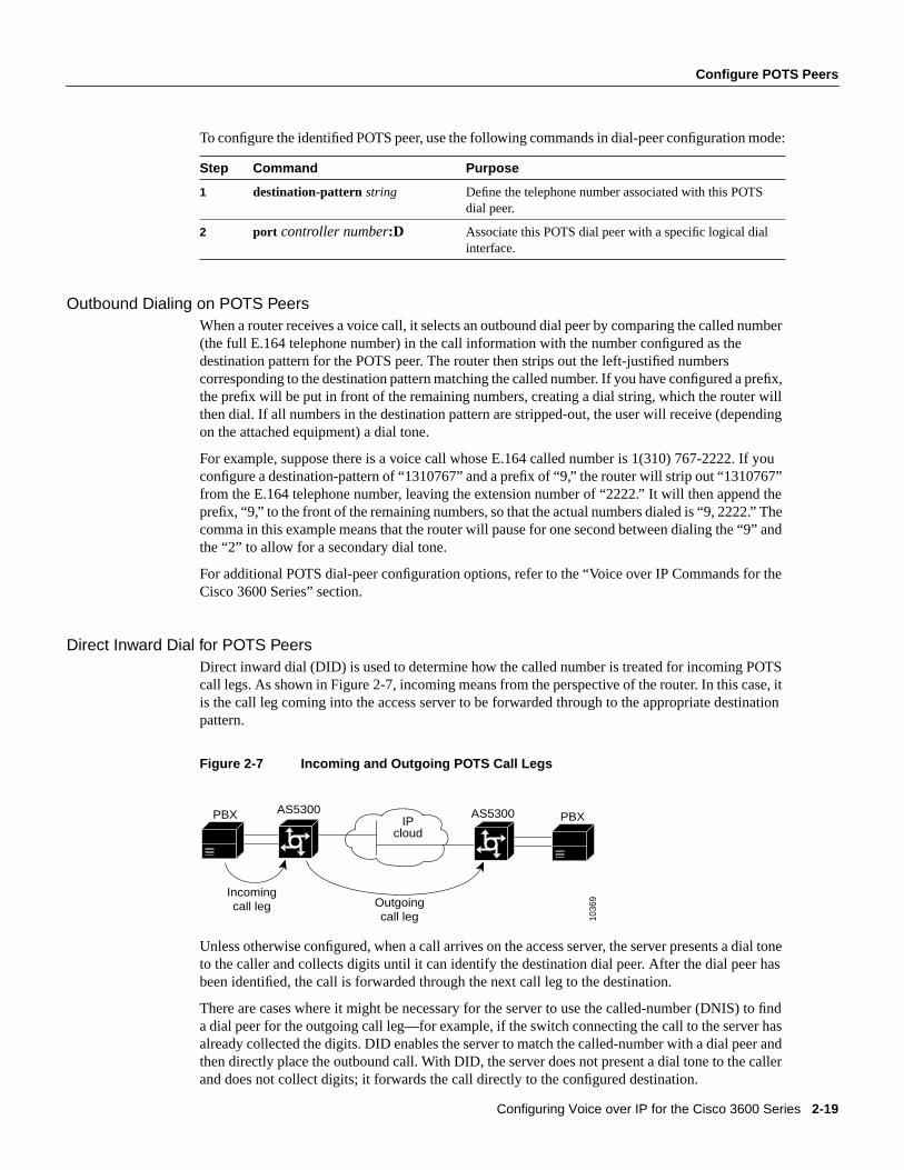
Configuring Voice over IP for the Cisco 3600 Series 2-19
Configure POTS Peers
To configure the identified POTS peer, use the following commands in dial-peer configuration mode:
Outbound Dialing on POTS PeersWhen a router receives a voice call, it selects an outbound dial peer by comparing the called number(the full E.164 telephone number) in the call information with the number configured as thedestination pattern for the POTS peer. The router then strips out the left-justified numberscorresponding to the destination pattern matching the called number. If you have configured a prefix,the prefix will be put in front of the remaining numbers, creating a dial string, which the router willthen dial. If all numbers in the destination pattern are stripped-out, the user will receive (dependingon the attached equipment) a dial tone.
For example, suppose there is a voice call whose E.164 called number is 1(310) 767-2222. If youconfigure a destination-pattern of “1310767” and a prefix of “9,” the router will strip out “1310767”from the E.164 telephone number, leaving the extension number of “2222.” It will then append theprefix, “9,” to the front of the remaining numbers, so that the actual numbers dialed is “9, 2222.” Thecomma in this example means that the router will pause for one second between dialing the “9” andthe “2” to allow for a secondary dial tone.
For additional POTS dial-peer configuration options, refer to the “Voice over IP Commands for theCisco 3600 Series” section.
Direct Inward Dial for POTS PeersDirect inward dial (DID) is used to determine how the called number is treated for incoming POTScall legs. As shown in Figure 2-7, incoming means from the perspective of the router. In this case, itis the call leg coming into the access server to be forwarded through to the appropriate destinationpattern.
Figure 2-7 Incoming and Outgoing POTS Call Legs
Unless otherwise configured, when a call arrives on the access server, the server presents a dial toneto the caller and collects digits until it can identify the destination dial peer. After the dial peer hasbeen identified, the call is forwarded through the next call leg to the destination.
There are cases where it might be necessary for the server to use the called-number (DNIS) to finda dial peer for the outgoing call leg—for example, if the switch connecting the call to the server hasalready collected the digits. DID enables the server to match the called-number with a dial peer andthen directly place the outbound call. With DID, the server does not present a dial tone to the callerand does not collect digits; it forwards the call directly to the configured destination.
Step Command Purpose
1 destination-pattern string Define the telephone number associated with this POTSdial peer.
2 port controller number:D Associate this POTS dial peer with a specific logical dialinterface.
PBX AS5300
Incomingcall leg Outgoing
call leg
AS5300 PBX
1036
9
IP cloud
Configure Dial Peers
Voice over IP for the Cisco 3600 Series Software Configuration Guide2-20
To use DID and incoming called-number, a dial peer must be associated with the incoming call leg.Before doing this, it helps if you understand the logic behind the algorithm used to associate theincoming call leg with the dial peer.
The algorithm used to associate incoming call legs with dial peers uses three inputs (which arederived from signaling and interface information associated with the call) and four defined dial peerelements. The three signaling inputs are:
• Called-number (DNIS)—Set of numbers representing the destination, which is derived from theISDN setup message or CAS DNIS.
• Calling-number (ANI)—Set of numbers representing the origin, which is derived from the ISDNsetup message or CAS DNIS.
• Voice port—The voice port carrying the call.
The four defined dial peer elements are:
• Destination pattern—A pattern representing the phone numbers to which the peer can connect.
• Answer address—A pattern representing the phone numbers from which the peer can connect.
• Incoming called-number—A pattern representing the phone numbers that associate an incomingcall leg to a peer based on the called-number or DNIS.
• Port—The port through which calls to this peer are placed.
Using the elements, the algorithm is as follows:
For all peers where call type (VoIP versus POTS) match dial peer type:if the type is matched, associate the called number with the incoming called-number
else if the type is matched, associate calling-number with answer-addresselse if the type is matched, associate calling-number with destination-patternelse if the type is matched, associate voice port to port
This algorithm shows that if a value is not configured for answer-address, the origin address is usedbecause, in most cases, the origin address and answer-address are the same.
To configure DID for a particular POTS dial peer, use the following commands, initially in globalconfiguration mode:
Note Direct inward dial is configured for the calling POTS dial peer.
For additional POTS dial-peer configuration options, refer to the “Voice over IP Commands for theCisco 3600 Series” chapter.
Step Command Purpose
1 dial-peer voicenumberpots Enter the dial-peer configuration mode to configure aPOTS peer.
2 direct-inward-dial Specify direct inward dial for this POTS peer.
Configuring Voice over IP for the Cisco 3600 Series 2-21
Configure VoIP Peers
Configure VoIP PeersOnce again, VoIP peers enable outgoing calls to be made from a particular telephony device. Toconfigure a VoIP peer, you need to uniquely identify the peer (by assigning it a unique tag number),define its destination telephone number and destination IP address. As with POTS peers, under mostcircumstances, the default values for the remaining dial-peer configuration commands will beadequate to establish connections.
To enter the dial-peer configuration mode (and select VoIP as the method of voice-relatedencapsulation), use the following command in global configuration mode:
Thenumbervalue of thedial-peer voice voipcommand is a tag that uniquely identifies the dial peer.
To configure the identified VoIP peer, use the following commands in dial-peer configuration mode:
For additional VoIP dial-peer configuration options, refer to the “Voice over IP Commands for theCisco 3600 Series” chapter. For examples of how to configure dial peers, refer to the chapter, “Voiceover IP Configuration Examples for the Cisco 3600 Series.”
VerifyYou can check the validity of your dial-peer configuration by performing the following tasks:
• If you have relatively few dial peers configured, you can use theshow dial-peer voicecommandto verify that the data configured is correct. Use this command to display a specific dial peer orto display all configured dial peers.
• Use theshow dialplan numbercommand to show the dial peer to which a particular number(destination pattern) resolves.
TipsIf you are having trouble connecting a call and you suspect the problem is associated with dial-peerconfiguration, you can try to resolve the problem by performing the following tasks:
• Ping the associated IP address to confirm connectivity. If you cannot successfully ping yourdestination, refer to the chapter “Configuring IP” in the Cisco IOS 11.3Network ProtocolsConfiguration Guide, Part 1.
• Use theshow dial-peer voicecommand to verify that the operational status of the dial peer is up.
• Use theshow dialplan numbercommand on the local and remote routers to verify that the datais configured correctly on both.
• If you have configured number expansion, use theshow num-exp command to check that thepartial number on the local router maps to the correct full E.164 telephone number on the remoterouter.
Command Purpose
dial-peer voicenumbervoip Enter the dial-peer configuration mode to configure a VoIP peer.
Step Command Purpose
1 destination-pattern string Define the destination telephone numberassociated with this VoIP dial peer.
2 session-target{ ipv4:destination-address|dns:host-name}
Specify a destination IP address for this dialpeer.

Configure Voice Ports
Voice over IP for the Cisco 3600 Series Software Configuration Guide2-22
• If you have configured a CODEC value, there can be a problem if both VoIP dial peers on eitherside of the connection have incompatible CODEC values. Make sure that both VoIP peers havebeen configured with the same CODEC value.
• Use thedebug vpm spi command to verify the output string the router dials is correct.
• Use thedebug cch323 rtp command to check RTP packet transport.
• Use thedebug cch323 h225 command to check the call setup.
Configure Voice PortsThe Cisco 3600 currently provides only analog voice ports for its implementation of Voice over IP.The type of signaling associated with these analog voice ports depends on the interface moduleinstalled into the device. The Cisco 3600 series router supports either a two-port or four-port voicenetwork module (VNM); VNMs can hold either 2 or 4 voice interface cards (VICs).
Each VIC is specific to a particular signaling type; therefore, VICs determine the type of signalingfor the voice ports on that particular VNM. This means that even though VNMs can hold multipleVICs, each VIC on a VNM must conform to the same signaling type. For more information aboutthe physical characteristics of VNMs and VICs or how to install them, refer to the installationdocument,Voice Network Module and Voice Interface Card Configuration Note, that came with yourVNM.
Voice ports on the Cisco 3600 series support three basic voice signaling types:
• FXO—Foreign Exchange Office interface. The FXO interface is an RJ-11 connector that allowsa connection to be directed at the PSTN’s central office (or to a standard PBX interface, if thelocal telecommunications authority permits). This interface is of value for off-premise extensionapplications.
• FXS—The Foreign Exchange Station interface is an RJ-11 connector that allows connection forbasic telephone equipment, keysets, PBXs, and supplies ring, voltage, and dial tone.
• E&M—The “Ear and Mouth” interface (or “RecEive and TransMit” interface) is an RJ-48connector that allows connection for PBX trunk lines (tie lines). It is a signaling technique for2-wire and 4-wire telephone and trunk interfaces.
In general, voice port commands define the characteristics associated with a particular voice portsignaling type. Under most circumstances, the default voice port command values are adequate toconfigure FXO and FXS ports to transport voice data over your existing IP network. Because of theinherent complexities involved with PBX networks, E&M ports might need specific voice portvalues configured, depending on the specifications of the devices in your telephony network.
Configuring FXO or FXS Voice PortsUnder most circumstances the default voice port values are adequate for both FXO and FXS voiceports. If you need to change the default configuration for these voice ports, perform the followingtasks. Items included in Step 1 and Step 2 are required; items included in Step 3 are optional.
Step 1 Identify the voice port and enter the voice-port configuration mode by using thevoice-port command.
Step 2 Configure the following mandatory voice-port parameters by using the indicatedcommands:
• Dial type (FXO only) using thedial-type command
• Signal type using the signal command

Configuring Voice over IP for the Cisco 3600 Series 2-23
Configuring FXO or FXS Voice Ports
• Call progress tone using thecptone command
• Ring frequency (FXS only) using thering frequency command
• Ring number (FXO only) using thering number command
Step 3 Configure one or more of the following optional voice-port parameters by using theindicated commands:
• PLAR connection mode using theconnection plar command
• Music-threshold using themusic-threshold command
• Description using thedescription command
• Comfort noise (if VAD is activated—VAD is a dial-peer command) using thecomfort-noise command
To configure FXO and FXS voice ports, use the following commands beginning in privileged EXECmode:
Step Command Purpose
1 configure terminal Enter the global configuration mode.
2 voice-port slot-number/subunit-number/port Identify the voice port you want to configure andenter the voice-port configuration mode.
3 dial-type {dtmf | pulse} (For FXO ports only) Select the appropriate dialtype for out-dialing.
4 signal { loop-start | ground-start} Select the appropriate signal type for this interface.
5 cptonecountry Select the appropriate voice call progress tone forthis interface.
The default for this command isus. For a list ofsupported countries, refer to theVoice, Video, andHome Applications Command Reference.
6 ring frequency {25 | 50} (For FXS ports only) Select the appropriate ringfrequency (in Hertz) specific to the equipmentattached to this voice port.
7 ring number number (For FXO ports only) Specify the maximum numberof rings to be detected before answering a call.
8 connection plarstring (Optional) Specify the private line auto ringdown(PLAR) connection, if this voice port is used for aPLAR connection. Thestring value specifies thedestination telephone number.
9 music-thresholdnumber (Optional) Specify the threshold (in decibels) foron-hold music. Valid entries are from -70 to -30.
10 description string (Optional) Attach descriptive text about thisvoice port connection.
11 comfort-noise (Optional) Specify that background noise will begenerated.

Configure Voice Ports
Voice over IP for the Cisco 3600 Series Software Configuration Guide2-24
Validation TipsYou can check the validity of your voice-port configuration by performing the following tasks:
• Pick up the handset of an attached telephony device and check for a dial tone.
• If you have dial tone, check for DTMF detection. If the dial tone stops when you dial a digit, thenthe voice port is most likely configured properly.
• Use theshow voice-port command to verify that the data configured is correct.
Troubleshooting TipsIf you are having trouble connecting a call and you suspect the problem is associated with voice-portconfiguration, you can try to resolve the problem by performing the following tasks:
• Ping the associated IP address to confirm connectivity. If you cannot successfully ping yourdestination, refer to theNetwork Protocols Configuration Guide, Part 1.
• Use theshow voice portcommand to make sure that the port is enabled. If the port is offline, usetheno shutdown command.
• If you have configured E&M interfaces, make sure that the values pertaining to your specific PBXsetup, such as timing and/or type, are correct.
• Check to see if the voice network module has been correctly installed. For more information,refer to the installation document,Voice Network Module and Voice Interface CardConfiguration Note, that came with your voice network module.
Fine-Tune FXO and FXS Voice PortsDepending on the specifics of your particular network, you might need to adjust voice parametersinvolving timing, input gain, and output attenuation for FXO or FXS voice ports. Collectively, thesecommands are referred to as voice-port tuning commands.
Note In most cases, the default values for voice-port tuning commands will be sufficient.
To configure voice-port tuning for FXO and FXS voice ports, perform the following steps:
Step 1 Identify the voice port and enter the voice-port configuration mode using thevoice-portcommand.
Step 2 For each of the following parameters, select the appropriate value using the commandsindicated:
• Input gain using theinput gain command
• Output attenuation using theoutput attenuation command
• Echo cancel coverage using theecho-cancel enable andecho-cancel coveragecommands
• Non-linear processing using thenon-linear command
• Initial digit timeouts using thetimeouts initial command
• Interdigit timeouts using thetimeouts interdigits command
• Timing other than timeouts, using thetiming digit , timing inter-digit , timingpulse-digit andtiming pulse-inter-digit commands.
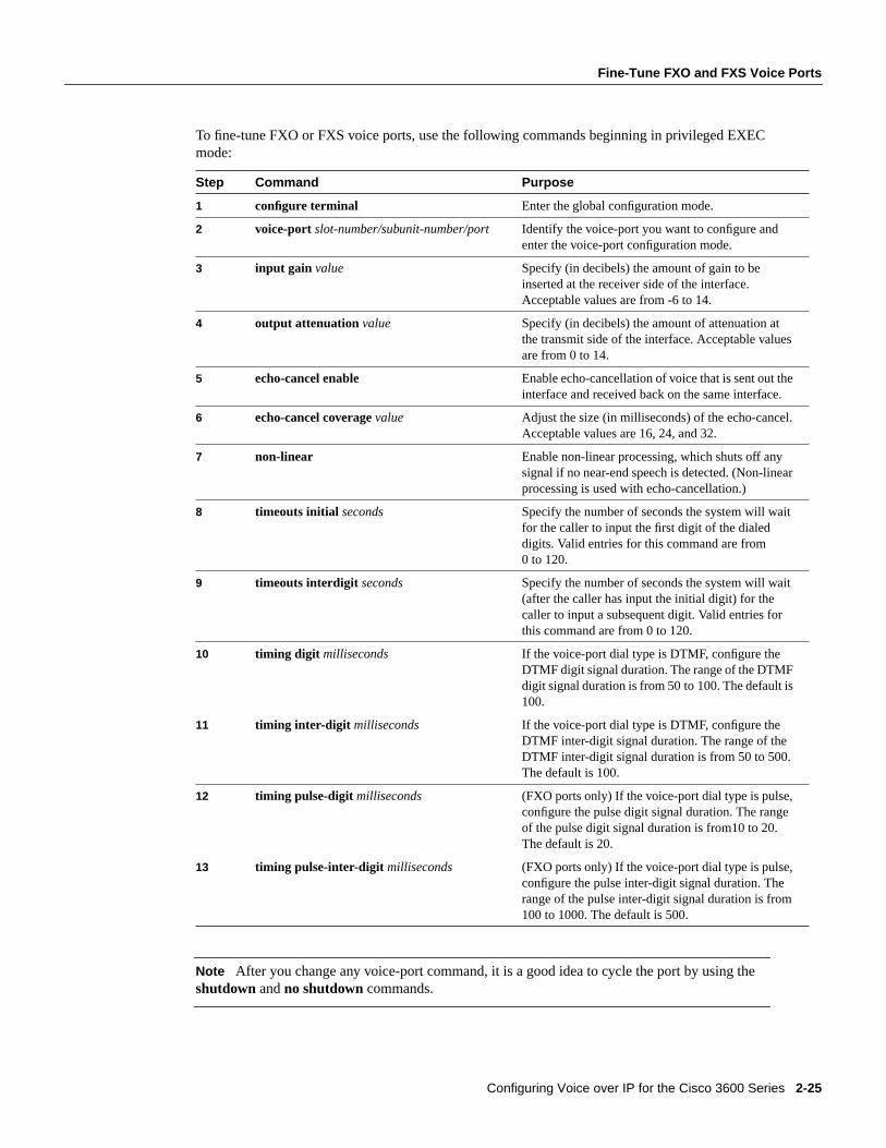
Configuring Voice over IP for the Cisco 3600 Series 2-25
Fine-Tune FXO and FXS Voice Ports
To fine-tune FXO or FXS voice ports, use the following commands beginning in privileged EXECmode:
Note After you change any voice-port command, it is a good idea to cycle the port by using theshutdown andno shutdown commands.
Step Command Purpose
1 configure terminal Enter the global configuration mode.
2 voice-port slot-number/subunit-number/port Identify the voice-port you want to configure andenter the voice-port configuration mode.
3 input gain value Specify (in decibels) the amount of gain to beinserted at the receiver side of the interface.Acceptable values are from -6 to 14.
4 output attenuation value Specify (in decibels) the amount of attenuation atthe transmit side of the interface. Acceptable valuesare from 0 to 14.
5 echo-cancel enable Enable echo-cancellation of voice that is sent out theinterface and received back on the same interface.
6 echo-cancel coveragevalue Adjust the size (in milliseconds) of the echo-cancel.Acceptable values are 16, 24, and 32.
7 non-linear Enable non-linear processing, which shuts off anysignal if no near-end speech is detected. (Non-linearprocessing is used with echo-cancellation.)
8 timeouts initial seconds Specify the number of seconds the system will waitfor the caller to input the first digit of the dialeddigits. Valid entries for this command are from0 to 120.
9 timeouts interdigit seconds Specify the number of seconds the system will wait(after the caller has input the initial digit) for thecaller to input a subsequent digit. Valid entries forthis command are from 0 to 120.
10 timing digit milliseconds If the voice-port dial type is DTMF, configure theDTMF digit signal duration. The range of the DTMFdigit signal duration is from 50 to 100. The default is100.
11 timing inter-digit milliseconds If the voice-port dial type is DTMF, configure theDTMF inter-digit signal duration. The range of theDTMF inter-digit signal duration is from 50 to 500.The default is 100.
12 timing pulse-digit milliseconds (FXO ports only) If the voice-port dial type is pulse,configure the pulse digit signal duration. The rangeof the pulse digit signal duration is from10 to 20.The default is 20.
13 timing pulse-inter-digit milliseconds (FXO ports only) If the voice-port dial type is pulse,configure the pulse inter-digit signal duration. Therange of the pulse inter-digit signal duration is from100 to 1000. The default is 500.
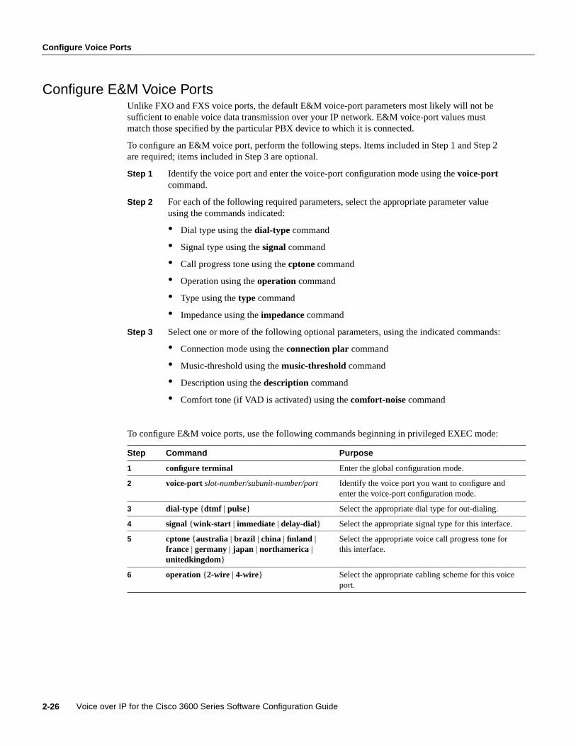
Configure Voice Ports
Voice over IP for the Cisco 3600 Series Software Configuration Guide2-26
Configure E&M Voice PortsUnlike FXO and FXS voice ports, the default E&M voice-port parameters most likely will not besufficient to enable voice data transmission over your IP network. E&M voice-port values mustmatch those specified by the particular PBX device to which it is connected.
To configure an E&M voice port, perform the following steps. Items included in Step 1 and Step 2are required; items included in Step 3 are optional.
Step 1 Identify the voice port and enter the voice-port configuration mode using thevoice-portcommand.
Step 2 For each of the following required parameters, select the appropriate parameter valueusing the commands indicated:
• Dial type using thedial-type command
• Signal type using thesignalcommand
• Call progress tone using thecptone command
• Operation using theoperation command
• Type using thetype command
• Impedance using the impedance command
Step 3 Select one or more of the following optional parameters, using the indicated commands:
• Connection mode using theconnection plar command
• Music-threshold using themusic-threshold command
• Description using thedescription command
• Comfort tone (if VAD is activated) using thecomfort-noise command
To configure E&M voice ports, use the following commands beginning in privileged EXEC mode:
Step Command Purpose
1 configure terminal Enter the global configuration mode.
2 voice-port slot-number/subunit-number/port Identify the voice port you want to configure andenter the voice-port configuration mode.
3 dial-type {dtmf | pulse} Select the appropriate dial type for out-dialing.
4 signal {wink-start | immediate | delay-dial} Select the appropriate signal type for this interface.
5 cptone {australia | brazil | china | finland |france | germany | japan | northamerica |unitedkingdom}
Select the appropriate voice call progress tone forthis interface.
6 operation { 2-wire | 4-wire} Select the appropriate cabling scheme for this voiceport.
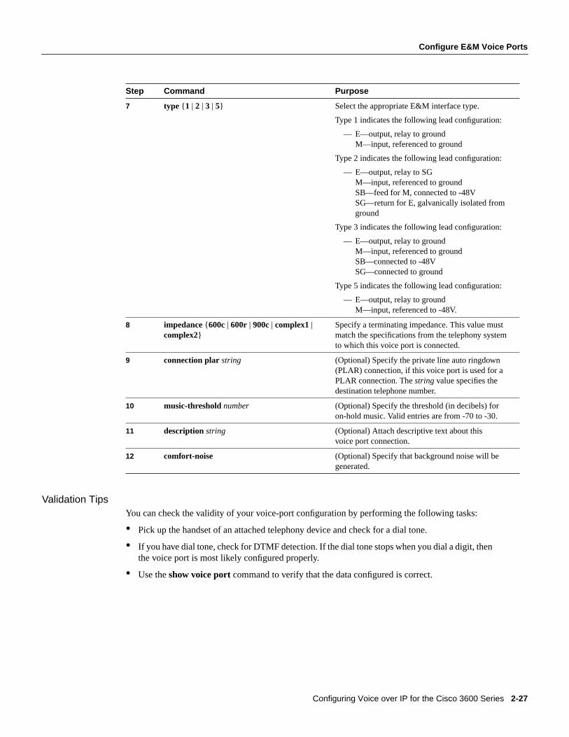
Configuring Voice over IP for the Cisco 3600 Series 2-27
Configure E&M Voice Ports
Validation TipsYou can check the validity of your voice-port configuration by performing the following tasks:
• Pick up the handset of an attached telephony device and check for a dial tone.
• If you have dial tone, check for DTMF detection. If the dial tone stops when you dial a digit, thenthe voice port is most likely configured properly.
• Use theshow voice port command to verify that the data configured is correct.
7 type { 1 | 2 | 3 | 5} Select the appropriate E&M interface type.
Type 1 indicates the following lead configuration:
— E—output, relay to groundM—input, referenced to ground
Type 2 indicates the following lead configuration:
— E—output, relay to SGM—input, referenced to groundSB—feed for M, connected to -48VSG—return for E, galvanically isolated fromground
Type 3 indicates the following lead configuration:
— E—output, relay to groundM—input, referenced to groundSB—connected to -48VSG—connected to ground
Type 5 indicates the following lead configuration:
— E—output, relay to groundM—input, referenced to -48V.
8 impedance {600c | 600r | 900c | complex1 |complex2}
Specify a terminating impedance. This value mustmatch the specifications from the telephony systemto which this voice port is connected.
9 connection plarstring (Optional) Specify the private line auto ringdown(PLAR) connection, if this voice port is used for aPLAR connection. Thestring value specifies thedestination telephone number.
10 music-thresholdnumber (Optional) Specify the threshold (in decibels) foron-hold music. Valid entries are from -70 to -30.
11 description string (Optional) Attach descriptive text about thisvoice port connection.
12 comfort-noise (Optional) Specify that background noise will begenerated.
Step Command Purpose

Configure Voice Ports
Voice over IP for the Cisco 3600 Series Software Configuration Guide2-28
Troubleshooting TipsIf you are having trouble connecting a call and you suspect the problem is associated with voice-portconfiguration, you can try to resolve the problem by performing the following tasks:
• Ping the associated IP address to confirm connectivity. If you cannot successfully ping yourdestination, refer to theNetwork Protocols Configuration Guide, Part 1.
• Use theshow voice-port command to make sure that the port is enabled. If the port is offline,use theno shutdown command.
• If you have configured E&M interfaces, make sure that the values pertaining to your specific PBXsetup, such as timing and/or type, are correct.
• Check to see if the voice network module has been correctly installed. For more information,refer to the installation document that came with your voice network module.
Fine-Tune E&M Voice PortsDepending on the specifics of your particular network, you may need to adjust voice parametersinvolving timing, input gain, and output attenuation for E&M voice ports. Collectively, thesecommands are referred to as voice-port tuning commands.
Note In most cases, the default values for voice-port tuning commands will be sufficient.
To configure voice-port tuning for E&M voice ports, perform the following steps:
Step 1 Identify the voice port and enter the voice-port configuration mode by using thevoice-port command.
Step 2 For each of the following parameters, select the appropriate value, using the commandsindicated:
• Input gain using theinput gain command
• Output attenuation using theoutput attenuation command
• Echo cancel coverage usingecho-cancel enable andecho-cancel coveragecommands
• Non-linear processing using thenon-linear command
• Initial digit timeouts using thetimeouts initial command
• Interdigit timeouts using thetimeouts interdigit command
• Timing other than timeouts using thetiming clear-wait, timing delay-duration,timing delay-start, timing dial-pulse min-delay, timing digit , timing pulse,timing pulse-inter-digit , timing wink-duration , andtiming wink-wait commands.
To fine-tune E&M voice ports, use the following commands beginning in privileged EXEC mode:
Step Command Purpose
1 configure terminal Enter the global configuration mode.
2 voice-port slot-number/subunit-number/port Identify the voice port you want to configureand enter the voice-port configuration mode.

Configuring Voice over IP for the Cisco 3600 Series 2-29
Fine-Tune E&M Voice Ports
Note After you change any voice-port command, it is a good idea to cycle the port by using theshutdown andno shutdown commands.
3 input gain value Specify (in decibels) the amount of gain tobe inserted at the receiver side of theinterface. Acceptable values are from -6 to14.
4 output attenuation value Specify (in decibels) the amount ofattenuation at the transmit side of theinterface. Acceptable values are from 0 to14.
5 echo-cancel enable Enable echo-cancellation of voice that is sentout the interface and received back on thesame interface.
6 echo-cancel coveragevalue Adjust the size (in milliseconds) of theecho-cancel. Acceptable values are 16, 24,and 32.
7 non-linear Enable non-linear processing, which shutsoff any signal if no near-end speech isdetected. (Non-linear processing is used withecho-cancellation.)
8 timeouts initial seconds Specify the number of seconds the systemwill wait for the caller to input the first digitof the dialed digits. Valid entries for thiscommand are from 0 to 120.
9 timeouts interdigit seconds Specify the number of seconds the systemwill wait (after the caller has input the initialdigit) for the caller to input a subsequentdigit. Valid entries for this command arefrom 0 to 120.
10 timing clear-wait millisecondstiming delay-duration millisecondstiming delay-start millisecondstiming dial-pulse min-delaymillisecondstiming digit millisecondstiming inter-digit millisecondstiming pulse pulse-per-secondtiming pulse-inter-digit millisecondstiming wink-duration millisecondstiming wink-wait milliseconds
Specify timing parameters. Valid entries forclear-wait are from 200 to 2000milliseconds. Valid entries fordelay-duration are from 100 to 5000milliseconds. Valid entries fordelay-startare from 20 to 2000 milliseconds. Validentries fordial-pulse min-delayare from 0to 5000 milliseconds. Valid entries fordigitare from 50 to 100 milliseconds. Validentries forinter-digit are from 50 to 500milliseconds. Valid entries forpulseare from10 to 20. Valid entries forpulse-inter-digitare 100 to 1000 milliseconds. Valid entriesfor wink-duration are from 100 to 400milliseconds. Valid entries forwink-wait arefrom 100 to 5000 milliseconds.
Step Command Purpose

Optimize Dial Peer and Network Interface Configurations
Voice over IP for the Cisco 3600 Series Software Configuration Guide2-30
Optimize Dial Peer and Network Interface ConfigurationsDepending on how you have configured your network interfaces, you might need to configureadditional VoIP dial-peer parameters. This section describes the following topics:
• Configure IP Precedence for Dial Peers
• Configure RSVP for Dial Peers
• Configure CODEC and VAD for Dial Peers
Configure IP Precedence for Dial PeersIf you want to give real-time voice traffic a higher priority than other network traffic, you can weightthe voice data traffic associated with a particular VoIP dial peer by using IP Precedence. IPPrecedence scales better than RSVP but provides no admission control.
To give real-time voice traffic precedence over other IP network traffic, use the following commands,beginning in global configuration mode:
In IP Precedence, the numbers 1 through 5 identify classes for IP flows; the numbers 6 through 7 areused for network and backbone routing and updates.
For example, to ensure that voice traffic associated with VoIP dial peer 103 is given a higher prioritythan other IP network traffic, enter the following:
dial-peer voice 103 voipip precedence 5
In this example, when an IP call leg is associated with VoIP dial peer 103, all packets transmitted tothe IP network via this dial peer will have their precedence bits set to 5. If the networks receivingthese packets have been configured to recognize precedence bits, the packets will be given priorityover packets with a lower configured precedence value.
Configure RSVP for Dial PeersIf you have configured your WAN or LAN interfaces for RSVP, you must configure the QoS for anyassociated VoIP peers. To configure quality of service for a selected VoIP peer, use the followingcommands, beginning in global configuration mode:
Note We suggest that you selectcontrolled-load for the requested quality of service.
Step Command Purpose
1 dial-peer voicenumbervoip Enter the dial-peer configuration mode to configure a VoIPpeer.
2 ip precedencenumber Select a precedence level for the voice traffic associatedwith that dial peer.
Step Command Purpose
1 dial-peer voicenumbervoip Enter the dial-peer configurationmode to configure a VoIP peer.
2 req-qos [best-effort | controlled-load |guaranteed-delay]
Specify the desired quality ofservice to be used.

Configuring Voice over IP for the Cisco 3600 Series 2-31
Configure CODEC and VAD for Dial Peers
For example, to specify guaranteed delay QoS for VoIP dial peer 108, enter the following:
Dial-peer voice 108 voipdestination-pattern +1408528req-qos controlled-loadsession target ipv4:10.0.0.8
In this example, every time a connection is made through VoIP dial peer 108, an RSVP reservationrequest is made between the local router, all intermediate routers in the path, and the final destinationrouter.
To generate an SNMP trap message if the reserved QoS is less than the configured value for aselected VoIP peer, use the following commands, beginning from the global configuration mode:
Note RSVP reservations are only one-way. If you configure RSVP, the VoIP dial peers on both endsof the connection must be configured for RSVP.
Configure CODEC and VAD for Dial PeersCoder-decoder (CODEC) and voice activity detection (VAD) for a dial peer determine how muchbandwidth the voice session uses. CODEC typically is used to transform analog signals into a digitalbit stream and digital signals back into analog signals—in this case, it specifies the voice coder rateof speech for a dial peer. VAD is used to disable the transmission of silence packets.
Configure CODEC for a VoIP Dial PeerTo specify a voice coder rate for a selected VoIP peer, use the following commands, initiallybeginning in global configuration mode:
The default for thecodeccommand isg729r8; normally the default configuration for this commandis the most desirable. If, however, you are operating on a high bandwidth network and voice qualityis of the highest importance, you should configure thecodeccommand forg711alaworulaw. Usingthis value will result in better voice quality, but it will also require higher bandwidth requirementsfor voice.
For example, to specify a CODEC rate of G.711a-law for VoIP dial peer 108, enter the following:
Dial-peer voice 108 voipdestination-pattern +1408528codec g711alawsession target ipv4:10.0.0.8
Step Command Purpose
1 dial-peer voicenumbervoip Enter the dial-peer configuration mode toconfigure a VoIP peer.
2 acc-qos [best-effort | controlled-load |guaranteed-delay]
Specify the QoS value below which an SNMPtrap will be generated.
Step Command Purpose
1 dial-peer voicenumbervoip Enter the dial-peer configuration mode to configurea VoIP peer.
2 codec [g711alaw| g711ulaw| g729r8] Specify the desired voice coder rate of speech.

Configure Voice over IP for Microsoft NetMeeting
Voice over IP for the Cisco 3600 Series Software Configuration Guide2-32
Configure VAD for a VoIP Dial PeerTo disable the transmission of silence packets for a selected VoIP peer, use the following commands,beginning in global configuration mode:
The default for thevad command is enabled; normally the default configuration for this commandis the most desirable. If you are operating on a high bandwidth network and voice quality is of thehighest importance, you should disablevad. Using this value will result in better voice quality, butit will also require higher bandwidth requirements for voice.
For example, to enable VAD for VoIP dial peer 108, enter the following:
Dial-peer voice 108 voipdestination-pattern +1408528vadsession target ipv4:10.0.0.8
Configure Voice over IP for Microsoft NetMeetingVoice over IP can be used with Microsoft NetMeeting (Version 2.x) when the Cisco 3600 seriesrouter is used as the voice gateway. Use the latest version of DirectX drivers from Microsoft on yourPC to improve the voice quality of NetMeeting.
Configure Voice over IP to Support Microsoft NetMeetingTo configure Voice over IP to support NetMeeting, create a VoIP peer that contains the followinginformation:
• Session Target—IP address or DNS name of the PC running NetMeeting
• CODEC—g711ulaw or g711alaw
Configure Microsoft NetMeeting for Voice over IPTo configure NetMeeting to work with Voice over IP, complete the following steps:
Step 1 From the Tools menu in the NetMeeting application, selectOptions. NetMeeting willdisplay the Options dialog box.
Step 2 Click theAudio tab.
Step 3 Click the “Calling a telephone using NetMeeting” check box.
Step 4 Enter the IP address of the Cisco 3600 series router in theIP address field.
Step 5 UnderGeneral, click Advanced.
Step 6 Click the “Manually configured compression settings” check box.
Step 7 Select the CODEC valueCCITT ulaw 8000Hz.
Step Command Purpose
1 dial-peer voicenumbervoip Enter the dial-peer configuration mode to configurea VoIP peer.
2 vad Disable the transmission of silence packets(enabling VAD).

Configuring Voice over IP for the Cisco 3600 Series 2-33
Initiate a Call Using Microsoft NetMeeting
Step 8 Click theUp button until this CODEC value is at the top of the list.
Step 9 Click OK to exit.
Initiate a Call Using Microsoft NetMeetingTo initiate a call using Microsoft NetMeeting, perform the following steps:
Step 1 Click the Call icon from the NetMeeting application. Microsoft NetMeeting will open thecall dialog box.
Step 2 From the Call dialog box, selectcall using H.323 gateway.
Step 3 Enter the telephone number in theAddress field.
Step 4 Click Call to initiate a call to the Cisco 3600 series router from Microsoft NetMeeting.

Managing System Performance FC-357
Managing System Performance
This chapter describes the basic tasks that you can perform to manage the general systemperformance.
For a complete description of the performance management commands in this chapter, refer to the“Performance Management Commands” chapter of the Configuration Fundamentals CommandReference. To locate documentation of other commands that appear in this chapter, use the commandreference master index or search online.
System Performance Management Task ListPerform any of the tasks in the following sections to manage system performance:
• Set the Interval for Load Data
• Limit TCP Transactions
• Configure Switching and Scheduling Priorities
• Establish Queueing and Congestion Strategies
• Configure Generic Traffic Shaping
• Modify the System Buffer Size
In addition, most chapters in this guide include performance tasks specific to the chapter content,and theInternetworking Design Guide includes detailed information on performance issues thatarise when designing a network.
See the “Performance Management Examples” section at the end of this chapter for examples.
Set the Interval for Load DataYou can change the period of time over which a set of data is used for computing load statistics.Decisions, such as dial backup decisions, are dependent on these statistics. If you decrease the loadinterval, the average statistics are computed over a shorter period of time and are more responsive tobursts of traffic.
To change the length of time for which a set of data is used to compute load statistics, perform thefollowing task in interface configuration mode:
Task Command
Set the length of time for which data is used forload calculations.
load-interval seconds

FC-358 Configuration Fundamentals Configuration Guide
Limit TCP Transactions
Limit TCP TransactionsWhen using a standard TCP implementation to send keystrokes between machines, TCP tends tosend one packet for each keystroke typed, which can use up bandwidth and contribute to congestionon larger networks.
John Nagle’s algorithm (RFC 896) helps alleviate the small-packet problem in TCP. The firstcharacter typed after connection establishment is sent in a single packet, but TCP holds anyadditional characters typed until the receiver acknowledges the previous packet. Then the second,larger packet is sent, and additional typed characters are saved until the acknowledgment comesback. The effect is to accumulate characters into larger chunks, and pace them out to the network ata rate matching the round-trip time of the given connection. This method is usually good for allTCP-based traffic. However, do not enable the Nagle slow packet avoidance algorithm if you haveXRemote users on X Window sessions.
By default, the Nagle algorithm is not enabled. To enable the Nagle algorithm and thereby reduceTCP transactions, perform the following task in global configuration mode:
Configure Switching and Scheduling PrioritiesThe normal operation of the network server allows the switching operations to use as much of thecentral processor as is required. If the network is running unusually heavy loads that do not allowthe processor the time to handle the routing protocols, you might need to give priority to the systemprocess scheduler. To do so, perform the following task in global configuration mode:
To change the amount of time that the CPU spends on fast switching and process level operations onthe Cisco 7200 series and Cisco 7500 series, perform the following task in global configurationmode:
Caution Cisco recommends that you do not change the default values of thescheduler allocatecommand.
Task Command
Enable the Nagle slow packet avoidancealgorithm.
service nagle
Task Command
Define the maximum amount of time that canelapse without running the lowest-priority systemprocesses.
scheduler intervalmilliseconds
Task Command
For the Cisco 7200 series and Cisco 7500 series,change the default time the CPU spends onprocess tasks and fast switching.
scheduler allocatenetwork-microsecondsprocess-microseconds
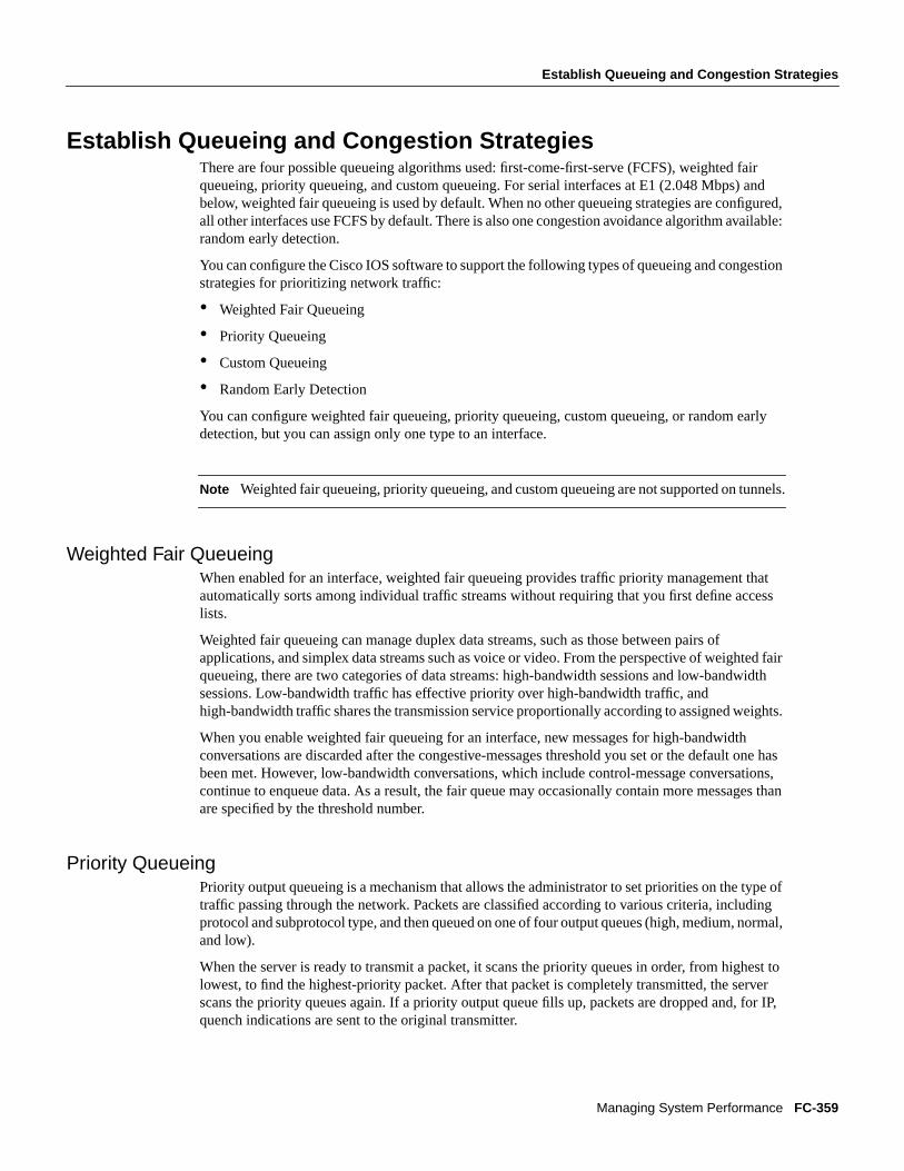
Establish Queueing and Congestion Strategies
Managing System Performance FC-359
Establish Queueing and Congestion StrategiesThere are four possible queueing algorithms used: first-come-first-serve (FCFS), weighted fairqueueing, priority queueing, and custom queueing. For serial interfaces at E1 (2.048 Mbps) andbelow, weighted fair queueing is used by default. When no other queueing strategies are configured,all other interfaces use FCFS by default. There is also one congestion avoidance algorithm available:random early detection.
You can configure the Cisco IOS software to support the following types of queueing and congestionstrategies for prioritizing network traffic:
• Weighted Fair Queueing
• Priority Queueing
• Custom Queueing
• Random Early Detection
You can configure weighted fair queueing, priority queueing, custom queueing, or random earlydetection, but you can assign only one type to an interface.
Note Weighted fair queueing, priority queueing, and custom queueing are not supported on tunnels.
Weighted Fair QueueingWhen enabled for an interface, weighted fair queueing provides traffic priority management thatautomatically sorts among individual traffic streams without requiring that you first define accesslists.
Weighted fair queueing can manage duplex data streams, such as those between pairs ofapplications, and simplex data streams such as voice or video. From the perspective of weighted fairqueueing, there are two categories of data streams: high-bandwidth sessions and low-bandwidthsessions. Low-bandwidth traffic has effective priority over high-bandwidth traffic, andhigh-bandwidth traffic shares the transmission service proportionally according to assigned weights.
When you enable weighted fair queueing for an interface, new messages for high-bandwidthconversations are discarded after the congestive-messages threshold you set or the default one hasbeen met. However, low-bandwidth conversations, which include control-message conversations,continue to enqueue data. As a result, the fair queue may occasionally contain more messages thanare specified by the threshold number.
Priority QueueingPriority output queueing is a mechanism that allows the administrator to set priorities on the type oftraffic passing through the network. Packets are classified according to various criteria, includingprotocol and subprotocol type, and then queued on one of four output queues (high, medium, normal,and low).
When the server is ready to transmit a packet, it scans the priority queues in order, from highest tolowest, to find the highest-priority packet. After that packet is completely transmitted, the serverscans the priority queues again. If a priority output queue fills up, packets are dropped and, for IP,quench indications are sent to the original transmitter.

FC-360 Configuration Fundamentals Configuration Guide
Establish Queueing and Congestion Strategies
Although you can enable priority output queueing for any interface, the intended application was forlow-bandwidth, congested serial interfaces. Cisco’s priority output queueing mechanism allowstraffic control based on protocol or interface type. You can also set the size of the queue and defaultsfor what happens to packets that are not defined by priority output queue rules.
The priority output queueing mechanism can be used to manage traffic from all networkingprotocols. Additional fine-tuning is available for IP and for setting boundaries on the packet size.
Note Priority queueing introduces extra overhead that is acceptable for slow interfaces, but may notbe acceptable for higher-speed interfaces such as Ethernet.
The four priority queues—high, medium, normal, and low—are listed in order from highest tolowest priority. Keepalives sourced by the network server are always assigned to the high-priorityqueue; all other management traffic (such as IGRP updates) must be configured. Packets that are notclassified by the priority list mechanism are assigned to the normal queue.
A priority list is a set of rules that describes how packets should be assigned to priority queues. Apriority list might also describe a default priority or the queue size limits of the various priorityqueues.
Custom QueueingPriority queueing introduces a fairness problem in that packets classified to lower-priority queuesmight not get serviced in a timely manner or at all, depending upon the bandwidth used by packetssent from the higher-priority output queues.
With custom output queueing, a “weighted fair” queueing strategy is implemented for the processingof interface output queues. You can control the percentage of an interface’s available bandwidth thatis used by a particular kind of traffic. When custom queueing is enabled on an interface, the systemmaintains 17 output queues for that interface that can be used to modify queueing behavior. You canspecify queues 1 through 16.
For queue numbers 1 through 16, the system cycles through the queues sequentially, deliveringpackets in the current queue before moving on to the next. Associated with each output queue is aconfigurable byte count, which specifies how many bytes of data the system should deliver from thecurrent queue before it moves on to the next queue. When a particular queue is being processed,packets are sent until the number of bytes sent exceed the queue byte count or the queue is empty.Bandwidth used by a particular queue can only be indirectly specified in terms of byte count andqueue length.
Queue number 0 is a system queue; it is emptied before any of the queues numbered 1 through 16are processed. The system queues high-priority packets, such as keepalive packets, to this queue.Other traffic cannot be configured to use this queue.
On most platforms, all protocols are classified in the fast switching path.
Note With custom or priority queueing enabled, the system takes longer to switch packets becausethe packets are classified by the processor card.
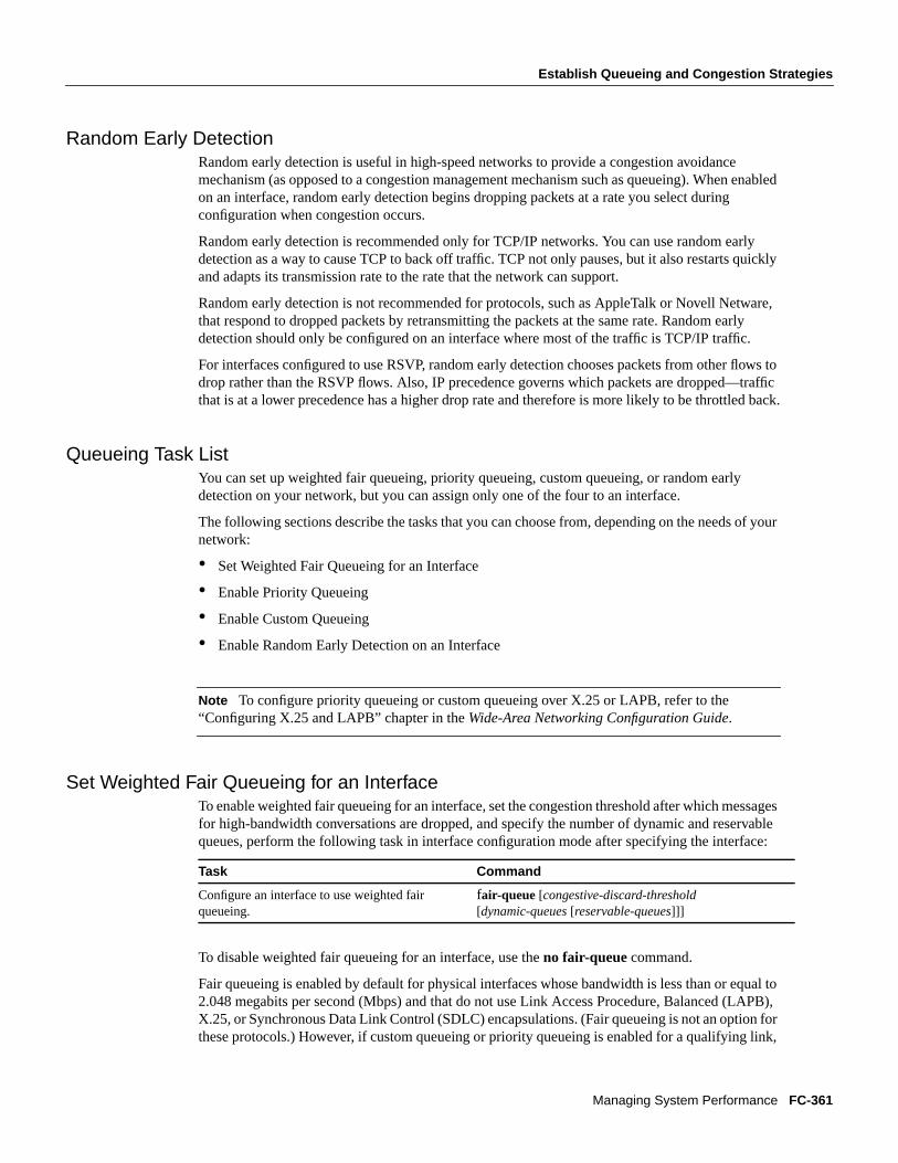
Establish Queueing and Congestion Strategies
Managing System Performance FC-361
Random Early DetectionRandom early detection is useful in high-speed networks to provide a congestion avoidancemechanism (as opposed to a congestion management mechanism such as queueing). When enabledon an interface, random early detection begins dropping packets at a rate you select duringconfiguration when congestion occurs.
Random early detection is recommended only for TCP/IP networks. You can use random earlydetection as a way to cause TCP to back off traffic. TCP not only pauses, but it also restarts quicklyand adapts its transmission rate to the rate that the network can support.
Random early detection is not recommended for protocols, such as AppleTalk or Novell Netware,that respond to dropped packets by retransmitting the packets at the same rate. Random earlydetection should only be configured on an interface where most of the traffic is TCP/IP traffic.
For interfaces configured to use RSVP, random early detection chooses packets from other flows todrop rather than the RSVP flows. Also, IP precedence governs which packets are dropped—trafficthat is at a lower precedence has a higher drop rate and therefore is more likely to be throttled back.
Queueing Task ListYou can set up weighted fair queueing, priority queueing, custom queueing, or random earlydetection on your network, but you can assign only one of the four to an interface.
The following sections describe the tasks that you can choose from, depending on the needs of yournetwork:
• Set Weighted Fair Queueing for an Interface
• Enable Priority Queueing
• Enable Custom Queueing
• Enable Random Early Detection on an Interface
Note To configure priority queueing or custom queueing over X.25 or LAPB, refer to the“Configuring X.25 and LAPB” chapter in theWide-Area Networking Configuration Guide.
Set Weighted Fair Queueing for an InterfaceTo enable weighted fair queueing for an interface, set the congestion threshold after which messagesfor high-bandwidth conversations are dropped, and specify the number of dynamic and reservablequeues, perform the following task in interface configuration mode after specifying the interface:
To disable weighted fair queueing for an interface, use theno fair-queue command.
Fair queueing is enabled by default for physical interfaces whose bandwidth is less than or equal to2.048 megabits per second (Mbps) and that do not use Link Access Procedure, Balanced (LAPB),X.25, or Synchronous Data Link Control (SDLC) encapsulations. (Fair queueing is not an option forthese protocols.) However, if custom queueing or priority queueing is enabled for a qualifying link,
Task Command
Configure an interface to use weighted fairqueueing.
fair-queue [congestive-discard-threshold[dynamic-queues[reservable-queues]]]
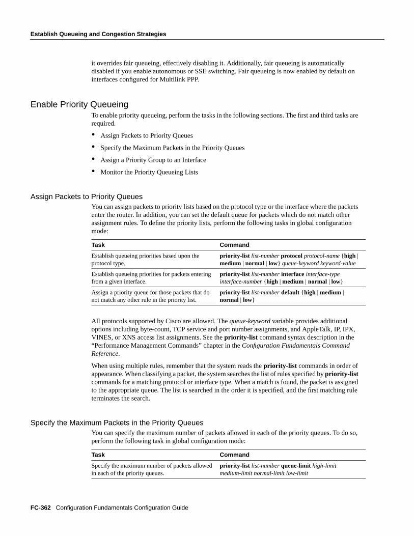
FC-362 Configuration Fundamentals Configuration Guide
Establish Queueing and Congestion Strategies
it overrides fair queueing, effectively disabling it. Additionally, fair queueing is automaticallydisabled if you enable autonomous or SSE switching. Fair queueing is now enabled by default oninterfaces configured for Multilink PPP.
Enable Priority QueueingTo enable priority queueing, perform the tasks in the following sections. The first and third tasks arerequired.
• Assign Packets to Priority Queues
• Specify the Maximum Packets in the Priority Queues
• Assign a Priority Group to an Interface
• Monitor the Priority Queueing Lists
Assign Packets to Priority QueuesYou can assign packets to priority lists based on the protocol type or the interface where the packetsenter the router. In addition, you can set the default queue for packets which do not match otherassignment rules. To define the priority lists, perform the following tasks in global configurationmode:
All protocols supported by Cisco are allowed. Thequeue-keyword variable provides additionaloptions including byte-count, TCP service and port number assignments, and AppleTalk, IP, IPX,VINES, or XNS access list assignments. See thepriority-list command syntax description in the“Performance Management Commands” chapter in theConfiguration Fundamentals CommandReference.
When using multiple rules, remember that the system reads thepriority-list commands in order ofappearance. When classifying a packet, the system searches the list of rules specified bypriority-listcommands for a matching protocol or interface type. When a match is found, the packet is assignedto the appropriate queue. The list is searched in the order it is specified, and the first matching ruleterminates the search.
Specify the Maximum Packets in the Priority QueuesYou can specify the maximum number of packets allowed in each of the priority queues. To do so,perform the following task in global configuration mode:
Task Command
Establish queueing priorities based upon theprotocol type.
priority-list list-numberprotocol protocol-name{ high |medium | normal | low} queue-keyword keyword-value
Establish queueing priorities for packets enteringfrom a given interface.
priority-list list-numberinterface interface-typeinterface-number{ high | medium | normal | low}
Assign a priority queue for those packets that donot match any other rule in the priority list.
priority-list list-numberdefault { high | medium |normal | low}
Task Command
Specify the maximum number of packets allowedin each of the priority queues.
priority-list list-numberqueue-limit high-limitmedium-limit normal-limit low-limit

Establish Queueing and Congestion Strategies
Managing System Performance FC-363
Assign a Priority Group to an InterfaceYou can assign a priority list number to an interface. Only one list can be assigned per interface. Toassign an priority group to an interface, perform the following task in interface configuration mode:
Monitor the Priority Queueing ListsYou can display information about the input and output queues when priority queueing is enabledon an interface. To do so, perform the following task in EXEC mode:
Enable Custom QueueingTo enable custom queueing, perform the tasks in the following sections. The first and third tasks arerequired.
• Assign Packets to Custom Queues
• Specify the Maximum Packets and Bytes in the Custom Queues
• Assign a Custom Queue to an Interface
• Monitor the Custom Queueing Lists
Assign Packets to Custom QueuesYou can assign packets to custom queues based on the protocol type or the interface where thepackets enter the router. In addition, you can set the default queue for packets which do not matchother assignment rules. To define the custom queueing lists, perform the following tasks in globalconfiguration mode:
All protocols supported by Cisco are allowed. Thequeue-keyword variable provides additionaloptions, including byte-count, TCP service and port number assignments, and AppleTalk, IP, IPX,VINES, or XNS access list assignments. See thequeue-list command syntax description in the“Performance Management Commands” chapter in theConfiguration Fundamentals CommandReference.
When using multiple rules, remember that the system reads thequeue-list commands in order ofappearance. When classifying a packet, the system searches the list of rules specified byqueue-listcommands for a matching protocol or interface type. When a match is found, the packet is assignedto the appropriate queue. The list is searched in the order it is specified, and the first matching ruleterminates the search.
Task Command
Assign a priority list number to the interface. priority-group list-number
Task Command
Show the status of the priority queueing lists. show queueing priority
Task Command
Establish queueing priorities based upon theprotocol type.
queue-list list-numberprotocol protocol-namequeue-number queue-keyword keyword-value
Establish custom queueing based on packetsentering from a given interface.
queue-list list-numberinterface interface-typeinterface-number queue-number
Assign a queue number for those packets that donot match any other rule in the custom queue list.
queue-list list-numberdefault queue-number
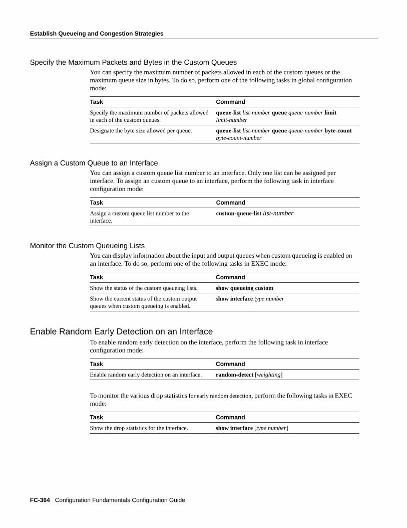
FC-364 Configuration Fundamentals Configuration Guide
Establish Queueing and Congestion Strategies
Specify the Maximum Packets and Bytes in the Custom QueuesYou can specify the maximum number of packets allowed in each of the custom queues or themaximum queue size in bytes. To do so, perform one of the following tasks in global configurationmode:
Assign a Custom Queue to an InterfaceYou can assign a custom queue list number to an interface. Only one list can be assigned perinterface. To assign an custom queue to an interface, perform the following task in interfaceconfiguration mode:
Monitor the Custom Queueing ListsYou can display information about the input and output queues when custom queueing is enabled onan interface. To do so, perform one of the following tasks in EXEC mode:
Enable Random Early Detection on an InterfaceTo enable random early detection on the interface, perform the following task in interfaceconfiguration mode:
To monitor the various drop statisticsfor early random detection, perform the following tasks in EXECmode:
Task Command
Specify the maximum number of packets allowedin each of the custom queues.
queue-list list-number queuequeue-numberlimitlimit-number
Designate the byte size allowed per queue. queue-list list-number queuequeue-numberbyte-countbyte-count-number
Task Command
Assign a custom queue list number to theinterface.
custom-queue-listlist-number
Task Command
Show the status of the custom queueing lists. show queueing custom
Show the current status of the custom outputqueues when custom queueing is enabled.
show interface type number
Task Command
Enable random early detection on an interface. random-detect [weighting]
Task Command
Show the drop statistics for the interface. show interface [type number]
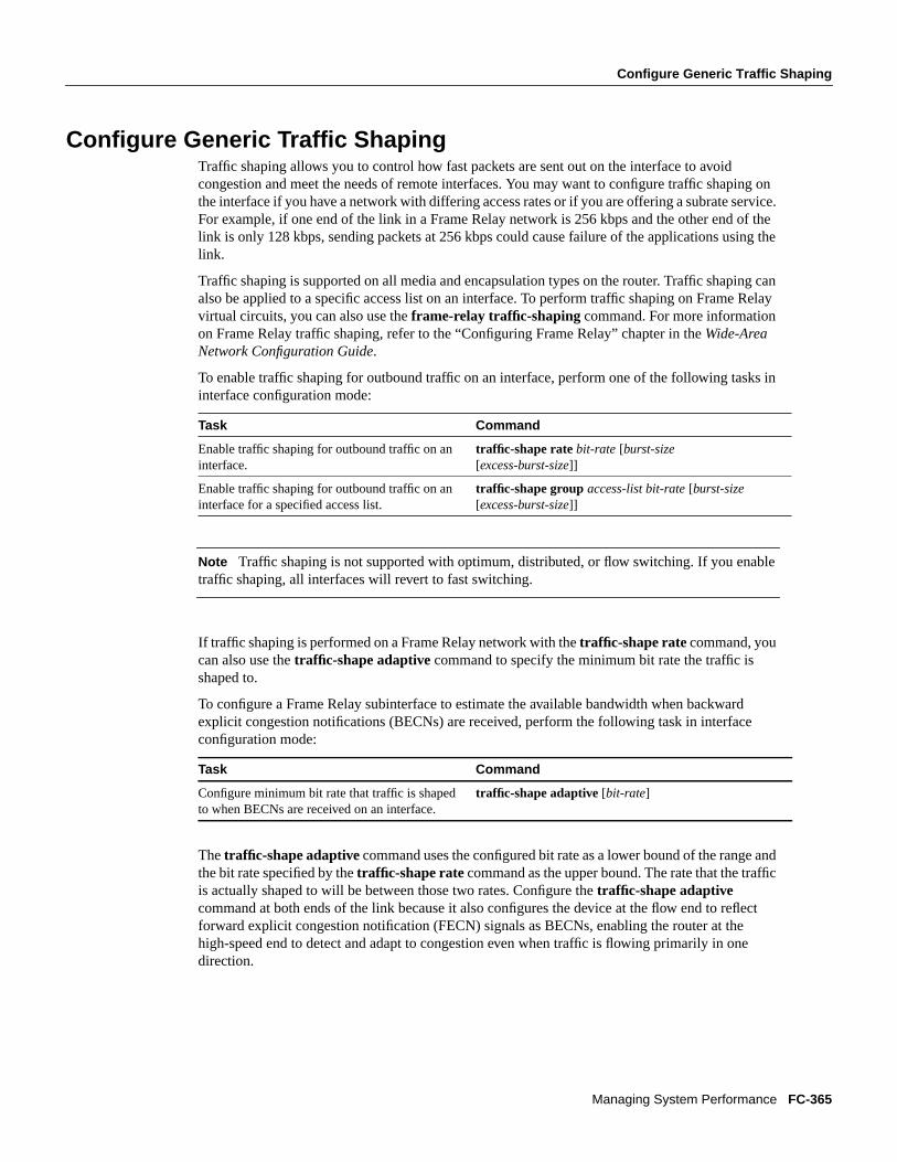
Configure Generic Traffic Shaping
Managing System Performance FC-365
Configure Generic Traffic ShapingTraffic shaping allows you to control how fast packets are sent out on the interface to avoidcongestion and meet the needs of remote interfaces. You may want to configure traffic shaping onthe interface if you have a network with differing access rates or if you are offering a subrate service.For example, if one end of the link in a Frame Relay network is 256 kbps and the other end of thelink is only 128 kbps, sending packets at 256 kbps could cause failure of the applications using thelink.
Traffic shaping is supported on all media and encapsulation types on the router. Traffic shaping canalso be applied to a specific access list on an interface. To perform traffic shaping on Frame Relayvirtual circuits, you can also use theframe-relay traffic-shaping command. For more informationon Frame Relay traffic shaping, refer to the “Configuring Frame Relay” chapter in theWide-AreaNetwork Configuration Guide.
To enable traffic shaping for outbound traffic on an interface, perform one of the following tasks ininterface configuration mode:
Note Traffic shaping is not supported with optimum, distributed, or flow switching. If you enabletraffic shaping, all interfaces will revert to fast switching.
If traffic shaping is performed on a Frame Relay network with thetraffic-shape ratecommand, youcan also use thetraffic-shape adaptive command to specify the minimum bit rate the traffic isshaped to.
To configure a Frame Relay subinterface to estimate the available bandwidth when backwardexplicit congestion notifications (BECNs) are received, perform the following task in interfaceconfiguration mode:
Thetraffic-shape adaptivecommand uses the configured bit rate as a lower bound of the range andthe bit rate specified by thetraffic-shape ratecommand as the upper bound. The rate that the trafficis actually shaped to will be between those two rates. Configure the traffic-shape adaptivecommand at both ends of the link because it also configures the device at the flow end to reflectforward explicit congestion notification (FECN) signals as BECNs, enabling the router at thehigh-speed end to detect and adapt to congestion even when traffic is flowing primarily in onedirection.
Task Command
Enable traffic shaping for outbound traffic on aninterface.
traffic-shape ratebit-rate [burst-size[excess-burst-size]]
Enable traffic shaping for outbound traffic on aninterface for a specified access list.
traffic-shape groupaccess-list bit-rate[burst-size[excess-burst-size]]
Task Command
Configure minimum bit rate that traffic is shapedto when BECNs are received on an interface.
traffic-shape adaptive[bit-rate]

FC-366 Configuration Fundamentals Configuration Guide
Modify the System Buffer Size
To display the current traffic-shaping configuration and statistics, perform the following tasks inEXEC mode:
For an example of configuring traffic shaping, see the section “Generic Traffic Shaping Example” atthe end of this chapter.
Modify the System Buffer SizeYou can adjust initial buffer pool settings and the limits at which temporary buffers are created anddestroyed. To do so, perform the following tasks in global configuration mode:
Caution Normally you need not adjust these parameters; do so only after consulting with technicalsupport personnel. Improper settings can adversely impact system performance.
During normal system operation, there are two sets of buffer pools: public and interface.
• The buffers in the public pools grow and shrink based upon demand. Some public pools aretemporary and are created and destroyed as needed. Other public pools are permanently allocatedand cannot be destroyed. The public buffer pools are small, middle, big, large, very big, and huge.
• Interface pools are static—that is, they are all permanent. One interface pool exists for eachinterface. For example, a Cisco 4000 1E 4T configuration has one Ethernet buffer pool and fourserial buffer pools. In thebuffers command, thetype andnumber arguments allow the user totune the interface pools.
See the section “Buffer Modification Examples” at the end of this chapter.
The server has one pool of queueing elements and six public pools of packet buffers of differentsizes. For each pool, the server keeps count of the number of buffers outstanding, the number ofbuffers in the free list, and the maximum number of buffers allowed in the free list. To displaystatistics about the buffer pool on the system, perform the following tasks in EXEC mode:
Task Command
Display the current traffic-shaping configuration.show traffic-shape[interface]
Display the current traffic-shaping statistics. show traffic-shape statistics[interface]
Task Command
Adjust the system buffer sizes. buffers { small | middle | big | verybig | large | huge |type number} { permanent | max-free | min-free |initial } number
Dynamically resize all huge buffers to the valuethat you supply.
buffers huge sizenumber
Task Command
Display all public pool information. show buffers
Display all public and interface pool information.show buffers all
Display a brief listing of all allocated buffers. show buffers alloc
Display interface pool information. show buffers [type number]
Dump all allocated buffers. show buffers alloc dump
Display all interface pool information. show buffers interface

Performance Management Examples
Managing System Performance FC-367
Performance Management ExamplesThe following sections provide performance management examples:
• Generic Traffic Shaping Example
• Buffer Modification Examples
Generic Traffic Shaping ExampleThis example shows the configuration of two traffic-shaped interfaces on a router. Ethernet 0 isconfigured to limit User Datagram Protocol (UDP) traffic to 1 Mbps. Ethernet 1 is configured to limitall output to 5 Mbps.
access-list 101 permit udp any anyinterface Ethernet0 traffic-shape group 101 1000000 125000 125000!interface Ethernet1 traffic-shape rate 5000000 625000 625000
The following is a sample display for theshow traffic-shapecommand for the example shown:
Router# show traffic-shape
access Target Byte Sustain Excess Interval Increment AdaptI/F list Rate Limit bits/int bits/int (ms) (bytes) ActiveEt0 101 1000000 23437 125000 125000 63 7813 -Et1 5000000 87889 625000 625000 16 9766 -
The following is a sample display for theshow traffic-shape statistics command for the exampleshown:
Router# show traffic-shape statistics
Access Queue Packets Bytes Packets Bytes ShapingI/F List Depth Delayed Delayed ActiveEt0 101 0 2 180 0 0 noEt1 0 0 0 0 0 no
Buffer Modification ExamplesThe following example instructs the system to keep at least 50 small buffers free:
buffers small min-free 50
The following example instructs the system to keep no more than 200 medium buffers free:
buffers middle max-free 200
If the specified interface has its own buffer pool,display information for that pool.
show buffers interfacetype number
Display a brief listing of buffers allocated for thisinterface.
show buffers interfacetype numberalloc
Dump the buffers allocated to this interface. show buffers interfacetype numberalloc dump
Task Command

FC-368 Configuration Fundamentals Configuration Guide
Performance Management Examples
The following example instructs the system to create one large temporary extra buffer, just after areload:
buffers large initial 1
The following example instructs the system to create one permanent huge buffer:
buffers huge permanent 1

C H A P T E R
Voice Over IP for the Cisco 3600 Series Commands 4-1
4
Voice Over IP for theCisco 3600 Series Commands
This chapter documents new commands. All other commands used with this feature are documentedin the Cisco IOS Release 11.3 command reference documents.
The following new commands are used to configure and monitor Voice over IP:
• acc-qos
• answer-address
• codec
• comfort-noise
• connection
• cptone
• description
• destination-pattern
• dial-control-mib
• dial-peer voice
• dial-type
• echo-cancel coverage
• echo-cancel enable
• expect-factor
• fax-rate
• icpif
• impedance
• input gain
• ip precedence
• ip udp checksum
• music-threshold
• non-linear
• num-exp
• operation

Voice over IP for the Cisco 3600 Series Software Configuration Guide4-2
• output attenuation
• port
• prefix
• req-qos
• ring frequency
• ring number
• session-protocol
• session-target
• show call active voice
• show call history voice
• show dial-peer voice
• show dialplan incall number
• show dialplan number
• show num-exp
• show voice port
• shutdown (dial-peer configuration)
• shutdown (voice-port configuration)
• signal
• snmp enable peer-trap poor-qov
• snmp-server enable traps
• snmp trap link-status
• timeouts initial
• timeouts interdigit
• timing clear-wait
• timing delay-duration
• timing delay-start
• timing dial-pulse min-delay
• timing digit
• timing interdigit
• timing pulse
• timing pulse-interdigit
• timing wink-duration
• timing wink-wait
• type
• vad
• voice-port

Voice Over IP for the Cisco 3600 Series Commands 4-3
A subset of the commands listed are voice-port commands. Voice-port commands are supported ondifferent voice signaling types, which vary depending on the platform. Table 4-1 lists the Cisco 3600series voice port commands and the signaling types supported.
Table 4-1 Cisco 3600 Series Commands and Signaling Types Supported
Voice Port Command FXO FXS E&M
comfort-noise
connection
cptone X X X
description X X X
dial-type X X
echo-cancel coverage
echo-cancel enable
impedance X X X
input gain X X X
music-threshold
non-linear
operation X
output attenuation X X X
ring frequency X
ring number X
shutdown X X X
signal X X X
snmp trap link-status
timeouts initial
timeouts interdigit
timing
timing clear-wait X
timing delay-duration X
timing delay-start X
timing dial-pulsemin-delay
X
timing digit X X X
timing inter-digit X X X
timing pulse X X
timing pulse-inter-digit X X
timing wink-duration X
timing wink-wait X
type X

Command Syntax Conventions
Voice over IP for the Cisco 3600 Series Software Configuration Guide4-4
Command Syntax ConventionsTable 4-2 describes the syntax used with the commands in this chapter.
Table 4-2 Command Syntax Guide
Convention Description
boldface font Commands and keywords.
italic font Command input that is supplied by you.
[ ] Keywords or arguments that appear within square brackets are optional.
{ x | x | x } A choice of keywords (represented by x) appears in braces separated by vertical bars.You must select one.
^ or Ctrl Represent the key labeledControl. For example, when you read ^D or Ctrl-D, youshould hold down the Control key while you press the D key.
screen font Examples of information displayed on the screen.
boldface screen font Examples of information that you must enter.
< > Nonprinting characters, such as passwords, appear in angled brackets.
[ ] Default responses to system prompts appear in square brackets.
Note Meansreader take note. Notes contain helpful suggestions or references to additionalinformation and material.
Caution
Meansreader be careful.In this situation, you might do amoething that could result inequipemnt damage or loss of data.
Timesaver
Meansthe described action saves time. You can save time by performing the actiondescribed in the paragraph.
12
6
9 3
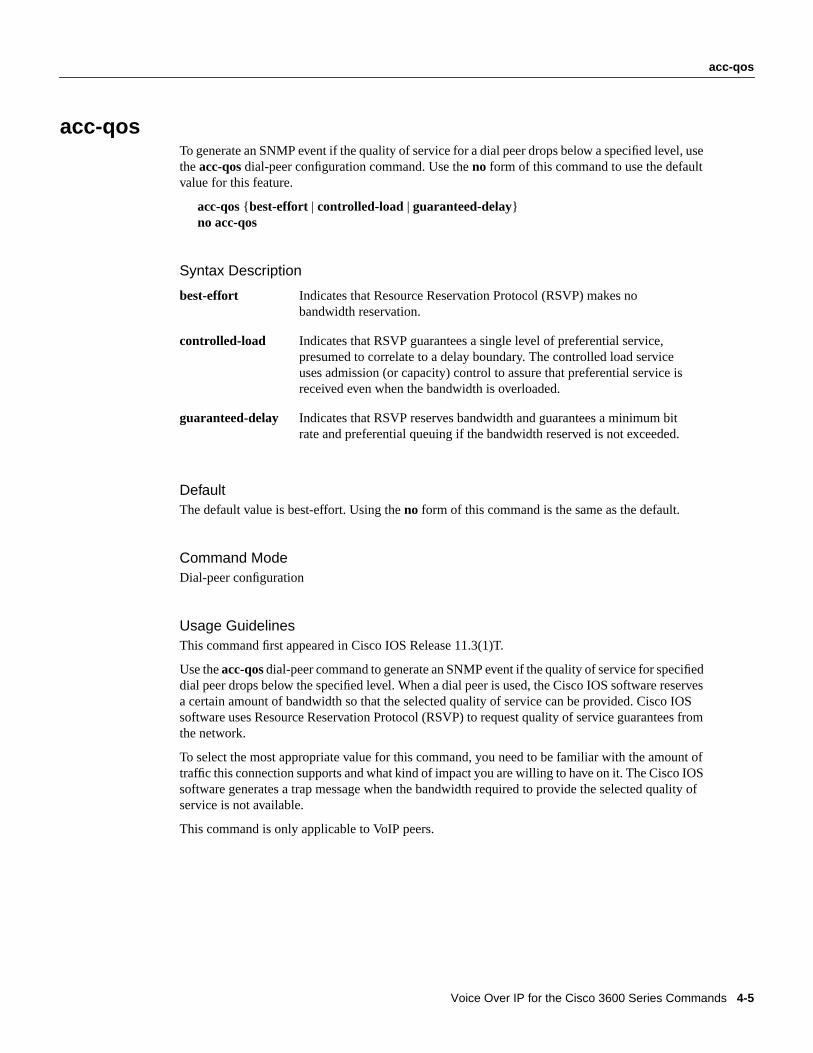
Voice Over IP for the Cisco 3600 Series Commands 4-5
acc-qos
acc-qosTo generate an SNMP event if the quality of service for a dial peer drops below a specified level, usetheacc-qos dial-peer configuration command. Use theno form of this command to use the defaultvalue for this feature.
acc-qos{ best-effort | controlled-load | guaranteed-delay}no acc-qos
Syntax Description
DefaultThe default value is best-effort. Using theno form of this command is the same as the default.
Command ModeDial-peer configuration
Usage GuidelinesThis command first appeared in Cisco IOS Release 11.3(1)T.
Use theacc-qosdial-peer command to generate an SNMP event if the quality of service for specifieddial peer drops below the specified level. When a dial peer is used, the Cisco IOS software reservesa certain amount of bandwidth so that the selected quality of service can be provided. Cisco IOSsoftware uses Resource Reservation Protocol (RSVP) to request quality of service guarantees fromthe network.
To select the most appropriate value for this command, you need to be familiar with the amount oftraffic this connection supports and what kind of impact you are willing to have on it. The Cisco IOSsoftware generates a trap message when the bandwidth required to provide the selected quality ofservice is not available.
This command is only applicable to VoIP peers.
best-effort Indicates that Resource Reservation Protocol (RSVP) makes nobandwidth reservation.
controlled-load Indicates that RSVP guarantees a single level of preferential service,presumed to correlate to a delay boundary. The controlled load serviceuses admission (or capacity) control to assure that preferential service isreceived even when the bandwidth is overloaded.
guaranteed-delay Indicates that RSVP reserves bandwidth and guarantees a minimum bitrate and preferential queuing if the bandwidth reserved is not exceeded.

acc-qos
Voice over IP for the Cisco 3600 Series Software Configuration Guide4-6
ExampleThe following example selects guaranteed-delay as the specified level below which an SNMP trapmessage will be generated:
dial-peer voice 10 voipacc-qos guaranteed-delay
Related CommandsYou can use the master index or search online to find documentation of related commands.
req-qos

Voice Over IP for the Cisco 3600 Series Commands 4-7
answer-address
answer-addressTo specify the full E.164 telephone number to be used to identify the dial peer of an incoming call,use theanswer-address dial-peer configuration command. Use theno form of this command todisable this feature.
answer-address[+]stringno answer-address
Syntax Description
DefaultThe default value is enabled with a null string.
Command ModeDial-peer configuration
Usage GuidelinesThis command first appeared in Cisco IOS Release 11.3(1)T.
Use theanswer-addresscommand to identify the origin (or dial peer) of incoming calls from the IPnetwork. Cisco IOS software identifies the dial peers of a call in one of two ways: either byidentifying the interface through which the call is received or through the telephone numberconfigured with theanswer-address command. In the absence of a configured telephone number,the peer associated with the interface will be associated with the incoming call.
For calls coming in from a POTS interface, theanswer-address command is not used to select anincoming dial peer. The incoming POTS dial peer is selected on the basis of the port configured forthat dial peer.
This command is applicable to both VoIP and POTS dial peers.
Note The Cisco IOS software does not check the validity of the E.164 telephone number; it willaccept any series of digits as a valid number.
string Series of digits that specify the E.164 or private dialing plan telephonenumber. Valid entries are:
• Digits 0 through 9, letters A through D, pound sign (#), and asterisk(*), which represent specific digits that can be entered.
• Plus sign (+), which is optionally used as the first digit to indicate anE.164 standard number.
• Comma (,), which inserts a pause between digits.
• Period (.), which matches any entered digit.
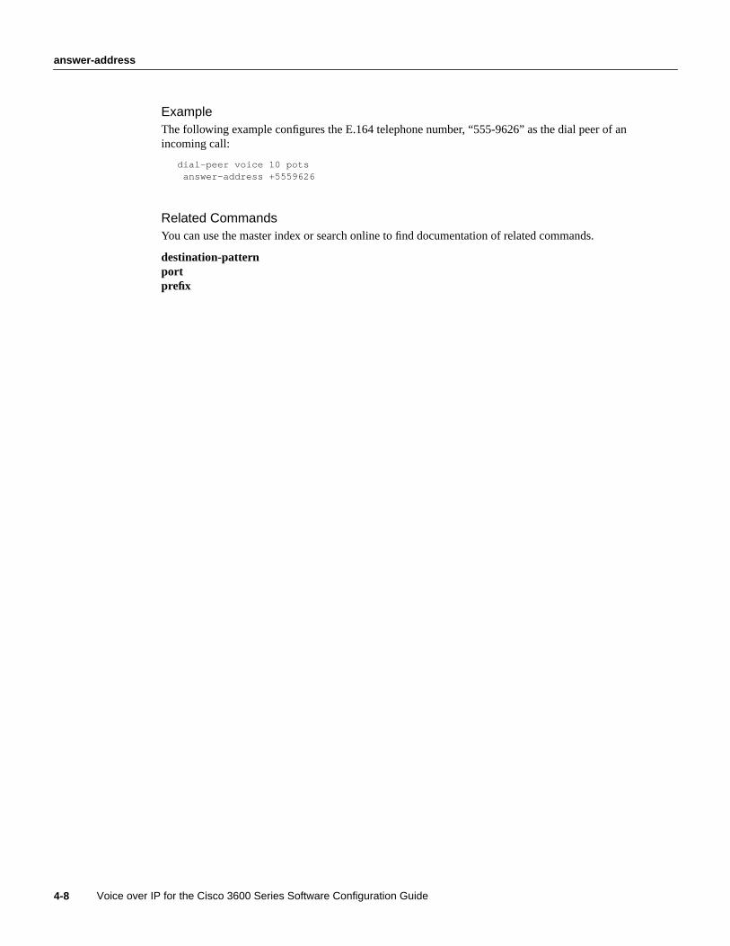
answer-address
Voice over IP for the Cisco 3600 Series Software Configuration Guide4-8
ExampleThe following example configures the E.164 telephone number, “555-9626” as the dial peer of anincoming call:
dial-peer voice 10 potsanswer-address +5559626
Related CommandsYou can use the master index or search online to find documentation of related commands.
destination-patternportprefix

Voice Over IP for the Cisco 3600 Series Commands 4-9
codec
codecTo specify the voice coder rate of speech for a dial peer, use thecodec dial-peer configurationcommand. Use theno form of this command to reset the default value for this command.
codec{ g711alaw | g711ulaw | g729r8}no codec
Syntax Description
DefaultThe default value for this command isg729r8.
Command ModeDial-peer configuration
Usage GuidelinesThis command first appeared in Cisco IOS Release 11.3(1)T.
Use thecodeccommand to define a specific voice coder rate of speech for a dial peer.
For toll quality, useg711alaw or g711ulaw. These values provide high-quality voice transmissionbut use a significant amount of bandwidth. For almost toll quality (and a significant savings inbandwidth), use theg729r8value.
If codec values for the VoIP peers of a connection do not match, the call will fail.
This command is only applicable to VoIP peers.
ExampleThe following example configures a voice coder rate that provides toll quality and uses a relativelyhigh amount of bandwidth:
dial-peer voice 10 voipcodec g711alaw
g711alaw G.711 A-Law 64,000 bits per second (bps).
g711ulaw G.711 u-Law 64,000 bps.
g729r8 G.729 8000 bps.
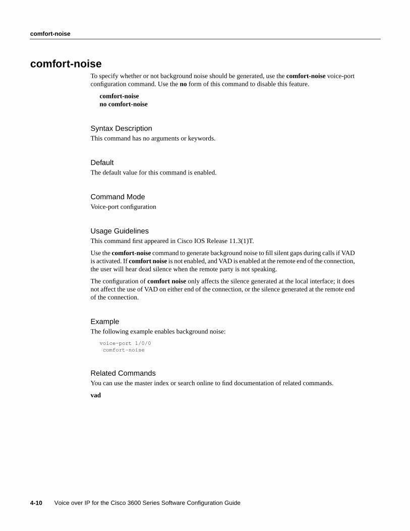
comfort-noise
Voice over IP for the Cisco 3600 Series Software Configuration Guide4-10
comfort-noiseTo specify whether or not background noise should be generated, use thecomfort-noisevoice-portconfiguration command. Use theno form of this command to disable this feature.
comfort-noiseno comfort-noise
Syntax DescriptionThis command has no arguments or keywords.
DefaultThe default value for this command is enabled.
Command ModeVoice-port configuration
Usage GuidelinesThis command first appeared in Cisco IOS Release 11.3(1)T.
Use thecomfort-noisecommand to generate background noise to fill silent gaps during calls if VADis activated. Ifcomfort noiseis not enabled, and VAD is enabled at the remote end of the connection,the user will hear dead silence when the remote party is not speaking.
The configuration ofcomfort noise only affects the silence generated at the local interface; it doesnot affect the use of VAD on either end of the connection, or the silence generated at the remote endof the connection.
ExampleThe following example enables background noise:
voice-port 1/0/0comfort-noise
Related CommandsYou can use the master index or search online to find documentation of related commands.
vad

Voice Over IP for the Cisco 3600 Series Commands 4-11
connection
connectionTo specify a connection mode for a specified voice port, use theconnectionvoice-port configurationcommand. Use theno form of this command to disable the selected connection mode.
connection plarstringno connection plarstring
Syntax Description
DefaultThe default value for this command is no connection.
Command ModeVoice-port configuration
Usage GuidelinesThis command first appeared in Cisco IOS Release 11.3(1)T.
Use theconnectioncommand to specify a connection mode for a specific interface. Use theconnection plarcommand to specify a PLAR interface. The string you configure for this commandis used as the called number for all calls coming in over this voice port. The destination dial peer isdetermined on the basis of this called number.
If the connection command is not configured, the standard session application outputs a dial tonewhen the interface goes off-hook until enough digits are collected to match a dial-peer and completethe call.
ExampleThe following example selects PLAR as the connection mode, with a destination telephone numberof 555-9262:
voice-port 1/0/0connection plar 5559262
Related CommandsYou can use the master index or search online to find documentation of related commands.
session-protocol
plar Specifies a private line auto ringdown (PLAR) connection. PLAR is handled byassociating a peer directly with an interface; when an interface goes off-hook, thepeer is used to set up the second call leg and conference them together without thecaller having to dial any digits.
string Specifies the destination telephone number. Valid entries are any series of digits thatspecify the E.164 telephone number.
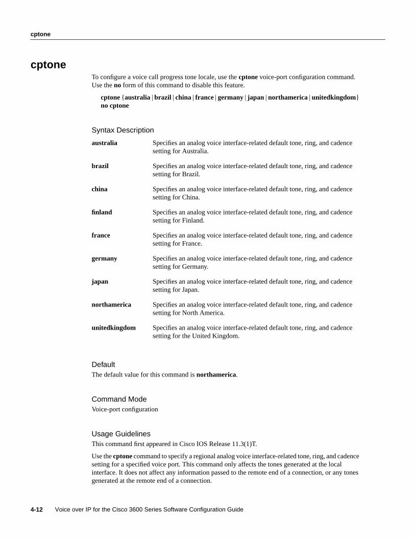
cptone
Voice over IP for the Cisco 3600 Series Software Configuration Guide4-12
cptoneTo configure a voice call progress tone locale, use thecptone voice-port configuration command.Use theno form of this command to disable this feature.
cptone{ australia |brazil | china | france |germany | japan |northamerica | unitedkingdom}no cptone
Syntax Description
DefaultThe default value for this command isnorthamerica.
Command ModeVoice-port configuration
Usage GuidelinesThis command first appeared in Cisco IOS Release 11.3(1)T.
Use thecptonecommand to specify a regional analog voice interface-related tone, ring, and cadencesetting for a specified voice port. This command only affects the tones generated at the localinterface. It does not affect any information passed to the remote end of a connection, or any tonesgenerated at the remote end of a connection.
australia Specifies an analog voice interface-related default tone, ring, and cadencesetting for Australia.
brazil Specifies an analog voice interface-related default tone, ring, and cadencesetting for Brazil.
china Specifies an analog voice interface-related default tone, ring, and cadencesetting for China.
finland Specifies an analog voice interface-related default tone, ring, and cadencesetting for Finland.
france Specifies an analog voice interface-related default tone, ring, and cadencesetting for France.
germany Specifies an analog voice interface-related default tone, ring, and cadencesetting for Germany.
japan Specifies an analog voice interface-related default tone, ring, and cadencesetting for Japan.
northamerica Specifies an analog voice interface-related default tone, ring, and cadencesetting for North America.
unitedkingdom Specifies an analog voice interface-related default tone, ring, and cadencesetting for the United Kingdom.

Voice Over IP for the Cisco 3600 Series Commands 4-13
cptone
ExampleThe following example configures North America as the call progress tone locale:
voice-port 1/0/0cptone northamerica

description
Voice over IP for the Cisco 3600 Series Software Configuration Guide4-14
descriptionTo include a description of what this voice port is connected to, use thedescription voice-portconfiguration command. Use theno form of this command to disable this feature.
description stringno description
Syntax Description
DefaultThe default for this command is enabled with a null string.
Command ModeVoice-port configuration
Usage GuidelinesThis command first appeared in Cisco IOS Release 11.3(1)T.
Use thedescription command to include descriptive text about this voice-port connection. Thisinformation is displayed when you enter a show command and does not affect the operation of theinterface in any way.
ExampleThe following example identifies this voice port as being connected to the Purchasing department:
voice-port 1/0/0description purchasing_dept
string Character string from 1 to 255 characters.

Voice Over IP for the Cisco 3600 Series Commands 4-15
destination-pattern
destination-patternTo specify either the prefix or the full E.164 telephone number (depending on your dial plan) to beused for a dial peer, use thedestination-pattern dial-peer configuration command. Use theno formof this command to disable this feature.
destination-pattern [+]stringno destination-pattern
Syntax Description
DefaultThe default value for this command is enabled with a null string.
Command ModeDial-peer configuration
Usage GuidelinesThis command first appeared in Cisco IOS Release 11.3(1)T.
Use thedestination-pattern command to define the E.164 telephone number for this dial peer. Thispattern is used to match dialed digits to a dial peer. The dial peer is then used to complete the call.
This command is applicable to both VoIP and POTS dial peers.
Note The Cisco IOS software does not check the validity of the E.164 telephone number; it willaccept any series of digits as a valid number.
ExampleThe following example configures the E.164 telephone number, “555-7922,” for a dial peer:
dial-peer voice 10 potsdestination-pattern +5557922
string Series of digits that specify the E.164 or private dialing plan telephonenumber. Valid entries are:
• Digits 0 through 9, letters A through D, pound sign (#), andasterisk (*), which represent specific digits that can be entered.
• Plus sign (+), which is optionally used as the first digit to indicate anE.164 standard number.
• Comma (,), which inserts a pause between digits.
• Period (.), which matches any entered digit.

destination-pattern
Voice over IP for the Cisco 3600 Series Software Configuration Guide4-16
Related CommandsYou can use the master index or search online to find documentation of related commands.
answer-addressprefix

Voice Over IP for the Cisco 3600 Series Commands 4-17
dial-control-mib
dial-control-mibTo specify attributes for the call history table, use thedial-control-mib global configurationcommand.
dial-control-mib { max-sizenumber | retain-timer number}
Syntax Description
DefaultThe default call history table length is 50 table entries. The default retain timer is 15 minutes.
Command ModeGlobal configuration
Usage GuidelinesThis command first appeared in Cisco IOS Release 11.3(1)T.
ExampleThe following example configures the call history table to hold 400 entries, with each entryremaining in the table for 10 minutes:
configure terminaldial-control-mib max-size 400dial-control-mib retain-timer 10
max-sizenumber Specifies the maximum size of the call history table. Valid entries arefrom 0 to 500 table entries. A value of 0 will prevent any history frombeing retained.
retain-timer number Specifies the length of time, in minutes, for entries in the call historytable. Valid entries are from0 to 2147483647 minutes. A value of 0 willprevent any history from being retained.
dial-peer voice
Voice over IP for the Cisco 3600 Series Software Configuration Guide4-18
dial-peer voiceTo enter the dial-peer configuration mode (and specify the method of voice-related encapsulation),use thedial-peer voiceglobal configuration command.
dial-peer voicenumber {voip | pots}
Syntax Description
Command ModeGlobal configuration
Usage GuidelinesThis command first appeared in Cisco IOS Release 11.3(1)T.
Use thedial-peer voiceglobal configuration command to switch to the dial-peer configuration modefrom the global configuration mode. Use theexit command to exit the dial-peer configuration modeand return to the global configuration mode.
ExampleThe following example accesses the dial-peer configuration mode and configures a POTS peeridentified as dial peer 10:
configure terminaldial-peer voice 10 pots
Related CommandsYou can use the master index or search online to find documentation of related commands.
voice-port
number Digit(s) defining a particular dial peer. Valid entries are from 1 to2147483647.
voip Indicates that this is a VoIP peer using voice encapsulation on the POTSnetwork.
pots Indicates that this is a POTS peer using Voice over IP encapsulation onthe IP backbone.
Voice Over IP for the Cisco 3600 Series Commands 4-19
dial-type
dial-typeTo specify the type of out-dialing for voice port interfaces, use thedial-type voice-port configurationcommand. Use theno form of this command to disable this feature.
dial-type { dtmf | pulse}no dial-type
Syntax Description
DefaultThe default value for this command isdtmf .
Command ModeVoice-port configuration
Usage GuidelinesThis command first appeared in Cisco IOS Release 11.3(1)T.
Use thedial-type command to specify an out-dialing type for an FXO or E&M voice port interface;this command is not applicable to FXS voice ports because they do not generate out-dialing. Voiceports can always detect dtmf and pulse signals. This command does not affect voice port dialingdetection.
Thedial-type command affects out-dialing as configured for the dial peer.
ExampleThe following example configures a voice port to support a touch-tone dialer:
voice-port 1/0/0dial-type dtmf
dtmf Specifies a touch-tone dialer.
pulse Specifies a pulse dialer.
echo-cancel coverage
Voice over IP for the Cisco 3600 Series Software Configuration Guide4-20
echo-cancel coverageTo adjust the size of the echo cancel, use theecho-cancel coveragevoice-port configurationcommand. Use theno form of this command to reset this command to the default value.
echo-cancel coveragevalueno echo-cancel coveragevalue
Syntax Description
DefaultThe default value for this command is 16.
Command ModeVoice-port configuration
Usage GuidelinesThis command first appeared in Cisco IOS Release 11.3(1)T.
Use theecho-cancel coveragecommand to adjust the coverage size of the echo canceller. Thiscommand enables cancellation of voice that is sent out the interface and received back on the sameinterface within the configured amount of time. If the local loop (the distance from the analoginterface to the connected equipment producing the echo) is longer, the configured value of thiscommand should be extended.
If you configure a longer value for this command, it will take the echo canceller longer to converge;in this case, the user might hear slight echo when the connection is initially set up. If the configuredvalue for this command is too short, the user might hear some echo for the duration of the callbecause the echo canceller is not cancelling the longer delay echoes.
There is no echo or echo cancellation on the IP side of the connection.
Note This command is valid only if the echo cancel feature has been enabled. For moreinformation, refer to theecho-cancel enable command.
ExampleThe following example adjusts the size of the echo canceller to 16 milliseconds:
voice-port 1/0/0echo-cancel enableecho-cancel coverage 16
value Number of milliseconds the echo-canceller will cover on a given signal. Validvalues are 16, 24, and 32.

Voice Over IP for the Cisco 3600 Series Commands 4-21
echo-cancel coverage
Related CommandsYou can use the master index or search online to find documentation of related commands.
echo-cancel enable
echo-cancel enable
Voice over IP for the Cisco 3600 Series Software Configuration Guide4-22
echo-cancel enableTo enable the echo cancel feature, use theecho-cancel enablevoice-port configuration command.Use theno form of this command to disable this feature.
echo-cancel enableno echo-cancel enable
Syntax DescriptionThis command has no arguments or keywords.
DefaultThe default value for this command is enabled for all interface types.
Command ModeVoice-port configuration
Usage GuidelinesThis command first appeared in Cisco IOS Release 11.3(1)T.
Theecho-cancelcommand enables cancellation of voice that is sent out the interface and is receivedback on the same interface. Disabling echo cancellation might cause the remote side of a connectionto hear an echo. Because echo cancellation is an invasive process that can minimally degrade voicequality, this command should be disabled if it is not needed.
Theecho-cancel command does not affect the echo heard by the user on the analog side of theconnection.
There is no echo path for a 4-wire E&M interface. The echo canceller should be disabled for thatinterface type.
Note This command is valid only if theecho-cancel coveragecommand has been configured. Formore information, refer to theecho-cancel coverage command.
ExampleThe following example enables the echo cancel feature for 16-millisecond echo coverage:
voice-port 1/0/0echo-cancel enableecho-cancel coverage 16
Related CommandsYou can use the master index or search online to find documentation of related commands.
echo-cancel coveragenon-linear

Voice Over IP for the Cisco 3600 Series Commands 4-23
expect-factor
expect-factorTo specify when the router will generate an alarm to the network manager, indicating that theexpected quality of voice has dropped, use theexpect-factordial-peer configuration command. Usetheno form of this command to reset the default value for this command.
expect-factorvalueno expect-factorvalue
Syntax Description
DefaultThe default value for this command is 10.
Command ModeDial-peer configuration
Usage GuidelinesThis command first appeared in Cisco IOS Release 11.3(1)T.
Voice over IP monitors the quality of voice received over the network. Use theexpect-factorcommand to specify when the router will generate an SNMP trap to the network manager.
This command is only applicable to VoIP peers.
ExampleThe following example configures toll quality of voice when connecting to a dial peer:
dial-peer voice 10 voipexpect-factor 0
value Integers that represent the ITU specification for quality of voice asdescribed in G.113. Valid entries are from 0 to 20, with 0 representingtoll quality.

fax-rate
Voice over IP for the Cisco 3600 Series Software Configuration Guide4-24
fax-rateTo establish the rate at which a fax will be sent to the specified dial peer, use thefax-rate dial-peerconfiguration command. Use theno form of this command to reset the default value for thiscommand.
fax-rate{ 2400 | 4800 | 7200 | 9600 | 14400 | disable | voice}no fax-rate
Syntax Description
DefaultThe default value for this command isvoice.
Command ModeDial-peer configuration
Usage GuidelinesThis command first appeared in Cisco IOS Release 11.3(1)T.
Use thefax-rate command to specify the fax transmission rate to the specified dial peer.
The values for this command apply only to the fax transmission speed and do not affect the qualityof the fax itself. The higher values provide a faster transmission speed but monopolize a significantlylarger portion of the available bandwidth. Slower transmission speeds use less bandwidth.
If the fax-rate command is set above the CODEC value in the same dial peer, the data sent over thenetwork for fax transmission will be above the bandwidth reserved for RVSP. Because more networkbandwidth will be monopolized by the fax transmission, we do not recommend setting thefax-ratevalue higher than thecodecvalue. If thefax-rate value is set lower than thecodecvalue, faxes willtake longer to transmit but will use less bandwidth.
This command is only applicable to VoIP peers.
2400 Specifies a fax transmission speed of 2400 bits per second (bps).
4800 Specifies a fax transmission speed of 4800 bps.
7200 Specifies a fax transmission speed of 7200 bps.
9600 Specifies a fax transmission speed of 9600 bps.
14400 Specifies a fax transmission speed of 14,400 bps.
disable Disables fax relay transmission capability.
voice Specifies the highest possible transmission speed allowed by voice rate.

Voice Over IP for the Cisco 3600 Series Commands 4-25
fax-rate
ExampleThe following example configures a facsimile rate of 9600 bps for faxes sent to a dial peer:
dial-peer voice 10 voipfax-rate 9600
Related CommandsYou can use the master index or search online to find documentation of related commands.
codec

icpif
Voice over IP for the Cisco 3600 Series Software Configuration Guide4-26
icpifTo specify the Calculated Planning Impairment Factor (ICPIF) for calls sent by a dial peer, use theicpif dial-peer configuration command. Use theno form of this command to restore the default valuefor this command.
icpif numberno icpif number
Syntax Description
DefaultThe default value for this command is 30.
Command ModeDial-peer configuration
Usage GuidelinesThis command first appeared in Cisco IOS Release 11.3(1)T.
Use theicpif command to specify the maximum acceptable impairment factor for the voice calls sentby the selected dial peer.
This command is applicable only to VoIP peers.
ExampleThe following example disables the icpif command:
dial-peer voice 10 voipicpif 0
number Integer, expressed in equipment impairment factor units, specifying theICPIF value. Valid entries are 0 to 55.

Voice Over IP for the Cisco 3600 Series Commands 4-27
impedance
impedanceTo specify the terminating impedance of a voice port interface, use theimpedance voice-portconfiguration command. Use theno form of this command to restore the default value.
impedance{ 600c | 600r | 900c | complex1 | complex2}no impedance
Syntax Description
DefaultThe default value for this command is 600.
Command ModeVoice-port configuration
Usage GuidelinesThis command first appeared in Cisco IOS Release 11.3(1)T.
Use theimpedancecommand to specify the terminating impedance of an FXO voice-port interface.The impedance value selected needs to match the specifications from the specific telephony systemto which it is connected. Different countries often have different standards for impedance. COswitches in the United States are predominantly 600r. PBXes in the United States are normally either600r or 900c.
If the impedance is set incorrectly (if there is an impedance mismatch), there will be a significantamount of echo generated (which could be masked if theecho-cancelcommand has been enabled).In addition, gains might not work correctly if there is an impedance mismatch.
Configuring the impedance on a voice port will change the impedance on both voice ports of a VNMcard. This voice port must be shut down and then opened for the new value to take effect.
This command is applicable to FXS, FXO, and E&M voice ports.
ExampleThe following example configures an FXO voice port for a terminating impedance of 600 Ohms:
impedance 600r
600c Specifies 600 Ohms complex.
600r Specifies 600 Ohms real.
900c Specifies 900 Ohms complex.
complex1 Specifies Complex 1.
complex2 Specifies Complex 2.

input gain
Voice over IP for the Cisco 3600 Series Software Configuration Guide4-28
input gainTo configure a specific input gain value, use theinput gain voice-port configuration command. Usetheno form of this command to disable this feature.
input gain valueno input gain value
Syntax Description
DefaultThe default value for FXO, FXS, and E&M ports is 0.
Command ModeVoice-port configuration
Usage GuidelinesThis command first appeared in Cisco IOS Release 11.3(1)T.
A system-wide loss plan must be implemented using both input gain andoutput attenuationcommands. Other equipment (including PBXes) in the system must be taken into account whencreating a loss plan. This default value for this command assumes that a standard transmission lossplan is in effect, meaning that normally, there must be -6 dB attenuation between phones.Connections are implemented to provide -6 dB of attenuation when theinput gain andoutputattenuation commands are configured with the default value of 0.
Please note that you can’t increase the gain of a signal going out into the PSTN, but you can decreaseit. Therefore, if the voice level is too high, you can decrease the volume by either decreasing the inputgain value or by increasing the output attenuation.
You can increase the gain of a signal coming in to the router. If the voice level is too low, you canincrease the input gain.
ExampleThe following example configures a 3-decibel gain to be inserted at the receiver side of the interface:
input gain 3
Related CommandsYou can use the master index or search online to find documentation of related commands.
output attenuation
value Specifies, in decibels, the amount of gain to be inserted at the receiverside of the interface. Acceptable value is any integer from -6 to 14.

Voice Over IP for the Cisco 3600 Series Commands 4-29
ip precedence
ip precedenceTo set IP precedence (priority) for packets sent by the dial peer, use theip precedencedial-peerconfiguration command. Use theno form of this command to restore the default value for thiscommand.
ip precedencenumberno ip precedence
Syntax Description
DefaultThe default value for this command is 0.
Command ModeDial-peer configuration
Usage GuidelinesThis command first appeared in Cisco IOS Release 11.3(1)T.
Use theip precedencecommand to configure the value set in the IP precedence field when voicedata packets are sent over the IP network. This command should be used if the IP link utilization ishigh and the QoS for voice packets need to have a higher priority than other IP packets. Theipprecedence command should also be used if RSVP is not enabled, and the user would like to givevoice packets a higher priority over other IP data traffic.
This command is applicable to VoIP peers.
ExampleThe following example sets the IP precedence at 5:
dial-peer voice 10 voipip precedence 5
number Integer specifying the IP precedence value. Valid entries are 0 to 7. Avalue of 0 means that no precedence (priority) has been set.

ip udp checksum
Voice over IP for the Cisco 3600 Series Software Configuration Guide4-30
ip udp checksumTo calculate the UDP checksum for voice packets transmitted by the dial peer, use theip udpchecksumdial-peer configuration command. Use theno form of this command to disable thisfeature.
ip udp checksumno ip udp checksum
Syntax DescriptionThis command has no arguments or keywords.
DefaultThe default value for this command is disabled.
Command ModeDial-peer configuration
Usage GuidelinesThis command first appeared in Cisco IOS Release 11.3(1)T.
Use theip udp checksumcommand to enable UDP checksum calculation for each of the outboundvoice packets. This command is disabled by default to speed up the transmission of the voicepackets. If you suspect that the connection has a high error rate, you should enableip udp checksumto prevent bad voice packets forwarded to the DSP.
This command is applicable to VoIP peers.
ExampleThe following example calculates the UDP checksum for voice packets transmitted by this dial peer:
dial-peer voice 10 voipip udp checksum

Voice Over IP for the Cisco 3600 Series Commands 4-31
music-threshold
music-thresholdTo specify the threshold for on-hold music for a specified voice port, use themusic-thresholdvoice-port configuration command. Use theno form of this command to disable this feature.
music-thresholdnumberno music-thresholdnumber
Syntax Description
DefaultThe default value for this command is -38.
Command ModeVoice-port configuration
Usage GuidelinesThis command first appeared in Cisco IOS Release 11.3(1)T.
Use themusic-thresholdcommand to specify the decibel level of music played when calls are puton hold. This command tells the firmware to pass steady data above the specified level. It only affectsthe operation of VAD when receiving voice.
If the value for this command is set too high, VAD will interpret music-on-hold as silence, and theremote end will not hear the music. If the value for this command is set too low, VAD will compressand pass silence when the background is noisy, creating unnecessary voice traffic.
ExampleThe following sets the decibel threshold to -35 for the music played when calls are put on hold:
voice port 1/0/0music-threshold -35
number Specifies the on-hold music threshold in decibels. Valid entries are anyinteger from -70 to -30.

non-linear
Voice over IP for the Cisco 3600 Series Software Configuration Guide4-32
non-linearTo enable non-linear processing in the echo canceller, use thenon-linear voice-port configurationcommand. Use theno form of this command to disable this feature.
non-linearno non-linear
Syntax DescriptionThis command has no arguments or keywords.
DefaultThe default for this command is enabled for all voice-port types.
Command ModeVoice-port configuration
Usage GuidelinesThis command first appeared in Cisco IOS Release 11.3(1)T.
This command is associated with the echo canceller operation. Theecho-cancel enable commandmust be enabled for thenon-linear command to take effect. Use the non-linear command to shutoff any signal if no near-end speech is detected.
Enabling thenon-linear command normally improves performance, although some users mightperceive truncation of consonants at the end of sentences when this command is enabled.
This feature is also generally known as residual echo suppression.
ExampleThe following example enables non-linear call processing:
voice-port 1/0/0non-linear
Related CommandsYou can use the master index or search online to find documentation of related commands.
echo-cancel enable

Voice Over IP for the Cisco 3600 Series Commands 4-33
num-exp
num-expTo define how to expand an extension number into a particular destination pattern, use thenum-expglobal configuration command.
num-expextension-number expanded-number
Syntax Description
Command ModeGlobal configuration
Usage GuidelinesThis command first appeared in Cisco IOS Release 11.3(1)T.
Use thenum-expglobal configuration command to define how to expand a particular set of numbers(for example, an extension number) into a particular destination pattern. With this command, youcan map specific extensions and expanded numbers together by explicitly defining each number, oryou can define extensions and expanded numbers using variables. You can also use this command toconvert 7-digit numbers to numbers containing less than 7 digits.
Use a period (.) as a variable or wild card, representing a single number. Use a separate period foreach number you want to represent with a wildcard—meaning that if you want to replace 4 numbersin an extension with wildcards, type in 4 periods.
ExamplesThe following example expands the extension number 55541 to be expanded to 14085555541:
num-exp 65541 14085555541
The following example shows how to expand all 5-digit extensions beginning with 5 to append thefollowing numbers at the beginning of the extension number 1408555:
num-exp 5.... 1408555....
extension-number Digit(s) defining an extension number for a particular dial peer.
expanded-number Digit(s) defining the expanded telephone number or destination patternfor the extension number listed.
operation
Voice over IP for the Cisco 3600 Series Software Configuration Guide4-34
operationTo select a specific cabling scheme for E&M ports, use theoperation voice-port configurationcommand. Use theno form of this command as an alternative method of configuring 2-wireoperation.
operation { 2-wire | 4-wire}no operation { 2-wire | 4-wire}
Syntax Description
Default2-wire operation
Command ModeVoice-port configuration
Usage GuidelinesThis command first appeared in Cisco IOS Release 11.3(1)T.
Theoperation command will only affect voice traffic. Signaling is independent of 2-wire versus4-wire settings. If the wrong cable scheme is specified, the user might get voice traffic in only onedirection.
Configuring theoperation command on a voice port changes the operation of both voice ports on aVPM card. The voice port must be shut down and then opened again for the new value to take effect.
This command is not applicable to FXS or FXO interfaces because those are, by definition, two-wireinterfaces.
ExampleThe following example specifies that an E&M port uses a 4-wire cabling scheme:
voice-port 1/0/0operation 4-wire
2-wire Specifies a 2-wire E&M cabling scheme.
4-wire Specifies a 4-wire E&M cabling scheme.
Voice Over IP for the Cisco 3600 Series Commands 4-35
output attenuation
output attenuationTo configure a specific output attenuation value, use theoutput attenuation voice-portconfiguration command. Use theno form of this command to disable this feature.
output attenuation valueno output attenuation
Syntax Description
DefaultThe default value for FXO, FXS, and E&M ports is 0.
Command ModeVoice-port configuration
Usage GuidelinesThis command first appeared in Cisco IOS Release 11.3(1)T.
A system-wide loss plan must be implemented using both input gain andoutput attenuationcommands. Other equipment (including PBXes) in the system must be taken into account whencreating a loss plan. This default value for this command assumes that a standard transmission lossplan is in effect, meaning that normally, there must be -6 dB attenuation between phones.Connections are implemented to provide -6 dB of attenuation when theinput gain andoutputattenuation commands are configured with the default value of 0.
Please note that you can’t increase the gain of a signal going out into the PSTN, but you can decreaseit. Therefore, if the voice level is too high, you can decrease the volume by either decreasing the inputgain value or by increasing the output attenuation.
ExampleThe following example configures a 3-decibel gain to be inserted at the transmit side of the interface:
voice-port 1/0/0output attenuation 3
Related CommandsYou can use the master index or search online to find documentation of related commands.
input gain
value Specifies, in decibels, the amount of attenuation at the transmit side ofthe interface. Acceptable value is any integer from 0 to 14. The defaultvalue for FXO, FXS, and E&M ports is 0.
port
Voice over IP for the Cisco 3600 Series Software Configuration Guide4-36
portTo associate a dial peer with a specific voice-port, use theport dial-peer configuration command.Use theno form of this command to cancel this association.
port slot-number/subunit-number/portno port
Syntax Description
DefaultNo port is configured.
Command ModeDial-peer configuration
Usage GuidelinesThis command first appeared in Cisco IOS Release 11.3(1)T.
Use theport configuration command to associate the designated voice port with the selected dialpeer.
This command is used for calls incoming from a telephony interface to select an incoming dial peerand for calls coming from the VoIP network to match a port with the selected outgoing dial peer.
This command is applicable only to POTS peers.
ExampleThe following example associates a dial peer with voice port 1, which is located on subunit 0, andaccessed through port 0:
dial-peer voice 10 potsport 1/0/0
slot-number/ Specifies the slot number in the Cisco router where the voice interfacecard is installed. Valid entries are from 0 to 3, depending on the slotwhere it has been installed.
subunit-number/ Specifies the subunit on the voice interface card where the voice port islocated. Valid entries are 0 or 1.
port Specifies the voice port. Valid entries are 0 or 1.

Voice Over IP for the Cisco 3600 Series Commands 4-37
prefix
prefixTo specify the prefix of the dialed digits for this dial peer, use theprefix dial-peer configurationcommand. Use theno form of this command to disable this feature.
prefix stringno prefix
Syntax Description
DefaultThe default for this command is a null string.
Command ModeDial-peer configuration
Usage GuidelinesThis command first appeared in Cisco IOS Release 11.3(1)T.
Use theprefix command to specify a prefix for a specific dial peer. When an outgoing call is initiatedto this dial peer, theprefix string value is sent to the telephony interface first, before the telephonenumber associated with the dial peer.
If you want to configure different prefixes for dialed numbers on the same interface, you need toconfigure different dial peers.
This command is applicable only to POTS peers.
ExampleThe following example specifies a prefix of “9” and then a pause:
dial-peer voice 10 potsprefix 9,
Related CommandsYou can use the master index or search online to find documentation of related commands.
answer-addressdestination-pattern
string Integers representing the prefix of the telephone number associated withthe specified dial peer. Valid numbers are0 through9, and a comma (,).Use a comma to include a pause in the prefix.
req-qos
Voice over IP for the Cisco 3600 Series Software Configuration Guide4-38
req-qosTo specify the desired quality of service to be used in reaching a specified dial peer, use thereq-qosdial-peer configuration command. Use theno form of this command to restore the default value forthis command.
req-qos{ best-effort | controlled-load | guaranteed-delay}no req-qos
Syntax Description
DefaultThe default value for this command is best-effort. Theno form of this command restores the defaultvalue.
Command ModeDial-peer configuration
Usage GuidelinesThis command first appeared in Cisco IOS Release 11.3(1)T.
Use thereq-qoscommand to request a specific quality of service to be used in reaching a dial peer.Like acc-qos, when you enter this command, the Cisco IOS software reserves a certain amount ofbandwidth so that the selected quality of service can be provided. Cisco IOS software uses ResourceReservation Protocol (RSVP) to request quality of service guarantees from the network.
This command is applicable only to VoIP peers.
ExampleThe following example configures guaranteed-delay as the desired (requested) quality of service toa dial peer:
dial-peer voice 10 voipreq-qos guaranteed-delay
Related CommandsYou can use the master index or search online to find documentation of related commands.
acc-qos
best-effort Indicates that Resource Reservation Protocol (RSVP) makes nobandwidth reservation.
controlled-load Indicates that RSVP guarantees a single level of preferential service,presumed to correlate to a delay boundary. The controlled load serviceuses admission (or capacity) control to assure that preferential service isreceived even when the bandwidth is overloaded.
guaranteed-delay Indicates that RSVP reserves bandwidth and guarantees a minimum bitrate and preferential queuing if the bandwidth reserved is not exceeded.
Voice Over IP for the Cisco 3600 Series Commands 4-39
ring frequency
ring frequencyTo specify the ring frequency for a specified FXS voice port, use thering frequency voice-portconfiguration command. Use theno form of this command to reset the default value for thiscommand.
ring frequency numberno ring frequency
Syntax Description
DefaultThe default value for this command is 25 Hertz.
Command ModeVoice-port configuration
Usage GuidelinesThis command first appeared in Cisco IOS Release 11.3(1)T.
Use thering frequency command to select a specific ring frequency for an FXS voice port. Use theno form of this command to reset the default value for this command, which is25 Hertz. The ringfrequency you select must match the connected equipment. If set incorrectly, the attached phonemight not ring or might buzz. In addition, the ring frequency is usually country-dependent and youshould take into account the appropriate ring frequency for your area before configuring thiscommand.
This command does not affect ringback, which is the ringing a user hears when placing a remote call.
ExampleThe following example configures the ring frequency for 50 Hertz:
voice-port 1/0/0ring frequency 50
Related CommandsYou can use the master index or search online to find documentation of related commands.
ring number
number Specifies the ring frequency (Hertz) used in the FXS interface. Validentries are 25 and 50.

ring number
Voice over IP for the Cisco 3600 Series Software Configuration Guide4-40
ring numberTo specify the number of rings for a specified FXO voice port, use thering number voice-portconfiguration command. Use theno form of this command to reset the default value for thiscommand.
ring number numberno ring number number
Syntax Description
DefaultThe default value is 1 ring.
Command ModeVoice-port configuration
Usage GuidelinesThis command first appeared in Cisco IOS Release 11.3(1)T.
Use thering number command to set the maximum number of rings to be detected beforeanswering a call over an FXO voice port. Use theno form of this command to reset the default value,which is1 ring.
Normally, this command should be set to the default so that incoming calls are answered quickly. Ifyou have other equipment available on the line to answer incoming calls, you might want to set thevalue higher to give the equipment sufficient time to respond. In that case, the FXO interface wouldanswer if the equipment online did not answer the incoming call in the configured number of rings.
This command is not applicable to FXS or E&M interfaces because they do not receive ringing toreceive a call.
ExampleThe following example sets 5 rings as the maximum number of rings to be detected before closinga connection over this voice port:
voice port 1/0/0ring number 5
Related CommandsYou can use the master index or search online to find documentation of related commands.
ring frequency
number Specifies the number of rings detected before answering the call. Validentries are numbers from 1 to 10.

Voice Over IP for the Cisco 3600 Series Commands 4-41
session protocol
session protocolTo establish a session protocol for calls between the local and remote routers via the packet network,use thesession protocoldial-peer configuration command. Use theno form of this command to resetthe default value for this command.
session protocol ciscono session protocol
Syntax Description
DefaultThe default value for this command iscisco.
Command ModeDial-peer configuration
Usage GuidelinesThis command first appeared in Cisco IOS Release 11.3(1)T.
For this release, Cisco Session Protocol (cisco) is the only applicable session protocol. Thiscommand is applicable only to VoIP peers.
ExampleThe following example selects Cisco Session Protocol as the session protocol:
dial-peer voice 10 voipsession protocol cisco
Related CommandsYou can use the master index or search online to find documentation of related commands.
session target
cisco Specifies Cisco Session Protocol.

session target
Voice over IP for the Cisco 3600 Series Software Configuration Guide4-42
session targetTo specify a network-specific address for a specified dial peer, use thesession target dial-peerconfiguration command. Use theno form of this command to disable this feature.
session target{ ipv4:destination-address | dns:[$s$. | $d$. | $u$.] host-name | loopback:rtp |loopback:compressed | loopback:uncompressed}
no session target
Syntax Description
DefaultThe default for this command is enabled with no IP address or domain name defined.
Command ModeDial-peer configuration
Usage GuidelinesThis command first appeared in Cisco IOS Release 11.3(1)T.
Use thesession targetcommand to specify a network-specific address or domain name for a dialpeer. Whether you select a network-specific address or a domain name depends on the sessionprotocol you select.
ipv4:destination-address IP address of the dial peer.
dns:host-name Indicates that the domain name server will be used to resolve the name ofthe IP address. Valid entries for this parameter are charactersrepresenting the name of the host device.
(Optional) You can use 1 of the following 3 wildcards with this keywordwhen defining the session target for VoIP peers:
• $s$.—Indicates that the source destination pattern will be used as partof the domain name.
• $d$.—Indicates that the destination number will be used as part of thedomain name.
• $u$.—Indicates that the unmatched portion of the destination pattern(such as a defined extension number) will be used as part of thedomain name.
loopback:rtp Indicates that all voice data will be looped-back to the originating source.This is applicable for VoIP peers.
loopback:compressed Indicates that all voice data will be looped-back in compressed mode tothe originating source. This is applicable for POTS peers.
loopback:uncompressed Indicates that all voice data will be looped-back in uncompressed modeto the originating source. This is applicable for POTS peers.

Voice Over IP for the Cisco 3600 Series Commands 4-43
session target
Thesession target loopbackcommand is used for testing the voice transmission path of a call. Theloopback point will depend on the call origination and the loopback type selected.
Thesession target dns command can be used with or without the specified wildcards. Using theoptional wildcards can reduce the number of VoIP dial-peer session targets you need to configure ifyou have groups of numbers associated with a particular router.
ExampleThe following example configures a session target using dns for a host, “voice_router,” in the domain“cisco.com”:
dial-peer voice 10 voipsession target dns:voice_router.cisco.com
The following example configures a session target using dns, with the optional $u$. wildcard. In thisexample, the destination pattern has been configured to allow for any four-digit extension, beginningwith the numbers 1310555. The optional wildcard$u$. indicates that the router will use theunmatched portion of the dialed number—in this case, the four-digit extension, to identify the dialpeer. As in the previous example, the domain is “cisco.com.”
dial-peer voice 10 voipdestination-pattern 1310555....session target dns:$u$.cisco.com
The following example configures a session target using dns, with the optional$d$.wildcard. In thisexample, the destination pattern has been configured for 13105551111. The optional wildcard $d$.indicates that the router will use the destination pattern to identify the dial peer in the “cisco.com”domain.
dial-peer voice 10 voipdestination-pattern 13105551111session target dns:$d$.cisco.com
Related CommandsYou can use the master index or search online to find documentation of related commands.
destination-patternsession protocol
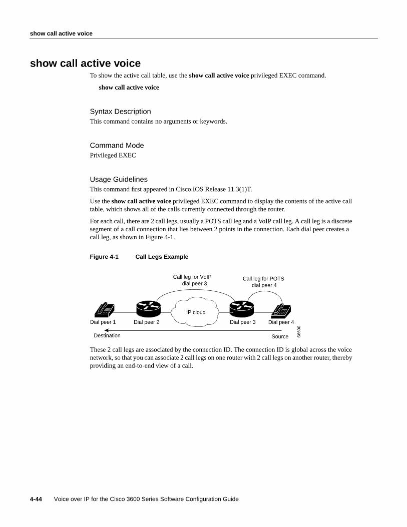
show call active voice
Voice over IP for the Cisco 3600 Series Software Configuration Guide4-44
show call active voiceTo show the active call table, use theshow call active voiceprivileged EXEC command.
show call active voice
Syntax DescriptionThis command contains no arguments or keywords.
Command ModePrivileged EXEC
Usage GuidelinesThis command first appeared in Cisco IOS Release 11.3(1)T.
Use theshow call active voiceprivileged EXEC command to display the contents of the active calltable, which shows all of the calls currently connected through the router.
For each call, there are 2 call legs, usually a POTS call leg and a VoIP call leg. A call leg is a discretesegment of a call connection that lies between 2 points in the connection. Each dial peer creates acall leg, as shown in Figure 4-1.
Figure 4-1 Call Legs Example
These 2 call legs are associated by the connection ID. The connection ID is global across the voicenetwork, so that you can associate 2 call legs on one router with 2 call legs on another router, therebyproviding an end-to-end view of a call.
S6
69
0
Dial peer 4Dial peer 2Dial peer 1 Dial peer 3
Destination Source
IP cloud
Call leg for POTS dial peer 4
Call leg for VoIP dial peer 3

Voice Over IP for the Cisco 3600 Series Commands 4-45
show call active voice
Sample DisplayThe following is sample output from theshow call active voicecommand:
sloth# show call active voiceGENERIC: SetupTime=21072 Index=0 PeerAddress= PeerSubAddress= PeerId=0PeerIfIndex=0 LogicalIfIndex=0 ConnectTime=0 CallState=3 CallOrigin=2 ChargedUnits=0InfoType=0 TransmitPackets=375413 TransmitBytes=7508260 ReceivePackets=377734ReceiveBytes=7554680
VOIP: ConnectionId[0x19BDF910 0xAF500007 0x0 0x58ED0] RemoteIPAddress=17635075RemoteUDPPort=16394 RoundTripDelay=0 SelectedQoS=0 SessionProtocol=1SessionTarget= OnTimeRvPlayout=0 GapFillWithSilence=0 GapFillWithPrediction=600GapFillWithInterpolation=0 GapFillWithRedundancy=0 HiWaterPlayoutDelay=110LoWaterPlayoutDelay=64 ReceiveDelay=94 VADEnable=0 CoderTypeRate=0
GENERIC: SetupTime=21072 Index=1 PeerAddress=+14085271001 PeerSubAddress=PeerId=0 PeerIfIndex=0 LogicalIfIndex=5 ConnectTime=21115 CallState=4 CallOrigin=1ChargedUnits=0 InfoType=1 TransmitPackets=377915 TransmitBytes=7558300ReceivePackets=375594 ReceiveBytes=7511880
TELE: ConnectionId=[0x19BDF910 0xAF500007 0x0 0x58ED0] TxDuration=16640VoiceTxDuration=16640 FaxTxDuration=0 CoderTypeRate=0 NoiseLevel=0 ACOMLevel=4OutSignalLevel=-440 InSignalLevel=-440 InfoActivity=2 ERLLevel=227SessionTarget=
Table 4-3 provides an alphabetical listing of the fields in this output and a description of each field.
Table 4-3 Show Call Active Voice Field Descriptions
Field Description
ACOM Level Current ACOM level for the call. This value is sum of the Echo Return Loss, EchoReturn Loss Enhancement, and nonlinear processing loss for the call.
CallOrigin Call origin; answer versus originate.
CallState Current state of the call.
CoderTypeRate Negotiated coder transmit rate of voice/fax compression during the call.
ConnectionId Global call identifier of a gateway call.
ConnectTime Time at which the call was connected.
Dial-Peer Tag of the dial peer transmitting this call.
ERLLevel Current Echo Return Loss (ERL) level for this call.
FaxTxDuration Duration of fax transmission from this peer to voice gateway for this call. You canderive the Fax Utilization Rate by dividing the FaxTxDuration value by theTxDuration value.
GapFillWith Silence Duration of voice signal replaced with silence because voice data was lost or notreceived on time for this call.
GapFillWithPrediction Duration of voice signal played out with signal synthesized from parameters orsamples of data preceding in time because voice data was lost or not received in timefrom the voice gateway for this call. An example of such pullout is frame-eraser orframe-concealment strategies in G.729 and G.723.1 compression algorithms.
GapFillWithInterpolation Duration of voice signal played out with signal synthesized from parameters orsamples of data preceding and following in time because voice data was lost or notreceived on time from voice gateway for this call.

show call active voice
Voice over IP for the Cisco 3600 Series Software Configuration Guide4-46
GapFillWith Redundancy Duration of voice signal played out with signal synthesized from redundancyparameters available because voice data was lost or not received on time from voicegateway for this call.
HiWaterPlayoutDelay High water mark Voice Playout FIFO Delay during this call.
Index Dial-peer identification number.
InfoActivity Active information transfer activity state for this call.
InfoType Information type for this call.
InSignalLevel Active input signal level from the telephony interface used by this call.
LogicalIfIndex Index number of the logical interface for this call.
LoWaterPlayoutDelay Low water mark Voice Playout FIFO Delay during the call.
NoiseLevel Active noise level for the call.
OnTimeRvPlayout Duration of voice playout from data received on time for this call. You can derive theTotal Voice Playout Duration for Active Voice by adding the OnTimeRvPlayoutvalue to the GapFill values.
OutSignalLevel Active output signal level to telephony interface used by this call.
PeerAddress Destination pattern associated with this peer.
PeerId ID value of the peer table entry to which this call was made.
PeerIfIndex Voice-port index number for this peer.
PeerSubaddress Subaddress to which this call is connected.
ReceiveBytes Number of bytes received by the peer during this call.
ReceiveDelay Average Playout FIFO Delay plus the decoder delay during the voice call.
ReceivePackets Number of packets received by this peer during this call.
RemoteIPAddress Remote system IP address for the VoIP call.
RemoteUDPPort Remote system UDP listener port to which voice packets are transmitted.
RoundTripDelay Voice packet round trip delay between the local and remote system on the IPbackbone during the call.
SelectedQoS Selected RSVP quality of service (QoS) for the call.
SessionProtocol Session protocol used for an Internet call between the local and remote router via theIP backbone.
SessionTarget Session target of the peer used for the call.
SetupTime Value of the System UpTime when the call associated with this entry was started.
TransmitBytes Number of bytes transmitted from this peer during the call.
TransmitPackets Number of packets transmitted from this peer during the call.
TxDuration Duration of transmit path open from this peer to the voice gateway for the call.
VADEnable Whether or not voice activation detection (VAD) was enabled for this call.
VoiceTxDuration Duration of voice transmission from this peer to voice gateway for this call. You canderive the Voice Utilization Rate by dividing the VoiceTxDuration value by theTxDuration value.
Table 4-3 Show Call Active Voice Field Descriptions (continued)
Field Description

Voice Over IP for the Cisco 3600 Series Commands 4-47
show call active voice
Related CommandsYou can use the master index or search online to find documentation of related commands.
show call history voiceshow dial-peer voiceshow num-expshow voice port

show call history voice
Voice over IP for the Cisco 3600 Series Software Configuration Guide4-48
show call history voiceTo display the call history table, use theshow call history voiceprivileged EXEC command.
show call history voice lastnumber
Syntax Description
Command ModePrivileged EXEC
Usage GuidelinesThis command first appeared in Cisco IOS Release 11.3(1)T.
Use theshow call history voiceprivileged EXEC command to display the call history table. Thecall history table contains a listing of all calls connected through this router in descending time ordersince Voice over IP was enabled. You can display subsets of the call history table by using specifickeywords. To display the last calls connected through this router, use the keywordlast, and definethe number of calls to be displayed with the argumentnumber.
Sample DisplayThe following is sample output from theshow call history voice command:
sloth# show call history voiceGENERIC: SetupTime=20405 Index=0 PeerAddress= PeerSubAddress= PeerId=0PeerIfIndex=0 LogicalIfIndex=0 DisconnectCause=NORMAL DisconnectText= ConnectTime=0DisconectTime=20595 CallOrigin=2 ChargedUnits=0 InfoType=0 TransmitPackets=0TransmitBytes=0 ReceivePackets=0 ReceiveBytes=0
VOIP: ConnectionId[0x19BDF910 0xAF500006 0x0 0x56590] RemoteIPAddress=17635075RemoteUDPPort=16392 RoundTripDelay=0 SelectedQoS=0 SessionProtocol=1SessionTarget= OnTimeRvPlayout=0 GapFillWithSilence=0 GapFillWithPrediction=0GapFillWithInterpolation=0 GapFillWithRedundancy=0 HiWaterPlayoutDelay=0LoWaterPlayoutDelay=0 ReceiveDelay=0 VADEnable=0 CoderTypeRate=0
TELE: ConnectionId=[0x19BDF910 0xAF500006 0x0 0x56590] TxDuration=3030VoiceTxDuration=2700 FaxTxDuration=0 CoderTypeRate=0 NoiseLevel=0 ACOMLevel=0SessionTarget=
last number Displays the last calls connected, where the number of calls displayed isdefined by the argumentnumber. A valid entry for the argument numberis any number from 1 to 2147483647.

Voice Over IP for the Cisco 3600 Series Commands 4-49
show call history voice
Table 4-4 provides an alphabetical listing of the fields in this output and a description of each field.
Table 4-4 Show Call History Voice Field Descriptions
Field Description
ACOMLevel Average ACOM level for this call. This value is the sum of the Echo Return Loss,Echo Return Loss Enhancement, and nonlinear processing loss for the call.
CallOrigin Call origin; answer versus originate.
CoderTypeRate Negotiated coder rate. This value specifies the transmit rate of voice/fax compressionto its associated call leg for the call.
ConnectionID Global call identifier for the gateway call.
ConnectTime Time the call was connected.
DisconnectCause Description explaining why the call was disconnected.
DisconnectText Descriptive text explaining the disconnect reason.
DisconnectTime Time the call was disconnected.
FaxDuration Duration of fax transmitted from this peer to the voice gateway for this call. You canderive the Fax Utilization Rate by dividing this value by the TxDuration value.
GapFillWithSilence Duration of voice signal replaced with silence because the voice data was lost or notreceived on time for this call.
GapFillWithPrediction Duration of voice signal played out with signal synthesized from parameters orsamples of data preceding and following in time because the voice data was lost ornot received on time from the voice gateway for this call.
GapFillWithInterpolation Duration of voice signal played out with signal synthesized from parameters orsamples of data preceding and following in time because the voice data was lost ornot received on time from the voice gateway for this call.
GapFillWithRedundancy Duration of voice signal played out with signal synthesized from redundancyparameters available because the voice data was lost or not received on time from thevoice gateway for this call.
HiWaterPlayoutDelay High water mark Voice Playout FIFO Delay during the voice call.
Index Index number identifying the voice-peer for this call.
InfoType Information type for this call.
LogicalIfIndex Index of the logical voice port for this call.
LoWaterPlayoutDelay Low water mark Voice Playout FIFO Delay during the voice call.
NoiseLevel Average noise level for this call.
OnTimeRvPlayout Duration of voice playout from data received on time for this call. You can derive theTotal Voice Playout Duration for Active Voice by adding the OnTimeRvPlayoutvalue to the GapFill values.
PeerAddress Destination pattern or number to which this call is connected.
PeerId ID value of the peer entry table to which this call was made.
PeerIfIndex Index number of the logical interface through which this call was made. For ISDNmedia, this would be the index number of the B channel used for the call.
PeerSubAddress Subaddress to which this call is connected.
ReceiveBytes Number of bytes received by the peer during this call.
ReceiveDelay Average Playout FIFO Delay plus the decoder delay during the voice call.
ReceivePackets Number of packets received by this peer during the call.

show call history voice
Voice over IP for the Cisco 3600 Series Software Configuration Guide4-50
Related CommandsYou can use the master index or search online to find documentation of related commands.
show call active voiceshow dial-peer voiceshow num-expshow voice port
RemoteIPAddress Remote system IP address for the call.
RemoteUDPPort Remote system UDP listener port to which voice packets for this call are transmitted.
RoundTripDelay Voice packet round trip delay between the local and remote system on the IPbackbone for this call.
SelectedQoS Selected RSVP quality of service for the call.
Session Protocol Session protocol to be used for an Internet call between the local and remote routervia the IP backbone.
Session Target Session target of the peer used for the call.
SetUpTime Value of the System UpTime when the call associated with this entry was started.
TransmitBytes Number of bytes transmitted by this peer during the call.
TransmitPackets Number of packets transmitted by this peer during the call.
TxDuration Duration of the transmit path open from this peer to the voice gateway for the call.
VADEnable Whether or not voice activation detection (VAD) was enabled for this call.
VoiceTxDuration Duration of voice transmitted from this peer to voice gateway for this call. You canderive the Voice Utilization Rate by dividing the VoiceTxDuration by the TxDurationvalue.
Table 4-4 Show Call History Voice Field Descriptions (continued)
Field Description

Voice Over IP for the Cisco 3600 Series Commands 4-51
show dial-peer voice
show dial-peer voiceTo display configuration information for dial peers, use theshow dial-peer voiceprivileged EXECcommand.
show dial-peer voice[number]
Syntax Description
Command ModePrivileged EXEC
Usage GuidelinesThis command first appeared in Cisco IOS Release 11.3(1)T.
Use theshow dial-peer voiceprivileged EXEC command to display the configuration for all VoIPand POTS dial peers configured for the router. To show configuration information for only onespecific dial peer, use the argumentnumber to identify the dial peer.
Sample DisplayThe following is sample output from theshow dial-peer voicecommand for a POTS dial peer:
sloth# show dial-peer voice 1VoiceEncapPeer1 tag = 1, dest-pat = `+14085551000', answer-address = `', group = 0, Admin state is up, Operation state is down Permission is Both, type = pots, prefix = `', session-target = `', voice-port = Connect Time = 0, Charged Units = 0 Successful Calls = 0, Failed Calls = 0 Accepted Calls = 0, Refused Calls = 0 Last Disconnect Cause is “” Last Disconnect Text is “” Last Setup Time = 0
number Displays configuration for the dial peer identified by the argumentnumber. Validentries are any integers that identify a specific dial peer, from 1 to 32767.

show dial-peer voice
Voice over IP for the Cisco 3600 Series Software Configuration Guide4-52
The following is sample output from theshow dial-peer voice command for a VoIP dial peer:
sloth# show dial-peer voice 10VoiceOverIpPeer10 tag = 10, dest-pat = `', incall-number = `+14087', group = 0, Admin state is up, Operation state is down Permission is Answer, type = voip, session-target = `', sess-proto = cisco, req-qos = bestEffort, acc-qos = bestEffort, fax-rate = voice, codec = g729r8, Expect factor = 10,Icpif = 30, VAD = disabled, Poor QOV Trap = disabled, Connect Time = 0, Charged Units = 0 Successful Calls = 0, Failed Calls = 0 Accepted Calls = 0, Refused Calls = 0 Last Disconnect Cause is “” Last Disconnect Text is “” Last Setup Time = 0
Table 4-5 explains the fields contained in both of these examples.
Table 4-5 Show Dial-Peer Voice Field Descriptions
Field Description
AcceptedCalls Number of calls from this peer accepted since system startup.
acc-qos Lowest acceptable quality of service configured for calls for this peer.
Admin state Administrative state of this peer.
Charged Units Total number of charging units applying to this peer since system startup.The unit ofmeasure is in hundredths of seconds.
codec Default voice coder rate of speech for this peer.
Connect Time Accumulated connect time to the peer since system startup for both incoming andoutgoing calls. The unit of value is in hundredths of seconds.
dest-pat Destination pattern (telephone number) for this peer.
Expect factor User-requested Expectation Factor of voice quality for calls via this peer.
fax-rate Fax transmission rate configured for this peer.
Failed Calls Number of failed call attempts to this peer since system startup.
group Group number associated with this peer.
ICPIF Configured Calculated Planning Impairment Factor (ICPIF) value for calls sent by adial peer.
incall-number Full E.164 telephone number to be used to identify the dial peer.
Last Disconnect Cause Encoded network cause associated with the last call. This value will be updatedwhenever a call is started or cleared and depends on the interface type and sessionprotocol being used on this interface.
Last Disconnect Text ASCII text describing the reason for the last call termination.
Last Setup Time Value of the System Up Time when the last call to this peer was started.
Operation state Operational state of this peer.
Permission Configured permission level for this peer.
Poor QOV Trap Whether Poor Quality of Voice trap messages have been enabled or disabled.
Refused Calls Number of calls from this peer refused since system startup.

Voice Over IP for the Cisco 3600 Series Commands 4-53
show dial-peer voice
Related CommandsYou can use the master index or search online to find documentation of related commands.
show call active voiceshow call-history voiceshow num-expshow voice port
req-qos Configured requested quality of service for calls for this dial peer.
session-target Session target of this peer.
sess-proto Session protocol to be used for Internet calls between local and remote router via theIP backbone.
Successful Calls Number of completed calls to this peer.
tag Unique dial-peer ID number.
VAD Whether or not voice activation detection (VAD) is enabled for this dial peer.
Table 4-5 Show Dial-Peer Voice Field Descriptions (continued)
Field Description
show dialplan incall number
Voice over IP for the Cisco 3600 Series Software Configuration Guide4-54
show dialplan incall numberTo pair different voice ports and telephone numbers together for troubleshooting, use theshowdialplan incall number privileged EXEC command.
show dialplan incallslot-number/subunit-number/port number dial string
Syntax Description
Command ModePrivileged EXEC
Usage GuidelinesThis command first appeared in Cisco IOS Release 11.3(1)T.
Occasionally, an incoming call cannot be matched to a dial peer in the dial-peer database. One reasonthis might occur is that the specified destination cannot be reached via the voice interface throughwhich the incoming call came. Use theshow dialplan incall numbercommand as a troubleshootingmethod to resolve the call destination by pairing voice ports and telephone numbers together untilthere is a match.
ExampleThe following example tests whether the telephone extension 57681 can be reached through voiceport 1/0/1:
show dialplan incall 1/0/1 number 57681
Related CommandsYou can use the master index or search online to find documentation of related commands.
show dialplan number
slot-number/ Specifies the slot number in the Cisco router where the voice networkmodule is installed. Valid entries are from 0 to 3, depending on the voiceinterface card you have installed.
subunit-number/ Specifies the subunit on the voice network module where the voice portis located. Valid entries are 0 or 1.
port Specifies the voice port. Valid entries are 0 or 1.
dial string Specifies a particular destination pattern (telephone number).
Voice Over IP for the Cisco 3600 Series Commands 4-55
show dialplan number
show dialplan numberTo show which dial peer is reached when a particular telephone number is dialed, use theshow dialplan number privileged EXEC command.
show dial plan numberdial string
Syntax Description
Command ModePrivileged EXEC
Usage GuidelinesThis command first appeared in Cisco IOS Release 11.3(1)T.
ExampleThe following example displays the dial peer associated with the destination pattern of 54567:
show dialplan number 54567
Related CommandsYou can use the master index or search online to find documentation of related commands.
show dialplan incall number
dial string Specifies a particular destination pattern (telephone number).

show num-exp
Voice over IP for the Cisco 3600 Series Software Configuration Guide4-56
show num-expTo show the number expansions configured, use theshow num-expprivileged EXEC command.
show num-exp[dialed- number]
Syntax Description
Command ModePrivileged EXEC
Usage GuidelinesThis command first appeared in Cisco IOS Release 11.3(1)T.
Use theshow num-expprivileged EXEC command to display all of the number expansionsconfigured for this router. To display number expansion for only one number, specify that numberby using thedialed-number argument.
Sample DisplayThe following is sample output from the show num-exp command:
sloth# show num-expDest Digit Pattern = '0...' Translation = '+14085550...'Dest Digit Pattern = '1...' Translation = '+14085551...'Dest Digit Pattern = '3..' Translation = '+140855503..'Dest Digit Pattern = '4..' Translation = '+140855504..'Dest Digit Pattern = '5..' Translation = '+140855505..'Dest Digit Pattern = '6....' Translation = '+1408555....'Dest Digit Pattern = '7....' Translation = '+1408555....'Dest Digit Pattern = '8...' Translation = '+14085558...'
Table 4-6 explains the fields in the sample output.
Table 4-6 Show Dial-Peer Voice Field Descriptions
Related CommandsYou can use the master index or search online to find documentation of related commands.
show call active voiceshow call history voiceshow dial-peer voiceshow voice port
dialed-number Displays number expansion for the specified dialed number.
Field Description
Dest Digit Pattern Index number identifying the destination telephone number digit pattern.
Translation Expanded destination telephone number digit pattern.

Voice Over IP for the Cisco 3600 Series Commands 4-57
show voice port
show voice portTo display configuration information about a specific voice port, use theshow voice portprivilegedEXEC command.
show voice portslot-number/subunit-number/port
Syntax Description
Command ModePrivileged EXEC
Usage GuidelinesThis command first appeared in Cisco IOS Release 11.3(1)T.
Use theshow voice portprivileged EXEC command to display configuration and voice interfacecard-specific information about a specific port.
Sample DisplayThe following is sample output from theshow voice portcommand for an E&M voice port:
sloth# show voice port 1/0/0E&M Slot is 1, Sub-unit is 0, Port is 0 Type of VoicePort is E&M Operation State is unknown Administrative State is unknown The Interface Down Failure Cause is 0 Alias is NULL Noise Regeneration is disabled Non Linear Processing is disabled Music On Hold Threshold is Set to 0 dBm In Gain is Set to 0 dB Out Attenuation is Set to 0 dB Echo Cancellation is disabled Echo Cancel Coverage is set to 16ms Connection Mode is Normal Connection Number is Initial Time Out is set to 0 s Interdigit Time Out is set to 0 s Analog Info Follows: Region Tone is set for northamerica Currently processing none Maintenance Mode Set to None (not in mtc mode) Number of signaling protocol errors are 0
slot-number/ Specifies the slot number in the Cisco router where the voice interfacecard is installed. Valid entries are from 0 to 3, depending on the slotwhere it has been installed.
subunit-number/ Specifies the subunit on the voice interface card where the voice port islocated. Valid entries are 0 or 1.
port Specifies the voice port. Valid entries are 0 or 1.
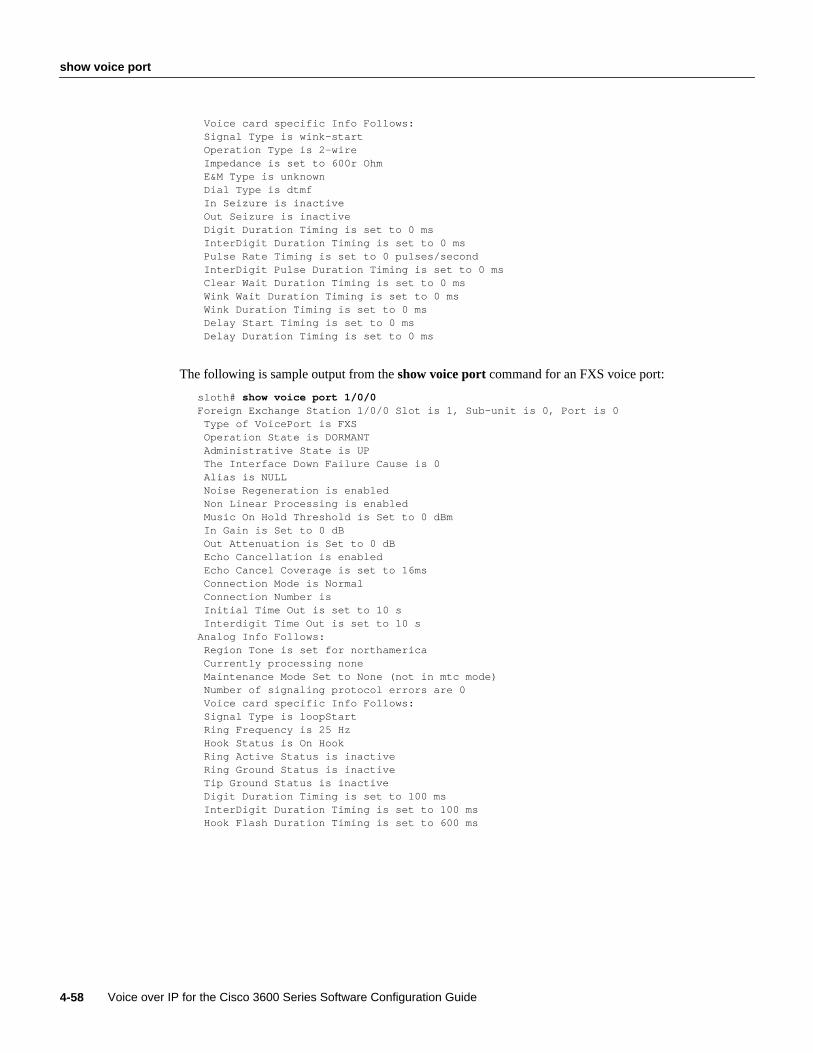
show voice port
Voice over IP for the Cisco 3600 Series Software Configuration Guide4-58
Voice card specific Info Follows: Signal Type is wink-start Operation Type is 2-wire Impedance is set to 600r Ohm E&M Type is unknown Dial Type is dtmf In Seizure is inactive Out Seizure is inactive Digit Duration Timing is set to 0 ms InterDigit Duration Timing is set to 0 ms Pulse Rate Timing is set to 0 pulses/second InterDigit Pulse Duration Timing is set to 0 ms Clear Wait Duration Timing is set to 0 ms Wink Wait Duration Timing is set to 0 ms Wink Duration Timing is set to 0 ms Delay Start Timing is set to 0 ms Delay Duration Timing is set to 0 ms
The following is sample output from theshow voice portcommand for an FXS voice port:
sloth# show voice port 1/0/0Foreign Exchange Station 1/0/0 Slot is 1, Sub-unit is 0, Port is 0 Type of VoicePort is FXS Operation State is DORMANT Administrative State is UP The Interface Down Failure Cause is 0 Alias is NULL Noise Regeneration is enabled Non Linear Processing is enabled Music On Hold Threshold is Set to 0 dBm In Gain is Set to 0 dB Out Attenuation is Set to 0 dB Echo Cancellation is enabled Echo Cancel Coverage is set to 16ms Connection Mode is Normal Connection Number is Initial Time Out is set to 10 s Interdigit Time Out is set to 10 sAnalog Info Follows: Region Tone is set for northamerica Currently processing none Maintenance Mode Set to None (not in mtc mode) Number of signaling protocol errors are 0 Voice card specific Info Follows: Signal Type is loopStart Ring Frequency is 25 Hz Hook Status is On Hook Ring Active Status is inactive Ring Ground Status is inactive Tip Ground Status is inactive Digit Duration Timing is set to 100 ms InterDigit Duration Timing is set to 100 ms Hook Flash Duration Timing is set to 600 ms

Voice Over IP for the Cisco 3600 Series Commands 4-59
show voice port
Table 4-7 explains the fields in the sample output.
Table 4-7 Show Voice Port Field Descriptions
Field Description
Administrative State Administrative state of the voice port.
Alias User-supplied alias for this voice port.
Clear Wait Duration Timing Time of inactive seizure signal to declare call cleared.
Connection Mode Connection mode of the interface.
Connection Number Full E.164 telephone number used to establish a connection with the trunk orPLAR mode.
Currently Processing Type of call currently being processed: none, voice, or fax.
Delay Duration Timing Maximum delay signal duration for delay dial signaling.
Delay Start Timing Timing of generation of delayed start signal from detection of incomingseizure.
Dial Type Out-dialing type of the voice port.
Digit Duration Timing DTMF Digit duration in milliseconds.
E&M Type Type of E&M interface.
Echo Cancel Coverage Echo Cancel Coverage for this port.
Echo Cancellation Whether or not echo cancellation is enabled for this port.
Hook Flash Duration Timing Maximum length of hook flash signal.
Hook Status Hook status of the FXO/FXS interface.
Impedance Configured terminating impedance for the E&M interface.
In Gain Amount of gain inserted at the receiver side of the interface.
In Seizure Incoming seizure state of the E&M interface.
Initial Time Out Amount of time the system waits for an initial input digit from the caller.
InterDigit Duration Timing DTMF interdigit duration in milliseconds.
InterDigit Pulse Duration Timing Pulse dialing interdigit timing in milliseconds.
Interdigit Time Out Amount of time the system waits for a subsequent input digit from the caller.
Maintenance Mode Maintenance mode of the voice-port.
Music On Hold Threshold Configured Music-On-Hold Threshold value for this interface.
Noise Regeneration Whether or not background noise should be played to fill silent gaps if VADis activated.
Number of signaling protocol errors Number of signaling protocol errors.
Non-Linear Processing Whether or not Non-Linear Processing is enabled for this port.
Operations State Operation state of the port.
Operation Type Operation of the E&M signal: 2-wire or 4-wire.
Out Attenuation Amount of attenuation inserted at the transmit side of the interface.
Out Seizure Outgoing seizure state of the E&M interface.
Port Port number for this interface associated with the voice interface card.
Pulse Rate Timing Pulse dialing rate in pulses per second (pps).
Regional Tone Configured regional tone for this interface.

show voice port
Voice over IP for the Cisco 3600 Series Software Configuration Guide4-60
Related CommandsYou can use the master index or search online to find documentation of related commands.
show call active voiceshow call history voiceshow dial-peer voiceshow num-exp
Ring Active Status Ring active indication.
Ring Frequency Configured ring frequency for this interface.
Ring Ground Status Ring ground indication.
Signal Type Type of signaling for a voice port: loop-start, ground-start, wink-start,immediate, and delay-dial.
Slot Slot used in the voice interface card for this port.
Sub-unit Subunit used in the voice interface card for this port.
Tip Ground Status Tip ground indication.
Type of VoicePort Type of voice port: FXO, FXS, and E&M.
The Interface Down Failure Cause Text string describing why the interface is down,
Wink Duration Timing Maximum wink duration for wink start signaling.
Wink Wait Duration Timing Maximum wink wait duration for wink start signaling.
Table 4-7 Show Voice Port Field Descriptions (continued)
Field Description
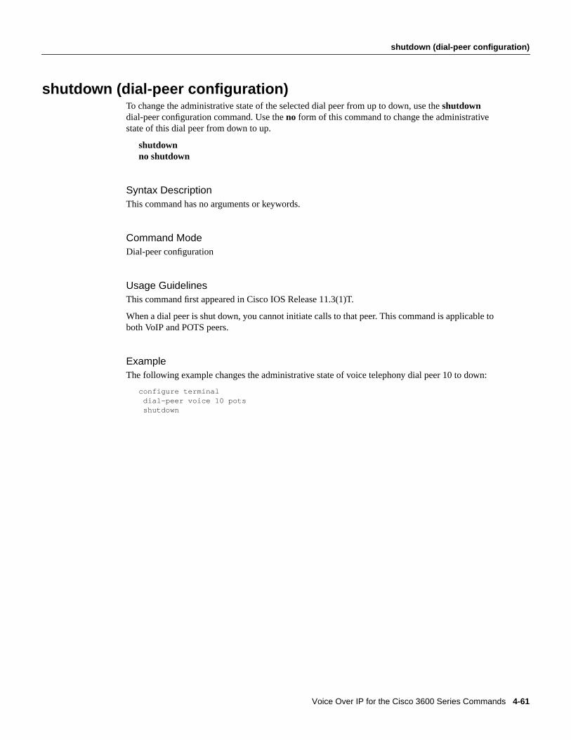
Voice Over IP for the Cisco 3600 Series Commands 4-61
shutdown (dial-peer configuration)
shutdown (dial-peer configuration)To change the administrative state of the selected dial peer from up to down, use theshutdowndial-peer configuration command. Use theno form of this command to change the administrativestate of this dial peer from down to up.
shutdownno shutdown
Syntax DescriptionThis command has no arguments or keywords.
Command ModeDial-peer configuration
Usage GuidelinesThis command first appeared in Cisco IOS Release 11.3(1)T.
When a dial peer is shut down, you cannot initiate calls to that peer. This command is applicable toboth VoIP and POTS peers.
ExampleThe following example changes the administrative state of voice telephony dial peer 10 to down:
configure terminaldial-peer voice 10 potsshutdown
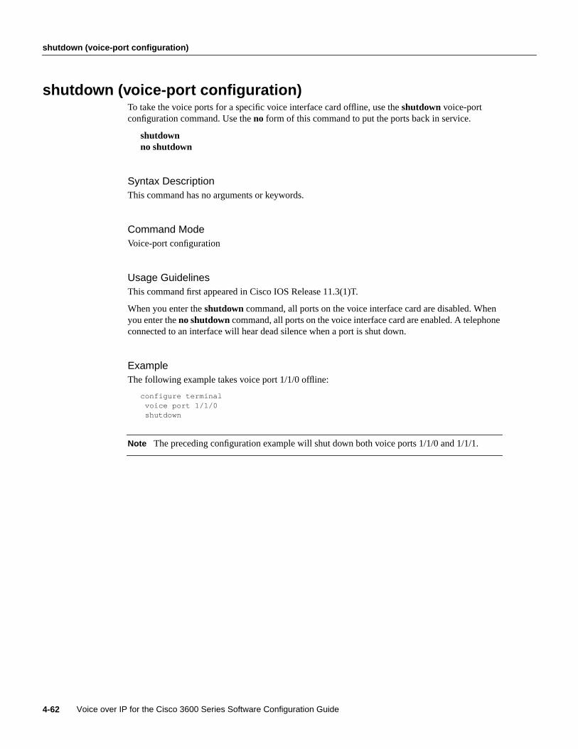
shutdown (voice-port configuration)
Voice over IP for the Cisco 3600 Series Software Configuration Guide4-62
shutdown (voice-port configuration)To take the voice ports for a specific voice interface card offline, use theshutdown voice-portconfiguration command. Use theno form of this command to put the ports back in service.
shutdownno shutdown
Syntax DescriptionThis command has no arguments or keywords.
Command ModeVoice-port configuration
Usage GuidelinesThis command first appeared in Cisco IOS Release 11.3(1)T.
When you enter theshutdown command, all ports on the voice interface card are disabled. Whenyou enter theno shutdowncommand, all ports on the voice interface card are enabled. A telephoneconnected to an interface will hear dead silence when a port is shut down.
ExampleThe following example takes voice port 1/1/0 offline:
configure terminalvoice port 1/1/0shutdown
Note The preceding configuration example will shut down both voice ports 1/1/0 and 1/1/1.

Voice Over IP for the Cisco 3600 Series Commands 4-63
signal
signalTo specify the type of signaling for a voice port, use thesignalvoice-port configuration command.Use theno form of this command to restore the default value for this command.
signal { loop-start | ground-start | wink-start | immediate | delay-dial}no signal
Syntax Description
DefaultThe default value isloop-start for FXO and FXS interfaces. The default value iswink-start forE&M interfaces.
Command ModeVoice-port configuration
Usage GuidelinesThis command first appeared in Cisco IOS Release 11.3(1)T.
Configuring thesignalcommand for an FXS or FXO voice port will change the signal value for bothvoice ports on a VPM card.
loop-start Specifies Loop Start signaling. Used for FXO and FXS interfaces. WithLoop Start signaling only one side of a connection can hang up. This isthe default setting for FXO and FXS voice ports.
ground-start Specifies Ground Start signaling. Used for FXO and FXS interfaces.Ground Start allows both sides of a connection to place a call and to hangup.
wink-start Indicates that the calling side seizes the line by going off-hook on itsE lead then waits for a short off-hook “wink” indication on its M leadfrom the called side before sending address information as DTMF digits.Used for E&M tie trunk interfaces. This is the default setting for E&Mvoice ports.
immediate Indicates that the calling side seizes the line by going off-hook on itsE lead and sends address information as DTMF digits. Used for E&M tietrunk interfaces.
delay-dial Indicates that the calling side seizes the line by going off-hook on itsE lead. After a timing interval, the calling side looks at the supervisionfrom the called side. If the supervision is on-hook, the calling side startssending information as DTMF digits; otherwise, the calling side waitsuntil the called side goes on-hook and then starts sending addressinformation. Used for E&M tie trunk interfaces.
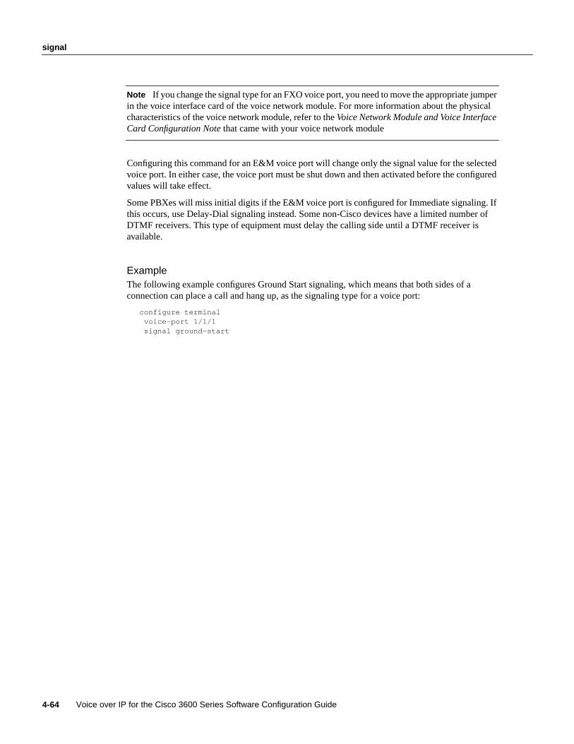
signal
Voice over IP for the Cisco 3600 Series Software Configuration Guide4-64
Note If you change the signal type for an FXO voice port, you need to move the appropriate jumperin the voice interface card of the voice network module. For more information about the physicalcharacteristics of the voice network module, refer to theVoice Network Module and Voice InterfaceCard Configuration Note that came with your voice network module
Configuring this command for an E&M voice port will change only the signal value for the selectedvoice port. In either case, the voice port must be shut down and then activated before the configuredvalues will take effect.
Some PBXes will miss initial digits if the E&M voice port is configured for Immediate signaling. Ifthis occurs, use Delay-Dial signaling instead. Some non-Cisco devices have a limited number ofDTMF receivers. This type of equipment must delay the calling side until a DTMF receiver isavailable.
ExampleThe following example configures Ground Start signaling, which means that both sides of aconnection can place a call and hang up, as the signaling type for a voice port:
configure terminalvoice-port 1/1/1signal ground-start

Voice Over IP for the Cisco 3600 Series Commands 4-65
snmp enable peer-trap poor-qov
snmp enable peer-trap poor-qovTo generate poor quality of voice notification for applicable calls associated with VoIP dial peers,use thesnmp enable peer-trap poor-qovdial-peer configuration command. Use theno form of thiscommand to disable this feature.
snmp enable peer-trap poor-qovno snmp enable peer-trap poor-qov
Syntax DescriptionThis command has no arguments or keywords.
DefaultDisabled
Command ModeDial-peer configuration
Usage GuidelinesThis command first appeared in Cisco IOS Release 11.3(1)T.
Use thesnmp enable peer-trap poor qovcommand to generate poor quality of voice notificationsfor applicable calls associated with this dial peer. If you have an SNMP manager that will use SNMPmessages when voice quality drops, you might want to enable this command. Otherwise, you shoulddisable this command to reduce unnecessary network traffic.
This command is applicable only to VoIP peers.
ExampleThe following example enables poor quality of voice notifications for calls associated with VoIP dialpeer 10:
dial-peer voice 10 voipsnmp enable peer-trap poor-qov
Related CommandsYou can use the master index or search online to find documentation of related commands.
snmp-server enable trap voice poor-qovsnmp trap link-status
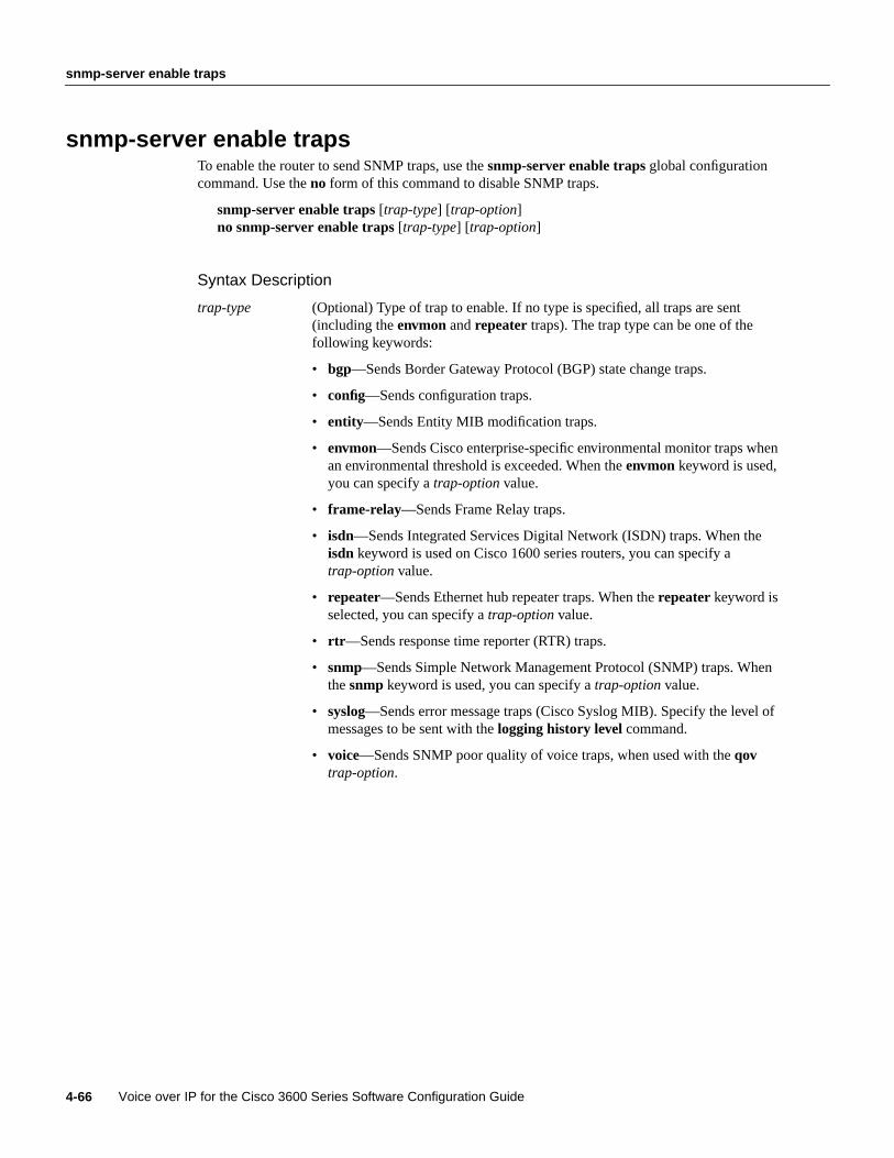
snmp-server enable traps
Voice over IP for the Cisco 3600 Series Software Configuration Guide4-66
snmp-server enable trapsTo enable the router to send SNMP traps, use thesnmp-server enable trapsglobal configurationcommand. Use theno form of this command to disable SNMP traps.
snmp-server enable traps[trap-type] [trap-option]no snmp-server enable traps[trap-type] [trap-option]
Syntax Description
trap-type (Optional) Type of trap to enable. If no type is specified, all traps are sent(including theenvmon andrepeater traps). The trap type can be one of thefollowing keywords:
• bgp—Sends Border Gateway Protocol (BGP) state change traps.
• config—Sends configuration traps.
• entity—Sends Entity MIB modification traps.
• envmon—Sends Cisco enterprise-specific environmental monitor traps whenan environmental threshold is exceeded. When theenvmon keyword is used,you can specify atrap-option value.
• frame-relay—Sends Frame Relay traps.
• isdn—Sends Integrated Services Digital Network (ISDN) traps. When theisdn keyword is used on Cisco 1600 series routers, you can specify atrap-option value.
• repeater—Sends Ethernet hub repeater traps. When therepeaterkeyword isselected, you can specify atrap-option value.
• rtr —Sends response time reporter (RTR) traps.
• snmp—Sends Simple Network Management Protocol (SNMP) traps. Whenthesnmp keyword is used, you can specify atrap-option value.
• syslog—Sends error message traps (Cisco Syslog MIB). Specify the level ofmessages to be sent with thelogging history level command.
• voice—Sends SNMP poor quality of voice traps, when used with theqovtrap-option.

Voice Over IP for the Cisco 3600 Series Commands 4-67
snmp-server enable traps
DefaultsThis command is disabled by default. No traps are enabled.
Some trap types cannot be controlled with this command. These traps are either always enabled orenabled by some other means. For example, the linkUpDown messages are disabled by theno snmptrap link-status command.
If you enter this command with no keywords, the default is to enable all trap types.
Command ModeGlobal configuration
Usage GuidelinesThis command first appeared in Cisco IOS Release 11.1.
This command is useful for disabling traps that are generating a large amount of uninteresting oruseless noise.
If you do not enter ansnmp-server enable trapscommand, no traps controlled by this commandare sent. In order to configure the router to send these SNMP traps, you must enter at least onesnmp-server enable trapscommand. If you enter the command with no keywords, all trap typesare enabled. If you enter the command with a keyword, only the trap type related to that keyword isenabled. In order to enable multiple types of traps, you must enter a separatesnmp-server enabletraps command for each trap type and option.
trap-option (Optional) When theenvmon keyword is used, you can enable a specificenvironmental trap type, or accept all trap types from the environmental monitorsystem. If no option is specified, all environmental types are enabled. The optioncan be one or more of the following keywords:voltage, shutdown, supply, fan,andtemperature.
When theisdn keyword is used on Cisco 1600 series routers, you can specify thecall-information keyword to enable an SNMP ISDN call information trap forthe ISDN MIB subsystem, or you can specify theisdnu-interface keyword toenable an SNMP ISDN U interface trap for the ISDN U interface MIBsubsystem.
When therepeater keyword is used, you can specify the repeater option. If nooption is specified, all repeater types are enabled. The option can be one or moreof the following keywords:
• health—Enables IETF Repeater Hub MIB (RFC 1516) health trap.
• reset—Enables IETF Repeater Hub MIB (RFC 1516) reset trap.
When thesnmp keyword is used, you can specify theauthentication option toenable SNMP Authentication Failure traps. (Thesnmp-server enable trapssnmp authenticationcommand replaces thesnmp-server trap-authenticationcommand.) If no option is specified, all SNMP traps are enabled.
When thevoice keyword is used, you can enable SNMP poor quality of voicetraps by using theqov option.
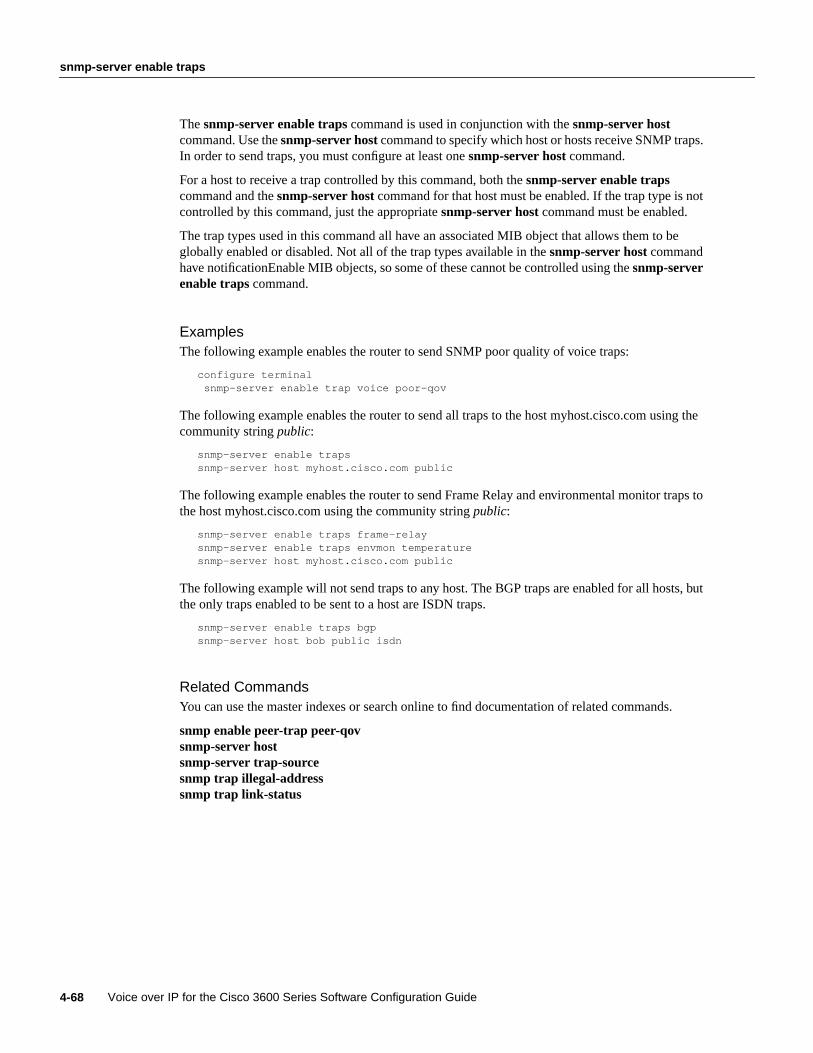
snmp-server enable traps
Voice over IP for the Cisco 3600 Series Software Configuration Guide4-68
Thesnmp-server enable trapscommand is used in conjunction with thesnmp-server hostcommand. Use thesnmp-server hostcommand to specify which host or hosts receive SNMP traps.In order to send traps, you must configure at least onesnmp-server host command.
For a host to receive a trap controlled by this command, both thesnmp-server enable trapscommand and thesnmp-server hostcommand for that host must be enabled. If the trap type is notcontrolled by this command, just the appropriatesnmp-server host command must be enabled.
The trap types used in this command all have an associated MIB object that allows them to beglobally enabled or disabled. Not all of the trap types available in thesnmp-server hostcommandhave notificationEnable MIB objects, so some of these cannot be controlled using thesnmp-serverenable trapscommand.
ExamplesThe following example enables the router to send SNMP poor quality of voice traps:
configure terminalsnmp-server enable trap voice poor-qov
The following example enables the router to send all traps to the host myhost.cisco.com using thecommunity stringpublic:
snmp-server enable trapssnmp-server host myhost.cisco.com public
The following example enables the router to send Frame Relay and environmental monitor traps tothe host myhost.cisco.com using the community stringpublic:
snmp-server enable traps frame-relaysnmp-server enable traps envmon temperaturesnmp-server host myhost.cisco.com public
The following example will not send traps to any host. The BGP traps are enabled for all hosts, butthe only traps enabled to be sent to a host are ISDN traps.
snmp-server enable traps bgpsnmp-server host bob public isdn
Related CommandsYou can use the master indexes or search online to find documentation of related commands.
snmp enable peer-trap peer-qovsnmp-server hostsnmp-server trap-sourcesnmp trap illegal-addresssnmp trap link-status

Voice Over IP for the Cisco 3600 Series Commands 4-69
snmp trap link-status
snmp trap link-statusTo enable Simple Network Management Protocol (SNMP) trap messages to be generated when thisvoice port is brought up or down, use thesnmp trap link-status voice-port configuration command.Use theno form of this command to disable this feature.
snmp trap link-statusno snmp trap link-status
Syntax DescriptionThis command contains no arguments or keywords.
DefaultThe default for this command is enabled.
Command ModeVoice-port configuration
Usage GuidelinesThis command first appeared in Cisco IOS Release 11.3(1)T.
Use thesnmp trap link-status command to enable SNMP trap messages (linkup and linkdown) tobe generated whenever this voice port is brought online or offline.
If you are managing the equipment with an SNMP manager, this command should be enabled.Enabling link-status messages will allow the SNMP manager to learn of a status change withoutpolling the equipment. If you are not using an SNMP manager, this command should be disabled toavoid unnecessary network traffic.
ExampleThe following example enables SNMP trap messages for voice-port 2/1/0:
voice-port 2/1/0snmp trap link-stat
Related CommandsYou can use the master index or search online to find documentation of related commands.
smnp enable peer-trap poor-qovsnmp-server enable trap poor-qov

timeouts initial
Voice over IP for the Cisco 3600 Series Software Configuration Guide4-70
timeouts initialTo configure the initial digit timeout value for a specified voice port, use thetimeouts initialvoice-port configuration command. Use theno form of this command to restore the default value forthis command.
timeouts initial secondsno timeouts initial seconds
Syntax Description
DefaultThe default value is 10 seconds.
Command ModeVoice-port configuration
Usage GuidelinesThis command first appeared in Cisco IOS Release 11.3(1)T.
Use thetimeouts initial command to specify the number of seconds the system will wait for thecaller to input the first digit of the dialed digits. The timeouts initial timer is activated when the callis accepted and is deactivated when the caller inputs the first digit. If the configured timeout value isexceeded, the caller is notified through the appropriate tone and the call is terminated.
To disable the timeouts initial timer, set theseconds value to0.
ExampleThe following example sets the initial digit timeout value to 15 seconds:
voice-port 1/0/0timeouts initial 15
Related CommandsYou can use the master index or search online to find documentation of related commands.
timeouts interdigittiming
initial seconds Specifies the initial timeout duration in seconds. Valid entries are anyinteger from 0 to 120.
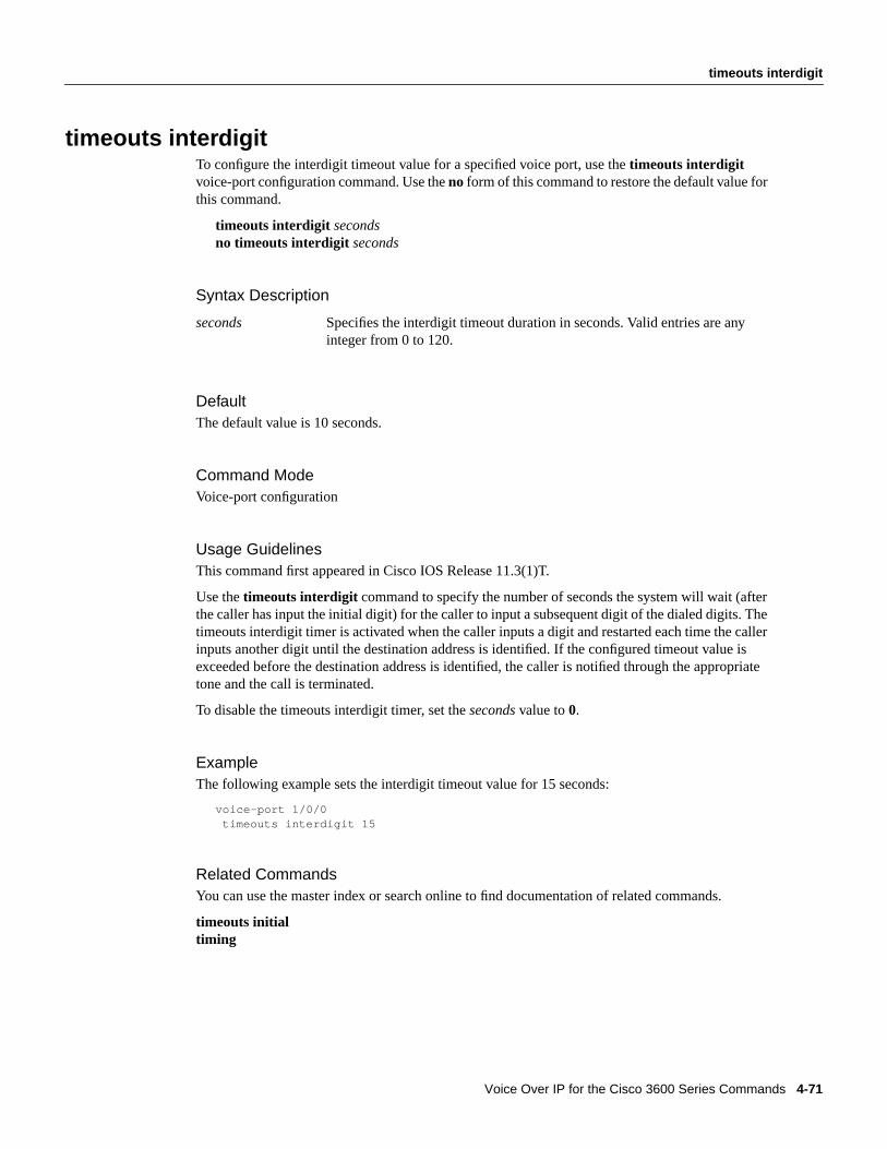
Voice Over IP for the Cisco 3600 Series Commands 4-71
timeouts interdigit
timeouts interdigitTo configure the interdigit timeout value for a specified voice port, use thetimeouts interdigitvoice-port configuration command. Use theno form of this command to restore the default value forthis command.
timeouts interdigit secondsno timeouts interdigit seconds
Syntax Description
DefaultThe default value is 10 seconds.
Command ModeVoice-port configuration
Usage GuidelinesThis command first appeared in Cisco IOS Release 11.3(1)T.
Use thetimeouts interdigit command to specify the number of seconds the system will wait (afterthe caller has input the initial digit) for the caller to input a subsequent digit of the dialed digits. Thetimeouts interdigit timer is activated when the caller inputs a digit and restarted each time the callerinputs another digit until the destination address is identified. If the configured timeout value isexceeded before the destination address is identified, the caller is notified through the appropriatetone and the call is terminated.
To disable the timeouts interdigit timer, set theseconds value to0.
ExampleThe following example sets the interdigit timeout value for 15 seconds:
voice-port 1/0/0timeouts interdigit 15
Related CommandsYou can use the master index or search online to find documentation of related commands.
timeouts initialtiming
seconds Specifies the interdigit timeout duration in seconds. Valid entries are anyinteger from 0 to 120.

timing clear-wait
Voice over IP for the Cisco 3600 Series Software Configuration Guide4-72
timing clear-waitTo indicate the minimum amount of time between the inactive seizure signal and the call beingcleared for a specified voice port, use thetiming clear-wait voice-port configuration command. Usetheno form of this command to reset the default value.
timing clear-wait millisecondsno timing clear-wait milliseconds
Syntax Description
Default400 milliseconds
Command ModeVoice-port configuration
Usage GuidelinesThis command first appeared in Cisco IOS Release 11.3(1)T.
ExamplesThe following example configures the clear-wait duration on a Cisco 3600 series voice port to300 milliseconds:
voice-port 1/0/0timing clear-wait 300
Related CommandsYou can use the master indexes or search online to find documentation of related commands.
timeouts initialtimeouts interdigittiming clear-waittiming delay-durationtiming delay-starttiming dial-pulse min-delaytiming digittiming interdigittiming pulsetiming pulse-interdigittiming wink-durationtiming wink-wait
milliseconds Minimum amount of time, in milliseconds, between the inactive seizuresignal and the call being cleared. Valid entries on the Cisco 3600 seriesare numbers from 200 to 2000. Supported on E&M ports only.
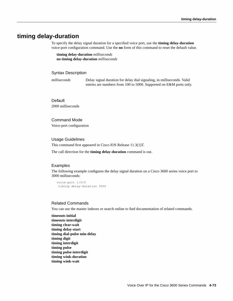
Voice Over IP for the Cisco 3600 Series Commands 4-73
timing delay-duration
timing delay-durationTo specify the delay signal duration for a specified voice port, use thetiming delay-durationvoice-port configuration command. Use theno form of this command to reset the default value.
timing delay-duration millisecondsno timing delay-duration milliseconds
Syntax Description
Default2000 milliseconds
Command ModeVoice-port configuration
Usage GuidelinesThis command first appeared in Cisco IOS Release 11.3(1)T.
The call direction for thetiming delay-duration command is out.
ExamplesThe following example configures the delay signal duration on a Cisco 3600 series voice port to3000 milliseconds:
voice-port 1/0/0timing delay-duration 3000
Related CommandsYou can use the master indexes or search online to find documentation of related commands.
timeouts initialtimeouts interdigittiming clear-waittiming delay-starttiming dial-pulse min-delaytiming digittiming interdigittiming pulsetiming pulse-interdigittiming wink-durationtiming wink-wait
milliseconds Delay signal duration for delay dial signaling, in milliseconds. Validentries are numbers from 100 to 5000. Supported on E&M ports only.
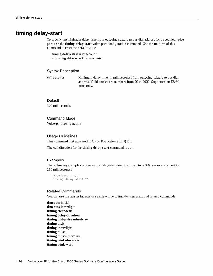
timing delay-start
Voice over IP for the Cisco 3600 Series Software Configuration Guide4-74
timing delay-startTo specify the minimum delay time from outgoing seizure to out-dial address for a specified voiceport, use thetiming delay-start voice-port configuration command. Use theno form of thiscommand to reset the default value.
timing delay-start millisecondsno timing delay-start milliseconds
Syntax Description
Default300 milliseconds
Command ModeVoice-port configuration
Usage GuidelinesThis command first appeared in Cisco IOS Release 11.3(1)T.
The call direction for thetiming delay-start command is out.
ExamplesThe following example configures the delay-start duration on a Cisco 3600 series voice port to250 milliseconds:
voice-port 1/0/0timing delay-start 250
Related CommandsYou can use the master indexes or search online to find documentation of related commands.
timeouts initialtimeouts interdigittiming clear-waittiming delay-durationtiming dial-pulse min-delaytiming digittiming interdigittiming pulsetiming pulse-interdigittiming wink-durationtiming wink-wait
milliseconds Minimum delay time, in milliseconds, from outgoing seizure to out-dialaddress. Valid entries are numbers from 20 to 2000. Supported on E&Mports only.

Voice Over IP for the Cisco 3600 Series Commands 4-75
timing dial-pulse min-delay
timing dial-pulse min-delayTo specify the time between wink-like pulses for a specified voice port on the Cisco 3600 series, usethetiming dial-pulse min-delayvoice-port configuration command. Use theno form of thiscommand to reset the default value.
timing dial-pulse min-delaymillisecondsno timing dial-pulse min-delaymilliseconds
Syntax Description
Default300 milliseconds
Command ModeVoice-port configuration
Usage GuidelinesThis command first appeared in Cisco IOS Release 11.3(1)T.
Use thetiming command with thedial-pulse min-delaykeyword with PBXes requiring a wink-likepulse, even though they have been configured for delay-dial signaling. If the value for this keywordis set to 0, the router will not generate this wink-like pulse. The call signal direction for thiscommand is in.
ExampleThe following example configures the time between the generation of wink-like pulses on aCisco 3600 series voice port to 350 milliseconds:
voice-port 1/0/0timing dial-pulse min-delay 350
Related CommandsYou can use the master indexes or search online to find documentation of related commands.
timeouts initialtimeouts interdigittiming clear-waittiming delay-durationtiming dialout-delaytiming digittiming interdigittiming pulsetiming pulse-interdigittiming wink-durationtiming wink-wait
milliseconds Time, in milliseconds, between the generation of wink-like pulses. Validentries are numbers from 0 to 5000.

timing digit
Voice over IP for the Cisco 3600 Series Software Configuration Guide4-76
timing digitTo specify the DTMF digit signal duration for a specified voice port, use thetiming digit voice-portconfiguration command. Use theno form of this command to reset the default value.
timing digit millisecondsno timing digit milliseconds
Syntax Description
Default100 milliseconds
Command ModeVoice-port configuration
Usage GuidelinesThis command first appeared in Cisco IOS Release 11.3(1)T.
The call signal direction for thetiming digit command is out.
ExamplesThe following example configures the DTMF digit signal duration on a Cisco 3600 series voice portto 50 milliseconds:
voice-port 1/0/0timing digit 50
Related CommandsYou can use the master indexes or search online to find documentation of related commands.
timeouts initialtimeouts interdigittiming clear-waittiming delay-durationtiming delay-starttiming dial-pulse min-delaytiming interdigittiming pulsetiming pulse-interdigittiming wink-durationtiming wink-wait
milliseconds The DTMF digit signal duration, in milliseconds. Valid entries arenumbers from 50 to 100. Supported on FXO, FXS and E&M ports.
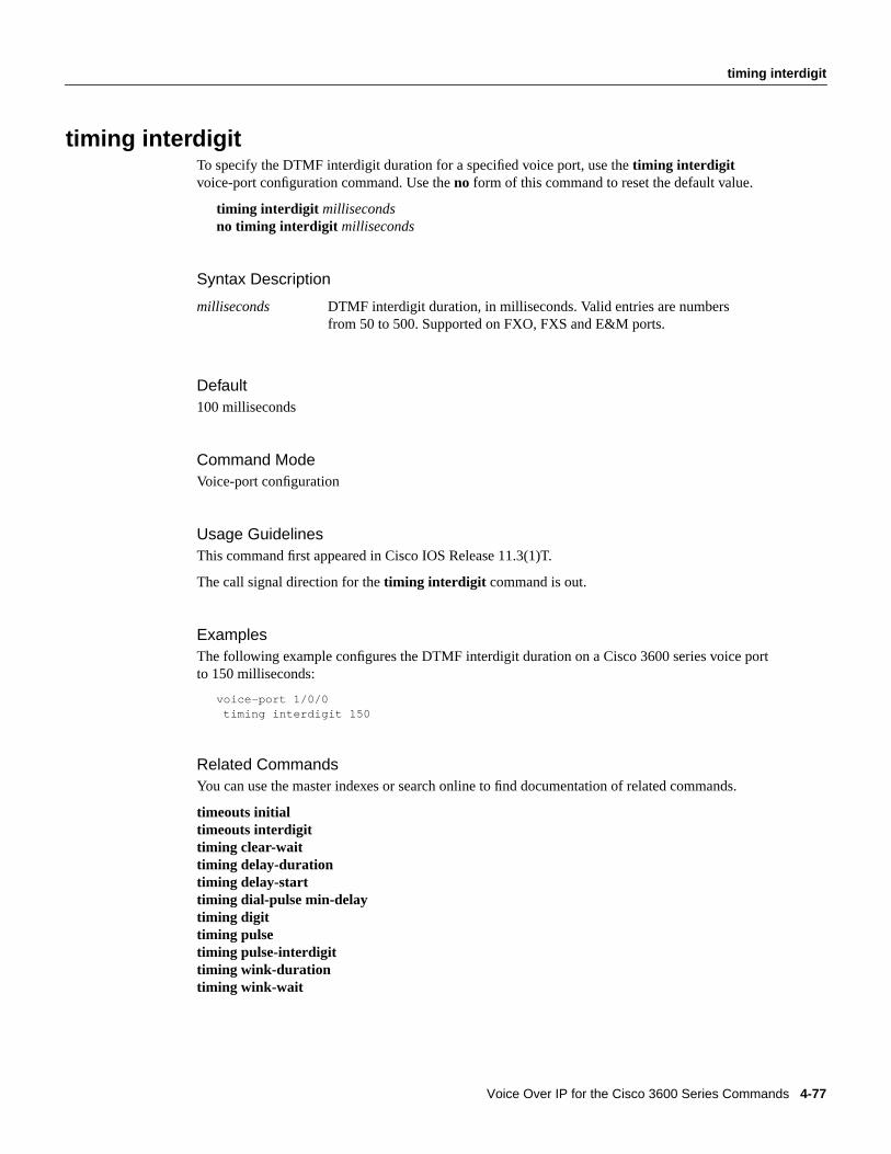
Voice Over IP for the Cisco 3600 Series Commands 4-77
timing interdigit
timing interdigitTo specify the DTMF interdigit duration for a specified voice port, use thetiming interdigitvoice-port configuration command. Use theno form of this command to reset the default value.
timing interdigit millisecondsno timing interdigit milliseconds
Syntax Description
Default100 milliseconds
Command ModeVoice-port configuration
Usage GuidelinesThis command first appeared in Cisco IOS Release 11.3(1)T.
The call signal direction for thetiming interdigit command is out.
ExamplesThe following example configures the DTMF interdigit duration on a Cisco 3600 series voice portto 150 milliseconds:
voice-port 1/0/0timing interdigit 150
Related CommandsYou can use the master indexes or search online to find documentation of related commands.
timeouts initialtimeouts interdigittiming clear-waittiming delay-durationtiming delay-starttiming dial-pulse min-delaytiming digittiming pulsetiming pulse-interdigittiming wink-durationtiming wink-wait
milliseconds DTMF interdigit duration, in milliseconds. Valid entries are numbersfrom 50 to 500. Supported on FXO, FXS and E&M ports.

timing pulse
Voice over IP for the Cisco 3600 Series Software Configuration Guide4-78
timing pulseTo specify the pulse dialing rate for a specified voice port, use thetiming pulse voice-portconfiguration command. Use theno form of this command to reset the default value.
timing pulse pulses-per-secondno timing pulsepulses-per-second
Syntax Description
Default20
Command ModeVoice-port configuration
Usage GuidelinesThis command first appeared in Cisco IOS Release 11.3(1)T.
The call signal direction for thetiming pulse command is out.
ExamplesThe following example configures the pulse dialing rate on a Cisco 3600 series voice port to15 pulses per second:
voice-port 1/0/0timing pulse 15
Related CommandsYou can use the master indexes or search online to find documentation of related commands.
timeouts initialtimeouts interdigittiming clear-waittiming delay-durationtiming delay-starttiming dial-pulse min-delaytiming digittiming interdigittiming pulse-interdigittiming wink-durationtiming wink-wait
pulses-per-second Pulse dialing rate, in pulses per second. Valid entries are numbers from10 to 20. Supported on FXO and E&M ports only.

Voice Over IP for the Cisco 3600 Series Commands 4-79
timing pulse-interdigit
timing pulse-interdigitTo specify the pulse interdigit timing for a specified voice port, use thetiming pulse-interdigitvoice-port configuration command. Use theno form of this command to reset the default value.
timing pulse-interdigit millisecondsno timing pulse-interdigit milliseconds
Syntax Description
Default500 milliseconds
Command ModeVoice-port configuration
Usage GuidelinesThis command first appeared in Cisco IOS Release 11.3(1)T.
The call signal direction for thetiming pulse-interdigit command is out.
ExamplesThe following example configures the pulse-dialing interdigit timing on a Cisco 3600 series voiceport to 300 milliseconds:
voice-port 1/0/0timing pulse-interdigit 300
Related CommandsYou can use the master indexes or search online to find documentation of related commands.
timeouts initialtimeouts interdigittiming clear-waittiming delay-durationtiming delay-starttiming dial-pulse min-delaytiming digittiming interdigittiming pulsetiming wink-durationtiming wink-wait
milliseconds Pulse dialing interdigit timing, in milliseconds. Valid entries are numbersfrom 100 to 1000. Supported on FXO and E&M ports only.

timing wink-duration
Voice over IP for the Cisco 3600 Series Software Configuration Guide4-80
timing wink-durationTo specify the maximum wink signal duration for a specified voice port, use thetimingwink-duration voice-port configuration command. Use theno form of this command to restore thedefault value.
timing wink-duration millisecondsno timing wink-duration milliseconds
Syntax Description
Default200 milliseconds
Command ModeVoice-port configuration
Usage GuidelinesThis command first appeared in Cisco IOS Release 11.3(1)T.
The call signal direction for thetiming wink-duration command is out.
ExamplesThe following example configures the wink signal duration on a Cisco 3600 series voice port to300 milliseconds:
voice-port 1/0/0timing wink-duration 300
Related CommandsYou can use the master indexes or search online to find documentation of related commands.
timeouts initialtimeouts interdigittiming clear-waittiming delay-durationtiming delay-starttiming dial-pulse min-delaytiming digittiming interdigittiming pulsetiming pulse-interdigittiming wink-wait
milliseconds Maximum wink signal duration, in milliseconds, for a wink-start signal.Valid entries are numbers from 100 to 400. Supported on E&M portsonly.

Voice Over IP for the Cisco 3600 Series Commands 4-81
timing wink-wait
timing wink-waitTo specify the maximum wink-wait duration for a specified voice port, use thetiming wink-waitvoice-port configuration command. Use theno form of this command to reset the default value.
timing wink-wait millisecondsno timing wink-wait milliseconds
Syntax Description
Default200 milliseconds
Command ModeVoice-port configuration
Usage GuidelinesThis command first appeared in Cisco IOS Release 11.3(1)T.
The call signal direction for thetiming wink-wait command is out.
ExamplesThe following example configures the wink-wait duration on a Cisco 3600 series voice port to300 milliseconds:
voice-port 1/0/0timing wink-wait 300
Related CommandsYou can use the master indexes or search online to find documentation of related commands.
timeouts initialtimeouts interdigittiming clear-waittiming delay-durationtiming delay-starttiming dial-pulse min-delaytiming digittiming interdigittiming pulsetiming pulse-interdigittiming wink-duration
milliseconds Maximum wink-wait duration, in milliseconds, for a wink start signal.Valid entries are numbers from 100 to 5000. Supported on E&M portsonly
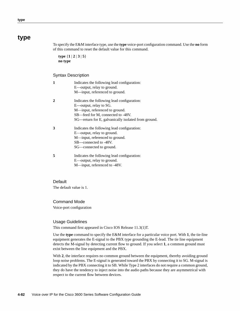
type
Voice over IP for the Cisco 3600 Series Software Configuration Guide4-82
typeTo specify the E&M interface type, use thetypevoice-port configuration command. Use theno formof this command to reset the default value for this command.
type { 1 | 2 | 3 | 5}no type
Syntax Description
DefaultThe default value is 1.
Command ModeVoice-port configuration
Usage GuidelinesThis command first appeared in Cisco IOS Release 11.3(1)T.
Use thetype command to specify the E&M interface for a particular voice port. With1, the tie-lineequipment generates the E-signal to the PBX type grounding the E-lead. The tie line equipmentdetects the M-signal by detecting current flow to ground. If you select1, a common ground mustexist between the line equipment and the PBX.
With 2, the interface requires no common ground between the equipment, thereby avoiding groundloop noise problems. The E-signal is generated toward the PBX by connecting it to SG. M-signal isindicated by the PBX connecting it to SB. While Type 2 interfaces do not require a common ground,they do have the tendency to inject noise into the audio paths because they are asymmetrical withrespect to the current flow between devices.
1 Indicates the following lead configuration:E—output, relay to ground.M—input, referenced to ground.
2 Indicates the following lead configuration:E—output, relay to SG.M—input, referenced to ground.SB—feed for M, connected to -48V.SG—return for E, galvanically isolated from ground.
3 Indicates the following lead configuration:E—output, relay to ground.M—input, referenced to ground.SB—connected to -48V.SG—connected to ground.
5 Indicates the following lead configuration:E—output, relay to ground.M—input, referenced to -48V.

Voice Over IP for the Cisco 3600 Series Commands 4-83
type
With 3, the interface operates the same as Type 1 interfaces with respect to the E-signal. TheM-signal, however, is indicated by the PBX connecting it to SB on assertion and alternatelyconnecting it to SG during inactivity. If you select 3, a common ground must be shared betweenequipment.
With 5, the Type 5 line equipment indicates E-signal to the PBX by grounding the E-lead. The PBXindicates M-signal by grounding the M-lead. A Type 5 interface is quasi-symmetrical in that whilethe line is up, current flow is more or less equal between the PBX and the line equipment but noiseinjection is a problem.
ExampleThe following example selects Type 3 as the interface type for your voice port:
voice-port 1/0/0type 3

vad
Voice over IP for the Cisco 3600 Series Software Configuration Guide4-84
vadTo enable voice activity detection (VAD) for the calls using this dial peer, use thevad dial-peerconfiguration command. Use theno form of this command to disable this feature.
vadno vad
Syntax DescriptionThis command has no arguments or keywords.
DefaultEnabled
Command ModeDial-peer configuration
Usage GuidelinesThis command first appeared in Cisco IOS Release 11.3(1)T.
Use thevad command to enable voice activity detection. With VAD, silence is not transmitted overthe network, only audible speech. If you enable VAD, the sound quality will be slightly degraded butthe connection will monopolize much less bandwidth. If you use theno form of this command, VADis disabled and voice data is continuously transmitted to the IP backbone.
This command is applicable only to VoIP peers.
ExampleThe following example enables VAD:
dial-peer voice 10 voipvad
Related CommandsYou can use the master index or search online to find documentation of related commands.
comfort-noise

Voice Over IP for the Cisco 3600 Series Commands 4-85
voice-port
voice-portTo enter the voice-port configuration mode, use thevoice-port global configuration command.
voice-port slot-number/subunit-number/port
Syntax Description
Command ModeGlobal configuration
Usage GuidelinesThis command first appeared in Cisco IOS Release 11.3(1)T.
Use thevoice-port global configuration command to switch to the voice-port configuration modefrom the global configuration mode. Use theexit command to exit the voice-port configuration modeand return to the global configuration mode.
For more information about the physical characteristics of the voice network module, or how toinstall it, refer to installation documentation that came with your voice network module.
ExampleThe following example accesses the voice-port configuration mode for port 0, located on subunit 0on a voice interface card installed in slot 1:
configure terminalvoice-port 1/0/0
Related CommandsYou can use the master index or search online to find documentation of related commands.
dial-peer
slot-number/ Specifies the slot number in the Cisco router where the voice networkmodule is installed. Valid entries are from 0 to 3, depending on the voiceinterface card you have installed.
subunit-number/ Specifies the subunit on the voice network module where the voice portis located. Valid entries are 0 or 1.
port Specifies the voice port. Valid entries are 0 or 1.

285
Anexo 4: Guía de antenas y accesorios necesarios en los puentes inalámbricos de la Serie Aironet
El primer archivo detalla los tipos de antenas y cables de bajas pérdidas que
se emplean con los puentes inalámbricos de la Serie Aironet 340. El segundo
archivo detalla cómo se debe colocar la protección contra rayos del puente.
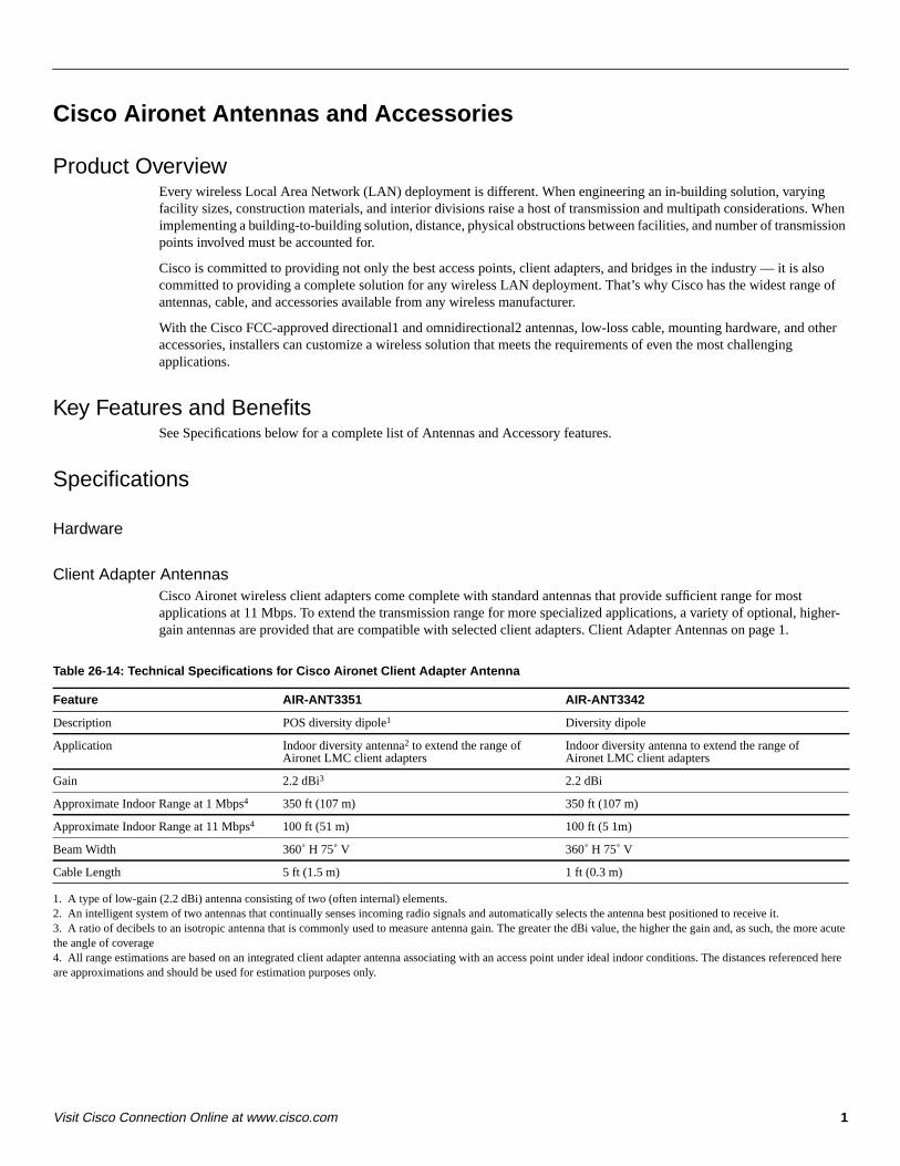
1Visit Cisco Connection Online at www.cisco.com
Cisco Aironet Antennas and Accessories
Product OverviewEvery wireless Local Area Network (LAN) deployment is different. When engineering an in-building solution, varyingfacility sizes, construction materials, and interior divisions raise a host of transmission and multipath considerations. Whenimplementing a building-to-building solution, distance, physical obstructions between facilities, and number of transmissionpoints involved must be accounted for.
Cisco is committed to providing not only the best access points, client adapters, and bridges in the industry — it is alsocommitted to providing a complete solution for any wireless LAN deployment. That’s why Cisco has the widest range ofantennas, cable, and accessories available from any wireless manufacturer.
With the Cisco FCC-approved directional1 and omnidirectional2 antennas, low-loss cable, mounting hardware, and otheraccessories, installers can customize a wireless solution that meets the requirements of even the most challengingapplications.
Key Features and BenefitsSee Specifications below for a complete list of Antennas and Accessory features.
Specifications
Hardware
Client Adapter AntennasCisco Aironet wireless client adapters come complete with standard antennas that provide sufficient range for mostapplications at 11 Mbps. To extend the transmission range for more specialized applications, a variety of optional, higher-gain antennas are provided that are compatible with selected client adapters. Client Adapter Antennas on page 1.
Table 26-14: Technical Specifications for Cisco Aironet Client Adapter Antenna
1. A type of low-gain (2.2 dBi) antenna consisting of two (often internal) elements.2. An intelligent system of two antennas that continually senses incoming radio signals and automatically selects the antenna best positioned to receive it.3. A ratio of decibels to an isotropic antenna that is commonly used to measure antenna gain. The greater the dBi value, the higher the gain and, as such, the more acutethe angle of coverage4. All range estimations are based on an integrated client adapter antenna associating with an access point under ideal indoor conditions. The distances referenced hereare approximations and should be used for estimation purposes only.
Feature AIR-ANT3351 AIR-ANT3342
Description POS diversity dipole1 Diversity dipole
Application Indoor diversity antenna2 to extend the range ofAironet LMC client adapters
Indoor diversity antenna to extend the range ofAironet LMC client adapters
Gain 2.2 dBi3 2.2 dBi
Approximate Indoor Range at 1 Mbps4 350 ft (107 m) 350 ft (107 m)
Approximate Indoor Range at 11 Mbps4 100 ft (51 m) 100 ft (5 1m)
Beam Width 360˚ H 75˚ V 360˚ H 75˚ V
Cable Length 5 ft (1.5 m) 1 ft (0.3 m)
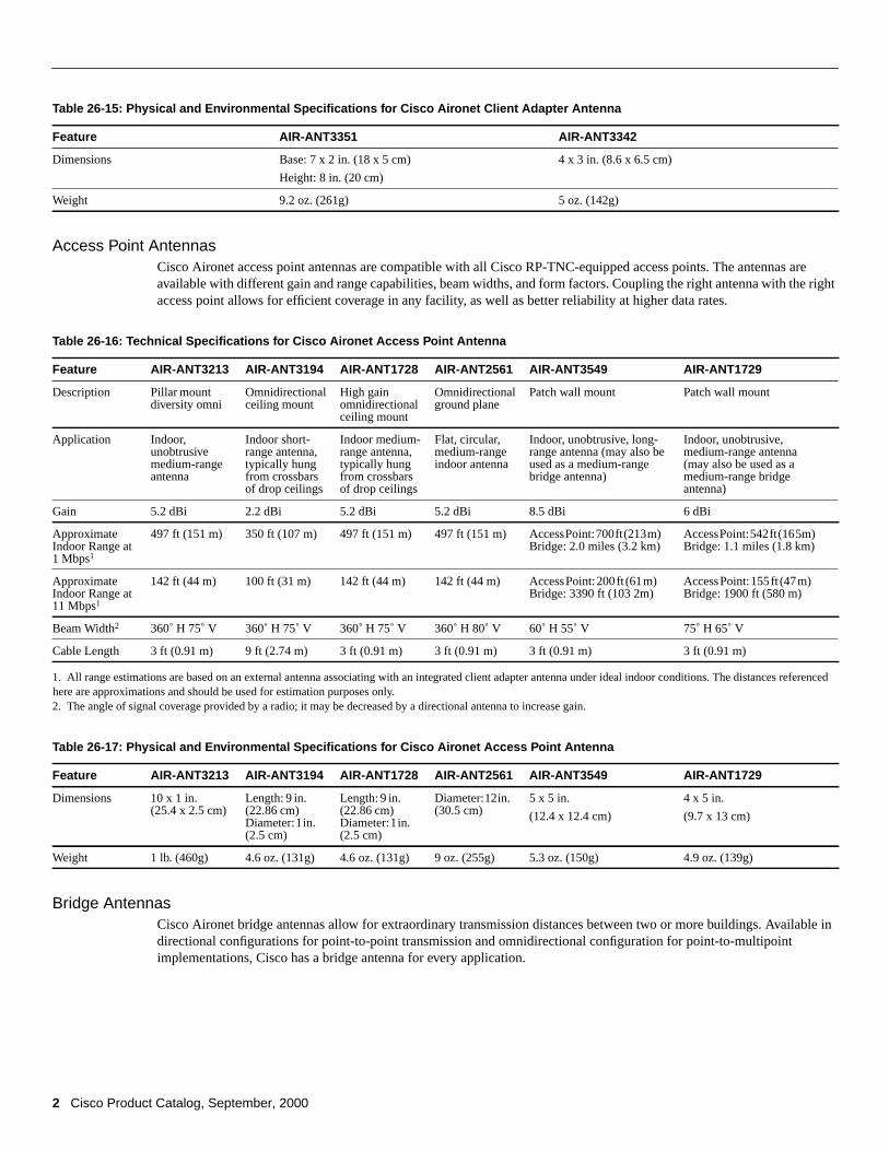
2 Cisco Product Catalog, September, 2000
Table 26-15: Physical and Environmental Specifications for Cisco Aironet Client Adapter Antenna
Access Point AntennasCisco Aironet access point antennas are compatible with all Cisco RP-TNC-equipped access points. The antennas areavailable with different gain and range capabilities, beam widths, and form factors. Coupling the right antenna with the rightaccess point allows for efficient coverage in any facility, as well as better reliability at higher data rates.
Table 26-16: Technical Specifications for Cisco Aironet Access Point Antenna
1. All range estimations are based on an external antenna associating with an integrated client adapter antenna under ideal indoor conditions. The distances referencedhere are approximations and should be used for estimation purposes only.2. The angle of signal coverage provided by a radio; it may be decreased by a directional antenna to increase gain.
Table 26-17: Physical and Environmental Specifications for Cisco Aironet Access Point Antenna
Bridge AntennasCisco Aironet bridge antennas allow for extraordinary transmission distances between two or more buildings. Available indirectional configurations for point-to-point transmission and omnidirectional configuration for point-to-multipointimplementations, Cisco has a bridge antenna for every application.
Feature AIR-ANT3351 AIR-ANT3342
Dimensions Base: 7 x 2 in. (18 x 5 cm)
Height: 8 in. (20 cm)
4 x 3 in. (8.6 x 6.5 cm)
Weight 9.2 oz. (261g) 5 oz. (142g)
Feature AIR-ANT3213 AIR-ANT3194 AIR-ANT1728 AIR-ANT2561 AIR-ANT3549 AIR-ANT1729
Description Pillar mountdiversity omni
Omnidirectionalceiling mount
High gainomnidirectionalceiling mount
Omnidirectionalground plane
Patch wall mount Patch wall mount
Application Indoor,unobtrusivemedium-rangeantenna
Indoor short-range antenna,typically hungfrom crossbarsof drop ceilings
Indoor medium-range antenna,typically hungfrom crossbarsof drop ceilings
Flat, circular,medium-rangeindoor antenna
Indoor, unobtrusive, long-range antenna (may also beused as a medium-rangebridge antenna)
Indoor, unobtrusive,medium-range antenna(may also be used as amedium-range bridgeantenna)
Gain 5.2 dBi 2.2 dBi 5.2 dBi 5.2 dBi 8.5 dBi 6 dBi
ApproximateIndoor Range at1 Mbps1
497 ft (151 m) 350 ft (107 m) 497 ft (151 m) 497 ft (151 m) AccessPoint:700ft(213m)Bridge: 2.0 miles (3.2 km)
AccessPoint:542ft(165m)Bridge: 1.1 miles (1.8 km)
ApproximateIndoor Range at11 Mbps1
142 ft (44 m) 100 ft (31 m) 142 ft (44 m) 142 ft (44 m) AccessPoint:200ft (61m)Bridge: 3390 ft (103 2m)
AccessPoint:155ft (47m)Bridge: 1900 ft (580 m)
Beam Width2 360˚ H 75˚ V 360˚ H 75˚ V 360˚ H 75˚ V 360˚ H 80˚ V 60˚ H 55˚ V 75˚ H 65˚ V
Cable Length 3 ft (0.91 m) 9 ft (2.74 m) 3 ft (0.91 m) 3 ft (0.91 m) 3 ft (0.91 m) 3 ft (0.91 m)
Feature AIR-ANT3213 AIR-ANT3194 AIR-ANT1728 AIR-ANT2561 AIR-ANT3549 AIR-ANT1729
Dimensions 10 x 1 in.(25.4 x 2.5 cm)
Length: 9 in.(22.86 cm)Diameter:1in.(2.5 cm)
Length: 9 in.(22.86 cm)Diameter:1in.(2.5 cm)
Diameter:12in.(30.5 cm)
5 x 5 in.
(12.4 x 12.4 cm)
4 x 5 in.
(9.7 x 13 cm)
Weight 1 lb. (460g) 4.6 oz. (131g) 4.6 oz. (131g) 9 oz. (255g) 5.3 oz. (150g) 4.9 oz. (139g)
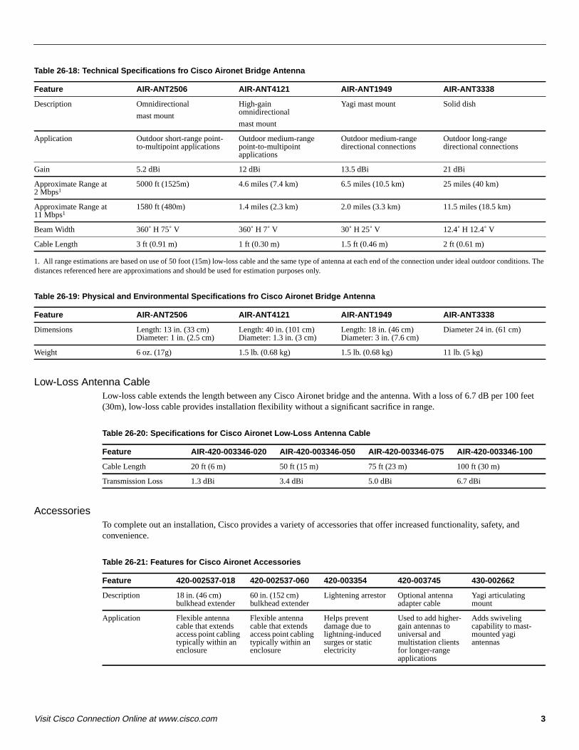
3Visit Cisco Connection Online at www.cisco.com
Table 26-18: Technical Specifications fro Cisco Aironet Bridge Antenna
1. All range estimations are based on use of 50 foot (15m) low-loss cable and the same type of antenna at each end of the connection under ideal outdoor conditions. Thedistances referenced here are approximations and should be used for estimation purposes only.
Table 26-19: Physical and Environmental Specifications fro Cisco Aironet Bridge Antenna
Low-Loss Antenna CableLow-loss cable extends the length between any Cisco Aironet bridge and the antenna. With a loss of 6.7 dB per 100 feet(30m), low-loss cable provides installation flexibility without a significant sacrifice in range.
Table 26-20: Specifications for Cisco Aironet Low-Loss Antenna Cable
AccessoriesTo complete out an installation, Cisco provides a variety of accessories that offer increased functionality, safety, andconvenience.
Table 26-21: Features for Cisco Aironet Accessories
Feature AIR-ANT2506 AIR-ANT4121 AIR-ANT1949 AIR-ANT3338
Description Omnidirectional
mast mount
High-gainomnidirectional
mast mount
Yagi mast mount Solid dish
Application Outdoor short-range point-to-multipoint applications
Outdoor medium-rangepoint-to-multipointapplications
Outdoor medium-rangedirectional connections
Outdoor long-rangedirectional connections
Gain 5.2 dBi 12 dBi 13.5 dBi 21 dBi
Approximate Range at2 Mbps1
5000 ft (1525m) 4.6 miles (7.4 km) 6.5 miles (10.5 km) 25 miles (40 km)
Approximate Range at11 Mbps1
1580 ft (480m) 1.4 miles (2.3 km) 2.0 miles (3.3 km) 11.5 miles (18.5 km)
Beam Width 360˚ H 75˚ V 360˚ H 7˚ V 30˚ H 25˚ V 12.4˚ H 12.4˚ V
Cable Length 3 ft (0.91 m) 1 ft (0.30 m) 1.5 ft (0.46 m) 2 ft (0.61 m)
Feature AIR-ANT2506 AIR-ANT4121 AIR-ANT1949 AIR-ANT3338
Dimensions Length: 13 in. (33 cm)Diameter: 1 in. (2.5 cm)
Length: 40 in. (101 cm)Diameter: 1.3 in. (3 cm)
Length: 18 in. (46 cm)Diameter: 3 in. (7.6 cm)
Diameter 24 in. (61 cm)
Weight 6 oz. (17g) 1.5 lb. (0.68 kg) 1.5 lb. (0.68 kg) 11 lb. (5 kg)
Feature AIR-420-003346-020 AIR-420-003346-050 AIR-420-003346-075 AIR-420-003346-100
Cable Length 20 ft (6 m) 50 ft (15 m) 75 ft (23 m) 100 ft (30 m)
Transmission Loss 1.3 dBi 3.4 dBi 5.0 dBi 6.7 dBi
Feature 420-002537-018 420-002537-060 420-003354 420-003745 430-002662
Description 18 in. (46 cm)bulkhead extender
60 in. (152 cm)bulkhead extender
Lightening arrestor Optional antennaadapter cable
Yagi articulatingmount
Application Flexible antennacable that extendsaccess point cablingtypically within anenclosure
Flexible antennacable that extendsaccess point cablingtypically within anenclosure
Helps preventdamage due tolightning-inducedsurges or staticelectricity
Used to add higher-gain antennas touniversal andmultistation clientsfor longer-rangeapplications
Adds swivelingcapability to mast-mounted yagiantennas

4 Cisco Product Catalog, September, 2000
SoftwareSoftware applications for Cisco products can be found at http://www.cisco.com/univercd/cc/td/doc/pcat/
Ordering Information
Part NumbersFor part numbers for all Cisco Aironet products, see Ordering Information in

Corporate Headquarters: Cisco Systems, Inc., 170 West Tasman Drive, San Jose, CA 95134-1706 USA
Copyright © 2000. Cisco Systems, Inc. All rights reserved. 78-10735-01
Mounting Instructions for theCisco Aironet 340 Series Lightning Arrestor
March 27, 2000
This document describes the lightning arrestor kit and provides instructions for mounting the arrestor.
IntroductionOvervoltage transients can be created through lightning static discharges, switch processes, directcontact with power lines or through earth currents.
Cisco Aironet lightning EMP protectors limit the amplitude and duration of disturbing interferencevoltages. Therefore, these protectors improve the overvoltage resistance of in-line equipment, systems,and components. The following mounting procedure balances the voltage potential, thus preventinginductive interference to parallel signal lines within the protected system.
WarningsPlease note the following warnings to prevent accidents during the installation of the arrestor.
Warning Disconnect or switch off in-line equipment when installing or inspecting lightningprotectors during an electrical storm.
Warning When connecting lightning protectors, make sure that the succeeding equipment andcomponents are disconnected or turned off.

2Mounting Instructions for the Cisco Aironet 340 Series Lightning Arrestor
78-10735-01
Installation Notes
Installation NotesThis arrestor is designed to be installed between your outdoor antenna cable and the Cisco Aironetwireless radio device. Installation should be completed indoors or inside a protected area. A goodground must be attached to the arrestor by using a ground lug attached to the arrestor and a heavy wire(#6 solid copper) connecting the lug to a good earth ground. See Figure 1.
Figure 1 Lightning Arrestor Installation
Lightning Arrestor Kit
Aironet part number: 420-003354
Contains: lightning arrestor, EMP grounding ring and instruction sheet.
The kit can be ordered through your Cisco Aironet distributor.
To antenna
To RF device
LugLockwasher
Nut
Ground wire33
594

3Mounting Instructions for the Cisco Aironet 340 Series Lightning Arrestor
78-10735-01
Installation Notes
Access Registrar, AccessPath, Any to Any, AtmDirector, Browse with Me, CCDA, CCDE, CCDP, CCIE, CCNA, CCNP, CCSI, CD-PAC, the Ciscologo, Cisco Certified Internetwork Expert logo,CiscoLink, the Cisco Management Connection logo, the Cisco NetWorkslogo, the Cisco PoweredNetwork logo, Cisco Systems Capital, the Cisco Systems Capital logo, Cisco Systems Networking Academy, the Cisco Systems NetworkingAcademy logo, the Cisco Technologies logo, ConnectWay, Fast Step, FireRunner, Follow Me Browsing, FormShare, GigaStack, IGX, Intelligencein the Optical Core, Internet Quotient, IP/VC, Kernel Proxy, MGX, MultiPath Data, MultiPath Voice, Natural Network Viewer, NetSonar, NetworkRegistrar, the Networkers logo,Packet, PIX, Point and Click Internetworking, Policy Builder, Precept, ScriptShare, Secure Script, ServiceWay,Shop with Me, SlideCast, SMARTnet, SVX,The Cell, TrafficDirector, TransPath, ViewRunner, Virtual Loop Carrier System, Virtual ServiceNode, Virtual Voice Line, VisionWay, VlanDirector, Voice LAN, WaRP, Wavelength Router, Wavelength Router Protocol, WebViewer,Workgroup Director, and Workgroup Stack are trademarks; Changing the Way We Work, Live, Play, and Learn, Empowering the InternetGeneration, The Internet Economy, and The New Internet Economy are service marks; and Aironet, ASIST, BPX, Catalyst, Cisco, Cisco IOS, theCisco IOS logo, Cisco Systems, the Cisco Systems logo, the Cisco Systems Cisco Press logo, Enterprise/Solver, EtherChannel, EtherSwitch,FastHub, FastLink, FastPAD, FastSwitch, GeoTel, IOS, IP/TV, IPX, LightStream, LightSwitch, MICA, NetRanger, Post-Routing, Pre-Routing,Registrar, StrataView Plus, Stratm, TeleRouter, and VCO are registered trademarks of Cisco Systems, Inc. or its affiliates in the U.S. and certainother countries. All other trademarks mentioned in this document are the property of their respective owners. The use of the word partner does notimply a partnership relationship between Cisco and any of its resellers. (9912R)
Copyright © 2000, Cisco Systems, Inc.All rights reserved.

293
Anexo 5: Manual de usuario de los puentes inalámbricos de la Serie Aironet 340
Este archivo comprende la guía del usuario provista por los fabricantes de los
puentes inalámbricos de la Serie Aironet.
170 West Tasman DriveSan Jose, CA 95134-1706USAhttp://www.cisco.com
Cisco Systems, Inc.Corporate Headquarters
Tel:800 553-NETS (6387)408 526-4000
Fax: 408 526-4100
Using the Cisco Aironet340 Series Wireless BridgesMarch 27, 2000
Text Part Number: OL-0399-01

THE SPECIFICATIONS AND INFORMATION REGARDING THE PRODUCTS IN THIS MANUAL ARE SUBJECT TO CHANGE WITHOUT NOTICE. ALL STATEMENTS, INFORMATION, AND RECOMMENDATIONS IN THIS MANUAL ARE BELIEVED TO BE ACCURATE BUT ARE PRESENTED WITHOUT WARRANTY OF ANY KIND, EXPRESS OR IMPLIED. USERS MUST TAKE FULL RESPONSIBILITY FOR THEIR APPLICATION OF ANY PRODUCTS.
THE SOFTWARE LICENSE AND LIMITED WARRANTY FOR THE ACCOMPANYING PRODUCT ARE SET FORTH IN THE INFORMATION PACKET THAT SHIPPED WITH THE PRODUCT AND ARE INCORPORATED HEREIN BY THIS REFERENCE. IF YOU ARE UNABLE TO LOCATE THE SOFTWARE LICENSE OR LIMITED WARRANTY, CONTACT YOUR CISCO REPRESENTATIVE FOR A COPY.
The following information is for FCC compliance of Class A devices: This equipment has been tested and found to comply with the limits for a Class A digital device, pursuant to part 15 of the FCC rules. These limits are designed to provide reasonable protection against harmful interference when the equipment is operated in a commercial environment. This equipment generates, uses, and can radiate radio-frequency energy and, if not installed and used in accordance with the instruction manual, may cause harmful interference to radio communications. Operation of this equipment in a residential area is likely to cause harmful interference, in which case users will be required to correct the interference at their own expense.
The following information is for FCC compliance of Class B devices: The equipment described in this manual generates and may radiate radio-frequency energy. If it is not installed in accordance with Cisco’s installation instructions, it may cause interference with radio and television reception. This equipment has been tested and found to comply with the limits for a Class B digital device in accordance with the specifications in part 15 of the FCC rules. These specifications are designed to provide reasonable protection against such interference in a residential installation. However, there is no guarantee that interference will not occur in a particular installation.
Modifying the equipment without Cisco’s written authorization may result in the equipment no longer complying with FCC requirements for Class A or Class B digital devices. In that event, your right to use the equipment may be limited by FCC regulations, and you may be required to correct any interference to radio or television communications at your own expense.
You can determine whether your equipment is causing interference by turning it off. If the interference stops, it was probably caused by the Cisco equipment or one of its peripheral devices. If the equipment causes interference to radio or television reception, try to correct the interference by using one or more of the following measures:
• Turn the television or radio antenna until the interference stops.
• Move the equipment to one side or the other of the television or radio.
• Move the equipment farther away from the television or radio.
• Plug the equipment into an outlet that is on a different circuit from the television or radio. (That is, make certain the equipment and the television or radio are on circuits controlled by different circuit breakers or fuses.)
Modifications to this product not authorized by Cisco Systems, Inc. could void the FCC approval and negate your authority to operate the product.
The Cisco implementation of TCP header compression is an adaptation of a program developed by the University of California, Berkeley (UCB) as part of UCB’s public domain version of the UNIX operating system. All rights reserved. Copyright © 1981, Regents of the University of California.
NOTWITHSTANDING ANY OTHER WARRANTY HEREIN, ALL DOCUMENT FILES AND SOFTWARE OF THESE SUPPLIERS ARE PROVIDED “AS IS” WITH ALL FAULTS. CISCO AND THE ABOVE-NAMED SUPPLIERS DISCLAIM ALL WARRANTIES, EXPRESSED OR IMPLIED, INCLUDING, WITHOUT LIMITATION, THOSE OF MERCHANTABILITY, FITNESS FOR A PARTICULAR PURPOSE AND NONINFRINGEMENT OR ARISING FROM A COURSE OF DEALING, USAGE, OR TRADE PRACTICE.
IN NO EVENT SHALL CISCO OR ITS SUPPLIERS BE LIABLE FOR ANY INDIRECT, SPECIAL, CONSEQUENTIAL, OR INCIDENTAL DAMAGES, INCLUDING, WITHOUT LIMITATION, LOST PROFITS OR LOSS OR DAMAGE TO DATA ARISING OUT OF THE USE OR INABILITY TO USE THIS MANUAL, EVEN IF CISCO OR ITS SUPPLIERS HAVE BEEN ADVISED OF THE POSSIBILITY OF SUCH DAMAGES.
Access Registrar, AccessPath, Any to Any, AtmDirector, Browse with Me, CCDA, CCDE, CCDP, CCIE, CCNA, CCNP, CCSI, CD-PAC, the Cisco logo, Cisco Certified Internetwork Expert logo, CiscoLink, the Cisco Management Connection logo, the Cisco NetWorks logo, the Cisco Powered Network logo, Cisco Systems Capital, the Cisco Systems Capital logo, Cisco Systems Networking Academy, the Cisco Systems Networking Academy logo, the Cisco Technologies logo, ConnectWay, Fast Step, FireRunner, Follow Me Browsing, FormShare, GigaStack, IGX, Intelligence in the Optical Core, Internet Quotient, IP/VC, Kernel Proxy, MGX, MultiPath Data, MultiPath Voice, Natural Network Viewer, NetSonar, Network Registrar, the Networkers logo, Packet, PIX, Point and Click Internetworking, Policy Builder, Precept, ScriptShare, Secure Script, ServiceWay, Shop with Me, SlideCast, SMARTnet, SVX, The Cell, TrafficDirector, TransPath, ViewRunner, Virtual Loop Carrier System, Virtual Service Node, Virtual Voice Line, VisionWay, VlanDirector, Voice LAN, WaRP, Wavelength Router, Wavelength Router Protocol, WebViewer, Workgroup Director, and Workgroup Stack are trademarks; Changing the Way We Work, Live, Play, and Learn, Empowering the Internet Generation, The

Internet Economy, and The New Internet Economy are service marks; and Aironet, ASIST, BPX, Catalyst, Cisco, Cisco IOS, the Cisco IOS logo, Cisco Systems, the Cisco Systems logo, the Cisco Systems Cisco Press logo, Enterprise/Solver, EtherChannel, EtherSwitch, FastHub, FastLink, FastPAD, FastSwitch, GeoTel, IOS, IP/TV, IPX, LightStream, LightSwitch, MICA, NetRanger, Post-Routing, Pre-Routing, Registrar, StrataView Plus, Stratm, TeleRouter, and VCO are registered trademarks of Cisco Systems, Inc. or its affiliates in the U.S. and certain other countries. All other trademarks mentioned in this document are the property of their respective owners. The use of the word partner does not imply a partnership relationship between Cisco and any of its resellers. (9912R)
Using the Cisco Aironet340 Series Wireless BridgesCopyright © 2000, Cisco Systems, Inc.All rights reserved.
ContentsAbout the User’s Guide ...................................................................................................... ix
Typographical Conventions .................................................................................................. xi
Welcome to the Aironet 240 Series Bridge
Data Transparency and Protocols .................................................................................. xii
Ethernet Compatibility .................................................................................................. xiii
Protocols Supported ...................................................................................................... xiii
Radio Characteristics .................................................................................................... xiii
Radio Ranges ................................................................................................................ xiv
Security Features ........................................................................................................... xv
Terminology .................................................................................................................. xv
Bridge System Configurations ...................................................................................... xvi
Chapter 1 - Installing the Aironet 340 Series Bridge
Before You Start ................................................................................................................. 1-2
Installation .......................................................................................................................... 1-3
Installing the Antennas .................................................................................................. 1-3
Installing the Console Port Cable ................................................................................ 1-5
Installing the Ethernet Connection .............................................................1-6
Attaching the AC/DC Power Pack and Powering On the Aironet 340 Series Bridge ................................................................ 1-8
Viewing the Indicator Displays ........................................................................................... 1-9
Top Panel Indicators ...................................................................................................... 1-9
Back Panel Indicators .................................................................................................... 1-11
Chapter 2 - Accessing the Console System
Access Methods .................................................................................................................. 2-2
Using the Console ............................................................................................................... 2-2
Sub-Menus ...............................................................................................2-3
Commands and Information .......................................................................................... 2-4
Commands That Display Information ........................................................................... 2-5
ii Contents
Command Line Mode ................................................................................................... 2-6
Telnet Access ...................................................................................................................... 2-6
Web Access ......................................................................................................................... 2-7
About the Menus ................................................................................................................. 2-10
Using the Configuration Console Menu ............................................................................. 2-11
Setting Privilege Levels and Passwords (Rpassword, Wpassword) ............................. 2-11
Controlling Telnet and Web Access to the Console ...................................................... 2-12
Controlling SNMP access to the configuration ............................................................. 2-13
Controlling Who Can Access the Console .................................................................... 2-14
Setting the Terminal Type (Type) .................................................................................. 2-14
Setting the Communication Port Parameters (Port) ...................................................... 2-15
Enabling Linemode (Linemode) ................................................................................... 2-16
Monitoring of the DTR Signal ............................................................................................ 2-17
Chapter 3 - Before You Begin
Viewing the Configuration Menu ....................................................................................... 3-2
Menu Descriptions ........................................................................................................ 3-2
Saving Configuration Parameters ................................................................................. 3-3
Backing up your Configuration (Dump) ....................................................................... 3-3
Restoring your Configuration ....................................................................................... 3-4
Chapter 4 - Configuring the Radio Network
Overview ............................................................................................................................ 4-2
Using the Configuration Radio Menu ................................................................................. 4-3
Establishing an SSID (SSID) ........................................................................................ 4-3
Enabling Root Mode (Root) .......................................................................................... 4-3
Selecting the Allowed Data Rates (Rates) .................................................................... 4-3
Basic Rates (Basic_rates) .............................................................................................. 4-4
Selecting Frequency (Frequency) ................................................................................. 4-4
Setting the Distance (Distance) ..................................................................................... 4-4
Using the Configuration Radio IEEE 802.11 Menu ........................................................... 4-5
Setting the Beacon Period (Beacon) ............................................................................. 4-5

Contents iii
Setting the Forwarding Time Interval (DTIM) ............................................................. 4-5
Adding IEEE 802.11 Management Packet Extensions (Extend) .................................. 4-6
Allowing the Broadcast SSID (Bcst_ssid) .................................................................... 4-6
Setting the RF RTS/CTS Parameter (RTS) ................................................................... 4-6
Packet Encapsulation (Encapsulation Menu) ..................................................................... 4-7
Packet Encapsulation in Mixed Networks .................................................................... 4-7
Packet Encryption (Privacy Menu) ..................................................................................... 4-9
Using the Configuration Radio LinkTests Menu ................................................................ 4-11
Running a Signal Strength Test (Strength) .................................................................... 4-11
Running a Carrier Busy Test ......................................................................................... 4-11
Running the Echo Tests (Multicast, Unicast, Remote) ................................................. 4-12
Using the Configuration Radio Extended Menu ................................................................. 4-17
Setting the Operating Mode (Bridge_mode) ................................................................. 4-17
Selecting a specific parent (Parent_id, Parent_timeout) ............................................... 4-17
Setting Retry Transmission Time (Time_Retries, Count_Retries) ............................... 4-18
Setting the Association Refresh Interval (Refresh) ....................................................... 4-18
Roaming Notification Mode (Roaming) ....................................................................... 4-19
Setting the Loading Balance (Balance) ......................................................................... 4-19
Setting Diversity (Diversity) ......................................................................................... 4-19
Setting the Power Level (Power) .................................................................................. 4-19
Setting Fragment Size (Fragment) ................................................................................ 4-19
Setting Purchasable Radio Options (Options) .............................................................. 4-20
Chapter 5 - Configuring the Ethernet Port
Using the Configuration Ethernet Menu ............................................................................. 5-2
Activating/Disabling the Ethernet Port (Active) ......................................................... 5-2
Setting the Maximum Frame Size (Size) ...................................................................... 5-2
Setting the Port Interface Type (Port) ........................................................................... 5-3
Chapter 6 - Setting Network Identifiers
Using the Configuration Ident Menu .................................................................................. 6-2
Using DHCP or BOOTP ............................................................................6-2

iv Contents
Assigning an IP Address (Inaddr) ................................................................................. 6-2
Specifying the IP Subnet Mask (Inmask) ..................................................................... 6-3
Setting Up the Domain Name Servers (Dns1,Dns1,Domain) ....................................... 6-3
Establishing a Node Name (Name) ............................................................................... 6-3
Setting SNMP Location and Contact Identifiers (Location,Contact) ........................... 6-3
Configuring the IP Routing Table (Gateway, Routing) ................................................ 6-3
Setting up the Time Base (Configuration Time) ........................................................... 6-5
Chapter 7 - Configuring Mobile IP
Using the Configuration Mobile IP Menu ...............................................................7-2
Setting the Agent Type (AgentType) ............................................................................ 7-2
Displaying the Active Clients (Mobile, Visitors) .......................................................... 7-2
Authorizing Mobile Nodes to Roam (Add/Remove/Display) ...................................... 7-3
Set up the Agent Parameters (Setup) ............................................................................ 7-4
Control Agent Advertisements (Advert) ....................................................................... 7-5
Chapter 8 - Using the Spanning Tree Protocol
Overview ............................................................................................................................ 8-2
Understanding Loops ................................................................................................... 8-3
How STP Protocol Works ................................................................................................... 8-4
Receiving Configuration Messages .............................................................................. 8-4
Determining the Root Bridge and Root Cost ................................................................ 8-5
Determining the Spanning Tree .................................................................................... 8-6
Understanding Bridge Failures ..................................................................................... 8-6
Avoiding Temporary Loops .......................................................................................... 8-6
Establishing Timeouts ................................................................................................... 8-7
Node Address Aging ..................................................................................................... 8-7
Implementing STP Protocol ............................................................................................... 8-8
Using the Configuration STP Menu (Root Bridge Only) ............................................................................................................... 8-9
Setting Port Parameters (Port) ....................................................................................... 8-14
Displaying the Protocol Status (Display) ...................................................................... 8-16
Viewing the Port State (State) ....................................................................................... 8-17

Contents v
Chapter 9 - Viewing Statistics
Viewing the Statistics Menu ............................................................................................... 9-2
Throughput Statistics (Throughput) .............................................................................. 9-3
Radio Error Statistics (Radio) ....................................................................................... 9-4
Error Statistics ............................................................................................................... 9-5
Displaying Overall Status (Status) ................................................................................ 9-7
Display a Network Map (Map) ..................................................................................... 9-8
Recording a Statistic History (Watch) ........................................................................... 9-8
Displaying a Statistic History (History) ........................................................................ 9-10
Displaying Node Information (Node) ........................................................................... 9-11
Displaying ARP Information (ARP) ............................................................................. 9-11
Setting Screen Display Time (Display_Time) .............................................................. 9-12
Determine Client IP Addresses (Ipadr) ......................................................................... 9-12
Chapter 10 - Setting Up the Association Table
Overview ............................................................................................................................ 10-2
Using the Association Menu ............................................................................................... 10-3
Displaying the Association Table (Display) ................................................................. 10-3
Displaying the Association Table Summary (Summary) .............................................. 10-5
Setting the Allowed Number of Child Nodes (Maximum) ........................................... 10-5
Controlling Associations With Static Entries (Autoassoc/Add/Remove) ..................... 10-6
Backbone LAN Node Stale Out Time (Staletime) ........................................................ 10-8
Specifying How Node Addresses are Displayed (NIDdisp) ......................................... 10-8
Chapter 11 - Using Filters
Overview ............................................................................................................................ 11-2
Using the Filter Menu ......................................................................................................... 11-2
Packet Direction (Direction) ......................................................................................... 11-2
Filtering Multicast Addresses (Multicast) ..................................................................... 11-3
Filtering Node Addresses (Node) ................................................................................. 11-5
Filtering Protocols (Protocols) ...................................................................................... 11-7

vi Contents
Chapter 12 - Setting Up Event Logs
Overview ............................................................................................................................ 12-2
Information Logs ......................................................................................................... 12-2
Error Logs .................................................................................................................... 12-5
Severe Error Logs ........................................................................................................ 12-5
Using the Logs Menu .......................................................................................................... 12-8
Viewing History Logs (History) ................................................................................... 12-8
Clearing the History Buffer (Clear) .............................................................................. 12-9
Specifying the Type of Logs to Print (Printlevel) ......................................................... 12-10
Specifying the Type of Logs to Save (Loglevel) .......................................................... 12-10
Specifying the Type of Logs to Light Status Indicator (Ledlevel) ................................ 12-10
Setting Statistic Parameters (Statistics) ......................................................................... 12-11
Log Network Roaming (Network) ................................................................................ 12-12
Logging Backbone Node changes (BnodeLog) ............................................................ 12-12
Setting up SNMP traps (Snmp) ..................................................................................... 12-12
Forwarding Logs to a Unix System (Syslog,SysLevel,Facility,Rcvsyslog) ................. 12-14
Chapter 13 - Performing Diagnostics
Using the Diagnostics Menu ............................................................................................... 13-2
Testing the Radio Link (Linktest) ................................................................................. 13-2
Restarting the Unit (Restart) ......................................................................................... 13-2
Returning the Unit to the Default Configuration (Default, Reset) ................................ 13-2
Using the Network Menu .................................................................................................... 13-3
Starting a Telnet Session (Connect) .............................................................................. 13-3
Changing the Escape Sequence (Escape) ...................................................................... 13-4
Physically Locating a Unit (Find) ................................................................................. 13-5
Sending a Ping Packet (Ping) ........................................................................................ 13-5
Loading New Firmware and Configurations (Load) .......................................................... 13-5
Downloading Using Xmodem Protocol (Xmodem/Crc-xmodem) ............................... 13-6
Downloading or Uploading using the File Transfer Protocol (Ftp) .............................. 13-7
Downloading Using the Internet Boot Protocol (Bootp/DHCP) .................................. 13-10
Distributing Firmware or Configuration (Distribute) ...........................................13-12
Contents vii
Appendix A -Aironet 340 Series Bridge Specifications
LAN Interfaces Supported .................................................................................................. A-1
Ethernet ......................................................................................................................... A-1
Radio Characteristics .........................................................................................A-1
Physical Specifications ....................................................................................................... A-2
Console Port Pin-Out .......................................................................................................... A-3
Appendix B -Console Menu Tree
Appendix C -SNMP Variables
Appendix D - Cisco Technical Support
Appendix E -Regulatory Information
Manufacturer’s Federal CommunicationCommission Declaration of Conformity Statement ............................................................ E-1
Professional Installation ................................................................................................ E-2
Department of Communications—CanadaCanadian Compliance Statement ........................................................................................ E-3
European Telecommunication Standards InstituteStatement of ComplianceInformation to User ............................................................................................................. E-4
About the User’s Guide - ix
About the User’s GuideThis manual covers the installation, configuration, control, and maintenance of your Aironet 340 Series Bridge.
Please read Chapter 1 – Installing the Aironet 340 Series Bridge before attempting to install or use the hardware and software described in this manual.
The user’s guide is arranged as follows:
Chapter 1 – Installing the Aironet 340 Series Bridge – Describes the physical installation of the Aironet 340 Series Bridge.
Chapter 2 – Accessing the Console System – Introduces you to the Con-sole Port and shows you how to set up and configure the Console Port parameters.
Chapter 3 – Before You Begin – Provides you with an overview of the Configuration Menu and how to save and restore your configurations.
Chapter 4 – Configuring the Radio Network – Contains detailed procedures for configuring your Radio Network.
Chapter 5 – Configuring the Ethernet Port – Contains detailed proce-dures for configuring the Ethernet port.
Chapter 6 – Setting Network Identifiers – Outlines the procedures for setting the Aironet 340 Series Bridge’s Network Identifiers.
Chapter 7 – Configuring Mobile IP – Describes how to configure the Aironet 340 Series Bridge for use with the Mobile IP Protocol.
Chapter 8 – Using the Spanning-Tree Protocol – Describes how toconfigure the Aironet 340 Series Bridge for use with the Spanning Tree Protocol.
Chapter 9 – Viewing Statistics – Describes how to use the Statistics Menu to monitor the performance of the Aironet 340 Series Bridge.
Chapter 10 – Setting Up the Association Table – Provides you with an introduction to the association process and detailed procedures for setting up the Aironet 340 Series Bridge’s Association Table.

x Aironet 340 Series Bridge
Chapter 11 – Using Filters – Describes how to control the forwarding of multicast messages.
Chapter 12 – Setting Up Event Logs – Outlines the procedures for set-ting up Event Logs and lists the common error log messages received on the Aironet 340 Series Bridge.
Chapter 13 – Performing Diagnostics – Provides you with detailed procedures for restarting your unit, returning to your default configura-tion, and loading new firmware versions.
Appendix A – Aironet 340 Series Bridge Specifications – Details the Aironet 340 Series Bridge radio and physical specifications.
Appendix B – Console Menu Tree – Provides you with a listing of all menus, sub-menus, and options contained in the Console Port.
Appendix C – SNMP Variables – Lists the SNMP variables supported by the Aironet 340 Series Bridge.
Appendix D – Cisco Technical Support – Describes how to contact Cisco for technical support.
Appendix E – Regulatory Information – Provides the FCC, DOC, and ETSI regulatory statements for the Aironet 340 Series Bridge.

About the User’s Guide - xi
Typographical Conventions
When reading the user’s guide, it’s important to understand the symbol and formatting conventions used in the documentation. The following symbols and formatting are used in the manual.
Convention Type of Information
Indicates a note which contains important information set off from the normal text.
A caution message that appears before proce-dures which, if not observed, could result in loss of data or damage to the equipment.
Bold type An action you must perform such as type or select.
Monospaced font Information and menus that are visible on the Console Port screens.
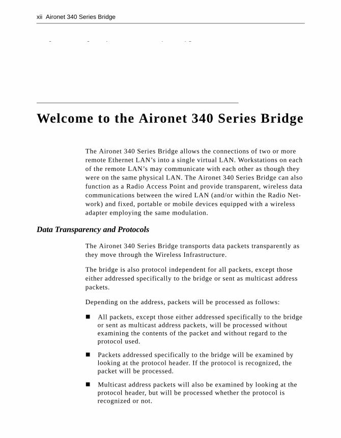
xii Aironet 340 Series Bridge
Welcome to the Aironet 240 Series Bridge
Welcome to the Aironet 340 Series Bridge
The Aironet 340 Series Bridge allows the connections of two or more remote Ethernet LAN’s into a single virtual LAN. Workstations on each of the remote LAN’s may communicate with each other as though they were on the same physical LAN. The Aironet 340 Series Bridge can also function as a Radio Access Point and provide transparent, wireless data communications between the wired LAN (and/or within the Radio Net-work) and fixed, portable or mobile devices equipped with a wireless adapter employing the same modulation.
Data Transparency and Protocols
The Aironet 340 Series Bridge transports data packets transparently as they move through the Wireless Infrastructure.
The bridge is also protocol independent for all packets, except those either addressed specifically to the bridge or sent as multicast address packets.
Depending on the address, packets will be processed as follows:
� All packets, except those either addressed specifically to the bridge or sent as multicast address packets, will be processed without examining the contents of the packet and without regard to the protocol used.
� Packets addressed specifically to the bridge will be examined by looking at the protocol header. If the protocol is recognized, the packet will be processed.
� Multicast address packets will also be examined by looking at the protocol header, but will be processed whether the protocol is recognized or not.
Aironet 340 Series Bridge xiii
� If protocol filtering is enabled then the appropriate parts of the packet will be examined.
Ethernet Compatibility
The Aironet 340 Series Bridge can attach directly to 10Base2 (Thinnet), 10Base5 (Thicknet) or 10BaseT (Twisted Pair) Ethernet LAN segments. These segments must conform to IEEE 802.3 or Ethernet Blue Book specifications.
If the existing infrastructure to which the bridge is to be attached is not Ethernet-based, an Ethernet segment can be added by installing an Ethernet Network Interface Card (NIC) in the File Server or by adding a third-party bridge.
The bridge appears as an Ethernet node and performs a routing function by moving packets from the wired LAN to remote workstations (per-sonal computers, laptops and hand held computing devices) on the Wire-less Infrastructure.
Protocols Supported
Protocols supported:� TCP/IP based protocol products
� SNMP Protocol – The resident agent is compliant with the MIB-I and MIB-II standards, TCP/IP based internets, as well as a custom MIB for specialized control of the system.
Radio Characteristics
The Aironet 340 Series Bridge uses a radio modulation technique known as Direct Sequence Spread Spectrum transmission (DSSS). It combines high data throughput with excellent immunity to interference. The bridge operates in the 2.4 GHz license-free Industrial Scientific and Medical (ISM) band. Data is transmitted over a half-duplex radio chan-nel operating at up to 11 Megabits per second (Mbps).
xiv Aironet 340 Series Bridge
Radio Ranges
The following section provides general guidelines on factors that influence infrastructure performance.
Site Survey
Because of differences in component configuration, placement, and physical environment, every infrastructure application is a unique instal-lation. Before installing the system, users should perform a site survey in order to determine the optimum utilization of networking components and to maximize range, coverage and infrastructure performance.
Here are some operating and environmental conditions that need to be considered:
� Data Rates. Sensitivity and range are inversely proportional to data bit rates. The maximum radio range is achieved at the lowest work-able data rate. There will be a decrease in receiver threshold as the radio data rate increases.
� Antenna Type and Placement. Proper antenna configuration is a critical factor in maximizing radio range. As a general guide, range increases in proportion to antenna height.
For a detailed explanation of antenna types and configurations along with guidelines on selecting antennas for specific environments, see the Aironet Antenna Guide, document number 710-003725.
� Physical Environments. Clear or open areas provide better radio range than closed or filled areas. Also, the less cluttered the work environment, the greater the range.
� Obstructions. A physical obstruction such as shelving or a pillar can hinder the performance of the bridge. Avoid locating the com-puting device and antenna in a location where there is a barrier between the sending and receiving antennas.
� Building Materials. Radio penetration is greatly influenced by the building material used in construction. For example, drywall con-struction allows greater range than concrete blocks.

Aironet 340 Series Bridge xv
Line of Site
A clear line of sight must be maintained between wireless bridge anten-nas. Any obstructions may impede the performance or prohibit the abil-ity of the wireless bridge to transmit and receive data. Directional antennas should be placed at both ends at appropriate elevation with maximum path clearance.
Security Features
The Aironet 340 Series Bridge employs Spread Spectrum Technology, previously developed for military “anti-jamming” and “low probability of intercept” radio systems.
The Aironet 340 Series Bridge must be set to the same System Identifier (SSID) as all other Aironet devices on the wireless infrastructure. Units with a different SSID will not be able to directly communicate with each other.
Terminology
When configuring your system, and when reading this manual, keep in mind the following terminology:
Infrastructure – The wireless infrastructure is the communications sys-tem that combines Aironet bridges, mobile nodes and fixed nodes. Airo-net bridges within the infrastructure can be either root units, which are physically wired to the LAN backbone, or can act as wireless repeaters. Other RF enabled devices serve as fixed nodes or mobile nodes.
Root Unit – The root unit is an Aironet bridge that is located at the top, or starting point, of a wireless infrastructure. The root bridge is usually connected to main wired backbone LAN. Since the radio traffic from the other bridges LANs will pass through this unit, the root unit is usually connected to the LAN which originates or receives the most traffic
Repeater – A repeater is an Aironet bridge that establishes a connection to the root bridge or another repeater bridge to make the wired LAN to which it is connected part of the bridged LAN.
End Node – A radio node that is located at the end of the network tree.
xvi Aironet 340 Series Bridge
Parent/Child Node – Refers to the relationships between nodes in the wireless infrastructure. The complete set of relationships is sometimes described as a network tree. For example, the Aironet bridge (at the top of the tree) would be the parent of the end nodes. Conversely, the end nodes would be the children of the Aironet bridge.
Association – Each root unit or repeater in the infrastructure contains an association table that controls the routing of packets between the bridge and the wireless infrastructure. The association table maintains entries for all the nodes situated below the Aironet bridge on the infrastructure including repeaters and radio nodes.
Power Saving Protocol (PSP) and Non-Power Saving Protocol – The Power Saving Protocol allows computers (usually portable comput-ers) to power up only part of the time to conserve energy. If a radio node is using the Power Saving Protocol to communicate with the infrastruc-ture, the Aironet bridge must be aware of this mode and implement addi-tional features such as message store and forward.
Bridge System Configurations
The Aironet 340 Series Bridge can be used in a variety of infrastructure configurations. How you configure your infrastructure will determine the size of the microcell, which is the area a single bridge will provide with RF coverage. You can extend the RF coverage area by creating mul-tiple microcells on a LAN.
Examples of some common system configurations are shown on the pages that follow, along with a brief description of each.
Point-to-Point Wireless Bridge
The Point-to-Point Wireless Bridge Configuration uses two units to bridge two individual LANs. Packets are sent between the file server and Workstation B through the wireless bridge units (root unit and remote node) over the radio link. Data packets sent from the file server to Work-station A go through the wired LAN segment and do not go across the wireless radio link.

Aironet 340 Series Bridge xvii
Figure 0.1 - Point-to-Point Wireless Bridge
Point-to-Multipoint Wireless Bridge
When connecting three or more LANs (usually in different buildings), each building requires an Aironet wireless bridge and antenna. This is called a Multipoint Wireless Bridge Configuration. One wireless bridge is designated as the central site. Its antenna is configured to transmit and receive signals from the wireless bridges at the other sites. Generally, the central site is equipped with an omni-directional antenna that pro-vides radio signal coverage in all directions. The other wireless bridges are typically served by directional antennas that direct radio signals toward the central site.
Under a Multipoint Wireless Bridge Configuration, workstationson any of the LANs can communicate with other workstations orwith any workstations on the remote LANs.
Remote Node(Wireless Bridge)
Root Unit(Wireless Bridge)
File Server
Workstation A
Workstation B
LAN Segment A
LAN Segment B

xviii Aironet 340 Series Bridge
The following example shows an example of a Point-to-Multi-point Configuration. Packets sent between Workstation A andWorkstation B are forwarded by their respective wirelessbridges to the root unit. Then the root unit forwards these pack-ets to the appropriate wireless bridge for routing to the worksta-tions. Packets sent between the file server and the remoteworkstations are routed through the root unit and the appropri-ate wireless bridge.
Figure 0.2 - Point-to-Multipoint Wireless Bridge
Infrastructure Extension with Repeaters
Wireless bridges can be configured as repeaters to extend the range of a wireless network beyond that of a single radio hop. Repeaters can
Root Unit
LAN Segment CLAN Segment B
File Server
LAN Segment A
WirelessBridge
WirelessBridge
Workstation A Workstation B
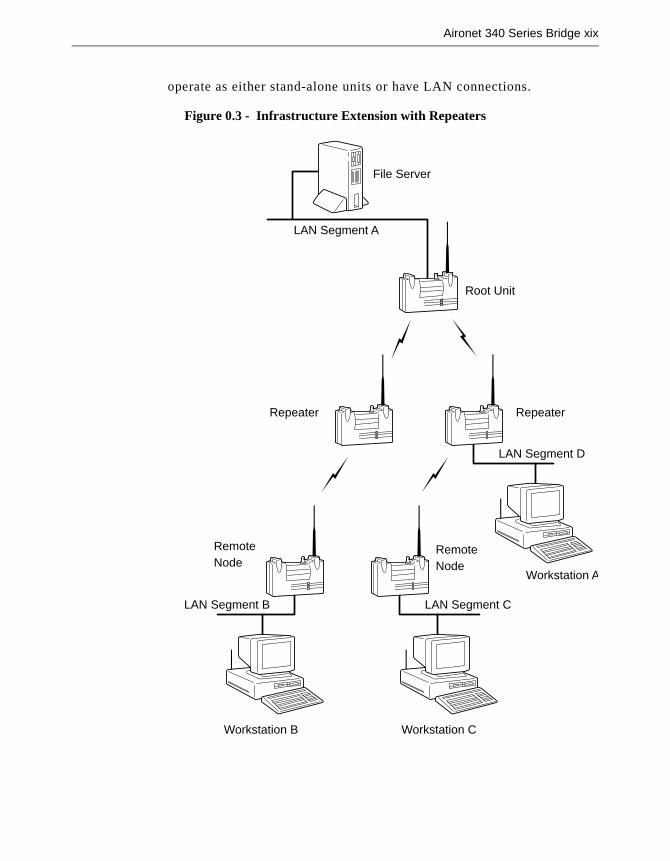
Aironet 340 Series Bridge xix
operate as either stand-alone units or have LAN connections.
Figure 0.3 - Infrastructure Extension with Repeaters
Root Unit
LAN Segment D
File Server
LAN Segment A
Repeater Repeater
LAN Segment C
RemoteNode
RemoteNode
LAN Segment B
Workstation CWorkstation B
Workstation A

Part 1 - Getting Started Part 1 - G
etting Started
Chapter 1 - Installing the Aironet 340 Series Bridge
1
C H A P T E R 1
Installing the Aironet 340 Series Bridge
This chapter describes the procedures for installing the Aironet 340 Series Bridge.
Here’s what you’ll find in this chapter:
� Before You Start
� Installation
� Installing the Antennas
� Installing the Console Port Cable
� Installing the Ethernet Connection
� Attaching the AC/DC Power Pack and Powering On the Aironet 340 Series Bridge
� Viewing the Indicator Displays

1 - 2 Aironet 340 Series Bridge
Before You StartAfter unpacking the system, make sure the following items are present and in good condition:
� Aironet 340 Series Bridge
� Power Pack. The power pack will be either 120VAC/60 Hz or90-264VAC/47-63Hz to 12-18VDC, whichever is appropriate for country of use.
� Lightning Arrestor (Bridge Package option)
� Mounting Kit (Bridge Package option)
� Low loss antenna cable (Bridge Package option)
� Appropriate directional antenna (Bridge Package option)
If any item is damaged or missing, contact your Aironet supplier. Saveall shipping and packing material in order to repack the unit should service be required.
Figure 1.1 - Overview of the Aironet 340 Series Bridge
Top Panel LEDs On/Off Button
AC/DC PowerPack Unit
Console PortRS-232 (DB-9
Female)
AntennaConnector
10Base2 (BNCT-Connector)
10Base5(AUI Port)
10BaseT (TwistedPair Ethernet)
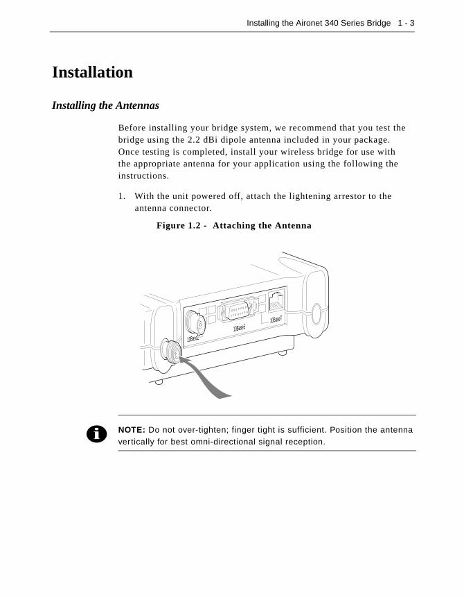
Installing the Aironet 340 Series Bridge 1 - 3
Installation
Installing the Antennas
Before installing your bridge system, we recommend that you test the bridge using the 2.2 dBi dipole antenna included in your package.Once testing is completed, install your wireless bridge for use withthe appropriate antenna for your application using the following the instructions.
1. With the unit powered off, attach the lightening arrestor to the antenna connector.
NOTE: Do not over-tighten; finger tight is sufficient. Position the antenna vertically for best omni-directional signal reception.
Figure 1.2 - Attaching the Antenna
10Base210Base5
10BaseT

1 - 4 Aironet 340 Series Bridge
2. Connect the lightning arrestor to one end of the low loss antenna cable.
NOTE: The lightning arrestor should be connected to the antenna con-nector on the wireless bridge. The lightning arrestor is added to provide surge protection to the bridge in the event of voltage surges as a result of a lightning strike.
3. Connect the antenna to the other end of the low loss antenna cable. Mount the bridge antenna at an appropriate elevation to ensure max-imum path clearance and line of sight considerations.
NOTE: Due to FCC and DOC Regulations, the antenna connectors onthe Aironet 340 Series Bridge are of reverse polarity to the standard TNC
connectors.

Installing the Aironet 340 Series Bridge 1 - 5
Installing the Console Port Cable
1. Attach the Console Port cable to the Serial Port. Attach the other cable end to the Serial Port on a terminal or a PC running a terminal emulation program. Use a 9-pin male to 9-pin female straight through cable (Figure 1.3).
NOTE: This connection is required for setting up initial configuration infor-mation. After configuration is completed, this cable may be removed until
additional configuration is required via the Serial Port.
2. Set the terminal to 9600 Baud, No-Parity, 8 data bits, 1 Stop bit, and ANSI compatible.
Figure 1.3 - Console Port Connection
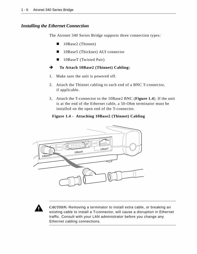
1 - 6 Aironet 340 Series Bridge
Installing the Ethernet Connection
The Aironet 340 Series Bridge supports three connection types:
� 10Base2 (Thinnet)
� 10Base5 (Thicknet) AUI connector
� 10BaseT (Twisted Pair)
� To Attach 10Base2 (Thinnet) Cabling:
1. Make sure the unit is powered off.
2. Attach the Thinnet cabling to each end of a BNC T-connector, if applicable.
3. Attach the T-connector to the 10Base2 BNC (Figure 1.4). If the unit is at the end of the Ethernet cable, a 50-Ohm terminator must be installed on the open end of the T-connector.
CAUTION: Removing a terminator to install extra cable, or breaking an existing cable to install a T-connector, will cause a disruption in Ethernet traffic. Consult with your LAN administrator before you change any Ethernet cabling connections.
Figure 1.4 - Attaching 10Base2 (Thinnet) Cabling
10Base210Base5
10BaseT

Installing the Aironet 340 Series Bridge 1 - 7
� To Attach the 10Base5 (Thicknet) Cabling:
1. Make sure the unit is powered off.
2. Attach the transceiver connector to the 10Base5 AUI port as shown in Figure 1.5.
3. Slide the locking mechanism in place.
4. Attach the other end of the transceiver drop cabling to an external transceiver.
� To Attach the 10BaseT (Twisted Pair) cabling:
1. Make sure the unit is powered off.
2. Plug the RJ-45 connector into the 10BaseT (Twisted Pair) port as shown in Figure 1.6.
3. Connect the other end of the Twisted Pair cabling to the LAN connection (such as a hub or concentrator).
Figure 1.5 - Attaching 10Base5 (Thicknet) Cabling
Figure 1.6 - Attaching 10BaseT (Twisted Pair) Cabling
10Base210Base5
10BaseT
10Base210Base5
10BaseT

1 - 8 Aironet 340 Series Bridge
Attaching the AC/DC Power Pack and Powering On the Aironet 340 Series Bridge
1. Insert the small plug on the end of the AC/DC power pack cord into the power port.
2. Plug the AC/DC power pack into an electrical outlet.(120VAC/60 Hz or 90-264VAC as appropriate)
3. Power on the Aironet 340 Series Bridge by pushing the On/Offbutton.
When power is initially applied to the bridge, all three indicators will flash in sequence to test the functionality of the indicators.
Figure 1.7 - AC to DC Power Pack Connections and On/Off Button
On/Off Button
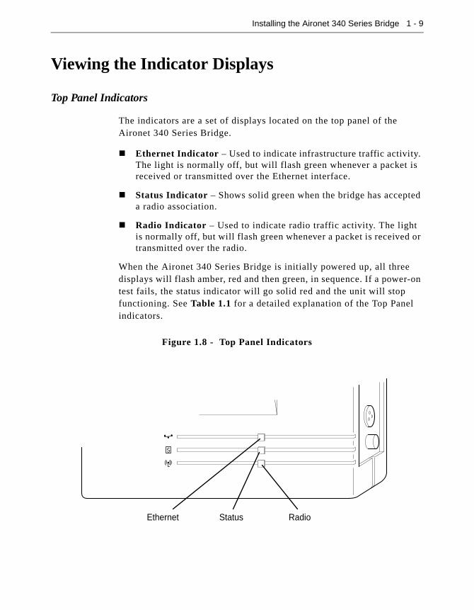
Installing the Aironet 340 Series Bridge 1 - 9
Viewing the Indicator Displays
Top Panel Indicators
The indicators are a set of displays located on the top panel of the Aironet 340 Series Bridge.
� Ethernet Indicator – Used to indicate infrastructure traffic activity. The light is normally off, but will flash green whenever a packet is received or transmitted over the Ethernet interface.
� Status Indicator – Shows solid green when the bridge has accepted a radio association.
� Radio Indicator – Used to indicate radio traffic activity. The light is normally off, but will flash green whenever a packet is received or transmitted over the radio.
When the Aironet 340 Series Bridge is initially powered up, all three displays will flash amber, red and then green, in sequence. If a power-on test fails, the status indicator will go solid red and the unit will stop functioning. See Table 1.1 for a detailed explanation of the Top Panel indicators.
Figure 1.8 - Top Panel Indicators
RadioStatusEthernet

1 - 10 Aironet 340 Series Bridge
Table 1.1 - Top Panel Indicator Description
TypeIndicator Display
DescriptionEthernet Status Radio
Nonassociated Node
Blinking Green
No nodes associated
Green One or more nodes associated
Operational Green Blinking Green
Transmitting/Receiving Radio packets
Blinking Green
Green Transmitting/Receiving packets
Green Blinking Amber
Maximum retries/buffer full occurred on radio
Error/Warning Blinking Amber
Green Transmit/Receive errors
Blinking Amber
General warning, check the logs
Failure Red Red Red Software failure
Firmware Upgrade
Red Flashing the firmware

Installing the Aironet 340 Series Bridge 1 - 11
Back Panel Indicators
The back panel indicators shown in Figure 1.9 are:
� 10BaseT polarity: Solid amber to indicate the 10BaseT polarity is reversed. Check cable connections.
� 10BaseT active: Solid green to indicate the 10BaseT has been config-ured as the active port.
� Ethernet Rx: Flashes green when an Ethernet packet has been received.
� Ethernet Tx: Flashes green when an Ethernet packet has beentransmitted.
� 10Base2 active: Solid green to indicate the 10Base2 has been config-ured as the active port.
� Packet Collision: Flashes amber to indicate a packet collision has occurred.
Figure 1.9 - Back Panel Indicators
10Base210Base5
10BaseT
PacketCollision
Ethernet Tx
10BaseT polarity
10BaseT active
10Base2 active
Ethernet Rx

Chapter 2 - Accessing the Console System
2
C H A P T E R 2
Accessing the Console System
This chapter describes the methods used to access the Console system of the Aironet 340 Series Bridge. This system contains all commands nec-essary to configure and monitor the operation of the unit.
Here’s what you’ll find in this chapter:
� Access Methods
� Using the Console
� Telnet Access
� Web Access
� About the Menus
� Using the Configuration Console Menu
� Monitoring of DTR Signal

2 - 2 Aironet 340 Series Bridge
Access MethodsThere are many ways in which you may configure and monitor the Airo-net 340 Series Bridge. When the unit is powered up, basic configuration must initially be performed by accessing the Console Serial Port. To gain access through the Serial Port, the bridge must be connected to a terminal or a PC running a terminal emulation program. See Chapter 1 “Installing the Aironet 340 Series Bridge”. Set the terminal to 9600 Baud, No-Parity, 8 data bits, 1 stop bit, and ANSI compatible.
Once the bridge has been assigned an IP address, you may then access the Console remotely using:
� Telnet protocol from a remote host or PC
� HTML browser, such as Netscape Navigator from a remote host
� Simple Network Management Protocol (SNMP) from a remote net-work management station
Using the ConsoleThe Console system is organized as a set of menus. Each selection in a menu list may either take you to a sub-menu or display a command that will configure or display information controlling the unit.
When the bridge is powered up, the main menu will be displayed.
Main Menu
Option Value Description
1 - Configuration [ menu ] - General configuration
2 - Statistics [ menu ] - Display statistics
3 - Association [ menu ] - Association table maintenance
4 - Filter [ menu ] - Control packet filtering
5 - Logs [ menu ] - Alarm and log control
6 - Diagnostics [ menu ] - Maintenance and testing commands
7 - Privilege [ write ] - Set privilege level
8 - Help - Introduction
Enter an option number or name
>
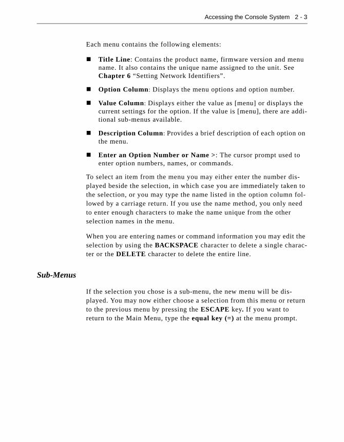
Accessing the Console System 2 - 3
Each menu contains the following elements:
� Title Line: Contains the product name, firmware version and menu name. It also contains the unique name assigned to the unit. See Chapter 6 “Setting Network Identifiers”.
� Option Column: Displays the menu options and option number.
� Value Column: Displays either the value as [menu] or displays the current settings for the option. If the value is [menu], there are addi-tional sub-menus available.
� Description Column: Provides a brief description of each option on the menu.
� Enter an Option Number or Name >: The cursor prompt used to enter option numbers, names, or commands.
To select an item from the menu you may either enter the number dis-played beside the selection, in which case you are immediately taken to the selection, or you may type the name listed in the option column fol-lowed by a carriage return. If you use the name method, you only need to enter enough characters to make the name unique from the other selection names in the menu.
When you are entering names or command information you may edit the selection by using the BACKSPACE character to delete a single charac-ter or the DELETE character to delete the entire line.
Sub-Menus
If the selection you chose is a sub-menu, the new menu will be dis-played. You may now either choose a selection from this menu or return to the previous menu by pressing the ESCAPE key. If you want to return to the Main Menu, type the equal key (=) at the menu prompt.

2 - 4 Aironet 340 Series Bridge
Commands and Information
If your selection is a command, you may be prompted for information before it executes. Information may be one of the following types:
� Token: A list of one or more fixed strings. To select a particular token, you need only enter enough of the starting characters of the token to allow it to be uniquely identified from the characters of the other tokens in the list.
Enter one of [off, readonly, write] : w
You would need only enter: “o”, “r”, or “w” followed by a carriage return.
� String: An arbitrary amount of characters. The prompt will indicate the allowable size range of the string.
Enter a name of from 1 to 10 characters: “abc def”
If the string contains a space, enclose the string in quotation marks. If you wish to enter an empty string, use two quotation marks with nothing between them.
� Integers: A decimal integer. The prompt will indicate the range of allowed values.
Enter a size between 1 and 100 : 99
hexadecimal integer – a number specified in hexadecimal using the characters 0-9 and a-f or A-F.
Enter a hex number between 1h and ffh : 1a
� Network address: An infrastructure or MAC level address of 12 characters or less. Omit leading zeros when entering an address.
Enter the remote network address : 4096123456
� IP address: An internet address in the form of 4 numbers from 0-255 separated by dots (.). Leading zeros in any of the numbers may be omitted.
Enter an IP address : 192.200.1.50
Once all information has been entered the command will execute. If the information entered changed a configuration item, the new value will be displayed in the menus.

Accessing the Console System 2 - 5
Some configuration commands only allow the choice between two fixed values. When the menu item is selected, the opposite value to the cur-rent value is chosen. For example, if the configuration item is only a selection between on and off, and the current value is on, then selecting the menu option will select the off value.
Some commands which have a severe effect on the operation of the unit (such as the restart command) and will prompt to be sure you want to execute the command.
Are you sure [y/n] :
If you enter anything other than a “y” or a “Y” the command will not be executed.
If you are being prompted for information, you may cancel the command and return to the menu by typing ESCAPE.
Commands That Display Information
There are several types of commands that display information to the operator. All displays end with a prompt before returning back to the menus. If nothing is entered at the prompt for 10 seconds, the display will automatically refresh.
� Single page non-statistical displays end with the following prompt.
Enter space to re-display, q[uit] :
Any character other than space will cause the display to exit.
� Single page statistical displays end with the following prompt.
Enter space to re-display, C[lear stats], q[uit] :
Entering a “C” (capital) will reset all statistics to zero.
� Multiple page table displays end with the following prompt.
Enter space to redisplay, f[irst], n[ext], p[revi-
ous], q[uit] :
Parts of the prompt may or may not be present depending on the dis-play. If you are not at the first page of the display, you may enter “f” to return to the first page or “p” to return to the previous page. If you are not at the last page you may enter “n” to go to the next page.

2 - 6 Aironet 340 Series Bridge
Command Line Mode
Another way to move within the Console is to enter commands directly from the Main Menu. Commands allow you to bypass the menu system and go directly to any level sub-menu or option. Enter the list of sub-menus, command names, and information separated by space characters.
Example 1: To access the Radio Configuration Menu (located two sub-menus down):
1. At the Main Menu prompt type:
configuration radio
2. Press ENTER. The Radio Configuration Menu appears.
Example 2: To access the packet size option from the Radio Link Test Menu (located three sub-menus down):
1. At the Main Menu prompt type:
configuration radio linktest size 25
2. Press ENTER and the Main Menu is re-displayed.
Telnet AccessOnce the Aironet 340 Series Bridge has been assigned an IP address and connected to the infrastructure, you may connect to the Console system from a remote PC or host by executing the telnet command.
Once the connection has been made, the Main Menu will appear. The menus function in the same way for both telnet access and Serial Port connections.

Accessing the Console System 2 - 7
While a telnet session is in progress, you may not use the Console Port to gain access to the menus. If any characters are entered, the following message is printed identifying the location of the connection.
Console taken over by remote operator at 192.200.1.1
<use BREAK to end>
If you enter a break sequence, the remote operator will be disconnected and control of the Console is returned to the Console Port.
You may disable telnet access to the bridge with a menu configuration command.
NOTE: If you are leaving telnet enabled, make sure you set passwords to
secure the Console. See “Enabling Linemode (Linemode)”.
Web AccessThe Aironet 340 Series Bridge supports access to the Console system through the use of an HTML browser. To start a connection use:
http://ip address of Aironet 340 Series Bridge/
The page displayed will show the general status of the unit:
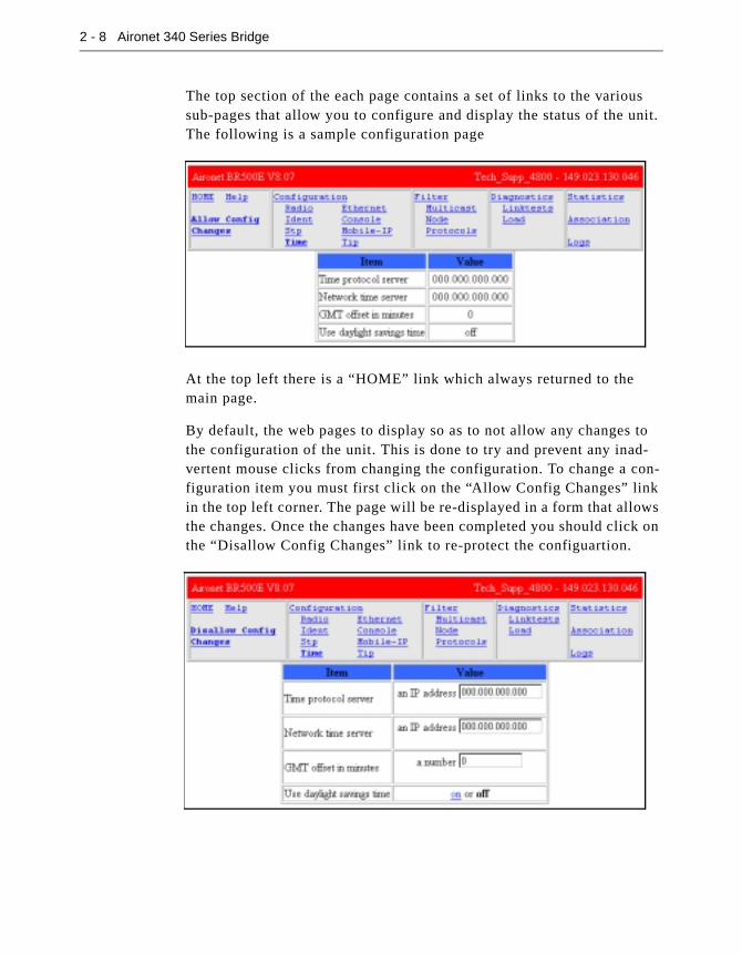
2 - 8 Aironet 340 Series Bridge
The top section of the each page contains a set of links to the various sub-pages that allow you to configure and display the status of the unit. The following is a sample configuration page
At the top left there is a “HOME” link which always returned to the main page.
By default, the web pages to display so as to not allow any changes to the configuration of the unit. This is done to try and prevent any inad-vertent mouse clicks from changing the configuration. To change a con-figuration item you must first click on the “Allow Config Changes” link in the top left corner. The page will be re-displayed in a form that allows the changes. Once the changes have been completed you should click on the “Disallow Config Changes” link to re-protect the configuartion.

Accessing the Console System 2 - 9
Some configuration items are displayed as a list of fixed choices. The currently active choice is displayed in bold and cannot be selected. The other choices are displayed as links that may be activated by clicking on them.
Other configuration items require the entry of some text. Enter the new value in the text box and then hit “Enter” to send the change to the AP for processing.
For those commands that display pages of information, the prompts function the same as those on the Console Port, except instead of having to type characters to select the different options, the option is a hyper-link.
You may disable web access to the bridge with a menu configuration command.
NOTE: If you are leaving web access enabled, make sure that you set passwords to secure the Console. See “Enabling Linemode (Linemode)”.

2 - 10 Aironet 340 Series Bridge
About the MenusPerform the following general functions using menus:
� Configuration: Allows you to configure Ethernet and Radio Param-eters and establish Network Identifications. See Chapters 3-6.
� Statistics: View a variety of statistical information such as transmit and receive data throughput, Ethernet and radio errors, and the gen-eral status of the Aironet 340 Series Bridge. See Chapter 9 “View-ing Statistics”.
� Association Table: A table that contains the addresses of all radio nodes associated below the Aironet 340 Series Bridge on the infra-structure. You may use the association table to display, add and remove static entries, and allow automatic additions to the table. See Chapter 10 “Setting Up the Association Table”.
� Filter: Controls packet filtering. The filter menu allows you to con-trol forwarding of multicast messages by blocking those multicast addresses and protocols that are not used on the radio network. See Chapter 11 “Using Filters”.
� Logs: Keeps a record of all events and alarms that occur on the unit. With the Logs Menu, you can view and/or print a history of all log entries, set alarm levels, and determine the type of logs you want to save. See Chapter 12 “Setting Up Event Logs”.
� Diagnostics: Allows you to run link tests between the Aironet 340 Series Bridge and other infrastructure nodes to test the quality of the radio link. Use the Diagnostics function to load new code versions of the bridge’s firmware. See Chapter 13 “Performing Diagnos-tics”.
� Privilege: Allows you to set privilege levels and passwords to restrict access to the Console Port’s menus and functions.
� Help: A brief help screen outlining the procedures for accessing menus and entering commands.

Accessing the Console System 2 - 11
Using the Configuration Console MenuThe Console system is configured using the Configuration Console Menu shown below. To access this menu, select Configuration from the Main Menu then select Console from the Configuration Menu.
Setting Privilege Levels and Passwords (Rpassword, Wpassword)
You can restrict access to the menus by setting privilege levels and pass-words. Privilege levels are set from the Main Menu. Passwords are set from the Configuration Console Menu.
There are three privilege levels:
� Logged Out Level (Off): Access denied to all sub-menus. Users are only allowed access to the privilege and help options of the Main Menu.
� Read-Only Level (Readonly): Read-only privileges for all sub-menus. Only those commands that do not modify the configuration may be used.
� Read-Write Level (Write): Allows users complete read and write access to all sub-menus and options.
Configuration Console Menu
Option Value Description
1 - Rpassword - Set readonly privilege password
2 - Wpassword - Set write privilege password
3 - Remote [ on ] - Allow remote operators
4 - Telnet [ on ] - Allow telnet connections
5 - Http [ on ] - Allow http connections
6 - Display - Display the remote operator list
7 - Add - Add an operator host
8 - Delete - Remove an operator host
9 - Communities [ menu ] - SNMP community properties
01 - Type [ ansi ] - Terminal type
02 - Port [ menu ] - Serial port set-up
03 - Linemode [ off ] - Console expects complete lines
Enter an option number or name, “=” main menu, <ESC> previous menu
>_

2 - 12 Aironet 340 Series Bridge
Keep in mind the following when setting Privilege Levels and Pass-words:
� Only Read-Only and Read-Write privilege levels can be password protected.
� You can always go from a higher privilege level to a lower privilege level without a password. If you try to go to a higher privilege level, you will be required to enter the password.
� Passwords are upper/lower case sensitive.
When Entering the passwords you will be prompted twice to ensure they were entered correctly. The prompting will be done with echoing off.
To change the current privilege level go to the main menu and use the “privilege” function. You will be prompted for the privilege level and its associated password.
NOTE: After a privilege level has been assigned, anyone attempting to access that level will be prompted for the password. This allows you to set various privilege levels for individuals, providing them with access to
some options, while denying them access to others. Remember pass-words are case sensitive.
CAUTION: Make sure you write down the passwords you have estab-lished and keep them in a safe place. If you forget your password, the unit will have to be returned for factory servicing. Please contact Cisco Tech-nical Support for further instructions.
Controlling Telnet and Web Access to the Console
You may disallow telnet and/or web access to the unit with the “telnet” and “http” menu items. Setting the value to “off” completely disables this type of access.
i

Accessing the Console System 2 - 13
Controlling SNMP access to the configuration
All SNMP management stations must include a community name string in all of their requests for information of the unit. This string functions as a password for the snmp access. Community names have either read-only or read/write access associated with them.
The read-only and read/write console passwords automatically are allowed as SNMP community names with the appropriate privilege.
The “Configuration Console Communities” menu may be used to add more community names for use by the network management stations.
You may use the “Add”, “Remove”, “Display” items to update and dis-play the table of allowed community names. A newly added name will by default only be allowed read-only access. To change the privilege level of a community use the “Access” item.
The “Remote” item is used to control whether a management station with write access is allowed to change the community names.
By default the standard SNMP community names of “public”, “proxy”, “private”, “regional” and “core” are allowed read-only access.
Configuration Console Communities Menu
Option Value Description
1 - Display - Display SNMP communities
2 - Add - Add a community
3 - Remove - Remove a community
4 - Access - Set community access mode
5 - Remote [ off ] - Allow remote NMS to change community info
Enter an option number or name, “=” main menu, <ESC> previous menu
>_
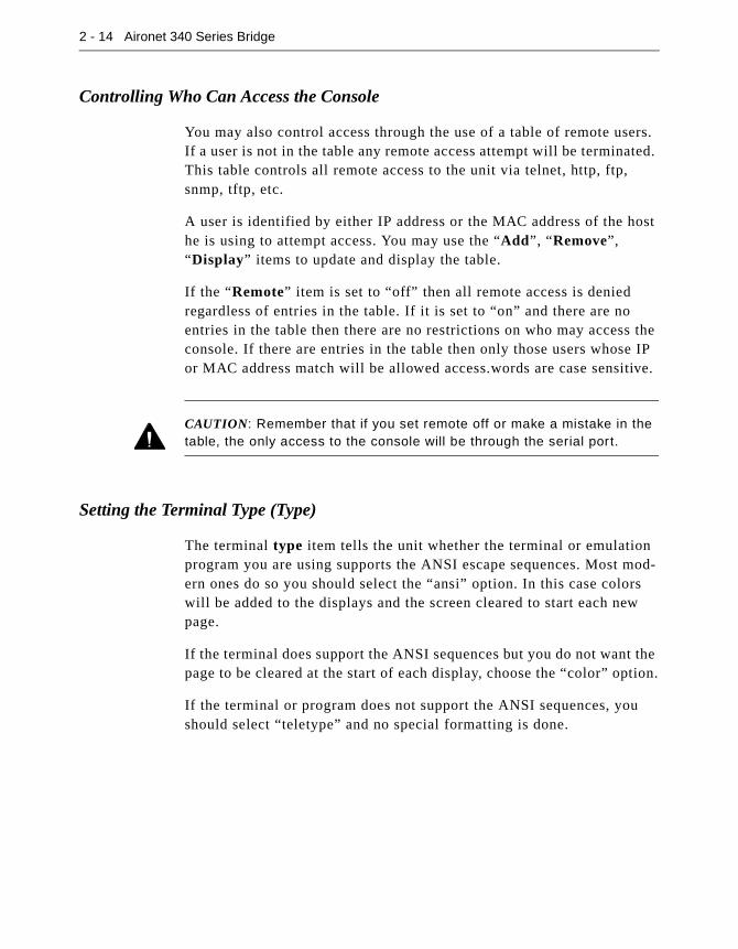
2 - 14 Aironet 340 Series Bridge
Controlling Who Can Access the Console
You may also control access through the use of a table of remote users. If a user is not in the table any remote access attempt will be terminated. This table controls all remote access to the unit via telnet, http, ftp, snmp, tftp, etc.
A user is identified by either IP address or the MAC address of the host he is using to attempt access. You may use the “Add”, “Remove”,“Display” items to update and display the table.
If the “Remote” item is set to “off” then all remote access is denied regardless of entries in the table. If it is set to “on” and there are no entries in the table then there are no restrictions on who may access the console. If there are entries in the table then only those users whose IP or MAC address match will be allowed access.words are case sensitive.
CAUTION: Remember that if you set remote off or make a mistake in the table, the only access to the console will be through the serial port.
Setting the Terminal Type (Type)
The terminal type item tells the unit whether the terminal or emulation program you are using supports the ANSI escape sequences. Most mod-ern ones do so you should select the “ansi” option. In this case colors will be added to the displays and the screen cleared to start each new page.
If the terminal does support the ANSI sequences but you do not want the page to be cleared at the start of each display, choose the “color” option.
If the terminal or program does not support the ANSI sequences, you should select “teletype” and no special formatting is done.
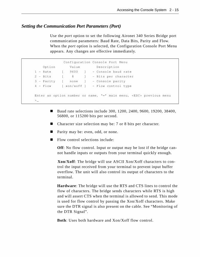
Accessing the Console System 2 - 15
Setting the Communication Port Parameters (Port)
Use the port option to set the following Aironet 340 Series Bridge port communication parameters: Baud Rate, Data Bits, Parity and Flow. When the port option is selected, the Configuration Console Port Menu appears. Any changes are effective immediately.
� Baud rate selections include 300, 1200, 2400, 9600, 19200, 38400, 56800, or 115200 bits per second.
� Character size selection may be: 7 or 8 bits per character.
� Parity may be: even, odd, or none.
� Flow control selections include:
Off: No flow control. Input or output may be lost if the bridge can-not handle inputs or outputs from your terminal quickly enough.
Xon/Xoff: The bridge will use ASCII Xon/Xoff characters to con-trol the input received from your terminal to prevent input buffer overflow. The unit will also control its output of characters to the terminal.
Hardware: The bridge will use the RTS and CTS lines to control the flow of characters. The bridge sends characters while RTS is high and will assert CTS when the terminal is allowed to send. This mode is used for flow control by passing the Xon/Xoff characters. Make sure the DTR signal is also present on the cable. See “Monitoring of the DTR Signal”.
Both: Uses both hardware and Xon/Xoff flow control.
Configuration Console Port Menu
Option Value Description
1 - Rate [ 9600 ] - Console baud rate
2 - Bits [ 8 ] - Bits per character
3 - Parity [ none ] - Console parity
4 - Flow [ xon/xoff ] - Flow control type
Enter an option number or name, “=” main menu, <ESC> previous menu
>_
2 - 16 Aironet 340 Series Bridge
Enabling Linemode (Linemode)
Enable linemode when working with telnet and terminal emulators that do not send characters when typed, but rather save them until the opera-tor presses the carriage return at the end of a line.
The Console will not automatically complete any typed commands or information when a space or carriage return is inserted.
To enable linemode:
1. Select Configuration on the Main Menu.
2. Select Linemode on the Configuration Console Menu.
3. Enter “On” to enable line mode.
NOTE: Some telnet programs will automatically invoke linemode by send-ing the appropriate telnet commands when they connect to the Aironet 340 Series Bridge.

Accessing the Console System 2 - 17
Monitoring of the DTR SignalThe Aironet 340 Series Bridge monitors the state of the Data Terminal Ready (DTR) signal. This signal is used to indicate the presence or absence of a DTE device connected to the Console Port.
If the state of the signal changes (up or down) the following actions will occur (unless a telnet session is in progress):
� Any currently executing command or display will be terminated
� Current menu will be returned to the Main Menu
� Console Privilege Menu will be set back to the highest level not requiring a password.
If the Console is configured for hardware flow control and the DTR sig-nal is currently down, all output will be discarded. The bridge would assume flow is off and the Console would eventually lock up.
If the cable used does not have the DTR signal connected it will not change state and no action will be taken.

Part 2 - Configuration
Part 2 - C
onfiguration
Chapter 3 - Before You Begin
3
C H A P T E R 3
Before You Begin
This chapter provides a general introduction to the Configuration Menu and describes the procedures for saving and restoring your configura-tions. See Chapters 4 - 11 for more information on configurations.
Here’s what you’ll find in this chapter:
� Viewing the Configuration Menu
� Menu Descriptions
� Saving Configuration Parameters
� Backing up your Configuration
� Restoring your Configuration

3 - 2 Aironet 340 Series Bridge
Viewing the Configuration MenuOnce you have completed the installation, the next step is to use the Configuration Menu commands to configure the Aironet 340 Series Bridge.
To access the Configuration Menu, select Configuration from the Main Menu.
Menu Descriptions
Radio: Used to set radio network parameters, such as system ID, frequency, and bitrate. See Chapter 4 “Configuring the RadioNetwork”.
Ethernet: Used to set the Ethernet Parameters. See Chapter 5 “Config-uring the Ethernet Port”.
Ident: Used to set various infrastructure identifiers such as Node Names, Network ID, and Internet Address. See Chapter 6 “Setting the Network Identifiers”.
Console: Used to set up the Console Port. See Chapter 2 “Accessing the Console System”.
STP: Used to configure the spanning tree protocol. See Chapter 8 “Using the Spanning Tree Protocol”.
Mobile-IP: Used to configure the unit as either a home or foreign mobile P agent. See Chapter 7 “Configuring Mobile IP”.
Configuration Menu
Option Value Description
1 - Radio [ menu ] - Radio network parameters
2 - Ethernet [ menu ] - Ethernet configuration
3 - Ident [ menu ] - Identification information
4 - Console [ menu ] - Control console access
5 - Stp [ menu ] - Spanning Tree Protocol
6 - Mobile-IP [ menu ] - Mobile IP Protocol Configuration
7 - Time [ menu ] - Network Time Setup
8 - Dump - Dump configuration to console
Enter an option number or name, “=” main menu, <ESC> previous menu
>_

Before You Begin 3 - 3
Time: Used to configure time server address to set a standard time base for displaying logs and alarms. See Chapter 6 “Setting the Network Identifiers”.
Dump: Used to dump the configuration commands to the Console Port. See “Backing up your Configuration (Dump)”.
Saving Configuration Parameters
Although there is no explicit save command, your configuration parame-ters are automatically saved to non-volatile flash memory each time a parameter is set or modified. This will ensure the configuration is main-tained during power failures or intentional power downs.
Most configuration settings become effective as soon as the command is executed. Those that do not immediately become effective will be noted in the command information.
Backing up your Configuration (Dump)
Once you have set the configuration parameters for the Aironet 340 Series Bridge, use the dump option to dump the configuration commands to the Console Port and save them as an ASCII file on a diskette, using a PC terminal emulation program.
If the non-volatile flash memory should ever become corrupted (and you lose your saved configuration), you can use a communications program to send the configuration commands to the Console Port. The system will automatically restore your configuration based on these commands.
� To Back Up Configurations:
NOTE: Commands may vary depending on the communications program used.
1. In the terminal emulation program, set Save to File to On.
2. Select Configuration from the Main Menu then select Dump. The following message appears:
Enter one of [all, non-default, distributable]:

3 - 4 Aironet 340 Series Bridge
� All: The entire configuration will be displayed.
� Non-default: Only the configuration options that are different from the original default settings will be displayed.
� Distributable: Only the configuration options that are not con-sidered unique to this unit are displayed. You may use the “diag-nostics load distribute” command to send this configuration to other units in the infrastructure.
3. Enter one of [standard, encoded]:
� Standard: The configuration is displayed in normal readable text form.
� Encoded: The configuration is displayed with each configura-tion command replaced by a unique number. This type of con-figuration is the best to save since the number will never change over the life of the product. Text may change or move as more items are added to the menus.
4. Enter your configuration command choice.
5. Save the file after the commands have been dumped.
6. Turn Save to File to Off.
7. Press any key to clear the screen.
Restoring your Configuration
If your configuration is ever lost or corrupted, you can use restore your configuration using the program’s ASCII upload commands.
Chapter 4 - Configuring the Radio Network
4
C H A P T E R 4
Configuring the Radio Network
This chapter describes the procedures for configuring the Aironet 340 Series Bridge Radio Network. It describes all of the functions in the “Configuration Radio Menu” and its sub-menus.
Here’s what you’ll find in this chapter:
� Setting up the basic radio configuration
� Setting up encryption
� Setting up the advanced radio configuration
� How to test the radio links
4 - 2 Aironet 340 Series Bridge
OverviewWhen configuring the radio network, all units should be configured while in close proximity to each other. This will allow your units to communicate with other radio nodes on your infrastructure as the units’ parameters are set.
Once configuration is complete, the units can then be moved to their permanent location. Tests can be run to check the reliability of the radio links. See “Running a Signal Strength Test (Strength)”.
The radio network parameters should be set in the order shown below:
1. Establish a system identifier.
2. Select a rate.
3. Select a frequency.
4. Enable root or repeater mode.
5. Set any extended parameters (optional).
CAUTION: Changing any of the radio parameters after you have com-pleted your configurations will cause the unit to drop all radio connections and restart with the changes you have made. Consequently, there will be a disruption in radio traffic through the unit.

Configuring the Radio Network 4 - 3
Using the Configuration Radio MenuThe radio network is configured using the Configuration Radio Menu. To access this menu, select Configuration from the Main Menu then select Radio from the Configuration Menu.
Establishing an SSID (SSID)
This string functions as a password to join the radio network. Nodes associating to the bridge must supply a matching value, determined by their configurations, or their association requests will be ignored.
Enabling Root Mode (Root)
Use the root option to enable or disable root mode.
There may only be one unit serving as the root unit and it is usually con-nected to the primary backbone infrastructure. Those acting as remote bridges, attached to a secondary backbone and communicating via radio to the root unit, should have their Root Mode set to “Off”. The default setting is “On”.
Selecting the Allowed Data Rates (Rates)
Use the rates option to define the data rate at which the unit is allowed to receive and transmit information. Other units in the radio cell are allowed to transmit data to us at any of these rates at their discretion.
Configuration Radio Menu
Option Value Description
1 - Ssid [ "test" ] - Service set identification
2 - Root [ on ] - Enable root mode
3 - Rates [ 1_11 ] - Allowed bit rates in megabits/second
4 - Basic_rates [ 1 ] - Basic bit rates in megabits/second
5 - Frequency [ "auto" ] - Center frequency in MHz
6 - Distance [ 0 ] - Maximum separation in kilometers
7 - I80211 [ menu ] - 802.11 parameters
8 - Linktests [ menu ] - Test the radio link
9 - Extended [ menu ] - Extended parameters
Enter an option number or name, “=” main menu, <ESC> previous menu
>_

4 - 4 Aironet 340 Series Bridge
When a repeater associates to a root unit data is usually transmitted between the units at the highest rate that they both support. The units may also downshift to use lower common rates if conditions warrant it.
Basic Rates (Basic_rates)
The basic rates option is set on the root bridge. It is the set of rates that all nodes in the radio cell must support or they will not be allowed to associate.
The lowest basic rate is use to transmit all broadcast and multicast traf-fic as well as any association control packets. Using the lowest rate helps ensure they will be received by all nodes even at the farthest dis-tances.
The highest basic rate determines the maximum rate at which an acknowledge packet may be transmitted.
Selecting Frequency (Frequency)
The actual frequency allowed depends on the regulatory body that con-trols the radio spectrum in the location in which the unit is used. If the setting is left as “auto”, the unit will sample all the allowed frequencies when it is first started and try to pick one that is not in use.
This setting is only allowed on the root unit as it is in charge of setting up the radio cell
Setting the Distance (Distance)
Since the radio link between bridges can be quite long, the time it takes for the radio signal to travel between the radios can become significant. This parameter is used to adjust the various timers used in the radio pro-tocol to account for the extra delay.
The parameter is only entered on the root bridge, which will tell all the repeaters. It should be entered as the distance in kilometers of the long-est radio link in the set of bridges.

Configuring the Radio Network 4 - 5
Using the Configuration Radio IEEE 802.11 Menu
Setting the Beacon Period (Beacon)
The beacon interval is the time (in kilo-microseconds) between trans-missions of the IEEE 802.11 beacon packet. The beacon packets are pri-marily used for radio network synchronization.
A small beacon period means faster response for roaming nodes. The default value is typically adequate.
Setting the Forwarding Time Interval (DTIM)
The DTIM count determines the count of normal beacons between the special DTIM beacons. If there no power saving client nodes in a cell, as is usually the case with bridges, it is not used.
If there are power saving nodes present, the 802.11 protocol defines that all power saving nodes must, at the minimum, wake up to receive the DTIM beacons. If power save nodes are present, the AP will also buffer any multicast packets it receives from the LAN and only transmit them after the DTIM beacon.
Setting the DTIM count low causes the multicasts to be transmitted more frequently, but sets a lower upper limit as to how long a power save node may remain asleep.
Configuration Radio I80211 Menu
Option Value Description
1 - Beacon [ 100 ] - Beacon period in Kusec
2 - Dtim [ 2 ] - DTIM interval
3 - Extend [ on ] - Allow proprietary extensions
4 - Bcst_ssid [ on ] - Allow broadcast SSID
5 - Rts [ 2048 ] - RTS/CTS packet size threshold
6 - Privacy [ menu ] - Privacy configuration
7 - Encapsulation [ menu ] - Configure packet encapsulation
Enter an option number or name, “=” main menu, <ESC> previous menu
>_
4 - 6 Aironet 340 Series Bridge
Adding IEEE 802.11 Management Packet Extensions (Extend)
If this parameter is enabled, the Aironet 340 Series Bridge will add extensions to some of the IEEE 802.11 management packets. This passes more information to other radio nodes allowing them to associate to the best bridge.
Even with the extensions enabled, other manufacturer’s nodes should ignore the extra information. However, if they become confused, this parameter may be disabled.
Allowing the Broadcast SSID (Bcst_ssid)
This option controls whether client nodes will be allowed to associate if they specify the empty or broadcast SSID. Clients that do not know the SSID of the bridge can transmit packets with the broadcast SSID. Any bridges present will respond with a packet showing their SSID. The cli-ent will then adopt the SSID and associate.
If you wish to ensure that clients know the SSID beforehand then dis-able this function.
Setting the RF RTS/CTS Parameter (RTS)
This parameter determines the minimum size transmitted packet that will use the RTS/CTS protocol. The value entered must be in the range of 100 to 2048 bytes.
This protocol is most useful in networks where the mobile nodes may roam far enough so the nodes on one side of the cell cannot hear the transmission of the nodes on the other side of the cell.
When the transmitted packet is large enough, a small packet is sent out (an RTS). The destination node must respond with another small packet (a CTS) before the originator may send the real data packet. A node at the far end of a cell will see the RTS to/from the bridge or the CTS to/from the bridge. The node will know how long to block its transmitter to allow the real packet to be received by the bridge. The RTS and CTS are small and, if lost in a collision, they can be retried more quickly and with less overhead than if the whole packet must be retried.

Configuring the Radio Network 4 - 7
The downside of using RTS/CTS is that for each data packet you trans-mit, you must transmit and receive another packet, which will affect throughput.
Packet Encapsulation (Encapsulation Menu)
The Encap option and the related encapsulation table commands of Show, Add and Remove are of concern only when both of the following conditions exist:
� You are assembling a wireless LAN that incorporates non-Aironet equipment.
� The non-Aironet equipment uses a proprietary method of packet encapsulation that is different from the method used by Aironet.
If your wireless LAN consists only of Aironet components, use the default Encap value of 802.1H and disregard the information in follow-ing discussion “Packet Encapsulation in Mixed Networks.”
Packet Encapsulation in Mixed Networks
Aironet LAN software allows you to assemble a wireless infrastructure using components from different suppliers. When combining equipment from different sources into a wireless LAN, you might need to accom-modate different methods of packet addressing and conversion. The complete subject of packet addressing is beyond the scope of this man-ual, and our purpose here is to provide only basic guidelines and consid-erations.
To combine a mix of equipment from alternate suppliers into a wireless LAN, you need to know the packet encapsulation methods used by the different suppliers. If you determine that your infrastructure will be mixing packet encapsulation methods, you will first need to determine
Configuration Radio I80211 Encapsulation Menu
Option Value Description
1 - Encap [ 802.1H ] - Default encapsulation method
2 - Show - Show encapsulation table
3 - Add - Add a protocol encapsulation method
4 - Remove - Remove a protocol encapsulation method
Enter an option number or name, “=” main menu, <ESC> previous menu
>_

4 - 8 Aironet 340 Series Bridge
your primary method, or standard, and choose that as the default setting with the Encap option. All methods other than the primary, or default, method need to be entered in the Encapsulation Table.
For all Aironet equipment, the defined packet encapsulation standard is 802.1H. The Show, Add and Remove options allow you to manage a table of alternate, non-I802.1H encapsulation methods that might be required to read data packets sent from the other, non-Aironet equip-ment. The primary alternate to the I802.1H standard is RFC 1042.
On an Ethernet LAN, the data portion of a frame may be in one of two formats: DIX or DSAP/SSAP. The two formats differ both in packet size specifications and in the manner of heading, or starting, the data por-tion. An 802 wireless LAN requires packets to start with the DSAP/SSAP format and therefore must provide a method of conversion. DSAP/SSAP packet types are easily converted since the header is already in the required style. DIX packet types present more of a problem since there are many different formats and no standard conversion method.
Aironet’s 802.1H conversion protocol accommodates both DIX and DSAP/SSAP packet types. In an 802.1H conversion, DIX type packets are prepended with a header that mimics the DSAP/SSAP header. In an Aironet infrastructure, this header style is not used by any wired Ether-net nodes so the remote radio node is always able to accurately recon-vert the packet.

Configuring the Radio Network 4 - 9
Packet Encryption (Privacy Menu)
This menu controls the use of encryption on the data packet transmitted over the air by the radios. The packets are encrypted using the RSA RC4 algorithm using one of up to 4 known keys. Each node in the radio cell must know all the keys in use, but they may select any one to use for their transmitted data.
The “Key” option is used to program the encryption keys into the radio. You will be prompted as to which of the four keys you wish to set and then you are prompted twice to enter the key with echoing disabled. Depending on whether the radio is authorized to use 40 bit or 128 bit keys, you must enter either 10 or 26 hexadecimal digits to define the key.
NOTE: The keys must match in all nodes in the radio cell and must be
entered in the same order.
You do not need to define all four keys as long as the number of keys matches in each radio in the cell.
Use the “Transmit” option to tell the radio which of the keys it should use to transmit its packets. Each radio is capable of de-crypting received packets sent with any of the four keys.
If the “Encryption” option is set to “off” then no encryption is done and the data is transmitted in the clear. If the value is set to “on” then all transmitted data packets will be encrypted and any un-encrypted received packet will be discards.
Configuration Radio I80211 Privacy Menu
Option Value Description
1 - Encryption [ off ] - Encrypt radio packets
2 - Auth [ open ] - Authentication mode
3 - Client [ open ] - Client authentication modes allowed
4 - Key - Set the keys
5 - Transmit - Key number for transmit
Enter an option number or name, “=” main menu, <ESC> previous menu
>_

4 - 10 Aironet 340 Series Bridge
The “Encryption” value may also be set to “mixed’. In this mode a root or repeater bridge will accept association from clients that have encryp-tion turned on or off. In this case only data packets between nodes that both support it will be encrypted. Multicast packets will be sent in the clear so that all nodes may see them.
CAUTION: We do not recommend the use of “mixed” mode. If a client with encryption enabled sends a multicast packet to its parent, the packet will be encrypted. The parent will then decrypt the packet and re-transmit it in the clear to the cell for the other nodes to see. Seeing a packet in both encrypted and un-encrypted form can greatly aid in breaking a key. This mode is only included for compatibility with other vendors.
The 802.11 protocol specifies a procedure in which a client must authen-ticate with a parent before it can associate. The “open” method of authentication is essentially a null operation. All clients will be allowed to authenticate. With the “shared key” the parent send the client a chal-lenge text which the client encrypts and sends back to the parent. If the parent can de-crypt it correctly the client is authenticated.
CAUTION: With the “shared-key” mode, since a clear text and encrypted version of the same data is transmitted on the air, we again do not recom-mend its use. It does not really gain you anything, since if the user’s key is wrong the unit will not be able to de-crypt any of his packets and they cannot gain access to the network.
The “Client” option determines the authentication mode that the client nodes are allowed to use to associate to the unit. The values allowed are “open”, “shared-key”, or “both”.
The “Auth” is used on repeater bridges to determine which authentica-tion mode the unit will use to connect with its parent. The allowed val-ues are “open” or “shared-key”.
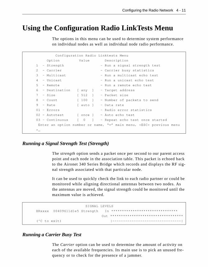
Configuring the Radio Network 4 - 11
Using the Configuration Radio LinkTests MenuThe options in this menu can be used to determine system performance on individual nodes as well as individual node radio performance.
Running a Signal Strength Test (Strength)
The strength option sends a packet once per second to our parent access point and each node in the association table. This packet is echoed back to the Aironet 340 Series Bridge which records and displays the RF sig-nal strength associated with that particular node.
It can be used to quickly check the link to each radio partner or could be monitored while aligning directional antennas between two nodes. As the antennas are moved, the signal strength could be monitored until the maximum value is achieved.
Running a Carrier Busy Test
The Carrier option can be used to determine the amount of activity on each of the available frequencies. Its main use is to pick an unused fre-quency or to check for the presence of a jammer.
Configuration Radio Linktests Menu
Option Value Description
1 - Strength - Run a signal strength test
2 - Carrier - Carrier busy statistics
3 - Multicast - Run a multicast echo test
4 - Unicast - Run a unicast echo test
5 - Remote - Run a remote echo test
6 - Destination [ any ] - Target address
7 - Size [ 512 ] - Packet size
8 - Count [ 100 ] - Number of packets to send
9 - Rate [ auto ] - Data rate
01 - Errors - Radio error statistics
02 - Autotest [ once ] - Auto echo test
03 - Continuous [ 0 ] - Repeat echo test once started
Enter an option number or name, “=” main menu, <ESC> previous menu
>_
SIGNAL LEVELS
BRxxxx 00409611d1e5 Strength In *******************************
Out **********************************
(^C to exit) |--------------------------------|

4 - 12 Aironet 340 Series Bridge
When started, the radio is put in a special mode, in which it will scan through all the allowed frequencies, pause on each one and measure the percentage of the time that the carrier detect line for the radio is busy.
CAUTION: Since this test uses a special operating mode all current asso-ciations to the unit will be lost during the test.
The display is a scaled bar graph with the frequencies along the bottom. The percentage utilization represented by the highest bar is given in the bottom line.
Running the Echo Tests (Multicast, Unicast, Remote)
An echo test consists of sending a number of packet between units. The packets are sent with a proprietary protocol, which the target nodes rec-ognize and will echo back to the test source along with information about how well it received the packets.
CARRIER BUSY / FREQUENCY
*
*
*
* *
* *
* *
* *
* * *
* * *
* * * * * * * * * * *
1 1 2 2 3 3 4 4 5 5 6
2 7 2 7 2 7 2 7 2 7 2
Highest point = 9% utilization
Enter space to redisplay, q[uit] :

Configuring the Radio Network 4 - 13
The multicast option is used to test transmission conditions within local radio cells. Packets are sent between the source and destination nodes without any acknowledgments or retries (as multicasts). This test pro-vides a good indication of the raw state of the path to the node since no attempt is made to recover from any radio errors.
The time is displayed in milliseconds. Each packet contains the time it was sent. When a packet is received by the source, the time difference indicates the round trip time. Longer times indicate that the processor’s or the radio’s bandwidth is full.
The signal strength numbers indicate the strength of the radio signal at the time the packets were received at each end. Signal strength is expressed as a percentage of full power.
The unicast option can be used to test the path between the Aironet 340 Series Bridge and any other Aironet node in the wired or radio network. The packets are sent with the same error recovery as normal user data so round trip times indicate the infrastructure throughput and congestion.
If the path to the target node was over the radio, a total number of radio retries necessary to complete the test is also displayed. If the total num-ber of retries is large, there may be problems with the link. Look for
Testing link to 00409611d1e5 with 100 multicast packets of size 512
Please wait:
GOOD ( 9% Lost) Time Strength %
msec In Out
---- ----- -----
Sent: 100, Avg: 19 78 85
Lost to Tgt: 8, Max: 29 85 92
Lost to Src: 1, Min: 17 71 85
Testing link to 00409611d1e5 with 100 unicast packets of size 512
GOOD (8% Retries) Time Strength % Retries
msec In Out In Out
---- ----- ----- ---- ----
Sent: 100, Avg: 25 78 85 Tot: 3 14
Lost to Tgt: 0, Max: 91 85 92 1 2
Lost to Src: 0, Min: 21 78 85 0 0
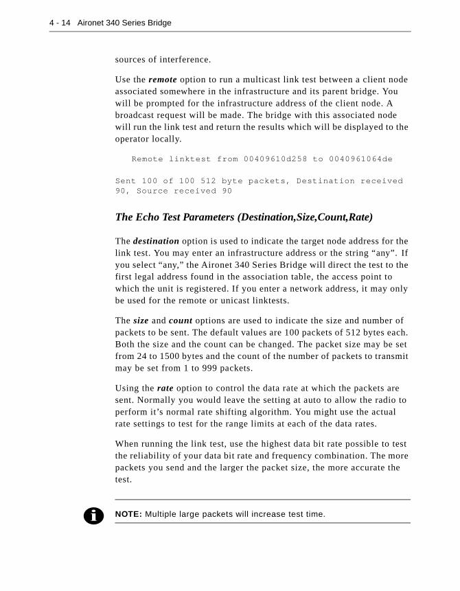
4 - 14 Aironet 340 Series Bridge
sources of interference.
Use the remote option to run a multicast link test between a client node associated somewhere in the infrastructure and its parent bridge. You will be prompted for the infrastructure address of the client node. A broadcast request will be made. The bridge with this associated node will run the link test and return the results which will be displayed to the operator locally.
Remote linktest from 00409610d258 to 0040961064de
Sent 100 of 100 512 byte packets, Destination received 90, Source received 90
The Echo Test Parameters (Destination,Size,Count,Rate)
The destination option is used to indicate the target node address for the link test. You may enter an infrastructure address or the string “any”. If you select “any,” the Aironet 340 Series Bridge will direct the test to the first legal address found in the association table, the access point to which the unit is registered. If you enter a network address, it may only be used for the remote or unicast linktests.
The size and count options are used to indicate the size and number of packets to be sent. The default values are 100 packets of 512 bytes each. Both the size and the count can be changed. The packet size may be set from 24 to 1500 bytes and the count of the number of packets to transmit may be set from 1 to 999 packets.
Using the rate option to control the data rate at which the packets are sent. Normally you would leave the setting at auto to allow the radio to perform it’s normal rate shifting algorithm. You might use the actual rate settings to test for the range limits at each of the data rates.
When running the link test, use the highest data bit rate possible to test the reliability of your data bit rate and frequency combination. The more packets you send and the larger the packet size, the more accurate the test.
NOTE: Multiple large packets will increase test time.

Configuring the Radio Network 4 - 15
Viewing Errors (Errors)
The errors option is used to view the Radio Error statistics that may have occurred during the link test. See Chapter 9 “Viewing Statistics”.
Continuously Running a Link Test (Continuous)
The continuous option is used to continuously repeat the link tests. If the value for the parameter is zero the tests are not repeated; otherwise, the value determines the delay (in seconds) between tests.
Setting the Automatic Link Test Mode (Autotest)
The autotest option is used to control the automatic running of a link test whenever a repeater associates to its parent. The test will use the currently configured test parameters which, by default, runs a test to the parent node.
� Off: An automatic test is never run.
� Once: Only one test is run the first time the unit associates to a par-ent after powering on.
� Always: The test is run each time the unit associates to a parent.

4 - 16 Aironet 340 Series Bridge
During an automatic link test the three indicators on the unit will turn green in a cyclic pattern to indicate a test is in progress. At the end of the test, the indicators will be set to a solid pattern for 4 seconds to indi-ate the test results. The particular pattern that will be displayed depends on the percentage of packets lost during the test as shown in Table 4.1
The Autotest procedure can be used to help determine the placement of repeater units. For example, at each prospective location, an installer could cycle the power on the unit and watch the indicator displays for the results of the link test. As the test begins to fail, the installer could determine the radio range to the infrastructure and adjust the location accordingly.
Table 4.1 - Auto Link Test Display Patterns
Radio Status Ethernet % of Packets Lost Quality
Green Green Green 0-2 Excellent
Green Green Amber 3-5 Very Good
Green Green Off 6-25 Good
Green Amber Off 26-50 Satisfactory
Amber Off Off 51-75 Fair
Red Off Off 76-100 Poor
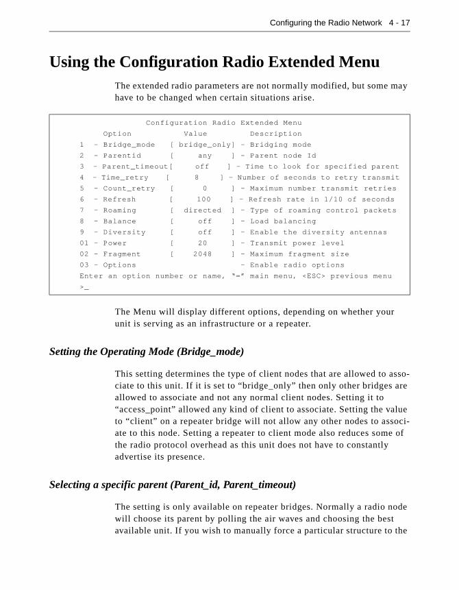
Configuring the Radio Network 4 - 17
Using the Configuration Radio Extended MenuThe extended radio parameters are not normally modified, but some may have to be changed when certain situations arise.
The Menu will display different options, depending on whether your unit is serving as an infrastructure or a repeater.
Setting the Operating Mode (Bridge_mode)
This setting determines the type of client nodes that are allowed to asso-ciate to this unit. If it is set to “bridge_only” then only other bridges are allowed to associate and not any normal client nodes. Setting it to “access_point” allowed any kind of client to associate. Setting the value to “client” on a repeater bridge will not allow any other nodes to associ-ate to this node. Setting a repeater to client mode also reduces some of the radio protocol overhead as this unit does not have to constantly advertise its presence.
Selecting a specific parent (Parent_id, Parent_timeout)
The setting is only available on repeater bridges. Normally a radio node will choose its parent by polling the air waves and choosing the best available unit. If you wish to manually force a particular structure to the
Configuration Radio Extended Menu
Option Value Description
1 - Bridge_mode [ bridge_only] - Bridging mode
2 - Parentid [ any ] - Parent node Id
3 - Parent_timeout[ off ] - Time to look for specified parent
4 - Time_retry [ 8 ] - Number of seconds to retry transmit
5 - Count_retry [ 0 ] - Maximum number transmit retries
6 - Refresh [ 100 ] - Refresh rate in 1/10 of seconds
7 - Roaming [ directed ] - Type of roaming control packets
8 - Balance [ off ] - Load balancing
9 - Diversity [ off ] - Enable the diversity antennas
01 - Power [ 20 ] - Transmit power level
02 - Fragment [ 2048 ] - Maximum fragment size
03 - Options - Enable radio options
Enter an option number or name, “=” main menu, <ESC> previous menu
>_

4 - 18 Aironet 340 Series Bridge
radio cell, usually because of knowledge of traffic patterns, you can use the parent_id option to select the MAC address of the parent the unit would always try and associate to.
If you set the parent_timeout option to off the unit will only associate with the specified parent. If you set a value, the unit will poll for the specified parent for the given number of seconds each time it needs to associate. If the parent is not found it will choose the best available par-ent. If the unit ever sees that the specified parent is present it will switch its association.
Setting Retry Transmission Time (Time_Retries, Count_Retries)
These settings allow the user to establish a particular level of radio per-formance by controlling the RF packet retry level. The lesser of the two values will be used. If the retry count is reached before the retry time is met, then retry process on this particular packet is stopped. If the desti-nation was a child node, it will be disassociated. If the destination was a parent bridge, the unit will begin scanning for a new parent.
The retry time may be set in the range of 1 to 30 seconds. The Aironet 340 Series Bridge will continually retry the packet in this time period while contending for the air waves with other transmitting nodes.
The retry count may be set in the range of 0 to 64 times. If the count is set to zero, only the retry time applies.
Use the retry count field if the Aironet 340 Series Bridge is mobile and you want to move from bridge to bridge very quickly after moving out of range. In non-mobile applications, since you can’t move out of range, it is most likely there is some temporary interference. Retry at a later time.
Setting the Association Refresh Interval (Refresh)
This setting is only present on repeater bridges. If there has been no directed traffic between the unit and its parent for the specified time (in tenths of a second) the unit will send an empty packet to the parent to verify that the connection is still alive.

Configuring the Radio Network 4 - 19
Roaming Notification Mode (Roaming)
When a node roams from one parent to another the new parent bridge sends packets to the wired network to inform any other bridge, switches and the old parent of the change in location.
If this option is set to directed and if the client node knows its old par-ent’s address, this packet is sent as a directed packet to the old parent. In all cases we have encountered this should update the other network devices correctly. If you are having any problems you may wish to set the option to broadcast to cause the packet to be sent as a broadcast and be guaranteed to be sent everywhere in the network.
Setting the Loading Balance (Balance)
On a root bridge you may use the balance option to control how often the repeater bridge will execute the load balancing algorithm (i80211 Extend must be enabled). The repeater bridges will search for better par-ents based on the data traffic load and number of association even if they are having no trouble with their current parent. The options may be set to Off, Slow (every 30 seconds), or Fast (every 4 seconds).
Setting Diversity (Diversity)
This parameter tells the unit whether you have two antennas installed. Set the parameter to “Off” if one antenna is installed. The single antenna must be installed on the right connector when facing the back of the unit with the LED display facing up.
Setting the Power Level (Power)
This parameter may be used to reduce the power level of the radio trans-mitter down from the maximum allowed by the regulatory commission. Depending on where you are located, you may be allowed to set the power to 50 milliwatts, 100 milliwatts or to full power.
Setting Fragment Size (Fragment)
This parameter determines the largest packet size that may be transmit-ted. Packets that are larger than this size will be broken into pieces that are transmitted separately and rebuilt on the receiving side.

4 - 20 Aironet 340 Series Bridge
If there is a lot of radio interference or collisions with other nodes, the smaller lost packets can be retried faster and with less impact on the air-waves. The disadvantage is if there is limited interference, long packets will take more time to transmit due to the extra packet overhead and acknowledgments for the fragments.
Set the fragment size between 256 and 2048 bytes.
Setting Purchasable Radio Options (Options)
This selection is used to enable special features in the radio that may be purchased separately. One example is stronger encryption. To enable an option select this menu item. You will be given the MAC address of this unit and prompted for a password. Call customer support give them this address and once payment has been verified you will be given the pass-word for this unit.
Chapter 5 - Configuring the Ethernet Port
5
C H A P T E R 5
Configuring the Ethernet Port
This chapter describes the procedures for configuring the Ethernet Port of the Aironet 340 Series Bridge.
Here’s what you’ll find in this chapter:
� Using the Configuration Ethernet Menu
� Activating/Disabling the Ethernet Port
� Setting the Maximum Frame Size and Port Interface Type

5 - 2 Aironet 340 Series Bridge
Using the Configuration Ethernet MenuThe Ethernet Port is configured using the Configuration Ethernet Menu. To access this menu, select Configuration from the Main Menu then select Ethernet from the Configuration Menu.
Activating/Disabling the Ethernet Port (Active)
NOTE: Do not activate the Ethernet Port until all other parameters have
been set correctly.
The active option is used to enable or disable the Ethernet Port connec-tion. The default setting for active is “On”.
The active option should be disabled if the port on the Aironet 340 Series Bridge is not going to be used. This informs the software not to route packets to the port and stops the use of processing power for scan-ning for Ethernet activity.
Setting the Maximum Frame Size (Size)
The size option allows you to increase the maximum size of the frames transmitted to and from the Ethernet infrastructure. Do not set the maxi-mum frame size greater than 1518 unless you are running proprietary software that allows you to exceed this maximum. You may set the value between 1518 to 4096.
Configuration Ethernet Menu
Option Value Description
1 - Active [ on ] - Connection active
2 - Size [ 1518 ] - Maximum frame size
3 - Port [ auto ] - Port selection
Enter an option number or name, “=” main menu, <ESC> previous menu
>_
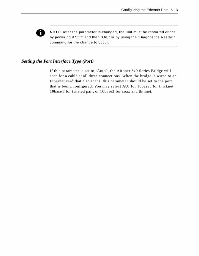
Configuring the Ethernet Port 5 - 3
NOTE: After the parameter is changed, the unit must be restarted either by powering it “Off” and then “On,” or by using the “Diagnostics Restart” command for the change to occur.
Setting the Port Interface Type (Port)
If this parameter is set to “Auto”, the Aironet 340 Series Bridge will scan for a cable at all three connections. When the bridge is wired to an Ethernet card that also scans, this parameter should be set to the port that is being configured. You may select AUI for 10base5 for thicknet, 10baseT for twisted pair, or 10base2 for coax and thinnet.

Chapter 6 - Setting Network Identifiers
6
C H A P T E R 6
Setting Network Identifiers
This chapter describes the procedures for setting the Aironet 340 Series Bridge network identifiers.
Here’s what you’ll find in this chapter:
� Setting the IP address, subnet mask, and routing tables
� Domain name server settings
� DHCP settings
� Setting the names assigned to the unit
� Setting up a time server
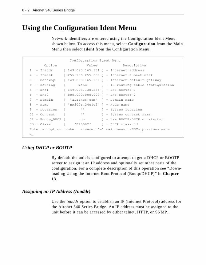
6 - 2 Aironet 340 Series Bridge
Using the Configuration Ident MenuNetwork identifiers are entered using the Configuration Ident Menu shown below. To access this menu, select Configuration from the Main Menu then select Ident from the Configuration Menu.
Using DHCP or BOOTP
By default the unit is configured to attempt to get a DHCP or BOOTP server to assign it an IP address and optionally set other parts of the configuration. For a complete description of this operation see “Down-loading Using the Internet Boot Protocol (Bootp/DHCP)” in Chapter 13.
Assigning an IP Address (Inaddr)
Use the inaddr option to establish an IP (Internet Protocol) address for the Aironet 340 Series Bridge. An IP address must be assigned to the unit before it can be accessed by either telnet, HTTP, or SNMP.
Configuration Ident Menu
Option Value Description
1 - Inaddr [ 149.023.165.131 ] - Internet address
2 - Inmask [ 255.255.255.000 ] - Internet subnet mask
3 - Gateway [ 149.023.165.050 ] - Internet default gateway
4 - Routing [ menu ] - IP routing table configuration
5 - Dns1 [ 149.023.130.254 ] - DNS server 1
6 - Dns2 [ 000.000.000.000 ] - DNS server 2
7 - Domain [ "aironet.com" ] - Domain name
8 - Name [ "BR500T_24c1e2" ] - Node name
9 - Location [ "" ] - System location
01 - Contact [ "" ] - System contact name
02 - Bootp_DHCP [ on ] - Use BOOTP/DHCP on startup
03 - Class [ "BR500T" ] - DHCP class id
Enter an option number or name, “=” main menu, <ESC> previous menu
>_

Setting Network Identifiers 6 - 3
Specifying the IP Subnet Mask (Inmask)
Use the inmask option to assign an IP Subnetwork mask to the Aironet 340 Series Bridge. The subnetwork mask determines the portion of the IP address that represents the subnet ID. A digit in a “bit” of the mask indicates that the corresponding “bit” in the IP address is part of the subnet ID.
Setting Up the Domain Name Servers (Dns1,Dns1,Domain)
A domain name server allows the operator to specify the name of a known host rather than its raw IP address when accessing another node in the network You should obtain the address of the primary and backup servers and well as the domain name for your network administrator.
Establishing a Node Name (Name)
The name option is used to establish a unique node name for the Aironet 340 Series Bridge. The name is a text string of up to 20 characters that appears on all Console Port Menus. It is passed in association messages to other nodes on the radio network. See Chapter 10 “Setting Up the Association Table”.
Setting SNMP Location and Contact Identifiers (Location,Contact)
Use the location and contact options to specify the location of the SNMP workstation and the contact name of the individual responsible for managing it in the event of problems.
You may enter an arbitrary string of up to 20 characters for each item.
Configuring the IP Routing Table (Gateway, Routing)
The IP routing table controls how IP packets originating from the bridge will be forwarded. Once the destination IP address is determined the fol-lowing checks are made:
1. If the destination IP address exactly matches a host entry in the table, the packet will be forwarded to the MAC address correspond-ing to the next hop IP address from the table entry.

6 - 4 Aironet 340 Series Bridge
2. If the destination is in the local subnet, ARP is used to determine the nodes MAC address.
3. If the destination address is on another subnet and matches the infra-structure portion of a net entry in the table (using the associated subnet mask), the packet will be forwarded to the MAC address cor-responding to the next hop IP address from the table entry.
4. If the destination address is on another subnet and does not match any entry in the table, the packet will be forwarded to the MAC address corresponding to the default gateway’s IP address.
Most subnets only have one router which is always used to access the rest of the network. Use the Gateway option to set the IP address of the default router. This address is also used if the destination address does not match any entries in the routing table described below.
The Routing options allows your to set specific entries in the routing table.
Use the Host option to add an entry for a single host. You will be prompted for the IP address of the host. Use the Net option to add an entry for an external subnet. You will be prompted for a network address and a subnet mask to identify the remote network. Use the Delete option to delete a table entry.
The Display options show the current table.
Configuration Ident Routing Menu
Option Value Description
1 - Display - Display route table entries
2 - Host - Add a static host route
3 - Net - Add a static network route
4 - Delete - Delete a static route
Enter an option number or name, “=” main menu, <ESC> previous menu
>_
Routing Table
Destination Next Hop Mask Flags Use
---------------- --------------- --------------- ------ ---
149.023.166.000 149.023.165.071 255.255.255.000 S N 0
default 149.023.165.050 000.000.000.000 S N 0
149.023.130.020 149.023.165.060 255.255.255.000 S H 0

Setting Network Identifiers 6 - 5
The Flags column displays letters identifying the type of entry:
� S: Entry is static (entered by operator)
� N: Entry is an remote network route
� H: Entry is a host route
The Use column indicates the number of packets that have been for-warded using this table entry.
Setting up the Time Base (Configuration Time)
This menu lets you configure the bridge to query a network time server such that any logs its printed can reference the current date and time.
The time_server option sets the IP address or name of a unix time proto-col server to be queried. The sntp_server option sets the IP address or name of an internet simple network time protocol server to be queried. You should configure only one type of server.
Since the time returned by the servers is based on Greenwich mean time you must use the Offset option to give the time difference in minutes (plus or minus) from GMT.
The Dst option selects whether your time zone uses daylight savings time.
Configuration Time Menu
Option Value Description
1 - Time_server [ 149.023.165.080 ] - Time protocol server
2 - Sntp_server [ 000.000.000.000 ] - Network time server
3 - Offset [ -300 ] - GMT offset in minutes
4 - Dst [ on ] - Use daylight savings time
>_
Enter an option number or name, “=” main menu, <ESC> previous menu

Chapter 7 - Configuring Mobile IP
7
C H A P T E R 7
Configuring Mobile IP
This chapter describes how to set up the bridge to serve as a mobile IP home or foreign agent. It assumes you understand the concepts and con-figuration necessary to use Mobile IP.
Mobile IP is a protocol that allows roaming across different IP subnets while maintaining their original IP address. It requires a Mobile IP stack to be set up on the client device as well. This IP stack is available from FTP corporation and other IP stack vendors.
Each client is assigned an IP address and a home agent IP address by the network administrator. The Home agent resides on the subnet for which the client’s IP address is local.
When the client roams to a foreign subnet, it contacts a foreign agent on that subnet, supplying its home agent address. The foreign agent con-tacts the home agent with the client’s information. The home agent begins relaying any packet found on its local LAN destined to the cli-ent’s IP address first back to the foreign agent and from there back to the client.

7 - 2 Aironet 340 Series Bridge
Using the Configuration Mobile IP Menu
Setting the Agent Type (AgentType)
Determine the type of agent the unit is configured for, Home or Foreign. Setting this to OFF disables the Mobile IP processing.
Displaying the Active Clients (Mobile, Visitors)
On a home agent the Mobile option displays information about mobile nodes that are currently away from their home network.
The first column displays the node’s IP address; the next shows the for-eign agent it is connected with. The lifetime column displays the count in seconds since this entry was refreshed and the count at which it will be removed. To understand the meaning of the flags, you should read the internet RFCs for Mobile IP. The flags have the following meanings:
� S - allow simultaneous care of addresses
� B - forward broadcasts to the node
� D - send directly to the mobile node
� M - use minimum encapsulation method
� G - use GRE encapsulation method
� V - use Van Jacobsen compression
Configuration Mobile-IP Menu
Option Value Description
1 - AgentType [ off ] - Home / Foreign Agent
2 - Mobile - Home Agent Active Mobile Nodes
3 - Visitors - Foreign Agent Visitor List
4 - Add - Add Mobile Nodes
5 - Remove - Remove Mobile Nodes
6 - Display - Display Home Agent Authorized Addresses
7 - Setup [ menu ] - Agent Configuration
8 - Advert [ menu ] - Advertisement Setup
Enter an option number or name, "=" main menu, <ESC> previous menu
>
Mobile Node Care of Addr Flags Lifetime
--------------- --------------- ------ --------
149.23.165.1 149.23.130.20 SBDMGV 120/200
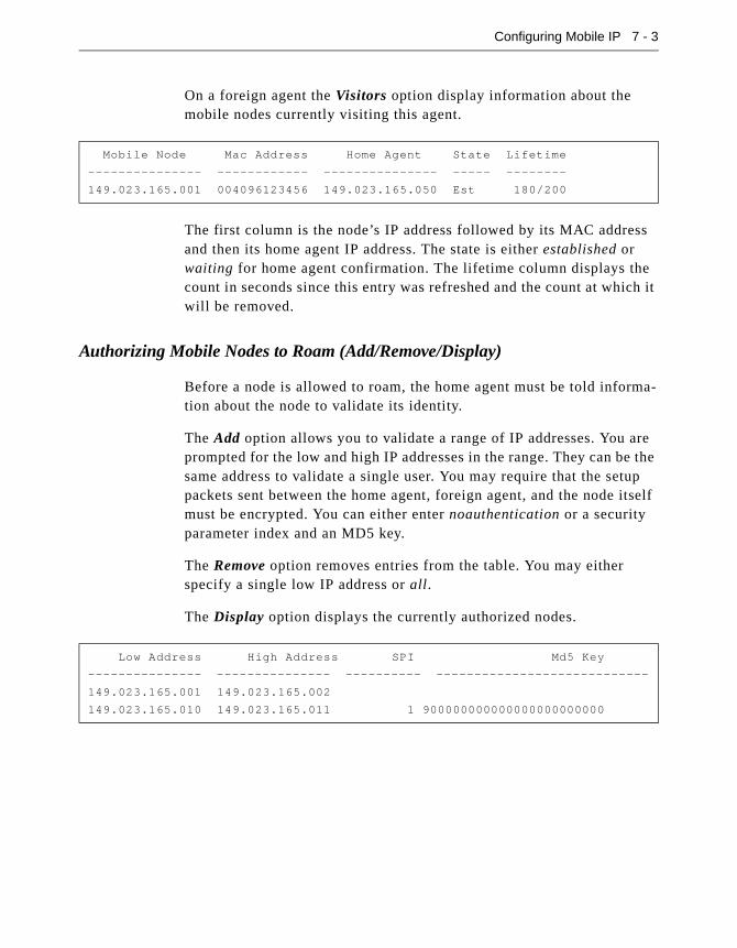
Configuring Mobile IP 7 - 3
On a foreign agent the Visitors option display information about the mobile nodes currently visiting this agent.
The first column is the node’s IP address followed by its MAC address and then its home agent IP address. The state is either established or waiting for home agent confirmation. The lifetime column displays the count in seconds since this entry was refreshed and the count at which it will be removed.
Authorizing Mobile Nodes to Roam (Add/Remove/Display)
Before a node is allowed to roam, the home agent must be told informa-tion about the node to validate its identity.
The Add option allows you to validate a range of IP addresses. You are prompted for the low and high IP addresses in the range. They can be the same address to validate a single user. You may require that the setup packets sent between the home agent, foreign agent, and the node itself must be encrypted. You can either enter noauthentication or a security parameter index and an MD5 key.
The Remove option removes entries from the table. You may either specify a single low IP address or all.
The Display option displays the currently authorized nodes.
Mobile Node Mac Address Home Agent State Lifetime
--------------- ------------ --------------- ----- --------
149.023.165.001 004096123456 149.023.165.050 Est 180/200
Low Address High Address SPI Md5 Key
--------------- --------------- ---------- ----------------------------
149.023.165.001 149.023.165.002
149.023.165.010 149.023.165.011 1 900000000000000000000000

7 - 4 Aironet 340 Series Bridge
Set up the Agent Parameters (Setup)
This menu lets you configure the parameters that control the operation of the agents.
The Lifetime parameter has two functions. It is the maximum amount of time the Home Agent will grant a mobile node to be registered on a for-eign network before renewing its registration. Note that the lifetime a mobile node asks for during the registration process may be more or less than this value. However, the Home Agent will only grant a lifetime up to this value.
The lifetime value is also placed in the agent advertisement packets. mobile odes typically use this field from the advertisements to generate the Lifetime value for the Registration Request.
The ReplayProt option determines the scheme used to prevent attacks based on capturing packets and playing them back at a later time. Two replay protection methods are allowed in Mobile IP: timestamps (man-datory) and nonces (optional). Due to a patent that may apply to nonce-based replay protection, we do not support nonces at this time. This value must be set to timestamps.
The Broadcasts option determines whether mobile nodes are allowed to request that broadcasts from their home network are forwarded via tun-neling to the mobile node. Some protocols require broadcast packets from the home network to maintain proper operation (i.e., NetBIOS). Unless needed, this option should be left at the default value of off to avoid unnecessary traffic.
If the RegRequired is off, mobile nodes are allowed the option of regis-tering to a Home Agent without the use of a Foreign Agent via a co-located care-of-address dynamically acquired while on the foreign net-
Configuration Mobile-IP Setup Menu
Option Value Description
1 - Lifetime [ 600 ] - Max Registration Lifetime
2 - ReplayProt [ timestamps ] - Replay Protection Method
3 - Broadcasts [ off ] - Broadcast Forwarding
4 - RegRequired [ on ] - Registration Required
5 - HostRedirects [ off ] - Enable ICMP Host Redirects to MN
Enter an option number or name, "=" main menu, <ESC> previous menu
>

Configuring Mobile IP 7 - 5
work. This is useful in cases where Foreign Agents have not yet been deployed on the foreign network; however, this scheme consumes IP addresses on that network. Setting this value to on will force mobile nodes on this network to always register using a Foreign Agent.
The HostRedirects option indicates whether or not the Foreign Agent will send an ICMP message to mobile nodes registered through it speci-fying the Address of an IP Router for the mobile node to use. If set to “off” (default), the mobile node will always use the Foreign Agent as its default gateway (router). Setting this value to “on” may improve perfor-mance while visiting a foreign network; however, there may be connec-tivity problems which result due to ARP broadcasts from the mobile node.
Control Agent Advertisements (Advert)
Agents advertise themselves on the LAN so that the mobile nodes can find them and determine whether they are home or away.
The AdvertType value specifies the type of datagram the Mobile Agent will use when sending out ICMP Agent Advertisements. The RFC 1256 recommendation and the default for the Access Point is to use the All Hosts Multicast address (224.0.0.1). In testing, it was discovered that some mobile nodes were not automatically joining this multicast group and thus were ignoring the agent advertisements. For these mobile nodes this value should be changed to ‘broadcast,’ which will use the limited broadcast address (255.255.255.255) for all unsolicited agent advertise-ments.
The AdvertInterval value specifies how frequently (in seconds) the Mobile Agent will send out an ICMP Router Advertisement multicast. These advertisements are used by the mobile nodes to locate the Mobile
Configuration Mobile-IP Setup Menu
Option Value Description
1 - AdvertType [ multicast ] - Advertisement type
2 - AdvertInterval [ 5 ] - Advertisement interval
3 - PrefixLen [ off ] - Advertise prefix length extension
4 - AdvertRtrs [ on ] - Advertise routers
Enter an option number or name, "=" main menu, <ESC> previous menu
>

7 - 6 Aironet 340 Series Bridge
Agents and to determine to which network they are currently attached. The more frequent the advertisement, the sooner the mobile node will be aware that it has attached to a new network and start the registration/de-registration process (if necessary). Since these are either multicast or broadcast datagrams (see below), the Access Point must be configured to forward these types of frames onto the RF network. We are currently working on a scheme to allow link layer notification of re-attachment resulting in a Router Solicitation from the mobile node. This will prompt a unicasted Router Advertisement from the Mobile Agent to the mobile node and allow multicast/broadcast forwarding on the Access Point to be turned off.
The PrefixLen option allows the Prefix Length extension to the Mobil-ity Agent (router) advertisement to be enabled or disabled. This exten-sion is used to indicate the number of bits in the subnet mask for the Mobility Agent generating the advertisement. The presence of the Prefix Length extension may be helpful to some mobile nodes in determining if they have attached to a foreign network. The default value is off. (Note: This option should be “on” for FTP TSR stacks and “off” for VxD stacks.)
RFC 2002 (Mobile IP) states that IP Routers MAY be included in the Router Advertisement (RFC 1256) portion of the Agent Advertisement. However, since the IP Address of the Agent itself is included in the router list, doing so may cause some hosts to select the Mobility Agent as its default router. In an attempt to minimize this situation, the Mobile Agent also includes the IP Address of its default router in the list of advertised routers with a higher “preference” value. If a host continues to select a Mobility Agent as its default router, the Agent can be config-ured to advertise zero routes by setting AdvertRtrs to “off”. The default value is “on”.
Chapter 8 - Using the Spanning Tree Protocol
8
C H A P T E R 8
Using the Spanning-Tree Protocol
This chapter describes how to configure the Aironet 340 Series Bridge for use with the Spanning Tree Protocol (STP) Protocol.
Here’s what you’ll find in this chapter:
� Overview
� Understanding Loops
� How STP Protocol Works
� Receiving Configuration Messages
� Determining the Root Bridge, Root Cost, and Spanning Tree
� Understanding Bridge Failures
� Avoiding Temporary Loops
� Establishing Timeouts
� Node Aging Addressing
� Implementing the STP Protocol

8 - 2 Aironet 340 Series Bridge
OverviewSTP is used to remove loops from a bridged LAN environment.
The Aironet 340 Series Bridge implements the IEEE 802.1d Spanning Tree Protocol (STP) specification to manage multiple bridges in an extended LAN environment. This allows the Aironet 340 Series Bridge to be used in bridged infrastructures with other 802.1d compliant bridges. The protocol also allows the bridges in an arbitrarily connected infrastructure to discover a topology that is loop free (a tree) and make sure there is a path between every pair of LANs (a spanning tree).
If you are administering a multiple-bridge infrastructure, this Chapter explains how the protocol works. However, if your infrastructure con-sists of a single bridge you can operate with the default values, although it might not be the optimal configuration required.

Using the Spanning-Tree Protocol 8 - 3
Understanding Loops
If there is more than one path from one LAN to another, the infrastruc-ture contains a loop.
If Node A transmits a multicast packet, both Bridge 1 and Bridge 2 will try and forward the packet to LAN 2. Each bridge, on seeing the other’s transmission on LAN 2, will forward the packet back to LAN 1. The cycle will continue and the packet will loop forever taking up all of the bandwidth of the bridges.
Topologies containing loops may be more complicated. For example, if Bridge 2 was replaced by two bridges with a LAN between them, the effect would still be the same.
Figure 8.1 - Example Loop on a Bridge Infrastructure
Node A
LAN 1
LAN 2
Bridge 1 Bridge 2
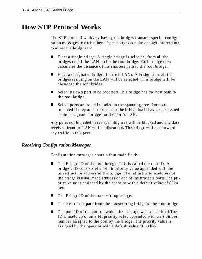
8 - 4 Aironet 340 Series Bridge
How STP Protocol WorksThe STP protocol works by having the bridges transmit special configu-ration messages to each other. The messages contain enough information to allow the bridges to:
� Elect a single bridge. A single bridge is selected, from all the bridges on all the LAN, to be the root bridge. Each bridge then calculates the distance of the shortest path to the root bridge.
� Elect a designated bridge (for each LAN). A bridge from all the bridges residing on the LAN will be selected. This bridge will be closest to the root bridge.
� Select its own port to be root port.This bridge has the best path to the root bridge.
� Select ports are to be included in the spanning tree. Ports are included if they are a root port or the bridge itself has been selected as the designated bridge for the port’s LAN.
Any ports not included in the spanning tree will be blocked and any data received from its LAN will be discarded. The bridge will not forward any traffic to this port.
Receiving Configuration Messages
Configuration messages contain four main fields.
� The Bridge ID of the root bridge. This is called the root ID. A bridge’s ID consists of a 16 bit priority value appended with the infrastructure address of the bridge. The infrastructure address of the bridge is usually the address of one of the bridge’s ports.The pri-ority value is assigned by the operator with a default value of 8000 hex.
� The Bridge ID of the transmitting bridge.
� The cost of the path from the transmitting bridge to the root bridge.
� The port ID of the port on which the message was transmitted.The ID is made up of an 8 bit priority value appended with an 8 bit port number assigned to the port by the bridge. The priority value is assigned by the operator with a default value of 80 hex.

Using the Spanning-Tree Protocol 8 - 5
Each bridge starts by assuming it is the root and its root cost is 0. When a bridge receives a configuration message, it records the values only if the message received is better than the message it would transmit out the port.
For example, message C1 is better than C2:
� If the root ID in C1 has a lower numeric value than the value from C2.
� If the root ID’s are equal and C1’s root cost is lower.
� If the root ID’s and costs are equal and C1’s transmitting Bridge ID has a lower numeric value.
� If the root ID, cost, and Bridge ID are equal and C1 was transmitted on a port with a lower port ID. This should only occur if two ports from the same bridge are connected to the same LAN.
If a port receives a better message than the one it would transmit, the bridge stops transmitting configuration messages on that port. Only one port on each LAN will be transmitting the messages. The bridge that contains this port is called the designated bridge for that LAN and the port is called the designated port.
Determining the Root Bridge and Root Cost
Each bridge determines the root bridge’s ID by comparing its own ID with those from the best messages received on all of its ports. The root ID is then used in all transmitted configuration messages.
If a bridge is the root, its root cost is 0. If a bridge is not a root, its cost is the minimum of the costs received in the messages from all its ports as well as the cost from the port on which the minimum cost message was received. This cost is then used in all transmitted configuration messages.
The port on which the minimum cost message was received is called the root port.

8 - 6 Aironet 340 Series Bridge
Determining the Spanning Tree
All ports on a bridge, either the root port or the designated port for their LAN, are allowed to forward packets. All others are blocked and do not transmit or receive any data packets.
Understanding Bridge Failures
All root and blocked ports monitor the LANs to which they are con-nected and watch for configuration messages transmitted by the desig-nated bridge for the LAN.
The STP protocol specifies a timeout period in which these ports must see at least one message. Each time a message is received, the timer is restarted. If the timeout period expires, the bridge assumes the desig-nated bridge has failed.
The bridge will discard the saved value for the port, make the port the designated port for that LAN, and restart sending configuration mes-sages. The bridge will also recalculate its values for the root bridge and root cost based on the active ports.
Other blocked ports on the same LAN will timeout and start to transmit messages. Eventually a new designated bridge, port, and root bridge will be determined.
Avoiding Temporary Loops
It will take a non-zero amount of time for the protocol to determine a stable loop free topology due to the time for messages to pass from one end of the infrastructure to the other. If the ports were allowed to for-ward while the protocol was stabilizing, then temporary loops could form.
To avoid temporary loops, ports are not allowed to go immediately from the blocked state to the forwarding state. They must first go through a state called listening. In this state, they may receive and transmit config-uration messages as needed but must block all data traffic. The time spent in the listening state must be at least twice the end-to-end transmit time of the infrastructure.

Using the Spanning-Tree Protocol 8 - 7
If the port is still part of the spanning tree at the end of the listening period it is put in the learning state. In this state it can still receive and transmit configuration messages, but is also allowed to learn the source addresses from the packets received from its LAN. It is still not allowed to forward any packets. The learning state is used to lessen the amount of flooding of unknown destination addresses that would occur if the port started forwarding before there were any entries in its learning table.
Once the learning period is over, the port is allowed to forward data normally.
Establishing Timeouts
The configured timeout values on the root bridge are passed to each bridge in a configuration message to ensure that all bridges on the infra-structure are using the same timeout periods.
The root bridge puts its own values in its messages. All other bridges copy the values contained in the configuration message sent to them from their root port. The value in this message is used in all of the bridge’s transmitted messages. Using this method, the values are propa-gated throughout the infrastructure.
Node Address Aging
Occasionally stations may be moved from one LAN to another. The bridges will remove learned addresses from their tables if no packets have been received from a node for a period of time.
If node addresses do not timeout, the bridge may continue to send pack-ets for a node to the wrong LAN. If a node sends packets from its new LAN location, the tables might be corrected, however, this is not guar-anteed. The default timeout period is 5 minutes.
If a new bridge or port is added to an infrastructure, the ports included in the spanning tree could change dramatically. It may appear that a node has changed location very quickly.
To allow for these quick changes of location, the spanning tree protocol specifies that every time a port enters the blocked or forwarding states, its bridge must send a topology changed message to the root bridge.
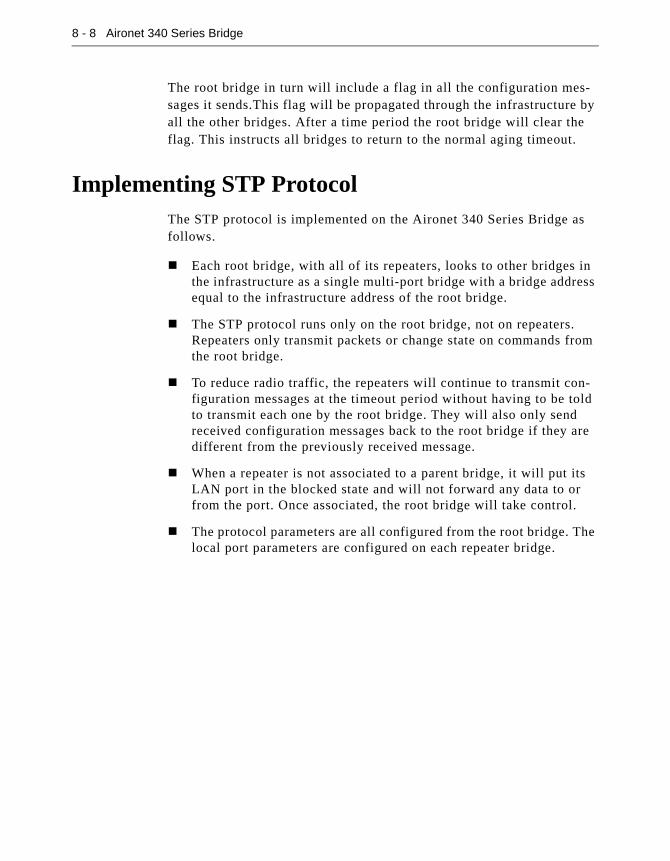
8 - 8 Aironet 340 Series Bridge
The root bridge in turn will include a flag in all the configuration mes-sages it sends.This flag will be propagated through the infrastructure by all the other bridges. After a time period the root bridge will clear the flag. This instructs all bridges to return to the normal aging timeout.
Implementing STP ProtocolThe STP protocol is implemented on the Aironet 340 Series Bridge asfollows.
� Each root bridge, with all of its repeaters, looks to other bridges in the infrastructure as a single multi-port bridge with a bridge address equal to the infrastructure address of the root bridge.
� The STP protocol runs only on the root bridge, not on repeaters. Repeaters only transmit packets or change state on commands from the root bridge.
� To reduce radio traffic, the repeaters will continue to transmit con-figuration messages at the timeout period without having to be told to transmit each one by the root bridge. They will also only send received configuration messages back to the root bridge if they are different from the previously received message.
� When a repeater is not associated to a parent bridge, it will put its LAN port in the blocked state and will not forward any data to or from the port. Once associated, the root bridge will take control.
� The protocol parameters are all configured from the root bridge. The local port parameters are configured on each repeater bridge.

Using the Spanning-Tree Protocol 8 - 9
Using the Configuration STP Menu (Root Bridge Only)
The STP Protocol for a root bridge is configured using the Configura-tion STP Menu. This menu will only appear if the Root Mode is “On” as described in Chapter 4 “Configuring the Radio Network”. To access this menu, select Configuration from the Main Menu, then select STP from the Configuration Menu.
Enabling STP Protocol (Active)
The active option acts as an On/Off switch for the STP protocol. The default setting is “Off”, which means all root and repeater LAN ports are placed in the forwarding state. If the option is turned “On”, the root and repeater LAN ports are placed in the listening state.
If you are running a small infrastructure, and there will never be any loops, leave the STP protocol “Off”. If you are unsure, change the set-ting to “On” as the overhead involved for bridges is small.
Setting Bridge Parameters (Bridge)
The bridge option allows you to set the overall parameters and timeout values for a root bridge. When the bridge option is selected, the Config-ure STP Bridge Menu appears.
Configuration Stp Menu
Option Value Description
1 - Active [ off ] - Protocol enabled
2 - Bridge [ menu ] - Bridge parameters
3 - Port [ menu ] - Port parameters
4 - Display - Protocol status
5 - State [ "Forward" ] - Local ethernet port state
Configuration Stp Bridge Menu
Option Value Description
1 - Priority [ 8000 ] - Bridge priority
2 - Hello_time [ 2 ] - Hello message interval
3 - Forward_delay [ 15 ] - Forwarding delay
4 - Msg_age_timeout [ 20 ] - Receive hello message timeout

8 - 10 Aironet 340 Series Bridge
Setting the Bridge Priority (Priority)
The priority option is used to set the priority value appended to the infrastructure address of the Bridge ID.
By changing the priority value, you can influence which bridge in the infrastructure will become the root bridge. The lower the priority value, the more likely the bridge will be the root. If all other bridges are set to the default value (8000 hex), a bridge set with a lower value will become the root.
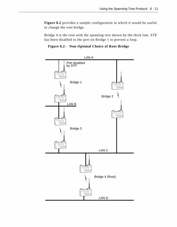
Using the Spanning-Tree Protocol 8 - 11
Figure 8.2 provides a sample configuration in which it would be useful to change the root bridge.
Bridge 4 is the root with the spanning tree shown by the thick line. STP has been disabled to the port on Bridge 1 to prevent a loop.
Figure 8.2 - Non-Optimal Choice of Root Bridge
LAN A
LAN C
LAN D
LAN B
Bridge 1
Bridge 3
Bridge 4 (Root)
Port disabledby STP
Bridge 2

8 - 12 Aironet 340 Series Bridge
If there is heavy traffic between LAN A and LAN B, it would be more efficient to have Bridge 1 become the root with the port on Bridge 3 being disabled.
Figure 8.3 - Alternate Root Bridge Arrangement
LAN A
LAN C
LAN D
LAN B
Bridge 1
Bridge 3
Bridge 4 (Root)
Port disabledby STP
Bridge 2
Using the Spanning-Tree Protocol 8 - 13
Setting the Hello Message Interval Time (Hello_Time)
The hello_time option is used to set the interval time, in seconds, between the transmission of configuration messages. This value is only used if the local bridge becomes the spanning tree root bridge. If not, the value in received configuration messages transmitted from the root bridge is used.
If the interval time is set too high, the infrastructure will respond slowly in resolving any conflict problems. However, if set too low, the infra-structure will be crowded with hello message traffic. The interval time values range between 1 and 10 with a default value of 2.
Setting the Forwarding Delay Time (Forward_Delay)
The forward_delay option is used to set the delay time, in seconds, that the ports will spend in the listening and learning states. This value is only used if the local bridge becomes the spanning tree root bridge. If not, the value in received configuration messages transmitted from the root bridge is used.
This option is also the timeout period used to age learned addresses whenever the spanning tree topology is changed. The value should be at least twice the transit time of a packet sent from one end of the infra-structure to the other. This allows for news of a topology change to reach all nodes and allows all ports to be blocked before new ports enter the forwarding state.
If the interval time is set too low, then temporary loops could be formed. However, if set too high, it will take longer for the infrastructure to become active after a spanning tree topology change has been made. The delay time values range between 4 and 30 with a default value of 15.
Setting the Receive Hello Message Timeout (Msg_age_timeout)
The msg_age_timeout option is used to set the timeout period, in sec-onds, a blocked or root port watches for configuration messages from the infrastructure’s designated port. This value is only used if the local bridge becomes the spanning tree bridge. If not, the value received in configuration messages transmitted from the root bridge is used.
Each time a configuration message is received, the timer is started. If the timer expires, the root bridge is assumed to have failed and the span-ning tree infrastructure will be reconfigured.

8 - 14 Aironet 340 Series Bridge
If the timeout period is set too low, the spanning tree infrastructure may reconfigure itself unnecessarily and messages can be lost due to heavy traffic on the infrastructure. However, if set too high, the infrastructure will take longer than necessary to recover from failed ports or bridges.
The upper limit on the allowed range is determined by the setting of the forwarding delay. The timeout period must be less than twice the for-warding delay, minus 1 second. The timeout values range between 6 and 29 with a default value of 20.
Setting Port Parameters (Port)
The port option allows you to set the port parameters for a root bridge’s local LAN port and for the ports of any active connected repeaters. When the port option is selected, the Configuration STP Port Menu appears.
Enabling the STP Protocol (Port)
The port option is used to enable the STP protocol on the local port. The default setting is “On”, which allows all root bridge LAN ports to be ini-tially placed in the listening state. If the option is turned “Off”, the LAN ports are placed in the forwarding state.
If the port’s LAN will always be connected to the bridge and loops will never occur, turn the protocol “Off” to prevent the port from transmit-ting configuration messages on every timeout period.
Configuration Stp Port Menu
Option Value Description
1 - Port [ on ] - Protocol enabled for ethernet port
2 - Priority [ 80 ] - Local ethernet port priority
3 - Cost [ 100 ] - Local ethernet port cost
4 - Rport - Protocol enabled for remote port
5 - Rpriority - Remote port priority
6 - Rcost - Remote port cost

Using the Spanning-Tree Protocol 8 - 15
Setting the Local Port Priority (Priority)
The priority option is only used when two or more repeaters are con-nected to the same LAN for redundancy and you want to select which one will forward the packets. The port assigned the lowest priority value will be the one to forward. The priority range is from 0 to ff hex with a default setting of 80.
Setting the Local Port Cost (Cost)
The value for the cost option is added to the root cost field from any received configuration messages to determine if the port has the least cost path to the root. Cost values can be set for 65535 or less with a default value is 100.
The larger the cost value, the more likely the port will be a backup for another active port on its LAN. If there is no active port, it is likely the LAN will be a leaf of the infrastructure tree or a less used LAN in the tree.
Configuring Ports of Active Connected Repeaters (Rport, Rcost, Rpriority)
The rport, rpriority and rcost options are used to configure the ports of active and connected repeaters in the root’s radio tree.
These options are identical to the port, priority and cost options described except when the values are entered, you will be prompted for the applicable port number. The port number can be obtained from the port ID field on the Protocol Status Display screen.

8 - 16 Aironet 340 Series Bridge
Displaying the Protocol Status (Display)
The display option shows the overall status of the STP protocol and the state of each port on the local bridge. When you select Display, the STP Status screen appears.
� Bridge Id: The ID of the local bridge.
� Root Id: The ID of the spanning tree root. If the local bridge is not the root, then the cost to the root is also displayed.
� Topology change: Indicates whether the short aging timeout is cur-rently in use because of a port state change somewhere on the infra-structure.
� Network Hello Interval, Network Forward Delay and Network Msg age Timeout: Shows the timeout values received from the root bridge which are in use by all bridges on the infrastructure. These values override any locally configured values.
� Port Address: The infrastructure address of the bridge on which the port resides.
� Id: The port ID, which consists of the port priority (high byte) and the port number (low byte). As each repeater connects to the root its port is assigned the next available port number.
� Cost: The operator configured cost for the port.
� State: Current state of the port. Shows one of forward, learn, listen, or blocked. The state may also be disabled if the port has been shut off by the operator.
� Type: Current port type. Shows one of root, designated, or blocked. The type will be disabled if the protocol is not running on the port.
� Designated (Bridge, Port, Root Cost): Displays the designated bridge and port for the specific LAN as well as the cost to the root from the designated port.
STP STATUS
Bridge Id : 8000-00409611cd0e Network Hello interval : 2 sec
Root Id : 8000-0000f3108678, Cost 100 Network Forward Delay : 5 sec
Topology change : off Network Msg age Timeout : 20 sec
------------Designated----------
Port Address LAN Id Cost State Type Bridge Port Root Cost
------------ --- ---- ----- -------- ---------- ----------------- ---- ---------
00409611cd0e Eth 8001 100 Forward Root 8000-0000f3108678 8002 0

Using the Spanning-Tree Protocol 8 - 17
Viewing the Port State (State)
The state option is a read-only value which displays the current STP state of the local LAN port. The states displayed are forward, learn, lis-ten, or blocked.

Part 3 - Control & Maintenance
Part 3 - C
ontrol & M
aintenance

Chapter 9 - Viewing Statistics
9
C H A P T E R 9
Viewing Statistics
This chapter describes how to use the Statistics Menu to monitor the performance of the Aironet 340 Series Bridge.
Here’s what you’ll find in this chapter:
� Viewing the Statistics Menu
� Throughput Statistics
� Radio Error Statistics
� Ethernet Error Statistics
� Displaying Source Routes
� Displaying Overall Status
� Recording a Statistic History
� Displaying a Statistic History
� Displaying Node Information
� Setting Screen Display Time
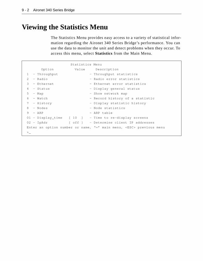
9 - 2 Aironet 340 Series Bridge
Viewing the Statistics MenuThe Statistics Menu provides easy access to a variety of statistical infor-mation regarding the Aironet 340 Series Bridge’s performance. You can use the data to monitor the unit and detect problems when they occur. To access this menu, select Statistics from the Main Menu.
Statistics Menu
Option Value Description
1 - Throughput - Throughput statistics
2 - Radio - Radio error statistics
3 - Ethernet - Ethernet error statistics
4 - Status - Display general status
5 - Map - Show network map
6 - Watch - Record history of a statistic
7 - History - Display statistic history
8 - Nodes - Node statistics
9 - ARP - ARP table
01 - Display_time [ 10 ] - Time to re-display screens
02 - IpAdr [ off ] - Determine client IP addresses
Enter an option number or name, “=” main menu, <ESC> previous menu
>_

Viewing Statistics 9 - 3
Throughput Statistics (Throughput)
The Throughput Statistics Display provides a detailed summary of the radio data packets passing through your unit. To access this display, select Statistics from the Main Menu then select Throughput from the Statistics Menu.
� Recent Rate/s: Displays the event rates, per second, averaged over the last 10 seconds.
� Total: Displays the number of events that have occurred since the statistics were last cleared.
� Average Rate: Displays the average event rates, per second, since the statistics were last cleared.
� Highest Rate: Displays the highest rate recorded since the statistics were last cleared.
� Packets: Displays the number of packets transmitted or received.
� Bytes: Displays the total number of data bytes in all the packets transmitted or received.
� Filtered: Displays the number of packets that were discarded as a result of an address filter being setup.
THROUGHPUT STATISTICS
Cleared 19:11:52 ago
Recent Average Highest
Statistic Rate/s Total Rate/s Rate/s
-------------------------- ---------- ---------- ---------- ----------
Radio Receive Packets 2 110798 1 174
Bytes 167 7143295 103 9086
Filter 0 0 0 0
Error 0 0 0 0
Radio Transmit Packets 4 131085 1 175
Bytes 377 18500991 267 37749
Errors 0 9036 0 27
Bridge Receive Packets 3 151112 2 321
Bytes 260 30547969 442 32549
Filtered 5 350282 5 928
Errors 0 2 0 0
Misses 0 0 0 0
Bridge Transmit Packets 2 54398 0 320
Bytes 193 1051355 93 170822
Errors 0 0 0 0
Enter space to redisplay, C[lear stats], q[uit] :

9 - 4 Aironet 340 Series Bridge
� Errors: Displays the number of errors that may have occurred.
� Enter space to redisplay, C[lear stats], q[quit]: To redisplay statistics, enter a space by pressing the space bar. To clear the statis-tics, press “C” (case sensitive). To exit the Statistics Menu, press “q”.
Radio Error Statistics (Radio)
The Radio Error Statistics Display provides a detailed summary of the radio receiver and transmitter errors that have occurred on the unit.
To access this display, select Statistics from the Main Menu then select Radio from the Statistics Menu.
� Buffer Full Frames Lost: Number of frames lost due to a lack of buffer space in the unit.
� Duplicate Frames: Number of frames that were received more than once. This is usually due to a frame acknowledgment being lost.
� CRC Errors: Number of frames received with an invalid CRC. Usu-ally caused by interference from nearby radio traffic. Occasional CRC errors can also occur due to random noise when the receiver is idle.
� Retries: A cumulative count of the number of times a frame had to be retransmitted due to an acknowledgment not being received.
� Max Retries / Frame: The maximum number of times any one frame had to be retransmitted. Excessive retries may indicate a poor quality radio link.
� Queue Full Discards: Number of times a packet was not transmitted due to too many retries occurring to the same destination. Discards will only occur if packets destined to this address are taking up more than their share of transmit buffers.
RADIO ERROR STATISTICS
Cleared 19:23:22 ago
Receive Transmit
-------------------------------------- ------------------------------------
Buffer full frames lost 0 Retries 45
Duplicate frames 0 Max retries / frame 7 +7
CRC errors 0 Excessive retries 0
Queue full discards 0
Enter space to redisplay, C[lear stats], q[uit]:
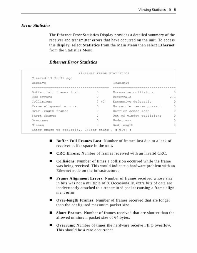
Viewing Statistics 9 - 5
Error Statistics
The Ethernet Error Statistics Display provides a detailed summary of the receiver and transmitter errors that have occurred on the unit. To access this display, select Statistics from the Main Menu then select Ethernet from the Statistics Menu.
Ethernet Error Statistics
� Buffer Full Frames Lost: Number of frames lost due to a lack of receiver buffer space in the unit.
� CRC Errors: Number of frames received with an invalid CRC.
� Collisions: Number of times a collision occurred while the frame was being received. This would indicate a hardware problem with an Ethernet node on the infrastructure.
� Frame Alignment Errors: Number of frames received whose size in bits was not a multiple of 8. Occasionally, extra bits of data are inadvertently attached to a transmitted packet causing a frame align-ment error.
� Over-length Frames: Number of frames received that are longer than the configured maximum packet size.
� Short Frames: Number of frames received that are shorter than the allowed minimum packet size of 64 bytes.
� Overruns: Number of times the hardware receive FIFO overflow. This should be a rare occurrence.
ETHERNET ERROR STATISTICS
Cleared 19:36:31 ago
Receive Transmit
-------------------------------------- -------------------------------
Buffer full frames lost 0 Excessive collisions 0
CRC errors 0 Deferrals 273
Collisions 2 +2 Excessive deferrals 0
Frame alignment errors 0 No carrier sense present 0
Over-length frames 0 Carrier sense lost 0
Short frames 0 Out of window collisions 0
Overruns 0 Underruns 0
Misses 0 Bad length 0
Enter space to redisplay, C[lear stats], q[uit] :
9 - 6 Aironet 340 Series Bridge
� Misses: The number of Ethernet packets that were lost due to a lack of buffer space on the unit.
� Excessive Collisions: Number of times transmissions failed due to excessive collisions. Usually indicates the frame had to be continu-ously retried due to heavy traffic on the Ethernet infrastructure.
� Deferrals: Number of times frames had to wait before transmitting due to activity on the cable.
� Excessive Deferrals: Number of times the frame failed to transmit due to excessive deferrals. Usually indicates the frame had to be continuously retried due to heavy traffic on the Ethernet infrastruc-ture.
� No Carrier Sense Present: Number of times the carrier was not present when a transmission was started. Usually indicates a prob-lem with a cable on the Ethernet infrastructure.
� Carrier Sense Lost: Number of times the carrier was lost during a transmission. Usually indicates a problem with a cable on the Ether-net infrastructure.
� Out of Window Collisions: Number of times a collision occurred after the 64th byte of a frame was transmitted. Usually indicates a problem with a cable on the Ethernet infrastructure.
� Underruns: Number of times the hardware transmit FIFO became empty during a transmit. This should be a rare occurrence.
� Bad Length: Number of times an attempt was made to transmit a packet larger than the specified maximum allowed.
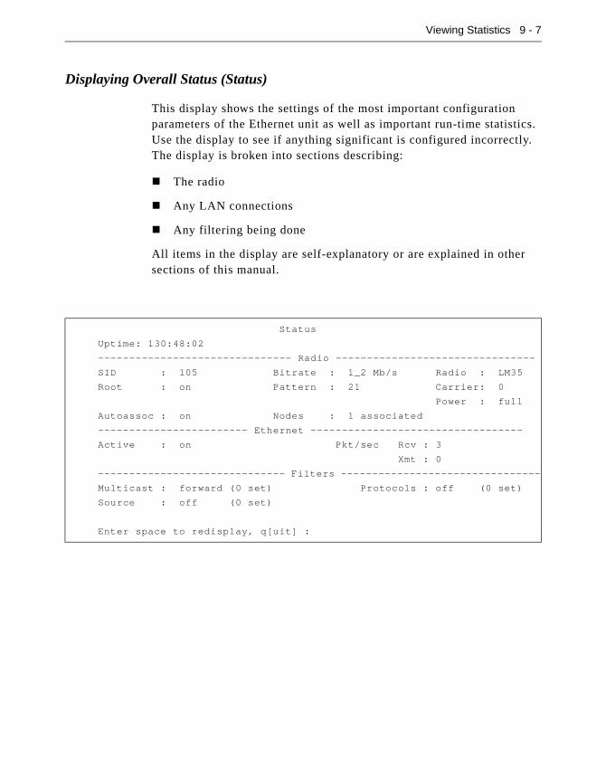
Viewing Statistics 9 - 7
Displaying Overall Status (Status)
This display shows the settings of the most important configuration parameters of the Ethernet unit as well as important run-time statistics. Use the display to see if anything significant is configured incorrectly. The display is broken into sections describing:
� The radio
� Any LAN connections
� Any filtering being done
All items in the display are self-explanatory or are explained in other sections of this manual.
Status
Uptime: 130:48:02
------------------------------- Radio --------------------------------
SID : 105 Bitrate : 1_2 Mb/s Radio : LM35
Root : on Pattern : 21 Carrier: 0
Power : full
Autoassoc : on Nodes : 1 associated
------------------------ Ethernet ----------------------------------
Active : on Pkt/sec Rcv : 3
Xmt : 0
------------------------------ Filters --------------------------------
Multicast : forward (0 set) Protocols : off (0 set)
Source : off (0 set)
Enter space to redisplay, q[uit] :

9 - 8 Aironet 340 Series Bridge
Display a Network Map (Map)
This command causes the bridge to poll all of the other bridges in the local infrastructure for information about the radio nodes associated to them. Nodes that are associated to parents are displayed indented one level from their parents on the display.
The version column displays the firmware release level currently run-ning on the unit.
Recording a Statistic History (Watch)
Use the watch option to record the values of a chosen Ethernet statistic over time. Once you select a statistic and a time interval, the unit will start a timer. At each timer expiration, the unit will record the current value of the statistic. The last 20 samples are saved.
� To Record a Statistic History:
1. Select the watch option.
NETWORK MAP
Device Node Id IP Address Ver Name
----------- ------------ --------------- ----- -----------------
BRE105E 00409611cd0e 149.023.165.163 4.1G BRE105E_22ff0a
AP4500T 00409611d1e5 149.023.165.169 4.1G hello there
UC4500E 004096207206 149.023.165.176 4.1G UC4500E_207206
LM4500 00409620222a 149.023.165.238
AP4500E 00409611855b 149.023.165.160 4.1B AP4500E_11855b
LM4500 00409620222d
Enter space to redisplay, q[uit]:
1. ra Radio
2. re Radio Error
3. et Ethernet
4. ee Ethernet
Enter category, one of [a number from 1 to 4, a short
form]:

Viewing Statistics 9 - 9
2. Type the applicable category number and press ENTER. For exam-ple, if you choose “Radio” the following information would appear:
3. Type the applicable statistic index number and press ENTER.
Enter a sample time in seconds from 1 to 3600 :
4. Type a time interval between samples and press ENTER. The longer the time you specify, the further back in time the samples will be saved (up to 20 samples).
Radio
Receive Transmit
1 rpa Packets 5 tpa Packets
2 rby Bytes 6 tby Bytes
3 rfi Filtered 7 ter Errors
4 rer Errors
Enter one of [a index from 1 to 7, a short form]:
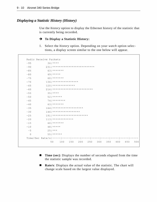
9 - 10 Aironet 340 Series Bridge
Displaying a Statistic History (History)
Use the history option to display the Ethernet history of the statistic that is currently being recorded.
� To Display a Statistic History:
1. Select the history option. Depending on your watch option selec-tions, a display screen similar to the one below will appear.
� Time (sec): Displays the number of seconds elapsed from the time the statistic sample was recorded.
� Rate/s: Displays the actual value of the statistic. The chart will change scale based on the largest value displayed.
Radio Receive Packets
-95 36|****
-90 231|**************************
-85 63|*******
-80 49|*****
-75 60|*******
-70 136|****************
-65 120|**************
-60 216|*************************
-55 35|****
-50 52|******
-45 74|********
-40 63|*******
-35 164|*******************
-30 146|*****************
-25 191|**********************
-20 113|*************
-15 60|*******
-10 48|*****
-5 25|***
0 55|******
Time/Sec Rate/s|-----|-----|-----|-----|-----|-----|-----|-----|-----
50 100 150 200 250 300 350 400 450 500

Viewing Statistics 9 - 11
Displaying Node Information (Node)
The node command displays current Ethernet information about theclient.
� Address: Displays the address of the client.
� Signal: Displays the signal strength of the client.
� Tx Pkt: Displays the number of packets transmitted from the client.
� Tx Byte: Displays the actual number of bytes transmitted from the client.
� Tx Retry: Displays the number of transmitted packets that were resent by the client.
� Rx Pkt: Displays the number of packets the client has received.
� Rx Byte: Displays the actual number of bytes received by the client.
Displaying ARP Information (ARP)
The ARP command displays the ARP table of IP address to MAC address. It also displays whether the node supports Ethernet Type II or IEEE 802.2 framing. The last column displays the time until the entry times out.
Radio Node Statistics
ID Address Signal Tx Pkt Tx Byte Tx Retry Rx Pkt Rx Byte Rate
--- ------- ------ ----- ------- -------- ------ ------- -----
004096128e76 45 1012 204322 39 1673 112386
Enter space to redisplay, q[uit]:
INTERNET ADDRESS TABLE
Internet Address Network Address ETHII 802.2 Time
---------------- --------------- ----- ------ ----------
149.023.165.175 0000c0d9657f Yes 0:14:57
149.023.165.040 0800099e0b1a Yes 0:14:57
Enter space to redisplay, q[uit] :

9 - 12 Aironet 340 Series Bridge
Setting Screen Display Time (Display_Time)
Use the display time option to set the Ethernet time interval for theautomatic redisplay of any repeating display. The default value is 10 seconds.
Determine Client IP Addresses (Ipadr)
This function can be enabled to get the unit to determine the IP address of the client nodes associated to it. The address are then display in the Map function described above.
If enabled the unit will watch traffic from the client associated to it and record the source IP addresses found.

Chapter 10 - Setting Up the Association Table
10
C H A P T E R 1 0
Setting Up the Association Table
This chapter describes the procedures for setting up the Association Table for the Aironet 340 Series Bridge.
Here’s what you’ll find in this chapter:
� Overview
� Using the Association Menu
� Displaying the Association Table
� Displaying the Association Table Summary
� Setting the Allowed Number of Child Nodes
� Controlling Associations with Static Entries
� Backbone LAN Node Stale Out Time
� Specifying How Node Addresses are Displayed

10 - 2 Aironet 340 Series Bridge
OverviewClient nodes and repeater bridges request to be associated with a parent bridge so the parent will forward data frames. This exchange of radio packets passes back and forth information such as a node’s address, device, association type, and ASCII name. This information is entered into the bridge’s association table along with the address of the parent bridge. Each bridge maintains entries in its table for all nodes associated to it and all nodes associated to any repeater serving it. There may be up to 2048 entries in the table.
A bridge will accept an association from any node that requests it.The operator may set up entries in the association table to controlwhich nodes are allowed to associate.
Using the information in the association table, the bridge can perform a variety of traffic-control functions in moving packets to their proper destination on the infrastructure. When packets are received from the Ethernet or radio network, the bridge will look in its table for the packet’s destination address and do one of the following:
� If the entry shows the radio node is associated to this unit, the packet can be forwarded directly.
� If the entry indicates that the entry is associated to a repeater serving this unit, the packet is forwarded to the repeater.
� If the address is not found, a root unit will forward the packet to the wired LAN, while a repeater will forward the packet to its own parent bridge.

Setting Up the Association Table 10 - 3
Using the Association MenuThe Association Menu contains options that allow you to view the table entries, add entries, and control the routing of packets on your radio network. To access this menu, select Association from the Main Menu.
Displaying the Association Table (Display)
Use the display option to view the association table entries. Select “dis-play” to enter the type of entries to be displayed.
� All: Displays all entries in the table.
� Connected: Displays only nodes that are actively connected to the Aironet 340 Series Bridge.
� Heirachy: A special shortened display which shows the association tree with children indented from their parents.
� Static: Displays only nodes for which a static entry has been made to control the nodes’ association.
� Multicast-filters: Displays only those entries for multicast addresses for which filters have been added. See Chapter 11 “Using Filters”.
� Node-filters: Displays only those entries for node address for which filters have been added. See Chapter 11 “Using Filters”.
Association Menu
Option Value Description
1 - Display - Display the table
2 - Summary - Display the table summary
3 - Maximum [ 1024 ] - Maximum allowable child nodes
4 - Autoassoc [ on ] - Allow automatic table additions
5 - Add - Control node association
6 - Remove - Remove association control
7 - Staletime [ 350 ] - Backbone LAN node stale out time
8 - Niddisp [ numeric ] - Node Ids display mode
Enter an option number or name, "=" main menu, <ESC> previous menu

10 - 4 Aironet 340 Series Bridge
The typical hierarchy display will resemble:
The rest of the displays will be similar to the one below.
� Address Column: Displays the address (in ascending numerical order) for each node on the infrastructure. An “N” before the address indicates that the node is a static entry and not associated. An “R” before the address indicates that the node is static and asso-ciated. The letters “N” and “R” only appear beside static entries.
� Type Column: Displays the node association type. The following types may appear in the table:
Me: Represents this Aironet 340 Series Bridge.
Psp: Indicates the node that is using the Power Saving Protocol (PSP) to communicate with the system. Some radio nodes, usually wireless client devices, only power up part of the time to conserve energy. Therefore the bridge must communicate to these nodes using PSP.
Prnt: Indicates a repeater’s parent node.
Rep: Indicates a repeater bridge.
RADIO HIERARCHY
Device Address Name
-------------------- ------------ --------------------
BRE105E 00409611cd0e BRE105E_22ff0a
BRE105T 00409611d1e5 hello there
UC4500E 004096207206 UC4500E_207206
BRE105E 00409611d602 BRE105E_22ff0a
UC4500E 0040962068b0 UC4500E_2068b0
LM4500 00409620222a
RADIO NODES
Address Device Type Parent Name Src
------------- --------- ---- ------------ ------------------ ---
00409611cd0e BRE105E Me BRE105E_22ff0a Fwd
00409611d1e5 AP4500T Rep Local hello there
N00409611d602 AP4500E Rep Local AP4500E_11d602 Fwd
00409620222a LM4500 Local Fwd
0040962068b0 UC4500E 00409611d602 UC4500E_2068b0 Fwd
004096207206 UC4500E 00409611d1e5 UC4500E_207206 Fwd
Enter space to redisplay, q[uit] :

Setting Up the Association Table 10 - 5
� Parent Column: Displays the node ID of the parent to which the node is associated. In place of a node ID, the column may display the following:
A blank entry: The node is not associated.
Local: The node is associated to this unit.
Local block: The node has been blocked and will not be allowed to associate with the local system directly.
Name Column: Displays the node name.
Rdst, Src: Displays the type of multicast filter action that has been set for Radio (RDst) and Source (Src) packets. A blank means that the action is forward. See Chapter 11 “Using Filters”.
Displaying the Association Table Summary (Summary)
Use the summary option to view a summary of the number of nodes associated to your unit. When you select the summary option, the Asso-ciation Table Summary Display appears:
� Direct Associations: Number of Non-PSP, PSP, or repeater nodes associated to this bridge.
� Indirect Associations: Number of Non-PSP, PSP, or repeater nodes associated to the Aironet 340 Series Bridge below the current bridge, on the radio network tree.
Setting the Allowed Number of Child Nodes (Maximum)
This command determines the maximum number of allowed child nodes that can be associated to the Aironet 340 Series Bridge.
ASSOCIATION TABLE SUMMARY
Non-Psp Psp Repeaters
------- ------- ----------
Direct associations : 1 0 2
Indirect associations : 2 0 0
10 - 6 Aironet 340 Series Bridge
Controlling Associations With Static Entries (Autoassoc/Add/Remove)
Use the auto-association parameter and the static association table entries to control associations.
In its default configuration, the bridge will allow any radio node in range to associate to it. For a more secure installation you must add static entries to the association table for these nodes. This allows control over which radio nodes are allowed to associate with which bridge.
If auto-association is “On”, any radio node will be allowed to associate. If the parameter is “Off”, only nodes whose address matches a static table entry will be allowed to associate.
Static table entries are association table entries added manually by the operator and saved in the configuration memory. To add an entry, use “Add” on the Association Menu. “Add” supplies the address of the node that is to be controlled.
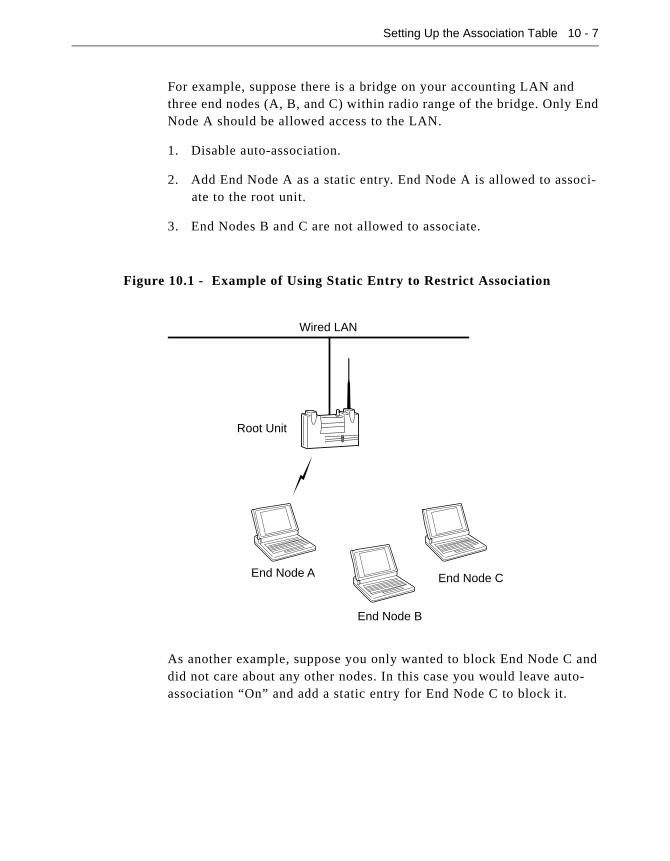
Setting Up the Association Table 10 - 7
For example, suppose there is a bridge on your accounting LAN and three end nodes (A, B, and C) within radio range of the bridge. Only End Node A should be allowed access to the LAN.
1. Disable auto-association.
2. Add End Node A as a static entry. End Node A is allowed to associ-ate to the root unit.
3. End Nodes B and C are not allowed to associate.
As another example, suppose you only wanted to block End Node C and did not care about any other nodes. In this case you would leave auto-association “On” and add a static entry for End Node C to block it.
Figure 10.1 - Example of Using Static Entry to Restrict Association
Wired LAN
Root Unit
End Node A
End Node B
End Node C
10 - 8 Aironet 340 Series Bridge
If you are going to use static entries to control associations, then the “association add all” command is a quick way to set up the table.
1. Leave auto-association “On” and let the nodes automatically associ-ate to the bridge.
2. Once they have associated, select Add from the Association Menu and type “All”. All entries currently in the table are now made static.
3. Turn off auto-association. You can now remove extra entries or add missing entries manually.
Backbone LAN Node Stale Out Time (Staletime)
When an entry is added to the association table for a wired LAN node, a timer is started for the number of seconds specified by the value of this option. Each time a packet is received containing the same source address, the timer is restarted.
Specifying How Node Addresses are Displayed (NIDdisp)
Use the NIDdisp option to specify how the node addresses are displayed on the Association Display Screen. The Aironet 340 Series Bridge has the ability to display node addresses as follows:
� If you specify “numeric”, the addresses are displayed entirely in numeric form (default).
� If you specify “name”, the Organizational Unique Identifier (OUI) portion of the address (the first three bytes) is examined to see if it is one of the known types. If it is in the list, the first three bytes will be replaced by the name of the company that owns the OUI. Other-wise the numeric value is displayed. For example, the address of a SUN workstation could be displayed as either 080020ladecc orSun-ladecc.
Chapter 11 - Using Filters
11
C H A P T E R 1 1
Using Filters
This chapter describes how to control the forwarding of multicast messages.
Here’s what you’ll find in this chapter:
� Overview
� Using the Filter Menu
� Filtering Multicast Addresses
� Filtering Node Addresses
� Filtering Protocols

11 - 2 Aironet 340 Series Bridge
OverviewIf your Aironet 340 Series Bridge is connected to an infrastructure with a large amount of multi-protocol traffic, you may be able to reduce the amount of radio traffic by blocking out (filtering) those addresses or protocols that are not needed.
This filtering is especially important for battery operated radio nodes which might otherwise have to waste considerable battery power receiv-ing multicast messages which are not relevant and will only be dis-carded.
Using the Filter MenuThe Filter Menu is used to control the forwarding of data packets. To access this menu, select Filter from the Main Menu.
NOTE: In order to achieve consistent performance on your infrastructure, any configurations that you set in the Filter Menu should be duplicated on all Aironet 340 Series Bridges. This maintains consistency as nodes
roam.
Packet Direction (Direction)
Use the direction options to control the direction a packet is traveling before affected by the filters.
� To_radio: Only packets from the LAN will have filters applied. Packets from the radio will not be filtered. This options reduces the amount of LAN traffic to the radio network.
Filter Menu
Option Value Description
1 - Multicast [ menu ] - Multicast address filtering
2 - Node [ menu ] - Node address filtering
3 - Protocols [ menu ] - Protocol filters
4 - Direction [ both ] - Packet direction affected by filters
Enter an option number or name, “=” main menu, <ESC> previous menu
>_

Using Filters 11 - 3
� Both: Packets in both directions will be filtered. This option allows control of the type of traffic the radio nodes may use.
Filtering Multicast Addresses (Multicast)
The multicast menu allows you to control the filtering of multicasts based on the actual multicast address. When you select the Multicast option the Filter Multicast Menu appears.
Setting the Default Action (Default)
The default option controls the filtering of multicasts whose address is not in the table. You may pick one of the following actions:
� Discard: Multicasts with no table entries will not be forwarded out the radio network.
� Forward: Multicasts with no table entries will be forwarded out the radio network.
� Accesspt: Multicasts with no table entry will only be forwarded to other access points and bridges, not to the client nodes.
� Nonpsp: Multicasts with no table entries will be forwarded out the radio network to non-power saving end nodes, not to any nodes using the PSP.
Displaying The Filters (Show)
Use the show option to display the multicast filters. When you select the show option the Multicast Filters screen appears.
Filter Multicast Menu
Option Value Description
1 - Default [ forward ]- Default multicast action
2 - Show - Display the multicast filters
3 - Add - Add a multicast address filter
4 - Remove - Remove a multicast address filter
5 - Radio_mcst[ everywhere ]- Where to forward multicasts from radio
Enter an option number or name, “=” main menu, <ESC> previous menu
>_

11 - 4 Aironet 340 Series Bridge
The filters are stored in the association table. The display of the multi-cast filters follows the format of the normal association display. At the end of each line the filter action for each address will be displayed.
This same display may also be produced with the “association display” command with either the “all” or “multicast-filters” information. See Chapter 10 “Setting Up the Association Table”.
Adding A Multicast Filter (Add)
Use the add option to add a multicast filter if there are special multicast addresses you want to filter differently than the default. You will first be prompted for the address and then for an action to be applied to this address only.
Removing a Filter (Remove)
Use the remove option to remove one or all of the non-default filters. The action for the removed entries will revert to the default action.
Filtering Radio Multicasts (Radio_Mcast)
If you know that the radio nodes are not going to communicate with each other, but will only communicate with nodes on the wired LAN, set this parameter to “lan_only”. With this setting multicasts received from the radio nodes are not re-broadcast to the radio cell but are forwarded to the wired LAN.
For example, if you have a system with a large number of radio clients which only talk to the network server, enabling multicast filtering will result in much less radio traffic congestion.
If the parameter is left at the default setting of “everywhere”, then radio nodes may broadcast to each other.
MULTICAST FILTERS
Address Device Type Parent Name
------------- --------- ---- ------------ ------------------
N010203040506 Mcst forward
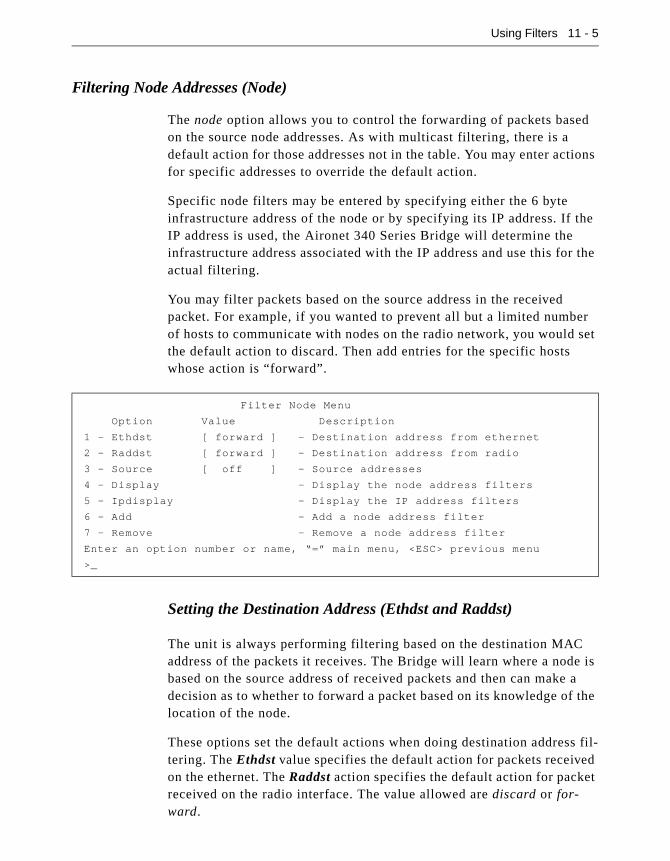
Using Filters 11 - 5
Filtering Node Addresses (Node)
The node option allows you to control the forwarding of packets based on the source node addresses. As with multicast filtering, there is a default action for those addresses not in the table. You may enter actions for specific addresses to override the default action.
Specific node filters may be entered by specifying either the 6 byte infrastructure address of the node or by specifying its IP address. If the IP address is used, the Aironet 340 Series Bridge will determine the infrastructure address associated with the IP address and use this for the actual filtering.
You may filter packets based on the source address in the received packet. For example, if you wanted to prevent all but a limited number of hosts to communicate with nodes on the radio network, you would set the default action to discard. Then add entries for the specific hosts whose action is “forward”.
Setting the Destination Address (Ethdst and Raddst)
The unit is always performing filtering based on the destination MAC address of the packets it receives. The Bridge will learn where a node is based on the source address of received packets and then can make a decision as to whether to forward a packet based on its knowledge of the location of the node.
These options set the default actions when doing destination address fil-tering. The Ethdst value specifies the default action for packets received on the ethernet. The Raddst action specifies the default action for packet received on the radio interface. The value allowed are discard or for-ward.
Filter Node Menu
Option Value Description
1 - Ethdst [ forward ] - Destination address from ethernet
2 - Raddst [ forward ] - Destination address from radio
3 - Source [ off ] - Source addresses
4 - Display - Display the node address filters
5 - Ipdisplay - Display the IP address filters
6 - Add - Add a node address filter
7 - Remove - Remove a node address filter
Enter an option number or name, “=” main menu, <ESC> previous menu
>_
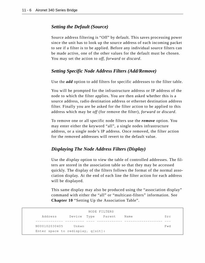
11 - 6 Aironet 340 Series Bridge
Setting the Default (Source)
Source address filtering is “Off” by default. This saves processing power since the unit has to look up the source address of each incoming packet to see if a filter is to be applied. Before any individual source filters can be made active, one of the other values for the default must be chosen. You may set the action to off, forward or discard.
Setting Specific Node Address Filters (Add/Remove)
Use the add option to add filters for specific addresses to the filter table.
You will be prompted for the infrastructure address or IP address of the node to which the filter applies. You are then asked whether this is a source address, radio destination address or ethernet destination address filter. Finally you are be asked for the filter action to be applied to this address which may be off (for remove the filter), forward or discard.
To remove one or all specific node filters use the remove option. You may enter either the keyword “all”, a single nodes infrastructure address, or a single node’s IP address. Once removed, the filter action for the removed addresses will revert to the default value.
Displaying The Node Address Filters (Display)
Use the display option to view the table of controlled addresses. The fil-ters are stored in the association table so that they may be accessed quickly. The display of the filters follows the format of the normal asso-ciation display. At the end of each line the filter action for each address will be displayed.
This same display may also be produced using the “association display” command with either the “all” or “multicast-filters” information. See Chapter 10 “Setting Up the Association Table”.
NODE FILTERS
Address Device Type Parent Name Src
------------- --------- ---- ------------ ------------------ ---
N000102030405 Unkwn Fwd
Enter space to redisplay, q[uit]:

Using Filters 11 - 7
Displaying the IP to Network Address Table (IPdisplay)
When a node address filter is entered by IP address, the Aironet 340 Series Bridge first determines the infrastructure address associated with this IP address. The actual filtering is done based on the infrastructure address.
Filtering Protocols (Protocols)
Protocol filtering bases the filtering decision on the type of protocol used to encapsulate the data in the packet. This type of filtering can have the most value in almost all situations and is the preferred method of fil-tering. With this type of filtering you may set the Aironet 340 Series Bridge to only forward those protocols, over the radio, that are being used by the remote radio nodes. Selecting protocols is easier than setting up filters based on addresses.
The Aironet 340 Series Bridge may be set up to monitor and record the list of protocols currently being forwarded over the radio. It will record the protocols found, how may packets were encountered and whether the packet came from the LAN or the radio.
To set up the protocol filters, start the monitor and let it run for a while under normal use. Add filters by selecting the protocols from the monitor list.
There is a default action for those protocols not in the list of explicitly filtered protocols. If you know exactly which protocols are going to be used by the radio nodes, set the default action to discard and add filters to forward only those protocols that will be used. If you are not sure of all the protocols that will be used but you know that there are certain protocols you will not use, you would set the default to forward and add filters to discard only those protocols you will not use.
For filtering purposes the bridge assumes that the data portion of the packets is in one of two forms:
IP ADDRESS FILTERS
IP Address MAC Address Src
--------------- ------------ ---
149.023.165.186 004096206892 Fwd
Enter space to redisplay, q[uit]:
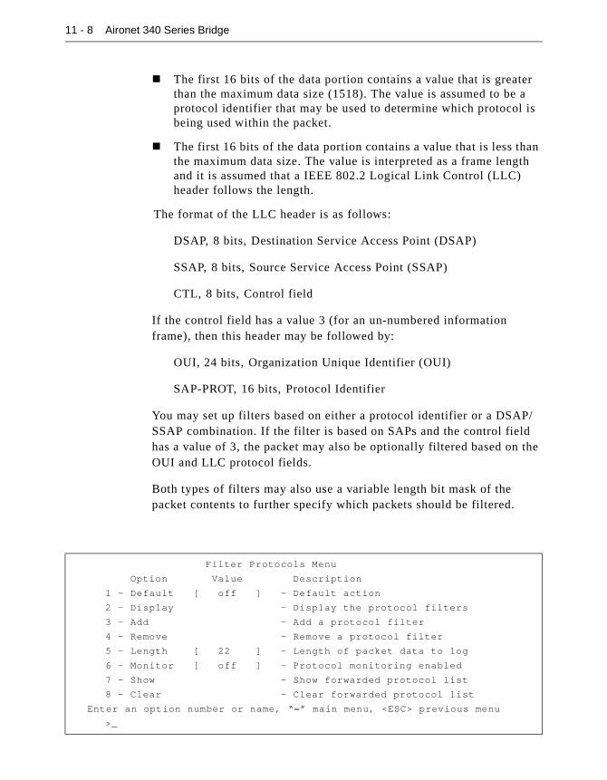
11 - 8 Aironet 340 Series Bridge
� The first 16 bits of the data portion contains a value that is greater than the maximum data size (1518). The value is assumed to be a protocol identifier that may be used to determine which protocol is being used within the packet.
� The first 16 bits of the data portion contains a value that is less than the maximum data size. The value is interpreted as a frame length and it is assumed that a IEEE 802.2 Logical Link Control (LLC) header follows the length.
The format of the LLC header is as follows:
DSAP, 8 bits, Destination Service Access Point (DSAP)
SSAP, 8 bits, Source Service Access Point (SSAP)
CTL, 8 bits, Control field
If the control field has a value 3 (for an un-numbered information frame), then this header may be followed by:
OUI, 24 bits, Organization Unique Identifier (OUI)
SAP-PROT, 16 bits, Protocol Identifier
You may set up filters based on either a protocol identifier or a DSAP/SSAP combination. If the filter is based on SAPs and the control field has a value of 3, the packet may also be optionally filtered based on the OUI and LLC protocol fields.
Both types of filters may also use a variable length bit mask of the packet contents to further specify which packets should be filtered.
Filter Protocols Menu
Option Value Description
1 - Default [ off ] - Default action
2 - Display - Display the protocol filters
3 - Add - Add a protocol filter
4 - Remove - Remove a protocol filter
5 - Length [ 22 ] - Length of packet data to log
6 - Monitor [ off ] - Protocol monitoring enabled
7 - Show - Show forwarded protocol list
8 - Clear - Clear forwarded protocol list
Enter an option number or name, “=” main menu, <ESC> previous menu
>_

Using Filters 11 - 9
Setting the Default Action (Default)
The default action is used for a packet whose protocol does not match any entry found in the table. It may be set to:
� Off: Protocol filtering is not done. It is a waste of processing power for the unit to examine each packet for its protocol only to discover no protocols need monitoring.
� Discard: The packet will not be forwarded out the radio network.
� Forward: The packet will be forwarded out the radio network.
� Accesspt: The packet will only be forwarded to other bridges and not to the client nodes.
� Nonpsp: The packet will be forwarded out the radio network to non-power saving end nodes and not to any nodes using PSP.
Displaying the Filters (Display)
Use the display option to view the list of protocol filters you have added.
Name: The name assigned to the protocol.
Action: The action that has been assigned for each protocol.
Protocol and LLC: The protocol header.
Masks: A bit mask applied to the packet that must match the packet con-tents before the protocol is identified. The mask is displayed in the fol-lowing form: 18- (start position), 0453 (value), 0 (don’t care mask)
PROTOCOL FILTERS
----------LLC--------- Masks
Name Action Protocol SAPs OUI Protocol
-------------- -------- -------- ---- ------ ---------
1. novell discard 8137
2. novell discard aaaa 000000 8137
3. Ethertalk discard aaaa 080007 809b
4. IPX-RIP discard ffff 18- 0453, 0
Enter space to redisplay, q[uit]:
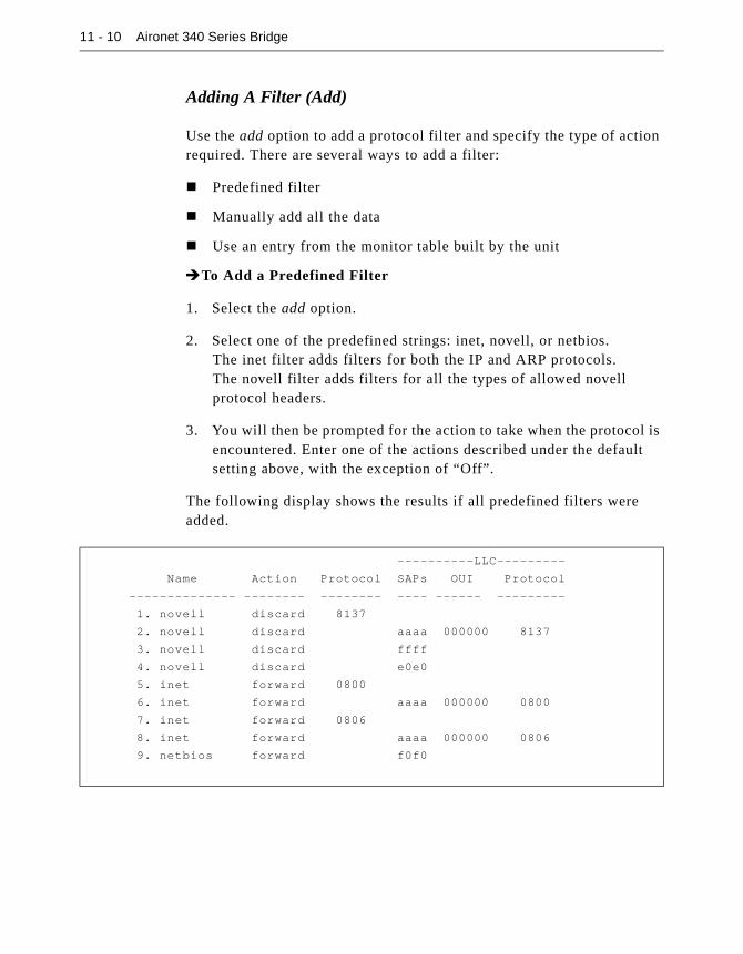
11 - 10 Aironet 340 Series Bridge
Adding A Filter (Add)
Use the add option to add a protocol filter and specify the type of action required. There are several ways to add a filter:
� Predefined filter
� Manually add all the data
� Use an entry from the monitor table built by the unit
�To Add a Predefined Filter
1. Select the add option.
2. Select one of the predefined strings: inet, novell, or netbios.The inet filter adds filters for both the IP and ARP protocols.The novell filter adds filters for all the types of allowed novellprotocol headers.
3. You will then be prompted for the action to take when the protocol is encountered. Enter one of the actions described under the default setting above, with the exception of “Off”.
The following display shows the results if all predefined filters were added.
----------LLC---------
Name Action Protocol SAPs OUI Protocol
-------------- -------- -------- ---- ------ ---------
1. novell discard 8137
2. novell discard aaaa 000000 8137
3. novell discard ffff
4. novell discard e0e0
5. inet forward 0800
6. inet forward aaaa 000000 0800
7. inet forward 0806
8. inet forward aaaa 000000 0806
9. netbios forward f0f0
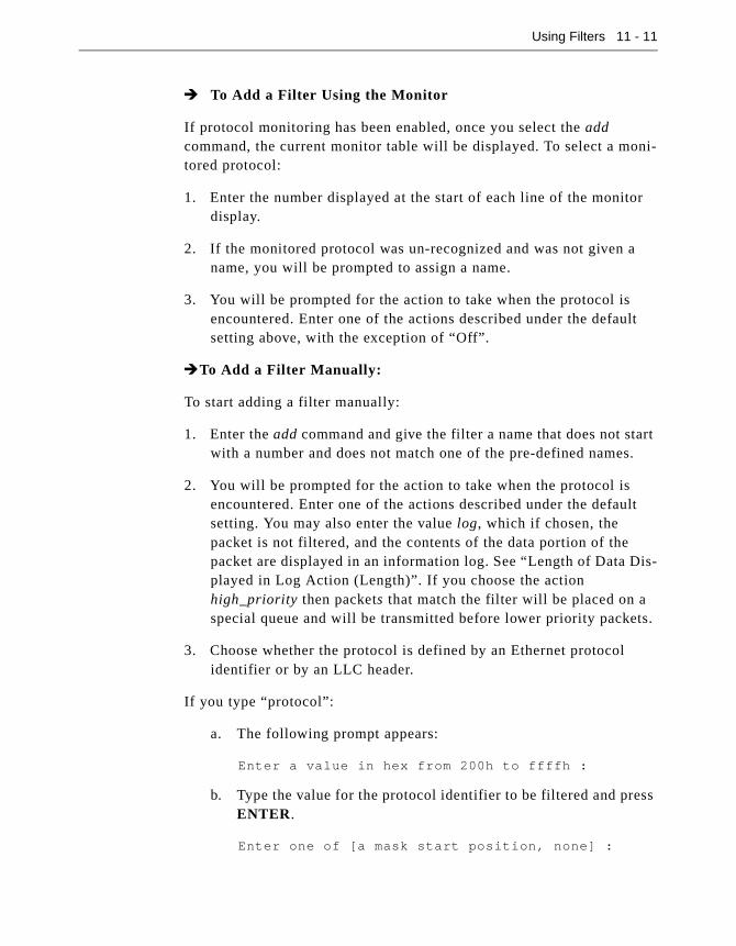
Using Filters 11 - 11
� To Add a Filter Using the Monitor
If protocol monitoring has been enabled, once you select the add command, the current monitor table will be displayed. To select a moni-tored protocol:
1. Enter the number displayed at the start of each line of the monitor display.
2. If the monitored protocol was un-recognized and was not given a name, you will be prompted to assign a name.
3. You will be prompted for the action to take when the protocol is encountered. Enter one of the actions described under the default setting above, with the exception of “Off”.
�To Add a Filter Manually:
To start adding a filter manually:
1. Enter the add command and give the filter a name that does not start with a number and does not match one of the pre-defined names.
2. You will be prompted for the action to take when the protocol is encountered. Enter one of the actions described under the default setting. You may also enter the value log, which if chosen, the packet is not filtered, and the contents of the data portion of the packet are displayed in an information log. See “Length of Data Dis-played in Log Action (Length)”. If you choose the action high_priority then packets that match the filter will be placed on a special queue and will be transmitted before lower priority packets.
3. Choose whether the protocol is defined by an Ethernet protocol identifier or by an LLC header.
If you type “protocol”:
a. The following prompt appears:
Enter a value in hex from 200h to ffffh :
b. Type the value for the protocol identifier to be filtered and press ENTER.
Enter one of [a mask start position, none] :

11 - 12 Aironet 340 Series Bridge
This allows you to specify a bit mask and corresponding hexa-decimal value to be applied to the packet. These two values must match the packet contents before the protocol is identified.
You must first specify a mask start position in the packet and match the mask value. The mask start position value should be a 0-based byte offset from the start of the data portion of the frame (after the MAC layer header). If you set the position to “none”, no mask is tested.
c. Type a mask start position value (or “none”, if applicable) and press ENTER.
Enter a hex value of 1 to 30 characters :
d. Type the value to be matched as a string of up to 30 hexadecimal digits and press ENTER. If the numbered digits is odd, the mask value will be adjusted to ignore the low 4 bits of the corre-sponding byte.
Enter a hex don’t care mask of 1 to 6 characters :
This allows you to enter a string of hexadecimal digits to indi-cate which bits of the packet data are meaningful.
A bit set in this value causes the corresponding bit in the packet to be ignored. Therefore, a 0 mask means that the packet con-tents must exactly match the previous value entered. If the mask entered is shorter than the value entered it is automatically extended to the correct length with zeros.
e. Type the applicable hexadecimal digits and press ENTER.
For example, to enter a mask that matches the value 4128H in the 16th byte data portion of the packet and have the high bit of each byte ignored, complete as follows:
Enter one of [a mask start position, none] : 15
Enter a hex value of 1 to 30 characters : 4128
Enter a hex don’t care mask of 1 to 4 characters :
8080
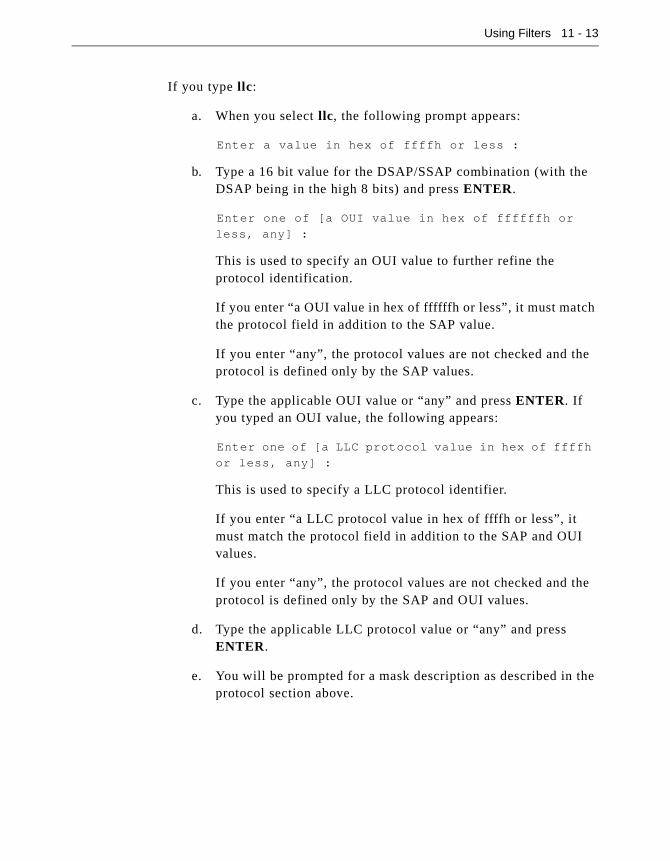
Using Filters 11 - 13
If you type llc:
a. When you select llc, the following prompt appears:
Enter a value in hex of ffffh or less :
b. Type a 16 bit value for the DSAP/SSAP combination (with the DSAP being in the high 8 bits) and press ENTER.
Enter one of [a OUI value in hex of ffffffh or
less, any] :
This is used to specify an OUI value to further refine the protocol identification.
If you enter “a OUI value in hex of ffffffh or less”, it must match the protocol field in addition to the SAP value.
If you enter “any”, the protocol values are not checked and the protocol is defined only by the SAP values.
c. Type the applicable OUI value or “any” and press ENTER. If you typed an OUI value, the following appears:
Enter one of [a LLC protocol value in hex of ffffh
or less, any] :
This is used to specify a LLC protocol identifier.
If you enter “a LLC protocol value in hex of ffffh or less”, it must match the protocol field in addition to the SAP and OUI values.
If you enter “any”, the protocol values are not checked and the protocol is defined only by the SAP and OUI values.
d. Type the applicable LLC protocol value or “any” and press ENTER.
e. You will be prompted for a mask description as described in the protocol section above.

11 - 14 Aironet 340 Series Bridge
Adding IP protocol Sub-Filters
Once you have added a filter for the IP protocol you may also filter packets based on their UDP or TCP port number, their IP sub-protocol (i.e., UDP/TCP/ICMP) or based on an IP address range.
To filter based on an IP sub- protocol use add ip_subprotocol. You are then prompted as to whether you want to filter tcp or udp or another pro-tocol based on its ID number. Finally you are prompted for a filter action as in the other manual filters.
To filter based on port number use add ip_port. You are prompted as to whether you want to filter a TCP or UDP source or destination port. You are then prompted for the port number and the action associated with it.
To filter based on an IP address range use add ip_address. You are prompted as to whether you want to filter a source or destination address and then for an IP address and address mask and a filter action. The fil-ter matches if the value of both the packet address and the filter address ANDED with the filter mask are equal.
Removing an Entry (Remove)
Use the remove option to remove a protocol filter entry. You may either remove all filters by entering the keyword “all” or a single entry by entering the number assigned to the filter and shown at the start of the line in the filter display.
Length of Data Displayed in Log Action (Length)
Use the length option to display the contents of packets being forwarded to the radio.
Use this option to setup the filter mask values to properly narrow down which packets are filtered.
If you add a protocol filter whose action is “log,” each time the filter matches, the contents of the data portion of the packet (after the MAC header) will be displayed on the console (in hexadecimal) for a length in bytes determined by the value of this option.

Using Filters 11 - 15
The contents of the data portion displayed in the information log will consist of:
� “p”
� Id number of the filter shown on the Protocol Filters screen
� Bytes of the packet displayed in hexadecimal
More than one protocol at a time can be set with a filter action of “Log”.
The following is an example of a protocol filter log entry:
p2: 01 e0 ff ff 01 eo 00 04 00 00 01 65 ff ff ff ff ff
ff 04 52 00 00
Protocol Monitoring (Monitor/ Show/ Clear)
The Aironet 340 Series Bridge allows you to create and display a list of the protocols currently being forwarded by the unit. This allows you to test if packets that contain data for unused protocols are being for-warded to the radio nodes.
Once enabled by the monitor option, the Aironet 340 Series Bridge will then begin to examine the protocol used in each packet forwarded. If the protocol is not already in the list, an entry is created. Otherwise, the packet count for the given protocol is incremented.
The show option will display the list of currently forwarded protocols.
� Name: If the protocol is recognized, it will be given a name. Other-wise, the name field is left blank.
PROTOCOLS FOUND
--------LLC----------
Name Source Count Protocol SAPs OUI Protocol
--------------- ------- --------- -------- ---- ------- --------
1. IP RadLan 7207 0800
2. ARP RadLan 782 0806
3. NetBIOS Lan 39 f0f0
4. ARP RadLan 63 aaaa 000000 0806
5. DEC MOP Lan 3 6002
Enter space to redisplay, C[lear stats], q[uit] :
11 - 16 Aironet 340 Series Bridge
� Source: This will contain the string “Rad” if a packet was received from the radio and “Lan” if a packet was received from the wired LAN.
� Count: Displays the number of times a packet with the given proto-col was encountered.
� Protocol and LLC: The protocol header found.
You may clear the list of found protocols either with the “clear” com-mand or by entering a “C” (case sensitive) at the re-display prompt of the “show” command.
Chapter 12 - Setting Up Event Logs
12
C H A P T E R 1 2
Setting Up Event Logs
This chapter describes how to use the Logs Menu to set up and view event logs on the Aironet 340 Series Bridge.
Here’s what you’ll find in this chapter:
� Overview
� Log Descriptions
� Using the Logs Menu
� Viewing History Logs
� Clearing the History Buffer
� Specifying the Type of Logs to Print/Save/Light Status LED
� Setting Statistic Parameters
� Forwarding Logs to a Unix System

12 - 2 Aironet 340 Series Bridge
OverviewThe Aironet 340 Series Bridge produces logs that record the occurrence of significant events occurring within your unit and on the infrastruc-ture. The type of events that are recorded as logs are:
� Information Logs: Records status changes that occur in the normal operation of the system. For example, when an end node associates to an Aironet 340 Series Bridge.
� Error Logs: Records errors that occur occasionally, but are easily recovered from by the unit. For example, errors that occur during the reception and transmission of packets to and from the unit.
� Severe Error Logs: Records errors which drastically affect the operation of the system. The system will continue to run, but action is required to return the unit to normal operating standards.
Information Logs
BOOTP/DHCP set new IP address
The BOOTP/DHCP server answered the request and assigned the unit an IP address different than the configured value.
Node “node address” “device name” added
A non-volatile entry was added to the association table.
Node “node address” “device name” added locally “ASCII name”
A new node associated with the local unit.
Node “node address” “device name” restarted “ASCII name”
A node that is currently associated to the local unit was reset.
Node “node address” “device name” “ASCII name” removed, max radio retries
A node was removed from the table because a response was not received from the node after attempts were made to transmit a packet to it. The node may have failed or moved to another cell.

Setting Up Event Logs 12 - 3
Node “node address” “device name” “ASCII name” removed, staled out
A node was removed from the table because data was not received from the node within the stale-out period. Different devices have different stale-out times. PSP nodes have very short stale-out times (around 10 seconds). Non-PSP nodes have longer times (usually several minutes).
Node “node address” “device name” “ASCII name” removed, NV removed
A node was removed from the association table because the operator used the “association remove” command.
Node “node address” “device name” “ASCII name” removed, deassoc notice from “address”
The node was removed from the association table because another bridge reported that it now has the node associated locally. This log is produced whenever a node handoff occurs.
RARP set new IP address
A RARP server answered a request for an IP address with an address different from the one currently saved. The currently saved value is overwritten.
Associated to router “node address”
This log is produced when the unit, configured as a repeater, associates to its parent node.
SNMP: “command text”
A SNMP management node sent the unit a “set” variable request which was successfully executed. The “command text” is a similar menu com-mand that has the same effect as the SNMP request.
SNMP access failure from “community name” “IP address” (node address)
A SNMP management node attempted to access the SNMP agent with an invalid community name or a name that it was not allowed to use.

12 - 4 Aironet 340 Series Bridge
STP: Listening for other Bridges
The spanning tree protocol is listening on the backbone port to look for other bridges in the infrastructure.
STP: Learning Addresses
The spanning tree protocol is listening on the backbone port. It adds any addresses it sees into the Association Table before it starts forwarding packets in order to avoid flooding packets unnecessarily.
STP: Forwarding Data
The spanning tree protocol has allowed the backbone port to forward data packets to the radio network.
STP: Port Blocked
The spanning tree protocol has determined that the backbone port must be automatically disabled to prevent a loop in the infrastructure.
STP Port “node address” receives hello timeout
The unit whose address is given in the log, has lost contact with the des-ignated bridge on its LAN. It will begin to arbitrate with other bridges on the LAN to see who will take over.
STP: Topology Changed
Somewhere on the infrastructure a new port has been enabled or dis-abled. Because of these possible changes to the spanning tree, the bridge will begin using a short staleout time for backbone nodes in case the location of nodes changes.
TFTP is loading “file name” from “ip address”
This log is produced when the BOOTP server gives the Aironet 340 Series Bridge the name of a configuration file and then the name of a firmware file to load.

Setting Up Event Logs 12 - 5
Error Logs
“Category” Error: nnn “type” errors
This log is produced when any error occurs that is marked by an asterisk“*” after its count in the statistics displays. These errors are serious enough to affect the operation of the unit. See the sections on each dis-play for an explanation of each error.
Node “node address” “device name” “ascii name” removed
These logs are similar to the information logs except that the node removed is a bridge. Since these nodes do not normally roam, it may be an indication that contact with a child repeater is lost.
Assoctable is full
The association table is completely full. To troubleshoot, try to force some radio nodes to associate to other bridges on the LAN using the specified router field in their association table.
Unable to locate IP address “ip address”
The unit was trying to send a packet to an IP address without knowing the hardware node ID. When this occurs, the unit will use the ARP pro-tocol to try to determine the proper address. This log is produced if there was no answer to the ARP request. Usually the unit is trying to find the destination for the SNMP traps.
Severe Error Logs
Ethernet cabling problem
If no traffic has been sent or received on the Ethernet cable in the last 10 seconds, the unit will send a packet to itself to test the connection. If the transmission succeeds, the timer is reset. If it fails, this log is produced and traffic for the connection will be discarded until the test succeeds.

12 - 6 Aironet 340 Series Bridge
Configuration is too large to save
The number of commands in the configuration is too large for the avail-able non-volatile memory. This may be caused by too many non-volatile entries in the association table.
Could not program the flash memory
An error occurred when trying to program a new version of the firmware into flash memory. The unit must be serviced.
EEPROM on radio is invalid
The radio installed in each unit contains an EEPROM (Electrically Erasable Programmable Read-only Memory) chip, identifying the type of radio installed. The contents of the EEPROM were found to be invalid. Have the unit serviced. (Bad EEPROM)
Lost our association, max radio retries
The unit, configured as a repeater, lost communications with its parent node after trying to send a packet the maximum number of times. The unit will try to re-associate. The problem may be a parent bridge failure. All local associations will be dropped.
Lost our association, max radio naks
The unit, configured as a repeater, lost communications with its parent node after trying to send a packet the maximum number of times. Each time the unit sent a packet, it received a response indicating that the par-ent’s receive buffers were full. The unit will try to re-associate. The likely cause is that the parent is handling too much traffic. All local associations will be dropped.
Lost our association, radio restarted
A radio configuration parameter has been changed. All associations will be dropped and the radio will be restarted.
Lost our association, changed repeater mode
A unit has changed from a root to a repeater or vice versa. If the unit is now a root unit, it will wait for nodes to associate to it. If the unit is now a repeater, it will attempt to associate to a parent.
Setting Up Event Logs 12 - 7
Lost our association, new specified router
The specified router parameter of this repeater has been changed. The unit will drop its current association and try to re-associate.
Lost our association, NAK from router
The unit responds as though it was associated to its parent, however, the parent does not have the association. The unit will attempt to re-associ-ate. The parent may have been rebooted.
No response to radio loopback test
The "config radio extended test" command was set on and no bridge in range responded to the loopback test. If you know there are units in range, then either the local radio has failed, or if there is only one remote in range, then the remote unit’s radio may have failed.
Radio Configuration Error nn
The Aironet 340 Series Bridge could not program the radio hardware to operate at the correct frequency and bit rate. Have the unit serviced.
Radio loopback test succeeded
After having failed, the radio loopback test heard a response from a remote.
The address PROM is invalid
Each unit contains a Programmable Read-Only Memory (PROM) chip that contains the unit’s hardware address. During power up, the unit was not able to read a valid address from the PROM. The unit must beserviced.
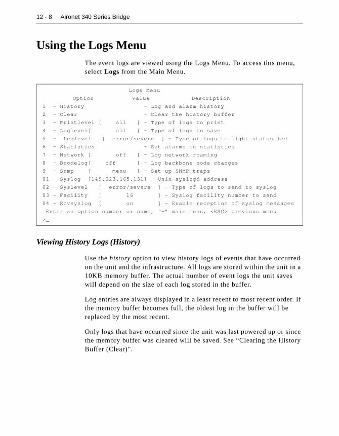
12 - 8 Aironet 340 Series Bridge
Using the Logs MenuThe event logs are viewed using the Logs Menu. To access this menu, select Logs from the Main Menu.
Viewing History Logs (History)
Use the history option to view history logs of events that have occurred on the unit and the infrastructure. All logs are stored within the unit in a 10KB memory buffer. The actual number of event logs the unit saves will depend on the size of each log stored in the buffer.
Log entries are always displayed in a least recent to most recent order. If the memory buffer becomes full, the oldest log in the buffer will be replaced by the most recent.
Only logs that have occurred since the unit was last powered up or since the memory buffer was cleared will be saved. See “Clearing the History Buffer (Clear)”.
Logs Menu
Option Value Description
1 - History - Log and alarm history
2 - Clear - Clear the history buffer
3 - Printlevel [ all ] - Type of logs to print
4 - Loglevel[ all ] - Type of logs to save
5 - Ledlevel [ error/severe ] - Type of logs to light status led
6 - Statistics - Set alarms on statistics
7 - Network [ off ] - Log network roaming
8 - Bnodelog[ off ] - Log backbone node changes
9 - Snmp [ menu ] - Set-up SNMP traps
01 - Syslog [149.023.165.131] - Unix syslogd address
02 - Syslevel [ error/severe ] - Type of logs to send to syslog
03 - Facility [ 16 ] - Syslog facility number to send
04 - Rcvsyslog [ on ] - Enable reception of syslog messages
Enter an option number or name, “=” main menu, <ESC> previous menu
>_

Setting Up Event Logs 12 - 9
NOTE: If a power failure occurs, the logs contained in the memory will not be saved.
The display will be similar to the following:
� First Line: “OLDEST” indicates the end of the buffer display. This will appear at the end of the history log.
� Display Lines: Displays the time since power-up that the log occurred, the severity level (I-information, E-error, or S-severe) and the actual log text.
� Last Line: Indicates the current time and the time the buffer was last cleared by the operator. “NEWEST” indicates the start of the history log.
� Option Line: Indicates the movement keys to use when viewing the history logs. Since displaying the entire history will take more than a screen page, use the following keys to navigate through the history log:
b: Back one page in the log
f: Forward one page in the log
n: Moves to the newest log entry
o: Moves to the oldest log entry
q: Exit the History Log screen
a: Dump entire log (usually captured to a file on a PC)
Clearing the History Buffer (Clear)
Use the clear option to delete all logs from the history buffer.
OLDEST
0:00:00 I Node 004096109e30 BRE105E Floor_2_109e30 added locally
0:00:03 I Node 0040961064de AP3500-T F3_1064de added for 004096109e30
30:35:09 NEWEST, cleared at 0:00:00
b[ackward], f[orward], n[ewest], o[ldest], a[ll], C[lear], q[uit] :
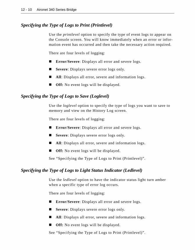
12 - 10 Aironet 340 Series Bridge
Specifying the Type of Logs to Print (Printlevel)
Use the printlevel option to specify the type of event logs to appear on the Console screen. You will know immediately when an error or infor-mation event has occurred and then take the necessary action required.
There are four levels of logging:
� Error/Severe: Displays all error and severe logs.
� Severe: Displays severe error logs only.
� All: Displays all error, severe and information logs.
� Off: No event logs will be displayed.
Specifying the Type of Logs to Save (Loglevel)
Use the loglevel option to specify the type of logs you want to save to memory and view on the History Log screen.
There are four levels of logging:
� Error/Severe: Displays all error and severe logs.
� Severe: Displays severe error logs only.
� All: Displays all error, severe and information logs.
� Off: No event logs will be displayed.
See “Specifying the Type of Logs to Print (Printlevel)”.
Specifying the Type of Logs to Light Status Indicator (Ledlevel)
Use the ledlevel option to have the indicator status light turn amber when a specific type of error log occurs.
There are four levels of logging:
� Error/Severe: Displays all error and severe logs.
� Severe: Displays severe error logs only.
� All: Displays all error, severe and information logs.
� Off: No event logs will be displayed.
See “Specifying the Type of Logs to Print (Printlevel)”.

Setting Up Event Logs 12 - 11
Setting Statistic Parameters (Statistics)
This command allows you to control how alarms are generated based on any of the available statistics kept by the bridge. Logs may be:
� Disabled for statistics
� Generated if the statistic changes at all
� Generated if the statistic changes at a greater than specified rate
� To Set Statistic Parameters:
1. Select statistics. Type a number or the short form.
1. ra Radio
2. re Radio error
Enter one of [a number from 1 to 2, a short form]:
2. You will be prompted for the statistics category. Enter the number or the short form. The short form is used to store the command in the configuration.
3. Type a category number or the short form and press ENTER.
4. Choose the particular statistics that you wish to change. If any of the statistics already have an alarm associated, the current setting is dis-played after the name.
Enter an action, one of [off, any, rate]:
Radio
Receive Transmit
1 rpa Packets 5 tpa Packets
2 rby Bytes 6 tby Bytes
3 rfi Filtered 7 ter Errors
4 rer Errors
Enter one of [a number from 1 to 7, a short form]:

12 - 12 Aironet 340 Series Bridge
5. Enter an action.
� Off: Turns off any alarms based on the statistics value.
� Any: An alarm will be generated if the statistics change value.
� Rate: Prompts for a rate per second change. If the statistic value changes faster than this rate, an alarm is produced.
Log Network Roaming (Network)
Normally the bridges only log changes in location for radio client that move to or from this unit. If the network option is enabled, log will be produced when the unit learns of any changes to radio nodes in any of the bridges any access points in the network.
Logging Backbone Node changes (BnodeLog)
Normally the bridge only log changes the state or location of its own radio nodes. If you enable this item it will produce a log whenever a backbone node is discovered or its table entry stales out.
Setting up SNMP traps (Snmp)
The bridge may be set up to generate SNMP traps and send them to a network management station.
Use the trapdest option to generate SNMP trap messages to a particular NMS whenever a significant event occurs.
If SNMP is enabled and the trapdest option is configured with a valid IP address, then the system will generate SNMP trap messages. If the trap-dest option is set to “none,” then traps will not be sent. Setting the “trapdest” parameter to address 0.0.0.0 is the same as disabling trap generation by using “none.”
Logs Snmp Menu
Option Value Description
1 - Trapdest [ none ] - IP destination for SNMP traps
2 - Trapcomm [ "public" ] - Community for SNMP traps
3 - Loglevel [ severe ] - Type of logs to cause a trap
4 - Authtrap [ off ] - Enable authentication failure trap
Enter an option number or name, “=” main menu, <ESC> previous menu
>_
Setting Up Event Logs 12 - 13
The following trap messages will be sent as they occur:
� A cold start trap will be sent when the unit first powers up.
� A link up trap is sent when the configuration is changed or restored for a severe error condition.
� A link down trap is sent when the configuration is changed or encounters a severe error condition.
� A link up trap is sent for an Aironet 340 Series Bridge as soon as the radio is configured.
� An authentication failure trap will be sent if an SNMP request is received with an unknown community name. This trap may be dis-abled by setting the “authtrap” parameter to “Off”. See “The gener-ated trap will contain the text of the log message along with the severity of the log. See the MIB definition files for the exact layout Enabling Authentication Failure Trap (Authtrap)”.
� Any normal alarms and logs you have configured to be sent by set-ting the “loglevel” parameter.
NOTE: Since the path to the trap destination may be through a failed or not yet established radio link, it is possible that cold start and link down
traps could be lost.
Use the trapcomm option to specify the community name that will be used in the trap message.
The LogLevel option configures The Aironet 340 Series Bridge to gen-erate enterprise specific traps whenever a log of a given severity or higher is produced. The trapdest parameter must be “On”.
The generated trap will contain the text of the log message along with the severity of the log. See the MIB definition files for the exact layout Enabling Authentication Failure Trap (Authtrap)
Use the authtrap option to control the generation of SNMP authentica-tion failure traps.

12 - 14 Aironet 340 Series Bridge
The failure traps may be sent if an NMS sends a request with an unknown community name or a community name that it is not allowed for use. You can enable or disable this option. The default setting is “Off”.
Forwarding Logs to a Unix System (Syslog,SysLevel,Facility,Rcvsyslog)
Use the syslog option to forward logs to a Unix host running the Syslogd deamon process. Enter the IP address of the Unix host. If the address remains at the default of 0.0.0.0., logs will not be sent. You may control the type of logs sent to the deamon with the Syslevel option which has the same arguments as the printlevel function described above.
Packets received by the Syslogd daemon process are recorded in the sys-tem log file on the Unix host. The logs are displayed on the Console in addition to being forwarded to the Unix host. If the Aironet 340 Series Bridge should fail for any reason, the logs may still be viewed on the Unix host.
The logs are sent using the syslog facility code “LOG_LOCAL0” which has a value of 16. You may change this value with the option Facility. The syslog priority depends on the priority of the log locally.
On the Unix host, the Syslogd deamon process will usually add the cur-rent time and IP address of the unit that sent the log. The Aironet 340 Series Bridge will pre-pend its own name to the log before it is sent.
A message similar to the following will appear on the host:
Jan 11 10:46:30 192.009.200.206 A630_10172c:
Node 0000c0d1587e 630 added for 004096104546
By default the bridges are set up to be able to receive and display syslog messages from other bridges in the network. The Rcvsyslog option enables or disables this function. You could choose one bridge to moni-tor and have all other units setup with this one as their syslog host.

Chapter 13 - Performing Diagnostics
13
C H A P T E R 1 3
Performing Diagnostics
This chapter describes how to use the Diagnostics Menu to maintain the Aironet 340 Series Bridge.
Here’s what you’ll find in this chapter:
� Using the Diagnostics Menu
� Starting a Telnet Session
� Changing the Escape Sequence
� Running a Linktest
� Restarting the Unit
� Preparing the Unit for Shutdown
� Returning the Unit to the Default Configuration
� Physically Locating a Unit
� Sending a Ping Packet
� Loading New Code Versions

13 - 2 Aironet 340 Series Bridge
Using the Diagnostics MenuDiagnostics are performed using the Diagnostics Menu. To access this menu, select Diagnostics from the Main Menu.
Testing the Radio Link (Linktest)
Use the linktest option to test the quality of the radio transmission between the Aironet 340 Series Bridge and other nodes on the radio net-work. See “Running a Linktest” in Chapter 4.
Restarting the Unit (Restart)
Use the restart option to reboot the Aironet 340 Series Bridge. All asso-ciations will be lost and the unit will react as though it had just been powered on.
Returning the Unit to the Default Configuration (Default, Reset)
Use the default option to return the Aironet 340 Series Bridge configu-ration to its default factory settings. The unit will erase the currently saved configuration and execute a restart command.
The Reset command can be used to only return parts of the configuration to the default state. If the argument entered is ident_save then all but those parts of the configuration identifying the unit (i.e., the IP address) will be defaulted. If the value is radio_default, then only the radio con-figuration is defaulted. If the value is filter_default, then only the filters
Diagnostics Menu
Option Value Description
1 - Network [ menu ] - Network connection commands
2 - Linktest [ menu ] - Run a link test
3 - Restart - Equivalent to power-up
4 - Defaults - Return to default configuration
5 - Reset - Default parts of the configuration
6 - Load [ menu ] - Load new version of firmware
Enter an option number or name, “=” main menu, <ESC> previous menu
>_

Performing Diagnostics 13 - 3
are defaults. You may determine into which configuration group each setting resides with the use of the configuration dump described in Chapter 3
Using the Network MenuNetwork connection commands are performed using the Network Menu. To access this menu, select Diagnostics from the Main Menu the select Network.
Starting a Telnet Session (Connect)
The connect option is used to start a telnet session with a remote unit on the infrastructure to gain access to its Console Menu. The connect option can also be used to access any remote node (PC or Server) that supports telnet access.
The connection may be initiated using the remote node’s IP address. The connection is completely routable and the destination may be anywhere in the internet.
If the connection is to be made to another Aironet unit which has not been assigned an IP address, start the connection using the MAC level infrastructure address of the unit. This connection uses a proprietary protocol which is not routable. The destination must lie on the local LAN. This is useful when assigning IP addresses to a large number of bridges.
Diagnostics Network Menu
Option Value Description
1 - Connect - Start telnet session
2 - Escape [ “^X^Y^Z” ] - Connection escape sequence
3 - Find - Flash LEDs to find unit
4 - Ping - Send an IP PING packet
Enter an option number or name, “=” main menu, <ESC> previous menu
>_

13 - 4 Aironet 340 Series Bridge
When starting a telnet session with the connect option:
� Make sure the telnet option on the remote is enabled before connect-ing to a remote bridge or client. See “Telnet Access” in Chapter 2.
� A message is printed on the remote’s Console stating where the con-nections originated from. The Console is then disabled for the dura-tion of the telnet session to prevent conflicting commands.
� The remote’s Console privilege is set to the highest level that does not have a password.
While the unit is attempting to connect to the remote node, the connec-tion can be terminated by typing “CTRL-C”. This may be required if the incorrect address was entered.
After connecting, you can close a telnet session and return to the local console by:
� Typing the escape sequence of characters as defined by the escape option in the Diagnostics Menu. See “Changing the Escape Sequence”.
� If the remote node is an Aironet node, choose the close option which is accessible on the Console Port Main Menu during a tel-net session only.
� Using the remote node’s logout command.
Changing the Escape Sequence (Escape)
Use the escape option to change the sequence of characters that are assigned to close a telnet session to a remote destination. Typically, you would change the sequence if the current sequence has meaning to the remote system.
The sequence may be up to 10 characters in length. To enter non-printable characters in the sequence you may:
� Use the two-character combination of caret (^) and the alphabetic character corresponding to the control character. For example, to enter “control Z”, use the string “^Z”.
� Use a backslash “\” followed by three octal numbers
� Use a dollar sign “$” followed by two hexadecimal numbers

Performing Diagnostics 13 - 5
Physically Locating a Unit (Find)
Use the find option to blink the amber indicators of the bridge on and off. Find a unit you can telnet to if you are not sure of it’s exact loca-tion. Type “CTRL-C” to stop the command.
Sending a Ping Packet (Ping)
Use the ping option to test infrastructure connectivity from the bridge to other IP nodes. The ping option sends an ICMP echo_request packet to a user-specified remote node. If the remote node receives the packet it will also respond with an ICMP echo_response packet.
The Aironet 340 Series Bridge will send the echo_response packet and wait 3 seconds for a response. If none is received, another echo packet is sent. This is repeated up to five times. If a response is received and a message is displayed, the command disappears from the screen. Type “CTRL-C” to stop the command.
Loading New Firmware and Configurations (Load)The Aironet 340 Series Bridge code and configuration are stored in a flash memory chip inside the unit. Use the load option to load new code versions of the Aironet 340 Series Bridge’s firmware or configurations and save them to flash memory.
To load new versions of the firmware, the code must be loaded into main memory first, then programmed into the flash memory. The unit will reboot using the new firmware. The flash memory will retain the new version even if the power is disconnected.
If the file downloaded begins with the string “! CONFIGURATION” then the file is considered to be a text file with lines of commands that are executed as though the were typed at the console.
The new firmware or configuration can be downloaded into the unit using:
� FTP: Load the new file into a single unit using either the Xmodem or FTP protocols. Then use the FTP protocol to upload (send) the file from the local unit to other remote units on the infrastructure.
� Distribute: Load the new file into a single unit using either the
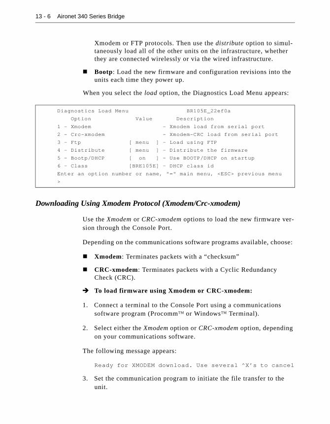
13 - 6 Aironet 340 Series Bridge
Xmodem or FTP protocols. Then use the distribute option to simul-taneously load all of the other units on the infrastructure, whether they are connected wirelessly or via the wired infrastructure.
� Bootp: Load the new firmware and configuration revisions into the units each time they power up.
When you select the load option, the Diagnostics Load Menu appears:
Downloading Using Xmodem Protocol (Xmodem/Crc-xmodem)
Use the Xmodem or CRC-xmodem options to load the new firmware ver-sion through the Console Port.
Depending on the communications software programs available, choose:
� Xmodem: Terminates packets with a “checksum”
� CRC-xmodem: Terminates packets with a Cyclic Redundancy Check (CRC).
� To load firmware using Xmodem or CRC-xmodem:
1. Connect a terminal to the Console Port using a communications software program (ProcommTM or WindowsTM Terminal).
2. Select either the Xmodem option or CRC-xmodem option, depending on your communications software.
The following message appears:
Ready for XMODEM download. Use several ^X’s to cancel
3. Set the communication program to initiate the file transfer to the unit.
Diagnostics Load Menu BR105E_22ef0a
Option Value Description
1 - Xmodem - Xmodem load from serial port
2 - Crc-xmodem - Xmodem-CRC load from serial port
3 - Ftp [ menu ] - Load using FTP
4 - Distribute [ menu ] - Distribute the firmware
5 - Bootp/DHCP [ on ] - Use BOOTP/DHCP on startup
6 - Class [BRE105E] - DHCP class id
Enter an option number or name, "=" main menu, <ESC> previous menu
>
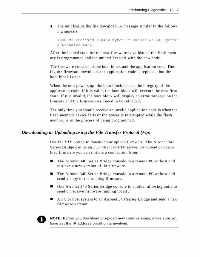
Performing Diagnostics 13 - 7
4. The unit begins the file download. A message similar to the follow-ing appears:
XMODEM: received 160450 bytes in 00:03:36; 800 bytes/
s transfer rate
After the loaded code for the new firmware is validated, the flash mem-ory is programmed and the unit will restart with the new code.
The firmware consists of the boot block and the application code. Dur-ing the firmware download, the application code is replaced, but the boot block is not.
When the unit powers up, the boot block checks the integrity of the application code. If it is valid, the boot block will execute the new firm-ware. If it is invalid, the boot block will display an error message on the Console and the firmware will need to be reloaded.
The only time you should receive an invalid application code is when the flash memory device fails or the power is interrupted while the flash memory is in the process of being programmed.
Downloading or Uploading using the File Transfer Protocol (Ftp)
Use the FTP option to download or upload firmware. The Aironet 340 Series Bridge can be an FTP client or FTP server. To upload or down-load firmware you can initiate a connection from:
� The Aironet 340 Series Bridge console to a remote PC or host and retrieve a new version of the firmware.
� The Aironet 340 Series Bridge console to a remote PC or host and send a copy of the running firmware.
� One Aironet 340 Series Bridge console to another allowing units to send or receive firmware running locally.
� A PC or host system to an Aironet 340 Series Bridge and send a new firmware version.
NOTE: Before you download or upload new code versions, make sure you have set the IP address on all units involved.

13 - 8 Aironet 340 Series Bridge
When you select the FTP option, the Diagnostics Load FTP Menu appears:
Downloading a New Firmware/Configuration File (Get)
Use the get option to download (retrieve) firmware or a configuration file. Once the file has been loaded, the unit will check the first charac-ters of the file. If “! CONFIGURATION” is present, the file contains menu configuration commands. Otherwise the file is considered to be firmware and will be loaded in the flash memory and then executed.
�To Download Firmware using FTP:
1. Load the file onto the PC, host, or bridge you will retrieve from.
2. Select the dest option and type in the IP address of the host PC or Aironet 340 Series Bridge.
3. Select the username option and type in the username required to access the firmware file.
If downloading from another Aironet 340 Series Bridge, the user-name option must have a value even though the value is not used by the remote Aironet 340 Series Bridge.
4. Select the password option and type the password associated with the username.
If downloading from another Aironet 340 Series Bridge, the login password value must match the console write privilege password on the remote Aironet 340 Series Bridge.
Diagnostics Load Ftp Menu
Option Value Description
1 - Get - Load a firmware/config file
2 - Put - Send a firmware file
3 - Config - Send a configuration file
4 - Dest [ 000.000.000.000 ] - Host IP address
5 - Username [ "" ] - Host username
6 - Password - Host password
7 - Filename [ "" ] - Host filename
Enter an option number or name, "=" main menu, <ESC> previous menu
>
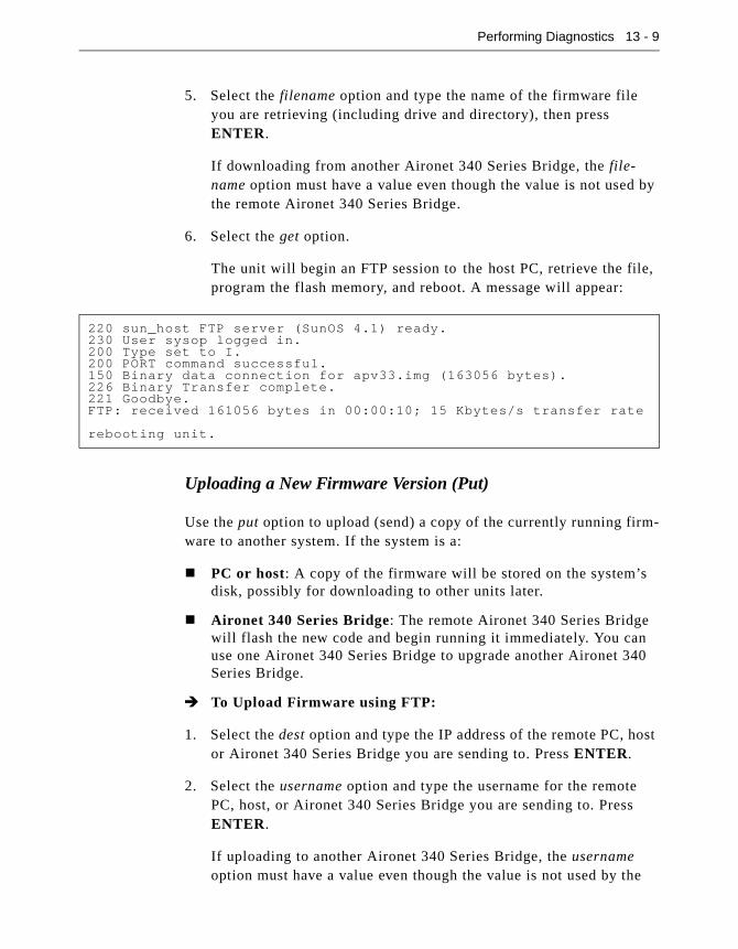
Performing Diagnostics 13 - 9
5. Select the filename option and type the name of the firmware file you are retrieving (including drive and directory), then press ENTER.
If downloading from another Aironet 340 Series Bridge, the file-name option must have a value even though the value is not used by the remote Aironet 340 Series Bridge.
6. Select the get option.
The unit will begin an FTP session to the host PC, retrieve the file, program the flash memory, and reboot. A message will appear:
Uploading a New Firmware Version (Put)
Use the put option to upload (send) a copy of the currently running firm-ware to another system. If the system is a:
� PC or host: A copy of the firmware will be stored on the system’s disk, possibly for downloading to other units later.
� Aironet 340 Series Bridge: The remote Aironet 340 Series Bridge will flash the new code and begin running it immediately. You can use one Aironet 340 Series Bridge to upgrade another Aironet 340 Series Bridge.
� To Upload Firmware using FTP:
1. Select the dest option and type the IP address of the remote PC, host or Aironet 340 Series Bridge you are sending to. Press ENTER.
2. Select the username option and type the username for the remote PC, host, or Aironet 340 Series Bridge you are sending to. Press ENTER.
If uploading to another Aironet 340 Series Bridge, the username option must have a value even though the value is not used by the
220 sun_host FTP server (SunOS 4.1) ready.230 User sysop logged in.200 Type set to I.200 PORT command successful.150 Binary data connection for apv33.img (163056 bytes).226 Binary Transfer complete.221 Goodbye.FTP: received 161056 bytes in 00:00:10; 15 Kbytes/s transfer rate
rebooting unit.

13 - 10 Aironet 340 Series Bridge
remote Aironet 340 Series Bridge.
3. Select the password option and type the access password for the remote PC, host, or the console. Press ENTER.
4. Select the filename option type the name of the firmware file you are sending to the PC, host, or Aironet 340 Series Bridge (including drive and directory). Press ENTER.
If uploading to another Aironet 340 Series Bridge, the filename option must have a value even though the value is not used by the remote Aironet 340 Series Bridge.
5. Select the put option. The unit will begin an FTP session to the remote host PC or Aironet 340 Series Bridge.
Uploading the Unit’s configuration (Config)
You may use this option to save the configuration on a remote host or PC in a format suitable for later downloading using FTP or BOOTP.
You are first prompted for the name of the file to be created on the remote system. Once the filename is entered the transfer will begin.
Downloading Using the Internet Boot Protocol (Bootp/DHCP)
The Bootp/DHCP option is enabled by default when the Aironet 340 Series Bridge is powered on. The process for downloading firmware files using the Bootp/DHCP parameter is:
1. On power up, the Aironet 340 Series Bridge will issue boot protocol requests to see if there are any Bootp or DHCP servers on the infra-structure that have been configured with the unit infrastructure address.
2. If no response is found, the request is repeated up to 30 times with a 4 second wait after the first request. It then doubles the time between requests for each additional retry. If there is still no response, the unit gives up.
3. If multiple responses are received, the unit will pick a DHCP server over a Bootp server.

Performing Diagnostics 13 - 11
4. If a response is received, the IP address assigned to this unit by the server is compared to the configured value. If they are different, the configured value is changed.
5. The downloaded file is examined. If the file is not empty, it is assumed to be a configuration file in the format produced by the “configuration dump” menu command. A Trivial File Transfer Protocol (TFTP) dialogue is used to retrieve the file from the server.
6. The contents of the configuration file is processed as though the commands have been entered by the operator at the console. The commands in the file will modify the currently running configura-tion.
NOTE: The current configuration is not set back to the defaults before the
file is processed. Therefore, the file contents do not have to be a com-plete configuration but may contain just the items you wish to change.
7. Once the configuration has been processed, the name stored in the “diagnostics load ftp filename” parameter is assumed to be the name of the firmware file to download. If the parameter is not empty, the unit will use the TFTP protocol to load the file into RAM.
� If the firmware is different from the currently running version, the unit will program the flash memory with the new code and restart to execute it.
� If the new firmware is the same, the unit discards the loaded file and continues normal operation
Use the class option to enter a class ID for a client node. The entered string is placed in the DHCP discover messages sent to the DHCP servers. The server will determine how to respond based on the class ID.

13 - 12 Aironet 340 Series Bridge
Distributing Firmware or Configuration (Distribute)
Use the distribute option to send the firmware or configuration from one Aironet 340 Series Bridge to all other Aironet 340 Series Bridges on the infrastructure (whether they are repeaters or are connected to the wired infrastructure). By using the distribute function the time needed to per-form firmware upgrades or make global changes to the configuration is greatly decreased.
Once a new version of the firmware has been loaded into a single Airo-net 340 Series Bridge, (using Xmodem, CRC-Modem, Ftp or Bootp) or the configuration has changed, use the distribute option to upgrade all other units.
Controlling Which Units the Distribute Affects
The control option controls how the remote units respond to your request to send them a configuration or firmware. Values may be set to:
� None: The unit will never respond and cannot be loaded by another unit using the distribute command.
� Any: The unit will always respond. It is up to the distributing unit to determine whether to load the local unit.
� Newer: The unit will only respond if the version of firmware being distributed has a larger version number than the code cur-rently running. This selection only applies to firmware down-loads. For configuration downloads this is equivalent to “any”.
� None of the Above: It is interpreted as a password that must have been entered by the operator of the unit doing the distribu-tion. The local unit will not respond to any distributions that do not supply this password.
Diagnostics Load Distribution Menu
Option Value Description
1 - Go - Start the distribution
2 - Type [firmware] - What to distribute
3 - Control [ “newer”] - How to control distributions
4 - Add - Change distributable configuration
5 - Remove - Remove change
6 - Show - Show changes
7 - Dump - Show Configuration
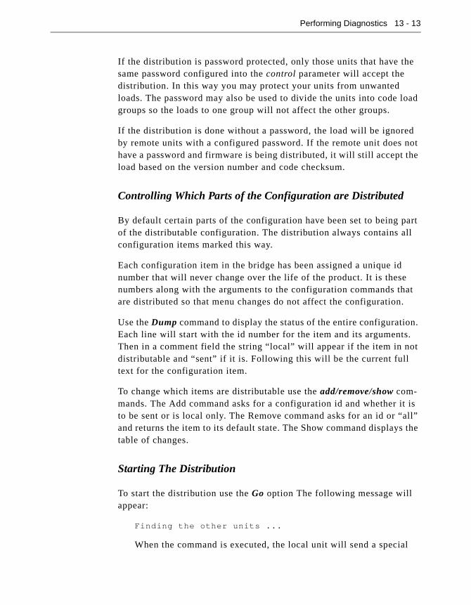
Performing Diagnostics 13 - 13
If the distribution is password protected, only those units that have the same password configured into the control parameter will accept the distribution. In this way you may protect your units from unwanted loads. The password may also be used to divide the units into code load groups so the loads to one group will not affect the other groups.
If the distribution is done without a password, the load will be ignored by remote units with a configured password. If the remote unit does not have a password and firmware is being distributed, it will still accept the load based on the version number and code checksum.
Controlling Which Parts of the Configuration are Distributed
By default certain parts of the configuration have been set to being part of the distributable configuration. The distribution always contains all configuration items marked this way.
Each configuration item in the bridge has been assigned a unique id number that will never change over the life of the product. It is these numbers along with the arguments to the configuration commands that are distributed so that menu changes do not affect the configuration.
Use the Dump command to display the status of the entire configuration. Each line will start with the id number for the item and its arguments. Then in a comment field the string “local” will appear if the item in not distributable and “sent” if it is. Following this will be the current full text for the configuration item.
To change which items are distributable use the add/remove/show com-mands. The Add command asks for a configuration id and whether it is to be sent or is local only. The Remove command asks for an id or “all” and returns the item to its default state. The Show command displays the table of changes.
Starting The Distribution
To start the distribution use the Go option The following message will appear:
Finding the other units ...
When the command is executed, the local unit will send a special

13 - 14 Aironet 340 Series Bridge
broadcast message similar to the one below to all other units on the infrastructure. It reports that it has a new firmware file with its assigned version number.
BR105E 004096001d45 has code version 3.2a (checksum
1598)
The remote units then decide whether to respond based on the value of their rcv_distribute parameter.
When the local unit receives a response to its request, the remote unit is added to a list of units to be loaded. When the response time-out period has expired (approximately 10 seconds), the local unit will begin loading all remote units in parallel using a proprietary protocol. A message similar to the one below will be displayed.
Loading 004096001d45
Loading 004096001d45
If any remote units timeout during the load, they are removed from the list. Once all units have completed loading, the local unit dis-plays a count of the successful loads. A message similar to the fol-lowing will be displayed.
Completed loading 004096001d45
Completed loading 00409610345f
Loading of 2 Aironet 340 Series Bridges completed

Appendix A - Aironet 340 Series Bridge Specifications
LAN Interfaces Supported
Ethernet
Radio Characteristics
Cable Specifications Connector
Thin Ethernet IEEE 802.3 10Base2 BNC Connector
Thick Ethernet IEEE 802.3 10Base5 DB-15 Connector (external Transceiver required)
Twisted Pair Ethernet IEEE 802.3 10BaseT RJ-45 Connector
Item Aironet 340 Series Bridge
Frequency 2.400 to 2.497 GHz*
Modulation Direct Sequence Spread Spectrum
Antenna The bridge ships with a single dipole antenna (2.2 dBi gain). Longer range antennas are available.
Compliance The bridge operates license-free under FCC Part 15 and complies as a Class B computing device. Complies with DOC regulations.
The bridge complies with ETS 300.328, FTZ 2100 and MPT 1349 standards (and others).

A-2 Aironet 340 Series Bridge
Physical Specifications
Item Description
Size 20 x 15 x 5 cm (7.8 x 5.9 x 1.9 inches)
Status Indicators Top Panel – Radio Traffic activity, Ethernet Traffic activity, Status Back Panel – Ethernet Rx and Tx activity, Polarity, Port connections, Collisions
Console Port DCE with DB-9 female connector
Power Supply Power Pack. The power pack will be either 120VAC/60Hz or 90-264VAC/47-63Hz to 12-18VDC, whichever is appropriate for country of use.
Weight 0.7 Kg (1 lb. 8 oz.)
Operating environ-ment
-20oC to 50oC (-4oF to 122oF)
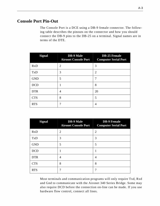
A-3
Console Port Pin-OutThe Console Port is a DCE using a DB-9 female connector. The follow-ing table describes the pinouts on the connector and how you should connect the DB-9 pins to the DB-25 on a terminal. Signal names are in terms of the DTE.
Most terminals and communication programs will only require Txd, Rxd and Gnd to communicate with the Aironet 340 Series Bridge. Some may also require DCD before the connection on-line can be made. If you use hardware flow control, connect all lines.
Signal DB-9 Male Aironet Console Port
DB-25 Female Computer Serial Port
RxD 2 3
TxD 3 2
GND 5 7
DCD 1 8
DTR 4 20
CTS 8 5
RTS 7 4
Signal DB-9 Male Aironet Console Port
DB-9 Female Computer Serial Port
RxD 2 2
TxD 3 3
GND 5 5
DCD 1 1
DTR 4 4
CTS 8 8
RTS 7 7

Appendix B - Console Menu Tree
The Console system consists of multiple sub-menus that branch off the Main Menu, much like a tree. This Appendix provides you with a detailed listing of all menu, sub-menus and options contained in the Console Port.
Main MenuConfiguration - General configuration
Radio - Radio network parameters
Ssid - Service set identification
Root - Enable root mode
Rates - Allowed bit rates in megabits/second
Basic_rates - Basic bit rates in megabits/second
Distance - Maximum separation in kilometers
I80211 - 802.11 parameters
Beacon - Beacon period in Kusec
Dtim - DTIM interval
Extend - Allow proprietary extensions
Bcst_ssid - Allow broadcast SSID
Rts - RTS/CTS packet size threshold
Privacy - Privacy configuration
Encryption - Encrypt radio packets
Auth - Authentication mode
Client - Client authentication modes allowed
Key - Set the keys
Transmit - Key number for transmit
Encapsulation - Configure packet encapsulation
Encap - Default encapsulation method
Show - Show encapsulation table
Add - Add a protocol encapsulation method
Remove - Remove a protocol encapsulation method
Linktests - Test the radio link
Strength - Run a signal strength test
Carrier - Carrier busy statistics
Align - Antenna alignment test
Multicast - Run a multicast echo test
Unicast - Run a unicast echo test
Remote - Run a remote echo test
Destination - Target address
Size - Packet size
Count - Number of packets to send
Rate - Data rate
Errors - Radio error statistics
Autotest - Auto echo test

B-2 Aironet 340 Series Bridge
Continuous - Repeat echo test once started
Extended - Extended parameters
Bridge_mode - Bridging mode
Parentid - Parent node Id
Parent_timeout - Time to look for specified parent
Parent_wait - How long to look for previous parent
Time_retry - Number of seconds to retry transmit
Count_retry - Maximum number transmit retries
Refresh - Refresh rate in 1/10 of seconds
Roaming - Type of roaming control packets
Balance - Load balancing
Diversity - Enable the diversity antennas
Power - Transmit power level
Fragment - Maximum fragment size
Options - Enable radio options
Ethernet - Ethernet configuration
Active - Connection active
Size - Maximum frame size
Port - Port selection
Ident - Identification information
Inaddr - Internet address
Inmask - Internet subnet mask
Gateway - Internet default gateway
Routing - IP routing table configuration
Display - Display Route Table Entries
Host - Add a Static Host Route
Net - Add a Static Network Route
Delete - Delete a Static Route
Dns1 - DNS server 1
Dns2 - DNS server 2
Domain - Domain name
Master - Master unit address
Nid - Network address
Name - Node name
Location - System location
Contact - System contact name
Bootp_DHCP - Use BOOTP/DHCP on startup
Class - DHCP class id
Console - Control console access
Rpassword - Set readonly privilege password
Wpassword - Set write privilege password
Remote - Allow remote operators
Telnet - Allow telnet connections
Http - Allow http connections
Display - Display the remote operator list
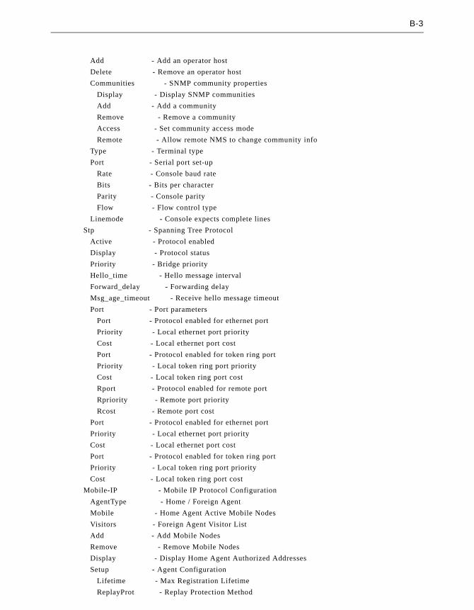
B-3
Add - Add an operator host
Delete - Remove an operator host
Communities - SNMP community properties
Display - Display SNMP communities
Add - Add a community
Remove - Remove a community
Access - Set community access mode
Remote - Allow remote NMS to change community info
Type - Terminal type
Port - Serial port set-up
Rate - Console baud rate
Bits - Bits per character
Parity - Console parity
Flow - Flow control type
Linemode - Console expects complete lines
Stp - Spanning Tree Protocol
Active - Protocol enabled
Display - Protocol status
Priority - Bridge priority
Hello_time - Hello message interval
Forward_delay - Forwarding delay
Msg_age_timeout - Receive hello message timeout
Port - Port parameters
Port - Protocol enabled for ethernet port
Priority - Local ethernet port priority
Cost - Local ethernet port cost
Port - Protocol enabled for token ring port
Priority - Local token ring port priority
Cost - Local token ring port cost
Rport - Protocol enabled for remote port
Rpriority - Remote port priority
Rcost - Remote port cost
Port - Protocol enabled for ethernet port
Priority - Local ethernet port priority
Cost - Local ethernet port cost
Port - Protocol enabled for token ring port
Priority - Local token ring port priority
Cost - Local token ring port cost
Mobile-IP - Mobile IP Protocol Configuration
AgentType - Home / Foreign Agent
Mobile - Home Agent Active Mobile Nodes
Visitors - Foreign Agent Visitor List
Add - Add Mobile Nodes
Remove - Remove Mobile Nodes
Display - Display Home Agent Authorized Addresses
Setup - Agent Configuration
Lifetime - Max Registration Lifetime
ReplayProt - Replay Protection Method

B-4 Aironet 340 Series Bridge
Broadcasts - Broadcast Forwarding
RegRequired - Registration Required
HostRedirects - Enable ICMP Host Redirects to MN
Advert - Advertisement Setup
AdvertType - Advertisement type
AdvertInterval - Advertisement interval
PrefixLen - Advertise prefix length extension
AdvertRtrs - Advertise routers
Time - Network Time Setup
Time_server - Time protocol server
Sntp_server - Network time server
Offset - GMT offset in minutes
Dst - Use daylight savings time
Dump - Dump configuration to console
Statistics - Display statistics
Throughput - Throughput statistics
Radio - Radio error statistics
Ethernet - Ethernet error statistics
Status - Display general status
Map - Show network map
Watch - Record history of a statistic
History - Display statistic history
Nodes - Node statistics
ARP - ARP table
Display_time - Time to re-display screens
IpAdr - Determine client IP addresses
Association - Association table maintenance
Display - Display the table
Summary - Display the table summary
Maximum - Maximum allowed child nodes
Autoreg - Allow automatic table additions
Add - Control node access
Remove - Remove access control
Staletime - Backbone LAN node stale out time
Niddisp - Node Ids display mode
Filter - Control packet filtering
Multicast - Multicast address filtering
Default - Default multicast action
Show - Display the multicast filters
Add - Add a multicast address filter
Remove - Remove a multicast address filter
Radio_mcst - Where to forward multicasts from radio
Node - Node address filtering
Ethdst - Destination address from ethernet
Tokdst - Destination address from token ring
Raddst - Destination address from radio
Source - Source addresses
Display - Display the node address filters

B-5
Ipdisplay - Display the IP address filters
Add - Add a node address filter
Remove - Remove a node address filter
Protocols - Protocol filters
Default - Default action
Unicast - Filter unicast packets
Display - Display the protocol filters
Add - Add a protocol filter
Remove - Remove a protocol filter
Length - Length of packet data to log
Monitor - Protocol monitoring enabled
Show - Show forwarded protocol list
Clear - Clear forwarded protocol list
Direction - Packet direction affected by filters
Logs - Alarm and log control
History - Log and alarm history
Clear - Clear the history buffer
Printlevel - Type of logs to print
Loglevel - Type of logs to save
Ledlevel - Type of logs to light status led
Statistics - Set alarms on statistics
Network - Log network roaming
Bnodelog - Log backbone node changes
Snmp - Set-up SNMP traps
Trapdest - IP destination for SNMP traps
Trapcomm - Community for SNMP traps
Loglevel - Type of logs to cause a trap
Authtrap - Enable authentication failure trap
Syslog - Unix syslogd address
Syslevel - Type of logs to send to syslog
Facility - Syslog facility number to send
Rcvsyslog - Enable reception of syslogmessages
Diagnostics - Maintenance and testing commands
Network - Network connection commands
Connect - Start telnet session
Escape - Connection escape sequence
Ping - Send an IP PING packet
Find - Flash LEDs to find unit
Linktests - Test the radio link
Strength - Run a signal strength test
Carrier - Carrier busy statistics
Align - Antenna alignment test
Multicast - Run a multicast echo test
Unicast - Run a unicast echo test
Remote - Run a remote echo test
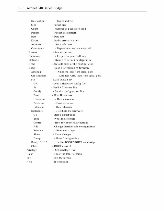
B-6 Aironet 340 Series Bridge
Destination - Target address
Size - Packet size
Count - Number of packets to send
Pattern - Packet data pattern
Rate - Data rate
Errors - Radio error statistics
Autotest - Auto echo test
Continuous - Repeat echo test once started
Restart - Restart the unit
Shutdown - Prepare to power off unit
Defaults - Return to default configuration
Reset - Default parts of the configuration
Load - Load new version of firmware
Xmodem - Xmodem load from serial port
Crc-xmodem - Xmodem-CRC load from serial port
Ftp - Load using FTP
Get - Load a firmware/config file
Put - Send a firmware file
Config - Send a configuration file
Dest - Host IP address
Username - Host username
Password - Host password
Filename - Host filename
Distribute - Distribute the firmware
Go - Start a distribution
Type - What to distribute
Control - How to control distributions
Add - Change distributable configuration
Remove - Remove change
Show - Show changes
Dump - Show Configuration
Bootp_DHCP - Use BOOTP/DHCP on startup
Class - DHCP class id
Privilege - Set privilege level
Close - Close the telnet session
Exit - Exit the menus
Help - Introduction

Appendix C - SNMP Variables
The Aironet 340 Series Bridge supports the Simple Network Management Protocol (SNMP). SNMP provides an industry standard mechanism for the exchange of informa-tion in a TCP/IP based internet environment.
The resident SNMP agent is compliant with subsets of the (Management Information Base) MIB-I and MIB-II for TCP/IP based internets as defined in Internet’s Request For Changes (RFC) 1156 and 1213. Since the Aironet 340 Series Bridge does not perform any IP routing or forwarding, certain (groups of) managed objects are not meaningful. For SNMP requests pertaining to such managed objects, the node simply returns a “no such name” error status in the response.
The Object ID (OID) prefix for the Aironet 340 Series Bridge resides under the Structure of Managed Information (SMI) tree for private enterprises in the Telxon.arlan.devices (551.2.1) branch. The system object identifier for the Aironet 340 Series Bridge is (1.3.6.1.4.1.551.2.1.76). The resident agent also supports a custom MIB that allows a management station to read/modify most of the parameters that may be set through the Console Menus. For a machine readable version of the custom MIB, contact Aironet Wireless Communications.
C.1 MIB II Variables
The System GroupMIBII.system (1.3.6.1.2.1.1.x)
Object ID
Object Name Object Type Access
1 sysDescr string read
2 sysObjectID oid read
3 sysUpTime time read
4 sysContact string write
5 sysName string write
6 sysLocation string write
7 sysServices integer read
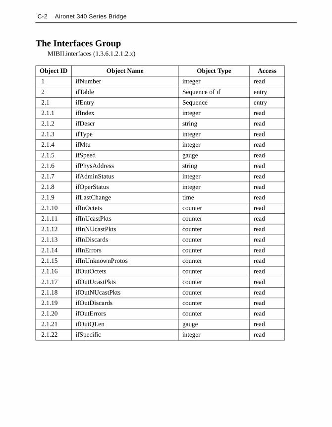
C-2 Aironet 340 Series Bridge
The Interfaces GroupMIBII.interfaces (1.3.6.1.2.1.2.x)
Object ID Object Name Object Type Access
1 ifNumber integer read
2 ifTable Sequence of if entry
2.1 ifEntry Sequence entry
2.1.1 ifIndex integer read
2.1.2 ifDescr string read
2.1.3 ifType integer read
2.1.4 ifMtu integer read
2.1.5 ifSpeed gauge read
2.1.6 ifPhysAddress string read
2.1.7 ifAdminStatus integer read
2.1.8 ifOperStatus integer read
2.1.9 ifLastChange time read
2.1.10 ifInOctets counter read
2.1.11 ifInUcastPkts counter read
2.1.12 ifInNUcastPkts counter read
2.1.13 ifInDiscards counter read
2.1.14 ifInErrors counter read
2.1.15 ifInUnknownProtos counter read
2.1.16 ifOutOctets counter read
2.1.17 ifOutUcastPkts counter read
2.1.18 ifOutNUcastPkts counter read
2.1.19 ifOutDiscards counter read
2.1.20 ifOutErrors counter read
2.1.21 ifOutQLen gauge read
2.1.22 ifSpecific integer read

C-3
The Address Translation Group (deprecated by MIB-II)MIBII.at (1.3.6.1.2.1.3.x)
Object Id Object Name Object Type Access
1 atTable Sequence of at entry
1.1 atEntry Sequence entry
1.1.1 atIfIndex integer read
1.1.2 atPhysAddress string read
1.1.3 atNetAddress ipaddress read
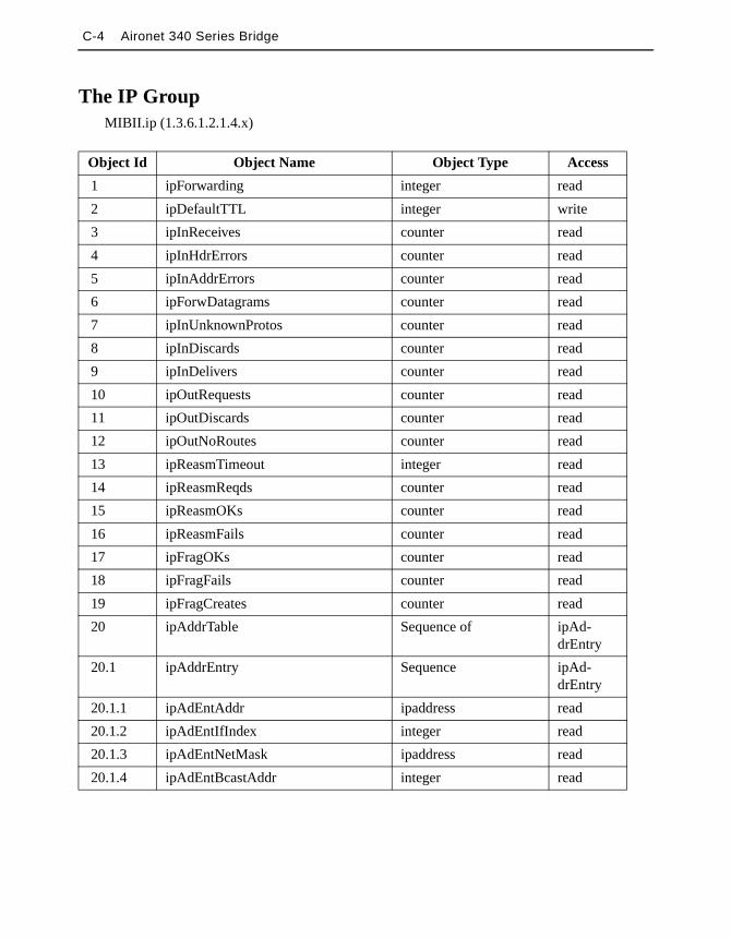
C-4 Aironet 340 Series Bridge
The IP GroupMIBII.ip (1.3.6.1.2.1.4.x)
Object Id Object Name Object Type Access
1 ipForwarding integer read
2 ipDefaultTTL integer write
3 ipInReceives counter read
4 ipInHdrErrors counter read
5 ipInAddrErrors counter read
6 ipForwDatagrams counter read
7 ipInUnknownProtos counter read
8 ipInDiscards counter read
9 ipInDelivers counter read
10 ipOutRequests counter read
11 ipOutDiscards counter read
12 ipOutNoRoutes counter read
13 ipReasmTimeout integer read
14 ipReasmReqds counter read
15 ipReasmOKs counter read
16 ipReasmFails counter read
17 ipFragOKs counter read
18 ipFragFails counter read
19 ipFragCreates counter read
20 ipAddrTable Sequence of ipAd-drEntry
20.1 ipAddrEntry Sequence ipAd-drEntry
20.1.1 ipAdEntAddr ipaddress read
20.1.2 ipAdEntIfIndex integer read
20.1.3 ipAdEntNetMask ipaddress read
20.1.4 ipAdEntBcastAddr integer read

C-5
The ICMP GroupMIBII.icmp (1.3.6.1.2.1.5.x)
Object Id Object Name Object Type Access
1 icmpInMsgs counter read
2 icmpInErrors counter read
3 icmpInDestUnreachs counter read
4 icmpInTimeExcds counter read
5 icmpInParmProbs counter read
6 icmpInSrcQuenchs counter read
7 icmpInRedirects counter read
8 icmpInEchos counter read
9 icmpInEchoReps counter read
10 icmpInTimestamps counter read
11 icmpInTimestampReps counter read
12 icmpInAddrMasks counter read
13 icmpInAddrMaskReps counter read
14 icmpOutMsgs counter read
15 icmpOutErrors counter read
16 icmpOutDestUnreachs counter read
17 icmpOutTimeExcds counter read
18 icmpOutParmProbs counter read
19 icmpOutSrcQuenchs counter read
20 icmpOutRedirects counter read
21 icmpOutEchos counter read
22 icmpOutEchoReps counter read
23 icmpOutTimestamps counter read
24 icmpOutTimestampReps counter read
25 icmpOutAddrMasks counter read
26 icmpOutAddrMaskReps counter read

C-6 Aironet 340 Series Bridge
The UDP GroupMIBII.udp (1.3.6.1.2.1.7.x)
Object Id Object Name Object Type Access
1 udpInDatagrams counter read
2 udpNoPorts counter read
3 udpInErrors counter read
4 udpOutDatagrams counter read

C-7
The Transmission GroupMIBII.transmission.dot3 (1.3.6.1.2.1.10.7.x)
Object Id Object Name Object Type Access
1 dot3Table Sequence of dot3 entry
1.1 dot3Entry Sequence entry
1.1.1.1 dot3Index integer read
1.1.3.1 dot3MacSubLayerStatus integer write
2 dot3StatsTable Sequence of dot3Stats entry
2.1 dot3StatsEntry Sequence entry
2.1.1.1 dot3StatsIndex integer read
2.1.2.1 dot3StatsAlignmentErrors counter read
2.1.3.1 dot3StatsFCSErrors counter read
2.1.4.1 dot3StatsSingleCollisionFrames counter read
2.1.5.1 dot3StatsMultipleCollisionFrames counter read
2.1.6.1 dot3StatsSQETestErrors counter read
2.1.7.1 dot3StatsDeferredTransmissions counter read
2.1.8.1 dot3StatsLateCollisions counter read
2.1.9.1 dot3StatsExcessiveCollisions counter read
2.1.10.1 dot3StatsInternalMacTransmitErrors counter read
2.1.11.1 dot3StatsCarrierSenseErrors counter read
2.1.12.1 dot3StatsExcessiveDeferrals counter read
2.1.13.1 dot3StatsFrameTooLongs counter read
2.1.14.1 dot3StatsInrangeLengthErrors counter read
2.1.15.1 dot3StatsOutOfRangeLengthFields counter read
2.1.16.1 dot3StatsInternalMacReceiveErrors counter read
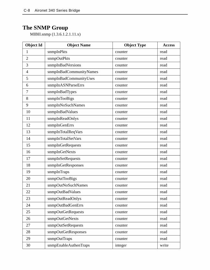
C-8 Aironet 340 Series Bridge
The SNMP GroupMIBII.snmp (1.3.6.1.2.1.11.x)
Object Id Object Name Object Type Access
1 snmpInPkts counter read
2 snmpOutPkts counter read
3 snmpInBadVersions counter read
4 snmpInBadCommunityNames counter read
5 snmpInBadCommunityUses counter read
6 snmpInASNParseErrs counter read
7 snmpInBadTypes counter read
8 snmpInTooBigs counter read
9 snmpInNoSuchNames counter read
10 snmpInBadValues counter read
11 snmpInReadOnlys counter read
12 snmpInGenErrs counter read
13 snmpInTotalReqVars counter read
14 snmpInTotalSetVars counter read
15 snmpInGetRequests counter read
16 snmpInGetNexts counter read
17 snmpInSetRequests counter read
18 snmpInGetResponses counter read
19 snmpInTraps counter read
20 snmpOutTooBigs counter read
21 snmpOutNoSuchNames counter read
22 snmpOutBadValues counter read
23 snmpOutReadOnlys counter read
24 snmpOutBadGenErrs counter read
25 snmpOutGetRequests counter read
26 snmpOutGetNexts counter read
27 snmpOutSetRequests counter read
28 snmpOutGetResponses counter read
29 snmpOutTraps counter read
30 snmpEnableAuthenTraps integer write
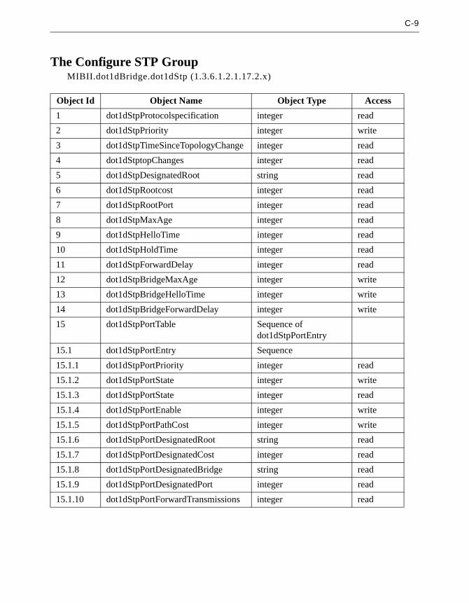
C-9
The Configure STP GroupMIBII.dot1dBridge.dot1dStp (1.3.6.1.2.1.17.2.x)
Object Id Object Name Object Type Access
1 dot1dStpProtocolspecification integer read
2 dot1dStpPriority integer write
3 dot1dStpTimeSinceTopologyChange integer read
4 dot1dStptopChanges integer read
5 dot1dStpDesignatedRoot string read
6 dot1dStpRootcost integer read
7 dot1dStpRootPort integer read
8 dot1dStpMaxAge integer read
9 dot1dStpHelloTime integer read
10 dot1dStpHoldTime integer read
11 dot1dStpForwardDelay integer read
12 dot1dStpBridgeMaxAge integer write
13 dot1dStpBridgeHelloTime integer write
14 dot1dStpBridgeForwardDelay integer write
15 dot1dStpPortTable Sequence of dot1dStpPortEntry
15.1 dot1dStpPortEntry Sequence
15.1.1 dot1dStpPortPriority integer read
15.1.2 dot1dStpPortState integer write
15.1.3 dot1dStpPortState integer read
15.1.4 dot1dStpPortEnable integer write
15.1.5 dot1dStpPortPathCost integer write
15.1.6 dot1dStpPortDesignatedRoot string read
15.1.7 dot1dStpPortDesignatedCost integer read
15.1.8 dot1dStpPortDesignatedBridge string read
15.1.9 dot1dStpPortDesignatedPort integer read
15.1.10 dot1dStpPortForwardTransmissions integer read

C-10 Aironet 340 Series Bridge
MIBII.dot1dBridge.dot1dTp (1.3.6.1.2.1.17.4.x)
Object Id Object Name Object Type Access
1 dot1dTpLearnedEntryDiscards counter read
2 dot1dTpAgingTime integer write
3 dot1dTpFdbTable Sequence of dot1dTpFdEntry
3.1 dot1dTpFdbEntry Sequency
3.1.1 dot1dTpFdAddress string read
3.1.2 dot1dTpFdbPort integer read
3.1.3 dot1dTpFdbStatus integer read

C-11
3.2 The ARLAN Custom MIB
The Configure Ethernet GroupACCESSPOINT.configuration.cfgEthernet (1.3.6.1.4.1.551.2.2.1.1.x)
The Configure ARLAN GroupACCESSPOINT.configuration.cfgArlan (1.3.6.1.4.1.551.2.2.1.2.x)
The Configure Filtering GroupACCESSPOINT.configuration.cfgFilter (1.3.6.1.4.1.551.2.2.1.3.x)
Object Id Object Name Object Type Access
1 cfgEthEnable integer write
2 cfgEthSize integer write
Object Id Object Name Object Type Access
1 cfgArlRoot integer write
7 cfgArlParent string write
8 cfgArlParentTime integer write
16 cfgArlSsid String write
Object Id Object Name Object Type Access
1 cfgFiltMcst integer write
7 cfgFiltSrc integer write

C-12 Aironet 340 Series Bridge
The Configure Console GroupACCESSPOINT.configuration.cfgConsole (1.3.6.1.4.1.551.2.2.1.4.x)
The Configure SNMP GroupACCESSPOINT.configuration.cfgSnmp (1.3.6.1.4.1.551.2.2.1.5.x)
Object Id Object Name Object Type Access
1 cfgConsPrivilege integer write
2 cfgConsReadPwd string write
3 cfgConsWritePwd string write
4 cfgConsType integer write
5 cfgConsBaud integer write
6 cfgConsBits integer write
7 cfgConsParity integer write
9 cfgConsTelnet integer write
11 cfgConsFlow integer write
Object Id Object Name Object Type Access
1 cfgSnmpDest ipaddress write
2 cfgSnmpAuth integer write
3 cfgSnmpTComm string write
4 cfgSnmpLog integer write
5 cfgSnmpCommTable Sequence of cfgSnmp-CommTableEntry
5.1 cfgSnmpCommTableEntry Sequence
5.1.1 cfgSnmpCommStatus integer write
5.1.2 cfgSnmpCommIndex integer write
5.1.3 cfgSnmpCommName string write
5.1.4 cfgSnmpCommAccess integer write
5.1.5 cfgSnmpCommIP1 ipaddress write
5.1.6 cfgSnmpCommIP2 ipaddress write
5.1.7 cfgSnmpCommIP3 ipaddress write
5.1.8 cfgSnmpCommIP4 ipaddress write
5.1.9 cfgSnmpCommIP5 ipaddress write
5.1.10 cfgSnmpCommNID1 string write

C-13
5.1.11 cfgSnmpCommNID2 string write
5.1.12 cfgSnmpCommNID3 string write
5.1.13 cfgSnmpCommNID4 string write
5.1.14 cfgSnmpCommNID5 string write
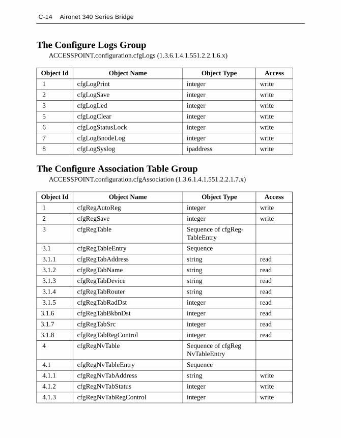
C-14 Aironet 340 Series Bridge
The Configure Logs GroupACCESSPOINT.configuration.cfgLogs (1.3.6.1.4.1.551.2.2.1.6.x)
The Configure Association Table GroupACCESSPOINT.configuration.cfgAssociation (1.3.6.1.4.1.551.2.2.1.7.x)
Object Id Object Name Object Type Access
1 cfgLogPrint integer write
2 cfgLogSave integer write
3 cfgLogLed integer write
5 cfgLogClear integer write
6 cfgLogStatusLock integer write
7 cfgLogBnodeLog integer write
8 cfgLogSyslog ipaddress write
Object Id Object Name Object Type Access
1 cfgRegAutoReg integer write
2 cfgRegSave integer write
3 cfgRegTable Sequence of cfgReg-TableEntry
3.1 cfgRegTableEntry Sequence
3.1.1 cfgRegTabAddress string read
3.1.2 cfgRegTabName string read
3.1.3 cfgRegTabDevice string read
3.1.4 cfgRegTabRouter string read
3.1.5 cfgRegTabRadDst integer read
3.1.6 cfgRegTabBkbnDst integer read
3.1.7 cfgRegTabSrc integer read
3.1.8 cfgRegTabRegControl integer read
4 cfgRegNvTable Sequence of cfgRegNvTableEntry
4.1 cfgRegNvTableEntry Sequence
4.1.1 cfgRegNvTabAddress string write
4.1.2 cfgRegNvTabStatus integer write
4.1.3 cfgRegNvTabRegControl integer write

C-15
4.1.4 cfgRegNvTabRadDst integer write
4.1.5 cfgRegNvTabBkbnDst integer write
4.1.6 cfgRegNvTabSrc integer write
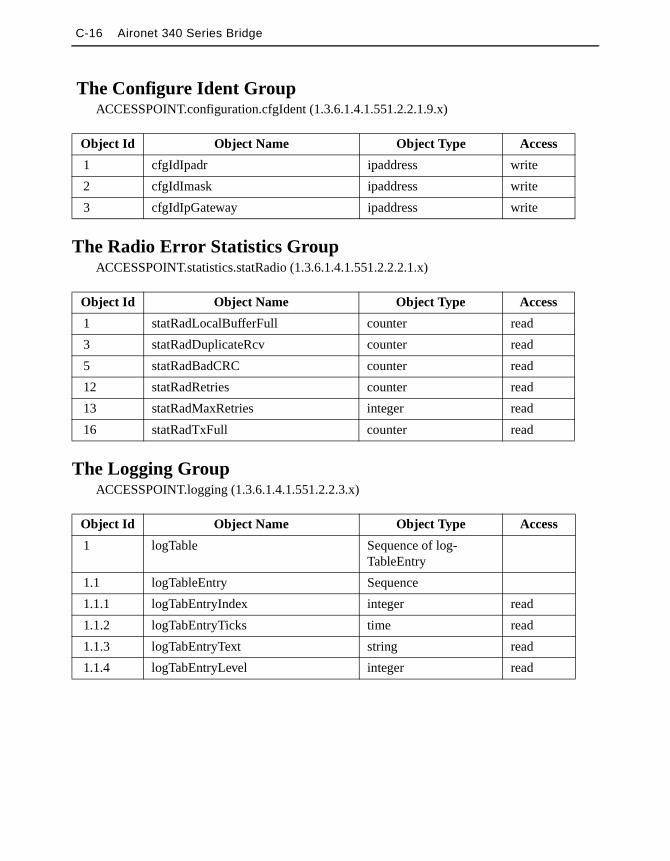
C-16 Aironet 340 Series Bridge
The Configure Ident GroupACCESSPOINT.configuration.cfgIdent (1.3.6.1.4.1.551.2.2.1.9.x)
The Radio Error Statistics GroupACCESSPOINT.statistics.statRadio (1.3.6.1.4.1.551.2.2.2.1.x)
The Logging GroupACCESSPOINT.logging (1.3.6.1.4.1.551.2.2.3.x)
Object Id Object Name Object Type Access
1 cfgIdIpadr ipaddress write
2 cfgIdImask ipaddress write
3 cfgIdIpGateway ipaddress write
Object Id Object Name Object Type Access
1 statRadLocalBufferFull counter read
3 statRadDuplicateRcv counter read
5 statRadBadCRC counter read
12 statRadRetries counter read
13 statRadMaxRetries integer read
16 statRadTxFull counter read
Object Id Object Name Object Type Access
1 logTable Sequence of log-TableEntry
1.1 logTableEntry Sequence
1.1.1 logTabEntryIndex integer read
1.1.2 logTabEntryTicks time read
1.1.3 logTabEntryText string read
1.1.4 logTabEntryLevel integer read

C-17
The Admin GroupACCESSPOINT.admin (1.3.6.1.4.1.551.2.2.4.x)
The Admin LinkTest GroupACCESSPOINT.admin.adminLinktest (1.3.6.1.4.1.551.2.2.4.2.x)
Object Id Object Name Object Type Access
1 adminRestart integer write
4 adminMajVersion integer read
5 adminMinVersion integer read
6 adminBootp integer write
7 adminDistribute integer write
8 adminDistributeCnt integer read
9 adminPing integer write
10 adminPingState integer read
11 adminFallback integer write
12 adminRcvDistribute integer write
13 adminBetaVersion integer read
Object Id Object Name Object Type Access
1 adminLtMultiTest integer write
2 adminLtDest string write
3 adminLtSize integer write
4 adminLtCount integer write
5 adminLtDstRcv counter read
6 adminLtSrcRcv counter read
7 adminLtSrcXmt counter read
8 adminLtAveTrip counter read
9 adminLtMinTrip counter read
10 adminLtMaxtrip counter read
11 adminLtUniTest integer write
12 adminLtAuto integer write

C-18 Aironet 340 Series Bridge
The Admin FTP GroupACCESSPOINT.admin.adminFTP (1.3.6.1.4.1.551.2.2.4.3.x)
Object Id Object Name Object Type Access
1 adminFtpGet integer write
2 adminFtpDest ipaddress write
3 adminFtpUser string write
4 adminFtpPassword string write
5 adminFtpFile string write
6 adminFtpPut integer write

Appendix D - Cisco Technical Support
If you are a network administrator and need personal technical assis-tance with a Cisco product that is under warranty or covered by a main-tenance contract, contact Cisco’s Technical Assistance Center (TAC) at 800 553-2447, 408 526-7209, or [email protected]. To obtain general information about Cisco Systems, Cisco products, or upgrades, contact 800 553-6387, 408 526-7208, or [email protected].

Appendix E - Regulatory Information
Manufacturer’s Federal CommunicationCommission Declaration of Conformity Statement
Models: BR340, BR342, BRI340, BRI341
Manufacturer: Cisco Systems, Inc.170 West Tasman DriveSan Jose, CA 95134 USA
This device complies with Part 15 rules. Operation is subject to the following two conditions:1) this device may not cause harmful interference, and 2) this device must accept any interference received, including interference that may cause undesired operation.
This equipment has been tested and found to comply with the limits of a Class B digital device, pursuant to Part 15 of the FCC Rules. These limits are designed to provide reasonable protection against harmful interference when the equipment is operated in a residential environment. This equipment generates, uses, and radiates radio frequency energy, and if not installed and used in accordance with the instructions, may cause harmful interference. However, there is no guarantee that interference will not occur. If this equipment does cause interference to radio or television reception, which can be determined by turning the equipment off and on, the user is encouraged to correct the interference by one of the following measures:
• Reorient or relocate the receiving antenna.
• Increase separation between the equipment and receiver.
• Connect the equipment into an outlet on a circuit different from which the receiver is connected.
• Consult the dealer or an experienced radio\TV technician.
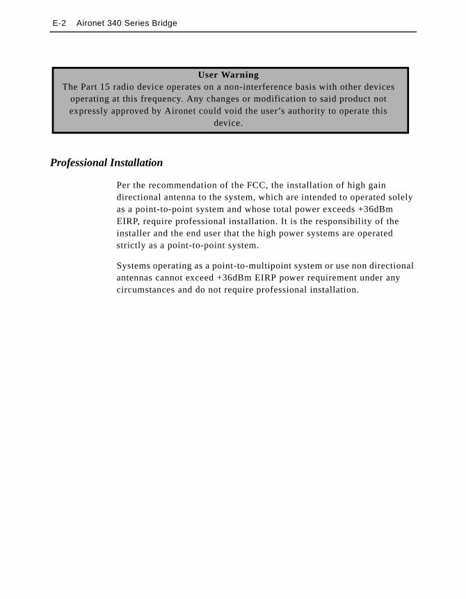
E-2 Aironet 340 Series Bridge
Professional Installation
Per the recommendation of the FCC, the installation of high gain directional antenna to the system, which are intended to operated solely as a point-to-point system and whose total power exceeds +36dBm EIRP, require professional installation. It is the responsibility of the installer and the end user that the high power systems are operated strictly as a point-to-point system.
Systems operating as a point-to-multipoint system or use non directional antennas cannot exceed +36dBm EIRP power requirement under any circumstances and do not require professional installation.
User WarningThe Part 15 radio device operates on a non-interference basis with other devices
operating at this frequency. Any changes or modification to said product not expressly approved by Aironet could void the user’s authority to operate this
device.
E-3
Department of Communications—CanadaCanadian Compliance Statement
This Digital apparatus meets all the requirements of the Canadian Interference - Causing Equipment Regulations.
Cet appareil numerique respecte les exigences du Reglement sur le material broilleur du Canada.
This device complies with Class B Limits of Industry of Canada. Operation is subject to the following two conditions: 1) this device may cause harmful interference, and 2) this device must accept any interference received, including interference that may cause undesired operation.
The device is certified to the requirements of RSS-139-1 and RSS-210 for 2.4 GHz spread spectrum devices. The use of this device in a system operating either partially or completely outdoors may require the user to obtain a license for the system according to the Canadian regulations. For further information, contact your local Industry Canada office.

E-4 Aironet 340 Series Bridge
European Telecommunication Standards InstituteStatement of ComplianceInformation to User
This equipment has been tested and found to comply with the European Telecommunications Standard ETS 300.328. This standard covers Wideband Data Transmission Systems referred in CEPT recommendation T/R 10.01.
This type accepted equipment is designed to provide reasonable protection against harmful interference when the equipment is operated in a commercial environment. This equipment generates, uses, and can radiate radio frequency energy, and if not installed and used in accordance with the instruction manual, may cause harmful interference to radio communications.

E-5
498
Anexo 6: Organigramas de Unisys Latinoamérica y Caribe
Este anexo muestra los organigramas de Unisys Latinoamérica y Caribe. El
primer organigrama muestra a los directores de departamentos; el segundo
organigrama muestra los directores a nivel de Branch y el último muestra la
organización del Departamento GNS (que es en el que el estudiante realizó el
Proyecto de Graduación).
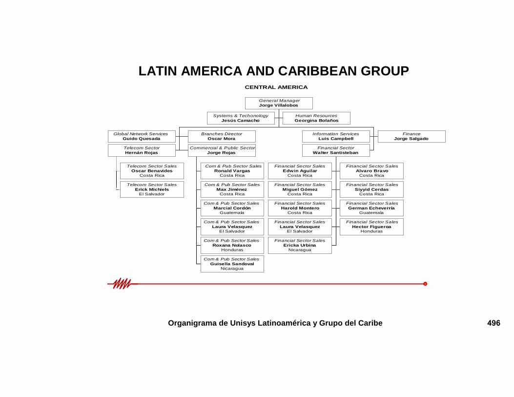
CENTRAL AMERICA
Systems & TechonologyJesús Camacho
Human ResourcesGeorgina Bolaños
Global Network ServicesGuido Quesada
Branches DirectorOscar Mora
Information ServicesLuis Campbell
FinanceJorge Salgado
Telecom Sector SalesOscar Benavides
Costa Rica
Telecom Sector SalesErick Michiels
El Salvador
Telecom SectorHernán Rojas
Com & Pub Sector SalesRonald Vargas
Costa Rica
Com & Pub Sector SalesMax Jiménez
Costa Rica
Com & Pub Sector SalesMarcial Cordón
Guatemala
Com & Pub Sector SalesLaura Velasquez
El Salvador
Com & Pub Sector SalesRoxana Nolasco
Honduras
Com & Pub Sector SalesGuisella Sandoval
Nicaragua
Commercial & Public SectorJorge Rojas
Financial Sector SalesEdwin Aguilar
Costa Rica
Financial Sector SalesAlvaro Bravo
Costa Rica
Financial Sector SalesMiguel Gómez
Costa Rica
Financial Sector SalesSiyyid Cerdas
Costa Rica
Financial Sector SalesHarold Montero
Costa Rica
Financial Sector SalesGerman Echeverría
Guatemala
Financial Sector SalesLaura Velasquez
El Salvador
Financial Sector SalesHector Figueroa
Honduras
Financial Sector SalesEricka Urbina
Nicaragua
Financial SectorWalter Santisteban
General ManagerJorge Villalobos
LATIN AMERICA AND CARIBBEAN GROUP
Organigrama de Unisys Latinoamérica y Grupo del Caribe 496

BRANCHES
Financial Sector SalesGerman Echeverría
Com & Pub Sector SalesMarcial Cordón
Branch ManagerMarino Vásquez
Guatemala
Financial Sector SLaura Velasqu
Telecom Sector SErick Michiels
Branch ManagerJavier Soriano
Financial Sector SalesHector Figueroa
Com & Pub Sector SalesRoxana Nolasco
Branch ManagerHector Martínez
Honduras
Financial Sector Ericka Urbin
Branches DirectorOscar Mora
LATIN AMERICA AND CARIBBEAN GROUP
Organigrama de Unisys Latinoamérica y Grupo del Ca
EL Salvador
2
alesez
Com & Pub Sector SalesLaura Velasquez
ales
Salesa
Com & Pub Sector SalesGuisella Sandoval
Branch ManagerLucía ZepedaNicaragua
ribe (Branches) 497
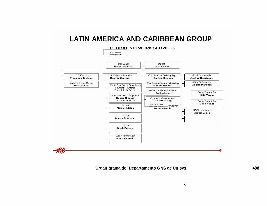
LATIN AMERICA AND CARIBBEAN GROUPGLOBAL NETWORK SERVICES
ControllerMario Calderon
Quality Erick Salas
C.A VentasFrancisco Jiménez
Unisys Direct SalesRicardo Lee Technical Consulting Sales
Randall RamírezCom & Pub Sector
Technical Consulting SalesHector Hídalgo
Com & Pub Sector
CCNAAlexis Hidalgo
CCNAMartin Arguedas
CCNAGerth Rauseo
Cisco TechnicianMinor Camaño
C.A Network PracticeRicardo Zamora
C.A Service Delivery Mgr. Carlos Elizondo
C.A Global SuManue
Microsoft SuCarlo
Contract MRobert
Service DesigRebec
GNS GuatemalaJosé A. Hernández
GNS NicaraguFrancisco Varg
GNS DirectorGuido Quesada
Organigrama del Departamento GN
3
pport Servicesl Méndez
pport Centers Luna
anagemento Walker
n Organizationa Knohr
Cisco TechnicianOtto Varela
Cisco TechnicianJulio Nuñez
GNS El SalvadorAdolfo Martínez
GNS HondurasMiguel López
aas
S de Unisys 498