Installing the CPU-NXT (A-008316-xx) - New Life Games LLC
32
08-11-2004 WMS Gaming Inc. 1 of 27 16-009693-06 Installing CPU-NXT ( A-008316-xx) Installing the CPU - NXT (A - 008316 - xx) I NSTALLATION B ULLETIN WWW.WMSGAMING.COM LOCAL CUSTOMER SERVICE (800) 378-7741 MODEL(S) AFFECTED UNIT AFFECTED THEME ESTIMATED TIME PARTS AND TOOLS NEEDED ⌧ CPU-NXT Upgrade Kit ⌧ OS, Game, and RAM Clear CompactFlash™ cards & EPROMs ⌧ EPROM extraction tool ⌧ ESD wrist strap ⌧ ESD mat ⌧ 3 /16", 11 /32", 7 /16", and 7 /8" nut drivers BULLETIN #: 16-009693-06 WMS Gaming Inc. is introducing a new upgrade to the electronic hardware and software for the Upright (550) and Slant Top (3601) models. The custom electronic circuit board mates with the existing cabinet backplanes and supports most existing peripherals, such as the Coin Acceptor, Bill Acceptor, and Hopper. The CPU-NXT board (A-008316-xx) supports the original complement of existing I/O such as lamps, player panel buttons, bell, knocker, and key switches. The CPU-NXT upgrade approach allows games currently in the field to utilize just the new hardware and software, which offers casino operators the opportunity to enhance an existing product without having to incur the cost of a new game. 550, 3601 Software/CPU N/A 25 min. per game IN THIS BULLETIN Part Number Information . . . . . . . . . . . . . . . . . . .2 Replacing the Host Communication Cable(s) . . . . .3 Installing the In-Line Power Filter Kit . . . . . . . . . . .4 Removing the Card Cage Door and Boards . . . . . .6 Installing the Belly Door Interlock Switch (550) . . .7 Preparing for Procedure . . . . . . . . . . . . . . . . . . .11 Installing the CPU Board . . . . . . . . . . . . . . . . . . .12 Performing a RAM Clear . . . . . . . . . . . . . . . . . . .13 Installing Game Software & New Card Cage Door .14 Configuring the Game . . . . . . . . . . . . . . . . . . . . .15 Calibrating the Touch Screen . . . . . . . . . . . . . . .16 Setting the Game Denomination . . . . . . . . . . . . .18 Setting the Paytable(s) . . . . . . . . . . . . . . . . . . .19 Setting Devices . . . . . . . . . . . . . . . . . . . . . . . . .20 Setting the Max Bet . . . . . . . . . . . . . . . . . . . . . .20 Setting the Date and Time . . . . . . . . . . . . . . . . .21 Setting the Comm . . . . . . . . . . . . . . . . . . . . . . .23 Comm Field Definitions . . . . . . . . . . . . . . . . . . . .24 Setting Machine Info . . . . . . . . . . . . . . . . . . . . . .25 Configuring the Game - Setting the Volume . . . . .26 Software Configuration Pending Tilts - Reference 27 Beginning Game Play . . . . . . . . . . . . . . . . . . . . .27 This bulletin details the installation and configuration of CPU-NXT on the Upright (550) and Slant Top (3601) models, which utilize the CPU board. This bulletin also includes the steps for installing the EMI In-Line Power Filter kit and the Belly Door Interlock Switch Kit (for 550 models only). The In-Line Power Filter kit, which is available for both 110-120V and 220-240V games, protects the CPU boards from electrical fast transients. The Belly Door Interlock Switch allows for the monitoring of the Belly Door switch. Reference the Part Number Information section on page 2 for kit part numbers, as well as information on additional parts that may be required for the upgrade. A C D F E B A - Jurisdictional ID Chip B - BIOS EPROM C - OCTAL UART D - NVRAM E - Compact Flash Drive F - Custom Logic Device CPU-NXT (A-008316-xx) Copyright © 2004 WMS Gaming Inc.® All rights reserved.
-
Upload
khangminh22 -
Category
Documents
-
view
1 -
download
0
Transcript of Installing the CPU-NXT (A-008316-xx) - New Life Games LLC
08-11-2004 WMS Gaming Inc. 1 of 2716-009693-06 Installing CPU-NXT ( A-008316-xx)
Installing tthe CCPU-NNXT ((A-0008316-xxx)
INSTALLATION BULLETINWWW.WMSGAMING.COM
LOCAL CUSTOMER SERVICE (800) 378-7741
MODEL(S) AFFECTED
UNIT AFFECTED
THEME
ESTIMATED TIME
PARTS
AND
TOOLS
NEEDED
⌧ CPU-NXT Upgrade Kit
⌧ OS, Game, and RAM Clear CompactFlash™ cards & EPROMs
⌧ EPROM extraction tool
⌧ ESD wrist strap
⌧ ESD mat
⌧ 3/16",11/32", 7/16", and 7/8" nut drivers
BULLETIN #: 16-009693-06
WMS Gaming Inc. is introducing a new upgrade to theelectronic hardware and software for the Upright (550)and Slant Top (3601) models. The custom electroniccircuit board mates with the existing cabinetbackplanes and supports most existing peripherals,such as the Coin Acceptor, Bill Acceptor, and Hopper.The CPU-NXT board (A-008316-xx) supports theoriginal complement of existing I/O such as lamps,player panel buttons, bell, knocker, and key switches.
The CPU-NXT upgrade approach allows gamescurrently in the field to utilize just the new hardware andsoftware, which offers casino operators the opportunityto enhance an existing product without having to incurthe cost of a new game.
550, 3601
Software/CPU
N/A
25 min. per game
IN THISBULLETIN
Part Number Information . . . . . . . . . . . . . . . . . . .2Replacing the Host Communication Cable(s) . . . . .3Installing the In-Line Power Filter Kit . . . . . . . . . . .4Removing the Card Cage Door and Boards . . . . . .6Installing the Belly Door Interlock Switch (550) . . .7Preparing for Procedure . . . . . . . . . . . . . . . . . . .11Installing the CPU Board . . . . . . . . . . . . . . . . . . .12Performing a RAM Clear . . . . . . . . . . . . . . . . . . .13Installing Game Software & New Card Cage Door .14Configuring the Game . . . . . . . . . . . . . . . . . . . . .15Calibrating the Touch Screen . . . . . . . . . . . . . . .16Setting the Game Denomination . . . . . . . . . . . . .18Setting the Paytable(s) . . . . . . . . . . . . . . . . . . .19Setting Devices . . . . . . . . . . . . . . . . . . . . . . . . .20Setting the Max Bet . . . . . . . . . . . . . . . . . . . . . .20Setting the Date and Time . . . . . . . . . . . . . . . . .21Setting the Comm . . . . . . . . . . . . . . . . . . . . . . .23Comm Field Definitions . . . . . . . . . . . . . . . . . . . .24Setting Machine Info . . . . . . . . . . . . . . . . . . . . . .25Configuring the Game - Setting the Volume . . . . .26Software Configuration Pending Tilts - Reference 27Beginning Game Play . . . . . . . . . . . . . . . . . . . . .27
This bulletin details the installation andconfiguration of CPU-NXT on theUpright (550) and Slant Top (3601)models, which utilize the CPU board.
This bulletin also includes the steps forinstalling the EMI In-Line Power Filter kit and the Belly Door InterlockSwitch Kit (for 550 models only). The In-Line Power Filter kit, whichis available for both 110-120V and 220-240V games, protects theCPU boards from electrical fast transients. The Belly Door InterlockSwitch allows for the monitoring of the Belly Door switch.
Reference the Part Number Information section on page 2 for kit partnumbers, as well as information on additional parts that may berequired for the upgrade.
A
C
D
F
E
B
A - Jurisdictional ID ChipB - BIOS EPROMC - OCTAL UARTD - NVRAME - Compact Flash DriveF - Custom Logic Device
CPU-NXT (A-008316-xx)
Copyright © 2004 WMS Gaming Inc.®All rights reserved.
08-11-2004 WMS Gaming Inc. 2 of 27
Part Number Information
16-009693-06 Installing CPU-NXT ( A-008316-xx)
INSTALLATION BULLETIN16-009693-06 Installing CPU-NXT ( A-008316-xx)
Part Number Information
Prior to beginning the CPU-NXT installation, ensure the correct kit and other required parts are available. The kittype required depends on the legacy model you are upgrading, the available voltage in the installation region, andthe game theme, as some themes require the 512 MB RAM CPU to operate.
Additional Parts Please note that additional parts are required to install CPU-NXT. All software must be ordered separately, as thereare a variety of theme and jurisdiction-dependent aspects that affect the ordering process. If the model beingupgraded utilizes a hinged Card Cage door, a replacement door (01-010729) must be ordered. Reference page6 for more information and photos of the two existing Card Cage door styles. Up to three cables are installed when upgrading to CPU-NXT. The existing Bill Validator Interface cable, H-005564-01 (550) or H-005698-01 (3601), is replaced to address false tilt conditions on both legacy platforms. If upgradinga ticket in/ticket out printer legacy game, the legacy game host communication cable, H-005746-03 (550) or H-005745-02 (3601), is removed from the game. This harness is replaced by two cables on the 550 model and asingle cable in the 3601. See page 3 for detailed information on installing the new cables.
WMS Part Number DescriptionA-011548-00-00 Kit: CPU-NXT Upgrade (550 - 110V); 256 MB RAM CPUA-011548-00-01 Kit: CPU-NXT Upgrade (550 - 220V); 256 MB RAM CPUA-011548-00-02 Kit: CPU-NXT Upgrade (3601 - 110V); 256 MB RAM CPUA-011548-00-03 Kit: CPU-NXT Upgrade (3601 - 220V); 256 MB RAM CPUA-011548-00-04 Kit: CPU-NXT Upgrade (550 - 110V); 512 MB RAM CPUA-011548-00-05 Kit: CPU-NXT Upgrade (550 - 220V); 512 MB RAM CPUA-011548-00-06 Kit: CPU-NXT Upgrade (3601 - 110V); 512 MB RAM CPUA-011548-00-07 Kit: CPU-NXT Upgrade (3601 - 220V); 512 MB RAM CPU
A-008316-xx CPU Board, rev. xxH-008680-02 DC power cable5556-006347-00 Torroid: large hex02-4640 Spacer: 4-40 MF hex threaded (2)A-010433 Card Cage door assembly
CPU-NXT Kits
Parts included in all CPU-NXT Kits
H-005564-01 Cable: Universal Bill Validator Interface (550)H-005698-01 Cable: Universal Bill Validator Interface (3601)A-004367 Kit: Belly Door Interlock Switch (550 kits ONLY)
A-010368-00 Kit: 110 - 120V In-line power filter (see kit parts below )A-010368-01 Kit: 220 - 240V in-line power filter (see kit parts below )
01-010011 Bracket: EMI f ilter mouting5102-009216-00 Filter: EMI in-line pow er f ilter4408-01128-00 8-32 keps (2)
5850-009386-00 Shielded line cord (110-120V kit)5850-010590-00 Shielded line cord (220-240V kit)
16-002040-00 Caution label (for line cord)
01-010729 Card Cage door (hinged door), if requiredH-010266-00 Cable: Dual host communication (550 and 3601)H-006846-01 Cable: Printer/Hopper (550 ONLY)
CPU-NXT RAM Clear CF CardCPU-NXT OS CF CardCPU-NXT Game CF CardCPU-NXT BIOS EPROMCPU-NXT Jurisdictional ID Chip
vary by theme, version, and jurisdiction
Parts to be ordered separately, if applicable
Parts that vary by kit type
08-11-2004 WMS Gaming Inc. 3 of 27
Replacing the Host Comm and Bill Validator Cable
16-009693-06 Installing CPU-NXT ( A-008316-xx)
Complete the following steps to replace the legacy cables. TheBill Validator cable replacement is required, while the HostComm cables depend on the current configuration of the game:1. Unlock and open the Main Door. 2. Turn the game power off at the PDU and disconnect the
game from the outlet. 3. On the 550, remove the Coin Tray and Hopper. On the
3601, lift and slide the coin chute towards you, Image 1. 4. Disconnect the existing Bill Validator Interface cable,
H-005564-00 (550) or H-005698-00 (3601). This cable isno longer needed.
5. Disconnect the existing Host Comm cable, H-005745-03 (550) or H-005745-02 (3601). This cableis no longer needed.
6. Connect the new cables as follows:
Image 2. Dual Host Command Printer/Hopper cablesinstalled (550).
INSTALLATION BULLETIN16-009693-06 Installing CPU-NXT ( A-008316-xx)
Replacing the Host Communication Cable(s)
Disconnect the power supply cord fromthe outlet before servicing to avoidelectrical shock.
! CAUTION
Image 1. Lift and slide the coinchute down the guide, leaning thechute towards you as shown onthe label.
chuteguide
C
B
A
P1 BILL VALIDATOR on Backplane, Image 2 (A)P2 Bill Validator Door switch:
fast-on: black/orange w ire NC1 terminalfast-on: black/gray w ire COM1 terminal
P3 12V DC power supply on PDU
P4 Player Tracking System (not to the Cashbox Missing switch)
P5 Bill Validator connector
P1 PRINTER/HOPPER on Backplane, Image 2 (B)P2 HopperP3 Printer
P1 BILL VALIDATOR on BackplaneP2 12V DC power supply on PDUP3 Slant Hatch Door switch:
fast-on: black/green w ire NC1 terminalfast-on: black/gray w ire COM1 terminal
P4 Bill Validator Door switch:fast-on: black/orange w ire NC1 terminal
fast-on: black/gray w ire COM1 terminalP5 Cashbox Missing switch, if used:
fast-on: black/brow n w ire NC1 terminalfast-on: black/gray w ire COM1 terminal
P6 Bill Validator connector
P1 Primary hostP2 Secondary hostP3 HOST COMM on Backplane, Image 2 (C)
Dual Host Comm cable, H-010266-00 (550 and 3601)
3601 Bill Validator Interface cable, H-005698-01
Bill Validator Interface cable, H-005564-01550 cables
Printer/Hopper cable, H-006846-01

08-11-2004 WMS Gaming Inc. 4 of 2716-009693-06 Installing CPU-NXT ( A-008316-xx)
INSTALLATION BULLETIN16-009693-06 Installing CPU-NXT ( A-008316-xx)
Installing the In-Line Power Filter Kit
Installing the In-Line Power Filter Kit
Image 5. Captive hex nuts to loosenand remove (550).
Image 3. In-line power filter secured tomounting bracket with two hex nuts (550).
loosenremove
open slot
Complete the following steps to install the in-Linepower filter kit:
1. Disconnect and remove the existing 24-pin DCpower cable (H-17965-00) from the PDU andthe Backplane. This power cable is no longerneeded.
2. Using an 11/32" nut driver, mount the power filteronto the mounting bracket using the two 8-32hex nuts included in the kit, Image 3. For the550, mount the filter so the filter line cord is onthe side with the open slot. For the 3601, mountthe filter so the line cord is on the side with theclosed slot, Image 8 on page 5.
3. Unplug and remove the game line cord fromthe outlet and PDU. The game line cord isreplaced with a shielded line cord included inthe in-line power filter kit.
4. Verify that the shielded line cord (5850-009386-0x) is equipped with the necessary Cautionlabel (16-002040-00). If not, adhere the label(included in kit) to the line cord within a foot ofthe outlet plug, Image 4.
5. Plug the shielded line cord from the kit into theoutlet and route into the game.
6. On the 550 (see step 7 for the 3601):a. Using the 11/32" nut driver, loosen the backleft captive hex nut securing the cable clamp,Image 5. b. Using the 11/32" nut driver, remove the frontleft captive hex nut securing the cable clamp,Image 5.
c. With the open slot, Image 3, and line cordfacing the back of the cabinet, slide the filtermounting assembly onto the back stud andover the front stud. On the back stud, ensurethe mounting bracket is under the cable clamp.
Image 4. Outlet line cord caution label.
08-11-2004 WMS Gaming Inc. 5 of 2716-009693-06 Installing CPU-NXT ( A-008316-xx)
INSTALLATION BULLETIN16-009693-06 Installing CPU-NXT ( A-008316-xx)
Installing the In-Line Power Filter Kit
Installing the In-Line Power Filter Kit, cont.
Image 7. Two captive hex nuts toremove (3601).
Image 9. In-line power filter Installed(3601).
AB
C
d. Tighten the back captive hex nut and replacethe front captive hex nut.
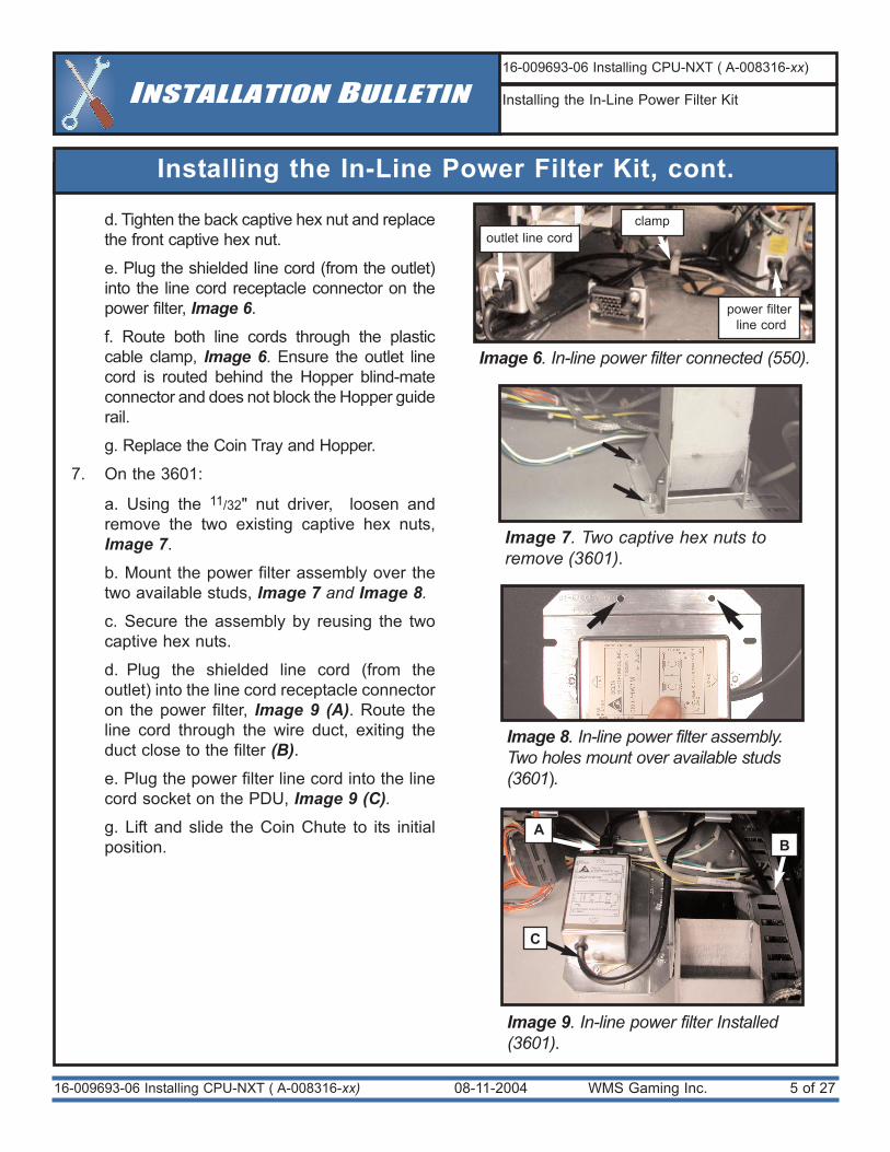
e. Plug the shielded line cord (from the outlet)into the line cord receptacle connector on thepower filter, Image 6.
f. Route both line cords through the plasticcable clamp, Image 6. Ensure the outlet linecord is routed behind the Hopper blind-mateconnector and does not block the Hopper guiderail.
g. Replace the Coin Tray and Hopper.
7. On the 3601:
a. Using the 11/32" nut driver, loosen andremove the two existing captive hex nuts,Image 7.
b. Mount the power filter assembly over thetwo available studs, Image 7 and Image 8.
c. Secure the assembly by reusing the twocaptive hex nuts.
d. Plug the shielded line cord (from theoutlet) into the line cord receptacle connectoron the power filter, Image 9 (A). Route theline cord through the wire duct, exiting theduct close to the filter (B).e. Plug the power filter line cord into the linecord socket on the PDU, Image 9 (C).g. Lift and slide the Coin Chute to its initialposition.
Image 8. In-line power filter assembly.Two holes mount over available studs(3601).
Image 6. In-line power filter connected (550).
outlet line cordclamp
power filterline cord
08-11-2004 WMS Gaming Inc. 6 of 2716-009693-06 Installing CPU-NXT ( A-008316-xx)
INSTALLATION BULLETIN16-009693-06 Installing CPU-NXT ( A-008316-xx)
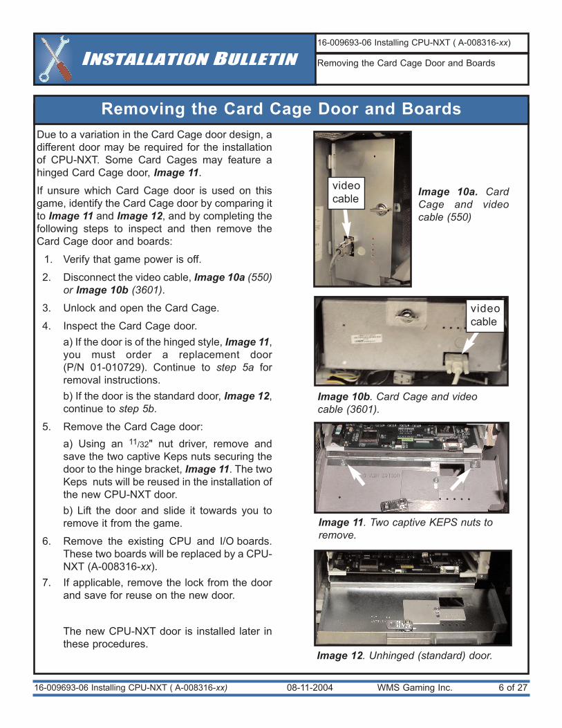
Removing the Card Cage Door and Boards
Due to a variation in the Card Cage door design, adifferent door may be required for the installationof CPU-NXT. Some Card Cages may feature ahinged Card Cage door, Image 11.
If unsure which Card Cage door is used on thisgame, identify the Card Cage door by comparing itto Image 11 and Image 12, and by completing thefollowing steps to inspect and then remove theCard Cage door and boards:
1. Verify that game power is off.
2. Disconnect the video cable, Image 10a (550)or Image 10b (3601).
3. Unlock and open the Card Cage.
4. Inspect the Card Cage door. a) If the door is of the hinged style, Image 11,you must order a replacement door (P/N 01-010729). Continue to step 5a forremoval instructions. b) If the door is the standard door, Image 12,continue to step 5b.
5. Remove the Card Cage door:a) Using an 11/32" nut driver, remove andsave the two captive Keps nuts securing thedoor to the hinge bracket, Image 11. The twoKeps nuts will be reused in the installation ofthe new CPU-NXT door. b) Lift the door and slide it towards you toremove it from the game.
6. Remove the existing CPU and I/O boards.These two boards will be replaced by a CPU-NXT (A-008316-xx).
7. If applicable, remove the lock from the doorand save for reuse on the new door.
The new CPU-NXT door is installed later inthese procedures.
Image 11. Two captive KEPS nuts toremove.
Image 12. Unhinged (standard) door.
Removing the Card Cage Door and Boards
videocable
videocable
Image 10b. Card Cage and videocable (3601).
Image 10a. CardCage and videocable (550)
08-11-2004 WMS Gaming Inc. 7 of 27
Installing the Belly Door Interlock Switch (550 ONLY)
16-009693-06 Installing CPU-NXT ( A-008316-xx)
Image 14. Two screws to remove.
Image 15. Removing the Bill Validator. Image 16. Four Phillips screwsto remove.
INSTALLATION BULLETIN16-009693-06 Installing CPU-NXT ( A-008316-xx)
Installing the Belly Door Interlock Switch
Image 13. Belly Door interlock switch andactuator on mounting bracket.
Switch
Actuator pin
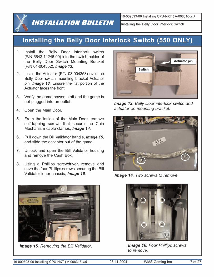
1. Install the Belly Door interlock switch (P/N 5643-14246-00) into the switch holder ofthe Belly Door Switch Mounting Bracket (P/N 01-004352), Image 13.
2. Install the Actuator (P/N 03-004353) over theBelly Door switch mounting bracket Actuatorpin, Image 13. Ensure the flat portion of theActuator faces the front.
3. Verify the game power is off and the game isnot plugged into an outlet.
4. Open the Main Door.
5. From the inside of the Main Door, removeself-tapping screws that secure the CoinMechanism cable clamps, Image 14.
6. Pull down the Bill Validator handle, Image 15,and slide the acceptor out of the game.
7. Unlock and open the Bill Validator housingand remove the Cash Box.
8. Using a Phillips screwdriver, remove andsave the four Phillips screws securing the BillValidator inner chassis, Image 16.
08-11-2004 WMS Gaming Inc. 8 of 27
Installing the Belly Door Interlock Switch (550 ONLY), cont.
16-009693-06 Installing CPU-NXT ( A-008316-xx)
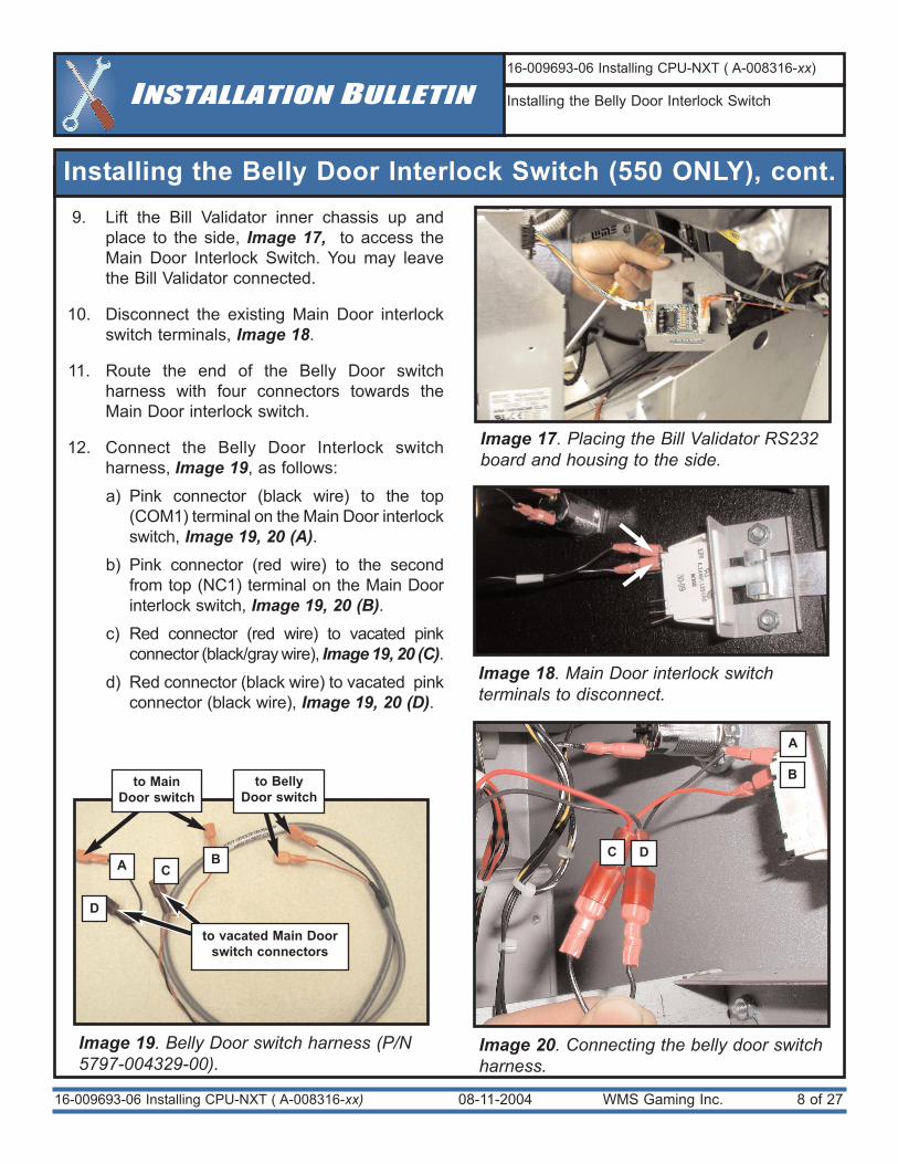
9. Lift the Bill Validator inner chassis up andplace to the side, Image 17, to access theMain Door Interlock Switch. You may leavethe Bill Validator connected.
10. Disconnect the existing Main Door interlockswitch terminals, Image 18.
11. Route the end of the Belly Door switchharness with four connectors towards theMain Door interlock switch.
12. Connect the Belly Door Interlock switchharness, Image 19, as follows:
a) Pink connector (black wire) to the top(COM1) terminal on the Main Door interlockswitch, Image 19, 20 (A).
b) Pink connector (red wire) to the secondfrom top (NC1) terminal on the Main Doorinterlock switch, Image 19, 20 (B).
c) Red connector (red wire) to vacated pinkconnector (black/gray wire), Image 19, 20 (C).
d) Red connector (black wire) to vacated pinkconnector (black wire), Image 19, 20 (D).
INSTALLATION BULLETIN16-009693-06 Installing CPU-NXT ( A-008316-xx)
Installing the Belly Door Interlock Switch
Image 18. Main Door interlock switchterminals to disconnect.
Image 19. Belly Door switch harness (P/N5797-004329-00).
Image 20. Connecting the belly door switchharness.
to BellyDoor switch
to MainDoor switch
to vacated Main Doorswitch connectors
A
B
A B C DC
D
Image 17. Placing the Bill Validator RS232board and housing to the side.
08-11-2004 WMS Gaming Inc. 9 of 27
Installing the Belly Door Interlock Switch (550 ONLY), cont.
16-009693-06 Installing CPU-NXT ( A-008316-xx)
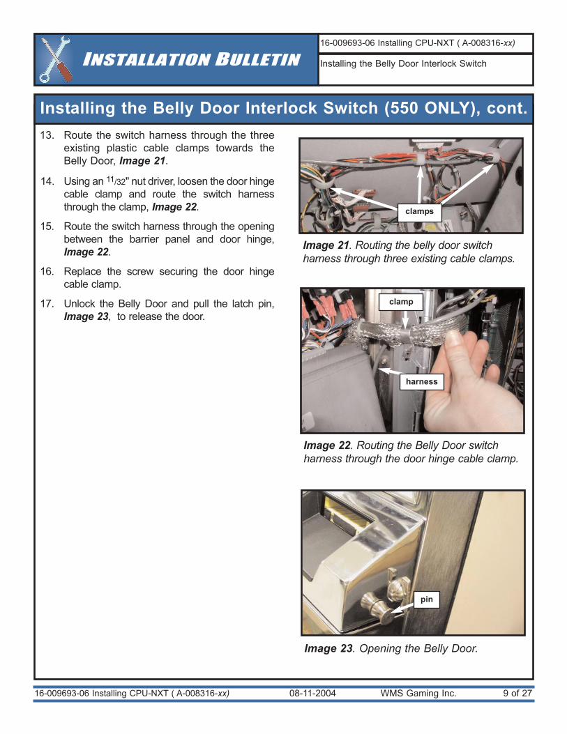
13. Route the switch harness through the threeexisting plastic cable clamps towards theBelly Door, Image 21.
14. Using an 11/32" nut driver, loosen the door hingecable clamp and route the switch harnessthrough the clamp, Image 22.
15. Route the switch harness through the openingbetween the barrier panel and door hinge,Image 22.
16. Replace the screw securing the door hingecable clamp.
17. Unlock the Belly Door and pull the latch pin,Image 23, to release the door.
INSTALLATION BULLETIN16-009693-06 Installing CPU-NXT ( A-008316-xx)
Installing the Belly Door Interlock Switch
Image 22. Routing the Belly Door switchharness through the door hinge cable clamp.
Image 23. Opening the Belly Door.
clamp
harness
pin
Image 21. Routing the belly door switchharness through three existing cable clamps.
clamps
08-11-2004 WMS Gaming Inc. 10 of 27
Installing the Belly Door Interlock Switch (550 ONLY), cont.
16-009693-06 Installing CPU-NXT ( A-008316-xx)
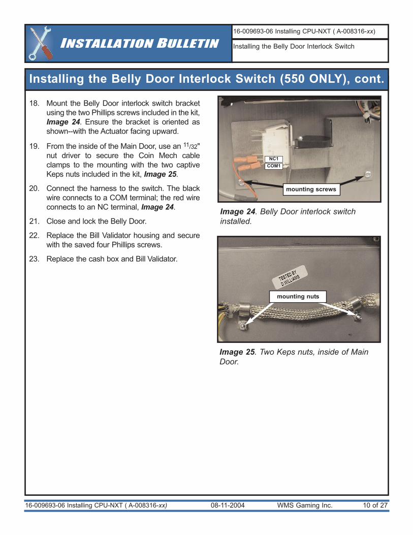
18. Mount the Belly Door interlock switch bracketusing the two Phillips screws included in the kit,Image 24. Ensure the bracket is oriented asshown--with the Actuator facing upward.
19. From the inside of the Main Door, use an 11/32"nut driver to secure the Coin Mech cableclamps to the mounting with the two captiveKeps nuts included in the kit, Image 25.
20. Connect the harness to the switch. The blackwire connects to a COM terminal; the red wireconnects to an NC terminal, Image 24.
21. Close and lock the Belly Door.
22. Replace the Bill Validator housing and securewith the saved four Phillips screws.
23. Replace the cash box and Bill Validator.
INSTALLATION BULLETIN16-009693-06 Installing CPU-NXT ( A-008316-xx)
Installing the Belly Door Interlock Switch
Image 24. Belly Door interlock switchinstalled.
COM1NC1
Image 25. Two Keps nuts, inside of MainDoor.
mounting screws
mounting nuts
08-11-2004 WMS Gaming Inc. 11 of 2716-009693-06 Installing CPU-NXT ( A-008316-xx)
INSTALLATION BULLETIN16-009693-06 Installing CPU-NXT ( A-008316-xx)
Preparing for Procedure
Preparing for Procedure
Image 26. ESD strap on arm.
ELECTROSTATIC DISCHARGE
(ESD) WARNING
Electrostatic discharge (ESD) damagecauses complete and/or intermittentfailures to video game components. Takeall necessary precautions to avoid damage.
Use the following anti-static steps beforeproceeding.
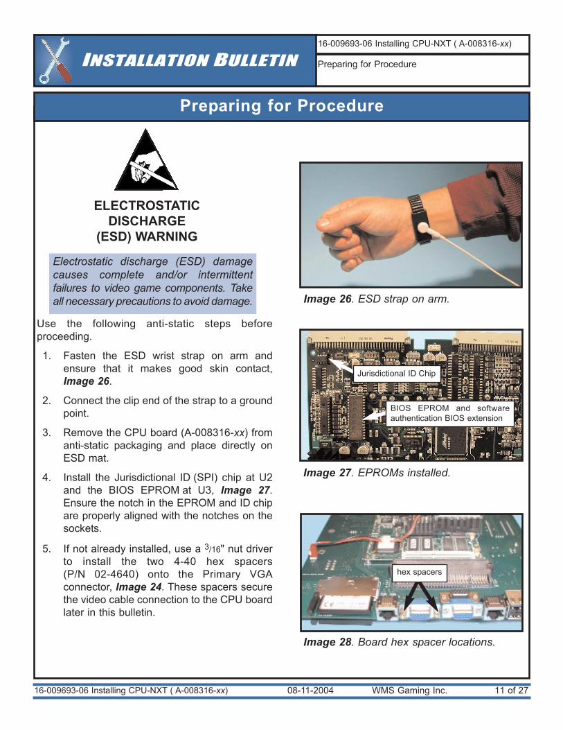
1. Fasten the ESD wrist strap on arm andensure that it makes good skin contact,Image 26.
2. Connect the clip end of the strap to a groundpoint.
3. Remove the CPU board (A-008316-xx) fromanti-static packaging and place directly onESD mat.
4. Install the Jurisdictional ID (SPI) chip at U2and the BIOS EPROM at U3, Image 27.Ensure the notch in the EPROM and ID chipare properly aligned with the notches on thesockets.
5. If not already installed, use a 3/16" nut driverto install the two 4-40 hex spacers (P/N 02-4640) onto the Primary VGAconnector, Image 24. These spacers securethe video cable connection to the CPU boardlater in this bulletin.
Image 27. EPROMs installed.
Image 28. Board hex spacer locations.
Jurisdictional ID Chip
BIOS EPROM and softwareauthentication BIOS extension
hex spacers
08-11-2004 WMS Gaming Inc. 12 of 27
Installing the CPU Board
16-009693-06 Installing CPU-NXT ( A-008316-xx)
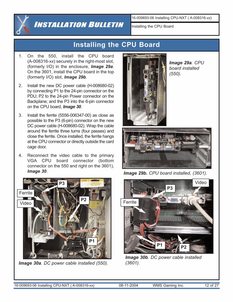
1. On the 550, install the CPU board (A-008316-xx) securely in the right-most slot,(formerly I/O) in the enclosure, Image 29a.On the 3601, install the CPU board in the top(formerly I/O) slot, Image 29b.
2. Install the new DC power cable (H-008680-02)by connecting P1 to the 24-pin connector on thePDU; P2 to the 24-pin Power connector on theBackplane; and the P3 into the 6-pin connectoron the CPU board, Image 30.
3. Install the ferrite (5556-006347-00) as close aspossible to the P3 (6-pin) connector on the newDC power cable (H-008680-02). Wrap the cablearound the ferrite three turns (four passes) andclose the ferrite. Once installed, the ferrite hangsat the CPU connector or directly outside the cardcage door.
4. Reconnect the video cable to the primaryVGA CPU board connector (bottomconnector on the 550 and right on the 3601),Image 30.
INSTALLATION BULLETIN16-009693-06 Installing CPU-NXT ( A-008316-xx)
Installing the CPU Board
Image 29b. CPU board installed, (3601).
Image 30b. DC power cable installed(3601). Image 30a. DC power cable installed (550).
P3
Ferrite
Video
Video P3
Ferrite P2
P2P1
P1
Image 29a. CPUboard installed(550).
08-11-2004 WMS Gaming Inc. 13 of 27
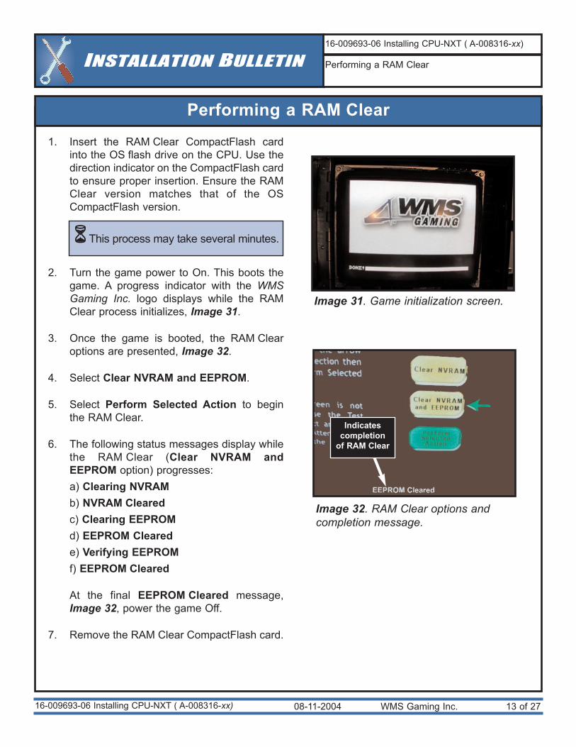
Performing a RAM Clear
16-009693-06 Installing CPU-NXT ( A-008316-xx)
INSTALLATION BULLETIN16-009693-06 Installing CPU-NXT ( A-008316-xx)
Performing a RAM Clear
Image 31. Game initialization screen.
Image 32. RAM Clear options andcompletion message.
Indicatescompletion
of RAM Clear
1. Insert the RAM Clear CompactFlash cardinto the OS flash drive on the CPU. Use thedirection indicator on the CompactFlash cardto ensure proper insertion. Ensure the RAMClear version matches that of the OSCompactFlash version.
2. Turn the game power to On. This boots thegame. A progress indicator with the WMSGaming Inc. logo displays while the RAMClear process initializes, Image 31.
3. Once the game is booted, the RAM Clearoptions are presented, Image 32.
4. Select Clear NVRAM and EEPROM.
5. Select Perform Selected Action to beginthe RAM Clear.
6. The following status messages display whilethe RAM Clear (Clear NVRAM andEEPROM option) progresses:a) Clearing NVRAMb) NVRAM Clearedc) Clearing EEPROMd) EEPROM Clearede) Verifying EEPROMf) EEPROM Cleared
At the final EEPROM Cleared message,Image 32, power the game Off.
7. Remove the RAM Clear CompactFlash card.
This process may take several minutes.
08-11-2004 WMS Gaming Inc. 14 of 27
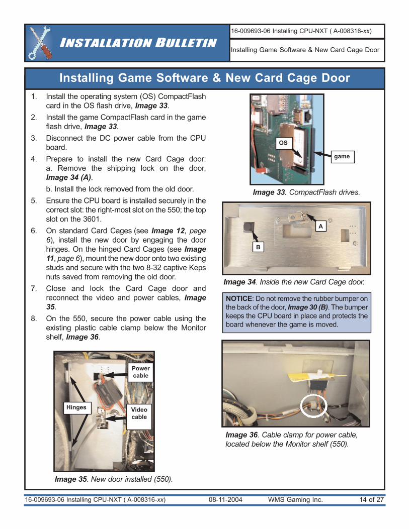
Installing Game Software & New Card Cage Door
16-009693-06 Installing CPU-NXT ( A-008316-xx)
1. Install the operating system (OS) CompactFlashcard in the OS flash drive, Image 33.
2. Install the game CompactFlash card in the gameflash drive, Image 33.
3. Disconnect the DC power cable from the CPUboard.
4. Prepare to install the new Card Cage door:a. Remove the shipping lock on the door,Image 34 (A). b. Install the lock removed from the old door.
5. Ensure the CPU board is installed securely in thecorrect slot: the right-most slot on the 550; the topslot on the 3601.
6. On standard Card Cages (see Image 12, page6), install the new door by engaging the doorhinges. On the hinged Card Cages (see Image11, page 6), mount the new door onto two existingstuds and secure with the two 8-32 captive Kepsnuts saved from removing the old door.
7. Close and lock the Card Cage door andreconnect the video and power cables, Image35.
8. On the 550, secure the power cable using theexisting plastic cable clamp below the Monitorshelf, Image 36.
INSTALLATION BULLETIN16-009693-06 Installing CPU-NXT ( A-008316-xx)
Installing Game Software & New Card Cage Door
Image 33. CompactFlash drives.
Image 35. New door installed (550).
game
Image 36. Cable clamp for power cable,located below the Monitor shelf (550).
Powercable
Image 34. Inside the new Card Cage door.
B
Hinges Videocable
A
OS
NOTICE: Do not remove the rubber bumper onthe back of the door, Image 30 (B). The bumperkeeps the CPU board in place and protects theboard whenever the game is moved.
08-11-2004 WMS Gaming Inc. 15 of 27
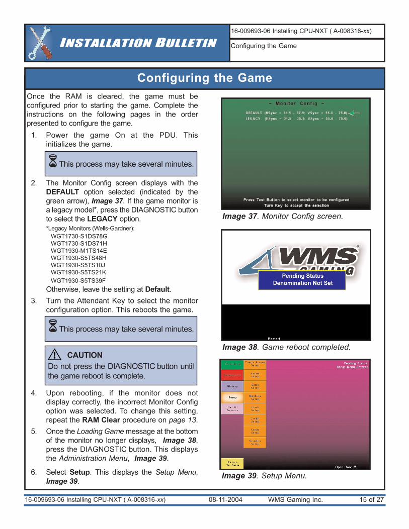
Configuring the Game
16-009693-06 Installing CPU-NXT ( A-008316-xx)
Once the RAM is cleared, the game must beconfigured prior to starting the game. Complete theinstructions on the following pages in the orderpresented to configure the game.
1. Power the game On at the PDU. Thisinitializes the game.
2. The Monitor Config screen displays with theDEFAULT option selected (indicated by thegreen arrow), Image 37. If the game monitor isa legacy model*, press the DIAGNOSTIC buttonto select the LEGACY option. *Legacy Monitors (Wells-Gardner):
WGT1730-S1DS78GWGT1730-S1DS71HWGT1930-M1TS14EWGT1930-S5TS48HWGT1930-S5TS10JWGT1930-S5TS21KWGT1930-S5TS39F
Otherwise, leave the setting at Default. 3. Turn the Attendant Key to select the monitor
configuration option. This reboots the game.
4. Upon rebooting, if the monitor does notdisplay correctly, the incorrect Monitor Configoption was selected. To change this setting,repeat the RAM Clear procedure on page 13.
5. Once the Loading Game message at the bottomof the monitor no longer displays, Image 38,press the DIAGNOSTIC button. This displaysthe Administration Menu, Image 39.
6. Select Setup. This displays the Setup Menu,Image 39.
INSTALLATION BULLETIN16-009693-06 Installing CPU-NXT ( A-008316-xx)
Configuring the Game
Image 38. Game reboot completed.
Image 37. Monitor Config screen.
Image 39. Setup Menu.
This process may take several minutes.
This process may take several minutes.
CAUTIONDo not press the DIAGNOSTIC button untilthe game reboot is complete.
!
08-11-2004 WMS Gaming Inc. 16 of 2716-009693-06 Installing CPU-NXT ( A-008316-xx)
INSTALLATION BULLETIN16-009693-06 Installing CPU-NXT ( A-008316-xx)
Configuring the Game
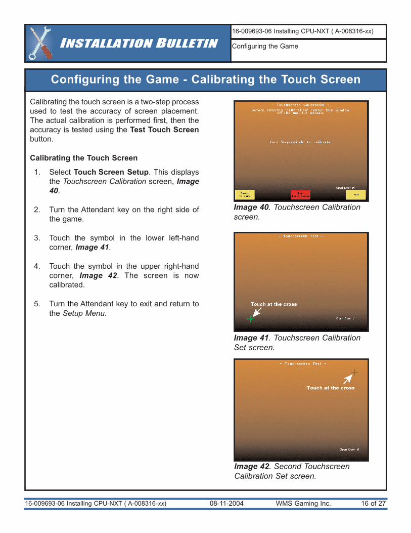
Configuring the Game - Calibrating the Touch Screen
Calibrating the touch screen is a two-step processused to test the accuracy of screen placement.The actual calibration is performed first, then theaccuracy is tested using the Test Touch Screenbutton.
Calibrating the Touch Screen
1. Select Touch Screen Setup. This displaysthe Touchscreen Calibration screen, Image40.
2. Turn the Attendant key on the right side ofthe game.
3. Touch the symbol in the lower left-handcorner, Image 41.
4. Touch the symbol in the upper right-handcorner, Image 42. The screen is nowcalibrated.
5. Turn the Attendant key to exit and return tothe Setup Menu.
Image 40. Touchscreen Calibrationscreen.
Image 41. Touchscreen CalibrationSet screen.
Image 42. Second TouchscreenCalibration Set screen.
08-11-2004 WMS Gaming Inc. 17 of 2716-009693-06 Installing CPU-NXT ( A-008316-xx)
INSTALLATION BULLETIN16-009693-06 Installing CPU-NXT ( A-008316-xx)
Configuring the Game
Configuring the Game - Calibrating the Touch Screen, cont.
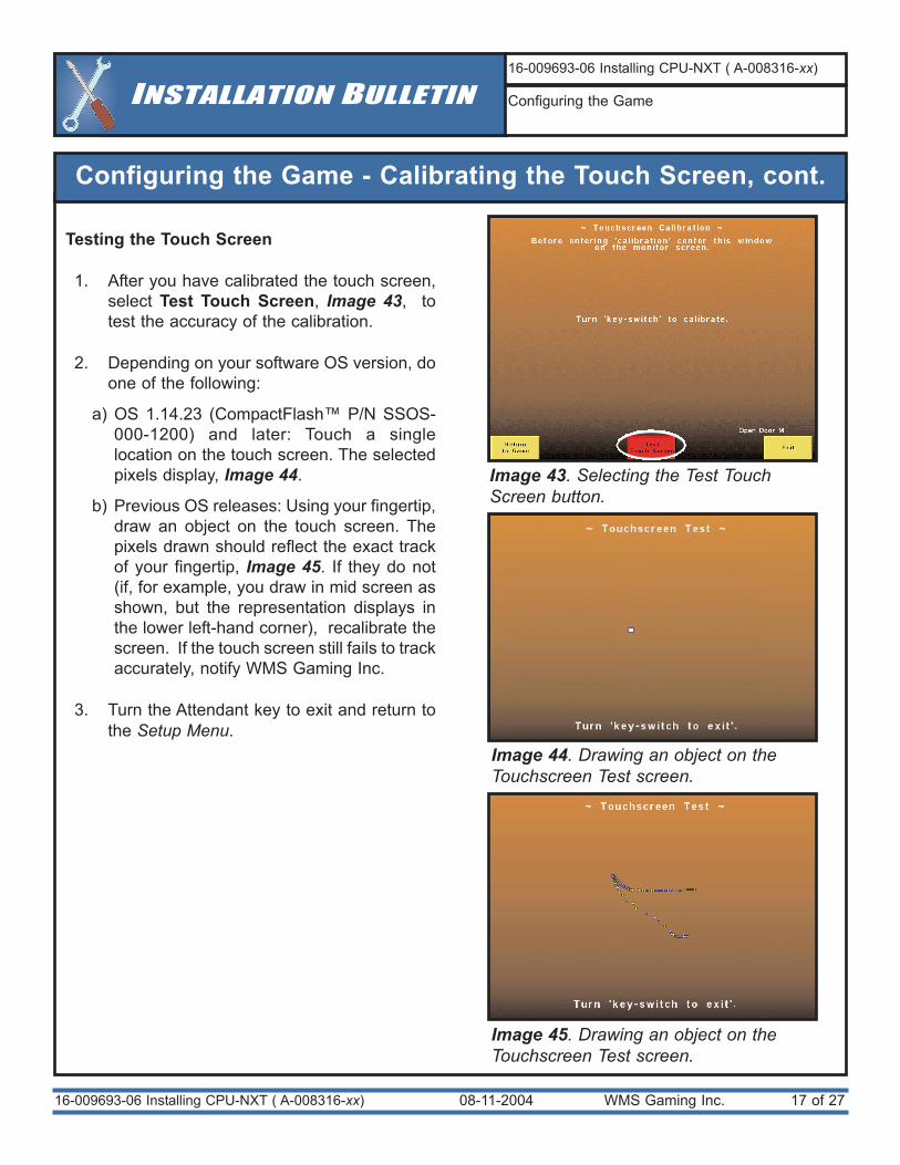
Testing the Touch Screen
1. After you have calibrated the touch screen,select Test Touch Screen, Image 43, totest the accuracy of the calibration.
2. Depending on your software OS version, doone of the following:
a) OS 1.14.23 (CompactFlash™ P/N SSOS-000-1200) and later: Touch a singlelocation on the touch screen. The selectedpixels display, Image 44.
b) Previous OS releases: Using your fingertip,draw an object on the touch screen. Thepixels drawn should reflect the exact trackof your fingertip, Image 45. If they do not(if, for example, you draw in mid screen asshown, but the representation displays inthe lower left-hand corner), recalibrate thescreen. If the touch screen still fails to trackaccurately, notify WMS Gaming Inc.
3. Turn the Attendant key to exit and return tothe Setup Menu.
Image 43. Selecting the Test TouchScreen button.
Image 44. Drawing an object on theTouchscreen Test screen.
Image 45. Drawing an object on theTouchscreen Test screen.
08-11-2004 WMS Gaming Inc. 18 of 2716-009693-06 Installing CPU-NXT ( A-008316-xx)
INSTALLATION BULLETIN16-009693-06 Installing CPU-NXT ( A-008316-xx)
Configuring the Game
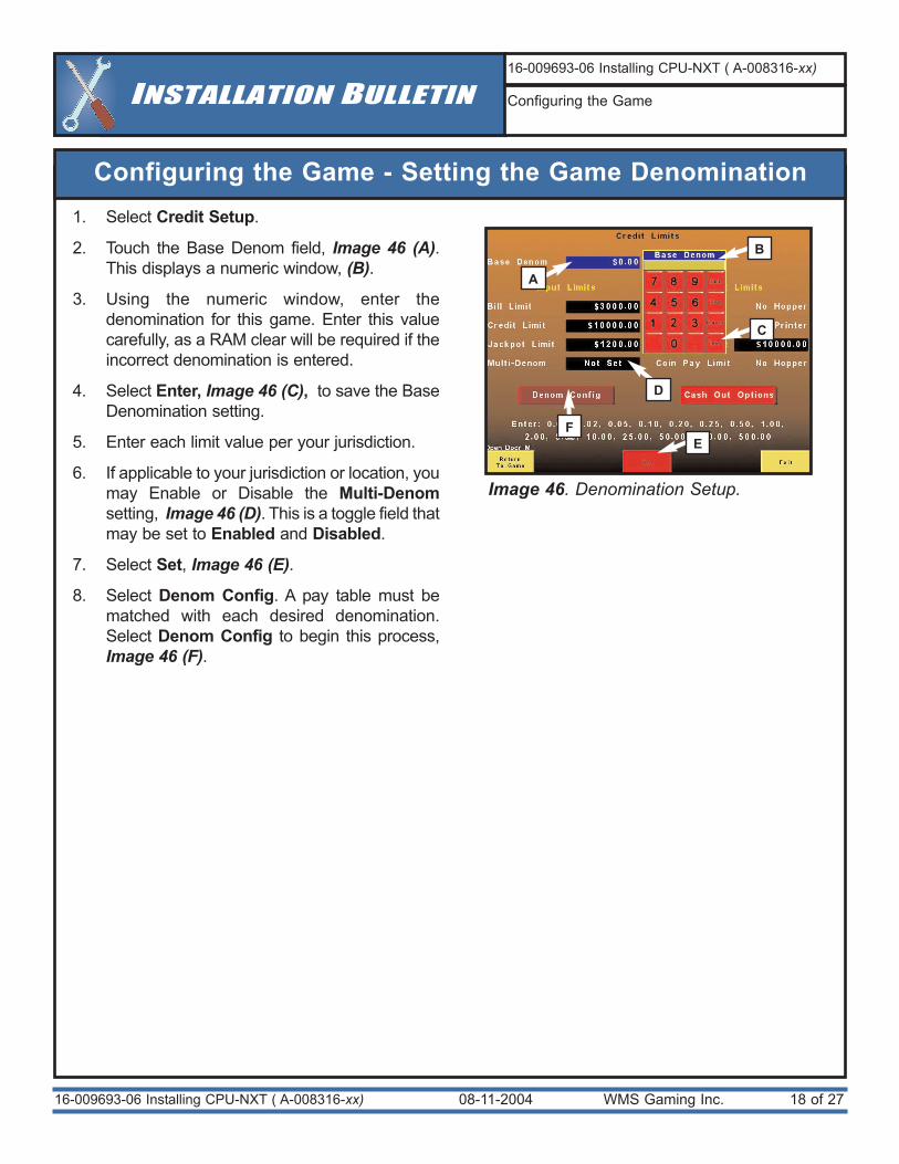
Configuring the Game - Setting the Game Denomination1. Select Credit Setup.
2. Touch the Base Denom field, Image 46 (A).This displays a numeric window, (B).
3. Using the numeric window, enter thedenomination for this game. Enter this valuecarefully, as a RAM clear will be required if theincorrect denomination is entered.
4. Select Enter, Image 46 (C), to save the BaseDenomination setting.
5. Enter each limit value per your jurisdiction.
6. If applicable to your jurisdiction or location, youmay Enable or Disable the Multi-Denomsetting, Image 46 (D). This is a toggle field thatmay be set to Enabled and Disabled.
7. Select Set, Image 46 (E).
8. Select Denom Config. A pay table must bematched with each desired denomination.Select Denom Config to begin this process,Image 46 (F).
Image 46. Denomination Setup.
A
D
F
B
C
E
Configuring the Game - Setting the Paytable(s)
08-11-2004 WMS Gaming Inc. 19 of 2716-009693-06 Installing CPU-NXT ( A-008316-xx)
INSTALLATION BULLETIN16-009693-06 Installing CPU-NXT ( A-008316-xx)
Configuring the Game
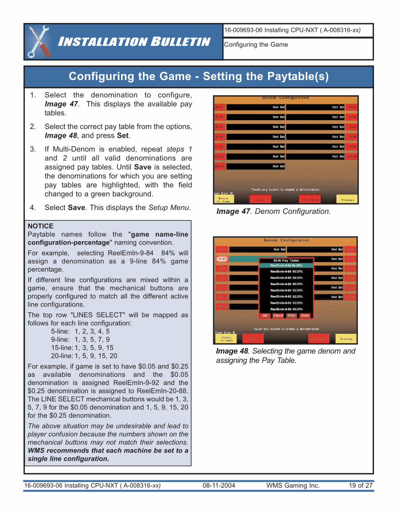
Image 47. Denom Configuration.
Image 48. Selecting the game denom andassigning the Pay Table.
1. Select the denomination to configure, Image 47. This displays the available paytables.
2. Select the correct pay table from the options,Image 48, and press Set.
3. If Multi-Denom is enabled, repeat steps 1and 2 until all valid denominations areassigned pay tables. Until Save is selected,the denominations for which you are settingpay tables are highlighted, with the fieldchanged to a green background.
4. Select Save. This displays the Setup Menu.
NOTICEPaytable names follow the "game name-lineconfiguration-percentage" naming convention. For example, selecting ReelEmIn-9-84 84% willassign a denomination as a 9-line 84% gamepercentage. If different line configurations are mixed within agame, ensure that the mechanical buttons areproperly configured to match all the different activeline configurations. The top row "LINES SELECT" will be mapped asfollows for each line configuration:
5-line: 1, 2, 3, 4, 59-line: 1, 3, 5, 7, 915-line: 1, 3, 5, 9, 1520-line: 1, 5, 9, 15, 20
For example, if game is set to have $0.05 and $0.25as available denominations and the $0.05denomination is assigned ReelEmIn-9-92 and the$0.25 denomination is assigned to ReelEmIn-20-88.The LINE SELECT mechanical buttons would be 1, 3,5, 7, 9 for the $0.05 denomination and 1, 5, 9, 15, 20for the $0.25 denomination. The above situation may be undesirable and lead toplayer confusion because the numbers shown on themechanical buttons may not match their selections.WMS recommends that each machine be set to asingle line configuration.
08-11-2004 WMS Gaming Inc. 20 of 2716-009693-06 Installing CPU-NXT ( A-008316-xx)
INSTALLATION BULLETIN16-009693-06 Installing CPU-NXT ( A-008316-xx)
Configuring the Game
Image 49. Game Setup screen.
A
B
Configuring the Game - Setting the Max Bet
Some of the Max Bet options are predeterminedbased on jurisdictional limits and restrictions. TheMax Bet options may be controlled by theJurisdictional ID (SPI) chip, which may set theavailable denominations, as well as the Max Bet.This functionality is available in OS 1.14.23(CompactFlash™ P/N SSOS-000-1200) and later.
1. Select Game Setup. This displays theGame Setup screen, Image 49.
2. Select each available denomination,Image 49 (A).
3. Select the Available Max Bet value for thedenomination, Image 49 (B).
4. If applicable, repeat steps 2 and 3 until allavailable denominations are configured.
5. Select Save and Exit. This displays theSetup Menu.
Configuring the Game - Setting Devices
Image 50. Device Config screen.
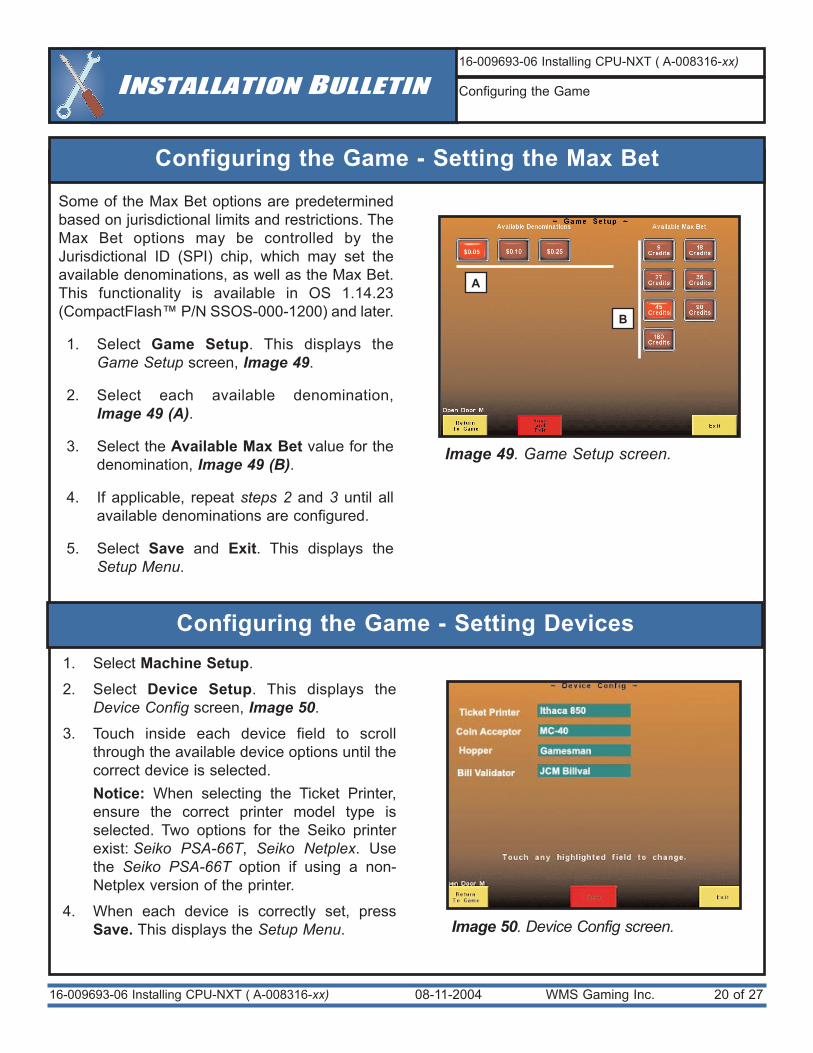
1. Select Machine Setup.
2. Select Device Setup. This displays theDevice Config screen, Image 50.
3. Touch inside each device field to scrollthrough the available device options until thecorrect device is selected. Notice: When selecting the Ticket Printer,ensure the correct printer model type isselected. Two options for the Seiko printerexist: Seiko PSA-66T, Seiko Netplex. Usethe Seiko PSA-66T option if using a non-Netplex version of the printer.
4. When each device is correctly set, pressSave. This displays the Setup Menu.
08-11-2004 WMS Gaming Inc. 21 of 2716-009693-06 Installing CPU-NXT ( A-008316-xx)
INSTALLATION BULLETIN16-009693-06 Installing CPU-NXT ( A-008316-xx)
Configuring the Game
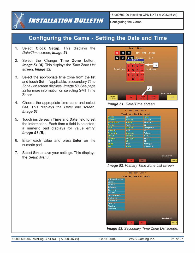
1. Select Clock Setup. This displays theDate/Time screen, Image 51.
2. Select the Change Time Zone button, Image 51 (A). This displays the Time Zone Listscreen, Image 52.
3. Select the appropriate time zone from the listand touch Set. If applicable, a secondary TimeZone List screen displays, Image 53. See page22 for more information on selecting GMT TimeZones.
4. Choose the appropriate time zone and selectSet. This displays the Date/Time screen, Image 51.
5. Touch inside each Time and Date field to setthe information. Each time a field is selected,a numeric pad displays for value entry, Image 51 (B).
6. Enter each value and press Enter on thenumeric pad.
7. Select Set to save your settings. This displaysthe Setup Menu.
Image 51. Date/Time screen.
Configuring the Game - Setting the Date and Time
A
B
Image 52. Primary Time Zone List screen.
Image 53. Secondary Time Zone List screen.
08-11-2004 WMS Gaming Inc. 22 of 27
Configuring the Game - Setting the Date and Time, cont.
16-009693-06 Installing CPU-NXT ( A-008316-xx)
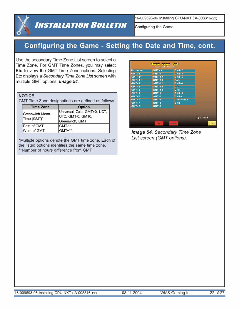
Use the secondary Time Zone List screen to select aTime Zone. For GMT Time Zones, you may selectEtc to view the GMT Time Zone options. SelectingEtc displays a Secondary Time Zone List screen withmultiple GMT options, Image 54.
INSTALLATION BULLETIN16-009693-06 Installing CPU-NXT ( A-008316-xx)
Configuring the Game
Image 54. Secondary Time ZoneList screen (GMT options).
NOTICEGMT Time Zone designations are defined as follows:
*Multiple options denote the GMT time zone. Each ofthe listed options identifies the same time zone.**Number of hours difference from GMT.
Time Zone Option
Greenwich Mean Time (GMT)*
Universal, Zulu, GMT+0, UCT, UTC, GMT-0, GMT0, Greenwich, GMT
East of GMT GMT-**West of GMT GMT+**
08-11-2004 WMS Gaming Inc. 23 of 2716-009693-06 Installing CPU-NXT ( A-008316-xx)
INSTALLATION BULLETIN16-009693-06 Installing CPU-NXT ( A-008316-xx)
Configuring the Game
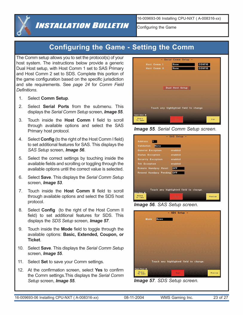
The Comm setup allows you to set the protocol(s) of yourhost system. The instructions below provide a genericDual Host setup, with Host Comm 1 set to SAS Primaryand Host Comm 2 set to SDS. Complete this portion ofthe game configuration based on the specific jurisdictionand site requirements. See page 24 for Comm FieldDefinitions.
1. Select Comm Setup.
2. Select Serial Ports from the submenu. Thisdisplays the Serial Comm Setup screen, Image 55.
3. Touch inside the Host Comm I field to scrollthrough available options and select the SASPrimary host protocol.
4. Select Config (to the right of the Host Comm I field)to set additional features for SAS. This displays theSAS Setup screen, Image 56.
5. Select the correct settings by touching inside theavailable fields and scrolling or toggling through theavailable options until the correct value is selected.
6. Select Save. This displays the Serial Comm Setupscreen, Image 53.
7. Touch inside the Host Comm II field to scrollthrough available options and select the SDS hostprotocol.
8. Select Config (to the right of the Host Comm IIfield) to set additional features for SDS. Thisdisplays the SDS Setup screen, Image 57.
9. Touch inside the Mode field to toggle through theavailable options: Basic, Extended, Coupon, orTicket.
10. Select Save. This displays the Serial Comm Setupscreen, Image 55.
11. Select Set to save your Comm settings.
12. At the confirmation screen, select Yes to confirmthe Comm settings.This displays the Serial CommSetup screen, Image 55.
Image 55. Serial Comm Setup screen.
Configuring the Game - Setting the Comm
Image 56. SAS Setup screen.
Image 57. SDS Setup screen.
08-11-2004 WMS Gaming Inc. 24 of 2716-009693-06 Installing CPU-NXT ( A-008316-xx)
INSTALLATION BULLETIN16-009693-06 Installing CPU-NXT ( A-008316-xx)
Configuring the Game
Image 58. Dual Host Setup Screen
Configuring the Game - Setting the Comm, cont.
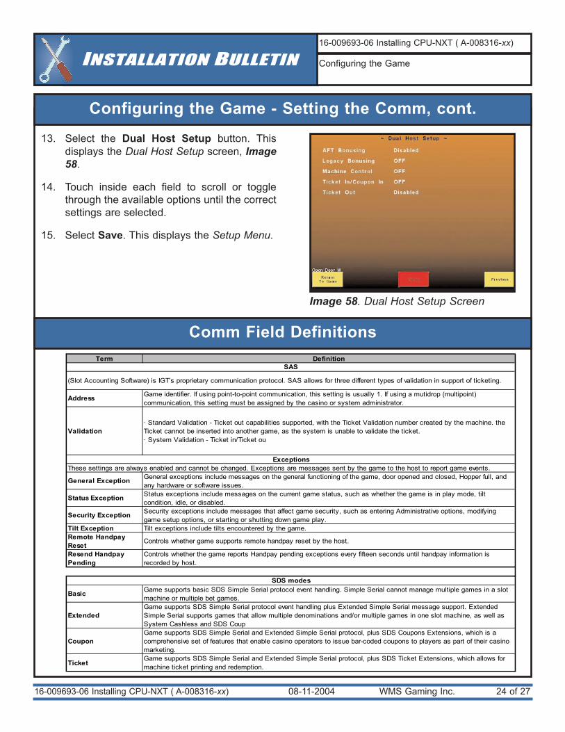
13. Select the Dual Host Setup button. Thisdisplays the Dual Host Setup screen, Image58.
14. Touch inside each field to scroll or togglethrough the available options until the correctsettings are selected.
15. Select Save. This displays the Setup Menu.
Comm Field DefinitionsTerm Definition
Address Game identifier. If using point-to-point communication, this setting is usually 1. If using a mutidrop (multipoint) communication, this setting must be assigned by the casino or system administrator.
Validation · Standard Validation - Ticket out capabilities supported, with the Ticket Validation number created by the machine. the Ticket cannot be inserted into another game, as the system is unable to validate the ticket.· System Validation - Ticket in/Ticket ou
General Exception General exceptions include messages on the general functioning of the game, door opened and closed, Hopper full, and any hardware or software issues.
Status Exception Status exceptions include messages on the current game status, such as whether the game is in play mode, tilt condition, idle, or disabled.
Security Exception Security exceptions include messages that affect game security, such as entering Administrative options, modifying game setup options, or starting or shutting down game play.
Tilt Exception Tilt exceptions include tilts encountered by the game.Remote Handpay Reset Controls whether game supports remote handpay reset by the host.
Resend Handpay Pending
Controls whether the game reports Handpay pending exceptions every fifteen seconds until handpay information is recorded by host.
Basic Game supports basic SDS Simple Serial protocol event handling. Simple Serial cannot manage multiple games in a slot machine or multiple bet games.
ExtendedGame supports SDS Simple Serial protocol event handling plus Extended Simple Serial message support. Extended Simple Serial supports games that allow multiple denominations and/or multiple games in one slot machine, as well as System Cashless and SDS Coup
CouponGame supports SDS Simple Serial and Extended Simple Serial protocol, plus SDS Coupons Extensions, which is a comprehensive set of features that enable casino operators to issue bar-coded coupons to players as part of their casino marketing.
Ticket Game supports SDS Simple Serial and Extended Simple Serial protocol, plus SDS Ticket Extensions, which allows for machine ticket printing and redemption.
SAS
SDS modes
ExceptionsThese settings are always enabled and cannot be changed. Exceptions are messages sent by the game to the host to report game events.
(Slot Accounting Software) is IGT’s proprietary communication protocol. SAS allows for three different types of validation in support of ticketing.
08-11-2004 WMS Gaming Inc. 25 of 2716-009693-06 Installing CPU-NXT ( A-008316-xx)
INSTALLATION BULLETIN16-009693-06 Installing CPU-NXT ( A-008316-xx)
Configuring the Game
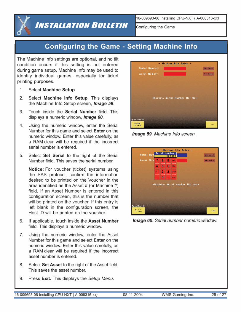
Configuring the Game - Setting Machine Info
Image 59. Machine Info screen.
Image 60. Serial number numeric window.
The Machine Info settings are optional, and no tiltcondition occurs if this setting is not enteredduring game setup. Machine Info may be used toidentify individual games, especially for ticketprinting purposes.
1. Select Machine Setup.
2. Select Machine Info Setup. This displaysthe Machine Info Setup screen, Image 59.
3. Touch inside the Serial Number field. Thisdisplays a numeric window, Image 60.
4. Using the numeric window, enter the SerialNumber for this game and select Enter on thenumeric window. Enter this value carefully, asa RAM clear will be required if the incorrectserial number is entered.
5. Select Set Serial to the right of the SerialNumber field. This saves the serial number.
Notice: For voucher (ticket) systems usingthe SAS protocol, confirm the informationdesired to be printed on the Voucher in thearea identified as the Asset # (or Machine #)field. If an Asset Number is entered in thisconfiguration screen, this is the number thatwill be printed on the voucher. If this entry isleft blank in the configuration screen, theHost ID will be printed on the voucher.
6. If applicable, touch inside the Asset Numberfield. This displays a numeric window.
7. Using the numeric window, enter the AssetNumber for this game and select Enter on thenumeric window. Enter this value carefully, asa RAM clear will be required if the incorrectasset number is entered.
8. Select Set Asset to the right of the Asset field.This saves the asset number.
9. Press Exit. This displays the Setup Menu.
08-11-2004 WMS Gaming Inc. 26 of 2716-009693-06 Installing CPU-NXT ( A-008316-xx)
INSTALLATION BULLETIN16-009693-06 Installing CPU-NXT ( A-008316-xx)
Configuring the Game
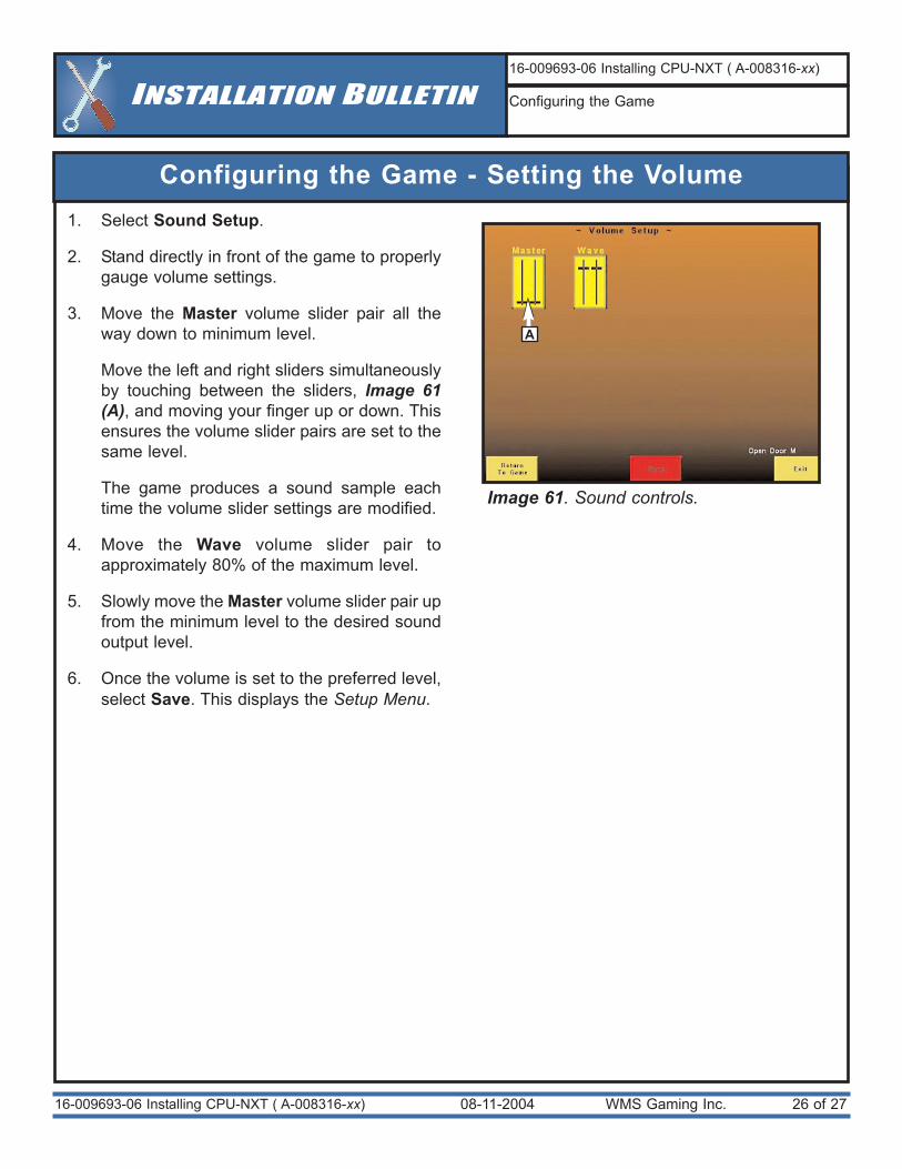
Configuring the Game - Setting the Volume1. Select Sound Setup.
2. Stand directly in front of the game to properlygauge volume settings.
3. Move the Master volume slider pair all theway down to minimum level.
Move the left and right sliders simultaneouslyby touching between the sliders, Image 61(A), and moving your finger up or down. Thisensures the volume slider pairs are set to thesame level.
The game produces a sound sample eachtime the volume slider settings are modified.
4. Move the Wave volume slider pair toapproximately 80% of the maximum level.
5. Slowly move the Master volume slider pair upfrom the minimum level to the desired soundoutput level.
6. Once the volume is set to the preferred level,select Save. This displays the Setup Menu.
Image 61. Sound controls.
A
08-11-2004 WMS Gaming Inc. 27 of 27
INSTALLATION BULLETIN16-009693-06 Installing CPU-NXT ( A-008316-xx)
Beginning Game PlaySoftware Configuration Pending Tilts
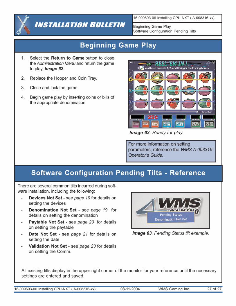
Beginning Game Play
Image 62. Ready for play.
For more information on settingparameters, reference the WMS A-008316Operator’s Guide.
1. Select the Return to Game button to closethe Administration Menu and return the gameto play, Image 62.
2. Replace the Hopper and Coin Tray.
3. Close and lock the game.
4. Begin game play by inserting coins or bills ofthe appropriate denomination
Software Configuration Pending Tilts - Reference
There are several common tilts incurred during soft-ware installation, including the following:
- Devices Not Set - see page 19 for details onsetting the devices
- Denomination Not Set - see page 19 fordetails on setting the denomination
- Paytable Not Set - see page 20 for detailson setting the paytable
- Date Not Set - see page 21 for details onsetting the date
- Validation Not Set - see page 23 for detailson setting the Comm.
Image 63. Pending Status tilt example.
All existing tilts display in the upper right corner of the monitor for your reference until the necessarysettings are entered and saved.
16-009693-06 Installing CPU-NXT ( A-008316-xx)
11-24-2003 WMS Gaming 1 of 316-010861-01 CPU-NXT Supported Peripherals & Ordering
INFORMATION BULLETINWWW.WMSGAMING.COM
LOCAL CUSTOMER SERVICE (800) 378-7741
MODEL(S) AFFECTED
UNIT AFFECTED
THEME
DISTRIBUTETO:
Legacy 550/ 3601
All
N/A
⌧ Sales⌧ Field Service⌧ Management
Legal⌧ Compliance⌧ Customers
BULLETIN #: 16-010861-01
Overview
Associated Technical BulletinsWMS recommends the cabinet upgrades outlined in the following Technical Bulletins be performed before theinstallation of CPU-NXT. Access the associated bulletins at https://secure.wms.com.
The purpose of this bulletin is to inform you of the peripherals supported by CPU-NXT, as well as to guide the ordering ofthe CPU-NXT upgrade kit and software. Please note that there are four available kits, with two for each platform, dependingon the voltage of the installation site. For the detailed steps on installing CPU-NXT, see16-009693-xx Installing CPU-NXT.For more information on WMS software part numbering, see 16-007028-xx, Software Part Numbering Conventions.
Contact your WMS Sales Representative for further information regarding NXT-specific game themes and ordering options.
CPU-NXT™(A-008316) Supported Peripherals and Conversion Kit Ordering Instructions
Required Parts for ConversionWMS Part Number Description
A-011548-00-00 Kit: CPU-NXT Upgrade (550 - 110V)A-011548-00-01 Kit: CPU-NXT Upgrade (550 - 220V)A-011548-00-02 Kit: CPU-NXT Upgrade (3601 - 110V)A-011548-00-03 Kit: CPU-NXT Upgrade (3601 - 220V)SBOT-000001-xxx CPU-NXT Boot EPROM (version xxx )SJUR-XXXXXX -xxx CPU-NXT SPI EEPROM (Jurisdiction ID Chip for jurisdiction XXXXXX , version xxx )SXXX-000-xxxxCC CPU-NXT Game Compact Flash Card (XXX theme, version xxxx , CC country/language code)SSOS-000-xxxxCC CPU-NXT OS Compact Flash Card (version xxxx , CC country/language code)SCLR-000-xxxxCC CPU-NXT RAM Clear Compact Flash Card (version xxxx , CC country/language code)
WMS Part Number Description Models Affected16-009693-03 CPU-NXT (A-008316) Installation Bulletin 55x , 3601
16-007245 Asahi Seiko Hopper Reinforced Coin Out Chute Cover Installation Bulletin
55x
16-008325-00 Asahi Seiko Hopper Bowl Probe Adjustment Installation Bulletin
55x
16-009304-01 Asahi Seiko Hopper Groundstrap Installation Bulletin 55x16-008654 Conductive Monitor Bezel Information Bulletin 55x
16-008655-01 Door Stop Bracket Installation Bulletin (Required in New Jersey)
55x
16-007995-03 ESD Components Information Bulletin 55x , 360116-009733-01 Ithaca/Transact Printer Cable Installation Bulletin 55x , 360116-007327 Main Door Locking Bar Installation Bulletin 55x16-008657 3.15 Amp Fuse Installation Bulletin 55x , 3601
11-24-2003 WMS Gaming 2 of 3
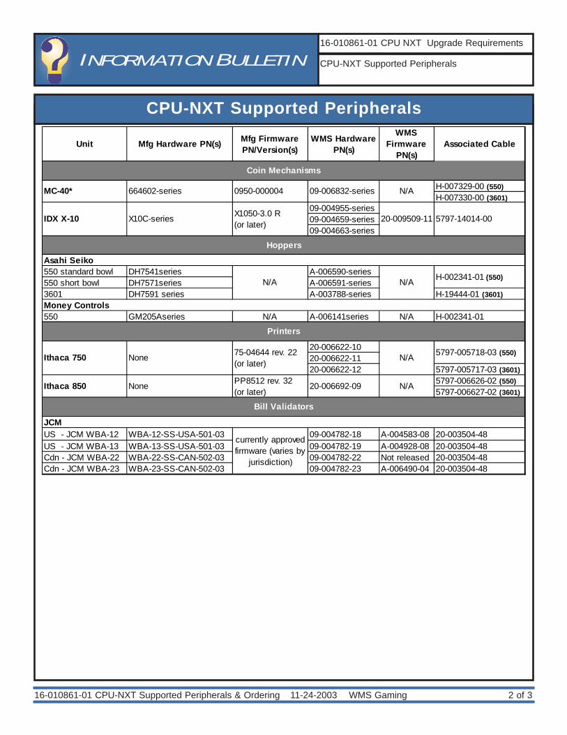
CPU-NXT Supported Peripherals
16-010861-01 CPU-NXT Supported Peripherals & Ordering
INFORMATION BULLETIN16-010861-01 CPU NXT Upgrade Requirements
CPU-NXT Supported Peripherals
Unit Mfg Hardware PN(s) Mfg Firmware PN/Version(s)
WMS Hardware PN(s)
WMS Firmware
PN(s)Associated Cable
H-007329-00 (550)H-007330-00 (3601)
09-004955-series09-004659-series09-004663-series
550 standard bowl DH7541series A-006590-series550 short bowl DH7571series A-006591-series3601 DH7591 series A-003788-series H-19444-01 (3601)
550 GM205Aseries N/A A-006141series N/A H-002341-01
20-006622-1020-006622-1120-006622-12 5797-005717-03 (3601)
5797-006626-02 (550)5797-006627-02 (3601)
US - JCM WBA-12 WBA-12-SS-USA-501-03 09-004782-18 A-004583-08 20-003504-48US - JCM WBA-13 WBA-13-SS-USA-501-03 09-004782-19 A-004928-08 20-003504-48Cdn - JCM WBA-22 WBA-22-SS-CAN-502-03 09-004782-22 Not released 20-003504-48Cdn - JCM WBA-23 WBA-23-SS-CAN-502-03 09-004782-23 A-006490-04 20-003504-48
currently approved firmware (varies by
jurisdiction)
Coin Mechanisms
MC-40* 664602-series 0950-000004 09-006832-series N/A
N/AIthaca 850 None
X1050-3.0 R(or later)
IDX X-10
NoneIthaca 750
JCM
5797-14014-0020-009509-11
H-002341-01 (550)
Bill Validators
PP8512 rev. 32 (or later)
20-006692-09
X10C-series
75-04644 rev. 22 (or later)
N/A
N/A
Hoppers
Printers
Money Controls
Asahi Seiko
5797-005718-03 (550)
N/A
11-24-2003 WMS Gaming 3 of 3
Instructions for Ordering the CPU-NXT Conversion Kit
16-010861-01 CPU-NXT Supported Peripherals & Ordering
The following instructions for ordering a CPU-NXT conversion kit correspond to the line numberson the Conversion Request Form. This form is available through your regional WMS office orthrough your Sales Representative, and includes CPU-NXT-specific steps and cabinet upgradeoptions. Please note that this form must be accompanied by the EPROM Request Form, whichis a separate document required to order software.
Enter data normally, except as indicated in the following instructions:
3. Software Information The software and the Compact Flash (CF) medium on which it is resident, is different forCPU-NXT. 3a. From the drop-down menu, select the NXT protocol. No other protocol is valid for theNXT upgrade.3b. The software for CPU-NXT is either multi-denominational or non-denominational. Fromthe drop-down menu, select M - Multi-Denom/Tokenization or Non Multi-Denom/Tokenization.
7. Coin MechOnly the IDX-X10 and MC40 coin mechanisms interface to CPU-0NXT. From the drop-downmenu, select the IDX or MC-40.
8. Printer InformationOnly the Transact/Ithaca thermal printers and Cole printer kits interface to CPU-NXT. Fromthe drop-down menu, select the size and ticket configuration of one of the following printersor printer kits:- Ithaca 750 thermal printer- Ithaca 850 thermal printer- Cole Thermal printer kit
10. Bill ValidatorNXT interfaces with several models of JCM bill validators. From the drop-down menu,select the desired WBA requirements of one the following JCM WBA models: - WBA 12 USA- WBA 13 USA- WBA 22 Canada- WBA 23 Canada
INFORMATION BULLETIN16-010861-01 CPU NXT Upgrade Requirements
Instructions for Ordering the CPU-NXT ConversionKit
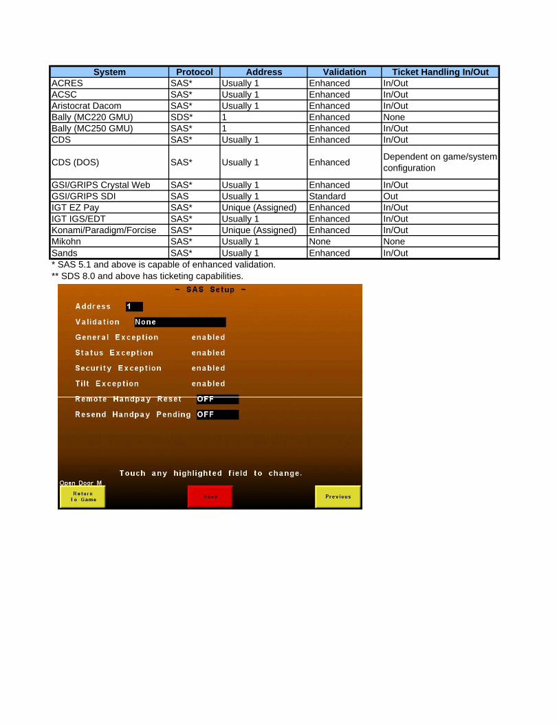
System Protocol Address Validation Ticket Handling In/OutACRES SAS* Usually 1 Enhanced In/OutACSC SAS* Usually 1 Enhanced In/OutAristocrat Dacom SAS* Usually 1 Enhanced In/OutBally (MC220 GMU) SDS* 1 Enhanced NoneBally (MC250 GMU) SAS* 1 Enhanced In/OutCDS SAS* Usually 1 Enhanced In/Out
CDS (DOS) SAS* Usually 1 Enhanced Dependent on game/system configuration
GSI/GRIPS Crystal Web SAS* Usually 1 Enhanced In/OutGSI/GRIPS SDI SAS Usually 1 Standard OutIGT EZ Pay SAS* Unique (Assigned) Enhanced In/OutIGT IGS/EDT SAS* Usually 1 Enhanced In/OutKonami/Paradigm/Forcise SAS* Unique (Assigned) Enhanced In/OutMikohn SAS* Usually 1 None NoneSands SAS* Usually 1 Enhanced In/Out* SAS 5.1 and above is capable of enhanced validation.** SDS 8.0 and above has ticketing capabilities.

January 2004 Bluebird Upright (Video) Service Manual Software Installation 2 - 9
SoftwareInstallation
S E R V I C EM A N U A L
Configuring the Game
Image 16. Game reboot completed.
Image 17. Setup Menu.
One-Time Settable ParametersSet each of the following carefully, asthese values may only be set onetime, requiring a RAM Clear to reset:
Parameter DescriptionDenomination Enter game Base DenominationMultiple Denominations Set game for Multiple DenominationsPay Table Percentage Set game Pay Table PercentageMachine Serial Number Enter game cabinet Serial NumberAsset Number Enter asset number for machineTicket Printer Enable & Type Enter Ticket Printer modelCoin Acceptor Enable & Type Enter Coin Acceptor modelHopper Enable & Type Enter Hopper modelBill Validator Enable & Type Enter Bill Validator modelHost Comm None, SAS Primary or SAS SecondaryRemote Hand Pay Reset Off, Enabled or DisabledRemote Hand Pay Pending Off, Enabled or DisabledLegacy Bonusing Off, Enabled or Disabled
1. After the game reboots, Image 16, pressthe DIAGNOSTIC button. This displaysthe Administration Menu.
Upon rebooting, if the monitor does notdisplay correctly, the incorrect MonitorConfig option was selected. To change thissetting, repeat the RAM Clear procedureon page 2-6.
2. Select Setup. This displays the SetupMenu, Image 17.
3. The settings that must be configured afterinstalling software are available from theSetup Menu.
CAUTIONDo not press the DIAGNOSTIC button untilthe game reboot is complete.
!