INSTALLATION AND OWNERS MANUAL LG AIR-COOLED ...
83
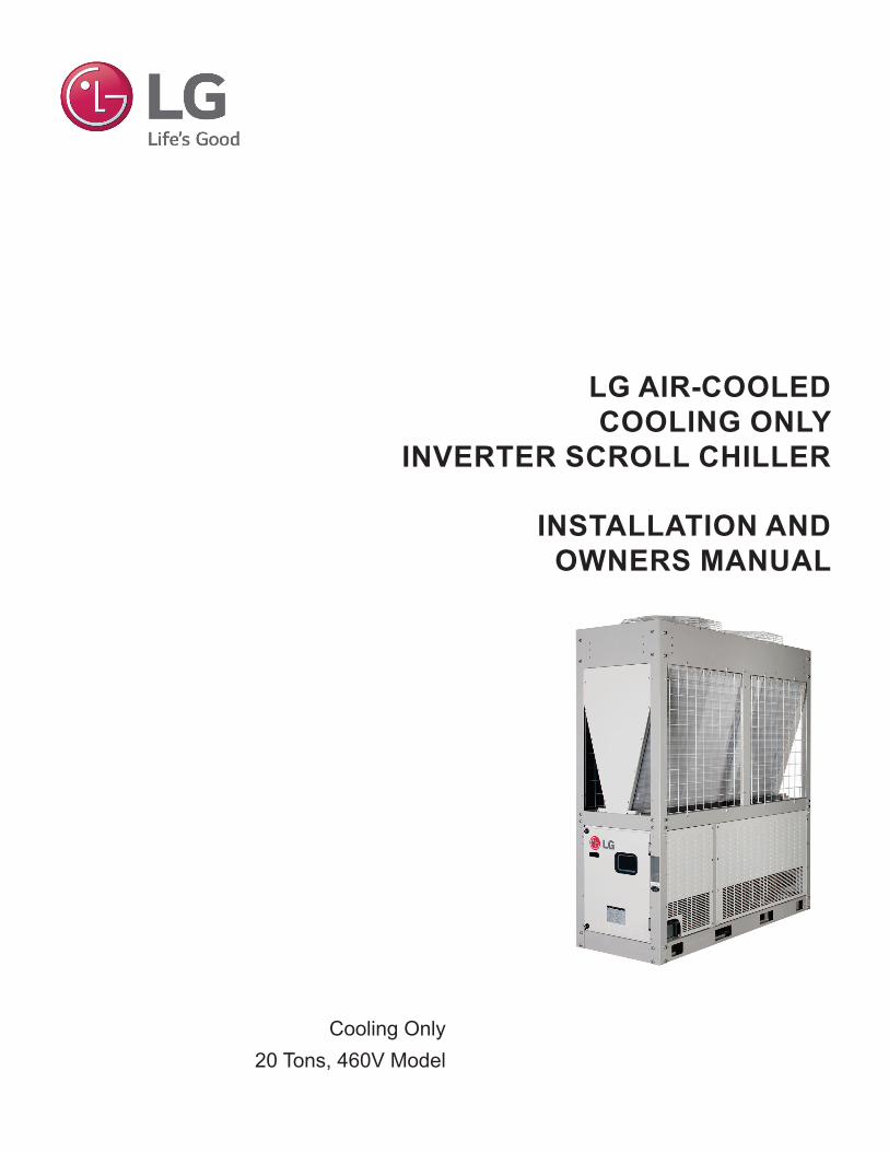
INSTALLATION AND OWNERS MANUAL LG AIR-COOLED COOLING ONLY INVERTER SCROLL CHILLER Cooling Only 20 Tons, 460V Model
-
Upload
khangminh22 -
Category
Documents
-
view
0 -
download
0
Transcript of INSTALLATION AND OWNERS MANUAL LG AIR-COOLED ...
INSTALLATION AND OWNERS MANUAL
LG AIR-COOLED COOLING ONLY
INVERTER SCROLL CHILLER
Cooling Only20 Tons, 460V Model

For continual product development, LG Electronics U.S.A., Inc. reserves the right to change specifications without notice. © LG Electronics U.S.A., Inc.
PROPRIETARY DATA NOTICE
For more technical materials such as submittals, catalogs, engineering, owner’s, best practices, and service manuals, visit www.lghvac.com.
Do not throw away, destroy, or lose this manual. Please read carefully and store in a safe place for future reference.
Content familiarity is required for proper installation.
The instructions included in this manual must be followed to prevent product malfunction, property damage, injury, or death to the user or other people. Incorrect operation due to ignoring any instructions will cause harm or damage. The level of seriousness is classified by the symbols described by the summary list of safety precautions on page 4.
This document, as well as all reports, illustrations, data, information, and other materials are the property of LG Electronics U.S.A., Inc., and are
disclosed by LG Electronics U.S.A., Inc. only in confidence.
3Due to our policy of continuous product innovation, some specifications may change without notification. ©LG Electronics U.S.A., Inc., Englewood Cliffs, NJ. All rights reserved. “LG” is a registered trademark of LG Corp.
TABLE OF CONTENTS
Safety Precautions ...................................................................................................................................................................................................... 4-7
Unit Nomenclature .......................................................................................................................................................................................................... 8
Introduction ................................................................................................................................................................................................................ 9-10
............................................................................................................................................................................................................... 11
Electrical Data ............................................................................................................................................................................................................... 12
Dimensions ................................................................................................................................................................................................................... 13
Refrigerant Piping ........................................................................................................................................................................................................ 14
Sensor Diagram ............................................................................................................................................................................................................ 14
Operation Range, Limit ................................................................................................................................................................................................ 14
Installation to Test Run Flowchart .............................................................................................................................................................................. 15
Placement Considerations ..................................................................................................................................................................................... 16-20
Transporting / Lifting ................................................................................................................................................................................................... 21
Storing Chiller / Installing Anti-Vibration, Anchor Bolts ........................................................................................................................................... 22
Water Pipe System / Piping .................................................................................................................................................................................... 23-25
Freezing Precautions ................................................................................................................................................................................................... 26
Water Pipe Installation / Pump Control ...................................................................................................................................................................... 27
Water Quality Management.......................................................................................................................................................................................... 27
........................................................................................................................................................................................ 28
Button Locations and Functions ............................................................................................................................................................................... 29
Optional Settings .......................................................................................................................................................................................................... 30
Chiller Address Settings .............................................................................................................................................................................................. 31
HMI Screens ............................................................................................................................................................................................................. 32-55
Electrical ................................................................................................................................................................................................................... 56-63
Modbus Protocol .......................................................................................................................................................................................................... 64
Modbus Protocol Registers .................................................................................................................................................................................... 65-69
Test Run ................................................................................................................................................................................................................... 70-72
Troubleshooting General Errors ............................................................................................................................................................................ 76-77
Error Code Tables .................................................................................................................................................................................................... 78-80
Checklist for Chiller Installation ............................................................................................................................................................................. 81-82

4
LG A
ir-Co
oled
Coo
ling
Onl
y In
verte
r Scr
oll C
hille
r Ins
talla
tion
and
Ow
ners
Man
ual
Due to our policy of continuous product innovation, some specifications may change without notification. ©LG Electronics U.S.A., Inc., Englewood Cliffs, NJ. All rights reserved. “LG” is a registered trademark of LG Corp.
TABLE OF SYMBOLSDANGER This symbol indicates an imminently hazardous situation which, if not avoided, will result in death or serious injury.
WARNING This symbol indicates a potentially hazardous situation which, if not avoided, could result in death or serious injury.
CAUTION This symbol indicates a potentially hazardous situation which, if not avoided, may result in minor or moderate injury.
This symbol indicates situations that may result in equipment or property damage accidents only.
This symbol indicates an action that should not be performed.
The instructions below must be followed to prevent product malfunction, property damage, injury or death to the user or other people. Incor-rect operation due to ignoring any instructions will cause harm or damage. The level of seriousness is classified by the symbols described below.
SAFETY PRECAUTIONS
Do not allow the end user to install or remove the chiller. The dealer or a trained technician must install the chiller.
injury or death.
The information contained in this manual is intended for use by an LG trained service technician.
For replacement of an installed unit, always contact an LG trained service provider.
Wear protective gloves when handling equipment. Sharp edges will cause personal injury.
Do not change the settings of the protection devices.If the protection devices have been bypassed or are forced to operate
Replace all control box and panel covers.If cover panels are not securely installed, dust, water, and animals will
death.
Always check for system refrigerant leaks after the unit has been installed or serviced.
illness or death.
If the chiller is installed in a small space, take measures to prevent the refrigerant concentration from exceeding safety limits in the event of a refrigerant leak.Consult the latest edition of American Society of Heating, Refrigerating, and Air Conditioning Engineers (ASHRAE) Standard 15. If the refrigerant
Dispose of the packing materials safely.•
will cause puncture wounds or other injuries.•
suffocation and death.
Install the chiller in a safe location where nobody can step on, fall onto it, or place objects on it. It will result in an accident that causes physical injury or death.
When installing or if moving the chiller to another site, do
the refrigerant cycle may malfunction and the product may be damaged.
INSTALLATIONDANGER
the chiller.
Do not install the chiller in an environment with oil, steam, sulfuric smoke, etc.
Do not supply power to the chiller until all wiring and piping are completed or reconnected and checked.
WARNING

5
Safety Precautions
Due to our policy of continuous product innovation, some specifications may change without notification. ©LG Electronics U.S.A., Inc., Englewood Cliffs, NJ. All rights reserved. “LG” is a registered trademark of LG Corp.
SAFETY PRECAUTIONS
Be very careful when transporting the product. There is a risk of the product falling and causing physical injury.•
capable of supporting the weights listed.• Do not use polypropylene bands to lift the unit. • Support the chiller at specified positions to avoid slipping out of the rigging apparatus. Ensure that the load of the chiller is evenly distribut-
ed and level during the move.•
The Limited Warranty will be null and void, and LG Electron-ics will not be responsible and will have no liability to any customer or third party to the extent any of the following oc-cur: acts, omissions, and conduct of any and all third parties including, but not limited to, the installing contractor and any repairs, service or maintenance by unauthorized or unquali-
The information contained in the manual is intended for use by
and equipped with the proper tools and test instruments.Failure to carefully read and follow all instructions in this manual can result in equipment malfunction, and / or property damage.
Do not install the chiller where it is exposed directly to ocean winds.Sea salt in the air will cause the product to corrode. Corrosion, par-
Do not install the chiller where there is an obstruction immediately above the unit. See installation clearances in this manual.
discharge air, where it can be re-circulated into the condenser coil inlet, causing operation malfunction.
Properly install and insulate the drain piping to ensure water is drained away properly.
condition and / or water damage.
Always check for system refrigerant leaks after the unit has been installed or serviced.
Do not make refrigerant substitutions. Use only the refrig-
unit will malfunction and damage will occur.
unit.
Do not install the chiller in an environment with oil, steam, sulfuric smoke, etc.
damage.
Do not use the chiller for mission critical or special pur-pose applications such as preserving foods, works of art, or other precision air conditioning applications. The equipment is designed to provide comfort cooling and heating.
When installing the chiller near a hospital, mechanical room,
Inverter equipment, power generators, high-frequency medical equip-ment or radio communication equipment will cause the chiller to operate improperly. The chiller will also affect such equipment by creating electri-cal noise that disturbs medical treatment or image broadcasting.
product damage and malfunction.
When connecting refrigerant piping, remember to allow for pipe expansion.Improper piping installation will cause system malfunction.
Do not install the chiller in a noise-sensitive area, or where hot air could damage surrounding structures.
Install the chiller in a safe location where no one can step on or fall onto it. Do not install the unit on a defective stand.
Install the drain hose to ensure adequate drainage.
CAUTION
WARNINGProperly install and insulate the drain piping to ensure water is drained away properly.
Install the unit considering the potential for strong winds or earthquakes.Improper installation will cause the unit to fall over, resulting in physical injury or death.

6
LG A
ir-Co
oled
Coo
ling
Onl
y In
verte
r Scr
oll C
hille
r Ins
talla
tion
and
Ow
ners
Man
ual
Due to our policy of continuous product innovation, some specifications may change without notification. ©LG Electronics U.S.A., Inc., Englewood Cliffs, NJ. All rights reserved. “LG” is a registered trademark of LG Corp.
SAFETY PRECAUTIONS
Do not supply power to the unit until all electrical wiring, controls wiring, piping installation, and refrigerant system evacuation are completed.The system will malfunction.
The information contained in this manual is intended for use
familiar with the NEC who is equipped with the proper tools and test instruments.Failure to carefully read and follow all instructions in this manual can result in equipment malfunction and property damage.
The information contained in this manual is intended for use
familiar with the NEC who is equipped with the proper tools and test instruments.Failure to carefully read and follow all instructions in this manual can result in personal injury or death.
-formed by a licensed electrician and conform to local building codes or, in the absence of local codes, with the NEC, and the instructions and wiring diagrams given in this manual.
death.
Refer to local, state, and federal codes, and use power wires
injury or death.
strain relief.Improperly securing wires will create undue stress on equipment power
and physical injury or death.
Ensure the system is connected to a dedicated power source that provides adequate power.
death.
Properly tighten all power connections.
injury or death.
Do not change the settings of the protection devices.If the protection devices have been bypassed or is forced to operate
WIRING
High voltage electricity is required to operate chiller. Adhere -
tions when wiring. Improper connections and inadequate grounding can cause accidental injury or death.
Always ground the unit following local, state, and NEC codes.
Do not supply power to the unit until all electrical wiring, controls wiring, piping installation, and refrigerant system evacuation are completed.
Properly size all circuit breakers, fuses and power wiring.
the electrical components are too small.
Do not share the electrical circuit with other devices. En-
heat generation.
Do not use damaged or loose power wiring. Do not modify or extend the chiller’s power wiring. Ensure that the power wiring will not be pulled nor weight be placed on the power wiring during operation.
DANGER
WARNING

7
Safety Precautions
Due to our policy of continuous product innovation, some specifications may change without notification. ©LG Electronics U.S.A., Inc., Englewood Cliffs, NJ. All rights reserved. “LG” is a registered trademark of LG Corp.
SAFETY PRECAUTIONS
Do not allow water, dirt, or animals to enter the unit.
moving parts.The rotating, hot, cold, and high-voltage parts of the unit can cause physical injury or death.
Do not touch the refrigerant piping during or after operation, or when checking the valves.It can cause burns or frostbite.
Do not insert hands or other objects in the air inlets or outlets while power is supplied to the chiller.Chiller has sharp and moving parts that will cause physical injury.
-tion. Follow industry standards and local, state, and federal when choosing and handling an antifreeze additive.If the water circuit freezes, the piping may burst and cause physical injury or death.
OPERATION
Service on this equipment is to be performed by an indus-
operation, routine checks, maintenance, cleaning, safety hazards, and troubleshooting procedures.Failure to follow all instructions can result in personal injury or death.
Do not allow unauthorized personnel to operate, clean, -
trained personnel away from the chiller.
or submerged.
Use a dedicated breaker for this product.
Do not operate the disconnect switch with wet hands.
Periodically verify that the equipment mounts nor the instal-lation area have not deteriorated.If the mounts or area collapse, the chiller could fall and cause physical injury or death.
-es.
If refrigerant leaks, ventilate the area before operating the unit.If the chiller is mounted in an enclosed, low-lying, or poorly ventilated
To avoid physical injury, use caution when cleaning or servicing the chiller.
Service on this equipment is to be performed by an indus-
operation, routine checks, maintenance, cleaning, safety hazards, and troubleshooting procedures.Failure to follow all instructions can result in product malfunction.
no metal scraps, screws, or bits of wiring have been left inside or surrounding the chiller.
Do not use the product for mission critical or special pur-pose applications such as preserving food, works of art, or other precision air conditioning applications. The equipment is designed to provide comfort cooling and heating.
Do not allow water, dirt, or animals to enter the unit.
moving parts.Non-secured covers can result in malfunction due to dust or water.
-ation begins.Starting operation immediately after turning on the main power switch will result in severe damage to internal components. Keep the power switch on during the operational season.
operation has been stopped.
otherwise it will result in product malfunction and / or damage.If re-operating the chiller after it has been in low temperature condition for an extended period, the touch function tem-porarily may not work. Wait, and after time, the product will function normally.
Do not block the inlet or outlet.Chiller will malfunction.
-tion. Follow industry standards and local, state, and federal when choosing and handling an antifreeze additive.If the water circuit freezes, it can cause product damage. Also, an improper antifreeze additive can damage copper piping.
DANGER
WARNING
CAUTION

8
LG A
ir-Co
oled
Coo
ling
Onl
y In
verte
r Scr
oll C
hille
r Ins
talla
tion
and
Ow
ners
Man
ual
Due to our policy of continuous product innovation, some specifications may change without notification. ©LG Electronics U.S.A., Inc., Englewood Cliffs, NJ. All rights reserved. “LG” is a registered trademark of LG Corp.
UNIT NOMENCLATURE
AC A 020H H T
EvaporatorT = Direct Exchange Type (DX) Type (Shell and Tube)
Power Specifications :H = 460V / 60 Hz / 3Ø
Capacity (RT)020 = 20 RT
Compressor TypeR = Low Pressure Scroll H = High Pressure Scroll
Cooling TypeA = Air Cooled, Cooling OnlyW = Water Cooled, Cooling OnlyH = Air Cooled, Heat PumpK = Water Cooled, Heat Pump
FamilyAC = R410A / Chiller
E
Product TypeE = Independent Model
B
Generation
9
Product Data
Due to our policy of continuous product innovation, some specifications may change without notification. ©LG Electronics U.S.A., Inc., Englewood Cliffs, NJ. All rights reserved. “LG” is a registered trademark of LG Corp.
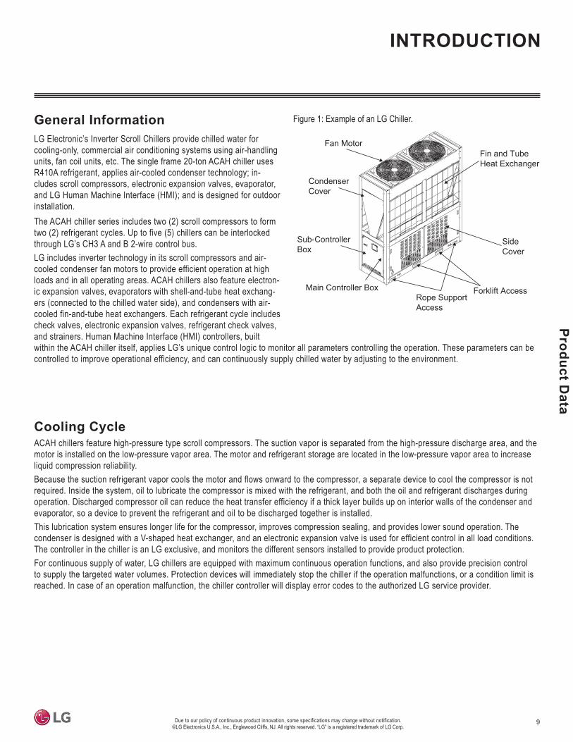
General InformationLG Electronic’s Inverter Scroll Chillers provide chilled water for cooling-only, commercial air conditioning systems using air-handling units, fan coil units, etc. The single frame 20-ton ACAH chiller uses R410A refrigerant, applies air-cooled condenser technology; in-cludes scroll compressors, electronic expansion valves, evaporator, and LG Human Machine Interface (HMI); and is designed for outdoor installation. The ACAH chiller series includes two (2) scroll compressors to form two (2) refrigerant cycles. Up to five (5) chillers can be interlocked through LG’s CH3 A and B 2-wire control bus. LG includes inverter technology in its scroll compressors and air-cooled condenser fan motors to provide efficient operation at high loads and in all operating areas. ACAH chillers also feature electron-ic expansion valves, evaporators with shell-and-tube heat exchang-ers (connected to the chilled water side), and condensers with air-cooled fin-and-tube heat exchangers. Each refrigerant cycle includes check valves, electronic expansion valves, refrigerant check valves, and strainers. Human Machine Interface (HMI) controllers, built within the ACAH chiller itself, applies LG’s unique control logic to monitor all parameters controlling the operation. These parameters can be controlled to improve operational efficiency, and can continuously supply chilled water by adjusting to the environment.
Cooling CycleACAH chillers feature high-pressure type scroll compressors. The suction vapor is separated from the high-pressure discharge area, and the motor is installed on the low-pressure vapor area. The motor and refrigerant storage are located in the low-pressure vapor area to increase liquid compression reliability.Because the suction refrigerant vapor cools the motor and flows onward to the compressor, a separate device to cool the compressor is not required. Inside the system, oil to lubricate the compressor is mixed with the refrigerant, and both the oil and refrigerant discharges during operation. Discharged compressor oil can reduce the heat transfer efficiency if a thick layer builds up on interior walls of the condenser and evaporator, so a device to prevent the refrigerant and oil to be discharged together is installed. This lubrication system ensures longer life for the compressor, improves compression sealing, and provides lower sound operation. The condenser is designed with a V-shaped heat exchanger, and an electronic expansion valve is used for efficient control in all load conditions. The controller in the chiller is an LG exclusive, and monitors the different sensors installed to provide product protection.For continuous supply of water, LG chillers are equipped with maximum continuous operation functions, and also provide precision control to supply the targeted water volumes. Protection devices will immediately stop the chiller if the operation malfunctions, or a condition limit is reached. In case of an operation malfunction, the chiller controller will display error codes to the authorized LG service provider.
Figure 1: Example of an LG Chiller.
Fan Motor Fin and Tube Heat Exchanger
Main Controller Box
Sub-ControllerBox
Condenser Cover
Side Cover
Rope Support Access
Forklift Access
INTRODUCTION

10
LG A
ir-Co
oled
Coo
ling
Onl
y In
verte
r Scr
oll C
hille
r Ins
talla
tion
and
Ow
ners
Man
ual
Due to our policy of continuous product innovation, some specifications may change without notification. ©LG Electronics U.S.A., Inc., Englewood Cliffs, NJ. All rights reserved. “LG” is a registered trademark of LG Corp.
Partial Load OperationEach cooling cycle operates independently; one (1) cooling cycle includes two (2) inverter compressors as shown in the diagram. Two (2) inverter compressors increase the rpm after initial start to gradually increase the cooling capacity. The user can operate the chiller smoothly, at optimal conditions, by setting the cooling capac-ity based on the linear control of LG chiller controller. LG chillers have efficient partial load performance at any load.
Cooling Cycle DescriptionThe cooling cycle of ACAH series can be described using the following pressure–enthalpy chart. , , , , and in the following chart shows the conditions of the refrigerant. The refrigerant comes into the compressor motor and cools the motor, and becomes overheated and moves to the suction inlet of the compressor. The oil inside the compressor seals the gap between the compressor scrolls and provides lubrication for the bearing to help the compression of the refrigerant. During this time, the refrig-erant is compressed and is discharged to the air cooled condenser. ( The compressed refrigerant passes through the air cooled condenser and exchanges the heat with the outdoor air. The condensed refrigerant then passes the condenser to be overcooled. ( ). The refrigerant that passed through the condenser expands in the electronic expansion valve to flow to the evaporator. ( ). The refrigerant is evaporated in the shell and tube type heat exchanger, the evaporator. ( ). Liquid refrigerant of low temperature pressure passes through the evaporator to cool the water flowing into the evaporator and the refrigerant itself receives the heat to evaporate to gas condition. ( ) The refrigerant continues to change the phase and continuously repeats the cooling cycle.
1 rosserpmoc deeps citatSyticapac gnilooCLoad (%)25% 50% 75% 100%
50%
25%
75%
100%
0%
Inverter Compressor 1
Inverter Compressor 2
Cooling Capacity
Capacity (%)
Lubrication SystemOil is efficiently separated inside the scroll compressor, and even when the cycle operates, most of the oil remains inside. Only a part of the oil will mix with the refrigerant to be circulated within the cycle.
Figure 3: Partial Load Operation Diagram.
Pressure
Enthalpy
Hot-Gas
Suction - Compressor
Figure 2: LG Chiller Pressure-Enthalpy Diagram.
INTRODUCTION

11
Product Data
Due to our policy of continuous product innovation, some specifications may change without notification. ©LG Electronics U.S.A., Inc., Englewood Cliffs, NJ. All rights reserved. “LG” is a registered trademark of LG Corp.
SPECIFICATIONS
Table 1:
Inverter Scroll ChillerModel No. ACAH020HETBType Cooling OnlyConfiguration Single
Power V, Lines, Phase 460, 3, 3
Capacity Btu/h 221,780Refrig. Ton 18.5
Input Power kW 21.5Efficiency Btu/Wh 10.32IPLV Btu/Wh 17.06Sound Pressure dB(A) 64CompressorType x No. Inverter Scroll x 2Oil Type PVEOil Charge cc 1,400 Each CircuitSump Heater W 60 Each CircuitRefrigerantType R410AFactory Charge lbs. 14.3 x 2EvaporatorType Shell and TubePressure drop psi 5.6Operating Max. Pressure (Refrigerant / Water) psi 609 / 145Water Flow Rate (Standard) gpm 49Water Flow Rate (Min. / Max.) gpm 34 / 64Water Pipe (Inlet / Outlet Dia.) Inch 2 / 2Fan MotorType Brushless Digitally ControlledNo. of Fans Each 2No. of Vanes (per Fan) Each 6Air Flow Rate cfm 8,687 x 2 @1,000 rpmMotor Power W 900 x 2OtherExpansion Unit Electronic Expansion ValveWeight lbs. 1,235Dimensions (W x H x D) Inch 30-1/8 x 86-5/8 x 84-13/16Footprint ft2 / RT 0.958High / Low Pressure Protection DeviceAnti-frost Protection DeviceRemote Control Modbus®
Outlet Temperature °F 39.2 ~ 68Ambient Air Temperature °F 5 ~ 118.4Load Capacity Range 20% ~ 100%
Capacities and Inputs are based on the following conditions: Cooling: Outdoor Air Temp. 95ºF, Water Inlet Temp. 54ºF, Water Outlet Temp. 44ºFTo choose the correct chiller for the application, use the LATS ISC Selection Software. (For the latest version of LATS ISC Software, go to www.ahridirectory.org.)Modbus® is a registered trademark of Schneider Electric USA, Inc.

12
LG A
ir-Co
oled
Coo
ling
Onl
y In
verte
r Scr
oll C
hille
r Ins
talla
tion
and
Ow
ners
Man
ual
Due to our policy of continuous product innovation, some specifications may change without notification. ©LG Electronics U.S.A., Inc., Englewood Cliffs, NJ. All rights reserved. “LG” is a registered trademark of LG Corp.
ELECTRICAL DATA
Tons Model No. Voltage Frequency (Hz)
Voltage Tolerance (Min. ~ Max.) MCA MFA Compressor Chiller Fan
Motor Input PowerMSC RLA kW FLA kW
20 ACAH020HETB 460 60 414 ~ 506 31 40 9.7 24.9 1.8 5 21.5
Table 2: Electrical Data for Single 460V Cooling Only Chiller.
Voltage Range: Power supplied to the chiller must fall within the voltage minimum to maximum range listed in the table above. The chiller will not operate normally if the power supply voltage falls below or above the tolerance range.Maximum allowable voltage variance permitted between phases is 2%.
MCA: Minimum Circuit Ampacity (A) (Criteria used to select the wiring standard).MFA: Maximum Fuse Amps (A) (Criteria used to select circuit breaker and ground error circuit breaker [electricity leakage circuit breaker]).MSC: Maximum Start Current (A)RLA: Rated Load Amps (A) (Current required when operating under the following conditions—Cooling: Outdoor Air Temperature: 8°1F DB / 66°F WB; Water Inlet / Outlet Temperature: 54°F / 44°F).FLA: Full Load Amps (A).

13
Product Data
Due to our policy of continuous product innovation, some specifications may change without notification. ©LG Electronics U.S.A., Inc., Englewood Cliffs, NJ. All rights reserved. “LG” is a registered trademark of LG Corp.
DIMENSIONS
Figure 4: Dimensions for Single 460V Cooling Only Chiller..
DB
C
A
EF
G
Water Outlet(2 inches [50 A])
Water Inlet(2 inches [50 A])
Front
B k
Side
(Unit: Inch)
Label Dimensions
30-1/8
86-17/32
86-5/8
84-13/16
19-31/32
27-9/16
15-1/8

14
LG A
ir-Co
oled
Coo
ling
Onl
y In
verte
r Scr
oll C
hille
r Ins
talla
tion
and
Ow
ners
Man
ual
Due to our policy of continuous product innovation, some specifications may change without notification. ©LG Electronics U.S.A., Inc., Englewood Cliffs, NJ. All rights reserved. “LG” is a registered trademark of LG Corp.
OperationRange
Cold Water InletTemperature 46.4°F or above
Cold Water OutletTemperature 39.2°F to 68°F
OutdoorTemperature 5°F to 118.4°F
OPERATION RANGE AND LIMIT
Figure 6: Single Chiller Refrigerant Piping and Sensor Location Diagram (ACAH020HETB).
M
S
CoolingRefrigerant
Fan Motor
Pressure Sensor
Pressure Switch
Solenoid Valve
Check Valve
Strainer
Electronic Expansion Valve
Expansion Valve
Flow Switch
Temperature Sensor
Compressor2
Air cooledcondenser
Air cooledcondenser
Oilseparator
OilSeparator
Sub-cooler
Water-out Water-in
Accumulator AccumulatorCompressor1
Sub-cooler
Operation Range and LimitThe table and the diagram shows the operation range of the product.
the chiller.
Refrigerant Piping and Sensor Diagram
Figure 5: Cooling Mode Operation Range Diagram.
-4°F 14° 32°F 50°F 68°F 86°F 104°F 122°F Outdoor Temperature
50°F
59°F
68°F
77°F
41°F
Water Temperature
118.4°F
46.4°F
Outlet Water Temperature
Inlet Water Temperature
• in cooling mode. If this is the case, increase the inlet temperature by circulating the load water, and then operate in cooling.
• Add antifreeze if the chiller is to operate in ambient air temperatures below 41°F (the water in the pipes could freeze).
Table 3: Operation Range and Limit Table.

15
Installation
Start
Delivery andInstallation
Test Operation
Instruction and installation of base following IOM and all applicable codes
Delivery and Installation
Wiring and Piping
Set Control Address
Check before Initial Start
Check During and After Initial Start
Stop
Load Operation and Operation Adjustment
Prepare Operation Data
Analyze Water Quality
Guide Operation
End
Lorem ipsum
INSTALLATION TO TEST RUN FLOWCHART
Figure 7: Installation to Test Run Flowchart.

16
LG A
ir-Co
oled
Coo
ling
Onl
y In
verte
r Scr
oll C
hille
r Ins
talla
tion
and
Ow
ners
’ Man
ual
PLACEMENT CONSIDERATIONS
Selecting the Best Location for the Chiller DANGER
• •
injury or death.•
pipes). These conditions could cause a fire, resulting in bodily injury or death.•
injury or death.•
• location is insufficient, the chiller could fall, causing physical injury or death.
WARNINGInstall a fence or barricade around the chiller to prevent animals and / or unauthorized individuals from accessing it. Install a boundary or danger sign
Do’sSelect a location for installing the chiller that meets the following conditions:• Where it is flat and there is enough strength to support the weight of and vibration from the chiller.• In an area that allows for optimum airflow at both inlet and outlet sides; enough space for wiring, and piping; and is easily accessible for
installation, inspection, maintenance, and service.• If the chiller is installed in a highly humid environment (near an ocean, lake, etc.), ensure the site is well-ventilated with a lot of natural light
(Example: Install on a rooftop).• If the chiller is not going to operate during winter, add antifreeze to the water supply.
Do Not’s•
• Do not install the chiller in an area where high-frequency electrical noise / electromagnetic waves will impact operation. • Do not install the chiller in an area where its operating sound will disturb inhabitants of surrounding buildings.•
side of the chiller.

17
Installation
Oceanside Installation Precautions• Avoid installing the chiller where it would be directly exposed to ocean winds.• Install the chiller on the side of the building opposite from direct ocean winds (so the building can block the winds).• Select a location with good drainage.
performance.
If the chiller must be placed in a location where it would be subjected to direct ocean winds, install a concrete (or similar material) windbreaker. The windbreaker wall height and width must be at least one and a half (1-1/2) times larger than the chiller, and must provide at least 40 inches clearance to allow for airflow.
Ocean Winds
Wall
Ocean WindsOcean Winds
PLACEMENT CONSIDERATIONS

18
LG A
ir-Co
oled
Coo
ling
Onl
y In
verte
r Scr
oll C
hille
r Ins
talla
tion
and
Ow
ners
’ Man
ual
PLACEMENT CONSIDERATIONS
Clearance RequirementsFollow the ventilation (suction and discharge air flow) and service requirements as shown below and on the next page when choosing a chiller installation area.
Installing Near One Wall• If one side of the chiller is near a wall, and the height of the wall is
less than 32 inches, the clearance space between the chiller and the wall must be a minimum of 32 inches.
• If one side of the chiller is near a wall, and the height of the wall is greater than 32 inches, the clearance space between the chiller and the wall must be a minimum of 32 inches plus half of h1 (differ-ence between 32 inches and the total wall height).
Installing Under a Ceiling• If the chiller is installed under a ceiling, the clearance space
between the top of the chiller and the ceiling must be a minimum of 197 inches.
• If the front or back of the chiller is near a wall, the clearance space between the chiller and the wall must be a minimum of 32 inches.
Ventilation Clearance RequirementsAir-cooled chillers must be installed in an open space or must have appropriate ventilation. If the chiller must be installed near one wall or under a ceiling, there must be enough space for ventilation.
Figure 8: Ventilation Clearance Requirements When Installing the Chiller Along One Wall.
Figure 9: Ventilation Clearance Requirements When Installing the Chiller Under a Ceiling.
Min. 32+h /2
h1
Min
. 32
Wall
Air
1
Min. 4 (Spring Isolation)
(Unit: Inches)
Concrete Slab or Base Materials
(Unit: Inches)
Ceiling
Min. 32
Min.
197
Wall
Air
Min. 4 (Spring Isolation)
Concrete Slab or Base Materials
Minimum height of spring isolation should be at least 4 inches, or use a larger spring isolation that follows applicable local, NEC, or other codes.

19
Installation
Service Clearance RequirementsEnsure there is enough space around the chiller for maintenance and service. See the figures below for minimum dimensions.
Figure 10: Service Clearance Requirements for One Chiller.
Figure 11: Service Clearance Requirements for Two Chillers.
Service Space
Min. 36
Min. 71
Min. 32Min. 32(Unit: Inches)
Location where the water pipes are installed. Ensure that there is sufficient clearance space for future service mainte-nance and repair.
Min. 71
Min. 36
Min. 32Min. 32
Min. 24
Service Space
(Unit: Inches)
Location where the water pipes are installed. Ensure that there is sufficient clearance space for future service mainte-nance and repair.
PLACEMENT CONSIDERATIONS
See images above for minimum clearances, or increase clearance space based on NEC or other applicable service or safety codes.

20
LG A
ir-Co
oled
Coo
ling
Onl
y In
verte
r Scr
oll C
hille
r Ins
talla
tion
and
Ow
ners
’ Man
ual
PLACEMENT CONSIDERATIONS
Seasonal Wind and Winter Installation PrecautionsTo ensure the chiller operates properly, certain measures are required in locations where strong cold winds, heavy snowfall, and freezing temperatures could occur.
Consider chiller fan operation when installing in snow-prone areas. If the chiller fan is installed below a certain level, it could trigger a high pressure error within the circuit and cause operation malfunction.
1. Snow could access the air discharge outlet of the condenser and freeze inside the chiller; in areas with potentially high snowfall amounts, install a cover over the chiller to prevent snow accumu-lation on its top.
2. The interior of the chiller could freeze if the air inlet becomes clogged with snow. Install the chiller in such a way that snow drifts do not blow into the air inlet, and install a hood to block the unit from heavy snow. Clear the area of snow around the chiller heat exchanger.
3. Install the concrete slab or base materials (plus spring isolation) so that the chiller is 4 inches (102 mm) higher than the accumu-lated snow (the chiller is to be installed 4 inches [102 mm] above the average accumulated snowfall for the geographical area).
4. If more than 4 inches (102 mm) of snow has accumulated on top of the chiller, remove the snow, and then operate the unit.
5. The height of the concrete slab or base materials (plus spring isolation) should not exceed the width of the chiller.
6. Do not install the chiller in an area where heavy snow accumulation could negatively impact chiller operation. Position the chiller in such a way that the side with the air heat exchanger does not face the direction of the snow (ensure the side with the air heat exchanger is parallel to snowfall direction). Add a wall high enough to prevent any snow accumulation from being drawn up into the coil side of the chiller (field installed).
7. If seasonal winds are strong and blow predominately from one direction, chiller capacity could be reduced or load imbalance could occur; therefore, install the chiller so that the product cycle is not impacted. If that isn’t possible, install a windbreaker, hood, etc. In locations with strong seasonal winter winds (especially near coastal areas), install a hood, taking into consideration wind direction, that doesn’t block the suction inlet of the chiller. If the chiller will be directly exposed to seasonal winter winds, field-install a wind baffle (in addition to the hood).
8. Do not install the chiller near an edge of a rooftop or overhang. Snow can fall off the roof or overhang and into the chiller. Do not allow snow to accumulate between the outside wall and the chiller. If snow accumulates in this location, chiller operation will malfunction due to reduced airflow.
Min. 4 inches above snow
accumulation (Stand plus
Spring Isolation)
Figure 12:
Figure 13: Installing the Chiller Away from Rooftops and Overhangs.
21
Installation
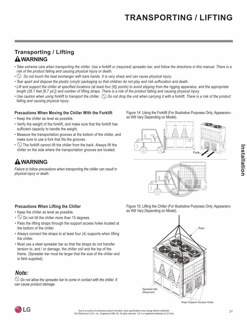
Precautions When Moving the Chiller With the Forklift• Keep the chiller as level as possible.• Verify the weight of the forklift, and make sure that the forklift has
sufficient capacity to handle the weight.• Measure the transportation grooves at the bottom of the chiller, and
make sure to use a fork that fits the grooves.• The forklift cannot lift the chiller from the back. Always lift the
chiller on the side where the transportation grooves are located.
WARNINGFailure to follow precautions when transporting the chiller can result in physical injury or death.
Fork
WARNING•
• • •
• falling and causing physical injury.
Figure 14: Using the Forklift (For Illustrative Purposes Only; Appearanc-es Will Vary Depending on Model).
Precautions When Lifting the Chiller• Keep the chiller as level as possible.• Do not tilt the chiller more than 15 degrees.• Pass the lifting straps through the support access holes located at
the bottom of the chiller.• Always connect the straps to at least four (4) supports when lifting
the chiller.• Must use a steel spreader bar so that the straps do not transfer
tension to, and / or damage, the chiller coil and the top of the frame. (Spreader bar must be larger that the size of the chiller and is field supplied).
Spreader Bar(Required)
Rope
Rope Support Access Holes
Figure 15: Lifting the Chiller (For Illustrative Purposes Only; Appearanc-es Will Vary Depending on Model).
Do not allow the spreader bar to come in contact with the chiller. It can cause product damage.
22
LG A
ir-Co
oled
Coo
ling
Onl
y In
verte
r Scr
oll C
hille
r Ins
talla
tion
and
Ow
ners
’ Man
ual Storing the Chiller
If the chiller must be stored at the construction site before installation / operation, do not allow dirt or moisture inside, and do not expose it to humidity. Place a protective cover on the chiller until ready for installation.
Installation Considerations• As soon as the chiller is delivered, check for any damages. If there are damages, immediately contact the shipping company.• Install in a location where it is flat and there is enough strength to support the weight of and vibration from the chiller.• Install in an area that allows for optimum airflow at both inlet and outlet sides; enough space for wiring, and piping; and is easily accessible
for installation, inspection, maintenance, and service. See the specification table, dimensions, and wiring diagram for clearance require-ments, net weight, etc.
• Inspect the field-installed base, and resolve any issues before installing the chiller. • Install the chiller so that it will not fall over due to strong winds or earthquakes.• If installing the chiller in a coastal area where it is impacted by ocean winds, additional anti-corrosive treatment must be applied to the
condenser.• If combining multiple chillers, it is best to ensure all are at the same level so that the water pipes can be easily connected.
WARNINGImproper installation will cause the unit to fall over, resulting in physical injury or death.
Improper installation can cause product malfunction and damage.
VIBRATION AND ANCHOR BOLTS
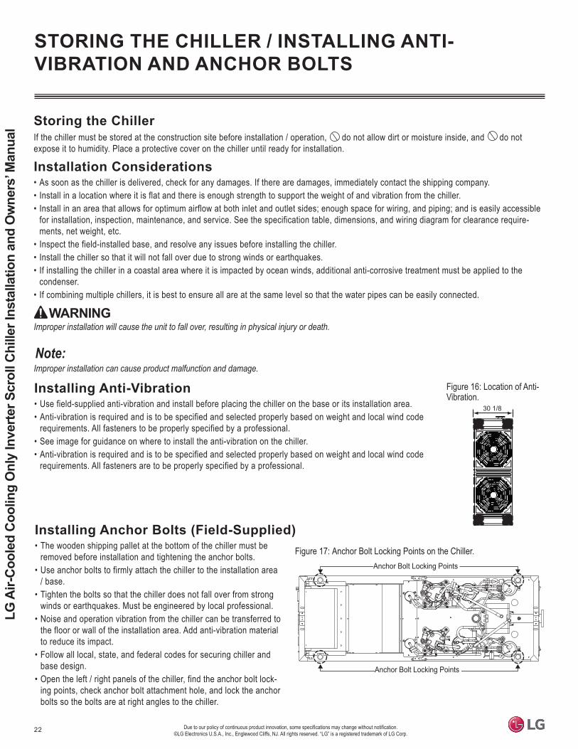
Installing Anti-Vibration• Use field-supplied anti-vibration and install before placing the chiller on the base or its installation area.• Anti-vibration is required and is to be specified and selected properly based on weight and local wind code
requirements. All fasteners to be properly specified by a professional.• See image for guidance on where to install the anti-vibration on the chiller. • Anti-vibration is required and is to be specified and selected properly based on weight and local wind code
requirements. All fasteners are to be properly specified by a professional.
30 1/8
Figure 16: Location of Anti- Vibration.
Anchor Bolt Locking Points
Anchor Bolt Locking Points
Figure 17: Anchor Bolt Locking Points on the Chiller.• The wooden shipping pallet at the bottom of the chiller must be removed before installation and tightening the anchor bolts.
• Use anchor bolts to firmly attach the chiller to the installation area / base.
• Tighten the bolts so that the chiller does not fall over from strong winds or earthquakes. Must be engineered by local professional.
• Noise and operation vibration from the chiller can be transferred to the floor or wall of the installation area. Add anti-vibration material to reduce its impact.
• Follow all local, state, and federal codes for securing chiller and base design.
• Open the left / right panels of the chiller, find the anchor bolt lock-ing points, check anchor bolt attachment hole, and lock the anchor bolts so the bolts are at right angles to the chiller.

23
Water Piping System
Installation
Water pipe system installation is an important part of the chiller system. Any defect in the water pipe system can lead to chiller malfunction. When designing the water pipe system, consider future service and maintenance, and install the field-supplied water pipe system compo-nents as detailed below.
Water Pipe System
reduced.
• Ensure that all installed components comply with the design water pressure (or higher).• Ensure that the water circulation complies with product specifications. Even when the water circulation complies with the product specifica-
tion, install a bypass circuit on the first side on the water piping system. If water flow is reduced during a low load, it can cause issues such as excessive and frequent compressor operation, and frozen components during cooling operation or if the operation stops.
• Maintain a constant water circulation flow as much as possible.
Expansion TankExpansion tanks receive and expel the excess water, and simultaneously remove air in the water pipe system. Choose an expansion tank with a capacity from 2 to 2-1/2 times of the water expansion amount. Generally, the expansion tank capacity is 3% to 5% of the entire water pipe system capacity. Check with local, state, and federal guidelines regarding expansion tank requirements and size.
Pipe Slope and Air Vent ValveIf air remains in the water pipes, water pipe system resistance increases, and / or the amount of circulating water is reduced significantly. If air remains in the pump during operation, it can result in chiller malfunction or shutdown. Install an air vent valve where there could be a chance of air remaining in the water pipe system. Include 1/200 of slope on the air vent valve side to reduce the likelihood of air remaining in the pipe.
Water Piping• Install the water pipe system so that the connections to the chiller are correct, tight, and without leaks. • Permitted water pressure resistance of the water pipe system is 145 psi (1 MPa).• Add insulation to the water system pipes to prevent any external heat loss, or to prevent condensate from forming during cooling operation.
Follow local, state, and federal guidelines on insulation.• Add pressure gauges and thermometers on the water inlets and outlets to check chiller operation.• Include a strainer with minimum 50 mesh on the water inlet to filter particles that could enter the heat exchanger. Install the strainer on a
horizontal pipe. • Before supplying water, clean inside the pipe system to remove particles that will damage the chiller.
If sand, debris, or rust are present in the water pipe system, these materials can corrode metallic parts and cause chiller operation failure.
• Install the on / off valve on the cold water inlet / outlet and bypass pipe on the pipe direction on the device side.• Install a pipe system bypass on the initial segment of the chiller water pipe system. A bypass circuit can help when cleaning the pipes before
chiller installation, and during annual water pipe system cleaning. • On / off valves can prevent water from backflowing into chillers that are not operating; also reduce power to the pump(s). Review site require-
ments for on / off valve installation. • Include flexible joints at the inlet / outlet pipes that reduce any vibration imparted to the water pipe system and chiller. Flexible joints help
prevent water leaks caused by operation vibration.

24
LG A
ir-Co
oled
Coo
ling
Onl
y In
verte
r Scr
oll C
hille
r Ins
talla
tion
and
Ow
ners
Man
ual
Installation Method A (Recommended)Independent product installation.
LG Supplied
P1
T1
T2
P2
LG Supplied
P2
T2
P1
T1
Leaving Cold Water
Entering Water
Symbol Description Symbol Description (Provided by Others)
Valve (100% Flow) T1 or T2 Temperature Sensor (1: Inlet, 2: Outlet)
Strainer (50 Mesh) P1 or P2 * Pressure Gauge (1: Inlet, 2: Outlet)
Flexible Joint Cold Water Pump (Pump Sized to Meet Minimum to Maximum Flow for LG Chiller)
Service Port for Cleaning
Optional*
*
*
*
* Required
Figure 18: Installation Method A.

25
Water Piping System
Installation
P2
T2
P1
T1
LG Supplied
P2
T2
P1
T1
LG Supplied
Leaving Cold Water
Entering Water
Installation Method BIndependent product installation.
Figure 19: Installation Method B.
Symbol Description Symbol Description (Provided by Others)
Valve (100% Flow) T1 or T2 Temperature Sensor (1: Inlet, 2: Outlet)
Strainer (50 Mesh) P1 or P2 * Pressure Gauge (1: Inlet, 2: Outlet)
Flexible Joint Cold Water Pump (Pump Sized to Meet Minimum to Maximum Flow for LG Chiller)
Service Port for Cleaning
Optional*
*
*
*
* Required
26
LG A
ir-Co
oled
Coo
ling
Onl
y In
verte
r Scr
oll C
hille
r Ins
talla
tion
and
Ow
ners
Man
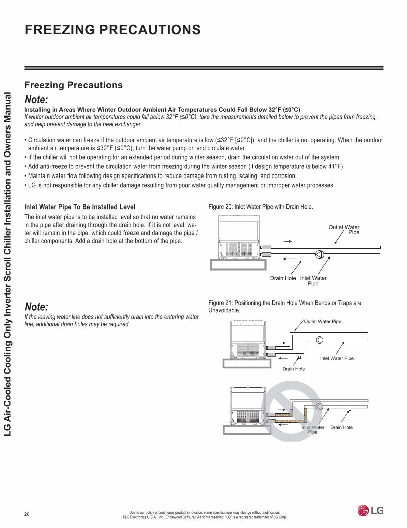
ual Freezing Precautions
•
• If the chiller will not be operating for an extended period during winter season, drain the circulation water out of the system.• Add anti-freeze to prevent the circulation water from freezing during the winter season (if design temperature is below 41°F).• Maintain water flow following design specifications to reduce damage from rusting, scaling, and corrosion.• LG is not responsible for any chiller damage resulting from poor water quality management or improper water processes.
Inlet WaterPipe
Drain Hole
Drain Hole
Inlet Water Pipe
let WatPipe
Inlenlet
Outlet Water Pipe
Figure 20: Inlet Water Pipe with Drain Hole.
Inlet WaterPipe
Drain Hole
Outlet WaterPipe
line, additional drain holes may be required.
Figure 21: Positioning the Drain Hole When Bends or Traps are Unavoidable.
Inlet Water Pipe To Be Installed LevelThe inlet water pipe is to be installed level so that no water remains in the pipe after draining through the drain hole. If it is not level, wa-ter will remain in the pipe, which could freeze and damage the pipe / chiller components. Add a drain hole at the bottom of the pipe.
FREEZING PRECAUTIONS

27
Water Piping System
Installation
Maximum Operating Pressure / Pressure DropFigure 22: Cold Water Head Loss Curve.
Pres
sure
dro
p (p
si)
Water flow rate (gpm)
36.3
29.0
21.8
14.5
7.25
52.8 105.6 158.5 211.3 264.1 317 369.8 422.60
0
One (1) Unit
* GPM : Gallon Per Minute
ACAH Heat Exchanger Pressure Drop Graph
Model No. Operating Maximum Pressure (psi)
Water Pressure Drop (psi)
ACAH020HETB Refrigerant: 597; Water: 142 5.63
Table 5: System Maximum Pressure and Water Pressure
Particles WaterCirculating Water Cold Water
pH (77°F [25°C]) 6.5 - 8.0 6.5 - 8.0500 or below 200 or below
Alkali Level (ppm) 100 or below 50 or belowHardness (ppm) 100 or below 50 or below
Chlorine Ion (ppm) 100 or below 50 or belowLactic Acid Ion (ppm) 100 or below 50 or below
Iron (ppm) 0.1 or below 0.3 or belowSulfur Ion (ppm) Must not be detected Must not be detected
Ammonium Ion (ppm) 0.5 or below 0.2 or belowSilica (ppm) 50 or below 30 or below
Table 4: Chiller Water Standards.
Water Pipe Installation• • Water pipe size must be the same or larger than that of the chiller.• To prevent the water pipe connections from sagging due to the load, install appropriate pipe supports.• Position the water inlet pipe at the bottom of the water pipe system, and position the outlet pipe at the top of the water pipe system.• If there is a risk of condensation, install insulation on the cold water outlet pipe.• To prevent the connected pipe from freezing during winter season, install the drain valve at the bottom of the pipe system.
Water Pump ControlIf the water pumps do not operate for an extended period, internal corrosion is more likely.
Water Quality ManagementImpurities in the water can influence chiller performance and life expectancy. The water must be tested and treated using a local water treat-ment professional, and water quality must not fall below the standards listed in the table.
QUALITY MANAGEMENT

28 Due to our policy of continuous product innovation, some specifications may change without notification. ©LG Electronics U.S.A., Inc., Englewood Cliffs, NJ. All rights reserved. “LG” is a registered trademark of LG Corp.
LG A
ir-Co
oled
Coo
ling
Onl
y In
verte
r Scr
oll C
hille
r Ins
talla
tion
and
Ow
ners
Man
ual
Figure 23:
Human Machine Interface (HMI)Use for basic product setting and commands; displays product information, and information for each cycle.
Main ControllerControls the input / output port and communicates with each cycle.
Power SupplySupplies power to the HMI.
MCCB (Molded Case Circuit Breaker (MCCB)Shuts off the overcurrent.
Line or High Voltage Terminal BlockThe terminal block that receives the external main power.
Main Controller
xoB lortnoC niaMxoB lortnoC b uS
Terminal Block
HMIPower Supply
MCCB
CONTROL PANEL CONFIGURATION
Control Panel Configuration

29
Control
Due to our policy of continuous product innovation, some specifications may change without notification. ©LG Electronics U.S.A., Inc., Englewood Cliffs, NJ. All rights reserved. “LG” is a registered trademark of LG Corp.
Figure 24: Button Locations.
Button Name DescriptionSW_RIGHT
Changes the Setting.SW_LEFTSW_UP
Moves the Screen.SW_DOWNSW_CONF Sets the Selected Function.SW_BACK Returns to the Previous Step.
The controller includes the buttons described below to set the functions listed in the table without using the HMI.
SW_CONFSW_LEFT
SW_UP
SW_BACK SW_RIGHTSW_DOWN
BUTTON LOCATIONS AND FUNCTIONS
Table 6: Button Function Table.
Button Locations and Functions

30 Due to our policy of continuous product innovation, some specifications may change without notification. ©LG Electronics U.S.A., Inc., Englewood Cliffs, NJ. All rights reserved. “LG” is a registered trademark of LG Corp.
LG A
ir-Co
oled
Coo
ling
Onl
y In
verte
r Scr
oll C
hille
r Ins
talla
tion
and
Ow
ners
Man
ual
1. Press the SW_CONF button to move to the 0 level screen on the SSD.
2. 3. When the desired function displays, press the SW_CONF button.
The screen changes to the 1 level screen on the SSD.4.
the SSD. When the desired function displays, press the SW_CONF button to set.
5. To return to the previous screen, press SW_BACK button.
No. Setting Description Screen Display (0 Level) Screen Display (1 Level)1 Start / Stop O P E R - R U N
S T O P2 Heating / Cooling C Y C L H E A T
C O O L3 Cooling Setpoint Temperature C - T E - - - 74 Heating Setpoint Temperature H - T E - - 4 5
5 Control Mode S Y S 1- L O CD I S TS C H E
6 Remote Mode S Y S 2 C O N T- B U S
7 Central Control Address A D D R - - - 18 Maximum Operation Frequency H I - R 1 1 09 Product Capacity H P 4 0 - - - -
C O 4 0 - - - -10 Version - - 1 0 - - - -
S V 1 0 - - - -
SSD
Optional Setting Buttons
Description Screen Display (1 Level) DetailsStart / Stop RUN / STOP Set RUN to operate the chiller, and STOP to stop the operation.
Heating / Cooling HEAT/COOL Sets the cooling / heating operation mode. COOL selects cooling mode, and HEAT selects heating mode.
Cooling Setpoint Temperature 7 Sets cooling target temperature. (39.2°F~ 68°F)Load Outflow Water Temperature - Shows the temperature value of load outflow water. (Specified in 0 level)
Control Mode LOC / DIST / SCHESets the product’s control mode. In LOC, chiller control is available through the HMI and the chiller controller. DIST refers to the remote control mode.In SCHE, the chiller is controlled following the schedule set at the HMI.
Remote Mode CONT / BUSDetermines how to set in remote mode. CONT enables the chiller’s operation mode by simple switch contacts. BUS enables the control on the entire chiller through communication from othercommunication devices.
Central Control Address 1 The chiller address can be set for communication with other communication devices. The address can be determined by selecting values from 1 to 247.
Maximum Operation Frequency 110 Sets the maximum operation frequency (70Hz~126Hz).Product Capacity - Shows the current capacity of product. (Specified in 0 level)
Version -Shows the program version information of the chiller controller installed.
Version information is subjected to change for product performance or qualityimprovement. (Specified in 0 level)
OPTIONAL SETTINGS
Figure 25: Option Setting Button Locations.
Figure 26: Option Setting Button Table.
Optional Settings
Figure 27: Option Detail Table.

31
Control
Due to our policy of continuous product innovation, some specifications may change without notification. ©LG Electronics U.S.A., Inc., Englewood Cliffs, NJ. All rights reserved. “LG” is a registered trademark of LG Corp.
Set the chiller address settings from HMI and main controller. If the two (2) addresses do not match, and HMI communication error will occur.
Setting the Address on the Main Controller1. 2. When “FN02” appears, press SW_CONF button.3. 4. To cancel, press the SW_BACK button.
No. Description Screen Display (0 Level) Screen Display (1 Level)1 Chiller Address F N 0 2 - - - 1
CHILLER ADDRESS SETTINGS
If the main controller address does not match the HMI address, an error will occur.
Figure 28: Setting the Address on the Main Controller.
Chiller Address Settings
32 Due to our policy of continuous product innovation, some specifications may change without notification. ©LG Electronics U.S.A., Inc., Englewood Cliffs, NJ. All rights reserved. “LG” is a registered trademark of LG Corp.
LG A
ir-Co
oled
Coo
ling
Onl
y In
verte
r Scr
oll C
hille
r Ins
talla
tion
and
Ow
ners
Man
ual
-
HMI SCREENS
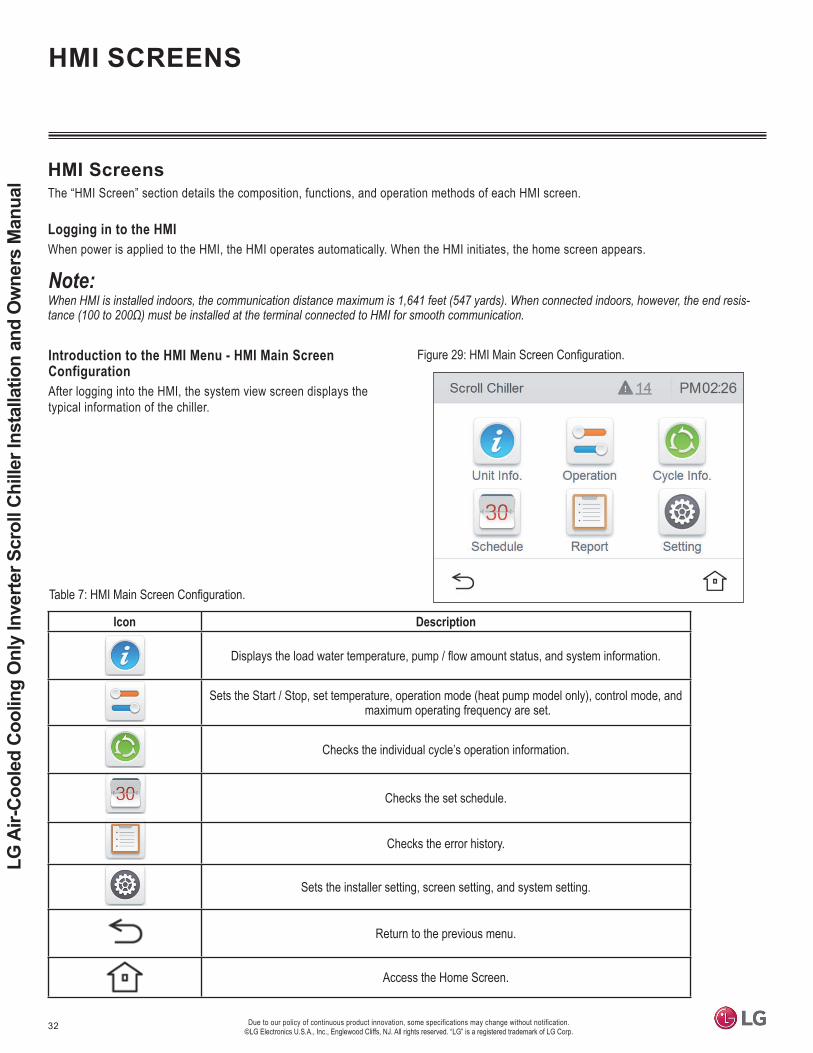
HMI ScreensThe “HMI Screen” section details the composition, functions, and operation methods of each HMI screen.
Logging in to the HMIWhen power is applied to the HMI, the HMI operates automatically. When the HMI initiates, the home screen appears.
Introduction to the HMI Menu - HMI Main Screen ConfigurationAfter logging into the HMI, the system view screen displays the typical information of the chiller.
Icon Description
Displays the load water temperature, pump / flow amount status, and system information.
Sets the Start / Stop, set temperature, operation mode (heat pump model only), control mode, and maximum operating frequency are set.
Checks the individual cycle’s operation information.
Checks the set schedule.
Checks the error history.
Sets the installer setting, screen setting, and system setting.
Return to the previous menu.
Access the Home Screen.
Figure 29:
Table 7:

33
Control
Due to our policy of continuous product innovation, some specifications may change without notification. ©LG Electronics U.S.A., Inc., Englewood Cliffs, NJ. All rights reserved. “LG” is a registered trademark of LG Corp.
View Chiller Information - Load Water Temperature ScreenChiller information includes load water temperature, pump / flow amount status, and, system information.
Icon DescriptionE.W.T Displays the common load entering water temperature value.L.W.T Displays the common load leaving water temperature value.
HMI SCREENS
View Chiller Information - Pump / Flow Amount Status Screen
Figure 30: Load Water Temperature Screen.Table 8: Load Water Temperature Screen Table.
Icon Description
Pump Output
If it is in operation, it always maintains an ON state.When the chiller operation stops, the freeze and burst prevention mode is applied, and operates as follows: According to the outdoor air temperature condition, the load water pump repeats operation ON and OFF.
The freeze and burst prevention mode is possible when the pump is connected. To interface with the pump, the pump output connect is to be installed. To verify that the pump operates, the pump interlockconnector is to be installed. (For installation,see the connection diagram.)
Pump Interlock Receives the status of the load water pump output through the external signal contact point of the pump. (When the chiller is in operation, the pump output maintains an “ON” state, otherwise, an alarm will occur.)
Flow Switch Displays the current load water’s flow amount switch status value. (When the chiller is in operation, the pump output maintains an “ON” state, otherwise, an alarm will occur.)
Capacity Displays the capacity of the device.
Figure 31: Pump / Flow Amount Status Screen.
Table 9: Pump / Flow Amount Status Screen Table.

34 Due to our policy of continuous product innovation, some specifications may change without notification. ©LG Electronics U.S.A., Inc., Englewood Cliffs, NJ. All rights reserved. “LG” is a registered trademark of LG Corp.
LG A
ir-Co
oled
Coo
ling
Onl
y In
verte
r Scr
oll C
hille
r Ins
talla
tion
and
Ow
ners
Man
ual
Figure 32: System Information Screen.
Icon Description
Setting Temp. Displays the set temperature for the currentoperation mode.
Outdoor Temp. Displays the current outdoor air temperaturevalue.
Operation Current Displays the operation compressor’s overall operation current value.
Starting Delay Displays the time of the standby state beforestarting the chiller.
View Chiller Information - System Information Screen
Table 10: Pump / Flow Amount Status Screen Table.
HMI SCREENS
Operation Information - Chiller ControlSets the Start / Stop (On / Off), Set Temperature, Operation Mode (Only for Heat Pump Models), Control, and Maximum Operating Frequency.
Icon Description
Selects the start and stop signal command of the chiller.
Sets the target temperature value for the current operation mode (Cooling: 39.2°F ~ 68°F).
Selects the control mode of the signal command method for the chiller control.
Max. Operating Frequency could save energy by limiting the operation capacity up to the frequency set by the user. (Setting Range : 70 Hz ~ 126 Hz)The standard set value for the Maximum Operating Frequency is 120 Hz. The setting unit for the Maximum Operating Frequency is 10 Hz.
Figure 33: Chiller Control Screen.
Table 11: Chiller Control Screen.

35
Control
Due to our policy of continuous product innovation, some specifications may change without notification. ©LG Electronics U.S.A., Inc., Englewood Cliffs, NJ. All rights reserved. “LG” is a registered trademark of LG Corp.
Operation Information - Chiller Control, ON / OFFAfter the ON area is pressed, a pop up window to select ON / OFF appears.
Operation Information - Chiller Control, Setting Tempera-tureAfter the area where the chiller control’s set temperature display is pressed, a pop up window to input the setting temperature appears.
In the temperature setting pop up window, change the temperature using the up / down arrows. After the temperature setting display area is pressed, input the setting temperature input using the numer-ic keyboard.
After changing the temperature setting, press Apply to reflect the set value. Press Cancel to maintain the previous setting.
Figure 34: ON / OFF Screen.
HMI SCREENS
Figure 35: Setting Temperature Screen.
Figure 36: Setting Temperature Screen Numeric Keyboard.

36 Due to our policy of continuous product innovation, some specifications may change without notification. ©LG Electronics U.S.A., Inc., Englewood Cliffs, NJ. All rights reserved. “LG” is a registered trademark of LG Corp.
LG A
ir-Co
oled
Coo
ling
Onl
y In
verte
r Scr
oll C
hille
r Ins
talla
tion
and
Ow
ners
Man
ual
Operation Information - Chiller Control, Control ModeAfter the chiller control’s control mode area is pressed, a pop up window to set the control mode appears.After selecting the desired control mode, press Apply to set mode. Press Cancel to maintain the previous setting.
Icon Description
Manual control mode through HMI.
If the schedule mode is set, manual and remote control are not possible, and only the start / stop by the schedule is possible.
ON/OFF is only possible by the chiller controller’s “Remote Start” signal.
ON/OFF is only possible by the external MODBUS communication.
HMI SCREENS
Figure 37: Control Mode Screen.
Table 12: Control Mode Screen Table.
Operation Information - Chiller Control, Maximum Operat-ing FrequencyAfter the Maximum Operating Frequency area is pressed, a pop up window to input the Maximum Operating Frequency is displayed.The Maximum Operating Frequency can be adjusted by pressing the up / down arrows in the pop up window.
Figure 38: Maximum Operating Frequency Screen.

37
Control
Due to our policy of continuous product innovation, some specifications may change without notification. ©LG Electronics U.S.A., Inc., Englewood Cliffs, NJ. All rights reserved. “LG” is a registered trademark of LG Corp.
Cycle Information Screen CompositionTo enter the cycle information screen, press the Cycle Information button in the HMI Main Screen.
Icon Description
Displays the currently selected cycle.
Selects the cycle information and the cycle temperature.
Displays the hot gas valve status.
Shows the sump heater status.
Icon Description
Displays the inverter compressor’s operation frequency value.
Displays the current EEV pulse signal value.
Displays the current high pressure value.
Displays the current low pressure value.
HMI SCREENS
Figure 39: Cycle Information Screen.
Table 13: Cycle Information Screen Table.
Figure 40: Current Cycle Screen.Cycle Information Screen Composition - Current Cycle Screen
Table 14: Current Cycle Screen Table.

38 Due to our policy of continuous product innovation, some specifications may change without notification. ©LG Electronics U.S.A., Inc., Englewood Cliffs, NJ. All rights reserved. “LG” is a registered trademark of LG Corp.
LG A
ir-Co
oled
Coo
ling
Onl
y In
verte
r Scr
oll C
hille
r Ins
talla
tion
and
Ow
ners
Man
ual
Figure 41: Current Cycle Operating Screen.
Icon DescriptionDisplays the operating current value of the current
cycle compressor.
Displays operation time.
Icon Description
Displays cycle individual outlet temperature value.
Displays cycle individual inlet temperature value.
Displays cycle condensation temperature value.
Displays cycle evaporation temperature value.
Cycle Information Screen Composition - Current Cycle Operating Screen
Cycle Information Screen Composition - Current Cycle Temperature Screen, Part 1
Figure 42: Current Cycle Temperature Screen, Part 1.
HMI SCREENS
Table 15: Current Cycle Operating Screen Table.
Icon Description
Displays cycle compressor discharge temperature value.
Displays cycle compressor suction temperature value.
Displays cycle HEX temperature value.
Displays cycle liquid line temperature value.
Table 16: Current Cycle Temperature Screen, Part 1 Table.
Cycle Information Screen Composition - Current Cycle Temperature Screen, Part 2
Figure 43: Current Cycle Temperature Screen, Part 2.
Table 17: Current Cycle Temperature Screen, Part 2 Table.

39
Control
Due to our policy of continuous product innovation, some specifications may change without notification. ©LG Electronics U.S.A., Inc., Englewood Cliffs, NJ. All rights reserved. “LG” is a registered trademark of LG Corp.
Schedule Menu CompositionUse the schedule menu to operate the chiller schedule. In Home screen, if you press the schedule icon, the schedule screen appears.To enter the schedule screen, press the Schedule button in the HMI Main Screen.
Icon DescriptionChecks the monthly set schedule at a glance.
Checks the start time of the schedule and the set operation mode.
Check the set schedule in a list.
HMI SCREENS
Figure 44: Schedule Menu - Month.
Figure 45: Schedule Menu - Week. Figure 46: Schedule Menu - List.
Table 18: Schedule Menu Table.

40 Due to our policy of continuous product innovation, some specifications may change without notification. ©LG Electronics U.S.A., Inc., Englewood Cliffs, NJ. All rights reserved. “LG” is a registered trademark of LG Corp.
LG A
ir-Co
oled
Coo
ling
Onl
y In
verte
r Scr
oll C
hille
r Ins
talla
tion
and
Ow
ners
Man
ual
Schedule Menu Composition - Add Schedule1. In the Schedule Menu screen, press the “Schedule Month”
button.
2. Press the Add button. When the Add screen appears, input the basic schedule information:
• Press the Name area, and a pop up window to input the schedule name appears. Input the name, and press the Apply button to set. If the Cancel button is pressed, the previous setting is maintained.
• Press the Date area, and a pop up window to set the date appears. Set the start and end dates to use the schedule operation function, and the press Apply button. If the Cancel button is pressed, the previ-ous setting is maintained.
• Press the Time area, an a pop up window to set the time appears. Set the time to use the schedule operation function, and press the Apply button. If Cancel button is pressed, the previous setting is maintained.
• Press the Days of Week selection area, and a pop up window to select the day of week appears. Select the day of week to use the schedule operation function, and press the Apply button. If the Cancel button is pressed, the previous setting is maintained.
HMI SCREENS
Figure 47: Schedule Month Screen.
Figure 48: Add Screen.
Figure 49: Name Screen. Figure 50: Date Screen.
Figure 51: Time Screen. Figure 52: Days of Week Screen.

41
Control
Due to our policy of continuous product innovation, some specifications may change without notification. ©LG Electronics U.S.A., Inc., Englewood Cliffs, NJ. All rights reserved. “LG” is a registered trademark of LG Corp.
Schedule Menu Composition - Add Schedule, continued.3. After the basic information is input, press the Next button, and a
screen to set detailed Operation information appears.• Press the Mode area, and a pop up window to select the mode is
displayed. Select the operation mode to use the schedule opera-tion function, and press the Apply button. If the Cancel button is pressed, the previous setting is maintained.
• Press the Setting Temperature area, and a pop up window to input the temperature setting appears. Set the temperature, and press the Apply button. If the Cancel button is pressed, the previous setting is maintained.
• Press the ON / OFF area, and a pop up window to select ON / OFF appears. Choose ON or OFF for the schedule operation function, and press the Apply button. If the Cancel button is pressed, the previous setting is maintained.
• Press the Maximum Operating Frequency area, and the pop up window to access the Maximum Operating Frequency window appears. Select a value to set, and then press the Apply button. If the Cancel button is pressed, the previous setting is maintained.
HMI SCREENS
Figure 53: Operation Screen.
Figure 54: Mode Screen. Figure 55: Setting Temperature Screen.
Figure 56: ON / OFF Screen. Figure 57: ON / OFF Screen.

42 Due to our policy of continuous product innovation, some specifications may change without notification. ©LG Electronics U.S.A., Inc., Englewood Cliffs, NJ. All rights reserved. “LG” is a registered trademark of LG Corp.
LG A
ir-Co
oled
Coo
ling
Onl
y In
verte
r Scr
oll C
hille
r Ins
talla
tion
and
Ow
ners
Man
ual
Schedule Menu Composition - Add Schedule, continued. 4. After the detailed information is input, press the Apply button of
the Chiller Control, and the Add Schedule information is com-plete. If the Cancel button is pressed, the previous setting is maintained.
HMI SCREENS
Schedule Menu Composition - Edit Schedule1. In the View Schedule _ List screen, select the schedule to edit.
2. After the pop up window of the selected schedule appears, press the buttons listed in the table below to set.
Figure 58: Operation Screen After Information is Set.
Icon DescriptionPop up window stating “Do you want to delete the selected schedule?” appears,
and when the Apply button is pressed, it is deleted from the list.
A pop up window to edit appears, and is set with the same method as the Add Schedule procedure.
It maintains the current setting, and the pop up window disappears.
Figure 59: Schedule_List Screen. Figure 60: Schedule_List Pop Up Screen.
Table 19: Schedule_List Pop Up Screen Table.

43
Control
Due to our policy of continuous product innovation, some specifications may change without notification. ©LG Electronics U.S.A., Inc., Englewood Cliffs, NJ. All rights reserved. “LG” is a registered trademark of LG Corp.
Icon Description
When the Add button is pressed, the Schedule Addition screen appears.
Select a list to active the Delete button.After the Delete button is activated, and when the Delete button is pressed, the selected list will be removed.
Schedule Menu Composition - Schedule List Edit1. In the View Schedule _ List screen, press the Edit button at the top right side.
2. When the Edit screen appears, edit and delete the schedule addition and lists as necessary.
HMI SCREENS
Figure 61: Schedule_List Screen. Figure 62: Edit Schedule_List Screen.
Table 20: Edit Schedule_List Screen Table.

44 Due to our policy of continuous product innovation, some specifications may change without notification. ©LG Electronics U.S.A., Inc., Englewood Cliffs, NJ. All rights reserved. “LG” is a registered trademark of LG Corp.
LG A
ir-Co
oled
Coo
ling
Onl
y In
verte
r Scr
oll C
hille
r Ins
talla
tion
and
Ow
ners
Man
ual
Report Menu CompositionUse the Report Menu to access the record of events that trigger errors.
Report Menu Composition - Error ScreenError history is stored chronologically; errors can be viewed by selecting day, week, and month.
Report Menu Composition - Detail InformationSelect a history to view in detail, and the Detail Information pop up window appears. The date, time, address, code, and the information of the error code appears. When OK is pressed, the pop up window disappears.
Report Menu Composition - Delete HistoryWhen the Clear button at the top side of the Error Screen is pressed, a pop up window to input the password appears.Input the password, and after the Apply button is pressed, all error histories will be deleted.
HMI SCREENS
Figure 63: Error Screen.
Figure 64: Detail Information Screen.
Figure 65: Password Screen. Figure 66: Error Screen Where the Errors Have Been Deleted.

45
Control
Due to our policy of continuous product innovation, some specifications may change without notification. ©LG Electronics U.S.A., Inc., Englewood Cliffs, NJ. All rights reserved. “LG” is a registered trademark of LG Corp.
View Setting Menu Composition Describes the View Setting Menu screen, and the setting procedure required for chiller operation.
View Setting Menu Composition - Setting ScreenFrom the Main Menu screen, press the Setting button. Input the password to access the Setting screen (the screen at right appears) (Initial password: digital21.)
View Setting Menu Composition - DeviceFrom the Setting Screen, press the Device Icon, and the Device Screen appears.
Icon Description
Edit Unit AddressSets chiller address and number of chiller units. Initial chiller address and number is one (1). For automatic control (or ACP), MODBUS communication, and HMI interface, if the chiller’s Main PCBaddress is changed, the chiller’s HMI address must changed (set as the same value).
System Password Selects whether to change and use password. (Initial password : digital21.)Temperature Offset Correction
(Common Water Out TemperatureOffset Correction)
Service function; restricted.
Thermo On Offset Correction(Value) Service function; restricted.
HMI SCREENS
Figure 67: Setting Screen.
Figure 68: Setting Screen.
Table 21: Setting Screen Table.

46 Due to our policy of continuous product innovation, some specifications may change without notification. ©LG Electronics U.S.A., Inc., Englewood Cliffs, NJ. All rights reserved. “LG” is a registered trademark of LG Corp.
LG A
ir-Co
oled
Coo
ling
Onl
y In
verte
r Scr
oll C
hille
r Ins
talla
tion
and
Ow
ners
Man
ual
View Setting Menu Composition - Device, Edit Unit AddressWhile in Device mode, press the Edit Unit Address area, and the Edit Unit Address window appears.After the Edit Unit Count area is pressed, a window to set the num-ber of chillers appears.Select from 1 to 5 (number of chillers to interface), and press the Apply button. If the Cancel button is pressed, the previous setting is maintained.
• five (5).
• Setting the chiller address: The chiller address must match in both the main PCB of the chiller, and the HMI. If the two addresses do not match, it will cause an HMI communication error.
• If the HMI address is reset while the chiller is operating, a commu-nication error will occur, and the chiller will stop operating. Reset the address only after the chiller completely stops operating.
Figure 69: Edit Unit Address Screen.
Figure 70: Edit Unit Count Screen.
HMI SCREENS
In the Edit Unit Address screen, press the Chiller 1 area, and the Edit Unit Address window appears. Input the desired address and press the Apply button to set. If the Cancel button is pressed, the previous setting is maintained.
If two (2) or more units are selected, an input address is necessary for each unit.
Figure 71: Edit Unit Address Screen.

47
Control
Due to our policy of continuous product innovation, some specifications may change without notification. ©LG Electronics U.S.A., Inc., Englewood Cliffs, NJ. All rights reserved. “LG” is a registered trademark of LG Corp.
View Setting Menu Composition - Device, PasswordWhile in Device mode, press the System Password area, and the Pass-word window appears.
1. Keep password.• When the Use ON area is pressed, it changes to Use OFF.• Press the Apply button to set. If the Cancel button is pressed, the
previous setting is maintained.
“Use” is the default. If it is necessary to apply “Use” again, press Use OFF, input password, and then press the Apply button. (Initial password: digital21.)
2. Change password.• When the Change Password area is pressed, the Change Pass-
word window appears.• Input Current P/W, New P/W, and Re-type P/W, and press the
Apply button.
-ize the password. If the Cancel button is pressed, the password input
HMI SCREENS
Figure 72: Password Screen.
Figure 73: Changing ON to OFF Screen.
Figure 74: Canceling Use Screen. Figure 75: Accessing the Change Password Screen.
Figure 76: Change Password Screen. Figure 77: Password Input Fail Screen.
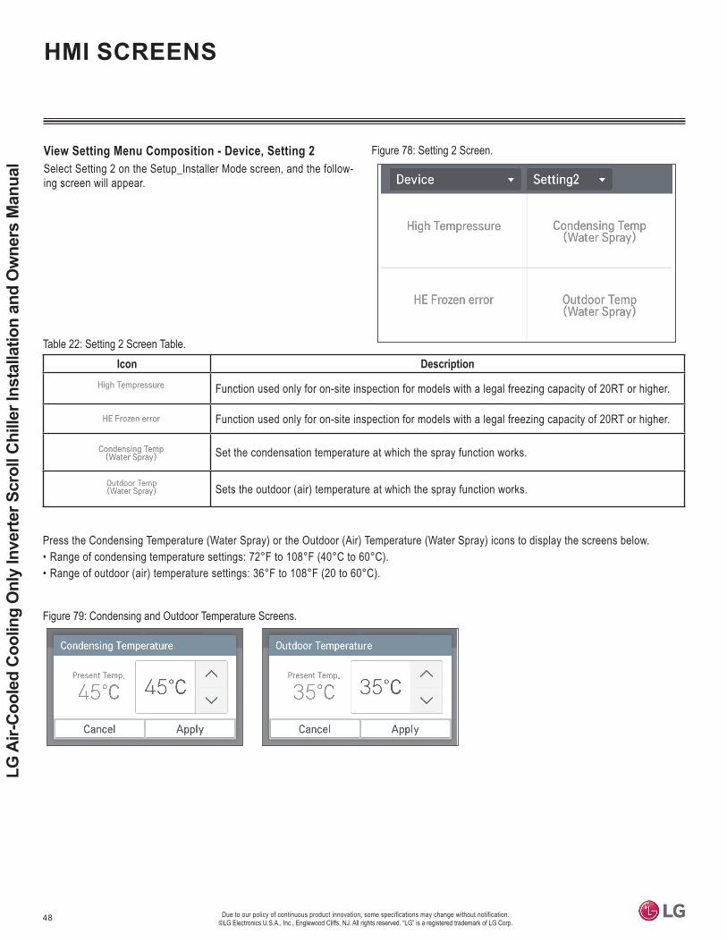
48 Due to our policy of continuous product innovation, some specifications may change without notification. ©LG Electronics U.S.A., Inc., Englewood Cliffs, NJ. All rights reserved. “LG” is a registered trademark of LG Corp.
LG A
ir-Co
oled
Coo
ling
Onl
y In
verte
r Scr
oll C
hille
r Ins
talla
tion
and
Ow
ners
Man
ual
Icon Description
Function used only for on-site inspection for models with a legal freezing capacity of 20RT or higher.
Function used only for on-site inspection for models with a legal freezing capacity of 20RT or higher.
Set the condensation temperature at which the spray function works.
Sets the outdoor (air) temperature at which the spray function works.
Press the Condensing Temperature (Water Spray) or the Outdoor (Air) Temperature (Water Spray) icons to display the screens below.• Range of condensing temperature settings: 72°F to 108°F (40°C to 60°C).• Range of outdoor (air) temperature settings: 36°F to 108°F (20 to 60°C).
View Setting Menu Composition - Device, Setting 2Select Setting 2 on the Setup_Installer Mode screen, and the follow-ing screen will appear.
HMI SCREENS
Figure 78: Setting 2 Screen.
Table 22: Setting 2 Screen Table.
Figure 79: Condensing and Outdoor Temperature Screens.

49
Control
Due to our policy of continuous product innovation, some specifications may change without notification. ©LG Electronics U.S.A., Inc., Englewood Cliffs, NJ. All rights reserved. “LG” is a registered trademark of LG Corp.
View Setting Menu Composition - ScreenIn the Setting Menu screen, press the Screen Icon to access the Screen window.
Icon Description
Applies or doesn’t apply the screen saver.
Sets the wait time for screen saver display.
Sets the time to change to the minimum brightness of the screen when touch input is not available.
Adjusts the screen brightness according to the ambient illumination intensity.
Figure 80: Screen Window.
Table 23: Screen Window Table.
HMI SCREENS
View Setting Menu Composition - Screen, Screen SaverPress the Screen Saver area on the Screen window to display the Screen Saver window.1. Press the area on the left side to Use or Not Use the screen
saver. Whenever that area is pressed, the selected value is changed.
2. Select Use to activate the screen saver preview. When the activated area is pressed, the set screen saver can be viewed in advance.
3. When the Apply button of the screen saver is pressed, the select-ed setting is applied. If the Cancel button is pressed, the previous setting is maintained.
Figure 81: Screen Saver Window.
Figure 82: Canceling Screen Saver. Figure 83: Set Screen Saver.

50 Due to our policy of continuous product innovation, some specifications may change without notification. ©LG Electronics U.S.A., Inc., Englewood Cliffs, NJ. All rights reserved. “LG” is a registered trademark of LG Corp.
LG A
ir-Co
oled
Coo
ling
Onl
y In
verte
r Scr
oll C
hille
r Ins
talla
tion
and
Ow
ners
Man
ual
HMI SCREENS
View Setting Menu Composition - Screen, Screen Saver Waiting TimeWhen the Screen Saver Standby area is pressed, the Screen Saver Standby window appears. Select the wait time, and then press the Apply button. If the Cancel button is pressed, the previous setting is maintained.
Screen saver waiting time
Figure 84: Screen Saver Wait Time Window.
Figure 85: Monitor Power Off Screen.View Setting Menu Composition - Screen, Monitor Power OffWhen the Screen Power Saving area is pressed, the Screen Power Saving window appears. Select the time, and then press the Apply button. If the Cancel button is pressed, the previous setting is maintained.
View Setting Menu Composition - Screen, BrightnessWhen the Screen Brightness area is pressed, the Screen Bright-ness window appears. Set the desired brightness by pressing the “–” or the “+” buttons at the left or right side of the screen, and then press the Apply button. If the Cancel button is pressed, the previous setting is maintained. Choose the screen brightness from 25%, 50%, 75%, and 100%.
Figure 86: Brightness Screen.

51
Control
Due to our policy of continuous product innovation, some specifications may change without notification. ©LG Electronics U.S.A., Inc., Englewood Cliffs, NJ. All rights reserved. “LG” is a registered trademark of LG Corp.
View Setting Menu Composition - System (Normal)On the Setting Screen, press the System area to access the System screen. The System menu is divided into normal and advance. Press the top right corner to access the normal or advance screens. When the Normal screen is chosen, the screen at the right appears.
Icon Description
Selects the base value of the date recognized by the chiller. The date display and the schedule interface date, etc., operate based on the set date.
Selected the base valve of the time recognized by the chiller. Thee time display and the schedule interface time, etc., operate based on the set time.
Input and edit the controller’s name. The applied name is displayed at the top left side of Main Screen.
Selects whether to use touch sound.
Selects the temperature unit to be displayed on the controller. Select from °C or °F.
Selects the language displayed on the controller. Select from Korean or English.
HMI SCREENS
View Setting Menu Composition - System (Normal), DateOn the System (Normal) screen, press the Date area. The Date window to set the date appears. Select the date by pressing the up / down buttons, and then press the Apply button to set. If the Cancel is button pressed, the previous setting is maintained.
Figure 87: System Screen.
Table 24: Normal Screen Table.
Figure 88: Date Screen.

52 Due to our policy of continuous product innovation, some specifications may change without notification. ©LG Electronics U.S.A., Inc., Englewood Cliffs, NJ. All rights reserved. “LG” is a registered trademark of LG Corp.
LG A
ir-Co
oled
Coo
ling
Onl
y In
verte
r Scr
oll C
hille
r Ins
talla
tion
and
Ow
ners
Man
ual
HMI SCREENS
View Setting Menu Composition - System (Normal), TimeOn the System (Normal) screen, press the Time area. The Time window to set the time appears. Select the time by pressing the up / down buttons, and then press the Apply button to set. If the Cancel is button pressed, the previous setting is maintained.
Figure 89: Time Screen.
View Setting Menu Composition - System (Normal), Controller Name EditOn the System (Normal) screen, press the Controller Name Edit area. The Controller Name Edit window appears. Input the desired controller name, and then press the Apply button to set. If the Cancel is button pressed, the previous setting is maintained.
Figure 90: Controller Name Edit Screen.
View Setting Menu Composition - System (Normal), SpeakerOn the System (Normal) screen, when the Speaker area is pressed, it switches between On and Off. Separate Apply and Cancel buttons are not necessary.
View Setting Menu Composition - System (Normal), Temperature UnitOn the System (Normal) screen, press the Tem-perature Unit area to access the pop up window. Press the Temperature Unit area in the pop up window to change the temperature unit. In the Celsius unit, the minimum temperature unit can be selected between 1°F and 0.5°F. Press the Apply button to set. If the Cancel is button pressed, the previous setting is maintained.
Figure 91: Speaker On / Off.
Figure 92: Temperature Unit Change.

53
Control
Due to our policy of continuous product innovation, some specifications may change without notification. ©LG Electronics U.S.A., Inc., Englewood Cliffs, NJ. All rights reserved. “LG” is a registered trademark of LG Corp.
Icon Description
Displays the software version of the controller.
Displays the open source contents.
Displays the overall operation time of the chiller. The Clear function is for trained service technicians only; end user use is restricted.
View Setting Menu Composition - System (Normal), LanguageOn the System (Normal) screen, press the Language Setting area. The Language window to set the language appears. Select the desired language, and press the Apply button to set. If the Cancel is button pressed, the previous setting is maintained.
HMI SCREENS
Figure 93: Language Screen.
Figure 94: Advance Screen.View Setting Menu Composition - System (Advance)On the Setting Screen, press the System area to access the System screen. The System menu is divided into normal and advance. Press the top right corner to access the normal or advance screens. When the Advance screen is chosen, the screen at the right appears.
Table 25: Advance Screen Table.
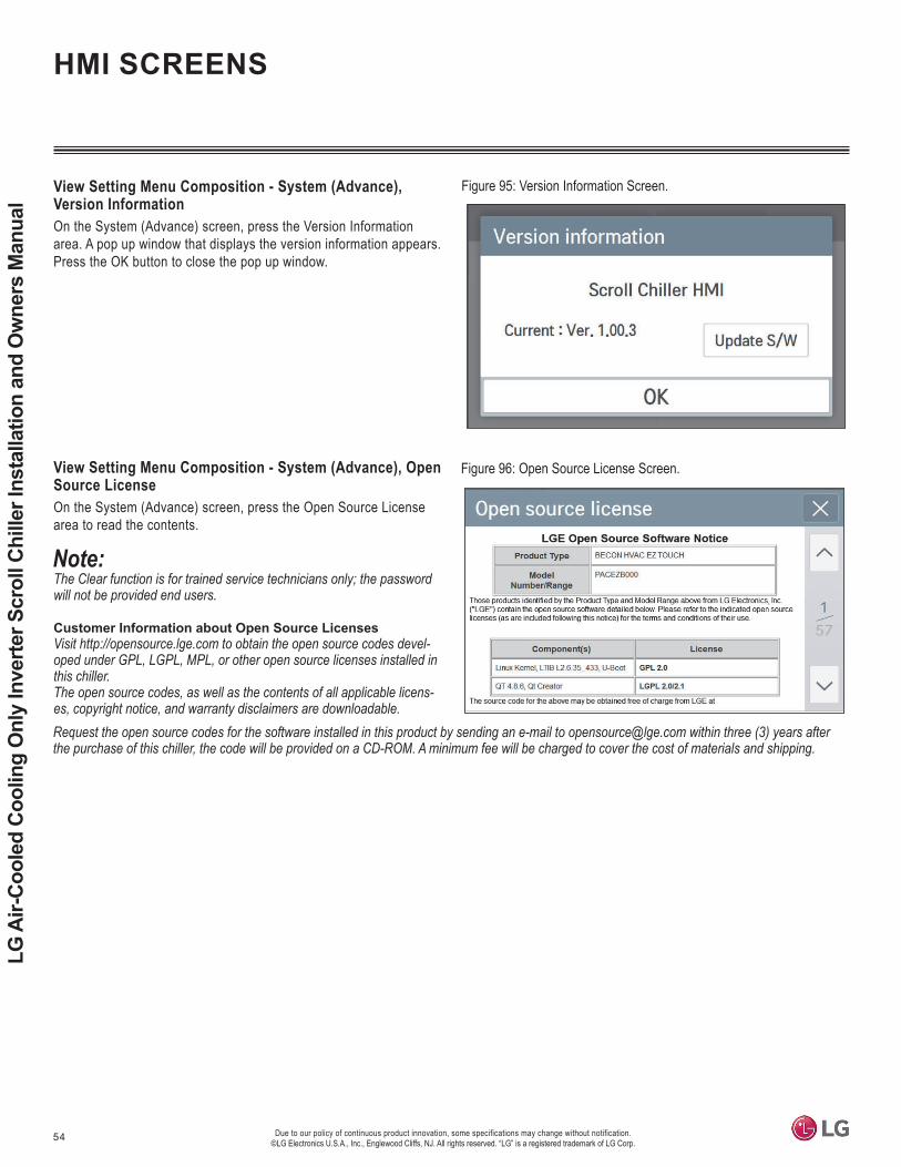
54 Due to our policy of continuous product innovation, some specifications may change without notification. ©LG Electronics U.S.A., Inc., Englewood Cliffs, NJ. All rights reserved. “LG” is a registered trademark of LG Corp.
LG A
ir-Co
oled
Coo
ling
Onl
y In
verte
r Scr
oll C
hille
r Ins
talla
tion
and
Ow
ners
Man
ual
View Setting Menu Composition - System (Advance), Open Source LicenseOn the System (Advance) screen, press the Open Source License area to read the contents.
will not be provided end users.
Customer Information about Open Source Licenses-
this chiller.The open source codes, as well as the contents of all applicable licens-es, copyright notice, and warranty disclaimers are downloadable.
HMI SCREENS
View Setting Menu Composition - System (Advance), Version InformationOn the System (Advance) screen, press the Version Information area. A pop up window that displays the version information appears. Press the OK button to close the pop up window.
Figure 95: Version Information Screen.
Figure 96: Open Source License Screen.
Request the open source codes for the software installed in this product by sending an e-mail to [email protected] within three (3) years after the purchase of this chiller, the code will be provided on a CD-ROM. A minimum fee will be charged to cover the cost of materials and shipping.
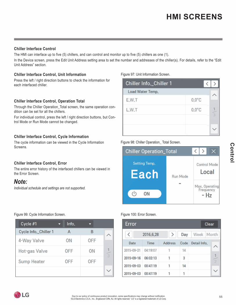
55
Control
Due to our policy of continuous product innovation, some specifications may change without notification. ©LG Electronics U.S.A., Inc., Englewood Cliffs, NJ. All rights reserved. “LG” is a registered trademark of LG Corp.
Chiller Interface ControlThe HMI can interface up to five (5) chillers, and can control and monitor up to five (5) chillers as one (1).In the Device screen, press the Edit Unit Address setting area to set the number and addresses of the chiller(s). For details, refer to the “Edit Unit Address” section.
Chiller Interface Control, Unit InformationPress the left / right direction buttons to check the information for each interfaced chiller.
Chiller Interface Control, Operation TotalThrough the Chiller Operation_Total screen, the same operation con-dition can be set for all the chillers.For individual control, press the left / right direction buttons, but Con-trol Mode or Run Mode cannot be changed.
Chiller Interface Control, Cycle InformationThe cycle information can be viewed in the Cycle Information Screens.
Chiller Interface Control, ErrorThe entire error history of the interfaced chillers can be viewed in the Error Screen.
Individual schedule and settings are not supported.
HMI SCREENS
Figure 97: Unit Information Screen.
Figure 98: Chiller Operation_ Total Screen.
Figure 99: Cycle Information Screen. Figure 100: Error Screen.

56 Due to our policy of continuous product innovation, some specifications may change without notification. ©LG Electronics U.S.A., Inc., Englewood Cliffs, NJ. All rights reserved. “LG” is a registered trademark of LG Corp.
LG A
ir-Co
oled
Coo
ling
Onl
y In
verte
r Scr
oll C
hille
r Ins
talla
tion
and
Ow
ners
Man
ual
WARNING•
state, and National Electrical Code (NEC) regulations related to electrical equipment and wiring, and following the instructions in this manu-
• Undersized wiring will lead to unacceptable voltage and will cause a fire, which will cause bodily injury or death.• Ensure that all power wiring / communication cables are properly terminated and firmly attached. If power wires and communication cables
• Do not install the wiring in reversed phase or missed phase. Connect all wires appropriately. If the system operates in reversed phase
•
• place before any power wiring is done to the system. Failure to do so will cause bodily injury or death.
• Be sure that main power to the unit is completely off before proceeding. Follow all safety and warning information outlined at the beginning
• Never touch any power lines or live cables before all power is cutoff to the system. To do so, will cause bodily injury or death.•
• Properly ground the chillers.
• -
• Do not install the wiring in reversed phase or missed phase. Connect all wires appropriately. If the system operates in reversed phase or missed phase, it will damage the compressors and other components.
•
• -ing system. Failure to properly provide a NEC-approved earth ground can result in property damage and equipment malfunction.
• components.
Tons Model No. Voltage Frequency (Hz)
Voltage Tolerance (Min. ~ Max.) MCA MFA Compressor Chiller Fan
Motor Input PowerMSC RLA kW FLA kW
20 ACAH020HETB 460 60 414 ~ 506 31 40 9.7 24.9 1.8 5 21.5
Table 26: Electrical Data for Single 460V Cooling Only Chiller.
Voltage Range: Power supplied to the chiller must fall within the voltage minimum to maximum range listed in the table above. The chiller will not operate normally if the power supply voltage falls below or above the tolerance range.Maximum allowable voltage variance permitted between phases is 2%.
MCA: Minimum Circuit Ampacity (A) (Criteria used to select the wiring standard).MFA: Maximum Fuse Amps (A) (Criteria used to select circuit breaker and ground error circuit breaker [electricity leakage circuit breaker]).MSC: Maximum Start Current (A)RLA: Rated Load Amps (A) (Current required when operating under the following conditions—Cooling: Outdoor Air Temperature: 8°1F DB / 66°F WB; Water Inlet / Outlet Temperature: 54°F / 44°F).FLA: Full Load Amps (A).
Chiller Electrical Data
General Precautions
ELECTRICAL

57
Electrical System Installation
Due to our policy of continuous product innovation, some specifications may change without notification. ©LG Electronics U.S.A., Inc., Englewood Cliffs, NJ. All rights reserved. “LG” is a registered trademark of LG Corp.
ELECTRICAL
1. Power wiring and communication cable access holes and connec-tions will be different depending on the chiller model and volume.
2. Single Chillers use the connection terminals located at the right (when viewing from the front).
3. Install the power wiring and communication cables separately so that communication is not impacted by electric noise (Use conduits for the power wiring and communication cable, but do not pass through the same conduit.)
WARNING• Properly ground the chillers. Do not connect ground wire to
• Install the power wiring only after the ring terminal is connected.
•• Install the power wiring only after the ring terminal is connected. Improper connections can damage electrical components.•
components.
WARNING•
state, and National Electrical Code (NEC) regulations related to electrical equipment and wiring, and following the instructions in this manu-
• Undersized wiring will lead to unacceptable voltage at the unit and will cause a fire, which will cause bodily injury or death.•
Right Side
Dual ChillerTriple Chiller of 208-230V Models
Triple Chiller
Single Chiller
Left Side
Figure 101: Chiller Wiring / Cable Access Holes.
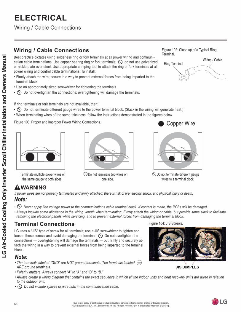
58 Due to our policy of continuous product innovation, some specifications may change without notification. ©LG Electronics U.S.A., Inc., Englewood Cliffs, NJ. All rights reserved. “LG” is a registered trademark of LG Corp.
LG A
ir-Co
oled
Coo
ling
Onl
y In
verte
r Scr
oll C
hille
r Ins
talla
tion
and
Ow
ners
Man
ual
• •
:Copper Wire
Terminate multiple power wires of the same gauge to both sides.
Do not terminate two wires on one side.
Do not terminate different gauge wires to a terminal block.
Best practice dictates using solderless ring or fork terminals at all power wiring and communi-cation cable terminations. Use copper bearing ring or fork terminals; do not use galvanized or nickle plate over steel. Use appropriate crimping tool to attach the ring or fork terminals at all power wiring and control cable terminations. To install: • Firmly attach the wire; secure in a way to prevent external forces from being imparted to the
terminal block.• Use an appropriately sized screwdriver for tightening the terminals. • Do not overtighten the connections; overtightening will damage the terminals.
If ring terminals or fork terminals are not available, then:• Do not terminate different gauge wires to the power terminal block. (Slack in the wiring will generate heat.)• When terminating wires of the same thickness, follow the instructions demonstrated in the figures below.
Ring TerminalWiring / Cable
Figure 102: Close up of a Typical Ring Terminal.
Figure 103: Proper and Improper Power Wiring Connections.
Terminal ConnectionsLG uses a “JIS” type of screw for all terminals; use a JIS screwdriver to tighten and loosen these screws and avoid damaging the terminal. Do not overtighten the connections — overtightening will damage the terminals — but firmly and securely at-tach the wiring in a way to prevent external forces from being imparted to the terminal block.
• ARE ground terminals.
• Polarity matters. Always connect “A” to “A” and “B” to “B.”•
to the outdoor unit.• Do not include splices or wire nuts in the communication cable.
Figure 104: JIS Screws.
WARNING
ELECTRICAL
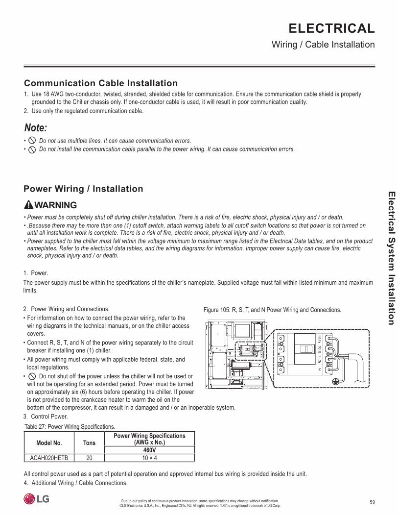
59
Electrical System Installation
Due to our policy of continuous product innovation, some specifications may change without notification. ©LG Electronics U.S.A., Inc., Englewood Cliffs, NJ. All rights reserved. “LG” is a registered trademark of LG Corp.
ELECTRICAL
1. Power.The power supply must be within the specifications of the chiller’s nameplate. Supplied voltage must fall within listed minimum and maximum limits.
2. Power Wiring and Connections.• For information on how to connect the power wiring, refer to the
wiring diagrams in the technical manuals, or on the chiller access covers.
• Connect R, S, T, and N of the power wiring separately to the circuit breaker if installing one (1) chiller.
• All power wiring must comply with applicable federal, state, and local regulations.
• Do not shut off the power unless the chiller will not be used or will not be operating for an extended period. Power must be turned on approximately six (6) hours before operating the chiller. If power is not provided to the crankcase heater to warm the oil on the bottom of the compressor, it can result in a damaged and / or an inoperable system.
3. Control Power.
Communication Cable Installation1. Use 18 AWG two-conductor, twisted, stranded, shielded cable for communication. Ensure the communication cable shield is properly
grounded to the Chiller chassis only. If one-conductor cable is used, it will result in poor communication quality. 2. Use only the regulated communication cable.
• Do not use multiple lines. It can cause communication errors.• Do not install the communication cable parallel to the power wiring. It can cause communication errors.
WARNING• • .Because there may be more than one (1) cutoff switch, attach warning labels to all cutoff switch locations so that power is not turned on
• nameplates. Refer to the electrical data tables, and the wiring diagrams for information. Improper power supply can cause fire, electric
All control power used as a part of potential operation and approved internal bus wiring is provided inside the unit.4. Additional Wiring / Cable Connections.
Model No. Tons (AWG x No.)460V
ACAH020HETB 20 10 × 4
Table 27:
Figure 105: R, S, T, and N Power Wiring and Connections.

60 Due to our policy of continuous product innovation, some specifications may change without notification. ©LG Electronics U.S.A., Inc., Englewood Cliffs, NJ. All rights reserved. “LG” is a registered trademark of LG Corp.
LG A
ir-Co
oled
Coo
ling
Onl
y In
verte
r Scr
oll C
hille
r Ins
talla
tion
and
Ow
ners
Man
ual
Index Signal Type Location RemarksPower DC Power 12 V DC Required
Central Control Communication Communication CH2 A, B RequiredHMI Communication Communication CH3 A, B Required
Modbus Communication CH4 A, B Optional (Field Installed)Ambient Thermistor DI UI1, G Required
Flow Switch DI UI5, G Factory Installed
Pump Interlock DI UI6, G Required Closed Contact from Pump During Flow
Remote On / Off DI DI1, GND Optional (Field Installed)Remote CO / HP DI DI2, GND Optional (Field Installed)
Remote Alarm DI DI3, GND Optional (Field Installed)Alarm Status DO DO1, COM Optional (Field Installed)
On / Off Status DO DO2 Optional (Field Installed)Pump Output DO DO3 Optional (Field Installed)Heater Output DO DO5 Optional (Field Installed)
Table 29: Field-Installed Wiring / Cable Connections.
Table 28: Power Wiring System to Multiple, Grouped Chillers.
Circuit Breaker Circuit Breaker Circuit Breaker
Main Power Supply
Circuit Breaker
Main Power Supply
Cir
Main y
Refer to the wiring diagram for field-installed wiring. Only the main panel (HMI installed panel) requires wiring at the site. The control box is shipped fully wired from the factory.5. Circuit Breaker and Power Wiring Connections.
• Each chiller must have its own circuit breaker and direct power wiring.
• Do not install one circuit breaker for multiple chillers. Do not daisy chain the power wiring from the main power supply to multiple chillers.
• Always label each circuit breaker and its connected chiller.• Refer to the specification and electrical data when selecting circuit
breaker capacities. Follow all state, local, and NEC guidelines when choosing and installing circuit breakers and power wiring.
ELECTRICAL
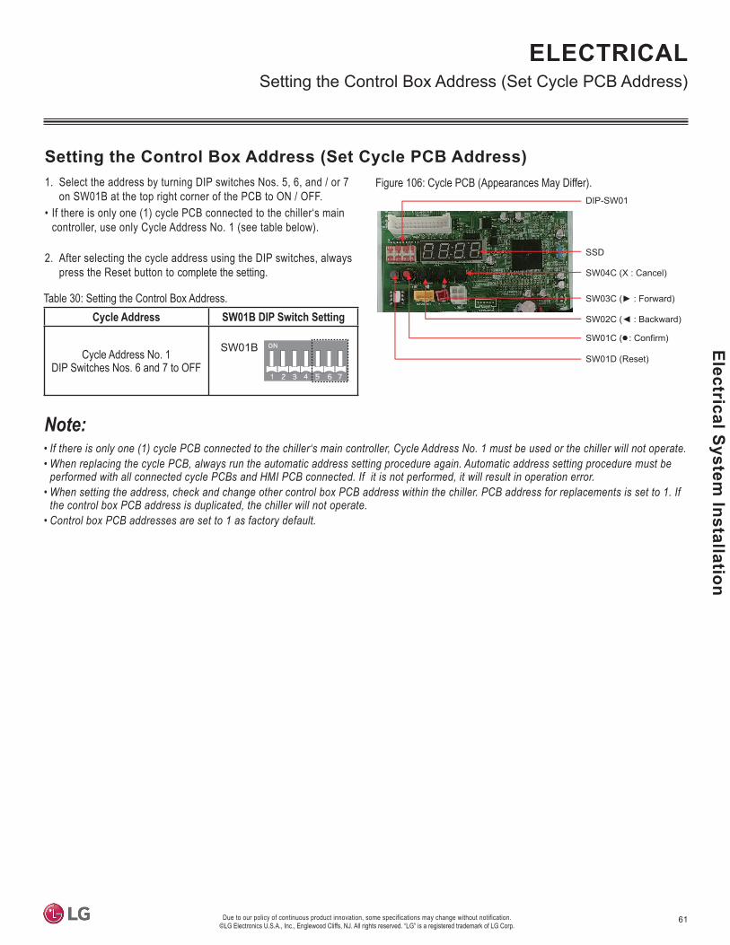
61
Electrical System Installation
Due to our policy of continuous product innovation, some specifications may change without notification. ©LG Electronics U.S.A., Inc., Englewood Cliffs, NJ. All rights reserved. “LG” is a registered trademark of LG Corp.
1. Select the address by turning DIP switches Nos. 5, 6, and / or 7 on SW01B at the top right corner of the PCB to ON / OFF.
• If there is only one (1) cycle PCB connected to the chiller‘s main controller, use only Cycle Address No. 1 (see table below).
2. After selecting the cycle address using the DIP switches, always press the Reset button to complete the setting.
DIP-SW01
SSD
SW04C (X : Cancel)
SW01C (
SW01D (Reset)
Table 30: Setting the Control Box Address.Cycle Address SW01B DIP Switch Setting
Cycle Address No. 1 DIP Switches Nos. 6 and 7 to OFF
SW01B
• If there is only one (1) cycle PCB connected to the chiller‘s main controller, Cycle Address No. 1 must be used or the chiller will not operate.• When replacing the cycle PCB, always run the automatic address setting procedure again. Automatic address setting procedure must be
performed with all connected cycle PCBs and HMI PCB connected. If it is not performed, it will result in operation error.•
•
Figure 106: Cycle PCB (Appearances May Differ).
ELECTRICAL

62 Due to our policy of continuous product innovation, some specifications may change without notification. ©LG Electronics U.S.A., Inc., Englewood Cliffs, NJ. All rights reserved. “LG” is a registered trademark of LG Corp.
LG A
ir-Co
oled
Coo
ling
Onl
y In
verte
r Scr
oll C
hille
r Ins
talla
tion
and
Ow
ners
Man
ual
ELECTRICAL
If the power adapter power cord and the HMI power wiring must be installed together, it is necessary to separate the power cable to the HMI from the communication cable to the HMI to avoid communication problems from electrical interference.
CH3B A
Installing the HMI Indoors
• The HMI can be installed on an interior wall. See below for instructions. Use a drill to add pilot holes before installing the screws.
grounded to the chiller chassis only. Do not ground the communication cable at any other point. 1. Choose the location in which to install the HMI. Verify that it is an appropriate location to connect the
communication cable and power wiring to the HMI, and that its distance from the chiller falls below maximum wiring / cable length requirements.
2. Use the drier and the M4 screw on the top wall of the communication cable to attach the back panel of the HMI. See diagram at right. It can be attached as shown, depending on the installation loca-tion.
3. Pull the communication cable through the hole on the back of the panel.4. Connect the cable to the communication port located on the back of the HMI.
• do not
to the compressors and other components.• -
so will result in a communication malfunction.•
Figure 107: Attaching the Back Panel of the HMI to the Wall.
Figure 108: Pulling the Communi-cation Cable Through the Back of the Panel.
WARNING•
• -
death.•
5. Connect the factory-supplied power adapter to the power terminal located on the back of the HMI.
6. Assemble the main body of the HMI to the wall panel. Position the hole at the top of the main HMI unit on the top of the back panel. Push the bottom of the HMI to the back panel to lock into place.
7. Plug in the power adapter to the HMI and the power supply.
Figure 109: HMI Terminal.
Figure 110: HMI Terminal.
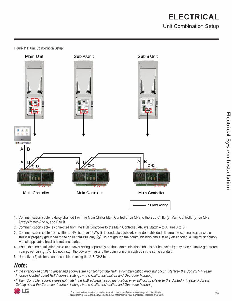
63
Electrical System Installation
Due to our policy of continuous product innovation, some specifications may change without notification. ©LG Electronics U.S.A., Inc., Englewood Cliffs, NJ. All rights reserved. “LG” is a registered trademark of LG Corp.
: Field wiring
Main Unit Sub A Unit Sub B Unit
Main Controller Main Controller Main Controller
CH3 3HC3HCA B A B
A B
A B
ELECTRICAL
1. Communication cable is daisy chained from the Main Chiller Main Controller on CH3 to the Sub Chiller(s) Main Controller(s) on CH3 Always Match A to A, and B to B.
2. Communication cable is connected from the HMI Controller to the Main Controller. Always Match A to A, and B to B.3. Communication cable from chiller to HMI is to be 18 AWG, 2-conductor, twisted, stranded, shielded. Ensure the communication cable
shield is properly grounded to the chiller chassis only. Do not ground the communication cable at any other point. Wiring must comply with all applicable local and national codes.
4. Install the communication cable and power wiring separately so that communication cable is not impacted by any electric noise generated from power wiring. Do not install the power wiring and the communication cables in the same conduit.
5. Up to five (5) chillers can be combined using the A-B CH3 bus.
•
• Setting about the Controller Address Settings in the Chiller Installation and Operation Manual.)
Figure 111: Unit Combination Setup.

64 Due to our policy of continuous product innovation, some specifications may change without notification. ©LG Electronics U.S.A., Inc., Englewood Cliffs, NJ. All rights reserved. “LG” is a registered trademark of LG Corp.
LG A
ir-Co
oled
Coo
ling
Onl
y In
verte
r Scr
oll C
hille
r Ins
talla
tion
and
Ow
ners
Man
ual
If the chiller enters the Modbus remote mode, all the information can only be monitored through the HMI. Actual operation control (start / stop or
-munication is recovered, it will automatically resume. If the remote Modbus connection is not used, reset the power of the main PCB of the chiller to cancel the alarm.
Modbus Interlock Protocol DetailsThe protocol details for Modbus interlock of external devices are:• Physical layer: RS-485 serial line• Mode: Modbus RTU mode
• Baud rate: 9,600• Parity: None parity
• One (1) stop bit• Applied function codes
Function Code Sub-function Function Name Start Address From Main Device0x01 None Read Coil Register Address-10x02 None Read Discrete Input Register Address-100010x03 None Read Holding Register Address-400010x04 None Read Input Register Address-300010x05 None Write Single Coil Register Address-10x06 None Write Single Holding Register Address-40001
0xF1~FF Reserved for Exception Code - -
Figure 112: Applied Function Codes.
See the Modbus protocols in the following pages.
MODBUS PROTOCOL
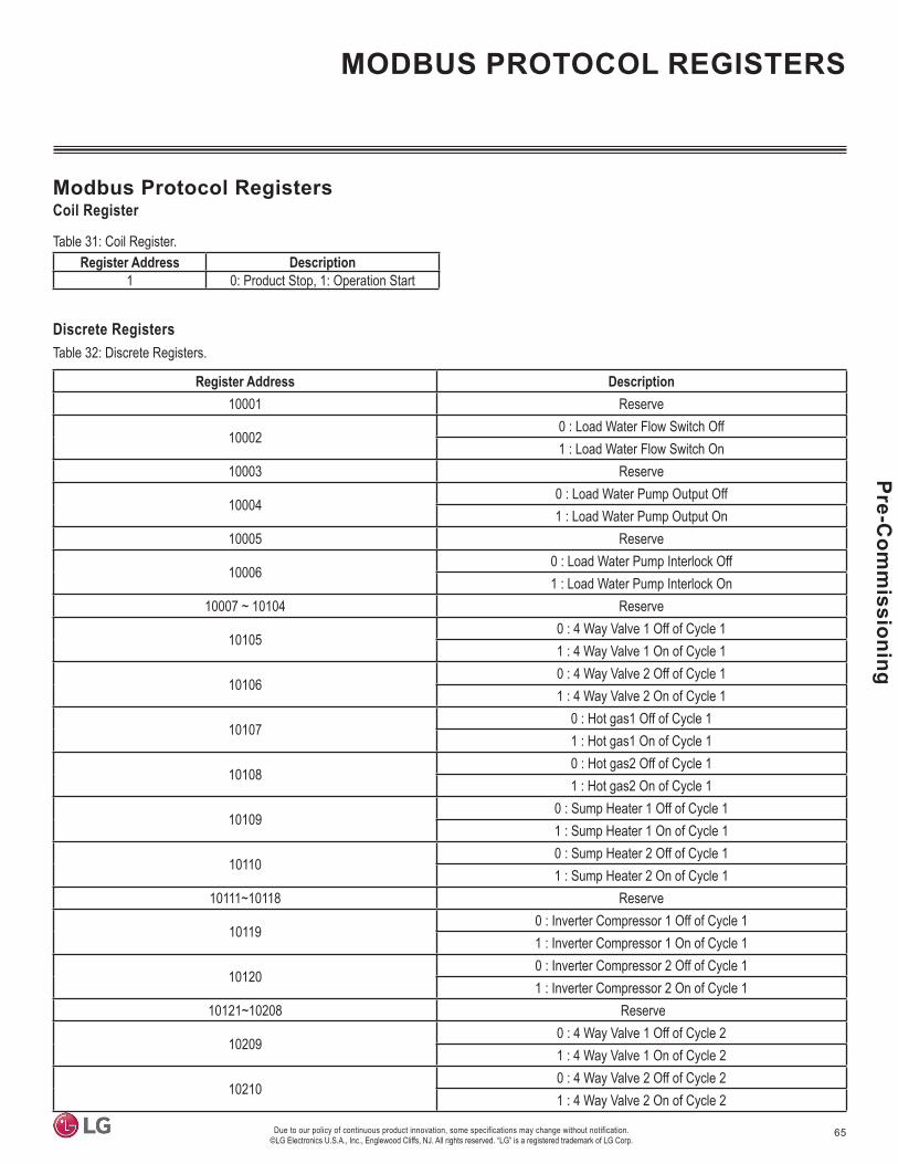
65
Pre-Com
missioning
Due to our policy of continuous product innovation, some specifications may change without notification. ©LG Electronics U.S.A., Inc., Englewood Cliffs, NJ. All rights reserved. “LG” is a registered trademark of LG Corp.
Register Address Description10001 Reserve
100020 : Load Water Flow Switch Off1 : Load Water Flow Switch On
10003 Reserve
100040 : Load Water Pump Output Off1 : Load Water Pump Output On
10005 Reserve
100060 : Load Water Pump Interlock Off1 : Load Water Pump Interlock On
10007 ~ 10104 Reserve
101050 : 4 Way Valve 1 Off of Cycle 11 : 4 Way Valve 1 On of Cycle 1
101060 : 4 Way Valve 2 Off of Cycle 11 : 4 Way Valve 2 On of Cycle 1
101070 : Hot gas1 Off of Cycle 11 : Hot gas1 On of Cycle 1
101080 : Hot gas2 Off of Cycle 11 : Hot gas2 On of Cycle 1
101090 : Sump Heater 1 Off of Cycle 11 : Sump Heater 1 On of Cycle 1
101100 : Sump Heater 2 Off of Cycle 11 : Sump Heater 2 On of Cycle 1
10111~10118 Reserve
101190 : Inverter Compressor 1 Off of Cycle 11 : Inverter Compressor 1 On of Cycle 1
101200 : Inverter Compressor 2 Off of Cycle 11 : Inverter Compressor 2 On of Cycle 1
10121~10208 Reserve
102090 : 4 Way Valve 1 Off of Cycle 21 : 4 Way Valve 1 On of Cycle 2
102100 : 4 Way Valve 2 Off of Cycle 21 : 4 Way Valve 2 On of Cycle 2
Modbus Protocol RegistersCoil Register
Table 31: Coil Register.Register Address Description
1 0: Product Stop, 1: Operation Start
Table 32: Discrete Registers.Discrete Registers
MODBUS PROTOCOL REGISTERS

66 Due to our policy of continuous product innovation, some specifications may change without notification. ©LG Electronics U.S.A., Inc., Englewood Cliffs, NJ. All rights reserved. “LG” is a registered trademark of LG Corp.
LG A
ir-Co
oled
Coo
ling
Onl
y In
verte
r Scr
oll C
hille
r Ins
talla
tion
and
Ow
ners
Man
ual Register Address Description
102110 : Hot gas1 Off of Cycle 21 : Hot gas1 On of Cycle 2
102120 : Hot gas2 Off of Cycle 21 : Hot gas2 On of Cycle 2
102130 : Sump Heater 1 Off of Cycle 21 : Sump Heater 1 On of Cycle 2
102140 : Sump Heater 2 Off of Cycle 21 : Sump Heater 2 On of Cycle 2
10215~10222 Reserve
102230 : Inverter Compressor 1 Off of Cycle 21 : Inverter Compressor 1 On of Cycle 2
102240 : Inverter Compressor 2 Off of Cycle 21 : Inverter Compressor 2 On of Cycle 2
10225~10312 Reserve
103130 : 4 Way Valve 1 Off of Cycle 31 : 4 Way Valve 1 On of Cycle 3
103140 : 4 Way Valve 2 Off of Cycle 31 : 4 Way Valve 2 On of Cycle 3
103150 : Hot gas1 Off of Cycle 31 : Hot gas1 On of Cycle 3
103160 : Hot gas2 Off of Cycle 31 : Hot gas2 On of Cycle 3
103170 : Sump Heater 1 Off of Cycle 31 : Sump Heater 1 On of Cycle 3
103180 : Sump Heater 2 Off of Cycle 31 : Sump Heater 2 On of Cycle 3
10319~10326 Reserve
103270 : Inverter Compressor 1 Off of Cycle 31 : Inverter Compressor 1 On of Cycle 3
103280 : Inverter Compressor 2 Off of Cycle 31 : Inverter Compressor 2 On of Cycle 3
10329~10416 Reserve
Table 33: Discrete Registers, continue.
MODBUS PROTOCOL REGISTERS

67
Pre-Com
missioning
Due to our policy of continuous product innovation, some specifications may change without notification. ©LG Electronics U.S.A., Inc., Englewood Cliffs, NJ. All rights reserved. “LG” is a registered trademark of LG Corp.
Table 34: Input Registers.Register Address Description
30001 Chiller Controller Version30002 Entire Operation Current30003 External Air Temperature30004 Common Load Water Output Temperature (Average Value of Individual Load Water Outputs)30005 Common Load Water Input Temperature (Average Value of Individual Load Water Inputs)
30006~30007 Reserve30008 Information of Refrigerator Failure (1~5)30009 Cycle Failure Information (0 : Common System Error, 1~10 : Error of Corresponding Cycle)30010 Failure Code30011 Start Waiting Time30013 Product’s Accumulated Operation Time Upper Level30014 Product’s Accumulated Operation Time Lower Level
30015~30100 Reserve30101, 30102 Load Water Output Temperature of Cycle 130103, 30104 Load Water Input Temperature of Cycle 130105~30108 Reserve
30109 Condensation Temperature (Left) of Cycle 130110 Condensation Temperature (Right) of Cycle 130111 Evaporation Temperature (Left) of Cycle 130112 Evaporation Temperature (Right) of Cycle 130113 Inverter Compressor 1 Frequency of Cycle 130114 Inverter Compressor 2 Frequency of Cycle 130115 High Pressure (Left) of Cycle 130116 High Pressure (Right) of Cycle 130117 Low Pressure (Left) of Cycle 130118 Low Pressure (Right) of Cycle 130119 Operation Current (Left) of Cycle 130120 Operation Current (Right) of Cycle 130121 Main EEV’s Status Value of Cycle 1 (Left)30122 Main EEV’s Status Value of Cycle 1 (Right)
30123~30124 Reserve30125 Discharge Temperature of Inverter Compressor 1 of Cycle 130126 Discharge Temperature of Inverter Compressor 2 of Cycle 130127 Intake Temperature of Inverter Compressor 1 of Cycle 130128 Intake Temperature of Inverter Compressor 2 of Cycle 1
MODBUS PROTOCOL REGISTERS
Input Registers

68 Due to our policy of continuous product innovation, some specifications may change without notification. ©LG Electronics U.S.A., Inc., Englewood Cliffs, NJ. All rights reserved. “LG” is a registered trademark of LG Corp.
LG A
ir-Co
oled
Coo
ling
Onl
y In
verte
r Scr
oll C
hille
r Ins
talla
tion
and
Ow
ners
Man
ual
Table 35: Input Registers, continued.Register Address Description
30129 Liquid Pipe Temperature (Left) of Cycle 130130 Liquid Pipe Temperature (Right) of Cycle 130131 Hex Temperature (Left) of Cycle 130132 Hex Temperature (Right) of Cycle 1
30133~30144 Reserve30145 Accumulated Operation Time of Inverter Compressor 1 of Cycle 1 (Upper Level)30146 Accumulated Operation Time of Inverter Compressor 1 of Cycle 1 (Lower Level)30147 Accumulated Operation Time of Inverter Compressor 2 of Cycle 1 (Upper Level)30148 Accumulated Operation Time of Inverter Compressor 2 of Cycle 1 (Lower Level)
30149~30200 Reserve30201, 30202 Load Water Output Temperature of Cycle 230203, 30204 Load Water Input Temperature of Cycle 230205~30208 Reserve
30209 Condensation Temperature (Left) of Cycle 230210 Condensation Temperature (Right) of Cycle 230211 Evaporation Temperature (Left) of Cycle 230212 Evaporation Temperature (Right) of Cycle 230213 Inverter Compressor 1 Frequency of Cycle 230214 Inverter Compressor 2 Frequency of Cycle 230215 High Pressure (Left) of Cycle 230216 High Pressure (Right) of Cycle 230217 Low Pressure (Left) of Cycle 230218 Low Pressure (Right) of Cycle 230219 Operation Current (Left) of Cycle 230220 Operation Current (Right) of Cycle 230221 Main EEV’s Status Value of Cycle 2 (Left)30222 Main EEV’s Status Value of Cycle 2 (Right)
30223~30224 Reserve30225 Discharge Temperature of Inverter Compressor 1 of Cycle 230226 Discharge Temperature of Inverter Compressor 2 of Cycle 230227 Intake Temperature of Inverter Compressor 1 of Cycle 230228 Intake Temperature of Inverter Compressor 2 of Cycle 230229 Liquid Pipe Temperature (Left) of Cycle 230230 Liquid Pipe Temperature (Right) of Cycle 230231 Hex Temperature (Left) of Cycle 230232 Hex Temperature (Right) of Cycle 2
30233~30244 Reserve30245 Accumulated Operation Time of Inverter Compressor 1 of Cycle 2 (Upper Level)30246 Accumulated Operation Time of Inverter Compressor 1 of Cycle 2 (Lower Level)30247 Accumulated Operation Time of Inverter Compressor 2 of Cycle 2 (Upper Level)30248 Accumulated Operation Time of Inverter Compressor 2 of Cycle 2 (Lower Level)
30249~30300 Reserve
MODBUS PROTOCOL REGISTERS

69
Pre-Com
missioning
Due to our policy of continuous product innovation, some specifications may change without notification. ©LG Electronics U.S.A., Inc., Englewood Cliffs, NJ. All rights reserved. “LG” is a registered trademark of LG Corp.
Table 36: Input Registers, continued.Register Address Description
30301, 30302 Load Water Output Temperature of Cycle 330303, 30304 Load Water Input Temperature of Cycle 330305~30308 Reserve
30309 Condensation Temperature (Left) of Cycle 330310 Condensation Temperature (Right) of Cycle 330311 Evaporation Temperature (Left) of Cycle 330312 Evaporation Temperature (Right) of Cycle 330313 Inverter Compressor 1 Frequency of Cycle 330314 Inverter Compressor 2 Frequency of Cycle 330315 High Pressure (Left) of Cycle 330316 High Pressure (Right) of Cycle 330317 Low Pressure (Left) of Cycle 330318 Low Pressure (Right) of Cycle 330319 Operation Current (Left) of Cycle 330320 Operation Current (Right) of Cycle 330321 Main EEV’s Status Value of Cycle 3 (Left)30322 Main EEV’s Status Value of Cycle 3 (Right)
30323~30324 Reserve30325 Discharge Temperature of Inverter Compressor 1 of Cycle 330326 Discharge Temperature of Inverter Compressor 2 of Cycle 330327 Intake Temperature of Inverter Compressor 1 of Cycle 330328 Intake Temperature of Inverter Compressor 2 of Cycle 330329 Liquid Pipe Temperature (Left) of Cycle 330330 Liquid Pipe Temperature (Right) of Cycle 330331 Hex Temperature (Left) of Cycle 330332 Hex Temperature (Right) of Cycle 3
30333~30344 Reserve30345 Accumulated Operation Time of Inverter Compressor 1 of Cycle 3 (Upper Level)30346 Accumulated Operation Time of Inverter Compressor 1 of Cycle 3 (Lower Level)30347 Accumulated Operation Time of Inverter Compressor 2 of Cycle 3 (Upper Level)30348 Accumulated Operation Time of Inverter Compressor 2 of Cycle 3 (Lower Level)
30349~39997 Reserve39998 Product Group Info.39999 Product Type Info.
Table 37: Holding Registers.Register Address Description
40001 Reserve40002 Operation Mode Setting (0 : Cooling, 4 : Heating)40003 Cooling Target Temperature Setting (41°F ~ 68°F)40004 Heating Target Temperature Setting (104°F ~ 134.6°F)40005 Control Mode Setting (On-site/Remote/Scheduled)40006 Remote Mode Setting (Contact / Modbus)40007 Cooling Type Setting (0 : Normal)40008 Max. Operating Frequency Setting: (0 : 120, 1 : 130, 2 : 110, 3 : 100, 4 : 90, 5 : 80, 6 : 70)
40009~40022 Reserve
Holding Registers
MODBUS PROTOCOL REGISTERS

70 Due to our policy of continuous product innovation, some specifications may change without notification. ©LG Electronics U.S.A., Inc., Englewood Cliffs, NJ. All rights reserved. “LG” is a registered trademark of LG Corp.
LG A
ir-Co
oled
Coo
ling
Onl
y In
verte
r Scr
oll C
hille
r Ins
talla
tion
and
Ow
ners
Man
ual Test Run
Checks Before Test RunBefore starting the chiller, check the supplementary devices such as the water circulation, water pump, air handler unit, etc. (see manufac-turer’s directions for operation information). Verify that all parts are installed properly and accurately; check if the wiring is installed correctly. Refer to the wiring diagrams.• Check the flow switch for appropriate operation; verify if the sensor is functioning properly.• For cooling, fill the water circuit with clean water. Purge the air so no air remains inside the water circuit. If the outdoor temperature is
expected to drop below 32°F, add anti-freeze to the water circuit to prevent freezing. The water circuit must be cleaned before connecting it to the chiller.
• Check and inspect all water piping. Check if the water is flowing in the correction direction, and if it is properly connected to the evaporator. Open all flow valves to the evaporator.
• Turn on the water pump. Measure the decrease in overall water pressure to check whether the flow is accurate. Compare it to the designed flow rate.
• Check all electric connections in the control panel. Verify all parts are tightly assembled with good contact conditions. Although the control panel connections are inspected at the factory, these can become loose from vibration during transportation.
• Check and inspect all fuses. All fuses in the power panel / control panel must be installed at an appropriate location.
Initial Operation• Check if the load is operating on the air processing device (or any other device) on the water supply side to the chiller. If the temperature of
the water is too high, the initial operation of the load device can be delayed. • If the chiller auto control is not working, check if the water circulation pump is operating.• Voltage variance must be within ±10%, Check that the phase voltage imbalance is not exceeding 5% between phases. Check whether the
power and capacity is appropriate for processing the load.• Check the power phase order.• Check / inspect the voltage monitoring meter in the power panel. The meter should not display any error codes.• Use the HMI device to check the water outlet temperature and water output temperature setting.• Set the start menu on the HMI device. Water circulation flow must be within the permitted range to control the temperature appropriately.
Checks During Initial OperationAfter the test run, operate the chiller to verify the product is functioning properly. If there are any issues, immediately stop operation, and follow the “Troubleshooting” process.• Check the rotation of the condenser fan motor. • Verify if the water outlet temperature matching the set temperature.• Through the HMI device, check if all of the sensors display the appropriate values. Temperature sensor detects the compressor discharge
temperature, compressor suction temperature, condenser outlet temperature and cold water inlet/outlet temperature.• Verify if the operating current, operation sound, and vibration matches the product specifications.
Stop Operation• Follow the procedure below when stopping chiller operation.• On the HMI, press the stop button• Measure how long it takes for the chiller to actually stop.• Stop the water pump.
Load Operation and Operation AdjustmentAfter start and stop, check the functions by operating the chiller, and adjusting if necessary. Adjust the water outlet temperature setting to adjust the load.
TEST RUN

71
Pre-Com
missioning
Due to our policy of continuous product innovation, some specifications may change without notification. ©LG Electronics U.S.A., Inc., Englewood Cliffs, NJ. All rights reserved. “LG” is a registered trademark of LG Corp.
Prepare Operation DataAlways record the chiller operating condition; check it against the product specification and determine if it is functioning normally.
Analyze Water QualityAnalyze water quality during the test run, and save the data. Compare the water quality results after a certain period (a monthly check isrecommended) against the test run data to determine when to change the water.
Additional Functions - DIP Switch SettingsSee below and the next two pages for DIP switch settings to the listed functions. Change the DIP switch settings on the control box PCB.
TEST RUN
Night Low Sound FunctionNight low sound function determines the hottest time of the day during cooling operation, and reduces the fan operation sound by running it at a low RPM at night.
•
• Request the function setting to the contractor after chiller installation.• If the function is not used, turn the DIP switch OFF and reset the
power.• If the chiller RPM is changed, the cooling capacity may be reduced.
Step Maximum Fan RPM
Standby Time (Hour)
Function Operation Time (Hour)
11 820
8 92 6.5 10.53 5 124
2 7508 9
5 6.5 10.56 5 127
3 7208 9
8 6.5 10.59 5 1210
-820 0 Continuous Operation
11 750 0 Continuous Operation12 720 0 Continuous Operation
DIP-SW01 7-Segment
SW04C(X : cancel)
SW01C(
Figure 113: DIP Switch Locations (Appearances May Vary).
Turn No. 5 on the Main PCB DIP switch bank SW01 to ON.
Press the SW01D button until “Func” appears.
Press the SW01C button until the “Fn3” function is displayed. Press the SW01D button once (1) to set the step.
When Fn3 is ON, press the SW10C or SW02C button until the applicable step is displayed.
1.Step 1~3; Maximum RPM = 8202. Step 4~6; Maximum RPM = 7503. Step 7~8; Maximum RPM = 720
*Refer to the table at right for standby time / function operation timeby step.
The Night Low Sound function automatically cancels after nine (9) hours of operation time.
Table 38: Setting the Time and Related Sound Level.
Figure 114: How to Set the Maximum RPM.
Figure 115: Starting the Night Low Sound Function (When Setting Step 1).
Figure 116: Stopping the Night Low Sound Function (When Setting Step 1).
After the maximum chiller temperature isdetected, it operates at 820 (Set) RPM after 8 hours (Standby time).

72 Due to our policy of continuous product innovation, some specifications may change without notification. ©LG Electronics U.S.A., Inc., Englewood Cliffs, NJ. All rights reserved. “LG” is a registered trademark of LG Corp.
LG A
ir-Co
oled
Coo
ling
Onl
y In
verte
r Scr
oll C
hille
r Ins
talla
tion
and
Ow
ners
Man
ual Self Diagnosis Function
This function self diagnoses the chiller, and displays the error. The error code appears in the pop up window in HMI. When the error is resolved, press the “Reset” button on HMI to close the pop up window.
OK ButtonThe OK Button closes the error pop up window. The error codes pop up window is closed for technician convenience from the HMI screen, but the current error code status is maintained.
Error CodeThe error code is configured as below.
HMI Communication Error
OK
Common ErrorCH10XXX error stops product operation.
Error By CycleWhen the error occurs by cycle, the applicable cycle is maintained at stopped condition and normal cycles operate normally. When the cycle error is canceled, the chiller resumes normal operation.
If comprised of three (3) cycles, chiller will maintain overall operation, even when two (2) cycles are in error. The chiller will stop only when all three (3) cycles are in error.
Figure 117: HMI Error Screen.
CH X XXXX
Displays the error code.
Displays the error cycle number. (0~3)0: Common Error1: Cycle 1 Error2: Cycle 2 Error3: Cycle 3 Error
Displays the unit number, and current product is set to 1.
Figure 118: Error Code Nomenclature.
TEST RUN

73
Water System
Maintenance
Due to our policy of continuous product innovation, some specifications may change without notification. ©LG Electronics U.S.A., Inc., Englewood Cliffs, NJ. All rights reserved. “LG” is a registered trademark of LG Corp.
WATER SYSTEM MAINTENANCE
Category Status Cause Action
Water sourcehas
malfunctioned.
CH13
Error detected during flow switch connection.
Water is not flowing, or water flowamount is insufficient.
(All operation conditions)
Verify if the water source supply pump is operating.Check if the water piping is blocked. Strainer needs cleaned, valve is locked,
there is a problem with the valve, there is air in the piping, etc.Check for a problem with the flow switch. Flow switch is malfunctioning,
unauthorized handling, flow switch is disconnected, etc.)
CH180 Water is not flowing, or water flowamount is insufficient.
Verify if the water source supply pump is operating.Check if the water piping is blocked. Strainer needs cleaned, valve is locked,
there is a problem with the valve, there is air in the piping, etc.
Shell-and-Tube Heat Exchanger MaintenanceAs scale accumulates, the efficiency of the shell-and-tube heat exchanger may decrease, and / or damage can occur if the flow amount decreases, causing the heat exchanger to freeze up and burst. It is necessary, therefore, to manage scale accumulation.
1. Before the cooling / heating season, check the following (one [1] time per year).• Inspect the water quality to see if it falls within standards.• Clean the strainer. • Verify that the water flow amount is adequate.• Check if operation conditions are adequate (pressure, flow amount, water outlet temperature, etc.).
2. To clean the shell-and-tube heat exchanger, follow the procedures below (one [1] time per year).• Check if a service port is mounted on the water pipe for solvent cleaning.• A 5% diluted formic acid, citric acid, oxalic acid (water acid), acetic acid, phosphoric acid, etc., are suitable as the solvent for scale cleaning.
• During the cleaning process, verify that the water inlet and outlet pipe gate valves and drain pipe valves are properly shut.• Connect the piping for cleaning through water pipe service port, fill the solvent of about 122°F~140°F in the heat exchanger, and circulate
for about two (2) to five (5) hours using a pump. Circulation time may be different according to solvent temperature or amount of scale. • Closely observe for solvent color changes to decide the circulation time.• After the solvent circulates, completely drain it out of the heat exchanger. Add 1~2 % concentration sodium hydroxide (NaOH) or hydrocar-
bon sodium (NaHCO3) and circulate for about 15 to 20 minutes to neutralize.• Flush with clean water. Measure the pH concentration of the water to verify if the solvent is properly removed.• If another solvent is used, verify that it does not contain any corrosive properties that will damage stainless or copper.• Contact a local water quality specialist for information regarding cleaning solvents.
3. After cleaning is complete, operate the chiller to see if it functions properly.
Water ManagementTroubleshooting Errors that Appear During Test Operation
If CH13 or CH180 occurs during a test run, there is a possibility of the shell-and-tube heat exchanger partially freezing. Restart the chiller after removing the cause of the partial freezing: Insufficient water flow, a blocked water supply, undercharged system refrig-erant, foreign particulates inside the shell-and-tube heat exchanger.
Table 39: Water Source Errors.

74 Due to our policy of continuous product innovation, some specifications may change without notification. ©LG Electronics U.S.A., Inc., Englewood Cliffs, NJ. All rights reserved. “LG” is a registered trademark of LG Corp.
LG A
ir-Co
oled
Coo
ling
Onl
y In
verte
r Scr
oll C
hille
r Ins
talla
tion
and
Ow
ners
Man
ual
WATER SYSTEM MAINTENANCE
Daily Inspection Management1. Water Quality ManagementThe chiller shell-and-tube heat exchanger cannot be disassembled and cleaned directly, nor can its parts be replaced. To prevent corrosion, or scale from accumulating in the shell-and-tube heat exchanger, special care must be applied to water quality management. Follow the local, state, and federal standards for water quality. If corrosion prevention solution or corrosion reduction solution is added, chemicals with no corrosive properties against stainless and copper must be used. To prevent contaminating the circulation water by outside air, periodically drain the water that is inside the water pipe, and then fill it with new water, even if the circulation water was not contaminated.
2. Water Flow Management.If the water flow is insufficient, the shell-and-tube heat exchanger may freeze and burst. Check if the strainer is blocked or filled with air. Measure the temperature and / or pressure differences between the inlet and outlet water piping. If there is a difference of temperature or pressure above the appropriate levels, the water flow has decreased. Immediately stop chiller operation, troubleshoot, and fix the issue before restarting. (If there is air in the water, purge the system. The air inside the water piping hinders water circulation, causing the flow amount to be insufficient and the heat exchanger to freeze and burst.)
3. Anti-freeze Concentration Management.If anti-freeze is added to the water system, use the designated type and concentration. Anti-freeze that includes calcium chloride cor-rodes the shell-and-tube heat exchanger cannot be used.If the anti-freeze is left alone, it absorbs moisture from the air, the concentration will decrease, which can lead to the shell-and-tube heat ex-changer freezing and bursting. Minimize the air contacting the anti-freeze, and periodically measure the concentration of anti-freeze. Maintain the anti-freeze concentration by adding as necessary.
Gate Valve (Locked)
Service Plug
Strainer
Drain Valve (Locked)
Gate Valve (Locked)
Chiller
Hose
Pump
Shell and Tube Type Heat Exchanger Cleaning
Filter
Figure 119: Cleaning the Shell-and-Tube Heat Exchanger.

75
Water System
Maintenance
Due to our policy of continuous product innovation, some specifications may change without notification. ©LG Electronics U.S.A., Inc., Englewood Cliffs, NJ. All rights reserved. “LG” is a registered trademark of LG Corp.
WATER SYSTEM MAINTENANCE
Period (Year)Category 1 2 3 4 5 6 7 8 9 10 11 12 13 14 15
Chiller Operation StatusClean Heat ExchangerClean StrainerInspect Water QualityInspect for Refrigerant Leaks
• The Water System Maintenance Schedule table above lists the minimum amount of time. More frequent inspections can be necessary
because of environmental, operation, and / or water quality conditions. • • • •
remove.• If the region in which the chiller is installed has poor quality, more frequent cleaning can be necessary.• Cleaning solvents are strongly acidic, flush the system completely with water to remove all traces of solvent.• • Perform an air purge procedure to remove all air inside the water pipe.•
Table 40: Water System Maintenance Schedule.

76 Due to our policy of continuous product innovation, some specifications may change without notification. ©LG Electronics U.S.A., Inc., Englewood Cliffs, NJ. All rights reserved. “LG” is a registered trademark of LG Corp.
LG A
ir-Co
oled
Coo
ling
Onl
y In
verte
r Scr
oll C
hille
r Ins
talla
tion
and
Ow
ners
Man
ual
TROUBLESHOOTING GENERAL ERRORS
troubleshooting of the Chiller product.WARNING
Troubleshooting General Errors
If the safety devices stopped chiller operation, identify and resolve the problem(s) before restart.
• If the chiller is not operating, check the power, refrigerant, configuration, and error settings. • To troubleshoot the power supply / wiring, check the voltage connected to the chiller terminal block in the control panel. If there is no power,
check if the circuit breaker has tripped.• If the power is properly connected, check the chiller refrigerant cycle pressure to verify if it is within the normal range.• If the chiller refrigerant cycle pressure exceeds the normal range, check for leaks within the piping system.• Before restarting the chiller, return it the default setting.• Check the error codes; error codes can be view using the HMI device.• If there is /are (an) error code(s) the alarm is turned on, see the Error Code tables to troubleshoot specific errors.
Symptom Cause Solution
Chiller does not start.
Check the power.Check over-current protection device.
Check if fuse is disconnected or shorted out.Turn power on.
Incorrect or inaccurate chiller configuration.Check configuration.
Check if wiring is incorrect.
Error appears.
Check the error condition.Check for the error code tables to review solutions and resolve
the issue.Follow direction.
Check the HMI input channel to review the error input.Entering delay time. Verify if the compressor is in start delay time.
Evaporation pressure islow and the chiller isconstantly stopping.
Insufficient refrigerant. Check for leaks and recharge refrigerant.
Insufficient water.Check water system (ensure rated flow.).
- Is the water system valve closed?- Is the pressure difference between inlet and outlet of thewater system appropriate?- Is the air from water system cold?
Condensation pressureis high and the chiller is
constantly stopping.
Outside temperature is high. Check if the outside temperature is within the operation condition range.
Foreign particles accumulated on the condenser. Clean condenser.Fan is defective. Replace fan.
Chiller is vibrating.
Bolt connecting the fan motor is loose. Check assembly and tighten bolt.Motor mount is loose. Check assembly and tighten bolt.Fan is not balanced. Check fan rotation range; replace fan.
Compressor assembly bolt is loose. Tighten assembly bolt / nut.Frame assembly bolt is loose. Check assembly and tighten bolt
Motor bearing is burned. Check for abnormal noise in motor (noise in multiple RPM)and replace motor.
Table 41: Troubleshooting General Errors.

77
Troubleshooting / Error Codes
Due to our policy of continuous product innovation, some specifications may change without notification. ©LG Electronics U.S.A., Inc., Englewood Cliffs, NJ. All rights reserved. “LG” is a registered trademark of LG Corp.
troubleshooting of the Chiller product.WARNING
Symptom Cause Solution
Reverberating sound.Rubber on the motor mount is defective. Replace motor mount.Pipe vibration heard near compressor. Replace the anti-vibration material on piping.
High frequency wave sound from front of
chiller.Fan defect in the control box. Clean the area around the fan.
Constantly searching forcold water. Insufficient cold water.
Check the water system (Ensure rated flow).- Is the water system valve closed?- Is the pressure difference between inlet and outlet of thewater system appropriate?- Is the air of water system cold?- Is the cooling load within appropriate range?
Evaporation pressure ishigh.
Temporary rise in water temperature due to abnormalload increase.
This is a normal condition, but verify if the pressure falls withinthe operating range.
Table 42: Troubleshooting General Errors, continued.
TROUBLESHOOTING GENERAL ERRORS

78 Due to our policy of continuous product innovation, some specifications may change without notification. ©LG Electronics U.S.A., Inc., Englewood Cliffs, NJ. All rights reserved. “LG” is a registered trademark of LG Corp.
LG A
ir-Co
oled
Coo
ling
Onl
y In
verte
r Scr
oll C
hille
r Ins
talla
tion
and
Ow
ners
Man
ual
ERROR CODE TABLES
troubleshooting of the Chiller product.WARNING
Table 43: Error Code Table.
Error Code Description Reason Chiller Status Error Resolution
CHxx001 Outdoor temperature sensor error.
Outdoor temperature sensor is disconnected, shorted, or opened. Stop product. Automatically returns to normal
condition.
CHxx003 HMI communication error.When communication between HMI and chiller controller is disconnected for more
than 180 seconds.Stop product. Automatically return to normal
condition.
CHxx005 Cycle control boxcommunication error.
When communication between chiller controller and cycle control box is
disconnected for more than 30 seconds.Stop product Automatically return to normal
condition.
CHxx009 Remote communication error.
When the Modbus communication withthe external device is not established for more than 180 seconds after the initial
communication with the remote Modbuscondition is established.
Stop product Automatically return to normal condition.
CHxx011 Load water pump interlock error.
When the load water pump is turned off for 3 seconds when starting or during
the operation for more than 3 times within 1 hour. When turned off more than 9
seconds within 1 hour.
Stop product Press the HMI Reset button.
CHxx013 Load water flow switch error.
When the load water flow switch is turned off for 3 seconds when starting or
during the operation for more than 3 times within 1 hour. When turned off more than 9
seconds within 1 hour.
Stop product Press the HMI Reset button.
CHxx015 Remote alarm.When the contact point signal of hardware wiring is short when entering the remote
control mode.Stop product Automatically return to normal
condition.
CHxx021 Inverter compressor IPM fault. Inverter compressor drive IPM defect/inverter compressor defect
Stop applicable cycle
Automatically return to normal condition.
CHxx022 Inverter compressor input over-current. Inverter compressor input over-current. Stop applicable
cycleAutomatically return to normal
condition.
CHxx023 Inverter compressor DC link low pressure. DC voltage charge defect. Stop applicable
cycleAutomatically return to normal
condition.
CHxx024 Cycle high pressure switch operation.
High pressure switch operates due to abnormal high pressure.
Stop applicable cycle
Automatically return to normal condition.
CHxx025 High/Low voltage of input voltage.
Over/Under permitted voltage of input voltage, N.
Stop applicable cycle
Automatically return to normal condition.
CHxx026 Inverter compressor start failure error. Initial start failure from compressor defect. Stop applicable
cycleAutomatically return to normal
condition.
CHxx028 Inverter DC link high voltage error. Defect from DC voltage and over-charge. Stop applicable
cycleAutomatically return to normal
condition.
CHxx029 Inverter compressor over-current. Exceed limit. Stop applicable
cycleAutomatically return to normal
condition.
CHxx032Surge in inverter #1,#2 compressor discharge
temperature.Stop applicable
cycleAutomatically return to normal
condition

79
Troubleshooting / Error Codes
Due to our policy of continuous product innovation, some specifications may change without notification. ©LG Electronics U.S.A., Inc., Englewood Cliffs, NJ. All rights reserved. “LG” is a registered trademark of LG Corp.
ERROR CODE TABLES
troubleshooting of the Chiller product.WARNING
Error Code Description Reason Chiller Status Error Resolution
CHxx034 Surge in high pressure Surge in high pressure side. Stop applicable cycle
Automatically return to normal condition
CHxx035 Surge in low pressure Drop in low pressure side. Stop applicable cycle
Automatically return to normal condition
CHxx036 Low compression rate error Low compression rate error. Stop applicable cycle
Automatically return to normal condition
CHxx040 Inverter compressor CT sensor error
Inverter compressor CT sensor is disconnected, shorted, or opened.
Stop applicable cycle
Automatically return to normal condition
CHxx041 Inverter compressor discharge temperature sensor error
Inverter compressor discharge temperature sensor is
disconnected, shorted, or opened.Stop applicable
cycleAutomatically return to normal
condition
CHxx042 Low pressure sensor error Low pressure sensor is disconnected, shorted, or opened.
Stop applicable cycle
Automatically return to normal condition
CHxx043 High pressure sensor error High pressure sensor is disconnected, shorted, or opened.
Stop applicable cycle
Automatically return to normal condition
CHxx045 Heat exchanger temperature sensor error
Heat exchanger temperature sensor is disconnected, shorted, or opened.
Stop applicable cycle
Automatically return to normal condition
CHxx046 Suction temperature sensor error
Suction temperature sensor is disconnected, shorted, or opened.
Stop applicable cycle
Automatically return to normal condition
CHxx050 Chiller 3 phase power missing phase Chiller 3 phase power missing phase Stop applicable
cycleAutomatically return to normal
condition
CHxx052 Communication error with inverter controller
Communication error with inverter controller
Stop applicable cycle
Automatically return to normal condition
CHxx053 Communication failure between indoor and chiller units.
Communication failure between indoor and chiller unit.
Stop applicable cycle
Automatically return to normal condition
CHxx054Reversed phase on chiller
unit’s 3 phased power source;Reversed connection on RST.
Reversed phase on chiller unit’s 3 phasedpower source; Reversed connection on
RST.Stop applicable
cycleAutomatically return to normal
condition
CHxx057 Communication error with inverter controller
Communication error with inverter controller
Stop applicable cycle
Automatically return to normal condition
CHxx059 Installation failure of series model outdoor unit
Installation failure of series model outdoor unit
Stop applicable cycle
Automatically return to normal condition
CHxx060 Inverter PCB EEPROM error Inverter PCB EEPROM error Stop applicable cycle
Automatically return to normal condition
CHxx062 Surge in inverter board IPM temperature Surge in inverter board IPM temperature Correspond cycle
stopAutomatic return to a normal
condition
CHxx065 Inverter IPM temperature sensor error
Inverter IPM temperature sensor is disconnected, shorted, or opened.
Stop applicable cycle
Automatically return to normal condition
CHxx067 Fan lock Fan locked Stop applicable cycle
Automatically return to normal condition
CHxx075 Fan CT sensor error Fan CT sensor is disconnected, shorted, or opened.
Stop applicable cycle
Automatically return to normal condition
CHxx077 Fan over-voltage error Fan over-voltage Stop applicable cycle
Automatically return to normal condition
Table 44: Error Code Table, continued.

80 Due to our policy of continuous product innovation, some specifications may change without notification. ©LG Electronics U.S.A., Inc., Englewood Cliffs, NJ. All rights reserved. “LG” is a registered trademark of LG Corp.
ERROR CODE TABLES
troubleshooting of the Chiller product.WARNING
Error Code Description Reason Chiller Status Error Resolution
CHxx077 Fan over-voltage error Fan over-voltage Stop applicable cycle
Automatically return to normal condition
CHxx079 Fan start failure error Fan start failure Stop applicable cycle
Automatically return to normal condition
CHxx086 Main PCB EEPROM error Main PCB EEPROM access error Stop applicable cycle
Automatically return to normal condition
CHxx087 Fan PCB EEPROM error Fan PCB EEPROM access error Stop applicable cycle
Automatically return to normal condition
CHxx090 Individual Inlet water temperature sensor error
Individual Inlet water temperature sensor is disconnected, shorted, or opened.
Stop applicable cycle
Automatically return to normal condition
CHxx091 Individual Outlet water temperature sensor error
Individual Outlet water temperature sensor is disconnected, shorted, or opened.
Stop applicable cycle
Automatically return to normal condition
CHxx104 Communication Error between units. Communication error between units. Stop applicable
cycleAutomatically return to normal
condition
CHxx105 Fan board communication error Fan board communication error. Stop applicable cycle
Automatically return to normal condition
CHxx106 Fan PCB IPM fault Fan PCB IPM fault. Stop applicable cycle
Automatically return to normal condition
CHxx107 Fan DC link low voltage error Fan DC link low voltage. Stop applicable cycle
Automatically return to normal condition
CHxx113 Liquid pipe temperature sensor error
Liquid temperature sensor is disconnected, shorted, or opened.
Stop applicable cycle
Automatically return to normal condition
CHxx114 Sub cooling suction temperature sensor error
Sub cooling suction temperature sensor is disconnected, shorted, or opened.
Stop applicable cycle
Automatically return to normal condition
CHxx115 Sub cooling outlet pipe temperature sensor error
Sub cooling outlet pipe temperature sensor is disconnected, shorted, or opened.
Correspond cycle stop
Automatic return to a normal condition
CHxx145 Main Board - External Board communication Error
Main Board - External Board communication Error
Stop applicable cycle
Automatically return to normal condition
CHxx150 Liquid Compression Prevention Error Liquid Compression Prevention Error Stop applicable
cycleAutomatically return to normal
condition
CHxx151 Reversing valve switching failed Mode switching failed Stop applicable cycle
Automatically return to normal condition
CHxx180 Shell and tube type heat exchanger frozen.
Cooling: Individual output water temperatureis maintained at 37.4°F or lower for at least 10 seconds.Heating: Individual output water temperatureis maintained at 140°F or higher for at least
10 seconds.Common in heating and cooling: The difference in input and output water temperature is maintained at 44.6°F orhigher for at least 30 seconds. and / orIf the low pressure is maintained at less than65.7 psi after the compressor started.
Stop applicable cycle
Automatically return to normal condition
CHxx193 Surge in fan board heat emitting plate temperature Surge in fan board heat sink temperature Stop applicable
cycleAutomatically return to normal
condition
CHxx194 Fan board heat emitting plate temperature sensor error
Fan board heat emitting plate temperature sensor is short/open
Stop applicable cycle
Automatically return to normal condition
Table 45: Error Code Table, continued.

Due to our policy of continuous product innovation, some specifications may change without notification. ©LG Electronics U.S.A., Inc., Englewood Cliffs, NJ. All rights reserved. “LG” is a registered trademark of LG Corp.
2. Model InformationContent Information
ProductModel Name: Model Name: Model Name:
Serial: Serial: Serial:
Compressor AModel Name: Model Name: Model Name:
Serial: Serial: Serial:
Compressor BModel Name: Model Name: Model Name:
Serial: Serial: Serial:
1. Project InformationContent Information
Project Name:
Address:
Installed by:
Sold by:
Test run by:
Checklist for Chiller Installation, Page 1 of 2

Due to our policy of continuous product innovation, some specifications may change without notification. ©LG Electronics U.S.A., Inc., Englewood Cliffs, NJ. All rights reserved. “LG” is a registered trademark of LG Corp.
3. Preparation ChecklistContent Check
Is there any damage? Yes NoAre the bolts / nuts assembled properly and firmly attached? Yes NoDoes the power specification match the product specification? Yes NoIs the wiring installed accurately? Yes NoIs the product installed correctly? Yes NoAre the protective devices of the electric circuit installed correctly in accordance with specificationsand codes? Yes No
Are all the terminal blocks connected properly? Yes NoAre all control plugs connected properly and seated at the terminal boards? Yes No
4. Check Water SystemContent Check
Are all valves connected to the chiller open? Yes NoAre all pipes connected accurately? Yes NoAre there any clogs in the drain pipe? Yes NoAre there any leaks? Yes NoIs the air within the system completely well discharged? Yes NoIs the water pump operating properly? Yes NoConfirm UI6-G has a closed contact during pump operation(must be external signal). Yes No
Is the water flow switch operating? Yes NoIs the strainer installed on the piping to the evaporator? Yes No
Checklist for Chiller Installation, Page 1 of 2

To access additional technical documentation, visit www.lghvac.com.
LG Electronics, U.S.A., Inc.Air Conditioning Technologies4300 North Point ParkwayAlpharetta, Georgia 30022www.lghvac.com New Issue: IOM_Chiller_CoolingOnly_460V_06_21