
Installation and Configuration Manual - X-One 1.8 - EVS ...
56
INSTALLATION AND CONFIGURATION MANUAL Version 1.8 - July 2021 X-One
-
Upload
khangminh22 -
Category
Documents
-
view
5 -
download
0
Transcript of Installation and Configuration Manual - X-One 1.8 - EVS ...

INSTALLATION ANDCONFIGURATIONMANUAL
Version 1.8 - July 2021
X-One

DisclaimerThis manual and the information contained herein are the sole property of EVSBroadcast Equipment SA and/or its affiliates (EVS) and are provided “as is” without anyexpressed or implied warranties, including, but not limited to, the implied warranties ofmerchantability and fitness for a particular purpose. In particular, EVS makes nowarranty regarding the use or the consequences of use of this manual and theinformation contained herein. Furthermore, EVS may not be held liable for any direct orindirect, incidental, punitive or consequential loss, damage, cost or expense of any kindwhatsoever and howsoever resulting from the normal or abnormal use of this manualand the information contained herein, even if advised of the possibility of such loss,damage, cost or expense.
While every effort has been made to ensure that the information contained in thismanual is accurate, up-to-date and reliable, EVS cannot be held liable for inaccuraciesor errors that may appear in this publication. The information in this manual is furnishedfor informational purpose and use only and subject to change without notice.
This manual cancels and replaces any previous versions thereof.
CopyrightCopyright © 2003-2021 EVS Broadcast Equipment SA. All rights reserved.
This manual may not be reproduced, transcribed, stored (in a database or a retrievalsystem), translated into any language, computer language, transmitted in any form or byany means – electronically, mechanically, printed, photocopied, optically, manually orotherwise – in whole or in part without the prior written consent of EVS.
TrademarksAll product and brand names are registered trademarks and trademarks of EVS or oftheir respective owners.
Improvement RequestsYour comments will help us improve the quality of the user documentation. Please sendimprovement requests, or report any error or inaccuracy on this user manual by e-mail [email protected].
Regional ContactsYou will find the full list of addresses and phone numbers on the following webpage:http://www.evs.com/contact.
INSTALLATION AND CONFIGURATION MANUAL X-One 1.8
I

User Manuals on EVS WebsiteThe latest version of the user manual, if any, and other user manuals on EVS productscan be found at the EVS download center, on the following webpage:https://www.evs.com/en/download-area.
II
EVS Broadcast Equipment SA 1.8.A - July 2021
Table of ContentsTABLE OF CONTENTS III
WHAT'S NEW? V
1. PRODUCT OVERVIEW 11.1. Description 11.2. Setup 1
2. REQUIREMENTS 22.1. Network Requirements 22.2. Other Technical Requirements 2
3. INSTALLATION 33.1. First Install 33.2. Upgrade 7
4. CABLING 114.1. Cabling the SDI Connectors 114.2. Securing the SDI Cables 114.3. Connecting the Video Monitors 124.4. Connecting the Beplay Remote and External Controller 134.5. DisplayPort Cable Warning 134.6. Connecting the BFE Tally Box 13
5. CONFIGURATION 165.1. Changing the Server's Management IP Address and Hostname 165.2. Arranging the Displays and Setting the Display Resolution 185.3. Mapping the Touchscreens 195.4. Managing the X-One Licenses 20
5.4.1. License Manager 205.5. Customizing the Beplay Remote Controls 225.6. Customizing the External Controller 24
6. MONITORING AND SUPPORT 266.1. Services Management Tool 266.2. Dashboard Page 276.3. Health Page 28
INSTALLATION AND CONFIGURATION MANUAL X-One 1.8
Table of Contents III

6.4. Metrics Page 306.4.1. SDI Tab 306.4.2. Sx Storage Tab 326.4.3. Sys. Stats. Tab 326.4.4. Temperature Tab 376.4.5. Ingests Tab 38
6.5. Docker Page 406.6. Services Page 416.7. Versions Page 426.8. Monitoring Video Inputs 436.9. Cleaning the X-OneClient 446.10. Consulting System Log Files and Crash Dumps 45
IV Table of Contents
EVS Broadcast Equipment SA 1.8.A - July 2021

What's New?
In the Installation and Configuration Manual the icon has been added on theleft margin to highlight information on updated features.
The changes linked to new features in version 1.8 are listed below:
Additional Speed Control Options
• See section "Customizing the Beplay Remote Controls" on page 22
• See section "Customizing the External Controller" on page 24.
INSTALLATION AND CONFIGURATION MANUAL X-One 1.8
What's New? V

1. Product Overview
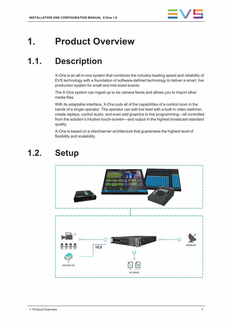
1.1. DescriptionX-One is an all-in-one system that combines the industry-leading speed and reliability ofEVS technology with a foundation of software-defined technology to deliver a smart, liveproduction system for small and mid-sized events.
The X-One system can ingest up to six camera feeds and allows you to import othermedia files.
With its adaptable interface, X-One puts all of the capabilities of a control room in thehands of a single operator. The operator can edit live feed with a built-in video switcher,create replays, control audio, and even add graphics to live programming—all controlledfrom the solution’s intuitive touch-screen—and output in the highest broadcast-standardquality.
X-One is based on a client/server architecture that guarantees the highest level offlexibility and scalability.
1.2. Setup
INSTALLATION AND CONFIGURATION MANUAL X-One 1.8
1. Product Overview 1
2. Requirements
2.1. Network RequirementsThe X-One client workstation and the X-One server hardware need to be connected by a1 Gbps link. This link can go through a switch or a direct connection.
Type of LinkThe type of link to use depends on the distance between the client and server:
• When the distance between the client and the server hardware is smaller than 80m,a standard Cat 6 network cable is enough.
• When the distance is greater than 80, the connection must go over a fiber link.
This can be achieved by extending the Cat 6 cable with fiber media converters, or byordering the SFP+ Fiber option on the client and/or the server.
2.2. Other Technical Requirements
Recommendations When Working with ExtendersIt can happen that extenders are used for the screen, keyboard, mouse and BEPlay.
The USB extenders used for the keyboard and mouse must support HID devices (USBHID class).
The USB extenders used for the touch screen(s) and BEPlay must be USB 2.0extenders.
It is important to respect the manufacturer’s recommendation in terms of distancesbetween the machine and USB device and grade of cable.
Recommendations When Working with Two ScreensWhen working with 2 screens, both screens must be:
• the same resolution;
• either 2 touch screens or 2 non-touch screens.
2 2. Requirements
EVS Broadcast Equipment SA 1.8.A - July 2021

3. Installation
3.1. First Install
Installation RequirementsTo be able to install X-One for the first time, the following requirements should befulfilled:
• X-One hardware (PMX-2U-4 Server or X-Client) ,
• 1 USB key 16 GB or higher (by preference USB 3.0).
Preparing the USB Key1. Connect the USB key to a Windows 7/10 machine.
If the USB key is not empty, please format it.
2. Launch the Rufus utility using the following link:https://github.com/pbatard/rufus/releases/download/v2.11/rufus-2.11p.exe
3. In the Device field, select your USB key.
4. Click the Click to Select an Image... button (CD icon).
INSTALLATION AND CONFIGURATION MANUAL X-One 1.8
3. Installation 3
5. Select the X-One image file.
The ISO file should have been shared with you: XONE-1.8.x-xxxx-xxx.iso .
6. Click Start.
You are prompted to select the appropriate write mode.
WARNING
If this dialog box does not appear, then you should copy the .iso file on yourlocal machine. Also, if you are using a laptop with a docking station, pleaseensure not to plug the USB key into the docking station. Use a USB port on thelaptop instead.
7. Select the optionWrite in DD Image mode and clickOK.
You will be notified that all data already on the USB drive will be overwritten.
8. ClickOK to continue.
4 3. Installation
EVS Broadcast Equipment SA 1.8.A - July 2021

Wait until the ISO file has been completely written to the USB key. This may take 30minutes, depending on the USB key you are using.
Installing X-One1. Connect the USB key to the server.
Warning: only this USB key should be connected to the machine.
2. Reboot the server.
3. Press F11 to enter the Boot menu.
4. If you're asked to enter a password: evsdvb.
5. Select your USB key as boot device.
6. From the EVS Production menu, select the desired installation package and pressENTER:
◦ X-One Server 1.8 - CentOS 7.5 1804 or
◦ X-One Client 1.8 - CentOS 7.5 1804
7. Wait until you see the message "Installation complete. Please return to quit", thenpress ENTER. Do not remove the USB key.
The server will reboot.
8. From the EVS Production menu, select Start Operating System and pressENTER.
9. Press ENTER when you are prompted to start the operating system again.
10. Enter the serial number of the server and press ENTER.
You can find the serial number at the back of your machine.
End of the Installation• If the installation was successful, the following messages are displayed:
[EVS] System is configured
[EVS] [Reboot]
• If the installation failed, the following messages are displayed:
[EVS] Installation failed.
logs are available at /var/log/evs/evs-xone-{server orclient}/install_evs-xone-{server or client}_<YYYYMMDDhhmmss>.log
Please do the following:
Take a picture of the screen
Contact EVS support (https://myservices.evs.com/).
11. After the machine reboot, please wait a few minutes before starting the Client:
INSTALLATION AND CONFIGURATION MANUAL X-One 1.8
3. Installation 5

◦ If you are installing an X-One server, please wait for 2-3 minutes and open theServices Management tool: http://127.0.0.1:9081 to check if everythingis ok on the Health page (green or at least orange status for the resolv.confcheck) before starting to use X-One.
◦ If you are installing an X-One Client, the Services Management page is notpresent, so please just wait for 30 seconds to be sure everything has startedbefore beginning to use X-One
6 3. Installation
EVS Broadcast Equipment SA 1.8.A - July 2021
3.2. UpgradeThis procedure is only to be followed when you want to upgrade from an X-One 1.6version to 1.8.
PrerequisitesTo be able to upgrade X-One, the following prerequisites should be fulfilled:
• X-One hardware PMX-2U-4 server or X-Client,
• 1 USB key 16 GB or higher (by preference USB 3.0).
Preparing the USB Key1. Connect the USB key to a Windows 7/10 machine.
If the USB key is not empty, please format it.
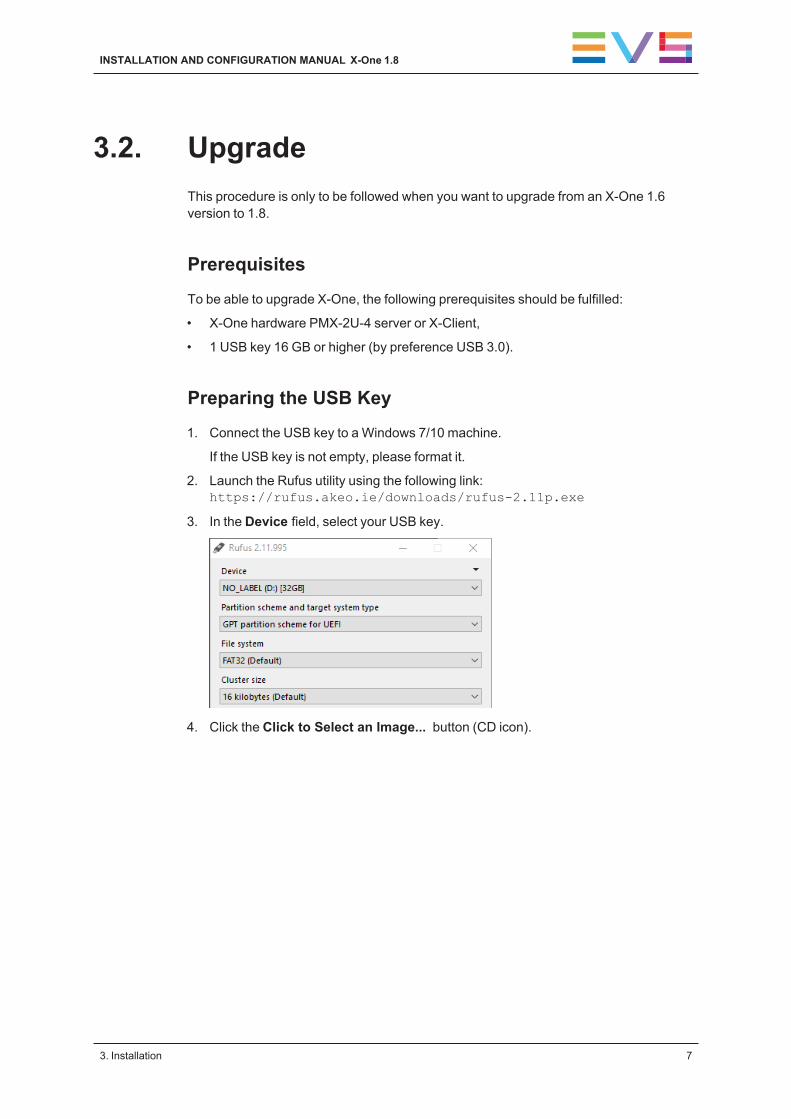
2. Launch the Rufus utility using the following link:https://rufus.akeo.ie/downloads/rufus-2.11p.exe
3. In the Device field, select your USB key.
4. Click the Click to Select an Image... button (CD icon).
INSTALLATION AND CONFIGURATION MANUAL X-One 1.8
3. Installation 7

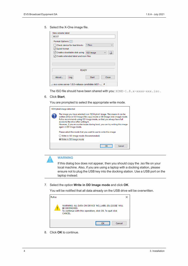
5. Select the X-One image file.
The ISO file should have been shared with you: XONE-1.8.x-xxxx-xxx.iso.
6. Click Start.
You are prompted to select the appropriate write mode.
7. Select the optionWrite in DD Image mode and clickOK.
You will be notified that all data already on the USB drive will be overwritten.
8. ClickOK to continue.
Wait until the ISO file has been completely written to the USB key.
Executing the Update
Command Line ProcedureOption 1 - Opening a Terminal Directly on the Server
8 3. Installation
EVS Broadcast Equipment SA 1.8.A - July 2021

A disc icon labeled BOOT will appear on the desktop.
1. Double-click the icon and navigate to:
install-evs-xone-server if you want to upgrade an X-One server;
install-evs-xone-client if you want to upgrade an X-One Client.
2. Right-click on a whitespace in the file explorer and select "open in terminal".
3. Execute the following command:
sh update_evs-xone-{server or client}.sh
and follow the on-screen instructions.
4. Once the upgrade script has ended successfully, the following messages aredisplayed:
[EVS] Upgrade evs-xone-{server or client} with success !
Remove the USB stick and press a key to reboot the system.
After pressing any key, the screen will display:
Rebooting.
If the upgrade failed, the following messages are displayed:
[EVS] Upgrade of evs-xone-{server or client} failed.
logs are available at /var/log/evs/evs-xone-{server orclient}/upgrade_evs-xone-{server or client}_<YYYYMMDDhhmmss>.log
please do the following :
- Take a picture of the screen
- Contact EVS support (https://myservices.evs.com/)
Option 2 - Opening a Terminal Through SSH
1. Plug your USB key into the server.
2. Remotely connect to the server through SSH.
3. Log into the console with user evs and password evs123.
4. Enter the following command:
sh update_evs-xone-{server or client}.sh
and follow the on-screen instructions.
WARNING
Do not disconnect the SSH connection during the upgrade process. If theSSH connection is broken, you will have to do a first install. See section "FirstInstall" on page 3.
5. Once the upgrade script has ended successfully, the following messages aredisplayed:
[EVS] Upgrade evs-xone-{server or client} with success !
Remove the USB stick and press a key to reboot the system.
After pressing any key, the screen will display:
INSTALLATION AND CONFIGURATION MANUAL X-One 1.8
3. Installation 9
Rebooting.
If the upgrade failed, the following messages are displayed:
[EVS] Upgrade of evs-xone-{server or client} failed.
logs are available at /var/log/evs/evs-xone-{server orclient}/upgrade_evs-xone-{server or client}_<YYYYMMDDhhmmss>.log
please do the following :
- Take a picture of the screen
- Contact EVS support (https://myservices.evs.com/)
6. After the machine reboot, please wait a few minutes before starting the Client:
◦ If you are upgrading an X-One server, please wait for 2-3 minutes and open theServices Management tool: http://127.0.0.1:9081 to check if everythingis ok on the Health page (green or at least orange status for the resolv.confcheck) before starting to use X-One.
◦ If you are upgrading an X-One Client, the Services Management page is notpresent, so please just wait for 30 seconds to be sure everything has startedbefore beginning to use X-One
10 3. Installation
EVS Broadcast Equipment SA 1.8.A - July 2021
4. Cabling
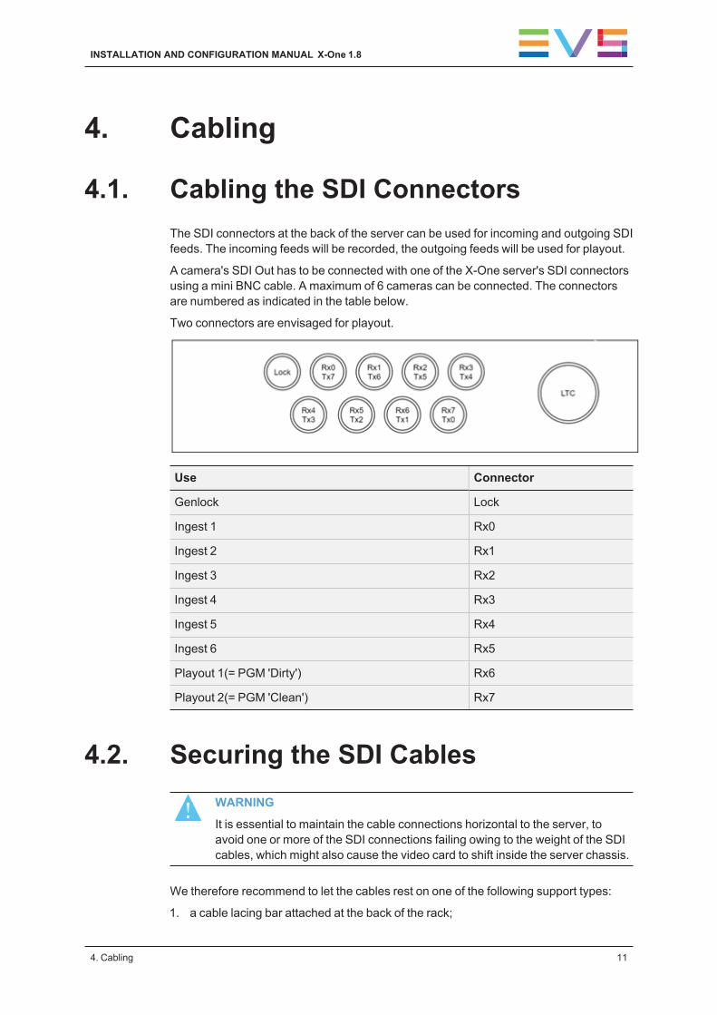
4.1. Cabling the SDI ConnectorsThe SDI connectors at the back of the server can be used for incoming and outgoing SDIfeeds. The incoming feeds will be recorded, the outgoing feeds will be used for playout.
A camera's SDI Out has to be connected with one of the X-One server's SDI connectorsusing a mini BNC cable. A maximum of 6 cameras can be connected. The connectorsare numbered as indicated in the table below.
Two connectors are envisaged for playout.
Use Connector
Genlock Lock
Ingest 1 Rx0
Ingest 2 Rx1
Ingest 3 Rx2
Ingest 4 Rx3
Ingest 5 Rx4
Ingest 6 Rx5
Playout 1(= PGM 'Dirty') Rx6
Playout 2(= PGM 'Clean') Rx7
4.2. Securing the SDI CablesWARNING
It is essential to maintain the cable connections horizontal to the server, toavoid one or more of the SDI connections failing owing to the weight of the SDIcables, which might also cause the video card to shift inside the server chassis.
We therefore recommend to let the cables rest on one of the following support types:
1. a cable lacing bar attached at the back of the rack;
INSTALLATION AND CONFIGURATION MANUAL X-One 1.8
4. Cabling 11

2. a ring bracket attached to the side of the rack or flight case;
3. the EVS cable management bracket mounted on the side of the server by means oftwo screws.
Old EVS Bracket New EVS Bracket
The cables should be secured using cable ties or Velcro® straps.
4.3. Connecting the Video MonitorsUp to two video monitors can be connected to an X-One server.
ConnectorsWhen working with a PMX2-4601D server, the following connectors can be used:
• 4 DisplayPort connectors.
12 4. Cabling
EVS Broadcast Equipment SA 1.8.A - July 2021

NOTE
The monitors have to be connected to display ports 1 & 2. The numbering ofthe display ports is from right to left, i.e. (4 3) 2 1.
WARNING
The VGA connection does not work.
4.4. Connecting the Beplay Remote andExternal ControllerThe Beplay remote and External Controller are connected via USB to the X-One server.The device is recognized as soon as it is plugged in.
4.5. DisplayPort Cable WarningIf you directly connect a server with a monitor using a DisplayPort cable, you need tomake sure that pin 20 (DP_PWR) of the cable is not wired and does not carry any power.If in doubt, use a multimeter to verify this.
According to the VESA specification, the DP_PWR (pin 20) is not supposed to be wiredin standard cables because both source and sink devices are designed to providepower. Ignoring this will in certain cases prevent the Avago RAID Controller (AOM-S3108-H8) from being initialized at startup and thus making the RAID unavailable for theOS.
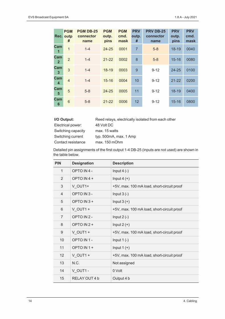
4.6. Connecting the BFE Tally BoxIn the current fixed output assignments, we only use 3 DB-25 connectors (1-4, 5-8 and9-12) to provide 6 PGM and 6 PRV relay contacts.
INSTALLATION AND CONFIGURATION MANUAL X-One 1.8
4. Cabling 13
Rec.PGMoutp#
PGM DB-25connector
name
PGMoutp.pins
PGMcmd.mask
PRVoutp.#
PRV DB-25connector
name
PRVoutp.pins
PRVcmd.mask
Cam1 1 1-4 24-25 0001 7 5-8 18-19 0040
Cam2 2 1-4 21-22 0002 8 5-8 15-16 0080
Cam3 3 1-4 18-19 0003 9 9-12 24-25 0100
Cam4 4 1-4 15-16 0004 10 9-12 21-22 0200
Cam5 5 5-8 24-25 0005 11 9-12 18-19 0400
Cam6 6 5-8 21-22 0006 12 9-12 15-16 0800
I/O Output: Reed relays, electrically isolated from each otherElectrical power: 48 Volt DCSwitching capacity max. 15 wattsSwitching current typ. 500mA, max. 1 AmpContact resistance max. 150 mOhm
Detailed pin assignments of the first output 1-4 DB-25 (inputs are not used) are shown inthe table below.
PIN Designation Description
1 OPTO IN 4 - Input 4 (-)
2 OPTO IN 4 + Input 4 (+)
3 V_OUT1+ +5V, max. 100 mA load, short-circuit proof
4 OPTO IN 3 - Input 3 (-)
5 OPTO IN 3 + Input 3 (+)
6 V_OUT1 + +5V, max. 100 mA load, short-circuit proof
7 OPTO IN 2 - Input 2 (-)
8 OPTO IN 2 + Input 2 (+)
9 V_OUT1 + +5V, max. 100 mA load, short-circuit proof
10 OPTO IN 1 - Input 1 (-)
11 OPTO IN 1 + Input 1 (+)
12 V_OUT1 + +5V, max. 100 mA load, short-circuit proof
13 N.C. Not assigned
14 V_OUT1 - 0 Volt
15 RELAY OUT 4 b Output 4 b
14 4. Cabling
EVS Broadcast Equipment SA 1.8.A - July 2021

PIN Designation Description
16 RELAY OUT 4 a Output 4 a
17 V_OUT1 - 0 Volt
18 RELAY OUT 3 b Output 3 b
19 RELAY OUT 3 a Output 3 a
20 V_OUT1 - 0 Volt
21 RELAY OUT 2 b Output 2 b
22 RELAY OUT 2 a Output 2 a
23 V_OUT1 - 0 Volt
24 RELAY OUT 1 b Output 1 b
25 RELAY OUT 1 a Output 1 a
INSTALLATION AND CONFIGURATION MANUAL X-One 1.8
4. Cabling 15
5. Configuration
5.1. Changing the Server's ManagementIP Address and Hostname
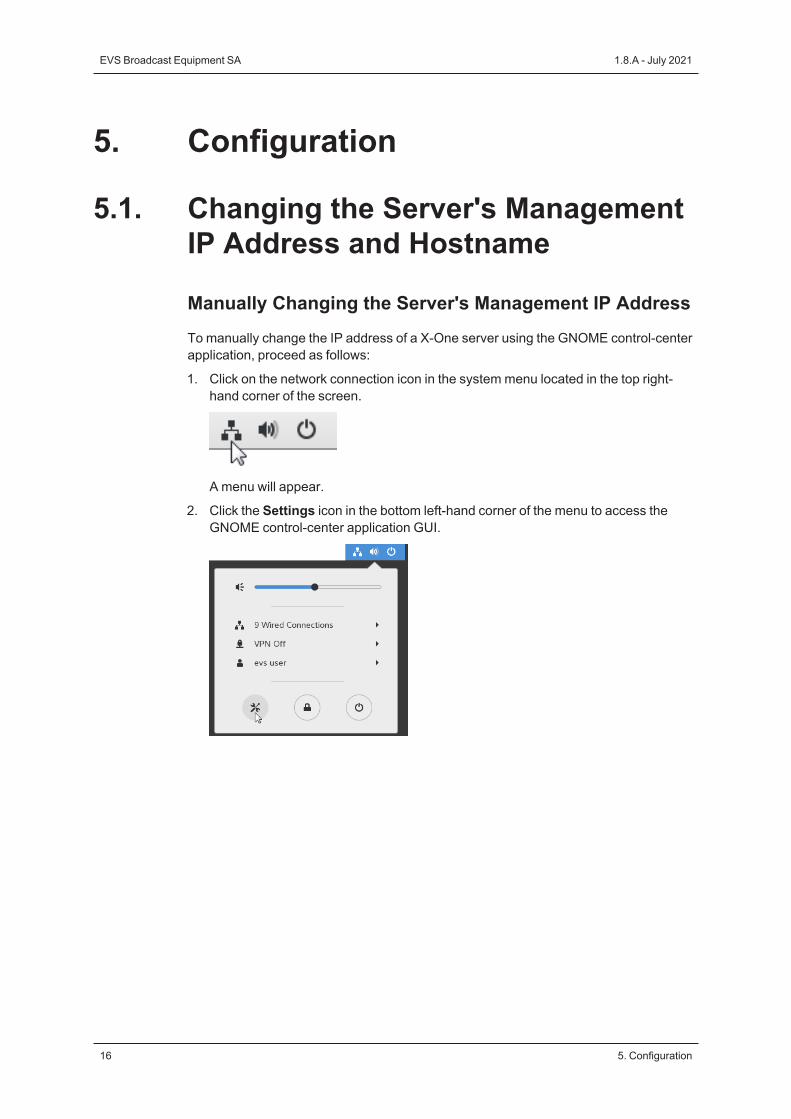
Manually Changing the Server's Management IP AddressTo manually change the IP address of a X-One server using the GNOME control-centerapplication, proceed as follows:
1. Click on the network connection icon in the system menu located in the top right-hand corner of the screen.
A menu will appear.
2. Click the Settings icon in the bottom left-hand corner of the menu to access theGNOME control-center application GUI.
16 5. Configuration
EVS Broadcast Equipment SA 1.8.A - July 2021
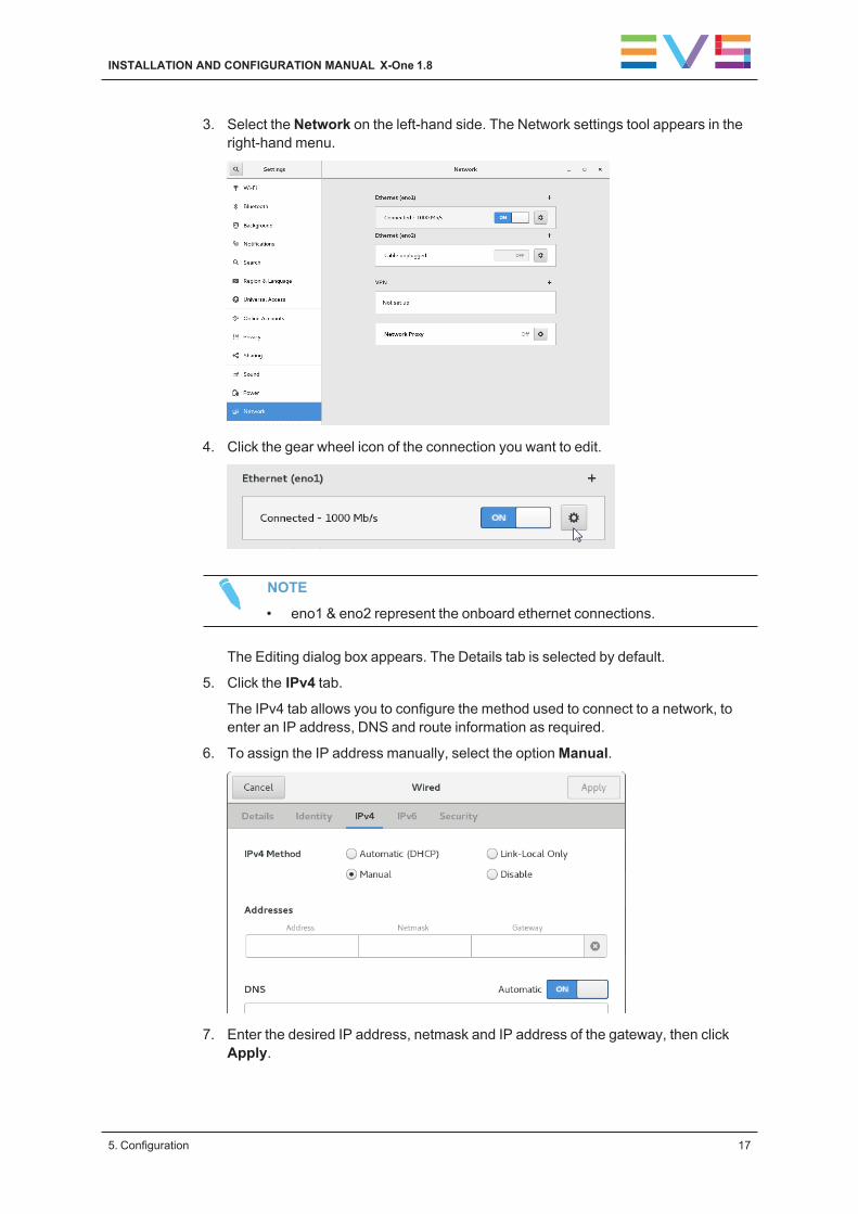
3. Select the Network on the left-hand side. The Network settings tool appears in theright-hand menu.
4. Click the gear wheel icon of the connection you want to edit.
NOTE
• eno1 & eno2 represent the onboard ethernet connections.
The Editing dialog box appears. The Details tab is selected by default.
5. Click the IPv4 tab.
The IPv4 tab allows you to configure the method used to connect to a network, toenter an IP address, DNS and route information as required.
6. To assign the IP address manually, select the optionManual.
7. Enter the desired IP address, netmask and IP address of the gateway, then clickApply.
INSTALLATION AND CONFIGURATION MANUAL X-One 1.8
5. Configuration 17
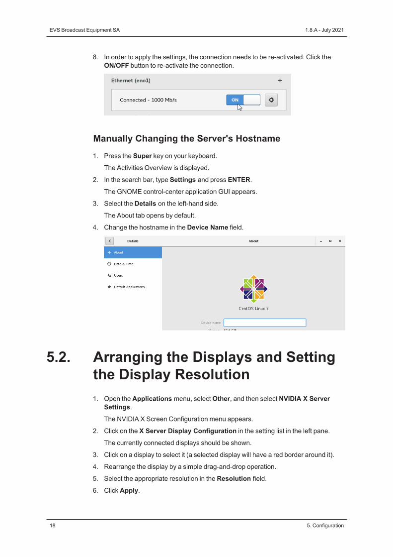
8. In order to apply the settings, the connection needs to be re-activated. Click theON/OFF button to re-activate the connection.
Manually Changing the Server's Hostname1. Press the Super key on your keyboard.
The Activities Overview is displayed.
2. In the search bar, type Settings and press ENTER.
The GNOME control-center application GUI appears.
3. Select the Details on the left-hand side.
The About tab opens by default.
4. Change the hostname in the Device Name field.
5.2. Arranging the Displays and Settingthe Display Resolution1. Open the Applications menu, selectOther, and then select NVIDIA X Server
Settings.
The NVIDIA X Screen Configuration menu appears.
2. Click on the X Server Display Configuration in the setting list in the left pane.
The currently connected displays should be shown.
3. Click on a display to select it (a selected display will have a red border around it).
4. Rearrange the display by a simple drag-and-drop operation.
5. Select the appropriate resolution in the Resolution field.
6. Click Apply.
18 5. Configuration
EVS Broadcast Equipment SA 1.8.A - July 2021

5.3. Mapping the Touchscreens
About the Mapping ProcessThe touchscreens are automatically mapped. The mapping process is necessary tomake sure that the touch gestures performed by the user on one particular half of themonitors, e.g. selecting an element, actually take effect on that half, and not on the samehalf of the other monitor.
If the touchscreen monitors are not mapped and the user selects an element on the lefthalf of the secondary screen, an element on the left half of the primary screen will beselected instead. If the user selects an element on the right half of the primary screen,an element on the right half of the secondary screen will be selected instead.
Touchscreen MapperThe Touchscreen Mapper application is the tool that performs the mapping for you.
It is automatically launched each time you start the X-One client. It also has a shortcuton the server desktop to manually start the application.
When to Start the Mapping ProcessThe mapping process has to be started each time:
• one of your monitors is unplugged and plugged in again;
• the order of the screens is changed;
• an X-One server (PMX) is rebooted.
How to Start the Mapping ProcessTo start the mapping of your touchscreens, proceed as follows:
1. Double-click the X-One client shortcut.
The TouchScreen Mapper application is automatically launched.
You are prompted to tap your main screen.
INSTALLATION AND CONFIGURATION MANUAL X-One 1.8
5. Configuration 19
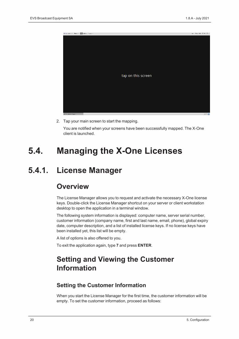
2. Tap your main screen to start the mapping.
You are notified when your screens have been successfully mapped. The X-Oneclient is launched.
5.4. Managing the X-One Licenses
5.4.1. License Manager
OverviewThe License Manager allows you to request and activate the necessary X-One licensekeys. Double-click the License Manager shortcut on your server or client workstationdesktop to open the application in a terminal window.
The following system information is displayed: computer name, server serial number,customer information (company name, first and last name, email, phone), global expirydate, computer description, and a list of installed license keys. If no license keys havebeen installed yet, this list will be empty.
A list of options is also offered to you.
To exit the application again, type 7 and press ENTER.
Setting and Viewing the CustomerInformation
Setting the Customer InformationWhen you start the License Manager for the first time, the customer information will beempty. To set the customer information, proceed as follows:
20 5. Configuration
EVS Broadcast Equipment SA 1.8.A - July 2021
1. Type 2 (Set Customer Info) and press ENTER.
2. Enter the following information:
◦ Company Name
◦ First Name
◦ Last Name
◦ Email Address
◦ Phone
The following fields are automatically completed:
◦ Serial Number
◦ Computer Description
Press ENTER each time you have entered a value.
You are informed that the customer info is successfully saved.
3. Press ENTER again to return to the main menu.
Viewing the Customer InformationTo view the customer information you just entered, type 1 (View Current CustomerInformation) and press ENTER.
Requesting and Importing a License Key
Requesting a License KeyTo request a license key, proceed as follows:
1. Type 3 (Generate a Request Key File) and press ENTER.
A request license key file is generated on the desktop. The naming convention forthe file is: hostname_ID_SystemID.xml.
2. Send the request key file to EVS Support.
Importing a License KeyTo import a license key, proceed as follows:
1. Type 5 (Import Keys) and press ENTER.
2. Drag and drop the license key into the terminal.
The full file path of the license key will appear in the terminal.
3. Press ENTER to continue.
After importing the key, a message is displayed: 'xx out of xx keys imported'.
To view the already installed license keys, type 5 (Installed Keys) and press ENTER.
INSTALLATION AND CONFIGURATION MANUAL X-One 1.8
5. Configuration 21
Deleting a License KeyTo delete an installed license key, proceed as follows:
1. Type 6 (Delete a Key) and press ENTER.
A numbered list is displayed of all the installed keys.
2. Enter the full key string of the key you wish to delete and press ENTER.
The key is deleted and a message is shown: 'Key deleted'.
5.5. Customizing the Beplay RemoteControlsOn the Beplay, it is possible to change the default action assignment of the operationalblock buttons (operational blocks 1-4) by modifying the remoteConfig.json file in the/home/evs/evs/ directory.
The configuration file consists of two parts.
The first part lists the names of the available buttons and the actions that can beassigned to each button.
The available buttons are:
TOP_1 BOTTOM_2TOP_2 BOTTOM_3TOP_3 BOTTOM_4TOP_4 BOTTOM_5TOP_5 LEFT_1F1 LEFT_2F2 LEFT_3F3 LEFT_4F4 RIGHT_1F5 RIGHT_2F6 RIGHT_3BOTTOM_1
The available actions are:
Editing
MARK SAVEIN OUT
Navigation
GO_TO_IN GO_TO_OUTGO_BACK_TO_TRAIN GO_TO_BEGIN_TRAINPREVIOUS_CLIP NEXT_CLIP
22 5. Configuration
EVS Broadcast Equipment SA 1.8.A - July 2021
PREVIOUS_FRAME NEXT_FRAMETOGGLE_SECONDARY_BAR_FOCUS TAKE
Preset
SEND_TO_PGM1 SEND_TO_PRV1SEND_TO_PGM2 SEND_TO_PRV2SEND_TO_PGM3 SEND_TO_PRV3SEND_TO_PGM4 SEND_TO_PRV4SEND_TO_PGM5 SEND_TO_PRV5SEND_TO_PGM6 SEND_TO_PRV6
Player
SELECT_PGM_SPEED1 SELECT_PGM_SPEED2SELECT_PGM_SPEED3 SELECT_PGM_SPEED4SELECT_PRV_SPEED1 SELECT_PRV_SPEED2SELECT_PRV_SPEED3 SELECT_PRV_SPEED4SELECT_PGM_DEFAULT_SPEED SELECT_PRV_DEFAULT_SPEED
The second part contains the configuration of each button. The configuration filecontains a section for each button. Each section contains three fields:
• key: Name of the button.
• press: Name of the action that is executed when pressing the button.
• shift: Name of the action that is executed when pressing the button in combinationwith the SHIFT button.
Example of the default configuration for the Live button:
{
"key": "F1",
"press": "SEND_TO_PGM1",
"shift": "SEND_TO_PRV1"
}
NOTE
The configuration file is read at startup. Changes while the Client applicationis running will be taken into account at the next restart.
NOTE
To reset the buttons to their default assignments, you can delete theremoteConfig.json file. X-One will automatically regenerate it at the nextClient application restart.
WARNING
If the format of the configuration file is not valid, a warning message willappear at the startup of the Client application: 'Invalid format for Beplayconfiguration file. Please correct the file and restart X-One client.
INSTALLATION AND CONFIGURATION MANUAL X-One 1.8
5. Configuration 23
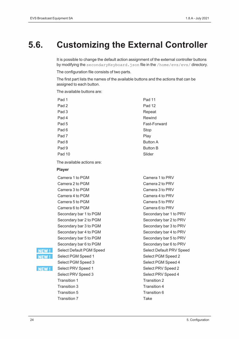
5.6. Customizing the External ControllerIt is possible to change the default action assignment of the external controller buttonsby modifying the secondaryKeyboard.json file in the /home/evs/evs/ directory.
The configuration file consists of two parts.
The first part lists the names of the available buttons and the actions that can beassigned to each button.
The available buttons are:
Pad 1 Pad 11Pad 2 Pad 12Pad 3 RepeatPad 4 RewindPad 5 Fast-ForwardPad 6 StopPad 7 PlayPad 8 Button APad 9 Button BPad 10 Slider
The available actions are:
Player
Camera 1 to PGM Camera 1 to PRVCamera 2 to PGM Camera 2 to PRVCamera 3 to PGM Camera 3 to PRVCamera 4 to PGM Camera 4 to PRVCamera 5 to PGM Camera 5 to PRVCamera 6 to PGM Camera 6 to PRVSecondary bar 1 to PGM Secondary bar 1 to PRVSecondary bar 2 to PGM Secondary bar 2 to PRVSecondary bar 3 to PGM Secondary bar 3 to PRVSecondary bar 4 to PGM Secondary bar 4 to PRVSecondary bar 5 to PGM Secondary bar 5 to PRVSecondary bar 6 to PGM Secondary bar 6 to PRVSelect Default PGM Speed Select Default PRV SpeedSelect PGM Speed 1 Select PGM Speed 2Select PGM Speed 3 Select PGM Speed 4Select PRV Speed 1 Select PRV Speed 2Select PRV Speed 3 Select PRV Speed 4Transition 1 Transition 2Transition 3 Transition 4Transition 5 Transition 6Transition 7 Take
24 5. Configuration
EVS Broadcast Equipment SA 1.8.A - July 2021
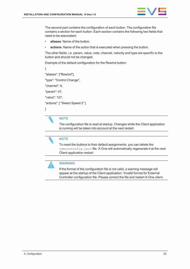
The second part contains the configuration of each button. The configuration filecontains a section for each button. Each section contains the following two fields thatneed to be associated:
• aliases: Name of the button.
• actions: Name of the action that is executed when pressing the button.
The other fields, i.e. param, value, note, channel, velocity and type are specific to thebutton and should not be changed.
Example of the default configuration for the Rewind button:
{
"aliases": ["Rewind"],
"type": "Control Change",
"channel": 9,
"param": 47,
"value": 127,
"actions": [ "Select Speed 2" ]
}
NOTE
The configuration file is read at startup. Changes while the Client applicationis running will be taken into account at the next restart.
NOTE
To reset the buttons to their default assignments, you can delete theremoteConfig.json file. X-One will automatically regenerate it at the nextClient application restart.
WARNING
If the format of the configuration file is not valid, a warning message willappear at the startup of the Client application: 'Invalid format for ExternalController configuration file. Please correct the file and restart X-One client.
INSTALLATION AND CONFIGURATION MANUAL X-One 1.8
5. Configuration 25
6. Monitoring and Support
6.1. Services Management Tool
About the Services Management ToolThe Services Management tool is a web tool which allows a system administrator orEVS support person to monitor for a particular X-One server in more detail the healthand status of its micro-services, to restart them in case of a problem and to export theirlogs. It also allows to check in more detail certain systemmetrics.
Accessing the Services Management ToolThe Services Management tool can be accessed via the following link:
http://<serverip>:9081
26 6. Monitoring and Support
EVS Broadcast Equipment SA 1.8.A - July 2021
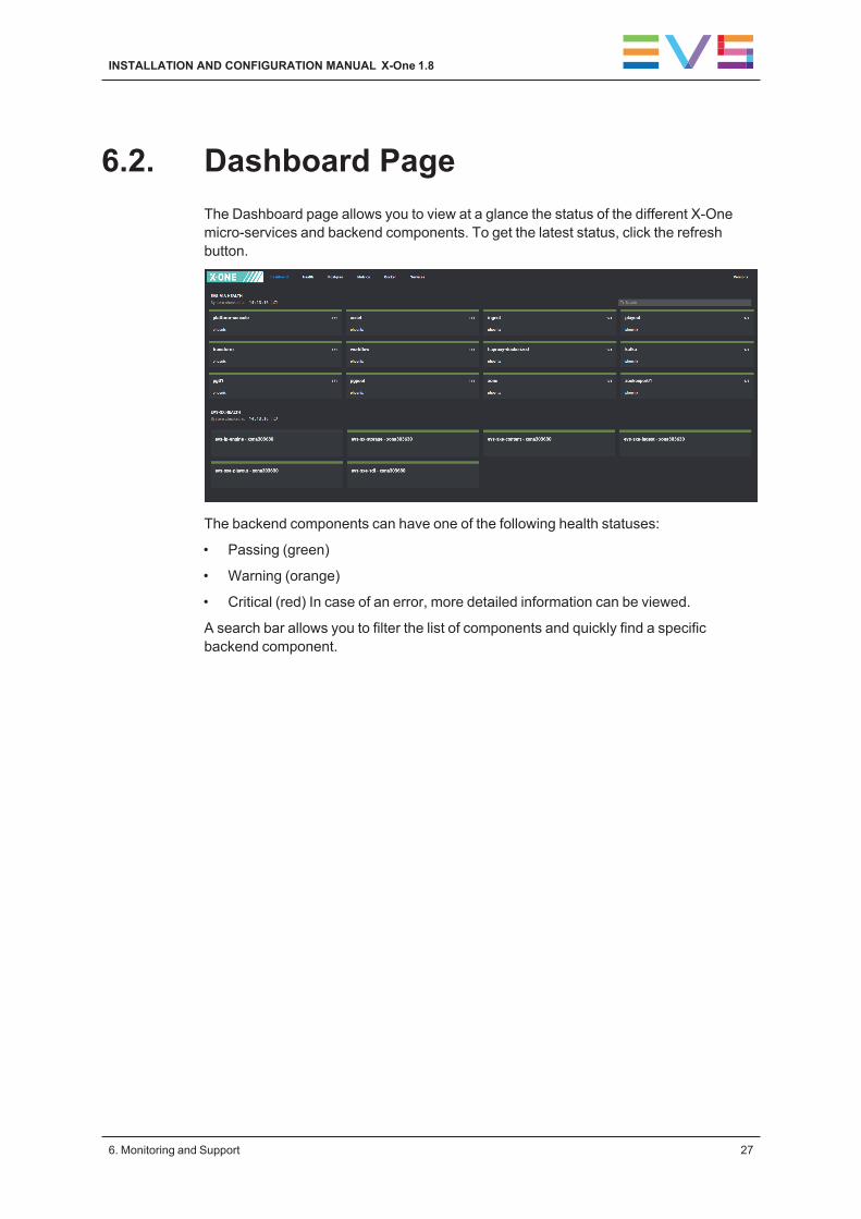
6.2. Dashboard PageThe Dashboard page allows you to view at a glance the status of the different X-Onemicro-services and backend components. To get the latest status, click the refreshbutton.
The backend components can have one of the following health statuses:
• Passing (green)
• Warning (orange)
• Critical (red) In case of an error, more detailed information can be viewed.
A search bar allows you to filter the list of components and quickly find a specificbackend component.
INSTALLATION AND CONFIGURATION MANUAL X-One 1.8
6. Monitoring and Support 27
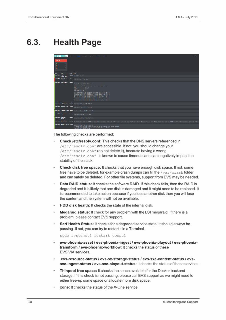
6.3. Health Page
The following checks are performed:
• Check /etc/resolv.conf: This checks that the DNS servers referenced in/etc/resolv.conf are accessible. If not, you should change your/etc/resolv.conf (do not delete it), because having a wrong/etc/resolv.conf is known to cause timeouts and can negatively impact thestability of the stack.
• Check disk free space: It checks that you have enough disk space. If not, somefiles have to be deleted, for example crash dumps can fill the /var/crash folderand can safely be deleted. For other file systems, support from EVSmay be needed.
• Data RAID status: It checks the software RAID. If this check fails, then the RAID isdegraded and it is likely that one disk is damaged and it might need to be replaced. Itis recommended to take action because if you lose another disk then you will losethe content and the system will not be available.
• HDD disk health: It checks the state of the internal disk.
• Megaraid status: It check for any problem with the LSI megaraid. If there is aproblem, please contact EVS support.
• Serf Health Status: It checks for a degraded service state. It should always bepassing. If not, you can try to restart it in a Terminal.
sudo systemctl restart consul
• evs-phoenix-asset / evs-phoenix-ingest / evs-phoenix-playout / evs-phoenix-transform / evs-phoenix-workflow: It checks the status of theseEVS VIA services.
• evs-resource-status / evs-sx-storage-status / evs-sxe-content-status / evs-sxe-ingest-status / evs-sxe-playout-status: It checks the status of these services.
• Thinpool free space: It checks the space available for the Docker backendstorage. If this check is not passing, please call EVS support as we might need toeither free-up some space or allocate more disk space.
• xone: It checks the status of the X-One service.
28 6. Monitoring and Support
EVS Broadcast Equipment SA 1.8.A - July 2021

• Zookeeper OK status: Checks the status of Zookeeper.
WARNING
After an installation, all checks on the Health page will be in orange for awhile. This is because the data RAID must be built for the first time.
INSTALLATION AND CONFIGURATION MANUAL X-One 1.8
6. Monitoring and Support 29

6.4. Metrics PageThe Metrics page displays several statistics about the health and performance of thebackend and server hardware components.
6.4.1. SDI TabThe SDI tab allows you to view the incoming and outgoing SDI feeds, check theirtechnical details and monitor their status. You can also see whether the feeds aregenlocked or not.
SDI Engine VersionCurrent version number of the evs-sxe-sdi service.
Board• Board type: Brand of the SDI board.
• Driver version: Device driver version.
• SDK version: Version of the software development kit.
• Firmware version: Firmware version of the SDI board.
• Genlock Status: Generic genlock status of the SDI board.
ChannelContains information about a specific input channel.
30 6. Monitoring and Support
EVS Broadcast Equipment SA 1.8.A - July 2021
ConfigurationThe Configuration section lists the input signal characteristics requested by the client(e.g. Ingest service).
ThumbnailThis section displays a JPEG thumbnail (270x180 pixels) of the incoming video signal.The thumbnail is refreshed every second.
• When a signal is received, 'Error: No error' will be displayed in the top left corner andthe thumbnail is automatically refreshed.
• When no signal is received, 'Error. No signal' will be displayed in the top left cornerand the thumbnail will be replaced with the error message "Error. Failed to retrievechannel thumbnail".
NOTE
With some early 12.x SDI engine versions, the last known image may bedisplayed instead of an error message.
SDI Status• Error:
◦ No Error
◦ No Signal: There is no incoming video signal or the cable is disconnected
◦ Bad Signal: The signal is not in the configured format
◦ Unknown: There is no stream.
• Running: Status of the evs-sxe-sdi service.
• SyncWithRef: Indicates if the incoming video signal is genlocked.
SignalThe Signal section lists the actual characteristics of the input signal monitored by theSDI adapter card.
The following information is displayed about each signal:
• Raster: Horizontal resolution, scan mode and framerate of the video stream.
• AudioTracks: The number of audio tracks present in the SDI input signal. Tracksare counted as individual mono tracks. Eight stereo SDI pairs are displayed assixteen audio tracks.
• 3G Interface: Indicates if the input is connected to a 3G-SDI signal.
• LtcValid: A valid LTC (= longitudinal time code) input signal has been detected.
INSTALLATION AND CONFIGURATION MANUAL X-One 1.8
6. Monitoring and Support 31
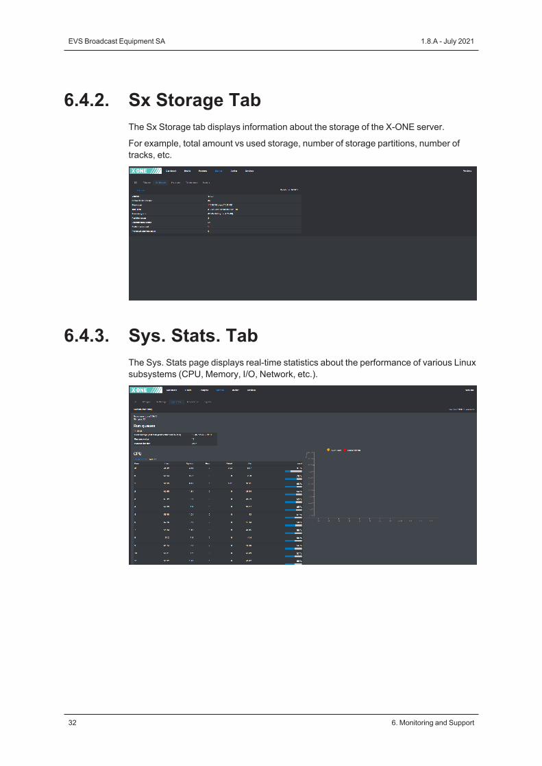
6.4.2. Sx Storage TabThe Sx Storage tab displays information about the storage of the X-ONE server.
For example, total amount vs used storage, number of storage partitions, number oftracks, etc.
6.4.3. Sys. Stats. TabThe Sys. Stats page displays real-time statistics about the performance of various Linuxsubsystems (CPU, Memory, I/O, Network, etc.).
32 6. Monitoring and Support
EVS Broadcast Equipment SA 1.8.A - July 2021

Run QueuesThis area contains run queue and load average data.
Parameter Description
Load average System load average for the last minute, past 5minutes, past 15 minutes.
Run queue size The number of kernel threads in memory that arewaiting for a CPU to run.
Process list size Number of tasks in the task list.
CPUThis area displays usage statistics of all CPUs as well as of individual CPUs.
Parameter Description
Core CPU core.
User Percentage of CPU utilization that occurred whileexecuting at the user level (application).
System Percentage of CPU utilization that occurred whileexecuting at the system level (kernel).
Nice Percentage of CPU utilization that occurred whileexecuting at the user level with nice priority.
IOWait Percentage of time that the CPU or CPUs were idleduring which the system had an outstanding diskI/O request.
Idle Percentage of time that the CPU or CPUs were idleand the system did not have an outstanding disk I/Orequest.
%Used Total percentage of CPU utilization.
INSTALLATION AND CONFIGURATION MANUAL X-One 1.8
6. Monitoring and Support 33

DisksThis area displays the activities by the individual block devices.
Parameter Description
Device Device (or partition) name as listed in the /devdirectory.
Avg queue len Average queue length of the requests that wereissued to the device.
Reads (sector)/sec Number of sectors (kilobytes, megabytes) read fromthe device per second.
Writes (sector)/sec Number of sectors (kilobytes, megabytes) written tothe device per second.
Transfer/sec Number of transfers per second that were issued tothe device. A transfer is an I/O request to thedevice. Multiple logical requests can be combinedinto a single I/O request to the device. A transfer isof indeterminate size.
Avg wait Average time (in milliseconds) for I/O requestsissued to the device to be served. This includes thetime spent by the requests in the queue and thetime spent servicing them.
% Util Percentage of elapsed time during which I/Orequests were issued to the device (bandwidthutilization for the device). Device saturation occurswhen this value is close to 100%.
34 6. Monitoring and Support
EVS Broadcast Equipment SA 1.8.A - July 2021

NetworkThis area displays network statistics.
Parameter Description
Interface Name of the network interface for which statisticsare reported.
rxpck/s Packet receiving rate (unit: packets/second).
txpck/s Packet transmitting rate (unit: packets/second).
rxKb/s Data receiving rate (unit: Kbytes/second).
txKb/s Data transmitting rate (unit: Kbytes/second).
rxcmp/s Compressed packets receiving rate (unit:Kbytes/second).
txcmp/s Compressed packets transmitting rate (unit:Kbytes/second).
mac MAC address of the network interface.
connected Indicates if the network interface is physicallyconnected to the network or not.
speed Speed of the network interface.
state Status of the network interface.
ip4 IP address of the network interface. Either manuallyadded or automatically assigned by DHCP.
dns IP address of the EVS DNS server.
gateway IP address of the router used to access externalnetworks.
dhcp Indicates if the IP address of the network interfacewas manually or automatically (via DHCP)assigned.
INSTALLATION AND CONFIGURATION MANUAL X-One 1.8
6. Monitoring and Support 35
MemoryThis area displays memory statistics.
Parameter Description
Buffers Memory used as buffers by the kernel in kilobytes.
Cached Memory used to cache data by the kernel inkilobytes.
Commit Memory in kilobytes needed for current workload.
Commit percent % of memory needed for current workload inrelation to the total memory (RAM+swap).
Mem used Memory used (excluding kernel usage).
Mem free Free memory available in kilobytes.
Mem used percent Percentage of memory used.
SwapThis area displays the swap statistics.
Parameter Description
Swap used Used swap in kilobytes.
Swap free Free swap in kilobytes.
Swap used percent Percentage of swap used.
36 6. Monitoring and Support
EVS Broadcast Equipment SA 1.8.A - July 2021
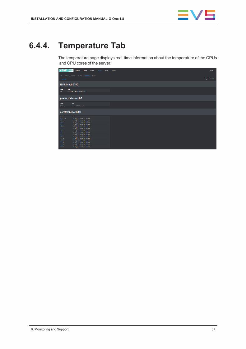
6.4.4. Temperature TabThe temperature page displays real-time information about the temperature of the CPUsand CPU cores of the server.
INSTALLATION AND CONFIGURATION MANUAL X-One 1.8
6. Monitoring and Support 37
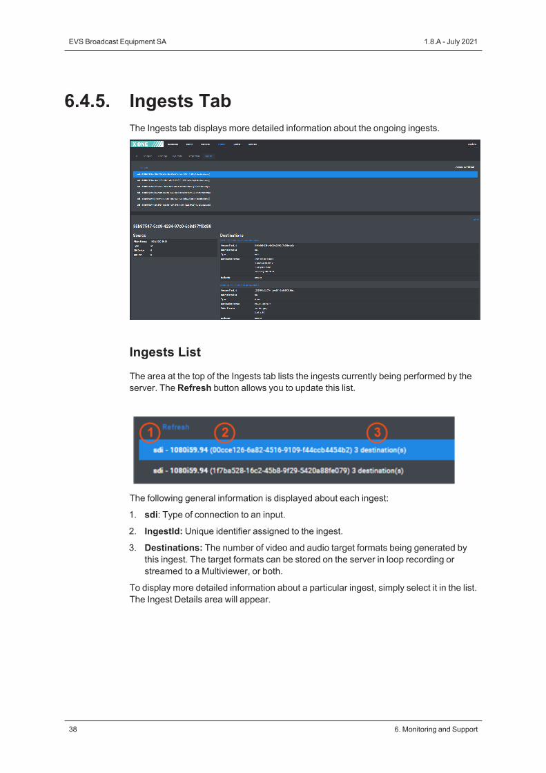
6.4.5. Ingests TabThe Ingests tab displays more detailed information about the ongoing ingests.
Ingests ListThe area at the top of the Ingests tab lists the ingests currently being performed by theserver. The Refresh button allows you to update this list.
The following general information is displayed about each ingest:
1. sdi: Type of connection to an input.
2. IngestId: Unique identifier assigned to the ingest.
3. Destinations: The number of video and audio target formats being generated bythis ingest. The target formats can be stored on the server in loop recording orstreamed to a Multiviewer, or both.
To display more detailed information about a particular ingest, simply select it in the list.The Ingest Details area will appear.
38 6. Monitoring and Support
EVS Broadcast Equipment SA 1.8.A - July 2021
Ingest DetailsThe Ingest Details area displays more detailed information about a particular ingest. Forexample, the target formats being generated.
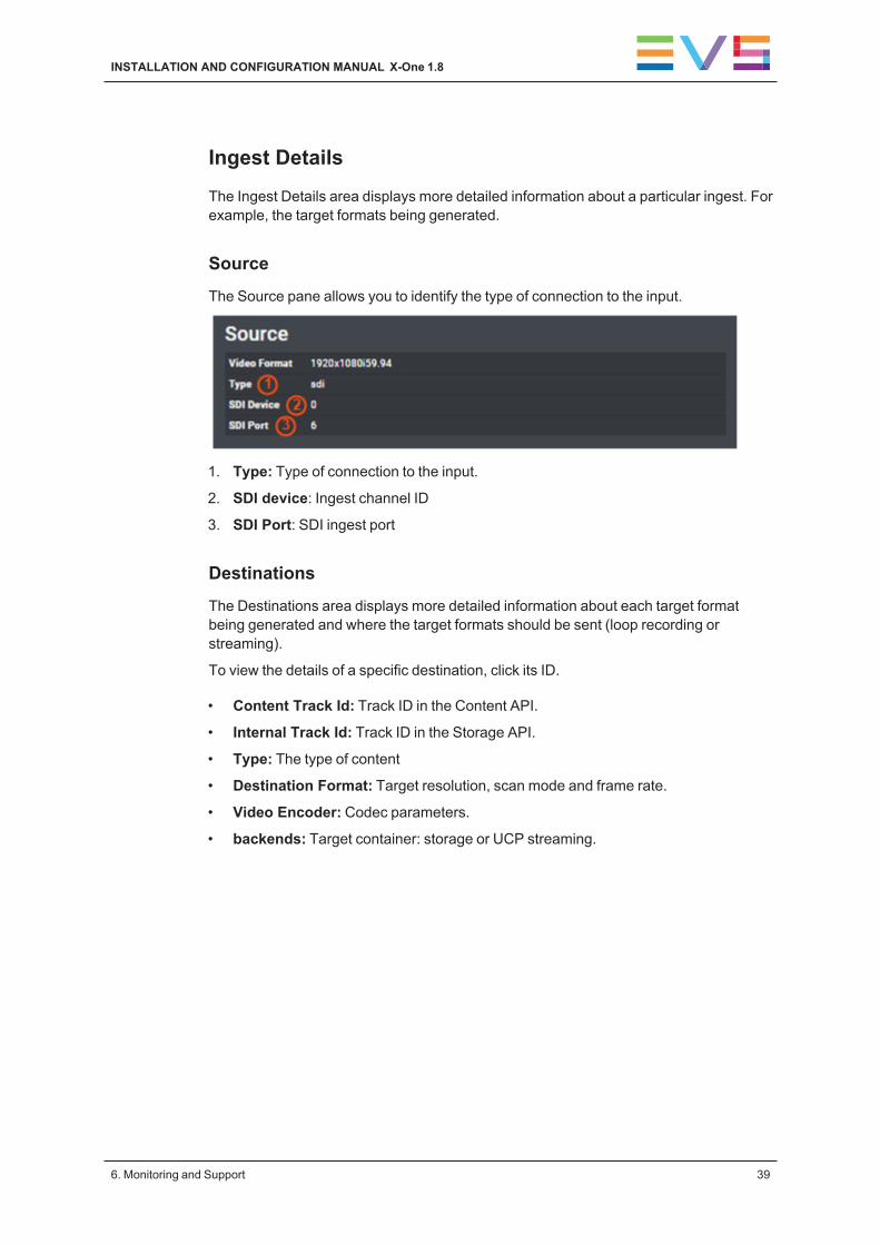
SourceThe Source pane allows you to identify the type of connection to the input.
1. Type: Type of connection to the input.
2. SDI device: Ingest channel ID
3. SDI Port: SDI ingest port
DestinationsThe Destinations area displays more detailed information about each target formatbeing generated and where the target formats should be sent (loop recording orstreaming).
To view the details of a specific destination, click its ID.
• Content Track Id: Track ID in the Content API.
• Internal Track Id: Track ID in the Storage API.
• Type: The type of content
• Destination Format: Target resolution, scan mode and frame rate.
• Video Encoder: Codec parameters.
• backends: Target container: storage or UCP streaming.
INSTALLATION AND CONFIGURATION MANUAL X-One 1.8
6. Monitoring and Support 39
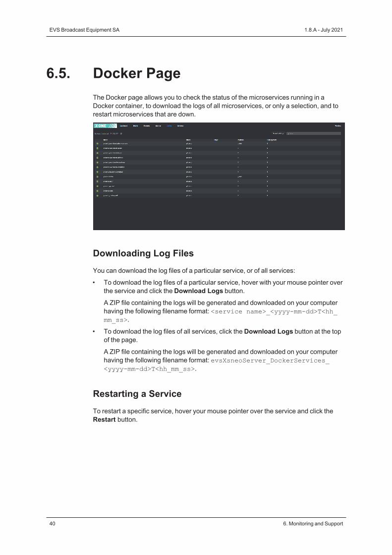
6.5. Docker PageThe Docker page allows you to check the status of the microservices running in aDocker container, to download the logs of all microservices, or only a selection, and torestart microservices that are down.
Downloading Log FilesYou can download the log files of a particular service, or of all services:
• To download the log files of a particular service, hover with your mouse pointer overthe service and click the Download Logs button.
A ZIP file containing the logs will be generated and downloaded on your computerhaving the following filename format: <service name>_<yyyy-mm-dd>T<hh_mm_ss>.
• To download the log files of all services, click the Download Logs button at the topof the page.
A ZIP file containing the logs will be generated and downloaded on your computerhaving the following filename format: evsXsneoServer_DockerServices_<yyyy-mm-dd>T<hh_mm_ss>.
Restarting a ServiceTo restart a specific service, hover your mouse pointer over the service and click theRestart button.
40 6. Monitoring and Support
EVS Broadcast Equipment SA 1.8.A - July 2021

6.6. Services PageThe Services page allows you to check the status of the native microservices running onX-One, and to restart them in case they are down.
Downloading Log FilesYou can download the log files of a particular service, or of all services:
• To download the log files of a particular service, hover with your mouse pointer overthe service and click the Download Logs button.
A ZIP file containing the logs will be generated and downloaded on your computerhaving the following filename format: <service name>_<date>.
• To download the log files of all services, click the Download Logs button at the topof the page.
A ZIP file containing the logs will be generated and downloaded on your computerhaving the following filename format: <platformBrandData>_<date>.
INSTALLATION AND CONFIGURATION MANUAL X-One 1.8
6. Monitoring and Support 41

6.7. Versions PageThe Versions page allows you to check the version of the native and Docker servicesthat are currently running on your server (= Active Version) and compare them with theversion that should actually be installed (= Version in content).
Interface
42 6. Monitoring and Support
EVS Broadcast Equipment SA 1.8.A - July 2021

6.8. Monitoring Video Inputs
Using a Terminal WindowTo monitor the Deltacast I/O board in case of input issues, you must execute thefollowing commands:
cd /var/log/evs/sdi-engine
tail -f deltacast.log
Using the Deltacast dCARE ToolTo check the status of the incoming video signals of a particular X-One server, you canmake use of the DELTACAST dCARE tool. To do this, proceed as follows:
1. Open a Terminal window on the X-One server.
2. Access the dCARE binaries directory by entering the following command:
cdb
3. Run the dCARE application by entering the following command:
./dcare_gui.sh
The Bidirectional Configuration dialog box opens.
4. Close the dialog box without changing the settings.
5. In the main window of the dCARE application, click the IO Control button in thebottom toolbar.
6. In the Channel area to the right, select the appropriate incoming video signal fromthe drop-down box. For example, select Rx0 for the first incoming signal.
7. Click the Autoset button.
The Setup tab of the Channel area will be updated with the data of the selectedincoming signal.
8. Click the Start button to see the incoming video signal.
9. Repeat steps 8 and 9 for all other incoming video signals.
10. To check the status of a particular incoming signal, select it from the drop-down listand open the Status tab.
11. Close the dCARE application.
INSTALLATION AND CONFIGURATION MANUAL X-One 1.8
6. Monitoring and Support 43
6.9. Cleaning the X-OneClient
Clean ScriptThe Clean script allows you to re-initialize the X-One client. Note that the followingsettings will be reverted to the factory settings: Shotbox preferences, NDI and tallyconfiguration, custom CGs.
Double-click the Clean shortcut to start the Clean script.
44 6. Monitoring and Support
EVS Broadcast Equipment SA 1.8.A - July 2021

6.10. Consulting System Log Files andCrash Dumps
Log Files FolderThe X-One system log files are stored in the following directory: /var/log/evs.
Crash Dump FolderCrash dumps are available in the following directory: /var/crash/.
Exporting System Log FilesTo generate and export the latest X-One system log files, proceed as follows:
1. Double-click or double-tap theGetLogs icon on your X-One client workstationdesktop.
A terminal window is opened.
The various system log files are generated and exported to the Logs directory onyour desktop in the form of a .tgz file with the following filename format: evs_logs_<hostname>_YYYYMMDD_HHMMSS.tgz.
You can either remove or keep all the log files.
2. Enter Y and press ENTER to remove all logs. Enter N and press ENTER to keep alllogs.
3. Tap or click X to close the terminal window again.
INSTALLATION AND CONFIGURATION MANUAL X-One 1.8
6. Monitoring and Support 45


To learn more about EVS go to www.evs.com
Corporate+32 4 361 7000
North & Latin America+1 973 575 7811
Asia & Pacifi c+852 2914 2501
Other regional offi ceswww.evs.com/contact
EVS Broadcast Equipment is continuously adapting and improving its products in accordance with the ever changingrequirements of the Broadcast Industry.The data contained herein is therefore subject to change without prior notice. Companies and product names aretrademarks or registered trademarks of their respective companies.
EVS Headquarters
Liège Science Park13, rue Bois St JeanB-4102 SeraingBelgium