
Class-11;EVS;Ch.4. Energy- Chapter(English Version) - Arya ...
Upload
khangminh22Category
view
6download
0
Easy Series
EasyPactTM EVSCatalog 2020LV air circuit breakers from 800 to 4000A

About Schneider ElectricSchneider Electric is a global specialist in energy management and automation, committed to providing clients with safe, reliable, efficient and green energy and process management. With over 142,000 employees in more than 100 countries, our sales hit 27.2 billion Euros in FY 2019. From simple switches to complex operating systems, our technology, software and services help customers manage and optimize operations. We also facilitate industrial optimization, improve urban environment, and enrich people’s lives through interconnected technologies.Schneider Electric is committed to ensuring Life Is ON.
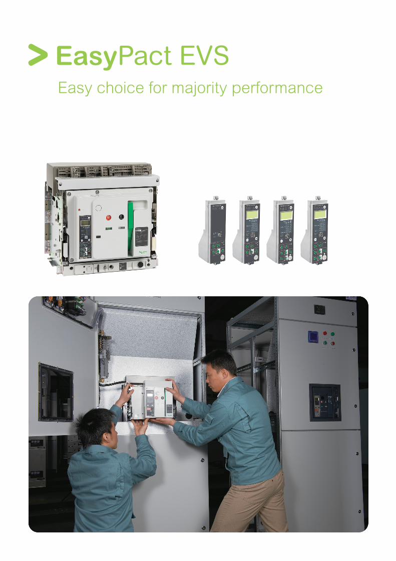
EasyPact EVS Easy choice for majority performance

Panel builder/contractorsSingle frame size from 800A to 4000A, with identical door cut-outs> Suitable for connection terminal with a single pole pitch of 115mm> Terminal orientation can be converted from horizontal to vertical and vice versa> Direct mounting Door frames without drilling any holes> Front fitted accessories like under-voltage release shunt release & closing coil for complete range> Conversion of manual operated breaker in to electrical operated, with single bolt fixing
End UserMoulded case design ensures high endurance without maintenance> Intelligent Trip system range trip unit with thermal memory> Overload run alarm & individual LED indications enable fault identification > Icu=Ics=Icw(1s) ensures complete selectivity> Inbuilt safety shutter & interlocks > Contact signal "Ready to close" indicating compliance and effectiveness of all safety parameters> No derating below 40 °C and stable operation in humidity under 95%> All 4 pole breakers are with fully rated neutral and protected with adjustable settings at OFF – 50%-100%
EasyPact EVS answers even to the most stringent application with most reliable distribution systems assuring continuity of service
DesignerConforms to IS/IEC60947-2 standards> Control module equipped with intelligent microprocessor, overload protection, short circuit protection and earth-fault protection and with thermal memory.> Full range: Icu=Ics=Icw(1s)> Typical opening release and closing release helps in simple interlocking schemes.> The contact "Ready to Close" ensures that all safety parameters comply with requirements and successful closing of the circuit breaker.> EasyPact EVS respects the environment throughout their life cycle
EasyPact EVS is designed to meet the needs of your customers with flexibility to achieve system efficiency during the design phase
EasyPact EVS Benefits for every customer

Excellent environmental adaptabilityThe great environmental adaptability of EVS low voltage circuit breakers ensures the stable operation of power distribution system under severe environmental changes or harsh environmental conditions, such as cubicle-type substations commonly used in the construction industry, underground power distribution rooms without air conditioning, or space-constrained installation.● In compliance with IEC68-2○ Ambient temperature between -25˚C and + 70˚C○ Suitable for various kinds of extreme atmospheric environmental conditions● Suitable for IEC60664-1 pollution degree 3○ Suitable for general or harsh industrial environment● Stable in humidity of 95% and below
Long-term stable operationThe EVS low voltage circuit breakers are designed for long-term operation. They are maintenance-free, which greatly reduces users’ daily maintenance of the low-voltage power distribution system.● Maintenance-free: integrated internal core components greatly reduce insulation and connection failures.● EVS 'unique arc-type main contact avoids wear, further improving service life and operation stability.
Reliable Operation

Filter-based breaking
The new arc chute
Filtered breaking
The patented new design of the arc chutes includes stainless-steel filters.The chutes absorb the energy released during breaking, thus limiting the stresses exerted on the installation. They filter and cool the gases produced, reducing ef-fects perceptible from the outside.
Electrical consistencyEach product complies with or enhances system performance at coordinationlevel: breaking capacity, temperature rise, etc. The leading edge technologies ensure high performance levels in protection, inter-product Electro Magnetic Compatibilty (EMC) is guaranteed.
Mechanical consistencyEach product adopts dimensional standards simplifying and optimizing its use within the system. It shares the same accessories and auxiliaries and complies with global ergonomic choices (utilization mode, operating mode, setting and configuration devices, tools, etc.) making its installation and operation within the system a simpler process.
Greater Dependability

One family,one frame size and one type
● H type: suitable for residential, commercial building and medium-sized industrial power distribution systems.
08 10 12 16 20 25 32 40H 65kA ● ● ● ● ● ● ● ●
Icu=Ics=Icw(1s)
Easy of installation
With optimized size, EVS ranges simplify the design of switchboards and standardize the installation of devices
● Power supply from the top or the bottom without reduction in performance
● No need for safe spacing
● Two types of connection are available
○ Horizontal or vertical rear connection
○ Mixed connection
Flexibility● Simply turn a horizontal rear connector 90° to make it a vertical connec-tor.*
*: For the 4000 A circuit breaker, connection not changeable between horizontal and vertical
Fixed breaker with horizontal and vertical rear connection
Easy Selection

Green Premium is the only label that allows you to effectively develop and promote an environmental policy whilst preserving your business efficiency. This ecolabel guarantees compliance with up-to-date environmental regulations, but it does more than this.
Discover what we mean by green ….
Check your products!
Schneider Electric’s Green Premium ecolabel is committed to offering transparency, by disclosing extensive and reliable information related to the environmental impact of its products:
RoHSSchneider Electric products are subject to RoHS requirements at a worldwide level, even for the many products that are not required to comply with the terms of the regulation. Compliance certificates are available for products that fulfil the criteria of this European initiative, which aims to eliminate hazardous substances.
REAChSchneider Electric applies the strict REACh regulation on its products at a worldwide level, and discloses extensive information concerning the presence of SVHC (Substances of Very High Concern) in all of these products.
PEP: Product Environmental ProfileSchneider Electric publishes complete set of environmental data, including carbon footprint and energy consumption data for each of the lifecycle phases on all of its products, in compliance with the ISO 14025 PEP ecopassport program. PEP is especially useful for monitoring, controlling, saving energy, and/or reducing carbon emissions.
EoLI: End of Life InstructionsAvailable at the click of a button, these instructions provide:• Recyclability rates for Schneider Electric products.• Guidance to mitigate personnel hazards during the dismantling of
products and before recycling operations.• Parts identification for recycling or for selective treatment, to mitigate
environmental hazards/ incompatibility with standard recycling processes.
Endorsing eco-friendly products in the industry
Green PremiumTM
Over 75% of Schneider Electric manufactured products have been awarded the Green Premium ecolabel

EasyPact EVS General contents
Functionsand characteristics A-1
Installationrecommendations B-1
Dimensionsand connection C-1
Electrical diagrams D-1
Additionalcharacteristics E-1
Catalogue numbers and order form F-1

Functions and characteristics
A-1
Functions and characteristics
General overview A-2Detailed contents A-2
Circuit breakers A-4EVS08 to EVS40 A-4
Identifying Trip system range A-6
Overview of functions A-8 Trip system A-8Trip system A A-10
Trip system A-12 Accessories and test equipment A-12
Connections A-13 Overview of solutions and accessories A-13Accessories and auxiliaries A-15
Locking A-17 On the device A-17On the chassis A-18
Indication contacts A-19
Remote operation A-20 Remote ON / OFF A-20Remote tripping A-22
Source-changeover systems A-23Mechanical interlocking A-23
Accessories A-24
Installation recommendations B-1Dimensions and connection C-1Electrical diagrams D-1Additional characteristics E-1Catalogue numbers and order form F-1
EasyPact EVS

A-2
Functionsand characteristics
General overviewDetailed contents
This overview describes all the functions offered byEasyPact EVS devices.
Circuit breakers page A-4 b Ratings: v EasyPact EVS 800 to 4000 A b Circuit breakers type H b 3 or 4 poles b Fixed or draw-out versions
Trip system page A-8 b 2.0 basic protection b 5.0 selective protection b 6.0 selective + earth-fault protection b Standard long-time rating plug: v Current setting (A) 0.4 to 1 x In
Trip system A with current measurement page A-10 b 2.0 basic protection b 5.0 selective protection b 6.0 selective + earth-fault protection b Standard long-time rating plug: v Current setting (A) 0.4 to 1 x In b External power-supply module
Connections page A-15 b Rear connection: v Horizontal v Vertical b Optional accessories: v Interphase barriers v Safety shutters
Locking page A-18 b Pushbutton locking by padlockable transparent cover
b OFF-position locking by keylock b Chassis locking in disconnected position by keylock
b Chassis locking in connected, disconnected and test positions
b Door interlock (inhibits door opening with breaker in ‘connected’ or ‘test’ position
CP
B10
0000
CD
B50
0000
Trip system 2.0 Trip system 5.0 Trip system 6.0
CD
B50
0001
CD
B50
0002
DB
1011
09
Door interlock
DB
1011
10
Chassis key lock
E46
459
Safety shutters
DB
1011
49
Interphase barriers

A-3
Indication contacts page A-20 b Standard: v ON/OFF indication (OF) v “Fault” trip indication (SDE) b Optional: v Additional ON/OFF indication (OF) v Ready-to-close contact (PF) v Carriage switches for connected (CE) disconnected (CD) and test (CT) positions
Remote operation page A-21 b Remote ON/OFF: v Gear motor v XF closing or MX opening voltage releases
b Remote tripping function: v MN voltage release
- Standard - Adjustable or non-adjustable
delay
Accessories page A-25 b Auxiliary terminal shield b Operation counter b Escutcheon (Door sealing frame) b Transparent cover for escutcheon b Escutcheon blanking plate
Source-changeover systems page A-24 b Mechanical interlocking using cables: v Interlocking between two devices v Interlocking between three devices
Functionsand characteristics
General overviewDetailed contents
PB
1043
54A
40C
PB
1000
03
DB
1011
13
Gear motor
DB
1011
14
MX, XF and MN volagereleases
E46
438
DB
1011
12
Ready-to-close contact
OF contact
CD
B50
0053
Interlocking of two devices
E46
669
E46
668
DB
1011
15
Mechanical operation counter
Escutcheon Transparent cover

A-4
Functionsand characteristics
Circuit breakers
EVS08 to EVS40
Common characteristicsNumber of poles 3/4Rated insulation voltage (V) Ui 1000Impulse withstand voltage (kV) Uimp 12Rated operational voltage (V AC 50/60 Hz) Ue 690Suitability for isolation IEC 60947-2 YesDegree of pollution IEC 60664-1 3
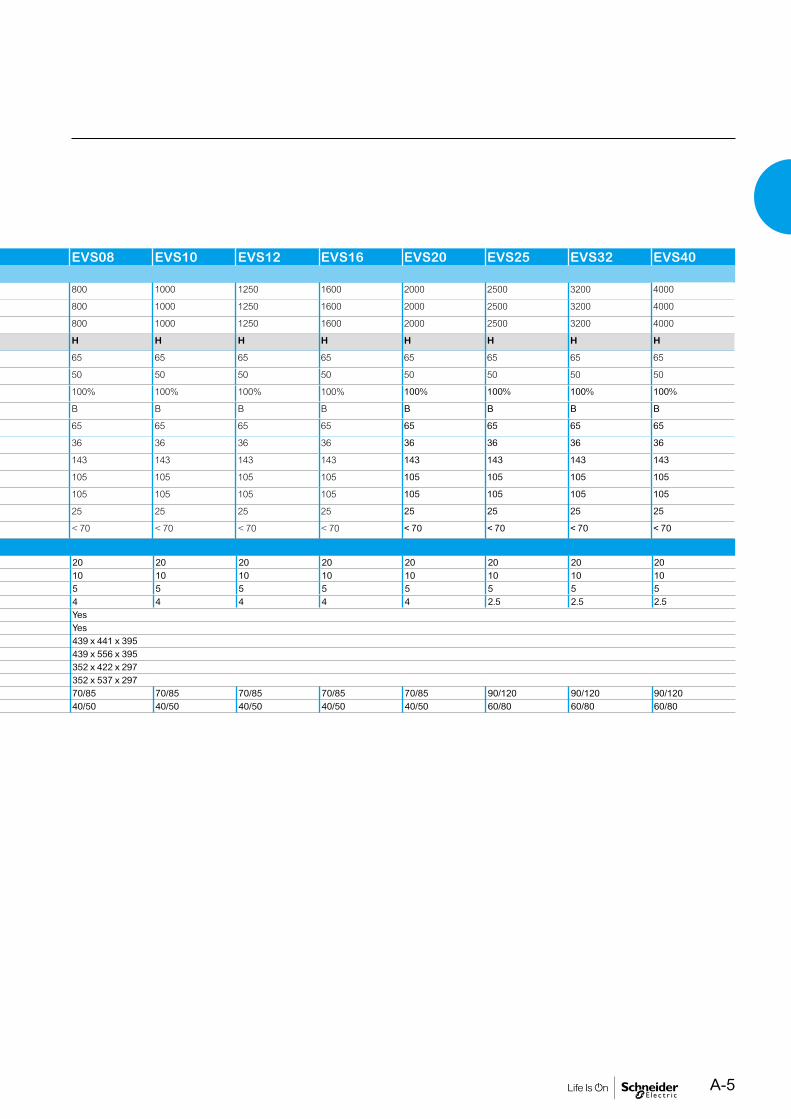
EVS08 EVS10 EVS12 EVS16 EVS20 EVS25 EVS32 EVS40Circuit-breaker as per IEC 60947-2Rated current In(A) at 40°C(1) 800 1000 1250 1600 2000 2500 3200 4000
Rating of 4th pole (A) 800 1000 1250 1600 2000 2500 3200 4000
Sensor ratings (A) 800 1000 1250 1600 2000 2500 3200 4000
Type of circuit breaker H H H H H H H H
Ultimate breaking capacity Icu(kA rms) 220...440V 65 65 65 65 65 65 65 65
V AC 50/60 Hz 690 V 50 50 50 50 50 50 50 50
Rated service breaking capacity Ics(kA rms) % Icu 100% 100% 100% 100% 100% 100% 100% 100%
Selectivity category B B B B B B B B
Rated short-time withstand current Icw(kA rms) 1s 65 65 65 65 65 65 65 65
V AC 50/60 Hz 3s 36 36 36 36 36 36 36 36
Rated making capacity Icm(kA peak) 220...440 V 143 143 143 143 143 143 143 143
V AC 50/60 Hz 690 V 105 105 105 105 105 105 105 105
Integrated instantaneous protection(DIN KA instantaneous ±10%) 105 105 105 105 105 105 105 105
Breaking time (ms) between tripping order and arc extinction (ms) 25 25 25 25 25 25 25 25
Closing time (ms) (ms) < 70 < 70 < 70 < 70 < 70 < 70 < 70 < 70
Maintenance/Connection/InstallationService life Mechanical with maintenance 20 20 20 20 20 20 20 20C/O cyclesx1000 without maintenance 10 10 10 10 10 10 10 10
Electrical without maintenance 440 V 5 5 5 5 5 5 5 5690 V 4 4 4 4 4 2.5 2.5 2.5
Connection Horizontal YesVertical Yes
Dimensions H x W x D Draw-out 3P 439 x 441 x 3954P 439 x 556 x 395
Fixed 3P 352 x 422 x 2974P 352 x 537 x 297
Weight (kg) Draw-out 3P/4P 70/85 70/85 70/85 70/85 70/85 90/120 90/120 90/120Fixed 3P/4P 40/50 40/50 40/50 40/50 40/50 60/80 60/80 60/80
CP
B10
0000
Circuit breaker.
(1) Refer page no. B-12 for details on temperature derating.
A-5
Common characteristicsNumber of poles 3/4Rated insulation voltage (V) Ui 1000Impulse withstand voltage (kV) Uimp 12Rated operational voltage (V AC 50/60 Hz) Ue 690Suitability for isolation IEC 60947-2 YesDegree of pollution IEC 60664-1 3
EVS08 EVS10 EVS12 EVS16 EVS20 EVS25 EVS32 EVS40Circuit-breaker as per IEC 60947-2Rated current In(A) at 40°C(1) 800 1000 1250 1600 2000 2500 3200 4000
Rating of 4th pole (A) 800 1000 1250 1600 2000 2500 3200 4000
Sensor ratings (A) 800 1000 1250 1600 2000 2500 3200 4000
Type of circuit breaker H H H H H H H H
Ultimate breaking capacity Icu(kA rms) 220...440V 65 65 65 65 65 65 65 65
V AC 50/60 Hz 690 V 50 50 50 50 50 50 50 50
Rated service breaking capacity Ics(kA rms) % Icu 100% 100% 100% 100% 100% 100% 100% 100%
Selectivity category B B B B B B B B
Rated short-time withstand current Icw(kA rms) 1s 65 65 65 65 65 65 65 65
V AC 50/60 Hz 3s 36 36 36 36 36 36 36 36
Rated making capacity Icm(kA peak) 220...440 V 143 143 143 143 143 143 143 143
V AC 50/60 Hz 690 V 105 105 105 105 105 105 105 105
Integrated instantaneous protection(DIN KA instantaneous ±10%) 105 105 105 105 105 105 105 105
Breaking time (ms) between tripping order and arc extinction (ms) 25 25 25 25 25 25 25 25
Closing time (ms) (ms) < 70 < 70 < 70 < 70 < 70 < 70 < 70 < 70
Maintenance/Connection/InstallationService life Mechanical with maintenance 20 20 20 20 20 20 20 20C/O cyclesx1000 without maintenance 10 10 10 10 10 10 10 10
Electrical without maintenance 440 V 5 5 5 5 5 5 5 5690 V 4 4 4 4 4 2.5 2.5 2.5
Connection Horizontal YesVertical Yes
Dimensions H x W x D Draw-out 3P 439 x 441 x 3954P 439 x 556 x 395
Fixed 3P 352 x 422 x 2974P 352 x 537 x 297
Weight (kg) Draw-out 3P/4P 70/85 70/85 70/85 70/85 70/85 90/120 90/120 90/120Fixed 3P/4P 40/50 40/50 40/50 40/50 40/50 60/80 60/80 60/80

A-6
Functionsand characteristics
Identifying Trip system
EasyPact EVS circuit breakers equipped with Trip system are designed to protect power circuit and connected loads.Measurement of current helps users to maintain continuity of service and optimize installation.
DependabilityIntegration of protection functions in an ASIC electronic component used in all trip units guarantees a high degree of reliability and immunity to conducted or radiated disturbances.On Trip System range, measurement functions are managed by an independent microprocessor. Protection functions are independent of measurement functions, ensure system protection even at very low load currents.
AccessoriesCertain functions require the addition of trip unit accessories, described on page A-14.
DB
1011
16
CP
B10
0011
DB
1011
17D
B10
1117
Trip unit name codesType of protection
b 2.0 for basic protection b 5.0 for selective protection b 6.0 for selective + earth-fault protection
Type of measurement b Trip System for basic b Trip System A for “Current”
Protection and measurement functionsTrip System Trip System A
b Fault indications b Settings in amperes and in seconds
b I1, I2, I3, IN, Iearth-fault, and maximeter for these measurements: v Fault indications v Settings in amperes and in seconds
Trip System 2.0: basic protection
Protection:long time+ instantaneous
2.0
Trip System 5.0: selective protection
Protection:long time+ short time+ instantaneous
5.0 5.0A
Trip System 6.0: selective + earth-fault protection
DB
1011
18
Protection:long time+ short time+ instantaneous+ earth fault
6.0 6.0A
CD
B50
0004
_EV
S

A-7
Functionsand characteristics
Identifying Trip system
Protection and measurement functionsTrip System Trip System A
b Fault indications b Settings in amperes and in seconds
b I1, I2, I3, IN, Iearth-fault, and maximeter for these measurements: v Fault indications v Settings in amperes and in seconds
Trip System 2.0: basic protection
Protection:long time+ instantaneous
2.0
Trip System 5.0: selective protection
Protection:long time+ short time+ instantaneous
5.0 5.0A
Trip System 6.0: selective + earth-fault protection
DB
1011
18
Protection:long time+ short time+ instantaneous+ earth fault
6.0 6.0A
CD
B50
0004
_EV
SC
DB
5000
02_E
VS

A-8
Functionsand characteristics
Overview of functionsTrip system
ProtectionProtection thresholds and delays are set using the adjustment dials.Overload protectionTrue rms long-time protection.Protects cables (phase and neutral) against overloadsThermal memory(1): thermal image before and after tripping.Short-time protection
b The short-time protection function protects the distribution system against impedant short-circuits
b The short-time tripping delay can be used to ensure discrimination with downstream circuit breaker
b The I2t ON and I2t OFF options enhance discrimination with a downstream protection devices
b Use of I2t curves with short-time protection: v I2t OFF selected: the protection function implements a constant time curve v I2t ON selected: the protection function implements an I2t inverse-time curve up to 10 lr. Above 10 lr, the time curve is constant
Earth-fault protection on Trip system 6.0Residual earth fault protection.Selection of I2t type (ON or OFF) for delay.A ground fault in the protection conductors can provoke local temperature rise at the site of the fault or in the conductors. The purpose of the ground-fault protection function is to eliminate this type of fault.Type DescriptionResidual b The function determines the zero-phase sequence current, i.e.
the vectorial sum of the phase and neutral currents b It detects faults downstream of the circuit breaker
Instantaneous protectionThe Instantaneous-protection function protects the distribution system against solid short-circuits. Contrary to the short-time protection function, the tripping delay for instantaneous protection is not adjustable. The tripping order is sent to the circuit breaker as soon as current exceeds the set value, with a fixed time delay of 20 milliseconds.Neutral protectionOn three-pole circuit breakers, neutral protection is not possible.On four-pole circuit breakers, neutral protection may be set using a three-positionswitch: neutral unprotected (4P 3d), neutral protection at 0.5 Ir (4P 3d + N/2), neutralprotection at Ir (4P 4d).Zone selective interlocking (ZSI)A ZSI(2) terminal block may be used to interconnect a number of control units to provide total discrimination for short-time and earth-fault protection, without a delay before tripping.
Overload alarmA yellow alarm LED goes on when the current exceeds the long-time trip threshold.
Fault indicationsLEDs indicate the type of fault:
b Overload (long-time protection Ir) b Short-circuit (short-time Isd or instantaneous li protection) b Earth fault (Ig) b Internal fault (Ap)
Battery powerThe fault indicating LEDs are powered by an in-built battery. The fault indication LEDs remain on until the test/reset button is pressed.
TestA hand-held test kit may be connected to the test connector on the front to check circuit-breaker operation. For Trip System 6.0 trip unit, the operation of earth-fault protection can be checked by pressing the test button located above the test connector.
Note: Trip System come with a transparent leadseal cover as standard.
CD
B50
0002
1 Long-time threshold and tripping delay.2 Overload alarm (LED) at 1,125 Ir.3 Short-time pick-up and tripping delay.4 Instantaneous pick-up.5 Earth-fault pick-up and tripping delay.6 Earth-fault test button.7 Long-time rating plug screw.8 Test connector.9 Lamp test, reset and battery test.10 Indication of tripping cause.
7
(1) The thermal memory continuously accounts for the amount of heat in the cables , both before and after tripping , whatever the value of the current(presence of an overload or not).The thermal memory optimises the long-time protection function of the circuit breaker by taking into account the temperature rise in the cables .The thermal memory assumes a cable cooling time of approximately 20 minutes.(2) Refer to page D-5 for more details on ZSI.
Trip System unit protect power circuits, under overload & short-circuit conditions. They are equipped with individual fault trip indication LEDs. Trip System 6.0 provides earth-fault protection.
A-9
Functionsand characteristics
Overview of functionsTrip system
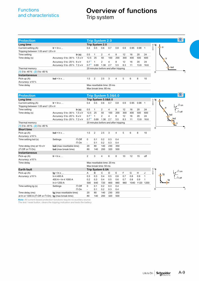
Protection Trip System 2.0Long time Trip System 2.0
DB
1011
26
Current setting (A) Ir = In x ... 0.4 0.5 0.6 0.7 0.8 0.9 0.95 0.98 1Tripping between 1.05 and 1.20 x IrTime setting tr (s) 0.5 1 2 4 8 12 16 20 24Time delay (s) Accuracy: 0 to -30 % 1.5 x Ir 12.5 25 50 100 200 300 400 500 600
Accuracy: 0 to -20 % 6 x Ir 0.7(1) 1 2 4 8 12 16 20 24Accuracy: 0 to -20 % 7.2 x Ir 0.7(2) 0.69 1.38 2.7 5.5 8.3 11 13.8 16.6
Thermal memory 20 minutes before and after tripping(1) 0 to -40 % - (2) 0 to -60 %InstantaneousPick-up (A) Isd = Ir x … 1.5 2 2.5 3 4 5 6 8 10Accuracy: ±10 %Time delay Max resettable time: 20 ms
Max break time: 80 ms
Protection Trip System 5.0&6.0Long time Trip System 5.0&6.0
DB
1011
27
Current setting (A) Ir = In x … 0.4 0.5 0.6 0.7 0.8 0.9 0.95 0.98 1Tripping between 1.05 and 1.20 x IrTime setting tr (s) 0.5 1 2 4 8 12 16 20 24Time delay (s) Accuracy: 0 to -30 % 1.5 x Ir 12.5 25 50 100 200 300 400 500 600
Accuracy: 0 to -20 % 6 x Ir 0.7(1) 1 2 4 8 12 16 20 24Accuracy: 0 to -20 % 7.2 x Ir 0.7(2) 0.69 1.38 2.7 5.5 8.3 11 13.8 16.6
Thermal memory 20 minutes before and after tripping(1) 0 to -40 % - (2) 0 to -60 %Short timePick-up (A) Isd = Ir x … 1.5 2 2.5 3 4 5 6 8 10Accuracy: ±10 %Time setting tsd (s) Settings I2t Off 0 0.1 0.2 0.3 0.4
I2t On - 0.1 0.2 0.3 0.4Time delay (ms) at 10 x Ir tsd (max resettable time) 20 80 140 230 350(I2t Off or I2t On) tsd (max break time) 80 140 200 320 500InstantaneousPick-up (A) Ii = In x … 2 3 4 6 8 10 12 15 offAccuracy: ±10 %Time delay Max resettable time: 20 ms
Max break time: 50 msEarth fault Trip System 6.0A
DB
1011
28
Pick-up (A) Ig = In x … A B C D E F G H JAccuracy: ±10 % In y 400 A 0.3 0.3 0.4 0.5 0.6 0.7 0.8 0.9 1
400 A < In y 1000 A 0.2 0.3 0.4 0.5 0.6 0.7 0.8 0.9 1In u 1250 A 500 640 720 800 880 960 1040 1120 1200
Time setting tg (s) Settings I2t Off 0 0.1 0.2 0.3 0.4I2t On - 0.1 0.2 0.3 0.4
Time delay (ms) tg (max resettable time) 20 80 140 230 350at In or 1200 A (I2t Off or I2t On) tg (max break time) 80 140 200 320 500
Note: All current-based protection functions require no auxiliary source.The test / reset button, clears the tripping indication and tests the battery.

A-10
Functionsand characteristics
Overview of functionsTrip system A
“Ammeter” measurementsTrip System A measure the true (rms) value of currents.They provide continuous current measurements from 0.2 to 1.2 In and are accurateto within 1.5 % (including the sensors).A digital LCD screen continuously displays the most heavily loaded phase (Imax) ordisplays the I1, I2, I3, IN, Ig, stored-current (maximeter) and setting values bysuccessively pressing the navigation button.The optional external power supply makes it possible to display currents < 20 % In.Below 0.1 In, measurements are not significant. Between 0.1 and 0.2 In, accuracychanges linearly from 4 % to 1.5 %.
ProtectionProtection thresholds and delays are set using the adjustment dials.Overload protectionTrue rms long-time protection.Protects cables (phase and neutral) against overloadsThermal memory(1): thermal image before and after tripping.Short-time protection
b The short-time protection function protects the distribution system against impedant short-circuits
b The short-time tripping delay can be used to ensure discrimination with downstream circuit breaker
b The I2t ON and I2t OFF options enhance discrimination with a downstream protection devices
b Use of I2t curves with short-time protection: v I2t OFF selected: the protection function implements a constant time curve v I2t ON selected: the protection function implements an I2t inverse-time curve up to 10 lr. Above 10 lr, the time curve is constant
Earth-fault protection on Trip System A trip systemResidual earth fault protection.Selection of I2t type (ON or OFF) for delay.A ground fault in the protection conductors can provoke local temperature rise at the site of the fault or in the conductors. The purpose of the ground-fault protection function is to eliminate this type of fault.Type DescriptionResidual b The function determines the zero-phase sequence current, i.e.
the vectorial sum of the phase and neutral currents b It detects faults downstream of the circuit breaker
Instantaneous protectionThe Instantaneous-protection function protects the distribution system against solid short-circuits. Contrary to the short-time protection function, the tripping delay for instantaneous protection is not adjustable. The tripping order is sent to the circuit breaker as soon as current exceeds the set value, with a fixed time delay of 20 milliseconds.Neutral protectionOn three-pole circuit breakers, neutral protection is not possible.On four-pole circuit breakers, neutral protection may be set using a three-positionswitch: neutral unprotected (4P 3d), neutral protection at 0.5 Ir (4P 3d + N/2), neutralprotection at Ir (4P 4d).Zone selective interlocking (ZSI)A ZSI(2) terminal block may be used to interconnect a number of control units to provide total discrimination for short-time and earth-fault protection, without a delay before tripping.
Overload alarmA yellow alarm LED goes on when the current exceeds the long-time trip threshold.
Fault indicationsLEDs indicate the type of fault:
b Overload (long-time protection Ir) b Short-circuit (short-time Isd or instantaneous li protection) b Earth fault (Ig) b Internal fault (Ap)
Battery powerThe fault indicating LEDs are powered by an in-built battery. The fault indication LEDs remain on until the test/reset button is pressed.
TestA hand-held test kit may be connected to the test connector on the front to check circuit-breaker operation. For Trip System 6.0A trip unit, the operation of earth-fault protection can be checked by pressing the test button located above the test connector.
CD
B50
0003
Trip System A trip units include all functions offered by Trip System trip unit. In addition, they also offer measurements, display and current maximeters.
1 Long-time threshold and tripping delay.2 Overload alarm (LED) at 1,125 Ir.3 Short-time pick-up and tripping delay.4 Instantaneous pick-up.5 Earth-fault pick-up and tripping delay.6 Earth-fault test button.7 Long-time rating plug screw.8 Test connector.9 Lamp test, reset and battery test.10 Indication of tripping cause.11 Digital display.12 Three-phase bargraph and ammeter.13 Navigation button to view menu contents.14 Navigation button to change menu.
Note: Trip System A come with a transparent leadseal cover as standard.
7
1314
(1) The thermal memory continuously accounts for the amount of heat in the cables , both before and after tripping , whatever the value of the current(presence of an overload or not).The thermal memory optimises the long-time protection function of the circuit breaker by taking into account the temperature rise in the cables .The thermal memory assumes a cable cooling time of approximately 20 minutes.(2) Refer to page D-5 for more details on ZSI.
A-11
Functionsand characteristics
Overview of functionsTrip system A
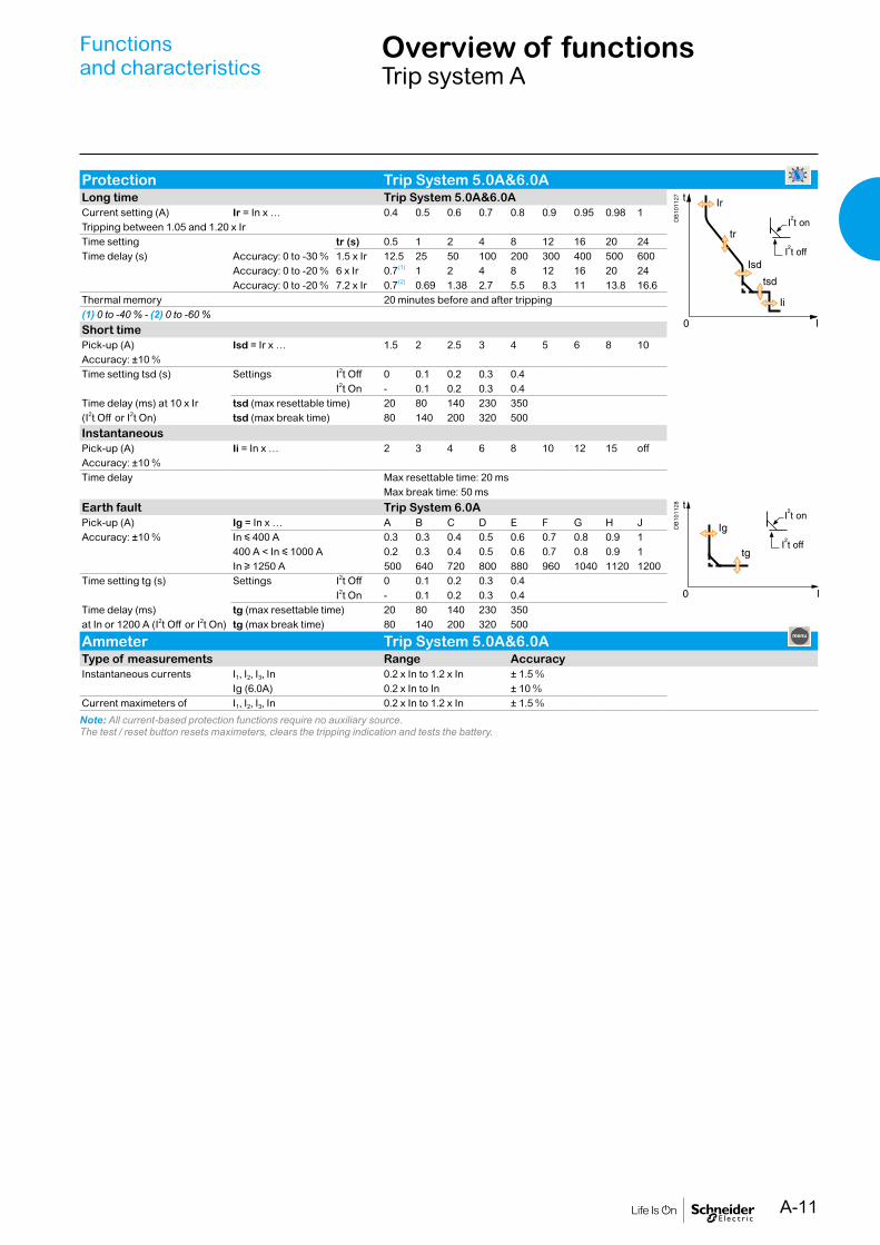
Protection Trip System 5.0A&6.0ALong time Trip System 5.0A&6.0A
DB
1011
27
Current setting (A) Ir = In x … 0.4 0.5 0.6 0.7 0.8 0.9 0.95 0.98 1Tripping between 1.05 and 1.20 x IrTime setting tr (s) 0.5 1 2 4 8 12 16 20 24Time delay (s) Accuracy: 0 to -30 % 1.5 x Ir 12.5 25 50 100 200 300 400 500 600
Accuracy: 0 to -20 % 6 x Ir 0.7(1) 1 2 4 8 12 16 20 24Accuracy: 0 to -20 % 7.2 x Ir 0.7(2) 0.69 1.38 2.7 5.5 8.3 11 13.8 16.6
Thermal memory 20 minutes before and after tripping(1) 0 to -40 % - (2) 0 to -60 %Short timePick-up (A) Isd = Ir x … 1.5 2 2.5 3 4 5 6 8 10Accuracy: ±10 %Time setting tsd (s) Settings I2t Off 0 0.1 0.2 0.3 0.4
I2t On - 0.1 0.2 0.3 0.4Time delay (ms) at 10 x Ir tsd (max resettable time) 20 80 140 230 350(I2t Off or I2t On) tsd (max break time) 80 140 200 320 500InstantaneousPick-up (A) Ii = In x … 2 3 4 6 8 10 12 15 offAccuracy: ±10 %Time delay Max resettable time: 20 ms
Max break time: 50 msEarth fault Trip System 6.0A
DB
1011
28
Pick-up (A) Ig = In x … A B C D E F G H JAccuracy: ±10 % In y 400 A 0.3 0.3 0.4 0.5 0.6 0.7 0.8 0.9 1
400 A < In y 1000 A 0.2 0.3 0.4 0.5 0.6 0.7 0.8 0.9 1In u 1250 A 500 640 720 800 880 960 1040 1120 1200
Time setting tg (s) Settings I2t Off 0 0.1 0.2 0.3 0.4I2t On - 0.1 0.2 0.3 0.4
Time delay (ms) tg (max resettable time) 20 80 140 230 350at In or 1200 A (I2t Off or I2t On) tg (max break time) 80 140 200 320 500
Ammeter Trip System 5.0A&6.0AType of measurements Range AccuracyInstantaneous currents I1, I2, I3, In 0.2 x In to 1.2 x In ± 1.5 %
Ig (6.0A) 0.2 x In to In ± 10 %Current maximeters of I1, I2, I3, In 0.2 x In to 1.2 x In ± 1.5 %
Note: All current-based protection functions require no auxiliary source.The test / reset button resets maximeters, clears the tripping indication and tests the battery.
A-12
Functionsand characteristics
Trip systemAccessories and test equipment
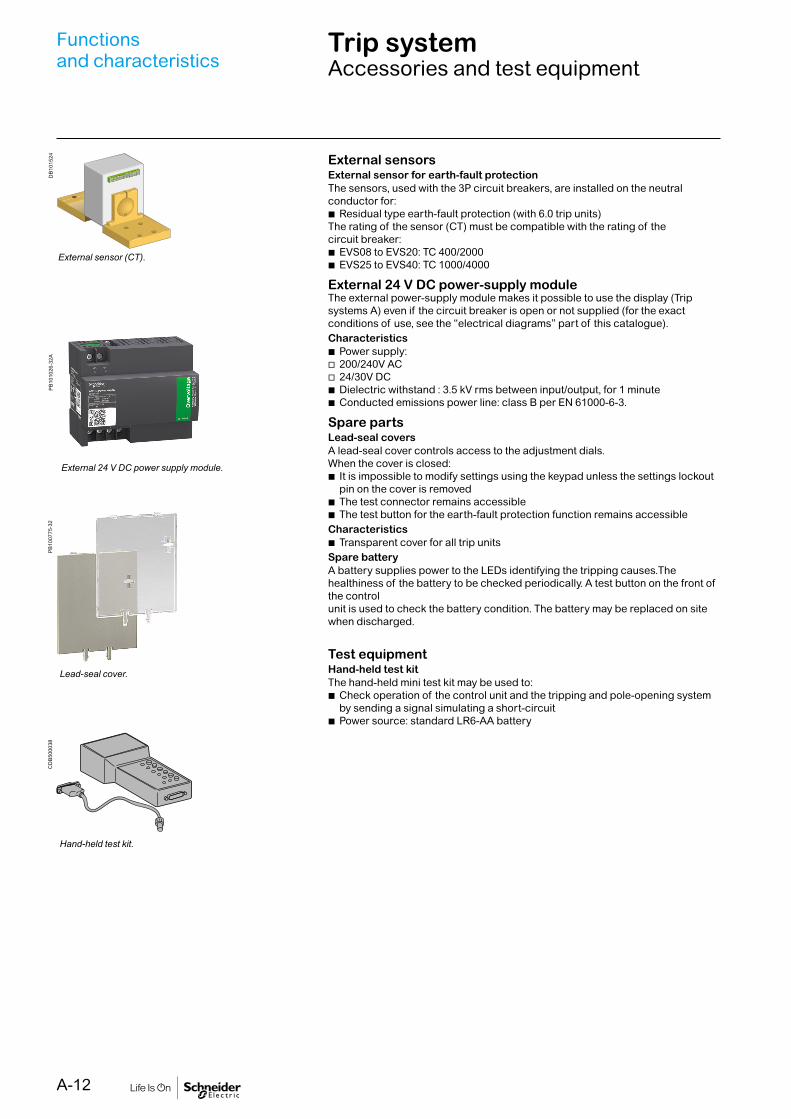
External sensorsExternal sensor for earth-fault protectionThe sensors, used with the 3P circuit breakers, are installed on the neutral conductor for:
b Residual type earth-fault protection (with 6.0 trip units)The rating of the sensor (CT) must be compatible with the rating of the circuit breaker:
b EVS08 to EVS20: TC 400/2000 b EVS25 to EVS40: TC 1000/4000
External 24 V DC power-supply moduleThe external power-supply module makes it possible to use the display (Trip systems A) even if the circuit breaker is open or not supplied (for the exact conditions of use, see the “electrical diagrams” part of this catalogue).Characteristics
b Power supply: v 200/240V AC v 24/30V DC b Dielectric withstand : 3.5 kV rms between input/output, for 1 minute b Conducted emissions power line: class B per EN 61000-6-3.
Spare partsLead-seal coversA lead-seal cover controls access to the adjustment dials.When the cover is closed:
b It is impossible to modify settings using the keypad unless the settings lockout pin on the cover is removed
b The test connector remains accessible b The test button for the earth-fault protection function remains accessible
Characteristics b Transparent cover for all trip units
Spare batteryA battery supplies power to the LEDs identifying the tripping causes.The healthiness of the battery to be checked periodically. A test button on the front of the control unit is used to check the battery condition. The battery may be replaced on site when discharged.
Test equipmentHand-held test kitThe hand-held mini test kit may be used to:
b Check operation of the control unit and the tripping and pole-opening system by sending a signal simulating a short-circuit
b Power source: standard LR6-AA battery
DB
1015
24P
B10
0775
-32
CD
B50
0038
PB
1010
26-3
2A
External sensor (CT).
Lead-seal cover.
Hand-held test kit.
External 24 V DC power supply module.

A-13
Functionsand characteristics
ConnectionsOverview of solutions and accessories
Available connection: b Rear connections: horizontal, vertical and mixed
The solutions presented are similar in principle for allEasyPact EVS fixed and draw-out devices.
Rear connectionHorizontal Vertical
Mixed
Simply turn a horizontal rear connector 90° to make it a vertical connector.
PB
1043
55A
40
PB
1043
59A
40P
B10
4354
A40

A-14
Functionsand characteristics
ConnectionsOverview of solutions and accessories
Interphase barriers EIPThese barriers are flexible insulated partitions used to reinforce isolation ofconnection points in installations with busbars, whether insulated or not.For EasyPact EVS devices, they are installed vertically between rear connection terminals. They are not compatible with spreaders.
Safety shutters VOMounted on the chassis, the safety shutters automatically block access to thedisconnecting contact cluster when the device is in the disconnected or test positions(degree of protection IP 20) When the device is removed from its chassis, no liveparts are accessible.The shutter-locking system is made up of a moving block (optional device) that can be padlocked (padlock not supplied). The block:
b Prevents connection of the device b Locks the shutters in the closed position
For EasyPact EVS08 to EVS40A support at the bottom of the chassis is used to store the blocks when they are not used:
b 2 blocks for EVS08 to EVS40
CP
B10
0010
PB
1043
64A
50

A-15
Functionsand characteristics
ConnectionsAccessories and auxiliaries
Type of accessory EasyPact EVS08 to EVS40Fixed breaker Draw-out breakerRear connection Rear connection
Interphasebarriers
DB
1011
49
Optional
DB
1011
49
OptionalSafety shutters
DB
1011
53
StandardSafety shutters locking blocks
E46
460
OptionalDoor interlock
E46
452
OptionalPushbutton locking device E
4666
6
OptionalE
4666
6
OptionalOFF position locking
CD
B50
0039
Optional
CD
B50
0039
Optional“Disconnected” position locking
DB
1174
58
OptionalON/OFF indication contacts(OF) E
4668
9
Standard
E46
689
StandardAdditional ON/OFF indication contacts(OF) E
4668
9
Optional
E46
689
Optional“Fault trip” indication contact(SDE)
CD
B50
0040
Standard
CD
B50
0040
Standard

A-16
Type of accessory EasyPact EVS08 to EVS40Fixed breaker Draw-out breakerRear connection Rear connection
“Connected, disconnected, test position”indication contact(CE,CD,CT)
E46
661
Optional“Ready to close” contact(PF) E
4643
8
Optional
E46
438
OptionalEscutcheon(CDP)
CD
B50
0061
Standard
CD
B50
0061
StandardMechanical operation counter(CDM)
DB
1256
17
Optional
DB
1256
17
OptionalEscutcheon blanking plate
E46
670
Optional
E46
670
OptionalAuxiliary terminal shield(CB) E
4645
8
OptionalTransparent cover (IP54)
E46
669
Optional
Functionsand characteristics
Accessories and auxiliaries

A-17
LockingOn the device
Pushbutton locking VBPThe transparent cover blocks access to the pushbuttons used to open and close the device.It is possible to independently lock the opening button and the closing button.The locking device is often combined with a remote operating mechanism.The pushbuttons may be locked using either:
b Three padlocks (not supplied) b Lead seal b Two screws
Device locking in the OFF position by keylocks VSPOThe circuit breaker is locked in the OFF position by physically maintaining theopening pushbutton pressed down:
b Using keylocks (one or two keylocks, supplied)Keys may be removed only when locking is effective (Profalux or Ronis type locks).The keylocks are available in any of the following configurations:
b One keylock b One keylock mounted on the device + one identical keylock supplied separately for interlocking with another device
A locking kit (without locks) is available for installation of one keylock (Ronis,Profalux).
Access to pushbuttons protected by transparent cover.
PB
1008
11-3
2P
B10
0810
-32
Pushbutton locking using a padlock.
CP
B10
0007
OFF position locking using a keylock.
CD
B50
0036
Profaulx Ronis
Door interlock catch VPECMounted on the right or left-hand side of the chassis, this device inhibits opening ofthe cubicle door when the circuit breaker is in “connected” or “test” position. It thebreaker is put in the “connected” position with the door open, the door may be closedwithout having to disconnect the circuit breaker.
Automatic spring discharge before breaker removal DAEThis option discharges the springs before the breaker is removed from the chassis.
CD
B50
0006
1 Reset button for mechanical trip indication.2 OFF pushbutton.3 OFF position lock.4 Door interlock.5 ON pushbutton.6 Spring charge indication.7 Pushbutton locking.8 Contact position indication.9 Operation counter.
MVS08 N
IEC 60947-2 50/60H
delay
short time
on I2t
.2
.3.4 .4
.1
.2
.10
long time
alarm
ground fault
setting
4
test
.4.5.6
.7.8 .9
.95
.981
Ir
x In
.512
48 12
1620
tr(s)
at 6 Ir24
x Ir
22.5
34 5
68
10
Isd
1.5
tsd(s)
x In3
68 10
1215
off2
BC
DE F
GH
I
Ig
Aon I
2t.2.3.4
.4
.1
.2.3
.10off
tg(s)
.3
instantaneous
I i
ET6G Trip System
alarm
Ir
ground fault
test
onoff
onoff
off
(s)
(s)
(s)
long time
short time
instantaneous
ET6G Trip System
Door interlock.
CP
B10
0008
Functionsand characteristics

A-18
LockingOn the chassis
CD
B50
0007
1 Door interlock.2 Keylock locking.3 Padlock locking.4 Position indicator.5 Chassis front plate (accessible with cubicle door closed).6 Racking-handle entry.7 Release button.8 Racking-handle storage.
“Connected”, “disconnected” and “test” position racking interlockThe “connected”, “disconnected” and “test” positions are shown by an indicator andare mechanically indexed. The exact position is obtained when the racking handleblocks. A release button is used to free it.
“Disconnected” position locking by padlocks or keylocks VSPDMounted on the chassis and accessible with the door closed, these devices lock thecircuit breaker in the “disconnected” position in two manners:
b Using padlocks (standard), up to three padlocks (not supplied) b Using keylocks (optional), one or two different keylocks are available
Profalux and Ronis keylocks are available in different options: b One keylock b Two identical key locks - one keylock mounted on the device + one identical keylock supplied separately for interlocking with another device
A locking kit (without locks) is available for installation of one or two keylocks (Ronis, Profalux).
Padlock
CP
B10
0006
CP
B10
0017
“Disconnected” position locking by padlock.
Circuit breaker in “disconnected” position.
Insert the shackle (max. diameter 5 to 8 mm) of the padlock(s).
Pull out the tab.
The crank connot be inserted.
Keylock
Circuit breaker in “disconnected” position.
Remove the key(s)
Turn the key(s).
The crank cannot be inserted.
18
56
4
7
2 3
“Disconnected” position locking by keylock.
Functionsand characteristics

A-19
Indication contactsP
B10
0818
-16
PB
1008
07-2
0
“Fault-trip” indication contact (SDE).
ON/OFF indication contacts(OF) (rotary type).
Indication contacts are available: b in the standard version for relay applications
ON/OFF indication contacts OFIndication contacts indicate the ON or OFF position of the circuit breaker:
b Rotary type changeover contacts directly driven by the mechanism for EasyPact EVS. These contacts trip when the minimum isolation distance between the main circuit-breaker contacts is reached
OF EVSSupplied as standard 1 (4 C/O)Optional contact 1 (4 C/O)Breaking capacity (A) Standard Minimum load: 100 mA/24 Vp.f.: 0.3 V AC 240/380 10/6 (1)
AC12/DC12 480 10/6 (1)
690 6V DC 24/48 10/6 (1)
125 10/6 (1)
250 3
(1) Standard contacts: 10 A; optional contacts: 6 A.
“Fault-trip” indication contacts SDECircuit-breaker tripping due to a fault is signalled by:
b A red mechanical fault indicator (reset) b One changeover contact SDE
Following tripping, the mechanical indicator must be reset before the circuit breakermay be closed. One SDE is supplied as standard.SDE EVSSupplied as standard 1Breaking capacity (A) Standard Minimum load: 100 mA/24 Vp.f.: 0.3 V AC 240/380 5AC12/DC12 480 5
690 3V DC 24/48 3
125 0.3250 0.15
“Connected”, “disconnected” and “test” position carriage switches CE, CD & CTThree series of optional auxiliary contacts are available for the chassis:
b Changeover contacts to indicate the “connected” position CE b Changeover contacts to indicate the “disconnected” position CD. This position is indicated when the required clearance for isolation of the power and auxiliary circuits is reached
b Changeover contacts to indicate the “test” position CT. In this position, the power circuits are disconnected and the auxiliary circuits are connected
EVSContacts CE/CD/CTMaximum number Standard 3 3 3Breaking capacity (A) Standard Minimum load: 100 mA/24 Vp.f.: 0.3 V AC 240 8AC12/DC12 380 8
480 8690 6
V DC 24/48 2.5125 0.8250 0.3
PB
1008
17-3
2
CE, CD and CT “connected/disconnected/test” positioncarriage switches.
Functionsand characteristics

A-20
Remote operationRemote ON / OFF
PB
1043
49A
68
DB
1117
83
The remote ON / OFF function is used to remotely open and close the circuit breaker.It is made up of:
b An electric motor MCH equipped with a “springs charged” limit switch contact CH
b Two voltage releases: v A closing release XF v An opening release MX
Optionally, other function may be added: b A “ready to close” contact PF
A remote-operation function is generally combined with: b Device ON / OFF indication OF b “Fault-trip” indication SDE
Wiring diagram of a point-to-point remote ON / OFF function
A point-to-point solution for remote operation of EasyPact EVS
Note: An opening order always takes priority over a closing order.If opening and closing orders occur simultaneously, themechanism discharges without any movement of the maincontacts. The circuit breaker remains in the open position(OFF).In the event of maintained opening and closing orders, thestandard mechanism provides an anti-pumping function byblocking the main contacts in open position.Anti-pumping function. After fault tripping or intentionalopening using the manual or electrical controls, the closingorder must first be discontinued, then reactivated to close thecircuit breaker.
Functionsand characteristics
A-21
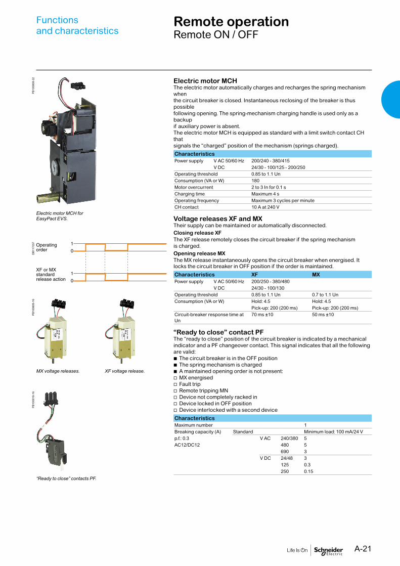
Electric motor MCHThe electric motor automatically charges and recharges the spring mechanism whenthe circuit breaker is closed. Instantaneous reclosing of the breaker is thus possiblefollowing opening. The spring-mechanism charging handle is used only as a backupif auxiliary power is absent.The electric motor MCH is equipped as standard with a limit switch contact CH thatsignals the “charged” position of the mechanism (springs charged).CharacteristicsPower supply V AC 50/60 Hz 200/240 - 380/415
V DC 24/30 - 100/125 - 200/250Operating threshold 0.85 to 1.1 UnConsumption (VA or W) 180Motor overcurrent 2 to 3 In for 0.1 sCharging time Maximum 4 sOperating frequency Maximum 3 cycles per minuteCH contact 10 A at 240 V
Voltage releases XF and MXTheir supply can be maintained or automatically disconnected.Closing release XFThe XF release remotely closes the circuit breaker if the spring mechanism is charged.Opening release MXThe MX release instantaneously opens the circuit breaker when energised. It locks the circuit breaker in OFF position if the order is maintained.Characteristics XF MXPower supply V AC 50/60 Hz 200/250 - 380/480
V DC 24/30 - 100/130 Operating threshold 0.85 to 1.1 Un 0.7 to 1.1 UnConsumption (VA or W) Hold: 4.5 Hold: 4.5
Pick-up: 200 (200 ms) Pick-up: 200 (200 ms)Circuit-breaker response time at Un
70 ms ±10 50 ms ±10
“Ready to close” contact PFThe “ready to close” position of the circuit breaker is indicated by a mechanical indicator and a PF changeover contact. This signal indicates that all the following are valid:
b The circuit breaker is in the OFF position b The spring mechanism is charged b A maintained opening order is not present: v MX energised v Fault trip v Remote tripping MN v Device not completely racked in v Device locked in OFF position v Device interlocked with a second device
CharacteristicsMaximum number 1Breaking capacity (A) Standard Minimum load: 100 mA/24 Vp.f.: 0.3 V AC 240/380 5AC12/DC12 480 5
690 3V DC 24/48 3
125 0.3250 0.15
PB
1008
09-1
6P
B10
0818
-16
DB
1170
37P
B10
0808
-32
MX voltage releases. XF voltage release.
“Ready to close” contacts PF.
Electric motor MCH forEasyPact EVS.
Functionsand characteristics
Remote operationRemote ON / OFF
A-22
Remote operationRemote tripping
DB
1008
09-1
605
6422
N
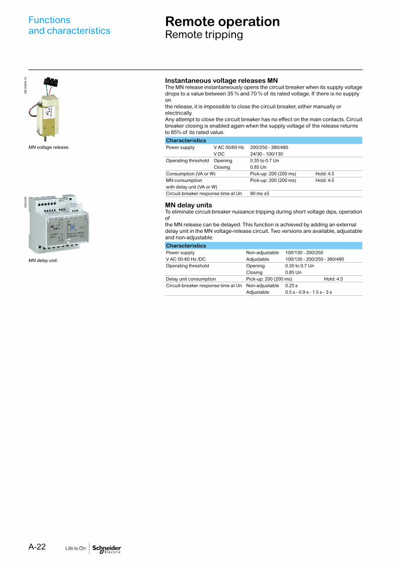
MN voltage release.
MN delay unit.
Instantaneous voltage releases MNThe MN release instantaneously opens the circuit breaker when its supply voltagedrops to a value between 35 % and 70 % of its rated voltage. If there is no supply onthe release, it is impossible to close the circuit breaker, either manually or electrically.Any attempt to close the circuit breaker has no effect on the main contacts. Circuit breaker closing is enabled again when the supply voltage of the release returns to 85% of its rated value.CharacteristicsPower supply V AC 50/60 Hz 200/250 - 380/480
V DC 24/30 - 100/130 Operating threshold Opening 0.35 to 0.7 Un
Closing 0.85 UnConsumption (VA or W) Pick-up: 200 (200 ms) Hold: 4.5MN consumption Pick-up: 200 (200 ms) Hold: 4.5with delay unit (VA or W)Circuit-breaker response time at Un 90 ms ±5
MN delay unitsTo eliminate circuit-breaker nuisance tripping during short voltage dips, operation ofthe MN release can be delayed. This function is achieved by adding an externaldelay unit in the MN voltage-release circuit. Two versions are available, adjustableand non-adjustable.CharacteristicsPower supply Non-adjustable 100/130 - 200/250V AC 50-60 Hz /DC Adjustable 100/130 - 200/250 - 380/480Operating threshold Opening 0.35 to 0.7 Un
Closing 0.85 UnDelay unit consumption Pick-up: 200 (200 ms) Hold: 4.5Circuit-breaker response time at Un Non-adjustable 0.25 s
Adjustable 0.5 s - 0.9 s - 1.5 s - 3 s
Functionsand characteristics
A-23
Source-changeover systemsMechanical interlocking
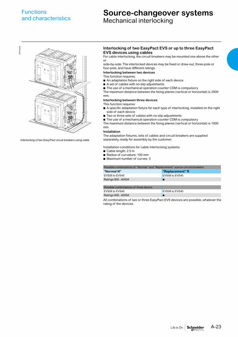
Interlocking of two EasyPact EVS or up to three EasyPact EVS devices using cablesFor cable interlocking, the circuit breakers may be mounted one above the other orside-by-side. The interlocked devices may be fixed or draw-out, three-pole or four-pole, and have different ratings.Interlocking between two devicesThis function requires:
b An adaptation fixture on the right side of each device b A set of cables with no-slip adjustments b The use of a mechanical operation counter CDM is compulsory
The maximum distance between the fixing planes (vertical or horizontal) is 2000 mm.Interlocking between three devicesThis function requires:
b A specific adaptation fixture for each type of interlocking, installed on the right side of each device
b Two or three sets of cables with no-slip adjustments b The use of a mechanical operation counter CDM is compulsory
The maximum distance between the fixing planes (vertical or horizontal) is 1000 mm.InstallationThe adaptation fixtures, sets of cables and circuit breakers are supplied separately, ready for assembly by the customer.
Installation conditions for cable interlocking systems: b Cable length: 2.5 m b Radius of curvature: 100 mm b Maximum number of curves: 3
Possible combinations of “Normal” and “Replacement” source circuit breakers“Normal N” “Replacement” REVS08 to EVS40 EVS08 to EVS40Ratings 800...4000A b
Possible combinations of three deviceEVS08 to EVS40 EVS08 to EVS40Ratings 800...4000A b
All combinations of two or three EasyPact EVS devices are possible, whatever the rating of the devices.
CP
B10
0009
Interlocking of two EasyPact circuit breakers using cable.
Functionsand characteristics

A-24
AccessoriesP
B10
4740
PB
1043
82A
32D
B10
1173
PB
1007
76-4
2
Escutcheon CDP with blanking plate.
Transparent cover CP for escutcheon.
Auxiliary terminal shield CBOptional equipment mounted on the chassis, the shield prevents access to theterminal block of the electrical auxiliaries.
Operation counter CDMThe operation counter sums the number of operating cycles and is visible on the front panel. It is compatible with manual and electrical control functions.This option is compulsory for all the source-changeover systems.
Escutcheon CDPStandard equipment mounted on the door of the cubicle, the escutcheon increasesthe degree of protection to IP 40 (circuit breaker installed free standing: IP30) .It is available in fixed and draw-out versions.
Blanking plate for escutcheon OPUsed with the escutcheon, this option closes off the door cut-out of a cubicle not yetequipped with a device. It may be used with the escutcheon for both fixed anddraw-out devices.
Transparent cover for escutcheon CPOptional equipment mounted on the escutcheon, the cover is hinged and secured bya screw. It increases the degree of protection to IP54, IK10. It adapts to draw-outdevices.
Functionsand characteristics

A-25

Installationrecommendations

B-1
Installation recommendations
Functions and characteristics A-1
Operating conditions B-2Installation in switchboard B-3 Door interlock catch B-5Control wiring B-6Power connection B-7Recommended busbars drilling B-9Busbar sizing B-10Temperature deratingPower dissipation B-12
Dimensions and connection C-1Electrical diagrams D-1Additional characteristics E-1Catalogue numbers and order form F-1
EasyPact EVS

B-2
Installationrecommendations
Operating conditions
EasyPact EVS circuit breakers have been tested for operation in industrial atmospheres. It is recommended that the equipment be cooled or heated to the proper operating temperature and kept free of excessive vibration and dust.
CD
B500
008 Ambient temperature
EasyPact EVS devices can operate under the following temperature conditions: b The electrical and mechanical characteristics are stipulated for an ambient temperature of -5°C to +60°C
b Circuit-breaker closing is guaranteed down to -35°CStorage conditions are as follows:
b -40 to +85°C for a EasyPact EVS device without its control unit b -25°C to +85°C for the control unit
CD
B500
011
CD
B500
012
AltitudeAt altitudes higher than 2000 metres, the modifications in the ambient air (electricalresistance, cooling capacity) lower the following characteristics as follows:
Altitude (m) 2000 3000Impulse withstand voltage uimp (kV) 12 11Rated insulation voltage (Ui) 1000 900Maximum rated operationnalvoltage 50/60 Hz Ue (V)
690 5901000 890
Rated current 40°C 1 x In 0.99 x In
Intermediate values may be obtained by interpolation.
Electromagnetic disturbancesEasyPact EVS devices are protected against:
b Overvoltages caused by devices that generate electromagnetic disturbances b Overvoltages caused by atmospheric disturbances or by a distribution-system outage (e.g. failure of a lighting system)
b Devices emitting radio waves (radios, walkie-talkies, radar, etc.) b Electrostatic discharges produced by users
EasyPact EVS devices have successfully passed the electromagnetic-compatibilitytests (EMC) defined by the following international standards:
b IEC 60947-2, appendix FThe above tests guarantee that:
b No nuisance tripping occurs b Tripping times are respected
MVS08 N
IEC 60947-2 50/60H
delay
short time
on I2t
.2
.3.4 .4
.1
.2
.10
long time
alarm
ground fault
setting
4
test
.4.5
.6
.7.8 .9
.95
.98
1
Ir
x In
.51
2
48 12
16
20
tr(s)
at 6 Ir24
x Ir
22.5
34 5
6
8
10
Isd
1.5
tsd
(s)
x In3
68 10
12
15
off2
B
C
DE F
G
H
I
Ig
Aon I
2t
.2
.3.4 .
4
.1
.2.3
.10off
tg
(s)
.3
instantaneous
I i
ET6G Trip System
alarm
Ir
ground fault
test
onoff
onoff
off
(s)
(s)
(s)
long time
short time
instantaneous
ET6G Trip System
2000(m)
MVS08 N
IEC 60947-2 50/60H
delay
short time
on I2t
.2
.3.4 .4
.1
.2
.10
long time
alarm
ground fault
setting
4
test
.4.5
.6
.7.8 .9
.95
.98
1
Ir
x In
.51
2
48 12
16
20
tr(s)
at 6 Ir24
x Ir
22.5
34 5
6
8
10
Isd
1.5
tsd
(s)
x In3
68 10
12
15
off2
B
C
DE F
G
H
I
Ig
Aon I
2t
.2
.3.4 .
4
.1
.2.3
.10off
tg
(s)
.3
instantaneous
I i
ET6G Trip System
alarm
Ir
ground fault
test
onoff
onoff
off
(s)
(s)
(s)
long time
short time
instantaneous
ET6G Trip System

B-3
Installation in switchboard
CD
B500
013
CD
B500
016
CD
B500
017
CD
B500
018
CD
B500
014
CD
B500
015
Possible positions
Power supplyEasyPact EVS devices can be supplied either from the top or from the bottom without reduction in performance, in order to facilitate connection when installed in a switchboard.
Mounting the circuit-breakerIt is important to distribute the weight of the device uniformily over a rigid mountingsurface such as rails or a base plate.This mounting plane should be perfectly flat (tolerance on support flatness: 2 mm).This eliminates any risk of deformation which could interfere with correct operationof the circuit breaker.EasyPact devices can also be mounted on a vertical plane using the special brackets.
Mounting on rails.
MVS08 N
IEC 60947-2 50/60H
delay
short time
on I2t
.2
.3.4 .4
.1
.2
.10
long time
alarm
ground fault
setting
4
test
.4.5.6
.7.8 .9
.95
.981
Ir
x In
.512
48 12
1620
tr(s)
at 6 Ir24
x Ir
22.5
34 5
68
10
Isd
1.5
tsd
(s)
x In3
68 10
1215
off2
BC
DE F
GH
I
Ig
Aon I
2t.2.3.4 .
4
.1
.2.3
.10off
tg
(s)
.3
instantaneous
I i
ET6G Trip System
alarm
Ir
ground fault
test
onoff
onoff
off
(s)
(s)
(s)
long time
short time
instantaneous
ET6G Trip System
MVS08 N
IEC 60947-2 50/60H
delay
short time
on I2t
.2
.3.4 .4
.1
.2
.10
long time
alarm
ground fault
setting
4
test
.4.5
.6
.7.8 .9
.95
.98
1
Ir
x In
.51
2
48 12
16
20
tr(s)
at 6 Ir24
x Ir
22.5
34 5
6
8
10
Isd
1.5
tsd
(s)
x In3
68 10
12
15
off2
B
C
DE F
G
H
I
Ig
Aon I
2t
.2
.3.4 .
4
.1
.2.3
.10off
tg
(s)
.3
instantaneous
I i
ET6G Trip System
alarm
Ir
ground fault
test
onoff
onoff
off
(s)
(s)
(s)
long time
short time
instantaneous
ET6G Trip System

B-4
DB1
0143
4D
B101
435
A : Non magnetic material.
PartitionsSufficient openings must be provided in partitions toensure good air circulation around the circuit breaker;Any partition between upstream and downstreamconnections of the device must be made of nonmagnetic material.For high currents, of 2500 A and upwards, the metalsupports or barriers in the immediate vicinity of aconductor must be made of non-magnetic material A.Metal barriers through which a conductor passes mustnot form a magnetic loop.
DB1
1704
5
DB1
0143
6BusbarsThe mechanical connection must be exclude thepossibility of formation of a magnetic loop around a conductor.
CD
B500
041
DB1
0143
9
453
Interphase barrierIf the insulation distance between phases is notsufficient (y 14 mm), it is advised to install phasebarriers (taking into account the safety clearances).
Installationrecommendations
Installation in switchboard
B-5
Door interlock catch
DB1
1704
4
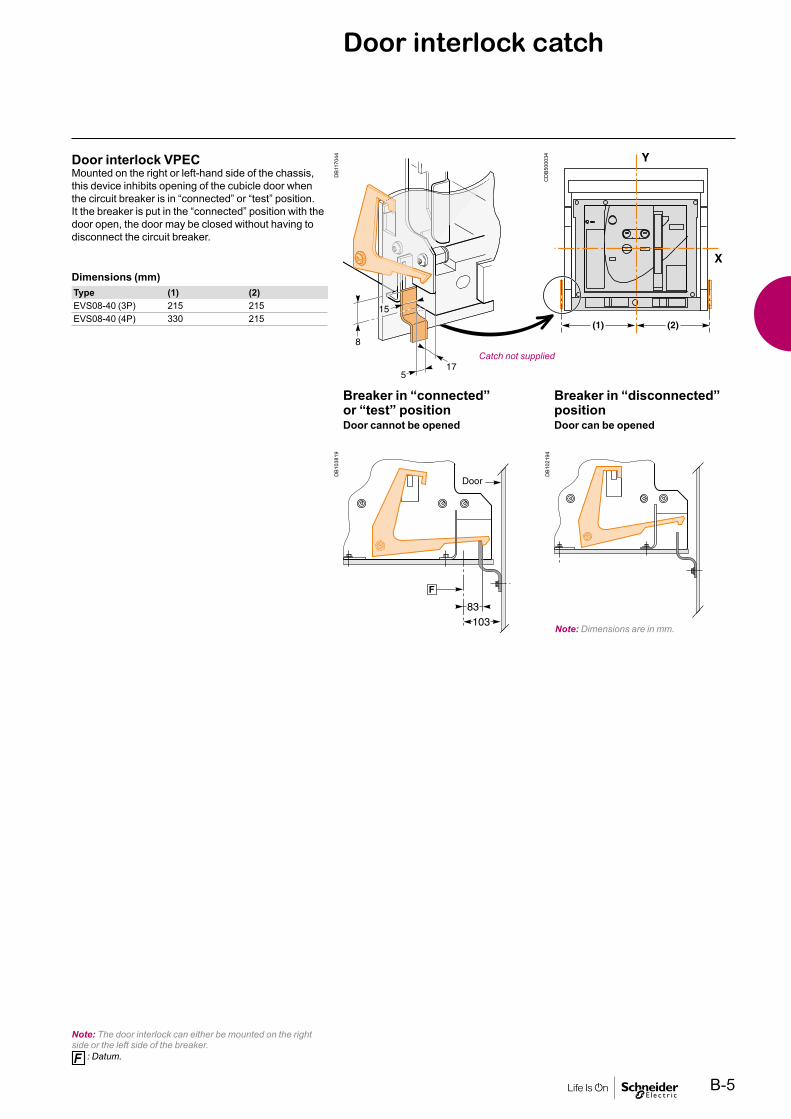
Catch not supplied
DB1
0381
9
83103
DB1
0219
4
Breaker in “connected” or “test” positionDoor cannot be opened
Breaker in “disconnected” positionDoor can be opened
Door interlock VPECMounted on the right or left-hand side of the chassis,this device inhibits opening of the cubicle door whenthe circuit breaker is in “connected” or “test” position.It the breaker is put in the “connected” position with thedoor open, the door may be closed without having todisconnect the circuit breaker.
Dimensions (mm)Type (1) (2)EVS08-40 (3P) 215 215EVS08-40 (4P) 330 215
Note: The door interlock can either be mounted on the right side or the left side of the breaker.
: Datum.
Note: Dimensions are in mm.
CD
B500
034

B-6
Control wiring
Wiring of voltage releasesDuring pick-up, the power consumed is approximately 150 to 200 VA. For low controlvoltages (12, 24, 48 V), maximum cable lengths are imposed by the voltage and thecross-sectional area of cables.Recommended maximum cable lengths (meter).
12 V 24 V 48 V2,5 mm2 1,5 mm2 2,5 mm2 1,5 mm2 2,5 mm2 1,5 mm2
MN U source 100 % – – 58 35 280 165U source 85 % – – 16 10 75 45
MX-XF U source 100 % 21 12 115 70 550 330U source 85 % 10 6 75 44 350 210
Note: The indicated length is that of each of the two wires.
24 V DC power-supply moduleExternal 24 V DC power-supply module (F1-, F2+)
b Do not connect the positive terminal (F2+) to earth b The negative terminal (F1-) can be connected to earth b A number of trip units can be connected to the same 24 V DC power supply (the consumption of a trip unit is approximately 100 mA)
b Do not connect any devices other than a trip unit b The maximum length for each conductor is ten metres. For greater distances, it is advised to twist the supply wires together
b The 24 V DC supply wires must cross the power cables perpendicularly. If this is difficult, it is advised to twist the supply wires together
b The technical characteristics of the external 24 V DC power-supply module are indicated on page A-14.
Note: Wiring of ZSI: it is recommended to use twisted shielded cable. The shield must be connected to earth at both ends.
Installationrecommendations

B-7
Power connection
Cables connectionsIf cables are used for the power connections, make sure that they do not apply excessive mechanical forces to the circuit breaker terminals.For this, make the connections as follows:
b Extend the circuit breaker terminals using short bars designed and installed according to the recommendations for bar-type power connections:
v For a single cable, use solution B opposite v For multiple cables, use solution C opposite b In all cases, follow the general rules for connections to busbars:
v Position the cable lugs before inserting the bolts v The cables should firmly secured to the framework E
DB1
0144
8
DB1
0144
9
DB1
0145
0D
B101
453
DB1
0145
1
DB1
0145
2Busbars connectionsThe busbars should be suitably adjusted to ensure thatthe connection points are positioned on the terminalsbefore the bolts are inserted BThe connections are held by the support which is solidly fixed to the framework of the switchboard, such that the circuit breaker terminals do not have to support its weight C. (This support should be placed close to the terminals).
Electrodynamic stressesThe first busbar support or spacer shall be situated within a maximum distance fromthe connection point of the breaker (see table below). This distance must berespected so that the connection can withstand the electrodynamic stressesbetween phases in the event of a short circuit.Maximum distance A between busbar to circuit breaker connection and the first busbarsupport or spacer with respect to the value of the prospective short-circuit current.Isc (kA) 30 50 65Distance A (mm) 350 300 250
B-8
DB1
0145
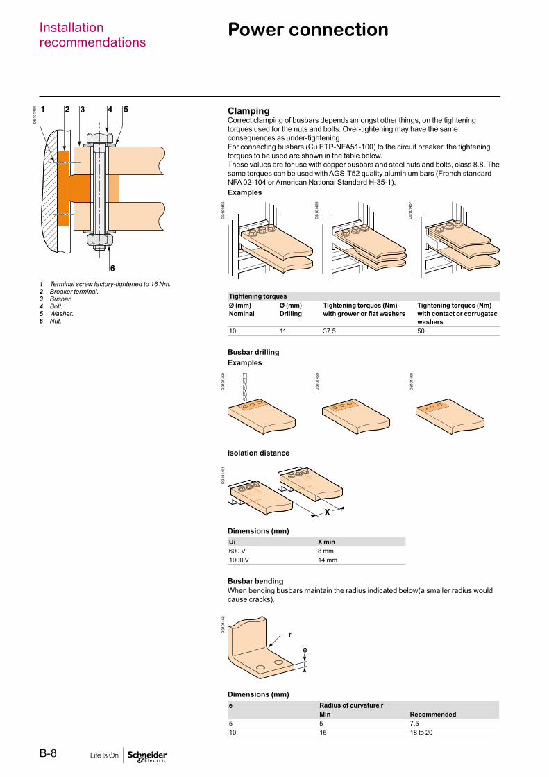
4 ClampingCorrect clamping of busbars depends amongst other things, on the tighteningtorques used for the nuts and bolts. Over-tightening may have the sameconsequences as under-tightening.For connecting busbars (Cu ETP-NFA51-100) to the circuit breaker, the tighteningtorques to be used are shown in the table below.These values are for use with copper busbars and steel nuts and bolts, class 8.8. The same torques can be used with AGS-T52 quality aluminium bars (French standardNFA 02-104 or American National Standard H-35-1).Examples
1 Terminal screw factory-tightened to 16 Nm.2 Breaker terminal.3 Busbar.4 Bolt.5 Washer.6 Nut.
DB1
0145
5
DB1
0145
6
DB1
0145
7
Tightening torquesØ (mm)Nominal
Ø (mm)Drilling
Tightening torques (Nm)with grower or flat washers
Tightening torques (Nm)with contact or corrugatecwashers
10 11 37.5 50
Busbar drillingExamples
DB1
0145
8
DB1
0145
9
DB1
0146
0
DB1
0146
1D
B101
462
Isolation distance
Dimensions (mm)Ui X min600 V 8 mm1000 V 14 mm
Busbar bendingWhen bending busbars maintain the radius indicated below(a smaller radius wouldcause cracks).
Dimensions (mm)e Radius of curvature r
Min Recommended5 5 7.510 15 18 to 20
Installationrecommendations
Power connection
B-9
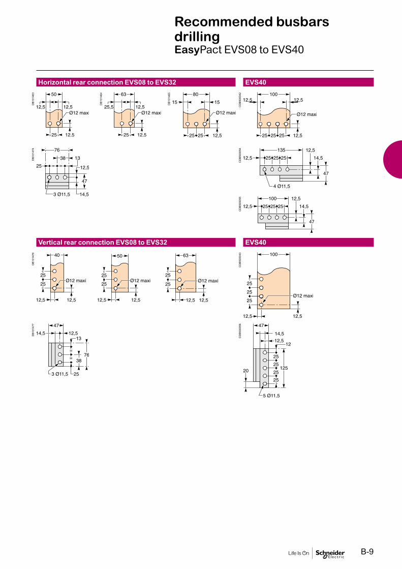
Recommended busbars drillingEasyPact EVS08 to EVS40
Horizontal rear connection EVS08 to EVS32
Vertical rear connection EVS08 to EVS32
EVS40
EVS40
DB1
0146
3
DB1
0146
4
DB1
0146
5
CD
B500
042
CD
B500
054
CD
B500
055
CD
B500
056
CD
B500
043
DB1
0147
4D
B101
476
DB1
0147
7

B-10
Installationrecommendations
Busbar sizing
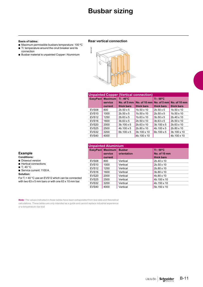
Basis of tables: b Maximum permissible busbars temperature: 100 ºC b Ti: temperature around the ciruit breaker and its connection
b Busbar material is unpainted Copper / Aluminium
ExampleConditions:
b Drawout version b Horizontal busbars b Ti: 50ºC b Service current: 1600A
Solution:For Ti = 50ºC, use an EVS16 which can be connected with 2 bars-63x10mm copper (or) 3 bars-80x10mm Aluminium.
Rear horizontal connection
Note: The values indicated in these tables have been extrapolated from test data and theoretical calculations. These tables are only intended as a guide and cannot replace industrial experience or a temperature rise test.
(Rear horizontal connection)
EEE
EEEE
EEEEE
E
B-11
Busbar sizing
Basis of tables: b Maximum permissible busbars temperature: 100 ºC b Ti: temperature around the ciruit breaker and its connection
b Busbar material is unpainted Copper / Aluminium
ExampleConditions:
b Drawout version b Hertical connections b Ti: 40 °C b Service current: 1100 A.
Solution:For Ti = 40 °C use an EVS12 which can be connected with two 63 x 5 mm bars or with one 63 x 10 mm bar.
Rear vertical connection
Note: The values indicated in these tables have been extrapolated from test data and theoretical calculations. These tables are only intended as a guide and cannot replace industrial experience or a temperature rise test.
EEEEEEE
E
EEEEEEE
E

B-12
Temperature deratingPower dissipation
Temperature deratingThe table below indicates the maximum current rating,for each connection type, as a function of Ti around thecircuit breaker and the busbars.For Ti greater than 60°C, consult us.Ti: temperature around the circuit breaker and its connection.
Version Draw-out FixedConnection Rear horizontal Rear vertical Rear horizontal Rear verticalTemp. Ti 40 °C 45 °C 50 °C 55 °C 60 °C 40 °C 45 °C 50 °C 55 °C 60 °C 40 °C 45 °C 50 °C 55 °C 60 °C 40 °C 45 °C 50 °C 55 °C 60 °CEVS (65kA)EVS08H 800 800 800 800EVS10H 1000 1000 1000 1000EVS12H 1250 1250 1250 1250EVS16H 1600 1600 1600 1600EVS20H 2000 1900 1800 2000 1900 2000 1920 2000EVS25H 2500 2450 2400 2300 2200 2500 2450 2400 2300 2500 2500EVS32H 3200 3100 3000 2900 3200 3200 3200EVS40H 4000 3900 3750 3650 4000 3900 4000 3900 3800 4000
Power dissipationTotal power dissipation is the value measured at IN, 50/60 Hz, for a 3 pole or 4 pole breaker (values above the power P = 3RI2). The resistance between input / output is the value measured per pole (cold state).
Type Draw-out Fixed65kA Power loss
(W)Input/output resistance (µohm)
Power loss (W)
Input/output resistance (µohm)
EVS08H 100 30 42 13EVS10H 150 30 70 13EVS12H 230 30 100 13EVS16H 390 30 170 13EVS20H 470 30 250 13EVS25H 600 19 260 8EVS32H 670 13 420 8EVS40H 900 11 650 8

B-13

Dimensions and connection

C-1
Dimensions and connection
Functions and characteristics A-1Installation recommendations B-1
EVS08 to EVS32 circuit breakers C-2Fixed 3/4-poles device C-2Draw-out 3/4-poles device C-4
EVS40 circuit breakers C-6Fixed 3/4-poles device C-6Draw-out 3/4-poles device C-8
Accessories C-10External modules C-11
Electrical diagrams D-1Additional characteristics E-1Catalogue numbers and order form F-1
EasyPact EVS
C-2
Dimensionsand connection
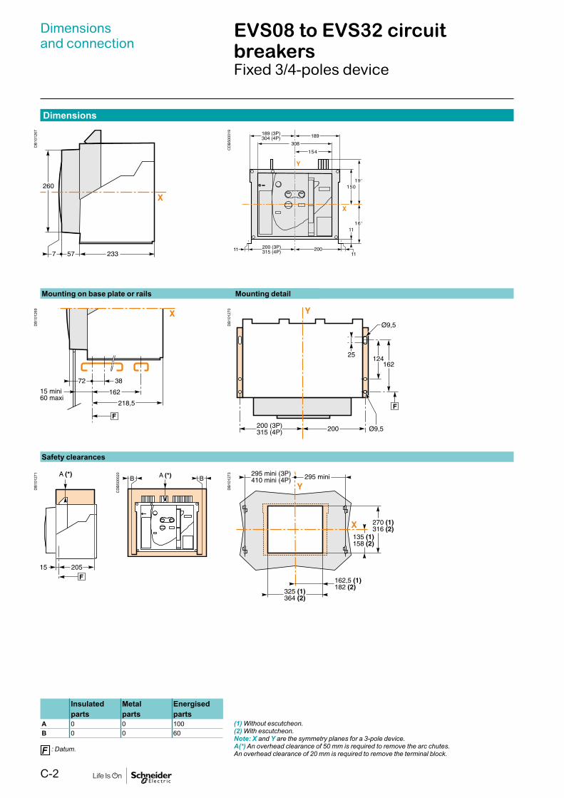
EVS08 to EVS32 circuit breakersFixed 3/4-poles device
Dimensions
DB1
0126
7
CD
B500
019
DB1
0126
9D
B101
271
CD
B500
020
DB1
0127
3D
B101
270
Mounting on base plate or rails Mounting detail
Safety clearances
(1) Without escutcheon.(2) With escutcheon.Note: X and Y are the symmetry planes for a 3-pole device.A(*) An overhead clearance of 50 mm is required to remove the arc chutes.An overhead clearance of 20 mm is required to remove the terminal block.
Insulated Metal Energisedparts parts parts
A 0 0 100B 0 0 60
: Datum.

C-3
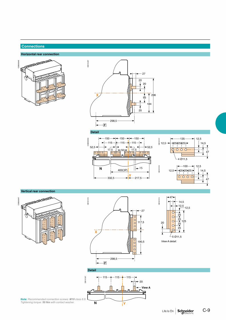
Connections
DB1
0127
4D
B101
279
DB1
0127
6
DB1
0127
7D
B101
287
DB1
0128
2D
B101
278
Horizontal rear connection
Vertical rear connection
Detail
Detail
Note: Recommended connection screws: M10 class 8.8.Tightening torque: 50 Nm with contact washer.
DB1
0128
0
View A detail.
C-4
Dimensionsand connection
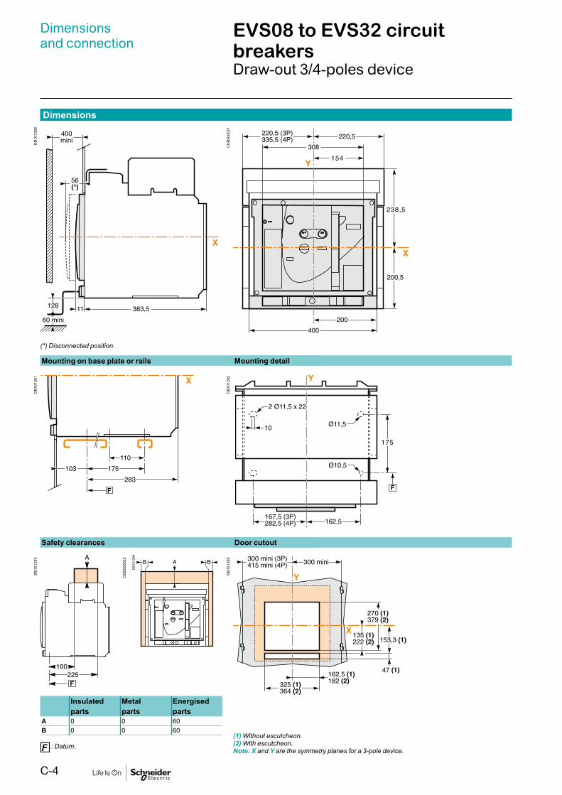
EVS08 to EVS32 circuit breakersDraw-out 3/4-poles device
Dimensions
DB1
0128
9
CD
B500
021
DB1
0129
1D
B101
293
CD
B500
022
DB1
0129
5D
B101
292
Mounting on base plate or rails Mounting detail
Safety clearances Door cutout
Insulated Metal Energisedparts parts parts
A 0 0 60B 0 0 60
: Datum.(1) Without escutcheon.(2) With escutcheon.Note: X and Y are the symmetry planes for a 3-pole device.
(*) Disconnected position.
DB
101294

C-5
Connections
CD
B500
044
CD
B500
045
DB1
0129
7D
B101
301
DB1
0129
8D
B101
307
Horizontal rear connection
Vertical rear connection
Detail
Detail
DB1
0128
2
View A detail.
Note: Recommended connection screws: M10 class 8.8.Tightening torque: 50 Nm with contact washer.
DB1
0127
8

C-6
Dimensionsand connection
EVS40 circuit breakersFixed 3/4-poles device
CD
B500
019
Dimensions
DB1
0126
7
Mounting on base plate or rails Mounting detail
DB1
0126
9D
B101
271
DB1
0127
3D
B101
270
Safety clearances
(1) Without escutcheon.(2) With escutcheon.Note: X and Y are the symmetry planes for a 3-pole device.A(*) An overhead clearance of 110 mm is required to remove the arc chutes.An overhead clearance of 20 mm is required to remove the terminal block.
Insulated Metal Energisedparts parts parts
A 0 0 100B 0 0 60
: Datum.
Door cutout
CD
B500
020

C-7
Connections
DB1
0130
9D
B101
312
Horizontal rear connection
Vertical rear connection
Detail
Detail
DB1
0131
1D
B101
314
DB1
0131
5
DB1
0127
6C
DB5
0004
9D
B101
287
DB1
0131
3
Note: Recommended connection screws: M10 class 8.8.Tightening torque: 50 Nm with contact washer.
CD
B500049
400(3P)15

C-8
Dimensionsand connection
EVS40 circuit breakersDraw-out 3/4-poles device
CD
B500
021
Dimensions
DB1
0128
9D
B101
291
DB1
0129
3
DB1
0129
5D
B101
292
Safety clearances Door cutout
Insulated Metal Energisedparts parts parts
A 0 0 60B 0 0 60
: Datum.
(1) Without escutcheon.(2) With escutcheon.Note: X and Y are the symmetry planes for a 3-pole device.The safety clearances take into account the space required to remove the arc chutes.
(*) Disconnected position.
Mounting on base plate or rails Mounting detail
CD
B500
022
DB
101294
C-9
Connections
CD
B500
046
CD
B500
047
DB1
0129
7
DB1
0130
7
Horizontal rear connection
Vertical rear connection
Note: Recommended connection screws: M10 class 8.8.Tightening torque: 50 Nm with contact washer.
Detail
Detail
DB1
0131
1D
B101
315
DB1
0131
4
CD
B500
050
DB1
0131
9
View A detail.
CD
B500050
400(3P)15

C-10
Dimensionsand connection
Accessories
Mounting on backplate with special brackets (EasyPact EVS08 to 32 fixed)
DB1
0135
0
DB1
0135
1

C-11
External modules
Connection of auxilary wiring to terminal block
External power supply module (AD)
Delay unit for MN release
DB1
0136
7
DB1
0137
5
DB1
1702
5D
B102
076
DB1
0136
8
One conductor only per connection point.
G3G4
Output
LN
AC/DC Power supply
LVA454444
Input: 200/240V
0.25A50/60Hz
Output: 24VDC
1A
High level Overvoltage(OVC4)
90
67.5 108
2 Ø4
82
G3G4
Output
LN
AC/DC Power supply
LVA454444
Input: 200/240V
0.25A50/60Hz
Output: 24VDC
1A
High level Overvoltage(OVC4)
90
67.5 108
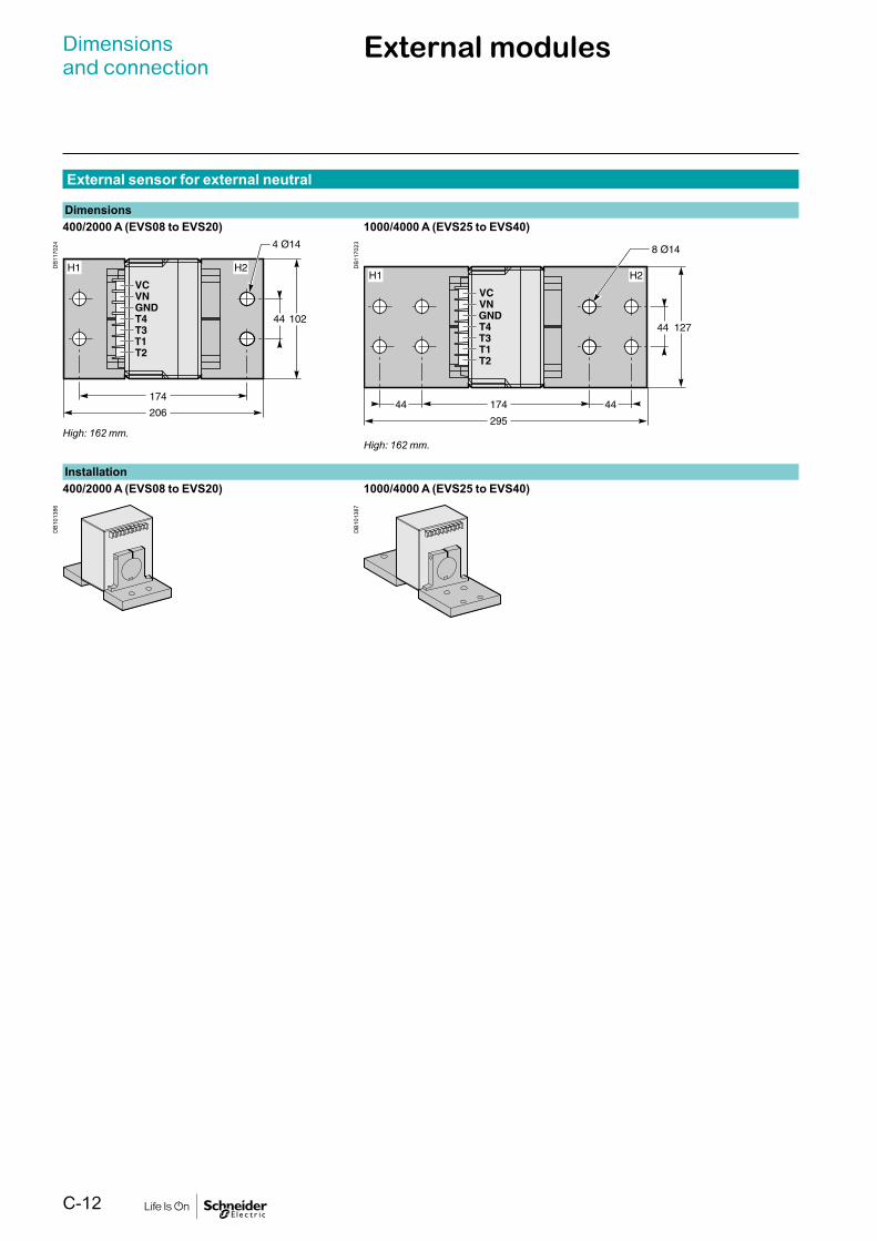
C-12
External sensor for external neutral
DB1
1702
4D
B101
386
DB1
0138
7D
B117
023
Dimensions400/2000 A (EVS08 to EVS20) 1000/4000 A (EVS25 to EVS40)
Installation400/2000 A (EVS08 to EVS20) 1000/4000 A (EVS25 to EVS40)
High: 162 mm.High: 162 mm.
Dimensionsand connection
External modules

C-13

Electrical diagrams

D-1
Electrical diagrams
Functions and characteristics A-1Installation recommendations B-1Dimensions and connection C-1
EasyPact EVS08 to 40 D-2Fixed and draw-out devices D-2
EasyPact EVS D-4Earth-fault protection/Neutral protection D-4Zone selective interlocking D-524 V DC external power supply AD module D-6
Additional characteristics E-1Catalogue numbers and order form F-1
EasyPact EVS

D-2
Electrical diagrams EasyPact EVS08 to EVS40Fixed and draw-out devices
The diagram is shown with circuitsde-energised, all devices open, connectedand charged and relays in normal position.
Power Trip system A Remote operation
Trip system
NCT
Trip system A
VN
U
V1
V2
V3
E89
955
StopFaul
t
E89
956
E60
065A
Ope
nE
4613
6A
Clo
seE
4613
7A
Rea
dy-
to-c
lose
E60
066A
Cha
rged
E60
067A
T rip systemUC1 UC2
Z5
Z3 Z4 T3 T4
Z1 Z2 T1 T2
Trip system AUC1 UC2 UC3
Z5 F2+
Z3 Z4 T3 T4 VN
Z1 Z2 T1 T2 F1-
Remote operationSDE MN MX XF PF MCH
84 D2 C2 A2 254 B2
82 252 B3
81 D1 C1 A1 251 B1
Trip system Remote operationUC1 :Z1-Z5 zone selective interlockingZ1=ZSI OUT SOURCEZ2=ZSI OUT ; Z3 = ZSI IN SOURCEZ4 =ZSI IN ST (short time)Z5 =ZSI IN GF (earth fault)
UC2 :T1, T2, T3, T4=external neutral
UC3 :F2+, F1-: external 24 V DC power supply
SDE: Fault-trip indication contact (supplied as standard)MN: Undervoltage releaseMX: Shunt release (standard for Electrical breaker)XF: Closing release (standard for Electrical breaker)PF: “Ready to close”contactMCH: Gear motor (standard for Electrical breaker)
External sensor (CT).
E47
477
External sensors ( Neutral CT)External sensor for earth-fault protectionThe sensors, used with the 3P circuit breakers, are installed on the neutral conductor for:1. Residual type earth-fault protection(6.0/6.0A trip system)
The rating of the sensor (CT) must be compatible with the rating of the circuit breaker:1. EVS08 to EVS20: CT 400/2000;2. EVS25 to EVS40: CT 1000/4000;

D-3
Electrical diagrams EasyPact EVS08 to EVS40Fixed and draw-out devices
Indication contacts
Indication contacts
Chassis contacts
Chassis contacts
DB
1014
09
Indication contactsOF4 OF3 OF2 OF1 OF14 OF13 OF12 OF11
44 34 24 14 144 134 124 114
42 32 22 12 142 132 122 112
41 31 21 11 141 131 121 111
Chassis contactsCD3 CD2 CD1 CE3 CE2 CE1 CT3 CT2 CT1
834 824 814 334 324 314 934 924 914
832 822 812 332 322 312 932 922 912
831 821 811 331 321 311 931 921 911
Standard Optional Optional
OF 4 StandardOF 3 ON/OFFOF 2 Indication contactsOF 1
OF 14 OptionalON/OFFIndication contacts
OF 13OF 12OF 11
CD3 Disconnected CE3 Connected CT3 TestCD2 Position CE2 Position CT2 PositionCD1 Contacts CE1 Contacts CT1 Contacts
Key:
Draw-out device only
XXX SDE1, OF1, OF2, OF3, OF4 supplied as standard
Interconnected connections (only one wire per connection point)
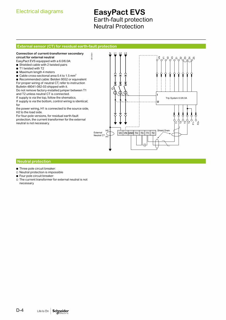
D-4
Electrical diagrams EasyPact EVSEarth-fault protectionNeutral Protection
External sensor (CT) for residual earth-fault protection
Neutral protection
DB
1256
01Connection of current-transformer secondary circuit for external neutralEasyPact EVS equipped with a 6.0/6.0A:
b Shielded cable with 2 twisted pairs b T1 twisted with T2 b Maximum length 4 meters b Cable cross-sectional area 0.4 to 1.5 mm2
b Recommended cable: Belden 9552 or equivalentFor proper wiring of neutral CT, refer to instructionBulletin 48041-082-03 shipped with it.Do not remove factory-installed jumper between T1and T2 unless neutral CT is connected.If supply is via the top, follow the shematics.If supply is via the bottom, control wiring is identical; forthe power wiring, H1 is connected to the source side,H2 to the load side.For four-pole versions, for residual earth-faultprotection, the current transformer for the externalneutral is not necessary.
b Three pole circuit breaker: v Neutral protection is impossible b Four pole circuit breaker: v The current transformer for external neutral is not necessary
Trip System 6.0/6.0A
VN
Shield DrainVNExternal
Neutral CT

D-5
Electrical diagrams EasyPact EVSZone Selective Interlocking
Zone selective interlocking
DB
1014
20Zone-selective interlocking is used to reduce theelectrodynamic forces exerted on the installation by shorteningthe time required to clear faults, while maintaining timediscrimination between the various devices.A pilot wire interconnects a number of circuit breakers equipped with Trip system, as illustrated in the diagram above.The control unit detecting a fault sends a signal upstream andchecks for a signal arriving from downstream. If there is a signalfrom downstream, the circuit breaker remains closed for the fullduration of its tripping delay. If there is no signal fromdownstream, the circuit breaker opens immediately, regardlessof the tripping-delay setting.
Fault 1.Only circuit breaker A detects the fault. Because it receives nosignal from downstream, it opens immediately, regardless of itstripping delay set to 0.3.
Fault 2.Circuit breakers A and B detect the fault. Circuit breaker Areceives a signal from B and remains closed for the full durationof its tripping delay set to 0.3. Circuit breaker B does notreceive a signal from downstream and opens immediately, inspite of its tripping delay set to 0.2.
Wiring b Maximum impedance: 2.7 W / 300 m b Capacity of connectors: 0.4 to 2.5 mm2
b Wires: single or multicore b Maximum lenght: 3000 m b Limits to device interconnection: v The common ZSI - OUT (Z1) and the output ZSI - OUT (Z2) can be connected to a maximum of 10 upstream device
v A maximum of 100 downstream devices may be connected to the common ZSI - IN (Z3) and to an input ZSI - IN CR ( Z4) or GF (Z5)

D-6
Electrical diagrams EasyPact EVS24 V DC external power supply AD module
b The 24 V DC external power-supply (AD module) for the Trip system (F1- F2+) is not required for basic protections LSIG
b With Trip System A, it is recommended to connect 24 V DC external power-supply (AD module) to the Trip System (F1- F2+) in order to keep available the display and the ammeter metering, even if Current < 20 % In
Note: In case of using the 24 V DC external power supply (AD module), maximum cable length between 24 V DC (G1, G2) and the control unit (F1-, F2+) must not exceed 10 meters.
The internal voltage taps are connected to the bottom side of the circuit breaker.
ConnectionThe maximum length for each conductor supplying power to the trip unit is 10 m.Do not ground F2+, F1-, or power supply output:
b The positive terminal (F2+) on the trip unit must not be connected to earth ground
b The negative terminal (F1-) on the trip unit must not be connected to earth ground
b The output terminals (- and +) of the 24 V DC power supply must not be grounded
Reduce electromagnetic interference: b The input and output wires of the 24 V DC power supply must be physically separated as much as possible
b If the 24 V DC power supply wires cross power cables, they must cross perpendicularly. If this is not physically possible, the power supply conductors must be twisted together
b Power supply conductors must be cut to length. Do not loop excess conductor
Trip system
DB
1283
83

D-7

Additional characteristics

E-1
Additional characteristics
Functions and characteristics A-1Installation recommendations B-1Dimensions and connection C-1Electrical diagrams D-1
Tripping curves E-2
Catalogue numbers and order form F-1
EasyPact EVS

E-2
Additionalcharacteristics
Tripping curves
Trip system - 2.0
Trip system - 5.0/5.0A/6.0/6.0A
DB1
0511
2D
B105
113

E-3
Trip system - 6.0/6.0A
DB1
0150
5
(1)
Ig = In x... A B C D E F G H IIn y 400 A 0.3 0.3 0.4 0.5 0.6 0.7 0.8 0.9 1400 A < In y 1000 A 0.2 0.3 0.4 0.5 0.6 0.7 0.8 0.9 1In u 1250A 500 640 720 800 880 960 1040 1120 1200

Catalogue numbersand order form

F-1
Catalogue numbersand order form
Functions and characteristics A-1Installation recommendations B-1Dimensions and connection C-1Electrical diagrams D-1Tripping curves E-2
Nomenclature F-2
EasyPact EVS F-5Connection F-5
Trip System & accessories F-6Remote operation F-7Chassis locking and accessories F-9Circuit breaker locking and accessories F-10Mechanical interlocking for source changeover F-11Indication contacts F-12Instructions F-13
Order form F-14
EasyPact EVS
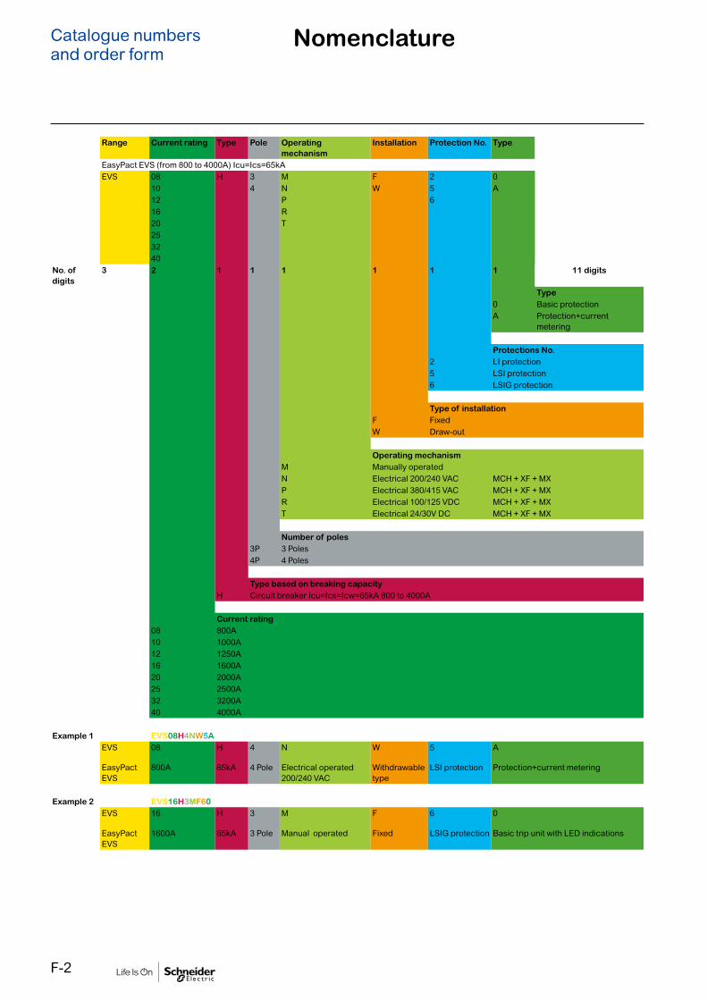
F-2
Catalogue numbersand order form
Nomenclature
Range Current rating Type Pole Operating mechanism
Installation Protection No. Type
EasyPact EVS (from 800 to 4000A) Icu=Ics=65kAEVS 08 H 3 M F 2 0
10 4 N W 5 A12 P 616 R20 T253240
No. of digits
3 2 1 1 1 1 1 1 11 digits
Type0 Basic protectionA Protection+current
metering
Protections No.2 LI protection5 LSI protection6 LSIG protection
Type of installation F FixedW Draw-out
Operating mechanismM Manually operatedN Electrical 200/240 VAC MCH + XF + MX P Electrical 380/415 VAC MCH + XF + MX R Electrical 100/125 VDC MCH + XF + MX T Electrical 24/30V DC MCH + XF + MX
Number of poles3P 3 Poles4P 4 Poles
Type based on breaking capacityH Circuit breaker Icu=Ics=Icw=65kA 800 to 4000A
Current rating08 800A10 1000A12 1250A16 1600A20 2000A25 2500A32 3200A40 4000A
Example 1 EVS08H4NW5AEVS 08 H 4 N W 5 A
EasyPact EVS
800A 65kA 4 Pole Electrical operated 200/240 VAC
Withdrawable type
LSI protection Protection+current metering
Example 2 EVS16H3MF60EVS 16 H 3 M F 6 0
EasyPact EVS
1600A 65kA 3 Pole Manual operated Fixed LSIG protection Basic trip unit with LED indications

F-3
Catalogue numbersand order form
EasyPact EVS800-4000AEasyPact EVS drawout 65KA
EasyPact EVS drawout type 65KA with Trip System3P 4PTrip System 2.0 Trip System 5.0 Trip System 6.0 Trip System 2.0 Trip System 5.0 Trip System 6.0
Manual 800A EVS08H3MW20 EVS08H3MW50 EVS08H3MW60 * * *1000A EVS10H3MW20 EVS10H3MW50 EVS10H3MW60 * * *1250A EVS12H3MW20 EVS12H3MW50 EVS12H3MW60 * * *1600A EVS16H3MW20 EVS16H3MW50 EVS16H3MW60 * * *2000A EVS20H3MW20 EVS20H3MW50 EVS20H3MW60 * * *2500A EVS25H3MW20 EVS25H3MW50 EVS25H3MW60 * * *3200A EVS32H3MW20 EVS32H3MW50 EVS32H3MW60 * * *4000A EVS40H3MW20 EVS40H3MW50 EVS40H3MW60 * * *
Electrical 800A EVS08H3NW20 EVS08H3NW50 EVS08H3NW60 * * *240V AC 1000A EVS10H3NW20 EVS10H3NW50 EVS10H3NW60 * * *
1250A EVS12H3NW20 EVS12H3NW50 EVS12H3NW60 * * *1600A EVS16H3NW20 EVS16H3NW50 EVS16H3NW60 * * *2000A EVS20H3NW20 EVS20H3NW50 EVS20H3NW60 * * *2500A EVS25H3NW20 EVS25H3NW50 EVS25H3NW60 * * *3200A EVS32H3NW20 EVS32H3NW50 EVS32H3NW60 * * *4000A EVS40H3NW20 EVS40H3NW50 EVS40H3NW60 * * *
EasyPact EVS drawout type 65KA with Trip System A 3P 4P
Trip System 5.0A Trip System 6.0A Trip System 5.0A Trip System 6.0AManual 800A * EVS08H3MW5A EVS08H3MW6A * EVS08H4MW5A EVS08H4MW6A
1000A * EVS10H3MW5A EVS10H3MW6A * EVS10H4MW5A EVS10H4MW6A1250A * EVS12H3MW5A EVS12H3MW6A * EVS12H4MW5A EVS12H4MW6A1600A * EVS16H3MW5A EVS16H3MW6A * EVS16H4MW5A EVS16H4MW6A2000A * EVS20H3MW5A EVS20H3MW6A * EVS20H4MW5A EVS20H4MW6A2500A * EVS25H3MW5A EVS25H3MW6A * EVS25H4MW5A EVS25H4MW6A3200A * EVS32H3MW5A EVS32H3MW6A * EVS32H4MW5A EVS32H4MW6A4000A * EVS40H3MW5A EVS40H3MW6A * EVS40H4MW5A EVS40H4MW6A
Electrical 800A * EVS08H3NW5A EVS08H3NW6A * EVS08H4NW5A EVS08H4NW6A240V AC 1000A * EVS10H3NW5A EVS10H3NW6A * EVS10H4NW5A EVS10H4NW6A
1250A * EVS12H3NW5A EVS12H3NW6A * EVS12H4NW5A EVS12H4NW6A1600A * EVS16H3NW5A EVS16H3NW6A * EVS16H4NW5A EVS16H4NW6A2000A * EVS20H3NW5A EVS20H3NW6A * EVS20H4NW5A EVS20H4NW6A2500A * EVS25H3NW5A EVS25H3NW6A * EVS25H4NW5A EVS25H4NW6A3200A * EVS32H3NW5A EVS32H3NW6A * EVS32H4NW5A EVS32H4NW6A4000A * EVS40H3NW5A EVS40H3NW6A * EVS40H4NW5A EVS40H4NW6A

F-4
Catalogue numbersand order form
EasyPact EVS800-4000AEasyPact EVS fixed 65KA
EasyPact EVS fixed type 65KA with Trip System3P 4PTrip System 2.0 Trip System 5.0 Trip System 6.0 Trip System 2.0 Trip System 5.0 Trip System 6.0
Manual 800A EVS08H3MF20 EVS08H3MF50 EVS08H3MF60 * * *1000A EVS10H3MF20 EVS10H3MF50 EVS10H3MF60 * * *1250A EVS12H3MF20 EVS12H3MF50 EVS12H3MF60 * * *1600A EVS16H3MF20 EVS16H3MF50 EVS16H3MF60 * * *2000A EVS20H3MF20 EVS20H3MF50 EVS20H3MF60 * * *2500A EVS25H3MF20 EVS25H3MF50 EVS25H3MF60 * * *3200A EVS32H3MF20 EVS32H3MF50 EVS32H3MF60 * * *4000A EVS40H3MF20 EVS40H3MF50 EVS40H3MF60 * * *
Electrical 800A EVS08H3NF20 EVS08H3NF50 EVS08H3NF60 * * *240V AC 1000A EVS10H3NF20 EVS10H3NF50 EVS10H3NF60 * * *
1250A EVS12H3NF20 EVS12H3NF50 EVS12H3NF60 * * *1600A EVS16H3NF20 EVS16H3NF50 EVS16H3NF60 * * *2000A EVS20H3NF20 EVS20H3NF50 EVS20H3NF60 * * *2500A EVS25H3NF20 EVS25H3NF50 EVS25H3NF60 * * *3200A EVS32H3NF20 EVS32H3NF50 EVS32H3NF60 * * *4000A EVS40H3NF20 EVS40H3NF50 EVS40H3NF60 * * *
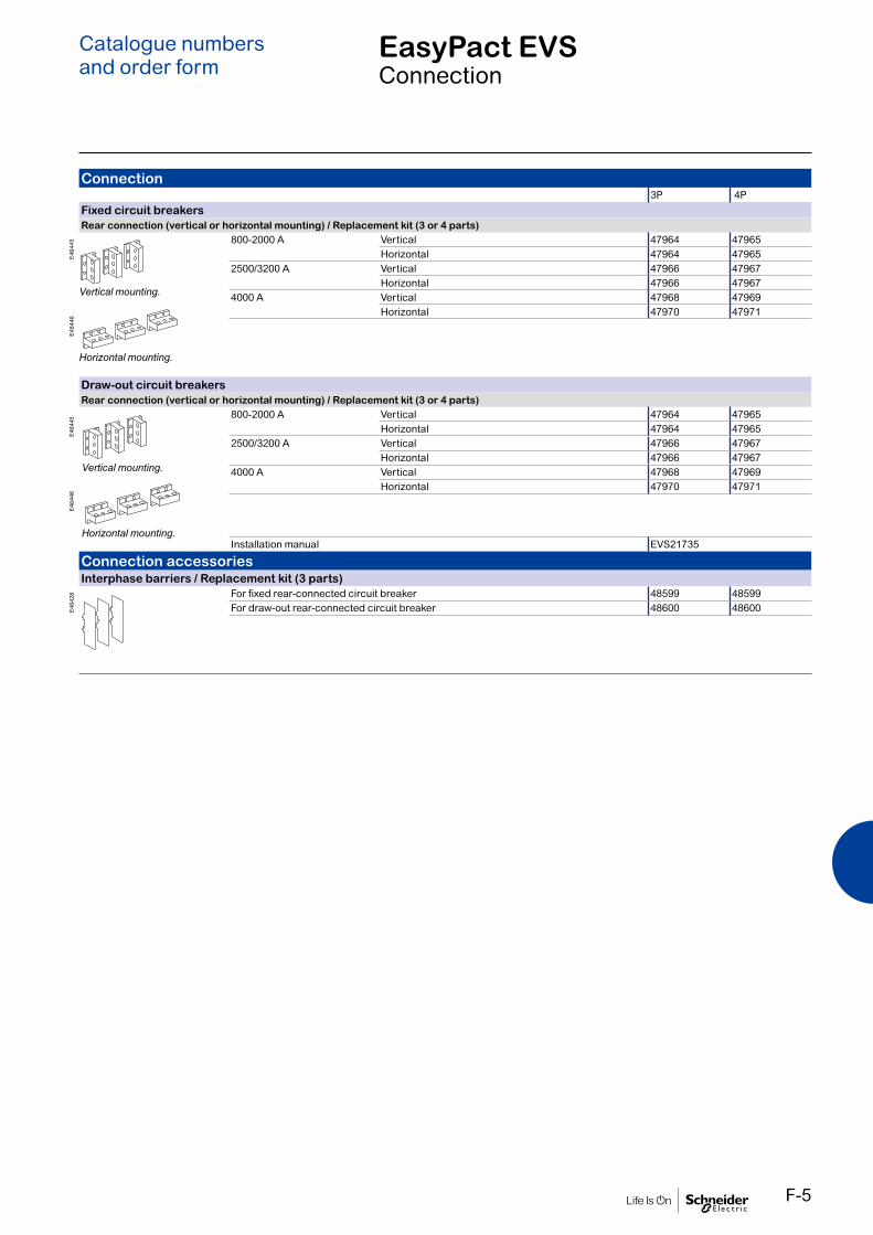
F-5
EasyPact EVSConnection
Catalogue numbersand order form
Connection3P 4P
Fixed circuit breakersRear connection (vertical or horizontal mounting) / Replacement kit (3 or 4 parts)
800-2000 A Vertical 47964 47965Horizontal 47964 47965
2500/3200 A Vertical 47966 47967Horizontal 47966 47967
4000 A Vertical 47968 47969Horizontal 47970 47971
Draw-out circuit breakersRear connection (vertical or horizontal mounting) / Replacement kit (3 or 4 parts)
800-2000 A Vertical 47964 47965Horizontal 47964 47965
2500/3200 A Vertical 47966 47967Horizontal 47966 47967
4000 A Vertical 47968 47969Horizontal 47970 47971
Installation manual EVS21735
Connection accessoriesInterphase barriers / Replacement kit (3 parts)
For fixed rear-connected circuit breaker 48599 48599For draw-out rear-connected circuit breaker 48600 48600
E46
446
E46
445
Vertical mounting.
Horizontal mounting.
E46
446
E46
445
Vertical mounting.
Horizontal mounting.
E46
428

F-6
EasyPact EVSTrip System & accessories
Catalogue numbersand order form
E95
540
E46
671
DB
1053
60
Trip units & accessoriesBattery + cover
Battery (1 part) 33593Cover (1 part) 33592
External sensorsExternal sensor for earth-fault protection (TCE) / 1 part
Sensor rating 400/2000 A 340351000/4000 A 34036
External power supply module (AD) / 1 part24-30 V DC LV54440200-240 V AC LV54444
menu
G3G4
Output
LN

F-7
EasyPact EVSRemote operation
Catalogue numbersand order form
Remote operationGear motor
MCH (1 part)AC 50/60 Hz 200/240 V 47894
380/415 V 47896DC 24/30 V 47888
100/125 V 47890Terminal block (1 part) For fixed circuit breaker 47074
For draw-out circuit breaker 47849
Closing release (XF)Standard coil (1 part)AC 50/60 HzDC
24/30 V DC, 24 V AC 33659100/130 V AC/DC MVS15511200/250 V AC/DC MVS15512380/480 V AC MVS15513
Terminal block (1 part) For fixed circuit breaker 47074For draw-out circuit breaker 47849
Opening release (MX)Standard coil (1 part)AC 50/60 HzDC
24/30 V DC, 24 V AC 33659100/130 V AC/DC 33661200/250 V AC/DC 33662380/480 V AC 33664
Terminal block (1 part) For fixed circuit breaker 47074For draw-out circuit breaker 47849
E95
172
E95
170
E95
170
E95
169
Fixed.
E95
171
Draw-out.
E95
169
Fixed.
E95
171
Draw-out.
E95
169
Fixed.
E95
171
Draw-out.
F-8
EasyPact EVSRemote operation
Catalogue numbersand order form
Remote operationUndervoltage release MN
Undervoltage release (1 part)AC 50/60 HzDC
24/30 V DC, 24 V AC 33668100/130 V AC/DC 33670200/250 V AC/DC 33671380/480 V AC 33673
Terminal block (1 part) For fixed circuit breaker 47074For draw-out circuit breaker 47849
MN delay unitMN delay unit (1 part)
R (non-adjustable) Rr (adjustable)100/130 V AC/DC 33684 33681200/250 V AC/DC 33685 33682380/480 V AC/DC 33683
E95
170
E46
694
E95
169
Fixed.
E95
171
Draw-out.

F-9
EasyPact EVSChassis locking and accessories
Catalogue numbersand order form
Chassis locking“Disconnected” position locking / 1 part
By padlocksVCPO Standard
By Profalux keylocksProfalux 1 lock+ 1 key (without adaptation kit) 42888Profalux 2 locks + 1 key (without adaptation kit) 42878Adaptation kit (without key locks) 48564
By Ronis keylocksRonis 1 lock+ 1 key (without adaptation kit) 41940Ronis 2 locks + 1 key (without adaptation kit) 41950Adaptation kit (without key locks) 48564
Door interlock / 1 partRight and left-hand side of chassis (VPECD or VPECG) 47914
Chassis accessoriesAuxiliary terminal shield (CB) / 1 part
800/4000 A 3P 485954P 48596
Shutter locking block (for replacement) / 1 part2 parts for 800/4000 A 48591
DB
1174
58E
4645
2E
4645
8E
4646
0
Racking handleRacking handle 47944
E95
561

F-10
Circuit breaker lockingPushbutton locking device / 1 part
By padlocks 48536
OFF position locking / 1 partBy Profalux keylocks
Profalux 1 lock+ 1 key (without adaptation kit) 42888Adaptation kit (without key locks) 64925
By Ronis keylocksRonis 1 lock+ 1 key (without adaptation kit) 41940Adaptation kit (without key locks) 64925
Mechanical operation counter / 1 partOperation counter CDM 48535
Escutcheon and accessories / 1 part
E46
669
E46
670
Escutcheon Cover Blanking plate
Fixed Draw-outEscutcheon 48601 48603Transparent cover (IP 54) - 48604Escutcheon blanking plate 48605 48605
E46
666
E46
735
DB
1256
17C
DB
5000
61EasyPact EVSCircuit breaker locking and accessories
Catalogue numbersand order form
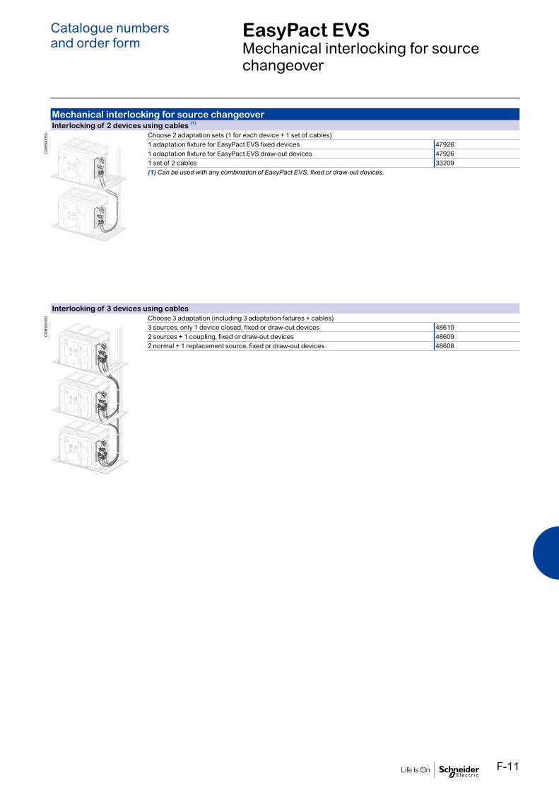
F-11
EasyPact EVSMechanical interlocking for source changeover
Catalogue numbersand order form
Mechanical interlocking for source changeoverInterlocking of 2 devices using cables (1)
Choose 2 adaptation sets (1 for each device + 1 set of cables)1 adaptation fixture for EasyPact EVS fixed devices 479261 adaptation fixture for EasyPact EVS draw-out devices 479261 set of 2 cables 33209(1) Can be used with any combination of EasyPact EVS, fixed or draw-out devices.
Interlocking of 3 devices using cablesChoose 3 adaptation (including 3 adaptation fixtures + cables)3 sources, only 1 device closed, fixed or draw-out devices 486102 sources + 1 coupling, fixed or draw-out devices 486092 normal + 1 replacement source, fixed or draw-out devices 48608
CD
B50
0053
CD
B50
0060

F-12
Indication contactsON/OFF indication contacts (OF) / 12 parts
1 additional block of 4 contacts 47887Wiring For fixed circuit breaker 47074
For draw-out circuit breaker 47849
“Ready to close” contact (1 max.) / 1 part1 changeover contact (5 A - 240 V) 47080Wiring For fixed circuit breaker 47074
For draw-out circuit breaker 47849
“Connected, disconnected, test position” indication contact (carriage switches) / 1 partChangeover contacts 6 A - 240 V 33170
Auxiliary terminals for chassis alone3 wire terminal (1 part) 478496 wire terminal (1 part) 47850Jumpers (10 parts) 47900
E46
689
E46
438
E46
661
EasyPact EVSIndication contacts
Catalogue numbersand order form

F-13
EasyPact EVSInstructions
Catalogue numbersand order form
InstructionsEasyPact EVS User Manual (English) EVS21734EasyPact EVS Installation Manual(English) EVS21735EasyPact EVS breaker accessories Installation Manual(English) EVS21737EasyPact EVS cradel accessories Installation Manual(English) EVS21738

F-14
To indicate your choices, check the applicable square boxes
And enter the appropriate information in the rectangles
Circuit breaker Quantity
Rating A
Circuit breaker H H
Number of poles 3 or 4
Optional Neutral on Right hand side yes
Type of equipment Fixed
Draw out with chassis
Draw out without chassis
(moving part only)
Chassis alone
Operating Mechanism Manual Operated
√ Electrical Operated
MX+XF+MCH Voltage
Voltage Option: 200/240 VAC;380/415 VAC;24/30 VDC;100/125VDC
Trip System
0- Without display 2.0 5.0 6.0
A - Current Metering 5.0 6.0
LR - Long-time rating plug Standard 0.4 to 1 Ir
Connection
Horizontal Top Bottom
Vertical Top Bottom
Trip System functions:2.0 : Basic protection (long time + inst.)5.0 : Selective protection (long time + short time + inst.)6.0 : Selective + earth-fault protection (long time + short time + inst. + earth-fault)
EasyPact EVS
EasyPact EVSCircuit breaker Customer Order form
Indication contacts
OF - ON/OFF indication contacts
Standard 1 block of 4 OF 10 A-240/380V AC
Additional 1 block of 4 OF 6 A-240/380V AC
SDE - “fault-trip” indication contact
Standard 1 SDE 5A -240/380V AC
Optional
Carriage switches 8 A-240/380V AC
CE - “Connected” position Max. 3 qty
CT - “Test” position Max. 3 qty
CD - “Disconnected” position Max. 3 qty
Remote tripping MN - Under voltage release V
R - Delay unit (fixed time delay) 0.25s
Rr - Adjustable delay unit 0.5s……3s
AD - External power-supply module V
TCE - External sensor (NCT) for neutral of 3 Phase-4 Wire systems 400/2000A
TCE - External sensor (NCT) for neutral of 3 Phase-4 Wire systems 1000/4000A √PF - “Ready to close” contact 5A-240/380V AC
LocksVBP - ON/OFF pushbutton locking (by transparent cover using padlock)
VSPO - Device locking in OFF position by key lock (Only one key lock per ACB possible)
Key lock kit (w/o key lock) Profalux Ronis
1 key lock Profalux Ronis
Chassis locking in “Disconnected” position:
VSPD - by key locks Key lock kit (w/o key lock) Profalux Ronis
1 key lock Profalux Ronis
2 identical key locks, 1 key Profalux Ronis
Door Interlock - VPEC On left-hand side of chassis (LH)
On right-hand side of chassis (RH)
Mechanical Interlocking of ACBs with Cable1 Normal source & 1 replacement source (2 devices)
2 normal + 1 replacement source, fixed or draw-out devices
2 sources with coupler on busbars (3 devices)
3 sources, only 1 device closed, fixed or draw-out devices
AccessoriesVO - Safety shutters on chassis Standard
CDP - Escutcheon Standard
Safety Shutter locking blocks
CP - Transparent cover for escutcheon
OP - Blanking plate for escutcheon
CDM - Mechanical operation counter for EVS
CB - Auxiliary terminal shield fitted on chassis
EIP - Interphase barriers
Notes:Customer can provide only the reference no. of the product for the listed references. Kindly refer to product catalogue for list of references. Customer to fill this order form for non-listed references.All breakers will be provided with 1 OF (4 c/o contacts), 1 SDE (trip contact), Escutcheon (Panel sealing frame) as standard.All draw-out breakers will be supplied with Chassis & safety shutter.For Electrical operated breakers, indicate the voltage ratings of MCH,XF & MXRefer to product catalogue for available voltage ratings of MCH/XF/MX/MN & AD ModuleThe orientation of customer connecting terminals can be changed at site from Horizontal to vertical or vice-versa. EasyPact EVS H order form V1.1
Order ref no:
Date:
Product ref no:OA No. (to be filled by Order booking team)
Catalogue numbersand order form

F-15

Schneider Electric Industries SAS
35, rue Joseph MonierCS 3032392506 Rueil Malmaison Cedex France
RCS Nanterre 954 503 439Capital social 928 298 512 €www.se.com
May-2020Document Number EVS21736
© 2019 - Schneider Electric. All Rights Reserved.All trademarks are owned by Schneider Electric Industries SAS or its affiliated companies.Document reference This document has been
printed on recycled paper
Copyright © 2022 FDOKUMEN