
INDUSTRIAL POWER TRANSMISSION BELTS
364
INDUSTRIAL POWER TRANSMISSION BELTS
-
Upload
khangminh22 -
Category
Documents
-
view
41 -
download
0
Transcript of INDUSTRIAL POWER TRANSMISSION BELTS

The Timken team applies their know-how to improve the reliability and performance of machinery in diverse markets worldwide. The company designs, makes and markets high-performance mechanical components, including bearings, belts, gears, chain and related mechanical power transmission products and services.
www.carlislebelts.com
15M 05-16 Order No. 10887 | Timken® is a trademark of The Timken Company. Carlisle® is a trademark used under license. | © 2016 The Timken Company | Printed in U.S.A.
INDUSTRIAL POWER TRANSMISSION BELTS
CARLISLE B
ELTS BY TIM
KEN CATA
LOG


www.carlislebelts.com i
Carlisle® Belts by TimkenIntroduction
Timken, the manufacturer of Carlisle® belts, is proud to present this comprehensive product catalog, affording you easy access to the latest Carlisle belts product information and technical specifications.
We invite you to grow your business with this broad line of premium power transmission products that deliver optimal performance you can depend on.
Our People
Timken’s strength lies in the performance of its people. For over a century, Timken has adhered to a philosophy of supplying innovative products, unrivaled quality, and superior customer service.
Our Service
Carlisle belts by Timken are supplied to distributors and original equipment manufacturers who seek the optimum in quality and service. Every belt is backed by extraordinary engineering and technical support, and by our personal, knowledgeable, and attentive customer service team.
On-Time Delivery
Understanding the importance of on-time delivery and fast turnaround, Timken’s flexible manufacturing model and short lead times provide responsive, reliable delivery that will meet or exceed your expectations.
Proudly Made in the USA
A comprehensive product line is made in ISO registered manufacturing facilities in the USA by a proud team of engineers, technicians, and craftsmen. The icon below is used throughout this catalog to identify each product line that is manufactured in Timken’s Springfield, Missouri or Fort Scott, Kansas plants.

www.carlislebelts.comii
Carlisle® Belts by TimkenPerformance Driven...Performance Proven
It’s no accident that Carlisle® belts are built by Timken to outlast and outperform competitors belts. That’s why recognized original equipment manufacturers turn to Timken to private-brand Carlisle belts for their products.
Every Carlisle belt is the result of science, engineering, and years of experience. Timken’s innovative product development, specially formulated components, time-tested methods, and state-of-the-art manufacturing techniques set us apart from the competition.
The team of belt experts at the Timken Technical Center in Springfield, Missouri is dedicated to the development and testing of new and existing products to assure that Carlisle belts provide outstanding performance in a multitude of the toughest, most demanding applications.

www.carlislebelts.com iii
Carlisle® Belts by TimkenPerformance Driven...Performance Proven
Chek Mate® V-Belt Matching
Chek Mate® is a manufacturing process that holds v-belt lengths within ARPM (Association for Rubber Products Manufacturers) tolerances for a matched set. Matching numbers are not required on these Carlisle® belts which carry the distinctive Chek Mate logo: Super Blue Ribbon®, Super II®, Super Power-Wedge®, Power-Wedge® Cog-Belt® and Gold-Ribbon® Cog-Belt®.
ISO Registration
Timken belt plants and Technical Center are registered as compliant with the International Standard ISO 9001.
ISO 9001 requirements include:
■■ Management that is committed, involved, focused and responsive
■■ People who are organized, responsible, authorized, competent, empowered and knowledgeable
■■ Processes that are visible, traceable, consistent, repeatable, measurable and documentable
■■ Documents that are appropriate, relevant, simple, understandable and consistent with processes in use
ISO 9001 certification ensures that organizations take time to understand their key quality processes, that the processes are implemented and followed by everyone in the organization and that the processes are documented and maintained to a degree that can be demonstrated to an outside agency.

Panther® XT Synchronous Belt Super Blue Ribbon® V-Belt Wedge-Band
Alternative to chain or drop-in replacement for polyurethane belts. Higher torque capacity than Panther. Formulated for enhanced performance and strength.
The finest wrapped belt in the industry and workhorse of classical v-belts.
Banded version of Super Power-Wedge. Belt whip and turnover are eliminated.
Panther® Synchronous Belt Aramax® Xtra Duty V-Belt Aramax® Wedge-Band®
Designed to improve performance and drive life while reducing maintenance and downtime. Higher torque capacity than Synchro-Cog® HT.
Designed for outdoor power equipment and aggressive applications with heavy shock loads. Delivers more horsepower, less stretch and longer service life.
Designed for extraordinary banded belt strength on the toughest drives. Belt whip and turnover are eliminated.
Synchro-Cog® HT Synchronous Belt Power-Wedge® Cog-Belt® Wedge-Band® Chipper Drive
Delivers trouble-free power transmission with a smooth, quiet and efficient drive system.
Combines the advantages of the narrow belt wedge design with raw edge performance for maximum operating efficiency in a compact drive package. Also available: Metric Power-Wedge Cog-Belt.
Specially designed and constructed to meet the unique demands of the forestry industry. Belt whip and turnover are eliminated.
Dual Synchronous Belt Super Power-Wedge® V-Belt Super Vee-Band®
Provides synchronized transfer of power from both sides of the belt for greater flexibility and efficiency in your drive design.
Enables design of a more compact belt drive. Ideal for heavy duty industrial drives with shock loads.
Banded version of Super Blue Ribbon. Belt whip and turnover are eliminated.
Synchro-Cog® Timing Belt Double Angle V-Belt Durapower®II FHP V-Belt
Trapezoidal tooth profile for clean, quiet operation on applications where synchronization between the driver and driven unit is required.
Ideally suited for serpentine drives where power needs to be transmitted equally from both sides of the belt.
Raw edge construction improves efficiency, performance and belt life.
Air Cool Heat Exchange Belt Vee-Rib™ Belt Dry Can Belt
Air Cool Heat Exchange Belts have a special “Z” twist cord construction designed to perform on air cooled heat exchange applications.
Provides smooth, vibration-free performance in a compact drive. Ideally suited for high speed drives where conventional v-belts cannot operate.
The original deep-groove notched design specifically developed for demanding textile industry double angle “CC” drives.
Cotton Drive® Timing Belt Variable Speed Cog-Belt® Thoro-Twist™ V-Belting
1” pitch timing belts designed for use on cotton cleaning machines. Uniquely constructed to handle this harsh, abrasive application.
For use with variable pitch pulleys to gain a wide range of driven speeds.
For use on drives that have no take-up adjustment capability or for emergency replacement.
Gold-Ribbon® Cog-Belt® Gold-Ribbon® Cog-Band® Round Belts
The Energy Saver! Reduce downtime and save energy with the benchmark for classical v-belt performance.
Combines the superior characteristics of the Gold-Ribbon Cog-Belt with the stability of a banded belt. Belt whip and turnover are eliminated.
High performance solution for conveyors, quarter-turn, twisted, and serpentine drives.
Super II® V-Belt Power-Wedge® Cog-Band®
The Problem Solver! The solution to the constant and costly problem of replacing ordinary v-belts on troublesome drives.
Banded version of Power-Wedge Cog-Belt. Belt whip and turnover are eliminated.
www.carlislebelts.comiv
You can depend on Carlisle® belts for a wide range of applications. We’ve got you covered with the right belt for most any job. Timken manufactures Carlisle belts in the USA from 3” to 900” for anything and everything – fans, mixers, pumps, conveyors, machine tools, centrifuges, robotics, and all types of industrial machines.
Carlisle belts are purpose-built and designed for optimal performance on the most demanding applications:
■■ Aggregate
■■ HVAC/R
■■ Outdoor Power Equipment
■■ Powersports
■■ Agriculture
■■ Industrial Machinery
■■ Petrochemical
■■ Wood/Paper
The world’s leading manufacturers specify Carlisle belts by Timken to keep their equipment running.
Carlisle® Belts by TimkenThe Right Belt for the Job®

Panther® XT Synchronous Belt Super Blue Ribbon® V-Belt Wedge-Band
Alternative to chain or drop-in replacement for polyurethane belts. Higher torque capacity than Panther. Formulated for enhanced performance and strength.
The finest wrapped belt in the industry and workhorse of classical v-belts.
Banded version of Super Power-Wedge. Belt whip and turnover are eliminated.
Panther® Synchronous Belt Aramax® Xtra Duty V-Belt Aramax® Wedge-Band®
Designed to improve performance and drive life while reducing maintenance and downtime. Higher torque capacity than Synchro-Cog® HT.
Designed for outdoor power equipment and aggressive applications with heavy shock loads. Delivers more horsepower, less stretch and longer service life.
Designed for extraordinary banded belt strength on the toughest drives. Belt whip and turnover are eliminated.
Synchro-Cog® HT Synchronous Belt Power-Wedge® Cog-Belt® Wedge-Band® Chipper Drive
Delivers trouble-free power transmission with a smooth, quiet and efficient drive system.
Combines the advantages of the narrow belt wedge design with raw edge performance for maximum operating efficiency in a compact drive package. Also available: Metric Power-Wedge Cog-Belt.
Specially designed and constructed to meet the unique demands of the forestry industry. Belt whip and turnover are eliminated.
Dual Synchronous Belt Super Power-Wedge® V-Belt Super Vee-Band®
Provides synchronized transfer of power from both sides of the belt for greater flexibility and efficiency in your drive design.
Enables design of a more compact belt drive. Ideal for heavy duty industrial drives with shock loads.
Banded version of Super Blue Ribbon. Belt whip and turnover are eliminated.
Synchro-Cog® Timing Belt Double Angle V-Belt Durapower®II FHP V-Belt
Trapezoidal tooth profile for clean, quiet operation on applications where synchronization between the driver and driven unit is required.
Ideally suited for serpentine drives where power needs to be transmitted equally from both sides of the belt.
Raw edge construction improves efficiency, performance and belt life.
Air Cool Heat Exchange Belt Vee-Rib™ Belt Dry Can Belt
Air Cool Heat Exchange Belts have a special “Z” twist cord construction designed to perform on air cooled heat exchange applications.
Provides smooth, vibration-free performance in a compact drive. Ideally suited for high speed drives where conventional v-belts cannot operate.
The original deep-groove notched design specifically developed for demanding textile industry double angle “CC” drives.
Cotton Drive® Timing Belt Variable Speed Cog-Belt® Thoro-Twist™ V-Belting
1” pitch timing belts designed for use on cotton cleaning machines. Uniquely constructed to handle this harsh, abrasive application.
For use with variable pitch pulleys to gain a wide range of driven speeds.
For use on drives that have no take-up adjustment capability or for emergency replacement.
Gold-Ribbon® Cog-Belt® Gold-Ribbon® Cog-Band® Round Belts
The Energy Saver! Reduce downtime and save energy with the benchmark for classical v-belt performance.
Combines the superior characteristics of the Gold-Ribbon Cog-Belt with the stability of a banded belt. Belt whip and turnover are eliminated.
High performance solution for conveyors, quarter-turn, twisted, and serpentine drives.
Super II® V-Belt Power-Wedge® Cog-Band®
The Problem Solver! The solution to the constant and costly problem of replacing ordinary v-belts on troublesome drives.
Banded version of Power-Wedge Cog-Belt. Belt whip and turnover are eliminated.
www.carlislebelts.com v
Carlisle® Belts by TimkenThe Right Belt for the Job®

www.carlislebelts.comvi
A commitment to quality, customers, and state-of-the-art manufacturing processes has remained steadfast throughout the long and rich history of the Timken belts business.
Maintaining a tradition of excellence for more than 100 years – Carlisle® belts continue to bring superior performance with unsurpassed reliability to the toughest industrial applications.
■■ 1905 Dayton Rubber Manufacturing Company (DRMC) founded in Dayton, Ohio
■■ 1921 DRMC develops first Raw Edge v-belt
■■ 1926 DRMC patents cog-type Raw Edge v-belt
■■ 1934 DRMC pioneers use of synthetic rubber technology
■■ 1957 DRC develops arched cross section v-belts for agricultural applications
■■ 1959 new belt manufacturing plant opens in Springfield, Missouri
■■ 1960 DRMC becomes Dayco
■■ 1985 Dayco introduces first chloroprene FHP v-belt
■■ 1986 new belt plant opens in Fort Scott, Kansas
■■ 1988 Dayco introduces first high performance CVT belt
■■ 1990 Pirelli Power Transmission acquires Durkee-Atwood
■■ 1993 Dayco acquires Pirelli Power Transmission
■■ 1994 Dayco introduces RPP® Panther® belts
■■ 1995 Dayco introduces Super II® classical v-belt line
■■ 2001 Carlisle Companies Inc. acquires the industrial belt division of Dayco forming Carlisle Power Transmission
■■ 2011 Carlisle combines Carlisle Tire and Wheel and Carlisle Power Transmission forming Carlisle Transportation Products
■■ 2013 Carlisle Transportation Products is acquired by American Industrial Partners (AIP) forming The Carlstar Group LLC
■■ 2015 The Timken Company acquires the belts business from Carlstar
Carlisle® Belts by TimkenA History of Innovation . . . A Tradition of Excellence

www.carlislebelts.com vii
Iron Clad Guarantee.
All Carlisle® belts by Timken are backed by our Ironclad Guarantee. Warranty terms are set forth below. If not completely satisfied with the performance of a Carlisle belt when properly installed on a drive, return it to an authorized Timken distributor of Carlisle belts who will replace the product or refund the original purchase price.
We’re confident that once you’ve tried Carlisle belts by Timken, you’ll never be satisfied with anything less.
Standard Belt Sizes Certain non-stock sizes (indicated by *) are shown in the catalog. Please contact Customer Service for Carlisle belts availability. Extended lead time and minimum order quantities may apply.
Belt and Pulley Measurements Cross-sectional dimensions and lengths are shown for belts. Dimensions are also listed for sheaves and sprockets.
Recommended Metal for Belt Types For quick reference, each belt section includes the recommended sheave or sprocket.
Belt and Pulley Weights Product weight is indicated for each size.
Troubleshooting Guide Common symptoms and possible causes of short belt life are included for synchronous and v-belts.
Brand Interchange The interchange helps convert other brands to the correct Carlisle belts by Timken product.
Made-to-Order This catalog is intended as a complete guide to the standard line of Carlisle belts by Timken. Special belt types and constructions not shown in this catalog may also be available by special order. Please contact Customer Service for Carlisle belts at 866-773-2926 for price and availability.
Drive Design Technical information may be obtained from “Drive Engineer,” Timken’s drive design software available at www.CarlisleBelts.com/drive-engineer.
A staff of Drive Specialists stands ready to assist with drive design, belt maintenance seminars, and any help needed with choosing the right belt for the application. Your Timken authorized distributor of Carlisle belts will also be an invaluable resource.
Carlisle® Belts by TimkenIronclad Guarantee
Carlisle Belts by Timken Limited Warranty
All Carlisle belts by Timken are warranted for the period of twelve (12) months from the date of sale to the initial customer to be free from defects in material and workmanship under normal operating conditions of recommended usage. This limited warranty does not apply to any belt which has been improperly installed or has been subjected to improper use. Neither distributors nor OEM customers have authority to make or give any additional warranty or representation to consumers and shall not hold itself out, whether as agent or otherwise, as having authority. This limited warranty is provided in lieu of any other warranty, express or implied, including any warranty of merchantability or fitness for a particular purpose.
Purchaser’s exclusive remedy for any breach of this limited warranty is for the replacement of the belt which is proven to be non-conforming or defective, or refund of the purchase price at Seller’s discretion. In no event shall Seller be liable for any other costs or damages, such as indirect, incidental, punitive, special or consequential damages, or lost profits, lost revenue or recall costs.
In order to make a claim under the terms of this Limited Warranty, purchaser must notify Seller in writing within thirty days of period after discovery of the claimed defect and shall furnish substantiating documentation. Purchaser, if requested, shall return the product to afford Seller the opportunity to inspect and analyze the product.
Catalog Features

The following are trademarks or registered trademarks of The Timken Company or its affiliates.
Aramax® Power-Wedge®
Belt-Finder® Raw Edge™
Blue Label™ RPP®
Blue Ribbon® Super Blue Ribbon®
Big Shot® Super II®
Chek Mate® Synchro-Cog®
Cog-Band® Tension-Finder®
Cog-Belt® The Right Belt for the Job®
Cotton Drive® Thoro-Twist™
Durapower® Ultra-Cord®
Frequency Finder™ Vee-Band®
Gold-Ribbon® Vee-Rib™
Panther® Wedge-Band®
Contact Us:
Timken strives for accuracy in all publications. If you discover an error or need more information, please contact the Timken belts Customer Service team at 866-773-2926 or email [email protected].
The Timken Company (NYSE: TKR; www.timken.com) added Carlisle® belts to its power transmission portfolio in September 2015. Timken engineers, manufactures and markets bearings, transmissions, gearboxes, belts, chain and related products.
www.carlislebelts.comviii
WARNINGFailure to observe the following warnings
could create a risk of death or serious injury.
Static electricity created by a belt in operation can ignite an explosive atmosphere. Special care must
be taken in the utilization of belts in or near locations which may contain explosive concentrations of
combustible gases or accumulations of dust such as grain, coal, or other combustible materials.
Proper dissipation of such potential static electricity discharge must be assured to prevent
any such explosion.
Aircraft Warning: Carlisle® belts by Timken are not designed or intended for aircraft use. Do not use Carlisle belts or pulleys on
aircraft propeller, rotor or accessory drives. Do not use Carlisle belts or pulleys on helicopters or private,
commercial, or ultralight aircraft.
Outdoor Power Equipment Aftermarket Association
Timken is a proud member of:
PROUD MEMBER 2016
CAUTIONFailure to observe the following cautions
could create a risk of serious physical injury or property damage.
Proper selection and installation of drive belts are critical tasks. Belts must be properly selected
and fitted to assure proper performance. Always follow equipment manufacturer installation and fitting
directions and selection guides.

www.carlislebelts.com 1
Introduction . . . . . . . . . . . . . . . . . . iPerformance Driven...Performance Proven . . . . . . iiChek Mate® V-Belt Matching . . . . . . . . . . . iiiThe Right Belt for the Job® . . . . . . . . . . . . ivA History of Innovation ...A Tradition of Excellence . . viIronclad Guarantee . . . . . . . . . . . . . . .vii
Index . . . . . . . . . . . . . . . . . . . . 1
Synchronous Belts . . . . . . . . . . . . . . 4Panther®XT . . . . . . . . . . . . . . . . . 5Panther® . . . . . . . . . . . . . . . . . .12Panther® Sleeves . . . . . . . . . . . . . . .24Synchro-Cog® HT . . . . . . . . . . . . . . .26Synchro-Cog® HT Sleeves . . . . . . . . . . .52Dual Synchronous . . . . . . . . . . . . . .59Dual Synchronous Sleeves . . . . . . . . . . .64Synchro-Cog® Timing Belt . . . . . . . . . . .66Synchro-Cog® Timing Belt Sleeves . . . . . . . .76Air Cool Heat Exchange Belt . . . . . . . . . .78Air Cool Heat Exchange Sleeves . . . . . . . . .81Cotton Drive® . . . . . . . . . . . . . . . .82
Heavy Duty V-Belts . . . . . . . . . . . . . .86Gold-Ribbon® Cog-Belt® . . . . . . . . . . . .87Super II® V-Belt . . . . . . . . . . . . . . .94Super Blue Ribbon® . . . . . . . . . . . . . 101Aramax® Xtra Duty . . . . . . . . . . . . . 112Power-Wedge® Cog-Belt® . . . . . . . . . . 118Metric Power-Wedge® Cog-Belt® . . . . . . . 123Super Power-Wedge® . . . . . . . . . . . . 127Double Angle V-Belt . . . . . . . . . . . . 130Vee-Rib™ Belt . . . . . . . . . . . . . . . 135Vee-Rib™ Sleeve . . . . . . . . . . . . . . 145Variable Speed Cog-Belt® . . . . . . . . . . 146
IndexCarlisle Belts by Timken Catalog

www.carlislebelts.com2
Banded Belts . . . . . . . . . . . . . . . 154Gold-Ribbon® Cog-Band® . . . . . . . . . . . 155Power-Wedge® Cog-Band® . . . . . . . . . . 159Wedge-Band® . . . . . . . . . . . . . . . 162Aramax® Wedge-Band® . . . . . . . . . . . 167Wedge-Band® Chipper Drive . . . . . . . . . 171Super Vee-Band® . . . . . . . . . . . . . . 173
Light-Duty Belts . . . . . . . . . . . . . . 178Durapower®II FHP Belt . . . . . . . . . . . . 179
Specialty Belts. . . . . . . . . . . . . . . 185Dry Can Specialty Belt . . . . . . . . . . . . 185Thoro-Twist™ Belting . . . . . . . . . . . . 187Round Belt . . . . . . . . . . . . . . . . 189
IndexCarlisle Belts by Timken Catalog

www.carlislebelts.com 3
Metal . . . . . . . . . . . . . . . . . . . 194Martin® Sprockets, Sheaves & Bushings Index . . 194Martin® Synchronous Drives . . . . . . . . . 196Martin® V-Belt Drives . . . . . . . . . . . . 248Interchangeable Bushings . . . . . . . . . . 325
General Information . . . . . . . . . . . . 334Static Conductive Belts . . . . . . . . . . . 334V-Belt Construction . . . . . . . . . . . . . 335V-Belt Drive Advantages . . . . . . . . . . . 335V-Belt Troubleshooting Guide . . . . . . . . . 336Synchronous Belt Drive Troubleshooting Guide . . 337V-Belt Installation Checklist . . . . . . . . . 338V-Belt Selection Guide . . . . . . . . . . . 338Banded V-Belt Matching Limits . . . . . . . . 340Spring-Loaded Belt Tensiometer . . . . . . . . 340V-Belt Tensioning Guide . . . . . . . . . . . 341Brand Name Interchange . . . . . . . . . . 342Recommended Sheave Diameters . . . . . . . 345Proper V-Belt Storage Guide . . . . . . . . . 345
Tools . . . . . . . . . . . . . . . . . . . 346Drive Engineer™ . . . . . . . . . . . . . . 346PowerMiser™ . . . . . . . . . . . . . . . 347Industrial V-Belt Drives Service Manual. . . . . 347Tension-Finder® . . . . . . . . . . . . . . 348Spring-Loaded Tensiometer . . . . . . . . . 348Frequency-Finder™ . . . . . . . . . . . . . 349Big Shot Tensioning Device . . . . . . . . . . 349Laser-Align . . . . . . . . . . . . . . . . 350Belt-Finder® . . . . . . . . . . . . . . . . 350Wallboard Display . . . . . . . . . . . . . 351Sheave Gauges . . . . . . . . . . . . . . 351
IndexCarlisle Belts by Timken Catalog

www.carlislebelts.com4
Panther®XTSynchronous Drive Belt
Sync
hron
ous
Bel
ts
www.carlislebelts.com 5
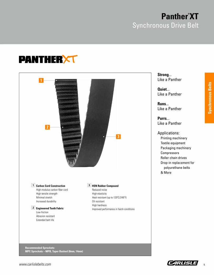
Strong... Like a Panther
Quiet... Like a Panther
Runs... Like a Panther
Purrs... Like a Panther
Applications: Printing machinery Textile equipment Packaging machinery Compressors Roller chain drives Drop-in replacement for polyurethane belts & More
Panther®XTSynchronous Drive Belt
1 Carbon Cord ConstructionHigh-modulus carbon fiber cord High tensile strengthMinimal stretchIncreased durability
2 Engineered Tooth FabricLow-frictionAbrasion resistantExtended belt life
3 HSN Rubber CompoundReduced noiseHigh elasticityHeat resistant (up to 120ºC/248˚F)Oil resistantHigh hardnessImproved performance in harsh conditions
Recommended Sprockets:MPC Sprockets – MPB, Taper Bushed (8mm, 14mm)
3
2
1

www.carlislebelts.com6
Panther®XTSynchronous Drive Belt
Panther®XT... PURRFECT TIMING
The strong, silent type, Panther®XT is the high torque synchronous belt that purrrs.
A powerful alternative to chain or a drop-in replacement for polyurethane belts, PantherXT offers higher torque capacity than the Panther® synchronous belt and is engineered to run quietly and efficiently in the harshest environments. Naturally agile, PantherXT moves quickly and easily to help achieve power ratings that easily meet or exceed the competition.
Carbon cord construction and abrasion-resistant, low friction tooth fabric promise the equivalent of nine lives of reduced downtime, maintenance, and noise levels.
RUNS like a panther■■ PantherXT is engineered to achieve higher power ratings
■■ Designed for efficiency, PantherXT minimizes drive widths resulting in more compact drive designs and reduced metal costs
STRONG like a panther■■ Carbon cord construction with high tensile strength and minimal stretch increases durability
■■ Fabric is engineered to be low-friction and abrasion-resistant for extended belt life
■■ Oil/heat resistant up to 120ºC/248˚F
■■ HSN rubber combines high elasticity and hardness for improved performance in harsh environments
QUIET like a panther■■ Rubber construction and special fabric design reduce high frequency noise substantially when compared to polyurethane belt construction
Our Panther®XT outlives the pack...by nine lives!
PANTHERXT Maximum Operating Temperature
PantherXT (HSN) Competition (Polyurethane)
185
248
Up
per
Tem
per
atur
e Li
mit
(°F)
PANTHERXT Break Strength Comparison
1009080706050403020100
PantherXT Competition
100%
79% 76%
63%55%
PANTHERXT Belt Life Comparison
600
500
400
300
200
100
0PantherXT Competition
Test Terminated
6.4
Hour
s Li
fe
500 500
20.6 2.4
PANTHERXT Tooth Shear Strength Comparison
1009080706050403020100
PantherXT Competition
100%
84%
46%38%

www.carlislebelts.com 7
Sync
hron
ous
Bel
ts
Panther®XTPart Numbers
Panther®XTSynchronous Drive Belt
PartNumber
NumberOf Teeth
Pitch Length Weight(lbs)
(mm) (in)
8MXT-640-12 80 640 25.2 0.08
8MXT-640-21 80 640 25.2 0.14
8MXT-640-36 80 640 25.2 0.24
8MXT-640-62 80 640 25.2 0.41
8MXT-720-12 90 720 28.3 0.09
8MXT-720-21 90 720 28.3 0.16
8MXT-720-36 90 720 28.3 0.27
8MXT-720-62 90 720 28.3 0.46
8MXT-800-12 100 800 31.5 0.10
8MXT-800-21 100 800 31.5 0.17
8MXT-800-36 100 800 31.5 0.30
8MXT-800-62 100 800 31.5 0.51
8MXT-896-12 112 896 35.3 0.11
8MXT-896-21 112 896 35.3 0.19
8MXT-896-36 112 896 35.3 0.33
8MXT-896-62 112 896 35.3 0.57
8MXT-960-12 120 960 37.8 0.12
8MXT-960-21 120 960 37.8 0.21
8MXT-960-36 120 960 37.8 0.36
8MXT-960-62 120 960 37.8 0.62
8MXT-1000-12 125 1000 39.4 0.12
8MXT-1000-21 125 1000 39.4 0.22
8MXT-1000-36 125 1000 39.4 0.37
8MXT-1000-62 125 1000 39.4 0.64
8MXT-1040-12 130 1040 40.9 0.13
8MXT-1040-21 130 1040 40.9 0.23
8MXT-1040-36 130 1040 40.9 0.39
8MXT-1040-62 130 1040 40.9 0.67
8MXT-1120-12 140 1120 44.1 0.14
8MXT-1120-21 140 1120 44.1 0.24
8MXT-1120-36 140 1120 44.1 0.42
8MXT-1120-62 140 1120 44.1 0.72
8MXT-1200-12 150 1200 47.2 0.15
PartNumber
NumberOf Teeth
Pitch Length Weight(lbs)
(mm) (in)
8MXT-1200-21 150 1200 47.2 0.26
8MXT-1200-36 150 1200 47.2 0.45
8MXT-1200-62 150 1200 47.2 0.77
8MXT-1224-12 153 1224 48.2 0.15
8MXT-1224-21 153 1224 48.2 0.27
8MXT-1224-36 153 1224 48.2 0.46
8MXT-1224-62 153 1224 48.2 0.78
8MXT-1280-12 160 1280 50.4 0.16
8MXT-1280-21 160 1280 50.4 0.28
8MXT-1280-36 160 1280 50.4 0.48
8MXT-1280-62 160 1280 50.4 0.82
8MXT-1440-12 180 1440 56.7 0.18
8MXT-1440-21 180 1440 56.7 0.31
8MXT-1440-36 180 1440 56.7 0.54
8MXT-1440-62 180 1440 56.7 0.92
8MXT-1600-12 200 1600 63.0 0.20
8MXT-1600-21 200 1600 63.0 0.35
8MXT-1600-36 200 1600 63.0 0.60
8MXT-1600-62 200 1600 63.0 1.03
8MXT-1760-12 220 1760 69.3 0.22
8MXT-1760-21 220 1760 69.3 0.38
8MXT-1760-36 220 1760 69.3 0.66
8MXT-1760-62 220 1760 69.3 1.13
8MXT-1792-12 224 1792 70.6 0.22
8MXT-1792-21 224 1792 70.6 0.39
8MXT-1792-36 224 1792 70.6 0.67
8MXT-1792-62 224 1792 70.6 1.15
8MXT-2000-12 250 2000 78.7 0.25
8MXT-2000-21 250 2000 78.7 0.43
8MXT-2000-36 250 2000 78.7 0.74
8MXT-2000-62 250 2000 78.7 1.28
8MXT-2200-12 275 2200 86.6 0.27
8MXT-2200-21 275 2200 86.6 0.48
8MXT Pitch – Recommended Sprockets:MPC Sprockets – MPB, Taper Bushed (8mm)
8MXT Pitch – Recommended Sprockets:MPC Sprockets – MPB, Taper Bushed (8mm)
Part Number Example: 8MXT-640-12 = 8M XT – 640 – 12 | | | | Tooth PantherXT Pitch Length Width Pitch Construction (millimeters) (millimeters)

www.carlislebelts.com8
Panther®XTPart Numbers
Panther®XTSynchronous Drive Belt
PartNumber
NumberOf Teeth
Pitch Length Weight(lbs)
(mm) (in)
8MXT-2200-36 275 2200 86.6 0.82
8MXT-2200-62 275 2200 86.6 1.41
8MXT-2240-12 280 2240 88.2 0.28
8MXT-2240-21 280 2240 88.2 0.49
8MXT-2240-36 280 2240 88.2 0.83
8MXT-2240-62 280 2240 88.2 1.44
8MXT-2400-12 300 2400 94.5 0.30
8MXT-2400-21 300 2400 94.5 0.52
8MXT-2400-36 300 2400 94.5 0.89
8MXT-2400-62 300 2400 94.5 1.54
8MXT-2520-12 315 2520 99.2 0.31
8MXT-2520-21 315 2520 99.2 0.55
8MXT-2520-36 315 2520 99.2 0.94
8MXT-2520-62 315 2520 99.2 1.62
8MXT-2600-12 325 2600 102.4 0.32
8MXT-2600-21 325 2600 102.4 0.56
8MXT-2600-36 325 2600 102.4 0.97
8MXT-2600-62 325 2600 102.4 1.67
8MXT-2800-12 350 2800 110.2 0.35
8MXT-2800-21 350 2800 110.2 0.61
8MXT-2800-36 350 2800 110.2 1.04
8MXT-2800-62 350 2800 110.2 1.79
8MXT-2840-12 355 2840 111.8 0.35
8MXT-2840-21 355 2840 111.8 0.62
8MXT-2840-36 355 2840 111.8 1.06
8MXT-2840-62 355 2840 111.8 1.82
8MXT-3048-12 381 3048 120.0 0.38
8MXT-3048-21 381 3048 120.0 0.66
8MXT-3048-36 381 3048 120.0 1.13
8MXT-3048-62 381 3048 120.0 1.95
8MXT-3200-12 400 3200 126.0 0.40
8MXT-3200-21 400 3200 126.0 0.69
8MXT-3200-36 400 3200 126.0 1.19
PartNumber
NumberOf Teeth
Pitch Length Weight(lbs)
(mm) (in)
8MXT-3200-62 400 3200 126.0 2.05
8MXT-3280-12 410 3280 129.1 0.41
8MXT-3280-21 410 3280 129.1 0.71
8MXT-3280-36 410 3280 129.1 1.22
8MXT-3280-62 410 3280 129.1 2.10
8MXT-3600-12 450 3600 141.7 0.45
8MXT-3600-21 450 3600 141.7 0.78
8MXT-3600-36 450 3600 141.7 1.34
8MXT-3600-62 450 3600 141.7 2.31
8MXT-4000-12 500 4000 157.5 0.50
8MXT-4000-21 500 4000 157.5 0.87
8MXT-4000-36 500 4000 157.5 1.49
8MXT-4000-62 500 4000 157.5 2.56
8MXT-4400-12 550 4400 173.2 0.55
8MXT-4400-21 550 4400 173.2 0.96
8MXT-4400-36 550 4400 173.2 1.64
8MXT-4400-62 550 4400 173.2 2.82
8MXT-4480-12 560 4480 176.4 0.56
8MXT-4480-21 560 4480 176.4 0.97
8MXT-4480-36 560 4480 176.4 1.67
8MXT-4480-62 560 4480 176.4 2.87
14MXT-994-20 71 994 39.1 0.36
14MXT-994-37 71 994 39.1 0.67
14MXT-994-68 71 994 39.1 1.24
14MXT-994-90 71 994 39.1 1.64
14MXT-994-125 71 994 39.1 2.28
14MXT-1120-20 80 1120 44.1 0.41
14MXT-1120-37 80 1120 44.1 0.76
14MXT-1120-68 80 1120 44.1 1.40
14MXT-1120-90 80 1120 44.1 1.85
14MXT-1120-125 80 1120 44.1 2.57
8MXT Pitch – Recommended Sprockets:MPC Sprockets – MPB, Taper Bushed (8mm)
8MXT Pitch – Recommended Sprockets:MPC Sprockets – MPB, Taper Bushed (8mm)
14MXT Pitch – Recommended Sprockets:MPC Sprockets – MPB, Taper Bushed (14mm)
www.carlislebelts.com 9
Sync
hron
ous
Bel
ts
Panther®XTSynchronous Drive Belt
PartNumber
NumberOf Teeth
Pitch Length Weight(lbs)
(mm) (in)
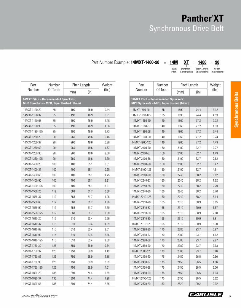
14MXT-1190-20 85 1190 46.9 0.44
14MXT-1190-37 85 1190 46.9 0.81
14MXT-1190-68 85 1190 46.9 1.48
14MXT-1190-90 85 1190 46.9 1.96
14MXT-1190-125 85 1190 46.9 2.73
14MXT-1260-20 90 1260 49.6 0.46
14MXT-1260-37 90 1260 49.6 0.86
14MXT-1260-68 90 1260 49.6 1.57
14MXT-1260-90 90 1260 49.6 2.08
14MXT-1260-125 90 1260 49.6 2.89
14MXT-1400-20 100 1400 55.1 0.51
14MXT-1400-37 100 1400 55.1 0.95
14MXT-1400-68 100 1400 55.1 1.75
14MXT-1400-90 100 1400 55.1 2.31
14MXT-1400-125 100 1400 55.1 3.21
14MXT-1568-20 112 1568 61.7 0.58
14MXT-1568-37 112 1568 61.7 1.06
14MXT-1568-68 112 1568 61.7 1.96
14MXT-1568-90 112 1568 61.7 2.59
14MXT-1568-125 112 1568 61.7 3.60
14MXT-1610-20 115 1610 63.4 0.59
14MXT-1610-37 115 1610 63.4 1.09
14MXT-1610-68 115 1610 63.4 2.01
14MXT-1610-90 115 1610 63.4 2.66
14MXT-1610-125 115 1610 63.4 3.69
14MXT-1750-20 125 1750 68.9 0.64
14MXT-1750-37 125 1750 68.9 1.19
14MXT-1750-68 125 1750 68.9 2.18
14MXT-1750-90 125 1750 68.9 2.89
14MXT-1750-125 125 1750 68.9 4.01
14MXT-1890-20 135 1890 74.4 0.69
14MXT-1890-37 135 1890 74.4 1.28
14MXT-1890-68 135 1890 74.4 2.36
PartNumber
NumberOf Teeth
Pitch Length Weight(lbs)
(mm) (in)
14MXT-1890-90 135 1890 74.4 3.12
14MXT-1890-125 135 1890 74.4 4.33
14MXT-1960-20 140 1960 77.2 0.72
14MXT-1960-37 140 1960 77.2 1.33
14MXT-1960-68 140 1960 77.2 2.44
14MXT-1960-90 140 1960 77.2 3.24
14MXT-1960-125 140 1960 77.2 4.49
14MXT-2100-20 150 2100 82.7 0.77
14MXT-2100-37 150 2100 82.7 1.43
14MXT-2100-68 150 2100 82.7 2.62
14MXT-2100-90 150 2100 82.7 3.47
14MXT-2100-125 150 2100 82.7 4.81
14MXT-2240-20 160 2240 88.2 0.82
14MXT-2240-37 160 2240 88.2 1.52
14MXT-2240-68 160 2240 88.2 2.79
14MXT-2240-90 160 2240 88.2 3.70
14MXT-2240-125 160 2240 88.2 5.14
14MXT-2310-20 165 2310 90.9 0.85
14MXT-2310-37 165 2310 90.9 1.57
14MXT-2310-68 165 2310 90.9 2.88
14MXT-2310-90 165 2310 90.9 3.81
14MXT-2310-125 165 2310 90.9 5.30
14MXT-2380-20 170 2380 93.7 0.87
14MXT-2380-37 170 2380 93.7 1.62
14MXT-2380-68 170 2380 93.7 2.97
14MXT-2380-90 170 2380 93.7 3.93
14MXT-2380-125 170 2380 93.7 5.46
14MXT-2450-20 175 2450 96.5 0.90
14MXT-2450-37 175 2450 96.5 1.66
14MXT-2450-68 175 2450 96.5 3.06
14MXT-2450-90 175 2450 96.5 4.04
14MXT-2450-125 175 2450 96.5 5.62
14MXT-2520-20 180 2520 99.2 0.92
Part Number Example: 14MXT-1400-90 = 14M XT – 1400 – 90 | | | | Tooth PantherXT Pitch Length Width Pitch Construction (millimeters) (millimeters)
14MXT Pitch – Recommended Sprockets:MPC Sprockets – MPB, Taper Bushed (14mm)
14MXT Pitch – Recommended Sprockets:MPC Sprockets – MPB, Taper Bushed (14mm)

www.carlislebelts.com10
Panther®XTPart Numbers
Panther®XTSynchronous Drive Belt
PartNumber
NumberOf Teeth
Pitch Length Weight(lbs)
(mm) (in)
14MXT-2520-37 180 2520 99.2 1.71
14MXT-2520-68 180 2520 99.2 3.14
14MXT-2520-90 180 2520 99.2 4.16
14MXT-2520-125 180 2520 99.2 5.78
14MXT-2590-20 185 2590 102.0 0.95
14MXT-2590-37 185 2590 102.0 1.76
14MXT-2590-68 185 2590 102.0 3.23
14MXT-2590-90 185 2590 102.0 4.28
14MXT-2590-125 185 2590 102.0 5.94
14MXT-2660-20 190 2660 104.7 0.98
14MXT-2660-37 190 2660 104.7 1.81
14MXT-2660-68 190 2660 104.7 3.32
14MXT-2660-90 190 2660 104.7 4.39
14MXT-2660-125 190 2660 104.7 6.10
14MXT-2800-20 200 2800 110.2 1.03
14MXT-2800-37 200 2800 110.2 1.90
14MXT-2800-68 200 2800 110.2 3.49
14MXT-2800-90 200 2800 110.2 4.62
14MXT-2800-125 200 2800 110.2 6.42
14MXT-3136-20 224 3136 123.5 1.15
14MXT-3136-37 224 3136 123.5 2.13
14MXT-3136-68 224 3136 123.5 3.91
14MXT-3136-90 224 3136 123.5 5.18
14MXT-3136-125 224 3136 123.5 7.19
14MXT-3304-20 236 3304 130.1 1.21
14MXT-3304-37 236 3304 130.1 2.24
14MXT-3304-68 236 3304 130.1 4.12
14MXT-3304-90 236 3304 130.1 5.45
14MXT-3304-125 236 3304 130.1 7.58
14MXT-3360-20 240 3360 132.3 1.23
14MXT-3360-37 240 3360 132.3 2.28
14MXT-3360-68 240 3360 132.3 4.19
14MXT-3360-90 240 3360 132.3 5.55
PartNumber
NumberOf Teeth
Pitch Length Weight(lbs)
(mm) (in)
14MXT-3360-125 240 3360 132.3 7.70
14MXT-3500-20 250 3500 137.8 1.28
14MXT-3500-37 250 3500 137.8 2.38
14MXT-3500-68 250 3500 137.8 4.37
14MXT-3500-90 250 3500 137.8 5.78
14MXT-3500-125 250 3500 137.8 8.02
14MXT-3850-20 275 3850 151.6 1.41
14MXT-3850-37 275 3850 151.6 2.61
14MXT-3850-68 275 3850 151.6 4.80
14MXT-3850-90 275 3850 151.6 6.36
14MXT-3850-125 275 3850 151.6 8.83
14MXT-3920-20 280 3920 154.3 1.44
14MXT-3920-37 280 3920 154.3 2.66
14MXT-3920-68 280 3920 154.3 4.89
14MXT-3920-90 280 3920 154.3 6.47
14MXT-3920-125 280 3920 154.3 8.99
14MXT-4326-20 309 4326 170.3 1.59
14MXT-4326-37 309 4326 170.3 2.94
14MXT-4326-68 309 4326 170.3 5.40
14MXT-4326-90 309 4326 170.3 7.14
14MXT-4326-125 309 4326 170.3 9.92
14MXT-4410-20 315 4410 173.6 1.62
14MXT-4410-37 315 4410 173.6 2.99
14MXT-4410-68 315 4410 173.6 5.50
14MXT-4410-90 315 4410 173.6 7.28
14MXT-4410-125 315 4410 173.6 10.11
14MXT Pitch – Recommended Sprockets:MPC Sprockets – MPB, Taper Bushed (14mm)
14MXT Pitch – Recommended Sprockets:MPC Sprockets – MPB, Taper Bushed (14mm)
Part Number Example: 14MXT-2520-90 = 14M XT – 2520 – 90 | | | | Tooth PantherXT Pitch Length Width Pitch Construction (millimeters) (millimeters)

www.carlislebelts.com 11
Panther®XTSynchronous Drive Belt
Sync
hron
ous
Bel
ts

www.carlislebelts.com12
Panther®
Synchronous Drive Belt

Sync
hron
ous
Bel
ts
www.carlislebelts.com 13
Ultra-Cord® tensile member
Advanced polymer compound
Maintenance-free
Energy efficient
Applications: Conveyors Blowers Packaging equipment Machine tools Industrial machinery & More
Panther®
Synchronous Drive Belt
1 Ultra-Cord Tensile MemberImproved belt lifeHigher strengthReduced tension decay Dimensional stability
2 Nylon Tooth Facing Graphite-loadedSelf-lubricatingWear resistant
3 RPP® ProfileGreater transfer of powerJump and shear resistant
4 BackingPrecision-groundSmoother operation with backside idler
5 Advanced Polymer CompoundIncreased performanceIncreased belt life
Recommended Sprockets:High Torque Synchronous (HTS) Sprockets – MPB, QD, Taper Bushed (8mm, 14mm, 20mm)
5
2
1
4
3

www.carlislebelts.com14
Panther®
Synchronous Drive Belt
www.carlislebelts.com14
The energy efficient Panther® offers higher torque capacity than the Carlisle® Synchro-Cog® HT and conventional synchronous belts.
■■ Strong – Panther shrugs off shock loads. Designed with Ultra-Cord, a non-aramid fiber tensile member that delivers strength and dimensional stability.
■■ Resilient – Uniquely engineered teeth are made of high performance polychloroprene, an advanced polymer compound which increases both the strength and abrasion resistance of the teeth. The RPP® profile offers superior performance in RPP, HTS and PGGT2® sprockets as well as HPPD, Hawk Pd® and HTD® sprockets.
■■ Energy Efficient – Panther performs at 98-99% operating efficiency for reduced energy consumption.
■■ Panther Power – Panther offers higher power ratings than conventional rubber synchronous belts. Available in 8, 14 and 20mm pitches.
Hawk Pd® is a registered trademark of Veyance Technologies, Inc. PGGT2® and HTD® are registered trademarks of Gates Corporation.
Panther® is designed to improve performance and drive life while reducing maintenance and downtime.

www.carlislebelts.com 15
Sync
hron
ous
Bel
ts
Panther®
Part Numbers
Panther®
Synchronous Drive Belt
PartNumber
NumberOf Teeth
Pitch Length Weight(lbs)
(mm) (in)
8M Pitch – High Torque Synchronous (HTS) Sprockets: MPB, QD, Taper Bushed (8mm)
480-8MPT-12 60 480 18.9 0.07
480-8MPT-20 60 480 18.9 0.12
480-8MPT-22 60 480 18.9 0.13
480-8MPT-30 60 480 18.9 0.17
480-8MPT-35 60 480 18.9 0.20
480-8MPT-50 60 480 18.9 0.29
480-8MPT-60 60 480 18.9 0.35
480-8MPT-85 60 480 18.9 0.49
560-8MPT-12 70 560 22.0 0.08
560-8MPT-20 70 560 22.0 0.14
560-8MPT-22 70 560 22.0 0.15
560-8MPT-30 70 560 22.0 0.20
560-8MPT-35 70 560 22.0 0.24
560-8MPT-50 70 560 22.0 0.34
560-8MPT-60 70 560 22.0 0.41
560-8MPT-85 70 560 22.0 0.57
600-8MPT-12 75 600 23.6 0.09
600-8MPT-20 75 600 23.6 0.14
600-8MPT-22 75 600 23.6 0.16
600-8MPT-30 75 600 23.6 0.22
600-8MPT-35 75 600 23.6 0.25
600-8MPT-50 75 600 23.6 0.36
600-8MPT-60 75 600 23.6 0.43
600-8MPT-85 75 600 23.6 0.61
640-8MPT-12 80 640 25.2 0.09
640-8MPT-20 80 640 25.2 0.15
640-8MPT-22 80 640 25.2 0.17
640-8MPT-30 80 640 25.2 0.23
640-8MPT-35 80 640 25.2 0.27
640-8MPT-50 80 640 25.2 0.39
640-8MPT-60 80 640 25.2 0.46
640-8MPT-85 80 640 25.2 0.66
720-8MPT-12 90 720 28.3 0.10
PartNumber
NumberOf Teeth
Pitch Length Weight(lbs)
(mm) (in)
8M Pitch – High Torque Synchronous (HTS) Sprockets: MPB, QD, Taper Bushed (8mm)
720-8MPT-20 90 720 28.3 0.17
720-8MPT-22 90 720 28.3 0.19
720-8MPT-30 90 720 28.3 0.26
720-8MPT-35 90 720 28.3 0.30
720-8MPT-50 90 720 28.3 0.43
720-8MPT-60 90 720 28.3 0.52
720-8MPT-85 90 720 28.3 0.74
800-8MPT-12 100 800 31.5 0.12
800-8MPT-20 100 800 31.5 0.19
800-8MPT-22 100 800 31.5 0.21
800-8MPT-30 100 800 31.5 0.29
800-8MPT-35 100 800 31.5 0.34
800-8MPT-50 100 800 31.5 0.48
800-8MPT-60 100 800 31.5 0.58
800-8MPT-85 100 800 31.5 0.82
880-8MPT-12 110 880 34.6 0.13
880-8MPT-20 110 880 34.6 0.21
880-8MPT-22 110 880 34.6 0.23
880-8MPT-30 110 880 34.6 0.32
880-8MPT-35 110 880 34.6 0.37
880-8MPT-50 110 880 34.6 0.53
880-8MPT-60 110 880 34.6 0.64
880-8MPT-85 110 880 34.6 0.90
896-8MPT-12 112 896 35.3 0.13
896-8MPT-20 112 896 35.3 0.22
896-8MPT-22 112 896 35.3 0.24
896-8MPT-30 112 896 35.3 0.32
896-8MPT-35 112 896 35.3 0.38
896-8MPT-50 112 896 35.3 0.54
896-8MPT-60 112 896 35.3 0.65
896-8MPT-85 112 896 35.3 0.92
920-8MPT-12 115 920 36.2 0.13
920-8MPT-20 115 920 36.2 0.22
Part Number Example: 1400-8MPT-50 = 1400 – 8M PT – 50 | | | | Pitch Length Tooth Panther Construction Width (millimeters) Pitch (RPP tooth profile) (millimeters)

www.carlislebelts.com16
Panther®
Part Numbers
Panther®
Synchronous Drive Belt
PartNumber
NumberOf Teeth
Pitch Length Weight(lbs)
(mm) (in)
8M Pitch – High Torque Synchronous (HTS) Sprockets: MPB, QD, Taper Bushed (8mm)
920-8MPT-22 115 920 36.2 0.24
920-8MPT-30 115 920 36.2 0.33
920-8MPT-35 115 920 36.2 0.39
920-8MPT-50 115 920 36.2 0.55
920-8MPT-60 115 920 36.2 0.67
920-8MPT-85 115 920 36.2 0.94
960-8MPT-12 120 960 37.8 0.14
960-8MPT-20 120 960 37.8 0.23
960-8MPT-22 120 960 37.8 0.25
960-8MPT-30 120 960 37.8 0.35
960-8MPT-35 120 960 37.8 0.41
960-8MPT-50 120 960 37.8 0.58
960-8MPT-60 120 960 37.8 0.69
960-8MPT-85 120 960 37.8 0.98
1000-8MPT-12 125 1000 39.4 0.14
1000-8MPT-20 125 1000 39.4 0.24
1000-8MPT-22 125 1000 39.4 0.27
1000-8MPT-30 125 1000 39.4 0.36
1000-8MPT-35 125 1000 39.4 0.42
1000-8MPT-50 125 1000 39.4 0.60
1000-8MPT-60 125 1000 39.4 0.72
1000-8MPT-85 125 1000 39.4 1.02
1040-8MPT-12 130 1040 40.9 0.15
1040-8MPT-20 130 1040 40.9 0.25
1040-8MPT-22 130 1040 40.9 0.28
1040-8MPT-30 130 1040 40.9 0.38
1040-8MPT-35 130 1040 40.9 0.44
1040-8MPT-50 130 1040 40.9 0.63
1040-8MPT-60 130 1040 40.9 0.75
1040-8MPT-85 130 1040 40.9 1.07
1120-8MPT-12 140 1120 44.1 0.16
1120-8MPT-20 140 1120 44.1 0.27
1120-8MPT-22 140 1120 44.1 0.30
PartNumber
NumberOf Teeth
Pitch Length Weight(lbs)
(mm) (in)
8M Pitch – High Torque Synchronous (HTS) Sprockets: MPB, QD, Taper Bushed (8mm)
1120-8MPT-30 140 1120 44.1 0.41
1120-8MPT-35 140 1120 44.1 0.47
1120-8MPT-50 140 1120 44.1 0.68
1120-8MPT-60 140 1120 44.1 0.81
1120-8MPT-85 140 1120 44.1 1.15
1152-8MPT-12 144 1152 45.4 0.17
1152-8MPT-20 144 1152 45.4 0.28
1152-8MPT-22 144 1152 45.4 0.31
1152-8MPT-30 144 1152 45.4 0.42
1152-8MPT-35 144 1152 45.4 0.49
1152-8MPT-50 144 1152 45.4 0.69
1152-8MPT-60 144 1152 45.4 0.83
1152-8MPT-85 144 1152 45.4 1.18
1200-8MPT-12 150 1200 47.2 0.17
1200-8MPT-20 150 1200 47.2 0.29
1200-8MPT-22 150 1200 47.2 0.32
1200-8MPT-30 150 1200 47.2 0.43
1200-8MPT-35 150 1200 47.2 0.51
1200-8MPT-50 150 1200 47.2 0.72
1200-8MPT-60 150 1200 47.2 0.87
1200-8MPT-85 150 1200 47.2 1.23
1224-8MPT-12 153 1224 48.2 0.18
1224-8MPT-20 153 1224 48.2 0.30
1224-8MPT-22 153 1224 48.2 0.32
1224-8MPT-30 153 1224 48.2 0.44
1224-8MPT-35 153 1224 48.2 0.52
1224-8MPT-50 153 1224 48.2 0.74
1224-8MPT-60 153 1224 48.2 0.89
1224-8MPT-85 153 1224 48.2 1.25
1248-8MPT-12 156 1248 49.1 0.18
1248-8MPT-20 156 1248 49.1 0.30
1248-8MPT-22 156 1248 49.1 0.33
1248-8MPT-30 156 1248 49.1 0.45

www.carlislebelts.com 17
Sync
hron
ous
Bel
ts
PartNumber
NumberOf Teeth
Pitch Length Weight(lbs)
(mm) (in)
8M Pitch – High Torque Synchronous (HTS) Sprockets: MPB, QD, Taper Bushed (8mm)
1248-8MPT-35 156 1248 49.1 0.53
1248-8MPT-50 156 1248 49.1 0.75
1248-8MPT-60 156 1248 49.1 0.90
1248-8MPT-85 156 1248 49.1 1.28
1280-8MPT-12 160 1280 50.4 0.19
1280-8MPT-20 160 1280 50.4 0.31
1280-8MPT-22 160 1280 50.4 0.34
1280-8MPT-30 160 1280 50.4 0.46
1280-8MPT-35 160 1280 50.4 0.54
1280-8MPT-50 160 1280 50.4 0.77
1280-8MPT-60 160 1280 50.4 0.93
1280-8MPT-85 160 1280 50.4 1.31
1360-8MPT-12 170 1360 53.5 0.20
1360-8MPT-20 170 1360 53.5 0.33
1360-8MPT-22 170 1360 53.5 0.36
1360-8MPT-30 170 1360 53.5 0.49
1360-8MPT-35 170 1360 53.5 0.57
1360-8MPT-50 170 1360 53.5 0.82
1360-8MPT-60 170 1360 53.5 0.98
1360-8MPT-85 170 1360 53.5 1.39
1400-8MPT-12 175 1400 55.1 0.20
1400-8MPT-20 175 1400 55.1 0.34
1400-8MPT-22 175 1400 55.1 0.37
1400-8MPT-30 175 1400 55.1 0.51
1400-8MPT-35 175 1400 55.1 0.59
1400-8MPT-50 175 1400 55.1 0.84
1400-8MPT-60 175 1400 55.1 1.01
1400-8MPT-85 175 1400 55.1 1.43
1440-8MPT-12 180 1440 56.7 0.21
1440-8MPT-20 180 1440 56.7 0.35
1440-8MPT-22 180 1440 56.7 0.38
1440-8MPT-30 180 1440 56.7 0.52
1440-8MPT-35 180 1440 56.7 0.61
PartNumber
NumberOf Teeth
Pitch Length Weight(lbs)
(mm) (in)
8M Pitch – High Torque Synchronous (HTS) Sprockets: MPB, QD, Taper Bushed (8mm)
1440-8MPT-50 180 1440 56.7 0.87
1440-8MPT-60 180 1440 56.7 1.04
1440-8MPT-85 180 1440 56.7 1.48
1600-8MPT-12 200 1600 63.0 0.23
1600-8MPT-20 200 1600 63.0 0.39
1600-8MPT-22 200 1600 63.0 0.42
1600-8MPT-30 200 1600 63.0 0.58
1600-8MPT-35 200 1600 63.0 0.68
1600-8MPT-50 200 1600 63.0 0.96
1600-8MPT-60 200 1600 63.0 1.16
1600-8MPT-85 200 1600 63.0 1.64
1760-8MPT-12 220 1760 69.3 0.25
1760-8MPT-20 220 1760 69.3 0.42
1760-8MPT-22 220 1760 69.3 0.47
1760-8MPT-30 220 1760 69.3 0.64
1760-8MPT-35 220 1760 69.3 0.74
1760-8MPT-50 220 1760 69.3 1.06
1760-8MPT-60 220 1760 69.3 1.27
1760-8MPT-85 220 1760 69.3 1.80
1800-8MPT-12 225 1800 70.9 0.26
1800-8MPT-20 225 1800 70.9 0.43
1800-8MPT-22 225 1800 70.9 0.48
1800-8MPT-30 225 1800 70.9 0.65
1800-8MPT-35 225 1800 70.9 0.76
1800-8MPT-50 225 1800 70.9 1.09
1800-8MPT-60 225 1800 70.9 1.30
1800-8MPT-85 225 1800 70.9 1.84
1904-8MPT-12 238 1904 75.0 0.28
1904-8MPT-20 238 1904 75.0 0.46
1904-8MPT-22 238 1904 75.0 0.51
1904-8MPT-30 238 1904 75.0 0.69
1904-8MPT-35 238 1904 75.0 0.80
1904-8MPT-50 238 1904 75.0 1.15
Part Number Example: 1400-8MPT-50 = 1400 – 8M PT – 50 | | | | Pitch Length Tooth Panther Construction Width (millimeters) Pitch (RPP tooth profile) (millimeters)
Panther®
Synchronous Drive Belt

www.carlislebelts.com18
Panther®
Synchronous Drive Belt
Panther®
Part NumbersPart
NumberNumberOf Teeth
Pitch Length Weight(lbs)
(mm) (in)
8M Pitch – High Torque Synchronous (HTS) Sprockets: MPB, QD, Taper Bushed (8mm)
1904-8MPT-60 238 1904 75.0 1.38
1904-8MPT-85 238 1904 75.0 1.95
2000-8MPT-12 250 2000 78.7 0.29
2000-8MPT-20 250 2000 78.7 0.48
2000-8MPT-22 250 2000 78.7 0.53
2000-8MPT-30 250 2000 78.7 0.72
2000-8MPT-35 250 2000 78.7 0.84
2000-8MPT-50 250 2000 78.7 1.21
2000-8MPT-60 250 2000 78.7 1.45
2000-8MPT-85 250 2000 78.7 2.05
2104-8MPT-12 263 2104 82.8 0.30
2104-8MPT-20 263 2104 82.8 0.51
2104-8MPT-22 263 2104 82.8 0.56
2104-8MPT-30 263 2104 82.8 0.76
2104-8MPT-35 263 2104 82.8 0.89
2104-8MPT-50 263 2104 82.8 1.27
2104-8MPT-60 263 2104 82.8 1.52
2104-8MPT-85 263 2104 82.8 2.16
2200-8MPT-12 275 2200 86.6 0.32
2200-8MPT-20 275 2200 86.6 0.53
2200-8MPT-22 275 2200 86.6 0.58
2200-8MPT-30 275 2200 86.6 0.80
2200-8MPT-35 275 2200 86.6 0.93
2200-8MPT-50 275 2200 86.6 1.33
2200-8MPT-60 275 2200 86.6 1.59
2200-8MPT-85 275 2200 86.6 2.25
2240-8MPT-12 280 2240 88.2 0.32
2240-8MPT-20 280 2240 88.2 0.54
2240-8MPT-22 280 2240 88.2 0.59
2240-8MPT-30 280 2240 88.2 0.81
2240-8MPT-35 280 2240 88.2 0.95
2240-8MPT-50 280 2240 88.2 1.35
2240-8MPT-60 280 2240 88.2 1.62
PartNumber
NumberOf Teeth
Pitch Length Weight(lbs)
(mm) (in)
8M Pitch – High Torque Synchronous (HTS) Sprockets: MPB, QD, Taper Bushed (8mm)
2240-8MPT-85 280 2240 88.2 2.30
2400-8MPT-12 300 2400 94.5 0.35
2400-8MPT-20 300 2400 94.5 0.58
2400-8MPT-22 300 2400 94.5 0.64
2400-8MPT-30 300 2400 94.5 0.87
2400-8MPT-35 300 2400 94.5 1.01
2400-8MPT-50 300 2400 94.5 1.45
2400-8MPT-60 300 2400 94.5 1.74
2400-8MPT-85 300 2400 94.5 2.46
2600-8MPT-12 325 2600 102.4 0.38
2600-8MPT-20 325 2600 102.4 0.63
2600-8MPT-22 325 2600 102.4 0.69
2600-8MPT-30 325 2600 102.4 0.94
2600-8MPT-35 325 2600 102.4 1.10
2600-8MPT-50 325 2600 102.4 1.57
2600-8MPT-60 325 2600 102.4 1.88
2600-8MPT-85 325 2600 102.4 2.66
2800-8MPT-12 350 2800 110.2 0.41
2800-8MPT-20 350 2800 110.2 0.68
2800-8MPT-22 350 2800 110.2 0.74
2800-8MPT-30 350 2800 110.2 1.01
2800-8MPT-35 350 2800 110.2 1.18
2800-8MPT-50 350 2800 110.2 1.69
2800-8MPT-60 350 2800 110.2 2.03
2800-8MPT-85 350 2800 110.2 2.87
3048-8MPT-12 381 3048 120.0 0.44
3048-8MPT-20 381 3048 120.0 0.74
3048-8MPT-22 381 3048 120.0 0.81
3048-8MPT-30 381 3048 120.0 1.10
3048-8MPT-35 381 3048 120.0 1.29
3048-8MPT-50 381 3048 120.0 1.84
3048-8MPT-60 381 3048 120.0 2.21
3048-8MPT-85 381 3048 120.0 3.12

www.carlislebelts.com 19
Sync
hron
ous
Bel
ts
PartNumber
NumberOf Teeth
Pitch Length Weight(lbs)
(mm) (in)
8M Pitch – High Torque Synchronous (HTS) Sprockets: MPB, QD, Taper Bushed (8mm)
3280-8MPT-12 410 3280 129.1 0.47
3280-8MPT-20 410 3280 129.1 0.79
3280-8MPT-22 410 3280 129.1 0.87
3280-8MPT-30 410 3280 129.1 1.19
3280-8MPT-35 410 3280 129.1 1.38
3280-8MPT-50 410 3280 129.1 1.98
3280-8MPT-60 410 3280 129.1 2.37
3280-8MPT-85 410 3280 129.1 3.36
3600-8MPT-12 450 3600 141.7 0.52
3600-8MPT-20 450 3600 141.7 0.87
3600-8MPT-22 450 3600 141.7 0.96
3600-8MPT-30 450 3600 141.7 1.30
3600-8MPT-35 450 3600 141.7 1.52
3600-8MPT-50 450 3600 141.7 2.17
3600-8MPT-60 450 3600 141.7 2.60
3600-8MPT-85 450 3600 141.7 3.69
4400-8MPT-12 550 4400 173.2 0.64
4400-8MPT-20 550 4400 173.2 1.06
4400-8MPT-22 550 4400 173.2 1.17
4400-8MPT-30 550 4400 173.2 1.59
4400-8MPT-35 550 4400 173.2 1.86
4400-8MPT-50 550 4400 173.2 2.65
4400-8MPT-60 550 4400 173.2 3.18
4400-8MPT-85 550 4400 173.2 4.51
14M Pitch – High Torque Synchronous (HTS) Sprockets: MPB, QD, Taper Bushed (14mm)
966-14MPT-20 69 966 38.0 0.39
966-14MPT-40 69 966 38.0 0.77
966-14MPT-42 69 966 38.0 0.81
966-14MPT-55 69 966 38.0 1.06
966-14MPT-65 69 966 38.0 1.26
966-14MPT-85 69 966 38.0 1.65
966-14MPT-90 69 966 38.0 1.74
PartNumber
NumberOf Teeth
Pitch Length Weight(lbs)
(mm) (in)
8M Pitch – High Torque Synchronous (HTS) Sprockets: MPB, QD, Taper Bushed (8mm)
966-14MPT-115 69 966 38.0 2.23
966-14MPT-120 69 966 38.0 2.32
966-14MPT-170 69 966 38.0 3.29
1092-14MPT-20 78 1092 43.0 0.44
1092-14MPT-40 78 1092 43.0 0.88
1092-14MPT-42 78 1092 43.0 0.92
1092-14MPT-55 78 1092 43.0 1.20
1092-14MPT-65 78 1092 43.0 1.42
1092-14MPT-85 78 1092 43.0 1.86
1092-14MPT-90 78 1092 43.0 1.97
1092-14MPT-115 78 1092 43.0 2.52
1092-14MPT-120 78 1092 43.0 2.63
1092-14MPT-170 78 1092 43.0 3.72
1190-14MPT-20 85 1190 46.9 0.48
1190-14MPT-40 85 1190 46.9 0.95
1190-14MPT-42 85 1190 46.9 1.00
1190-14MPT-55 85 1190 46.9 1.31
1190-14MPT-65 85 1190 46.9 1.55
1190-14MPT-85 85 1190 46.9 2.03
1190-14MPT-90 85 1190 46.9 2.15
1190-14MPT-115 85 1190 46.9 2.74
1190-14MPT-120 85 1190 46.9 2.86
1190-14MPT-170 85 1190 46.9 4.05
1400-14MPT-20 100 1400 55.1 0.56
1400-14MPT-40 100 1400 55.1 1.12
1400-14MPT-42 100 1400 55.1 1.18
1400-14MPT-55 100 1400 55.1 1.54
1400-14MPT-65 100 1400 55.1 1.82
1400-14MPT-85 100 1400 55.1 2.38
1400-14MPT-90 100 1400 55.1 2.52
1400-14MPT-115 100 1400 55.1 3.23
1400-14MPT-120 100 1400 55.1 3.37
1400-14MPT-170 100 1400 55.1 4.77
Part Number Example: 2240-8MPT-85 = 2240 – 8M PT – 85 | | | | Pitch Length Tooth Panther Construction Width (millimeters) Pitch (RPP tooth profile) (millimeters)
Panther®
Synchronous Drive Belt
14M Pitch – High Torque Synchronous (HTS) Sprockets: MPB, QD, Taper Bushed (14mm)

www.carlislebelts.com20
Panther®
Part Numbers
Panther®
Synchronous Drive Belt
PartNumber
NumberOf Teeth
Pitch Length Weight(lbs)
(mm) (in)
8M Pitch – High Torque Synchronous (HTS) Sprockets: MPB, QD, Taper Bushed (8mm)
1610-14MPT-20 115 1610 63.4 0.65
1610-14MPT-40 115 1610 63.4 1.29
1610-14MPT-42 115 1610 63.4 1.35
1610-14MPT-55 115 1610 63.4 1.77
1610-14MPT-65 115 1610 63.4 2.10
1610-14MPT-85 115 1610 63.4 2.74
1610-14MPT-90 115 1610 63.4 2.90
1610-14MPT-115 115 1610 63.4 3.71
1610-14MPT-120 115 1610 63.4 3.87
1610-14MPT-170 115 1610 63.4 5.48
1750-14MPT-20 125 1750 68.9 0.70
1750-14MPT-40 125 1750 68.9 1.40
1750-14MPT-42 125 1750 68.9 1.47
1750-14MPT-55 125 1750 68.9 1.93
1750-14MPT-65 125 1750 68.9 2.28
1750-14MPT-85 125 1750 68.9 2.98
1750-14MPT-90 125 1750 68.9 3.16
1750-14MPT-115 125 1750 68.9 4.03
1750-14MPT-120 125 1750 68.9 4.21
1750-14MPT-170 125 1750 68.9 5.96
1764-14MPT-20 126 1764 69.4 0.71
1764-14MPT-40 126 1764 69.4 1.41
1764-14MPT-42 126 1764 69.4 1.48
1764-14MPT-55 126 1764 69.4 1.94
1764-14MPT-65 126 1764 69.4 2.30
1764-14MPT-85 126 1764 69.4 3.00
1764-14MPT-90 126 1764 69.4 3.18
1764-14MPT-115 126 1764 69.4 4.06
1764-14MPT-120 126 1764 69.4 4.24
1764-14MPT-170 126 1764 69.4 6.01
1778-14MPT-20 127 1778 70.0 0.71
1778-14MPT-40 127 1778 70.0 1.43
1778-14MPT-42 127 1778 70.0 1.50
PartNumber
NumberOf Teeth
Pitch Length Weight(lbs)
(mm) (in)
8M Pitch – High Torque Synchronous (HTS) Sprockets: MPB, QD, Taper Bushed (8mm)
1778-14MPT-55 127 1778 70.0 1.96
1778-14MPT-65 127 1778 70.0 2.32
1778-14MPT-85 127 1778 70.0 3.03
1778-14MPT-90 127 1778 70.0 3.21
1778-14MPT-115 127 1778 70.0 4.10
1778-14MPT-120 127 1778 70.0 4.28
1778-14MPT-170 127 1778 70.0 6.06
1792-14MPT-20 128 1792 70.6 0.72
1792-14MPT-40 128 1792 70.6 1.44
1792-14MPT-42 128 1792 70.6 1.51
1792-14MPT-55 128 1792 70.6 1.97
1792-14MPT-65 128 1792 70.6 2.33
1792-14MPT-85 128 1792 70.6 3.05
1792-14MPT-90 128 1792 70.6 3.23
1792-14MPT-115 128 1792 70.6 4.13
1792-14MPT-120 128 1792 70.6 4.31
1792-14MPT-170 128 1792 70.6 6.10
1820-14MPT-20 130 1820 71.7 0.73
1820-14MPT-40 130 1820 71.7 1.46
1820-14MPT-42 130 1820 71.7 1.53
1820-14MPT-55 130 1820 71.7 2.01
1820-14MPT-65 130 1820 71.7 2.37
1820-14MPT-85 130 1820 71.7 3.10
1820-14MPT-90 130 1820 71.7 3.28
1820-14MPT-115 130 1820 71.7 4.19
1820-14MPT-120 130 1820 71.7 4.38
1820-14MPT-170 130 1820 71.7 6.20
1848-14MPT-20 132 1848 72.8 0.74
1848-14MPT-40 132 1848 72.8 1.48
1848-14MPT-42 132 1848 72.8 1.56
1848-14MPT-55 132 1848 72.8 2.04
1848-14MPT-65 132 1848 72.8 2.41
1848-14MPT-85 132 1848 72.8 3.15
14M Pitch – High Torque Synchronous (HTS) Sprockets: MPB, QD, Taper Bushed (14mm)
14M Pitch – High Torque Synchronous (HTS) Sprockets: MPB, QD, Taper Bushed (14mm)

www.carlislebelts.com 21
Sync
hron
ous
Bel
ts
PartNumber
NumberOf Teeth
Pitch Length Weight(lbs)
(mm) (in)
8M Pitch – High Torque Synchronous (HTS) Sprockets: MPB, QD, Taper Bushed (8mm)
1848-14MPT-90 132 1848 72.8 3.33
1848-14MPT-115 132 1848 72.8 4.26
1848-14MPT-120 132 1848 72.8 4.44
1848-14MPT-170 132 1848 72.8 6.29
1862-14MPT-20 133 1862 73.3 0.75
1862-14MPT-40 133 1862 73.3 1.49
1862-14MPT-42 133 1862 73.3 1.57
1862-14MPT-55 133 1862 73.3 2.05
1862-14MPT-65 133 1862 73.3 2.43
1862-14MPT-85 133 1862 73.3 3.17
1862-14MPT-90 133 1862 73.3 3.36
1862-14MPT-115 133 1862 73.3 4.29
1862-14MPT-120 133 1862 73.3 4.48
1862-14MPT-170 133 1862 73.3 6.34
1890-14MPT-20 135 1890 74.4 0.76
1890-14MPT-40 135 1890 74.4 1.51
1890-14MPT-42 135 1890 74.4 1.59
1890-14MPT-55 135 1890 74.4 2.08
1890-14MPT-65 135 1890 74.4 2.46
1890-14MPT-85 135 1890 74.4 3.22
1890-14MPT-90 135 1890 74.4 3.41
1890-14MPT-115 135 1890 74.4 4.36
1890-14MPT-120 135 1890 74.4 4.54
1890-14MPT-170 135 1890 74.4 6.44
1904-14MPT-20 136 1904 75.0 0.76
1904-14MPT-40 136 1904 75.0 1.53
1904-14MPT-42 136 1904 75.0 1.60
1904-14MPT-55 136 1904 75.0 2.10
1904-14MPT-65 136 1904 75.0 2.48
1904-14MPT-85 136 1904 75.0 3.24
1904-14MPT-90 136 1904 75.0 3.43
1904-14MPT-115 136 1904 75.0 4.39
1904-14MPT-120 136 1904 75.0 4.58
PartNumber
NumberOf Teeth
Pitch Length Weight(lbs)
(mm) (in)
8M Pitch – High Torque Synchronous (HTS) Sprockets: MPB, QD, Taper Bushed (8mm)
1904-14MPT-170 136 1904 75.0 6.49
1960-14MPT-20 140 1960 77.2 0.79
1960-14MPT-40 140 1960 77.2 1.57
1960-14MPT-42 140 1960 77.2 1.65
1960-14MPT-55 140 1960 77.2 2.16
1960-14MPT-65 140 1960 77.2 2.55
1960-14MPT-85 140 1960 77.2 3.34
1960-14MPT-90 140 1960 77.2 3.53
1960-14MPT-115 140 1960 77.2 4.52
1960-14MPT-120 140 1960 77.2 4.71
1960-14MPT-170 140 1960 77.2 6.68
2100-14MPT-20 150 2100 82.7 0.84
2100-14MPT-40 150 2100 82.7 1.68
2100-14MPT-42 150 2100 82.7 1.77
2100-14MPT-55 150 2100 82.7 2.31
2100-14MPT-65 150 2100 82.7 2.74
2100-14MPT-85 150 2100 82.7 3.58
2100-14MPT-90 150 2100 82.7 3.79
2100-14MPT-115 150 2100 82.7 4.84
2100-14MPT-120 150 2100 82.7 5.05
2100-14MPT-170 150 2100 82.7 7.15
2310-14MPT-20 165 2310 90.9 0.93
2310-14MPT-40 165 2310 90.9 1.85
2310-14MPT-42 165 2310 90.9 1.94
2310-14MPT-55 165 2310 90.9 2.55
2310-14MPT-65 165 2310 90.9 3.01
2310-14MPT-85 165 2310 90.9 3.93
2310-14MPT-90 165 2310 90.9 4.17
2310-14MPT-115 165 2310 90.9 5.32
2310-14MPT-120 165 2310 90.9 5.55
2310-14MPT-170 165 2310 90.9 7.87
2450-14MPT-20 175 2450 96.5 0.98
2450-14MPT-40 175 2450 96.5 1.96
14M Pitch – High Torque Synchronous (HTS) Sprockets: MPB, QD, Taper Bushed (14mm)
Part Number Example: 1610-14MPT-20 = 1610 – 14M PT – 20 | | | | Pitch Length Tooth Panther Construction Width (millimeters) Pitch (RPP tooth profile) (millimeters)
Panther®
Synchronous Drive Belt
14M Pitch – High Torque Synchronous (HTS) Sprockets: MPB, QD, Taper Bushed (14mm)

www.carlislebelts.com22
Panther®
Part Numbers
Panther®
Synchronous Drive Belt
PartNumber
NumberOf Teeth
Pitch Length Weight(lbs)
(mm) (in)
8M Pitch – High Torque Synchronous (HTS) Sprockets: MPB, QD, Taper Bushed (8mm)
2450-14MPT-42 175 2450 96.5 2.06
2450-14MPT-55 175 2450 96.5 2.70
2450-14MPT-65 175 2450 96.5 3.19
2450-14MPT-85 175 2450 96.5 4.17
2450-14MPT-90 175 2450 96.5 4.42
2450-14MPT-115 175 2450 96.5 5.65
2450-14MPT-120 175 2450 96.5 5.89
2450-14MPT-170 175 2450 96.5 8.35
2590-14MPT-20 185 2590 102.0 1.04
2590-14MPT-40 185 2590 102.0 2.08
2590-14MPT-42 185 2590 102.0 2.18
2590-14MPT-55 185 2590 102.0 2.85
2590-14MPT-65 185 2590 102.0 3.37
2590-14MPT-85 185 2590 102.0 4.41
2590-14MPT-90 185 2590 102.0 4.67
2590-14MPT-115 185 2590 102.0 5.97
2590-14MPT-120 185 2590 102.0 6.23
2590-14MPT-170 185 2590 102.0 8.82
2800-14MPT-20 200 2800 110.2 1.12
2800-14MPT-40 200 2800 110.2 2.24
2800-14MPT-42 200 2800 110.2 2.36
2800-14MPT-55 200 2800 110.2 3.09
2800-14MPT-65 200 2800 110.2 3.65
2800-14MPT-85 200 2800 110.2 4.77
2800-14MPT-90 200 2800 110.2 5.05
2800-14MPT-115 200 2800 110.2 6.45
2800-14MPT-120 200 2800 110.2 6.73
2800-14MPT-170 200 2800 110.2 9.54
3150-14MPT-20 225 3150 124.0 1.26
3150-14MPT-40 225 3150 124.0 2.52
3150-14MPT-42 225 3150 124.0 2.65
3150-14MPT-55 225 3150 124.0 3.47
3150-14MPT-65 225 3150 124.0 4.10
PartNumber
NumberOf Teeth
Pitch Length Weight(lbs)
(mm) (in)
8M Pitch – High Torque Synchronous (HTS) Sprockets: MPB, QD, Taper Bushed (8mm)
3150-14MPT-85 225 3150 124.0 5.36
3150-14MPT-90 225 3150 124.0 5.68
3150-14MPT-115 225 3150 124.0 7.26
3150-14MPT-120 225 3150 124.0 7.57
3150-14MPT-170 225 3150 124.0 10.73
3360-14MPT-20 240 3360 132.3 1.35
3360-14MPT-40 240 3360 132.3 2.69
3360-14MPT-42 240 3360 132.3 2.83
3360-14MPT-55 240 3360 132.3 3.70
3360-14MPT-65 240 3360 132.3 4.38
3360-14MPT-85 240 3360 132.3 5.72
3360-14MPT-90 240 3360 132.3 6.06
3360-14MPT-115 240 3360 132.3 7.74
3360-14MPT-120 240 3360 132.3 8.08
3360-14MPT-170 240 3360 132.3 11.45
3500-14MPT-20 250 3500 137.8 1.40
3500-14MPT-40 250 3500 137.8 2.81
3500-14MPT-42 250 3500 137.8 2.95
3500-14MPT-55 250 3500 137.8 3.86
3500-14MPT-65 250 3500 137.8 4.56
3500-14MPT-85 250 3500 137.8 5.96
3500-14MPT-90 250 3500 137.8 6.31
3500-14MPT-115 250 3500 137.8 8.07
3500-14MPT-120 250 3500 137.8 8.42
3500-14MPT-170 250 3500 137.8 11.92
3850-14MPT-20 275 3850 151.6 1.54
3850-14MPT-40 275 3850 151.6 3.09
3850-14MPT-42 275 3850 151.6 3.24
3850-14MPT-55 275 3850 151.6 4.24
3850-14MPT-65 275 3850 151.6 5.01
3850-14MPT-85 275 3850 151.6 6.56
3850-14MPT-90 275 3850 151.6 6.94
3850-14MPT-115 275 3850 151.6 8.87
14M Pitch – High Torque Synchronous (HTS) Sprockets: MPB, QD, Taper Bushed (14mm)
14M Pitch – High Torque Synchronous (HTS) Sprockets: MPB, QD, Taper Bushed (14mm)

www.carlislebelts.com 23
Sync
hron
ous
Bel
ts
PartNumber
NumberOf Teeth
Pitch Length Weight(lbs)
(mm) (in)
8M Pitch – High Torque Synchronous (HTS) Sprockets: MPB, QD, Taper Bushed (8mm)
3850-14MPT-120 275 3850 151.6 9.26
3850-14MPT-170 275 3850 151.6 13.11
4326-14MPT-20 309 4326 170.3 1.73
4326-14MPT-40 309 4326 170.3 3.47
4326-14MPT-42 309 4326 170.3 3.64
4326-14MPT-55 309 4326 170.3 4.77
4326-14MPT-65 309 4326 170.3 5.63
4326-14MPT-85 309 4326 170.3 7.37
4326-14MPT-90 309 4326 170.3 7.80
4326-14MPT-115 309 4326 170.3 9.97
4326-14MPT-120 309 4326 170.3 10.40
4326-14MPT-170 309 4326 170.3 14.74
4578-14MPT-20 327 4578 180.2 1.83
4578-14MPT-40 327 4578 180.2 3.67
4578-14MPT-42 327 4578 180.2 3.85
4578-14MPT-55 327 4578 180.2 5.05
4578-14MPT-65 327 4578 180.2 5.96
4578-14MPT-85 327 4578 180.2 7.80
4578-14MPT-90 327 4578 180.2 8.26
4578-14MPT-115 327 4578 180.2 10.55
4578-14MPT-120 327 4578 180.2 11.01
4578-14MPT-170 327 4578 180.2 15.59
4956-14MPT-20 354 4956 195.1 1.99
4956-14MPT-40 354 4956 195.1 3.97
4956-14MPT-42 354 4956 195.1 4.17
4956-14MPT-55 354 4956 195.1 5.46
4956-14MPT-65 354 4956 195.1 6.45
4956-14MPT-85 354 4956 195.1 8.44
4956-14MPT-90 354 4956 195.1 8.94
4956-14MPT-115 354 4956 195.1 11.42
4956-14MPT-120 354 4956 195.1 11.92
4956-14MPT-170 354 4956 195.1 16.88
PartNumber
NumberOf Teeth
Pitch Length Weight(lbs)
(mm) (in)
8M Pitch – High Torque Synchronous (HTS) Sprockets: MPB, QD, Taper Bushed (8mm)
2000-20MPT-115 100 2000 78.7 7.46
2000-20MPT-170 100 2000 78.7 11.03
2000-20MPT-230 100 2000 78.7 14.92
2000-20MPT-290 100 2000 78.7 18.81
2000-20MPT-340 100 2000 78.7 22.06
2500-20MPT-115 125 2500 98.4 9.33
2500-20MPT-170 125 2500 98.4 13.79
2500-20MPT-230 125 2500 98.4 18.65
2500-20MPT-290 125 2500 98.4 23.52
2500-20MPT-340 125 2500 98.4 27.57
3400-20MPT-115 170 3400 133.9 12.68
3400-20MPT-170 170 3400 133.9 18.75
3400-20MPT-230 170 3400 133.9 25.37
3400-20MPT-290 170 3400 133.9 31.98
3400-20MPT-340 170 3400 133.9 37.50
3800-20MPT-115 190 3800 149.6 14.17
3800-20MPT-170 190 3800 149.6 20.95
3800-20MPT-230 190 3800 149.6 28.35
3800-20MPT-290 190 3800 149.6 35.75
3800-20MPT-340 190 3800 149.6 41.91
4200-20MPT-115 210 4200 165.4 15.67
4200-20MPT-170 210 4200 165.4 23.16
4200-20MPT-230 210 4200 165.4 31.33
4200-20MPT-290 210 4200 165.4 39.51
4200-20MPT-340 210 4200 165.4 46.32
4600-20MPT-115 230 4600 181.1 17.16
4600-20MPT-170 230 4600 181.1 25.37
4600-20MPT-230 230 4600 181.1 34.32
4600-20MPT-290 230 4600 181.1 43.27
4600-20MPT-340 230 4600 181.1 50.73
Part Number Example: 2450-14MPT-42 = 2450 – 14M PT – 42 | | | | Pitch Length Tooth Panther Construction Width (millimeters) Pitch (RPP tooth profile) (millimeters)
Panther®
Synchronous Drive Belt
14M Pitch – High Torque Synchronous (HTS) Sprockets: MPB, QD, Taper Bushed (14mm)
20M Pitch – High Torque Synchronous (HTS) Sprockets: MPB, QD, Taper Bushed (20mm)
*Non-stock item. Minimum order quantity and/or extended lead times may apply. Contact customer service for availability.

www.carlislebelts.com24
Panther® SleevePart Numbers
Panther®XTSynchronous Drive BeltPanther®
Sleeves
Timken maintains inventory of most Carlisle® sleeve sizes. Non-stock sizes will be indicated by an asterisk following the part number. Contact customer service for availability. Minimum order quantity and/or extended lead times may apply.Occasional production inconsistencies which may render a portion of the sleeve unusable can be present as a normal part of the production process.Each sleeve is inspected to ensure that it contains 90% or more usable product. A full width sleeve with less than 10% unusable product is considered acceptable.
■■ Full factory width sleeves ■■ All sleeves will have the edges trimmed before shipment ■■ Cut sleeves cannot be accepted for return ■■ All weights are approximate
PartNumber
Sleeve Width(mm)
Sleeve Weight(lbs)
480-8MPT-470SL 470 2.72
560-8MPT-470SL 470 3.17
600-8MPT-470SL 470 3.40
640-8MPT-470SL 470 3.63
720-8MPT-470SL 470 4.08
800-8MPT-470SL 470 4.53
880-8MPT-470SL 470 4.99
896-8MPT-470SL 470 5.08
920-8MPT-470SL 470 5.21
960-8MPT-470SL 470 5.44
1000-8MPT-470SL 470 5.67
1040-8MPT-470SL 470 5.89
1120-8MPT-470SL 470 6.35
1152-8MPT-470SL 470 6.53
1200-8MPT-470SL 470 6.80
1224-8MPT-470SL 470 6.94
1248-8MPT-470SL 470 7.07
1280-8MPT-470SL 470 7.25
1360-8MPT-470SL 470 7.71
1400-8MPT-470SL 470 7.93
1440-8MPT-470SL 470 8.16
1600-8MPT-470SL 470 9.07
1760-8MPT-470SL 470 9.97
1800-8MPT-470SL 470 10.20
1904-8MPT-470SL 470 10.79
2000-8MPT-470SL 470 11.33
2104-8MPT-470SL 470 11.92
2200-8MPT-470SL 470 12.47
2240-8MPT-470SL 470 12.70
2400-8MPT-470SL 470 13.60
2600-8MPT-470SL 470 14.74
2800-8MPT-470SL 470 15.87
3048-8MPT-470SL 470 17.27
8M Pitch – High Torque Synchronous (HTS) Sprockets: MPB, QD, Taper Bushed (8mm)

www.carlislebelts.com 25
Sync
hron
ous
Bel
ts
Panther®XTSynchronous Drive Belt
Sync
hron
ous
Bel
ts
Panther®XTSynchronous Drive Belt
www.carlislebelts.com 25
Panther®
Sleeves
PartNumber
Sleeve Width(mm)
Sleeve Weight(lbs)
3280-8MPT-470SL 470 18.59
3600-8MPT-470SL 470 20.40
4400-8MPT-470SL 470 24.94
966-14MPT-470SL 470 9.10
1092-14MPT-470SL 470 10.28
1190-14MPT-470SL 470 11.21
1400-14MPT-470SL 470 13.18
1610-14MPT-470SL 470 15.16
1750-14MPT-470SL 470 16.48
1764-14MPT-470SL 470 16.61
1778-14MPT-470SL 470 16.74
1792-14MPT-470SL 470 16.88
1820-14MPT-470SL 470 17.14
1848-14MPT-470SL 470 17.40
1862-14MPT-470SL 470 17.54
1890-14MPT-470SL 470 17.80
1904-14MPT-470SL 470 17.93
1960-14MPT-470SL 470 18.46
2100-14MPT-470SL 470 19.78
2310-14MPT-470SL 470 21.75
2450-14MPT-470SL 470 23.07
2590-14MPT-470SL 470 24.39
2800-14MPT-470SL 470 26.37
3150-14MPT-470SL 470 29.67
3360-14MPT-470SL 470 31.64
3500-14MPT-470SL 470 32.96
3850-14MPT-470SL 470 36.26
4326-14MPT-470SL 470 40.74
4578-14MPT-470SL 470 43.11
4956-14MPT-540SL 540 46.67
PartNumber
Sleeve Width(mm)
Sleeve Weight(lbs)
2000-20MPT-570SL 570 30.49
2500-20MPT-570SL 570 38.11
3400-20MPT-570SL 570 51.83
3800-20MPT-570SL 570 57.93
4200-20MPT-570SL 570 64.03
4600-20MPT-570SL 570 70.13
8M Pitch – High Torque Synchronous (HTS) Sprockets: MPB, QD, Taper Bushed (8mm)
Part Number Example: 1400-8MPT-470SL = 1400 – 8M PT – 470 SL | | | | Pitch Length Tooth Panther Construction Width Sleeve (millimeters) Pitch (RPP tooth profile) (millimeters)
20M Pitch – High Torque Synchronous (HTS) Sprockets: MPB, QD, Taper Bushed (20mm)
14M Pitch – High Torque Synchronous (HTS) Sprockets: MPB, QD, Taper Bushed (14mm)
www.carlislebelts.com26
Synchro-Cog® HTSynchronous Drive Belt

Sync
hron
ous
Bel
ts
www.carlislebelts.com 27
High torque capacity
Economical
Smaller, more compact packages
Maximum drive efficiency
HTD tooth profile
Applications: Blowers Mixers Machine tools Sewing machines Food processing Paper processing & More
Synchro-Cog® HTSynchronous Drive Belt
1 Fiberglass CordChemically treated to assure superior length stability, maximum flexibility, and high tensile strength for heavy shock loads.
2 Fabric CoverResistance to tooth wear and shear from friction.
3 TeethPrecisely formed and accurately spaced for smooth, uniform transfer of power and resistance to shear.
4 Synthetic Rubber BackingFor maximum resistance to ozone, grease, heat build-up, sunlight and flex fatigue
Recommended Sprockets:High Torque Synchronous (HTS) Sprockets – MPB, QD, Taper Bushed (3mm, 5mm, 8mm, 14mm)
4
3
2
1

www.carlislebelts.com28
Synchro-Cog® HTSynchronous Drive Belt
www.carlislebelts.com28
Synchro-Cog® HT Belts are made using fiberglass cord that is treated to assure length stability, flexibility, and high tensile strength. The rubber teeth are precisely formed and accurately spaced for smooth, uniform transfer of power and shear resistance.
A specially formulated rubber backing resists ozone, grease, heat build-up, sunlight and flex-fatigue.
The nylon fabric cover is designed to provide drive efficiency and resistance to tooth wear and shear.
Synchro-Cog® HT delivers trouble-free power transmission with a smooth and quiet drive system.

www.carlislebelts.com 29
Sync
hron
ous
Bel
ts
Synchro-Cog® HTPart Numbers
Synchro-Cog® HTSynchronous Drive Belt
PartNumber
NumberOf Teeth
Pitch Length Weight(lbs)
(mm) (in)
144-3M-6 48 144 5.7 0.005
144-3M-9 48 144 5.7 0.007
144-3M-15 48 144 5.7 0.012
150-3M-6 50 150 5.9 0.005
150-3M-9 50 150 5.9 0.007
150-3M-15 50 150 5.9 0.012
159-3M-6 53 159 6.3 0.005
159-3M-9 53 159 6.3 0.008
159-3M-15 53 159 6.3 0.013
168-3M-6 56 168 6.6 0.005
168-3M-9 56 168 6.6 0.008
168-3M-15 56 168 6.6 0.014
177-3M-6 59 177 7.0 0.006
177-3M-9 59 177 7.0 0.009
177-3M-15 59 177 7.0 0.014
180-3M-6 60 180 7.1 0.006
180-3M-9 60 180 7.1 0.009
180-3M-15 60 180 7.1 0.015
186-3M-6 62 186 7.3 0.006
186-3M-9 62 186 7.3 0.009
186-3M-15 62 186 7.3 0.015
189-3M-6 63 189 7.4 0.006
189-3M-9 63 189 7.4 0.009
189-3M-15 63 189 7.4 0.015
192-3M-6 64 192 7.6 0.006
192-3M-9 64 192 7.6 0.009
192-3M-15 64 192 7.6 0.016
201-3M-6 67 201 7.9 0.007
201-3M-9 67 201 7.9 0.010
201-3M-15 67 201 7.9 0.016
207-3M-6 69 207 8.1 0.007
207-3M-9 69 207 8.1 0.010
207-3M-15 69 207 8.1 0.017
PartNumber
NumberOf Teeth
Pitch Length Weight(lbs)
(mm) (in)
210-3M-6 70 210 8.3 0.007
210-3M-9 70 210 8.3 0.010
210-3M-15 70 210 8.3 0.017
213-3M-6 71 213 8.4 0.007
213-3M-9 71 213 8.4 0.010
213-3M-15 71 213 8.4 0.017
222-3M-6 74 222 8.7 0.007
222-3M-9 74 222 8.7 0.011
222-3M-15 74 222 8.7 0.018
225-3M-6 75 225 8.9 0.007
225-3M-9 75 225 8.9 0.011
225-3M-15 75 225 8.9 0.018
228-3M-6 76 228 9.0 0.007
228-3M-9 76 228 9.0 0.011
228-3M-15 76 228 9.0 0.019
234-3M-6 78 234 9.2 0.008
234-3M-9 78 234 9.2 0.011
234-3M-15 78 234 9.2 0.019
240-3M-6 80 240 9.4 0.008
240-3M-9 80 240 9.4 0.012
240-3M-15 80 240 9.4 0.019
252-3M-6 84 252 9.9 0.008
252-3M-9 84 252 9.9 0.012
252-3M-15 84 252 9.9 0.020
255-3M-6 85 255 10.0 0.008
255-3M-9 85 255 10.0 0.012
255-3M-15 85 255 10.0 0.021
264-3M-6 88 264 10.4 0.009
264-3M-9 88 264 10.4 0.013
264-3M-15 88 264 10.4 0.021
267-3M-6 89 267 10.5 0.009
267-3M-9 89 267 10.5 0.013
267-3M-15 89 267 10.5 0.022
3M Pitch – High Torque Synchronous (HTS) Sprockets: MPB, QD, Taper Bushed (3mm)
Part Number Example: 144-3M-15 = 144 – 3M – 15 | | | Pitch Length Tooth Pitch Width (millimeters) (HTD profile) (millimeters)
3M Pitch – High Torque Synchronous (HTS) Sprockets: MPB, QD, Taper Bushed (3mm)

www.carlislebelts.com30
PartNumber
NumberOf Teeth
Pitch Length Weight(lbs)
(mm) (in)
276-3M-6 92 276 10.9 0.009
276-3M-9 92 276 10.9 0.013
276-3M-15 92 276 10.9 0.022
285-3M-6 95 285 11.2 0.009
285-3M-9 95 285 11.2 0.014
285-3M-15 95 285 11.2 0.023
300-3M-6 100 300 11.8 0.010
300-3M-9 100 300 11.8 0.015
300-3M-15 100 300 11.8 0.024
312-3M-6 104 312 12.3 0.010
312-3M-9 104 312 12.3 0.015
312-3M-15 104 312 12.3 0.025
318-3M-6 106 318 12.5 0.010
318-3M-9 106 318 12.5 0.015
318-3M-15 106 318 12.5 0.026
324-3M-6 108 324 12.8 0.011
324-3M-9 108 324 12.8 0.016
324-3M-15 108 324 12.8 0.026
330-3M-6 110 330 13.0 0.011
330-3M-9 110 330 13.0 0.016
330-3M-15 110 330 13.0 0.027
339-3M-6 113 339 13.3 0.011
339-3M-9 113 339 13.3 0.017
339-3M-15 113 339 13.3 0.028
357-3M-6 119 357 14.1 0.012
357-3M-9 119 357 14.1 0.017
357-3M-15 119 357 14.1 0.029
360-3M-6 120 360 14.2 0.012
360-3M-9 120 360 14.2 0.018
360-3M-15 120 360 14.2 0.029
363-3M-6 121 363 14.3 0.012
363-3M-9 121 363 14.3 0.018
363-3M-15 121 363 14.3 0.029
PartNumber
NumberOf Teeth
Pitch Length Weight(lbs)
(mm) (in)
375-3M-6 125 375 14.8 0.012
375-3M-9 125 375 14.8 0.018
375-3M-15 125 375 14.8 0.030
384-3M-6 128 384 15.1 0.012
384-3M-9 128 384 15.1 0.019
384-3M-15 128 384 15.1 0.031
390-3M-6 130 390 15.4 0.013
390-3M-9 130 390 15.4 0.019
390-3M-15 130 390 15.4 0.032
405-3M-6 135 405 15.9 0.013
405-3M-9 135 405 15.9 0.020
405-3M-15 135 405 15.9 0.033
420-3M-6 140 420 16.5 0.014
420-3M-9 140 420 16.5 0.020
420-3M-15 140 420 16.5 0.034
447-3M-6 149 447 17.6 0.015
447-3M-9 149 447 17.6 0.022
447-3M-15 149 447 17.6 0.036
456-3M-6 152 456 18.0 0.015
456-3M-9 152 456 18.0 0.022
456-3M-15 152 456 18.0 0.037
474-3M-6 158 474 18.7 0.015
474-3M-9 158 474 18.7 0.023
474-3M-15 158 474 18.7 0.038
483-3M-6 161 483 19.0 0.016
483-3M-9 161 483 19.0 0.024
483-3M-15 161 483 19.0 0.039
495-3M-6 165 495 19.5 0.016
495-3M-9 165 495 19.5 0.024
495-3M-15 165 495 19.5 0.040
501-3M-6 167 501 19.7 0.016
501-3M-9 167 501 19.7 0.024
501-3M-15 167 501 19.7 0.041
Synchro-Cog® HTPart Numbers
Synchro-Cog® HTSynchronous Drive Belt
3M Pitch – High Torque Synchronous (HTS) Sprockets: MPB, QD, Taper Bushed (3mm)
3M Pitch – High Torque Synchronous (HTS) Sprockets: MPB, QD, Taper Bushed (3mm)

www.carlislebelts.com 31
Sync
hron
ous
Bel
ts
PartNumber
NumberOf Teeth
Pitch Length Weight(lbs)
(mm) (in)
513-3M-6 171 513 20.2 0.017
513-3M-9 171 513 20.2 0.025
513-3M-15 171 513 20.2 0.042
522-3M-6 174 522 20.6 0.017
522-3M-9 174 522 20.6 0.025
522-3M-15 174 522 20.6 0.042
531-3M-6 177 531 20.9 0.017
531-3M-9 177 531 20.9 0.026
531-3M-15 177 531 20.9 0.043
564-3M-6 188 564 22.2 0.018
564-3M-9 188 564 22.2 0.027
564-3M-15 188 564 22.2 0.046
570-3M-6 190 570 22.4 0.019
570-3M-9 190 570 22.4 0.028
570-3M-15 190 570 22.4 0.046
582-3M-6 194 582 22.9 0.019
582-3M-9 194 582 22.9 0.028
582-3M-15 194 582 22.9 0.047
600-3M-6 200 600 23.6 0.019
600-3M-9 200 600 23.6 0.029
600-3M-15 200 600 23.6 0.049
633-3M-6 211 633 24.9 0.021
633-3M-9 211 633 24.9 0.031
633-3M-15 211 633 24.9 0.051
711-3M-6 237 711 28.0 0.023
711-3M-9 237 711 28.0 0.035
711-3M-15 237 711 28.0 0.058
735-3M-6 245 735 28.9 0.024
735-3M-9 245 735 28.9 0.036
735-3M-15 245 735 28.9 0.060
750-3M-6 250 750 29.5 0.024
750-3M-9 250 750 29.5 0.037
750-3M-15 250 750 29.5 0.061
PartNumber
NumberOf Teeth
Pitch Length Weight(lbs)
(mm) (in)
804-3M-6 268 804 31.7 0.026
804-3M-9 268 804 31.7 0.039
804-3M-15 268 804 31.7 0.065
1026-3M-6 342 1026 40.4 0.033
1026-3M-9 342 1026 40.4 0.050
1026-3M-15 342 1026 40.4 0.083
1401-3M-6 467 1401 55.2 0.046
1401-3M-9 467 1401 55.2 0.068
1401-3M-15 467 1401 55.2 0.114
180-5M-9 36 180 7.1 0.014
180-5M-15 36 180 7.1 0.024
180-5M-25 36 180 7.1 0.040
200-5M-9 40 200 7.9 0.016
200-5M-15 40 200 7.9 0.027
200-5M-25 40 200 7.9 0.045
210-5M-9 42 210 8.3 0.017
210-5M-15 42 210 8.3 0.028
210-5M-25 42 210 8.3 0.047
215-5M-9 43 215 8.5 0.017
215-5M-15 43 215 8.5 0.029
215-5M-25 43 215 8.5 0.048
225-5M-9 45 225 8.9 0.018
225-5M-15 45 225 8.9 0.030
225-5M-25 45 225 8.9 0.050
230-5M-9 46 230 9.1 0.019
230-5M-15 46 230 9.1 0.031
230-5M-25 46 230 9.1 0.051
235-5M-9 47 235 9.3 0.019
235-5M-15 47 235 9.3 0.032
235-5M-25 47 235 9.3 0.053
245-5M-9 49 245 9.6 0.020
Synchro-Cog® HTSynchronous Drive Belt
Part Number Example: 180-5M-25 = 180 – 5M – 25 | | | Pitch Length Tooth Pitch Width (millimeters) (HTD profile) (millimeters)
3M Pitch – High Torque Synchronous (HTS) Sprockets: MPB, QD, Taper Bushed (3mm)
3M Pitch – High Torque Synchronous (HTS) Sprockets: MPB, QD, Taper Bushed (3mm)
5M Pitch – High Torque Synchronous (HTS) Sprockets: MPB, QD, Taper Bushed (5mm)

www.carlislebelts.com32
PartNumber
NumberOf Teeth
Pitch Length Weight(lbs)
(mm) (in)
245-5M-15 49 245 9.6 0.033
245-5M-25 49 245 9.6 0.055
250-5M-9 50 250 9.8 0.020
250-5M-15 50 250 9.8 0.034
250-5M-25 50 250 9.8 0.056
255-5M-9 51 255 10.0 0.021
255-5M-15 51 255 10.0 0.034
255-5M-25 51 255 10.0 0.057
260-5M-9 52 260 10.2 0.021
260-5M-15 52 260 10.2 0.035
260-5M-25 52 260 10.2 0.058
265-5M-9 53 265 10.4 0.021
265-5M-15 53 265 10.4 0.036
265-5M-25 53 265 10.4 0.059
270-5M-9 54 270 10.6 0.022
270-5M-15 54 270 10.6 0.036
270-5M-25 54 270 10.6 0.060
275-5M-9 55 275 10.8 0.022
275-5M-15 55 275 10.8 0.037
275-5M-25 55 275 10.8 0.061
280-5M-9 56 280 11.0 0.023
280-5M-15 56 280 11.0 0.038
280-5M-25 56 280 11.0 0.063
285-5M-9 57 285 11.2 0.023
285-5M-15 57 285 11.2 0.038
285-5M-25 57 285 11.2 0.064
290-5M-9 58 290 11.4 0.023
290-5M-15 58 290 11.4 0.039
290-5M-25 58 290 11.4 0.065
295-5M-9 59 295 11.6 0.024
295-5M-15 59 295 11.6 0.040
295-5M-25 59 295 11.6 0.066
300-5M-9 60 300 11.8 0.024
PartNumber
NumberOf Teeth
Pitch Length Weight(lbs)
(mm) (in)
300-5M-15 60 300 11.8 0.040
300-5M-25 60 300 11.8 0.067
305-5M-9 61 305 12.0 0.025
305-5M-15 61 305 12.0 0.041
305-5M-25 61 305 12.0 0.068
310-5M-9 62 310 12.2 0.025
310-5M-15 62 310 12.2 0.042
310-5M-25 62 310 12.2 0.069
320-5M-9 64 320 12.6 0.026
320-5M-15 64 320 12.6 0.043
320-5M-25 64 320 12.6 0.072
325-5M-9 65 325 12.8 0.026
325-5M-15 65 325 12.8 0.044
325-5M-25 65 325 12.8 0.073
330-5M-9 66 330 13.0 0.027
330-5M-15 66 330 13.0 0.044
330-5M-25 66 330 13.0 0.074
340-5M-9 68 340 13.4 0.027
340-5M-15 68 340 13.4 0.046
340-5M-25 68 340 13.4 0.076
345-5M-9 69 345 13.6 0.028
345-5M-15 69 345 13.6 0.046
345-5M-25 69 345 13.6 0.077
350-5M-9 70 350 13.8 0.028
350-5M-15 70 350 13.8 0.047
350-5M-25 70 350 13.8 0.078
360-5M-9 72 360 14.2 0.029
360-5M-15 72 360 14.2 0.048
360-5M-25 72 360 14.2 0.080
365-5M-9 73 365 14.4 0.029
365-5M-15 73 365 14.4 0.049
365-5M-25 73 365 14.4 0.082
370-5M-9 74 370 14.6 0.030
Synchro-Cog® HTPart Numbers
Synchro-Cog® HTSynchronous Drive Belt
5M Pitch – High Torque Synchronous (HTS) Sprockets: MPB, QD, Taper Bushed (5mm)
5M Pitch – High Torque Synchronous (HTS) Sprockets: MPB, QD, Taper Bushed (5mm)

www.carlislebelts.com 33
Sync
hron
ous
Bel
ts
PartNumber
NumberOf Teeth
Pitch Length Weight(lbs)
(mm) (in)
370-5M-15 74 370 14.6 0.050
370-5M-25 74 370 14.6 0.083
375-5M-9 75 375 14.8 0.030
375-5M-15 75 375 14.8 0.050
375-5M-25 75 375 14.8 0.084
380-5M-9 76 380 15.0 0.031
380-5M-15 76 380 15.0 0.051
380-5M-25 76 380 15.0 0.085
385-5M-9 77 385 15.2 0.031
385-5M-15 77 385 15.2 0.052
385-5M-25 77 385 15.2 0.086
390-5M-9 78 390 15.4 0.031
390-5M-15 78 390 15.4 0.052
390-5M-25 78 390 15.4 0.087
395-5M-9 79 395 15.6 0.032
395-5M-15 79 395 15.6 0.053
395-5M-25 79 395 15.6 0.088
400-5M-9 80 400 15.7 0.032
400-5M-15 80 400 15.7 0.054
400-5M-25 80 400 15.7 0.089
405-5M-9 81 405 15.9 0.033
405-5M-15 81 405 15.9 0.054
405-5M-25 81 405 15.9 0.090
410-5M-9 82 410 16.1 0.033
410-5M-15 82 410 16.1 0.055
410-5M-25 82 410 16.1 0.092
420-5M-9 84 420 16.5 0.034
420-5M-15 84 420 16.5 0.056
420-5M-25 84 420 16.5 0.094
425-5M-9 85 425 16.7 0.034
425-5M-15 85 425 16.7 0.057
425-5M-25 85 425 16.7 0.095
430-5M-9 86 430 16.9 0.035
PartNumber
NumberOf Teeth
Pitch Length Weight(lbs)
(mm) (in)
430-5M-15 86 430 16.9 0.058
430-5M-25 86 430 16.9 0.096
435-5M-9 87 435 17.1 0.035
435-5M-15 87 435 17.1 0.058
435-5M-25 87 435 17.1 0.097
440-5M-9 88 440 17.3 0.035
440-5M-15 88 440 17.3 0.059
440-5M-25 88 440 17.3 0.098
445-5M-9 89 445 17.5 0.036
445-5M-15 89 445 17.5 0.060
445-5M-25 89 445 17.5 0.099
450-5M-9 90 450 17.7 0.036
450-5M-15 90 450 17.7 0.060
450-5M-25 90 450 17.7 0.101
460-5M-9 92 460 18.1 0.037
460-5M-15 92 460 18.1 0.062
460-5M-25 92 460 18.1 0.103
465-5M-9 93 465 18.3 0.037
465-5M-15 93 465 18.3 0.062
465-5M-25 93 465 18.3 0.104
470-5M-9 94 470 18.5 0.038
470-5M-15 94 470 18.5 0.063
470-5M-25 94 470 18.5 0.105
475-5M-9 95 475 18.7 0.038
475-5M-15 95 475 18.7 0.064
475-5M-25 95 475 18.7 0.106
480-5M-9 96 480 18.9 0.039
480-5M-15 96 480 18.9 0.064
480-5M-25 96 480 18.9 0.107
490-5M-9 98 490 19.3 0.039
490-5M-15 98 490 19.3 0.066
490-5M-25 98 490 19.3 0.109
500-5M-9 100 500 19.7 0.040
Synchro-Cog® HTSynchronous Drive Belt
Part Number Example: 370-5M-15 = 370 – 5M – 15 | | | Pitch Length Tooth Pitch Width (millimeters) (HTD profile) (millimeters)
5M Pitch – High Torque Synchronous (HTS) Sprockets: MPB, QD, Taper Bushed (5mm)
5M Pitch – High Torque Synchronous (HTS) Sprockets: MPB, QD, Taper Bushed (5mm)

www.carlislebelts.com34
PartNumber
NumberOf Teeth
Pitch Length Weight(lbs)
(mm) (in)
500-5M-15 100 500 19.7 0.067
500-5M-25 100 500 19.7 0.112
505-5M-9 101 505 19.9 0.041
505-5M-15 101 505 19.9 0.068
505-5M-25 101 505 19.9 0.113
510-5M-9 102 510 20.1 0.041
510-5M-15 102 510 20.1 0.068
510-5M-25 102 510 20.1 0.114
520-5M-9 104 520 20.5 0.042
520-5M-15 104 520 20.5 0.070
520-5M-25 104 520 20.5 0.116
525-5M-9 105 525 20.7 0.042
525-5M-15 105 525 20.7 0.070
525-5M-25 105 525 20.7 0.117
530-5M-9 106 530 20.9 0.043
530-5M-15 106 530 20.9 0.071
530-5M-25 106 530 20.9 0.118
535-5M-9 107 535 21.1 0.043
535-5M-15 107 535 21.1 0.072
535-5M-25 107 535 21.1 0.120
540-5M-9 108 540 21.3 0.043
540-5M-15 108 540 21.3 0.072
540-5M-25 108 540 21.3 0.121
550-5M-9 110 550 21.7 0.044
550-5M-15 110 550 21.7 0.074
550-5M-25 110 550 21.7 0.123
560-5M-9 112 560 22.0 0.045
560-5M-15 112 560 22.0 0.075
560-5M-25 112 560 22.0 0.125
565-5M-9 113 565 22.2 0.045
565-5M-15 113 565 22.2 0.076
565-5M-25 113 565 22.2 0.126
570-5M-9 114 570 22.4 0.046
PartNumber
NumberOf Teeth
Pitch Length Weight(lbs)
(mm) (in)
570-5M-15 114 570 22.4 0.076
570-5M-25 114 570 22.4 0.127
575-5M-9 115 575 22.6 0.046
575-5M-15 115 575 22.6 0.077
575-5M-25 115 575 22.6 0.128
580-5M-9 116 580 22.8 0.047
580-5M-15 116 580 22.8 0.078
580-5M-25 116 580 22.8 0.130
585-5M-9 117 585 23.0 0.047
585-5M-15 117 585 23.0 0.078
585-5M-25 117 585 23.0 0.131
590-5M-9 118 590 23.2 0.047
590-5M-15 118 590 23.2 0.079
590-5M-25 118 590 23.2 0.132
600-5M-9 120 600 23.6 0.048
600-5M-15 120 600 23.6 0.080
600-5M-25 120 600 23.6 0.134
605-5M-9 121 605 23.8 0.049
605-5M-15 121 605 23.8 0.081
605-5M-25 121 605 23.8 0.135
610-5M-9 122 610 24.0 0.049
610-5M-15 122 610 24.0 0.082
610-5M-25 122 610 24.0 0.136
615-5M-9 123 615 24.2 0.049
615-5M-15 123 615 24.2 0.082
615-5M-25 123 615 24.2 0.137
620-5M-9 124 620 24.4 0.050
620-5M-15 124 620 24.4 0.083
620-5M-25 124 620 24.4 0.139
625-5M-9 125 625 24.6 0.050
625-5M-15 125 625 24.6 0.084
625-5M-25 125 625 24.6 0.140
635-5M-9 127 635 25.0 0.051
Synchro-Cog® HTPart Numbers
Synchro-Cog® HTSynchronous Drive Belt
5M Pitch – High Torque Synchronous (HTS) Sprockets: MPB, QD, Taper Bushed (5mm)
5M Pitch – High Torque Synchronous (HTS) Sprockets: MPB, QD, Taper Bushed (5mm)

www.carlislebelts.com 35
Sync
hron
ous
Bel
ts
PartNumber
NumberOf Teeth
Pitch Length Weight(lbs)
(mm) (in)
635-5M-15 127 635 25.0 0.085
635-5M-25 127 635 25.0 0.142
640-5M-9 128 640 25.2 0.051
640-5M-15 128 640 25.2 0.086
640-5M-25 128 640 25.2 0.143
645-5M-9 129 645 25.4 0.052
645-5M-15 129 645 25.4 0.086
645-5M-25 129 645 25.4 0.144
650-5M-9 130 650 25.6 0.052
650-5M-15 130 650 25.6 0.087
650-5M-25 130 650 25.6 0.145
655-5M-9 131 655 25.8 0.053
655-5M-15 131 655 25.8 0.088
655-5M-25 131 655 25.8 0.146
665-5M-9 133 665 26.2 0.053
665-5M-15 133 665 26.2 0.089
665-5M-25 133 665 26.2 0.149
670-5M-9 134 670 26.4 0.054
670-5M-15 134 670 26.4 0.090
670-5M-25 134 670 26.4 0.150
675-5M-9 135 675 26.6 0.054
675-5M-15 135 675 26.6 0.090
675-5M-25 135 675 26.6 0.151
685-5M-9 137 685 27.0 0.055
685-5M-15 137 685 27.0 0.092
685-5M-25 137 685 27.0 0.153
690-5M-9 138 690 27.2 0.056
690-5M-15 138 690 27.2 0.093
690-5M-25 138 690 27.2 0.154
695-5M-9 139 695 27.4 0.056
695-5M-15 139 695 27.4 0.093
695-5M-25 139 695 27.4 0.155
700-5M-9 140 700 27.6 0.056
PartNumber
NumberOf Teeth
Pitch Length Weight(lbs)
(mm) (in)
700-5M-15 140 700 27.6 0.094
700-5M-25 140 700 27.6 0.156
710-5M-9 142 710 28.0 0.057
710-5M-15 142 710 28.0 0.095
710-5M-25 142 710 28.0 0.159
720-5M-9 144 720 28.3 0.058
720-5M-15 144 720 28.3 0.097
720-5M-25 144 720 28.3 0.161
725-5M-9 145 725 28.5 0.058
725-5M-15 145 725 28.5 0.097
725-5M-25 145 725 28.5 0.162
740-5M-9 148 740 29.1 0.060
740-5M-15 148 740 29.1 0.099
740-5M-25 148 740 29.1 0.165
750-5M-9 150 750 29.5 0.060
750-5M-15 150 750 29.5 0.101
750-5M-25 150 750 29.5 0.168
755-5M-9 151 755 29.7 0.061
755-5M-15 151 755 29.7 0.101
755-5M-25 151 755 29.7 0.169
770-5M-9 154 770 30.3 0.062
770-5M-15 154 770 30.3 0.103
770-5M-25 154 770 30.3 0.172
775-5M-9 155 775 30.5 0.062
775-5M-15 155 775 30.5 0.104
775-5M-25 155 775 30.5 0.173
780-5M-9 156 780 30.7 0.063
780-5M-15 156 780 30.7 0.105
780-5M-25 156 780 30.7 0.174
790-5M-9 158 790 31.1 0.064
790-5M-15 158 790 31.1 0.106
790-5M-25 158 790 31.1 0.177
800-5M-9 160 800 31.5 0.064
Synchro-Cog® HTSynchronous Drive Belt
Part Number Example: 700-5M-15 = 700 – 5M – 15 | | | Pitch Length Tooth Pitch Width (millimeters) (HTD profile) (millimeters)
5M Pitch – High Torque Synchronous (HTS) Sprockets: MPB, QD, Taper Bushed (5mm)
5M Pitch – High Torque Synchronous (HTS) Sprockets: MPB, QD, Taper Bushed (5mm)
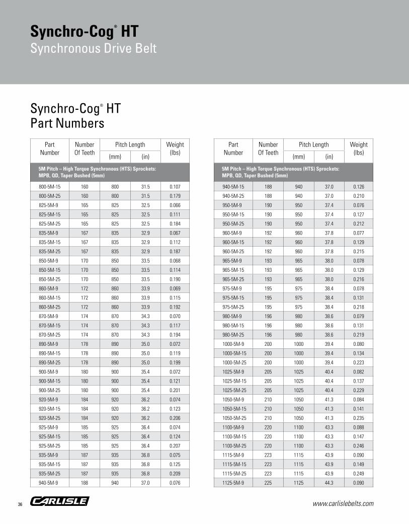
www.carlislebelts.com36
PartNumber
NumberOf Teeth
Pitch Length Weight(lbs)
(mm) (in)
800-5M-15 160 800 31.5 0.107
800-5M-25 160 800 31.5 0.179
825-5M-9 165 825 32.5 0.066
825-5M-15 165 825 32.5 0.111
825-5M-25 165 825 32.5 0.184
835-5M-9 167 835 32.9 0.067
835-5M-15 167 835 32.9 0.112
835-5M-25 167 835 32.9 0.187
850-5M-9 170 850 33.5 0.068
850-5M-15 170 850 33.5 0.114
850-5M-25 170 850 33.5 0.190
860-5M-9 172 860 33.9 0.069
860-5M-15 172 860 33.9 0.115
860-5M-25 172 860 33.9 0.192
870-5M-9 174 870 34.3 0.070
870-5M-15 174 870 34.3 0.117
870-5M-25 174 870 34.3 0.194
890-5M-9 178 890 35.0 0.072
890-5M-15 178 890 35.0 0.119
890-5M-25 178 890 35.0 0.199
900-5M-9 180 900 35.4 0.072
900-5M-15 180 900 35.4 0.121
900-5M-25 180 900 35.4 0.201
920-5M-9 184 920 36.2 0.074
920-5M-15 184 920 36.2 0.123
920-5M-25 184 920 36.2 0.206
925-5M-9 185 925 36.4 0.074
925-5M-15 185 925 36.4 0.124
925-5M-25 185 925 36.4 0.207
935-5M-9 187 935 36.8 0.075
935-5M-15 187 935 36.8 0.125
935-5M-25 187 935 36.8 0.209
940-5M-9 188 940 37.0 0.076
PartNumber
NumberOf Teeth
Pitch Length Weight(lbs)
(mm) (in)
940-5M-15 188 940 37.0 0.126
940-5M-25 188 940 37.0 0.210
950-5M-9 190 950 37.4 0.076
950-5M-15 190 950 37.4 0.127
950-5M-25 190 950 37.4 0.212
960-5M-9 192 960 37.8 0.077
960-5M-15 192 960 37.8 0.129
960-5M-25 192 960 37.8 0.215
965-5M-9 193 965 38.0 0.078
965-5M-15 193 965 38.0 0.129
965-5M-25 193 965 38.0 0.216
975-5M-9 195 975 38.4 0.078
975-5M-15 195 975 38.4 0.131
975-5M-25 195 975 38.4 0.218
980-5M-9 196 980 38.6 0.079
980-5M-15 196 980 38.6 0.131
980-5M-25 196 980 38.6 0.219
1000-5M-9 200 1000 39.4 0.080
1000-5M-15 200 1000 39.4 0.134
1000-5M-25 200 1000 39.4 0.223
1025-5M-9 205 1025 40.4 0.082
1025-5M-15 205 1025 40.4 0.137
1025-5M-25 205 1025 40.4 0.229
1050-5M-9 210 1050 41.3 0.084
1050-5M-15 210 1050 41.3 0.141
1050-5M-25 210 1050 41.3 0.235
1100-5M-9 220 1100 43.3 0.088
1100-5M-15 220 1100 43.3 0.147
1100-5M-25 220 1100 43.3 0.246
1115-5M-9 223 1115 43.9 0.090
1115-5M-15 223 1115 43.9 0.149
1115-5M-25 223 1115 43.9 0.249
1125-5M-9 225 1125 44.3 0.090
Synchro-Cog® HTPart Numbers
Synchro-Cog® HTSynchronous Drive Belt
5M Pitch – High Torque Synchronous (HTS) Sprockets: MPB, QD, Taper Bushed (5mm)
5M Pitch – High Torque Synchronous (HTS) Sprockets: MPB, QD, Taper Bushed (5mm)
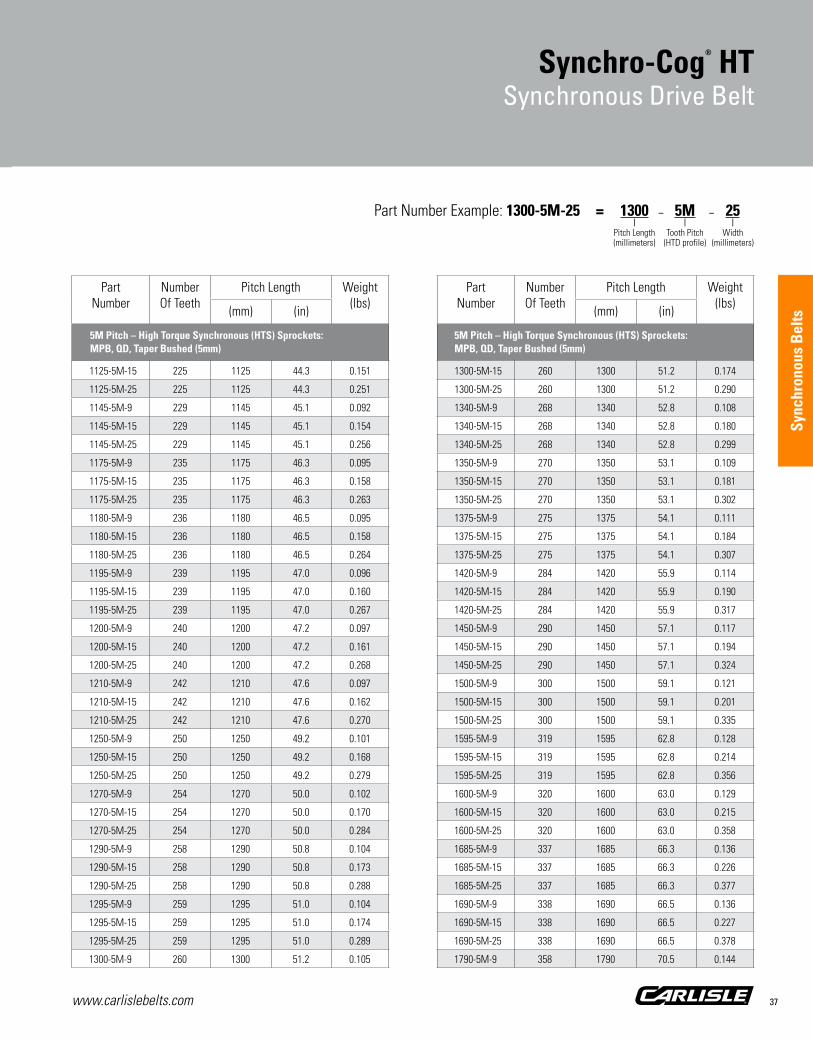
www.carlislebelts.com 37
Sync
hron
ous
Bel
ts
PartNumber
NumberOf Teeth
Pitch Length Weight(lbs)
(mm) (in)
1125-5M-15 225 1125 44.3 0.151
1125-5M-25 225 1125 44.3 0.251
1145-5M-9 229 1145 45.1 0.092
1145-5M-15 229 1145 45.1 0.154
1145-5M-25 229 1145 45.1 0.256
1175-5M-9 235 1175 46.3 0.095
1175-5M-15 235 1175 46.3 0.158
1175-5M-25 235 1175 46.3 0.263
1180-5M-9 236 1180 46.5 0.095
1180-5M-15 236 1180 46.5 0.158
1180-5M-25 236 1180 46.5 0.264
1195-5M-9 239 1195 47.0 0.096
1195-5M-15 239 1195 47.0 0.160
1195-5M-25 239 1195 47.0 0.267
1200-5M-9 240 1200 47.2 0.097
1200-5M-15 240 1200 47.2 0.161
1200-5M-25 240 1200 47.2 0.268
1210-5M-9 242 1210 47.6 0.097
1210-5M-15 242 1210 47.6 0.162
1210-5M-25 242 1210 47.6 0.270
1250-5M-9 250 1250 49.2 0.101
1250-5M-15 250 1250 49.2 0.168
1250-5M-25 250 1250 49.2 0.279
1270-5M-9 254 1270 50.0 0.102
1270-5M-15 254 1270 50.0 0.170
1270-5M-25 254 1270 50.0 0.284
1290-5M-9 258 1290 50.8 0.104
1290-5M-15 258 1290 50.8 0.173
1290-5M-25 258 1290 50.8 0.288
1295-5M-9 259 1295 51.0 0.104
1295-5M-15 259 1295 51.0 0.174
1295-5M-25 259 1295 51.0 0.289
1300-5M-9 260 1300 51.2 0.105
PartNumber
NumberOf Teeth
Pitch Length Weight(lbs)
(mm) (in)
1300-5M-15 260 1300 51.2 0.174
1300-5M-25 260 1300 51.2 0.290
1340-5M-9 268 1340 52.8 0.108
1340-5M-15 268 1340 52.8 0.180
1340-5M-25 268 1340 52.8 0.299
1350-5M-9 270 1350 53.1 0.109
1350-5M-15 270 1350 53.1 0.181
1350-5M-25 270 1350 53.1 0.302
1375-5M-9 275 1375 54.1 0.111
1375-5M-15 275 1375 54.1 0.184
1375-5M-25 275 1375 54.1 0.307
1420-5M-9 284 1420 55.9 0.114
1420-5M-15 284 1420 55.9 0.190
1420-5M-25 284 1420 55.9 0.317
1450-5M-9 290 1450 57.1 0.117
1450-5M-15 290 1450 57.1 0.194
1450-5M-25 290 1450 57.1 0.324
1500-5M-9 300 1500 59.1 0.121
1500-5M-15 300 1500 59.1 0.201
1500-5M-25 300 1500 59.1 0.335
1595-5M-9 319 1595 62.8 0.128
1595-5M-15 319 1595 62.8 0.214
1595-5M-25 319 1595 62.8 0.356
1600-5M-9 320 1600 63.0 0.129
1600-5M-15 320 1600 63.0 0.215
1600-5M-25 320 1600 63.0 0.358
1685-5M-9 337 1685 66.3 0.136
1685-5M-15 337 1685 66.3 0.226
1685-5M-25 337 1685 66.3 0.377
1690-5M-9 338 1690 66.5 0.136
1690-5M-15 338 1690 66.5 0.227
1690-5M-25 338 1690 66.5 0.378
1790-5M-9 358 1790 70.5 0.144
Synchro-Cog® HTSynchronous Drive Belt
Part Number Example: 1300-5M-25 = 1300 – 5M – 25 | | | Pitch Length Tooth Pitch Width (millimeters) (HTD profile) (millimeters)
5M Pitch – High Torque Synchronous (HTS) Sprockets: MPB, QD, Taper Bushed (5mm)
5M Pitch – High Torque Synchronous (HTS) Sprockets: MPB, QD, Taper Bushed (5mm)

www.carlislebelts.com38
PartNumber
NumberOf Teeth
Pitch Length Weight(lbs)
(mm) (in)
1790-5M-15 358 1790 70.5 0.240
1790-5M-25 358 1790 70.5 0.400
1800-5M-9 360 1800 70.9 0.145
1800-5M-15 360 1800 70.9 0.241
1800-5M-25 360 1800 70.9 0.402
1895-5M-9 379 1895 74.6 0.152
1895-5M-15 379 1895 74.6 0.254
1895-5M-25 379 1895 74.6 0.423
2000-5M-9 400 2000 78.7 0.161
2000-5M-15 400 2000 78.7 0.268
2000-5M-25 400 2000 78.7 0.447
2100-5M-9 420 2100 82.7 0.169
2100-5M-15 420 2100 82.7 0.282
2100-5M-25 420 2100 82.7 0.469
2350-5M-9 470 2350 92.5 0.189
2350-5M-15 470 2350 92.5 0.315
2350-5M-25 470 2350 92.5 0.525
2525-5M-9 505 2525 99.4 0.203
2525-5M-15 505 2525 99.4 0.339
2525-5M-25 505 2525 99.4 0.564
2635-5M-9 527 2635 103.7 0.212
2635-5M-15 527 2635 103.7 0.353
2635-5M-25 527 2635 103.7 0.589
4260-5M-9 852 4260 167.7 0.343
4260-5M-15 852 4260 167.7 0.571
4260-5M-25 852 4260 167.7 0.952
320-8M-20 40 320 12.6 0.077
320-8M-30 40 320 12.6 0.116
320-8M-50 40 320 12.6 0.193
320-8M-85 40 320 12.6 0.328
368-8M-20 46 368 14.5 0.089
PartNumber
NumberOf Teeth
Pitch Length Weight(lbs)
(mm) (in)
368-8M-30 46 368 14.5 0.133
368-8M-50 46 368 14.5 0.222
368-8M-85 46 368 14.5 0.378
400-8M-20 50 400 15.7 0.097
400-8M-30 50 400 15.7 0.145
400-8M-50 50 400 15.7 0.242
400-8M-85 50 400 15.7 0.411
408-8M-20 51 408 16.1 0.099
408-8M-30 51 408 16.1 0.148
408-8M-50 51 408 16.1 0.246
408-8M-85 51 408 16.1 0.419
424-8M-20 53 424 16.7 0.102
424-8M-30 53 424 16.7 0.154
424-8M-50 53 424 16.7 0.256
424-8M-85 53 424 16.7 0.435
440-8M-20 55 440 17.3 0.106
440-8M-30 55 440 17.3 0.159
440-8M-50 55 440 17.3 0.266
440-8M-85 55 440 17.3 0.452
448-8M-20 56 448 17.6 0.108
448-8M-30 56 448 17.6 0.162
448-8M-50 56 448 17.6 0.271
448-8M-85 56 448 17.6 0.460
480-8M-20 60 480 18.9 0.116
480-8M-30 60 480 18.9 0.174
480-8M-50 60 480 18.9 0.290
480-8M-85 60 480 18.9 0.493
512-8M-20 64 512 20.2 0.124
512-8M-30 64 512 20.2 0.186
512-8M-50 64 512 20.2 0.309
512-8M-85 64 512 20.2 0.526
520-8M-20 65 520 20.5 0.126
520-8M-30 65 520 20.5 0.188
Synchro-Cog® HTPart Numbers
Synchro-Cog® HTSynchronous Drive Belt
5M Pitch – High Torque Synchronous (HTS) Sprockets: MPB, QD, Taper Bushed (5mm)
8M Pitch – High Torque Synchronous (HTS) Sprockets: MPB, QD, Taper Bushed (8mm)
8M Pitch – High Torque Synchronous (HTS) Sprockets: MPB, QD, Taper Bushed (8mm)

www.carlislebelts.com 39
Sync
hron
ous
Bel
ts
PartNumber
NumberOf Teeth
Pitch Length Weight(lbs)
(mm) (in)
520-8M-50 65 520 20.5 0.314
520-8M-85 65 520 20.5 0.534
536-8M-20 67 536 21.1 0.129
536-8M-30 67 536 21.1 0.194
536-8M-50 67 536 21.1 0.324
536-8M-85 67 536 21.1 0.550
544-8M-20 68 544 21.4 0.131
544-8M-30 68 544 21.4 0.197
544-8M-50 68 544 21.4 0.328
544-8M-85 68 544 21.4 0.558
560-8M-20 70 560 22.0 0.135
560-8M-30 70 560 22.0 0.203
560-8M-50 70 560 22.0 0.338
560-8M-85 70 560 22.0 0.575
568-8M-20 71 568 22.4 0.137
568-8M-30 71 568 22.4 0.206
568-8M-50 71 568 22.4 0.343
568-8M-85 71 568 22.4 0.583
576-8M-20 72 576 22.7 0.139
576-8M-30 72 576 22.7 0.209
576-8M-50 72 576 22.7 0.348
576-8M-85 72 576 22.7 0.591
584-8M-20 73 584 23.0 0.141
584-8M-30 73 584 23.0 0.212
584-8M-50 73 584 23.0 0.353
584-8M-85 73 584 23.0 0.599
592-8M-20 74 592 23.3 0.143
592-8M-30 74 592 23.3 0.214
592-8M-50 74 592 23.3 0.357
592-8M-85 74 592 23.3 0.608
600-8M-20 75 600 23.6 0.145
600-8M-30 75 600 23.6 0.217
600-8M-50 75 600 23.6 0.362
PartNumber
NumberOf Teeth
Pitch Length Weight(lbs)
(mm) (in)
600-8M-85 75 600 23.6 0.616
608-8M-20 76 608 23.9 0.147
608-8M-30 76 608 23.9 0.220
608-8M-50 76 608 23.9 0.367
608-8M-85 76 608 23.9 0.624
624-8M-20 78 624 24.6 0.151
624-8M-30 78 624 24.6 0.226
624-8M-50 78 624 24.6 0.377
624-8M-85 78 624 24.6 0.641
632-8M-20 79 632 24.9 0.153
632-8M-30 79 632 24.9 0.229
632-8M-50 79 632 24.9 0.382
632-8M-85 79 632 24.9 0.649
640-8M-20 80 640 25.2 0.155
640-8M-30 80 640 25.2 0.232
640-8M-50 80 640 25.2 0.386
640-8M-85 80 640 25.2 0.657
648-8M-20 81 648 25.5 0.157
648-8M-30 81 648 25.5 0.235
648-8M-50 81 648 25.5 0.391
648-8M-85 81 648 25.5 0.665
656-8M-20 82 656 25.8 0.158
656-8M-30 82 656 25.8 0.238
656-8M-50 82 656 25.8 0.396
656-8M-85 82 656 25.8 0.673
680-8M-20 85 680 26.8 0.164
680-8M-30 85 680 26.8 0.246
680-8M-50 85 680 26.8 0.411
680-8M-85 85 680 26.8 0.698
688-8M-20 86 688 27.1 0.166
688-8M-30 86 688 27.1 0.249
688-8M-50 86 688 27.1 0.415
688-8M-85 86 688 27.1 0.706
Synchro-Cog® HTSynchronous Drive Belt
Part Number Example: 600-8M-85 = 600 – 8M – 85 | | | Pitch Length Tooth Pitch Width (millimeters) (HTD profile) (millimeters)
8M Pitch – High Torque Synchronous (HTS) Sprockets: MPB, QD, Taper Bushed (8mm)
8M Pitch – High Torque Synchronous (HTS) Sprockets: MPB, QD, Taper Bushed (8mm)

www.carlislebelts.com40
PartNumber
NumberOf Teeth
Pitch Length Weight(lbs)
(mm) (in)
696-8M-20 87 696 27.4 0.168
696-8M-30 87 696 27.4 0.252
696-8M-50 87 696 27.4 0.420
696-8M-85 87 696 27.4 0.714
712-8M-20 89 712 28.0 0.172
712-8M-30 89 712 28.0 0.258
712-8M-50 89 712 28.0 0.430
712-8M-85 89 712 28.0 0.731
720-8M-20 90 720 28.3 0.174
720-8M-30 90 720 28.3 0.261
720-8M-50 90 720 28.3 0.435
720-8M-85 90 720 28.3 0.739
760-8M-20 95 760 29.9 0.184
760-8M-30 95 760 29.9 0.275
760-8M-50 95 760 29.9 0.459
760-8M-85 95 760 29.9 0.780
768-8M-20 96 768 30.2 0.186
768-8M-30 96 768 30.2 0.278
768-8M-50 96 768 30.2 0.464
768-8M-85 96 768 30.2 0.788
776-8M-20 97 776 30.6 0.187
776-8M-30 97 776 30.6 0.281
776-8M-50 97 776 30.6 0.469
776-8M-85 97 776 30.6 0.797
784-8M-20 98 784 30.9 0.189
784-8M-30 98 784 30.9 0.284
784-8M-50 98 784 30.9 0.473
784-8M-85 98 784 30.9 0.805
792-8M-20 99 792 31.2 0.191
792-8M-30 99 792 31.2 0.287
792-8M-50 99 792 31.2 0.478
792-8M-85 99 792 31.2 0.813
800-8M-20 100 800 31.5 0.193
PartNumber
NumberOf Teeth
Pitch Length Weight(lbs)
(mm) (in)
800-8M-30 100 800 31.5 0.290
800-8M-50 100 800 31.5 0.483
800-8M-85 100 800 31.5 0.821
816-8M-20 102 816 32.1 0.197
816-8M-30 102 816 32.1 0.296
816-8M-50 102 816 32.1 0.493
816-8M-85 102 816 32.1 0.838
824-8M-20 103 824 32.4 0.199
824-8M-30 103 824 32.4 0.299
824-8M-50 103 824 32.4 0.498
824-8M-85 103 824 32.4 0.846
840-8M-20 105 840 33.1 0.203
840-8M-30 105 840 33.1 0.304
840-8M-50 105 840 33.1 0.507
840-8M-85 105 840 33.1 0.862
848-8M-20 106 848 33.4 0.205
848-8M-30 106 848 33.4 0.307
848-8M-50 106 848 33.4 0.512
848-8M-85 106 848 33.4 0.870
856-8M-20 107 856 33.7 0.207
856-8M-30 107 856 33.7 0.310
856-8M-50 107 856 33.7 0.517
856-8M-85 107 856 33.7 0.879
864-8M-20 108 864 34.0 0.209
864-8M-30 108 864 34.0 0.313
864-8M-50 108 864 34.0 0.522
864-8M-85 108 864 34.0 0.887
880-8M-20 110 880 34.6 0.213
880-8M-30 110 880 34.6 0.319
880-8M-50 110 880 34.6 0.531
880-8M-85 110 880 34.6 0.903
896-8M-20 112 896 35.3 0.216
896-8M-30 112 896 35.3 0.325
Synchro-Cog® HTPart Numbers
Synchro-Cog® HTSynchronous Drive Belt
8M Pitch – High Torque Synchronous (HTS) Sprockets: MPB, QD, Taper Bushed (8mm)
8M Pitch – High Torque Synchronous (HTS) Sprockets: MPB, QD, Taper Bushed (8mm)

www.carlislebelts.com 41
Sync
hron
ous
Bel
ts
PartNumber
NumberOf Teeth
Pitch Length Weight(lbs)
(mm) (in)
896-8M-50 112 896 35.3 0.541
896-8M-85 112 896 35.3 0.920
912-8M-20 114 912 35.9 0.220
912-8M-30 114 912 35.9 0.330
912-8M-50 114 912 35.9 0.551
912-8M-85 114 912 35.9 0.936
920-8M-20 115 920 36.2 0.222
920-8M-30 115 920 36.2 0.333
920-8M-50 115 920 36.2 0.556
920-8M-85 115 920 36.2 0.944
928-8M-20 116 928 36.5 0.224
928-8M-30 116 928 36.5 0.336
928-8M-50 116 928 36.5 0.560
928-8M-85 116 928 36.5 0.953
936-8M-20 117 936 36.9 0.226
936-8M-30 117 936 36.9 0.339
936-8M-50 117 936 36.9 0.565
936-8M-85 117 936 36.9 0.961
944-8M-20 118 944 37.2 0.228
944-8M-30 118 944 37.2 0.342
944-8M-50 118 944 37.2 0.570
944-8M-85 118 944 37.2 0.969
952-8M-20 119 952 37.5 0.230
952-8M-30 119 952 37.5 0.345
952-8M-50 119 952 37.5 0.575
952-8M-85 119 952 37.5 0.977
960-8M-20 120 960 37.8 0.232
960-8M-30 120 960 37.8 0.348
960-8M-50 120 960 37.8 0.580
960-8M-85 120 960 37.8 0.985
968-8M-20 121 968 38.1 0.234
968-8M-30 121 968 38.1 0.351
968-8M-50 121 968 38.1 0.585
PartNumber
NumberOf Teeth
Pitch Length Weight(lbs)
(mm) (in)
968-8M-85 121 968 38.1 0.994
976-8M-20 122 976 38.4 0.236
976-8M-30 122 976 38.4 0.354
976-8M-50 122 976 38.4 0.589
976-8M-85 122 976 38.4 1.002
1000-8M-20 125 1000 39.4 0.242
1000-8M-30 125 1000 39.4 0.362
1000-8M-50 125 1000 39.4 0.604
1000-8M-85 125 1000 39.4 1.027
1016-8M-20 127 1016 40.0 0.245
1016-8M-30 127 1016 40.0 0.368
1016-8M-50 127 1016 40.0 0.614
1016-8M-85 127 1016 40.0 1.043
1024-8M-20 128 1024 40.3 0.247
1024-8M-30 128 1024 40.3 0.371
1024-8M-50 128 1024 40.3 0.618
1024-8M-85 128 1024 40.3 1.051
1040-8M-20 130 1040 40.9 0.251
1040-8M-30 130 1040 40.9 0.377
1040-8M-50 130 1040 40.9 0.628
1040-8M-85 130 1040 40.9 1.068
1056-8M-20 132 1056 41.6 0.255
1056-8M-30 132 1056 41.6 0.383
1056-8M-50 132 1056 41.6 0.638
1056-8M-85 132 1056 41.6 1.084
1064-8M-20 133 1064 41.9 0.257
1064-8M-30 133 1064 41.9 0.385
1064-8M-50 133 1064 41.9 0.642
1064-8M-85 133 1064 41.9 1.092
1080-8M-20 135 1080 42.5 0.261
1080-8M-30 135 1080 42.5 0.391
1080-8M-50 135 1080 42.5 0.652
1080-8M-85 135 1080 42.5 1.109
Synchro-Cog® HTSynchronous Drive Belt
Part Number Example: 1000-8M-50 = 1000 – 8M – 50 | | | Pitch Length Tooth Pitch Width (millimeters) (HTD profile) (millimeters)
8M Pitch – High Torque Synchronous (HTS) Sprockets: MPB, QD, Taper Bushed (8mm)
8M Pitch – High Torque Synchronous (HTS) Sprockets: MPB, QD, Taper Bushed (8mm)
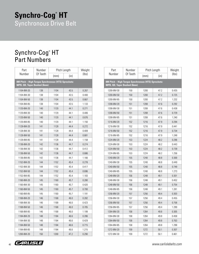
www.carlislebelts.com42
PartNumber
NumberOf Teeth
Pitch Length Weight(lbs)
(mm) (in)
1104-8M-20 138 1104 43.5 0.267
1104-8M-30 138 1104 43.5 0.400
1104-8M-50 138 1104 43.5 0.667
1104-8M-85 138 1104 43.5 1.133
1120-8M-20 140 1120 44.1 0.271
1120-8M-30 140 1120 44.1 0.406
1120-8M-50 140 1120 44.1 0.676
1120-8M-85 140 1120 44.1 1.150
1128-8M-20 141 1128 44.4 0.272
1128-8M-30 141 1128 44.4 0.409
1128-8M-50 141 1128 44.4 0.681
1128-8M-85 141 1128 44.4 1.158
1136-8M-20 142 1136 44.7 0.274
1136-8M-30 142 1136 44.7 0.412
1136-8M-50 142 1136 44.7 0.686
1136-8M-85 142 1136 44.7 1.166
1152-8M-20 144 1152 45.4 0.278
1152-8M-30 144 1152 45.4 0.417
1152-8M-50 144 1152 45.4 0.696
1152-8M-85 144 1152 45.4 1.183
1160-8M-20 145 1160 45.7 0.280
1160-8M-30 145 1160 45.7 0.420
1160-8M-50 145 1160 45.7 0.700
1160-8M-85 145 1160 45.7 1.191
1168-8M-20 146 1168 46.0 0.282
1168-8M-30 146 1168 46.0 0.423
1168-8M-50 146 1168 46.0 0.705
1168-8M-85 146 1168 46.0 1.199
1184-8M-20 148 1184 46.6 0.286
1184-8M-30 148 1184 46.6 0.429
1184-8M-50 148 1184 46.6 0.715
1184-8M-85 148 1184 46.6 1.215
1200-8M-20 150 1200 47.2 0.290
PartNumber
NumberOf Teeth
Pitch Length Weight(lbs)
(mm) (in)
1200-8M-30 150 1200 47.2 0.435
1200-8M-50 150 1200 47.2 0.725
1200-8M-85 150 1200 47.2 1.232
1208-8M-20 151 1208 47.6 0.292
1208-8M-30 151 1208 47.6 0.438
1208-8M-50 151 1208 47.6 0.729
1208-8M-85 151 1208 47.6 1.240
1216-8M-20 152 1216 47.9 0.294
1216-8M-30 152 1216 47.9 0.441
1216-8M-50 152 1216 47.9 0.734
1216-8M-85 152 1216 47.9 1.248
1224-8M-20 153 1224 48.2 0.296
1224-8M-30 153 1224 48.2 0.443
1224-8M-50 153 1224 48.2 0.739
1224-8M-85 153 1224 48.2 1.256
1240-8M-20 155 1240 48.8 0.300
1240-8M-30 155 1240 48.8 0.449
1240-8M-50 155 1240 48.8 0.749
1240-8M-85 155 1240 48.8 1.273
1248-8M-20 156 1248 49.1 0.301
1248-8M-30 156 1248 49.1 0.452
1248-8M-50 156 1248 49.1 0.754
1248-8M-85 156 1248 49.1 1.281
1256-8M-20 157 1256 49.4 0.303
1256-8M-30 157 1256 49.4 0.455
1256-8M-50 157 1256 49.4 0.758
1256-8M-85 157 1256 49.4 1.289
1264-8M-20 158 1264 49.8 0.305
1264-8M-30 158 1264 49.8 0.458
1264-8M-50 158 1264 49.8 0.763
1264-8M-85 158 1264 49.8 1.298
1272-8M-20 159 1272 50.1 0.307
1272-8M-30 159 1272 50.1 0.461
Synchro-Cog® HTPart Numbers
Synchro-Cog® HTSynchronous Drive Belt
8M Pitch – High Torque Synchronous (HTS) Sprockets: MPB, QD, Taper Bushed (8mm)
8M Pitch – High Torque Synchronous (HTS) Sprockets: MPB, QD, Taper Bushed (8mm)

www.carlislebelts.com 43
Sync
hron
ous
Bel
ts
PartNumber
NumberOf Teeth
Pitch Length Weight(lbs)
(mm) (in)
1272-8M-50 159 1272 50.1 0.768
1272-8M-85 159 1272 50.1 1.306
1280-8M-20 160 1280 50.4 0.309
1280-8M-30 160 1280 50.4 0.464
1280-8M-50 160 1280 50.4 0.773
1280-8M-85 160 1280 50.4 1.314
1304-8M-20 163 1304 51.3 0.315
1304-8M-30 163 1304 51.3 0.472
1304-8M-50 163 1304 51.3 0.787
1304-8M-85 163 1304 51.3 1.339
1312-8M-20 164 1312 51.7 0.317
1312-8M-30 164 1312 51.7 0.475
1312-8M-50 164 1312 51.7 0.792
1312-8M-85 164 1312 51.7 1.347
1320-8M-20 165 1320 52.0 0.319
1320-8M-30 165 1320 52.0 0.478
1320-8M-50 165 1320 52.0 0.797
1320-8M-85 165 1320 52.0 1.355
1328-8M-20 166 1328 52.3 0.321
1328-8M-30 166 1328 52.3 0.481
1328-8M-50 166 1328 52.3 0.802
1328-8M-85 166 1328 52.3 1.363
1344-8M-20 168 1344 52.9 0.325
1344-8M-30 168 1344 52.9 0.487
1344-8M-50 168 1344 52.9 0.812
1344-8M-85 168 1344 52.9 1.380
1352-8M-20 169 1352 53.2 0.327
1352-8M-30 169 1352 53.2 0.490
1352-8M-50 169 1352 53.2 0.816
1352-8M-85 169 1352 53.2 1.388
1360-8M-20 170 1360 53.5 0.328
1360-8M-30 170 1360 53.5 0.493
1360-8M-50 170 1360 53.5 0.821
PartNumber
NumberOf Teeth
Pitch Length Weight(lbs)
(mm) (in)
1360-8M-85 170 1360 53.5 1.396
1376-8M-20 172 1376 54.2 0.332
1376-8M-30 172 1376 54.2 0.499
1376-8M-50 172 1376 54.2 0.831
1376-8M-85 172 1376 54.2 1.413
1392-8M-20 174 1392 54.8 0.336
1392-8M-30 174 1392 54.8 0.504
1392-8M-50 174 1392 54.8 0.841
1392-8M-85 174 1392 54.8 1.429
1400-8M-20 175 1400 55.1 0.338
1400-8M-30 175 1400 55.1 0.507
1400-8M-50 175 1400 55.1 0.845
1400-8M-85 175 1400 55.1 1.437
1424-8M-20 178 1424 56.1 0.344
1424-8M-30 178 1424 56.1 0.516
1424-8M-50 178 1424 56.1 0.860
1424-8M-85 178 1424 56.1 1.462
1440-8M-20 180 1440 56.7 0.348
1440-8M-30 180 1440 56.7 0.522
1440-8M-50 180 1440 56.7 0.870
1440-8M-85 180 1440 56.7 1.478
1456-8M-20 182 1456 57.3 0.352
1456-8M-30 182 1456 57.3 0.528
1456-8M-50 182 1456 57.3 0.879
1456-8M-85 182 1456 57.3 1.495
1464-8M-20 183 1464 57.6 0.354
1464-8M-30 183 1464 57.6 0.530
1464-8M-50 183 1464 57.6 0.884
1464-8M-85 183 1464 57.6 1.503
1480-8M-20 185 1480 58.3 0.357
1480-8M-30 185 1480 58.3 0.536
1480-8M-50 185 1480 58.3 0.894
1480-8M-85 185 1480 58.3 1.519
Synchro-Cog® HTSynchronous Drive Belt
Part Number Example: 1400-8M-50 = 1400 – 8M – 50 | | | Pitch Length Tooth Pitch Width (millimeters) (HTD profile) (millimeters)
8M Pitch – High Torque Synchronous (HTS) Sprockets: MPB, QD, Taper Bushed (8mm)
8M Pitch – High Torque Synchronous (HTS) Sprockets: MPB, QD, Taper Bushed (8mm)

www.carlislebelts.com44
PartNumber
NumberOf Teeth
Pitch Length Weight(lbs)
(mm) (in)
1512-8M-20 189 1512 59.5 0.365
1512-8M-30 189 1512 59.5 0.548
1512-8M-50 189 1512 59.5 0.913
1512-8M-85 189 1512 59.5 1.552
1520-8M-20 190 1520 59.8 0.367
1520-8M-30 190 1520 59.8 0.551
1520-8M-50 190 1520 59.8 0.918
1520-8M-85 190 1520 59.8 1.560
1552-8M-20 194 1552 61.1 0.375
1552-8M-30 194 1552 61.1 0.562
1552-8M-50 194 1552 61.1 0.937
1552-8M-85 194 1552 61.1 1.593
1560-8M-20 195 1560 61.4 0.377
1560-8M-30 195 1560 61.4 0.565
1560-8M-50 195 1560 61.4 0.942
1560-8M-85 195 1560 61.4 1.601
1576-8M-20 197 1576 62.0 0.381
1576-8M-30 197 1576 62.0 0.571
1576-8M-50 197 1576 62.0 0.952
1576-8M-85 197 1576 62.0 1.618
1584-8M-20 198 1584 62.4 0.383
1584-8M-30 198 1584 62.4 0.574
1584-8M-50 198 1584 62.4 0.956
1584-8M-85 198 1584 62.4 1.626
1600-8M-20 200 1600 63.0 0.386
1600-8M-30 200 1600 63.0 0.580
1600-8M-50 200 1600 63.0 0.966
1600-8M-85 200 1600 63.0 1.642
1640-8M-20 205 1640 64.6 0.396
1640-8M-30 205 1640 64.6 0.594
1640-8M-50 205 1640 64.6 0.990
1640-8M-85 205 1640 64.6 1.684
1648-8M-20 206 1648 64.9 0.398
PartNumber
NumberOf Teeth
Pitch Length Weight(lbs)
(mm) (in)
1648-8M-30 206 1648 64.9 0.597
1648-8M-50 206 1648 64.9 0.995
1648-8M-85 206 1648 64.9 1.692
1680-8M-20 210 1680 66.1 0.406
1680-8M-30 210 1680 66.1 0.609
1680-8M-50 210 1680 66.1 1.014
1680-8M-85 210 1680 66.1 1.725
1696-8M-20 212 1696 66.8 0.410
1696-8M-30 212 1696 66.8 0.614
1696-8M-50 212 1696 66.8 1.024
1696-8M-85 212 1696 66.8 1.741
1728-8M-20 216 1728 68.0 0.417
1728-8M-30 216 1728 68.0 0.626
1728-8M-50 216 1728 68.0 1.043
1728-8M-85 216 1728 68.0 1.774
1744-8M-20 218 1744 68.7 0.421
1744-8M-30 218 1744 68.7 0.632
1744-8M-50 218 1744 68.7 1.053
1744-8M-85 218 1744 68.7 1.790
1752-8M-20 219 1752 69.0 0.423
1752-8M-30 219 1752 69.0 0.635
1752-8M-50 219 1752 69.0 1.058
1752-8M-85 219 1752 69.0 1.798
1760-8M-20 220 1760 69.3 0.425
1760-8M-30 220 1760 69.3 0.638
1760-8M-50 220 1760 69.3 1.063
1760-8M-85 220 1760 69.3 1.807
1784-8M-20 223 1784 70.2 0.431
1784-8M-30 223 1784 70.2 0.646
1784-8M-50 223 1784 70.2 1.077
1784-8M-85 223 1784 70.2 1.831
1792-8M-20 224 1792 70.6 0.433
1792-8M-30 224 1792 70.6 0.649
Synchro-Cog® HTPart Numbers
Synchro-Cog® HTSynchronous Drive Belt
8M Pitch – High Torque Synchronous (HTS) Sprockets: MPB, QD, Taper Bushed (8mm)
8M Pitch – High Torque Synchronous (HTS) Sprockets: MPB, QD, Taper Bushed (8mm)

www.carlislebelts.com 45
Sync
hron
ous
Bel
ts
PartNumber
NumberOf Teeth
Pitch Length Weight(lbs)
(mm) (in)
1792-8M-50 224 1792 70.6 1.082
1792-8M-85 224 1792 70.6 1.840
1800-8M-20 225 1800 70.9 0.435
1800-8M-30 225 1800 70.9 0.652
1800-8M-50 225 1800 70.9 1.087
1800-8M-85 225 1800 70.9 1.848
1840-8M-20 230 1840 72.4 0.444
1840-8M-30 230 1840 72.4 0.667
1840-8M-50 230 1840 72.4 1.111
1840-8M-85 230 1840 72.4 1.889
1856-8M-20 232 1856 73.1 0.448
1856-8M-30 232 1856 73.1 0.672
1856-8M-50 232 1856 73.1 1.121
1856-8M-85 232 1856 73.1 1.905
1896-8M-20 237 1896 74.6 0.458
1896-8M-30 237 1896 74.6 0.687
1896-8M-50 237 1896 74.6 1.145
1896-8M-85 237 1896 74.6 1.946
1904-8M-20 238 1904 75.0 0.460
1904-8M-30 238 1904 75.0 0.690
1904-8M-50 238 1904 75.0 1.150
1904-8M-85 238 1904 75.0 1.955
1920-8M-20 240 1920 75.6 0.464
1920-8M-30 240 1920 75.6 0.696
1920-8M-50 240 1920 75.6 1.159
1920-8M-85 240 1920 75.6 1.971
1928-8M-20 241 1928 75.9 0.466
1928-8M-30 241 1928 75.9 0.699
1928-8M-50 241 1928 75.9 1.164
1928-8M-85 241 1928 75.9 1.979
1936-8M-20 242 1936 76.2 0.468
1936-8M-30 242 1936 76.2 0.701
1936-8M-50 242 1936 76.2 1.169
PartNumber
NumberOf Teeth
Pitch Length Weight(lbs)
(mm) (in)
1936-8M-85 242 1936 76.2 1.987
1952-8M-20 244 1952 76.9 0.471
1952-8M-30 244 1952 76.9 0.707
1952-8M-50 244 1952 76.9 1.179
1952-8M-85 244 1952 76.9 2.004
1992-8M-20 249 1992 78.4 0.481
1992-8M-30 249 1992 78.4 0.722
1992-8M-50 249 1992 78.4 1.203
1992-8M-85 249 1992 78.4 2.045
2000-8M-20 250 2000 78.7 0.483
2000-8M-30 250 2000 78.7 0.725
2000-8M-50 250 2000 78.7 1.208
2000-8M-85 250 2000 78.7 2.053
2056-8M-20 257 2056 80.9 0.497
2056-8M-30 257 2056 80.9 0.745
2056-8M-50 257 2056 80.9 1.241
2056-8M-85 257 2056 80.9 2.111
2080-8M-20 260 2080 81.9 0.502
2080-8M-30 260 2080 81.9 0.754
2080-8M-50 260 2080 81.9 1.256
2080-8M-85 260 2080 81.9 2.135
2104-8M-20 263 2104 82.8 0.508
2104-8M-30 263 2104 82.8 0.762
2104-8M-50 263 2104 82.8 1.270
2104-8M-85 263 2104 82.8 2.160
2136-8M-20 267 2136 84.1 0.516
2136-8M-30 267 2136 84.1 0.774
2136-8M-50 267 2136 84.1 1.290
2136-8M-85 267 2136 84.1 2.193
2160-8M-20 270 2160 85.0 0.522
2160-8M-30 270 2160 85.0 0.783
2160-8M-50 270 2160 85.0 1.304
2160-8M-85 270 2160 85.0 2.217
Synchro-Cog® HTSynchronous Drive Belt
Part Number Example: 2000-8M-50 = 2000 – 8M – 50 | | | Pitch Length Tooth Pitch Width (millimeters) (HTD profile) (millimeters)
8M Pitch – High Torque Synchronous (HTS) Sprockets: MPB, QD, Taper Bushed (8mm)
8M Pitch – High Torque Synchronous (HTS) Sprockets: MPB, QD, Taper Bushed (8mm)

www.carlislebelts.com46
PartNumber
NumberOf Teeth
Pitch Length Weight(lbs)
(mm) (in)
2208-8M-20 276 2208 86.9 0.533
2208-8M-30 276 2208 86.9 0.800
2208-8M-50 276 2208 86.9 1.333
2208-8M-85 276 2208 86.9 2.267
2240-8M-20 280 2240 88.2 0.541
2240-8M-30 280 2240 88.2 0.812
2240-8M-50 280 2240 88.2 1.353
2240-8M-85 280 2240 88.2 2.299
2272-8M-20 284 2272 89.4 0.549
2272-8M-30 284 2272 89.4 0.823
2272-8M-50 284 2272 89.4 1.372
2272-8M-85 284 2272 89.4 2.332
2304-8M-20 288 2304 90.7 0.557
2304-8M-30 288 2304 90.7 0.835
2304-8M-50 288 2304 90.7 1.391
2304-8M-85 288 2304 90.7 2.365
2328-8M-20 291 2328 91.7 0.562
2328-8M-30 291 2328 91.7 0.843
2328-8M-50 291 2328 91.7 1.406
2328-8M-85 291 2328 91.7 2.390
2392-8M-20 299 2392 94.2 0.578
2392-8M-30 299 2392 94.2 0.867
2392-8M-50 299 2392 94.2 1.444
2392-8M-85 299 2392 94.2 2.455
2400-8M-20 300 2400 94.5 0.580
2400-8M-30 300 2400 94.5 0.870
2400-8M-50 300 2400 94.5 1.449
2400-8M-85 300 2400 94.5 2.464
2504-8M-20 313 2504 98.6 0.605
2504-8M-30 313 2504 98.6 0.907
2504-8M-50 313 2504 98.6 1.512
2504-8M-85 313 2504 98.6 2.570
2584-8M-20 323 2584 101.7 0.624
PartNumber
NumberOf Teeth
Pitch Length Weight(lbs)
(mm) (in)
2584-8M-30 323 2584 101.7 0.936
2584-8M-50 323 2584 101.7 1.560
2584-8M-85 323 2584 101.7 2.653
2600-8M-20 325 2600 102.4 0.628
2600-8M-30 325 2600 102.4 0.942
2600-8M-50 325 2600 102.4 1.570
2600-8M-85 325 2600 102.4 2.669
2656-8M-20 332 2656 104.6 0.642
2656-8M-30 332 2656 104.6 0.962
2656-8M-50 332 2656 104.6 1.604
2656-8M-85 332 2656 104.6 2.726
2736-8M-20 342 2736 107.7 0.661
2736-8M-30 342 2736 107.7 0.991
2736-8M-50 342 2736 107.7 1.652
2736-8M-85 342 2736 107.7 2.809
2800-8M-20 350 2800 110.2 0.676
2800-8M-30 350 2800 110.2 1.014
2800-8M-50 350 2800 110.2 1.691
2800-8M-85 350 2800 110.2 2.874
3048-8M-20 381 3048 120.0 0.736
3048-8M-30 381 3048 120.0 1.104
3048-8M-50 381 3048 120.0 1.841
3048-8M-85 381 3048 120.0 3.129
3120-8M-20 390 3120 122.8 0.754
3120-8M-30 390 3120 122.8 1.130
3120-8M-50 390 3120 122.8 1.884
3120-8M-85 390 3120 122.8 3.203
3168-8M-20 396 3168 124.7 0.765
3168-8M-30 396 3168 124.7 1.148
3168-8M-50 396 3168 124.7 1.913
3168-8M-85 396 3168 124.7 3.252
3200-8M-20 400 3200 126.0 0.773
3200-8M-30 400 3200 126.0 1.159
Synchro-Cog® HTPart Numbers
Synchro-Cog® HTSynchronous Drive Belt
8M Pitch – High Torque Synchronous (HTS) Sprockets: MPB, QD, Taper Bushed (8mm)
8M Pitch – High Torque Synchronous (HTS) Sprockets: MPB, QD, Taper Bushed (8mm)

www.carlislebelts.com 47
Sync
hron
ous
Bel
ts
PartNumber
NumberOf Teeth
Pitch Length Weight(lbs)
(mm) (in)
3200-8M-50 400 3200 126.0 1.932
3200-8M-85 400 3200 126.0 3.285
3280-8M-20 410 3280 129.1 0.792
3280-8M-30 410 3280 129.1 1.188
3280-8M-50 410 3280 129.1 1.981
3280-8M-85 410 3280 129.1 3.367
3400-8M-20 425 3400 133.9 0.821
3400-8M-30 425 3400 133.9 1.232
3400-8M-50 425 3400 133.9 2.053
3400-8M-85 425 3400 133.9 3.490
3600-8M-20 450 3600 141.7 0.870
3600-8M-30 450 3600 141.7 1.304
3600-8M-50 450 3600 141.7 2.174
3600-8M-85 450 3600 141.7 3.696
3824-8M-20 478 3824 150.6 0.924
3824-8M-30 478 3824 150.6 1.385
3824-8M-50 478 3824 150.6 2.309
3824-8M-85 478 3824 150.6 3.925
4000-8M-20 500 4000 157.5 0.966
4000-8M-30 500 4000 157.5 1.449
4000-8M-50 500 4000 157.5 2.415
4000-8M-85 500 4000 157.5 4.106
4400-8M-20 550 4400 173.2 1.063
4400-8M-30 550 4400 173.2 1.594
4400-8M-50 550 4400 173.2 2.657
4400-8M-85 550 4400 173.2 4.517
5120-8M-20 640 5120 201.6 1.237
5120-8M-30 640 5120 201.6 1.855
5120-8M-50 640 5120 201.6 3.092
5120-8M-85 640 5120 201.6 5.256
5576-8M-20 697 5576 219.5 1.347
5576-8M-30 697 5576 219.5 2.020
5576-8M-50 697 5576 219.5 3.367
PartNumber
NumberOf Teeth
Pitch Length Weight(lbs)
(mm) (in)
5576-8M-85 697 5576 219.5 5.724
5600-8M-20 700 5600 220.5 1.353
5600-8M-30 700 5600 220.5 2.029
5600-8M-50 700 5600 220.5 3.382
5600-8M-85 700 5600 220.5 5.749
5960-8M-20 745 5960 234.6 1.440
5960-8M-30 745 5960 234.6 2.159
5960-8M-50 745 5960 234.6 3.599
5960-8M-85 745 5960 234.6 6.118
966-14M-40 69 966 38.0 0.757
966-14M-55 69 966 38.0 1.040
966-14M-85 69 966 38.0 1.608
966-14M-115 69 966 38.0 2.175
966-14M-170 69 966 38.0 3.216
1036-14M-40 74 1036 40.8 0.812
1036-14M-55 74 1036 40.8 1.116
1036-14M-85 74 1036 40.8 1.724
1036-14M-115 74 1036 40.8 2.333
1036-14M-170 74 1036 40.8 3.449
1092-14M-40 78 1092 43.0 0.855
1092-14M-55 78 1092 43.0 1.176
1092-14M-85 78 1092 43.0 1.818
1092-14M-115 78 1092 43.0 2.459
1092-14M-170 78 1092 43.0 3.635
1120-14M-40 80 1120 44.1 0.877
1120-14M-55 80 1120 44.1 1.206
1120-14M-85 80 1120 44.1 1.864
1120-14M-115 80 1120 44.1 2.522
1120-14M-170 80 1120 44.1 3.729
1148-14M-40 82 1148 45.2 0.899
1148-14M-55 82 1148 45.2 1.236
Synchro-Cog® HTSynchronous Drive Belt
Part Number Example: 3200-8M-50 = 3200 – 8M – 50 | | | Pitch Length Tooth Pitch Width (millimeters) (HTD profile) (millimeters)
8M Pitch – High Torque Synchronous (HTS) Sprockets: MPB, QD, Taper Bushed (8mm)
8M Pitch – High Torque Synchronous (HTS) Sprockets: MPB, QD, Taper Bushed (8mm)
14M Pitch – High Torque Synchronous (HTS) Sprockets: MPB, QD, Taper Bushed (14mm)

www.carlislebelts.com48
PartNumber
NumberOf Teeth
Pitch Length Weight(lbs)
(mm) (in)
1148-14M-85 82 1148 45.2 1.911
1148-14M-115 82 1148 45.2 2.585
1148-14M-170 82 1148 45.2 3.822
1190-14M-40 85 1190 46.9 0.932
1190-14M-55 85 1190 46.9 1.282
1190-14M-85 85 1190 46.9 1.981
1190-14M-115 85 1190 46.9 2.680
1190-14M-170 85 1190 46.9 3.962
1246-14M-40 89 1246 49.1 0.976
1246-14M-55 89 1246 49.1 1.342
1246-14M-85 89 1246 49.1 2.074
1246-14M-115 89 1246 49.1 2.806
1246-14M-170 89 1246 49.1 4.148
1260-14M-40 90 1260 49.6 0.987
1260-14M-55 90 1260 49.6 1.357
1260-14M-85 90 1260 49.6 2.097
1260-14M-115 90 1260 49.6 2.838
1260-14M-170 90 1260 49.6 4.195
1316-14M-40 94 1316 51.8 1.031
1316-14M-55 94 1316 51.8 1.417
1316-14M-85 94 1316 51.8 2.191
1316-14M-115 94 1316 51.8 2.964
1316-14M-170 94 1316 51.8 4.381
1344-14M-40 96 1344 52.9 1.053
1344-14M-55 96 1344 52.9 1.448
1344-14M-85 96 1344 52.9 2.237
1344-14M-115 96 1344 52.9 3.027
1344-14M-170 96 1344 52.9 4.474
1400-14M-40 100 1400 55.1 1.097
1400-14M-55 100 1400 55.1 1.508
1400-14M-85 100 1400 55.1 2.330
1400-14M-115 100 1400 55.1 3.153
1400-14M-170 100 1400 55.1 4.661
PartNumber
NumberOf Teeth
Pitch Length Weight(lbs)
(mm) (in)
1442-14M-40 103 1442 56.8 1.130
1442-14M-55 103 1442 56.8 1.553
1442-14M-85 103 1442 56.8 2.400
1442-14M-115 103 1442 56.8 3.247
1442-14M-170 103 1442 56.8 4.800
1456-14M-40 104 1456 57.3 1.140
1456-14M-55 104 1456 57.3 1.568
1456-14M-85 104 1456 57.3 2.424
1456-14M-115 104 1456 57.3 3.279
1456-14M-170 104 1456 57.3 4.847
1470-14M-40 105 1470 57.9 1.151
1470-14M-55 105 1470 57.9 1.583
1470-14M-85 105 1470 57.9 2.447
1470-14M-115 105 1470 57.9 3.310
1470-14M-170 105 1470 57.9 4.894
1540-14M-40 110 1540 60.6 1.206
1540-14M-55 110 1540 60.6 1.659
1540-14M-85 110 1540 60.6 2.563
1540-14M-115 110 1540 60.6 3.468
1540-14M-170 110 1540 60.6 5.127
1568-14M-40 112 1568 61.7 1.228
1568-14M-55 112 1568 61.7 1.689
1568-14M-85 112 1568 61.7 2.610
1568-14M-115 112 1568 61.7 3.531
1568-14M-170 112 1568 61.7 5.220
1610-14M-40 115 1610 63.4 1.261
1610-14M-55 115 1610 63.4 1.734
1610-14M-85 115 1610 63.4 2.680
1610-14M-115 115 1610 63.4 3.626
1610-14M-170 115 1610 63.4 5.360
1652-14M-40 118 1652 65.0 1.294
1652-14M-55 118 1652 65.0 1.779
1652-14M-85 118 1652 65.0 2.750
Synchro-Cog® HTPart Numbers
Synchro-Cog® HTSynchronous Drive Belt
14M Pitch – High Torque Synchronous (HTS) Sprockets: MPB, QD, Taper Bushed (14mm)
14M Pitch – High Torque Synchronous (HTS) Sprockets: MPB, QD, Taper Bushed (14mm)

www.carlislebelts.com 49
Sync
hron
ous
Bel
ts
PartNumber
NumberOf Teeth
Pitch Length Weight(lbs)
(mm) (in)
1652-14M-115 118 1652 65.0 3.720
1652-14M-170 118 1652 65.0 5.500
1750-14M-40 125 1750 68.9 1.371
1750-14M-55 125 1750 68.9 1.885
1750-14M-85 125 1750 68.9 2.913
1750-14M-115 125 1750 68.9 3.941
1750-14M-170 125 1750 68.9 5.826
1764-14M-40 126 1764 69.4 1.382
1764-14M-55 126 1764 69.4 1.900
1764-14M-85 126 1764 69.4 2.936
1764-14M-115 126 1764 69.4 3.973
1764-14M-170 126 1764 69.4 5.872
1778-14M-40 127 1778 70.0 1.393
1778-14M-55 127 1778 70.0 1.915
1778-14M-85 127 1778 70.0 2.960
1778-14M-115 127 1778 70.0 4.004
1778-14M-170 127 1778 70.0 5.919
1792-14M-40 128 1792 70.6 1.404
1792-14M-55 128 1792 70.6 1.930
1792-14M-85 128 1792 70.6 2.983
1792-14M-115 128 1792 70.6 4.036
1792-14M-170 128 1792 70.6 5.966
1806-14M-40 129 1806 71.1 1.415
1806-14M-55 129 1806 71.1 1.945
1806-14M-85 129 1806 71.1 3.006
1806-14M-115 129 1806 71.1 4.067
1806-14M-170 129 1806 71.1 6.012
1820-14M-40 130 1820 71.7 1.426
1820-14M-55 130 1820 71.7 1.960
1820-14M-85 130 1820 71.7 3.029
1820-14M-115 130 1820 71.7 4.099
1820-14M-170 130 1820 71.7 6.059
1890-14M-40 135 1890 74.4 1.480
PartNumber
NumberOf Teeth
Pitch Length Weight(lbs)
(mm) (in)
1890-14M-55 135 1890 74.4 2.036
1890-14M-85 135 1890 74.4 3.146
1890-14M-115 135 1890 74.4 4.256
1890-14M-170 135 1890 74.4 6.292
1932-14M-40 138 1932 76.1 1.513
1932-14M-55 138 1932 76.1 2.081
1932-14M-85 138 1932 76.1 3.216
1932-14M-115 138 1932 76.1 4.351
1932-14M-170 138 1932 76.1 6.432
1960-14M-40 140 1960 77.2 1.535
1960-14M-55 140 1960 77.2 2.111
1960-14M-85 140 1960 77.2 3.262
1960-14M-115 140 1960 77.2 4.414
1960-14M-170 140 1960 77.2 6.525
2100-14M-40 150 2100 82.7 1.645
2100-14M-55 150 2100 82.7 2.262
2100-14M-85 150 2100 82.7 3.495
2100-14M-115 150 2100 82.7 4.729
2100-14M-170 150 2100 82.7 6.991
2240-14M-40 160 2240 88.2 1.755
2240-14M-55 160 2240 88.2 2.413
2240-14M-85 160 2240 88.2 3.729
2240-14M-115 160 2240 88.2 5.044
2240-14M-170 160 2240 88.2 7.457
2310-14M-40 165 2310 90.9 1.809
2310-14M-55 165 2310 90.9 2.488
2310-14M-85 165 2310 90.9 3.845
2310-14M-115 165 2310 90.9 5.202
2310-14M-170 165 2310 90.9 7.690
2450-14M-40 175 2450 96.5 1.919
2450-14M-55 175 2450 96.5 2.639
2450-14M-85 175 2450 96.5 4.078
2450-14M-115 175 2450 96.5 5.517
Synchro-Cog® HTSynchronous Drive Belt
Part Number Example: 2100-14M-40 = 2100 – 14M – 40 | | | Pitch Length Tooth Pitch Width (millimeters) (HTD profile) (millimeters)
14M Pitch – High Torque Synchronous (HTS) Sprockets: MPB, QD, Taper Bushed (14mm)
14M Pitch – High Torque Synchronous (HTS) Sprockets: MPB, QD, Taper Bushed (14mm)

www.carlislebelts.com50
PartNumber
NumberOf Teeth
Pitch Length Weight(lbs)
(mm) (in)
2450-14M-170 175 2450 96.5 8.156
2590-14M-40 185 2590 102.0 2.029
2590-14M-55 185 2590 102.0 2.790
2590-14M-85 185 2590 102.0 4.311
2590-14M-115 185 2590 102.0 5.833
2590-14M-170 185 2590 102.0 8.622
2660-14M-40 190 2660 104.7 2.084
2660-14M-55 190 2660 104.7 2.865
2660-14M-85 190 2660 104.7 4.428
2660-14M-115 190 2660 104.7 5.990
2660-14M-170 190 2660 104.7 8.855
2800-14M-40 200 2800 110.2 2.193
2800-14M-55 200 2800 110.2 3.016
2800-14M-85 200 2800 110.2 4.661
2800-14M-115 200 2800 110.2 6.306
2800-14M-170 200 2800 110.2 9.321
3108-14M-40 222 3108 122.4 2.435
3108-14M-55 222 3108 122.4 3.347
3108-14M-85 222 3108 122.4 5.173
3108-14M-115 222 3108 122.4 6.999
3108-14M-170 222 3108 122.4 10.347
3150-14M-40 225 3150 124.0 2.467
3150-14M-55 225 3150 124.0 3.393
3150-14M-85 225 3150 124.0 5.243
3150-14M-115 225 3150 124.0 7.094
3150-14M-170 225 3150 124.0 10.486
3304-14M-40 236 3304 130.1 2.588
3304-14M-55 236 3304 130.1 3.559
3304-14M-85 236 3304 130.1 5.500
3304-14M-115 236 3304 130.1 7.441
3304-14M-170 236 3304 130.1 10.999
3360-14M-40 240 3360 132.3 2.632
3360-14M-55 240 3360 132.3 3.619
PartNumber
NumberOf Teeth
Pitch Length Weight(lbs)
(mm) (in)
3360-14M-85 240 3360 132.3 5.593
3360-14M-115 240 3360 132.3 7.567
3360-14M-170 240 3360 132.3 11.186
3500-14M-40 250 3500 137.8 2.742
3500-14M-55 250 3500 137.8 3.770
3500-14M-85 250 3500 137.8 5.826
3500-14M-115 250 3500 137.8 7.882
3500-14M-170 250 3500 137.8 11.652
3668-14M-40 262 3668 144.4 2.873
3668-14M-55 262 3668 144.4 3.951
3668-14M-85 262 3668 144.4 6.105
3668-14M-115 262 3668 144.4 8.260
3668-14M-170 262 3668 144.4 12.211
3850-14M-40 275 3850 151.6 3.016
3850-14M-55 275 3850 151.6 4.147
3850-14M-85 275 3850 151.6 6.408
3850-14M-115 275 3850 151.6 8.670
3850-14M-170 275 3850 151.6 12.817
4326-14M-40 309 4326 170.3 3.389
4326-14M-55 309 4326 170.3 4.659
4326-14M-85 309 4326 170.3 7.201
4326-14M-115 309 4326 170.3 9.742
4326-14M-170 309 4326 170.3 14.401
4536-14M-40 324 4536 178.6 3.553
4536-14M-55 324 4536 178.6 4.885
4536-14M-85 324 4536 178.6 7.550
4536-14M-115 324 4536 178.6 10.215
4536-14M-170 324 4536 178.6 15.101
4578-14M-40 327 4578 180.2 3.586
4578-14M-55 327 4578 180.2 4.931
4578-14M-85 327 4578 180.2 7.620
4578-14M-115 327 4578 180.2 10.310
4578-14M-170 327 4578 180.2 15.240
Synchro-Cog® HTPart Numbers
Synchro-Cog® HTSynchronous Drive Belt
14M Pitch – High Torque Synchronous (HTS) Sprockets: MPB, QD, Taper Bushed (14mm)
14M Pitch – High Torque Synchronous (HTS) Sprockets: MPB, QD, Taper Bushed (14mm)

www.carlislebelts.com 51
Sync
hron
ous
Bel
ts
PartNumber
NumberOf Teeth
Pitch Length Weight(lbs)
(mm) (in)
4956-14M-40 354 4956 195.1 3.882
4956-14M-55 354 4956 195.1 5.338
4956-14M-85 354 4956 195.1 8.249
4956-14M-115 354 4956 195.1 11.161
4956-14M-170 354 4956 195.1 16.499
5320-14M-40 380 5320 209.4 4.167
5320-14M-55 380 5320 209.4 5.730
5320-14M-85 380 5320 209.4 8.855
5320-14M-115 380 5320 209.4 11.981
5320-14M-170 380 5320 209.4 17.710
5740-14M-40 410 5740 226.0 4.496
5740-14M-55 410 5740 226.0 6.182
5740-14M-85 410 5740 226.0 9.554
5740-14M-115 410 5740 226.0 12.926
5740-14M-170 410 5740 226.0 19.109
6160-14M-40 440 6160 242.5 4.825
6160-14M-55 440 6160 242.5 6.635
6160-14M-85 440 6160 242.5 10.253
6160-14M-115 440 6160 242.5 13.872
6160-14M-170 440 6160 242.5 20.507
6860-14M-40 490 6860 270.1 5.373
6860-14M-55 490 6860 270.1 7.389
6860-14M-85 490 6860 270.1 11.419
6860-14M-115 490 6860 270.1 15.449
6860-14M-170 490 6860 270.1 22.837
Synchro-Cog® HTSynchronous Drive Belt
Part Number Example: 3500-14M-55 = 3500 – 14M – 55 | | | Pitch Length Tooth Pitch Width (millimeters) (HTD profile) (millimeters)
14M Pitch – High Torque Synchronous (HTS) Sprockets: MPB, QD, Taper Bushed (14mm)

www.carlislebelts.com52
Synchro-Cog® HTSleeves
Timken maintains inventory of most Carlisle® sleeve sizes. Non-stock sizes will be indicated by an asterisk following the part number. Contact customer service for availability. Minimum order quantity and/or extended lead times may apply.Occasional production inconsistencies which may render a portion of the sleeve unusable can be present as a normal part of the production process.Each sleeve is inspected to ensure that it contains 90% or more usable product. A full width sleeve with less than 10% unusable product is considered acceptable.
■■ Full factory width sleeves ■■ All sleeves will have the edges trimmed before shipment ■■ Cut sleeves cannot be accepted for return ■■ All weights are approximate
PartNumber
Sleeve Width(mm)
Sleeve Weight(lbs)
144-3M-100SL 100 0.078
150-3M-160SL 160 0.130
159-3M-200SL 200 0.172
168-3M-200SL 200 0.182
177-3M-200SL 200 0.192
180-3M-200SL 200 0.195
186-3M-160SL 160 0.161
189-3M-160SL 160 0.164
192-3M-160SL 160 0.166
201-3M-200SL 200 0.218
207-3M-200SL 200 0.224
210-3M-200SL 200 0.227
213-3M-200SL 200 0.231
222-3M-200SL 200 0.240
225-3M-200SL 200 0.244
228-3M-200SL 200 0.247
234-3M-200SL 200 0.253
240-3M-200SL 200 0.260
252-3M-450SL 450 0.614
255-3M-450SL 450 0.621
264-3M-450SL 450 0.643
267-3M-450SL 450 0.650
276-3M-450SL 450 0.672
285-3M-450SL 450 0.694
300-3M-450SL 450 0.731
312-3M-450SL 450 0.760
318-3M-450SL 450 0.775
324-3M-450SL 450 0.789
330-3M-450SL 450 0.804
339-3M-450SL 450 0.826
357-3M-450SL 450 0.870
360-3M-450SL 450 0.877
363-3M-450SL 450 0.884
Synchro-Cog® HT SleevePart Numbers
3M Pitch – High Torque Synchronous (HTS) Sprockets: MPB, QD, Taper Bushed (3mm)

Sync
hron
ous
Bel
ts
www.carlislebelts.com 53
Synchro-Cog® HTSleeves
PartNumber
Sleeve Width(mm)
Sleeve Weight(lbs)
144-3M-100SL 100 0.078
150-3M-160SL 160 0.130
159-3M-200SL 200 0.172
168-3M-200SL 200 0.182
177-3M-200SL 200 0.192
180-3M-200SL 200 0.195
186-3M-160SL 160 0.161
189-3M-160SL 160 0.164
192-3M-160SL 160 0.166
201-3M-200SL 200 0.218
207-3M-200SL 200 0.224
210-3M-200SL 200 0.227
213-3M-200SL 200 0.231
222-3M-200SL 200 0.240
225-3M-200SL 200 0.244
228-3M-200SL 200 0.247
234-3M-200SL 200 0.253
240-3M-200SL 200 0.260
252-3M-450SL 450 0.614
255-3M-450SL 450 0.621
264-3M-450SL 450 0.643
267-3M-450SL 450 0.650
276-3M-450SL 450 0.672
285-3M-450SL 450 0.694
300-3M-450SL 450 0.731
312-3M-450SL 450 0.760
318-3M-450SL 450 0.775
324-3M-450SL 450 0.789
330-3M-450SL 450 0.804
339-3M-450SL 450 0.826
357-3M-450SL 450 0.870
360-3M-450SL 450 0.877
363-3M-450SL 450 0.884
PartNumber
Sleeve Width(mm)
Sleeve Weight(lbs)
375-3M-450SL 450 0.913
384-3M-450SL 450 0.935
390-3M-450SL 450 0.950
405-3M-450SL 450 0.987
420-3M-450SL 450 1.023
447-3M-450SL 450 1.089
456-3M-450SL 450 1.111
474-3M-450SL 450 1.155
483-3M-450SL 450 1.177
495-3M-450SL 450 1.206
501-3M-450SL 450 1.220
513-3M-450SL 450 1.250
522-3M-450SL 450 1.272
531-3M-450SL 450 1.293
564-3M-200SL 200 0.611
570-3M-450SL 450 1.388
582-3M-200SL 200 0.630
600-3M-450SL 450 1.462
633-3M-450SL 450 1.542
711-3M-450SL 450 1.732
735-3M-450SL 450 1.790
750-3M-450SL 450 1.827
804-3M-450SL 450 1.959
1026-3M-450SL 450 2.499
1401-3M-200SL 200 1.517
180-5M-200SL 200 0.322
200-5M-200SL 200 0.358
210-5M-200SL 200 0.375
215-5M-200SL 200 0.384
225-5M-200SL 200 0.402
230-5M-450SL 450 0.925
PartNumber
Sleeve Width(mm)
Sleeve Weight(lbs)
235-5M-200SL 200 0.420
245-5M-450SL 450 0.985
250-5M-450SL 450 1.005
255-5M-200SL 200 0.456
260-5M-450SL 450 1.046
265-5M-450SL 450 1.066
270-5M-450SL 450 1.086
275-5M-450SL 450 1.106
280-5M-450SL 450 1.126
285-5M-450SL 450 1.146
290-5M-450SL 450 1.166
295-5M-450SL 450 1.186
300-5M-450SL 450 1.207
305-5M-450SL 450 1.227
310-5M-450SL 450 1.247
320-5M-450SL 450 1.287
325-5M-450SL 450 1.307
330-5M-450SL 450 1.327
340-5M-450SL 450 1.367
345-5M-450SL 450 1.388
350-5M-450SL 450 1.408
360-5M-450SL 450 1.448
365-5M-450SL 450 1.468
370-5M-450SL 450 1.488
375-5M-450SL 450 1.508
380-5M-450SL 450 1.528
385-5M-450SL 450 1.548
390-5M-450SL 450 1.569
395-5M-450SL 450 1.589
400-5M-450SL 450 1.609
405-5M-450SL 450 1.629
410-5M-450SL 450 1.649
420-5M-450SL 450 1.689
Part Number Example: 375-3M-450SL = 375 – 3M – 450 SL | | | | Pitch Length Tooth Pitch Width Sleeve (millimeters) (HTD profile) (millimeters)
3M Pitch – High Torque Synchronous (HTS) Sprockets: MPB, QD, Taper Bushed (3mm)
5M Pitch – High Torque Synchronous (HTS) Sprockets:MPB, QD, Taper Bushed (5mm)
5M Pitch – High Torque Synchronous (HTS) Sprockets:MPB, QD, Taper Bushed (5mm)

www.carlislebelts.com54
PartNumber
Sleeve Width(mm)
Sleeve Weight(lbs)
425-5M-450SL 450 1.709
430-5M-450SL 450 1.729
435-5M-450SL 450 1.750
440-5M-450SL 450 1.770
445-5M-450SL 450 1.790
450-5M-450SL 450 1.810
460-5M-450SL 450 1.850
465-5M-450SL 450 1.870
470-5M-450SL 450 1.890
475-5M-450SL 450 1.910
480-5M-450SL 450 1.931
490-5M-450SL 450 1.971
500-5M-450SL 450 2.011
505-5M-450SL 450 2.031
510-5M-450SL 450 2.051
520-5M-450SL 450 2.091
525-5M-450SL 450 2.112
530-5M-450SL 450 2.132
535-5M-450SL 450 2.152
540-5M-450SL 450 2.172
550-5M-450SL 450 2.212
560-5M-450SL 450 2.252
565-5M-200SL 200 1.010
570-5M-450SL 450 2.293
575-5M-450SL 450 2.313
580-5M-450SL 450 2.333
585-5M-450SL 450 2.353
590-5M-450SL 450 2.373
600-5M-450SL 450 2.413
605-5M-450SL 450 2.433
610-5M-450SL 450 2.453
615-5M-450SL 450 2.474
620-5M-450SL 450 2.494
PartNumber
Sleeve Width(mm)
Sleeve Weight(lbs)
625-5M-450SL 450 2.514
635-5M-450SL 450 2.554
640-5M-450SL 450 2.574
645-5M-450SL 450 2.594
650-5M-450SL 450 2.614
655-5M-450SL 450 2.634
665-5M-450SL 450 2.675
670-5M-450SL 450 2.695
675-5M-450SL 450 2.715
685-5M-450SL 450 2.755
690-5M-450SL 450 2.775
695-5M-450SL 450 2.795
700-5M-450SL 450 2.815
710-5M-450SL 450 2.856
720-5M-450SL 450 2.896
725-5M-450SL 450 2.916
740-5M-450SL 450 2.976
750-5M-450SL 450 3.016
755-5M-450SL 450 3.000
770-5M-450SL 450 3.097
775-5M-450SL 450 3.117
780-5M-450SL 450 3.137
790-5M-450SL 450 3.177
800-5M-450SL 450 3.218
825-5M-450SL 450 3.318
835-5M-450SL 450 3.358
850-5M-450SL 450 3.419
860-5M-450SL 450 3.459
870-5M-450SL 450 3.499
890-5M-450SL 450 3.580
900-5M-450SL 450 3.620
920-5M-450SL 450 3.700
925-5M-450SL 450 3.720
Synchro-Cog® HT SleevePart Numbers
Synchro-Cog® HTSleeves
5M Pitch – High Torque Synchronous (HTS) Sprockets:MPB, QD, Taper Bushed (5mm)
5M Pitch – High Torque Synchronous (HTS) Sprockets:MPB, QD, Taper Bushed (5mm)

www.carlislebelts.com 55
Sync
hron
ous
Bel
ts
PartNumber
Sleeve Width(mm)
Sleeve Weight(lbs)
935-5M-450SL 450 3.761
940-5M-450SL 450 3.781
950-5M-450SL 450 3.821
960-5M-450SL 450 3.861
965-5M-450SL 450 3.881
975-5M-450SL 450 3.921
980-5M-450SL 450 3.942
1000-5M-450SL 450 4.022
1025-5M-450SL 450 4.123
1050-5M-450SL 450 4.223
1100-5M-450SL 450 4.424
1115-5M-450SL 450 4.485
1125-5M-450SL 450 4.525
1145-5M-450SL 450 4.605
1175-5M-450SL 450 4.726
1180-5M-450SL 450 4.746
1195-5M-450SL 450 4.806
1200-5M-450SL 450 4.826
1210-5M-450SL 450 4.867
1250-5M-450SL 450 5.027
1270-5M-450SL 450 5.108
1290-5M-450SL 450 5.188
1295-5M-450SL 450 5.208
1300-5M-450SL 450 5.229
1340-5M-450SL 450 5.389
1350-5M-450SL 450 5.430
1375-5M-450SL 450 5.530
1420-5M-450SL 450 5.711
1450-5M-450SL 450 5.832
1500-5M-450SL 450 6.033
1595-5M-450SL 450 6.415
1600-5M-450SL 450 6.435
1685-5M-450SL 450 6.777
PartNumber
Sleeve Width(mm)
Sleeve Weight(lbs)
1690-5M-450SL 450 6.797
1790-5M-450SL 450 7.199
1800-5M-450SL 450 7.240
1895-5M-440SL 440 7.452
2000-5M-450SL 450 8.044
2100-5M-450SL 450 8.446
2350-5M-450SL 450 9.452
2525-5M-450SL 450 10.156
2635-5M-450SL 450 10.598
4260-5M-440SL 440 16.753
320-8M-450SL 450 1.739
368-8M-450SL 450 2.000
400-8M-450SL 450 2.174
408-8M-450SL 450 2.217
424-8M-450SL 450 2.304
440-8M-450SL 450 2.391
448-8M-450SL 450 2.435
480-8M-450SL 450 2.609
512-8M-450SL 450 2.783
520-8M-450SL 450 2.826
536-8M-450SL 450 2.913
544-8M-450SL 450 2.956
560-8M-450SL 450 3.043
568-8M-450SL 450 3.087
576-8M-450SL 450 3.130
584-8M-450SL 450 3.174
592-8M-450SL 450 3.217
600-8M-450SL 450 3.261
608-8M-450SL 450 3.304
624-8M-450SL 450 3.391
632-8M-450SL 450 3.435
Synchro-Cog® HTSleeves
5M Pitch – High Torque Synchronous (HTS) Sprockets:MPB, QD, Taper Bushed (5mm)
5M Pitch – High Torque Synchronous (HTS) Sprockets:MPB, QD, Taper Bushed (5mm)
8M Pitch – High Torque Synchronous (HTS) Sprockets: MPB, QD, Taper Bushed (8mm)
Part Number Example: 1000-5M-450SL = 1000 – 5M – 450 SL | | | | Pitch Length Tooth Pitch Width Sleeve (millimeters) (HTD profile) (millimeters)

www.carlislebelts.com56
PartNumber
Sleeve Width(mm)
Sleeve Weight(lbs)
640-8M-450SL 450 3.478
648-8M-450SL 450 3.522
656-8M-450SL 450 3.565
680-8M-450SL 450 3.696
688-8M-450SL 450 3.739
696-8M-450SL 450 3.782
712-8M-450SL 450 3.869
720-8M-450SL 450 3.913
760-8M-450SL 450 4.130
768-8M-450SL 450 4.174
776-8M-450SL 450 4.217
784-8M-450SL 450 4.261
792-8M-450SL 450 4.304
800-8M-450SL 450 4.348
816-8M-450SL 450 4.435
824-8M-450SL 450 4.478
840-8M-450SL 450 4.565
848-8M-450SL 450 4.609
856-8M-450SL 450 4.652
864-8M-450SL 450 4.695
880-8M-450SL 450 4.782
896-8M-450SL 450 4.869
912-8M-450SL 450 4.956
920-8M-450SL 450 5.000
928-8M-450SL 450 5.043
936-8M-450SL 450 5.087
944-8M-450SL 450 5.130
952-8M-450SL 450 5.174
960-8M-450SL 450 5.217
968-8M-450SL 450 5.261
976-8M-450SL 450 5.304
1000-8M-450SL 450 5.435
1016-8M-450SL 450 5.522
PartNumber
Sleeve Width(mm)
Sleeve Weight(lbs)
1024-8M-450SL 450 5.565
1040-8M-450SL 450 5.652
1056-8M-450SL 450 5.739
1064-8M-450SL 450 5.782
1080-8M-450SL 450 5.869
1104-8M-450SL 450 6.000
1120-8M-450SL 450 6.087
1128-8M-450SL 450 6.130
1136-8M-450SL 450 6.174
1152-8M-450SL 450 6.261
1160-8M-450SL 450 6.304
1168-8M-450SL 450 6.348
1184-8M-450SL 450 6.435
1200-8M-450SL 450 6.521
1208-8M-450SL 450 6.565
1216-8M-450SL 450 6.608
1224-8M-450SL 450 6.652
1240-8M-450SL 450 6.739
1248-8M-450SL 450 6.782
1256-8M-450SL 450 6.826
1264-8M-450SL 450 6.869
1272-8M-450SL 450 6.913
1280-8M-450SL 450 6.956
1304-8M-450SL 450 7.087
1312-8M-450SL 450 7.130
1320-8M-450SL 450 7.174
1328-8M-450SL 450 7.217
1344-8M-450SL 450 7.304
1352-8M-450SL 450 7.348
1360-8M-450SL 450 7.391
1376-8M-450SL 450 7.478
1392-8M-450SL 450 7.565
1400-8M-440SL 440 7.439
Synchro-Cog® HT SleevePart Numbers
Synchro-Cog® HTSleeves
8M Pitch – High Torque Synchronous Sprockets – MPB, QD, Taper Bushed (5mm, 8mm, 14mm, 20mm)
8M Pitch – High Torque Synchronous Sprockets – MPB, QD, Taper Bushed (5mm, 8mm, 14mm, 20mm)
8M Pitch – High Torque Synchronous (HTS) Sprockets: MPB, QD, Taper Bushed (8mm)
8M Pitch – High Torque Synchronous (HTS) Sprockets: MPB, QD, Taper Bushed (8mm)
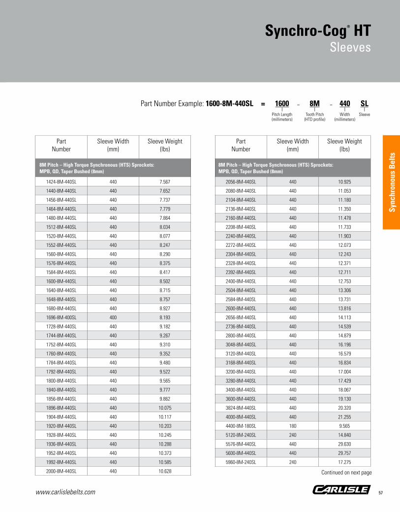
www.carlislebelts.com 57
Sync
hron
ous
Bel
ts
PartNumber
Sleeve Width(mm)
Sleeve Weight(lbs)
1424-8M-440SL 440 7.567
1440-8M-440SL 440 7.652
1456-8M-440SL 440 7.737
1464-8M-440SL 440 7.779
1480-8M-440SL 440 7.864
1512-8M-440SL 440 8.034
1520-8M-440SL 440 8.077
1552-8M-440SL 440 8.247
1560-8M-440SL 440 8.290
1576-8M-440SL 440 8.375
1584-8M-440SL 440 8.417
1600-8M-440SL 440 8.502
1640-8M-440SL 440 8.715
1648-8M-440SL 440 8.757
1680-8M-440SL 440 8.927
1696-8M-400SL 400 8.193
1728-8M-440SL 440 9.182
1744-8M-440SL 440 9.267
1752-8M-440SL 440 9.310
1760-8M-440SL 440 9.352
1784-8M-440SL 440 9.480
1792-8M-440SL 440 9.522
1800-8M-440SL 440 9.565
1840-8M-440SL 440 9.777
1856-8M-440SL 440 9.862
1896-8M-440SL 440 10.075
1904-8M-440SL 440 10.117
1920-8M-440SL 440 10.203
1928-8M-440SL 440 10.245
1936-8M-440SL 440 10.288
1952-8M-440SL 440 10.373
1992-8M-440SL 440 10.585
2000-8M-440SL 440 10.628
PartNumber
Sleeve Width(mm)
Sleeve Weight(lbs)
2056-8M-440SL 440 10.925
2080-8M-440SL 440 11.053
2104-8M-440SL 440 11.180
2136-8M-440SL 440 11.350
2160-8M-440SL 440 11.478
2208-8M-440SL 440 11.733
2240-8M-440SL 440 11.903
2272-8M-440SL 440 12.073
2304-8M-440SL 440 12.243
2328-8M-440SL 440 12.371
2392-8M-440SL 440 12.711
2400-8M-440SL 440 12.753
2504-8M-440SL 440 13.306
2584-8M-440SL 440 13.731
2600-8M-440SL 440 13.816
2656-8M-440SL 440 14.113
2736-8M-440SL 440 14.539
2800-8M-440SL 440 14.879
3048-8M-440SL 440 16.196
3120-8M-440SL 440 16.579
3168-8M-440SL 440 16.834
3200-8M-440SL 440 17.004
3280-8M-440SL 440 17.429
3400-8M-440SL 440 18.067
3600-8M-440SL 440 19.130
3824-8M-440SL 440 20.320
4000-8M-440SL 440 21.255
4400-8M-180SL 180 9.565
5120-8M-240SL 240 14.840
5576-8M-440SL 440 29.630
5600-8M-440SL 440 29.757
5960-8M-240SL 240 17.275
Synchro-Cog® HTSleeves
8M Pitch – High Torque Synchronous Sprockets – MPB, QD, Taper Bushed (5mm, 8mm, 14mm, 20mm)
14M Pitch – High Torque Synchronous Sprockets – MPB, QD, Taper Bushed (5mm, 8mm, 14mm, 20mm)
8M Pitch – High Torque Synchronous (HTS) Sprockets: MPB, QD, Taper Bushed (8mm)
8M Pitch – High Torque Synchronous (HTS) Sprockets: MPB, QD, Taper Bushed (8mm)
Part Number Example: 1600-8M-440SL = 1600 – 8M – 440 SL | | | | Pitch Length Tooth Pitch Width Sleeve (millimeters) (HTD profile) (millimeters)
Continued on next page

www.carlislebelts.com58
PartNumber
Sleeve Width(mm)
Sleeve Weight(lbs)
966-14M-440SL 440 8.323
1036-14M-440SL 440 8.927
1092-14M-440SL 440 9.409
1120-14M-440SL 440 9.650
1148-14M-440SL 440 9.892
1190-14M-440SL 440 10.253
1246-14M-440SL 440 10.736
1260-14M-440SL 440 10.857
1316-14M-440SL 440 11.339
1344-14M-440SL 440 11.580
1400-14M-440SL 440 12.063
1442-14M-440SL 440 12.425
1456-14M-440SL 440 12.545
1470-14M-440SL 440 12.666
1540-14M-440SL 440 13.269
1568-14M-440SL 440 13.510
1610-14M-440SL 440 13.872
1652-14M-440SL 440 14.234
1750-14M-440SL 440 15.079
1764-14M-440SL 440 15.199
1778-14M-440SL 440 15.320
1792-14M-440SL 440 15.440
1806-14M-440SL 440 15.561
1820-14M-440SL 440 15.682
1890-14M-440SL 440 16.285
1932-14M-440SL 440 16.647
1960-14M-440SL 440 16.888
2100-14M-440SL 440 18.094
2240-14M-440SL 440 19.301
2310-14M-440SL 440 19.904
2450-14M-440SL 440 21.110
2590-14M-440SL 440 22.316
2660-14M-440SL 440 22.919
PartNumber
Sleeve Width(mm)
Sleeve Weight(lbs)
2800-14M-440SL 440 24.126
3108-14M-430SL 430 26.171
3150-14M-430SL 430 26.525
3304-14M-430SL 430 27.821
3360-14M-430SL 430 28.293
3500-14M-430SL 430 29.472
3668-14M-430SL 430 30.886
3850-14M-430SL 430 32.419
4326-14M-350SL 350 29.650
4536-14M-430SL 430 38.195
4578-14M-230SL 230 20.619
4956-14M-430SL 430 41.732
5320-14M-430SL 430 44.797
5740-14M-430SL 430 48.334
6160-14M-430SL 430 51.870
6860-14M-430SL 430 57.765
Synchro-Cog® HTSleeve Part Numbers
Synchro-Cog® HTSleeves
14M Pitch – High Torque Synchronous Sprockets – MPB, QD, Taper Bushed (5mm, 8mm, 14mm, 20mm)
14M Pitch – High Torque Synchronous (HTS) Sprockets: MPB, QD, Taper Bushed (14mm)
14M Pitch – High Torque Synchronous (HTS) Sprockets: MPB, QD, Taper Bushed (14mm)
Part Number Example: 1400-14M-440SL = 1400 – 14M – 440 SL | | | | Pitch Length Tooth Pitch Width Sleeve (millimeters) (HTD profile) (millimeters)

Sync
hron
ous
Bel
ts
www.carlislebelts.com 59
Superior performance
Smaller, more compact system
Reduced drive weight and space
100% load capacity on both sides
Applications: Printing presses Mixers Agitators Machine tools Robotics Sewing machines Vending machines & More
Dual SynchronousSynchronous Drive Belt
1 Molded Tooth Construction
Provides greater shear resistance and load capacity.
2 RPP® ProfileTooth design allows for smoother,quieter operation.
3 Load Capacity100% on both sides of belt.
Recommended Sprockets:High Torque Synchronous Sprockets – MPB, QD, Taper Bushed (8mm, 14mm)
2
3
1

www.carlislebelts.com60
Dual Synchronous Synchronous Drive Belt
www.carlislebelts.com60
The Dual Synchronous Belt yields proven performance in a double sided design providing maintenance-free synchronization from both sides of the belt.
Molded teeth provide excellent shear resistance and resistance to tooth jump.
The manufacturing process allows for equal load capacity on both sides of the belt, a feature not found in many dual sided belts on the market.
Achieve greater drive design flexibility and efficiency with the Dual Synchronous Belt.
Choose Dual Synchronous Belts for a compact, efficient, quiet, and smoother running drive.
Proven performance from both sides of the belt for greater flexibility and efficiency in your drive design.

www.carlislebelts.com 61
Sync
hron
ous
Bel
ts
Dual SynchronousPart Numbers
Dual SynchronousSynchronous Drive Belt
PartNumber
NumberOf Teeth
Pitch Length Weight(lbs)
(mm) (in)
D720-8M-20 90 720 28.00 0.23
D720-8M-30 90 720 28.00 0.35
D720-8M-50 90 720 28.00 0.58
D720-8M-85 90 720 28.00 0.98
D800-8M-20 100 800 32.00 0.26
D800-8M-30 100 800 32.00 0.38
D800-8M-50 100 800 32.00 0.64
D800-8M-85 100 800 32.00 1.09
D840-8M-20 105 840 33.00 0.27
D840-8M-30 105 840 33.00 0.40
D840-8M-50 105 840 33.00 0.67
D840-8M-85 105 840 33.00 1.14
D880-8M-20 110 880 35.00 0.28
D880-8M-30 110 880 35.00 0.42
D880-8M-50 110 880 35.00 0.71
D880-8M-85 110 880 35.00 1.20
D920-8M-20 115 920 36.20 0.29
D920-8M-30 115 920 36.20 0.44
D920-8M-50 115 920 36.20 0.74
D920-8M-85 115 920 36.20 1.25
D960-8M-20 120 960 38.00 0.31
D960-8M-30 120 960 38.00 0.46
D960-8M-50 120 960 38.00 0.77
D960-8M-85 120 960 38.00 1.31
D1040-8M-20 130 1040 41.00 0.33
D1040-8M-30 130 1040 41.00 0.50
D1040-8M-50 130 1040 41.00 0.83
D1040-8M-85 130 1040 41.00 1.42
D1120-8M-20 140 1120 44.00 0.36
D1120-8M-30 140 1120 44.00 0.54
D1120-8M-50 140 1120 44.00 0.90
D1120-8M-85 140 1120 44.00 1.53
D1200-8M-20 150 1200 47.00 0.38
PartNumber
NumberOf Teeth
Pitch Length Weight(lbs)
(mm) (in)
D1200-8M-30 150 1200 47.00 0.58
D1200-8M-50 150 1200 47.00 0.96
D1200-8M-85 150 1200 47.00 1.63
D1280-8M-20 160 1280 50.00 0.41
D1280-8M-30 160 1280 50.00 0.62
D1280-8M-50 160 1280 50.00 1.03
D1280-8M-85 160 1280 50.00 1.74
D1440-8M-20 180 1440 57.00 0.46
D1440-8M-30 180 1440 57.00 0.69
D1440-8M-50 180 1440 57.00 1.15
D1440-8M-85 180 1440 57.00 1.96
D1600-8M-20 200 1600 63.00 0.51
D1600-8M-30 200 1600 63.00 0.77
D1600-8M-50 200 1600 63.00 1.28
D1600-8M-85 200 1600 63.00 2.18
D1760-8M-20 220 1760 69.00 0.56
D1760-8M-30 220 1760 69.00 0.85
D1760-8M-50 220 1760 69.00 1.41
D1760-8M-85 220 1760 69.00 2.40
D1800-8M-20 225 1800 71.00 0.58
D1800-8M-30 225 1800 71.00 0.87
D1800-8M-50 225 1800 71.00 1.44
D1800-8M-85 225 1800 71.00 2.45
D2000-8M-20 250 2000 79.00 0.64
D2000-8M-30 250 2000 79.00 0.96
D2000-8M-50 250 2000 79.00 1.60
D2000-8M-85 250 2000 79.00 2.72
D2200-8M-20 275 2200 86.60 0.71
D2200-8M-30 275 2200 86.60 1.06
D2200-8M-50 275 2200 86.60 1.76
D2200-8M-85 275 2200 86.60 3.00
D2400-8M-20 300 2400 94.00 0.77
D2400-8M-30 300 2400 94.00 1.15
8M Pitch – High Torque Synchronous (HTS) Sprockets: MPB, QD, Taper Bushed (8mm)
8M Pitch – High Torque Synchronous (HTS) Sprockets: MPB, QD, Taper Bushed (8mm)
Part Number Example: D1200-8M-50 = D 1200 – 8M – 50 | | | | Dual Sided Pitch Length Tooth Pitch Width Construction (millimeters) (RPP tooth profile) (millimeters)

www.carlislebelts.com62
PartNumber
NumberOf Teeth
Pitch Length Weight(lbs)
(mm) (in)
D2400-8M-50 300 2400 94.00 1.92
D2400-8M-85 300 2400 94.00 3.27
D2600-8M-20 325 2600 102.00 0.83
D2600-8M-30 325 2600 102.00 1.25
D2600-8M-50 325 2600 102.00 2.08
D2600-8M-85 325 2600 102.00 3.54
D2800-8M-20 350 2800 110.00 0.90
D2800-8M-30 350 2800 110.00 1.35
D2800-8M-50 350 2800 110.00 2.24
D2800-8M-85 350 2800 110.00 3.81
D3048-8M-20 381 3048 120.00 0.98
D3048-8M-30 381 3048 120.00 1.47
D3048-8M-50 381 3048 120.00 2.44
D3048-8M-85 381 3048 120.00 4.15
D3280-8M-20 410 3280 129.00 1.05
D3280-8M-30 410 3280 129.00 1.58
D3280-8M-50 410 3280 129.00 2.63
D3280-8M-85 410 3280 129.00 4.47
D3600-8M-20 450 3600 142.00 1.15
D3600-8M-30 450 3600 142.00 1.73
D3600-8M-50 450 3600 142.00 2.89
D3600-8M-85 450 3600 142.00 4.90
D4400-8M-20 550 4400 173.00 1.41
D4400-8M-30 550 4400 173.00 2.12
D4400-8M-50 550 4400 173.00 3.53
D4400-8M-85 550 4400 173.00 5.99
D966-14M-115 69 966 38.00 2.86
D966-14M-170 69 966 38.00 4.22
D966-14M-40 69 966 38.00 0.99
D966-14M-55 69 966 38.00 1.37
D966-14M-85 69 966 38.00 2.11
PartNumber
NumberOf Teeth
Pitch Length Weight(lbs)
(mm) (in)
D1190-14M-115 85 1190 46.90 3.52
D1190-14M-170 85 1190 46.90 5.20
D1190-14M-40 85 1190 46.90 1.22
D1190-14M-55 85 1190 46.90 1.68
D1190-14M-85 85 1190 46.90 2.60
D1400-14M-115 100 1400 55.00 4.14
D1400-14M-170 100 1400 55.00 6.12
D1400-14M-40 100 1400 55.00 1.44
D1400-14M-55 100 1400 55.00 1.98
D1400-14M-85 100 1400 55.00 3.06
D1610-14M-115 115 1610 63.00 4.76
D1610-14M-170 115 1610 63.00 7.04
D1610-14M-40 115 1610 63.00 1.66
D1610-14M-55 115 1610 63.00 2.28
D1610-14M-85 115 1610 63.00 3.52
D1778-14M-115 127 1778 70.00 5.26
D1778-14M-170 127 1778 70.00 7.77
D1778-14M-40 127 1778 70.00 1.83
D1778-14M-55 127 1778 70.00 2.51
D1778-14M-85 127 1778 70.00 3.88
D1890-14M-115 135 1890 74.00 5.59
D1890-14M-170 135 1890 74.00 8.26
D1890-14M-40 135 1890 74.00 1.94
D1890-14M-55 135 1890 74.00 2.67
D1890-14M-85 135 1890 74.00 4.13
D2100-14M-115 150 2100 83.00 6.21
D2100-14M-170 150 2100 83.00 9.18
D2100-14M-40 150 2100 83.00 2.16
D2100-14M-55 150 2100 83.00 2.97
D2100-14M-85 150 2100 83.00 4.59
D2310-14M-115 165 2310 91.00 6.83
D2310-14M-170 165 2310 91.00 10.09
D2310-14M-40 165 2310 91.00 2.38
Dual SynchronousPart Numbers
Dual SynchronousSynchronous Drive Belt
8M Pitch – High Torque Synchronous (HTS) Sprockets: MPB, QD, Taper Bushed (8mm)
14M Pitch – High Torque Synchronous Sprockets: MPB, QD, Taper Bushed (14mm)
14M Pitch – High Torque Synchronous (HTS) Sprockets: MPB, QD, Taper Bushed (14mm)

www.carlislebelts.com 63
Sync
hron
ous
Bel
ts
PartNumber
NumberOf Teeth
Pitch Length Weight(lbs)
(mm) (in)
D2310-14M-55 165 2310 91.00 3.27
D2310-14M-85 165 2310 91.00 5.05
D2450-14M-115 175 2450 96.00 7.24
D2450-14M-170 175 2450 96.00 10.71
D2450-14M-40 175 2450 96.00 2.52
D2450-14M-55 175 2450 96.00 3.46
D2450-14M-85 175 2450 96.00 5.35
D2590-14M-115 185 2590 102.00 7.66
D2590-14M-170 185 2590 102.00 11.32
D2590-14M-40 185 2590 102.00 2.66
D2590-14M-55 185 2590 102.00 3.66
D2590-14M-85 185 2590 102.00 5.66
D2800-14M-115 200 2800 110.00 8.28
D2800-14M-170 200 3150 110.00 12.24
D2800-14M-40 200 2800 110.00 2.88
D2800-14M-55 200 2800 110.00 3.96
D2800-14M-85 200 2800 110.00 6.12
D3150-14M-115 225 3150 124.00 9.31
D3150-14M-170 225 3360 124.00 13.76
D3150-14M-40 225 3150 124.00 3.24
D3150-14M-55 225 3150 124.00 4.45
D3150-14M-85 225 3150 124.00 6.88
D3360-14M-115 240 3360 132.00 9.93
D3360-14M-170 240 3360 132.00 14.68
D3360-14M-40 240 3360 132.00 3.45
D3360-14M-55 240 3360 132.00 4.75
D3360-14M-85 240 3360 132.00 7.34
D3500-14M-115 250 3500 138.00 10.35
D3500-14M-170 250 3500 138.00 15.29
D3500-14M-40 250 3500 138.00 3.60
D3500-14M-55 250 3500 138.00 4.95
D3500-14M-85 250 3500 138.00 7.65
D3850-14M-115 275 3850 152.00 11.38
PartNumber
NumberOf Teeth
Pitch Length Weight(lbs)
(mm) (in)
D3850-14M-170 275 3850 152.00 16.82
D3850-14M-40 275 3850 152.00 3.96
D3850-14M-55 275 3850 152.00 5.44
D3850-14M-85 275 3850 152.00 8.41
D4326-14M-115 309 4326 170.00 12.79
D4326-14M-170 309 4326 170.00 18.90
D4326-14M-40 309 4326 170.00 4.45
D4326-14M-55 309 4326 170.00 6.12
D4326-14M-85 309 4326 170.00 9.45
D4578-14M-115 327 4578 180.00 13.53
D4578-14M-170 327 4578 180.00 20.01
D4578-14M-40 327 4578 180.00 0.47
D4578-14M-55 327 4578 180.00 6.47
D4578-14M-85 327 4578 180.00 10.00
D4956-14M-115 354 4956 195.00 14.65
D4956-14M-170 354 4956 195.00 21.66
D4956-14M-40 354 4956 195.00 5.10
D4956-14M-55 354 4956 195.00 7.01
D4956-14M-85 354 4956 195.00 10.83
Dual SynchronousSynchronous Drive Belt
Part Number Example: D2400-8M-50 = D 2400 – 8M – 50 | | | | Dual Sided Cog Pitch Length Tooth Pitch Width Construction (millimeters) (RPP tooth profile) (millimeters)
14M Pitch – High Torque Synchronous (HTS) Sprockets: MPB, QD, Taper Bushed (14mm)
14M Pitch – High Torque Synchronous (HTS) Sprockets: MPB, QD, Taper Bushed (14mm)

www.carlislebelts.com64
Dual SynchronousSleeves
PartNumber
Sleeve Width(mm)
Sleeve Weight(lbs)
D720-8M-150SL 150 1.73
D800-8M-150SL 150 1.92
D840-8M-150SL 150 2.02
D880-8M-150SL 150 2.12
D920-8M-150SL 150 2.21
D960-8M-215SL 215 3.31
D1040-8M-215SL 215 3.58
D1120-8M-215SL 215 3.86
D1200-8M-215SL 215 4.14
D1224-8M-150SL 150 4.22
D1280-8M-215SL 215 4.41
D1440-8M-215SL 215 4.96
D1600-8M-215SL 215 5.51
D1760-8M-215SL 215 6.07
D1800-8M-215SL 215 6.20
D2000-8M-215SL 215 6.89
D2200-8M-215SL 215 7.58
D2400-8M-215SL 215 8.27
D2600-8M-215SL 215 8.96
D2800-8M-215SL 215 9.65
D3048-8M-215SL 215 10.50
D3280-8M-215SL 215 11.30
D3600-8M-215SL 215 12.41
D4400-8M-215SL 215 15.16
Dual Synchronous SleevePart Numbers
8M Pitch – High Torque Synchronous (HTS) Sprockets:MPB, QD, Taper Bushed (8mm)
Timken maintains inventory of most Carlisle® sleeve sizes. Non-stock sizes will be indicated by an asterisk following the part number. Contact customer service for availability. Minimum order quantity and/or extended lead times may apply.Occasional production inconsistencies which may render a portion of the sleeve unusable can be present as a normal part of the production process.Each sleeve is inspected to ensure that it contains 90% or more usable product. A full width sleeve with less than 10% unusable product is considered acceptable.
■■ Full factory width sleeves ■■ All sleeves will have the edges trimmed before shipment ■■ Cut sleeves cannot be accepted for return ■■ All weights are approximate

www.carlislebelts.com 65
Sync
hron
ous
Bel
ts
PartNumber
Sleeve Width(mm)
Sleeve Weight(lbs)
D966-14M-170SL 170 4.22
D1190-14M-170SL 170 5.20
D1400-14M-215SL 215 7.74
D1610-14M-215SL 215 8.90
D1778-14M-215SL 215 9.83
D1890-14M-215SL 215 10.45
D2100-14M-215SL 215 11.61
D2310-14M-215SL 215 12.77
D2450-14M-215SL 215 13.54
D2590-14M-215SL 215 14.31
D2800-14M-215SL 215 15.47
D3150-14M-215SL 215 17.41
D3360-14M-215SL 215 18.57
D3500-14M-215SL 215 19.34
D3850-14M-215SL 215 21.28
D4326-14M-215SL 215 23.91
D4578-14M-215SL 215 25.30
D4956-14M-215SL 215 27.39
14M Pitch – High Torque Synchronous (HTS) Sprockets:MPB, QD, Taper Bushed ( 14mm)
Dual SynchronousSleeves
Part Number Example: D1200-8M-215SL = D – 1200 8M – 215 SL | | | | Dual Sided Cog Pitch Length Tooth Pitch Width Sleeve Construction (millimeters) (RPP tooth profile) (millimeters)

www.carlislebelts.com66
Synchro-Cog® Timing BeltSynchronous Drive Belt

Sync
hron
ous
Bel
ts
www.carlislebelts.com 67
Trapezoidal tooth profile
Perfect synchronization between driver and driven units
Low maintenance
Long life
Clean and quiet
Applications: Machine tools Sewing machines Packaging equipment Vending machines Food processing equipment & More
Synchro-Cog® Timing BeltSynchronous Drive Belt
1 Tensile CordSpecially treated to provide strength, added flex life and resistance to stretching.
2 Molded TeethShear resistant. Designed to assure smooth, positive meshing with the sprocket.
3 Tooth FabricProvides maximum flexibility and wear resistance for extended belt life.
Recommended Pulleys:Timing Pulleys – MPB, QD, Taper Bushed (XL, L, H, XH)
3
2
1

www.carlislebelts.com68
Synchro-Cog® TimingSynchronous Drive Belt
www.carlislebelts.com68
The first synchronous belts had a trapezoidal tooth profile and are often called timing belts. Synchro-Cog® timing belts are an excellent choice for energy efficient, low maintenance performance on positive drive applications.
Synchro-Cog provides a wide range of load capacities and speeds. Belts are oil, heat, and abrasion resistant. No lubrication is required so you can enjoy clean, maintenance free performance.
Synchro-Cog is ideal for use in positioning applications or on inaccessible drives where maintenance is difficult. Synchro-Cog eliminates lubrication and re-tensioning, and provides a long service life.
Synchro-Cog trapezoidal timing belts are available in the following pitches:
XL = Extra Light (0.200” pitch)
L = Light (0.375” pitch)
H = Heavy (0.500” pitch)
XH = Extra Heavy (0.875” pitch)
XXH = Double Extra Heavy (1.250” pitch)
The Synchro-Cog® Timing Belt has a trapezoidal tooth profile for applications where synchronization between the driving and driven units is required.
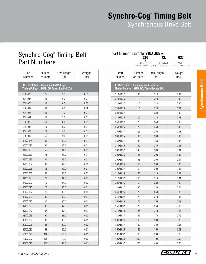
www.carlislebelts.com 69
Sync
hron
ous
Bel
ts
Synchro-Cog® Timing BeltPart Numbers
Synchro-Cog® Timing BeltSynchronous Drive Belt
Part Number
Number of Teeth
Pitch Length (in)
Weight (lbs)
XL (1/5”) Pitch – Recommended Pulleys: Timing Pulleys – MPB, QD, Taper Bushed (XL)
50XL025 25 5.0 0.01
50XL037 25 5.0 0.01
60XL025 30 6.0 0.05
60XL037 30 6.0 0.08
70XL025 35 7.0 0.01
70XL037 35 7.0 0.01
80XL025 40 8.0 0.01
80XL037 40 8.0 0.01
90XL025 45 9.0 0.01
90XL037 45 9.0 0.01
100XL025 50 10.0 0.01
100XL037 50 10.0 0.01
110XL025 55 11.0 0.01
110XL037 55 11.0 0.01
120XL025 60 12.0 0.01
120XL037 60 12.0 0.02
130XL025 65 13.0 0.01
130XL037 65 13.0 0.02
140XL025 70 14.0 0.01
140XL037 70 14.0 0.02
150XL025 75 15.0 0.01
150XL037 75 15.0 0.02
160XL025 80 16.0 0.01
160XL037 80 16.0 0.02
170XL025 85 17.0 0.02
170XL037 85 17.0 0.02
180XL025 90 18.0 0.02
180XL037 90 18.0 0.02
190XL025 95 19.0 0.02
190XL037 95 19.0 0.03
200XL025 100 20.0 0.02
200XL037 100 20.0 0.03
210XL025 105 21.0 0.02
Part Number
Number of Teeth
Pitch Length (in)
Weight (lbs)
XL (1/5”) Pitch – Recommended Pulleys: Timing Pulleys – MPB, QD, Taper Bushed (XL)
210XL037 105 21.0 0.03
220XL025 110 22.0 0.02
220XL037 110 22.0 0.00
230XL025 115 23.0 0.02
230XL037 115 23.0 0.03
240XL025 120 24.0 0.02
240XL037 120 24.0 0.03
250XL025 125 25.0 0.02
250XL037 125 25.0 0.03
260XL025 130 26.0 0.02
260XL037 130 26.0 0.03
280XL025 140 28.0 0.03
280XL037 140 28.0 0.04
290XL025 145 29.0 0.03
290XL037 145 29.0 0.04
300XL025 150 30.0 0.03
300XL037 150 30.0 0.04
310XL025 155 31.0 0.03
310XL037 155 31.0 0.04
330XL025 165 33.0 0.03
330XL037 165 33.0 0.04
340XL025 170 34.0 0.03
340XL037 170 34.0 0.04
350XL025 175 35.0 0.03
350XL037 175 35.0 0.05
370XL025 185 37.0 0.03
370XL037 185 37.0 0.05
380XL025 190 38.0 0.03
380XL037 190 38.0 0.05
390XL025 195 39.0 0.03
390XL037 195 39.0 0.05
400XL025 200 40.0 0.04
400XL037 200 40.0 0.05
Part Number Example: 210XL037 = 210 XL 037 | | | Pitch Length Tooth Pitch Width (inches in tenths: 21.0”) (inches) (inches in tenths: 0.37”)

www.carlislebelts.com70
Part Number
Number of Teeth
Pitch Length (in)
Weight (lbs)
XL (1/5”) Pitch – Recommended Pulleys: Timing Pulleys – MPB, QD, Taper Bushed (XL)
420XL025 210 42.0 0.04
420XL037 210 42.0 0.06
450XL025 225 45.0 0.04
450XL037 225 45.0 0.06
460XL025 230 46.0 0.04
460XL037 230 46.0 0.06
480XL025 240 48.0 0.10
480XL037 240 48.0 0.06
570XL025 285 57.0 0.05
570XL037 285 57.0 0.08
630XL025 315 63.0 0.06
630XL037 315 63.0 0.08
L (3/8”) Pitch – Recommended Pulleys: Timing Pulleys – MPB, QD, Taper Bushed (L)
124L050 33 12.4 0.03
124L075 33 12.4 0.05
124L100 33 12.4 0.06
135L050 36 13.5 0.03
135L075 36 13.5 0.05
135L100 36 13.5 0.07
150L050 40 15.0 0.04
150L075 40 15.0 0.06
150L100 40 15.0 0.08
165L050 44 16.5 0.04
165L075 44 16.5 0.06
165L100 44 16.5 0.08
187L050 50 18.8 0.05
187L075 50 18.8 0.07
187L100 50 18.8 0.09
195L050 52 19.5 0.05
195L075 52 19.5 0.07
195L100 52 19.5 0.10
210L050 56 21.0 0.05
Part Number
Number of Teeth
Pitch Length (in)
Weight (lbs)
XL (1/5”) Pitch – Recommended Pulleys: Timing Pulleys – MPB, QD, Taper Bushed (XL)
210L075 56 21.0 0.08
210L100 56 21.0 0.11
225L050 60 22.5 0.06
225L075 60 22.5 0.09
225L100 60 22.5 0.11
240L050 64 24.0 0.06
240L075 64 24.0 0.09
240L100 64 24.0 0.12
255L050 68 25.5 0.06
255L075 68 25.5 0.10
255L100 68 25.5 0.13
270L050 72 27.0 0.07
270L075 72 27.0 0.10
270L100 72 27.0 0.14
285L050 76 28.5 0.07
285L075 76 28.5 0.11
285L100 76 28.5 0.14
300L050 80 30.0 0.08
300L075 80 30.0 0.11
300L100 80 30.0 0.15
315L050 84 31.5 0.08
315L075 84 31.5 0.12
315L100 84 31.5 0.16
322L050 86 32.3 0.08
322L075 86 32.3 0.12
322L100 86 32.3 0.16
345L050 92 34.5 0.09
345L075 92 34.5 0.13
345L100 92 34.5 0.17
367L050 98 36.8 0.09
367L075 98 36.8 0.14
367L100 98 36.8 0.19
390L050 104 39.0 0.10
Synchro-Cog® Timing BeltPart Numbers
Synchro-Cog® Timing BeltSynchronous Drive Belt
L (3/8”) Pitch – Recommended Pulleys: Timing Pulleys – MPB, QD, Taper Bushed (L)

www.carlislebelts.com 71
Sync
hron
ous
Bel
ts
Part Number
Number of Teeth
Pitch Length (in)
Weight (lbs)
XL (1/5”) Pitch – Recommended Pulleys: Timing Pulleys – MPB, QD, Taper Bushed (XL)
390L075 104 39.0 0.15
390L100 104 39.0 0.20
420L050 112 42.0 0.11
420L075 112 42.0 0.16
420L100 112 42.0 0.21
450L050 120 45.0 0.11
450L075 120 45.0 0.17
450L100 120 45.0 0.23
480L050 128 48.0 0.12
480L075 128 48.0 0.18
480L100 128 48.0 0.24
510L050 136 51.0 0.13
510L075 136 51.0 0.19
510L100 136 51.0 0.26
540L050 144 54.0 0.14
540L075 144 54.0 0.20
540L100 144 54.0 0.27
600L050 160 60.0 0.15
600L075 160 60.0 0.23
600L100 160 60.0 0.30
660L050 176 66.0 0.15
660L075 176 66.0 0.25
660L100 176 66.0 0.33
817L050 218 81.8 0.21
817L075 218 81.8 0.31
817L100 218 81.8 0.41
900L050 240 90.0 0.23
900L075 240 90.0 0.34
900L100 240 90.0 0.46
H (1/2”) Pitch – Recommended Pulleys: Timing Pulleys – MPB, QD, Taper Bushed (H)
210H075 42 21.0 0.10
210H100 42 21.0 0.14
Part Number
Number of Teeth
Pitch Length (in)
Weight (lbs)
XL (1/5”) Pitch – Recommended Pulleys: Timing Pulleys – MPB, QD, Taper Bushed (XL)
210H150 42 21.0 0.21
210H200 42 21.0 0.28
210H300 42 21.0 0.42
220H075 44 22.0 0.11
220H100 44 22.0 0.15
220H150 44 22.0 0.22
220H200 44 22.0 0.29
220H300 44 22.0 0.44
230H075 46 23.0 0.11
230H100 46 23.0 0.15
230H150 46 23.0 0.23
230H200 46 23.0 0.31
230H300 46 23.0 0.46
240H075 48 24.0 0.12
240H100 48 24.0 0.16
240H150 48 24.0 0.24
240H200 48 24.0 0.32
240H300 48 24.0 0.48
270H075 54 27.0 0.13
270H100 54 27.0 0.18
270H150 54 27.0 0.27
270H200 54 27.0 0.36
270H300 54 27.0 0.54
300H075 60 30.0 0.15
300H100 60 30.0 0.20
300H150 60 30.0 0.30
300H200 60 30.0 0.40
300H300 60 30.0 0.60
320H075 64 32.0 0.16
320H100 64 32.0 0.21
320H150 64 32.0 0.32
320H200 64 32.0 0.42
320H300 64 32.0 0.64
Synchro-Cog® Timing BeltSynchronous Drive Belt
Part Number Example: 300H100 = 300 H 100 | | | Pitch Length Tooth Pitch Width (inches in tenths: 30.0”) (inches) (inches in tenths: 1.00”)
L (3/8”) Pitch – Recommended Pulleys: Timing Pulleys – MPB, QD, Taper Bushed (L)
H (1/2”) Pitch – Recommended Pulleys: Timing Pulleys – MPB, QD, Taper Bushed (H)

www.carlislebelts.com72
Part Number
Number of Teeth
Pitch Length (in)
Weight (lbs)
XL (1/5”) Pitch – Recommended Pulleys: Timing Pulleys – MPB, QD, Taper Bushed (XL)
330H075 66 33.0 0.16
330H100 66 33.0 0.22
330H150 66 33.0 0.33
330H200 66 33.0 0.44
330H300 66 33.0 0.66
340H075 68 34.0 0.17
340H100 68 34.0 0.23
340H150 68 34.0 0.34
340H200 68 34.0 0.45
340H300 68 34.0 0.68
350H075 70 35.0 0.17
350H100 70 35.0 0.23
350H150 70 35.0 0.35
350H200 70 35.0 0.46
350H300 70 35.0 0.70
360H075 72 36.0 0.18
360H100 72 36.0 0.24
360H150 72 36.0 0.36
360H200 72 36.0 0.48
360H300 72 36.0 0.72
370H075 74 37.0 0.18
370H100 74 37.0 0.25
370H150 74 37.0 0.37
370H200 74 37.0 0.49
370H300 74 37.0 0.74
390H075 78 39.0 0.19
390H100 78 39.0 0.26
390H150 78 39.0 0.39
390H200 78 39.0 0.52
390H300 78 39.0 0.78
400H075 80 40.0 0.20
400H100 80 40.0 0.27
400H150 80 40.0 0.40
Part Number
Number of Teeth
Pitch Length (in)
Weight (lbs)
XL (1/5”) Pitch – Recommended Pulleys: Timing Pulleys – MPB, QD, Taper Bushed (XL)
400H200 80 40.0 0.53
400H300 80 40.0 0.80
410H075 82 41.0 0.20
410H100 82 41.0 0.27
410H150 82 41.0 0.41
410H200 82 41.0 0.54
410H300 82 41.0 0.82
420H075 84 42.0 0.21
420H100 84 42.0 0.28
420H150 84 42.0 0.42
420H200 84 42.0 0.56
420H300 84 42.0 0.84
450H075 90 45.0 0.22
450H100 90 45.0 0.30
450H150 90 45.0 0.45
450H200 90 45.0 0.60
450H300 90 45.0 0.90
480H075 96 48.0 0.24
480H100 96 48.0 0.32
480H150 96 48.0 0.48
480H200 96 48.0 0.64
480H300 96 48.0 0.96
490H075 98 49.0 0.24
490H100 98 49.0 0.33
490H150 98 49.0 0.49
490H200 98 49.0 0.65
490H300 98 49.0 0.98
510H075 102 51.0 0.25
510H100 102 51.0 0.34
510H150 102 51.0 0.51
510H200 102 51.0 0.68
510H300 102 51.0 1.02
540H075 108 54.0 0.27
Synchro-Cog® Timing BeltPart Numbers
Synchro-Cog® Timing BeltSynchronous Drive Belt
H (1/2”) Pitch – Recommended Pulleys: Timing Pulleys – MPB, QD, Taper Bushed (H)
H (1/2”) Pitch – Recommended Pulleys: Timing Pulleys – MPB, QD, Taper Bushed (H)
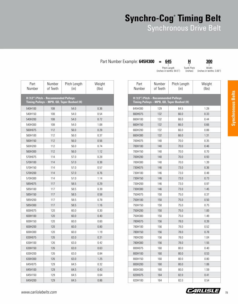
www.carlislebelts.com 73
Sync
hron
ous
Bel
ts
Part Number
Number of Teeth
Pitch Length (in)
Weight (lbs)
XL (1/5”) Pitch – Recommended Pulleys: Timing Pulleys – MPB, QD, Taper Bushed (XL)
540H100 108 54.0 0.36
540H150 108 54.0 0.54
540H200 108 54.0 0.72
540H300 108 54.0 1.08
560H075 112 56.0 0.28
560H100 112 56.0 0.37
560H150 112 56.0 0.56
560H200 112 56.0 0.74
560H300 112 56.0 1.12
570H075 114 57.0 0.28
570H100 114 57.0 0.38
570H150 114 57.0 0.57
570H200 114 57.0 0.76
570H300 114 57.0 1.14
585H075 117 58.5 0.29
585H100 117 58.5 0.39
585H150 117 58.5 0.58
585H200 117 58.5 0.78
585H300 117 58.5 1.16
600H075 120 60.0 0.30
600H100 120 60.0 0.40
600H150 120 60.0 0.60
600H200 120 60.0 0.80
600H300 120 60.0 1.19
630H075 126 63.0 0.31
630H100 126 63.0 0.42
630H150 126 63.0 0.63
630H200 126 63.0 0.84
630H300 126 63.0 1.25
645H075 129 64.5 0.32
645H100 129 64.5 0.43
645H150 129 64.5 0.64
645H200 129 64.5 0.86
Part Number
Number of Teeth
Pitch Length (in)
Weight (lbs)
XL (1/5”) Pitch – Recommended Pulleys: Timing Pulleys – MPB, QD, Taper Bushed (XL)
645H300 129 64.5 1.28
660H075 132 66.0 0.33
660H100 132 66.0 0.44
660H150 132 66.0 0.66
660H200 132 66.0 0.88
660H300 132 66.0 1.31
700H075 140 70.0 0.35
700H100 140 70.0 0.46
700H150 140 70.0 0.70
700H200 140 70.0 0.93
700H300 140 70.0 1.39
730H075 146 73.0 0.36
730H100 146 73.0 0.48
730H150 146 73.0 0.73
730H200 146 73.0 0.97
730H300 146 73.0 1.45
750H075 150 75.0 0.37
750H100 150 75.0 0.50
750H150 150 75.0 0.75
750H200 150 75.0 1.00
750H300 150 75.0 1.49
780H075 156 78.0 0.39
780H100 156 78.0 0.52
780H150 156 78.0 0.78
780H200 156 78.0 1.04
780H300 156 78.0 1.55
800H075 160 80.0 0.40
800H100 160 80.0 0.53
800H150 160 80.0 0.80
800H200 160 80.0 1.06
800H300 160 80.0 1.59
820H075 164 82.0 0.41
820H100 164 82.0 0.54
Synchro-Cog® Timing BeltSynchronous Drive Belt
Part Number Example: 645H300 = 645 H 300 | | | Pitch Length Tooth Pitch Width (inches in tenths: 64.5”) (inches) (inches in tenths: 3.00”)
H (1/2”) Pitch – Recommended Pulleys: Timing Pulleys – MPB, QD, Taper Bushed (H)
H (1/2”) Pitch – Recommended Pulleys: Timing Pulleys – MPB, QD, Taper Bushed (H)
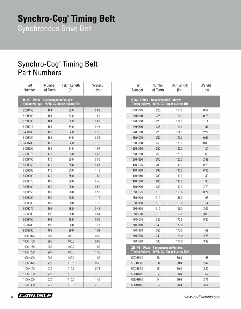
www.carlislebelts.com74
Part Number
Number of Teeth
Pitch Length (in)
Weight (lbs)
XL (1/5”) Pitch – Recommended Pulleys: Timing Pulleys – MPB, QD, Taper Bushed (XL)
820H150 164 82.0 0.82
820H200 164 82.0 1.09
820H300 164 82.0 1.63
840H075 168 84.0 0.42
840H100 168 84.0 0.56
840H150 168 84.0 0.84
840H200 168 84.0 1.12
840H300 168 84.0 1.67
850H075 170 85.0 0.42
850H100 170 85.0 0.56
850H150 170 85.0 0.85
850H200 170 85.0 1.13
850H300 170 85.0 1.69
900H075 180 90.0 0.45
900H100 180 90.0 0.60
900H150 180 90.0 0.90
900H200 180 90.0 1.19
900H300 180 90.0 1.79
960H075 192 96.0 0.48
960H100 192 96.0 0.64
960H150 192 96.0 0.96
960H200 192 96.0 1.27
960H300 192 96.0 1.91
1000H075 200 100.0 0.50
1000H100 200 100.0 0.66
1000H150 200 100.0 1.00
1000H200 200 100.0 1.33
1000H300 200 100.0 1.99
1100H075 220 110.0 0.55
1100H100 220 110.0 0.73
1100H150 220 110.0 1.10
1100H200 220 110.0 1.46
1100H300 220 110.0 2.19
Part Number
Number of Teeth
Pitch Length (in)
Weight (lbs)
XL (1/5”) Pitch – Recommended Pulleys: Timing Pulleys – MPB, QD, Taper Bushed (XL)
1140H075 228 114.0 0.57
1140H100 228 114.0 0.76
1140H150 228 114.0 1.14
1140H200 228 114.0 1.51
1140H300 228 114.0 2.27
1250H075 250 125.0 0.62
1250H100 250 125.0 0.83
1250H150 250 125.0 1.24
1250H200 250 125.0 1.66
1250H300 250 125.0 2.49
1400H075 280 140.0 0.70
1400H100 280 140.0 0.93
1400H150 280 140.0 1.39
1400H200 280 140.0 1.86
1400H300 280 140.0 2.79
1550H075 310 155.0 0.77
1550H100 310 155.0 1.03
1550H150 310 155.0 1.54
1550H200 310 155.0 2.06
1550H300 310 155.0 3.09
1700H075 340 170.0 0.85
1700H100 340 170.0 1.13
1700H150 340 170.0 1.69
1700H200 340 170.0 2.26
1700H300 340 170.0 3.39
507XH200 58 50.8 1.65
507XH300 58 50.8 2.47
507XH400 58 50.8 3.30
560XH200 64 56.0 1.82
560XH300 64 56.0 2.73
560XH400 64 56.0 3.64
Synchro-Cog® Timing BeltPart Numbers
Synchro-Cog® Timing BeltSynchronous Drive Belt
H (1/2”) Pitch – Recommended Pulleys: Timing Pulleys – MPB, QD, Taper Bushed (H)
XH (7/8”) Pitch – Recommended Pulleys: Timing Pulleys – MPB, QD, Taper Bushed (XH)
H (1/2”) Pitch – Recommended Pulleys: Timing Pulleys – MPB, QD, Taper Bushed (H)

www.carlislebelts.com 75
Sync
hron
ous
Bel
ts
Part Number
Number of Teeth
Pitch Length (in)
Weight (lbs)
XL (1/5”) Pitch – Recommended Pulleys: Timing Pulleys – MPB, QD, Taper Bushed (XL)
630XH200 72 63.0 2.05
630XH300 72 63.0 3.08
630XH400 72 63.0 4.10
700XH200 80 70.0 2.28
700XH300 80 70.0 3.42
700XH400 80 70.0 4.56
770XH200 88 77.0 2.51
770XH300 88 77.0 3.76
770XH400 88 77.0 5.01
840XH200 96 84.0 2.73
840XH300 96 84.0 4.10
840XH400 96 84.0 5.47
980XH200 112 98.0 3.19
980XH300 112 98.0 4.78
980XH400 112 98.0 6.38
1120XH200 128 112.0 3.64
1120XH300 128 112.0 5.47
1120XH400 128 112.0 7.29
1260XH200 144 126.0 4.10
1260XH300 144 126.0 6.15
1260XH400 144 126.0 8.20
1400XH200 160 140.0 4.56
1400XH300 160 140.0 6.83
1400XH400 160 140.0 9.11
1540XH200 176 154.0 5.01
1540XH300 176 154.0 7.52
1540XH400 176 154.0 10.02
1750XH200 200 175.0 5.69
1750XH300 200 175.0 8.54
1750XH400 200 175.0 11.39
Part Number
Number of Teeth
Pitch Length (in)
Weight (lbs)
XL (1/5”) Pitch – Recommended Pulleys: Timing Pulleys – MPB, QD, Taper Bushed (XL)
700XXH200 56 70.0 3.00
700XXH300 56 70.0 4.49
700XXH400 56 70.0 5.99
700XXH500 56 70.0 7.49
800XXH200 64 80.0 3.42
800XXH300 64 80.0 5.13
800XXH400 64 80.0 6.85
800XXH500 64 80.0 8.56
900XXH200 72 90.0 3.85
900XXH300 72 90.0 5.78
900XXH400 72 90.0 7.70
900XXH500 72 90.0 9.63
1000XXH200 80 100.0 4.28
1000XXH300 80 100.0 6.42
1000XXH400 80 100.0 8.56
1000XXH500 80 100.0 10.70
1200XXH200 96 120.0 5.13
1200XXH300 96 120.0 7.70
1200XXH400 96 120.0 10.27
1200XXH500 96 120.0 12.84
1400XXH200 112 140.0 5.99
1400XXH300 112 140.0 8.99
1400XXH400 112 140.0 11.98
1400XXH500 112 140.0 14.98
1600XXH200 128 160.0 6.85
1600XXH300 128 160.0 10.27
1600XXH400 128 160.0 13.69
1600XXH500 128 160.0 17.11
1800XXH200 144 180.0 7.70
1800XXH300 144 180.0 11.55
1800XXH400 144 180.0 15.40
1800XXH500 144 180.0 19.25
Synchro-Cog® Timing BeltSynchronous Drive Belt
Part Number Example: 630XH200 = 630 XH 200 | | | Pitch Length Tooth Pitch Width (inches in tenths: 63.0”) (inches) (inches in tenths: 2.00”)
XH (7/8”) Pitch – Recommended Pulleys: Timing Pulleys – MPB, QD, Taper Bushed (XH)
XXH (1-1/4”) Pitch

www.carlislebelts.com76
Synchro-Cog® Timing BeltSleeves
Part Number
Sleeve Width (in)
Weight (lbs)
XL (1/5”) Pitch – Recommended Pulleys: Timing Pulleys – MPB, QD, Taper Bushed (XL)
60XL1600SL 16.0 0.34
70XL1600SL 16.0 0.40
80XL1600SL 16.0 0.46
90XL1600SL 16.0 0.90
100XL2800SL 28.0 1.00
110XL2800SL 28.0 1.10
120XL2800SL 28.0 1.20
130XL2800SL 28.0 1.30
140XL2800SL 28.0 1.40
150XL2800SL 28.0 1.50
160XL2800SL 28.0 1.60
170XL2800SL 28.0 1.70
180XL1600SL 16.0 1.03
190XL1600SL 16.0 1.09
200XL1600SL 16.0 1.14
210XL1600SL 16.0 1.20
220XL1600SL 16.0 1.26
230XL1600SL 16.0 1.31
240XL1600SL 16.0 1.37
250XL1600SL 16.0 1.43
260XL1600SL 16.0 1.49
290XL2126SL 21.3 2.20
310XL1850SL 18.5 2.05
330XL1850SL 18.5 2.18
390XL1850SL 18.5 2.58
L (3/8”) Pitch – Recommended Pulleys: Timing Pulleys – MPB, QD, Taper Bushed (L)
124L1600SL 16.0 1.00
150L2800SL 28.0 2.12
187L2800SL 28.0 2.65
210L1600SL 16.0 1.70
225L3800SL 38.0 4.32
240L3800SL 38.0 4.61
Synchro-Cog® Timing BeltSleeve Part Numbers
Timken maintains inventory of most Carlisle® sleeve sizes. Non-stock sizes will be indicated by an asterisk following the part number. Contact customer service for availability. Minimum order quantity and/or extended lead times may apply.Occasional production inconsistencies which may render a portion of the sleeve unusable can be present as a normal part of the production process.Each sleeve is inspected to ensure that it contains 90% or more usable product. A full width sleeve with less than 10% unusable product is considered acceptable.
■■ Full factory width sleeves ■■ All sleeves will have the edges trimmed before shipment ■■ Cut sleeves cannot be accepted for return ■■ All weights are approximate

Sync
hron
ous
Bel
ts
www.carlislebelts.com 77
Synchro-Cog® Timing BeltSleeves
Part Number
Sleeve Width (in)
Weight (lbs)
XL (1/5”) Pitch – Recommended Pulleys: Timing Pulleys – MPB, QD, Taper Bushed (XL)
255L3800SL 38.0 4.90
270L3800SL 38.0 5.19
285L3800SL 38.0 5.48
300L3800SL 38.0 5.77
322L3800SL 38.0 6.19
345L3800SL 38.0 6.63
367L3800SL 38.0 7.05
390L3800SL 38.0 7.50
420L3800SL 38.0 8.07
450L1850SL 18.5 4.21
480L1850SL 18.5 4.49
510L1850SL 18.5 4.77
540L1850SL 18.5 5.05
600L3800SL 38.0 11.53
817L1850SL 18.5 7.65
H (1/2”) Pitch – Recommended Pulleys: Timing Pulleys – MPB, QD, Taper Bushed (H)
240H3800SL 38.0 6.05
270H3800SL 38.0 6.81
300H3800SL 38.0 7.57
330H3800SL 38.0 8.32
360H3800SL 38.0 9.08
390H3800SL 38.0 9.84
420H3800SL 38.0 10.59
450H3800SL 38.0 11.35
480H3800SL 38.0 12.11
510H3800SL 38.0 12.86
540H3800SL 38.0 13.62
570H3800SL 38.0 14.38
600H3800SL 38.0 15.13
630H3800SL 38.0 15.89
660H3800SL 38.0 16.65
700H3800SL 38.0 17.66
Part Number
Sleeve Width (in)
Weight (lbs)
XL (1/5”) Pitch – Recommended Pulleys: Timing Pulleys – MPB, QD, Taper Bushed (XL)
750H3800SL 38.0 18.92
800H2200SL 22.0 11.68
850H2200SL 22.0 12.41
900H2200SL 22.0 1.19
1000H2200SL 22.0 14.60
1100H2200SL 22.0 15.52
1140H2126SL 21.3 13.62
1250H2200SL 22.0 18.25
1400H2200SL 22.0 20.44
1700H2200SL 22.0 23.99
XH (7/8”) Pitch – Recommended Pulleys: Timing Pulleys – MPB, QD, Taper Bushed (XH)
507XH2126SL 21.3 31.35
560XH3800SL 38.0 34.62
630XH3800SL 38.0 38.95
700XH3800SL 38.0 43.28
770XH3800SL 38.0 47.61
840XH2126SL 21.3 29.06
980XH2200SL 22.0 35.08
1120XH2126SL 21.3 38.74
1260XH2126SL 21.3 43.59
1400XH2126SL 21.3 48.43
1540XH2126SL 21.3 53.27
1750XH2126SL 21.3 60.54
XXH (1-1/4”) Pitch
800XXH2126SL 21.3 36.39
900XXH2126SL 21.3 40.93
1000XXH2126SL 21.3 45.48
1200XXH2126SL 21.3 54.58
1400XXH2126SL 21.3 63.68
1600XXH2126SL 21.3 72.77
1800XXH2126SL 21.3 81.87
Part Number Example: 200XL1600SL = 200 XL 1600 SL | | | | Pitch Length Tooth Pitch Width Sleeve (inches in tenths: 20.0”) (inches) (inches in tenths: 16.00”)
H (1/2”) Pitch – Recommended Pulleys: Timing Pulleys – MPB, QD, Taper Bushed (H)
L (3/8”) Pitch – Recommended Pulleys: Timing Pulleys – MPB, QD, Taper Bushed (L)

www.carlislebelts.com78
Air Cool Heat ExchangeSynchronous Drive Belt

Sync
hron
ous
Bel
ts
Panther®XTSynchronous Drive Belt
www.carlislebelts.com 79
6
3
2
1
5
4
Special “Z” twist construction for air cooled heat exchangers
“Z” twist cord construction provides an upward direction of lateral movement which helps keep the belt off of the bottom flanges, reducing excessive wear on the bottom side of the belt.
Applications: HVAC Air cooled heat exchangers
Air Cool Heat ExchangeSynchronous Drive Belt
Recommended Sprockets:High Torque Synchronous Sprockets – MPB, QD, Taper Bushed (14mm)
1 Ultra-Cord® Tensile Member
Z-twist construction Improved belt lifeHigher strengthReduced tension decay
2 Tooth IndentationShock absorbingReduced noise
3 Nylon Tooth Facing Graphite-loadedSelf-lubricatingWear resistant
4 RPP® ProfileGreater transfer of powerJump and shear resistantReduced sprocket wear
5 BackingPrecision-groundSmoother operation with backside idler
6 Able CompoundIncreased performanceIncreased belt life

Carlisle® Air Cool Heat Exchange synchronous belts are manufactured using special “Z” twist construction. Because the drive has a vertical shaft, the belt is built with “Z” twist cords only. This gives the belt an upward direction
of lateral movement which reduces excessive wear on the bottom side of the belt.
The cord in a synchronous belt is made up of a number of small fiber strands twisted together. These strands can be twisted either clockwise or counterclockwise. The two twist directions are referred to as “S” twist and “Z” twist. To reduce lateral movement, most synchronous belts are constructed by alternately spiraling “S” and “Z” type cords. This specially constructed Carlisle belt for air cooled heat exchange applications uses only “Z” twist cords to predetermine the lateral movement of the belt.
Timken offers the following special construction “Z” twist synchronous belts for air-cooled heat exchange drives.
www.carlislebelts.com80 www.carlislebelts.com80
14mm
14M
Air Cool Heat ExchangeSynchronous Drive Belt
Special “Z” twist cord construction for air cooled heat exchange applications.
Air Cool Heat Exchange Belt Part Numbers
PartNumber
Pitch Length (mm)
Top Width (mm)
Number of Teeth
Weight(lbs)
14M Pitch – High Torque Synchronous (HTS) Sprockets: MPB, QD, Taper Bushed (14mm)
2800-14M-55F 2800 55 200 3.09
2800-14M-85F 2800 85 200 4.77
3150-14M-55F 3150 55 225 3.47
3150-14M-85F 3150 85 225 5.36
3360-14M-55F 3360 55 240 3.70
3360-14M-85F 3360 85 240 5.72
3500-14M-25F 3500 25 250 1.75
3500-14M-37F 3500 37 250 2.59
3500-14M-40F 3500 40 250 2.81
3500-14M-55F 3500 55 250 3.86
3500-14M-85F 3500 85 250 5.96
3850-14M-30F 3850 30 275 2.31
3850-14M-40F 3850 40 275 3.09
3850-14M-55F 3850 55 275 4.24
3850-14M-85F 3850 85 275 6.56
4326-14M-40F 4326 40 309 3.47
4326-14M-55F 4326 55 309 4.77
4326-14M-85F 4326 85 309 7.37
Note: Air Cool Heat Exchange belts can be cut to different widths as needed.
Part Number Example: 3150-14M-55F = 3150 – 14M – 55 F | | | | Pitch Length Tooth Pitch Width Z-Twist (millimeters) (RPP tooth profile) (millimeters) Cord Construction

www.carlislebelts.com 81
Sync
hron
ous
Bel
ts
Timken maintains inventory of most Carlisle® sleeve sizes. Non-stock sizes will be indicated by an asterisk following the part number. Contact customer service for availability. Minimum order quantity and/or extended lead times may apply.Occasional production inconsistencies which may render a portion of the sleeve unusable can be present as a normal part of the production process.Each sleeve is inspected to ensure that it contains 90% or more usable product. A full width sleeve with less than 10% unusable product is considered acceptable.
■■ Full factory width sleeves ■■ All sleeves will have the edges trimmed before shipment ■■ Cut sleeves cannot be accepted for return ■■ All weights are approximate
Air Cool Heat ExchangeSynchronous Drive Sleeves
Air Cool Heat Exchange Sleeve Part Numbers
PartNumber
Top Width(mm)
Sleeve Weight(lbs)
14M Pitch – High Torque Synchronous (HTS) Sprockets: MPB, QD, Taper Bushed (14mm)
2800-14M-570SLF 570 31.98
3150-14M-570SLF 570 35.98
3360-14M-570SLF 570 38.38
3500-14M-570SLF 570 39.97
3850-14M-570SLF 570 43.97
4326-14M-570SLF 570 49.41
Part Number Example: 3150-14M-570SLF = 3150 – 14M – 570 SL F | | | | Pitch Length Tooth Pitch Width Sleeve Z-Twist (millimeters) (RPP tooth profile) (millimeters) Cord Construction

www.carlislebelts.com82
Cotton Drive® Timing BeltsSynchronous Drive Belt
Phot
o co
urte
sy o
f Lum
mus
Cor
pora
tion

www.carlislebelts.com 83
Cotton Drive® Timing BeltsSynchronous Drive Belt
Ultra-Cord® tensile member
Custom designed for exact OEM replacement on cotton gin drives
Innovative engineering incorporates Ultra-Cord technology to provide the strength and length stability of steel cord, and offers improved life and performance over aramid fiber cords.
1 Ultra-Cord®
Delivers unequaled strength and dimensional stability
2 Tooth CoverSuperior resistance to heat, ozone, grease, oil and friction wear
3 Rubber CompoundFormulated for increased resistance to tooth shear and jump resulting in increased belt life
Sync
hron
ous
Bel
ts
3
2
1
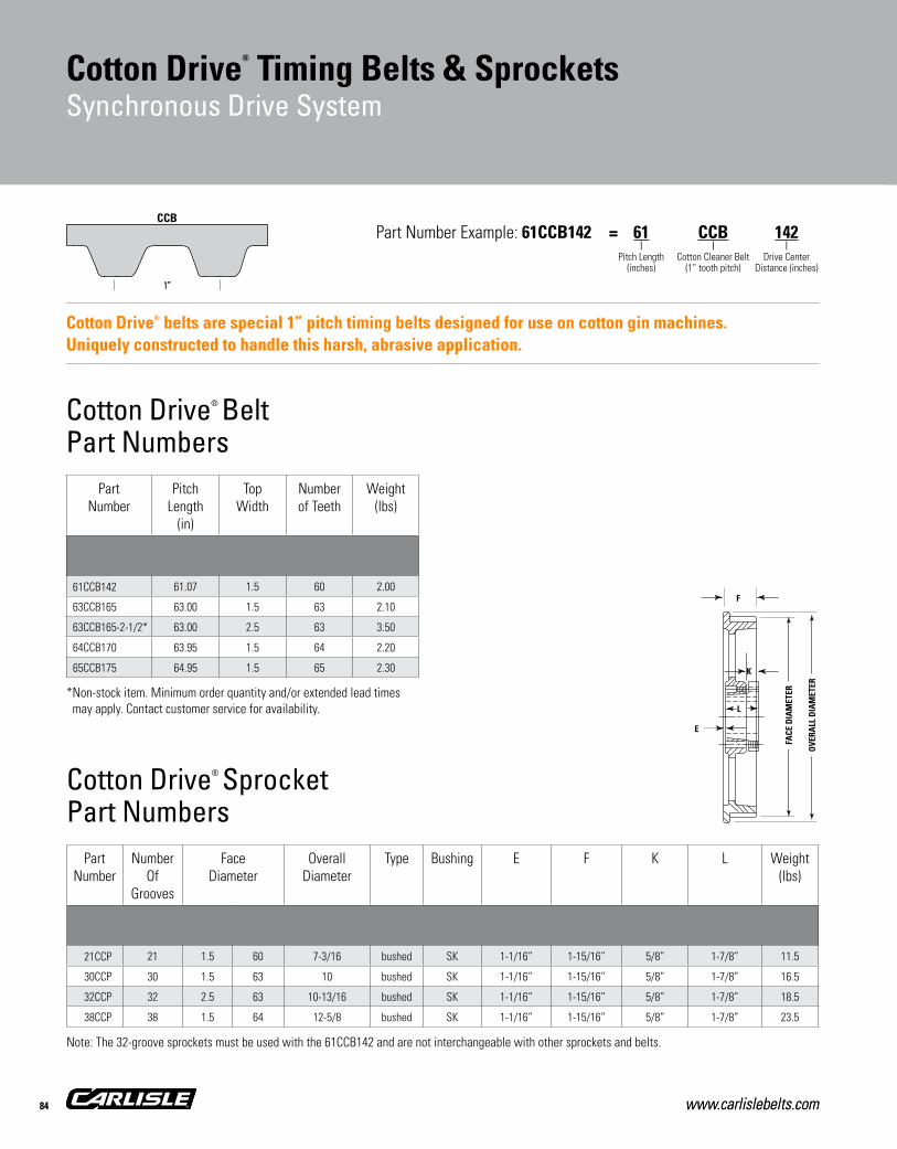
CCB
1”
Cotton Drive® Sprocket Part Numbers
Part Number Example: 61CCB142 = 61 CCB 142 | | | Pitch Length Cotton Cleaner Belt Drive Center (inches) (1” tooth pitch) Distance (inches)
PartNumber
Number Of
Grooves
FaceDiameter
Overall Diameter
Type Bushing E F K L Weight(lbs)
21CCP 21 1.5 60 7-3/16 bushed SK 1-1/16” 1-15/16” 5/8” 1-7/8” 11.5
30CCP 30 1.5 63 10 bushed SK 1-1/16” 1-15/16” 5/8” 1-7/8” 16.5
32CCP 32 2.5 63 10-13/16 bushed SK 1-1/16” 1-15/16” 5/8” 1-7/8” 18.5
38CCP 38 1.5 64 12-5/8 bushed SK 1-1/16” 1-15/16” 5/8” 1-7/8” 23.5
www.carlislebelts.com84
Cotton Drive® Timing Belts & SprocketsSynchronous Drive System
www.carlislebelts.com84
Cotton Drive® belts are special 1” pitch timing belts designed for use on cotton gin machines. Uniquely constructed to handle this harsh, abrasive application.
Cotton Drive® BeltPart Numbers
PartNumber
Pitch Length
(in)
Top Width
Number of Teeth
Weight(lbs)
61CCB142 61.07 1.5 60 2.00
63CCB165 63.00 1.5 63 2.10
63CCB165-2-1/2* 63.00 2.5 63 3.50
64CCB170 63.95 1.5 64 2.20
65CCB175 64.95 1.5 65 2.30 K
L
E
F
FACE
DIA
MET
ER
OVE
RALL
DIA
MET
ER
Note: The 32-groove sprockets must be used with the 61CCB142 and are not interchangeable with other sprockets and belts.
*Non-stock item. Minimum order quantity and/or extended lead times may apply. Contact customer service for availability.
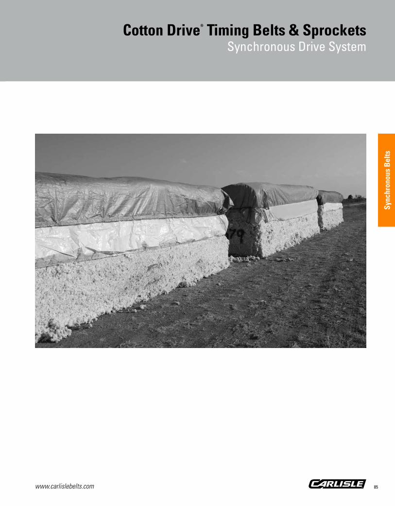
www.carlislebelts.com 85
Sync
hron
ous
Bel
ts
Cotton Drive® Timing Belts & SprocketsSynchronous Drive System

www.carlislebelts.com86
Gold-Ribbon® Cog-Belt®
V-Belt

www.carlislebelts.com 87
The energy saver
High performance EPDM construction:
Broader temperature operating range (-50° – +250°)
50% longer life
30% higher horsepower
Static conductive
Greater design flexibility
matching
Applications:BlowersPumpsHVACHigh ambient temperature exhaust fans& More
Gold-Ribbon® Cog-Belt®
V-Belt
1 Unique Cog Design
permits flexibility that enables the belt to bend more easily around the pulley. It runs cooler – less heat equals longer belt life. Smaller pulley diameters mean lower cost and space savings.
2 Raw Edge Sidewalls
produce a higher coefficient of friction which keeps a tighter grip on the pulley and minimizes slippage. Improves performance and belt efficiency for unmatched economy of operation.
3 EPDM Construction
offers superior flex and load carrying capacity. It’s durable as well as resistant to heat, hardening, and glazing. EPDM has excellent flexibility at high and low temperatures.
Recommended Sheaves:Conventional – QD, Taper Bushed, or MST (A-B, C, D)
2
3
1
Hea
vy D
uty
V-B
elts

www.carlislebelts.com88
Gold-Ribbon® Cog-Belt®
V-Belt
21/32”
7/16”BX
7/8”
17/32”CX
1-1/4”
3/4”DX
1/2”
11/32”AX
Unique Gold-Ribbon® Cog-Belt® construction combines the superior flex capability of precision molded cogs with the tenacious gripping power of raw-edge sidewalls to provide significantly longer belt life, higher efficiency, and greater horsepower ratings than conventional wrapped belts.
Now made with EPDM, a synthetic rubber with outstanding properties, the Carlisle® Gold-Ribbon® Cog-Belt® is static conductive, more durable, and more resistant to heat, hardening, and glazing than ever before.
Ordinary wrapped belts waste energy, time, and money. The Gold-Ribbon Cog-Belt has been engineered to take advantage of countless developments in materials and technology. Today’s Gold-Ribbon Cog-Belt has earned industry wide respect and acceptance as the performance leader.
More reasons to switch to the Carlisle® Gold-Ribbon Cog-Belt:
■■ Specially formulated EPDM withstands extreme heat, dirt, grease, chemicals and environmental conditions.
■■ Design flexibility – Gold-Ribbon Cog-Belts transmit up to 30% more horse-power than conventional belts utilizing the same drive space – or pack the same horsepower into a space one-half to two-thirds the size.
■■ No excessive heat build-up or wear problems even under adverse operating conditions such as reverse bends, backside idlers and constant starts and stops.
■■ Save space with narrower pulleys, shorter centers and smaller pulley diameters.
■■ Reduced weight and overhang decreases bearing loads.
Performance and savings in one package. The Gold-Ribbon Cog-Belt gets the job done anywhere there are space, weight or pulley limitations– or where increased horsepower capacity and/or higher speeds are necessary. Using smaller pulleys, the Gold-Ribbon Cog-Belt provides a higher horsepower rating than conventional wrapped v-belts on the market. This enables you to design more efficient, more compact, and ultimately more profitable drives.
A new gold standard! Gold-Ribbon® sets the benchmark for classical v-belt performance – now made of EPDM (Ethylene Propylene Diene Monomer). Reduce downtime and save energy by selecting the right Gold-Ribbon® Cog-Belt® for your drive– the industry’s best just got better!
Horsepower Rating Comparison
Gold-Ribbon Cog-BeltConventional Wrapped Belt
HP
6.0
4.0
2.0
0.0
1500 RPM1.5:1 Belt Drive Ratio

www.carlislebelts.com 89
PartNumber
Outside Circumference
Weight(lbs)
AX Section – Recommended Sheaves:Conventional – QD, Taper Bushed, or MST (A-B)
AX20 22.3 0.12
AX21 23.3 0.13
AX22 24.3 0.13
AX23 25.3 0.14
AX24 26.3 0.14
AX25 27.3 0.15
AX26 28.3 0.16
AX27 29.3 0.16
AX28 30.3 0.17
AX29 31.3 0.17
AX30 32.3 0.18
AX31 33.3 0.19
AX32 34.3 0.19
AX33 35.3 0.21
AX34 36.3 0.17
AX35 37.3 0.17
AX36 38.3 0.22
AX37 39.3 0.22
AX38 40.3 0.23
AX39 41.3 0.23
AX40 42.3 0.24
AX41 43.3 0.25
AX42 44.3 0.21
AX43 45.3 0.26
AX44 46.3 0.26
AX45 47.3 0.27
AX46 48.3 0.29
AX47 49.3 0.28
AX48 50.3 0.23
AX49 51.3 0.24
AX50 52.3 0.30
AX51 53.3 0.30
AX52 54.3 0.31
PartNumber
Outside Circumference
Weight(lbs)
AX Section – Recommended Sheaves:Conventional – QD, Taper Bushed, or MST (A-B)
AX53 55.3 0.32
AX54 56.3 0.32
AX55 57.3 0.33
AX56 58.3 0.33
AX57 59.3 0.34
AX58 60.3 0.36
AX59 61.3 0.35
AX60 62.3 0.29
AX61 63.3 0.36
AX62 64.3 0.37
AX63 65.3 0.38
AX64 66.3 0.38
AX65 67.3 0.39
AX66 68.3 0.32
AX67 69.3 0.40
AX68 70.3 0.33
AX69 71.3 0.41
AX70 72.3 0.42
AX71 73.3 0.42
AX72 74.3 0.35
AX73 75.3 0.43
AX74 76.3 0.44
AX75 77.3 0.36
AX76 78.3 0.45
AX77 79.3 0.46
AX78 80.3 0.46
AX79 81.3 0.46
AX80 82.3 0.47
AX81 83.3 0.39
AX82 84.3 0.39
AX83 85.3 0.40
AX84 86.3 0.40
AX85 87.3 0.49
Part Number Example: AX50 = A X 50 | | | Cross Cogged Inside Circumference Section Construction (inches)
Gold-Ribbon® Cog-Belt®
Part Numbers
Gold-Ribbon® Cog-Belt®
V-Belt
Hea
vy D
uty
V-B
elts
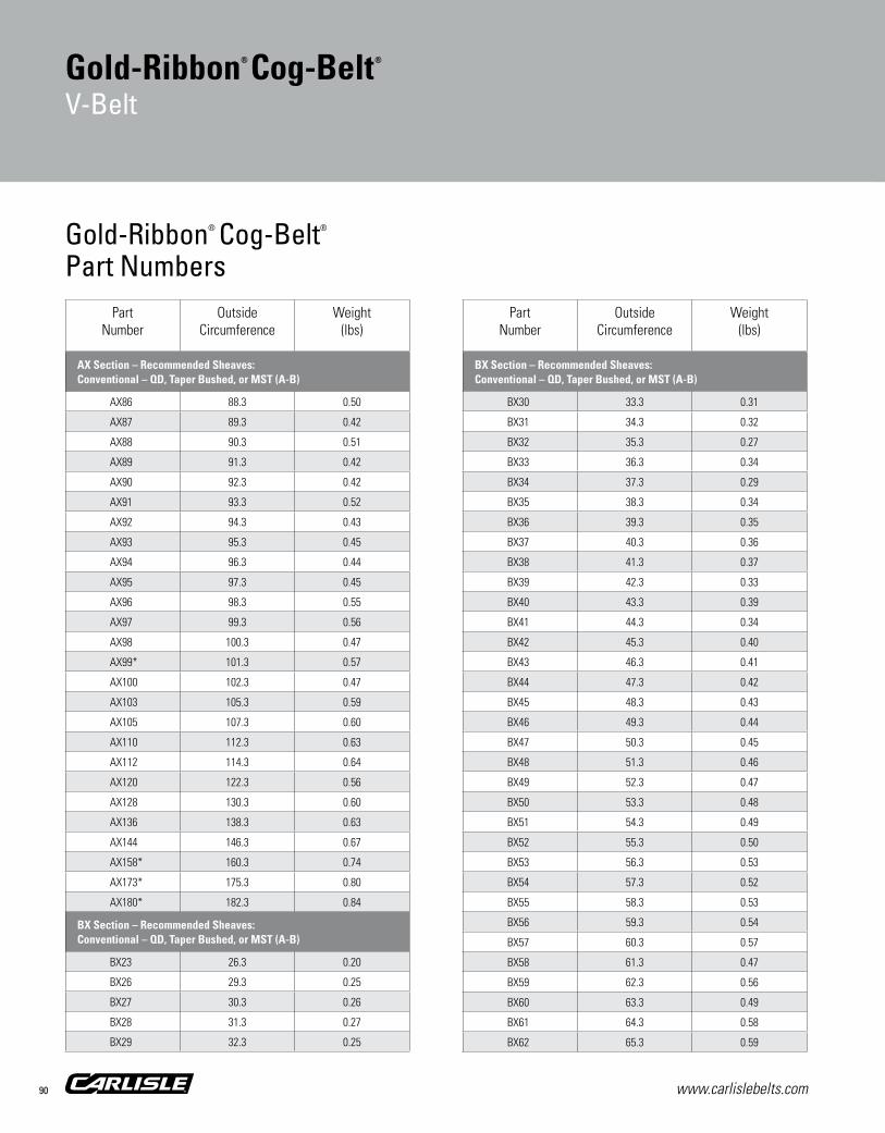
www.carlislebelts.com90
Gold-Ribbon® Cog-Belt®
Part Numbers
Gold-Ribbon® Cog-Belt®
V-Belt
PartNumber
Outside Circumference
Weight(lbs)
AX Section – Recommended Sheaves:Conventional – QD, Taper Bushed, or MST (A-B)
AX86 88.3 0.50
AX87 89.3 0.42
AX88 90.3 0.51
AX89 91.3 0.42
AX90 92.3 0.42
AX91 93.3 0.52
AX92 94.3 0.43
AX93 95.3 0.45
AX94 96.3 0.44
AX95 97.3 0.45
AX96 98.3 0.55
AX97 99.3 0.56
AX98 100.3 0.47
AX99* 101.3 0.57
AX100 102.3 0.47
AX103 105.3 0.59
AX105 107.3 0.60
AX110 112.3 0.63
AX112 114.3 0.64
AX120 122.3 0.56
AX128 130.3 0.60
AX136 138.3 0.63
AX144 146.3 0.67
AX158* 160.3 0.74
AX173* 175.3 0.80
AX180* 182.3 0.84
BX Section – Recommended Sheaves:Conventional – QD, Taper Bushed, or MST (A-B)
BX23 26.3 0.20
BX26 29.3 0.25
BX27 30.3 0.26
BX28 31.3 0.27
BX29 32.3 0.25
PartNumber
Outside Circumference
Weight(lbs)
BX Section – Recommended Sheaves:Conventional – QD, Taper Bushed, or MST (A-B)
BX30 33.3 0.31
BX31 34.3 0.32
BX32 35.3 0.27
BX33 36.3 0.34
BX34 37.3 0.29
BX35 38.3 0.34
BX36 39.3 0.35
BX37 40.3 0.36
BX38 41.3 0.37
BX39 42.3 0.33
BX40 43.3 0.39
BX41 44.3 0.34
BX42 45.3 0.40
BX43 46.3 0.41
BX44 47.3 0.42
BX45 48.3 0.43
BX46 49.3 0.44
BX47 50.3 0.45
BX48 51.3 0.46
BX49 52.3 0.47
BX50 53.3 0.48
BX51 54.3 0.49
BX52 55.3 0.50
BX53 56.3 0.53
BX54 57.3 0.52
BX55 58.3 0.53
BX56 59.3 0.54
BX57 60.3 0.57
BX58 61.3 0.47
BX59 62.3 0.56
BX60 63.3 0.49
BX61 64.3 0.58
BX62 65.3 0.59

www.carlislebelts.com 91
Sync
hron
ous
Bel
ts
PartNumber
Outside Circumference
Weight(lbs)
BX Section – Recommended Sheaves:Conventional – QD, Taper Bushed, or MST (A-B)
BX63 66.3 0.60
BX64 67.3 0.61
BX65 68.3 0.62
BX66 69.3 0.53
BX67 70.3 0.64
BX68 71.3 0.55
BX69 72.3 0.66
BX70 73.3 0.67
BX71 74.3 0.57
BX72 75.3 0.68
BX73 76.3 0.70
BX74 77.3 0.71
BX75 78.3 0.60
BX76 79.3 0.72
BX77 80.3 0.73
BX78 81.3 0.73
BX79 82.3 0.74
BX80 83.3 0.75
BX81 84.3 0.65
BX82 85.3 0.66
BX83 86.3 0.67
BX84 87.3 0.82
BX85 88.3 0.68
BX86 89.3 0.81
BX87 90.3 0.70
BX88 91.3 0.83
BX89 92.3 0.71
BX90 93.3 0.72
BX91 94.3 0.73
BX92 95.3 0.90
BX93 96.3 0.87
BX94 97.3 0.88
BX95 98.3 0.89
PartNumber
Outside Circumference
Weight(lbs)
BX Section – Recommended Sheaves:Conventional – QD, Taper Bushed, or MST (A-B)
BX96 99.3 0.77
BX97 100.3 0.77
BX98 101.3 0.78
BX99 102.3 0.93
BX100 103.3 0.94
BX103 106.3 0.82
BX105 108.3 0.99
BX106 109.3 0.85
BX108 111.3 0.86
BX112 115.3 0.89
BX113 116.3 1.06
BX115 118.3 0.92
BX116 119.3 1.09
BX120 123.3 0.95
BX123 126.3 0.98
BX124 127.3 0.98
BX126 129.3 1.00
BX128 131.3 1.02
BX130 133.3 1.03
BX133 136.3 1.05
BX136 139.3 1.08
BX140 143.3 1.11
BX144 147.3 1.14
BX148 151.3 1.17
BX150 153.3 1.19
BX151* 154.3 1.19
BX154 157.3 1.22
BX158 161.3 1.25
BX162 165.3 1.28
BX173 176.3 1.36
BX180 183.3 1.42
BX191 194.3 1.50
BX195 198.3 1.53
Part Number Example: BX70 = B X 70 | | | Cross Cogged Inside Circumference Section Construction (inches)
Gold-Ribbon® Cog-Belt®
V-Belt
Hea
vy D
uty
V-B
elts

www.carlislebelts.com92
Gold-Ribbon® Cog-Belt®
V-Belt
Gold-Ribbon® Cog-Belt®
Part Numbers Part
NumberOutside
CircumferenceWeight
(lbs)
BX Section – Recommended Sheaves:Conventional – QD, Taper Bushed, or MST (A-B)
BX205* 208.3 1.80
BX210 213.3 2.15
BX225 227.4 2.35
BX240 242.4 2.50
BX255* 257.4 3.10
BX270* 272.4 3.05
BX300* 302.4 3.05
CX Section – Recommended Sheaves:Conventional – QD, Taper Bushed, or MST (C)
CX51 55.4 0.77
CX52* 56.4 0.77
CX55 59.4 0.83
CX60 64.4 0.90
CX66 70.4 0.96
CX68 72.4 1.01
CX72 76.4 1.06
CX75 79.4 1.10
CX78 82.4 1.15
CX81 85.4 1.19
CX85 89.4 1.24
CX90 94.4 1.31
CX96 100.4 1.39
CX98* 102.4 1.39
CX100 104.4 1.45
CX101 105.4 1.46
CX103 107.4 1.46
CX105 109.4 1.52
CX106* 110.4 1.50
CX109 113.4 1.57
CX111 115.4 1.60
CX112 116.4 1.62
CX115 119.4 1.66
CX120 124.4 1.73
PartNumber
Outside Circumference
Weight(lbs)
CX Section – Recommended Sheaves:Conventional – QD, Taper Bushed, or MST (C)
CX124 128.4 1.78
CX128 132.4 1.84
CX133 137.4 1.86
CX136 140.4 1.95
CX144 148.4 2.06
CX148 152.4 2.11
CX150 154.4 2.14
CX158 162.4 2.25
CX162 166.4 2.31
CX173 177.4 2.46
CX180 184.4 2.55
CX190 194.4 2.63
CX195 199.4 2.76
CX210 214.4 3.25
CX225 228.1 3.75
CX240 243.1 4.10
CX255 258.1 4.45
CX270 273.1 3.85
CX300 303.1 4.95
CX330* 333.1 5.35
DX Section – Recommended Sheaves:Conventional – QD, Taper Bushed, or MST (D)
DX71* 76.5 2.15
DX120 125.5 4.26
DX128* 133.5 3.75
DX144* 149.5 4.19
DX158* 163.5 4.58
DX162* 167.5 4.69
DX173* 178.5 5.00
DX180* 185.5 5.20
DX195* 200.5 5.61
DX210* 215.5 7.20
DX225* 228.6 7.70

www.carlislebelts.com 93
PartNumber
Outside Circumference
Weight(lbs)
DX Section – Recommended Sheaves:Conventional – QD, Taper Bushed, or MST (D)
DX240 243.6 8.15
DX255* 258.6 7.50
DX270 273.6 9.00
DX300* 303.6 9.50
DX330* 333.6 10.90
Part Number Example: DX270 = D X 270 | | | Cross Cogged Inside Circumference Section Construction (inches)
*Non-stock item. Minimum order quantity and/or extended lead times may apply. Contact customer service for availability.
Gold-Ribbon® Cog-Belt®
V-Belt
Hea
vy D
uty
V-B
elts

www.carlislebelts.com94
Super II®
V-Belt

www.carlislebelts.com 95
The “Problem Solver”
Blows the cover off conventional wrapped belts
For classical applications
Matching
Applications:Shaker screensDebarkersHVAC Industrial washers and dryers & More
Super II®
V-Belt
1 High-modulus polyester cord located in the belt mid-section is specially treated to withstand extreme belt loads and shock without stretching. The central position contributes to greater strength, balance and longer life.
2 Multiple fabric plies, top and bottom, relieve stress on the load-carrying center cord for added flexibility. Quantity of fabric plies varies per cross section, with equal number of plies above and below center cord: A=3 plies, B=4 plies, C=5 plies.
3 Unique Raw Edge belt sidewalls grip pulleys better to minimize belt slip, noise and drive vibration.
4 Specially formulated rubber compound supports cord more evenly, top and bottom to dissipate heat more readily, and provide better oil, heat and ozone resistance.
Recommended Sheaves:Conventional – QD, Taper Bushed, or MST (A-B, C)
3
2
1
4
Hea
vy D
uty
V-B
elts

www.carlislebelts.com96
Super II®
V-Belt
The Problem Solver! The solution to the constant and costly problem of replacing or re-tensioning ordinary v-belts on troublesome drives.
Look what the Super II® v-belt has to offer: ■■ Greater strength
■■ Longer life
■■ Better heat dissipation
■■ Better grip for controlled slippage
■■ Greater flexibility
Timken has designed this belt for the toughest, heavy-duty industrial applications – the kind that devour ordinary wrapped belts. The Super II® puts an end to the constant, costly problem of replacing or re-tensioning belts. Our secret: Super II v-belt’s unique construction.
Don’t take our word for it! Compare Super II to the belt you are now using on your heavy torque, high horsepower and extreme shock-load applications.
Tensile Strength
% Increased Tensile Strength
Super II BeltConventional Wrapped Belt
Prof
ile
A
B
C
11%
18%
4%
Accelerated Life Test (Laboratory)
Super II BeltConventional Wrapped Belt
Hour
s
6800
6600
6400
6200
6000
5800
5600
21/32”
7/16”B
7/8”
9/16”C
1/2”
11/32”A

www.carlislebelts.com 97
Super II®
V-Belt
Part Number Example: A50 = A 50 | | Cross Inside Circumference Section (inches)
PartNumber
Outside Circumference
Weight(lbs)
A Section – Recommended Sheaves:Conventional – QD, Taper Bushed, or MST (A-B)
A21 23.2 0.15
A22 24.2 0.16
A23 25.2 0.17
A24 26.2 0.17
A25 27.2 0.18
A26 28.2 0.19
A27 29.2 0.19
A28 30.2 0.20
A29 31.2 0.20
A30 32.2 0.21
A31 33.2 0.22
A32 34.2 0.23
A33 35.2 0.23
A34 36.2 0.24
A35 37.2 0.25
A36 38.2 0.25
A37 39.2 0.26
A38 40.2 0.27
A39 41.2 0.27
A40 42.2 0.28
A41 43.2 0.29
A42 44.2 0.29
A43 45.2 0.30
A44 46.2 0.31
A45 47.2 0.31
A46 48.2 0.32
A47 49.2 0.33
A48 50.2 0.33
A49 51.2 0.34
A50 52.2 0.35
A51 53.2 0.35
A52 54.2 0.36
A53 55.2 0.37
PartNumber
Outside Circumference
Weight(lbs)
A Section – Recommended Sheaves:Conventional – QD, Taper Bushed, or MST (A-B)
A54 56.2 0.38
A55 57.2 0.38
A56 58.2 0.39
A57 59.2 0.39
A58 60.2 0.40
A59 61.2 0.41
A60 62.2 0.42
A61 63.2 0.42
A62 64.2 0.43
A63 65.2 0.44
A64 66.2 0.44
A65 67.2 0.45
A66 68.2 0.46
A67 69.2 0.46
A68 70.2 0.46
A69 71.2 0.47
A70 72.2 0.48
A71 73.2 0.48
A72 74.2 0.49
A73 75.2 0.50
A74 76.2 0.51
A75 77.2 0.51
A76 78.2 0.52
A77 79.2 0.53
A78 80.2 0.53
A79 81.2 0.54
A80 82.2 0.55
A81 83.2 0.55
A82 84.2 0.56
A83 85.2 0.57
A84 86.2 0.57
A85 87.2 0.58
A86 88.2 0.59
Super II® V-BeltPart Numbers
Hea
vy D
uty
V-B
elts
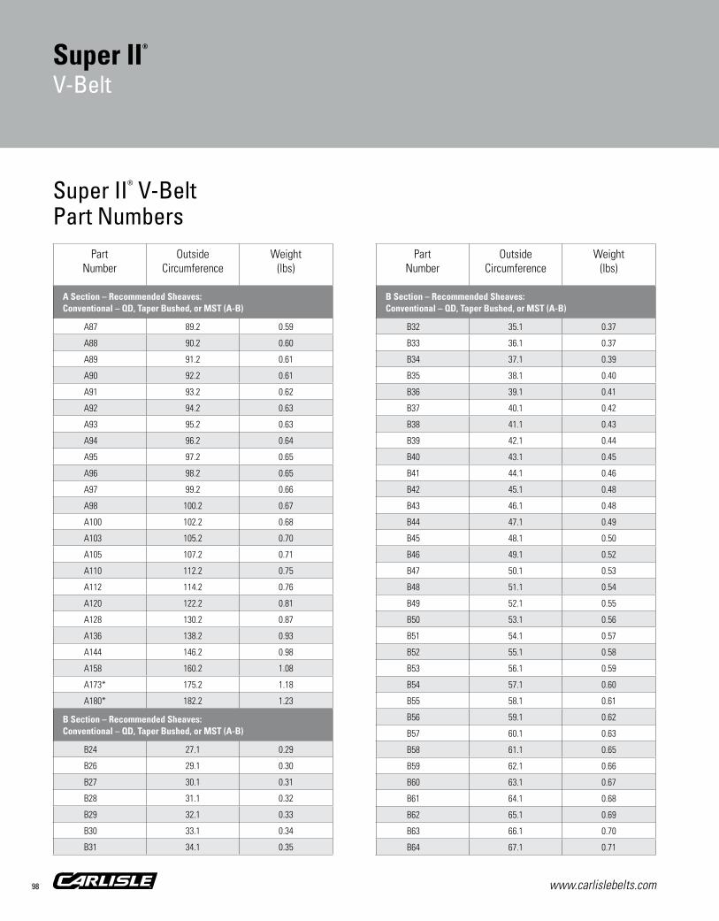
www.carlislebelts.com98
PartNumber
Outside Circumference
Weight(lbs)
A Section – Recommended Sheaves:Conventional – QD, Taper Bushed, or MST (A-B)
A87 89.2 0.59
A88 90.2 0.60
A89 91.2 0.61
A90 92.2 0.61
A91 93.2 0.62
A92 94.2 0.63
A93 95.2 0.63
A94 96.2 0.64
A95 97.2 0.65
A96 98.2 0.65
A97 99.2 0.66
A98 100.2 0.67
A100 102.2 0.68
A103 105.2 0.70
A105 107.2 0.71
A110 112.2 0.75
A112 114.2 0.76
A120 122.2 0.81
A128 130.2 0.87
A136 138.2 0.93
A144 146.2 0.98
A158 160.2 1.08
A173* 175.2 1.18
A180* 182.2 1.23
B Section – Recommended Sheaves:Conventional – QD, Taper Bushed, or MST (A-B)
B24 27.1 0.29
B26 29.1 0.30
B27 30.1 0.31
B28 31.1 0.32
B29 32.1 0.33
B30 33.1 0.34
B31 34.1 0.35
PartNumber
Outside Circumference
Weight(lbs)
B Section – Recommended Sheaves:Conventional – QD, Taper Bushed, or MST (A-B)
B32 35.1 0.37
B33 36.1 0.37
B34 37.1 0.39
B35 38.1 0.40
B36 39.1 0.41
B37 40.1 0.42
B38 41.1 0.43
B39 42.1 0.44
B40 43.1 0.45
B41 44.1 0.46
B42 45.1 0.48
B43 46.1 0.48
B44 47.1 0.49
B45 48.1 0.50
B46 49.1 0.52
B47 50.1 0.53
B48 51.1 0.54
B49 52.1 0.55
B50 53.1 0.56
B51 54.1 0.57
B52 55.1 0.58
B53 56.1 0.59
B54 57.1 0.60
B55 58.1 0.61
B56 59.1 0.62
B57 60.1 0.63
B58 61.1 0.65
B59 62.1 0.66
B60 63.1 0.67
B61 64.1 0.68
B62 65.1 0.69
B63 66.1 0.70
B64 67.1 0.71
Super II® V-BeltPart Numbers
Super II®
V-Belt

www.carlislebelts.com 99
Sync
hron
ous
Bel
ts
PartNumber
Outside Circumference
Weight(lbs)
B Section – Recommended Sheaves:Conventional – QD, Taper Bushed, or MST (A-B)
B65 68.1 0.72
B66 69.1 0.73
B67 70.1 0.74
B68 71.1 0.75
B69 72.1 0.77
B70 73.1 0.78
B71 74.1 0.79
B72 75.1 0.80
B73 76.1 0.81
B74 77.1 0.82
B75 78.1 0.83
B76 79.1 0.84
B77 80.1 0.85
B78 81.1 0.86
B79 82.1 0.87
B80 83.1 0.88
B81 84.1 0.90
B82 85.1 0.90
B83 86.1 0.92
B84 87.1 0.93
B85 88.1 0.94
B86 89.1 0.95
B87 90.1 0.96
B88 91.1 0.97
B89 92.1 0.98
B90 93.1 0.99
B91 94.1 1.00
B92 95.1 1.01
B93 96.1 1.03
B94 97.1 1.04
B95 98.1 1.05
B96 99.1 1.06
B97 100.1 1.07
PartNumber
Outside Circumference
Weight(lbs)
B Section – Recommended Sheaves:Conventional – QD, Taper Bushed, or MST (A-B)
B98 101.1 1.08
B99 102.1 1.09
B100 103.1 1.10
B101 104.1 1.11
B103 106.1 1.13
B105 108.1 1.15
B106 109.1 1.17
B108 111.1 1.19
B112 115.1 1.23
B115 118.1 1.26
B116 119.1 1.27
B118 121.1 1.30
B120 123.1 1.27
B123 126.1 1.35
B124 127.1 1.36
B126 129.1 1.38
B128 131.1 1.41
B130 133.1 1.43
B133 136.1 1.46
B136 139.1 1.49
B140 143.1 1.54
B142 145.1 1.56
B143* 146.1 1.57
B144 147.1 1.58
B148 151.1 1.62
B150 153.1 1.64
B154 157.1 1.69
B156 159.1 1.71
B158 161.1 1.73
B162 165.1 1.77
B173 176.1 1.89
B180 183.1 1.97
B188 191.1 2.05
Part Number Example: B70 = B 70 | | Cross Inside Circumference Section (inches)
Super II®
V-Belt
Hea
vy D
uty
V-B
elts
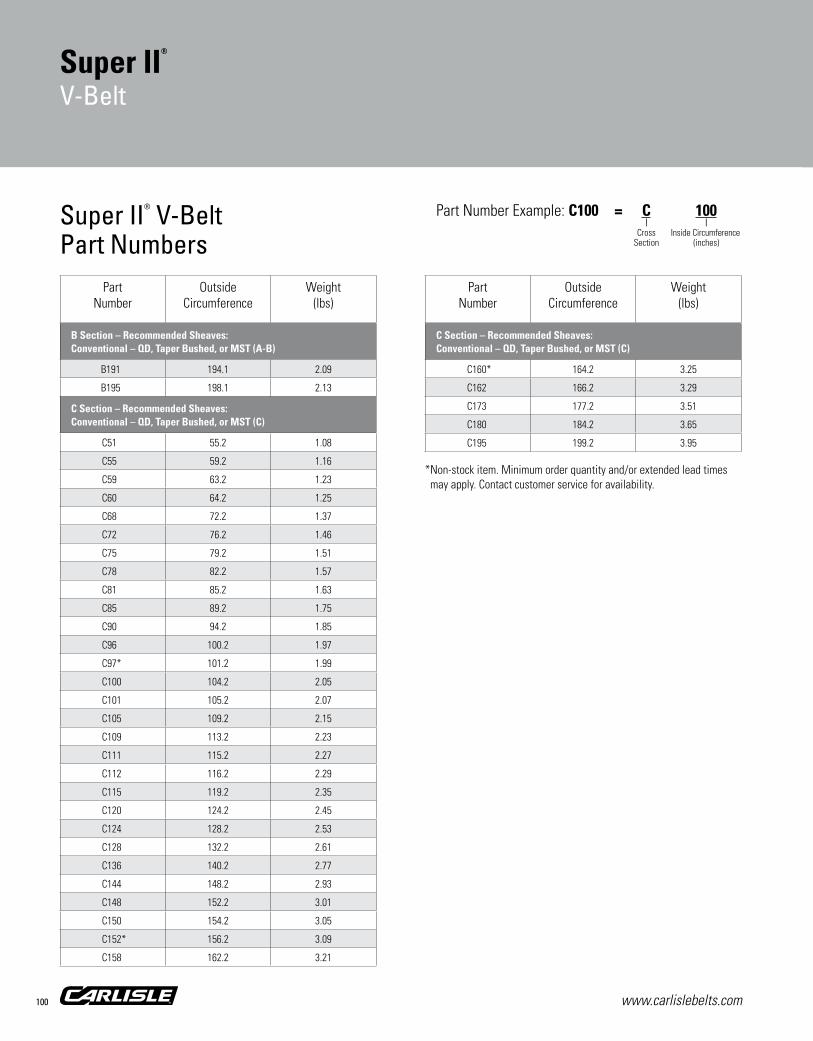
www.carlislebelts.com100
Part Number Example: C100 = C 100 | | Cross Inside Circumference Section (inches)
PartNumber
Outside Circumference
Weight(lbs)
B Section – Recommended Sheaves:Conventional – QD, Taper Bushed, or MST (A-B)
B191 194.1 2.09
B195 198.1 2.13
C Section – Recommended Sheaves:Conventional – QD, Taper Bushed, or MST (C)
C51 55.2 1.08
C55 59.2 1.16
C59 63.2 1.23
C60 64.2 1.25
C68 72.2 1.37
C72 76.2 1.46
C75 79.2 1.51
C78 82.2 1.57
C81 85.2 1.63
C85 89.2 1.75
C90 94.2 1.85
C96 100.2 1.97
C97* 101.2 1.99
C100 104.2 2.05
C101 105.2 2.07
C105 109.2 2.15
C109 113.2 2.23
C111 115.2 2.27
C112 116.2 2.29
C115 119.2 2.35
C120 124.2 2.45
C124 128.2 2.53
C128 132.2 2.61
C136 140.2 2.77
C144 148.2 2.93
C148 152.2 3.01
C150 154.2 3.05
C152* 156.2 3.09
C158 162.2 3.21
PartNumber
Outside Circumference
Weight(lbs)
C Section – Recommended Sheaves:Conventional – QD, Taper Bushed, or MST (C)
C160* 164.2 3.25
C162 166.2 3.29
C173 177.2 3.51
C180 184.2 3.65
C195 199.2 3.95
Super II® V-BeltPart Numbers
Super II®
V-Belt
*Non-stock item. Minimum order quantity and/or extended lead times may apply. Contact customer service for availability.

www.carlislebelts.com 101
The finest wrapped belt in the industry
Super rated at standard prices
Longer life
matching
Applications:MixersPumps ConveyorsHVACAnything and everything & More
Super Blue Ribbon®
V-Belt
1 Cord The cord is coated with
a special compound that produces a secure, long-lasting bond with the surrounding rubber to assure longer life without separation problems. In addition, Blue Ribbon’s dependable length stability means the belt requires significantly less re-tensioning and take-up.
2 Cover The heavy-duty fabric cover
not only protects the core; but its extra flexibility permits the belt to bend more easily around the smallest pulleys with far less strain on the fabric. It’s a smoother running belt. Longer belt life results in less frequent replacement, less downtime and lower maintenance costs.
PLUS! The Timken Ironclad Guarantee
assures worry-free belt performance!
Recommended Sheaves:Conventional – QD, Taper Bushed, or MST (A-B, C, D)
1
2
Hea
vy D
uty
V-B
elts
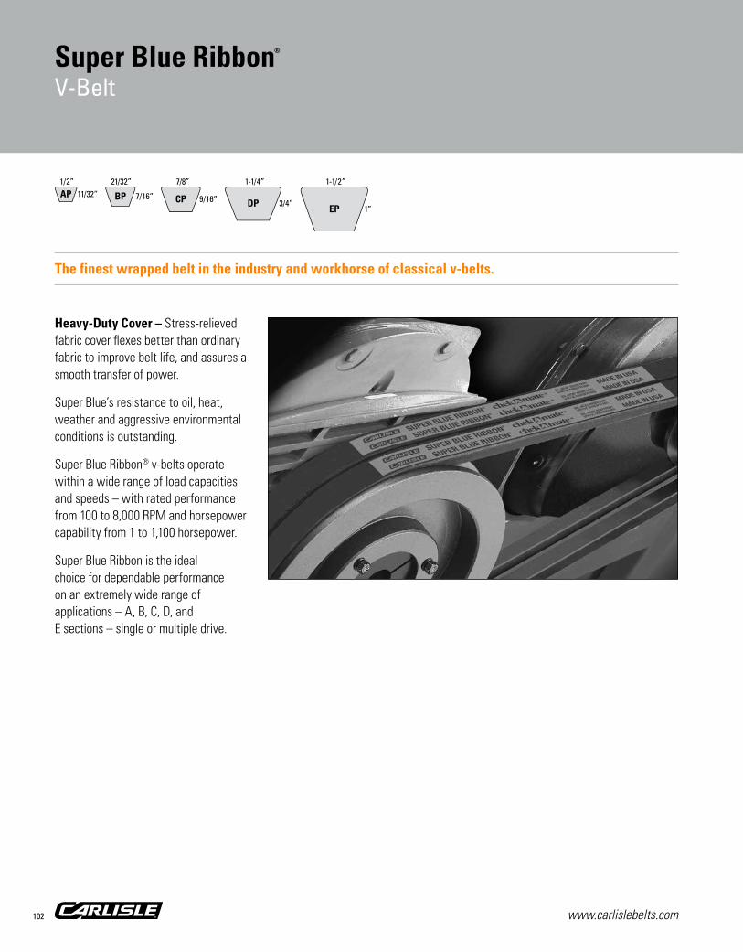
www.carlislebelts.com102
Super Blue Ribbon®
V-Belt
The finest wrapped belt in the industry and workhorse of classical v-belts.
Heavy-Duty Cover – Stress-relieved fabric cover flexes better than ordinary fabric to improve belt life, and assures a smooth transfer of power.
Super Blue’s resistance to oil, heat, weather and aggressive environmental conditions is outstanding.
Super Blue Ribbon® v-belts operate within a wide range of load capacities and speeds – with rated performance from 100 to 8,000 RPM and horsepower capability from 1 to 1,100 horsepower.
Super Blue Ribbon is the ideal choice for dependable performance on an extremely wide range of applications – A, B, C, D, and E sections – single or multiple drive.
21/32”
7/16”BP
1/2”AP 11/32”
1-1/2”
1”EPCP 9/16”
7/8”
3/4”DP
1-1/4”

www.carlislebelts.com 103
Super Blue Ribbon®
Part NumbersPart
NumberOutside
CircumferenceWeight
(lbs)
A Section – Recommended Sheaves:Conventional – QD, Taper Bushed, or MST (A-B)
AP20 22.3 0.11
AP21 23.3 0.14
AP22 24.3 0.15
AP23 25.3 0.15
AP24 26.3 0.16
AP25 27.3 0.17
AP26 28.3 0.17
AP27 29.3 0.18
AP28 30.3 0.19
AP29 31.3 0.19
AP30 32.3 0.20
AP31 33.3 0.21
AP32 34.3 0.21
AP33 35.3 0.22
AP34 36.3 0.22
AP35 37.3 0.23
AP36 38.3 0.24
AP37 39.3 0.24
AP38 40.3 0.25
AP39 41.3 0.26
AP40 42.3 0.26
AP41 43.3 0.27
AP42 44.3 0.27
AP43 45.3 0.28
AP44 46.3 0.29
AP45 47.3 0.29
AP46 48.3 0.30
AP47 49.3 0.31
AP48 50.3 0.31
AP49 51.3 0.32
AP50 52.3 0.32
AP51 53.3 0.33
AP52 54.3 0.34
PartNumber
Outside Circumference
Weight(lbs)
A Section – Recommended Sheaves:Conventional – QD, Taper Bushed, or MST (A-B)
AP53 55.3 0.34
AP54 56.3 0.35
AP55 57.3 0.36
AP56 58.3 0.36
AP57 59.3 0.37
AP58 60.3 0.37
AP59 61.3 0.38
AP60 62.3 0.39
AP61 63.3 0.39
AP62 64.3 0.40
AP63 65.3 0.41
AP64 66.3 0.41
AP65 67.3 0.41
AP66 68.3 0.43
AP67 69.3 0.43
AP68 70.3 0.44
AP69 71.3 0.44
AP70 72.3 0.45
AP71 73.3 0.46
AP72 74.3 0.46
AP73 75.3 0.46
AP74 76.3 0.47
AP75 77.3 0.48
AP76 78.3 0.48
AP77 79.3 0.49
AP78 80.3 0.49
AP79 81.3 0.50
AP80 82.3 0.51
AP81 83.3 0.51
AP82 84.3 0.52
AP83 85.3 0.52
AP84 86.3 0.53
AP85 87.3 0.54
Super Blue Ribbon®
V-Belt
Part Number Example: AP50 = A P 50 | | | Cross Wrapped Molded Inside Circumference Section Construction (inches)
Hea
vy D
uty
V-B
elts
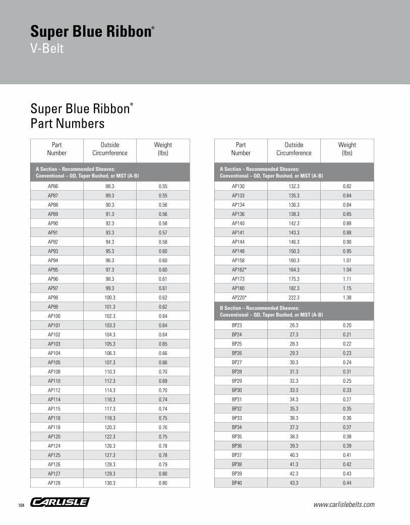
www.carlislebelts.com104
PartNumber
Outside Circumference
Weight(lbs)
A Section – Recommended Sheaves:Conventional – QD, Taper Bushed, or MST (A-B)
AP86 88.3 0.55
AP87 89.3 0.55
AP88 90.3 0.56
AP89 91.3 0.56
AP90 92.3 0.58
AP91 93.3 0.57
AP92 94.3 0.58
AP93 95.3 0.60
AP94 96.3 0.60
AP95 97.3 0.60
AP96 98.3 0.61
AP97 99.3 0.61
AP98 100.3 0.62
AP99 101.3 0.62
AP100 102.3 0.64
AP101 103.3 0.64
AP102 104.3 0.64
AP103 105.3 0.65
AP104 106.3 0.66
AP105 107.3 0.66
AP108 110.3 0.70
AP110 112.3 0.69
AP112 114.3 0.70
AP114 116.3 0.74
AP115 117.3 0.74
AP116 118.3 0.75
AP118 120.3 0.76
AP120 122.3 0.75
AP124 126.3 0.78
AP125 127.3 0.78
AP126 128.3 0.79
AP127 129.3 0.80
AP128 130.3 0.80
PartNumber
Outside Circumference
Weight(lbs)
A Section – Recommended Sheaves:Conventional – QD, Taper Bushed, or MST (A-B)
AP130 132.3 0.82
AP133 135.3 0.84
AP134 136.3 0.84
AP136 138.3 0.85
AP140 142.3 0.88
AP141 143.3 0.88
AP144 146.3 0.90
AP148 150.3 0.95
AP158 160.3 1.01
AP162* 164.3 1.04
AP173 175.3 1.11
AP180 182.3 1.15
AP220* 222.3 1.38
B Section – Recommended Sheaves:Conventional – QD, Taper Bushed, or MST (A-B)
BP23 26.3 0.20
BP24 27.3 0.21
BP25 28.3 0.22
BP26 29.3 0.23
BP27 30.3 0.24
BP28 31.3 0.31
BP29 32.3 0.25
BP30 33.3 0.33
BP31 34.3 0.27
BP32 35.3 0.35
BP33 36.3 0.36
BP34 37.3 0.37
BP35 38.3 0.38
BP36 39.3 0.39
BP37 40.3 0.41
BP38 41.3 0.42
BP39 42.3 0.43
BP40 43.3 0.44
Super Blue Ribbon®
Part Numbers
Super Blue Ribbon®
V-Belt

www.carlislebelts.com 105
Sync
hron
ous
Bel
ts
PartNumber
Outside Circumference
Weight(lbs)
B Section – Recommended Sheaves:Conventional – QD, Taper Bushed, or MST (A-B)
BP41 44.3 0.44
BP42 45.3 0.45
BP43 46.3 0.47
BP44 47.3 0.48
BP45 48.3 0.49
BP46 49.3 0.50
BP47 50.3 0.51
BP48 51.3 0.52
BP49 52.3 0.53
BP50 53.3 0.54
BP51 54.3 0.55
BP52 55.3 0.56
BP53 56.3 0.57
BP54 57.3 0.58
BP55 58.3 0.59
BP56 59.3 0.60
BP57 60.3 0.61
BP58 61.3 0.62
BP59 62.3 0.63
BP60 63.3 0.64
BP61 64.3 0.65
BP62 65.3 0.66
BP63 66.3 0.67
BP64 67.3 0.68
BP65 68.3 0.69
BP66 69.3 0.70
BP67 70.3 0.71
BP68 71.3 0.72
BP69 72.3 0.74
BP70 73.3 0.74
BP71 74.3 0.75
BP72 75.3 0.77
BP73 76.3 0.78
PartNumber
Outside Circumference
Weight(lbs)
B Section – Recommended Sheaves:Conventional – QD, Taper Bushed, or MST (A-B)
BP74 77.3 0.79
BP75 78.3 0.80
BP76 79.3 0.81
BP77 80.3 0.82
BP78 81.3 0.83
BP79 82.3 0.84
BP80 83.3 0.85
BP81 84.3 0.86
BP82 85.3 0.87
BP83 86.3 0.88
BP84 87.3 0.89
BP85 88.3 0.90
BP86 89.3 0.91
BP87 90.3 0.92
BP88 91.3 0.93
BP89 92.3 0.92
BP90 93.3 0.95
BP91 94.3 0.94
BP92 95.3 0.97
BP93 96.3 0.98
BP94 97.3 0.97
BP95 98.3 1.00
BP96 99.3 1.01
BP97 100.3 1.02
BP98 101.3 1.01
BP99 102.3 1.02
BP100 103.3 1.06
BP101 104.3 1.04
BP102 105.3 1.05
BP103 106.3 1.09
BP104 107.3 1.07
BP105 108.3 1.11
BP106 109.3 1.09
Part Number Example: BP50 = B P 50 | | | Cross Wrapped Molded Inside Circumference Section Construction (inches)
Super Blue Ribbon®
V-Belt
Hea
vy D
uty
V-B
elts

www.carlislebelts.com106
PartNumber
Outside Circumference
Weight(lbs)
B Section – Recommended Sheaves:Conventional – QD, Taper Bushed, or MST (A-B)
BP107 110.3 1.10
BP108 111.3 1.14
BP109 112.3 1.12
BP110 113.3 1.13
BP111 114.3 1.14
BP112 115.3 1.18
BP113 116.3 1.16
BP114 117.3 1.17
BP115 118.3 1.18
BP116 119.3 1.22
BP117 120.3 1.20
BP118 121.3 1.21
BP119 122.3 1.22
BP120 123.3 1.26
BP122 125.3 1.24
BP123 126.3 1.25
BP124 127.3 1.27
BP125 128.3 1.27
BP126 129.3 1.29
BP128 131.3 1.31
BP130 133.3 1.33
BP131 134.3 1.33
BP132 135.3 1.35
BP133 136.3 1.36
BP134 137.3 1.37
BP135 138.3 1.38
BP136 139.3 1.39
BP138 141.3 1.41
BP140 143.3 1.43
BP141 144.3 1.44
BP142 145.3 1.45
BP144 147.3 1.48
BP146 149.3 1.49
PartNumber
Outside Circumference
Weight(lbs)
B Section – Recommended Sheaves:Conventional – QD, Taper Bushed, or MST (A-B)
BP148 151.3 1.51
BP150 153.3 1.53
BP151 154.3 1.54
BP152 155.3 1.55
BP154 157.3 1.57
BP156 159.3 1.59
BP157 160.3 1.60
BP158 161.3 1.61
BP160 163.3 1.64
BP161 164.3 1.65
BP162 165.3 1.66
BP164 167.3 1.68
BP165 168.3 1.69
BP168 171.3 1.72
BP170 173.3 1.74
BP172 175.3 1.76
BP173 176.3 1.77
BP175 178.3 1.79
BP176 179.3 1.80
BP180 183.3 1.84
BP182 185.3 1.86
BP184 187.3 1.88
BP190 193.3 1.94
BP191 194.3 1.95
BP195 198.3 1.99
BP198 201.3 2.02
BP203 206.3 2.05
BP205 208.3 2.07
BP210 213.3 2.12
BP214 217.3 2.16
BP217* 220.3 2.19
BP220 223.3 2.22
BP221 224.3 2.23
Super Blue Ribbon®
Part Numbers
Super Blue Ribbon®
V-Belt

www.carlislebelts.com 107
PartNumber
Outside Circumference
Weight(lbs)
B Section – Recommended Sheaves:Conventional – QD, Taper Bushed, or MST (A-B)
BP224* 227.3 2.25
BP225 228.3 2.26
BP228 231.3 2.30
BP240 241.7 2.41
BP250 251.7 2.52
BP253* 254.7 2.55
BP255 256.7 2.56
BP265 266.7 2.67
BP270 271.7 2.71
BP280 281.7 2.81
BP285 286.7 2.86
BP300 301.7 3.01
BP315 316.7 3.16
BP330 331.7 3.31
BP360 361.7 3.68
BP361* 362.7 3.70
BP364* 365.7 3.80
BP433* 434.7 4.43
BP443* 444.7 4.53
BP512 513.7 5.22
BP543* 544.7 5.53
BP553* 554.7 5.64
C Section – Recommended Sheaves:Conventional – QD, Taper Bushed, or MST (C)
CP46 50.4 0.79
CP50 54.4 0.91
CP51 55.4 0.98
CP53 57.4 1.01
CP54 58.4 1.04
CP55 59.4 1.06
CP56 60.4 1.01
CP57 61.4 1.04
CP58 62.4 1.00
PartNumber
Outside Circumference
Weight(lbs)
C Section – Recommended Sheaves:Conventional – QD, Taper Bushed, or MST (C)
CP60 64.4 1.15
CP61 65.4 1.16
CP62 66.4 1.18
CP63 67.4 1.20
CP64 68.4 1.22
CP65 69.4 1.10
CP66 70.4 1.25
CP67 71.4 1.27
CP68 72.4 1.29
CP69 73.4 1.30
CP70 74.4 1.27
CP71 75.4 1.34
CP72 76.4 1.36
CP73 77.4 1.38
CP74 78.4 1.40
CP75 79.4 1.46
CP76 80.4 1.49
CP77 81.4 1.50
CP78 82.4 1.52
CP79 83.4 1.54
CP80 84.4 1.55
CP81 85.4 1.58
CP82 86.4 1.59
CP83 87.4 1.61
CP84 88.4 1.63
CP85 89.4 1.65
CP86 90.4 1.67
CP87 91.4 1.69
CP88 92.4 1.71
CP89 93.4 1.73
CP90 94.4 1.74
CP91 95.4 1.76
CP92 96.4 1.79
Part Number Example: CP50 = C P 50 | | | Cross Wrapped Molded Inside Circumference Section Construction (inches)
Super Blue Ribbon®
V-Belt
Hea
vy D
uty
V-B
elts

www.carlislebelts.com108
PartNumber
Outside Circumference
Weight(lbs)
C Section – Recommended Sheaves:Conventional – QD, Taper Bushed, or MST (C)
CP93 97.4 1.81
CP94 98.4 1.82
CP95 99.4 1.84
CP96 100.4 1.86
CP97 101.4 1.88
CP98 102.4 1.90
CP99 103.4 1.92
CP100 104.4 1.94
CP101 105.4 1.96
CP102 106.4 1.97
CP103 107.4 1.99
CP104 108.4 2.01
CP105 109.4 2.03
CP106 110.4 2.04
CP107 111.4 2.07
CP108 112.4 2.09
CP109 113.4 2.10
CP110 114.4 2.12
CP111 115.4 2.14
CP112 116.4 2.16
CP113 117.4 2.18
CP114 118.4 2.20
CP115 119.4 2.22
CP116 120.4 2.23
CP117 121.4 2.25
CP118 122.4 2.27
CP119 123.4 2.29
CP120 124.4 2.31
CP121 125.4 2.33
CP122 126.4 2.34
CP123 127.4 2.37
CP124 128.4 2.38
CP125 129.4 2.40
PartNumber
Outside Circumference
Weight(lbs)
C Section – Recommended Sheaves:Conventional – QD, Taper Bushed, or MST (C)
CP126 130.4 2.42
CP127 131.4 2.44
CP128 132.4 2.46
CP129 133.4 2.48
CP130 134.4 2.50
CP131 135.4 2.52
CP132 136.4 2.53
CP133 137.4 2.55
CP134 138.4 2.57
CP135 139.4 2.59
CP136 140.4 2.61
CP137 141.4 2.63
CP138 142.4 2.66
CP139 143.4 2.57
CP140 144.4 2.68
CP141 145.4 2.70
CP142 146.4 2.72
CP143 147.4 2.74
CP144 148.4 2.76
CP145 149.4 2.78
CP146 150.4 2.80
CP147 151.4 2.81
CP148 152.4 2.83
CP149 153.4 2.85
CP150 154.4 2.87
CP151 155.4 2.89
CP152 156.4 2.91
CP153 157.4 2.93
CP154 158.4 2.95
CP155 159.4 2.97
CP156 160.4 2.98
CP157 161.4 3.00
CP158 162.4 3.02
Super Blue Ribbon®
Part Numbers
Super Blue Ribbon®
V-Belt

www.carlislebelts.com 109
Sync
hron
ous
Bel
ts
PartNumber
Outside Circumference
Weight(lbs)
C Section – Recommended Sheaves:Conventional – QD, Taper Bushed, or MST (C)
CP159 163.4 3.04
CP160 164.4 3.06
CP161 165.4 3.08
CP162 166.4 3.10
CP163 167.4 3.12
CP164 168.4 3.13
CP165 169.4 3.15
CP166 170.4 3.17
CP167 171.4 3.19
CP168 172.4 3.21
CP169 173.4 3.23
CP170 174.4 3.25
CP171 175.4 3.27
CP172* 176.4 3.28
CP173 177.4 3.30
CP174 178.4 3.32
CP175 179.4 3.34
CP176 180.4 3.36
CP177 181.4 3.38
CP178 182.4 3.40
CP180 184.4 3.43
CP181 185.4 3.46
CP182 186.4 3.47
CP183 187.4 3.49
CP184 188.4 3.51
CP185 189.4 3.53
CP186 190.4 3.55
CP187 191.4 3.57
CP188 192.4 3.58
CP189 193.4 3.60
CP190 194.4 3.62
CP193 197.4 3.68
CP194 198.4 3.70
PartNumber
Outside Circumference
Weight(lbs)
C Section – Recommended Sheaves:Conventional – QD, Taper Bushed, or MST (C)
CP195 199.4 3.72
CP196 200.4 3.73
CP197 201.4 3.75
CP198 202.4 3.77
CP200 204.4 3.81
CP204 208.4 3.76
CP205 209.4 3.78
CP208 212.4 3.83
CP210 214.4 3.87
CP215 219.4 3.96
CP218 222.4 4.02
CP220 224.4 4.05
CP225 229.4 4.11
CP228 232.4 4.16
CP230 234.4 4.20
CP235 239.4 4.29
CP236* 240.4 4.31
CP240 242.5 4.38
CP245 247.5 4.47
CP248 250.5 4.52
CP250* 252.5 4.56
CP255 257.5 4.65
CP260 262.5 4.74
CP264* 266.5 4.81
CP265 267.5 4.83
CP269* 271.5 4.90
CP270 272.5 4.92
CP275 277.5 5.01
CP276* 278.5 5.03
CP280 282.5 5.12
CP285 287.5 5.19
CP290 292.5 5.28
CP297* 299.5 5.41
Part Number Example: CP200 = C P 200 | | | Cross Wrapped Molded Inside Circumference Section Construction (inches)
Super Blue Ribbon®
V-Belt
Hea
vy D
uty
V-B
elts

www.carlislebelts.com110
PartNumber
Outside Circumference
Weight(lbs)
C Section – Recommended Sheaves:Conventional – QD, Taper Bushed, or MST (C)
CP300 302.5 5.47
CP314* 316.5 5.72
CP315 317.5 5.74
CP330 332.5 6.01
CP340* 342.5 6.19
CP345 347.5 6.28
CP360 362.5 6.65
CP390 392.5 7.20
CP420 422.5 7.75
D Section – Recommended Sheaves:Conventional – QD, Taper Bushed, or MST (D)
DP88* 93.5 3.02
DP90 95.5 3.08
DP96 101.5 3.28
DP100 105.5 3.41
DP101* 106.5 3.45
DP104 109.5 3.54
DP105 110.5 3.58
DP108 113.5 3.68
DP112 117.5 3.81
DP115* 120.5 3.91
DP120 125.5 4.33
DP124* 129.5 4.13
DP128 133.5 4.61
DP132 137.5 4.47
DP135 140.5 4.57
DP136 141.5 4.60
DP144 149.5 4.85
DP152 157.5 5.11
DP158 163.5 5.31
DP160* 165.5 5.37
DP162 167.5 5.44
DP164 169.5 5.50
PartNumber
Outside Circumference
Weight(lbs)
D Section – Recommended Sheaves:Conventional – QD, Taper Bushed, or MST (D)
DP165 170.5 5.54
DP166 171.5 5.57
DP170* 175.5 5.70
DP171 176.5 5.73
DP173 178.5 5.80
DP178 183.5 5.96
DP180 185.5 6.03
DP189 194.5 6.33
DP195 200.5 6.52
DP210 215.5 7.02
DP225 230.5 7.43
DP230* 235.5 7.59
DP240 243.0 7.92
DP255 258.0 8.41
DP260* 263.0 8.58
DP270 273.0 8.91
DP280 283.0 9.23
DP285 288.0 9.40
DP300 303.0 9.89
DP315 318.0 10.38
DP330 333.0 10.88
DP345 348.0 11.37
DP360 363.0 12.01
DP390 393.0 13.01
DP420 423.0 14.01
DP450* 453.0 15.20
DP480* 483.0 16.20
DP540 543.0 18.22
DP600* 603.0 20.60
DP660* 663.0 22.25
Super Blue Ribbon®
Part Numbers
Super Blue Ribbon®
V-Belt

www.carlislebelts.com 111
PartNumber
Outside Circumference
Weight(lbs)
E Section – Recommended Sheaves:Conventional – QD, Taper Bushed, or MST (E*)
EP144* 150.2 7.90
EP180* 186.2 9.82
EP195* 201.2 10.70
EP210* 216.2 11.42
EP225* 231.2 12.03
EP240 243.7 12.83
EP270 273.7 14.43
EP300 303.7 16.02
EP330 333.7 17.62
EP360 363.7 19.32
EP390* 393.7 20.93
EP420* 423.7 22.54
EP441* 444.7 23.70
EP480* 483.7 25.75
EP540* 543.7 28.96
EP600* 603.7 32.20
EP660* 663.7 35.39
Part Number Example: DP300 = D P 300 | | | Cross Wrapped Molded Inside Circumference Section Construction (inches)
*Non-stock item. Minimum order quantity and/or extended lead times may apply. Contact customer service for availability.
Super Blue Ribbon®
V-Belt
Hea
vy D
uty
V-B
elts

www.carlislebelts.com112
Aramax® Xtra DutyV-Belt

Panther®XTV-Belt
www.carlislebelts.com 113
New and improved premium rubber compound provides longer belt life
Smooth clutching cover for shock-loaded, backside-idler drives
Superior shock resistance
Applications:Outdoor power Equipment including Lawnmowers Edgers Snow blowers& More
Aramax® Xtra DutyV-Belt
Recommended Sheaves:Conventional – QD, Taper Bushed, or MST (A-B)
1 Aramid Tensile Cords Carries load with increased
strength and durability
2 Rubber Compound New and improved
compound for longer belt life
3 Clutching Cover Superior fabric for
smoother clutching and resistance to rollover
2
1
3
Hea
vy D
uty
V-B
elts

www.carlislebelts.com114
Aramax® Xtra DutyV-Belt
PartNumber
Outside Circumference
Weight(lbs)
3L Section – Recommended Sheaves:Conventional – QD, Taper Bushed, or MST (3L*)
3L150K* 15.1 0.05
3L160K* 16.1 0.05
3L170K* 17.1 0.05
3L180K* 18.1 0.06
3L190K 19.1 0.06
3L200K* 20.1 0.06
3L210K* 21.1 0.06
3L220K 22.1 0.07
3L230K* 23.1 0.07
3L240K* 24.1 0.07
3L250K* 25.1 0.08
3L260K* 26.1 0.08
3L270K* 27.1 0.08
3L280K 28.1 0.09
3L290K 29.1 0.09
3L300K* 30.1 0.09
3L310K 31.1 0.09
3L320K 32.1 0.10
3L330K 33.1 0.10
3L340K 34.1 0.11
3L350K 35.1 0.11
3L360K* 36.1 0.11
3L370K 37.1 0.11
3L380K 38.1 0.12
3L390K 39.1 0.12
3L400K* 40.1 0.12
3L410K 41.1 0.12
3L420K* 42.1 0.13
3L430K* 43.1 0.13
3L440K 44.1 0.13
3L450K* 45.1 0.14
3L460K* 46.1 0.14
3L470K* 47.1 0.14
Specifically designed for aggressive applications with heavy shock loads and backside-idler driven equipment.
Performance Driven…Performance Proven ■■ Aramax® Xtra Duty v-belts are designed for outdoor power equipment. Aramax features a brown smooth clutching cover and strong aramid cord. This high performance construction delivers more horsepower, less stretch and longer service life.
Sizes■■ 3L, A, B section belts
■■ 3L sizes use industry standard part number ending in K
■■ Classical part numbers are AK, BK• Dual branded with ASABE length designations HA, HB
Features/Advantages■■ Superior clutching fabric
• Smoother clutching • Increased thread count• Resistance to rollover
■■ Aramid tensile cords• Increased strength and durability• Reduced stretch
■■ Oil and heat resistant
Please note: When Aramax belts are used as a matched set, all belts must have the same SAG number. These high modulus aramid cord belts require closer matching than standard belts in order to tension properly and work together as a set.
1/2”
A 11/32”
3/8”
3L 7/32”
21/32”
7/16”B

www.carlislebelts.com 115
Aramax® Xtra DutyV-Belt
Aramax® Xtra Duty V-BeltPart Numbers
Part Number Example: AK15 = A K 15 | | | Cross Aramid Cord Inside Circumference Section Construction (inches)
PartNumber
Outside Circumference
Weight(lbs)
3L Section – Recommended Sheaves:Conventional – QD, Taper Bushed, or MST (3L*)
3L480K* 48.1 0.15
3L490K* 49.1 0.15
3L500K* 50.1 0.15
3L510K* 51.1 0.15
3L520K* 52.1 0.16
3L530K* 53.1 0.16
3L540K* 54.1 0.16
3L550K* 55.1 0.17
3L560K* 56.1 0.17
3L570K* 57.1 0.17
3L580K* 58.1 0.18
3L590K* 59.1 0.18
3L600K* 60.1 0.18
3L610K* 61.1 0.18
3L620K* 62.1 0.19
3L740K* 74.1 0.22
A Section – Recommended Sheaves:Conventional – QD, Taper Bushed, or MST (A-B)
AK15 17.3 0.09
AK16 18.3 0.09
AK17* 19.3 0.10
AK18 20.3 0.10
AK19 21.3 0.11
AK20 22.3 0.11
AK21 23.3 0.13
AK22 24.3 0.13
AK23 25.3 0.14
AK24 26.3 0.14
AK25 27.3 0.15
AK26 28.3 0.16
AK27 29.3 0.16
AK28 30.3 0.17
AK29 31.3 0.17
PartNumber
Outside Circumference
Weight(lbs)
A Section – Recommended Sheaves:Conventional – QD, Taper Bushed, or MST (A-B)
AK30 32.3 0.18
AK31 33.3 0.18
AK32 34.3 0.19
AK33 35.3 0.20
AK34 36.3 0.20
AK35 37.3 0.21
AK36 38.3 0.21
AK37 39.3 0.22
AK38 40.3 0.22
AK39 41.3 0.23
AK40 42.3 0.23
AK41 43.3 0.24
AK42 44.3 0.25
AK43 45.3 0.25
AK44 46.3 0.26
AK45 47.3 0.26
AK46 48.3 0.27
AK47 49.3 0.27
AK48 50.3 0.28
AK49 51.3 0.28
AK50 52.3 0.29
AK51 53.3 0.30
AK52 54.3 0.30
AK53 55.3 0.31
AK54 56.3 0.31
AK55 57.3 0.32
AK56 58.3 0.32
AK57 59.3 0.33
AK58 60.3 0.33
AK59 61.3 0.34
AK60 62.3 0.35
AK61 63.3 0.35
AK62 64.3 0.36
Hea
vy D
uty
V-B
elts

www.carlislebelts.com116
PartNumber
Outside Circumference
Weight(lbs)
A Section – Recommended Sheaves:Conventional – QD, Taper Bushed, or MST (A-B)
AK63 65.3 0.36
AK64 66.3 0.37
AK65 67.3 0.37
AK66 68.3 0.38
AK67 69.3 0.39
AK68 70.3 0.39
AK69 71.3 0.40
AK70 72.3 0.40
AK71 73.3 0.41
AK72 74.3 0.41
AK73 75.3 0.42
AK74 76.3 0.42
AK75 77.3 0.43
AK76 78.3 0.44
AK77 79.3 0.44
AK78 80.3 0.45
AK79 81.3 0.45
AK80 82.3 0.46
AK81 83.3 0.46
AK82 84.3 0.47
AK83 85.3 0.47
AK84 86.3 0.48
AK85 87.3 0.49
AK86 88.3 0.49
AK87 89.3 0.50
AK88 90.3 0.50
AK89 91.3 0.51
AK90 92.3 0.51
AK91 93.3 0.52
AK92 94.3 0.53
AK93 95.3 0.53
AK94 96.3 0.54
AK95 97.3 0.54
PartNumber
Outside Circumference
Weight(lbs)
A Section – Recommended Sheaves:Conventional – QD, Taper Bushed, or MST (A-B)
AK96 98.3 0.55
AK97 99.3 0.55
AK98 100.3 0.56
AK100* 102.3 0.57
AK101 103.3 0.58
AK103 105.3 0.59
AK105* 107.3 0.60
AK112* 114.3 0.64
AK115* 117.3 0.70
B Section – Recommended Sheaves:Conventional – QD, Taper Bushed, or MST (A-B)
BK20* 23.3 0.18
BK21 24.3 0.19
BK22* 25.3 0.19
BK23* 26.3 0.20
BK24* 27.3 0.21
BK25* 28.3 0.22
BK26 29.3 0.23
BK27 30.3 0.23
BK28 31.3 0.29
BK29 32.3 0.25
BK30 33.3 0.26
BK31 34.3 0.27
BK32 35.3 0.33
BK33 36.3 0.34
BK34 37.3 0.35
BK35 38.3 0.36
BK36 39.3 0.37
BK37 40.3 0.38
BK38 41.3 0.39
BK39 42.3 0.40
BK40 43.3 0.41
BK41 44.3 0.42
Aramax® Xtra Duty V-BeltPart Numbers
Aramax® Xtra DutyV-Belt

www.carlislebelts.com 117
Aramax® Xtra DutyV-Belt
Part Number Example: BK50 = B K 50 | | | Cross Aramid Cord Inside Circumference Section Construction (inches)
PartNumber
Outside Circumference
Weight(lbs)
B Section – Recommended Sheaves:Conventional – QD, Taper Bushed, or MST (A-B)
BK42 45.3 0.42
BK43 46.3 0.44
BK44 47.3 0.45
BK45 48.3 0.46
BK46 49.3 0.47
BK47 50.3 0.47
BK48 51.3 0.48
BK49 52.3 0.49
BK50 53.3 0.50
BK51 54.3 0.52
BK52 55.3 0.52
BK53 56.3 0.53
BK54 57.3 0.54
BK55 58.3 0.56
BK56 59.3 0.56
BK57 60.3 0.57
BK58 61.3 0.58
BK59 62.3 0.59
BK60 63.3 0.60
BK61 64.3 0.61
BK62 65.3 0.62
BK63 66.3 0.63
BK64 67.3 0.64
BK65 68.3 0.65
BK66 69.3 0.66
BK67 70.3 0.67
BK68 71.3 0.68
BK69 72.3 0.69
BK70 73.3 0.70
BK71 74.3 0.71
BK72 75.3 0.72
BK73 76.3 0.73
BK74 77.3 0.74
PartNumber
Outside Circumference
Weight(lbs)
B Section – Recommended Sheaves:Conventional – QD, Taper Bushed, or MST (A-B)
BK75 78.3 0.75
BK76 79.3 0.76
BK77 80.3 0.77
BK78 81.3 0.78
BK79 82.3 0.79
BK80 83.3 0.80
BK81 84.3 0.81
BK82 85.3 0.82
BK83 86.3 0.83
BK84* 87.3 0.84
BK85 88.3 0.85
BK86 89.3 0.86
BK87 90.3 0.87
BK88 91.3 0.88
BK89* 92.3 0.89
BK90 93.3 0.90
BK91* 94.3 0.91
BK92* 95.3 0.92
BK93 96.3 0.92
BK94 97.3 0.93
BK95* 98.3 0.94
BK96* 99.3 0.95
BK97* 100.3 0.96
BK98 101.3 0.97
BK100 102.9 0.99
*Non-stock item. Minimum order quantity and/or extended lead times may apply. Contact customer service for availability.
Hea
vy D
uty
V-B
elts

www.carlislebelts.com118
Power-Wedge® Cog-Belt®
V-Belt

Panther®XTV-Belt
www.carlislebelts.com 119
Energy efficient
Smoother running
Design flexibility
High performance EPDM construction:
High HP ratings
Longer belt life
Oil and heat resistant
Resists hardening and glazing
Broad operating temperature range (-50°F to +250°F)
matching
Static conductive
Imperial and metric cross-sections
Applications:Fans PumpsHVACCompressors & More
119
Power-Wedge® Cog-Belt®
V-Belt
1 High-Modulus Cords Carries high horsepower loads with minimum
stretch. Better belt stability. Fewer take-up adjustments.
2 Precision Molded Cogs Improves belt flex, reduces bending stress. Helps
dissipate heat and requires less power. Improves flexibility for increased performance on small diameter pulleys.
3 EPDM Construction EPDM offers superior flex and load carrying
capacity. It resists belt cracking and won’t stretch. EPDM has excellent flexibility at high and low temperatures.
4 Raw Edge Side Walls Produces a higher coefficient of friction. Keeps
a tighter grip on the sheave to reduce slippage. Improves performance and efficiency. Reduces vibration for extended component life.
1
2
Recommended Sheaves:Hi-Cap Wedge – QD, Taper Bushed, or MST (3V, 5V, 8V)
4
3
Hea
vy D
uty
V-B
elts

www.carlislebelts.com120
Power-Wedge® Cog-Belt®
V-Belt
The Power-Wedge® Cog-Belt® combines the advantages of the narrow belt wedge design with raw edge performance for maximum operating efficiency in a compact drive package – now made of EPDM (Ethylene Propylene Diene Monomer), a synthetic rubber with outstanding properties.
More Grip…Less Slip
Our Power-Wedge® Cog-Belt® provides more torque with little or no slippage. The result is savings – in time, in belt life and in energy costs.
The narrow profile permits reduced drive widths and a smaller drive envelope. Higher horsepower ratings translate into greater design flexibility – reducing drive cost, space and weight.
The Power-Wedge Cog-Belt is available in 3VX, 5VX, and 8VX cross sections as well as metric sizes SPZX, SPAX, SPBX, and SPCX. Where applicable, belts are dual branded with imperial and metric part numbers.
Horsepower Ratings Comparison
Power-Wedge Cog-BeltConventional V-Belt
HP
40
30
20
10
0
5V Section Drive 1750 RPM1.5.1 Belt Drive Ratio
5/8”
17/32”5VX
3/8”3VX 5/16”
1”
7/8”8VXSPAX 10.0mm
12.7mm 22.0mm
SPCX 18.0mm
16.3mm
13.0mmSPBX
9.7mm
8.0mmSPZX

Part Number Example: 5VX500 = 5V X 500 | | | Cross Cogged Effective Length Section Construction (inches in tenths: 50.0”)
www.carlislebelts.com 121
Power-Wedge® Cog-Belt® Part Numbers
PartNumber
Effective Length (in)
MetricNumber
Weight(lbs)
3V Section – Recommended Sheaves:Hi-Cap Wedge – QD, Taper Bushed, or MST (3V)
3VX250 24.9 9XN630 0.08
3VX265 26.5 9XN670 0.08
3VX280 28.0 9XN710 0.09
3VX300 29.9 9XN760 0.09
3VX315 31.5 9XN800 0.10
3VX335 33.3 9XN850 0.10
3VX355 35.6 9XN900 0.11
3VX375 37.5 9XN950 0.12
3VX400 40.0 9XN1015 0.13
3VX425 42.5 9XN1080 0.13
3VX450 45.0 9XN1145 0.14
3VX475 47.5 9XN1205 0.14
3VX500 50.0 9XN1270 0.16
3VX530 52.9 9XN1345 0.17
3VX560 56.0 9XN1420 0.18
3VX600 60.1 9XN1525 0.19
3VX630 62.9 9XN1600 0.20
3VX670 67.0 9XN1700 0.21
3VX710 71.1 9XN1800 0.22
3VX750 74.8 9XN1900 0.23
3VX800 79.9 9XN2030 0.25
3VX850 84.9 9XN2160 0.27
3VX900 89.9 9XN2290 0.28
3VX950 94.9 9XN2410 0.30
3VX1000 100.0 9XN2540 0.31
3VX1060 105.9 9XN2690 0.33
3VX1120 111.9 9XN2840 0.35
3VX1180 117.9 9XN3000 0.37
3VX1250 125.0 9XN3180 0.39
3VX1320 132.0 9XN3350 0.41
3VX1400 140.0 9XN3550 0.44
3VX1500 150.0 9XN3810 0.47
PartNumber
Effective Length (in)
MetricNumber
Weight(lbs)
5V Section – Recommended Sheaves:Hi-Cap Wedge – QD, Taper Bushed, or MST (5V)
5VX450 45.0 15XN1150 0.36
5VX470 46.9 15XN1190 0.38
5VX490 49.0 15XN1250 0.40
5VX500 50.0 15XN1270 0.40
5VX510 51.0 15XN1290 0.41
5VX530 53.1 15XN1345 0.43
5VX540 53.9 15XN1370 0.44
5VX550 55.0 15XN1400 0.44
5VX560 56.0 15XN1420 0.45
5VX570 56.9 15XN1450 0.46
5VX580 57.9 15XN1470 0.47
5VX590 59.1 15XN1500 0.48
5VX600 60.1 15XN1525 0.64
5VX610 61.0 15XN1550 0.49
5VX630 62.9 15XN1600 0.51
5VX650 65.1 15XN1650 0.53
5VX660 66.0 15XN1680 0.53
5VX670 67.0 15XN1700 0.54
5VX680 67.9 15XN1730 0.55
5VX690 68.9 15XN1750 0.56
5VX710 71.1 15XN1800 0.57
5VX730 72.9 15XN1850 0.59
5VX740 73.9 15XN1880 0.59
5VX750 75.1 15XN1900 0.60
5VX780 78.0 15XN1980 0.63
5VX790 78.9 15XN2000 0.63
5VX800 79.9 15XN2030 0.64
5VX810 80.8 15XN2060 0.65
5VX830 83.0 15XN2110 0.67
5VX840 83.9 15XN2130 0.67
5VX850 84.9 15XN2160 0.68
5VX860 85.8 15XN2180 0.69
5VX880 88.0 15XN2240 0.71
Power-Wedge® Cog-Belt®
V-Belt
Hea
vy D
uty
V-B
elts

www.carlislebelts.com122
PartNumber
Effective Length (in)
MetricNumber
Weight(lbs)
5V Section – Recommended Sheaves:Hi-Cap Wedge – QD, Taper Bushed, or MST (5V)
5VX900 89.9 15XN2290 0.72
5VX930 93.0 15XN2360 0.75
5VX950 94.9 15XN2410 0.76
5VX960 95.9 15XN2440 0.77
5VX990 99.0 15XN2500 0.79
5VX1000 100.0 15XN2540 0.80
5VX1030 102.8 15XN2620 0.82
5VX1060 105.9 15XN2690 0.85
5VX1080 108.1 15XN2740 0.87
5VX1120 111.9 15XN2840 0.90
5VX1150 115.0 15XN2920 0.92
5VX1160 116.3 15XN2950 0.93
5VX1180 118.2 15XN3000 0.95
5VX1230 123.0 15XN3130 0.99
5VX1250 125.0 15XN3180 1.00
5VX1320 132.0 15XN3350 1.06
5VX1400 140.0 15XN3550 1.12
5VX1500 150.0 15XN3810 1.20
5VX1600 160.0 15XN4060 1.28
5VX1700 170.0 15XN4320 1.36
5VX1800 180.0 15XN4570 1.44
5VX1900 190.0 15XN4830 1.52
5VX2000 200.0 15XN5080 1.60
PartNumber
Effective Length (in)
MetricNumber
Weight(lbs)
8V Section – Recommended Sheaves:Hi-Cap Wedge – QD, Taper Bushed, or MST (8V)
8VX1000 100.0 25XN2540 2.35
8VX1060 106.0 25XN2690 2.49
8VX1120 112.0 25XN2840 2.63
8VX1180 118.0 25XN3000 2.77
8VX1250 125.0 25XN3180 2.93
8VX1320 132.0 25XN3350 3.09
8VX1400 140.0 25XN3550 3.28
8VX1500 150.0 25XN3810 3.51
8VX1600 160.0 25XN4060 3.74
8VX1700 170.0 25XN4320 3.98
8VX1800 180.0 25XN4570 4.21
8VX1900 190.0 25XN4830 4.44
8VX2000 200.0 25XN5080 4.50
Power-Wedge® Cog-Belt®
V-Belt
Power-Wedge® Cog-Belt® Part Numbers
Part Number Example: 5VX1000 = 5V X 1000 | | | Cross Cogged Effective Length Section Construction (inches in tenths: 100.0”)

www.carlislebelts.com 123
PartNumber
Outside Circumference
(mm)
Outside Circumference
(in)
Datum Length
Weight(lbs)
SPZX Section – Recommended Sheaves:Hi-Cap Wedge – QD, Taper Bushed, or MST (3V)
SPZX630 643.0 25.3 24.8 0.11
SPZX670 683.0 26.9 26.4 0.12
SPZX710 723.0 28.5 28.0 0.12
SPZX750* 763.0 30.0 29.5 0.13
SPZX800 813.0 32.0 31.5 0.14
SPZX850 863.0 34.0 33.5 0.15
SPZX875 888.0 35.0 34.4 0.15
SPZX900 913.0 35.9 35.4 0.16
SPZX925 938.0 36.9 36.4 0.16
SPZX940 953.0 37.5 37.0 0.16
SPZX950 963.0 37.9 37.4 0.17
SPZX1000 1013.0 39.9 39.4 0.17
SPZX1010 1023.0 40.3 39.8 0.18
SPZX1030 1043.0 41.1 40.6 0.18
SPZX1060 1073.0 42.2 41.7 0.19
SPZX1080 1093.0 43.0 42.5 0.19
SPZX1090 1103.0 43.4 42.9 0.19
SPZX1120 1133.0 44.6 44.1 0.20
SPZX1140 1153.0 45.4 44.9 0.20
SPZX1150 1163.0 45.8 45.3 0.20
SPZX1180 1193.0 47.0 46.5 0.21
SPZX1200 1213.0 47.8 47.2 0.21
SPZX1220 1233.0 48.5 48.0 0.21
SPZX1250 1263.0 49.7 49.2 0.22
SPZX1270 1283.0 50.5 50.0 0.22
SPZX1280* 1293.0 50.9 50.4 0.23
SPZX1320 1333.0 52.5 52.0 0.23
SPZX1340 1353.0 53.3 52.8 0.24
SPZX1360 1373.0 54.1 53.5 0.24
SPZX1400* 1413.0 55.6 55.1 0.25
SPZX1420 1433.0 56.4 55.9 0.25
SPZX1450* 1463.0 57.6 57.1 0.26
PartNumber
Outside Circumference
(mm)
Outside Circumference
(in)
Datum Length
Weight(lbs)
SPZX Section – Recommended Sheaves:Hi-Cap Wedge – QD, Taper Bushed, or MST (3V)
SPZX1470 1483.0 58.4 57.9 0.26
SPZX1500 1513.0 59.6 59.1 0.26
SPZX1520 1533.0 60.4 59.8 0.19
SPZX1560 1573.0 61.9 61.4 0.28
SPZX1600 1613.0 63.5 63.0 0.28
SPZX1650* 1663.0 65.5 65.0 0.29
SPZX1700 1713.0 67.4 66.9 0.30
SPZX1800 1813.0 71.4 70.9 0.32
SPZX1850* 1863.0 73.3 72.8 0.23
SPZX1900 1913.0 75.3 74.8 0.34
SPZX2000 2013.0 79.3 78.7 0.25
SPZX2030 2043.0 80.4 79.9 0.35
SPZX2120* 2133.0 84.0 83.5 0.26
SPZX2160 2173.0 85.6 85.0 0.38
SPZX2240 2253.0 88.7 88.2 0.28
SPZX2280 2293.0 90.3 89.8 0.40
SPZX2360* 2373.0 93.4 92.9 0.29
SPZX2410 2423.0 95.4 94.9 0.42
SPZX2500* 2513.0 98.9 98.4 0.31
SPZX2540 2553.0 100.5 100.0 0.44
SPZX2650* 2663.0 104.8 104.3 0.33
SPZX2670* 2683.0 105.6 105.1 0.33
SPZX2690 2703.0 106.4 105.9 0.47
SPZX2800* 2813.0 110.7 110.2 0.35
SPZX2840 2853.0 112.3 111.8 0.50
SPZX3000 3013.0 118.6 118.1 0.52
SPZX3150 3163.0 124.5 124.0 0.39
SPZX3170 3183.0 125.3 124.8 0.39
SPZX3350 3363.0 132.4 131.9 0.41
SPZX3450* 3463.0 136.3 135.8 0.58
SPZX3550 3563.0 140.3 139.8 0.44
SPZX3810 3823.0 150.5 150.0 0.47
Metric Power-Wedge®
Cog-Belt® Part Numbers
Metric Power-Wedge® Cog-Belt®
V-Belt
Part Number Example: SPZX1000 = SPZ X 1000 | | | Cross Cogged Pitch Length Section Construction (millimeters)
Hea
vy D
uty
V-B
elts

www.carlislebelts.com124
PartNumber
Outside Circumference
(mm)
Outside Circumference
(in)
Datum Length
Weight(lbs)
SPAX Section – Recommended Sheaves:Hi-Cap Wedge – QD, Taper Bushed, or MST (3V, 5V, 8V)
SPAX800 818.0 32.2 31.5 0.23
SPAX850 868.0 34.2 33.5 0.24
SPAX900 918.0 36.1 35.4 0.26
SPAX925 943.0 37.1 36.4 0.26
SPAX950 968.0 38.1 37.4 0.27
SPAX1000 1018.0 40.1 39.4 0.29
SPAX1060 1078.0 42.4 41.7 0.30
SPAX1090 1108.0 43.6 42.9 0.31
SPAX1120 1138.0 44.8 44.1 0.32
SPAX1150 1168.0 46.0 45.3 0.33
SPAX1180 1198.0 47.2 46.5 0.34
SPAX1220 1238.0 48.7 48.0 0.35
SPAX1250 1268.0 49.9 49.2 0.36
SPAX1280 1298.0 51.1 50.4 0.37
SPAX1320 1338.0 52.7 52.0 0.38
SPAX1360 1378.0 54.3 53.5 0.39
SPAX1400 1418.0 55.8 55.1 0.40
SPAX1450 1468.0 57.8 57.1 0.42
SPAX1500 1518.0 59.8 59.1 0.43
SPAX1532* 1550.0 61.0 60.3 0.44
SPAX1550 1568.0 61.7 61.0 0.45
SPAX1600 1618.0 63.7 63.0 0.46
SPAX1650 1668.0 65.7 65.0 0.48
SPAX1700 1718.0 67.6 66.9 0.49
SPAX1750 1768.0 69.6 68.9 0.51
SPAX1800 1818.0 71.6 70.9 0.35
SPAX1832* 1850.0 72.8 72.1 0.36
SPAX1850 1868.0 73.5 72.8 0.36
SPAX1900 1918.0 75.5 74.8 0.37
SPAX1950 1968.0 77.5 76.8 0.38
SPAX1957* 1975.0 77.8 77.0 0.38
SPAX1982* 2000.0 78.7 78.0 0.39
PartNumber
Outside Circumference
(mm)
Outside Circumference
(in)
Datum Length
Weight(lbs)
SPAX Section – Recommended Sheaves:Hi-Cap Wedge – QD, Taper Bushed, or MST (3V, 5V, 8V)
SPAX2000 2018.0 79.4 78.7 0.39
SPAX2032* 2050.0 80.7 80.0 0.40
SPAX2057* 2075.0 81.7 81.0 0.40
SPAX2060 2078.0 81.8 81.1 0.40
SPAX2120* 2138.0 84.2 83.5 0.41
SPAX2160* 2178.0 85.7 85.0 0.42
SPAX2180 2198.0 86.5 85.8 0.43
SPAX2182* 2200.0 86.6 85.9 0.43
SPAX2240 2258.0 88.9 88.2 0.44
SPAX2282* 2300.0 90.6 89.8 0.44
SPAX2300* 2318.0 91.3 90.6 0.45
SPAX2360 2378.0 93.6 92.9 0.46
SPAX2432* 2450.0 96.5 95.7 0.47
SPAX2482* 2500.0 98.4 98.4 0.48
SPAX2500 2518.0 99.1 98.4 0.49
SPAX2532* 2550.0 100.4 99.7 0.49
SPAX2582* 2600.0 102.4 101.7 0.50
SPAX2607* 2625.0 103.3 102.6 0.51
SPAX2632* 2650.0 104.3 103.6 0.51
SPAX2650 2668.0 105.0 104.3 0.52
SPAX2682* 2700.0 106.3 105.6 0.52
SPAX2732* 2750.0 108.3 107.6 0.53
SPAX2782* 2800.0 110.2 109.5 0.54
SPAX2800 2818.0 110.9 110.2 0.55
SPAX3000 3018.0 118.8 118.1 0.58
SPAX3150* 3168.0 124.7 124.0 0.61
SPAX3350* 3368.0 132.6 131.9 0.65
SPAX3550 3568.0 140.5 139.8 0.69
SPAX3750 3768.0 148.3 147.6 0.73
SPAX4000* 4018.0 158.2 157.5 0.78
SPAX4250* 4268.0 168.0 167.3 0.83
SPAX4500* 4518.0 177.9 177.2 0.88
Metric Power-Wedge® Cog-Belt® Part Numbers
Metric Power-Wedge® Cog-Belt®
V-Belt

www.carlislebelts.com 125
PartNumber
Outside Circumference
(mm)
Outside Circumference
(in)
Datum Length
Weight(lbs)
SPBX Section – Recommended Sheaves:Hi-Cap Wedge – QD, Taper Bushed, or MST (5V)
SPBX1150* 1172.0 46.1 45.3 0.50
SPBX1200* 1222.0 48.1 47.2 0.38
SPBX1230 1252.0 49.3 49.2 0.40
SPBX1250 1272.0 50.1 49.2 0.55
SPBX1260 1282.0 50.5 49.6 0.40
SPBX1320 1342.0 52.8 52.0 0.58
SPBX1340 1362.0 53.6 52.8 0.59
SPBX1370* 1392.0 54.8 53.9 0.60
SPBX1400* 1422.0 56.0 55.1 0.62
SPBX1410 1432.0 56.4 55.5 0.45
SPBX1450* 1472.0 58.0 57.1 0.46
SPBX1500 1522.0 59.9 59.1 0.66
SPBX1525* 1547.0 60.9 60.0 0.49
SPBX1550* 1572.0 61.9 61.0 0.50
SPBX1600 1622.0 63.9 63.0 0.71
SPBX1650 1672.0 65.8 65.0 0.73
SPBX1700 1722.0 67.8 66.9 0.75
SPBX1750 1772.0 69.8 68.9 0.77
SPBX1800 1822.0 71.7 70.9 0.80
SPBX1850 1872.0 73.7 72.8 0.59
SPBX1900 1922.0 75.7 74.8 0.84
SPBX2000 2022.0 79.6 78.7 0.89
SPBX2020 2042.0 80.4 79.5 0.90
SPBX2060 2082.0 82.0 81.1 0.65
SPBX2120 2142.0 84.3 83.5 0.94
SPBX2150 2172.0 85.5 84.6 0.96
SPBX2180 2202.0 86.7 85.8 0.69
SPBX2240 2262.0 89.1 88.2 0.71
SPBX2280 2302.0 90.6 89.8 1.01
SPBX2360 2382.0 93.8 92.9 0.75
SPBX2410 2432.0 95.7 94.9 1.07
PartNumber
Outside Circumference
(mm)
Outside Circumference
(in)
Datum Length
Weight(lbs)
SPBX Section – Recommended Sheaves:Hi-Cap Wedge – QD, Taper Bushed, or MST (3V, 5V, 8V)
SPBX2440* 2462.0 96.9 96.1 0.77
SPBX2500 2522.0 99.3 98.4 1.11
SPBX2530 2552.0 100.5 99.6 1.13
SPBX2610* 2632.0 103.6 102.8 0.83
SPBX2650 2672.0 105.2 104.3 0.84
SPBX2680 2702.0 106.4 105.5 0.85
SPBX2740* 2762.0 108.7 107.9 0.87
SPBX2800 2822.0 111.1 110.2 0.89
SPBX2840 2862.0 112.7 111.8 1.27
SPBX2900 2922.0 115.0 114.2 0.92
SPBX2920 2942.0 115.8 115.0 0.93
SPBX3000 3022.0 119.0 118.1 0.95
SPBX3150 3172.0 124.9 124.0 1.00
SPBX3170 3192.0 125.7 124.8 1.00
SPBX3250 3272.0 128.8 128.0 1.03
SPBX3350 3372.0 132.8 131.9 1.06
SPBX3550 3572.0 140.6 139.8 1.12
SPBX3750 3772.0 148.5 147.6 1.19
SPBX3800 3822.0 150.5 149.6 1.20
SPBX3870 3892.0 153.2 152.4 1.23
SPBX4000 4022.0 158.3 157.5 1.27
SPBX4060 4082.0 160.7 159.8 1.28
SPBX4250 4272.0 168.2 167.3 1.35
SPBX4310 4332.0 170.6 169.7 1.36
SPBX4500 4522.0 178.0 177.2 1.42
SPBX4560 4582.0 180.4 179.5 1.44
SPBX4750 4772.0 187.9 187.0 1.50
SPBX4820 4842.0 190.6 189.8 1.52
SPBX5000 5022.0 197.7 196.9 1.58
SPBX5070 5092.0 200.5 199.6 1.60
Part Number Example: SPBX2000 = SPB X 2000 | | | Cross Cogged Pitch Length Section Construction (millimeters)
Metric Power-Wedge® Cog-Belt®
V-Belt
Continued on next page
Hea
vy D
uty
V-B
elts

www.carlislebelts.com126
PartNumber
Outside Circumference
(mm)
Outside Circumference
(in)
Datum Length
Weight(lbs)
SPCX Section – Recommended Sheaves:Hi-Cap Wedge – QD, Taper Bushed, or MST (3V, 5V, 8V)
SPCX2000 2030.0 79.9 78.7 1.43
SPCX2120 2150.0 84.6 83.5 1.51
SPCX2240 2270.0 89.4 88.2 1.59
SPCX2360 2390.0 94.1 92.9 1.68
SPCX2500 2530.0 99.6 98.4 1.77
SPCX2650 2680.0 105.5 104.3 1.88
SPCX2800 2830.0 111.4 110.2 1.98
SPCX3000 3030.0 119.3 118.1 2.12
SPCX3150 3180.0 125.2 124.0 2.23
SPCX3350 3380.0 133.1 131.9 2.37
SPCX3550 3580.0 140.9 139.8 2.50
SPCX3750 3780.0 148.8 147.6 2.64
SPCX4000 4030.0 158.7 157.5 2.82
SPCX4250 4280.0 168.5 167.3 2.99
SPCX4500 4530.0 178.3 177.2 3.17
SPCX4750 4780.0 188.2 187.0 3.34
SPCX5000 5030.0 198.0 196.9 3.51
Metric Power-Wedge®
Cog-Belt® Part Numbers
*Non-stock item. Minimum order quantity and/or extended lead times may apply. Contact customer service for availability.
Metric Power-Wedge® Cog-Belt®
V-Belt
Part Number Example: SPCX2000 = SPC X 2000 | | | Cross Cogged Pitch Length Section Construction (millimeters)

www.carlislebelts.com 127
Smooth transfer of power
Greater design flexibility
Longer belt life
Lower cost
Less space
matching
Applications:Pumps Mixers & More
1 High-Modulus Cords Tough enough to carry high HP loads with minimum stretch. Results in better belt stability and fewer take-up adjustments.
2 Maximum Cord Support Contributes to a quiet,
smooth-running belt.
3 Compression Section Multi-layered compression section features
fiber reinforcement to provide excellent support to the cord line while maintaining belt flexibility. Helps eliminate compression cracks and contributes to longer wear.
4 Heavy Duty Cover Stress-relieved fabric cover flexes better
than ordinary fabric to improve belt life. Assures a smooth transfer of power.
Recommended Sheaves:Hi-Cap Wedge – QD, Taper Bushed, or MST (5V, 8V)
4
3
1
2
Super Power-Wedge®
V-Belt
Hea
vy D
uty
V-B
elts

www.carlislebelts.com128
Super Power-Wedge® enables design of a more compact belt drive. It’s ideal for heavy duty industrial drives with shock loads.
Super Power-Wedge® is perfect for use in applications requiring long lengths or when cog-belts are too aggressive. It also allows more compact design on multiple belt drives.
■■ Made of specially formulated rubber compounds
■■ Heavy duty cover protects against harsh environmental conditions and contributes to longer life in applications where oil, heat and grease exist
■■ Provides excellent static dissipation
■■ The proven wedge configuration assures stability when heavy shock loads are encountered
■■ Delivers an ideal balance between controlled power transfer and slippage
Super Power-Wedge®
V-Belt
5/8”
17/32”5V8V 7/8”
1”

www.carlislebelts.com 129
Super Power-Wedge®
Part NumbersPart
NumberEffective Length
Weight(lbs)
5V Section – Recommended Sheaves:Hi-Cap Wedge – QD, Taper Bushed, or MST (5V)
5V500 50.0 0.59
5V530 53.0 0.62
5V560 56.0 0.66
5V600 60.0 0.71
5V630 63.0 0.74
5V670 67.0 0.79
5V710 71.0 0.84
5V750 75.0 0.89
5V800 80.0 0.94
5V850 85.0 1.00
5V900 90.0 1.06
5V950 95.0 1.12
5V1000 100.0 1.18
5V1060 106.0 1.25
5V1120 112.0 1.33
5V1180 118.0 1.40
5V1250 125.0 1.48
5V1320 132.0 1.56
5V1400 140.0 1.66
5V1500 150.0 1.72
5V1600 160.0 1.84
5V1700 170.0 1.95
5V1800 180.0 2.07
5V1900 190.0 2.19
5V2000 200.0 2.30
5V2120 212.0 2.43
5V2240 224.0 2.57
5V2360 236.0 2.71
5V2500 250.0 2.87
5V2650 265.0 3.05
5V2800 280.0 3.22
5V3000 300.0 3.45
5V3150 315.0 3.62
PartNumber
Effective Length
Weight(lbs)
5V Section – Recommended Sheaves:Hi-Cap Wedge – QD, Taper Bushed, or MST (5V)
5V3350 335.0 3.85
5V3550 335.0 4.09
8V Section – Recommended Sheaves:Hi-Cap Wedge – QD, Taper Bushed, or MST (8V)
8V1000 100.0 3.08
8V1060 106.0 3.26
8V1120 112.0 3.39
8V1180 118.0 3.63
8V1250 125.0 3.84
8V1320 132.0 4.06
8V1400 140.0 4.30
8V1500 150.0 4.58
8V1600 160.0 4.89
8V1700 170.0 5.20
8V1800 180.0 5.50
8V1900 190.0 5.81
8V2000 200.0 6.12
8V2120 212.0 6.49
8V2240 224.0 6.86
8V2360 236.0 7.24
8V2500 250.0 7.67
8V2650 265.0 8.13
8V2800 280.0 8.60
8V3000 300.0 9.22
8V3150 315.0 9.68
8V3350 335.0 10.30
8V3550 355.0 10.92
8V3750 375.0 11.95
8V4000 400.0 12.75
8V4250 425.0 13.55
8V4500 450.0 14.36
8V4750* 475.0 15.19
8V5000* 500.0 15.99
Super Power-Wedge®
V-Belt
*Non-stock item. Minimum order quantity and/or extended lead times may apply. Contact customer service for availability.
Part Number Example: 5V1000 = 5V 1000 | | Cross Effective Length Section (inches in tenths: 100.0”)
Hea
vy D
uty
V-B
elts

www.carlislebelts.com130
Double AngleV-Belt

www.carlislebelts.com 131
Double AngleV-Belt
1 Double wrapped heavy duty fabric assures maximum resistance to heat, sunlight, grease, oil and dirt.
2 The core of the belt is made of a special blend of compounds
to provide long life and superior horsepower capacity.
Recommended Sheaves:Conventional – QD, Taper Bushed, or MST (B, C)
2
1
Applications:Conveyors Mills Cooling or heating drums & More
Hea
vy D
uty
V-B
elts

www.carlislebelts.com132
Double AngleV-Belt
Double Angle V-BeltPart Numbers
PartNumber
Outside Circumference
Weight(lbs)
AA Section – Recommended Sheaves:Conventional – QD, Taper Bushed, or MST (B)
AA51 54.3 0.40
AA55 58.3 0.43
AA60 63.3 0.47
AA62 65.3 0.49
AA64 67.3 0.50
AA66 69.3 0.52
AA68 71.3 0.53
AA70 73.3 0.55
AA75 78.3 0.58
AA78 81.3 0.61
AA80 83.3 0.63
AA85 88.3 0.66
AA90 93.3 0.69
AA92* 95.3 0.72
AA96 99.3 0.75
AA105 108.3 0.82
AA112 115.3 0.87
AA120 123.3 0.93
AA128 131.3 0.99
AA130* 133.3 1.00
AA131* 134.3 1.01
AA136* 139.3 1.05
AA148 151.3 1.14
BB Section – Recommended Sheaves:Conventional – QD, Taper Bushed, or MST (B)
BB42* 46.5 0.57
BB43 47.5 0.58
BB45* 49.5 0.60
BB51 55.5 0.69
BB53 57.5 0.72
BB54 58.5 0.72
BB55 59.5 0.73
BB60 64.5 0.79
Ideally suited for serpentine drives where power needs to be transmitted equally from both sides of the belt.
■■ Heavy-duty wrapped cover provides excellent resistance to abrasive wear, heat, ozone, grease, oil, or dirt
■■ Centrally located cord and special synthetic rubber compounds assure long v-belt life and smooth, capable horsepower capacity
■■ Available in AA, BB, and CC cross sections
21/32”
BB 17/32”AA 13/32”
1/2” 7/8”
CC 11/16”

www.carlislebelts.com 133
Sync
hron
ous
Bel
ts
Double AngleV-Belt
Part Number Example: AA51 = AA 51 | | Cross Section Inside Circumference (inches)
PartNumber
Outside Circumference
Weight(lbs)
BB Section – Recommended Sheaves:Conventional – QD, Taper Bushed, or MST (B)
BB64 68.5 0.86
BB68 72.5 0.89
BB71 75.5 0.95
BB72 76.5 0.96
BB73 77.5 0.97
BB74 78.5 0.98
BB75 79.5 1.00
BB76 80.5 1.01
BB77 81.5 1.02
BB78 82.5 1.04
BB80* 84.5 1.06
BB81 85.5 1.07
BB83 87.5 1.10
BB85 89.5 1.13
BB89 93.5 1.18
BB90 94.5 1.19
BB91* 95.5 1.20
BB92 96.5 1.22
BB93 97.5 1.23
BB94 98.5 1.24
BB95 99.5 1.25
BB96 100.5 1.27
BB97 101.5 1.28
BB100 104.5 1.32
BB103 107.5 1.36
BB105 109.5 1.38
BB107 111.5 1.41
BB108 112.5 1.42
BB111 115.5 1.46
BB112 116.5 1.47
BB116 120.5 1.52
BB117 121.5 1.53
BB118 122.5 1.55
PartNumber
Outside Circumference
Weight(lbs)
BB Section – Recommended Sheaves:Conventional – QD, Taper Bushed, or MST (B)
BB120 124.5 1.57
BB122 126.5 1.60
BB123 127.5 1.61
BB124 128.5 1.62
BB128 132.5 1.68
BB129 133.5 1.69
BB130 134.5 1.70
BB131* 135.5 1.71
BB136 140.5 1.78
BB140 144.5 1.84
BB144 148.5 1.89
BB155 159.5 2.03
BB157 161.5 2.06
BB158 162.5 2.07
BB160 164.5 2.10
BB162 166.5 2.12
BB168* 172.5 2.20
BB169* 173.5 2.21
BB170 174.5 2.23
BB173 177.5 2.26
BB180 184.5 2.35
BB182 186.5 2.38
BB190 194.5 2.48
BB195 199.5 2.55
BB210 214.5 2.72
BB225* 229.5 2.90
BB226* 230.5 2.91
BB228 232.5 2.94
BB230* 234.5 2.96
BB240* 244.5 3.09
BB255 259.5 3.28
BB267* 271.5 3.43
BB270 274.5 3.47
Hea
vy D
uty
V-B
elts

www.carlislebelts.com134
Double Angle V-BeltPart Numbers
Double AngleV-Belt
PartNumber
Outside Circumference
Weight(lbs)
BB Section – Recommended Sheaves:Conventional – QD, Taper Bushed, or MST (B)
BB273* 277.5 3.51
BB277* 281.5 3.56
BB278 282.5 3.58
BB285* 289.5 3.67
BB300 304.5 3.86
BB360* 364.5 4.69
CC Section – Recommended Sheaves:Conventional – QD, Taper Bushed, or MST (C)
CC75* 81.4 1.84
CC81 87.4 1.97
CC85 91.4 2.07
CC90 96.4 2.18
CC96* 102.4 2.32
CC105 111.4 2.53
CC112 118.4 2.69
CC119* 125.4 2.85
CC120 126.4 2.87
CC128 134.4 3.06
CC136* 142.4 3.24
CC144 150.4 3.43
CC148* 154.4 3.54
CC150 156.4 3.59
CC158 164.4 3.75
CC162 168.4 3.84
CC173 179.4 4.10
CC176* 182.4 4.17
CC180 186.4 4.27
CC195 201.4 4.62
CC210 216.4 4.97
CC225 231.4 5.27
CC240 246.4 5.62
CC255* 261.4 5.97
PartNumber
Outside Circumference
Weight(lbs)
CC Section – Recommended Sheaves:Conventional – QD, Taper Bushed, or MST (C)
CC270 276.4 6.32
CC300 306.4 7.01
CC330* 336.4 7.70
CC360 366.4 8.44
CC390 396.4 9.14
CC420 426.4 9.84
Part Number Example: CC75 = CC 75 | | Cross Section Inside Circumference (inches)
*Non-stock item. Minimum order quantity and/or extended lead times may apply. Contact customer service for availability.

www.carlislebelts.com 135
Vibration-free
Heat resistant
Maximum flexibility
High horsepower
Abrasion resistant
Applications:Industrial dryers Fitness equipmentMachine toolsHigh speed blowers & More
1 Special, chemically treated polyester cord enhances belt stability.
2 Thin belt profile with smaller cord diameters for maximum flexibility at high speeds over small pulley diameters.
3 Molded rib construction yields better rib formation.
3
2
1
Vee-Rib™
V-Belt
Hea
vy D
uty
V-B
elts

www.carlislebelts.com136
Vee-Rib™
V-Belt
Vee-Rib™ Belts are ideally suited for high speed drives where conventional v-belts cannot operate.
.092”
.16”
J
Our Vee-Rib™ belt is ideally suited for high speed and high drive ratio applications that conventional v-belts just can’t handle. The Carlisle® Vee-Rib belt by Timken offers smooth, vibration-free performance in a single, compact drive belt.
Vee-Rib belts allow the design of compact, vibration-free drives that are resistant to heat and abrasion for longer belt life.

www.carlislebelts.com 137
Sync
hron
ous
Bel
ts
Vee-Rib™ V-BeltPart Numbers
PartNumber
Outside Circumference
EffectiveLength
Number of Ribs
Weight(lbs)
2-Rib
140J2 14.5 14 2 0.01
150J2 15.5 15 2 0.01
160J2 16.5 16 2 0.02
170J2 17.5 17 2 0.02
180J2 18.5 18 2 0.02
190J2 19.5 19 2 0.02
200J2 20.5 20 2 0.02
210J2 21.5 21 2 0.02
220J2 22.5 22 2 0.02
230J2 23.5 23 2 0.02
240J2 24.5 24 2 0.02
260J2 26.5 26 2 0.03
280J2 28.5 28 2 0.03
290J2 29.5 29 2 0.03
300J2 30.5 30 2 0.03
310J2 31.5 31 2 0.03
320J2 32.5 32 2 0.03
330J2 33.5 33 2 0.03
340J2 34.5 34 2 0.03
350J2 35.5 35 2 0.03
360J2 36.5 36 2 0.03
370J2 37.5 37 2 0.04
380J2 38.5 38 2 0.04
390J2 39.5 39 2 0.04
400J2 40.5 40 2 0.04
410J2 41.5 41 2 0.04
420J2 42.5 42 2 0.04
430J2 43.5 43 2 0.04
440J2 44.5 44 2 0.04
450J2 45.5 45 2 0.04
460J2 46.5 46 2 0.04
490J2 49.5 49 2 0.05
520J2 52.5 52 2 0.05
PartNumber
Outside Circumference
EffectiveLength
Number of Ribs
Weight(lbs)
2-Rib
530J2 53.5 53 2 0.05
540J2 54.5 54 2 0.05
550J2 55.5 55 2 0.05
580J2 58.5 58 2 0.11
610J2 61.5 61 2 0.06
650J2 65.5 65 2 0.06
690J2 69.5 69 2 0.07
730J2 73.5 73 2 0.07
770J2 77.5 77 2 0.07
820J2 82.5 82 2 0.08
840J2 84.5 84 2 0.08
890J2 89.5 89 2 0.09
920J2 92.5 92 2 0.09
940J2 94.5 94 2 0.09
970J2 97.5 97 2 0.09
980J2 98.5 98 2 0.10
3-Rib
140J3 14.5 14 3 0.02
150J3 15.5 15 3 0.02
160J3 16.5 16 3 0.02
170J3 17.5 17 3 0.02
180J3 18.5 18 3 0.03
190J3 19.5 19 3 0.03
200J3 20.5 20 3 0.03
210J3 21.5 21 3 0.03
220J3 22.5 22 3 0.03
230J3 23.5 23 3 0.03
240J3 24.5 24 3 0.03
260J3 26.5 26 3 0.04
280J3 28.5 28 3 0.04
290J3 29.5 29 3 0.04
300J3 30.5 30 3 0.04
Part Number Example: 140J2 = 140 J 2 | | | Effective Length Cross Number (inches in tenths: 14.0”) Section of Ribs
Vee-Rib™
V-Belt
Hea
vy D
uty
V-B
elts

www.carlislebelts.com138
Vee-Rib™ V-BeltPart Numbers
PartNumber
Outside Circumference
EffectiveLength
Number of Ribs
Weight(lbs)
3-Rib
310J3 31.5 31 3 0.05
320J3 32.5 32 3 0.05
330J3 33.5 33 3 0.05
340J3 34.5 34 3 0.05
350J3 35.5 35 3 0.05
360J3 36.5 36 3 0.05
370J3 37.5 37 3 0.05
380J3 38.5 38 3 0.06
390J3 39.5 39 3 0.06
400J3 40.5 40 3 0.06
410J3 41.5 41 3 0.06
420J3 42.5 42 3 0.06
430J3 43.5 43 3 0.06
440J3 44.5 44 3 0.06
450J3 45.5 45 3 0.07
460J3 46.5 46 3 0.07
490J3 49.5 49 3 0.07
520J3 52.5 52 3 0.08
530J3 53.5 53 3 0.08
540J3 54.5 54 3 0.08
550J3 55.5 55 3 0.08
580J3 58.5 58 3 0.08
610J3 61.5 61 3 0.09
650J3 65.5 65 3 0.09
690J3 69.5 69 3 0.10
730J3 73.5 73 3 0.11
770J3 77.5 77 3 0.11
820J3 82.5 82 3 0.12
840J3 84.5 84 3 0.12
890J3 89.5 89 3 0.13
920J3 92.5 92 3 0.13
940J3 94.5 94 3 0.14
970J3 97.5 97 3 0.14
PartNumber
Outside Circumference
EffectiveLength
Number of Ribs
Weight(lbs)
3-Rib
980J3 98.5 98 3 0.14
4-Rib
140J4 14.5 14 4 0.03
150J4 15.5 15 4 0.03
160J4 16.5 16 4 0.03
170J4 17.5 17 4 0.03
180J4 18.5 18 4 0.03
190J4 19.5 19 4 0.04
200J4 20.5 20 4 0.04
210J4 21.5 21 4 0.04
220J4 22.5 22 4 0.04
230J4 23.5 23 4 0.04
240J4 24.5 24 4 0.05
260J4 26.5 26 4 0.05
280J4 28.5 28 4 0.05
290J4 29.5 29 4 0.06
300J4 30.5 30 4 0.06
310J4 31.5 31 4 0.06
320J4 32.5 32 4 0.06
330J4 33.5 33 4 0.06
340J4 34.5 34 4 0.07
350J4 35.5 35 4 0.07
360J4 36.5 36 4 0.07
370J4 37.5 37 4 0.07
380J4 38.5 38 4 0.07
390J4 39.5 39 4 0.08
400J4 40.5 40 4 0.08
410J4 41.5 41 4 0.08
420J4 42.5 42 4 0.08
430J4 43.5 43 4 0.08
440J4 44.5 44 4 0.09
450J4 45.5 45 4 0.09
Vee-Rib™
V-Belt
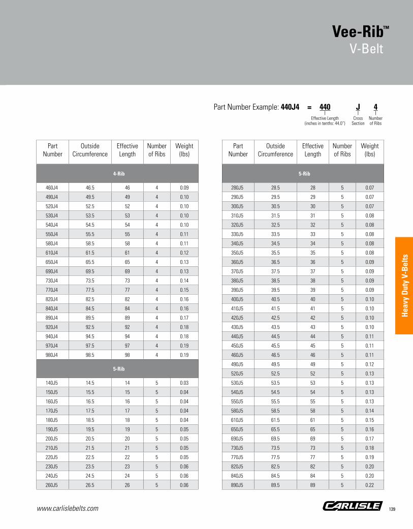
www.carlislebelts.com 139
Sync
hron
ous
Bel
ts
PartNumber
Outside Circumference
EffectiveLength
Number of Ribs
Weight(lbs)
4-Rib
460J4 46.5 46 4 0.09
490J4 49.5 49 4 0.10
520J4 52.5 52 4 0.10
530J4 53.5 53 4 0.10
540J4 54.5 54 4 0.10
550J4 55.5 55 4 0.11
580J4 58.5 58 4 0.11
610J4 61.5 61 4 0.12
650J4 65.5 65 4 0.13
690J4 69.5 69 4 0.13
730J4 73.5 73 4 0.14
770J4 77.5 77 4 0.15
820J4 82.5 82 4 0.16
840J4 84.5 84 4 0.16
890J4 89.5 89 4 0.17
920J4 92.5 92 4 0.18
940J4 94.5 94 4 0.18
970J4 97.5 97 4 0.19
980J4 98.5 98 4 0.19
5-Rib
140J5 14.5 14 5 0.03
150J5 15.5 15 5 0.04
160J5 16.5 16 5 0.04
170J5 17.5 17 5 0.04
180J5 18.5 18 5 0.04
190J5 19.5 19 5 0.05
200J5 20.5 20 5 0.05
210J5 21.5 21 5 0.05
220J5 22.5 22 5 0.05
230J5 23.5 23 5 0.06
240J5 24.5 24 5 0.06
260J5 26.5 26 5 0.06
PartNumber
Outside Circumference
EffectiveLength
Number of Ribs
Weight(lbs)
5-Rib
280J5 28.5 28 5 0.07
290J5 29.5 29 5 0.07
300J5 30.5 30 5 0.07
310J5 31.5 31 5 0.08
320J5 32.5 32 5 0.08
330J5 33.5 33 5 0.08
340J5 34.5 34 5 0.08
350J5 35.5 35 5 0.08
360J5 36.5 36 5 0.09
370J5 37.5 37 5 0.09
380J5 38.5 38 5 0.09
390J5 39.5 39 5 0.09
400J5 40.5 40 5 0.10
410J5 41.5 41 5 0.10
420J5 42.5 42 5 0.10
430J5 43.5 43 5 0.10
440J5 44.5 44 5 0.11
450J5 45.5 45 5 0.11
460J5 46.5 46 5 0.11
490J5 49.5 49 5 0.12
520J5 52.5 52 5 0.13
530J5 53.5 53 5 0.13
540J5 54.5 54 5 0.13
550J5 55.5 55 5 0.13
580J5 58.5 58 5 0.14
610J5 61.5 61 5 0.15
650J5 65.5 65 5 0.16
690J5 69.5 69 5 0.17
730J5 73.5 73 5 0.18
770J5 77.5 77 5 0.19
820J5 82.5 82 5 0.20
840J5 84.5 84 5 0.20
890J5 89.5 89 5 0.22
Part Number Example: 440J4 = 440 J 4 | | | Effective Length Cross Number (inches in tenths: 44.0”) Section of Ribs
Vee-Rib™
V-Belt
Hea
vy D
uty
V-B
elts

www.carlislebelts.com140
Vee-Rib™ V-BeltPart Numbers
PartNumber
Outside Circumference
EffectiveLength
Number of Ribs
Weight(lbs)
5-Rib
920J5 92.5 92 5 0.22
940J5 94.5 94 5 0.23
970J5 97.5 97 5 0.24
980J5 98.5 98 5 0.24
6-Rib
140J6 14.5 14 6 0.04
150J6 15.5 15 6 0.04
160J6 16.5 16 6 0.05
170J6 17.5 17 6 0.05
180J6 18.5 18 6 0.05
190J6 19.5 19 6 0.06
200J6 20.5 20 6 0.06
210J6 21.5 21 6 0.06
220J6 22.5 22 6 0.06
230J6 23.5 23 6 0.07
240J6 24.5 24 6 0.07
260J6 26.5 26 6 0.08
280J6 28.5 28 6 0.08
290J6 29.5 29 6 0.08
300J6 30.5 30 6 0.09
310J6 31.5 31 6 0.09
320J6 32.5 32 6 0.09
330J6 33.5 33 6 0.10
340J6 34.5 34 6 0.10
350J6 35.5 35 6 0.10
360J6 36.5 36 6 0.10
370J6 37.5 37 6 0.11
380J6 38.5 38 6 0.11
390J6 39.5 39 6 0.11
400J6 40.5 40 6 0.12
410J6 41.5 41 6 0.12
420J6 42.5 42 6 0.12
PartNumber
Outside Circumference
EffectiveLength
Number of Ribs
Weight(lbs)
6-Rib
430J6 43.5 43 6 0.13
440J6 44.5 44 6 0.13
450J6 45.5 45 6 0.13
460J6 46.5 46 6 0.13
490J6 49.5 49 6 0.14
520J6 52.5 52 6 0.15
530J6 53.5 53 6 0.15
540J6 54.5 54 6 0.16
550J6 55.5 55 6 0.16
580J6 58.5 58 6 0.17
610J6 61.5 61 6 0.18
650J6 65.5 65 6 0.19
690J6 69.5 69 6 0.20
730J6 73.5 73 6 0.21
770J6 77.5 77 6 0.22
820J6 82.5 82 6 0.24
840J6 84.5 84 6 0.24
890J6 89.5 89 6 0.26
920J6 92.5 92 6 0.27
940J6 94.5 94 6 0.27
970J6 97.5 97 6 0.28
980J6 98.5 98 6 0.29
8-Rib
140J8 14.5 14 8 0.05
150J8 15.5 15 8 0.06
160J8 16.5 16 8 0.06
170J8 17.5 17 8 0.07
180J8 18.5 18 8 0.07
190J8 19.5 19 8 0.07
200J8 20.5 20 8 0.08
210J8 21.5 21 8 0.08
220J8 22.5 22 8 0.09
Vee-Rib™
V-Belt

www.carlislebelts.com 141
Sync
hron
ous
Bel
ts
PartNumber
Outside Circumference
EffectiveLength
Number of Ribs
Weight(lbs)
8-Rib
230J8 23.5 23 8 0.09
240J8 24.5 24 8 0.09
260J8 26.5 26 8 0.10
280J8 28.5 28 8 0.11
290J8 29.5 29 8 0.11
300J8 30.5 30 8 0.12
310J8 31.5 31 8 0.12
320J8 32.5 32 8 0.12
330J8 33.5 33 8 0.13
340J8 34.5 34 8 0.13
350J8 35.5 35 8 0.14
360J8 36.5 36 8 0.14
370J8 37.5 37 8 0.14
380J8 38.5 38 8 0.15
390J8 39.5 39 8 0.15
400J8 40.5 40 8 0.16
410J8 41.5 41 8 0.16
420J8 42.5 42 8 0.16
430J8 43.5 43 8 0.17
440J8 44.5 44 8 0.17
450J8 45.5 45 8 0.17
460J8 46.5 46 8 0.18
490J8 49.5 49 8 0.19
520J8 52.5 52 8 0.20
530J8 53.5 53 8 0.21
540J8 54.5 54 8 0.21
550J8 55.5 55 8 0.21
580J8 58.5 58 8 0.23
610J8 61.5 61 8 0.24
650J8 65.5 65 8 0.25
690J8 69.5 69 8 0.27
730J8 73.5 73 8 0.28
770J8 77.5 77 8 0.30
PartNumber
Outside Circumference
EffectiveLength
Number of Ribs
Weight(lbs)
8-Rib
820J8 82.5 82 8 0.32
840J8 84.5 84 8 0.33
890J8 89.5 89 8 0.35
920J8 92.5 92 8 0.36
940J8 94.5 94 8 0.36
970J8 97.5 97 8 0.38
980J8 98.5 98 8 0.38
10-Rib
140J10 14.5 14 10 0.07
150J10 15.5 15 10 0.07
160J10 16.5 16 10 0.08
170J10 17.5 17 10 0.08
180J10 18.5 18 10 0.09
190J10 19.5 19 10 0.09
200J10 20.5 20 10 0.10
210J10 21.5 21 10 0.10
220J10 22.5 22 10 0.11
230J10 23.5 23 10 0.11
240J10 24.5 24 10 0.12
260J10 26.5 26 10 0.13
280J10 28.5 28 10 0.14
290J10 29.5 29 10 0.14
300J10 30.5 30 10 0.15
310J10 31.5 31 10 0.15
320J10 32.5 32 10 0.16
330J10 33.5 33 10 0.16
340J10 34.5 34 10 0.16
350J10 35.5 35 10 0.17
360J10 36.5 36 10 0.17
370J10 37.5 37 10 0.18
380J10 38.5 38 10 0.18
390J10 39.5 39 10 0.19
Part Number Example: 240J8 = 240 J 8 | | | Effective Length Cross Number (inches in tenths: 24.0”) Section of Ribs
Vee-Rib™
V-Belt
Hea
vy D
uty
V-B
elts

www.carlislebelts.com142
Vee-Rib™ V-BeltPart Numbers
PartNumber
Outside Circumference
EffectiveLength
Number of Ribs
Weight(lbs)
10-Rib
400J10 40.5 40 10 0.19
410J10 41.5 41 10 0.20
420J10 42.5 42 10 0.20
430J10 43.5 43 10 0.21
440J10 44.5 44 10 0.21
450J10 45.5 45 10 0.22
460J10 46.5 46 10 0.22
490J10 49.5 49 10 0.24
520J10 52.5 52 10 0.25
530J10 53.5 53 10 0.26
540J10 54.5 54 10 0.26
550J10 55.5 55 10 0.27
580J10 58.5 58 10 0.28
610J10 61.5 61 10 0.30
650J10 65.5 65 10 0.32
690J10 69.5 69 10 0.33
730J10 73.5 73 10 0.35
770J10 77.5 77 10 0.37
820J10 82.5 82 10 0.40
840J10 84.5 84 10 0.41
920J10 92.5 92 10 0.45
940J10 94.5 94 10 0.46
970J10 97.5 97 10 0.47
980J10 98.5 98 10 0.48
16-Rib
140J16 14.5 14 16 0.11
150J16 15.5 15 16 0.12
160J16 16.5 16 16 0.12
170J16 17.5 17 16 0.13
180J16 18.5 18 16 0.14
190J16 19.5 19 16 0.15
200J16 20.5 20 16 0.16
PartNumber
Outside Circumference
EffectiveLength
Number of Ribs
Weight(lbs)
16-Rib
210J16 21.5 21 16 0.16
220J16 22.5 22 16 0.17
230J16 23.5 23 16 0.18
240J16 24.5 24 16 0.19
260J16 26.5 26 16 0.20
280J16 28.5 28 16 0.22
290J16 29.5 29 16 0.23
300J16 30.5 30 16 0.23
310J16 31.5 31 16 0.24
320J16 32.5 32 16 0.25
330J16 33.5 33 16 0.26
340J16 34.5 34 16 0.26
350J16 35.5 35 16 0.27
360J16 36.5 36 16 0.28
370J16 37.5 37 16 0.29
380J16 38.5 38 16 0.29
390J16 39.5 39 16 0.30
400J16 40.5 40 16 0.31
410J16 41.5 41 16 0.32
420J16 42.5 42 16 0.33
430J16 43.5 43 16 0.33
440J16 44.5 44 16 0.34
450J16 45.5 45 16 0.35
460J16 46.5 46 16 0.36
490J16 49.5 49 16 0.38
520J16 52.5 52 16 0.40
530J16 53.5 53 16 0.41
540J16 54.5 54 16 0.42
550J16 55.5 55 16 0.43
580J16 58.5 58 16 0.45
610J16 61.5 61 16 0.47
650J16 65.5 65 16 0.50
690J16 69.5 69 16 0.54
Vee-Rib™
V-Belt

www.carlislebelts.com 143
Sync
hron
ous
Bel
ts
PartNumber
Outside Circumference
EffectiveLength
Number of Ribs
Weight(lbs)
16-Rib
730J16 73.5 73 16 0.57
770J16 77.5 77 16 0.60
820J16 82.5 82 16 0.64
840J16 84.5 84 16 0.65
920J16 92.5 92 16 0.71
940J16 94.5 94 16 0.73
970J16 97.5 97 16 0.75
980J16 98.5 98 16 0.76
24-Rib
140J24 14.5 14 24 0.16
150J24 15.5 15 24 0.17
160J24 16.5 16 24 0.19
170J24 17.5 17 24 0.20
180J24 18.5 18 24 0.21
190J24 19.5 19 24 0.22
200J24 20.5 20 24 0.23
210J24 21.5 21 24 0.24
220J24 22.5 22 24 0.26
230J24 23.5 23 24 0.27
240J24 24.5 24 24 0.28
260J24 26.5 26 24 0.30
280J24 28.5 28 24 0.33
290J24 29.5 29 24 0.34
300J24 30.5 30 24 0.35
310J24 31.5 31 24 0.36
320J24 32.5 32 24 0.37
330J24 33.5 33 24 0.38
340J24 34.5 34 24 0.40
350J24 35.5 35 24 0.41
360J24 36.5 36 24 0.42
370J24 37.5 37 24 0.43
380J24 38.5 38 24 0.44
PartNumber
Outside Circumference
EffectiveLength
Number of Ribs
Weight(lbs)
24-Rib
390J24 39.5 39 24 0.45
400J24 40.5 40 24 0.47
410J24 41.5 41 24 0.48
420J24 42.5 42 24 0.49
430J24 43.5 43 24 0.50
440J24 44.5 44 24 0.51
450J24 45.5 45 24 0.52
460J24 46.5 46 24 0.54
490J24 49.5 49 24 0.57
520J24 52.5 52 24 0.61
530J24 53.5 53 24 0.62
540J24 54.5 54 24 0.63
550J24 55.5 55 24 0.64
580J24 58.5 58 24 0.68
610J24 61.5 61 24 0.71
650J24 65.5 65 24 0.76
690J24 69.5 69 24 0.80
730J24 73.5 73 24 0.85
770J24 77.5 77 24 0.90
820J24 82.5 82 24 0.95
840J24 84.5 84 24 0.98
920J24 92.5 92 24 1.07
940J24 94.5 94 24 1.09
970J24 97.5 97 24 1.13
980J24 98.5 98 24 1.14
30-Rib
140J30 14.5 14 30 0.20
150J30 15.5 15 30 0.22
160J30 16.5 16 30 0.23
170J30 17.5 17 30 0.25
180J30 18.5 18 30 0.26
190J30 19.5 19 30 0.28
Part Number Example: 840J16 = 840 J 16 | | | Effective Length Cross Number (inches in tenths: 84.0”) Section of Ribs
Vee-Rib™
V-Belt
Hea
vy D
uty
V-B
elts

www.carlislebelts.com144
Vee-Rib® V-BeltPart Numbers
PartNumber
Outside Circumference
EffectiveLength
Number of Ribs
Weight(lbs)
30-Rib
200J30 20.5 20 30 0.29
210J30 21.5 21 30 0.31
220J30 22.5 22 30 0.32
230J30 23.5 23 30 0.33
240J30 24.5 24 30 0.35
260J30 26.5 26 30 0.38
280J30 28.5 28 30 0.41
290J30 29.5 29 30 0.42
300J30 30.5 30 30 0.44
310J30 31.5 31 30 0.45
320J30 32.5 32 30 0.47
330J30 33.5 33 30 0.48
340J30 34.5 34 30 0.49
350J30 35.5 35 30 0.51
360J30 36.5 36 30 0.52
370J30 37.5 37 30 0.54
380J30 38.5 38 30 0.55
390J30 39.5 39 30 0.57
400J30 40.5 40 30 0.58
410J30 41.5 41 30 0.60
420J30 42.5 42 30 0.61
430J30 43.5 43 30 0.63
440J30 44.5 44 30 0.64
450J30 45.5 45 30 0.65
460J30 46.5 46 30 0.67
490J30 49.5 49 30 0.71
520J30 52.5 52 30 0.76
530J30 53.5 53 30 0.77
540J30 54.5 54 30 0.79
550J30 55.5 55 30 0.80
580J30 58.5 58 30 0.84
610J30 61.5 61 30 0.89
650J30 65.5 65 30 0.95
PartNumber
Outside Circumference
EffectiveLength
Number of Ribs
Weight(lbs)
30-Rib
690J30 69.5 69 30 1.00
730J30 73.5 73 30 1.06
770J30 77.5 77 30 1.12
820J30 82.5 82 30 1.19
840J30 84.5 84 30 1.22
920J30 92.5 92 30 1.34
970J30 97.5 97 30 1.41
980J30 98.5 98 30 1.43
Vee-Rib™ V-BeltPart Numbers
Vee-Rib™
V-Belt

www.carlislebelts.com 145
Sync
hron
ous
Bel
ts
PartNumber
Sleeve WidthRibs
Weight(lbs)
J Sleeves (40-Rib)
200J40* 40 0.39
210J40* 40 0.41
220J40* 40 0.43
230J40* 40 0.45
240J40* 40 0.47
260J40* 40 0.50
270J40* 40 0.52
280J40* 40 0.54
290J40* 40 0.56
300J40* 40 0.58
310J40* 40 0.60
320J40* 40 0.62
330J40* 40 0.64
340J40* 40 0.66
350J40* 40 0.68
360J40* 40 0.70
370J40* 40 0.72
380J40* 40 0.74
390J40* 40 0.76
400J40* 40 0.78
410J40* 40 0.80
420J40* 40 0.81
PartNumber
Sleeve WidthRibs
Weight(lbs)
J Sleeves (40-Rib)
430J40* 40 0.83
440J40* 40 0.85
450J40* 40 0.87
460J40* 40 0.89
470J40* 40 0.91
480J40* 40 0.93
490J40* 40 0.95
500J40* 40 0.97
520J40* 40 1.01
530J40* 40 1.03
540J40* 40 1.05
550J40* 40 1.07
580J40* 40 1.13
610J40* 40 1.18
650J40* 40 1.26
690J40* 40 1.34
730J40* 40 1.42
770J40* 40 1.49
840J40* 40 1.63
920J40* 40 1.78
980J40* 40 1.90
*Non-stock item. Minimum order quantity and/or extended lead times may apply. Contact customer service for availability.
Vee-Rib™ J SleevePart Numbers Part Number Example: 200J40 = 200 J 40 | | | Effective Length Cross Number (inches in tenths: 20.0”) Section of Ribs
■■ Full factory width sleeves
■■ Sleeve edges are trimmed prior to shipment
■■ Sleeves cannot be returned
■■ All sleeve weights are approximateTimken maintains inventory of most Carlisle® sleeve sizes. Non-stock sizes will be indicated by an asterisk following the part number. Contact customer service for availability.
Minimum order quantity and/or extended lead times may apply.Occasional production inconsistencies which may render a portion of the sleeve unusable can be present as a normal part of the production process.Each sleeve is inspected to ensure that it contains 90% or more usable product. A full width sleeve with less than 10% unusable product is considered acceptable.
Vee-Rib™
Sleeve
Hea
vy D
uty
V-B
elts

www.carlislebelts.com146
Variable Speed Cog-Belt®
V-Belt

www.carlislebelts.com 147
Smooth running
Oil and heat resistant
Long belt life
Wide selection of sizes
Applications:Industrial variable speed drives & More
1 Fabric Cover Stretches up to 175% more
than ordinary bias-cut fabric to significantly improve belt flex life.
2 High-Modulus Cords Located for maximum
strength to carry high HP loads with minimum belt stretch. Resists fatigue and shock. Provides excellent belt stability.
3 Stiff-flex Compound Provides uniform cord
support and crosswise rigidity for longer belt life.
4 Precision Molded Cogs Provide more surface area
for heat dissipation and increase belt flexibility. Cooler operation means longer flex life.
5 Raw Edge Sidewalls Improve gripping contact
with pulley sidewalls. Assure less vibration. Smoother, quieter performance.
3
1
2
5
4
Variable Speed Cog-Belt®
V-Belt
Hea
vy D
uty
V-B
elts

www.carlislebelts.com148
■■ The Variable Speed Cog-Belt® is designed for use in applications requiring exact speed control
■■ A replacement belt that’s been engineered to the same high standards that Timken applies to belts produced for original equipment manufacturers (OEMs)
■■ Raw Edge sidewalls improve gripping action
■■ Unitized belt bonding and specially formulated rubber compounds provide superior resistance to aging caused by wear, oil, heat, grease and other harmful environmental factors
■■ Static dissipating
Variable Speed Cog-Belt® Part Numbers
PartNumber
Top Width(in)
Outside Circumference
Weight(lbs)
1228V255 0.75 26.1 0.36
1422V240 0.91 24.6 0.30
1422V270 0.91 27.6 0.34
1422V290 0.91 29.6 0.36
1422V300 0.91 30.6 0.37
1422V330* 0.91 33.6 0.41
1422V340 0.91 34.6 0.43
1422V360 0.91 36.6 0.45
1422V400 0.91 40.6 0.50
1422V420 0.91 42.6 0.53
1422V440 0.91 44.6 0.56
1422V460* 0.91 46.6 0.58
1422V466* 0.91 47.2 0.59
1422V470* 0.91 47.6 0.59
1422V480 0.91 48.6 0.61
1422V540* 0.91 54.6 0.69
1422V600* 0.91 60.6 0.76
1422V660* 0.91 66.6 0.84
1422V720* 0.91 72.6 0.92
1422V780* 0.91 78.6 1.00
1430V215 0.92 21.9 0.25
1626V262* 1.06 26.8 0.43
1626V293* 1.06 29.9 0.48
1626V304 1.06 31.0 0.50
1626V330 1.06 33.6 0.54
1626V339* 1.06 34.5 0.56
1626V384 1.02 39.0 0.60
1626V428* 1.06 43.4 0.70
1626V440* 1.06 44.6 0.72
1626V513* 1.06 51.9 0.84
1626V517* 1.06 52.3 0.85
1626V604* 1.06 61.0 0.99
1626V700* 1.06 70.6 1.14
Variable Speed Cog-Belt®
V-Belt
For use with variable speed pulleys to gain a wide range of driven speeds.
TH
ANGLE
TW

www.carlislebelts.com 149
Part Number Example: 1228V255 = 12 28 V 255 | | | | Top Width Pulley Variable Pitch Length (inches in sixteenths: 12/16”) Angle Speed (inches in tenths: 25.5”)
Variable Speed Cog-Belt®
V-Belt
PartNumber
Top Width(in)
Outside Circumference
Weight(lbs)
1628V210* 1.00 21.2 0.23
1628V315* 1.00 32.0 0.48
1632V210* 1.00 21.5 0.24
1632V220* 1.00 22.5 0.26
1822V328* 1.13 33.4 0.59
1828V368* 1.13 37.5 0.83
1922V256* 1.19 26.2 0.49
1922V277* 1.19 28.3 0.53
1922V282* 1.19 28.8 0.54
1922V298 1.19 30.4 0.57
1922V302* 1.19 30.8 0.58
1922V321 1.19 32.7 0.61
1922V332 1.19 33.8 0.63
1922V338 1.19 34.4 0.64
1922V363 1.19 36.9 0.69
1922V381* 1.19 38.7 0.73
1922V386 1.19 39.2 0.73
1922V403 1.19 40.9 0.77
1922V417* 1.19 42.3 0.79
1922V426 1.19 43.2 0.81
1922V443 1.19 44.9 0.84
1922V454 1.19 46.0 0.86
1922V460 1.19 46.6 0.87
1922V484 1.19 49.0 0.92
1922V526 1.19 53.2 1.00
1922V544 1.19 55.0 1.03
1922V604 1.19 61.0 1.14
1922V630* 1.19 63.6 1.19
1922V646* 1.19 65.2 1.22
1922V666* 1.19 67.2 1.26
1922V686* 1.19 69.2 1.30
1922V706* 1.19 71.2 1.33
1922V726* 1.19 73.2 1.37
PartNumber
Top Width(in)
Outside Circumference
Weight(lbs)
1922V751* 1.19 75.7 1.42
1922V756* 1.19 76.2 1.43
1922V806 1.19 81.2 1.52
1922V846 1.19 85.2 1.60
1922V891* 1.19 89.7 1.68
1922V966* 1.19 97.2 1.82
1926V250* 1.19 25.9 0.38
1926V275* 1.19 28.3 0.40
1926V390* 1.19 39.6 0.56
1930V366* 1.23 37.4 0.91
1930V375* 1.23 38.3 0.93
1930V400 1.23 40.8 1.00
1930V425* 1.23 43.3 1.06
1930V431* 1.23 43.9 1.07
1930V491 1.23 49.9 1.22
1930V530* 1.23 53.8 1.31
1930V541* 1.23 54.9 1.34
1930V591* 1.23 59.9 1.46
1930V600* 1.23 60.8 1.48
1930V641* 1.23 64.9 1.58
1930V691* 1.23 69.9 1.70
1930V750* 1.23 75.8 1.89
1930V791* 1.23 79.9 1.94
1930V891* 1.23 89.9 2.18
1930V991* 1.23 99.9 2.43
1930V1091* 1.23 109.9 2.67
1930V1191* 1.23 119.9 2.91
2126V309* 1.31 31.5 0.72
2126V468* 1.31 47.4 0.96
2226V307* 1.41 31.3 0.80
2230V266* 1.41 27.8 0.60
2230V275 1.41 28.5 0.61
2230V326 1.38 33.6 0.65
Hea
vy D
uty
V-B
elts

www.carlislebelts.com150
Variable Speed Cog-Belt® Part Numbers
PartNumber
Top Width(in)
Outside Circumference
Weight(lbs)
2230V375* 1.38 38.4 0.60
2322V347 1.44 35.4 1.06
2322V364 1.44 37.1 1.11
2322V384* 1.44 39.1 1.17
2322V396 1.44 40.3 1.20
2322V421 1.44 42.8 1.27
2322V441 1.44 44.8 1.33
2322V481 1.44 48.8 1.45
2322V486* 1.44 49.3 1.47
2322V521 1.44 52.8 1.57
2322V541 1.44 54.8 1.63
2322V601 1.44 60.8 1.81
2322V621* 1.44 62.8 1.87
2322V661* 1.44 66.8 1.99
2322V681* 1.44 68.8 2.04
2322V701* 1.44 70.8 2.10
2322V721* 1.44 72.8 2.16
2322V801* 1.44 80.8 2.40
2322V826* 1.44 83.3 2.47
2322V846* 1.44 85.3 2.53
2322V886* 1.44 89.3 2.65
2322V921* 1.44 92.8 2.75
2322V1001* 1.44 100.8 2.99
2322V1061* 1.44 106.8 3.17
2326V310* 1.47 31.5 0.73
2326V359 1.44 36.6 1.08
2330V273* 1.44 28.0 0.56
2426V343 1.50 35.0 0.96
2428V707* 1.50 71.4 2.18
2430V297* 1.56 30.4 0.87
2430V345 1.56 35.2 1.01
2436V331* 1.56 33.8 0.95
2526V314* 1.56 32.0 0.91
PartNumber
Top Width(in)
Outside Circumference
Weight(lbs)
2530V309* 1.64 31.6 0.95
2530V470* 1.63 48.1 2.07
2530V490 1.63 50.1 2.16
2530V530* 1.63 54.1 2.33
2530V550* 1.63 56.1 2.42
2530V575* 1.63 58.6 2.53
2530V595* 1.63 60.6 2.61
2530V610* 1.63 62.1 2.68
2530V630* 1.63 64.1 2.77
2530V660* 1.63 67.1 2.90
2530V670* 1.63 68.1 2.94
2530V690* 1.63 70.1 3.02
2530V700* 1.63 71.1 3.07
2530V730* 1.63 74.1 3.20
2530V740* 1.63 75.1 3.24
2530V750* 1.63 76.1 3.28
2530V790* 1.63 80.1 3.46
2530V840* 1.63 85.1 3.68
2530V890* 1.63 90.3 3.90
2530V934* 1.63 94.5 4.08
2530V990* 1.63 100.1 4.32
2530V1090* 1.63 110.1 4.75
2530V1190* 1.63 120.1 5.18
2530V1290* 1.63 130.1 5.62
2530V1490* 1.63 150.1 6.48
2530V1690* 1.63 170.1 7.35
2626V369* 1.66 37.6 1.15
2626V388 1.63 39.6 1.29
2630V345* 1.63 35.8 1.04
2636V332* 1.66 33.9 1.01
2822V778* 1.75 78.6 2.80
2826V412* 1.75 42.0 1.57
2826V452 1.75 46.0 1.62
Variable Speed Cog-Belt®
V-Belt

www.carlislebelts.com 151
Sync
hron
ous
Bel
ts
Part Number Example: 2530V309 = 25 30 V 309 | | | | Top Width Pulley Variable Pitch Length (inches in sixteenths: 25/16”) Angle Speed (inches in tenths: 30.9”)
Variable Speed Cog-Belt®
V-Belt
PartNumber
Top Width(in)
Outside Circumference
Weight(lbs)
2830V337* 1.78 34.5 1.14
2830V363 1.78 37.0 1.23
2830V366* 1.78 37.2 1.23
2830V367 1.78 37.4 1.37
2830V393 1.78 40.0 1.33
2830V396* 1.78 40.5 1.34
2830V422 1.78 42.9 1.42
2830V428* 1.78 43.4 1.44
2836V343* 1.75 35.1 1.20
2836V361* 1.75 36.9 1.26
2836V380* 1.78 38.8 1.35
2926V366* 1.86 37.4 1.60
2926V400* 1.86 40.8 1.75
2926V426* 1.86 43.4 1.86
2926V471* 1.86 47.9 2.05
2926V477* 1.86 48.5 2.08
2926V486 1.86 49.6 2.12
2926V491* 1.86 50.1 2.15
2926V521 1.86 52.9 2.27
2926V546 1.86 56.1 2.40
2926V574* 1.86 58.2 2.49
2926V586* 1.86 59.4 2.54
2926V606 1.86 61.4 2.63
2926V616 1.86 62.6 2.68
2926V636* 1.86 64.4 2.76
2926V646* 1.86 65.4 2.80
2926V666* 1.86 67.4 2.88
2926V686 1.86 69.6 2.98
2926V706 1.86 71.4 3.05
2926V726 1.86 73.4 3.14
2926V776 1.86 78.4 3.35
2926V786* 1.86 79.4 3.40
2926V834* 1.86 84.2 3.60
PartNumber
Top Width(in)
Outside Circumference
Weight(lbs)
2926V856* 1.86 86.4 3.70
2926V891* 1.86 89.9 3.84
2926V906 1.86 91.4 3.91
2926V966* 1.86 97.4 4.16
2926V1006* 1.86 101.4 4.34
3226V392 2.06 39.8 1.92
3226V395* 2.00 40.3 1.87
3226V400* 2.00 40.8 1.89
3226V439* 2.00 44.7 2.07
3226V450 2.06 46.7 2.64
3226V465* 2.00 47.3 2.19
3226V505 2.00 51.3 2.38
3226V514* 2.00 52.2 2.42
3226V545* 2.00 55.3 2.56
3226V585* 2.00 59.3 2.75
3226V603 2.00 61.1 2.83
3226V663* 2.00 67.1 3.11
3226V723 2.00 73.1 3.39
3226V783 2.00 79.1 3.66
3226V843* 2.00 85.1 3.94
3226V903 2.00 91.1 4.22
3226V963* 2.00 97.1 4.50
3226V1023* 2.00 103.1 4.77
3226V1083* 2.00 109.1 5.05
3230V419* 2.03 43.4 1.64
3230V560* 2.00 57.0 2.12
3230V710* 2.00 72.0 2.68
3230HV528* 2.05 53.9 3.00
3230HV553* 2.05 56.4 3.14
3230HV570* 2.05 58.1 3.24
3230HV585* 2.05 59.6 3.32
3230HV603* 2.05 61.4 3.42
3230HV613* 2.05 62.4 3.48
Hea
vy D
uty
V-B
elts

www.carlislebelts.com152
Variable Speed Cog-Belt® Part Numbers
Variable Speed Cog-Belt®
V-Belt
PartNumber
Top Width(in)
Outside Circumference
Weight(lbs)
3230HV620* 2.05 63.1 3.52
3230HV626* 2.05 63.7 3.55
3230HV644* 2.05 65.5 3.65
3230HV656* 2.05 66.7 3.72
3230HV670* 2.05 68.1 3.79
3230HV685* 2.05 69.6 3.88
3230HV702* 2.05 71.3 3.97
3230HV723 2.05 73.4 4.09
3230HV821 2.05 83.2 4.64
3230HV856* 2.05 86.7 4.83
3230HV931 2.05 94.2 5.25
3230HV960 2.05 97.1 5.41
3230HV1060 2.05 107.1 5.97
3236HV389* 2.00 40.2 2.12
3236V342* 2.00 35.2 1.30
3236V369* 2.00 37.9 1.69
3236V432* 2.03 44.0 1.77
3326V478* 2.09 48.7 2.53
3432V450 2.19 45.6 2.02
3432V456 2.19 46.4 2.06
3432V480 2.19 48.6 2.15
3432V484* 2.19 49.2 2.18
3432V534* 2.19 54.2 2.40
3636V479* 2.25 48.7 2.49
3726V558* 2.34 56.7 3.14
3826V459* 2.38 46.9 2.10
3826V465* 2.38 47.5 2.66
3830V510 2.44 52.4 3.01
3830V580* 2.44 59.0 3.50
3830V587* 2.38 59.7 3.34
3836V418* 2.38 42.8 2.32
3836V426* 2.38 43.6 2.37
3836V654* 2.38 66.4 3.62
PartNumber
Top Width(in)
Outside Circumference
Weight(lbs)
3836V734* 2.38 74.4 4.05
3836V794* 2.38 80.4 4.38
4030V538* 2.50 54.8 3.20
4036V541 2.50 55.2 3.64
4036V574* 2.56 58.4 3.46
4230V556 2.63 56.8 3.54
4230V605* 2.63 61.5 3.83
4230V653* 2.63 66.3 4.13
4430V510* 2.81 52.1 4.14
4430V530* 2.81 54.1 4.30
4430V548* 2.81 55.9 4.44
4430V555* 2.81 56.6 4.50
4430V570* 2.81 58.1 4.62
4430V578* 2.81 58.9 4.68
4430V600* 2.81 61.1 4.85
4430V610 2.81 62.1 4.93
4430V630 2.81 64.1 5.09
4430V660 2.81 67.1 5.33
4430V670 2.81 68.1 5.41
4430V690 2.81 70.1 5.57
4430V700 2.81 71.1 5.65
4430V718* 2.81 72.9 5.79
4430V730 2.81 74.1 5.89
4430V740* 2.81 75.1 5.97
4430V760* 2.81 77.1 6.13
4430V767 2.80 78.3 8.11
4430V790 2.81 80.1 6.36
4430V850 2.81 86.1 6.84
4430V910 2.81 92.1 7.32
4430V970 2.81 98.1 7.80
4430V1030 2.81 104.1 8.27
4430V1090 2.81 110.1 8.75
4430V1150 2.81 116.1 9.23

www.carlislebelts.com 153
Sync
hron
ous
Bel
ts
Variable Speed Cog-Belt®
V-Belt
Part Number Example: 3836V734 = 38 36 V 734 | | | | Top Width Pulley Variable Pitch Length (inches in sixteenths: 38/16”) Angle Speed (inches in tenths: 73.4”)
PartNumber
Top Width(in)
Outside Circumference
Weight(lbs)
4430V1320 2.81 133.1 10.58
4430V1460 2.81 147.1 11.69
4430V1610 2.81 162.1 12.89
4436V329* 2.80 34.0 1.79
4436V525* 2.80 53.6 4.00
4436V551* 2.80 56.2 4.20
4436V561* 2.80 57.2 4.10
4436V576* 2.80 58.7 4.55
4436V646* 2.81 65.7 4.94
4626V596* 2.88 60.9 5.65
4630V650* 2.88 66.3 6.15
4630V663 2.91 67.4 6.93
4630V683* 2.88 69.2 6.43
4630V733* 2.88 74.3 7.50
4636V613* 2.88 62.6 5.63
4830V602* 3.00 61.5 5.95
4830V653* 3.00 66.4 6.45
4830V699 3.00 71.2 6.95
4830V750* 3.00 76.3 7.47
4836V588* 3.00 59.9 4.50
4836V608* 3.00 61.8 61.80
4836V618* 3.06 62.9 4.81
4836V642* 3.00 65.3 5.62
4836V655 3.06 66.6 5.50
4836V670* 3.00 68.1 5.87
4836V710* 3.00 72.1 6.22
4836V750* 3.06 76.1 6.29
4836V800* 3.00 81.1 7.03
4836V850* 3.00 86.1 7.48
4836V900* 3.06 91.1 7.52
4836V950* 3.06 96.1 7.94
4836V1000* 3.06 101.1 8.35
4836V1060* 3.06 107.1 8.85
PartNumber
Top Width(in)
Outside Circumference
Weight(lbs)
4836V1120* 3.06 113.1 9.34
4836V1180* 3.00 119.1 10.43
4836V1250 3.06 126.1 10.41
5130V732 3.22 74.6 8.58
5130V799 3.19 81.2 9.23
5228V930* 3.28 93.8 11.00
5230V734 3.25 74.6 8.67
5230V867* 3.28 88.0 10.32
5430V783* 3.44 79.9 10.80
5636V750* 3.50 76.4 9.40
5636V774* 3.50 78.8 9.70
5636V845* 3.50 85.9 1.10
5830V756* 3.63 77.0 10.02
6136V751* 3.84 76.4 10.49
6136V756 3.84 76.9 10.55
*Non-stock item. Minimum order quantity and/or extended lead times may apply. Contact customer service for availability.
Hea
vy D
uty
V-B
elts
www.carlislebelts.com154
Gold-Ribbon® Cog-Band®
Banded Belt
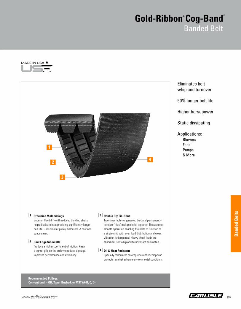
www.carlislebelts.com 155
Eliminates belt whip and turnover
50% longer belt life
Higher horsepower
Static dissipating
Applications:Blowers Fans Pumps & More
Gold-Ribbon® Cog-Band®
Banded Belt
1 Precision Molded Cogs Superior flexibility with reduced bending stress
helps dissipate heat providing significantly longer belt life. Uses smaller pulley diameters. A cost and space saver.
2 Raw Edge Sidewalls Produce a higher coefficient of friction. Keep
a tighter grip on the pulley to reduce slippage. Improves performance and efficiency.
3 Double Ply Tie-Band Two-layer highly engineered tie-band permanently
bonds or “ties” multiple belts together. This assures smooth operation enabling the belts to function as a single unit, with even load distribution and wear. Vibration is dampened. Heavy shock loads are absorbed. Belt whip and turnover are eliminated.
4 Oil & Heat Resistant Specially formulated chloroprene rubber compound
protects against adverse environmental conditions.
Recommended Pulleys:Conventional – QD, Taper Bushed, or MST (A-B, C, D)
2
1
4
3
Ban
ded
Bel
ts

www.carlislebelts.com156
21/32”
7/16”RBX
7/8”
17/32”RCX
1-1/4”
3/4”RDX
This banded version of “The Energy Saver”combines the longer life and superior performance of the Gold-Ribbon® Cog-Belt® with the stability of a banded belt. Gold-Ribbon’s unique construction (combining the superior flexing of precision molded cogs with the tenacious gripping power of raw edge sidewalls) provides significantly longer belt life, higher efficiency and horsepower ratings, and opportunities to save time, energy and space.
An ideal choice for applications where increased horsepower or speed is required or when unusually severe shock loads are encountered.
The reinforced band across the top of two or more individual v-belts greatly enhances stability by eliminating belt whip and turnover. It prevents the belt from turning over or jumping off the drive.
For complete part number, add number of ribs required as indicated in example provided.
Prevents belt whip and rollover on long center distance drives.
Energy Efficiency Comparison
Gold-Ribbon Cog-BandConventional V-Band
95%
90%
85%
80%
75%
Gold-Ribbon® Cog-Band®
Banded Belt
Horsepower Rating Comparison
Gold-Ribbon Cog-BeltConventional Wrapped Belt
HP
6.0
4.0
2.0
0.0
1500 RPM1.5:1 Belt Drive Ratio

www.carlislebelts.com 157
Gold-Ribbon® Cog-Band®
Banded Belt Part NumbersPart Number Example: RBX100-3 = R B X 100 - 3 | | | | | Banded Cross Cogged Inside Circumference Number Construction Section Construction (inches) of Ribs
PartNumber
OutsideCircumference (in)
WeightPer Rib (lbs)
RBX – Banded BX Section; Recommended Pulleys: Conventional – QD, Taper Bushed, or MST (A-B)
RBX51 54.9 0.63
RBX53 56.9 0.65
RBX55 58.9 0.68
RBX56 59.9 0.69
RBX58 61.9 0.71
RBX59 62.9 0.72
RBX60 63.9 0.74
RBX61 64.9 0.75
RBX62 65.9 0.76
RBX63 66.9 0.77
RBX64 67.9 0.78
RBX65 68.9 0.80
RBX66 69.9 0.81
RBX67 70.9 0.82
RBX68 71.9 0.83
RBX70 73.9 0.86
RBX71 74.9 0.87
RBX75 78.9 0.92
RBX77 80.9 0.94
RBX78 81.9 0.95
RBX79 82.9 0.97
RBX80 83.9 0.98
RBX81 84.9 0.99
RBX83 86.9 1.02
RBX85 88.9 1.04
RBX90 93.9 1.10
RBX93 96.9 1.14
RBX95 98.9 1.16
RBX97 100.9 1.19
RBX100 103.9 1.22
RBX102 105.9 1.25
RBX103 106.9 1.26
RBX105 108.9 1.28
PartNumber
OutsideCircumference (in)
WeightPer Rib (lbs)
RBX – Banded BX Section Recommended Pulleys:Conventional – QD, Taper Bushed, or MST (A-B)
RBX108 111.9 1.32
RBX112 115.9 1.37
RBX116 119.9 1.42
RBX120 123.9 1.46
RBX128 131.9 1.56
RBX136 139.9 1.66
RBX144 147.9 1.76
RBX158 161.9 1.92
RBX173 176.9 2.10
RBX180 183.9 2.18
RBX195 198.9 2.36
RBL – Gold-Ribbon Band† – BL Section Recommended Pulleys: Conventional – QD, Taper Bushed, or MST (A-B)
RBL210† 214.0 2.92
RBL240† 242.5 3.32
RBL270*† 272.5 3.73
RCX – Banded CX Section Recommended Pulleys:Conventional – QD, Taper Bushed, or MST (C)
RCX68 72.9 1.38
RCX75 79.9 1.51
RCX75 79.9 1.51
RCX78 82.9 1.57
RCX81 85.9 1.63
RCX85 89.9 1.71
RCX90 94.9 1.80
RCX96 100.9 1.92
RCX105 109.9 2.10
RCX112 116.9 2.24
RCX120 124.9 2.40
RCX128 132.9 2.56
RCX131 135.9 2.62
RCX136 140.9 2.71
RCX137 141.9 2.73
Gold-Ribbon® Cog-Band®
Banded Belt
Ban
ded
Bel
ts

www.carlislebelts.com158
Gold-Ribbon® Cog-Band®
Banded Belt Part Numbers
PartNumber
OutsideCircumference (in)
WeightPer Rib (lbs)
RCX – Banded CX Section Recommended Pulleys:Conventional – QD, Taper Bushed, or MST (C)
RCX144 148.9 2.87
RCX158 162.9 3.15
RCX162 166.9 3.23
RCX173 177.9 3.45
RCX180 184.9 3.59
RCX190 194.9 3.78
RCX195 199.9 3.88
RCL – Gold-Ribbon Band† – CL Section Recommended Pulleys: Conventional – QD, Taper Bushed, or MST (C)
RCL210† 215.3 4.78
RCL225† 228.3 5.07
RCL240*† 243.3 5.41
RCL255*† 258.3 5.74
RCL270*† 273.3 6.07
RCL300*† 303.3 6.74
RCL330*† 333.3 7.41
RDX–Banded DX Section Recommended Pulleys:Conventional – QD, Taper Bushed, or MST (D)
RDX120* 124.9 5.80
RDX128* 132.9 6.10
RDX144* 148.9 6.90
RDX158* 162.9 7.50
RDX180* 184.9 8.50
RDX195* 199.9 9.30
RDL – Gold-Ribbon Band† – DL Section Recommended Pulleys: Conventional – QD, Taper Bushed, or MST (D)
RDL210*† 213.9 8.99
RDL225*† 228.9 9.51
RDL240*† 243.9 10.14
RDL255† 258.9 10.77
RDL270*† 273.9 11.40
RDL300*† 303.9 12.66
RDL330*† 333.9 13.92
Part Number Example: RCX190-3 = R C X 190 - 3 | | | | | Banded Cross Cogged Inside Circumference Number Construction Section Construction (inches) of Ribs
Gold-Ribbon® Cog-Band®
Banded Belt
For complete part number, add number of ribs required as indicated in example above.
* Non-stock item. Minimum order quantity and/or extended lead times may apply. Contact customer service for availability.
† Gold-Ribbon Band uses laminated construction and replaces the Gold-Ribbon Cog-Band in the longer sizes (200” and above) only.
A matched set of Carlisle Gold-Ribbon Bands consists of 3 adjacent SAG numbers.

www.carlislebelts.com 159
1 Oversized Polyester Cord Adds belt strength and stability during peak shock
loads. Chemically treated for maximum resistance to belt stretch.
2 Raw Edge Sidewalls
Produce a higher coefficient of friction. They grip the pulley more tightly to reduce slippage while improving overall performance and efficiency.
3 Precision Molded Cogs Improve belt flex, reduce bending stress, help
dissipate heat and contribute to longer belt life.
4 Double Ply Tie-Band Two-layer highly engineered tie-band
permanently bonds or “ties” multiple belts together. This assures smooth operation enabling the belts to function as a single unit, with even load distribution and wear. Vibration is dampened. Heavy shock loads are absorbed. Belt whip and turnover are eliminated.
Recommended Pulleys:Hi-Cap Wedge – QD, Taper Bushed, or MST (3V, 5V)
3
2
1
Power-Wedge® Cog-Band®
Banded Belt
Raw Edge construction
Eliminates belt whip and turnover
Higher horsepower
Longer belt life
Oil and heat resistant
Static dissipating
Applications:Fans Pumps Compressors & More
4
Ban
ded
Bel
ts

www.carlislebelts.com160
The Power-Wedge® Cog-Band® permanently bonds the individual elements together to assure pre-matched size and quality. Belt whip and turnover are eliminated. Vibration is dampened. Shock is absorbed.
The long life and performance of the cog-belt is combined with banded stability. The unique laminated construction combines the superior flexing of precision molded cogs with the gripping power of raw edge sidewalls. The result, a perfect balance of controlled transfer of power and slippage.
Recommended for applications requiring increased horsepower or speed, or where unusually severe shock loads are encountered.
For complete part number, add number of ribs required as indicated in example provided.
Power-Wedge® Cog-Band®
Banded Belt
3/8”
R3VX 5/16”
5/8”
17/32”R5VX
Designed to minimize belt whip and turnover on the drive, the Power-Wedge® Cog-Band® provides outstanding resistance to oil, heat and harsh environments.
Horsepower Per Rib Comparison
Power-Wedge Cog-BandConventional Wrapped Band
HP
20
15
10
5
0

www.carlislebelts.com 161
Power-Wedge® Cog-Band®
Banded Belt Part NumbersPart Number Example: R5VX1000-3 = R 5V X 1000 - 3 | | | | | Banded Cross Cogged Effective Length Number Construction Section Construction (inches in tenths: 100.0) of Ribs
PartNumber
OutsideCircumference (in)
Weight Per Rib (lbs)
R3VX – Banded 3VX Section Recommended Pulleys:Hi-Cap Wedge – QD, Taper Bushed, or MST (3V)
R3VX250 26.1 0.13
R3VX265 27.6 0.14
R3VX280 29.1 0.15
R3VX300 31.1 0.16
R3VX315 32.6 0.16
R3VX335 34.6 0.17
R3VX355 36.6 0.18
R3VX375 38.6 0.19
R3VX400 40.8 0.20
R3VX425 43.3 0.21
R3VX450 45.8 0.22
R3VX475 48.3 0.24
R3VX500 50.8 0.25
R3VX530 53.8 0.26
R3VX560 56.8 0.28
R3VX600 60.8 0.30
R3VX630 63.8 0.32
R3VX670 67.8 0.34
R3VX710 71.8 0.36
R3VX750 75.8 0.38
R3VX800 80.8 0.40
R3VX850 85.8 0.43
R3VX900 90.8 0.45
R3VX950 95.8 0.48
R3VX1000 100.8 0.51
R3VX1060 106.8 0.54
R3VX1120 112.8 0.57
R3VX1180 118.8 0.60
R3VX1250 125.8 0.63
R3VX1320 132.8 0.67
R3VX1400 140.8 0.71
PartNumber
OutsideCircumference (in)
Weight Per Rib (lbs)
R5VX – Banded 5VX Section Recommended Pulleys:Hi-Cap Wedge – QD, Taper Bushed, or MST (5V)
R5VX500 51.1 0.63
R5VX530 54.1 0.66
R5VX560 57.1 0.70
R5VX600 61.1 0.76
R5VX630 64.1 0.80
R5VX670 68.1 0.85
R5VX710 72.1 0.90
R5VX750 76.1 0.95
R5VX800 81.1 1.02
R5VX850 86.1 1.08
R5VX900 91.1 1.15
R5VX950 96.1 1.22
R5VX1000 101.1 1.28
R5VX1060 107.1 1.36
R5VX1120 113.1 1.44
R5VX1180 119.1 1.52
R5VX1250 126.1 1.61
R5VX1320 133.1 1.70
R5VX1400 141.1 1.80
R5VX1500 151.1 1.94
R5VX1600 161.1 2.07
R5VX1700 171.1 2.20
R5VX1800 181.1 2.33
R5VX1900 191.1 2.46
R5VX2000 201.1 2.59
Power-Wedge® Cog-Band®
Banded Belt
For complete part number, add number of ribs required as indicated in example above.
Ban
ded
Bel
ts

www.carlislebelts.com162
Wedge-Band®
Banded Belt
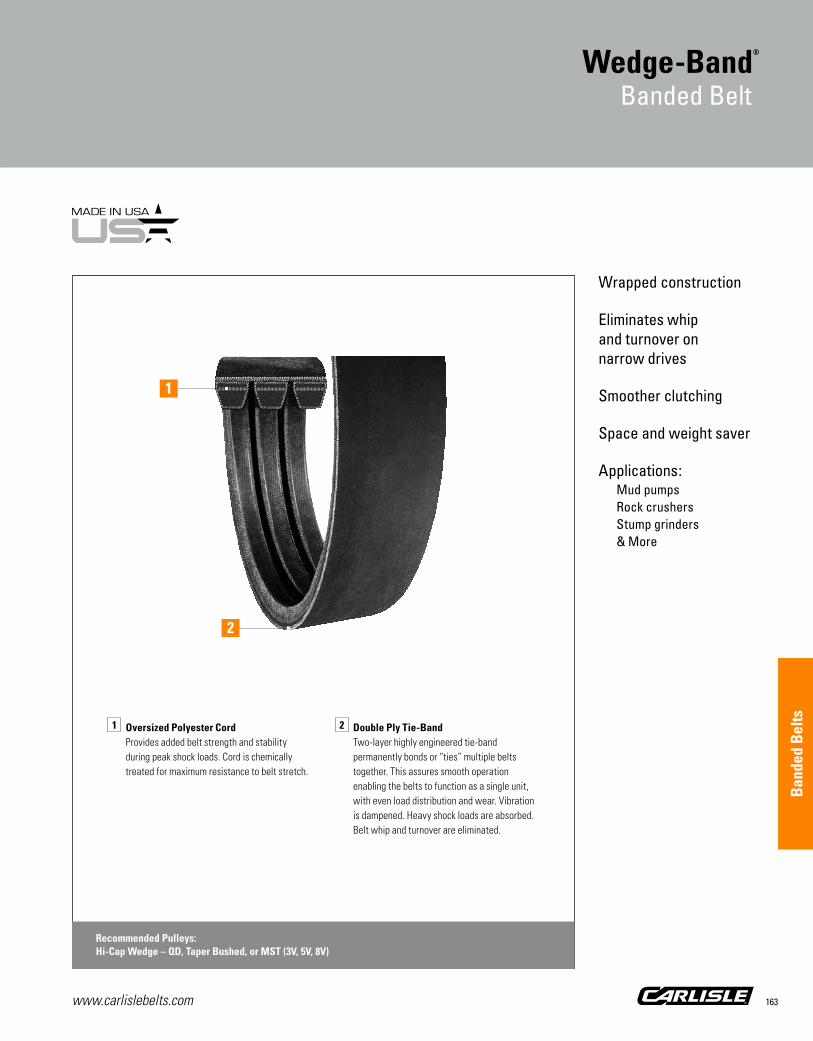
Panther®XTV-Belt
www.carlislebelts.com 163
Wrapped construction
Eliminates whip and turnover on narrow drives
Smoother clutching
Space and weight saver
Applications:Mud pumps Rock crushers Stump grinders & More
1 Oversized Polyester Cord
Provides added belt strength and stability during peak shock loads. Cord is chemically treated for maximum resistance to belt stretch.
2 Double Ply Tie-Band Two-layer highly engineered tie-band
permanently bonds or “ties” multiple belts together. This assures smooth operation enabling the belts to function as a single unit, with even load distribution and wear. Vibration is dampened. Heavy shock loads are absorbed. Belt whip and turnover are eliminated.
Recommended Pulleys:Hi-Cap Wedge – QD, Taper Bushed, or MST (3V, 5V, 8V)
1
Wedge-Band®
Banded Belt
2
Ban
ded
Bel
ts

www.carlislebelts.com164
An excellent choice for narrow multiple drives where belt whip and turnover are a problem.
Wedge-Band®
Banded Belt
The Carlisle® Wedge-Band® by Timken is an excellent choice for virtually any application where increased horsepower capacity and output is needed, or where conventional multiple-belt drives are impractical because of space or weight limitations.
Wedge-Band is the banded version of the hard-working Carlisle Super Power-Wedge Belt.
The patented banding process assures smoother, quieter operation. Specially compounded wrapped construction is ideal for clutching operations. Wedge-Band is oil and heat resistant, static dissipating, and it won’t turn over or jump off the drive.
For complete part number, add number of ribs required as indicated in example provided.
R8V 7/8”
1”
R3V3/8”
5/16” R5V 17/32”
5/8”4-RIB
3-RIB

Part Number Example: R5V670-3 = R 5V 670 - 3 | | | | Banded Cross Effective Length Number Construction Section (inches in tenths: 67.0) of Ribs
www.carlislebelts.com 165
Wedge-Band® Banded BeltPart Numbers
PartNumber
OutsideCircumference (in)
WeightPer Rib (lbs)
R3V – Banded 3V Section Recommended Pulleys:Hi-Cap Wedge – QD, Taper Bushed, or MST (3V)
R3V335* 34.6 0.20
R3V355 36.6 0.21
R3V375 38.6 0.22
R3V400 41.1 0.23
R3V425* 43.6 0.25
R3V450 46.1 0.26
R3V475 48.6 0.28
R3V500 51.1 0.29
R3V530 54.1 0.31
R3V560 57.1 0.33
R3V600 61.1 0.35
R3V630 64.1 0.37
R3V670 68.1 0.39
R3V710 72.1 0.42
R3V750 76.1 0.44
R3V800 81.1 0.47
R3V850 86.1 0.50
R3V900 91.1 0.53
R3V950 96.1 0.53
R3V1000 101.1 0.56
R3V1060 107.1 0.59
R3V1120 113.1 0.63
R3V1180 119.1 0.66
R3V1250 126.1 0.70
R3V1320 133.1 0.74
R3V1400 141.1 0.79
R5V – Banded 5V Section Recommended Pulleys:Hi-Cap Wedge – QD, Taper Bushed, or MST (5V)
R5V500* 51.1 0.68
R5V530* 54.1 0.73
R5V560 57.1 0.77
R5V600 61.1 0.82
R5V630 64.1 0.86
PartNumber
OutsideCircumference (in)
WeightPer Rib (lbs)
R5V – Banded 5V Section Recommended Pulleys:Hi-Cap Wedge – QD, Taper Bushed, or MST (5V)
R5V670 68.1 0.92
R5V710 72.1 0.97
R5V750 76.1 1.03
R5V800 81.1 1.10
R5V850 86.1 1.17
R5V900 91.1 1.24
R5V950 96.1 1.31
R5V1000 101.1 1.38
R5V1060 107.1 1.46
R5V1120 113.1 1.54
R5V1180 119.1 1.63
R5V1250 126.1 1.73
R5V1320 133.1 1.82
R5V1400 141.1 1.93
R5V1500 151.1 2.07
R5V1600 161.1 2.21
R5V1700 171.1 2.35
R5V1800 181.1 2.49
R5V1800 181.1 2.49
R5V1900 191.1 2.63
R5V2000 201.1 2.76
R5V2120 213.1 2.93
R5V2240 225.1 3.10
R5V2360 237.1 3.26
R5V2500 251.1 3.46
R5V2650 266.1 3.67
R5V2800 281.1 3.87
R5V3000 301.1 4.15
R5V3150 316.1 4.36
R5V3350 336.1 4.64
R5V3550 356.1 4.91
Wedge-Band®
Banded Belt
Ban
ded
Bel
ts

www.carlislebelts.com166
PartNumber
OutsideCircumference (in)
WeightPer Rib (lbs)
R8V – Banded 8V Section Recommended Pulleys:Hi-Cap Wedge – QD, Taper Bushed, or MST (8V)
R8V1000 101.1 3.57
R8V1060 107.1 3.78
R8V1120 113.1 4.01
R8V1180 119.1 4.22
R8V1250 126.1 4.48
R8V1320 133.1 4.73
R8V1400 141.1 5.02
R8V1500 151.1 5.39
R8V1600 161.1 5.75
R8V1700 171.1 6.11
R8V1800 181.1 6.47
R8V1900 191.1 6.84
R8V2000 201.1 7.20
R8V2120 213.1 7.63
R8V2240 225.1 8.07
R8V2360 237.1 8.51
R8V2500 251.1 9.01
R8V2650 266.1 9.56
R8V2800 281.1 10.11
R8V3000 301.1 10.83
R8V3150 316.1 11.38
R8V3350 336.1 12.11
R8V3550 356.1 12.83
R8V3750 376.1 14.06
R8V4000 401.1 15.00
R8V4250 426.1 15.94
R8V4500 451.1 16.88
R8V4750* 476.1 17.83
R8V5000* 501.1 18.76
R8V5600* 561.1 21.03
R8V6000* 601.1 22.53
R8V6600* 661.1 24.80
Wedge-Band® Banded BeltPart Numbers
Wedge-Band®
Banded Belt
Part Number Example: R8V1000-3 = R 8V 1000 - 3 | | | | Banded Cross Effective Length Number Construction Section (inches in tenths: 100.0) of Ribs
For complete part number, add number of ribs required as indicated in example above.
* Non-stock item. Minimum order quantity and/or extended lead times may apply. Contact customer service for availability.

www.carlislebelts.com 167
Super high performance banded belt
Tough aramid cord construction
Excels in harsh oil field and industrial applications
Applications:Oil field mud pumps & More
1 Aramid Cord Provides high horsepower capability and
maximum protection against shock loads.
2 Double Ply Tie-Band Two-layer highly engineered tie-band
permanently bonds or “ties” multiple belts together. This assures smooth operation enabling the belts to function as a single unit, with even load distribution and wear. Vibration is dampened. Heavy shock loads are absorbed. Belt whip and turnover are eliminated.
Aramax® Wedge-Band®
Banded Belt
2
1
Ban
ded
Bel
ts

www.carlislebelts.com168
The Aramax® Wedge-Band® is ideally suited for oil field equipment, rock and quarry applications, forestry industry applications and heavy construction machinery. Aramid cord provides maximum protection against belt breakage due to shock loads.
Because of the high horsepower loads involved, standard 8V cast iron Q-D® pulleys typically DO NOT have sufficient horsepower capacity to operate with the Aramax Wedge-Band at the belt’s rated horsepower. As a result, special pulleys are frequently required as well.
Due to the unique nature of these “super high performance” banded belts, no drive design literature is available. Rather, we strongly suggest that you work with our application engineering department for design assistance. This assures a safe and satisfactory drive.
Note: When these R8VK belts are used as a matched set, all belts in the set must have the same sag number. These high modulus aramid cord belts require closer matching than standard R8V belts in order to tension properly as a set.
Q-D® is a registered trademark of Regal Beloit America, Inc.
Aramax® Wedge-Band®
Banded Belt Part Numbers
PartNumber
Number of Ribs
OutsideCircumference (in)
Weight(lbs)
R8V Cross Section
R8VK1500-4* 4 151.1 21.41
R8VK1500-5* 5 151.1 26.76
R8VK1500-6* 6 151.1 32.11
R8VK1500-8* 8 151.1 42.81
R8VK1500-10* 10 151.1 53.51
R8VK1500-12* 12 151.1 64.22
R8VK1600-4* 4 161.1 22.87
R8VK1600-5* 5 161.1 28.58
R8VK1600-6* 6 161.1 34.30
R8VK1600-8* 8 161.1 45.73
R8VK1600-10* 10 161.1 57.17
R8VK1600-12* 12 161.1 68.60
R8VK1700-4* 4 171.1 24.31
R8VK1700-5* 5 171.1 30.39
R8VK1700-6* 6 171.1 36.46
R8VK1700-8* 8 171.1 48.62
R8VK1700-10* 10 171.1 60.77
R8VK1700-12* 12 171.1 72.93
R8VK1800-4 4 181.1 25.75
R8VK1800-5 5 181.1 32.19
R8VK1800-6 6 181.1 38.63
R8VK1800-8 8 181.1 51.50
R8VK1800-10 10 181.1 64.38
R8VK1800-12 12 181.1 77.25
R8VK1900-4 4 191.1 27.21
R8VK1900-5 5 191.1 34.02
R8VK1900-6 6 191.1 40.82
R8VK1900-8 8 191.1 54.42
R8VK1900-10 10 191.1 68.03
R8VK1900-12 12 191.1 81.64
R8VK2000-4 4 201.1 28.65
R8VK2000-5 5 201.1 35.82
R8VK2000-6 6 201.1 42.98
Aramax® Wedge-Band®
Banded Belt
The Aramax® Wedge-Band® is designed for extraordinary banded belt strength on the toughest belt drives.
1”
R8VK 7/8”

www.carlislebelts.com 169
PartNumber
Number of Ribs
OutsideCircumference (in)
Weight(lbs)
R8V Cross Section
R8VK2000-8 8 201.1 57.31
R8VK2000-10 10 201.1 71.63
R8VK2000-12 12 201.1 85.96
R8VK2120-4 4 213.1 30.38
R8VK2120-5 5 213.1 37.98
R8VK2120-6 6 213.1 45.58
R8VK2120-8 8 213.1 60.77
R8VK2120-10 10 213.1 75.96
R8VK2120-12 12 213.1 91.15
R8VK2240-4 4 225.1 32.13
R8VK2240-5 5 225.1 40.17
R8VK2240-6 6 225.1 48.20
R8VK2240-8 8 225.1 64.27
R8VK2240-10 10 225.1 80.33
R8VK2240-12 12 225.1 96.40
R8VK2360-4 4 237.1 33.86
R8VK2360-5 5 237.1 42.33
R8VK2360-6 6 237.1 50.80
R8VK2360-8 8 237.1 67.73
R8VK2360-10 10 237.1 84.66
R8VK2360-12 12 237.1 101.59
R8VK2500-4 4 251.1 35.88
R8VK2500-5 5 251.1 44.85
R8VK2500-6 6 251.1 53.82
R8VK2500-8 8 251.1 71.76
R8VK2500-10 10 251.1 89.71
R8VK2500-12 12 251.1 107.65
R8VK2650-4 4 266.1 38.05
R8VK2650-5 5 266.1 47.57
R8VK2650-6 6 266.1 57.08
R8VK2650-8 8 266.1 76.11
R8VK2650-10 10 266.1 95.14
R8VK2650-12 12 266.1 114.16
PartNumber
Number of Ribs
OutsideCircumference (in)
Weight(lbs)
R8V Cross Section
R8VK2800-4 4 281.1 40.23
R8VK2800-5 5 281.1 50.28
R8VK2800-6 6 281.1 60.34
R8VK2800-8 8 281.1 80.45
R8VK2800-10 10 281.1 100.57
R8VK2800-12 12 281.1 120.68
R8VK3000-4 4 301.1 43.13
R8VK3000-5 5 301.1 53.91
R8VK3000-6 6 301.1 64.70
R8VK3000-8 8 301.1 86.26
R8VK3000-10 10 301.1 107.83
R8VK3000-12 12 301.1 129.39
R8VK3150-4 4 316.1 45.30
R8VK3150-5 5 316.1 56.63
R8VK3150-6 6 316.1 67.95
R8VK3150-8 8 316.1 90.61
R8VK3150-10 10 316.1 113.26
R8VK3150-12 12 316.1 135.91
R8VK3350-4 4 336.1 48.19
R8VK3350-5 5 336.1 60.23
R8VK3350-6 6 336.1 72.28
R8VK3350-8 8 336.1 96.37
R8VK3350-10 10 336.1 120.47
R8VK3350-12 12 336.1 144.56
R8VK3550-4 4 356.1 51.09
R8VK3550-5 5 356.1 63.86
R8VK3550-6 6 356.1 76.63
R8VK3550-8 8 356.1 102.18
R8VK3550-10 10 356.1 127.72
R8VK3550-12 12 356.1 153.27
R8VK3750-4 4 376.1 53.97
R8VK3750-5 5 376.1 67.47
R8VK3750-6 6 376.1 80.96
Aramax® Wedge-Band®
Banded Belt
Part Number Example: R8VK1500-4 = R 8V K 1500 - 4 | | | | | Banded Cross Aramid Cord Effective Length Number Construction Section Construction (inches in tenths: 150.0) of Ribs
Ban
ded
Bel
ts

www.carlislebelts.com170
PartNumber
Number of Ribs
OutsideCircumference (in)
Weight(lbs)
R8V Cross Section
R8VK3750-8 8 376.1 107.95
R8VK3750-10 10 376.1 134.93
R8VK3750-12 12 376.1 161.92
R8VK4000-4* 4 401.1 57.12
R8VK4000-5* 5 401.1 71.40
R8VK4000-6* 6 401.1 85.68
R8VK4000-8* 8 401.1 114.24
R8VK4000-10* 10 401.1 142.80
R8VK4000-12* 12 401.1 171.36
R8VK4250-4* 4 426.1 59.92
R8VK4250-5* 5 426.1 74.90
R8VK4250-6* 6 426.1 89.88
R8VK4250-8* 8 426.1 119.84
R8VK4250-10* 10 426.1 149.80
R8VK4250-12* 12 426.1 179.76
R8VK4500-4* 4 451.1 62.72
R8VK4500-5* 5 451.1 78.40
R8VK4500-6* 6 451.1 94.08
R8VK4500-8* 8 451.1 125.44
R8VK4500-10* 10 451.1 156.80
R8VK4500-12* 12 451.1 188.16
R8VK4750-4* 4 476.1 65.52
R8VK4750-5* 5 476.1 81.90
R8VK4750-6* 6 476.1 98.28
R8VK4750-8* 8 476.1 131.04
R8VK4750-10* 10 476.1 163.80
R8VK4750-12* 12 476.1 196.56
R8VK5000-4* 4 501.1 68.32
R8VK5000-5* 5 501.1 85.40
R8VK5000-6* 6 501.1 102.48
R8VK5000-8* 8 501.1 136.64
R8VK5000-10* 10 501.1 170.80
R8VK5000-12* 12 501.1 204.96
PartNumber
Number of Ribs
OutsideCircumference (in)
Weight(lbs)
R8V Cross Section
R8VK5600-4* 4 561.1 76.72
R8VK5600-5* 5 561.1 95.90
R8VK5600-6* 6 561.1 115.08
R8VK5600-8* 8 561.1 153.44
R8VK5600-10* 10 561.1 191.80
R8VK5600-12* 12 561.1 230.16
Aramax® Wedge-Band®
Banded Belt
Aramax® Wedge-Band®
Banded Belt Part NumbersPart Number Example: R8VK3350-4 = R 8V K 3350 - 4 | | | | | Banded Cross Aramid Cord Effective Length Number Construction Section Construction (inches in tenths: 335.0) of Ribs
* Non-stock item. Minimum order quantity and/or extended lead times may apply. Contact customer service for availability.
Note: Maximum number of ribs available is 12.

www.carlislebelts.com 171
Built tough for forestry applications
Time and money saver
Ironclad guarantee
Applications:Chipper saws De-barker drives Head rigs & More
Wedge-Band® Chipper Drive Banded Belt
1 Extra Large Diameter Treated Polycord Oversized polyester cord provides added belt strength
and stability during peak shock loads to minimize snub breaks. The cord is chemically treated for maximum resistance to belt stretch.
2 Six Plies of Laminated Fabric and Rubber Six separate plies of rubber and fabric are
bonded together in the compression section of the belt. While the Raw Edge laminated construction provides drive efficiency, the plies of the lower section reduce belt aggressiveness – a combination that provides the key to controlled slippage under peak loads.
3 Stiff-flex & Graphite-Loaded Rubber Compounds
Special static dissipating compounds provide improved crosswise belt rigidity and maximum cord support in the cushion section for smoother running belt operation. Chloroprene rubber resists oils, grease, sap and other harmful environmental conditions.
4 Double Ply Tie-Band Two-layer highly engineered tie-band permanently
bonds or “ties” multiple belts together. This assures smooth operation enabling the belts to function as a single unit, with even load-distribution and wear. The tie-band helps prevent wood chips from lodging in the drive. Vibration is dampened. Heavy shock loads are absorbed. Belt whip and turnover are eliminated.
Recommended Pulleys:Hi-Cap Wedge – QD, Taper Bushed, or MST (5V)
4
2
3
1
Ban
ded
Bel
ts

www.carlislebelts.com172
Instead of using sets of individual belts this banded belt is engineered with a special Raw Edge laminated construction that provides perfect balance between the controlled transfer of power and slippage.
It is actually designed to slip during “overload” or drive stall conditions. By allowing the belt to have controlled slippage during overload situations, less heat is generated, which results in longer belt life.
The Carlisle® Wedge-Band® Chipper Drive belt will not only outperform your present belt, it will last longer, reducing emergency shutdowns and lost production time.
It’s the ideal belt for applications such as chipper saws, de-barker drives, head rigs and hogs.
So tough it’s backed by our Ironclad, money-back, performance guarantee.
Wedge-Band® Chipper Drive
Banded Belt
Carlisle® Wedge-Band® Chipper Drive Belts are specially designed and constructed to meet the unique demands of the forestry industry.
Part Number Example: R5VL1000-5 = R 5V L 1000 - 5 | | | | | Banded Cross Non-Cogged Effective Length Number Construction Section Construction (inches in tenths: 100.0) of Ribs
Wedge-Band® Chipper Drive Banded Belt Part Numbers
PartNumber
Number of Ribs
OutsideCircumference (in)
Weight(lbs)
5VL – Banded Section Recommended Pulleys:Hi-Cap Wedge – QD, Taper Bushed, or MST (5V)
R5VL800-5* 5 81.1 5.67
R5VL850-5* 5 86.1 5.98
R5VL900-5* 5 91.1 6.38
R5VL950-5* 5 96.1 6.74
R5VL1000-5* 5 101.1 7.09
R5VL1060-5* 5 107.1 6.80
R5VL1120-5* 5 113.1 7.95
R5VL1180-5* 5 119.1 7.60
R5VL1320-5* 5 133.1 9.37
R5VL1700-5* 5 171.1 12.08
5/8”
17/32”R5VL
* Non-stock item. Minimum order quantity and/or extended lead times may apply. Contact customer service for availability.

www.carlislebelts.com 173
Provides cross-wise rigidity for multiple belt drives
Eliminates belt turnover and whip
Vee-Band® patented banding process
Available in a wide range of sizes
Applications:Rock crushers Vibrating equipment Saws Pumps & More
Super Vee-Band®
Banded Belt
1 Double Ply Tie-Band Two-layer highly engineered
tie-band permanently bonds or “ties” multiple belts together. This assures smooth operation enabling the belts to function as a single unit, with even load distribution and wear. Vibration is dampened. Heavy shock loads are absorbed. Belt whip and turnover are eliminated.
2 Bias Ply Belt Fabric Carlisle’s superior design
provides maximum flexibility and extended belt life.
Recommended Pulleys:Conventional – QD, Taper Bushed, or MST (A-B, C, D)
2
1
Ban
ded
Bel
ts

www.carlislebelts.com174
The Carlisle® Super Vee-Band® line is specifically designed to handle the toughest industrial applications including rock crushers, vibrating equipment, saws and pumps.
Super Vee-Band features the always-reliable performance and classical design of the Carlisle Super Blue Ribbon®. It is especially suited for challenging applications that experience pulsating or stalling characteristics.
By combining multiple classical belts utilizing a patented banding process, the tendency for single belts to come off or turn over in drives subjected to fluctuating load tensions is eliminated.
The static-dissipating Super Vee-Band provides superior resistance to oil and heat which is critical in these tough industrial applications.
For complete part number, add number of ribs required as indicated in example provided.
Super Vee-Band®
Banded Belt
Super Vee-Band® is an ideal choice on classical drives where individual v-belts tend to roll over or whip severely due to fluctuating load conditions or harsh vibration.
1-1/4”
RDP 3/4”21/32”
RBP 7/16”
7/8”
RCP 9/16”

www.carlislebelts.com 175
Sync
hron
ous
Bel
ts
Super Vee-Band®
Banded Belt
Super Vee-Band® Banded Belt Part Numbers
Part Number Example: RBP100-3 = R B P 100 - 3 | | | | | Banded Cross Wrapped Molded Inside Circumference Number Construction Section Construction (inches) of Ribs
PartNumber
OutsideCircumference (in)
WeightPer Rib (lbs)
RBP – Banded BP Section Recommended Pulleys:Conventional – QD, Taper Bushed, or MST (A-B)
RBP35 39.0 0.52
RBP38 42.0 0.56
RBP40 44.0 0.59
RBP41 45.0 0.61
RBP42 46.0 0.62
RBP43* 47.0 0.63
RBP44 48.0 0.65
RBP46 50.0 0.67
RBP48 52.0 0.70
RBP49 53.0 0.72
RBP50 54.0 0.73
RBP51 55.0 0.75
RBP52 56.0 0.76
RBP53 57.0 0.77
RBP54 58.0 0.78
RBP55 59.0 0.80
RBP56 60.0 0.81
RBP57 61.0 0.82
RBP58 62.0 0.84
RBP59 63.0 0.85
RBP60 64.0 0.87
RBP61 65.0 0.88
RBP62 66.0 0.90
RBP63 67.0 0.91
RBP64 68.0 0.92
RBP65 69.0 0.93
RBP66 70.0 0.95
RBP67 71.0 0.96
RBP68 72.0 0.98
RBP70 74.0 1.01
RBP71 75.0 1.02
RBP72 76.0 1.04
RBP73 77.0 1.05
PartNumber
OutsideCircumference (in)
WeightPer Rib (lbs)
RBP – Banded BP Section Recommended Pulleys:Conventional – QD, Taper Bushed, or MST (A-B)
RBP74 78.0 1.06
RBP75 79.0 1.08
RBP77 81.0 1.11
RBP78 82.0 1.12
RBP79 83.0 1.13
RBP80 84.0 1.14
RBP81 85.0 1.16
RBP82 86.0 1.17
RBP83 87.0 1.19
RBP85 89.0 1.22
RBP87 91.0 1.24
RBP88 92.0 1.26
RBP90 94.0 1.28
RBP93 97.0 1.31
RBP95 99.0 1.34
RBP96 100.0 1.36
RBP97 101.0 1.37
RBP99 103.0 1.40
RBP100 104.0 1.41
RBP103 107.0 1.45
RBP105 109.0 1.48
RBP108 112.0 1.52
RBP112 116.0 1.58
RBP120 124.0 1.68
RBP124 128.0 1.74
RBP128 132.0 1.79
RBP130 134.0 1.82
RBP133 137.0 1.86
RBP136 140.0 1.91
RBP138 142.0 1.93
RBP140 144.0 1.96
RBP142 146.0 1.99
RBP144 148.0 2.02
Ban
ded
Bel
ts

www.carlislebelts.com176
Super Vee-Band® Banded BeltPart Numbers
Super Vee-Band®
Banded Belt
PartNumber
OutsideCircumference (in)
WeightPer Rib (lbs)
RBP – Banded BP Section Recommended Pulleys:Conventional – QD, Taper Bushed, or MST (A-B)
RBP148 152.0 2.07
RBP158 162.0 2.21
RBP162 166.0 2.26
RBP173 177.0 2.41
RBP180 184.0 2.51
RBP195 199.0 2.72
RBP210 214.0 2.92
RBP225 227.5 3.10
RBP240 242.5 3.32
RBP255 257.5 3.52
RBP270 272.5 3.73
RBP285* 287.5 3.93
RBP300* 302.5 4.14
RBP315* 317.5 4.35
RCP–Banded CP Section Recommended Pulleys:Conventional – QD, Taper Bushed, or MST (C)
RCP51* 56.3 1.24
RCP55* 60.3 1.34
RCP60* 65.3 1.45
RCP68 73.3 1.63
RCP71* 76.3 1.70
RCP75 80.3 1.79
RCP81 86.3 1.93
RCP85 90.3 2.02
RCP90 95.3 2.13
RCP96 101.3 2.26
RCP97 102.3 2.28
RCP99 104.3 2.33
RCP100 105.3 2.35
RCP105 110.3 2.47
RCP108 113.3 2.53
RCP109 114.3 2.56
RCP112 117.3 2.62
PartNumber
OutsideCircumference (in)
WeightPer Rib (lbs)
RCP – Banded CP Section Recommended Pulleys:Conventional – QD, Taper Bushed, or MST (C)
RCP115 120.3 2.69
RCP120 125.3 2.80
RCP124 129.3 2.90
RCP128 133.3 2.99
RCP136 141.3 3.17
RCP144 149.3 3.35
RCP158 163.3 3.67
RCP162 167.3 3.76
RCP173 178.3 4.01
RCP180 185.3 4.11
RCP195 200.3 4.45
RCP210 215.3 4.78
RCP225 228.3 5.07
RCP240 243.3 5.41
RCP255 258.3 5.74
RCP270 273.3 6.07
RCP285 288.3 6.41
RCP300 303.3 6.74
RCP315 318.3 7.08
RCP330 333.3 7.41
RCP345 348.3 7.75
RCP360 363.3 8.15
RCP390 393.3 8.82
RCP420 423.3 9.50

www.carlislebelts.com 177
Sync
hron
ous
Bel
ts
PartNumber
OutsideCircumference (in)
WeightPer Rib (lbs)
RDP – Banded DP Section Recommended Pulleys:Conventional – QD, Taper Bushed, or MST (D)
RDP120* 126.4 5.22
RDP128* 134.4 5.40
RDP144* 150.4 6.22
RDP158* 164.4 6.81
RDP162* 168.4 6.98
RDP173* 179.4 7.44
RDP180* 186.4 7.73
RDP195* 201.4 8.36
RDP210* 216.4 8.99
RDP225* 228.9 9.51
RDP240* 243.9 10.14
RDP255* 258.9 10.77
RDP270* 273.9 11.40
RDP285* 288.9 12.03
RDP300 303.9 12.66
RDP315 318.9 13.29
RDP330 333.9 13.92
RDP345* 348.9 14.55
RDP360 363.9 15.29
RDP390 393.9 16.56
RDP420* 423.9 17.83
RDP450* 453.9 19.10
RDP480* 483.9 20.37
RDP540* 543.9 22.90
RDP600* 603.9 25.44
RDP660* 663.9 27.98
Super Vee-Band®
Banded Belt
Part Number Example: RBP148-3 = R B P 148 - 3 | | | | | Banded Cross Wrapped Molded Inside Circumference Number Construction Section Construction (inches) of Ribs
For complete part number, add number of ribs required as indicated in example above.
* Non-stock item. Minimum order quantity and/or extended lead times may apply. Contact customer service for availability.
Ban
ded
Bel
ts

www.carlislebelts.com178
Durapower®II Raw Edge FHP BeltLight Duty Fractional Horsepower Belt

www.carlislebelts.com 179
Energy efficient
Reduces maintenance and downtime
Assures smoother, quieter operation with less vibration
Lengthens belt life and improves system-wide performance
Applications:HVACFans& More
Durapower®II Raw Edge FHP BeltLight Duty Fractional Horsepower Belt
1 Load Carrying Section High modulus polyester cords
are specially treated to carry loads without stretching. Lower cord placement reduces stress when used with backside idlers.
2 Raw Edge Sidewalls Performance-proven to
grip pulley grooves better than wrapped type belts, to minimize belt slip, noise and drive vibration.
3 Compression Section Specially formulated rubber
compounds located between the cushion stock and compression fabric support cords evenly and resist flex fatigue. Also provides superior resistance to oil, grease, dirt and ozone.
Recommended Pulleys:FHP – Bore-to-Size, MST (AK, BK)
3
2
1
Ligh
t Dut
y Be
lts

Durapower®II’s strength and lasting power can be attributed to Timken engineers and their ability to successfully combine the advantages of Raw Edge technology with the unique CNA belt building process. Centralized Neutral Axis (CNA) refers to the placement of cords in the middle of the belt’s cross section. This lower-than-normal cord placement gives the belt greater flexibility and keeps it stable in the pulleys on high shock load applications. To further assure top performance, Durapower II utilizes fiber-loaded rubber called stiff-flex – a compound previously found only in higher priced premium belts.
By combining Raw Edge belt sidewalls, CNA cord placement and construction using specially formulated rubber, Timken offers Durapower II – an economically proven v-belt with value added benefits unequaled at any price in light duty v-belts.
The Carlisle® Durapower®II by Timken is a competitively priced Raw Edge v-belt that provides value added benefits – superior performance and efficiency.
www.carlislebelts.com180
Durapower®II Raw Edge FHP BeltLight Duty Fractional Horsepower Belt
1/4”5/32”2L
3/8”
3L 7/32”
1/2”
4L 9/32”
5/8”
5L 11/32”
Belt Life Comparison
% Increased Belt Life
Durapower II BeltStandard Belt
Prof
ile
3L
4L
5L
303%
94%
190%

Part Number Example: 4L200R = 4L 200 R | | | Cross Outside Circumference Raw Edge Section (inches in tenths: 20.0) Construction
www.carlislebelts.com 181
Durapower®II FHP BeltPart Numbers
Durapower®II Raw Edge FHP BeltLight Duty Fractional Horsepower Belt
PartNumber
OutsideCircumference (in)
Weight(lbs)
2L Section Recommended Pulleys:FHP – Bore-to-Size, MST (AK, BK)
2L110R 11.0 0.02
2L140R 14.0 0.03
2L150R 15.0 0.03
2L160R* 16.0 0.03
2L200R 20.0 0.04
2L230R* 23.0 0.05
2L250R 25.0 0.05
2L360R* 36.0 0.07
3L Section Recommended Pulleys:FHP – Bore-to-Size, MST (AK, BK)
3L150† 15.0 0.05
3L160† 16.0 0.05
3L170† 17.0 0.05
3L180† 18.0 0.06
3L190R 19.0 0.06
3L200R 20.0 0.07
3L210R 21.0 0.07
3L220R 22.0 0.07
3L230R 23.0 0.08
3L240R 24.0 0.08
3L250R 25.0 0.08
3L260R 26.0 0.09
3L270R 27.0 0.09
3L280R 28.0 0.09
3L290R 29.0 0.10
3L300R 30.0 0.10
3L310R 31.0 0.11
3L320R 32.0 0.11
3L330R 33.0 0.11
3L340R 34.0 0.12
3L350R 35.0 0.12
3L360R 36.0 0.12
PartNumber
OutsideCircumference (in)
Weight(lbs)
3L Section Recommended Pulleys:FHP – Bore-to-Size, MST (AK, BK)
3L370R 37.0 0.13
3L380R 38.0 0.13
3L390R 39.0 0.13
3L400R 40.0 0.14
3L410R 41.0 0.14
3L420R 42.0 0.14
3L430R 43.0 0.15
3L440R 44.0 0.15
3L450R 45.0 0.15
3L460R 46.0 0.16
3L470R 47.0 0.16
3L480R 48.0 0.16
3L490R 49.0 0.17
3L500R 50.0 0.17
3L510R 51.0 0.17
3L520R* 52.0 0.18
3L530R 53.0 0.18
3L540R* 54.0 0.18
3L550R* 55.0 0.19
3L560R 56.0 0.19
3L570R 57.0 0.19
3L580R* 58.0 0.20
3L590R* 59.0 0.20
3L600R 60.0 0.21
3L610R* 61.0 0.21
3L620R* 62.0 0.21
3L630R* 63.0 0.22
3L670R* 67.0 0.23
3L690R* 69.0 0.24
3L710R* 71.0 0.24
3L740R* 74.0 0.25
3L750R* 75.0 0.26
Ligh
t Dut
y Be
lts

www.carlislebelts.com182
Durapower®II Raw Edge FHP BeltLight Duty Fractional Horsepower Belt
Durapower®II FHP BeltPart Numbers
PartNumber
OutsideCircumference (in)
Weight(lbs)
4L Section Recommended Pulleys:FHP – Bore-to-Size, MST (AK, BK)
4L160*† 16.0 0.08
4L170† 17.0 0.09
4L180† 18.0 0.09
4L190R 19.0 0.11
4L200R 20.0 0.11
4L210R 21.0 0.12
4L220R 22.0 0.12
4L230R 23.0 0.13
4L240R 24.0 0.14
4L250R 25.0 0.14
4L260R 26.0 0.15
4L270R 27.0 0.15
4L280R 28.0 0.16
4L290R 29.0 0.16
4L300R 30.0 0.17
4L305R* 30.5 0.17
4L310R 31.0 0.18
4L315R* 31.5 0.18
4L320R 32.0 0.18
4L330R 33.0 0.19
4L340R 34.0 0.19
4L350R 35.0 0.20
4L360R 36.0 0.21
4L370R 37.0 0.21
4L380R 38.0 0.22
4L390R 39.0 0.22
4L400R 40.0 0.23
4L410R 41.0 0.23
4L420R 42.0 0.24
4L430R 43.0 0.25
4L440R 44.0 0.25
4L450R 45.0 0.26
4L460R 46.0 0.26
PartNumber
OutsideCircumference (in)
Weight(lbs)
4L Section Recommended Pulleys:FHP – Bore-to-Size, MST (AK, BK)
4L470R 47.0 0.27
4L480R 48.0 0.27
4L490R 49.0 0.28
4L500R 50.0 0.29
4L510R 51.0 0.29
4L515R* 51.0 0.30
4L520R 52.0 0.30
4L530R 53.0 0.30
4L540R 54.0 0.31
4L550R 55.0 0.32
4L560R 56.0 0.32
4L570R 57.0 0.33
4L580R 58.0 0.33
4L590R 59.0 0.34
4L600R 60.0 0.35
4L610R 61.0 0.35
4L620R 62.0 0.36
4L630R 63.0 0.36
4L640R 64.0 0.37
4L650R 65.0 0.38
4L660R 66.0 0.38
4L670R 67.0 0.39
4L680R 68.0 0.39
4L690R 69.0 0.40
4L700R 70.0 0.40
4L710R 71.0 0.41
4L720R 72.0 0.41
4L730R* 73.0 0.42
4L740R 74.0 0.42
4L750R* 75.0 0.43
4L760R* 76.0 0.44
4L770R 77.0 0.44
4L780R* 78.0 0.45

www.carlislebelts.com 183
PartNumber
OutsideCircumference (in)
Weight(lbs)
4L Section Recommended Pulleys:FHP – Bore-to-Size, MST (AK, BK)
4L790R 79.0 0.45
4L800R* 80.0 0.46
4L810R 81.0 0.46
4L820R* 82.0 0.47
4L830R* 83.0 0.48
4L840R* 84.0 0.48
4L850R* 85.0 0.49
5L Section Recommended Pulleys:FHP – Bore-to-Size, MST (AK, BK)
5L230R 23.0 0.20
5L240R 24.0 0.21
5L250R 25.0 0.22
5L260R 26.0 0.22
5L270R 27.0 0.23
5L280R 28.0 0.24
5L290R 29.0 0.25
5L300R 30.0 0.26
5L310R 31.0 0.27
5L320R 32.0 0.28
5L330R 33.0 0.29
5L340R 34.0 0.29
5L350R 35.0 0.31
5L360R 36.0 0.31
5L370R 37.0 0.32
5L380R 38.0 0.33
5L390R 39.0 0.34
5L400R 40.0 0.35
5L410R 41.0 0.36
5L420R 42.0 0.37
5L430R 43.0 0.38
5L440R 44.0 0.39
5L450R 45.0 0.39
5L460R 46.0 0.40
PartNumber
OutsideCircumference (in)
Weight(lbs)
5L Section Recommended Pulleys:FHP – Bore-to-Size, MST (AK, BK)
5L470R 47.0 0.41
5L480R 48.0 0.42
5L490R 49.0 0.43
5L500R 50.0 0.44
5L510R 51.0 0.45
5L520R 52.0 0.46
5L530R 53.0 0.47
5L540R 54.0 0.48
5L550R 55.0 0.48
5L560R 56.0 0.49
5L570R 57.0 0.50
5L580R 58.0 0.51
5L590R 59.0 0.52
5L600R 60.0 0.53
5L610R 61.0 0.54
5L620R 62.0 0.55
5L630R 63.0 0.56
5L640R* 64.0 0.57
5L650R 65.0 0.57
5L660R 66.0 0.58
5L670R 67.0 0.59
5L680R 68.0 0.60
5L690R 69.0 0.61
5L700R 70.0 0.62
5L710R 71.0 0.63
5L720R* 72.0 0.61
5L730R 73.0 0.62
5L740R* 74.0 0.63
5L750R* 75.0 0.64
5L760R* 76.0 0.65
5L770R* 77.0 0.66
5L780R 78.0 0.69
5L790R* 79.0 0.70
Durapower®II Raw Edge FHP BeltLight Duty Fractional Horsepower Belt
Part Number Example: 5L460R = 5L 460 R | | | Cross Outside Circumference Raw Edge Section (inches in tenths: 46.0) Construction
Ligh
t Dut
y Be
lts

www.carlislebelts.com184
Durapower®II Raw Edge FHP BeltLight Duty Fractional Horsepower Belt
Durapower®II FHP BeltPart Numbers
PartNumber
OutsideCircumference (in)
Weight(lbs)
5L Section Recommended Pulleys:FHP – Bore-to-Size, MST (AK, BK)
5L800R* 80.0 0.71
5L810R* 81.0 0.69
5L820R* 82.0 0.70
5L830R* 83.0 0.74
5L840R* 84.0 0.75
5L850R* 85.0 0.75
* Non-stock item. Minimum order quantity and/or extended lead times may apply. Contact customer service for availability.† Available in wrapped construction only.
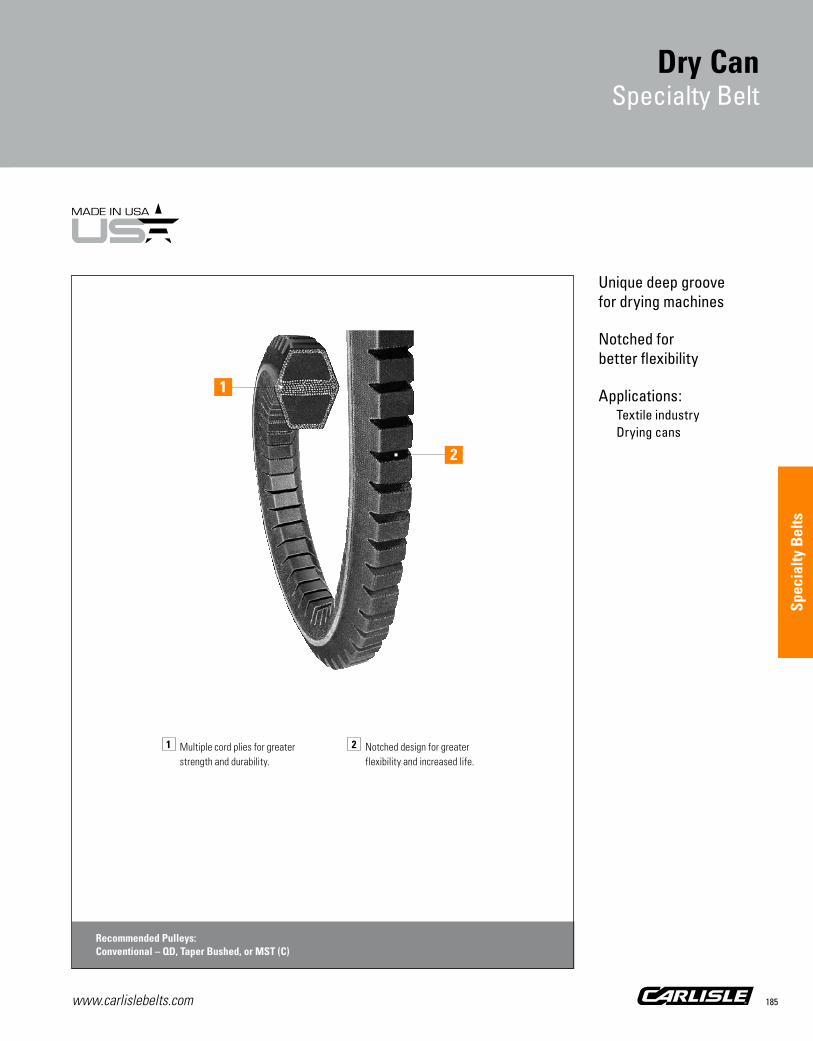
www.carlislebelts.com 185
Unique deep groove for drying machines
Notched for better flexibility
Applications:Textile industry Drying cans
1 Multiple cord plies for greater strength and durability.
2 Notched design for greater flexibility and increased life.
Recommended Pulleys:Conventional – QD, Taper Bushed, or MST (C)
2
1
Dry Can Specialty Belt
Spec
ialty
Bel
ts

www.carlislebelts.com186
Dry Can Specialty BeltPart Numbers
Part Number Example: CC600S = CC 600 S | | | Cross Section Pitch Length Notched Cog Double Angle (inches) Construction
PartNumber
Pitch Length(in)
Weight(lbs)
C Belt Recommended Pulleys:Conventional – QD, Taper Bushed, or MST (C)
CC210S 214.1 7.97
CC240S* 242.1 9.02
CC270S* 272.1 10.14
CC300S* 302.1 11.25
CC330S 332.1 12.37
CC360S 362.1 13.49
CC390S* 392.1 14.61
CC420S 422.1 15.73
CC440S 442.1 16.47
CC450S* 452.1 16.84
CC480S 482.1 17.96
CC540S 542.1 20.20
CC550S 552.1 20.57
CC600S 602.1 22.43
CC640S 642.1 23.92
CC660S 662.1 24.67
CC670S 672.1 25.04
CC680S* 682.1 25.41
CC700S* 702.1 26.16
CC720S 722.1 26.91
CC750S 752.1 28.02
CC780S 782.1 29.14
CC800S* 802.1 29.89
CC840S 842.1 31.38
CC900S 902.1 33.61
Dry Can
Specialty Belt
Deep groove double “CC” belts are designed for drives with long center, serpentine applications. Dry Can specialty belts are notched for added flexibility.
Important Application Information
Dry Can belts are normally used as a single belt on a drive and matching is not required. When ordering two or more Dry Can belts to be used as a matched set on the same drive, please specify that the belts must be a matched set.
15/16” CW
1-1/8” THCC
The original deep-groove notched design is specifically developed for the demanding textile industry double angle “CC” drives.
* Non-stock item. Minimum order quantity and/or extended lead times may apply. Contact customer service for availability.
For sizes not listed contact customer service for availability.

www.carlislebelts.com 187
Perfect candidate for v-belt drives that have no take-up adjustment capability
Ideal as an emergency replacement belt
Strong, flexible, fabric reinforced urethane construction
Applications:Emergency replacement
Thoro-Twist™ V-Belt
Specialty Belt
Recommended Pulleys:Conventional – QD, Taper Bushed, or MST (A-B, C); FHP – Bore-to-Size and MST (AK, BK)
1 High performance polyurethane elastomer, reinforced with
multiple plies of polyester fabric.
2 Oil, chemical, and temperature resistant.
2
1
Spec
ialty
Bel
ts

www.carlislebelts.com188
Panther®XTV-Belt
Carlisle® Thoro-Twist™ v-belts outperform other link v-belts time after time in harsh environments. An incredibly strong, yet flexible belt with the same horsepower ratings as classical section v-belts.
Easy installation. Thoro-Twist v-belts can be made to required length, by hand, in seconds and rolled onto the drive just like a bicycle chain.
Thoro-Twist v-belts have the same cross section dimensions as regular belts and can be installed on existing sheaves with no changes in setup.
Thoro-Twist™
Part Numbers
Thoro-Twist™ V-Belt
Specialty Belt
Part Number Example: 3LTwist = 3L Twist | | Cross Thoro-Twist Section (link) Belting
PartNumber
TopWidth (in) Replaces Weight
(lbs)MOQ
(meters)
Recommended Pulleys: Conventional – QD, Taper Bushed, or MST (A-B, C); FHP – Bore-to-Size and MST (AK, BK)
3LTwist 3/8 3L, O 11.50 30
ATwist 1/2 4L, A 14.50 30
BTwist 21/32 5L, B 22.50 30
CTwist 7/8 C 32.50 30
Thoro-Twist™ v-belting is a perfect candidate for drives that have no take-up adjustment capability or for use as an emergency replacement belt.
1/2”
A 11/32”
3/8”3L 7/32”
7/8”
C 9/16”
21/32”
B 7/16”
Minimum order quantity: One carton, 30 meter roll (approximately 98’)

www.carlislebelts.com 189
Minimal stretch for minimum take-up requirements
No splice for added durability
Available in most popular sizes for conveyor applications
Applications:Conveyors & More
Round
Specialty Belt
1 High-Modulus Cords Carries HP loads with
minimum stretch. Results in better belt stability and fewer take-up adjustments.
2 Compression Section Provides more uniform
cord support and improves belt flex life.
3 Heavy Duty Cover Stress relieved fabric
cover flexes better for improved belt life.
Recommended Pulleys:Conventional – QD, Taper Bushed, or MST (A-B)
2
1
3
Spec
ialty
Bel
ts

www.carlislebelts.com190
Round
Specialty Belt
Round belts are used on quarter-turn or twisted drives and serpentine drives. Round belts are available in various lengths in 7/16” and 9/16” diameters.
Other sizes are available. Please contact your Timken belts Customer Service team. Extended lead times and minimum order quantities may apply.
Round belts are a high performance solution for conveyors, quarter-turn, twisted, and serpentine drives.
7/16” 9/16”

www.carlislebelts.com 191
Round BeltPart Numbers
PartNumber
Diameter(in)
EffectiveLength (in)
Weight(lbs)
7/16” Diameter Recommended Pulleys:Conventional – QD, Taper Bushed, or MST (A-B)
716R70* 0.438 70.0 0.43
716R71* 0.438 71.0 0.43
716R72* 0.438 72.0 0.44
716R73* 0.438 73.0 0.45
716R74* 0.438 74.0 0.45
716R75* 0.438 75.0 0.46
716R76* 0.438 76.0 0.47
716R77* 0.438 77.0 0.47
716R78* 0.438 78.0 0.48
716R79* 0.438 79.0 0.48
716R80* 0.438 80.0 0.49
716R81* 0.438 81.0 0.50
716R82* 0.438 82.0 0.50
716R83* 0.438 83.0 0.51
716R84* 0.438 84.0 0.51
716R85* 0.438 85.0 0.52
716R86* 0.438 86.0 0.53
716R87* 0.438 87.0 0.53
716R88* 0.438 88.0 0.54
716R89* 0.438 89.0 0.54
716R90* 0.438 90.0 0.55
716R91* 0.438 91.0 0.56
716R92* 0.438 92.0 0.56
716R93* 0.438 93.0 0.57
716R94* 0.438 94.0 0.58
716R95* 0.438 95.0 0.58
716R96* 0.438 96.0 0.59
716R97* 0.438 97.0 0.59
716R98* 0.438 98.0 0.60
716R99* 0.438 99.0 0.61
716R100* 0.438 100.0 0.61
716R101* 0.438 101.0 0.62
716R102* 0.438 102.0 0.62
PartNumber
Diameter(in)
EffectiveLength (in)
Weight(lbs)
7/16” Diameter Recommended Pulleys:Conventional – QD, Taper Bushed, or MST (A-B)
716R103* 0.438 103.0 0.63
716R104* 0.438 104.0 0.64
716R105* 0.438 105.0 0.64
716R106* 0.438 106.0 0.65
716R151 0.438 150.7 0.92
9/16” Diameter Recommended Pulleys:Conventional – QD, Taper Bushed, or MST (A-B)
916R70* 0.563 70.0 0.70
916R71* 0.563 71.0 0.71
916R72* 0.563 72.0 0.72
916R73* 0.563 73.0 0.73
916R74* 0.563 74.0 0.74
916R75* 0.563 75.0 0.75
916R76* 0.563 76.0 0.76
916R77* 0.563 77.0 0.77
916R78* 0.563 78.0 0.79
916R79* 0.563 79.0 0.80
916R80* 0.563 80.0 0.81
916R81* 0.563 81.0 0.82
916R82* 0.563 82.0 0.83
916R83* 0.563 83.0 0.84
916R84* 0.563 84.0 0.85
916R85* 0.563 85.0 0.86
916R86* 0.563 86.0 0.87
916R87* 0.563 87.0 0.88
916R88* 0.563 88.0 0.89
916R89* 0.563 89.0 0.90
916R90* 0.563 90.0 0.91
916R91* 0.563 91.0 0.92
916R92* 0.563 92.0 0.93
916R93* 0.563 93.0 0.94
916R94* 0.563 94.0 0.95
916R95* 0.563 95.0 0.96
Round
Specialty Belt
Part Number Example: 716R100 = 716 R 100 | | | Diameter Round Belt Effective Length (fractional inches: 7/16”) Construction (inches)
Spec
ialty
Bel
ts
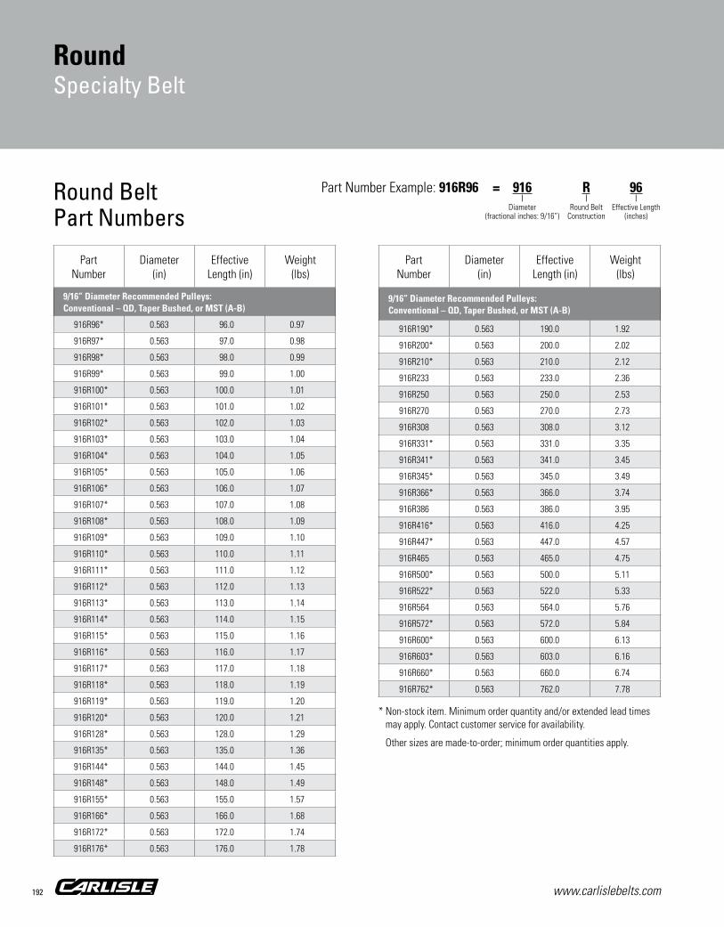
www.carlislebelts.com192
Round
Specialty Belt
PartNumber
Diameter(in)
EffectiveLength (in)
Weight(lbs)
9/16” Diameter Recommended Pulleys:Conventional – QD, Taper Bushed, or MST (A-B)
916R96* 0.563 96.0 0.97
916R97* 0.563 97.0 0.98
916R98* 0.563 98.0 0.99
916R99* 0.563 99.0 1.00
916R100* 0.563 100.0 1.01
916R101* 0.563 101.0 1.02
916R102* 0.563 102.0 1.03
916R103* 0.563 103.0 1.04
916R104* 0.563 104.0 1.05
916R105* 0.563 105.0 1.06
916R106* 0.563 106.0 1.07
916R107* 0.563 107.0 1.08
916R108* 0.563 108.0 1.09
916R109* 0.563 109.0 1.10
916R110* 0.563 110.0 1.11
916R111* 0.563 111.0 1.12
916R112* 0.563 112.0 1.13
916R113* 0.563 113.0 1.14
916R114* 0.563 114.0 1.15
916R115* 0.563 115.0 1.16
916R116* 0.563 116.0 1.17
916R117* 0.563 117.0 1.18
916R118* 0.563 118.0 1.19
916R119* 0.563 119.0 1.20
916R120* 0.563 120.0 1.21
916R128* 0.563 128.0 1.29
916R135* 0.563 135.0 1.36
916R144* 0.563 144.0 1.45
916R148* 0.563 148.0 1.49
916R155* 0.563 155.0 1.57
916R166* 0.563 166.0 1.68
916R172* 0.563 172.0 1.74
916R176* 0.563 176.0 1.78
PartNumber
Diameter(in)
EffectiveLength (in)
Weight(lbs)
9/16” Diameter Recommended Pulleys:Conventional – QD, Taper Bushed, or MST (A-B)
916R190* 0.563 190.0 1.92
916R200* 0.563 200.0 2.02
916R210* 0.563 210.0 2.12
916R233 0.563 233.0 2.36
916R250 0.563 250.0 2.53
916R270 0.563 270.0 2.73
916R308 0.563 308.0 3.12
916R331* 0.563 331.0 3.35
916R341* 0.563 341.0 3.45
916R345* 0.563 345.0 3.49
916R366* 0.563 366.0 3.74
916R386 0.563 386.0 3.95
916R416* 0.563 416.0 4.25
916R447* 0.563 447.0 4.57
916R465 0.563 465.0 4.75
916R500* 0.563 500.0 5.11
916R522* 0.563 522.0 5.33
916R564 0.563 564.0 5.76
916R572* 0.563 572.0 5.84
916R600* 0.563 600.0 6.13
916R603* 0.563 603.0 6.16
916R660* 0.563 660.0 6.74
916R762* 0.563 762.0 7.78
Part Number Example: 916R96 = 916 R 96 | | | Diameter Round Belt Effective Length (fractional inches: 9/16”) Construction (inches)
Round BeltPart Numbers
* Non-stock item. Minimum order quantity and/or extended lead times may apply. Contact customer service for availability.
Other sizes are made-to-order; minimum order quantities apply.

www.carlislebelts.com 193
Round
Specialty Belt
Spec
ialty
Bel
ts

www.carlislebelts.com194 www.martinsprocket.com Images provided courtesy of Martin®
Sprockets, Sheaves & Bushings
Timken is proud to partner with Sprocket & Gear, Inc. to provide full coverage for all your belt driven power transmission needs.
Martin sprockets, sheaves and bushings are now available and can be ordered along with Carlisle belts by Timken.
For optimum performance and increased belt life, use Martin’s comprehensive line of heavy-duty industrial sheaves, light-duty sheaves and synchronous sprockets.
Timken shares Martin’s philosophy of providing quality products, exceptional inventory and service “second to none.”
Timken is your one-stop for belt drive solutions:
• Product• Service• Delivery• Quality• Engineering Support
Martin®, MPC®, MST®, HI-CAP® are registered trademarks of Martin Sprocket & Gear, Inc.

195www.carlislebelts.com Images provided courtesy of Martin® www.martinsprocket.com
Sprockets, Sheaves & Bushings
Synchronous Drives
Timing Pulleys Timing Pulley Nomenclature 196 XL 197 L 198 H 203 XH 210
High Torque Sprockets 5mm 213 8mm 214 14mm 218 20mm 223
HTS® Synchronous Sprockets HTS Synchronous Sprockets Nomenclature 227 8mm 228 14mm 230
MPC® Sprockets MPC Sprockets Nomenclature 235 8mm 236 8mm Air Cool Heat Exchange 240 14mm 241 14mm Air Cool Heat Exchange 246
V-Belt Drives
Sheave Nomenclature 248
QD Hi-Cap® Wedge 3V Section 249 5V Section 252 8V Section 256
QD Conventional A-B Combination Groove 258 C Section 262 D Section 265
Taper Bushed Hi-Cap Wedge 3V Section 267 5V Section 270 8V Section 273
Taper Bushed Conventional A-B Combination Groove 275 C Section 278 D Section 281
FHP Sheaves AK/2AK Bored-To-Size 283 AK-H/2AK-H MST® Bushed 285 BK/2BK Bored-To-Size 287 BK-H/2BK-H MST Bushed 289
Variable Pitch Sheaves 1VP/2VP Bored-To-Size 291
MST® Hi-Cap Wedge 3V Section 293 5V Section 299 8V Section 303
MST Conventional A-B Combination Groove 307 C Section 315
Interchangeable Bushings
QD Bushings All Steel QD Bushings 325 Standard QD Bushings 326 QD Short Bushings 327
Taper Bushings Installation & Removal 328 Dimensions No. 1008-3030 329 No. 3535-5050 330 No. 4030-5040 330 No. 6050-120100 331 Metric and Reborable 332
MST® Bushings Bushing Specifications 333
Mar
tin S
proc
kets
, She
aves
& B
ushi
ngs

www.carlislebelts.com196 www.martinsprocket.com Images provided courtesy of Martin®
Timing Pulleys
K-2
Stock TimingPulleys
STOCK TIMING PULLEYS1/5" - 7/8" PITCHQD — TAPER BUSHED
AND STOCK BORE
Stock Bore QDTaper Bushed
PITCH PULLEY IN. DESIGNATION
1⁄5" XL (Extra Light)
3⁄8" L (Light)
1⁄2" H (Heavy)
7⁄8" XH (Extra Heavy)
Martin Timing Pulleys are manufactured to extremely close speci cations andare stocked in minimum plain bore, Taper Bushed and Q.D. bushed stylesdepending on size and pitch.
See tables for stock pulley types. Bushings are priced separately and must beadded to pulley price.
Illustrations below indicate stock pulley construction type listed in tables.
Type DF
Type D
E F
H
ML
Type CF
Type C
E L MF
Type KF
E L MF
Type A
EF
M
KL
Type G
E F
LK
M
Type H
E L
K
MF
Type J
“F” designation in pulley type means pulley is anged. When drive center distance is eight times the diameter of the smaller pulleyor when drive is operating on vertical shafts, both pulleys should be anged.
DEFINITION OF CATALOG NUMBERSEX: TB 20L100
TB — Requires Taper Bushing 20 — Number of Teeth L — 3⁄8" Pitch (Light) 100 — Belt Width 1"
EX: 72L100SD 72 — Number of Teeth L — 3⁄8" Pitch (Light) 100 — Belt Width 1" SD — Requires QD Bushing
EX: 16L100 Min. Plain Bore
Pulley sizes shown stocked as stock bore only: max. bore listed is withoutkeyway. If keyway is used reduce max. bore by twice keyway depth.
Pulley Style DesignationAs Shown in Tables
Dash 1 = Block Body StyleDash 2 = Web StyleDash 3 = Arm/Spoke Style
Size XXH (11⁄4" Pitch).Available as made-to-order.Call your nearest Martin facility.
Let us quote your made-to-order and largequantity requirements.
Type AF
K1 - K16_K1 - K16 4/23/14 2:39 PM Page K-2

197www.carlislebelts.com Images provided courtesy of Martin® www.martinsprocket.com
Sync
hron
ous
| Ti
min
g Pu
lleys
XL - 1⁄5"PitchXL 037 For Belts 1⁄4" and 3⁄8" WideMinimum Plain Bore F = 9⁄16
No. Part Pitch Max Type Bore
Teeth Number Diameter FL O.D. Stk. Max. E H L WT
K-5
Stock Timing XLPulleys 1⁄5" Pitch
E L MF
E
F M
L
E
L
M
KF
Dash 1 = Solid Style Dash 2 = Web Style Dash 3 = Arm/Spoke Style“F” type description indicates flanged.
10 10XL037 0.637 0.929 DF-1 3⁄16 1⁄4 7⁄32 7⁄16 25⁄32 0.03 11 11XL037 0.700 0.929 DF-1 3⁄16 1⁄4 7⁄32 7⁄16 25⁄32 0.04 12 12XL037 0.764 0.993 DF-1 3⁄16 5⁄16 7⁄32 1⁄2 25⁄32 0.06 14 14XL037 0.891 1.120 DF-1 1⁄4 3⁄8 7⁄32 9⁄16 25⁄32 0.08 15 15XL037 0.955 1.184 DF-1 1⁄4 7⁄16 7⁄32 5⁄8 25⁄32 0.09 16 16XL037 1.019 1.248 DF-1 1⁄4 1⁄2 7⁄32 11⁄16 25⁄32 0.10
18 18XL037 1.146 1.375 DF-1 1⁄4 9⁄16 7⁄32 13⁄16 25⁄32 0.13 20 20XL037 1.273 1.502 DF-1 1⁄4 11⁄16 5⁄16 15⁄16 7⁄8 0.18 21 21XL037 1.337 1.566 DF-1 1⁄4 11⁄16 5⁄16 15⁄16 7⁄8 0.19 22 22XL037 1.401 1.630 DF-1 1⁄4 3⁄4 5⁄16 1 7⁄8 0.22 24 24XL037 1.528 1.756 DF-1 1⁄4 13⁄16 5⁄16 11⁄16 7⁄8 0.25
28 28XL037 1.783 2.011 DF-1 1⁄4 15⁄16 5⁄16 13⁄16 7⁄8 0.34 30 30XL037 1.910 2.138 DF-1 5⁄16 11⁄16 5⁄16 13⁄8 7⁄8 0.41 32 32XL037 2.037 — D-1 5⁄16 13⁄16 7⁄16 11⁄2 1 0.25 36 36XL037 2.292 — D-1 5⁄16 13⁄16 7⁄16 11⁄2 1 0.29 40 40XL037 2.546 — D-1 5⁄16 13⁄16 7⁄16 11⁄2 1 0.35
42 42XL037 2.674 — D-1 5⁄16 13⁄16 7⁄16 11⁄2 1 0.31 44 44XL037 2.801 — D-1 5⁄16 13⁄16 7⁄16 11⁄2 1 0.34 48 48XL037 3.056 — D-1 5⁄16 13⁄16 7⁄16 11⁄2 1 0.63 60 60XL037 3.820 — D-1 3⁄8 13⁄16 7⁄16 11⁄2 1 0.90 72 72XL037 4.584 — D-1 3⁄8 13⁄16 7⁄16 11⁄2 1 0.50
Note: XL Pulleys stocked min. plain bore with 2 setscrews @ 90˚. If keyway is used, reduce max. bore by twice keyway depth.Pulley O.D. = P.D. – .02".
Type AF
Type A
Type DF
Type D
Type E
Type EF
Type GF
Type G
K1 - K16_K1 - K16 4/23/14 2:40 PM Page K-5
1/5” Pitch Timing Pulleys | XL
Every effort is made to keep all catalog dimensions and styles current in the catalog. However, from time to time it is necessary because of manufacturing changes to alter stock
products dimensionally. If any stock product dimension or style in this catalog section is critical to your application please contact for certification.

www.carlislebelts.com198 www.martinsprocket.com Images provided courtesy of Martin®
L | 3/8” Pitch Timing Pulleys
K-6
L Stock Timing3⁄8" Pitch Pulleys
L - 3⁄8"PitchL050 For Belts 1⁄2" Wide Minimum Plain Bore F = 3⁄4 No. Part Pitch Max Bore Dimensions
Teeth Number Diameter FL O.D. Type Stk. Max. E H L Wt.
L Pulleys 10 - 16 teeth min. plain bore stocked with 1 set screw. If keyway is used, reduced max. bore by twice keyway depth.Dimensions in inches. Weight in poundsPulley O.D. = P.D. – .03"
10 10L050 1.194 1 7⁄16 DF-1 3⁄8 9⁄16 3⁄8 13⁄16 1 1⁄8 0.28 12 12L050 1.432 1 43⁄64 DF-1 3⁄8 13⁄16 1⁄2 1 1⁄16 1 1⁄4 0.30 13 13L050 1.552 1 3⁄4 DF-1 3⁄8 13⁄16 1⁄2 1 1⁄8 1 1⁄4 0.35 14 14L050 1.671 1 59⁄64 DF-1 3⁄8 7⁄8 1⁄2 1 1⁄8 1 1⁄4 0.40 15 15L050 1.790 2 DF-1 1⁄2 15⁄16 1⁄2 1 1⁄8 1 1⁄4 0.50
16 16L050 1.910 2 5⁄32 DF-1 1⁄2 1 1⁄8 5⁄8 1 7⁄16 1 3⁄8 0.60 17 17L050 2.029 2 9⁄32 DF-1 1⁄2 1 1⁄8 5⁄8 1 1⁄2 1 3⁄8 0.65 18 18L050 2.149 2 25⁄64 DF-1 1⁄2 1 3⁄16 5⁄8 1 5⁄8 1 3⁄8 0.75 19 19L050 2.268 2 3⁄8 DF-1 1⁄2 1 3⁄16 5⁄8 1 5⁄8 1 3⁄8 0.80 20 20L050 2.387 2 5⁄8 DF-1 1⁄2 1 1⁄4 5⁄8 1 11⁄16 1 3⁄8 0.94
21 21L050 2.507 2 3⁄4 DF-1 1⁄2 1 5⁄16 11⁄16 1 7⁄8 1 7⁄16 1.00 22 22L050 2.626 2 7⁄8 DF-1 1⁄2 1 1⁄2 3⁄4 2 1 1⁄2 1.10 24 24L050 2.865 3 7⁄64 DF-1 1⁄2 1 5⁄8 3⁄4 2 1⁄4 1 1⁄2 1.60 26 26L050 3.104 3 11⁄32 DF-1 1⁄2 1 5⁄8 3⁄4 2 1⁄2 1 1⁄2 2.30 28 28L050 3.342 3 37⁄64 DF-1 1⁄2 1 5⁄8 3⁄4 2 3⁄4 1 1⁄2 2.50
30 30L050 3.581 3 53⁄64 DF-1 1⁄2 1 5⁄8 3⁄4 2 3⁄8 1 1⁄2 2.70 32 32L050 3.820 4 1⁄16 DF-1 1⁄2 1 7⁄8 7⁄8 3 1⁄16 1 5⁄8 3.00
L - 3⁄8"PitchL050 For Belts 1⁄2" Wide (3⁄8" Pitch) QD Type F = 3⁄4 No. Part Pitch Max Bore Dimensions Wt. Less Teeth Number Diameter FL O.D. Type Bush Range E K L M Bush.
Dimensions in inches. Weight in poundsPulley O.D. = P.D. – .03"*Reverse mount drilled only+Bushing Projects 1⁄16 on Small End.
18 18L050JA 2.149 225⁄64 EF-1* JA 1⁄2-11⁄4 3⁄16 — 11⁄16 1⁄2 0.40 20 20L050JA 2.387 25⁄8 EF-1* JA 1⁄2-11⁄4 3⁄16 — 11⁄16 1⁄2 0.50 22 22L050JA 2.626 27⁄8 EF-1* JA 1⁄2-11⁄4 3⁄16 — 11⁄16 1⁄2 0.70 24 24L050SH 2.865 37⁄64 GF-1 + SH 1⁄2-111⁄16 9⁄16 — 15⁄16 0 0.70 26 26L050SH 3.104 311⁄32 GF-1 + SH 1⁄2-111⁄16 9⁄16 0 15⁄16 0 1.00
28 28L050SH 3.342 337⁄64 GF-1 + SH 1⁄2-111⁄16 9⁄16 0 15⁄16 0 1.10 30 30L050SDS 3.581 353⁄64 GF-1 SDS 1⁄2-2 5⁄8 0 13⁄8 0 1.10 32 32L050SDS 3.820 41⁄16 GF-1 SDS 1⁄2-2 5⁄8 0 13⁄8 0 1.40 36 36L050SDS 4.297 417⁄32 GF-1 SDS 1⁄2-2 5⁄8 0 13⁄8 0 2.00 40 40L050SDS 4.775 51⁄64 GF-1 SDS 1⁄2-2 5⁄8 0 13⁄8 0 2.80
44 44L050SDS 5.252 531⁄64 GF-1 SDS 1⁄2-2 5⁄8 0 13⁄8 0 3.60 48 48L050SDS 5.730 61⁄64 GF-1 SDS 1⁄2-2 5⁄8 0 13⁄8 0 4.40 60 60L050SD 7.162 — G-3 SD 1⁄2-2 7⁄8 1⁄4 113⁄16 1⁄4 4.20 72 72L050SD 8.594 — G-3 SD 1⁄2-2 7⁄8 1⁄4 113⁄16 1⁄4 6.60 84 84L050SD 10.027 — G-3 SD 1⁄2-2 7⁄8 1⁄4 113⁄16 1⁄4 5.80
L050 Taper Bushedon Page K7
E F
H
ML
E
L
M
KF
E
FK
L
M
E L MF
Type CF
Type C
Type DF
Type D
Type EF
Type E
Type GF
Type G
Type HF
Type H Type KF
Dash 1 = Solid Style Dash 2 = Web Style Dash 3 = Arm/Spoke Style
F
E L
M
K1 - K16_K1 - K16 4/23/14 2:40 PM Page K-6

199www.carlislebelts.com Images provided courtesy of Martin® www.martinsprocket.com
Sync
hron
ous
| Ti
min
g Pu
lleys
K-7
Stock Timing LPulleys 3⁄8"Pitch
E F
H
ML
E
L
M
KF
E
FK
L
M
E L MF
Type CF
Type C
Type DF
Type D
Type EF
Type E
Type GF
Type G
Type HF
Type H Type KF
Dash 1 = Solid Style Dash 2 = Web Style Dash 3 = Arm/Spoke Style
L - 3⁄8"PitchL050 For Belts 1⁄2" Wide (3⁄8" Pitch) Taper Bushed Type F = 3⁄4 No. Part Pitch Max Bore Dimensions Wt. Less Teeth Number Diameter FL O.D. Type Bush Range E H L M Bush.
Dimensions in inches. Weight in poundsPulley O.D. = P.D. – .03"
18 TB18L050 2.149 225⁄64 CF-1 1008 1⁄2-1 1⁄8 15⁄8 7⁄8 — 0.45 20 TB20L050 2.387 25⁄8 CF-1 1008 1⁄2-1 1⁄8 111⁄16 7⁄8 — 0.68 22 TB22L050 2.626 27⁄8 CF-1 1008 1⁄2-1 1⁄8 2 7⁄8 — 0.90 24 TB24L050 2.865 37⁄64 CF-1 1210 1⁄2-11⁄4 1⁄4 21⁄4 1 — 1.00 26 TB26L050 3.104 311⁄32 CF-1 1210 1⁄2-11⁄4 1⁄4 21⁄2 1 — 1.20
28 TB28L050 3.342 337⁄64 CF-1 1610 1⁄2-11⁄4 1⁄4 23⁄4 1 — 1.40 30 TB30L050 3.581 353⁄64 CF-1 1610 1⁄2-15⁄8 1⁄4 27⁄8 1 — 1.50 32 TB32L050 3.820 41⁄16 CF-1 1610 1⁄2-15⁄8 1⁄4 31⁄16 1 — 1.90 40 TB40L050 4.775 51⁄64 CF-1 2012 1⁄2-2 1⁄2 311⁄16 11⁄4 — 2.40 48 TB48L050 5.730 61⁄64 CF-1 2012 1⁄2-2 1⁄2 311⁄16 11⁄4 — 3.20
60 TB60L050 7.162 — C-2 2012 1⁄2-2 1⁄4 43⁄8 11⁄4 1⁄4 4.90
L - 3⁄8"PitchL075 For Belts 3⁄4" Wide (3⁄8" Pitch) Minimum Plain Bore F = 1 No. Part Pitch Max Bore Dimensions
Teeth Number Diameter FL O.D. Type Stk. Max. E H L Wt.
Dimensions in inches. Weight in pounds.Pulley O.D. = P.D. – .03"L Pulleys 12 - 16 teeth min. plain bore stocked with 1-SS. If keyway is used, reduce max. bore by twice keyway depth.
12 12L075 1.432 143⁄64 DF-1 3⁄8 13⁄16 1⁄2 11⁄16 11⁄2 0.40 14 14L075 1.671 159⁄64 DF-1 3⁄8 7⁄8 1⁄2 11⁄8 11⁄2 0.50 16 16L075 1.910 25⁄32 DF-1 1⁄2 11⁄8 5⁄8 17⁄16 15⁄8 0.70 18 18L075 2.149 225⁄64 DF-1 1⁄2 13⁄16 5⁄8 15⁄8 15⁄8 0.90 20 20L075 2.387 25⁄8 DF-1 1⁄2 11⁄4 5⁄8 111⁄16 15⁄8 1.50
22 22L075 2.626 27⁄8 DF-1 5⁄8 11⁄2 3⁄4 2 13⁄4 1.80 24 24L075 2.865 37⁄64 DF-1 5⁄8 15⁄8 3⁄4 21⁄4 13⁄4 2.10 26 26L075 3.104 311⁄32 DF-1 5⁄8 15⁄8 7⁄8 21⁄2 17⁄8 2.80 28 28L075 3.342 337⁄64 DF-1 5⁄8 17⁄8 1 23⁄4 2 3.10 30 30L075 3.581 353⁄64 DF-1 5⁄8 17⁄8 1 27⁄8 2 3.40
32 32L075 3.820 41⁄16 DF-1 5⁄8 17⁄8 1 31⁄16 2 3.70
F
E L
M
K1 - K16_K1 - K16 4/23/14 2:40 PM Page K-7
3/8” Pitch Timing Pulleys | L
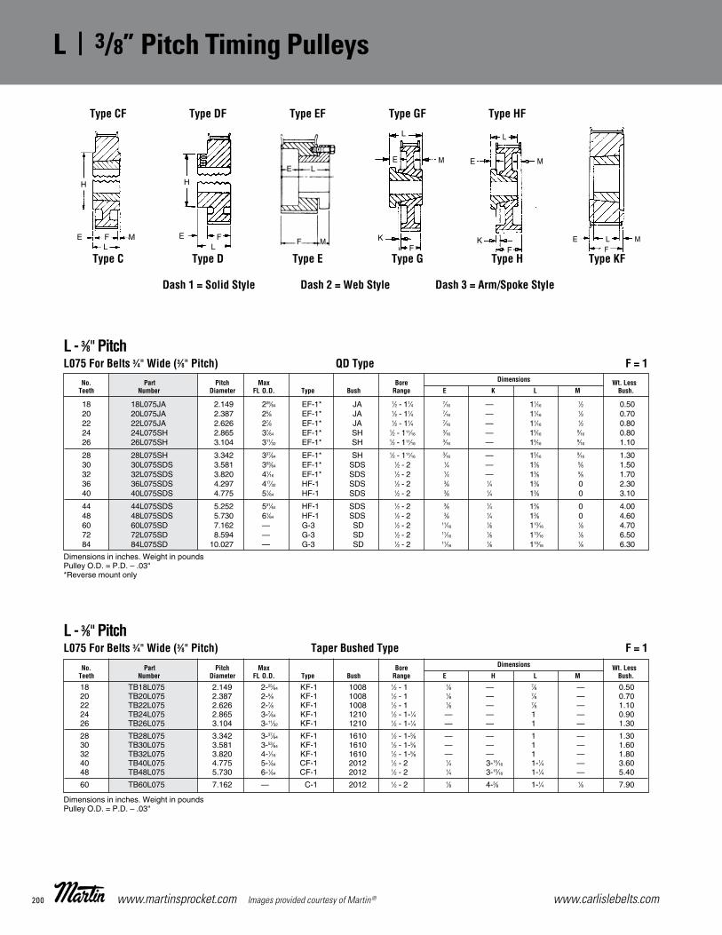
www.carlislebelts.com200 www.martinsprocket.com Images provided courtesy of Martin®
K-8
L Stock Timing3⁄8"Pitch Pulleys
L - 3⁄8"PitchL075 For Belts 3⁄4" Wide (3⁄8" Pitch) QD Type F = 1 No. Part Pitch Max Bore Dimensions Wt. Less Teeth Number Diameter FL O.D. Type Bush Range E K L M Bush.
Dimensions in inches. Weight in poundsPulley O.D. = P.D. – .03"*Reverse mount only
18 18L075JA 2.149 225⁄64 EF-1* JA 1⁄2 - 11⁄4 7⁄16 — 11⁄16 1⁄2 0.50 20 20L075JA 2.387 25⁄8 EF-1* JA 1⁄2 - 11⁄4 7⁄16 — 11⁄16 1⁄2 0.70 22 22L075JA 2.626 27⁄8 EF-1* JA 1⁄2 - 11⁄4 7⁄16 — 11⁄16 1⁄2 0.80 24 24L075SH 2.865 37⁄64 EF-1* SH 1⁄2 - 111⁄16 3⁄16 — 15⁄16 9⁄16 0.80 26 26L075SH 3.104 311⁄32 EF-1* SH 1⁄2 - 111⁄16 3⁄16 — 15⁄16 9⁄16 1.10
28 28L075SH 3.342 337⁄64 EF-1* SH 1⁄2 - 111⁄16 3⁄16 — 15⁄16 9⁄16 1.30 30 30L075SDS 3.581 353⁄64 EF-1* SDS 1⁄2 - 2 1⁄4 — 13⁄8 5⁄8 1.50 32 32L075SDS 3.820 41⁄16 EF-1* SDS 1⁄2 - 2 1⁄4 — 13⁄8 5⁄8 1.70 36 36L075SDS 4.297 417⁄32 HF-1 SDS 1⁄2 - 2 3⁄8 1⁄4 13⁄8 0 2.30 40 40L075SDS 4.775 51⁄64 HF-1 SDS 1⁄2 - 2 3⁄8 1⁄4 13⁄8 0 3.10
44 44L075SDS 5.252 531⁄64 HF-1 SDS 1⁄2 - 2 3⁄8 1⁄4 13⁄8 0 4.00 48 48L075SDS 5.730 61⁄64 HF-1 SDS 1⁄2 - 2 3⁄8 1⁄4 13⁄8 0 4.60 60 60L075SD 7.162 — G-3 SD 1⁄2 - 2 11⁄16 1⁄8 113⁄16 1⁄8 4.70 72 72L075SD 8.594 — G-3 SD 1⁄2 - 2 11⁄16 1⁄8 113⁄16 1⁄8 6.50 84 84L075SD 10.027 — G-3 SD 1⁄2 - 2 11⁄16 1⁄8 113⁄16 1⁄8 6.30
L - 3⁄8"PitchL075 For Belts 3⁄4" Wide (3⁄8" Pitch) Taper Bushed Type F = 1 No. Part Pitch Max Bore Dimensions Wt. Less Teeth Number Diameter FL O.D. Type Bush Range E H L M Bush.
Dimensions in inches. Weight in poundsPulley O.D. = P.D. – .03"
18 TB18L075 2.149 2-25⁄64 KF-1 1008 1⁄2 - 1 1⁄8 — 7⁄8 — 0.50 20 TB20L075 2.387 2-5⁄8 KF-1 1008 1⁄2 - 1 1⁄8 — 7⁄8 — 0.70 22 TB22L075 2.626 2-7⁄8 KF-1 1008 1⁄2 - 1 1⁄8 — 7⁄8 — 1.10 24 TB24L075 2.865 3-7⁄64 KF-1 1210 1⁄2 - 1-1⁄4 — — 1 — 0.90 26 TB26L075 3.104 3-11⁄32 KF-1 1210 1⁄2 - 1-1⁄4 — — 1 — 1.30
28 TB28L075 3.342 3-37⁄64 KF-1 1610 1⁄2 - 1-5⁄8 — — 1 — 1.30 30 TB30L075 3.581 3-53⁄64 KF-1 1610 1⁄2 - 1-5⁄8 — — 1 — 1.60 32 TB32L075 3.820 4-1⁄16 KF-1 1610 1⁄2 - 1-5⁄8 — — 1 — 1.80 40 TB40L075 4.775 5-1⁄64 CF-1 2012 1⁄2 - 2 1⁄4 3-15⁄16 1-1⁄4 — 3.60 48 TB48L075 5.730 6-1⁄64 CF-1 2012 1⁄2 - 2 1⁄4 3-15⁄16 1-1⁄4 — 5.40
60 TB60L075 7.162 — C-1 2012 1⁄2 - 2 1⁄8 4-3⁄8 1-1⁄4 1⁄8 7.90
E F
H
ML
E
L
M
KF
E
FK
L
M
E L MF
Type CF
Type C
Type DF
Type D
Type EF
Type E
Type GF
Type G
Type HF
Type H Type KF
Dash 1 = Solid Style Dash 2 = Web Style Dash 3 = Arm/Spoke Style
F
E L
M
K1 - K16_K1 - K16 4/23/14 2:40 PM Page K-8
L | 3/8” Pitch Timing Pulleys

201www.carlislebelts.com Images provided courtesy of Martin® www.martinsprocket.com
Sync
hron
ous
| Ti
min
g Pu
lleys
K-9
Stock Timing LPulleys 3⁄8"Pitch
L - 3⁄8"PitchL100 For Belts 1" Wide (3⁄8" Pitch) Minimum Plain Bore F = 11⁄4 No. Part Pitch Max Bore Dimensions
Teeth Number Diameter FL O.D. Type Stk. Max. E H L Wt.
Dimensions in inches. Weight in poundsPulley O.D. = P.D. – .03"L Pulleys 14 - 16 teeth min. plain bore stocked with 1-S.S. If keyway is used, reduce max. bore by twice keyway depth.
14 14L100 1.671 159⁄64 DF-1 3⁄8 7⁄8 1⁄2 11⁄8 13⁄4 0.60 16 16L100 1.910 25⁄32 DF-1 1⁄2 11⁄8 5⁄8 17⁄16 17⁄8 0.80 17 17L100 2.029 29⁄32 DF-1 1⁄2 11⁄8 5⁄8 11⁄2 17⁄8 1.00 18 18L100 2.149 225⁄64 DF-1 1⁄2 13⁄16 5⁄8 15⁄8 17⁄8 1.10 19 19L100 2.268 23⁄8 DF-1 1⁄2 13⁄16 5⁄8 15⁄8 17⁄8 1.40
20 20L100 2.387 25⁄8 DF-1 1⁄2 13⁄16 5⁄8 111⁄16 17⁄8 1.75 21 21L100 2.507 23⁄4 DF-1 5⁄8 15⁄16 11⁄16 17⁄8 17⁄8 1.80 22 22L100 2.626 27⁄8 DF-1 5⁄8 11⁄2 3⁄4 2 2 2.00 24 24L100 2.865 37⁄64 DF-1 5⁄8 15⁄8 3⁄4 21⁄4 2 2.50 26 26L100 3.104 311⁄32 DF-1 5⁄8 15⁄8 7⁄8 21⁄2 21⁄8 3.30
28 28L100 3.342 337⁄64 DF-1 5⁄8 17⁄8 1 23⁄4 21⁄4 3.60 30 30L100 3.581 353⁄64 DF-1 5⁄8 17⁄8 1 27⁄8 21⁄4 4.00 32 32L100 3.820 41⁄16 DF-1 5⁄8 17⁄8 1 31⁄16 21⁄4 4.40
L - 3⁄8"PitchL100 For Belts 1" Wide (3⁄8" Pitch) QD Type F = 11⁄4 No. Part Pitch Max Bore Dimensions Wt. Less Teeth Number Diameter FL O.D. Type Bush Range E K L M Bush.
Dimensions in inches. Weight in poundsPulley O.D. = P.D. – .03"*Reverse mount only
18 18L100JA 2.149 225⁄64 EF-1* JA 1⁄2 - 11⁄4 11⁄16 — 11⁄16 1⁄2 0.70 20 20L100JA 2.387 25⁄8 EF-1* JA 1⁄2 - 11⁄4 11⁄16 — 11⁄16 1⁄2 0.90 22 22L100JA 2.626 27⁄8 EF-1* JA 1⁄2 - 11⁄4 11⁄16 — 11⁄16 1⁄2 1.00 24 24L100SH 2.865 37⁄64 EF-1* SH 1⁄2 -111⁄16 7⁄16 — 15⁄16 9⁄16 1.00 26 26L100SH 3.104 311⁄32 EF-1* SH 1⁄2 -111⁄16 7⁄16 — 15⁄16 9⁄16 1.30
28 28L100SH 3.342 337⁄64 EF-1* SH 1⁄2 -111⁄16 7⁄16 — 15⁄16 9⁄16 1.70 30 30L100SDS 3.581 353⁄64 EF-1* SDS 1⁄2 -2 1⁄2 — 13⁄8 5⁄8 2.00 32 32L100SDS 3.820 41⁄16 EF-1* SDS 1⁄2 -2 1⁄2 — 13⁄8 5⁄8 2.10 36 36L100SDS 4.297 417⁄32 HF-1 SDS 1⁄2 -2 1⁄8 1⁄2 13⁄8 0 2.60 40 40L100SDS 4.775 51⁄64 HF-1 SDS 1⁄2 -2 1⁄8 1⁄2 13⁄8 0 3.40
44 44L100SDS 5.252 531⁄64 HF-1 SDS 1⁄2 -2 1⁄8 1⁄2 13⁄8 0 4.20 48 48L100SDS 5.730 61⁄64 HF-1 SDS 1⁄2 -2 1⁄8 1⁄2 13⁄8 0 5.10 60 60L100SD 7.162 — G-3 SD 1⁄2 -2 5⁄8 0 113⁄16 0 6.00 72 72L100SD 8.594 — G-3 SD 1⁄2 -2 5⁄8 0 113⁄16 0 8.00 84 84L100SD 10.027 — G-3 SD 1⁄2 -2 5⁄8 0 113⁄16 0 9.20
E F
H
ML
E
L
M
KF
E
FK
L
M
E L MF
Type CF
Type C
Type DF
Type D
Type EF
Type E
Type GF
Type G
Type HF
Type H Type KF
Dash 1 = Solid Style Dash 2 = Web Style Dash 3 = Arm/Spoke Style
F
E L
M
K1 - K16_K1 - K16 4/23/14 2:40 PM Page K-9
3/8” Pitch Timing Pulleys | L

www.carlislebelts.com202 www.martinsprocket.com Images provided courtesy of Martin®
K-10
L Stock Timing3⁄8"Pitch Pulleys
E F
H
ML
E
L
M
KF
E
FK
L
M
E L MF
L - 3⁄8"PitchL100 For Belts 1" Wide (3⁄8" Pitch) Taper Bushed Type F = 11⁄4 No. Part Pitch Max Bore Dimensions Wt. Less Teeth Number Diameter FL.O.D. Type Bush Range E K L M Bush.
Dimensions in inches. Weight in poundsPulley O.D. = P.D. – .03"
18 TB18L100 2.149 225⁄64 KF-1 1008 1⁄2 - 1 3⁄8 — 7⁄8 — 0.70 20 TB20L100 2.387 25⁄8 KF-1 1008 1⁄2 - 1 3⁄8 — 7⁄8 — 1.00 22 TB22L100 2.626 27⁄8 KF-1 1008 1⁄2 - 1 3⁄8 — 7⁄8 — 1.30 24 TB24L100 2.865 37⁄64 KF-1 1210 1⁄2 -11⁄4 1⁄4 — 1 — 1.30 26 TB26L100 3.104 311⁄32 KF-1 1210 1⁄2 -11⁄4 1⁄4 — 1 — 1.70
28 TB28L100 3.342 337⁄64 KF-1 1610 1⁄2 -15⁄8 1⁄4 — 1 — 1.70 30 TB30L100 3.581 353⁄64 KF-1 1610 1⁄2 -15⁄8 1⁄4 — 1 — 2.20 32 TB32L100 3.820 41⁄16 KF-1 1610 1⁄2 -15⁄8 1⁄4 — 1 — 2.70 40 TB40L100 4.775 51⁄64 KF-1 2012 1⁄2 -2 1⁄16 — 11⁄4 — 3.60 48 TB48L100 5.730 61⁄64 KF-1 2012 1⁄2 -2 1⁄16 — 11⁄4 — 5.10
60 TB60L100 7.162 — C-2 2012 1⁄2 -2 — — 11⁄4 — 6.00
Type CF Type DF Type EF Type GF
Type C Type D Type E Type G
Type HF
Type H Type KF
Dash 1 = Solid Style
Dash 2 = Web Style
Dash 3 = Arm/Spoke Style
“F” in type description indicates flanged.
E L
F M
K1 - K16_K1 - K16 4/23/14 2:40 PM Page K-10
L | 3/8” Pitch Timing Pulleys

203www.carlislebelts.com Images provided courtesy of Martin® www.martinsprocket.com
K-11
Stock Timing HPulleys 1⁄2" Pitch
H — 1⁄2" PitchH100 For Belts 3⁄4" and 1" Wide (1⁄2" Pitch) Minimum Plain Bore F = 15⁄16
No. Part Pitch Max Bore Dimensions
Teeth Number Diameter FL. O.D. Type Stk. Max. E H L Wt.
Dimensions in inches. Weight in poundsPulley O.D. = P.D. – .054"
14 14H100 2.228 231⁄64 DF-1 5⁄8 1 5⁄8 11⁄2 115⁄16 1.4 16 16H100 2.546 251⁄64 DF-1 5⁄8 11⁄4 11⁄16 2 2 2.0 18 18H100 2.865 37⁄64 DF-1 5⁄8 11⁄2 11⁄16 21⁄4 2 2.8 20 20H100 3.183 37⁄16 DF-1 5⁄8 15⁄8 7⁄8 21⁄2 23⁄16 3.4 21 21H100 3.342 39⁄16 DF-1 3⁄4 111⁄16 1 25⁄8 21⁄4 3.8
22 22H100 3.501 33⁄4 DF-1 3⁄4 17⁄8 1 27⁄8 25⁄16 4.3 24 24H100 3.820 41⁄64 DF-1 3⁄4 21⁄8 1 31⁄8 25⁄16 5.3 26 26H100 4.138 425⁄64 DF-1 3⁄4 21⁄2 1-1⁄8 31⁄2 27⁄16 6.7 28 28H100 4.456 445⁄64 DF-1 3⁄4 25⁄8 1-1⁄8 35⁄8 27⁄16 8.0
H — 1⁄2" PitchH100 For Belts 3⁄4" and 1" Wide (1⁄2" Pitch) QD Type F = 15⁄16
No. Part Pitch Max Bore Dimensions Wt. Less Teeth Number Diameter FL. O.D. Type Bush Range E H K L M Bush.
Dimensions in inches. Weight in poundsPulley O.D. = P.D. – .054"*Reverse mount only
14 14H100JA 2.228 231⁄64 EF-1* JA 1⁄2 -11⁄4 3⁄4 — — 11⁄16 1⁄2 1.0 16 16H100JA 2.546 251⁄64 EF-1* JA 1⁄2 -11⁄4 3⁄4 — — 11⁄16 1⁄2 1.5 18 18H100SH 2.865 37⁄64 EF-1* SH 1⁄2 -111⁄16 9⁄16 — — 15⁄16 9⁄16 1.2 20 20H100SH 3.183 37⁄16 EF-1* SH 1⁄2 -111⁄16 9⁄16 — — 15⁄16 9⁄16 1.2 22 22H100SDS 3.501 33⁄4 EF-1* SDS 1⁄2 -2 9⁄16 — — 13⁄8 5⁄8 1.4
24 24H100SDS 3.820 41⁄64 EF-1* SDS 1⁄2 -2 9⁄16 — — 13⁄8 5⁄8 1.7 26 26H100SDS 4.138 425⁄64 HF-1 SDS 1⁄2 -2 1⁄16 — 9⁄16 13⁄8 — 2.0 28 28H100SDS 4.456 445⁄64 HF-1 SDS 1⁄2 -2 1⁄16 — 9⁄16 13⁄8 — 2.6 30 30H100SD 4.775 51⁄64 GF-1 SD 1⁄2 -2 5⁄8 — — 113⁄16 — 3.0 32 32H100SK 5.093 521⁄64 GF-1 SK 1⁄2 -25⁄8 11⁄16 — — 115⁄16 — 4.9
36 36H100SK 5.730 561⁄64 GF-1 SK 1⁄2 -25⁄8 11⁄16 — — 115⁄16 — 5.6 40 40H100SK 6.366 637⁄64 GF-1 SK 1⁄2 -25⁄8 11⁄16 — — 115⁄16 — 8.2 44 44H100SK 7.003 71⁄4 GF-1 SK 1⁄2 -25⁄8 11⁄16 — — 115⁄16 — 10.0 48 48H100SK 7.639 81⁄64 GF-2 SK 1⁄2 -25⁄8 11⁄16 — — 115⁄16 — 12.5 60 60H100SF 9.549 — H-2 SF 1⁄2 -215⁄16 11⁄16 — — 21⁄16 — 10.9
72 72H100SF 11.459 — H-3 SF 1⁄2 -215⁄16 11⁄16 — — 21⁄16 — 14.0 84 84H100SF 13.369 — H-3 SF 1⁄2 -215⁄16 11⁄16 51⁄8 — 21⁄16 — 20.0 96 96H100SF 15.279 — H-3 SF 1⁄2 -215⁄16 11⁄16 51⁄8 — 21⁄16 — 27.0 120 120H100SF 19.099 — H-3 SF 1⁄2 -215⁄16 11⁄16 51⁄8 — 21⁄16 — 38.0
E
L
M
KF
E
FK
L
ME L
F M
Type DF Type EF Type GF Type HF
Type D Type E Type G Type H
K1 - K16_K1 - K16 4/23/14 2:40 PM Page K-11
Sync
hron
ous
| Ti
min
g Pu
lleys
1/2” Pitch Timing Pulleys | H

www.carlislebelts.com204 www.martinsprocket.com Images provided courtesy of Martin®
K-12
H Stock Timing1⁄2" Pitch Pulleys
E L
F ME F
H
ML
E
L
M
KF
E
FK
L
M
Type C Type D Type E Type G Type H
H — 1⁄2" PitchH100 For Belts 3⁄4" and 1" Wide (1⁄2" Pitch) Taper Bushed Type F = 15⁄16
No. Part Pitch Max Bore Dimensions Wt. Less Teeth Number Diameter FL. O.D. Type Bush Range E H L M Bush.
Dimensions in inches. Weight in poundsPulley O.D. = P.D. – .054"
14 TB14H100 2.228 231⁄64 KF-1 1008 1⁄2 - 1 7⁄16 — 7⁄8 — 0.80 16 TB16H100 2.546 251⁄64 KF-1 1008 1⁄2 - 1 7⁄16 — 7⁄8 — 1.30 18 TB18H100 2.865 37⁄64 KF-1 1210 1⁄2 - 11⁄4 5⁄16 — 1 — 1.20 20 TB20H100 3.183 37⁄16 KF-1 1210 1⁄2 - 11⁄4 5⁄16 — 1 — 1.70 22 TB22H100 3.501 33⁄4 KF-1 1610 1⁄2 - 15⁄8 5⁄16 — 1 — 1.80
24 TB24H100 3.820 41⁄64 KF-1 1610 1⁄2 - 15⁄8 5⁄16 — 1 — 2.30 26 TB26H100 4.138 425⁄64 KF-1 2012 1⁄2 - 2 1⁄16 — 11⁄4 — 2.60 28 TB28H100 4.456 445⁄64 KF-1 2012 1⁄2 - 2 1⁄16 — 11⁄4 — 2.80 30 TB30H100 4.775 51⁄64 KF-1 2012 1⁄2 - 2 1⁄16 — 11⁄4 — 4.20 32 TB32H100 5.093 521⁄64 CF-1 2517 1⁄2 - 21⁄2 7⁄16 47⁄16 13⁄4 — 4.30
40 TB40H100 6.366 637⁄64 CF-1 2517 1⁄2 - 21⁄2 7⁄16 47⁄16 13⁄4 — 7.80 48 TB48H100 7.639 81⁄64 CF-1 2517 1⁄2 - 21⁄2 7⁄16 47⁄16 13⁄4 — 12.10 60 TB60H100 9.549 — C-2 3020 7⁄8 - 3 11⁄32 61⁄4 2 11⁄32 10.30
Dash 1 = Solid Style Dash 2 = Web Style Dash 3 = Arm/Spoke Style
“F” in description indicates flanged.
Type CF Type DF Type EF Type GF Type HF
K1 - K16_K1 - K16 4/23/14 2:40 PM Page K-12
H | 1/2” Pitch Timing Pulleys

205www.carlislebelts.com Images provided courtesy of Martin® www.martinsprocket.com
K-13
Stock Timing HPulleys 1⁄2" Pitch
E L
F M
H — 1⁄2" PitchH150 For Belts 11⁄2" Wide (1⁄2" Pitch) Minimum Plain Bore F = 113⁄16
No. Part Pitch Max Bore Dimensions
Teeth Number Diameter FL O.D. Type Stk. Max. E H L Wt.
Dimensions in inches. Weight in poundsPulley O.D. = P.D. – .054"
14 14H150 2.228 231⁄64 DF-1 3⁄4 1 5⁄8 11⁄2 27⁄16 1.8 16 16H150 2.546 251⁄64 DF-1 3⁄4 11⁄4 3⁄4 2 29⁄16 2.5 18 18H150 2.865 37⁄64 DF-1 3⁄4 11⁄2 3⁄4 21⁄4 29⁄16 3.3 19 19H150 3.024 31⁄4 DF-1 3⁄4 19⁄16 7⁄8 21⁄4 25⁄8 3.9 20 20H150 3.183 37⁄16 DF-1 3⁄4 15⁄8 7⁄8 21⁄2 211⁄16 4.3
21 21H150 3.342 39⁄16 DF-1 3⁄4 111⁄16 15⁄16 21⁄2 23⁄4 5.3 22 22H150 3.501 33⁄4 DF-1 3⁄4 17⁄8 1 27⁄8 213⁄16 5.4 24 24H150 3.820 41⁄16 DF-1 3⁄4 21⁄8 1 31⁄8 213⁄16 6.5 26 26H150 4.138 425⁄32 DF-1 3⁄4 21⁄2 1 31⁄2 213⁄16 8.4
E L MF
E F
H
ML
E
L
M
KF
Type AF Type CF Type DF Type EF Type GF
Type A Type C Type D Type E Type G
E
FK
L
M
E L MF
Type HF
Type H Type KF
Dash 1 = Solid Style
Dash 2 = Web Style
Dash 3 = Arm/Spoke Style
“F” in type description indicates flanged.
K1 - K16_K1 - K16 4/23/14 2:40 PM Page K-13
Sync
hron
ous
| Ti
min
g Pu
lleys
1/2” Pitch Timing Pulleys | H

www.carlislebelts.com206 www.martinsprocket.com Images provided courtesy of Martin®
K-14
H Stock Timing1⁄2" Pitch Pulleys
H — 1⁄2" PitchH150 For Belts 11⁄2" Wide (1⁄2" Pitch) QD Type F = 113⁄16
No. Part Pitch Max Bore Dimensions Wt. Less Teeth Number Diameter FL O.D. Type Bush. Range E K L M Bush.
Dimensions in inches. Weight in poundsPulley O.D. = P.D. – .054"*Reverse mount only
14 14H150JA 2.228 231⁄64 EF-1* JA 1⁄2 - 11⁄4 11⁄4 — 11⁄16 1⁄2 1.5 16 16H150JA 2.546 251⁄64 EF-1* JA 1⁄2 - 11⁄4 11⁄4 — 11⁄16 1⁄2 2.0 18 18H150SH 2.865 37⁄64 EF-1* SH 1⁄2 - 111⁄16 1 — 15⁄16 9⁄16 1.3 20 20H150SH 3.183 37⁄16 EF-1* SH 1⁄2 - 111⁄16 1 — 15⁄16 9⁄16 1.8 22 22H150SD 3.501 33⁄4 EF-1* SD 1⁄2 - 2 9⁄16 — 113⁄16 5⁄8 2.0
24 24H150SD 3.820 41⁄16 EF-1* SD 1⁄2 - 2 9⁄16 — 113⁄16 5⁄8 2.6 26 26H150SD 4.138 425⁄32 HF-1 SD 1⁄2 - 2 1⁄16 9⁄16 113⁄16 1⁄16 3.0 28 28H150SD 4.456 445⁄64 HF-1 SD 1⁄2 - 2 1⁄16 9⁄16 113⁄16 1⁄16 4.0 30 30H150SD 4.775 51⁄64 HF-1 SD 1⁄2 - 2 1⁄16 9⁄16 113⁄16 1⁄16 4.9 32 32H150SK 5.093 521⁄64 HF-1 SK 1⁄2 - 25⁄8 1⁄8 9⁄16 115⁄16 0 5.8
36 36H150SK 5.730 561⁄64 HF-1 SK 1⁄2 - 25⁄8 1⁄8 9⁄16 115⁄16 0 7.0 40 40H150SK 6.366 637⁄64 HF-1 SK 1⁄2 - 25⁄8 1⁄8 9⁄16 115⁄16 0 9.2 44 44H150SK 7.003 71⁄4 HF-1 SK 1⁄2 - 25⁄8 1⁄8 9⁄16 115⁄16 0 11.0 48 48H150SK 7.639 81⁄64 HF-2 SK 1⁄2 - 25⁄8 1⁄8 9⁄16 115⁄16 0 13.7 60 60H150SF 9.549 — H-2 SF 1⁄2 - 215⁄16 13⁄32 9⁄32 21⁄16 9⁄32 12.5
72 72H150SF 11.459 — H-3 SF 1⁄2 - 215⁄16 13⁄32 9⁄32 21⁄16 9⁄32 17.0 84 84H150SF 13.369 — H-3 SF 1⁄2 - 215⁄16 13⁄32 9⁄32 21⁄16 9⁄32 21.5 96 96H150SF 15.279 — H-3 SF 1⁄2 - 215⁄16 13⁄32 9⁄32 21⁄16 9⁄32 31.0 120 120H150SF 19.099 — H-3 SF 1⁄2 - 215⁄16 13⁄32 9⁄32 21⁄16 9⁄32 40.0
H — 1⁄2" PitchH150 For Belts 11⁄2" Wide (1⁄2" Pitch) Taper Bushed Type F = 113⁄16
No. Part Pitch Max Bore Dimensions Wt. Less Teeth Number Diameter FL O.D. Type Bush Range E H K L M Bush.
Dimensions in inches. Weight in poundsPulley O.D. = P.D. – .054"
14 TB14H150 2.228 231⁄64 KF-1 1008 1⁄2 - 1 15⁄32 — — 7⁄8 15⁄32 1.0 16 TB16H150 2.546 251⁄64 KF-1 1008 1⁄2 - 1 15⁄32 — — 7⁄8 15⁄32 1.5 18 TB18H150 2.865 37⁄64 KF-1 1215 1⁄2 - 11⁄4 5⁄16 — — 11⁄2 — 1.6 20 TB20H150 3.183 37⁄16 KF-1 1215 1⁄2 - 11⁄4 5⁄16 — — 11⁄2 — 2.2 22 TB22H150 3.501 33⁄4 KF-1 1615 1⁄2 - 15⁄8 5⁄16 — — 11⁄2 — 2.5
24 TB24H150 3.820 41⁄16 KF-1 2012 1⁄2 - 2 9⁄16 — — 11⁄4 — 2.7 26 TB26H150 4.138 425⁄32 KF-1 2012 1⁄2 - 2 9⁄16 — — 11⁄4 — 3.2 28 TB28H150 4.456 445⁄64 KF-1 2012 1⁄2 - 2 9⁄16 — — 11⁄4 — 4.1 30 TB30H150 4.775 51⁄64 KF-1 2012 1⁄2 - 2 9⁄16 — — 11⁄4 — 5.1 32 TB32H150 5.093 521⁄64 KF-1 2517 1⁄2 - 21⁄2 1⁄16 — — 13⁄4 — 5.6
40 TB40H150 6.366 637⁄64 KF-1 2517 1⁄2 - 21⁄2 1⁄16 — — 13⁄4 — 8.6 48 TB48H150 7.639 81⁄64 AF-1 2517 1⁄2 - 21⁄2 — — 1⁄16 13⁄4 1⁄16 13.6 60 TB60H150 9.549 — C-2 3020 7⁄8 - 3 3⁄32 6-1⁄4 — 2 3⁄32 12.3
E L MF
E F
H
ML
E
FK
L
M
E L MF
Type AF Type CF Type E Type HF
Type A Type C Type EF Type H Type KF
Dash 1 = Solid Style Dash 2 = Web Style Dash 3 = Arm/Spoke Style
“F” in type description indicates flanged.
E L
F M
K1 - K16_K1 - K16 4/23/14 2:40 PM Page K-14
H | 1/2” Pitch Timing Pulleys

207www.carlislebelts.com Images provided courtesy of Martin® www.martinsprocket.com
K-15
Stock Timing HPulleys 1⁄2" Pitch
E L MF
E
FK
L
ME L
K
MF
E L MF
Type AF Type DF Type E Type HF Type JF
Type A Type D Type EF Type H Type J Type KF
H — 1⁄2" PitchH200 For Belts 2" Wide (1⁄2" Pitch) Minimum Plain Bore F = 2-11⁄32
Dash 1 = Solid Style Dash 2 = Web Style Dash 3 = Arm/Spoke Style
“F” in type description indicates flanged.
No. Part Pitch Max Bore Dimensions
Teeth Number Diameter FL O.D. Type Stk. Max. E H L Wt.
Dimensions in inches. Weight in poundsPulley O.D. = P.D. – .054"
14 14H200 2.228 23⁄8 DF-1 3⁄4 1 5⁄8 11⁄2 231⁄32 2.2 16 16H200 2.546 251⁄64 DF-1 3⁄4 11⁄4 3⁄4 2 33⁄32 3.1 18 18H200 2.865 37⁄64 DF-1 3⁄4 11⁄2 3⁄4 2 33⁄32 3.7 19 19H200 3.024 31⁄4 DF-1 3⁄4 19⁄16 7⁄8 21⁄4 37⁄32 3.9 20 20H200 3.183 37⁄16 DF-1 3⁄4 15⁄8 7⁄8 21⁄2 37⁄32 4.9
22 22H200 3.501 33⁄4 DF-1 1 17⁄8 1 27⁄8 311⁄32 6.3 24 24H200 3.820 41⁄16 DF-1 1 21⁄8 1 31⁄8 311⁄32 7.5 26 26H200 4.138 425⁄32 DF-1 1 21⁄2 1-1⁄8 31⁄2 315⁄32 9.5
E L
F M
K1 - K16_K1 - K16 4/23/14 2:40 PM Page K-15
Sync
hron
ous
| Ti
min
g Pu
lleys
1/2” Pitch Timing Pulleys | H

www.carlislebelts.com208 www.martinsprocket.com Images provided courtesy of Martin®
K-16
H Stock Timing1⁄2" Pitch Pulleys
H — 1⁄2" PitchH200 For Belts 2" Wide (1⁄2" Pitch) QD Type F = 2-11⁄32
No. Part Pitch Max. Bore Dimensions Wt. Less Teeth Number Diameter FL. O.D. Type Bush Range E K L M Bush.
Dimensions in inches. Weight in poundsPulley O.D. = P.D. – .054"*Reverse mount only
16 16H200JA 2.546 251⁄64 EF-1* JA 1⁄2 - 11⁄4 125⁄32 — 11⁄16 1⁄2 2.6 18 18H200SH 2.865 37⁄64 EF-1* SH 1⁄2 - 111⁄16 117⁄32 — 15⁄16 9⁄16 1.6 20 20H200SH 3.183 37⁄16 EF-1* SH 1⁄2 - 111⁄16 117⁄32 — 15⁄16 9⁄16 2.2 22 22H200SD 3.501 33⁄4 EF-1* SD 1⁄2 - 2 13⁄32 — 113⁄16 5⁄8 2.5 24 24H200SD 3.820 41⁄16 EF-1* SD 1⁄2 - 2 13⁄32 — 113⁄16 5⁄8 3.0
26 26H200SD 4.138 425⁄32 HF-1 SD 1⁄2 - 2 5⁄64 35⁄64 113⁄16 35⁄64 3.9 28 28H200SD 4.456 445⁄64 HF-1 SD 1⁄2 - 2 5⁄64 35⁄64 113⁄16 35⁄64 4.7 30 30H200SD 4.775 51⁄64 HF-1 SD 1⁄2 - 2 5⁄64 35⁄64 113⁄16 35⁄64 5.7 32 32H200SK 5.093 521⁄64 HF-1 SK 1⁄2 - 25⁄8 9⁄64 35⁄64 115⁄16 35⁄64 6.7 36 36H200SK 5.730 561⁄64 HF-1 SK 1⁄2 - 25⁄8 9⁄64 35⁄64 115⁄16 35⁄64 8.0
40 40H200SK 6.366 637⁄64 HF-1 SK 1⁄2 - 25⁄8 9⁄64 35⁄64 115⁄16 35⁄64 10.2 44 44H200SK 7.003 71⁄4 HF-1 SK 1⁄2 - 25⁄8 9⁄64 35⁄64 115⁄16 35⁄64 12.5 48 48H200SF 7.639 81⁄64 HF-2 SF 1⁄2 - 215⁄16 9⁄64 35⁄64 21⁄16 35⁄64 14.1 60 60H200SF 9.549 — H-2 SF 1⁄2 - 215⁄16 9⁄64 35⁄64 21⁄16 35⁄64 14.6 72 72H200SF 11.459 — H-3 SF 1⁄2 - 215⁄16 9⁄64 35⁄64 21⁄16 35⁄64 21.0
84 84H200SF 13.369 — H-3 SF 1⁄2 - 215⁄16 9⁄64 35⁄64 25⁄16 35⁄64 23.0 96 96H200E 15.279 — H-3 E 7⁄8 - 31⁄2 33⁄64 23⁄64 25⁄8 23⁄64 34.0 120 120H200E 19.099 — H-3 E 7⁄8 - 31⁄2 33⁄64 23⁄64 25⁄8 23⁄64 42.0
H — 1⁄2" PitchH200 For Belts 2" Wide (1⁄2" Pitch) Taper Bushed Type F = 211⁄32
No. Part Pitch Max. Bore Dimensions Wt. Less Teeth Number Diameter FL. O.D. Type Bush Range E L M Bush.
Dimensions in inches. Weight in poundsPulley O.D. = P.D. – .054"
16 TB16H200 2.546 251⁄64 KF-1 1008 1⁄2 - 1 3⁄4 7⁄8 23⁄32 1.9 18 TB18H200 2.865 37⁄64 KF-1 1215 1⁄2 - 11⁄4 7⁄16 11⁄2 13⁄32 1.8 20 TB20H200 3.183 37⁄16 KF-1 1215 1⁄2 - 11⁄4 27⁄64 11⁄2 27⁄64 2.6 22 TB22H200 3.501 33⁄4 KF-1 1615 1⁄2 - 15⁄8 27⁄64 11⁄2 27⁄64 2.8 24 TB24H200 3.820 41⁄16 KF-1 2012 1⁄2 - 2 35⁄64 11⁄4 35⁄64 2.8
26 TB26H200 4.138 425⁄32 KF-1 2012 1⁄2 - 2 35⁄64 11⁄4 35⁄64 3.6 28 TB28H200 4.456 445⁄64 KF-1 2012 1⁄2 - 2 35⁄64 11⁄4 35⁄64 5.1 30 TB30H200 4.775 51⁄64 KF-1 2012 1⁄2 - 2 13⁄32 11⁄4 — 7.0 32 TB32H200 5.093 521⁄64 KF-1 2517 1⁄2 - 21⁄2 19⁄32 13⁄4 — 8.5 40 TB40H200 6.366 637⁄64 KF-1 2517 1⁄2 - 21⁄2 19⁄32 13⁄4 — 9.9
48 TB48H200 7.639 81⁄64 KF-1 3020 7⁄8 - 3 11⁄32 2 — 14.3 60 TB60H200 9.549 — A-2 3020 7⁄8 - 3 11⁄64 2 11⁄64 15.3
E L MF
E
FK
L
M
E L MF
Type AF Type E Type HF
Type A Type EF Type H Type KF
Dash 1 = Solid Style Dash 2 = Web Style Dash 3 = Arm/Spoke Style
“F” in type description indicates flanged.
E L
F M
K1 - K16_K1 - K16 4/23/14 2:40 PM Page K-16
H | 1/2” Pitch Timing Pulleys

209www.carlislebelts.com Images provided courtesy of Martin® www.martinsprocket.com
K-17
Stock Timing HPulleys 1⁄2" Pitch
No. Part Pitch Max. Bore Dimensions
Teeth Number Diameter FL. O.D. Type Stk. Max. E H L Wt.
16 16H300 2.546 251⁄64 DF-1 3⁄4 11⁄4 3⁄4 2 41⁄8 4.2
H - 1⁄2"PitchH300 For Belts 3" Wide (1⁄2" Pitch) Minimum Plain Bore F = 3-3⁄8
Dimensions in inches. Weight in poundsPulley O.D. = P.D. – .054"
H - 1⁄2"PitchH300 For Belts 3" Wide (1⁄2" Pitch) QD Type F = 3-3⁄8 No. Part Pitch Max. Bore Dimensions Wt. Less Teeth Number Diameter FL. O.D. Type Bush Range E K L M Bush.
Dimensions in inches. Weight in poundsPulley O.D. = P.D. – .054"*Reverse mount only
22 22H300SD 3.501 33⁄4 EF-1* SD 1⁄2 - 2 21⁄8 — 113⁄16 5⁄8 4.1 24 24H300SD 3.820 41⁄16 EF-1* SD 1⁄2 - 2 21⁄8 — 113⁄16 5⁄8 4.1 26 26H300SD 4.138 425⁄64 JF-1 SD 1⁄2 - 2 7⁄16 11⁄16 113⁄16 11⁄16 5.0 28 28H300SD 4.456 445⁄64 JF-1 SD 1⁄2 - 2 7⁄16 11⁄16 113⁄16 11⁄16 6.0 30 30H300SD 4.775 51⁄64 JF-1 SD 1⁄2 - 2 7⁄16 11⁄16 113⁄16 11⁄16 7.2
32 32H300SK 5.093 521⁄64 JF-1 SK 1⁄2 - 25⁄8 3⁄8 11⁄16 115⁄16 11⁄16 8.4 36 36H300SK 5.730 561⁄64 JF-1 SK 1⁄2 - 25⁄8 3⁄8 11⁄16 115⁄16 11⁄16 10.0 40 40H300SK 6.366 637⁄64 JF-1 SK 1⁄2 - 25⁄8 3⁄8 11⁄16 115⁄16 11⁄16 12.2 44 44H300SK 7.003 71⁄4 JF-1 SK 1⁄2 - 25⁄8 3⁄8 11⁄16 115⁄16 11⁄16 15.5 48 48H300SF 7.639 81⁄64 JF-2 SF 1⁄2 - 215⁄16 3⁄8 11⁄16 21⁄16 11⁄16 16.6
60 60H300SF 9.549 — J-2 SF 1⁄2 - 215⁄16 3⁄8 11⁄16 21⁄16 11⁄16 17.9 72 72H300SF 11.459 — J-2 SF 1⁄2 - 215⁄16 3⁄16 11⁄16 21⁄16 11⁄16 23.0 84 84H300SF 13.369 — J-2 SF 1⁄2 - 215⁄16 3⁄16 11⁄16 21⁄16 11⁄16 30.0 96 96H300E 15.279 — H-3 E 7⁄8 - 31⁄2 0 7⁄8 25⁄8 7⁄8 38.0 120 120H300E 19.099 — H-3 E 7⁄8 - 31⁄2 0 7⁄8 25⁄8 7⁄8 51.0
H - 1⁄2"PitchH300 For Belts 3" Wide (1⁄2" Pitch) Taper Bushed Type F = 3-3⁄8 No. Part Pitch Max. Bore Dimensions Wt. Less Teeth Number Diameter FL. O.D. Type Bush Range E L M Bush.
Dimensions in inches. Weight in poundsPulley O.D. = P.D. – .054"
18 TB18H300 2.865 37⁄64 KF-1 1215 1⁄2 - 11⁄4 15⁄16 11⁄2 15⁄16 2.6 20 TB20H300 3.183 37⁄16 KF-1 1215 1⁄2 - 11⁄4 15⁄16 11⁄2 15⁄16 3.9 22 TB22H300 3.501 33⁄4 KF-1 1615 1⁄2 - 15⁄8 15⁄16 11⁄2 15⁄16 4.0 24 TB24H300 3.820 41⁄16 KF-1 2012 1⁄2 - 2 11⁄16 11⁄4 11⁄16 4.3 26 TB26H300 4.138 425⁄64 KF-1 2012 1⁄2 - 2 11⁄16 11⁄4 11⁄16 5.4
28 TB28H300 4.456 445⁄64 KF-1 2012 1⁄2 - 2 11⁄16 11⁄4 11⁄16 6.8 30 TB30H300 4.775 51⁄64 KF-1 2012 1⁄2 - 2 11⁄16 11⁄4 11⁄16 7.5 32 TB32H300 5.093 521⁄64 KF-1 2517 1⁄2 - 21⁄2 13⁄16 13⁄4 13⁄16 7.4 40 TB40H300 6.366 637⁄64 KF-1 2517 1⁄2 - 21⁄2 13⁄16 13⁄4 13⁄16 12.1 48 TB48H300 7.639 81⁄64 KF-1 3020 7⁄8 - 3 11⁄16 2 11⁄16 16.3
60 TB60H300 9.549 — A-2 3020 7⁄8 - 3 9⁄16 2 9⁄16 17.3
E F
H
ML
E
L
M
KF
E
FK
L
M
E L MF
Type CF
Type C
Type DF
Type D
Type EF
Type E
Type GF
Type G
Type HF
Type H Type KF
Dash 1 = Solid Style Dash 2 = Web Style Dash 3 = Arm/Spoke Style
F
E L
M
K17 - K32_K17 - K32 7/24/14 4:01 PM Page K-17
Sync
hron
ous
| Ti
min
g Pu
lleys
1/2” Pitch Timing Pulleys | H

www.carlislebelts.com210 www.martinsprocket.com Images provided courtesy of Martin®
K-18
XH Stock Timing7⁄8" Pitch Pulleys
E L
F M
XH — 7⁄8 PitchXH200 For Belts 2" Wide (7⁄8" Pitch) Minimum Plain Bore F = 29⁄16
No. Part Pitch Max. Bore Dimensions
Teeth Number Diameter FL O.D. Type Stk. Max. E H L Wt.
Dimensions in inches. Weight in poundsPulley O.D. = P.D. – .11"
18 18XH200 5.013 537⁄64 DF-1 1 25⁄8 7⁄8 311⁄16 37⁄16 12.0 20 20XH200 5.570 67⁄64 DF-1 1 31⁄4 1 41⁄8 39⁄16 16.0
E L MF
E F
H
ML
E L MF
E
FK
L
M
Type AF Type CF Type DF Type EF Type HF
Type A Type C Type D Type E Type H
E L
K
MF
Type JF
Type J Type KF
Dash 1 = Solid Style
Dash 2 = Web Style
Dash 3 = Arm/Spoke Style
“F” in type description indicates flanged.
XH — 7⁄8 PitchXH200 For Belts 2" Wide (7⁄8" Pitch) Taper Bushed Type F = 29⁄16
No. Part Pitch Max. Bore Dimensions Wt. Less Teeth Number Diameter FL O.D. Type Bush Range E H L M Bush.
Dimensions in inches. Weight in poundsPulley O.D. = P.D. – .11"
22 TB22XH200 6.127 619⁄32 KF-1 2517 1⁄2 - 21⁄2 13⁄16 — 13⁄4 — 10.6 24 TB24XH200 6.685 79⁄32 KF-1 3020 7⁄8 - 3 9⁄16 — 2 — 11.3 26 TB26XH200 7.241 725⁄32 KF-1 3020 7⁄8 - 3 9⁄16 — 2 — 13.3 28 TB28XH200 7.799 817⁄64 CF-1 3535 13⁄16 - 31⁄2 15⁄16 61⁄2 31⁄2 — 13.5 30 TB30XH200 8.356 91⁄32 CF-1 3535 13⁄16 - 31⁄2 15⁄16 61⁄2 31⁄2 — 18.5
32 TB32XH200 8.913 933⁄64 CF-1 3535 13⁄16 - 31⁄2 15⁄16 61⁄2 31⁄2 — 21.5 40 TB40XH200 11.141 1151⁄64 CF-1 4040 17⁄16 - 4 17⁄16 81⁄2 4 — 37.5 48 TB48XH200 13.369 — C-2 4040 17⁄16 - 4 13⁄32 81⁄2 4 23⁄32 44.5 60 TB60XH200 16.711 — C-3 4040 17⁄16 - 4 23⁄32 81⁄2 4 23⁄32 47.0
K17 - K32_K17 - K32 7/24/14 4:01 PM Page K-18
XH | 7/8” Pitch Timing Pulleys

211www.carlislebelts.com Images provided courtesy of Martin® www.martinsprocket.com
K-19
Stock Timing XHPulleys 7⁄8" Pitch
E L
F ME F
H
ML
E L MF
E L
K
MF
Type CF Type DF Type EF Type JF
Type C Type D Type E Type KF Type J
XH — 7⁄8 PitchXH300 For Belts 3" Wide (7⁄8" Pitch) Minimum Plain Bore F = 35⁄8 No. Part Pitch Max. Bore Dimensions
Teeth Number Diameter FL O.D. Type Stk. Max. E H L M Wt.
18 18XH300 5.013 537⁄64 DF-1 1 25⁄8 7⁄8 311⁄16 41⁄2 1* 15.0 20 20XH300 5.570 67⁄64 DF-1 1 31⁄4 1 41⁄8 45⁄8 3⁄4* 19.0
XH — 7⁄8 PitchXH300 For Belts 3" Wide (7⁄8" Pitch) Taper Bushed Type F = 35⁄8 No. Part Pitch Max. Bore Bore Dimensions
Teeth Number Diameter FL O.D. Type Bush Range E H L M Wt.
22 TB22XH300 6.127 621⁄32 KF-1 2517 1⁄2 - 21⁄2 15⁄16 — 13⁄4 15⁄16 13.6 24 TB24XH300 6.685 79⁄32 KF-1 3020 7⁄8 - 3 13⁄16 — 2 13⁄16 15.3 26 TB26XH300 7.241 725⁄32 KF-1 3020 7⁄8 - 3 13⁄16 — 2 13⁄16 17.3 28 TB28XH300 7.799 817⁄64 KF-1 3535 13⁄16 - 31⁄2 1⁄8 — 31⁄2 — 17.5 30 TB30XH300 8.356 91⁄32 KF-1 3535 13⁄16 - 31⁄2 1⁄8 — 31⁄2 — 22.5
32 TB32XH300 8.913 933⁄64 KF-1 3535 13⁄16 - 31⁄2 1⁄8 — 31⁄2 — 26.5 40 TB40XH300 11.141 1151⁄64 CF-1 4040 17⁄16 - 4 3⁄8 73⁄4 4 — 43.5 48 TB48XH300 13.369 — C-2 4040 17⁄16 - 4 3⁄16 81⁄2 4 3⁄16 51.5 60 TB60XH300 16.711 — C-3 4040 17⁄16 - 4 3⁄16 81⁄2 4 3⁄16 55.5
XH — 7⁄8 PitchXH400 For Belts 4" Wide (7⁄8" Pitch) QD Type F = 411⁄16
No. Part Pitch Max. Bore Dimensions
Teeth Number Diameter FL O.D. Type Bush Range E K L M Wt.
Dimensions in inches. Weight in poundsPulley O.D. = P.D. – .11"
20 20XH400SK 5.570 63⁄32 JF-1 SK 1⁄2 - 21⁄2 1⁄2 13⁄16 115⁄16 21⁄4 12.4 22 22XH400SK 6.127 621⁄32 JF-1 SK 1⁄2 - 21⁄2 1⁄2 13⁄16 115⁄16 21⁄4 16.7 24 24XH400SF 6.685 77⁄32 JF-1 SF 1⁄2 - 27⁄8 1⁄2 13⁄16 21⁄16 23⁄16 19.2 26 26XH400SF 7.242 725⁄32 JF-1 SF 1⁄2 - 27⁄8 1⁄2 13⁄16 21⁄16 23⁄16 23.0 28 28XH400E 7.799 811⁄32 JF-1 E 7⁄8 - 31⁄2 21⁄32 117⁄32 25⁄8 113⁄32 24.0
30 30XH400E 8.356 829⁄32 JF-1 E 7⁄8 - 31⁄2 21⁄32 117⁄32 25⁄8 113⁄32 30.7 32 32XH400E 8.913 97⁄16 JF-1 E 7⁄8 - 31⁄2 21⁄32 117⁄32 25⁄8 113⁄32 34.0 40 40XH400F 11.141 1111⁄16 HF-2 F 1 - 315⁄16 3⁄32 13⁄32 35⁄8 11⁄32 49.0 48 48XH400J 13.369 — H-3 J 17⁄16 - 41⁄2 3⁄16 1 41⁄2 7⁄8 67.3 60 60XH400J 16.711 — H-3 J 17⁄16 - 41⁄2 7⁄16 3⁄4 41⁄2 5⁄8 85.0
72 72XH400J 20.054 — H-3 J 17⁄16 - 41⁄2 7⁄16 3⁄4 41⁄2 5⁄8 108.0 84 84XH400J 23.396 — H-3 J 17⁄16 - 41⁄2 7⁄16 3⁄4 41⁄2 5⁄8 119.0 96 96XH400J 26.738 — H-3 J 17⁄16 - 41⁄2 7⁄16 3⁄4 41⁄2 5⁄8 187.5 120 120XH400J 33.423 — H-3 J 17⁄16 - 41⁄2 7⁄16 3⁄4 41⁄2 5⁄8 187.5
K17 - K32_K17 - K32 7/24/14 4:01 PM Page K-19
Sync
hron
ous
| Ti
min
g Pu
lleys
7/8” Pitch Timing Pulleys | XH

www.carlislebelts.com212 www.martinsprocket.com Images provided courtesy of Martin®
5mm | High Torque Sprockets For use with:
Panther®
Synchro-Cog® HT
Dual Synchronous Belt
Air Cool Heat Exchange Belt

213www.carlislebelts.com Images provided courtesy of Martin® www.martinsprocket.com
High Torque Sprockets 5mm
K-24
MPB 15mm (.591 in.) Wide Belts (5M-15)
No. Weight* of Catalog Diameter (in.) Max. Dimensions (in.) Approx. Teeth Number Bore Pitch O.D. Flange Type + Bore E L M K H F G W (lbs)
* Weight Shown is for Sprocket Less Bushing.• Reverse Mount Only
+ The numbers (1=Solid, 2=Web, 3=Arms) within the “Type” indicates
Type B Type C Type D Type E• Type D (MPB Only)
Type BF Type CF Type DF Type EF• Type DF (MPB Only)
32 P325M15-MPB 1⁄2 2.005 1.960 2.16 DF-1 0.88 0.50 1.73 .— .— 1.55 0.84 .— 0.65 1.12 34 P345M15-MPB 1⁄2 2.130 2.085 2.29 DF-1 1.00 0.50 1.73 .— .— 1.68 0.84 .— 0.65 1.25 36 P365M15-MPB 1⁄2 2.256 2.211 2.41 DF-1 1.12 0.50 1.73 .— .— 1.80 0.84 .— 0.65 1.39
38 P385M15-JA JA 2.381 2.336 2.54 • EF-1 1.25 0.67 1.00 0.44 .— .— 0.84 1.34 0.65 0.80 40 P405M15-JA JA 2.506 2.461 2.66 • EF-1 1.25 0.67 1.00 0.44 .— .— 0.84 1.34 0.65 1.06 44 P445M15-JA JA 2.757 2.712 2.91 • EF-1 1.25 0.67 1.00 0.44 .— .— 0.84 1.34 0.65 1.40 48 P485M15-JA JA 3.008 2.963 3.16 BF-1 1.25 0.23 1.00 0.00 0.67 .— 0.84 2.36 0.65 1.20 52 P525M15-JA JA 3.258 3.213 3.41 BF-1 1.25 0.23 1.00 0.00 0.67 .— 0.84 2.62 0.65 1.43 56 P565M15-SH SH 3.509 3.464 3.66 DF-1 1.68 0.08 1.25 0.06 0.42 .— 0.84 2.86 0.65 1.64 60 P605M15-SH SH 3.760 3.715 3.92 DF-1 1.68 0.08 1.25 0.06 0.42 .— 0.84 3.12 0.65 1.83 64 P645M15-SH SH 4.010 3.965 4.16 DF-1 1.68 0.08 1.25 0.06 0.42 .— 0.84 3.37 0.65 2.16 68 P685M15-SDS SDS 4.261 4.216 4.41 CF-1 2.00 0.08 1.31 0.00 0.48 .— 0.84 3.50 0.65 2.48 72 P725M15-SDS SDS 4.511 4.466 4.66 CF-1 2.00 0.08 1.31 0.00 0.48 .— 0.84 3.75 0.65 2.84 80 P805M15-SDS SDS 5.013 4.968 .— C-1 2.00 0.08 1.31 0.00 0.48 .— 0.84 4.25 0.65 3.61 90 P905M15-SDS SDS 5.639 5.594 .— C-1 2.00 0.08 1.31 0.00 0.48 .— 0.84 4.88 0.65 4.69 112 P1125M15-SDS SDS 7.018 6.973 .— C-2 2.00 0.08 1.31 0.00 0.48 .— 0.84 6.05 0.65 6.02
32 P325M25-MPB 1⁄2 2.005 1.960 2.16 DF-1 0.88 0.50 1.34 .— .— 1.55 1.23 .— 1.04 0.84 34 P345M25-MPB 1⁄2 2.130 2.085 2.29 DF-1 1.00 0.50 1.34 .— .— 1.68 1.23 .— 1.04 0.93- 36 P365M25-MPB 1⁄2 2.256 2.211 2.41 DF-1 1.12 0.50 1.34 .— .— 1.80 1.23 .— 1.04 1.03 38 P385M25-JA JA 2.381 2.336 2.54 • EF-1 1.25 0.28 1.00 0.44 .— .— 1.23 1.34 1.04 0.61 40 P405M25-JA JA 2.506 2.461 2.66 • EF-1 1.25 0.28 1.00 0.44 .— .— 1.23 1.34 1.04 0.72 44 P445M25-JA JA 2.757 2.712 2.91 • EF-1 1.25 0.28 1.00 0.44 .— .— 1.23 1.34 1.04 0.95 48 P485M25-JA JA 3.008 2.963 3.16 CF-1 1.25 0.16 1.00 0.00 0.28 .— 1.23 2.36 1.04 0.97 52 P525M25-JA JA 3.258 3.213 3.41 CF-1 1.25 0.16 1.00 0.00 0.28 .— 1.23 2.62 1.04 1.17 56 P565M25-SH SH 3.509 3.464 3.66 DF-1 1.68 0.50 1.25 0.09 0.00 .— 1.23 .— 1.04 1.37 60 P605M25-SH SH 3.760 3.715 3.92 DF-1 1.68 0.50 1.25 0.09 0.00 .— 1.23 .— 1.04 1.68 64 P645M25-SH SH 4.010 3.965 4.16 DF-1 1.68 0.50 1.25 0.09 0.00 .— 1.23 .— 1.04 1.80 68 P685M25-SDS SDS 4.261 4.216 4.41 CF-1 2.00 0.47 1.31 0.00 0.09 .— 1.23 3.50 1.04 2.10 72 P725M25-SDS SDS 4.511 4.466 4.66 CF-1 2.00 0.47 1.31 0.00 0.09 .— 1.23 3.75 1.04 2.43 80 P805M25-SDS SDS 5.013 4.968 .— C-1 2.00 0.47 1.31 0.00 0.09 .— 1.23 4.25 1.04 3.15 90 P905M25-SDS SDS 5.639 5.594 .— C-1 2.00 0.47 1.31 0.00 0.09 .— 1.23 4.88 1.04 4.17 112 P1125M25-SDS SDS 7.018 6.973 .— C-1 2.00 0.47 1.31 0.00 0.09 .— 1.23 6.05 1.04 5.16
MPB 25mm (.984in.) Wide Belts (5M-25)
QD 15mm (.591in.) Wide Belts (5M-15)
QD 25mm (.984in.) Wide Belts (5M-25)
K17 - K32_K17 - K32 7/24/14 4:01 PM Page K-24
Sync
hron
ous
| Hi
gh T
orqu
e Sp
rock
ets
High Torque Sprockets | 5mm

www.carlislebelts.com214 www.martinsprocket.com Images provided courtesy of Martin®
High TorqueSprockets 8mm
K-25
20 P208M20-MPB 1⁄2 2.005 1.951 2.375 DF-1 7⁄8 5⁄8 13⁄4 0 — 13⁄8 11⁄8 .— 7⁄8 .90 21 P218M20-MPB 1⁄2 2.105 2.051 2.468 DF-1 1 5⁄8 13⁄4 0 — 11⁄2 11⁄8 .— 7⁄8 1.00 22 P228M20-MPB 1⁄2 2.206 2.152 2.562 DF-1 13⁄16 5⁄8 13⁄4 0 — 15⁄8 11⁄8 .— 7⁄8 1.60
24 P248M20-JA JA 2.406 2.352 2.750 • EF-1 11⁄4 9⁄16 11⁄16 7⁄16 — — 11⁄8 1.34 7⁄8 1.50 26 P268M20-JA JA 2.607 2.553 2.937 • EF-1 11⁄4 9⁄16 11⁄16 7⁄16 — — 11⁄8 1.34 7⁄8 1.80 28 P288M20-H H 2.807 2.753 3.156 • EF-1 13⁄8 1⁄4 11⁄4 3⁄8 — — 11⁄8 1.57 7⁄8 1.40 30 P308M20-H H 3.008 2.954 3.344 • EF-1 13⁄8 1⁄4 11⁄4 3⁄8 — — 11⁄8 1.57 7⁄8 1.90 32 P328M20-H H 3.208 3.154 3.562 CF-1 13⁄8 1⁄8 11⁄4 0 1⁄4 — 11⁄8 2.56 7⁄8 2.00 34 P348M20-SH SH 3.409 3.355 3.750 DF-1 111⁄16 3⁄16 11⁄4 1⁄16 5⁄16 — 11⁄8 2.75 7⁄8 2.20 36 P368M20-SH SH 3.609 3.555 3.937 DF-1 111⁄16 3⁄16 11⁄4 1⁄16 5⁄16 — 11⁄8 2.82 7⁄8 2.50 38 P388M20-SH SH 3.810 3.756 4.156 DF-1 111⁄16 3⁄16 11⁄4 1⁄16 5⁄16 — 11⁄8 3.00 7⁄8 2.80 40 P408M20-SH SH 4.010 3.956 4.344 DF-1 111⁄16 3⁄16 11⁄4 1⁄16 5⁄16 — 11⁄8 3.00 7⁄8 3.00 44 P448M20-SDS SDS 4.411 4.357 4.750 CF-1 2 3⁄16 11⁄4 0 3⁄8 — 11⁄8 3.50 7⁄8 3.20 48 P488M20-SDS SDS 4.812 4.758 5.157 CF-1 2 3⁄16 15⁄16 0 3⁄8 — 11⁄8 3.8 7⁄8 3.40 56 P568M20-SDS SDS 5.614 5.560 5.937 CF-1 2 3⁄16 15⁄16 0 3⁄8 — 11⁄8 4.6 7⁄8 4.50 64 P648M20-SDS SDS 6.416 6.362 6.750 CF-1 2 3⁄16 15⁄16 0 3⁄8 — 11⁄8 5.4 7⁄8 5.50 72 P728M20-SDS SDS 7.218 7.164 7.562 CF-1 2 3⁄16 15⁄16 0 3⁄8 — 11⁄8 6.2 7⁄8 6.00 80 P808M20-SDS SDS 8.020 7.966 8.375 CF-2 2 3⁄16 15⁄16 0 3⁄8 — 11⁄8 6.9 7⁄8 6.50 90 P908M20-SDS SDS 9.023 8.969 .— C-2 2 3⁄16 15⁄16 0 3⁄8 — 11⁄8 7.62 .— 7.00 112 P1128M20-SK SK 11.229 11.175 .— C-3 25⁄8 3⁄4 115⁄16 1⁄16 1⁄16 — 11⁄8 9.87 .— 10.50 144 P1448M20-SF SF 14.447 14.388 .— C-3 215⁄16 3⁄4 21⁄16 1⁄16 1⁄16 — 11⁄8 12.88 .— 14.50
24 P248M20-1108 1108 2.406 2.352 2.75 KF-1 1 1⁄16 7⁄8 3⁄16 — -- 11⁄8 1.783 7⁄8 .7 26 P268M20-1108 1108 2.607 2.553 2.94 KF-1 1 1⁄16 7⁄8 3⁄16 — -- 11⁄8 1.971 7⁄8 .9 28 P288M20-1108 1108 2.807 2.753 3.16 KF-1 1 1⁄16 7⁄8 3⁄16 — -- 11⁄8 2.000 7⁄8 1.2 30 P308M20-1210 1210 3.008 2.954 3.34 KF-1 11⁄4 1⁄8 1 — — -- 11⁄8 — 7⁄8 1.2 32 P328M20-1210 1210 3.208 3.154 3.56 KF-1 11⁄4 1⁄8 1 — — -- 11⁄8 — 7⁄8 1.4 34 P348M20-1610 1610 3.409 3.355 3.75 KF-1 111⁄16 1⁄8 1 — — -- 11⁄8 — 7⁄8 1.4 36 P368M20-1610 1610 3.609 3.555 3.94 KF-1 111⁄16 1⁄8 1 — — -- 11⁄8 — 7⁄8 1.7 38 P388M20-1610 1610 3.810 3.756 4.16 KF-1 111⁄16 1⁄8 1 — — -- 11⁄8 — 7⁄8 2.0 40 P408M20-1610 1610 4.010 3.956 4.34 KF-1 111⁄16 1⁄8 1 — — -- 11⁄8 — 7⁄8 2.4 44 P448M20-2012 2012 4.411 4.357 4.75 CF-1 21⁄8 — 11⁄4 1⁄8 — 327⁄32 11⁄8 — 7⁄8 2.6 48 P488M20-2012 2012 4.812 4.758 5.16 CF-1 21⁄8 — 11⁄4 1⁄8 — 37⁄8 11⁄8 — 7⁄8 3.4 56 P568M20-2012 2012 5.614 5.560 5.94 CF-1 21⁄8 — 11⁄4 1⁄8 — 37⁄8 11⁄8 — 7⁄8 5.3 64 P648M20-2012 2012 6.416 6.362 6.75 CF-1 21⁄8 — 11⁄4 1⁄8 — 43⁄8 11⁄8 — 7⁄8 7.5 72 P728M20-2012 2012 7.218 7.164 7.56 CF-1 21⁄8 — 11⁄4 1⁄8 — 43⁄8 11⁄8 — 7⁄8 9.9 80 P808M20-2517 2517 8.020 7.966 8.38 CF-2 211⁄16 — 13⁄4 5⁄8 — 47⁄8 11⁄8 6.900 7⁄8 11.9 90 P908M20-2517 2517 9.023 8.969 — C-2 211⁄16 — 13⁄4 5⁄8 — — 11⁄8 7.630 — 12.9
MPB 20mm (.787 in.) Wide Belts (8M-20)
No. Weight* of Catalog Diameter (in.) Max. Dimensions (in.) Approx. Teeth Number Bore Pitch O.D. Flange Type + Bore E L M K H F G W (lbs)
* Weight Shown is for Sprocket Less Bushing.• Reverse Mount Only
+ The numbers (1=Solid, 2=Web, 3=Arms) within the “Type” indicates
Type A Type B Type C Type D Type E• Type D (MPB Only)
Type AF Type BF Type CF Type DF Type EF• Type DF (MPB Only)
QD 20mm (.787 in.) Wide Belts (8M-20)
Taper Bushed 20mm (.787 in.) Wide Belts (8M-20)
K17 - K32_K17 - K32 7/24/14 4:01 PM Page K-25
8mm | High Torque Sprockets
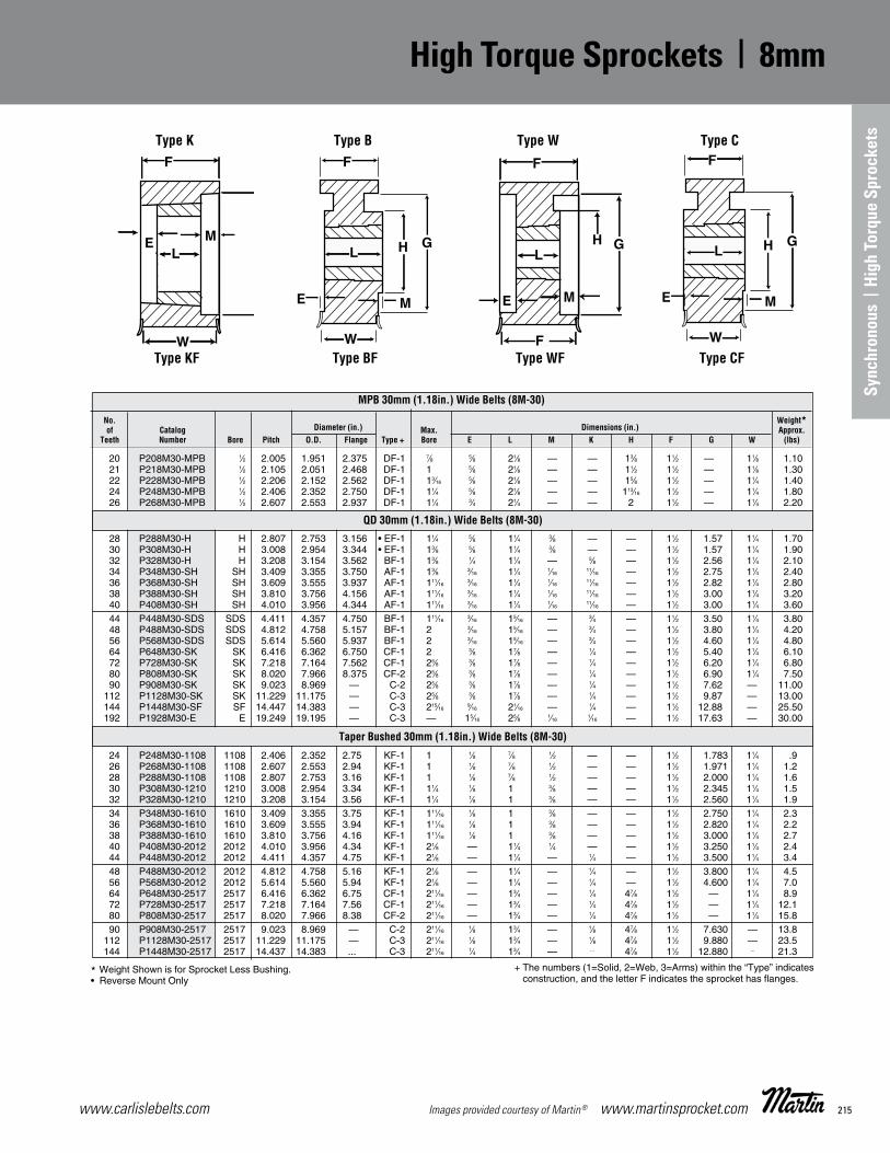
215www.carlislebelts.com Images provided courtesy of Martin® www.martinsprocket.com
High Torque Sprockets 8mm
K-26
MPB 30mm (1.18in.) Wide Belts (8M-30)
No. Weight* of Catalog Diameter (in.) Max. Dimensions (in.) Approx. Teeth Number Bore Pitch O.D. Flange Type + Bore E L M K H F G W (lbs)
* Weight Shown is for Sprocket Less Bushing.• Reverse Mount Only
+ The numbers (1=Solid, 2=Web, 3=Arms) within the “Type” indicates
Type K Type B Type W Type C
Type KF Type BF Type WF Type CF
20 P208M30-MPB 1⁄2 2.005 1.951 2.375 DF-1 7⁄8 5⁄8 21⁄8 — — 13⁄8 11⁄2 .— 11⁄8 1.10 21 P218M30-MPB 1⁄2 2.105 2.051 2.468 DF-1 1 5⁄8 21⁄8 — — 11⁄2 11⁄2 .— 11⁄8 1.30 22 P228M30-MPB 1⁄2 2.206 2.152 2.562 DF-1 13⁄16 5⁄8 21⁄8 — — 15⁄8 11⁄2 .— 11⁄4 1.40 24 P248M30-MPB 1⁄2 2.406 2.352 2.750 DF-1 11⁄4 5⁄8 21⁄8 — — 113⁄16 11⁄2 .— 11⁄4 1.80 26 P268M30-MPB 1⁄2 2.607 2.553 2.937 DF-1 11⁄4 3⁄4 21⁄4 — — 2 11⁄2 .— 11⁄4 2.20
28 P288M30-H H 2.807 2.753 3.156 • EF-1 11⁄4 5⁄8 11⁄4 3⁄8 — — 11⁄2 1.57 11⁄4 1.70 30 P308M30-H H 3.008 2.954 3.344 • EF-1 13⁄8 5⁄8 11⁄4 3⁄8 — — 11⁄2 1.57 11⁄4 1.90 32 P328M30-H H 3.208 3.154 3.562 BF-1 13⁄8 1⁄4 11⁄4 — 5⁄8 — 11⁄2 2.56 11⁄4 2.10 34 P348M30-SH SH 3.409 3.355 3.750 AF-1 13⁄8 3⁄16 11⁄4 1⁄16 11⁄16 — 11⁄2 2.75 11⁄4 2.40 36 P368M30-SH SH 3.609 3.555 3.937 AF-1 111⁄16 3⁄16 11⁄4 1⁄16 11⁄16 — 11⁄2 2.82 11⁄4 2.80 38 P388M30-SH SH 3.810 3.756 4.156 AF-1 111⁄16 3⁄16 11⁄4 1⁄16 11⁄16 — 11⁄2 3.00 11⁄4 3.20 40 P408M30-SH SH 4.010 3.956 4.344 AF-1 111⁄16 3⁄16 11⁄4 1⁄16 11⁄16 — 11⁄2 3.00 11⁄4 3.60 44 P448M30-SDS SDS 4.411 4.357 4.750 BF-1 111⁄16 3⁄16 15⁄16 — 3⁄4 — 11⁄2 3.50 11⁄4 3.80 48 P488M30-SDS SDS 4.812 4.758 5.157 BF-1 2 3⁄16 15⁄16 — 3⁄4 — 11⁄2 3.80 11⁄4 4.20 56 P568M30-SDS SDS 5.614 5.560 5.937 BF-1 2 3⁄16 15⁄16 — 3⁄4 — 11⁄2 4.60 11⁄4 4.80 64 P648M30-SK SK 6.416 6.362 6.750 CF-1 2 3⁄8 17⁄8 — 1⁄4 — 11⁄2 5.40 11⁄4 6.10 72 P728M30-SK SK 7.218 7.164 7.562 CF-1 25⁄8 3⁄8 17⁄8 — 1⁄4 — 11⁄2 6.20 11⁄4 6.80 80 P808M30-SK SK 8.020 7.966 8.375 CF-2 25⁄8 3⁄8 17⁄8 — 1⁄4 — 11⁄2 6.90 11⁄4 7.50 90 P908M30-SK SK 9.023 8.969 — C-2 25⁄8 3⁄8 17⁄8 — 1⁄4 — 11⁄2 7.62 .— 11.00 112 P1128M30-SK SK 11.229 11.175 — C-3 25⁄8 3⁄8 17⁄8 — 1⁄4 — 11⁄2 9.87 .— 13.00 144 P1448M30-SF SF 14.447 14.383 — C-3 215⁄16 9⁄16 21⁄16 — 1⁄4 — 11⁄2 12.88 .— 25.50 192 P1928M30-E E 19.249 19.195 — C-3 — 15⁄16 25⁄8 1⁄16 1⁄16 — 11⁄2 17.63 .— 30.00
24 P248M30-1108 1108 2.406 2.352 2.75 KF-1 1 1⁄8 7⁄8 1⁄2 — — 11⁄2 1.783 11⁄4 .9 26 P268M30-1108 1108 2.607 2.553 2.94 KF-1 1 1⁄8 7⁄8 1⁄2 — — 11⁄2 1.971 11⁄4 1.2 28 P288M30-1108 1108 2.807 2.753 3.16 KF-1 1 1⁄8 7⁄8 1⁄2 — — 11⁄2 2.000 11⁄4 1.6 30 P308M30-1210 1210 3.008 2.954 3.34 KF-1 11⁄4 1⁄8 1 3⁄8 — — 11⁄2 2.345 11⁄4 1.5 32 P328M30-1210 1210 3.208 3.154 3.56 KF-1 11⁄4 1⁄8 1 3⁄8 — — 11⁄2 2.560 11⁄4 1.9 34 P348M30-1610 1610 3.409 3.355 3.75 KF-1 111⁄16 1⁄8 1 3⁄8 — — 11⁄2 2.750 11⁄4 2.3 36 P368M30-1610 1610 3.609 3.555 3.94 KF-1 111⁄16 1⁄8 1 3⁄8 — — 11⁄2 2.820 11⁄4 2.2 38 P388M30-1610 1610 3.810 3.756 4.16 KF-1 111⁄16 1⁄8 1 3⁄8 — — 11⁄2 3.000 11⁄4 2.7 40 P408M30-2012 2012 4.010 3.956 4.34 KF-1 21⁄8 — 11⁄4 1⁄4 — — 11⁄2 3.250 11⁄4 2.4 44 P448M30-2012 2012 4.411 4.357 4.75 KF-1 21⁄8 — 11⁄4 — 1⁄4 — 11⁄2 3.500 11⁄4 3.4 48 P488M30-2012 2012 4.812 4.758 5.16 KF-1 21⁄8 — 11⁄4 — 1⁄4 — 11⁄2 3.800 11⁄4 4.5 56 P568M30-2012 2012 5.614 5.560 5.94 KF-1 21⁄8 — 11⁄4 — 1⁄4 — 11⁄2 4.600 11⁄4 7.0 64 P648M30-2517 2517 6.416 6.362 6.75 CF-1 211⁄16 — 13⁄4 — 1⁄4 47⁄8 11⁄2 — 11⁄4 8.9 72 P728M30-2517 2517 7.218 7.164 7.56 CF-1 211⁄16 — 13⁄4 — 1⁄4 47⁄8 11⁄2 — 11⁄4 12.1 80 P808M30-2517 2517 8.020 7.966 8.38 CF-2 211⁄16 — 13⁄4 — 1⁄4 47⁄8 11⁄2 — 11⁄4 15.8 90 P908M30-2517 2517 9.023 8.969 — C-2 211⁄16 1⁄8 13⁄4 — 1⁄8 47⁄8 11⁄2 7.630 — 13.8 112 P1128M30-2517 2517 11.229 11.175 — C-3 211⁄16 1⁄8 13⁄4 — 1⁄8 47⁄8 11⁄2 9.880 — 23.5 144 P1448M30-2517 2517 14.437 14.383 ... C-3 211⁄16 1⁄4 13⁄4 — ... 47⁄8 11⁄2 12.880 ... 21.3
QD 30mm (1.18in.) Wide Belts (8M-30)
Taper Bushed 30mm (1.18in.) Wide Belts (8M-30)
K17 - K32_K17 - K32 7/24/14 4:01 PM Page K-26
Sync
hron
ous
| Hi
gh T
orqu
e Sp
rock
ets
High Torque Sprockets | 8mm

www.carlislebelts.com216 www.martinsprocket.com Images provided courtesy of Martin®
High TorqueSprockets 8mm
K-27
MPB 50mm (1.97 in.) Wide Belts (8M-50) No. Weight* of Catalog Diameter (in.) Max. Dimensions (in.) Approx. Teeth Number Bore Pitch O.D. Flange Type + Bore E L M K H F G W (lbs)
* Weight Shown is for Sprocket Less Bushing.• Reverse Mount Only
+ The numbers (1=Solid, 2=Web, 3=Arms) within the “Type” indicates
Type A Type C Type D Type E• Type D (MPB Only)
Type AF Type CF Type DF Type EF• Type DF (MPB Only)
QD 50mm (1.97 in.) Wide Belts (8M-50)
Taper Bushed 50mm (1.97 in.) Wide Belts (8M-50)
28 P288M50-MPB 1⁄2 2.807 2.753 3.156 DF-1 11⁄4 3⁄4 31⁄8 — — 29⁄32 23⁄8 — 21⁄8 4.2 30 P308M50-MPB 1⁄2 3.008 2.954 3.344 DF-1 11⁄4 3⁄4 31⁄8 — — 215⁄32 23⁄8 — 21⁄8 4.9 32 P328M50-MPB 1⁄2 3.208 3.154 3.562 DF-1 15⁄8 3⁄4 31⁄8 — — 219⁄32 23⁄8 — 21⁄8 5.4
32 P328M50-H H 3.208 3.154 3.562 AF-1 13⁄8 1⁄2 11⁄4 5⁄8 3⁄4 — 23⁄8 2.56 21⁄8 2.9 34 P348M50-SH SH 3.409 3.355 3.750 AF-1 111⁄16 — 11⁄4 11⁄8 1⁄2 — 23⁄8 2.75 21⁄8 3.2 36 P368M50-SH SH 3.609 3.555 3.937 AF-1 111⁄16 — 11⁄4 11⁄8 1⁄2 — 23⁄8 2.82 21⁄8 3.8 38 P388M50-SH SH 3.810 3.756 4.156 AF-1 111⁄16 — 11⁄4 11⁄8 1⁄2 — 23⁄8 3.00 21⁄8 4.2 40 P408M50-SH SH 4.010 3.956 4.344 AF-1 111⁄16 — 11⁄4 11⁄8 1⁄2 — 23⁄8 3.00 21⁄8 4.6 44 P448M50-SD SD 4.411 4.357 4.750 AF-1 2 — 113⁄16 9⁄16 9⁄16 — 23⁄8 3.50 21⁄8 5.2 48 P488M50-SD SD 4.812 4.758 5.157 AF-1 2 — 113⁄16 9⁄16 9⁄16 — 25⁄8 3.80 21⁄8 6.0 56 P568M50-SK SK 5.614 5.560 5.937 DF-1 25⁄8 1⁄16 17⁄8 9⁄16 9⁄16 — 23⁄8 4.60 21⁄8 7.6 64 P648M50-SK SK 6.416 6.362 6.750 DF-1 25⁄8 1⁄16 17⁄8 9⁄16 9⁄16 — 23⁄8 5.40 21⁄8 10.3 72 P728M50-SK SK 7.218 7.164 7.562 DF-1 25⁄8 1⁄16 17⁄8 9⁄16 9⁄16 — 23⁄8 6.20 21⁄8 13.3 80 P808M50-SF SF 8.020 7.966 8.326 DF-1 27⁄8 1⁄16 2 7⁄16 9⁄16 — 25⁄8 6.90 21⁄8 12.7 90 P908M50-SF SF 9.023 8.969 .— D-2 27⁄8 1⁄16 2 7⁄16 9⁄16 — 23⁄8 7.62 21⁄8 16.0 112 P1128M50-SF SF 11.229 11.175 .— D-3 27⁄8 1⁄16 2 7⁄16 9⁄16 — 23⁄8 9.88 21⁄8 21.0 144 P1448M50-E E 14.437 14.383 .— D-3 31⁄2 1⁄2 25⁄8 2 3⁄8 — 23⁄8 12.88 21⁄8 35.0 192 P1928M50-E E 19.249 19.195 .— D-3 31⁄2 1⁄2 25⁄8 2 3⁄8 — 23⁄8 17.63 21⁄8 45.0 28 P288M50-1108 1108 2.807 2.753 3.16 KF-1 1 — 7⁄8 11⁄2 — — 23⁄8 2.000 21⁄8 2.1 30 P308M50-1210 1210 3.008 2.954 3.34 KF-1 11⁄4 — 1 13⁄8 — — 23⁄8 2.345 21⁄8 2.2 32 P328M50-1210 1210 3.208 3.154 3.56 KF-1 11⁄4 — 1 13⁄8 — — 23⁄8 2.560 21⁄8 2.1 34 P348M50-1610 1610 3.409 3.355 3.75 KF-1 111⁄16 — 1 13⁄8 — — 23⁄8 2.750 21⁄8 2.1 36 P368M50-1610 1610 3.609 3.555 3.94 KF-1 111⁄16 — 1 13⁄8 — — 23⁄8 2.820 21⁄8 2.7 38 P388M50-1610 1610 3.810 3.756 4.16 KF-1 111⁄16 — 1 13⁄8 — — 23⁄8 3.000 21⁄8 3.1 40 P408M50-2012 2012 4.010 3.956 4.34 KF-1 21⁄8 — 11⁄4 11⁄8 — — 23⁄8 3.250 21⁄8 3.4 44 P448M50-2012 2012 4.411 4.357 4.75 KF-1 21⁄8 — 11⁄4 11⁄8 — — 23⁄8 3.500 21⁄8 4.3 48 P488M50-2012 2012 4.812 4.758 5.16 KF-1 21⁄8 — 11⁄4 11⁄8 — — 23⁄8 3.800 21⁄8 5.5 56 P568M50-2517 2517 5.614 5.560 5.94 KF-1 211⁄16 — 13⁄4 5⁄8 — — 23⁄8 4.600 21⁄8 8.1 64 P648M50-2517 2517 6.416 6.362 6.75 KF-1 211⁄16 — 13⁄4 5⁄8 — — 23⁄8 5.400 21⁄8 11.7 72 P728M50-2517 2517 7.218 7.164 7.56 KF-1 211⁄16 — 13⁄4 5⁄8 — — 23⁄8 6.200 21⁄8 15.7 80 P808M50-2517 2517 8.020 7.966 8.38 KF-1 211⁄16 — 13⁄4 5⁄8 — — 23⁄8 6.900 21⁄8 20.3 90 P908M50-3020 3020 9.023 8.969 — W-1 31⁄4 — 2 3⁄8 — — 23⁄8 7.630 21⁄8 31.7 112 P1128M50-3020 3020 11.229 11.175 — W-3 31⁄4 — 2 3⁄8 — 61⁄4 23⁄8 9.880 21⁄8 34.7 144 P1448M50-3020 3020 14.437 14.383 — W-3 31⁄4 — 2 3⁄8 — 71⁄2 23⁄8 12.880 21⁄8 36.0 192 P1928M50-3020 3020 19.249 19.195 — W-3 31⁄4 — 2 3⁄8 — 71⁄2 23⁄8 17.630 21⁄8 67.2
K17 - K32_K17 - K32 7/24/14 4:01 PM Page K-27
8mm | High Torque Sprockets

217www.carlislebelts.com Images provided courtesy of Martin® www.martinsprocket.com
High Torque Sprockets 8mm
K-28
MPB 85mm (3.35 in.) Wide Belts (8M-85) No. Weight of Catalog Diameter (in.) Max. Dimensions (in.) Approx. Teeth Number Bore Pitch O.D. Flange Type + Bore E L M K H F G W (lbs)
34 P348M85-MPB 3⁄4 3.409 3.355 3.750 DF-1 111⁄16 3⁄4 41⁄2 0 — 251⁄64 33⁄4 — 31⁄2 10.00 36 P368M85-MPB 3⁄4 3.609 3.555 3.937 DF-1 13⁄4 3⁄4 41⁄2 0 — 3 33⁄4 — 31⁄2 11.30 38 P388M85-MPB 3⁄4 3.810 3.756 4.156 DF-1 115⁄16 3⁄4 41⁄2 0 — 33⁄16 33⁄4 — 31⁄2 12.60 40 P408M85-MPB 3⁄4 4.010 3.956 4.344 DF-1 21⁄8 3⁄4 41⁄2 0 — 313⁄32 33⁄4 — 31⁄2 14.90 44 P448M85-MPB 3⁄4 4.411 4.357 4.750 DF-1 21⁄4 3⁄4 41⁄2 0 — 351⁄64 33⁄4 — 31⁄2 17.20 48 P488M85-MPB 3⁄4 4.812 4.758 5.157 DF-1 21⁄2 3⁄4 41⁄2 0 — 43⁄16 33⁄4 — 31⁄2 20.60
56 P568M85-MPB 7⁄8 5.614 5.560 5.937 DF-1 3 3⁄4 41⁄2 0 — 5 33⁄4 — 31⁄2 28.00
34 P348M85-SH SH 3.409 3.355 3.819 AF-1 111⁄16 1 11⁄4 11⁄2 11⁄2 — 33⁄4 2.75 31⁄2 4.6 36 P368M85-SH SH 3.609 3.555 3.937 AF-1 111⁄16 1 11⁄4 11⁄2 11⁄2 — 33⁄4 2.82 31⁄2 5.2 38 P388M85-SH SH 3.810 3.756 4.134 AF-1 111⁄16 1 11⁄4 11⁄2 11⁄2 — 33⁄4 3.00 31⁄2 5.8 40 P408M85-SD SD 4.010 3.956 4.344 AF-1 2 11⁄16 113⁄16 11⁄4 11⁄4 — 33⁄4 3.25 31⁄2 5.6 44 P448M85-SD SD 4.411 4.357 4.750 AF-1 2 11⁄16 113⁄16 11⁄4 11⁄4 — 33⁄4 3.50 31⁄2 6.2 48 P488M85-SD SD 4.812 4.758 5.157 AF-1 2 11⁄16 113⁄16 11⁄4 11⁄4 — 33⁄4 3.80 31⁄2 7.8
56 P568M85-SK SK 5.614 5.560 5.937 AF-1 25⁄8 5⁄8 17⁄8 11⁄4 11⁄4 — 33⁄4 4.60 31⁄2 9.8 64 P648M85-SF SF 6.416 6.362 6.750 AF-1 25⁄8 5⁄8 17⁄8 11⁄4 11⁄4 — 33⁄4 5.40 31⁄2 13.0 72 P728M85-E E 7.218 7.164 7.562 AF-1 215⁄16 5⁄8 2 11⁄8 11⁄4 — 33⁄4 6.20 31⁄2 16.0 80 P808M85-E E 8.020 7.966 8.375 AF-1 215⁄16 5⁄8 2 11⁄8 11⁄4 — 33⁄4 6.90 31⁄2 17.0 90 P908M85-E E 9.023 8.969 .— A-2 215⁄16 5⁄8 2 11⁄8 11⁄4 — 33⁄4 7.62 — 20.0 112 P1128M85-F F 11.229 11.175 .— A-3 215⁄16 5⁄8 2 11⁄8 11⁄4 — 33⁄4 9.88 — 28.0 144 P1448M85-F F 14.447 14.383 .— A-3 4 3⁄8 35⁄8 14 1⁄4 — 33⁄4 12.88 31⁄2 79.0 192 P1928M85-F F 19.249 19.195 .— A-3 4 3⁄8 35⁄8 1⁄2 5⁄8 — 33⁄4 17.65 31⁄2 101.4
34 P348M85-1615 1615 3.409 3.355 3.75 WF-1 111⁄16 3⁄4 11⁄2 11⁄2 — — 33⁄4 2.750 31⁄2 3.3 36 P368M85-1615 1615 3.609 3.555 3.94 WF-1 111⁄16 3⁄4 11⁄2 11⁄2 — — 33⁄4 2.820 31⁄2 4.2 38 P388M85-1615 1615 3.810 3.756 4.16 WF-1 111⁄16 3⁄4 11⁄2 11⁄2 — — 33⁄4 3.000 31⁄2 4.7 40 P408M85-2012 2012 4.010 3.956 4.34 WF-1 21⁄8 11⁄4 11⁄4 11⁄4 — — 33⁄4 3.250 31⁄2 4.7 44 P448M85-2012 2012 4.411 4.357 4.75 WF-1 21⁄8 11⁄4 11⁄4 11⁄4 — — 33⁄4 3.500 31⁄2 6.4
48 P488M85-2012 2012 4.812 4.758 5.16 WF-1 21⁄8 11⁄4 11⁄4 11⁄4 — — 33⁄4 3.800 31⁄2 8.0 56 P568M85-2517 2517 5.614 5.560 5.94 WF-1 211⁄16 1 13⁄4 1 — — 33⁄4 4.500 31⁄2 11.0 64 P648M85-2517 2517 6.416 6.362 6.75 WF-1 211⁄16 1 13⁄4 1 — — 33⁄4 5.400 31⁄2 15.0 72 P728M85-3020 3020 7.218 7.164 7.56 WF-1 31⁄4 7⁄8 2 7⁄8 — — 33⁄4 6.200 31⁄2 18.2 80 P808M85-3020 3020 8.020 7.966 8.38 WF-1 31⁄4 7⁄8 2 7⁄8 — — 33⁄4 6.900 31⁄2 24.2
90 P908M85-3020 3020 9.023 8.969 — W-1 31⁄4 7⁄8 2 7⁄8 — — 33⁄4 7.630 — 31.9 112 P1128M85-3020 3020 11.229 11.175 — W-3 31⁄4 7⁄8 2 7⁄8 — 61⁄4 33⁄4 9.880 — 34.6 144 P1448M85-3535 3535 14.437 14.383 — W-3 315⁄16 1⁄8 31⁄2 1⁄8 — 7 33⁄4 12.880 — 49.6 192 P1928M85-3535 3535 19.249 19.195 — W-3 315⁄16 1⁄8 31⁄2 1⁄8 — 7 33⁄4 17.630 — 81.4
* Weight Shown is for Sprocket Less Bushing.• Reverse Mount Only
+ The numbers (1=Solid, 2=Web, 3=Arms), within the “Type” indicates
Type K Type B Type W Type C
Type KF Type BF Type WF Type CF
Taper Bushed 85mm (3.35 in.) Wide Belts (8M-85)
QD 85mm (3.35 in.) Wide Belts (8M-85)
K17 - K32_K17 - K32 7/24/14 4:01 PM Page K-28
Sync
hron
ous
| Hi
gh T
orqu
e Sp
rock
ets
High Torque Sprockets | 8mm

www.carlislebelts.com218 www.martinsprocket.com Images provided courtesy of Martin®
High Torque Sprockets 14mm
K-29
QD 40mm (1.570 in.) Wide Belts (140M-40)
No. Weight of Catalog Diameter (in.) Max. Dimensions (in.) Approx. Teeth Number Bore P.D. O.D. Flange Type + Bore E L M K H F G W (lbs)
* Weight Shown is for Sprocket Less Bushing.• Reverse Mount Only
+ The numbers (1=Solid, 2=Web, 3=Arms), within the “Type” indicates
Type A Type C Type D Type E• Type D (MPB Only)
Type AF Type CF Type DF Type EF• Type DF (MPB Only)
28 P2814M40-SK SK 4.912 4.802 5.56 • EF-1 25⁄8 7⁄8 17⁄8 5⁄8 — — 21⁄8 3.13 113⁄16 5.5 29 P2914M40-SK SK 5.088 4.978 5.56 • EF-1 25⁄8 7⁄8 17⁄8 5⁄8 — — 21⁄8 3.13 113⁄16 6.5 30 P3014M40-SK SK 5.263 5.153 6.13 DF-1 25⁄8 3⁄16 17⁄8 7⁄16 — — 21⁄8 3.92 113⁄16 6.0 32 P3214M40-SK SK 5.614 5.504 6.13 DF-1 25⁄8 3⁄16 17⁄8 7⁄16 7⁄16 — 21⁄8 3.92 113⁄16 8.0 34 P3414M40-SK SK 5.965 5.855 6.50 DF-1 25⁄8 3⁄16 17⁄8 7⁄16 7⁄16 — 21⁄8 4.06 113⁄16 8.5 36 P3614M40-SF SF 6.316 6.206 6.81 DF-1 27⁄8 3⁄16 2 5⁄16 7⁄16 — 21⁄8 4.69 113⁄16 9.5 38 P3814M40-SF SF 6.667 6.557 7.16 DF-1 27⁄8 3⁄16 2 5⁄16 7⁄16 — 21⁄8 4.94 113⁄16 11.5 40 P4014M40-SF SF 7.018 6.909 7.50 DF-1 27⁄8 3⁄16 2 5⁄16 7⁄16 — 21⁄8 5.06 113⁄16 13.0
44 P4414M40-E E 7.720 7.610 8.22 DF-1 31⁄2 5⁄8 25⁄8 1⁄8 1⁄4 — 21⁄8 6.12 113⁄16 16.5 48 P4814M40-E E 8.421 8.311 8.94 DF-1 31⁄2 5⁄8 25⁄8 1⁄8 1⁄4 — 21⁄8 6.50 113⁄16 20.0 52 P5214M40-E E 9.123 9.013 9.69 DF-1 31⁄2 5⁄8 25⁄8 1⁄8 1⁄4 — 21⁄8 7.18 113⁄16 24.0 56 P5614M40-E E 9.825 9.715 10.38 DF-1 31⁄2 5⁄8 25⁄8 1⁄8 1⁄4 — 21⁄8 7.88 113⁄16 28.0 60 P6014M40-E E 10.527 10.417 11.06 DF-1 31⁄2 5⁄8 25⁄8 1⁄8 1⁄4 — 21⁄8 8.50 113⁄16 32.0 64 P6414M40-E E 11.229 11.119 11.75 DF-2 31⁄2 5⁄8 25⁄8 1⁄8 1⁄4 — 21⁄8 9.25 113⁄16 29.0 68 P6814M40-E E 11.930 11.820 12.50 DF-2 31⁄2 5⁄8 25⁄8 1⁄8 1⁄4 — 21⁄8 10.00 113⁄16 31.0 72 P7214M40-E E 12.632 12.522 13.19 DF-2 31⁄2 5⁄8 25⁄8 1⁄8 1⁄4 — 21⁄8 10.69 113⁄16 33.0
80 P8014M40-E E 14.036 13.926 14.63 DF-2 31⁄2 5⁄8 25⁄8 1⁄8 1⁄4 — 21⁄8 12.13 113⁄16 38.0 90 P9014M40-E E 15.790 15.680 — D-3 31⁄2 5⁄8 25⁄8 1⁄8 1⁄4 — 21⁄8 14.00 — 39.0 112 P11214M40-E E 19.650 19.540 — D-3 31⁄2 5⁄8 25⁄8 1⁄8 1⁄4 — 21⁄8 17.80 — 51.0 144 P14414M40-E E 25.264 25.154 — D-3 31⁄2 5⁄8 25⁄8 1⁄8 1⁄4 — 21⁄8 23.38 — 80.0
28 P2814M40-2012 2012 4.912 4.802 5.56 KF-1 21⁄8 — 11⁄4 7⁄8 — — 21⁄8 3.375 113⁄16 3.5 29 P2914M40-2012 2012 5.088 4.978 5.56 KF-1 21⁄8 — 11⁄4 7⁄8 — — 21⁄8 3.375 113⁄16 3.9 30 P3014M40-2012 2012 5.263 5.153 6.13 KF-1 21⁄8 — 11⁄4 7⁄8 — — 21⁄8 3.928 113⁄16 6.4 32 P3214M40-2012 2012 5.614 5.504 6.13 KF-1 21⁄8 — 11⁄4 7⁄8 — — 21⁄8 3.928 113⁄16 8.0 34 P3414M40-2012 2012 5.965 5.855 6.50 KF-1 21⁄8 — 11⁄4 7⁄8 — — 21⁄8 4.063 113⁄16 9.4
36 P3614M40-2517 2517 6.316 6.206 6.81 KF-1 211⁄16 — 13⁄4 3⁄8 — — 21⁄8 4.688 113⁄16 10.5 38 P3814M40-2517 2517 6.667 6.557 7.16 KF-1 211⁄16 — 13⁄4 3⁄8 — — 21⁄8 4.813 113⁄16 12.2 40 P4014M40-2517 2517 7.018 6.908 7.50 KF-1 211⁄16 — 13⁄4 3⁄8 — — 21⁄8 5.188 113⁄16 14.2 44 P4414M40-2517 2517 7.720 7.610 8.22 KF-1 211⁄16 — 13⁄4 3⁄8 — — 21⁄8 6.125 113⁄16 17.6 48 P4814M40-2517 2517 8.421 8.311 8.94 KF-1 211⁄16 — 13⁄4 3⁄8 — — 21⁄8 6.500 113⁄16 22.0
52 P5214M40-2517 2517 9.123 9.013 9.69 KF-1 211⁄16 — 13⁄4 3⁄8 — — 21⁄8 7.188 113⁄16 26.5 56 P5614M40-2517 2517 9.825 9.715 10.38 WF-2 211⁄16 — 13⁄4 3⁄8 47⁄8 — 21⁄8 7.875 113⁄16 21.5 60 P6014M40-3020 3020 10.527 10.417 11.06 WF-2 31⁄4 — 2 1⁄8 61⁄4 — 21⁄8 8.500 113⁄16 33.7 64 P6414M40-3020 3020 11.229 11.119 11.75 WF-2 31⁄4 — 2 1⁄8 61⁄4 — 21⁄8 9.250 113⁄16 36.5 68 P6814M40-3020 3020 11.930 11.820 12.50 WF-2 31⁄4 — 2 1⁄8 61⁄4 — 21⁄8 10.000 113⁄16 39.3
72 P7214M40-3020 3020 12.632 12.522 13.19 WF-2 31⁄4 — 2 1⁄8 61⁄4 — 21⁄8 10.688 113⁄16 42.6 80 P8014M40-3020 3020 14.036 13.926 14.63 WF-3 31⁄4 — 2 1⁄8 61⁄4 — 21⁄8 12.125 113⁄16 38.8 90 P9014M40-3020 3020 15.790 15.680 — W-3 31⁄4 — 2 1⁄8 61⁄4 — 21⁄8 13.563 — 44.5 112 P11214M40-3020 3020 19.650 19.540 — W-3 31⁄4 — 2 1⁄8 61⁄4 — 21⁄8 17.375 — 64.9 144 P14414M40-3020 3020 25.264 25.154 — W-3 31⁄4 — 2 1⁄8 61⁄4 — 21⁄8 23.000 — 97.4
Taper Bushed 40mm (1.570 in.) Wide Belts (140M-40)
K17 - K32_K17 - K32 7/24/14 4:01 PM Page K-29
14mm | High Torque Sprockets
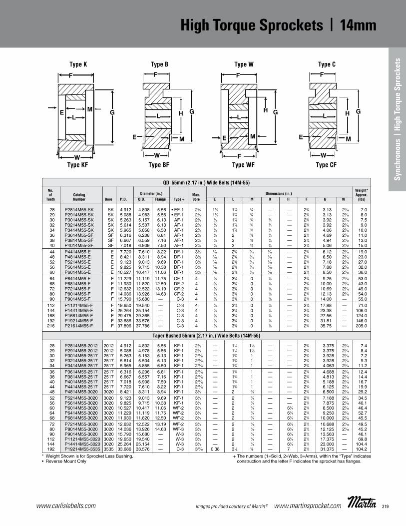
219www.carlislebelts.com Images provided courtesy of Martin® www.martinsprocket.com
High Torque Sprockets 14mm
K-30
QD 55mm (2.17 in.) Wide Belts (14M-55) No. Weight* of Catalog Diameter (in.) Max. Dimensions (in.) Approx. Teeth Number Bore P.D. O.D. Flange Type + Bore E L M K H F G W (lbs)
* Weight Shown is for Sprocket Less Bushing.• Reverse Mount Only
+ The numbers (1=Solid, 2=Web, 3=Arms), within the “Type” indicates
Type K Type B Type W Type C
Type KF Type BF Type WF Type CF
28 P2814M55-SK SK 4.912 4.808 5.56 • EF-1 25⁄8 11⁄2 17⁄8 5⁄8 — — 23⁄4 3.13 27⁄16 7.0 29 P2914M55-SK SK 5.088 4.983 5.56 • EF-1 25⁄8 11⁄2 17⁄8 5⁄8 — — 23⁄4 3.13 27⁄16 8.0 30 P3014M55-SK SK 5.263 5.157 6.13 AF-1 25⁄8 1⁄8 17⁄8 3⁄4 3⁄4 — 23⁄4 3.92 27⁄16 7.5 32 P3214M55-SK SK 5.614 5.507 6.13 AF-1 25⁄8 1⁄8 17⁄8 3⁄4 3⁄4 — 23⁄4 3.92 27⁄16 9.0 34 P3414M55-SK SK 5.965 5.858 6.50 AF-1 25⁄8 1⁄8 17⁄8 3⁄4 3⁄4 — 23⁄4 4.06 27⁄16 10.0 36 P3614M55-SF SF 6.316 6.208 6.81 AF-1 27⁄8 1⁄8 2 5⁄8 3⁄4 — 23⁄4 4.69 27⁄16 11.0 38 P3814M55-SF SF 6.667 6.559 7.16 AF-1 27⁄8 1⁄8 2 5⁄8 3⁄4 — 23⁄4 4.94 27⁄16 13.0 40 P4014M55-SF SF 7.018 6.909 7.50 AF-1 27⁄8 1⁄8 2 5⁄8 3⁄4 — 23⁄4 5.06 27⁄16 15.0 44 P4414M55-E E 7.720 7.610 8.22 DF-1 31⁄2 5⁄16 25⁄8 7⁄16 9⁄16 — 23⁄4 6.12 27⁄16 19.0 48 P4814M55-E E 8.421 8.311 8.94 DF-1 31⁄2 5⁄16 25⁄8 7⁄16 9⁄16 — 23⁄4 6.50 27⁄16 23.0 52 P5214M55-E E 9.123 9.013 9.69 DF-1 31⁄2 5⁄16 25⁄8 7⁄16 9⁄16 — 23⁄4 7.18 27⁄16 27.0 56 P5614M55-E E 9.825 9.715 10.38 DF-1 31⁄2 5⁄16 25⁄8 7⁄16 9⁄16 — 23⁄4 7.88 27⁄16 32.0 60 P6014M55-E E 10.527 10.417 11.06 DF-1 31⁄2 5⁄16 25⁄8 7⁄16 9⁄16 — 23⁄4 8.50 27⁄16 36.0 64 P6414M55-F F 11.229 11.119 11.75 CF-1 4 7⁄8 35⁄8 0 1⁄8 — 23⁄4 9.25 27⁄16 53.0 68 P6814M55-F F 11.930 11.820 12.50 DF-2 4 7⁄8 35⁄8 0 1⁄8 — 23⁄4 10.00 27⁄16 43.0 72 P7214M55-F F 12.632 12.522 13.19 CF-2 4 7⁄8 35⁄8 0 1⁄8 — 23⁄4 10.69 27⁄16 49.0 80 P8014M55-F F 14.036 13.926 14.63 CF-2 4 7⁄8 35⁄8 0 1⁄8 — 23⁄4 12.13 27⁄16 54.0 90 P9014M55-F F 15.790 15.680 — C-3 4 7⁄8 35⁄8 0 1⁄8 — 23⁄4 14.00 — 55.0 112 P11214M55-F F 19.650 19.540 — C-3 4 7⁄8 35⁄8 0 1⁄8 — 23⁄4 17.88 — 71.0 144 P14414M55-F F 25.264 25.154 — C-3 4 7⁄8 35⁄8 0 1⁄8 — 23⁄4 23.38 — 106.0 168 P16814M55-F F 29.475 29.365 — C-3 4 7⁄8 35⁄8 0 1⁄8 — 23⁄4 27.56 — 124.0 192 P19214M55-F F 33.686 33.576 — C-3 4 7⁄8 35⁄8 0 1⁄8 — 23⁄4 31.81 — 146.0 216 P21614M55-F F 37.896 37.786 — C-3 4 7⁄8 35⁄8 0 1⁄8 — 23⁄4 35.75 — 205.0
28 P2814M55-2012 2012 4.912 4.802 5.56 KF-1 21⁄8 — 11⁄4 11⁄2 — — 23⁄4 3.375 27⁄16 7.4 29 P2914M55-2012 2012 5.088 4.978 5.56 KF-1 21⁄8 — 11⁄4 11⁄2 — — 23⁄4 3.375 27⁄16 8.4 30 P3014M55-2517 2517 5.263 5.153 6.13 KF-1 211⁄16 — 13⁄4 1 — — 23⁄4 3.928 27⁄16 7.2 32 P3214M55-2517 2517 5.614 5.504 6.13 KF-1 211⁄16 — 13⁄4 1 — — 23⁄4 3.928 27⁄16 9.3 34 P3414M55-2517 2517 5.965 5.855 6.50 KF-1 211⁄16 — 13⁄4 1 — — 23⁄4 4.063 27⁄16 11.2 36 P3614M55-2517 2517 6.316 6.206 6.81 KF-1 211⁄16 — 13⁄4 1 — — 23⁄4 4.688 27⁄16 12.4 38 P3814M55-2517 2517 6.667 6.557 7.16 KF-1 211⁄16 — 13⁄4 1 — — 23⁄4 4.813 27⁄16 14.4 40 P4014M55-2517 2517 7.018 6.908 7.50 KF-1 211⁄16 — 13⁄4 1 — — 23⁄4 5.188 27⁄16 16.7 44 P4414M55-2517 2517 7.720 7.610 8.22 KF-1 211⁄16 — 13⁄4 1 — — 23⁄4 6.125 27⁄16 19.9 48 P4814M55-3020 3020 8.421 8.311 8.94 KF-1 31⁄4 — 2 3⁄4 — — 23⁄4 6.500 27⁄16 29.2 52 P5214M55-3020 3020 9.123 9.013 9.69 KF-1 31⁄4 — 2 3⁄4 — — 23⁄4 7.188 27⁄16 34.5 56 P5614M55-3020 3020 9.825 9.715 10.38 KF-1 31⁄4 — 2 3⁄4 — — 23⁄4 7.875 27⁄16 40.1 60 P6014M55-3020 3020 10.527 10.417 11.06 WF-2 31⁄4 — 2 3⁄4 — 61⁄4 23⁄4 8.500 27⁄16 46.4 64 P6414M55-3020 3020 11.229 11.119 11.75 WF-2 31⁄4 — 2 3⁄4 — 61⁄4 23⁄4 9.250 27⁄16 52.7 68 P6814M55-3020 3020 11.930 11.820 12.50 WF-2 31⁄4 — 2 3⁄4 — 61⁄4 23⁄4 10.000 27⁄16 45.5 72 P7214M55-3020 3020 12.632 12.522 13.19 WF-2 31⁄4 — 2 3⁄4 — 61⁄4 23⁄4 10.688 27⁄16 49.5 80 P8014M55-3020 3020 14.036 13.926 14.63 WF-3 31⁄4 — 2 3⁄4 — 61⁄4 23⁄4 12.125 27⁄16 45.2 90 P9014M55-3020 3020 15.790 15.680 — W-3 31⁄4 — 2 3⁄4 — 61⁄4 23⁄4 13.563 — 46.1 112 P11214M55-3020 3020 19.650 19.540 — W-3 31⁄4 — 2 3⁄4 — 61⁄4 23⁄4 17.375 — 69.8 144 P14414M55-3020 3020 25.264 25.154 — W-3 31⁄4 — 2 3⁄4 — 61⁄4 23⁄4 23.000 — 104.4 192 P19214M55-3535 3535 33.686 33.576 — C-3 315⁄16 0.38 31⁄2 3⁄8 — 7 23⁄4 31.375 — 104.2
Taper Bushed 55mm (2.17 in.) Wide Belts (14M-55)
K17 - K32_K17 - K32 7/24/14 4:01 PM Page K-30
Sync
hron
ous
| Hi
gh T
orqu
e Sp
rock
ets
High Torque Sprockets | 14mm

www.carlislebelts.com220 www.martinsprocket.com Images provided courtesy of Martin®
High Torque Sprockets 14mm
K-31
* Weight Shown is for Sprocket Less Bushing.• Reverse Mount Only
+ The numbers (1=Solid, 2=Web, 3=Arms), within the “Type” indicates
Type A Type C Type D Type E• Type D (MPB Only)
Type AF Type CF Type DF Type EF• Type DF (MPB Only)
28 P2814M85-MPB 11⁄4 4.912 4.802 5.56 DF-1 25⁄16 1 4 1 — 311⁄16 4 3.13 311⁄16 18.0 29 P2914M85-MPB 11⁄4 5.088 4.983 5.56 DF-1 25⁄16 1 4 1 — 311⁄16 4 3.13 311⁄16 19.4
30 P3014M85-MPB 11⁄4 5.263 5.157 6.13 DF-1 21⁄2 1 4 1 — 49⁄64 4 3.72 311⁄16 20.6 32 P3214M85-MPB 11⁄4 5.614 5.507 6.13 DF-1 21⁄2 1 4 1 — 49⁄64 4 3.72 311⁄16 23.4 34 P3414M85-MPB 11⁄4 5.965 5.858 6.50 DF-1 2 11⁄16 1 4 1 — 431⁄64 4 4.06 311⁄16 27.4
30 P3014M85-SK SK 5.293 5.157 6.13 AF-1 25⁄8 3⁄4 17⁄8 13⁄8 13⁄8 — 4 3.92 311⁄16 10.0 32 P3214M85-SK SK 5.614 5.507 6.13 AF-1 27⁄8 3⁄4 17⁄8 13⁄8 13⁄8 — 4 3.92 311⁄16 13.0 34 P3414M85-SK SK 5.965 5.853 6.13 AF-1 27⁄8 3⁄4 17⁄8 13⁄8 13⁄8 — 4 4.06 311⁄16 14.0
36 P3614M85-SF SF 6.316 6.206 6.81 AF-1 27⁄8 3⁄4 2 11⁄4 13⁄8 — 4 4.69 311⁄16 15.0 38 P3814M85-SF SF 6.667 6.557 7.16 AF-1 27⁄8 3⁄4 2 11⁄4 13⁄8 — 4 4.94 311⁄16 18.0 40 P4014M85-SF SF 7.018 6.909 7.50 AF-1 27⁄8 3⁄4 2 11⁄4 13⁄8 — 4 5.06 311⁄16 20.0
44 P4414M85-E E 7.720 7.610 8.22 AF-1 31⁄2 5⁄16 25⁄8 11⁄16 13⁄16 — 4 6.12 311⁄16 25.0 48 P4814M85-E E 8.421 8.311 8.94 AF-1 31⁄2 5⁄16 25⁄8 11⁄16 13⁄16 — 4 6.50 311⁄16 29.0 52 P5214M85-E E 9.123 9.013 9.69 AF-1 31⁄2 5⁄16 25⁄8 11⁄16 13⁄16 — 4 7.18 311⁄16 32.0
56 P5614M85-F F 9.825 9.715 10.38 DF-1 4 1⁄4 35⁄8 5⁄8 3⁄4 — 4 7.88 311⁄16 46.0 60 P6014M85-F F 10.527 10.417 11.06 DF-1 4 1⁄4 35⁄8 5⁄8 3⁄4 — 4 8.50 311⁄16 51.0 64 P6414M85-F F 11.229 11.119 11.75 DF-1 4 1⁄4 35⁄8 5⁄8 3⁄4 — 4 9.25 311⁄16 62.0 68 P6814M85-F F 11.930 11.820 12.50 DF-2 4 1⁄4 35⁄8 5⁄8 3⁄4 — 4 10.00 311⁄16 51.0 72 P7214M85-F F 12.632 12.522 13.19 DF-2 4 1⁄4 35⁄8 5⁄8 3⁄4 — 4 10.69 311⁄16 60.0 80 P8014M85-F F 14.036 13.926 14.63 DF-2 4 1⁄4 35⁄8 5⁄8 3⁄4 — 4 12.13 311⁄16 66.0 90 P9014M85-F F 15.790 15.680 — D-3 4 1⁄4 35⁄8 5⁄8 3⁄4 — 4 14.00 — 69.0
112 P11214M85-F F 19.650 19.540 — D-3 4 1⁄4 35⁄8 5⁄8 3⁄4 — 4 17.88 — 89.0 144 P14414M85-F F 25.264 25.154 — D-3 4 1⁄4 35⁄8 5⁄8 3⁄4 — 4 23.38 — 127.0 168 P16814M85-J J 29.475 29.365 — D-3 41⁄2 1⁄4 35⁄8 5⁄8 3⁄4 — 4 27.56 — 148.0 192 P19214M85-J J 33.686 33.576 — D-3 41⁄2 1⁄4 35⁄8 5⁄8 3⁄4 — 4 31.81 — 177.0 216 P21614M85-J J 37.896 37.786 — D-3 41⁄2 1⁄4 35⁄8 5⁄8 3⁄4 — 4 35.75 — 251.0
30 P3014M85-2517 2517 5.263 5.153 6.13 WF-1 21⁄2 1⁄2 13⁄4 13⁄4 — — 4 3.928 311⁄16 9.7 32 P3214M85-2517 2517 5.614 5.504 6.13 WF-1 211⁄16 7⁄8 13⁄4 13⁄8 — — 4 3.928 311⁄16 12.7 34 P3414M85-2517 2517 5.965 5.855 6.50 WF-1 211⁄16 7⁄8 13⁄4 13⁄8 — — 4 4.063 311⁄16 15.3 36 P3614M85-3020 3020 6.316 6.206 6.81 WF-1 31⁄4 17⁄32 2 115⁄32 — — 4 4.688 311⁄16 19.3 38 P3814M85-3020 3020 6.667 6.557 7.16 WF-1 31⁄4 17⁄32 2 115⁄32 — — 4 4.813 311⁄16 21.9
40 P4014M85-3020 3020 7.018 6.908 7.50 WF-1 31⁄4 17⁄32 2 115⁄32 — — 4 5.063 311⁄16 25.1 44 P4414M85-3020 3020 7.720 7.610 8.22 WF-1 31⁄4 17⁄32 2 115⁄32 — — 4 6.125 311⁄16 28.4 48 P4814M85-3020 3020 8.421 8.311 8.94 WF-1 31⁄4 17⁄32 2 115⁄32 — — 4 6.500 311⁄16 35.4 52 P5214M85-3535 3535 9.123 9.013 9.69 KF-1 315⁄16 — 31⁄2 1⁄2 — — 4 7.188 311⁄16 42.9 56 P5614M85-3535 3535 9.825 9.715 10.38 KF-1 315⁄16 — 31⁄2 1⁄2 — — 4 7.875 311⁄16 52.4
60 P6014M85-3535 3535 10.527 10.417 11.06 KF-1 315⁄16 — 31⁄2 1⁄2 — — 4 8.500 311⁄16 62.7 64 P6414M85-3535 3535 11.229 11.119 11.75 KF-1 315⁄16 — 31⁄2 1⁄2 — — 4 9.250 311⁄16 73.6 68 P6814M85-3535 3535 11.930 11.820 12.50 KF-1 315⁄16 — 31⁄2 1⁄2 — — 4 10.000 311⁄16 64.2 72 P7214M85-3535 3535 12.632 12.522 13.19 KF-1 315⁄16 — 31⁄2 1⁄2 — — 4 10.688 311⁄16 97.4 80 P8014M85-3535 3535 14.036 13.926 14.63 WF-2 315⁄16 — 31⁄2 1⁄2 — — 4 12.125 311⁄16 68.4
90 P9014M85-3535 3535 15.790 15.680 — W-3 315⁄16 — 31⁄2 1⁄2 — 7 4 13.563 — 69.1 112 P11214M85-3535 3535 19.650 19.540 — W-3 315⁄16 — 31⁄2 1⁄2 — 7 4 17.375 — 85.7 144 P14414M85-4040 4040 25.264 25.154 — W-3 47⁄16 — 4 — — 81⁄2 4 23.000 — 131.6 168 P16814M85-4040 4040 29.475 29.365 — W-3 47⁄16 — 4 — — 81⁄2 4 27.250 — 146.1 192 P19214M85-4040 4040 33.686 33.576 — W-3 47⁄16 — 4 — — 81⁄2 4 31.375 — 161.4
QD 85mm (3.35in.) Wide Belts (14M-85)
Taper Bushed 85mm (3.35in.) Wide Belts (14M-85)
MPB 85mm (3.35in.) Wide Belts (14M-85)
No. Weight* of Catalog Diameter (in.) Max. Dimensions (in.) Approx. Teeth Number Bore P.D. O.D. Flange Type + Bore E L M K H F G W (lbs)
K17 - K32_K17 - K32 7/24/14 4:01 PM Page K-31
14mm | High Torque Sprockets

221www.carlislebelts.com Images provided courtesy of Martin® www.martinsprocket.com
High Torque Sprockets 14mm
K-32
MPB 115mm (4.53 in.) Wide Belts (14M-115) No. Weight* of Catalog Diameter (in.) Max. Dimensions (in.) Approx. Teeth Number Bore P.D. O.D. Flange Type + Bore E L M K H F G W (lbs)
* Weight Shown is for Sprocket Less Bushing.• Reverse Mount Only
+ The numbers (1=Solid, 2=Web, 3=Arms) within the “Type” indicates
Type A Type C Type D Type E• Type D (MPB Only)
Type AF Type CF Type DF Type EF• Type DF (MPB Only)
QD 115mm (4.53 in.) Wide Belts (14M-115)
Taper Bushed 115mm (4.53 in.) Wide Belts (14M-115)
28 P2814M115-MPB 11⁄4 4.912 4.808 5.56 DF-1 2 5⁄16 11⁄4 5 11⁄2 — 311⁄16 51⁄4 3.13 415⁄16 23.2 29 P2914M115-MPB 11⁄4 5.088 4.983 5.56 DF-1 2 5⁄16 11⁄4 5 11⁄2 — 311⁄16 51⁄4 3.13 415⁄16 24.8 30 P3014M115-MPB 11⁄4 5.263 5.157 6.13 DF-1 21⁄2 11⁄4 5 11⁄2 — 49⁄64 51⁄4 3.90 415⁄16 26.4 32 P3214M115-MPB 11⁄4 5.614 5.507 6.13 DF-1 21⁄2 11⁄4 5 11⁄2 — 49⁄64 51⁄4 3.90 415⁄16 30.8 34 P3414M115-MPB 11⁄4 5.965 5.858 6.50 DF-1 211⁄16 11⁄4 5 11⁄2 — 431⁄64 51⁄4 4.06 415⁄16 35.2 36 P3614M115-MPB 11⁄4 6.316 6.208 6.81 DF-1 3 11⁄4 5 11⁄2 — 47⁄8 51⁄4 4.69 415⁄16 38.8 38 P3814M115-MPB 11⁄4 6.667 6.559 7.16 DF-1 31⁄4 11⁄4 5 11⁄2 — 5 11⁄64 51⁄4 4.94 415⁄16 44.4 40 P4014M115-MPB 11⁄4 7.018 6.909 7.50 DF-1 37⁄16 11⁄4 5 11⁄2 — 59⁄16 51⁄4 5.06 415⁄16 50.0
30 P3014M115-SK 11⁄4 5.263 5.157 6.13 AF-1 27⁄8 13⁄8 17⁄8 2 2 — 51⁄4 3.92 415⁄16 12.0 32 P3214M115-SK 11⁄4 5.614 5.507 6.13 AF-1 27⁄8 13⁄8 17⁄8 2 2 — 51⁄4 3.92 415⁄16 16.0 34 P3414M115-SK 11⁄4 5.965 5.858 6.50 AF-1 27⁄8 13⁄8 17⁄8 2 2 — 51⁄4 4.06 415⁄16 17.0 36 P3614M115-SF 11⁄4 6.316 6.208 6.81 AF-1 3 13⁄8 2 17⁄8 2 — 51⁄4 4.69 415⁄16 18.0 38 P3814M115-SF 11⁄4 6.667 6.559 7.16 AF-1 3 13⁄8 2 17⁄8 2 — 51⁄4 4.94 415⁄16 22.0 40 P4014M115-SF 11⁄4 7.018 6.909 7.50 AF-1 3 13⁄8 2 17⁄8 2 — 51⁄4 5.06 415⁄16 25.0
44 P4414M115-E E 7.720 7.610 8.22 AF-1 31⁄2 15⁄16 25⁄8 111⁄16 113⁄16 — 51⁄4 6.12 415⁄16 30.0 48 P4814M115-E E 8.421 8.311 8.94 AF-1 31⁄2 15⁄16 25⁄8 111⁄16 113⁄16 — 51⁄4 6.50 415⁄16 35.0 52 P5214M115-F F 9.123 9.013 9.69 AF-1 4 3⁄8 35⁄8 11⁄4 13⁄8 — 51⁄4 7.18 415⁄16 42.0 56 P5614M115-F F 9.825 9.715 10.38 AF-1 4 3⁄8 35⁄8 11⁄4 13⁄8 — 51⁄4 7.88 415⁄16 53.0 60 P6014M115-F F 10.527 10.417 11.06 AF-1 41⁄2 3⁄8 35⁄8 11⁄4 13⁄8 — 51⁄4 8.50 415⁄16 60.0 64 P6414M115-J J 11.229 11.119 11.75 DF-1 41⁄2 3⁄16 41⁄2 15⁄16 1 — 51⁄4 9.25 415⁄16 76.0 68 P6814M115-J J 11.930 11.820 12.50 DF-1 41⁄2 3⁄16 41⁄2 15⁄16 1 — 51⁄4 10.00 415⁄16 83.0 72 P7214M115-J J 12.632 12.522 13.19 DF-1 41⁄2 3⁄16 41⁄2 15⁄16 1 — 51⁄4 10.69 415⁄16 99.0 80 P8014M115-J J 14.036 13.926 14.63 DF-2 41⁄2 3⁄16 41⁄2 15⁄16 1 — 51⁄4 12.13 415⁄16 87.0 90 P9014M115-J J 15.790 15.680 — D-2 41⁄2 3⁄16 41⁄2 15⁄16 1 — 51⁄4 14.00 — 95.0 112 P11214M115-J J 19.650 19.540 — D-3 41⁄2 3⁄16 41⁄2 15⁄16 1 — 51⁄4 17.88 — 114.0 144 P14414M115-J J 25.264 25.154 — D-3 41⁄2 3⁄16 41⁄2 15⁄16 1 — 51⁄4 23.38 — 166.0 168 P16814M115-M M 29.475 29.365 — D-3 51⁄2 3⁄16 41⁄2 15⁄16 1 — 51⁄4 27.56 — 198.0 192 P19214M115-M M 33.686 33.576 — D-3 51⁄2 3⁄16 41⁄2 15⁄16 1 — 51⁄4 31.81 — 232.0 216 P21614M115-M M 37.896 37.786 — D-3 51⁄2 3⁄16 41⁄2 15⁄16 1 — 51⁄4 35.75 — 307.0
30 P3014M115-2517 2517 5.263 5.153 6.13 WF-1 211⁄16 13⁄4 13⁄4 13⁄4 — — 51⁄4 3.928 415⁄16 13.5 32 P3214M115-2517 2517 5.614 5.504 6.13 WF-1 211⁄16 13⁄4 13⁄4 13⁄4 — — 51⁄4 3.928 411⁄16 17.3 34 P3414M115-2517 2517 5.965 5.855 6.50 WF-1 211⁄16 13⁄4 13⁄4 13⁄4 — — 51⁄4 4.063 411⁄16 20.9 36 P3614M115-3020 3020 6.316 6.206 6.81 WF-1 31⁄4 15⁄8 2 15⁄8 — — 51⁄4 4.688 411⁄16 18.6 38 P3814M115-3020 3020 6.667 6.557 7.16 WF-1 31⁄4 15⁄8 2 15⁄8 — — 51⁄4 4.813 411⁄16 22.5 40 P4014M115-3020 3020 7.018 6.908 7.50 WF-1 31⁄4 15⁄8 2 15⁄8 — — 51⁄4 5.063 411⁄16 26.8 44 P4414M115-3535 3535 7.720 7.610 8.22 WF-1 315⁄16 7⁄8 31⁄2 7⁄8 — — 51⁄4 6.125 411⁄16 30.8 48 P4814M115-3535 3535 8.421 8.311 8.94 WF-1 315⁄16 7⁄8 31⁄2 7⁄8 — — 51⁄4 6.500 411⁄16 41.1 52 P5214M115-4040 4040 9.123 9.013 9.69 WF-1 47⁄16 5⁄8 4 5⁄8 — — 51⁄4 7.188 411⁄16 46.9 56 P5614M115-4040 4040 9.825 9.715 10.38 WF-1 47⁄16 5⁄8 4 5⁄8 — — 51⁄4 7.875 4 11⁄16 58.3 60 P6014M115-4040 4040 10.527 10.417 11.06 WF-1 47⁄16 5⁄8 4 5⁄8 — — 51⁄4 8.500 411⁄16 70.9 64 P6414M115-4545 4545 11.229 11.119 11.75 WF-1 415⁄16 3⁄8 41⁄2 3⁄8 — — 51⁄4 9.250 411⁄16 82.1 68 P6814M115-4545 4545 11.930 11.820 12.50 WF-1 415⁄16 3⁄8 41⁄2 3⁄8 — — 51⁄4 10.000 411⁄16 97.1 72 P7214M115-4545 4545 12.632 12.522 13.19 WF-1 415⁄16 3⁄8 41⁄2 3⁄8 — — 51⁄4 10.688 411⁄16 113.3 80 P8014M115-4545 4545 14.036 13.926 14.63 WF-2 415⁄16 3⁄8 41⁄2 3⁄8 91⁄2 — 51⁄4 12.125 411⁄16 108.9 90 P9014M115-4545 4545 15.790 15.680 — W-2 415⁄16 3⁄8 41⁄2 3⁄8 91⁄2 — 51⁄4 13.563 — 112.9 112 P11214M115-4545 4545 19.650 19.540 — W-3 415⁄16 3⁄8 41⁄2 3⁄8 91⁄2 — 51⁄4 17.375 — 122.4 144 P14414M115-4545 4545 25.264 25.154 — W-3 415⁄16 3⁄8 41⁄2 3⁄8 91⁄2 — 51⁄4 23.000 — 155.0 168 P16814M115-4545 4545 29.475 29.365 — W-3 415⁄16 3⁄8 41⁄2 3⁄8 91⁄2 — 51⁄4 27.250 — 188.0 192 P19214M115-4545 4545 33.686 33.576 — W-3 415⁄16 3⁄8 41⁄2 3⁄8 91⁄2 — 51⁄4 31.375 — 318.8 216 P21614M115-6050 6050 37.896 37.786 — W-3 6 — 5 1⁄4 151⁄2 — 51⁄4 35.625 — 350.3
K17 - K32_K17 - K32 7/24/14 4:01 PM Page K-32
Sync
hron
ous
| Hi
gh T
orqu
e Sp
rock
ets
High Torque Sprockets | 14mm

www.carlislebelts.com222 www.martinsprocket.com Images provided courtesy of Martin®
K-33
High Torque Sprockets 14mm
MPB 170mm (6.69 in.) Wide Belts (14M-170) No. Weight* of Catalog Pitch Diameter (in.) Max. Dimensions (in.) Approx. Teeth Number Bore Diameter O.D. Flange Type + Bore E L M K H F G W (lbs)
* Weight Shown is for Sprocket Less Bushing.• Reverse Mount Only
+ The numbers (1=Solid, 2=Web, 3=Arms), within the “Type” indicates construction and the letter F indicates the sprocket has anges.
Type A Type C Type D Type E• Type D (MPB Only)
Type AF Type CF Type DF Type EF• Type DF (MPB Only)
Type K Type B Type W Type C
Type KF Type BF Type WF Type CF
QD 170mm (6.69 in.) Wide Belts (14M-170)
Taper Bushed 170mm (6.69 in.) Wide Belts (14M-170)
36 P3614M170-MPB 11⁄2 6.316 6.208 6.81 DF-1 3 11⁄4 6 25⁄8 — 47⁄8 73⁄8 4.69 71⁄16 47.0 38 P3814M170-MPB 11⁄2 6.667 6.559 7.16 DF-1 31⁄4 11⁄4 6 25⁄8 — 511⁄64 73⁄8 4.94 71⁄16 55.7 40 P4014M170-MPB 11⁄2 7.018 6.909 7.50 DF-1 37⁄16 11⁄4 6 25⁄8 — 5 9⁄16 73⁄8 5.06 71⁄16 63.7 44 P4414M170-MPB 11⁄2 7.720 7.610 8.22 DF-1 43⁄8 11⁄4 6 25⁄8 — 6 41⁄64 73⁄8 6 .13 71⁄16 75.7 48 P4814M170-MPB 11⁄2 8.421 8.311 8.94 DF-1 41⁄2 11⁄4 6 25⁄8 — 615⁄16 73⁄8 6.50 71⁄16 94.0
44 P4414M170-E E 7.720 7.610 8.22 AF-1 35⁄8 2 25⁄8 23⁄4 27⁄8 — 73⁄8 6.12 71⁄16 38.0 48 P4814M170-E E 8.421 8.311 8.94 AF-1 35⁄8 2 25⁄8 23⁄4 27⁄16 — 73⁄8 6.50 71⁄16 45.0 52 P5214M170-F F 9.123 9.013 9.69 AF-1 4 17⁄16 35⁄8 25⁄16 27⁄16 — 73⁄8 7.18 71⁄16 52.0 56 P5614M170-F F 9.825 9.715 10.38 AF-1 4 17⁄16 35⁄8 25⁄16 21⁄8 — 73⁄8 7.88 71⁄16 65.0 60 P6014M170-J J 10.527 10.417 11.06 AF-1 41⁄2 15⁄16 41⁄2 115⁄16 21⁄8 — 73⁄8 8.50 71⁄16 75.0 64 P6414M170-J J 11.229 11.119 11.75 AF-1 41⁄2 15⁄16 41⁄2 115⁄16 21⁄8 — 73⁄8 9.25 71⁄16 91.0 68 P6814M170-J J 11.930 11.820 12.50 AF-1 41⁄2 15⁄16 41⁄2 115⁄16 21⁄8 — 73⁄8 10.00 71⁄16 96.0 72 P7214M170-J J 12.632 12.522 13.19 AF-1 41⁄2 15⁄16 41⁄2 115⁄16 21⁄8 — 73⁄8 10.69 71⁄16 115.0 80 P8014M170-J J 14.036 13.926 14.63 AF-2 41⁄2 15⁄16 41⁄2 115⁄16 21⁄8 — 73⁄8 12.13 71⁄16 107.0 90 P9014M170-J J 15.790 15.680 — A-2 41⁄2 15⁄16 41⁄2 115⁄16 21⁄8 — 73⁄8 14.00 — 116.0 112 P11214M170-M M 19.650 19.540 — A-3 51⁄2 — 63⁄4 5⁄8 17⁄16 — 73⁄8 17.88 — 175.0 144 P14414M170-M M 25.264 25.154 — A-3 51⁄2 — 63⁄4 5⁄8 17⁄16 — 73⁄8 23.38 — 240.0 168 P16814M170-M M 29.475 29.365 — A-3 51⁄2 — 63⁄4 5⁄8 17⁄16 — 73⁄8 27.56 — 278.0 192 P19214M170-M M 33.686 33.576 — A-3 51⁄2 — 63⁄4 5⁄8 17⁄16 — 73⁄8 31.81 — 322.0 216 P21614M170-M M 37.896 37.786 — A-3 51⁄2 — 63⁄4 5⁄8 17⁄16 — 73⁄8 35.75 399.0
44 P4414M170-3535 3535 7.720 7.610 8.22 WF-1 315⁄16 115⁄16 31⁄2 115⁄16 — — 73⁄8 6.13 71⁄16 39.7 48 P4814M170-3535 3535 8.421 8.311 8.94 WF-1 315⁄16 115⁄16 31⁄2 115⁄16 — — 73⁄8 6.50 71⁄16 52.8 52 P5214M170-4040 4040 9.123 9.013 9.69 WF-1 47⁄16 111⁄16 4 111⁄16 — — 73⁄8 7.19 71⁄16 59.8 56 P5614M170-4040 4040 9.825 9.715 10.38 WF-1 47⁄16 111⁄16 4 111⁄16 — — 73⁄8 7.88 71⁄16 72.4 60 P6014M170-4545 4545 10.527 10.417 11.06 WF-1 415⁄16 17⁄16 41⁄2 17⁄16 — — 73⁄8 8.50 7 1⁄16 83.7 64 P6414M170-4545 4545 11.229 11.119 11.75 WF-1 415⁄16 17⁄16 41⁄2 17⁄16 — — 73⁄8 9.25 71⁄16 98.6 68 P6814M170-4545 4545 11.930 11.820 12.50 WF-1 415⁄16 17⁄16 41⁄2 17⁄16 — — 73⁄8 10.00 71⁄16 114.4 72 P7214M170-4545 4545 12.632 12.522 13.19 WF-1 415⁄16 17⁄16 41⁄2 17⁄16 — — 73⁄8 10.69 71⁄16 131.8 80 P8014M170-4545 4545 14.036 13.926 14.63 WF-2 415⁄16 17⁄16 41⁄2 17⁄16 — 91⁄2 73⁄8 12.13 71⁄16 129.3 90 P9014M170-4545 4545 15.790 15.680 — W-2 415⁄16 17⁄16 41⁄2 17⁄16 — 91⁄2 73⁄8 13.56 — 126.8 112 P11214M170-4545 4545 19.650 19.540 — W-3 415⁄16 17⁄16 41⁄2 13⁄16 — 91⁄2 73⁄8 17.38 — 148.0 144 P14414M170-6050 6050 25.264 25.154 — W-3 6 13⁄16 5 13⁄16 — 151⁄2 73⁄8 23.00 — 208.0 168 P16814M170-6050 6050 29.475 29.365 — W-3 6 13⁄16 5 13⁄16 — 151⁄2 73⁄8 27.25 — 227.0 192 P19214M170-6050 6050 33.686 33.576 — W-3 6 13⁄16 5 13⁄16 — 151⁄2 73⁄8 31.38 — 340.0 216 P21614M170-6050 6050 37.896 37.786 — W-3 6 13⁄16 5 13⁄16 — 151⁄2 73⁄8 35.63 — 390.0
SECTION K K33 - K50-new_K33 - K46 4/23/14 2:22 PM Page K-33
14mm | High Torque Sprockets
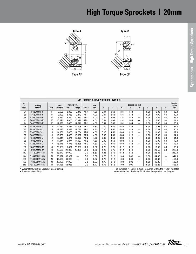
223www.carlislebelts.com Images provided courtesy of Martin® www.martinsprocket.com
K-34
High Torque Sprockets 20mm
* Weight Shown is for Sprocket less Bushing.• Reverse Mount Only
+ The numbers (1=Solid, 2=Web, 3=Arms), within the “Type” indicates construction and the letter F indicates the sprocket has anges.
QD 115mm (4.53 in.) Wide Belts (20M-115) No. Weight* of Catalog Pitch Diameter (in.) Max. Dimensions (in.) Approx. Teeth Number Bore Diameter O.D. Flange Type + Bore E L M K H F G W (lbs)
34 P3420M115-F F 8.522 8.352 9.449 AF-1 4.00 0.44 3.63 1.31 1.44 — 5.38 6.88 5.0 32.0 36 P3620M115-F F 9.023 8.853 9.843 AF-1 4.00 0.44 3.63 1.31 1.44 — 5.38 7.00 5.0 40.0 38 P3820M115-F F 9.524 9.354 10.433 AF-1 4.00 0.44 3.63 1.31 1.44 — 5.38 7.56 5.0 45.0 40 P4020M115-F F 10.026 9.856 10.827 AF-1 4.00 0.44 3.63 1.31 1.44 — 5.38 8.00 5.0 51.0 44 P4420M115-F F 11.028 10.858 11.811 AF-1 4.00 0.44 3.63 1.31 1.44 — 5.38 8.93 5.0 63.0
48 P4820M115-J J 12.031 11.861 12.795 AF-1 4.50 0.00 4.50 0.88 1.18 — 5.38 9.93 5.0 84.0 52 P5220M115-J J 13.033 12.863 13.764 AF-2 4.50 0.00 4.50 0.88 1.18 — 5.38 10.88 5.0 80.0 56 P5620M115-J J 14.036 13.866 14.764 AF-2 4.50 0.00 4.50 0.88 1.18 — 5.38 11.88 5.0 87.0 60 P6020M115-J J 15.038 14.868 15.927 AF-2 4.50 0.00 4.50 0.88 1.18 — 5.38 13.06 5.0 94.0 64 P6420M115-J J 16.041 15.871 16.929 AF-2 4.50 0.00 4.50 0.88 1.18 — 5.38 14.06 5.0 104.0 68 P6820M115-J J 17.044 16.874 17.927 AF-2 4.50 0.00 4.50 0.88 1.18 — 5.38 15.00 5.0 110.0 72 P7220M115-J J 18.046 17.876 18.898 AF-2 4.50 0.00 4.50 0.88 1.18 — 5.38 16.00 5.0 119.0
80 P8020M115-M M 20.051 19.881 20.866 CF-2 5.50 1.25 6.75 0.12 0.18 — 5.38 18.00 5.0 182.0 90 P9020M115-M M 22.558 22.388 23.425 CF-2 5.50 1.25 6.75 0.12 0.18 — 5.38 20.56 5.0 212.0 112 P11220M115-M M 28.072 27.902 — C-3 5.50 1.25 6.75 0.12 0.18 — 5.38 26.38 — 239.0
144 P14420M115-N N 36.092 35.922 — C-3 5.87 1.75 8.12 1.00 0.00 — 5.38 34.38 — 341.0 168 P16820M115-N N 42.108 41.938 — C-3 5.87 1.75 8.12 1.00 0.00 — 5.38 40.38 — 417.0 192 P19220M115-N N 48.123 47.953 — C-3 5.87 1.75 8.12 1.00 0.00 — 5.38 46.25 — 500.0 216 P21620M115-N N 54.138 53.968 — C-3 5.77 1.75 8.12 1.00 0.00 — 5.38 52.25 — 566.0
Type A Type C
Type AF Type CF
SECTION K K33 - K50-new_K33 - K46 4/23/14 2:22 PM Page K-34
Sync
hron
ous
| Hi
gh T
orqu
e Sp
rock
ets
High Torque Sprockets | 20mm
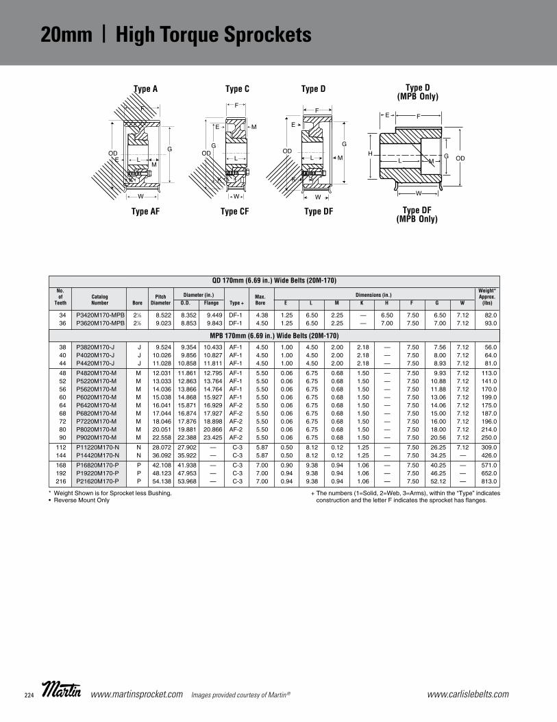
www.carlislebelts.com224 www.martinsprocket.com Images provided courtesy of Martin®
K-35
High Torque Sprockets 20mm
* Weight Shown is for Sprocket less Bushing.• Reverse Mount Only
+ The numbers (1=Solid, 2=Web, 3=Arms), within the “Type” indicates construction and the letter F indicates the sprocket has anges.
QD 170mm (6.69 in.) Wide Belts (20M-170) No. Weight* of Catalog Pitch Diameter (in.) Max. Dimensions (in.) Approx. Teeth Number Bore Diameter O.D. Flange Type + Bore E L M K H F G W (lbs)
MPB 170mm (6.69 in.) Wide Belts (20M-170)
34 P3420M170-MPB 21⁄8 8.522 8.352 9.449 DF-1 4.38 1.25 6.50 2.25 .— 6.50 7.50 6.50 7.12 82.0 36 P3620M170-MPB 21⁄8 9.023 8.853 9.843 DF-1 4.50 1.25 6.50 2.25 .— 7.00 7.50 7.00 7.12 93.0
38 P3820M170-J J 9.524 9.354 10.433 AF-1 4.50 1.00 4.50 2.00 2.18 .— 7.50 7.56 7.12 56.0 40 P4020M170-J J 10.026 9.856 10.827 AF-1 4.50 1.00 4.50 2.00 2.18 .— 7.50 8.00 7.12 64.0 44 P4420M170-J J 11.028 10.858 11.811 AF-1 4.50 1.00 4.50 2.00 2.18 .— 7.50 8.93 7.12 81.0
48 P4820M170-M M 12.031 11.861 12.795 AF-1 5.50 0.06 6.75 0.68 1.50 .— 7.50 9.93 7.12 113.0 52 P5220M170-M M 13.033 12.863 13.764 AF-1 5.50 0.06 6.75 0.68 1.50 .— 7.50 10.88 7.12 141.0 56 P5620M170-M M 14.036 13.866 14.764 AF-1 5.50 0.06 6.75 0.68 1.50 .— 7.50 11.88 7.12 170.0 60 P6020M170-M M 15.038 14.868 15.927 AF-1 5.50 0.06 6.75 0.68 1.50 .— 7.50 13.06 7.12 199.0 64 P6420M170-M M 16.041 15.871 16.929 AF-2 5.50 0.06 6.75 0.68 1.50 .— 7.50 14.06 7.12 175.0 68 P6820M170-M M 17.044 16.874 17.927 AF-2 5.50 0.06 6.75 0.68 1.50 .— 7.50 15.00 7.12 187.0 72 P7220M170-M M 18.046 17.876 18.898 AF-2 5.50 0.06 6.75 0.68 1.50 .— 7.50 16.00 7.12 196.0 80 P8020M170-M M 20.051 19.881 20.866 AF-2 5.50 0.06 6.75 0.68 1.50 .— 7.50 18.00 7.12 214.0 90 P9020M170-M M 22.558 22.388 23.425 AF-2 5.50 0.06 6.75 0.68 1.50 .— 7.50 20.56 7.12 250.0
112 P11220M170-N N 28.072 27.902 .— C-3 5.87 0.50 8.12 0.12 1.25 .— 7.50 26.25 7.12 309.0 144 P14420M170-N N 36.092 35.922 .— C-3 5.87 0.50 8.12 0.12 1.25 .— 7.50 34.25 .— 426.0
168 P16820M170-P P 42.108 41.938 .— C-3 7.00 0.90 9.38 0.94 1.06 .— 7.50 40.25 .— 571.0 192 P19220M170-P P 48.123 47.953 .— C-3 7.00 0.94 9.38 0.94 1.06 .— 7.50 46.25 — 652.0 216 P21620M170-P P 54.138 53.968 .— C-3 7.00 0.94 9.38 0.94 1.06 .— 7.50 52.12 .— 813.0
Type A Type C Type D
Type AF Type CF Type DF
Type D(MPB Only)
Type DF (MPB Only)
SECTION K K33 - K50-new_K33 - K46 4/23/14 2:22 PM Page K-35
20mm | High Torque Sprockets

225www.carlislebelts.com Images provided courtesy of Martin® www.martinsprocket.com
K-36
High Torque Sprockets 20mm
Type A Type C Type D
Type AF Type CF Type DF
* Weight Shown is for Sprocket less Bushing.• Reverse Mount Only
+ The numbers (1=Solid, 2=Web, 3=Arms), within the “Type” indicates construction and the letter F indicates the sprocket has anges.
MPB 230mm (9.06 in.) Wide Belts (20M-230)
No. Weight* of Catalog Pitch Diameter (in.) Max. Dimensions (in.) Approx. Teeth Number Bore Diameter O.D. Flange Type + Bore E L M K H F G W (lbs)
QD 230mm (9.06 in.) Wide Belts (20M-230)
38 P3820M230-MPB 27⁄8 9.524 9.354 10.433 DF-1 4.75 1.25 7.50 3.63 .— 7.50 9.88 7.56 9.50 120.0 40 P4020M230-MPB 27⁄8 10.026 9.856 10.827 DF-1 5.25 1.25 8.50 2.63 .— 8.00 9.88 8.00 9.50 147.0 44 P4420M230-MPB 27⁄8 11.028 10.858 11.811 DF-1 5.25 1.25 8.50 2.63 .— 8.25 9.88 8.93 9.50 180.0
48 P4820M230-M M 12.031 11.861 12.795 AF-1 5.50 0.56 6.75 2.56 2.00 .— 9.88 9.93 9.50 129.0 52 P5220M230-M M 13.033 12.863 13.764 AF-1 5.50 0.56 6.75 2.56 2.00 — 9.88 10.88 9.50 158.0 56 P5620M230-M M 14.036 13.866 14.764 AF-1 5.50 0.56 6.75 2.56 2.00 — 9.88 11.88 9.50 189.0 60 P6020M230-M M 15.038 14.868 15.927 AF-1 5.50 0.56 6.75 2.56 2.00 .— 9.88 13.06 9.50 217.0 64 P6420M230-M M 16.041 15.871 16.929 AF-2 5.50 0.56 6.75 2.56 2.00 — 9.88 14.06 9.50 198.0
68 P6820M230-N N 17.044 16.874 17.927 AF-1 5.87 0.06 8.12 1.69 1.81 — 9.88 15.00 9.50 324.0 72 P7220M230-N N 18.046 17.876 18.898 AF-2 5.87 0.06 8.12 1.69 1.81 — 9.88 16.00 9.50 287.0 80 P8020M230-N N 20.051 19.881 20.866 AF-2 5.87 0.06 8.12 1.69 1.81 — 9.88 18.00 9.50 280.0 90 P9020M230-N N 22.558 22.388 23.425 AF-2 5.87 0.06 8.12 1.69 1.81 — 9.88 20.56 9.50 319.0 112 P11220M230-N N 28.072 27.902 — A-3 5.87 0.06 8.12 1.69 1.81 — 9.88 26.25 — 357.0
144 P14420M230-P P 36.092 35.922 — D-3 7.00 0.69 9.38 1.19 1.31 .— 9.88 34.25 — 535.0 168 P16820M230-P P 42.108 41.938 — D-3 7.00 0.69 9.38 1.19 1.31 — 9.88 40.25 — 654.0
192 P19220M230-W W 48.123 47.953 — C-3 8.50 0.75 11.38 0.75 1.50 — 9.88 46.00 — 935.0 216 P21620M230-W W 54.138 53.968 — C-3 8.50 0.75 11.38 0.75 1.50 — 9.88 52.00 — 1062.0
Type D(MPB Only)
Type DF (MPB Only)
SECTION K K33 - K50-new_K33 - K46 4/23/14 2:22 PM Page K-36
Sync
hron
ous
| Hi
gh T
orqu
e Sp
rock
ets
High Torque Sprockets | 20mm

www.carlislebelts.com226 www.martinsprocket.com Images provided courtesy of Martin®
52 P5220M290-N N 13.033 12.863 13.764 AF-1 5.87 0.75 8.12 2.38 2.50 — 12.25 10.88 11.88 187.0 56 P5620M290-N N 14.036 13.866 14.764 AF-1 5.87 0.75 8.12 2.38 2.50 — 12.25 11.88 11.88 223.0 60 P6020M290-N N 15.038 14.868 15.927 AF-1 5.87 0.75 8.12 2.38 2.50 — 12.25 13.06 11.88 257.0 64 P6420M290-N N 16.041 15.871 16.929 AF-1 5.87 0.75 8.12 2.38 2.50 — 12.25 14.06 11.88 299.0 68 P6820M290-N N 17.044 16.874 17.927 AF-1 5.87 0.75 8.12 2.38 2.50 — 12.25 15.00 11.88 346.0 72 P7220M290-N N 18.046 17.876 18.898 AF-2 5.87 0.75 8.12 2.38 2.50 — 12.25 16.00 11.88 311.0 80 P8020M290-N N 20.051 19.881 20.866 AF-2 5.87 0.75 8.12 2.38 2.50 — 12.25 18.00 11.88 314.0 90 P9020M290-N N 22.558 22.388 23.425 AF-2 5.87 0.75 8.12 2.38 2.50 — 12.25 20.56 11.88 359.0
112 P11220M290-P P 28.072 27.902 .— A-2 7.00 0.50 9.38 2.38 2.50 — 12.25 26.12 .— 513.0 144 P14420M290-P P 36.092 35.922 .— A-3 7.00 0.50 9.38 2.38 2.50 — 12.25 34.00 .— 637.0
168 P16820M290-W W 42.108 41.938 .— A-3 8.50 0.44 11.38 0.44 2.68 — 12.25 40.00 .— 891.0 192 P19220M290-W W 48.123 47.953 .— A-3 8.50 0.44 11.38 0.44 2.68 — 12.25 46.00 .— 1061.0 216 P21620M290-W W 54.138 53.968 .— A-3 8.50 0.44 11.38 0.44 2.68 — 12.25 52.00 .— 1239.0
52 P5220M340-N N 13.033 12.863 13.764 AF-1 5.87 0.75 8.12 5.38 2.50 — 14.25 10.88 13.88 201.0 56 P5620M340-N N 14.036 13.866 14.764 AF-1 5.87 0.75 8.12 5.38 2.50 — 14.25 11.88 13.88 239.0 60 P6020M340-N N 15.038 14.868 15.927 AF-1 5.87 0.75 8.12 5.38 2.50 — 14.25 13.06 13.88 273.0 64 P6420M340-N N 16.041 15.871 16.929 AF-1 5.87 0.75 8.12 5.38 2.50 — 14.25 14.06 13.88 316.0 68 P6820M340-N N 17.044 16.874 17.927 AF-1 5.87 0.75 8.12 5.38 2.50 — 14.25 15.00 13.88 364.0 72 P7220M340-N N 18.046 17.876 18.898 AF-2 5.87 0.75 8.12 5.38 2.50 — 14.25 16.00 13.88 330.0
80 P8020M340-P P 20.051 19.881 20.866 AF-2 7.00 1.50 9.38 3.38 3.50 — 14.25 18.00 13.88 406.0 90 P9020M340-P P 22.558 22.388 23.425 AF-2 7.00 1.50 9.38 3.38 3.50 — 14.25 20.56 13.88 426.0 112 P11220M340-P P 28.072 27.902 .— A-2 7.00 1.50 9.38 3.38 3.50 — 14.25 26.12 .— 543.0
144 P14420M340-W W 36.092 35.922 .— A-3 8.50 0.38 11.38 2.50 2.63 — 14.25 34.00 .— 814.0 168 P16820M340-W W 42.108 41.938 .— A-3 8.50 0.38 11.38 2.50 2.63 — 14.25 40.00 .— 947.0
192 P19220M340-S S 48.123 47.953 .— D-3 10.00 2.50 15.75 1.00 1.12 — 14.25 46.00 .— 1368.0 216 P21620M340-S S 54.138 53.968 .— D-3 10.00 2.50 15.75 1.00 1.12 — 14.25 51.88 .— 1555.0
K-37
High Torque Sprockets 20mm
* Weight Shown is for Sprocket less Bushing.• Reverse Mount Only
+ The numbers (1=Solid, 2=Web, 3=Arms), within the “Type” indicates construction and the letter F indicates the sprocket has anges.
QD 340 mm (13.39 in.) Wide Belts (20M-340)
QD 290mm (11.42 in.) Wide Belts (20M-290)
No. Weight of Catalog Pitch Diameter (in.) Max. Dimensions (in.) Approx. Teeth Number Bore Diameter O.D. Flange Type + Bore E L M H K F G W (lbs)
Type A Type D
Type AF Type DF
SECTION K K33 - K50-new_K33 - K46 4/23/14 2:22 PM Page K-37
20mm | High Torque Sprockets

227www.carlislebelts.com Images provided courtesy of Martin® www.martinsprocket.com
Sync
hron
ous
| Hi
gh T
orqu
e Sp
rock
ets
High HP HTS® Sprockets
K-44
High HP HTS® Sprockets
“W” High HP HTS Sprockets (RPP® Tooth Pro le) –Run with Hawk Pd®, Panther®, QT Power Chain®
belts.
“W” High HP HTS Sprockets are designed to runwith latest design, higher horsepower belts.
Martin’s High HP HTS Sprockets aredesigned to run with today’s highesthorsepower RPP® pro le belts. High HP HTS Synchronous Sprockets allowyou more exibility in your selection criteria. Theexpanded line allows you to t the applicationwith the most cost effective sprockets.
Hawk Pd® and Falcon Pd® are registered trademarks of Goodyear. QT Power Chain® is a registered trademark of TB Wood’s.RPP® and Panther® are registered trademarks of Carlisle Power Transmission. Poly Chain® GT®2 is a registered trademark of Gates Corporation.
• Available in 8mm and 14mm pitches
• Belt widths: 12mm, 22mm, 35mm, 60mm (8mm pitch)
20mm, 42mm, 65mm, 90mm, 120mm (14mm pitch)
Available in QD, TB or MPB styles from stock.
• Typical Part Number: W248M22-JA
High HP HTS Synchronous Sprockets
SECTION K K33 - K50-new_K33 - K46 4/23/14 2:22 PM Page K-44
Hawk Pd® and Falcon Pd® are registered trademarks of Veyance Technologies, Inc. QT Power Chain® is a registered trademark of Altra Industrial Motion Corp. PolyChain® GT2® and HTS® are registered trademarks of Gates Corporation.

www.carlislebelts.com228 www.martinsprocket.com Images provided courtesy of Martin®
K-45
High HP HTS®
Sprockets 8mm
8mm Pitch, 12 mm (.47 in.) Wide Belts (8M-12)
No. Weight* of Catalog Pitch Diameter (in.) Max. Dimensions (in.) Approx. Teeth Number Bore Diameter O.D. Flange Type + Bore E L M K H F G W (lbs)
22 W228M12-MPB MPB 2.206 2.154 2.562 MPB 1.188 0.623 1.452 ... ... 1.620 0.827 ... 0.577 1.0 24 W248M12-JA JA 2.406 2.354 2.750 EF-1 • 1.250 0.265 1.063 0.500 0.000 ... 0.827 1.340 0.577 0.5 26 W268M12-JA JA 2.607 2.554 2.937 EF-1 • 1.250 0.265 1.063 0.500 0.000 ... 0.827 1.340 0.577 0.6 28 W288M12-H H 2.807 2.755 3.156 EF-1 • 1.500 -0.048 1.250 0.375 0.000 ... 0.827 1.570 0.577 0.7 30 W308M12-H H 3.008 2.955 3.344 EF-1 • 1.500 -0.048 1.250 0.375 0.000 ... 0.827 1.570 0.577 0.9 32 W328M12-H H 3.208 3.155 3.562 EF-1 • 1.500 -0.048 1.250 0.375 0.000 ... 0.827 1.570 0.577 1.1 34 W348M12-SH SH 3.409 3.355 3.750 DF-1 1.688 0.500 1.313 0.014 0.000 ... 0.827 2.750 0.577 1.1 36 W368M12-SH SH 3.609 3.556 3.937 DF-1 1.688 0.500 1.313 0.014 0.000 ... 0.827 2.820 0.577 1.3 38 W388M12-SH SH 3.810 3.756 4.156 DF-1 1.688 0.500 1.313 0.014 0.000 ... 0.827 3.000 0.577 1.6 40 W408M12-SH SH 4.010 3.956 4.344 DF-1 1.688 0.500 1.313 0.014 0.000 ... 0.827 3.000 0.577 1.9 44 W448M12-SDS SDS 4.411 4.357 4.750 CF-1 2.000 0.548 1.375 0.000 0.077 ... 0.827 3.500 0.577 2.1 48 W488M12-SDS SDS 4.812 4.757 5.157 CF-1 2.000 0.548 1.375 0.000 0.077 ... 0.827 3.800 0.577 2.7 56 W568M12-SDS SDS 5.614 5.558 5.937 CF-1 2.000 0.548 1.375 0.000 0.077 ... 0.827 4.600 0.577 4.0 64 W648M12-SDS SDS 6.416 6.359 6.750 CF-1 2.000 0.548 1.375 0.000 0.077 ... 0.827 5.400 0.577 5.5 72 W728M12-SDS SDS 7.218 7.160 7.562 CF-1 2.000 0.548 1.375 0.000 0.077 ... 0.827 6.200 0.577 7.3 80 W808M12-SDS SDS 8.020 7.961 8.375 CF-2 2.000 0.548 1.375 0.000 0.077 ... 0.827 6.900 0.577 9.2 90 W908M12-SDS SDS 9.023 8.963 ... C-2 2.000 0.548 1.375 0.000 0.077 ... 0.827 7.625 ... 9.5 112 W1128M12-SK SK 11.229 11.166 ... C-3 2.625 0.688 1.938 0.423 0.000 ... 0.827 9.875 ... 13.3 144 W1448M12-SK SK 14.447 14.370 ... C-3 2.625 0.688 1.938 0.423 0.000 ... 0.827 12.875 ... 19.1 192 W1928M12-SF SF 19.249 19.176 ... C-3 2.938 0.813 2.063 0.423 0.000 ... 0.827 17.625 ... 23.0
22 W228M22-MPB MPB 2.206 2.154 2.562 MPBF-1 1.188 0.619 1.840 0.000 ... 1.625 1.22 ... 0.97 1.3 24 W248M22-JA JA 2.406 2.354 2.750 EF-1 • 1.250 0.658 1.063 0.500 0.000 ... 1.22 1.34 0.97 0.7 26 W268M22-JA JA 2.607 2.554 2.937 EF-1 • 1.250 0.658 1.063 0.500 0.000 ... 1.22 1.34 0.97 1.0 28 W288M22-H H 2.807 2.755 3.156 EF-1 • 1.500 0.345 1.250 0.375 0.000 ... 1.22 1.57 0.97 1.1 30 W308M22-H H 3.008 2.955 3.344 EF-1 • 1.500 0.345 1.250 0.375 0.000 ... 1.22 1.57 0.97 1.3 32 W328M22-H H 3.208 3.155 3.562 CF-1 • 1.500 0.030 1.250 0.000 0.345 ... 1.22 1.57 0.97 1.7 34 W348M22-SH SH 3.409 3.355 3.750 DF-1 1.688 0.092 1.313 0.000 0.408 ... 1.22 2.75 0.97 1.3 36 W368M22-SH SH 3.609 3.556 3.937 DF-1 1.688 0.092 1.313 0.000 0.408 ... 1.22 2.82 0.97 1.6 38 W388M22-SH SH 3.810 3.756 4.156 DF-1 1.688 0.092 1.313 0.000 0.408 ... 1.22 3.00 0.97 1.9 40 W408M22-SH SH 4.010 3.956 4.344 DF-1 1.688 0.092 1.313 0.000 0.408 ... 1.22 3.00 0.97 2.3 44 W448M22-SDS SDS 4.411 4.357 4.750 DF-1 2.000 0.155 1.375 0.000 0.470 ... 1.22 3.50 0.97 2.5 48 W488M22-SDS SDS 4.812 4.757 5.157 DF-1 2.000 0.155 1.375 0.000 0.470 ... 1.22 3.80 0.97 3.2 56 W568M22-SDS SDS 5.614 5.558 5.937 DF-1 2.000 0.155 1.375 0.000 0.470 ... 1.22 4.60 0.97 4.6 64 W648M22-SK SK 6.416 6.359 6.750 DF-1 2.625 0.438 1.938 -0.280 0.250 ... 1.22 5.40 0.97 7.7 72 W728M22-SK SK 7.218 7.160 7.562 DF-1 2.625 0.438 1.938 -0.280 0.250 ... 1.22 6.20 0.97 9.1 80 W808M22-SK SK 8.020 7.961 8.375 DF-2 2.625 0.438 1.938 -0.280 0.250 ... 1.22 6.90 0.97 9.1 90 W908M22-SK SK 9.023 8.963 ... D-2 2.625 0.438 1.938 -0.280 0.250 ... 1.22 7.63 ... 12.0 112 W1128M22-SK SK 11.229 11.166 ... D-3 2.625 0.438 1.938 -0.280 0.250 ... 1.22 9.88 ... 15.3 144 W1448M22-SF SF 14.447 14.370 ... D-3 2.938 0.563 2.063 -0.280 0.250 ... 1.22 12.88 ... 19.1 192 W1928M22-E E 19.249 19.176 ... C-3 3.500 1.202 2.625 0.202 -0.202 ... 1.22 17.63 ... 38.4
Type A Type C Type D Type E•
Type AF Type CF Type DF Type EF•
8mm Pitch, 22 mm (.86 in.) Wide Belts (8M-22)
* Weight Shown is for Sprocket Less Bushing.• Reverse Mount Only
+ The numbers (1=Solid, 2=Web, 3=Arms) within the “Type” indicates construction, and the letter F indicates the sprocket has flanges.
SECTION K K33 - K50-new_K33 - K46 4/23/14 2:22 PM Page K-45
8mm | High HP HTS® Sprockets

229www.carlislebelts.com Images provided courtesy of Martin® www.martinsprocket.com
K-46
High HP HTS®
Sprockets 8mm
+ The numbers (1=Solid, 2=Web, 3=Arms) within the “Type” indicates construction, and the letter F indicates the sprocket has flanges.
8mm Pitch, 35 mm (1.38in.) Wide Belts (8M - 35)
No. Weight* of Catalog Pitch Diameter (in.) Max. Dimensions (in.) Approx. Teeth Number Bore Diameter O.D. Flange Type + Bore E L M K H F G W (lbs)
Type MPBF Type KF Type WF
* Weight Shown is for Sprocket Less Bushing.• Reverse Mount Only
22 W228M35-MPB MPB 2.206 2.154 2.56 MBPF-1 1.188 0.618 2.3500 ... ... 1.6250 1.73 ... 1.428 1.6 24 W248M35-MPB MPB 2.406 2.354 2.75 MBPF-1 1.250 0.618 2.3500 ... ... 1.8125 1.73 ... 1.428 2.0 26 W268M35-MPB MPB 2.607 2.554 2.94 MBPF-1 1.375 0.618 2.3500 ... ... 2.0000 1.73 ... 1.428 2.4 28 W288M35-H H 2.807 2.755 3.16 EF-1 • 1.500 0.855 1.2500 0.375 0.000 ... 1.73 1.570 1.428 1.5 30 W308M35-H H 3.008 2.955 3.34 EF-1 • 1.500 0.855 1.2500 0.375 0.000 ... 1.73 1.570 1.428 1.9 32 W328M35-H H 3.208 3.155 3.56 AF-1 • 1.500 0.245 1.2500 0.235 0.620 ... 1.73 1.570 1.428 2.4 34 W348M35-SH SH 3.409 3.355 3.75 AF-1 1.688 0.120 1.3125 0.298 0.620 ... 1.73 2.750 1.428 2.4 36 W368M35-SH SH 3.609 3.556 3.94 AF-1 1.688 0.120 1.3125 0.298 0.620 ... 1.73 2.820 1.428 2.8 38 W388M35-SH SH 3.810 3.756 4.16 AF-1 1.688 0.120 1.3125 0.298 0.620 ... 1.73 3.000 1.428 3.0 40 W408M35-SH SH 4.010 3.956 4.34 AF-1 1.688 0.120 1.3125 0.298 0.620 ... 1.73 3.000 1.428 2.8 44 W448M35-SD SD 4.411 4.357 4.75 DF-1 2.000 0.313 1.8125 0.232 0.250 ... 1.73 3.500 1.428 3.1 48 W488M35-SD SD 4.812 4.757 5.16 DF-1 2.000 0.313 1.8125 0.232 0.250 ... 1.73 3.800 1.428 3.5 56 W568M35-SK SK 5.614 5.558 5.94 DF-1 2.625 0.438 1.9375 0.230 0.250 ... 1.73 4.600 1.428 5.3 64 W648M35-SK SK 6.416 6.359 6.75 DF-1 2.625 0.438 1.9375 0.230 0.250 ... 1.73 5.400 1.428 8.4 72 W728M35-SK SK 7.218 7.160 7.56 DF-1 2.625 0.438 1.9375 0.230 0.250 ... 1.73 6.200 1.428 9.1 80 W808M35-SF SF 8.020 7.961 8.38 DF-1 2.938 0.563 2.0625 0.230 0.250 ... 1.73 6.900 1.428 15.1 90 W908M35-SF SF 9.023 8.963 ... D-2 2.938 0.563 2.0625 0.230 0.250 ... 1.73 7.625 ... 20.7 112 W1128M35-SF SF 11.229 11.166 ... A-3 2.938 0.563 2.0625 0.230 0.250 ... 1.73 9.875 ... 18.0 144 W1448M35-E E 14.447 14.370 ... C-3 3.500 0.893 2.6250 0.000 0.107 ... 1.73 12.875 ... 38.0 192 W1928M35-E E 19.249 19.176 ... C-3 3.500 0.893 2.6250 0.000 0.107 ... 1.73 17.625 ... 53.0
22 W228M60-MPB MPB 2.206 2.154 2.562 MPBF-1 1.188 0.619 3.375 ... ... 1.625 2.756 ... 2.506 2.2 24 W248M60-MPB MPB 2.406 2.354 2.750 MPBF-1 1.250 0.619 3.375 ... ... 1.813 2.756 ... 2.506 2.7 26 W268M60-MPB MPB 2.607 2.554 2.937 MPBF-1 1.375 0.619 3.375 ... ... 2.000 2.756 ... 2.506 3.3 28 W288M60-MPB MPB 2.807 2.755 3.156 MPBF-1 1.500 0.619 3.375 ... ... 2.281 2.756 ... 2.506 4.4 30 W308M60-MPB MPB 3.008 2.955 3.344 MPBF-1 1.563 0.619 3.375 ... ... 2.468 2.756 ... 2.506 5.1 32 W328M60-MPB MPB 3.208 3.155 3.562 MPBF-1 1.625 0.619 3.375 ... ... 2.593 2.756 ... 2.506 5.9 34 W348M60-MPB MPB 3.409 3.355 3.750 MPBF-1 1.688 0.619 3.375 ... ... 2.796 2.756 ... 2.506 6.6 36 W368M60-MPB MPB 3.609 3.556 3.937 MPBF-1 1.750 0.619 3.375 ... ... 3.000 2.756 ... 2.506 7.8 36 W368M60-2012 2012* 3.609 3.556 3.937 KF-1 2.000 1.506 1.250 0.000 ... ... 2.756 2.820 2.506 2.3 38 W388M60-MPB MPB 3.810 3.756 4.156 MPBF-1 1.938 0.619 3.375 ... ... 3.188 2.756 ... 2.506 8.8 38 W388M60-2012 2012* 3.810 3.756 4.156 KF-1 2.000 1.506 1.250 0.000 ... ... 2.756 3.000 2.506 2.8 40 W408M60-MPB MPB 4.010 3.956 4.344 MPBF-1 2.125 0.619 3.375 ... ... 3.813 2.756 ... 2.506 9.8 40 W408M60-2012 2012* 4.010 3.956 4.344 WF-1 2.000 1.506 1.250 0.000 ... ... 2.756 3.000 2.506 2.3 44 W448M60-2517 2517 4.411 4.357 4.750 WF-1 2.500 0.503 1.750 0.503 ... ... 2.756 3.500 2.506 5.4 48 W488M60-2517 2517 4.812 4.757 5.157 WF-1 2.500 0.503 1.750 0.503 ... ... 2.756 3.800 2.506 3.2 56 W568M60-3020 3020 5.614 5.558 5.937 WF-1 3.000 0.378 2.000 0.378 ... ... 2.756 4.600 2.506 6.3 64 W648M60-SF SF 6.416 6.359 6.750 AF-1 2.938 -0.061 2.063 0.754 0.752 ... 2.756 5.400 2.506 9.8 72 W728M60-E E 7.218 7.160 7.562 AF-1 3.500 0.000 2.625 0.131 1.000 ... 2.756 6.200 2.506 12.8 80 W808M60-E E 8.020 7.961 8.375 AF-1 3.500 0.000 2.625 0.131 1.000 ... 2.756 6.900 2.506 19.3 90 W908M60-E E 9.023 8.963 ... A-1 3.500 0.000 2.625 0.131 1.000 ... 2.756 7.625 ... 20.7 112 W1128M60-F F 11.229 11.166 ... C-3 4.000 0.869 3.625 0.000 0.256 ... 2.756 9.875 ... 50.3 144 W1448M60-F F 14.447 14.370 ... C-3 4.000 0.869 3.625 0.000 0.256 ... 2.756 12.875 ... 73.2 192 W1928M60-F F 19.249 19.176 ... C-3 4.000 0.869 3.625 0.000 0.256 ... 2.756 17.625 ... 81.3
Type MPB Type K Type W
8mm Pitch, 60 mm (2.36 in.) Wide Belts (8M-60)
SECTION K K33 - K50-new_K33 - K46 4/23/14 2:22 PM Page K-46
Sync
hron
ous
| Hi
gh H
P H
TS®
Spr
ocke
ts
High HP HTS® Sprockets | 8mm

www.carlislebelts.com230 www.martinsprocket.com Images provided courtesy of Martin®
14mm | High HP HTS® Sprockets
K-47
High HP HTS®
Sprockets 14mm
* Weight Shown is for Sprocket Less Bushing.• Reverse Mount Only
+ The numbers (1=Solid, 2=Web, 3=Arms) within the “Type” indicates construction, and the letter F indicates the sprocket has flanges.
Type A Type C Type D Type E• Type MPB Type K
Type AF Type CF Type DF Type EF• Type MPBF Type KF
14mm Pitch, 20 mm (.79in.) Wide Belts (14M - 20)
No. Weight* of Catalog Pitch Diameter (in.) Max. Dimensions (in.) Approx. Teeth Number Bore Diameter O.D. Flange Type + Bore E L M K H F G W (lbs)
14mm Pitch, 42 mm (1.65 in.) Wide Belts (14M-42)
28 W2814M20-SK SK 4.912 4.805 5.56 DF-1 2.625 0.688 1.938 -0.030 0.000 .. 1.220 2.740 0.908 3.6 29 W2914M20-SK SK 5.088 4.981 5.56 DF-1 2.625 0.688 1.938 -0.030 0.000 .. 1.220 2.740 0.908 4.0 30 W3014M20-SK SK 5.263 5.156 6.13 DF-1 2.625 0.688 1.938 -0.030 0.000 .. 1.220 2.740 0.908 4.4 32 W3214M20-SK SK 5.614 5.507 6.13 DF-1 2.625 0.688 1.938 -0.030 0.000 .. 1.220 2.740 0.908 5.3 34 W3414M20-SK SK 5.965 5.857 6.5 DF-1 2.625 0.688 1.938 -0.030 0.000 .. 1.220 2.740 0.908 6.2 36 W3614M20-SF SF 6.316 6.208 6.81 CF-1 2.938 0.813 2.063 -0.030 0.000 .. 1.220 3.050 0.908 5.7 38 W3814M20-SF SF 6.667 6.559 7.16 CF-1 2.938 0.813 2.063 -0.030 0.000 .. 1.220 3.050 0.908 6.5 40 W4014M20-SF SF 7.018 6.910 7.5 CF-1 2.938 0.813 2.063 -0.030 0.000 .. 1.220 3.050 0.908 7.6 44 W4414M20-E E 7.720 7.611 8.22 CF-1 3.500 1.000 2.625 0.405 0.000 .. 1.220 ... 0.908 10.2 48 W4814M20-E E 8.421 8.312 8.94 CF-1 3.500 1.000 2.625 0.405 0.000 .. 1.220 ... 0.908 13.0 52 W5214M20-E E 9.123 9.014 9.69 CF-1 3.500 1.000 2.625 0.405 0.000 .. 1.220 ... 0.908 16.7 56 W5614M20-E E 9.825 9.715 10.38 CF-1 3.500 1.000 2.625 0.405 0.000 .. 1.220 ... 0.908 20.4 60 W6014M20-E E 10.527 10.417 11.06 CF-1 3.500 1.000 2.625 0.405 0.000 .. 1.220 ... 0.908 23.6 64 W6414M20-E E 11.229 11.118 11.75 CF-1 3.500 1.000 2.625 0.405 0.000 .. 1.220 ... 0.908 27.1 68 W6814M20-E E 11.930 11.820 12.5 CF-2 3.500 1.000 2.625 0.405 0.000 .. 1.220 ... 0.908 26.8 72 W7214M20-E E 12.632 12.521 13.19 CF-2 3.500 1.000 2.625 0.405 0.000 .. 1.220 ... 0.908 29.6 80 W8014M20-E E 14.036 13.924 14.63 CF-2 3.500 1.000 2.625 0.405 0.000 .. 1.220 ... 0.908 35.3 90 W9014M20-E E 15.790 15.677 ... C-3 3.500 1.188 2.625 0.218 -0.188 .. 1.220 13.563 ... 36.6 112 W11214M20-E E 19.650 19.535 ... C-3 3.500 1.188 2.625 0.218 -0.188 .. 1.220 17.375 ... 48.0 144 W14414M20-E E 25.264 25.147 ... C-3 3.500 1.188 2.625 0.218 -0.188 .. 1.220 23.000 ... 59.4 168 W16814M20-F F 29.475 29.355 ... C-3 4.000 1.563 3.625 0.842 -0.438 .. 1.220 27.250 ... 98.4 192 W19214M20-J J 33.686 33.564 ... C-3 4.500 1.938 4.500 1.342 -0.626 .. 1.220 31.375 ... 147.4 216 W21614M20-J J 37.896 37.772 ... C-3 4.500 1.938 4.500 1.342 -0.626 .. 1.220 35.625 ... 155.6
28 W2814M42-SK SK 4.912 4.805 5.56 EF-1 • 2.625 0.837 1.938 0.688 ... .. 2.087 2.740 1.774 5.5 29 W2914M42-SK SK 5.088 4.981 5.56 EF-1 • 2.625 0.837 1.938 0.688 ... .. 2.087 2.740 1.774 6.2 30 W3014M42-SK SK 5.263 5.156 6.13 DF-1 2.625 0.267 1.938 0.416 0.421 .. 2.087 3.920 1.774 5.9 32 W3214M42-SK SK 5.614 5.507 6.13 DF-1 2.625 0.267 1.938 0.416 0.42 .. 2.087 3.920 1.774 7.4 34 W3414M42-SF SF 5.965 5.857 6.50 DF-1 2.938 0.391 2.063 0.415 0.421 .. 2.087 3.920 1.774 8.8 36 W3614M42-SF SF 6.316 6.208 6.81 DF-1 2.938 0.391 2.063 0.415 0.421 .. 2.087 4.688 1.774 7.8 38 W3814M42-SF SF 6.667 6.559 7.16 DF-1 2.938 0.391 2.063 0.415 0.421 .. 2.087 4.938 1.774 9.2 40 W4014M42-SF SF 7.018 6.910 7.50 DF-1 2.938 0.391 2.063 0.415 0.421 .. 2.087 5.063 1.774 10.8 44 W4414M42-E E 7.720 7.611 8.22 DF-1 3.500 0.772 2.625 0.234 0.228 .. 2.087 6.125 1.774 13.1 48 W4814M42-E E 8.421 8.312 8.94 DF-1 3.500 0.772 2.625 0.234 0.228 .. 2.087 6.500 1.774 17.2 52 W5214M42-E E 9.123 9.014 9.69 DF-1 3.500 0.772 2.625 0.234 0.228 .. 2.087 7.188 1.774 21.2 56 W5614M42-E E 9.825 9.715 10.38 DF-1 3.500 0.772 2.625 0.234 0.228 .. 2.087 7.875 1.774 25.6 60 W6014M42-E E 10.527 10.417 11.06 DF-1 3.500 0.772 2.625 0.234 0.228 .. 2.087 8.500 1.774 30.3 64 W6414M42-E E 11.229 11.118 11.75 DF-1 3.500 0.772 2.625 0.234 0.228 .. 2.087 9.250 1.774 35.1 68 W6814M42-E E 11.930 11.820 12.50 DF-2 3.500 0.772 2.625 0.234 0.228 .. 2.087 10.000 1.774 33.7 72 W7214M42-E E 12.632 12.521 13.19 DF-2 3.500 0.772 2.625 0.234 0.228 .. 2.087 10.688 1.774 37.3 80 W8014M42-E E 14.036 13.924 14.63 DF-2 3.500 0.772 2.625 0.234 0.228 .. 2.087 12.125 1.774 44.5 90 W9014M42-F F 15.790 15.677 ... C-3 4.000 1.125 3.625 0.413 ... .. 2.087 13.563 ... 50.8 112 W11214M42-F F 19.650 19.535 ... C-3 4.000 1.125 3.625 0.413 ... .. 2.087 17.375 ... 77.3 144 W14414M42-F F 25.264 25.147 ... C-3 4.000 1.125 3.625 0.413 ... .. 2.087 23.000 ... 97.4 168 W16814M42-F F 29.475 29.355 ... C-3 4.000 1.125 3.625 0.413 ... .. 2.087 27.250 ... 119.3 192 W19214M42-J J 33.686 33.564 ... C-3 4.500 1.505 4.500 0.908 .. -0.192 2.087 31.375 ... 173.5 216 W21614M42-J J 37.896 37.772 ... C-3 4.500 1.505 4.500 0.908 .. -0.192 2.087 35.625 ... 206.0
SECTION K K33 - K50-new_K33 - K46 4/23/14 2:22 PM Page K-47

231www.carlislebelts.com Images provided courtesy of Martin® www.martinsprocket.com
K-48
High HP HTS®
Sprockets 14mm
28 W2814M65-MPB MPB 4.912 4.805 5.56 MPBF-1 2.313 1.000 4.032 0.000 - 3.688 3.032 0.000 2.719 15.0 29 W2914M65-MPB MPB 5.088 4.981 5.56 MPBF-1 2.313 1.000 4.032 0.000 - 3.688 3.032 0.000 2.719 16.0 30 W3014M65-MPB MPB 5.263 5.156 6.13 MPBF-1 2.500 1.000 4.032 0.000 - 4.141 3.032 0.000 2.719 18.0 32 W3214M65-MPB MPB 5.614 5.507 6.13 MPBF-1 2.500 1.000 4.032 0.000 - 4.141 3.032 0.000 2.719 20.2 34 W3414M65-MPB MPB 5.965 5.857 6.50 MPBF-1 2.688 1.000 4.032 0.000 - 4.484 3.032 0.000 2.719 23.4 36 W3614M65-MPB MPB 6.316 6.208 6.81 MPBF-1 3.000 1.000 4.032 0.000 - 4.875 3.032 0.000 2.719 24.5 36 W3614M65-3030 3030* 6.316 6.208 6.81 MPBF-1 3.000 0.032 3.000 0.000 - 0.000 3.032 0.000 2.719 10.8 38 W3814M65-MPB MPB 6.667 6.559 7.16 MPBF-1 3.250 1.000 4.032 0.000 - 5.172 3.032 0.000 2.719 27.6 38 W3814M65-3030 3030* 6.667 6.559 7.16 MPBF-1 3.000 0.032 3.000 0.000 - 0.000 3.032 0.000 2.719 13.4 40 W4014M65-MPB MPB 7.018 6.910 7.50 MPBF-1 3.438 1.000 4.032 0.000 - 5.563 3.032 0.000 2.719 31.5 40 W4014M65-3535 3535* 7.018 6.910 7.50 CF-1 3.500 0.468 3.500 0.000 - 6.125 3.032 3.875 2.719 13.2 44 W4414M65-E E 7.720 7.611 8.22 DF-1 3.500 0.125 2.625 0.532 0.875 ... 3.032 6.125 2.719 16.2 48 W4814M65-E E 8.421 8.312 8.94 DF-1 3.500 0.125 2.625 0.532 0.875 ... 3.032 6.500 2.719 21.4 52 W5214M65-E E 9.123 9.014 9.69 DF-1 3.500 0.125 2.625 0.532 0.875 ... 3.032 7.188 2.719 25.9 56 W5614M65-F F 9.825 9.715 10.38 CF-1 4.000 0.594 3.625 0.000 0.531 ... 3.032 7.875 2.719 36.3 60 W6014M65-F F 10.527 10.417 11.06 CF-1 4.000 0.594 3.625 0.000 0.531 ... 3.032 8.500 2.719 43.5 64 W6414M65-F F 11.229 11.118 11.75 CF-1 4.000 0.594 3.625 0.000 0.531 ... 3.032 9.250 2.719 51.0 68 W6814M65-F F 11.930 11.820 12.50 CF-2 4.000 0.594 3.625 0.000 0.531 7.750 3.032 10.000 2.719 47.9 72 W7214M65-F F 12.632 12.521 13.19 CF-2 4.000 0.594 3.625 0.000 0.531 7.750 3.032 10.688 2.719 52.7 80 W8014M65-F F 14.036 13.924 14.63 CF-2 4.000 0.594 3.625 0.000 0.531 7.750 3.032 12.125 2.719 61.2 90 W9014M65-F F 15.790 15.677 ... C-3 4.000 0.594 3.625 0.000 0.531 7.750 3.032 13.563 ... 59.8 112 W11214M65-J J 19.650 19.535 ... C-3 4.500 1.250 4.500 0.219 0.063 9.000 3.032 17.375 ... 104.2 144 W14414M65-M M 25.264 25.147 ... C-3 5.500 2.063 6.750 1.657 -0.500 11.375 3.032 23.000 ... 197.3 168 W16814M65-M M 29.475 29.355 ... C-3 5.500 2.063 6.750 1.657 -0.500 11.375 3.032 27.250 ... 207.0 192 W19214M65-M M 33.686 33.564 ... C-3 5.500 2.063 6.750 1.657 -0.500 11.375 3.032 31.375 ... 173.5 216 W21614M65-M M 37.896 37.772 ... C-3 5.500 2.063 6.750 1.657 -0.500 11.375 3.032 35.625 ... 253.0
14mm Pitch, 65 mm (2.56in.) Wide Belts (14M - 65)
No. Weight* of Catalog Pitch Diameter (in.) Max. Dimensions (in.) Approx. Teeth Number Bore Diameter O.D. Flange Type + Bore E L M K H F G W (lbs)
* Weight Shown is for Sprocket Less Bushing.• Reverse Mount Only
+ The numbers (1=Solid, 2=Web, 3=Arms) within the “Type” indicates construction, and the letter F indicates the sprocket has flanges.
Type MPBF Type CF Type DF
Type MPB Type C Type D
SECTION K K33 - K50-new_K33 - K46 4/23/14 2:22 PM Page K-48
High HP HTS® Sprockets | 14mm
Sync
hron
ous
| Hi
gh H
P H
TS®
Spr
ocke
ts

www.carlislebelts.com232 www.martinsprocket.com Images provided courtesy of Martin®
14mm | High HP HTS® Sprockets
14mm Pitch, 90 mm (3.54 in.) Wide Belts (14M-90)
No. Weight* of Catalog Pitch Diameter (in.) Max. Dimensions (in.) Approx. Teeth Number Bore Diameter O.D. Flange Type + Bore E L M K H F G W (lbs)
K-49
High HP HTS®
Sprockets 14mm
28 W2814M90-MPB MPB 4.912 4.805 5.56 MPBF-1 2.313 1.000 5.055 ... ... 3.688 4.055 0.000 3.743 18.9 29 W2914M90-MPB MPB 5.088 4.981 5.56 MPBF-1 2.313 1.000 5.055 ... ... 3.688 4.055 0.000 3.743 20.2 30 W3014M90-MPB MPB 5.263 5.156 6.13 MPBF-1 2.500 1.000 5.055 ... ... 4.141 4.055 0.000 3.743 10.9 32 W3214M90-MPB MPB 5.614 5.507 6.13 MPBF-1 2.500 1.000 5.055 ... ... 4.141 4.055 0.000 3.743 13.9 34 W3414M90-MPB MPB 5.965 5.857 6.50 MPBF-1 2.688 1.000 5.055 ... ... 4.484 4.055 0.000 3.743 16.7 36 W3614M90-MPB MPB 6.316 6.208 6.81 MPBF-1 3.000 1.000 5.055 ... ... 4.875 4.055 0.000 3.743 31.4 38 W3814M90-MPB MPB 6.667 6.559 7.16 MPBF-1 3.250 1.000 5.055 ... ... 5.172 4.055 4.938 3.743 35.5 40 W4014M90-3535 3535 7.018 6.910 7.50 KF-1 3.500 0.555 3.500 0.000 ... ... 4.055 ... 3.743 17.1 44 W4414M90-3535 3535 7.720 7.611 8.22 KF-1 4.000 0.555 3.500 0.000 ... ... 4.055 ... 3.743 24.8 48 W4814M90-4040 4040 8.421 8.312 8.94 KF-1 4.000 0.055 4.000 0.000 ... ... 4.055 ... 3.743 27.0 52 W5214M90-F F 9.123 9.014 9.69 DF-1 4.000 0.347 3.625 0.778 0.778 ... 4.055 7.188 3.743 34.7 56 W5614M90-F F 9.825 9.715 10.38 DF-1 4.000 0.347 3.625 0.778 0.778 ... 4.055 7.875 3.743 36.3 60 W6014M90-F F 10.527 10.417 11.06 DF-1 4.000 0.347 3.625 0.778 0.778 ... 4.055 8.500 3.743 49.8 64 W6414M90-F F 11.229 11.118 11.75 DF-1 4.000 0.347 3.625 0.778 0.778 ... 4.055 9.250 3.743 57.6 68 W6814M90-F F 11.930 11.820 12.50 DF-2 4.000 0.347 3.625 0.778 0.778 ... 4.055 10.000 3.743 54.8 72 W7214M90-F F 12.632 12.521 13.19 DF-2 4.000 0.347 3.625 0.778 0.778 ... 4.055 10.688 3.743 60.0 80 W8014M90-J J 14.036 13.924 14.63 CF-2 4.500 0.375 4.500 0.070 0.938 ... 4.055 12.125 3.743 81.5 90 W9014M90-J J 15.790 15.677 ... C-3 4.500 0.375 4.500 0.070 0.938 ... 4.055 13.563 ... 77.4 112 W11214M90-J J 19.650 19.535 ... C-3 4.500 0.375 4.500 0.070 0.938 ... 4.055 17.375 ... 116.2 144 W14414M90-M M 25.264 25.147 ... C-3 5.500 1.563 6.750 1.132 0.000 11.375 4.055 23.000 ... 220.0 168 W16814M90-M M 29.475 29.355 ... C-3 5.500 1.563 6.750 1.132 0.000 11.375 4.055 27.250 ... 207.0 192 W19214M90-M M 33.686 33.564 ... C-3 5.500 1.563 6.750 1.132 0.000 11.375 4.055 31.375 ... 268.4 216 W21614M90-M M 37.896 37.772 ... C-3 5.500 1.563 6.750 1.132 0.000 11.375 4.055 35.625 ... 278.1
* Weight Shown is for Sprocket Less Bushing.• Reverse Mount Only
+ The numbers (1=Solid, 2=Web, 3=Arms) within the “Type” indicates construction, and the letter F indicates the sprocket has flanges.
Type C Type D Type MPB Type K
Type CF Type DF Type MPBF Type KF
SECTION K K33 - K50-new_K33 - K46 4/23/14 2:22 PM Page K-49

233www.carlislebelts.com Images provided courtesy of Martin® www.martinsprocket.com
K-50
High HP HTS®
Sprockets 14mm
14mm Pitch, 120 mm (4.72 in.) Wide Belts (14M-120)
No. Weight* of Catalog Pitch Diameter (in.) Max. Dimensions (in.) Approx. Teeth Number Bore Diameter O.D. Flange Type + Bore E L M K H F G W (lbs)
* Weight Shown is for Sprocket Less Bushing.• Reverse Mount Only
+ The numbers (1=Solid, 2=Web, 3=Arms) within the “Type” indicates construction, and the letter F indicates the sprocket has flanges.
28 W2814M120-MPB MPB 4.912 4.805 5.56 MPBF-1 2.313 1.000 4.986 1.250 ... 3.688 5.236 3.125 4.924 22.0 29 W2914M120-MPB MPB 5.088 4.981 5.56 MPBF-1 2.313 1.000 4.986 1.250 ... 3.688 5.236 3.125 4.924 23.8 30 W3014M120-MPB MPB 5.263 5.156 6.13 MPBF-1 2.500 1.000 4.986 1.250 ... 4.141 5.236 3.906 4.924 25.1 32 W3214M120-MPB MPB 5.614 5.507 6.13 MPBF-1 2.500 1.000 4.986 1.250 ... 4.141 5.236 3.906 4.924 29.0 34 W3414M120-MPB MPB 5.965 5.857 6.50 MPBF-1 2.688 1.000 4.986 1.250 ... 4.484 5.236 4.063 4.924 33.7 36 W3614M120-MPB MPB 6.316 6.208 6.81 MPBF-1 3.000 1.000 4.986 1.250 ... 4.875 5.236 4.688 4.924 34.0 38 W3814M120-MPB MPB 6.667 6.559 7.16 MPBF-1 3.250 1.000 4.986 1.250 ... 5.172 5.236 4.938 4.924 38.4 40 W4014M120-MPB MPB 7.018 6.910 7.50 MPBF-1 3.438 1.000 4.986 1.250 ... 5.563 5.236 5.063 4.924 43.4 44 W4414M120-3535 3535 7.720 7.611 8.22 KF-1 4.000 0.868 3.500 0.868 ... ... 5.236 5.875 4.924 24.8 48 W4814M120-4040 4040 8.421 8.312 8.94 KF-1 4.000 0.618 4.000 0.618 ... ... 5.236 6.625 4.924 31.8 52 W5214M120-F F 9.123 9.014 9.69 AF-1 4.000 1.125 3.625 1.361 1.375 ... 5.236 7.188 4.924 34.7 56 W5614M120-F F 9.825 9.715 10.38 AF-1 4.000 1.125 3.625 1.361 1.375 ... 5.236 7.875 4.924 48.4 60 W6014M120-F F 10.527 10.417 11.06 AF-1 4.000 1.125 3.625 1.361 1.375 ... 5.236 8.500 4.924 57.1 64 W6414M120-J J 11.229 11.118 11.75 DF-1 4.500 0.293 4.500 1.029 1.020 ... 5.236 9.250 4.924 69.7 68 W6814M120-J J 11.930 11.820 12.50 DF-1 4.500 0.293 4.500 1.029 1.020 ... 5.236 10.000 4.924 80.4 72 W7214M120-J J 12.632 12.521 13.19 DF-1 4.500 0.293 4.500 1.029 1.020 ... 5.236 10.688 4.924 92.2 80 W8014M120-J J 14.036 13.924 14.63 DF-2 4.500 0.293 4.500 1.029 1.020 ... 5.236 12.125 4.924 92.5 90 W9014M120-M M 15.790 15.677 ... C-2 5.500 1.514 6.750 0.000 0.049 10.000 5.236 13.563 ... 134.5 112 W11214M120-M M 19.650 19.535 ... C-3 5.500 1.514 6.750 0.000 0.049 11.375 5.236 17.375 ... 193.4 144 W14414M120-M M 25.264 25.147 ... C-3 5.500 1.514 6.750 0.000 0.049 11.375 5.236 23.000 ... 234.6 168 W16814M120-M M 29.475 29.355 ... C-3 5.500 1.514 6.750 0.000 0.049 11.375 5.236 27.250 ... 245.8 192 W19214M120-N N 33.686 33.564 ... C-3 6.000 1.875 8.125 1.014 0.000 12.000 5.236 31.375 ... 381.5
Type MPBF Type KF TypeAF Type DF
Type MPB Type K TypeA Type D
SECTION K K33 - K50-new_K33 - K46 4/23/14 2:22 PM Page K-50
High HP HTS® Sprockets | 14mm
Sync
hron
ous
| Hi
gh H
P H
TS®
Spr
ocke
ts

www.carlislebelts.com234 www.martinsprocket.com Images provided courtesy of Martin®
MPC® Sprockets
For use with:
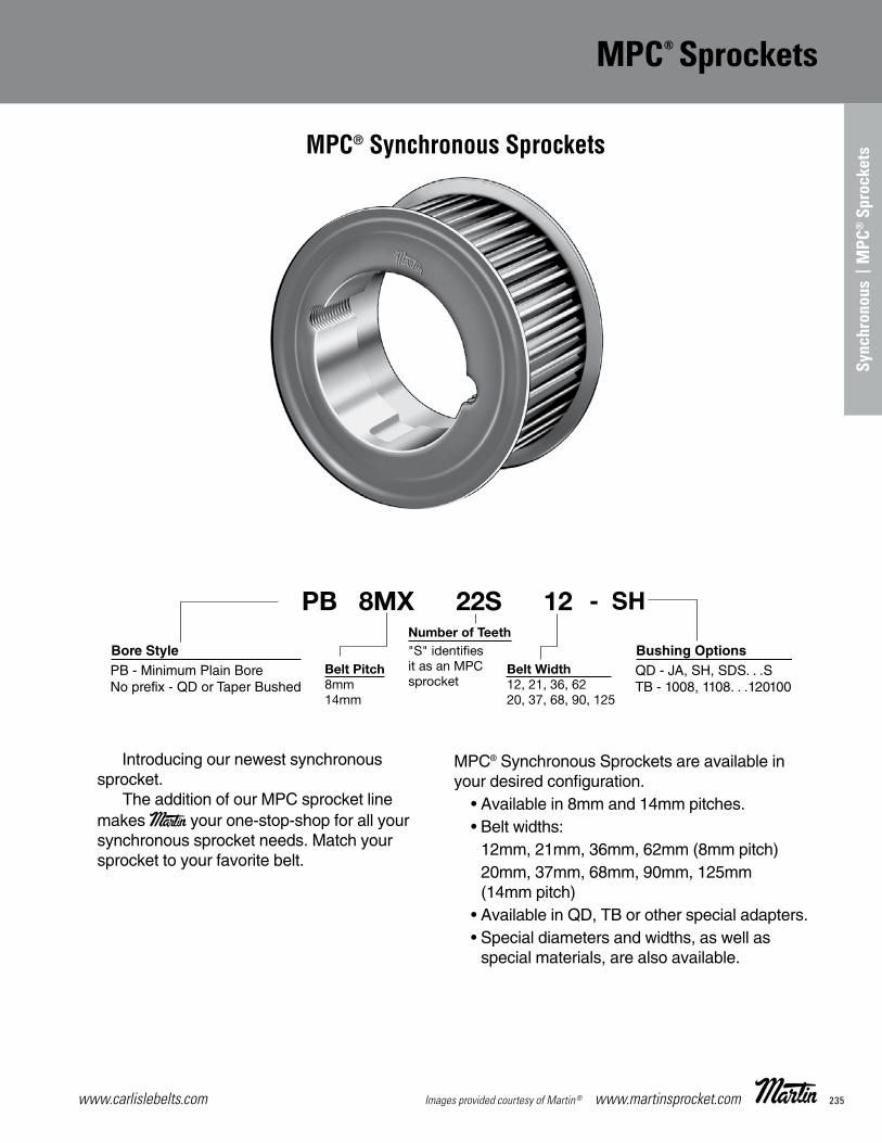
235www.carlislebelts.com Images provided courtesy of Martin® www.martinsprocket.com
MPC® Sprockets
K-51
MPC® Synchronous Sprockets are available in
• Available in 8mm and 14mm pitches.• Belt widths:
12mm, 21mm, 36mm, 62mm (8mm pitch)20mm, 37mm, 68mm, 90mm, 125mm(14mm pitch)
• Available in QD, TB or other special adapters.sa llew sa ,shtdiw dna sretemaid laicepS •
special materials, are also available.
MPC® Synchronous Sprockets
Introducing our newest synchronoussprocket. The addition of our MPC sprocket linemakes Martin your one-stop-shop for all yoursynchronous sprocket needs. Match yoursprocket to your favorite belt.
SECTION K K51 - K64-MAY 2015.qxp 5/7/15 2:02 PM Page K-51
MPC® Sprockets
Sync
hron
ous
| M
PC®
Spr
ocke
ts

www.carlislebelts.com236 www.martinsprocket.com Images provided courtesy of Martin®
8mm | MPC® Sprockets
Type A Type B Type C Type D Type 6
Type AF Type BF Type CF Type DF Type 6F
No. ofTeeth
Catalog Number Bore Pitch
Diameter
Diameter (in.)Type Max.
Bore
Dimensions (in.) WeightApprox.(lbs.)O.D. Max.
Flange O.D. A B C D E F M F-CL
MBP 8mm Pitch, 12mm (0.47 in.) Wide Belts (8M -12)
22 PB8MX22S12 1/2 2.206 2.143 2.610 6F-1 1.188 1.79 0.57 1.31 0.46 0.82 0.41 1.125 PB8MX25S12 1/2 2.506 2.443 2.910 6F-1 1.500 2.08 0.57 1.31 0.46 0.82 0.41 1.528 PB8MX28S12 1/2 2.807 2.744 3.210 6F-1 1.750 2.34 0.57 1.31 0.46 0.82 0.41 1.930 PB8MX30S12 1/2 3.008 2.945 3.410 6F-1 1.813 2.54 0.57 1.42 0.57 0.82 0.41 2.332 PB8MX32S12 1/2 3.208 3.145 3.610 6F-1 2.000 2.73 0.57 1.42 0.57 0.82 0.41 2.7
Taper Bushed 8mm Pitch, 12mm (0.47 in.) Wide Belts (8M -12)
22 8MX22S12-1008 1008 2.206 2.143 2.610 AF-1 1.000 0.63 0.88 0.88 0.44 0.525 8MX25S12-1108 1108 2.506 2.443 2.910 AF-1 1.125 0.63 0.88 0.88 0.44 0.726 8MX26S12-1108 1108 2.607 2.906 2.906 AF-1 1.125 0.63 0.88 0.88 0.44 0.827 8MX27S12-1108 1108 2.707 2.644 3.207 AF-1 1.125 0.63 0.88 0.88 0.44 0.928 8MX28S12-1108 1108 2.807 2.744 3.210 AF-1 1.125 0.63 0.88 0.88 0.44 1.029 8MX29S12-1108 1108 2.907 2.844 3.090 AF-1 1.125 0.63 0.88 0.88 0.44 1.230 8MX30S12-1108 1108 3.008 2.945 3.410 AF-1 1.125 0.63 0.88 0.88 0.44 1.331 8MX31S12-1210 1210 3.108 3.045 3.328 AF-1 1.250 0.75 1.00 1.00 0.50 1.332 8MX32S12-1210 1210 3.208 3.145 3.610 AF-1 1.250 0.75 1.00 1.00 0.50 1.433 8MX33S12-1610 1610 3.308 3.245 3.566 AF-1 1.625 0.75 1.00 1.00 0.50 1.334 8MX34S12-1610 1610 3.409 3.346 3.810 AF-1 1.625 0.75 1.00 1.00 0.50 1.335 8MX35S12-1610 1610 3.509 3.446 3.805 AF-1 1.625 0.75 1.00 1.00 0.50 1.336 8MX36S12-1610 1610 3.609 3.456 4.010 AF-1 1.625 0.75 1.00 1.00 0.50 1.237 8MX37S12-1610 1610 3.709 3.646 4.044 AF-1 1.625 0.75 1.00 1.00 0.50 1.638 8MX38S12-1610 1610 3.810 3.747 4.210 AF-1 1.625 0.75 1.00 1.00 0.50 1.739 8MX39S12-1610 1610 3.910 3.847 4.410 AF-1 1.625 0.75 1.00 1.00 0.50 1.740 8MX40S12-2012 2012 4.010 3.947 4.410 BF-1 2.000 3.56 0.57 1.25 0.82 0.43 0.41 1.741 8MX41S12-2012 2012 4.110 4.047 4.520 BF-1 2.000 3.65 0.65 1.25 0.82 0.43 0.41 1.842 8MX42S12-2012 2012 4.211 4.148 4.910 BF-1 2.000 3.76 0.57 1.25 0.82 0.43 0.41 2.245 8MX45S12-2012 2012 4.511 4.448 4.910 BF-1 2.000 3.76 0.57 1.25 0.82 0.43 0.41 2.548 8MX48S12-2012 2012 4.812 4.749 5.210 BF-1 2.000 3.76 0.57 1.25 0.82 0.43 0.41 3.450 8MX50S12-2012 2012 5.013 4.950 5.410 BF-1 2.000 3.76 0.57 1.25 0.82 0.43 0.41 3.753 8MX53S12-2012 2012 5.314 5.251 5.500 BF-1 2.000 3.76 0.57 1.25 0.82 0.43 0.41 4.756 8MX56S12-2012 2012 5.614 5.551 6.010 BF-1 2.000 3.76 0.57 1.25 0.82 0.43 0.41 5.460 8MX60S12-2012 2012 6.015 5.952 6.410 BF-1 2.000 3.76 0.57 1.25 0.82 0.43 0.41 6.363 8MX63S12-2012 2012 6.316 6.253 6.720 CF-1 2.000 5.71 4.00 0.57 1.25 0.82 0.43 0.41 5.667 8MX67S12-2012 2012 6.717 6.654 6.870 CF-1 2.000 6.14 4.00 0.57 1.25 0.82 0.43 0.41 4.371 8MX71S12-2012 2012 7.118 7.055 7.500 CF-1 2.000 6.51 4.00 0.57 1.25 0.82 0.43 0.41 4.775 8MX75S12-2012 2012 7.519 7.456 7.920 CF-1 2.000 6.90 4.00 0.57 1.25 0.82 0.43 0.41 5.180 8MX80S12-2012 2012 8.020 7.957 8.420 CF-1 2.000 7.23 4.00 0.57 1.25 0.82 0.43 0.41 5.890 8MX90S12-2012 2012 9.023 8.96 - C-2 2.000 8.05 4.00 1.25 0.82 0.43 0.41 9.4112 8MX112S12-2012 2012 11.229 11.166 - C-2 2.000 10.25 4.00 1.25 0.82 0.43 0.41 16.6140 8MX140S12-2012 2012 14.036 13.973 - C-3 2.000 11.96 4.38 1.25 0.82 0.43 0.41 17.3180 8MX180S12-2517 2517 18.046 17.893 - C-3 2.500 15.80 4.88 1.75 0.82 0.93 0.41 30.0224 8MX224S12-2517 2517 22.457 22.394 - C-3 2.500 20.17 4.88 1.75 0.82 0.93 0.41 41.2
8mm Pitch — 12mm Wide Belt
Type: 1- Solid 2 - Web 3 - Arms F=FlangedNOTE: Weights for Minimum Plain Bore (MPB) Sprockets are with minimum bore.
Weights for Bushed Sprockets less bushing.Dimensions in Inches. Weight in pounds.
K-52
MPC® Sprockets8mm
SECTION K K51 - K64-MAY 2015.qxp 5/7/15 2:02 PM Page K-52

237www.carlislebelts.com Images provided courtesy of Martin® www.martinsprocket.com
K-53
MPC® Sprockets8mm
8mm Pitch — 21mm Wide BeltNo. ofTeeth
CatalogNumber Bore Pitch
Diameter
Diameter (in.)Type Max.
Bore
Dimensions (in.) WeightApprox.(lbs.)O.D. Max.
Flange O.D. A B C D E F M F-CL
MBP 8mm Pitch, 21mm (0.83 in.) Wide Belts (8M -21)
22 PB8MX22S21 MPB 2.206 2.143 2.610 6F-1 1.188 1.79 0.92 1.65 0.45 1.20 0.60 1.325 PB8MX25S21 MPB 2.506 2.443 2.910 6F-1 1.500 2.08 0.92 1.65 0.45 1.20 0.60 1.828 PB8MX28S21 MPB 2.807 2.744 3.210 6F-1 1.750 2.34 0.92 1.65 0.45 1.20 0.60 2.330 PB8MX30S21 MPB 3.008 2.945 3.410 6F-1 1.813 2.54 0.92 1.77 0.57 1.20 0.60 2.832 PB8MX32S21 MPB 3.208 3.145 3.610 6F-1 2.000 2.73 0.92 1.77 0.57 1.20 0.60 3.2
Taper Bushed 8mm Pitch, 21mm (0.83 in.) Wide Belts (8M -21)
22 8MX22S21-1008 1008 2.206 2.143 2.610 AF-1 1.000 1.63 0.92 0.88 1.20 0.60 0.625 8MX25S21-1108 1108 2.506 2.443 2.910 AF-1 1.125 1.92 0.92 0.88 1.20 0.60 0.826 8MX26S21-1108 1108 2.607 2.906 2.906 AF-1 1.125 1.85 0.92 0.88 1.20 0.60 0.827 8MX27S21-1108 1108 2.707 2.644 3.207 AF-1 1.125 1.95 0.92 0.88 1.20 0.60 1.028 8MX28S21-1108 1108 2.807 2.744 3.210 AF-1 1.125 2.18 0.92 0.88 1.20 0.60 1.129 8MX29S21-1108 1108 2.907 2.844 3.090 AF-1 1.125 2.15 0.92 0.88 1.20 0.60 1.430 8MX30S21-1108 1108 3.008 2.945 3.410 AF-1 1.125 2.38 0.92 0.88 1.20 0.60 1.531 8MX31S21-1210 1210 3.108 3.045 3.328 AF-1 1.250 2.35 0.92 1.00 1.20 0.60 1.632 8MX32S21-1210 1210 3.208 3.145 3.610 AF-1 1.250 2.58 0.92 1.00 1.20 0.60 3.033 8MX33S21-1610 1610 3.308 3.245 3.566 AF-1 1.625 2.6 0.92 1.00 1.20 0.60 1.434 8MX34S21-1610 1610 3.409 3.346 3.810 AF-1 1.625 2.66 0.92 1.00 1.20 0.60 1.935 8MX35S21-1610 1610 3.509 3.446 3.805 AF-1 1.625 2.75 0.92 1.00 1.20 0.60 1.536 8MX36S21-1610 1610 3.609 3.456 4.010 AF-1 1.625 2.96 0.92 1.00 1.20 0.60 1.637 8MX37S21-1610 1610 3.709 3.646 4.044 AF-1 1.625 2.95 0.92 1.00 1.20 0.60 1.738 8MX38S21-1610 1610 3.810 3.747 4.210 AF-1 1.625 3.15 0.92 1.00 1.20 0.60 1.939 8MX39S21-1610 1610 3.910 3.847 4.410 AF-1 1.625 3.14 0.92 1.00 1.20 0.60 2.040 8MX40S21-2012 2012 4.010 3.947 4.410 AF-1 2.000 0.97 1.25 1.25 0.63 2.041 8MX41S21-2012 2012 4.110 4.047 4.520 BF-1 2.000 3.4 1.00 1.25 1.20 0.60 2.242 8MX42S21-2012 2012 4.211 4.148 4.910 AF-1 2.000 0.97 1.25 1.25 0.63 2.445 8MX45S21-2012 2012 4.511 4.448 4.910 AF-1 2.000 0.97 1.25 1.25 0.63 3.048 8MX48S21-2012 2012 4.812 4.749 5.210 AF-1 2.000 0.97 1.25 1.25 0.63 3.450 8MX50S21-2012 2012 5.013 4.950 5.410 AF-1 2.000 0.97 1.25 1.25 0.63 4.253 8MX53S21-2012 2012 5.314 5.251 5.500 AF-1 2.000 0.97 1.25 1.25 0.63 5.056 8MX56S21-2012 2012 5.614 5.551 6.010 AF-1 2.000 0.97 1.25 1.25 0.63 4.960 8MX60S21-2012 2012 6.015 5.952 6.410 AF-1 2.000 0.97 1.25 1.25 0.63 6.963 8MX63S21-2012 2012 6.316 6.253 6.720 CF-1 2.000 5.71 3.76 0.92 1.25 1.20 0.05 0.60 7.767 8MX67S21-2517 2517 6.717 6.654 6.870 CF-1 2.500 6.14 4.50 0.92 1.75 1.20 0.55 0.60 5.771 8MX71S21-2517 2517 7.118 7.055 7.500 CF-1 2.500 6.51 4.50 0.92 1.75 1.20 0.55 0.60 6.175 8MX75S21-2517 2517 7.519 7.456 7.920 CF-1 2.500 6.90 4.50 0.92 1.75 1.20 0.55 0.60 9.280 8MX80S21-2517 2517 8.020 7.957 8.420 CF-1 2.500 7.23 4.50 0.92 1.75 1.20 0.55 0.60 7.590 8MX90S21-2517 2517 9.023 8.96 - C-2 2.500 7.78 4.50 1.75 1.20 0.55 0.60 11.0112 8MX112S21-2517 2517 11.229 11.166 - C-2 2.500 10.00 4.50 1.75 1.20 0.55 0.60 19.4140 8MX140S21-2517 2517 14.036 13.973 - C-3 2.500 11.74 4.88 1.75 1.20 0.55 0.60 26.8180 8MX180S21-3020 3020 18.046 17.893 - C-3 3.000 15.49 6.25 2.00 1.20 0.80 0.60 36.6224 8MX224S21-3020 3020 22.457 22.394 - C-3 3.000 19.86 6.25 2.00 1.20 0.80 0.60 50.1
Type: 1- Solid 2 - Web 3 - Arms F=Flanged NOTE: Weights for Minimum Plain Bore (MPB) Sprockets are with minimum bore.
Weights for Bushed Sprockets less bushing.Dimensions in Inches. Weight in pounds.
Type A Type B Type C Type D Type 6
Type AF Type BF Type CF Type DF Type 6F
SECTION K K51 - K64-MAY 2015.qxp 5/7/15 2:02 PM Page K-53
MPC® Sprockets | 8mm
Sync
hron
ous
| M
PC®
Spr
ocke
ts

www.carlislebelts.com238 www.martinsprocket.com Images provided courtesy of Martin®
8mm | MPC® Sprockets
K-54
MPC® Sprockets8mm
8mm Pitch — 36mm Wide BeltNo. of Teeth
Catalog Number Bore Pitch
Diameter
DiameterType Max.
Bore
Dimensions WeightApprox.(lbs.)O.D. Max.
Flange O.D. A B C D E F M F-CL
MBP 8mm Pitch, 36mm (1.42 in.) Wide Belts (8M -36)
22 PB8MX22S36 MPB 2.206 2.143 2.610 6F-1 1.188 1.79 1.58 2.44 0.61 1.83 0.93 2.025 PB8MX25S36 MPB 2.506 2.443 2.910 6F-1 1.500 2.08 1.58 2.44 0.61 1.83 0.93 2.728 PB8MX28S36 MPB 2.807 2.744 3.210 6F-1 1.750 2.34 1.58 2.44 0.61 1.83 0.93 3.530 PB8MX30S36 MPB 3.008 2.945 3.410 6F-1 1.813 2.54 1.58 2.44 0.61 1.83 0.93 4.132 PB8MX32S36 MPB 3.208 3.145 3.610 6F-1 2.000 2.73 1.58 2.44 0.61 1.83 0.93 3.9
34 PB8MX34S36 MPB 3.409 3.346 3.810 6F-1 2.125 2.82 1.58 2.45 0.62 1.83 0.93 4.336 PB8MX36S36 MPB 3.609 3.546 4.010 6F-1 2.313 3.13 1.58 2.51 0.68 1.83 0.93 5.938 PB8MX38S36 MPB 3.810 3.747 4.210 6F-1 2.438 3.32 1.58 2.51 0.68 1.83 0.93 6.7
Taper Bushed 8mm Pitch, 36mm (1.42 in.) Wide Belts (8M -36)
32 8MX32S36-1210 1210 3.208 3.145 3.610 AF-1 1.250 2.58 1.58 1.00 1.83 0.83 0.93 2.033 8MX33S36-1610 1610 3.308 3.245 3.566 AF-1 1.625 2.56 1.66 1.00 1.83 0.83 0.93 1.734 8MX34S36-1610 1610 3.409 3.346 3.810 AF-1 1.625 2.66 1.58 1.00 1.83 0.83 0.93 1.835 8MX35S36-1610 1610 3.509 3.446 3.805 AF-1 1.625 2.76 1.66 1.00 1.83 0.83 0.93 2.036 8MX36S36-1610 1610 3.609 3.546 4.010 AF-1 1.625 2.96 1.58 1.00 1.83 0.83 0.93 2.7
37 8MX37S36-1610 1610 3.709 3.646 4.044 AF-1 1.625 2.90 1.66 1.00 1.83 0.83 0.93 2.138 8MX38S36-1610 1610 3.810 3.747 4.210 AF-1 1.625 3.15 1.58 1.00 1.83 0.83 0.93 2.939 8MX39S36-1610 1610 3.910 3.847 4.410 AF-1 1.625 3.10 1.58 1.00 1.83 0.83 0.93 2.440 8MX40S36-2012 2012 4.010 3.947 4.410 AF-1 2.000 3.35 1.58 1.25 1.83 0.58 0.93 2.541 8MX41S36-2012 2012 4.110 4.047 4.520 AF-1 2.000 3.36 1.58 1.25 1.83 0.58 0.93 2.4
42 8MX42S36-2012 2012 4.211 4.148 4.910 AF-1 2.000 3.62 1.58 1.25 1.83 0.58 0.93 2.845 8MX45S36-2012 2012 4.511 4.448 4.910 AF-1 2.000 3.62 1.58 1.25 1.83 0.58 0.93 4.048 8MX48S36-2012 2012 4.812 4.749 5.210 AF-1 2.000 4.14 1.58 1.25 1.83 0.58 0.93 4.350 8MX50S36-2012 2012 5.013 4.95 5.410 AF-1 2.000 4.13 1.58 1.25 1.83 0.58 0.93 5.153 8MX53S36-2012 2012 5.314 5.251 5.500 AF-1 2.000 4.76 1.58 1.25 1.83 0.58 0.93 6.0
56 8MX56S36-2012 2012 5.614 5.551 6.010 AF-1 2.000 4.92 1.58 1.25 1.83 0.58 0.93 6.560 8MX60S36-2517 2517 6.015 5.952 6.420 AF-1 2.500 5.13 1.58 1.75 1.83 0.58 0.93 8.963 8MX63S36-2517 2517 6.316 6.253 6.720 AF-1 2.500 5.71 1.58 1.75 1.83 0.08 0.93 9.367 8MX67S36-2517 2517 6.717 6.654 6.880 DF-1 2.500 5.98 4.25 1.58 1.75 1.83 0.08 0.93 10.071 8MX71S36-2517 2517 7.118 7.055 7.500 DF-1 2.500 6.39 4.25 1.58 1.75 1.83 0.08 0.93 7.0
75 8MX75S36-2517 2517 7.519 7.456 7.920 DF-1 2.500 6.79 4.25 1.58 1.75 1.83 0.08 0.93 13.380 8MX80S36-3020 3020 8.020 7.957 8.420 BF-1 3.000 5.75 1.58 2.00 1.83 0.08 0.93 15.390 8MX90S36-3020 3020 9.023 8.960 - B-1 3.000 5.75 2.00 1.83 0.17 0.93 20.9112 8MX112S36-3020 3020 11.229 11.166 - C-2 3.000 9.80 5.75 2.00 1.83 0.17 0.93 22.0140 8MX140S36-3020 3020 14.036 13.973 - C-3 3.000 11.72 6.25 2.00 1.83 0.17 0.93 39.3
180 8MX180S36-3020 3020 18.046 17.983 - C-3 3.000 15.31 6.25 2.00 1.83 0.17 0.93 48.9224 8MX224S36-3525 3525 22.457 22.394 - C-3 3.500 19.62 8.75 2.50 1.83 0.67 0.93 92.2
Type: 1- Solid 2 - Web 3 - Arms F=FlangedNOTE: Weights for Minimum Plain Bore (MPB) Sprockets are with minimum bore.
Weights for Bushed Sprockets less bushing.Dimensions in Inches. Weight in pounds.
Type A Type B Type C Type D Type 6
Type AF Type BF Type CF Type DF Type 6F
SECTION K K51 - K64-MAY 2015.qxp 5/7/15 2:02 PM Page K-54

239www.carlislebelts.com Images provided courtesy of Martin® www.martinsprocket.com
K-55
MPC® Sprockets8mm
8mm Pitch — 62mm Wide BeltNo. ofTeeth
CatalogNumber Bore Pitch
Diameter
Diameter (in.)Type Max.
Bore
Dimensions (in.) WeightApprox.(lbs.)O.D. Max.
Flange O.D. A B C D E F M F-CL
MPB 8mm Pitch, 62 mm (2.44 in.) Wide Belts (8M - 62)
22 PB8MX22S62 MPB 2.206 2.143 2.610 6F-1 1.188 1.79 2.63 3.56 0.68 2.88 1.46 2.4
25 PB8MX25S62 MPB 2.506 2.443 2.910 6F-1 1.500 2.08 2.63 3.56 0.68 2.88 1.46 3.6
28 PB8MX28S62 MPB 2.807 2.744 3.210 6F-1 1.750 2.34 2.63 3.56 0.68 2.88 1.46 4.6
30 PB8MX30S62 MPB 3.008 2.945 3.410 6F-1 1.813 2.54 2.63 3.50 0.62 2.88 1.46 5.3
32 PB8MX32S62 MPB 3.208 3.145 3.610 6F-1 2.000 2.73 2.63 3.50 0.62 2.88 1.46 5.6
34 PB8MX34S62 MPB 3.409 3.346 3.810 6F-1 2.125 2.82 2.63 3.50 0.62 2.88 1.46 5.7
36 PB8MX36S62 MPB 3.609 3.546 4.010 6F-1 2.313 3.13 2.63 3.56 0.68 2.88 1.46 8.0
38 PB8MX38S62 MPB 3.812 3.747 4.210 6F-1 2.438 3.32 2.63 3.56 0.68 2.88 1.46 9.1
40 PB8MX40S62 MPB 4.010 3.947 4.410 6F-1 2.563 3.52 2.63 3.63 0.75 2.88 1.46 10.3
42 PB8MX42S62 MPB 4.211 4.148 4.910 6F-1 2.750 3.79 2.63 3.63 0.75 2.88 1.46 11.6
45 PB8MX45S62 MPB 4.511 4.448 4.910 6F-1 2.750 3.79 2.63 3.63 0.75 2.88 1.46 13.1
Taper Bushed 8mm Pitch, 62mm (2.44 in.) Wide Belts (8M - 62)
34 8MX34S62-1610 1610 3.409 3.346 3.810 AF-1 1.625 2.66 2.63 1.00 2.88 1.46 5.0
36 8MX36S62-1610 1610 3.609 3.546 4.010 AF-1 1.625 2.96 2.63 1.00 2.88 1.46 5.3
38 8MX38S62-1610 1610 3.812 3.747 4.210 AF-1 1.625 3.15 2.63 1.00 2.88 1.46 5.6
40 8MX40S62-2012 2012 4.010 3.947 4.410 AF-1 2.000 3.35 2.63 1.25 2.88 1.46 5.9
42 8MX42S62-2012 2012 4.211 4.148 4.910 AF-1 2.000 3.62 2.63 1.25 2.88 1.46 3.5
45 8MX45S62-2012 2012 4.511 4.448 4.910 AF-1 2.000 3.62 2.63 1.25 2.88 1.46 6.5
48 8MX48S62-2517 2517 4.812 4.749 5.210 AF-1 2.500 4.14 2.63 1.75 2.88 1.46 6.6
50 8MX50S62-2517 2517 5.013 4.950 5.410 AF-1 2.500 4.13 2.63 1.75 2.88 1.46 6.7
53 8MX53S62-2517 2517 5.314 5.251 5.500 AF-1 2.500 4.76 2.63 1.75 2.88 1.46 6.9
56 8MX56S62-2517 2517 5.614 5.551 6.010 AF-1 2.500 4.92 2.63 1.75 2.88 1.46 7.2
60 8MX60S62-3020 3020 6.015 5.952 6.420 AF-1 3.000 5.13 2.63 2.00 2.88 1.46 8.9
63 8MX63S62-3020 3020 6.316 6.253 6.720 AF-1 3.000 5.71 2.63 2.00 2.88 1.46 10.3
67 8MX67S62-3020 3020 6.717 6.654 6.880 AF-1 3.000 6.14 2.63 2.00 2.88 1.46 11.0
71 8MX71S62-3020 3020 7.118 7.055 7.500 AF-1 3.000 6.51 2.63 2.00 2.88 1.46 13.5
75 8MX75S62-3020 3020 7.519 7.456 7.920 AF-1 3.000 6.90 2.63 2.00 2.88 1.46 15.4
80 8MX80S62-3020 3020 8.020 7.957 8.420 AF-1 3.000 7.23 2.63 2.00 2.88 1.46 23.0
90 8MX90S62-3020 3020 9.023 8.960 - D-1 3.000 7.39 5.42 2.00 2.88 0.91 1.46 32.7
112 8MX112S62-3020 3020 11.229 11.166 - D-2 3.000 9.60 5.42 2.00 2.88 0.91 1.46 38.9
140 8MX140S62-3525 3525 14.036 13.973 - D-2 3.500 12.40 8.75 2.50. 2.88 0.41 1.46 54.5
180 8MX180S62-3525 3525 18.046 17.983 - D-3 3.500 15.33 8.75 2.50 2.88 0.41. 1.46 90.0
224 8MX224S62-3525 3525 22.457 22.394 - D-3 3.500 19.38 8.75 2.50 2.88 0.41 1.46 92.3
Type: 1- Solid 2 - Web 3 - Arms F=FlangedNOTE: Weights for Minimum Plain Bore (MPB) Sprockets are with minimum bore.
Weights for Bushed Sprockets less bushing.Dimensions in Inches. Weight in pounds.
Type A Type B Type C Type D Type 6
Type AF Type BF Type CF Type DF Type 6F
SECTION K K51 - K64-MAY 2015.qxp 5/7/15 2:02 PM Page K-55
MPC® Sprockets | 8mm
Sync
hron
ous
| M
PC®
Spr
ocke
ts

www.carlislebelts.com240 www.martinsprocket.com Images provided courtesy of Martin®
8mm | MPC® Sprockets Air Cool Heat Exchange
K-56
MPC® Sprockets 8mm Air Cool Heat Exchange
Type A Type B Type C Type D
Type E Type F Type G Type 6
8mm Pitch — 21mm Wide Air Cool Heat Exchange BeltNo. ofTeeth
Catalog Number Bore Pitch
Diameter
Diameter (in.)Type Max.
Bore
Dimensions (in.) WeightApprox.(lbs.)O.D. Max.
Flange O.D. A B C D E F L M F-CL
QD Bushed 8mm Pitch, 21mm (0.93 in.) Wide Belt (8M-21)
36 F8MX36S21-SH SH 3.609 3.546 4.009 AF-1 1.688 2.85 0.92 0.81 0.0475 1.20 1.94 0.39 0.60 2.1
38 F8MX38S21-SH SH 3.810 3.747 4.210 AF-1 1.688 3.04 0.92 0.81 0.0475 1.20 1.94 0.39 0.60 2.1
40 F8MX40S21-SH SH 4.010 3.947 4.410 AF-1 1.688 3.24 0.92 0.81 0.0475 1.20 1.94 0.39 0.60 2.3
42 F8MX42S21-SH SH 4.211 4.148 4.911 AF-1 1.688 3.44 0.92 0.81 0.0475 1.20 1.94 0.39 0.60 2.5
140 F8MX140S21-SF SF 14.036 13.973 C-1 2.938 13.17 6.38 1.25 0.6125 1.20 2.06 0.05 0.60 25.0
168 F8MX168S21-SF SF 16.843 16.780 C-3 2.938 15.95 6.38 1.25 0.6125 1.20 2.06 0.05 0.60 33.8
180 F8MX180S21-SF SF 18.046 17.983 C-3 2.938 17.14 6.38 1.25 1.305 1.20 2.06 0.03 0.60 36.6
224 F8MX224S21-E E 22.457 22.394 C-3 3.500 21.51 7.50 1.25 1.305 1.20 2.75 0.43 0.60 50.1
Type: 1- Solid 2 - Web 3 - Arms F=FlangedNOTE: Weights for Minimum Plain Bore (MPB) Sprockets are with minimum bore.
Weights for Bushed Sprockets less bushing.Dimensions in Inches. Weight in pounds.
SECTION K K51 - K64-MAY 2015.qxp 5/7/15 2:02 PM Page K-56
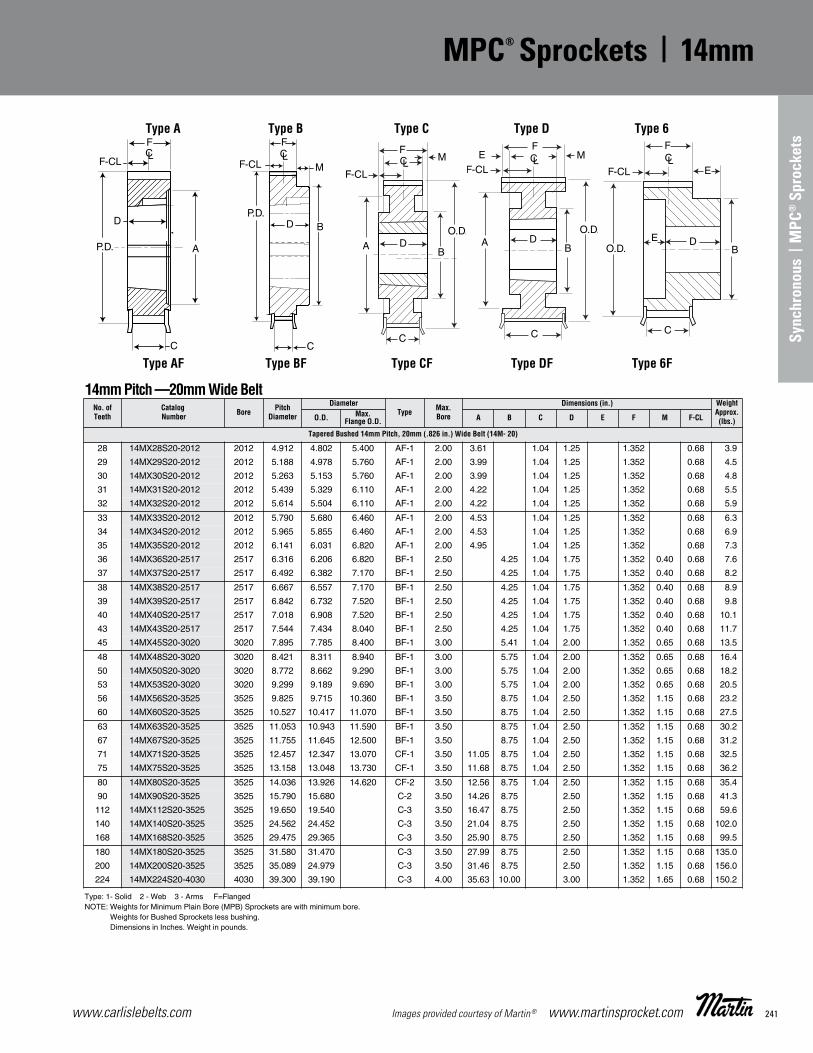
241www.carlislebelts.com Images provided courtesy of Martin® www.martinsprocket.com
K-57
MPC® Sprockets 14mm
14mm Pitch —20mm Wide BeltNo. ofTeeth
CatalogNumber Bore Pitch
Diameter
DiameterType Max.
Bore
Dimensions (in.) WeightApprox.(lbs.)O.D. Max.
Flange O.D. A B C D E F M F-CL
Tapered Bushed 14mm Pitch, 20mm (.826 in.) Wide Belt (14M- 20)
28 14MX28S20-2012 2012 4.912 4.802 5.400 AF-1 2.00 3.61 1.04 1.25 1.352 0.68 3.9
29 14MX29S20-2012 2012 5.188 4.978 5.760 AF-1 2.00 3.99 1.04 1.25 1.352 0.68 4.5
30 14MX30S20-2012 2012 5.263 5.153 5.760 AF-1 2.00 3.99 1.04 1.25 1.352 0.68 4.8
31 14MX31S20-2012 2012 5.439 5.329 6.110 AF-1 2.00 4.22 1.04 1.25 1.352 0.68 5.5
32 14MX32S20-2012 2012 5.614 5.504 6.110 AF-1 2.00 4.22 1.04 1.25 1.352 0.68 5.9
33 14MX33S20-2012 2012 5.790 5.680 6.460 AF-1 2.00 4.53 1.04 1.25 1.352 0.68 6.3
34 14MX34S20-2012 2012 5.965 5.855 6.460 AF-1 2.00 4.53 1.04 1.25 1.352 0.68 6.9
35 14MX35S20-2012 2012 6.141 6.031 6.820 AF-1 2.00 4.95 1.04 1.25 1.352 0.68 7.3
36 14MX36S20-2517 2517 6.316 6.206 6.820 BF-1 2.50 4.25 1.04 1.75 1.352 0.40 0.68 7.6
37 14MX37S20-2517 2517 6.492 6.382 7.170 BF-1 2.50 4.25 1.04 1.75 1.352 0.40 0.68 8.2
38 14MX38S20-2517 2517 6.667 6.557 7.170 BF-1 2.50 4.25 1.04 1.75 1.352 0.40 0.68 8.9
39 14MX39S20-2517 2517 6.842 6.732 7.520 BF-1 2.50 4.25 1.04 1.75 1.352 0.40 0.68 9.8
40 14MX40S20-2517 2517 7.018 6.908 7.520 BF-1 2.50 4.25 1.04 1.75 1.352 0.40 0.68 10.1
43 14MX43S20-2517 2517 7.544 7.434 8.040 BF-1 2.50 4.25 1.04 1.75 1.352 0.40 0.68 11.7
45 14MX45S20-3020 3020 7.895 7.785 8.400 BF-1 3.00 5.41 1.04 2.00 1.352 0.65 0.68 13.5
48 14MX48S20-3020 3020 8.421 8.311 8.940 BF-1 3.00 5.75 1.04 2.00 1.352 0.65 0.68 16.4
50 14MX50S20-3020 3020 8.772 8.662 9.290 BF-1 3.00 5.75 1.04 2.00 1.352 0.65 0.68 18.2
53 14MX53S20-3020 3020 9.299 9.189 9.690 BF-1 3.00 5.75 1.04 2.00 1.352 0.65 0.68 20.5
56 14MX56S20-3525 3525 9.825 9.715 10.360 BF-1 3.50 8.75 1.04 2.50 1.352 1.15 0.68 23.2
60 14MX60S20-3525 3525 10.527 10.417 11.070 BF-1 3.50 8.75 1.04 2.50 1.352 1.15 0.68 27.5
63 14MX63S20-3525 3525 11.053 10.943 11.590 BF-1 3.50 8.75 1.04 2.50 1.352 1.15 0.68 30.2
67 14MX67S20-3525 3525 11.755 11.645 12.500 BF-1 3.50 8.75 1.04 2.50 1.352 1.15 0.68 31.2
71 14MX71S20-3525 3525 12.457 12.347 13.070 CF-1 3.50 11.05 8.75 1.04 2.50 1.352 1.15 0.68 32.5
75 14MX75S20-3525 3525 13.158 13.048 13.730 CF-1 3.50 11.68 8.75 1.04 2.50 1.352 1.15 0.68 36.2
80 14MX80S20-3525 3525 14.036 13.926 14.620 CF-2 3.50 12.56 8.75 1.04 2.50 1.352 1.15 0.68 35.4
90 14MX90S20-3525 3525 15.790 15.680 C-2 3.50 14.26 8.75 2.50 1.352 1.15 0.68 41.3
112 14MX112S20-3525 3525 19.650 19.540 C-3 3.50 16.47 8.75 2.50 1.352 1.15 0.68 59.6
140 14MX140S20-3525 3525 24.562 24.452 C-3 3.50 21.04 8.75 2.50 1.352 1.15 0.68 102.0
168 14MX168S20-3525 3525 29.475 29.365 C-3 3.50 25.90 8.75 2.50 1.352 1.15 0.68 99.5
180 14MX180S20-3525 3525 31.580 31.470 C-3 3.50 27.99 8.75 2.50 1.352 1.15 0.68 135.0
200 14MX200S20-3525 3525 35.089 24.979 C-3 3.50 31.46 8.75 2.50 1.352 1.15 0.68 156.0
224 14MX224S20-4030 4030 39.300 39.190 C-3 4.00 35.63 10.00 3.00 1.352 1.65 0.68 150.2
Type: 1- Solid 2 - Web 3 - Arms F=FlangedNOTE: Weights for Minimum Plain Bore (MPB) Sprockets are with minimum bore.
Weights for Bushed Sprockets less bushing.Dimensions in Inches. Weight in pounds.
Type A Type B Type C Type D Type 6
Type AF Type BF Type CF Type DF Type 6F
SECTION K K51 - K64-MAY 2015.qxp 5/7/15 2:03 PM Page K-57
MPC® Sprockets | 14mm
Sync
hron
ous
| M
PC®
Spr
ocke
ts

www.carlislebelts.com242 www.martinsprocket.com Images provided courtesy of Martin®
14mm | MPC® Sprockets
K-58
MPC® Sprockets14mm
14mm Pitch —37mm Wide Belt
Type: 1- Solid 2 - Web 3 - Arms F=FlangedNOTE: Weights for Minimum Plain Bore (MPB) Sprockets are with minimum bore.
Weights for Bushed Sprockets less bushing.Dimensions in Inches. Weight in pounds.
Type A Type B Type C Type D Type 6
Type AF Type BF Type CF Type DF Type 6F
No. ofTeeth
Catalog Number
Bore P.DDiameter (in.)
Type Max. Bore
Dimensions (in.) WeightApprox.(lbs.)
O.D. Max. Flange O.D. A B C D E F M F-CL
MPB 14mm Pitch, 37mm (1.46 in.) Wide Belt (14M-37)28 PB14MX28S37 MPB 4.912 4.802 5.400 6F-1 2.938 3.97 1.74 2.86 0.80 2.06 1.03 11.7
Taper Bushed 14mm Pitch, 37mm (1.46 in.) Wide Belt (14M-37)
28 14MX28S37-2012 2012 4.912 4.802 5.400 AF-1 2.00 3.61 1.74 1.25 2.06 0.81 1.03 4.2
29 14MX29S37-2517 2517 5.088 4.978 5.760 AF-1 2.50 3.99 1.74 1.75 2.06 0.31 1.03 4.7
30 14MX30S37-2517 2517 5.263 5.153 5.760 AF-1 2.50 3.99 1.74 1.75 2.06 0.31 1.03 5.0
31 14MX31S37-2517 2517 5.439 5.329 6.110 AF-1 2.50 4.22 1.74 1.75 2.06 0.31 1.03 6.0
32 14MX32S37-2517 2517 5.614 5.504 6.110 AF-1 2.50 4.22 1.74 1.75 2.06 0.31 1.03 7.233 14MX33S37-2517 2517 5.790 5.680 6.460 AF-1 2.50 4.53 1.74 1.75 2.06 0.31 1.03 7.534 14MX34S37-2517 2517 5.965 5.855 6.460 AF-1 2.50 4.53 1.74 1.75 2.06 0.31 1.03 7.835 14MX35S37-2517 2517 6.141 6.031 6.820 AF-1 2.50 4.95 1.74 1.75 2.06 0.31 1.03 8.336 14MX36S37-2517 2517 6.316 6.206 6.820 AF-1 2.50 4.95 1.74 1.75 2.06 0.31 1.03 8.837 14MX37S37-2517 2517 6.492 6.382 7.170 AF-1 2.50 5.27 1.74 1.75 2.06 0.31 1.03 9.338 14MX38S37-3020 3020 6.667 6.557 7.170 AF-1 3.00 5.27 1.74 2.00 2.06 0.06 1.03 10.839 14MX39S37-3020 3020 6.842 6.732 7.520 AF-1 3.00 5.54 1.74 2.00 2.06 0.06 1.03 11.940 14MX40S37-3020 3020 7.018 6.908 7.520 AF-1 3.00 5.54 1.74 2.00 2.06 0.06 1.03 12.243 14MX43S37-3020 3020 7.544 7.434 8.040 AF-1 3.00 6.16 1.74 2.00 2.06 0.06 1.03 12.545 14MX45S37-3020 3020 7.895 7.785 8.400 AF-1 3.00 6.42 1.74 2.00 2.06 0.06 1.03 15.848 14MX48S37-3020 3020 8.421 8.311 8.940 AF-1 3.00 6.96 1.74 2.00 2.06 0.06 1.03 18.750 14MX50S37-3020 3020 8.772 8.662 9.290 AF-1 3.00 7.44 1.74 2.00 2.06 0.06 1.03 21.153 14MX53S37-3020 3020 9.299 9.189 9.690 AF-1 3.00 7.84 1.74 2.00 2.06 0.06 1.03 24.756 14MX56S37-3525 3525 9.825 9.715 10.360 BF-1 3.50 8.70 1.74 2.50 2.06 0.44 1.03 28.260 14MX60S37-3525 3525 10.527 10.417 11.070 BF-1 3.50 8.75 1.74 2.50 2.06 0.44 1.03 32.263 14MX63S37-3525 3525 11.053 10.943 11.590 BF-1 3.50 8.75 1.74 2.50 2.06 0.44 1.03 42.867 14MX67S37-3525 3525 11.755 11.645 12.500 BF-1 3.50 8.75 1.74 2.50 2.06 0.44 1.03 43.571 14MX71S37-3525 3525 12.457 12.347 13.070 BF-1 3.50 8.75 1.74 2.50 2.06 0.44 1.03 44.175 14MX75S37-3525 3525 13.158 13.048 13.730 CF-1 3.50 11.68 8.75 1.74 2.50 2.06 0.44 1.03 45.580 14MX80S37-3525 3525 14.036 13.926 14.620 CF-2 3.50 12.56 8.75 1.74 2.50 2.06 0.44 1.03 48.790 14MX90S37-3525 3525 15.790 15.680 C-2 3.50 14.26 8.75 2.50 2.06 0.44 1.03 53.3112 14MX112S37-3525 3525 19.650 19.540 C-3 3.50 16.39 8.75 2.50 2.06 0.44 1.03 87.0126 14MX126S37-3525 3525 22.106 21.996 C-3 3.50 20.56 8.75 2.50 2.06 0.44 1.03 76.3140 14MX140S37-3525 3525 24.562 24.452 C-3 3.50 20.84 8.75 2.50 2.06 0.44 1.03 100.9154 14MX154S37-3525 3525 27.019 26.909 C-3 3.50 25.42 8.75 2.50 2.06 0.44 1.03 125.5168 14MX168S37-4030 4030 29.475 29.365 C-3 4.00 25.51 10.00 3.00 2.06 0.94 1.03 175.1180 14MX180S37-4030 4030 31.580 31.470 C-3 4.00 27.59 10.00 3.00 2.06 0.94 1.03 191.4200 14MX200S37-4030 4030 35.089 34.979 C-3 4.00 31.07 10.00 3.00 2.06 0.94 1.03 224.8224 14MX224S37-4030 4030 39.300 39.190 C-3 4.00 35.24 10.00 3.00 2.06 0.94 1.03 267.7
SECTION K K51 - K64-MAY 2015.qxp 5/7/15 2:03 PM Page K-58

243www.carlislebelts.com Images provided courtesy of Martin® www.martinsprocket.com
K-59
MPC® Sprockets14mm
14mm Pitch — 68mm Wide BeltNo. of Teeth
CatalogNumber Bore Pitch
Diameter
Diameter (in.)Type Max.
Bore
Dimensions (in.) WeightApprox.(lbs.)O.D. Max. Flange
O.D. A B C D E F M F-CL
MPB 14mm Pitch, 68mm (2.68 in.) Wide Belt (14M-68)
28 PB14MX28S68 MPB 4.912 4.802 5.400 6F-1 2.938 3.97 3.01 4.13 0.81 3.322 1.66 17.029 PB14MX29S68 MPB 5.088 4.978 5.760 6F-1 3.188 4.35 3.01 4.13 0.81 3.322 1.66 19.030 PB14MX30S68 MPB 5.263 5.153 5.760 6F-1 3.188 4.35 3.01 4.13 0.81 3.322 1.66 20.031 PB14MX31S68 MPB 5.439 5.329 6.110 6F-1 3.438 4.57 3.01 4.13 0.81 3.322 1.66 16.832 PB14MX32S68 MPB 5.614 5.504 6.110 6F-1 3.438 4.57 3.01 4.13 0.81 3.322 1.66 18.033 PB14MX33S68 MPB 5.790 5.680 6.470 6F-1 3.500 4.89 3.01 4.33 1.01 3.322 1.66 26.034 PB14MX34S68 MPB 5.965 5.855 6.470 6F-1 3.500 4.89 3.01 4.33 1.01 3.322 1.66 21.1
Taper Bushed 14mm Pitch, 68mm (2.68 in.) Wide Belt (14M-68)
29 14MX29S68-2517 2517 5.088 4.978 5.760 AF-1 2.500 3.99 3.01 1.75 3.322 1.66 14.730 14MX30S68-2517 2517 5.263 5.153 5.760 AF-1 2.500 3.99 3.01 1.75 3.322 1.66 14.031 14MX31S68-2517 2517 5.439 5.329 6.110 AF-1 2.500 4.22 3.01 1.75 3.322 1.66 14.332 14MX32S68-2517 2517 5.614 5.504 6.110 AF-1 2.500 4.22 3.01 1.75 3.322 1.66 14.633 14MX33S68-2517 2517 5.790 5.680 6.460 AF-1 2.500 4.53 3.01 1.75 3.322 1.66 14.934 14MX34S68-2517 2517 5.965 5.855 6.460 AF-1 2.500 4.53 3.01 1.75 3.322 1.66 15.235 14MX35S68-3020 3020 6.141 6.031 6.820 AF-1 3.000 4.95 3.01 2.00 3.322 1.66 15.536 14MX36S68-3020 3020 6.316 6.206 6.820 AF-1 3.000 4.95 3.01 2.00 3.322 1.66 15.837 14MX37S68-3020 3020 6.492 6.382 7.170 AF-1 3.000 5.27 3.01 2.00 3.322 1.66 16.138 14MX38S68-3020 3020 6.667 6.557 7.170 AF-1 3.000 5.27 3.01 2.00 3.322 1.66 16.439 14MX39S68-3020 3020 6.842 6.732 7.520 AF-1 3.000 5.54 3.01 2.00 3.322 1.66 16.740 14MX40S68-3020 3020 7.018 6.908 7.520 AF-1 3.000 5.54 3.01 2.00 3.322 1.66 17.043 14MX43S68-3020 3020 7.544 7.434 8.040 AF-1 3.000 6.16 3.01 2.00 3.322 1.66 17.245 14MX45S68-3020 3020 7.895 7.785 8.390 AF-1 3.000 6.42 3.01 2.00 3.322 1.66 20.448 14MX48S68-3525 3525 8.421 8.311 8.940 AF-1 3.500 6.96 3.01 2.50 3.322 1.66 24.650 14MX50S68-3525 3525 8.772 8.662 9.290 AF-1 3.500 7.44 3.01 2.50 3.322 1.66 29.453 14MX53S68-3525 3525 9.299 9.189 9.690 AF-1 3.500 7.84 3.01 2.50 3.322 1.66 35.756 14MX56S68-3525 3525 9.825 9.715 10.360 AF-1 3.500 8.35 3.01 2.50 3.322 1.66 39.960 14MX60S68-3525 3525 10.527 10.417 11.070 AF-1 3.500 9.06 3.01 2.50 3.322 1.66 50.663 14MX63S68-3525 3525 11.053 10.943 11.590 AF-1 3.500 9.59 3.01 2.50 3.322 1.66 58.067 14MX67S68-3525 3525 11.755 11.645 12.500 DF-1 3.500 10.36 8.75 3.01 2.50 3.322 0.82 1.66 60.071 14MX71S68-3525 3525 12.457 12.347 13.070 DF-1 3.500 11.05 8.75 3.01 2.50 3.322 0.82 1.66 63.375 14MX75S68-3525 3525 13.158 13.048 13.730 DF-1 3.500 11.68 8.75 3.01 2.50 3.322 0.82 1.66 68.680 14MX80S68-3525 3525 14.036 13.926 14.620 DF-2 3.500 12.56 8.75 3.01 2.50 3.322 0.82 1.66 76.390 14MX90S68-4030 4030 15.790 15.680 D-2 4.000 14.26 10.00 3.00 3.322 0.32 1.66 82.6112 14MX112S68-4030 4030 19.650 19.540 D-3 4.000 16.35 10.00 3.00 3.322 0.32 1.66 100.4140 14MX140S68-4030 4030 24.562 24.452 D-3 4.500 20.78 10.00 3.00 3.322 0.32 1.66 190.0168 14MX168S68-4535 4535 29.475 29.365 C-3 4.500 25.23 10.50 3.50 3.322 0.18 1.66 239.1180 14MX180S68-4353 4535 31.580 31.470 C-3 4.500 27.16 10.50 3.50 3.322 0.18 1.66 250.6200 14MX200568-4535 4535 35.089 34.979 C-3 4.500 30.65 10.50 3.50 3.322 0.18 1.66 262.5224 14MX224S68-5040 5040 39.300 39.190 C-3 5.000 34.82 11.00 4.00 3.322 0.68 1.66 350.0
Type: 1- Solid 2 - Web 3 - Arms F=FlangedNOTE: Weights for Minimum Plain Bore (MPB) Sprockets are with minimum bore.
Weights for Bushed Sprockets less bushing.Dimensions in Inches. Weight in pounds.
Type A Type B Type C Type D Type 6
Type AF Type BF Type CF Type DF Type 6F
SECTION K K51 - K64-MAY 2015.qxp 5/7/15 2:03 PM Page K-59
MPC® Sprockets | 14mm
Sync
hron
ous
| M
PC®
Spr
ocke
ts

www.carlislebelts.com244 www.martinsprocket.com Images provided courtesy of Martin®
14mm | MPC® Sprockets
K-60
MPC® Sprockets14mm
14mm Pitch — 90mm Wide BeltNo. ofTeeth Catalog Number Bore P.D
Diameter (in)Type Max.
Bore
Dimensions (in) WeightApprox.(lbs.)O.D. Max. Flange
O.D. A B C D E F M F-CL
MPB 14mm Pitch, 90mm (3.54 in.) Wide Belt (14M-90)
28 PB14MX28S90 MPB 4.912 4.802 5.400 6F-1 3.97 3.88 5.14 0.95 4.192 2.10 20.029 PB14MX29S90 MPB 5.088 4.978 5.760 6F-1 4.35 3.88 5.00 0.81 4.192 2.10 22.130 PB14MX30S90 MPB 5.263 5.153 5.760 6F-1 4.35 3.88 5.00 0.81 4.192 2.10 24.031 PB14MX31S90 MPB 5.439 5.329 6.110 6F-1 4.57 3.88 5.00 0.81 4.192 2.10 21.832 PB14MX32S90 MPB 5.614 5.504 6.110 6F-1 4.57 3.88 5.00 0.81 4.192 2.10 27.033 PB14MX33S90 MPB 5.790 5.680 6.470 6F-1 4.89 3.88 5.20 1.01 4.192 2.10 30.034 PB14MX34S90 MPB 5.965 5.855 6.470 6F-1 4.89 3.88 5.20 1.01 4.192 2.10 27.2
35 PB14MX35S90 MPB 6.141 6.031 6.820 6F-1 5.30 3.88 5.20 1.01 4.192 2.10 28.736 PB14MX36S90 MPB 6.316 6.206 6.820 6F-1 5.30 3.88 5.20 1.01 4.192 2.10 30.337 PB14MX90S90 MPB 6.492 6.382 7.170 6F-1 5.63 3.88 5.20 1.01 4.192 2.10 32.138 PB14MX38S90 MPB 6.667 6.557 7.170 6F-1 5.63 3.88 5.20 1.01 4.192 2.10 33.939 PB14MX39S90 MPB 6.842 6.732 7.500 6F-1 5.89 3.88 5.20 1.01 4.192 2.10 35.840 PB14MX40S90 MPB 7.018 6.908 7.520 6F-1 5.89 3.88 5.20 1.01 4.192 2.10 37.7
Taper Bushed 14mm Pitch, 90mm (3.54 in.) Wide Belt (14M-90)
35 14MX35S90-3020 3020 6.141 6.031 6.820 AF-1 3.00 4.95 3.88 2.00 4.192 2.19 2.10 22.936 14MX36S90-3020 3020 6.316 6.206 6.820 AF-1 3.00 4.95 3.88 2.00 4.192 2.19 2.10 23.137 14MX90S90-3020 3020 6.492 6.382 7.170 AF-1 3.00 5.27 3.88 2.00 4.192 2.19 2.10 23.438 14MX38S90-3020 3020 6.667 6.557 7.170 AF-1 3.00 5.27 3.88 2.00 4.192 2.19 2.10 23.739 14MX39S90-3020 3020 6.842 6.732 7.520 AF-1 3.00 5.54 3.88 2.00 4.192 2.19 2.10 24.040 14MX40S90-3020 3020 7.018 6.908 7.520 AF-1 3.00 5.54 3.88 2.00 4.192 2.19 2.10 24.343 14MX43S90-3525 3525 7.544 7.434 8.040 AF-1 3.50 6.16 3.88 2.50 4.192 1.69 2.10 24.745 14MX45S90-3525 3525 7.895 7.785 8.390 AF-1 3.50 6.42 3.88 2.50 4.192 1.69 2.10 27.348 14MX48S90-3525 3525 8.421 8.311 8.940 AF-1 3.50 6.96 3.88 2.50 4.192 1.69 2.10 33.450 14MX50S90-3525 3525 8.772 8.662 9.290 AF-1 3.50 7.44 3.88 2.50 4.192 1.69 2.10 29.353 14MX53S90-3525 3525 9.299 9.189 9.690 AF-1 3.50 7.83 3.88 2.50 4.192 1.69 2.10 46.856 14MX56S90-4030 4030 9.825 9.715 10.360 AF-1 4.00 8.35 3.88 3.00 4.192 1.69 2.10 42.160 14MX60S90-4030 4030 10.527 10.417 11.070 AF-1 4.00 9.06 3.88 3.00 4.192 1.69 2.10 50.563 14MX63S90-4030 4030 11.053 10.943 11.590 AF-1 4.00 9.59 3.88 3.00 4.192 1.69 2.10 64.667 14MX67S90-4030 4030 11.755 11.645 12.500 AF-1 4.00 9.88 3.88 3.00 4.192 1.69 2.10 70.071 14MX71S90-4030 4030 12.457 12.347 13.070 AF-1 4.00 10.67 3.88 3.00 4.192 1.69 2.10 86.775 14MX75S90-4030 4030 13.158 13.048 13.730 AF-1 4.00 11.63 3.88 3.00 4.192 1.69 2.10 85.080 14MX80S90-4030 4030 14.036 13.926 14.620 DF-1 4.00 12.56 10.00 3.88 3.00 4.192 1.69 2.10 88.090 14MX90S90-4030 4030 15.790 15.680 D-2 4.00 14.26 10.00 3.00 4.192 1.69 2.10 89.0112 14MX112S90-4535 4535 19.650 19.540 D-2 4.50 16.35 10.50 3.50 4.192 0.69 2.10 197.9140 14MX140S90-5040 5040 24.562 24.452 D-3 5.00 20.74 11.00 4.00 4.192 0.19 2.10 240.0168 14MX168S90-6050 6050 29.475 29.365 C-3 6.00 25.11 15.50 5.00 4.192 0.81 2.10 327.3180 14MX180S90-6050 6050 31.580 31.470 C-3 6.00 27.06 15.50 5.00 4.192 0.81 2.10 335.9200 14MX200S90-6050 6050 35.089 34.979 C-3 6.00 30.29 15.50 5.00 4.192 0.81 2.10 344.5224 14MX224S90-6050 6050 39.300 39.190 C-3 6.00 34.46 15.50 5.00 4.192 0.81 2.10 589.0
Type: 1- Solid 2 - Web 3 - Arms F=FlangedNOTE: Weights for Minimum Plain Bore (MPB) Sprockets are with minimum bore.
Weights for Bushed Sprockets less bushing.
Type A Type B Type C Type D Type 6
Type AF Type BF Type CF Type DF Type 6F
SECTION K K51 - K64-MAY 2015.qxp 5/7/15 2:03 PM Page K-60

245www.carlislebelts.com Images provided courtesy of Martin® www.martinsprocket.com
K-61
MPC® Sprockets14mm
14mm Pitch — 125mm Wide BeltNo. of Teeth
Catalog Number Bore Pitch
Diameter
DiameterType Max.
Bore
Dimensions (in.) WeightApprox.(lbs.)O.D. Max.
Flange O.D. A B C D E F M F-CL
MPB 14mm Pitch, 125mm (4.92 in.) Wide Belt (14M-125)
28 PB14MX28S125 MPB 4.912 4.802 5.400 6F-1 2.938 3.97 5.29 6.50 0.89 5.61 2.81 22.0
29 PB14MX29S125 MPB 5.088 4.978 5.760 6F-1 3.188 4.35 5.29 6.50 0.89 5.61 2.81 27.0
30 PB14MX30S125 MPB 5.263 5.153 5.760 6F-1 3.188 4.35 5.29 6.50 0.89 5.61 2.81 30.2
31 PB14MX31S125 MPB 5.439 5.329 6.110 6F-1 3.438 4.57 5.29 6.50 0.89 5.61 2.81 32.0
32 PB14MX32S125 MPB 5.614 5.504 6.110 6F-1 3.438 4.57 5.29 6.50 0.89 5.61 2.81 34.0
33 PB14MX33S125 MPB 5.790 5.680 6.470 6F-1 3.500 4.89 5.29 6.69 1.08 5.61 2.81 31.8
34 PB14MX34S125 MPB 5.965 5.855 6.470 6F-1 3.500 4.89 5.29 6.69 1.08 5.61 2.81 34.3
35 PB14MX35S125 MPB 6.141 6.031 6.820 6F-1 3.813 5.30 5.29 6.69 1.08 5.61 2.81 36.2
36 PB14MX36S125 MPB 6.316 6.206 6.820 6F-1 3.813 5.30 5.29 6.69 1.08 5.61 2.81 38.0
37 PB14MX37S125 MPB 6.492 6.382 7.170 6F-1 4.125 5.63 5.29 6.69 1.08 5.61 2.81 40.3
38 PB14MX38S125 MPB 6.667 6.557 7.170 6F-1 4.125 5.63 5.29 6.69 1.08 5.61 2.81 42.5
39 PB14MX39S125 MPB 6.842 6.732 7.520 6F-1 4.375 5.89 5.29 6.69 1.08 5.61 2.81 44.9
40 PB14MX40S125 MPB 7.018 6.908 7.520 6F-1 4.375 5.89 5.29 6.69 1.08 5.61 2.81 47.2
43 PB14MX43S125 MPB 7.543 7.434 8.040 6F-1 4.813 6.510 5.29 6.81 1.20 5.61 2.81 55.5
45 PB14MX45S125 MPB 7.894 7.785 8.400 6F-1 5.000 6.760 5.29 6.81 1.20 5.61 2.81 61.3
48 PB14MX48S125 MPB 8.421 8.311 8.940 6F-1 5.625 7.290 5.29 6.81 1.20 5.61 2.81 68.7
Taper Bushed 14mm Pitch, 125mm (4.92 in.) Wide Belt (14M-125)
50 14MX50S125-4535 4535 8.772 8.662 9.290 AF-1 4.500 7.44 5.29 3.50 5.61 2.81 39.4
53 14MX53S125-4535 4535 9.299 9.189 9.690 AF-1 4.500 7.83 5.29 3.50 5.61 2.81 50.1
56 14MX56S125-4535 4535 9.825 9.715 10.360 AF-1 4.500 8.35 5.29 3.50 5.61 2.81 52.6
60 14MX60S125-4535 4535 10.527 10.417 11.070 AF-1 4.500 9.06 5.29 3.50 5.61 2.81 63.3
63 14MX63S125-4535 4535 11.053 10.943 11.590 AF-1 4.500 9.59 5.29 3.50 5.61 2.81 77.2
67 14MX67S125-4535 4535 11.755 11.645 12.500 AF-1 4.500 9.88 5.29 3.50 5.61 2.81 93.8
71 14MX71S125-5040 5040 12.457 12.347 13.070 AF-1 5.000 10.67 5.29 4.00 5.61 2.81 93.0
75 14MX75S125-5040 5040 13.158 13.048 13.730 AF-1 5.000 11.63 5.29 4.00 5.61 2.81 132.8
80 14MX80S125-5040 5040 14.036 13.926 14.620 AF-1 5.000 12.59 5.29 4.00 5.61 2.81 137.0
90 14MX90S125-5040 5040 15.790 15.680 D-1 5.000 14.26 11.00 4.00 5.61 1.61 2.81 121.0
112 14MX112S125-6050 6050 19.650 19.540 A-1 6.000 16.35 5.00 5.61 0.61 2.81 210.6
140 14MX140S125-6050 6050 24.562 24.452 D-3 6.000 20.74 15.50 5.00 5.61 0.61 2.81 270.3
168 14MX168S125-7060 7060 29.475 29.365 C-3 7.000 25.11 17.00 6.00 5.61 0.39 2.81 345.2
180 14MX180S125-7060 7060 31.580 31.470 C-3 7.000 27.06 17.00 6.00 5.61 0.39 2.81 365.2
200 14MX200S125-7060 7060 35.089 34.979 C-3 7.000 30.29 17.00 6.00 5.61 0.39 2.81 373.5
224 14MX224S125-7060 7060 39.300 39.190 C-3 7.000 34.21 17.00 6.00 5.61 0.39 2.81 482.3
Type: 1- Solid 2 - Web 3 - Arms F=FlangedNOTE: Weights for Minimum Plain Bore (MPB) Sprockets are with minimum bore.
Weights for Bushed Sprockets less bushing.
Type A Type B Type C Type D Type 6
Type AF Type BF Type CF Type DF Type 6F
SECTION K K51 - K64-MAY 2015.qxp 5/7/15 2:03 PM Page K-61
MPC® Sprockets | 14mm
Sync
hron
ous
| M
PC®
Spr
ocke
ts

www.carlislebelts.com246 www.martinsprocket.com Images provided courtesy of Martin®
14mm | MPC® Sprockets Air Cool Heat Exchange
K-62
MPC® Sprockets 14mm Air Cool Heat Exchange
14mm Pitch — 20mm Wide Air Cool Heat Exchange Belt
No. ofTeeth Catalog Number Bore Pitch
Diameter
Diameter (in)
Type Max. Bore
Dimensions (in)WeightApprox.(lbs.)O.D.
Max.FlangeO.D.
A B C D E F L M F-CL
MPB 14mm Pitch, 20mm (0.787 in.) Wide Belt (14M-20)
28 F14MX28S20-SK SK 4.912 4.802 5.402 AF-1 2.625 3.61 1.04 1.251. 0.45 1.36 1.94 0.11 0.68 3.90
29 F14MX29S20-SK SK 5.088 4.978 5.763 AF-1 2.625 3.85 1.04 1.25 0.45 1.36 1.94 0.11 0.68 4.50
30 F14MX30S20-SK SK 5.263 5.153 5.763 AF-1 2.625 3.99 1.04 1.25 0.45 1.36 1.94 0.11 0.68 4.80
31 F14MX31S20-SK SK 5.439 5.329 6.114 AF-1 2.625 4.20 1.04 1.25 0.45 1.36 1.94 0.11 0.68 5.50
32 F14MX32S20-SK SK 5.614 5.504 6.114 AF-1 2.625 4.22 1.04 1.25 0.45 1.36 1.94 0.11 0.68 5.9
33 F14MX33S20-SK SK 5.79 5.680 6.465 AF-1 2.625 4.53 1.04 1.25 0.45 1.36 1.94 0.11 0.68 6.3
34 F14MX34S20-SK SK 5.965 5.855 6.465 AF-1 2.625 4.53 1.04 1.25 0.45 1.36 1.94 0.11 0.68 6.9
35 F14MX35S20-SK SK 6.141 6.031 6.816 AF-1 2.625 4.89 1.04 1.25 0.45 1.36 1.94 0.11 0.68 7.3
140 F14MX140S20-E E 24.560 24.452 C-3 3.500 23.21 7.50 1.04 1.63 1.15 1.36 2.75 0.27 0.68 66.10
168 F14MX168S20-F F 29.472 29.365 G-3 4.000 27.46 7.25 1.04 2.50 1:58 1.36 3.75 0.56 0.68 90.00
180 F14MX180S20-F F 31.580 31.470 C-3 4.000 29.38 7.25 1.04 2.50 2.14 1.36 3.75 1.14 0.68 107.30
200 F14MX200S20-F F 35.086 34.98 G-3 4.000 32.88 7.25 1.04 2.5 1.26 1.36 3.75 0.88 0.68 119.00
224 F14MX224S20-F F 39.300 39.190 C-3 4.000 37.13 7.25 1.04 2.50 1.15 1.36 3.75 1.14 0.68 125.00
Type: 1- Solid 2 - Web 3 - Arms F=FlangedNOTE: Weights for Minimum Plain Bore (MPB) Sprockets are with minimum bore.
Weights for Bushed Sprockets less bushing.
C
L
F
D
E
M
A O.D.
C
L
F
D
E
M
A O.D.
C
L
F
D
E
M
B O.D.
C
L
F
D
E
M
BA O.D.
C
F
E
M
B AO.D.
C
F
E
M
B AO.D.
K
DL
C
FE
M
Type G
B A O.D.
K
D
L B O.D.
C
F
D
E
Type A Type B Type C Type D
Type E Type F Type G Type 6
SECTION K K51 - K64-new 4/23/14 2:19 PM Page K-62
BACK TO MENU INDEX

247www.carlislebelts.com Images provided courtesy of Martin® www.martinsprocket.com
K-63
MPC® Sprockets 14mm Air Cool Heat Exchange
14mm Pitch — 37mm Wide Air Cool Heat Exchange Belt
Type: 1- Solid 2 - Web 3 - Arms F=FlangedNOTE: Weights for Minimum Plain Bore (MPB) Sprockets are with minimum bore.
Weights for Bushed Sprockets less bushing.
No. of Teeth Catalog Number Bore Pitch
Diameter
Diameter (in.)Type Max.
Bore
Dimensions (in.) WeightApprox.(lbs.)O.D. Max.
Flange O.D. A B C D E F L M F-CL
MPB 14mm Pitch, 20mm (0.787 in.) Wide Belt (14M-20)
28 F14MX28S37-SK SK 4.912 4.802 5.402 BF-1 2.625 3.61 1.74 1.25 0.56 2.06 1.94 0.81 1.03 4.2029 F14MX29S37-SK SK 5.088 4.978 5.763 BF-1 2.625 3.75 1.74 1.25 0.56 2.06 1.94 0.81 1.03 4.7030 F14MX30S37-SK SK 5.263 5.153 5.763 BF-1 2.625 3.89 1.74 1.25 0.56 2.06 1.94 0.81 1.03 5.0031 F14MX31S37-SK SK 5.439 5.329 6.114 AF-1 2.625 4.06 1.74 1.25 -0.25 2.06 1.94 0.81 1.03 6.0032 F14MX32S37-SK SK 5.614 5.504 6.114 AF-1 2.625 4.22 1.74 1.25 -0.25 2.06 1.94 0.81 1.03 7.1033 F14MX33S37-SK SK 5.79 5.680 6.465 AF-1 2.625 4.41 1.74 1.25 -0.25 2.06 1.94 0.81 1.03 7.5034 F14MX34S37-SK SK 5.965 5.855 6.465 AF-1 2.625 4.53 1.74 1.25 -0.25 2.06 1.94 0.81 1.03 7.8035 F14MX35S37-SK SK 6.141 6.031 6.816 AF-1 2.625 4.75 1.74 1.25 -0.25 2.06 1.94 0.81 1.03 8.3036 F14MX36S37-SF SF 6.315 6.206 6.816 AF-1 2.813 4.94 1.74 1.50 -0.19 2.06 2.06 0.56 1.03 8.80180 F14MX180S37-E E 31.580 31.470 D-3 3.500 29.38 7.50 1.63 0.69 2.03 2.75 0.21 1.02 120.0200 F14MX200S37-E E 35.086 34.980 D-3 3.500 32.92 7.50 1.63 0.69 2.03 2.75 0.21 1.02 130.0224 F14MX224S37-E E 39.300 39.190 D-3 3.500 37.13 7.50 1.63 0.69 2.03 2.75 0.21 1.02 177.0
C
L
F
D
E
M
A O.D.
C
L
F
D
E
M
A O.D.
C
L
F
D
E
M
B O.D.
C
L
F
D
E
M
BA O.D.
C
F
E
M
B AO.D.
C
F
E
M
B AO.D.
K
DL
C
FE
M
Type G
B A O.D.
K
D
L B O.D.
C
F
D
E
Type A Type B Type C Type D
Type E Type F Type G Type 6
SECTION K K51 - K64-new 4/23/14 2:19 PM Page K-63
Air Cool Heat Exchange MPC® Sprockets | 14mm
Sync
hron
ous
| M
PC®
Spr
ocke
ts

www.carlislebelts.com248 www.martinsprocket.com Images provided courtesy of Martin®
D-2
Belt Drives
Martin V-belt sheaves meet the toughest demands of industry, while continuing the Martin tradition of providing theutmost in service and maintaining unsurpassed manufacturing standards.
Totally committed to meeting the individual needs of customers, Martin Sprocket & Gear now serves the V-beltindustry with extensive stock inventories, the capacity to meet large quantity requirements and the versatility to respondquickly to made-to-order applications.
HI-CAP® WEDGE CONVENTIONAL (Also Referred To As “Narrow”) (Also Referred To As “Classical”)
2 3V 220 JA 12 D 580 P 2 — Number of Grooves 12 — Number of Grooves 3V — Belt Cross Section D — Belt Cross Section 220 — 2.2" Outside Diameter 580 — 58.0" Pitch Diameter JA — Bushing Required P — Bushing Required
HI-CAP® WEDGE CONVENTIONAL (Also Referred To As “Narrow”) (Also Referred To As “Classical”)
10 8V 5300 TB 1 B 34 TB 10 — Number of Grooves 1 — Number of Grooves 8V — Belt Cross Section B — Belt Cross Section 5300 — 53.00" Outside Diameter 34 — 3.4" Pitch Diameter (B-Belt) TB — Taper Bushing Required TB — Taper Bushing Required
Call Martin for your made-to-order and large quantity requirements.
TAPER BUSHED
HI-CAP® WEDGE CONVENTIONAL (Also Referred To As “Narrow”) (Also Referred To As “Classical”)
6 5V 925 R 3 C 110 Q 6 — Number of Grooves 3 — Number of Grooves 5V — Belt Cross Section C — Belt Cross Section 925 — 9.25" Outside Diameter 110 — 11.0" Pitch Diameter (B-Belt) R — Taper Bushing Required TQ — Taper Bushing Required
MST
QD
NOMENCLATURE
Section D-ELF-2015-1-32.qxp_Section D 5/5/15 3:02 PM Page D-2
Sheave Nomenclature
2-3V-220-JA
10-8V-5300-TB
12-D-580-P
1-B-34-TB
3-C-110-Q6-5V-925-R
PLEASE NOTE: Dashes are REQUIRED in place of spaces when
ordering or searching on PTplace.com.
Q

249www.carlislebelts.com Images provided courtesy of Martin® www.martinsprocket.com
V-Be
lt |
QD
Shea
ves
Hi-Cap® Wedge QD Sheaves | 3V3V
D-3
Hi-Cap Wedge StockQD Sheaves
1 3V 220 JA 2.20 2.15 E-1 JA 11⁄4 9⁄16 7⁄16 11⁄16 15⁄16 .7 2 3V 220 JA E-1 JA 11⁄4 31⁄32 7⁄16 11⁄16 15⁄16 .9 1 3V 235 JA 2.35 2.30 E-1 JA 11⁄4 9⁄16 7⁄16 11⁄16 15⁄16 .8 2 3V 235 JA E-1 JA 11⁄4 31⁄32 7⁄16 11⁄16 15⁄16 1.0 1 3V 250 JA 2.50 2.45 E-1 JA 11⁄4 9⁄16 7⁄16 11⁄16 15⁄16 .8 2 3V 250 JA E-1 JA 11⁄4 31⁄32 7⁄16 11⁄16 15⁄16 1.2 1 3V 265 JA 2.65 2.60 C-1 JA 11⁄4 3⁄8 1⁄8 11⁄16 0 .9 2 3V 265 JA D-1 JA 11⁄4 3⁄8 1⁄8 11⁄16 13⁄32 1.3 1 3V 280 JA 2.80 2.75 C-1 JA 11⁄4 3⁄8 1⁄8 11⁄16 0 .9 2 3V 280 JA D-1 JA 11⁄4 3⁄8 1⁄8 11⁄16 13⁄32 1.4 1 3V 300 JA 3.00 2.95 C-1 JA 11⁄4 3⁄8 1⁄8 11⁄16 0 1.0 2 3V 300 JA D-1 JA 11⁄4 3⁄8 1⁄8 11⁄16 13⁄32 1.6 1 3V 315 JA 3.15 3.10 C-1 JA 11⁄4 3⁄8 1⁄8 11⁄16 0 1.0 2 3V 315 JA D-1 JA 11⁄4 3⁄8 1⁄8 11⁄16 13⁄32 1.8 1 3V 335 JA 3.35 3.30 C-1 JA 11⁄4 3⁄8 1⁄8 11⁄16 0 1.1 2 3V 335 SH D-1 SH 111⁄16 27⁄64 9⁄64 15⁄16 13⁄64 2.0 1 3V 365 SH 3.65 3.60 D-1 SH 111⁄16 9⁄16 0 15⁄16 1⁄16 1.3 2 3V 365 SH D-1 SH 111⁄16 27⁄64 9⁄64 15⁄16 13⁄64 2.4 1 3V 412 SH 4.12 4.07 D-1 SH 111⁄16 9⁄16 0 15⁄16 1⁄16 1.7 2 3V 412 SH D-1 SH 111⁄16 9⁄32 9⁄32 15⁄16 1⁄16 2.7 1 3V 450 SH 4.50 4.45 D-2 SH 111⁄16 9⁄16 0 15⁄16 1⁄16 2.1 2 3V 450 SH D-1 SH 111⁄16 1⁄4 5⁄16 15⁄16 1⁄32 2.9 1 3V 475 SH 4.75 4.70 D-2 SH 111⁄16 9⁄16 0 15⁄16 1⁄16 2.5 2 3V 475 SH D-1 SH 111⁄16 1⁄4 5⁄16 15⁄16 1⁄32 3.1 1 3V 500 SH 5.00 4.95 D-2 SH 111⁄16 9⁄16 0 15⁄16 1⁄16 2.8 2 3V 500 SH D-1 SH 111⁄16 1⁄4 5⁄16 15⁄16 1⁄32 3.6 1 3V 530 SH 5.30 5.25 D-2 SH 111⁄16 9⁄16 0 15⁄16 1⁄16 3.2 2 3V 530 SH D-1 SH 111⁄16 1⁄4 5⁄16 15⁄16 1⁄32 4.5 1 3V 560 SH 5.60 5.55 D-2 SH 111⁄16 9⁄16 0 15⁄16 1⁄16 3.2 2 3V 560 SH D-1 SH 111⁄16 1⁄4 5⁄16 15⁄16 1⁄32 5.0 1 3V 600 SH 6.00 5.95 D-2 SH 111⁄16 9⁄16 0 15⁄16 1⁄16 3.5 2 3V 600 SH D-1 SH 111⁄16 1⁄4 5⁄16 15⁄16 1⁄32 5.5 1 3V 650 SH 6.50 6.45 D-3 SH 111⁄16 9⁄16 0 15⁄16 1⁄16 3.9 2 3V 650 SDS D-3 SDS 2 5⁄16 5⁄16 13⁄8 1⁄32 5.8 1 3V 690 SH 6.90 6.85 D-3 SH 111⁄16 9⁄16 0 15⁄16 1⁄16 4.5 2 3V 690 SDS D-3 SDS 2 5⁄16 5⁄16 13⁄8 1⁄32 6.6 1 3V 800 SDS 8.00 7.95 C-3 SDS 2 5⁄8 0 13⁄8 0 5.5 2 3V 800 SDS D-3 SDS 2 5⁄16 5⁄16 13⁄8 1⁄32 7.0 1 3V 1060 SDS 10.60 10.55 C-3 SDS 2 5⁄8 0 13⁄8 0 8.0 2 3V 1060 SK C-3 SK 25⁄8 7⁄16 1⁄4 115⁄16 13⁄32 10.0 1 3V 1400 SK 14.00 13.95 C-3 SK 25⁄8 11⁄16 0 115⁄16 0 13.5 2 3V 1400 SK C-3 SK 25⁄8 7⁄16 1⁄4 115⁄16 13⁄32 16.0 1 3V 1900 SK 19.00 18.95 C-3 SK 25⁄8 11⁄16 0 115⁄16 0 17.0 2 3V 1900 SK C-3 SK 25⁄8 7⁄16 1⁄4 115⁄16 13⁄32 25.0 25.00 24.95 2 3V 2500 SF C-3 SF 215⁄16 7⁄16 1⁄4 21⁄16 17⁄32 28.0
TYPE A TYPE B TYPE C TYPE D TYPE E
1 Groove* 2 Groove F = 11⁄16 F = 13⁄32
L L PD Bush Length Wt. Bush Length Wt. Part 3V Max. Thru Less Part Max. Thru Less Number OD Belt Type Bush Bore E K Bore M Bush Number Type Bush Bore E K Bore M Bush
P.D.
O.D.
P.D.
O.D.
P.D.
O.D.
P.D.
O.D.
P.D.
O.D.
NOTE: Dimensions in inches, weight in pounds. Weights do not include bushings. See page B-3 and B-4 for additional bushing dimensions. * F = 3⁄4" for 1 3V 800 SDS and 1 3V 1060 SDS, F = 13⁄16" for 1 3V 1400 SK and 1 3V 1900 SK
E and M dimensions are nominal and will vary depending on shaft tolerances. Type E sheaves are drilled for reverse mounting only.
Dimensions for Martin sheaves are listed in the following tables with QD bushings in place. The type of sheave shown below isindicated by a letter, and the construction is indicated by a number, as shown on facing page.
QD Sheaves — 3V
Dimensions for Martin sheaves are listed in the following tables with QD bushings in place. The type of sheave shown below isindicated by a letter, and the construction is indicated by a number, as shown on facing page.
Section D-ELF-2015-1-32.qxp_Section D 5/5/15 3:02 PM Page D-3
Nomenclature Example: 1-3V-220-JA
PLEASE NOTE: Dashes are REQUIRED in place of spaces when ordering or searching on PTplace.com.
Every effort is made to keep all catalog dimensions and styles current in the catalog. However, from time to time it is necessary because of manufacturing changes to alter stock
products dimensionally. If any stock product dimension or style in this catalog section is critical to your application please contact for certification.
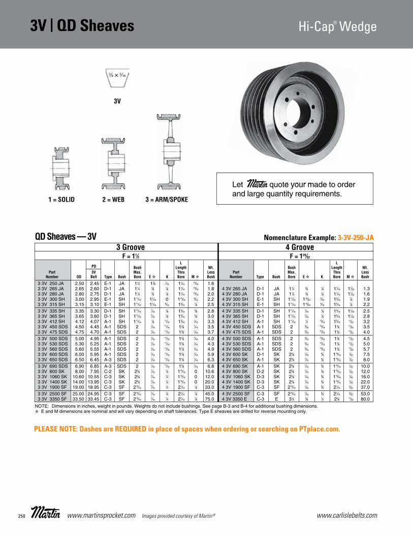
www.carlislebelts.com250 www.martinsprocket.com Images provided courtesy of Martin®
3V | QD Sheaves Hi-Cap® Wedge 3V
D-4
Hi-Cap Wedge StockQD Sheaves
3 3V 250 JA 2.50 2.45 E-1 JA 11⁄4 13⁄8 7⁄16 11⁄16 15⁄16 1.6 3 3V 265 JA 2.65 2.60 D-1 JA 11⁄4 3⁄8 1⁄8 11⁄16 13⁄16 1.8 4 3V 265 JA D-1 JA 11⁄4 3⁄8 1⁄8 11⁄16 17⁄32 1.33 3V 280 JA 2.80 2.75 D-1 JA 11⁄4 3⁄8 1⁄8 11⁄16 13⁄16 2.0 4 3V 280 JA D-1 JA 11⁄4 3⁄8 1⁄8 11⁄16 17⁄32 1.63 3V 300 SH 3.00 2.95 E-1 SH 111⁄16 11⁄16 0 115⁄16 9⁄16 2.2 4 3V 300 SH E-1 SH 111⁄16 115⁄32 5⁄16 15⁄16 7⁄8 1.93 3V 315 SH 3.15 3.10 E-1 SH 111⁄16 11⁄16 5⁄16 15⁄16 7⁄8 2.5 4 3V 315 SH E-1 SH 111⁄16 115⁄32 5⁄16 15⁄16 7⁄8 2.23 3V 335 SH 3.35 3.30 D-1 SH 111⁄16 7⁄16 1⁄8 15⁄16 5⁄8 2.8 4 3V 335 SH D-1 SH 111⁄16 7⁄16 1⁄8 15⁄16 11⁄32 2.53 3V 365 SH 3.65 3.60 D-1 SH 111⁄16 7⁄16 1⁄8 15⁄16 5⁄8 3.0 4 3V 365 SH D-1 SH 111⁄16 7⁄16 1⁄8 15⁄16 11⁄32 2.83 3V 412 SH 4.12 4.07 A-1 SH 111⁄16 1⁄8 11⁄16 15⁄16 1⁄16 3.3 4 3V 412 SH A-1 SH 111⁄16 1⁄4 13⁄16 15⁄16 11⁄32 3.23 3V 450 SDS 4.50 4.45 A-1 SDS 2 1⁄16 11⁄16 13⁄8 1⁄16 3.5 4 3V 450 SDS A-1 SDS 2 3⁄16 13⁄16 13⁄8 11⁄32 3.53 3V 475 SDS 4.75 4.70 A-1 SDS 2 1⁄16 11⁄16 13⁄8 1⁄16 3.7 4 3V 475 SDS A-1 SDS 2 3⁄16 13⁄16 13⁄8 11⁄32 4.03 3V 500 SDS 5.00 4.95 A-1 SDS 2 1⁄16 11⁄16 13⁄8 1⁄16 4.0 4 3V 500 SDS A-1 SDS 2 3⁄16 13⁄16 13⁄8 11⁄32 4.53 3V 530 SDS 5.30 5.25 A-1 SDS 2 1⁄16 11⁄16 13⁄8 1⁄16 4.3 4 3V 530 SDS A-1 SDS 2 3⁄16 13⁄16 13⁄8 11⁄32 5.03 3V 560 SDS 5.60 5.55 A-1 SDS 2 1⁄16 11⁄16 13⁄8 1⁄16 4.9 4 3V 560 SDS A-1 SDS 2 3⁄16 13⁄16 13⁄8 11⁄32 5.73 3V 600 SDS 6.00 5.95 A-1 SDS 2 1⁄16 11⁄16 13⁄8 1⁄16 5.9 4 3V 600 SK D-1 SK 25⁄8 1⁄16 5⁄8 115⁄16 1⁄32 7.53 3V 650 SDS 6.50 6.45 A-3 SDS 2 1⁄16 11⁄16 13⁄8 1⁄16 6.3 4 3V 650 SK A-1 SK 25⁄8 1⁄16 5⁄8 115⁄16 1⁄32 8.03 3V 690 SDS 6.90 6.85 A-3 SDS 2 1⁄16 11⁄16 13⁄8 1⁄16 6.8 4 3V 690 SK A-1 SK 25⁄8 1⁄16 5⁄8 115⁄16 1⁄32 10.03 3V 800 SK 8.00 7.95 C-2 SK 25⁄8 7⁄16 1⁄4 115⁄16 0 10.6 4 3V 800 SK D-2 SK 25⁄8 1⁄16 5⁄8 115⁄16 1⁄32 12.03 3V 1060 SK 10.60 10.55 C-3 SK 25⁄8 7⁄16 1⁄4 115⁄16 0 12.0 4 3V 1060 SK D-3 SK 25⁄8 1⁄16 5⁄8 115⁄16 1⁄32 16.03 3V 1400 SK 14.00 13.95 C-3 SK 25⁄8 7⁄16 1⁄4 115⁄16 0 20.0 4 3V 1400 SK D-3 SK 25⁄8 1⁄16 5⁄8 115⁄16 1⁄32 22.03 3V 1900 SF 19.00 18.95 C-3 SF 215⁄16 7⁄16 1⁄4 21⁄16 1⁄8 33.0 4 3V 1900 SF C-3 SF 215⁄16 1⁄16 5⁄8 21⁄16 3⁄32 37.03 3V 2500 SF 25.00 24.95 C-3 SF 215⁄16 7⁄16 1⁄4 21⁄16 1⁄8 45.0 4 3V 2500 SF C-3 SF 215⁄16 1⁄16 5⁄8 21⁄16 3⁄32 53.03 3V 3350 SF 33.50 33.45 C-3 SF 215⁄16 7⁄16 1⁄4 21⁄16 1⁄8 75.0 4 3V 3350 E C-3 E 31⁄2 3⁄8 1⁄2 25⁄8 11⁄32 80.0
1 = SOLID 2 = WEB 3 = ARM/SPOKE
3 Groove 4 Groove F = 11⁄2 F = 129⁄32
L L PD Bush Length Wt. Bush Length Wt. Part 3V Max. Thru Less Part Max. Thru Less Number OD Belt Type Bush Bore E K Bore M Bush Number Type Bush Bore E K Bore M Bush
3V
Let Martin quote your made to orderand large quantity requirements.
QD Sheaves — 3V
3⁄8 × 5⁄16
NOTE: Dimensions in inches, weight in pounds. Weights do not include bushings. See page B-3 and B-4 for additional bushing dimensions. E and M dimensions are nominal and will vary depending on shaft tolerances. Type E sheaves are drilled for reverse mounting only.
Section D-ELF-2015-1-32.qxp_Section D 5/5/15 3:02 PM Page D-4
Nomenclature Example: 3-3V-250-JA
PLEASE NOTE: Dashes are REQUIRED in place of spaces when ordering or searching on PTplace.com.

251www.carlislebelts.com Images provided courtesy of Martin® www.martinsprocket.com
3V | QD Sheaves Hi-Cap® Wedge Hi-Cap® Wedge QD Sheaves | 3V
V-Be
lt |
QD
Shea
ves
3V
D-5
Hi-Cap Wedge StockQD Sheaves
8 3V 475 SK 4.75 4.70 D-1 SK 25⁄8 9⁄16 1⁄8 115⁄16 25⁄32 6.0 10 3V 475 SK D-1 SK 25⁄8 9⁄16 1⁄8 115⁄16 231⁄32 7.08 3V 500 SK 5.00 4.95 D-1 SK 25⁄8 9⁄16 1⁄8 115⁄16 25⁄32 6.9 10 3V 500 SK D-1 SK 25⁄8 9⁄16 1⁄8 115⁄16 231⁄32 8.68 3V 530 SK 5.30 5.25 A-1 SK 25⁄8 5⁄8 15⁄16 115⁄16 31⁄32 7.8 10 3V 530 SK A-1 SK 25⁄8 3⁄4 17⁄16 115⁄16 121⁄32 9.08 3V 560 SK 5.60 5.55 A-1 SK 25⁄8 5⁄8 15⁄16 115⁄16 31⁄32 9.0 10 3V 560 SK A-1 SK 25⁄8 3⁄4 17⁄16 115⁄16 121⁄32 10.08 3V 600 SK 6.00 5.95 A-1 SK 25⁄8 5⁄8 15⁄16 115⁄16 31⁄32 10.0 10 3V 600 SK A-1 SK 25⁄8 3⁄4 17⁄16 115⁄16 121⁄32 11.08 3V 650 SK 6.50 6.45 A-2 SK 25⁄8 5⁄8 15⁄16 115⁄16 31⁄32 12.9 10 3V 650 SK A-2 SK 25⁄8 3⁄4 17⁄16 115⁄16 121⁄32 14.08 3V 690 SK 6.90 6.85 A-2 SK 25⁄8 5⁄8 15⁄16 115⁄16 31⁄32 14.0 10 3V 690 SK A-2 SK 25⁄8 3⁄4 17⁄16 115⁄16 121⁄32 16.08 3V 800 SF 8.00 7.95 A-1 SF 215⁄16 7⁄16 11⁄8 21⁄16 11⁄32 20.0 10 3V 800 SF A-1 SF 215⁄16 13⁄16 11⁄2 21⁄16 115⁄32 22.08 3V 1060 SF 10.60 10.55 A-2 SF 215⁄16 7⁄16 11⁄8 21⁄16 11⁄32 28.0 10 3V 1060 E A-2 E 31⁄2 3⁄8 11⁄4 25⁄8 111⁄32 33.08 3V 1400 E 14.00 13.95 A-3 E 31⁄2 3⁄8 11⁄4 25⁄8 17⁄32 40.0 10 3V 1400 E A-3 E 31⁄2 3⁄8 11⁄4 25⁄8 111⁄32 43.08 3V 1900 E 19.00 18.95 A-3 E 31⁄2 3⁄8 11⁄4 25⁄8 17⁄32 62.0 10 3V 1900 E A-3 E 31⁄2 3⁄8 11⁄4 25⁄8 111⁄32 66.08 3V 2500 E 25.00 24.95 A-3 E 31⁄2 3⁄8 11⁄4 25⁄8 17⁄32 87.0 10 3V 2500 F A-3 F 315⁄16 5⁄16 15⁄16 35⁄8 13⁄32 98.08 3V 3350 F 33.50 33.45 B-3 F 315⁄16 1⁄16 11⁄16 35⁄8 5⁄32 152.0 10 3V 3350 F A-3 F 315⁄16 5⁄16 15⁄16 35⁄8 13⁄32 178.0
5 3V 475 SDS 4.75 4.70 A-2 SDS 2 3⁄16 13⁄16 13⁄8 3⁄4 4.5 6 3V 475 SK D-1 SK 25⁄8 9⁄16 1⁄8 115⁄16 111⁄32 6.05 3V 500 SDS 5.00 4.95 A-2 SDS 2 3⁄16 13⁄16 13⁄8 3⁄4 5.3 6 3V 500 SK D-1 SK 25⁄8 9⁄16 1⁄8 115⁄16 111⁄32 6.55 3V 530 SK 5.30 5.25 A-1 SK 25⁄8 1⁄4 15⁄16 115⁄16 1⁄8 5.8 6 3V 530 SK A-1 SK 25⁄8 5⁄8 15⁄16 115⁄16 5⁄32 6.85 3V 560 SK 5.60 5.55 A-1 SK 25⁄8 1⁄4 15⁄16 115⁄16 1⁄8 7.0 6 3V 560 SK A-1 SK 25⁄8 5⁄8 15⁄16 115⁄16 5⁄32 8.05 3V 600 SK 6.00 5.95 A-1 SK 25⁄8 1⁄4 15⁄16 115⁄16 1⁄8 8.3 6 3V 600 SK A-1 SK 25⁄8 5⁄8 15⁄16 115⁄16 5⁄32 9.05 3V 650 SK 6.50 6.45 A-1 SK 25⁄8 1⁄4 15⁄16 115⁄16 1⁄8 9.0 6 3V 650 SK A-2 SK 25⁄8 5⁄8 15⁄16 115⁄16 5⁄32 10.05 3V 690 SK 6.90 6.85 A-1 SK 25⁄8 1⁄4 15⁄16 115⁄16 1⁄8 12.0 6 3V 690 SK A-2 SK 25⁄8 5⁄8 15⁄16 115⁄16 5⁄32 11.55 3V 800 SK 8.00 7.95 A-2 SK 25⁄8 1⁄4 15⁄16 115⁄16 1⁄8 13.0 6 3V 800 SK A-2 SK 25⁄8 3⁄16 7⁄8 115⁄16 19⁄32 17.05 3V 1060 SK 10.60 10.55 A-3 SK 25⁄8 1⁄4 15⁄16 115⁄16 1⁄8 17.0 6 3V 1060 SF A-2 SF 215⁄16 3⁄16 7⁄8 21⁄16 15⁄32 25.05 3V 1400 SF 14.00 13.95 A-3 SK 215⁄16 3⁄16 7⁄8 21⁄16 1⁄16 27.0 6 3V 1400 SF A-3 SF 215⁄16 3⁄16 7⁄8 21⁄16 15⁄32 34.05 3V 1900 SF 19.00 18.95 A-3 SK 215⁄16 3⁄16 7⁄8 21⁄16 1⁄16 40.0 6 3V 1900 E B-3 E 31⁄2 1⁄8 1 25⁄8 1⁄32 45.05 3V 2500 E 25.00 24.95 C-3 E 31⁄2 1⁄4 5⁄8 25⁄8 1⁄16 69.0 6 3V 2500 E B-3 E 31⁄2 1⁄8 1 25⁄8 1⁄32 75.05 3V 3350 E 33.50 33.45 C-3 E 31⁄2 1⁄4 5⁄8 25⁄8 1⁄16 97.0 6 3V 3350 E B-3 E 31⁄2 1⁄8 1 25⁄8 1⁄32 98.0
5 Groove 6 Groove F = 25⁄16 F = 223⁄32
L L PD Bush Length Wt. Bush Length Wt. Part 3V Max. Thru Less Part Max. Thru Less Number OD Belt Type Bush Bore E K Bore M Bush Number Type Bush Bore E K Bore M Bush
8 Groove 10 Groove F = 317⁄32 F = 411⁄32
L L PD Bush Length Wt. Bush Length Wt. Part 3V Max. Thru Less Part Max. Thru Less Number OD Belt Type Bush Bore E K Bore M Bush Number Type Bush Bore E K Bore M Bush
QD Sheaves — 3V
QD Sheaves — 3V
TYPE A TYPE B TYPE C TYPE D TYPE E
P.D.
O.D.
P.D.
O.D.
P.D.
O.D.
P.D.
O.D.
P.D.
O.D.
NOTE: Dimensions in inches, weight in pounds. Weights do not include bushings. See page B-3 and B-4 for additional bushing dimensions. E and M dimensions are nominal and will vary depending on shaft tolerances. Type E sheaves are drilled for reverse mounting only.
NOTE: Dimensions in inches, weight in pounds. Weights do not include bushings. See page B-3 and B-4 for additional bushing dimensions. E and M dimensions are nominal and will vary depending on shaft tolerances. Type E sheaves are drilled for reverse mounting only.
Section D-ELF-2015-1-32.qxp_Section D 5/5/15 3:02 PM Page D-5
Nomenclature Example: 5-3V-475-SDS
Nomenclature Example: 8-3V-475-SK
PLEASE NOTE: Dashes are REQUIRED in place of spaces when ordering or searching on PTplace.com.

www.carlislebelts.com252 www.martinsprocket.com Images provided courtesy of Martin®
5V | QD Sheaves Hi-Cap® Wedge 5V
D-6
Hi-Cap Wedge StockQD Sheaves
2 5V 440 SH 4.40 4.30 A-1 SH 111⁄16 5⁄16 7⁄8 15⁄16 1⁄16 4.0 3 5V 440 SDS E-1 SDS 2 15⁄8 0 13⁄8 5⁄8 5.52 5V 465 SDS 4.65 4.55 E-1 SDS 2 15⁄16 0 13⁄8 5⁄8 4.5 3 5V 465 SDS E-1 SDS 2 15⁄8 0 13⁄8 5⁄8 6.52 5V 490 SDS 4.90 4.80 A-1 SDS 2 1⁄16 11⁄16 13⁄8 1⁄4 5.0 3 5V 490 SDS A-1 SDS 2 7⁄16 11⁄16 13⁄8 9⁄16 7.02 5V 520 SDS 5.20 5.10 A-1 SDS 2 1⁄16 11⁄16 13⁄8 1⁄4 5.5 3 5V 520 SDS A-1 SDS 2 7⁄16 11⁄16 13⁄8 9⁄16 7.52 5V 550 SDS 5.50 5.40 A-1 SDS 2 1⁄16 11⁄16 13⁄8 1⁄4 6.0 3 5V 550 SDS A-1 SDS 2 7⁄16 11⁄16 13⁄8 9⁄16 8.02 5V 590 SDS 5.90 5.80 A-1 SDS 2 1⁄16 11⁄16 13⁄8 1⁄4 7.0 3 5V 590 SDS A-1 SDS 2 7⁄16 11⁄16 13⁄8 9⁄16 8.52 5V 630 SK 6.30 6.20 C-1 SK 25⁄8 1⁄4 7⁄16 115⁄16 0 8.0 3 5V 630 SK A-1 SK 25⁄8 3⁄8 11⁄16 115⁄16 1⁄16 11.02 5V 670 SK 6.70 6.60 C-1 SK 25⁄8 1⁄4 7⁄16 115⁄16 0 10.0 3 5V 670 SK A-1 SK 25⁄8 3⁄8 11⁄16 115⁄16 1⁄16 11.52 5V 710 SK 7.10 7.00 C-1 SK 25⁄8 1⁄4 7⁄16 115⁄16 0 11.0 3 5V 710 SF A-1 SF 215⁄16 5⁄16 1 21⁄16 0 13.02 5V 750 SK 7.50 7.40 C-1 SK 25⁄8 1⁄4 7⁄16 115⁄16 0 13.0 3 5V 750 SF A-1 SF 215⁄16 5⁄16 1 21⁄16 0 14.02 5V 800 SK 8.00 7.90 C-1 SK 25⁄8 1⁄4 7⁄16 115⁄16 0 14.0 3 5V 800 SF A-1 SF 215⁄16 5⁄16 1 21⁄16 0 15.02 5V 850 SK 8.50 8.40 C-1 SK 25⁄8 1⁄4 7⁄16 115⁄16 0 15.0 3 5V 850 SF A-1 SF 215⁄16 5⁄16 1 21⁄16 0 16.02 5V 900 SK 9.00 8.90 C-2 SK 25⁄8 1⁄4 7⁄16 115⁄16 0 16.0 3 5V 900 SF A-2 SF 215⁄16 5⁄16 1 21⁄16 0 17.02 5V 925 SK 9.25 9.15 C-2 SK 25⁄8 1⁄4 7⁄16 115⁄16 0 16.5 3 5V 925 SF A-2 SF 215⁄16 5⁄16 1 21⁄16 0 18.02 5V 975 SK 9.75 9.65 C-3 SK 25⁄8 1⁄4 7⁄16 115⁄16 0 17.0 3 5V 975 SF A-2 SF 215⁄16 5⁄16 1 21⁄16 0 19.02 5V 1030 SK 10.30 10.20 C-3 SK 25⁄8 1⁄4 7⁄16 115⁄16 0 18.0 3 5V 1030 SF A-2 SF 215⁄16 5⁄16 1 21⁄16 0 22.02 5V 1090 SK 10.90 10.80 C-3 SK 25⁄8 1⁄4 7⁄16 115⁄16 0 19.0 3 5V 1090 SF A-2 SF 215⁄16 5⁄16 1 21⁄16 0 25.02 5V 1130 SK 11.30 11.20 C-3 SK 25⁄8 1⁄4 7⁄16 115⁄16 0 19.5 3 5V 1130 SF A-2 SF 215⁄16 5⁄16 1 21⁄16 0 25.02 5V 1180 SK 11.80 11.70 C-3 SK 25⁄8 1⁄4 7⁄16 115⁄16 0 20.0 3 5V 1180 SF A-2 SF 215⁄16 5⁄16 1 21⁄16 0 29.02 5V 1250 SF 12.50 12.40 C-3 SF 215⁄16 1⁄4 7⁄16 21⁄16 1⁄8 25.0 3 5V 1250 E C-2 E 31⁄2 1⁄8 3⁄4 25⁄8 1⁄8 32.02 5V 1320 SF 13.20 13.10 C-3 SF 215⁄16 1⁄4 7⁄16 21⁄16 1⁄8 27.0 3 5V 1320 E C-3 E 31⁄2 1⁄8 3⁄4 25⁄8 1⁄8 38.02 5V 1400 SF 14.00 13.90 C-3 SF 215⁄16 1⁄4 7⁄16 21⁄16 1⁄8 28.0 3 5V 1400 E C-3 E 31⁄2 1⁄8 3⁄4 25⁄8 1⁄8 43.02 5V 1500 SF 15.00 14.90 C-3 SF 215⁄16 1⁄4 7⁄16 21⁄16 1⁄8 30.0 3 5V 1500 E C-3 E 31⁄2 1⁄8 3⁄4 25⁄8 1⁄8 44.02 5V 1600 SF 16.00 15.90 C-3 SF 215⁄16 1⁄4 7⁄16 21⁄16 1⁄8 34.0 3 5V 1600 E C-3 E 31⁄2 1⁄8 3⁄4 25⁄8 1⁄8 46.02 5V 1870 SF 18.70 18.60 C-3 SF 215⁄16 1⁄4 7⁄16 21⁄16 1⁄8 49.0 3 5V 1870 E C-3 E 31⁄2 1⁄8 3⁄4 25⁄8 1⁄8 60.02 5V 2120 SF 21.20 21.10 C-3 SF 215⁄16 1⁄4 7⁄16 21⁄16 1⁄8 50.0 3 5V 2120 E C-3 E 31⁄2 1⁄8 3⁄4 25⁄8 1⁄8 68.02 5V 2360 E 23.60 23.50 C-3 E 31⁄2 5⁄8 1⁄4 25⁄8 5⁄16 72.0 3 5V 2360 E C-3 E 31⁄2 1⁄8 3⁄4 25⁄8 1⁄8 80.02 5V 2800 E 28.00 27.90 C-3 E 31⁄2 5⁄8 1⁄4 25⁄8 5⁄16 80.0 3 5V 2800 E C-3 E 31⁄2 1⁄8 3⁄4 25⁄8 1⁄8 92.0
31.50 31.40 3 5V 3150 F C-3 F 315⁄16 7⁄16 9⁄16 35⁄8 13⁄16 136.0 37.50 37.40 3 5V 3750 F C-3 F 315⁄16 7⁄16 9⁄16 35⁄8 13⁄16 156.0 50.00 49.90 3 5V 5000 F C-3 F 315⁄16 7⁄16 9⁄16 35⁄8 13⁄16 210.0
2 Groove 3 Groove F = 111/16 F = 23⁄8 L L PD Bush Length Wt. Bush Length Wt. Part 5V Max. Thru Less Part Max. Thru Less Number OD Belt Type Bush Bore E K Bore M Bush Number Type Bush Bore E K Bore M Bush
5V 1 = SOLID 2 = WEB 3 = ARM/SPOKE
QD Sheaves — 5V
5⁄8 × 17⁄32
NOTE: Dimensions in inches, weight in pounds. Weights do not include bushings. See page B-3 and B-4 for additional bushing dimensions. E and M dimensions are nominal and will vary depending on shaft tolerances. Type E sheaves are drilled for reverse mounting only.
Section D-ELF-2015-1-32.qxp_Section D 5/5/15 3:02 PM Page D-6
Nomenclature Example: 2-5V-440-SH
PLEASE NOTE: Dashes are REQUIRED in place of spaces when ordering or searching on PTplace.com.

253www.carlislebelts.com Images provided courtesy of Martin® www.martinsprocket.com
V-Be
lt |
QD
Shea
ves
5V | QD Sheaves Hi-Cap® Wedge Hi-Cap® Wedge QD Sheaves | 5V5V
D-7
Hi-Cap Wedge StockQD Sheaves
4 5V 440 SD 4.40 4.30 E-1 SD 2 17⁄8 0 113⁄16 5⁄8 5.0 5 5V 440 SD E-1 SD 2 29⁄16 0 113⁄16 5⁄8 6.04 5V 465 SD 4.65 4.55 E-1 SD 2 17⁄8 0 113⁄16 5⁄8 6.0 5 5V 465 SD E-1 SD 2 29⁄16 15⁄16 113⁄16 5⁄8 7.04 5V 490 SD 4.90 4.80 A-1 SD 2 11⁄16 15⁄16 113⁄16 9⁄16 7.0 5 5V 490 SD A-1 SD 2 11⁄16 15⁄16 113⁄16 11⁄4 8.04 5V 520 SD 5.20 5.10 A-1 SD 2 11⁄16 15⁄16 113⁄16 9⁄16 8.0 5 5V 520 SD A-1 SD 2 11⁄16 15⁄16 113⁄16 11⁄4 9.04 5V 550 SD 5.50 5.40 A-1 SD 2 11⁄16 15⁄16 113⁄16 9⁄16 9.0 5 5V 550 SD A-1 SD 2 11⁄16 15⁄16 113⁄16 11⁄4 10.04 5V 590 SD 5.90 5.80 A-1 SD 2 11⁄16 15⁄16 113⁄16 9⁄16 10.8 5 5V 590 SK A-1 SK 25⁄8 5⁄8 15⁄16 115⁄16 13⁄16 11.04 5V 630 SK 6.30 6.20 A-1 SK 25⁄8 5⁄8 15⁄16 115⁄16 1⁄2 12.0 5 5V 630 SK A-1 SK 25⁄8 5⁄8 15⁄16 115⁄16 13⁄16 12.04 5V 670 SK 6.70 6.60 A-1 SK 25⁄8 5⁄8 15⁄16 115⁄16 1⁄2 14.0 5 5V 670 SF A-1 SF 215⁄16 5⁄8 15⁄16 21⁄16 11⁄16 13.04 5V 710 SF 7.10 7.00 A-1 SF 215⁄16 3⁄8 11⁄16 21⁄16 5⁄8 15.0 5 5V 710 SF A-1 SF 215⁄16 11⁄16 13⁄8 21⁄16 1 14.04 5V 750 SF 7.50 7.40 A-1 SF 215⁄16 3⁄8 11⁄16 21⁄16 5⁄8 16.0 5 5V 750 SF A-1 SF 215⁄16 11⁄16 13⁄8 21⁄16 1 16.04 5V 800 E 8.00 7.90 B-1 E 31⁄2 9⁄16 17⁄16 25⁄8 1⁄8 19.0 5 5V 800 E A-1 E 31⁄2 7⁄8 13⁄4 25⁄8 1⁄4 19.04 5V 850 E 8.50 8.40 B-1 E 31⁄2 9⁄16 17⁄16 25⁄8 1⁄8 23.0 5 5V 850 E A-1 E 31⁄2 7⁄8 13⁄4 25⁄8 1⁄4 22.04 5V 900 E 9.00 8.90 B-1 E 31⁄2 9⁄16 17⁄16 25⁄8 1⁄8 25.0 5 5V 900 E A-1 E 31⁄2 7⁄8 13⁄4 25⁄8 1⁄4 26.04 5V 925 E 9.25 9.15 B-1 E 31⁄2 9⁄16 17⁄16 25⁄8 1⁄8 26.0 5 5V 925 E A-1 E 31⁄2 7⁄8 13⁄4 25⁄8 1⁄4 28.04 5V 975 E 9.75 9.65 B-1 E 31⁄2 9⁄16 17⁄16 25⁄8 1⁄8 28.0 5 5V 975 E A-1 E 31⁄2 7⁄8 13⁄4 25⁄8 1⁄4 30.04 5V 1030 E 10.30 10.20 B-1 E 31⁄2 9⁄16 17⁄16 25⁄8 1⁄8 30.0 5 5V 1030 E A-1 E 31⁄2 7⁄8 13⁄4 25⁄8 1⁄4 33.04 5V 1090 E 10.90 10.80 B-2 E 31⁄2 9⁄16 17⁄16 25⁄8 1⁄8 39.0 5 5V 1090 E A-1 E 31⁄2 7⁄8 13⁄4 25⁄8 1⁄4 41.04 5V 1130 E 11.30 11.20 B-2 E 31⁄2 9⁄16 17⁄16 25⁄8 1⁄8 40.0 5 5V 1130 E A-1 E 31⁄2 7⁄8 13⁄4 25⁄8 1⁄4 42.04 5V 1180 E 11.80 11.70 B-2 E 31⁄2 9⁄16 17⁄16 25⁄8 1⁄8 41.0 5 5V 1180 E A-1 E 31⁄2 7⁄8 13⁄4 25⁄8 1⁄4 44.04 5V 1250 E 12.50 12.40 B-3 E 31⁄2 9⁄16 17⁄16 25⁄8 1⁄8 43.0 5 5V 1250 E A-3 E 31⁄2 7⁄8 13⁄4 25⁄8 1⁄4 45.04 5V 1320 E 13.20 13.10 B-3 E 31⁄2 9⁄16 17⁄16 25⁄8 1⁄8 45.0 5 5V 1320 E A-3 E 31⁄2 7⁄8 13⁄4 25⁄8 1⁄4 46.04 5V 1400 E 14.00 13.90 B-3 E 31⁄2 9⁄16 17⁄16 25⁄8 1⁄8 46.0 5 5V 1400 E A-3 E 31⁄2 7⁄8 13⁄4 25⁄8 1⁄4 47.04 5V 1500 E 15.00 14.90 B-3 E 31⁄2 9⁄16 17⁄16 25⁄8 1⁄8 47.0 5 5V 1500 E A-3 E 31⁄2 7⁄8 13⁄4 25⁄8 1⁄4 53.04 5V 1600 E 16.00 15.90 B-3 E 31⁄2 9⁄16 17⁄16 25⁄8 1⁄8 49.0 5 5V 1600 E A-3 E 31⁄2 7⁄8 13⁄4 25⁄8 1⁄4 56.04 5V 1870 E 18.70 18.60 A-3 E 31⁄2 3⁄8 11⁄4 25⁄8 1⁄16 71.0 5 5V 1870 F B-3 F 315⁄16 5⁄16 15⁄16 35⁄8 3⁄16 96.04 5V 2120 E 21.20 21.10 A-3 E 31⁄2 3⁄8 11⁄4 25⁄8 1⁄16 72.0 5 5V 2120 F B-3 F 315⁄16 5⁄16 15⁄16 35⁄8 3⁄16 98.04 5V 2360 F 23.60 23.50 C-3 F 315⁄16 1⁄8 7⁄8 35⁄8 7⁄16 111.0 5 5V 2360 F B-3 F 315⁄16 5⁄16 15⁄16 35⁄8 3⁄16 120.04 5V 2800 F 28.00 27.90 C-3 F 315⁄16 1⁄8 7⁄8 35⁄8 7⁄16 118.0 5 5V 2800 F B-3 F 315⁄16 5⁄16 15⁄16 35⁄8 3⁄16 135.04 5V 3150 F 31.50 31.40 C-3 F 315⁄16 1⁄8 7⁄8 35⁄8 7⁄16 146.7 5 5V 3150 J C-3 J 41⁄2 3⁄16 1 41⁄2 9⁄16 188.04 5V 3750 F 37.50 37.40 C-3 F 315⁄16 1⁄8 7⁄8 35⁄8 7⁄16 178.0 5 5V 3750 J C-3 J 41⁄2 3⁄16 1 41⁄2 9⁄16 224.04 5V 5000 J 50.00 49.90 C-3 J 41⁄2 1⁄2 11⁄16 41⁄2 15⁄16 266.0 5 5V 5000 J C-3 J 41⁄2 3⁄16 1 41⁄2 9⁄16 308.0
4 Groove 5 Groove F = 31⁄16 F = 33⁄4 L L PD Bush Length Wt. Bush Length Wt. Part 5V Max. Thru Less Part Max. Thru Less Number OD Belt Type Bush Bore E K Bore M Bush Number Type Bush Bore E K Bore M Bush
QD Sheaves — 5V
TYPE A TYPE B TYPE C TYPE D TYPE E
P.D.
O.D.
P.D.
O.D.
P.D.
O.D.
P.D.
O.D.
P.D.
O.D.
NOTE: Dimensions in inches, weight in pounds. Weights do not include bushings. See page B-3 and B-4 for additional bushing dimensions. E and M dimensions are nominal and will vary depending on shaft tolerances. Type E sheaves are drilled for reverse mounting only.
Section D-ELF-2015-1-32.qxp_Section D 5/5/15 3:02 PM Page D-7
Nomenclature Example: 4-5V-440-SD
PLEASE NOTE: Dashes are REQUIRED in place of spaces when ordering or searching on PTplace.com.

www.carlislebelts.com254 www.martinsprocket.com Images provided courtesy of Martin®
5V | QD Sheaves Hi-Cap® Wedge 5V
D-8
Hi-Cap Wedge StockQD Sheaves
6 5V 440 SD 4.40 4.30 E-1 SD 2 31⁄4 0 113⁄16 5⁄8 7.06 5V 465 SD 4.65 4.55 E-1 SD 2 31⁄4 0 113⁄16 5⁄8 7.86 5V 490 SD 4.90 4.80 A-1 SD 2 11⁄16 15⁄16 113⁄16 115⁄16 9.06 5V 520 SD 5.20 5.10 A-1 SD 2 11⁄16 15⁄16 113⁄16 115⁄16 10.86 5V 550 SD 5.50 5.40 A-1 SD 2 11⁄16 15⁄16 113⁄16 115⁄16 11.36 5V 590 SK 5.90 5.80 A-1 SK 25⁄8 5⁄8 15⁄16 115⁄16 17⁄8 12.06 5V 630 SK 6.30 6.20 A-1 SK 25⁄8 5⁄8 15⁄16 115⁄16 17⁄8 13.06 5V 670 SF 6.70 6.60 A-1 SF 215⁄16 15⁄16 15⁄8 21⁄16 17⁄16 14.06 5V 710 SF 7.10 7.00 A-1 SF 215⁄16 15⁄16 15⁄8 21⁄16 17⁄16 15.0 7 5V 710 SF A-1 SF 215⁄16
15⁄16 15⁄8 21⁄16 21⁄8 17.0 6 5V 750 SF 7.50 7.40 A-1 SF 215⁄16 15⁄16 15⁄8 21⁄16 17⁄16 17.0 7 5V 750 SF A-1 SF 215⁄16 15⁄16 15⁄8 21⁄16 21⁄8 19.06 5V 800 E 8.00 7.90 A-1 E 31⁄2 11⁄8 2 25⁄8 11⁄16 20.0 7 5V 800 E A-1 E 31⁄2 11⁄8 2 25⁄8 13⁄8 22.06 5V 850 E 8.50 8.40 A-1 E 31⁄2 11⁄8 2 25⁄8 11⁄16 25.0 7 5V 850 E A-1 E 31⁄2 11⁄8 2 25⁄8 13⁄8 26.06 5V 900 E 9.00 8.90 A-1 E 31⁄2 11⁄8 2 25⁄8 11⁄16 28.0 7 5V 900 E A-1 E 31⁄2 11⁄8 2 25⁄8 13⁄8 29.06 5V 925 E 9.25 9.15 A-1 E 31⁄2 11⁄8 2 25⁄8 11⁄16 29.0 7 5V 925 E A-1 E 31⁄2 11⁄8 2 25⁄8 13⁄8 33.06 5V 975 E 9.75 9.65 A-1 E 31⁄2 11⁄8 2 25⁄8 11⁄16 31.0 7 5V 975 E A-1 E 31⁄2 11⁄8 2 25⁄8 13⁄8 37.06 5V 1030 E 10.30 10.20 A-1 E 31⁄2 11⁄8 2 25⁄8 11⁄16 33.0 7 5V 1030 F B-1 F 315⁄16 15⁄8 29⁄16 35⁄8
1⁄8 49.06 5V 1090 E 10.90 10.80 A-1 E 31⁄2 11⁄8 2 25⁄8 11⁄16 38.0 7 5V 1090 F B-1 F 315⁄16 15⁄8 29⁄16 35⁄8
1⁄8 56.06 5V 1130 E 11.30 11.20 A-1 E 31⁄2 11⁄8 2 25⁄8 11⁄16 41.0 7 5V 1130 F B-1 F 315⁄16 15⁄8 29⁄16 35⁄8
1⁄8 61.06 5V 1180 E 11.80 11.70 A-1 E 31⁄2 11⁄8 2 25⁄8 11⁄16 43.0 7 5V 1180 F B-2 F 315⁄16 15⁄8 29⁄16 35⁄8
1⁄8 56.06 5V 1250 F 12.50 12.40 B-3 F 315⁄16 11⁄16 21⁄16 35⁄8 1⁄4 45.0 7 5V 1250 F B-3 F 315⁄16 15⁄8 29⁄16 35⁄8
1⁄8 53.06 5V 1320 F 13.20 13.10 B-3 F 315⁄16 11⁄16 21⁄16 35⁄8 1⁄4 48.0 7 5V 1320 F B-3 F 315⁄16 15⁄8 29⁄16 35⁄8
1⁄8 52.06 5V 1400 F 14.00 13.90 B-3 F 315⁄16 11⁄16 21⁄16 35⁄8 1⁄4 59.0 7 5V 1400 F B-3 F 315⁄16 15⁄8 29⁄16 35⁄8
1⁄8 62.06 5V 1500 F 15.00 14.90 B-3 F 315⁄16 11⁄16 21⁄16 35⁄8 1⁄4 64.0 7 5V 1500 F B-3 F 315⁄16 15⁄8 29⁄16 35⁄8
1⁄8 67.06 5V 1600 F 16.00 15.90 B-3 F 315⁄16 11⁄16 21⁄16 35⁄8 1⁄4 68.0 7 5V 1600 F B-3 F 315⁄16 15⁄8 29⁄16 35⁄8
1⁄8 77.06 5V 1870 F 18.70 18.60 A-3 F 315⁄16 5⁄16 15⁄16 35⁄8 1⁄2 83.8 7 5V 1870 F A-3 F 315⁄16 3⁄8 15⁄16 35⁄8 11⁄8 99.06 5V 2120 F 21.20 21.10 A-3 F 315⁄16 5⁄16 15⁄16 35⁄8 1⁄2 110.0 7 5V 2120 J C-3 J 41⁄2 3⁄16 15⁄16 41⁄2
7⁄16 138.06 5V 2360 J 23.60 23.50 B-3 J 41⁄2 1⁄8 15⁄16 41⁄2 3⁄16 148.0 7 5V 2360 J C-3 J 41⁄2 3⁄16 15⁄16 41⁄2
7⁄16 174.06 5V 2800 J 28.00 27.90 B-3 J 41⁄2 1⁄8 15⁄16 41⁄2 3⁄16 169.0 7 5V 2800 J C-3 J 41⁄2 3⁄16 15⁄16 41⁄2
7⁄16 169.06 5V 3150 J 31.50 31.40 B-3 J 41⁄2 1⁄8 15⁄16 41⁄2 3⁄16 206.0 7 5V 3150 J C-3 J 41⁄2 3⁄16 15⁄16 41⁄2
7⁄16 241.06 5V 3750 J 37.50 37.40 B-3 J 41⁄2 1⁄8 15⁄16 41⁄2 3⁄16 241.0 7 5V 3750 M C-3 M 51⁄2 9⁄16 115⁄16 63⁄4 23⁄16 300.06 5V 5000 M 50.00 49.90 C-3 M 51⁄2 1⁄8 1⁄2 63⁄4 13⁄8 388.0 7 5V 5000 M C-3 M 51⁄2 7⁄8
1⁄2 63⁄4 3⁄4 408.0
6 Groove 7 Groove F = 47⁄16 F = 51⁄8 L L PD Bush Length Wt. Bush Length Wt. Part 5V Max. Thru Less Part Max. Thru Less Number OD Belt Type Bush Bore E K Bore M Bush Number Type Bush Bore E K Bore M Bush
QD Sheaves — 5V 5V 1 = SOLID 2 = WEB 3 = ARM/SPOKE
5⁄8 × 17⁄32
TYPE A TYPE B TYPE C TYPE D TYPE E
P.D.
O.D.
P.D.
O.D.
P.D.
O.D.
P.D.
O.D.
NOTE: Dimensions in inches, weight in pounds. Weights do not include bushings. See page B-3 and B-4 for additional bushing dimensions. E and M dimensions are nominal and will vary depending on shaft tolerances. Type E sheaves are drilled for reverse mounting only.
Section D-ELF-2015-1-32.qxp_Section D 5/5/15 3:02 PM Page D-8
PLEASE NOTE: Dashes are REQUIRED in place of spaces when ordering or searching on PTplace.com.
Nomenclature Example: 6-5V-440-SD

255www.carlislebelts.com Images provided courtesy of Martin® www.martinsprocket.com
V-Be
lt |
QD
Shea
ves
5V | QD Sheaves Hi-Cap® Wedge Hi-Cap® Wedge QD Sheaves | 5V
10 5V 800 E 8.00 7.90 A-1 E 31⁄2 23⁄8 31⁄4 25⁄8 23⁄16 27.010 5V 850 E 8.50 8.40 A-1 E 31⁄2 23⁄8 31⁄4 25⁄8 23⁄16 32.010 5V 900 F 9.00 8.90 A-1 F 315⁄16 25⁄16 35⁄16 35⁄8 11⁄4 41.0105V 925 F 9.25 9.15 A-1 F 315⁄16 25⁄16 35⁄16 35⁄8 11⁄4 47.010 5V 975 F 9.75 9.65 A-1 F 315⁄16 25⁄16 35⁄16 35⁄8 11⁄4 58.010 5V 1030 F 10.30 10.20 A-1 F 315⁄16 25⁄16 35⁄16 35⁄8 11⁄4 66.010 5V 1090 F 10.90 10.80 A-1 F 315⁄16 25⁄16 35⁄16 35⁄8 11⁄4 75.010 5V 1130 F 11.30 11.20 A-1 F 315⁄16 25⁄16 35⁄16 35⁄8 11⁄4 79.010 5V 1180 F 11.80 11.70 A-1 F 315⁄16 25⁄16 35⁄16 35⁄8 11⁄4 80.010 5V 1250 J 12.50 12.40 A-1 J 41⁄2 23⁄8 39⁄16 41⁄2 5⁄16 82.010 5V 1320 J 13.20 13.10 A-1 J 41⁄2 23⁄8 39⁄16 41⁄2 5⁄16 85.010 5V 1400 J 14.00 13.90 A-1 J 41⁄2 23⁄8 39⁄16 41⁄2 5⁄16 90.010 5V 1500 J 15.00 14.90 A-2 J 41⁄2 23⁄8 39⁄16 41⁄2 5⁄16 92.010 5V 1600 J 16.00 15.90 A-1 J 41⁄2 23⁄8 39⁄16 41⁄2 5⁄16 102.010 5V 1870 J 18.70 18.60 A-3 J 41⁄2 3⁄8 19⁄16 41⁄2 23⁄16 150.010 5V 2120 J 21.20 21.10 A-3 J 41⁄2 3⁄8 19⁄16 41⁄2 23⁄16 164.010 5V 2360 M 23.60 23.50 B-3 M 51⁄2 1⁄2 115⁄16 63⁄4 1⁄16 258.010 5V 2800 M 28.00 27.90 B-3 M 51⁄2 1⁄2 115⁄16 63⁄4 1⁄16 278.010 5V 3150 M 31.50 31.40 B-3 M 51⁄2 1⁄2 115⁄16 63⁄4 1⁄16 318.010 5V 3750 M 37.50 37.40 B-3 M 51⁄2 1⁄2 115⁄16 63⁄4 1⁄16 340.010 5V 5000 M 50.00 49.90 B-3 M 51⁄2 1⁄2 115⁄16 63⁄4 1⁄16 538.0
10 Groove F = 73⁄16
LPD Bush Length Wt.
Part 5V Max. Thru LessNumber OD Belt Type Bush Bore E K Bore M Bush
8 5V 710 SF 7.10 7.00 A-1 SF 215⁄16 17⁄16 21⁄8 21⁄16 25⁄16 19.08 5V 750 SF 7.50 7.40 A-1 SF 215⁄16 17⁄16 21⁄8 21⁄16 25⁄16 20.08 5V 800 E 8.00 7.90 A-1 E 31⁄2 15⁄8 21⁄2 25⁄8 19⁄16 25.0 9 5V 800 E A-1 E 31⁄2 15⁄8 21⁄2 25⁄8 21⁄4 26.08 5V 850 E 8.50 8.40 A-1 E 31⁄2 15⁄8 21⁄2 25⁄8 19⁄16 29.0 9 5V 850 E A-1 E 31⁄2 15⁄8 21⁄2 25⁄8 21⁄4 30.08 5V 900 E 9.00 8.90 A-1 E 31⁄2 15⁄8 21⁄2 25⁄8 19⁄16 32.0 9 5V 900 E A-1 E 31⁄2 15⁄8 21⁄2 25⁄8 21⁄4 33.0
8 5V 925 F 9.25 9.15 A-1 F 31⁄2 19⁄16 29⁄16 35⁄8 5⁄8 39.0 9 5V 925 F A-1 F 315⁄16 15⁄8 29⁄16 35⁄8 11⁄4 33.08 5V 975 F 9.75 9.65 A-1 F 315⁄16 19⁄16 29⁄16 35⁄8 5⁄8 42.0 9 5V 975 F A-1 F 315⁄16 15⁄8 29⁄16 35⁄8 11⁄4 45.08 5V 1030 F 10.30 10.20 A-1 F 315⁄16 19⁄16 29⁄16 35⁄8 5⁄8 52.0 9 5V 1030 F A-1 F 315⁄16 15⁄8 29⁄16 35⁄8 11⁄4 54.08 5V 1090 F 10.90 10.80 A-1 F 315⁄16 19⁄16 29⁄16 35⁄8 5⁄8 59.0 9 5V 1090 F A-1 F 315⁄16 15⁄8 29⁄16 35⁄8 11⁄4 62.08 5V 1130 F 11.30 11.20 A-1 F 315⁄16 19⁄16 29⁄16 35⁄8 5⁄8 62.0 9 5V 1130 F A-1 F 315⁄16 15⁄8 29⁄16 35⁄8 11⁄4 67.0
8 5V 1180 F 11.80 11.70 A-1 F 315⁄16 19⁄16 29⁄16 35⁄8 5⁄8 64.0 9 5V 1180 F A-1 F 315⁄16 15⁄8 29⁄16 35⁄8 11⁄4 73.08 5V 1250 F 12.50 12.40 A-3 F 315⁄16 19⁄16 29⁄16 35⁄8 5⁄8 66.0 9 5V 1250 F A-3 F 315⁄16 15⁄8 29⁄16 35⁄8 11⁄4 61.08 5V 1320 F 13.20 13.10 A-3 F 315⁄16 19⁄16 29⁄16 35⁄8 5⁄8 68.0 9 5V 1320 F A-3 F 315⁄16 15⁄8 29⁄16 35⁄8 11⁄4 60.08 5V 1400 F 14.00 13.90 A-3 F 315⁄16 19⁄16 29⁄16 35⁄8 5⁄8 70.0 9 5V 1400 F A-3 F 315⁄16 15⁄8 29⁄16 35⁄8 11⁄4 70.08 5V 1500 F 15.00 14.90 A-3 F 315⁄16 19⁄16 29⁄16 35⁄8 5⁄8 73.0 9 5V 1500 J B-2 J 41⁄2 27⁄16 39⁄16 41⁄2 7⁄16 95.0
8 5V 1600 F 16.00 15.90 A-3 F 315⁄16 19⁄16 19⁄16 35⁄8 5⁄8 89.0 9 5V 1600 J B-2 J 41⁄2 27⁄16 39⁄16 41⁄2 7⁄16 103.08 5V 1870 J 18.70 18.60 A-3 J 41⁄2 3⁄8 19⁄16 41⁄2 15⁄16 132.0 9 5V 1870 J A-3 J 41⁄2 7⁄16 19⁄16 41⁄2 19⁄16 140.08 5V 2120 J 21.20 21.10 A-3 J 41⁄2 3⁄8 19⁄16 41⁄2 15⁄16 150.0 9 5V 2120 J A-3 J 41⁄2 7⁄16 19⁄16 41⁄2 19⁄16 152.08 5V 2360 J 23.60 23.50 A-3 J 41⁄2 3⁄8 19⁄16 41⁄2 15⁄16 162.0 9 5V 2360 J A-3 J 41⁄2 7⁄16 19⁄16 41⁄2 19⁄16 176.08 5V 2800 J 28.00 27.90 A-3 J 41⁄2 3⁄8 19⁄16 41⁄2 15⁄16 191.0 9 5V 2800 M B-3 M 51⁄2 9⁄16 115⁄16 63⁄4 13⁄16 265.0
8 5V 3150 M 31.50 31.40 B-3 M 51⁄2 1⁄2 115⁄16 63⁄4 17⁄16 298.0 9 5V 3150 M B-3 M 51⁄2 9⁄16 115⁄16 63⁄4 13⁄16 313.08 5V 3750 M 37.50 37.40 B-3 M 51⁄2 1⁄2 115⁄16 63⁄4 17⁄16 319.0 9 5V 3750 M B-3 M 51⁄2 9⁄16 115⁄16 63⁄4 13⁄16 409.08 5V 5000 M 50.00 49.90 B-3 M 51⁄2 1⁄2 115⁄16 63⁄4 17⁄16 497.0 9 5V 5000 M B-3 M 51⁄2 9⁄16 115⁄16 63⁄4 13⁄16 483.0
8 Groove 9 Groove F = 513⁄16 F = 61⁄2 PD Bush L Wt. Bush L Wt. Part 5V Max. Length Less Part Max. Length Less Number OD Belt Type Bush Bore E K Thru Bore M Bush Number Type Bush Bore E K Thru Bore M Bush
5V
D-9
Hi-Cap Wedge StockQD Sheaves
QD Sheaves — 5V
QD Sheaves — 5V
NOTE: Dimensions in inches, weight in pounds. Weights do not include bushings. See page B-3 and B-4 for additional bushing dimensions. E and M dimensions are nominal and will vary depending on shaft tolerances. Type E sheaves are drilled for reverse mounting only.
NOTE: Dimensions in inches, weight in pounds. Weights do not include bushings. See page B-3 and B-4 for additional bushing dimensions.
E and M dimensions are nominal and will vary depending on shaft tolerances. Type E sheaves are drilled for reverse mounting only.
Section D-ELF-2015-1-32.qxp_Section D 5/5/15 3:02 PM Page D-9
Nomenclature Example: 10-5V-800-EPLEASE NOTE: Dashes are REQUIRED in place of spaces when ordering or searching on PTplace.com.

www.carlislebelts.com256 www.martinsprocket.com Images provided courtesy of Martin®
8V
D-10
Hi-Cap Wedge StockQD Sheaves
6 8V 1250 F 12.50 12.30 A-1 F 315⁄16 15⁄16 25⁄16 35⁄8 23⁄16 86.0 8 8V 1250 J A-1 J 41⁄2 23⁄8 39⁄16 41⁄2 21⁄2 108.06 8V 1320 F 13.20 13.00 A-1 F 315⁄16 15⁄16 25⁄16 35⁄8 23⁄16 94.0 8 8V 1320 J A-1 J 41⁄2 23⁄8 39⁄16 41⁄2 21⁄2 118.06 8V 1400 F 14.00 13.80 A-1 F 315⁄16 15⁄16 25⁄16 35⁄8 23⁄16 108.0 8 8V 1400 J A-1 J 41⁄2 23⁄8 39⁄16 41⁄2 21⁄2 131.06 8V 1500 J 15.00 14.80 A-1 J 41⁄2 13⁄8 29⁄16 41⁄2 11⁄4 138.0 8 8V 1500 J A-1 J 41⁄2 23⁄8 39⁄16 41⁄2 21⁄2 151.06 8V 1600 J 16.00 15.80 A-1 J 41⁄2 13⁄8 29⁄16 41⁄2 11⁄4 142.0 8 8V 1600 J A-1 J 41⁄2 23⁄8 39⁄16 41⁄2 21⁄2 155.06 8V 1700 J 17.00 16.80 A-2 J 41⁄2 13⁄8 29⁄16 41⁄2 11⁄4 144.0 8 8V 1700 M A-2 M 51⁄2 21⁄2 315⁄16 63⁄4 1⁄8 188.06 8V 1800 J 18.00 17.80 A-2 J 41⁄2 13⁄8 29⁄16 41⁄2 11⁄4 160.0 8 8V 1800 M A-2 M 51⁄2 21⁄2 315⁄16 63⁄4 1⁄8 202.06 8V 1900 J 19.00 18.80 A-2 J 41⁄2 13⁄8 29⁄16 41⁄2 11⁄4 172.0 8 8V 1900 M A-2 M 51⁄2 21⁄2 315⁄16 63⁄4 1⁄8 221.06 8V 2000 M 20.00 19.80 B-2 M 51⁄2 11⁄2 215⁄16 63⁄4 11⁄8 204.0 8 8V 2000 M A-2 M 51⁄2 21⁄2 315⁄16 63⁄4 1⁄8 236.06 8V 2120 M 21.20 21.00 B-2 M 51⁄2 11⁄2 215⁄16 63⁄4 11⁄8 226.0 8 8V 2120 M A-2 M 51⁄2 21⁄2 315⁄16 63⁄4 1⁄8 267.06 8V 2240 M 22.40 22.20 B-3 M 51⁄2 11⁄2 215⁄16 63⁄4 11⁄8 235.0 8 8V 2240 M A-3 M 51⁄2 21⁄2 315⁄16 63⁄4 1⁄8 284.06 8V 2480 M 24.80 24.60 B-3 M 51⁄2 1⁄2 115⁄16 63⁄4 1⁄8 246.0 8 8V 2480 N A-2 N 6 1⁄2 21⁄4 81⁄8 3⁄4 418.06 8V 3000 M 30.00 29.80 B-3 M 6 1⁄2 115⁄16 63⁄4 1⁄8 306.0 8 8V 3000 N A-3 N 6 1⁄2 21⁄4 81⁄8 3⁄4 447.06 8V 3550 N 35.50 35.30 C-3 N 6 5⁄8 11⁄8 81⁄8 3⁄8 466.0 8 8V 3550 N A-3 N 6 1⁄2 21⁄4 81⁄8 3⁄4 553.06 8V 4000 N 40.00 39.80 C-3 N 6 5⁄8 11⁄8 81⁄8 3⁄8 548.0 8 8V 4000 N A-3 N 6 1⁄2 21⁄4 81⁄8 3⁄4 648.06 8V 4450 N 44.50 44.30 C-3 N 6 5⁄8 11⁄8 81⁄8 3⁄8 590.0 8 8V 4450 P B-3 P 63⁄4 5⁄8 25⁄8 93⁄8 5⁄8 679.06 8V 5300 N 53.00 52.80 C-3 N 6 5⁄8 11⁄8 81⁄8 3⁄8 658.0 8 8V 5300 P B-3 P 63⁄4 5⁄8 25⁄8 93⁄8 5⁄8 946.06 8V 6300 P 63.00 62.80 C-3 P 63⁄4 0 2 93⁄8 17⁄8 860.0 8 8V 6300 P B-3 P 63⁄4 5⁄8 25⁄8 93⁄8 1⁄4 1372.06 8V 7100 P 71.00 70.80 B-3 P 63⁄4 0 2 93⁄8 17⁄8 1272.0 8 8V 7100 W C-3 W 81⁄2 7⁄8 13⁄8 113⁄8 3⁄4 1680.0
4 8V 1250 F 12.50 12.30 A-1 F 315⁄16 3⁄16 13⁄16 35⁄8 11⁄16 63.0 5 8V 1250 F A-1 F 315⁄16 15⁄16 25⁄16 35⁄8 11⁄16 68.04 8V 1320 F 13.20 13.00 A-2 F 315⁄16 3⁄16 13⁄16 35⁄8 11⁄16 66.0 5 8V 1320 F A-2 F 315⁄16 15⁄16 25⁄16 35⁄8 11⁄16 75.04 8V 1400 F 14.00 13.80 A-2 F 315⁄16 3⁄16 13⁄16 35⁄8 11⁄16 70.0 5 8V 1400 F A-2 F 315⁄16 15⁄16 25⁄16 35⁄8 11⁄16 78.04 8V 1500 F 15.00 14.80 A-2 F 315⁄16 3⁄16 13⁄16 35⁄8 11⁄16 74.0 5 8V 1500 F A-2 F 315⁄16 15⁄16 25⁄16 35⁄8 11⁄16 94.04 8V 1600 F 16.00 15.80 A-2 F 315⁄16 3⁄16 13⁄16 35⁄8 11⁄16 82.0 5 8V 1600 F A-2 F 315⁄16 15⁄16 25⁄16 35⁄8 11⁄16 101.04 8V 1700 F 17.00 16.80 A-3 F 315⁄16 3⁄16 13⁄16 35⁄8 11⁄16 94.0 5 8V 1700 J A-3 J 41⁄2 13⁄16 2 41⁄2 11⁄16 111.04 8V 1800 F 18.00 17.80 A-3 F 315⁄16 3⁄16 13⁄16 35⁄8 11⁄16 99.0 5 8V 1800 J A-3 J 41⁄2 13⁄16 2 41⁄2 11⁄16 130.04 8V 1900 F 19.00 18.80 A-3 F 315⁄16 3⁄16 13⁄16 35⁄8 11⁄16 105.0 5 8V 1900 J A-3 J 41⁄2 13⁄16 2 41⁄2 11⁄16 135.04 8V 2000 J 20.00 19.80 A-3 J 41⁄2 1⁄4 17⁄16 41⁄2 1⁄8 141.0 5 8V 2000 J A-3 J 41⁄2 13⁄16 2 41⁄2 11⁄16 152.04 8V 2120 J 21.20 21.00 A-3 J 41⁄2 1⁄4 17⁄16 41⁄2 1⁄8 150.0 5 8V 2120 J A-3 J 41⁄2 13⁄16 2 41⁄2 11⁄16 153.04 8V 2240 J 22.40 22.20 A-3 J 41⁄2 1⁄4 17⁄16 41⁄2 1⁄8 177.0 5 8V 2240 M B-3 M 51⁄2 1⁄2 115⁄16 63⁄4 11⁄4 223.04 8V 2480 M 24.80 24.60 C-3 M 51⁄2 5⁄8 13⁄16 63⁄4 11⁄4 223.0 5 8V 2480 M B-3 M 51⁄2 1⁄2 115⁄16 63⁄4 11⁄4 234.04 8V 3000 M 30.00 29.80 C-3 M 51⁄2 5⁄8 13⁄16 63⁄4 11⁄4 285.0 5 8V 3000 M B-3 M 51⁄2 1⁄2 115⁄16 63⁄4 11⁄4 294.04 8V 3550 M 35.50 35.30 C-3 M 51⁄2 5⁄8 13⁄16 63⁄4 11⁄4 305.0 5 8V 3550 M B-3 M 51⁄2 1⁄2 115⁄16 63⁄4 11⁄4 325.04 8V 4000 M 40.00 39.80 C-3 M 51⁄2 5⁄8 13⁄16 63⁄4 11⁄4 355.0 5 8V 4000 M B-3 M 51⁄2 1⁄2 115⁄16 63⁄4 11⁄4 430.04 8V 4450 M 44.50 44.30 C-3 M 51⁄2 5⁄8 13⁄16 63⁄4 11⁄4 369.0 5 8V 4450 N C-3 N 6 13⁄16 15⁄16 81⁄8 15⁄16 485.04 8V 5300 M 53.00 52.80 C-3 M 51⁄2 3⁄8 13⁄16 63⁄4 11⁄4 478.0 5 8V 5300 N C-3 N 6 13⁄16 15⁄16 81⁄8 15⁄16 672.0
4 Groove 5 Groove F = 47⁄8 F = 6 L L PD Bush Length Wt. Bush Length Wt. Part 8V Max. Thru Less Part Max. Thru Less Number OD Belt Type Bush Bore E K Bore M Bush Number Type Bush Bore E K Bore M Bush
6 Groove 8 Groove F = 71⁄8 F = 93⁄8 L L PD Bush Length Wt. Bush Length Wt. Part 8V Max. Thru Less Part Max. Thru Less Number OD Belt Type Bush Bore E K Bore M Bush Number Type Bush Bore E K Bore M Bush
QD Sheaves — 8V
QD Sheaves — 8V
NOTE: Dimensions in inches, weight in pounds. Weights do not include bushings. See page B-3 and B-4 for additional bushing dimensions. E and M dimensions are nominal and will vary depending on shaft tolerances. Type E sheaves are drilled for reverse mounting only.
NOTE: Dimensions in inches, weight in pounds. Weights do not include bushings. See page B-3 and B-4 for additional bushing dimensions. E and M dimensions are nominal and will vary depending on shaft tolerances. Type E sheaves are drilled for reverse mounting only.
Section D-ELF-2015-1-32.qxp_Section D 5/5/15 3:02 PM Page D-10
8V | QD Sheaves Hi-Cap® Wedge
PLEASE NOTE: Dashes are REQUIRED in place of spaces when ordering or searching on PTplace.com.
Nomenclature Example: 4-8V-1250-F
Nomenclature Example: 6-8V-1250-F

257www.carlislebelts.com Images provided courtesy of Martin® www.martinsprocket.com
V-Be
lt |
QD
Shea
ves
8V | QD Sheaves Hi-Cap® Wedge Hi-Cap® Wedge QD Sheaves | 8V
10 8V 1250 J 12.50 12.30 A-1 J 41⁄2 23⁄8 39⁄16 41⁄2 43⁄4 122.0 12 8V 1250 M A-1 M 51⁄2 21⁄2 315⁄16 63⁄4 45⁄8 161.010 8V 1320 J 13.20 13.00 A-1 J 41⁄2 23⁄8 39⁄16 41⁄2 43⁄4 140.0 12 8V 1320 M A-1 M 51⁄2 21⁄2 315⁄16 63⁄4 45⁄8 185.010 8V 1400 J 14.00 13.80 A-1 J 41⁄2 23⁄8 39⁄16 41⁄2 43⁄4 152.0 12 8V 1400 M A-1 M 51⁄2 21⁄2 315⁄16 63⁄4 45⁄8 211.010 8V 1500 M 15.00 14.80 A-1 M 51⁄2 21⁄2 315⁄16 63⁄4 23⁄8 212.0 12 8V 1500 M A-1 M 51⁄2 21⁄2 315⁄16 63⁄4 45⁄8 234.010 8V 1600 M 16.00 15.80 A-1 M 51⁄2 21⁄2 315⁄16 63⁄4 23⁄8 219.0 12 8V 1600 M A-1 M 51⁄2 21⁄2 315⁄16 63⁄4 45⁄8 285.010 8V 1700 M 17.00 16.80 A-2 M 51⁄2 21⁄2 315⁄16 63⁄4 23⁄8 228.0 12 8V 1700 M A-1 M 51⁄2 21⁄2 315⁄16 63⁄4 45⁄8 324.010 8V 1800 M 18.00 17.80 A-2 M 51⁄2 21⁄2 315⁄16 63⁄4 23⁄8 236.0 12 8V 1800 M A-2 M 51⁄2 21⁄2 315⁄16 63⁄4 45⁄8 330.010 8V 1900 M 19.00 18.80 A-2 M 51⁄2 21⁄2 315⁄16 63⁄4 23⁄8 260.0 12 8V 1900 N A-2 N 6 1⁄2 21⁄4 81⁄8 51⁄4 338.010 8V 2000 M 20.00 19.80 A-2 M 51⁄2 21⁄2 315⁄16 63⁄4 23⁄8 280.0 12 8V 2000 N A-2 N 6 1⁄2 21⁄4 81⁄8 51⁄4 365.010 8V 2120 M 21.20 21.00 A-2 M 51⁄2 21⁄2 315⁄16 63⁄4 23⁄8 298.0 12 8V 2120 N A-2 N 6 1⁄2 21⁄4 81⁄8 51⁄4 382.010 8V 2240 N 22.40 22.20 A-2 N 6 1⁄2 21⁄4 81⁄8 3 366.0 12 8V 2240 N A-2 N 6 1⁄2 21⁄4 81⁄8 51⁄4 399.010 8V 2480 N 24.80 24.60 A-2 N 6 1⁄2 21⁄4 81⁄8 3 454.0 12 8V 2480 N A-2 N 6 1⁄2 21⁄4 81⁄8 51⁄4 454.010 8V 3000 N 30.00 29.80 A-3 N 6 1⁄2 21⁄4 81⁄8 3 468.0 12 8V 3000 P A-3 P 63⁄4 5⁄8 25⁄8 93⁄8 37⁄8 605.010 8V 3550 P 35.50 35.30 A-3 P 63⁄4 5⁄8 25⁄8 93⁄8 15⁄8 784.0 12 8V 3550 P A-3 P 63⁄4 5⁄8 25⁄8 93⁄8 37⁄8 706.010 8V 4000 P 40.00 39.80 A-3 P 63⁄4 5⁄8 25⁄8 93⁄8 15⁄8 826.0 12 8V 4000 P A-3 P 63⁄4 5⁄8 25⁄8 93⁄8 37⁄8 766.010 8V 4450 P 44.50 44.30 A-3 P 63⁄4 5⁄8 25⁄8 93⁄8 15⁄8 996.0 12 8V 4450 P A-3 P 63⁄4 5⁄8 25⁄8 93⁄8 37⁄8 910.010 8V 5300 P 53.00 52.80 A-3 P 63⁄4 5⁄8 25⁄8 93⁄8 1⁄4 1010.0 12 8V 5300 W A-3 W 81⁄2 5⁄8 27⁄8 113⁄8 21⁄4 1333.010 8V 6300 W 63.00 62.80 A-3 W 81⁄2 5⁄8 27⁄8 113⁄8 0 1443.0 12 8V 6300 W A-3 W 81⁄2 5⁄8 27⁄8 113⁄8 21⁄4 1777.010 8V 7100 W 71.00 70.80 A-3 W 81⁄2 5⁄8 27⁄8 113⁄8 0 1842.0 12 8V 7100 W A-3 W 81⁄2 5⁄8 27⁄8 113⁄8 21⁄4 2002.0
10 Groove 12 Groove F = 115⁄8 F = 14 L L PD Bush Length Wt. Bush Length Wt. Part 8V Max. Thru Less Part Max. Thru Less Number OD Belt Type Bush Bore E K Bore M Bush Number Type Bush Bore E K Bore M Bush
8V
D-11
Hi-Cap Wedge StockQD Sheaves
TYPE A TYPE B TYPE C TYPE D TYPE E
1 = SOLID 2 = WEB 3 = ARM/SPOKE
QD Sheaves — 8V
P.D.
O.D.
P.D.
O.D.
P.D.
O.D.
P.D.
O.D.
P.D.
O.D.
NOTE: Dimensions in inches, weight in pounds. Weights do not include bushings. See page B-3 and B-4 for additional bushing dimensions. E and M dimensions are nominal and will vary depending on shaft tolerances. Type E sheaves are drilled for reverse mounting only.
Section D-ELF-2015-1-32.qxp_Section D 5/5/15 3:02 PM Page D-11
Nomenclature Example: 10-8V-1250-J
PLEASE NOTE: Dashes are REQUIRED in place of spaces when ordering or searching on PTplace.com.

www.carlislebelts.com258 www.martinsprocket.com Images provided courtesy of Martin®
A-B | QD Sheaves Combination Groove Conventional A-B
D-12
Combination Groove Conventional Stock QD Sheaves
1 B 34 SH 3.0 3.4 3.75 D-1 SH 111⁄16 9⁄16 0 15⁄16 1⁄8 1.4 2 B 34 SH E-1 SH 111⁄16 1 0 15⁄16 9⁄16 2.81 B 36 SH 3.2 3.6 3.95 D-1 SH 111⁄16 9⁄16 0 15⁄16 1⁄8 1.6 2 B 36 SH D-1 SH 111⁄16 3⁄8 3⁄16 15⁄16 13⁄16 2.81 B 38 SH 3.4 3.8 4.15 D-1 SH 111⁄16 9⁄16 0 15⁄16 1⁄8 1.2 2 B 38 SH D-1 SH 111⁄16 3⁄8 3⁄16 15⁄16 13⁄16 3.31 B 40 SH 3.6 4.0 4.35 C-1 SH 111⁄16 1⁄4 5⁄16 15⁄16 3⁄16 2.2 2 B 40 SH A-1 SH 111⁄16 1⁄8 11⁄16 15⁄16 5⁄16 3.41 B 42 SH 3.8 4.2 4.55 C-1 SH 111⁄16 1⁄4 5⁄16 15⁄16 3⁄16 6.9 2 B 42 SH A-1 SH 111⁄16 1⁄8 11⁄16 15⁄16 5⁄16 3.81 B 44 SH 4.0 4.4 4.75 C-1 SH 111⁄16 1⁄4 5⁄16 15⁄16 3⁄16 2.9 2 B 44 SH A-1 SH 111⁄16 1⁄8 11⁄16 15⁄16 5⁄16 4.61 B 46 SDS 4.2 4.6 4.95 C-1 SDS 2 5⁄16 5⁄16 13⁄8 3⁄16 2.6 2 B 46 SDS A-2 SDS 2 1⁄16 11⁄16 13⁄8 5⁄16 4.31 B 48 SDS 4.4 4.8 5.15 C-1 SDS 2 5⁄16 5⁄16 13⁄8 3⁄16 3.1 2 B 48 SDS A-2 SDS 2 1⁄16 11⁄16 13⁄8 5⁄16 4.81 B 50 SDS 4.6 5.0 5.35 C-1 SDS 2 5⁄16 5⁄16 13⁄8 3⁄16 3.5 2 B 50 SDS A-2 SDS 2 1⁄16 11⁄16 13⁄8 5⁄16 5.51 B 52 SDS 4.8 5.2 5.55 C-1 SDS 2 5⁄16 5⁄16 13⁄8 3⁄16 3.7 2 B 52 SDS A-2 SDS 2 1⁄16 11⁄16 13⁄8 5⁄16 5.81 B 54 SDS 5.0 5.4 5.75 C-1 SDS 2 5⁄16 5⁄16 13⁄8 3⁄16 4.0 2 B 54 SDS A-2 SDS 2 1⁄16 11⁄16 13⁄8 5⁄16 6.11 B 56 SDS 5.2 5.6 5.95 C-1 SDS 2 5⁄16 5⁄16 13⁄8 3⁄16 4.2 2 B 56 SDS A-2 SDS 2 1⁄16 11⁄16 13⁄8 5⁄16 6.61 B 58 SDS 5.4 5.8 6.15 C-1 SDS 2 5⁄16 5⁄16 13⁄8 3⁄16 4.5 2 B 58 SDS A-1 SDS 2 1⁄16 11⁄16 13⁄8 5⁄16 7.21 B 60 SDS 5.6 6.0 6.35 C-1 SDS 2 5⁄16 5⁄16 13⁄8 3⁄16 4.9 2 B 60 SDS A-2 SDS 2 1⁄16 11⁄16 13⁄8 5⁄16 7.61 B 62 SDS 5.8 6.2 6.55 C-2 SDS 2 5⁄16 5⁄16 13⁄8 3⁄16 5.5 2 B 62 SDS A-2 SDS 2 1⁄16 11⁄16 13⁄8 5⁄16 7.01 B 64 SDS 6.0 6.4 6.75 C-2 SDS 2 5⁄16 5⁄16 13⁄8 3⁄16 5.7 2 B 64 SDS A-2 SDS 2 1⁄16 11⁄16 13⁄8 5⁄16 7.01 B 66 SDS 6.2 6.6 6.95 C-2 SDS 2 5⁄16 5⁄16 13⁄8 3⁄16 5.9 2 B 66 SDS A-2 SDS 2 1⁄16 11⁄16 13⁄8 5⁄16 9.01 B 68 SDS 6.4 6.8 7.15 C-2 SDS 2 5⁄16 5⁄16 13⁄8 3⁄16 4.8 2 B 68 SDS A-2 SDS 2 1⁄16 11⁄16 13⁄8 5⁄16 9.21 B 70 SDS 6.6 7.0 7.35 C-2 SDS 2 1⁄2 1⁄8 13⁄8 1⁄8 5.8 2 B 70 SK D-2 SK 25⁄8 1⁄4 7⁄16 115⁄16 1⁄16 8.81 B 74 SDS 7.0 7.4 7.75 C-2 SDS 2 1⁄2 1⁄8 13⁄8 1⁄8 6.4 2 B 74 SK D-2 SK 25⁄8 1⁄4 7⁄16 115⁄16 1⁄16 11.01 B 80 SDS 7.6 8.0 8.35 C-3 SDS 2 1⁄2 1⁄8 13⁄8 1⁄8 6.8 2 B 80 SK D-2 SK 25⁄8 1⁄4 7⁄16 115⁄16 1⁄16 12.61 B 86 SDS 8.2 8.6 8.95 C-3 SDS 2 1⁄2 1⁄8 13⁄8 1⁄8 7.2 2 B 86 SK D-3 SK 25⁄8 1⁄4 7⁄16 115⁄16 1⁄16 12.01 B 94 SDS 9.0 9.4 9.75 C-3 SDS 2 1⁄2 1⁄8 13⁄8 1⁄8 8.0 2 B 94 SK D-3 SK 25⁄8 1⁄4 7⁄16 115⁄16 1⁄16 13.41 B 110 SDS 10.6 11.0 11.35 C-3 SDS 2 1⁄2 1⁄8 13⁄8 1⁄8 9.0 2 B 110 SK D-3 SK 25⁄8 1⁄4 7⁄16 115⁄16 1⁄16 16.41 B 124 SDS 12.0 12.4 12.75 C-3 SDS 2 1⁄2 1⁄8 13⁄8 1⁄8 11.0 2 B 124 SK D-3 SK 25⁄8 1⁄4 7⁄16 115⁄16 1⁄16 19.21 B 136 SDS 13.2 13.6 13.95 C-3 SDS 2 1⁄2 1⁄8 13⁄8 1⁄8 12.0 2 B 136 SK D-3 SK 25⁄8 1⁄4 7⁄16 115⁄16 1⁄16 19.01 B 154 SK 15.0 15.4 15.75 C-3 SK 25⁄8 9⁄16 1⁄8 115⁄16 3⁄8 13.0 2 B 154 SK D-3 SK 25⁄8 1⁄4 7⁄16 115⁄16 1⁄16 22.01 B 160 SK 15.6 16.0 16.35 C-3 SK 25⁄8 9⁄16 1⁄8 115⁄16 3⁄8 15.0 2 B 160 SK D-3 SK 25⁄8 1⁄4 7⁄16 115⁄16 1⁄16 26.01 B 184 SK 18.0 18.4 18.75 C-3 SK 25⁄8 9⁄16 1⁄8 115⁄16 3⁄8 19.0 2 B 184 SK D-3 SK 25⁄8 1⁄4 7⁄16 115⁄16 1⁄16 30.01 B 200 SK 19.6 20.0 20.35 C-3 SK 25⁄8 9⁄16 1⁄8 115⁄16 3⁄8 25.0 2 B 200 SF D-3 SF 215⁄16 5⁄16 3⁄8 21⁄16 0 35.0 24.6 25.0 25.35 2 B 250 SF D-3 SF 215⁄16 5⁄16 3⁄8 21⁄16 0 57.0 29.6 30.0 30.35 2 B 300 SF D-3 SF 215⁄16 5⁄16 3⁄8 21⁄16 0 80.0 37.6 38.0 38.35 2 B 380 SF D-3 SF 215⁄16 5⁄16 3⁄8 21⁄16 0 99.0
1 Groove 2 Groove F = 7⁄8 thru 1 B 64 SDS / F = 1 others F = 13⁄4 L L PD Bush Length Wt. Bush Length Wt. Part A B Max. Thru Less Part Max. Thru Less Number Belts Belts OD Type Bush Bore E K Bore M Bush Number Type Bush Bore E K Bore M Bush
QD Sheaves — A-B
Drawing shows position of “A” and “B”belts in groove when used with QD sheaves.
Combination Groove Dimensions Belt Section E S O.D.
“AB” 1⁄2 3⁄4 P.D. “B” + .35
A
1⁄2 × 5⁄16
21⁄32 × 13⁄32
O.D
.
P.D
. A B
ELT
P.D
. B B
ELT
B
NOTE: Dimensions in inches, weight in pounds. Weights do not include bushings. See page B-3 and B-4 for additional bushing dimensions. E and M dimensions are nominal and will vary depending on shaft tolerances. Type E sheaves are drilled for reverse mounting only.
Section D-ELF-2015-1-32.qxp_Section D 5/5/15 3:02 PM Page D-12
Nomenclature Example: 1-B-34-SH
PLEASE NOTE: Dashes are REQUIRED in place of spaces when ordering or searching on PTplace.com.

259www.carlislebelts.com Images provided courtesy of Martin® www.martinsprocket.com
A-B | QD Sheaves Combination Groove Conventional
V-Be
lt |
QD
Shea
ves
Combination Groove Conventional QD Sheaves | A-BA-B
D-13
Combination Groove Conventional Stock QD Sheaves
3 B 34 SH 3.0 3.4 3.75 E-1 SH 111⁄16 13⁄4 0 15⁄16 9⁄16 3.4 4 B 34 SD E-1 SD 2 23⁄8 5⁄16 113⁄16 15⁄16 4.03 B 36 SH 3.2 3.6 3.95 E-1 SH 111⁄16 3⁄8 3⁄16 15⁄16 19⁄16 3.8 4 B 36 SD E-1 SD 2 23⁄8 5⁄16 113⁄16 15⁄16 5.03 B 38 SH 3.4 3.8 4.15 E-1 SH 111⁄16 3⁄8 3⁄16 15⁄16 19⁄16 4.0 4 B 38 SD E-1 SD 2 23⁄8 5⁄16 113⁄16 15⁄16 5.53 B 40 SH 3.6 4.0 4.35 A-1 SH 111⁄16 1⁄2 11⁄16 15⁄16 11⁄16 4.5 4 B 40 SD E-1 SD 2 21⁄16 0 113⁄16 5⁄8 6.03 B 42 SH 3.8 4.2 4.55 A-1 SH 111⁄16 1⁄2 11⁄16 15⁄16 11⁄16 5.0 4 B 42 SD E-1 SD 2 21⁄16 0 113⁄16 5⁄8 7.03 B 44 SH 4.0 4.4 4.75 A-1 SH 111⁄16 1⁄2 11⁄16 15⁄16 11⁄16 5.5 4 B 44 SD E-1 SD 2 21⁄16 0 113⁄16 5⁄8 7.33 B 46 SD 4.2 4.6 4.95 A-1 SD 2 7⁄16 11⁄16 113⁄16 1⁄4 6.0 4 B 46 SD A-1 SD 2 11⁄16 15⁄16 113⁄16 3⁄4 7.63 B 48 SD 4.4 4.8 5.15 A-1 SD 2 7⁄16 11⁄16 113⁄16 1⁄4 6.5 4 B 48 SD A-1 SD 2 11⁄16 15⁄16 113⁄16 3⁄4 8.03 B 50 SD 4.6 5.0 5.35 A-1 SD 2 7⁄16 11⁄16 113⁄16 1⁄4 7.0 4 B 50 SD A-1 SD 2 11⁄16 15⁄16 113⁄16 3⁄4 9.03 B 52 SD 4.8 5.2 5.55 A-1 SD 2 7⁄16 11⁄16 113⁄16 1⁄4 8.0 4 B 52 SD A-1 SD 2 11⁄16 15⁄16 113⁄16 3⁄4 10.03 B 54 SD 5.0 5.4 5.75 A-1 SD 2 7⁄16 11⁄16 113⁄16 1⁄4 8.5 4 B 54 SD A-1 SD 2 11⁄16 15⁄16 113⁄16 3⁄4 10.53 B 56 SD 5.2 5.6 5.95 A-1 SD 2 7⁄16 11⁄16 113⁄16 1⁄4 9.0 4 B 56 SD A-1 SD 2 11⁄16 15⁄16 113⁄16 3⁄4 11.03 B 58 SD 5.4 5.8 6.15 A-1 SD 2 7⁄16 11⁄16 113⁄16 1⁄4 10.0 4 B 58 SD A-1 SD 2 11⁄16 15⁄16 113⁄16 3⁄4 12.03 B 60 SD 5.6 6.0 6.35 A-1 SD 2 7⁄16 11⁄16 113⁄16 1⁄4 11.0 4 B 60 SD A-1 SD 2 11⁄16 15⁄16 113⁄16 3⁄4 12.53 B 62 SD 5.8 6.2 6.55 A-1 SD 2 7⁄16 11⁄16 113⁄16 1⁄4 12.0 4 B 62 SD A-1 SD 2 11⁄16 15⁄16 113⁄16 3⁄4 13.03 B 64 SD 6.0 6.4 6.75 A-1 SD 2 7⁄16 11⁄16 113⁄16 1⁄4 12.3 4 B 64 SD A-1 SD 2 11⁄16 15⁄16 113⁄16 3⁄4 14.03 B 66 SD 6.2 6.6 6.95 A-1 SD 2 7⁄16 11⁄16 113⁄16 1⁄4 12.6 4 B 66 SD A-1 SD 2 11⁄16 15⁄16 113⁄16 3⁄4 14.53 B 68 SD 6.4 6.8 7.15 A-1 SD 2 7⁄16 11⁄16 113⁄16 1⁄4 13.0 4 B 68 SD A-1 SD 2 11⁄16 15⁄16 113⁄16 3⁄4 15.03 B 70 SK 6.6 7.0 7.35 A-1 SK 25⁄8 0 11⁄16 115⁄16 9⁄16 14.0 4 B 70 SK A-1 SK 25⁄8 5⁄16 1 115⁄16 1 15.53 B 74 SK 7.0 7.4 7.75 A-1 SK 25⁄8 0 11⁄16 115⁄16 9⁄16 15.0 4 B 74 SK A-1 SK 25⁄8 5⁄16 1 115⁄16 1 16.03 B 80 SK 7.6 8.0 8.35 A-1 SK 25⁄8 0 11⁄16 115⁄16 9⁄16 16.0 4 B 80 SK A-1 SK 25⁄8 5⁄16 1 115⁄16 1 17.03 B 86 SK 8.2 8.6 8.95 A-3 SK 25⁄8 0 11⁄16 115⁄16 9⁄16 17.0 4 B 86 SK A-3 SK 25⁄8 5⁄16 1 115⁄16 1 18.03 B 94 SK 9.0 9.4 9.75 A-3 SK 25⁄8 0 11⁄16 115⁄16 9⁄16 18.0 4 B 94 SK A-3 SK 25⁄8 5⁄16 1 115⁄16 1 19.03 B 110 SK 10.6 11.0 11.35 A-3 SK 25⁄8 0 11⁄16 115⁄16 9⁄16 19.0 4 B 110 SK A-3 SK 25⁄8 5⁄16 1 115⁄16 1 24.03 B 124 SK 12.0 12.4 12.75 A-3 SK 25⁄8 0 11⁄16 115⁄16 9⁄16 23.0 4 B 124 SK A-3 SK 25⁄8 5⁄16 1 115⁄16 1 26.03 B 136 SK 13.2 13.6 13.95 A-3 SK 25⁄8 0 11⁄16 115⁄16 9⁄16 24.1 4 B 136 SK A-3 SK 25⁄8 5⁄16 1 115⁄16 1 28.03 B 154 SK 15.0 15.4 15.75 A-3 SK 25⁄8 0 11⁄16 115⁄16 9⁄16 28.0 4 B 154 SF A-3 SF 215⁄16 5⁄16 1 21⁄16 7⁄8 41.03 B 160 SK 15.6 16.0 16.35 A-3 SK 25⁄8 0 11⁄16 115⁄16 9⁄16 29.0 4 B 160 SF A-3 SF 215⁄16 5⁄16 1 21⁄16 7⁄8 42.03 B 184 SK 18.0 18.4 18.75 A-3 SK 25⁄8 0 11⁄16 115⁄16 9⁄16 37.0 4 B 184 SF A-3 SF 215⁄16 5⁄16 1 21⁄16 7⁄8 48.03 B 200 SF 19.6 20.0 20.35 D-3 SF 215⁄16 1⁄16 5⁄8 21⁄16 1⁄2 39.0 4 B 200 SF A-3 SF 215⁄16 5⁄16 1 21⁄16 7⁄8 58.03 B 250 SF 24.6 25.0 25.35 D-3 SF 215⁄16 1⁄16 5⁄8 21⁄16 1⁄2 67.0 4 B 250 E A-3 E 31⁄2 1⁄8 1 25⁄8 1⁄2 78.03 B 300 SF 29.6 30.0 30.35 D-3 SF 215⁄16 1⁄16 5⁄8 21⁄16 1⁄2 74.0 4 B 300 E A-3 E 31⁄2 1⁄8 1 25⁄8 1⁄2 93.03 B 380 E 37.6 38.0 38.35 D-3 E 31⁄2 1⁄4 5⁄8 25⁄8 1⁄8 122.0 4 B 380 E A-3 E 31⁄2 1⁄8 1 25⁄8 1⁄2 138.0
QD Sheaves — A-B
TYPE A TYPE B TYPE C TYPE D TYPE E
P.D.
O.D.
P.D.
O.D.
P.D.
O.D.
P.D.
O.D.
P.D.
O.D.
3 Groove 4 Groove F = 21⁄2 F = 31⁄4 L L PD Bush Length Wt. Bush Length Wt. Part A B Max. Thru Less Part Max. Thru Less Number Belts Belts OD Type Bush Bore E K Bore M Bush Number Type Bush Bore E K Bore M Bush
NOTE: Dimensions in inches, weight in pounds. Weights do not include bushings. See page B-3 and B-4 for additional bushing dimensions. E and M dimensions are nominal and will vary depending on shaft tolerances. Type E sheaves are drilled for reverse mounting only.
Section D-ELF-2015-1-32.qxp_Section D 5/5/15 3:02 PM Page D-13
Nomenclature Example: 3-B-34-SH
PLEASE NOTE: Dashes are REQUIRED in place of spaces when ordering or searching on PTplace.com.

www.carlislebelts.com260 www.martinsprocket.com Images provided courtesy of Martin®
A-B | QD Sheaves Combination Groove Conventional A-B
D-14
Combination Groove Conventional Stock QD Sheaves
5 B 34 SD 3.0 3.4 3.75 E-1 SD 2 31⁄4 7⁄16 113⁄16 11⁄16 5.0 6 B 34 SD E-1 SD 2 37⁄8 5⁄16 113⁄16 15⁄16 6.05 B 36 SD 3.2 3.6 3.95 E-1 SD 2 31⁄4 7⁄16 113⁄16 11⁄16 6.0 6 B 36 SD E-1 SD 2 37⁄8 5⁄16 113⁄16 13⁄16 7.05 B 38 SD 3.4 3.8 4.15 E-1 SD 2 31⁄8 5⁄16 113⁄16 15⁄16 6.5 6 B 38 SD E-1 SD 2 37⁄8 5⁄16 113⁄16 13⁄16 7.55 B 40 SD 3.6 4.0 4.35 E-1 SD 2 213⁄16 0 113⁄16 5⁄8 7.0 6 B 40 SD E-1 SD 2 39⁄16 0 113⁄16 5⁄8 8.05 B 42 SD 3.8 4.2 4.55 E-1 SD 2 213⁄16 0 113⁄16 5⁄8 7.5 6 B 42 SD E-1 SD 2 39⁄16 0 113⁄16 5⁄8 9.05 B 44 SD 4.0 4.4 4.75 E-1 SD 2 213⁄16 0 113⁄16 5⁄8 8.0 6 B 44 SD E-1 SD 2 39⁄16 0 113⁄16 5⁄8 9.55 B 46 SD 4.2 4.6 4.95 A-1 SD 2 11⁄16 15⁄16 113⁄16 11⁄2 9.0 6 B 46 SD A-1 SD 2 9⁄16 13⁄16 113⁄16 23⁄8 10.05 B 48 SD 4.4 4.8 5.15 A-1 SD 2 11⁄16 15⁄16 113⁄16 11⁄2 9.5 6 B 48 SD A-1 SD 2 21⁄4 13⁄16 113⁄16 23⁄8 10.55 B 50 SD 4.6 5.0 5.35 A-1 SD 2 11⁄16 15⁄16 113⁄16 11⁄2 10.0 6 B 50 SD A-1 SD 2 21⁄4 13⁄16 113⁄16 23⁄8 11.05 B 52 SD 4.8 5.2 5.55 A-1 SD 2 11⁄16 15⁄16 113⁄16 11⁄2 10.5 6 B 52 SD A-1 SD 2 21⁄4 13⁄16 113⁄16 23⁄8 11.55 B 54 SK 5.0 5.4 5.75 A-1 SK 25⁄8 5⁄8 15⁄16 115⁄16 17⁄16 11.0 6 B 54 SK A-1 SK 25⁄8 5⁄8 15⁄16 115⁄16 23⁄16 12.05 B 56 SK 5.2 5.6 5.95 A-1 SK 25⁄8 5⁄8 15⁄16 115⁄16 17⁄16 11.5 6 B 56 SK A-1 SK 25⁄8 5⁄8 15⁄16 115⁄16 23⁄16 13.05 B 58 SK 5.4 5.8 6.15 A-1 SK 25⁄8 5⁄8 15⁄16 115⁄16 17⁄16 12.0 6 B 58 SK A-1 SK 25⁄8 5⁄8 15⁄16 115⁄16 23⁄16 14.05 B 60 SK 5.6 6.0 6.35 A-1 SK 25⁄8 5⁄8 15⁄16 115⁄16 17⁄16 13.0 6 B 60 SK A-1 SK 25⁄8 5⁄8 15⁄16 115⁄16 23⁄16 15.05 B 62 SK 5.8 6.2 6.55 A-1 SK 25⁄8 5⁄8 15⁄16 115⁄16 17⁄16 14.0 6 B 62 SK A-1 SK 25⁄8 5⁄8 15⁄16 115⁄16 23⁄16 16.05 B 64 SK 6.0 6.4 6.75 A-1 SK 25⁄8 5⁄8 15⁄16 115⁄16 17⁄16 15.0 6 B 64 SK A-1 SK 25⁄8 5⁄8 15⁄16 115⁄16 23⁄16 17.05 B 66 SK 6.2 6.6 6.95 A-1 SK 25⁄8 5⁄8 15⁄16 115⁄16 17⁄16 16.0 6 B 66 SK A-1 SK 25⁄8 5⁄8 15⁄16 115⁄16 23⁄16 18.05 B 68 SK 6.4 6.8 7.15 A-1 SK 25⁄8 5⁄8 15⁄16 115⁄16 17⁄16 17.0 6 B 68 SK A-1 SK 25⁄8 5⁄8 15⁄16 115⁄16 23⁄16 19.05 B 70 SF 6.6 7.0 7.35 A-1 SF 215⁄16 5⁄8 15⁄16 21⁄16 15⁄16 18.0 6 B 70 SF A-1 SF 215⁄16 1 111⁄16 21⁄16 111⁄16 19.55 B 74 SF 7.0 7.4 7.75 A-1 SF 215⁄16 5⁄8 15⁄16 21⁄16 15⁄16 20.0 6 B 74 SF A-1 SF 215⁄16 1 111⁄16 21⁄16 111⁄16 22.05 B 80 SF 7.6 8.0 8.35 A-1 SF 215⁄16 5⁄8 15⁄16 21⁄16 15⁄16 23.0 6 B 80 SF A-1 SF 215⁄16 1 111⁄16 21⁄16 111⁄16 25.05 B 86 SF 8.2 8.6 8.95 A-2 SF 215⁄16 5⁄8 15⁄16 21⁄16 15⁄16 24.0 6 B 86 SF A-2 SF 215⁄16 1 111⁄16 21⁄16 111⁄16 28.05 B 94 SF 9.0 9.4 9.75 A-2 SF 215⁄16 5⁄8 15⁄16 21⁄16 15⁄16 26.0 6 B 94 SF A-2 SF 215⁄16 1 111⁄16 21⁄16 111⁄16 29.05 B 110 SF 10.6 11.0 11.35 A-2 SF 215⁄16 5⁄8 15⁄16 21⁄16 15⁄16 32.0 6 B 110 SF A-2 SF 215⁄16 1 111⁄16 21⁄16 111⁄16 30.05 B 124 SF 12.0 12.4 12.75 A-3 SF 215⁄16 5⁄8 15⁄16 21⁄16 15⁄16 35.0 6 B 124 SF A-3 SF 215⁄16 1 111⁄16 21⁄16 111⁄16 40.05 B 136 SF 13.2 13.6 13.95 A-3 SF 215⁄16 5⁄8 15⁄16 21⁄16 15⁄16 36.0 6 B 136 SF A-3 SF 215⁄16 1 111⁄16 21⁄16 111⁄16 45.05 B 154 SF 15.0 15.4 15.75 A-3 SF 215⁄16 5⁄8 15⁄16 21⁄16 15⁄16 46.0 6 B 154 SF A-3 SF 215⁄16 1 111⁄16 21⁄16 111⁄16 46.05 B 160 SF 15.6 16.0 16.35 A-3 SF 215⁄16 5⁄8 15⁄16 21⁄16 15⁄16 48.0 6 B 160 SF A-3 SF 215⁄16 1 111⁄16 21⁄16 111⁄16 50.05 B 184 SF 18.0 18.4 18.75 A-3 SF 215⁄16 5⁄8 15⁄16 21⁄16 15⁄16 50.0 6 B 184 SF A-3 SF 215⁄16 1 111⁄16 21⁄16 111⁄16 60.05 B 200 E 19.6 20.0 20.35 A-3 E 31⁄2 3⁄8 11⁄4 25⁄8 1 72.0 6 B 200 E A-3 E 31⁄2 1⁄2 13⁄8 25⁄8 15⁄8 78.05 B 250 E 24.6 25.0 25.35 A-3 E 31⁄2 3⁄8 11⁄4 25⁄8 1 90.0 6 B 250 E A-3 E 31⁄2 1⁄2 13⁄8 25⁄8 15⁄8 98.05 B 300 E 29.6 30.0 30.35 A-3 E 31⁄2 3⁄8 11⁄4 25⁄8 1 108.0 6 B 300 E A-3 E 31⁄2 1⁄2 13⁄8 25⁄8 15⁄8 109.05 B 380 E 37.6 38.0 38.35 A-3 E 31⁄2 3⁄8 11⁄4 25⁄8 1 145.0 6 B 380 E A-3 E 31⁄2 1⁄2 13⁄8 25⁄8 15⁄8 173.0
5 Groove 6 Groove F = 4 F = 43⁄4 L L PD Bush Length Wt. Bush Length Wt. Part A B Max. Thru Less Part Max. Thru Less Number Belts Belts OD Type Bush Bore E K Bore M Bush Number Type Bush Bore E K Bore M Bush
QD Sheaves — A-B
A B 1 = SOLID 2 = WEB 3 = ARM/SPOKE
1⁄2 × 5⁄1621⁄32 × 13⁄32
NOTE: Dimensions in inches, weight in pounds. Weights do not include bushings. See page B-3 and B-4 for additional bushing dimensions. E and M dimensions are nominal and will vary depending on shaft tolerances. Type E sheaves are drilled for reverse mounting only.
Section D-ELF-2015-1-32.qxp_Section D 5/5/15 3:03 PM Page D-14
Nomenclature Example: 5-B-34-SD
PLEASE NOTE: Dashes are REQUIRED in place of spaces when ordering or searching on PTplace.com.
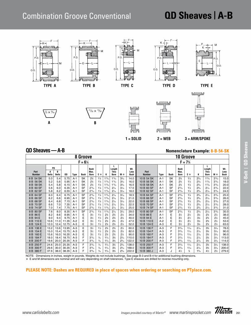
261www.carlislebelts.com Images provided courtesy of Martin® www.martinsprocket.com
A-B | QD Sheaves Combination Groove Conventional
V-Be
lt |
QD
Shea
ves
Combination Groove Conventional QD Sheaves | A-BA-B
D-15
Combination Groove Conventional Stock QD Sheaves
8 B 54 SK 5.0 5.4 5.75 A-1 SK 25⁄8 11⁄8 113⁄16 115⁄16 33⁄16 14.0 10 B 54 SK A-1 SK 25⁄8 17⁄8 29⁄16 115⁄16 315⁄16 15.08 B 56 SK 5.2 5.6 5.95 A-1 SK 25⁄8 11⁄8 113⁄16 115⁄16 33⁄16 16.0 10 B 56 SK A-1 SK 25⁄8 17⁄8 29⁄16 115⁄16 315⁄16 18.08 B 58 SK 5.4 5.8 6.15 A-1 SK 25⁄8 11⁄8 113⁄16 115⁄16 33⁄16 16.5 10 B 58 SK A-1 SK 25⁄8 17⁄8 29⁄16 115⁄16 315⁄16 20.08 B 60 SF 5.6 6.0 6.35 A-1 SF 215⁄16 11⁄8 113⁄16 21⁄16 31⁄16 17.0 10 B 60 SF A-1 SF 215⁄16 17⁄8 29⁄16 21⁄16 313⁄16 22.08 B 62 SF 5.8 6.2 6.55 A-1 SF 215⁄16 11⁄8 113⁄16 21⁄16 31⁄16 18.0 10 B 62 SF A-1 SF 215⁄16 17⁄8 29⁄16 21⁄16 313⁄16 24.08 B 64 SF 6.0 6.4 6.75 A-1 SF 215⁄16 11⁄8 113⁄16 21⁄16 31⁄16 18.5 10 B 64 SF A-1 SF 215⁄16 17⁄8 29⁄16 21⁄16 313⁄16 25.08 B 66 SF 6.2 6.6 6.95 A-1 SF 215⁄16 11⁄8 113⁄16 21⁄16 31⁄16 21.0 10 B 66 SF A-1 SF 215⁄16 17⁄8 29⁄16 21⁄16 313⁄16 26.08 B 68 SF 6.4 6.8 7.15 A-1 SF 215⁄16 11⁄8 113⁄16 21⁄16 31⁄16 22.0 10 B 68 SF A-1 SF 215⁄16 17⁄8 29⁄16 21⁄16 313⁄16 27.08 B 70 SF 6.6 7.0 7.35 A-1 SF 215⁄16 11⁄8 113⁄16 21⁄16 31⁄16 22.5 10 B 70 SF A-1 SF 215⁄16 17⁄8 29⁄16 21⁄16 313⁄16 28.08 B 74 SF 7.0 7.4 7.75 A-1 SF 215⁄16 11⁄8 113⁄16 21⁄16 31⁄16 25.0 10 B 74 SF A-1 SF 215⁄16 17⁄8 29⁄16 21⁄16 313⁄16 31.08 B 80 SF 7.6 8.0 8.35 A-1 SF 215⁄16 11⁄8 113⁄16 21⁄16 31⁄16 29.0 10 B 80 SF A-1 SF 215⁄16 17⁄8 29⁄16 21⁄16 313⁄16 35.08 B 86 E 8.2 8.6 8.95 A-1 E 31⁄2 11⁄2 23⁄8 25⁄8 21⁄8 34.0 10 B 86 E A-1 E 31⁄2 21⁄4 31⁄8 25⁄8 27⁄8 38.08 B 94 E 9.0 9.4 9.75 A-1 E 31⁄2 11⁄2 23⁄8 25⁄8 21⁄8 40.0 10 B 94 E A-1 E 31⁄2 21⁄4 31⁄8 25⁄8 27⁄8 45.08 B 110 E 10.6 11.0 11.35 A-2 E 31⁄2 11⁄2 23⁄8 25⁄8 21⁄8 47.0 10 B 110 E A-2 E 31⁄2 21⁄4 31⁄8 25⁄8 27⁄8 53.08 B 124 E 12.0 12.4 12.75 A-3 E 31⁄2 11⁄2 23⁄8 25⁄8 21⁄8 52.0 10 B 124 E A-3 E 31⁄2 21⁄4 31⁄8 25⁄8 27⁄8 63.08 B 136 E 13.2 13.6 13.95 A-3 E 31⁄2 11⁄2 23⁄8 25⁄8 21⁄8 60.0 10 B 136 F A-3 F 315⁄16 11⁄16 21⁄16 35⁄8 31⁄16 78.08 B 154 E 15.0 15.4 15.75 A-3 E 31⁄2 11⁄2 23⁄8 25⁄8 21⁄8 82.0 10 B 154 F A-3 F 315⁄16 11⁄16 21⁄16 35⁄8 31⁄16 90.08 B 160 E 15.6 16.0 16.35 A-3 E 31⁄2 11⁄2 23⁄8 25⁄8 21⁄8 90.0 10 B 160 F A-3 F 315⁄16 11⁄16 21⁄16 35⁄8 31⁄16 96.08 B 184 F 18.0 18.4 18.75 A-3 F 315⁄16 5⁄16 15⁄16 35⁄8 25⁄16 110.0 10 B 184 F A-3 F 315⁄16 11⁄16 21⁄16 35⁄8 31⁄16 113.08 B 200 F 19.6 20.0 20.35 A-3 F 315⁄16 5⁄16 15⁄16 35⁄8 25⁄16 122.0 10 B 200 F A-3 F 315⁄16 11⁄16 21⁄16 35⁄8 31⁄16 114.08 B 250 F 24.6 25.0 25.35 A-3 F 315⁄16 5⁄16 15⁄16 35⁄8 25⁄16 138.0 10 B 250 F A-3 F 315⁄16 11⁄16 21⁄16 35⁄8 31⁄16 138.08 B 300 F 29.6 30.0 30.35 A-3 F 315⁄16 5⁄16 15⁄16 35⁄8 25⁄16 168.0 10 B 300 F A-3 F 315⁄16 11⁄16 21⁄16 35⁄8 31⁄16 200.08 B 380 F 37.6 38.0 38.35 A-3 F 315⁄16 5⁄16 15⁄16 35⁄8 25⁄16 222.0 10 B 380 J A-3 J 41⁄2 3⁄8 19⁄16 41⁄2 27⁄8 279.0
8 Groove 10 Groove F = 61⁄4 F = 73⁄4 L L PD Bush Length Wt. Bush Length Wt. Part A B Max. Thru Less Part Max. Thru Less Number Belts Belts OD Type Bush Bore E K Bore M Bush Number Type Bush Bore E K Bore M Bush
QD Sheaves — A-B
TYPE A TYPE B TYPE C TYPE D TYPE E
1 = SOLID 2 = WEB 3 = ARM/SPOKE
A B
1⁄2 × 5⁄1621⁄32 × 13⁄32
P.D.
O.D.
P.D.
O.D.
P.D.
O.D.
P.D.
O.D.
P.D.
O.D.
NOTE: Dimensions in inches, weight in pounds. Weights do not include bushings. See page B-3 and B-4 for additional bushing dimensions. E and M dimensions are nominal and will vary depending on shaft tolerances. Type E sheaves are drilled for reverse mounting only.
Section D-ELF-2015-1-32.qxp_Section D 5/5/15 3:03 PM Page D-15
A-B
D-15
Combination Groove Conventional Stock QD Sheaves
8 B 54 SK 5.0 5.4 5.75 A-1 SK 25⁄8 11⁄8 113⁄16 115⁄16 33⁄16 14.0 10 B 54 SK A-1 SK 25⁄8 17⁄8 29⁄16 115⁄16 315⁄16 15.08 B 56 SK 5.2 5.6 5.95 A-1 SK 25⁄8 11⁄8 113⁄16 115⁄16 33⁄16 16.0 10 B 56 SK A-1 SK 25⁄8 17⁄8 29⁄16 115⁄16 315⁄16 18.08 B 58 SK 5.4 5.8 6.15 A-1 SK 25⁄8 11⁄8 113⁄16 115⁄16 33⁄16 16.5 10 B 58 SK A-1 SK 25⁄8 17⁄8 29⁄16 115⁄16 315⁄16 20.08 B 60 SF 5.6 6.0 6.35 A-1 SF 215⁄16 11⁄8 113⁄16 21⁄16 31⁄16 17.0 10 B 60 SF A-1 SF 215⁄16 17⁄8 29⁄16 21⁄16 313⁄16 22.08 B 62 SF 5.8 6.2 6.55 A-1 SF 215⁄16 11⁄8 113⁄16 21⁄16 31⁄16 18.0 10 B 62 SF A-1 SF 215⁄16 17⁄8 29⁄16 21⁄16 313⁄16 24.08 B 64 SF 6.0 6.4 6.75 A-1 SF 215⁄16 11⁄8 113⁄16 21⁄16 31⁄16 18.5 10 B 64 SF A-1 SF 215⁄16 17⁄8 29⁄16 21⁄16 313⁄16 25.08 B 66 SF 6.2 6.6 6.95 A-1 SF 215⁄16 11⁄8 113⁄16 21⁄16 31⁄16 21.0 10 B 66 SF A-1 SF 215⁄16 17⁄8 29⁄16 21⁄16 313⁄16 26.08 B 68 SF 6.4 6.8 7.15 A-1 SF 215⁄16 11⁄8 113⁄16 21⁄16 31⁄16 22.0 10 B 68 SF A-1 SF 215⁄16 17⁄8 29⁄16 21⁄16 313⁄16 27.08 B 70 SF 6.6 7.0 7.35 A-1 SF 215⁄16 11⁄8 113⁄16 21⁄16 31⁄16 22.5 10 B 70 SF A-1 SF 215⁄16 17⁄8 29⁄16 21⁄16 313⁄16 28.08 B 74 SF 7.0 7.4 7.75 A-1 SF 215⁄16 11⁄8 113⁄16 21⁄16 31⁄16 25.0 10 B 74 SF A-1 SF 215⁄16 17⁄8 29⁄16 21⁄16 313⁄16 31.08 B 80 SF 7.6 8.0 8.35 A-1 SF 215⁄16 11⁄8 113⁄16 21⁄16 31⁄16 29.0 10 B 80 SF A-1 SF 215⁄16 17⁄8 29⁄16 21⁄16 313⁄16 35.08 B 86 E 8.2 8.6 8.95 A-1 E 31⁄2 11⁄2 23⁄8 25⁄8 21⁄8 34.0 10 B 86 E A-1 E 31⁄2 21⁄4 31⁄8 25⁄8 27⁄8 38.08 B 94 E 9.0 9.4 9.75 A-1 E 31⁄2 11⁄2 23⁄8 25⁄8 21⁄8 40.0 10 B 94 E A-1 E 31⁄2 21⁄4 31⁄8 25⁄8 27⁄8 45.08 B 110 E 10.6 11.0 11.35 A-2 E 31⁄2 11⁄2 23⁄8 25⁄8 21⁄8 47.0 10 B 110 E A-2 E 31⁄2 21⁄4 31⁄8 25⁄8 27⁄8 53.08 B 124 E 12.0 12.4 12.75 A-3 E 31⁄2 11⁄2 23⁄8 25⁄8 21⁄8 52.0 10 B 124 E A-3 E 31⁄2 21⁄4 31⁄8 25⁄8 27⁄8 63.08 B 136 E 13.2 13.6 13.95 A-3 E 31⁄2 11⁄2 23⁄8 25⁄8 21⁄8 60.0 10 B 136 F A-3 F 315⁄16 11⁄16 21⁄16 35⁄8 31⁄16 78.08 B 154 E 15.0 15.4 15.75 A-3 E 31⁄2 11⁄2 23⁄8 25⁄8 21⁄8 82.0 10 B 154 F A-3 F 315⁄16 11⁄16 21⁄16 35⁄8 31⁄16 90.08 B 160 E 15.6 16.0 16.35 A-3 E 31⁄2 11⁄2 23⁄8 25⁄8 21⁄8 90.0 10 B 160 F A-3 F 315⁄16 11⁄16 21⁄16 35⁄8 31⁄16 96.08 B 184 F 18.0 18.4 18.75 A-3 F 315⁄16 5⁄16 15⁄16 35⁄8 25⁄16 110.0 10 B 184 F A-3 F 315⁄16 11⁄16 21⁄16 35⁄8 31⁄16 113.08 B 200 F 19.6 20.0 20.35 A-3 F 315⁄16 5⁄16 15⁄16 35⁄8 25⁄16 122.0 10 B 200 F A-3 F 315⁄16 11⁄16 21⁄16 35⁄8 31⁄16 114.08 B 250 F 24.6 25.0 25.35 A-3 F 315⁄16 5⁄16 15⁄16 35⁄8 25⁄16 138.0 10 B 250 F A-3 F 315⁄16 11⁄16 21⁄16 35⁄8 31⁄16 138.08 B 300 F 29.6 30.0 30.35 A-3 F 315⁄16 5⁄16 15⁄16 35⁄8 25⁄16 168.0 10 B 300 F A-3 F 315⁄16 11⁄16 21⁄16 35⁄8 31⁄16 200.08 B 380 F 37.6 38.0 38.35 A-3 F 315⁄16 5⁄16 15⁄16 35⁄8 25⁄16 222.0 10 B 380 J A-3 J 41⁄2 3⁄8 19⁄16 41⁄2 27⁄8 279.0
8 Groove 10 Groove F = 61⁄4 F = 73⁄4 L L PD Bush Length Wt. Bush Length Wt. Part A B Max. Thru Less Part Max. Thru Less Number Belts Belts OD Type Bush Bore E K Bore M Bush Number Type Bush Bore E K Bore M Bush
QD Sheaves — A-B
TYPE A TYPE B TYPE C TYPE D TYPE E
1 = SOLID 2 = WEB 3 = ARM/SPOKE
A B
1⁄2 × 5⁄1621⁄32 × 13⁄32
P.D.
O.D.
P.D.
O.D.
P.D.
O.D.
P.D.
O.D.
P.D.
O.D.
NOTE: Dimensions in inches, weight in pounds. Weights do not include bushings. See page B-3 and B-4 for additional bushing dimensions. E and M dimensions are nominal and will vary depending on shaft tolerances. Type E sheaves are drilled for reverse mounting only.
Section D-ELF-2015-1-32.qxp_Section D 5/5/15 3:03 PM Page D-15
Nomenclature Example: 8-B-54-SK
PLEASE NOTE: Dashes are REQUIRED in place of spaces when ordering or searching on PTplace.com.

www.carlislebelts.com262 www.martinsprocket.com Images provided courtesy of Martin®
C | QD Sheaves Conventional
1 C 60 SK 6.00 6.40 C-1 SK 25⁄8 9⁄16 1⁄8 115⁄16 0 9.4 2 C 60 SF A-1 SF 215⁄16 3⁄16 7⁄8 21⁄16 1⁄8 8.0
1 C 70 SF 7.00 7.40 C-1 SF 215⁄16 9⁄16 1⁄8 21⁄16 1⁄8 9.8 2 C 70 SF A-1 SF 215⁄16 1⁄8 13⁄16 21⁄16 3⁄16 12.0
1 C 75 SF 7.50 7.90 C-1 SF 215⁄16 9⁄16 1⁄8 21⁄16 1⁄8 11.0 2 C 75 SF A-1 SF 215⁄16 1⁄8 13⁄16 21⁄16 3⁄16 15.0
1 C 80 SF 8.00 8.40 C-1 SF 215⁄16 9⁄16 1⁄8 21⁄16 1⁄8 13.0 2 C 80 SF A-1 SF 215⁄16 1⁄8 13⁄16 21⁄16 3⁄16 16.0
1 C 85 SF 8.50 8.90 C-1 SF 215⁄16 9⁄16 1⁄8 21⁄16 1⁄8 13.3 2 C 85 SF A-1 SF 215⁄16 1⁄8 13⁄16 21⁄16 3⁄16 19.0
1 C 90 SF 9.00 9.40 C-3 SF 215⁄16 9⁄16 1⁄8 21⁄16 1⁄8 13.5 2 C 90 SF A-2 SF 215⁄16 1⁄8 13⁄16 21⁄16 3⁄16 19.5
1 C 95 SF 9.50 9.90 C-3 SF 215⁄16 9⁄16 1⁄8 21⁄16 1⁄8 13.8 2 C 95 SF A-2 SF 215⁄16 1⁄8 13⁄16 21⁄16 3⁄16 21.0
1 C 100 SF 10.00 10.40 C-3 SF 215⁄16 9⁄16 1⁄8 21⁄16 1⁄8 14.0 2 C 100 SF A-2 SF 215⁄16 1⁄8 13⁄16 21⁄16 3⁄16 22.0
1 C 105 SF 10.50 10.90 C-3 SF 215⁄16 9⁄16 1⁄8 21⁄16 1⁄8 15.0 2 C 105 SF A-2 SF 215⁄16 1⁄8 13⁄16 21⁄16 3⁄16 25.0
1 C 110 SF 11.00 11.40 C-3 SF 215⁄16 9⁄16 1⁄8 21⁄16 1⁄8 15.8 2 C 110 SF A-3 SF 215⁄16 1⁄8 13⁄16 21⁄16 3⁄16 26.0
1 C 120 SF 12.00 12.40 C-3 SF 215⁄16 9⁄16 1⁄8 21⁄16 1⁄8 17.0 2 C 120 SF D-3 SF 215⁄16 1⁄8 9⁄16 21⁄16 7⁄16 29.0
1 C 130 SF 13.00 13.40 C-3 SF 215⁄16 9⁄16 1⁄8 21⁄16 1⁄8 18.0 2 C 130 SF D-3 SF 215⁄16 1⁄8 9⁄16 21⁄16 7⁄16 31.0
1 C 140 SF 14.00 14.40 C-3 SF 215⁄16 9⁄16 1⁄8 21⁄16 1⁄8 20.0 2 C 140 SF D-3 SF 215⁄16 1⁄8 9⁄16 21⁄16 7⁄16 35.0
1 C 150 SF 15.00 15.40 C-3 SF 215⁄16 9⁄16 1⁄8 21⁄16 1⁄8 21.0 2 C 150 SF D-3 SF 215⁄16 1⁄8 9⁄16 21⁄16 7⁄16 39.0
1 C 160 SF 16.00 16.40 C-3 SF 215⁄16 9⁄16 1⁄8 21⁄16 1⁄8 24.0 2 C 160 SF D-3 SF 215⁄16 1⁄8 9⁄16 21⁄16 7⁄16 43.0
1 C 180 SF 18.00 18.40 C-3 SF 215⁄16 9⁄16 1⁄8 21⁄16 1⁄8 27.0 2 C 180 SF D-3 SF 215⁄16 1⁄8 9⁄16 21⁄16 7⁄16 48.0
1 C 200 SF 20.00 20.40 C-3 SF 215⁄16 9⁄16 1⁄8 21⁄16 1⁄8 31.0 2 C 200 SF D-3 SF 215⁄16 1⁄8 9⁄16 21⁄16 7⁄16 55.0
1 C 240 SF 24.00 24.40 C-3 SF 215⁄16 9⁄16 1⁄8 21⁄16 1⁄8 37.0 2 C 240 SF D-3 SF 215⁄16 1⁄8 9⁄16 21⁄16 7⁄16 65.0
27.00 27.40 2 C 270 F C-3 F 315⁄16 11⁄16 5⁄16 35⁄8 9⁄16 107.0
30.00 30.40 2 C 300 F C-3 F 315⁄16 11⁄16 5⁄16 35⁄8 9⁄16 115.0
C
D-16
Conventional StockQD Sheaves
1 Groove 2 Groove F = 13⁄8 F = 23⁄8 L L PD Bush Length Wt. Bush Length Wt. Part C Max. Thru Less Part Max. Thru Less Number Belt OD Type Bush Bore E K Bore M Bush Number Type Bush Bore E K Bore M Bush
QD Sheaves — C
C
7⁄8 × 17⁄32
TYPE A TYPE B TYPE C TYPE D TYPE E
1 = SOLID 2 = WEB 3 = ARM/SPOKE
P.D.
O.D.
P.D.
O.D.
P.D.
O.D.
P.D.
O.D.
P.D.
O.D.
E and M dimensions are nominal and will vary depending on shaft tolerances. Type E sheaves are drilled for reverse mounting only.See page B-3 and B-4 for additional bushing dimensions.
Section D-ELF-2015-1-32.qxp_Section D 5/5/15 3:03 PM Page D-16
Nomenclature Example: 1-C-60-SK
PLEASE NOTE: Dashes are REQUIRED in place of spaces when ordering or searching on PTplace.com.

263www.carlislebelts.com Images provided courtesy of Martin® www.martinsprocket.com
C | QD Sheaves Conventional
V-Be
lt |
QD
Shea
ves
Conventional QD Sheaves | CCConventional StockQD Sheaves
D-17
3 C 50 SD 5.00 5.40 A-1 SD 2 5⁄8 11⁄4 113⁄16 15⁄16 8.0 4 C 50 SD A-1 SD 2 5⁄8 11⁄4 113⁄16 115⁄16 10.03 C 54 SD 5.40 5.80 A-1 SD 2 11⁄16 15⁄16 113⁄16 7⁄8 9.0 4 C 54 SD A-1 SD 2 11⁄16 15⁄16 113⁄16 17⁄8 12.03 C 55 SD 5.50 5.90 A-1 SD 2 11⁄16 15⁄16 113⁄16 7⁄8 10.0 4 C 55 SD A-1 SD 2 11⁄16 15⁄16 113⁄16 17⁄8 12.43 C 56 SD 5.60 6.00 A-1 SD 2 11⁄16 15⁄16 113⁄16 7⁄8 11.0 4 C 56 SD A-1 SD 2 11⁄16 15⁄16 113⁄16 17⁄8 12.43 C 60 SF 6.00 6.40 A-1 SF 215⁄16 3⁄16 7⁄8 21⁄16 11⁄8 12.0 4 C 60 SF A-1 SF 215⁄16 3⁄16 7⁄8 21⁄16 21⁄8 12.63 C 70 SF 7.00 7.40 A-1 SF 215⁄16 5⁄8 15⁄16 21⁄16 11⁄16 14.0 4 C 70 SF A-2 SF 215⁄16 7⁄8 19⁄16 21⁄16 17⁄16 13.03 C 75 SF 7.50 7.90 A-1 SF 215⁄16 5⁄8 15⁄16 21⁄16 11⁄16 17.0 4 C 75 SF A-2 SF 215⁄16 7⁄8 19⁄16 21⁄16 17⁄16 19.03 C 80 E 8.00 8.40 B-1 E 31⁄2 7⁄8 13⁄4 25⁄8 1⁄8 19.0 4 C 80 E A-2 E 31⁄2 11⁄8 2 25⁄8 5⁄8 24.03 C 85 E 8.50 8.90 B-1 E 31⁄2 7⁄8 13⁄4 25⁄8 1⁄8 22.0 4 C 85 E A-1 E 31⁄2 11⁄8 2 25⁄8 5⁄8 27.03 C 90 E 9.00 9.40 B-1 E 31⁄2 7⁄8 13⁄4 25⁄8 1⁄8 26.0 4 C 90 E A-1 E 31⁄2 11⁄8 2 25⁄8 5⁄8 30.03 C 95 E 9.50 9.90 B-1 E 31⁄2 7⁄8 13⁄4 25⁄8 1⁄8 29.0 4 C 95 E A-1 E 31⁄2 11⁄8 2 25⁄8 5⁄8 33.03 C 100 E 10.00 10.40 B-1 E 31⁄2 7⁄8 13⁄4 25⁄8 1⁄8 27.0 4 C 100 E A-1 E 31⁄2 11⁄8 2 25⁄8 5⁄8 35.03 C 105 E 10.50 10.90 B-2 E 31⁄2 7⁄8 13⁄4 25⁄8 1⁄8 31.0 4 C 105 E A-2 E 31⁄2 11⁄8 2 25⁄8 5⁄8 40.03 C 110 E 11.00 11.40 B-2 E 31⁄2 7⁄8 13⁄4 25⁄8 1⁄8 38.0 4 C 110 E A-1 E 31⁄2 11⁄8 2 25⁄8 5⁄8 45.03 C 120 E 12.00 12.40 B-3 E 31⁄2 7⁄8 13⁄4 25⁄8 1⁄8 40.0 4 C 120 E A-1 E 31⁄2 11⁄8 2 25⁄8 5⁄8 48.03 C 130 E 13.00 13.40 B-3 E 31⁄2 7⁄8 13⁄4 25⁄8 1⁄8 43.0 4 C 130 E A-3 E 31⁄2 11⁄8 2 25⁄8 5⁄8 49.03 C 140 E 14.00 14.40 B-3 E 31⁄2 7⁄8 13⁄4 25⁄8 1⁄8 46.0 4 C 140 E A-3 E 31⁄2 11⁄8 2 25⁄8 5⁄8 56.03 C 150 E 15.00 15.40 B-3 E 31⁄2 7⁄8 13⁄4 25⁄8 1⁄8 52.0 4 C 150 E A-3 E 31⁄2 11⁄8 2 25⁄8 5⁄8 62.03 C 160 E 16.00 16.40 B-3 E 31⁄2 7⁄8 13⁄4 25⁄8 1⁄8 58.0 4 C 160 E A-3 E 31⁄2 11⁄8 2 25⁄8 5⁄8 68.03 C 180 E 18.00 18.40 B-3 E 31⁄2 7⁄8 13⁄4 25⁄8 1⁄8 67.0 4 C 180 E A-3 E 31⁄2 11⁄8 2 25⁄8 5⁄8 74.03 C 200 E 20.00 20.40 A-3 E 31⁄2 1⁄8 1 25⁄8 5⁄8 70.0 4 C 200 E A-3 E 31⁄2 5⁄8 11⁄2 25⁄8 11⁄8 81.03 C 240 E 24.00 24.40 A-3 E 31⁄2 1⁄8 1 25⁄8 5⁄8 90.0 4 C 240 F A-3 F 315⁄16 5⁄16 15⁄16 35⁄8 7⁄16 120.03 C 270 F 27.00 27.40 C-3 F 315⁄16 3⁄16 13⁄16 35⁄8 1⁄16 124.0 4 C 270 F A-3 F 315⁄16 5⁄16 15⁄16 35⁄8 7⁄16 138.03 C 300 F 30.00 30.40 C-3 F 315⁄16 3⁄16 13⁄16 35⁄8 1⁄16 130.0 4 C 300 F A-3 F 315⁄16 5⁄16 15⁄16 35⁄8 7⁄16 166.03 C 360 F 36.00 36.40 C-3 F 315⁄16 3⁄16 13⁄16 35⁄8 1⁄16 166.0 4 C 360 F A-3 F 315⁄16 5⁄16 15⁄16 35⁄8 7⁄16 176.03 C 440 F 44.00 44.40 C-3 F 315⁄16 3⁄16 13⁄16 35⁄8 1⁄16 208.0 4 C 440 J B-3 J 41⁄2 3⁄8 19⁄16 41⁄2 1⁄2 254.03 C 500 F 50.00 50.40 C-3 F 315⁄16 3⁄16 13⁄16 35⁄8 1⁄16 250.0 4 C 500 J B-3 J 41⁄2 3⁄8 19⁄16 41⁄2 1⁄2 318.0
5 C 60 SF 6.00 6.40 A-1 SF 215⁄16 3⁄8 7⁄8 21⁄16 31⁄8 14.0 6 C 60 SF A-1 SF 215⁄16 3⁄16 7⁄8 21⁄16 41⁄8 16.05 C 70 SF 7.00 7.40 A-1 SF 215⁄16 11⁄4 115⁄16 21⁄16 21⁄16 19.0 6 C 70 SF A-1 SF 215⁄16 11⁄4 115⁄16 21⁄16 31⁄16 22.05 C 75 SF 7.50 7.90 A-1 SF 215⁄16 11⁄4 115⁄16 21⁄16 21⁄16 22.0 6 C 75 SF A-1 SF 215⁄16 11⁄4 115⁄16 21⁄16 31⁄16 25.05 C 80 E 8.00 8.40 A-1 E 31⁄2 11⁄2 23⁄8 25⁄8 11⁄4 28.0 6 C 80 E A-1 E 31⁄2 11⁄2 23⁄8 25⁄8 21⁄4 31.05 C 85 E 8.50 8.90 A-1 E 31⁄2 11⁄2 23⁄8 25⁄8 11⁄4 31.0 6 C 85 E A-1 E 31⁄2 11⁄2 23⁄8 25⁄8 21⁄4 35.05 C 90 E 9.00 9.40 A-1 E 31⁄2 11⁄2 23⁄8 25⁄8 11⁄4 32.0 6 C 90 F A-1 F 315⁄16 17⁄16 27⁄16 35⁄8 15⁄16 40.05 C 95 E 9.50 9.90 A-1 E 31⁄2 11⁄2 23⁄8 25⁄8 11⁄4 36.0 6 C 95 F A-1 F 315⁄16 17⁄16 27⁄16 35⁄8 15⁄16 44.05 C 100 E 10.00 10.40 A-2 E 31⁄2 11⁄2 23⁄8 25⁄8 11⁄4 38.0 6 C 100 F A-1 F 315⁄16 17⁄16 27⁄16 35⁄8 15⁄16 50.05 C 105 E 10.50 10.90 A-2 E 31⁄2 11⁄2 23⁄8 25⁄8 11⁄4 43.0 6 C 105 F A-1 F 315⁄16 17⁄16 27⁄16 35⁄8 15⁄16 56.05 C 110 E 11.00 11.40 A-1 E 31⁄2 11⁄2 23⁄8 25⁄8 11⁄4 50.0 6 C 110 F A-1 F 315⁄16 17⁄16 27⁄16 35⁄8 15⁄16 60.05 C 120 E 12.00 12.40 A-1 E 31⁄2 11⁄2 23⁄8 25⁄8 11⁄4 55.0 6 C 120 F A-1 F 315⁄16 17⁄16 27⁄16 35⁄8 15⁄16 65.05 C 130 E 13.00 13.40 A-3 E 31⁄2 11⁄2 23⁄8 25⁄8 11⁄4 58.0 6 C 130 F A-3 F 315⁄16 17⁄16 27⁄16 35⁄8 15⁄16 67.05 C 140 E 14.00 14.40 A-3 E 31⁄2 11⁄2 23⁄8 25⁄8 11⁄4 61.0 6 C 140 F A-3 F 315⁄16 17⁄16 27⁄16 35⁄8 15⁄16 75.05 C 150 E 15.00 15.40 A-3 E 31⁄2 11⁄2 23⁄8 25⁄8 11⁄4 69.0 6 C 150 F A-3 F 315⁄16 17⁄16 27⁄16 35⁄8 15⁄16 91.05 C 160 E 16.00 16.40 A-3 E 31⁄2 11⁄2 23⁄8 25⁄8 11⁄4 75.0 6 C 160 F A-3 F 315⁄16 17⁄16 27⁄16 35⁄8 15⁄16 93.05 C 180 E 18.00 18.40 A-3 E 31⁄2 11⁄2 23⁄8 25⁄8 11⁄4 85.0 6 C 180 F A-3 F 315⁄16 17⁄16 27⁄16 35⁄8 15⁄16 106.05 C 200 F 20.00 20.40 A-3 F 315⁄16 5⁄16 15⁄16 35⁄8 17⁄16 108.0 6 C 200 F A-3 F 315⁄16 15⁄16 115⁄16 35⁄8 113⁄16 125.05 C 240 F 24.00 24.40 A-3 F 315⁄16 5⁄16 15⁄16 35⁄8 17⁄16 124.0 6 C 240 F A-3 F 315⁄16 15⁄16 115⁄16 35⁄8 113⁄16 162.05 C 270 F 27.00 27.40 A-3 F 315⁄16 5⁄16 15⁄16 35⁄8 17⁄16 154.0 6 C 270 J A-3 J 315⁄16 3⁄8 19⁄16 41⁄2 11⁄2 190.05 C 300 F 30.00 30.40 A-3 F 315⁄16 5⁄16 15⁄16 35⁄8 17⁄16 174.0 6 C 300 J A-3 J 41⁄2 3⁄8 19⁄16 41⁄2 11⁄2 229.05 C 360 J 36.00 36.40 A-3 J 41⁄2 3⁄8 19⁄16 41⁄2 1⁄2 226.0 6 C 360 J A-3 J 41⁄2 3⁄8 19⁄16 41⁄2 11⁄2 270.05 C 440 J 44.00 44.40 A-3 J 41⁄2 3⁄8 19⁄16 41⁄2 1⁄2 289.0 6 C 440 J A-3 J 41⁄2 3⁄8 19⁄16 41⁄2 11⁄2 301.05 C 500 J 50.00 50.40 A-3 J 41⁄2 3⁄8 19⁄16 41⁄2 1⁄2 316.0 6 C 500 M B-3 M 51⁄2 1⁄2 115⁄16 63⁄4 7⁄8 444.0
5 Groove 6 Groove F = 53⁄8 F = 63⁄8 L L PD Bush Length Wt. Bush Length Wt. Part C Max. Thru Less Part Max. Thru Less Number Belt OD Type Bush Bore E K Bore M Bush Number Type Bush Bore E K Bore M Bush
NOTE: Dimensions in inches, weight in pounds. Weights do not include bushings. See page B-3 and B-4 for additional bushing dimensions. E and M dimensions are nominal and will vary depending on shaft tolerances. Type E sheaves are drilled for reverse mounting only.
TYPE A 1 = SOLID 2 = WEB 3 = ARM/SPOKE C
7⁄8 × 17⁄32
P.D.
O.D.
3 Groove 4 Groove F = 33⁄8 F = 43⁄8 L L PD Bush Length Wt. Bush Length Wt. Part C Max. Thru Less Part Max. Thru Less Number Belt OD Type Bush Bore E K Bore M Bush Number Type Bush Bore E K Bore M Bush
QD Sheaves — C
Section D-ELF-2015-1-32.qxp_Section D 5/5/15 3:03 PM Page D-17
Nomenclature Example: 3-C-50-SD

www.carlislebelts.com264 www.martinsprocket.com Images provided courtesy of Martin®
C | QD Sheaves Conventional C
D-18
Conventional StockQD Sheaves
12 C 90 J 9.00 9.40 A-1 J 41⁄2 27⁄8 41⁄16 41⁄2 5 63.012 C 95 J 9.50 9.90 A-1 J 41⁄2 27⁄8 41⁄16 41⁄2 5 75.012 C 100 J 10.00 10.40 A-1 J 41⁄2 27⁄8 41⁄16 41⁄2 5 84.012 C 105 J 10.50 10.90 A-1 J 41⁄2 27⁄8 41⁄16 41⁄2 5 86.012 C 110 J 11.00 11.40 A-1 J 41⁄2 27⁄8 41⁄16 41⁄2 5 97.012 C 120 J 12.00 12.40 A-1 J 41⁄2 27⁄8 41⁄16 41⁄2 5 119.012 C 130 J 13.00 13.40 A-2 J 41⁄2 27⁄8 41⁄16 41⁄2 5 125.012 C 140 J 14.00 14.40 A-2 J 41⁄2 27⁄8 41⁄16 41⁄2 5 139.012 C 150 J 15.00 15.40 A-2 J 41⁄2 27⁄8 41⁄16 41⁄2 5 156.012 C 160 J 16.00 16.40 A-3 J 41⁄2 27⁄8 41⁄16 41⁄2 5 175.012 C 180 J 18.00 18.40 A-3 J 41⁄2 27⁄8 41⁄16 41⁄2 5 185.0 12 C 200 M 20.00 20.40 A-3 M 51⁄2 1⁄2 115⁄16 63⁄4 51⁄8 228.012 C 240 M 24.00 24.40 A-3 M 51⁄2 1⁄2 115⁄16 63⁄4 51⁄8 287.012 C 300 M 30.00 30.40 A-3 M 51⁄2 1⁄2 115⁄16 63⁄4 51⁄8 350.012 C 360 M 36.00 36.40 A-3 M 51⁄2 1⁄2 115⁄16 63⁄4 51⁄8 430.012 C 440 M 44.00 44.40 A-3 M 51⁄2 1⁄2 115⁄16 63⁄4 51⁄8 565.012 C 500 M 50.00 50.40 A-3 M 51⁄2 1⁄2 115⁄16 63⁄4 51⁄8 595.0
8 C 70 SF 7.00 7.40 A-1 SF 215⁄16 25⁄16 3 21⁄16 4 35.0 8 C 80 E 8.00 8.40 A-1 E 31⁄2 23⁄8 31⁄4 25⁄8 33⁄8 36.6 10 C 80 E A-1 E 31⁄2 23⁄8 31⁄4 25⁄8 53⁄8 42.88 C 85 E 8.50 8.90 A-1 E 31⁄2 23⁄8 31⁄4 25⁄8 33⁄8 41.0 10 C 85 E A-1 E 31⁄2 23⁄8 31⁄4 25⁄8 53⁄8 48.58 C 90 F 9.00 9.40 A-1 F 315⁄16 25⁄16 35⁄16 35⁄8 27⁄16 50.0 10 C 90 J A-1 J 41⁄2 23⁄8 39⁄16 41⁄2 31⁄2 54.08 C 95 F 9.50 9.90 A-1 F 315⁄16 25⁄16 35⁄16 35⁄8 27⁄16 51.0 10 C 95 J A-1 J 41⁄2 23⁄8 39⁄16 41⁄2 31⁄2 60.08 C 100 F 10.00 10.40 A-1 F 315⁄16 25⁄16 35⁄16 35⁄8 27⁄16 60.0 10 C 100 J A-1 J 41⁄2 23⁄8 39⁄16 41⁄2 31⁄2 68.08 C 105 F 10.50 10.90 A-1 F 315⁄16 25⁄16 35⁄16 35⁄8 27⁄16 67.0 10 C 105 J A-1 J 41⁄2 23⁄8 39⁄16 41⁄2 31⁄2 75.08 C 110 F 11.00 11.40 A-1 F 315⁄16 25⁄16 35⁄16 35⁄8 27⁄16 74.0 10 C 110 J A-1 J 41⁄2 23⁄8 39⁄16 41⁄2 31⁄2 90.08 C 120 F 12.00 12.40 A-1 F 315⁄16 25⁄16 35⁄16 35⁄8 27⁄16 87.0 10 C 120 J A-1 J 41⁄2 23⁄8 39⁄16 41⁄2 31⁄2 106.08 C 130 F 13.00 13.40 A-3 F 315⁄16 25⁄16 35⁄16 35⁄8 27⁄16 94.0 10 C 130 J A-2 J 41⁄2 23⁄8 39⁄16 41⁄2 31⁄2 110.08 C 140 F 14.00 14.40 A-3 F 315⁄16 25⁄16 35⁄16 35⁄8 27⁄16 99.0 10 C 140 J A-2 J 41⁄2 23⁄8 39⁄16 41⁄2 31⁄2 124.08 C 150 F 15.00 15.40 A-2 F 315⁄16 25⁄16 35⁄16 35⁄8 27⁄16 111.0 10 C 150 J A-2 J 41⁄2 23⁄8 39⁄16 41⁄2 31⁄2 138.08 C 160 F 16.00 16.40 A-3 F 315⁄16 25⁄16 35⁄16 35⁄8 27⁄16 112.0 10 C 160 J A-3 J 41⁄2 23⁄8 39⁄16 41⁄2 31⁄2 139.08 C 180 F 18.00 18.40 A-3 F 315⁄16 25⁄16 35⁄16 35⁄8 27⁄16 116.0 10 C 180 J A-3 J 41⁄2 23⁄8 39⁄16 41⁄2 31⁄2 168.08 C 200 J 20.00 20.40 A-3 J 41⁄2 3⁄8 19⁄16 41⁄2 31⁄2 146.0 10 C 200 J A-3 J 41⁄2 23⁄8 39⁄16 41⁄2 31⁄2 182.08 C 240 J 24.00 24.40 A-3 J 41⁄2 3⁄8 19⁄16 41⁄2 31⁄2 195.0 10 C 240 M A-3 M 51⁄2 1⁄2 115⁄16 63⁄4 31⁄8 272.08 C 270 J 27.00 27.40 A-3 J 41⁄2 3⁄8 19⁄16 41⁄2 31⁄2 216.0 8 C 300 J 30.00 30.40 A-3 J 41⁄2 3⁄8 19⁄16 41⁄2 31⁄2 268.0 10 C 300 M A-3 M 51⁄2 1⁄2 115⁄16 63⁄4 31⁄8 355.08 C 360 M 36.00 36.40 A-3 M 51⁄2 1⁄2 115⁄16 63⁄4 11⁄8 364.0 10 C 360 M A-3 M 51⁄2 1⁄2 115⁄16 63⁄4 31⁄8 455.08 C 440 M 44.00 44.40 A-3 M 51⁄2 1⁄2 115⁄16 63⁄4 11⁄8 413.0 10 C 440 M A-3 M 51⁄2 1⁄2 115⁄16 63⁄4 31⁄8 544.08 C 500 M 50.00 50.40 A-3 M 51⁄2 1⁄2 115⁄16 63⁄4 11⁄8 474.0 10 C 500 M A-3 M 51⁄2 1⁄2 115⁄16 63⁄4 31⁄8 622.0
8 Groove 10 Groove F = 83⁄8 F = 103⁄8 L L PD Bush Length Wt. Bush Length Wt. Part C Max. Thru Less Part Max. Thru Less Number Belt OD Type Bush Bore E K Bore M Bush Number Type Bush Bore E K Bore M Bush
QD Sheaves — C
12 Groove F = 123⁄8 PD Bush L Wt. Part C Max. Thru Less Number Belt OD Type Bush Bore E K Bore M Bush
Dimensions in inches, weight in pounds. Weights do not include bushings. See page B-3and B-4 for additional bushing dimensions.
QD Sheaves — C
P.D
.O
.D.
W
S E
Combination Groove Dimensions Belt Section E S OD
“C” 11⁄16 1 P.D. + .40
W = S(N-1) + 2EN = No. of Grooves
Section D-ELF-2015-1-32.qxp_Section D 5/5/15 3:03 PM Page D-18
Nomenclature Example: 8-C-70-SF
Nomenclature Example: 12-C-90-J
PLEASE NOTE: Dashes are REQUIRED in place of spaces when ordering or searching on PTplace.com.

265www.carlislebelts.com Images provided courtesy of Martin® www.martinsprocket.com
C | QD Sheaves Conventional
V-Be
lt |
QD
Shea
ves
Conventional QD Sheaves | DDConventional StockQD Sheaves
D-19
5 D 120 F 12.0 12.6 A-2 F 315⁄16 21⁄16 31⁄16 35⁄8 113⁄16 87.05 D 130 F 13.0 13.6 A-2 F 315⁄16 21⁄16 31⁄16 35⁄8 113⁄16 88.05 D 135 F 13.5 14.1 A-2 F 315⁄16 21⁄16 31⁄16 35⁄8 113⁄16 92.05 D 140 F 14.0 14.6 A-2 F 315⁄16 21⁄16 31⁄16 35⁄8 113⁄16 96.05 D 145 F 14.5 15.1 A-2 F 315⁄16 21⁄16 31⁄16 35⁄8 113⁄16 111.05 D 150 F 15.0 15.6 A-2 F 315⁄16 21⁄16 31⁄16 35⁄8 113⁄16 115.05 D 155 F 15.5 16.1 A-2 F 315⁄16 21⁄16 31⁄16 35⁄8 113⁄16 121.05 D 160 F 16.0 16.6 A-2 F 315⁄16 21⁄16 31⁄16 35⁄8 113⁄16 128.05 D 170 J 17.0 17.6 A-2 J 41⁄2 3⁄8 19⁄16 41⁄2 2 5⁄8 135.05 D 180 J 18.0 18.6 A-3 J 41⁄2 3⁄8 19⁄16 41⁄2 2 5⁄8 148.05 D 200 J 20.0 20.6 A-3 J 41⁄2 3⁄8 19⁄16 41⁄2 2 5⁄8 184.05 D 220 J 22.0 22.6 A-3 J 41⁄2 3⁄8 19⁄16 41⁄2 2 5⁄8 202.05 D 270 M 27.0 27.6 A-3 M 51⁄2 1⁄2 115⁄16 63⁄4 1⁄4 250.05 D 330 M 33.0 33.6 A-3 M 51⁄2 1⁄2 115⁄16 63⁄4 1⁄4 280.05 D 400 M 40.0 40.6 A-3 M 51⁄2 1⁄2 115⁄16 63⁄4 1⁄4 380.0
3 D 120 F 12.0 12.6 A-2 F 315⁄16 1⁄2 11⁄2 35⁄8 1⁄2 58.0 4 D 120 F A-2 F 315⁄16 15⁄16 25⁄16 35⁄8 11⁄8 68.03 D 130 F 13.0 13.6 A-2 F 315⁄16 1⁄2 11⁄2 35⁄8 1⁄2 63.0 4 D 130 F A-2 F 315⁄16 15⁄16 25⁄16 35⁄8 11⁄8 78.03 D 135 F 13.5 14.1 A-2 F 315⁄16 1⁄2 11⁄2 35⁄8 1⁄2 68.0 4 D 135 F A-2 F 315⁄16 15⁄16 25⁄16 35⁄8 11⁄8 82.03 D 140 F 14.0 14.6 A-2 F 315⁄16 1⁄2 11⁄2 35⁄8 1⁄2 71.0 4 D 140 F A-2 F 315⁄16 15⁄16 25⁄16 35⁄8 11⁄8 91.03 D 145 F 14.5 15.1 A-2 F 315⁄16 1⁄2 11⁄2 35⁄8 1⁄2 82.0 4 D 145 F A-2 F 315⁄16 15⁄16 25⁄16 35⁄8 11⁄8 93.03 D 150 F 15.0 15.6 A-2 F 315⁄16 1⁄2 11⁄2 35⁄8 1⁄2 86.0 4 D 150 F A-2 F 315⁄16 15⁄16 25⁄16 35⁄8 11⁄8 99.03 D 155 F 15.5 16.1 A-2 F 315⁄16 1⁄2 11⁄2 35⁄8 1⁄2 93.0 4 D 155 F A-2 F 315⁄16 15⁄16 25⁄16 35⁄8 11⁄8 111.03 D 160 F 16.0 16.6 A-2 F 315⁄16 1⁄2 11⁄2 35⁄8 1⁄2 95.0 4 D 160 F A-2 F 315⁄16 15⁄16 25⁄16 35⁄8 11⁄8 122.0 4 D 170 J A-2 J 41⁄2 13⁄8 25⁄16 41⁄2 3⁄16 136.03 D 180 J 18.0 18.6 A-3 J 41⁄2 0 13⁄16 41⁄2 1⁄8 105.0 4 D 180 J A-3 J 41⁄2 13⁄8 25⁄16 41⁄2 3⁄16 141.03 D 200 J 20.0 20.6 A-2 J 41⁄2 0 13⁄16 41⁄2 1⁄8 148.0 4 D 200 J A-2 J 41⁄2 3⁄8 19⁄16 41⁄2 13⁄16 167.03 D 220 J 22.0 22.6 A-3 J 41⁄2 0 13⁄16 41⁄2 1⁄8 164.0 4 D 220 J A-3 J 41⁄2 3⁄8 19⁄16 41⁄2 13⁄16 183.03 D 270 J 27.0 27.6 A-3 J 41⁄2 0 13⁄16 41⁄2 1⁄8 180.0 4 D 270 J A-3 J 41⁄2 3⁄8 19⁄16 41⁄2 13⁄16 222.03 D 330 J 33.0 33.6 A-3 J 41⁄2 0 13⁄16 41⁄2 1⁄8 195.0 4 D 330 M B-3 M 51⁄2 1⁄2 115⁄16 63⁄4 13⁄16 315.03 D 400 J 40.0 40.6 A-3 J 41⁄2 0 13⁄16 41⁄2 1⁄8 260.0 4 D 400 M B-3 M 51⁄2 1⁄2 115⁄16 63⁄4 13⁄16 337.0
5 Groove F = 71⁄2 PD Bush L Wt. Part D Max. Thru Less Number OD Belt Type Bush Bore E K Bore M Bush
1 = SOLID 2 = WEB 3 = ARM/SPOKE
11⁄4 × 3⁄4
3 Groove 4 Groove F = 45⁄8 F = 61⁄16
PD Bush L Wt. Bush L Wt. Part D Max. Thru Less Part Max. Thru Less Number Belt OD Type Bush Bore E K Bore M Bush Number Type Bush Bore E K Bore M Bush
QD Sheaves — C
Dimensions in inches, weight in pounds. Weights do not include bushings. See page B-3an B-4 for additional bushing dimensions.
QD Sheaves — C
P.D
.O
.D.
W
S E
Groove Dimensions Belt Section E S O.D.
“D” 7⁄8 17⁄16 P.D. + .60
W = S(N-1) + 2EN = No. of Grooves
D
Section D-ELF-2015-1-32.qxp_Section D 5/5/15 3:03 PM Page D-19
D
D
Nomenclature Example: 3-D-120-F
Nomenclature Example: 5-D-120-F
PLEASE NOTE: Dashes are REQUIRED in place of spaces when ordering or searching on PTplace.com.

www.carlislebelts.com266 www.martinsprocket.com Images provided courtesy of Martin®
D | QD Sheaves Conventional
D-20
D Conventional StockQD Sheaves
10 D 120 M 12.00 12.60 A-1 M 51⁄2 21⁄2 315⁄16 63⁄4 57⁄16 158.0 12 D 120 M A-1 M 51⁄2 31⁄2 415⁄16 63⁄4 75⁄16 158.010 D 125 M 12.50 13.10 A-1 M 51⁄2 21⁄2 315⁄16 63⁄4 57⁄16 178.0 10 D 130 M 13.00 13.60 A-1 M 51⁄2 21⁄2 315⁄16 63⁄4 57⁄16 196.0 12 D 130 M A-1 M 51⁄2 31⁄2 415⁄16 63⁄4 75⁄16 219.010 D 135 M 13.50 14.10 A-1 M 51⁄2 21⁄2 315⁄16 63⁄4 57⁄16 207.0 12 D 135 M A-1 M 51⁄2 31⁄2 415⁄16 63⁄4 75⁄16 242.010 D 140 M 14.00 14.60 A-1 M 51⁄2 21⁄2 315⁄16 63⁄4 57⁄16 225.0 12 D 140 M A-1 M 51⁄2 31⁄2 415⁄16 63⁄4 75⁄16 246.010 D 145 M 14.50 15.10 A-1 M 51⁄2 21⁄2 315⁄16 63⁄4 57⁄16 238.0 12 D 145 M A-1 M 51⁄2 31⁄2 415⁄16 63⁄4 75⁄16 266.010 D 150 M 15.00 15.60 A-1 M 51⁄2 21⁄2 315⁄16 63⁄4 57⁄16 260.0 12 D 150 M A-1 M 51⁄2 31⁄2 415⁄16 63⁄4 75⁄16 287.010 D 155 M 15.50 16.10 A-1 M 51⁄2 21⁄2 315⁄16 63⁄4 57⁄16 279.0 12 D 155 M A-1 M 51⁄2 31⁄2 415⁄16 63⁄4 75⁄16 308.010 D 160 M 16.00 16.60 A-1 M 51⁄2 21⁄2 315⁄16 63⁄4 57⁄16 292.0 12 D 160 M A-1 M 51⁄2 31⁄2 415⁄16 63⁄4 75⁄16 325.010 D 170 M 17.00 17.60 A-1 M 51⁄2 21⁄2 315⁄16 63⁄4 57⁄16 330.0 12 D 170 M A-1 M 51⁄2 31⁄2 415⁄16 63⁄4 75⁄16 330.010 D 180 M 18.00 18.60 A-1 M 51⁄2 21⁄2 315⁄16 63⁄4 57⁄16 340.0 12 D 180 M A-1 M 51⁄2 31⁄2 415⁄16 63⁄4 75⁄16 340.010 D 200 M 20.00 20.60 A-2 M 51⁄2 21⁄2 315⁄16 63⁄4 57⁄16 355.0 12 D 200 M A-2 M 51⁄2 31⁄2 415⁄16 63⁄4 75⁄16 355.010 D 220 M 22.00 22.60 A-3 M 51⁄2 11⁄2 215⁄16 63⁄4 67⁄16 348.0 12 D 220 M A-2 M 51⁄2 21⁄2 315⁄16 63⁄4 85⁄16 392.010 D 270 M 27.00 27.60 A-3 M 51⁄2 11⁄2 215⁄16 63⁄4 67⁄16 434.0 12 D 270 M A-3 N 6 21⁄2 41⁄4 63⁄4 615⁄16 505.010 D 330 N 33.00 33.60 A-3 N 6 11⁄2 31⁄4 81⁄8 51⁄16 502.0 12 D 330 M A-3 N 6 21⁄2 41⁄4 63⁄4 615⁄16 619.010 D 400 N 40.00 40.60 A-3 N 6 11⁄2 31⁄4 81⁄8 51⁄16 727.0 12 D 400 P A-3 P 63⁄4 5⁄8 25⁄8 81⁄8 79⁄16 946.010 D 480 P 48.00 48.60 A-3 P 63⁄4 5⁄8 25⁄8 93⁄8 411⁄16 755.0 12 D 480 P A-3 P 63⁄4 5⁄8 25⁄8 81⁄8 79⁄16 1155.010 D 580 P 58.00 58.60 A-3 P 63⁄4 5⁄8 25⁄8 93⁄8 411⁄16 1286.0 12 D 580 P A-3 P 63⁄4 5⁄8 25⁄8 81⁄8 713⁄16 1576.0
6 D 120 J 12.00 12.60 A-1 J 41⁄2 21⁄8 35⁄16 41⁄2 25⁄16 104.0 8 D 120 J A-1 J 41⁄2 23⁄8 39⁄16 41⁄2 415⁄16 126.06 D 130 J 13.00 13.60 A-1 J 41⁄2 21⁄8 35⁄16 41⁄2 25⁄16 122.0 8 D 130 J A-1 J 41⁄2 23⁄8 39⁄16 41⁄2 415⁄16 147.06 D 135 J 13.50 14.10 A-1 J 41⁄2 21⁄8 35⁄16 41⁄2 25⁄16 125.0 8 D 135 J A-1 J 41⁄2 23⁄8 39⁄16 41⁄2 415⁄16 150.06 D 140 J 14.00 14.60 A-2 J 41⁄2 21⁄8 35⁄16 41⁄2 25⁄16 128.0 8 D 140 J A-1 J 41⁄2 23⁄8 39⁄16 41⁄2 415⁄16 155.06 D 145 J 14.50 15.10 A-2 J 41⁄2 21⁄8 35⁄16 41⁄2 25⁄16 130.0 8 D 145 J A-1 J 41⁄2 23⁄8 39⁄16 41⁄2 415⁄16 160.06 D 150 J 15.00 15.60 A-2 J 41⁄2 21⁄8 35⁄16 41⁄2 25⁄16 136.0 8 D 150 J A-2 J 41⁄2 23⁄8 39⁄16 41⁄2 415⁄16 176.06 D 155 J 15.50 16.10 A-2 J 41⁄2 21⁄8 35⁄16 41⁄2 25⁄16 139.0 8 D 155 J A-2 J 41⁄2 23⁄8 39⁄16 41⁄2 415⁄16 180.06 D 160 J 16.00 16.60 A-2 J 41⁄2 21⁄8 35⁄16 41⁄2 25⁄16 141.0 8 D 160 J A-2 J 41⁄2 23⁄8 39⁄16 41⁄2 415⁄16 200.06 D 170 J 17.00 17.60 A-2 J 41⁄2 21⁄8 35⁄16 41⁄2 25⁄16 154.0 8 D 170 M A-1 M 51⁄2 21⁄2 315⁄16 63⁄4 29⁄16 225.06 D 180 J 18.00 18.60 A-2 J 41⁄2 21⁄8 35⁄16 41⁄2 25⁄16 172.0 8 D 180 M A-2 M 51⁄2 21⁄2 315⁄16 63⁄4 29⁄16 250.06 D 200 J 20.00 20.60 A-2 J 41⁄2 21⁄8 35⁄16 41⁄2 25⁄16 183.0 8 D 200 M A-2 M 51⁄2 21⁄2 315⁄16 63⁄4 29⁄16 270.06 D 220 M 22.00 22.60 A-2 M 51⁄2 1⁄2 115⁄16 63⁄4 111⁄16 272.0 8 D 220 M A-2 M 51⁄2 1⁄2 115⁄16 63⁄4 49⁄16 316.06 D 270 M 27.00 27.60 A-3 M 51⁄2 1⁄2 115⁄16 63⁄4 111⁄16 280.0 8 D 270 N A-3 M 51⁄2 1⁄2 115⁄16 63⁄4 49⁄16 440.06 D 330 M 33.00 33.60 A-3 M 51⁄2 1⁄2 115⁄16 63⁄4 111⁄16 356.0 8 D 330 N A-3 M 51⁄2 1⁄2 115⁄16 63⁄4 49⁄16 458.06 D 400 M 40.00 40.60 A-3 M 51⁄2 1⁄2 115⁄16 63⁄4 111⁄16 415.0 8 D 400 N A-3 N 51⁄2 1⁄2 21⁄4 81⁄8 33⁄16 638.06 D 440 M 44.00 44.60 A-3 M 51⁄2 1⁄2 115⁄16 63⁄4 111⁄16 536.0 8 D 440 N A-3 N 6 1⁄2 21⁄4 81⁄8 33⁄16 616.06 D 480 M 48.00 48.60 A-3 M 51⁄2 1⁄2 115⁄16 63⁄4 111⁄16 572.0 8 D 480 N A-3 N 6 1⁄2 21⁄4 81⁄8 33⁄16 755.06 D 580 N 58.00 58.60 A-3 N 6 1⁄2 21⁄4 81⁄8 5⁄16 1006.0 8 D 580 N A-3 N 6 1⁄2 21⁄4 81⁄8 33⁄16 1112.0
6 Groove 8 Groove F = 815⁄16 F = 1113⁄16
PD Bush L Wt. Bush L Wt. Part D Max. Thru Less Part Max. Thru Less Number Belt OD Type Bush Bore E K Bore M Bush Number Type Bush Bore E K Bore M Bush
10 Groove 12 Groove F = 1411⁄16 F = 179⁄16
PD Bush L Wt. Bush L Wt. Part D Max. Thru Less Part Max. Thru Less Number Belt OD Type Bush Bore E K Bore M Bush Number Type Bush Bore E K Bore M Bush
E and M dimensions are nominal and will vary depending on shaft tolerances. See page B-3 and B-4 for additional bushing dimensions.
TYPE A TYPE B TYPE C TYPE D
P.D.
O.D.
P.D.
O.D.
P.D.
O.D.
P.D.
O.D.
QD Sheaves — D Nomenclature Example: 6-D-120-J
PLEASE NOTE: Dashes are REQUIRED in place of spaces when ordering or searching on PTplace.com.

267www.carlislebelts.com Images provided courtesy of Martin® www.martinsprocket.com
D | QD Sheaves Conventional Hi-Cap® Wedge Taper Bushed Sheaves | 3V
V-Be
lt |
Tap
er B
ushe
d Sh
eave
s
D-21
1 = SOLID 2 = WEB 3 = ARM/SPOKE
3VHi-Cap Wedge StockTaper Bushed Sheaves
1 3V 265 TB 2.65 2.60 A-1 1108 11⁄8 7⁄32 7⁄8 0 .75 2 3V 265 TB A-1 1108 11⁄8 7⁄32 7⁄8 0 .751 3V 280 TB 2.80 2.75 A-1 1108 11⁄8 7⁄32 7⁄8 0 .85 2 3V 280 TB A-1 1108 11⁄8 7⁄32 7⁄8 0 .901 3V 300 TB 3.00 2.95 A-1 1108 11⁄8 7⁄32 7⁄8 0 1.00 2 3V 300 TB A-1 1210 11⁄4 1⁄2 1 0 1.401 3V 315 TB 3.15 3.10 A-1 1108 11⁄8 7⁄32 7⁄8 0 1.25 2 3V 315 TB A-1 1210 11⁄4 1⁄2 1 0 1.601 3V 335 TB 3.35 3.30 A-1 1610 15⁄8 0 1 0 1.50 2 3V 335 TB A-1 1610 15⁄8 1⁄2 1 0 1.701 3V 365 TB 3.65 3.60 A-1 1610 15⁄8 0 1 0 2.00 2 3V 365 TB A-1 1610 15⁄8 1⁄2 11⁄2 0 2.001 3V 412 TB 4.12 4.07 B-1 1610 15⁄8 0 1 13⁄32 2.25 2 3V 412 TB A-1 1610 15⁄8 0 1 0 2.101 3V 450 TB 4.50 4.45 B-1 1610 15⁄8 0 1 13⁄32 3.00 2 3V 450 TB A-1 1610 15⁄8 0 1 0 2.701 3V 475 TB 4.75 4.70 B-1 1610 15⁄8 0 1 13⁄32 3.25 2 3V 475 TB A-1 1610 15⁄8 0 1 0 3.001 3V 500 TB 5.00 4.95 B-1 1610 15⁄8 0 1 13⁄32 3.50 2 3V 500 TB A-1 1610 15⁄8 0 1 0 4.001 3V 530 TB 5.30 5.25 B-1 1610 15⁄8 0 1 13⁄32 3.75 2 3V 530 TB A-1 1610 15⁄8 0 1 0 5.001 3V 560 TB 5.60 5.55 B-1 1610 15⁄8 0 1 13⁄32 4.00 2 3V 560 TB A-1 1610 15⁄8 0 1 0 6.001 3V 600 TB 6.00 5.95 B-1 1610 15⁄8 0 1 13⁄32 5.00 2 3V 600 TB A-1 1610 15⁄8 0 1 0 7.001 3V 650 TB 6.50 6.45 B-1 1610 15⁄8 0 1 13⁄32 6.00 2 3V 650 TB A-1 1610 15⁄8 0 1 0 8.001 3V 690 TB 6.90 6.85 B-1 1610 15⁄8 0 1 13⁄32 7.00 2 3V 690 TB A-1 1610 15⁄8 0 1 0 9.001 3V 800 TB 8.00 7.95 B-2 2517 21⁄2 0 13⁄4 11⁄16 9.00 2 3V 800 TB B-2 2517 21⁄2 0 13⁄4 21⁄32 10.01 3V 1060 TB 10.60 10.55 B-2 2517 21⁄2 0 13⁄4 11⁄16 13.00 2 3V 1060 TB B-2 2517 21⁄2 0 13⁄4 21⁄32 14.01 3V 1400 TB* 14.00 13.95 B-3 2517 21⁄2 0 13⁄4 15⁄16 15.00 2 3V 1400 TB B-3 2517 21⁄2 0 13⁄4 21⁄32 18.01 3V 1900 TB* 19.00 18.95 B-3 3020 3 0 2 13⁄16 27.00 2 3V 1900 TB B-3 3020 3 0 2 21⁄32 32.0
25.00 24.95 2 3V 2500 TB C-3 3020 3 1⁄8 2 21⁄32 45.0
1 Groove 2 Groove F = 11⁄16* F = 13⁄32
Diameters Bush L Wt. Bush L Wt. Part Pitch Max. Thru Less Part Max. Thru Less Number OD 3V Type Bush Bore E Bore M Bush Number Type Bush Bore E Bore M Bush
Taper Bushed Sheaves — 3V
* F= 11⁄16" thru 1 3V 1400 TB F= 13⁄16" thru 1 3V 1400 TB and 1 3V 1900 TB
TYPE A TYPE B TYPE C
3⁄8 × 5⁄16
3V
Section D-ELF-2015-1-32.qxp_Section D 5/5/15 3:03 PM Page D-21
Nomenclature Example: 1-3V-265-TB
PLEASE NOTE: Dashes are REQUIRED in place of spaces when ordering or searching on PTplace.com.

www.carlislebelts.com268 www.martinsprocket.com Images provided courtesy of Martin®
3V | Taper Bushed Sheaves Hi-Cap® Wedge3V
D-22
Hi-Cap Wedge StockTaper Bushed Sheaves
1 = SOLID 2 = WEB 3 = ARM/SPOKE
TYPE A TYPE B TYPE C
3 3V 265 TB 2.65 2.60 A-1 1108 11⁄8 5⁄8 7⁄8 0 1.0 4 3V 265 TB A-1 1108 11⁄8 11⁄32 7⁄8 0 1.23 3V 280 TB 2.80 2.75 A-1 1108 11⁄8 5⁄8 7⁄8 0 1.1 4 3V 280 TB A-1 1108 11⁄8 11⁄32 7⁄8 0 1.33 3V 300 TB 3.00 2.95 A-1 1210 11⁄4 29⁄32 1 0 1.8 4 3V 300 TB A-1 1210 11⁄4 15⁄16 1 0 2.13 3V 315 TB 3.15 3.10 A-1 1210 11⁄4 29⁄32 1 0 2.0 4 3V 315 TB A-1 1210 11⁄4 15⁄16 1 0 2.23 3V 335 TB 3.35 3.30 A-1 1610 15⁄8 29⁄32 1 0 2.3 4 3V 335 TB A-1 1610 15⁄8 15⁄16 1 0 2.43 3V 365 TB 3.65 3.60 A-1 1610 15⁄8 29⁄32 1 0 2.6 4 3V 365 TB A-1 1610 15⁄8 29⁄32 1 0 2.83 3V 412 TB 4.12 4.07 A-1 1610 15⁄8 1⁄2 1 0 3.0 4 3V 412 TB A-1 1610 15⁄8 29⁄32 1 0 3.03 3V 450 TB 4.50 4.45 A-1 1610 15⁄8 1⁄2 1 0 3.2 4 3V 450 TB A-1 1610 15⁄8 29⁄32 1 0 4.03 3V 475 TB 4.75 4.70 A-1 1610 15⁄8 1⁄2 1 0 4.0 4 3V 475 TB A-1 1610 15⁄8 29⁄32 1 0 5.03 3V 500 TB 5.00 4.95 A-1 1610 15⁄8 1⁄2 1 0 4.5 4 3V 500 TB A-1 1610 15⁄8 29⁄32 1 0 5.53 3V 530 TB 5.30 5.25 A-1 1610 15⁄8 1⁄2 1 0 5.0 4 3V 530 TB A-1 1610 15⁄8 29⁄32 1 0 6.03 3V 560 TB 5.60 5.55 A-1 1610 15⁄8 1⁄2 1 0 6.0 4 3V 560 TB A-1 1610 15⁄8 29⁄32 1 0 7.03 3V 600 TB 6.00 5.95 B-1 2517 21⁄2 5⁄32 13⁄4 13⁄32 7.0 4 3V 600 TB A-1 2517 21⁄2 5⁄32 13⁄4 0 8.03 3V 650 TB 6.50 6.45 B-1 2517 21⁄2 5⁄32 13⁄4 13⁄32 9.0 4 3V 650 TB A-1 2517 21⁄2 5⁄32 13⁄4 0 10.03 3V 690 TB 6.90 6.85 B-1 2517 21⁄2 5⁄32 13⁄4 13⁄32 10.0 4 3V 690 TB A-1 2517 21⁄2 5⁄32 13⁄4 0 12.03 3V 800 TB 8.00 7.95 B-1 2517 21⁄2 5⁄32 13⁄4 13⁄32 15.0 4 3V 800 TB A-1 2517 21⁄2 5⁄32 13⁄4 0 18.03 3V 1060 TB 10.60 10.55 B-2 2517 21⁄2 0 13⁄4 1⁄4 18.0 4 3V 1060 TB A-2 2517 21⁄2 5⁄32 13⁄4 0 19.03 3V 1400 TB 14.00 13.95 B-3 2517 21⁄2 0 13⁄4 1⁄4 20.0 4 3V 1400 TB A-3 2517 21⁄2 0 13⁄4 5⁄32 22.03 3V 1900 TB 19.00 18.95 B-3 3020 3 0 2 1⁄2 36.0 4 3V 1900 TB C-3 3020 3 0 2 3⁄32 45.03 3V 2500 TB 25.00 24.95 B-3 3020 3 0 2 1⁄2 47.0 4 3V 2500 TB C-3 3020 3 0 2 3⁄32 63.03 3V 3350 TB 33.50 33.45 B-3 3020 3 1⁄4 2 1⁄4 76.0 4 3V 3350 TB C-3 3030 3 35⁄64 3 35⁄64 80.0
3⁄8 × 5⁄16
3 Groove 4 Groove F = 11⁄2 F = 129⁄32
Diameter Bush L Wt. Bush L Wt. Part Pitch Max. Thru Less Part Max. Thru Less Number OD 3V Type Bush Bore E Bore M Bush Number Type Bush Bore E Bore M Bush
Taper Bushed Sheaves — 3V
3V
Dimensions in inches, weight in pounds. Weights do not include bushings. See page B-8 thru B-10 for additional bushing dimensions.
Section D-ELF-2015-1-32.qxp_Section D 5/5/15 3:03 PM Page D-22
Nomenclature Example: 3-3V-265-TB
PLEASE NOTE: Dashes are REQUIRED in place of spaces when ordering or searching on PTplace.com.

269www.carlislebelts.com Images provided courtesy of Martin® www.martinsprocket.com
V-Be
lt |
Tap
er B
ushe
d Sh
eave
s
3V
D-23
Hi-Cap Wedge StockTaper Bushed Sheaves
8 3V 475 TB 4.75 4.70 A-1 2517 21⁄2 125⁄32 13⁄4 0 5.0 10 3V 475 TB A-1 2517 21⁄2 219⁄32 13⁄4 0 6.08 3V 500 TB 5.00 4.95 A-1 2517 21⁄2 125⁄32 13⁄4 0 6.0 10 3V 500 TB A-1 2517 21⁄2 219⁄32 13⁄4 0 7.08 3V 530 TB 5.30 5.25 A-1 2517 21⁄2 11⁄32 13⁄4 3⁄4 7.8 10 3V 530 TB A-1 2517 21⁄2 127⁄32 13⁄4 3⁄4 8.08 3V 560 TB 5.60 5.55 A-1 2517 21⁄2 1⁄4 13⁄4 117⁄32 9.0 10 3V 560 TB A-1 2517 21⁄2 1⁄2 13⁄4 2 3⁄32 9.08 3V 600 TB 6.00 5.95 A-1 2517 21⁄2 1⁄4 13⁄4 117⁄32 11.0 10 3V 600 TB A-1 2517 21⁄2 1⁄2 13⁄4 2 3⁄32 12.08 3V 650 TB 6.50 6.45 A-1 2517 21⁄2 1⁄4 13⁄4 117⁄32 13.0 10 3V 650 TB A-1 2517 21⁄2 1⁄2 13⁄4 2 3⁄32 14.08 3V 690 TB 6.90 6.85 A-1 2517 21⁄2 1⁄4 13⁄4 117⁄32 15.0 10 3V 690 TB A-1 2517 21⁄2 1⁄2 13⁄4 2 3⁄32 17.08 3V 800 TB 8.00 7.95 A-1 3020 3 1⁄2 2 11⁄32 19.0 10 3V 800 TB A-1 3020 3 1⁄4 2 2 3⁄32 22.08 3V 1060 TB 10.60 10.55 A-2 3020 3 1⁄2 2 11⁄32 26.0 10 3V 1060 TB A-2 3020 3 27⁄32 2 11⁄2 32.08 3V 1400 TB 14.00 13.95 A-3 3020 3 21⁄32 2 7⁄8 52.0 10 3V 1400 TB A-2 3535 31⁄2 0 31⁄2 27⁄32 59.08 3V 1900 TB 19.00 18.95 A-3 3535 31⁄2 0 31⁄2 1⁄32 63.0 10 3V 1900 TB A-3 3535 31⁄2 0 31⁄2 27⁄32 71.08 3V 2500 TB 25.00 24.95 A-3 3535 31⁄2 0 31⁄2 1⁄32 89.0 10 3V 2500 TB A-3 4040 4 0 4 11⁄32 121.08 3V 3350 TB 33.50 33.45 C-3 4040 4 15⁄64 4 15⁄64 131.0 10 3V 3350 TB A-3 4040 4 11⁄64 4 11⁄32 172.0
5 Groove 6 Groove F = 25⁄16 F = 223⁄32
Diameter Bush L Wt. Bush L Wt. Part Pitch Max. Thru Less Part Max. Thru Less Number OD 3V Type Bush Bore E Bore M Bush Number Type Bush Bore E Bore M Bush
8 Groove 10 Groove F = 317⁄32 F = 411⁄32
Diameter Bush L Wt. Bush L Wt. Part Pitch Max. Thru Less Part Max. Thru Less Number OD 3V Type Bush Bore E Bore M Bush Number Type Bush Bore E Bore M Bush
TYPE A TYPE B TYPE C
5 3V 450 TB 4.50 4.45 A-1 1615 15⁄8 0 11⁄2 13⁄16 4.0 5 3V 475 TB 4.75 4.70 A-1 2517 21⁄2 9⁄16 13⁄4 0 4.0 6 3V 475 TB A-1 2517 21⁄2 31⁄32 13⁄4 0 4.45 3V 500 TB 5.00 4.95 A-1 2517 21⁄2 9⁄16 13⁄4 0 4.8 6 3V 500 TB A-1 2517 21⁄2 31⁄32 13⁄4 0 5.45 3V 530 TB 5.30 5.25 A-1 2517 21⁄2 9⁄16 13⁄4 0 5.9 6 3V 530 TB A-1 2517 21⁄2 31⁄32 13⁄4 0 6.55 3V 560 TB 5.60 5.55 A-1 2517 21⁄2 9⁄16 13⁄4 0 7.0 6 3V 560 TB A-1 2517 21⁄2 31⁄32 13⁄4 0 7.75 3V 600 TB 6.00 5.95 A-1 2517 21⁄2 9⁄16 13⁄4 0 8.0 6 3V 600 TB A-1 2517 21⁄2 31⁄32 13⁄4 0 9.55 3V 650 TB 6.50 6.45 A-1 2517 21⁄2 9⁄16 13⁄4 0 11.0 6 3V 650 TB A-1 2517 21⁄2 31⁄32 13⁄4 0 12.05 3V 690 TB 6.90 6.85 A-1 2517 21⁄2 9⁄16 13⁄4 0 13.0 6 3V 690 TB A-1 2517 21⁄2 31⁄32 13⁄4 0 13.05 3V 800 TB 8.00 7.95 A-1 2517 21⁄2 9⁄16 13⁄4 0 19.0 6 3V 800 TB A-1 2517 21⁄2 31⁄32 13⁄4 0 20.05 3V 1060 TB 10.60 10.55 A-2 2517 21⁄2 9⁄16 13⁄4 0 21.0 6 3V 1060 TB A-2 2517 21⁄2 31⁄32 13⁄4 0 21.05 3V 1400 TB 14.00 13.95 A-3 2517 21⁄2 0 13⁄4 9⁄16 30.0 6 3V 1400 TB A-3 2517 21⁄2 7⁄32 13⁄4 0 30.05 3V 1900 TB 19.00 18.95 A-3 3030 3 0 2 5⁄16 51.0 6 3V 1900 TB B-3 3020 3 0 2 23⁄32 51.05 3V 2500 TB 25.00 24.95 B-3 3030 3 0 3 11⁄16 76.0 6 3V 2500 TB B-3 3030 3 0 3 9⁄32 81.05 3V 3350 TB 33.50 33.45 C-3 3030 3 11⁄32 3 11⁄32 97.0 6 3V 3350 TB C-3 3030 3 9⁄64 3 9⁄64 110.0
Taper Bushed Sheaves — 3V
Section D-ELF-2015-1-32.qxp_Section D 5/5/15 3:03 PM Page D-23
3V | Taper Bushed Sheaves Hi-Cap® Wedge Hi-Cap® Wedge Taper Bushed Sheaves | 3V
Nomenclature Example: 5-3V-450-TB
PLEASE NOTE: Dashes are REQUIRED in place of spaces when ordering or searching on PTplace.com.

www.carlislebelts.com270 www.martinsprocket.com Images provided courtesy of Martin®
5V | Taper Bushed Sheaves Hi-Cap® Wedge
D-24
5VHi-Cap Wedge StockTaper Bushed Sheaves
2 Groove 3 Groove F = 111⁄16 F = 2 3⁄8 Diameter Bush L Wt. Bush L Wt. Part Pitch Max. Thru Less Part Max. Thru Less Number OD 5V Type Bush Bore E Bore M Bush Number Type Bush Bore E Bore M Bush
* 2 5V 440 TB 4.4 4.30 A-1 1610 15⁄8 1⁄16 1 5⁄8 3.0 * 3 5V 440 TB A-1 1610 15⁄8 13⁄8 1 0 4.0* 2 5V 465 TB 4.65 4.55 A-1 1610 15⁄8 1⁄16 1 5⁄8 3.0 * 3 5V 465 TB A-1 1610 15⁄8 1⁄16 1 15⁄16 5.0*2 5V 490 TB 4.9 4.80 A-1 1610 15⁄8 1⁄16 1 5⁄8 4.0 * 3 5V 490 TB A-1 1610 15⁄8 1⁄16 1 15⁄16 5.0* 2 5V 520 TB 5.2 5.10 A-1 1610 15⁄8 1⁄16 1 5⁄8 4.2 * 3 5V 520 TB A-1 1610 15⁄8 1⁄16 1 15⁄16 6.0* 2 5V 550 TB 5.5 5.40 A-1 1610 15⁄8 1⁄16 1 5⁄8 5.2 * 3 5V 550 TB A-1 1610 15⁄8 1⁄16 1 15⁄16 6.0* 2 5V 590 TB 5.9 5.8 A-1 1610 15⁄8 1⁄16 1 5⁄8 5.6 * 3 5V 590 TB A-1 2517 21⁄2 0 13⁄4 5⁄8 7.0* 2 5V 630 TB 6.3 6.20 A-1 1610 15⁄8 0 1 11⁄16 7.6 * 3 5V 630 TB A-1 2517 21⁄2 0 13⁄4 5⁄8 9.0* 2 5V 670 TB 6.7 6.60 A-1 1610 15⁄8 0 1 11⁄16 9.4 * 3 5V 670 TB A-1 2517 21⁄2 0 13⁄4 5⁄8 10.0
2 5V 710 TB 7.10 7.00 B-1 2517 21⁄2 1⁄16 13⁄4 0 10.0 3 5V 710 TB A-1 2517 21⁄2 5⁄8 13⁄4 0 11.0 2 5V 750 TB 7.50 7.40 B-1 2517 21⁄2 1⁄16 13⁄4 0 13.0 3 5V 750 TB A-1 2517 21⁄2 5⁄8 13⁄4 0 14.0 2 5V 800 TB 8.00 7.90 B-1 2517 21⁄2 1⁄16 13⁄4 0 14.0 3 5V 800 TB A-1 2517 21⁄2 5⁄8 13⁄4 0 16.0 2 5V 850 TB 8.50 8.40 B-2 2517 21⁄2 1⁄16 13⁄4 0 15.0 3 5V 850 TB A-2 2517 21⁄2 5⁄8 13⁄4 0 17.0 2 5V 900 TB 9.00 8.90 B-2 2517 21⁄2 1⁄16 13⁄4 0 16.0 3 5V 900 TB A-2 2517 21⁄2 5⁄8 13⁄4 0 19.0 2 5V 925 TB 9.25 9.15 B-2 3020 3 0 2 5⁄16 17.0 3 5V 925 TB A-1 3020 3 0 2 3⁄8 23.0 2 5V 975 TB 9.75 9.65 B-2 3020 3 0 2 5⁄16 18.0 3 5V 975 TB A-1 3020 3 0 2 3⁄8 24.0 2 5V 1030 TB 10.30 10.20 B-2 3020 3 0 2 5⁄16 20.0 3 5V 1030 TB A-2 3020 3 0 2 3⁄8 27.0 2 5V 1090 TB 10.90 10.80 B-2 3020 3 0 2 5⁄16 22.0 3 5V 1090 TB A-2 3020 3 0 2 3⁄8 28.0 2 5V 1180 TB 11.80 11.70 B-2 3020 3 0 2 5⁄16 26.0 3 5V 1180 TB A-2 3020 3 0 2 3⁄8 30.0
2 5V 1250 TB 12.50 12.40 B-2 3020 3 0 2 5⁄16 28.0 3 5V 1250 TB A-2 3020 3 0 2 3⁄8 32.0 2 5V 1320 TB 13.20 13.10 B-3 3020 3 0 2 5⁄16 29.0 3 5V 1320 TB A-2 3020 3 0 2 3⁄8 34.0 2 5V 1400 TB 14.00 13.90 B-3 3020 3 0 2 5⁄16 33.0 3 5V 1400 TB A-3 3020 3 0 2 3⁄8 36.0 2 5V 1500 TB 15.00 14.90 B-3 3020 3 0 2 5⁄16 35.0 3 5V 1500 TB A-3 3020 3 0 2 3⁄8 41.0 2 5V 1600 TB 16.00 15.90 B-3 3020 3 0 2 5⁄16 45.0 3 5V 1600 TB A-3 3020 3 0 2 3⁄8 50.0 2 5V 1870 TB 18.7 18.60 C-3 3020 3 0 2 5⁄16 50.1 3 5V 1870 TB A-3 3020 3 0 2 3⁄8 52.0 2 5V 2120 TB 21.20 21.10 C-3 3535 31⁄2 3⁄8 31⁄2 17⁄16 60.0 3 5V 2120 TB B-3 3535 31⁄2 0 31⁄2 11⁄8 65.0
2 5V 2360 TB 23.6 23.50 C-3 3535 31⁄2 1⁄4 31⁄2 19⁄16 68.0 3 5V 2360 TB C-3 3535 31⁄2 0 31⁄2 11⁄8 68.0 2 5V 2800 TB 28.00 27.90 C-3 3535 31⁄2 3⁄8 31⁄2 17⁄16 96.0 3 5V 2800 TB B-3 3535 31⁄2 0 31⁄2 11⁄8 99.0
3 5V 3150 TB C-3 3535 31⁄2 11⁄32 31⁄2 25⁄32 96.0 3 5V 3750 TB C-3 4040 4 1⁄2 4 11⁄8 172.0
3 5V 5000 TB C-3 4040 4 1⁄2 4 11⁄8 201.0
Dimensions in inches, weight in pounds. Weights do not include bushings. See page B-8 thru B-10 for additional bushing dimensions.* 5VX Belts only on these sizes.
TYPE A TYPE B TYPE C 5V 1 = SOLID 2 = WEB 3 = ARM/ SPOKE
5⁄8 × 17⁄32
Taper Bushed Sheaves — 5V
Section D-ELF-2015-1-32.qxp_Section D 5/5/15 3:03 PM Page D-24
Nomenclature Example: 2-5V-710-TB
PLEASE NOTE: Dashes are REQUIRED in place of spaces when ordering or searching on PTplace.com.

271www.carlislebelts.com Images provided courtesy of Martin® www.martinsprocket.com
V-Be
lt |
Tap
er B
ushe
d Sh
eave
s
D-25
5VHi-Cap Wedge StockTaper Bushed Sheaves
*4 5V 440 TB 4.4 4.30 A-1 1610 15⁄8 21⁄16 1 0 6.0 *4 5V 465 TB 4.65 4.55 A-1 1610 15⁄8 21⁄16 1 0 6.0 *4 5V 490 TB 4.9 4.80 A-1 1610 15⁄8 21⁄16 1 0 6.0 *4 5V 520 TB 5.2 5.10 A-1 1610 15⁄8 21⁄16 1 0 7.0 *4 5V 550 TB 5.5 5.40 A-1 2517 21⁄2 15⁄16 13⁄4 0 8.0 *4 5V 590 TB 5.9 5.80 A-1 2517 21⁄2 15⁄16 13⁄4 0 10.0 *5 5V 590 TB A-1 2517 21⁄2 9⁄16 13⁄4 17⁄16 11.0*4 5V 630 TB 6.3 6.20 A-1 2517 21⁄2 0 13⁄4 15⁄16 11.0 *5 5V 630 TB A-1 2517 21⁄2 9⁄16 13⁄4 17⁄16 12.0*4 5V 670 TB 6.7 6.60 A-1 2517 21⁄2 0 13⁄4 15⁄16 12.0 *5 5V 670 TB A-1 2517 21⁄2 9⁄16 13⁄4 17⁄16 13.04 5V 710 TB 7.10 7.00 A-1 2517 21⁄2 15⁄16 13⁄4 0 14.0 5 5V 710 TB A-1 3020 3 1⁄2 2 11⁄4 15.04 5V 750 TB 7.50 7.40 A-1 2517 21⁄2 15⁄16 13⁄4 0 16.0 5 5V 750 TB A-1 3020 3 1⁄2 2 11⁄4 17.04 5V 800 TB 8.00 7.90 A-1 2517 21⁄2 15⁄16 13⁄4 0 17.0 5 5V 800 TB A-1 3020 3 1⁄2 2 11⁄4 20.04 5V 850 TB 8.50 8.40 A-2 2517 21⁄2 15⁄16 13⁄4 0 18.0 5 5V 850 TB A-1 3020 3 1⁄2 2 11⁄4 22.04 5V 900 TB 9.00 8.90 A-2 2517 21⁄2 15⁄16 13⁄4 0 19.0 5 5V 900 TB A-1 3020 3 1⁄2 2 11⁄4 30.04 5V 925 TB 9.25 9.15 A-1 3020 3 1⁄2 2 9⁄16 22.0 5 5V 925 TB A-1 3020 3 1⁄2 2 11⁄4 36.04 5V 975 TB 9.75 9.65 A-1 3020 3 1⁄2 2 9⁄16 27.0 5 5V 975 TB A-1 3020 3 1⁄2 2 11⁄4 37.04 5V 1030 TB 10.30 10.20 A-2 3020 3 1⁄2 2 9⁄16 28.0 5 5V 1030 TB A-2 3020 3 1⁄2 2 11⁄4 38.04 5V 1090 TB 10.90 10.80 A-2 3020 3 1⁄2 2 9⁄16 31.0 5 5V 1090 TB A-2 3020 3 1⁄2 2 11⁄4 39.04 5V 1130 TB 11.3 11.20 A-1 3020 3 0 2 11⁄16 32.0 5 5V 1130 TB A-1 3020 3 1⁄2 2 11⁄4 38.04 5V 1180 TB 11.80 11.70 A-2 3020 3 1⁄2 2 9⁄16 35.0 5 5V 1180 TB A-2 3020 3 1⁄2 2 11⁄4 40.04 5V 1250 TB 12.50 12.40 A-2 3020 3 0 2 11⁄16 44.0 5 5V 1250 TB A-2 3535 31⁄2 0 31⁄2 1⁄4 50.04 5V 1320 TB 13.20 13.10 A-3 3020 3 0 2 11⁄16 42.0 5 5V 1320 TB A-2 3535 31⁄2 0 31⁄2 1⁄4 56.04 5V 1400 TB 14.00 13.90 B-3 3535 31⁄2 0 31⁄2 7⁄16 53.0 5 5V 1400 TB A-3 3535 31⁄2 0 31⁄2 1⁄4 58.04 5V 1500 TB 15.00 14.90 B-3 3535 31⁄2 0 31⁄2 7⁄16 54.0 5 5V 1500 TB A-3 3535 31⁄2 0 31⁄2 1⁄4 65.04 5V 1600 TB 16.00 15.90 B-3 3535 31⁄2 0 31⁄2 7⁄16 60.0 5 5V 1600 TB A-3 3535 31⁄2 0 31⁄2 1⁄4 70.04 5V 1870 TB 18.7 18.60 C-3 3535 31⁄2 7⁄16 31⁄2 0 63.0 5 5V 1870 TB A-3 3535 31⁄2 0 31⁄2 1⁄4 84.04 5V 2120 TB 21.20 21.10 B-3 3535 31⁄2 0 31⁄2 7⁄16 72.0 5 5V 2120 TB B-3 4040 4 0 4 1⁄4 115.04 5V 2360 TB 23.6 23.50 C-3 3535 31⁄2 0 31⁄2 7⁄16 79.0 5 5V 2360 TB C-3 4040 4 0 4 1⁄4 92.04 5V 2800 TB 28.00 27.90 B-3 3535 31⁄2 0 31⁄2 7⁄16 125.0 5 5V 2800 TB B-3 4040 4 0 4 1⁄4 160.04 5V 3150 TB 31.5 31.40 C-3 3535 31⁄2 0 31⁄2 7⁄16 114.0 5 5V 3150 TB A-3 4040 4 0 4 1⁄4 155.04 5V 3750 TB 37.50 37.40 B-3 4040 4 0 4 15⁄16 189.0 5 5V 3750 TB B-3 4040 4 0 4 1⁄4 182.04 5V 5000 TB 50.00 49.90 B-3 4040 4 0 4 15⁄16 371.0 5 5V 5000 TB B-3 4545 41⁄2 0 41⁄2 3⁄4 288.0
4 Groove 5 Groove F = 31⁄16 F = 3 3⁄4 Diameter Bush L Wt. Bush L Wt. Part Pitch Max. Thru Less Part Max. Thru Less Number OD 5V Type Bush Bore E Bore M Bush Number Type Bush Bore E Bore M Bush
Taper Bushed Sheaves — 5V
TYPE A TYPE B TYPE C 5V 1 = SOLID 2 = WEB 3 = ARM/ SPOKE
Dimensions in inches, weight in pounds. Weights do not include bushings. See page B-8 thru B-10 for additional bushing dimensions.* 5VX Belts only on these sizes.
5⁄8 × 17⁄32
Section D-ELF-2015-1-32.qxp_Section D 5/5/15 3:03 PM Page D-25
5V | Taper Bushed Sheaves Hi-Cap® Wedge Hi-Cap® Wedge Taper Bushed Sheaves | 5V
Nomenclature Example: 4-5V-710-TB
PLEASE NOTE: Dashes are REQUIRED in place of spaces when ordering or searching on PTplace.com.

www.carlislebelts.com272 www.martinsprocket.com Images provided courtesy of Martin®
5V | Taper Bushed Sheaves Hi-Cap® Wedge
* 6 5V 590 TB 5.90 5.80 A-1 2517 21⁄2 11⁄8 13⁄4 19⁄16 13.0 * 6 5V 630 TB 6.30 6.20 A-1 2517 21⁄2 13⁄16 13⁄4 17⁄8 13.0 * 6 5V 670 TB 6.70 6.60 A-1 2517 21⁄2 13⁄16 13⁄4 17⁄8 15.0 6 5V 710 TB 7.10 7.00 A-1 3020 3 3⁄4 2 111⁄16 17.0 8 5V 710 TB A-1 3030 3 1 3 113⁄16 24.0 6 5V 750 TB 7.50 7.40 A-1 3020 3 3⁄4 2 111⁄16 20.0 8 5V 750 TB A-1 3030 3 1 3 113⁄16 27.0 6 5V 800 TB 8.00 7.90 A-1 3020 3 3⁄4 2 111⁄16 24.0 8 5V 800 TB A-1 3030 3 1 3 113⁄16 33.0 6 5V 850 TB 8.50 8.40 A-1 3020 3 3⁄4 2 111⁄16 28.0 8 5V 850 TB A-1 3030 3 1 3 113⁄16 39.0 6 5V 900 TB 9.00 8.90 A-1 3020 3 3⁄4 2 111⁄16 32.0 8 5V 900 TB A-1 3535 31⁄2 1 31⁄2 15⁄16 44.0 6 5V 925 TB 9.25 9.15 A-1 3535 31⁄2 0 31⁄2 15⁄16 39.0 8 5V 925 TB A-1 3535 31⁄2 1 31⁄2 15⁄16 48.0 6 5V 975 TB 9.75 9.65 A-1 3535 31⁄2 0 31⁄2 15⁄16 50.0 8 5V 975 TB A-1 3535 31⁄2 1 31⁄2 15⁄16 55.0 6 5V 1030 TB 10.30 10.20 A-1 3535 31⁄2 0 31⁄2 15⁄16 58.0 8 5V 1030 TB A-1 3535 31⁄2 1 31⁄2 15⁄16 64.0 6 5V 1090 TB 10.90 10.80 A-1 3535 31⁄2 0 31⁄2 15⁄16 60.0 8 5V 1090 TB A-1 3535 31⁄2 1 31⁄2 15⁄16 68.0
11.30 11.20 8 5V 1130 TB A-1 3535 31⁄2 1 31⁄2 15⁄16 57.0 6 5V 1180 TB 11.80 11.70 A-2 3535 31⁄2 0 31⁄2 15⁄16 62.0 8 5V 1180 TB A-1 3535 31⁄2 1 31⁄2 15⁄16 74.0 6 5V 1250 TB 12.50 12.40 A-2 3535 31⁄2 0 31⁄2 15⁄16 65.0 8 5V 1250 TB A-1 4040 4 1⁄4 4 19⁄16 82.0 6 5V 1320 TB 13.20 13.10 A-2 3535 31⁄2 0 31⁄2 15⁄16 68.0 8 5V 1320 TB A-1 4040 4 1⁄4 4 19⁄16 87.0 6 5V 1400 TB 14.00 13.90 A-2 3535 31⁄2 0 31⁄2 15⁄16 72.0 8 5V 1400 TB A-2 4040 4 1⁄4 4 19⁄16 90.0 6 5V 1500 TB 15.00 14.90 A-2 4040 4 0 4 7⁄16 91.0 8 5V 1500 TB A-2 4040 4 1⁄4 4 19⁄16 97.0 6 5V 1600 TB 16.00 15.90 A-3 4040 4 0 4 7⁄16 97.0 8 5V 1600 TB A-3 4040 4 1⁄4 4 19⁄16 106.0 6 5V 1870 TB 18.70 18.60 A-2 4040 4 0 4 7⁄16 97.0 8 5V 1870 TB A-3 4040 4 1⁄4 4 19⁄16 112.0 6 5V 2120 TB 21.20 21.10 A-3 4040 4 0 4 7⁄16 123.0 8 5V 2120 TB A-3 4040 4 1⁄4 4 19⁄16 144.0 6 5V 2360 TB 23.60 23.50 A-3 4040 4 0 4 7⁄16 124.0 8 5V 2360 TB A-3 4040 4 1⁄4 4 19⁄16 145.0 6 5V 2800 TB 28.00 27.90 A-3 4040 4 0 4 7⁄16 176.0 8 5V 2800 TB A-3 4545 41⁄2 1⁄4 41⁄2 11⁄16 206.0 6 5V 3150 TB 31.50 31.40 A-3 4040 4 0 4 7⁄16 171.0 8 5V 3150 TB A-3 4545 41⁄2 1⁄4 41⁄2 11⁄16 228.0 6 5V 3750 TB 37.50 37.40 B-3 4545 41⁄2 0 41⁄2 1⁄16 254.0 8 5V 3750 TB A-3 4545 41⁄2 1⁄4 41⁄2 11⁄16 271.0 6 5V 5000 TB 50.00 49.90 B-3 4545 41⁄2 0 41⁄2 1⁄16 386.0 8 5V 5000 TB A-3 4545 41⁄2 1⁄4 41⁄2 11⁄16 458.0
D-26
5VHi-Cap Wedge StockTaper Bushed Sheaves
10 5V 800 TB 8.00 7.90 A-1 3030 3 1 3 33⁄16 36.0 10 5V 850 TB 8.50 8.40 A-1 3030 3 1 3 33⁄16 42.0 10 5V 900 TB 9.00 8.90 A-1 3535 31⁄2 1 31⁄2 211⁄16 47.0 10 5V 925 TB 9.25 9.15 A-1 4040 4 1 4 23⁄16 50.0 10 5V 975 TB 9.75 9.65 A-1 4040 4 1 4 23⁄16 58.0 10 5V 1030 TB 10.30 10.20 A-1 4040 4 1 4 23⁄16 69.0 10 5V 1090 TB 10.90 10.80 A-1 4040 4 1 4 23⁄16 79.0 10 5V 1130 TB 11.30 11.20 A-1 4040 4 1 4 23⁄16 80.010 5V 1180 TB 11.80 11.70 A-1 4040 4 1 4 23⁄16 96.0 10 5V 1250 TB 12.50 12.40 A-2 4040 4 3⁄4 4 27⁄16 116.0 10 5V 1320 TB 13.20 13.10 A-2 4040 4 3⁄4 4 27⁄16 130.0 10 5V 1400 TB 14.00 13.90 A-2 4545 41⁄2 3⁄4 41⁄2 115⁄16 150.0 10 5V 1500 TB 15.00 14.90 A-2 4545 41⁄2 3⁄4 41⁄2 115⁄16 155.0 10 5V 1600 TB 16.00 15.90 A-2 4545 41⁄2 3⁄4 41⁄2 115⁄16 160.0 10 5V 1870 TB 18.70 18.60 A-2 4545 41⁄2 1⁄2 41⁄2 23⁄16 116.010 5V 2120 TB 21.20 21.10 A-3 4545 41⁄2 3⁄4 41⁄2 115⁄16 210.0 10 5V 2360 TB 23.60 23.50 A-2 4545 41⁄2 1⁄2 41⁄2 23⁄16 191.010 5V 2800 TB 28.00 27.90 A-3 4545 41⁄2 3⁄4 41⁄2 115⁄16 248.010 5V 3150 TB 31.50 31.40 A-3 4545 41⁄2 3⁄4 41⁄2 115⁄16 259.010 5V 3750 TB 37.50 37.40 A-3 4545 41⁄2 3⁄4 41⁄2 115⁄16 375.010 5V 5000 TB 50.00 49.90 A-3 5050 5 3⁄4 5 17⁄16 502.0
10 Groove F = 73⁄16
Diameter Bush L Wt. Part Pitch Max. Thru Less Number OD 5V Type Bush Bore E Bore M Bush
6 Groove 8 Groove F = 47⁄16 F = 5 13⁄16
Diameter Bush L Wt. Bush L Wt. Part Pitch Max. Thru Less Part Max. Thru Less Number OD 5V Type Bush Bore E Bore M Bush Number Type Bush Bore E Bore M Bush
5⁄8 × 17⁄32
5V
Dimensions in inches, weight in pounds. Weights do not include bushings. See page B-8 thru B-10 for additional bushing dimensions.* 5VX Belts only on these sizes.
Taper Bushed Sheaves — 5V
Taper Bushed Sheaves — 5V
Section D-ELF-2015-1-32.qxp_Section D 5/5/15 3:03 PM Page D-26
Nomenclature Example: 6-5V-710-TB
Example: 10-5V-800-TBPLEASE NOTE: Dashes are REQUIRED in place of spaces when ordering or searching on PTplace.com.

273www.carlislebelts.com Images provided courtesy of Martin® www.martinsprocket.com
V-Be
lt |
Tap
er B
ushe
d Sh
eave
s
D-27
8VHi-Cap Wedge StockTaper Bushed Sheaves
4 8V 1250 TB 12.5 12.3 A-1 4040 4 0 4 7⁄8 88.0 5 8V 1250 TB A-1 4040 4 3⁄16 4 113⁄16 100.04 8V 1320 TB 13.2 13.0 A-1 4040 4 0 4 7⁄8 102.0 5 8V 1320 TB A-1 4040 4 3⁄16 4 113⁄16 115.04 8V 1400 TB 14.0 13.8 A-1 4040 4 0 4 7⁄8 123.0 5 8V 1400 TB A-1 4040 4 3⁄16 4 113⁄16 133.04 8V 1500 TB 15.0 14.8 A-1 4040 4 0 4 7⁄8 145.0 5 8V 1500 TB A-1 4040 4 3⁄16 4 113⁄16 156.04 8V 1600 TB 16.0 15.8 A-2 4040 4 0 4 7⁄8 111.0 5 8V 1600 TB A-1 4040 4 1⁄2 4 11⁄2 181.04 8V 1700 TB 17.0 16.8 A-2 4040 4 0 4 7⁄8 120.0 5 8V 1700 TB A-2 4545 41⁄2 0 41⁄2 11⁄2 146.04 8V 1800 TB 18.0 17.8 A-2 4040 4 0 4 7⁄8 130.0 5 8V 1800 TB A-2 4545 41⁄2 0 41⁄2 11⁄2 156.04 8V 1900 TB 19.0 18.8 A-2 4040 4 0 4 7⁄8 140.0 5 8V 1900 TB A-2 4545 41⁄2 0 41⁄2 11⁄2 176.04 8V 2000 TB 20.0 19.8 A-2 4545 41⁄2 0 41⁄2 3⁄8 151.0 5 8V 2000 TB A-2 4545 41⁄2 0 41⁄2 11⁄2 186.04 8V 2120 TB 21.2 21.0 A-3 4545 41⁄2 0 41⁄2 3⁄8 154.0 5 8V 2120 TB A-3 4545 41⁄2 0 41⁄2 11⁄2 195.04 8V 2240 TB 22.4 22.2 A-3 4545 41⁄2 0 41⁄2 3⁄8 185.0 5 8V 2240 TB A-3 4545 41⁄2 0 41⁄2 11⁄2 200.04 8V 2480 TB 24.8 24.6 D-3 5050 5 15⁄16 5 13⁄16 191.0 5 8V 2480 TB A-3 5050 5 0 5 11⁄2 206.04 8V 3000 TB 30.0 29.8 C-3 5050 5 0 5 1⁄8 246.0 5 8V 3000 TB A-3 5050 5 0 5 1 278.04 8V 3550 TB 35.5 35.3 D-3 5050 5 11⁄8 5 1 278.0 5 8V 3550 TB A-3 5050 5 0 5 1 399.04 8V 4000 TB 40.0 39.8 B-3 5050 5 0 5 1⁄8 292.0 5 8V 4000 TB A-3 5050 5 0 5 1 350.04 8V 4450 TB 44.5 44.3 D-3 5050 5 1⁄4 5 1⁄8 367.0 5 8V 4450 TB A-3 5050 5 0 5 1 572.04 8V 5300 TB 53.0 52.8 B-3 5050 5 0 5 1⁄8 573.0 5 8V 5300 TB A-3 5050 5 0 5 1 565.0
4 Groove 5 Groove F = 47⁄8 F = 6 Diameters Bush L Wt. Bush L Wt. Part Pitch Max. Thru Less Part Max. Thru Less Number OD 8V Type Bush Bore E Bore M Bush Number Type Bush Bore E Bore M Bush
TYPE A TYPE C
1 = SOLID 2 = WEB 3 = ARM/SPOKE
Dimensions in inches, weight in pounds. Weights do not include bushings. See page B-8 thru B-10 for additional bushing dimensions.
Taper Bushed Sheaves — 8V
Section D-ELF-2015-1-32.qxp_Section D 5/5/15 3:03 PM Page D-27
5V | Taper Bushed Sheaves Hi-Cap® Wedge Hi-Cap® Wedge Taper Bushed Sheaves | 8V
Nomenclature Example: 4-8V-1250-TB
PLEASE NOTE: Dashes are REQUIRED in place of spaces when ordering or searching on PTplace.com.
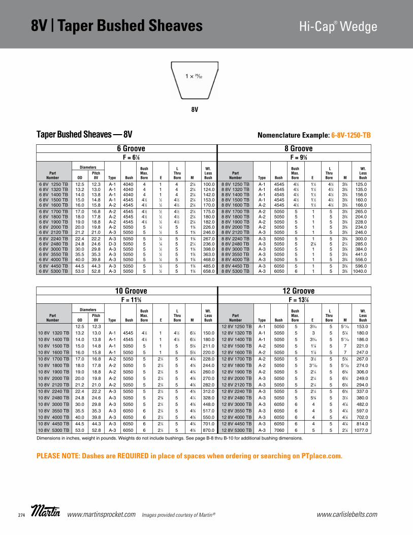
www.carlislebelts.com274 www.martinsprocket.com Images provided courtesy of Martin®
8V | Taper Bushed Sheaves Hi-Cap® Wedge
D-28
8VHi-Cap Wedge StockTaper Bushed Sheaves
12.5 12.3 12 8V 1250 TB A-1 5050 5 33⁄16 5 511⁄16 153.010 8V 1320 TB 13.2 13.0 A-1 4545 41⁄2 1 41⁄2 61⁄8 150.0 12 8V 1320 TB A-1 5050 5 3 5 57⁄8 180.010 8V 1400 TB 14.0 13.8 A-1 4545 41⁄2 1 41⁄2 61⁄8 180.0 12 8V 1400 TB A-1 5050 5 33⁄16 5 511⁄16 186.010 8V 1500 TB 15.0 14.8 A-1 5050 5 1 5 55⁄8 211.0 12 8V 1500 TB A-2 5050 5 17⁄8 5 7 221.010 8V 1600 TB 16.0 15.8 A-1 5050 5 1 5 55⁄8 220.0 12 8V 1600 TB A-2 5050 5 17⁄8 5 7 247.010 8V 1700 TB 17.0 16.8 A-2 5050 5 21⁄4 5 43⁄8 228.0 12 8V 1700 TB A-2 5050 5 31⁄2 5 53⁄8 267.010 8V 1800 TB 18.0 17.8 A-2 5050 5 21⁄4 5 43⁄8 244.0 12 8V 1800 TB A-2 5050 5 317⁄32 5 511⁄32 274.010 8V 1900 TB 19.0 18.8 A-2 5050 5 21⁄4 5 43⁄8 260.0 12 8V 1900 TB A-2 5050 5 21⁄4 5 65⁄8 306.010 8V 2000 TB 20.0 19.8 A-2 5050 5 21⁄4 5 43⁄8 270.0 12 8V 2000 TB A-3 5050 5 21⁄4 5 65⁄8 249.010 8V 2120 TB 21.2 21.0 A-2 5050 5 21⁄4 5 43⁄8 282.0 12 8V 2120 TB A-3 5050 5 21⁄4 5 65⁄8 294.010 8V 2240 TB 22.4 22.2 A-3 5050 5 21⁄4 5 43⁄8 312.0 12 8V 2240 TB A-3 5050 5 21⁄4 5 65⁄8 337.010 8V 2480 TB 24.8 24.6 A-3 5050 5 23⁄8 5 41⁄4 328.0 12 8V 2480 TB A-3 5050 5 53⁄8 5 31⁄2 380.010 8V 3000 TB 30.0 29.8 A-3 5050 5 21⁄4 5 43⁄8 448.0 12 8V 3000 TB A-3 6050 6 4 5 47⁄8 482.010 8V 3550 TB 35.5 35.3 A-3 6050 6 21⁄4 5 43⁄8 517.0 12 8V 3550 TB A-3 6050 6 4 5 47⁄8 597.010 8V 4000 TB 40.0 39.8 A-3 6050 6 21⁄4 5 43⁄8 550.0 12 8V 4000 TB A-3 6050 6 4 5 47⁄8 702.010 8V 4450 TB 44.5 44.3 A-3 6050 6 21⁄4 5 43⁄8 701.0 12 8V 4450 TB A-3 6050 6 4 5 47⁄8 814.010 8V 5300 TB 53.0 52.8 A-3 6050 6 21⁄4 5 43⁄8 870.0 12 8V 5300 TB A-3 7060 6 5 5 27⁄8 1077.0
6 8V 1250 TB 12.5 12.3 A-1 4040 4 1 4 21⁄8 100.0 8 8V 1250 TB A-1 4545 41⁄2 11⁄2 41⁄2 33⁄8 125.06 8V 1320 TB 13.2 13.0 A-1 4040 4 1 4 21⁄8 124.0 8 8V 1320 TB A-1 4545 41⁄2 11⁄2 41⁄2 33⁄8 135.06 8V 1400 TB 14.0 13.8 A-1 4040 4 1 4 21⁄8 142.0 8 8V 1400 TB A-1 4545 41⁄2 11⁄2 41⁄2 33⁄8 156.06 8V 1500 TB 15.0 14.8 A-1 4545 41⁄2 1⁄2 41⁄2 21⁄8 153.0 8 8V 1500 TB A-1 4545 41⁄2 11⁄2 41⁄2 33⁄8 160.06 8V 1600 TB 16.0 15.8 A-2 4545 41⁄2 1⁄2 41⁄2 21⁄8 170.0 8 8V 1600 TB A-2 4545 41⁄2 11⁄2 41⁄2 33⁄8 166.06 8V 1700 TB 17.0 16.8 A-2 4545 41⁄2 1⁄2 41⁄2 21⁄8 175.0 8 8V 1700 TB A-2 5050 5 1 5 33⁄8 265.06 8V 1800 TB 18.0 17.8 A-2 4545 41⁄2 1⁄2 41⁄2 21⁄8 180.0 8 8V 1800 TB A-2 5050 5 1 5 33⁄8 204.06 8V 1900 TB 19.0 18.8 A-2 4545 41⁄2 1⁄2 41⁄2 21⁄8 182.0 8 8V 1900 TB A-2 5050 5 1 5 33⁄8 228.06 8V 2000 TB 20.0 19.8 A-2 5050 5 1⁄2 5 15⁄8 226.0 8 8V 2000 TB A-2 5050 5 1 5 33⁄8 234.06 8V 2120 TB 21.2 21.0 A-3 5050 5 1⁄2 5 15⁄8 246.0 8 8V 2120 TB A-3 5050 5 1 5 33⁄8 246.06 8V 2240 TB 22.4 22.2 A-3 5050 5 1⁄2 5 15⁄8 267.0 8 8V 2240 TB A-3 5050 5 1 5 33⁄8 300.06 8V 2480 TB 24.8 24.6 D-3 5050 5 1⁄8 5 21⁄4 236.0 8 8V 2480 TB A-3 5050 5 21⁄8 5 21⁄4 285.06 8V 3000 TB 30.0 29.8 A-3 5050 5 1⁄2 5 15⁄8 398.0 8 8V 3000 TB A-3 5050 5 1 5 33⁄8 384.06 8V 3550 TB 35.5 35.3 A-3 5050 5 1⁄2 5 15⁄8 363.0 8 8V 3550 TB A-3 5050 5 1 5 33⁄8 441.06 8V 4000 TB 40.0 39.8 A-3 5050 5 1⁄2 5 15⁄8 468.0 8 8V 4000 TB A-3 5050 5 1 5 33⁄8 556.06 8V 4450 TB 44.5 44.3 A-3 5050 5 1⁄2 5 15⁄8 485.0 8 8V 4450 TB A-3 6050 5 1 5 33⁄8 596.06 8V 5300 TB 53.0 52.8 A-3 5050 5 1⁄2 5 15⁄8 658.0 8 8V 5300 TB A-3 6050 6 1 5 33⁄8 1040.0
6 Groove 8 Groove F = 61⁄8 F = 93⁄8 Diameters Bush L Wt. Bush L Wt. Part Pitch Max. Thru Less Part Max. Thru Less Number OD 8V Type Bush Bore E Bore M Bush Number Type Bush Bore E Bore M Bush
Dimensions in inches, weight in pounds. Weights do not include bushings. See page B-8 thru B-10 for additional bushing dimensions.
8V
1 × 29⁄32
10 Groove 12 Groove F = 115⁄8 F = 137⁄8 Diameters Bush L Wt. Bush L Wt. Part Pitch Max. Thru Less Part Max. Thru Less Number OD 8V Type Bush Bore E Bore M Bush Number Type Bush Bore E Bore M Bush
Taper Bushed Sheaves — 8V
Section D-ELF-2015-1-32.qxp_Section D 5/5/15 3:03 PM Page D-28
Nomenclature Example: 6-8V-1250-TB
PLEASE NOTE: Dashes are REQUIRED in place of spaces when ordering or searching on PTplace.com.

275www.carlislebelts.com Images provided courtesy of Martin® www.martinsprocket.com
V-Be
lt |
Tap
er B
ushe
d Sh
eave
s
A-B
D-29
Combination Groove ConventionalTaper Bushed Stock Sheaves
1 B 34 TB 3.0 3.4 3.75 A-1 1210 11⁄4 0 1 0 2.2 2 B 34 TB A-1 1210 11⁄4 3⁄4 1 0 2.21 B 36 TB 3.2 3.6 3.95 A-1 1210 11⁄4 0 1 0 2.6 2 B 36 TB A-1 1210 11⁄4 3⁄4 1 0 2.61 B 38 TB 3.4 3.8 4.15 A-1 1610 15⁄8 0 1 0 2.8 2 B 38 TB A-1 1610 15⁄8 3⁄4 1 0 2.81 B 40 TB 3.6 4.0 4.35 A-1 1610 15⁄8 0 1 0 3.0 2 B 40 TB A-1 1610 15⁄8 3⁄4 1 0 3.01 B 42 TB 3.8 4.2 4.55 A-1 1610 15⁄8 0 1 0 3.5 2 B 42 TB A-1 1610 15⁄8 3⁄4 1 0 4.01 B 44 TB 4.0 4.4 4.75 A-1 1610 15⁄8 0 1 0 3.8 2 B 44 TB A-1 1610 15⁄8 3⁄4 1 0 4.51 B 46 TB 4.2 4.6 4.95 A-1 1610 15⁄8 0 1 0 4.0 2 B 46 TB A-1 1610 15⁄8 3⁄4 1 0 5.01 B 48 TB 4.4 4.8 5.15 A-1 1610 15⁄8 0 1 0 4.5 2 B 48 TB A-1 1610 15⁄8 3⁄4 1 0 5.51 B 50 TB 4.6 5.0 5.35 A-1 1610 15⁄8 0 1 0 4.8 2 B 50 TB A-1 1610 15⁄8 3⁄4 1 0 6.01 B 52 TB 4.8 5.2 5.55 A-1 1610 15⁄8 0 1 0 5.0 2 B 52 TB A-1 1610 15⁄8 3⁄4 1 0 6.51 B 54 TB 5.0 5.4 5.75 A-1 1610 15⁄8 0 1 0 5.5 2 B 54 TB A-1 1610 15⁄8 3⁄4 1 0 7.01 B 56 TB 5.2 5.6 5.95 A-1 1610 15⁄8 0 1 0 6.0 2 B 56 TB A-1 1610 15⁄8 3⁄4 1 0 8.21 B 58 TB 5.4 5.8 6.15 A-1 1610 15⁄8 0 1 0 6.3 2 B 58 TB A-1 1610 15⁄8 3⁄4 1 0 8.61 B 60 TB 5.6 6.0 6.35 A-1 1610 15⁄8 0 1 0 6.7 2 B 60 TB A-1 1610 15⁄8 3⁄4 1 0 8.81 B 62 TB 5.8 6.2 6.55 A-1 1610 15⁄8 0 1 0 7.0 2 B 62 TB A-1 1610 15⁄8 3⁄4 1 0 9.01 B 64 TB 6.0 6.4 6.75 A-1 1610 15⁄8 0 1 0 8.0 2 B 64 TB A-1 1610 15⁄8 3⁄4 1 0 10.01 B 66 TB 6.2 6.6 6.95 A-1 1610 15⁄8 0 1 0 8.5 2 B 66 TB A-1 1610 15⁄8 3⁄4 1 0 10.51 B 68 TB 6.4 6.8 7.15 A-1 1610 15⁄8 0 1 0 9.0 2 B 68 TB A-1 1610 15⁄8 3⁄4 1 0 11.01 B 70 TB 7.0 7.4 7.35 B-1 2517 21⁄2 0 13⁄4 3⁄4 8.5 2 B 74 TB A-1 2517 21⁄2 0 13⁄4 0 16.01 B 74 TB 7.0 7.4 7.75 B-1 2517 21⁄2 0 13⁄4 3⁄4 9.4 2 B 86 TB A-2 2517 21⁄2 0 13⁄4 0 18.01 B 86 TB 8.2 8.6 8.95 B-2 2517 21⁄2 0 13⁄4 3⁄4 12.0 2 B 94 TB A-2 2517 21⁄2 0 13⁄4 0 20.01 B 94 TB 9.0 9.4 9.75 B-2 2517 21⁄2 0 13⁄4 3⁄4 14.0 2 B 110 TB A-2 2517 21⁄2 0 13⁄4 0 25.01 B 110 TB 10.6 11.0 11.35 B-2 2517 21⁄2 0 13⁄4 3⁄4 15.6 2 B 124 TB A-3 2517 21⁄2 0 13⁄4 0 27.01 B 124 TB 12.0 12.4 12.75 C-3 2517 21⁄2 1⁄4 13⁄4 1⁄2 16.2 2 B 136 TB C-3 2517 21⁄2 0 13⁄4 0 24.01 B 136 TB 13.6 14.0 13.95 C-3 2517 21⁄2 1⁄4 13⁄4 1⁄2 17.2 2 B 154 TB A-3 2517 21⁄2 0 13⁄4 0 31.01 B 154 TB 15.0 15.4 15.75 C-3 2517 21⁄2 1⁄4 13⁄4 1⁄2 18.0 2 B 160 TB C-3 2517 21⁄2 0 13⁄4 0 26.01 B 160 TB 16.0 16.4 16.35 C-3 2517 21⁄2 3⁄8 13⁄4 3⁄8 24.1 2 B 184 TB A-3 2517 21⁄2 0 13⁄4 0 33.01 B 184 TB 18.0 18.4 18.75 C-3 2517 21⁄2 3⁄16 13⁄4 7⁄16 31.2 2 B 200 TB C-3 3020 3 0 2 1⁄4 49.0
2 B 250 TB C-3 3020 3 0 2 1⁄4 65.0 2 B 300 TB C-3 3020 3 0 2 1⁄4 75.0 2 B 380 TB C-3 3020 3 0 2 1⁄4 112.0
1 Groove 2 Groove F = 1* F = 13⁄4 Pitch Diameters Bush L Wt. Bush L Wt. Part A B Max. Thru Less Part Max. Thru Less Number Belt Belt OD Type Bush Bore E Bore M Bush Number Type Bush Bore E Bore M Bush
TYPE A TYPE B TYPE C
Taper Bushed Sheaves — A-B
Dimensions in inches, weight in pounds. Weights do not include bushings. See page B-8 thru B-10 for additional bushing dimensions.* F = 1" 1 B 154 TB F = 11⁄8" for 1 B 184 TB
Section D-ELF-2015-1-32.qxp_Section D 5/5/15 3:03 PM Page D-29
8V | Taper Bushed Sheaves Hi-Cap® Wedge Combination Groove Conventional Taper Bushed | A-B
Nomenclature Example: 1-B-34-TB
PLEASE NOTE: Dashes are REQUIRED in place of spaces when ordering or searching on PTplace.com.

www.carlislebelts.com276 www.martinsprocket.com Images provided courtesy of Martin®
A-B | Taper Bushed Combination Groove ConventionalA-B
D-30
3 B 34 TB 3.0 3.4 3.75 A-1 1210 11⁄4 11⁄2 1 0 3.0 4 B 34 TB A-1 1210 11⁄4 21⁄4 1 0 3.03 B 36 TB 3.2 3.6 3.95 A-1 1210 11⁄4 11⁄2 1 0 3.5 4 B 36 TB A-1 1210 11⁄4 21⁄4 1 0 3.53 B 38 TB 3.4 3.8 4.15 A-1 1610 15⁄8 11⁄2 1 0 4.0 4 B 38 TB A-1 1610 15⁄8 21⁄4 1 0 4.03 B 40 TB 3.6 4.0 4.35 A-1 1610 15⁄8 11⁄2 1 0 5.0 4 B 40 TB A-1 1610 15⁄8 21⁄4 1 0 5.03 B 42 TB 3.8 4.2 4.55 A-1 1610 15⁄8 11⁄2 1 0 6.0 4 B 42 TB A-1 1610 15⁄8 21⁄4 1 0 5.53 B 44 TB 4.0 4.4 4.75 A-1 1610 15⁄8 11⁄2 1 0 6.5 4 B 44 TB A-1 1610 15⁄8 21⁄4 1 0 6.03 B 46 TB 4.2 4.6 4.95 A-1 1610 15⁄8 11⁄2 1 0 7.0 4 B 46 TB A-1 1610 15⁄8 21⁄4 1 0 7.03 B 48 TB 4.4 4.8 5.15 A-1 1610 15⁄8 11⁄2 1 0 8.0 4 B 48 TB A-1 1610 15⁄8 21⁄4 1 0 8.03 B 50 TB 4.6 5.0 5.35 A-1 1610 15⁄8 11⁄2 1 0 8.5 4 B 50 TB A-1 2517 21⁄2 11⁄2 13⁄4 0 8.53 B 52 TB 4.8 5.2 5.55 A-1 1610 15⁄8 11⁄2 1 0 9.0 4 B 52 TB A-1 2517 21⁄2 11⁄2 13⁄4 0 9.03 B 54 TB 5.0 5.4 5.75 A-1 2517 21⁄2 11⁄2 13⁄4 0 9.5 4 B 54 TB A-1 2517 21⁄2 11⁄2 13⁄4 0 9.53 B 56 TB 5.2 5.6 5.95 A-1 2517 21⁄2 11⁄2 13⁄4 0 10.0 4 B 56 TB A-1 2517 21⁄2 11⁄2 13⁄4 0 10.03 B 58 TB 5.4 5.8 6.15 A-1 2517 21⁄2 3⁄4 13⁄4 0 10.5 4 B 58 TB A-1 2517 21⁄2 11⁄2 13⁄4 0 12.03 B 60 TB 5.6 6.0 6.35 A-1 2517 21⁄2 3⁄4 13⁄4 0 11.0 4 B 60 TB A-1 2517 21⁄2 11⁄2 13⁄4 0 12.53 B 62 TB 5.8 6.2 6.55 A-1 2517 21⁄2 3⁄4 13⁄4 0 11.5 4 B 62 TB A-1 2517 21⁄2 11⁄2 13⁄4 0 13.03 B 64 TB 6.0 6.4 6.75 A-1 2517 21⁄2 3⁄4 13⁄4 0 12.0 4 B 64 TB A-1 2517 21⁄2 11⁄2 13⁄4 0 14.03 B 66 TB 6.2 6.6 6.95 A-1 2517 21⁄2 3⁄4 13⁄4 0 12.3 4 B 66 TB A-1 2517 21⁄2 11⁄2 13⁄4 0 15.03 B 68 TB 6.4 6.8 7.15 A-1 2517 21⁄2 3⁄4 13⁄4 0 12.8 4 B 68 TB A-1 2517 21⁄2 11⁄2 13⁄4 0 16.03 B 74 TB 7.0 7.4 7.75 A-1 2517 21⁄2 3⁄4 13⁄4 0 16.0 4 B 74 TB A-1 2517 21⁄2 11⁄2 13⁄4 0 16.03 B 80 TB 8.0 8.4 8.35 A-1 2517 21⁄2 0 13⁄4 3⁄4 19.0 4 B 70 TB A-1 2517 21⁄2 0 13⁄4 11⁄2 20.03 B 86 TB 8.2 8.6 8.95 A-2 2517 21⁄2 3⁄4 13⁄4 0 19.0 4 B 80 TB A-1 2517 21⁄2 0 13⁄4 11⁄2 21.03 B 94 TB 9.0 9.4 9.75 A-2 2517 21⁄2 3⁄4 13⁄4 0 21.0 4 B 86 TB A-2 2517 21⁄2 11⁄2 13⁄4 0 21.03 B 110 TB 10.6 11.0 11.35 A-2 2517 21⁄2 3⁄4 13⁄4 0 24.0 4 B 94 TB A-2 2517 21⁄2 11⁄2 13⁄4 0 23.03 B 124 TB 12.0 12.4 12.75 A-3 2517 21⁄2 0 13⁄4 3⁄4 28.0 4 B 110 TB A-2 2517 21⁄2 11⁄2 13⁄4 0 28.03 B 136 TB 13.6 14.0 13.95 A-3 2517 21⁄2 0 13⁄4 3⁄4 25.0 4 B 124 TB A-3 2517 21⁄2 3⁄8 13⁄4 11⁄8 32.83 B 154 TB 15.0 15.4 15.75 A-3 2517 21⁄2 0 13⁄4 3⁄4 30.0 4 B 136 TB A-3 2517 21⁄2 3⁄8 13⁄4 11⁄8 34.03 B 160 TB 16.0 16.4 16.35 A-3 2517 21⁄2 0 13⁄4 3⁄4 32.0 4 B 154 TB A-3 2517 21⁄2 3⁄8 13⁄4 11⁄8 42.03 B 184 TB 18.0 18.4 18.75 A-3 2517 21⁄2 0 13⁄4 3⁄4 44.0 4 B 160 TB A-3 2517 21⁄2 3⁄8 13⁄4 11⁄8 45.13 B 200 TB 19.6 20.0 20.35 A-3 3020 3 0 2 1⁄2 58.0 4 B 184 TB A-3 2517 21⁄2 1⁄2 13⁄4 1 53.03 B 250 TB 24.6 25.0 25.35 A-3 3020 3 0 2 1⁄2 74.0 4 B 200 TB A-3 3020 3 1⁄2 2 3⁄4 63.03 B 300 TB 29.6 30.0 30.35 A-3 3020 3 0 2 1⁄2 84.0 4 B 250 TB A-3 3030 3 0 3 11⁄4 80.03 B 380 TB 37.6 38.0 38.35 B-3 3020 3 0 3 1⁄2 135.0 4 B 300 TB A-3 3030 3 0 3 11⁄4 100.0
4 B 380 TB A-3 3030 3 0 3 11⁄4 142.0
3 Groove 4 Groove F = 21⁄2 F = 31⁄4 Diameters Bush L Wt. Bush L Wt. Part A B Max. Thru Less Part Max. Thru Less Number Belts Belts OD Type Bush Bore E Bore M Bush Number Type Bush Bore E Bore M Bush
1 = SOLID 2 = WEB 3 = ARM/SPOKE
Taper Bushed Sheaves — A-B
Dimensions in inches, weight in pounds. Weights do not include bushings. See page B-8 thru B-10 for additional bushing dimensions.
Combination Groove Dimensions Belt Section E S OD
“AB” 1⁄2 3⁄4 P.D. “B” +.35
W = S (N-1) + 2E N = No. of Grooves
Drawing shows position of “A” and “B” belts in groove.
Combination Groove ConventionalTaper Bushed Stock Sheaves
O.D
.
P.D
. A B
ELT
P.D
. B B
ELT
Section D-ELF-2015-1-32.qxp_Section D 5/5/15 3:03 PM Page D-30
Nomenclature Example: 3-B-34-TB
PLEASE NOTE: Dashes are REQUIRED in place of spaces when ordering or searching on PTplace.com.

277www.carlislebelts.com Images provided courtesy of Martin® www.martinsprocket.com
V-Be
lt |
Tap
er B
ushe
d Sh
eave
s
A-B
D-31
Combination Groove ConventionalTaper Bushed Stock Sheaves
5 B 34 TB 3.0 3.4 3.75 A-1 1210 11⁄4 21⁄2 11⁄2 0 5.0 5 B 36 TB 3.2 3.6 3.95 A-1 1210 11⁄4 21⁄2 11⁄2 0 5.55 B 38 TB 3.4 3.8 4.15 A-1 1215 15⁄8 7⁄8 11⁄2 15⁄8 6.05 B 40 TB 3.6 4.0 4.35 A-1 1215 15⁄8 7⁄8 11⁄2 15⁄8 6.55 B 42 TB 3.8 4.2 4.55 A-1 1615 15⁄8 21⁄2 11⁄2 0 7.0 6 B 42 TB A-1 1615 15⁄8 31⁄4 11⁄2 0 8.0 5 B 44 TB 4.0 4.4 4.75 A-1 1615 15⁄8 21⁄2 11⁄2 0 8.0 6 B 44 TB A-1 1615 15⁄8 31⁄4 11⁄2 0 9.0 5 B 46 TB 4.2 4.6 4.95 A-1 1615 15⁄8 21⁄2 11⁄2 0 9.0 6 B 46 TB A-1 1615 15⁄8 31⁄4 11⁄2 0 10.0 5 B 48 TB 4.8 5.2 5.15 A-1 1615 15⁄8 7⁄8 11⁄2 15⁄8 9.4 6 B 48 TB A-1 1615 15⁄8 11⁄4 11⁄2 2 11.05 B 50 TB 4.6 5.0 5.35 A-1 1615 15⁄8 7⁄8 11⁄2 0 10.5 6 B 50 TB A-1 1615 15⁄8 11⁄4 11⁄2 2 11.9 5 B 52 TB 4.8 5.2 5.55 A-1 1615 15⁄8 7⁄8 11⁄2 0 11.3 6 B 52 TB A-1 1615 15⁄8 11⁄4 11⁄2 2 12.8 5 B 54 TB 5.0 5.4 5.75 A-1 2517 21⁄2 21⁄4 13⁄4 0 11.5 6 B 54 TB A-1 2517 15⁄8 11⁄4 11⁄2 2 13.7 5 B 56 TB 5.2 5.6 5.95 A-1 2517 21⁄2 21⁄4 13⁄4 0 12.0 6 B 56 TB A-1 2517 15⁄8 11⁄4 11⁄2 2 14.6 5 B 58 TB 5.8 6.2 6.15 A-1 2517 21⁄2 13⁄16 13⁄4 17⁄16 13.0 6 B 58 TB A-1 2517 21⁄2 11⁄8 13⁄4 17⁄8 14.05 B 60 TB 5.6 6.0 6.35 A-1 2517 21⁄2 21⁄4 13⁄4 0 14.0 6 B 60 TB A-1 2517 21⁄2 3 13⁄4 0 16.0 5 B 62 TB 6.2 6.6 6.55 A-1 2517 21⁄2 13⁄16 13⁄4 17⁄16 14.0 6 B 62 TB A-1 2517 21⁄2 11⁄8 13⁄4 17⁄8 16.05 B 64 TB 6.0 6.4 6.75 A-1 2517 21⁄2 21⁄4 13⁄4 0 16.0 6 B 64 TB A-1 2517 21⁄2 3 13⁄4 0 19.5 5 B 66 TB 6.6 7.0 6.95 A-1 2517 21⁄2 13⁄16 13⁄4 17⁄16 16.0 6 B 66 TB A-1 2517 21⁄2 11⁄8 13⁄4 17⁄8 20.05 B 68 TB 6.4 6.8 7.15 A-1 2517 21⁄2 21⁄4 13⁄4 0 18.0 6 B 68 TB A-1 2517 21⁄2 3 13⁄4 0 21.0 5 B 70 TB 7.0 7.4 7.35 A-1 2517 21⁄2 3⁄4 13⁄4 11⁄2 18.0 6 B 70 TB A-1 2517 21⁄2 11⁄2 13⁄4 11⁄2 21.05 B 74 TB 7.0 7.4 7.75 A-1 2517 21⁄2 21⁄4 13⁄4 0 22.0 6 B 74 TB A-1 2517 21⁄2 3 13⁄4 0 25.0 5 B 80 TB 8.0 8.4 8.35 A-1 2517 21⁄2 1⁄2 13⁄4 13⁄4 23.0 6 B 80 TB A-1 2517 21⁄2 11⁄2 13⁄4 11⁄2 26.05 B 86 TB 8.2 8.6 8.95 A-2 2517 21⁄2 21⁄4 13⁄4 0 24.0 6 B 86 TB A-2 2517 21⁄2 3 13⁄4 0 27.0 5 B 94 TB 9.0 9.4 9.75 A-2 2517 21⁄2 21⁄4 13⁄4 0 26.0 6 B 94 TB A-2 2517 21⁄2 3 13⁄4 0 28.0 5 B 110 TB 10.6 11.0 11.35 A-2 2517 21⁄2 21⁄4 13⁄4 0 35.0 6 B 110 TB A-2 2517 21⁄2 3 13⁄4 0 34.0 5 B 124 TB 12.0 12.4 12.75 A-3 2517 21⁄2 3⁄4 13⁄4 11⁄2 40.0 6 B 124 TB A-3 2517 21⁄2 11⁄8 13⁄4 17⁄8 43.0 5 B 136 TB 13.6 14.0 13.95 A-3 2517 21⁄2 1 13⁄4 11⁄4 38.0 6 B 136 TB A-3 2517 21⁄2 11⁄2 13⁄4 11⁄2 42.05 B 154 TB 15.0 15.4 15.75 A-3 2517 21⁄2 3⁄4 13⁄4 11⁄2 47.0 6 B 154 TB A-3 2517 21⁄2 11⁄2 13⁄4 11⁄2 52.0 5 B 160 TB 16.0 16.4 16.35 A-3 2517 21⁄2 3⁄4 13⁄4 11⁄2 67.0 6 B 160 TB A-3 2517 21⁄2 11⁄2 13⁄4 11⁄2 53.05 B 184 TB 18.0 18.4 18.75 A-3 2517 21⁄2 3⁄4 13⁄4 11⁄2 52.0 6 B 184 TB A-3 2517 21⁄2 11⁄2 13⁄4 11⁄2 62.0 5 B 200 TB 19.6 20.0 20.35 A-3 3030 3 1⁄4 3 3⁄4 75.0 6 B 200 TB A-3 3030 3 1⁄2 3 11⁄4 85.0 5 B 250 TB 24.6 25.0 25.35 A-3 3030 3 1⁄4 3 3⁄4 81.0 6 B 250 TB A-3 3030 3 1⁄2 3 11⁄4 100.0 5 B 300 TB 29.6 30.0 30.35 A-3 3030 3 1⁄4 3 3⁄4 109.0 6 B 300 TB A-3 3030 3 1⁄2 3 11⁄4 137.0 5 B 380 TB 37.6 38.0 38.35 A-3 3030 3 1⁄4 3 3⁄4 158.0 6 B 380 TB A-3 3030 3 1⁄2 3 11⁄4 168.0
8 B 54 TB 5.0 5.4 5.75 A-1 2517 21⁄2 17⁄8 13⁄4 25⁄8 16.0 10 B 54 TB A-1 2517 21⁄2 3 13⁄4 3 18.0 8 B 56 TB 5.2 5.6 5.95 A-1 2517 21⁄2 17⁄8 13⁄4 25⁄8 17.0 10 B 56 TB A-1 2517 21⁄2 3 13⁄4 3 20.0 8 B 60 TB 5.6 6.0 6.35 A-1 2517 21⁄2 17⁄8 13⁄4 25⁄8 19.0 10 B 60 TB A-1 2517 21⁄2 3 13⁄4 3 22.0 8 B 64 TB 6.0 6.4 6.75 A-1 2517 21⁄2 17⁄8 13⁄4 25⁄8 21.0 10 B 64 TB A-1 2517 21⁄2 3 13⁄4 3 25.5 8 B 68 TB 6.4 6.8 7.15 A-1 2517 21⁄2 17⁄8 13⁄4 25⁄8 25.0 10 B 68 TB A-1 2517 21⁄2 3 13⁄4 3 28.0 8 B 74 TB 7.0 7.4 7.75 A-1 2517 21⁄2 17⁄8 13⁄4 25⁄8 29.0 10 B 74 TB A-1 2517 21⁄2 3 13⁄4 3 35.0 8 B 86 TB 8.2 8.6 8.95 A-1 3030 3 1 3 21⁄4 37.0 10 B 86 TB A-1 3030 3 2 3 23⁄4 43.0 8 B 94 TB 9.0 9.4 9.95 A-2 3030 3 1 3 21⁄4 41.0 10 B 94 TB A-2 3030 3 2 3 23⁄4 46.0 8 B 110 TB 10.6 11.0 11.35 A-2 3030 3 1 3 21⁄4 51.0 10 B 110 TB A-2 3030 3 2 3 23⁄4 52.0 8 B 124 TB 12.0 12.4 12.75 A-3 3030 3 1 3 21⁄4 56.08 B 154 TB 15.0 15.4 15.75 A-3 3030 3 1 3 21⁄4 69.08 B 184 TB 18.0 18.4 18.75 A-3 3030 3 1 3 21⁄4 99.08 B 200 TB 19.6 20.0 20.35 A-3 3030 3 1 3 21⁄4 115.08 B 250 TB 24.6 25.0 25.35 A-3 3535 31⁄2 3⁄4 31⁄2 2 145.08 B 300 TB 29.6 30.0 30.35 A-3 3535 31⁄2 3⁄4 31⁄2 2 170.08 B 380 TB 37.6 38.0 38.35 A-3 4040 4 11⁄8 4 11⁄8 260.0
8 Groove 10 Groove F = 61⁄4 F = 73⁄4 Diameters Bush L Wt. Bush L Wt. Part A B Max. Thru Less Part Max. Thru Less Number Belts Belts OD Type Bush Bore E Bore M Bush Number Type Bush Bore E Bore M Bush
5 Groove 6 Groove F = 4 F = 43⁄4 Diameters Bush L Wt. Bush L Wt. Part A B Max. Thru Less Part Max. Thru Less Number Belts Belts OD Type Bush Bore E Bore M Bush Number Type Bush Bore E Bore M Bush
Taper Bushed Sheaves — A-B
Dimensions in inches, weight in pounds. Weights do not include bushings. See page B-8 thru B-10 for additional bushing dimensions.
Section D-ELF-2015-1-32.qxp_Section D 5/5/15 3:03 PM Page D-31
A-B | Taper Bushed Combination Groove Conventional Combination Groove Conventional Taper Bushed | A-B
Nomenclature Example: 5-B-34-TB
PLEASE NOTE: Dashes are REQUIRED in place of spaces when ordering or searching on PTplace.com.

www.carlislebelts.com278 www.martinsprocket.com Images provided courtesy of Martin®
C | Taper Bushed Sheaves Conventional
D-32
C Conventional StockTaper Bushed Sheaves
2 C 70 TB 7.00 7.40 A-1 2517 21⁄2 5⁄8 13⁄4 0 15.0 3 C 70 TB A-1 2517 21⁄2 1⁄4 13⁄4 13⁄8 18.02 C 75 TB 7.50 7.90 A-1 2517 21⁄2 5⁄8 13⁄4 0 17.0 3 C 75 TB A-1 2517 21⁄2 1⁄4 13⁄4 13⁄8 20.02 C 80 TB 8.00 8.40 A-1 2517 21⁄2 5⁄8 13⁄4 0 20.0 3 C 80 TB A-1 2517 21⁄2 1⁄4 13⁄4 13⁄8 22.02 C 85 TB 8.50 8.90 A-2 2517 21⁄2 5⁄8 13⁄4 0 22.0 3 C 85 TB A-2 2517 21⁄2 1⁄4 13⁄4 13⁄8 23.02 C 90 TB 9.00 9.40 A-2 2517 21⁄2 5⁄8 13⁄4 0 23.0 3 C 90 TB A-2 2517 21⁄2 1⁄4 13⁄4 13⁄8 24.02 C 95 TB 9.50 9.90 A-2 2517 21⁄2 5⁄8 13⁄4 0 24.0 3 C 95 TB A-2 2517 21⁄2 1⁄4 13⁄4 13⁄8 27.02 C 100 TB 10.00 10.40 A-2 2517 21⁄2 5⁄8 13⁄4 0 25.0 3 C 100 TB A-2 2517 21⁄2 1⁄4 13⁄4 13⁄8 29.02 C 105 TB 10.50 10.90 A-2 2517 21⁄2 5⁄8 13⁄4 0 26.0 3 C 105 TB A-2 2517 21⁄2 1⁄4 13⁄4 13⁄8 32.02 C 110 TB 11.00 11.40 A-2 2517 21⁄2 5⁄8 13⁄4 0 27.0 3 C 110 TB A-2 2517 21⁄2 1⁄4 13⁄4 13⁄8 35.02 C 120 TB 12.00 12.40 A-2 2517 21⁄2 5⁄8 13⁄4 0 33.0 3 C 120 TB A-2 3020 3 0 2 13⁄8 44.02 C 130 TB 13.00 13.40 A-3 2517 21⁄2 5⁄8 13⁄4 0 35.0 3 C 130 TB A-3 3020 3 0 2 13⁄8 49.02 C 140 TB 14.00 14.40 A-3 2517 21⁄2 5⁄8 13⁄4 0 36.0 3 C 140 TB A-3 3020 3 0 2 13⁄8 50.02 C 160 TB 16.00 16.40 A-3 2517 21⁄2 5⁄8 13⁄4 0 42.0 3 C 160 TB A-3 3020 3 0 2 13⁄8 64.02 C 180 TB 18.00 18.40 A-3 3020 3 0 2 3⁄8 42.0 3 C 180 TB A-3 3030 3 0 3 3⁄8 64.02 C 200 TB 20.00 20.40 A-3 3020 3 0 2 3⁄8 45.0 3 C 200 TB A-3 3030 3 0 3 3⁄8 78.02 C 240 TB 24.00 24.40 A-3 3020 3 0 2 3⁄8 72.0 3 C 240 TB A-3 3030 3 0 3 3⁄8 96.02 C 300 TB 30.00 30.40 C-3 3535 31⁄2 1⁄2 31⁄2 5⁄8 85.0 3 C 300 TB B-3 3535 31⁄2 0 31⁄2 1⁄8 125.0 36.00 36.40 3 C 360 TB B-3 3535 31⁄2 0 31⁄2 1⁄8 175.0
2 Groove 3 Groove F = 23⁄8 F = 33⁄8 PD Bush L Wt. Bush L Wt. Part C Max. Thru Less Part Max. Thru Less Number Belt OD Type Bush Bore E Bore M Bush Number Type Bush Bore E Bore M Bush
TYPE A TYPE B TYPE C
1 = SOLID 2 = WEB 3 = ARM/SPOKE
Taper Bushed Sheaves — C
Groove Dimensions Belt Section E S O.D.
“C” 11⁄16 1 P.D. + .40
W = S(N-1) + 2EN = No. of Grooves
Dimensions in inches, weight in pounds. Weights do not include bushings. See page B-8 thru B-10 for additional bushing dimensions.
P.D
.
O.D
.
Section D-ELF-2015-1-32.qxp_Section D 5/5/15 3:04 PM Page D-32
Nomenclature Example: 2-C-70-TB
PLEASE NOTE: Dashes are REQUIRED in place of spaces when ordering or searching on PTplace.com.

279www.carlislebelts.com Images provided courtesy of Martin® www.martinsprocket.com
V-Be
lt |
Tap
er B
ushe
d Sh
eave
s
D-33
C
4 C 70 TB 7.00 7.40 A-1 2517 21⁄2 1⁄2 13⁄4 21⁄8 20.0 5 C 70 TB A-1 2517 21⁄2 11⁄2 13⁄4 21⁄8 23.04 C 75 TB 7.50 7.90 A-1 2517 21⁄2 1⁄2 13⁄4 21⁄8 23.0 5 C 75 TB A-1 2517 21⁄2 11⁄2 13⁄4 21⁄8 26.04 C 80 TB 8.00 8.40 A-1 2517 21⁄2 1⁄2 13⁄4 21⁄8 25.0 5 C 80 TB A-1 2517 21⁄2 11⁄2 13⁄4 21⁄8 30.04 C 85 TB 8.50 8.90 A-2 2517 21⁄2 1⁄2 13⁄4 21⁄8 26.0 5 C 85 TB A-1 2517 21⁄2 11⁄2 13⁄4 21⁄8 34.04 C 90 TB 9.00 9.40 A-2 2517 21⁄2 1⁄2 13⁄4 21⁄8 27.0 5 C 90 TB A-2 2517 21⁄2 11⁄2 13⁄4 21⁄8 35.04 C 95 TB 9.50 9.90 A-2 2517 21⁄2 1⁄2 13⁄4 21⁄8 36.0 5 C 95 TB A-2 2517 21⁄2 11⁄2 13⁄4 21⁄8 36.04 C 100 TB 10.00 10.40 A-2 2517 21⁄2 1⁄2 13⁄4 21⁄8 39.0 5 C 100 TB A-2 2517 21⁄2 11⁄2 13⁄4 21⁄8 39.04 C 105 TB 10.50 10.90 A-2 2517 21⁄2 1⁄2 13⁄4 21⁄8 42.0 5 C 105 TB A-2 2517 21⁄2 11⁄2 13⁄4 21⁄8 42.04 C 110 TB 11.00 11.40 A-2 2517 21⁄2 1⁄2 13⁄4 21⁄8 45.0 5 C 110 TB A-2 2517 21⁄2 11⁄2 13⁄4 21⁄8 43.04 C 120 TB 12.00 12.40 A-2 3030 3 0 3 13⁄8 47.0 5 C 120 TB A-2 3030 3 1⁄2 3 17⁄8 58.04 C 130 TB 13.00 13.40 A-3 3030 3 0 3 13⁄8 51.0 5 C 130 TB A-3 3030 3 1⁄2 3 17⁄8 63.04 C 140 TB 14.00 14.40 A-3 3030 3 0 3 13⁄8 54.0 5 C 140 TB A-3 3030 3 1⁄2 3 17⁄8 65.04 C 160 TB 16.00 16.40 A-3 3030 3 0 3 13⁄8 71.0 5 C 160 TB A-3 3030 3 1⁄2 3 17⁄8 70.04 C 180 TB 18.00 18.40 A-3 3030 3 0 3 13⁄8 81.0 5 C 180 TB A-3 3030 3 1⁄2 3 17⁄8 83.04 C 200 TB 20.00 20.40 A-3 3030 3 0 3 13⁄8 84.0 5 C 200 TB A-3 3535 31⁄2 0 31⁄2 17⁄8 110.04 C 240 TB 24.00 24.40 A-3 3030 3 0 3 13⁄8 116.0 5 C 240 TB A-3 3535 31⁄2 0 31⁄2 17⁄8 138.04 C 300 TB 30.00 30.40 A-3 3535 31⁄2 0 31⁄2 7⁄8 164.0 5 C 300 TB A-3 3535 31⁄2 0 31⁄2 17⁄8 176.04 C 360 TB 36.00 36.40 A-3 3535 31⁄2 0 31⁄2 7⁄8 192.0 5 C 360 TB A-3 4040 4 1⁄4 4 11⁄8 244.04 C 440 TB 44.00 44.40 A-3 4040 4 0 4 3⁄8 282.0 5 C 440 TB A-3 4040 4 1⁄4 4 11⁄8 288.0
4 Groove 5 Groove F = 43⁄8 F = 53⁄8 PD Bush L Wt. Bush L Wt. Part C Max. Thru Less Part Max. Thru Less Number Belt OD Type Bush Bore E Bore M Bush Number Type Bush Bore E Bore M Bush
1 = SOLID 2 = WEB 3 = ARM/SPOKE
Taper Bushed Sheaves — C
Conventional Taper Bushed Sheaves
TYPE A TYPE B TYPE C
C | Taper Bushed Sheaves Conventional Conventional Taper Bushed Sheaves | C
Nomenclature Example: 4-C-70-TB
PLEASE NOTE: Dashes are REQUIRED in place of spaces when ordering or searching on PTplace.com.

www.carlislebelts.com280 www.martinsprocket.com Images provided courtesy of Martin®
C | Taper Bushed Sheaves ConventionalC
D-34
Conventional StockTaper Bushed Sheaves
TYPE A TYPE B TYPE C
6 C 70 TB 7.00 7.40 A-1 3030 3 1 3 23⁄8 30.0 6 C 75 TB 7.50 7.90 A-1 3030 3 1 3 23⁄8 31.0 6 C 80 TB 8.00 8.40 A-1 3030 3 1 3 23⁄8 35.0 8 C 80 TB A-1 3030 3 2 3 33⁄8 45.06 C 85 TB 8.50 8.90 A-1 3030 3 1 3 23⁄8 40.0 8 C 85 TB A-1 3030 3 2 3 33⁄8 47.06 C 90 TB 9.00 9.40 A-1 3030 3 1 3 23⁄8 47.0 8 C 90 TB A-1 3535 31⁄2 11⁄2 31⁄2 33⁄8 64.06 C 95 TB 9.50 9.90 A-1 3030 3 1 3 23⁄8 53.0 8 C 95 TB A-1 3535 31⁄2 11⁄2 31⁄2 33⁄8 67.06 C 100 TB 10.00 10.40 A-1 3030 3 1 3 23⁄8 57.0 8 C 100 TB A-1 3535 31⁄2 11⁄2 31⁄2 33⁄8 70.06 C 105 TB 10.50 10.90 A-2 3030 3 1 3 23⁄8 58.0 8 C 105 TB A-1 3535 31⁄2 11⁄2 31⁄2 33⁄8 84.06 C 110 TB 11.00 11.40 A-2 3030 3 1 3 23⁄8 66.0 8 C 110 TB A-1 3535 31⁄2 11⁄2 31⁄2 33⁄8 87.06 C 120 TB 12.00 12.40 A-2 3030 3 1 3 23⁄8 70.0 8 C 120 TB A-2 3535 31⁄2 11⁄2 31⁄2 33⁄8 90.06 C 130 TB 13.00 13.40 A-3 3030 3 1 3 23⁄8 75.0 8 C 130 TB A-2 3535 31⁄2 11⁄2 31⁄2 33⁄8 97.06 C 140 TB 14.00 14.40 A-3 3535 31⁄2 1⁄2 31⁄2 23⁄8 80.0 8 C 140 TB A-2 3535 31⁄2 11⁄2 31⁄2 33⁄8 105.06 C 160 TB 16.00 16.40 A-3 3535 31⁄2 1⁄2 31⁄2 23⁄8 87.0 8 C 160 TB A-3 3535 31⁄2 11⁄2 31⁄2 33⁄8 115.06 C 180 TB 18.00 18.40 A-3 3535 31⁄2 1⁄2 31⁄2 23⁄8 102.0 8 C 180 TB A-3 4040 4 11⁄2 4 27⁄8 137.06 C 200 TB 20.00 20.40 A-3 3535 31⁄2 1⁄2 31⁄2 23⁄8 126.0 8 C 200 TB A-3 4040 4 11⁄2 4 27⁄8 180.06 C 240 TB 24.00 24.40 A-3 3535 31⁄2 1⁄2 31⁄2 23⁄8 150.0 8 C 240 TB A-3 4040 4 11⁄2 4 27⁄8 205.06 C 300 TB 30.00 30.40 A-3 4040 4 1 4 13⁄8 226.0 8 C 300 TB A-3 4040 4 11⁄2 4 27⁄8 263.06 C 360 TB 36.00 36.40 A-3 4040 4 1 4 13⁄8 270.0 8 C 360 TB A-3 4545 41⁄2 11⁄4 41⁄2 25⁄8 343.06 C 440 TB 44.00 44.40 A-3 4040 4 1 4 13⁄8 320.0 8 C 440 TB A-3 4545 41⁄2 11⁄4 41⁄2 25⁄8 432.0
6 Groove 8 Groove F = 63⁄8 F = 83⁄8 PD Bush L Wt. Bush L Wt. Part C Max. Thru Less Part Max. Thru Less Number Belt OD Type Bush Bore E Bore M Bush Number Type Bush Bore E Bore M Bush
10 C 90 TB 9.00 9.40 A-1 4545 41⁄2 11⁄2 41⁄2 43⁄8 57.0 12 C 90 TB A-1 4040 4 31⁄2 4 47⁄8 65.010 C 95 TB 9.50 9.90 A-1 4545 41⁄2 11⁄2 41⁄2 43⁄8 66.0 12 C 95 TB A-1 4040 4 31⁄2 4 47⁄8 75.010 C 100 TB 10.00 10.40 A-1 4545 41⁄2 11⁄2 41⁄2 43⁄8 77.0 12 C 100 TB A-1 4040 4 31⁄2 4 47⁄8 85.010 C 105 TB 10.50 10.90 A-1 4545 41⁄2 11⁄2 41⁄2 43⁄8 87.0 12 C 105 TB A-1 4040 4 31⁄2 4 47⁄8 95.010 C 110 TB 11.00 11.40 A-1 4545 41⁄2 11⁄2 41⁄2 43⁄8 98.0 12 C 110 TB A-1 4040 4 31⁄2 4 47⁄8 104.010 C 120 TB 12.00 12.40 A-1 4545 41⁄2 11⁄2 41⁄2 43⁄8 121.0 12 C 120 TB A-1 4040 4 31⁄2 4 47⁄8 126.010 C 130 TB 13.00 13.40 A-1 4545 41⁄2 2 41⁄2 37⁄8 146.0 12 C 130 TB A-1 4545 41⁄2 3 41⁄2 47⁄8 156.010 C 140 TB 14.00 14.40 A-2 4545 41⁄2 2 41⁄2 37⁄8 170.1 12 C 140 TB A-1 4545 41⁄2 3 41⁄2 47⁄8 184.010 C 160 TB 16.00 16.40 A-2 4545 41⁄2 2 41⁄2 37⁄8 173.4 10 C 180 TB 18.00 18.40 A-2 4545 41⁄2 2 41⁄2 37⁄8 180.1 10 C 200 TB 20.00 20.40 A-3 4545 41⁄2 2 41⁄2 37⁄8 201.0 10 C 240 TB 24.00 24.40 A-3 4545 41⁄2 2 41⁄2 37⁄8 243.0 10 C 300 TB 30.00 30.40 A-3 4545 41⁄2 2 41⁄2 37⁄8 320.0 10 C 360 TB 36.00 36.40 A-3 4545 41⁄2 2 41⁄2 37⁄8 464.0 10 C 440 TB 44.00 44.40 A-3 4545 41⁄2 2 41⁄2 37⁄8 508.0
10 Groove 12 Groove F = 103⁄8 F = 123⁄8 PD Bush L Wt. Bush L Wt. Part C Max. Thru Less Part Max. Thru Less Number Belt OD Type Bush Bore E Bore M Bush Number Type Bush Bore E Bore M Bush
Dimensions in inches, weight in pounds. Weights do not include bushings. See page B-8 thru B-10 for additional bushing dimensions.
Taper Bushed Sheaves — C Nomenclature Example: 6-C-70-TB
PLEASE NOTE: Dashes are REQUIRED in place of spaces when ordering or searching on PTplace.com.

281www.carlislebelts.com Images provided courtesy of Martin® www.martinsprocket.com
V-Be
lt |
Tap
er B
ushe
d Sh
eave
s
DConventional StockTaper Bushed Sheaves
D-35
4 D 120 TB 12.0 12.6 A-2 3535 31⁄2 3⁄4 31⁄2 113⁄16 63.0 5 D 120 TB A-1 4040 4 1⁄4 4 23⁄4 82.04 D 130 TB 13.0 13.6 A-2 3535 31⁄2 3⁄4 31⁄2 113⁄16 73.0 5 D 130 TB A-2 4040 4 3⁄4 4 23⁄4 87.04 D 135 TB 13.5 14.1 A-2 3535 31⁄2 3⁄4 31⁄2 113⁄16 78.0 5 D 135 TB A-2 4040 4 3⁄4 4 23⁄4 92.04 D 140 TB 14.0 14.6 A-2 3535 31⁄2 3⁄4 31⁄2 113⁄16 83.0 5 D 140 TB A-2 4040 4 3⁄4 4 23⁄4 97.04 D 145 TB 14.5 15.1 A-2 3535 31⁄2 3⁄4 31⁄2 113⁄16 94.0 5 D 145 TB A-2 4040 4 3⁄4 4 23⁄4 102.04 D 150 TB 15.0 15.6 A-2 3535 31⁄2 3⁄4 31⁄2 113⁄16 94.0 5 D 150 TB A-2 4040 4 3⁄4 4 23⁄4 107.04 D 155 TB 15.5 16.1 A-2 3535 31⁄2 3⁄4 31⁄2 113⁄16 99.0 5 D 155 TB A-2 4040 4 3⁄4 4 23⁄4 112.04 D 160 TB 16.0 16.6 A-2 3535 31⁄2 3⁄4 31⁄2 113⁄16 104.0 5 D 160 TB A-2 4040 4 3⁄4 4 23⁄4 112.04 D 180 TB 18.0 18.6 A-3 3535 31⁄2 3⁄4 31⁄2 113⁄16 109.0 5 D 180 TB A-3 4040 4 1 4 21⁄2 132.04 D 220 TB 22.0 22.6 A-3 4040 4 3⁄4 4 15⁄16 142.0 5 D 220 TB A-3 4040 4 1 4 21⁄2 162.04 D 270 TB 27.0 27.6 A-3 4040 4 3⁄4 4 15⁄16 182.0 5 D 270 TB A-3 4040 4 1 4 21⁄2 207.0
4 Groove 5 Groove F = 61⁄16 F = 71⁄2 PD Bush L Wt. Bush L Wt. Part OD Max. Thru Less Part Max. Thru Less Number D Belt Type Bush Bore E Bore M Bush Number Type Bush Bore E Bore M Bush
TYPE A TYPE B TYPE C
1 = SOLID 2 = WEB 3 = ARM/SPOKE
Taper Bushed Sheaves — D
Let Martin quote your made to order andlarge quantity requirements.
C | Taper Bushed Sheaves Conventional Conventional Taper Bushed Sheaves | D
Nomenclature Example: 4-D-120-TB
PLEASE NOTE: Dashes are REQUIRED in place of spaces when ordering or searching on PTplace.com.

www.carlislebelts.com282 www.martinsprocket.com Images provided courtesy of Martin®
D | Taper Bushed Sheaves ConventionalD
D-36
Conventional StockTaper Bushed Sheaves
6 D 120 TB 12.0 12.6 A-1 4040 4 1 4 315⁄16 100.0 8 D 120 TB A-1 4545 41⁄2 1⁄2 41⁄2 613⁄16 125.06 D 130 TB 13.0 13.6 A-2 4040 4 11⁄2 4 37⁄16 100.0 8 D 130 TB A-1 4545 41⁄2 1⁄2 41⁄2 613⁄16 155.06 D 135 TB 13.5 14.1 A-2 4040 4 11⁄2 4 37⁄16 107.0 8 D 135 TB A-2 4545 41⁄2 1 41⁄2 65⁄16 150.06 D 140 TB 14.0 14.6 A-2 4040 4 11⁄2 4 37⁄16 112.0 8 D 140 TB A-1 4545 41⁄2 1 41⁄2 65⁄16 155.06 D 145 TB 14.5 15.1 A-2 4040 4 11⁄2 4 37⁄16 117.0 8 D 145 TB A-2 4545 41⁄2 2 41⁄2 55⁄16 155.06 D 150 TB 15.0 15.6 A-2 4040 4 11⁄2 4 37⁄16 122.0 8 D 150 TB A-2 4545 41⁄2 2 41⁄2 55⁄16 135.06 D 155 TB 15.5 16.1 A-2 4040 4 11⁄2 4 37⁄16 127.0 8 D 155 TB A-2 4545 41⁄2 2 41⁄2 55⁄16 165.06 D 160 TB 16.0 16.6 A-2 4040 4 11⁄2 4 37⁄16 175.0 8 D 160 TB A-2 4545 41⁄2 2 41⁄2 55⁄16 165.06 D 180 TB 18.0 18.6 A-2 4040 4 11⁄2 4 37⁄16 185.0 8 D 180 TB A-2 4545 41⁄2 23⁄4 41⁄2 49⁄16 180.06 D 220 TB 22.0 22.6 A-3 4040 4 11⁄2 4 37⁄16 210.0 8 D 220 TB A-3 4545 41⁄2 23⁄4 41⁄2 49⁄16 275.06 D 270 TB 27.0 27.6 A-3 4545 41⁄2 13⁄4 41⁄2 211⁄16 260.0 8 D 270 TB A-3 4545 41⁄2 23⁄4 41⁄2 49⁄16 345.06 D 330 TB 33.0 33.6 A-3 4545 41⁄2 13⁄4 41⁄2 211⁄16 340.0 8 D 330 TB A-3 4545 41⁄2 23⁄4 41⁄2 49⁄16 455.0
6 Groove 8 Groove F = 815⁄16 F = 1113⁄16
PD Bush L Wt. Bush L Wt. Part OD Max. Thru Less Part Max. Thru Less Number D Belt Type Bush Bore E Bore M Bush Number Type Bush Bore E Bore M Bush
Taper Bushed Sheaves — D
10 D 120 TB 12.0 12.6 A-1 4545 41⁄2 23⁄8 41⁄2 713⁄16 140.010 D 130 TB 13.0 13.6 A-1 4545 41⁄2 23⁄8 41⁄2 713⁄16 170.010 D 135 TB 13.5 14.1 A-2 4545 41⁄2 23⁄8 41⁄2 713⁄16 170.010 D 140 TB 14.0 14.6 A-2 4545 41⁄2 23⁄8 41⁄2 713⁄16 175.010 D 145 TB 14.5 15.1 A-2 4545 41⁄2 23⁄8 41⁄2 713⁄16 180.010 D 150 TB 15.0 15.6 A-2 4545 41⁄2 23⁄8 41⁄2 713⁄16 195.010 D 155 TB 15.5 16.1 A-2 4545 41⁄2 23⁄8 41⁄2 713⁄16 175.010 D 160 TB 16.0 16.6 A-2 4545 41⁄2 23⁄8 41⁄2 713⁄16 195.010 D 180 TB 18.0 18.6 A-2 4545 41⁄2 4 41⁄2 63⁄16 195.010 D 220 TB 22.0 22.6 A-3 4545 41⁄2 4 41⁄2 63⁄16 340.010 D 270 TB 27.0 27.6 A-3 4545 41⁄2 4 41⁄2 63⁄16 415.010 D 330 TB 33.0 33.6 A-3 4545 41⁄2 41⁄4 41⁄2 515⁄16 485.0
10 Groove F = 1411⁄16
PD Bush L Wt. Part OD Max. Thru Less Number D Belt Type Bush Bore E Bore M Bush
Dimensions in inches, weight in pounds. Weights do not include bushings. See page B-8thru B-10 for additional bushing dimensions.
D
Groove Dimensions Belt Section E S OD
“D” 7⁄8 17⁄16 P.D. + .60
W = S(N-1) + 2EN = No. of Grooves
Taper Bushed Sheaves — D
11⁄4 × 3⁄4
P.D
.
O.D
.
Nomenclature Example: 6-D-120-TB
Example: 10-D-120-TB
PLEASE NOTE: Dashes are REQUIRED in place of spaces when ordering or searching on PTplace.com.

283www.carlislebelts.com Images provided courtesy of Martin® www.martinsprocket.com
D | Taper Bushed Sheaves Conventional
V-Be
lt |
FHP
She
aves
Bored-To-Size Single Groove FHP Sheaves | AK AK
D-50
Single Groove FHP SheavesBored-To-Size
TYPE A TYPE B TYPE C Solid Web Arm / Spoke
E = 25/32 FOR BORE SIZES <= 11/2" Bore - setscrew only - no keyway
Diameter Datum Pitch L Weight Part A(4L) 3L Stock Finished Bores Thru Lbs. Number OD Belts Belts Type Includes Keyway and Setscrew F E Bore (Approx.)AK15 1.55 1.30 – A ⁄ – ⁄ ⁄ ⁄ 1³⁄₃₂ 0.3AK17 1.75 1.50 1.16 A ⁄ – ⁄ ⁄ ⁄ ⁄ 0.3AK19 1.95 1.70 1.36 A ⁄ – ⁄ – ⁄ – ⁄ ⁄ ⁄ ⁄ 0.5AK20 2.00 1.80 1.46 A ⁄ – ⁄ – ⁄ – ⁄ ⁄ ⁄ 0.5AK21 2.10 1.90 1.56 A ⁄ – ⁄ – ⁄ – ⁄ ⁄ ⁄ 0.5AK22 2.20 2.00 1.66 A ⁄ – ⁄ – ⁄ – ⁄ ⁄ ⁄ ⁄ 0.6AK23 2.30 2.10 1.76 A ⁄ – ⁄ – ⁄ – ⁄ ⁄ ⁄ 0.6AK24 2.40 2.20 1.86 A ⁄ – ⁄ – ⁄ – ⁄ – – 1 ⁄ ⁄ ⁄ 0.6AK25 2.50 2.30 1.96 B ⁄ – ⁄ – ⁄ – ⁄ – – ⁄ ⁄ ⁄ 0.7AK26 2.60 2.40 2.06 B ⁄ – ⁄ – ⁄ – – – ⁄ ⁄ ⁄ 0.7AK27 2.70 2.50 2.16 B ⁄ – ⁄ – ⁄ – – – 1 ⁄ ⁄ ⁄ 0.8AK28 2.80 2.60 2.26 B ⁄ – ⁄ – ⁄ – ⁄ – – ⁄ ⁄ ⁄ 0.8AK30 3.05 2.80 2.46 B ⁄ – ⁄ – ⁄ – ⁄ – – 1 ⁄ ⁄ ⁄ 0.9AK32 3.25 3.00 2.66 B ⁄ – ⁄ – ⁄ – ⁄ – – 1 ⁄ ⁄ ⁄ 1.0AK34 3.45 3.20 2.86 B ⁄ – ⁄ – ⁄ – ⁄ – – 1 ⁄ ⁄ ⁄ 1.1AK35 3.55 3.30 2.96 B ⁄ – ⁄ – ⁄ – ⁄ – – 1 ⁄ ⁄ ⁄ 1.2AK39 3.75 3.50 3.16 B ⁄ – ⁄ – ⁄ – ⁄ – ⁄ – 1 ⁄ ⁄ 1 ⁄ 1.6AK41 3.95 3.70 3.36 B ⁄ – ⁄ – ⁄ – ⁄ – ⁄ – 1 – 1⁄ ⁄ ⁄ 1 ⁄ 1.6AK44 4.25 4.00 3.66 B ⁄ – ⁄ – ⁄ – ⁄ – ⁄ – 1 – 1⁄ ⁄ ⁄ 1 ⁄ 1.9AK46 4.45 4.20 3.86 B ⁄ – ⁄ – ⁄ – ⁄ – ⁄ – 1 – 1⁄ ⁄ ⁄ 1 ⁄ 2.0AK49 4.75 4.50 4.16 B ⁄ – ⁄ – ⁄ – ⁄ – ⁄ – 1 – 1⁄ ⁄ ⁄ 1 ⁄ 2.1AK51 4.95 4.70 4.36 B ⁄ – ⁄ – ⁄ – ⁄ – – 1 – 1⁄ ⁄ ⁄ 1 ⁄ 2.2AK54 5.25 5.00 4.66 B ⁄ – ⁄ – ⁄ – ⁄ – ⁄ – 1 – 1⁄ – 1 ⁄ ⁄ ⁄ 1 ⁄ 2.4AK56 5.45 5.20 4.86 B ⁄ – ⁄ – ⁄ – ⁄ – ⁄ – 1 – 1⁄ – 1 ⁄ ⁄ ⁄ 1 ⁄ 2.5AK59 5.75 5.50 5.16 C ⁄ – ⁄ – ⁄ – ⁄ – ⁄ – 1 – 1⁄ – 1 ⁄ ⁄ ⁄ 1 ⁄ 2.7AK61 5.95 5.70 5.36 C ⁄ – ⁄ – ⁄ – ⁄ – ⁄ – 1 – 1⁄ – 1 ⁄ ⁄ ⁄ 1 ⁄ 2.8AK64 6.25 6.00 5.66 C ⁄ – ⁄ – ⁄ – ⁄ – ⁄ – 1 – 1⁄ – 1 ⁄ ⁄ ⁄ 1 ⁄ 3.0AK66 6.45 6.20 5.86 C – ⁄ – ⁄ – – – 1 – 1⁄ – ⁄ ⁄ 1 ⁄ 3.0AK69 6.75 6.50 6.16 C – – ⁄ – – – 1 – 1⁄ – ⁄ ⁄ 1 ⁄ 3.7AK71 6.95 6.70 6.36 C ⁄ – ⁄ – ⁄ – – – 1 – 1⁄ – – – – 1 ⁄ ⁄ ⁄ 1 ⁄ 4.3AK74 7.25 7.00 6.66 C ⁄ – ⁄ – ⁄ – – ⁄ – 1 – 1⁄ – 1 ⁄ – 1¹⁄₄ – – 1 ⁄ ⁄ ⁄ * 1 ⁄ 4.5AK79 7.75 7.50 7.16 C – – ⁄ – – – 1 – 1⁄ – – – – 1 ⁄ ⁄ ⁄ 1 ⁄ 4.7AK81 7.95 7.70 7.36 C – ⁄ – ⁄ – – – 1 – – 1 ⁄ – – – ⁄ ⁄ 1 ⁄ 4.7AK84 8.25 8.00 7.66 C ⁄ – ⁄ – ⁄ – – ⁄ – 1 – – 1 ⁄ – – – 1 ⁄ ⁄ ⁄ * 1 ⁄ 5.0AK89 8.75 8.50 8.16 C – – ⁄ – – – 1 – 1⁄ – – – – 1 ⁄ ⁄ ⁄ 1 ⁄ 5.2AK91 8.95 8.70 8.36 C – – ⁄ – – – 1 – – – – – ⁄ ⁄ 1 ⁄ 5.2AK94 9.25 9.00 8.66 C ⁄ – ⁄ – ⁄ – – ⁄ – 1 – – 1 ⁄ – 1¹⁄₄ – – 1 ⁄ ⁄ ⁄ * 1 ⁄ 5.5AK99 9.75 9.50 9.16 C – ⁄ – – – 1 – – – – – 1 ⁄ ⁄ ⁄ * 1 ⁄ 5.7AK104 10.25 10.00 9.66 C ⁄ – ⁄ – – – 1 – – 1 ⁄ – 1¹⁄₄ – 1 ⁄ – 1 ⁄ ⁄ ⁄ 1 ⁄ 5.9AK109 10.75 10.50 10.16 C – ⁄ – – – 1 – – – – 1 ⁄ – 1 ⁄ ⁄ ⁄ 1 ⁄ 6.1AK114 11.25 11.00 10.66 C – ⁄ – – – 1 – – 1 ⁄ – – – 1 ⁄ ⁄ ⁄ * 1 ⁄ 6.7AK124 12.25 12.00 11.66 C ⁄ – ⁄ – – – 1 – – 1 ⁄ – 1¹⁄₄ – – 1 ⁄ ⁄ ⁄ * 1 ⁄ 7.3AK134 13.25 13.00 12.66 C ⁄ – – – 1 – – 1 ⁄ – – 1 ⁄ – 1 ⁄ ⁄ ⁄ 1 ⁄ 8.2AK144 14.25 14.00 13.66 C ⁄ – – – 1 – – 1 ⁄ – – – 1 ⁄ ⁄ ⁄ 1 ⁄ 8.7AK154 15.25 15.00 14.66 C ⁄ – – – 1 – – – – – 1 ⁄ ⁄ ⁄ 1 ⁄ 9.7AK184 18.25 18.00 17.66 C ⁄ – – – 1 – – 1 ⁄ – – – 1 ⁄ ⁄ ⁄ 1 ⁄ 11.8
FHP Sheave — AK Nomenclature Example: AK15-1/2
PLEASE NOTE: Dashes are REQUIRED in place of spaces when ordering or searching on PTplace.com.

www.carlislebelts.com284 www.martinsprocket.com Images provided courtesy of Martin®
2AK | Two Groove FHP Sheaves Bored-To-Size2AKTwo Groove FHP SheavesBored-To-Size
D-51
1/2" Bore - setscrew only - no keyway
Diameter Datum Pitch L Weight Part A(4L) 3L Stock Finished Bores Thru Lbs. Number OD Belts Belts Type Includes Keyway and Setscrew F E Bore (Approx.)
2AK20 2.00 1.80 1.46 A ⁄ - ⁄ - ⁄ 1 ⁄ ⁄ 1 ⁄ 0.82AK21 2.15 1.90 1.56 A ⁄ - ⁄ - ⁄ 1 ⁄ ⁄ 1 ⁄ 0.92AK22 2.25 2.00 1.66 A ⁄ - ⁄ - ⁄ - ⁄ - - 1 1 ⁄ ⁄ 1 ⁄ 1.12AK23 2.35 2.10 1.76 A - ⁄ - ⁄ - ⁄ - - 1 1 ⁄ ⁄ 1 ⁄ 1.22AK25 2.55 2.30 1.96 A - ⁄ - ⁄ - ⁄ - - 1 1 ⁄ ⁄ 1 ⁄ 1.42AK26 2.65 2.40 2.06 A - ⁄ - ⁄ - ⁄ - - 1 ⁄ ⁄ 1 ⁄ 1.52AK27 2.75 2.50 2.16 A - ⁄ - ⁄ - ⁄ - - 1 1 ⁄ ⁄ 1 ⁄ 1.62AK28 2.85 2.60 2.26 A - ⁄ - ⁄ - ⁄ - - 1 1 ⁄ ⁄ 1 ⁄ 1.72AK30 3.05 2.80 2.46 A ⁄ - ⁄ - ⁄ - ⁄ - - 1 - 1 ⁄ 1 ⁄ ⁄ 1 ⁄ 2.02AK32 3.25 3.00 2.66 A ⁄ - ⁄ - ⁄ - - 1 - 1 ⁄ 1 ⁄ ⁄ 1 ⁄ 2.22AK34 3.45 3.20 2.86 A ⁄ - ⁄ - ⁄ - - 1 - 1 ⁄ 1 ⁄ ⁄ 1 ⁄ 2.52AK39 3.75 3.50 3.16 B ⁄ - ⁄ - ⁄ - - 1 - 1 ⁄ 1 ⁄ ⁄ 1 ⁄ 2.62AK41 3.95 3.70 3.36 B ⁄ - ⁄ - ⁄ - - 1 - 1 ⁄ 1 ⁄ ⁄ 1 ⁄ 2.92AK44 4.25 4.00 3.66 B ⁄ - ⁄ - ⁄ - - 1 - 1 ⁄ 1 ⁄ ⁄ 1 ⁄ 3.32AK46 4.45 4.20 3.86 B ⁄ - - ⁄ - - 1 - 1 ⁄ 1 ⁄ ⁄ 1 ⁄ 3.62AK49 4.75 4.50 4.16 B - ⁄ - ⁄ - - 1 - 1 ⁄ - - 1 ⁄ 1 ⁄ ⁄ 1 ⁄ 3.82AK51 4.95 4.70 4.36 B - ⁄ - ⁄ - - 1 - 1 ⁄ - - 1 ⁄ 1 ⁄ ⁄ 1 ⁄ 4.12AK54 5.25 5.00 4.66 B ⁄ - ⁄ - ⁄ - - 1 - 1 ⁄ - - 1 ⁄ 1 ⁄ ⁄ 1 ⁄ 4.32AK56 5.45 5.20 4.86 B ⁄ - ⁄ - - - 1 - 1 ⁄ - - 1 ⁄ 1 ⁄ ⁄ 1 ⁄ 4.52AK59 5.75 5.50 5.16 B - - - 1 - 1 ⁄ - - 1 ⁄ 1 ⁄ ⁄ 1 ⁄ 4.92AK61 5.95 5.70 5.36 B ⁄ - ⁄ - - 1 - 1 ⁄ - - 1 ⁄ 1 ⁄ ⁄ 1 ⁄ 5.22AK64 6.25 6.00 5.66 C ⁄ - - - 1 - 1 ⁄ - 1 ⁄ - 1 ⁄ - 1 ⁄ 1 ⁄ ⁄ 1 ⁄ 5.62AK74 7.25 7.00 6.66 C ⁄ - - - 1 - 1 ⁄ - 1 ⁄ - 1 ⁄ - 1 ⁄ 1 ⁄ ⁄ 1 ⁄ 6.52AK84 8.25 8.00 7.66 C ⁄ - - ⁄ - 1 - 1 ⁄ - - 1 ⁄ - 1 ⁄ 1 ⁄ ⁄ 1 ⁄ 7.22AK94 9.25 9.00 8.66 C ⁄ - ⁄ - - 1 - 1 ⁄ - 1 ⁄ - 1 ⁄ - 1 ⁄ 1 ⁄ ⁄ 1 ⁄ 8.02AK104 10.25 10.00 9.66 C ⁄ - - ⁄ - 1 - - 1 ⁄ - - 1 ⁄ 1 ⁄ ⁄ 1 ⁄ 9.02AK114 11.25 11.00 10.66 C 1 - - 1 ⁄ - 1 ⁄ - 1 ⁄ 1 ⁄ ⁄ 1 ⁄ 9.72AK124 12.25 12.00 11.66 C 1 - - 1 ⁄ - - 1 ⁄ 1 ⁄ ⁄ 1 ⁄ 10.52AK134 13.25 13.00 12.66 C - - 1 ⁄ - - 1 ⁄ 1 ⁄ ⁄ 1 ⁄ 12.72AK144 14.25 14.00 13.66 C 1 - - - - 1 ⁄ 1 ⁄ ⁄ 1 ⁄ 13.12AK154 15.25 15.00 14.66 C 1 ⁄ - - 1 ⁄ 1 ⁄ ⁄ 1 ⁄ 14.32AK184 18.25 18.00 17.66 C 1 ⁄ - - 1 ⁄ 1 ⁄ ⁄ 1 ⁄ 17.1
FHP Sheave — 2AK
Diameter Keyway Of Shaft Width × Depth
1/2 NONE
5/8 - 7/8 3/16 × 3/32
15/16 - 1-1/4 1/4 × 1/8
1-5/16 - 1-3/8 5/16 × 5/32
1-7/16 - 1-3/4 3/8 × 3/16
TYPE A TYPE B TYPE C Solid Web Arm / Spoke
Keyway Dimensions Inch Bore
Nomenclature Example: 2AK20-1/2
PLEASE NOTE: Dashes are REQUIRED in place of spaces when ordering or searching on PTplace.com.

285www.carlislebelts.com Images provided courtesy of Martin® www.martinsprocket.com
2AK | Two Groove FHP Sheaves Bored-To-Size
V-Be
lt |
FHP
She
aves
MST® Bushed Single Groove FHP Sheaves | AK-H AK-H
D-52
Diameter Datum Pitch Bush L Weight Part A(4L) 3L Max. Thru Less Number OD Belts Belts Type Bush Bore F E Bore M Bush
AK30-H 3.05 2.80 2.46 A H 1-1/2 3/4 3/8 1-1/4 7/8 1.3AK32-H 3.25 3.00 2.66 A H 1-1/2 3/4 3/8 1-1/4 7/8 1.4AK34-H 3.45 3.20 2.86 A H 1-1/2 3/4 1/16 1-1/4 9/16 1.2AK39-H 3.75 3.50 3.16 A H 1-1/2 3/4 1/16 1-1/4 9/16 1.4AK41-H 3.95 3.70 3.36 A H 1-1/2 3/4 1/16 1-1/4 9/16 1.6AK44-H 4.25 4.00 3.66 A H 1-1/2 3/4 1/16 1-1/4 9/16 2.0AK46-H 4.45 4.20 3.86 A H 1-1/2 3/4 1/16 1-1/4 9/16 2.2AK49-H 4.75 4.50 4.16 B H 1-1/2 3/4 1/16 1-1/4 9/16 2.1AK51-H 4.95 4.70 4.36 B H 1-1/2 3/4 1/16 1-1/4 9/16 2.3AK54-H 5.25 5.00 4.66 B H 1-1/2 3/4 1/16 1-1/4 9/16 2.3AK56-H 5.45 5.20 4.86 B H 1-1/2 3/4 1/16 1-1/4 9/16 2.4AK59-H 5.75 5.50 5.16 B H 1-1/2 3/4 1/16 1-1/4 9/16 2.5AK61-H 5.95 5.70 5.36 C H 1-1/2 3/4 1/16 1-1/4 9/16 2.6AK64-H 6.25 6.00 5.66 C H 1-1/2 3/4 1/16 1-1/4 9/16 2.8AK66-H 6.45 6.20 5.86 C H 1-1/2 3/4 1/16 1-1/4 9/16 2.8AK69-H 6.75 6.50 6.16 C H 1-1/2 3/4 1/16 1-1/4 9/16 3.0AK71-H 6.95 6.70 6.36 C H 1-1/2 3/4 1/16 1-1/4 9/16 3.0AK74-H 7.25 7.00 6.66 C H 1-1/2 3/4 1/16 1-1/4 9/16 3.3AK79-H 7.75 7.50 7.16 C H 1-1/2 3/4 1/16 1-1/4 9/16 3.5AK84-H 8.25 8.00 7.66 C H 1-1/2 3/4 1/16 1-1/4 9/16 3.8AK89-H 8.75 8.50 8.16 C H 1-1/2 3/4 1/16 1-1/4 9/16 4.0AK94-H 9.25 9.00 8.66 C H 1-1/2 3/4 1/16 1-1/4 9/16 4.4AK99-H 9.75 9.50 9.16 C H 1-1/2 3/4 1/16 1-1/4 9/16 4.7AK104-H 10.25 10.00 9.66 C H 1-1/2 3/4 1/16 1-1/4 9/16 5.0AK109-H 10.75 10.50 10.16 C H 1-1/2 3/4 1/16 1-1/4 9/16 5.2AK114-H 11.25 11.00 10.66 C H 1-1/2 3/4 1/16 1-1/4 9/16 5.5AK124-H 12.25 12.00 11.66 C H 1-1/2 3/4 1/16 1-1/4 9/16 6.0AK134-H 13.25 13.00 12.66 C H 1-1/2 3/4 1/16 1-1/4 9/16 7.3AK144-H 14.25 14.00 13.66 C H 1-1/2 3/4 1/16 1-1/4 9/16 7.9AK154-H 15.25 15.00 14.66 C H 1-1/2 3/4 1/16 1-1/4 9/16 8.9AK184-H 18.25 18.00 17.66 C H 1-1/2 3/4 1/16 1-1/4 9/16 11.4
Single Groove FHP SheavesMST® Bushed
TYPE A TYPE B TYPE C Solid Web Arm / Spoke
Dimensions in inches, weight in pounds. Weights do not include bushings. See page D-58 for additional bushing information.
FHP Sheave — AK-H Nomenclature Example: AK30-H

www.carlislebelts.com286 www.martinsprocket.com Images provided courtesy of Martin®
2AK-H | Two Groove FHP Sheaves MST® Bushed2AK-HTwo Groove FHP SheavesMST® Bushed
D-53
FHP Sheave —2AK-H
TYPE A TYPE B TYPE C Solid Web Arm / Spoke
Diameter Datum Pitch Bush L Weight Part A(4L) 3L Max. Thru Less Number OD Belts Belts Type Bush Bore F E Bore M Bush
2AK30-H 3.05 2.80 2.46 A H 1-1/2 1-3/8 1 1-1/4 7/8 1.72AK32-H 3.25 3.00 2.66 A H 1-1/2 1-3/8 1 1-1/4 7/8 1.92AK34-H 3.45 3.20 2.86 A H 1-1/2 1-3/8 9/16 1-1/4 7/16 1.72AK39-H 3.75 3.50 3.16 A H 1-1/2 1-3/8 9/16 1-1/4 7/16 2.02AK41-H 3.95 3.70 3.36 B H 1-1/2 1-3/8 1/16 1-1/4 1/16 2.22AK44-H 4.25 4.00 3.66 B H 1-1/2 1-3/8 1/16 1-1/4 1/16 2.72AK46-H 4.45 4.20 3.86 B H 1-1/2 1-3/8 1/16 1-1/4 1/16 3.02AK49-H 4.75 4.50 4.16 B H 1-1/2 1-3/8 1/16 1-1/4 1/16 3.12AK51-H 4.95 4.70 4.36 B H 1-1/2 1-3/8 1/16 1-1/4 1/16 3.52AK54-H 5.25 5.00 4.66 B H 1-1/2 1-3/8 1/16 1-1/4 1/16 3.42AK56-H 5.45 5.20 4.86 B H 1-1/2 1-3/8 1/16 1-1/4 1/16 3.62AK59-H 5.75 5.50 5.16 C H 1-1/2 1-3/8 1/16 1-1/4 1/16 3.42AK61-H 5.95 5.70 5.36 C H 1-1/2 1-3/8 1/16 1-1/4 1/16 3.72AK64-H 6.25 6.00 5.66 C H 1-1/2 1-3/8 1/16 1-1/4 1/16 3.92AK74-H 7.25 7.00 6.66 C H 1-1/2 1-3/8 1/16 1-1/4 1/16 5.02AK84-H 8.25 8.00 7.66 C H 1-1/2 1-3/8 1/16 1-1/4 1/16 5.62AK94-H 9.25 9.00 8.66 C H 1-1/2 1-3/8 1/16 1-1/4 1/16 6.32AK104-H 10.25 10.00 9.66 C H 1-1/2 1-3/8 1/16 1-1/4 1/16 7.62AK114-H 11.25 11.00 10.66 C H 1-1/2 1-3/8 1/16 1-1/4 1/16 8.42AK124-H 12.25 12.00 11.66 C H 1-1/2 1-3/8 1/16 1-1/4 1/16 9.22AK134-H 13.25 13.00 12.66 C H 1-1/2 1-3/8 1/16 1-1/4 1/16 11.52AK144-H 14.25 14.00 13.66 C H 1-1/2 1-3/8 1/16 1-1/4 1/16 11.82AK154-H 15.25 15.00 14.66 C H 1-1/2 1-3/8 1/16 1-1/4 1/16 13.32AK184-H 18.25 18.00 17.66 C H 1-1/2 1-3/8 1/16 1-1/4 1/16 16.9
Dimensions in inches, weight in pounds. Weights do not include bushings. See page D-58 for additional bushing information.
Diameter Keyway Diameter Keyway Of Shaft Width × Depth Of Shaft Width × Depth 3/8 NONE 1 1/4 × 1/8 7/16 NONE 1-1/16 1/4 × 1/8
1/2 1/8 × 1/16 1-1/8 1/4 × 1/8 9/16 1/8 × 1/16 1-3/16 1/4 × 1/8 19/32 1/8 × 1/16 1-1/4 1/4 × 1/8 5/8 3/16 × 3/32 1-5/16 5/16 × 1/16 21/32 3/16 × 3/32 1-3/8 5/16 × 1/16 11/16 3/16 × 3/32 1-3/8 3/8 × 1/16 3/4 3/16 × 3/32 1-7/16 3/8 × 1/16 25/32 3/16 × 3/32 1-1/2 3/8 × 1/32 13/16 3/16 × 3/32 7/8 3/16 × 3/32
15/16 1/4 × 1/8 31/32 1/4 × 1/8
MST “H” Bushings – Inch Bore Diameter Keyway Diameter Keyway Of Shaft Width × Depth Of Shaft Width × Depth
10 NONE 22 6 × 2.8 11 NONE 24 8 × 3.3 12 NONE 25 8 × 3.3 14 5 × 2.3 28 8 × 3.3 16 5 × 2.3 30 8 × 3.3 18 6 × 2.8 32 10 × 1.3 19 6 × 2.8 35 10 × 0.3 20 6 × 2.8 36 10 × 1.3
38 10 × 0.3
MST “H” Bushings – Millimeter Bore
Nomenclature Example: 2AK30-H

287www.carlislebelts.com Images provided courtesy of Martin® www.martinsprocket.com
2AK-H | Two Groove FHP Sheaves MST® Bushed
V-Be
lt |
FHP
She
aves
Bored-To-Size Single Groove FHP Sheaves | BK BK
D-54
Single Groove FHP SheavesBored-To-Size
E = 13/32 FOR BORE SIZES <= 11/2" Bore - setscrew only - no keyway
TYPE A TYPE B TYPE C Solid Web Arm / Spoke
Diameter Datum Datum L Weight Part A(4L) B(5L) Stock Finished Bores Thru Lbs. Number OD Belts Belts Type Includes Keyway and Setscrew F E Bore (Approx.)
BK23 2.30 - 2.10 A ⁄ - - - - 1 ¹ ⁄ ⁄ 1 ⁄ 0.4BK24 2.40 1.80 2.20 A ⁄ - ⁄ - ⁄ - ⁄ - - ¹ ⁄ ⁄ 1 ⁄ 0.4BK25 2.50 1.90 2.30 A ⁄ - ⁄ - ⁄ - ⁄ - - ¹ ⁄ ⁄ 1 ⁄ 0.5BK26 2.60 2.00 2.40 A ⁄ - ⁄ - ⁄ - ⁄ - - ¹ ⁄ ⁄ 1 ⁄ 0.6BK27 2.70 2.10 2.50 B ⁄ - ⁄ - ⁄ - ⁄ - - - 1 ⁄ ¹ ⁄ ⁄ 1 ⁄ 0.6BK28 2.95 2.20 2.60 B ⁄ - ⁄ - ⁄ - ⁄ - - 1 - 1 ⁄ ¹ ⁄ ⁄ 1 ⁄ 0.8BK30 3.15 2.40 2.80 B ⁄ - ⁄ - ⁄ - ⁄ - - 1 - 1 ⁄ ¹ ⁄ ⁄ 1 ⁄ 0.8BK32 3.35 2.60 3.00 B ⁄ - ⁄ - ⁄ - ⁄ - - 1 - ¹ ⁄ ⁄ 1 ⁄ 0.8BK34 3.55 2.80 3.20 B ⁄ - ⁄ - ⁄ - ⁄ - - 1 - 1 ⁄ ⁄ ⁄ 1 ⁄ 1.3BK36 3.75 3.00 3.40 B ⁄ - ⁄ - ⁄ - ⁄ - - 1 - 1 ⁄ ⁄ ⁄ 1 ⁄ 1.5BK40 3.95 3.20 3.60 B ⁄ - ⁄ - ⁄ - ⁄ - - 1 - 1 ⁄ ⁄ ⁄ 1 ⁄ 1.5BK45 4.25 3.50 3.90 B ⁄ - ⁄ - ⁄ - ⁄ - - 1 - 1 ⁄ ⁄ ⁄ 1 ⁄ 1.8BK46 4.35 3.60 4.00 B - - - ⁄ - - - ⁄ ⁄ 1 ⁄ 1.8BK47 4.45 3.70 4.10 B ⁄ - ⁄ - ⁄ - ⁄ - - 1 - 1 ⁄ ⁄ ⁄ 1 ⁄ 1.8BK48 4.55 3.80 4.20 B ⁄ - ⁄ - ⁄ - ⁄ - - - 1 ⁄ ⁄ ⁄ 1 ⁄ 2.0BK50 4.75 4.00 4.40 B ⁄ - ⁄ - ⁄ - ⁄ - ⁄ - 1 - 1 ⁄ ⁄ ⁄ 1 ⁄ 2.0BK52 4.95 4.20 4.60 B ⁄ - ⁄ - ⁄ - ⁄ - - 1 - 1 ⁄ ⁄ ⁄ 1 ⁄ 2.0BK55 5.25 4.50 4.90 B ⁄ - ⁄ - ⁄ - ⁄ - - 1 - 1 ⁄ - 1 ⁄ ⁄ ⁄ 1 ⁄ 2.2BK57 5.45 4.70 5.10 B - ⁄ - ⁄ - ⁄ - ⁄ - 1 - 1 ⁄ - ⁄ ⁄ 1 ⁄ 2.3BK60 5.75 5.00 5.40 B ⁄ - ⁄ - ⁄ - ⁄ - - 1 - 1 ⁄ - 1 ⁄ ⁄ ⁄ 1 ⁄ 2.3BK62 5.95 5.20 5.60 B ⁄ - ⁄ - ⁄ - ⁄ - ⁄ - 1 - 1 ⁄ - 1 ⁄ ⁄ ⁄ 1 ⁄ 2.4BK65 6.25 5.50 5.90 B ⁄ - ⁄ - ⁄ - - 1 - 1 ⁄ - ⁄ ⁄ 1 ⁄ 2.7BK67 6.45 5.70 6.10 C ⁄ - ⁄ - ⁄ - - 1 - 1 ⁄ - ⁄ ⁄ 1 ⁄ 2.8BK70 6.75 6.00 6.40 C ⁄ - ⁄ - ⁄ - ⁄ - 1 - 1 ⁄ - 1 ⁄ - - - 1 ⁄ ⁄ ⁄ * 1 ⁄ 3.3BK72 6.95 6.20 6.60 C - ⁄ - - - 1 - 1 ⁄ - - - 1 ⁄ - 1 ⁄ ⁄ ⁄ 1 ⁄ 3.9BK75 7.25 6.50 6.90 C - ⁄ - - - 1 - 1 ⁄ - - - - 1 ⁄ ⁄ ⁄ 1 ⁄ 3.9BK77 7.45 6.70 7.10 C - ⁄ - - - 1 - 1 ⁄ - - - 1 ⁄ - 1 ⁄ ⁄ ⁄ 1 ⁄ 4.1BK80 7.75 7.00 7.40 C ⁄ - ⁄ - ⁄ - - 1 - 1 ⁄ - 1 ⁄ - 1¹⁄₄ - 1 ⁄ - 1 ⁄ ⁄ ⁄ 1 ⁄ 4.4BK85 8.25 7.50 7.90 C ⁄ - - - 1 - 1 ⁄ - 1 ⁄ - - 1 ⁄ - 1 ⁄ ⁄ ⁄ 1 ⁄ 5.0BK90 8.75 8.00 8.40 C ⁄ - ⁄ - ⁄ - 1 - 1 ⁄ - 1 ⁄ - - 1 ⁄ - 1 ⁄ ⁄ ⁄ 1 ⁄ 5.0BK95 9.25 8.50 8.90 C ⁄ - - - 1 - 1 ⁄ - - - 1 ⁄ - 1 ⁄ ⁄ ⁄ 1 ⁄ 5.4BK100 9.75 9.00 9.40 C ⁄ - ⁄ - - 1 - 1 ⁄ - 1 ⁄ - 1¹⁄₄ - 1 ⁄ - 1 ⁄ ⁄ ⁄ 1 ⁄ 5.6BK105 10.25 9.50 9.90 C - - - 1 - - - - 1 ⁄ - 1 ⁄ ⁄ ⁄ 1 ⁄ 5.8BK110 10.75 10.00 10.40 C ⁄ - - - 1 - 1 ⁄ - 1 ⁄ - - 1 ⁄ - 1 ⁄ ⁄ ⁄ 1 ⁄ 6.4BK115 11.25 10.50 10.90 C - - - 1 - - - - 1 ⁄ - 1 ⁄ ⁄ ⁄ 1 ⁄ 6.9BK120 11.75 11.00 11.40 C ⁄ - - - 1 - - 1 ⁄ - - 1 ⁄ - 1 ⁄ ⁄ ⁄ 1 ⁄ 7.4BK130 12.75 12.00 12.40 C ⁄ - ⁄ - - 1 - 1 ⁄ - 1 ⁄ - - 1 ⁄ ⁄ ⁄ 1 ⁄ 8.4BK140 13.75 13.00 13.40 C ⁄ - - - 1 - - 1 ⁄ - - 1 ⁄ ⁄ ⁄ 1 ⁄ 9.4BK160 15.75 15.00 15.40 C 1 - 1 ⁄ - 1 ⁄ - 1¹⁄₄ - 1 ⁄ ⁄ ⁄ 1 ⁄ 11.4BK190 18.75 18.00 18.40 C 1 - - 1 ⁄ - 1¹⁄₄ - 1 ⁄ ⁄ ⁄ 1 ⁄ 13.4
FHP Sheave — BK Nomenclature Example: BK23-5/8
PLEASE NOTE: Dashes are REQUIRED in place of spaces when ordering or searching on PTplace.com.

www.carlislebelts.com288 www.martinsprocket.com Images provided courtesy of Martin®
2BK | Two Groove FHP Sheaves Bored-To-Size2BKTwo Groove FHP SheavesBored-To-Size
D-55
TYPE A TYPE B TYPE C Solid Web Arm / Spoke
1/2" Bore - setscrew only - no keyway
Diameter Datum Datum L Weight Part A(4L) B(5L) Stock Finished Bores Thru Lbs. Number OD Belts Belts Type Includes Keyway and Setscrew F E Bore (Approx.)2BK25 2.50 1.90 2.30 A ⁄ – ⁄ – ⁄ – ⁄ 1 ⁄ ⁄ 1³¹⁄₃₂ 1.32BK26 2.60 2.00 2.40 A – ⁄ – – ⁄ – – 1⁄ 1 ⁄ ⁄ 1³¹⁄₃₂ 1.52BK27 2.70 2.10 2.50 A ⁄ – ⁄ – ⁄ – ⁄ – 1 – 1 ⁄ ⁄ 1³¹⁄₃₂ 1.62BK28 2.95 2.20 2.60 A ⁄ – ⁄ – ⁄ – ⁄ – 1 – 1⁄ 1 ⁄ ⁄ 1³¹⁄₃₂ 1.92BK30 3.15 2.40 2.80 A ⁄ – ⁄ – ⁄ – ⁄ – 1 – 1⁄ 1 ⁄ ⁄ 1³¹⁄₃₂ 2.32BK32 3.35 2.60 3.00 A ⁄ – – ⁄ – 1 – 1⁄ 1 ⁄ ⁄ 1³¹⁄₃₂ 2.62BK34 3.55 2.80 3.20 A ⁄ – ⁄ – ⁄ – 1 – 1⁄ 1 ⁄ ⁄ 1³¹⁄₃₂ 2.82BK36 3.75 3.00 3.40 A – ⁄ – ⁄ – 1 – 1⁄ – – 1 ⁄ 1 ⁄ ⁄ 1³¹⁄₃₂ 3.32BK40 3.95 3.20 3.60 B ⁄ – ⁄ – ⁄ – 1 – 1⁄ – – 1 ⁄ ⁄ 1 ⁄ 3.32BK45 4.25 3.50 3.90 B – – 1 – 1⁄ – – 1 ⁄ 1 ⁄ ⁄ 1 ⁄ 3.32BK47 4.45 3.70 4.10 B – ⁄ – 1 – 1⁄ – – 1 ⁄ ⁄ 1 ⁄ 3.72BK50 4.75 4.00 4.40 B ⁄ – – 1 – 1⁄ – – 1 ⁄ 1 ⁄ ⁄ 1 ⁄ 4.12BK52 4.95 4.20 4.60 B – ⁄ – 1 – 1⁄ – – 1 ⁄ 1 ⁄ ⁄ 1 ⁄ 4.52BK55 5.25 4.50 4.90 B – – – 1⁄ – – 1 ⁄ 1 ⁄ ⁄ 1 ⁄ 4.52BK57 5.45 4.70 5.10 B – – 1 – 1⁄ – – 1 ⁄ 1 ⁄ ⁄ 1 ⁄ 5.12BK60 5.75 5.00 5.40 B ⁄ – ⁄ – 1 – 1⁄ – – 1 ⁄ 1 ⁄ ⁄ 1 ⁄ 4.92BK62 5.95 5.20 5.60 B – – 1 – 1⁄ – – 1 ⁄ 1 ⁄ ⁄ 1 ⁄ 4.82BK65 6.25 5.50 5.90 B – – 1 – 1⁄ – – 1 ⁄ 1 ⁄ ⁄ 1 ⁄ 5.02BK67 6.45 5.70 6.10 C – – 1 – 1⁄ – – 1 ⁄ 1 ⁄ ⁄ 1 ⁄ 5.02BK70 6.75 6.00 6.40 C ⁄ – – 1 – 1⁄ – 1 ⁄ – 1 ⁄ – 1 ⁄ 1 ⁄ ⁄ 1 ⁄ 6.62BK80 7.75 7.00 7.40 C ⁄ – – 1 – 1⁄ – 1 ⁄ – 1 ⁄ – 1 ⁄ 1 ⁄ ⁄ 1 ⁄ 7.22BK90 8.75 8.00 8.40 C ⁄ – – 1 – 1⁄ – 1 ⁄ – 1 ⁄ – 1 ⁄ 1 ⁄ ⁄ 1 ⁄ 8.42BK100 9.75 9.00 9.40 C ⁄ – – 1 – – 1 ⁄ – 1 ⁄ – 1 ⁄ 1 ⁄ ⁄ 1 ⁄ 9.42BK110 10.75 10.00 10.40 C 1 – – 1 ⁄ – – 1 ⁄ 1 ⁄ ⁄ 1 ⁄ 10.42BK120 11.75 11.00 11.40 C 1 – – 1 ⁄ – – 1 ⁄ 1 ⁄ ⁄ 1 ⁄ 11.82BK130 12.75 12.00 12.40 C 1 – – 1 ⁄ – – 1 ⁄ 1 ⁄ ⁄ 1 ⁄ 14.92BK140 13.75 13.00 13.40 C 1 – – 1 ⁄ – – 1 ⁄ 1 ⁄ ⁄ 1 ⁄ 16.32BK160 15.75 15.00 15.40 C 1 – – 1 ⁄ – – 1 ⁄ 1 ⁄ ⁄ 1 ⁄ 18.02BK190 18.75 18.00 18.40 C 1 – – 1 ⁄ – – 1 ⁄ 1 ⁄ ⁄ 1 ⁄ 23.3
FHP Sheave — 2BK
Diameter Keyway Of Shaft Width × Depth
1/2 NONE
5/8 - 7/8 3/16 × 3/32
15/16 - 1-1/4 1/4 × 1/8
1-5/16 - 1-3/8 5/16 × 5/32
1-7/16 - 1-3/4 3/8 × 3/16
Keyway Dimensions Inch Bore
PLEASE NOTE: Dashes are REQUIRED in place of spaces when ordering or searching on PTplace.com.
2BKTwo Groove FHP SheavesBored-To-Size
D-55
TYPE A TYPE B TYPE C Solid Web Arm / Spoke
1/2" Bore - setscrew only - no keyway
Diameter Datum Datum L Weight Part A(4L) B(5L) Stock Finished Bores Thru Lbs. Number OD Belts Belts Type Includes Keyway and Setscrew F E Bore (Approx.)2BK25 2.50 1.90 2.30 A ⁄ – ⁄ – ⁄ – ⁄ 1 ⁄ ⁄ 1³¹⁄₃₂ 1.32BK26 2.60 2.00 2.40 A – ⁄ – – ⁄ – – 1⁄ 1 ⁄ ⁄ 1³¹⁄₃₂ 1.52BK27 2.70 2.10 2.50 A ⁄ – ⁄ – ⁄ – ⁄ – 1 – 1 ⁄ ⁄ 1³¹⁄₃₂ 1.62BK28 2.95 2.20 2.60 A ⁄ – ⁄ – ⁄ – ⁄ – 1 – 1⁄ 1 ⁄ ⁄ 1³¹⁄₃₂ 1.92BK30 3.15 2.40 2.80 A ⁄ – ⁄ – ⁄ – ⁄ – 1 – 1⁄ 1 ⁄ ⁄ 1³¹⁄₃₂ 2.32BK32 3.35 2.60 3.00 A ⁄ – – ⁄ – 1 – 1⁄ 1 ⁄ ⁄ 1³¹⁄₃₂ 2.62BK34 3.55 2.80 3.20 A ⁄ – ⁄ – ⁄ – 1 – 1⁄ 1 ⁄ ⁄ 1³¹⁄₃₂ 2.82BK36 3.75 3.00 3.40 A – ⁄ – ⁄ – 1 – 1⁄ – – 1 ⁄ 1 ⁄ ⁄ 1³¹⁄₃₂ 3.32BK40 3.95 3.20 3.60 B ⁄ – ⁄ – ⁄ – 1 – 1⁄ – – 1 ⁄ ⁄ 1 ⁄ 3.32BK45 4.25 3.50 3.90 B – – 1 – 1⁄ – – 1 ⁄ 1 ⁄ ⁄ 1 ⁄ 3.32BK47 4.45 3.70 4.10 B – ⁄ – 1 – 1⁄ – – 1 ⁄ ⁄ 1 ⁄ 3.72BK50 4.75 4.00 4.40 B ⁄ – – 1 – 1⁄ – – 1 ⁄ 1 ⁄ ⁄ 1 ⁄ 4.12BK52 4.95 4.20 4.60 B – ⁄ – 1 – 1⁄ – – 1 ⁄ 1 ⁄ ⁄ 1 ⁄ 4.52BK55 5.25 4.50 4.90 B – – – 1⁄ – – 1 ⁄ 1 ⁄ ⁄ 1 ⁄ 4.52BK57 5.45 4.70 5.10 B – – 1 – 1⁄ – – 1 ⁄ 1 ⁄ ⁄ 1 ⁄ 5.12BK60 5.75 5.00 5.40 B ⁄ – ⁄ – 1 – 1⁄ – – 1 ⁄ 1 ⁄ ⁄ 1 ⁄ 4.92BK62 5.95 5.20 5.60 B – – 1 – 1⁄ – – 1 ⁄ 1 ⁄ ⁄ 1 ⁄ 4.82BK65 6.25 5.50 5.90 B – – 1 – 1⁄ – – 1 ⁄ 1 ⁄ ⁄ 1 ⁄ 5.02BK67 6.45 5.70 6.10 C – – 1 – 1⁄ – – 1 ⁄ 1 ⁄ ⁄ 1 ⁄ 5.02BK70 6.75 6.00 6.40 C ⁄ – – 1 – 1⁄ – 1 ⁄ – 1 ⁄ – 1 ⁄ 1 ⁄ ⁄ 1 ⁄ 6.62BK80 7.75 7.00 7.40 C ⁄ – – 1 – 1⁄ – 1 ⁄ – 1 ⁄ – 1 ⁄ 1 ⁄ ⁄ 1 ⁄ 7.22BK90 8.75 8.00 8.40 C ⁄ – – 1 – 1⁄ – 1 ⁄ – 1 ⁄ – 1 ⁄ 1 ⁄ ⁄ 1 ⁄ 8.42BK100 9.75 9.00 9.40 C ⁄ – – 1 – – 1 ⁄ – 1 ⁄ – 1 ⁄ 1 ⁄ ⁄ 1 ⁄ 9.42BK110 10.75 10.00 10.40 C 1 – – 1 ⁄ – – 1 ⁄ 1 ⁄ ⁄ 1 ⁄ 10.42BK120 11.75 11.00 11.40 C 1 – – 1 ⁄ – – 1 ⁄ 1 ⁄ ⁄ 1 ⁄ 11.82BK130 12.75 12.00 12.40 C 1 – – 1 ⁄ – – 1 ⁄ 1 ⁄ ⁄ 1 ⁄ 14.92BK140 13.75 13.00 13.40 C 1 – – 1 ⁄ – – 1 ⁄ 1 ⁄ ⁄ 1 ⁄ 16.32BK160 15.75 15.00 15.40 C 1 – – 1 ⁄ – – 1 ⁄ 1 ⁄ ⁄ 1 ⁄ 18.02BK190 18.75 18.00 18.40 C 1 – – 1 ⁄ – – 1 ⁄ 1 ⁄ ⁄ 1 ⁄ 23.3
FHP Sheave — 2BK
Diameter Keyway Of Shaft Width × Depth
1/2 NONE
5/8 - 7/8 3/16 × 3/32
15/16 - 1-1/4 1/4 × 1/8
1-5/16 - 1-3/8 5/16 × 5/32
1-7/16 - 1-3/4 3/8 × 3/16
Keyway Dimensions Inch Bore
Nomenclature Example: 2BK25-1/2

289www.carlislebelts.com Images provided courtesy of Martin® www.martinsprocket.com
2BK | Two Groove FHP Sheaves Bored-To-Size
V-Be
lt |
FHP
She
aves
MST® Bushed Single Groove FHP Sheaves | BK-H BK-H
D-56
Single Groove FHP SheavesMST® Bushed
Diameter Datum Datum Bush L Weight Part A(4L) B(5L) Max. Thru Less Number OD Belts Belts Type Bush Bore F E Bore M Bush
BK30-H 3.15 2.40 2.80 A H 1-1/2 7/8 1/2 1-1/4 7/8 1.3BK32-H 3.35 2.60 3.00 A H 1-1/2 7/8 1/2 1-1/4 7/8 1.5BK34-H 3.55 2.80 3.20 A H 1-1/2 7/8 1/2 1-1/4 7/8 1.7BK36-H 3.75 3.00 3.40 B H 1-1/2 7/8 1/16 1-1/4 7/16 1.3BK40-H 3.95 3.20 3.60 B H 1-1/2 7/8 1/16 1-1/4 7/16 1.5BK45-H 4.25 3.50 3.90 B H 1-1/2 7/8 1/16 1-1/4 7/16 1.9BK47-H 4.45 3.70 4.10 B H 1-1/2 7/8 1/16 1-1/4 7/16 2.2BK50-H 4.75 4.00 4.40 B H 1-1/2 7/8 1/16 1-1/4 7/16 2.2BK52-H 4.95 4.20 4.60 B H 1-1/2 7/8 1/16 1-1/4 7/16 2.5BK55-H 5.25 4.50 4.90 B H 1-1/2 7/8 1/16 1-1/4 7/16 3.0BK57-H 5.45 4.70 5.10 B H 1-1/2 7/8 1/16 1-1/4 7/16 3.2BK60-H 5.75 5.00 5.40 B H 1-1/2 7/8 1/16 1-1/4 7/16 3.2BK62-H 5.95 5.20 5.60 B H 1-1/2 7/8 1/16 1-1/4 7/16 3.6BK65-H 6.25 5.50 5.90 B H 1-1/2 7/8 1/16 1-1/4 7/16 4.0BK67-H 6.45 5.70 6.10 B H 1-1/2 7/8 1/16 1-1/4 7/16 4.2BK70-H 6.75 6.00 6.40 C H 1-1/2 7/8 1/8 1-1/4 1/2 3.3BK72-H 6.95 6.20 6.60 C H 1-1/2 7/8 1/8 1-1/4 1/2 3.6BK75-H 7.25 6.50 6.90 C H 1-1/2 7/8 1/8 1-1/4 1/2 3.4BK77-H 7.45 6.70 7.10 C H 1-1/2 7/8 1/8 1-1/4 1/2 3.7BK80-H 7.75 7.00 7.40 C H 1-1/2 7/8 1/8 1-1/4 1/2 4.0BK85-H 8.25 7.50 7.90 C H 1-1/2 7/8 1/8 1-1/4 1/2 4.1BK90-H 8.75 8.00 8.40 C H 1-1/2 7/8 1/8 1-1/4 1/2 4.5BK95-H 9.25 8.50 8.90 C H 1-1/2 7/8 1/8 1-1/4 1/2 4.8BK100-H 9.75 9.00 9.40 C H 1-1/2 7/8 1/8 1-1/4 1/2 5.1BK105-H 10.25 9.50 9.90 C H 1-1/2 7/8 1/8 1-1/4 1/2 5.4BK110-H 10.75 10.00 10.40 C H 1-1/2 7/8 1/8 1-1/4 1/2 6.0BK115-H 11.25 10.50 10.90 C H 1-1/2 7/8 1/8 1-1/4 1/2 6.3BK120-H 11.75 11.00 11.40 C H 1-1/2 7/8 1/8 1-1/4 1/2 6.6BK130-H 12.75 12.00 12.40 C H 1-1/2 7/8 1/8 1-1/4 1/2 7.2BK140-H 13.75 13.00 13.40 C H 1-1/2 7/8 1/8 1-1/4 1/2 8.6BK150-H 14.75 14.00 14.40 C H 1-1/2 7/8 1/8 1-1/4 1/2 9.4BK160-H 15.75 15.00 15.40 C H 1-1/2 7/8 1/8 1-1/4 1/2 10.1BK190-H 18.75 18.00 18.40 C H 1-1/2 7/8 1/8 1-1/4 1/2 12.3
TYPE A TYPE B TYPE C Solid Web Arm / Spoke
Dimensions in inches, weight in pounds. Weights do not include bushings. See page D-58 for additional bushing information.
FHP Sheave — BK-H
BK-H
D-56
Single Groove FHP SheavesMST® Bushed
Diameter Datum Datum Bush L Weight Part A(4L) B(5L) Max. Thru Less Number OD Belts Belts Type Bush Bore F E Bore M Bush
BK30-H 3.15 2.40 2.80 A H 1-1/2 7/8 1/2 1-1/4 7/8 1.3BK32-H 3.35 2.60 3.00 A H 1-1/2 7/8 1/2 1-1/4 7/8 1.5BK34-H 3.55 2.80 3.20 A H 1-1/2 7/8 1/2 1-1/4 7/8 1.7BK36-H 3.75 3.00 3.40 B H 1-1/2 7/8 1/16 1-1/4 7/16 1.3BK40-H 3.95 3.20 3.60 B H 1-1/2 7/8 1/16 1-1/4 7/16 1.5BK45-H 4.25 3.50 3.90 B H 1-1/2 7/8 1/16 1-1/4 7/16 1.9BK47-H 4.45 3.70 4.10 B H 1-1/2 7/8 1/16 1-1/4 7/16 2.2BK50-H 4.75 4.00 4.40 B H 1-1/2 7/8 1/16 1-1/4 7/16 2.2BK52-H 4.95 4.20 4.60 B H 1-1/2 7/8 1/16 1-1/4 7/16 2.5BK55-H 5.25 4.50 4.90 B H 1-1/2 7/8 1/16 1-1/4 7/16 3.0BK57-H 5.45 4.70 5.10 B H 1-1/2 7/8 1/16 1-1/4 7/16 3.2BK60-H 5.75 5.00 5.40 B H 1-1/2 7/8 1/16 1-1/4 7/16 3.2BK62-H 5.95 5.20 5.60 B H 1-1/2 7/8 1/16 1-1/4 7/16 3.6BK65-H 6.25 5.50 5.90 B H 1-1/2 7/8 1/16 1-1/4 7/16 4.0BK67-H 6.45 5.70 6.10 B H 1-1/2 7/8 1/16 1-1/4 7/16 4.2BK70-H 6.75 6.00 6.40 C H 1-1/2 7/8 1/8 1-1/4 1/2 3.3BK72-H 6.95 6.20 6.60 C H 1-1/2 7/8 1/8 1-1/4 1/2 3.6BK75-H 7.25 6.50 6.90 C H 1-1/2 7/8 1/8 1-1/4 1/2 3.4BK77-H 7.45 6.70 7.10 C H 1-1/2 7/8 1/8 1-1/4 1/2 3.7BK80-H 7.75 7.00 7.40 C H 1-1/2 7/8 1/8 1-1/4 1/2 4.0BK85-H 8.25 7.50 7.90 C H 1-1/2 7/8 1/8 1-1/4 1/2 4.1BK90-H 8.75 8.00 8.40 C H 1-1/2 7/8 1/8 1-1/4 1/2 4.5BK95-H 9.25 8.50 8.90 C H 1-1/2 7/8 1/8 1-1/4 1/2 4.8BK100-H 9.75 9.00 9.40 C H 1-1/2 7/8 1/8 1-1/4 1/2 5.1BK105-H 10.25 9.50 9.90 C H 1-1/2 7/8 1/8 1-1/4 1/2 5.4BK110-H 10.75 10.00 10.40 C H 1-1/2 7/8 1/8 1-1/4 1/2 6.0BK115-H 11.25 10.50 10.90 C H 1-1/2 7/8 1/8 1-1/4 1/2 6.3BK120-H 11.75 11.00 11.40 C H 1-1/2 7/8 1/8 1-1/4 1/2 6.6BK130-H 12.75 12.00 12.40 C H 1-1/2 7/8 1/8 1-1/4 1/2 7.2BK140-H 13.75 13.00 13.40 C H 1-1/2 7/8 1/8 1-1/4 1/2 8.6BK150-H 14.75 14.00 14.40 C H 1-1/2 7/8 1/8 1-1/4 1/2 9.4BK160-H 15.75 15.00 15.40 C H 1-1/2 7/8 1/8 1-1/4 1/2 10.1BK190-H 18.75 18.00 18.40 C H 1-1/2 7/8 1/8 1-1/4 1/2 12.3
TYPE A TYPE B TYPE C Solid Web Arm / Spoke
Dimensions in inches, weight in pounds. Weights do not include bushings. See page D-58 for additional bushing information.
FHP Sheave — BK-H Nomenclature Example: BK30-H

www.carlislebelts.com290 www.martinsprocket.com Images provided courtesy of Martin®
2BK-H | Two Groove FHP Sheaves MST® Bushed2BK-HTwo Groove FHP SheavesMST® Bushed
D-57
FHP Sheave — 2BK-H
TYPE A TYPE B TYPE C Solid Web Arm / Spoke
Diameter Datum Datum Bush L Weight Part A(4L) B(5L) Max. Thru Less Number OD Belts Belts Type Bush Bore F E Bore M Bush
2BK32-H 3.35 2.60 3.00 A H 1-1/2 1-3/4 1-3/8 1-1/4 7/8 2.22BK34-H 3.55 2.80 3.20 A H 1-1/2 1-3/4 1-3/8 1-1/4 7/8 2.62BK36-H 3.75 3.00 3.40 A H 1-1/2 1-3/4 15/16 1-1/4 7/16 2.42BK40-H 3.95 3.20 3.60 A H 1-1/2 1-3/4 15/16 1-1/4 7/16 2.62BK45-H 4.25 3.50 3.90 A H 1-1/2 1-3/4 15/16 1-1/4 7/16 3.12BK47-H 4.45 3.70 4.10 B H 1-1/2 1-3/4 1/16 1-1/4 7/16 3.22BK50-H 4.75 4.00 4.40 B H 1-1/2 1-3/4 1/16 1-1/4 7/16 3.72BK52-H 4.95 4.20 4.60 B H 1-1/2 1-3/4 1/16 1-1/4 7/16 4.12BK55-H 5.25 4.50 4.90 B H 1-1/2 1-3/4 1/16 1-1/4 7/16 4.22BK57-H 5.45 4.70 5.10 B H 1-1/2 1-3/4 1/16 1-1/4 7/16 4.52BK60-H 5.75 5.00 5.40 B H 1-1/2 1-3/4 1/16 1-1/4 7/16 4.92BK62-H 5.95 5.20 5.60 B H 1-1/2 1-3/4 1/16 1-1/4 7/16 5.22BK65-H 6.25 5.50 5.90 C H 1-1/2 1-3/4 5/16 1-1/4 3/16 5.72BK67-H 6.45 5.70 6.10 C H 1-1/2 1-3/4 5/16 1-1/4 3/16 5.82BK70-H 6.75 6.00 6.40 C H 1-1/2 1-3/4 5/16 1-1/4 3/16 6.12BK72-H 6.95 6.20 6.60 C H 1-1/2 1-3/4 5/16 1-1/4 3/16 6.12BK80-H 7.75 7.00 7.40 C H 1-1/2 1-3/4 5/16 1-1/4 3/16 7.42BK90-H 8.75 8.00 8.40 C H 1-1/2 1-3/4 5/16 1-1/4 3/16 8.52BK100-H 9.75 9.00 9.40 C H 1-1/2 1-3/4 5/16 1-1/4 3/16 9.72BK110-H 10.75 10.00 10.40 C H 1-1/2 1-3/4 5/16 1-1/4 3/16 10.92BK120-H 11.75 11.00 11.40 C H 1-1/2 1-3/4 5/16 1-1/4 3/16 12.02BK130-H 12.75 12.00 12.40 C H 1-1/2 1-3/4 5/16 1-1/4 3/16 13.42BK140-H 13.75 13.00 13.40 C H 1-1/2 1-3/4 5/16 1-1/4 3/16 15.32BK160-H 15.75 15.00 15.40 C H 1-1/2 1-3/4 5/16 1-1/4 3/16 17.82BK190-H 18.75 18.00 18.40 C H 1-1/2 1-3/4 5/16 1-1/4 3/16 22.8
Dimensions in inches, weight in pounds. Weights do not include bushings. See page D-58 for additional bushing information.
Diameter Keyway Diameter Keyway Of Shaft Width × Depth Of Shaft Width × Depth 3/8 NONE 1 1/4 × 1/8 7/16 NONE 1-1/16 1/4 × 1/8
1/2 1/8 × 1/16 1-1/8 1/4 × 1/8 9/16 1/8 × 1/16 1-3/16 1/4 × 1/8 19/32 1/8 × 1/16 1-1/4 1/4 × 1/8 5/8 3/16 × 3/32 1-5/16 5/16 × 1/16 21/32 3/16 × 3/32 1-3/8 5/16 × 1/16 11/16 3/16 × 3/32 1-3/8 3/8 × 1/16 3/4 3/16 × 3/32 1-7/16 3/8 × 1/16 25/32 3/16 × 3/32 1-1/2 3/8 × 1/32 13/16 3/16 × 3/32 7/8 3/16 × 3/32
15/16 1/4 × 1/8 31/32 1/4 × 1/8
MST “H” Bushings – Inch Bore
Diameter Keyway Diameter Keyway Of Shaft Width × Depth Of Shaft Width × Depth 10 NONE 22 6 × 2.8
11 NONE 24 8 × 3.3 12 NONE 25 8 × 3.3 14 5 × 2.3 28 8 × 3.3 16 5 × 2.3 30 8 × 3.3 18 6 × 2.8 32 10 × 1.3 19 6 × 2.8 35 10 × 0.3 20 6 × 2.8 36 10 × 1.3
38 10 × 0.3
MST “H” Bushings – Millimeter Bore
Nomenclature Example: 2BK32-H

291www.carlislebelts.com Images provided courtesy of Martin® www.martinsprocket.com
2BK-H | Two Groove FHP Sheaves MST® Bushed
V-Be
lt |
Var
iabl
e Pi
tch
Shea
ves
Bored-To-Size Single Groove Variable Pitch | 1VP 1VP
D-59
Single Groove Variable PitchSheaves – Bored-To-Size
L Wt. Part Thru Stock Finished Bores Lbs. Number OD Type Bore Includes Keyway and Setscrew (Approx.)
1VP25 2.50 A 1-23/32 1/2 - 5/8 - 3/4 0.81VP30 2.87 A 1-11/16 1/2 - 5/8 - 3/4 1.11VP34 3.15 A 1-29/32 1/2 - 5/8 - 3/4 - 7/8 1.41VP40 3.75 A 1-7/8 1/2 - 5/8 - 3/4 - 7/8 1.71VP44 4.15 A 1-7/8 1/2 - 5/8 - 3/4 2.41VP44 4.15 B 2-3/16 7/8 - 1 - 1-1/8 3.01VP50 4.75 A 2 1/2 - 5/8 - 3/4 2.71VP50 4.75 B 2-5/32 7/8 - 1 - 1-1/8 3.51VP56 5.35 A 1-15/16 1/2 - 5/8 - 3/4 4.11VP56 5.35 B 2-5/32 7/8 - 1 - 1-1/8 4.41VP60 6.00 B 2-7/32 5/8 - 3/4 - 7/8 - 1 - 1-1/8 - - 1-3/8 6.31VP62 5.95 B 1-29/32 5/8 - 3/4 - 7/8 - 1 - 1-1/8 - 1-1/4 - 1-3/8 6.11VP65 6.50 B 2-7/32 - 3/4 - 7/8 - - 1-1/8 - - 1-3/8 7.11VP68 6.55 B 1-29/32 5/8 - 3/4 - 7/8 - 1 - 1-1/8 - 1-1/4 - 1-3/8 7.31VP71 7.10 B 2-7/32 3/4 - 7/8 - - 1-1/8 - - 1-3/8 8.21VP75 7.50 B 2-7/32 3/4 - 7/8 - 1 - 1-1/8 - - 1-3/8 9.0
Sock Size Dimensions
Belt Dimensions
TYPE A TYPE B
Diameter Keyway Of Shaft Width X Depth
1/2 NONE
5/8 - 7/8 3/16 × 3/32
15/16 - 1-1/4 1/4 × 1/8
1-5/16 - 1-3/8 5/16 × 5/32
1-7/16 - 1-3/4 3/8 × 3/16
Keyway Dimensions Inch Bore
1/2" Bore - setscrew only - no keyway
Diameters And Turns
3L Belts A or 4L Belts B or 5L Belts 5V Belts
Part Min. Turns Max. Turns Min. Turns Max. Turns Min. Turns Max. Turns Min. Turns Max. Turns Number Pitch Open Pitch Open Datum Open Datum Open Datum Open Datum Open Pitch Open Pitch Open
1VP25 1.6 4 2.4 0 - - - - - - - - - - - -1VP30 1.8 4 2.7 0 - - - - - - - - - - - -1VP34 1.9 4 2.8 0 2.0 5 3.0 0 2.3 5 3.2 1 - - - -1VP40 2.4 4 3.2 0 2.5 5 3.5 0 2.6 6 3.6 1 - - - -1VP44 2.8 4 3.7 0 2.9 5 3.9 0 3.0 6 4.0 1 - - - -1VP50 3.4 4 4.2 0 3.5 5 4.5 0 3.6 6 4.6 1 - - - -1VP56 4.0 4 4.8 0 4.1 5 5.1 0 4.2 6 5.2 1 - - - -1VP60 - - - - 4.2 5 5.2 0 4.4 6 5.6 0 - - - -1VP62 4.6 4 5.4 0 4.7 5 5.7 0 4.8 6 5.8 1 5.1 6 6.1 11VP65 - - - - 4.7 5 5.7 0 4.9 6 6.1 0 5.1 6 6.3 01VP68 5.2 4 6.0 0 5.3 5 6.3 0 5.4 6 6.4 1 5.7 6 6.7 11VP71 - - - - 5.3 5 6.3 0 5.5 6 6.7 0 5.7 6 6.9 01VP75 - - - - 5.7 5 6.7 0 5.9 6 7.1 0 6.1 6 7.3 0
Dimensions in Inches
Dimensions in Inches
Nomenclature Example: 1VP25 or 1VP25-1/2
PLEASE NOTE: Dashes are REQUIRED in place of spaces when ordering or searching on PTplace.com.

www.carlislebelts.com292 www.martinsprocket.com Images provided courtesy of Martin®
2VP | Two Groove Variable Pitch Bored-To-Size2VP
D-60
Two Groove Variable PitchSheaves – Bored-To-Size
Diameters And Turns
3L Belts A or 4L Belts B or 5L Belts 5V Belts
Part Min. Turns Max. Turns Min. Turns Max. Turns Min. Turns Max. Turns Min. Turns Max. Turns Number Pitch Open Pitch Open Datum Open Datum Open Datum Open Datum Open Pitch Open Pitch Open
2VP36 2.0 4 2.8 0 2.1 5 3.1 0 2.4 5 3.2 1 - - - -2VP42 2.6 4 3.4 0 2.7 5 3.7 0 2.8 6 3.8 1 - - - -2VP50 3.4 4 4.2 0 3.5 5 4.5 0 3.6 6 4.6 1 - - - -2VP56 4.0 4 4.8 0 4.1 5 5.1 0 4.2 6 5.2 1 - - - -2VP60 - - - - 4.2 5 5.2 0 4.4 6 5.6 0 - - - -2VP62 4.6 4 5.4 0 4.7 5 5.7 0 4.8 6 5.8 1 5.1 6 6.1 12VP65 - - - - 4.7 5 5.7 0 4.9 6 6.1 0 5.1 6 6.3 02VP68 5.2 4 6.0 0 5.3 5 6.3 0 5.4 6 6.4 1 5.7 6 6.7 12VP71 - - - - 5.3 5 6.3 0 5.5 6 6.7 0 5.7 6 6.9 02VP75 - - - - 5.7 5 6.7 0 5.9 6 7.1 0 6.1 6 7.3 0
TYPE A TYPE B
L Wt. Part Thru Stock Finished Bores Lbs. Number OD Type Bore Includes Keyway and Setscrew (Approx.)
2VP36 3.35 A 3 1/2 - 5/8 - 3/4 - 7/8 - 1 3.62VP42 3.95 A 3 5/8 - 3/4 - 7/8 - 1 - 1-1/8 4.52VP50 4.75 B 3 5/8 - 3/4 - 7/8 - 1 - 1-1/8 6.12VP56 5.35 B 3 5/8 - 3/4 - 7/8 - 1 - 1-1/8 7.52VP60 6.00 B 3-1/4 3/4 - 7/8 - 1 - 1-1/8 - - 1-3/8 10.92VP62 5.95 B 3 3/4 - 7/8 - 1 - 1-1/8 - - 1-3/8 10.02VP65 6.50 B 3-1/4 3/4 - 7/8 - - 1-1/8 - - 1-3/8 12.52VP68 6.55 B 3 3/4 - 7/8 - 1 - 1-1/8 - 1-1/4 - 1-3/8 11.72VP71 7.10 B 3-1/4 3/4 - 7/8 - - 1-1/8 - - 1-3/8 14.72VP75 7.50 B 3-1/4 3/4 - 7/8 - 1 - 1-1/8 - - 1-3/8 16.3
Diameter Keyway Of Shaft Width × Depth
1/2 NONE
5/8 - 7/8 3/16 × 3/32
15/16 - 1-1/4 1/4 × 1/8
1-5/16 - 1-3/8 5/16 × 5/32
1-7/16 - 1-3/4 3/8 × 3/16
Keyway Dimensions Inch Bore
1/2" Bore - setscrew only - no keyway
Sock Size Dimensions
Belt Dimensions
Dimensions in Inches
Dimensions in Inches
Nomenclature Example: 2VP36 or 2VP36-1/2
PLEASE NOTE: Dashes are REQUIRED in place of spaces when ordering or searching on PTplace.com.

293www.carlislebelts.com Images provided courtesy of Martin® www.martinsprocket.com
2VP | Two Groove Variable Pitch Bored-To-Size
V-Be
lt |
MST
® S
heav
es
Hi-Cap® Wedge MST® Sheaves | 3V 3V
D-65
NOTE: Dimensions in inches, weight in pounds. Weights do not include bushings 1 = Solid 2 = Web 3 = Spoked
3V MST Sheaves
O.D.
C
F
L
G
P.D. O.D.
C F
L
P.D.
O.D.
E
K
FX
L G
P.D.
1 GrooveF = 11/16
Part Number ODPD
Type Bush Bush Max.Bore C E G K Length Thru
Bore X Wt. Less Bushing3V Belt
1 3V 265 G 2.65 2.60 A-1 G 1.00 0.13 – 0.19 0.06 1.00 0.63 0.60
1 3V 280 G 2.80 2.75 A-1 G 1.00 0.13 – 0.19 0.06 1.00 0.63 0.70
1 3V 300 G 3.00 2.95 A-1 G 1.00 0.13 – 0.19 0.06 1.00 0.63 0.90
1 3V 315 H 3.15 3.10 C-1 H 1.50 0.13 – 0.19 0.31 1.25 0.88 0.80
1 3V 335 H 3.35 3.30 C-1 H 1.50 0.13 – 0.19 0.31 1.25 0.88 0.90
1 3V 365 H 3.65 3.60 E-1 H 1.50 – 0.44 0.19 0.19 1.25 0.88 1.40
1 3V 365 P 3.65 3.60 G-1 P1 1.75 – 0.63 0.25 0.63 1.94 1.31 2.00
1 3V 412 H 4.12 4.07 E-1 H 1.50 – 0.44 0.19 0.19 1.25 0.88 1.90
1 3V 412 P 4.12 4.07 G-1 P1 1.75 – 0.63 0.25 0.63 1.94 1.31 2.60
1 3V 450 H 4.50 4.45 E-1 H 1.50 – 0.44 0.19 0.19 1.25 0.88 2.20
1 3V 450 P 4.50 4.45 G-1 P1 1.75 – 0.63 0.25 0.63 1.94 1.31 3.00
1 3V 475 H 4.75 4.70 E-1 H 1.50 – 0.44 0.19 0.19 1.25 0.88 2.40
1 3V 475 P 4.75 4.70 G-1 P1 1.75 – 0.63 0.25 0.63 1.94 1.31 3.50
1 3V 500 H 5.00 4.95 E-1 H 1.50 – 0.44 0.19 0.19 1.25 0.88 2.60
1 3V 500 P 5.00 4.95 G-1 P1 1.75 – 0.63 0.25 0.63 1.94 1.31 3.80
1 3V 530 H 5.30 5.25 E-1 H 1.50 – 0.44 0.19 0.19 1.25 0.88 2.50
1 3V 530 P 5.30 5.25 G-1 P1 1.75 – 0.63 0.25 0.63 1.94 1.31 4.20
1 3V 560 H 5.60 5.55 E-1 H 1.50 – 0.44 0.19 0.19 1.25 0.88 2.60
1 3V 560 P 5.60 5.55 G-1 P1 1.75 – 0.63 0.25 0.63 1.94 1.31 4.60
1 3V 600 H 6.00 5.95 E-1 H 1.50 – 0.44 0.19 0.19 1.25 0.88 2.90
1 3V 600 P 6.00 5.95 G-1 P1 1.75 – 0.63 0.25 0.63 1.94 1.31 5.30
1 3V 650 P 6.50 6.45 L-3 P1 1.75 0.31 0.63 0.25 0.63 1.94 1.31 5.50
1 3V 690 P 6.90 6.85 L-3 P1 1.75 0.31 0.63 0.25 0.63 1.94 1.31 4.90
1 3V 800 P 8.00 7.95 L-3 P1 1.75 0.31 0.63 0.25 0.63 1.94 1.31 6.50
1 3V 1060 P 10.60 10.55 L-3 P1 1.75 0.31 0.63 0.25 0.94 1.94 1.31 7.80
1 3V 1400 Q 14.00 13.95 L-3 Q1 2.69 0.53 0.75 0.28 1.06 2.50 1.75 18.10
1 3V 1900 Q 19.00 18.95 L-3 Q1 2.69 0.53 0.75 0.28 1.06 2.50 1.75 26.30
1 3V 2500 Q 25.00 24.95 L-3 Q1 2.69 0.53 0.75 0.28 1.06 2.50 1.75 38.30
TYPE A TYPE C TYPE E
O.D.
EXF
L G
P.D.
TYPE G TYPE L
P.D.
O.D.
E
K
LC G
FX
Hi-Cap Wedge StockMST® Sheaves
MST Sheaves_D17-D32 11/13/14 10:43 AM Page D-65
BACK TO MENU INDEX
Nomenclature Example: 1-3V-265-G
PLEASE NOTE: Dashes are REQUIRED in place of spaces when ordering or searching on PTplace.com.

www.carlislebelts.com294 www.martinsprocket.com Images provided courtesy of Martin®
3V | MST® Sheaves Hi-Cap® Wedge
D-66
3V MST Sheaves
NOTE: Dimensions in inches, weight in pounds. Weights do not include bushings 1 = Solid 2 = Web 3 = Spoked
3V Hi-Cap Wedge StockMST® Sheaves
2 GrooveF = 1-1/32
Part Number ODPD
Type Bush Bush Max.Bore C E G K Length Thru
Bore X Wt. Less Bushing3V Belt
2 3V 265 G 2.65 2.60 B-1 G 1.00 0.41 0.44 0.19 – 1.00 0.97 0.80
2 3V 280 G 2.80 2.75 B-1 G 1.00 0.41 0.44 0.19 – 1.00 0.97 0.90
2 3V 300 G 3.00 2.95 B-1 G 1.00 0.41 0.44 0.19 – 1.00 0.97 1.30
2 3V 315 H 3.15 3.10 D-1 H 1.50 0.22 0.44 0.19 – 1.25 0.81 0.90
2 3V 335 H 3.35 3.30 D-1 H 1.50 0.22 0.44 0.19 – 1.25 0.81 1.30
2 3V 365 H 3.65 3.60 F-1 H 1.50 – 0.44 0.19 0.19 1.25 0.88 1.60
2 3V 365 P 3.65 3.60 G-1 P1 1.75 – 0.63 0.25 – 1.94 1.31 2.00
2 3V 412 H 4.12 4.07 F-1 H 1.50 – 0.44 0.19 0.19 1.25 0.88 2.30
2 3V 412 P 4.12 4.07 G-1 P1 1.75 – 0.63 0.25 – 1.94 1.31 2.80
2 3V 450 H 4.50 4.45 F-1 H 1.50 – 0.44 0.19 0.19 1.25 0.88 2.80
2 3V 450 P 4.50 4.45 G-1 P1 1.75 – 0.63 0.25 – 1.94 1.31 3.50
2 3V 475 H 4.75 4.70 F-1 H 1.50 – 0.44 0.19 0.19 1.25 0.88 3.10
2 3V 475 P 4.75 4.70 G-1 P1 1.75 – 0.63 0.25 – 1.94 1.31 4.00
2 3V 500 H 5.00 4.95 F-1 H 1.50 – 0.44 0.19 0.19 1.25 0.88 3.40
2 3V 500 P 5.00 4.95 G-1 P1 1.75 – 0.63 0.25 – 1.94 1.31 4.60
2 3V 530 H 5.30 5.25 F-1 H 1.50 – 0.44 0.19 0.19 1.25 0.88 3.70
2 3V 530 P 5.30 5.25 G-1 P1 1.75 – 0.63 0.25 – 1.94 1.31 5.60
2 3V 560 H 5.60 5.55 F-1 H 1.50 – 0.44 0.19 0.19 1.25 0.88 3.10
2 3V 560 P 5.60 5.55 G-1 P1 1.75 – 0.63 0.25 – 1.94 1.31 6.00
2 3V 600 H 6.00 5.95 F-1 H 1.50 – 0.44 0.19 0.19 1.25 0.88 3.60
2 3V 600 P 6.00 5.95 G-1 P1 1.75 – 0.63 0.25 – 1.94 1.31 6.80
2 3V 650 P 6.50 6.45 L-3 P1 1.75 0.33 0.75 0.28 1.05 2.50 1.75 8.30
2 3V 690 P 6.90 6.85 L-3 P1 1.75 0.33 0.75 0.28 1.05 2.50 1.75 9.80
2 3V 800 P 8.00 7.95 L-3 Q1 2.69 0.33 0.75 0.28 1.05 2.50 1.75 10.80
2 3V 1060 P 10.60 10.55 L-3 Q1 2.69 0.33 0.75 0.28 1.05 2.50 1.75 13.50
2 3V 1400 Q 14.00 13.95 L-3 Q1 2.69 0.53 0.75 0.28 1.06 2.50 1.75 22.50
2 3V 1900 Q 19.00 18.95 L-3 Q1 2.69 0.53 0.75 0.28 1.06 2.50 1.75 28.90
2 3V 2500 Q 25.00 24.95 L-3 Q1 2.69 0.53 0.75 0.28 1.06 2.50 1.75 43.50
O.D.
EXF
L G
P.D.
TYPE B TYPE D TYPE F TYPE G TYPE L
F
O.D.P.D.
EX
C GLK
X EF
K
L
O.D.
P.D. P.D.
O.D.
E
K
LC G
FXF
X E
EGLC
O.D.
P.D.
MST Sheaves_D17-D32 11/13/14 10:43 AM Page D-66
BACK TO MENU INDEX
Nomenclature Example: 2-3V-265-G
PLEASE NOTE: Dashes are REQUIRED in place of spaces when ordering or searching on PTplace.com.

295www.carlislebelts.com Images provided courtesy of Martin® www.martinsprocket.com
3V | MST® Sheaves Hi-Cap® Wedge
V-Be
lt |
MST
® S
heav
es
Hi-Cap® Wedge MST® Sheaves | 3V
D-67
3 GrooveF = 1-1/2
Part Number ODPD
Type Bush Bush Max.Bore C E G K Length Thru
Bore X Wt. Less Bushing3V Belt
3 3V 265 G 2.65 2.60 B-1 G 1.00 0.81 0.44 0.19 0.06 1.00 0.63 1.10
3 3V 280 G 2.80 2.75 B-1 G 1.00 0.81 0.44 0.19 0.06 1.00 0.63 1.60
3 3V 300 G 3.00 2.95 B-1 G 1.00 0.81 0.44 0.19 0.06 1.00 0.63 1.80
3 3V 315 H 3.15 3.10 D-1 H 1.50 0.56 0.44 0.19 0.06 1.25 0.88 1.40
3 3V 335 H 3.35 3.30 D-1 H 1.50 0.56 0.44 0.19 0.06 1.25 0.88 1.80
3 3V 365 P 3.65 3.60 S-1 P1 1.75 0.19 0.63 0.25 0.00 1.94 1.31 2.50
3 3V 412 P 4.12 4.07 S-1 P1 1.75 0.19 0.63 0.25 0.00 1.94 1.31 3.00
3 3V 450 P 4.50 4.45 J-1 P1 1.75 – 0.63 0.25 0.19 1.94 1.31 3.90
3 3V 475 P 4.75 4.70 J-1 P1 1.75 – 0.63 0.25 0.19 1.94 1.31 4.40
3 3V 500 P 5.00 4.95 J-1 P1 1.75 – 0.63 0.25 0.19 1.94 1.31 4.90
3 3V 530 P 5.30 5.25 J-1 P1 1.75 – 0.63 0.25 0.19 1.94 1.31 5.90
3 3V 560 P 5.60 5.55 J-1 P1 1.75 – 0.63 0.25 0.19 1.94 1.31 7.50
3 3V 600 P 6.00 5.95 J-1 P1 1.75 – 0.63 0.25 0.19 1.94 1.31 8.00
3 3V 650 Q 6.50 6.45 L-1 Q1 2.69 0.13 0.75 0.28 0.38 2.50 1.75 9.90
3 3V 690 Q 6.90 6.85 L-1 Q1 2.69 0.13 0.75 0.28 0.38 2.50 1.75 11.30
3 3V 800 Q 8.00 7.95 L-2 Q1 2.69 0.13 0.75 0.28 0.38 2.50 1.75 11.90
3 3V 1060 Q 10.60 10.55 L-3 Q1 2.69 0.13 0.75 0.28 0.38 2.50 1.75 15.10
3 3V 1400 Q 14.00 13.95 L-3 Q1 2.69 0.13 0.75 0.28 0.38 2.50 1.75 24.50
3 3V 1900 R 19.00 18.95 L-3 R1 3.75 0.25 0.88 0.28 0.75 2.88 2.00 35.10
3 3V 2500 R 25.00 24.95 L-3 R1 3.75 0.25 0.88 0.28 0.75 2.88 2.00 55.00
3 3V 3350 R 33.50 33.45 L-3 R1 3.75 0.25 0.88 0.28 0.75 2.88 2.00 80.00
NOTE: Dimensions in inches, weight in pounds. Weights do not include bushings 1 = Solid 2 = Web 3 = Spoked
3V MST Sheaves
3VHi-Cap Wedge StockMST® Sheaves
F
O.D.P.D.
EX
C GLK
F
X E
EGLC
O.D.
P.D.P.D.
O.D.
E
K
LC G
FX
TYPE B TYPE D TYPE S TYPE J
P.D.
TYPE L
MST Sheaves_D17-D32 11/13/14 10:43 AM Page D-67
BACK TO MENU INDEX
Nomenclature Example: 3-3V-265-G
PLEASE NOTE: Dashes are REQUIRED in place of spaces when ordering or searching on PTplace.com.

www.carlislebelts.com296 www.martinsprocket.com Images provided courtesy of Martin®
3V | MST® Sheaves Hi-Cap® Wedge
D-68
NOTE: Dimensions in inches, weight in pounds. Weights do not include bushings 1 = Solid 2 = Web 3 = Spoked
3V MST Sheaves
3V Hi-Cap Wedge StockMST® Sheaves
4 GrooveF = 1-29/32
Part Number ODPD
Type Bush Bush Max.Bore C E G K Length Thru
Bore X Wt. Less Bushing3V Belt
4 3V 265 G 2.65 2.60 H-1 G 1.00 1.22 0.44 0.19 0.06 1.00 0.63 1.40
4 3V 280 G 2.80 2.75 H-1 G 1.00 1.22 0.44 0.19 0.06 1.00 0.63 1.80
4 3V 300 G 3.00 2.95 H-1 G 1.00 1.22 0.44 0.19 0.06 1.00 0.63 2.10
4 3V 315 H 3.15 3.10 H-1 H 1.50 0.97 0.44 0.19 0.06 1.25 0.88 1.80
4 3V 335 H 3.35 3.30 H-1 H 1.50 0.97 0.44 0.19 0.06 1.25 0.88 2.30
4 3V 365 P 3.65 3.60 S-1 P1 1.75 0.59 0.63 0.25 0.00 1.94 1.31 2.80
4 3V 412 P 4.12 4.07 S-1 P1 1.75 0.59 0.63 0.25 0.00 1.94 1.31 3.70
4 3V 450 P 4.50 4.45 J-1 P1 1.75 – 0.63 0.25 0.59 1.94 1.31 4.40
4 3V 475 P 4.75 4.70 J-1 P1 1.75 – 0.63 0.25 0.59 1.94 1.31 5.10
4 3V 500 P 5.00 4.95 J-1 P1 1.75 – 0.63 0.25 0.59 1.94 1.31 5.80
4 3V 530 P 5.30 5.25 J-1 P1 1.75 – 0.63 0.25 0.59 1.94 1.31 6.50
4 3V 560 P 5.60 5.55 J-1 P1 1.75 – 0.63 0.25 0.59 1.94 1.31 8.10
4 3V 600 Q 6.00 5.95 J-1 Q1 2.69 – 0.75 0.28 0.16 2.50 1.75 9.00
4 3V 650 Q 6.50 6.45 J-2 Q1 2.69 0.08 0.75 0.28 0.08 2.50 1.75 11.10
4 3V 690 Q 6.90 6.85 J-2 Q1 2.69 0.08 0.75 0.28 0.08 2.50 1.75 12.90
4 3V 800 Q 8.00 7.95 J-2 Q1 2.69 0.08 0.75 0.28 0.08 2.50 1.75 13.10
4 3V 1060 Q 10.60 10.55 J-3 Q1 2.69 0.08 0.75 0.28 0.08 2.50 1.75 15.90
4 3V 1400 Q 14.00 13.95 J-3 Q1 2.69 0.08 0.75 0.28 0.08 2.50 1.75 25.40
4 3V 1900 R 19.00 18.95 J-3 R1 3.75 0.05 0.88 0.28 0.14 2.88 2.00 37.30
4 3V 2500 R 25.00 24.95 J-3 R1 3.75 0.05 0.88 0.28 0.14 2.88 2.00 60.00
4 3V 3350 R 33.50 33.45 J-3 R1 3.75 0.05 0.88 0.28 0.14 2.88 2.00 88.00
P.D.
O.D.
E
K
LC G
FX
TYPE H TYPE S TYPE J
MST Sheaves_D17-D32 11/13/14 10:43 AM Page D-68
BACK TO MENU INDEX
Nomenclature Example: 4-3V-265-G
PLEASE NOTE: Dashes are REQUIRED in place of spaces when ordering or searching on PTplace.com.

297www.carlislebelts.com Images provided courtesy of Martin® www.martinsprocket.com
3V | MST® Sheaves Hi-Cap® Wedge
V-Be
lt |
MST
® S
heav
es
Hi-Cap® Wedge MST® Sheaves | 3V
D-69
NOTE: Dimensions in inches, weight in pounds. Weights do not include bushings 1 = Solid 2 = Web 3 = Spoked
3V MST Sheaves
3VHi-Cap Wedge StockMST® Sheaves
5 GrooveF = 2-5/16
Part Number ODPD
Type Bush Bush Max.Bore C E G K Length Thru
Bore X Wt. Less Bushing3V Belt
5 3V 475 P 4.75 4.70 J-2 P1 1.75 0.38 0.63 0.25 0.62 1.94 1.31 5.60
5 3V 500 P 5.00 4.95 J-2 P1 1.75 0.38 0.63 0.25 0.62 1.94 1.31 6.00
5 3V 530 P 5.30 5.25 J-2 P1 1.75 0.38 0.63 0.25 0.62 1.94 1.31 7.10
5 3V 560 P 5.60 5.55 J-2 P1 1.75 0.38 0.63 0.25 0.62 1.94 1.31 8.10
5 3V 600 Q 6.00 5.95 J-2 Q1 2.69 0.00 0.75 0.28 0.56 2.50 1.75 9.50
5 3V 650 Q 6.50 6.45 J-2 Q1 2.69 0.28 0.75 0.28 0.28 2.50 1.75 11.60
5 3V 690 Q 6.90 6.85 J-2 Q1 2.69 0.28 0.75 0.28 0.28 2.50 1.75 13.90
5 3V 800 Q 8.00 7.95 J-2 Q1 2.69 0.28 0.75 0.28 0.28 2.50 1.75 14.30
5 3V 1060 Q 10.60 10.55 J-3 Q1 2.69 0.28 0.75 0.28 0.28 2.50 1.75 17.50
5 3V 1400 Q 14.00 13.95 J-3 Q1 2.69 0.28 0.75 0.28 0.28 2.50 1.75 27.50
5 3V 1900 R 19.00 18.95 J-3 R1 3.75 0.16 0.88 0.28 0.16 2.88 2.00 40.90
5 3V 2500 R 25.00 24.95 J-3 R1 3.75 0.16 0.88 0.28 0.16 2.88 2.00 64.00
5 3V 3350 R 33.50 33.45 J-3 R1 3.75 0.16 0.88 0.28 0.16 2.88 2.00 92.00
6 GrooveF = 2-23/32
Part Number ODPD
Type Bush Bush Max.Bore C E G K Length Thru
Bore X Wt. Less Bushing3V Belt
6 3V 475 Q 4.75 4.70 S-1 Q1 2.69 0.97 – 0.28 – 2.50 1.75 5.60
6 3V 500 Q 5.00 4.95 S-1 Q1 2.69 0.97 – 0.28 – 2.50 1.75 6.10
6 3V 530 Q 5.30 5.25 S-1 Q1 2.69 0.97 – 0.28 – 2.50 1.75 7.30
6 3V 560 Q 5.60 5.55 J-1 Q1 2.69 0.22 0.75 0.28 0.75 2.50 1.75 8.80
6 3V 600 Q 6.00 5.95 J-2 Q1 2.69 0.22 0.75 0.28 0.75 2.50 1.75 10.10
6 3V 650 Q 6.50 6.45 J-2 Q1 2.69 0.48 0.75 0.28 0.48 2.50 1.75 12.90
6 3V 690 Q 6.90 6.85 J-2 Q1 2.69 0.48 0.75 0.28 0.48 2.50 1.75 14.40
6 3V 800 Q 8.00 7.95 J-2 Q1 2.69 0.48 0.75 0.28 0.48 2.50 1.75 16.10
6 3V 1060 R 10.60 10.55 J-3 R1 3.75 0.36 0.88 0.28 0.36 2.88 2.00 22.40
6 3V 1400 R 14.00 13.95 J-3 R1 3.75 0.36 0.88 0.28 0.36 2.88 2.00 32.10
6 3V 1900 R 19.00 18.95 J-3 R1 3.75 0.36 0.88 0.28 0.36 2.88 2.00 42.80
6 3V 2500 R 25.00 24.95 J-3 R1 3.75 0.36 0.88 0.28 0.36 2.88 2.00 64.00
6 3V 3350 R 33.50 33.45 J-3 R1 3.75 0.36 0.88 0.28 0.36 2.88 2.00 99.00
P.D.
O.D.
E
K
LC G
FX
TYPE S TYPE J
MST Sheaves_D17-D32 11/13/14 10:43 AM Page D-69
BACK TO MENU INDEX
Nomenclature Example: 5-3V-475-P
PLEASE NOTE: Dashes are REQUIRED in place of spaces when ordering or searching on PTplace.com.

www.carlislebelts.com298 www.martinsprocket.com Images provided courtesy of Martin®
3V | MST® Sheaves Hi-Cap® Wedge
D-70
3V Hi-Cap Wedge StockMST® Sheaves
O.D.
XF
K
E
G
P.D.
TYPE K
3V MST Sheaves
NOTE: Dimensions in inches, weight in pounds. Weights do not include bushings 1 = Solid 2 = Web 3 = Spoked
8 GrooveF = 3-17/32
Part Number ODPD
Type Bush Bush Max. Bore C E G K Length Thru
Bore X Wt. Less Bushing3V Belt
8 3V 475 Q 4.75 4.70 S-1 Q2 2.63 0.78 0.75 0.28 – 3.50 2.75 7.30
8 3V 500 Q 5.00 4.95 S-1 Q2 2.63 0.78 0.75 0.28 – 3.50 2.75 8.60
8 3V 530 Q 5.30 5.25 S-1 Q2 2.63 0.78 0.75 0.28 – 3.50 2.75 10.30
8 3V 560 Q 5.60 5.55 K-1 Q2 2.63 – 0.75 0.28 0.78 3.50 2.75 12.30
8 3V 600 Q 6.00 5.95 K-1 Q2 2.63 – 0.75 0.28 0.78 3.50 2.75 15.10
8 3V 650 Q 6.50 6.45 J-2 Q2 2.63 0.39 0.75 0.28 0.39 3.50 2.75 18.30
8 3V 690 Q 6.90 6.85 J-2 Q2 2.63 0.39 0.75 0.28 0.39 3.50 2.75 21.40
8 3V 800 R 8.00 7.95 J-2 R1 3.75 0.77 0.88 0.28 0.77 2.88 2.00 23.20
8 3V 1060 R 10.60 10.55 J-3 R1 3.75 0.77 0.88 0.28 0.77 2.88 2.00 24.50
8 3V 1400 R 14.00 13.95 J-3 R1 3.75 0.77 0.88 0.28 0.77 2.88 2.00 39.00
8 3V 1900 R 19.00 18.95 J-3 R1 3.75 0.77 0.88 0.28 0.77 2.88 2.00 49.00
8 3V 2500 R 25.00 24.95 J-3 R1 3.75 0.77 0.88 0.28 0.77 2.88 2.00 76.00
8 3V 3350 S 33.50 33.45 J-3 S1 4.25 0.11 1.06 0.38 0.11 4.38 3.31 126.00
10 GrooveF = 4-11/32
Part Number ODPD
Type Bush Bush Max.Bore C E G K Length Thru
Bore X Wt. Less Bushing3V Belt
10 3V 475 Q 4.75 4.70 S-1 Q2 2.63 1.59 0.75 0.28 – 3.50 2.75 8.40
10 3V 500 Q 5.00 4.95 S-1 Q2 2.63 1.59 0.75 0.28 – 3.50 2.75 9.90
10 3V 530 Q 5.30 5.25 S-1 Q2 2.63 1.59 0.75 0.28 – 3.50 2.75 11.40
10 3V 560 Q 5.60 5.55 J-2 Q2 2.63 0.84 0.75 0.28 0.75 3.50 2.75 13.80
10 3V 600 Q 6.00 5.95 J-2 Q2 2.63 0.84 0.75 0.28 0.75 3.50 2.75 16.50
10 3V 650 Q 6.50 6.45 K-2 Q2 2.63 0.80 0.75 0.28 0.80 3.50 2.75 20.40
10 3V 690 Q 6.90 6.85 K-2 Q2 2.63 0.80 0.75 0.28 0.80 3.50 2.75 23.40
10 3V 800 R 8.00 7.95 K-2 R1 3.75 1.17 0.88 0.28 1.17 2.88 2.00 26.00
10 3V 1060 R 10.60 10.55 K-3 R1 3.75 1.17 0.88 0.28 1.17 2.88 2.00 28.40
10 3V 1400 R 14.00 13.95 K-3 R1 3.75 1.17 0.88 0.28 1.17 2.88 2.00 42.30
10 3V 1900 R 19.00 18.95 K-3 R1 3.75 1.17 0.88 0.28 1.17 2.88 2.00 54.00
10 3V 2500 S 25.00 24.95 J-3 S1 4.25 0.52 1.06 0.38 0.52 4.38 3.31 103.00
10 3V 3350 S 33.50 33.45 J-3 S1 4.25 0.52 1.06 0.38 0.52 4.38 3.31 138.00
P.D.
O.D.
E
K
LC G
FX
TYPE S TYPE J
MST Sheaves_D17-D32 11/13/14 10:43 AM Page D-70
BACK TO MENU INDEX
Nomenclature Example: 8-3V-475-Q
PLEASE NOTE: Dashes are REQUIRED in place of spaces when ordering or searching on PTplace.com.

299www.carlislebelts.com Images provided courtesy of Martin® www.martinsprocket.com
3V | MST® Sheaves Hi-Cap® Wedge
V-Be
lt |
MST
® S
heav
es
Hi-Cap® Wedge MST® Sheaves | 5V
D-71
5VHi-Cap Wedge StockMST® Sheaves
NOTE: Dimensions in inches, weight in pounds. Weights do not include bushings 1 = Solid 2 = Web 3 = Spoked
5V MST Sheaves
O.D.
C F
L G
P.D.
TYPE C
P.D.
TYPE L
2 GrooveF = 1-11/16
Part Number ODPD
Type Bush Bush Max.Bore C E G K Length Thru
Bore X Wt. Less Bushing5V Belt
2 5V 440 P 4.40 4.30 J-1 P1 1.75 0.19 0.63 0.25 – 1.94 1.31 3.80
2 5V 460 Q 4.60 4.50 C-1 Q1 2.69 – 0.75 0.28 – 2.50 1.75 6.60
2 5V 490 Q 4.90 4.80 C-1 Q1 2.69 – 0.75 0.28 – 2.50 1.75 6.20
2 5V 520 Q 5.20 5.10 C-1 Q1 2.69 – 0.75 0.28 – 2.50 1.75 5.60
2 5V 550 Q 5.50 5.40 C-1 Q1 2.69 – 0.75 0.28 – 2.50 1.75 6.60
2 5V 590 Q 5.90 5.80 C-1 Q1 2.69 – 0.75 0.28 – 2.50 1.75 7.60
2 5V 630 Q 6.30 6.20 C-1 Q1 2.69 – 0.75 0.28 – 2.50 1.75 9.40
2 5V 670 Q 6.70 6.60 C-1 Q1 2.69 – 0.75 0.28 – 2.50 1.75 11.00
2 5V 710 Q 7.10 7.00 C-1 Q1 2.69 – 0.75 0.28 – 2.50 1.75 11.60
2 5V 750 Q 7.50 7.40 C-1 Q1 2.69 – 0.75 0.28 – 2.50 1.75 14.10
2 5V 800 Q 8.00 7.90 C-1 Q1 2.69 – 0.75 0.28 – 2.50 1.75 11.60
2 5V 850 Q 8.50 8.40 L-2 Q1 2.69 – 0.75 0.28 – 2.50 1.75 12.90
2 5V 900 Q 9.00 8.90 L-2 Q1 2.69 0.03 0.75 0.28 0.03 2.50 1.75 16.30
2 5V 925 Q 9.25 9.15 L-2 Q1 2.69 0.03 0.75 0.28 0.03 2.50 1.75 15.10
2 5V 975 Q 9.75 9.65 L-2 Q1 2.69 0.03 0.75 0.28 0.03 2.50 1.75 16.10
2 5V 1030 Q 10.30 10.20 L-2 Q1 2.69 0.03 0.75 0.28 0.03 2.50 1.75 18.80
2 5V 1090 Q 10.90 10.80 L-2 Q1 2.69 0.03 0.75 0.28 0.03 2.50 1.75 19.30
2 5V 1180 Q 11.80 11.70 L-2 Q1 2.69 0.03 0.75 0.28 0.03 2.50 1.75 21.40
2 5V 1250 Q 12.50 12.40 L-2 Q1 2.69 0.03 0.75 0.28 0.03 2.50 1.75 23.80
2 5V 1320 Q 13.20 13.10 L-2 Q1 2.69 0.03 0.75 0.28 0.03 2.50 1.75 25.50
2 5V 1400 R 14.00 13.90 L-3 R1 3.75 0.16 0.88 0.28 0.16 2.88 2.00 27.60
2 5V 1500 R 15.00 14.90 L-3 R1 3.75 0.16 0.88 0.28 0.16 2.88 2.00 30.90
2 5V 1600 R 16.00 15.90 L-3 R1 3.75 0.16 0.88 0.28 0.16 2.88 2.00 33.30
2 5V 2120 R 21.20 21.10 L-3 R1 3.75 0.16 0.88 0.28 0.16 2.88 2.00 47.50
2 5V 2800 R 28.00 27.90 L-3 R1 3.75 0.16 0.88 0.28 0.16 2.88 2.00 71.00
P.D.
O.D.
E
K
LC G
FX
TYPE J TYPE S
MST Sheaves_D17-D32 11/13/14 10:43 AM Page D-71
BACK TO MENU INDEX
Nomenclature Example: 2-5V-440-P
PLEASE NOTE: Dashes are REQUIRED in place of spaces when ordering or searching on PTplace.com.

www.carlislebelts.com300 www.martinsprocket.com Images provided courtesy of Martin®
5V | MST® Sheaves Hi-Cap® Wedge
D-72
5V Hi-Cap Wedge StockMST® Sheaves
5V MST Sheaves
NOTE: Dimensions in inches, weight in pounds. Weights do not include bushings 1 = Solid 2 = Web 3 = Spoked
3 GrooveF = 2-3/8
Part Number ODPD
Type Bush Bush Max.Bore C E G K Length Thru
Bore X Wt. Less Bushing5V Belt
3 5V 440 P 4.40 4.30 S-1 P1 1.75 0.53 0.63 0.25 0.53 1.94 1.31 3.103 5V 460 Q 4.60 4.50 S-1 Q1 2.69 1.78 0.75 0.28 1.16 2.50 1.75 7.603 5V 490 Q 4.90 4.80 S-1 Q1 2.69 0.63 0.75 0.28 0.00 2.50 1.75 7.303 5V 520 Q 5.20 5.10 J-1 Q1 2.69 0.63 0.75 0.28 0.00 2.50 1.75 5.803 5V 550 Q 5.50 5.40 J-1 Q1 2.69 0.63 0.75 0.28 0.00 2.50 1.75 7.503 5V 590 Q 5.90 5.80 J-1 Q1 2.69 0.19 0.75 0.28 0.44 2.50 1.75 8.603 5V 630 Q 6.30 6.20 J-1 Q1 2.69 0.19 0.75 0.28 0.44 2.50 1.75 10.303 5V 670 Q 6.70 6.60 J-2 Q1 2.69 0.19 0.75 0.28 0.44 2.50 1.75 12.003 5V 710 Q 7.10 7.00 J-2 Q1 2.69 0.19 0.75 0.28 0.44 2.50 1.75 13.903 5V 750 Q 7.50 7.40 J-2 Q1 2.69 0.19 0.75 0.28 0.44 2.50 1.75 16.003 5V 800 R 8.00 7.90 J-1 R1 3.75 0.19 0.88 0.28 0.19 2.88 2.00 17.203 5V 850 R 8.50 8.40 J-1 R1 3.75 0.19 0.88 0.28 0.19 2.88 2.00 20.503 5V 900 R 9.00 8.90 J-1 R1 3.75 0.19 0.88 0.28 0.19 2.88 2.00 22.203 5V 925 R 9.25 9.15 L-3 R1 3.75 0.19 0.88 0.28 0.19 2.88 2.00 24.103 5V 975 R 9.75 9.65 L-3 R1 3.75 0.19 0.88 0.28 0.19 2.88 2.00 24.803 5V 1030 R 10.30 10.20 J-2 R1 3.75 0.19 0.88 0.28 0.19 2.88 2.00 26.403 5V 1090 R 10.90 10.80 J-3 R1 3.75 0.19 0.88 0.28 0.19 2.88 2.00 28.003 5V 1180 R 11.80 11.70 J-3 R1 3.75 0.19 0.88 0.28 0.19 2.88 2.00 31.903 5V 1250 R 12.50 12.40 J-3 R1 3.75 0.19 0.88 0.28 0.19 2.88 2.00 35.103 5V 1320 R 13.20 13.10 J-3 R1 3.75 0.19 0.88 0.28 0.19 2.88 2.00 29.003 5V 1400 R 14.00 13.90 J-3 R1 3.75 0.19 0.88 0.28 0.19 2.88 2.00 32.303 5V 1500 R 15.00 14.90 J-3 R1 3.75 0.19 0.88 0.28 0.19 2.88 2.00 35.003 5V 1600 R 16.00 15.90 J-3 R1 3.75 0.19 0.88 0.28 0.19 2.88 2.00 38.703 5V 2120 R 21.20 21.10 J-3 R1 3.75 0.19 0.88 0.28 0.19 2.88 2.00 52.003 5V 2800 R 28.00 27.90 J-3 R1 3.75 0.19 0.88 0.28 0.19 2.88 2.00 80.003 5V 3750 S 37.50 37.40 L-3 S1 4.25 0.19 1.06 0.38 1.13 4.38 3.31 147.003 5V 5000 U 50.00 49.90 L-3 U0 5.50 0.69 1.19 0.47 2.06 4.94 3.75 216.00
4 GrooveF = 3-1/16
Part Number ODPD
Type Bush Bush Max. Bore C E G K Length Thru
Bore X Wt. Less Bushing5V Belt
4 5V 440 P 4.40 4.30 S-1 P1 1.75 0.88 0.63 0.25 0.87 1.94 1.31 3.204 5V 465 Q 4.60 4.50 S-1 Q2 2.63 1.47 0.75 0.28 1.16 3.50 2.75 8.604 5V 490 Q 4.90 4.80 S-1 Q1 2.69 1.31 0.75 0.28 – 2.50 1.75 8.504 5V 520 Q 5.20 5.10 J-1 Q1 2.69 1.31 0.75 0.28 – 2.50 1.75 7.804 5V 550 Q 5.50 5.40 J-1 Q1 2.69 1.31 0.75 0.28 – 2.50 1.75 8.304 5V 590 Q 5.90 5.80 J-1 Q1 2.69 0.56 0.75 0.28 0.75 2.50 1.75 10.104 5V 630 Q 6.30 6.20 J-2 Q1 2.69 0.56 0.75 0.28 0.75 2.50 1.75 11.804 5V 670 Q 6.70 6.60 J-2 Q1 2.69 0.56 0.75 0.28 0.75 2.50 1.75 13.604 5V 710 Q 7.10 7.00 J-2 Q1 2.69 0.56 0.75 0.28 0.75 2.50 1.75 15.904 5V 750 Q 7.50 7.40 J-2 Q1 2.69 0.56 0.75 0.28 0.75 2.50 1.75 18.404 5V 800 R 8.00 7.90 J-1 R1 3.75 0.53 0.88 0.28 0.53 2.88 2.00 19.404 5V 850 R 8.50 8.40 J-1 R1 3.75 0.53 0.88 0.28 0.53 2.88 2.00 22.804 5V 900 R 9.00 8.90 J-2 R1 3.75 0.53 0.88 0.28 0.53 2.88 2.00 24.504 5V 925 R 9.25 9.15 J-2 R1 3.75 0.53 0.88 0.28 0.53 2.88 2.00 26.604 5V 975 R 9.75 9.65 J-2 R1 3.75 0.53 0.88 0.28 0.53 2.88 2.00 28.004 5V 1030 R 10.30 10.20 J-2 R1 3.75 0.53 0.88 0.28 0.53 2.88 2.00 30.804 5V 1090 R 10.90 10.80 J-2 R1 3.75 0.53 0.88 0.28 0.53 2.88 2.00 31.704 5V 1180 R 11.80 11.70 J-3 R1 3.75 0.53 0.88 0.28 0.53 2.88 2.00 35.304 5V 1250 R 12.50 12.40 J-3 R1 3.75 0.53 0.88 0.28 0.53 2.88 2.00 37.904 5V 1320 R 13.20 13.10 J-3 R1 3.75 0.53 0.88 0.28 0.53 2.88 2.00 33.304 5V 1400 R 14.00 13.90 J-3 R1 3.75 0.53 0.88 0.28 0.53 2.88 2.00 36.504 5V 1500 R 15.00 14.90 J-3 R1 3.75 0.53 0.88 0.28 0.53 2.88 2.00 40.904 5V 1600 R 16.00 15.90 J-3 R1 3.75 0.53 0.88 0.28 0.53 2.88 2.00 43.304 5V 2120 R 21.20 21.10 J-3 R1 3.75 0.53 0.88 0.28 0.53 2.88 2.00 59.004 5V 2800 S 28.00 27.90 L-3 S1 4.25 0.13 1.06 0.38 0.38 4.38 3.31 135.004 5V 3750 S 37.50 37.40 L-3 S1 4.25 0.13 1.06 0.38 0.38 4.38 3.31 157.004 5V 5000 Q 50.00 49.90 L-3 Q1 2.69 0.34 0.75 0.28 0.97 2.50 1.75 239.00
MST Sheaves_D17-D32 11/13/14 10:43 AM Page D-72
BACK TO MENU INDEX
Nomenclature Example: 3-5V-440-P
PLEASE NOTE: Dashes are REQUIRED in place of spaces when ordering or searching on PTplace.com.

301www.carlislebelts.com Images provided courtesy of Martin® www.martinsprocket.com
5V | MST® Sheaves Hi-Cap® Wedge
V-Be
lt |
MST
® S
heav
es
Hi-Cap® Wedge MST® Sheaves | 5V
D-73
5VHi-Cap Wedge StockMST® Sheaves
NOTE: Dimensions in inches, weight in pounds. Weights do not include bushings 1 = Solid 2 = Web 3 = Spoked
5V MST Sheaves5 GrooveF = 3-3/4
Part Number ODPD
Type Bush Bush Max.Bore C E G K Length Thru
Bore X Wt. Less Bushing5V Belt
5 5V 465 Q 4.60 4.50 S-1 Q2 2.63 2.31 0.75 0.28 1.31 3.50 2.75 8.905 5V 490 Q 4.90 4.80 S-1 Q2 2.63 1.00 0.75 0.28 0.00 3.50 2.75 9.205 5V 520 Q 5.20 5.10 J-1 Q2 2.63 1.00 0.75 0.28 0.00 3.50 2.75 9.005 5V 550 Q 5.50 5.40 J-1 Q2 2.63 1.00 0.75 0.28 0.00 3.50 2.75 10.805 5V 590 Q 5.90 5.80 J-1 Q2 2.63 0.25 0.75 0.28 0.75 3.50 2.75 13.205 5V 630 Q 6.30 6.20 J-2 Q2 2.63 0.25 0.75 0.28 0.75 3.50 2.75 15.905 5V 670 Q 6.70 6.60 J-2 Q2 2.63 0.25 0.75 0.28 0.75 3.50 2.75 18.605 5V 710 Q 7.10 7.00 K-1 Q2 2.63 0.25 0.75 0.28 0.75 3.50 2.75 22.005 5V 750 Q 7.50 7.40 K-1 Q2 2.63 0.25 0.75 0.28 0.75 3.50 2.75 25.005 5V 800 R 8.00 7.90 K-1 R1 3.75 0.88 0.88 0.28 0.88 2.88 2.00 21.705 5V 850 R 8.50 8.40 J-1 R1 3.75 0.88 0.88 0.28 0.88 2.88 2.00 25.105 5V 900 R 9.00 8.90 J-1 R1 3.75 0.88 0.88 0.28 0.88 2.88 2.00 25.405 5V 925 R 9.25 9.15 J-3 R1 3.75 0.88 0.88 0.28 0.88 2.88 2.00 28.405 5V 975 R 9.75 9.65 J-3 R1 3.75 0.88 0.88 0.28 0.88 2.88 2.00 31.805 5V 1030 R 10.30 10.20 J-2 R1 3.75 0.88 0.88 0.28 0.88 2.88 2.00 32.505 5V 1090 R 10.90 10.80 K-2 R1 3.75 0.88 0.88 0.28 0.88 2.88 2.00 35.105 5V 1180 R 11.80 11.70 J-2 R1 3.75 0.88 0.88 0.28 0.88 2.88 2.00 38.805 5V 1250 R 12.50 12.40 J-2 R1 3.75 0.88 0.88 0.28 0.88 2.88 2.00 41.805 5V 1320 R 13.20 13.10 K-3 R1 3.75 0.88 0.88 0.28 0.88 2.88 2.00 37.105 5V 1400 R 14.00 13.90 K-3 R1 3.75 0.88 0.88 0.28 0.88 2.88 2.00 41.605 5V 1500 R 15.00 14.90 K-3 R1 3.75 0.88 0.88 0.28 0.88 2.88 2.00 45.005 5V 1600 R 16.00 15.90 K-3 R1 3.75 0.88 0.88 0.28 0.88 2.88 2.00 48.005 5V 2120 S 21.20 21.10 J-3 S1 4.25 0.22 1.06 0.38 0.22 4.38 3.31 90.005 5V 2500 S 25.00 24.90 J-3 S1 4.25 0.22 1.06 0.38 0.22 4.38 3.31 105.005 5V 2800 S 28.00 27.90 J-3 S1 4.25 0.22 1.06 0.38 0.22 4.38 3.31 120.005 5V 3750 U 37.50 37.40 K-2 U0 5.50 0.00 1.19 0.47 0.00 4.94 3.75 185.005 5V 5000 U 50.00 49.90 J-1 U0 5.50 0.00 1.19 0.47 0.00 4.94 3.75 244.00
6 GrooveF = 4-7/16
Part Number ODPD
Type Bush Bush Max.Bore C E G K Length Thru
Bore X Wt. Less Bushing5V Belt
6 5V 710 Q 7.10 7.00 J-2 Q2 2.63 0.44 0.28 0.75 1.25 3.50 2.75 23.606 5V 750 Q 7.50 7.40 J-2 Q2 2.63 0.44 0.28 0.75 1.25 3.50 2.75 27.306 5V 800 R 8.00 7.90 K-2 R1 3.75 1.22 0.28 0.88 1.22 2.88 2.00 23.306 5V 850 R 8.50 8.40 K-2 R1 3.75 1.22 0.28 0.88 1.22 2.88 2.00 27.306 5V 900 R 9.00 8.90 K-2 R1 3.75 1.22 0.28 0.88 1.22 2.88 2.00 28.806 5V 925 R 9.25 9.15 J-1 R1 3.75 1.22 0.28 0.88 1.22 2.88 2.00 31.106 5V 975 R 9.75 9.65 J-3 R1 3.75 1.22 0.28 0.88 1.22 2.88 2.00 34.506 5V 1030 R 10.30 10.20 K-2 R1 3.75 1.22 0.28 0.88 1.22 2.88 2.00 36.806 5V 1090 R 10.90 10.80 J-1 R1 3.75 1.22 0.28 0.88 1.22 2.88 2.00 39.606 5V 1180 R 11.80 11.70 J-1 R1 3.75 1.22 0.28 0.88 1.22 2.88 2.00 42.506 5V 1250 S 12.50 12.40 J-3 S1 4.25 0.56 0.38 1.06 0.56 4.38 3.31 65.006 5V 1320 S 13.20 13.10 J-3 S1 4.25 0.56 0.38 1.06 0.56 4.38 3.31 71.006 5V 1400 S 14.00 13.90 J-2 S1 4.25 0.56 0.38 1.06 0.56 4.38 3.31 70.006 5V 1500 S 15.00 14.90 J-3 S1 4.25 0.56 0.38 1.06 0.56 4.38 3.31 69.006 5V 1600 S 16.00 15.90 J-3 S1 4.25 0.56 0.38 1.06 0.56 4.38 3.31 79.006 5V 2120 S 21.20 21.10 J-3 S1 4.25 0.56 0.38 1.06 0.56 4.38 3.31 97.006 5V 2500 S 25.00 24.90 J-3 S1 4.25 0.56 0.38 1.06 0.56 4.38 3.31 113.006 5V 2800 S 28.00 27.90 J-3 S1 4.25 0.56 0.38 1.06 0.56 4.38 3.31 128.006 5V 3750 U 37.50 37.40 K-2 U0 5.50 0.34 0.47 1.19 0.34 4.94 3.75 206.006 5V 5000 U 50.00 49.90 K-2 U0 5.50 0.34 0.47 1.19 0.34 4.94 3.75 271.00
MST Sheaves_D17-D32 11/13/14 10:43 AM Page D-73
BACK TO MENU INDEX
Nomenclature Example: 5-5V-465-Q
PLEASE NOTE: Dashes are REQUIRED in place of spaces when ordering or searching on PTplace.com.

www.carlislebelts.com302 www.martinsprocket.com Images provided courtesy of Martin®
5V | MST® Sheaves Hi-Cap® Wedge
D-74
5V Hi-Cap Wedge StockMST® Sheaves
5V MST Sheaves
NOTE: Dimensions in inches, weight in pounds. Weights do not include bushings 1 = Solid 2 = Web 3 = Spoked
8 GrooveF = 5-13/16
Part Number ODPD
Type Bush Bush Max.Bore C E G K Length Thru
Bore X Wt. Less Bushing5V Belt
8 5V 710 Q 7.10 7.00 K-2 Q2 2.63 1.31 0.75 0.28 1.75 3.50 2.75 28.008 5V 750 Q 7.50 7.40 K-2 Q2 2.63 1.31 0.75 0.28 1.75 3.50 2.75 32.008 5V 800 R 8.00 7.90 K-2 R2 3.63 0.91 0.88 0.28 0.91 4.88 4.00 45.308 5V 850 R 8.50 8.40 K-2 R2 3.63 0.91 0.88 0.28 0.91 4.88 4.00 45.508 5V 900 R 9.00 8.90 K-2 R2 3.63 0.91 0.88 0.28 0.91 4.88 4.00 50.008 5V 925 S 9.25 9.15 K-2 S1 4.25 1.25 1.06 0.38 1.25 4.38 3.31 47.308 5V 975 S 9.75 9.65 K-2 S1 4.25 1.25 1.06 0.38 1.25 4.38 3.31 50.008 5V 1030 S 10.30 10.20 K-2 S1 4.25 1.25 1.06 0.38 1.25 4.38 3.31 63.008 5V 1090 S 10.90 10.80 K-2 S1 4.25 1.25 1.06 0.38 1.25 4.38 3.31 71.008 5V 1180 S 11.80 11.70 K-2 S1 4.25 1.25 1.06 0.38 1.25 4.38 3.31 85.008 5V 1250 S 12.50 12.40 K-3 S1 4.25 1.25 1.06 0.38 1.25 4.38 3.31 76.008 5V 1320 S 13.20 13.10 K-3 S1 4.25 1.25 1.06 0.38 1.25 4.38 3.31 79.008 5V 1400 S 14.00 13.90 K-3 S1 4.25 1.25 1.06 0.38 1.25 4.38 3.31 77.008 5V 1500 S 15.00 14.90 K-3 S1 4.25 1.25 1.06 0.38 1.25 4.38 3.31 83.008 5V 1600 S 16.00 15.90 K-3 S1 4.25 1.25 1.06 0.38 1.25 4.38 3.31 90.008 5V 2120 U 21.20 21.10 J-3 U1 5.50 0.09 1.50 0.47 0.09 7.13 5.63 175.008 5V 2500 U 25.00 24.90 J-3 U1 5.50 0.09 1.50 0.47 0.09 7.13 5.63 190.008 5V 2800 U 28.00 27.90 J-3 U1 5.50 0.09 1.50 0.47 0.09 7.13 5.63 222.008 5V 3750 U 37.50 37.40 J-3 U1 5.50 0.09 1.50 0.47 0.09 7.13 5.63 264.008 5V 5000 U 50.00 49.90 J-3 U1 5.50 0.09 1.50 0.47 0.09 7.13 5.63 393.00
TYPE K
P.D.
O.D.
E
K
LC G
FX
TYPE J
O.D.
XF
K
E
G
P.D.
10 GrooveF = 7-5/16
Part Number ODPD
Type Bush Bush Max.Bore C E G K Length Thru
Bore X Wt. Less Bushing5V Belt
10 5V 800 R 8.00 7.90 K-2 R2 3.63 1.59 0.88 0.28 1.59 4.88 4.00 43.8010 5V 850 R 8.50 8.40 K-2 R2 3.63 1.59 0.88 0.28 1.59 4.88 4.00 53.0010 5V 900 R 9.00 8.90 K-2 R2 3.63 1.59 0.88 0.28 1.59 4.88 4.00 59.0010 5V 925 S 9.25 9.15 K-2 S1 4.25 1.94 1.06 0.38 1.94 4.38 3.31 53.0010 5V 975 S 9.75 9.65 K-2 S1 4.25 1.94 1.06 0.38 1.94 4.38 3.31 60.0010 5V 1030 S 10.30 10.20 K-2 S1 4.25 1.94 1.06 0.38 1.94 4.38 3.31 69.0010 5V 1090 S 10.90 10.80 K-2 S1 4.25 1.94 1.06 0.38 1.94 4.38 3.31 78.0010 5V 1180 S 11.80 11.70 J-2 S1 4.25 1.94 1.06 0.38 1.94 4.38 3.31 93.0010 5V 1250 U 12.50 12.40 J-2 U1 5.50 0.78 1.50 0.47 0.78 7.13 5.63 132.0010 5V 1320 U 13.20 13.10 J-2 U1 5.50 0.78 1.50 0.47 0.78 7.13 5.63 151.0010 5V 1400 U 14.00 13.90 J-2 U1 5.50 0.78 1.50 0.47 0.78 7.13 5.63 177.0010 5V 1500 U 15.00 14.90 J-2 U1 5.50 0.78 1.50 0.47 0.78 7.13 5.63 164.0010 5V 1600 U 16.00 15.90 J-3 U1 5.50 0.78 1.50 0.47 0.78 7.13 5.63 138.0010 5V 2120 U 21.20 21.10 J-3 U1 5.50 0.78 1.50 0.47 0.78 7.13 5.63 188.0010 5V 2500 U 25.00 24.90 J-3 U1 5.50 0.78 1.50 0.47 0.78 7.13 5.63 213.0010 5V 2800 U 28.00 27.90 J-3 U1 5.50 0.78 1.50 0.47 0.78 7.13 5.63 238.0010 5V 3750 U 37.50 37.40 J-3 U1 5.50 0.78 1.50 0.47 0.78 7.13 5.63 293.0010 5V 5000 U 50.00 49.90 J-3 U1 5.50 0.78 1.50 0.47 0.78 7.13 5.63 428.00
MST Sheaves_D17-D32 11/13/14 10:43 AM Page D-74
BACK TO MENU INDEX
Nomenclature Example: 8-5V-710-Q
PLEASE NOTE: Dashes are REQUIRED in place of spaces when ordering or searching on PTplace.com.

303www.carlislebelts.com Images provided courtesy of Martin® www.martinsprocket.com
5V | MST® Sheaves Hi-Cap® Wedge
V-Be
lt |
MST
® S
heav
es
Hi-Cap® Wedge MST® Sheaves | 8V
D-75
8VHi-Cap Wedge StockMST® Sheaves
NOTE: Dimensions in inches, weight in pounds. Weights do not include bushings 1 = Solid 2 = Web 3 = Spoked
8V MST Sheaves4 GrooveF = 4-7/8
Part Number ODPD
Type Bush Bush Max.Bore C E G K Length Thru
Bore X Wt. Less Bushing8V Belt
4 8V 1250 S 12.50 12.30 K-2 S1 4.25 – 1.06 0.38 1.56 4.38 3.31 94.004 8V 1320 S 13.20 13.00 K-2 S1 4.25 – 1.06 0.38 1.56 4.38 3.31 99.004 8V 1400 S 14.00 13.80 K-2 S1 4.25 – 1.06 0.38 1.56 4.38 3.31 114.004 8V 1500 S 15.00 14.80 K-2 S1 4.25 – 1.06 0.38 1.56 4.38 3.31 107.004 8V 1600 S 16.00 15.80 K-2 S1 4.25 – 1.06 0.38 1.56 4.38 3.31 113.00
4 8V 1700 S 17.00 16.80 K-2 S1 4.25 – 1.06 0.38 1.56 4.38 3.31 115.004 8V 1800 S 18.00 17.80 K-2 S1 4.25 – 1.06 0.38 1.56 4.38 3.31 123.004 8V 1900 S 19.00 18.80 K-2 S1 4.25 – 1.06 0.38 1.56 4.38 3.31 132.004 8V 2000 S 20.00 19.80 K-2 S1 4.25 – 1.06 0.38 1.56 4.38 3.31 147.004 8V 2120 S 21.20 21.00 K-2 S1 4.25 – 1.06 0.38 1.56 4.38 3.31 159.00
4 8V 2240 U 22.40 22.20 J-3 U0 5.50 0.56 1.19 0.47 0.56 4.94 3.75 159.004 8V 3000 U 30.00 29.80 J-3 U0 5.50 0.56 1.19 0.47 0.56 4.94 3.75 218.004 8V 4000 U 40.00 39.80 J-3 U0 5.50 0.56 1.19 0.47 0.56 4.94 3.75 296.004 8V 4800 U 48.00 47.80 J-3 U0 5.50 0.56 1.19 0.47 0.56 4.94 3.75 405.004 8V 5300 U 53.00 52.80 J-3 U0 5.50 0.56 1.19 0.47 0.56 4.94 3.75 450.00
4 8V 5800 U 58.00 57.80 J-3 U0 5.50 0.56 1.19 0.47 0.56 4.94 3.75 495.004 8V 6400 U 64.00 63.80 J-3 U0 5.50 0.56 1.19 0.47 0.56 4.94 3.75 520.00
5 GrooveF = 6
Part Number ODPD
Type Bush Bush Max.Bore C E G K Length Thru
Bore X Wt. Less Bushing8V Belt
5 8V 1250 S 12.50 12.30 K-2 S1 4.25 0.75 1.06 0.38 1.94 4.38 3.31 100.005 8V 1320 S 13.20 13.00 K-2 S1 4.25 0.75 1.06 0.38 1.94 4.38 3.31 109.005 8V 1400 S 14.00 13.80 K-2 S1 4.25 0.75 1.06 0.38 1.94 4.38 3.31 127.005 8V 1500 S 15.00 14.80 K-2 S1 4.25 0.75 1.06 0.38 1.94 4.38 3.31 120.005 8V 1600 S 16.00 15.80 K-2 S1 4.25 0.75 1.06 0.38 1.94 4.38 3.31 121.00
5 8V 1700 S 17.00 16.80 K-2 S1 4.25 0.75 1.06 0.38 1.94 4.38 3.31 133.005 8V 1800 S 18.00 17.80 K-2 S1 4.25 0.75 1.06 0.38 1.94 4.38 3.31 140.005 8V 1900 S 19.00 18.80 K-2 S1 4.25 0.75 1.06 0.38 1.94 4.38 3.31 158.005 8V 2000 S 20.00 19.80 K-2 S1 4.25 0.75 1.06 0.38 1.94 4.38 3.31 166.005 8V 2120 S 21.20 21.00 K-2 S1 4.25 0.75 1.06 0.38 1.94 4.38 3.31 174.00
5 8V 2240 U 22.40 22.20 J-3 U0 5.50 1.13 1.19 0.47 1.13 4.94 3.75 157.005 8V 3000 U 30.00 29.80 J-3 U0 5.50 1.13 1.19 0.47 1.13 4.94 3.75 243.005 8V 4000 U 40.00 39.80 J-3 U0 5.50 1.13 1.19 0.47 1.13 4.94 3.75 325.005 8V 4800 U 48.00 47.80 J-3 U0 5.50 1.13 1.19 0.47 1.13 4.94 3.75 440.005 8V 5300 U 53.00 52.80 J-3 U0 5.50 1.13 1.19 0.47 1.13 4.94 3.75 480.00
5 8V 5800 U 58.00 57.80 J-3 U0 5.50 1.13 1.19 0.47 1.13 4.94 3.75 525.005 8V 6400 U 64.00 63.80 J-3 U0 5.50 1.13 1.19 0.47 1.13 4.94 3.75 555.00
TYPE K
P.D.
O.D.
E
K
LC G
FX
TYPE J
O.D.
XF
K
E
G
P.D.
MST Sheaves_D17-D32 11/13/14 10:43 AM Page D-75
BACK TO MENU INDEX
Nomenclature Example: 4-8V-1250-S
PLEASE NOTE: Dashes are REQUIRED in place of spaces when ordering or searching on PTplace.com.

www.carlislebelts.com304 www.martinsprocket.com Images provided courtesy of Martin®
8V | MST® Sheaves Hi-Cap® Wedge
D-76
8V Hi-Cap Wedge StockMST® Sheaves
8V MST Sheaves
NOTE: Dimensions in inches, weight in pounds. Weights do not include bushings 1 = Solid 2 = Web 3 = Spoked
6 GrooveF = 7-1/8
Part Number ODPD
Type Bush Bush Max.Bore C E G K Length Thru
Bore X Wt. Less Bushing8V Belt
6 8V 1250 S 12.50 12.30 K-2 S1 4.25 0.75 1.06 0.38 3.06 4.38 3.31 109.006 8V 1320 S 13.20 13.00 K-2 S1 4.25 0.75 1.06 0.38 3.06 4.38 3.31 119.006 8V 1400 S 14.00 13.80 K-2 S1 4.25 0.75 1.06 0.38 3.06 4.38 3.31 135.006 8V 1500 S 15.00 14.80 K-2 S1 4.25 0.75 1.06 0.38 3.06 4.38 3.31 129.006 8V 1600 S 16.00 15.80 K-2 S1 4.25 0.75 1.06 0.38 3.06 4.38 3.31 133.00
6 8V 1700 S 17.00 16.80 K-2 S1 4.25 0.75 1.06 0.38 3.06 4.38 3.31 147.006 8V 1800 S 18.00 17.80 K-2 S1 4.25 0.75 1.06 0.38 3.06 4.38 3.31 154.006 8V 1900 S 19.00 18.80 K-2 S1 4.25 0.75 1.06 0.38 3.06 4.38 3.31 167.006 8V 2000 S 20.00 19.80 K-2 S1 4.25 0.75 1.06 0.38 3.06 4.38 3.31 178.006 8V 2120 S 21.20 21.00 K-2 S1 4.25 0.75 1.06 0.38 3.06 4.38 3.31 186.00
6 8V 2240 U 22.40 22.20 K-3 U0 5.50 1.69 1.19 0.47 1.69 4.94 3.75 195.006 8V 3000 U 30.00 29.80 K-3 U0 5.50 1.69 1.19 0.47 1.69 4.94 3.75 263.006 8V 4000 U 40.00 39.80 K-3 U0 5.50 1.69 1.19 0.47 1.69 4.94 3.75 363.006 8V 4800 U 48.00 47.80 K-3 U0 5.50 1.69 1.19 0.47 1.69 4.94 3.75 478.006 8V 5300 U 53.00 52.80 K-3 U0 5.50 1.69 1.19 0.47 1.69 4.94 3.75 510.00
6 8V 5800 U 58.00 57.80 K-3 U0 5.50 1.69 1.19 0.47 1.69 4.94 3.75 555.006 8V 6400 U 64.00 63.80 K-3 U0 5.50 1.69 1.19 0.47 1.69 4.94 3.75 585.00
8 GrooveF = 9-3/8
Part Number ODPD
Type Bush Bush Max.Bore C E G K Length Thru
Bore X Wt. Less Bushing8V Belt
8 8V 1250 S 12.50 12.30 K-3 S2 4.19 0.75 1.06 0.38 2.94 6.75 5.69 140.008 8V 1320 S 13.20 13.00 K-2 S2 4.19 0.75 1.06 0.38 2.94 6.75 5.69 176.008 8V 1400 S 14.00 13.80 K-2 S2 4.19 0.75 1.06 0.38 2.94 6.75 5.69 205.008 8V 1500 S 15.00 14.80 K-2 S2 4.19 0.75 1.06 0.38 2.94 6.75 5.69 186.008 8V 1600 S 16.00 15.80 K-2 S2 4.19 0.75 1.06 0.38 2.94 6.75 5.69 210.00
8 8V 1700 U 17.00 16.80 K-3 U1 5.50 1.00 1.50 0.47 2.75 7.13 5.63 248.008 8V 1800 U 18.00 17.80 K-2 U1 5.50 1.00 1.50 0.47 2.75 7.13 5.63 249.008 8V 1900 U 19.00 18.80 K-2 U1 5.50 1.00 1.50 0.47 2.75 7.13 5.63 235.008 8V 2000 U 20.00 19.80 K-2 U1 5.50 1.00 1.50 0.47 2.75 7.13 5.63 251.008 8V 2120 U 21.20 21.00 K-2 U1 5.50 1.00 1.50 0.47 2.75 7.13 5.63 268.008 8V 2240 U 22.40 22.20 K-2 U1 5.50 1.88 1.50 0.47 1.88 7.13 5.63 253.008 8V 3000 U 30.00 29.80 K-3 U1 5.50 1.88 1.50 0.47 1.88 7.13 5.63 358.008 8V 4000 W 40.00 39.80 K-3 W1 7.44 1.50 1.88 0.56 1.50 1.44 6.38 567.008 8V 4800 W 48.00 47.80 J-3 W1 7.44 1.50 1.88 0.56 1.50 1.44 6.38 715.008 8V 5300 W 53.00 52.80 J-3 W1 7.44 1.50 1.88 0.56 1.50 1.44 6.38 762.008 8V 5800 W 58.00 57.80 J-3 W1 7.44 1.50 1.88 0.56 1.50 1.44 6.38 914.008 8V 6400 W 64.00 63.80 J-3 W1 7.44 1.50 1.88 0.56 1.50 1.44 6.38 970.00
TYPE K
P.D.
O.D.
E
K
LC G
FX
TYPE J
O.D.
XF
K
E
G
P.D.
MST Sheaves_D17-D32 11/13/14 10:43 AM Page D-76
BACK TO MENU INDEX
Nomenclature Example: 6-8V-1250-S
PLEASE NOTE: Dashes are REQUIRED in place of spaces when ordering or searching on PTplace.com.

305www.carlislebelts.com Images provided courtesy of Martin® www.martinsprocket.com
8V | MST® Sheaves Hi-Cap® Wedge
V-Be
lt |
MST
® S
heav
es
Hi-Cap® Wedge MST® Sheaves | 8V
D-77
8VHi-Cap Wedge StockMST® Sheaves
NOTE: Dimensions in inches, weight in pounds. Weights do not include bushings 1 = Solid 2 = Web 3 = Spoked
8V MST Sheaves10 GrooveF = 11-5/8
Part Number ODPD
Type Bush Bush Max.Bore C E G K Length Thru
Bore X Wt. Less Bushing8V Belt
10 8V 1250 U 12.50 12.30 K-2 U1 5.50 1.00 1.50 0.47 5.00 7.13 5.63 156.0010 8V 1320 U 13.20 13.00 K-2 U1 5.50 1.00 1.50 0.47 5.00 7.13 5.63 182.0010 8V 1400 U 14.00 13.80 K-2 U1 5.50 1.00 1.50 0.47 5.00 7.13 5.63 207.0010 8V 1500 U 15.00 14.80 K-2 U1 5.50 1.00 1.50 0.47 5.00 7.13 5.63 240.0010 8V 1600 U 16.00 15.80 K-2 U1 5.50 1.00 1.50 0.47 5.00 7.13 5.63 283.00
10 8V 1700 U 17.00 16.80 K-2 U1 5.50 1.00 1.50 0.47 5.00 7.13 5.63 274.0010 8V 1800 U 18.00 17.80 K-2 U1 5.50 1.00 1.50 0.47 5.00 7.13 5.63 282.0010 8V 1900 U 19.00 18.80 K-2 U1 5.50 1.00 1.50 0.47 5.00 7.13 5.63 264.0010 8V 2000 U 20.00 19.80 K-2 U1 5.50 1.00 1.50 0.47 5.00 7.13 5.63 279.0010 8V 2120 U 21.20 21.00 K-2 U1 5.50 1.00 1.50 0.47 5.00 7.13 5.63 296.00
10 8V 2240 U 22.40 22.20 K-3 U1 5.50 3.00 1.50 0.47 3.00 7.13 5.63 309.0010 8V 3000 U 30.00 29.80 K-3 U1 5.50 3.00 1.50 0.47 3.00 7.13 5.63 410.0010 8V 4000 W 40.00 39.80 K-3 W1 7.44 2.63 1.88 0.56 2.63 1.44 6.38 625.0010 8V 4800 W 48.00 47.80 K-3 W1 7.44 2.63 1.88 0.56 2.63 1.44 6.38 811.0010 8V 5300 W 53.00 52.80 K-3 W1 7.44 2.63 1.88 0.56 2.63 1.44 6.38 955.00
10 8V 5800 W 58.00 57.80 K-3 W1 7.44 2.63 1.88 0.56 2.63 1.44 6.38 1060.0010 8V 6400 W 64.00 63.80 K-3 W1 7.44 2.63 1.88 0.56 2.63 1.44 6.38 1170.00
12 GrooveF = 13-7/8
Part Number ODPD
Type Bush Bush Max.Bore C E G K Length Thru
Bore X Wt. Less Bushing8V Belt
12 8V 1250 U 12.50 12.30 K-2 U2 5.00 1.00 1.50 0.47 4.25 1.06 8.63 200.0012 8V 1320 U 13.20 13.00 K-2 U2 5.00 1.00 1.50 0.47 4.25 1.06 8.63 243.0012 8V 1400 U 14.00 13.80 K-2 U2 5.00 1.00 1.50 0.47 4.25 1.06 8.63 282.0012 8V 1500 U 15.00 14.80 K-2 U2 5.00 1.00 1.50 0.47 4.25 1.06 8.63 331.0012 8V 1600 U 16.00 15.80 K-2 U2 5.00 1.00 1.50 0.47 4.25 1.06 8.63 387.00
12 8V 1700 U 17.00 16.80 K-2 U2 5.00 1.00 1.50 0.47 4.25 1.06 8.63 395.0012 8V 1800 U 18.00 17.80 K-2 U2 5.00 1.00 1.50 0.47 4.25 1.06 8.63 408.0012 8V 1900 U 19.00 18.80 K-2 U2 5.00 1.00 1.50 0.47 4.25 1.06 8.63 435.0012 8V 2000 U 20.00 19.80 K-2 U2 5.00 1.00 1.50 0.47 4.25 1.06 8.63 428.0012 8V 2120 U 21.20 21.00 K-2 U2 5.00 1.00 1.50 0.47 4.25 1.06 8.63 450.00
12 8V 2240 U 22.40 22.20 K-3 U2 5.00 2.63 1.50 0.47 2.63 1.06 8.63 421.0012 8V 3000 U 30.00 29.80 K-3 U2 5.00 2.63 1.50 0.47 2.63 1.06 8.63 509.0012 8V 4000 W 40.00 39.80 K-3 W2 7.44 2.25 1.88 0.56 11.63 11.25 0.00 764.0012 8V 4800 W 48.00 47.80 K-3 W2 7.44 2.25 1.88 0.56 11.63 11.25 0.00 1000.0012 8V 5300 W 53.00 52.80 K-3 W2 7.44 2.25 1.88 0.56 11.63 11.25 0.00 1160.00
12 8V 5800 W 58.00 57.80 K-3 W2 7.44 2.25 1.88 0.56 11.63 11.25 0.00 1330.0012 8V 6400 W 64.00 63.80 K-3 W2 7.44 2.25 1.88 0.56 11.63 11.25 0.00 1460.00
TYPE K
O.D.
XF
K
E
G
P.D.
MST Sheaves_D17-D32 11/13/14 10:43 AM Page D-77
BACK TO MENU INDEX
Nomenclature Example: 10-8V-1250-U
PLEASE NOTE: Dashes are REQUIRED in place of spaces when ordering or searching on PTplace.com.

www.carlislebelts.com306 www.martinsprocket.com Images provided courtesy of Martin®
8V | MST® Sheaves Hi-Cap® Wedge
D-78
8V Hi-Cap Wedge StockMST® Sheaves
8V MST Sheaves
NOTE: Dimensions in inches, weight in pounds. Weights do not include bushings 1 = Solid 2 = Web 3 = Spoked
14 GrooveF = 16-1/8
Part Number ODPD
Type Bush Bush Max.Bore C E G K Length Thru
Bore X Wt. Less Bushing8V Belt
14 8V 1250 U 12.50 12.30 K-2 U2 5.00 1.00 1.50 0.47 6.50 1.06 8.63 220.0014 8V 1320 U 13.20 13.00 K-2 U2 5.00 1.00 1.50 0.47 6.50 1.06 8.63 261.0014 8V 1400 U 14.00 13.80 K-2 U2 5.00 1.00 1.50 0.47 6.50 1.06 8.63 300.0014 8V 1500 U 15.00 14.80 K-2 U2 5.00 1.00 1.50 0.47 6.50 1.06 8.63 370.0014 8V 1600 U 16.00 15.80 K-2 U2 5.00 1.00 1.50 0.47 6.50 1.06 8.63 415.00
14 8V 1700 U 17.00 16.80 K-2 U2 5.00 1.00 1.50 0.47 6.50 1.06 8.63 440.0014 8V 1800 U 18.00 17.80 K-2 U2 5.00 1.00 1.50 0.47 6.50 1.06 8.63 450.0014 8V 1900 U 19.00 18.80 K-2 U2 5.00 1.00 1.50 0.47 6.50 1.06 8.63 470.0014 8V 2000 U 20.00 19.80 K-2 U2 5.00 1.00 1.50 0.47 6.50 1.06 8.63 490.0014 8V 2120 U 21.20 21.00 K-2 U2 5.00 1.00 1.50 0.47 6.50 1.06 8.63 510.00
14 8V 2240 U 22.40 22.20 K-3 U2 5.00 3.75 1.50 0.47 3.75 1.06 8.63 459.0014 8V 3000 U 30.00 29.80 K-3 U2 5.00 3.75 1.50 0.47 3.75 1.06 8.63 710.0014 8V 4000 W 40.00 39.80 K-3 W2 7.44 3.38 1.88 0.56 12.75 11.25 0.00 840.0014 8V 4800 W 48.00 47.80 K-3 W2 7.44 3.38 1.88 0.56 12.75 11.25 0.00 1140.0014 8V 5300 W 53.00 52.80 K-3 W2 7.44 3.38 1.88 0.56 12.75 11.25 0.00 1234.00
14 8V 5800 W 58.00 57.80 K-3 W2 7.44 3.38 1.88 0.56 12.75 11.25 0.00 1450.0014 8V 6400 W 64.00 63.80 K-3 W2 7.44 3.38 1.88 0.56 12.75 11.25 0.00 1550.00
TYPE K
O.D.
XF
K
E
G
P.D.
16 GrooveF = 18-3/8
Part Number ODPD
Type Bush Bush Max.Bore C E G K Length Thru
Bore X Wt. Less Bushing8V Belt
16 8V 1250 U 12.50 12.30 K-2 U2 5.00 1.00 1.50 0.47 8.75 1.06 8.63 270.0016 8V 1320 U 13.20 13.00 K-2 U2 5.00 1.00 1.50 0.47 8.75 1.06 8.63 280.0016 8V 1400 U 14.00 13.80 K-2 U2 5.00 1.00 1.50 0.47 8.75 1.06 8.63 323.0016 8V 1500 U 15.00 14.80 K-2 U2 5.00 1.00 1.50 0.47 8.75 1.06 8.63 430.0016 8V 1600 U 16.00 15.80 K-2 U2 5.00 1.00 1.50 0.47 8.75 1.06 8.63 445.00
16 8V 1700 U 17.00 16.80 K-2 U2 5.00 1.00 1.50 0.47 8.75 1.06 8.63 447.0016 8V 1800 U 18.00 17.80 K-2 U2 5.00 1.00 1.50 0.47 8.75 1.06 8.63 480.0016 8V 1900 U 19.00 18.80 K-2 U2 5.00 1.00 1.50 0.47 8.75 1.06 8.63 494.0016 8V 2000 U 20.00 19.80 K-2 U2 5.00 1.00 1.50 0.47 8.75 1.06 8.63 520.0016 8V 2120 U 21.20 21.00 K-2 U2 5.00 1.00 1.50 0.47 8.75 1.06 8.63 538.00
16 8V 2240 U 22.40 22.20 K-3 U2 5.00 4.88 1.50 0.47 4.88 1.06 8.63 522.0016 8V 3000 W 30.00 29.80 K-3 W2 7.44 4.50 1.88 0.56 13.88 11.25 0.00 990.0016 8V 4000 W 40.00 39.80 K-3 W2 7.44 4.50 1.88 0.56 13.88 11.25 0.00 871.0016 8V 4800 W 48.00 47.80 K-3 W2 7.44 4.50 1.88 0.56 13.88 11.25 0.00 1360.0016 8V 5300 W 53.00 52.80 K-3 W2 7.44 4.50 1.88 0.56 13.88 11.25 0.00 1490.00
16 8V 5800 W 58.00 57.80 K-3 W2 7.44 4.50 1.88 0.56 13.88 11.25 0.00 1620.0016 8V 6400 W 64.00 63.80 K-3 W2 7.44 4.50 1.88 0.56 13.88 11.25 0.00 1790.00
MST Sheaves_D17-D32 11/13/14 10:43 AM Page D-78
BACK TO MENU INDEX
Nomenclature Example: 14-8V-1250-U
PLEASE NOTE: Dashes are REQUIRED in place of spaces when ordering or searching on PTplace.com.
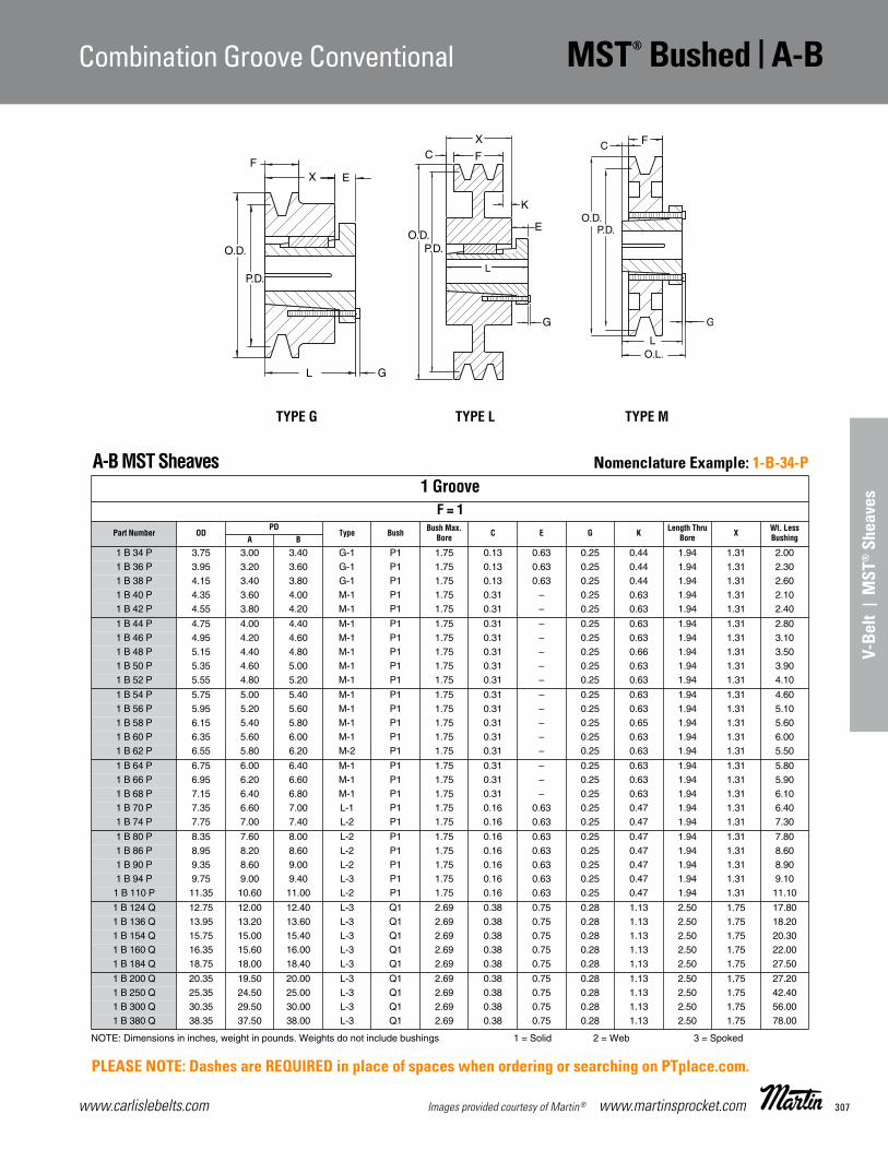
307www.carlislebelts.com Images provided courtesy of Martin® www.martinsprocket.com
8V | MST® Sheaves Hi-Cap® Wedge
V-Be
lt |
MST
® S
heav
es
Combination Groove Conventional MST® Bushed | A-B
D-79
F
TYPE M
O.D.
EXF
L G
P.D.
P.D.
TYPE G TYPE L
A-B MST Sheaves
NOTE: Dimensions in inches, weight in pounds. Weights do not include bushings 1 = Solid 2 = Web 3 = Spoked
1 GrooveF = 1
Part Number ODPD
Type Bush Bush Max.Bore C E G K Length Thru
Bore X Wt. Less BushingA B
1 B 34 P 3.75 3.00 3.40 G-1 P1 1.75 0.13 0.63 0.25 0.44 1.94 1.31 2.001 B 36 P 3.95 3.20 3.60 G-1 P1 1.75 0.13 0.63 0.25 0.44 1.94 1.31 2.301 B 38 P 4.15 3.40 3.80 G-1 P1 1.75 0.13 0.63 0.25 0.44 1.94 1.31 2.601 B 40 P 4.35 3.60 4.00 M-1 P1 1.75 0.31 – 0.25 0.63 1.94 1.31 2.101 B 42 P 4.55 3.80 4.20 M-1 P1 1.75 0.31 – 0.25 0.63 1.94 1.31 2.40
1 B 44 P 4.75 4.00 4.40 M-1 P1 1.75 0.31 – 0.25 0.63 1.94 1.31 2.801 B 46 P 4.95 4.20 4.60 M-1 P1 1.75 0.31 – 0.25 0.63 1.94 1.31 3.101 B 48 P 5.15 4.40 4.80 M-1 P1 1.75 0.31 – 0.25 0.66 1.94 1.31 3.501 B 50 P 5.35 4.60 5.00 M-1 P1 1.75 0.31 – 0.25 0.63 1.94 1.31 3.901 B 52 P 5.55 4.80 5.20 M-1 P1 1.75 0.31 – 0.25 0.63 1.94 1.31 4.10
1 B 54 P 5.75 5.00 5.40 M-1 P1 1.75 0.31 – 0.25 0.63 1.94 1.31 4.601 B 56 P 5.95 5.20 5.60 M-1 P1 1.75 0.31 – 0.25 0.63 1.94 1.31 5.101 B 58 P 6.15 5.40 5.80 M-1 P1 1.75 0.31 – 0.25 0.65 1.94 1.31 5.601 B 60 P 6.35 5.60 6.00 M-1 P1 1.75 0.31 – 0.25 0.63 1.94 1.31 6.001 B 62 P 6.55 5.80 6.20 M-2 P1 1.75 0.31 – 0.25 0.63 1.94 1.31 5.50
1 B 64 P 6.75 6.00 6.40 M-1 P1 1.75 0.31 – 0.25 0.63 1.94 1.31 5.801 B 66 P 6.95 6.20 6.60 M-1 P1 1.75 0.31 – 0.25 0.63 1.94 1.31 5.901 B 68 P 7.15 6.40 6.80 M-1 P1 1.75 0.31 – 0.25 0.63 1.94 1.31 6.101 B 70 P 7.35 6.60 7.00 L-1 P1 1.75 0.16 0.63 0.25 0.47 1.94 1.31 6.401 B 74 P 7.75 7.00 7.40 L-2 P1 1.75 0.16 0.63 0.25 0.47 1.94 1.31 7.30
1 B 80 P 8.35 7.60 8.00 L-2 P1 1.75 0.16 0.63 0.25 0.47 1.94 1.31 7.801 B 86 P 8.95 8.20 8.60 L-2 P1 1.75 0.16 0.63 0.25 0.47 1.94 1.31 8.601 B 90 P 9.35 8.60 9.00 L-2 P1 1.75 0.16 0.63 0.25 0.47 1.94 1.31 8.901 B 94 P 9.75 9.00 9.40 L-3 P1 1.75 0.16 0.63 0.25 0.47 1.94 1.31 9.101 B 110 P 11.35 10.60 11.00 L-2 P1 1.75 0.16 0.63 0.25 0.47 1.94 1.31 11.10
1 B 124 Q 12.75 12.00 12.40 L-3 Q1 2.69 0.38 0.75 0.28 1.13 2.50 1.75 17.801 B 136 Q 13.95 13.20 13.60 L-3 Q1 2.69 0.38 0.75 0.28 1.13 2.50 1.75 18.201 B 154 Q 15.75 15.00 15.40 L-3 Q1 2.69 0.38 0.75 0.28 1.13 2.50 1.75 20.301 B 160 Q 16.35 15.60 16.00 L-3 Q1 2.69 0.38 0.75 0.28 1.13 2.50 1.75 22.001 B 184 Q 18.75 18.00 18.40 L-3 Q1 2.69 0.38 0.75 0.28 1.13 2.50 1.75 27.50
1 B 200 Q 20.35 19.50 20.00 L-3 Q1 2.69 0.38 0.75 0.28 1.13 2.50 1.75 27.201 B 250 Q 25.35 24.50 25.00 L-3 Q1 2.69 0.38 0.75 0.28 1.13 2.50 1.75 42.401 B 300 Q 30.35 29.50 30.00 L-3 Q1 2.69 0.38 0.75 0.28 1.13 2.50 1.75 56.001 B 380 Q 38.35 37.50 38.00 L-3 Q1 2.69 0.38 0.75 0.28 1.13 2.50 1.75 78.00
A-BCombination Groove ConventionalMST® Bushed Stock Sheaves
MST Sheaves_D17-D32 11/13/14 10:43 AM Page D-79
BACK TO MENU INDEX
Nomenclature Example: 1-B-34-P
PLEASE NOTE: Dashes are REQUIRED in place of spaces when ordering or searching on PTplace.com.

www.carlislebelts.com308 www.martinsprocket.com Images provided courtesy of Martin®
A-B | MST® Bushed Combination Groove Conventional
D-80
A-B MST Sheaves
NOTE: Dimensions in inches, weight in pounds. Weights do not include bushings 1 = Solid 2 = Web 3 = Spoked
2 GrooveF = 1-3/4
Part Number ODPD
Type Bush Bush Max.Bore C E G K Length Thru
Bore X Wt. Less BushingA B
2 B 34 P 3.75 3.00 3.40 G-1 P1 1.75 0.88 0.63 0.25 1.31 1.31 2.19 2.902 B 36 P 3.95 3.20 3.60 G-1 P1 1.75 0.88 0.63 0.25 1.31 1.94 2.19 3.802 B 38 P 4.15 3.40 3.80 S-1 P1 1.75 0.44 – 0.25 – 1.31 1.31 3.002 B 40 P 4.35 3.60 4.00 S-1 P1 1.75 0.44 – 0.25 – 1.31 1.31 3.802 B 42 P 4.55 3.80 4.20 S-1 P1 1.75 0.44 – 0.25 – 1.94 1.31 3.902 B 44 P 4.75 4.00 4.40 J-1 P1 1.75 – 0.63 0.25 0.44 1.31 1.31 3.902 B 46 P 4.95 4.20 4.60 J-1 P1 1.75 – 0.63 0.25 0.44 1.31 1.31 4.502 B 48 P 5.15 4.40 4.80 J-1 P1 1.75 – 0.63 0.25 0.44 1.94 1.31 5.302 B 50 P 5.35 4.60 5.00 J-1 P1 1.75 – 0.63 0.25 0.44 1.31 1.31 5.602 B 52 P 5.55 4.80 5.20 J-1 P1 1.75 – 0.63 0.25 0.44 1.94 1.31 6.102 B 54 P 5.75 5.00 5.40 J-1 P1 1.75 – 0.63 0.25 0.44 1.31 1.31 6.502 B 54 Q 5.75 5.00 5.40 S-1 Q1 2.69 – 0.63 0.28 – 2.50 1.75 6.002 B 56 P 5.95 5.20 5.60 J-1 P1 1.75 – 0.63 0.25 0.44 1.31 1.31 7.402 B 56 Q 5.95 5.20 5.60 S-1 Q1 2.69 – 0.63 0.28 – 2.50 1.75 7.302 B 58 P 6.15 5.40 5.80 J-1 P1 1.75 – 0.63 0.25 0.44 1.31 1.31 8.002 B 58 Q 6.15 5.40 5.80 S-1 Q1 2.69 – 0.63 0.28 – 2.50 1.75 7.902 B 60 P 6.35 5.60 6.00 J-1 P1 1.75 – 0.63 0.25 0.44 1.31 1.31 8.902 B 60 Q 6.35 5.60 6.00 S-1 Q1 2.69 – 0.63 0.28 – 2.50 1.75 8.902 B 62 P 6.55 5.80 6.20 J-2 P1 1.75 – 0.63 0.25 0.44 1.31 1.31 7.602 B 62 Q 6.55 5.80 6.20 S-1 Q1 2.69 – 0.63 0.28 – 2.50 1.75 9.402 B 64 P 6.75 6.00 6.40 J-2 P1 1.75 – 0.63 0.25 0.44 1.31 1.31 7.802 B 64 Q 6.75 6.00 6.40 S-1 Q1 2.69 – 0.63 0.28 – 2.50 1.75 10.102 B 66 P 6.95 6.20 6.60 J-2 P1 1.75 – 0.63 0.25 0.44 1.31 1.31 8.302 B 66 Q 6.95 6.20 6.60 S-1 Q1 2.69 – 0.63 0.28 – 2.50 1.75 11.102 B 68 P 7.15 6.40 6.80 J-2 P1 1.75 – 0.63 0.25 0.44 1.31 1.31 8.802 B 68 Q 7.15 6.40 6.80 S-1 Q1 2.69 – 0.63 0.28 – 2.50 1.75 12.302 B 70 Q 7.35 6.60 7.00 J-2 Q1 2.69 – 0.75 0.28 – 1.75 1.75 11.102 B 74 Q 7.75 7.00 7.40 J-2 Q1 2.69 – 0.75 0.28 – 2.50 1.75 11.502 B 80 Q 8.35 7.60 8.00 J-2 Q1 2.69 – 0.75 0.28 – 1.75 1.75 12.802 B 86 Q 8.95 8.20 8.60 J-2 Q1 2.69 – 0.75 0.28 – 2.50 1.75 16.002 B 90 Q 9.35 8.60 9.00 J-3 Q1 2.69 – 0.75 0.28 – 1.75 1.75 15.102 B 94 Q 9.75 9.00 9.40 J-3 Q1 2.69 – 0.75 0.28 – 2.50 1.75 15.502 B 110 Q 11.35 10.60 11.00 J-3 Q1 2.69 – 0.75 0.28 – 1.75 1.75 18.902 B 124 Q 12.75 12.00 12.40 J-3 Q1 2.69 – 0.75 0.28 – 1.75 1.75 21.102 B 136 Q 13.95 13.20 13.60 J-3 Q1 2.69 – 0.75 0.28 – 2.50 1.75 23.002 B 154 Q 15.75 15.00 15.40 J-3 Q1 2.69 – 0.75 0.28 – 1.75 1.75 24.802 B 154 R 15.75 15.00 15.40 L-3 R1 3.75 0.13 0.75 0.28 0.25 2.88 2.00 30.602 B 160 Q 16.35 15.60 16.00 J-3 Q1 2.69 – 0.75 0.28 – 1.75 1.75 27.002 B 160 R 16.35 15.60 16.00 L-3 R1 3.75 0.13 0.75 0.28 0.25 2.88 2.00 32.002 B 184 Q 18.75 18.00 18.40 J-3 Q1 2.69 – 0.75 0.28 – 1.75 1.75 32.302 B 184 R 18.75 18.00 18.40 L-3 R1 3.75 0.13 0.75 0.28 0.38 2.88 2.00 39.102 B 200 Q 20.35 19.50 20.00 J-3 Q1 2.69 – 0.75 0.28 – 1.75 1.75 42.302 B 200 R 20.35 19.50 20.00 L-3 R1 3.75 0.13 0.75 0.28 0.25 2.88 2.00 43.502 B 250 Q 25.35 24.50 25.00 J-3 Q1 2.69 – 0.75 0.28 – 1.75 1.75 50.302 B 250 R 25.35 24.50 25.00 L-3 R1 3.75 0.13 0.75 0.28 0.25 2.88 2.00 58.002 B 300 Q 30.35 29.50 30.00 J-3 Q1 2.69 – 0.75 0.28 – 1.75 1.75 68.802 B 300 R 30.35 29.50 30.00 L-3 R1 3.75 0.13 0.75 0.28 0.25 2.88 2.00 81.002 B 380 Q 38.35 37.50 38.00 J-3 Q1 2.69 – 0.75 0.28 – 1.75 1.75 95.502 B 380 R 38.35 37.50 38.00 L-3 R1 3.75 0.13 0.75 0.28 0.25 2.88 2.00 92.00
O.D.
EXF
L G
P.D.
P.D.
TYPE G TYPE L
P.D.
O.D.
E
K
LC G
FX
TYPE JTYPE S
A-BCombination Groove ConventionalMST® Bushed Stock Sheaves
MST Sheaves_D17-D32 11/13/14 10:43 AM Page D-80
BACK TO MENU INDEX
Nomenclature Example: 2-B-34-P
PLEASE NOTE: Dashes are REQUIRED in place of spaces when ordering or searching on PTplace.com.

309www.carlislebelts.com Images provided courtesy of Martin® www.martinsprocket.com
V-Be
lt |
MST
® S
heav
es
Combination Groove Conventional MST® Bushed | A-B
D-81
A-B MST Sheaves
NOTE: Dimensions in inches, weight in pounds. Weights do not include bushings 1 = Solid 2 = Web 3 = Spoked
3 GrooveF = 2-1/2
Part Number ODPD
Type Bush Bush Max.Bore C E G K Length Thru
Bore X Wt. Less BushingA B
3 B 34 P 3.75 3.00 3.40 G-1 P2 1.75 0.63 0.63 0.25 0.44 2.94 2.31 3.803 B 36 P 3.95 3.20 3.60 N-1 P2 1.75 0.63 0.63 0.25 0.44 2.31 2.31 4.403 B 38 P 4.15 3.40 3.80 S-1 P1 1.75 1.19 – 0.25 – 1.94 1.31 3.803 B 40 P 4.35 3.60 4.00 S-1 P1 1.75 1.19 – 0.25 – 1.94 1.31 4.503 B 42 P 4.55 3.80 4.20 S-1 P1 1.75 1.19 – 0.25 – 1.31 1.31 4.903 B 44 P 4.75 4.00 4.40 J-1 P1 1.75 0.56 0.63 0.25 0.63 1.94 1.31 5.103 B 46 P 4.95 4.20 4.60 J-2 P1 1.75 0.56 0.63 0.25 0.63 1.31 1.31 6.003 B 48 P 5.15 4.40 4.80 J-2 P1 1.75 0.56 0.63 0.25 0.63 1.94 1.31 6.303 B 50 P 5.35 4.60 5.00 J-2 P1 1.75 0.56 0.63 0.25 0.63 1.31 1.31 6.903 B 52 P 5.55 4.80 5.20 J-2 P1 1.75 0.56 0.63 0.25 0.63 1.94 1.31 7.503 B 54 P 5.75 5.00 5.40 J-2 P1 1.75 0.56 0.63 0.25 0.63 1.31 1.31 8.303 B 54 Q 5.75 5.00 5.40 S-1 Q1 2.69 0.56 0.63 0.28 0.19 2.50 1.75 7.903 B 56 P 5.95 5.20 5.60 J-2 P1 1.75 0.56 0.63 0.25 0.63 1.31 1.31 9.003 B 56 Q 5.95 5.20 5.60 S-1 Q1 2.69 0.75 0.63 0.28 – 2.50 1.75 9.003 B 58 P 6.15 5.40 5.80 J-2 P1 1.75 0.56 0.63 0.25 0.63 1.31 1.31 9.603 B 58 Q 6.15 5.40 5.80 J-2 Q1 2.69 0.56 0.63 0.28 0.19 2.50 1.75 9.403 B 60 P 6.35 5.60 6.00 J-2 P1 1.75 0.56 0.63 0.25 0.63 1.31 1.31 10.503 B 60 Q 6.35 5.60 6.00 J-2 Q1 2.69 0.38 0.63 0.28 0.38 2.50 1.75 10.403 B 62 P 6.55 5.80 6.20 J-2 P1 1.75 0.56 0.63 0.25 0.63 1.31 1.31 9.403 B 62 Q 6.55 5.80 6.20 J-2 Q1 2.69 0.56 0.63 0.28 0.19 2.50 1.75 11.303 B 64 P 6.75 6.00 6.40 J-2 P1 1.75 0.56 0.63 0.25 0.63 1.31 1.31 9.503 B 64 Q 6.75 6.00 6.40 J-2 Q1 2.69 0.38 0.63 0.28 0.38 2.50 1.75 12.103 B 66 P 6.95 6.20 6.60 J-2 P1 1.75 0.56 0.63 0.25 0.63 1.31 1.31 10.003 B 66 Q 6.95 6.20 6.60 J-2 Q1 2.69 0.56 0.63 0.28 0.19 2.50 1.75 13.003 B 68 P 7.15 6.40 6.80 J-2 P1 1.75 0.56 0.63 0.25 0.63 1.31 1.31 10.403 B 68 Q 7.15 6.40 6.80 J-2 Q1 2.69 0.56 0.63 0.28 0.19 2.50 1.75 14.303 B 70 Q 7.35 6.60 7.00 J-2 Q1 2.69 0.38 0.75 0.28 0.38 1.75 1.75 13.003 B 74 Q 7.75 7.00 7.40 J-2 Q1 2.69 0.38 0.75 0.28 0.38 2.50 1.75 0.003 B 80 Q 8.35 7.60 8.00 J-2 Q1 2.69 0.38 0.75 0.28 0.38 1.75 1.75 15.303 B 86 Q 8.95 8.20 8.60 J-2 Q1 2.69 0.38 0.75 0.28 0.38 2.50 1.75 0.003 B 90 Q 9.35 8.60 9.00 J-3 Q1 2.69 0.38 0.75 0.28 0.38 1.75 1.75 18.103 B 94 Q 9.75 9.00 9.40 J-3 Q1 2.69 0.38 0.75 0.28 0.38 2.50 1.75 0.003 B 110 Q 11.35 10.60 11.00 J-3 Q1 2.69 0.38 0.75 0.28 0.38 1.75 1.75 21.303 B 124 Q 12.75 12.00 12.40 J-3 Q1 2.69 0.38 0.75 0.28 0.38 2.50 1.75 25.403 B 136 Q 13.95 13.20 13.60 J-3 Q1 2.69 0.38 0.75 0.28 0.38 1.75 1.75 27.403 B 154 Q 15.75 15.00 15.40 J-3 Q1 2.69 0.38 0.75 0.28 0.38 1.75 1.75 29.803 B 154 R 15.75 15.00 15.40 J-3 R1 3.75 0.38 0.75 0.28 0.13 2.88 2.00 35.503 B 160 Q 16.35 15.60 16.00 J-3 Q1 2.69 0.38 0.75 0.28 0.38 1.75 1.75 32.003 B 160 R 16.35 15.60 16.00 J-3 R1 3.75 0.38 0.75 0.28 0.13 2.88 2.00 38.003 B 184 Q 18.75 18.00 18.40 J-3 Q1 2.69 0.38 0.75 0.28 0.38 1.75 1.75 37.803 B 184 R 18.75 18.00 18.40 J-3 R1 3.75 0.38 0.75 0.28 0.13 2.88 2.00 44.803 B 200 Q 20.35 19.50 20.00 J-3 Q1 2.69 0.38 0.75 0.28 0.38 1.75 1.75 49.903 B 200 R 20.35 19.50 20.00 J-3 R1 3.75 0.38 0.75 0.28 0.13 2.88 2.00 50.303 B 250 Q 25.35 24.50 25.00 J-3 Q1 2.69 0.38 0.75 0.28 0.38 1.75 1.75 61.003 B 250 R 25.35 24.50 25.00 J-3 R1 3.75 0.38 0.75 0.28 0.13 2.88 2.00 65.003 B 300 Q 30.35 29.50 30.00 J-3 Q1 2.69 0.38 0.75 0.28 0.38 1.75 1.75 78.503 B 300 R 30.35 29.50 30.00 J-3 R1 3.75 0.38 0.75 0.28 0.13 2.88 2.00 89.003 B 380 Q 38.35 37.50 38.00 J-3 Q1 2.69 0.38 0.75 0.28 0.38 1.75 1.75 110.003 B 380 R 38.35 37.50 38.00 J-3 R1 3.75 0.38 0.75 0.28 0.13 2.88 2.00 106.00
P.D.
O.D.
E
K
LC G
FX
TYPE JTYPE S TYPE N
A-BCombination Groove ConventionalMST® Bushed Stock Sheaves
MST Sheaves_D17-D32 11/13/14 10:43 AM Page D-81
BACK TO MENU INDEX
Nomenclature Example: 3-B-34-P
PLEASE NOTE: Dashes are REQUIRED in place of spaces when ordering or searching on PTplace.com.
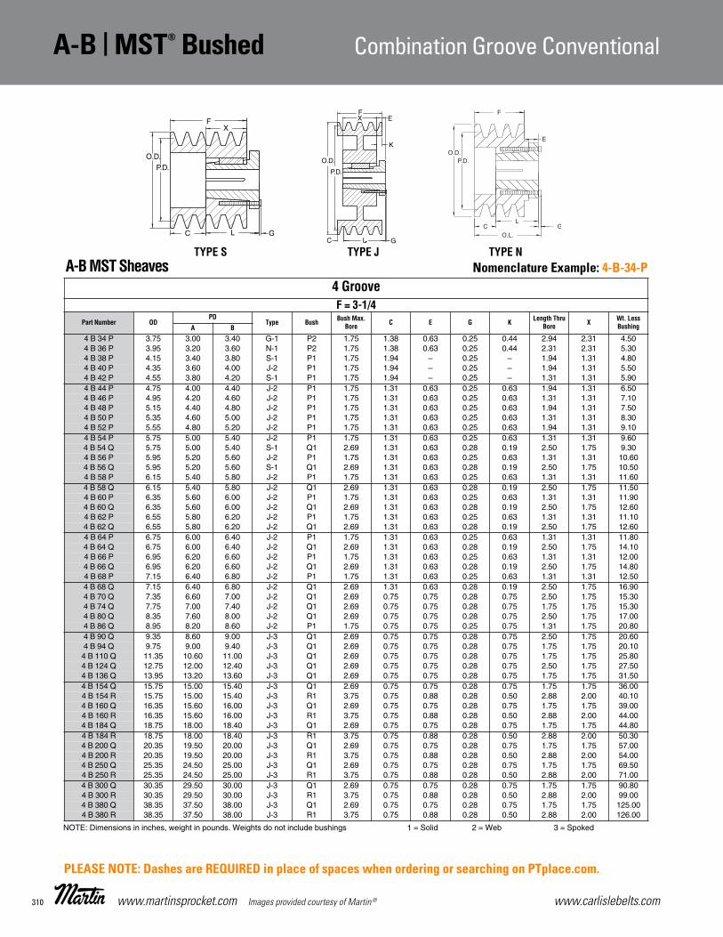
www.carlislebelts.com310 www.martinsprocket.com Images provided courtesy of Martin®
A-B | MST® Bushed Combination Groove Conventional
D-82
A-B MST Sheaves
NOTE: Dimensions in inches, weight in pounds. Weights do not include bushings 1 = Solid 2 = Web 3 = Spoked
4 GrooveF = 3-1/4
Part Number ODPD
Type Bush Bush Max.Bore C E G K Length Thru
Bore X Wt. Less BushingA B
4 B 34 P 3.75 3.00 3.40 G-1 P2 1.75 1.38 0.63 0.25 0.44 2.94 2.31 4.504 B 36 P 3.95 3.20 3.60 N-1 P2 1.75 1.38 0.63 0.25 0.44 2.31 2.31 5.304 B 38 P 4.15 3.40 3.80 S-1 P1 1.75 1.94 – 0.25 – 1.94 1.31 4.804 B 40 P 4.35 3.60 4.00 J-2 P1 1.75 1.94 – 0.25 – 1.94 1.31 5.504 B 42 P 4.55 3.80 4.20 S-1 P1 1.75 1.94 – 0.25 – 1.31 1.31 5.904 B 44 P 4.75 4.00 4.40 J-2 P1 1.75 1.31 0.63 0.25 0.63 1.94 1.31 6.504 B 46 P 4.95 4.20 4.60 J-2 P1 1.75 1.31 0.63 0.25 0.63 1.31 1.31 7.104 B 48 P 5.15 4.40 4.80 J-2 P1 1.75 1.31 0.63 0.25 0.63 1.94 1.31 7.504 B 50 P 5.35 4.60 5.00 J-2 P1 1.75 1.31 0.63 0.25 0.63 1.31 1.31 8.304 B 52 P 5.55 4.80 5.20 J-2 P1 1.75 1.31 0.63 0.25 0.63 1.94 1.31 9.104 B 54 P 5.75 5.00 5.40 J-2 P1 1.75 1.31 0.63 0.25 0.63 1.31 1.31 9.604 B 54 Q 5.75 5.00 5.40 S-1 Q1 2.69 1.31 0.63 0.28 0.19 2.50 1.75 9.304 B 56 P 5.95 5.20 5.60 J-2 P1 1.75 1.31 0.63 0.25 0.63 1.31 1.31 10.604 B 56 Q 5.95 5.20 5.60 S-1 Q1 2.69 1.31 0.63 0.28 0.19 2.50 1.75 10.504 B 58 P 6.15 5.40 5.80 J-2 P1 1.75 1.31 0.63 0.25 0.63 1.31 1.31 11.604 B 58 Q 6.15 5.40 5.80 J-2 Q1 2.69 1.31 0.63 0.28 0.19 2.50 1.75 11.504 B 60 P 6.35 5.60 6.00 J-2 P1 1.75 1.31 0.63 0.25 0.63 1.31 1.31 11.904 B 60 Q 6.35 5.60 6.00 J-2 Q1 2.69 1.31 0.63 0.28 0.19 2.50 1.75 12.604 B 62 P 6.55 5.80 6.20 J-2 P1 1.75 1.31 0.63 0.25 0.63 1.31 1.31 11.104 B 62 Q 6.55 5.80 6.20 J-2 Q1 2.69 1.31 0.63 0.28 0.19 2.50 1.75 12.604 B 64 P 6.75 6.00 6.40 J-2 P1 1.75 1.31 0.63 0.25 0.63 1.31 1.31 11.804 B 64 Q 6.75 6.00 6.40 J-2 Q1 2.69 1.31 0.63 0.28 0.19 2.50 1.75 14.104 B 66 P 6.95 6.20 6.60 J-2 P1 1.75 1.31 0.63 0.25 0.63 1.31 1.31 12.004 B 66 Q 6.95 6.20 6.60 J-2 Q1 2.69 1.31 0.63 0.28 0.19 2.50 1.75 14.804 B 68 P 7.15 6.40 6.80 J-2 P1 1.75 1.31 0.63 0.25 0.63 1.31 1.31 12.504 B 68 Q 7.15 6.40 6.80 J-2 Q1 2.69 1.31 0.63 0.28 0.19 2.50 1.75 16.904 B 70 Q 7.35 6.60 7.00 J-2 Q1 2.69 0.75 0.75 0.28 0.75 2.50 1.75 15.304 B 74 Q 7.75 7.00 7.40 J-2 Q1 2.69 0.75 0.75 0.28 0.75 1.75 1.75 15.304 B 80 Q 8.35 7.60 8.00 J-2 Q1 2.69 0.75 0.75 0.28 0.75 2.50 1.75 17.004 B 86 Q 8.95 8.20 8.60 J-2 P1 1.75 0.75 0.75 0.25 0.75 1.31 1.75 20.804 B 90 Q 9.35 8.60 9.00 J-3 Q1 2.69 0.75 0.75 0.28 0.75 2.50 1.75 20.604 B 94 Q 9.75 9.00 9.40 J-3 Q1 2.69 0.75 0.75 0.28 0.75 1.75 1.75 20.104 B 110 Q 11.35 10.60 11.00 J-3 Q1 2.69 0.75 0.75 0.28 0.75 1.75 1.75 25.804 B 124 Q 12.75 12.00 12.40 J-3 Q1 2.69 0.75 0.75 0.28 0.75 2.50 1.75 27.504 B 136 Q 13.95 13.20 13.60 J-3 Q1 2.69 0.75 0.75 0.28 0.75 1.75 1.75 31.504 B 154 Q 15.75 15.00 15.40 J-3 Q1 2.69 0.75 0.75 0.28 0.75 1.75 1.75 36.004 B 154 R 15.75 15.00 15.40 J-3 R1 3.75 0.75 0.88 0.28 0.50 2.88 2.00 40.104 B 160 Q 16.35 15.60 16.00 J-3 Q1 2.69 0.75 0.75 0.28 0.75 1.75 1.75 39.004 B 160 R 16.35 15.60 16.00 J-3 R1 3.75 0.75 0.88 0.28 0.50 2.88 2.00 44.004 B 184 Q 18.75 18.00 18.40 J-3 Q1 2.69 0.75 0.75 0.28 0.75 1.75 1.75 44.804 B 184 R 18.75 18.00 18.40 J-3 R1 3.75 0.75 0.88 0.28 0.50 2.88 2.00 50.304 B 200 Q 20.35 19.50 20.00 J-3 Q1 2.69 0.75 0.75 0.28 0.75 1.75 1.75 57.004 B 200 R 20.35 19.50 20.00 J-3 R1 3.75 0.75 0.88 0.28 0.50 2.88 2.00 54.004 B 250 Q 25.35 24.50 25.00 J-3 Q1 2.69 0.75 0.75 0.28 0.75 1.75 1.75 69.504 B 250 R 25.35 24.50 25.00 J-3 R1 3.75 0.75 0.88 0.28 0.50 2.88 2.00 71.004 B 300 Q 30.35 29.50 30.00 J-3 Q1 2.69 0.75 0.75 0.28 0.75 1.75 1.75 90.804 B 300 R 30.35 29.50 30.00 J-3 R1 3.75 0.75 0.88 0.28 0.50 2.88 2.00 99.004 B 380 Q 38.35 37.50 38.00 J-3 Q1 2.69 0.75 0.75 0.28 0.75 1.75 1.75 125.004 B 380 R 38.35 37.50 38.00 J-3 R1 3.75 0.75 0.88 0.28 0.50 2.88 2.00 126.00
P.D.
O.D.
E
K
LC G
FX
TYPE JTYPE S TYPE N
A-BCombination Groove ConventionalMST® Bushed Stock Sheaves
MST Sheaves_D17-D32 11/13/14 10:43 AM Page D-82
BACK TO MENU INDEX
Nomenclature Example: 4-B-34-P
PLEASE NOTE: Dashes are REQUIRED in place of spaces when ordering or searching on PTplace.com.

311www.carlislebelts.com Images provided courtesy of Martin® www.martinsprocket.com
V-Be
lt |
MST
® S
heav
es
Combination Groove Conventional MST® Bushed | A-B
D-83
A-B MST Sheaves
NOTE: Dimensions in inches, weight in pounds. Weights do not include bushings 1 = Solid 2 = Web 3 = Spoked
5 GrooveF = 4
Part Number ODPD
Type Bush Bush Max.Bore C E G K Length Thru
Bore X Wt. Less BushingA B
5 B 34 P 3.75 3.00 3.40 N-1 P2 1.75 2.13 0.63 0.25 0.44 2.31 2.31 5.305 B 36 P 3.95 3.20 3.60 G-1 P2 1.75 2.13 0.63 0.25 0.44 2.94 2.31 6.105 B 38 P 4.15 3.40 3.80 S-1 P2 1.75 1.69 – 0.25 – 2.31 2.31 6.105 B 40 P 4.35 3.60 4.00 S-1 P2 1.75 1.69 – 0.25 – 2.31 2.31 7.005 B 42 P 4.55 3.80 4.20 S-1 P2 1.75 1.69 – 0.25 – 2.94 2.31 7.805 B 44 P 4.75 4.00 4.40 J-2 P2 1.75 1.06 0.63 0.25 0.63 2.31 2.31 8.505 B 46 P 4.95 4.20 4.60 J-2 P2 1.75 1.06 0.63 0.25 0.63 2.94 2.31 9.805 B 48 P 5.15 4.40 4.80 J-2 P2 1.75 1.06 0.63 0.25 0.63 2.31 2.31 10.505 B 50 P 5.35 4.60 5.00 J-2 P2 1.75 1.06 0.63 0.25 0.63 2.94 2.31 11.605 B 52 P 5.55 4.80 5.20 J-2 P2 1.75 1.06 0.63 0.25 0.63 2.94 2.31 12.505 B 54 Q 5.75 5.00 5.40 J-2 Q1 2.69 1.50 0.75 0.28 0.75 1.75 1.75 10.405 B 56 Q 5.95 5.20 5.60 J-2 Q1 2.69 1.50 0.75 0.28 0.75 2.50 1.75 11.805 B 58 Q 6.15 5.40 5.80 J-2 Q1 2.69 1.50 0.75 0.28 0.75 1.75 1.75 12.805 B 60 Q 6.35 5.60 6.00 J-2 Q1 2.69 1.50 0.75 0.28 0.75 2.50 1.75 13.805 B 62 Q 6.55 5.80 6.20 J-2 Q1 2.69 1.50 0.75 0.28 0.75 1.75 1.75 14.605 B 64 Q 6.75 6.00 6.40 J-2 Q1 2.69 1.50 0.75 0.28 0.75 2.50 1.75 16.405 B 66 Q 6.95 6.20 6.60 J-2 Q1 2.69 1.50 0.75 0.28 0.75 1.75 1.75 17.105 B 68 Q 7.15 6.40 6.80 J-2 Q1 2.69 1.50 0.75 0.28 0.75 2.50 1.75 17.905 B 70 Q 7.35 6.60 7.00 J-2 Q2 2.63 0.63 0.75 0.28 0.63 2.75 2.75 20.905 B 70 R 7.35 6.60 7.00 J-2 R1 3.75 1.00 0.88 0.28 1.00 2.88 2.00 17.005 B 74 Q 7.75 7.00 7.40 J-2 Q2 2.63 0.63 0.75 0.28 0.63 2.75 2.75 19.805 B 74 R 7.75 7.00 7.40 J-2 R1 3.75 1.00 0.88 0.28 1.00 2.88 2.00 20.305 B 80 Q 8.35 7.60 8.00 J-2 Q2 2.63 0.63 0.75 0.28 0.63 2.75 2.75 22.305 B 80 R 8.35 7.60 8.00 J-2 R1 3.75 1.00 0.88 0.28 1.00 2.88 2.00 24.805 B 86 Q 8.95 8.20 8.60 J-2 Q2 2.63 0.63 0.75 0.28 0.63 2.75 2.75 29.505 B 86 R 8.95 8.20 8.60 J-2 R1 3.75 1.00 0.88 0.28 1.00 2.88 2.00 27.305 B 90 Q 9.35 8.60 9.00 J-3 Q2 2.63 0.63 0.75 0.28 0.63 2.75 2.75 28.605 B 90 R 9.35 8.60 9.00 J-2 R1 3.75 1.00 0.88 0.28 1.00 2.88 2.00 29.105 B 94 Q 9.75 9.00 9.40 J-3 Q2 2.63 0.63 0.75 0.28 0.63 2.75 2.75 29.505 B 94 R 9.75 9.00 9.40 J-2 R1 3.75 1.00 0.88 0.28 1.00 2.88 2.00 30.00
5 B 110 Q 11.35 10.60 11.00 J-3 Q2 2.63 0.63 0.75 0.28 0.63 2.75 2.75 32.805 B 110 R 11.35 10.60 11.00 K-3 R1 3.75 1.00 0.88 0.28 1.00 2.88 2.00 32.805 B 124 Q 12.75 12.00 12.40 J-3 Q2 2.63 0.63 0.75 0.28 0.63 2.75 2.75 35.405 B 124 R 12.75 12.00 12.40 K-3 R1 3.75 1.00 0.88 0.28 1.00 2.88 2.00 36.005 B 136 Q 13.95 13.20 13.60 J-3 Q2 2.63 0.63 0.75 0.28 0.63 2.75 2.75 41.005 B 136 R 13.95 13.20 13.60 K-3 R1 3.75 1.00 0.88 0.28 1.00 2.88 2.00 40.305 B 154 Q 15.75 15.00 15.40 J-3 Q2 2.63 0.63 0.75 0.28 0.63 2.75 2.75 45.305 B 154 R 15.75 15.00 15.40 K-3 R1 3.75 1.00 0.88 0.28 1.00 2.88 2.00 45.005 B 160 Q 16.35 15.60 16.00 J-3 Q2 2.63 0.63 0.75 0.28 0.63 2.75 2.75 48.005 B 160 R 16.35 15.60 16.00 K-3 R1 3.75 1.00 0.88 0.28 1.00 2.88 2.00 48.005 B 184 Q 18.75 18.00 18.40 J-3 Q2 2.63 0.63 0.75 0.28 0.63 2.75 2.75 57.305 B 184 R 18.75 18.00 18.40 K-3 R1 3.75 1.00 0.88 0.28 1.00 2.88 2.00 54.005 B 200 Q 20.35 19.50 20.00 J-3 Q2 2.63 0.63 0.75 0.28 0.63 2.75 2.75 66.005 B 200 R 20.35 19.50 20.00 K-3 R1 3.75 1.00 0.88 0.28 1.00 2.88 2.00 64.005 B 250 Q 25.35 24.50 25.00 J-3 Q2 2.63 0.63 0.75 0.28 0.63 2.75 2.75 82.505 B 250 R 25.35 24.50 25.00 K-3 R1 3.75 1.00 0.88 0.28 1.00 2.88 2.00 79.005 B 300 Q 30.35 29.50 30.00 J-3 Q2 2.63 0.63 0.75 0.28 0.63 2.75 2.75 117.005 B 300 R 30.35 29.50 30.00 K-3 R1 3.75 1.00 0.88 0.28 1.00 2.88 2.00 115.005 B 380 Q 38.35 37.50 38.00 J-3 Q2 2.63 0.63 0.75 0.28 0.63 2.75 2.75 159.005 B 380 R 38.35 37.50 38.00 K-3 R1 3.75 1.00 0.88 0.28 1.00 2.88 2.00 150.00
P.D.
O.D.
E
K
LC G
FX
TYPE JTYPE S TYPE NTYPE K
O.D.
XF
K
E
G
P.D.
A-BCombination Groove ConventionalMST® Bushed Stock Sheaves
MST Sheaves_D17-D32 11/13/14 10:43 AM Page D-83
BACK TO MENU INDEX
Nomenclature Example: 5-B-34-P
PLEASE NOTE: Dashes are REQUIRED in place of spaces when ordering or searching on PTplace.com.

www.carlislebelts.com312 www.martinsprocket.com Images provided courtesy of Martin®
A-B | MST® Bushed Combination Groove Conventional
D-84
A-B MST Sheaves
NOTE: Dimensions in inches, weight in pounds. Weights do not include bushings 1 = Solid 2 = Web 3 = Spoked
6 GrooveF = 4-3/4
Part Number ODPD
Type Bush Bush Max.Bore C E G K Length Thru
Bore X Wt. Less BushingA B
6 B 34 P 3.75 3.00 3.40 N-1 P2 1.75 0.00 0.63 0.25 2.44 2.94 2.31 6.106 B 36 P 3.95 3.20 3.60 N-1 P2 1.75 2.88 0.63 0.25 0.44 2.31 2.31 7.306 B 38 P 4.15 3.40 3.80 S-1 P2 1.75 – – 0.25 2.44 2.94 2.31 7.006 B 40 P 4.35 3.60 4.00 S-1 P2 1.75 – – 0.25 2.44 2.94 2.31 8.106 B 42 P 4.55 3.80 4.20 S-1 P2 1.75 2.44 – 0.25 – 2.31 2.31 9.306 B 44 P 4.75 4.00 4.40 J-2 P2 1.75 – 0.63 0.25 2.44 2.94 2.31 9.906 B 46 P 4.95 4.20 4.60 J-2 P2 1.75 – 0.63 0.25 2.44 2.94 2.31 11.006 B 48 P 5.15 4.40 4.80 J-2 P2 1.75 1.81 0.63 0.25 0.63 2.31 2.31 11.806 B 50 P 5.35 4.60 5.00 J-2 P2 1.75 – 0.63 0.25 2.44 2.94 2.31 12.906 B 52 P 5.55 4.80 5.20 J-2 P2 1.75 1.81 0.63 0.25 0.63 2.31 2.31 14.806 B 54 Q 5.75 5.00 5.40 J-2 Q1 2.69 – 0.75 0.28 3.00 2.50 1.75 11.806 B 56 Q 5.95 5.20 5.60 J-2 Q1 2.69 2.25 0.75 0.28 0.75 1.75 1.75 17.306 B 58 Q 6.15 5.40 5.80 J-2 Q1 2.69 – 0.75 0.28 3.00 2.50 1.75 14.506 B 60 Q 6.35 5.60 6.00 J-2 Q1 2.69 – 0.75 0.28 3.00 2.50 1.75 15.406 B 62 Q 6.55 5.80 6.20 J-2 Q1 2.69 2.25 0.75 0.28 0.75 1.75 1.75 16.406 B 64 Q 6.75 6.00 6.40 J-2 Q1 2.69 – 0.75 0.28 3.00 2.50 1.75 18.606 B 66 Q 6.95 6.20 6.60 J-2 Q1 2.69 2.25 0.75 0.28 0.75 1.75 1.75 18.506 B 68 Q 7.15 6.40 6.80 J-2 Q1 2.69 – 0.75 0.28 3.00 2.50 1.75 20.806 B 70 Q 7.35 6.60 7.00 K-2 Q2 2.63 1.00 0.75 0.28 1.00 2.75 2.75 22.806 B 70 R 7.35 6.60 7.00 J-2 R1 3.75 – 0.88 0.28 2.75 2.88 2.00 19.006 B 74 Q 7.75 7.00 7.40 K-2 Q2 2.63 1.00 0.75 0.28 1.00 2.75 2.75 26.506 B 74 R 7.75 7.00 7.40 J-2 R1 3.75 – 0.88 0.28 2.75 2.88 2.00 21.806 B 80 Q 8.35 7.60 8.00 K-2 Q2 2.63 1.00 0.75 0.28 1.00 2.75 2.75 24.106 B 80 R 8.35 7.60 8.00 J-2 R1 3.75 – 0.88 0.28 2.75 2.88 2.00 26.806 B 86 Q 8.95 8.20 8.60 K-2 Q2 2.63 1.00 0.75 0.28 1.00 2.75 2.75 27.106 B 86 R 8.95 8.20 8.60 J-2 R1 3.75 – 0.88 0.28 2.75 2.88 2.00 29.406 B 90 Q 9.35 8.60 9.00 K-2 Q2 2.63 1.00 0.75 0.28 1.00 2.75 2.75 30.606 B 90 R 9.35 8.60 9.00 J-2 R1 3.75 – 0.88 0.28 2.75 2.88 2.00 31.406 B 94 Q 9.75 9.00 9.40 K-3 Q2 2.63 1.00 0.75 0.28 1.00 2.75 2.75 32.806 B 94 R 9.75 9.00 9.40 J-2 R1 3.75 – 0.88 0.28 2.75 2.88 2.00 32.80
6 B 110 Q 11.35 10.60 11.00 K-3 Q2 2.63 1.00 0.75 0.28 1.00 2.75 2.75 36.606 B 110 R 11.35 10.60 11.00 J-2 R1 3.75 – 0.88 0.28 2.75 2.88 2.00 37.006 B 124 Q 12.75 12.00 12.40 K-3 Q2 2.63 1.00 0.75 0.28 1.00 2.75 2.75 39.806 B 124 R 12.75 12.00 12.40 J-2 R1 3.75 – 0.88 0.28 2.75 2.88 2.00 39.406 B 136 Q 13.95 13.20 13.60 K-3 Q2 2.63 1.00 0.75 0.28 1.00 2.75 2.75 44.906 B 136 R 13.95 13.20 13.60 K-3 R1 3.75 – 0.88 0.28 2.75 2.88 2.00 45.306 B 154 Q 15.75 15.00 15.40 K-3 Q2 2.63 1.00 0.75 0.28 1.00 2.75 2.75 49.906 B 154 R 15.75 15.00 15.40 K-3 R1 3.75 – 0.88 0.28 2.75 2.88 2.00 49.106 B 160 Q 16.35 15.60 16.00 K-3 Q2 2.63 1.00 0.75 0.28 1.00 2.75 2.75 54.006 B 160 R 16.35 15.60 16.00 K-3 R1 3.75 – 0.88 0.28 2.75 2.88 2.00 52.006 B 184 Q 18.75 18.00 18.40 K-3 Q2 2.63 1.00 0.75 0.28 1.00 2.75 2.75 62.006 B 184 R 18.75 18.00 18.40 K-3 R1 3.75 – 0.88 0.28 2.75 2.88 2.00 59.006 B 200 Q 20.35 19.50 20.00 K-3 Q2 2.63 1.00 0.75 0.28 1.00 2.75 2.75 74.006 B 200 R 20.35 19.50 20.00 K-3 R1 3.75 – 0.88 0.28 2.75 2.88 2.00 69.006 B 250 Q 25.35 24.50 25.00 K-3 Q2 2.63 1.00 0.75 0.28 1.00 2.75 2.75 89.506 B 250 R 25.35 24.50 25.00 K-3 R1 3.75 – 0.88 0.28 2.75 2.88 2.00 83.006 B 300 Q 30.35 29.50 30.00 K-3 Q2 2.63 1.00 0.75 0.28 1.00 2.75 2.75 128.006 B 300 R 30.35 29.50 30.00 K-3 R1 3.75 – 0.88 0.28 2.75 2.88 2.00 126.006 B 380 Q 38.35 37.50 38.00 K-3 Q2 2.63 1.00 0.75 0.28 1.00 2.75 2.75 179.006 B 380 R 38.35 37.50 38.00 K-3 R1 3.75 – 0.88 0.28 2.75 2.88 2.00 170.00
P.D.
O.D.
E
K
LC G
FX
TYPE JTYPE S TYPE NTYPE K
O.D.
XF
K
E
G
P.D.
A-BCombination Groove ConventionalMST® Bushed Stock Sheaves
MST Sheaves_D17-D32 11/13/14 10:43 AM Page D-84
BACK TO MENU INDEX
Nomenclature Example: 6-B-34-P
PLEASE NOTE: Dashes are REQUIRED in place of spaces when ordering or searching on PTplace.com.

313www.carlislebelts.com Images provided courtesy of Martin® www.martinsprocket.com
V-Be
lt |
MST
® S
heav
es
Combination Groove Conventional MST® Bushed | A-B
D-85
O.D.
XF
K
E
G
P.D.
TYPE KTYPE S
A-B MST Sheaves
NOTE: Dimensions in inches, weight in pounds. Weights do not include bushings 1 = Solid 2 = Web 3 = Spoked
8 GrooveF = 6-1/4
Part Number ODPD
Type Bush Bush Max.Bore E G K Length Thru
Bore X Wt. Less BushingA B
8 B 54 Q 5.75 5.00 5.40 S-1 Q2 2.63 0.75 0.28 3.50 3.50 2.75 18.10
8 B 56 Q 5.95 5.20 5.60 S-1 Q2 2.63 0.75 0.28 3.50 3.50 2.75 20.60
8 B 58 Q 6.15 5.40 5.80 K-2 Q2 2.63 0.75 0.28 3.50 3.50 2.75 20.90
8 B 60 Q 6.35 5.60 6.00 K-2 Q2 2.63 0.75 0.28 3.50 3.50 2.75 23.00
8 B 62 Q 6.55 5.80 6.20 K-2 Q2 2.63 0.75 0.28 3.50 3.50 2.75 23.00
8 B 64 Q 6.55 5.80 6.20 K-2 Q2 2.63 0.75 0.28 3.50 3.50 2.75 25.00
8 B 66 Q 6.95 6.20 6.60 K-2 Q2 2.63 0.75 0.28 3.50 3.50 2.75 27.30
8 B 68 Q 7.15 6.40 6.80 K-2 Q2 2.63 0.75 0.28 3.50 3.50 2.75 31.10
8 B 70 R 7.35 6.60 7.00 K-2 R2 3.63 0.88 0.28 2.25 4.88 4.00 29.50
8 B 74 R 7.75 7.00 7.40 K-2 R2 3.63 0.88 0.28 2.25 4.88 4.00 34.90
8 B 80 R 8.35 7.60 8.00 K-2 R2 3.63 0.88 0.28 2.25 4.88 4.00 42.90
8 B 86 R 8.95 8.20 8.60 K-2 R2 3.63 0.88 0.28 2.25 4.88 4.00 52.00
8 B 90 R 9.35 8.60 9.00 K-2 R2 3.63 0.88 0.28 2.25 4.88 4.00 48.30
8 B 94 R 9.75 9.00 9.40 K-2 R2 3.63 0.88 0.28 2.25 4.88 4.00 49.30
8 B 110 R 11.35 10.60 11.00 K-2 R2 3.63 0.88 0.28 2.25 4.88 4.00 55.00
8 B 124 R 12.75 12.00 12.40 K-3 R2 3.63 0.88 0.28 2.25 4.88 4.00 60.00
8 B 136 R 13.95 13.20 13.60 K-3 R2 3.63 0.88 0.28 2.25 4.88 4.00 68.50
8 B 154 R 15.75 15.00 15.40 K-3 R2 3.63 0.88 0.28 2.25 4.88 4.00 77.30
8 B 184 R 18.75 18.00 18.40 K-3 R2 3.63 0.88 0.28 2.25 4.88 4.00 90.00
8 B 200 R 20.35 19.50 20.00 K-3 R2 3.63 0.88 0.28 2.25 4.88 4.00 96.00
8 B 250 R 25.35 24.50 25.00 K-3 R2 3.63 0.88 0.28 2.25 4.88 4.00 129.00
8 B 300 R 30.35 29.50 30.00 K-3 R2 3.63 0.88 0.28 2.25 4.88 4.00 163.00
8 B 300 S 30.35 29.50 30.00 K-3 S1 4.25 1.06 0.38 2.94 4.38 3.31 168.00
8 B 380 R 38.35 37.50 38.00 K-3 R2 3.63 0.88 0.28 2.25 4.88 4.00 228.00
8 B 380 S 38.35 37.50 38.00 K-3 S1 4.25 1.06 0.38 2.94 4.38 3.31 238.00
A-BCombination Groove ConventionalMST® Bushed Stock Sheaves
MST Sheaves_D17-D32 11/13/14 10:43 AM Page D-85
BACK TO MENU INDEX
Nomenclature Example: 8-B-54-Q
PLEASE NOTE: Dashes are REQUIRED in place of spaces when ordering or searching on PTplace.com.

www.carlislebelts.com314 www.martinsprocket.com Images provided courtesy of Martin®
A-B | MST® Bushed Combination Groove Conventional
D-86
A-BCombination Groove ConventionalMST® Bushed Stock Sheaves
A-B MST Sheaves
NOTE: Dimensions in inches, weight in pounds. Weights do not include bushings 1 = Solid 2 = Web 3 = Spoked
10 GrooveF = 7-3/4
Part Number ODPD
Type Bush Bush Max.Bore E G K Length Thru
Bore X Wt. Less BushingA B
10 B 54 Q 5.75 5.00 5.40 S-1 Q2 2.63 0.75 0.28 5.00 3.50 2.75 21.50
10 B 56 Q 5.95 5.20 5.60 S-1 Q2 2.63 0.75 0.28 5.00 3.50 2.75 24.90
10 B 58 Q 6.15 5.40 5.80 K-2 Q2 2.63 0.75 0.28 5.00 3.50 2.75 23.50
10 B 60 Q 6.35 5.60 6.00 K-2 Q2 2.63 0.75 0.28 5.00 3.50 2.75 25.60
10 B 62 Q 6.55 5.80 6.20 K-2 Q2 2.63 0.75 0.28 5.00 3.50 2.75 27.50
10 B 64 Q 6.75 6.00 6.40 K-2 Q2 2.63 0.75 0.28 5.00 3.50 2.75 31.40
10 B 66 Q 6.95 6.20 6.60 K-2 Q2 2.63 0.75 0.28 5.00 3.50 2.75 32.50
10 B 68 Q 7.15 6.40 6.80 K-2 Q2 2.63 0.75 0.28 5.00 3.50 2.75 36.10
10 B 70 R 7.35 6.60 7.00 K-2 R2 3.63 0.88 0.28 3.75 4.88 4.00 34.00
10 B 74 R 7.75 7.00 7.40 K-2 R2 3.63 0.88 0.28 3.75 4.88 4.00 39.30
10 B 80 R 8.35 7.60 8.00 K-2 R2 3.63 0.88 0.28 3.75 4.88 4.00 48.50
10 B 86 R 8.95 8.20 8.60 K-2 R2 3.63 0.88 0.28 3.75 4.88 4.00 51.50
10 B 90 R 9.35 8.60 9.00 K-2 R2 3.63 0.88 0.28 3.75 4.88 4.00 52.30
10 B 94 R 9.75 9.00 9.40 K-2 R2 3.63 0.88 0.28 3.75 4.88 4.00 54.00
10 B 110 R 11.35 10.60 11.00 K-2 R2 3.63 0.88 0.28 3.75 4.88 4.00 61.00
10 B 124 R 12.75 12.00 12.40 K-2 R2 3.63 0.88 0.28 3.75 4.88 4.00 77.50
10 B 136 R 13.95 13.20 13.60 K-2 R2 3.63 0.88 0.28 3.75 4.88 4.00 76.50
10 B 154 R 15.75 15.00 15.40 K-3 R2 3.63 0.88 0.28 3.75 4.88 4.00 89.00
10 B 184 R 18.75 18.00 18.40 K-3 R2 3.63 0.88 0.28 3.75 4.88 4.00 104.00
10 B 200 R 20.35 19.50 20.00 K-3 R2 3.63 0.88 0.28 3.75 4.88 4.00 112.00
10 B 250 R 25.35 24.50 25.00 K-3 R2 3.63 0.88 0.28 3.75 4.88 4.00 153.00
10 B 300 R 30.35 29.50 30.00 K-3 R2 3.63 0.88 0.28 3.75 4.88 4.00 188.00
10 B 380 R 38.35 37.50 38.00 K-3 R2 3.63 0.88 0.28 3.75 4.88 4.00 258.00
10 B 380 U 38.35 37.50 38.00 K-3 U0 5.50 1.19 0.47 4.00 4.94 3.75 270.00
O.D.
XF
K
E
G
P.D.
TYPE KTYPE S
MST Sheaves_D17-D32 11/13/14 10:43 AM Page D-86
BACK TO MENU INDEX
Nomenclature Example: 10-B-54-Q
PLEASE NOTE: Dashes are REQUIRED in place of spaces when ordering or searching on PTplace.com.

315www.carlislebelts.com Images provided courtesy of Martin® www.martinsprocket.com
V-Be
lt |
MST
® S
heav
es
Conventional MST® Bushed Sheaves | C C
D-87
ConventionalMST® Bushed Stock Sheaves
F
TYPE M
P.D.
TYPE L
C MST Sheaves
NOTE: Dimensions in inches, weight in pounds. Weights do not include bushings 1 = Solid 2 = Web 3 = Spoked
1 GrooveF = 1-1/4
Part Number ODPD
Type Bush Bush Max.Bore C E G K Length Thru
Bore X Wt. Less BushingC
1 C 56 P 6.00 5.60 M-1 P1 1.75 0.06 0.63 0.25 – 1.94 1.31 6.00
1 C 60 Q 6.40 6.00 M-1 Q1 2.69 0.50 0.75 0.28 – 2.50 1.75 6.10
1 C 70 Q 7.40 7.00 M-1 Q1 2.69 0.50 0.75 0.28 – 2.50 1.25 9.30
1 C 72 Q 7.60 7.20 M-2 Q1 2.69 0.50 0.75 0.28 – 2.50 1.25 10.10
1 C 74 Q 7.80 7.40 M-2 Q1 2.69 0.50 0.75 0.28 – 2.50 1.25 10.80
1 C 76 Q 8.00 7.60 M-2 Q1 2.69 0.50 0.75 0.28 – 2.50 1.25 11.40
1 C 78 Q 8.20 7.80 M-2 Q1 2.69 0.50 0.75 0.28 – 2.50 1.25 9.80
1 C 80 Q 8.40 8.00 M-2 Q1 2.69 0.50 0.75 0.28 – 2.50 1.25 9.90
1 C 82 Q 8.60 8.20 M-2 Q1 2.69 0.50 0.75 0.28 – 2.50 1.25 10.10
1 C 84 Q 8.80 8.40 M-2 Q1 2.69 0.50 0.75 0.28 – 2.50 1.25 11.00
1 C 86 Q 9.00 8.60 M-2 Q1 2.69 0.50 0.75 0.28 – 2.50 1.25 10.60
1 C 88 Q 9.20 8.80 M-2 Q1 2.69 0.50 0.75 0.28 – 2.50 1.25 11.60
1 C 90 Q 9.40 9.00 M-2 Q1 2.69 0.50 0.75 0.28 – 2.50 1.25 11.40
1 C 92 Q 9.60 9.20 M-2 Q1 2.69 0.50 0.75 0.28 – 2.50 1.25 12.60
1 C 94 Q 9.80 9.40 L-3 Q1 2.69 0.25 0.75 0.28 1.00 2.50 1.75 14.80
1 C 96 Q 10.00 9.60 L-3 Q1 2.69 0.25 0.75 0.28 1.00 2.50 1.75 15.80
1 C 98 Q 10.20 9.80 L-3 Q1 2.69 0.25 0.75 0.28 1.00 2.50 1.75 15.90
1 C 100 Q 10.40 10.00 L-3 Q1 2.69 0.25 0.75 0.28 1.00 2.50 1.75 16.80
1 C 102 Q 10.60 10.20 L-3 Q1 2.69 0.25 0.75 0.28 1.00 2.50 1.75 16.10
1 C 106 Q 11.00 10.60 L-3 Q1 2.69 0.25 0.75 0.28 1.00 2.50 1.75 17.30
1 C 110 Q 11.40 11.00 L-3 Q1 2.69 0.25 0.75 0.28 1.00 2.50 1.75 17.50
1 C 114 Q 11.80 11.40 L-3 Q1 2.69 0.25 0.75 0.28 1.00 2.50 1.75 18.60
1 C 120 Q 12.40 12.00 L-3 Q1 2.69 0.25 0.75 0.28 1.00 2.50 1.75 19.50
1 C 130 Q 13.40 13.00 L-3 Q1 2.69 0.25 0.75 0.28 1.00 2.50 1.75 22.80
1 C 160 Q 16.40 16.00 L-3 Q1 2.69 0.25 0.75 0.28 1.00 2.50 1.75 28.50
1 C 200 Q 20.40 20.00 L-3 Q1 2.69 0.25 0.75 0.28 1.00 2.50 1.75 37.80
1 C 240 Q 24.40 24.00 L-3 Q1 2.69 0.25 0.75 0.28 1.00 2.50 1.75 49.50
MST Sheaves_D17-D32 11/13/14 10:43 AM Page D-87
BACK TO MENU INDEX
Nomenclature Example: 1-C-56-P
PLEASE NOTE: Dashes are REQUIRED in place of spaces when ordering or searching on PTplace.com.

www.carlislebelts.com316 www.martinsprocket.com Images provided courtesy of Martin®
D-88
P.D.
O.D.
E
K
LC G
FX
TYPE J
C MST Sheaves2 GrooveF = 2-1/4
Part Number ODPD
Type Bush Bush Max.Bore C E G K Length Thru
Bore X Wt. Less BushingC
2 C 56 P 6.00 5.60 J-2 P1 1.75 0.31 0.63 0.25 0.63 1.94 1.31 8.40
2 C 60 Q 6.40 6.00 J-2 Q1 2.69 0.00 0.75 0.28 0.50 2.50 1.75 9.50
2 C 70 Q 7.40 7.00 J-2 Q1 2.69 0.25 0.75 0.28 0.25 2.50 1.75 14.00
2 C 72 Q 7.60 7.20 J-2 Q1 2.69 0.25 0.75 0.28 0.25 2.50 1.75 15.40
2 C 74 Q 7.80 7.40 J-2 Q1 2.69 0.25 0.75 0.28 0.25 2.50 1.75 16.60
2 C 76 Q 8.00 7.60 J-2 Q1 2.69 0.25 0.75 0.28 0.25 2.50 1.75 17.60
2 C 78 Q 8.20 7.80 J-2 Q1 2.69 0.25 0.75 0.28 0.25 2.50 1.75 14.10
2 C 80 Q 8.40 8.00 J-2 Q1 2.69 0.25 0.75 0.28 0.25 2.50 1.75 14.30
2 C 82 Q 8.60 8.20 J-2 Q1 2.69 0.25 0.75 0.28 0.25 2.50 1.75 14.80
2 C 84 Q 8.80 8.40 J-2 Q1 2.69 0.25 0.75 0.28 0.25 2.50 1.75 16.40
2 C 86 Q 9.00 8.60 J-2 Q1 2.69 0.25 0.75 0.28 0.25 2.50 1.75 16.10
2 C 88 Q 9.20 8.80 J-2 Q1 2.69 0.25 0.75 0.28 0.25 2.50 1.75 17.10
2 C 90 Q 9.40 9.00 J-2 Q1 2.69 0.25 0.75 0.28 0.25 2.50 1.75 16.80
2 C 92 Q 9.60 9.20 J-2 Q1 2.69 0.25 0.75 0.28 0.25 2.50 1.75 18.40
2 C 94 Q 9.80 9.40 J-3 Q1 2.69 0.25 0.75 0.28 0.25 2.50 1.75 19.10
2 C 96 Q 10.00 9.60 J-3 Q1 2.69 0.25 0.75 0.28 0.25 2.50 1.75 20.60
2 C 98 Q 10.20 9.80 J-3 Q1 2.69 0.25 0.75 0.28 0.25 2.50 1.75 19.50
2 C 100 Q 10.40 10.00 J-3 Q1 2.69 0.25 0.75 0.28 0.25 2.50 1.75 22.00
2 C 102 Q 10.60 10.20 J-3 Q1 2.69 0.25 0.75 0.28 0.25 2.50 1.75 21.30
2 C 106 Q 11.00 10.60 J-3 Q1 2.69 0.25 0.75 0.28 0.25 2.50 1.75 22.40
2 C 110 Q 11.40 11.00 J-3 Q1 2.69 0.25 0.75 0.28 0.25 2.50 1.75 22.40
2 C 114 Q 11.80 11.40 J-3 Q1 2.69 0.25 0.75 0.28 0.25 2.50 1.75 23.50
2 C 120 Q 12.40 12.00 J-3 Q1 2.69 0.25 0.75 0.28 0.25 2.50 1.75 24.90
2 C 130 Q 13.40 13.00 J-3 Q1 2.69 0.25 0.75 0.28 0.25 2.50 1.75 28.60
2 C 140 R 14.40 14.00 J-3 R1 3.75 0.13 0.88 0.28 0.13 2.88 2.00 33.50
2 C 160 Q 16.40 16.00 J-3 Q1 2.69 0.25 0.75 0.28 0.25 2.50 1.75 36.00
2 C 180 R 18.40 18.00 J-3 R1 3.75 0.13 0.88 0.28 0.13 2.88 2.00 42.30
2 C 200 Q 20.40 20.00 J-3 Q1 2.69 0.25 0.75 0.28 0.25 2.50 1.75 46.00
2 C 240 Q 24.40 24.00 J-3 Q1 2.69 0.25 0.75 0.28 0.25 2.50 1.75 59.50
2 C 270 R 27.40 27.00 J-3 R1 3.75 0.13 0.88 0.28 0.13 2.88 2.00 77.00
2 C 300 R 30.40 30.00 J-3 R1 3.75 0.13 0.88 0.28 0.13 2.88 2.00 93.00
2 C 360 R 36.40 36.00 J-3 R1 3.75 0.13 0.88 0.28 0.13 2.88 2.00 117.00
2 C 440 R 44.40 44.00 J-3 R1 3.75 0.13 0.88 0.28 0.13 2.88 2.00 164.00
NOTE: Dimensions in inches, weight in pounds. Weights do not include bushings 1 = Solid 2 = Web 3 = Spoked
C ConventionalMST® Bushed Stock Sheaves
MST Sheaves_D17-D32 11/13/14 10:44 AM Page D-88
BACK TO MENU INDEX
C | MST® Bushed Sheaves Conventional
Nomenclature Example: 2-C-56-P
PLEASE NOTE: Dashes are REQUIRED in place of spaces when ordering or searching on PTplace.com.
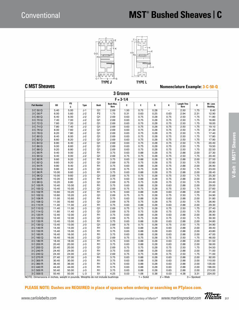
317www.carlislebelts.com Images provided courtesy of Martin® www.martinsprocket.com
V-Be
lt |
MST
® S
heav
es
D-89
C MST Sheaves
NOTE: Dimensions in inches, weight in pounds. Weights do not include bushings 1 = Solid 2 = Web 3 = Spoked
3 GrooveF = 3-1/4
Part Number ODPD
Type Bush Bush Max.Bore C E G K Length Thru
Bore X Wt. Less BushingC
3 C 50 Q 5.40 5.00 J-1 Q1 2.69 1.50 0.75 0.28 – 2.50 1.75 8.403 C 56 P 6.00 5.60 J-2 P2 1.75 0.31 0.63 0.25 0.63 2.94 2.31 12.903 C 60 Q 6.40 6.00 J-2 Q1 2.69 0.63 0.75 0.28 0.75 2.50 1.75 11.803 C 70 Q 7.40 7.00 J-2 Q1 2.69 0.63 0.75 0.28 0.75 2.50 1.75 16.803 C 72 Q 7.60 7.20 J-2 Q1 2.69 0.63 0.75 0.28 0.75 2.50 1.75 18.003 C 74 Q 7.80 7.40 J-2 Q1 2.69 0.63 0.75 0.28 0.75 2.50 1.75 19.103 C 76 Q 8.00 7.60 J-2 Q1 2.69 0.63 0.75 0.28 0.75 2.50 1.75 21.303 C 78 Q 8.20 7.80 J-2 Q1 2.69 0.63 0.75 0.28 0.75 2.50 1.75 17.403 C 80 Q 8.40 8.00 J-2 Q1 2.69 0.63 0.75 0.28 0.75 2.50 1.75 17.803 C 82 Q 8.60 8.20 J-2 Q1 2.69 0.63 0.75 0.28 0.75 2.50 1.75 17.903 C 84 Q 8.80 8.40 J-2 Q1 2.69 0.63 0.75 0.28 0.75 2.50 1.75 20.403 C 86 Q 9.00 8.60 J-2 Q1 2.69 0.63 0.75 0.28 0.75 2.50 1.75 19.503 C 88 Q 9.20 8.80 J-2 Q1 2.69 0.63 0.75 0.28 0.75 2.50 1.75 22.503 C 90 R 9.40 9.00 J-2 R1 3.75 0.63 0.88 0.28 0.75 2.88 2.00 27.303 C 90 Q 9.40 9.00 J-2 Q1 2.69 0.75 0.75 0.28 0.75 2.50 1.75 20.403 C 92 R 9.60 9.20 J-2 R1 3.75 0.63 0.88 0.28 0.75 2.88 2.00 27.503 C 92 Q 9.60 9.20 J-2 Q1 2.69 0.75 0.75 0.28 0.75 2.50 1.75 22.803 C 94 R 9.80 9.40 J-3 R1 3.75 0.63 0.88 0.28 0.75 2.88 2.00 26.903 C 94 Q 9.80 9.40 J-3 Q1 2.69 0.75 0.75 0.28 0.75 2.50 1.75 23.003 C 96 R 10.00 9.60 J-3 R1 3.75 0.63 0.88 0.28 0.75 2.88 2.00 28.403 C 96 Q 10.00 9.60 J-3 Q1 2.69 0.75 0.75 0.28 0.75 2.50 1.75 25.303 C 98 R 10.20 9.80 J-3 R1 3.75 0.63 0.88 0.28 0.75 2.88 2.00 29.303 C 98 Q 10.20 9.80 J-3 Q1 2.69 0.75 0.75 0.28 0.75 2.50 1.75 24.403 C 100 R 10.40 10.00 J-2 R1 3.75 0.63 0.88 0.28 0.63 2.88 2.00 29.003 C 100 Q 10.40 10.00 J-3 Q1 2.69 0.75 0.75 0.28 0.75 2.50 1.75 27.603 C 102 R 10.60 10.20 J-2 R1 3.75 0.63 0.88 0.28 0.63 2.88 2.00 31.403 C 102 Q 10.60 10.20 J-3 Q1 2.69 0.75 0.75 0.28 0.75 2.50 1.75 24.903 C 106 R 11.00 10.60 J-2 R1 3.75 0.63 0.88 0.28 0.63 2.88 2.00 31.803 C 106 Q 11.00 10.60 J-3 Q1 2.69 0.75 0.75 0.28 0.75 2.50 1.75 26.903 C 110 R 11.40 11.00 J-2 R1 3.75 0.63 0.88 0.28 0.63 2.88 2.00 29.303 C 110 Q 11.40 11.00 J-3 Q1 2.69 0.75 0.75 0.28 0.75 2.50 1.75 27.403 C 114 Q 11.80 11.40 J-3 Q1 2.69 0.75 0.75 0.28 0.75 2.50 1.75 28.303 C 120 R 12.40 12.00 J-2 R1 3.75 0.63 0.88 0.28 0.63 2.88 2.00 36.903 C 120 Q 12.40 12.00 J-3 Q1 2.69 0.75 0.75 0.28 0.75 2.50 1.75 30.303 C 130 R 13.40 13.00 J-3 R1 3.75 0.63 0.88 0.28 0.63 2.88 2.00 34.803 C 130 Q 13.40 13.00 J-3 Q1 2.69 0.75 0.75 0.28 0.75 2.50 1.75 34.903 C 140 R 14.40 14.00 J-3 R1 3.75 0.63 0.88 0.28 0.63 2.88 2.00 39.403 C 150 R 15.40 15.00 J-3 R1 3.75 0.63 0.88 0.28 0.63 2.88 2.00 43.803 C 160 R 16.40 16.00 J-3 R1 3.75 0.63 0.88 0.28 0.63 2.88 2.00 47.003 C 160 Q 16.40 16.00 J-3 Q1 2.69 0.75 0.75 0.28 0.75 2.50 1.75 46.003 C 180 R 18.40 18.00 J-3 R1 3.75 0.63 0.88 0.28 0.63 2.88 2.00 51.503 C 200 R 20.40 20.00 J-3 R1 3.75 0.63 0.88 0.28 0.63 2.88 2.00 58.003 C 200 Q 20.40 20.00 J-3 Q1 2.69 0.75 0.75 0.28 0.75 2.50 1.75 54.503 C 240 R 24.40 24.00 J-3 R1 3.75 0.63 0.88 0.28 0.63 2.88 2.00 71.003 C 240 Q 24.40 24.00 J-3 Q1 2.69 0.75 0.75 0.28 0.75 2.50 1.75 71.003 C 270 R 27.40 27.00 J-3 R1 3.75 0.63 0.88 0.28 0.63 2.88 2.00 92.003 C 300 R 30.40 30.00 J-3 R1 3.75 0.63 0.88 0.28 0.63 2.88 2.00 110.003 C 360 R 36.40 36.00 J-3 R1 3.75 0.63 0.88 0.28 0.63 2.88 2.00 135.003 C 440 R 44.40 44.00 J-3 R1 3.75 0.63 0.88 0.28 0.63 2.88 2.00 196.003 C 500 R 50.40 50.00 J-3 R1 3.75 0.63 0.88 0.28 0.63 2.88 2.00 213.003 C 500 S 50.40 50.00 L-3 S1 4.25 0.03 1.06 0.38 0.03 4.38 3.31 224.00
P.D.
TYPE L
P.D.
O.D.
E
K
LC G
FX
TYPE J
CConventionalMST® Bushed Stock Sheaves
MST Sheaves_D17-D32 11/13/14 10:44 AM Page D-89
BACK TO MENU INDEX
Conventional MST® Bushed Sheaves | C
Nomenclature Example: 3-C-50-Q
PLEASE NOTE: Dashes are REQUIRED in place of spaces when ordering or searching on PTplace.com.

www.carlislebelts.com318 www.martinsprocket.com Images provided courtesy of Martin®
D-90
C MST Sheaves
NOTE: Dimensions in inches, weight in pounds. Weights do not include bushings 1 = Solid 2 = Web 3 = Spoked
4 GrooveF = 4-1/4
Part Number ODPD
Type Bush Bush Max.Bore C E G K Length Thru
Bore X Wt. Less BushingC
4 C 50 Q 5.40 5.00 J-1 Q2 2.63 1.50 2.75 0.28 – 3.50 2.75 10.904 C 56 P 6.00 5.60 J-2 P2 1.75 1.31 0.63 0.25 0.63 2.94 2.31 15.404 C 60 Q 6.40 6.00 J-2 Q2 2.63 0.75 2.75 0.28 0.88 3.50 2.75 17.004 C 70 Q 7.40 7.00 J-2 Q2 2.63 0.75 0.75 0.28 0.75 3.50 2.75 23.804 C 72 Q 7.60 7.20 J-2 Q2 2.63 0.75 0.75 0.28 0.75 3.50 2.75 26.804 C 74 Q 7.80 7.40 J-2 Q2 2.63 0.75 0.75 0.28 0.75 3.50 2.75 27.504 C 76 Q 8.00 7.60 J-2 Q2 2.63 0.75 0.75 0.28 0.75 3.50 2.75 30.304 C 78 Q 8.20 7.80 J-2 Q2 2.63 0.75 0.75 0.28 0.75 3.50 2.75 26.404 C 80 Q 8.40 8.00 J-2 Q2 2.63 0.75 0.75 0.28 0.75 3.50 2.75 29.004 C 82 Q 8.60 8.20 J-2 Q2 2.63 0.75 0.75 0.28 0.75 3.50 2.75 26.804 C 84 Q 8.80 8.40 J-2 Q2 2.63 0.75 0.75 0.28 0.75 3.50 2.75 28.804 C 86 Q 9.00 8.60 J-2 Q2 2.63 0.75 0.75 0.28 0.75 3.50 2.75 27.904 C 88 Q 9.20 8.80 J-2 Q2 2.63 0.75 0.75 0.28 0.75 3.50 2.75 31.604 C 90 R 9.40 9.00 K-2 R1 3.75 1.13 0.88 0.28 1.13 2.88 2.00 30.004 C 90 Q 9.40 9.00 J-2 Q2 2.63 0.75 0.75 0.28 0.75 3.50 2.75 28.404 C 92 R 9.60 9.20 K-2 R1 3.75 1.13 0.88 0.28 1.13 2.88 2.00 31.604 C 92 Q 9.60 9.20 J-2 Q2 2.63 0.75 0.75 0.28 0.75 3.50 2.75 32.304 C 94 R 9.80 9.40 K-2 R1 3.75 1.13 0.88 0.28 1.13 2.88 2.00 31.604 C 94 Q 9.80 9.40 J-2 Q2 2.63 0.75 0.75 0.28 0.75 3.50 2.75 31.804 C 96 R 10.00 9.60 K-2 R1 3.75 1.13 0.88 0.28 1.13 2.88 2.00 31.104 C 96 Q 10.00 9.60 J-2 Q2 2.63 0.75 0.75 0.28 0.75 3.50 2.75 35.204 C 98 R 10.20 9.80 K-2 R1 3.75 1.13 0.88 0.28 1.13 2.88 2.00 33.404 C 98 Q 10.20 9.80 J-2 Q2 2.63 0.75 0.75 0.28 0.75 3.50 2.75 33.004 C 100 R 10.40 10.00 K-2 R1 3.75 1.13 0.88 0.28 1.13 2.88 2.00 34.104 C 100 Q 10.40 10.00 J-3 Q2 2.63 0.75 0.75 0.28 0.75 3.50 2.75 37.004 C 102 R 10.60 10.20 K-2 R1 3.75 1.13 0.88 0.28 1.13 2.88 2.00 36.504 C 102 Q 10.60 10.20 J-3 Q2 2.63 0.75 0.88 0.28 0.75 3.50 2.75 33.504 C 106 R 11.00 10.60 K-2 R1 3.75 1.13 0.88 0.28 1.13 2.88 2.00 36.504 C 106 Q 11.00 10.60 J-3 Q2 2.63 0.75 0.88 0.28 0.75 3.50 2.75 36.304 C 110 R 11.40 11.00 K-2 R1 3.75 1.13 0.88 0.28 1.13 2.88 2.00 33.004 C 110 Q 11.40 11.00 J-3 Q2 2.63 0.75 0.88 0.28 0.75 3.50 2.75 36.304 C 114 Q 11.80 11.40 J-3 Q2 2.63 0.75 0.75 0.28 0.75 3.50 2.75 38.404 C 120 R 12.40 12.00 K-2 R1 3.75 1.13 0.88 0.28 1.13 2.88 2.00 42.904 C 120 Q 12.40 12.00 J-3 Q2 2.63 0.75 0.88 0.28 0.75 3.50 2.75 40.504 C 130 R 13.40 13.00 K-3 R1 3.75 1.13 0.88 0.28 1.13 2.88 2.00 40.104 C 130 Q 13.40 13.00 J-3 Q2 2.63 0.75 0.88 0.28 0.75 3.50 2.75 43.604 C 140 R 14.40 14.00 K-3 R1 3.75 1.13 0.88 0.28 1.13 2.88 2.00 46.604 C 150 R 15.40 15.00 K-3 R1 3.75 1.13 0.88 0.28 1.13 2.88 2.00 52.004 C 160 R 16.40 16.00 K-3 R1 3.75 1.13 0.88 0.28 1.13 2.88 2.00 55.004 C 160 Q 16.40 16.00 J-3 Q2 2.63 0.75 0.88 0.28 0.75 3.50 2.75 55.004 C 180 R 18.40 18.00 K-3 R1 3.75 1.13 0.88 0.28 1.13 2.88 2.00 60.004 C 180 S 18.40 18.00 J-3 S1 4.25 0.47 1.06 0.38 0.47 4.38 3.31 92.004 C 200 R 20.40 20.00 K-3 R1 3.75 1.13 0.88 0.28 1.13 2.88 2.00 69.004 C 200 S 20.40 20.00 J-3 S1 4.25 0.47 1.06 0.38 0.47 4.38 3.31 103.004 C 200 Q 20.40 20.00 J-3 Q2 2.63 0.75 1.06 0.28 0.75 3.50 2.75 103.004 C 240 R 24.40 24.00 K-3 R1 3.75 1.13 0.88 0.28 1.13 2.88 2.00 86.004 C 240 S 24.40 24.00 J-3 S1 4.25 0.47 1.06 0.38 0.47 4.38 3.31 120.004 C 240 Q 24.40 24.00 J-3 Q2 2.63 0.75 1.06 0.28 0.75 3.50 2.75 120.004 C 270 R 27.40 27.00 K-3 R1 3.75 1.13 0.88 0.28 1.13 2.88 2.00 110.004 C 270 S 27.40 27.00 J-3 S1 4.25 0.47 1.06 0.38 0.47 4.38 3.31 123.004 C 300 R 30.40 30.00 K-3 R1 3.75 1.13 0.88 0.28 1.13 2.88 2.00 123.004 C 300 S 30.40 30.00 J-3 S1 4.25 0.47 1.06 0.38 0.47 4.38 3.31 142.004 C 360 R 36.40 36.00 K-3 R1 3.75 1.13 0.88 0.28 1.13 2.88 2.00 156.004 C 360 S 36.40 36.00 J-3 S1 4.25 0.47 1.06 0.38 0.47 4.38 3.31 183.004 C 440 R 44.40 44.00 K-3 R1 3.75 1.13 0.88 0.28 1.13 2.88 2.00 218.004 C 440 U 44.40 44.00 J-3 U0 5.50 0.25 1.19 0.47 0.25 4.94 3.75 241.004 C 500 R 50.40 50.00 K-3 R1 3.75 1.13 0.88 0.28 1.13 2.88 2.00 240.004 C 500 U 50.40 50.00 J-3 U0 5.50 0.25 1.19 0.47 0.25 4.94 3.75 283.00
C ConventionalMST® Bushed Stock Sheaves
MST Sheaves_D17-D32 11/13/14 10:44 AM Page D-90
BACK TO MENU INDEX
C | MST® Bushed Sheaves Conventional
Nomenclature Example: 4-C-50-Q
PLEASE NOTE: Dashes are REQUIRED in place of spaces when ordering or searching on PTplace.com.
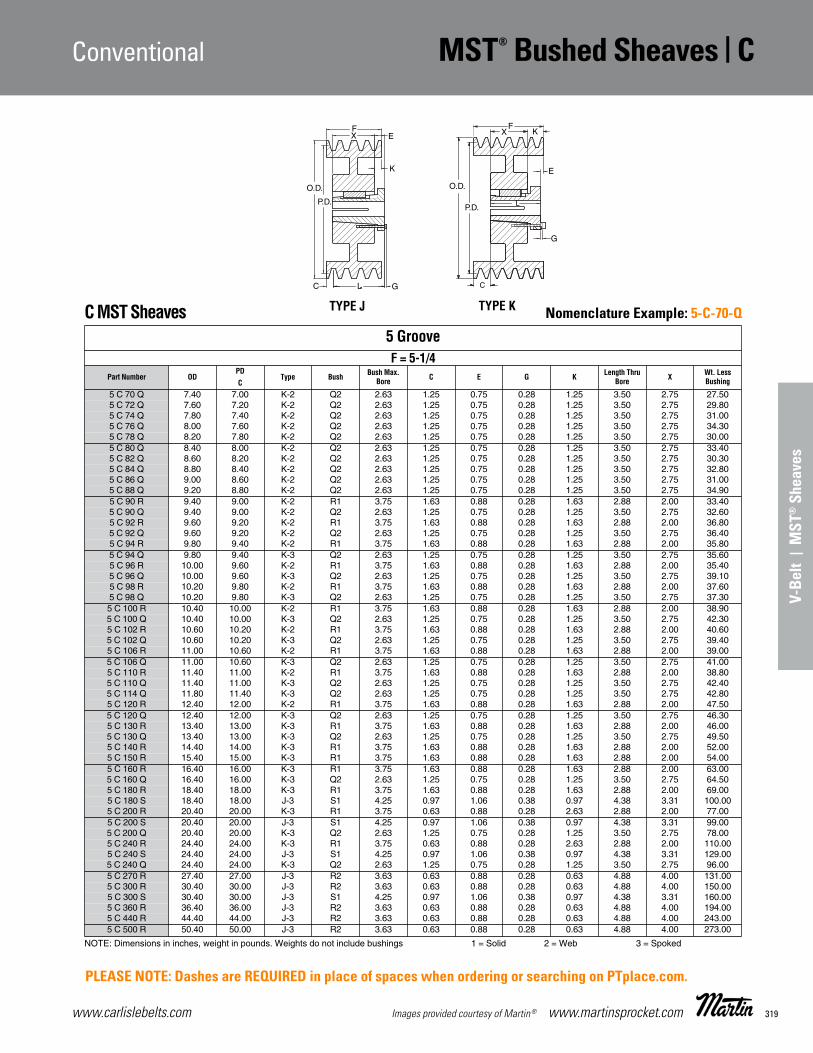
319www.carlislebelts.com Images provided courtesy of Martin® www.martinsprocket.com
V-Be
lt |
MST
® S
heav
es
D-91
C MST Sheaves
NOTE: Dimensions in inches, weight in pounds. Weights do not include bushings 1 = Solid 2 = Web 3 = Spoked
5 GrooveF = 5-1/4
Part Number ODPD
Type Bush Bush Max.Bore C E G K Length Thru
Bore X Wt. Less BushingC
5 C 70 Q 7.40 7.00 K-2 Q2 2.63 1.25 0.75 0.28 1.25 3.50 2.75 27.505 C 72 Q 7.60 7.20 K-2 Q2 2.63 1.25 0.75 0.28 1.25 3.50 2.75 29.805 C 74 Q 7.80 7.40 K-2 Q2 2.63 1.25 0.75 0.28 1.25 3.50 2.75 31.005 C 76 Q 8.00 7.60 K-2 Q2 2.63 1.25 0.75 0.28 1.25 3.50 2.75 34.305 C 78 Q 8.20 7.80 K-2 Q2 2.63 1.25 0.75 0.28 1.25 3.50 2.75 30.005 C 80 Q 8.40 8.00 K-2 Q2 2.63 1.25 0.75 0.28 1.25 3.50 2.75 33.405 C 82 Q 8.60 8.20 K-2 Q2 2.63 1.25 0.75 0.28 1.25 3.50 2.75 30.305 C 84 Q 8.80 8.40 K-2 Q2 2.63 1.25 0.75 0.28 1.25 3.50 2.75 32.805 C 86 Q 9.00 8.60 K-2 Q2 2.63 1.25 0.75 0.28 1.25 3.50 2.75 31.005 C 88 Q 9.20 8.80 K-2 Q2 2.63 1.25 0.75 0.28 1.25 3.50 2.75 34.905 C 90 R 9.40 9.00 K-2 R1 3.75 1.63 0.88 0.28 1.63 2.88 2.00 33.405 C 90 Q 9.40 9.00 K-2 Q2 2.63 1.25 0.75 0.28 1.25 3.50 2.75 32.605 C 92 R 9.60 9.20 K-2 R1 3.75 1.63 0.88 0.28 1.63 2.88 2.00 36.805 C 92 Q 9.60 9.20 K-2 Q2 2.63 1.25 0.75 0.28 1.25 3.50 2.75 36.405 C 94 R 9.80 9.40 K-2 R1 3.75 1.63 0.88 0.28 1.63 2.88 2.00 35.805 C 94 Q 9.80 9.40 K-3 Q2 2.63 1.25 0.75 0.28 1.25 3.50 2.75 35.605 C 96 R 10.00 9.60 K-2 R1 3.75 1.63 0.88 0.28 1.63 2.88 2.00 35.405 C 96 Q 10.00 9.60 K-3 Q2 2.63 1.25 0.75 0.28 1.25 3.50 2.75 39.105 C 98 R 10.20 9.80 K-2 R1 3.75 1.63 0.88 0.28 1.63 2.88 2.00 37.605 C 98 Q 10.20 9.80 K-3 Q2 2.63 1.25 0.75 0.28 1.25 3.50 2.75 37.305 C 100 R 10.40 10.00 K-2 R1 3.75 1.63 0.88 0.28 1.63 2.88 2.00 38.905 C 100 Q 10.40 10.00 K-3 Q2 2.63 1.25 0.75 0.28 1.25 3.50 2.75 42.305 C 102 R 10.60 10.20 K-2 R1 3.75 1.63 0.88 0.28 1.63 2.88 2.00 40.605 C 102 Q 10.60 10.20 K-3 Q2 2.63 1.25 0.75 0.28 1.25 3.50 2.75 39.405 C 106 R 11.00 10.60 K-2 R1 3.75 1.63 0.88 0.28 1.63 2.88 2.00 39.005 C 106 Q 11.00 10.60 K-3 Q2 2.63 1.25 0.75 0.28 1.25 3.50 2.75 41.005 C 110 R 11.40 11.00 K-2 R1 3.75 1.63 0.88 0.28 1.63 2.88 2.00 38.805 C 110 Q 11.40 11.00 K-3 Q2 2.63 1.25 0.75 0.28 1.25 3.50 2.75 42.405 C 114 Q 11.80 11.40 K-3 Q2 2.63 1.25 0.75 0.28 1.25 3.50 2.75 42.805 C 120 R 12.40 12.00 K-2 R1 3.75 1.63 0.88 0.28 1.63 2.88 2.00 47.505 C 120 Q 12.40 12.00 K-3 Q2 2.63 1.25 0.75 0.28 1.25 3.50 2.75 46.305 C 130 R 13.40 13.00 K-3 R1 3.75 1.63 0.88 0.28 1.63 2.88 2.00 46.005 C 130 Q 13.40 13.00 K-3 Q2 2.63 1.25 0.75 0.28 1.25 3.50 2.75 49.505 C 140 R 14.40 14.00 K-3 R1 3.75 1.63 0.88 0.28 1.63 2.88 2.00 52.005 C 150 R 15.40 15.00 K-3 R1 3.75 1.63 0.88 0.28 1.63 2.88 2.00 54.005 C 160 R 16.40 16.00 K-3 R1 3.75 1.63 0.88 0.28 1.63 2.88 2.00 63.005 C 160 Q 16.40 16.00 K-3 Q2 2.63 1.25 0.75 0.28 1.25 3.50 2.75 64.505 C 180 R 18.40 18.00 K-3 R1 3.75 1.63 0.88 0.28 1.63 2.88 2.00 69.005 C 180 S 18.40 18.00 J-3 S1 4.25 0.97 1.06 0.38 0.97 4.38 3.31 100.005 C 200 R 20.40 20.00 K-3 R1 3.75 0.63 0.88 0.28 2.63 2.88 2.00 77.005 C 200 S 20.40 20.00 J-3 S1 4.25 0.97 1.06 0.38 0.97 4.38 3.31 99.005 C 200 Q 20.40 20.00 K-3 Q2 2.63 1.25 0.75 0.28 1.25 3.50 2.75 78.005 C 240 R 24.40 24.00 K-3 R1 3.75 0.63 0.88 0.28 2.63 2.88 2.00 110.005 C 240 S 24.40 24.00 J-3 S1 4.25 0.97 1.06 0.38 0.97 4.38 3.31 129.005 C 240 Q 24.40 24.00 K-3 Q2 2.63 1.25 0.75 0.28 1.25 3.50 2.75 96.005 C 270 R 27.40 27.00 J-3 R2 3.63 0.63 0.88 0.28 0.63 4.88 4.00 131.005 C 300 R 30.40 30.00 J-3 R2 3.63 0.63 0.88 0.28 0.63 4.88 4.00 150.005 C 300 S 30.40 30.00 J-3 S1 4.25 0.97 1.06 0.38 0.97 4.38 3.31 160.005 C 360 R 36.40 36.00 J-3 R2 3.63 0.63 0.88 0.28 0.63 4.88 4.00 194.005 C 440 R 44.40 44.00 J-3 R2 3.63 0.63 0.88 0.28 0.63 4.88 4.00 243.005 C 500 R 50.40 50.00 J-3 R2 3.63 0.63 0.88 0.28 0.63 4.88 4.00 273.00
O.D.
XF
K
E
G
P.D.
TYPE K
P.D.
O.D.
E
K
LC G
FX
TYPE J
CConventionalMST® Bushed Stock Sheaves
MST Sheaves_D17-D32 11/13/14 10:44 AM Page D-91
BACK TO MENU INDEX
Conventional MST® Bushed Sheaves | C
Nomenclature Example: 5-C-70-Q
PLEASE NOTE: Dashes are REQUIRED in place of spaces when ordering or searching on PTplace.com.

www.carlislebelts.com320 www.martinsprocket.com Images provided courtesy of Martin®
C | MST® Bushed Sheaves Conventional
D-92
C MST Sheaves
NOTE: Dimensions in inches, weight in pounds. Weights do not include bushings 1 = Solid 2 = Web 3 = Spoked
6 GrooveF = 6-1/4
Part Number ODPD
Type Bush Bush Max.Bore C E G K Length Thru
Bore X Wt. Less BushingC
6 C 70 Q 7.40 7.00 K-2 Q2 2.63 1.75 0.75 0.28 1.75 3.50 2.75 29.906 C 72 Q 7.60 7.20 K-2 Q2 2.63 1.75 0.75 0.28 1.75 3.50 2.75 33.606 C 74 Q 7.80 7.40 K-2 Q2 2.63 1.75 0.75 0.28 1.75 3.50 2.75 33.306 C 76 Q 8.00 7.60 K-2 Q2 2.63 1.75 0.75 0.28 1.75 3.50 2.75 37.906 C 78 Q 8.20 7.80 K-2 Q2 2.63 1.75 0.75 0.28 1.75 3.50 2.75 33.50
6 C 80 Q 8.40 8.00 K-2 Q2 2.63 1.75 0.75 0.28 1.75 3.50 2.75 37.606 C 82 Q 8.60 8.20 K-2 Q2 2.63 1.75 0.75 0.28 1.75 3.50 2.75 34.006 C 84 Q 8.80 8.40 K-2 Q2 2.63 1.75 0.75 0.28 1.75 3.50 2.75 37.006 C 86 Q 9.00 8.60 K-2 Q2 2.63 1.75 0.75 0.28 1.75 3.50 2.75 35.006 C 88 Q 9.20 8.80 K-2 Q2 2.63 1.75 0.75 0.28 1.75 3.50 2.75 39.40
6 C 90 R 9.40 9.00 K-2 R2 3.63 1.13 0.88 0.28 1.13 4.88 4.00 53.006 C 90 Q 9.40 9.00 K-2 Q2 2.63 1.75 0.75 0.28 1.75 3.50 2.75 36.806 C 92 R 9.60 9.20 K-2 R2 3.63 1.13 0.88 0.28 1.13 4.88 4.00 58.006 C 92 Q 9.60 9.20 K-2 Q2 2.63 1.75 0.75 0.28 1.75 3.50 2.75 41.006 C 94 R 9.80 9.40 K-2 R2 3.63 1.13 0.88 0.28 1.13 4.88 4.00 63.50
6 C 94 Q 9.80 9.40 K-3 Q2 2.63 1.75 0.75 0.28 1.75 3.50 2.75 39.406 C 96 R 10.00 9.60 K-2 R2 3.63 1.13 0.88 0.28 1.13 4.88 4.00 55.006 C 96 Q 10.00 9.60 K-3 Q2 2.63 1.75 0.75 0.28 1.75 3.50 2.75 43.606 C 98 R 10.20 9.80 K-2 R2 3.63 1.13 0.88 0.28 1.13 4.88 4.00 65.006 C 98 Q 10.20 9.80 K-3 Q2 2.63 1.75 0.75 0.28 1.75 3.50 2.75 42.00
6 C 100 R 10.40 10.00 K-2 R2 3.63 1.13 0.88 0.28 1.13 4.88 4.00 62.006 C 100 Q 10.40 10.00 K-3 Q2 2.63 1.75 0.75 0.28 1.75 3.50 2.75 47.306 C 102 R 10.60 10.20 K-2 R2 3.63 1.13 0.88 0.28 1.13 4.88 4.00 68.006 C 102 Q 10.60 10.20 K-3 Q2 2.63 1.75 0.75 0.28 1.75 3.50 2.75 44.406 C 106 R 11.00 10.60 K-2 R2 3.63 1.13 0.88 0.28 1.13 4.88 4.00 55.00
6 C 106 Q 11.00 10.60 K-3 Q2 2.63 1.75 0.75 0.28 1.75 3.50 2.75 45.406 C 110 R 11.40 11.00 K-2 R2 3.63 1.13 0.88 0.28 1.13 4.88 4.00 51.506 C 110 Q 11.40 11.00 K-3 Q2 2.63 1.75 0.75 0.28 1.75 3.50 2.75 47.006 C 114 Q 11.80 11.40 K-3 Q2 2.63 1.75 0.75 0.28 1.75 3.50 2.75 49.606 C 120 R 12.40 12.00 K-2 R2 3.63 1.13 0.88 0.28 1.13 4.88 4.00 64.00
6 C 120 Q 12.40 12.00 K-3 Q2 2.63 1.75 0.75 0.28 1.75 3.50 2.75 51.006 C 130 R 13.40 13.00 K-3 R2 3.63 1.13 0.88 0.28 1.13 4.88 4.00 61.006 C 130 Q 13.40 13.00 K-3 Q2 2.63 1.75 0.75 0.28 1.75 3.50 2.75 56.006 C 140 R 14.40 14.00 K-3 R2 3.63 1.13 0.88 0.28 1.13 4.88 4.00 69.006 C 150 R 15.40 15.00 K-3 R2 3.63 1.13 0.88 0.28 1.13 4.88 4.00 68.00
6 C 160 R 16.40 16.00 K-3 R2 3.63 1.13 0.88 0.28 1.13 4.88 4.00 77.006 C 160 Q 16.40 16.00 K-3 Q2 2.63 1.75 0.75 0.28 1.75 3.50 2.75 72.006 C 180 R 18.40 18.00 K-3 R2 3.63 1.13 0.88 0.28 1.13 4.88 4.00 84.006 C 180 S 18.40 18.00 K-3 S1 4.25 1.47 1.06 0.28 1.47 4.38 3.31 107.006 C 200 R 20.40 20.00 K-3 R2 3.63 1.13 0.88 0.28 1.13 4.88 4.00 91.50
6 C 200 S 20.40 20.00 K-3 S1 4.25 1.47 1.06 0.38 1.47 4.38 3.31 127.006 C 200 Q 20.40 20.00 K-3 Q2 2.63 1.75 0.75 0.28 1.75 3.50 2.75 88.306 C 240 R 24.40 24.00 K-3 R2 3.63 1.13 0.88 0.28 1.13 4.88 4.00 116.006 C 240 S 24.40 24.00 K-3 S1 4.25 1.47 1.06 0.38 1.47 4.38 3.31 125.006 C 240 Q 24.40 24.00 K-3 Q2 2.63 1.75 0.75 0.28 1.75 3.50 2.75 108.00
6 C 270 R 27.40 27.00 K-3 R2 3.63 1.13 0.88 0.28 1.13 4.88 4.00 144.006 C 270 S 27.40 27.00 K-3 S1 4.25 1.47 1.06 0.38 1.47 4.38 3.31 151.006 C 300 R 30.40 30.00 K-3 R2 3.63 1.13 0.88 0.28 1.13 4.88 4.00 160.006 C 300 U 30.40 30.00 K-3 U0 5.50 1.25 1.19 0.47 1.25 4.94 3.75 191.006 C 360 R 36.40 36.00 K-3 R2 3.63 1.13 0.88 0.28 1.13 4.88 4.00 211.00
6 C 360 U 36.40 36.00 K-3 U0 5.50 1.25 1.19 0.47 1.25 4.94 3.75 233.006 C 440 R 44.40 44.00 K-3 R2 3.63 1.13 0.88 0.28 1.13 4.88 4.00 286.006 C 500 R 50.40 50.00 K-3 R2 3.63 1.13 0.88 0.28 1.13 4.88 4.00 303.00
C ConventionalMST® Bushed Stock Sheaves
MST Sheaves_D17-D32 11/13/14 10:44 AM Page D-92
BACK TO MENU INDEX
Nomenclature Example: 6-C-70-Q
PLEASE NOTE: Dashes are REQUIRED in place of spaces when ordering or searching on PTplace.com.

321www.carlislebelts.com Images provided courtesy of Martin® www.martinsprocket.com
V-Be
lt |
MST
® S
heav
es
Conventional MST® Bushed Sheaves | C C
D-93
ConventionalMST® Bushed Stock Sheaves
C MST Sheaves
NOTE: Dimensions in inches, weight in pounds. Weights do not include bushings 1 = Solid 2 = Web 3 = Spoked
7 GrooveF = 7-1/4
Part Number ODPD
Type Bush Bush Max Bore C E G K Length
Thru Bore X Wt. Less BushingC
7 C 70 Q 7.40 7.00 K-2 Q3 2.500 1.500 0.750 0.281 1.500 5.000 0.000 37.50
7 C 80 R 8.40 8.00 K-2 R2 3.625 1.625 0.875 0.281 1.625 4.875 4.000 45.60
7 C 86 R 9.00 8.60 K-2 R2 3.625 1.625 0.875 0.281 1.625 4.875 4.000 52.80
7 C 90 R 9.40 9.00 K-2 R2 3.625 1.625 0.875 0.281 1.625 4.875 4.000 58.00
7 C 92 R 9.60 9.20 K-2 R2 3.625 1.625 0.875 0.281 1.625 4.875 4.000 63.00
7 C 94 R 9.80 9.40 K-2 R2 3.625 1.625 0.875 0.281 1.625 4.875 4.000 68.00
7 C 98 R 10.20 9.80 K-2 R2 3.625 1.625 0.875 0.281 1.625 4.875 4.000 73.00
7 C 100 R 10.40 10.00 K-2 R2 3.625 1.625 0.875 0.281 1.625 4.875 4.000 71.00
7 C 102 R 10.60 10.20 K-2 R2 3.625 1.625 0.875 0.281 1.625 4.875 4.000 76.00
7 C 106 R 11.00 10.60 K-2 R2 3.625 1.625 0.875 0.281 1.625 4.875 4.000 71.00
7 C 110 R 11.40 11.00 K-2 R2 3.625 1.625 0.875 0.281 1.625 4.875 4.000 68.00
7 C 120 R 12.40 12.00 K-2 R2 3.625 1.625 0.875 0.281 1.625 4.875 4.000 67.00
7 C 130 R 13.40 13.00 K-3 R2 3.625 1.625 0.875 0.281 1.625 4.875 4.000 84.00
7 C 140 R 14.40 14.00 K-3 R2 3.625 1.625 0.875 0.281 1.625 4.875 4.000 83.00
7 C 150 R 15.40 15.00 K-3 R2 3.625 1.625 0.875 0.281 1.625 4.875 4.000 86.00
7 C 160 R 16.40 16.00 K-3 R2 3.625 1.625 0.875 0.281 1.625 4.875 4.000 88.00
7 C 180 S 18.40 18.00 J-3 S2 4.188 0.781 1.062 0.375 1.281 6.750 5.688 137.00
7 C 180 U 18.40 18.00 K-3 U0 5.500 1.750 1.188 0.468 1.750 4.938 3.750 133.00
7 C 200 S 20.40 20.00 J-3 S2 4.188 0.781 1.062 0.375 1.281 6.750 5.688 152.00
7 C 200 U 20.40 20.00 K-3 U0 5.500 1.750 1.188 0.468 1.750 4.938 3.750 144.00
7 C 240 S 24.40 24.00 J-3 S2 4.188 0.781 1.062 0.375 1.281 6.750 5.688 173.00
7 C 270 S 27.40 27.00 J-3 S2 4.188 0.781 1.062 0.375 1.281 6.750 5.688 197.00
7 C 270 U 27.40 27.00 K-3 U0 5.500 1.750 1.188 0.468 1.750 4.938 3.750 196.00
7 C 300 S 30.40 30.00 J-3 S2 4.188 0.781 1.062 0.375 1.281 6.750 5.688 220.00
7 C 300 U 30.40 30.00 K-3 U0 5.500 1.750 1.188 0.468 1.750 4.938 3.750 217.00
7 C 360 S 36.40 36.00 J-3 S2 4.188 0.781 1.062 0.375 1.281 6.750 5.688 279.00
7 C 440 S 44.40 44.00 J-3 S2 4.188 0.781 1.062 0.375 1.281 6.750 5.688 337.00
7 C 500 S 50.40 50.00 J-3 S2 4.188 0.781 1.062 0.375 1.281 6.750 5.688 382.00
O.D.
XF
K
E
G
P.D.
TYPE K
MST Sheaves_D17-D32 11/13/14 10:44 AM Page D-93
BACK TO MENU INDEX
Nomenclature Example: 7-C-70-Q
PLEASE NOTE: Dashes are REQUIRED in place of spaces when ordering or searching on PTplace.com.

www.carlislebelts.com322 www.martinsprocket.com Images provided courtesy of Martin®
C | MST® Bushed Sheaves Conventional
D-94
C ConventionalMST® Bushed Stock Sheaves
C MST Sheaves
NOTE: Dimensions in inches, weight in pounds. Weights do not include bushings 1 = Solid 2 = Web 3 = Spoked
8 GrooveF = 8-1/4
Part Number ODPD
Type Bush Bush Max.Bore C E G K Length Thru
Bore X Wt. Less BushingC
8 C 70 Q 7.40 7.00 K-2 Q3 2.50 1.63 0.75 0.28 2.38 5.00 0.00 40.00
8 C 80 R 8.40 8.00 K-2 R2 3.63 1.63 0.88 0.28 2.63 4.88 4.00 49.00
8 C 86 R 9.00 8.60 K-2 R2 3.63 1.63 0.88 0.28 2.63 4.88 4.00 57.00
8 C 90 R 9.40 9.00 K-2 R2 3.63 1.63 0.88 0.28 2.63 4.88 4.00 62.00
8 C 92 R 9.60 9.20 K-2 R2 3.63 1.63 0.88 0.28 2.63 4.88 4.00 68.00
8 C 94 R 9.80 9.40 K-2 R2 3.63 1.63 0.88 0.28 2.63 4.88 4.00 73.00
8 C 96 R 10.00 9.60 K-2 R2 3.63 1.63 0.88 0.28 2.63 4.88 4.00 70.00
8 C 98 R 10.20 9.80 K-2 R2 3.63 1.63 0.88 0.28 2.63 4.88 4.00 76.00
8 C 100 R 10.40 10.00 K-2 R2 3.63 1.63 0.88 0.28 2.63 4.88 4.00 72.00
8 C 102 R 10.60 10.20 K-2 R2 3.63 1.63 0.88 0.28 2.63 4.88 4.00 79.00
8 C 106 R 11.00 10.60 K-2 R2 3.63 1.63 0.88 0.28 2.63 4.88 4.00 76.00
8 C 110 R 11.40 11.00 K-2 R2 3.63 2.13 0.88 0.28 2.13 4.88 4.00 73.00
8 C 120 R 12.40 12.00 K-2 R2 3.63 2.13 0.88 0.28 2.13 4.88 4.00 74.00
8 C 130 R 13.40 13.00 K-3 R2 3.63 2.13 0.88 0.28 2.13 4.88 4.00 80.00
8 C 140 R 14.40 14.00 K-3 R2 3.63 2.13 0.88 0.28 2.13 4.88 4.00 84.00
8 C 150 R 15.40 15.00 K-3 R2 3.63 2.13 0.88 0.28 2.13 4.88 4.00 93.00
8 C 160 R 16.40 16.00 K-3 R2 3.63 2.13 0.88 0.28 2.13 4.88 4.00 100.00
8 C 180 S 18.40 18.00 K-3 S2 4.19 1.28 1.06 0.38 1.28 6.75 5.69 140.00
8 C 180 U 18.40 18.00 K-3 U0 5.50 2.25 1.19 0.47 2.25 4.94 3.75 141.00
8 C 200 S 20.40 20.00 K-3 S2 4.19 1.28 1.06 0.38 1.28 6.75 5.69 163.00
8 C 200 U 20.40 20.00 K-3 U0 5.50 2.25 1.19 0.47 2.25 4.94 3.75 160.00
8 C 240 S 24.40 24.00 K-3 S2 4.19 1.28 1.06 0.38 1.28 6.75 5.69 194.00
8 C 240 U 24.40 24.00 K-3 U0 5.50 2.25 1.19 0.47 2.25 4.94 3.75 184.00
8 C 270 S 27.40 27.00 K-3 S2 4.19 1.28 1.06 0.38 1.28 6.75 5.69 224.00
8 C 300 S 30.40 30.00 K-3 S2 4.19 1.28 1.06 0.38 1.28 6.75 5.69 212.00
8 C 300 U 30.40 30.00 K-3 U0 5.50 2.25 1.19 0.47 2.25 4.94 3.75 227.00
8 C 360 S 36.40 36.00 K-3 S2 4.19 1.28 1.06 0.38 1.28 6.75 5.69 261.00
8 C 360 U 36.40 36.00 K-3 U0 5.50 2.25 1.19 0.47 2.25 4.94 3.75 288.00
8 C 440 S 44.40 44.00 K-3 S2 4.19 1.28 1.06 0.38 1.28 6.75 5.69 368.00
8 C 440 U 44.40 44.00 K-3 U0 5.50 2.25 1.19 0.47 2.25 4.94 3.75 358.00
8 C 500 S 50.40 50.00 K-3 S2 4.19 1.28 1.06 0.38 1.28 6.75 5.69 429.00
8 C 500 U 50.40 50.00 K-3 U0 5.50 2.25 1.19 0.47 2.25 4.94 3.75 417.00
O.D.
XF
K
E
G
P.D.
TYPE K
MST Sheaves_D17-D32 11/13/14 10:44 AM Page D-94
BACK TO MENU INDEX
Nomenclature Example: 8-C-70-Q
PLEASE NOTE: Dashes are REQUIRED in place of spaces when ordering or searching on PTplace.com.

323www.carlislebelts.com Images provided courtesy of Martin® www.martinsprocket.com
V-Be
lt |
MST
® S
heav
es
Conventional MST® Bushed Sheaves | C C
D-95
ConventionalMST® Bushed Stock Sheaves
O.D.
XF
K
E
G
P.D.
TYPE KC MST Sheaves
NOTE: Dimensions in inches, weight in pounds. Weights do not include bushings 1 = Solid 2 = Web 3 = Spoked
10 GrooveF = 10-1/4
Part Number ODPD
Type Bush Bush Max.Bore C E G K Length Thru
Bore X Wt. Less BushingC
10 C 80 R 8.40 8.00 K-2 R2 3.63 1.63 0.88 0.28 4.63 4.88 4.00 70.00
10 C 86 R 9.00 8.60 K-2 R2 3.63 1.63 0.88 0.28 4.63 4.88 4.00 72.00
10 C 90 R 9.40 9.00 K-2 R2 3.63 1.63 0.88 0.28 4.63 4.88 4.00 72.00
10 C 92 R 9.60 9.20 K-2 R2 3.63 1.63 0.88 0.28 4.63 4.88 4.00 70.00
10 C 94 R 9.80 9.40 K-2 R2 3.63 1.63 0.88 0.28 4.63 4.88 4.00 78.00
10 C 96 R 10.00 9.60 K-2 R2 3.63 1.63 0.88 0.28 4.63 4.88 4.00 73.00
10 C 98 R 10.20 9.80 K-2 R2 3.63 1.63 0.88 0.28 4.63 4.88 4.00 88.00
10 C 100 R 10.40 10.00 K-2 R2 3.63 1.63 0.88 0.28 4.63 4.88 4.00 89.00
10 C 102 R 10.60 10.20 K-2 R2 3.63 1.63 0.88 0.28 4.63 4.88 4.00 97.00
10 C 106 R 11.00 10.60 K-2 R2 3.63 1.63 0.88 0.28 4.63 4.88 4.00 84.00
10 C 110 R 11.40 11.00 K-2 R2 3.63 3.13 0.88 0.28 4.63 4.88 4.00 84.00
10 C 120 R 12.40 12.00 K-2 R2 3.63 3.13 0.88 0.28 4.63 4.88 4.00 97.00
10 C 130 R 13.40 13.00 K-3 R2 3.63 3.13 0.88 0.28 4.63 4.88 4.00 102.00
10 C 140 R 14.40 14.00 K-3 R2 3.63 3.13 0.88 0.28 4.63 4.88 4.00 106.00
10 C 150 R 15.40 15.00 K-3 R2 3.63 3.13 0.88 0.28 4.63 4.88 4.00 110.00
10 C 160 R 16.40 16.00 K-3 R2 3.63 3.13 0.88 0.28 4.63 4.88 4.00 111.00
10 C 180 S 18.40 18.00 K-3 S2 4.19 2.28 1.06 0.38 2.28 6.75 5.69 164.00
10 C 180 U 18.40 18.00 K-3 U0 5.50 3.25 1.19 0.47 3.25 4.94 3.75 163.00
10 C 200 S 20.40 20.00 K-3 S2 4.19 2.28 1.06 0.38 2.28 6.75 5.69 170.00
10 C 200 U 20.40 20.00 K-3 U0 5.50 3.25 1.19 0.47 3.25 4.94 3.75 178.00
10 C 240 S 24.40 24.00 K-3 S2 4.19 2.28 1.06 0.38 2.28 6.75 5.69 210.00
10 C 240 U 24.40 24.00 K-3 U0 5.50 3.25 1.19 0.47 3.25 4.94 3.75 208.00
10 C 270 S 27.40 27.00 K-3 S2 4.19 2.28 1.06 0.38 2.28 6.75 5.69 246.00
10 C 300 S 30.40 30.00 K-3 S2 4.19 2.28 1.06 0.38 2.28 6.75 5.69 278.00
10 C 300 U 30.40 30.00 K-3 U1 5.50 2.31 1.50 0.47 2.31 7.13 5.63 298.00
10 C 360 S 36.40 36.00 K-3 S2 4.19 2.28 1.06 0.38 2.28 6.75 5.69 324.00
10 C 360 U 36.40 36.00 K-3 U1 5.50 2.31 1.50 0.47 2.31 7.13 5.63 362.00
10 C 440 U 44.40 44.00 K-3 U1 5.50 2.31 1.50 0.47 2.31 7.13 5.63 463.00
10 C 500 U 50.40 50.00 K-3 U1 5.50 2.31 1.50 0.47 2.31 7.13 5.63 480.00
MST Sheaves_D17-D32 11/13/14 10:44 AM Page D-95
BACK TO MENU INDEX
Nomenclature Example: 10-C-80-R
PLEASE NOTE: Dashes are REQUIRED in place of spaces when ordering or searching on PTplace.com.

www.carlislebelts.com324 www.martinsprocket.com Images provided courtesy of Martin®
C | MST® Bushed Sheaves Conventional
D-96
C
C MST Sheaves
NOTE: Dimensions in inches, weight in pounds. Weights do not include bushings 1 = Solid 2 = Web 3 = Spoked
12 GrooveF = 12-1/4
Part Number ODPD
Type Bush Bush Max.Bore C E G K Length Thru
Bore X Wt. Less BushingC
12 C 90 S 9.40 9.00 K-2 S2 4.19 2.00 1.06 0.38 4.56 6.75 5.69 88.00
12 C 92 S 9.60 9.20 K-2 S2 4.19 2.00 1.06 0.38 4.56 6.75 5.69 93.00
12 C 94 S 9.80 9.40 K-2 S2 4.19 2.00 1.06 0.38 4.56 6.75 5.69 104.00
12 C 96 S 10.00 9.60 K-2 S2 4.19 2.00 1.06 0.38 4.56 6.75 5.69 102.00
12 C 98 S 10.20 9.80 K-2 S2 4.19 2.00 1.06 0.38 4.56 6.75 5.69 111.00
12 C 100 S 10.40 10.00 K-2 S2 4.19 2.00 1.06 0.38 4.56 6.75 5.69 112.00
12 C 102 S 10.60 10.20 K-2 S2 4.19 2.00 1.06 0.38 4.56 6.75 5.69 121.00
12 C 106 S 11.00 10.60 K-2 S2 4.19 2.00 1.06 0.38 4.56 6.75 5.69 133.00
12 C 110 S 11.40 11.00 K-2 S2 4.19 3.28 1.06 0.38 3.28 6.75 5.69 128.00
12 C 120 S 12.40 12.00 K-2 S2 4.19 3.28 1.06 0.38 3.28 6.75 5.69 140.00
12 C 130 S 13.40 13.00 K-2 S2 4.19 3.28 1.06 0.38 3.28 6.75 5.69 165.00
12 C 140 S 14.40 14.00 K-3 S2 4.19 3.28 1.06 0.38 3.28 6.75 5.69 148.00
12 C 150 S 15.40 15.00 K-3 S2 4.19 3.28 1.06 0.38 3.28 6.75 5.69 162.00
12 C 160 S 16.40 16.00 K-3 S2 4.19 3.28 1.06 0.38 3.28 6.75 5.69 163.00
12 C 180 U 18.40 18.00 K-3 U1 5.50 3.31 1.50 0.47 3.31 7.13 5.63 204.00
12 C 200 U 20.40 20.00 K-3 U1 5.50 3.31 1.50 0.47 3.31 7.13 5.63 224.00
12 C 240 U 24.40 24.00 K-3 U1 5.50 3.31 1.50 0.47 3.31 7.13 5.63 257.00
12 C 270 U 27.40 27.00 K-3 U1 5.50 3.31 1.50 0.47 3.31 7.13 5.63 300.00
12 C 300 U 30.40 30.00 K-3 U1 5.50 3.31 1.50 0.47 3.31 7.13 5.63 327.00
12 C 360 U 36.40 36.00 K-3 U1 5.50 3.31 1.50 0.47 3.31 7.13 5.63 397.00
12 C 440 U 44.40 44.00 K-3 U1 5.50 3.31 1.50 0.47 3.31 7.13 5.63 519.00
12 C 500 U 50.40 50.00 K-3 U1 5.50 3.31 1.50 0.47 3.31 7.13 5.63 551.00
O.D.
P.D.
C
G
E
FX K
ConventionalMST® Bushed Stock Sheaves
TYPE K
MST Sheaves_D17-D32 11/13/14 10:44 AM Page D-96
BACK TO MENU INDEX
Nomenclature Example: 12-C-90-S
PLEASE NOTE: Dashes are REQUIRED in place of spaces when ordering or searching on PTplace.com.
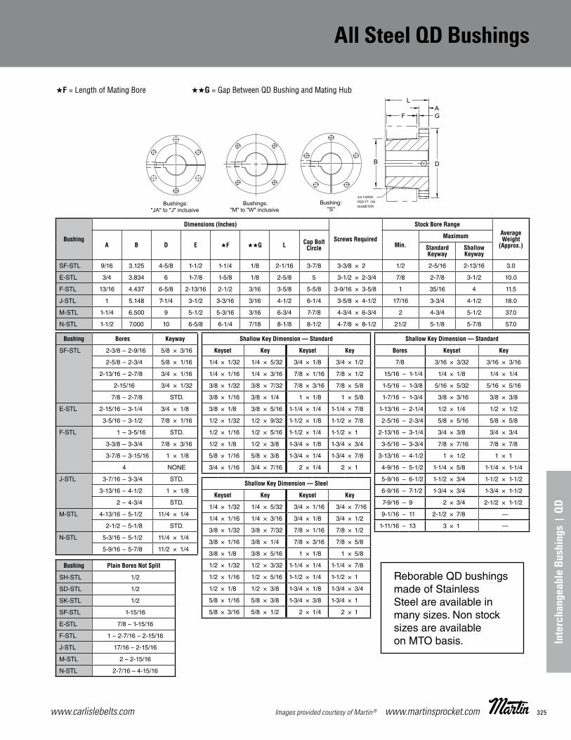
325www.carlislebelts.com Images provided courtesy of Martin® www.martinsprocket.com
Inte
rcha
ngea
ble
Bush
ings
| Q
D
B-3
All SteelQD Bushings
★F = Length of Mating Bore ★★G = Gap Between QD Bushing and Mating Hub
Bushing
Dimensions (Inches)
Screws Required
Stock Bore RangeAverage Weight
(Approx.)A B D E ★F ★★G L Cap Bolt Circle Min.
Maximum
Standard Keyway
Shallow Keyway
SF-STL 9/16 3.125 4-5/8 1-1/2 1-1/4 1/8 2-1/16 3-7/8 3-3/8 × 2 1/2 2-5/16 2-13/16 3.0
E-STL 3/4 3.834 6 1-7/8 1-5/8 1/8 2-5/8 5 3-1/2 × 2-3/4 7/8 2-7/8 3-1/2 10.0
F-STL 13/16 4.437 6-5/8 2-13/16 2-1/2 3/16 3-5/8 5-5/8 3-9/16 × 3-5/8 1 35/16 4 11.5
J-STL 1 5.148 7-1/4 3-1/2 3-3/16 3/16 4-1/2 6-1/4 3-5/8 × 4-1/2 17/16 3-3/4 4-1/2 18.0
M-STL 1-1/4 6.500 9 5-1/2 5-3/16 3/16 6-3/4 7-7/8 4-3/4 × 6-3/4 2 4-3/4 5-1/2 37.0
N-STL 1-1/2 7.000 10 6-5/8 6-1/4 7/18 8-1/8 8-1/2 4-7/8 × 8-1/2 21/2 5-1/8 5-7/8 57.0
Bushing Bores Keyway
SF-STL 2-3/8 – 2-9/16 5/8 × 3/16
2-5/8 – 2-3/4 5/8 × 1/16
2-13/16 – 2-7/8 3/4 × 1/16
2-15/16 3/4 × 1/32
7/8 – 2-7/8 STD.
E-STL 2-15/16 – 3-1/4 3/4 × 1/8
3-5/16 – 3-1/2 7/8 × 1/16
F-STL 1 – 3-5/16 STD.
3-3/8 – 3-3/4 7/8 × 3/16
3-7/8 – 3-15/16 1 × 1/8
4 NONE
J-STL 3-7/16 – 3-3/4 STD.
3-13/16 – 4-1/2 1 × 1/8
2 – 4-3/4 STD.
M-STL 4-13/16 – 5-1/2 11/4 × 1/4
2-1/2 – 5-1/8 STD.
N-STL 5-3/16 – 5-1/2 11/4 × 1/4
5-9/16 – 5-7/8 11/2 × 1/4
Bushing Plain Bores Not Split
SH-STL 1/2
SD-STL 1/2
SK-STL 1/2
SF-STL 1-15/16
E-STL 7/8 – 1-15/16
F-STL 1 – 2-7/16 – 2-15/16
J-STL 17/16 – 2-15/16
M-STL 2 – 2-15/16
N-STL 2-7/16 – 4-15/16
Shallow Key Dimension — Standard
Keyset Key Keyset Key
1/4 × 1/32 1/4 × 5/32 3/4 × 1/8 3/4 × 1/2
1/4 × 1/16 1/4 × 3/16 7/8 × 1/16 7/8 × 1/2
3/8 × 1/32 3/8 × 7/32 7/8 × 3/16 7/8 × 5/8
3/8 × 1/16 3/8 × 1/4 1 × 1/8 1 × 5/8
3/8 × 1/8 3/8 × 5/16 1-1/4 × 1/4 1-1/4 × 7/8
1/2 × 1/32 1/2 × 9/32 1-1/2 × 1/8 1-1/2 × 7/8
1/2 × 1/16 1/2 × 5/16 1-1/2 × 1/4 1-1/2 × 1
1/2 × 1/8 1/2 × 3/8 1-3/4 × 1/8 1-3/4 × 3/4
5/8 × 1/16 5/8 × 3/8 1-3/4 × 1/4 1-3/4 × 7/8
3/4 × 1/16 3/4 × 7/16 2 × 1/4 2 × 1
Shallow Key Dimension — Steel
Keyset Key Keyset Key
1/4 × 1/32 1/4 × 5/32 3/4 × 1/16 3/4 × 7/16
1/4 × 1/16 1/4 × 3/16 3/4 × 1/8 3/4 × 1/2
3/8 × 1/32 3/8 × 7/32 7/8 × 1/16 7/8 × 1/2
3/8 × 1/16 3/8 × 1/4 7/8 × 3/16 7/8 × 5/8
3/8 × 1/8 3/8 × 5/16 1 × 1/8 1 × 5/8
1/2 × 1/32 1/2 × 3/32 1-1/4 × 1/4 1-1/4 × 7/8
1/2 × 1/16 1/2 × 5/16 1-1/2 × 1/4 1-1/2 × 1
1/2 × 1/8 1/2 × 3/8 1-3/4 × 1/8 1-3/4 × 3/4
5/8 × 1/16 5/8 × 3/8 1-3/4 × 3/8 1-3/4 × 1
5/8 × 3/16 5/8 × 1/2 2 × 1/4 2 × 1
Shallow Key Dimension — Standard
Bores Keyset Key
7/8 3/16 × 3/32 3/16 × 3/16
15/16 – 1-1/4 1/4 × 1/8 1/4 × 1/4
1-5/16 – 1-3/8 5/16 × 5/32 5/16 × 5/16
1-7/16 – 1-3/4 3/8 × 3/16 3/8 × 3/8
1-13/16 – 2-1/4 1/2 × 1/4 1/2 × 1/2
2-5/16 – 2-3/4 5/8 × 5/16 5/8 × 5/8
2-13/16 – 3-1/4 3/4 × 3/8 3/4 × 3/4
3-5/16 – 3-3/4 7/8 × 7/16 7/8 × 7/8
3-13/16 – 4-1/2 1 × 1/2 1 × 1
4-9/16 – 5-1/2 1-1/4 × 5/8 1-1/4 × 1-1/4
5-9/16 – 6-1/2 1-1/2 × 3/4 1-1/2 × 1-1/2
6-9/16 – 7-1/2 1-3/4 × 3/4 1-3/4 × 1-1/2
7-9/16 – 9 2 × 3/4 2-1/2 × 1-1/2
9-1/16 – 11 2-1/2 × 7/8 —
1-11/16 – 13 3 × 1 —
Reborable QD bushings made of Stainless Steel are available in many sizes. Non stock sizes are available on MTO basis.
All Steel QD Bushings

www.carlislebelts.com326 www.martinsprocket.com Images provided courtesy of Martin®
Standard QD Bushings
B-4
StandardQD Bushings
Bushing
Dimensions (Inches)
Cap Screws Required
Stock Bore Range
Set Screw Size
Average Weight (lbs)
(Approx.)A B D E F G L Bolt Circle Minimum
Maximum
Standard Keyway
Shallow Keyway
JA 0.375 1.375 2.000 0.688 0.563 0.125 1.000 1.665 3 – 10 × 1 0.375 1.000 1.250 10 – 24 0.90 SH 0.438 1.871 2.688 0.875 0.813 0.125 1.250 2.250 3 – 1/4 × 1-3/8 0.500 1.375 1.688 1/4 – 20 1.00SDS 0.500 2.187 3.188 0.875 0.750 0.125 1.375 2.688 3 – 1/4 × 1-3/8 0.500 1.688 2.000 1/4 – 20 1.00 SD 0.500 2.187 3.188 0.938 1.250 0.125 1.813 2.688 3 – 1/4 × 1-7/8 0.500 1.688 1.938 1/4 – 20 1.50 SK 0.563 2.812 3.875 1.375 1.250 0.125 1.125 3.313 3 – 5/16 × 2 0.500 2.125 2.500 5/16 – 18 2.00 SF 0.563 3.125 4.625 1.500 1.250 0.125 2. 000 3.875 3 – 3/8 × 2 0.500 2.313 2.316 5/16 – 18 3.00 E 0.750 3.834 6.000 1.875 1.625 0.125 2.625 5.000 3 – 1/2 × 2-3/4 0.875 2.875 3.500 3/8 – 16 10.00 F 0.813 4.437 6.625 2.813 2.500 0.188 3.625 5.625 3 – 9/16 × 3-5/8 1.000 3.313 3.938 1/2 – 13 11.50 J 1.000 5.148 7.250 3.500 3.188 0.188 4.500 6.250 3 – 5/8 × 4-1/2 1.438 3.750 4.500 5/8 – 11 18.00 M 1.250 6.500 9.000 5.500 5.188 0.188 6.750 7.875 4 – 3/4 × 6-3/4 1.938 4.750 5.500 3/4 – 10 37.00 N 1.500 7.000 10.250 6.625 6.250 0.250 8.125 8.500 4 – 7/8 × 8-1/2 2.438 5.125 6.000 3/4 – 10 57.00 P 1.750 8.250 11.750 7.625 7.250 0.250 9.375 10.000 4 – 1 × 9-1/2 2.938 5.938 7.000 7/8 – 9 120.00 W 2.000 10.437 15.000 9.375 9.000 0.250 11.375 12.750 4 – 1-1/8 × 1-11/2 4.000 7.500 8.500 1 – 8 250.00 S 3.250 12.125 17.750 12.500 – 0.375 15.750 15.000 5 – 1-1/4 × 15-1/2 6.000 8.250 10.000 1-1/4 – 7 400.00
Bushing Bores Keyway
JA
3/8 – 7/16 1/2 – 1
1-1/18 – 1-1/8 13/16 1-1/4
NO K.W.STD.
1/4 – 1/16 1/4 – 1/16NO K.W.
SH
1/2 – 1-3/8 1-7/16 – 1-1/2 1-9/16 – 1-5/8
1-11/16
STD3/8 × 1/16 3/8 – 1/16 NO K.W.
SDS
1/2 – 1-11/161-3/4
1-13/16 1-7/8 – 1-15/16
2
STD.3/8 × 1/8 1/2 × 1/8 1/2 × 1/16NO K.W.
SD
1/2 – 1-11/161-3/4
1-13/16 1-7/8
1-15/16 2
STD. 3/8 × 1/8 1/2 × 1/8 1/2 × 1/161/2 × 1/16 NO K.W.
SK
1/2 – 2-1/8 2-3/16 – 2-1/4 2-5/16 – 2-1/2 2-9/16 – 2-5/8
STD. 1/2 × 1/8 5/8 × 1/16 NO K.W.
SF
1/2 – 2-1/4 2-5/16 – 2-1/2 2-9/16 – 2-3/4 2-13/16 – 2-7/8
2-15/16
STD. 5/8 × 3/16 5/8 × 1/16 3/4 × 1/16 3/4 × 1/32
E
7/8 – 2-7/8 2-15/16 – 3-1/4 3-3/8 – 3-1/2
3-5/16
STD. 3/4 × 1/8 7/8 × 1/16 7/8 × 1/8
F
1 – 3-5/163-3/8 – 3-3/4 37/8 – 315/16
4
STD. 7/8 × 3/16
1 × 1/8 NONE
J 1-1/4 – 3-3/4
3-13/16 – 4-1/2 STD.
1 × 1/8
M 2 – 4-3/4
4-13/16 – 5-1/2 STD.
1-1/4 × 1/4
N 2-7/16 – 5
5-1/8 – 5-1/2 5-9/16 – 6
STD. 1-1/4 × 1/4 1-1/2 × 1/4
P 2-15/16 – 5-15/16
6 – 6-1/2 6-9/16 – 7
STD. 1-1/2 × 1/4 1-3/4 × 1/8
W 4 – 7-1/2
7-9/16 – 8-1/2 STD.
2 × 1/4
Keystock provided for nonstandard keyways.
Bushing BoresMM
Key Stock Size ★w × t
SH 24, 25 28, 30
8 × 7
32, 35 10 × 8
SDS
24, 25 28, 30
8 × 7
32, 35 38
10 × 8
40, 42 12 × 8
SD
24, 25 28, 30
8 × 7
32, 35 38
10 × 8
40, 42 12 × 8
SK
24, 25 28, 30
8 × 7
32, 35 38
10 × 8
40, 42 48, 50
55
12 × 8 14 × 9 16 × 10
SF
28, 30 8 × 7 32, 35
38 10 × 8
40, 42 48, 50
55 60
12 × 8 14 × 9 16 × 10 18 × 11
E
35, 38 40, 42 48, 50
55 60, 65 70, 75
10 × 8 12 × 8 14 × 9 16 × 10 18 × 11 20 × 12
F
48, 50 55
60, 65 70, 75 80, 85
90
14 × 9 16 × 10 18 × 11 20 × 12 22 × 14 25 × 14
J
50 55
60, 65 70, 75 80, 85 90, 95
100
14 × 9 16 × 10 18 × 11 20 × 12 22 × 14 25 × 14 28 × 16
★ Important — The metric system does not refer to keyseat or keyway dimensions as does the English system; instead, dimensions are given for the key itself which is rectangular in shape, not square as in the English system.
NOTE: .03937" = 1mmEx—24 mm = 0.94488"
TO ORDER: SH 24 mm
Inch Bore Millimeter Bore

327www.carlislebelts.com Images provided courtesy of Martin® www.martinsprocket.com
B-5
QD ShortBushings
Bushing Bores Keyway Weight lbs (approx)
JS
2-7/162-15/16
5/8 × 5/163/4 × 3/8
1917
3-7/163-1/2
7/8 × 7/161515
3-15/164-7/16
1 × 1/81310
MS
3-7/163-1/2
7/8 × 7/163837
3-15/164-7/16
1 × 1/23430
4-15/165-7/165-1/2
1-1/4 × 1/4262120
NS
3-15/164-7/16
1 × 1/25449
4-15/16 1-1/4 × 5/8 435-7/165-1/2
1-1/4 × 1/43837
5-15/166
1-1/2 × 1/43130
PS
4-15/165-7/16
1-1/4 × 5/87670
5-15/16 1-1/2 × 3/4 626
6-7/166-1/2
1-1/2 × 1/4625554
6-15/167
1-3/4 × 1/84745
WS
5-7/16 1-1/4 × 5/8 154 515/16
66-7/166-1/2
1-1/2 × 3/4
145144136135
6-15/167
7-1/21-3/4 × 3/4
126125114
7-15/168
8-7/168-1/2
2 × 1/4
1061059493
Inch Bore
Millimeter Bore
QD Short Bushings are suitable for use in belt conveyor applications wherever the short hubs of a conveyor pulley require the QD Short Bushing style.
BushingDimensions (Inches) Cap Screws
RequiredSet Screw
SizeA B D E L Bolt Circle
JS 1.00 5.1484 7.25 2.38 3.38 6.25 5/8 × 2-1/2 (3) 5/8 MS 1.19 6.5000 9.00 3.62 4.81 7.88 3/4 × 3 (4) 3/4 NS 1.50 7.0000 10.00 4.50 6.00 8.50 7/8 × 3-1/2 (4) 3/4 PS 1.50 8.2500 11.75 5.00 6.50 10.00 1 × 4 (4) 7/8 WS 1.75 10.4370 15.00 5.50 7.25 12.75 1-1/8 × 5 (4) 1
QD Short Bushings
Inte
rcha
ngea
ble
Bush
ings
| Q
D
Standard QD Bushings

www.carlislebelts.com328 www.martinsprocket.com Images provided courtesy of Martin®
B-7
Taper BushingInstallation
IMPORTANT NOTE: Please follow the instructions on this sheet in order for the Martin bushing to perform satisfactorily.
INSTALLATION1. Clean all oil, dirt, and paint from shaft, bushing bore, outside of bushing and component (sprocket, sheave...etc.) bore.2. Insert bushing into component. Match the hole pattern, not the threaded holes (each hole will be threaded on one side only.)3. Thread set or cap screws into those half threaded holes indicated by ❍ on above diagram. Mount assembly on shaft.4. Alternately torque set or cap screws* to recommended torque setting in chart below. 5. On 3535 and larger bushings use a block, sleeve or drift and hammer large end of bushing (do not hammer bushing directly).6. Repeat steps 4 and 5 until torque wrench reading, after hammering, is the same as before hammering.7. Fill all unoccupied holes with grease.
REMOVAL1. Remove all set or cap screws.2. Insert set or cap screws in holes indicated by ● on drawing. Loosen bushing by alternately tightening set or cap screws.3. To reinstall, complete all seven (7) installation instructions.
WARNING: Because of the possible danger to person(s) or property from accidents which may result from the improper use of products, it is important that correct procedures be followed: Products must be used in accordance with the engineering information specified in the catalog. Proper installation, maintenance and operation procedures must be observed. The instructions given above must be followed. Inspections should be made as necessary to assure safe operation under prevailing conditions. All rotating power transmission products when used in a drive are potentially dangerous and must be guarded by the user as required by applicable laws, regulations, standards, and good safety practice. (Refer to ANSI Standard B15.1.)
Taper Bushings Installation & Removal

329www.carlislebelts.com Images provided courtesy of Martin® www.martinsprocket.com
Dimensions Taper Bushings
Inte
rcha
ngea
ble
| T
aper
Bus
hing
s
Taper Bushings Installation & Removal
B-8
Taper BushingsDimensions
BushingNumber Bore Wt. lbs
(appr)BushingKeyseat
ShaftKeyseat
1008 1/2 to 9/16 .27 1/8 × 1/16 1/8 × 1/165/8 to 7/8 .21 3/16 × 3/32 3/16 × 3/3215/16 to 1 .16 1/4 × 1/16 ▼ 1/4 × 1/8
1108
1/2 to 9/16 .33 1/8 × 1/16 1/8 × 1/165/8 to 7/8 .27 3/16 × 3/32 3/16 × 3/3215/16 to 1 .22 1/4 × 1/8 1/4 × 1/8
1-1/16 to 1-1/8 .17 1/4 × 1/16 ▼ 1/4 × 1/8
1210
1/2 to 9/16 .61 1/8 × 1/16 1/8 × 1/165/8 to 7/8 .55 3/16 × 3/32 3/16 × 3/32
15/16 to 1-1/4 .49 1/4 × 1/8 1/4 × 1/8
1215 1/2 to 9/16 .8 1/8 × 1/16 1/8 × 1/165/8 to 7/8 .7 3/16 × 3/32 3/16 × 3/32
15/16 to 1-1/4 .6 1/4 × 1/8 1/4 × 1/8
1310
1/2 to 9/16 .7 1/8 × 1/16 1/8 × 1/165/8 to 7/8 .7 3/16 × 3/32 3/16 × 3/32
15/16 to 1-1/4 .6 1/4 × 1/8 1/4 × 1/81-5/16 to 1-3/8 .6 5/16 × 5/32 5/16 × 5/32
1610
1/2 to 9/16 .9 1/8 × 1/16 1/8 × 1/165/8 to 7/8 .8 3/16 3/32 3/16 3/32
15/16 to 1-1/4 .7 1/4 × 1/8 1/4 × 1/81-5/16 to 1-3/8 .7 5/16 × 5/32 5/16 × 5/321-7/16 to 1-1/2 .6 3/8 × 3/16 3/8 × 3/161-9/16 to 1-5/8 .5 3/8 × 1/8 ▼ 3/8 × 3/16
1615
1/2 to 9/16 1.2 1/8 × 1/16 1/8 × 1/165/8 to 7/8 1.1 3/16 × 3/32 3/16 × 3/32
15/16 to 1-1/4 1.0 1/4 × 1/8 1/4 × 1/8 1-5/16 to 1-3/8 .8 5/16 × 5/32 5/16 × 5/321-7/16 to 1-1/2 .7 3/8 × 3/16 3/8 × 3/161-9/16 to 1-5/8 .6 3/8 × 1/8 ▼ 3/8 × 3/16
2012
1/2 to 9/16 1.7 1/8 × 1/16 1/8 × 1/165/8 to 7/8 1.6 3/16 × 3/32 3/16 × 3/32
15/16 to 1-1/4 1.5 1/4 × 1/8 ▼ 1/4 × 1/81-5/16 to 1-3/8 1.4 5/16 × 5/32 5/16 × 5/321-7/16 to 1-3/4 1.2 3/8 × 3/16 3/8 × 3/161-13/16 to 1-7/8 1.0 1/2 × 1/4 1/2 × 1/4
1-15/16 to 2 1.0 1/2 × 3/16 ▼ 1/2 × 1/4
2517
1/2 to 9/16 3.5 1/8 × 1/16 1/8 × 1/165/8 to 7/8 3.4 3/16 × 3/32 3/16 × 3/32
15/16 to 1-1/4 3.3 1/4 × 1/8 1/4 × 1/81-5/16 to 1-3/8 3.2 5/16 × 5/32 5/16 × 5/321-7/16 to 1-3/4 3.0 3/8 × 3/16 3/8 × 3/16
1-13/16 to 2-1/4 2.4 1/2 × 1/4 1/2 × 1/42-5/16 to 2-1/2 1.9 5/8 × 3/16 ▼ 5/8 × 5/16
2525
3/4 to 7/8 4.9 3/16 × 3/32 3/16 × 3/3215/16 to 1-1/4 4.7 1/4 × 1/8 1/4 × 1/815-/16 to 1-3/8 4.5 5/16 × 5/32 5/16 × 5/321-7/16 to 1-3/4 4.2 3/8 × 3/16 3/8 × 3/16
1-13/16 to 2-1/4 3.3 1/2 × 1/4 1/2 × 1/42-5/16 to 2-1/2 2.5 5/8 × 3/16 ▼ 5/8 × 5/16
3020
15/16 to 1-1/4 6.5 1/4 × 1/8 1/4 × 1/81-5/16 to 1-3/8 6.3 5/16 × 5/32 5/16 × 5/321-7/16 to 1-3/4 6.0 3/8 × 3/16 3/8 × 3/16
1-13/16 to 2-1/4 5.3 1/2 × 1/4 1/2 × 1/4 2-5/16 to 2-3/4 4.5 5/8 × 5/16 5/8 × 5/16
2-13/16 to 3 3.9 3/4 × 1/4 ▼ 3/4 × 3/8
3030
15/16 to 1-1/4 9.2 1/4 × 1/8 1/4 × 1/81-5/16 to 1-3/8 8.9 5/16 × 5/32 5/16 × 5/321-7/16 to 1-3/4 8.6 3/8 × 3/16 3/8 × 3/16
1-13/16 to 2-1/4 7.6 1/2 × 1/4 1/2 × 1/42-5/16 to 2-3/4 6.2 5/8 × 5/16 5/8 × 5/16
2-13/16 to 3 5.0 3/4 × 1/4 ▼ 3/4 × 3/8
BushingNumber A B
C Ø
D F †
L ★ M ★★
Class 20 Gray Iron
Class 30 Gray
IronSteel Standard
Hex. KeyShort Key ‡
Standard Hex. Key
Short Key ‡
1008 1.386 7/8 2-3/8 2-3/16 1-15/16 1-21/64 1/4 × 1/2 1-1/8 5/8 1-1/4 3/4 1108 1.511 7/8 2-1/2 2-5/16 2-1/16 1-29/64 1/4 × 1/2 1-1/8 5/8 1-1/4 3/4 1210 1-7/8 1 3-5/8 3-1/4 2-7/8 1-3/4 3/8 × 5/8 1-3/8 13/16 1-5/8 1-1/16 1215 1-7/8 1-1/2 3-1/8 2-7/8 2-5/8 1-3/4 3/8 × 5/8 1-3/8 13/16 1-5/8 1-1/16 1310 2 1 3-3/4 3-3/8 3 1-7/8 3/8 × 5/8 1-3/8 13/16 1-5/8 1-1/16 1610 2-1/4 1 4 3-5/8 3-1/4 2-1/8 3/8 × 5/8 1-3/8 13/16 1-5/8 1-1/16 1615 2-1/4 1-1/2 3-1/2 3-1/4 3 2-1/8 3/8 × 5/8 1-3/8 13/16 1-5/8 1-1/16 2012 2-3/4 1-1/4 4-3/4 4-3/8 3-7/8 2-5/8 7/16 × 7/8 1-9/16 15/16 2 1-3/8 2517 3-3/8 1-3/4 5-1/2 4-7/8 4-3/8 3-1/4 1/2 × 1 1-5/8 1 2-1/4 1-5/8 2525 3-3/8 2-1/2 4-3/4 4-1/2 4-1/4 3-1/4 1/2 × 1 1-5/8 1 2-1/4 1-5/8 3020 4-1/4 2 7 6-1/4 5-5/8 4 5/8 × 1-1/4 1-13/16 1-3/16 2-11/16 2-1/16 3030 4-1/4 3 6-1/4 5-3/4 5-3/8 4 5/8 × 1-1/4 1-13/16 1-3/16 2-11/16 2-1/16
No. 1008 to 3030 Taper Bushings
Dimensions
C (H
UB
DIAM
.)
D (B
OLT
CIR
CLE
S)
B
A
L
M A
A
F
SECTION A-A
POSITION OF SCREWTO TIGHTEN BUSHING
8º TAPERINCLUDED ANGLE
SET SCREWFOR TIGHTENING ON SHAFT:
HUB HALF OF HOLE THREADED,BUSHING HALF OF HOLE NOT THREDED
FOR REMOVING FROM SHAFT:BUSHING HALF OF HOLE THREADED.HUB HALF OF HOLE NOT THREADED.
55º
85º
Bushings cannot be bored larger than largest bore listed.
For detail dimensions required for machining hubs, consult factory.
▼ Key furnished for these sizes only.
Ø For general reference. Severe conditions may require larger hub. Heavy well-located web may permit smaller hub. Hub diameter required depends on the particular application. Consult giving full information on the proposed design. Hub diameters shown are based on 20,000, 30,000, and 50,000 P.S.I. minimum ultimate tensile strength respectively for Class 20 gray iron, Class 30 gray iron, and steel hubs.
† 2 screws required. Use in positions shown for tightening bushing on shaft. In removing bushing from shaft, remove screws and use one of them in the other hole. Bushing price includes screws.
★ Space required to tighten bushing. Also space required to loosen screws to permit removal of hub by puller.
★★ Space required to loosen bushing using one screw as jackscrew — no puller required.
‡ Standard hex key cut to minimum usable length.
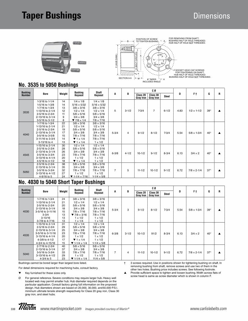
www.carlislebelts.com330 www.martinsprocket.com Images provided courtesy of Martin®
B-9
Taper Bushings Dimensions
BushingNumber Bore Weight Bushing
KeyseatShaft
Keyseat A BC Ø
D F † G RClass 20 Gray Iron
Class 30 Gray Iron Steel
3535
1-3/16 to 1-1/4 14 1/4 × 1/8 1/4 × 1/8
5 3-1/2 7-3/4 7 6-1/2 4.83 1/2 × 1-1/2 39° ▲
1-5/16 to 1-3/8 14 5/16 × 5/32 5/16 × 5/32 1-7/16 to 1-3/4 13 3/8 × 3/16 3/8 × 3/16
1-13/16 to 2-1/4 12 1/2 × 1/4 1/2 × 1/4 2-5/16 to 2-3/4 11 5/8 × 5/16 5/8 × 5/16 2-13/16 to 3-1/4 9 3/4 × 3/8 3/4 × 3/8 3-5/16 to 3-1/2 8 ▼ 7/8 × 1/4 7/8 × 7/16
4040
1-7/16 to 1-3/4 22 3/8 × 3/16 3/8 × 3/16
5-3/4 4 9-1/2 8-1/2 7-3/4 5.54 5/8 × 1-3/4 40° ▲
1-13/16 to 2-1/4 21 1/2 × 1/4 1/2 × 1/4 2-5/16 to 2-3/4 19 5/8 × 5/16 5/8 × 5/16 2-13/16 to 3-1/4 17 3/4 × 3/8 3/4 × 3/8 3-5/16 to 3-5/8 15 7/8 × 7/16 7/8 × 7/16 3-11/16 to 3-3/4 14 ▼ 1 × 1/4 7/8 × 7/16
3-13/16 to 4 13 ▼ 1 × 1/4 1 × 1/2
4545
1-15/16 to 2-1/4 30 1/2 × 1/4 1/2 × 1/4
6-3/8 4-1/2 10-1/2 9-1/2 8-3/4 6.13 3/4 × 2 40° ▲
2-5/16 to 2-3/4 28 5/8 × 5/16 5/8 × 5/16 2-13/16 to 3-1/4 26 3/4 × 3/8 3/4 × 3/8 3-5/16 to 3-3/4 23 7/8 × 7/16 7/8 × 7/16 3-13/16 to 4-1/4 20 1 × 1/2 1 × 1/2 4-5/16 to 4-1/2 18 ▼ 1 × 1/4 1 × 1/2
5050
2-5/16 to 2-3/4 38 5/8 × 5/16 5/8 × 5/16
7 5 11-1/2 10-1/2 9-1/2 6.72 7/8 × 2-1/4 37° ▲2-13/16 to 3-1/4 35 3/4 × 3/8 3/4 × 3/8 3-5/16 to 3-3/4 32 7/8 × 7/16 7/8 × 7/16 3-13/16 to 4-1/2 27 1 × 1/2 1 × 1/2
4-9/16 to 5 24 ▼ 1-1/4 × 7/16 1-1/4 × 5/8
BushingNumber Bore Weight Bushing
KeyseatShaft
Keyseat A BC Ø
D F † G RClass 20 Gray Iron
Class 30 Gray Iron Steel
4030
1-7/16 to 1-3/4 24 3/8 × 3/16 3/8 × 3/16
5-3/4 3 9-1/2 8-1/2 7-3/4 5.54 5/8 × 1-3/4 39° ▲
1-13/16 to 2-1/4 21 1/2 × 1/4 1/2 × 1/4 2-5/16 to 2-3/4 20 5/8 × 5/16 5/8 × 5/16 2-13/16 to 3-1/4 18 3/4 × 3/8 3/4 × 3/8 3-5/16 to 3-11/16 15 7/8 × 7/16 7/8 × 7/16
3-3/4 13 ▼ 7/8 × 3/16 7/8 × 7/16 3-13/16 13 1 × 1/2 1 × 1/2
3-7/8 to 4-7/16 13 1 × 1/4 1 × 1/2
4535
1-15/16 to 2-1/4 31 1/2 × 1/4 1/2 × 1/4
6-3/8 3-1/2 10-1/2 91/2 8-3/4 6.13 3/4 × 2 40° ▲
2-5/16 to 2-3/4 29 5/8 × 5/16 5/8 × 5/16 2-13/16 to 3-1/4 25 3/4 × 3/8 3/4 × 3/8 3-5/16 to 3-11/16 23 7/8 × 7/16 7/8 × 7/16 3-13/1 6 to 4-1/4 20 1 × 1/2 1 × 1/2 4-3/8 to 4-1/2 17 ▼ 1 × 1/4 1 × 1/2
4-3/4 to 4-15/16 15 ▼ 1-1/4 × 1/4 1-1/4 × 5/8
5040
2-7/16 to 2-3/4 40 5/8 × 5/16 5/8 × 5/16
7 4 11-1/2 10-1/2 9-1/2 6.72 7/8 × 2-1/4 37° ▲2-13/16 to 3-1/4 37 3/4 × 3/8 3/4 × 3/8 3-5/16 to 3-3/4 33 7/8 × 7/16 7/8 × 7/16 3-13/16 to 4-1/2 29 1 × 1/2 1 × 1/2
4-3/4 to 5 23 ▼ 1-1/4 × 1/4 11/4 × 5/8
No. 3535 to 5050 Bushings
No. 4030 to 5040 Short Taper Bushings
C (
HU
B D
IAM
.)
D (
BO
LT C
IRC
LES
)
B
A
L
M A
A
F
SECTION A-A
POSITION OF SCREWTO TIGHTEN BUSHING
8° TAPERINCLUDED ANGLE
SOCKET HEAD CAP SCREWSFOR TIGHTENING ON SHAFT:
HUB HALF OF HOLE THREADED.BUSHING HALF OF HOLE NOT THREADED.
FOR REMOVING FROM SHAFT:BUSHING HALF OF HOLE THREADED.HUB HALF OF HOLE NOT THREADED.
55°
52°60°
Bushings cannot be bored larger than largest bore listed.
For detail dimensions required for machining hubs, consult factory.
▼ Key furnished for these sizes only.
Ø For general reference. Severe conditions may require larger hub. Heavy well located web may permit smaller hub. Hub diameter required depends on the particular application. Consult factory giving full information on the proposed design. Hub diameters shown are based on 20,000, 30,000, and 50,000 P.S.I. minimum ultimate tensile strength respectively for Class 20 gray iron, Class 30 gray iron, and steel hubs.
† 3 screws required. Use in positions shown for tightening bushing on shaft. In removing bushing from shaft, remove screws and use two of them in the
other two holes. Bushing price includes screws. See following footnote.▲ Provide sufficient space to tighten and loosen bushing. screw head is same as screw diameter which is shown in column F.
Taper Bushings Dimensions

331www.carlislebelts.com Images provided courtesy of Martin® www.martinsprocket.com
Dimensions Taper Bushings
Inte
rcha
ngea
ble
| T
aper
Bus
hing
s
Taper Bushings Dimensions
B-10
Taper BushingsDimensions
BushingNumber Bore Weight Bushing
KeyseatShaft
Keyseat A BC Ø
D E F † L ★ M ★★Class 20 Gray Iron
Class 30 Gray Iron Steel
6050 3-13/16 to 4-1/2 60 1 × 1/2 1 × 1/2
9-1/4 5 17 15-1/2 13-1/2 9 6-3/4 1-1/4 × 3-1/2 1-5/8 4-3/8 49/16 to 5-1/2 55 1-1/4 × 5/8 1-1/4 × 5/8 5-9/16 to 6 50 1-1/2 × 3/4 1-1/2 × 3/4
7060 4-9/16 to 5-1/2 85 1-1/4 × 5/8 1-1/4 × 5/8
10-1/4 6 18-1/2 17 14-3/4 10 7-3/4 1-1/4 × 3-1/2 1-5/8 4-3/8 5-9/16 to 6-1/2 75 1-1/2 × 3/4 1-1/2 × 3/4 6-9/16 to 7 65 1-3/4 × 3/4 1-3/4 × 3/4
Ф 8065
5-1/16 to 5-1/2 120 1-1/4 × 5/8 1-1/4 × 5/8
11-1/4 6-1/2 19 17-1/2 15-1/2 11 8-3/4 1-1/4 × 3-1/2 1-5/8 4-3/8 5-9/16 to 6-1/2 105 1-1/2 × 3/4 1-1/2 × 3/4 6-9/16 to 7-1/2 90 1-3/4 × 3/4 1-3/4 × 3/4
7-9/16 to 8 75 2 × 3/4 2 × 3/4
Ф 10085 6-9/16 to 7-1/2 260 1-3/4 × 3/4 1-3/4 × 3/4
14-3/4 8-1/2 23-1/2 22 19-1/2 14-1/2 11-3/4 1-1/2 × 4-1/4 2 5-3/8 7-9/16 to 9 230 2 × 3/4 2 × 3/4 9-1/16 to 10 190 2-1/2 × 7/8 2-1/2 × 7/8
Ф 120100 7-9/16 to 9 410 2 × 3/4 2 × 3/4
17-1/4 10 28 26 23 17 14-1/4 1-1/2 × 4-1/4 2 5-3/8 9-1/16 to 11 360 2-1/2 × 7/8 2-1/2 × 7/8 11-1/16 to 12 290 3 × 1 3 × 1
No 6050 to 120100 Taper Bushings
Bushings cannot be bored larger than largest bore listed.
For detail dimensions required for machining hubs, consult .
Ø For general reference. Severe conditions may require larger hub. Heavy well located web may permit smaller hub. Hub diameter required depends on the particular application. Consult giving full information on the proposed design. Hub diameters shown are based on 20,000, 30,000, and 50,000 P.S.I. minimum ultimate tensile strength respectively for Class 20 gray iron, Class 30 gray iron, and steel hubs.
† 3 screws for 6050; four for 7060 to 10085; six for 120100. Use in positions shown for tightening bushing on shaft. In loosening bushing, remove screws and use all except one in the other holes. Bushing price includes screws.
★ Space required to tighten bushing. Also space required to loosen screws to permit removal of hub by puller.
★★ Space required to loosen bushing using screws as jackscrews— no puller required.
Ф Not currently stocked — Available on order.
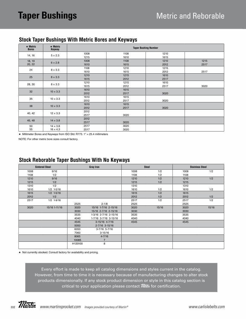
www.carlislebelts.com332 www.martinsprocket.com Images provided courtesy of Martin®
B-12
Taper BushingsMetric and Reborable
Stock Taper Bushings With Metric Bores and Keyways
Stock Reborable Taper Bushings With No Keyways
★ MetricBores
★ MetricKeyway Taper Bushing Number
14, 16 5 × 2.3 1008 1108 1210 1215 1610 1615
18, 19 20, 22
6 × 2.8 1008 1108 1210 1215 1610 1615 2012 2517
24 8 × 3.3 1108 1210 1215 1610 1615 2012 2517
25 8 × 3.3 1210 1215 1610 1615 2012 2517
28, 30 8 × 3.3 1210 1215 1610 1615 2012 2517 3020
32 10 × 3.3 1610 1615 2012 2517 3020
35 10 × 3.3 1610 1615 2012 2517 3020
38 10 × 3.3 1610 1615 2012 2517 3020
40, 42 12 × 3.3 2012 2517 3020
45, 48 14 × 3.8 2012 2517 3020
50 55
14 × 3.8 16 × 4.3
2517 3020 2517 3020
Sintered Steel Gray Iron Steel Stainless Steel
1008 9/16 1008 1/2 1008 1/2 1108 1/2 1108 1/2 1108 1210 9/16 1210 1/2 1210 1/2 1215 1/2 1215 1/2 1215 1310 1/2 1310 1310 1610 1/2 1-5/16 1610 1/2 1610 1/2 1615 1/2 1-5/16 1615 1/2 1615 2012 1/2 2012 1/2 2012 1/2 2517 1/2 1-9/16 2517 1/2 2517 1/2
2525 2-1/8 2525 2525 3020 15/16 1-11/16 3020 15/16 1-7/16 2-15/16 3020 15/16 3020 15/16
3030 15/16 2-7/16 2-15/16 3030 3030 3535 1-3/16 2-7/16 2-15/16 3535 3535 4040 1-7/16 3-7/16 3-15/16 4040 4040 4545 3-15/16 4-7/16 4545 4545 5050 2-7/16 3-15/16 6050 3-7/16 5-7/16 7060 3-15/16 8065 4-7/16 10085 7 H120100 8
★ Millimeter Bores and Keyways from ISO Std. R773. 1" = 25.4 millimeters
NOTE: For other metric bore sizes consult factory.
★ Not currently stocked. Consult factory for availability and pricing.
Taper Bushings Metric and Reborable
Every effort is made to keep all catalog dimensions and styles current in the catalog. However, from time to time it is necessary because of manufacturing changes to alter stock
products dimensionally. If any stock product dimension or style in this catalog section is critical to your application please contact for certification.

333www.carlislebelts.com Images provided courtesy of Martin® www.martinsprocket.com
MST® Bushings
Inte
rcha
ngea
ble
| M
ST®
Bus
hing
s
Taper Bushings Metric and Reborable
B-14
MST® Bushings
“G” & “H” BUSHINGS
“S” & “U” BUSHINGS
“P”, “Q” & “R” BUSHINGS
“W” BUSHINGS
“R”
“S ”
“U”“U1”, “U2”
Part Number
Dimensions Stock Bore Range Cap ScrewsAv. Wt.
Lbs.Wrench Torque In./lbs.D L A B Large
End G B.C. W Type 1 Type 2 No. Size
G 2.00 1.00 0.25 1.1720 0.19 1.56 — 3/8 – 15/16 1 2 1/4 × 5/8 0.5 95H 2.50 1.25 0.25 1.6250 0.19 2.00 — 3/8 – 1-3/8 1-7/16 – 1-1/2 2 1/4 × 3/4 0.8 95 P1 3.00 1.94 0.41 1.9375 0.22 2.44 0.375 1/2 – 1-7/16 1-1/2 – 1-3/4 3 5/16 × 1 1.3 192 P2 3.00 2.94 0.41 1.9375 0.22 2.44 0.375 3/4 – 1-7/16 1-1/2 – 1-3/4 3 5/16 × 1 1.5 192 P3 3.00 4.44 0.41 1.9375 0.22 2.44 0.375 1-1/8 – 1-3/8 1-5/8 3 5/16 × 1 2.0 192 Q1 4.12 2.50 0.53 2.8750 0.22 3.38 0.500 3/4 – 2-1/16 2-1/8 – 2-11/16 3 3/8 × 1-1/4 3.5 348 Q2 4.12 3.50 0.53 2.8750 0.22 3.38 0.500 1 – 2-1/16 2-1/8 – 2-5/8 3 3/8 × 1-1/4 4.5 348 Q3 4.12 5.00 0.53 2.8750 0.22 3.38 0.500 1-3/8 – 2-1/16 2-1/8 – 2-1/2 3 3/8 × 1-1/4 5.5 348 R1 5.38 2.88 0.62 4.0000 0.25 4.62 0.750 1-1/8 – 2-13/16 2-7/8 – 3-3/4 3 3/8 × 1-3/4 7.5 348 R2 5.38 4.88 0.62 4.0000 0.25 4.62 0.750 1-3/8 – 2-13/16 2-7/8 – 3-5/8 3 3/8 × 1-3/4 11.0 348 S1 6.38 4.38 0.75 4.6250 0.31 5.38 0.750 1-11/16 – 3-3/16 3-1/4 – 4-1/4 3 1/2 × 2-1/4 13.5 840 S2 6.38 6.75 0.75 4.6250 0.31 5.38 0.750 1-7/8 – 3-3/16 3-1/4 – 4-3/16 3 1/2 × 2-1/4 19.0 840 UO 8.38 5.25 1.06 6.0000 0.44 7.00 1.250 2-3/8 – 3-1/16 — 3 5/8 × 2-3/4 30.0 1680 UO 8.38 4.94 0.75 6.0000 0.44 7.00 1.250 3-1/4 – 4-1/4 4-3/8 – 5-1/2 3 5/8 × 2-3/4 27.0 1680 U1 8.38 7.12 1.06 6.0000 0.44 7.00 1.250 2-3/8 – 4-1/4 4-3/8 – 5-1/2 3 5/8 × 2-3/4 40.0 1680 U2 8.38 10.12 1.06 6.0000 0.44 7.00 1.250 2-7/16 – 4-1/4 4-3/8 – 5 3 5/8 × 2-3/4 50.0 1680 W1 12.50 8.25 1.44 8.5000 0.44 10.00 1.250 3-3/8 – 6-3/16 6-1/4 – 7-7/16 4 3/4 × 3 104.0 3000 W2 12.50 11.25 1.44 8.5000 0.44 10.00 1.250 3-3/8 – 6-3/16 6-1/4 – 7-7/16 4 3/4 × 3 133.0 3000
All tapers are 3/4" per 12" on Diameter.
All dimensions are in inches except, as noted.
All bushings are cast iron, ductile iron, sintered steel, or steel. .
Metric bushings also available.
Bushing Specifications

Under certain conditions of temperature and humidity, a belt drive may generate static electricity. Belts intended for operation in a potentially dangerous atmosphere should be constructed with a relatively low electrical resistance characteristic. It has become common practice to specify and refer to such belts as “static conductive,” “static dissipating,” or “anti-static.”
The accumulation of electro-static charges can be dangerous for different reasons:
■■ Generation of radio interference that can cause disturbance to electrical apparatus
■■ Risk of ignition and explosion in an atmosphere with high levels of combustible materials
■■ Risk of injury to workers in contact with the components
V-Belt DrivesCarlisle belts checked on the chart to the right are static conductive based on testing developed by the Association for Rubber Products Manufacturers (ARPM Bulletin IP3-3). These belts are branded as “static dissipating.”
Synchronous Belt DrivesCarlisle synchronous belts are not static dissipating.
www.carlislebelts.com334
General InformationStatic Conductive Belts
Carlisle® Belts Cross Section Static Dissipating
Panther®XT Synchronous Belt 8M, 14M No
Panther® Synchronous Belt 8M, 14M, 20M No
Synchro-Cog® HT Belt 3M, 5M, 8M, 14M No
Dual Synchronous Belt D8M, D14M No
Synchro-Cog® Timing Belt XL, L, H, XH, XXH No
Air Cool Heat Exchange Belt 14M No
Cotton Drive® Timing Belt CCB No
Gold-Ribbon® Cog-Belt® AX, BX, CX, DX 4
Super II® V-Belt A, B, C 4
Super Blue Ribbon® V-Belt AP, BP, CP, DP, EP 4
Aramax® Xtra Duty V-Belt 3L, AK, BK No
Power-Wedge® Cog-Belt® 3VX, 5VX, 8VX 4
Metric Power-Wedge® Cog-Belt® SPZX, SPAX, SPBX, SPCX 4
Super Power-Wedge® V-Belt 5V, 8V 4
Double Angle V-Belt AA, BB, CC Special Order Only
Vee-Rib™ Belt J No
Variable Speed Cog-Belt Various 4
Gold-Ribbon® Cog-Band® RBX, RCX, RDX, RBL, RCL, RDL 4
Power-Wedge® Cog-Band® R3VX, R5VX 4
Wedge-Band® R3V, R5V, R8V 4
Aramax® Wedge-Band® R8VK 4
Wedge-Band® Chipper Drive R5VL Special Order Only
Super Vee-Band® RBP, RCP, RDP 4
Durapower®II FHP V-Belt 2L, 3L, 4L, 5L 4
Dry Can Belt CC Special Order Only
Thoro-Twist™ V-Belting 3L, A, B, C No
Round Belts 7/16, 9/16 Special Order Only
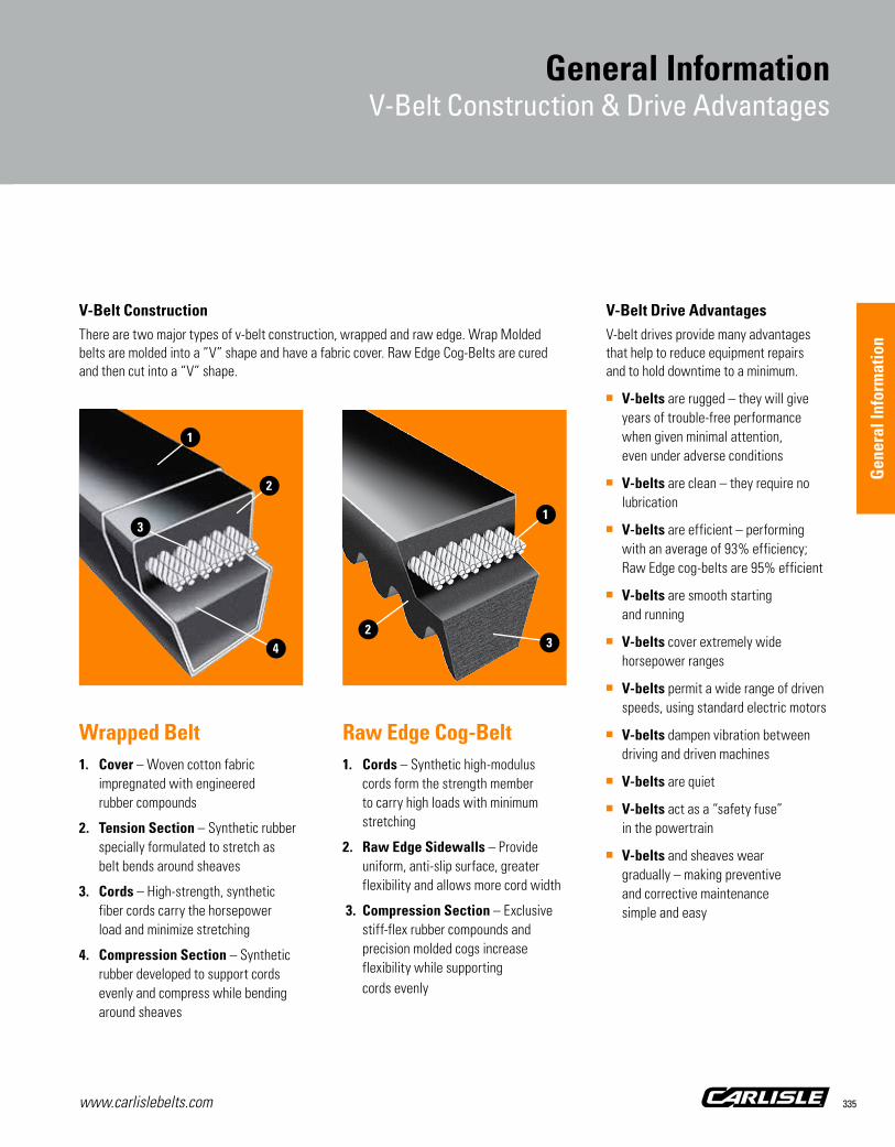
V-Belt ConstructionThere are two major types of v-belt construction, wrapped and raw edge. Wrap Molded belts are molded into a ”V” shape and have a fabric cover. Raw Edge Cog-Belts are cured and then cut into a “V” shape.
Wrapped Belt1. Cover – Woven cotton fabric
impregnated with engineered rubber compounds
2. Tension Section – Synthetic rubber specially formulated to stretch as belt bends around sheaves
3. Cords – High-strength, synthetic fiber cords carry the horsepower load and minimize stretching
4. Compression Section – Synthetic rubber developed to support cords evenly and compress while bending around sheaves
Raw Edge Cog-Belt1. Cords – Synthetic high-modulus
cords form the strength member to carry high loads with minimum stretching
2. Raw Edge Sidewalls – Provide uniform, anti-slip surface, greater flexibility and allows more cord width
3. Compression Section – Exclusive stiff-flex rubber compounds and precision molded cogs increase flexibility while supporting cords evenly
V-Belt Drive AdvantagesV-belt drives provide many advantages that help to reduce equipment repairs and to hold downtime to a minimum.
■■ V-belts are rugged – they will give years of trouble-free performance when given minimal attention, even under adverse conditions
■■ V-belts are clean – they require no lubrication
■■ V-belts are efficient – performing with an average of 93% efficiency; Raw Edge cog-belts are 95% efficient
■■ V-belts are smooth starting and running
■■ V-belts cover extremely wide horsepower ranges
■■ V-belts permit a wide range of driven speeds, using standard electric motors
■■ V-belts dampen vibration between driving and driven machines
■■ V-belts are quiet
■■ V-belts act as a “safety fuse” in the powertrain
■■ V-belts and sheaves wear gradually – making preventive and corrective maintenance simple and easy
www.carlislebelts.com 335
General InformationV-Belt Construction & Drive Advantages
2
1
3
1
4
2
3
Gen
eral
Info
rmat
ion

www.carlislebelts.com336
General InformationV-Belt Troubleshooting Guide
Some of the more common symptoms of short v-belt life are listed in the chart below. This chart is intended to help identify the cause of short belt life so problems can be addressed and corrected. For more information on proper v-belt maintenance, request the “Service Manual for Industrial V-Belt Drives” from your local distributor of Carlisle belts. It is also available at carlislebelts.com/ServiceManual or by simply scanning the QR code to the right.
Symptoms Caus
es
Belts
prie
d on
or m
ispl
aced
sla
ck
Belts
rubb
ing
guar
d
Shea
ves
mis
alig
ned
Wor
n or
dam
aged
she
aves
Shea
ves
too
far f
rom
bea
ring
Poor
bea
ring
or s
haft
con
ditio
n
Insu
ffic
ient
tens
ion
Exce
ssiv
e te
nsio
n
Impr
oper
she
ave
inst
alla
tion
Belts
wor
n (n
orm
al s
ervi
ce li
fe)
Wro
ng b
elt c
ross
-sec
tion
or ty
pe
Mis
mat
ched
bel
ts o
r mix
ed b
rand
s
Mac
hine
-indu
ced
impu
lse
or s
hock
Impr
oper
or p
rolo
nged
sto
rage
Exce
ssiv
e he
at
Exce
ssiv
e oi
l or g
reas
e
Use
of b
elt d
ress
ing
Abra
sive
env
ironm
ent
Fore
ign
obje
cts
in g
roov
es
Exce
ssiv
e m
oist
ure
Over
load
ed d
rive/
unde
rbel
ting
Driv
e se
rious
ly o
verb
elte
d
Shea
ves
too
smal
l
Insu
ffic
ient
wra
p on
sm
all s
heav
e
Back
side
idle
r
Harm
onic
s
Rapid sidewall wear ■ ■ ■ ■ ■ ■ ■ ■ ■ ■ ■ ■ ■
Worn cover on back ■ ■
Belt turns over or jumps off sheave ■ ■ ■ ■ ■ ■ ■ ■ ■
Belt soft, swollen ■ ■
Belt slips, squeals (spin burn) ■ ■ ■ ■ ■ ■ ■ ■ ■ ■ ■ ■ ■ ■
Belt cover split ■ ■
Underside cracked ■ ■ ■ ■ ■ ■ ■ ■ ■
Tie-band damaged ■ ■ ■ ■ ■
Snub break ■ ■ ■ ■ ■ ■ ■
Belts ride too high ■
Belts bottoming ■ ■ ■ ■ ■ ■
Repeated take-up necessary ■ ■ ■ ■ ■ ■ ■ ■ ■
Belts vibrate excessively or appear mismatched
■ ■ ■ ■ ■ ■ ■ ■ ■
Bearings are hot ■ ■ ■ ■ ■ ■ ■
Shafts whip or bend ■ ■ ■ ■ ■ ■ ■
Cracked bushings ■ ■
Sheave wobble ■ ■ ■ ■
■■■Indicates most common causes ■■■Indicates other possible causes

www.carlislebelts.com 337
General InformationSynchronous Belt Drive Troubleshooting Guide
*NOTE: Effective noise reduction for power transmission drives can be accomplished by incorporating a flexible noise absorbing material with the protective guard. The guard design must allow a cooling air passage on the top and bottom to prevent overheating the drive.
Type of Failure Cause of Failure Corrective Action
Excessive edge wear (exposed tensile member)Misalignment or non-rigid centers Check alignment and/or reinforce mounting
Belt flange Straighten flange
Jacket wear on pressure-face side of belt tooth Excessive overload and/or incorrect tensionChange installation tension and/or increase drive load carrying capacity
Excessive jacket wear between belt teeth (exposed tension members)
Excessive installation tension Reduce installation tension
Cracks in backingExposure to excessive low temp (below -30°F) Eliminate low temperature condition or
consult factory for proper belt constructionChemical exposure
Softening of backing Chemical and/or oilEliminate oil condition or consult factory for proper belt construction
Excessive sprocket tooth wear (on pressure-face and/or OD)
Excessive overload and/or excessive belt tightnessReduce installation tension and/or increase drive load-carrying capacity
Insufficient hardness of sprocket material Surface harden sprocket or use harder material
Normal wear/end-of-service/grit or debris Replace sprockets
Unmounting of flangeIncorrect flange installation Reinstall flange correctly
Misalignment Correct alignment
Excessive drive noise*
Misalignment Correct alignment
Excessive installation tension Reduce tension
Excessive load Increase drive load-carrying capacity
Sub-minimum sprocket diameter Increase sprocket diameters
High speeds Slow drives down
Tooth shear
Less than 6 teeth in mesh (TIM) Increase TIM or use next smaller pitch
Excessive load Increase drive load-carrying capacity
Low tension Increase tension
Apparent belt stretch Reduction of center distance or non-rigid mounting Re-tention drive and/or reinforce mounting
Cracks or premature wear at belt tooth rootImproper sprocket groove top radius Re-groove or install new sprockets
Low tension Increase tension
Tensile breakExcessive load Increase load-carrying capacity of drive
Sub-minimum sprocket diameter Increase sprocket diameters
Gen
eral
Info
rmat
ion
Gen
eral
Info
rmat
ion

www.carlislebelts.com338
General InformationV-Belt Installation Check List & Selection Guide
V-Belt Installation Check List
1. Cut off and lock out power source
2. Observe all safety procedures
3. Follow the recommendations of the original equipment manufacturer
4. Remove belt guard
5. Loosen motor mounts
6. Shorten center distance
7. Remove old belts
8. Inspect belt wear patterns for possible troubleshooting
9. Inspect drive elements – bearings, shaft, etc
10. Inspect sheaves for wear; clean sheaves
11. Check sheave alignment (preliminary)
12. Select proper replacement belts
13. Install new belts
14. Properly tension belts
15. Check sheave alignment (final)
16. Replace guard
17. Start drive (look and listen)
18. Check tension after 24 hours
Carlisle® Belts by Timken
Chek Mate® Matching
Generic Belt Type (Cross Sections)
Normal Horsepower
Range
Maximum Belt Speed (FT/Min) (1)
Normal Temperature Range (°F) (2) Oil/Heat
ResistanceStatic Dissipating General Application
Min. Max.
Gold-Ribbon® Cog-Belt®*Classical Cogged Multiple (AX, BX, CX, DX)
1-500 6500 -50 250 Good 4 Longer life, high efficiency, small diameters
Super II® V-Belt Classical Multiple (A, B, C) 1-500 6500 -35 120 Good 4 General purpose heavy duty industrial drives
Super Blue Ribbon® V-Belt Classical Multiple (A, B, C, D) 1-500 6500 -35 120 Good 4 General purpose heavy duty industrial drives
Aramax® Xtra Duty V-Belt Classical Multiple (3L, AK, BK) 1-500 6500 -35 120 Good No General purpose heavy duty industrial drives
Power-Wedge® Cog-Belt®*Narrow Cogged Multiple (3VX, 5VX, 8VX)
1-600 6500 -50 250 Good 4 High-performance, compact industrial drives
Metric Power-Wedge® Cog-Belt®
Narrow Cogged Multiple (SPZX, SPAX, SPBX, SPCX)
1-600 6500 -50 250 Good 4 High-performance, compact industrial drives
Super Power-Wedge® Narrow Multiple (5V, 8V) 1-1000 6500 -35 130 Very Good 4 High-performance, compact industrial drives
Double Angle V-Belt Double V-Belts (AA, BB, CC) 1-200 6500 -35 120 Good Special Order Only Serpentine drives
Vee-Rib™ V-Ribbed (J) 4-500 6500 -35 130 Very Good No Small diameters, high speed ratios, compact
Gold-Ribbon® Cog-Band® Classical Cogged Banded (RBX, RCX, RDX)
1-500 6500 -35 130 Good 4Longer life, high efficiency, reduces belt whip, turnover on pulsating surge loads
Power-Wedge® Cog-Band® Narrow Cogged Banded (R3VX, R5VX)
1-1000 6500 -35 130 Good 4 Eliminates belt whip and turnover
Wedge-Band® Narrow Banded (R3V, R5V, R8V) 1-1000 6500 -35 130 Very Good 4 Eliminates belt whip and turnover
Aramax® Wedge-Band® Narrow Banded (R8VK) 1-2000 6500 -35 130 Very Good 4 Heavy duty, high load machinery
Wedge-Band® Chipper Drive Narrow Banded (R5VL) 1-600 6500 -35 130 Very Good Special Order Only Chipper drives
Super Vee-Band® Classical Banded (RBP, RCP, RDP) 1-500 6500 -35 120 Good 4 Eliminates belt whip and turnover
Durapower®II FHP (2L, 3L, 4L, 5L) Light Duty 6500 -35 120 Fair 4 Using a single belt/low load/small HVAC
Dry-Can Belt Double Angle (CC***S) 1-500 6500 -35 120 Good Special Order Only Dry-Can applications
Thoro-Twist™ Link (3L, A, B, C) 1-300 5000 (1000 min.) -35 130 Excellent No Emergency replacement, fixed center distance
Round Belts Round (716R, 916R) 1-200 6500 -35 130 Good Special Order Only Conveyor applications
This symbol indicates product manufactured to tolerances.
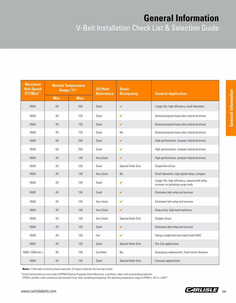
www.carlislebelts.com 339
General InformationV-Belt Installation Check List & Selection Guide
Notes: (1) Normally limited by sheave materials. (2) Expect moderate life loss due to heat.
* Some Carlisle belts are now made of EPDM (Ethylene Propylene Diene Monomer), a synthetic rubber with outstanding properties. EPDM is durable, static conductive and resistant to oil, heat, hardening and glazing. The operating temperature range of EPDM is -50° to +250°F.
Carlisle® Belts by Timken
Chek Mate® Matching
Generic Belt Type (Cross Sections)
Normal Horsepower
Range
Maximum Belt Speed (FT/Min) (1)
Normal Temperature Range (°F) (2) Oil/Heat
ResistanceStatic Dissipating General Application
Min. Max.
Gold-Ribbon® Cog-Belt®*Classical Cogged Multiple (AX, BX, CX, DX)
1-500 6500 -50 250 Good 4 Longer life, high efficiency, small diameters
Super II® V-Belt Classical Multiple (A, B, C) 1-500 6500 -35 120 Good 4 General purpose heavy duty industrial drives
Super Blue Ribbon® V-Belt Classical Multiple (A, B, C, D) 1-500 6500 -35 120 Good 4 General purpose heavy duty industrial drives
Aramax® Xtra Duty V-Belt Classical Multiple (3L, AK, BK) 1-500 6500 -35 120 Good No General purpose heavy duty industrial drives
Power-Wedge® Cog-Belt®*Narrow Cogged Multiple (3VX, 5VX, 8VX)
1-600 6500 -50 250 Good 4 High-performance, compact industrial drives
Metric Power-Wedge® Cog-Belt®
Narrow Cogged Multiple (SPZX, SPAX, SPBX, SPCX)
1-600 6500 -50 250 Good 4 High-performance, compact industrial drives
Super Power-Wedge® Narrow Multiple (5V, 8V) 1-1000 6500 -35 130 Very Good 4 High-performance, compact industrial drives
Double Angle V-Belt Double V-Belts (AA, BB, CC) 1-200 6500 -35 120 Good Special Order Only Serpentine drives
Vee-Rib™ V-Ribbed (J) 4-500 6500 -35 130 Very Good No Small diameters, high speed ratios, compact
Gold-Ribbon® Cog-Band® Classical Cogged Banded (RBX, RCX, RDX)
1-500 6500 -35 130 Good 4Longer life, high efficiency, reduces belt whip, turnover on pulsating surge loads
Power-Wedge® Cog-Band® Narrow Cogged Banded (R3VX, R5VX)
1-1000 6500 -35 130 Good 4 Eliminates belt whip and turnover
Wedge-Band® Narrow Banded (R3V, R5V, R8V) 1-1000 6500 -35 130 Very Good 4 Eliminates belt whip and turnover
Aramax® Wedge-Band® Narrow Banded (R8VK) 1-2000 6500 -35 130 Very Good 4 Heavy duty, high load machinery
Wedge-Band® Chipper Drive Narrow Banded (R5VL) 1-600 6500 -35 130 Very Good Special Order Only Chipper drives
Super Vee-Band® Classical Banded (RBP, RCP, RDP) 1-500 6500 -35 120 Good 4 Eliminates belt whip and turnover
Durapower®II FHP (2L, 3L, 4L, 5L) Light Duty 6500 -35 120 Fair 4 Using a single belt/low load/small HVAC
Dry-Can Belt Double Angle (CC***S) 1-500 6500 -35 120 Good Special Order Only Dry-Can applications
Thoro-Twist™ Link (3L, A, B, C) 1-300 5000 (1000 min.) -35 130 Excellent No Emergency replacement, fixed center distance
Round Belts Round (716R, 916R) 1-200 6500 -35 130 Good Special Order Only Conveyor applications
Gen
eral
Info
rmat
ion
Gen
eral
Info
rmat
ion

Matching numbers are indicated on each banded belt next to the brand, e.g. 49, 50, 51, etc. For example, a match limit of 1 in the table below indicates the belts must all have the same matching number. Similary, a match limit of 2 indicates that a matched set may consist of any two adjacent matching numbers, i.e. 49 and 50 would constitute a matched set.
Spring-Loaded Belt TensiometerProper tensioning is one of the most important factors necessary for long, satisfactory operation. This tensioning method is based on the fact that the force required to deflect a given span length by a given amount is related to the tension in the belt.
Procedure for Using the Tensiometer
1. Measure the span length of the drive.(See Fig. 2). Set the large “O” ring at 1/64˝ for each inch of belt span. For example, set the large “O” ring at 1/4˝ for a span length of 16,̋ at 1/2˝ for a span length of 32,̋ or at 1˝ for a span length of 64˝, etc.
2. Set the small “O” ring at zero (See Fig. 1) and press down the Tensiometer at the center of the belt span.
a. On a single belt drive, depress the tensiometer until the large “O” ring is even with the bottom of a straight edge placed on the outside rims of the two sheaves.
b. On a multiple belt drive, depress the Tensiometer until the large “O” ring is even with the top of the next belt. Measure each belt in the drive and take the average reading of all belt tensions.
3. Remove the Tensiometer and observe that the small “O” ring has moved from its original setting at zero to the number of pounds required to deflect the belt.
4. Check this reading against the value of the deflection force in the V-Belt Tensioning table (page 341).
Guidelines presented are suggestions to help install and maintain belts properly. Please always follow the recommendations of the original equipment manufacturer.
www.carlislebelts.com340
General InformationBanded V-Belt Matching Limits
Product Type and Length Code
Match Limit
Gold-Ribbon® Cog-Band®
RBX51 – RBX61 1
RBX62 – RBX144 2
RBX158 and longer 3
RCX68 – RCX144 2
RCX158 and longer 3
RDX120 – RDX144 2
RDX158 and longer 3
Wedge-Band®
R3VX250 – R3VX630 1
R3VX670 – R3VX1400 2
R5VX500 – R5VX630 1
R5VX670 – R5VX1500 2
R5VX1600 and up 3
R8V1000 – R8V1500 2
R8V1600 and up 3
Super Vee-Band®
RBP35 – RBP60 1
RBP61 – RBP144 2
RBP148 and up 3
RCP51 – RCP60 1
RCP68 – RCP144 2
RCP158 and up 3
RDP120 – RDP144 2
RDP158 and up 3
Figure 2
Figure 1

www.carlislebelts.com 341
General InformationV-Belt Tensioning
Gen
eral
Info
rmat
ion
Average Tensioning Values (recommended minimum force per belt)
This table shows minimum deflection force values. New belts should be installed at 2.0 times these values. Used belts should be between 1.0 and 1.5 times these values.
Carlisle Belts V-Belt SectionSmall Sheave Deflection Force for the Drive Speed Ratio (lbs.)
Speed Range Diameter 1.0 1.5 2.0 4.0 and over
Super II® & Super Blue Ribbon®
AAP
1800-3600 3.0 2.0 2.3 2.4 3.31800-3600 4.0 2.6 2.8 3.0 3.31800-3600 5.0 3.0 3.3 3.4 3.71800-3600 7.0 3.5 3.7 3.8 4.3
B BP
1200-1800 4.6 3.7 4.3 4.5 5.01200-1800 5.0 4.1 4.6 4.8 5.61200-1800 6.0 4.8 5.3 5.5 6.31200-1800 8.0 5.7 6.2 6.4 7.2
C CP
900-1800 7.0 6.5 7.0 8.0 9.0900-1800 9.0 8.0 9.0 10.0 11.0900-1800 12.0 10.0 11.0 12.0 13.0700-1500 16.0 12.0 13.0 13.0 14.0
DP
900-1500 12.0 13.0 15.0 16.0 17.0900-1500 15.0 16.0 18.0 19.0 21.0700-1200 18.0 19.0 21.0 22.0 24.0700-1200 22.0 22.0 23.0 24.0 26.0
Gold-Ribbon® Cog-Belt®
AX
1800-3600 3.0 2.5 2.8 3.0 3.31800-3600 4.0 3.3 3.6 3.8 4.21800-3600 5.0 3.7 4.1 4.3 4.61800-3600 7.0 4.3 4.6 4.8 5.3
BX
1200-1800 4.6 5.2 5.8 6.0 6.91200-1800 5.0 5.4 6.0 6.3 7.11200-1800 6.0 6.0 6.4 6.7 7.71200-1800 8.0 6.6 7.1 7.5 8.2
CX
900-1800 7.0 10.0 11.0 12.0 13.0900-1800 9.0 11.0 12.0 13.0 14.0900-1800 12.0 12.0 13.0 13.0 14.0700-1500 16.0 13.0 14.0 14.0 15.0
DX
900-1500 12.0 16.0 18.0 19.0 20.0900-1500 15.0 19.0 21.0 22.0 24.0700-1200 18.0 22.0 24.0 25.0 27.0700-1200 22.0 25.0 27.0 28.0 30.0
Power-Wedge® Cog-Belt®
3VX
1200-3600 2.2 2.2 2.5 2.7 3.01200-3600 2.5 2.6 2.9 3.1 3.61200-3600 3.0 3.1 3.5 3.7 4.21200-3600 4.1 3.9 4.3 4.5 5.11200-3600 5.3 4.6 4.9 5.1 5.71200-3600 6.9 5.0 5.4 5.6 6.2
5VX
1200-3600 4.4 6.5 7.5 8.0 9.01200-3600 5.2 8.0 9.0 9.5 10.01200-3600 6.3 9.5 10.0 11.0 12.01200-3600 7.1 10.0 11.0 12.0 13.0900-1800 9.0 12.0 13.0 14.0 15.0900-1800 14.0 14.0 15.0 16.0 17.0
8VX
900-1800 12.5 18.0 21.0 23.0 25.0900-1800 14.0 21.0 23.0 24.0 28.0700-1500 17.0 24.0 26.0 28.0 30.0700-1200 21.2 28.0 30.0 32.0 34.0400-1000 24.8 31.0 32.0 34.0 36.0
Super Power-Wedge®
5V
900-1800 7.1 8.5 9.5 10.0 11.0900-1800 9.0 10.0 11.0 12.0 13.0900-1800 14.0 12.0 13.0 14.0 15.0700-1200 21.2 14.0 15.0 16.0 17.0
8V
900-1800 12.5 18.0 21.0 23.0 25.0900-1800 14.0 21.0 23.0 24.0 28.0700-1500 17.0 24.0 26.0 28.0 30.0700-1200 21.2 28.0 30.0 32.0 34.0400-1000 24.8 31.0 32.0 34.0 36.0
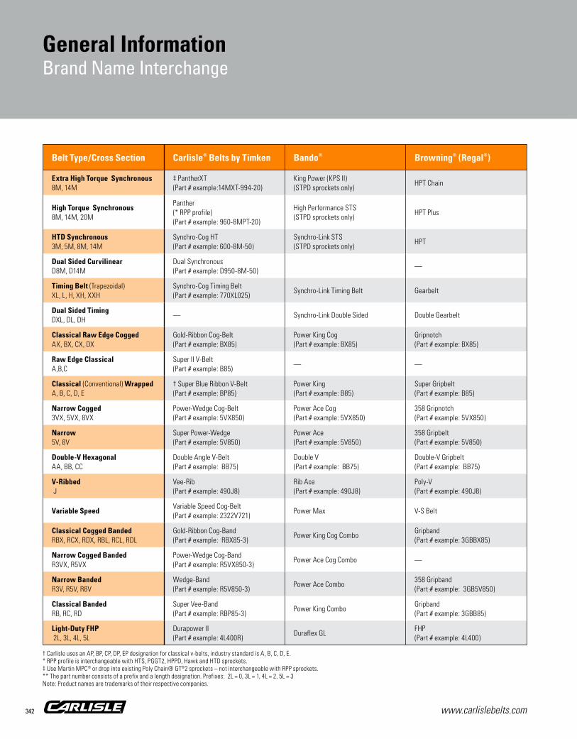
www.carlislebelts.com342
General InformationBrand Name Interchange
Belt Type/Cross Section Carlisle® Belts by Timken Bando® Browning® (Regal®) ContiTech® Gates® Jason® (Megadyne®) MBL®
Extra High Torque Synchronous8M, 14M
‡ PantherXT(Part # example:14MXT-994-20)
King Power (KPS II)(STPD sprockets only)
HPT Chain SynchroChain or Falcon PD Poly Chain GT Carbon RPP Platinum GigaTorque
High Torque Synchronous8M, 14M, 20M
Panther(* RPP profile)(Part # example: 960-8MPT-20)
High Performance STS(STPD sprockets only)
HPT Plus BlackHawk PD Power Grip GT2 Tiger
HTD Synchronous3M, 5M, 8M, 14M
Synchro-Cog HT(Part # example: 600-8M-50)
Synchro-Link STS (STPD sprockets only)
HPT Hawk PD Power Grip GTHTD
HTB (HTD) High Torque Timing
Dual Sided CurvilinearD8M, D14M
Dual Synchronous (Part # example: D950-8M-50)
— Dual Hi-Performance Pd® GT2 Twin Power Dual HTB (HTD)
Timing Belt (Trapezoidal)XL, L, H, XH, XXH
Synchro-Cog Timing Belt(Part # example: 770XL025)
Synchro-Link Timing Belt Gearbelt Positive Drive Power Grip Standard Timing Three Stars Timing
Dual Sided Timing DXL, DL, DH
— Synchro-Link Double Sided Double Gearbelt Dual Positive Drive Power Grip Twin Power Dual Timing Three Stars Dual Timing
Classical Raw Edge CoggedAX, BX, CX, DX
Gold-Ribbon Cog-Belt(Part # example: BX85)
Power King Cog(Part # example: BX85)
Gripnotch(Part # example: BX85)
Torque Flex(Part # example: BX85)
Tri-PowerMolded Notch(Part # example: BX85)
Uni-Match Cogged(Part # example: BX85)
Raw Edge Cogged(Part # example: BX85)
Raw Edge Classical A,B,C
Super II V-Belt(Part # example: B85)
— — — — — —
Classical (Conventional) WrappedA, B, C, D, E
† Super Blue Ribbon V-Belt(Part # example: BP85)
Power King(Part # example: B85)
Super Gripbelt(Part # example: B85)
HY-T(Part # example: B85)
Hi-Power II(Part # example: B85)
Uni-Match(Part # example: B85)
Conventional(Part # example: B85)
Narrow Cogged3VX, 5VX, 8VX
Power-Wedge Cog-Belt(Part # example: 5VX850)
Power Ace Cog(Part # example: 5VX850)
358 Gripnotch(Part # example: 5VX850)
HY-T Wedge Cog(Part # example: 5VX850)
Super HC Molded Notch(Part # example: 5VX850)
Uni-Match cogged(Part # example: 5VX850)
Maxstar Wedge Supreme(Part # example: 5VX850)
Narrow5V, 8V
Super Power-Wedge(Part # example: 5V850)
Power Ace(Part # example: 5V850)
358 Gripbelt(Part # example: 5V850)
HY-T Wedge(Part # example: 5V850)
Super HC(Part # example: 5V850)
Uni-Match Deep Wedge(Part # example: 5V850)
Maxstar Wedge(Part # example: 5V850)
Double-V HexagonalAA, BB, CC
Double Angle V-Belt(Part # example: BB75)
Double V(Part # example: BB75)
Double-V Gripbelt(Part # example: BB75)
Hex(Part # example: BB75)
Hi-Power II Double V(Part # example: BB75)
Double Multiple V-Belt(Part # example: BB75)
Double(Part # example: BB75)
V-Ribbed J
Vee-Rib (Part # example: 490J8)
Rib Ace(Part # example: 490J8)
Poly-V(Part # example: 490J8)
Poly-V(Part # example: 490J8)
Micro-V(Part # example: 490J8)
Multi-Rib(Part # example: 490J8)
Ribstar(Part # example: 490J8)
Variable SpeedVariable Speed Cog-Belt(Part # example: 2322V721)
Power Max V-S Belt Variable Speed Multi-Speed Variable Speed Vari-Star
Classical Cogged Banded RBX, RCX, RDX, RBL, RCL, RDL
Gold-Ribbon Cog-Band(Part # example: RBX85-3)
Power King Cog ComboGripband(Part # example: 3GBBX85)
Torque Team Cogged(Part # example: 3/BX85)
Tri-Power Molded Notch(Part # example: 3/BX85)
Uni-Match
Narrow Cogged BandedR3VX, R5VX
Power-Wedge Cog-Band(Part # example: R5VX850-3)
Power Ace Cog Combo — — — — —
Narrow BandedR3V, R5V, R8V
Wedge-Band(Part # example: R5V850-3)
Power Ace Combo358 Gripband(Part # example: 3GB5V850)
HY-T Wedge Torque Team(Part # example: 3/5V850)
Super HC Power Band(Part # example: 3/5V850)
Uni-Match Wedge Banded(Part # example: R5V850-3)
Classical BandedRB, RC, RD
Super Vee-Band(Part # example: RBP85-3)
Power King ComboGripband(Part # example: 3GBB85)
HY-T Torque Team(Part # example: 3/B85)
Hi-Power II Power Band(Part # example: 3/B85)
Conventional Banded
Light-Duty FHP 2L, 3L, 4L, 5L
Durapower II(Part # example: 4L400R)
Duraflex GLFHP(Part # example: 4L400)
FHP(Part # example: 4L400)
Truflex**(Part # example: 2400)
FHP FHP
† Carlisle uses an AP, BP, CP, DP, EP designation for classical v-belts, industry standard is A, B, C, D, E. * RPP profile is interchangeable with HTS, PGGT2, HPPD, Hawk and HTD sprockets. ‡ Use Martin MPC® or drop into existing Poly Chain® GT®2 sprockets – not interchangeable with RPP sprockets. ** The part number consists of a prefix and a length designation. Prefixes: 2L = 0, 3L = 1, 4L = 2, 5L = 3 Note: Product names are trademarks of their respective companies.

www.carlislebelts.com 343
General InformationBrand Name Interchange
Gen
eral
Info
rmat
ion
Belt Type/Cross Section Carlisle® Belts by Timken Bando® Browning® (Regal®) ContiTech® Gates® Jason® (Megadyne®) MBL®
Extra High Torque Synchronous8M, 14M
‡ PantherXT(Part # example:14MXT-994-20)
King Power (KPS II)(STPD sprockets only)
HPT Chain SynchroChain or Falcon PD Poly Chain GT Carbon RPP Platinum GigaTorque
High Torque Synchronous8M, 14M, 20M
Panther(* RPP profile)(Part # example: 960-8MPT-20)
High Performance STS(STPD sprockets only)
HPT Plus BlackHawk PD Power Grip GT2 Tiger
HTD Synchronous3M, 5M, 8M, 14M
Synchro-Cog HT(Part # example: 600-8M-50)
Synchro-Link STS (STPD sprockets only)
HPT Hawk PD Power Grip GTHTD
HTB (HTD) High Torque Timing
Dual Sided CurvilinearD8M, D14M
Dual Synchronous (Part # example: D950-8M-50)
— Dual Hi-Performance Pd® GT2 Twin Power Dual HTB (HTD)
Timing Belt (Trapezoidal)XL, L, H, XH, XXH
Synchro-Cog Timing Belt(Part # example: 770XL025)
Synchro-Link Timing Belt Gearbelt Positive Drive Power Grip Standard Timing Three Stars Timing
Dual Sided Timing DXL, DL, DH
— Synchro-Link Double Sided Double Gearbelt Dual Positive Drive Power Grip Twin Power Dual Timing Three Stars Dual Timing
Classical Raw Edge CoggedAX, BX, CX, DX
Gold-Ribbon Cog-Belt(Part # example: BX85)
Power King Cog(Part # example: BX85)
Gripnotch(Part # example: BX85)
Torque Flex(Part # example: BX85)
Tri-PowerMolded Notch(Part # example: BX85)
Uni-Match Cogged(Part # example: BX85)
Raw Edge Cogged(Part # example: BX85)
Raw Edge Classical A,B,C
Super II V-Belt(Part # example: B85)
— — — — — —
Classical (Conventional) WrappedA, B, C, D, E
† Super Blue Ribbon V-Belt(Part # example: BP85)
Power King(Part # example: B85)
Super Gripbelt(Part # example: B85)
HY-T(Part # example: B85)
Hi-Power II(Part # example: B85)
Uni-Match(Part # example: B85)
Conventional(Part # example: B85)
Narrow Cogged3VX, 5VX, 8VX
Power-Wedge Cog-Belt(Part # example: 5VX850)
Power Ace Cog(Part # example: 5VX850)
358 Gripnotch(Part # example: 5VX850)
HY-T Wedge Cog(Part # example: 5VX850)
Super HC Molded Notch(Part # example: 5VX850)
Uni-Match cogged(Part # example: 5VX850)
Maxstar Wedge Supreme(Part # example: 5VX850)
Narrow5V, 8V
Super Power-Wedge(Part # example: 5V850)
Power Ace(Part # example: 5V850)
358 Gripbelt(Part # example: 5V850)
HY-T Wedge(Part # example: 5V850)
Super HC(Part # example: 5V850)
Uni-Match Deep Wedge(Part # example: 5V850)
Maxstar Wedge(Part # example: 5V850)
Double-V HexagonalAA, BB, CC
Double Angle V-Belt(Part # example: BB75)
Double V(Part # example: BB75)
Double-V Gripbelt(Part # example: BB75)
Hex(Part # example: BB75)
Hi-Power II Double V(Part # example: BB75)
Double Multiple V-Belt(Part # example: BB75)
Double(Part # example: BB75)
V-Ribbed J
Vee-Rib (Part # example: 490J8)
Rib Ace(Part # example: 490J8)
Poly-V(Part # example: 490J8)
Poly-V(Part # example: 490J8)
Micro-V(Part # example: 490J8)
Multi-Rib(Part # example: 490J8)
Ribstar(Part # example: 490J8)
Variable SpeedVariable Speed Cog-Belt(Part # example: 2322V721)
Power Max V-S Belt Variable Speed Multi-Speed Variable Speed Vari-Star
Classical Cogged Banded RBX, RCX, RDX, RBL, RCL, RDL
Gold-Ribbon Cog-Band(Part # example: RBX85-3)
Power King Cog ComboGripband(Part # example: 3GBBX85)
Torque Team Cogged(Part # example: 3/BX85)
Tri-Power Molded Notch(Part # example: 3/BX85)
Uni-Match
Narrow Cogged BandedR3VX, R5VX
Power-Wedge Cog-Band(Part # example: R5VX850-3)
Power Ace Cog Combo — — — — —
Narrow BandedR3V, R5V, R8V
Wedge-Band(Part # example: R5V850-3)
Power Ace Combo358 Gripband(Part # example: 3GB5V850)
HY-T Wedge Torque Team(Part # example: 3/5V850)
Super HC Power Band(Part # example: 3/5V850)
Uni-Match Wedge Banded(Part # example: R5V850-3)
Classical BandedRB, RC, RD
Super Vee-Band(Part # example: RBP85-3)
Power King ComboGripband(Part # example: 3GBB85)
HY-T Torque Team(Part # example: 3/B85)
Hi-Power II Power Band(Part # example: 3/B85)
Conventional Banded
Light-Duty FHP 2L, 3L, 4L, 5L
Durapower II(Part # example: 4L400R)
Duraflex GLFHP(Part # example: 4L400)
FHP(Part # example: 4L400)
Truflex**(Part # example: 2400)
FHP FHP
Bando® is a registered trademark of Bando Chemical Industries, Ltd. Optibelt® is a registered trademark of the OPTIBELT Corporation. PIX® is a registered trademark of Pix Transmissions Limited. Thermoid® is a registered trademarks of HBD/Thermoid, Inc. TB Woods® is a registered trademark of Altra Industrial Motion Corp. Browning® is a registered trademark of Regal Beloit America, Inc. ContiTech® is a registered trademark of ContiTech AG. Gates®, PowerGrip®, HTD® and GT® are registered trademarks of Gates Corporation. Jason® is a registered trademark of Jason Industrial, Inc. Megadyne® is a registered trademark of Megadyne S.p.A. MBL® is a registered trademark of Mitsuboshi Belting Ltd. Martin® MPC® are registered trademarks of Martin Sprocket & Gear, Inc. Note: Product names are trademarks of their respective companies.

www.carlislebelts.com344
General InformationBrand Name Interchange – Continued
† Timken uses an AP, BP, CP, DP, EP designation for classical v-belts, industry standard is A, B, C, D, E. * RPP® profile is interchangeable with HTS, PGGT2, HPPD, Hawk and HTD sprockets. ‡ Use Martin MPC® or drop into existing Poly Chain® GT®2 sprockets – not interchangeable with RPP sprockets. ** The part number consists of a prefix and a length designation. Prefixes: 2L = 0, 3L = 1, 4L = 2, 5L = 3 Note: Product names are trademarks of their respective companies.
Belt Type/Cross Section Optibelt® PIX® Thermoid® TB Woods®
Extra High Torque Synchronous 8M, 14M
— —QT PowerChain®IIGT2 tooth profile
High Torque Synchronous8M, 14M, 20M
Omega HP Pix-X’act HP —
HTD Synchronous3M, 5M, 8M, 14M
Omega HL Pix-X’act HTD Grip-Tite HTSynchronous Plus(Part # example: 600-8M-50)
Dual Sided CurvilinearD8M, D14M
— —Twin Power(Part # example: TP950-8M-50)
Timing Belt (Trapezoidal)XL, L, H, XH, XXH
Timing Belt ZR Pix-X’act CT Grip-Tite TimingSure Grip Timing(Part # example: 770XL025)
Dual Sided Timing DXL, DL, DH
Double Timing ZRD — Grip-Tite Dual TimingTwin Power Timing(Part # example: TP770XL025)
Classical Raw Edge CoggedAX, BX, CX, DX
Optibelt Super TX M-S(Part # example: BX85)
Pix-X’tra cogged(Part # example: BX85)
Prime Mover Cogged(Part # example: BX85)
Torque Flex II(Part # example: BX85)
Raw Edge Classical A,B,C
— — — —
Classical (Conventional) Wrapped A, B, C, D, E
VB(Part # example: B85)
Pix-X’set Classical(Part # example: B85)
Prime Mover(Part # example: B85)
Sure Grip(Part # example: BP85)
Narrow Cogged3VX, 5VX, 8VX
Super TX M=S(Part # example: 5VX850)
Pix-X’tra cogged wedge(Part # example: 5VX850)
Maxipower Cogged(Part # example: 5VX850)
Ultra-V Cog(Part # example: 5VX850)
Narrow5V, 8V
Optibelt SK(Part # example: 5V850)
Pix-X’set Narrow(Part # example: 5V850)
Maxipower(Part # example: 5V850)
Ultra-V(Part # example: 5V850)
Double-V HexagonalAA, BB, CC
Optibelt DK(Part # example: BB75)
Pix-X’set DS Hexagonal(Part # example: BB75)
Hex Double V(Part # example: BB75)
Double-V (Hex)(Part # example: BB75)
V-Ribbed J
Ribbed Belt RB(Part # example: 490J8)
PIX-X’ceed(Part # example: 490J8)
Multi-Ribbed(Part # example: 490J8)
Poly-V(Part # example: 490J8)
Variable Speed Super VX Pix-X’tra VS Variable SpeedVariable Speed(Part # example: 2322V721)
Classical Cogged Banded RBX, RCX, RDX, RBL, RCL, RDL
Kraftbands KBXCog Flex Banded(Part # example: 3RBX85)
Narrow Cogged BandedR3VX, R5VX
— Pix-X’tra MB Cogged Banded —Ultra-V Cog Banded(Part # example: 3R5VX850)
Narrow BandedR3V, R5V, R8V
Kraftbands KB Pix-X’Set MB Wedge BandedMaxi-Power Band(Part # example: 5V850/3)
Ultra-V Band(Part # example: 3R5V850)
Classical BandedRB, RC, RD
Kraftband Pix-X’Set MB BandedPrime Mover Banded(Part # example: B85/3)
Sure Grip Banded(Part # example: 3RBP85)
Light-Duty FHP 2L, 3L, 4L, 5L
Optibelt LD Pix Light DutyGlasstex(Part # example: 4L400)
Light-Duty FHP(Part # example: 4L400)

www.carlislebelts.com 345
General InformationRecommended Sheave & Idler Diameters & Proper V-Belt Storage
Gen
eral
Info
rmat
ion
V-Belt Cross Section Minimum P.D. Sheave or Inside Idler
Minimum O.D. Flat Backside Idler*
A, AP 3.0 4.5
B, BP 5.0 7.5
C, CP 9.0 13.5
D, DP 13.0 19.5
E, EP 21.0 31.5
AX 2.6 4.0
BX 4.0 6.0
CX 7.0 10.5
DX 11.0 16.5
3V 2.6 —
3VX 2.2 —
5V 7.0 —
5VX 4.3 —
8V 12.4 —
8VX 11.2 —
Belt Cross Section Belt Length (inches)
Number of Coilings*
Number of Loops*
A, AA, 3V, and B
Under 60.0 60.0 to 120.0 120.0 to 180.0 180.0 and up
None 1 2 3
1 3 5 7
BB, C, and 5V
Under 75.0 75.0 to 144.0
144.0 to 240.0 240.0 and up
None 1 2 3
1 3 5 7
D
Under 120.0 120.0 to 240.0
240.0 to 330.00 330.0 to 420.0 420.0 and up
None 1 2 3 4
1 3 5 7 9
E and 8V
Under 180.0 180.0 to 270.0
270.0 to 390.00 390.0 to 480.0 480.0 and up
None 1 2 3 4
1 3 5 7 9
*One coiling results in three loops; two coilings result in five loops, etc.
Proper V-Belt Storage GuideMaximum Number of Coilings for V-Belts Stored on HooksImproper or prolonged storage can reduce service life considerably. V-belts should be stored in a cool, dry place with no direct sunlight. If stored on pegs, the longer belts should be coiled in loops of suitable size to prevent distortion from the weight of the belt.
The table on the left, provided by the Association for Rubber Products Manufacturers (ARPM), should be followed for optimum conditions.
Minimum Recommended Sheave and Idler Diameters

www.carlislebelts.com346
Tools
Drive EngineerDrive design software can be downloaded at: www.carlislebelts.com/drive-engineer, or scan the QR code provided.
This Windows®-based program is user friendly and facilitates both new drive selection as well as existing drive analysis. The package includes information about part numbers, pricing, horsepower capacity, warnings for drive limits, service factors, hub loads, bushings, diameters, center distance and tensioning – in short, everything needed to design a maximum-efficiency drive system. Drive Engineer is a new generation of analysis software that helps end users increase their drive efficiency, drive life and overall knowledge of belt drives.
Windows® is a registered trademark of Microsoft Corporation.
Ensuring long belt life and optimum performance requires more than a quality belt. Carlisle® belts by Timken are backed by a team of experienced sales people, expert engineers, and an array of useful tools that can assist you in properly selecting, installing and maintaining your equipment to realize superior efficiencies and maximum belt life – saving you time and money. Always eager to assist you in analyzing or designing your next drive, Timken can provide training and guidance in the use of these tools.

www.carlislebelts.com 347
Tools
Industrial V-Belt Drives Service ManualProper belt tensioning and alignment are important for energy efficiency and drive life. Consult Timken’s “Industrial V-Belt Drives Service Manual” for helpful tips on proper installation and maintenance of belt drives.
Available at: www.carlislebelts.com/service manual, or scan the QR code provided.
PowerMiserUse the PowerMiser program to calculate the savings you’ll realize with Carlisle® belts by Timken.
Simply enter the basic parameters of your drive system such as hours used per year, motor rating (HP), and motor efficiency. Plug in your local utility rate, and select an energy efficient Carlisle belt. PowerMiser does the rest, providing estimated annual energy costs, savings and payback.
PowerMiser is included with Drive Engineer software or can be downloaded as a separate tool at: www.carlislebelts.com/powermiser or scan the QR code provided.
Tool
s

www.carlislebelts.com348
ToolsToolsTools
Single Stem Tensiometer
Up to 30 lbs deflection force
Double Stem Tensiometer
Up to 60 lbs deflection force
Triple Stem Tensiometer
Up to 90 lbs deflection force
Spring-Loaded TensiometerSingle Stem Part Number 102761 Double Stem Part Number 105575 Triple Stem Part Number 105576
Proper belt tensioning is one of the most important factors for satisfactory operation and long service life. Too little tension will result in slippage, causing rapid belt and sheave wear. Too much tension can result in excessive stress on the belts, bearings, and shafts.
The force required to deflect a span length by a given amount is related to the tension in the belt. The tensiometer measures that deflection. It can be used on v-belts, banded belts or synchronous belts.
Tension-Finder® V-Belt Tensioning DevicePart Number 108039-A
Eliminate your tensioning headaches with the “Tension-Finder®” – a simple, easy and accurate alternative for tensioning individual v-belts or bands.
■■ No measurements ■■ No math ■■ No computers ■■ No o-rings
NOTE: Not for use on belts with aramid, glass or carbon fiber cords.
It’s practical! It’s reusable! It’s easy! It works!
See V-Belt Tensioning Table on page 341 for more information

www.carlislebelts.com 349
Tools
Frequency-FinderPart Number 109061
The Frequency-Finder is an electronic instrument that precisely measures the frequency used to calculate the static tension in synchronous, v-belts, and v-ribbed belts. It displays the frequency on an LCD screen.
The Frequency-Finder works on the principle of forced vibration. The frequency of vibration is related to the tension of the belt, i.e. the higher the frequency reading, the higher the belt tension.
■■ Measures the natural frequency of vibration in the belt span
■■ Simple, fast, repeatable and reliable■■ Can be used on any type of belt■■ Most precise method
Big Shot Tensioning DevicePart Number 109081
A big shot is important and influential. A big shot has a reputation for getting the job done. The Timken “Big Shot” is a quick, easy and accurate device for tensioning new v-belts or bands. It’s half the size of the Tension-Finder for use on drives with span lengths of 6”-12”, including some HVAC applications.
Proper tensioning is necessary for long, satisfactory operation of any belt drive. Big Shot can be used to tension new classical and wedge v-belts or bands.
NOTE: Not for use on belts with aramid, glass or carbon fiber cords.
Classical Belts A, B, C, AP, BP, CP, DP, AX, BX, CX, DX, RBP, RCP, RDP, RBX, RCX, RDX
Wedge Belts 3V, 5V, 8V, 3VX, 5VX, 8VX, SPZX, SPAX, SPBX, SPCX, R3V, R5V, R8V, R3VX, R5VX
Tool
s

www.carlislebelts.com350
Tools
Belt-Finder®
Part Number 93859
This belt measuring device helps you easily find the correct replacement belt. A quick check shows the top width and length of classical (A and B section belts), wedge (3V and 5V section belts) and all FHP belts. The Belt-Finder measures belts up to 100 inches.
Laser-AlignPart Number 109083
Laser-Align is a tool for fast and accurate alignment of belt drive pulleys. Laser-Align is magnetically mounted against the side of one of the pulleys and two magnetic targets are placed against the top, bottom or side of the opposite pulley. The laser projects from the end of the tool onto the targets allowing the user to quickly correct all types of misalignment between the pulleys. Only one person is needed to perfectly align your drives.
Along with proper tensioning, alignment is critical to satisfactory belt life and performance.
A properly aligned drive saves money.
■■ Reduces wear ■■ Reduces vibration■■ Increases belt life ■■ Increases energy savings

www.carlislebelts.com 351
Wallboard DisplayPart Number 93899
A popular inventory and display system for v-belts. One box includes 10 boards and 80 hooks. Each board is 36 inches long. The standard 6-inch hooks extend 5-3/8 inches. Extra hooks come in boxes of 250.
6” hooks, box of 250 Part Number 93899-H6 8” hooks, box of 250 Part Number 93899-H8 12” hooks, box of 250 Part Number 93899-H12
Tools
Tool
s
Sheave GaugesPart Number 102495
Sheave condition and alignment are vital to v-belt life and performance. New v-belts should never be installed without a thorough inspection of the sheaves. Particular attention should be given to wobbling sheaves, a shiny groove bottom and worn groove sidewalls.
Use the sheave gauge to accurately check grooves for wear. A flashlight held behind the template, when placed in the groove, will help you observe the amount of wear. Wear should not exceed 1/32” for individual v-belt drives and 1/64” for banded belt drives.

www.carlislebelts.com352
Notes


The Timken team applies their know-how to improve the reliability and performance of machinery in diverse markets worldwide. The company designs, makes and markets high-performance mechanical components, including bearings, belts, gears, chain and related mechanical power transmission products and services.
www.carlislebelts.com
15M 05-16 Order No. 10887 | Timken® is a trademark of The Timken Company. Carlisle® is a trademark used under license. | © 2016 The Timken Company | Printed in U.S.A.
INDUSTRIAL POWER TRANSMISSION BELTS
CARLISLE B
ELTS BY TIM
KEN CATA
LOG