Industrial Dissolved Oxygen Meter HD-480 Instruction Manual
71
Industrial Dissolved Oxygen Meter HD-480 Instruction Manual CODE:M500770(I1002574000)
-
Upload
khangminh22 -
Category
Documents
-
view
0 -
download
0
Transcript of Industrial Dissolved Oxygen Meter HD-480 Instruction Manual

Industrial Dissolved Oxygen MeterHD-480
Instruction ManualCODE:M500770(I1002574000)

PrefaceThis manual describes the operation of the Industrial Dissolved Oxygen Meter, HD-480. Be sure to read this manual before using the product to ensure proper and safe operation ofthe instrument. Also safely store the manual so it is readily available whenever necessary.
Product specifications and appearance, as well as the contents of this manual are subject tochange without notice.
Warranty and ResponsibilityHORIBA Advanced Techno warrants that the Product shall be free from defects in materialand workmanship and agrees to repair or replace free of charge, at HORIBA AdvancedTechno’s option, any malfunctioned or damaged Product attributable to HORIBA AdvancedTechno’s responsibility for a period of one (1) year from the delivery unless otherwise agreedwith a written agreement. In any one of the following cases, none of the warranties set forthherein shall be extended;
Any malfunction or damage attributable to improper operationAny malfunction attributable to repair or modification by any person not authorized byHORIBA Advanced Techno Any malfunction or damage attributable to the use in an environment not specified in thismanualAny malfunction or damage attributable to violation of the instructions in this manual oroperations in the manner not specified in this manualAny malfunction or damage attributable to any cause or causes beyond the reasonablecontrol of HORIBA Advanced Techno such as natural disastersAny deterioration in appearance attributable to corrosion, rust, and so onReplacement of consumables
HORIBA ADVANCED TECHN SHALL NOT BE LIABLE FOR ANY DAMAGES RESULTINGFROM ANY MALFUNCTIONS OF THE PRODUCT, ANY ERASURE OF DATA, OR ANYOTHER USES OF THE PRODUCT.
TrademarksGenerally, company names and brand names are either registered trademarks or trademarksof the respective companies.

Conformable DirectiveThis equipment conforms to the following directives and standards;
FCC rules
WARNINGThis equipment has been tested and found to comply with the limits a Class A digital device,pursuant to part 15 of the FCC Rules. These limits are designed to provided reasonableprotection against harmful interference when the equipment is operated in a commercialenvironment. This equipment generates, uses, and radiates radio frequency energy and, if notinstalled and used in accordance with the instruction manual, may cause harmful interferenceto radio communications. Operation of this equipment in a residential area is likely to causeharmful interference in which case the user will be required to correct the interference at hisown expense.
Installation EnvironmentPollution Degree2
Directives: The EMC Directives 89/336/EEC in accordance with Article 10 (1) of the Directive.The Low Voltage Directive 73/23/EEC
Standard: [The EMC Directive] EN61326: 1997 + A1: 1998 + A2: 2001(Emission: Class A, Immunity: for Industry location)[The Low Voltage Directive] EN61010-1: 2001This equipment shall not be used in the residential, commercial and light-industrial environment.
NoteIf the sensor cable, transmission cable, or junction cable is extended to 30 m orlonger, this product does not conform with the serge immunity specified in the EMCdirectives.

Safety Policy
Meaning of signal words
Notational conventions used in this manualNotes and cautions are described in the following styles in this manual:
GlossaryFor explaining the operation of the converter, the following terms are being used.
Warning: This indicates a potentially hazardous situation which, if not avoided, couldresult in death or serious injury.
Caution: This indicates a potentially hazardous situation which, if not avoided, mayresult in minor or moderate injury. It may also be used to alert against unsafepractices.
Mandatory: This indicates actions you are required to do. The actual content ofrequirement is described using figures and text along with pictographs.
Prohibited: This indicates actions you are prohibited to do. The actual content ofprohibition is described using figures and text along with pictographs.
Warning
The internal solution of DO sensor is strong alkarine. In case that the diaphragm of DO sensor is broken and the internal solution is attached to your clothes or skin, wash it off thoroughly.Since the cornea of eye is vulnerable to alkali, pay extreme attention not to let the internal solution gets into your eyes. In case that it gets into your eyes, wash it out immediately.
Caution
When the instrument is turned off, the C-NC contact is shorted. Be careful when connecting a load.
Mandatory
To connect a load beyond the contact capacity or use inductive load (such as a motor, or pump), be sure to use a power relay whose ratio is higher than the load.
Prohibited
Do not operate the keys or push the panel surface with a sharp object, such as the fingernail.
Term Explanation
Long press To hold down the object until the lamp lights or the display changes.
Single press To lightly press the object once.
Flash To flicker quickly several times, and the setting is established.

Contents
1 Overview . . . . . . . . . . . . . . . . . . . . . . . . . . . . . . . . . . . . . . . . . 11.1 Components . . . . . . . . . . . . . . . . . . . . . . . . . . . . . . . . . . . . . . . . . 2
1.1.1 Operation keys . . . . . . . . . . . . . . . . . . . . . . . . . . . . . . . . . . . . . . . . . 31.1.2 Indicator lamps . . . . . . . . . . . . . . . . . . . . . . . . . . . . . . . . . . . . . . . . . 4
1.2 Operation modes and menus . . . . . . . . . . . . . . . . . . . . . . . . . . . . 5
2 Installation . . . . . . . . . . . . . . . . . . . . . . . . . . . . . . . . . . . . . . . 72.1 Installation environment . . . . . . . . . . . . . . . . . . . . . . . . . . . . . . . . 7
2.2 Installation procedure . . . . . . . . . . . . . . . . . . . . . . . . . . . . . . . . . . 82.2.1 Installing the instrument body . . . . . . . . . . . . . . . . . . . . . . . . . . . . . . 82.2.2 Installing the sensor (separately purchased) . . . . . . . . . . . . . . . . . . . 10
2.3 Connection . . . . . . . . . . . . . . . . . . . . . . . . . . . . . . . . . . . . . . . . . . 132.3.1 Connecting the contact outputs . . . . . . . . . . . . . . . . . . . . . . . . . . . . . 132.3.2 Connecting the sensor cable . . . . . . . . . . . . . . . . . . . . . . . . . . . . . . . 142.3.3 Connecting the transmission output cable . . . . . . . . . . . . . . . . . . . . . 152.3.4 Connecting the power supply . . . . . . . . . . . . . . . . . . . . . . . . . . . . . . 162.3.5 Attaching the terminal covers . . . . . . . . . . . . . . . . . . . . . . . . . . . . . . 16
3 Preparation . . . . . . . . . . . . . . . . . . . . . . . . . . . . . . . . . . . . . . . 17
4 Measurement . . . . . . . . . . . . . . . . . . . . . . . . . . . . . . . . . . . . . 204.1 Measurement . . . . . . . . . . . . . . . . . . . . . . . . . . . . . . . . . . . . . . . . 20
4.2 Basic settings . . . . . . . . . . . . . . . . . . . . . . . . . . . . . . . . . . . . . . . . 204.2.1 Sensor type . . . . . . . . . . . . . . . . . . . . . . . . . . . . . . . . . . . . . . . . . . . . 224.2.2 Measurement conditions . . . . . . . . . . . . . . . . . . . . . . . . . . . . . . . . . . 224.2.3 Display method . . . . . . . . . . . . . . . . . . . . . . . . . . . . . . . . . . . . . . . . . 244.2.4 Calibration method . . . . . . . . . . . . . . . . . . . . . . . . . . . . . . . . . . . . . . 254.2.5 Contact output . . . . . . . . . . . . . . . . . . . . . . . . . . . . . . . . . . . . . . . . . . 264.2.6 Transmission output . . . . . . . . . . . . . . . . . . . . . . . . . . . . . . . . . . . . . 34
4.3 Calibration . . . . . . . . . . . . . . . . . . . . . . . . . . . . . . . . . . . . . . . . . . 394.3.1 Temperature sensor calibration . . . . . . . . . . . . . . . . . . . . . . . . . . . . . 404.3.2 DO sensor calibration . . . . . . . . . . . . . . . . . . . . . . . . . . . . . . . . . . . . 41
4.4 Control value setup menu . . . . . . . . . . . . . . . . . . . . . . . . . . . . . . . 45
4.5 Security menu . . . . . . . . . . . . . . . . . . . . . . . . . . . . . . . . . . . . . . . . 474.5.1 Key lock . . . . . . . . . . . . . . . . . . . . . . . . . . . . . . . . . . . . . . . . . . . . . . . 474.5.2 Password locking . . . . . . . . . . . . . . . . . . . . . . . . . . . . . . . . . . . . . . . . 48
4.6 User check menu . . . . . . . . . . . . . . . . . . . . . . . . . . . . . . . . . . . . . 504.6.1 Status check . . . . . . . . . . . . . . . . . . . . . . . . . . . . . . . . . . . . . . . . . . . 504.6.2 Instrument reset . . . . . . . . . . . . . . . . . . . . . . . . . . . . . . . . . . . . . . . . . 51

5 For More Accurate Measurements. . . . . . . . . . . . . . . . . . . . 525.1 Daily calibration (calibration mode) . . . . . . . . . . . . . . . . . . . . . . . . 52
5.2 Maintenance for the instrument body . . . . . . . . . . . . . . . . . . . . . . 535.2.1 Inspection of the meter . . . . . . . . . . . . . . . . . . . . . . . . . . . . . . . . . . . 53
5.3 Maintaining the DO sensor . . . . . . . . . . . . . . . . . . . . . . . . . . . . . . 535.3.1 Washing the DO sensor . . . . . . . . . . . . . . . . . . . . . . . . . . . . . . . . . . 535.3.2 Replacing the DO sensor . . . . . . . . . . . . . . . . . . . . . . . . . . . . . . . . . 545.3.3 Storage . . . . . . . . . . . . . . . . . . . . . . . . . . . . . . . . . . . . . . . . . . . . . . . 55
6 Troubleshooting . . . . . . . . . . . . . . . . . . . . . . . . . . . . . . . . . . 566.1 Troubleshooting . . . . . . . . . . . . . . . . . . . . . . . . . . . . . . . . . . . . . . 56
6.2 Out of the measurement range . . . . . . . . . . . . . . . . . . . . . . . . . . . 56
6.3 Error code . . . . . . . . . . . . . . . . . . . . . . . . . . . . . . . . . . . . . . . . . . . 576.3.1 Description of error codes . . . . . . . . . . . . . . . . . . . . . . . . . . . . . . . . . 576.3.2 Remedies for error codes . . . . . . . . . . . . . . . . . . . . . . . . . . . . . . . . . 58
7 Data. . . . . . . . . . . . . . . . . . . . . . . . . . . . . . . . . . . . . . . . . . . . . 597.1 Measurement principle . . . . . . . . . . . . . . . . . . . . . . . . . . . . . . . . . 59
7.2 Specifications . . . . . . . . . . . . . . . . . . . . . . . . . . . . . . . . . . . . . . . . 60
7.3 Saturated dissolved oxygen for temperatures and salinities (mg/L) 62
7.4 Parts list . . . . . . . . . . . . . . . . . . . . . . . . . . . . . . . . . . . . . . . . . . . . 637.4.1 Options . . . . . . . . . . . . . . . . . . . . . . . . . . . . . . . . . . . . . . . . . . . . . . . 637.4.2 Consumables . . . . . . . . . . . . . . . . . . . . . . . . . . . . . . . . . . . . . . . . . . 63

1 Overview
1
1 OverviewOutline
IP65 (dust and water proof) panel.Selectable sub-display items, including current temperature.Concentrated control keys on the front panel for all settings.A rich set of maintenance featuresAutomatic validation of the sensor characteristics are acceptable at the time of calibrationFree transmission output rangeFree voltage power supply (100 V to 240 V AC, 50/60 Hz)Memory backup
FeaturesEasy-to-read display (large characters)Improvement in operability of the keys using the embossed sheetRelaxed resistance limit of the loads to the transmission output (Max. 900 Ω)(250 Ω receiver × 3 + wiring resistance)
Special featuresImproved and expanded status display with icons.Downsized converter.The volume is reduced by 20% compared to its predecessor.

1 Overview
2
1.1 ComponentsFront panel
Terminal block
Prohibited
Do not operate the keys or push the panel surface with a sharp object, such as the fingernail.
Measurement display
Displays a measured value.
Sub-display
Displays a set value or error code.
Operation keys
There are six operation keys.
Indicates the status of output.
Status indicator lamp
Mode indicator lamp
Unit display
Contact output R1(Refer to page 13)
Contact output R2(Refer to page 13)
Transmission output(Refer to page 15)
Sensor(Refer to page 14)
Power supply(Refer to page 16)

1 Overview
3
1.1.1 Operation keysOperation keys are used to switch displays, enter settings, and perform calibration, etc.You can change the value or item while the display is blinking.Select a value or item using the UP/DOWN keys and press the ENT key. And the display willflash, and the setting will be established.To disabled the key operations use the security menu.
KeyNotations in the
text(Meaning)
Description/Operation
MEAS key(Measurement)
Use this key to return to the measurement mode from another mode.In the setup menus of the measurement and maintenance modes, pressing once will cancel the last change and make the display return to the previous item.To return to the measurement mode, press this key repeatedly until the MEAS lamp lights up.
CAL key(Calibration)
Long press
Hold down this key until the CAL lamp lights up, and the calibration mode will be enabled.
MNT key(Maintenance)
Single press
The control value setup menu will be enabled, and “Set” will be displayed.
Long press
Hold down this key until the MNT lamp lights up and the MEAS lamp turns off, and the maintenance mode will be enabled.
UP keyDOWN key(Selection)
Use these keys to change the displayed value or item.For a numerical value, pressing once will increment/decrement the value by one count, and holding down the key will increase/decrease the value continuously.The UP key and the DOWN key scroll the display in the opposite directions. When you have pressed one of the buttons excessively, press the other key, to go back.
ENT key(Enter)
Use this key to establish set values and calibration values.
NoteIf you use the MEAS key instead of the ENT key to return to theprevious menu, the last changes are cancelled.

1 Overview
4
1.1.2 Indicator lamps
Mode display
Status display
Measurement lampLights up during the measurement mode.This lamp is turned OFF during the calibration and maintenance modes, during which measurement is stopped.
Calibration lampLights up during the calibration mode.To enter the calibration mode, hold down the CAL key until this lamp lights up.Calibration can be performed while this lamp lights up is being lit. Measurement is stopped in this state.
Maintenance lampLights up during the maintenance mode.To enter the maintenance mode, hold down the MNT key until this lamp lights up.Setups can be made while this lamp lights up. Measurement is stopped in this state.
Lights up when the transmission output is held constant.
Lights up when an alarm (FAIL) has been issued.
Lights up when an error has occurred.
Lights up when the relevant contact output is ON (C-NO is conducted).

1 Overview
5
1.2 Operation modes and menusThis instrument has 3 operation modes and 5 menus in its major category.
Operation modesMeasurement modeMeasurements and instrument control are performed.Calibration modeCalibration are performed.Maintenance modeMeasurements and outputs are stopped, and performs various setups are performed.
MenuThe following menus are provided under the measurement and maintenance mode.For how to enter each of the modes and menus, see the respective description pages.Basic setup menuThis menu allows you to set up all the parameters related to measurement, such as terminalallocation of detector information.Calibration menuThis menu allows you to performs calibration.User check menuThis menu allows you to check the output state or measured values, and to reset the setvalues to the factory settings.Control value setup menuThis menu allows you to set or change control values while checking the output duringmeasurement.Security menuThis menu prevents you from wrong or illegal operation.

1 Overview
6
Modes and menus from the measurement mode
Measurement mode
Press the CAL key for a while.Refer to page 52Calibration mode
Press the MNT key for a while.
Maintenance mode
DOWN keyBasic setup menu
DOWN keyCalibration menu
DOWN keyUser check menu
Press the MNT key once.Control value setup menu
Press the UP/DOWN key for a while.
Password lock setting
Refer to page 50
Refer to page 39
Refer to page 20
Refer to page 45
Refer to page 48
Press the MEAS key for a while.
Key lock setting Refer to page 47
Security menu
(Temperature and sensor calibration)
(Sensor calibration)

2 Installation
7
2 Installation
2.1 Installation environmentTo keep the instrument stable and reliable for use, install it in a place where the followingconditions are satisfied.
Instrument bodyWell-ventilatedAmbient temperature is in the range of -5°C to 45°CWhere the air is not hotNot exposed to direct sunlightNot to exposed to direct radiant heatAmbient relative humidity is less than 85%The instrument is not splashed with water or chemicalsMechanical vibration is rareThere is enough space for maintenance and wiringDust and corrosive gases are not presentThe influence of electromagnetic fields is rareThe altitude is less than 2000 mThe range of power supply voltage fluctuation is within 10% of the rated voltageOvervoltage Category II is satisfied (This regulation is applied to the electrical machinery that is powered by stationaryequipment such as a switchboard.)
SensorSensors can be checked and maintainedNo bubbles appear in the measuring solutionMeasuring solution does not corrode the wetted part of the sensor.The flowrate of test water is 25 cm/s or more in the sensor unit.

2 Installation
8
2.2 Installation procedure
2.2.1 Installing the instrument bodyMount the instrument on a control panel.The panel thickness should be 1.0 mm to 9.0 mm.
Cut a square with dimensions shown in the figure below from the control panel.
When installing the instruments in a row, leave an interval of 70 mm or more horizontally and130 mm or more vertically between the square openings.
[ Unit: mm ]
45+0.6 0
92+0
.8 0
[ Unit: mm ]
130
(or m
ore)
70
(or more)

2 Installation
9
MountingInsert the instrument into the square opening and secure it with fixtures.1. Insert the instrument body from into the opening the front of the control panel.2. Attach one of the two fixtures on the instrument, fitting its notches into the grooves
located on the top and bottom of the body case.3. Attach the other fixture, in the same way.4. Slide the both fixtures to the front panel to secure the instrument body.
NoteThe gasket is a consumable. Replace it with a new one when its holding power has become weak.
Dismounting1. Remove the cables from the terminal block.
Remove the fixtures one by one, and then the instrument body from the panel.2. Insert a slotted screwdriver or the like into the gap between a fixture and the
instrument body to detach a notch from the groove.3. Remove the fixture.4. Remove the other fixture, in the same way.5. Pull out the instrument body from the control panel.
Grooves
FixtureFixtures (after the installation)
Front panel
Grooves
Notches
Gasket
Fixtures
Insert a slottedscrewdriver orthe like here.

2 Installation
10
2.2.2 Installing the sensor (separately purchased)This instrument does not come with probe and DO sensor. Please purchase it separately.
Installing the DO sensorAttach a DO sensor to the probe.1. Unscrew the protective tube, and remove the cap.
2. Take out the DO sensor from the bag.
3. Remove the tape, and then detach the protective cover and socket.
NoteKeep the bag, deoxidizer, protective cover, and socket. They will be needed when the sensor isstored.
4. Make sure that the O ring is attached to the sensor.
Prohibited
Be sure not to damage the diaphragm.Because the diaphragm is a thin film, DO NOT hit the film with a hard object nor press it strongly. Otherwise, it may be damaged.
Mandatory
The internal solution of DO sensor is strong alkarine. In case that the diaphragm of DO sensor is broken and the internal solution is attached to your clothes or skin, wash it off thoroughly.Since the cornea of eye is vulnerable to alkali, pay extreme attention not to let the internal solution gets into your eyes. In case that it gets into your eyes, wash it out immediately.
CapProtective tube Probe body
O ring (sensor accessory)
Protective cover Sensor Socket

2 Installation
11
5. Mount the sensor to the probe.The sensor is equipped with two connector pins, a thick one and thin one.Insert it into the probe paying attention to the direction.
6. Put the protective tube onto the probe body and screw it firmly.
Installing the sensorThere are two methods for installing a sensor, as described below.
Precautions on the sensor installationTo measure dissolved oxygen correctly, the flowrate of 25 cm/s is required for the testwater flowing in the sensor unit.When installed in a batch tank:The flowrate is low near the tank wall. To make sure that the flowrate is high enough forthe sensor, install the sensor in a position far enough from the wall (approx. 1 m). Generally, if the flowrate is low, concentration gradient is generated on the surface of thesensor diaphragm, resulting in lowered readouts.When installed in an aerating tankIf the water current is slow, the diaphragm may attract bubbles raising the readouttemporarily for the moment, resulting in unstable readout.
In the case of throw-in type sensor:Install the probe to a place where it is immersed in the measured solution even when thelevel of the solution fluctuates. Make sure that nothing hits the sensor at the tip of the probe to prevent the film from beingdamaged.
Insert
O ring (sensor accessory)Connector pin (thick)
Connector pin (thin)
Protective tube Probe body
Throw-in type: The sensor is thrown into the measured solution together with theprobe.
Immersion type holder: The sensor is attached to the immerse type holder, and thenimmersed in the measured solution.

2 Installation
12
In the case of the immersion type holder:Prepare a pole (50A) mounted horizontally to install the sensor.
When using the holder (DH-10-2.0) of 2 m long, 2 poles (50A) are required for installation.1. Attach the mounting brackets to the poles (50A) mounted in advance.2. Secure the holder on the mounting bracket.3. Insert the probe from the top of the holder.
Insert the probe until the tip of the probe comes out from the tip of the holder.4. Secure the probe cable with the nut at the top of the holder.
In the case of mounting bracket DN-50 In the case of mounting bracket SDK-1
Mounting bracket DN-50
Holder DH-10
Mounting bracket SDK-1
Sensor
Pole (50A)
Nut

2 Installation
13
2.3 Connection
2.3.1 Connecting the contact outputsThe contact capacity is 240 V AC 3 A or less, or 30 V DC 3 A or less.If load noise is observed, use a varistor or noise killer.
Make output connections as shown in the figure shown below.
Relationship between contact terminals and contact output ON/OFF
Mandatory
To connect a load beyond the contact capacity or use inductive load (such as a motor, or pump), be sure to use a power relay whose rating is higher than the load.
Caution
When the instrument is turned off, the C-NC contact is shorted. Be careful when connecting a load.
R1 contact output: capacity(load resistance)
240 V AC, 3 A or less30 V DC, 3 A or less
R2 contact output: capacity(load resistance)
240 V AC, 3 A or less30 V DC, 3 A or less
NO2
NC2
C2
NO1
NC1
C1
C-NO connection C-NC connection
Contact ON CLOSE OPEN
Contact OFF OPEN CLOSE
Power shutdown OPEN CLOSE

2 Installation
14
2.3.2 Connecting the sensor cablePrecautions for handling the sensor cableThe sensor cable is highly insulated. Follow the instructions below when handling it.
Do not wet the terminals of the cable or the terminal block, nor stain them with fingermarks or oil. Otherwise, the insulation of the cable is weakened.If the insulation is weakened, the readout may become unstable. Keep the cable dry andclean all the time.If a terminal is stained, wipe the dirt off using alcohol or the like and dry the terminal well.Allow enough cable length for calibration, or inspection/replacement of the sensor.Wire the sensor cable and junction cables keeping them off any devices that may giveinductive interferences such as a motor or its cables.
When extending the sensor cableUse our exclusive junction cable and relay box. When ordering a junction cable, specify thelength of it you need. We deliver the cables after modifying the terminals in our factory.
Reference“7.4.1 Options” (page 63)
Precautions on extending the sensor cableLimit the distance from the instrument body to the sensor within 50 m.It is recommended to enclose the special junction cable with a conduit tube to preventstatic electricity from generating due to electrical conduction, vibration, etc.
ConnectionsThe sensor cable is provided with the following terminals.
Connect the sensor cables to the terminal block being careful to match them with the correctterminals in accordance with the figure shown below. When you do not use a junction cable, connect the sensor cable to the terminal block directly.
Reference“4.2.1 Sensor type” (page 22)
A : Sensor terminalK : Sensor terminalT, T : Temperature compensation sensor terminalE : Shielded wire
Terminal block
Junction cable C-7E
Relay box CT-20DO

2 Installation
15
2.3.3 Connecting the transmission output cableA signal of 4 mA to 20 mA DC corresponding to the measurement range is output.The maximum allowable input resistance of the receiver device is 900 Ω.Select an appropriate receiver device (recorder or meter relay).
1. Connect the cable to the terminal block referring to the figure below.Use a shielded wire for the transmission cable.
2. Ground the shielded line via the grounding terminal of the receiver device side.
When two or more receiver devices are connected.Connect them in a series as shown in the figure below.The allowable total resistance of the connected receiver devices is max 900 Ω.
Up to 900 Ω
Transmission output4 mA to 20 mA DC (insulation output)The maximum load resistance: 900 Ω
Shield
Grounding terminal
Receiver device
Receiving resistance up to 900 Ω
Shield
OUTPUT (mA)
Mandatory
Install lightning arresters both at the instrument and receiver device.
Receiver device 1
Receiver device 2
Receiving resistance 1
Receiving resistance 2
OUTPUT (mA)

2 Installation
16
2.3.4 Connecting the power supply
About the power switchThis instrument has no power switch. Install a power switch or circuit breaker around to turnON/OFF the instrument.Connecting the power cableThe power supply of this instrument is a free voltage power supply (100 V AC to 240 V AC, 50/60 Hz).The maximum power is 10 VA.
Connect and ground the power cable referring to the figure below.
About the grounding
The grounding for the instrument should be separated from that of electrical devices such as amotor.
2.3.5 Attaching the terminal coversBe sure to attach the terminal cover after wiring to the terminal block is completed.
Warning
Electric ShockMake sure that no electric power is supplied to the instrument before starting this work.Do not turn on the power until your work is completed.
Caution
Operating the instrument using a voltage out of the rated range may cause it to malfunction. Be sure to check the voltage of the power supply. Also make sure that the fluctuation of the power supply voltage is within the range of 10% of the rated voltage.
Supplied powerVoltage: 100 V to 240 V ACFrequency: 50/60 Hz
Class D grounding
Mandatory
Be sure to ground the earth terminal (class D grounding) for safety.

3 Preparation
17
3 PreparationWhen you start using the instrument for the first time after factory shipment or resetting it tofactory settings, be sure to complete the following preparation procedures.
Wiring checkingInitial set upCalibration
Wiring checkingCheck the following.
Are the power cable, sensor cable, and transmission cable properly wired?Are the terminal block screws firmly tightened?Is the fluctuation of the power supply voltage within ±10% of the rated voltage?
Initial set upWhen the instrument is powered on in the factory setting state, it starts up in the Maintenancemode.Check the current settings referring to Table 1.If necessary, change settings following the instructions in “4.2 Basic settings” (page 20).To finish the initial setup, press the MEAS key repeatedly until the MEAS lamp lights up to goto the measurement mode.Once the initial setup is finished, the instrument starts up in the measurement mode sincethen. This is the normal measurement mode.
Table 1 Basic setup items
Display Description Options Factory setting
Sensor setting
Selection of sensor 5400, 5401, 5405 5400
Setting of parameters used for measurement
Setting of the measurement items (range) 20.00 (mg/L) , 200 (%) 20.00
Setting of times of moving average (dumping factor) 1 to 20 (times) 1 to 20 (times) 1
Setting of salinity compensation value 0.0 to 5.0 (%) 0.0
Display setting
Setting of items to appear on the sub-display no, 1.SEt, 2.SEt, t, SAt.L no
Measurement range cutSetting not to display values outside the range specified in “Setting of the measurement items (range)”
YES, no YES
Calibration setting
Selection of calibration method Air, SoL Air

3 Preparation
18
Setting for relay output 1
Selection of relay 1 output target non, do, Hold, Err, FAiL, t do
Reverse-outputs relay 1 YES, no no
Selection of the operations for upper and lower limits of relay 1 H, L H
Setting of the control value for relay 1
DO (mg/L) 0.00 to 20.00 20.00
DO (%) 0 to 200 200
Temperature t (°C) 0.0 to 40.0 40.0
Selection of the control width type of relay 1 d.diF, S.diF d.diF
Set values for control width in both directions
DO (mg/L) 0.00 to 4.00 0.10
DO (%) 0 to 40 10
Temperature t (°C) 0.0 to 10.0 2.0
For control width in a single direction: the width below the control value
DO (mg/L) 0.00 to 2.00 0.05
DO (%) 0 to 20 5
Temperature t (°C) 0.0 to 5.0 1.0
For control width in a single direction: the width over the control value
DO (mg/L) 0.00 to 2.00 0.05
DO (%) 0 to 20 5
Temperature t (°C) 0.0 to 5.0 1.0
Duration for which an alarm is output until the contact output (between C and NO) is turned ON
0 to 600 (seconds) 0
Duration for which an alarm cancellation is output until the contact output (between C and NO) is turned OFF
0 to 600 (seconds) 0
Setting for relay output 2
Selection of relay 2 output target non, do, Hold, Err, FAiL, t do
Reverse-outputs relay 2 YES, no no
Selection of the operations for upper and lower limits of relay 2 H, L L
Setting of the control value for relay 2
DO (mg/L) 0.00 to 20.00 0.00
DO (%) 0 to 200 0
Temperature t (°C) 0.0 to 40.0 0.0
Selection of the control width type of relay 2 d.diF, S.diF d.diF
Set values for control width in both directions
DO (mg/L) 0.00 to 4.00 0.10
DO (%) 0 to 40 10
Temperature t (°C) 0.0 to 10.0 2.0
Display Description Options Factory setting

3 Preparation
19
CalibrationPerform the sensor and temperature calibrations referring to the following pages.
“4.3.1 Temperature sensor calibration” (page 40)“4.3.2 DO sensor calibration” (page 41)
For control width in a single direction: the width below the control value
DO (mg/L) 0.00 to 2.00 0.05
DO (%) 0 to 20 5
Temperature t (°C) 0.0 to 5.0 1.0
For control width in a single direction: the width over the control value
DO (mg/L) 0.00 to 2.00 0.05
DO (%) 0 to 20 5
Temperature t (°C) 0.0 to 5.0 1.0
Duration for which an alarm is output until the contact output (between C and NO) is turned ON
0 to 600 (seconds) 0
Duration for which an alarm cancellation is output until the contact output (between C and NO) is turned OFF
0 to 600 (seconds) 0
Transmission output setting
Dissolved oxygen value of the zero point (4 mA) in the transmission output range
DO (mg/L) 0.00 to 22.00 0.00
DO (%) 0 to 220 0
Dissolved oxygen value of the span point (20 mA) in the transmission output range
DO (mg/L) 0.00 to 22.00 20.00
DO (%) 0 to 220 200
Setting for executing the previous value hold for the transmission output in the calibration mode (not in the maintenance mode)
YES, PrES, no YES
Set value for preset (optional value) holdDO (mg/L) 0.00 to 22.00 0.00
DO (%) 0 to 220 0
Transmission output cutThe setting for not outputting values outside the range of 4 mA to 20 mA
YES, no YES
Display Description Options Factory setting

4 Measurement
20
4 Measurement
4.1 MeasurementPower on the instrument with the preparation (see page 17) completed, and the instrumentwill start up in the measurement mode.1. Turn the power on.
The measurement target appears on the measurement display.The measurement range is then displayed and the instrument enters the measurementmode.After the measurement value is displayed, and the measurement starts.This is the normal measurement mode.
4.2 Basic settingsEnter the maintenance mode to set up the sensor type, measurement conditions, displaysettings, calibration method, contact output and transmission output.
PrecautionsPrevious value hold is used for transmission output.Contact outputs are the following status:
OFF when the control target is set to non, do, Err, or t.ON when the control target is set to Hold, ONFAIL when the control target is set to FAiL and a system error occurs.
How to open basic setup menus1. Hold down the MNT key in the measurement mode until the MNT lamp lights up.
The maintenance mode is enabled, and “SEt” is shown on the measurement display.2. Press the ENT key.
The basic setup menu is enabled, and “SEnS” is shown on the sub-display.3. Press the UP/DOWN key to display the item to be set up on the sub-display.4. Press the ENT key.
The display shows the setup screen, ready for selection of setting items.The displays shown on the sub-display and setting items are shown in the table below.
Table 2 Displays shown on the sub-display and setting items
Display Basic setup item Description Reference Remarks
Sensor type Sensor type page 22
Measurement condition
Setting of measurement items (range) page 22
Number of moving average values (dumping factor) page 23
Setting of salinity compensation value page 23
Display methodSub-display setting page 24 During measurementMeasurement range cut ON/OFF page 24
Calibration method
Switching between the air calibration and the solution calibration
page 25

4 Measurement
21
TipPress the MEAS key to return to the menu one tier up.To return to the basic setup menu from the setup screen, press the MEAS key repeatedly until “SEt” isshown on the measurement display and nothing is shown on the sub-display, and then press the ENTkey.
Contact output: R1/R2
Control target selection page 27Reverse output setting page 28Control method setting page 29 Valid only when
measured value “do” and temperature “t” have been selected for the control target.
Control value setting page 29Control width type selection page 30
Control width setting page 31
Delay time (setting for relay ON.) page 33
Delay time (setting for relay OFF.) page 33
Transmission output Transmission output setting page 34
Display Basic setup item Description Reference Remarks

4 Measurement
22
4.2.1 Sensor typeSet the sensor to be used for measurements.1. Open the sensor type setup screen referring to “ How to open basic setup
menus” (page 20).
2. Press the ENT key.The sub-display starts blinking. Now you can change the setting.
3. Press the UP/DOWN key to select the sensor type from 5400, (5401), and 5405.
NoteDo not select "5401" here.
4. Press the ENT key to establish the setting.
TipPress the MEAS key to return to the basic setup menu.
4.2.2 Measurement conditions
Measurement items (range) settingSet the display method of the measurement results using the range setting. 1. Open the measurement condition setting screen referring to “ How to open basic
setup menus” (page 20).The setup item selection screen is displayed on the measurement display, showing thedisplay for measurement unit (range) setting, “rnG”.
2. Press the ENT key.The sub-display starts blinking. Now you can change the setting.
3. Set the measurement range by pressing the UP/DOWN keys.
4. Press the ENT key to establish the setting.
NoteEven when the measurement range is set to 200, “saturation of dissolved oxygen at the temperatureof the measured solution (%)”, calibration is done in “mass of dissolved oxygen in the measuredsolution of 1L (mg/L)”.
TipTo set another item of measurement setting next, press the DOWN key to display it.Press the MEAS key to return to the basic setup menu.
← Current setting
← Current setting
20.00 : Measurement results are shown as mass of dissolved oxygen in themeasured solution of 1L (mg/L). The measurement range will be 0.00mg/L to 20.00 mg/L.
200 : Measurement results are shown as saturation of dissolved oxygen atthe temperature of the measured solution (%). The measurementrange will be 0% to 200%.

4 Measurement
23
Number of moving average samplings (dumping factor)Set the number of moving average samplings used for the measurement value displayed onthe screen.1. Open the measurement condition setting screen referring to “ How to open basic
setup menus” (page 20).The setup item selection screen is displayed on the measurement display, showing thedisplay for measurement unit (range) setting, “rnG”.
2. Press the DOWN key to display “dFct” on the measurement display, and then theENT key.The sub-display starts blinking. Now you can change the setting.
3. Set the number of moving average samplings by pressing the UP/DOWN keys.UP key: Increments the value by 1 (time).DOWN key: Decrements the value by 1 (time).The settable range is 1 to 20 times.
4. Press the ENT key to establish the setting.
TipTo set another item of measurement setting next, press the UP/DOWN key to display it.Press the MEAS key to return to the basic setup menu.
Salinity compensation settingThis setting allows you to compensate for the salinity contained in the sample water. To com-pensate for the salinity, you must measure the salinity in the sample water in advance.1. Open the measurement condition setting screen referring to “ How to open basic
setup menus” (page 20).The setup item selection screen is displayed on the measurement display, showing thedisplay for measurement unit (range) setting, “rnG”.
2. Press the DOWN key to display “SAL” on the measurement display, and then theENT key.The sub-display starts blinking. Now you can change the setting.
3. Set the salinity compensation value (salinity of the sample water) by pressing theUP/DOWN keys.UP key: Increments the value by 0.1%.DOWN key: Decrements the value by 0.1%.The settable range is 0.0% to 5.0%.
4. Press the ENT key to establish the setting.
Reference“7.3 Saturated dissolved oxygen for temperatures and salinities (mg/L)” (page 62)
TipTo set another item of measurement setting next, press the UP/DOWN key to display it.Press the MEAS key to return to the basic setup menu.

4 Measurement
24
4.2.3 Display method
Sub-display settingSelect the item to be displayed on the sub-display during measurement.1. Open the basic setup menu and press the UP/DOWN keys to display the current
sub-display setting (as below) on the panel, referring to “ How to open basicsetup menus” (page 20).The setup item selection screen is displayed on the measurement display, showing thedisplay for sub-display setting, “S.dSP”.
2. Press the ENT key.The sub-display starts blinking. Now you can change the setting.
3. Press the UP/DOWN key to select a setting.no: Nothing is displayed.1.Set: Control value of relay 12.Set: Control value of relay 2t: TemperatureSAt.L: Saturation of dissolved oxygen
NoteWhen the measurement range has been set to 200, “saturation of dissolved oxygen at the temperatureof the measured solution (%)”, “SAt.L” cannot be selected.
4. Press the ENT key to establish the setting.
TipTo set another item of current sub-display setting next, press the DOWN key to display it.Press the MEAS key to return to the basic setup menu.
Measurement range cut ON/OFFSelect whether values outside the measurement range, are displayed or not.1. Open the basic setup menu and press the UP/DOWN keys to display the current
sub-display setting on the panel, referring to “ How to open basic setup menus”(page 20).The setup item selection screen is displayed on the measurement display, showing thedisplay for sub-display setting, “S.dSP”.
2. Press the DOWN key to display “r.cut” on the measurement display, and press theENT key.The sub-display starts blinking. Now you can change the setting.
3. Press the UP/DOWN key to select a setting.YES : Values outside the measurement range are not displayed.no : Values outside the measurement range are displayed.
4. Press the ENT key to establish the setting.
TipTo set another item of current sub-display setting next, press the UP key to display it.Press the MEAS key to return to the basic setup menu.
← Current setting

4 Measurement
25
4.2.4 Calibration methodChoose a calibration method from the air calibration method and the solution calibrationmethod.Air calibration methodThis is a simplified calibration method that calibrates the instrument by performing the zerocalibration with the DO sensor removed from the probe and performing the span calibrationwith the sensor mounted on the probe by measuring the oxygen (O2) in the air.Solution calibration methodThis method calibrates the instrument by using sodium sulfite water and air saturated water.
Switching between the air calibration and the solution calibration1. Open the calibration setting screen referring to “ How to open basic setup
menus” (page 20).
2. Press the ENT key.The sub-display starts blinking. Now you can change the setting.
3. Press the UP/DOWN key to select the calibration method.Air: Air calibration SoL: Solution calibration
4. Press the ENT key to establish the setting.
TipPress the MEAS key to return to the basic setup menu.
← Current setting

4 Measurement
26
4.2.5 Contact outputSet control actions for R1 and R2 respectively.This section explains the setup procedures using R1 as an example. Set up the R2 actions inthe same way.The following control items can be set:
Table 3 Contact output: the setting items for R1
Display Item Description Reference
Control target
Select the control target from: do: Measured value Err: Error FAiL: FAIL Hold: During maintenance t: Temperature non: No target
page 27
When the control target has been set to “FAiL”:
Reverse output Select the reverse output setting, whether the output is reversed or not page 28
When the control target has been set to “do”, measurement value, or “t”, temperature:
Control method Select the limit operation, upper or lower page 29
Control value Set the control value, used as the criterion for switching the relay output ON/OFF. page 29
Control width type
d.diF:The same width is set for both over and under thecontrol value at the center.S.diF:Different widths are set for over and under the controlvalue.
page 30
When the control width type has been set to “d.diF”:
Control width Set the width (1.diF) from the control value at the center. page 31
When the control width type has been set to “S.diF”:
Control width Set the width under the control value (1.udF) and the width over the control value (1.odF). page 31
When the contact output is used for alarms:
Delay time(Relay ON)
Set the alarm output duration from the start until the C-NO contact output turns ON (unit: seconds) page 33
Delay time(Relay OFF)
Set the alarm clear duration from the cancellation until the C-NO contact output turns OFF (unit: seconds) page 33

4 Measurement
27
Control target selectionSelect the control target of the contact output.1. Open the basic setup menu and press the UP/DOWN keys to display the control
target setting for R1 (as below) on the panel, referring to “ How to open basicsetup menus” (page 20).
2. Press the ENT key.The sub-display starts blinking. Now you can change the setting.
3. Press the UP/DOWN key to select a setting.non: No target: Contact output is disabled.do: Measured value: Controlled by the dissolved oxygen value of the
measured solutionHold: During maintenance: “During maintenance” is output during calibration and
maintenanceErr: Error: An alarm is output when any error has occurred during
measurements.FAiL: FAIL: An alarm is output when any failure has occurred.t: Temperature: Controlled by the temperature of the measured solution
4. Press the ENT key to establish the setting.
TipTo set another item of relay output 1 setting next, press the DOWN key to display it.Press the MEAS key to return to the basic setup menu.
← Current setting

4 Measurement
28
Reverse output settingSelect whether or not to invert the control output of the control target.Use the reverse output for control outputs only when the control target has been set to “FAIL”.
NoteWhen the control output is reversed, the target of the delay time setting is also reversed. When youwish to delay the FAIL output, do so by setting the delay time for relay OFF.
1. Open the basic setup menu and press the UP/DOWN keys to display the controltarget setting for R1 on the panel, referring to “ How to open basic setup menus”(page 20).
2. Press the DOWN key to display “1. rE” on the measurement display, and then pressthe ENT key.The sub-display starts blinking. Now you can change the setting.
3. Press the UP/DOWN key to select a setting.UP key: YES: The control output is reversed.DOWN key: no: The control output is not reversed.
4. Press the ENT key to establish the setting.
TipTo set another item of relay output 1 setting next, press the UP/DOWN key to display it.Press the MEAS key to return to the basic setup menu.
How to output FAIL during power OFF.To output FAIL while the power supply is turned off, make the following three setting.
Connect a cable between C and NC.Set the control target (1.SEL) to FAiL.Set the reverse output (1. rE) YES.

4 Measurement
29
Control method settingSelect the limit operation, upper or lower1. Open the basic setup menu and press the UP/DOWN keys to display the control
target setting for R1 on the panel, referring to “ How to open basic setup menus”(page 20).
2. Press the DOWN key to display “1.H-L” on the measurement display, and thenpress the ENT key.The sub-display starts blinking. Now you can change the setting.
3. Press the UP/DOWN key to select a setting.UP key: H : Upper limit operationDOWN key:L : Lower limit operation
4. Press the ENT key to establish the setting.
TipTo set another item of relay output 1 setting next, press the UP/DOWN key to display it.Press the MEAS key to return to the basic setup menu.
Control value settingSet the control value, used as the criterion for switching the relay output ON/OFF.1. Open the basic setup menu and press the UP/DOWN keys to display the control
target setting for R1 on the panel, referring to “ How to open basic setup menus”(page 20).
2. Press the DOWN key to display “1.SEt” on the measurement display, and thenpress the ENT key.The sub-display starts blinking. Now you can change the setting.
3. Press the UP/DOWN key to set a setting.The settings to be made differ depending on the combinations of the control targets andmeasurement items. See the table below:
Reference“ Control target selection” (page 27), “ Measurement items (range) setting” (page 22)
4. Press the ENT key to establish the setting.
TipTo set another item of relay output 1 setting next, press the UP/DOWN key to display it.Press the MEAS key to return to the basic setup menu.
Control target Measurement value “do” Temperature “t”
Measurement item (range) setting 20.00 200
Value added by pressing the UP key 0.01 mg/L 1% 0.1°C
Value reduced by pressing the DOWN key 0.01 mg/L 1% 0.1°C
Setting range 0.00 mg/L to 20.00 mg/L 0% to 200% 0.0°C to 40.0°C

4 Measurement
30
Control width type settingSelect the control width type.1. Open the basic setup menu and press the UP/DOWN keys to display the control
target setting for R1 on the panel, referring to “ How to open basic setup menus”(page 20).
2. Press the UP/DOWN key to display “1.dFS”, and then press the ENT key.The sub-display starts blinking. Now you can change the setting.
3. Press the UP/DOWN key to select a setting.UP key: d.diF : Sets the same width is set both over and under the control value at the
center.DOWN key:S.diF : Different widths are set over and under the control value.
4. Press the ENT key to establish the setting.
TipTo set another item of relay output 1 setting next, press the UP/DOWN key to display it.Press the MEAS key to return to the basic setup menu.
Example of d.diF setting
When setting the upper limitWhen the control value has been set to 10.00 mg/L and 1.dif to 0.50 mg/L, the relay turns ONat 10.25 mg/L and turns OFF at 9.75 mg/L.When setting the lower limitWhen the control value has been set to 10.00 mg/L and 1.dif to 0.50 mg/L, the relay turns ONat 9.75 mg/L and turns OFF at 10.25 mg/L.
Example of S.diF setting
When setting the upper limitWhen the control value has been set to 10.00 mg/L, 1.udf to 0.50 mg/L, and 1.odf to 1.00 mg/L, the relay turns ON at 11.00 mg/L and turns OFF at 9.50 mg/L.When setting the lower limitWhen the control value has been set to 10.00 mg/L, 1.udf to 0.50 mg/L, and 1.odf to 1.00 mg/L, the relay turns ON at 9.00 mg/L and turns OFF at 10.50 mg/L.
Control value
1.diF
relay operationON
OFF
Control value
1.diF
relay operationON
OFF
When setting the upper limit When setting the lower limit
Control value
1.udF
relay operationON
OFF
Control value
1.odF
relay operationON
OFF
When setting the upper limit When setting the lower limit
1.odF 1.udF

4 Measurement
31
Control width settingSet the control widths. The procedures are different depending on the selected control widthtype.
When the control width type is “d.diF”Sets the same width is set both over and under the control value at the center.1. Open the basic setup menu and press the UP/DOWN keys to display the control
target setting for R1 on the panel, referring to “ How to open basic setup menus”(page 20).
2. Press the UP/DOWN key to display “1.diF”, and then press the ENT key.The sub-display starts blinking. Now you can change the setting.
3. Press the UP/DOWN key to select the control width.The settings to be made differ depending on the combinations of the control targets andmeasurement items. See the table below:
Reference“ Control target selection” (page 27), “ Measurement items (range) setting” (page 22)
4. Press the ENT key to establish the setting.
TipTo set another item of relay output 1 setting next, press the UP/DOWN key to display it.Press the MEAS key to return to the basic setup menu.
Control target Measurement value “do” Temperature “t”
Measurement item (range) setting 20.00 200
Value added by pressing the UP key 0.01 mg/L 1% 0.1°C
Value reduced by pressing the DOWN key 0.01 mg/L 1% 0.1°C
Setting range 0.00 mg/L to 4.00 mg/L 0% to 40% 0.0°C to 10.0°C

4 Measurement
32
When the control width type is “S.diF”Different widths are set over and under the control value.1. Open the basic setup menu and press the UP/DOWN keys to display the control
target setting for R1 on the panel, referring to “ How to open basic setup menus”(page 20).
2. Press the UP/DOWN key to display “1.udF”, and then press the ENT key.The sub-display starts blinking. Now you can change the setting.
3. Press the UP/DOWN key to set the control width for under the control value.The settings to be made differ depending on the combinations of the control targets andmeasurement items. See the table below:
Reference“ Control target selection” (page 27), “ Measurement items (range) setting” (page 22)
4. Press the ENT key to establish the setting.The display returns to the contact output setting menu.
5. Press the DOWN key to display “1.odF”, and then press the ENT key.The sub-display starts blinking. Now you can change the setting.
6. Press the UP/DOWN key to select the control width over the control value.The settings to be made differ depending on the combinations of the control targets andmeasurement items. See the table below:
7. Press the ENT key to establish the setting.
TipTo set another item of relay output 1 setting next, press the UP/DOWN key to display it.Press the MEAS key to return to the basic setup menu.
Control target Measurement value “do” Temperature “t”
Measurement item (range) setting 20.00 200
Value added by pressing the UP key 0.01 mg/L 1% 0.1°C
Value reduced by pressing the DOWN key 0.01 mg/L 1% 0.1°C
Setting range 0.00 mg/L to 2.00 mg/L 0% to 20% 0.0°C to 5.0°C
Control target Measurement value “do” Temperature “t”
Measurement item (range) setting 20.00 200
Value added by pressing the UP key 0.01 mg/L 1% 0.1°C
Value reduced by pressing the DOWN key 0.01 mg/L 1% 0.1°C
Setting range 0.00 mg/L to 2.00 mg/L 0% to 20% 0.0°C to 5.0°C

4 Measurement
33
Delay time setting for relay ONSet the alarm output duration from the start until the C-NO contact output turns ON (unit:seconds).1. Open the basic setup menu and press the UP/DOWN keys to display the control
target setting for R1 on the panel, referring to “ How to open basic setup menus”(page 20).
2. Press the UP/DOWN key to display “1.ond” on the measurement display, and thenpress the ENT key.The sub-display starts blinking. Now you can change the setting.
3. Press the UP/DOWN key to set the delay time (seconds).UP key: Increments the value by one second.DOWN key: Decrements the value by one second.The allowable value is 0 seconds to 600 seconds.
4. Press the ENT key to establish the setting.
TipTo set another item of relay output 1 setting next, press the UP/DOWN key to display it.Press the MEAS key to return to the basic setup menu.
Delay time setting for relay OFFSet the alarm clear duration from the cancellation until the C-NO contact output turns OFF(unit: seconds).1. Open the basic setup menu and press the UP/DOWN keys to display the control
target setting for R1 on the panel, referring to “ How to open basic setup menus”(page 20).
2. Press the DOWN key to display “1.oFd” on the measurement display, and thenpress the ENT key.The sub-display starts blinking. Now you can change the setting.
3. Press the UP/DOWN key to set the delay time (seconds).UP key: Value increases in the unit for one second.DOWN key: Value decreases in the unit for one second.The allowable value is 0 seconds to 600 seconds.
4. Press the ENT key to establish the setting.
TipTo set another item of relay output 1 setting next, press the UP/DOWN key to display it.Press the MEAS key to return to the basic setup menu.
4 Measurement
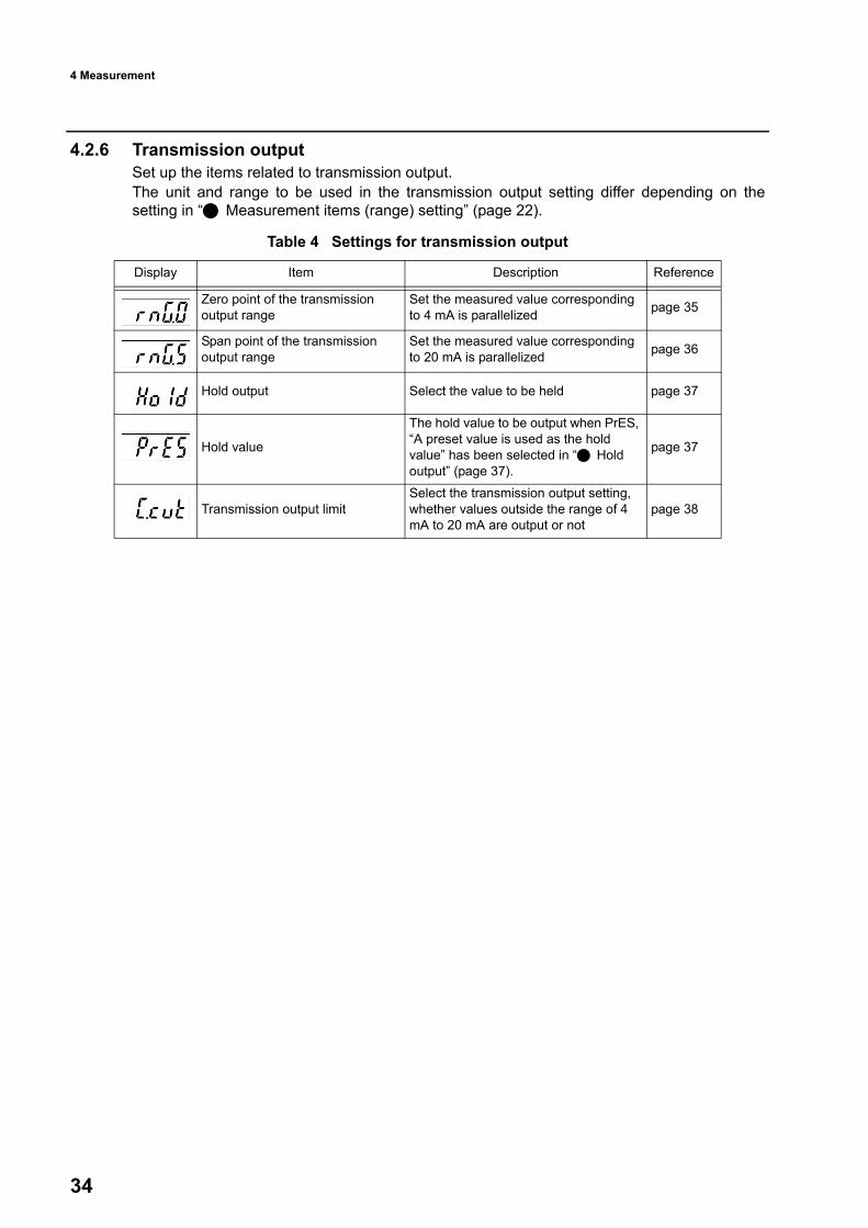
34
4.2.6 Transmission outputSet up the items related to transmission output.The unit and range to be used in the transmission output setting differ depending on thesetting in “ Measurement items (range) setting” (page 22).
Table 4 Settings for transmission output
Display Item Description Reference
Zero point of the transmission output range
Set the measured value corresponding to 4 mA is parallelized page 35
Span point of the transmission output range
Set the measured value corresponding to 20 mA is parallelized page 36
Hold output Select the value to be held page 37
Hold value
The hold value to be output when PrES, “A preset value is used as the hold value” has been selected in “ Hold output” (page 37).
page 37
Transmission output limitSelect the transmission output setting, whether values outside the range of 4 mA to 20 mA are output or not
page 38

4 Measurement
35
Zero point of the transmission output rangeSet the dissolved oxygen value corresponding to the zero point output. 1. Open the basic setup menu and press the UP/DOWN keys to display the zero
setting of transmission output (as below) on the panel, referring to “ How toopen basic setup menus” (page 20).
2. Press the ENT key.The sub-display starts blinking. Now you can change the setting.
3. Press the UP/DOWN key to specify a dissolved oxygen value corresponding to thezero point output.The settings to be made differ depending on the combinations of the control targets andmeasurement items. See the table below:
Reference“ Measurement items (range) setting” (page 22)
4. Press the ENT key to establish the setting.
TipTo set another item of transmission output setting next, press the UP/DOWN key to display it.Press the MEAS key to return to the basic setup menu.
← Current setting
Measurement item (range) setting 20.00 200
Value added by pressing the UP key 0.01 mg/L 1%
Value reduced by pressing the DOWN key 0.01 mg/L 1%
Setting range 0.00 mg/L to 22.00 mg/L 0% to 220%

4 Measurement
36
Span point of the transmission output rangeSet the dissolved oxygen value corresponding to the span point output. 1. Open the basic setup menu and press the UP/DOWN keys to display the zero
setting of transmission output on the panel, referring to “ How to open basicsetup menus” (page 20).
2. Press the DOWN key to display “rnG.S”, and then press the ENT key.The sub-display starts blinking. Now you can change the setting.
3. Press the UP/DOWN key to set the dissolved oxygen value corresponding to thespan point output.The settings to be made differ depending on the combinations of the control targets andmeasurement items. See the table below:
Reference“ Measurement items (range) setting” (page 22)
4. Press the ENT key to establish the setting.
NoteIf the zero point and span point are set to the same value, the actual output is fixed to 20 mA.
TipTo set another item of transmission output setting next, press the UP/DOWN key to display it.Press the MEAS key to return to the basic setup menu.
Measurement item (range) setting 20.00 200
Value added by pressing the UP key 0.01 mg/L 1%
Value reduced by pressing the DOWN key 0.01 mg/L 1%
Setting range 0.00 to 22.00 mg/L 0 to 220%

4 Measurement
37
Hold outputSelect the hold method when the mode is switched from measurement to calibration.
TipWhen the mode is switched to maintenance, the previous value hold is used as the hold value.
1. Open the basic setup menu and press the UP/DOWN keys to display the zerosetting of transmission output on the panel, referring to “ How to open basicsetup menus” (page 20).
2. Press the DOWN key to display “Hold”, and then press the ENT key.The sub-display starts blinking. Now you can change the setting.
3. Press the UP/DOWN key to select a setting.YES: The previous value is used as the hold value (Previous value hold).PrES: A preset value is used as the hold value (Preset hold).no: Hold output is not used (Actual data is output continuously).
4. Press the ENT key to establish the setting.
TipTo set another item of transmission output setting next, press the UP/DOWN key to display it.Press the MEAS key to return to the basic setup menu.
Hold valueSet the hold value which is used for transmission output if the hold output has been set toPrES, “A preset value is used as the hold value”.1. Open the basic setup menu and press the UP/DOWN keys to display the zero
setting of transmission output on the panel, referring to “ How to open basicsetup menus” (page 20).
2. Press the DOWN key to display “PrES” on the measurement display, and thenpress the ENT key.The sub-display starts blinking. Now you can change the setting.
3. Press the UP/DOWN key to specify a dissolved oxygen value to output as the holdvalue.The settings to be made differ depending on the combinations of the control targets andmeasurement items. See the table below:
Reference“ Measurement items (range) setting” (page 22)
4. Press the ENT key to establish the setting.
TipTo set another item of transmission output setting next, press the UP/DOWN key to display it.Press the MEAS key to return to the basic setup menu.
Measurement item (range) setting 20.00 200
Value added by pressing the UP key 0.01 mg/L 1%
Value reduced by pressing the DOWN key 0.01 mg/L 1%
Setting range 0.00 to 22.00 mg/L 0 to 220%

4 Measurement
38
Transmission output limitSelect the transmission output setting, whether values outside the range of 4 mA to 20 mA areoutput or not.1. Open the basic setup menu and press the UP/DOWN keys to display the zero
setting of transmission output on the panel, referring to “ How to open basicsetup menus” (page 20).
2. Press the DOWN key to display “C.cut” on the measurement display, and thenpress the ENT key.The sub-display starts blinking. Now you can change the setting.
3. Press the UP/DOWN key to set the transmission output limit ON/OFF.UP key: YES:Values under the zero point or over the span point are not output.DOWN key:no: Values below the zero point or over the span point are output.
4. Press the ENT key to establish the setting.
TipTo set another item of transmission output setting next, press the UP/DOWN key to display it.Press the MEAS key to return to the basic setup menu.

4 Measurement
39
4.3 CalibrationThe display and calibration items for the calibration menu is shown below. Perform calibration in accordance with the timing, order, and calibration items shown in thetable below.
NoteThe interval for the periodic calibration changes depending on the usage conditions. Check the mea-surement conditions regularly and perform calibrations as necessary.
PrecautionsWash the probe and DO sensor before performing calibration as necessary.Do not reuse standard solution.Previous value hold is used for transmission output during the maintenance mode.Contact outputs are in the following states during the maintenance, depending on theselected control target.
OFF when the control target is set to non, do, Err, or t.ON when the control target is set to Hold.FAIL when the control target is set to FAiL and a system error occurs.
If the error code “E-12” (degraded sensor sensitivity) is shown during calibration, thesensor has run out of useful life and needs replacement. Even when the measurement range has been set to 200, “saturation of dissolved oxygenat the temperature of the measured solution (%)”, calibration is done in “mass of dissolvedoxygen in the measured solution of 1L (mg/L)”.When a new sensor is used for the first time, it takes time for the sensor to become stable.Thus, calibration may not be possible in this state. In that case, turn on the power for theinstrument with the sensor attached and wait for the sensor to become stable to performcalibration.
Display Item
Timing
When the instrument is
used for the first time
When the probe is replaced
When the DO sensor is replaced
Periodic calibra-tion (every one
month)
Temperature calibration 1 1 - -
Dissolved oxygen sensor calibration
Zero calibration 2 2 1 -
Span calibration 3 3 2 1

4 Measurement
40
How to enter the calibration modeEnter the calibration mode from the measurement mode. 1. Hold down the MNT key in the measurement mode until the MNT lamp lights up.
The instrument enters the maintenance mode, and “SEt” is shown on the measurementdisplay.Measurement stops, and the instrument enters a state of hold.
2. Press the DOWN key to display “CAL” on the measurement display, and then pressthe ENT key.The instrument enters the calibration menu and “t” is displayed on the sub-display.
3. Select the calibration item you wish perform by pressing the UP/DOWN keys.t: Temperature sensor calibration “4.3.1 Temperature sensor calibration” (page 40)do: DO sensor calibration “4.3.2 DO sensor calibration” (page 41)
TipYou can open the calibration menu directly from the measurement mode. For how to do it, refer to “5.1Daily calibration (calibration mode)” (page 52).
4.3.1 Temperature sensor calibrationPerform the calibration for the temperature sensor using two solutions whose temperaturesare known and the difference between them is at least 10°C.
TipTo cancel the calibration in the middle of it, press the MEAS key. The instrument will return to themeasurement mode without updating the calibration data.If any error is displayed, take necessary actions referring to the description in “6.3 Error code”(page 57).
Operation1. Enter the calibration menu from the measurement mode referring to “ How to
enter the calibration mode” (page 40).2. Immerse the sensor in the solution of the first point and take time to let the sensor
to be prepared for measuring the temperature.3. Press the ENT key with the instrument showing “CAL” on the measurement display
and “t” on the sub-display.The instrument enters the temperature calibration menu, showing “t” on the measurementdisplay and “-1-” on the sub-display.
4. Press the ENT key.The temperature calibration starts for the first point.
5. Adjust the value shown on the measurement display to match the actual tempera-ture of the solution by pressing the UP/DOWN keys.UP key: Increments the value by 0.1°C.DOWN key: Decrements the value by 0.1°C.The settable range is -10°C to 10°C.
6. Press the ENT key to establish the calibration for the first point. The sub-display shows “-2-” next, indicating that the instrument has entered the calibra-tion for the second point.
7. Immerse the sensor in the solution of the second point and take time to let the sen-sor to be prepared for measuring the temperature.
8. Press the ENT key.The temperature calibration starts for the second point.

4 Measurement
41
The temperature of the second-point solution will be displayed on the measurement dis-play in blinking.
NoteAn error is caused if the temperature difference between two solutions is below 10°C.
9. After the measurement value has been stabilized, press the ENT key.The sub-display starts blinking.
10. Adjust the value shown on the measurement display to match the actual tempera-ture of the solution by pressing the UP/DOWN keys.UP key: Increments the value by 0.1°C.DOWN key: Decrements the value by 0.1°C.The settable range is 0°C to 40°C.
11. Press the ENT key to establish the calibration for the second point. The instrument shows “CAL” on the measurement display and “good” on the sub-display,indicating that the new temperature calibration values have been applied.
The above completes the temperature calibration.
TipPress the MEAS key to return to the screen for selecting calibration items.
4.3.2 DO sensor calibration Two methods are provided for performing the DO sensor calibration, air calibration andsolution calibration.
ReferenceFor how to switch between the two methods, refer to “4.2.4 Calibration method” (page 25).
Air calibrationIn this method, a zero calibration is performed with the DO sensor removed from the probe. Aspan calibration is performed with the DO sensor attached to the probe based on the oxygen(O2) in the air.
NoteBefore performing an air calibration, remove the probe from the solution and take time to let the SOsensor to dry completely.
TipTo cancel the calibration in the middle of it, press the MEAS key. The instrument will return to themeasurement mode without updating the calibration data.If any error is displayed, take necessary actions referring to the description in “6.3 Error code”(page 57).
Zero calibration to span calibrationThe section describes the procedure for performing an zero calibration and span calibration insuccession.
1. Enter the calibration menu from the measurement mode referring to “ How toenter the calibration mode” (page 40).

4 Measurement
42
2. Remove the DO sensor from the probe. 3. Press the ENT key with the instrument showing “CAL” on the measurement display
and “do” on the sub-display.The instrument enters the calibration mode, showing “0.CAL” on the measurementdisplay and the selected calibration method on the sub-display.
4. Press the ENT key.The instrument shows the current measurement value on the measurement display inblinking and the temperature on the sub-display.
5. Press the ENT key to establish the zero point. The instrument shows “S.CAL” on the measurement display and the selected calibrationmethod on the sub-display. Next perform a span calibration.
6. Attach the DO sensor to the probe. 7. Press the ENT key.
The instrument shows the current measurement value on the measurement display inblinking and the temperature on the sub-display.
8. After the measurement value has been stabilized, press the ENT key.The instrument shows “CAL” on the measurement display and “good” on the sub-display,indicating that the span point has been established.
The above completes the zero and span calibrations for air calibration.
TipPress the MEAS key to return to the screen for selecting calibration items.
Span calibrationThis section describes the procedure for performing a span calibration alone.
1. Enter the calibration menu from the measurement mode referring to “ How toenter the calibration mode” (page 40).
2. Press the ENT key with the instrument showing “CAL” on the measurement displayand “do” on the sub-display.The instrument enters the calibration mode, showing “0.CAL” on the measurementdisplay and the selected calibration method on the sub-display.
3. Press the DOWN key to show “S.CAL”, and press the ENT key.The instrument shows the current measurement value on the measurement display inblinking and the temperature on the sub-display.
4. After the measurement value has been stabilized, press the ENT key.The instrument shows “CAL” on the measurement display and “good” on the sub-display,indicating that the span point has been established.
The above completes the span calibration for air calibration.
TipPress the MEAS key to return to the screen for selecting calibration items.

4 Measurement
43
Solution calibrationIn this method, a zero calibration is performed using a zero solution (sodium sulfite water) anda span calibration is performed using a span solution (air saturated water).
Tip
Precautions on solution calibrationFlow the calibration solution at 25 cm/s or more using a magnetic stirrer or somethingsimilar.If the flowrate is low, the span sensitivity is improperly set high. Set the probe so that the temperature sensor is immersed in the water fully. You can use saturated water containing salinity for this calibration. In this case, measurethe salinity in the solution and perform salinity compensation of this instrument before per-forming a calibration. (Refer to“ Salinity compensation setting” (page 23).)
TipTo cancel the calibration in the middle of it, press the MEAS key. The instrument will return to themeasurement mode without updating the calibration data.If any error is displayed, take necessary actions referring to the description in “6.3 Error code”(page 57).
Zero calibration to span calibrationThis section describes the procedure for performing an zero calibration and span calibration insuccession.
1. Enter the calibration menu from the measurement mode referring to “ How toenter the calibration mode” (page 40).
2. Remove the sensor from the solution and wash it with tap water. 3. Immerse the sensor in the zero solution (sodium sulfite water) and air saturated
water. 4. Press the ENT key with the instrument showing “CAL” on the measurement display
and “do” on the sub-display.The instrument enters the calibration mode, showing “0.CAL” on the measurementdisplay and the selected calibration method on the sub-display.
5. Press the ENT key.The instrument shows the current measurement value on the measurement display inblinking and the temperature on the sub-display.
6. Press the ENT key.The sub-display shows “0.00” in blinking. Now you can adjust the DO value.
Name PreparationZero solution (sodium sulfite water)
Dissolve 20 g of sodium sulfite in 100 mL of water (approx. 20%). Increase the amount of solution if necessary. The useful life of the solution is around one day.
Span solution (air saturated water)
(Example)Have a 500-mL beaker, air pump, and bubbler ready.Pour about 500 mL of water into the beaker, and bubble the water for 15 minutes to 30 minutes, and then leave it at rest for about one minute.

4 Measurement
44
7. Change the value shown on the measurement display to match the DO value of thezero solution by pressing the UP/DOWN keys. UP key: Increments the value by 0.01 mg/L.DOWN key: Decrements the value by 0.01 mg/L.The settable range is 0.00 mg/L to 0.30 mg/L.
8. Press the ENT key to establish the zero point. The instrument shows “S.CAL” on the measurement display and the selected calibrationmethod on the sub-display. Next perform a span calibration.
9. Immerse the sensor in the air saturated water. 10. Press the ENT key with “S.CAL” being displayed.
The instrument shows the current measurement value on the measurement display inblinking and the temperature on the sub-display.
11. After the measurement value has been stabilized, press the ENT key.The instrument shows “CAL” on the measurement display and “good” on the sub-display,indicating that the span point has been established.
The above completes the zero and span calibrations for solution calibration.
TipPress the MEAS key to return to the screen for selecting calibration items.
Span calibrationThis section describes the procedure for performing a span calibration alone.
1. Enter the calibration menu from the measurement mode referring to “ How toenter the calibration mode” (page 40).
2. Remove the sensor from the solution and wash it with tap water. 3. Immerse the sensor in the air saturated water. 4. Press the ENT key with the instrument showing “CAL” on the measurement display
and “do” on the sub-display.The instrument enters the calibration mode, showing “0.CAL” on the measurementdisplay and the selected calibration method on the sub-display.
5. Press the DOWN key to show “S.CAL”, and press the ENT key.The instrument shows the current measurement value on the measurement display inblinking and the temperature on the sub-display.
6. After the measurement value has been stabilized, press the ENT key.The instrument shows “CAL” on the measurement display and “good” on the sub-display,indicating that the span point has been established.
The above completes the span calibrations for solution calibration.
TipPress the MEAS key to return to the screen for selecting calibration items.

4 Measurement
45
4.4 Control value setup menuThis menu allows you to change the following control-related settings while performingmeasurements in the measurement mode.
Table 5 Contact output: setting items
Display Item Description Remarks
Number of data used for moving average
Select the number of data used for moving average, which is performed to display measured values. page 23
When “do” (measurement value) or “t” (temperature) has been selected in “ Control target selection” (page 27).
Control value Set the control value, used as the criterion for switching the relay output ON/OFF. page 29
When “d.diF” has been selected in “ Control width type setting” (page 30).
Control width Set the control width whose center is the control value (1.diF). page 31
When “S.diF” has been selected in “ Control width type setting” (page 30).
Control width Set the control width under the control value (1.udF) and the width over the control value (1.odF). page 31
Delay time(Relay ON)
Set the alarm output duration from the start until the C-NO contact output turns ON (unit: seconds) page 33
Delay time(Relay OFF)
Set the alarm clear duration from the cancellation until the C-NO contact output turns OFF (unit: seconds) page 33
When “do” (measurement value) or “t” (temperature) has been selected in “ Control target selection” (page 27).
Control value Set the control value, used as the criterion for switching the relay output ON/OFF. page 29
When “d.diF” has been selected in “ Control width type setting” (page 30).
Control width Set the control width whose center is the control value (2.diF). page 31
When “S.diF” has been selected in “ Control width type setting” (page 30).
Control width Set the control width under the control value (2.udF) and the width over the control value (2.odF). page 31
Delay time(Relay ON)
Set the alarm output duration from the start until the C-NO contact output turns ON (unit: seconds) page 33
Delay time(Relay OFF)
Set the alarm clear duration from the cancellation until the C-NO contact output turns OFF (unit: seconds) page 33

4 Measurement
46
Operation1. Press the MNT key in the measurement mode.
The sub-display shows “dFct”. (The measurement display keep showing a measured value.)2. Press the UP/DOWN key to display on the sub-display.
The setting items are displayed in the order shown in Table 5.3. Press the ENT key.
Now you can change the setting.4. Change the setting referring to the instruction page of the selected item.
TipIf you do not operate any keys for 10 seconds during item selection (step 2. mentioned above), thisfunction is closed automatically (the display returns to the normal measurement status).During setting change (step 3. or later), this function is always open.

4 Measurement
47
4.5 Security menuThis menu allows you two functions:Key lock, to prevent accidental operation; and password lock, to prevent illegal operation.
4.5.1 Key lockThis function prevents accidental key operation, which may cause unintended setting changeor hold output.
Set up1. Hold down the MEAS key in the measurement mode displayed until “Lock” on the
measurement display and “on” on the sub-display respectively.The key lock displayed function starts working. Releasing the key lets the instrumentreturn to the measurement mode, and the setup for the key locking is completed.No key operation is accepted hereafter and when any key is pressed, “Lock” is displayedon the measurement display and “on” on the sub-display respectively.
Release1. Press the MEAS key when a measured value is displayed.
The instrument will display “Lock” on the measurement display and “on” on the sub-display.
NoteYou cannot release the key lock immediately after key lock setup, with the displays showing “Lock”and “on”. Make sure to start the release operation with a measured value displayed.
2. Hold down the key in the measurement mode continuously until the display of thesub-display turns into “oFF” from “on”.When you release the MEAS key with “oFF” displayed on the sub-display, key lockrelease is completed.The instrument returnees to the measurement mode, and now all keys are enabled.

4 Measurement
48
4.5.2 Password lockingThis function prevents illegal operation by unauthorized persons using the preset first andsecond passwords.Each password is a 4-digit number.When the password lock is enabled, the instrument performs measurement and rejects anykey operations except for password lock setup (mentioned below).You can enable/disable the lock only by following the procedure described below.
NoteNote that if the password locking is enabled, the maintenance functions such as calibration andsettings are disabled. Set it up carefully.The password before factory shipment has been set to 0000-0000.
Password settingYou must input the current passwords before setting up new passwords.
NoteIt is recommended to use numbers which is easy to remember and hard to forget.If you forget the passwords you set, send the instrument back to HORIBA Advanced Techno. We will send it back to you after resetting the passwords to the default setting (0000-0000).(Charged)
P
1. Perform the steps 1. to 5. of “Password operations” (page 49).Measurement display shows “Lock” and the sub-display shows the current lock status,“on” for enabled or “oFF” for disabled.
2. Press the UP/DOWN key to select the password to be set.3. Press the ENT key.
The instrument enters the setup state and the sub-display starts blinking.
TipTo cancel the whole password setting and return to the measurement mode, press the MEAS key witha digit blinking.
4. Press the UP/DOWN key to set a new password.5. Press the ENT key.
The setting is established and the digit stops blinking.Then the next digit starts blinking.
6. Repeat steps 4. to 5. to the rightmost digit.When the rightmost digit is established, all the four digits flashes and the password is readinto the instrument.
7. To change the other password next, press the UP/DOWN key to select the otherpassword, and change it in the same way.

4 Measurement
49
Password operations1. Hold down the UP key and DOWN keys at the same time in the measurement mode
until “PASS” is shown on the main display.When you release the buttons, the measurement display shows “PAS1”, and the sub-display shows “0000” with the leftmost digit blinking. You can change the value of theblinking digit.
TipTo cancel the whole password setting and return to the measurement mode, press the MEAS key witha digit blinking.
2. Press the UP/DOWN key to select a value for the blinking digit.3. Press the ENT key.
The setting is established and the digit stops blinking.Then the next digit starts blinking.
4. Repeat steps 2. to 3. to the rightmost digit.When the rightmost digit is established, all the four digits flashes and the first password isread into the instrument.And then the measurement display shows “PAS2” and the sub-display shows “0000”.
5. Input the second password in the same way.When the two passwords are correct, the measurement display shows “Lock” and thesub-display shows the current lock status, “on” for enabled or “oFF” for disabled.
NoteIf either of the passwords is wrong, the measurement display shows “PASS” and the sub-displayshows “bad”, and the instrument returns to the measurement mode.The instrument does not tell you which password was wrong.
6. If necessary, to change the setting press the ENT key.The instrument enters the setup state and the sub-display starts blinking.
7. Press the UP/DOWN key to set the password locking.UP key: on:Enables the password lock.Down key:oFF: Disables the password lock.
8. Press the ENT key.The sub-display flashes, and the setting is established. The measurement display shows“Lock” and the sub-display shows the current lock status, “on” for enabled or “oFF” fordisabled.
9. Press the MEAS key to return to the measurement mode.

4 Measurement
50
4.6 User check menuThe user check menu allow you to check the instrument status, and to reset it to the default.Operate it from the user check menu.
How to open the user check menuStart the operation it from the measurement mode.1. Hold down the MNT key until the MNT lamp lights up.
The instrument enters the maintenance mode, and “SEt” is shown on the measurementdisplay.
2. Press the DOWN key to display “USr” on the measurement display, and then pressthe ENT key.The instrument opens the user check menu, and “LEd” is shown on the sub-display.Refer to the below instructions for perform each of the available operations in accordancewith the following description.
4.6.1 Status checkYou can check the four items shown below.
LEDsTransmission outputRelay operationMeasured value and temperature
OperationsPerform the following operations after opening the user check menu.
LEDs1. Press the UP/DOWN key, if necessary, to display “LEd” on the sub-display, and
press the ENT key.All the LED will light up normally.
2. Check that LEDs light up without problems.3. Press the MEAS key.
The instrument returns to the user check menu entrance.
Transmission outputYou can output an electric current of 4 mA, 12 mA and 20 mA from the transmission output.1. Press the UP/DOWN key to display “Cur” on the sub-display.2. Press the ENT key.
“4-20” is shown on the measurement display and “4” on the sub-display outputting a 4 mAtransmission output.
3. To switch the current output, press the UP/DOWN key to select the valuecorresponding to the current (mA) to be output from 4, 12, or 20.
4. Check that the electric current is being output properly.5. Press the MEAS key.
The instrument returns to the user check menu entrance.

4 Measurement
51
Relay operationCheck the operations of contact outputs R1 and R2.Checking the contact output R11. Press the UP/DOWN key to display “rLY” on the sub-display.2. Press the ENT key.
“rLY1” is shown on the measurement display and “rLY” on the sub-display.3. Press the ENT key.
The relay lamp R1 lights up and the relay is turned on, normally.Press the ENT key to switch the relay ON/OFF to check the operation.
4. Press the MEAS key.The instrument returns to the user check menu entrance.
Checking the contact output R2You can check R2 in the same way as R1. But, press the UP/DOWN key to display “rLY2” onthe sub-display after the step 2.
Measured value and temperature1. Press the UP/DOWN key in the user check menu to display “diSP” on the sub-
display.2. Press the ENT key.
The current measured value is shown on the measurement display and the currenttemperature on the sub-display.
3. Press the MEAS key.The instrument returns to the user check menu entrance.
4.6.2 Instrument resetThis operation allows you to initialize all the settings and restart the instrument.Then preform the steps in “ Initial set up” (page 17) in the automatically opened basic setupmenu.Calibration values are also reset. Be sure to perform the steps in “4.3 Calibration” (page 39)before use.
Operation1. Enter the user check menu referring to “How to open the user check menu” (page
50).”USr” is shown on the measurement display and “LEd” on the sub-display.
2. Press the DOWN key to display “init” on the sub-display, and then press the ENTkey.The sub-display shows “no” and starts blinking.
3. Press the DOWN key to select “YES”, and then press the ENT key.The instrument is reset to the state before factory shipment.The sub-display shows “good” with flashing, and the instrument restarts.
TipThe initial settings are shown in “Table 1 Basic setup items” (page 17).To return to the user check menu entrance without resetting, select “no” in step 3. and press theENT key.

5 For More Accurate Measurements
52
5 For More Accurate MeasurementsThis is the maintenance information to keep the precision of this instrument and to use itbetter.This chapter explains the maintenance to keep the precision of the instrument such as dailycalibration.
5.1 Daily calibration (calibration mode)Here we explain how to perform daily calibration.
Precautions for calibrationThe transmission output is put to the state set in the “ Hold output” (page 37) setting ofthe basic setup.Contact outputs are put to the following conditions:
Turned OFF when set to non, do, Err, or t.Turned ON when set to Hold, ON.FAIL is output if a system error is raised when set to FAiL.
Even when the measurement range has been set to 200, “saturation of dissolved oxygenat the temperature of the measured solution (%)”, calibration is done in “mass of dissolvedoxygen in the measured solution of 1L (mg/L)”.
Calibration operationOperate it from the measurement mode.1. Hold down the CAL key until the CAL lamp lights up.
The DO sensor calibration menu appears and the calibration selected in the basic setup(air calibration or solution calibration) starts.
2. Perform a calibration in accordance with the procedure described in “ Aircalibration” (page 41) or “ Solution calibration” (page 43).
TipIf you want to abort the calibration, press the MEAS key. The display returns to the measurementmode without updating the calibration data.If any error is displayed, take necessary actions referring to the description in “6.3 Error code”(page 57).To perform the temperature calibration, call up the calibration screen from the maintenancemode.

5 For More Accurate Measurements
53
5.2 Maintenance for the instrument body
5.2.1 Inspection of the meterIf the insulation of the terminals for connecting the DO sensor has been weakened, accuratemeasurement becomes difficult.Inspect the terminal assembly periodically (once a year or so) to check for rust and the likethat cause insulation to become weak.Wipe out the dirt from the body case with soft cloth.
5.3 Maintaining the DO sensorThis section describes the procedure for maintaining the DO sensors.
5.3.1 Washing the DO sensorStain on the DO sensor is a cause of slow response, drifting readout, and unstable readout. Check the DO sensor periodically and wash out stains on it using tap water to keep it clean. It is recommended to wash the DO sensor at the same time of calibration. In this case, be sureto perform a calibration after washing the sensor.
NoteTake due care not to damage the DO sensor diaphragm.
Prohibited
Do not use an organic solvent or something similar.

5 For More Accurate Measurements
54
5.3.2 Replacing the DO sensor
Precaution on the handling
Replacement procedure
Be sure not to damage the diaphragm.Because the diaphragm is a thin film, DO NOT hit the filmwith a hard object nor press it strongly. Otherwise, it may getdamaged.Check the O ring.An O ring is used to bridge the DO sensor and probe to pre-vent water from getting into the instrument. Check that the Oring is attached and secure it with the protective tube.
1. Remove the probe from the measured solu-tion.
2. Wipe off the moisture on the probe well.
3. Unscrew the protective tube.4. Remove the DO sensor.
NoteWhen disposing of a DO sensor, treat it as an industrialwaste.
5. Make sure that the connector for the probehas no moisture in it.
保護管
センサ
Oリング
(センサに付属)
プローブProbe
O ring(DO sensor acces-sory)
DO sensor
Protective tube
Diaphragm
Warning
The internal solution of DO sensor is strong alkarine. In case that the diaphragm of DO sensor is broken and the internal solution is attached to your clothes or skin, wash it off thoroughly.Since the cornea of eye is vulnerable to alkali, pay extreme attention not to let the internal solution gets into your eyes. In case that it gets into your eyes, wash it out immediately.
Protective tube
Connectorinside

5 For More Accurate Measurements
55
5.3.3 StorageThis section describes the procedure for removing the DO sensor from the probe and store it. 1. Remove the DO sensor from the probe referring to “5.3.2 Replacing the DO sensor”
(page 54).2. Attach the protective cover and socket. to the sensor.
3. Put the DO sensor in the bag in which the sensor was contained and a deoxidizerpack also.
4. Let the air out of the bag and completely seal the bag with heat seal, etc.In case you have lost the bag in which the DO sensor was contained, use an aluminum-evaporated bag which does not allow oxygen to penetrate. As for deoxidizer, use the oneincluded in the bag or a commercially available one.
NoteThe storage procedure above is treatment for minimizing the degradation of the sensor.
6. Take out the DO sensor from the bag.
7. Remove the tape, and then remove theprotective cover and socket.
NoteKeep the bag, deoxidizer, protective cover, and socket.They will be needed when the sensor is stored.
8. Mount the DO sensor to the probe. The sensor is equipped with two connectorpins, a thick one and thin one. Insert it into theprobe paying attention to the direction.Make sure that the DO sensor has the O ringattached.
9. Screw the protective tube into the probefirmly.
The above completes the replacement of a DO sen-sor.Before making measurements, perform a tempera-ture calibration and DO sensor calibration.
Protective cover Socket
ProbeProtective tube O ring
DO sensor (with an O ring) SocketProtective cover

6 Troubleshooting
56
6 Troubleshooting
6.1 Troubleshooting
6.2 Out of the measurement rangeWhen the measurement value is out of the measurement range (-0.01 mg/L or less/-1% orless, or 20.01 mg/L or more/201% or more), “oF” is displayed on the sub-display in blinking.If that happens, follow the instructions given below.
Problems Causes or possibilities Remedies
The measurement readout is unstable.
Bubbles stick to the sensor.Bubbles appear because the flow rate istoo fast.The level of the measuring solution haschanged, and thus the area of the sensorthat contact with liquid has changed.
Do not allow bubbles to appear in themeasurement liquid.Control the flow rate.Install the instrument in a way that the level ofthe measuring solution does not change.
Rapid changes in liquid temperature.Screws of the terminal block are loose.Insulation of the terminal block has beenweakened.
Install the instrument in a place where liquidtemperature does not change drastically.Tighten them securely.Drain the moisture of the terminal block.Clean the terminal block.
Abnormal value is displayed.
The sensor is stained.The sensor is not soaked in the sampleliquid.
Wash the sensor.Install the instrument in a way that the level ofthe measuring solution does not change.
Disconnection or short circuit of thesensor cableLoose connection with the terminal block
Check the sensor cable.Check the terminal block.
Response is slow.
The flow rates is slow.The uneven concentration of themeasuring solution (when a tank hasbeen installed)
Increase the flow rate.Stir the sample well.Install it in a place where the concentration iseven.
The instrument cannot be turned on.
The power supply voltage is out of therated voltage range.Wiring mistakeInternal error of the instrument
Check the power supply voltage.Check the wiring.Contact HORIBA Advanced Techno.
Code Causes or possibilities Remedies
oF(out of the measurement range)
The concentration is too high.
Check to see if the concentration is within the measurement range by manual analysis. If it is within the measurement range, contact HORIBA Advanced Techno.
Temperature sensor error (The temperature readout is lower than the actual temperature.)
Perform a temperature calibration.
Terminals A and K are connected oppositely.
Check the wiring and connect terminals A and K correctly. If the instrument does not operate normally even if the terminals are correctly connected, contact HORIBA Advanced Techno.

6 Troubleshooting
57
6.3 Error codeThe instrument is equipped with the function to display various error codes.Error codes are shown on the sub-display in a blinking state.
6.3.1 Description of error codes
TipErrors and FAILs can be output as an anomaly by setting the basic setup items.If any error code is displayed, the transmission output is preset to the value just before the errorhappens.
Error code Error Description Occurrence Contact output
E-12 Error Span calibration error
The current for the sensor is low during span (sensitivity) calibration. At the time of
calibration *1 None *1
E-13 Error Zero calibration error
The current for the sensor is low during zero calibration.
E-21 FAILTemperature sensor disconnected
The lead of the temperature sensor is broken.
At the time of measurementandcalibration
Yes *2
E-22 FAILTemperature sensor short-circuited
The lead of the temperature sensor has been short-circuited.
E-23 Error
Out of the temperature compensation range
The measured temperature is 45°C or more.
E-24 Error
Out of the temperature compensation range
The measured temperature is -5°C or less.
E-25 Error Temperature calibration error The temperature calibration has failed.
E-90 FAIL System error Initialization error
System error YesE-91 FAIL System error The content of the memory such as set values and calibration values has been lost.
E-92 FAIL System error Malfunction of the A/D converter
*1: The contact output is not activated even if the target of the contact output has been set to Err.
*2: The contact output is not activated during calibrations.

6 Troubleshooting
58
6.3.2 Remedies for error codesWhen an error code is displayed, take necessary actions in accordance with the table below.
Error code Causes or possibilities Remedies
E-12 (span calibration error)
The sensor has desensitized. Replace the sensor.The sensor diaphragm has been damaged.
(It has a pin-hole, etc.)
E-13 (zero calibration error)
When using sodium sulfite, its concentration is low. Prepare it again.
The calibration has not been successfully performed or the instrument has been damaged.
Recalibrate the instrument again. After the adjusted value has been stabilized, press the ENT key. If the instrument does not operate normally even after being calibrated with leads A and K disconnected, it is malfunctioning.
E-21(temperature sensor disconnected)
Resistance error between T and T of the sensor.
If the resistance value is out of the range 6.2 kΩ to 7.7 kΩ, the sensor is defective. Replace it with a new one.
Wrong wiring of the sensor cable or junction cable
Check to see if that the wiring is open between T and T.
E-22(temperature sensor short-circuited)
Resistance error between T and T of the sensor.
If the resistance value is out of the range 6.2 kΩ to 7.7 kΩ, the sensor is defective. Replace it with a new one.
Wrong wiring of the sensor cable or junction cable
Check to see if that the wiring has been shorted between T and T.
E-23(out of the temperature compensation range)
The wiring between terminals T and T is open. (The lead wire has been disconnected.)
Check the wiring.
The temperature sensor is defective.
Check that the resistance between T and T is within the range 6.2 kΩ to 7.7 kΩ.(If the temperature sensor is defective, replace the probe.)
The temperature of the solution is 45°C or higher. Lower the solution temperature to below 45°C.
E-24(out of the temperature compensation range)
The wiring between terminals T and T has been shorted. Replace the probe.
The temperature sensor is defective. Replace the probe.
The temperature of the test water is -5°C or less. Check the temperature of the test water.
E-25(temperature calibration error)
The temperature sensor is defective.
Check that the resistance between T and T is within the range 6.2 kΩ to 7.7 kΩ.(If the temperature sensor is defective, replace the probe.)
The calibration was performed when the temperature difference between the first and second points was 10°C or less.
Recalibrate the instrument using two solutions whose difference in temperature is more than 10°C.
E-90E-91E-92(System error)
System error in the instrument
Turn the power OFF and turn it ON again.If the system error persists even after restarting the instrument, contact HORIBA Advanced Techno.

7 Data
59
7 Data
7.1 Measurement principleThe structure of a diaphragm-type galvanic sensor is shown in the figure below.In the sensor, an anode made of base metal (lead) and an cathode made of precious metal(silver) are immersed in the alkaline electrolyte partitioned by a gas permeable membranemade of FEP (fluororesin film), and the cathode is positioned closely contact with thediaphragm. This forms a galvanic cell.
The oxygen in a test water permeates the FEP film, and starts the following electrochemicalreactions on the surface of the cathode.
Cathode reaction O2+2H2O+4e- → 4OH-
Anode reaction 2Pb → 2Pb2++4e-
The cathode surface is reduced by oxygen, causing the external load connected between thetwo poles to be energized. Since the current intensity changes in proportion to the partialpressure of oxygen in the test water, the dissolved oxygen can be measured by detecting thiscurrent. However, since the permeability of the diaphragm for oxygen and the air-saturatedoxygen concentration in water change by temperature, the instrument detects the temperatureand performs the computation for compensating for it using a microcomputer. In addition,since the concentration gradient is generated on the surface of the diaphragm if the flowrate oftest water is low, the flowrate of the stipulated rate or higher is needed.
アノードカソード
電流の方向
絶縁体
アノード(鉛)
アルカリ性電解液
テフロン隔膜
カソード(銀)
Directions of current
Cathode Anode
Insulator
Anode (lead)Alkaline electrolyteCathode (silver)FEP diaphragm

7 Data
60
7.2 SpecificationsProduct name Industrial dissolved oxygen meter
Model HD-480
Measurement method Galvanic cell method
Measuring rangeDissolved oxygen 0 mg/L to 20 mg/L, 0.01 mg/L resolution Saturation 0% to 200%, 1% resolutionTemperature 0°C to 40°C, 0.1°C resolution
Repeatability Within ±0.5% of the full scale (by equivalent input)
Linearity Within ±0.5% of the full scale (by equivalent input)
Transmissionoutput
4 mA to 20 mA DC, input/output isolated typeMaximum load resistance: 900 ΩTransmission output range: Freely settable within the measuring range
Contact output
Outputs: 2 pointsAlarm contact output (R1 and R2) Contact type: relay contact, SPDT (1c) Contact rating: 240 V AC, 3 A and 30 V DC, 3 A (resistance load) Contact function: Selectable from “Upper limit operation”, “lower limit operation” (ON/
OFF control), “anomaly alarm”, “during maintenance”, and “temperature”
Calibration functionAir calibration and solution calibrationSalinity compensation (0.0% to 5.0%)Temperature calibration (two points)
Transmission output hold feature
Previous value holdOptional value holdContinuous
Selectable from the above (However, only the previous value hold is available in the maintenance mode.)
Self-diagnosis function
Calibration failure Zero error and sensitivity error
Sensor diagnosis Short-circuit or disconnection of temperature sensor
Measuring range error
Converter error
Temperature-compensated range
0°C to 40°C
Ambient temperature -5°C to 45°C
Relative humidity 20% to 85% (without dew condensation)
Storage temperature -25°C to 65°C
Power supply Rated voltage 100 V AC to 240 V AC, 50/60 Hz, 10 VA (max)
StructureIndoor-use panel installation type Panel case: ABS, Terminal: PBTPanel: IP65 dust and water proof structure
Protective structure
Panel: IP65 (IEC60529, JIS C0920)Rear case: IP20, Terminal:IP00Class II device (IEC61010-1)Pollution level 2 (IEC61010-1)
Conforming standards
CE Marking
EMC Directives (89/336/EEC)EN61326:1997/A1:1998 /A2:2001Low Voltage Directive (73/23/EEC)EN61010-1:2001
Immunity (industrial environment)Noise increase ±0.4 mg/L or less
FCC Rule FCC Part15

7 Data
61
External dimensions
48(W) mm x 96 (H) mm x 115 (D) mmCase depth: approx. 105 mm
Mass Approx. 400 g
Compatible sensors
Probe DP-100 Operating temperature: 0°C to 45°CSensor 5400, 5405

7 Data
62
7.3 Saturated dissolved oxygen for temperatures and salinities (mg/L)Temperature Salinity (%)
(°C) 0 0.5 1 1.5 2 2.5 3 3.5 4 4.5 5
0 14.16 13.74 13.32 12.90 12.48 12.06 11.64 11.22 10.80 10.38 9.96
1 13.77 13.37 12.96 12.55 12.14 11.73 11.33 10.92 10.51 10.10 9.70
2 13.40 13.01 12.61 12.22 11.82 11.42 11.03 10.63 10.24 9.84 9.45
3 13.05 12.66 12.28 11.89 11.51 11.13 10.74 10.36 9.98 9.59 9.21
4 12.70 12.33 11.96 11.59 11.21 10.84 10.47 10.10 9.72 9.35 8.98
5 12.37 12.01 11.65 11.29 10.93 10.57 10.21 9.85 9.48 9.12 8.76
6 12.06 11.71 11.36 11.01 10.66 10.31 9.96 9.61 9.26 8.91 8.55
7 11.76 11.42 11.08 10.74 10.40 10.06 9.72 9.38 9.04 8.70 8.36
8 11.47 11.14 10.81 10.48 10.15 9.82 9.49 9.16 8.83 8.50 8.17
9 11.19 10.87 10.55 10.23 9.91 9.59 9.27 8.95 8.63 8.31 7.99
10 10.92 10.61 10.30 9.99 9.68 9.37 9.06 8.75 8.44 8.12 7.81
11 10.67 10.37 10.07 9.76 9.46 9.16 8.86 8.55 8.25 7.95 7.65
12 10.43 10.13 9.84 9.55 9.25 8.96 8.67 8.37 8.08 7.78 7.49
13 10.20 9.91 9.63 9.34 9.05 8.77 8.48 8.20 7.91 7.63 7.34
14 9.98 9.70 9.42 9.14 8.86 8.59 8.31 8.03 7.75 7.47 7.20
15 9.76 9.49 9.22 8.95 8.68 8.41 8.14 7.87 7.60 7.33 7.06
16 9.56 9.30 9.04 8.77 8.51 8.24 7.98 7.72 7.45 7.19 6.93
17 9.37 9.11 8.86 8.60 8.34 8.09 7.83 7.57 7.31 7.06 6.80
18 9.19 8.94 8.68 8.43 8.18 7.93 7.68 7.43 7.18 6.93 6.68
19 9.01 8.77 8.52 8.28 8.03 7.79 7.54 7.30 7.05 6.81 6.56
20 8.84 8.60 8.37 8.13 7.89 7.65 7.41 7.17 6.93 6.69 6.45
21 8.68 8.45 8.22 7.98 7.75 7.51 7.28 7.05 6.81 6.58 6.34
22 8.53 8.30 8.07 7.84 7.61 7.39 7.16 6.93 6.70 6.47 6.24
23 8.39 8.16 7.94 7.71 7.49 7.26 7.04 6.81 6.59 6.36 6.14
24 8.25 8.03 7.81 7.58 7.36 7.14 6.92 6.70 6.48 6.26 6.04
25 8.12 7.90 7.68 7.46 7.25 7.03 6.81 6.59 6.38 6.16 5.94
26 7.99 7.77 7.56 7.35 7.13 6.92 6.70 6.49 6.28 6.06 5.85
27 7.87 7.66 7.44 7.23 7.02 6.81 6.60 6.39 6.18 5.97 5.75
28 7.75 7.54 7.33 7.12 6.92 6.71 6.50 6.29 6.08 5.87 5.66
29 7.64 7.43 7.23 7.02 6.81 6.61 6.40 6.19 5.99 5.78 5.57
30 7.53 7.33 7.12 6.92 6.71 6.51 6.30 6.10 5.89 5.69 5.48
31 7.43 7.22 7.02 6.82 6.61 6.41 6.21 6.00 5.80 5.60 5.39
32 7.33 7.12 6.92 6.72 6.52 6.31 6.11 5.91 5.71 5.50 5.30
33 7.23 7.03 6.82 6.62 6.42 6.22 6.02 5.82 5.61 5.41 5.21
34 7.13 6.93 6.73 6.53 6.33 6.13 5.92 5.72 5.52 5.32 5.12
35 7.04 6.84 6.64 6.44 6.23 6.03 5.83 5.63 5.43 5.23 5.02
36 6.95 6.75 6.55 6.34 6.14 5.94 5.74 5.54 5.33 5.13 4.93
37 6.86 6.66 6.45 6.25 6.05 5.85 5.64 5.44 5.24 5.03 4.83
38 6.77 6.57 6.36 6.16 5.96 5.75 5.55 5.34 5.14 4.93 4.73
39 6.68 6.48 6.27 6.07 5.86 5.66 5.45 5.24 5.04 4.83 4.63
40 6.60 6.39 6.18 5.97 5.77 5.56 5.35 5.14 4.94 4.73 4.52

7 Data
63
7.4 Parts list
7.4.1 Options
7.4.2 Consumables
Part names Models Specifications Part codes
Holder
DH-10-1.0 Immersion type holder length (1 m standard) 9220100500
DH-10-1.5 Immersion type holder length (1.5 m) 9220100600
DH-10-2.0 Immersion type holder length (2 m) 9220100700
Mounting bracket SDK-1 9220101500
Mounting bracket DN-50 SUS 9220101400
Relay box CT-20DO 9220110000
Junction cable C-7E Processed to the specified length (40 m or less) 9100101700
Probe DP-100 Immersion type (throw-in type) PVC titanium CR 9220102300
Part names Models Specifications Part codes
DO sensor
5400
Operating temperature range :0°C to 40°COperating pressure range :0 MPa to 0.1 MPaMaterial :FEPFilm thickness :25 µm
9220540000
5405
Operating temperature range :0°C to 40°COperating pressure range :0 MPa to 0.1 MPaMaterial :FEPFilm thickness :50 µm
9220540500
Consumables that come with the product
Mounting bracket -
Parts that come with the product
9010900100
Terminal cover - 9010900200
Gasket - 9010900300


http://www.horiba-adt.jp
Headquarters31 Miyanonishi-cho Kisshoinn Minami-ku, Kyoto-shi, 601-8306TEL:+81-75-321-7184 FAX:+81-75-321-7291
Tokyo OfficeArute-Build Higashikanda. 4F, Higashikanda 1-7-8, Chiyoda-ku, Tokyo 101-0031TEL:+81-3-3851-3150 FAX:+81-3-3851-3140
Nagoya OfficeSumitomo Seimei Chigusa Dai-ni Building 6F3-15-31, Aoi Higashi-ku, Nagoya-shi, 461-0004TEL:+81-52-937-0812 FAX:+81-52-937-0675
CODE:M500770(I1002574000) Ver.1 December, 2005© 2005 HORIBA Advanced Techno, Co., Ltd.