increasing the electricity generation capacity from solar ...
Upload
khangminh22Category
view
0download
0
EFFECTIVE JULY 2018
Retrofit Solutions
Increasing Performance and Efficiency

Tech
.Doc
- 07
/18
- Sub
ject
to c
hang
e. ©
Bel
imo
Airc
ontro
ls (U
SA),
Inc.
®
800-543-9038 USA 866-805-7089 CANADA 203-791-8396 LATIN AMERICA/CARIBBEAN
1
Table of Contents Actuator Retrofi t Solutions
Retrofi t and Replacement3 How to Select an Actuator
Solutions for Specifi c Actuator Manufacturer5 Discontinued Belimo Products8 Honeywell11 Invensys14 Johnson Controls17 Siemens19 Actuator Installation on Jackshaft20 Accessories
Fire and Smoke Actuator Retrofi t Solutions
Solutions for Specifi c Fire & Smoke Actuator Manufacturer
24 Honeywell25 Ruskin, ECM, Prefco, Pneumatic26 Ruskin (Phillips), Multiproducts27 Siemens, Siebe
Economizer Retrofi t Solutions
29 ZIP Economizer Selection Guide30 Honeywell33 Retrofi t Kits and ZIP Packs
Zone Valve Replacement Solutions
37 Belimo to Belimo
Globe Valve Retrofi t Solutions
39 How to Select a Globe Valve41 UGLK…/UGSP… Retrofi t Linkage for Globe Valves44 UGVL Globe Valve Linkage45 SGVL Globe Valve Linkage46 FGVL Globe Valve Linkage47 WGVL Warren Globe Valve Linkage48 UGSL1200 Globe Valve Linkage for Siemens 599
Butterfl y Valve Retrofi t Solutions
89 How to Select a Butterfly Valve Retrofi t Solution90 Butterfly Valve Retrofi t Actuators92 UFLK.../UFSP Linkages
Solutions for Specifi c Manufacturer96 Bray98 Centerline99 Johnson Controls100 Keystone102 Milwaukee103 Nibco103 PDC104 Victualic
Specialty Solutions for Valve Manufacturers105 Apollo, Challenger, Chemtrol, Dezurik, FNW,
Gruvlok, Hammond, Jamesbury, Jenkins, Metraflex, Mueller, PDC Quartermaster, Watts
106 Custom Butterfly Valve Retrofi t Solution Form108 Component Identifi cation109 Accessories
Ball Valve Retrofi t Solutions
113 UBSP0004 Retrofi t Linkage114 UBSP0006 Retrofi t Linkage115 UBSP0008 Retrofi t Linkage116 UBSP0012 Retrofi t Linkage117 Custom Ball Valve Retrofi t Solution Form 119 Component Identifi cation
120 Belimo Platinum Distributors
Solutions for Specifi c Manufacturer49 Honeywell54 Johnson Controls65 Robertshaw65 Siebe - Invensys - Barber Colman69 Siemens - Landis - Powers71 Warren Controls73 Custom Globe Valve Solutions75 Custom Globe Valve Retrofi t Solution Form76 UGSP Series Globe Valve Retrofi t Solution86 UGLK Retrofi t, Components87 Accessories

®
Actuator Retrofi tSolutionsBelimo HVAC damper actuator retrofi ts are designed to replace failed or non-functioning actuators used in a wide variety of on/off, modulatingor communicating damper applications. With a comprehensive torquerange (18 in-lbs to 1,400 in-lbs), and the ability to direct mount onstandard damper shafts or jackshafts, these actuator solutions are idealfor air handlers, economizer units, VAV terminal units, fan coil units, and unit ventilators.
Tech
.Doc
- 07
/18
- Sub
ject
to c
hang
e. ©
Bel
imo
Airc
ontro
ls (U
SA),
Inc.
®
800-543-9038 USA 866-805-7089 CANADA 203-791-8396 LATIN AMERICA/CARIBBEAN
3
The “10 questions” method for sizing and selection shown below isrecommended as the best method for your actuation requirements. Use the “Application Data” column in this chart as a worksheet to help in the selection process.
Retrofit and ReplacementHow to Select an Actuator
APPLICATION INFO APPLICATION DATA
1 What is the total area of the damper?
sq.ft.
2 Opposed blade or Parallel blade controlconstruction?
L” x W” = Total sq inches/144 = total sq feet
Opposed Bladew/o seals 3 in-lbs/sq feet*
Opposed Bladew/ seals 5 in-lbs/sq feet
Parallel Bladew/o seals 4 in-lbs/sq feet
Parallel Bladew/ seals 7 in-lbs/sq feet
*Less than 1,000 feet perminute
❑ Opposed Blade
❑ Parallel Blade
3 Are there blade and edge seals on the damper?
This will impactthe properselection as theseals add resistancerequiring more torque.If unknown, usea worst casescenario, parallelblade with seals.
e
e.e
❑ Yes
❑ No
4 For the damper in question, what does the manufacturerspecify as thetorque rating?
If this informationis not availablerefer to the“typical damperrequirements andsizing” chartbelow.
in-lbs/sq.ft.
5 What is the air velocity, static pressure, or design CFM?
Systems above 1,000 FPMrequire additional actuator torque
_______W.G.
_______CFM
_______FPM
ACTUATOR REQUIREMENTS APPLICATION DATA
6 Is fail-safe actuationrequired?
Consider the application. Is theactuator and/or damper exposed tooutside air? If yes, use spring return.
❑ Yes
❑ No
7 What is the supply voltage to the actuator?• 24 VAC/DC
• 120 VAC
• 230 VACsingle phase
Do you needa step downtransformer?
If replacing an oilimmersed geartrain actuator, is the transformer in thedefective actuator? You may need topurchase one.
❑ 24 VAC
❑ 120 VAC
❑ 230 VAC
8 What is the control signal to the actuator?
• 2 position
• Floating point
• Modulating
• Sequencing
• “Non-standard” voltage signals
❑ On/Off
❑ Floating Point
❑ 2-10 VDC
❑ 0-10 VDC
❑ 4-20 mA
❑ PWM____range
❑ Other (MFT)
This will be a critical component tothe selection of an actuator. Consider the …MFT actuator product range andthe flexibility of its application.
9 Can you direct couple to a damper shaft?
Direct-coupling hasbecome theindustry standard. Some retrofitapplications
do not allow direct coupling. Refer tothe Belimo “Mounting & Methods Guide” for application details.
❑ Yes
❑ No, seeaccessoriespage
10 Are there additional accessories required?
PA… SA…
KH-AF USKH-AF-1 US
K4-2 US
For example, some applications require the addition of an auxiliary switch forproof of position; a retrofit application may require an additional mounting bracket and linkage kit. We advise that you identify these needs prior to leaving the job site or ordering products.
❑ No
❑ Yes, seeaccessoriessection oractuatorseries fordetails
TYPICAL DAMPER REQUIREMENTS AND SIZING
Square Damper (with square shape): ft2 = h x w /144; (h= height, w= width, in inches)
EXAMPLE: Damper Area (8 ft2) x Rated Torque Loading of Damper (4 in-lbs/ft2) = Total in-lbs Required (32 in-lbs) Belimo LF 35 in-lbs/ LM 45 in-lbs actuators
Torque Loading in-lbs/ft2
Damper Blade Type < 1000 FPM 1000-2500 FPM 2500-3500 FPM
SQUA
RE
Parallel blade/edge seals 7 (Typical) 10.5 14Opposed blade/edge seals 5 (Typical) 7.5 10Parallel blade/no edge seals 4 6 8Opposed blade/no edge seals 3 4.5 6Round 10 14 20

Tech
.Doc
- 07
/18
- Sub
ject
to c
hang
e. ©
Bel
imo
Airc
ontro
ls (U
SA),
Inc.
®
800-543-9038 USA 866-805-7089 CANADA 203-791-8396 LATIN AMERICA/CARIBBEAN
4
CONTROL SIGNAL OVERVIEW
Belimo actuators are compatible with many control inputs and all direct digital control (DDC) systems. There are many signals to select from with today’s controllers.
On/Off or Open-Close: The actuator is able to drive either to its fullclockwise (CW) position, or to its full counter-clockwise (CCW) position. The same indication is used for spring return typeactuators. Where the actuator will drive to its full CW position and spring return to its CCW position. This can also be reversed.
3-point, Tri-State, Floating Point: The actuator has both clockwise(CW) and counter-clockwise (CCW) control inputs. One drives the actuator to its CW, the other to its CCW position. If there is no signal (Null point) on either input the actuator simply stays in its last position.
Proportional Control: The actuator drives proportional to its control input and modulates throughout its angle of rotation. This control type is usually a variation of VDC. Common values are:
0-10 VDC 2-10 VDC
It is common to also have a 0-20/4-20 mA output from a controller. This can be very easily converted to 0-10 VDC or 2-10 VDC with a 500 Ω resistor.
Pulse Width Modulation (PWM): The actuator drives to a specified position according to a pulse duration, the “length” of signal. Thepulse can originate from a dry contact closure or a triac sink or source controller. An example of PWM control:
Time base: 0 to 10 seconds
Output pulse: 5 seconds
Actuator position: 50%
Phasecut: An actuator drives depending on the power result of aremaining wave. This signal type cuts the amplitude of the wave and the actuator recognizes this signal as a proportional movement.
Multi-Functional Technology (MFT): This technology wasdeveloped by Belimo for incorporation into our damper and valve actuators. MFT provides the ability to program certain characteristics of the actuators. Some of the key characteristics to change are:
CONTROL INPUTSelectable on/off, VDC, PWM or floating point
MOTION VALUESSelectable running time adjustment
FEEDBACKSelectable feedback values
Retrofit and ReplacementHow to Select an Actuator
TYPICAL DAMPER REQUIREMENTS AND SIZING EXAMPLE:
APPLICATION REQUIREMENTS SQUARE DAMPER ROUND DAMPERDamper Length 24”Damper Width 12”Damper (Round) 12”Blade Type Opposed Round Edge Seals Edge SealsDesign CFM 1800 CFM 700 CFMFail-Safe Yes YesSupply Voltage 24 Volt 24 VoltControl Signal 2-10 VDC 2-10 VDCCALCULATIONSDamper Area (sq inches) 24” x 12” = 288 in2 πr² =113.04 in2 Damper Area (sq feet)* 288 in2 x 1ft/12 in x 1ft/12 in = 2 ft2 113.04 in2 / 1ft/12in x 1ft/12in= 0.785 ft2
Velocity 1800 ft3/min / 2 ft2 = 900 ft/min 700 ft3/min / .785 ft2 = 892 ft/minSee chart under <1000 FPM (ft/min) See chart under <1000 FPM (ft/min)
Rated Torque Loading (in-lbs/ft2)** Select 5 in-lbs/ft2 for Opposed Blade/Edge Seals Select 10 in-lbs/ft2 for Round Damper
EXAMPLE EQUATION *Damper Area (sq ft) x **Rated Torque Loading of Damper (in-lbs/ft2) = Total in-lbs Required
2 ft2 x 5 in-lbs/ft2 = 10 in-lbsBelimo LF24-SR US @ 35 in-lbs
0.785 ft2 x 10 in-lbs/ft2 = 7.85 in-lbsBelimo LF24-SR US @ 35 in-lbs

Tech
.Doc
- 07
/18
- Sub
ject
to c
hang
e. ©
Bel
imo
Airc
ontro
ls (U
SA),
Inc.
®
800-543-9038 USA 866-805-7089 CANADA 203-791-8396 LATIN AMERICA/CARIBBEAN
5
Discontinued Belimo to BelimoActuator Replacement Cross Reference
SPRING RETURN ACTUATORSDISCONTINUED MODEL REPLACEMENT MODEL DISCONTINUED MODEL REPLACEMENT MODELAF120 US AFBUP FSAF230-S US FSAF230A-S AF120-S US AFBUP-S FSAF24 US FSAF24A AF230 US AFBUP FSAF24-BAL US FSAFB24-SR + SGA24 or SGF24 AF230-S US AFBUP-S FSAF24-BAL-S US FSAFB24-SR-S + SGA24 or SGF24 AF24 US AFB24 FSAF24-S US FSAF24A-S AF24-3 US AFX24-MFT + F ❑ ❑ FSAF24-SR US FSAFB24-SR AF24-3-S US AFX24-MFT-S + F ❑ ❑ FSAF24-SR-S US FSAFB24-SR-S AF24-MFT US AFB24-MFT LF24-SR-MP US LF24-MFT-20 USAF24-MFT95 US AFB24-MFT95 LF24-SR-S-MP US LF24-MFT-S-20 USAF24-MFT-S US AFB24-MFT-S NF120 US NFBUPAF24-PC US AFB24-PC NF120-S US NFBUP-SAF24-PWM US AFX24-MFT + W ❑ ❑ NF230 US NFBUPAF24-S US AFB24-S NF230-S US NFBUP-SAF24-SR US AFB24-SR** NF24 US NFB24AF24-SR US* AFB24-PC if phasecut is needed NF24-MFT US NFB24-MFTAF24-SR95 US AFB24-MFT95 NF24-S US NFB24-SAF24-SR-S US AFB24-SR-S** NF24-S2 US NFB24-SAFA24-SR US** AFB24-SR** NF24-SR US NFB24-SRAFR120 US AFBUP NF24-SR-S US NFB24-SR-SAFR120-S US AFBUP-S SF120 US AFBUPAFR24 US AFB24 SF120-S US AFBUP-SAFR24-3 US AFX24-MFT + F ❑ ❑ SF24 US AFB24AFR24-3-S US AFX24-MFT-S + F ❑ ❑ SF24-S US AFB24-SAFR24-S US AFB24-S TF120 US TFB120AFR24-SR US AFB24-SR** TF120-S US TFB120-SFM24 US AFB24 TF24 US TFB24FM24-SR US AFB24-SR TF24-3 US TFB24-3FM24-SR90 US AFB24-MFT95 TF24-3-S US TFB24-3-SFM24-SR95 US AFB24-MFT95 TF24-MFT US TFB24-MFTFS24 AFB24 TF24-MFT-S US TFB24-MFT-SFS24-S AFB24-S TF24-S US TFB24-SFSAF120 US FSAF120A TF24-SR US TFB24-SRFSAF120-S US FSAF120A-S TF24-SR-S US TFB24-SR-SFSAF230 US FSAF230A TFC120-S US TFCB120-S
* Purchased before May 2003. ** Not piggy back capable.

Tech
.Doc
- 07
/18
- Sub
ject
to c
hang
e. ©
Bel
imo
Airc
ontro
ls (U
SA),
Inc.
®
800-543-9038 USA 866-805-7089 CANADA 203-791-8396 LATIN AMERICA/CARIBBEAN
6
Discontinued Belimo to BelimoActuator Replacement Cross Reference
NON FAIL-SAFE ACTUATORSDISCONTINUED MODEL REPLACEMENT MODEL DISCONTINUED MODEL REPLACEMENT MODELAM24 US AMB24-3 LM24-SR-T US LMB24-SR-TAM24-MFT 95 US AMX24-MFT95 + # AM0L0 1C1 R01 LM24-SR-T.1 US LMB24-SR-T.1AM24-MFT US AMX24-MFT + # AM100 1C1 ❑ ❑ ❑ LM24-SR-T-2.0 US LMB24-SR-TAM24-PC US AMX24-PC + # AM0N0 1C1 ❑ ❑ ❑ LMC24-SR US LMCB24-SRAM24-PWM-A US AMX24-MFT + # AM100 1C1 W02 NM24 EU NMB24-3AM24-PWM-B US AMX24-MFT + # AM100 1C1 W03 NM24 US NMB24-3AM24-PWM-C US AMX24-MFT + # AM100 1C1 W01 NM24-1 US NMB24-3AM24-S US AMB24-3-S NM24-1/200 US NMX24-3 + # NM00 1C3 000AM24-SR US AMB24-SR NM24-1/300 US NMX24-3 + # NM00 1C3 000AM24-SRS-A US AMX24-MFT + # AM100 1C1 A04 NM24-MFT US NMX24-MFT + # NM100 1C1 ❑ ❑ ❑
AM24-SRS-B US AMX24-MFT + # AM100 1C1 A05 NM24-MFT.1 US NMX24-MFT + # NM100 1C1 ❑ ❑ ❑
AM24-SRS-C US AMX24-MFT + # AM100 1C1 A06 NM24-PWM US NMX24-MFT + # NM100 1C1 W ❑ ❑
GM24 US GMB24-3 NM24-SR US NMB24-SRGM24-MFT US GMX24-MFT+ # GM110 1C1 ❑ ❑ ❑ NM24-SRS US NMX24-MFT + # NM100 1C1 A ❑ ❑
GM24-SR US GMB24-SR NMQ24-MFT US NMQX24-MFT + #NMQD00 1C1 ❑ ❑ ❑
GM24-SR US GMX24-PC if phasecut is needed NMV24-D US NMV-D3-MFTLM24 US LMB24-3 NMV24-V US NMV-D3-MFTLM24-3 US LMB24-3 SM24 US AMB24-3LM24-MFT US LMX24-MFT + # LM100 1C1 ❑ ❑ ❑ SM24-S US AMX24-MFT + # AM110 1C1 ❑ ❑ ❑ + S1A/S2ALM24-MFT.1 US LMX24-MFT+ # LM100 1C1 ❑ ❑ ❑ SM24-SR US AMB24-SRLM24-SR US LMB24-SR SM24-SR US AMX24-PC if phasecut is neededLM24-SR.1 US LMB24-SR.1 SM24-SR94 US AMX24-MFT95 + # AM0L0 1C1 R01LM24-SR-2.0 US LMB24-SR SM24-SRS US AMX24-MFT + # AM100 1C1 A ❑ ❑
* Purchased before May 2003. ** Not piggy back capable. ❑ Placeholder for custom options.

Tech
.Doc
- 07
/18
- Sub
ject
to c
hang
e. ©
Bel
imo
Airc
ontro
ls (U
SA),
Inc.
®
800-543-9038 USA 866-805-7089 CANADA 203-791-8396 LATIN AMERICA/CARIBBEAN
7
Discontinued Belimo to BelimoActuator Replacement Cross Reference
SPRING RETURN ACTUATORSDISCONTINUED MODEL REPLACEMENT MODELAF24 US AFRB24AF24-SR US AFRB24-SRAF24-3 US AFX24-MFT +F ❑ ❑
AF24-3-S US AFX24-MFT-S + F ❑ ❑
AF24-PWM US AFX24-MFT + W ❑ ❑
AF24-SR95 US AFB24-MFT95AF24-SR-S US AFB24-SR-SLF24-SR-MP US LF24-MFT-20 USLF24-SR-S-MP US LF24-MFT-S-20 USNVF24-MFT US SVKX24-MFT* or SVKB24-SR*NVF24-MFT-E US SVKX24-MFT* or SVKB24-SR**New linkage required.
NON FAIL-SAFE ACTUATORSDISCONTINUED MODEL REPLACEMENT MODELLR24 US LRB24-3LR24/200 US* LRX24-3 + # LR000 RC3 002LR24/300 US LRX24-3 + # LR000 RC3 002LR24-1 US LRB24-3LR24-1/200 US* LRX24-3 + # LR000 RC3 002LR24-1/300 US LRB24-3 + # LR000 RC3 002LR24-3-1 US LRB24-3LR24-3-1/200 US* LRX24-3 + # LR000 RC3 002LR24-3-1/300 US LRX24-3 + # LR000 RC3 002LR24-MFT US LRX24-MFT + # LR100 RC1 ❑ ❑ ❑
LR24-MFT/200 US* LRX24-MFT + # LR100 RC3 ❑ ❑ ❑
LR24-MFT/300 US LRX24-MFT + # LR100 RC3 ❑ ❑ ❑
LR24-SR/200 US* LRX24-SR + # LR030 RC3 002LR24-SR/300 US LRX24-SR + # LR030 RC3 002LR24-SR-1 US LRB24-SRLR24-SR-1/200 US* LRX24-SR + # LR030 RC3 002LR24-SR-1/300 US LRX24-SR + # LR030 RC3 002LR24-SR-1-2.0 US LRB24-SRLR24-SR-1-2.0/200 US* LRX24-SR + # LR030 RC3 002LR24-SR-1-2.0/300 US LRX24-SR + # LR030 RC3 002LR24-SR-2.0 US LRB24-SRLR24-SR-2.0/200 US* LRX24-SR + # LR030 RC3 002LR24-SR-2.0/300 US LRX24-SR + # LR030 RC3 002LV24 US CCV with LR...or TR...or Zonetight with CQLV24/200 US* CCV with LR...or TR...or Zonetight with CQLV24/300 US CCV with LR...or TR...or Zonetight with CQLV24-1 US CCV with LR...or TR...or Zonetight with CQLV24-1/200 US* CCV with LR...or TR...or Zonetight with CQLV24-1/300 US CCV with LR...or TR...or Zonetight with CQLV24-3 US CCV with LR...or TR...or Zonetight with CQLV24-3-1 US CCV with LR...or TR...or Zonetight with CQLV24-SR US CCV with LR...or TR...or Zonetight with CQLV24-SR/200 US* CCV with LR...or TR...or Zonetight with CQLV24-SR/300 US CCV with LR...or TR...or Zonetight with CQLV24-SR-1 US CCV with LR...or TR...or Zonetight with CQLV24-SR-1/200 US* CCV with LR...or TR...or Zonetight with CQLV24-SR-1/300 US CCV with LR...or TR...or Zonetight with CQLV24-SR-1-2.0 US CCV with LR...or TR...or Zonetight with CQLV24-SR-1-2.0/200 US* CCV with LR...or TR...or Zonetight with CQLV24-SR-1-2.0/300 US CCV with LR...or TR...or Zonetight with CQ
❑ Placeholder for custom options.*These models had a 2m/6’ long cable and the replacement is a 3m/10’ long cable.CV must be known for proper replacement.
NON FAIL-SAFE ACTUATORSDISCONTINUED MODEL REPLACEMENT MODELAM24 US ARB24-3AM24-MFT US ARX24-MFT + # AR100 RC1 ❑ ❑ ❑
AM24-S US ARB24-S USNM24 US ARB24-3NM24-MFT US ARX24-MFT + # AR100 RC1A ❑ ❑
NM24-SR US ARX24-SR + # AR030 RC1 ❑ ❑ ❑
NM24-SRS US ARX24-MFT + # AR100 RC1W ❑ ❑
NR24-3 US** LRB24-3NR24-SR US** LRX24-MFT + # LR100 RC1 ❑ ❑ ❑
NV24-3 US SVX24-3*NV24-MFT US SVX24-MFT* or SVB24-SR*NVG24-MFT US EVX24-MFT* or EVX24-3** New linkage required.❑ Placeholder for custom options.** Consider ambient temperature for application.
NON FAIL-SAFE – 24 VAC NON FAIL-SAFE – 24 VAC
DISCONTINUED MODEL Torque (in-lbs) REPLACEMENT MODEL Torque
(in-lbs)MAR100B-24V 1,500 SY4-24* 3,560MAR160-B-24V 2,000 SY4-24* 3,560MAR100BP-24V 1,800 SY4-24MFT* 3,560MAR160-BP-24V 2,500 SY4-24MFT* 3,560MAR250-60-24V 5,000 SY5-24* 4,450MAR250-60P-24V 5,000 SY5-24MFT* 4,450
*New linkage required.
NON FAIL-SAFE – 110 VAC NON FAIL-SAFE – 110 VAC
DISCONTINUED MODEL Torque (in-lbs) REPLACEMENT MODEL Torque
(in-lbs)MAR100B 1,500 SY4-110* 3,559MAR160B 2,000 SY4-110* 3,560MAR100BP 1,800 SY4-120MFT* 3,560MAR160-BP 2,500 SY4-120MFT* 3,560MAR250-30 5,000 SY5-110* 4,450MAR250-30P 5,000 SY6-110* 6,450
SY6-120MFT* 6,450MAR800-30 10,000 SY7-110* 9,790MAR800-30P 10,000 SY8-110 * 13,350
SY8-120MFT* 13,350MAR1600-70 21,000 SY10-110* 22,250MAR1600-70P 21,000 SY10-120MFT* 22,250MAR4000-70 48,000 SY12-110* 31,150MAR4000-70P 48,000 SY12-120MFT* 31,150
*New linkage required.
NON FAIL-SAFE – SY ACTUATORS NON FAIL-SAFE - 24-240 VACDISCONTINUED MODEL Torque (in-lbs) REPLACEMENT
MODEL Torque (in-lbs)
SY2-110* 800 PRBUP-3-T 1,400SY3-110* 1,335 PRBUP-3-T 1,400SY2-120MFT* 800 PRBUP-MFT-T 1,400SY3-120MFT* 1,335 PRBUP-MFT-T 1,400SY2-24 800 PRBUP-3-T 1,400SY2-24MFT 1,335 PRBUP-MFT-T 1,400SY3-24 800 PRBUP-3-T 1,400SY3-24MFT 1,335 PRBUP-MFT-T 1,400
*New linkage required.
When replacing an actuator on a valve, whether Belimo or other manufacture, be sure to consider the application parameters. The new product maynot be the best fit for the application. For example, an existing MAR actuator mounted to a valve linkage. The direct replacement of the actuator wouldbe the PR series actuator. The MAR and the PR have different linkage construction. The linkage would also need to be replaced.
When retrofitting or replacing actuators, it is recommended to select the new product based on application parameters. This ensures the selected actuator is fit for the application.
Please consult Belimo for assistance with valve actuator replacement.
Tech
.Doc
- 07
/18
- Sub
ject
to c
hang
e. ©
Bel
imo
Airc
ontro
ls (U
SA),
Inc.
®
800-543-9038 USA 866-805-7089 CANADA 203-791-8396 LATIN AMERICA/CARIBBEAN
8
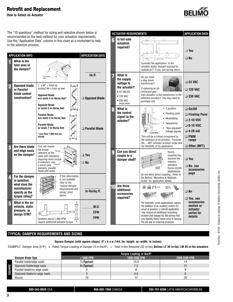
Model Numbers
HONEYWELL BELIMO** SpringReturn Control Signal Power Torque (in-lbs) Feedback Auxiliary Switches Timing (seconds)
M4185A1001 NFBUP Yes On/Off On/Off 120 24-240 60 90 30-60 <75M4185B1009 NFBUP-S Yes On/Off On/Off 120 24-240 60 90 1 2 30-60 <75
M4185B1058 NFBUP-S Yes On/Off On/Off 100-230 24-240 60 90 1 2 30-60 <75
M4185C1007 NFBUP-S Yes On/Off On/Off 120 24-240 60 90 2 2 30-60 <75M6184A1015 AMB24-3 No Floating Point On/Off, Floating Pt. 24 24 150 180 30-60 150M6184A1023 NMX120-3 No Floating Point On/Off, Floating Pt. 120 120 75 90 15-30 45M6184D1001 NMBC24-3 No Floating Point On/Off, Floating Pt. 24 24 75 90 15-30 45M6184D1035 AMCX24-MFT No Floating Point On/Off, Floating Pt. 24 24 150 180 2-10 VDC 30-60 35-adjM6184D1068 AMX24-MFT No Floating Point On/Off, Floating Pt. 24 24 150 180 2-10 VDC 120-240 150-adjM6184F1014 AMCX24-MFT No Floating Point On/Off, Floating Pt. 24 24 150 180 2-10 VDC 2 add S2A 30-60 35-adjM6194B1011 GMB24-3 No Floating Point On/Off, Floating Pt. 24 24 300 360 1 add S1A 60-120 150M6194D1017 GMB24-3 No Floating Point On/Off, Floating Pt. 24 24 300 360 120-240 150M6194E1006 GMB24-3 No Floating Point On/Off, Floating Pt. 24 24 300 360 1 add S1A 120-240 150M6284A1055 AMCX24-MFT* No Floating Point On/Off, Floating Pt. 120 24 150 180 2-10 VDC 30-60 35-adjM6284D1000 AMCX24-MFT No Floating Point On/Off, Floating Pt. 24 24 150 180 2-10 VDC 30-60 35-adjM6284F1013 AMCX24-MFT No Floating Point On/Off, Floating Pt. 24 24 150 180 2-10 VDC 2 add S2A 30-60 35-adj
M6285A1005 NFX24-MFT Yes Floating Point MFT, 2-10 VDC default 24 24 60 90 2-10 VDC 30-60 150-adj
M6285C1001 NFX24-MFT-S Yes Floating Point MFT, 2-10 VDC default 24 24 60 90 2-10 VDC 2 2 30-60 150-adj
M6294D1008 GMB24-3 No Floating Point On/Off, Floating Pt. 24 24 300 360 120-240 150
M7164A1017 LMCB24-SR No 2-10 VDC, 4-20 mA
MFT, 2-10 VDC default 24 24 35 35 2-10 VDC 30-60 35
M7164G1030 LMCB24-SR* No 2-10 VDC, 4-20 mA
MFT, 2-10 VDC default 120 24 35 35 2-10 VDC 30-60 35
M7215A1008 LF24-SR US Yes 2-10 VDC, 4-20 mA 2-10 VDC, 4-20 mA 24 24 25 35 2-10 VDC 2-10 VDC 90 95M7284A1004 AMCX24-MFT* No 2-10 VDC, 4-20 mA 2-10 VDC, 4-20 mA 120 24 150 180 2-10 VDC 30-60 35-adjM7284A1012 AMCX24-MFT* No 2-10 VDC, 4-20 mA 2-10 VDC, 4-20 mA 120 24 150 180 2-10 VDC 30-60 35-adjM7284A1038 AMCX24-MFT* No 2-10 VDC, 4-20 mA 2-10 VDC, 4-20 mA 120 24 75 180 2-10 VDC 15-30 35-adjM7284A1079 AMCX24-MFT No 2-10 VDC, 4-20 mA 2-10 VDC, 4-20 mA 24 24 150 180 2-10 VDC 30-60 35-adjM7284C1000 AMCX24-MFT* No 2-10 VDC, 4-20 mA 2-10 VDC, 4-20 mA 120 24 150 180 2-10 VDC 2 add S2A 30-60 35-adjM7284C1059 AMCX24-MFT No On/Off, Floating Pt. On/Off, Floating Pt. 24 24 150 180 2-10 VDC 2 add S2A 30 35-adjM7284C1067 AMCX24-MFT No On/Off, Floating Pt. On/Off, Floating Pt. 24 24 150 180 2-10 VDC 2 add S2A 60 35-adjM7284Q1009 AMCX24-MFT* No 2-10 VDC, 4-20 mA 2-10 VDC, 4-20 mA 120 24 150 180 2-10 VDC 2 add S2A 30-60 35-adjM7284Q1033 AMCX24-MFT No 2-10 VDC, 4-20 mA 2-10 VDC, 4-20 mA 24 24 150 180 2-10 VDC 2 add S2A 30 35-adjM7284Q1041 AMCX24-MFT No 2-10 VDC, 4-20 mA 2-10 VDC, 4-20 mA 24 24 150 180 2-10 VDC 2 add S2A 60 35-adjM7285A1003 NFX24-MFT* Yes 2-10 VDC, 4-20 mA 2-10 VDC, 4-20 mA 120 24 50 90 2-10 VDC 30-60 150-adjM7285A1045 NFX24-MFT Yes 2-10 VDC, 4-20 mA 2-10 VDC, 4-20 mA 24 24 50 90 2-10 VDC 30-60 150-adjM7285C1009 NFX24-MFT-S* Yes 2-10 VDC, 4-20 mA 2-10 VDC, 4-20 mA 120 24 50 90 2-10 VDC 2 2 30-60 150-adjM7285Q1008 NFX24-MFT-S* Yes 2-10 VDC, 4-20 mA 2-10 VDC, 4-20 mA 120 24 50 90 2-10 VDC 2 2 30-60 150-adjM7286G1009 NFX24-MFT Yes 2-10 VDC, 4-20 mA 2-10 VDC, 4-20 mA 24 24 60 90 2-10 VDC 30-60 150-adjM7294A1010 GMB24-SR No 2-10 VDC, 4-20 mA 2-10 VDC, 4-20 mA 24 24 300 360 2-10 VDC 60-120 150M7294Q1007 GMB24-SR* No 2-10 VDC, 4-20 mA 2-10 VDC, 4-20 mA 120 24 300 360 2-10 VDC 2 add S2A 60-120 150
M7415A1006 LF24-ECON-R03 US Yes Thermistor, 3000ohm NTC
Thermistor, 3000 ohm NTC 24 24 25 35 2-10 VDC 2-10 VDC 90 95
M7415B1004 LF24-ECON-R03 US Yes Thermistor, 3000ohm NTC
Thermistor, 3000 ohm NTC 24 24 25 35 2-10 VDC 2-10 VDC 90 95
M7685A1025 NFX24-MFT Yes 2-10 VDC, 4-20 mA MFT, 2-10 VDCdefault 24 24 60 90 2-10 VDC 30-60 150-adj
M8185D1006 NFB24 Yes On/Off On/Off 24 24 60 90 30-60 <75M8405A1006 LF24-SR-E US Yes On/Off, Floating Pt. 2-10 VDC, 4-20 mA 24 24 25 35 2-10 VDC 2-10 VDC 90 150-adjM9164A1005 LMX24-MFT95* No 0-135 ohm 0-135 ohm 120 24 35 45 2-10 VDC 30-60 150-adj
M9164A1013 LMX24-MFT95* No 0-135 ohm 0-135 ohm 100-230 24 35 45 2-10 VDC 30-60 150-adj
M9164A1013 LMX24-MFT95* No 0-135 ohm 0-135 ohm 100-230 24 35 45 2-10 VDC 30-60 150-adj
M9164A1070 LMX24-MFT95 No 0-135 ohm 0-135 ohm 24 24 35 45 2-10 VDC 30-60 150-adjM9164C1001 LMX24-MFT95 No 0-135 ohm 0-135 ohm 24 24 35 45 2-10 VDC 2 add S2A 30-60 150-adj
Auxiliary Switchesadd S2A 2 auxiliary switches (add-on)add S1A 1 auxiliary switch (add-on)1 1 auxiliary switch (built-in)2 2 auxiliary switches (built-in)
Legend
HONEYWELL“WHITE”
BELIMO“GRAY”
Belimo 24V actuators are AC/DC
Honeywell to BelimoActuator Replacement Cross Reference
** Belimo actuators are 95° max rotation.* Add 120/24 volt transformer.
Tech
.Doc
- 07
/18
- Sub
ject
to c
hang
e. ©
Bel
imo
Airc
ontro
ls (U
SA),
Inc.
®
800-543-9038 USA 866-805-7089 CANADA 203-791-8396 LATIN AMERICA/CARIBBEAN
9
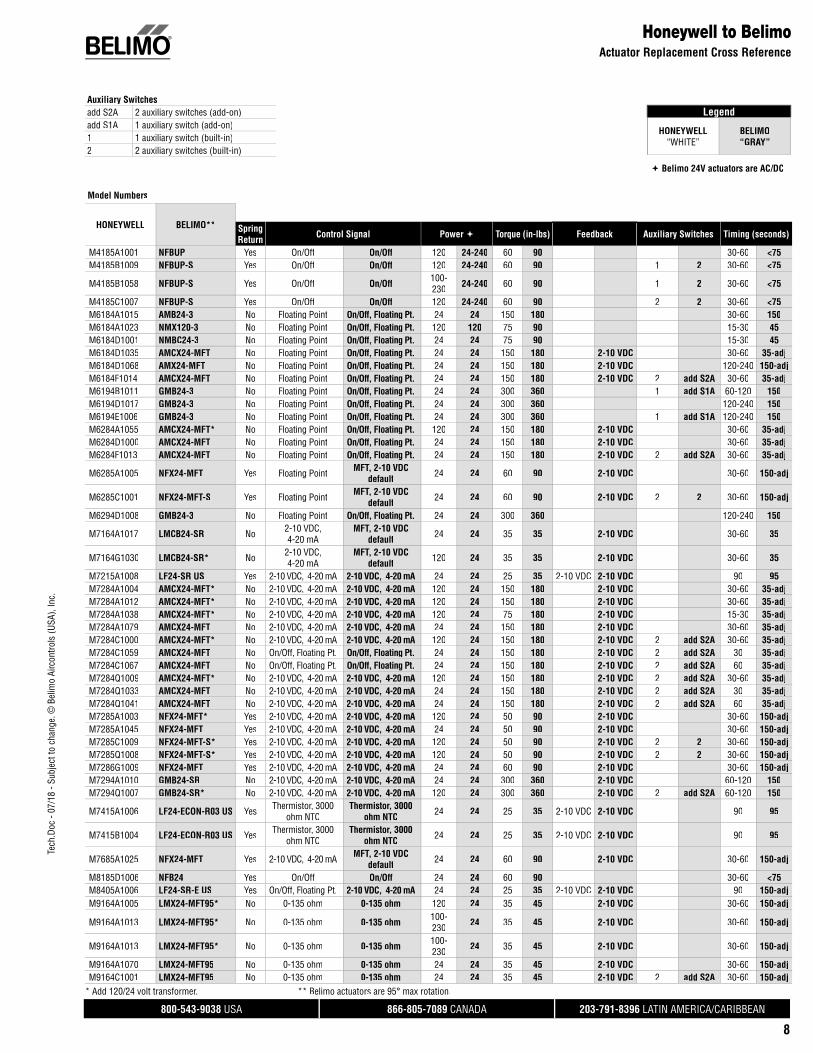
Honeywell to BelimoActuator Replacement Cross Reference
M9164C1068 LMX24-MFT95* No 0-135 ohm 0-135 ohm 24 24 35 45 2-10 VDC 2 add S2A 30-60 150-adjM9164D1009 LMX24-MFT95 No 0-135 ohm 0-135 ohm 24 24 35 45 2-10 VDC 30-60 150-adjM9174B1027 NMX24-MFT95* No 0-135 ohm 0-135 ohm 24 24 75 90 2-10 VDC 1 add S1A 30-60 150-adjM9174C1025 NMX24-MFT95* No 0-135 ohm 0-135 ohm 24 24 75 90 2-10 VDC 2 add S2A 30-60 150-adjM9174C1033 NMX24-MFT95* No 0-135 ohm 0-135 ohm 24 24 75 90 2-10 VDC 2 add S2A 30-60 150-adjM9174D1007 NMX24-MFT95 No 0-135 ohm 0-135 ohm 24 24 75 90 2-10 VDC 30-60 150-adjM9184A1019 AMX24-MFT95 No 0-135 ohm 0-135 ohm 24 24 150 180 2-10 VDC 30-60 150-adjM9184C1031 AMX24-MFT95 No 0-135 ohm 0-135 ohm 24 24 150 180 2-10 VDC 2 add S2A 30-60 150-adjM9184D1005 NMX24-MFT95 No 0-135 ohm 0-135 ohm 24 24 75 90 2-10 VDC 15-30 150-adjM9184D1021 AMX24-MFT95 No 0-135 ohm 0-135 ohm 24 24 150 180 2-10 VDC 30-60 150-adjM9184F1034 AMX24-MFT95 No 0-135 ohm 0-135 ohm 24 24 150 180 2-10 VDC 2 add S2A 30-60 150-adjM9185A1018 AFB24-MFT95 Yes 0-135 ohm 0-135 ohm 24 24 60 180 2-10 VDC 30-60 150-adjM9185C1006 AFB24-MFT95 Yes 0-135 ohm 0-135 ohm 24 24 60 180 2-10 VDC 2 30-60 150-adjM9185D1004 AFB24-MFT95 Yes 0-135 ohm 0-135 ohm 24 24 60 180 2-10 VDC 30-60 150-adjM9185E1019 AFB24-MFT95 Yes 0-135 ohm 0-135 ohm 24 24 60 180 2-10 VDC 1 30-60 150-adjM9186G1006 AFB24-MFT95 Yes 0-135 ohm 0-135 ohm 24 24 60 180 2-10 VDC 30-60 150-adjM9194D1003 GMX24-MFT95 No 0-135 ohm 0-135 ohm 24 24 300 360 2-10 VDC 120-240 150-adjM9194E1000 GMX24-MFT95 No 0-135 ohm 0-135 ohm 24 24 300 360 2-10 VDC 1 add S1A 120-240 150-adjML6131B2001 LMQX24-MFT No On/Off, Floating Pt. On/Off, Floating Pt. 24 24 6 35 15 2.5-adjML6161A2008 LMB24-SR No 2-10 VDC, 4-20 mA 2-10 VDC, 4-20 mA 24 24 35 45 2-10 VDC 90 95ML6161A2009 LMB24-3-P5-T No On/Off, Floating Pt. On/Off, Floating Pt. 24 24 35 45 2 kΩ 5 kΩ 90 95ML6161B2024 LMB24-3-T No On/Off, Floating Pt. On/Off, Floating Pt. 24 24 35 45 90 95ML6161B2024 LMB24-3-T No On/Off, Floating Pt. On/Off, Floating Pt. 24 24 35 45 90 95ML6174A2002 NMB24-3 No Floating Point Floating Point 24 24 70 90 90 95ML6174A2010 AMB24-3 No Floating Point Floating Point 24 24 70 180 180 95ML6174B2019 NMB24-3 No Floating Point Floating Point 24 24 70 90 90 95ML6174B2019 NMB24-3 No On/Off, Floating Pt. On/Off, Floating Pt. 24 24 90 90 90 95ML6174D2009 NMB24-3 No Floating Point Floating Point 24 24 70 90 90 95ML6174E2008 NMB24-3 No Floating Point Floating Point 24 24 70 90 90 95ML7161A2008 LMB24-SR No 2-10 VDC, 4-20 mA 2-10 VDC, 4-20 mA 24 24 35 45 2-10 VDC 90 95ML7161A2008 LMB24-SR-T No 2-10 VDC, 4-20 mA 2-10 VDC, 4-20 mA 24 24 35 45 2-10 VDC 90 95ML7174A2001 NMB24-SR No 2-10 VDC, 4-20 mA 2-10 VDC, 4-20 mA 24 24 70 90 2-10 VDC 90 95ML7174A2019 NMB24-SR No 2-10 VDC, 4-20 mA 2-10 VDC, 4-20 mA 24 24 70 90 2-10 VDC 2-10 VDC 90 95ML7174E2007 NMB24-SR No 2-10 VDC, 4-20 mA 2-10 VDC, 4-20 mA 24 24 70 90 2-10 VDC 2-10 VDC 90 95MN6120A1002 AMB24-3 No On/Off, Floating Pt. On/Off, Floating Pt. 24 24 175 180 90 95MN6120A1200 AMB24-3 No On/Off, Floating Pt. On/Off, Floating Pt. 24 24 175 180 2 add S2A 90 95MN6134A1003 GMB24-3 No On/Off, Floating Pt. On/Off, Floating Pt. 24 24 300 360 90 150MN6134A1003 GMB24-3 No On/Off, Floating Pt. On/Off, Floating Pt. 24 24 300 360 90 150MN7220A2007 AMB24-SR No 2-10 VDC, 4-20 mA 2-10 VDC, 4-20 mA 24 24 175 180 2-10 VDC 2-10 VDC 90 95MN7234A2008 GMB24-SR No 2-10 VDC, 4-20 mA 2-10 VDC, 4-20 mA 24 24 300 360 2-10 VDC 2-10 VDC 90 150
MS4105A1002 LF230 US Yes On/Off On/Off 100-250 230 35 35 90 40-75
MS4105A1002 LF120 US Yes On/Off On/Off 100-250 120 35 35 90 40-75
MS4110A1002 NFBUP Yes On/Off, Floating Pt. On/Off 100-250 24-240 88 90 90 <75
MS4110A1002 NFBUP Yes On/Off, Floating Pt. On/Off 100-250 24-240 88 90 90 <75
MS4110A1200 LF120-S US Yes On/Off On/Off 100-250 120 35 35 2 1 90 40-75
MS4110A1200 LF230-S US Yes On/Off On/Off 100-250 230 35 35 2 1 90 40-75
MS4120A1001 AFBUP Yes On/Off On/Off 100-250 24-240 175 180 90 <75
MS4120A1209 AFBUP-S Yes On/Off On/Off 100-250 24-240 175 180 2 2 90 <75
MS7150A2206 LF24-SR-S Yes 2-10 VDC, 4-20 mA 2-10 VDC, 4-20 mA 24 24 44 35 2-10 VDC 2-10 VDC 2 1 90 150
MS7505A2008 LFC24-3-R US Yes 2-10 VDC, 4-20 mA, Floating Pt., On/Off Floating Point 24 24 44 35 2-10 VDC 2-10 VDC 90 90
MS7510A2008 NFX24-MFT Yes 2-10 VDC, 4-20 mA, Floating Pt., On/Off
MFT, 2-10 VDC default 24 24 88 90 2-10 VDC 2-10 VDC 90 150-adj
MS7510A2206 LF24-MFT-S US Yes 2-10 VDC, 4-20 mA, Floating Pt., On/Off
MFT, 2-10 VDC default 24 24 88 35 2-10 VDC 2-10 VDC 2 1 90 150-adj
MS7520A2007 AFX24-MFT Yes 2-10 VDC, 4-20 mA, Floating Pt., On/Off
MFT, 2-10 VDC default 24 24 175 180 2-10 VDC 2-10 VDC 90 150-adj
HONEYWELL BELIMO** SpringReturn Control Signal Power Torque (in-lbs) Feedback Auxiliary Switches Timing (seconds)
* Add 120/24 volt transformer.
** Belimo actuators are 95° max rotation.

Tech
.Doc
- 07
/18
- Sub
ject
to c
hang
e. ©
Bel
imo
Airc
ontro
ls (U
SA),
Inc.
®
800-543-9038 USA 866-805-7089 CANADA 203-791-8396 LATIN AMERICA/CARIBBEAN
10
Honeywell to BelimoActuator Replacement Cross Reference
MS7520A2205 AFX24-MFT-S Yes 2-10 VDC, 4-20 mA, Floating Pt., On/Off
MFT, 2-10 VDC default 24 24 175 180 2-10 VDC 2-10 VDC 2 2 90 150-adj
MS8105A1008 LF24 US Yes On/Off On/Off 24 24 44 35 90 40-75MS8110A1008 NFB24 Yes On/Off, Floating Pt. On/Off 24 24 88 90 90 <75MS8110A1206 NFB24-S Yes On/Off, Floating Pt. On/Off 24 24 88 90 2 2 90 <75MS8120A1007 AFB24 Yes On/Off On/Off 24 24 175 180 90 <75MS8120A1205 AFB24-S Yes On/Off On/Off 24 24 175 180 2 2 90 <75MS8309F1001 FSNF24 US Yes On/Off On/Off 24 24 80 70 25 <15
HONEYWELL BELIMO** SpringReturn Control Signal Power Torque (in-lbs) Feedback Auxiliary Switches Timing (seconds)
** Belimo actuators are 95° max rotation.

Tech
.Doc
- 07
/18
- Sub
ject
to c
hang
e. ©
Bel
imo
Airc
ontro
ls (U
SA),
Inc.
®
800-543-9038 USA 866-805-7089 CANADA 203-791-8396 LATIN AMERICA/CARIBBEAN
11
Legend
INVENSYS“WHITE”
BELIMO“GRAY”
Belimo 24V actuators are AC/DC
Invensys to BelimoActuator Replacement Cross Reference
Model Numbers
INVENSYS BELIMO** SpringReturn Control Signal Power Torque (in-lbs) Feedback Auxiliary Switches Timing (seconds)
MA-305 TFB24 Yes On/Off On/Off 24 24 16 22 75MA-305 TFB24-MFT Yes On/Off On/Off 24 24 16 22 2-10 VDC 150-adjMA-305-500 TFB24-S Yes On/Off On/Off 24 24 16 22 1 1 75MA-305-500 TFB24-MFT-S Yes On/Off On/Off 24 24 16 22 2-10 VDC 1 1 150-adjMA-318 NFBUP Yes On/Off On/Off 120 24-240 60 90 <75MA-318-500 NFBUP-S Yes On/Off On/Off 230 24-240 60 90 1 2 <75MA-405 TFB120 Yes On/Off On/Off 120 120 16 22 75MA-405 TFCB120-S Yes On/Off On/Off 120 120 16 22 1 <30MA-405-500 TFB120-S Yes On/Off On/Off 120 120 16 22 1 1 75MA-405-500 TFCB120-S Yes On/Off On/Off 120 120 16 22 1 1 <30MA40-7040 LF120 US Yes On/Off On/Off 120 120 35 35 50 40-75MA40-7040-501 LF120-S US Yes On/Off On/Off 120 120 35 35 1 1 50 40-75MA40-7041 LF230 US Yes On/Off On/Off 230 230 35 35 50 40-75MA40-7041-501 LF230-S US Yes On/Off On/Off 230 230 35 35 1 1 50 40-75MA40-7043 LF24 US Yes On/Off On/Off 24 24 35 35 50 40-75MA40-7043-501 LF24-S US Yes On/Off On/Off 24 24 35 35 1 1 50 40-75MA40-7151 AFBUP Yes On/Off On/Off 230 24-240 133 180 190 <75MA40-7070 NFBUP Yes On/Off On/Off 120 24-240 60 90 80 <75MA40-7070-502 NFBUP-S Yes On/Off On/Off 120 24-240 60 90 2 2 80 <75MA40-7071 NFBUP Yes On/Off On/Off 230 24-240 60 90 80 <75MA40-7071-502 NFBUP-S Yes On/Off On/Off 230 24-240 60 90 2 2 80 <75MA40-7073 NFB24 Yes On/Off On/Off 24 24 60 90 80 <75MA40-7073-502 NFB24-S Yes On/Off On/Off 24 24 60 90 2 2 80 <75MA40-7150 AFBUP Yes On/Off On/Off 120 24-240 133 180 190 <75MA40-7150-502 AFBUP-S Yes On/Off On/Off 120 24-240 133 180 2 2 190 <75MA40-7153 AFB24 Yes On/Off On/Off 24 24 133 180 190 <75MA40-7153-502 AFB24-S Yes On/Off On/Off 24 24 133 180 2 2 190 <75MA40-7170 AFBUP Yes On/Off On/Off 120 24-240 150 180 145 <75MA40-7171 AFBUP Yes On/Off On/Off 230 24-240 150 180 145 <75MA40-7173 AFB24 Yes On/Off On/Off 24 24 150 180 145 <75MA-416 NFBUP Yes On/Off On/Off 208 24-240 60 90 104 <75MA-416-500 NFBUP-S Yes On/Off On/Off 208 24-240 60 90 1 2 104 <75MA41-7073 NFB24 Yes On/Off On/Off 24 24 90 <75MA-418-500 NFBUP-S Yes On/Off On/Off 120 24-240 60 90 1 2 <75MA-419 NFBUP Yes On/Off On/Off 240 24-240 60 90 120 <75MA-419-500 NFBUP-S Yes On/Off On/Off 240 24-240 60 90 1 2 120 <75MA40-7151-502 AFBUP-S Yes On/Off On/Off 230 24-240 133 180 2 2 190 <75MA5-419 NFBUP Yes On/Off On/Off 240 24-240 60 90 120 <75MA5-419-500 NFBUP-S Yes On/Off On/Off 240 24-240 60 90 1 2 120 <75MC-351 GMB24-3 No On/Off On/Off, Floating Pt. 24 24 220 360 70 95
MC-421 AMQX24-MFT No On/Off MFT, 2-10 VDC default 24 24 175 140 2-10 VDC 20 7-adj
MC-431 GMB24-MFT No On/Off MFT, 2-10 VDC default 24 24 220 360 2-10 VDC 30 150-adj
MC-4311 GMB24-MFT No On/Off MFT, 2-10 VDC default 24 24 220 360 2-10 VDC 30 150-adj
MC5-4311 GMB24-MFT No On/Off MFT, 2-10 VDC default 24 24 220 360 2-10 VDC 36 150-adj
MF40-6043 LMB24-3 No Floating Point Floating Point 24 24 35 45 <90 95MF40-6043-502 LMB24-3 No Floating Point Floating Point 24 24 35 45 2 add S2A <90 95MF40-6043-510 LMB24-3 No Floating Point Floating Point 24 24 35 45 <90 95MF40-6083 NMB24-3 No Floating Point Floating Point 24 24 70 90 120 95MF40-6153 AMB24-3 No Floating Point Floating Point 24 24 133 180 120 95MF40-7043 LF24-3 US Yes Floating Point Floating Point 24 24 35 35 2-10 VDC 130 150MF40-7043-501 LF24-3-S US Yes Floating Point Floating Point 24 24 35 35 1 1 195 150
MF40-7073 NFX24-MFT Yes Floating Point MFT, 2-10 VDC default 24 24 60 90 2-10 VDC 190 150-adj
MF40-7073-502 NFX24-MFT-S Yes Floating Point MFT, 2-10 VDC default 24 24 60 90 2-10 VDC 2 2 195 150-adj
Auxiliary Switchesadd S2A 2 auxiliary switches (add-on)add S1A 1 auxiliary switch (add-on)1 1 auxiliary switch (built-in)2 2 auxiliary switches (built-in)
** Belimo actuators are 95° max rotation.

Tech
.Doc
- 07
/18
- Sub
ject
to c
hang
e. ©
Bel
imo
Airc
ontro
ls (U
SA),
Inc.
®
800-543-9038 USA 866-805-7089 CANADA 203-791-8396 LATIN AMERICA/CARIBBEAN
12
MF40-7153 AFX24-MFT Yes Floating Point MFT, 2-10 VDC default 24 24 133 180 2-10 VDC 190 150-adj
MF40-7153-502 AFX24-MFT-S Yes Floating Point MFT, 2-10 VDC default 24 24 133 180 2-10 VDC 2 2 190 150-adj
MF40-7173 AFX24-MFT Yes Floating Point MFT, 2-10 VDC default 24 24 150 180 2-10 VDC 145 150-adj
MF41-6043 LMB24-3 No Floating Point Floating Point 24 24 35 45 90 95MF41-6043-502 LMB24-3 No Floating Point Floating Point 24 24 35 45 2 add S2A 90 95MF41-6043-510 LMB24-3-P10-T No Floating Point Floating Point 24 24 35 45 1 kΩ 10 kΩ 90 95MF41-6083 NMB24-3 No Floating Point Floating Point 24 24 70 90 90 95MF41-6083-502 NMB24-3 No Floating Point Floating Point 24 24 70 90 2 add S2A 90 95MF41-6153 AMB24-3 No Floating Point Floating Point 24 24 133 180 90 95MF41-6343 GMB24-3 No Floating Point Floating Point 24 24 300 360 90 150
MF41-7073 NFX24-MFT Yes Floating Point MFT, 2-10 VDC default 24 24 60 90 2-10 VDC 195 150-adj
MF41-7073-502 NFX24-MFT-S Yes Floating Point MFT, 2-10 VDC default 24 24 60 90 2-10 VDC 2 2 195 150-adj
MF41-7153 AFX24-MFT Yes Floating Point MFT, 2-10 VDC default 24 24 133 180 2-10 VDC 190 150-adj
MF41-7153-502 AFX24-MFT-S Yes Floating Point MFT, 2-10 VDC default 24 24 133 180 2-10 VDC 2 2 190 150-adj
MF-6343 GMB24-3 No Floating Point Floating Point 24 24 300 360 145 150MM-400 LMCB24-SR No 2-10 VDC, 4-20 mA 2-10 VDC, 4-20 mA 24 24 150 45 2-10 VDC 50 35MM-400-002 LMCB24-SR No 2-10 VDC, 4-20 mA 2-10 VDC, 4-20 mA 24 24 150 45 2-10 VDC 2 add S2A 50 35
MM-500 NFX24-MFT Yes 2-10 VDC, 4-20 mA MFT, 2-10 VDC default 24 24 50 90 2-10 VDC 55 150-adj
MM-500-002 NFX24-MFT-S Yes 2-10 VDC, 4-20 mA MFT, 2-10 VDC default 24 24 50 90 2-10 VDC 2 2 55 150-adj
MMR-400 LMCB24-SR No 2-10 VDC, 4-20 mA 2-10 VDC, 4-20 mA 24 24 150 45 2-10 VDC 50 35MMR-400-002 LMCB24-SR No 2-10 VDC, 4-20 mA 2-10 VDC, 4-20 mA 24 24 150 45 2-10 VDC 2 add S2A 50 35
MMR-500 NFX24-MFT Yes 2-10 VDC, 4-20 mA MFT, 2-10 VDC default 24 24 50 90 2-10 VDC 55 150-adj
MMR-500-002 NFX24-MFT-S Yes 2-10 VDC, 4-20 mA MFT, 2-10 VDC default 24 24 50 90 2-10 VDC 2 2 55 150-adj
MP-361 NFB24-SR-S Yes 2-10 VDC, 4-20 mA 2-10 VDC, 4-20 mA 24 24 50 90 2-10 VDC 1 2 95 95
MP-361-600 NFX24-MFT-S Yes 2-10 VDC, 4-20 mA MFT, 2-10 VDC default 24 24 50 90 2-10 VDC 1 2 90 150-adj
MP-361-691 NFX24-MFT-S Yes 2-10 VDC, 4-20 mA MFT, 2-10 VDC default 24 24 50 90 2-10 VDC 1 2 90 150-adj
MP-371 NFB24-SR-S Yes 2-10 VDC, 4-20 mA 2-10 VDC, 4-20 mA 24 24 50 90 2-10 VDC 1 2 90 95
MP-371-600 NFX24-MFT-S Yes 2-10 VDC, 4-20 mA MFT, 2-10 VDC default 24 24 50 90 2-10 VDC 1 2 90 150-adj
MP-371-602 NFX24-MFT-S Yes 2-10 VDC, 4-20 mA MFT, 2-10 VDC default 24 24 50 90 2-10 VDC 1 2 90 150-adj
MP-381 GMB24-SR No 2-10 VDC, 4-20 mA 2-10 VDC, 4-20 mA 24 24 220 360 2-10 VDC 1 add S1A 130 150MP-382 GMB24-SR No 2-10 VDC, 4-20 mA 2-10 VDC, 4-20 mA 24 24 220 360 2-10 VDC 1 add S1A 130 150
MP-421 NMX24-MFT* No 2-10 VDC, 4-20 mA MFT, 2-10 VDC default 120 24 60 90 2-10 VDC 1 add S1A 25 150-adj
MP-422 NMX24-MFT* No 2-10 VDC, 4-20 mA MFT, 2-10 VDC default 120 24 60 90 2-10 VDC 1 add S1A 25-250 150-adj
MP-424 NMX24-MFT* No 2-10 VDC, 4-20 mA MFT, 2-10 VDC default 120 24 60 90 2-10 VDC 1 add S1A 13-130 150-adj
MP-451 NMX24-MFT* No 2-10 VDC, 4-20 mA MFT, 2-10 VDC default 120 24 80 90 2-10 VDC 1 add S1A 80 150-adj
MP-453 GMX24-MFT* No 2-10 VDC, 4-20 mA MFT, 2-10 VDC default 120 24 220 360 2-10 VDC 1 add S1A 40 150-adj
MP-465 NFB24-SR-S* Yes 2-10 VDC, 4-20 mA 2-10 VDC, 4-20 mA 120 24 50 90 2-10 VDC 1 2 50 95MP-475 NFB24-SR-S* Yes 2-10 VDC, 4-20 mA 2-10 VDC, 4-20 mA 120 24 50 90 2-10 VDC 1 2 50 95
MP-481 AMX24-MFT* No 2-10 VDC, 4-20 mA MFT, 2-10 VDC default 120 24 130 180 2-10 VDC 1 add S1A 130 150-adj
MP-483 NMX24-MFT* No 2-10 VDC, 4-20 mA MFT, 2-10 VDC default 120 24 65 90 2-10 VDC 1 add S1A 65 150-adj
MP-485 AMX24-MFT* No 2-10 VDC, 4-20 mA MFT, 2-10 VDC default 120 24 130 180 2-10 VDC 1 add S1A 130 150-adj
MP-495 AMX24-MFT* No 2-10 VDC, 4-20 mA MFT, 2-10 VDC default 120 24 130 180 2-10 VDC 1 add S1A 130 150-adj
MP-483 NMX24-MFT* No 2-10 VDC, 4-20 mA MFT, 2-10 VDC default 120 24 65 90 2-10 VDC 1 add S1A 65 150-adj
Invensys to BelimoActuator Replacement Cross Reference
BELIMO** SpringReturn Control Signal Power Torque (in-lbs) Feedback Auxiliary Switches Timing (seconds)
* Add 120/24 volt transformer.
** Belimo actuators are 95° max rotation.

Tech
.Doc
- 07
/18
- Sub
ject
to c
hang
e. ©
Bel
imo
Airc
ontro
ls (U
SA),
Inc.
®
800-543-9038 USA 866-805-7089 CANADA 203-791-8396 LATIN AMERICA/CARIBBEAN
13
MP-485 AMX24-MFT* No 2-10 VDC, 4-20 mA MFT, 2-10 VDC default 120 24 130 180 2-10 VDC 1 add S1A 130 150-adj
MP-5233 TFB24-MFT Yes 2-10 VDC, 4-20 mA MFT, 2-10 VDC default 24 24 19 22 2-10 VDC 60 150-adj
MP-5433 TFB24-MFT* Yes 2-10 VDC, 4-20 mA MFT, 2-10 VDC default 120 24 19 22 2-10 VDC 60 150-adj
MP-5613 TFB24-MFT Yes 2-10 VDC, 4-20 mA MFT, 2-10 VDC default 24 24 22 2-10 VDC 60 150-adj
MS-1233 TFB24-MFT No 2-10 VDC, 4-20 mA MFT, 2-10 VDC default 24 24 20 22 2-10 VDC 225 150-adj
MS-1233-002 TFB24-MFT No 2-10 VDC, 4-20 mA MFT, 2-10 VDC default 24 24 20 22 2-10 VDC 225 150-adj
MS-1233-100 TFB24-MFT No 2-10 VDC, 4-20 mA MFT, 2-10 VDC default 24 24 20 22 2-10 VDC 225 150-adj
MS-1233-102 TFB24-MFT No 2-10 VDC, 4-20 mA MFT, 2-10 VDC default 24 24 20 17 2-10 VDC 225 150-adj
MS40-7171 AFB24-SR Yes 2-10 VDC, 4-20 mA 2-10 VDC, 4-20 mA 24 24 150 180 2-10 VDC 2-10 VDC 145 95MS40-7171 AFB24-MFT Yes 2-10 VDC, 4-20 mA 2-10 VDC, 4-20 mA 24 24 150 180 2-10 VDC 2-10 VDC 145 150-adjMS40-7043 LF24-SR US Yes 2-10 VDC, 4-20 mA 2-10 VDC, 4-20 mA 24 24 35 35 2-10 VDC 2-10 VDC 130 150MS40-7043-501 LF24-SR-S US Yes 2-10 VDC, 4-20 mA 2-10 VDC, 4-20 mA 24 24 35 35 2-10 VDC 2-10 VDC 1 1 130 150MS40-7073-502 NFB24-SR-S Yes 2-10 VDC, 4-20 mA 2-10 VDC, 4-20 mA 24 24 60 90 2-10 VDC 2-10 VDC 2 2 130 95MS40-7153 AFB24-SR Yes 2-10 VDC, 4-20 mA 2-10 VDC, 4-20 mA 24 24 133 180 2-10 VDC 2-10 VDC 130 95
MS40-7153-502 AFB24-MFT-S Yes 2-10 VDC, 4-20 mA MFT, 2-10 VDC default 24 24 133 180 2-10 VDC 2-10 VDC 2 2 195 150-adj
MS40-7170 AFB24-SR* Yes 2-10 VDC, 4-20 mA 2-10 VDC, 4-20 mA 120 24 150 180 2-10 VDC 2-10 VDC 145 95MS40-7170 AFB24-MFT* Yes 2-10 VDC, 4-20 mA 2-10 VDC, 4-20 mA 120 24 150 180 2-10 VDC 2-10 VDC 145 150-adjMS40-7173 AFB24-SR Yes 2-10 VDC, 4-20 mA 2-10 VDC, 4-20 mA 24 24 150 180 2-10 VDC 2-10 VDC 145 95MS40-7173 AFB24-MFT Yes 2-10 VDC, 4-20 mA 2-10 VDC, 4-20 mA 24 24 150 180 2-10 VDC 2-10 VDC 145 150-adjMS41-6043 LMCB24-SR No 2-10 VDC, 4-20 mA 2-10 VDC, 4-20 mA 24 24 35 45 2-10 VDC 2-10 VDC 35MS41-6043-502 LMB24-SR No 2-10 VDC, 4-20 mA 2-10 VDC, 4-20 mA 24 24 35 45 2-10 VDC 2-10 VDC 95MS41-6043-520 LMB24-MFT No 2-10 VDC, 4-20 mA 2-10 VDC, 4-20 mA 24 24 35 45 2-10 VDC 2-10 VDC 150-adjMS41-6043-522 LMB24-MFT No 2-10 VDC, 4-20 mA 2-10 VDC, 4-20 mA 24 24 35 45 2-10 VDC 2-10 VDC 150-adjMS41-6083 NMB24-SR No 2-10 VDC, 4-20 mA 2-10 VDC, 4-20 mA 24 24 70 90 2-10 VDC 2-10 VDC 150 95MS41-6083-502 NMB24-MFT No 2-10 VDC, 4-20 mA 2-10 VDC, 4-20 mA 24 24 70 90 2-10 VDC 2-10 VDC 150 150-adjMS41-6083-520 NMB24-MFT No 2-10 VDC, 4-20 mA 2-10 VDC, 4-20 mA 24 24 70 90 2-10 VDC 2-10 VDC 150 150-adjMS41-6083-522 NMB24-MFT No 2-10 VDC, 4-20 mA 2-10 VDC, 4-20 mA 24 24 70 90 2-10 VDC 2-10 VDC 150 150-adjMS41-6153 AMB24-SR No 2-10 VDC, 4-20 mA 2-10 VDC, 4-20 mA 24 24 133 180 2-10 VDC 2-10 VDC 95MS41-6343 GMB24-SR No 2-10 VDC, 4-20 mA 2-10 VDC, 4-20 mA 24 24 300 360 2-10 VDC 2-10 VDC 150MS41-7073 NFB24-SR Yes 2-10 VDC, 4-20 mA 2-10 VDC, 4-20 mA 24 24 60 90 2-10 VDC 2-10 VDC 195 95MS41-7153 AFB24-SR Yes 2-10 VDC, 4-20 mA 2-10 VDC, 4-20 mA 24 24 133 180 2-10 VDC 2-10 VDC 190 95
MS50-E2001 AFB24-MFT Yes 2-10 VDC, 4-20 mA MFT, 2-10 VDC default 24 24 150 180 2-10 VDC 145 150-adj
MS50-E2101 AFB24-MFT Yes 2-10 VDC, 4-20 mA MFT, 2-10 VDC default 24 24 150 180 2-10 VDC 145 150-adj
MS50-E2301 AFB24-MFT Yes 2-10 VDC, 4-20 mA MFT, 2-10 VDC default 24 24 150 180 2-10 VDC 145 150-adj
MS50-H2001 GMB24-MFT No 2-10 VDC, 4-20 mA MFT, 2-10 VDC default 24 24 300 360 2-10 VDC 145 150-adj
MS50-H2101 GMB24-MFT No 2-10 VDC, 4-20 mA MFT, 2-10 VDC default 24 24 300 360 2-10 VDC 145 150-adj
MS50-H2301 GMB24-MFT No 2-10 VDC, 4-20 mA MFT, 2-10 VDC default 24 24 300 360 2-10 VDC 145 150-adj
Invensys to BelimoActuator Replacement Cross Reference
INVENSYS BELIMO** SpringReturn Control Signal Power Torque (in-lbs) Feedback Auxiliary Switches Timing (seconds)
* Add 120/24 volt transformer.
** Belimo actuators are 95° max rotation.
Tech
.Doc
- 07
/18
- Sub
ject
to c
hang
e. ©
Bel
imo
Airc
ontro
ls (U
SA),
Inc.
®
800-543-9038 USA 866-805-7089 CANADA 203-791-8396 LATIN AMERICA/CARIBBEAN
14
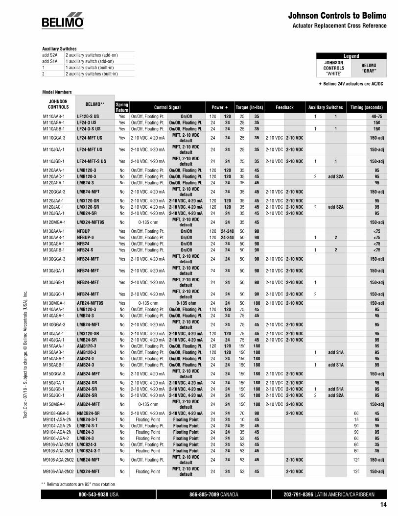
LegendJOHNSON
CONTROLS“WHITE”
BELIMO“GRAY”
Belimo 24V actuators are AC/DC
Johnson Controls to BelimoActuator Replacement Cross Reference
Model Numbers
JOHNSONCONTROLS BELIMO** Spring
Return Control Signal Power Torque (in-lbs) Feedback Auxiliary Switches Timing (seconds)
M110AAB-1 LF120-S US Yes On/Off, Floating Pt. On/Off 120 120 25 35 1 1 40-75M110AGA-1 LF24-3 US Yes On/Off, Floating Pt. On/Off, Floating Pt. 24 24 25 35 150M110AGB-1 LF24-3-S US Yes On/Off, Floating Pt. On/Off, Floating Pt. 24 24 25 35 1 1 150
M110GGA-3 LF24-MFT US Yes 2-10 VDC, 4-20 mA MFT, 2-10 VDC default 24 24 25 35 2-10 VDC 2-10 VDC 150-adj
M110JGA-1 LF24-MFT US Yes 2-10 VDC, 4-20 mA MFT, 2-10 VDC default 24 24 25 35 2-10 VDC 2-10 VDC 150-adj
M110JGB-1 LF24-MFT-S US Yes 2-10 VDC, 4-20 mA MFT, 2-10 VDC default 24 24 25 35 2-10 VDC 2-10 VDC 1 1 150-adj
M120AAA-1 LMB120-3 No On/Off, Floating Pt. On/Off, Floating Pt. 120 120 35 45 95M120AAC-1 LMB120-3 No On/Off, Floating Pt. On/Off, Floating Pt. 120 120 35 45 2 add S2A 95M120AGA-1 LMB24-3 No On/Off, Floating Pt. On/Off, Floating Pt. 24 24 35 45 95
M120GGA-3 LMB24-MFT No 2-10 VDC, 4-20 mA MFT, 2-10 VDC default 24 24 35 45 2-10 VDC 2-10 VDC 150-adj
M120JAA-1 LMX120-SR No 2-10 VDC, 4-20 mA 2-10 VDC, 4-20 mA 120 120 35 45 2-10 VDC 2-10 VDC 95M120JAC-1 LMX120-SR No 2-10 VDC, 4-20 mA 2-10 VDC, 4-20 mA 120 120 35 45 2-10 VDC 2-10 VDC 2 add S2A 95M120JGA-1 LMB24-SR No 2-10 VDC, 4-20 mA 2-10 VDC, 4-20 mA 24 24 35 45 2-10 VDC 2-10 VDC 95
M120MGA-1 LMX24-MFT95 No 0-135 ohm MFT, 2-10 VDC default 24 24 35 45 150-adj
M130AAA-1 NFBUP Yes On/Off, Floating Pt. On/Off 120 24-240 50 90 <75M130AAB-1 NFBUP-S Yes On/Off, Floating Pt. On/Off 120 24-240 50 90 1 2 <75M130AGA-1 NFB24 Yes On/Off, Floating Pt. On/Off 24 24 50 90 <75M130AGB-1 NFB24-S Yes On/Off, Floating Pt. On/Off 24 24 50 90 1 2 <75
M130GGA-3 NFB24-MFT Yes 2-10 VDC, 4-20 mA MFT, 2-10 VDC default 24 24 50 90 2-10 VDC 2-10 VDC 150-adj
M130JGA-1 NFB24-MFT Yes 2-10 VDC, 4-20 mA MFT, 2-10 VDC default 24 24 50 90 2-10 VDC 2-10 VDC 150-adj
M130JGB-1 NFB24-MFT Yes 2-10 VDC, 4-20 mA MFT, 2-10 VDC default 24 24 50 90 2-10 VDC 2-10 VDC 1 150-adj
M130JGC-1 NFB24-MFT Yes 2-10 VDC, 4-20 mA MFT, 2-10 VDC default 24 24 50 90 2-10 VDC 2-10 VDC 2 150-adj
M130MGA-1 AFB24-MFT95 Yes 0-135 ohm 0-135 ohm 24 24 50 180 2-10 VDC 2-10 VDC 150-adjM140AAA-1 LMB120-3 No On/Off, Floating Pt. On/Off, Floating Pt. 120 120 75 45 95M140AGA-1 LMB24-3 No On/Off, Floating Pt. On/Off, Floating Pt. 24 24 75 45 95
M140GGA-3 LMB24-MFT No 2-10 VDC, 4-20 mA MFT, 2-10 VDC default 24 24 75 45 2-10 VDC 2-10 VDC 95
M140JAA-1 LMX120-SR No 2-10 VDC, 4-20 mA 2-10 VDC, 4-20 mA 120 120 75 45 2-10 VDC 2-10 VDC 95M140JGA-1 LMB24-SR No 2-10 VDC, 4-20 mA 2-10 VDC, 4-20 mA 24 24 75 45 2-10 VDC 2-10 VDC 95M150AAA-1 AMB120-3 No On/Off, Floating Pt. On/Off, Floating Pt. 120 120 150 180 95M150AAB-1 AMB120-3 No On/Off, Floating Pt. On/Off, Floating Pt. 120 120 150 180 1 add S1A 95M150AGA-1 AMB24-3 No On/Off, Floating Pt. On/Off, Floating Pt. 24 24 150 180 95M150AGB-1 AMB24-3 No On/Off, Floating Pt. On/Off, Floating Pt. 24 24 150 180 1 add S1A 95
M150GGA-3 AMB24-MFT No 2-10 VDC, 4-20 mA MFT, 2-10 VDC default 24 24 150 180 2-10 VDC 2-10 VDC 150-adj
M150JGA-1 AMB24-SR No 2-10 VDC, 4-20 mA 2-10 VDC, 4-20 mA 24 24 150 180 2-10 VDC 2-10 VDC 95M150JGB-1 AMB24-SR No 2-10 VDC, 4-20 mA 2-10 VDC, 4-20 mA 24 24 150 180 2-10 VDC 2-10 VDC 1 add S1A 95M150JGC-1 AMB24-SR No 2-10 VDC, 4-20 mA 2-10 VDC, 4-20 mA 24 24 150 180 2-10 VDC 2-10 VDC 2 add S2A 95
M150MGA-1 AMB24-MFT No 0-135 ohm MFT, 2-10 VDC default 24 24 150 180 2-10 VDC 2-10 VDC 150-adj
M9108-GGA-2 NMCB24-SR No 2-10 VDC, 4-20 mA 2-10 VDC, 4-20 mA 24 24 70 90 2-10 VDC 60 45M9101-AGA-2N LMB24-3-T No Floating Point Floating Point 24 24 10 45 15 95M9104-AGA-2N LMB24-3-T No On/Off, Floating Pt. Floating Point 24 24 35 45 90 95M9104-AGA-2N LMB24-3 No Floating Point Floating Point 24 24 35 45 90 95M9106-AGA-2 LMB24-3 No Floating Point Floating Point 24 24 53 45 60 95M9106-AGA-2N01 LMCB24-3 No On/Off, Floating Pt. Floating Point 24 24 53 45 60 35M9106-AGA-2N01 LMCB24-3-T No Floating Point Floating Point 24 24 53 45 60 35
M9106-AGA-2N02 LMB24-MFT No On/Off, Floating Pt. MFT, 2-10 VDC default 24 24 53 45 2-10 VDC 120 150-adj
M9106-AGA-2N02 LMX24-MFT No Floating Point MFT, 2-10 VDC default 24 24 53 45 2-10 VDC 120 150-adj
Auxiliary Switchesadd S2A 2 auxiliary switches (add-on)add S1A 1 auxiliary switch (add-on)1 1 auxiliary switch (built-in)2 2 auxiliary switches (built-in)
** Belimo actuators are 95° max rotation.

Tech
.Doc
- 07
/18
- Sub
ject
to c
hang
e. ©
Bel
imo
Airc
ontro
ls (U
SA),
Inc.
®
800-543-9038 USA 866-805-7089 CANADA 203-791-8396 LATIN AMERICA/CARIBBEAN
15
Johnson Controls to BelimoActuator Replacement Cross Reference
JOHNSONCONTROLS BELIMO** Spring
Return Control Signal Power Torque (in-lbs) Feedback Auxiliary Switches Timing (seconds)
M9106-AGC-2 LMB24-3 No Floating Point Floating Point 24 24 53 45 2 add S2A 60 95M9106-AGF-2 LMB24-3-P10-T No Floating Point Floating Point 24 24 53 45 10 kΩ 60 95M9106-GGA-2 LMB24-SR No 2-10 VDC, 4-20 mA 2-10 VDC, 4-20 mA 24 24 53 45 2-10 VDC 60 95M9106-IGA-2 LMB24-MFT No Floating Point Floating Point 24 24 53 45 2-10 VDC 60 150-adjM9108-AGA-2 NMCB24-3 No Floating Point Floating Point 24 24 70 90 25-50 45M9108-AGC-2 NMCB24-3 No Floating Point Floating Point 24 24 70 90 2 add S2A 25-50 45M9108-GGC-2 NMCB24-SR No 2-10 VDC, 4-20 mA 2-10 VDC, 4-20 mA 24 24 70 90 2-10 VDC 2 add S2A 25-50 45
M9108-HGA-2 NMB24-MFT No 2-10 VDC w/ adj.start and span
MFT, 2-10 VDC default 24 24 70 90 2-10 VDC 25-50 150-adj
M9108-HGC-2 NMB24-MFT No 2-10 VDC w/ adj.start and span
MFT, 2-10 VDC default 24 24 70 90 2-10 VDC 2 add S2A 25-50 150-adj
M9109-AGA-2 NMB24-3 No Floating Point Floating Point 24 24 80 90 60 95M9109-AGC-2 NMB24-3 No Floating Point Floating Point 24 24 80 90 2 add S2A 60 95M9109-GGA-2 NMB24-SR No 2-10 VDC, 4-20 mA 2-10 VDC, 4-20 mA 24 24 80 90 2-10 VDC 60 95M9109-GGC-2 NMB24-SR No 2-10 VDC, 4-20 mA 2-10 VDC, 4-20 mA 24 24 80 90 2-10 VDC 2 add S2A 60 95M9116-AGA-2 AMB24-3 No Floating Point On/Off, Floating Pt. 24 24 140 180 0-10 VDC 70-115 95M9116-AGA-2 AMB24-3 No Floating Point Floating Point 24 24 140 180 70-115 95M9116-AGC-2 AMB24-3-S No Floating Point On/Off, Floating Pt. 24 24 140 180 0-10 VDC 2 add S2A 70-115 95M9116-AGC-2 AMB24-3 No Floating Point Floating Point 24 24 140 180 2 add S2A 70-115 95M9116-AGD-2 AMB24-3 + P140A No Floating Point On/Off, Floating Pt. 24 24 140 180 0-10 VDC 0-140 Ω 70-115 95M9116-AGE-2 AMB24-3 + P1000A No Floating Point On/Off, Floating Pt. 24 24 140 180 0-10 VDC 0-1000 Ω 70-115 95M9116-AGE-2 AMB24-3 + P1000A No Floating Point Floating Point 24 24 140 180 0-1000 Ω 70-115 95M9116-GGA-2 AMB24-SR No 2-10 VDC, 4-20 mA 2-10 VDC, 4-20 mA 24 24 140 180 0-10 VDC 2-10 VDC 70-115 95M9116-GGA-2 AMB24-MFT No 2-10 VDC, 4-20 mA 2-10 VDC, 4-20 mA 24 24 140 180 0-10 VDC 2-10 VDC 70-115 150-adjM9116-GGC-2 AMB24-SR-S No 2-10 VDC, 4-20 mA 2-10 VDC, 4-20 mA 24 24 140 180 0-10 VDC 2-10 VDC 2 add S2A 70-115 95M9116-GGC-2 AMB24-SR No 2-10 VDC, 4-20 mA 2-10 VDC, 4-20 mA 24 24 140 180 2-10 VDC 2 add S2A 70-115 95
M9116-HGA-2 AMB24-MFT No 2-10 VDC w/ adj.start and span
MFT, 2-10 VDC default 24 24 140 180 0-10 VDC 2-10 VDC 70-115 150-adj
M9116-HGA-2 AMB24-MFT No 2-10 VDC w/ adj.start and span
MFT, 2-10 VDC default 24 24 140 180 2-10 VDC 70-115 150-adj
M9116-HGC-2 AMB24-MFT No 2-10 VDC w/ adj.start and span
MFT, 2-10 VDC default 24 24 140 180 0-10 VDC 2-10 VDC 2 70-115 150-adj
M9124-AGA-2 GMB24-3 No Floating Point On/Off, Floating Pt. 24 24 210 360 115-175 150M9124-AGC-2 GMB24-3 No Floating Point On/Off, Floating Pt. 24 24 210 360 2 add S2A 70-130 150M9124-AGD-2 GMB24-3 + P140A No Floating Point On/Off, Floating Pt. 24 24 210 360 0-140 Ω 115-175 150M9124-AGE-2 GMB24-3 + P1000A No Floating Point On/Off, Floating Pt. 24 24 210 360 0-1000 Ω 70-130 150M9124-GGA-2 GMB24-SR No 2-10 VDC, 4-20 mA 2-10 VDC, 4-20 mA 24 24 210 360 2-10 VDC 70-130 150
M9124-HGA-2 GMB24-MFT No 2-10 VDC w/ adj.start and span
MFT, 2-10 VDC default 24 24 210 360 2-10 VDC 70-130 150-adj
M9124-HGC-2 GMB24-MFT No 2-10 VDC w/ adj.start and span
MFT, 2-10 VDC default 24 24 210 360 2-10 VDC 2 add S2A 70-130 150-adj
M9132-AGA-2 GMB24-3 No Floating Point On/Off, Floating Pt. 24 24 280 360 115-205 150M9132-AGC-2 GMB24-3 No Floating Point On/Off, Floating Pt. 24 24 280 360 2 add S2A 70-130 150M9132-AGE-2 GMB24-3 + P1000A No Floating Point On/Off, Floating Pt. 24 24 280 360 0-1000 Ω 115-205 150M9132-GGA-2 GMB24-SR No 2-10 VDC, 4-20 mA 2-10 VDC, 4-20 mA 24 24 280 360 2-10 VDC 70-130 150M9132-GGC-2 GMB24-SR No 2-10 VDC, 4-20 mA 2-10 VDC, 4-20 mA 24 24 280 360 2-10 VDC 2 add S2A 70-130 150
M9206-AGA-2 NFX24-MFT Yes Floating Point MFT, 2-10 VDC default 24 24 53 90 2-10 VDC 90 150-adj
M9206-AGC-2 NFX24-MFT Yes Floating Point MFT, 2-10 VDC default 24 24 53 90 2-10 VDC 2 90 150-adj
M9206-BAA-2S NFBUP Yes On/Off On/Off 120 24-240 53 90 90 <75M9206-BAC-2S NFBUP-S Yes On/Off On/Off 120 24-240 53 90 2 2 90 <75M9206-BGA-2S NFB24 Yes On/Off On/Off 24 24 53 90 60 <75M9206-BGB-2S NFB24-S Yes On/Off On/Off 24 24 53 90 1 2 60 <75M9206-BGC-2 NFB24-S Yes On/Off On/Off 24 24 53 90 2 2 60 <75M9206-GGA-2 NFB24-SR Yes 2-10 VDC, 4-20 mA 2-10 VDC, 4-20 mA 24 24 53 90 2-10 VDC 60 95M9206-GGA-2MP LF24-MFT-20 US Yes 2-10 VDC, 4-20 mA MFT, 2-10 VDC
default 24 24 53 35 2-10 VDC 90 150-adj
M9206-GGC-2 LF24-SR-S US Yes 2-10 VDC, 4-20 mA 2-10 VDC, 4-20 mA 24 24 53 35 2-10 VDC 2 1 90 40-75
M9206-GGC-2MP LF24-MFT-S-20 US Yes 2-10 VDC, 4-20 mA MFT, 2-10 VDC default 24 24 53 35 2-10 VDC 2 1 90 150-adj
M9216-AGA-2 AFX24-MFT Yes Floating Point MFT, 2-10 VDC default 24 24 140 180 2-10 VDC 70-130 150-adj
M9216-AGC-2 AFX24-MFT-S Yes Floating Point MFT, 2-10 VDC default 24 24 140 180 2-10 VDC 2 2 70-130 150-adj
M9216-BAA-2 AFBUP Yes On/Off On/Off 120 24-240 140 180 70-130 <75M9216-BAC-2 AFBUP-S Yes On/Off On/Off 120 24-240 140 180 2 2 70-115 <75M9216-BGA-2 AFB24 Yes On/Off On/Off 24 24 140 180 70-130 <75
** Belimo actuators are 95° max rotation.

Tech
.Doc
- 07
/18
- Sub
ject
to c
hang
e. ©
Bel
imo
Airc
ontro
ls (U
SA),
Inc.
®
800-543-9038 USA 866-805-7089 CANADA 203-791-8396 LATIN AMERICA/CARIBBEAN
16
JOHNSONCONTROLS BELIMO** Spring
Return Control Signal Power Torque (in-lbs) Feedback Auxiliary Switches Timing (seconds)
Johnson Controls to BelimoActuator Replacement Cross Reference
M9216-BGC-2 AFB24-S Yes On/Off On/Off 24 24 140 180 2 2 70-130 <75M9216-GGA-2 AFB24-SR Yes 2-10 VDC, 4-20 mA 2-10 VDC, 4-20 mA 24 24 140 180 2-10 VDC 70-130 95
M9216-GGC-2 AFB24-MFT-S Yes 2-10 VDC, 4-20 mA MFT, 2-10 VDC default 24 24 140 180 2-10 VDC 2 2 70-130 150-adj
M9216-HGA-2 AFB24-MFT Yes 2-10 VDC w/ adj.start and span
MFT, 2-10 VDC default 24 24 140 180 2-10 VDC 70-130 150-adj
M9216-HGC-2 AFB24-MFT-S Yes 2-10 VDC w/ adj.start and span
MFT, 2-10 VDC default 24 24 140 180 2-10 VDC 2 2 70-130 150-adj
M9216-JGA-2 AFX24-MFT Yes Floating Point Floating Point 24 24 140 180 2-10 VDC 70-130 150-adjM9208-AGA-1 NFX24-MFT Yes On/Off, Floating Pt. On/Off, Floating Pt. 24 24 70 90 150 150-adjM9208-AGC-1 NFX24-MFT-S Yes On/Off, Floating Pt. On/Off, Floating Pt. 24 24 70 90 2 2 150 150-adjM9208-BGA-1 NFB24 Yes On/Off On/Off 24 24 70 90 55-71 <75M9208-BGC-1 NFB24-S Yes On/Off On/Off 24 24 70 90 2 2 55-71 <75M9208-BDA-1 NFBUP Yes On/Off On/Off 230 24-240 70 90 55-71 <75M9208-BDC-1 NFBUP-S Yes On/Off On/Off 230 24-240 70 90 2 2 55-71 <75M9208-GGA-1 NFB24-SR Yes 2-10 VDC, 4-20 mA 2-10 VDC, 4-20 mA 24 24 70 90 2-10 VDC 2-10 VDC 150 95M9208-GGC-1 NFB24-SR-S Yes 2-10 VDC, 4-20 mA 2-10 VDC, 4-20 mA 24 24 70 90 2-10 VDC 2-10 VDC 2 2 150 95
** Belimo actuators are 95° max rotation.

Tech
.Doc
- 07
/18
- Sub
ject
to c
hang
e. ©
Bel
imo
Airc
ontro
ls (U
SA),
Inc.
®
800-543-9038 USA 866-805-7089 CANADA 203-791-8396 LATIN AMERICA/CARIBBEAN
17
Legend
SIEMENS“WHITE”
BELIMO“GRAY”
Belimo 24V actuators are AC/DC
Siemens to BelimoActuator Replacement Cross Reference
Model Numbers
SIEMENS BELIMO** SpringReturn Control Signal Power Torque (in-lbs) Feedback Auxiliary Switches Timing (seconds)
GBB151.1U AMB24-SR No 2-10 VDC, 4-20 mA 2-10 VDC, 4-20 mA 24 24 177 180 2-10 VDC 150 95GBB156.1U AMB24-SR No On/Off 2-10 VDC, 4-20 mA 24 24 177 180 2-10 VDC 2 add S2A 150 95GBB161.1U AMB24-SR No 2-10 VDC, 4-20 mA 2-10 VDC, 4-20 mA 24 24 177 180 2-10 VDC 2-10 VDC 150 95
GBB163.1U AMB24-MFT No 2-10 VDC w/ adj.start and span
MFT, 2-10 VDC default 24 24 177 180 2-10 VDC 2-10 VDC 150 150-adj
GBB164.1U AMB24-MFT No 2-10 VDC w/ adj.start and span
MFT, 2-10 VDC default 24 24 177 180 2-10 VDC 2-10 VDC add S2A 150 150-adj
GBB166.1U AMB24-SR No 2-10 VDC, 4-20 mA 2-10 VDC, 4-20 mA 24 24 177 180 2-10 VDC 2-10 VDC 2 150 95GBB171.1U AMB24-3 No On/Off On/Off, Floating Pt. 24 24 177 180 150 95GBB175.1U AMB24-SR No On/Off 2-10 VDC, 4-20 mA 24 24 177 180 2-10 VDC 150 95GCA121.1U AFB24 Yes On/Off On/Off 24 24 160 180 90 <75GCA126.1U AFB24-S Yes On/Off On/Off 24 24 160 180 2 2 90 <75GCA131.1P AFB24 Yes On/Off On/Off 24 24 160 180 90 <75GCA135.1U AFB24-S Yes On/Off On/Off 24 24 160 180 2 2 90 <75
GCA151.1U AFB24-MFT Yes 4-20 mA MFT, 2-10 VDC default 24 24 160 180 2-10 VDC 90 150-adj
GCA156.1U AFB24-MFT-S Yes 4-20 mA MFT, 2-10 VDC default 24 24 160 180 2-10 VDC 2 2 90 150-adj
GCA161.1U AFB24-MFT Yes 2-10 VDC, 4-20 mA MFT, 2-10 VDC default 24 24 160 180 2-10 VDC 2-10 VDC 90 150-adj
GCA163.1U AFB24-MFT Yes 2-10 VDC, 4-20 mA MFT, 2-10 VDC default 24 24 160 180 2-10 VDC 2-10 VDC 90 150-adj
GCA164.1U AFB24-MFT-S Yes 2-10 VDC, 4-20 mA MFT, 2-10 VDC default 24 24 160 180 2-10 VDC 2-10 VDC 2 2 90 150-adj
GCA166.1U AFB24-MFT-S Yes 2-10 VDC, 4-20 mA MFT, 2-10 VDC default 24 24 160 180 2-10 VDC 2-10 VDC 2 2 90 150-adj
GCA166.1U AFB24-MFT Yes 2-10 VDC, 4-20 mA 2-10 VDC, 4-20 mA 24 24 160 180 2-10 VDC 2-10 VDC 2 2 90 150-adjGCA221.1U AFBUP Yes On/Off On/Off 120 120 160 180 90 <75GCA226.1U AFBUP-S Yes On/Off On/Off 120 120 160 180 2 2 90 <75GDE131.1P LMB24-3 No 3 position On/Off, Floating Pt. 24 24 44 45 90 95GDE136.1P LMB24-3 No 3 position On/Off, Floating Pt. 24 24 44 45 2 add S2A 90 95GDE161.1P LMB24-SR No 2-10 VDC, 4-20 mA 2-10 VDC, 4-20 mA 24 24 44 45 2-10 VDC 90 95GDE163.1P LMB24-SR No 2-10 VDC, 4-20 mA 2-10 VDC, 4-20 mA 24 24 44 45 2-10 VDC 90 95GDE164.1P LMB24-SR No 2-10 VDC, 4-20 mA 2-10 VDC, 4-20 mA 24 24 44 45 2-10 VDC 2 add S2A 90 95GDE166.1P LMB24-SR No 2-10 VDC, 4-20 mA 2-10 VDC, 4-20 mA 24 24 44 45 2-10 VDC 2 add S2A 90 95GEB131.1U LMB24-3 No 3 position On/Off, Floating Pt. 24 24 44 45 90 95GIB151.1U GMB24-SR No 4-20 mA 2-10 VDC, 4-20 mA 24 24 310 360 2-10 VDC 150 150GIB156.1U GMB24-SR No 4-20 mA 2-10 VDC, 4-20 mA 24 24 310 360 2-10 VDC 2 add S2A 150 150GIB161.1U GMB24-SR No 2-10 VDC, 4-20 mA 2-10 VDC, 4-20 mA 24 24 310 360 2-10 VDC 2-10 VDC 150 150
GIB163.1U GMB24-MFT No 2-10 VDC, 4-20 mA MFT, 2-10 VDC default 24 24 310 360 2-10 VDC 2-10 VDC 150 150-adj
GIB164.1U GMB24-MFT No 2-10 VDC, 4-20 mA MFT, 2-10 VDC default 24 24 310 360 2-10 VDC 2-10 VDC 2 add S2A 150 150-adj
GIB166.1U GMB24-SR No 2-10 VDC, 4-20 mA 2-10 VDC, 4-20 mA 24 24 310 360 2-10 VDC 2-10 VDC 2 add S2A 150 150GIB171.1U GMB24-3 No On/Off, Floating Pt. On/Off, Floating Pt. 24 24 310 360 150 150GIB171.1U GMB24-3 No On/Off, Floating Pt. On/Off, Floating Pt. 24 24 310 360 150 150GIB175.1U GMB24-3 No On/Off, Floating Pt. On/Off, Floating Pt. 24 24 310 360 2 add S2A 150 150GLB131.1P NMB24-3 No 3 position On/Off, Floating Pt. 24 24 88 90 150 150GLB136.1P NMB24-3 No 3 position On/Off, Floating Pt. 24 24 88 90 2 add S2A 150 150GLB161.1P NMB24-SR No 2-10 VDC, 4-20 mA 2-10 VDC, 4-20 mA 24 24 88 90 2-10 VDC 2-10 VDC 150 150
GLB163.1P NMB24-MFT No 2-10 VDC, 4-20 mA MFT, 2-10 VDC default 24 24 88 90 2-10 VDC 2-10 VDC 150 150-adj
GLB164.1P NMB24-SR No 2-10 VDC, 4-20 mA 2-10 VDC, 4-20 mA 24 24 88 90 2-10 VDC 2-10 VDC 2 add S2A 150 150GLB166.1P NMB24-SR No 2-10 VDC, 4-20 mA 2-10 VDC, 4-20 mA 24 24 88 90 2-10 VDC 2-10 VDC 2 add S2A 150 150GMA121.1U NFB24 Yes On/Off On/Off 24 24 62 90 90 <75GMA126.1U NFB24-S Yes On/Off On/Off 24 24 62 90 2 2 90 <75
GMA131.1U NFX24-MFT Yes 3 position MFT, 2-10 VDC default 24 24 62 90 2-10 VDC 90 150-adj
GMA136.1U NFX24-MFT-S Yes 3 position MFT, 2-10 VDC default 24 24 62 90 2-10 VDC 2 2 90 150-adj
Auxiliary Switchesadd S2A 2 auxiliary switches (add-on)add S1A 1 auxiliary switch (add-on)1 1 auxiliary switch (built-in)2 2 auxiliary switches (built-in)
** Belimo actuators are 95° max rotation.

Tech
.Doc
- 07
/18
- Sub
ject
to c
hang
e. ©
Bel
imo
Airc
ontro
ls (U
SA),
Inc.
®
800-543-9038 USA 866-805-7089 CANADA 203-791-8396 LATIN AMERICA/CARIBBEAN
18
Siemens to BelimoActuator Replacement Cross Reference
GMA161.1U NFB24-MFT Yes 2-10 VDC, 4-20 mA MFT, 2-10 VDC default 24 24 62 90 2-10 VDC 2-10 VDC 90 150-adj
GMA163.1U NFB24-MFT Yes 2-10 VDC, 4-20 mA MFT, 2-10 VDC default 24 24 62 90 2-10 VDC 2-10 VDC 90 150-adj
GMA166.1U NFB24-MFT-S Yes 2-10 VDC, 4-20 mA MFT, 2-10 VDC default 24 24 62 90 2-10 VDC 2-10 VDC 2 2 90 150-adj
GMA221.1U NFBUP Yes On/Off On/Off 120 24-240 62 90 90 <75GMA226.1U NFBUP-S Yes On/Off On/Off 120 24-240 62 90 2 2 90 <75GQD121.1P TFB24 Yes On/Off On/Off 24 24 20 22 40-75 <75GQD131.1P TFB24-3 Yes Floating Point Floating Point 24 24 20 22 40-75 95GQD151.1P TFB24-MFT Yes 2-10 VDC, 4-20 mA 2-10 VDC, 4-20 mA 24 24 20 22 2-10 VDC 2-10 VDC 40-75 150-adjGQD221.1U TFCB120-S* Yes On/Off On/Off 120 120 20 22 40-75 30
SIEMENS BELIMO** SpringReturn Control Signal Power Torque (in-lbs) wFeedback Auxiliary Switches Timing (seconds)
*Do not wire switch.
** Belimo actuators are 95° max rotation.

Tech
.Doc
- 07
/18
- Sub
ject
to c
hang
e. ©
Bel
imo
Airc
ontro
ls (U
SA),
Inc.
®
800-543-9038 USA 866-805-7089 CANADA 203-791-8396 LATIN AMERICA/CARIBBEAN
19
Actuator Retrofi t LinkageQuick Actuator Installation on Jackshaft
ApplicationThe ZG-JSL jackshaft linkage is designed to easily attach to any part of a jackshaft and allows easy installation of select Belimo actuators.
The unique open ended design and clamp insert allows the ZG-JSL to be used with any jackshaft from ½” to ¾” in diameter. Removal of the insert will allow the linkage to attach to a maximum shaft diameter of 1.05”. Changing the anti-rotation plate will allow various actuators to be mounted.
Default/ConfigurationThe ZG-JSL linkage can also be configured by moving the anti-rotation plate 90° for space saving applications. See mounting configurations below. TheZG-JSLA will have a factory mounted actuator on the linkage in the vertical position only.
OperationThe ¾” diameter built-in steel shaft allows direct coupling to Belimo series actuators (chart below). There is a torque reduction when using the ZG-JSL linkage. Verify application requirements before ordering.
Actuator Torque ReductionEF Series* 239 in-lbs
Classic AF Series 123 in-lbs
AF Series 166 in-lbs
NF Series 87 in-lbs
LF Series*** 33 in-lbs
GM/GK Series** 288 in-lbs
AM Series 166 in-lbs
NM Series 87 in-lbs
* ZG-121 adapter must be used with EF.** EF, GM/GK not for use with ½” shafts.*** K6-1 clamp must be used with LF.
Dimensions (Inches [mm])
4.76
” [12
1]
8.74” [222]
14.05” [357]
10.16” [258]
4.13” [105] 1.93” [49]
3.86” [98]
4.41” [112]
4.65
” [11
8]
6.42
” [16
3]
10.3
1” [2
62]
D314
Technical Data ZG-JSL, ZG-JSLAFits shaft diameter ½” to ¾” with insert, 1.05” without insertMaterials: Housing galvanized steel Bearings GF Delrin Shafts steelMax torque output 90% of rated actuator torqueMax actuator yield see chart on rightMech. angle of rotation 90° mountableAmbient temperature -22°F to +122°F [-33°C to +50°C]Storage temperature -40°F to +176°F [-40°C to +80°C]Housing type NEMA 2Weight 3.25 lbs [1.47 kg]
Mounting Configurations

Tech
.Doc
- 07
/18
- Sub
ject
to c
hang
e. ©
Bel
imo
Airc
ontro
ls (U
SA),
Inc.
®
800-543-9038 USA 866-805-7089 CANADA 203-791-8396 LATIN AMERICA/CARIBBEAN
20
Accessories
CRANK ARM KITS AND MOUNTING PLATES
ZG-AFB118Crank arm adaptor kit
The ZG-AFB118 is provided with hole patterns to mount the NF and AF series actuators in either a horizontal or vertical position to meet space requirements. The ZG-AFB118 mounting bracket is designed to mount the NF and AF series actuator in the same mounting locations as common foot mounted, crank arm style actuators. Hole patterns in the base match common Honeywell®, Siebe®
(Barber Colman®), and Johnson Controls® actuators for easy retrofit.
ZG-AFBCrank arm adaptor kit
The ZG-AFB crank arm adaptor kit is designed for applications where the actuator cannot be mounteddirectly to the damper shaft.
ZG-100 and ZG-101 universal mounting brackets are needed to fully convert to crank arm operation.
ZG-100 and ZG101Universal mounting brackets
The ZG-100 and ZG-101 universal mounting brackets are designed for applications where the actuatorcannot be mounted directly to the shaft, and no proper mounting surface is available. It can be used for outside or inside the duct mounting, fastened to the duct work or directly to the damper assembly. Itcan also be used to mount to other surfaces rather than the duct.The ZG-100 and ZG-101 are provided with pre-punched hole patterns for the AM, GM, NF, and AFseries actuators. The ZG-100 hole pattern layout allows mounting these actuators in three different,mounting orientations.
ZG-118Universal mounting brackets
The ZG-118 is provided with hole patterns to mount the NF and AF series actuators in either a horizontal or vertical position to meet space requirements. The ZG-118 is designed to mount the NFand AF series actuators in the same mounting locations as common foot mounted, crank arm styleactuators. Hole patterns in the base match common Honeywell®, Siebe® (Barber Colman®), and Johnson Controls® actuators for easy retrofit.
The ZG-118 is designed to place the KH-AFB crank arm in the same relative position as theHoneywell® Mod IV and Mod III actuators.
KH-AFBCrank arm The KH-AFB crank arm is required to fully convert the AF for crank arm operation.
ZG-112
KH-LFcrank arm
ZG-LF112
ZG-TF112
ZG-LF112 and ZG-TF112Crank arm adaptor kit
The ZG-112/113 is provided with hole patterns to mount the LF and TF series actuators in either ahorizontal or vertical position to meet space requirements.The ZG-112/113 mounting bracket is designed to mount the LF and TF series actuator in the samemounting locations as common foot mounted, crank arm style actuators. Hole patterns in the basematch common Honeywell®, Siebe® (Barber Colman®), and Johnson Controls® actuators for easy retrofit.Note: May require crank arm and ball joints.
KH-LF2crank arm
KH-TF2crank arm
ZG-LF2 and ZG-TF2Crank arm adaptor kit
The ZG-LF2 and ZG-TF2 crank arm adaptor kits can be used to replace foot mounted, crank arm style actuators. The ZG-LF2 allows for easy retrofit of Honeywell®, Siebe® (Barber Colman®), and Johnson Controls® actuators. Note: May require additional damper shaft crank arm and ball joints.
ZG-GMA and ZG-NMACrank arm adaptor kits
The ZG-GMA and ZG-NMA crank arm adaptor kits are designed for applications where the actuatorcannot be mounted directly to the damper shaft.
ZG-100, ZG-101, ZG-103 and ZG-104 universal mounting brackets are needed to fully convert to crank arm operation.
ZG-103 and ZG-104Universal mounting brackets
The ZG-103 and ZG-104 universal mounting brackets are designed for applications where the actuator cannot be mounted directly to the shaft, and no proper mounting surface is available. It may be used for outside or inside the duct mounting, fastened to the duct work or directly to the damper assembly. It may also be used to mount to other surfaces rather than the duct. The ZG-103 and ZG-104 are provided with pre-punched hole patterns for the NM, AM, GM, NF, and AF series actuators. The ZG-103 and ZG-104 hole pattern layout allows mounting these actuators in two different, mounting orientations.

Tech
.Doc
- 07
/18
- Sub
ject
to c
hang
e. ©
Bel
imo
Airc
ontro
ls (U
SA),
Inc.
®
800-543-9038 USA 866-805-7089 CANADA 203-791-8396 LATIN AMERICA/CARIBBEAN
21
MOUNTING PLATES
ZG-102GM and AF dual mountingbracket
The ZG-102 multiple actuator mounting bracket is designed for where it is necessary to mount two actuators to one shaft to provide extra torque.The dual mounting bracket is typically used with AF and GM series actuators offering the highesttorque range available.
ZG-LFC114Mounting kit for TraneVoyager unit retrofi t
The ZG-LFC114 crank arm adaptor kit is designed for use with a LF actuator for aTrane Voyager® economizer actuator retrofit. Use this kit when replacing Honeywell® M84... and M7... actuators.
ZG-121Support plate forZG-JSL with EF actuator
The ZG-121 support plate is designed for use with the ZG-JSL jackshaft shaft linkage and the EF actuator.
ZG-EFBCrank arm adaptor kit
The ZG-EFB crank arm adaptor kit is designed for applications where the actuator cannot be mounted directly to the damper shaft. ZG-100 and ZG-1010 universal mounting brackets are needed to fully convert to crank arm operation.
Accessories
®
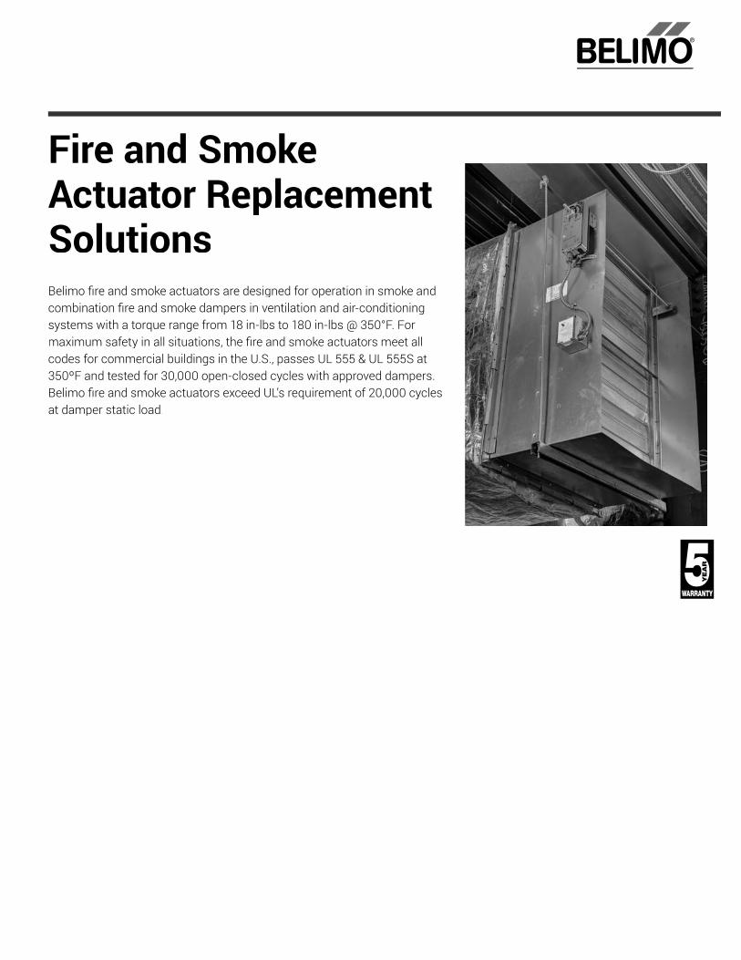
Fire and SmokeActuator ReplacementSolutionsBelimo fi re and smoke actuators are designed for operation in smoke andcombination fi re and smoke dampers in ventilation and air-conditioning systems with a torque range from 18 in-lbs to 180 in-lbs @ 350°F. Formaximum safety in all situations, the fi re and smoke actuators meet allcodes for commercial buildings in the U.S., passes UL 555 & UL 555S at 350ºF and tested for 30,000 open-closed cycles with approved dampers.Belimo fi re and smoke actuators exceed UL’s requirement of 20,000 cyclesat damper static load.

Belimo fi re and smoke actuators have an extensive torque offering and are specifi cally designed for operationwith fi re, smoke and combination fi re, and smoke dampers in ventilation and air-conditioning systems. Anintegral part of the life safety system, Belimo fi re and smoke actuators provide high performance, low power consumption, and are complaint with Life Safety Codes and Standards.
• Fire and smoke actuators meet UL555 and UL555S listing with all damper manufacturers
• UL 2043 suitable for use in air-handling spaces (plenums)
• Meets New York City OTCR and MEA requirements; California State Fire Marshall Listed
• Compact solutions for space constrained locations
• Range of torque offerings to fi t variety of applications (18, 30, 70, and 180 in-lbs)
• Saves energy and cost with lowest current draws versus the competition
• Retrofi t installation instructions available at www.belimo.us/fi resmoke
For assistance with your project, contact Belimo Technical Support at 800-543-9038 (USA) or 866-805-7089 (Canada).
PROBLEM SOLUTION
Actuator replacement for defective or obsolete motors providing maximum safety

Tech
.Doc
- 07
/18
- Sub
ject
to c
hang
e. ©
Bel
imo
Airc
ontro
ls (U
SA),
Inc.
®
800-543-9038 USA 866-805-7089 CANADA 203-791-8396 LATIN AMERICA/CARIBBEAN
24
Start with the damper, not the actuator and use the UL damper/actuator OEM listings or the recommended torques below.Different methods are employed by different manufacturers to achieve the fire spring-closed function. For example, Pottorff damper with the MA220 actuator is a single spring. To replace the discontinued MA220, the fusible link must be removed and a thermal sensor installed. Ruskin dampers use an external spring and a thermal sensor, so removal of the old MA220 and external spring and replacement with Belimo is all thatis required.Note: NFPA 80 and NFPA 105 require that dampers be repaired as soon as possible. In most jurisdictions, this is a normal repair. In some areas, a permit and 3rd party inspection may be required. In all cases, a log of periodic testing and any repairs must be maintained within the facility. Repair of any fire and smoke damper is required by codes. A permit and retest may be required if the replacement is not an ordinary repair.When any fire alarm wiring is touched, or any structural changes are made, the fire department or building official must be consulted, and a permit plus inspection is required.Visit http://www.belimo.us/firesmoke for detailed instructions for each damper manufacturer.
Fire and Smoke Actuator Replacement Solutions
Honeywell to BelimoFire and Smoke Actuator Replacement Cross Reference
Model Belimo Replacement Model
NOTES HONEYWELL BELIMO SpringReturn Control Signal Power Supply Torque (in-lbs)
Go to www.belimo.us/fi resmoke forInstallation Instructions.
FSTF may be used on dampers<1.5 sq.ft.
Use FSLF for dampers < 4 sq.ft.
Use FSNF for dampers between 4 sq.ft.and 12 sq.ft.
Use FSAF*A for dampers up to 16 sq.ft.
Multi-section dampers should beinvestigated for number of actuatorsrequired.
See data sheets for linkages. FSLF is directcouple only.
ML4105A1000 FSLF120 US Yes On/Off 120 VAC 30ML4105B1009 FSLF120 US Yes On/Off 120 VAC 30ML4105C1008 FSLF230 US Yes On/Off 230 VAC 30ML4105D1007 FSLF230 US Yes On/Off 230 VAC 30ML4115A1009 FSLF120 US Yes On/Off 120 VAC 30ML4115A1017 FSLF120 US Yes On/Off 120 VAC 30ML4115B1008 FSLF120 US Yes On/Off 120 VAC 30ML4115B1016 FSLF120 US Yes On/Off 120 VAC 30ML4115C1007 FSLF230 US Yes On/Off 230 VAC 30ML4115C1015 FSLF230 US Yes On/Off 230 VAC 30
ML4115D FSLF230 US Yes On/Off 230 VAC 30ML4115D1006 FSLF230 US Yes On/Off 230 VAC 30
ML4115H FSLF120 US Yes On/Off 120 VAC 30ML4115H1002 FSLF120 US Yes On/Off 120 VAC 30
ML4115J FSLF120 US Yes On/Off 120 VAC 30ML4202 FSLF120 US Yes On/Off 120 VAC 30
ML4202F1000 FSLF120 US Yes On/Off 120 VAC 30ML4302F1008 FSLF120 US Yes On/Off 120 VAC 30
ML4702 FSLF120 US Yes On/Off 120 VAC 30ML4802 FSLF230 US Yes On/Off 230 VAC 30
ML8105A1006 FSLF24 US Yes On/Off 24 VAC 30ML8105B1005 FSLF24 US Yes On/Off 24 VAC 30ML8115A1005 FSLF24 US Yes On/Off 24 VAC 30ML8115A1013 FSLF24 US Yes On/Off 24 VAC 30ML8115B1004 FSLF24 US Yes On/Off 24 VAC 30ML8115B1012 FSLF24 US Yes On/Off 24 VAC 30
ML8115H FSLF24 US Yes On/Off 24 VAC 30ML8115J FSLF24 US Yes On/Off 24 VAC 30ML8202 FSLF24 US Yes On/Off 24 VAC 30ML8302 FSLF24 US Yes On/Off 24 VAC 30
MS4104F1010 FSLF120 US Yes On/Off 120 VAC 30MS4104F1010 FSLF120 US Yes On/Off 120 VAC 30MS4104F1210 FSLF120-S US Yes On/Off 120 VAC 30MS4109F1010 FSNF120 US Yes On/Off 120 VAC 70MS4109F1210 FSNF120-S US Yes On/Off 120 VAC 70MS4120F1006 FSAF120A Yes On/Off 120 VAC 180MS4120F1204 FSAF120A-S Yes On/Off 120 VAC 180
MS4209F FSNF120 US Yes On/Off 120 VAC 70MS4209F1007 FSNF120 US Yes On/Off 120 VAC 70
MS4309F FSNF120 US Yes On/Off 120 VAC 70MS4309F1005 FSNF120 US Yes On/Off 120 VAC 70MS4604F1010 FSLF230 US Yes On/Off 230 VAC 30MS4604F1210 FSLF230-S US Yes On/Off 230 VAC 30

Tech
.Doc
- 07
/18
- Sub
ject
to c
hang
e. ©
Bel
imo
Airc
ontro
ls (U
SA),
Inc.
®
800-543-9038 USA 866-805-7089 CANADA 203-791-8396 LATIN AMERICA/CARIBBEAN
25
Honeywell and Ruskin to BelimoFire and Smoke Actuator Replacement Cross Reference
ECM Call Belimo for assistance. Digital photographs of damper and old motor mounting will be needed. Generally replaced by FSLF for direct coupled and FSNF iflinkages are needed. Motors were non-spring. Damper OEM external spring must be removed or disabled.
Prefco Honeywell, 5800 EMB 2X and other models can easily be replaced if damper shaft is present. Call Belimo for more information. Refer to Multiproducts on page 27.
Modulating Various models of Honeywell and other modulating can be replaced. FSAFB24-SR and FSAFB24-SR-S are available.
Pneumatic Retrofi t of pneumatic actuators with Belimo electronic ones will usually require some re-control also. Depending on age and manufacturer, the fusible links, fusibleair valve, smoke control relays, or other components may have to be replaced or upgraded.
Model Belimo Replacement Model
NOTES HONEYWELL BELIMO SpringReturn Control Signal Power Supply Torque (in-lbs)
Go to www.belimo.us/fi resmoke forInstallation Instructions.
FSTF may be used on dampers<1.5 sq.ft.
Use FSLF for dampers < 4 sq.ft.
Use FSNF for dampers between 4 sq.ft.and 12 sq.ft.
Use FSAF*A for dampers up to 16 sq.ft.
Multi-section dampers should beinvestigated for number of actuatorsrequired.
See data sheets for linkages. FSLF isdirect couple only.
MS4609F1010 FSNF230 US Yes On/Off 230 VAC 70MS4609F1210 FSNF230-S US Yes On/Off 230 VAC 70MS4620F1005 FSAF230A Yes On/Off 230 VAC 180MS4620F1203 FSAF230A-S Yes On/Off 230 VAC 180
MS4709F FSNF230 US Yes On/Off 230 VAC 70MS4709F1014 FSNF230 US Yes On/Off 230 VAC 70
MS4809F FSNF230 US Yes On/Off 230 VAC 70MS4809F1012 FSNF230 US Yes On/Off 230 VAC 70MS7520A2015 FSAFB24-SR Yes 2-10V, 4-20mA 24 VAC 180MS8104F1010 FSLF24 US Yes On/Off 24 VAC 30MS8104F1210 FSLF24 US Yes On/Off 24 VAC 30MS8109F1010 FSNF24 US Yes On/Off 24 VAC 70MS8109F1210 FSNF24-S US Yes On/Off 24 VAC 70MS8120F1002 FSAF24A Yes On/Off 24 VAC 180MS8120F1200 FSAF24A-S Yes On/Off 24 VAC 180
MS8209F FSNF24 US Yes On/Off 24 VAC 70MS8209F1003 FSNF24 US Yes On/Off 24 VAC 70
MS8309F FSNF24 US Yes On/Off 24 VAC 70MS8309F1001 FSNF24 US Yes On/Off 24 VAC 70
S20230-F FSAF230A Yes On/Off 230 VAC 180S20230-F-SW2 FSAF230A-S Yes On/Off 230 VAC 180
S2024-F FSAF24A Yes On/Off 24 VAC 180S2024-F-SW2 FSAF24A-S Yes On/Off 24 VAC 180
Auxiliary switch packages 32003532-002 Aux Switch Package
Use Belimo “-S”models N/A N/A N/A N/A
Model Belimo Replacement Model
NOTES RUSKIN BELIMO SpringReturn Control Signal Power Supply Torque (in-lbs)
The Ruskin/HW motors vary irregularlyin torque. It is best to use damper sizeto select. < 4 sq.ft. use FSLF Series. > 4 sq.ft. use FSNF Series.
H-2000A/3 Low FSLF120 US Yes On/Off 120 VAC 30H-2000A/6 Medium FSNF120 US Yes On/Off 120 VAC 70
H-2000A/8 High FSNF120 US Yes On/Off 120 VAC 70H-2000B/3 Low FSLF120 US Yes On/Off 120 VAC 30
H-2000B/6 Medium FSNF120 US Yes On/Off 120 VAC 70H-2000B/8 High FSNF120 US Yes On/Off 120 VAC 70H-2024A/3 Low FSLF24 US Yes On/Off 24 VAC 30
H-2024A/6 Medium FSNF24 US Yes On/Off 24 VAC 70H-2024A/8 High FSNF24 US Yes On/Off 24 VAC 70H-2024B/3 Low FSLF24 US Yes On/Off 24 VAC 30
H-2024B/6 Medium FSNF24 US Yes On/Off 24 VAC 70H-2024B/8 High FSNF24 US Yes On/Off 24 VAC 70H-2230A/3 Low FSLF230 US Yes On/Off 230 VAC 30
H-2230A/6 Medium FSNF230 US Yes On/Off 230 VAC 70H-2230A/8 High FSNF230 US Yes On/Off 230 VAC 70H-2230B/3 Low FSLF230 US Yes On/Off 230 VAC 30
H-2230B/6 Medium FSNF230 US Yes On/Off 230 VAC 70H-2230B/8 High FSNF230 US Yes On/Off 230 VAC 70
RH-24 FSNF24 US Yes On/Off 24 VAC 70RH-24-S FSNF24-S US Yes On/Off 24 VAC 70RH-120 FSNF120 US Yes On/Off 120 VAC 70
RH-120-S FSNF120-S US Yes On/Off 120 VAC 70RH-24-MOD FSAFB24-SR Yes 2-10 VDC 24 VAC 180

Tech
.Doc
- 07
/18
- Sub
ject
to c
hang
e. ©
Bel
imo
Airc
ontro
ls (U
SA),
Inc.
®
800-543-9038 USA 866-805-7089 CANADA 203-791-8396 LATIN AMERICA/CARIBBEAN
26
Ruskin and Multiproducts to BelimoFire and Smoke Actuator Replacement Cross Reference
Model Belimo Replacement Model
NOTES- PHILLIPS P150 RUSKIN BELIMO SpringReturn Power Supply Torque
Shaft spring must be disabled. See Ruskin with Phillips P150 atwww.belimo.us/fi resmoke
Linkages and switch model available. Some used with Negator springs;if so, call for assistance.
Use FSNF for dampers up to 12 sq.ft.
Use FSNF*A for dampers up to 16 sq.ft
Phillips P150 See notes at left Yes On/Off See notes at left
Model Belimo Replacement Model
NOTES MULTIPRODUCTS BELIMO SpringReturn
Control Signal Power Supply Torque
(in-lbs)Greenheck. Typically these were linkaged using a crank arm on the squaremotor shaft and the spring was on the round shaft. Remove all linkageparts and direct couple to damper shaft.
2430
FSLF120 US ifdirect coupled.See notes 1, 2,
3 below
No On/Off 120 VAC 30
Air Balance. Square shaft inserted into damper sleeve with specialcrankarm. If a smoke damper, replacement may be possible and requires anew shaft and other linkage parts. If a combination fi re and smoke damper,it is possible Belimo cannot be used. Most dampers must be replaced.
2553A No On/Off 120 VAC 30
Greenheck. Typically these were linkaged using a crank arm on the squaremotor shaft and the spring was on the round shaft. Remove all linkageparts and direct couple to damper shaft.
2585, 2586 No On/Off 120 VAC 30
Safe-Air / Imperial. Typically linkaged. There was an internal spring andfusible link for the fi re function. 2659 No On/Off 120 VAC 30
Air Balance. FSLF < 3 sq.ft.; FSNF 3 to 8 sq.ft. Remove old motor andexternal spring. Belimo mounts on shaft without linkages. Use old motor asa mounting platform for anti-rotation strap.
2724 No On/Off 120 VAC 30
Ruskin. FSLF120/MP Kit available from Ruskin Reps. See instructions fornegator spring removal. Some dampers will need fusible linkreplaced and thermal sensor installed.
2781 or 1161B No On/Off 24/120 VAC 30
Ruskin. 10 in-lb. "A" model = CW rotation; plain = CCW. Check voltage. FSLFreplaces both in most cases. Use FSTF when linkages necessary. 2814A-SQ No On/Off 120 VAC 30
Depends on specifi c geometry of installation. All FSTF & FSNF parts can beused. Inside clamp mounting or a shaft extension required. Inside clampmounting or a shaft extension may be required.
2920 No On/Off 120 VAC 30
Greenheck.Typically these were linkaged using a crank arm on the squareshaft and the spring was on the round shaft. Remove all linkage parts anddirect couple to damper shaft. (Model difference is CW vs. CCW.)
2985, 2986 No On/Off 120 VAC 30
Greenheck. Some were direct coupled to the damper shaft with an externalspring. Some were linkaged using a crank arm on the square motor shaftand the spring was on the round shaft. Remove all linkage parts and directcouple to damper shaft. (Model difference is CW vs. CCW.)p p ( )
3158, 3159 No On/Off 120 VAC 30
Prefco. Outside the duct, 1 is top mount, power open. 10 is bottom mount,power closed. Review of linkages, springs, fusible link or McCabeLink©
must be performed. Power closed typically used in smoke control systemsso switches may be needed.
5800EMB1,10 No On/Off 120 VAC 30
Prefco. Review of linkages, springs, fusible link or McCabeLink© must beperformed.
5800EMB2XPC,PO, 5800EMB8, 9 No On/Off 120 VAC 30
Prefco. Inside the duct, 5 is top mount, power open. 7 is bottom mount,power closed. Review of linkages, springs, fusible link or McCabeLink©
must be performed. Power closed typically used in smoke control systemsso switches may be needed.
5800EMB5, 7 No On/Off 120 VAC 30
Nailor. Remove linkage parts and mount to damper shaft. FSLF for dampers< 4 sq.ft. and FSNF for dameprs > 4 sq.ft.
6247 No On/Off 120 VAC 30
MZRHM No On/Off 120 VAC 30
Greenheck and others. Typically these were linkaged using a crank arm onthe square motor shaft and the spring was on the round shaft. Remove alllinkage parts and direct couple to damper shaft.
TB2001, TSB2000 No On/Off 120 VAC 30
1. In general, use FSLF If a shaft is available for direct coupling and damper is < 4 sq.ft. Use FSNF and ZG-AF US or other linkage if linkage is necessary and damper is > 4 sq.ft.. UseFSTF if damper < 1.5 sq.ft. Linkage or direct couple.
2. Note that in almost all cases the old linkage, spring, and motor can be removed and mounting Belimo to the shaft is the accepted procedure to make the assembly conform to modernfi re & smoke dampers.
3. Investigation of each application is necessary. Check voltage and breakers. In all cases disconnect external motor spring without compromising fusible link and internal spring abilityto close the blades. These are quite old and changes may have been made by others over the years. Check fusible links or McCabe© Link. Verify damper functions after replacement bytesting damper open and spring closed.

Tech
.Doc
- 07
/18
- Sub
ject
to c
hang
e. ©
Bel
imo
Airc
ontro
ls (U
SA),
Inc.
®
800-543-9038 USA 866-805-7089 CANADA 203-791-8396 LATIN AMERICA/CARIBBEAN
27
Siemens and Siebe to BelimoFire and Smoke Actuator Replacement Cross Reference
Model Belimo Replacement Model
NOTES SIEBE BELIMO SpringReturn
Control Signal Power Supply Damper Size
Where linkages are needed, use FSNF. Timing is a functionof damper spring.
When replacing the actuator, remove the old spring fromthe damper.
If the damper has one spring, add a new electric thermalsensor. (Belimo BAE 165)
A -500 part number indicates an auxiliary switch. Replacewith a Belimo “-S” version.
MA220 FSLF120 US Yes On/Off 120 VAC
For <4 sq. ft. dampersuse FSLF Series
For >4 sq. ft.use FSNF Series
MA221 FSLF230 US Yes On/Off 240 VAC MA223 FSLF24 US Yes On/Off 24 VAC MA230 FSNF120 US Yes On/Off 120 VAC MA231 FSNF230 US Yes On/Off 240 VACMA233 FSNF24 US Yes On/Off 24 VAC MA240 Call Belimo Yes On/Off 120 VAC MA250 FSNF120 US Yes On/Off 120 VAC MA251 FSNF230 US Yes On/Off 230 VAC MA253 FSNF24 US Yes On/Off 24 VAC MA-318 FSNF24 US Yes On/Off 24 VAC
MA-318-500 FSNF24 -S US Yes On/Off 24 VAC MA-418 FSNF120 US Yes On/Off 120 VAC
MA-418-500 FSNF120-S US Yes On/Off 120 VAC <4 sq.ft use FSLF>4.sq.ft. use FSNF
Model Belimo Replacement Model
NOTES SIEMENS* BELIMO SpringReturn
Control Signal Power Supply Torque
(in-lbs)
GGD121.1U FSAF24A Yes On/Off 24 VAC 180
GGD121.3U FSAF24A Yes On/Off 24 VAC 180GGD221.1U FSAF120A Yes On/Off 120 VAC 180GGD221.3U FSAF120A Yes On/Off 120 VAC 180GGD321.1U FSAF230A Yes On/Off 230 VAC 180GND12x.1x FSLF24 US Yes On/Off 24 VAC 30GND22x.1x FSLF120 US Yes On/Off 120 VAC 30GND32x.1x FSLF230 US Yes On/Off 230 VAC 30
This is a 165ºF thermal sensor. Call for information. ASK79.165 BAE165 US
* While drive torque of Siemens is 142 in-lbs, spring torque is 110 in-lbs. Belimo has passed UL555S at 12 sq.ft.
Qualifi cations for Belimo in Replacing Defective Competitive Actuators
Belimo is UL 555S Listed with all damper manufacturers. In addition, all Belimo Fire and Smoke actuators have passed UL 2043 in accordance to requirements of the NEC 300.22 (c) and theIMC 602 for use in plenums. The basic UL listings are either UL 873 or UL 60730 which has supplanted UL 873. UL 873 has been grandfathered.
Infrequently, the fi re alarm standard, UL 864, and list of qualifi ed smoke control systems, UUKL, are specifi ed. UL has clearly stated that it will not investigate dampers or actuators inaccordance with these standards and that UL 555 (fi re) and UL 555S (smoke) are the only correct standards.
UL has stated that while fi eld replacement of actuators is allowed, the local AHJ is in charge; UL does not regulate fi eld repairs. NFPA 80 (fi re) & NFPA 105 (smoke) are the standardsreferenced by the IBC which regulate replacement and repair.
Visit www.belimo.us/firesmoke for detailed instructions for each damper manufacturer.

®
Economizer Retrofi t SolutionsAirside economizers provide the correct ratio of outside air and return airto deliver proper indoor air quality (IAQ) to meet codes; many economizersystems are not accomplishing these goals. Belimo offers a drop-ineconomizer replacement solution. The Belimo ZIP Packs provide apackaged solution for selection and simple retrofi tting of non-functioningenergy wasting economizers. The ZIP Economizer has built-in all the relevant climate zone and energy code data, by entering in your ZIP code you automatically maximize energy savings for your location. Thepacks are in one box with a single part number. ZIP Packs include the ZIPEconomizer, air sensors, energy module for Demand Control Ventilation(DCV) integration, spring return actuator, and retrofi t hardware backed with a 5-year warranty. The ZIP Packs can get systems back on track andmeets compliance criteria with the latest energy codes, standards, andIAQ requirements.

8 - S
ubje
ct t
®
800-543-9038 USA 866-805-7089 CANADA 203-791-8396 LATIN AMERICA/CARIBBEAN
29
TFB24-SR up to 7.5 Tons
LF24-SR7.5-12 Tons
NFB24-SR12-15 Tons
AFB24-SR15-30 Tons
ECON-ZIP BASE ECON-ZIP-10K (Supply Air Sensor)
AND
OR
ECON-ZIP-TH
ECON-ZIP-10K
DRY BULB ENTHALPY
Note: Differential control requires one additional sensor for return air.
• Demand Control Ventilation (DCV)* - ECON-ZIP-EM + CO2 sensor of your choice (0-2000PPM, 0-10VDC).
• Preoccupancy Purge* - ECON-ZIP-EMRequires thermostat with purge setting and contacts.
• Remote Damper Override - ECON-ZIP-EM + SGA24
• Exhaust Fan - ECON-ZIP-EM
• Remote Alarm Notifi cation* - ECON-ZIP-COM• Required for BACnet MS/TP communication
* May be required by local codes
ZIP EconomizerSelection Guide

Tech
.Doc
- 07
/18
- Sub
ject
to c
hang
e. ©
Bel
imo
Airc
ontro
ls (U
SA),
Inc.
®
800-543-9038 USA 866-805-7089 CANADA 203-791-8396 LATIN AMERICA/CARIBBEAN
30
Dimensions (Inches [mm]) Dimensions (Inches [mm])
Honeywell to BelimoEconomizer Replacement Cross Reference
W7210 WIRE TERMINATION ZIP ECONOMIZER WIRE TERMINATION
1 Y12 CC13 Y24 CC25 NA
TR RTR1 C
ST6008 OCC Timer GP-P1 AUX2
Located on ECON-ZIP-EMT-T1 Supply Air – New Sensor
So-So+ Outside Air- New SensorSr-Sr+ New Sensors
+ ACT3- ACT1
24 VAC HOT ACT2ACT5
Honeywell W7210 Belimo ZIP EconomizerBelimo Z

Tech
.Doc
- 07
/18
- Sub
ject
to c
hang
e. ©
Bel
imo
Airc
ontro
ls (U
SA),
Inc.
®
800-543-9038 USA 866-805-7089 CANADA 203-791-8396 LATIN AMERICA/CARIBBEAN
31
Dimensions (Inches [mm]) Dimensions (Inches [mm])
W7212 WIRE TERMINATION ZIP ECONOMIZER WIRE TERMINATION
1 Y12 CC13 Y24 CC25 NA
TR RTR1 CN G
P-P1 AUX2Located on ECON-ZIP-EM
T-T1 Supply Air – New SensorSo-So+ Outside Air- New Sensor
New SensorsAQ-AQ1 C02 +/-EF-EF1 EF*
*EF, EFH1 provide 24 VAC out. Interposing relay or contactor may be needed for exhaust fan control. Verify with RTU wiring.
Honeywell W7212 Belimo ZIP EconomizerBelimo Z
Honeywell to BelimoEconomizer Replacement Cross Reference

Tech
.Doc
- 07
/18
- Sub
ject
to c
hang
e. ©
Bel
imo
Airc
ontro
ls (U
SA),
Inc.
®
800-543-9038 USA 866-805-7089 CANADA 203-791-8396 LATIN AMERICA/CARIBBEAN
32
Dimensions (Inches [mm]) Dimensions (Inches [mm])
W7459 WIRE TERMINATION ZIP ECONOMIZER WIRE TERMINATION
1 Y12 CC13 Y24 CC25 NA
TR RTR1 CN G
P-P1 AUX2Located on ECON-ZIP-EM
T-T1 Supply Air - New SensorSo-So+ Outside Air - New SensorSr-Sr+ New Sensors
Honeywell W7459 Belimo ZIP EconomizerBelimo Z
Honeywell to BelimoEconomizer Replacement Cross Reference

Tech
.Doc
- 07
/18
- Sub
ject
to c
hang
e. ©
Bel
imo
Airc
ontro
ls (U
SA),
Inc.
®
800-543-9038 USA 866-805-7089 CANADA 203-791-8396 LATIN AMERICA/CARIBBEAN
33
BELIMO RETROFIT KITS
Part Number Description Components (# included in kit)
ECON-ZIP-ACT Actuator Shaft Adapter allows easy retrofi t from Honeywell® black box motors(M7XXX) to Belimo spring return actuator.
Shaft, M4x8 Screws (4), Locking Nuts (4)
ECON-ZIP-LF1 Bracket with hole patterns to mount the LF Series actuator, horizontal or verticalposition to meet space requirements.
ECON-ZIP-ACT, ZG-112, Screws
ECON-ZIP-TF1 Bracket with hole patterns to mount the TF Series actuator, horizontal or verticalposition to meet space requirements.
ECON-ZIP-ACT, ZG-113, Spacers and Screws
HONEYWELL Y PACK BELIMO ZIP PACKPart Number Description Part Number DescriptionY7220A7215 Dry Bulb with black motor ECON-ZIP-SDTF Single Dry Bulb with DCV Capability, 22 in-lbs
YL7220A7503 Dry Bulb with non-communicating DCA ECON-ZIP-SDTF Single Dry Bulb with DCV Capability, 22 in-lbs
YL7220AJ3103 Dry Bulb with communicating 27 in-lbs DCA ECON-ZIP-SDTF* Single Dry Bulb with DCV Capability, 22 in-lbs
YL7220AJ3105 Dry Bulb with communicating 44 in-lbs DCA ECON-ZIP-SDLF* Single Dry Bulb with DCV Capability, 35 in-lbs
Y7220S7215 Enthalpy with black motor ECON-ZIP-SETF Single Enthalpy with DCV Capability, 22 in-lbs
YL7220S7503 Enthalpy with non-communicating DCA ECON-ZIP-SETF Single Enthalpy with DCV Capability, 22 in-lbs
YL7220SJ3103 Enthalpy with communicating 27 in-lbs DCA ECON-ZIP-SETF* Single Enthalpy with DCV Capability, 22 in-lbs
YL7220SJ3105 Enthalpy with communicating 44 in-lbs DCA ECON-ZIP-SELF* Single Enthalpy with DCV Capability, 35 in-lbs
*May be a lower torque cross, but acceptable for damper.
Economizer Retrofi t SolutionsRetrofi t Kits and ZIP Packs
BELIMO ZIP PACK
Part Number Description Components (# included in kit)
Single Dry Bulb with DCV Capability and TF Spring Return Actuator (22 in-lbs)
ECON-ZIP-Base, ECON-ZIP-EM, ECON-ZIP-10K (2), TFB24-SR, ECON-ZIP-TF1
ECON-ZIP-DDTF Differential Dry Bulb with DCV Capability and TFSpring Return Actuator (22 in-lbs)
ECON-ZIP-BASE, ECON-ZIP-EM, ECON-ZIP-10K (3), TFB24-SR, ECON-ZIP-TF1
ECON-ZIP-SETF Single Enthalpy with DCV Capability and TF Spring Return Actuator (22 in-lbs)
ECON-ZIP-BASE, ECON-ZIP-EM, ECON-ZIP-10K, ECON-ZIP-TH, TFB24-SR, ECON-ZIP-TF1
ECON-ZIP-SDLF Single Dry Bulb with DCV Capability and LF Spring Return Actuator (35 in-lbs)
ECON-ZIP-BASE, ECON-ZIP-EM, ECON-ZIP-10K (2), LF24-SR US, ECON-ZIP-LF1
ECON-ZIP-DDLF Differential Dry Bulb with DCV Capability and LFSpring Return Actuator (35 in-lbs)
ECON-ZIP-BASE, ECON-ZIP-EM, ECON-ZIP-10K (3), LF24-SR US, ECON-ZIP-LF1
ECON-ZIP-SELF Single Enthalpy with DCV Capability and LF Spring Return Actuator (35 in-lbs)
ECON-ZIP-BASE, ECON-ZIP-EM, ECON-ZIP-TH, ECON-ZIP-10K, LF24-SR US, ECON-ZIP-LF1

Tech
.Doc
- 07
/18
- Sub
ject
to c
hang
e. ©
Bel
imo
Airc
ontro
ls (U
SA),
Inc.
®
800-543-9038 USA 866-805-7089 CANADA 203-791-8396 LATIN AMERICA/CARIBBEAN
34
R
C
G
OCC
W1
O/B
Y1
Y2
ACT1 ACT2 ACT3
ACT5R
C
R
C
G W1
Y1
Y2
CC1
CC2
OAT+
OAT-
OAH+
OAH-
SAT+
SAT-
RAT+
RAT-
RAH+
RAH-
-SR
1 - Common
2 + Hot
3 Y Input, 2 to 10V
5 U Output, 2 to 10V
ACT 1
ACT 2
ACT 3
ACT 5
R
C
Y1
Y2
ECON-ZIP-10KSupply Air Temp
SAT +
SAT -
OAT +
OAT -
CC1
CC2
OCC
W1
RTU Stage 1 Mechanical Cooling
Circuitry
RTU Stage 2 Mechanical Cooling
Circuitry
ECON-ZIP-10KOutside Air Temp
THERMOSTAT RTU TERMINAL
ECON-ZIP-BASE
1 3 6 46
52
51
53
R
C
G
OCC
W1
O/B
Y1
Y2
ACT1 ACT2 ACT3
ACT5R
C
R
C
G W1
Y1
Y2
CC1
CC2
OAT+
OAT-
OAH+
OAH-
SAT+
SAT-
RAT+
RAT-
RAH+
RAH-
-SR
1 - Common
2 + Hot
3 Y Input, 2 to 10V
5 U Output, 2 to 10V
ACT 1
ACT 2
ACT 3
ACT 5
R
C
Y1
Y2
ECON-ZIP-10KSupply Air Temp
SAT +
SAT -
OAT +
OAT -
THERMOSTAT RTU TERMINAL
CC1
CC2
OCC
W1
RTU Stage 1 Mechanical Cooling
Circuitry
RTU Stage 2 Mechanical Cooling
Circuitry
ECON-ZIP-10KOutside Air Temp
ECON-ZIP-10KReturn Air Temp
RAT
ECON-ZIP-BASE
1 3 6 46
52
51
53
Single Dry Bulb
Differential Dry Bulb
ZIP EconomizerWiring Diagrams

Tech
.Doc
- 07
/18
- Sub
ject
to c
hang
e. ©
Bel
imo
Airc
ontro
ls (U
SA),
Inc.
®
800-543-9038 USA 866-805-7089 CANADA 203-791-8396 LATIN AMERICA/CARIBBEAN
35
ZIP EconomizerWiring Diagrams
Single Enthalpy
R
C
G
OCC
W1
O/B
Y1
Y2
ACT1 ACT2 ACT3
ACT5R
C
R
C
G W1
Y1
Y2
CC1
CC2
OAT+
OAT-
OAH+
OAH-
SAT+
SAT-
RAT+
RAT-
RAH+
RAH-
-SR
1 - Common
2 + Hot
3 Y Input, 2 to 10V
5 U Output, 2 to 10V
ACT 1
ACT 2
ACT 3
ACT 5
R
C
Y1
Y2
ECON-ZIP-10KSupply Air Temp
SAT +
SAT -
OAT +
OAT -
CC1
CC2
OCC
W1
RTU Stage 1 Mechanical Cooling
Circuitry
RTU Stage 2 Mechanical Cooling
Circuitry
ECON-ZIP-THOutside Air Enthalpy
ECON-ZIP-THReturn Air Enthalpy
RAT+ T (+)
T (-)
24 V (R)
RH (+)
RH (-)
RAT-
RAH+
RAH-
R
T (+)
T (-)
24 V (R)
RH (+)
RH (-)
OAH +
OAH -
R
ECON-ZIP-BASE
THERMOSTAT RTU TERMINAL
1 3 6 46
50
52
51
53
50
R
C
G
OCC
W1
O/B
Y1
Y2
ACT1 ACT2 ACT3
ACT5R
C
R
C
G W1
Y1
Y2
CC1
CC2
OAT+
OAT-
OAH+
OAH-
SAT+
SAT-
RAT+
RAT-
RAH+
RAH-
-SR
1 - Common
2 + Hot
3 Y Input, 2 to 10V
5 U Output, 2 to 10V
ACT 1
ACT 2
ACT 3
ACT 5
R
C
Y1
Y2
ECON-ZIP-10KSupply Air Temp
SAT +
SAT -
CC1
CC2
OCC
W1
RTU Stage 1 Mechanical Cooling
Circuitry
RTU Stage 2 Mechanical Cooling
Circuitry
ECON-ZIP-THOutside Air Enthalpy
T (+)
T (-)
24 V (R)
RH (+)
RH (-)
OAT +
OAT -
OAH +
OAH -
R
ECON-ZIP-BASE
THERMOSTAT RTU TERMINAL
1 3 6 46
50
52
51
53
CO2 -
CO2 +
Purge ContactThermostat
24 VAC AUX1+
AUX1 -
AUX2 +
AUX2 -
Indoor Fan Low Speed Relay / VFD Enable
Exhaust Fan Circuit
CO2 Sensor
1 - Common
2 +
3 + Y Input, 0 to 10 VDC
4 - 0 to 10 VDC
SGA24 SGF24
Common - 1
+ 2
Y Input, 2 to 10 VDC + 3
2 to 10 VDC + 4
AUX1 + CO2 +
AUX1 - CO2 -
AUX2 +
AUX2 -
IF
EF
ECON-ZIP-EM
52
51
53
51
55
54
Differential Enthalpy
ECON-ZIP-EM

®
Zone ValveReplacement SolutionsBelimo zone valve retrofi t solutions are designed to replace failed ornon-functioning valves used in a variety of applications. Belimo offers a full product range of zone valves. The self-cleaning ball design helpsminimize energy losses caused by clogging and eliminates overflow frompump pressure seat lift. Also offering high close-off capabilities allowfor true equal percentage flow characteristics. Zone valves are suited forcommercial applications where higher close-off is required such as fi ntube casing, fan coils, radiant panels and duct coils.

Tech
.Doc
- 07
/18
- Sub
ject
to c
hang
e. ©
Bel
imo
Airc
ontro
ls (U
SA),
Inc.
®
800-543-9038 USA 866-805-7089 CANADA 203-791-8396 LATIN AMERICA/CARIBBEAN
37
Zone Valve Replacement SolutionsBelimo to Belimo
ZONE VALVES*
DISCONTINUED MODEL Size Cv Rating Close-off (psi) REPLACEMENT MODEL Size Cv Rating Close-off
(psi)
Z214T+SEF24 NO ½” 2.3 43.5 ZONE215N-10+ZONE24NOZONE215N-25+ZONE24NO ½” 1
2.57550
Z215T+SEF24 NO ½” 3.7 30 ZONE215N-35+ZONE24NO ½” 3.5 30
Z220T+SEF24 NO ¾” 3.7 30 ZONE220N-35+ZONE24NOZONE220N-50+ZONE24NO ¾” 3.5
5 30
Z214T+SEF120 NO ½” 2.3 43.5 ZONE215N-10+ZONE120NOZONE215N-25+ZONE120NO ½” 1
2.5 75
Z215T+SEF120 NO ½” 3.7 30 ZONE215N-35+ZONE120NO ½” 3.5 30
Z220T+SEF120 NO ¾” 3.7 30 ZONE220N-35+ZONE120NOZONE220N-50+ZONE120NO ¾” 3.5
53025
Z214T+SEF24 NC ½” 2.3 43.5 ZONE215N-10+ZONE24NCZONE215N-25+ZONE24NC ½” 1
2.57550
Z215T+SEF24 NC ½” 3.7 30 ZONE215N-35+ZONE24NC ½” 3.5 30
Z220T+SEF24 NC ¾” 3.7 30 ZONE220N-35+ZONE24NCZONE220N-50+ZONE24NC ¾” 3.5
53025
Z214T+SEF120 NC ½” 2.3 43.5 ZONE215N-10+ZONE120NCZONE215N-25+ZONE120NC ½” 1
2.57550
Z215T+SEF120 NC ½” 3.7 30 ZONE215N-35+ZONE120NC ½” 3.5 30
Z220T+SEF120 NC ¾” 3.7 30 ZONE220N-35+ZONE120NCZONE220N-50+ZONE120NC ¾” 3.5
53025
Z315T+SEF24 NC ½” 5 30ZONE315N-10+ZONE24NCZONE315N-25+ZONE24NCZONE315N-35+ZONE24NC
½”1
2.53.5
755030
Z315T+SEF120 NC ½” 5 30ZONE315N-10+ZONE120NCZONE315N-25+ZONE120NCZONE315N-35+ZONE120NC
½”1
2.53.5
755030
Z320T+SEF24 NC ¾” 5.4 30 ZONE320N-35+ZONE24NCZONE320N-50+ZONE24NC ¾” 3.5
53025
Z320T+SEF120 NC ¾” 5.4 30 ZONE320N-35+ZONE120NCZONE320N-50+ZONE120NC ¾” 3.5
53025
Z814T+SEF24 NO ½” 2.3 43.5 ZONE215S-10+ZONE24NCZONE215S-25+ZONE24NC ½” 1
2.57550
Z815T+SEF24 NO ½” 3.7 30 ZONE215S-35+ZONE24NO ½” 3.5 30
Z820T+SEF24 NO ¾” 3.7 30 ZONE220S-35+ZONE24NOZONE220S-50+ZONE24NO ¾” 3.5
53025
Z814T+SEF120 NO ½” 2.3 43.5 ZONE215S-10+ZONE120NOZONE215S-25+ZONE120NO ½” 1
2.57550
Z815T+SEF120 NO ½” 3.7 30 ZONE215S-35+ZONE120NO ½” 3.5 30
Z820T+SEF120 NO ¾” 3.7 30 ZONE220S-35+ZONE120NOZONE220S-50+ZONE120NO ¾” 3.5
53025
Z814T+SEF24 NC ½” 2.3 43.5 ZONE215S-10+ZONE24NCZONE215S-25+ZONE24NC ½” 1
2.57550
Z815T+SEF24 NC ½” 3.7 30 ZONE215S-35+ZONE24NC ½” 3.5 30
Z820T+SEF24 NC ¾” 3.7 30 ZONE220S-35+ZONE24NCZONE220S-50+ZONE24NC ¾” 3.5
53025
Z814T+SEF120 NC ½” 2.3 43.5 ZONE215S-10+ZONE120NCZONE215S-25+ZONE120NC ½” 1
2.57550
Z815T+SEF120 NC ½” 3.7 30 ZONE215S-35+ZONE120NC ½” 3.5 30
Z820T+SEF120 NC ¾” 3.7 30 ZONE220S-35+ZONE120NCZONE220S-50+ZONE120NC ¾” 3.5
53025
Z915T+SEF24 NC ½” 5 30ZONE315S-10+ZONE24NCZONE315S-25+ZONE24NCZONE315S-35+ZONE24NC
½”1
2.53.5
755030
Z915T+SEF120 NC ½” 5 30ZONE315S-10+ZONE120NCZONE315S-25+ZONE120NCZONE315S-35+ZONE120NC
½”1
2.53.5
755030
Z920T+SEF24 NC ¾” 5.4 30 ZONE320S-35+ZONE24NCZONE320S-50+ZONE24NC ¾” 3.5
53025
Z920T+SEF120 NC ¾” 5.4 30 ZONE320S-35+ZONE120NCZONE320S-50+ZONE120NC ¾” 3.5
53025
*The recommended replacements must be considered depending on the Cv rating and Close-off requirement involving your application.

®
Globe Valve Retrofi tSolutionsGlobe valve retrofi t solutions are designed to easily attach to the valvebonnet and stem of other manufacturers globe valves utilizing Belimoactuators. Actuator and linkages restore service without having to removethe valve saving on down time and costs.

Tech
.Doc
- 07
/18
- Sub
ject
to c
hang
e. ©
Bel
imo
Airc
ontro
ls (U
SA),
Inc.
®
800-543-9038 USA 866-805-7089 CANADA 203-791-8396 LATIN AMERICA/CARIBBEAN
39
BASIC PRODUCTS
ModelControl Input Feedback Power
Supply
Running Time(s)VA Rating Auxiliary
Switch
AFB24 On/Off - 24 VAC/DC <75 seconds 20 secs 7.5 -
AFB24-S On/Off - 24 VAC/DC <75 seconds 20 secs 7.5 Built-In
AFBUP On/Off - 24-240 VAC <75 seconds 20 secs 8.5 -
AFBUP-S On/Off - 24-240 VAC <75 seconds 20 secs 8.5 Built-In
AFB24-SR 2-10 VDC (4-20mA) 2-10 VDC 24 VAC/DC 95 seconds <20 secs 8.5 -
AFB24AFB24AFB24 SR S-SR-SSR S 2 102-102 10 VDC (VDC (VDC (4 20m4-20m4 20mA)A)A) 2 102-102 10 VDCVDCVDC 24 VA24 VA24 VA24 V C/DCC/DCC/DC 9595 se95 se dcondsconds 20<20 s<20 secsecs 8 58 58.5 B iltBuiltBuilt In-InIn
AFB24AFB24-PC-PC 0-100-10 V PhaV Phasecutsecut 2-102 10 VDCVDC 24 VA24 VAC/DCC/DC 150 s150 secondecondss <20 s<20 secsecs 10 -
AFB24AFB24-MFTMFT 2-102 10 VDC (VDC (4-20m4 20mA)A) 2-102 10 VDCVDC 24 VA24 VAC/DCC/DC 150 s150 secondecondss <20 secs 1010 -24AFB24 MFT-MFT-SS 2 102-10 VDC (VDC ((4 204-20mA)A)) 2 102-10 VDCVDC 24 VA24 VAC/DCC/DC 150 s150 secondecondss <20 s<20 secsecs 1010 BuiltBuilt In-In
AFB24AFB24 MFT9-MFT955 0 to0 to 135135 2-102-10 VDCVDC 24 VA24 VAC/DCC/DC 150 s150 secondecondss <20 s<20 secsecs 1010 -
Siemens\Landis\Powers658 Series Valves Linkage/Actuator Selection Guide
Valve Body Model ValveConfi guration Size Fail-safe Close-Off psi
BelimoActuator Series Belimo
Linkage
658 Series 2-way 1¼” No 78 LM UGLK1350
156 NM UGLK1350
236 SV UGVL
250 AM UGLK1214
Yes 61 LF UGLK1350
156156 NFNF UGLKUGLK12141214
236236 SVKSVK UGVLUGVL
2 0250250 AFAFAF UGLKUGLKUGLK12112141214
How to Select a Globe Valve Retrofit SolutionFollow the four steps listed below when ordering a globe valve retrofit kit for either UGLK or GVL series linkages.
Example: Siemens 658 series, 1¼” valve, needing 200 psi close-off pressure and Fail-Safe actuation.
1 Based on the Valve Number, Configuration and Size, select the proper linkage or linkages for your valve.
Some valves will have more than one linkage offered, use the actuator or combination pages to determine the appropriate linkage for a given application. In this example there is a UGLK1214, UGLK1350 and a UGVL series linkage available.
2 Use the selection guide and your close-off pressure requirement to select the correct actuator series for your application. Looking at the UGLK1350 there are no fail-safe actuators that will achieve 200 psi close-off for 1¼" valve. Looking at the UGLK1214 or UGVL, the AF or SVK Series actuator will provide over 200 psi close-off for the 1¼” valve.
3 Use the actuator listings to make your final actuator selection.
4 HOW TO ORDER:
1
Select linkage solution based on the ValveNumber, Confi guration, and Size; select theproper Linkage Solutionfor your valve.
Example: Siemens Series #658, 2-Way, 1¼” valve to be retrofi tted.
Choose correct kit UGLK1214or UGVL.
2
Verify close-off is suitablefor application.Looking at the UGLK orUGVL, the AF and SVK Seriesactuator will provide 200 psi close-off for the 1¼” valve.
3
Select actuator based on needed control type.Decide between AFB24, AFB24-MFT
or SVKX24-3, SVKB24-MFT.Consult actuator overview section for full details.
4
Complete Ordering ExampleOption One:
Item 1: UGLK1214Item 2: AFB24-MFT
4
Complete Ordering ExampleOption Two:
Item 1: UGVL + SVKB24-MFT
Option One:Item 1 1pc UGLK1214 Item 2 1pc AFB24-MFT
Option Two:Item 1 1pc UGVL + SVKB24-MFT
ACTUATOR PART # LVKX24-3 LVKB24-SR LVKB24-MFT SVKX24-3 SVKB24-SR SVKB24-MFT
Control type On/Off,Floating Point Modulating Modulating/MFT On/Off,
Floating Point Modulating Modulating/MFT
Input signal / Feedback - 2-10 VDC Variable - 2-10 VDC Variable
Running time Motor 150 seconds 150 seconds Variable 150 seconds 150 seconds Variable
Fail-Safe 35 seconds 35 seconds 35 seconds 35 seconds 35 seconds 35 seconds
Actuator travel 24mm 24mm 24mm 24mm 24mm 24mm
Actuator noise level <45 dB(A) <45 dB(A) <45 dB(A) <45 dB(A) <45 dB(A) <45 dB(A)
GVL LINKAGES
UGVL Universal Adjustable for1/2” to 2” $ $ $ $ $ $
SGVLSGVLSGVLSGVL S h iS h iSchniSchni ddedereder VB7VB7VB7VB7.. VBVBVB., VB, 9999... $$$$$ $$$$$ $$$$$ $$$$$ $$$$$ $$$$$

Tech
.Doc
- 07
/18
- Sub
ject
to c
hang
e. ©
Bel
imo
Airc
ontro
ls (U
SA),
Inc.
®
800-543-9038 USA 866-805-7089 CANADA 203-791-8396 LATIN AMERICA/CARIBBEAN
40
Globe Valve Retrofi t ActuatorsActuator Suggestion Guide
MULTI-FUNCTION TECHNOLOGYPROGRAMMING CODE Control Input Running Time Built-in Feedback
ROTA
RY A
CTUA
TOR
P-10001 A01 2-10 VDC 150 seconds 2-10 VDCP-10002 A02 0.5-10 VDC 150 seconds 0.5-10 VDCP-10028 A28 0.5-10 VDC 150 seconds 0.5-10 VDCP-10063 A63 0.5-4.5 VDC 150 seconds 0.5-4.5 VDCP-10064 A64 5.5-10 VDC 150 seconds 5.5-10 VDCP-20002 W02 0.02-5.00 seconds PWM 150 seconds 2-10 VDCP-20003 W03 0.10-25.5 seconds PWM 150 seconds 2-10 VDCP-30001 F01 Floating Point 150 seconds 2-10 VDCP-40002 J02 On/Off 150 seconds 2-10 VDC
LINE
ARAC
TUAT
OR
G43 2-10 VDC 90 seconds 2-10 VDC
G53 0.5-10 VDC 90 seconds 0.5-10 VDC
W3M 0.02-5.00 seconds PWM 90 seconds 2-10 VDC
G13 Floating Point 90 seconds 2-10 VDC
G03 On/Off 90 seconds 2-10 VDC
LINEAR ACTUATORS**
SERIES MODEL Fail-Safe Control Input Feedback Position
PowerSupply
StandardRunning Time*
Force
LV Series
LVB24-3 No Floating Pt., On/Off N/A 24 VAC/DC 90 seconds 112 lbfLVX120-3 No Floating Pt., On/Off N/A 120-240 VAC 90 seconds 112 lbfLVBSR-SR No 2-10 VDC 2-10 VDC 24 VAC/DC 90 seconds 112 lbfLVX24-MFT No Variable with MFT Variable VDC 24 VAC/DC 90 seconds 112 lbf
LVK Series
LVKX24-3 Yes Floating Pt., On/Off N/A 24 VAC 90 seconds 112 lbfLVKX120-3 Yes Floating Pt., On/Off N/A 120-240 VAC 90 seconds 112 lbfLVKBSR-SR Yes 2-10 VDC 2-10 VDC 24 VAC/DC 90 seconds 112 lbfLVKX24-MFT Yes Variable with MFT Variable VDC 24 VAC/DC 90 seconds 112 lbf
SV Series
SVX24-3 No Floating Pt., On/Off N/A 24 VAC/DC 90 seconds 337 lbfSVX120-3 No Floating Pt., On/Off N/A 120-240 VAC 90 seconds 337 lbfSVBSR-SR No 2-10 VDC 2-10 VDC 24 VAC/DC 90 seconds 337 lbfSVX24-MFT No Variable with MFT Variable VDC 24 VAC/DC 90 seconds 337 lbf
SVK Series
SVKX24-3 Yes Floating Pt., On/Off N/A 24 VAC 90 seconds 337 lbfSVKX120-3 Yes Floating Pt., On/Off N/A 120-240 VAC 90 seconds 337 lbfSVKBSR-SR Yes 2-10 VDC 2-10 VDC 24 VAC/DC 90 seconds 337 lbfSVKX24-MFT Yes Variable with MFT Variable VDC 24 VAC/DC 90 seconds 337 lbf
AVK SeriesAVKB24-3 Yes Floating Pt., On/Off N/A 24 VAC 90 seconds 450 lbfAVKB120-3 Yes Floating Pt., On/Off N/A 120-240 VAC 90 seconds 450 lbfAVKB24-MFT Yes Variable with MFT Variable VDC 24 VAC/DC 90 seconds 450 lbf
EV SeriesEVB24-3 No Floating Pt., On/Off N/A 24 VAC/DC 90 seconds 562 lbfEVB120-3 No Floating Pt., On/Off N/A 120-240 VAC 90 seconds 562 lbfEVB24-MFT No Variable with MFT Variable VDC 24 VAC/DC 90 seconds 562 lbf
RV SeriesRVB24-3 No Floating Pt., On/Off N/A 24 VAC/DC 90 seconds 1011 lbfRVB24-MFT No Variable with MFT Variable VDC 24 VAC/DC 90 seconds 1011 lbf
* Other speeds available on request. ** Sold as an assembly with linkage.
ROTARY ACTUATORS SUGGESTION
SERIES TORQUE MODEL Spring Return
ElectronicFail-Safe
Tandem Mounting Avail. Control Input Feedback
PositionPowerSupply
StandardRunning Time
LF Series* 35 in-lbs [4 Nm]
LF24 US • On/Off - 24 VAC/DC
Cons
ult S
peci
fi cat
ions
LF24-MFT US • Variable with MFT** variable VDC 24 VAC/DC
NF Series* 90 in-lbs [10 Nm]
NFBUP-X1 • On/Off - 24-240 VACNFX24-MFT-X1 • (24 VAC/DC) Variable with MFT** variable VDC 24 VAC/DC
AF Series* 180 in-lbs [20 Nm]
AFBUP-X1 • • On/Off - 24-240 VACAFX24-MFT-X1 • • Variable with MFT** variable VDC 24 VAC/DC
LM Series* 45 in-lbs [5 Nm]
LMB24-3-X1 Floating Point, On/Off - 24 VAC/DCLMX24-MFT-X1 Variable with MFT** variable VDC 24 VAC/DC
NM Series* 90 in-lbs [10 Nm]
NMB24-3-X1 Floating Point, On/Off - 24 VAC/DCNMX24-MFT-X1 Variable with MFT** variable VDC 24 VAC/DC
AM Series* 180 in-lbs [20 Nm]
AMB24-3-X1 Floating Point, On/Off - 24 VAC/DCAMX24-MFT-X1 Variable with MFT** variable VDC 24 VAC/DC
GM Series* 360 in-lbs [40 Nm]
GMB24-3-X1 • Floating Point, On/Off - 24 VAC/DCGMX24-MFT-X1 • Variable with MFT** variable VDC 24 VAC/DC
GK Series* 360 in-lbs [40 Nm]
GKB24-3-X1 • Floating Point, On/Off - 24 VACGKX24-MFT-X1 • • Variable with MFT** variable VDC 24 VAC/DC
*Please consult the damper actuator sections for a full list of product offerings. Standard run times should be considered in the selection. All airside products are applicable for retrofi t kits.Select “X1” actuators come with a handle.** Variable with MFT includes VDC, PWM, Floating Point, On/Off

Tech
.Doc
- 07
/18
- Sub
ject
to c
hang
e. ©
Bel
imo
Airc
ontro
ls (U
SA),
Inc.
®
800-543-9038 USA 866-805-7089 CANADA 203-791-8396 LATIN AMERICA/CARIBBEAN
41
UGLK.../UGSP... Retrofi t Linkage for Globe ValvesFor LM and LF Series Actuators
ApplicationThe UGLK/UGSP retrofit kit is designed to easily attach to the valve bonnet on select competitor valves utilizing Belimo LM and LF series actuators. The kit is used to restore service to the valve without removal of the valve, saving down time.
The unique collar design allows the UGLK to be mounted on various two-way or three-way valves. The rack and pinion construction allow the linkage to be used with normally open and normally closed valves.
Default/ConfigurationThe actuator is sold separately from the linkage. This allows users to select the actuator with the desired control signal. The linkage utilizes standard air-side actuators that can be purchased at any time and mounted in the field. With the free spring design of the linkage, clearance is not an issue. The linkage can be oriented at any angle on the bonnet.
OperationThe UGLK/UGSP linkage provides approximately ½” of downward stroke with 95° rotation on the actuator. The linkage travel is based on the size of gear inside. Thegear size is stamped on the frame. This allows the valve to extend fully open or closed based on signal. When directional needs vary, the actuator can be flipped or the directional switch turned to a new rotation. The compact design allows for installationin tight spaces.
Suitable Actuators Close-Off RangesLM Series 2-250 psiLF Series 22-250 psi
Competitor Valves** HoneywellJCISiemens / Powers Siebe / Invensys / TAC / Schneider
**Consult pages 49-72 of the Retrofit Technical Documentation and/or SelectPro for close-off pressures and a cross reference of each valve.
UGLK / UGSP
Technical Data UGLK... / UGSP...Materials: Frame, plate, base stainless steel Collar brass Drive shaft ½” brass Gears, rack sinttered steel Bearing bronze Stem adaptor brassStroke max (gear teeth) ½” (12 teeth)Mounting position 360° mountableAmbient temperature -22°F to +122°F [-30°C to +50°C]Storage temperature -40°F to +176°F [-40°C to +80°C]Servicing chilled or hot water
max steam inlet 50 psiWeight 2.8 lbs [1.3 kg]
UGLK / UGSP Parts Breakdown
B C
H2
H1
D
Dimensions (Inches [mm])A 6.5” [165] D 4.0” [102]B 1.5” [33] H1 4.0” [102]C 5.0” [127][ ] H2 3.5” [89][ ]
Drive Shaft
Box Frame
Retaining Ring
Collar
Stem Adapter
RackBase Bracket
Actuator PlateK Part Overview

Tech
.Doc
- 07
/18
- Sub
ject
to c
hang
e. ©
Bel
imo
Airc
ontro
ls (U
SA),
Inc.
®
800-543-9038 USA 866-805-7089 CANADA 203-791-8396 LATIN AMERICA/CARIBBEAN
42
UGLK.../UGSP... Retrofi t Linkage for Globe ValvesFor Single Mounted GK, AF, NF, GM, AM and NM Series Actuators
ApplicationThe UGLK/UGSP retrofit kit is designed to easily attach to the valve bonnet on selectcompetitor valves utilizing Belimo GK, AF, NF, GM, AM and NM series actuators. The kitis used to restore service to the valve without removal of the valve, saving down time.
The unique collar design allows the UGLK to be mounted on various two-way or three-way valves. The rack and pinion construction allow the linkage to be used withnormally open and normally closed valves.
Default/ConfigurationThe actuator is sold separately from the linkage. This allows users to select theactuator with the desired control signal. The linkage utilizes standard air-side actuatorsthat can be purchased at any time and mounted in the field. Due to the free springdesign of the linkage, clearance is not an issue. The linkage can be oriented at anyangle on the bonnet.
OperationThe UGLK/UGSP linkage provides approximately ½” to 1-½” of downward stroke with95° rotation on the actuator. The linkage travel is based on the size of gear inside. Thegear size is stamped on the frame. This allows the valve to extend fully open or closedbased on signal. When directional needs vary, the actuator can be flipped or directionalswitch turned to a new rotation.
Suitable Actuators Close-Off RangesGK Series 10-250 psiAF Series 4-250 psiNF Series 10-250 psiGM Series 10-250 psiAM Series 4-250 psiNM Series 10-250 psi
Competitor Valves** HoneywellJCISiemens / Powers Siebe / Invensys / TAC / SchneiderWarren Controls
**Consult pages 49-72 of the Retrofit Technical Documentation and/or SelectPro for close-off pressures and a cross reference of each valve.
UGLK / UGSP
Technical Data UGLK... / UGSP...Materials: Frame, plate, base stainless steel Collar brass Drive shaft ¾” brass Gears, rack sinttered steel Bearing bronze Stem adaptor brassStroke max (gear teeth) ½” (12 teeth)
¾” (17 teeth)1-1/8” (25 teeth)1-½” (33 teeth)
Mounting position 360° mountableAmbient temperature -22°F to +122°F [-30°C to +50°C]Storage temperature -40°F to +176°F [-40°C to +80°C]Servicing chilled or hot water, and steamWeight 5.7 lbs [2.6 kg]
UGLK / UGSP Parts Breakdown
Dimensions (Inches [mm])A 9”-11” [178-356] D 4.0” [102]B 1.5” [33] H1 4.0” [102]C 5.0” [127][ ] H2 3.5” [89][ ]
Drive Shaft
Box Frame
Retaining Ring
Collar
Stem Adapter
RackBase Bracket
Actuator PlateK Part Overview
A
B C
H1
H2
D
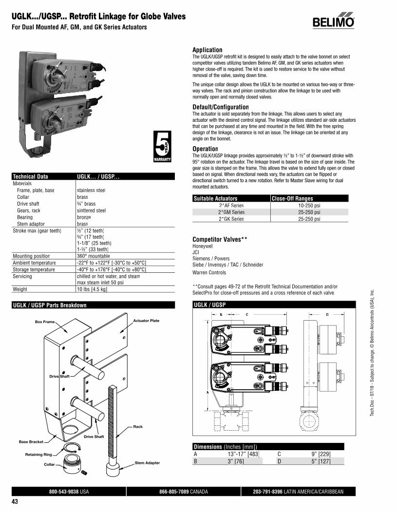
Tech
.Doc
- 07
/18
- Sub
ject
to c
hang
e. ©
Bel
imo
Airc
ontro
ls (U
SA),
Inc.
®
800-543-9038 USA 866-805-7089 CANADA 203-791-8396 LATIN AMERICA/CARIBBEAN
43
UGLK.../UGSP... Retrofi t Linkage for Globe ValvesFor Dual Mounted AF, GM, and GK Series Actuators
ApplicationThe UGLK/UGSP retrofit kit is designed to easily attach to the valve bonnet on select competitor valves utilizing tandem Belimo AF, GM, and GK series actuators when higher close-off is required. The kit is used to restore service to the valve withoutremoval of the valve, saving down time.
The unique collar design allows the UGLK to be mounted on various two-way or three-way valves. The rack and pinion construction allow the linkage to be used with normally open and normally closed valves.
Default/ConfigurationThe actuator is sold separately from the linkage. This allows users to select any actuator with the desired control signal. The linkage utilizes standard air-side actuators that can be purchased at any time and mounted in the field. With the free spring design of the linkage, clearance is not an issue. The linkage can be oriented at any angle on the bonnet.
OperationThe UGLK/UGSP linkage provides approximately ½” to 1-½” of downward stroke with 95° rotation on the actuator. The linkage travel is based on the size of gear inside. Thegear size is stamped on the frame. This allows the valve to extend fully open or closed based on signal. When directional needs vary, the actuators can be flipped or directional switch turned to a new rotation. Refer to Master Slave wiring for dualmounted actuators.
Suitable Actuators Close-Off Ranges2*AF Series 10-250 psi2*GM Series 25-250 psi2*GK Series 25-250 psi
Competitor Valves** HoneywellJCISiemens / Powers Siebe / Invensys / TAC / SchneiderWarren Controls
**Consult pages 49-72 of the Retrofit Technical Documentation and/or SelectPro for close-off pressures and a cross reference of each valve.
UGLK / UGSP
Technical Data UGLK... / UGSP...Materials: Frame, plate, base stainless steel Collar brass Drive shaft ¾” brass Gears, rack sinttered steel Bearing bronze Stem adaptor brassStroke max (gear teeth) ½” (12 teeth)
¾” (17 teeth)1-1/8” (25 teeth)1-½” (33 teeth)
Mounting position 360° mountableAmbient temperature -22°F to +122°F [-30°C to +50°C]Storage temperature -40°F to +176°F [-40°C to +80°C]Servicing chilled or hot water, and steam
max steam inlet 50 psiWeight 10 lbs [4.5 kg]
UGLK / UGSP Parts BreakdownC D
Dimensions (Inches [mm])A 13”-17” [483] C 9” [229]B 3” [76][ ] D 5” [127][ ]
Box Frame
Drive Shaft
Actuator Plate
Rack
Stem Adapter
Base Bracket
Retaining Ring
Collar
Drive Shaft

Tech
.Doc
- 07
/18
- Sub
ject
to c
hang
e. ©
Bel
imo
Airc
ontro
ls (U
SA),
Inc.
®
800-543-9038 USA 866-805-7089 CANADA 203-791-8396 LATIN AMERICA/CARIBBEAN
44
UGVL Universal Globe Valve LinkageFor Use with LV and SV Series Actuators
Technical Data
Service chilled or hot water and steamApplicable valve size ½” [13], ¾” [19], 1” [25], 1-¼” [32], 1-½”
[38], 2” [50]Stem fits slotted or threadedFrame, plate, base aluminum and steelCollar aluminum and steel, (fits bonnets up to 1.7” dia.)Stem adaptor aluminum and steel (fits 0.66” dia. threaded or
slotted)Stroke 0.6” [15 mm] LVK, 0.75” [20 mm] SVKMounting position 360°Media temp range (water) 20°F to 250°F [-7°C to +120°C]Media temp range (steam) 32°F to 388°F [0°C to 170°C]Weight 1.9 lbs
ApplicationThe UGVL retrofit kit is designed to easily attach LV and SV series actuators to select globe valves. Its unique adjustable design allows the UGVL to be mounted on ½” to 2” two-way or three-way valves in both normally open and normally closedconfigurations.
Default/ConfigurationThe default set up for a UGVL linkage will be factory installed along with a LV or SV series actuator. Included in the kit will be all the necessary hardware to facilitatemounting to the valve.
OperationThe UGVL linkage with actuator will provide 20 mm of linear travel to accommodate awide range of valves.
Suitable Actuators
Linkage Non-Spring Return Electronic Fail-Safe
UGVL LV, SV LVK, SVK
Dimensions (Inches [mm]) with LV and SV Series Actuators
C
A
B
H1
B
H2
A B C H1 H2
8” [203.2] 4.4” [113] 8.60” [218] 7.5” [190] 11.4” [290]
Dimensions (Inches [mm]) with LVK and SVK Series Actuators
C
A
B
H2
B
H1
A B C H1 H2
8.5” [217] 4.4” [113] 9.6” [244] 8.4” [207] 12.1” [307]
Application Notes
**Consult pages 49-72 of the Retrofit Technical Documentation and/or SelectPro for close-off pressures and a cross reference of each valve.

Tech
.Doc
- 07
/18
- Sub
ject
to c
hang
e. ©
Bel
imo
Airc
ontro
ls (U
SA),
Inc.
®
800-543-9038 USA 866-805-7089 CANADA 203-791-8396 LATIN AMERICA/CARIBBEAN
45
SGVL Schneider Globe Valve LinkageFor use with LV and SV Series Actuators
Technical Data
Service chilled or hot water and steam
Applicable valve size ½” [13], ¾” [19], 1” [25], 1-¼” [32], 1-½”[38], 2” [50]
Frame, plate, base aluminumCollar* aluminum
(fi ts VB7 ½” to 2”/VB9 ½” to 1-¼” valves)Coupling aluminumStem adaptor steelStroke 0.6” [15 mm] LVK, 0.75” [20 mm] SVKMounting position 360°Media temp range (water) 20°F to 250°F [-7°C to +120°C]Media temp range (steam) 20°F to 250°F [-7°C to +120°C]Housing material aluminum die cast and plastic casingWeight 0.5 lbs*Will also fi t post 1994 VB9 1-½” to 2” valves.
ApplicationThe SGVL retrofi t kit is designed to easily attach LV and SV series actuators to select Schneider® globe valves. The cast base and free spinning collar allow the SGVL tobe mounted on ½” to 2” two-way or three-way valves in both normally open andnormally closed confi gurations.
Default/ConfigurationThe default set up for a SGVL linkage will be factory installed along with a LV or SV series actuator. Included in the kit is all the necessary hardware to facilitate mounting to the Schneider valve.
OperationThe SGVL linkage with actuator will provide 20 mm of linear travel to accommodate a wide range of valve sizes.
Suitable Actuators
Linkage Non-Spring Return Electronic Fail-Safe
SGVL LV, SV LVK, SVK
Dimensions (Inches [mm]) with LV and SV Series Actuators
C
A
B
A B C
6” [152] 3.9” [98] 7.8” [199]
Dimensions (Inches [mm]) with LVK and SVK Series Actuators
BC
A
A B C
6.7” [169] 3.9” [98] 8.2” [209]
Application Notes
**Consult pages 49-72 of the Retrofit Technical Documentation and/or SelectPro for close-off pressures and a cross reference of each valve.
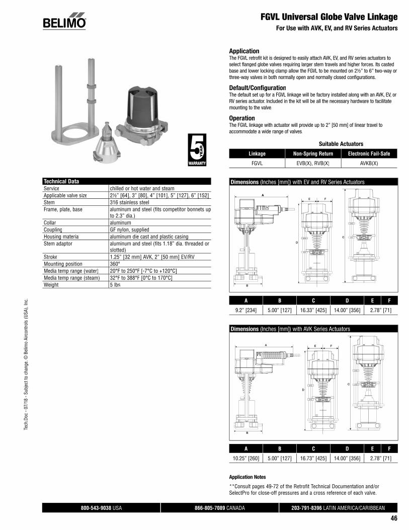
Tech
.Doc
- 07
/18
- Sub
ject
to c
hang
e. ©
Bel
imo
Airc
ontro
ls (U
SA),
Inc.
®
800-543-9038 USA 866-805-7089 CANADA 203-791-8396 LATIN AMERICA/CARIBBEAN
46
FGVL Universal Globe Valve LinkageFor Use with AVK, EV, and RV Series Actuators
Technical Data
Service chilled or hot water and steamApplicable valve size 2½” [64], 3” [80], 4” [101], 5” [127], 6” [152]Stem 316 stainless steelFrame, plate, base aluminum and steel (fits competitor bonnets up
to 2.3” dia.)Collar aluminumCoupling GF nylon, suppliedHousing material aluminum die cast and plastic casingStem adaptor aluminum and steel (fits 1.18” dia. threaded or
slotted)Stroke 1.25” [32 mm] AVK, 2” [50 mm] EV/RVMounting position 360°Media temp range (water) 20°F to 250°F [-7°C to +120°C]Media temp range (steam) 32°F to 388°F [0°C to 170°C]Weight 5 lbs
ApplicationThe FGVL retrofit kit is designed to easily attach AVK, EV, and RV series actuators toselect flanged globe valves requiring larger stem travels and higher forces. Its castedbase and lower locking clamp allow the FGVL to be mounted on 2½” to 6” two-way orthree-way valves in both normally open and normally closed configurations.
Default/ConfigurationThe default set up for a FGVL linkage will be factory installed along with an AVK, EV, orRV series actuator. Included in the kit will be all the necessary hardware to facilitate mounting to the valve.
OperationThe FGVL linkage with actuator will provide up to 2” [50 mm] of linear travel toaccommodate a wide range of valves.
Suitable Actuators
Linkage Non-Spring Return Electronic Fail-Safe
FGVL EVB(X), RVB(X) AVKB(X)
Dimensions (Inches [mm]) with EV and RV Series Actuators
A
D
C
E FA
B
A B C D E F
9.2” [234] 5.00” [127] 16.33” [425] 14.00” [356] 2.78” [71]
Dimensions (Inches [mm]) with AVK Series Actuators
B
A
D
E F
C
A B C D E F
10.25” [260] 5.00” [127] 16.73” [425] 14.00” [356] 2.78” [71]
Application Notes
**Consult pages 49-72 of the Retrofit Technical Documentation and/or SelectPro for close-off pressures and a cross reference of each valve.

Tech
.Doc
- 07
/18
- Sub
ject
to c
hang
e. ©
Bel
imo
Airc
ontro
ls (U
SA),
Inc.
®
800-543-9038 USA 866-805-7089 CANADA 203-791-8396 LATIN AMERICA/CARIBBEAN
47
WGVL Warren Globe Valve LinkageFor use with EV, RV and AVK Series Actuators
Technical Data
Service chilled or hot water and steamApplicable valve size 2" [50], 2-½" [65], 3" [80], 4" [100], 5" [125],
6" [150]Stem 316 stainless steelFrame, plate, base aluminum, steel (fits Warren Type 20,22,23,30,
and 32) (Belimo G6 & G7 series)Collar steelStem adaptor steelStroke 2" [50 mm]Mounting position 360°Media temp range (water) 20°F to 250°F [-7°C to +120°C]Media temp range (steam) 32°F to 388°F [0°C to 170°C]Housing material aluminum die cast and plastic casingWeight 2.59 lbs
ApplicationThe WGVL retrofit kit is designed to easily attach AVK, EV and RV series actuators toselect Warren® globe valves. The cast base and lower lock nut allow the WGVL to bemounted on 2-½” to 6” two-way or three-way valves in both normally open andnormally closed configurations.
Default/ConfigurationThe default set up for a WGVL linkage will be factory installed along with an AVK or EV,RV series actuator. Included in the kit is all the necessary hardware to facilitatemounting to the Warren valve.
OperationThe WGVL linkage with actuator will provide 50 mm of linear travel to accommodate awide range of valve sizes.
Suitable Actuators
Linkage Non-Spring Return Electronic Fail-Safe
WGVL EV, RV AVK
Dimensions (Inches [mm]) with EV and RV Series Actuators
BC
DA
A B C D
10.2" [259] 5.5" [140] 9.2" [233] 10.9" [276]
Dimensions (Inches [mm]) with AVK Series Actuators
BC
DA
A B C D
10.4" [264] 5.5" [140] 10.3" [262] 10.9" [276]
Application Notes
**Consult pages 49-72 of the Retrofit Technical Documentation and/or SelectPro for close-off pressures and a cross reference of each valve.

Tech
.Doc
- 07
/18
- Sub
ject
to c
hang
e. ©
Bel
imo
Airc
ontro
ls (U
SA),
Inc.
®
800-543-9038 USA 866-805-7089 CANADA 203-791-8396 LATIN AMERICA/CARIBBEAN
48
Retrofit and Replacement, Siemens 599 MT/MZUGSL1200 Short-Stroke Valve Retrofit Kit for CM and TF Series Actuators
ApplicationThe UGSL1200 retrofit kit is designed to easily attach to the valve bonnet onselect Siemens 599 MT/MZ short-stroke valves utilizing Belimo CM and TF*series actuators. See accessories in Technical Data table for all availablecompetitor collars.
The unique coupler design allows the UGSL1200 to be mounted on any ½” to1¼” two-way or three-way valves. In addition, the linkage is suitable for bothnormally open and normally closed valves.
Default/ConfigurationThe default set up for this linkage is for usage with the CM actuator. Included inthe kit is an extension piece for TF actuators. Hardware is supplied to attach theshaft extension and anti-rotation screws to both a CM or TF actuator.
OperationThe UGSL1200 linkage provides 6 mm of downward stroke with 95° CW rotationon the actuator. This allows the valve to extend fully open or closed based onsignal. The slot located on the housing provides indication when the maximumstroke has been reached. For troubleshooting when using a CM actuator, the operator may use the manual override feature to rotate the linkage up or down. When using the TF, refer to electronic override instructions according to actuatormodel.
Note: Linkage cannot be used on 1½” normally closed valves.
*TFL actuators required for on/off applications.** CMB24-SR-R for 2V stem down, CMB24-SR-L for 2V stem up.
Technical Data UGSL1200Housing aluminumMaterials: Coupling nut brass Shafts stainless steel Base plate aluminum Upper plate stainless steel Cams nylon 6/6 with MDSStroke 6 mm in CW directionMax out force 67 lbf [300 N]Mounting position 360° mountable as shownAmbient temperature -22°F to +122°F [-30°C to +50°C]Storage temperature -40°F to +176°F [-40°C to +80°C]Servicing chilled or hot water
max steam inlet 15 psi Weight 1.25 lbs [0.57 kg]Accessories UGSL-ADPT Collar for:
• Danfoss • HW Braukman• Oventrop • Siemens• Cazzaniga • JCI• Spartan • Taco
Mounting Configurations
CM Dimensions (Inches [mm])
2.4”
[60.
3]
6.3” [159.8]
3.7”
[95.
2]
2.8”
[72]
1.5”
[37.
9]
2.4”
[60.
3]
D316
360°
360°3
TF Actuator*
CM Actuator**CM Actuator**
TF Dimensions (Inches [mm])
D315

800-543-9038 USA 866-805-7089 CANADA 203-791-8396 LATIN AMERICA/CARIBBEAN
49
Valve Body Model Size Fail-Safe Close-Off psi BelimoActuator Series
BelimoLinkage
Tech
.Doc
- 07
/18
- Sub
ject
to c
hang
e. ©
Bel
imo
Airc
ontro
ls (U
SA),
Inc.
All close-off pressures listed are approximate and based on valve condition and application.
VP526 Series5/8”
No58
CM UGLK1808Yes TF UGLK1808
VP531 SeriesNo
70CM UGLK1808
Yes TF UGLK1808
VP531 Series 7/8”No
70CM UGLK1808
Yes TF UGLK1808
V5011 Series
½”
No236
LV UGVL
YesLVK UGVLLF UGLK1806
V5011F(1014, 1022, 1030, 1048, 1121, 1139) Yes 236
NF UGLK1800LF UGLK1806
V5011G(1137, 1145, 1152, 1160, 1178, 1186) Yes 236
NF UGLK1800LF UGLK1806
V5011H (1002, 1010) Yes 236NF UGLK1800LF UGLK1806
V5011J (1012, 1079) Yes 236NF UGLK1800LF UGLK1806
V5013 SeriesNo
236LV UGVL
Yes LVK UGVL
V5013F (1004, 1012, 1079) Yes 236NF UGLK1800LF UGLK1806
V5013N SeriesNo
236LV UGVL
YesLVK UGVLLF UGLK1806
V5045No
236AM UGLK1804
Yes NF UGLK1804
VP525 SeriesNo
110CM UGLK1808
Yes TF UGLK1808
VP526 SeriesNo
50CM UGLK1808
Yes TF UGLK1808
VP527 SeriesNo
45CM UGLK1808
Yes TF UGLK1808
VP531 SeriesNo
70CM UGLK1808
Yes TF UGLK1808
V5011 (H1028, G1194, J1023)
¾”
Yes 236 NF UGLK1800Yes 110 LF UGLK1806
V5011 SeriesNo
211LV UGVL
Yes LVK UGVLYes 110 LF UGLK1806
V5011F (1055, 1147)Yes 236 NF UGLK1800Yes 110 LF UGLK1806
V5013 SeriesNo
211LV UGVL
Yes LVK UGVL
V5013F (1020, 1087)Yes 236 NF UGLK1800Yes 110 LF UGLK1806
V5013N SeriesNo
211LV UGVL
Yes LVK UGVLYes 110 LF UGLK1806
V5045 Yes 236 NF UGLK1804
VP525 SeriesNo
55CM UGLK1808
Yes TF UGLK1808
VP531 SeriesNo
70CM UGLK1808
Yes TF UGLK1808
V5011 (F1063, F1154, H1028, G1194)
1”
Yes 236 AF UGLK1800Yes 65 LF UGLK1806
V5011 Series
No93
LV UGVLYes LVK UGVLNo
236SV UGVL
YesSVK UGVLAF UGLK1800
Yes 65 LF UGLK1806
V5013 Series
No93
LV UGVLYes LVK UGVLNo
236SV UGVL
Yes SVK UGVL
HoneywellVP5.., V5011, V5013, V5045 Series Valves
Linkage/Actuator Selection Guide

800-543-9038 USA 866-805-7089 CANADA 203-791-8396 LATIN AMERICA/CARIBBEAN
50
Tech
.Doc
- 07
/18
- Sub
ject
to c
hang
e. ©
Bel
imo
Airc
ontro
ls (U
SA),
Inc.
Valve Body Model Size Fail-Safe Close-Off psi BelimoActuator Series
BelimoLinkage
All close-off pressures listed are approximate and based on valve condition and application.
V5013F (1038, 1095)
1”
Yes 236 AF UGLK1800Yes 65 LF UGLK1806
V5013N Series
No93
LV UGVLYes LVK UGVLNo
236SV UGVL
YesSVK UGVLAF UGLK1800
Yes 65 LF UGLK1806
V5045No
236AM UGLK1804
Yes NF UGLK1804
V5011 (H1044, G1210, J1049)
1¼”
Yes 221 AF UGLK1800Yes 40 LF UGLK1806
V5011 Series
Yes 221 AF UGLK1800No
236SV UGVL
Yes SVK UGVLYes 40 LF UGLK1806
V5011F (1071, 1162)Yes 221 AF UGLK1800Yes 40 LF UGLK1806
V5013 SeriesNo
236SV UGVL
Yes SVK UGVL
V5013F (1046, 1103)Yes 221 AF UGLK1800Yes 40 LF UGLK1806
V5013N Series
Yes 221 AF UGLK1800No
236SV UGVL
Yes SVK UGVLYes 40 LF UGLK1806
V5045No 236 AM UGLK1804Yes 160 NF UGLK1804
V5011 (F1089, F1178, G1228)
1½”
Yes 153 AF UGLK1800Yes 26 LF UGLK1806
V5011 Series
Yes 153 AF UGLK1800No
160SV UGVL
Yes SVK UGVLYes 26 LF UGLK1806
V5013 SeriesNo
160SV UGVL
Yes SVK UGVL
V5013F (1053, 1111)Yes 153 AF UGLK1800Yes 26 LF UGLK1806
V5013N Series
Yes 153 AF UGLK1800No
160SV UGVL
Yes SVK UGVLYes 26 LF UGLK1806
V5045No
211AM UGLK1804
Yes AF UGLK1804
V5011 (F1097, F1188, G1103)
2”
Yes 86 AF UGLK1800Yes 173 GK UGLK1800Yes 40 NF UGLK1800Yes 14 LF UGLK1806
V5011 Series
Yes 86 AF UGLK1800Yes 173 GK UGLK1800No
85SV UGVL
Yes SVK UGVLYes 14 LF UGLK1806
V5013 SeriesNo
85SV UGVL
Yes SVK UGVL
V5013F (1061, 1129)
Yes 86 AF UGLK1800Yes 173 GK UGLK1800Yes 40 NF UGLK1800Yes 14 LF UGLK1806
V5013N Series
Yes 86 AF UGLK1800Yes 173 GK UGLK1800No
85SV UGVL
Yes SVK UGVLYes 14 LF UGLK1806
V5045No
120AM UGLK1804
Yes AF UGLK1804
HoneywellV5013, V5045, V5011 Series Valves
Linkage/Actuator Selection Guide

800-543-9038 USA 866-805-7089 CANADA 203-791-8396 LATIN AMERICA/CARIBBEAN
51
Valve Body Model Size Fail-Safe Close-Off psi BelimoActuator Series
BelimoLinkage
Tech
.Doc
- 07
/18
- Sub
ject
to c
hang
e. ©
Bel
imo
Airc
ontro
ls (U
SA),
Inc.
All close-off pressures listed are approximate and based on valve condition and application.
V3350(A2009, A2017, B2007, C2013, D2003)
2½”
Yes 211 2*GK UGLK1870Yes 110 2*AF UGLK1870No
55SV UGVL
Yes SVK UGVL
V3351 (A2008, C2005, D2002)
Yes 211 2*GK UGLK1870Yes 110 2*AF UGLK1870No
55SV UGVL
Yes SVK UGVL
V3360E2008, V3361E2007
Yes 211 2*GK UGLK1870Yes 110 2*AF UGLK1870No
55SV UGVL
Yes SVK UGVLYes 52 AF UGLK1800
V3450(A2008, A2016, B2006, C2012, D2002)
Yes 211 2*GK UGLK1870Yes 110 2*AF UGLK1870No
55SV UGVL
Yes SVK UGVLYes 52 AF UGLK1800
V3451 (A2007, C2003, C2004)
Yes 211 2*GK UGLK1870Yes 110 2*AF UGLK1870No
77SV UGVL
Yes SVK UGVLYes 52 AF UGLK1800
V3460E2007, V3461E2006
Yes 211 2*GK UGLK1870Yes 110 2*AF UGLK1870No
55SV UGVL
Yes SVK UGVLYes 52 AF UGLK1800
V5011 (A1734, F1105, F1196, G1111) Yes 211 2*GK UGLK1870
V5011 SeriesNo
52SV UGVL
Yes SVK UGVL
V5013 (B1003, C1001)Yes 211 2*GK UGLK1870Yes 52 AF UGLK1800
V5013 SeriesNo
52SV UGVL
Yes SVK UGVL
V3350(A3007, A3015, B3005, C3011, D3001)
3”
Yes 77 2*AF UGLK1870Yes 38 AF UGLK1800Yes 136 2*GK UGLK1870No
38SV UGVL
Yes SVK UGVL
V3351 (A3006, C3002, C3003)
Yes 77 2*AF UGLK1870Yes 38 AF UGLK1800Yes 136 2*GK UGLK1870No
38SV UGVL
Yes SVK UGVL
V3360E3006, V3361E3005
Yes 77 2*AF UGLK1870Yes 38 AF UGLK1800Yes 136 2*GK UGLK1870No
38SV UGVL
Yes SVK UGVL
V3450(A3006, A3014, B3004, C3010, D3000)
Yes 77 2*AF UGLK1870Yes 38 AF UGLK1800Yes 136 2*GK UGLK1870No
38SV UGVL
Yes SVK UGVL
V3451 (A3005, C3001, C3002)
Yes 77 2*AF UGLK1870Yes 38 AF UGLK1800Yes 136 2*GK UGLK1870No
38SV UGVL
Yes SVK UGVL
V3460E3005, V3461E3004
Yes 77 2*AF UGLK1870Yes 38 AF UGLK1800Yes 136 2*GK UGLK1870No
38SV UGVL
Yes SVK UGVL
HoneywellV3350, V3351, V3360, V3450, V3451, V3460, V5011, V5013 Series Valves
Linkage/Actuator Selection Guide

800-543-9038 USA 866-805-7089 CANADA 203-791-8396 LATIN AMERICA/CARIBBEAN
52
Tech
.Doc
- 07
/18
- Sub
ject
to c
hang
e. ©
Bel
imo
Airc
ontro
ls (U
SA),
Inc.
Valve Body Model Size Fail-Safe Close-Off psi BelimoActuator Series
BelimoLinkage
All close-off pressures listed are approximate and based on valve condition and application.
V5011 (A1767, F1113, F1204, G1129)
3”
Yes 38 AF UGLK1800Yes 136 2*GK UGLK1870
V5011 SeriesNo
40SV UGVL
Yes SVK UGVL
V5013 (B1011, C1019)Yes 77 GK UGLK1800Yes 136 2*GK UGLK1870
V5013 SeriesNo
40SV UGVL
Yes SVK UGVL
V3350(A4005, A4013, B4003, C4019, D4009)
4”
No22
EV FGVLYes 2*AF UGLK1872No
40RV FGVL
Yes 2*GK UGLK1872Yes 10 AF UGLK1802
V3351 ( A4004, C4000, C4001)
No22
EV FGVLYes 2*AF UGLK1872No
40RV FGVL
Yes 2*GK UGLK1872Yes 10 AF UGLK1802
V3360E4004, V3361E4003
No22
EV FGVLYes 2*AF UGLK1872No
40RV FGVL
Yes 2*GK UGLK1872Yes 10 AF UGLK1802
V3450(A4004, A4012, B4002, C4018, D4008)
No22
EV FGVLYes 2*AF UGLK1872No
40RV FGVL
Yes 2*GK UGLK1872Yes 10 AF UGLK1802
V3451 (A4003, C4000, C4009)
No22
EV FGVLYes 2*AF UGLK1872No
40RV FGVL
Yes 2*GK UGLK1872Yes 10 AF UGLK1802
V3460E4003, V3461E4002
No22
EV FGVLYes 2*AF UGLK1872No
40RV FGVL
Yes 2*GK UGLK1872Yes 10 AF UGLK1802
V5011 (A1858, B1013)
No 22 EV FGVLNo
40RV FGVL
Yes 2*GK UGLK1872Yes 10 AF UGLK1802
V5013 (B1029, C1027)
No22
EV FGVLYes GK UGLK1802No
40RV FGVL
Yes 2*GK UGLK1872
V3350(A5002, A5010, B5000, C5016, D5006)
5”
No22
RV FGVLYes 2*GK UGLK1872No
14EV FGVL
YesGK UGLK1802
2*AF UGLK1872Yes 10 AF UGLK1802
V3351 (A5001, C5008, D5005)
No22
RV FGVLYes 2*GK UGLK1872No
14EV FGVL
YesGK UGLK1802
2*AF UGLK1872Yes 10 AF UGLK1802
V3360E5001, V3361E5000
No22
RV FGVLYes 2*GK UGLK1872No
14EV FGVL
YesGK UGLK1802
2*AF UGLK1872Yes 10 AF UGLK1802
HoneywellV5011, V5013, V3350, V3351, V3360, V3450, V3451, V3460 Series Valves
Linkage/Actuator Selection Guide

800-543-9038 USA 866-805-7089 CANADA 203-791-8396 LATIN AMERICA/CARIBBEAN
53
Valve Body Model Size Fail-Safe Close-Off psi BelimoActuator Series
BelimoLinkage
Tech
.Doc
- 07
/18
- Sub
ject
to c
hang
e. ©
Bel
imo
Airc
ontro
ls (U
SA),
Inc.
All close-off pressures listed are approximate and based on valve condition and application.
V3450(A5001, A5019, B5009, C5015, D5005)
5”
No22
RV FGVLYes 2*GK UGLK1872No
14EV FGVL
YesGK UGLK1802
2*AF UGLK1872Yes 10 AF UGLK1802
V3451 (A5000, C5006, C5007)
No22
RV FGVLYes 2*GK UGLK1872No
14EV FGVL
YesGK UGLK1802
2*AF UGLK1872Yes 10 AF UGLK1802
V3460E5000, V3461E5009
No22
RV FGVLYes 2*GK UGLK1872No
14EV FGVL
YesGK UGLK1802
2*AF UGLK1872Yes 10 AF UGLK1802
V5011 (A1882, B1047)
No22
RV FGVLYes 2*GK UGLK1872
Yes 14GK UGLK1802
2*AF UGLK1872Yes 10 AF UGLK1802
V5013 (B1037, C1035)
No22
RV FGVLYes 2*GK UGLK1872No
14EV FGVL
YesGK UGLK1802
2*AF UGLK1872Yes 10 AF UGLK1802
V3350(A6000, A6008, A6018, C6014, D6004)
6”
No22
RV FGVLYes 2*GK UGLK1872
Yes 10GK UGLK1802
2*AF UGLK1872
V3351 (A6009, C6005, C6006)
No22
RV FGVLYes 2*GK UGLK1872
Yes 10GK UGLK1802
2*AF UGLK1872
V3360E6009, V3361E6008
No22
RV FGVLYes 2*GK UGLK1872
Yes 10GK UGLK1802
2*AF UGLK1872
V3450(A6009, A6007, A6017, C6013, D6003)
No22
RV FGVLYes 2*GK UGLK1872
Yes 10GK UGLK1802
2*AF UGLK1872
V3451 (A6008, C6004, C6005)
No22
RV FGVLYes 2*GK UGLK1872
Yes 10GK UGLK1802
2*AF UGLK1872
V3460E6008, V3461E6007
No22
RV FGVLYes 2*GK UGLK1872
Yes 10GK UGLK1802
2*AF UGLK1872
V5011 (A1916, B1078)
No22
RV FGVLYes 2*GK UGLK1872
Yes 10GK UGLK1802
2*AF UGLK1872
V5013 (B1045, C1043)
No22
RV FGVLYes 2*GK UGLK1872
Yes 10GK UGLK1802
2*AF UGLK1872
VGF2.. Series2½”
No
52
EV FGVLYes AVK FGVL
VGF3.. SeriesNo EV FGVLYes AVK FGVL
HoneywellV3360, V3450, V3451, V3460, V5011, V5013, V3350, V3351, VGF2, VGF3 Series Valves
Linkage/Actuator Selection Guide

800-543-9038 USA 866-805-7089 CANADA 203-791-8396 LATIN AMERICA/CARIBBEAN
54
Tech
.Doc
- 07
/18
- Sub
ject
to c
hang
e. ©
Bel
imo
Airc
ontro
ls (U
SA),
Inc.
Valve Body Model Size Fail-Safe Close-Off psi BelimoActuator Series
BelimoLinkage
All close-off pressures listed are approximate and based on valve condition and application.
VGF2.. Series3”
No
40
EV FGVLYes AVK FGVL
VGF3.. SeriesNo EV FGVLYes AVK FGVL
VGF2.. Series4”
No 50 EV FGVLVGF3.. Series No 50 EV FGVLVGF2.. Series
5”No 40 RV FGVL
VGF3.. Series No 40 RV FGVLVGF2.. Series
6”No 30 RV FGVL
VGF3.. Series No 30 RV FGVLJOHNSON CONTROLS
V-3766
½”
No236
LM UGLK1552Yes LF UGLK1552
V-3854-5No
236LM UGLK1554
Yes LF UGLK1554
V-3966No
236LM UGLK1552
Yes LF UGLK1552
V-4332No
236LV UGVL
Yes LVK UGVL
VG7000 SeriesNo
236LV UGVL
Yes LVK UGVLVG7XXX-(C, E, GT) *Threaded Stem Only Yes 236 LF UGLK1416
VTM-TN-(007, 019, 047)*Threaded Stem Only
No
236
LM UGLK1550
YesLF UGLK1550LV UGVL
LVK UGVL
V(B)-3754 Series, Bronze Trim
¾”
No211
LV UGVLYes LVK UGVL
V(B)-3974 Series, Bronze TrimNo
211LV UGVL
Yes LVK UGVL
V(B)-4324 Series, Bronze TrimNo
211LV UGVL
Yes LVK UGVL
V(B)-5844 SeriesNo
211LV UGVL
Yes LVK UGVLV-3754-(4, 1008, 1022, 1026) Yes 211 LF UGLK1550V-3974-(4, 1004, 1010) Yes 211 LF UGLK1550V-4324-(4, 1005, 1006, 1013) Yes 211 LF UGLK1550
V-4332No
211
LV UGVLYes LVK UGVL
VG7000 SeriesNo LV UGVLYes LVK UGVL
VG7XXX-LT *Threaded Stem Only Yes 169 LF UGLK1416
V(B)-3754 Series, Bronze Trim
1”
No93
LV UGVLYes LVK UGVLNo
236SV UGVL
Yes SVK UGVL
V(B)-3974 Series, Bronze Trim
No93
LV UGVLYes LVK UGVLNo
236SV UGVL
Yes SVK UGVL
V(B)-4324 Series, Bronze TrimNo
93LV UGVL
Yes LVK UGVL
V(B)-4324 Series, Bronze TrimNo
236SV UGVL
Yes SVK UGVL
V(B)-5844 Series
No93
LV UGVLYes LVK UGVLNo
236SV UGVL
Yes SVK UGVL
V-3754-(5, 1010, 1023, 1027)Yes 173 NF UGLK1402Yes 236 AF UGLK1402
V-3974-(5, 1005, 1011)Yes 173 NF UGLK1402Yes 236 AF UGLK1402
V-4324-(5, 1007, 1008, 1014)Yes 173 NF UGLK1402Yes 236 AF UGLK1402
HoneywellV5013, VGF2, VGF3 Series Valves
Linkage/Actuator Selection Guide
Johnson ControlsV-37, V-38, V-39, V-43, VG7, VTM, V(B)-37, V(B)39, V(B)43, V(B)-58 Series Valves
Linkage/Actuator Selection Guide

800-543-9038 USA 866-805-7089 CANADA 203-791-8396 LATIN AMERICA/CARIBBEAN
55
Valve Body Model Size Fail-Safe Close-Off psi BelimoActuator Series
BelimoLinkage
Tech
.Doc
- 07
/18
- Sub
ject
to c
hang
e. ©
Bel
imo
Airc
ontro
ls (U
SA),
Inc.
All close-off pressures listed are approximate and based on valve condition and application.
V-4332
1”
No93
LV UGVLYes LVK UGVLNo
236SV UGVL
Yes SVK UGVL
VG7000 Series
No93
LV UGVLYes LVK UGVLNo
236SV UGVL
Yes SVK UGVLVG7XXX-NT *Threaded Stem Only Yes 93 LF UGLK1418
V(B)-3754 Series, Bronze Trim
1¼”
No236
SV UGVLYes SVK UGVL
V(B)-3974 Series, Bronze TrimNo
236SV UGVL
Yes SVK UGVL
V(B)-4324 Series, Bronze TrimNo
236SV UGVL
Yes SVK UGVL
V(B)-5844 SeriesNo
236SV UGVL
Yes SVK UGVL
V-3754-8Yes 221 AF UGLK1402Yes 110 NF UGLK1402
V-4324-8Yes 221 AF UGLK1402Yes 110 NF UGLK1402
V-4332No
236SV UGVL
Yes SVK UGVL
VG7000 SeriesNo
236SV UGVL
Yes SVK UGVLVG7XXX-PT *Threaded Stem Only Yes 65 LF UGLK1418
V(B)-3754 Series, Bronze Trim
1½”
No160
SV UGVLYes SVK UGVL
V(B)-3974 Series, Bronze TrimNo
160SV UGVL
Yes SVK UGVL
V(B)-4324 Series, Bronze TrimNo
160SV UGVL
Yes SVK UGVL
V(B)-5844 SeriesNo
160SV UGVL
Yes SVK UGVL
V-3754-(6, 1028, 1029, 1030)
Yes 77 NF UGLK1402Yes 153 AF UGLK1402Yes 236 GK UGLK1402Yes 211 2*AF UGLK1478
V-3974-(6, 1012, 1013)
Yes 77 NF UGLK1402Yes 153 AF UGLK1402Yes 236 GK UGLK1402Yes 211 2*AF UGLK1478
V-4324-(6,1015, 1016, 1017)
Yes 77 NF UGLK1402Yes 153 AF UGLK1402Yes 236 GK UGLK1402Yes 211 2*AF UGLK1478
V-4332No
160SV UGVL
Yes SVK UGVL
V-5254-(1, 2, 3, 11)
Yes 77 NF UGLK1404No
153AM UGLK1404
Yes AF UGLK1404
No 236GM UGLK1404
2*GM UGLK1472
V-5254-(1, 2, 3, 11) Yes 236GK UGLK1404
2*AF UGLK14722*GK UGLK1472
V-5464-(1, 2, 11)
Yes 77 NF UGLK1404No
153AM UGLK1404
Yes AF UGLK1404
No
236
GM UGLK14042*GM UGLK1472
YesGK UGLK1404
2*AFUGLK1472
2*GK
Johnson ControlsV(B)-58, V-37, V-39, V-43, VG7, V(B)-37, V(B)-39, V(B)-43, V(B)-58, V-52 Series Valves
Linkage/Actuator Selection Guide

800-543-9038 USA 866-805-7089 CANADA 203-791-8396 LATIN AMERICA/CARIBBEAN
56
Tech
.Doc
- 07
/18
- Sub
ject
to c
hang
e. ©
Bel
imo
Airc
ontro
ls (U
SA),
Inc.
Valve Body Model Size Fail-Safe Close-Off psi BelimoActuator Series
BelimoLinkage
All close-off pressures listed are approximate and based on valve condition and application.
V-5844-(1, 2, 3, 11)
1½”
Yes 77 NF UGLK1404Yes 153 AF UGLK1404No
236
2*GM UGLK1472
YesGK UGLK1404
2*AFUGLK1472
2*GK
VG7000 SeriesNo
160SV UGVL
Yes SVK UGVL
VG7XXX-RT *Threaded Stem Only
Yes 77 NF UGLK1422Yes 153 AF UGLK1422No
236GM UGLK1422
Yes GK UGLK1422Yes 26 LF UGLK1420
V(B)-3754 Series, Bronze Trim
2”
No85
SV UGVLYes SVK UGVL
V(B)-3974 Series, Bronze TrimNo
85SV UGVL
Yes SVK UGVL
V(B)-4324 Series, Bronze TrimNo
85SV UGVL
Yes SVK UGVL
V(B)-5844 SeriesNo
85SV UGVL
Yes SVK UGVL
V-3754-7
Yes 86 AF UGLK1406No
173GM UGLK1406
YesGK UGLK1406
2*AF UGLK1474No
2362*GM UGLK1474
Yes 2*GK UGLK1474Yes 40 NF UGLK1406
V-3974-7
Yes 86 AF UGLK1406No
173GM UGLK1406
YesGK UGLK1406
2*AF UGLK1474No
2362*GM UGLK1474
Yes 2*GK UGLK1474Yes 40 NF UGLK1406
V-4324-7
Yes 86 AF UGLK1406No
173GM UGLK1406
YesGK UGLK1406
2*AF UGLK1474No
2362*GM UGLK1474
Yes 2*GK UGLK1474Yes 40 NF UGLK1406
V-4332No
85SV UGVL
Yes SVK UGVL
V-5254-(4, 5, 6, 12)
No86
AM UGLK1406Yes AF UGLK1406No
173GM UGLK1406
YesGK UGLK1406
2*AF UGLK1474No
2362*GM UGLK1474
Yes 2*GK UGLK1474Yes 40 NF UGLK1406
V-5464-(3, 4, 12)
No86
AM UGLK1406Yes AF UGLK1406No 173 GM UGLK1406
Yes 173GK UGLK1406
2*AF UGLK1474No
2362*GM UGLK1474
Yes 2*GK UGLK1474Yes 40 NF UGLK1406
Johnson ControlsV-54, V-58. VG7, V(B)-37, V(B)-39, V(B)-43, V(B)-58, V-37, V-39, V-43, V-52, V-54 Series Valves
Linkage/Actuator Selection Guide
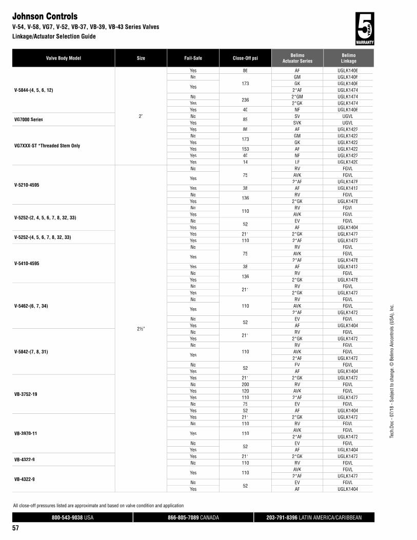
800-543-9038 USA 866-805-7089 CANADA 203-791-8396 LATIN AMERICA/CARIBBEAN
57
Valve Body Model Size Fail-Safe Close-Off psi BelimoActuator Series
BelimoLinkage
Tech
.Doc
- 07
/18
- Sub
ject
to c
hang
e. ©
Bel
imo
Airc
ontro
ls (U
SA),
Inc.
All close-off pressures listed are approximate and based on valve condition and application.
V-5844-(4, 5, 6, 12)
2”
Yes 86 AF UGLK1406No
173GM UGLK1406
YesGK UGLK1406
2*AF UGLK1474No
2362*GM UGLK1474
Yes 2*GK UGLK1474Yes 40 NF UGLK1406
VG7000 SeriesNo
85SV UGVL
Yes SVK UGVL
VG7XXX-ST *Threaded Stem Only
Yes 86 AF UGLK1422No
173GM UGLK1422
Yes GK UGLK1422Yes 153 AF UGLK1422Yes 40 NF UGLK1422Yes 14 LF UGLK1420
V-5210-4595
2½”
No75
RV FGVL
YesAVK FGVL2*AF UGLK1478
Yes 38 AF UGLK1412No
136RV FGVL
Yes 2*GK UGLK1478
V-5252-(2, 4, 5, 6, 7, 8, 32, 33)
No110
RV FGVLYes AVK FGVLNo
52EV FGVL
Yes AF UGLK1404
V-5252-(4, 5, 6, 7, 8, 32, 33)Yes 211 2*GK UGLK1472Yes 110 2*AF UGLK1472
V-5410-4595
No75
RV FGVL
YesAVK FGVL2*AF UGLK1478
Yes 38 AF UGLK1412No
136RV FGVL
Yes 2*GK UGLK1478
V-5462-(6, 7, 34)
No211
RV FGVLYes 2*GK UGLK1472No
110RV FGVL
YesAVK FGVL2*AF UGLK1472
No52
EV FGVLYes AF UGLK1404
V-5842-(7, 8, 31)
No211
RV FGVLYes 2*GK UGLK1472No
110RV FGVL
YesAVK FGVL2*AF UGLK1472
No52
EV FGVLYes AF UGLK1404
VB-3752-19
Yes 211 2*GK UGLK1472No 200 RV FGVLYes 120 AVK FGVLYes 110 2*AF UGLK1472No 75 EV FGVLYes 52 AF UGLK1404
VB-3970-11
Yes 211 2*GK UGLK1472No 110 RV FGVL
Yes 110AVK FGVL2*AF UGLK1472
No52
EV FGVLYes AF UGLK1404
VB-4322-9Yes 211 2*GK UGLK1472No 110 RV FGVL
VB-4322-9Yes 110
AVK FGVL2*AF UGLK1472
No52
EV FGVLYes AF UGLK1404
Johnson ControlsV-54, V-58, VG7, V-52, VB-37, VB-39, VB-43 Series Valves
Linkage/Actuator Selection Guide

800-543-9038 USA 866-805-7089 CANADA 203-791-8396 LATIN AMERICA/CARIBBEAN
58
Tech
.Doc
- 07
/18
- Sub
ject
to c
hang
e. ©
Bel
imo
Airc
ontro
ls (U
SA),
Inc.
Valve Body Model Size Fail-Safe Close-Off psi BelimoActuator Series
BelimoLinkage
All close-off pressures listed are approximate and based on valve condition and application.
VG2231 TM
2½”
No 211 RV FGVLNo
110EV FGVL
Yes AVK FGVLYes 211 2*GK UGLK1472Yes 110 2*AF UGLK1472Yes 52 AF UGLK1404
VG2431 TM
No 211 RV FGVLNo
110EV FGVL
Yes AVK FGVLYes 211 2*GK UGLK1472Yes 110 2*AF UGLK1472Yes 52 AF UGLK1404
VG2831 TM
No 211 RV FGVLNo
110EV FGVL
Yes AVK FGVLYes 211 2*GK UGLK1472Yes 110 2*AF UGLK1472Yes 52 AF UGLK1404
V-5210-4596
3”
No93
RV FGVLYes 2*GK UGLK1478No
52EV FGVL
YesAVK FGVL2*AF UGLK1478
Yes 26 AF UGLK1412
V-5252-(12, 13, 35)
No93
RV FGVLYes 2*GK UGLK1476No
52EV FGVL
YesAVK FGVL2*AF UGLK1476
Yes 26 AF UGLK1410
V-5252-(9, 10, 11, 34)
Yes 77 2*AF UGLK1472Yes 38 AF UGLK1404Yes 136 2*GK UGLK1472No 93 RV FGVLNo
52EV FGVL
Yes AVK FGVL
V-5410-4596
No93
RV FGVLYes 2*GK UGLK1478No
52EV FGVL
YesAVK FGVL2*AF UGLK1478
Yes 26 AF UGLK1412
V-5462-10
No93
RV FGVLYes 2*GK UGLK1478No
52EV FGVL
YesAVK FGVL2*AF UGLK1478
Yes 26 AF UGLK1412
V-5462-35
No93
RV FGVLYes 2*GK UGLK1476No
52EV FGVL
YesAVK FGVL2*AF UGLK1476
Yes 26 AF UGLK1410
V-5462-36
No93
RV FGVLYes 2*GK UGLK1478No
52EV FGVL
YesAVK FGVL2*AF UGLK1478
Yes 26 AF UGLK1412
Johnson ControlsVB-43, VG22, VG24, VG28, V-52, V-54 Series Valves
Linkage/Actuator Selection Guide

800-543-9038 USA 866-805-7089 CANADA 203-791-8396 LATIN AMERICA/CARIBBEAN
59
Valve Body Model Size Fail-Safe Close-Off psi BelimoActuator Series
BelimoLinkage
Tech
.Doc
- 07
/18
- Sub
ject
to c
hang
e. ©
Bel
imo
Airc
ontro
ls (U
SA),
Inc.
All close-off pressures listed are approximate and based on valve condition and application.
V-5462-8
3”
No93
RV FGVLYes 2*GK UGLK1476No
52EV FGVL
YesAVK FGVL2*AF UGLK1476
Yes 26 AF UGLK1410
V-5462-9
No93
RV FGVLYes 2*GK UGLK1476No
52EV FGVL
YesAVK FGVL2*AF UGLK1476
Yes 26 AF UGLK1410
V-5842-10
No93
RV FGVLYes 2*GK UGLK1476No
52EV FGVL
YesAVK FGVL2*AF UGLK1476
Yes 26 AF UGLK1410
V-5842-17
No93
RV FGVLYes 2*GK UGLK1478No
52EV FGVL
YesAVK FGVL2*AF UGLK1478
Yes 26 AF UGLK1412
V-5842-18
No93
RV FGVLYes 2*GK UGLK1478No
52EV FGVL
YesAVK FGVL2*AF UGLK1478
Yes 26 AF UGLK1412
V-5842-32
No93
RV FGVLYes 2*GK UGLK1476No
52EV FGVL
YesAVK FGVL2*AF UGLK1476
Yes 26 AF UGLK1410
V-5842-33
No93
RV FGVLYes 2*GK UGLK1478No
52EV FGVL
YesAVK FGVL2*AF UGLK1478
Yes 26 AF UGLK1412
V-5842-9
No93
RV FGVLYes 2*GK UGLK1476No
52EV FGVL
YesAVK FGVL2*AF UGLK1476
Yes 26 AF UGLK1410
VB-3752-22
No93
RV FGVLYes 2*GK UGLK1476No 70 EV FGVLYes 60 AVK FGVLYes 52 2*AF UGLK1476Yes 26 AF UGLK1410
VB-3970-14
No93
RV FGVLYes 2*GK UGLK1476No
52EV FGVL
YesAVK FGVL2*AF UGLK1476
Yes 26 AF UGLK1410
VB-4322-11
No93
RV FGVLYes 2*GK UGLK1476No
52EV FGVL
YesAVK FGVL2*AF UGLK1476
Yes 26 AF UGLK1410
Johnson ControlsV-54, V-58, VB-37, VB-39, VB-43 Series Valves
Linkage/Actuator Selection Guide
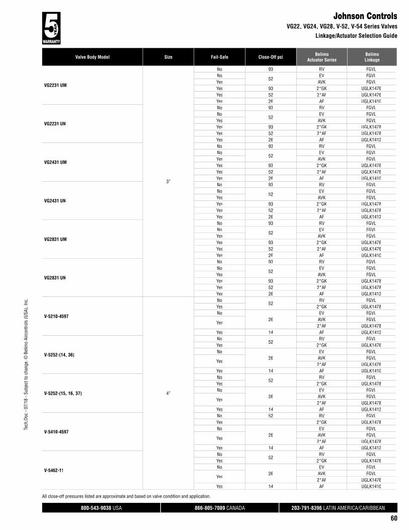
800-543-9038 USA 866-805-7089 CANADA 203-791-8396 LATIN AMERICA/CARIBBEAN
60
Tech
.Doc
- 07
/18
- Sub
ject
to c
hang
e. ©
Bel
imo
Airc
ontro
ls (U
SA),
Inc.
Valve Body Model Size Fail-Safe Close-Off psi BelimoActuator Series
BelimoLinkage
All close-off pressures listed are approximate and based on valve condition and application.
VG2231 UM
3”
No 93 RV FGVLNo
52EV FGVL
Yes AVK FGVLYes 93 2*GK UGLK1476Yes 52 2*AF UGLK1476Yes 26 AF UGLK1410
VG2231 UN
No 93 RV FGVLNo
52EV FGVL
Yes AVK FGVLYes 93 2*GK UGLK1478Yes 52 2*AF UGLK1478Yes 26 AF UGLK1412
VG2431 UM
No 93 RV FGVLNo
52EV FGVL
Yes AVK FGVLYes 93 2*GK UGLK1476Yes 52 2*AF UGLK1476Yes 26 AF UGLK1410
VG2431 UN
No 93 RV FGVLNo
52EV FGVL
Yes AVK FGVLYes 93 2*GK UGLK1478Yes 52 2*AF UGLK1478Yes 26 AF UGLK1412
VG2831 UM
No 93 RV FGVLNo
52EV FGVL
Yes AVK FGVLYes 93 2*GK UGLK1476Yes 52 2*AF UGLK1476Yes 26 AF UGLK1410
VG2831 UN
No 93 RV FGVLNo
52EV FGVL
Yes AVK FGVLYes 93 2*GK UGLK1478Yes 52 2*AF UGLK1478Yes 26 AF UGLK1412
V-5210-4597
4”
No52
RV FGVLYes 2*GK UGLK1478No
26EV FGVL
YesAVK FGVL2*AF UGLK1478
Yes 14 AF UGLK1412
V-5252-(14, 36)
No52
RV FGVLYes 2*GK UGLK1476No
26EV FGVL
YesAVK FGVL2*AF UGLK1476
Yes 14 AF UGLK1410
V-5252-(15, 16, 37)
No52
RV FGVLYes 2*GK UGLK1478No
26EV FGVL
YesAVK FGVL2*AF UGLK1478
Yes 14 AF UGLK1412
V-5410-4597
No 52 RV FGVLYes 2*GK UGLK1478No
26EV FGVL
YesAVK FGVL2*AF UGLK1478
Yes 14 AF UGLK1412
V-5462-11
No52
RV FGVLYes 2*GK UGLK1476No
26EV FGVL
YesAVK FGVL2*AF UGLK1476
Yes 14 AF UGLK1410
Johnson ControlsVG22, VG24, VG28, V-52, V-54 Series Valves
Linkage/Actuator Selection Guide

800-543-9038 USA 866-805-7089 CANADA 203-791-8396 LATIN AMERICA/CARIBBEAN
61
Valve Body Model Size Fail-Safe Close-Off psi BelimoActuator Series
BelimoLinkage
Tech
.Doc
- 07
/18
- Sub
ject
to c
hang
e. ©
Bel
imo
Airc
ontro
ls (U
SA),
Inc.
All close-off pressures listed are approximate and based on valve condition and application.
V-5462-12
4”
No52
RV FGVLYes 2*GK UGLK1476No
26EV FGVL
YesAVK FGVL2*AF UGLK1476
Yes 14 AF UGLK1410
V-5462-13
No52
RV FGVLYes 2*GK UGLK1478No
26EV FGVL
YesAVK FGVL2*AF UGLK1478
Yes 14 AF UGLK1412
V-5462-14
No52
RV FGVLYes 2*GK UGLK1478No
26EV FGVL
YesAVK FGVL2*AF UGLK1478
Yes 14 AF UGLK1412
V-5462-37
No52
RV FGVLYes 2*GK UGLK1476No
26EV FGVL
YesAVK FGVL2*AF UGLK1476
Yes 14 AF UGLK1410
V-5462-38
No52
RV FGVLYes 2*GK UGLK1478No
26EV FGVL
YesAVK FGVL2*AF UGLK1478
Yes 14 AF UGLK1412
V-5842-11
No52
RV FGVLYes 2*GK UGLK1478No
26EV FGVL
YesAVK FGVL2*AF UGLK1478
Yes 14 AF UGLK1412
V-5842-12
No52
RV FGVLYes 2*GK UGLK1478No
26EV FGVL
YesAVK FGVL2*AF UGLK1478
Yes 14 AF UGLK1412
V-5842-34
No52
RV FGVLYes 2*GK UGLK1478No
26EV FGVL
YesAVK FGVL2*AF UGLK1478
Yes 14 AF UGLK1412
VB-3752-25
No52
RV FGVLYes 2*GK UGLK1476No 40 EV FGVLYes 30 AVK FGVLYes 26 2*AF UGLK1476Yes 14 AF UGLK1410
VB-3970-17
No52
RV FGVLYes 2*GK UGLK1476No
26EV FGVL
YesAVK FGVL2*AF UGLK1476
Yes 14 AF UGLK1410
VB-4322-13
No52
RV FGVLYes 2*GK UGLK1476No
26EV FGVL
YesAVK FGVL2*AF UGLK1476
Yes 14 AF UGLK1410
Johnson ControlsV-54, V-58, VB-37, VB-39, VB-43 Series Valves
Linkage/Actuator Selection Guide

800-543-9038 USA 866-805-7089 CANADA 203-791-8396 LATIN AMERICA/CARIBBEAN
62
Tech
.Doc
- 07
/18
- Sub
ject
to c
hang
e. ©
Bel
imo
Airc
ontro
ls (U
SA),
Inc.
Valve Body Model Size Fail-Safe Close-Off psi BelimoActuator Series
BelimoLinkage
All close-off pressures listed are approximate and based on valve condition and application.
VG2231 VM
4”
No 52 RV FGVLNo
26EV FGVL
Yes AVK FGVLYes 52 2*GK UGLK1476Yes 26 2*AF UGLK1476Yes 14 AF UGLK1410
VG2231 VN
No 52 RV FGVLNo
26EV FGVL
Yes AVK FGVLYes 52 2*GK UGLK1478Yes 26 2*AF UGLK1478Yes 14 AF UGLK1412
VG2431 VM
No 52 RV FGVLNo
26EV FGVL
Yes AVK FGVLYes 52 2*GK UGLK1476Yes 26 2*AF UGLK1476Yes 14 AF UGLK1410
VG2431 VN
No 52 RV FGVLNo
26EV FGVL
Yes AVK FGVLYes 52 2*GK UGLK1478Yes 26 2*AF UGLK1478Yes 14 AF UGLK1412
VG2831 VM
No 52 RV FGVLNo
26EV FGVL
Yes AVK FGVLYes 52 2*GK UGLK1476Yes 26 2*AF UGLK1476Yes 14 AF UGLK1410
VG2831 VN
No 52 RV FGVLNo
26EV FGVL
Yes AVK FGVLYes 52 2*GK UGLK1478Yes 26 2*AF UGLK1478Yes 14 AF UGLK1412
V-5252-17
5”
No22
RV FGVLYes 2*GK UGLK1480No
14EV FGVL
YesGK UGLK1414
2*AF UGLK1480Yes 10 AF UGLK1414
V-5252-18
No22
RV FGVLYes 2*GK UGLK1480No
14EV FGVL
YesGK UGLK1414
2*AF UGLK1480Yes 10 AF UGLK1414
V-5252-38
No22
RV FGVLYes 2*GK UGLK1480No
14EV FGVL
YesGK UGLK1414
2*AF UGLK1480Yes 10 AF UGLK1414
V-5462-15
No22
RV FGVLYes 2*GK UGLK1480No
14EV FGVL
YesGK UGLK1414
2*AF UGLK1480Yes 10 AF UGLK1414
V-5462-16
No22
RV FGVLYes 2*GK UGLK1480No
14EV FGVL
YesGK UGLK1414
2*AF UGLK1480Yes 10 AF UGLK1414
Johnson ControlsVG22, VG24, VG28, V-52, V-54 Series Valves
Linkage/Actuator Selection Guide
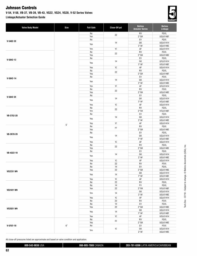
800-543-9038 USA 866-805-7089 CANADA 203-791-8396 LATIN AMERICA/CARIBBEAN
63
Valve Body Model Size Fail-Safe Close-Off psi BelimoActuator Series
BelimoLinkage
Tech
.Doc
- 07
/18
- Sub
ject
to c
hang
e. ©
Bel
imo
Airc
ontro
ls (U
SA),
Inc.
All close-off pressures listed are approximate and based on valve condition and application.
V-5462-39
5”
No22
RV FGVLYes 2*GK UGLK1480No
14EV FGVL
YesGK UGLK1414
2*AF UGLK1480Yes 10 AF UGLK1414
V-5842-13
No22
RV FGVLYes 2*GK UGLK1480No
14EV FGVL
YesGK UGLK1414
2*AF UGLK1480Yes 10 AF UGLK1414
V-5842-14
No22
RV FGVLYes 2*GK UGLK1480No
14EV FGVL
YesGK UGLK1414
2*AF UGLK1480Yes 10 AF UGLK1414
V-5842-35
No22
RV FGVLYes 2*GK UGLK1480No
14EV FGVL
YesGK UGLK1414
2*AF UGLK1480Yes 10 AF UGLK1414
VB-3752-28
No22
RV FGVLYes 2*GK UGLK1480No
14EV FGVL
YesGK UGLK1414
2*AF UGLK1480Yes 10 AF UGLK1414
VB-3970-20
No22
RV FGVLYes 2*GK UGLK1480No
14EV FGVL
YesGK UGLK1414
2*AF UGLK1480Yes 10 AF UGLK1414
VB-4322-19
No22
RV FGVLYes 2*GK UGLK1480No
14EV FGVL
YesGK UGLK1414
2*AF UGLK1480Yes 10 AF UGLK1414
VG2231 WN
No 22 RV FGVLNo 14 EV FGVLYes 22 2*GK UGLK1480
Yes 14GK UGLK1414
2*AF UGLK1480Yes 10 AF UGLK1414
VG2431 WN
No 22 RV FGVLNo 14 EV FGVLYes 22 2*GK UGLK1480
Yes 14GK UGLK1414
2*AF UGLK1480Yes 10 AF UGLK1414
VG2831 WN
No 22 RV FGVLNo 14 EV FGVLYes 22 2*GK UGLK1480
Yes 14GK UGLK1414
2*AF UGLK1480Yes 10 AF UGLK1414
V-5252-19 6”
No22
RV FGVLYes 2*GK UGLK1480No
10EV FGVL
YesGK UGLK1414
2*AF UGLK1480
Johnson ControlsV-54, V-58, VB-37, VB-39, VB-43, VG22, VG24, VG28, V-52 Series Valves
Linkage/Actuator Selection Guide

800-543-9038 USA 866-805-7089 CANADA 203-791-8396 LATIN AMERICA/CARIBBEAN
64
Tech
.Doc
- 07
/18
- Sub
ject
to c
hang
e. ©
Bel
imo
Airc
ontro
ls (U
SA),
Inc.
Valve Body Model Size Fail-Safe Close-Off psi BelimoActuator Series
BelimoLinkage
All close-off pressures listed are approximate and based on valve condition and application.
V-5252-39
6”
No22
RV FGVLYes 2*GK UGLK1480No
10EV FGVL
YesGK UGLK1414
2*AF UGLK1480
V-5462-17
No22
RV FGVLYes 2*GK UGLK1480No
10EV FGVL
YesGK UGLK1414
2*AF UGLK1480
V-5462-18
No22
RV FGVLYes 2*GK UGLK1480No
10EV FGVL
YesGK UGLK1414
2*AF UGLK1480
V-5462-40
No22
RV FGVLYes 2*GK UGLK1480No
10EV FGVL
YesGK UGLK1414
2*AF UGLK1480
V-5842-15
No22
RV FGVLYes 2*GK UGLK1480No
10EV FGVL
YesGK UGLK1414
2*AF UGLK1480
V-5842-16
No22
RV FGVLYes 2*GK UGLK1480No
10EV FGVL
YesGK UGLK1414
2*AF UGLK1480
V-5842-36
No22
RV FGVLYes 2*GK UGLK1480No
10EV FGVL
YesGK UGLK1414
2*AF UGLK1480
VB-3752-31
No22
RV FGVLYes 2*GK UGLK1480No
10EV FGVL
YesGK UGLK1414
2*AF UGLK1480
VB-3970-23
No22
RV FGVLYes 2*GK UGLK1480No
10EV FGVL
YesGK UGLK1414
2*AF UGLK1480
VB-4322-18
No22
RV FGVLYes 2*GK UGLK1480No
10EV FGVL
YesGK UGLK1414
2*AF UGLK1480
VG2231 YN
No 22 RV FGVLNo 10 EV FGVLYes 22 2*GK UGLK1480
Yes 10GK UGLK1414
2*AF UGLK1480
VG2431 YN
No 22 RV FGVLNo 10 EV FGVLYes 22 2*GK UGLK1480
Yes 10GK UGLK1414
2*AF UGLK1480
VG2831 YN
No 22 RV FGVLNo 10 EV FGVLYes 22 2*GK UGLK1480
Yes 10GK UGLK1414
2*AF UGLK1480
Johnson ControlsV-52, V-54, V-58, VB-37, VB-39, VB-43, VG22, VG24, VG28 Series Valves
Linkage/Actuator Selection Guide

800-543-9038 USA 866-805-7089 CANADA 203-791-8396 LATIN AMERICA/CARIBBEAN
65
Valve Body Model Size Fail-Safe Close-Off psi BelimoActuator Series
BelimoLinkage
Tech
.Doc
- 07
/18
- Sub
ject
to c
hang
e. ©
Bel
imo
Airc
ontro
ls (U
SA),
Inc.
All close-off pressures listed are approximate and based on valve condition and application.
V6600½”
No236
LV UGVLYes LVK UGVL
V6700No
236LV UGVL
Yes LVK UGVL
V6600¾”
No211
LV UGVLYes LVK UGVL
V6700, V6800No
211LV UGVL
Yes LVK UGVL
V6600
1”
No93
LV UGVLYes LVK UGVLNo
236SV UGVL
Yes SVK UGVL
V6700
No93
LV UGVLYes LVK UGVLNo
236SV UGVL
Yes SVK UGVL
V66001¼”
No236
SV UGVLYes SVK UGVL
V6700No
236SV UGVL
Yes SVK UGVL
V66001½”
No160
SV UGVLYes SVK UGVL
V6700No
160SV UGVL
Yes SVK UGVL
V66002”
No85
SV UGVLYes SVK UGVL
V6700No
85SV UGVL
Yes SVK UGVLSIEBE\INVENSYS\BARBER COLMAN\SCHNEIDER
Belimo USA G2/G2S Series(OLD = pre April 2018)
½”
Yes 250 LF UGLK1150**No
250LV SGVL
Yes LVK SGVL
Belimo USA G3 Series(OLD = pre April 2018)
Yes 250 LF UGLK1150**No
250LV SGVL
Yes LVK SGVL
VB304X-0-1-4No
236LM UGLK1002
YesLF UGLK1002AF UGLK1004
VB7000 SeriesNo
236LV SGVL
Yes LVK SGVLVB7XXX-0-4-1 Yes 236 LF UGLK1150**VB7XXX-0-4-2 Yes 236 LF UGLK1150**VB7XXX-0-4-3 Yes 236 LF UGLK1150**VB7XXX-0-4-4 Yes 236 LF UGLK1150**
VB804X-0-1-4No
236LM UGLK1002
YesLF UGLK1002AF UGLK1004
VB9000 SeriesNo
236LV SGVL
Yes LVK SGVLVB9XXX-0-4-1 Yes 236 LF UGLK1150**VB9XXX-0-4-2 Yes 236 LF UGLK1150**VB9XXX-0-4-3 Yes 236 LF UGLK1150**VB9XXX-0-4-4 Yes 236 LF UGLK1150**
Belimo USA G2/G2S Series(OLD = pre April 2018)
¾”
Yes 215 LF UGLK1150**No
250LV SGVL
Yes LVK SGVL
Belimo USA G3 Series(OLD = pre April 2018)
Yes 215 LF UGLK1150**No
250LV SGVL
Yes LVK SGVL
VB304X-0-1-7No 236 NM UGLK1002Yes 110 LF UGLK1002
VB7000 SeriesNo
211LV SGVL
Yes LVK SGVLVB7XXX-0-4-5 Yes 211 LF UGLK1150**VB7XXX-0-4-6 Yes 211 LF UGLK1150**
Siebe\Invensys\Barber Colman\SchneiderBelimo USA G2, Belimo USA G3, VB30.., VB7.., VB80.., VB9.. Series Valves
Linkage/Actuator Selection Guide
RobertshawV6600, V6700, V6800 Series Valves
Linkage/Actuator Selection Guide
**Not compatible with the new Belimo G2xxB-x, G2xxS-x, and G3xxB-x globe valves.

800-543-9038 USA 866-805-7089 CANADA 203-791-8396 LATIN AMERICA/CARIBBEAN
66
Tech
.Doc
- 07
/18
- Sub
ject
to c
hang
e. ©
Bel
imo
Airc
ontro
ls (U
SA),
Inc.
Valve Body Model Size Fail-Safe Close-Off psi BelimoActuator Series
BelimoLinkage
All close-off pressures listed are approximate and based on valve condition and application.
VB804X-0-1-7
¾”
No 236 NM UGLK1002Yes 110 LF UGLK1002
VB9000 SeriesNo
211LV SGVL
Yes LVK SGVLVB9XXX-0-4-5 Yes 211 LF UGLK1150**VB9XXX-0-4-6 Yes 211 LF UGLK1150**
Belimo USA G2/G2S Series(OLD = pre April 2018)
1”
Yes 95 LF UGLK1150**Yes 250 AF UGLK1000**No 250 SV SGVLYes 236 SVK SGVL
Belimo USA G3 Series(OLD = pre April 2018)
Yes 95 LF UGLK1150**Yes 250 AF UGLK1000**No 250 SV SGVLYes 236 SVK SGVL
VB304X-0-1-8
No 173 NM UGLK1002No
236AM UGLK1004
Yes AF UGLK1004Yes 65 LF UGLK1002
VB7000 Series
No93
SV SGVLYes SVK SGVLNo
236SV SGVL
Yes SVK SGVLVB7XXX-0-4-(7, 8) Yes 236 AF UGLK1000**VB7XXX-0-4-7 Yes 93 LF UGLK1150**VB7XXX-0-4-8 Yes 93 LF UGLK1150**
VB804X-0-1-8
No 173 NM UGLK1002No
236AM UGLK1004
Yes AF UGLK1004Yes 65 LF UGLK1002
VB9000 Series
No93
SV SGVLYes LVK SGVLNo
236SV SGVL
Yes SVK SGVLVB9XXX-0-4-(7, 8) Yes 236 AF UGLK1000**VB9XXX-0-4-7 Yes 93 LF UGLK1150**VB9XXX-0-4-8 Yes 93 LF UGLK1150**
Belimo USA G2/G2S Series(OLD = pre April 2018)
1¼”
Yes 61 LF UGLK1150**Yes 250 AF UGLK1000**Yes 236 SVK SGVLNo 235 SV SGVL
Belimo USA G3 Series(OLD = pre April 2018)
Yes 61 LF UGLK1150**Yes 250 AF UGLK1000**Yes 236 SVK SGVLNo 235 SV SGVL
VB304X-0-1-9
No221
AM UGLK1004Yes AF UGLK1004No 110 NM UGLK1002Yes 40 LF UGLK1002
VB7000 SeriesNo
236SV SGVL
Yes SVK SGVL
VB7XXX-0-4-9Yes 236 AF UGLK1000**Yes 65 LF UGLK1150**
VB804X-0-1-9
No221
AM UGLK1004Yes AF UGLK1004No 110 NM UGLK1002Yes 40 LF UGLK1002
VB9000 SeriesNo
236SV SGVL
Yes SVK SGVL
VB9XXX-0-4-9Yes 236 AF UGLK1000**Yes 65 LF UGLK1150**
Belimo USA G2/G2S Series(OLD = pre April 2018)
1½”
Yes 217 AF UGLK1000**No
160SV SGVL
Yes SVK SGVL
Belimo USA G3 Series(OLD = pre April 2018)
Yes 217 AF UGLK1000**No
160SV SGVL
Yes SVK SGVL
Siebe\Invensys\Barber Colman\SchneiderVB80.., VB9.., Belimo USA G2, Belimo USA G3, VB30.., VB7.. Series Valves
Linkage/Actuator Selection Guide
**Not compatible with the new Belimo G2xxB-x, G2xxS-x, and G3xxB-x globe valves.

800-543-9038 USA 866-805-7089 CANADA 203-791-8396 LATIN AMERICA/CARIBBEAN
67
Valve Body Model Size Fail-Safe Close-Off psi BelimoActuator Series
BelimoLinkage
Tech
.Doc
- 07
/18
- Sub
ject
to c
hang
e. ©
Bel
imo
Airc
ontro
ls (U
SA),
Inc.
All close-off pressures listed are approximate and based on valve condition and application.
VB304X-0-1-10
1½”
No 77 NM UGLK1002No
153AM UGLK1004
Yes AF UGLK1004No
236GM UGLK1004
Yes GK UGLK1004Yes 26 LF UGLK1002
VB7000 SeriesNo
160SV SGVL
Yes SVK SGVLVB7XXX-0-4-10 Yes 211 AF UGLK1000**
VB804X-0-1-10
No 77 NM UGLK1002No
153AM UGLK1004
Yes AF UGLK1004No
236GM UGLK1004
Yes GK UGLK1004Yes 26 LF UGLK1002
VB9XXX-0-4-10 (Post ‘94)*
Yes 79 AF UGLK1016No
2362*GM UGLK1066
Yes 2*GK UGLK1066Yes 211 2*AF UGLK1066No
160GM UGLK1016
Yes GK UGLK1016
VB9XXX-0-4-10 (Pre ‘94)
No236
2*GM UGLK1064Yes 2*GK UGLK1064No
211GM UGLK1008
YesGK UGLK1008
2*AF UGLK1064
Yes110
AF UGLK1008SV UGVL
No SVK UGVL
Belimo USA G2/G2S Series(OLD = pre April 2018)
2”
Yes 122 AF UGLK1000**No 90 SV SGVLYes 85 SVK SGVL
Belimo USA G3 Series(OLD = pre April 2018)
Yes 122 AF UGLK1000**No 90 SV SGVLYes 85 SVK SGVL
VB304X-0-1-11
No86
AM UGLK1004Yes AF UGLK1004No
173GM UGLK1004
Yes GK UGLK1004No 40 NM UGLK1002Yes 14 LF UGLK1002
VB7000 SeriesNo
85SV SGVL
Yes SVK SGVLVB7XXX-0-4-11 Yes 120 AF UGLK1000**
VB804X-0-1-11
No86
AM UGLK1004Yes AF UGLK1004No
173GM UGLK1004
Yes GK UGLK1004No 40 NM UGLK1002Yes 14 LF UGLK1002
VB9XXX-0-4-11 (Post ‘94)
No89
GM UGLK1016Yes GK UGLK1016No
2112*GM UGLK1066
Yes 2*GK UGLK1066Yes 110 2*AF UGLK1066Yes 40 AF UGLK1016
VB9XXX-0-4-11 (Pre ‘94)
No211
2*GM UGLK1064Yes 2*GK UGLK1064No
110GM UGLK1008
YesGK UGLK1008
2*AF UGLK1064
Yes52 AF UGLK1008
110SVK UGVL
No SV UGVL
Siebe\Invensys\Barber Colman\Schneider VB30.., VB7.. VB80.., VB9.., Belimo USA G2, Belimo USA G3 Series Series Valves
Linkage/Actuator Selection Guide
**Not compatible with the new Belimo G2xxB-x, G2xxS-x, and G3xxB-x globe valves.

800-543-9038 USA 866-805-7089 CANADA 203-791-8396 LATIN AMERICA/CARIBBEAN
68
Tech
.Doc
- 07
/18
- Sub
ject
to c
hang
e. ©
Bel
imo
Airc
ontro
ls (U
SA),
Inc.
Valve Body Model Size Fail-Safe Close-Off psi BelimoActuator Series
BelimoLinkage
All close-off pressures listed are approximate and based on valve condition and application.
VB304X-0-2-12 2½”
Yes 75 2*AF UGLK1072Yes 38 AF UGLK1006No
1362*GM UGLK1072
Yes 2*GK UGLK1072
VB304X-0-2-12
2½”
No 90 RV FGVLYes 80 AVK FGVLNo 45 EV FGVL
VB804X-0-2-12
Yes 75 2*AF UGLK1072Yes 38 AF UGLK1006No
1362*GM UGLK1072
Yes 2*GK UGLK1072No 90 RV FGVLYes 85 AVK FGVLNo 40 EV FGVL
VB9XXX-0-4-12
No75
GM UGLK1010
YesGK UGLK1010
2*AF UGLK1070No
38AM UGLK1010
Yes AF UGLK1010No
1362*GM UGLK1070
Yes 2*GK UGLK1070
VB9XXX-0-5-12
Yes 75 2*AF UGLK1070Yes 38 AF UGLK1010Yes 136 2*GK UGLK1070No 150 RV FGVLNo
80EV FGVL
Yes AVK FGVL
VB304X-0-2-13
3”
No93
2*GM UGLK1072Yes 2*GK UGLK1072No 70 RV FGVLYes 60 AVK FGVLYes 52 2*AF UGLK1072No 35 EV FGVLYes 26 AF UGLK1006
VB804X-0-2-13
No93
2*GM UGLK1072Yes 2*GK UGLK1072No 65 RV FGVLYes 60 AVK FGVLYes 52 2*AF UGLK1072No 30 EV FGVLYes 26 AF UGLK1006
VB9XXX-0-4-13
No93
2*GM UGLK1070Yes 2*GK UGLK1070No
52GM UGLK1010
YesGK UGLK1010
2*AF UGLK1070No
26AM UGLK1010
Yes AF UGLK1010
VB9XXX-0-5-13
Yes 93 2*GK UGLK1070No 90 RV FGVLYes 52 2*AF UGLK1070No
40EV FGVL
Yes AVK FGVLYes 26 AF UGLK1010
VB304X-0-2-14
4”
No52
2*GM UGLK1072Yes 2*GK UGLK1072No 35 RV FGVLYes 30 AVK FGVLYes 26 2*AF UGLK1072No 20 EV FGVLYes 14 AF UGLK1006
VB804X-0-2-14
No52
2*GM UGLK1072Yes 2*GK UGLK1072No 45 RV FGVLYes 30 AVK FGVL
Siebe\Invensys\Barber Colman\SchneiderVB30.., VB80.., VB9 Series Valves
Linkage/Actuator Selection Guide

800-543-9038 USA 866-805-7089 CANADA 203-791-8396 LATIN AMERICA/CARIBBEAN
69
Valve Body Model Size Fail-Safe Close-Off psi BelimoActuator Series
BelimoLinkage
Tech
.Doc
- 07
/18
- Sub
ject
to c
hang
e. ©
Bel
imo
Airc
ontro
ls (U
SA),
Inc.
All close-off pressures listed are approximate and based on valve condition and application.
VB804X-0-2-14
4”
Yes 26 2*AF UGLK1072No 20 EV FGVLYes 14 AF UGLK1006
VB9XXX-0-5-14
Yes 22 2*AF UGLK1074No 40 2*GM UGLK1074Yes 40 2*GK UGLK1074No 30 RV FGVLYes 25 AVK FGVLNo 15 EV FGVLYes 10 AF UGLK1012
VB304X-0-2-15
5”
No22
2*GM UGLK1076Yes 2*GK UGLK1076No 24 RV FGVLNo 15 EV FGVLYes 14 2*AF UGLK1076Yes 10 AF UGLK1014
VB804X-0-2-15
Yes 22 2*GK UGLK1076No 20 RV FGVLNo 15 EV FGVL
Yes 14GK UGLK1014
2*AF UGLK1076Yes 10 AF UGLK1014
VB9XXX-0-5-15 No 20 RV FGVL
VB304X-0-2-16
6”
No22
2*GM UGLK1076Yes 2*GK UGLK1076No 15 RV FGVLNo 13 EV FGVL
Yes 10AF UGLK1014
2*AF UGLK1076
VB804X-0-2-16
Yes 22 2*GK UGLK1076No 22 RV FGVLNo 13 EV FGVL
Yes 10AF
UGLK1014GK
2*AF UGLK1076VB9XXX-0-5-16 No 15 RV FGVLSIEMENS\LANDIS\POWERS
591 Series
½”
No236
LV UGVL
YesLVK UGVLNF UGLK1200
599 FlowriteNo
236LV UGVL
YesLVK UGVLNF UGLK1208
599 MZ/MT SeriesNo
10-120CM UGSL1200
Yes TF UGSL1200656, 658 Series Yes 236 LF UGLK1350
591 Series
¾”
Yes 236 NF UGLK1200No
211LV UGVL
Yes LVK UGVL
599 Flowrite
No236
AM UGLK1208Yes AF UGLK1208No
211LV UGVL
Yes LVK UGVL
599 MZ/MT SeriesNo
10-120CM UGSL1200
Yes TF UGSL1200656, 658 Series Yes 211 LF UGLK1350
591 Series 1”No
236
SV UGVLAM UGLK1200
YesSVK UGVLAF UGLK1200
Siemens\Landis\Powers591, 599, 656, 658 Series Valves
Linkage/Actuator Selection Guide
Siebe\Invensys\Barber Colman\SchneiderVB9.., VB30.., VB80.. Series Valves
Linkage/Actuator Selection Guide
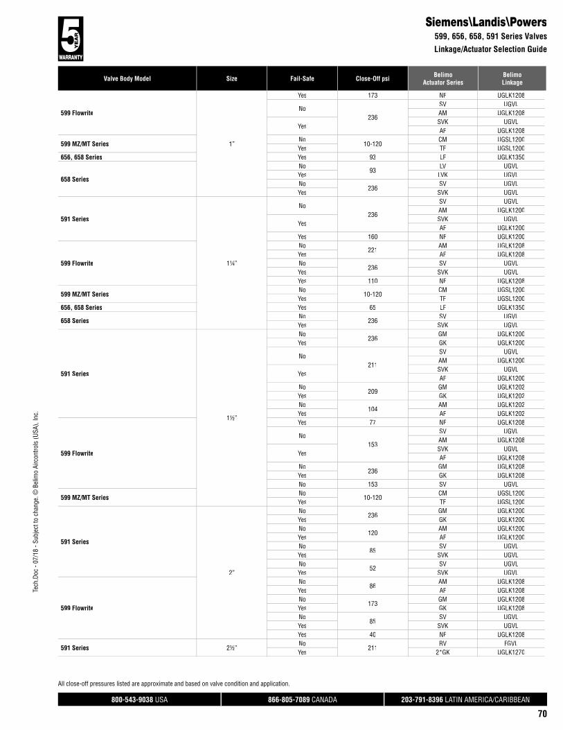
800-543-9038 USA 866-805-7089 CANADA 203-791-8396 LATIN AMERICA/CARIBBEAN
70
Tech
.Doc
- 07
/18
- Sub
ject
to c
hang
e. ©
Bel
imo
Airc
ontro
ls (U
SA),
Inc.
Valve Body Model Size Fail-Safe Close-Off psi BelimoActuator Series
BelimoLinkage
All close-off pressures listed are approximate and based on valve condition and application.
599 Flowrite
1”
Yes 173 NF UGLK1208
No236
SV UGVLAM UGLK1208
YesSVK UGVLAF UGLK1208
599 MZ/MT SeriesNo
10-120CM UGSL1200
Yes TF UGSL1200656, 658 Series Yes 93 LF UGLK1350
658 Series
No93
LV UGVLYes LVK UGVLNo
236SV UGVL
Yes SVK UGVL
591 Series
1¼”
No236
SV UGVLAM UGLK1200
YesSVK UGVLAF UGLK1200
Yes 160 NF UGLK1200
599 Flowrite
No221
AM UGLK1208Yes AF UGLK1208No
236SV UGVL
Yes SVK UGVLYes 110 NF UGLK1208
599 MZ/MT SeriesNo
10-120CM UGSL1200
Yes TF UGSL1200656, 658 Series Yes 65 LF UGLK1350
658 SeriesNo
236SV UGVL
Yes SVK UGVL
591 Series
1½”
No236
GM UGLK1200Yes GK UGLK1200
No211
SV UGVLAM UGLK1200
YesSVK UGVLAF UGLK1200
No209
GM UGLK1202Yes GK UGLK1202No
104AM UGLK1202
Yes AF UGLK1202
599 Flowrite
Yes 77 NF UGLK1208
No153
SV UGVLAM UGLK1208
YesSVK UGVLAF UGLK1208
No236
GM UGLK1208Yes GK UGLK1208No 153 SV UGVL
599 MZ/MT SeriesNo
10-120CM UGSL1200
Yes TF UGSL1200
591 Series
2”
No236
GM UGLK1200Yes GK UGLK1200No
120AM UGLK1200
Yes AF UGLK1200No
85SV UGVL
Yes SVK UGVLNo
52SV UGVL
Yes SVK UGVL
599 Flowrite
No86
AM UGLK1208Yes AF UGLK1208No
173GM UGLK1208
Yes GK UGLK1208No
85SV UGVL
Yes SVK UGVLYes 40 NF UGLK1208
591 Series 2½”No
211RV FGVL
Yes 2*GK UGLK1270
Siemens\Landis\Powers599, 656, 658, 591 Series Valves
Linkage/Actuator Selection Guide

800-543-9038 USA 866-805-7089 CANADA 203-791-8396 LATIN AMERICA/CARIBBEAN
71
Valve Body Model Size Fail-Safe Close-Off psi BelimoActuator Series
BelimoLinkage
Tech
.Doc
- 07
/18
- Sub
ject
to c
hang
e. ©
Bel
imo
Airc
ontro
ls (U
SA),
Inc.
All close-off pressures listed are approximate and based on valve condition and application.
591 Series2½”
No110
EV FGVL
YesAVK FGVL2*AF UGLK1270
599 FlowriteYes 211 2*GK UGLK1272Yes 110 2*AF UGLK1272
591 Series3”
Yes 77AVK FGVL2*AF UGLK1270
No136
RV FGVLYes 2*GK UGLK1270No 90 EV FGVL
599 FlowriteYes 77 2*AF UGLK1272Yes 136 2*GK UGLK1272
591 Series
4”
Yes 22GK UGLK1206
2*AF UGLK1274No
40RV FGVL
Yes 2*GK UGLK1274No 30 EV FGVLYes 10 AF UGLK1206
599 FlowriteYes 22
GK UGLK12122*AF UGLK1276
Yes 40 2*GK UGLK1276Yes 10 AF UGLK1212
591 Series
5”
Yes 22 2*GK UGLK1274No 25 RV FGVLNo 20 EV FGVL
Yes 14GK UGLK1206
2*AF UGLK1274
599 FlowriteYes 22 2*GK UGLK1276
Yes 14GK UGLK1212
2*AF UGLK1276
591 Series 6”No
22RV FGVL
Yes 2*GK UGLK1274Yes 10 2*AF UGLK1274
WARREN CONTROLS
100 SGL SEAT
2½”
Yes 110 2*GK UGLK2272No
52RV WGVL
Yes AVK WGVLNo 26 EV WGVL
1800 3-WayNo
1102*GM UGLK2272
Yes 2*GK UGLK2272No 52 EV WGVL
1800 BALNo
1102*GM UGLK2272
Yes 2*GK UGLK2272No 52 EV WGVL
Type 20-22No 93 EV WGVLNo 185 RV WGVLYes 71 AVK WGVL
Type 23No
211EV WGVL
Yes AVK WGVL
Type 30-32No 93 EV WGVLNo 185 RV WGVLYes 71 AVK WGVL
100 SGL SEAT
3”
Yes 70 2*GK UGLK2272No 22 EV WGVLNo
40RV WGVL
Yes AVK WGVL
1800 3-WayNo
702*GM UGLK2272
Yes 2*GK UGLK2272No 40 EV WGVL
1800 BALNo
702*GM UGLK2272
Yes 2*GK UGLK2272No 40 EV WGVL
Siemens\Landis\Powers591, 599 Series Valves
Linkage/Actuator Selection Guide
Warren Controls100, 1800, Type 20-22, Type 23, Type 30-32 Series Valves
Linkage/Actuator Selection Guide
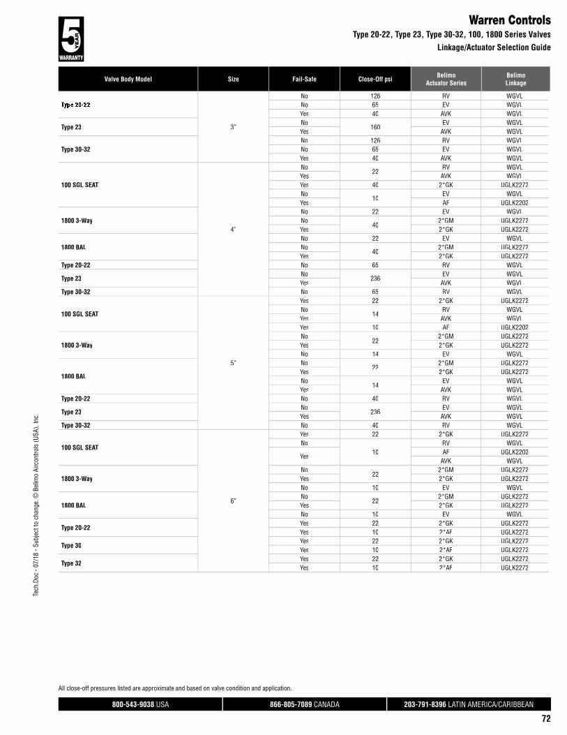
800-543-9038 USA 866-805-7089 CANADA 203-791-8396 LATIN AMERICA/CARIBBEAN
72
Tech
.Doc
- 07
/18
- Sub
ject
to c
hang
e. ©
Bel
imo
Airc
ontro
ls (U
SA),
Inc.
Valve Body Model Size Fail-Safe Close-Off psi BelimoActuator Series
BelimoLinkage
All close-off pressures listed are approximate and based on valve condition and application.
3”
No 126 RV WGVLNo 65 EV WGVLYes 40 AVK WGVL
Type 23No
160EV WGVL
Yes AVK WGVL
Type 30-32No 126 RV WGVLNo 65 EV WGVLYes 40 AVK WGVL
100 SGL SEAT
4”
No22
RV WGVLYes AVK WGVLYes 40 2*GK UGLK2272No
10EV WGVL
Yes AF UGLK2202
1800 3-WayNo 22 EV WGVLNo
402*GM UGLK2272
Yes 2*GK UGLK2272
1800 BALNo 22 EV WGVLNo
402*GM UGLK2272
Yes 2*GK UGLK2272Type 20-22 No 65 RV WGVL
Type 23No
236EV WGVL
Yes AVK WGVLType 30-32 No 65 RV WGVL
100 SGL SEAT
5”
Yes 22 2*GK UGLK2272No
14RV WGVL
Yes AVK WGVLYes 10 AF UGLK2202
1800 3-WayNo
222*GM UGLK2272
Yes 2*GK UGLK2272No 14 EV WGVL
1800 BAL
No22
2*GM UGLK2272Yes 2*GK UGLK2272No
14EV WGVL
Yes AVK WGVLType 20-22 No 40 RV WGVL
Type 23No
236EV WGVL
Yes AVK WGVLType 30-32 No 40 RV WGVL
100 SGL SEAT
6”
Yes 22 2*GK UGLK2272No
10RV WGVL
YesAF UGLK2202
AVK WGVL
1800 3-WayNo
222*GM UGLK2272
Yes 2*GK UGLK2272No 10 EV WGVL
1800 BALNo
222*GM UGLK2272
Yes 2*GK UGLK2272No 10 EV WGVL
Type 20-22Yes 22 2*GK UGLK2272Yes 10 2*AF UGLK2272
Type 30Yes 22 2*GK UGLK2272Yes 10 2*AF UGLK2272
Type 32Yes 22 2*GK UGLK2272Yes 10 2*AF UGLK2272
Warren ControlsType 20-22, Type 23, Type 30-32, 100, 1800 Series Valves
Linkage/Actuator Selection Guide

Tech
.Doc
- 07
/18
- Sub
ject
to c
hang
e. ©
Bel
imo
Airc
ontro
ls (U
SA),
Inc.
®
800-543-9038 USA 866-805-7089 CANADA 203-791-8396 LATIN AMERICA/CARIBBEAN
73
Custom Globe Valve SolutionsUGSP Series Globe Valve Retrofit System
Globe valve retrofits that cannot be matched to one of the Belimo UGLK part numbers; please use part number UGSP0000 for valves requiring single actuation and UGSP0002 for valves requiring dual actuation. These part numbers have no Bill of Materials (BOM) associated with them, therefore cannot be produced and shipped. When these two part numbers are quoted, sold and orders processed, the “Globe Valve Retrofit” form must be completed and accompany the order. Belimo’s engineering department will establish the correct UGSP linkage number for production. UGSP0000 and UGSP0002 will NOT show up on final paperwork. The correct UGSP part numberwill be stated.
UGSP0000
A
B C
H1
H2
D
UGSP0002
A
C D
The single actuated globe retrofit linkage (shown left) depicts dimensional data for use in determining the envelope space required to mount the linkage. These dimensions do NOT include VALVE dimensions which will affect combined heightrequirements.
Dims H1 & H2 are used only when override handles are utilized on the linkage system, and are not required for proper operation of the linkage system.
Dim A 7.5” [190] to 14” [356] Dim H1 9.5” [242]Dim B 3” [76] Dim H2 9.5” [242]Dim C 9” [229]Dim D 5” [127]
The dual actuated globe retrofit linkage (shown left) depicts dimensional data for use in determining the envelope space required to mount the linkage. These dimensions do NOT include VALVE dimensions which will affect combined heightrequirements.
Dim A 9.5” [241] to 19” [483]Dim B 3” [76]Dim C 9” [229]Dim D 5” [127]
Custom kits are designed to your unique specifi cations and are not returnable.

Tech
.Doc
- 07
/18
- Sub
ject
to c
hang
e. ©
Bel
imo
Airc
ontro
ls (U
SA),
Inc.
®
800-543-9038 USA 866-805-7089 CANADA 203-791-8396 LATIN AMERICA/CARIBBEAN
74
Custom Globe Valve Retrofit Solution FormUGSP Series
Note: Before completing this form, contact Belimo technical support to ensure a UGVL will fit your valve.
Required tools needed a caliper, thread gauge, retrofit form, flashlight, and ladder (if applicable).
Dimensions A, B, & C relate to the existing valve stem. Dim A is the stem diameter where it is NOT threaded (Style A), or grooved (Style B). Dim B refers to the length of the threaded region on the valve stem or top region of the grooved stem. Dim C is the actual thread specification for the threaded style stem (1/4-28, 5/16-24, 3/8-24, 7/16-20 & 1/2-20 are typical). Dim C for the grooved style is the measurement of the stem groove height. This information is used to design a stem adapter which will connect the valve stem to the new linkage drive rack. It is important to specify the correct thread pattern, as incorrect data will prevent the stem adapter from attaching to your valve. If you cannot determine the correct thread spec, you can send a nut from the valve stem and we will match the correct specification. In some cases where older valves are concerned, some valve stems must be trimmed in the field to allow attachment of the linkage system. In these cases, a stem adapter is designed to “bite” into the smooth surface of the valve stem itself.
Dimensions D1, D2 & D3 are used to determine the height of the linkage assembly required to clear the valves’ full stroke. A minimum of two dimensions are required to manufacture the correct linkage system for your valve. These dimensions also provide the information necessary to determine valve stroke. The maximum stroke from Belimo globe valve retrofit systems is 1.500”.
Dimension E refers to the valve bonnet diameter (regardless if threads are present or not). Over time, impurities will react to the bonnet threads and corrode them to the point where they no longer meet the original thread specification. Because of this, we manufacture slip fit collars designed to slide over the bonnet threads, and locking setscrews are provided which “bite” into the original threads. All retrofit systems are designed to work with the raw valve body and do not account for previous actuation components which must be removed from the valve body before attaching the new linkage system.
Dimension F refers to the thread specification on threaded bonnets, and refers to the minor diameter on slip on bonnets (Landis type). Thisinformation helps us determine the length of the locking devices required to hold the collar onto the bonnet.
Dimensions G & H are used to determine working height of the bonnet region of your globe valve, while Dim I is used in calculating the minimum ID of the collar that will fit over the packing nut. Additionally, information about the environment and process in which this linkage system will be utilized should be provided.
All the requested information contained on this form is required to guarantee the complete, perfect fit of your retrofit system. Keep in mind that retrofit kits are designed with close-tolerance components which afford the most efficient linkage systems. Measurements rounded to the nearest 1/8 or 1/16 inch will not perform as well as a kit designed around careful measurements using proper equipment. Our designs are typically +.005” tolerance.
DISCLAIMER:
We will do our best to provide a linkage system designed around your specifications and measurements. However, we cannot be held responsible for linkages which do not fit as a result of incorrect data given to Belimo. We will re-work components which do not fit properly for a nominal fee.
To reduce the possibility of incorrect linkage solutions, we respectfully request that you fill out the retrofit form completely and forward that information with your order. This will serve as a double check between your valve and the actuator/linkage package designed for your application.
Actuation, weather shields and linkages cannot be pre-assembled at the Belimo factory prior to your receipt. The linkages are designed to be attached onto the valve body first, then optional weather shields, and finally actuation products.
Close-off pressures are calculated using actuator torque, valve stroke, and valve area. Other factors may affect the rated close-off pressures, including flow rates, system maintenance schedules, chemicals used in the shot feeder process, vicinity to pumps, condition of valve stem seals, and assembly of linkage material in the field.
Valves that are being considered for retrofit of actuation should be analyzed for their life expectancy before the retrofit has taken place. Valves that leak through stem seals or casings will continue to leak with the new linkage system in place, maybe even more so. Rebuilding the packing on these valves may be more costly than replacing the valves themselves. In some instances, older valve stem heights will require field modifications to the valve in order to utilize the retrofit kit. Belimo takes no responsibility for the operation of these valves after they have been modified.
Instructions for Completing this Form

Tech
.Doc
- 07
/18
- Sub
ject
to c
hang
e. ©
Bel
imo
Airc
ontro
ls (U
SA),
Inc.
®
800-543-9038 USA 866-805-7089 CANADA 203-791-8396 LATIN AMERICA/CARIBBEAN
75
Custom Globe Valve Retrofit Solution FormUGSP Series
EXISTING ACTUATOR MODEL: _______________________ CONTROL TYPE: ON/OFF FLOATING POINT VDC PWM FAIL SAFE: YES NOFAIL POSITION: NO NC VOLTAGE _____
ACTUATOR
STEM STYLE A STEM STYLE B
VALVE STYLE 1 VALVE STYLE 2 VALVE STYLE 3
VALVE STYLE 4
STEM DIAMETERDIM A:
STEM STYLEA or B:
2 WAY/3 WAY:
VALVE SIZE:
MEDIA TEMP:
MEDIA TYPE:
SYSTEM PRESSURE:
VALVE MANUFACTURER:
VALVE SERIES:
VALVE MODEL:
VALVE TAG/LOCATION:
QUANTITY:
Range:_____
COMPANY:
JOB NAME:
PO#:
PHONE:
EMAIL:
NOTE: THIS INFORMATION WILL BE UTILIZED IN THE FABRICATION OF A CUSTOM LINKAGE SYSTEM FOR YOUR VALVE REQUIREMENT; THEREFORE, IT IS ESSENTIAL THAT THE
ABOVE DIMENSIONS BE FURNISHED WITH READINGS TAKEN TO THE NEAREST .001". ANY ERRONEOUS DIMENSIONS FURNISHED WHICH RESULT IN IMPROPER FIT OF THIS LINKAGE
SYSTEM ARE NOT THE RESPONSIBILITY OF BELIMO AIRCONTROLS. ANY REWORK REQUIRED WILL RESULT IN AN EXTRA CHARGE.
CUSTOM KITS ARE DESIGNED TO YOUR UNIQUE SPECIFICATIONS AND ARE NOT RETURNABLE.
COMPANY CONTACT/DIMENSIONS PROVIDED BY: ____________________________________________________________________ DATE: ___________________
INDOOR OUTDOOR
VALVE STYLE 5
Range:_____
D3 D1
(i.e. Barber Colman)
HG
E
F
Nut "F" rotates onvalve bonnet
NOTE:
D2
Internal Packing Nut
G
E
F
D3 D1
D2
(i.e. Powers)
H GI
EF
D3 D1
D2
External Packing Nut
GI
EF
D3 D1
D2
(i.e. Honeywell)
G
EFE
H
D3 D1
D2 VALVE STYLE:DIM D1*: Stem up, length to base mount surface
DIM D2: Stem stroke, stem up vs. stem down (D1-D3)
DIM D3: Stem down, length to base mount surface
DIM E: Bonnet major diameter
DIM F: Thread spec or bonnet minor diameter
DIM G: Bonnet mount height
DIM H: Bonnet minor diameter height
DIM I: External packaging nut, across points
VALVE STYLE DIMENSIONS
AØ
C BB
C
THREAD LENGTHDIM B:
TO STEM GROOVEDIM B:
STEM GROOVE HEIGHTDIM C:
THREADS PER INCHDIM C:
*MAXIMUM LENGTH LINKAGE FRAME WILL ACCOMODATE UP TO 6.500” D1 MEASUREMENT VALVE STEMS LONGER THAN THIS NEED TO BE CUT.
max.1.500”
AØ

®
800-543-9038 USA 866-805-7089 CANADA 203-791-8396 LATIN AMERICA/CARIBBEAN
76
Dimensions Needed
E
GH
A
C
F
D1D3
D2
B
UGSP Series Globe Valve Retrofit SolutionRetrofitting STYLE 1 Globe Valves Typical for Siebe\Invensys\Barber Colman
Identification & Measurement of Existing Valves
Follow these important steps to properly measure STYLE 1 type globe valves for a retrofit linkage.Reference the photos and line drawing to help guide you through the data collection process.
The valve should be stripped down to its basic form, as shown. Remove all other linkage components in order to obtain correct dimensional data for the retrofit kit. Note that the bonnet nut isp y y, p ypermanently attached to the valve body, and that it also spins freely.
1
2
Dimension A on the retrofit form is measuredas shown, with the end of the calipers layingPERPENDICULAR to the center line of the valvestem. Record this readingto three decimal places.
Measure the LENGTH of the threaded area of the valve stem, and record this information for Dimension B on the retrofit form.
Using the WIDE area of the calipers, measure the MAJOR Diameter of the stem threads. Record this information for Dimension C on the retrofit form.Count how many threads per inch. Typical threadspecs are 1/4-28, 3/8-24 & 1/2-20. If available, you should use a thread gage to determine the correct thread spec. Alternatively,you may send a valvestem nut to Belimo and we will determine thecorrect thread spec. Correct thread identification is importantas this is the point of highest mechanical stressafter the retrofitting has been completed.
3

®
800-543-9038 USA 866-805-7089 CANADA 203-791-8396 LATIN AMERICA/CARIBBEAN
77
UGSP Series Globe Valve Retrofit SolutionRetrofitting STYLE 1 Globe Valves Typical for Siebe\Invensys\Barber Colman
4
5
Dimension D1 on the retrofit form is measuredas shown, with the depth gage used to measure the STEM UP distance to the bonnet base.
Dimension D3 on the retrofit form is measured as shown, with the depth gage used to measure the STEM DN distance to the bonnet base.
Dimension F is measuredusing a thread gage or by counting the number of threads per inch.
8
7 Dimension E is measured across the MAJOR diameter of the bonnet threads. Use the calipersas shown to determinethe correct dimension and record accordinglyon the retrofit form.
6 Dimension D2 on the retrofit form is themeasured distance between the STEM UP and STEM DN heights, which gives the full travel of the valve. Only TWO of the three dimensions D1, D2 & D3 are needed.
9 Measure Dimension G using the caliper depth gage, and record on the retrofit form.
10 Dimension H is measured as the distance between the bonnet mounting baseheight and the TOP of the stem packing retainer.

®
800-543-9038 USA 866-805-7089 CANADA 203-791-8396 LATIN AMERICA/CARIBBEAN
78
UGSP Series Globe Valve Retrofit SolutionRetrofitting STYLE 2 Globe Valves Typical for Internal Packing Nut Type Valves
Dimensions Needed
G
E
A
C
D3
F
D2
D1
B
Identification & Measurement of Existing Valves
Follow these important steps to properly measure STYLE 2 type globe valves for a retrofit linkage.Reference the photos and line drawing to help guide you through the data collection process.
The valve should be stripped down to its basic form, as shown. Remove all other linkage components in order to obtain correct dimensional data for the retrofit kit. Note that the packing nut is inside the bonnet, and does NOT interfere with the bonnet threads.
1
2
Dimension A on the retrofit form is measuredas shown, with the end of the calipers layingPERPENDICULAR to the center line of the valvestem. Record this readingto three decimal places.
Measure the LENGTH of the threaded area of the valve stem, and record this information for Dimension B on the retrofit form.
Using the WIDE area of the calipers, measure the MAJOR Diameter of the stem threads. Record thisinformation for Dimension C on the retrofit form.Count how many threads per inch. Typical thread specs are 1/4-28, 3/8-24 & 1/2-20. If available, youshould use a thread gage to determine the correct thread spec. Alternatively,you may send a valvestem nut to Belimo and we will determine the correct thread spec. Correct thread identification is importantas this is the point of highest mechanical stressafter the retrofitting has been completed.
3

®
800-543-9038 USA 866-805-7089 CANADA 203-791-8396 LATIN AMERICA/CARIBBEAN
79
UGSP Series Globe Valve Retrofit SolutionRetrofitting STYLE 2 Globe Valves Typical for Internal Packing Nut Type Valves
4
5
Dimension D1 on the retrofit form is measuredas shown, with the depth gage used to measure the STEM UP distance to the bonnet base.
Dimension D3 on the retrofit form is measured as shown, with the depth gage used to measure the STEM DN distance to the bonnet base.
Dimension F is measuredusing a thread gage or by counting the number of threads per inch.
8
7 Dimension E is measured across the MAJOR diameter of the bonnet threads. Use the calipersas shown to determinethe correct dimension and record accordinglyon the retrofit form.
6 Dimension D2 on the retrofit form is themeasured distance between the STEM UP and STEM DN heights, which gives the full travel of the valve. Only TWO of the three dimensions D1, D2 & D3 are needed.
9 Measure Dimension G using the caliper depth gage, and record on the retrofit form.

®
800-543-9038 USA 866-805-7089 CANADA 203-791-8396 LATIN AMERICA/CARIBBEAN
80
UGSP Series Globe Valve Retrofit SolutionRetrofitting STYLE 3 Globe Valves Typical for Powers 599 Series
and Other Non-Threaded, Non-Tapered Bonnet Valves
Dimensions Needed
F
H G
A
C
E
B
D3I
D1
D2
Identification & Measurement of Existing Valves
Follow these important steps to properly measure STYLE 3 type globe valves for a retrofit linkage.Reference the photos and line drawing to help guide you through the data collection process.
The valve should be stripped down to its basic form, as shown. Remove all other linkage components in order to obtain correct dimensional data for the retrofit kit. Note that there are no threads on the bonnet. The packing nut is smaller that the diameter of the bonnet. There is a groove in the bonnet used to secure the retrofit collar to the valve.
1
2
Dimension A on the retrofit form is measuredas shown, with the end of the calipers layingPERPENDICULAR to the center line of the valvestem. Record this readingto three decimal places.
Measure the LENGTH of the threaded area of the valve stem, and record this information for Dimension B on the retrofit form.
Using the WIDE area of the calipers, measure the MAJOR Diameter of the stem threads. Record thisinformation for Dimension C on the retrofit form.Count how many threads per inch. Typical threadspecs are 1/4-28, 3/8-24 & 1/2-20. If available, youshould use a thread gage to determine the correct thread spec. Alternatively, you may send a valvestem nut to Belimo and we will determine thecorrect thread spec. Correct thread identification is importantas this is the point of highest mechanical stressafter the retrofitting has been completed.
3

®
800-543-9038 USA 866-805-7089 CANADA 203-791-8396 LATIN AMERICA/CARIBBEAN
81
UGSP Series Globe Valve Retrofit SolutionRetrofitting STYLE 3 Globe Valves Typical for Powers 599 Seriesand Other Non-Threaded, Non-Tapered Bonnet Valves
4
5
Dimension D1 on the retrofit form is measured as shown, with the depth gage used to measure the STEM UP distance to the bonnet base.
Dimension D3 on the retrofit form is measured as shown, with the depth gage used to measure the STEM DN distance to the bonnet base.
DImension F is measured using calipers across the MINOR diameter of the bonnet. This may be a square or a round groove. Measure the SMALLEST dimension of this groove.
8
7 Dimension E is measured across the MAJOR diameter of the bonnet. Use the calipers asshown to determine the correct dimension and record accordingly on the retrofit form. Thisdimension should be checked both above and below the locking groove.
6 Dimension D2 on the retrofit form is themeasured distance between the STEM UP and STEM DN heights, which gives the full travel of the valve. Only TWO of the three dimensions D1, D2 & D3 are needed.
9 Measure Dimension G using the caliper depth gage, and record on the retrofit form.
10 Measure Dimension H using the caliper depth gage, and record on the retrofit form.
11 Dimension I is measured on the outside diameter of the external packing nut.
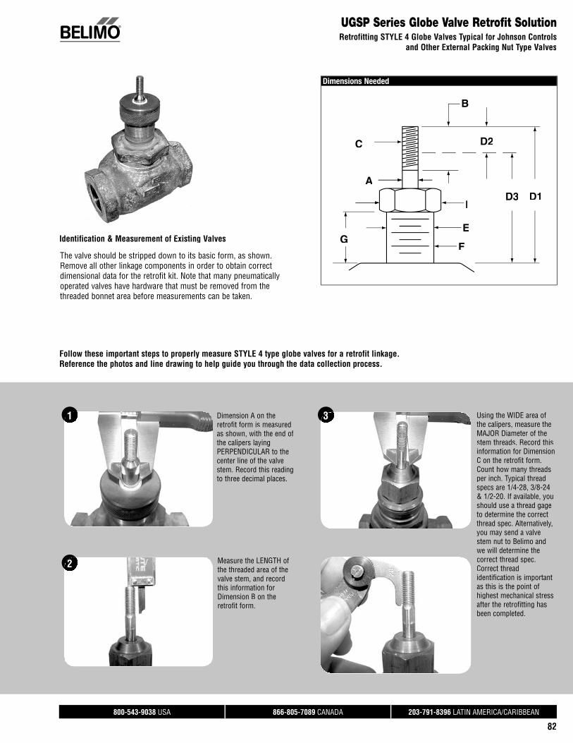
®
800-543-9038 USA 866-805-7089 CANADA 203-791-8396 LATIN AMERICA/CARIBBEAN
82
UGSP Series Globe Valve Retrofit SolutionRetrofitting STYLE 4 Globe Valves Typical for Johnson Controls
and Other External Packing Nut Type Valves
Dimensions Needed
C
G
A
D2
E
F
ID3 D1
B
Identification & Measurement of Existing Valvesf Existi
Follow these important steps to properly measure STYLE 4 type globe valves for a retrofit linkage.Reference the photos and line drawing to help guide you through the data collection process.
The valve should be stripped down to its basic form, as shown. Remove all other linkage components in order to obtain correct dimensional data for the retrofit kit. Note that many pneumaticallyoperated valves have hardware that must be removed from the threaded bonnet area before measurements can be taken.
1
2
Dimension A on the retrofit form is measuredas shown, with the end of the calipers layingPERPENDICULAR to the center line of the valvestem. Record this readingto three decimal places.
Measure the LENGTH of the threaded area of the valve stem, and record this information for Dimension B on the retrofit form.
Using the WIDE area of the calipers, measure the MAJOR Diameter of the stem threads. Record thisinformation for Dimension C on the retrofit form.Count how many threads per inch. Typical threadspecs are 1/4-28, 3/8-24 & 1/2-20. If available, youshould use a thread gage to determine the correct thread spec. Alternatively, you may send a valvestem nut to Belimo and we will determine thecorrect thread spec. Correct thread identification is importantas this is the point of highest mechanical stressafter the retrofitting has been completed.
3

®
800-543-9038 USA 866-805-7089 CANADA 203-791-8396 LATIN AMERICA/CARIBBEAN
83
UGSP Series Globe Valve Retrofit SolutionRetrofitting STYLE 4 Globe Valves Typical for Johnson Controlsand Other External Packing Nut Type Valves
4
5
Dimension D1 on the retrofit form is measuredas shown, with the depth gage used to measure the STEM UP distance to the bonnet base.
Dimension D3 on the retrofit form is measured as shown, with the depth gage used to measure the STEM DN distance to the bonnet base.
DImension F is measured using a thread gage or by counting the number of threads per inch.It is easier to use a thread gage with theexternal packing nut removed.
8
7 Dimension E is measured across the MAJOR diameter of the bonnet. Use the calipers as shown to determine the correct dimension and record accordingly on the retrofit form. Do NOTmeasure the diameter of the packing nut for this dimension.
6 Dimension D2 on the retrofit form is themeasured distance between the STEM UP and STEM DN heights, which gives the full travel of the valve. Only TWO of the three dimensions D1, D2 & D3 are needed.
9 Measure Dimension G using the caliper depth gage to measure the distance between the bottom on the packing nut and the valve collar seating surface.
10 Dimension I is measured on the outside diameter or point of the externalpacking nut.

®
800-543-9038 USA 866-805-7089 CANADA 203-791-8396 LATIN AMERICA/CARIBBEAN
84
UGSP Series Globe Valve Retrofit SolutionRetrofitting STYLE 5 Globe Valves Typical for Honeywell
and Other Non-Threaded, Tapered Bonnet Valves
Dimensions Needed
G F
E
E
A
C
H
D3
D2
B
D1
Identification & Measurement of Existing Valves
Follow these important steps to properly measure STYLE 5 type globe valves for a retrofit linkage.Reference the photos and line drawing to help guide you through the data collection process.
The valve should be stripped down to its basic form, as shown. Remove all other linkage components in order to obtain correct dimensional data for the retrofit kit.Note that there are no threads on the bonnet. The packing nut is smaller that the diameter of the bonnet. There is a groove in the bonnet used to secure the retrofit collar to the valve.
1
2
Dimension A on the retrofit form is measuredas shown, with the end of the calipers layingPERPENDICULAR to the center line of the valvestem. Record this readingto three decimal places.
Measure the LENGTH of the threaded area of the valve stem, and record this information for Dimension B on the retrofit form.
Using the WIDE area of the calipers, measure the MAJOR Diameter of the stem threads. Record thisinformation for Dimension C on the retrofit form.Count how many threads per inch. Typical threadspecs are 1/4-28, 3/8-24 & 1/2-20. If available, youshould use a thread gage to determine the correct thread spec. Alternatively, you may send a valvestem nut to Belimo and we will determine thecorrect thread spec. Correct thread identification is importantas this is the point of highest mechanical stressafter the retrofitting has been completed.
3
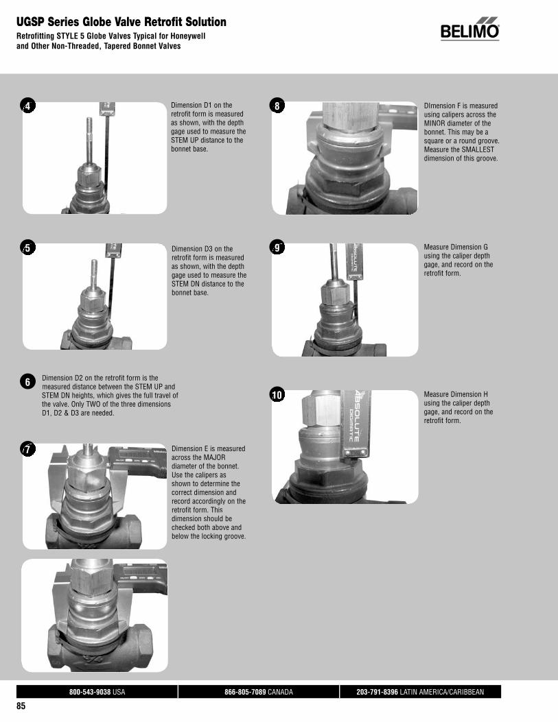
®
800-543-9038 USA 866-805-7089 CANADA 203-791-8396 LATIN AMERICA/CARIBBEAN
85
UGSP Series Globe Valve Retrofit SolutionRetrofitting STYLE 5 Globe Valves Typical for Honeywelland Other Non-Threaded, Tapered Bonnet Valves
4
5
Dimension D1 on the retrofit form is measuredas shown, with the depth gage used to measure theSTEM UP distance to the bonnet base.
Dimension D3 on the retrofit form is measured as shown, with the depth gage used to measure the STEM DN distance to the bonnet base.
DImension F is measuredusing calipers across the MINOR diameter of the bonnet. This may be a square or a round groove. Measure the SMALLEST dimension of this groove.
8
7 Dimension E is measured across the MAJOR diameter of the bonnet. Use the calipers as shown to determine the correct dimension and record accordingly on the retrofit form. Thisdimension should be checked both above and below the locking groove.
6 Dimension D2 on the retrofit form is themeasured distance between the STEM UP and STEM DN heights, which gives the full travel of the valve. Only TWO of the three dimensions D1, D2 & D3 are needed.
9 Measure Dimension G using the caliper depth gage, and record on the retrofit form.
10 Measure Dimension H using the caliper depth gage, and record on the retrofit form.

Tech
.Doc
- 07
/18
- Sub
ject
to c
hang
e. ©
Bel
imo
Airc
ontro
ls (U
SA),
Inc.
®
800-543-9038 USA 866-805-7089 CANADA 203-791-8396 LATIN AMERICA/CARIBBEAN
86
UGLK Collars* Most Commonly Used Valve StylePart Number Inside Diameter Description Style 1 Style 2 Style 3 Style 4 Style 5UGLK-COL-1005 1.000” 3 setscrews, for frame type •UGLK-COL-1063 1.063” 3 setscrews, for frame type •UGLK-COL-1100 1.100” 3 setscrews, for frame type, counterbored top •UGLK-COL-1255 1.250” 3 setscrews, for frame type •UGLK-COL-1315 1.315” 3 setscrews, for frame type, can be used with VB7 with shim •UGLK-COL-1375 1.375” 3 setscrews, for frame type •UGLK-COL-BC10 1.250”- 16 Thd. Fits Siebe VB7/VB9. Use on frame type only •UGLK-COL-HY02 1.370” 1 setscrew, for frame type •UGLK-COL-LG02 1.740” 1 setscrew, for frame type •UGLK-COL-LG04 1.740” 1 setscrew, for frame type •UGLK-COL-JC05 1.070” 3 setscrews, for frame type •UGLK-COL-JC06 1.562- 14 Thd. Threaded, brass •UGLK-COL-JC08 0.760” 3 setscrews, for frame type, counterbored top •UGLK-COL-JC15 1.070” Ring, no setscrews •UGLK-COL-0880 0.880” 3 setscrews, for frame type, counterbored top •UGLK-COL-WNUT 1.375”- 20 Thd. Replacement Warren nut. Will not go over damaged threads •UGLK-COL-AD01 1.250”- 16 Thd. Fits Siebe VB7/VB9. For VB7 frame only •UGLK-COL-UNIV Custom 3 setscrews, for frame type. Must be machined • • • •UGSL-ADPT Custom Custom collar for UGSL1200. Must be machined
UGLK Stem Adapters Most Commonly Used Valve StylePart Number Inside Diameter Description Style 1 Style 2 Style 3 Style 4 Style 5UGLK-STM-1800 1/4”- 28 Stem Thd. Stem adapter for 1/4”- 28 valve stems • • • • •UGLK-STM-1801 3/8”- 24 Stem Thd. Stem adapter for 3/8”- 24 valve stems • • • • •UGLK-STM-1802 1/2”- 20 Stem Thd. Stem adapter for 1/2”- 20 valve stems • • •UGLK-STM-1803 7/16”- 20 Stem Thd. Stem adapter for 7/16”- 20 valve stems •UGLK-STM-1501 3/8”- 24 Stem Thd. For Warren FLG valves with UGLK •UGLK-STM-1805 3/8” OD Grooved Landis 2.5-3” -599 Series •UGLK-STM-2305 1/2” OD Grooved Landis 4-6” -599 Series •UGLK-STM-UNIV Custom Must be machined • • • • •
UGLK Stem Adapters UGLK Collars
UGLK Retrofi t SolutionComponents
Style 1
Style 2 Style 4
Style 3Style 5
* Must reuse retaining clip and set screws.
Actuator PlateAnti-Rotation
Screw
Retaining Ring
Base Bracket
Collar
Box Frame
Jam Nut
Stem Adapter
Set Screw
Rack
Drive Shaft
Back Plate
Gear
Set Screw

Tech
.Doc
- 07
/18
- Sub
ject
to c
hang
e. ©
Bel
imo
Airc
ontro
ls (U
SA),
Inc.
®
800-543-9038 USA 866-805-7089 CANADA 203-791-8396 LATIN AMERICA/CARIBBEAN
87
Valve AccessoriesGlobe Valves
WEATHER SHIELDS GM 2*GM LF NF AF 2*
AF GK 2*GK
LV/SV
EV/RV
LVK/SVK AVK
ZS-SPGV-60For LF actuators on G2/G3 series •
ZS-SPGV-10For dual AF series actuators on fl anged globe valves •
ZS-SPGV-20For single NF, AF actuator series • •
ZS-SPGV-40For GM, GK series on fl anged globe valves • •
ZS-SPGV-50For dual GM, GK series on fl anged globe valves • •
ZS-GV-001For LV, SV actuators on NPT series • •
ZS-GV-002For EV, RV, AVK actuator on fl anged series • •
BATTERY BACKUP EV RV
NSV24 USBattery backup module • •
NSV-BAT 12VDC 1.2 AH battery(2 required)
• •
AUXILIARY SWITCHES & POTENTIOMETERS LR/LM NR/NM AR/AM GR/GM AK GK/GKR DR
S1AAuxiliary switch 1x SPDT, 3A(0.5A inductive) @ 250 VAC
• • • • • • •
S2AAuxiliary switch 2x SPDT, 3A(0.5A inductive) @ 250 VAC
• • • • • • •
P140A GRFeedback potentiometer 140 • • • • • • •
P500A GRFeedback potentiometer 500 • • • • • • •
P500A GRFeedback potentiometer 500 • • • • • • •
P1000A GR Feedback potentiometer 1000 • • • • • • •
P2800A GRFeedback potentiometer 2800 • • • • • • •
P5000A GRFeedback potentiometer 5000 • • • • • • •
P10000A GRFeedback potentiometer 10000 • • • • • • •
LV/SV EV RV LVK/SVK AVK
S2A-GVAuxiliary switch 2x SPDT, 3A(0.5A inductive) @ 250 VAC for LV, SV, EV, and AVKseries actuators.
• • • • •

®
Butterfl y Valve Retrofi t SolutionsBelimo’s butterfly retrofi t solutions are designed to easily attach to thevalve-mounting pad of competitor valves utilizing Belimo actuators.Butterfly valves can quickly and conveniently be restored withoutinterruption in service and the removal of the valve, saving on down timeand costs. Belimo retrofi t solutions increase performance and effi ciency of integrated building technology.

Tech
.Doc
- 07
/18
- Sub
ject
to c
hang
e. ©
Bel
imo
Airc
ontro
ls (U
SA),
Inc.
®
800-543-9038 USA 866-805-7089 CANADA 203-791-8396 LATIN AMERICA/CARIBBEAN
89
1
Select linkage solution based on the ValveNumber, Confi guration, and Size; select theproper Linkage Solutionfor your valve.
UFLK3500Example: Centerline C200 Series,2½” valve using a non fail-safe Belimo actuation.
Choose correct linkage UFLK3500.
2
Verify close-off is suitablefor application.Looking at the UFLK3500, the GM Series actuator willprovide 200 psi close-off for the 2½” valve.
3
Select actuator based onneeded control type.Decide between GMB24-3-X1 and GMB24-MFT-X1.Consult actuator overviewsection for full details.
4Complete Ordering Example:
Item 1: UFLK3500Item 2: GMB24-MFT-X1
Valve Body Model ValveConfi guration Size Fail-Safe Close-Off
psi
BelimoActuator Series Belimo
Linkage
CenterlineC200 Round Top Series Butterfly Valves
Linkage/Actuator Selection Guide
How to Select a Butterfly Valve Retrofit SolutionFollow the four steps listed below when ordering a butterfly valve retrofit kit.
Example: Centerline C200 Series, 2½” valve, using a Non Fail-Safe Belimo actuator.
1 Identify the Valve Manufacturer, Valve Series and Valve Size.
2 Determine the type of actuator you require: Belimo spring-return, non fail-safe, or electronic failsafe. Belimo springand non fail-safe actuators are typically only available on smaller sizes.
Look at the solution using the Non Fail-Safe Belimo Actuator. Looking at the UFLK3500, the GM Series actuator will provide a 200 psi close-off for the 2½” valve with Non Fail-Safe actuation.
3 Use the actuator listings to make your final actuator selection. Decide between GMB24-3-X1 and GMB24-MFT-X1.
ACTUATOR NOT INCLUDED IN THE LIST PRICE OF THE LINKAGE.
4 HOW TO ORDER: Item 1 1pc UFLK3500 Item 2 1pc GMB24-MFT-X1
C200 Round Top Series Butterfl y Valves
2-way 2” No 200 AM UFLK3500YesYes 200200 AFAF UFLKUFLK35003500
2½”2½ NoNo 200200 GMGM UFLKUFLK35003500YesYes 200200 2*AF2 AF UFLKUFLK35023502
GKG UFLKUFLK350035003” No 200 GM UFLK3500
Yes 200 2*AF UFLK3502GK UFLK3500
BASIC PRODUCTS
Model Control Input Feedback PowerSupply
RunningTime(s)[Default]
VA Rating AuxiliarySwitch Cable Length
GMB24-3-X1 On/Off, Floating Point Add-on 24 VAC/DC 150 seconds 6 Add-on 3 ft.GMB24-SR 2-10 VDC (4-20 mA*) 2-10 VDC 24 VAC/DC 150 seconds 6.5 Add-on 3 ft.GMB24GMB24 MFT-MFT-X1X1 2 102-10 VDCVDC 2 102-10 VDCVDC 24 VA24 VAC/DCC/DC 1 0150 s deconds 7 AddAdd-on 3 f3 ft.
Variable with MFT‡ Pric‡ Prices does do not renot reflectfl ect additiadditional ponal programrogramming cming code suode surchargrchargee.
NOTE:NOTE: 10’ an10 and 16’d 16 cablescables are aare availabvailable witle with a $2h a $28 00 a8.00 and $48nd $48 00 ad.00 adder exder except fcept for theor the PC anPC and MFT9d MFT95 vers5 version wion, which ahich are onlre only avaiy availablelable with awith a 3’ c3 cableable.

Tech
.Doc
- 07
/18
- Sub
ject
to c
hang
e. ©
Bel
imo
Airc
ontro
ls (U
SA),
Inc.
®
800-543-9038 USA 866-805-7089 CANADA 203-791-8396 LATIN AMERICA/CARIBBEAN
90
Butterfl y Valve Retrofi t ActuatorsActuator Selection Guide
SY ACTUATORSCONTROL TYPE
Series Torque Model Run Time(s) 90°@60Hz Power Supply Duty Cycle Proportional 3 Point/
Floating On/Off Feedback
SY4 3540 in-lbs[400 Nm]
SY4-110 18 seconds 120 VAC ±10%, 50/60 Hz 30% • • none, opt 1kSY4-24 25 seconds 24 VAC ±10%, 50/60 Hz 30% • • none, opt 1kSY4-220 18 seconds 230 VAC ±10%, 50/60 Hz 30% • • none, opt 1k
SY4-24MFT 16 seconds 24 VAC ±10%, 50/60 Hz 75% • 2-10 VDC/4-20 mASY4-120MFT 18 seconds 120 VAC ±10%, 50/60 Hz 75% • 2-10 VDC/4-20 mASY4-230MFT 18 seconds 230 VAC ±10%, 50/60 Hz 75% • 2-10 VDC/4-20 mA
SY5 4430 in-lbs[500 Nm]
SY5-110 25 seconds 120 VAC ±10%, 50/60 Hz 30% • • none, opt 1kSY5-24 37 seconds 24 VAC ±10%, 50/60 Hz 30% • • none, opt 1kSY5-220 25 seconds 230 VAC ±10%, 50/60 Hz 30% • • none, opt 1k
SY5-24MFT 22 seconds 24 VAC ±10%, 50/60 Hz 75% • 2-10 VDC/4-20 mASY5-120MFT 25 seconds 120 VAC ±10%, 50/60 Hz 75% • 2-10 VDC/4-20 mASY5-230MFT 25 seconds 230 VAC ±10%, 50/60 Hz 75% • 2-10 VDC/4-20 mA
SY6 5750 in-lbs[650 Nm]
SY6-110 29 seconds 120 VAC ±10%, 50/60 Hz 30% • • none, opt 1kSY6-220 28 seconds 230 VAC ±10%, 50/60 Hz 30% • • none, opt 1k
SY6-120MFT 31 seconds 120 VAC ±10%, 50/60 Hz 75% • 2-10 VDC/4-20 mASY6-230MFT 31 seconds 230 VAC ±10%, 50/60 Hz 75% • 2-10 VDC/4-20 mA
SY7 8850 in-lbs[1000 Nm]
SY7-110 54 seconds 120 VAC ±10%, 50/60 Hz 30% • • none, opt 1kSY7-220 54 seconds 230 VAC ±10%, 50/60 Hz 30% • • none, opt 1k
SY7-120MFT 55 seconds 120 VAC ±10%, 50/60 Hz 75% • 2-10 VDC/4-20 mASY7-230MFT 55 seconds 230 VAC ±10%, 50/60 Hz 75% • 2-10 VDC/4-20 mA
SY8 13280 in-lbs[1500 Nm]
SY8-110 58 seconds 120 VAC ±10%, 50/60 Hz 30% • • none, opt 1kSY8-220 55 seconds 230 VAC ±10%, 50/60 Hz 30% • • none, opt 1k
SY8-120MFT 55 seconds 120 VAC ±10%, 50/60 Hz 75% • 2-10 VDC/4-20 mASY8-230MFT 55 seconds 230 VAC ±10%, 50/60 Hz 75% • 2-10 VDC/4-20 mA
SY9 17700 in-lbs[2000 Nm]
SY9-110 62 seconds 120 VAC ±10%, 50/60 Hz 30% • • none, opt 1kSY9-220 63 seconds 230 VAC ±10%, 50/60 Hz 30% • • none, opt 1k
SY9-120MFT 70 seconds 120 VAC ±10%, 50/60 Hz 50% • 2-10 VDC/4-20 mASY9-230MFT 70 seconds 230 VAC ±10%, 50/60 Hz 50% • 2-10 VDC/4-20 mA
SY10 22130 in-lbs[2500 Nm]
SY10-110 63 seconds 120 VAC ±10%, 50/60 Hz 30% • • none, opt 1kSY10-220 64 seconds 230 VAC ±10%, 50/60 Hz 30% • • none, opt 1k
SY10-120MFT 70 seconds 120 VAC ±10%, 50/60 Hz 50% • 2-10 VDC/4-20 mASY10-230MFT 70 seconds 230 VAC ±10%, 50/60 Hz 50% • 2-10 VDC/4-20 mA
SY11 26550 in-lbs[3000 Nm]
SY11-110 65 seconds 120 VAC ±10%, 50/60 Hz 30% • • none, opt 1kSY11-220 64 seconds 230 VAC ±10%, 50/60 Hz 30% • • none, opt 1k
SY11-120MFT 70 seconds 120 VAC ±10%, 50/60 Hz 50% • 2-10 VDC/4-20 mASY11-230MFT 70 seconds 230 VAC ±10%, 50/60 Hz 50% • 2-10 VDC/4-20 mA
SY12 30980 in-lbs[3500 Nm]
SY12-110 65 seconds 120 VAC ±10%, 50/60 Hz 30% • • none, opt 1kSY12-220 63 seconds 230 VAC ±10%, 50/60 Hz 30% • • none, opt 1k
SY12-120MFT 70 seconds 120 VAC ±10%, 50/60 Hz 50% • 2-10 VDC/4-20 mASY12-230MFT 70 seconds 230 VAC ±10%, 50/60 Hz 50% • 2-10 VDC/4-20 mA
Proportional actuators will accept 0-10 VDC, 2-10 VDC, or 4-20 mA control signals as standard.All SY actuators are non-spring return, but can be used with NSV-SY back up systems for fail-safe applications.These products carry a two year warranty when sold as part of an assembly or with a UFLK retrofi t kit.

Tech
.Doc
- 07
/18
- Sub
ject
to c
hang
e. ©
Bel
imo
Airc
ontro
ls (U
SA),
Inc.
®
800-543-9038 USA 866-805-7089 CANADA 203-791-8396 LATIN AMERICA/CARIBBEAN
91
Butterfl y Valve Retrofi t ActuatorsActuator Selection Guide
ROTARY ACTUATORS
SERIES TORQUE MODEL Spring Return
Electronic Fail-Safe
Tandem Mounting Available
Control Input Feedback Position
Power Supply
AF Series* 180 in-lbs [20 Nm]
AFBUP-X1 • • On/Off - 24-240 VAC
AFX24-MFT-X1 • • Variable with MFT(VDC, PWM, Floating Point, On/Off) variable VDC 24 VAC/DC
AM Series* 180 in-lbs [20 Nm]
AMB24-3-X1 Floating Point, On/Off - 24 VAC/DC
AMX24-MFT-X1 Variable with MFT(VDC, PWM, Floating Point, On/Off) variable VDC 24 VAC/DC
GM Series* 360 in-lbs [40 Nm]
GMB24-3-X1 Floating Point, On/Off - 24 VAC/DC
GMX24-MFT-X1 • Variable with MFT(VDC, PWM, Floating Point, On/Off) variable VDC 24 VAC/DC
GK Series* 360 in-lbs [40 Nm]
GKB24-3-X1 • Floating Point, On/Off - 24 VAC
GKX24-MFT-X1 • • Variable with MFT(VDC, PWM, Floating Point, On/Off) variable VDC 24 VAC/DC
PR Series 1400 in-lbs [160 Nm]
PRBUP-3-T Floating Point, On/Off -24-240 VAC/ 24-
125 VDC, 50/60 HzPRBUP-MFT-T Variable with MFT
(VDC, PWM, Floating Point, On/Off) variable VDC
PK Series 1400 in-lbs [160 Nm] PKRBUP-MFT-T • Variable with MFT
(VDC, PWM, Floating Point, On/Off) variable VDC 24-240 VAC/ 24-125 VDC, 50/60 Hz
*Please consult the Damper sections of the Product Guide and Price List for a full list of product offerings. Standard run times should be considered in the selection. All air side products are applicable for retrofi t kits.Select “X1” actuators come with a handle.
MULTI-FUNCTION TECHNOLOGYP-CODE Control Input Running Time Built-in Feedback
ROTA
RY A
CTUA
TOR
CODE
S P-10001 A01 2-10 VDC 150 seconds 2-10 VDCP-10002 A02 0-10 VDC 150 seconds 0-10 VDCP-10028 A28 0-10 VDC 150 seconds 0-10 VDCP-10063 A63 0.5-4.5 VDC 150 seconds 0.5-4.5 VDCP-10064 A64 5.5-10 VDC 150 seconds 5.5-10 VDCP-20002 W02 0.02-5.00 seconds PWM 150 seconds 2-10 VDCP-20003 W03 0.10-25.5 seconds PWM 150 seconds 2-10 VDCP-30001 F01 Floating Point 150 seconds 2-10 VDCP-40002 J02 On/Off 150 seconds 2-10 VDC
Consult Belimo for programming code, if not shown on chart.
SY MULTI-FUNCTION TECHNOLOGYDescription MFT-CODE Control Input Built-in Feedback Loss of Signal Running Time
MFT ACE 2-10 VDC 2-10 VDC stopp ( )actuator(s) constant( )MFT ACF 0.5-10 VDC 0.5-10 VDC stopp ( )actuator(s) constant( )MFT ACG 4-20 mA 4-20 mA stopp ( )actuator(s) constant( )MFT ACH 4-20 mA 2-10 VDC stopp ( )actuator(s) constant( )MFT ACJ 2-10 VDC 2-10 VDC openp ( )actuator(s) constant( )MFT ACK 0.5-10 VDC 0.5-10 VDC openp ( )actuator(s) constant( )MFT ACL 4-20 mA 4-20 mA openp ( )actuator(s) constant( )MFT ACM 4-20 mA 2-10 VDC openp ( )actuator(s) constant( )MFT ACN 2-10 VDC 2-10 VDC close ( )actuator(s) constant( )MFT ACP 0.5-10 VDC 0.5-10 VDC close ( )actuator(s) constant( )MFT ACR 4-20 mA 4-20 mA close ( )actuator(s) constant( )MFT ACS 4-20 mA 2-10 VDC close ( )actuator(s) constant( )
Standard delivery may vary, please consult your customer service representative for the latest lead time(s).

Tech
.Doc
- 07
/18
- Sub
ject
to c
hang
e. ©
Bel
imo
Airc
ontro
ls (U
SA),
Inc.
®
800-543-9038 USA 866-805-7089 CANADA 203-791-8396 LATIN AMERICA/CARIBBEAN
92
UFLK.../UFSP... Retrofi t Linkage for Butterfl y ValvesFor 2-Way AF and GM Series Actuators
ApplicationThe UFLK/UFSP retrofit kit is designed to easily attach to the valve mounting pad onselect 2-way competitor valves utilizing Belimo AF and GM series actuators. This kit will help to restore service without removal of the valve, saving down time. The UFLK/UFSP retrofit kit is available in various configurations for use with both 2-way and 3-way valves utilizing single or dual actuation.
Default/ConfigurationThe actuator is sold separately from the linkage. This allows users to select any actuator with the desired control signal. Since the linkage utilizes standard air-side actuators, they can be purchased at any time and mounted in the field.
OperationThe UFLK/UFSP and mounted actuator(s) are capable of rotating 95° in both CW and CCW directions. This allows the disc to fully open or close. When directional needsvary, the actuators can be flipped or directional switch turned to a new rotation. Refer to the actuator wiring guides on Master/Slave wiring for dual mounted actuators.
Suitable Actuators Close-Off RangesAF Series 50-200 psiGM Series 50-300 psiGK Series 50-300 psi
2*AF Series 50-300 psi2*GM Series 50-740 psi2*GK Series 50-740 psi
Competitor Valves** Bray Victaulic Nibco
PDC Keystone Flowseal
Centerline JCI Milwaukee
**Consult pages 96-105 of the Retrofit Technical Documentation and/or SelectPro for close-off pressures and cross reference of each valve.
UFLK / UFSP Dual Shown
Technical Data UFLK... / UFSPMaterials: Plate stainless steel Coupling stainless steel Shafts stainless steelMounting position 360° mountableAmbient temperature -22°F to +122°F [-30°C to +50°C]Storage temperature -40°F to +176°F [-40°C to +80°C]Servicing chilled or hot water
max steam inlet 50 psiWeight 4.8 lbs [2.2 kg]
UFLK / UFSP Parts Breakdown- Single Shown
DRIVE SHAFT
PIN
SHAFT LOCK
ANTI-ROTATION NUT
ANTI-ROTATION PIN
ACTUATOR PLATE
BOLT (4)
NUT (4)
EXISTING VALVE BODY
VALVE STEM
TOP MOUNTING HOLES
VALVE DISC
LUG MOUNTING HOLES
VALVE COUPLING
Maximum Dimensions (Inches)Size B C D(Max) Actuator2” 9 9 19.5 AF/GK2” 7 7 15 AMB(X)
2½” 9 9 20 AF2½” 9 9 20 2*AF/2*GK2½” 7 7 15.5 AMB(X)3” 7 7 16 AMB(X)3” 8 8 16 GMB(X)3” 9 9 20.5 2*AF/2*GK4” 8 8 17 GMB(X)4” 9 9 21 2*AF/ 2*GK4” 8 8 21 2*GMB(X)5” 8 8 17.5 GMB(X)5” 9 9 22 2*AF/ 2*GK6” 8 8 22.5 GMB(X)
D
B C

Tech
.Doc
- 07
/18
- Sub
ject
to c
hang
e. ©
Bel
imo
Airc
ontro
ls (U
SA),
Inc.
®
800-543-9038 USA 866-805-7089 CANADA 203-791-8396 LATIN AMERICA/CARIBBEAN
93
UFLK.../UFSP... Retrofi t Linkage for Butterfl y ValvesFor 3-Way AF and GM Series Actuators
ApplicationThe UFLK/UFSP retrofit kit is designed to easily attach to the valve mounting pad onselect 3-way competitor valves utilizing Belimo AF and GM series actuators. This kitwill help to restore service without removal of the valve, saving down time. The UFLK/UFSP retrofit kit is available in various configurations for use with both 2-way and3-way valves utilizing single or dual actuation.
Default/ConfigurationThe actuator is sold separately from the linkage. This allows users to select anyactuator with the desired control signal. Since the linkage utilizes standard air-sideactuators, they can be purchased at any time and mounted in the field.
OperationThe UFLK/UFSP and mounted actuator(s) are capable of rotating 95° in both CW andCCW directions. This allows the disc to fully open or close. When directional needsvary, the actuators can be flipped or directional switch turned to a new rotation. Referto the actuator wiring guides on Master/Slave wiring for dual mounted actuators.
Suitable Actuators Close-Off RangesAF Series 50-200 psiGM Series 50-300 psiGK Series 50-300 psi
2*AF Series 50-300 psi2*GM Series 50-740 psi2*GK Series 50-740 psi
Competitor Valves**Bray Victaulic Nibco
PDC Keystone Flowseal
Centerline JCI Milwaukee
**Consult pages 96-105 of the Retrofit Technical Documentation and/orSelectPro for close-off pressures and cross reference of each valve.
UFLK / UFSP Dual ShownUFLK / UFSP Parts Breakdown- Single Shown
EXISTING VALVE
CRANK ARM (2)
COTTER PIN (2)
CONNECTINGROD
EXISTING VALVE
EXISTING TEE
ANTI-ROTATION NUT
NUT (4)
TOP MOUNTING HOLES
ANTI-ROTATION PIN
ACTUATOR PLATE
BOLT (4)
SHAFT LOCK (2)
PIN
CLEVIS PIN (2)
YOKE (2)
DRIVE SHAFT
CRANK LOCK (2)
JAMB NUT
VALVE COUPLING (2)
VALVE STEM
A
D
C B
Maximum Dimensions (Inches)Size A B C D(Max) Actuator2” 7 9 9 19.5 AF/GK2” 5 7 7 15 AMB(X)
2½” 7 9 9 20 AF2½” 7 9 9 20 2*AF/2*GK2½” 5 7 7 15.5 AMB(X)3” 5 7 7 16 AMB(X)3” 6 8 8 16 GMB(X)3” 7 9 9 20.5 2*AF/2*GK4” 6 8 8 17 GMB(X)4” 7 9 9 21 2*AF/ 2*GK4” 6 8 8 21 2*GMB(X)5” 6 8 8 17.5 GMB(X)5” 7 9 9 22 2*AF/ 2*GK6” 6 8 8 22.5 GMB(X)
Technical Data UFLK... / UFSPMaterials: Bracket stainless steel Couplings stainless steel Crank arms steel Yoke steel Rod steel
Mounting position configuration specific (X10-X35)Ambient temperature -22°F to +122°F [-30°C to +50°C]Storage temperature -40°F to +176°F [-40°C to +80°C]Servicing chilled or hot waterWeight 7 lbs [3.2 kg]

Tech
.Doc
- 07
/18
- Sub
ject
to c
hang
e. ©
Bel
imo
Airc
ontro
ls (U
SA),
Inc.
®
800-543-9038 USA 866-805-7089 CANADA 203-791-8396 LATIN AMERICA/CARIBBEAN
94
UFLK.../UFSP... Retrofi t Linkage for Butterfl y ValvesFor 2-way SY, PR and PKR Industrial Actuators
ApplicationThe UFLK/UFSP retrofit kit is designed to easily attach to the valve mounting pad onselect 2-way competitor valves utilizing Belimo SY industrial series actuators. This kit will help to restore service without removal of the valve, saving down time. The UFLK/UFSP retrofit kit is available in various configurations for use with both 2-way and 3-way valves.
Default/ConfigurationThe actuator is sold separately from the linkage. This allows users to select any actuator with the desired control signal. Since the linkage utilizes standard SY actuators, they can be purchased at any time and mounted in the field.
OperationThe UFLK/UFSP and mounted actuator(s) are capable of rotating 95° in both CW and CCW directions. This allows the disc to fully open or close. When directional needs vary, the actuator’s directional switch can be flipped to change the rotation. The SY is NEMA 4 rated and can be used outdoors.
Suitable Actuators Close-Off RangesPR/PKR Series 50-200 psi
SY4 Series 50-780 psiSY5 Series 150-300 psi
SY6-SY12 Series 150-780 psi
Competitor Valves** Bray Victaulic Nibco
PDC Keystone Flowseal
Centerline JCI Milwaukee
**Consult pages 96-105 of the Retrofit Technical Documentation and/or SelectPro for close-off pressures and cross reference of each valve.
Technical Data UFLK... / UFSPMaterials: Bracket stainless steel Couplings stainless steel Crank arms steel Yoke steel Rod steel
Mounting position 360° mountableAmbient temperature -22°F to +122°F [-30°C to +50°C]Storage temperature -40°F to +176°F [-40°C to +80°C]Servicing chilled or hot waterWeight 7 lbs [3.2 kg]
UFLK / UFSP Parts Breakdown
LUG MOUNTING HOLES VALVE DISC
TOP MOUNTING HOLES
EXISTING VALVE BODY
VALVE STEM
COUPLING(WELDED)
INDUSTRIAL
BRACKET
BOLT (4)
BOLT (4)
NUT (4)
UFLK / UFSP
D
B C
Maximum Dimensions (Inches)Size B C D(Max) Actuator2” 3.94 3.94 18.5 PR/PKR
2½” 3.94 3.94 18.75 PR/PKR3” 3.94 3.94 19 PR/PKR4” 3.94 3.94 19.75 PR/PKR5” 3.94 3.94 20.25 PR/PKR6” 3.94 3.94 20.75 PR/PKR8” 3.94 3.94 22.25 PR/PKR8” 11.37 11.37 29 SY4…10” 13.58 13.58 30 SY4…12” 15.01 15.01 32 SY4…12” 15.01 15.01 32 SY5…14” 17.02 17.02 33 SY6…16” 18.39 18.39 38.5 SY7…18” 20.63 20.63 39.5 SY9…20” 23 23 41.5 SY9…24” 27.9 27.9 53.25 SY12…

Tech
.Doc
- 07
/18
- Sub
ject
to c
hang
e. ©
Bel
imo
Airc
ontro
ls (U
SA),
Inc.
®
800-543-9038 USA 866-805-7089 CANADA 203-791-8396 LATIN AMERICA/CARIBBEAN
95
UFLK.../UFSP... Retrofi t Linkage for Butterfl y ValvesFor 3-way SY, PR and PKR Industrial Actuators
ApplicationThe UFLK/UFSP retrofit kit is designed to easily attach to the valve mounting pad onselect 3-way competitor valves utilizing Belimo SY industrial series actuators. This kitwill help to restore service without removal of the valve, saving down time. The UFLK/UFSP retrofit kit is available in various configurations for use with both 2-way and3-way valves.
Default/ConfigurationThe actuator is sold separately from the linkage. This allows users to select anyactuator with the desired control signal. Since the linkage utilizes standard SY actuators, they can be purchased at any time and mounted in the field.
OperationThe UFLK/UFSP and mounted actuator(s) are capable of rotating 95° in both CW andCCW directions. This allows the disc to fully open or close. When directional needsvary, the actuator’s directional switch can be flipped to change the rotation. The SY isNEMA 4 rated and can be used outdoors.
Suitable Actuators Close-Off RangesPR/PKR Series 50-200 psi
SY4 Series 50-780 psiSY5 Series 150-300 psi
SY6-SY12 Series 150-780 psi
Competitor Valves** Bray Victaulic Nibco
PDC Keystone Flowseal
Centerline JCI Milwaukee
**Consult pages 96-105 of the Retrofit Technical Documentation and/or SelectPro for close-off pressures and cross reference of each valve.
Technical Data UFLK... / UFSPMaterials: Bracket stainless steel Couplings stainless steel Crank arms steel Yoke steel Rod steelMounting position configuration specific (X10-X35)Ambient temperature -22°F to +122°F [-30°C to +50°C]Storage temperature -40°F to +176°F [-40°C to +80°C]Servicing chilled or hot waterWeight 12.6 lbs [5.73 kg]
UFLK / UFSP Parts Breakdown
MASTER VALVE COUPLING
ACTUATOR COUPLING
MASTER CRANK ARM
WELDED ASSEMBLY
BRACKET
YOKE (2)
JAMB NUT
CONNECTING ROD
CONNECTING ROD
SLAVE CRANK ARM
SLAVE VALVE COUPLINGN
SHAFT LOCK
CLEVIS BOLT (2)
LOCK WASHER (2)
CLEVISNUT (2)
BOLT (4)
LOCK WASHER (4)
NUT (4)
EXISTING TEE
EXISTING SLAVE VALVE
EXISTING MASTER VALVE
VALVE STEM
TOP MOUNTING HOLES
BOLT (4)
LOCK WASHER (4)
WELDEDASSEMBLY
0
S
D
A B
CC
Maximum Dimensions (Inches)Size A B C D(Max) Actuator2” 4.15 6.15 6.15 18.25 PR/PKR
2½” 4.76 6.76 6.76 18.75 PR/PKR3” 5.28 7.28 7.28 19 PR/PKR4” 6.55 8.55 8.55 19.75 PR/PKR5” 7.64 9.64 9.64 20.25 PR/PKR6” 8.19 10.19 10.19 20.75 PR/PKR8” 9.37 11.37 11.37 22.25 PR/PKR8” 9.37 11.37 11.37 29 SY4…10” 11.58 13.58 13.58 30 SY4…12” 13.01 15.01 15.01 32 SY4…12” 13.01 15.01 15.01 32 SY5…14” 15.02 17.02 17.02 33 SY6…16” 16.39 18.39 18.39 38.5 SY7…18” 18.63 20.63 20.63 39.5 SY9…20” 21 23 23 41.5 SY9…24” 25.9 27.9 27.9 53.25 SY12…
UFLK / UFSP

800-543-9038 USA 866-805-7089 CANADA 203-791-8396 LATIN AMERICA/CARIBBEAN
96
Tech
.Doc
- 07
/18
- Sub
ject
to c
hang
e. ©
Bel
imo
Airc
ontro
ls (U
SA),
Inc.
Valve Body Model ValveConfi guration Fail-Safe Size Belimo
LinkageBelimo
Actuator Series
2-way
No
2”UFLK1100 AMUFLKP004 PR
2½”UFLK1100 GMUFLKP004 PR
3”UFLK1102 2*GMUFLKP004 PR
4”UFLK1108 2*GMUFLKP008 PR
5” UFLKP014 PR6” UFLKP014 PR8” UFLK1138 SY410” UFLK1140 SY412” UFLK1142 SY614” UFLK1144 SY716” UFLK1144 SY818” UFLK1146 SY920” UFLK1146 SY10
Yes
2” UFLK1102 2*AF
2½”UFLK1102 2*AFUFLK1100 GK
3” UFLK1102 2*GK4” UFLK1108 2*GK5” UFLKP014 PKR6” UFLKP014 PKR
3-way
No
2” UFLKP104 PR
2½”UFLK4102 2*GMUFLKP104 PR
3”UFLK4102 2*GMUFLKP104 PR
4” UFLKP108 PR5” UFLK4136 SY46” UFLK4136 SY48” UFLK4138 SY510” UFLK4140 SY612” UFLK4142 SY714” UFLK4144 SY816” UFLK4146 SY918” UFLK4148 SY1120” UFLK4148 SY12
Yes2” UFLK4102 2*AF
2½” UFLK4102 2*GK3” UFLK4102 2*GK
40/41 Series Butterfl y Valves
2-way
No
2½”UFLK1200 2*GMUFLKP008 PR
3”UFLK1200 2*GMUFLKP008 PR
4”UFLK1200 2*GMUFLKP008 PR
5” UFLKP014 PR6” UFLK1228 SY48” UFLK1230 SY410” UFLK1232 SY612” UFLK1234 SY714” UFLK1236 SY816” UFLK1238 SY918” UFLK1240 SY1120” UFLK1242 SY12
Yes2½” UFLK1200 2*GK3” UFLK1200 2*GK4” UFLK1200 2*GK
3-way No2½”
UFLK4200 2*GMUFLKP108 PR
3”UFLK4200 2*GMUFLKP108 PR
Bray30/31, 40/41 Series Butterfly Valves
Linkage/Actuator Selection Guide

800-543-9038 USA 866-805-7089 CANADA 203-791-8396 LATIN AMERICA/CARIBBEAN
97
Tech
.Doc
- 07
/18
- Sub
ject
to c
hang
e. ©
Bel
imo
Airc
ontro
ls (U
SA),
Inc.
Valve Body Model ValveConfi guration Size Fail-Safe Belimo
LinkageBelimo
Actuator Series
40/41 Series Butterfl y Valves 3-wayNo
4” UFLKP108 PR5” UFLK4224 SY46” UFLK4224 SY48” UFLK4226 SY510” UFLK4228 SY712” UFLK4230 SY814” UFLK4232 SY1016” UFLK4234 SY12
Yes2½” UFLK4200 2*GK3” UFLK4200 2*GK
CENTERLINE
C200 Round Top Series Butterfl y Valves
2-way
No
2”UFLK3500 AMUFLKP030 PR
2½”UFLK3500 GMUFLKP030 PR
3”UFLK3500 GMUFLKP030 PR
4”UFLK3508 2*GMUFLKP031 PR
5” UFLKP032 PR6” UFLKP032 PR8” UFLK3546 SY410” UFLK3548 SY412” UFLK3550 SY514” UFLK3550 SY516” UFLK3552 SY718” UFLK3554 SY820” UFLK3556 SY824” UFLK3558 SY10
Yes
2” UFLK3500 AF
2½”UFLK3502 2*AFUFLK3500 GK
3”UFLK3502 2*AFUFLK3500 GK
4” UFLK3508 2*GK5” UFLKP032 PKR6” UFLKP032 PKR
3-way
No
2”UFLK6500 AMUFLKP130 PR
2½”UFLK6500 GMUFLKP130 PR
3”UFLK6502 2*GMUFLKP130 PR
4”UFLK6508 2*GMUFLKP131 PR
5” UFLKP132 PR6” UFLK6544 SY48” UFLK6546 SY410” UFLK6548 SY512” UFLK6550 SY714” UFLK6550 SY716” UFLK6552 SY818” UFLK6554 SY920” UFLK6556 SY10
Yes
2” UFLK6502 2*AF
2½”UFLK6502 2*AFUFLK6500 GK
3” UFLK6502 2*GK4” UFLK6508 2*GK
CenterlineC200 Round Top Series Butterfly Valves
Linkage/Actuator Selection Guide
Bray40/41 Series Butterfly Valves
Linkage/Actuator Selection Guide

800-543-9038 USA 866-805-7089 CANADA 203-791-8396 LATIN AMERICA/CARIBBEAN
98
Tech
.Doc
- 07
/18
- Sub
ject
to c
hang
e. ©
Bel
imo
Airc
ontro
ls (U
SA),
Inc.
Valve Body Model ValveConfi guration Fail-Safe Size Belimo
LinkageBelimo
Actuator Series
C200 Square Top Series Butterfl y Valves
2-way
No
2”UFLK1300 AMUFLKP004 PR
2½”UFLK1300 GMUFLKP004 PR
3”UFLK1300 GMUFLKP004 PR
4”UFLK1308 2*GMUFLKP011 PR
5” UFLKP016 PR6” UFLKP016 PR8” UFLK1346 SY410” UFLK1348 SY412” UFLK1350 SY514” UFLK1350 SY516” UFLK1352 SY718” UFLK1354 SY820” UFLK1356 SY824” UFLK1358 SY10
Yes
2” UFLK1300 AF
2½”UFLK1302 2*AFUFLK1300 GK
3”UFLK1302 2*AFUFLK1300 GK
4” UFLK1308 2*GK5” UFLKP016 PKR6” UFLKP016 PKR
3-way
No
2”UFLK4300 AMUFLKP104 PR
2½”UFLK4300 GMUFLKP104 PR
3”UFLK4302 2*GMUFLKP104 PR
4”UFLK4308 2*GMUFLKP111 PR
5” UFLKP116 PR6” UFLK4346 SY48” UFLK4348 SY410” UFLK4350 SY512” UFLK4352 SY714” UFLK4352 SY716” UFLK4354 SY818” UFLK4356 SY920” UFLK4358 SY10
Yes
2” UFLK4302 2*AF
2½”UFLK4302 2*AFUFLK4300 GK
3” UFLK4302 2*GK4” UFLK4308 2*GK
C225 Square Top Series Butterfl y Valves 2-way No
2”UFLK1400 GMUFLKP004 PR
2½”UFLK1400 GMUFLKP004 PR
3”UFLK1400 GMUFLKP004 PR
4”UFLK1408 2*GMUFLKP011 PR
5” UFLKP016 PR6” UFLK1444 SY48” UFLK1446 SY4
CenterlineC200 Square Top, C225 Square Top Series Butterfly Valves
Linkage/Actuator Selection Guide

800-543-9038 USA 866-805-7089 CANADA 203-791-8396 LATIN AMERICA/CARIBBEAN
99
Tech
.Doc
- 07
/18
- Sub
ject
to c
hang
e. ©
Bel
imo
Airc
ontro
ls (U
SA),
Inc.
Valve Body Model ValveConfi guration Size Fail-Safe Belimo
LinkageBelimo
Actuator Series
2-way
No
10” UFLK1448 SY512” UFLK1450 SY614” UFLK1452 SY716” UFLK1454 SY918” UFLK1456 SY1020” UFLK1458 SY10
Yes
2”UFLK1402 2*AFUFLK1400 GK
2½”UFLK1402 2*AFUFLK1400 GK
3”UFLK1402 2*AFUFLK1400 GK
4”UFLK1408 2*GKUFLKP011 PKR
5” UFLKP016 PKR
3-way
No
2”UFLK4400 GMUFLKP104 PR
2½”UFLK4400 GMUFLKP104 PR
3”UFLK4402 2*GMUFLKP104 PR
4” UFLKP111 PR5” UFLKP116 PR6” UFLK4444 SY48” UFLK4446 SY510” UFLK4448 SY712” UFLK4450 SY814” UFLK4452 SY816” UFLK4454 SY12
Yes
2” UFLK4400 GK2½” UFLK4400 GK
3”UFLK4402 2*GKUFLKP104 PKR
4” UFLKP111 PKR5” UFLKP116 PKR
JOHNSON CONTROLS
VF.. (H) Series Butterfl y Valves
2-way
No
2” UFLK2100 GM
2½”UFLK2100 GMUFLKP007 PR
3”UFLK2100 GMUFLKP007 PR
4”UFLK2108 2*GMUFLKP009 PR
5” UFLKP015 PR6” UFLK2144 SY48” UFLK2158 SY412” UFLK2148 SY714” UFLK2156 SY718” UFLK2152 SY1020” UFLK2154 SY10
Yes
2”UFLK2102 2*AFUFLK2100 GK
2½”UFLK2102 2*AFUFLK2100 GK
3”UFLK2102 2*AFUFLK2100 GK
4” UFLK2108 2*GK
3-way No2” UFLK5100 GM
2½” UFLK5102 2*GM3” UFLK5102 2*GM
CenterlineC225 Square Top Series Butterfly Valves
Linkage/Actuator Selection Guide
Johnson ControlsVF...(H) Series Butterfly Valves
Linkage/Actuator Selection Guide

800-543-9038 USA 866-805-7089 CANADA 203-791-8396 LATIN AMERICA/CARIBBEAN
100
Tech
.Doc
- 07
/18
- Sub
ject
to c
hang
e. ©
Bel
imo
Airc
ontro
ls (U
SA),
Inc.
Valve Body Model ValveConfi guration Fail-Safe Size Belimo
LinkageBelimo
Actuator Series
VF.. (H) Series Butterfl y Valves 3-way
No
4” UFLKP109 PR5” UFLK5136 SY46” UFLK5136 SY48” UFLK5138 SY512” UFLK5142 SY714” UFLK5144 SY816” UFLK5146 SY918” UFLK5148 SY1120” UFLK5150 SY12
Yes2”
UFLK5102 2*AFUFLK5100 GK
2½” UFLK5102 2*GK3” UFLK5102 2*GK
KEYSTONE
360/362 Series Butterfl y Valves, K-LOK
2-way
No
3” UFLK2408 2*GM
4”UFLK2414 2*GMUFLKP013 PR
5” UFLKP013 PR10” UFLK2452 SY414” UFLK2456 SY616” UFLK2458 SY618” UFLK2460 SY720” UFLK2462 SY924” UFLK2464 SY9
Yes2½”
UFLK2402 2*AFUFLK2400 GK
3” UFLK2408 2*GK4” UFLK2414 2*GK
3-way
No
2½” UFLK5400 GM4” UFLK5414 2*GM10” UFLK5450 SY414” UFLK5454 SY716” UFLK5456 SY818” UFLK5458 SY920” UFLK5460 SY1124” UFLK5462 SY12
Yes2½”
UFLK5402 2*AFUFLK5400 GK
3” UFLK5408 2*GK4” UFLK5414 2*GK
370/372 Series Butterfl y Valves, K-LOK
2-way No
4” UFLK2530 SY45” UFLK2530 SY412” UFLK2538 SY914” UFLK2540 SY9
3-way No
4” UFLK5530 SY45” UFLK5530 SY48” UFLK5534 SY814” UFLK5540 SY12
AR1/AR2 Series Butterfl y Valves 2-way No
2” UFLK2300 GM2½” UFLK2300 GM3” UFLK2300 GM
4”UFLK2308 2*GMUFLKP009 PR
5” UFLKP013 PR6” UFLK2356 SY48” UFLK2342 SY410” UFLK2344 SY512” UFLK2346 SY720” UFLK2352 SY1124” UFLK2354 SY12
Johnson ControlsVF...(H) Series Butterfly Valves
Linkage/Actuator Selection Guide
Keystone360/362, 370/372, AR1/AR2 Series Butterfly Valves
Linkage/Actuator Selection Guide

800-543-9038 USA 866-805-7089 CANADA 203-791-8396 LATIN AMERICA/CARIBBEAN
101
Tech
.Doc
- 07
/18
- Sub
ject
to c
hang
e. ©
Bel
imo
Airc
ontro
ls (U
SA),
Inc.
Valve Body Model ValveConfi guration Size Fail-Safe Belimo
LinkageBelimo
Actuator Series
AR1/AR2 Series Butterfl y Valves
2-way Yes
2” UFLK2300 GK
2½”UFLK2302 2*AFUFLK2300 GK
3”UFLK2302 2*AFUFLK2300 GK
4” UFLK2308 2*GK
3-way
No
2” UFLK5300 GM2½” UFLK5300 GM4” UFLKP109 PR5” UFLK5338 SY46” UFLK5338 SY48” UFLK5340 SY512” UFLK5344 SY816” UFLK5348 SY1018” UFLK5350 SY12
Yes
2”UFLK5302 2*AFUFLK5300 GK
2½”UFLK5302 2*AFUFLK5300 GK
3” UFLK5302 2*GK
Figure 222/221 Series Butterfl y Valves
2-way
No
2”UFLK2200 GMUFLKP003 PR
2½”UFLK2200 GMUFLKP003 PR
3”UFLK2200 GMUFLKP003 PR
4”UFLK2208 2*GMUFLKP009 PR
5” UFLKP013 PR6” UFLK2232 SY48” UFLK2234 SY410” UFLK2236 SY512” UFLK2238 SY7
Yes
2”UFLK2202 2*AFUFLK2200 GK
2½”UFLK2202 2*AFUFLK2200 GK
3”UFLK2202 2*AFUFLK2200 GK
4” UFLK2208 2*GK
3-way
No
2”UFLK5200 GMUFLKP103 PR
2½”UFLK5200 GMUFLKP103 PR
3”UFLK5202 2*GMUFLKP103 PR
4” UFLKP109 PR5” UFLK5228 SY46” UFLK5228 SY48” UFLK5230 SY510” UFLK5232 SY712” UFLK5234 SY8
Yes
2”UFLK5202 2*AFUFLK5200 GK
2½”UFLK5202 2*AFUFLK5200 GK
3” UFLK5202 2*GK
KeystoneAR1/AR2, Figure 222/221 Series Butterfly Valves
Linkage/Actuator Selection Guide

800-543-9038 USA 866-805-7089 CANADA 203-791-8396 LATIN AMERICA/CARIBBEAN
102
Tech
.Doc
- 07
/18
- Sub
ject
to c
hang
e. ©
Bel
imo
Airc
ontro
ls (U
SA),
Inc.
Valve Body Model ValveConfi guration Fail-Safe Size Belimo
LinkageBelimo
Actuator Series
CL Series Butterfl y Valves
2-way
No
2” UFLK2600 AM2½” UFLK2600 AM3” UFLK2600 GM
4”UFLK2608 2*GMUFLKP005 PR
5”UFLK2608 2*GMUFLKP005 PR
6” UFLKP010 PR8” UFLK2634 SY410” UFLK2636 SY412” UFLK2636 SY5
Yes
2” UFLK2600 AF2½” UFLK2600 AF3” UFLK2600 GK4” UFLK2608 2*GK5” UFLK2608 2*GK
3-way
No
2” UFLK5600 AM2½” UFLK5600 GM3” UFLK5600 GM4” UFLK5608 2*GM6” UFLK5628 SY48” UFLK5630 SY410” UFLK5632 SY6
Yes2½”
UFLK5602 2*AFUFLK5600 GK
3”UFLK5602 2*AFUFLK5600 GK
ML Series Butterfl y Valves
2-way
No
2” UFLK2700 AM2½” UFLK2700 AM3” UFLK2700 GM
4”UFLK2708 2*GMUFLKP005 PR
5”UFLK2708 2*GMUFLKP005 PR
6” UFLKP010 PR8” UFLK2740 SY410” UFLK2742 SY412” UFLK2742 SY514” UFLK2744 SY716” UFLK2744 SY718” UFLK2746 SY824” UFLK2750 SY10
Yes
2” UFLK2700 AF2½” UFLK2700 AF3” UFLK2700 GK4” UFLK2708 2*GK5” UFLK2708 2*GK
3-way No
2” UFLK5700 AM3” UFLK5700 GM4” UFLK5708 2*GM8” UFLK5740 SY410” UFLK5742 SY612” UFLK5744 SY714” UFLK5746 SY816” UFLK5748 SY920” UFLK5750 SY11
ML Series Butterfl y Valves 2-way Yes
2” UFLK5702 2*AF2½” UFLK5702 2*AF
3”UFLK5702 2*AFUFLK5700 GK
4” UFLK5708 2*GK
MilwaukeeCL, ML Series Butterfly Valves
Linkage/Actuator Selection Guide

800-543-9038 USA 866-805-7089 CANADA 203-791-8396 LATIN AMERICA/CARIBBEAN
103
Tech
.Doc
- 07
/18
- Sub
ject
to c
hang
e. ©
Bel
imo
Airc
ontro
ls (U
SA),
Inc.
Valve Body Model ValveConfi guration Size Fail-Safe Belimo
LinkageBelimo
Actuator Series
2-way No
14” UFLK2960 SY716” UFLK2968 SY818” UFLK2962 SY820” UFLK2964 SY924” UFLK2966 SY11
3-way No
14” UFLK5956 SY816” UFLK5958 SY918” UFLK5960 SY1020” UFLK5962 SY12
LD2/WD2, LD3 Series Butterfl y Valves
2-way
No
2” UFLK2900 GM
2½”UFLK2908 GMUFLKP002 PR
3”UFLK2910 2*GMUFLKP002 PR
4”UFLK2916 2*GMUFLKP006 PR
5” UFLKP012 PR6” UFLKP012 PR8” UFLK2954 SY410” UFLK2956 SY412” UFLK2958 SY6
Yes
2”UFLK2902 2*AFUFLK2900 GK
2½”UFLK2910 2*AFUFLK2908 GK
3” UFLK2910 2*GK4” UFLK2916 2*GK5” UFLKP012 PKR6” UFLKP012 PKR
3-way
No
2” UFLK5900 GM2½” UFLK5910 2*GM3” UFLK5910 2*GM4” UFLKP106 PR5” UFLK5948 SY46” UFLK5948 SY48” UFLK5950 SY612” UFLK5954 SY8
Yes2”
UFLK5902 2*AFUFLK5900 GK
2½” UFLK5910 2*GK3” UFLK5910 2*GK
PDC
27 Series Butterfl y Valves (Pinned Shaft Type)
2-way
No
2” UFLK3100 GM2½” UFLK3102 2*GM3” UFLK3102 2*GM4” UFLK3108 2*GM6” UFLKP010 PR8” UFLK3132 SY4
Yes
2”UFLK3102 2*AFUFLK3100 GK
2½” UFLK3102 2*GK3” UFLK3102 2*GK4” UFLK3108 2*GK
3-way No
2” UFLK6100 GM2½” UFLK6102 2*GM3” UFLK6102 2*GM5” UFLK6126 SY4
27 Series Butterfl y Valves (Pinned Shaft Type) 3-way
No
6” UFLK6128 SY48” UFLK6130 SY410” UFLK6132 SY612” UFLK6134 SY7
Yes2”
UFLK6102 2*AFUFLK6100 GK
2½” UFLK6102 2*GK3” UFLK6102 2*GK
NibcoLD1/WD1, LD2/WD2, LD3 Series Butterfly Valves
Linkage/Actuator Selection Guide
PDC27 Series Butterfly Valves
Linkage/Actuator Selection Guide

800-543-9038 USA 866-805-7089 CANADA 203-791-8396 LATIN AMERICA/CARIBBEAN
104
Tech
.Doc
- 07
/18
- Sub
ject
to c
hang
e. ©
Bel
imo
Airc
ontro
ls (U
SA),
Inc.
Valve Body Model ValveConfi guration Fail-Safe Size Belimo
LinkageBelimo
Actuator Series
Masterseal (New Style) Series Butterfl y Valves
2-way
No
2”UFLK8172 AMUFLKP001 PR
2½”UFLK8172 GMUFLKP001 PR
3”UFLK8172 GMUFLKP001 PR
4”UFLK8176 2*GMUFLKP008 PR
5” UFLKP013 PR6” UFLKP013 PR8” UFLK8188 SY410” UFLK8190 SY512” UFLK8190 SY6
Yes
2” UFLK8174 2*AF
2½”UFLK8174 2*AFUFLK8172 GK
3” UFLK8172 GK4” UFLK8176 2*GK4” UFLKP008 PKR5” UFLKP013 PKR6” UFLKP013 PKR
3-way
No
2”UFLK7400 GMUFLKP101 PR
2½”UFLK7402 2*GMUFLKP101 PR
3” UFLKP101 PR4” UFLKP108 PR5” UFLKP113 PR6” UFLK7412 SY48” UFLK7414 SY410” UFLK7416 SY612” UFLK7418 SY7
Yes
2”UFLK7402 2*AFUFLK7400 GK
2½” UFLK7402 2*GK2½” UFLKP101 PKR3” UFLKP101 PKR4” UFLKP108 PKR5” UFLKP113 PKR
Vic300 (Old Style) Series Butterfl y Valves 2-way
No
2” UFLK3300 AM2½” UFLK3308 AM3” UFLK3308 GM4” UFLK3316 2*GM8” UFLK3352 SY410” UFLK3354 SY412” UFLK3356 SY4
Yes
2” UFLK3300 AF2½” UFLK3308 AF
3”UFLK3310 2*AFUFLK3308 GK
4” UFLK3316 2*GK
Vic300 (Old Style) Series Butterfl y Valves 3-way
No
2”UFLK6300 GMUFLK6336 SY1
2½” UFLK6308 GM6” UFLK6348 SY48” UFLK6350 SY410” UFLK6352 SY512” UFLK6354 SY6
Yes2”
UFLK6300 AFUFLK6300 GK
2½”UFLK6310 2*AFUFLK6308 GK
VictaulicMasterseal, Vic300 Series Butterfly Valves
Linkage/Actuator Selection Guide
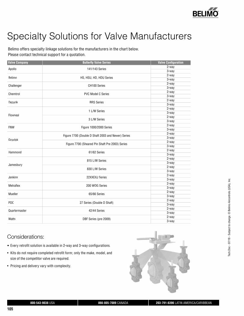
Tech
.Doc
- 07
/18
- Sub
ject
to c
hang
e. ©
Bel
imo
Airc
ontro
ls (U
SA),
Inc.
®
800-543-9038 USA 866-805-7089 CANADA 203-791-8396 LATIN AMERICA/CARIBBEAN
105
Belimo offers specialty linkage solutions for the manufacturers in the chart below. Please contact technical support for a quotation.
Specialty Solutions for Valve Manufacturers
Valve Company Butterfl y Valve Series Valve Confi guration
Apollo 141/143 Series2-way3-way
Belimo HS, HSU, HD, HDU Series2-way3-way
Challenger CH100 Series2-way3-way
Chemtrol PVC Model C Series2-way3-way
Dezurik BRS Series2-way3-way
Flowseal1 L/W Series
2-way3-way
3 L/W Series2-way3-way
FNW Figure 1000/2000 Series2-way3-way
GruvlokFigure 7700 (Double D Shaft 2003 and Newer) Series
2-way3-way
Figure 7700 (Sheared Pin Shaft Pre 2003) Series2-way3-way
Hammond 61/62 Series2-way3-way
Jamesbury815 L/W Series
2-way3-way
830 L/W Series2-way3-way
Jenkins 22XXEXJ Series2-way3-way
Metrafl ex 200 WOG Series2-way3-way
Mueller 65/66 Series2-way3-way
PDC 27 Series (Double D Shaft)2-way3-way
Quartermaster 42/44 Series2-way3-way
Watts DBF Series (pre 2009)2-way3-way
Considerations:• Every retrofi t solution is available in 2-way and 3-way confi gurations.
• Kits do not require completed retrofi t form; only the make, model, and
size of the competitor valve are required.
• Pricing and delivery vary with complexity.

Tech
.Doc
- 07
/18
- Sub
ject
to c
hang
e. ©
Bel
imo
Airc
ontro
ls (U
SA),
Inc.
®
800-543-9038 USA 866-805-7089 CANADA 203-791-8396 LATIN AMERICA/CARIBBEAN
106
Custom Butterfl y Valve Retrofi t Solution FormUFSP Series
Instructions for Completing this FormRequired tools needed a caliper, thread gauge, retrofi t form, fl ashlight, and ladder (if applicable).
Please keep in mind that all dimensions should be taken with ALL original actuation and hardware components removed from the valve body.
Examples of dimensions A & B (Dim A and Dim B) relate to the TOP mounting holes on the butterfl y valve body. These holes are usually arranged onthe body in either an “X” pattern (MOUNT STYLE 1), or a cross pattern (MOUNT STYLE 2). This information is entered on the UFSP Series Butterfl y Valve Retrofi t Form in the MOUNT STYLE section. The length of the valve stem sticking out of the top of the valve body is recorded under Dim C. TheTOP mounting holes are usually drilled through the top fl ange, but sometimes are threaded. Enter this information on the form next to the mount styleinformation previously recorded.
Next is the valve stem data. The fi ve styles of valve stems cover 98% of the butterfl y valves ever produced. Examine the valve being retrofi tted to establishwhich shaft style matches the diagrams above. Use caution when recording these dimensions. Careless use of calipers will result in a sloppy and possibly dysfunctional linkage system. Dim D refers to the valve stem diameter and should be measured at several points up and down as well as around the stemitself. Dim E refers to the length of the drive surface available, whether it be a key, fl atted surface, or the distance a drive hole is from the top of the stem. There are two types of keys (Keyway-Shaft Style 4 and Woodruff Key-Shaft Style 5). Please select the key size as noted in the column “For Shaft Style 4 & 5”.Dim F refers to the width of the drive surface. This is the most critical dimension for correct linkage operation. Please measure accordingly.
In addition, we require information about the environment and process in which this linkage system will be utilized.
The form must be completed in its entirety to guarantee the complete, perfect fi t of your retrofi t system. Keep in mind that retrofi t kits are designed with close-tolerance components which afford the most effi cient linkage system for the facility. Measurements rounded to the nearest 1/8// or 1/16// inch will not perform as well (sometimes not at all) as a kit designed around careful measurements using proper equipment. Our designs are typically+.005” tolerance.
DISCLAIMER
We will do our best to provide a linkage system designed around your specifications and measurements. However, we cannot be held responsible for linkages which do not fit as a result of incorrect data given to Belimo. We will re-work components which do not fit properly for a nominal fee.
To reduce the possibility of incorrect linkage solutions, we respectfully request that you fill out the retrofit form completely and forward that information with your order. This will serve as a double check between your valve and the actuator/linkage package designed for your application.
Actuation, weather shields and linkages cannot be pre-assembled at the Belimo factory prior to your receipt. The linkages are designed to be attached onto the valve body first, then optional weather shields, and finally actuation products.
Close-off pressures are calculated using actuator torque, valve stroke, and valve area. Other factors may affect the rated close-off pressures, including flow rates, system maintenance schedules, chemicals used in the shot feeder process, vicinity to pumps, condition of valve stem seals, and assembly of linkage material in the field.
Valves that are being considered for retrofit of actuation should be analyzed for their life expectancy before the retrofit has taken place. Valves that leak through stem seals or casings will continue to leak with the new linkage system in place, maybe even more so. Rebuilding the packing on these valves may be more costly than replacing the valves themselves. In some instances, older valve stem heights will require field modifications to the valve in order to utilize the retrofit kit. Belimo takes no responsibility for the operation of these valves after they have been modified.

Tech
.Doc
- 07
/18
- Sub
ject
to c
hang
e. ©
Bel
imo
Airc
ontro
ls (U
SA),
Inc.
®
800-543-9038 USA 866-805-7089 CANADA 203-791-8396 LATIN AMERICA/CARIBBEAN
107
Custom Butterfl y Valve Retrofi t Solution FormUFSP Series
EXISTING ACTUATOR MODEL: _______________________ CONTROL TYPE: ON/OFF FLOATING POINT VDC PWM FAIL SAFE: YES NOFAIL POSITION: NO NC VOLTAGE_____
ACTUATOR
MOUNT STYLE 1 MOUNT STYLE 2
MOUNT STYLE 3
DIM F:DIM E:DIM D:SHAFT STYLE
DIM G: DIM H:
2 WAY/3 WAY:
VALVE SIZE:
MEDIA TEMP:
MEDIA TYPE:
SYSTEM PRESSURE:
VALVE MANUFACTURE:
VALVE SERIES:
VALVE MODEL:
VALVE TAG/LOCATION:
QUANTITY:
Range:_____
COMPANY:
JOB NAME:
PO#:
PHONE:
EMAIL:
NOTE: THIS INFORMATION WILL BE UTILIZED IN THE FABRICATION OF A CUSTOM LINKAGE SYSTEM FOR YOUR VALVE REQUIREMENT; THEREFORE, IT IS ESSENTIAL THAT THE
ABOVE DIMENSIONS BE FURNISHED WITH READINGS TAKEN TO THE NEAREST .001". ANY ERRONEOUS DIMENSIONS FURNISHED WHICH RESULT IN IMPROPER FIT OF THIS LINKAGE
SYSTEM ARE NOT THE RESPONSIBILITY OF BELIMO AIRCONTROLS. ANY REWORK REQUIRED WILL RESULT IN AN EXTRA CHARGE.
CUSTOM KITS ARE DESIGNED TO YOUR UNIQUE SPECIFICATIONS AND ARE NOT RETURNABLE. COMPANY CONTACT/DIMENSIONS PROVIDED BY: ____________________________________________________________________ DATE: ___________________
INDOOR OUTDOORRange:_____
VALVE
B
A
SHAFT
CBODY
BA
SHAFT
VALVEBODY C
BA
CBODYVALVE
SHAFT
SHAFT STYLE 9
VALVE CLOSED
CHECK ONE
FG
PINNED
SHAFT STYLE 8
E
DFD
E
SHAFT STYLE 6
DOUBLE DKEYWAY
SHAFT STYLE 4
E
D
D
E
SHAFT STYLE 9
SQUARE
F
KEY SIZE
.125"
.1875"
.250"
.3125"
.375"
.4375"
.500"H
E
D
F
G
SHAFT STYLE 5
WOODRUFF KEY
F
E
SHAFT STYLE 7
HEXCHECK ONE
DIA Ø:
DRILLED
MOUNTING HOLES:
MOUNT STYLE
DIM C:
DIM B:
DIM A:
THREAD
SPEC.
DIM. A & B MEASURED FROM CENTER OF HOLE
TAPPED
MOUNT STYLE DIMENSIONS
MOUNT STYLE 4 SKETCH YOUR MOUNT STYLE USING MOUNT STYLE EXAMPLES.
D
Ex: 0.437"
Ex: 1/2-20
MOUNTINGHOLES
MOUNTINGHOLES
MOUNTINGHOLES
F
G

Tech
.Doc
- 07
/18
- Sub
ject
to c
hang
e. ©
Bel
imo
Airc
ontro
ls (U
SA),
Inc.
®
800-543-9038 USA 866-805-7089 CANADA 203-791-8396 LATIN AMERICA/CARIBBEAN
108
Custom Butterfly Valve Retrofit SolutionsComponent Identification
2-way Single ActuatorGeneric – Retrofit Form Required
2-way Dual ActuatorGeneric – Retrofit Form Required
2-way SY / PR / PKR ActuatorGeneric – Retrofit Form Required
PIN
SHAFT LOCK
TI-ROTATION NUT
ANTI-ROTATION PIN
ACTUATOR PLATE
BOLT (4)
NUT (4)
EXISTING VALVE BODY
VALVE STEM
TOP MOUNTING HOLES
VALVE DISC
LUG MOUNTING HOLES
VALVE COUPLING
EXISTING VALVE BODY
LUG MOUNTING HOLESVALVE DISC
TOP MOUNTING HOLES
ANTI-ROTATION PIN
NUT (4)
ANTI-ROTATION NUTBOLT (4)
VALVE STEM
ACTUATOR PLATE
SHAFT LOCK
PIN
DRIVE SHAFT
VALVE COUPLING
(2)
(2)
LUG MOUNTING HOLES VALVE DISC
TOP MOUNTING HOLES
EXISTING VALVE BODY
VALVE STEM
COUPLING(WELDED)
INDUSTRIAL
BRACKET
BOLT (4)
BOLT (4)
NUT (4)
UFSP0000 UFSP0008 UFSP0020* PR, PKR, SY4 - SY8 UFSP0022* SY9 - SY12
3-way Single ActuatorGeneric – Retrofit Form Required
3-way Dual ActuatorGeneric – Retrofit Form Required
3-way SY / PR / PKR ActuatorGeneric – Retrofit Form Required
EXISTING VALVE
CRANK ARM (2)
COTTER PIN (2)
CONNECTING ROD
EXISTING VALVE
EXISTING TEE
ANTI-ROTATION NUT
NUT (4)
TOP MOUNTING HOLES
ANTI-ROTATION PIN
ACTUATOR PLATE
BOLT (4)
SHAFT LOCK (2)
PIN
CLEVIS PIN (2)
YOKE (2)
DRIVE SHAFT
CRANK LOCK (2)
JAMB NUT
VALVE COUPLING (2)
VALVE STEM
EXISTING VALVE
NUT (8)
EXISTING VALVEN
TOP MOUNTING HOLES
ANTI-ROTATION PIN (2)
ANTI-ROTATION NUT (2)
ACTUATOR PLATE (2)
CRANK ARM (2)
COTTER PIN (2)
CONNECTINGROD
YOKE (2)
DRIVE SHAFT (2)
PIN (2)
SHAFT LOCK (2)
BOLT (8)
CLEVIS PIN (2)
EXISTING TEE
CRANK LOCK (2)
VALVE STEM
VALVE COUPLING (2)
JAMB NUT
UFSP0002 UFSP0010 UFSP0024* PR, PKR, SY4 - SY8 UFSP0026* SY9 - SY12
NOTE: 3-way bracket configuration shown is only one of many possible arrangements. Custom kits aredesigned to your unique specifi cation and are not returnable.
*Reference page 100-101 Keystone AR1/AR2 for approximate actuator sizing.
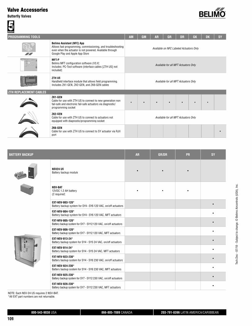
Tech
.Doc
- 07
/18
- Sub
ject
to c
hang
e. ©
Bel
imo
Airc
ontro
ls (U
SA),
Inc.
®
800-543-9038 USA 866-805-7089 CANADA 203-791-8396 LATIN AMERICA/CARIBBEAN
109
PROGRAMMING TOOLS AM GM AR GR DR GK DK SY
Belimo Assistant (NFC) AppAllows fast programming, commissioning, and troubleshootingeven when the actuator is not powered. Available throughGoogle Play and Apple App Store
Available on NFC Labeled Actuators Only
MFT-PBelimo MFT confi guration software (V3.X)Includes: PC-Tool software (interface cables [ZTH US] notincluded)
Available for all MFT Actuators Only
ZTH USHandheld interface module that allows fi eld programming.Includes ZK1-GEN, ZK2-GEN, and ZK6-GEN cables
Available for all MFT Actuators Only
ZTH REPLACEMENT CABLESZK1-GENCable for use with ZTH US to connect to new generation nonfail-safe and electronic fail-safe actuators via diagnostic/programming socket
• • • • • • •
ZK2-GENCable for use with ZTH US to connect to actuators notequipped with diagnostic/programming socket
Available for all MFT Actuators Only
ZK6-GENCable for use with ZTH US to connect to SY actuator via RJIIport
•
Valve AccessoriesButterfly Valves
BATTERY BACKUP AR GR/DR PR SY
NSV24 USBattery backup module • • •
NSV-BAT 12VDC 1.2 AH battery (2 required)
• • •
EXT-NSV-B03-120*Battery backup system for SY4 - SY6 120 VAC, on/off actuators •
EXT-NSV-B04-120*Battery backup system for SY4 - SY6 120 VAC, MFT actuators •
EXT-NSV-B05-120*Battery backup system for SY7 - SY12 120 VAC, on/off actuators •
EXT-NSV-B06-120*Battery backup system for SY7 - SY12 120 VAC, MFT actuators •
EXT-NSV-B13-24*Battery backup system for SY4 - SY5 24 VAC, on/off actuators •
EXT-NSV-B14-24*Battery backup system for SY4 - SY5 24 VAC, MFT actuators •
EXT-NSV-B23-230*Battery backup system for SY4 - SY6 230 VAC, on/off actuators •
EXT-NSV-B24-230*Battery backup system for SY4 - SY6 230 VAC, MFT actuators •
EXT-NSV-B25-230*Battery backup system for SY7 - SY12 230 VAC, on/off actuators •
EXT-NSV-B26-230*Battery backup system for SY7 - SY12 230 VAC, MFT actuators •
NOTE: Each NSV-24 US requires 2 NSV-BAT.*All EXT part numbers are not returnable.

Tech
.Doc
- 07
/18
- Sub
ject
to c
hang
e. ©
Bel
imo
Airc
ontro
ls (U
SA),
Inc.
®
800-543-9038 USA 866-805-7089 CANADA 203-791-8396 LATIN AMERICA/CARIBBEAN
110
Valve AccessoriesButterfly Valves
AUXILIARY SWITCHES & POTENTIOMETERS LR/LM NR/NM AR/AM GR/GM AK GK/GKR DR SY
S1AAuxiliary switch 1x SPDT, 3A(0.5A inductive) @ 250 VAC
• • • • • • •
S2AAuxiliary switch 2x SPDT, 3A(0.5A inductive) @ 250 VAC
• • • • • • •
P140A GRFeedback potentiometer 140 • • • • • • •
P500A GRFeedback potentiometer 500 • • • • • • •
P500A GRFeedback potentiometer 500 • • • • • • •
P1000A GR Feedback potentiometer 1000 • • • • • • •
P2800A GRFeedback potentiometer 2800 • • • • • • •
P5000A GRFeedback potentiometer 5000 • • • • • • •
P10000A GRFeedback potentiometer 10000 • • • • • • •
SY-1000-FB01Feedback potentiometer 1000 , 2 position, factory installed option only
•
SY-1000-FB02Feedback potentiometer 1000 , modulating (modelsSYx…-MFT), factory installed option only
•
WEATHER SHIELDS GM 2*GM
DR/GR/GKR AF 2*
AF GK 2*GK
ZS-BFV-20**For GM, GK actuators on F6, F7, HD,HDU, SHP, and VIC series
• •
ZS-BFV-30**For AF actuators on F6, F7, HD, HDU SHP, and VIC series •
ZS-BFV-60**For dual GM, GK actuators onbutterfl y valves F6, HD, HDU (4” - 6”), SHP, and VIC series
• •
ZS-BFV-70**For dual AF series on butterfl y valves F6, HD, HDU(2½” - 3”), SHP and VIC series
•
ZS-BFV-80**For dual AF series on butterfl y valves F6, HD, HDU(4” - 5”), SHP and VIC series
•
ZS-BFV-90**FBGL weather shield for F7 series (dual act, <4”)No holes unless factory mounted
• • •
ZS-BFV-100**Dual GM/GK series for F7, HD, HDU, SHP (4-6”)Two required
• •
ZS-BFV-110DR, GR, GKR series for F6, HD, HDU (4”-6”) •
**Cannot be used with direct mount actuators.

Tech
.Doc
- 07
/18
- Sub
ject
to c
hang
e. ©
Bel
imo
Airc
ontro
ls (U
SA),
Inc.
®
800-543-9038 USA 866-805-7089 CANADA 203-791-8396 LATIN AMERICA/CARIBBEAN
111
ELECTRIC DISCONNECT SY
HOA-120VLocal electric disconnect for SY4-SY12 110/230V - 2 position
•
•
HOA-120VMFTLocal electric disconnect for SY4-SY12 110/230V - modulating
•
•
HOA-24VLocal electric disconnect for SY4-SY12 24V - 2 position
•
•
HOA-24VMFTLocal electric disconnect for SY4-SY12 24V - modulating
•
•
HAND CRANK PR PKR
ZG-HND PRReplacement hand crank for PR and PKR actuators • •
VALVE TYPE
PR/PKR RETROFIT LINKAGE BUTTERFLY
IND-PR01Valve linkage for 4” - 6” HDU/HD series 2-waywith indicator
•
IND-PR02Valve linkage for 4” - 6” HDU/HD series 2-way without indicator •
IND-PR03Valve linkage for 8” - 12” L series 2-waywith indicator
•
IND-PR04Valve linkage for 8” - 12” L series 2-waywithout indicator
•
Valve AccessoriesButterfly Valves

®
Ball Valve Retrofi tSolutionsBelimo ball valve retrofi t solutions are designed to easily attach to the valve mounting pad of competitor valves utilizing Belimo actuators. Ballvalves can conveniently be restored to service without removing the valve,saving down time and costs.

Tech
.Doc
- 07
/18
- Sub
ject
to c
hang
e. ©
Bel
imo
Airc
ontro
ls (U
SA),
Inc.
®
800-543-9038 USA 866-805-7089 CANADA 203-791-8396 LATIN AMERICA/CARIBBEAN
113
UBSP0004 Custom Retrofi t Linkage for Ball ValvesFor use with Belimo Rotary Actuators
Technical Data
Service chilled or hot water and steamApplicable valve size ½” [13], ¾” [19], 1” [25], 1¼” [32],
1½” [38], 2” [50]Frame, plate, base stainless steelShaft diameter ½” to ¾” roundShaft stainless steelCoupling stainless steelBearing bronze oil-liteMounting position 360°Media temp. range (water) -22°F to +298°F [-30°C to +148°C]Media temp. range (steam) 20°F to 298°F [-7°C to +148°C]Weight 9 lbs
ApplicationThe UBSP custom retrofit kit is designed to easily attach to the valve mounting pad on select competitor valves utilizing Belimo actuators. This kit will help to restore servicewithout removal of the valve, saving down time. The UBSP retrofit kit is available invarious configurations for use with both 2-way and 3-way valves utilizing single ordual actuation.
OperationThe UBSP custom kit and mounted actuator(s) are capable of rotating 95° in both CWand CCW directions. This allows the ball to fully open or close. When directional needsvary, the actuators can be flipped or directional switch turned to a new rotation. Referto Master Slave wiring for dual mounted actuators.
Default/ConfigurationThe actuator is sold separately from the linkage, allowing users to select an actuatorwith the desired control signal. The linkage utilizes standard airside or SY actuatorswhich can be purchased at any time and mounted in the field.
Suitable Actuators
Linkage Spring Return Electronic Fail-Safe
Non-Spring Return
UBSP0004 LF, NF, AF GK LM, NM, AM, GM
Dimensions (Inches [mm])
F
A
BC
A B C F
8.00 [203.2] 2.00 [51] 8.00 [203] 6.00 [152.4]
Application NotesBefore ordering, a completed retrofit form is required.
DRIVE SHAFT
ROLL PIN
BUSHING
NYLON WASHER
VALVE COUPLING
MOUNTINGBRACKET
NUT
LOCK WASHER
BOLT
ANTI-ROTATIONPIN
ACTUATOR PLATE
NUT
BOLT

Tech
.Doc
- 07
/18
- Sub
ject
to c
hang
e. ©
Bel
imo
Airc
ontro
ls (U
SA),
Inc.
®
800-543-9038 USA 866-805-7089 CANADA 203-791-8396 LATIN AMERICA/CARIBBEAN
114
UBSP0006 Custom Retrofi t Linkage for Ball ValvesFor use with Belimo Rotary Actuators
Technical Data
Service chilled or hot water and steamApplicable valve size ½” [13], ¾” [19], 1” [25], 1¼” [32],
1½” [38], 2” [50]Frame, plate, base stainless steelShaft diameter ½” to ¾” roundShaft stainless steelCoupling stainless steelBearing bronze oil-liteMounting position 360°Media temp. range (water) -22°F to +298°F [-30°C to +148°C]Media temp. range (steam) 20°F to 298°F [-7°C to +148°C]Weight 18 lbs
ApplicationThe UBSP custom retrofit kit is designed to easily attach to the valve mounting pad onselect competitor valves utilizing Belimo actuators. This kit will help to restore servicewithout removal of the valve, saving down time. The UBSP retrofit kit is available in various configurations for use with both 2-way and 3-way valves utilizing single ordual actuation.
OperationThe UBSP custom kit and mounted actuator(s) are capable of rotating 95° in both CWand CCW directions. This allows the ball to fully open or close. When directional needsvary, the actuators can be flipped or directional switch turned to a new rotation. Referto Master Slave wiring for dual mounted actuators.
Default/ConfigurationThe actuator is sold separately from the linkage, allowing users to select an actuatorwith the desired control signal. The linkage utilizes standard airside or SY actuatorswhich can be purchased at any time and mounted in the field.
Suitable Actuators
Linkage Spring Return Electronic Fail-Safe
Non-Spring Return
UBSP0006 2*AF 2*GK 2*GM
Dimensions (Inches [mm])
FBC
A
A B C F
15.60 [396.24] 8.00 [203] 8.00 [203] 6.00 [152.4]
Application NotesBefore ordering, a completed retrofit form is required.
NUT
ANTI-ROTATION PIN
NUT
EXTENSION
EXTENSION
BOLT
BUSHING ACTUATOR PLATE
ROLL PIN
DRIVE SHAFT
BUSHING
NYLONWASHER
VALVE COUPLING
NUTNUT
LOCKWASHER
MOUNTINGBRACKET
BOLTANTI-ROTATION
PIN
NUT
ACTUATOR PLATE
BOLT
BOLT

Tech
.Doc
- 07
/18
- Sub
ject
to c
hang
e. ©
Bel
imo
Airc
ontro
ls (U
SA),
Inc.
®
800-543-9038 USA 866-805-7089 CANADA 203-791-8396 LATIN AMERICA/CARIBBEAN
115
UBSP0008 Custom Retrofi t Linkage for Ball ValvesFor use with Belimo SY, PR, and PKR Actuators
Technical Data
Service chilled or hot water and steamApplicable valve size ½” [13], ¾” [19], 1” [25], 1-¼” [32], 1-½”
[38], 2” [50], 2-½” [63.5], 3” [76.2]Frame, plate, base stainless steelShaft steelCoupling steelMounting position 360°Media temp. range (water) -22°F to +298°F [-30°C to +148°C]Media temp. range (steam) 20°F to 298°F [-7°C to +148°C]Housing NEMA 4X, IP66Weight 12 lbs
ApplicationThe UBSP custom retrofit kit is designed to easily attach to the valve mounting pad onselect competitor valves utilizing Belimo actuators. This kit will help to restore servicewithout removal of the valve, saving down time. The UBSP retrofit kit is available invarious configurations for use with both 2-way and 3-way valves utilizing single ordual actuation.
OperationThe UBSP custom kit and mounted actuator(s) are capable of rotating 95° in both CWand CCW directions. This allows the ball to fully open or close. When directional needsvary, the actuators can be flipped or directional switch turned to a new rotation. Referto Master Slave wiring for dual mounted actuators.
Default/ConfigurationActuators are sold separately and mounted in the field.
Suitable Actuators
Linkage Non-Spring Return Electronic Fail-Safe
UBSP0008 SY1, SY4, SY5, SY6, PR PKR
Dimensions (Inches [mm])
A B C
14.63 [372] 10.00 [254] 13.00 [330]
Application NotesBefore ordering, a completed retrofit form is required.
MOUNTINGBRACKET
SY CPL/INTERFACE
VALVE COUPLING
NUT
LOCK WASHER
BOLT
BOLT
SPLIT LOCKWASHER
Dimensions (Inches [mm])
A
A B C
16.63 [422]* 12.00 [305] 15.00 [381]
*Based on SY6
CB
A
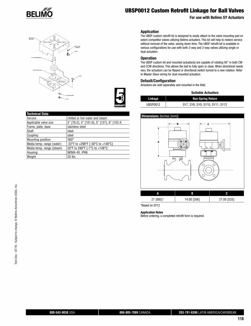
Tech
.Doc
- 07
/18
- Sub
ject
to c
hang
e. ©
Bel
imo
Airc
ontro
ls (U
SA),
Inc.
®
800-543-9038 USA 866-805-7089 CANADA 203-791-8396 LATIN AMERICA/CARIBBEAN
116
UBSP0012 Custom Retrofi t Linkage for Ball ValvesFor use with Belimo SY Actuators
Technical Data
Service chilled or hot water and steamApplicable valve size 3” [76.2], 4” [101.6], 5” [127], 6” [152.4]Frame, plate, base stainless steelShaft steelCoupling steelMounting position 360°Media temp. range (water) -22°F to +298°F [-30°C to +148°C]Media temp. range (steam) 20°F to 298°F [-7°C to +148°C]Housing NEMA 4X, IP66Weight 20 lbs
ApplicationThe UBSP custom retrofit kit is designed to easily attach to the valve mounting pad on select competitor valves utilizing Belimo actuators. This kit will help to restore service without removal of the valve, saving down time. The UBSP retrofit kit is available in various configurations for use with both 2-way and 3-way valves utilizing single or dual actuation.
OperationThe UBSP custom kit and mounted actuator(s) are capable of rotating 95° in both CWand CCW directions. This allows the ball to fully open or close. When directional needs vary, the actuators can be flipped or directional switch turned to a new rotation. Refer to Master Slave wiring for dual mounted actuators.
Default/ConfigurationActuators are sold separately and mounted in the field.
Suitable Actuators
Linkage Non-Spring Return
UBSP0012 SY7, SY8, SY9, SY10, SY11, SY12
Dimensions (Inches [mm])
A
A B C
27 [685]* 14.00 [356] 21.00 [533]
*Based on SY12
Application NotesBefore ordering, a completed retrofit form is required.
MOUNTINGBRACKET
SY CPL/INTERFACE
VALVE COUPLING
NUT
LOCK WASHER
BOLT
BOLT
SPLIT LOCKWASHER

Tech
.Doc
- 07
/18
- Sub
ject
to c
hang
e. ©
Bel
imo
Airc
ontro
ls (U
SA),
Inc.
®
800-543-9038 USA 866-805-7089 CANADA 203-791-8396 LATIN AMERICA/CARIBBEAN
117
Custom Ball Valve Retrofi t Solution FormUBSP Series
Instructions for Completing this FormRequired tools needed a caliper, thread gauge, retrofi t form, fl ashlight, and ladder (if applicable).
Ball valves without a mounting fl ange are typically not designed for installing actuation; therefore the valve design may not support modulation outside of manual usage. Belimo does not recommend retrofi tting these types of ball valves.
All dimensions should be taken with ALL original actuation and hardware components removed from the valve body.
An example using Mounting Style 3: Dimensions A & B (Dim A and Dim B) relate to the TOP mounting holes on the ball valve body. These holes are usually arranged on the body in a “X” pattern (MOUNT STYLE 3). This information is entered on the UBSP Series Ball Valve Retrofi t Form in the MOUNT STYLE section. The length of the valve stem sticking out of the top of the valve body is recorded under Dim D and E. The TOP mounting holes are usually drilled through the top fl ange, but sometimes are threaded. Enter this information on the form next to the mount style information previously recorded.
MOUNT STYLE 3: Dimensions A & B (Dim A and Dim B) relate to the TOP mounting holes on the ball valve body. These holes are usually arranged on the body in a “X” pattern (MOUNT STYLE 3). This information is entered on the UBSP Series Ball Valve Retrofi t Form in the MOUNT STYLE section. The length of the valve stem sticking out of the top of the valve body is recorded under Dim D and E. The TOP mounting holes are usually drilled through the top fl ange, but sometimes are threaded. Enter this information on the form next to the mount style information previously recorded.
STEM STYLE: Examine the valve being retrofi tted to establish which stem style matches the diagrams. Use caution when recording these dimensions. Dim H refers to the valve stem diameter and should be measured at several points up and down as well as around the stem itself. Dim E refers to the length of the drive surface available, whether it is a key or fl atted surface. Dim F refers to the width of the drive surface or the distance across the fl ats. This is the most critical dimension for correct linkage operation. Please measure accordingly. Lastly please specify the desired actuator orientation in reference to the valve body using the ports as reference, i.e. over the “A” port etc. We have also includes an ISO-5211 standard dimension chart for reference. If the valve is labeled please specify its “F” number so that we may confi rm the dimensions per the ISO spec.
In addition, we require information about the environment and process in which this linkage system will be utilized, as well as the frequency of use the current actuator runs. This will help to ensure the longevity of the new linkage and actuator. Having the prior actuator spec and model will help.
The form must be completed in its entirety to guarantee the complete, perfect fi t of your retrofi t system. Keep in mind that retrofi t kits are designed with close-tolerance components which afford the most effi cient linkage systems. Measurements rounded to the nearest 1/8 or 1/16 inch will not perform as well (sometimes not at all) as a kit designed around careful measurements using proper equipment. Our designs are typically +.005” tolerance.
We will do our best to provide a linkage system designed around your specifications and measurements. However, we cannot be held responsible for linkages which do not fit as a result of incorrect data given to Belimo. We will re-work components which do not fit properly for a nominal fee.
To reduce the possibility of incorrect linkage solutions, we respectfully request that you fill out the retrofit form completely and forward that information with your order. This will serve as a double check between your valve and the actuator/linkage package designed for your application.
Actuation, weather shields and linkages cannot be pre-assembled at the Belimo factory prior to your receipt. The linkages are designed to be attached onto the valve body first, then optional weather shields, and finally actuation products.
Close-off pressures are calculated using actuator torque, valve stroke, and valve area. Other factors may affect the rated close-off pressures, including flow rates, system maintenance schedules, chemicals used in the shot feeder process, vicinity to pumps, condition of valve stem seals, and assembly of linkage material in the field.
Valves that are being considered for retrofit of actuation should be analyzed for their life expectancy before the retrofit has taken place. Valves that leak through stem seals or casings will continue to leak with the new linkage system in place, maybe even more so. Rebuilding the packing on these valves may be more costly than replacing the valves themselves. In some instances, older valve stem heights will require field modifications to the valve in order to utilize the retrofit kit. Belimo takes no responsibility for the operation of these valves after they have been modified.
DISCLAIMER

Tech
.Doc
- 07
/18
- Sub
ject
to c
hang
e. ©
Bel
imo
Airc
ontro
ls (U
SA),
Inc.
®
800-543-9038 USA 866-805-7089 CANADA 203-791-8396 LATIN AMERICA/CARIBBEAN
118
Custom Ball Valve Retrofi t Solution Form
EXISTING ACTUATOR MODEL: _______________________ CONTROL TYPE: ON/OFF FLOATING POINT VDC PWM FAIL SAFE: YES NOFAIL POSITION: NO NC FREQUENCY OF OPERATION (specify how often): DAILY_____ WEEKLY_____ MONTHLY_____
ACTUATORORIENTATION:
SKETCH YOUR MOUNT STYLE USING EXAMPLES ABOVE
DIA Ø:DRILLED
MOUNTING HOLES:MOUNT STYLE
DIM C:
DIM B:
DIM A:
A A
B
THREAD SPEC.
DIM. A & B MEASURED FROM CENTER OF HOLE
TAPPED
ACTUATOR
B
A
MOUNTING HOLE
HACROSS FLATS
I LARGEST AREATO CLEAR OR NUT
# OF NUTS: ______
G
F
TOP OF NUT TO TOP OF STEM
J DIAMETER OF STEM
C
J DIAMETER OF STEM
NUT ON STEM NO NUT
G F
STEM STYLE 1
DIM D:
D
STEM STYLE 2
MOUNT STYLE 1 MOUNT STYLE 2 MOUNT STYLE 3
MOUNT STYLE 4
STEM STYLE 3
VALVE IN CLOSED POSITION
DIM H:DIM G:DIM F:STEM STYLE
DIM I: DIM J:
CENTER OF STEMTO END OF STOP
MOUNTING HOLE MOUNTING HOLE
ISO STANDARD
H
H
G
F
TOP OF NUT TO TOP OF STEM
DIAGONAL PARALLEL
2 WAY/3 WAY:
VALVE SIZE:
MEDIA TEMP:
MEDIA TYPE:
SYSTEM PRESSURE:
VALVE MANUFACTURER:
VALVE SERIES:
VALVE MODEL:
VALVE TAG/LOCATION:
QUANTITY:
ISO BOLT SQUARE
BOLT SIZE Ø
CHECK ONE
F03 1.002 M5F04 1.169 M5F05 1.392 M6F07 1.949 M8F10 2.840 M10F12 3.480 M12F14 3.879 M16F16 4.593 M20F25 7.071 M16
Range:_____
COMPANY:
JOB NAME:
PO#:
PHONE:
EMAIL:
NOTE: THIS INFORMATION WILL BE UTILIZED IN THE FABRICATION OF A CUSTOM LINKAGE SYSTEM FOR YOUR VALVE REQUIREMENT; THEREFORE, IT IS ESSENTIAL THAT THE
ABOVE DIMENSIONS BE FURNISHED WITH READINGS TAKEN TO THE NEAREST .001". ANY ERRONEOUS DIMENSIONS FURNISHED WHICH RESULT IN IMPROPER FIT OF THIS LINKAGE
SYSTEM ARE NOT THE RESPONSIBILITY OF BELIMO AIRCONTROLS. ANY REWORK REQUIRED WILL RESULT IN AN EXTRA CHARGE.
CUSTOM KITS ARE DESIGNED TO YOUR UNIQUE SPECIFICATIONS AND ARE NOT RETURNABLE. COMPANY CONTACT/DIMENSIONS PROVIDED BY: ____________________________________________________________________ DATE: ___________________
A AB
B
INDOOR OUTDOOR
DIM E:
E E
E
MOUNT STYLE DIMENSIONS
Range:_____
SQUARE DRIVE
VOLTAGE: _____
I

Tech
.Doc
- 07
/18
- Sub
ject
to c
hang
e. ©
Bel
imo
Airc
ontro
ls (U
SA),
Inc.
®
800-543-9038 USA 866-805-7089 CANADA 203-791-8396 LATIN AMERICA/CARIBBEAN
119
Custom Ball Valve Retrofi t SolutionsComponent Identification
2-way/3-way Single ActuatorGeneric – Retrofit Form Required
2-way/3-way Dual ActuatorGeneric – Retrofit Form Required
DRIVE SHAFT
ROLL PIN
BUSHING
NYLON WASHER
VALVE COUPLING
MOUNTINGBRACKET
NUT
LOCK WASHER
BOLT
ANTI-ROTATIONPIN
ACTUATOR PLATE
NUT
BOLT
NUT
ANTI-ROTATION PIN
NUT
EXTENSION
EXTENSION
BOLT
BUSHING ACTUATOR PLATE
ROLL PIN
DRIVE SHAFT
BUSHING
NYLONWASHER
VALVE COUPLING
NUTNUT
LOCKWASHER
MOUNTINGBRACKET
BOLTANTI-ROTATION
PIN
NUT
ACTUATOR PLATE
BOLT
BOLT
UBSP0004 UBSP0006
Industrial Electronic 2-way/3-wayGeneric – Retrofit Form Required
MOUNTINGBRACKET
SY CPL/INTERFACE
VALVE COUPLING
NUT
LOCK WASHER
BOLT
BOLT
SPLIT LOCKWASHER
UBSP0012 SY7-SY9 Custom kits are designed to your unique specifi cation and are not returnable.
UBSP0008 PR, PKR, SY4 - SY6
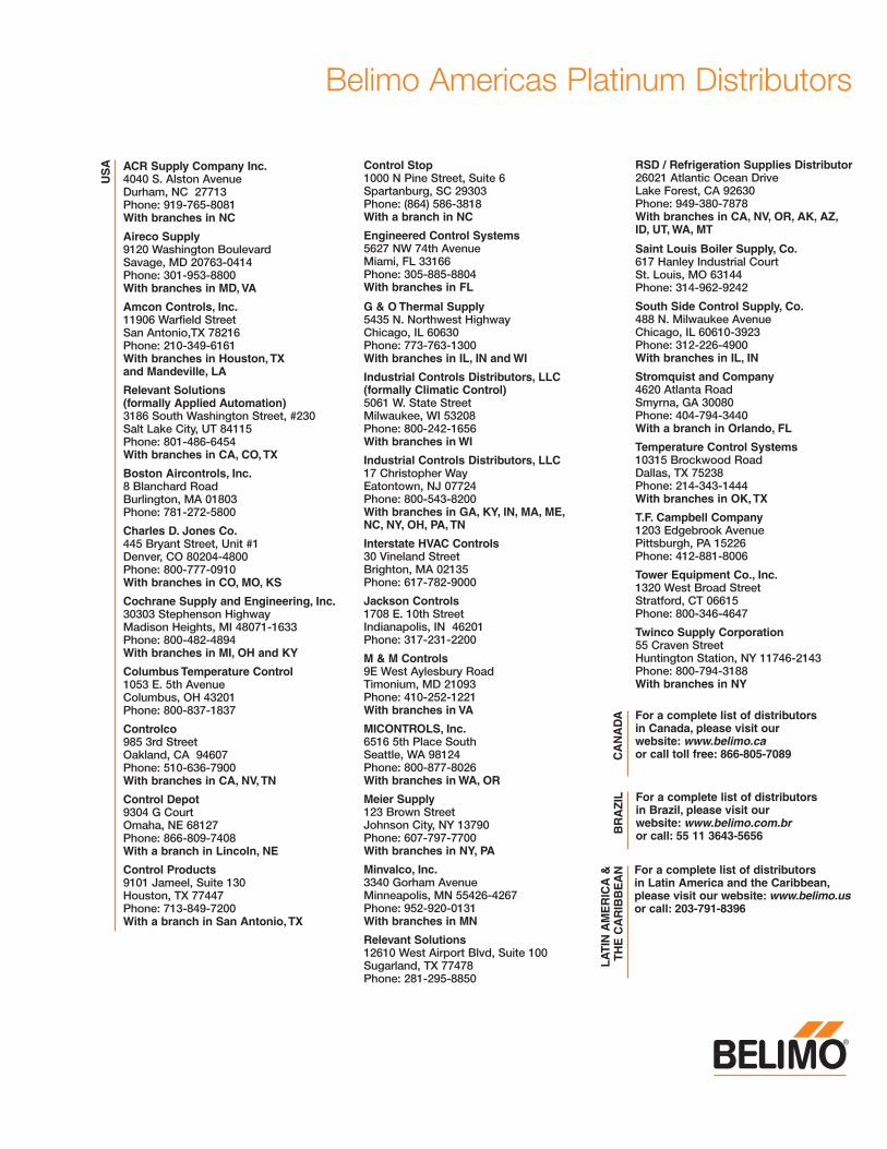
Belimo Americas Platinum DistributorsU
SA ACR Supply Company Inc.
4040 S. Alston AvenueDurham, NC 27713Phone: 919-765-8081With branches in NC
Aireco Supply9120 Washington BoulevardSavage, MD 20763-0414Phone: 301-953-8800With branches in MD, VA
Amcon Controls, Inc.11906 Warfield StreetSan Antonio,TX 78216Phone: 210-349-6161With branches in Houston, TXand Mandeville, LA
Relevant Solutions (formally Applied Automation) 3186 South Washington Street, #230Salt Lake City, UT 84115Phone: 801-486-6454With branches in CA, CO, TX
Boston Aircontrols, Inc.8 Blanchard RoadBurlington, MA 01803Phone: 781-272-5800
Charles D. Jones Co.445 Bryant Street, Unit #1Denver, CO 80204-4800Phone: 800-777-0910With branches in CO, MO, KS
Cochrane Supply and Engineering, Inc.30303 Stephenson HighwayMadison Heights, MI 48071-1633Phone: 800-482-4894With branches in MI, OH and KY
Columbus Temperature Control1053 E. 5th AvenueColumbus, OH 43201Phone: 800-837-1837
Controlco985 3rd StreetOakland, CA 94607 Phone: 510-636-7900With branches in CA, NV, TN
Control Depot9304 G CourtOmaha, NE 68127Phone: 866-809-7408With a branch in Lincoln, NE
Control Products9101 Jameel, Suite 130Houston, TX 77447Phone: 713-849-7200With a branch in San Antonio, TX
Control Stop1000 N Pine Street, Suite 6Spartanburg, SC 29303 Phone: (864) 586-3818With a branch in NC
Engineered Control Systems5627 NW 74th AvenueMiami, FL 33166Phone: 305-885-8804With branches in FL
G & O Thermal Supply5435 N. Northwest HighwayChicago, IL 60630Phone: 773-763-1300With branches in IL, IN and WI
Industrial Controls Distributors, LLC (formally Climatic Control) 5061 W. State StreetMilwaukee, WI 53208Phone: 800-242-1656With branches in WI
Industrial Controls Distributors, LLC17 Christopher WayEatontown, NJ 07724Phone: 800-543-8200With branches in GA, KY, IN, MA, ME, NC, NY, OH, PA, TN
Interstate HVAC Controls30 Vineland StreetBrighton, MA 02135 Phone: 617-782-9000
Jackson Controls1708 E. 10th StreetIndianapolis, IN 46201Phone: 317-231-2200
M & M Controls9E West Aylesbury RoadTimonium, MD 21093Phone: 410-252-1221With branches in VA
MICONTROLS, Inc.6516 5th Place SouthSeattle, WA 98124Phone: 800-877-8026With branches in WA, OR
Meier Supply123 Brown StreetJohnson City, NY 13790 Phone: 607-797-7700With branches in NY, PA
Minvalco, Inc.3340 Gorham AvenueMinneapolis, MN 55426-4267Phone: 952-920-0131With branches in MN
Relevant Solutions12610 West Airport Blvd, Suite 100Sugarland, TX 77478Phone: 281-295-8850
RSD / Refrigeration Supplies Distributor 26021 Atlantic Ocean DriveLake Forest, CA 92630Phone: 949-380-7878With branches in CA, NV, OR, AK, AZ, ID, UT, WA, MT
Saint Louis Boiler Supply, Co. 617 Hanley Industrial CourtSt. Louis, MO 63144Phone: 314-962-9242
South Side Control Supply, Co. 488 N. Milwaukee AvenueChicago, IL 60610-3923Phone: 312-226-4900With branches in IL, IN
Stromquist and Company4620 Atlanta RoadSmyrna, GA 30080Phone: 404-794-3440With a branch in Orlando, FL
Temperature Control Systems10315 Brockwood RoadDallas, TX 75238Phone: 214-343-1444With branches in OK, TX
T.F. Campbell Company1203 Edgebrook AvenuePittsburgh, PA 15226Phone: 412-881-8006
Tower Equipment Co., Inc.1320 West Broad StreetStratford, CT 06615Phone: 800-346-4647
Twinco Supply Corporation55 Craven StreetHuntington Station, NY 11746-2143Phone: 800-794-3188With branches in NY
For a complete list of distributors in Canada, please visit our website: www.belimo.caor call toll free: 866-805-7089
For a complete list of distributors in Latin America and the Caribbean, please visit our website: www.belimo.usor call: 203-791-8396
C
AN
AD
AL
AT
IN A
ME
RIC
A &
TH
E C
AR
IBB
EA
N
For a complete list of distributors in Brazil, please visit our website: www.belimo.com.bror call: 55 11 3643-5656
B
RA
ZIL
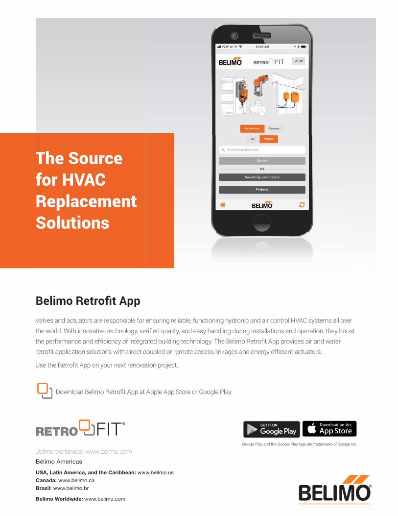
Valves and actuators are responsible for ensuring reliable, functioning hydronic and air control HVAC systems all over the world. With innovative technology, verifi ed quality, and easy handling during installations and operation, they boost the performance and effi ciency of integrated building technology. The Belimo Retrofi t App provides air and water retrofi t application solutions with direct coupled or remote access linkages and energy effi cient actuators.
Use the Retrofi t App on your next renovation project.
Download Belimo Retrofi t App at Apple App Store or Google Play.
Google Play and the Google Play logo are trademarks of Google Inc.
Belimo Retrofi t App
The Source for HVAC Replacement Solutions
Belimo worldwide: www.belimo.com
Belimo Americas
USA, Latin America, and the Caribbean: www.belimo.us
Canada: www.belimo.ca
Brazil: www.belimo.br
Belimo Worldwide: www.belimo.com
Copyright © 2022 FDOKUMEN