Improving Net Joint Torque Calculations Through a Two-Step ...
7
Raziel Riemer Ph.D. Department of Industrial Engineering and Management, Ben-Gurion University, Beer-Sheva 84105, Israel Elizabeth T. Hsiao-Wecksler 1 Ph.D. Department of Mechanical and Science Engineering, University of Illinois at Urbana-Champaign, MC-244, 1206 West Green Street, Urbana, IL 61801 e-mail: [email protected] Improving Net Joint Torque Calculations Through a Two-Step Optimization Method for Estimating Body Segment Parameters Two main sources of error in inverse dynamics based calculations of net joint torques are inaccuracies in segmental motions and estimates of anthropometric body segment param- eters (BSPs). Methods for estimating BSP (i.e., segmental moment of inertia, mass, and center of mass location) have been previously proposed; however, these methods are limited due to low accuracies, cumbersome use, need for expensive medical equipment, and/or sensitivity of performance. This paper proposes a method for improving the ac- curacy of calculated net joint torques by optimizing for subject-specific BSP in the pres- ence of characteristic and random errors in motion data measurements. A two-step op- timization approach based on solving constrained nonlinear optimization problems was used. This approach minimized the differences between known ground reaction forces (GRFs), such as those measured by a force plate, and the GRF calculated via a top-down inverse dynamics approach. In step 1, a series of short calibration motions was used to compute first approximations of optimized segment motions and BSP for each motion. In step 2, refined optimal BSPs were derived from a combination of these motion profiles. We assessed the efficacy of this approach using a set of reference motions in which the true values for the BSP, segment motion, GRF, and net joint torques were known. To imitate real-world data, we introduced various noise conditions on the true motion and BSP data. We compared the root mean squared errors in calculated net joint torques relative to the true values due to the optimal BSP versus traditionally-derived BSP (from anthropometric tables derived from regression equations) and found that the optimized BSP reduced the error by 77%. These results suggest that errors in calculated net joint torques due to traditionally-derived BSP estimates could be reduced substantially using this optimization approach. DOI: 10.1115/1.3005155 Keywords: inverse dynamics, optimization, joint moments, error reduction 1 Introduction Inverse dynamics is a procedure commonly used in the biome- chanical analysis of human movement. This procedure calculates force and net torque reactions at various body joints using anthro- pometric, kinematic, and kinetic input data 1. Uncertainty in estimated net joint torques derived from this method can, how- ever, range from 6% to 232% of the peak net torque 2. This uncertainty depends on measurement and/or estimation errors of the input parameters to the inverse dynamics expressions. Main contributors to these uncertainties were identified to be inaccura- cies in estimated segment angles and body segment parameters BSPs2. Errors in segment angular data arise from two main sources: noise in the motion-capture system and movement arti- facts of skin-mounted markers 2,3. Inaccuracies in body seg- ment parameters are due to errors in estimating segmental mass, moment of inertia, and center of mass COM location 2,4–7. Several methods have been proposed for estimating BSPs. Commonly used to estimate BSP are weighting coefficients based on regression equation relationships derived from measurements on cadavers or living subjects 8–11. These coefficients relate subject height and weight to the BSP. Error due to estimations based on cadaveric data may exceed 40% 4. Errors based on living-subject data are smaller than cadaveric data, but are still considered relatively high 10. Geometric approaches 12,13 es- timate body segment shapes and use estimated density to calculate BSP. These approaches may produce smaller errors e.g., less than 5% 12, but achieving such accuracy is cumbersome as it re- quires large numbers of measurements per subject between 90 13 and 248 12. Methods based on medical imaging e.g., Refs. 14,15 have high accuracy errors of 5% or less. These methods, however, need medical imaging equipment that is not always available and additionally expose subjects to radiation. Recently, a technique for identifying arm BSP based on arm ki- nematics and manipulator-hand contact forces was proposed 16. Another approach that used external forces for estimating BSP was proposed by Vaughan et al. 17. This method used the over- determined nature of the inverse dynamics approach to formulate a nonlinear optimization problem. This overdeterminancy is ex- plained as follows. Traditionally, two approaches have been used for inverse dynamics computations. The first requires only kine- matic and anthropometric data to calculate net joint torques. Re- ferred to as the top-down approach, this process often starts at the distal segment of the upper extremityies and proceeds downward such that dynamic equilibrium conditions are satisfied for each 1 Corresponding author. Contributed by the Bioengineering Division of ASME for publication in the JOUR- NAL OF BIOMECHANICAL ENGINEERING. Manuscript received December 1, 2007; final manuscript received September 22, 2008; published online November 20, 2008. Re- view conducted by Mohamed Samir Hefzy. Paper presented at the 31st Annual Meeting of the American Society of Biomechanics, Stanford, CA, August 22–25, 2007. Journal of Biomechanical Engineering JANUARY 2009, Vol. 131 / 011007-1 Copyright © 2009 by ASME Downloaded 22 Nov 2010 to 130.126.177.3. Redistribution subject to ASME license or copyright; see http://www.asme.org/terms/Terms_Use.cfm
-
Upload
khangminh22 -
Category
Documents
-
view
0 -
download
0
Transcript of Improving Net Joint Torque Calculations Through a Two-Step ...
1
cfpeeutcc�sfmm
C
N
mvM2
J
Downlo
Raziel RiemerPh.D.
Department of Industrial Engineering andManagement,
Ben-Gurion University,Beer-Sheva 84105, Israel
Elizabeth T.Hsiao-Wecksler1
Ph.D.Department of Mechanical and Science
Engineering,University of Illinois at Urbana-Champaign,
MC-244,1206 West Green Street,
Urbana, IL 61801e-mail: [email protected]
Improving Net Joint TorqueCalculations Through a Two-StepOptimization Method forEstimating Body SegmentParametersTwo main sources of error in inverse dynamics based calculations of net joint torques areinaccuracies in segmental motions and estimates of anthropometric body segment param-eters (BSPs). Methods for estimating BSP (i.e., segmental moment of inertia, mass, andcenter of mass location) have been previously proposed; however, these methods arelimited due to low accuracies, cumbersome use, need for expensive medical equipment,and/or sensitivity of performance. This paper proposes a method for improving the ac-curacy of calculated net joint torques by optimizing for subject-specific BSP in the pres-ence of characteristic and random errors in motion data measurements. A two-step op-timization approach based on solving constrained nonlinear optimization problems wasused. This approach minimized the differences between known ground reaction forces(GRFs), such as those measured by a force plate, and the GRF calculated via a top-downinverse dynamics approach. In step 1, a series of short calibration motions was used tocompute first approximations of optimized segment motions and BSP for each motion. Instep 2, refined optimal BSPs were derived from a combination of these motion profiles.We assessed the efficacy of this approach using a set of reference motions in which thetrue values for the BSP, segment motion, GRF, and net joint torques were known. Toimitate real-world data, we introduced various noise conditions on the true motion andBSP data. We compared the root mean squared errors in calculated net joint torquesrelative to the true values due to the optimal BSP versus traditionally-derived BSP (fromanthropometric tables derived from regression equations) and found that the optimizedBSP reduced the error by 77%. These results suggest that errors in calculated net jointtorques due to traditionally-derived BSP estimates could be reduced substantially usingthis optimization approach. �DOI: 10.1115/1.3005155�
Keywords: inverse dynamics, optimization, joint moments, error reduction
IntroductionInverse dynamics is a procedure commonly used in the biome-
hanical analysis of human movement. This procedure calculatesorce and net torque reactions at various body joints using anthro-ometric, kinematic, and kinetic input data �1�. Uncertainty instimated net joint torques derived from this method can, how-ver, range from 6% to 232% of the peak net torque �2�. Thisncertainty depends on measurement and/or estimation errors ofhe input parameters to the inverse dynamics expressions. Mainontributors to these uncertainties were identified to be inaccura-ies in estimated segment angles and body segment parametersBSPs� �2�. Errors in segment angular data arise from two mainources: noise in the motion-capture system and movement arti-acts of skin-mounted markers �2,3�. Inaccuracies in body seg-ent parameters are due to errors in estimating segmental mass,oment of inertia, and center of mass �COM� location �2,4–7�.Several methods have been proposed for estimating BSPs.
ommonly used to estimate BSP are weighting coefficients based
1Corresponding author.Contributed by the Bioengineering Division of ASME for publication in the JOUR-
AL OF BIOMECHANICAL ENGINEERING. Manuscript received December 1, 2007; finalanuscript received September 22, 2008; published online November 20, 2008. Re-
iew conducted by Mohamed Samir Hefzy. Paper presented at the 31st Annualeeting of the American Society of Biomechanics, Stanford, CA, August 22–25,
007.
ournal of Biomechanical Engineering Copyright © 20
aded 22 Nov 2010 to 130.126.177.3. Redistribution subject to ASME
on regression equation relationships derived from measurementson cadavers or living subjects �8–11�. These coefficients relatesubject height and weight to the BSP. Error due to estimationsbased on cadaveric data may exceed 40% �4�. Errors based onliving-subject data are smaller than cadaveric data, but are stillconsidered relatively high �10�. Geometric approaches �12,13� es-timate body segment shapes and use estimated density to calculateBSP. These approaches may produce smaller errors �e.g., less than5% �12��, but achieving such accuracy is cumbersome as it re-quires large numbers of measurements per subject �between 90�13� and 248 �12��. Methods based on medical imaging �e.g.,Refs. �14,15�� have high accuracy �errors of 5% or less�. Thesemethods, however, need medical imaging equipment that is notalways available and additionally expose subjects to radiation.Recently, a technique for identifying arm BSP based on arm ki-nematics and manipulator-hand contact forces was proposed �16�.
Another approach that used external forces for estimating BSPwas proposed by Vaughan et al. �17�. This method used the over-determined nature of the inverse dynamics approach to formulatea nonlinear optimization problem. This overdeterminancy is ex-plained as follows. Traditionally, two approaches have been usedfor inverse dynamics computations. The first requires only kine-matic and anthropometric data to calculate net joint torques. Re-ferred to as the top-down approach, this process often starts at thedistal segment of the upper extremity�ies� and proceeds downward
such that dynamic equilibrium conditions are satisfied for eachJANUARY 2009, Vol. 131 / 011007-109 by ASME
license or copyright; see http://www.asme.org/terms/Terms_Use.cfm
spgtpsstuvrgmmia
teszgtfiiodfejwaGprttmpmcse
nsteimsupdcs
2
oaetCcawo
0
Downlo
uccessive segment. The second method, or the bottom-up ap-roach, is typically used to analyze locomotor tasks and usesround reaction force �GRF� measurements. This method starts athe distal segment of one or both of the lower extremities androceeds upward through the body. By incorporating GRF mea-urements, boundary conditions are defined for the bottommostegment. These added conditions result in an overdetermined sys-em since there are now more equilibrium equations than systemnknowns �17–19�. Due to errors in input parameters to the in-erse dynamics calculations, these traditional methods result inesidual forces and torques on the most-distal segment. The propa-ation of systematic errors typically limits either method to proxi-al net joint torque calculations; however, if it was possible toitigate the effects of one or more of these input inaccuracies,
mprovements in net torque calculations �for all joints� could bechieved.
This overdeterminancy has been used to reduce error effectshrough optimization methods that adjust specific input param-ters in the top-down calculations �17–19�. To improve subject-pecific BSP estimates, Vaughan et al. �17� formulated an optimi-ation problem that minimized the residuals between the knownround reaction measurements and those predicted through theop-down calculation. This promising method, proposed in 1982,ailed to gain popularity due to the complexity and high comput-ng demands of solving an optimization problem. Newer comput-ng capabilities have reduced these difficulties. Another weaknessf this work was that they did not account for errors in the motionata. Furthermore, Vaughan et al. assumed that minimizing a costunction is sufficient for reducing the net joint torque calculationrror. Their cost function did not contain information on the netoint torques; therefore, it is possible to minimize the cost functionhile simultaneously increasing error in the net joint torques. In
n effort to minimize errors due to noise in measured data �i.e.,RF measurements and segment motion�, Kuo �19� overcame thisroblem by suggesting an additional success criterion. This crite-ion stated that the difference between the true net joint torque andhe torque determined from the optimized solution should be lesshan the difference between the true and traditional �nonopti-
ized� inverse dynamics solution. Delp et al. �20� recently pro-osed the use of slight controlled adjustments to kinematic andass parameters to reduce the residual between measured and
alculated GRFs; however, this approach was used to create betterimulations of human movement rather than used to determinexperimental net joint torques.
This paper describes a method that used the overdeterminedature of the inverse dynamics approach to find an optimal set ofubject-specific BSP estimates that reduce the error in joint netorques �due to inaccurate BSP estimation�, while accounting forrrors in motion data measurements. The premise of our approachs that a test subject/patient would perform a series of calibration
otions, which would be used to derive optimized subject-pecific BSPs. Once these BSPs are determined, then they can besed in inverse dynamics calculations for any desired task motionerformed by the subject. The long-term goal of our work is toevelop a method to increase the accuracy of joint net torquealculations through improvements of estimates for both BSP andegment motions using optimization techniques.
MethodThe approach proposed in the current study was inspired by
ptimization methods used by Vaughan et al. �17�, Cappozzo �21�nd Mazza and Cappozzo �22�. As noted previously, Vaughant al. �17� used GRF data to compute optimal BSP estimates, butheir method breaks-down when motion data errors are present.appozzo �21� and Mazza and Cappozzo �22� used GRF data toompute optimal solutions for joint angular motion, but did notddress errors in BSP. Our optimization method builds from theseorks and uses a two-step sequential approach to determine a set
f optimal BSP estimates that improve net joint torque accuracy.11007-2 / Vol. 131, JANUARY 2009
aded 22 Nov 2010 to 130.126.177.3. Redistribution subject to ASME
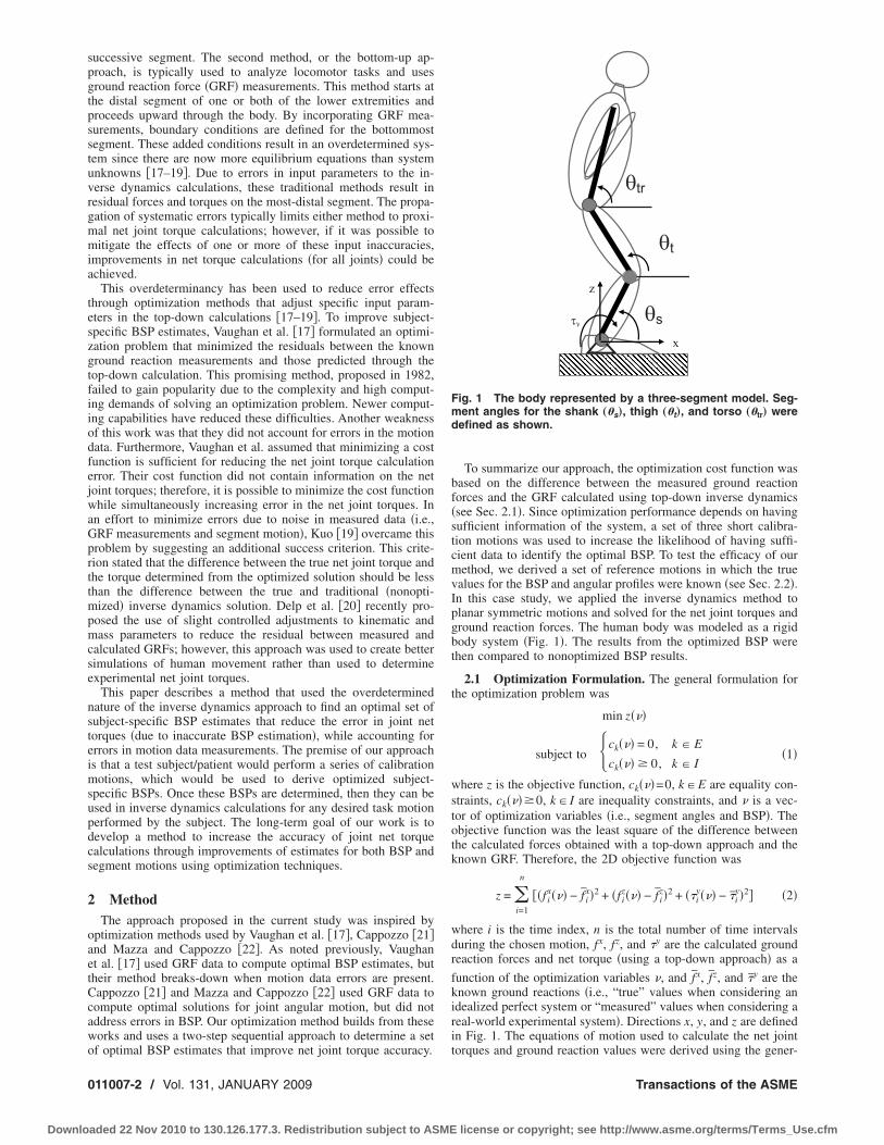
To summarize our approach, the optimization cost function wasbased on the difference between the measured ground reactionforces and the GRF calculated using top-down inverse dynamics�see Sec. 2.1�. Since optimization performance depends on havingsufficient information of the system, a set of three short calibra-tion motions was used to increase the likelihood of having suffi-cient data to identify the optimal BSP. To test the efficacy of ourmethod, we derived a set of reference motions in which the truevalues for the BSP and angular profiles were known �see Sec. 2.2�.In this case study, we applied the inverse dynamics method toplanar symmetric motions and solved for the net joint torques andground reaction forces. The human body was modeled as a rigidbody system �Fig. 1�. The results from the optimized BSP werethen compared to nonoptimized BSP results.
2.1 Optimization Formulation. The general formulation forthe optimization problem was
min z���
subject to �ck��� = 0, k � E
ck��� � 0, k � I� �1�
where z is the objective function, ck���=0, k�E are equality con-straints, ck����0, k� I are inequality constraints, and � is a vec-tor of optimization variables �i.e., segment angles and BSP�. Theobjective function was the least square of the difference betweenthe calculated forces obtained with a top-down approach and theknown GRF. Therefore, the 2D objective function was
z = �i=1
n
��f ix��� − f̄ i
x�2 + �f iz��� − f̄ i
z�2 + ��iy��� − �̄i
y�2� �2�
where i is the time index, n is the total number of time intervalsduring the chosen motion, fx, fz, and �y are the calculated groundreaction forces and net torque �using a top-down approach� as a
function of the optimization variables �, and f̄ x, f̄ z, and �̄y are theknown ground reactions �i.e., “true” values when considering anidealized perfect system or “measured” values when considering areal-world experimental system�. Directions x, y, and z are definedin Fig. 1. The equations of motion used to calculate the net joint
θs
θt
θtr
z
x
τy
Fig. 1 The body represented by a three-segment model. Seg-ment angles for the shank „�s…, thigh „�t…, and torso „�tr… weredefined as shown.
torques and ground reaction values were derived using the gener-
Transactions of the ASME
license or copyright; see http://www.asme.org/terms/Terms_Use.cfm
a
sbb
cecalssl
wika0m
a
woulemts
fitdmdF
wsts
paBgc
wtlpawm
J
Downlo
lized coordinate approach �19�.The objective function was minimized under two types of con-
traints: �1� motion constraints on the angular profiles and �2�ody segment parameter constraints. Both of which are detailedelow.
2.1.1 Motion (Angular Profile) Constraints. Equality motiononstraints were used to calculate the angular velocity and accel-ration of each segment. These values were obtained using theentral finite difference method. The inequality motion constraintspply only to step 1 because in that step the optimization manipu-ates the angular profiles, whereas the combined motion profile intep 2 is not optimized. Inequality constraints on the angular po-itions limited the optimized values to be within the upper andower bounds:
�̄i,j + �a � �i,j � �̄i,j − �a �3�
here �̄i,j is the measured angle, �i,j is the optimized value, and js the segment index. �a is the maximum possible error in thenown angle and can be derived by examining skin movementrtifacts �23–25�. In this study, we used 0.035 rad, 0.07 rad, and.07 rad for the shank, thigh, and head-arm-torso �HAT� seg-ents, respectively.An additional inequality constraint provided bounds on angular
cceleration. This constraint was expressed in the following form:
�̈̄i,j + �acc � �̈i,j � �̈̄i,j − �acc �4�
here �̈̄ is the measured value for the angle acceleration, �̈ is theptimized value, and �acc is the maximum acceleration error. Thispper bound for the acceleration error is not well documented initerature, and as such, we used estimations from Ref. �2� andstimations based on studies that evaluated errors due to the skinovement artifact �23–25� and the motion-capture system �26�. In
his study, we used 1.3 rad /s2, 1.8 rad /s2, and 2.5 rad /s2 for thehank, thigh, and HAT segments, respectively.
Another inequality constraint was based on the kinematic con-guration, such that errors in the location of each joint center had
o fall within a specified range �k. The error was defined as theifference between the joint center location determined from theotion-capture system measurement �x̄ , z̄� and the location pre-
icted by the link length �Lj� and optimized segment angle ��i,j�.or 2D, these constraints take the following form:
�k � �x̄i,k − �j=1
k
Lj cos��i,j�2
+ � z̄i,k − �j=1
k
Lj sin��i,j�2
�5�
here k is the joint number. �k was derived from joint centertudies �27–30�. In this study, we used �k of 0.0005 m for ankleo knee, 0.0012 m for ankle to hip, and 0.001 m for ankle tohoulder.
2.1.2 Body Segment Parameter Constraints. Body segmentarameter constraints were applied in cases when BSPs were vari-bles in the optimization �i.e., steps 1 and 2�. Upper and lowerSP bounds, which represent the maximum possible error in theiven parameter, were defined with the following inequalityonstraints:
P̄l + �lP̄l � Pl � P̄l − �lP̄l �6�
here P̄l is the initial estimate for a body segment parameter, Pl ishe optimized value, and �l is the percent of possible error in theth BSP. The values for �l were based on error estimations fromast studies �5–7� and are presented in Table 1. The body wasssumed to be bilaterally symmetrical for all BSPs. In addition,e added the following equality constraints to conserve the total
ass:ournal of Biomechanical Engineering
aded 22 Nov 2010 to 130.126.177.3. Redistribution subject to ASME
total body mass = �l=1
p
m̄l = �l=1
p
ml �7�
where m̄l is the initial estimation for mass segments, ml isthe estimation after the optimization, and p is the number ofsegments.
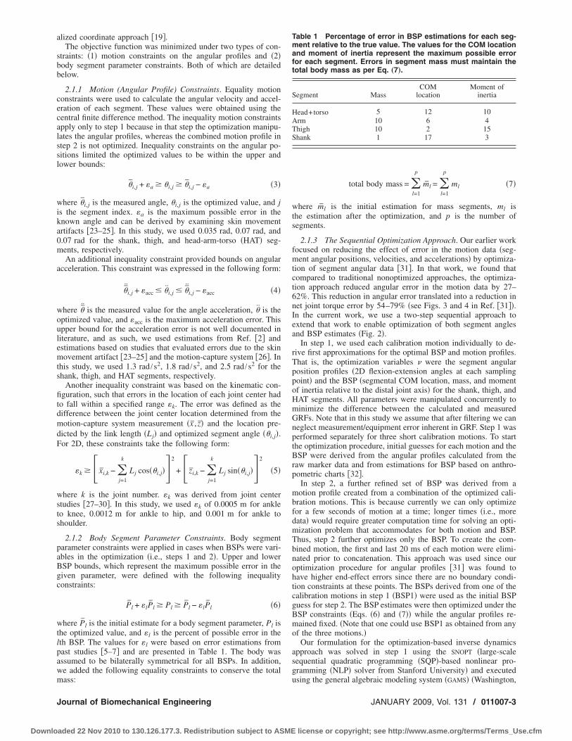
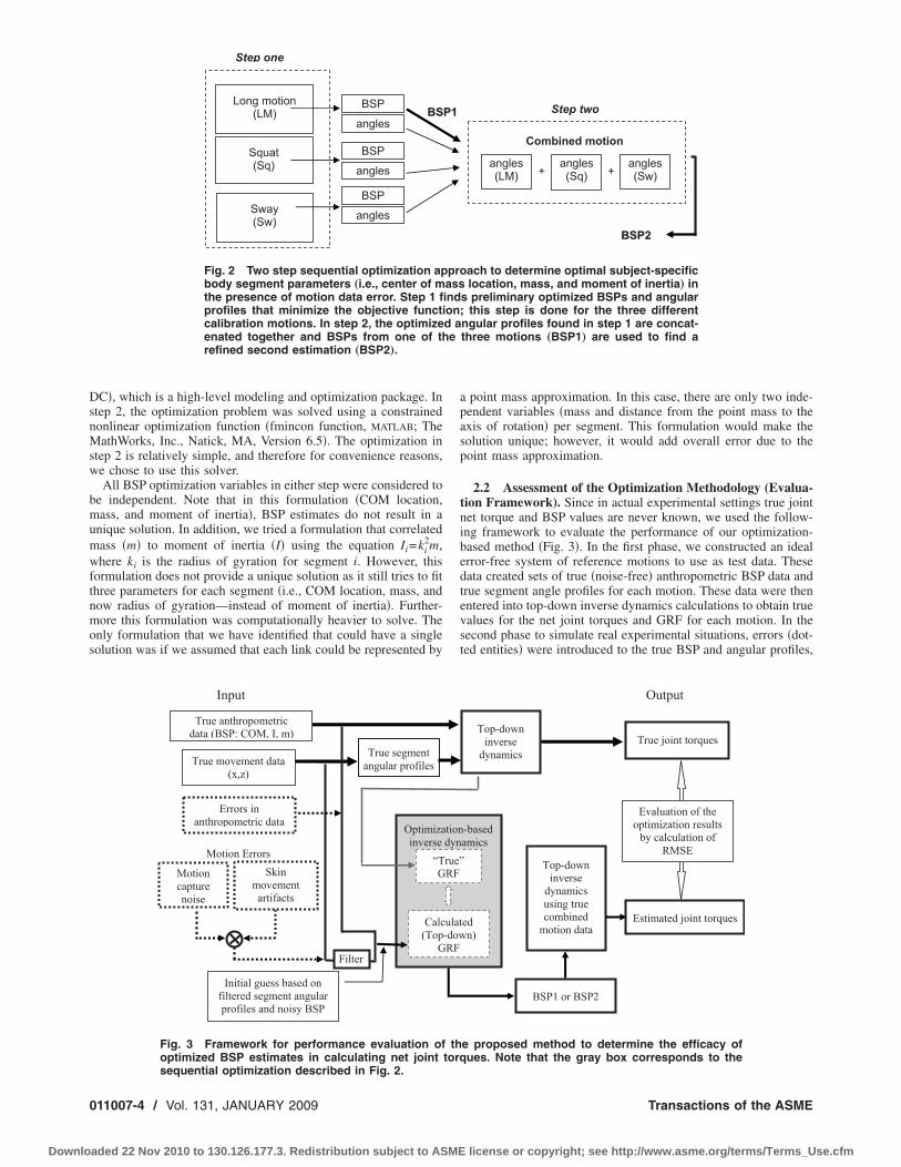
2.1.3 The Sequential Optimization Approach. Our earlier workfocused on reducing the effect of error in the motion data �seg-ment angular positions, velocities, and accelerations� by optimiza-tion of segment angular data �31�. In that work, we found thatcompared to traditional nonoptimized approaches, the optimiza-tion approach reduced angular error in the motion data by 27–62%. This reduction in angular error translated into a reduction innet joint torque error by 54–79% �see Figs. 3 and 4 in Ref. �31��.In the current work, we use a two-step sequential approach toextend that work to enable optimization of both segment anglesand BSP estimates �Fig. 2�.
In step 1, we used each calibration motion individually to de-rive first approximations for the optimal BSP and motion profiles.That is, the optimization variables � were the segment angularposition profiles �2D flexion-extension angles at each samplingpoint� and the BSP �segmental COM location, mass, and momentof inertia relative to the distal joint axis� for the shank, thigh, andHAT segments. All parameters were manipulated concurrently tominimize the difference between the calculated and measuredGRFs. Note that in this study we assume that after filtering we canneglect measurement/equipment error inherent in GRF. Step 1 wasperformed separately for three short calibration motions. To startthe optimization procedure, initial guesses for each motion and theBSP were derived from the angular profiles calculated from theraw marker data and from estimations for BSP based on anthro-pometric charts �32�.
In step 2, a further refined set of BSP was derived from amotion profile created from a combination of the optimized cali-bration motions. This is because currently we can only optimizefor a few seconds of motion at a time; longer times �i.e., moredata� would require greater computation time for solving an opti-mization problem that accommodates for both motion and BSP.Thus, step 2 further optimizes only the BSP. To create the com-bined motion, the first and last 20 ms of each motion were elimi-nated prior to concatenation. This approach was used since ouroptimization procedure for angular profiles �31� was found tohave higher end-effect errors since there are no boundary condi-tion constraints at these points. The BSPs derived from one of thecalibration motions in step 1 �BSP1� were used as the initial BSPguess for step 2. The BSP estimates were then optimized under theBSP constraints �Eqs. �6� and �7�� while the angular profiles re-mained fixed. �Note that one could use BSP1 as obtained from anyof the three motions.�
Our formulation for the optimization-based inverse dynamicsapproach was solved in step 1 using the SNOPT �large-scalesequential quadratic programming �SQP�-based nonlinear pro-gramming �NLP� solver from Stanford University� and executed
Table 1 Percentage of error in BSP estimations for each seg-ment relative to the true value. The values for the COM locationand moment of inertia represent the maximum possible errorfor each segment. Errors in segment mass must maintain thetotal body mass as per Eq. „7….
Segment MassCOM
locationMoment of
inertia
Head+torso 5 12 10Arm 10 6 4Thigh 10 2 15Shank 1 17 3
using the general algebraic modeling system �GAMS� �Washington,
JANUARY 2009, Vol. 131 / 011007-3
license or copyright; see http://www.asme.org/terms/Terms_Use.cfm
DsnMsw
bmumwftnmos
0
Downlo
C�, which is a high-level modeling and optimization package. Intep 2, the optimization problem was solved using a constrainedonlinear optimization function �fmincon function, MATLAB; TheathWorks, Inc., Natick, MA, Version 6.5�. The optimization in
tep 2 is relatively simple, and therefore for convenience reasons,e chose to use this solver.All BSP optimization variables in either step were considered to
e independent. Note that in this formulation �COM location,ass, and moment of inertia�, BSP estimates do not result in a
nique solution. In addition, we tried a formulation that correlatedass �m� to moment of inertia �I� using the equation Ii=ki
2m,here ki is the radius of gyration for segment i. However, this
ormulation does not provide a unique solution as it still tries to fithree parameters for each segment �i.e., COM location, mass, andow radius of gyration—instead of moment of inertia�. Further-ore this formulation was computationally heavier to solve. The
nly formulation that we have identified that could have a singleolution was if we assumed that each link could be represented by
BBSSLong motion
(LM)
Squat(Sq)
Sway(Sw)
angles
BSP
angles
BSP
angles
BSP
Step one
Fig. 2 Two step sequential optimization apbody segment parameters „i.e., center of mthe presence of motion data error. Step 1 fiprofiles that minimize the objective functcalibration motions. In step 2, the optimizeenated together and BSPs from one of threfined second estimation „BSP2….
Filter
True movement data(x,z)
Input
Optimizainverse
“TG
Calc(TopG
True segmentangular profiles
Initial guess based onfiltered segment angularprofiles and noisy BSP
Errors inanthropometric data
Motioncapturenoise
Motion Errors
True anthropometricdata (BSP: COM, I, m)
Skinmovementartifacts
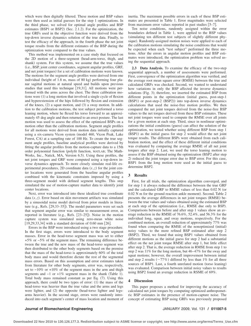
Fig. 3 Framework for performance evaluation ofoptimized BSP estimates in calculating net joint
sequential optimization described in Fig. 2.11007-4 / Vol. 131, JANUARY 2009
aded 22 Nov 2010 to 130.126.177.3. Redistribution subject to ASME
a point mass approximation. In this case, there are only two inde-pendent variables �mass and distance from the point mass to theaxis of rotation� per segment. This formulation would make thesolution unique; however, it would add overall error due to thepoint mass approximation.
2.2 Assessment of the Optimization Methodology (Evalua-tion Framework). Since in actual experimental settings true jointnet torque and BSP values are never known, we used the follow-ing framework to evaluate the performance of our optimization-based method �Fig. 3�. In the first phase, we constructed an idealerror-free system of reference motions to use as test data. Thesedata created sets of true �noise-free� anthropometric BSP data andtrue segment angle profiles for each motion. These data were thenentered into top-down inverse dynamics calculations to obtain truevalues for the net joint torques and GRF for each motion. In thesecond phase to simulate real experimental situations, errors �dot-ted entities� were introduced to the true BSP and angular profiles,
Combined motion
BBSSPP22
angles(LM)
Step two
angles(Sq)
angles(Sw)+ +
ach to determine optimal subject-specificlocation, mass, and moment of inertia… in
s preliminary optimized BSPs and angular; this step is done for the three differentngular profiles found in step 1 are concat-three motions „BSP1… are used to find a
BSP1 or BSP2
True joint torquesTop-downinversedynamics
Output
Evaluation of theoptimization resultsby calculation of
RMSE
-basedamics
edn)
Top-downinversedynamicsusing truecombinedmotion data
Estimated joint torques
e proposed method to determine the efficacy ofues. Note that the gray box corresponds to the
PP11
proassnd
iond ae
tiondynrue”RF
ulat-dowRF
thtorq
Transactions of the ASME
license or copyright; see http://www.asme.org/terms/Terms_Use.cfm
wwtetttto
ts�aTinsftaotlmmmfuFmfioWnvptctsc
dbttrc�
Im+tttbmfssTahwad
J
Downlo
hich were then digitally filtered. These motion and BSP valuesere then used as initial guesses for the step 1 optimizations. In
he third phase, we solved for optimal angle profiles and BSPstimates �BSP1 or BSP2� �Sec. 2.1.2�. For the optimization, therue GRFs used in the objective function were derived from theop-down inverse dynamics solution of the true data. Finally, toest the efficacy of the approach, in the fourth phase the net jointorque results from the different estimates of the BSP during theptimization were compared to the true values.
This method was implemented on a case study that focused onhe 2D motion of a three-segment �head-arm-torso, thigh, andhank� system. For this system, we assume that the true valuesi.e., BSP, joint center coordinates, segment angular profiles, GRF,nd net joint torques� for a set of calibration motions were known.he motions for the segment angle profiles were derived from one
ndividual �height of 1.8 m, mass of 80 kg� performing four pla-ar sagittal motions at natural speed and builds upon previoustudies that used this technique �19,31�. All motions were per-ormed with the arms across the chest. The three calibration mo-ions were �1� a long motion that involved a single cycle of flexionnd hyperextension of the hips followed by flexion and extensionf the knees, �2� a squat motion, and �3� a sway motion. In addi-ion to the calibration motions, the test subject preformed a torsoeaning motion, where he flexed his torso forward to an approxi-
ately 45 deg angle and then returned to an erect posture. The lastotion was used to assess the effect of the optimized BSPs on aotion other than the calibration motions. Segment angle profiles
or all motions were derived from motion data initially capturedsing a six-camera Vicon system �model 460, Vicon Peak, Lakeorest, CA� at a sampling rate of 100 Hz. To create the true seg-ent angle profiles, baseline analytical profiles were derived bytting the angular profiles from the motion-capture data to a 15thrder polynomial function �polyfit function, MATLAB; The Math-orks, Inc., Natick, MA, Version 6.5�. Using these profiles, the
et joint torques and GRF were computed using a top-down in-erse dynamics approach. To more closely simulate real-life ex-erimental procedures, 2D coordinate data �x ,z� for the joint cen-er locations were generated from the baseline angular profilesombined with the kinematic constraints imposed by using ahree-segment model with defined segment lengths. This stepimulated the use of motion-capture marker data to identify jointenter locations.
Next, error was introduced into these idealized true coordinateata �x ,z�. Error based on skin movement artifacts was simulatedy a sinusoidal noise model derived from prior models in litera-ure �e.g., Refs. �29,33–35��. The model parameters were set suchhat segment angular error was similar to measurement error, aseported in literature �e.g., Refs. �23–25��. Noise in the motionapture system was simulated using zero-mean white noise19,29,33,34� with a standard deviation of 0.60 mm �26�.
Errors in the BSP were introduced using a two stage procedure.n the first stage, errors were introduced to the body segmentasses. Error in the head-torso segment mass was set to either5% or −5% of the segment mass. The remaining difference be-
ween the true and the new mass of the head-torso segment washen distributed to the other body segments based on the premisehat the mass of the head-torso is approximately 60% of the totalody mass and would therefore dictate the rest of the segmentalass errors. Based on this assumption and error estimates taken
rom literature for other body segments, error was, respectively,et to −10% or +10% of the segment mass in the arm and thighegments and −1 or +1% segment mass in the shank �Table 1�.otal body mass remained constant as per Eq. �7�. Using thispproach, there could be two types of error: �1� the mass of theead-torso was heavier than the true value and the arms and legsere lighter, and �2� the opposite �head-torso lighter and legs-
rms heavier�. In the second stage, errors were randomly intro-
uced into each segment’s center of mass location and moment ofournal of Biomechanical Engineering
aded 22 Nov 2010 to 130.126.177.3. Redistribution subject to ASME
inertia. The maximum possible errors in each of these BSP esti-mates are presented in Table 1. Error magnitudes were selectedfrom maximum error values reported in past studies �5–7�.
Ten noise conditions, randomly assigned within the errorboundaries defined in Table 1, were applied to the BSP values�simulating ten different test subjects of slightly different phy-sique�. Randomly-assigned motion noises were applied to each ofthe calibration motions simulating the noise conditions that wouldbe expected when each “test subject” performed the three mo-tions. After the errors in angular motion profiles and BSP esti-mates were introduced, the optimization problem was solved us-ing the sequential approach.
2.3 Data Analysis. To examine the efficacy of the two-stepsequential approach, a number of assessments were performed.First, convergence of the optimization algorithm was verified, andthe average root mean square error �RMSE� between the true andcalculated GRFs was checked. Second, we wanted to understandhow variations in only the BSP affected the inverse dynamicssolutions �Fig. 3�; therefore, we inserted the estimated BSP fromdifferent points in the optimization �initial guess, post-step-1�BSP1� or post-step-2 �BSP2�� into top-down inverse dynamicscalculations that used the noise-free motion profiles. We thencompared the net joint torques derived from the noise-free BSPvalues to the net torques derived from these BSP estimates. Thesenet joint torques were used to compute the RMSE over all jointsfor a given motion at each step. Third, since in nonlinear optimi-zations the initial conditions �guess� can affect the solution of theoptimization, we tested whether using different BSP from step 1�BSP1� as the initial guess for step 2 would affect the net jointtorque results. The different BSPs were obtained from each cali-bration motion, and the effect of these different initial conditionswas evaluated by comparing the average RMSE of all net jointtorques after step 2. Last, we used the torso leaning motion toassess if the BSP obtained using the optimization �BSP2 after step2� reduced the joint torque error due to BSP error. For this case,BSP1 from the long motion were used as the initial guess todetermine BSP2.
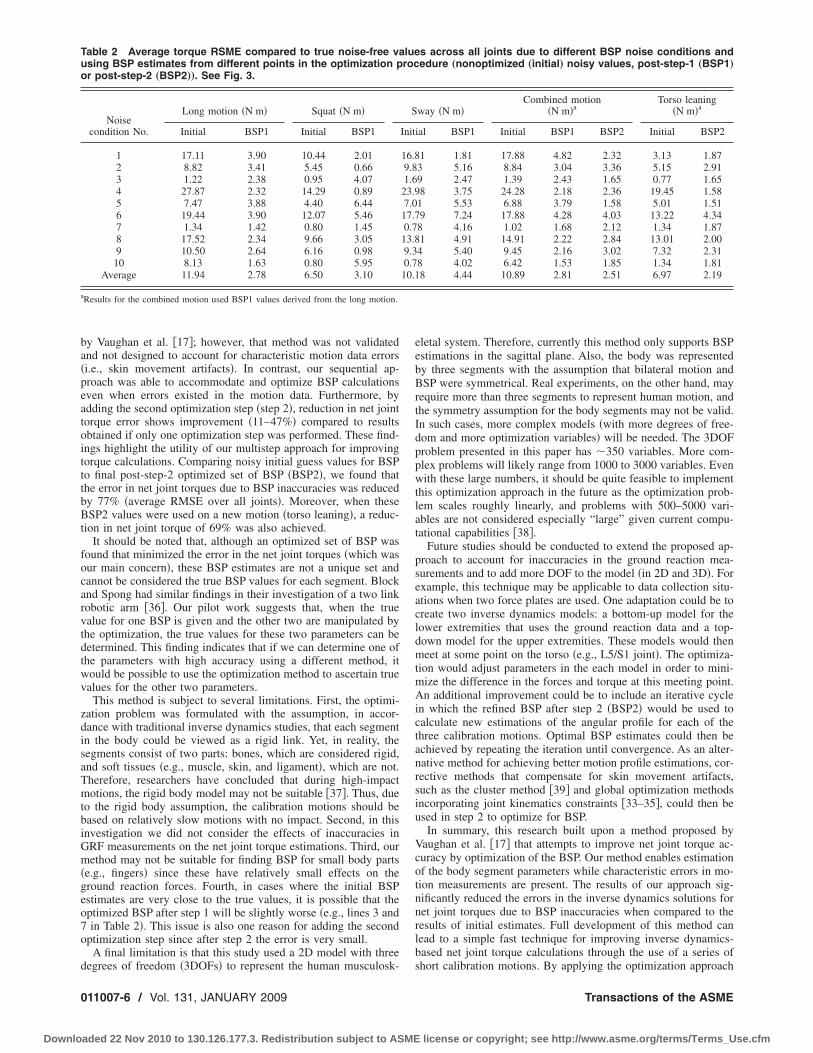
3 ResultsFirst, for all trials, the optimization algorithm converged, and
for step 1 it always reduced the difference between the true GRFand the calculated GRF to RMSE values of less than 0.02 N �or0.02 N m for the ground reaction ankle moment�. Second, Table 2presents the average differences in net joint torques �RMSE� be-tween the true values and values obtained using the estimated BSPat each step of the optimization �i.e., RMSE due only to BSP�.Comparisons between before and after step 1 values show an av-erage reduction in the RMSE of 76.6%, 52.4%, and 56.3% for theindividual long, squat, and sway motions, respectively. For thecombined motion, an overall reduction of approximately 77% wasfound when comparing the RMSE of the nonoptimized �initial�noisy values to the more refined BSP estimated after step 2�BSP2�. Third, we found that using BSP1 values obtained fromdifferent motions as the initial guess for step 2 had a substantialeffect on the net joint torque RMSE after step 1, but little effectafter step 2. That is, the average reduction in RMSE from step 1 tostep 2 was 11% for the long motion, but 46–47% for the sway andsquat motions; however, the overall improvement between initialand step 2 results �77% � differed by less than 1% for all threesources of BSP1. Last, a fourth unrelated motion �torso leaning�was evaluated. Comparison between initial noisy values to resultsusing BSP2 found an average reduction in RSME of 69%.
4 DiscussionThis paper proposes a method for improving the accuracy of
calculated net joint torques by computing optimized anthropomet-ric BSP estimates in the presence of motion-capture noise. The
concept of estimating BSP using GRFs was previously proposedJANUARY 2009, Vol. 131 / 011007-5
license or copyright; see http://www.asme.org/terms/Terms_Use.cfm
ba�peatoitttbBt
focarvtdtwv
zdisaTmtbiGm�geo7o
d
Tuo
a
0
Downlo
y Vaughan et al. �17�; however, that method was not validatednd not designed to account for characteristic motion data errorsi.e., skin movement artifacts�. In contrast, our sequential ap-roach was able to accommodate and optimize BSP calculationsven when errors existed in the motion data. Furthermore, bydding the second optimization step �step 2�, reduction in net jointorque error shows improvement �11–47%� compared to resultsbtained if only one optimization step was performed. These find-ngs highlight the utility of our multistep approach for improvingorque calculations. Comparing noisy initial guess values for BSPo final post-step-2 optimized set of BSP �BSP2�, we found thathe error in net joint torques due to BSP inaccuracies was reducedy 77% �average RMSE over all joints�. Moreover, when theseSP2 values were used on a new motion �torso leaning�, a reduc-
ion in net joint torque of 69% was also achieved.It should be noted that, although an optimized set of BSP was
ound that minimized the error in the net joint torques �which wasur main concern�, these BSP estimates are not a unique set andannot be considered the true BSP values for each segment. Blocknd Spong had similar findings in their investigation of a two linkobotic arm �36�. Our pilot work suggests that, when the truealue for one BSP is given and the other two are manipulated byhe optimization, the true values for these two parameters can beetermined. This finding indicates that if we can determine one ofhe parameters with high accuracy using a different method, itould be possible to use the optimization method to ascertain truealues for the other two parameters.
This method is subject to several limitations. First, the optimi-ation problem was formulated with the assumption, in accor-ance with traditional inverse dynamics studies, that each segmentn the body could be viewed as a rigid link. Yet, in reality, theegments consist of two parts: bones, which are considered rigid,nd soft tissues �e.g., muscle, skin, and ligament�, which are not.herefore, researchers have concluded that during high-impactotions, the rigid body model may not be suitable �37�. Thus, due
o the rigid body assumption, the calibration motions should beased on relatively slow motions with no impact. Second, in thisnvestigation we did not consider the effects of inaccuracies inRF measurements on the net joint torque estimations. Third, ourethod may not be suitable for finding BSP for small body parts
e.g., fingers� since these have relatively small effects on theround reaction forces. Fourth, in cases where the initial BSPstimates are very close to the true values, it is possible that theptimized BSP after step 1 will be slightly worse �e.g., lines 3 andin Table 2�. This issue is also one reason for adding the second
ptimization step since after step 2 the error is very small.A final limitation is that this study used a 2D model with three
able 2 Average torque RSME compared to true noise-free vasing BSP estimates from different points in the optimization pr post-step-2 „BSP2……. See Fig. 3.
Noisecondition No.
Long motion �N m� Squat �N m�
Initial BSP1 Initial BSP1
1 17.11 3.90 10.44 2.012 8.82 3.41 5.45 0.663 1.22 2.38 0.95 4.074 27.87 2.32 14.29 0.895 7.47 3.88 4.40 6.446 19.44 3.90 12.07 5.467 1.34 1.42 0.80 1.458 17.52 2.34 9.66 3.059 10.50 2.64 6.16 0.9810 8.13 1.63 0.80 5.95
Average 11.94 2.78 6.50 3.10
Results for the combined motion used BSP1 values derived from the long motion.
egrees of freedom �3DOFs� to represent the human musculosk-
11007-6 / Vol. 131, JANUARY 2009
aded 22 Nov 2010 to 130.126.177.3. Redistribution subject to ASME
eletal system. Therefore, currently this method only supports BSPestimations in the sagittal plane. Also, the body was representedby three segments with the assumption that bilateral motion andBSP were symmetrical. Real experiments, on the other hand, mayrequire more than three segments to represent human motion, andthe symmetry assumption for the body segments may not be valid.In such cases, more complex models �with more degrees of free-dom and more optimization variables� will be needed. The 3DOFproblem presented in this paper has 350 variables. More com-plex problems will likely range from 1000 to 3000 variables. Evenwith these large numbers, it should be quite feasible to implementthis optimization approach in the future as the optimization prob-lem scales roughly linearly, and problems with 500–5000 vari-ables are not considered especially “large” given current compu-tational capabilities �38�.
Future studies should be conducted to extend the proposed ap-proach to account for inaccuracies in the ground reaction mea-surements and to add more DOF to the model �in 2D and 3D�. Forexample, this technique may be applicable to data collection situ-ations when two force plates are used. One adaptation could be tocreate two inverse dynamics models: a bottom-up model for thelower extremities that uses the ground reaction data and a top-down model for the upper extremities. These models would thenmeet at some point on the torso �e.g., L5/S1 joint�. The optimiza-tion would adjust parameters in the each model in order to mini-mize the difference in the forces and torque at this meeting point.An additional improvement could be to include an iterative cyclein which the refined BSP after step 2 �BSP2� would be used tocalculate new estimations of the angular profile for each of thethree calibration motions. Optimal BSP estimates could then beachieved by repeating the iteration until convergence. As an alter-native method for achieving better motion profile estimations, cor-rective methods that compensate for skin movement artifacts,such as the cluster method �39� and global optimization methodsincorporating joint kinematics constraints �33–35�, could then beused in step 2 to optimize for BSP.
In summary, this research built upon a method proposed byVaughan et al. �17� that attempts to improve net joint torque ac-curacy by optimization of the BSP. Our method enables estimationof the body segment parameters while characteristic errors in mo-tion measurements are present. The results of our approach sig-nificantly reduced the errors in the inverse dynamics solutions fornet joint torques due to BSP inaccuracies when compared to theresults of initial estimates. Full development of this method canlead to a simple fast technique for improving inverse dynamics-based net joint torque calculations through the use of a series of
s across all joints due to different BSP noise conditions andedure „nonoptimized „initial… noisy values, post-step-1 „BSP1…
way �N m�Combined motion
�N m�aTorso leaning
�N m�a
ial BSP1 Initial BSP1 BSP2 Initial BSP2
1 1.81 17.88 4.82 2.32 3.13 1.873 5.16 8.84 3.04 3.36 5.15 2.919 2.47 1.39 2.43 1.65 0.77 1.658 3.75 24.28 2.18 2.36 19.45 1.58
1 5.53 6.88 3.79 1.58 5.01 1.519 7.24 17.88 4.28 4.03 13.22 4.34
8 4.16 1.02 1.68 2.12 1.34 1.871 4.91 14.91 2.22 2.84 13.01 2.00
4 5.40 9.45 2.16 3.02 7.32 2.318 4.02 6.42 1.53 1.85 1.34 1.818 4.44 10.89 2.81 2.51 6.97 2.19
lueroc
S
Init
16.89.81.623.97.017.70.713.89.30.710.1
short calibration motions. By applying the optimization approach
Transactions of the ASME
license or copyright; see http://www.asme.org/terms/Terms_Use.cfm
tfifnemvmp
A
zp
R
J
Downlo
o these calibration motions, it is possible to identify a set of BSPor a given individual. These BSP values would then be used innverse dynamics analyses of desired experimental motion�s� per-ormed by the subject. While knowledge in optimization tech-iques is currently necessary to further explore this method, wenvision a future where optimization methods for improving esti-ations for BSP, motion profiles, joint torques, etc., will be pro-
ided by motion-capture system manufacturers or third-party bio-echanics companies in the same manner that they currently
rovide programs to calculate 2D/3D joint torque and angle data.
cknowledgmentWe thank Professor Placid Ferreira for assistance with optimi-
ation concepts and Alex Shorter for help in conducting the ex-eriments and constructive comments.
eferences�1� Winter, D. A., 2005, Biomechanics and Motor Control of Human Movement,
Wiley, Hoboken, NJ.�2� Riemer, R., Hsiao-Wecksler, E. T., and Zhang, X., 2008, “Uncertainties in
Inverse Dynamics Solutions: A Comprehensive Analysis and an Application toGait,” Gait and Posture, 27�4�, pp. 578–588.
�3� Leardini, A., Chiari, L., Croce, U. D., and Cappozzo, A., 2005, “HumanMovement Analysis Using Stereophotogrammetry: Part 3: Soft Tissue ArtifactAssessment and Compensation,” Gait and Posture, 21�2�, pp. 212–225.
�4� Cappozzo, A., and Berme, N., 1990, Biomechanics of Human Movement Ap-plications in Rehabilitation, Sports and Ergonomics, Worthington, OH, BertecCorporation, Subject Specific Segment Inertial Parameter Determination: ASurvey of Current Methods.
�5� Challis, J. H., 1996, “Accuracy of Human Limb Moment of Inertia Estimationsand Their Influence on Resultant Joint Moments,” J. Appl. Biomech., 12�4�,pp. 517–530.
�6� Ganley, K. J., and Powers, C. M., 2004, “Determination of Lower ExtremityAnthropometric Parameters Using Dual Energy X-Ray Absorptiometry: TheInfluence on Net Joint Moments During Gait,” Clin. Biomech. �Bristol, Avon�,19�1�, pp. 50–56.
�7� Kingma, I., Toussaint, H. M., De Looze, M. P., and Van Dieen, J. H., 1996,“Segment Inertial Parameter Evaluation in Two Anthropometric Models byApplication of a Dynamic Linked Segment Model,” J. Biomech., 29�5�, pp.693–704.
�8� Dempster, W., T, 1955, “Space Requirements of Seated Operator,” AerospaceMedical Research Laboratories, Technical Report No. WADC-TR-55-159.
�9� De Leva, P., 1996, “Adjustments to Zatsiorsky-Seluyanov’s Segment InertiaParameters,” J. Biomech., 29�9�, pp. 1223–1230.
�10� Durkin, J. L., and Dowling, J. J., 2003, “Analysis of Body Segment ParameterDifferences Between Four Human Populations and the Estimation Errors ofFour Popular Mathematical Models,” ASME J. Biomech. Eng., 125��4��, pp.515–522.
�11� Zatsiorsky, V., Seluyanov, V., and Chugunova, L. G., 1990, “ContemporaryProblems of Biomechanics,” Methods of Determining Mass-Inertial Charac-teristics of Human Body Segments, CRC Press, Boston.
�12� Hatze, H., 1980, “A Mathematical Model for the Computational Determinationof Parameter Values of Anthropomorphic Segments,” J. Biomech., 13�10�, pp.833–843.
�13� Yeadon, M. R., 1990, “The Simulation of Aerial Movement—II. A Mathemati-cal Inertia Model of the Human Body,” J. Biomech., 23�1�, pp. 67–74.
�14� Durkin, J. L., James, J. D. B., and Andrews, D. M., 2002, “The Measurementof Body Segment Inertial Parameters Using Dual Energy X-Ray Absorptiom-etry,” J. Biomech., 35�12�, pp. 1575–1580.
�15� Zatsiorsky, V. M., and Seluyanov, V. N., 1983, “The Mass and Inertia Char-acteristics of the Main Segments of the Human Body,” Biomechanics VIII-B,Human Kinetics, Champaign, IL.
�16� Kodek, T., and Munih, M., 2006, “An Identification Technique for Evaluating
ournal of Biomechanical Engineering
aded 22 Nov 2010 to 130.126.177.3. Redistribution subject to ASME
Body Segment Parameters in the Upper Extremity from Manipulator-HandContact Forces and Arm Kinematics,” Clin. Biomech. �Bristol, Avon�, 21�7�,pp. 710–716.
�17� Vaughan, C. L., Andrews, J. G., and Hay, J. G., 1982, “Selection of BodySegment Parameters by Optimization Methods,” ASME J. Biomech. Eng.,104�1�, pp. 38–44.
�18� Cahouet, V., Luc, M., and David, A., 2002, “Static Optimal Estimation of JointAccelerations for Inverse Dynamics Problem Solution,” J. Biomech., 35�11�,pp. 1507–1513.
�19� Kuo, A. D., 1998, “A Least-Squares Estimation Approach to Improving thePrecision of Inverse Dynamics Computations,” ASME J. Biomech. Eng.,120�1�, pp. 148–159
�20� Delp, S. L., Anderson, F. C., Arnold, A. S., Loan, P., Habib, A., John, C. T.,Guendelman, E., and Thelen, D. G., 2007, “Opensim: Open-Source Softwareto Create and Analyze Dynamic Simulations of Movement,” IEEE Trans.Biomed. Eng., 54�11�, pp. 1940–1950.
�21� Cappozzo, A., 2002, “Minimum Measured-Input Models for the Assessment ofMotor Ability,” J. Biomech., 35�4�, pp. 437–446.
�22� Mazza, C., and Cappozzo, A., 2004, “An Optimization Algorithm for HumanJoint Angle Time-History Generation Using External Force Data,” Ann.Biomed. Eng., 32�5�, pp. 764–772.
�23� Cappozzo, A., Catani, F., Leardini, A., Benedetti, M. G., and Della Croce, U.,1996, “Position and Orientation in Space of Bones During Movement: Experi-mental Artefacts,” Clin. Biomech. �Bristol, Avon�, 11�2�, pp. 90–100.
�24� Holden, J. P., Orsini, J. A., Siegel, K. L., Kepple, T. M., Gerber, L. H., andStanhope, S. J., 1997, “Surface Movement Errors in Shank Kinematics andKnee Kinetics During Gait,” Gait and Posture, 5�3�, pp. 217–227.
�25� Stagni, R., Fantozzi, S., Cappello, A., and Leardini, A., 2005, “Quantificationof Soft Tissue Artefact in Motion Analysis by Combining 3D Fluoroscopy andStereophotogrammetry: A Study on Two Subjects,” Clin. Biomech. �Bristol,Avon�, 20�3�, pp. 320–329.
�26� Richards, J. G., 1999, “The Measurement of Human Motion: A Comparison ofCommercially Available Systems,” Hum. Mov. Sci., 18�5�, pp. 589–602
�27� Bell, A. L., Pedersen, D. R., and Brand, R. A., 1990, “A Comparison of theAccuracy of Several Hip Center Location Prediction Methods,” J. Biomech.,23�6�, pp. 617–621.
�28� Leardini, A., Cappozzo, A., Catani, F., Toksvig-Larsen, S., Petitto, A., Sforza,V., Cassanelli, G., and Giannini, S., 1999, “Validation of a Functional Methodfor the Estimation of Hip Joint Centre Location,” J. Biomech., 32�1�, pp.99–103.
�29� Roux, E., Bouilland, S., Godillon-Maquinghen, A. P., and Bouttens, D., 2002,“Evaluation of the Global Optimisation Method Within the Upper Limb Kine-matics Analysis,” J. Biomech., 35�9�, pp. 1279–1283.
�30� Schwartz, M. H., and Rozumalski, A., 2005, “A New Method for EstimatingJoint Parameters From Motion Data,” J. Biomech., 38�1�, pp. 107–116.
�31� Riemer, R., and Hsiao-Wecksler, E. T., 2008, “Optimization-Based InverseDynamics to Reduce the Effect of Motion Errors in Joint Torque Calcula-tions,” J. Biomech., 41�7�, pp. 1503–1509.
�32� Chaffin, B. D., Gunnar, B. J. A., and Martin, B., 1999, Occupational Biome-chanics, Wiley, New York.
�33� Cheze, L., Fregly, B. J., and Dimnet, J., 1995, “A Solidification Procedure toFacilitate Kinematic Analyses Based on Video System Data,” J. Biomech.,28�7�, pp. 879–884.
�34� Lu, T. W., and O’Connor, J. J., 1999, “Bone Position Estimation From SkinMarker Co-Ordinates Using Global Optimisation With Joint Constraints,” J.Biomech., 32�2�, pp. 129–134.
�35� Reinbolt, J. A., Schutte, J. F., Fregly, B. J., Koh, B. I., Haftka, R. T., George,A. D., and Mitchell, K. H., 2005, “Determination of Patient-Specific Multi-Joint Kinematic Models Through Two-Level Optimization,” J. Biomech.,38�3�, pp. 621–626.
�36� Block, D. J., and Spong, M. W., 1995, Mechanical Design and Control of thePendubot, Peoria, IL, pp. 1–4.
�37� Gruber, K., Denoth, J., Stuessi, E., and Ruder, H., 1987, “The Wobbling MassModel,” Biomechanics X-B, B. Jonsson, ed., Human Kinetics, Champaign, IL.
�38� Saunders, M. A., 2008 private communication.�39� Alexander, E. J., and Andriacchi, T. P., 2001, “Correcting for Deformation in
Skin-Based Marker Systems,” J. Biomech., 34�3�, pp. 355–361.
JANUARY 2009, Vol. 131 / 011007-7
license or copyright; see http://www.asme.org/terms/Terms_Use.cfm