Improved Ultra-Rapid UT1-UTC Determination and Its ... - MDPI
15
remote sensing Article Improved Ultra-Rapid UT1-UTC Determination and Its Preliminary Impact on GNSS Satellite Ultra-Rapid Orbit Determination Fei Ye 1 , Yunbin Yuan 1, * and Zhiguo Deng 2 1 State Key Laboratory of Geodesy and Earth’s Dynamics, Innovation Academy for Precision Measurement Science and Technology, Chinese Academy of Sciences, Wuhan 430077, China; [email protected] 2 Deutsches GeoForschungsZentrum, TELEGRAFENBERG 1, Deutschland, 14473 Potsdam, Germany; [email protected] * Correspondence: [email protected]; Tel.: +86-027-6888-1072 Received: 24 August 2020; Accepted: 30 October 2020; Published: 31 October 2020 Abstract: Errors in ultra-rapid UT1-UTC primarily affect the overall rotation of spatial datum expressed by GNSS (Global Navigation Satellite System) satellite ultra-rapid orbit. In terms of existing errors of traditional strategy, e.g., piecewise linear functions, for ultra-rapid UT1-UTC determination, and the requirement to improve the accuracy and consistency of ultra-rapid UT1-UTC, the potential to improve the performance of ultra-rapid UT1-UTC determination based on an LS (Least Square) + AR (Autoregressive) combination model is explored. In this contribution, based on the LS+AR combination model and by making joint post-processing/rapid UT1-UTC observation data, we propose a new strategy for ultra-rapid UT1-UTC determination. The performance of the new strategy is subsequently evaluated using data provided by IGS (International GNSS Services), iGMAS (international GNSS Monitoring and Assessment System), and IERS (International Earth Rotation and Reference Systems Service). Compared to the traditional strategy, the numerical results over more than 1 month show that the new strategy improved ultra-rapid UT1-UTC determination by 29–43%. The new strategy can provide a reference for GNSS data processing to improve the performance of ultra-rapid products. Keywords: GNSS; ultra-rapid UT1-UTC determination; LS + AR; piecewise linear function; ultra-rapid orbit determination 1. Introduction In recent years, the requirement of GNSS (Global Navigation Satellite System) to have real-time precise positioning is becoming more and more urgent for real-time detection research in the field of Earth sciences and for the increasing number of real-time high-precision positioning applications [1–3]. GNSS satellite ultra-rapid orbit is the key in determining real-time precise orbits and achieving real-time precision point positioning (PPP) [4,5]. The accuracy and stability of GNSS satellite ultra-rapid orbit determination directly or indirectly affects and limits the performance and promotion of real-time PPP and related applications [6–8]. UT1 is the angle of the Earth’s rotation about the CIP (Celestial Intermediate Pole) axis defined by its conventional linear relation to the Earth Rotation Angle (ERA), and UT1-UTC is the difference between the UT1 parameter derived from observations and UTC (Coordinated Universal Time) [9]. Ultra-rapid UT1-UTC is currently one of the main factors affecting the performance of GNSS satellite ultra-rapid orbit determination [10]. Compared with the present performance, the existing error in ultra-rapid UT1-UTC has a significant impact on ultra-rapid orbit determination [6,11–13]. Therefore, further improvement in the processing strategy of ultra-rapid Remote Sens. 2020, 12, 3584; doi:10.3390/rs12213584 www.mdpi.com/journal/remotesensing
-
Upload
khangminh22 -
Category
Documents
-
view
0 -
download
0
Transcript of Improved Ultra-Rapid UT1-UTC Determination and Its ... - MDPI
remote sensing
Article
Improved Ultra-Rapid UT1-UTC Determination andIts Preliminary Impact on GNSS Satellite Ultra-RapidOrbit Determination
Fei Ye 1, Yunbin Yuan 1,* and Zhiguo Deng 2
1 State Key Laboratory of Geodesy and Earth’s Dynamics, Innovation Academy for Precision MeasurementScience and Technology, Chinese Academy of Sciences, Wuhan 430077, China; [email protected]
2 Deutsches GeoForschungsZentrum, TELEGRAFENBERG 1, Deutschland, 14473 Potsdam, Germany;[email protected]
* Correspondence: [email protected]; Tel.: +86-027-6888-1072
Received: 24 August 2020; Accepted: 30 October 2020; Published: 31 October 2020�����������������
Abstract: Errors in ultra-rapid UT1-UTC primarily affect the overall rotation of spatial datumexpressed by GNSS (Global Navigation Satellite System) satellite ultra-rapid orbit. In terms ofexisting errors of traditional strategy, e.g., piecewise linear functions, for ultra-rapid UT1-UTCdetermination, and the requirement to improve the accuracy and consistency of ultra-rapid UT1-UTC,the potential to improve the performance of ultra-rapid UT1-UTC determination based on an LS(Least Square) + AR (Autoregressive) combination model is explored. In this contribution, based onthe LS+AR combination model and by making joint post-processing/rapid UT1-UTC observationdata, we propose a new strategy for ultra-rapid UT1-UTC determination. The performance of thenew strategy is subsequently evaluated using data provided by IGS (International GNSS Services),iGMAS (international GNSS Monitoring and Assessment System), and IERS (International EarthRotation and Reference Systems Service). Compared to the traditional strategy, the numerical resultsover more than 1 month show that the new strategy improved ultra-rapid UT1-UTC determinationby 29–43%. The new strategy can provide a reference for GNSS data processing to improve theperformance of ultra-rapid products.
Keywords: GNSS; ultra-rapid UT1-UTC determination; LS + AR; piecewise linear function; ultra-rapidorbit determination
1. Introduction
In recent years, the requirement of GNSS (Global Navigation Satellite System) to have real-timeprecise positioning is becoming more and more urgent for real-time detection research in the field ofEarth sciences and for the increasing number of real-time high-precision positioning applications [1–3].GNSS satellite ultra-rapid orbit is the key in determining real-time precise orbits and achieving real-timeprecision point positioning (PPP) [4,5]. The accuracy and stability of GNSS satellite ultra-rapid orbitdetermination directly or indirectly affects and limits the performance and promotion of real-timePPP and related applications [6–8]. UT1 is the angle of the Earth’s rotation about the CIP (CelestialIntermediate Pole) axis defined by its conventional linear relation to the Earth Rotation Angle (ERA),and UT1-UTC is the difference between the UT1 parameter derived from observations and UTC(Coordinated Universal Time) [9]. Ultra-rapid UT1-UTC is currently one of the main factors affectingthe performance of GNSS satellite ultra-rapid orbit determination [10]. Compared with the presentperformance, the existing error in ultra-rapid UT1-UTC has a significant impact on ultra-rapid orbitdetermination [6,11–13]. Therefore, further improvement in the processing strategy of ultra-rapid
Remote Sens. 2020, 12, 3584; doi:10.3390/rs12213584 www.mdpi.com/journal/remotesensing
Remote Sens. 2020, 12, 3584 2 of 15
UT1-UTC determination will significantly improve the performance of spatial datum expressed byGNSS satellite ultra-rapid orbit.
In general, the research of UT1-UTC prediction involved in satellite precise orbit determinationmainly focuses on the construction and evaluation of UT1-UTC prediction models. The currentprediction models can be divided into linear models [12,14], nonlinear models [15], and their improvedmodels [16–20]. Global ERP (Earth rotation parameter) prediction and test results have been comparedby the Vienna University of Technology and IERS (International Earth Rotation and ReferenceSystems Service), and they showed it is impossible to use the current prediction models to accuratelypredict ERP under various conditions [21,22]. Compared to other models such as spectral analysis,kalman filter, and neural networks, the LS (Least Square) + AR (Autoregressive) combination modelhas a good performance for short-term prediction of UT1-UTC based on C04 provided by IERS [21,23].The UT1-UTC prediction sequence provided by IERS is generally generated directly by these modelsor their combined models [24,25]. Because this prediction sequence cannot directly apply to GNSSsatellite ultra-rapid orbit solution, it is usually necessary to obtain ultra-rapid UT1-UTC after furtherprocessing this sequence [10]. At present, in ultra-rapid orbit determination, a piecewise linear functionis generally used to process the consecutive single types of UT1-UTC observation data, e.g., Bulletin A,for several days provided by IERS to obtain the ultra-rapid UT1-UTC. However, Wang et al. [13] hasshown that the correlation coefficients for the interpolated UT1-UTC of true values and fitting values aregradually reduced when the time resolution of UT1-UTC is increased, and using only the consecutivesingle type of UT1-UTC observation data over several days to determine ultra-rapid UT1-UTC may alsoneed to be further analyzed and discussed. On the other hand, there is systematic bias in GNSS-basedlength-of-day (LOD) with respect to the values of EOP (Earth orientation parameter) 14 CO4 of IERS,and it is possible to improve the effect of this systematic bias and provide a more reliable initial valuefor ultra-rapid LOD derived from ultra-rapid UT1-UTC [26].
Accordingly, compared to the traditional strategy, e.g., the piecewise linear function, there ispotential to further improve the performance of ultra-rapid UT1-UTC when using the joint productsreleased by IERS to generate ultra-rapid UT1-UTC based on the LS+AR combination model. Therefore,the research and analysis of ultra-rapid UT1-UTC determination used for ultra-rapid orbit determinationare carried out. We propose a new strategy for ultra-rapid UT1-UTC determination based on jointpost-processing/rapid UT1-UTC observation data (EOP 14 C04 and IERS gpsrapid.daily) and anLS+AR combination model. The basic model and strategy are described in detail in the “Materials andMethods” section. Then, the new strategy is evaluated, and the 29–43% performance improvement isdisplayed. Finally, discussions and summaries are given.
2. Materials and Methods
Preprocessing of UT1-UTC, including removing leap seconds and tides, is firstly performed beforeapplying it to the combination model of LS and AR [27]. TAI (International Atomic Time) can beobtained after removing leap seconds from UTC, and UT1R can be obtained after tidal effects areremoved from UT1. The UT1R-TAI time series obtained after preprocessing can all be divided intothree parts: periodic, linear, and residual terms. The periodic and linear terms can be fitted andextrapolated by the LS model, and the residual terms can be fitted by the LS model and predictedby the AR model [14,28]. A brief principle of the combined LS + AR model and a new strategy forultra-rapid UT1-UTC determination are introduced in the following.
2.1. Basic Principles of LS + AR Combination Model
The fitted equation of an LS model for periodic and linear terms of UT1R-TAI can be written asfollows [29]:
ft = a + bt +k∑
i=1
[ci cos(2πt/PEi) + di sin(2πt/PEi)] (1)
Remote Sens. 2020, 12, 3584 3 of 15
where ft is the time sequence of UT1R-TAI; k refers to the number of periodic terms in these series;PEi is the corresponding oscillation period obtained by spectrum analysis; and a, b, ci, and di are theunknown parameters to be estimated.
The equation of the AR(p) model for the fitted residual terms of UT1R-TAI can be written asfollows [29,30]:
Zt =
p∑i=1
ϕiZt−i + at (2)
where ϕi is the unknown parameter to be estimated, Zt is the fitted residual terms, at refers to whitenoise, p is the order of the AR model, and the search range of p is 1 ∼
√N; the rule for estimating
the AR model order is to take the minimum values of FPE (Final Prediction Error) [31], AIC (AkaikeInformation Criterion) [32], and BIC (Bayes Information Criterion) [33], where N represents the numberof residual terms used for modeling.
In evaluating the quality of earth rotation parameters, the mean absolute error (MAS) [27] adoptedby EOP PCC (prediction comparison campaign) can be written as follows:
(MAE)l =1N
N∑i=1
∣∣∣Oli − Pl
i
∣∣∣ (3)
where l and N are the prediction span and the number of prediction periods, respectively. Oli and Pl
irefer to the reference value and predicted value of earth rotation parameters. The value of
∣∣∣Oli − Pl
i
∣∣∣ isthe absolute residual.
2.2. New Strategy of Ultra-Rapid UT1-UTC Determination for Ultra-Rapid Orbit
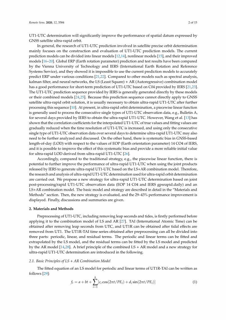
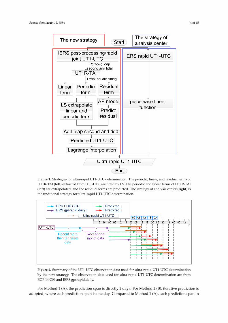
Figure 1 shows the new strategy for ultra-rapid UT1-UTC determination based on the LS + ARcombination model and the traditional strategy. The other details for new strategy are displayed inthe following.
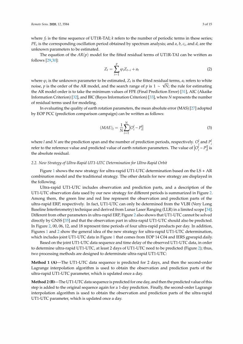
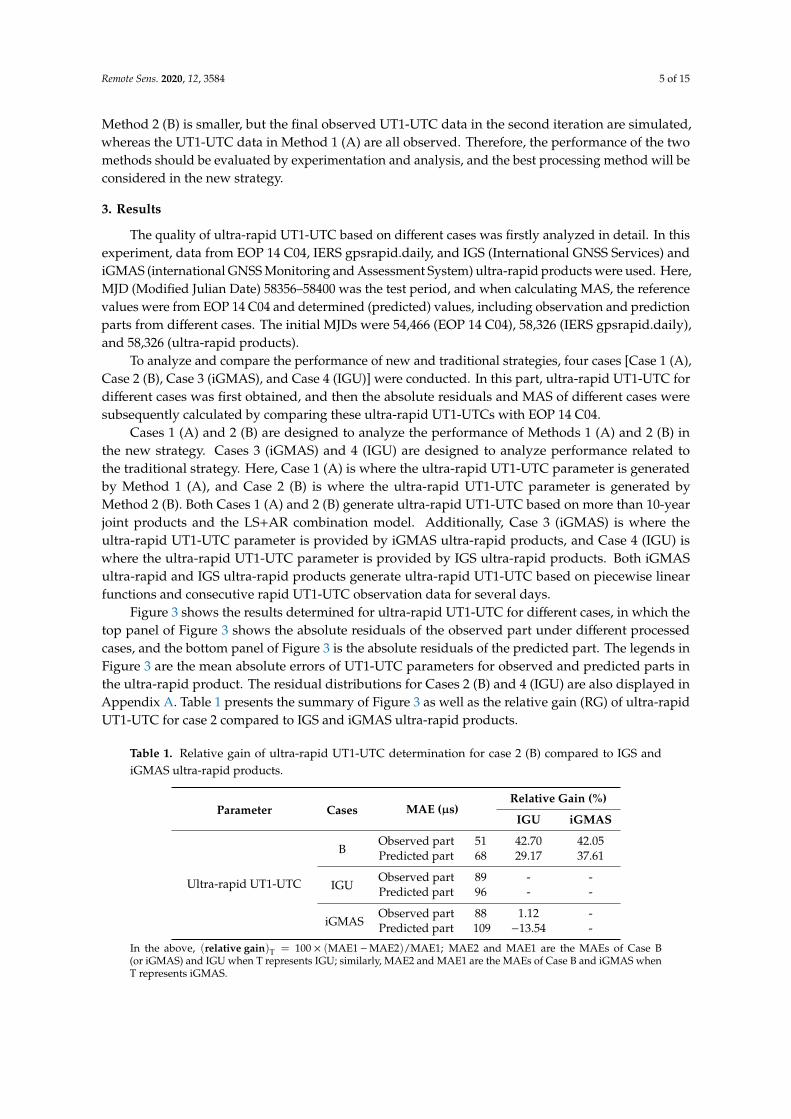
Ultra-rapid UT1-UTC includes observation and prediction parts, and a description of theUT1-UTC observation data used by our new strategy for different periods is summarized in Figure 2.Among them, the green line and red line represent the observation and prediction parts of theultra-rapid ERP, respectively. In fact, UT1-UTC can only be determined from the VLBI (Very LongBaseline Interferometry) technique and derived from Lunar Laser Ranging (LLR) in a limited scope [34].Different from other parameters in ultra-rapid ERP, Figure 2 also shows that UT1-UTC cannot be solveddirectly by GNSS [35] and that the observation part in ultra-rapid UT1-UTC should also be predicted.In Figure 2, 00, 06, 12, and 18 represent time periods of four ultra-rapid products per day. In addition,Figures 1 and 2 show the general idea of the new strategy for ultra-rapid UT1-UTC determination,which includes joint UT1-UTC data in Figure 1 that comes from EOP 14 C04 and IERS gpsrapid.daily.
Based on the joint UT1-UTC data sequence and time delay of the observed UT1-UTC data, in orderto determine ultra-rapid UT1-UTC, at least 2 days of UT1-UTC need to be predicted (Figure 2); thus,two processing methods are designed to determinate ultra-rapid UT1-UTC:
Method 1 (A)—The UT1-UTC data sequence is predicted for 2 days, and then the second-orderLagrange interpolation algorithm is used to obtain the observation and prediction parts of theultra-rapid UT1-UTC parameter, which is updated once a day.
Method 2 (B)—The UT1-UTC data sequence is predicted for one day, and then the predicted value of thisstep is added to the original sequence again for a 1-day prediction. Finally, the second-order Lagrangeinterpolation algorithm is used to obtain the observation and prediction parts of the ultra-rapidUT1-UTC parameter, which is updated once a day.
Remote Sens. 2020, 12, 3584 4 of 15
Remote Sens. 2020, 12, 3584 4 of 16
Lagrange interpolation algorithm is used to obtain the observation and prediction parts of the ultra-rapid UT1-UTC parameter, which is updated once a day.
Figure 1. Strategies for ultra-rapid UT1-UTC determination. The periodic, linear, and residual terms of UT1R-TAI (left) extracted from UT1-UTC are fitted by LS. The periodic and linear terms of UT1R-TAI (left) are extrapolated, and the residual terms are predicted. The strategy of analysis center (right) is the traditional strategy for ultra-rapid UT1-UTC determination.
Figure 2. Summary of the UT1-UTC observation data used for ultra-rapid UT1-UTC determination by the new strategy. The observation data used for ultra-rapid UT1-UTC determination are from EOP 14 C04 and IERS gpsrapid.daily.
Figure 1. Strategies for ultra-rapid UT1-UTC determination. The periodic, linear, and residual terms ofUT1R-TAI (left) extracted from UT1-UTC are fitted by LS. The periodic and linear terms of UT1R-TAI(left) are extrapolated, and the residual terms are predicted. The strategy of analysis center (right) isthe traditional strategy for ultra-rapid UT1-UTC determination.
Remote Sens. 2020, 12, 3584 4 of 16
Lagrange interpolation algorithm is used to obtain the observation and prediction parts of the ultra-rapid UT1-UTC parameter, which is updated once a day.
Figure 1. Strategies for ultra-rapid UT1-UTC determination. The periodic, linear, and residual terms of UT1R-TAI (left) extracted from UT1-UTC are fitted by LS. The periodic and linear terms of UT1R-TAI (left) are extrapolated, and the residual terms are predicted. The strategy of analysis center (right) is the traditional strategy for ultra-rapid UT1-UTC determination.
Figure 2. Summary of the UT1-UTC observation data used for ultra-rapid UT1-UTC determination by the new strategy. The observation data used for ultra-rapid UT1-UTC determination are from EOP 14 C04 and IERS gpsrapid.daily.
Figure 2. Summary of the UT1-UTC observation data used for ultra-rapid UT1-UTC determinationby the new strategy. The observation data used for ultra-rapid UT1-UTC determination are fromEOP 14 C04 and IERS gpsrapid.daily.
For Method 1 (A), the prediction span is directly 2 days. For Method 2 (B), iterative prediction isadopted, where each prediction span is one day. Compared to Method 1 (A), each prediction span in
Remote Sens. 2020, 12, 3584 5 of 15
Method 2 (B) is smaller, but the final observed UT1-UTC data in the second iteration are simulated,whereas the UT1-UTC data in Method 1 (A) are all observed. Therefore, the performance of the twomethods should be evaluated by experimentation and analysis, and the best processing method will beconsidered in the new strategy.
3. Results
The quality of ultra-rapid UT1-UTC based on different cases was firstly analyzed in detail. In thisexperiment, data from EOP 14 C04, IERS gpsrapid.daily, and IGS (International GNSS Services) andiGMAS (international GNSS Monitoring and Assessment System) ultra-rapid products were used. Here,MJD (Modified Julian Date) 58356–58400 was the test period, and when calculating MAS, the referencevalues were from EOP 14 C04 and determined (predicted) values, including observation and predictionparts from different cases. The initial MJDs were 54,466 (EOP 14 C04), 58,326 (IERS gpsrapid.daily),and 58,326 (ultra-rapid products).
To analyze and compare the performance of new and traditional strategies, four cases [Case 1 (A),Case 2 (B), Case 3 (iGMAS), and Case 4 (IGU)] were conducted. In this part, ultra-rapid UT1-UTC fordifferent cases was first obtained, and then the absolute residuals and MAS of different cases weresubsequently calculated by comparing these ultra-rapid UT1-UTCs with EOP 14 C04.
Cases 1 (A) and 2 (B) are designed to analyze the performance of Methods 1 (A) and 2 (B) inthe new strategy. Cases 3 (iGMAS) and 4 (IGU) are designed to analyze performance related tothe traditional strategy. Here, Case 1 (A) is where the ultra-rapid UT1-UTC parameter is generatedby Method 1 (A), and Case 2 (B) is where the ultra-rapid UT1-UTC parameter is generated byMethod 2 (B). Both Cases 1 (A) and 2 (B) generate ultra-rapid UT1-UTC based on more than 10-yearjoint products and the LS+AR combination model. Additionally, Case 3 (iGMAS) is where theultra-rapid UT1-UTC parameter is provided by iGMAS ultra-rapid products, and Case 4 (IGU) iswhere the ultra-rapid UT1-UTC parameter is provided by IGS ultra-rapid products. Both iGMASultra-rapid and IGS ultra-rapid products generate ultra-rapid UT1-UTC based on piecewise linearfunctions and consecutive rapid UT1-UTC observation data for several days.
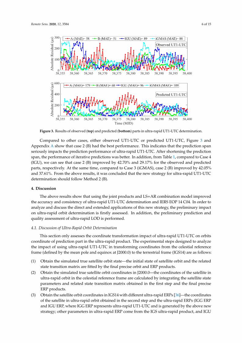
Figure 3 shows the results determined for ultra-rapid UT1-UTC for different cases, in which thetop panel of Figure 3 shows the absolute residuals of the observed part under different processedcases, and the bottom panel of Figure 3 is the absolute residuals of the predicted part. The legends inFigure 3 are the mean absolute errors of UT1-UTC parameters for observed and predicted parts inthe ultra-rapid product. The residual distributions for Cases 2 (B) and 4 (IGU) are also displayed inAppendix A. Table 1 presents the summary of Figure 3 as well as the relative gain (RG) of ultra-rapidUT1-UTC for case 2 compared to IGS and iGMAS ultra-rapid products.
Table 1. Relative gain of ultra-rapid UT1-UTC determination for case 2 (B) compared to IGS andiGMAS ultra-rapid products.
Parameter Cases MAE (µs)Relative Gain (%)
IGU iGMAS
Ultra-rapid UT1-UTC
BObserved part 51 42.70 42.05Predicted part 68 29.17 37.61
IGUObserved part 89 - -Predicted part 96 - -
iGMASObserved part 88 1.12 -Predicted part 109 −13.54 -
In the above, (relative gain)T = 100 × (MAE1−MAE2)/MAE1; MAE2 and MAE1 are the MAEs of Case B(or iGMAS) and IGU when T represents IGU; similarly, MAE2 and MAE1 are the MAEs of Case B and iGMAS whenT represents iGMAS.
Remote Sens. 2020, 12, 3584 6 of 15Remote Sens. 2020, 12, 3584 6 of 16
Figure 3. Results of observed (top) and predicted (bottom) parts in ultra-rapid UT1-UTC determination.
Compared to other cases, either observed UT1-UTC or predicted UT1-UTC, Figure 3 and Appendix A show that case 2 (B) had the best performance. This indicates that the prediction span seriously impacts the prediction performance of ultra-rapid UT1-UTC. After shortening the prediction span, the performance of iterative predictions was better. In addition, from Table 1, compared to Case 4 (IGU), we can see that case 2 (B) improved by 42.70% and 29.17% for the observed and predicted parts, respectively. At the same time, compared to Case 3 (iGMAS), case 2 (B) improved by 42.05% and 37.61%. From the above results, it was concluded that the new strategy for ultra-rapid UT1-UTC determination should follow Method 2 (B).
4. Discussion
The above results show that using the joint products and LS+AR combination model improved the accuracy and consistency of ultra-rapid UT1-UTC determination and IERS EOP 14 C04. In order to analyze and discuss the direct and extended applications of this new strategy, the preliminary impact on ultra-rapid orbit determination is firstly assessed. In addition, the preliminary prediction and quality assessment of ultra-rapid LOD is performed.
4.1. Discussion of Ultra-Rapid Orbit Determination
This section only assesses the coordinate transformation impact of ultra-rapid UT1-UTC on orbits coordinate of prediction part in the ultra-rapid product. The experimental steps designed to analyze the impact of using ultra-rapid UT1-UTC in transforming coordinates from the celestial reference frame (defined by the mean pole and equinox at J2000.0) to the terrestrial frame (IGS14) are as follows:
(1) Obtain the simulated true satellite orbit state—the initial state of satellite orbit and the related state transition matrix are fitted by the final precise orbit and ERP products.
(2) Obtain the simulated true satellite orbit coordinates in J2000.0—the coordinates of the satellite in ultra-rapid orbit in the celestial reference frame are calculated by integrating the satellite state parameters and related state transition matrix obtained in the first step and the final precise ERP products.
Figure 3. Results of observed (top) and predicted (bottom) parts in ultra-rapid UT1-UTC determination.
Compared to other cases, either observed UT1-UTC or predicted UT1-UTC, Figure 3 andAppendix A show that case 2 (B) had the best performance. This indicates that the prediction spanseriously impacts the prediction performance of ultra-rapid UT1-UTC. After shortening the predictionspan, the performance of iterative predictions was better. In addition, from Table 1, compared to Case 4(IGU), we can see that case 2 (B) improved by 42.70% and 29.17% for the observed and predictedparts, respectively. At the same time, compared to Case 3 (iGMAS), case 2 (B) improved by 42.05%and 37.61%. From the above results, it was concluded that the new strategy for ultra-rapid UT1-UTCdetermination should follow Method 2 (B).
4. Discussion
The above results show that using the joint products and LS+AR combination model improvedthe accuracy and consistency of ultra-rapid UT1-UTC determination and IERS EOP 14 C04. In order toanalyze and discuss the direct and extended applications of this new strategy, the preliminary impacton ultra-rapid orbit determination is firstly assessed. In addition, the preliminary prediction andquality assessment of ultra-rapid LOD is performed.
4.1. Discussion of Ultra-Rapid Orbit Determination
This section only assesses the coordinate transformation impact of ultra-rapid UT1-UTC on orbitscoordinate of prediction part in the ultra-rapid product. The experimental steps designed to analyzethe impact of using ultra-rapid UT1-UTC in transforming coordinates from the celestial referenceframe (defined by the mean pole and equinox at J2000.0) to the terrestrial frame (IGS14) are as follows:
(1) Obtain the simulated true satellite orbit state—the initial state of satellite orbit and the relatedstate transition matrix are fitted by the final precise orbit and ERP products.
(2) Obtain the simulated true satellite orbit coordinates in J2000.0—the coordinates of the satellite inultra-rapid orbit in the celestial reference frame are calculated by integrating the satellite stateparameters and related state transition matrix obtained in the first step and the final preciseERP products.
(3) Obtain the satellite orbit coordinates in IGS14 with different ultra-rapid ERPs [36]—the coordinatesof the satellite in ultra-rapid orbit obtained in the second step and the ultra-rapid ERPs (IGG ERPand IGU ERP, where IGG ERP represents ultra-rapid UT1-UTC and is generated by the above newstrategy; other parameters in ultra-rapid ERP come from the IGS ultra-rapid product, and IGU
Remote Sens. 2020, 12, 3584 7 of 15
ERP represents ultra-rapid ERP and is provided by the IGS ultra-rapid product) obtained inthe above part are used to transform the coordinates of the satellite in ultra-rapid orbit in theterrestrial frame.
(4) Comparative analysis—the 6-hour prediction for each arc of satellite in ultra-rapid orbit obtainedin the third step is compared with the final precise orbit products, and the residual of each satelliteand its maximum (Max), average (Ave), and RMS (Root Mean Square) are calculated.
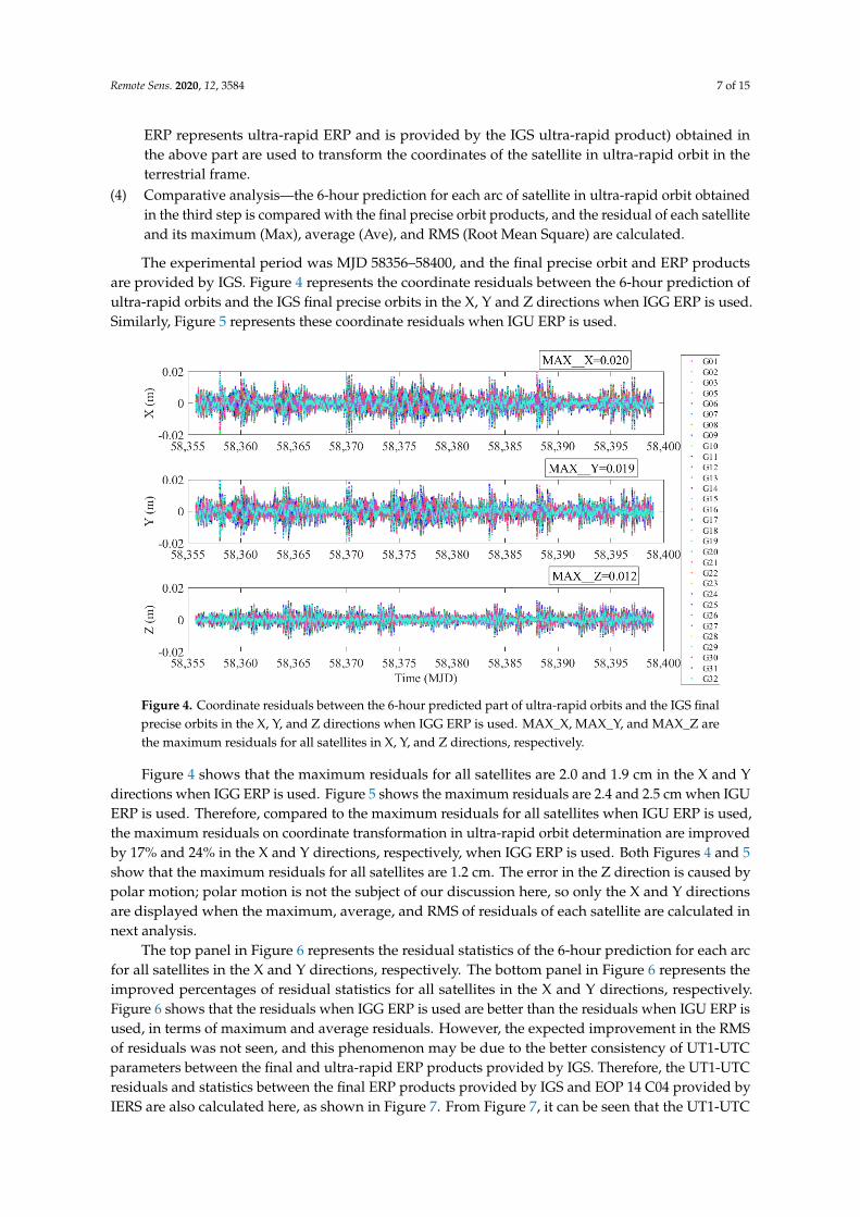
The experimental period was MJD 58356–58400, and the final precise orbit and ERP productsare provided by IGS. Figure 4 represents the coordinate residuals between the 6-hour prediction ofultra-rapid orbits and the IGS final precise orbits in the X, Y and Z directions when IGG ERP is used.Similarly, Figure 5 represents these coordinate residuals when IGU ERP is used.
Remote Sens. 2020, 12, 3584 7 of 16
(3) Obtain the satellite orbit coordinates in IGS14 with different ultra-rapid ERPs [36]—the coordinates of the satellite in ultra-rapid orbit obtained in the second step and the ultra-rapid ERPs (IGG ERP and IGU ERP, where IGG ERP represents ultra-rapid UT1-UTC and is generated by the above new strategy; other parameters in ultra-rapid ERP come from the IGS ultra-rapid product, and IGU ERP represents ultra-rapid ERP and is provided by the IGS ultra-rapid product) obtained in the above part are used to transform the coordinates of the satellite in ultra-rapid orbit in the terrestrial frame.
(4) Comparative analysis—the 6-hour prediction for each arc of satellite in ultra-rapid orbit obtained in the third step is compared with the final precise orbit products, and the residual of each satellite and its maximum (Max), average (Ave), and RMS (Root Mean Square) are calculated.
The experimental period was MJD 58356–58400, and the final precise orbit and ERP products are provided by IGS. Figure 4 represents the coordinate residuals between the 6-hour prediction of ultra-rapid orbits and the IGS final precise orbits in the X, Y and Z directions when IGG ERP is used. Similarly, Figure 5 represents these coordinate residuals when IGU ERP is used.
Figure 4. Coordinate residuals between the 6-hour predicted part of ultra-rapid orbits and the IGS final precise orbits in the X, Y, and Z directions when IGG ERP is used. MAX_X, MAX_Y, and MAX_Z are the maximum residuals for all satellites in X, Y, and Z directions, respectively.
Figure 4. Coordinate residuals between the 6-hour predicted part of ultra-rapid orbits and the IGS finalprecise orbits in the X, Y, and Z directions when IGG ERP is used. MAX_X, MAX_Y, and MAX_Z arethe maximum residuals for all satellites in X, Y, and Z directions, respectively.
Figure 4 shows that the maximum residuals for all satellites are 2.0 and 1.9 cm in the X and Ydirections when IGG ERP is used. Figure 5 shows the maximum residuals are 2.4 and 2.5 cm when IGUERP is used. Therefore, compared to the maximum residuals for all satellites when IGU ERP is used,the maximum residuals on coordinate transformation in ultra-rapid orbit determination are improvedby 17% and 24% in the X and Y directions, respectively, when IGG ERP is used. Both Figures 4 and 5show that the maximum residuals for all satellites are 1.2 cm. The error in the Z direction is caused bypolar motion; polar motion is not the subject of our discussion here, so only the X and Y directionsare displayed when the maximum, average, and RMS of residuals of each satellite are calculated innext analysis.
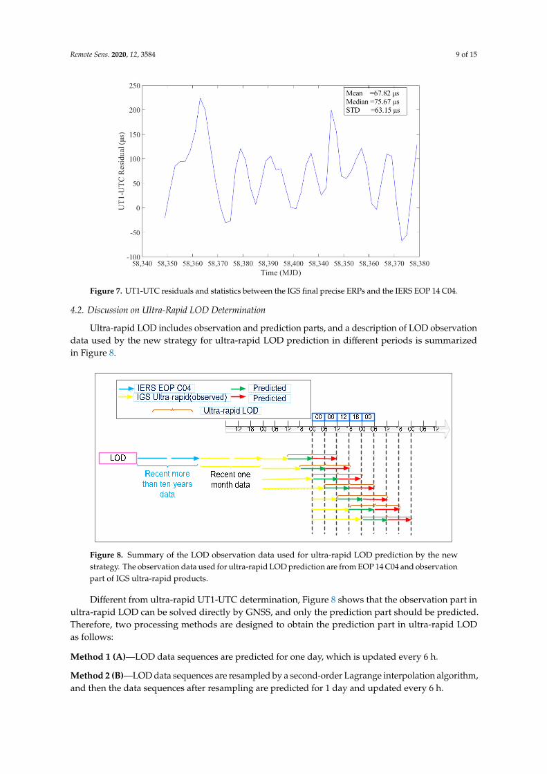
The top panel in Figure 6 represents the residual statistics of the 6-hour prediction for each arcfor all satellites in the X and Y directions, respectively. The bottom panel in Figure 6 represents theimproved percentages of residual statistics for all satellites in the X and Y directions, respectively.Figure 6 shows that the residuals when IGG ERP is used are better than the residuals when IGU ERP isused, in terms of maximum and average residuals. However, the expected improvement in the RMSof residuals was not seen, and this phenomenon may be due to the better consistency of UT1-UTCparameters between the final and ultra-rapid ERP products provided by IGS. Therefore, the UT1-UTCresiduals and statistics between the final ERP products provided by IGS and EOP 14 C04 provided byIERS are also calculated here, as shown in Figure 7. From Figure 7, it can be seen that the UT1-UTC
Remote Sens. 2020, 12, 3584 8 of 15
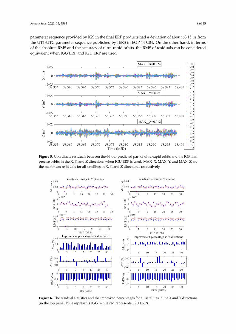
parameter sequence provided by IGS in the final ERP products had a deviation of about 63.15 µs fromthe UT1-UTC parameter sequence published by IERS in EOP 14 C04. On the other hand, in termsof the absolute RMS and the accuracy of ultra-rapid orbits, the RMS of residuals can be consideredequivalent when IGG ERP and IGU ERP are used.Remote Sens. 2020, 12, 3584 8 of 16
Figure 5. Coordinate residuals between the 6-hour predicted part of ultra-rapid orbits and the IGS final precise orbits in the X, Y, and Z directions when IGU ERP is used. MAX_X, MAX_Y, and MAX_Z are the maximum residuals for all satellites in X, Y, and Z directions, respectively.
Figure 4 shows that the maximum residuals for all satellites are 2.0 and 1.9 cm in the X and Y directions when IGG ERP is used. Figure 5 shows the maximum residuals are 2.4 and 2.5 cm when IGU ERP is used. Therefore, compared to the maximum residuals for all satellites when IGU ERP is used, the maximum residuals on coordinate transformation in ultra-rapid orbit determination are improved by 17% and 24% in the X and Y directions, respectively, when IGG ERP is used. Both Figures 4 and 5 show that the maximum residuals for all satellites are 1.2 cm. The error in the Z direction is caused by polar motion; polar motion is not the subject of our discussion here, so only the X and Y directions are displayed when the maximum, average, and RMS of residuals of each satellite are calculated in next analysis.
The top panel in Figure 6 represents the residual statistics of the 6-hour prediction for each arc for all satellites in the X and Y directions, respectively. The bottom panel in Figure 6 represents the improved percentages of residual statistics for all satellites in the X and Y directions, respectively. Figure 6 shows that the residuals when IGG ERP is used are better than the residuals when IGU ERP is used, in terms of maximum and average residuals. However, the expected improvement in the RMS of residuals was not seen, and this phenomenon may be due to the better consistency of UT1-UTC parameters between the final and ultra-rapid ERP products provided by IGS. Therefore, the UT1-UTC residuals and statistics between the final ERP products provided by IGS and EOP 14 C04 provided by IERS are also calculated here, as shown in Figure 7. From Figure 7, it can be seen that the UT1-UTC parameter sequence provided by IGS in the final ERP products had a deviation of about 63.15 µs from the UT1-UTC parameter sequence published by IERS in EOP 14 C04. On the other hand, in terms of the absolute RMS and the accuracy of ultra-rapid orbits, the RMS of residuals can be considered equivalent when IGG ERP and IGU ERP are used.
Figure 5. Coordinate residuals between the 6-hour predicted part of ultra-rapid orbits and the IGS finalprecise orbits in the X, Y, and Z directions when IGU ERP is used. MAX_X, MAX_Y, and MAX_Z arethe maximum residuals for all satellites in X, Y, and Z directions, respectively.Remote Sens. 2020, 12, 3584 9 of 16
Figure 6. The residual statistics and the improved percentages for all satellites in the X and Y directions (in the top panel, blue represents IGG, while red represents IGU ERP).
Figure 7. UT1-UTC residuals and statistics between the IGS final precise ERPs and the IERS EOP 14 C04.
Figure 6. The residual statistics and the improved percentages for all satellites in the X and Y directions(in the top panel, blue represents IGG, while red represents IGU ERP).
Remote Sens. 2020, 12, 3584 9 of 15
Remote Sens. 2020, 12, 3584 9 of 16
Figure 6. The residual statistics and the improved percentages for all satellites in the X and Y directions (in the top panel, blue represents IGG, while red represents IGU ERP).
Figure 7. UT1-UTC residuals and statistics between the IGS final precise ERPs and the IERS EOP 14 C04.
Figure 7. UT1-UTC residuals and statistics between the IGS final precise ERPs and the IERS EOP 14 C04.
4.2. Discussion on Ultra-Rapid LOD Determination
Ultra-rapid LOD includes observation and prediction parts, and a description of LOD observationdata used by the new strategy for ultra-rapid LOD prediction in different periods is summarizedin Figure 8.
Remote Sens. 2020, 12, 3584 10 of 16
4.2. Discussion on Ultra-Rapid LOD Determination
Ultra-rapid LOD includes observation and prediction parts, and a description of LOD observation data used by the new strategy for ultra-rapid LOD prediction in different periods is summarized in Figure 8.
Figure 8. Summary of the LOD observation data used for ultra-rapid LOD prediction by the new strategy. The observation data used for ultra-rapid LOD prediction are from EOP 14 C04 and observation part of IGS ultra-rapid products.
Different from ultra-rapid UT1-UTC determination, Figure 8 shows that the observation part in ultra-rapid LOD can be solved directly by GNSS, and only the prediction part should be predicted. Therefore, two processing methods are designed to obtain the prediction part in ultra-rapid LOD as follows:
Method 1 (A)—LOD data sequences are predicted for one day, which is updated every 6 h.
Method 2 (B)—LOD data sequences are resampled by a second-order Lagrange interpolation algorithm, and then the data sequences after resampling are predicted for 1 day and updated every 6 h.
The data from EOP 14 C04 [MJD: 54,466–58,400 and MJD: 58,356–38,400 are the test period as the reference (true) value compared to the determined value, also namely prediction part value, of different cases], and IGS and iGMAS ultra-rapid products (MJD: 58,326–58,400) are used, and four cases [Case 1 (A), Case 2 (B), Case 3 (iGMAS), and Case 4 (IGU)] are conducted similarly.
Figure 9 shows the absolute residuals of the LOD parameter for predicted parts under different processed cases, and the legend in Figure 9 shows mean absolute errors of the LOD parameter for predicted parts in the ultra-rapid product. Table 2 presents a summary of Figure 9 and the relative gain of the LOD parameter for the predicted part in case 1 compared to IGS and iGMAS products. From Table 2, compared to Case 4 (IGU), we can see that the improvement in case 1 (A) was 20.83%. At the same time, compared to Case 3 (iGMAS), the improvement in case 1 (A) was 64.81%.
Figure 8. Summary of the LOD observation data used for ultra-rapid LOD prediction by the newstrategy. The observation data used for ultra-rapid LOD prediction are from EOP 14 C04 and observationpart of IGS ultra-rapid products.
Different from ultra-rapid UT1-UTC determination, Figure 8 shows that the observation part inultra-rapid LOD can be solved directly by GNSS, and only the prediction part should be predicted.Therefore, two processing methods are designed to obtain the prediction part in ultra-rapid LODas follows:
Method 1 (A)—LOD data sequences are predicted for one day, which is updated every 6 h.
Method 2 (B)—LOD data sequences are resampled by a second-order Lagrange interpolation algorithm,and then the data sequences after resampling are predicted for 1 day and updated every 6 h.

Remote Sens. 2020, 12, 3584 10 of 15
The data from EOP 14 C04 [MJD: 54,466–58,400 and MJD: 58,356–38,400 are the test period asthe reference (true) value compared to the determined value, also namely prediction part value,of different cases], and IGS and iGMAS ultra-rapid products (MJD: 58,326–58,400) are used, and fourcases [Case 1 (A), Case 2 (B), Case 3 (iGMAS), and Case 4 (IGU)] are conducted similarly.
Figure 9 shows the absolute residuals of the LOD parameter for predicted parts under differentprocessed cases, and the legend in Figure 9 shows mean absolute errors of the LOD parameter forpredicted parts in the ultra-rapid product. Table 2 presents a summary of Figure 9 and the relativegain of the LOD parameter for the predicted part in case 1 compared to IGS and iGMAS products.From Table 2, compared to Case 4 (IGU), we can see that the improvement in case 1 (A) was 20.83%.At the same time, compared to Case 3 (iGMAS), the improvement in case 1 (A) was 64.81%.Remote Sens. 2020, 12, 3584 11 of 16
Figure 9. Results of the prediction part of ultra-rapid LOD.
Table 2. Relative gain of predicted LOD for case 1 (A) compared to IGS and iGMAS products.
Parameter Strategies MAE (µs) Relative Gain (%)
IGU iGMAS
the prediction part of ultra-rapid LOD A 19 20.83 64.81
IGU 24 - - iGMAS 54 −125.00 -
In the above, ( ) ( )T 100 MAE1 MAE2 / MAE1= × −relative gain ; MAE2 and MAE1 are the
MAEs of Case A (or iGMAS) and IGU when T represents IGU; similarly, MAE2 and MAE1 are the MAEs of Case A and iGMAS when T represents iGMAS.
Therefore, based on the LS + AR combination model, the above assessment shows that the new strategy further improves the performance of ultra-rapid UT1-UTC determination and the prediction performance of ultra-rapid LOD when using joint observation data.
On the one hand, ultra-rapid UT1-UTC determined by the new strategy can directly apply to GNSS satellite ultra-rapid orbit determination and can directly constrain the known value. The prior value in ultra-rapid LOD can also be derived directly from ultra-rapid UT1-UTC. In addition, ultra-rapid LOD prediction directly by the new strategy should depend on the observation part in ultra-rapid LOD, so iterations are essential, and the time consumed needs to be balanced. Therefore, the impact of the new strategy for ultra-rapid LOD on ultra-rapid orbit determination needs to be further analyzed and researched. In addition, typically a combination of GNSS [37] and Satellite Laser Ranging (SLR) observations in the LAser GEOdynamics Satellite (LAGEOS) and Etalon satellites are used to determine LOD [38]. In a limited scope, Doppler Orbitography and Radio-positioning Integrated by Satellite (DORIS) observations can be employed to derive LOD values as well [39]. These observations will be used to enrich the strategy in the future.
On the other hand, it is worth noting that EOP 14 C04 and IERS gpsrapid.daily sometimes have increased latency in practice, which will result in a slower performance of the new strategy. However, as long as the two products are released on time, the performance will be ensured Compared to the LS+AR combination model, the other improved prediction models and methods (e.g., [16,17]) can also be used in this new strategy after appropriate modifications, and the performance should be better. However, this was not assessed and verified here, and future works are required.
Figure 9. Results of the prediction part of ultra-rapid LOD.
Table 2. Relative gain of predicted LOD for case 1 (A) compared to IGS and iGMAS products.
Parameter Strategies MAE (µs)Relative Gain (%)
IGU iGMAS
the prediction part of ultra-rapid LODA 19 20.83 64.81
IGU 24 - -iGMAS 54 −125.00 -
In the above, (relative gain)T = 100 × (MAE1−MAE2)/MAE1; MAE2 and MAE1 are the MAEs of Case A(or iGMAS) and IGU when T represents IGU; similarly, MAE2 and MAE1 are the MAEs of Case A and iGMAS whenT represents iGMAS.
Therefore, based on the LS + AR combination model, the above assessment shows that the newstrategy further improves the performance of ultra-rapid UT1-UTC determination and the predictionperformance of ultra-rapid LOD when using joint observation data.
On the one hand, ultra-rapid UT1-UTC determined by the new strategy can directly apply to GNSSsatellite ultra-rapid orbit determination and can directly constrain the known value. The prior valuein ultra-rapid LOD can also be derived directly from ultra-rapid UT1-UTC. In addition, ultra-rapidLOD prediction directly by the new strategy should depend on the observation part in ultra-rapidLOD, so iterations are essential, and the time consumed needs to be balanced. Therefore, the impact ofthe new strategy for ultra-rapid LOD on ultra-rapid orbit determination needs to be further analyzedand researched. In addition, typically a combination of GNSS [37] and Satellite Laser Ranging (SLR)

Remote Sens. 2020, 12, 3584 11 of 15
observations in the LAser GEOdynamics Satellite (LAGEOS) and Etalon satellites are used to determineLOD [38]. In a limited scope, Doppler Orbitography and Radio-positioning Integrated by Satellite(DORIS) observations can be employed to derive LOD values as well [39]. These observations will beused to enrich the strategy in the future.
On the other hand, it is worth noting that EOP 14 C04 and IERS gpsrapid.daily sometimes haveincreased latency in practice, which will result in a slower performance of the new strategy. However,as long as the two products are released on time, the performance will be ensured Compared to theLS+AR combination model, the other improved prediction models and methods (e.g., [16,17]) can alsobe used in this new strategy after appropriate modifications, and the performance should be better.However, this was not assessed and verified here, and future works are required.
5. Conclusions
In order to explore the potential to improve the accuracy and consistency of ultra-rapid UT1-UTCdetermination to better serve ultra-rapid orbit determination of GNSS satellites, this study has proposeda new strategy related to ultra-rapid UT1-UTC. Furthermore, to assess the performance of the newstrategy, we used UT1-UTC data of EOP 14 C04 provided by IERS, daily rapid products provided byIERS, and ultra-rapid products provided by IGS and iGMAS.
The ultra-rapid UT1-UTC test results of the new strategy showed an overall better performancethan the ultra-rapid UT1-UTC test results with the traditional strategy. Compared to the UT1-UTCparameter of IGS ultra-rapid products, the improvements to observation and prediction part accuracieswere 42.70% and 29.17%, respectively, while compared to the UT1-UTC parameter of iGMAS ultra-rapidproducts, the improvements were 42.05% and 37.61%, respectively. Results show that the new strategycan improve the maximum and average of residuals for ultra-rapid orbit determination, but the RMSof residuals are almost equivalent. Additionally, the extended application results show that the newstrategy can improve the prior value in ultra-rapid LOD.
Different from the traditional strategy, if the complexity of the new strategy is tolerated duringultra-rapid orbit determination, this strategy can provide an available reference to improve theperformance of the ultra-rapid UT1-UTC determination and reduce the impact on coordinatetransformation between the celestial (inertial) reference frame and the terrestrial frame in ultra-rapidorbit determination.
Author Contributions: F.Y. provided the initial idea for this study; F.Y. and Y.Y. conceived and designed theexperiment; F.Y., Y.Y. and Z.D. analyzed the results; F.Y., Y.Y. and Z.D. wrote the paper. All authors have read andagreed to the published version of the final manuscript.
Funding: This work was supported by the Collaborative Precision Positioning Project funded by the Ministry ofScience and Technology of China (No. 2016YFB0501900), China Natural Science Funds (No. 42004016) and HuBeiNatural Science Funds (No. 2020CFB329).
Acknowledgments: The authors would like to acknowledge the International Earth Rotation and ReferenceSystems Service (IERS), Multi-GNSS Experiment (MGEX), the Crustal Dynamics Data Information System(CDDIS) of the International GNSS Services (IGS), and Chinese iGMAS networks for providing the data andproducts. In addition, we also thank these websites (http://www.igs.org/products; http://www.igmas.org/Product;ftp://ftp.igs.org/pub/center/analysis/).
Conflicts of Interest: The authors declare no conflict of interest.
Remote Sens. 2020, 12, 3584 12 of 15
Appendix A
Remote Sens. 2020, 12, 3584 12 of 16
5. Conclusions
In order to explore the potential to improve the accuracy and consistency of ultra-rapid UT1-UTC determination to better serve ultra-rapid orbit determination of GNSS satellites, this study has proposed a new strategy related to ultra-rapid UT1-UTC. Furthermore, to assess the performance of the new strategy, we used UT1-UTC data of EOP 14 C04 provided by IERS, daily rapid products provided by IERS, and ultra-rapid products provided by IGS and iGMAS.
The ultra-rapid UT1-UTC test results of the new strategy showed an overall better performance than the ultra-rapid UT1-UTC test results with the traditional strategy. Compared to the UT1-UTC parameter of IGS ultra-rapid products, the improvements to observation and prediction part accuracies were 42.70% and 29.17%, respectively, while compared to the UT1-UTC parameter of iGMAS ultra-rapid products, the improvements were 42.05% and 37.61%, respectively. Results show that the new strategy can improve the maximum and average of residuals for ultra-rapid orbit determination, but the RMS of residuals are almost equivalent. Additionally, the extended application results show that the new strategy can improve the prior value in ultra-rapid LOD.
Different from the traditional strategy, if the complexity of the new strategy is tolerated during ultra-rapid orbit determination, this strategy can provide an available reference to improve the performance of the ultra-rapid UT1-UTC determination and reduce the impact on coordinate transformation between the celestial (inertial) reference frame and the terrestrial frame in ultra-rapid orbit determination.
Author Contributions: F.Y. provided the initial idea for this study; F.Y. and Y.Y. conceived and designed the experiment; F.Y., Y.Y. and Z.D. analyzed the results; F.Y., Y.Y. and Z.D. wrote the paper. All authors have read and agreed to the published version of the final manuscript.
Funding: This work was supported by the Collaborative Precision Positioning Project funded by the Ministry of Science and Technology of China (No. 2016YFB0501900), China Natural Science Funds (No. 42004016) and HuBei Natural Science Funds (No. 2020CFB329).
Acknowledgments: The authors would like to acknowledge the International Earth Rotation and Reference Systems Service (IERS), Multi-GNSS Experiment (MGEX), the Crustal Dynamics Data Information System (CDDIS) of the International GNSS Services (IGS), and Chinese iGMAS networks for providing the data and products. In addition, we also thank these websites (http://www.igs.org/products; http://www.igmas.org/Product; ftp://ftp.igs.org/pub/center/analysis/).
Conflicts of Interest: The authors declare no conflicts of interest.
Appendix A
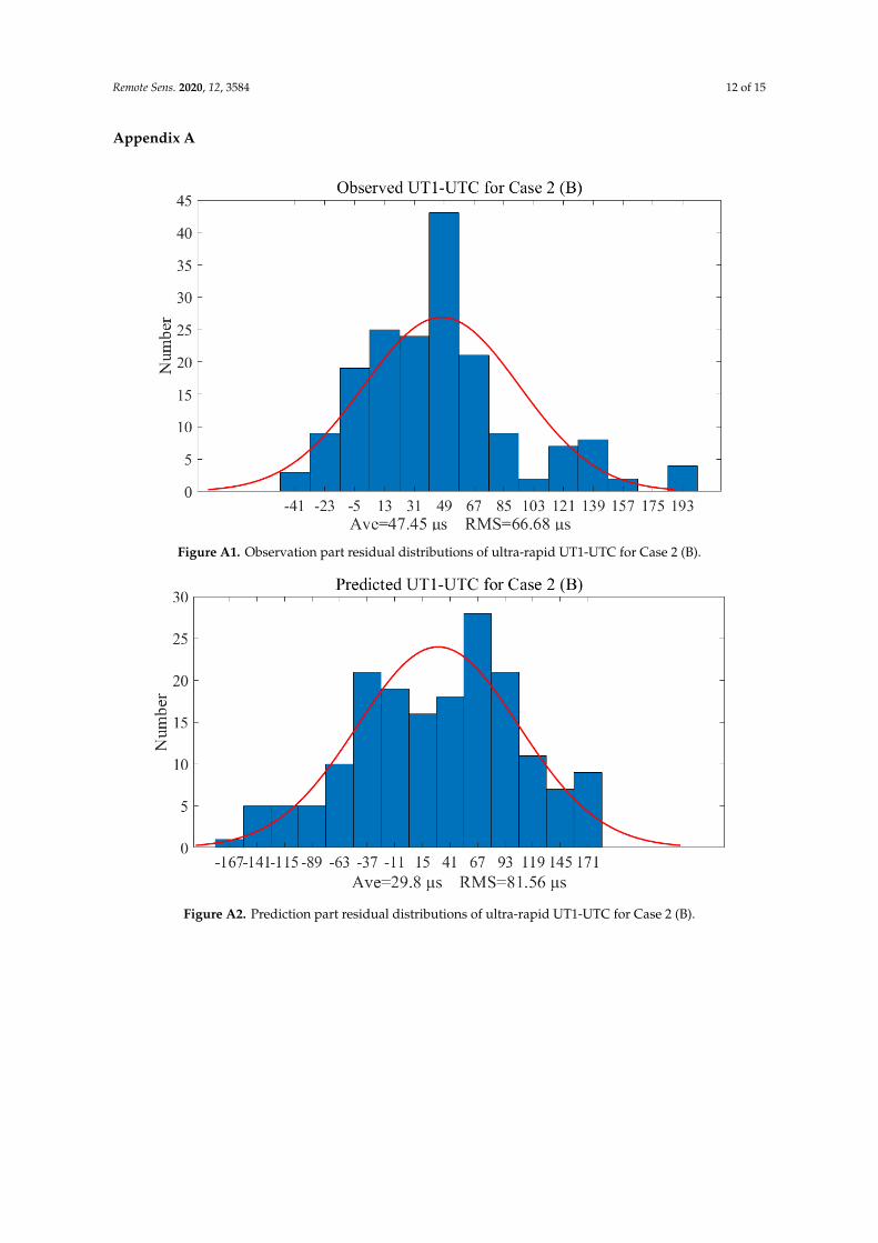
Figure A1. Observation part residual distributions of ultra-rapid UT1-UTC for Case 2 (B). Figure A1. Observation part residual distributions of ultra-rapid UT1-UTC for Case 2 (B).Remote Sens. 2020, 12, 3584 13 of 16
Figure A2. Prediction part residual distributions of ultra-rapid UT1-UTC for Case 2 (B).
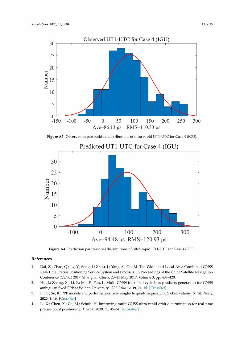
Figure A3. Observation part residual distributions of ultra-rapid UT1-UTC for Case 4 (IGU).
Figure A2. Prediction part residual distributions of ultra-rapid UT1-UTC for Case 2 (B).
Remote Sens. 2020, 12, 3584 13 of 15
Remote Sens. 2020, 12, 3584 13 of 16
Figure A2. Prediction part residual distributions of ultra-rapid UT1-UTC for Case 2 (B).
Figure A3. Observation part residual distributions of ultra-rapid UT1-UTC for Case 4 (IGU). Figure A3. Observation part residual distributions of ultra-rapid UT1-UTC for Case 4 (IGU).Remote Sens. 2020, 12, 3584 14 of 16
Figure A4. Prediction part residual distributions of ultra-rapid UT1-UTC for Case 4 (IGU).
References
1. Dai, Z.; Zhao, Q.; Lv, Y.; Song, J.; Zhou, J.; Yang, S.; Gu, M. The Wide- and Local-Area Combined GNSS Real-Time Precise Positioning Service System and Products. In Proceedings of The China Satellite Navigation Conference (CSNC) 2017, Shanghai, China, 23–25 May 2017; Volume 3, pp. 409–428.
2. Hu, J.; Zhang, X.; Li, P.; Ma, F.; Pan, L. Multi-GNSS fractional cycle bias products generation for GNSS ambiguity-fixed PPP at Wuhan University. GPS Solut. 2019, 24, 15, doi:10.1007/s10291-019-0929-9.
3. Jin, S.; Su, K. PPP models and performances from single- to quad-frequency BDS observations. Satell. Navig. 2020, 1, 16, doi:10.1186/s43020-020-00014-y.
4. Li, X.; Chen, X.; Ge, M.; Schuh, H. Improving multi-GNSS ultra-rapid orbit determination for real-time precise point positioning. J. Geod. 2019, 93, 45–64, doi:10.1007/s00190-018-1138-y.
5. Ye, F.; Yuan, Y.; Tan, B.; Deng, Z.; Ou, J. The Preliminary Results for Five-System Ultra-Rapid Precise Orbit Determination of the One-Step Method Based on the Double-Difference Observation Model. Remote Sens. 2018, 11, 46, doi:10.3390/rs11010046.
6. Wang, Q.; Zhang, K.; Wu, S.; Zou, Y.; Hu, C. A method for identification of optimal minimum number of multi-GNSS tracking stations for ultra-rapid orbit and ERP determination. Adv. Space Res. 2019, 63, 2877–2888, doi: 10.1016/j.asr.2017.12.006.
7. Dousa, J. Development of the GLONASS Ultra-Rapid Orbit Determination at Geodetic Observatory Pecný. In Proceedings of the 2009 IAG Symposium, Buenos Aires, Argentina, 31 August—4 September 2009; pp. 1029–1035.
8. Ye, F.; Yuan, Y.; Zhang, B. Impact analysis of arc length in multi-GNSS ultra-rapid orbit determination based on the one-step method. Meas. Sci. Technol. 2020, 31, 055012, doi:10.1088/1361-6501/ab69d4.
9. Petit, G.; Luzum, B. IERS Conventions. IERS Tech. Note 2010, 36, 179. 10. Lutz, S.; Beutler, G.; Schaer, S.; Dach, R.; Jäggi, A. CODE’s new ultra-rapid orbit and ERP products for the
IGS. GPS Solut. 2016, 20, 239–250, doi:10.1007/s10291-014-0432-2. 11. Wan, L.; Wei, E.; Jin, S. Earth Rotation Parameter Estimation from GNSS and Its Impact on Aircraft Orbit
Determination. In Proceedings of The China Satellite Navigation Conference (CSNC) 2014, Nanjing, China, 21–23 May 2014; pp. 105–114.
12. Jia, S.; Xu, T.-H.; Sun, Z.-Z.; Li, J.-J. Middle and long-term prediction of UT1-UTC based on combination of Gray Model and Autoregressive Integrated Moving Average. Adv. Space Res. 2017, 59, 888–894, doi: 10.1016/j.asr.2016.05.044.
13. Wang, Q.; Chao, H.; Xu, T.; Chang, G.; Moraleda, A.H. Impacts of Earth rotation parameters on GNSS ultra-rapid orbit prediction: Derivation and real-time correction. Adv. Space Res. 2017, 60, 2855–2870.
Figure A4. Prediction part residual distributions of ultra-rapid UT1-UTC for Case 4 (IGU).
References
1. Dai, Z.; Zhao, Q.; Lv, Y.; Song, J.; Zhou, J.; Yang, S.; Gu, M. The Wide- and Local-Area Combined GNSSReal-Time Precise Positioning Service System and Products. In Proceedings of the China Satellite NavigationConference (CSNC) 2017, Shanghai, China, 23–25 May 2017; Volume 3, pp. 409–428.
2. Hu, J.; Zhang, X.; Li, P.; Ma, F.; Pan, L. Multi-GNSS fractional cycle bias products generation for GNSSambiguity-fixed PPP at Wuhan University. GPS Solut. 2019, 24, 15. [CrossRef]
3. Jin, S.; Su, K. PPP models and performances from single- to quad-frequency BDS observations. Satell. Navig.2020, 1, 16. [CrossRef]
4. Li, X.; Chen, X.; Ge, M.; Schuh, H. Improving multi-GNSS ultra-rapid orbit determination for real-timeprecise point positioning. J. Geod. 2019, 93, 45–64. [CrossRef]
Remote Sens. 2020, 12, 3584 14 of 15
5. Ye, F.; Yuan, Y.; Tan, B.; Deng, Z.; Ou, J. The Preliminary Results for Five-System Ultra-Rapid Precise OrbitDetermination of the One-Step Method Based on the Double-Difference Observation Model. Remote Sens.2018, 11, 46. [CrossRef]
6. Wang, Q.; Zhang, K.; Wu, S.; Zou, Y.; Hu, C. A method for identification of optimal minimum numberof multi-GNSS tracking stations for ultra-rapid orbit and ERP determination. Adv. Space Res. 2019, 63,2877–2888. [CrossRef]
7. Dousa, J. Development of the GLONASS Ultra-Rapid Orbit Determination at Geodetic Observatory Pecný.In Proceedings of the 2009 IAG Symposium, Buenos Aires, Argentina, 31 August—4 September 2009;pp. 1029–1035.
8. Ye, F.; Yuan, Y.; Zhang, B. Impact analysis of arc length in multi-GNSS ultra-rapid orbit determination basedon the one-step method. Meas. Sci. Technol. 2020, 31, 055012. [CrossRef]
9. Petit, G.; Luzum, B. IERS Conventions. IERS Tech. Note 2010, 36, 179.10. Lutz, S.; Beutler, G.; Schaer, S.; Dach, R.; Jäggi, A. CODE’s new ultra-rapid orbit and ERP products for the
IGS. GPS Solut. 2016, 20, 239–250. [CrossRef]11. Wan, L.; Wei, E.; Jin, S. Earth Rotation Parameter Estimation from GNSS and Its Impact on Aircraft Orbit
Determination. In Proceedings of the China Satellite Navigation Conference (CSNC) 2014, Nanjing, China,21–23 May 2014; pp. 105–114.
12. Jia, S.; Xu, T.-H.; Sun, Z.-Z.; Li, J.-J. Middle and long-term prediction of UT1-UTC based on combination ofGray Model and Autoregressive Integrated Moving Average. Adv. Space Res. 2017, 59, 888–894. [CrossRef]
13. Wang, Q.; Chao, H.; Xu, T.; Chang, G.; Moraleda, A.H. Impacts of Earth rotation parameters on GNSSultra-rapid orbit prediction: Derivation and real-time correction. Adv. Space Res. 2017, 60, 2855–2870.[CrossRef]
14. Xu, X.; Zhou, Y. EOP prediction using least square fitting and autoregressive filter over optimized dataintervals. Adv. Space Res. 2015, 56, 2248–2253. [CrossRef]
15. Schuh, H.; Ulrich, M.; Egger, D.; Müller, J.; Schwegmann, W. Prediction of Earth orientation parameters byartificial neural networks. J. Geod. 2002, 76, 247–258. [CrossRef]
16. Wu, F.; Chang, G.; Deng, K. One-step method for predicting LOD parameters based on LS+AR model.J. Spat. Sci. 2019, 1–12. [CrossRef]
17. Modiri, S.; Belda, S.; Hoseini, M.; Heinkelmann, R.; Ferrándiz, J.M.; Schuh, H. A new hybrid method toimprove the ultra-short-term prediction of LOD. J. Geod. 2020, 94, 23. [CrossRef]
18. Zotov, L.; Xu, X.; Zhou, Y.; Skorobogatov, A. Combined SAI-SHAO prediction of Earth Orientation Parameterssince 2012 till 2017. Geod. Geodyn. 2018, 9, 485–490. [CrossRef]
19. Malkin, Z. Employing Combination Procedures to Short-Time Eop Prediction. Artif. Satell. 2010, 45, 87–93.[CrossRef]
20. Hu, C.; Wang, Q.; Wang, Z.; Mao, Y. A Method for Improving the Short-Term Prediction Model for ERPBased on Long-Term Observations. In Proceedings of the China Satellite Navigation Conference (CSNC)2019, Beijing, China, 22–25 May 2019; pp. 24–38.
21. Kalarus, M.; Schuh, H.; Kosek, W.; Akyilmaz, O.; Bizouard, C.; Gambis, D.; Gross, R.; Jovanovic, B.;Kumakshev, S.; Kutterer, H.; et al. Achievements of the Earth orientation parameters prediction comparisoncampaign. J. Geod. 2010, 84, 587–596. [CrossRef]
22. Shumate, N.A.; Luzum, B.J.; Kosek, W. Earth Orientation Parameters Combination of Prediction Pilot Project.In Proceedings of the Agu Fall Meeting 2013, San Fransisco, CA, USA, 9–13 December 2013; p. G13A-0928.
23. Kosek, W. Future Improvements in EOP Prediction. In Proceedings of the 2009 IAG Symposium, Buenos Aires,Argentina, 31 August—4 September 2009; pp. 513–520.
24. Johnson, T. IERS Annual Report 2005; IERS Rapid Service/Prediction Centre: Washington, DC, USA, 2005;pp. 57–66.
25. Dick, W.R.; Thaller, D. IERS Annual Report 2018; IERS Rapid Service/Prediction Centre: Washington, DC,USA, 2020; pp. 102–124.
26. Zajdel, R.; Sosnica, K.; Bury, G.; Dach, R.; Prange, L. System-specific systematic errors in earth rotationparameters derived from GPS, GLONASS, and Galileo. GPS Solut. 2020, 24, 74. [CrossRef]
27. Niedzielski, T.; Kosek, W. Prediction of UT1–UTC, LOD and AAM χ 3 by combination of least-squares andmultivariate stochastic methods. J. Geod. 2008, 82, 83–92. [CrossRef]
Remote Sens. 2020, 12, 3584 15 of 15
28. Niedzielski, T.; Kosek, W. Prediction Analysis of UT1-UTC Time Series by Combination of the Least-Squaresand Multivariate Autoregressive Method. In Proceedings of the VII Hotine-Marussi Symposium onMathematical Geodesy, Rome, Italy, 6–10 June 2009; pp. 153–157.
29. Xu, X.Q.; Zhou, Y.H.; Liao, X.H. Short-term earth orientation parameters predictions by combination of theleast-squares, AR model and Kalman filter. J. Geodyn. 2012, 62, 83–86. [CrossRef]
30. Box, G.E.; Jenkins, G.M.; Reinsel, G.C.; Ljung, G.M. Time series analysis: Forecasting and control. J. Oper.Res. Soc. 2015, 22, 199–201.
31. Akaike, H. Fitting autoregressive models for prediction. Ann. Inst. Stat. Math. 1969, 21, 243–247. [CrossRef]32. Akaike, H. A new look at the statistical model identification. In Selected Papers of Hirotugu Akaike; Springer:
Berlin/Heidelberg, Germany, 1974; pp. 215–222.33. Schwarz, G. Estimating the dimension of a model. Ann. Stat. 1978, 6, 461–464. [CrossRef]34. Hofmann, F.; Biskupek, L.; Müller, J. Contributions to reference systems from Lunar Laser Ranging using the
IfE analysis model. J. Geod. 2018, 92, 975–987. [CrossRef]35. Rothacher, M.; Beutler, G.; Herring, T.A.; Weber, R. Estimation of nutation using the Global Positioning
System. J. Geophys. Res. Solid Earth 1999, 104, 4835. [CrossRef]36. Bizouard, C.; Lambert, S.; Gattano, C.; Becker, O.; Richard, J.-Y. The IERS EOP 14C04 solution for Earth
orientation parameters consistent with ITRF 2014. J. Geod. 2019, 93, 621–633. [CrossRef]37. Rebischung, P.; Altamimi, Z.; Ray, J.; Garayt, B. The IGS contribution to ITRF2014. J. Geod. 2016, 90, 611–630.
[CrossRef]38. Pearlman, M.; Arnold, D.; Davis, M.; Barlier, F.; Biancale, R.; Vasiliev, V.; Ciufolini, I.; Paolozzi, A.; Pavlis, E.C.;
Sosnica, K.; et al. Laser geodetic satellites: A high-accuracy scientific tool. J. Geod. 2019, 93, 2181–2194.[CrossRef]
39. Štepánek, P.; Hugentobler, U.; Buday, M.; Filler, V. Estimation of the Length of Day (LOD) from DORISobservations. Adv. Space Res. 2018, 62, 370–382. [CrossRef]
Publisher’s Note: MDPI stays neutral with regard to jurisdictional claims in published maps and institutionalaffiliations.
© 2020 by the authors. Licensee MDPI, Basel, Switzerland. This article is an open accessarticle distributed under the terms and conditions of the Creative Commons Attribution(CC BY) license (http://creativecommons.org/licenses/by/4.0/).