Importing a 3D Model from an Industrial Design - Theseus
52
Thien Mai Tran Thi Importing a 3D Model from an Industrial Design Helsinki Metropolia University of Applied Sciences Bachelor of Engineering Media Engineering Thesis 4 September 2015
-
Upload
khangminh22 -
Category
Documents
-
view
1 -
download
0
Transcript of Importing a 3D Model from an Industrial Design - Theseus

Thien Mai Tran Thi
Importing a 3D Model from an Industrial Design
Helsinki Metropolia University of Applied Sciences
Bachelor of Engineering
Media Engineering
Thesis
4 September 2015

Abstract
Author(s) Title Number of Pages Date
Thien Mai Tran Thi Importing a 3D model from an industrial design 47 pages 4 September 2015
Degree Bachelor of Engineering
Degree Programme Media Engineering
Specialisation option Audio Visual Technology
Instructor(s) Jonna Eriksson, Senior Lecturer
In the media industry, sharing and transferring a 3D model to other programs for different stages of design is widely used. The final year project was carried out based on a case study in which a 3D model was imported from an industrial design to Autodesk 3ds Max. The thesis focuses on defining the workflow for importing a third-party 3D model to the 3ds Max program. In general, importing a 3D model made by one program to another one al-ways presents many challenges. The purposes of this study were to introduce: a) how three different file formats, i.e. 3DS, STEP, and IGES, can be imported to the 3ds Max program; b) what the existing problems are; and c) what the possible solution is. Firstly, the thesis presents some background information by going through the 3D model-ling workflow, and different stages of 3D modelling are discussed. Secondly, file formats that are compatible with 3ds Max are described. Finally, the case study demonstrates dif-ferent problems, which rose during the transfer of 3D models between different industrial design programs, and possible solutions for each problem. The outcomes of the study are two-fold a) for a successful conversion, the STEP format is preferable; b) alongside with the preferable format, the study suggests a list of tips users need to keep in mind during the converting process. In summary, the thesis deals with the workflow of converting the 3D model from the CAD software into the 3ds Max program and making the model ready for later designing pro-cesses. The thesis specifically discusses common challenges that rose during the process and presents potential solutions for each problem.
Keywords Importing, exporting, modelling, texture, render, Xref objects, Xref scenes

Contents
List of Abbreviations
1 Introduction 1
2 3D Modelling Workflow 3
3 Modelling and Texturing 5
3.1 Modelling 5 3.2 Texturing 7
4 Rendering 9
4.1 Local Rendering 9 4.2 Network Rendering 11 4.3 Common Rules 14
5 Importing 15
5.1 IGES File 18 5.2 STEP File 18 5.3 3DS File 19
6 Case Study 21
6.1 IGES File 21 6.2 STEP File 22 6.3 3DS File 26
7 Set-up 28
7.1 Name and Scale 28 7.2 Xref Scenes and Xref Objects 29
7.2.1 Xref Scenes 30 7.2.2 Xref Objects 34
8 Problems and Solutions 37
8.1 Polygon Breaking 37 8.2 Overlapping 38 8.3 Duplicates 40
9 Discussion 42
10 Conclusion 44
References 45

List of Abbreviations
3D Three-dimensional
3DS MAX 3D Studio Max
CAD/CAM Computer-Aided Design / Computer-Aided Manufacturing
CATIA Computer-Aided Three-Dimensional Interactive Application
IGES The Initial Graphics Exchange Specification
STEP Standard for the Exchange of Product model data
3DS Graphics (Autodesk Three-dimensional Studio)
UAS University of Applied Sciences

1 (47)
1 Introduction
The three-dimensional (3D) technology, producing realistic 3D objects and characters,
has become more important to the media industry over the past twenty years and it has
always introduced new functions and practices in the industry. In this thesis, the author
will deal with the theories and practical issues on the 3D modelling process, specifically
the sharing and transferring of a 3D model from one piece of design software to anoth-
er.
This study was carried out based on a case study of a collaboration project between
Helsinki Metropolia University of Applied Sciences (UAS) and a Finnish ship-design
company called Deltamarin. Deltamarin designs different kinds of ships and they also
specialize in offshore engineering. In this project, the company co-operated with
Metropolia UAS in making a short commercial video for their new ship design. The
problem of the project was that the 3D model of the ship, which was designed in the
CAD software, did not come with texture and animation required for an impressive
commercial video. Hence, in order to make a realistic model for short animation, first of
all, the original design had to be transferred to the premises of Metropolia UAS and
refined by Autodesk 3ds Max, a common tool used in the media and entertainment
industry that Metropolia has licenses for. Eventually, importing the 3D model made by
the CAD software to Autodesk 3ds Max became the first and the most important part of
the project.
A model, which is imported into other programs for more design stages, always con-
tains errors and problems. The model in this case was exported from CATIA and could
not be used directly in 3ds Max. To make the model ready to be used, different tools
were essentially used for different types of processes. In the later part of the thesis, I
will define the workflow of converting a 3D model from an industrial design to 3ds Max,
as well as the necessary post-process for producing a usable model.
To be able to transfer the most accurate and detailed 3D model, many file formats were
tested and eventually three file formats that are compatible with 3ds Max were export-
ed and evaluated. My final observation is that only one format, the STEP format, works.

2 (47)
Alongside with the preferable format (STEP), the thesis also includes a list of tips that
users need to keep in mind during the converting process of a 3D model.
The thesis is structured as follows. Firstly, the thesis introduces a general 3D modelling
workflow. All the processes needed to implement a 3D model are described. Next, the
file formats that were used to import a 3D model are explained. Finally, the demonstra-
tion of how to import a 3D model made by the CAD software to 3ds Max is presented
together with possible challenges that might occur during the process. The section is
concluded with some potential solutions tackling the challenges.
As a disclaimer, because of the confidentiality of the project, only a small portion of the
full model (including pictures) was used in the project described in this thesis. Despite
its imperfections, enough information, explanations and analysis will be presented in
the thesis.

3 (47)
2 3D Modelling Workflow
In the world of computer design, 3D modelling is the process of developing graphics
and images that appear to have three dimensions and the process of transforming a
simple object into a refined and detailed object. Models may be created automatically
or manually. From models to virtual objects, the process is complicated. In general, the
approach completes by connecting the knowledge of 3D modelling, texturing and ren-
dering. [1.]
3D models display a 3D object using a point collection in 3D space. The model gener-
ally involves connecting a set of points with various geometric entities such as trian-
gles, lines and curved surfaces. [1.]
3D modelled virtual objects can be found in many fields, for example movies, games,
designs and media. Depending on the purpose of the uses, 3D models can be created
using different software. The models are easier to do with the programs designed ex-
pressly for that purpose. There are many various programs that are used all over the
world such as CATIA, Autodesk, Blender, and Houdini. [1.]
Because of use requirements, 3D models sometimes need to be shared and trans-
ferred to different software for different stages of a design. An importing and an export-
ing method can help to transfer 3D models from one to others.
In order to make the model ready for use, the processes require many stages, as it is
shown in figure 1.
Figure 1: 3D model process stages.

4 (47)
The thesis covers all the processes that are shown in figure 1. This information is nec-
essary to have a deeper understanding of the workflow of the 3D model to the very last
stage.

5 (47)
3 Modelling and Texturing
According to Michele Bousquet, “Models are the main building blocks of scenes. When
creating a model, it is important to model just enough detail to make a good rendering.
It is easy to get bogged down in small details that take a long time to model and will not
even be noticeable in the final rendering”. [2.] Users spend most of their time model-
ling, and then lightings, texturing and animations are applied on the model. In the early
stage of the media industry, when computer graphics were new and not widely known,
any model, texture and render were impressive. Nowadays, especially in the media
industry clients expect a more decent quality for production. If the production does not
look realism, it is useless. To achieve the goal of making the 3D model look realism,
the best approach is to take time at the very first stage to gather all the reference mate-
rials such as photos, drawings, and textures. In order to save time, users should know
beforehand what they are going to do and what outputs clients expect. Clear structure,
useful instruction and vivid output pictures can let users achieve the goal without hesi-
tating. [2.]
3.1 Modelling
Kelly Murdock said, “Modelling is the process of the pure creation. Whether it is sculpt-
ing, building with blocks, construction work, carving, and architecture or advanced in-
jection modelling, many ways exits for creating objects. 3ds Max includes many differ-
ent model types and even more ways to work with them”. [3.] This process is one of the
most important parts in the modelling process in order to make models for virtual ob-
jects. In fact, users spend a lot of time modelling. It is possible to draw basic lines and
create curved surfaces, making detailed and vivid models.
3D modelling is used to design 3D objects with specific programs to make virtual ob-
jects. The 3D objects are represented as a collection of points in 3D space. They are
connected by various geometric entities such as triangles, lines and curved surfaces as
it shows in figure 2.

6 (47)
Figure 2: Polygonal Meshes. Copied from Autodesk Mudbox 2009 [4].
The point collection creates the edges, and then edges can form a plane in the gaps
between the edges. These polygons assemble and build the object’s surface; the com-
bination of these polygons is called polygon mesh. The surface of the polygon area is
called face, and each of these polygons has its own face. [1.]
To represent a model, there are four specific methods:
• Primitive modelling: This is the most basic and simplest modelling method. In
general, it involves geometric basics use such as cylinders, cones, cubes and
spheres. This method is popular and used in creating 3D models of technical
applications.
• Polygonal modelling: This is a more advanced approach to 3D modelling. Line
segments are connected through points in a 3D space to form a polygonal
mesh and they are called vertices. Polygonal modelling becomes the most pop-
ular method in modelling since it is simple and easy to use. However, because
of creating exact curved surfaces, this method is limited of use in some certain
application.
• NURBS modelling: This is one of the best ways to create smooth, curved sur-
faces. This method allows users to bend the space of the curves. This method
is most used across platforms.
• Splines and patches modelling: This method is a more advanced form of
NURBS modelling. It becomes popular in the 3D modelling industry since it al-
lows users to use curved lines to identify and design the visible surface.
[1.]

7 (47)
Out of the four above ways, the users can choose the right way to use depending on
the models and their needs.
Sharing a 3D model with other software for different design stages, it is really important
to pay attention to the model’s format. Many 3D formats are mesh-based. Sometimes
when importing a model as a mesh objects, it can cause problems. By collapsing an
imported model to an editable mesh, it is possible to help to clean up the problems. [2.]
3.2 Texturing
Michele Bousquet has stated, “Good texture maps are the key to believability in render-
ings. Realistic textures can bring a crude model to life.” [2.] Alongside with the model-
ling, texture takes the most of user’s time in designing parts. A good model but texture
that look awful can fully destroy a model.
According to Justin Slick, “A texture map is a two dimensional image file that can be
applied to the surface of a 3D model to add colour, texture and other surface detail like
glossiness, reflectivity or transparency”. [5.] To make the model look realistic, texture
map is one of the important methods that need to be applied.
Similar to modelling, texturing also has various methods to apply on the model. Textur-
ing contains different methods with different tasks:
• Texture is defined as the process of details and graphics being added on the
surface of an object polygon. This helps lengthen the period of existence of an
object and make it look appealing and real. Having the accurate textures for
rendering realistic 3D images is very important.
• A shader describes the material on an object in detail, including how the light is
reflected, how it is absorbed, and translucency and bump maps. The 3D object
can have its particular look when a texture gets connected to a shader.
• Specularity determines how a surface reflects light that is basically the texture’s
reflection of the light source. It is necessary to have the right specularity in de-
fining what the 3D object’s material is made from.
• UV mapping stretches out the 3D model into a 2D image so that it can be easier
for a program to apply an image on the model.

8 (47)
[6.]
Apart from the methods of texturing, there are some other techniques to decorate the
models as described below:
• Colour map: to add colour or texture on the surface of an object, this method is
a simple method like applying a wood grain texture on a table surface.
• Specular map: This is to divide object into various parts to apply different sepa-
rated texture. For example, texturing for a game character, multiple materials
such as skin, clothing and a metal sword are added on the model. As a result, a
specular map would need to convey the different levels of glossiness.
• Bump, displacement or normal map: this method is more complex compared to
either of the two methods above.
o A bump map: simulates bums and wrinkles on the surface of an object.
o A displacement map: displaces the texture on the geometry of surfaces.
o A normal map: adds details without using more polygons, and it simu-
lates the impression of a detailed 3D surface by modifying the shade of
the surface of an object.
[5.]
All these methods with different ways of using are the most popular in texturing. To
make the process faster and easier, users need to get familiar with the methods so that
they can choose an accurate technique to apply on the model.

9 (47)
4 Rendering
Rendering is the final step of 3D modelling. A model in a 3D scene is actually a math-
ematical representation of points and surfaces in three-dimensional spaces. Therefore,
the term rendering refers to a number of calculations by a 3D software render engine.
The engine translates the scene from a 3D model to a finalized image. During the pro-
cess, the entire scene lighting and the textural and form information are calculated to
determine the colour of each scene so that it translates into image. In general, render-
ing is similar to taking pictures of things, to translating all the virtual bits of 3D virtual
objects into actual output images so that people can see the model in every single
shadow and detail as videos or still images. All the reflections and the shadow details
used in the texture are calculated for every pixel in the rendering process. Besides, the
camera effects such as fog and depth of field are also taken into account during the
rendering process. [7.]
4.1 Local Rendering
Rendering is an essential part because it represents all the work that has been done so
far. The process is to render out the finished animated model to the last sequence
frames. All the textures and mapping that are applied on the model, they will be dis-
played on the image in every small shadow of the pixel. [7.]
There are two ways of rendering the frame images, which are rendering on the com-
puter that the model has been working and network rendering. If the model is small, it
simply can render on one computer. In case the model is too big and heavy with too
much polygons and textures, it is easier and faster to use network rendering.
Local rendering is rendering the model on a computer that has been used to model and
texture. In 3ds Max, it is easy to find a render scene on the top menu bar as can be
seen in figure 3. [8.]
10 (47)
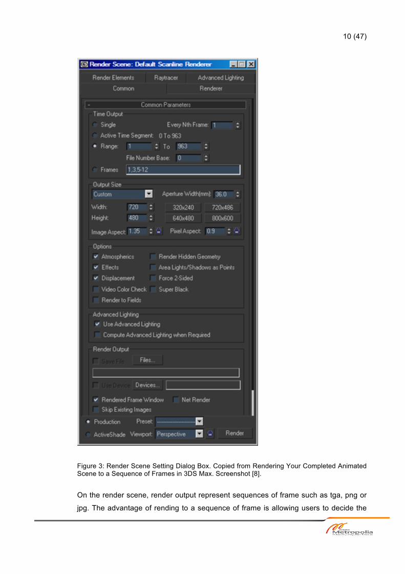
Figure 3: Render Scene Setting Dialog Box. Copied from Rendering Your Completed Animated Scene to a Sequence of Frames in 3DS Max. Screenshot [8].
On the render scene, render output represent sequences of frame such as tga, png or
jpg. The advantage of rending to a sequence of frame is allowing users to decide the

11 (47)
amount frames of the output. Customizing the output size for multiple file formats can
modify the highest image quality. [8.]
4.2 Network Rendering
Network rendering is sending the work over a network to multiple computers. In order
to facilitate network rendering, Autodesk Backburner is installed with 3ds Max. There
are few software tools that can support network rendering such as Lux Render, Render
Pal V2 and Backburner. Autodesk Backburner is a free software application packaged
with 3ds Max, Flame, Maya and other Autodesk products. The Backburner software is
responsible for coordinating how job assignments are processed. [9.] It acts as the
queue manager for background and managed network-processing tasks. It allows more
than one computer to perform the tasks while maintaining the main Autodesk program
available for use. In order to make the tasks more quickly and efficiently, Backburner
breaks the job into many smaller parts. This feature works both on local networks and
over the Internet as long as the same version of servers is installed. [9.]
In order to use the network rendering, the following condition must be applied:
• 3ds Max must be installed on all computers. It is not necessary to have a 3ds
Max license on those computers if they are just for rendering.
• All network communications and protocols should be installed and operating
correctly.
• Each computer must run a recent version of Windows such as Windows 7.
• All computers must be named as letters.
• Manager and Server should not be installed as services.
[9.]
As it is demonstrated in figure 4, the networks render setting dialog shows:

12 (47)
Figure 4: Network Render Setting Dialog Box. Copied from 3ds Max Network Rendering. Screenshot [10].
Backburner is the software used to render over network. It consists of three different
components.
• Backburner Manager is the centre of the process.
• Backburner Server is mainly used to run on workstations, also known as slaves.
The server runs on slaves when all machines are free to use. Slaves do the
hard time taking calculations and then save all resulting images on the same
output folder that is normally called “output Render”.

13 (47)
• Backburner Monitor is used for monitoring the render jobs and how the process
is implemented, whether the process is successful or there are errors that need
to be fixed.
As can be seen in figure 5, the monitor-setting dialog of Backburner software tool
shows:
Figure 5: Backburner Monitor setting. Copied from 3ds Max Network Rendering. Screenshot [10].
In order to recheck the render system, “Monitor” should be opened and “connect to
manager” should be selected to check the work that has been doing so far. Monitor
lists all the current jobs, showing the names, owners, states and progress of the jobs.
The bottom part shows a list of all the servers that are connected to the system, the list
displays all the slaves that can be used and whether they are online or not.
• Job Summary: To show details of the job, mainly when it was submitted and fin-
ished.

14 (47)
• Task Summary: To show the processing details, for example whether it is done
or under processing and how long it took to render.
• Job Details: To check if the set output path is correct.
• Errors: shows if there is anything wrong or error.
If there is an error that needs to be edited, the project name should be right clicked and
“Edit setting” should be chosen. This function helps designers to edit certain things
without sending the job all over again. [10.]
4.3 Common Rules
The rendering process takes time and space. After rendering the images can be trans-
formed into video. In order to make the process easier, the output folder should be
empty. All unnecessary images should be cleared up. [2.]
Additionally, the name of the job or folder should be short and simple. It is important to
avoid extra-long names, non-alphanumeric or special characters. The best relevant
choice is to use naming that combines letters a-z and numbers 0-9. [2.]
The output format has to use an image format such as tiff, png, jpg and tga. Due to
experience in rendering, the tiff format is given the best resolution when converted to
video. Therefore, it is recommended to use the tiff format as the final image format for
output rendering. [2.]
In order to make the rendering successful, it is really important to save the location and
set the output path so that the system knows where the images can be stored. [2.]

15 (47)
5 Importing
The actual dimensions are referred to as 2D and 3D in a computer workspace. 2D is
flat and uses the horizontal and vertical (X and Y) dimensions. Since the image has
only two dimensions, when turning the image into one side, it becomes a flat image. On
the other way, 3D adds the depth (Z) dimension that allows rotation and visualization
from multiple perspectives. This shows how different a photo and a sculpture are. [11.]
3D modelling is widely used in different industries like films, animation and gaming,
interior designing and architecture. Besides these, it is used in the medical industry for
interactive representations of anatomy. In constructing digital representations of me-
chanical models or parts, the large numbers of 3D software are utilized before they are
actually manufactured. With the software used in such fields as CAD/CAM related
software, not only the mechanical models are constructed but also assembled and
functionality is observed. [12.]
Moreover, 3D modelling is utilized in the industrial design in which 3D products are
modelled before being represented to the customers. 3D modelling is used in media
and event industries for the stage or set design. [12.]
Different programs support different functionalities and different tools are used for dif-
ferent types of projects. Hence, the models are shared and transferred between differ-
ent programs for different stages of the design.
The various 3D programs have been launched and used in the media industry. Hence,
exchanging files between them is where the importing and exporting menu commands
come in. These command options can be found in the file menu as it shows in figure 6.

16 (47)
Figure 6: Import Command Menu. Screenshot [13].
The importing and exporting commands allow users to share 3D geometry with other
3D program. There are many 3D programs used in the world nowadays. Depending on
the purpose the software is chosen to meet the requirement.
Autodesk 3ds Max is one of the programs widely used in the media and entertainment
industry all over the world. It is also utilized in media education institutions such as,
Metropolia US. It was also used in the project that this thesis describes.
There are several file formats that can be imported and exported into 3ds Max. All ac-
ceptable files are automatically displayed in the file dialog box when selecting the im-
port option. [14.]

17 (47)
The available import formats include the following:
• Autodesk (FBX) • 3D Studio Mesh, Project and Shapes (3DS, PRJ; SHP) • Adobe Illustrator (AI) • Collada (DAE) • LandXML/DEM/DDF • AutoCAD and Legacy AutoCAD (DWG, DXF) • Flight Studio OpenFlight (FLT) • Motion Analysis (HTR, TRC) • Initial Graphics Exchange Standard (IGE, IGS, IGES) • Autodesk Inventor (IPT, WIRE, IAM) • Lightscape (LS, VW, LP) • OBJ Material and Object (OBJ) • ACIS SAT (SAT) • Google SketchUp (SKP) • StereoLitho (STL) • VIZ Material XML Import (XML) • STEP (STP, STEP) • Rhino (3DM)
[14.]
Many available options can be imported into 3ds Max, but not all of them are men-
tioned in this thesis. In the thesis, only those formats were utilized to import a 3D model
for the project of the case study are analyzed. STEP, IGES and 3DS are file formats
used to export the model. Though those format files are exported from the same CAD
file, two of them are not compatible.
In the case study, the model designed by the CAD software is utilized mostly in indus-
tries. The model cannot be used directly because it lacks textures and materials. In
order for it to work in video commercials, it needs to be transferred to other software for
more designs. Moreover, to give more options for using the model with fewer errors
and the best result, the model is exported into three different formats IGES, STEP and
3DS.
How these formats work is explained in the next chapter.

18 (47)
5.1 IGES File
IGES (Initial Graphics Exchange Specification) was the first specification for CAD data
exchange published in 1980 as a NBS (National Bureau of Standards) report in USA.
[11.] IGES was originally created for exchanging the drafting data like 2D/3D wireframe
models, text, dimensioning data, and a limited class of surfaces. Due to developing and
requiring of users, IGES has been ongoing improvement and now it can support more
capabilities such as entities, syntax, clarity and consistency.
The IGES specification describes the file format, language format, and the product def-
inition data. In the product definition, geometric, topological, and non-geometric data
are included. The geometric entities used to define the geometry are determined in the
geometry part. The topology part describes the entities that identify the relationship
between the geometric entities. There are three divisions such as annotation, definition,
and organization in the non-geometric part. The annotation category contains dimen-
sions, drafting notations and text. With the definition category, users can define specif-
ic properties of individuality or collections of entities. The organization category de-
scribes groupings of geometry, annotation, or property elements. An IGES file has six
sections, which are Flag, Start, Global, Directory Entry, Parameter Data, and Termi-
nate. A directory entry and parameter data entry are included in each entity instance.
The directory entry has an index and attributes to describe the data. The parameter
data defines the specific entity and is defined by fixed length records in accordance
with the corresponding entity. The size of the IGES files and the processing time are
practical problems. As IGES files are composed of fixed format records and in both the
directory entry section and the parameter data section each entry has to have record,
errors occurs in pre-and post-processor implementations. [16.]
5.2 STEP File
STEP (Standard for the Exchange of Product model data) is a new international stand-
ard (ISO 10303) for representing and exchanging product model information including
an object-flavored data specification language called EXPRESS. STEP also describes
implementation methods, for example, a physical transfer files, and offers different re-
sources such as geometric and topological representation. STEP was developed in

19 (47)
1984 as a worldwide collaboration with the purpose of defining a standard to cover all
aspects of a product during its lifetime. It is a collection of standards to represent and
exchange product information. While the main parts of STEP are already international
standards, many parts remain to be under development. The development is per-
formed under the control of the International Standards Organization (ISO), Technical
Committee 184 (TC184, Industrial Automation Systems) and Subcommittee 4 (SC4,
Industrial Data and Global Manufacturing Programming Languages). STEP aims to
offer system-independent mechanisms describe the product information in computer-
aided systems throughout its lifetime. It separates the representation of product infor-
mation from the implementation methods that are used for data exchange. A basis for
archiving product information and a methodology for the conformance testing of imple-
mentations are provided by STEP. EXPRESS is used to specify the representation of
product information. This facilitates development of implementation and enables con-
sistency of representation. STEP does not only define the geometric sharpness of a
product, but also includes topology, features, tolerance specifications, material proper-
ties, so that the goal of the design, manufacturing, testing, inspection and support of
the product is completely defined. STEP covers the total product life cycle in terms of
sharing, storage and exchange. It is said that STEP is the most important effort ever
established in engineering and will take the position of current CAD exchange stand-
ards. [17.]
STEP is well known and widely used as an exchange data form. It is supported by
many software tools such as ECAD or EDA (Altium Designer, Circuit Studio, Circuit
Maker, Cadence, etc.), MCAD (IDA step and express Engine), Dassault Systemes
(Catia, Solid Works and 3DVIA shape), PTC and Autodesk [16.]
5.3 3DS File
There is a series of information in a 3DS file and it is used to describe every detail of a
3d scene composed of one or more objects. A 3DS file also contains a series of blocks
called chunks. The name of each object, the vertices coordinates, the mapping coordi-
nates, the list of polygons, the face colors and the animation key frames are what is
necessary to describe a scene. These chunks do not have a linear structure, thus
some chunks depend on others and can only be read if their relative parent chunks are
read first. There is no necessity to read all the chunks, so only the most important

20 (47)
ones are mentioned here. A description of the 3DS file format on the information con-
tained in the 3dsinfo.txt file written by Jochen Wibelmy is shown [18.]. A chunk is com-
posed of three fields:
-An identifier is a hexadecimal number two bytes in length that identifies the chunk.
-Length of the chunk is a 4-byte number that is the sum of the chunk length and all the
lengths of every contained sub-chunk.
-Chunk data include all the data for the scene and the data has variable length, de-
pending on the scene data information.
[18.]

21 (47)
6 Case Study
A case study was based on a project between Deltamarin and Metropolia UAS. In or-
der to make a short commercial video for their new design, they made co-operation
with Metropolia UAS.
A 3D model of a ship was designed by using a 3D software program. In order to make
the video, the 3D model designed by Deltamarin had to transfer to the premises of
Metropolia UAS so that it could be transformed into video. Prior to the project, Metropo-
lia UAS and Deltamarin had been using two different programs. Detamarin used a CAD
software for industrial design usage. In turn, Metropolia UAS used Autodesk 3ds Max
for the media and entertainment industry involving for example films, animations and
games. Hence, accurate formats had to be chosen for the 3D ship model so that it
could be imported successfully into 3ds Max.
The model used for this case study was designed for industrial usage without texture
and material related data. Moreover, in order to create the 3D ship model for the video,
the model needed more tasks. The model needed some refinement to ensure making
them realistic, being able to create a short animation, and rendering to take pictures of
all things and then translating all the virtual bits of 3D model into actual output images
that transform to real videos in high quality.
Importing the model to other software for more design stages always contains errors
and problems. The model in this case was exported from CATIA and could not be used
directly. The model needed to implement the basic workflow of 3D modelling which was
illustrated in figure 1. To make the model ready to use, different tools were essentially
used for different types of process.
To be able to transfer the most accurate and detailed 3D model, many files are chosen.
Though many file formats support importing into 3ds Max, in this case only three file
formats are compatible and could be exported. Three file formats were tested and used
to import the model, but only one file was compatible to use.
6.1 IGES File
22 (47)
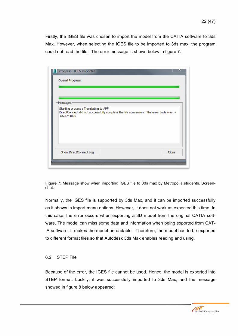
Firstly, the IGES file was chosen to import the model from the CATIA software to 3ds
Max. However, when selecting the IGES file to be imported to 3ds max, the program
could not read the file. The error message is shown below in figure 7:
Figure 7: Message show when importing IGES file to 3ds max by Metropolia students. Screen-shot.
Normally, the IGES file is supported by 3ds Max, and it can be imported successfully
as it shows in import menu options. However, it does not work as expected this time. In
this case, the error occurs when exporting a 3D model from the original CATIA soft-
ware. The model can miss some data and information when being exported from CAT-
IA software. It makes the model unreadable. Therefore, the model has to be exported
to different format files so that Autodesk 3ds Max enables reading and using.
6.2 STEP File
Because of the error, the IGES file cannot be used. Hence, the model is exported into
STEP format. Luckily, it was successfully imported to 3ds Max, and the message
showed in figure 8 below appeared:

23 (47)
Figure 8: Importing message from the STEP file. Screenshot.
The model was effectively imported. However, some problems needed to be solved
such as that the entire object names were missing and many helpers were invented.
[19.]
As it shows in figure 9 and figure 10, many helpers were found and all objects names
were missing in the case study.
Figure 9: Helpers were invented automatically when being imported the STEP file. Screenshot.

24 (47)
Figure 10: Missing object names. Screenshot.
A common error when importing the STEP files to 3ds Max is that all the object names
are lost and many helpers are created. This leads users to be confused when dealing
with the model. The object names must be renamed correctly in order to work easily
with the model. The helpers somehow are difficult to find, because they exist as tiny
dots on the scene. However, they do not affect the model or object much, as users can
delete or hide them.
As can be seen in figure 11, a way to fix the helper is showed.

25 (47)
Figure 11: Select Object Dialog Box. Screenshot [20].
In order to hide or delete the helpers, it is necessary to open the Select By Name Dia-
log from the top of the user interface. In the list types, the “None” button should be
clicked and the helpers should be turned on as figure 11 shows. Subsequently, all the
helpers should be selected by clicking the “All” button under the list, and then all the
helpers from the imported model are selected. They can be grouped for hiding or simp-
ly deleting. [20.]
After dealing with the helpers, the model implements the stages described in figure 1.

26 (47)
6.3 3DS File
Since the STEP file caused too many errors, the model was exported into the 3DS for-
mat to get a better result. As was suggested in theory section, 3DS is a product of 3ds
max. Thus, any 3DS file is supposed to be imported easily into the 3ds Max software.
However, this did not work, when the 3DS file was selected to be imported into 3ds
Max. The error message that was shown can be seen in figure 12:
Figure 12: 3DS file importing message. Screenshot.
The problem above is reminded of once again that it is really important to pay attention
when exporting 3D model files. Users should be discreet when exporting the 3D mod-
els, and the files should be set up so that no names are lost and no files are missing. If
something is missed when being exported, errors occur and the third party programs
are unable to read the file. In fact, materials and mapping in each 3d model programs
are different. In order to avoid the error, the model should be prepared properly before
being exported. Nevertheless, if the designers were not known beforehand whether or
not the model is exported, they could design the model that met target software re-
quirements. The error can be reduced in the setting of the file. Selecting all the materi-
als and mapping related to the model is necessary for the file when importing.
At the beginning, people who worked for this project hope that there is no problem
when sharing and transferring 3D model from industrial CATIA usage to 3ds Max. As
many options are available to import files from the CATIA software to Autodesk 3ds
Max, the model can be designed for media usage which is the most important purpose
for this project. However, after testing how different formats are imported to 3ds Max,
the files could not be read well in 3ds Max. Therefore, there was no choice but using
the model exported from the STEP file. Though only one file can be read so far even

27 (47)
with some enclosed problems, it is used to solve the problems. This brings some chal-
lenges but that is good to learn how to over the difficulties.

28 (47)
7 Set-up
7.1 Name and Scale
Before working on the model, there are a few things designers should pay attention to.
The first is to create folders for the project. All the files and related folders should stay
in the same common folder so that it can be easily defined. No file and folder is missing
when implementing. [2.]
Folders should be created as follows:
Figure 13: Folder files. Screenshot.
The name of the file must simple and easy to remember. The program and computer
can be shut down at any time. When working on the product, every single change
should be saved; in case the computer is corrupted, the file would not lose information.
It is very smart to make a backup of the file for the safekeeping, to make sure that de-
signers do not need to work again and again from the very starting point. Without prop-
er processes and pre-thought workflows, refining an existing 3D model in another soft-
ware can become an intriguing task. Many changes can be made and many files are
saved. Therefore, a simple name can easily tell which one is the latest one or which
one is the one the designer is looking for. [2.]
Secondly, the very first thing users need to do after importing is applying the appropri-
ate scale so that the product will be at the correct scale. In fact, materials from a partic-
ular inventor are not imported with the correct scaling and orientation. Sharing and
transferring 3D modelling appears different from mapping differences between other

29 (47)
programs as a mesh or body object. Therefore, they produce different results when
being imported. [21.] It is really significant, if the users do not want all the changes to
be in the incorrect scale. An incorrect scale can lead the product into trouble such as
unrealistic model, rendering taking a really long time to implement and the file being
corrupted. Moreover, with scenes in 3ds Max, if the model has too small or too large
units, it often behaves in a very odd way in viewport. This primarily affects the value
scale of lights, shadows and cameras. It is really important to use the rescale world unit
utility at the beginning. To perform the accurate scale on the model, this is a good thing
when dealing with the next stages.
Thirdly, it is important to change the number of levels with the customization setting,
and it can help to increase the number of undo and redo actions. It is really helpful
when making mistakes, as the designer can easily be back to the very last change to
redo it one again.
Finally, before start working with the model, one of the simplest and most important
things users should do to help keep the models and scenes being organized are to give
objects of the models meaningful names. [2.] In fact, there are numerous objects creat-
ed during the process. Organizing and naming objects correctly, helps users to know
which one they want to deal with. However, Rename Object Tool can be used to re-
name object names when necessary.
7.2 Xref Scenes and Xref Objects
Autodesk supports Xref Objects and Xref Scenes allows users to divide the model into
separate files. Xref scenes can make large files much easier to work with, as well as
dividing the file into small parts. It also can allow many users in a team to animate,
model and texture a model at the same time. This function allows members in a team
to work on different sections of a project without interrupting one another or altering
each other’s work. [3.]
External references objects and scenes break the model into separate Max files made
available for reference during a Max session. There are two types of references, refer-
ence objects and reference scenes with different purposes of use. [3.]

30 (47)
Since the model in this case study is too large, it is not easy to work and takes too
much time for the model to run and sometimes causes the file to be corrupted. There-
fore, Xref Scenes is used to divide the model into many small files to make it easy to
model and texture.
To help people have clear ideas about how these functions work, the explanations are
described as below.
7.2.1 Xref Scenes
An external referenced scene displays in the current Max session. The scene is linked
to a parent object and it can be updated automatically once changes are made and
saved to the source file but users cannot edit the scene or change anything on the
master scene. [3.]
Xref scene allows users to divide the model into small files to make larger files much
easier to deal with. An external reference scene displays the entire contents of an ex-
ternal Max file in the current scene. In order to prevent accidental changes, the objects
within the external file are frozen, and they can be visible but cannot be selected.
Any changes from the original file can also be updated and changed in the target file
once the changes are made and saved to the file. [22.]
Kelly Murdock pointed out that “Xref Scenes makes it easy for creative team to collabo-
rate on a project without having to wait for another group member to finish his or her
respective production task”. [3.] Each user can deal with one of the files. A modeller
can create the character, and an animator can animate the character without making
changes to the setting of the character. If the setting file is changed, the changes will
be reflected in the animator’s scene. When it is done, the files can merge together as it
shows in figure 14. [22.]

31 (47)
Figure 14: Xref Scenes Dialog Box. Screenshot.
The figure shows several options for controlling the appearance of the scene objects.
Users can choose whether the scene can be updated automatically or not, and to
which object the scene is bound. This dialog box is modeless and the options can be
changed anytime as users wish. To change the options of the file, the Xref scene dia-
log box has to be selected and any option that is needed should be kept. [22.]
There are several options to select from in the dialog box:

32 (47)
• The Convert Selected button can allow users to convert any selected objects in
the current scene to Xref objects by saving them as a separate file. When this
button is selected, the new dialog will be opened and it allows naming and sav-
ing the file as a new file. In case, no file is selected, then this option is disabled.
• Updating an external scene is used to set the scene automatically updated. By
choosing this option box, the scene is updated anytime any changes are made
and saved to the source file.
• External scene appearance: this option lets users to decide how a scene is dis-
played in the viewports. Users can choose whether or not to display the exter-
nal scene invisible or visible. The option allows external scenes invisible from
the viewports. Despite this the scene is still included in the rendered output. In
order to remove it clearly from the rendered output, the Enable option should be
deselected.
• Positioning an external scene: This option is implemented by binding the scene
to an object in the current scene. Autodesk allows users to change the selection
any time because the Xref scene dialog box is modeless.
• Specifying an Xref as an overlay: This option makes the Xref scene visible to
the current scene but not to any other scene that including the overlay. This al-
lows users to hide Xref content from more than one level.
[22.]
Besides the freezing the objects, Xref scenes allow functionalities such as Snap, Au-
toGrid, Clone and Align to position local objects in context, as well as to pick up objects
as the target location for the clones. In order to move, rotate or scale objects in refer-
ence scene, users can bind them to a local object. [22.]
Transforming the object in the reference scene was bound to transform all the objects
in the reference scene. When all changes from external referenced files are saved, an
update of Xref scene will inherit the changes. [22.]
Another way to use an Xref scene is to create a scene with light or cameras. Light and
cameras can be positioned at regular intervals around the scene. An Xref scene dialog
box lets users to disable lights, cameras and helpers from the source file. Lights, cam-
eras and helpers can be created again and repositioned.

33 (47)
In order to reposition the Xref scene as needed, users can create dummy object from
the Helpers options, after having dummy object, in the Xref scene dialog box, and after
selecting the Bind button and then the dummy object. Now this enables repositioning
the Xref scene.
One hint needs to be remembered in this process, which is to make sure the scale of
the model is correct. This helps to reduce the errors and causing problems.
Application on Case Study
The model was exported from a CATIA file and when importing it to 3ds Max, the file
seems too big to deal with. If the file is too large, it not only causes problems for users
working on the model but also lowering the speed of rendering.
As can be seen in figure 15, the summary information of the file shows the content of
the file.
Figure 15: Summary Information Dialog Box. Screenshot.
Summary information displays statistics about the current scene, which was imported
from CATIA. The information was sorted by category and included the names of ob-

34 (47)
jects, assigned material name, type of material, object vertex and so on. On the left
corner, the scene total group lists the number of objects in the current scene by type.
The number of vertex and faces are also listed under the Mesh total. [22.]
As a result, the file was divided into small parts by using Xref scene. The file was
smaller as it shows in figure 16.
Figure 16: One separate file from the current scene by using the Xref scene. Screenshot.
The file showed in figure 16 is one of four files, which is separated from the main cur-
rent scene by Xref Scene. It makes the file easy to work with the model. Moreover, the
study case is a group work project. Using the Xref scene lets members in a team work-
ing on the model without interfering with each other’s work. [3.]
7.2.2 Xref Objects
External referenced objects appear in the master (current) scene but are actually from
external 3ds Max files. Therefore, the objects from a source file are protected from
modifications the user makes to the Xref objects. Any change made from the source
object can also be updated in the current file when the source scene is reloaded. [23.]

35 (47)
According to Kelly Murdock, “Xref objects are slightly different from Xref scenes. Xref
objects appear in a scene and can be transformed and animated but the original ob-
ject’s structure and Modifier Stack cannot be changed”. [3.] This function is not similar
to the Xref scene since the object in the scene is not freezing but it can move and ani-
mate.
As can be seen in figure 17, Xref object dialog box shows:
Figure 17: Xref Object dialog box (3ds max Help). Screenshot [24].
The dialog box of Xref objects is divided into two sections. The top section displays the
external referenced source files and lower section displays the objects, materials or
controllers selected from the source file. It helps users to understand and work easily.
[23.]
Xref object’s function allows users to edit and animate the objects in the scene. It de-
pends on the Xref object setting so that users may or may not be able to edit the ob-
ject’s entities such as transforms, materials, manipulators or modifiers.

36 (47)
The function is really useful and efficient in teamwork projects. However, there is no
need to use this function for the case study. Only the Xref scene is utilized for dividing
the model into separate files to make it easier to work with.

37 (47)
8 Problems and Solutions
When exporting and importing models to other programs, users are ready to face the
fact that there will be many problems and errors in the model. The common problems
users always meet are polygon breaking, overlapping, duplicate. Therefore, the prob-
lems are explained and analyzed in this thesis.
8.1 Polygon Breaking
As mentioned above, the software supports various fields based on the main use of the
model to choose the correct software. However, sometimes for some reasons, users
need to share the model with and transfer them to other software that might not support
that model. That is the reason why errors have occurred. For example, the pipe is cre-
ated in the CATIA file, when it is imported to 3ds Max. 3ds Max cannot read the elbow
of the pipe. Thus, the program automatically performs the elbow into many small poly-
gons. The pipe somehow was broken in many parts that could not be used for model-
ling and texturing.
As it is demonstrated in figure 18, breaking polygons was taken from the case study.

38 (47)
Figure 18: Polygon breaking example.
The figure shows the error of the coconut tree. The leaves in this situation were broken
into many polygons that are not easy to fix.
In fact, when sharing and transferring 3D files to other programs, the breaking of poly-
gons is a common problem that users meet. Normally, when facing this problem, users
usually choose to delete an object to create a new similar object. If the model has only
a few broken polygons, it can be fixed by using editable poly tools.
8.2 Overlapping
Overlapping is also one of the most common errors met when sharing the 3D files. This
error happens when the third party cannot read the texture that has been applied on
the model from the previous software. The third party will automatically modify that tex-

39 (47)
ture by the plane; this will cause the model present many layers on top of each other as
can be seen in figure 19.
Figure 19: Overlapping polygon.
If only a few polygons have overlapping problems, it is easy to remove and delete them
manually. However, if there are thousands of them, users obviously do not want to
spend time removing every single layer one by one. There is a way around for each
case. In 3ds Max, there are three common overlapping cases, overlapping face, over
lapping UVs, and overlapping vertices.
• Overlapping UVs can be fixed by using Unwrap UVW tool to edit the overlap-
ping. In Edit UVWs, tools and render UV template should be selected, and then
“show” overlapping should be turned on. The overlapping will be showed in red
and it is easy to fix by relaxing the overlapping area. [25.]
• Overlapping Faces: the problem can be fixed by following these instructions.
1. Select the model and make sure that the object is ungrouped
2. Go to “Customize”, then “Units setup”, and select “Generic units” so that
the unit matches the checkmate script.
3. Go to “Xview” tool and select “overlapping Faces”.
4. When the model is selected, click on “Click here to configure” at the bot-
tom of the scene.
5. Change the “Tolerance”: to 0.0001

40 (47)
6. Overlapping Faces appear in green now. On the Modifier List, select
Poly in the Editable Poly tool.
7. It is possible to fix the overlapping faces by moving it out slightly by
moving the X-coordinate or selecting “Absolute Mode Transform Type-
In”, entering the X-coordinate where it should be moved from original lo-
cation.
• Overlapping Vertices is similar to overlapping faces to fix overlapping vertices.
Therefore, the instructions from step 1 to 5 are as same as above. Overlapping
is showed in green but in case it did not show up, select “Click here to Update”
at the bottom. In order to remove the overlapping vertices, select “Vertex” in Ed-
itable Poly and on the setting button next to the “Weld” button, set the “Weld
Threshold” to what is needed. In most cases, this works well. However, if it
does not work, then it means that there is no need to remove the overlapping
Faces. Therefore, there is another way to fix overlapping vertices [27.]
1. Select the overlapping Vertices Object, right click and select “Convert to
Faces”
2. Select “Alt” and then “click” to deselect all the faces that have been high-
lighted in red
3. Click Delete to delete the unneeded overlapping faces.
4. Now repeat the steps that have been done before with “Vertex” and
“Weld”
[27.]
8.3 Duplicates
Duplicates are more complex than either of the two problems above. Duplicates hap-
pen when objects or polygons are cloned on top of each other or objects with the same
names.
There are three ways to fix the problems.
• Select all faces, with Multiple Objects Tools selected, the tool will find and se-
lect faces that are duplicated

41 (47)
• Using Customize User Interface Tool by selecting Customize and then Custom-
ize User Interface, toolbars tab, category and Collins Script should be selected.
To run this option, the duplicated will be found.
• Run script: Autodesk supports using script for making modelling easier. There is
a code of script that can be used to remove duplicates. These codes are dis-
played on the script bar, which is found on the left corner of the scene of the
3ds Max software program.
[28.]

42 (47)
9 Discussion
As mentioned in the beginning, the main goal of this study was to create a short video
of a 3D model. To create the video, the model needed to have some short animation.
Moreover, the model was created in the CATIA software and designed for industrial
usage, but lacking texture and animation. As a result, the model had to be imported to
software that could model, texture and make some short animation. In this case study,
3ds Max that is compatible with modelling and transforming the model into the video
was used to implement the project.
From models to virtual objects, the process was complicated. Progress was achieved
by combining the knowledge of 3D modeling, texturing and rendering. Different models
were accomplished in different operations. In order to make the models look more ap-
pealing and real, many stages needed to be implemented. Some suggestions of mod-
elling and texturing methods were applied for the model. Modelling and texturing was
one of the most important parts in the process as good modelling and texturing can
bring a crude model to life. However, to make the model ready to be used in the media
industry, users need to put more effort and work into testing and rendering as well.
Rendering is a process to transform the model into high quality image pixels with all
reflections and shadow details. Rendering output represents the sequence of frames.
To ensure the model looks realistic and that it meets the requirements as closely as
possible, rendering the frame was checked, which helped to figure out what needs to
be improved. Overall, this process made the work proceed.
The process was modified many times. For each rendering time, something needed to
be improved. Therefore, instead of rendering the whole sequence of frames, it was
better to render only the frame the users wants to check. Because the model was too
large, network rendering was utilized to make the render process quickly and efficient-
ly.
To render out the finished animation to a sequence of frames such as tgd, png and jpg,
the highest quality images was retained for the frames to multiple file formats, and it
was imported into a video-editing program such as Adobe Premiere. A sequence of
one frame could be modified with an audio track and video setting to produce the high
quality video image.

43 (47)
Since the project of the case study needed to be done in a short time of five weeks, it
was really essential to use some 3D models from another application so that the mod-
els could be merged and imported to the project. Models created in another session of
3ds Max allowed users to merge files together. However, the models used after merg-
ing or importing were also necessary to reset the scale operation and texturing. There
were many free 3D models for downloading which could be found via the Internet such
as Turbosquid, 3DModelFree, and Archive3D. In order to use the free model from the
Internet, the licence of using had to be checked carefully. Otherwise there would be
trouble. The models downloaded from the Internet were just small portions of the pro-
ject. Adding more objects to the project helped to save time and make the model look
realistic.

44 (47)
10 Conclusion
3D modelling is becoming more popular in different media and non-media industries
such as films, animations, games and architectures. The developments in the field of
computer design have tremendous impacts on the modelling technology. Various pro-
grams are used to produce 3D models and different tools provide different functions.
Sometimes a model needs to be transferred between different software for different
designing functions. Thus, sharing and transferring a 3D model has become an essen-
tial process in the media industry.
The case study described in this thesis demonstrates that in order to minimize the
number of errors and to improve the readability of the converted model, a 3D model
should be properly prepared before being imported to other software in order to make it
readable. In fact, when importing the 3D model from one program to another, problems
always occur. Hence, the thesis presents some potential solutions for each problem.
Overall, the project was really time consuming and challenging because of many prob-
lems accompanying with the file format. The result of the project was not as good as
expected. If the project were carried out again, the result would have changed and im-
proved.

45 (47)
References
1. What Is 3D Modeling [online]. Wise Geek.
URL: http://www.wisegeek.com/what-is-3d-modeling.htm.
Accessed 3 August 2015.
2. Bousquet M. How to Cheat in 3ds Max 2010. Abingdon: Focal Press; 2010.
3. Kelly L. Murdock. 3ds Max 2011. Hoboken: Wiley Pushing Inc; 2010.
4. Polygonal Meshes [online]. Autodesk Mudbox 2009.
URL:http://download.autodesk.com/esd/mudbox/help2009/index.html?url=WS1
a9193826455f5ff6026605b1181c8f4f2e-1e05.htm,topicNumber=d0e10585. Ac-
cessed 3 August 2015.
5. Surfacing 101-Texture Mapping [online]. About Tech.
URL:http://3d.about.com/od/3d-101-The-Basics/a/Surfacing-101-Texture-
Mapping.htm. Accessed 3 August 2015.
6. Slick J. Essential 3D Texturing Terms You Need to Know [online].
URL:http://blog.digitaltutors.com/cover-bases-common-3d-texturing-
terminology/. Accessed 3 August 2015.
7. Slick J. What Is Rendering? Finalising the 3D Image [online].
URL: http://3d.about.com/od/3d-101-The-Basics/a/Rendering-Finalizing-The-3d-
Image.htm. Accessed 3 August 2015.
8. Rendering Your Completed Animated Scene to a Sequence of Frames in 3DS
Max [online].
URL:http://courses.confederationc.on.ca/rriddell/3dtutorials/render_max_scene
_sequence.htm. Accessed 3 August 2015.
9. Palmer G.D. What Is Autodesk Backburner [online].
URL: http://smallbusiness.chron.com/autodesk-backburner-61233.html.
Accessed 3 August 2015.
10. Metropolia: IT Service. 3ds Max Network Rendering [online].
URL:https://tietohallinto.metropolia.fi/display/itservices/3.+Monitoring+and+Editi
ng+Jobs. Accessed 3 August 2015.
11. Comparison between 2D and 3D [online].
URL: http://www.wikiecho.org/wiki/Comparison_between_2D_and_3D.
Accessed 3 August 2015.
12. Ghost D. Theory of 3D Modeling [online]. Sketch up Ur Space.
URL: http://www.sketchup-ur-space.com/2014/aug/theory-of-3D-modeling.html.

46 (47)
Accessed 3 August 2015.
13. Easy 3D Models in Infrastructure Modeller [online]. Civil 3D Plus
URL: https://civil3dplus.wordpress.com/tag/3ds-max/.
Accessed 3 August 2015.
14. About Importing Files from Other CAD Systems [online]. Autodesk Knowledge
Network.
URL: http://knowledge.autodesk.com/support/inventor-products/getting-
started/caas/CloudHelp/cloudhelp/2016/ENU/Inventor-Help/files/GUID-
7FACB50F-ED00-419D-8C23-F98283CCD8F8-htm.html.
Accessed 3 August 2015.
15. The IGES, DXF and STEP Exchange Formats [online]. CAE Homepages.
URL: http://homepages.cae.wisc.edu/~me232/info/dxf_iges_step.pdf.
Accessed 3 August 2015.
16. What Is The Most Popular File Format Used for Sharing CAD Files [online].
URL: http://www.quora.com/What-is-the-most-popular-file-format-used-for-
sharing-CAD-files-Can-you-please-provide-a-reference-to-document-your-
answer. Accessed 3 August 2015.
17. What Is a STEP File [online]. PCB 3D.
URL: http://www.pcb-3d.com/knowledge-base/step-file-faq. Accessed: 3 August
2015.
18. Tutorial 4: 3DS Loader [online]. Space simulator net.
URL:
http://www.idea2ic.com/File_Formats/3DS%20FILE%20STRUCTURE.pdf.
Accessed 3 August 2015.
19. Describe What Is Needed for The Best Possible CAD Import Workflow [online].
Autodesk 3DS MAX Feedback.
URL: http://3dsmaxfeedback.autodesk.com/forums/76187-importing-cad-data-
in-3ds-max/suggestions/6806238-new-format-for-inventor-3dsmax. Accessed 3
August 2015.
20. Davis GM. Importing 3rd Party Models into Discreet 3ds Max [online].
URL: http://www.visualz.com/free/3dsmax_importing_models.pdf. Accessed 3
August 2015.
21. Harper JM. Mastering Autodesk 3ds Max 2013.Hoboken: John Wiley & Sons,
Inc; 2012.
22. Xref Scene [Online]. Autodesk 3DS MAX.

47 (47)
URL:http://knowledge.autodesk.com/support/3ds-max/learn-
explore/caas/CloudHelp/cloudhelp/2015/ENU/3DSMax/files/GUID-5DB41A62-
D7A5-4D54-AC83-5D03C9F7DB11-htm.html. Accessed 3 August 2015.
23. Xref Object [online]. Autodesk 3DS MAX.
URL:http://knowledge.autodesk.com/support/3ds-max/learn-
explore/caas/CloudHelp/cloudhelp/2015/ENU/3DSMax/files/GUID-F9CE15BD-
FD57-4671-8F3A-8E742B766555-htm.html. Accessed 3 August 2015.
24. XRef Objects Dialog [online]. 3ds Max Help.
URL:http://docs.autodesk.com/3DSMAX/15/ENU/3ds-Max-
Help/index.html?url=files/GUID-AEDE75F6-F3CB-497B-A2CC-
3B0DC521061F.htm,topicNumber=d30e483372. Accessed 3 August 2015.
25. Overlapping UVs in 3ds Max [online]. YouTube.
URL: https://www.youtube.com/watch?v=_agNgk8c6ag. Accessed 3 August
2015.
26. TurboSquid. How to Video: Fixing Overlapping Vertices in 3ds Max [online]. Art-
ist Newsletter; September 2012.
URl:http://blog.turbosquid.com/2012/09/26/how-to-video-fixing-overlapping-
vertices-in-3ds-max/. Accessed 3 August 2015.
27. TurboSquid. How to Video: Fixing Overlapping Faces in 3ds Max [online].
URL:http://blog.turbosquid.com/2012/09/17/how-to-video-fixing-overlapping-
faces-in-3ds-max/. Accessed 3 August 2015.
28. Colinsenner. Find Coinstances [online]. Script spot; 05 August 2008.
URL: http://www.scriptspot.com/3ds-max/scripts/find-coinstances.
Accessed 3 August 2015.