Anna University May/June 2013 Exams ME2151 Engineering Mechanics Important Questions
Upload
khangminh22Category
view
3download
0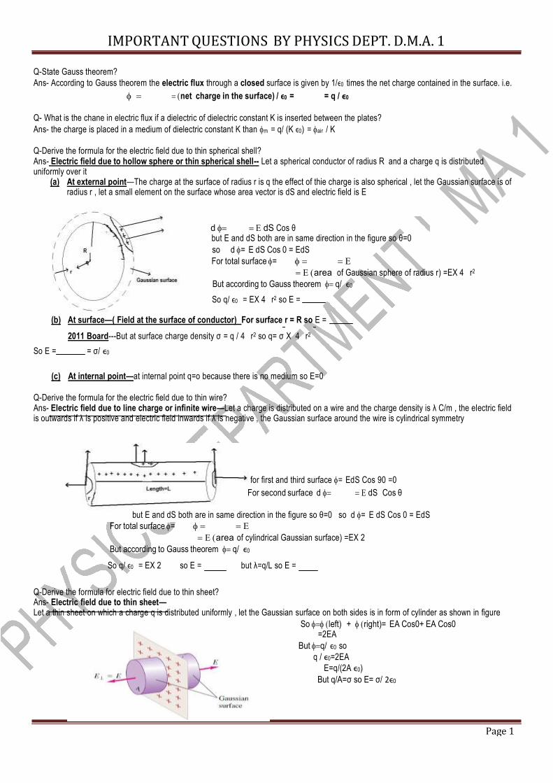
IMPORTANT QUESTIONS BY PHYSICS DEPT. D.M.A. 1
Page 1
Q-State Gauss theorem? Ans- According to Gauss theorem the electric flux through a closed surface is given by 1/ϵ0 times the net charge contained in the surface. i.e.
net charge in the surface) / ϵ0 = = q / ϵ0 Q- What is the chane in electric flux if a dielectric of dielectric constant K is inserted between the plates? Ans- the charge is placed in a medium of dielectric constant K than m = q/ (K ϵ0) = air / K Q-Derive the formula for the electric field due to thin spherical shell? Ans- Electric field due to hollow sphere or thin spherical shell-- Let a spherical conductor of radius R and a charge q is distributed uniformly over it (a) At external point—The charge at the surface of radius r is q the effect of thie charge is also spherical , let the Gaussian surface is of radius r , let a small element on the surface whose area vector is dS and electric field is E
d dS Cos θ but E and dS both are in same direction in the figure so θ=0 so d= E dS Cos 0 = EdS For total surface = area of Gaussian sphere of radius r) =EX 4 r2 But according to Gauss theorem q/ ϵ0 So q/ ϵ0 = EX 4 r2 so E =
(b) At surface—( Field at the surface of conductor) For surface r = R so E =
2011 Board---But at surface charge density σ = q / 4 r2 so q= σ X 4 r2 So E = = σ/ ϵ0
(c) At internal point—at internal point q=o because there is no medium so E=0 Q-Derive the formula for the electric field due to thin wire? Ans- Electric field due to line charge or infinite wire—Let a charge is distributed on a wire and the charge density is λ C/m , the electric field is outwards if λ is positive and electric field inwards if λ is negative , the Gaussian surface around the wire is cylindrical symmetry
for first and third surface = EdS Cos 90 =0 For second surface d dS Cos θ
but E and dS both are in same direction in the figure so θ=0 so d= E dS Cos 0 = EdS For total surface = area of cylindrical Gaussian surface) =EX 2 But according to Gauss theorem q/ ϵ0
So q/ ϵ0 = EX 2 so E = but λ=q/L so E =
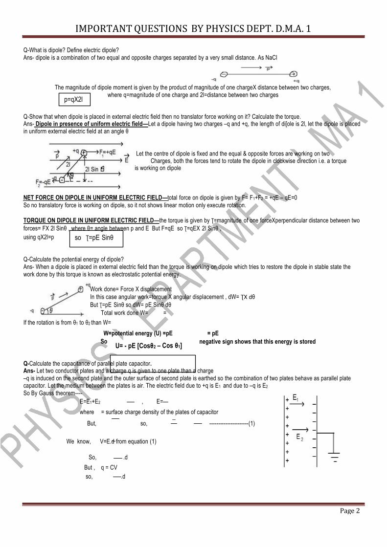
Q-Derive the formula for electric field due to thin sheet? Ans- Electric field due to thin sheet— Let a thin sheet on which a charge q is distributed uniformly , let the Gaussian surface on both sides is in form of cylinder as shown in figure So left) + right)= EA Cos0+ EA Cos0 =2EA But q/ ϵ0 so
q / ϵ0=2EA E=q/(2A ϵ0)
But q/A=σ so E= σ/ 2ϵ0
IMPORTANT QUESTIONS BY PHYSICS DEPT. D.M.A. 1
Page 2
2
Q-What is dipole? Define electric dipole? Ans- dipole is a combination of two equal and opposite charges separated by a very small distance. As NaCl
The magnitude of dipole moment is given by the product of magnitude of one chargeX distance between two charges, where q=magnitude of one charge and 2l=distance between two charges p=qX2l
Q-Show that when dipole is placed in external electric field then no translator force working on it? Calculate the torque. Ans- Dipole in presence of uniform electric field—Let a dipole having two charges –q and +q, the length of di[ole is 2l, let the dipole is placed in uniform external electric field at an angle θ
Let the centre of dipole is fixed and the equal & opposite forces are working on two Charges, both the forces tend to rotate the dipole in clockwise direction i.e. a torque is working on dipole NET FORCE ON DIPOLE IN UNIFORM ELECTRIC FIELD—total force on dipole is given by F= F1+F2 = +qE – qE=0 So no translatory force is working on dipole, so it not shows linear motion only execute rotation. TORQUE ON DIPOLE IN UNIFORM ELECTRIC FIELD—the torque is given by Ʈ=magnitude of one forceXperpendicular distance between two forces= FX 2l Sinθ , where θ= angle between p and E But F=qE so Ʈ=qEX 2l Sinθ , using qX2l=p so Ʈ=pE Sinθ
Q-Calculate the potential energy of dipole? Ans- When a dipole is placed in external electric field than the torque is working on dipole which tries to restore the dipole in stable state the work done by this torque is known as electrostatic potential energy.
Work done= Force X displacement In this case angular work=torque X angular displacement , dW= ƮX dθ But Ʈ=pE Sinθ so dW= pE Sinθ dθ
Total work done W= = If the rotation is from θ1 to θ2 than W=
W=potential energy (U) =pE = pE So U= - pE [Cosθ – Cos θ1] negative sign shows that this energy is stored
Q-Calculate the capacitance of parallel plate capacitor. Ans- Let two conductor plates and a charge q is given to one plate than a charge –q is induced on the second plate and the outer surface of second plate is earthed so the combination of two plates behave as parallel plate capacitor. Let the medium between the plates is air. The electric field due to +q is E1 and due to –q is E2 So By Gauss theorem----
E=E1+E2 , E= where = surface charge density of the plates of capacitor But, so, ----------------------(1)
We know, V=E.d from equation (1) So, .d
But , q = CV so, .d
IMPORTANT QUESTIONS BY PHYSICS DEPT. D.M.A. 1
Page 3
so C=A /d } or {C }
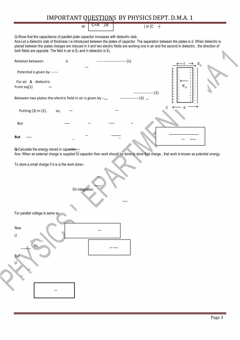
Q-Show that the capacitance of parallel plate capacitor increases with dielectric slab. Ans-Let a dielectric slab of thickness t is introduced between the plates of capacitor. The separation between the plates is d. When dielectric is placed between the plates charges are induced in it and two electric fields are working one in air and the second in dielectric , the direction of both fields are opposite. The field in air is E0 and in dielectric is Ed Relation between is ------------------------ (1)
Potential is given by ------ For air & dielectric From eq(1) -----------------(2)
Between two plates the electric field in air is given by :- ----------------(3) Putting (3) in (2), so,
But But
Q-Calculate the energy stored in capacitor. Ans- When an external charge is supplied to capacitor then work should be done to store that charge , that work is known as potential energy. To store a small charge if d w is the work done:-
On integration, For parallel voltage is same so Now
U So,
But U
IMPORTANT QUESTIONS BY PHYSICS DEPT. D.M.A. 1
Page 4
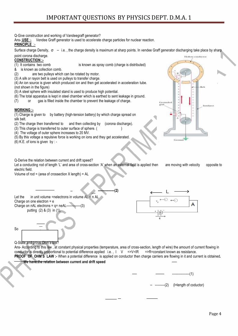
Q-Give construction and working of Vandeegraff generator? Ans- USE :- Vendee Graff generator is used to accelerate charge particles for nuclear reaction. PRINCIPLE :- Surface charge Density, σ i.e. , the charge density is maximum at sharp points. In vendee Graff generator discharging take place by sharp point corona discharge. CONSTRUCTION :- (1) It contains two comb is known as spray comb (charge is distributed) & is known as collection comb. (2) are two pulleys which can be rotated by motor. (3) A silk or rayon belt is used on pulleys to transfer charge. (4) An ion source is given which produced ion and then get accelerated in acceleration tube. (not shown in the figure) (5) A steel sphere with insulated stand is used to produce high potential. (6) The total apparatus is kept in steel chamber which is earthed to sent leakage in ground. (7) or gas is filled inside the chamber to prevent the leakage of charge. WORKING :- (1) Charge is given to by battery (high-tension battery) by which charge spread on silk belt. (2) The charge then transferred to and then collecting by (corona discharge). (3) This charge is transferred to outer surface of sphere. ( ) (4) The voltage of outer sphere increases to 20 MV. (5) By this voltage a repulsive force is working on ions and they get accelerated. (6) K.E. of ions is given by : - Q-Derive the relation between current and drift speed? Let a conducting rod of length ‘L’ and area of cross-section ‘A’ when an external field is applied then are moving with velocity opposite to electric field. Volume of rod = (area of crossection X length) = AL
---------------(2)
Let the in unit volume =nelectrons in volume AL = n AL Charge on one electron = e Charge on nAL electrons = q= neAL-------------(3) putting (2) & (3) in (1),
So Q-State and prove Ohm’s law? Ans- According to this law , at constant physical properties (temperature, area of cross-section, length of wire) the amount of current flowing in conductor is directly proportional to potential difference applied i.e. , I V =>V=IR =>R=constant known as resistance. PROOF OF OHM’S LAW :- When a potential difference is applied on conductor then charge carriers are flowing in it and current is obtained.
We have the relation between current and drift speed
----------------(1) ---------(2) (l=length of coductor)
IMPORTANT QUESTIONS BY PHYSICS DEPT. D.M.A. 1
Page 5
Q-Derive the formula for resistivity? Ans- we have, On camparing, so
Q-State Kirchoff law? Ans-
= 1/σ
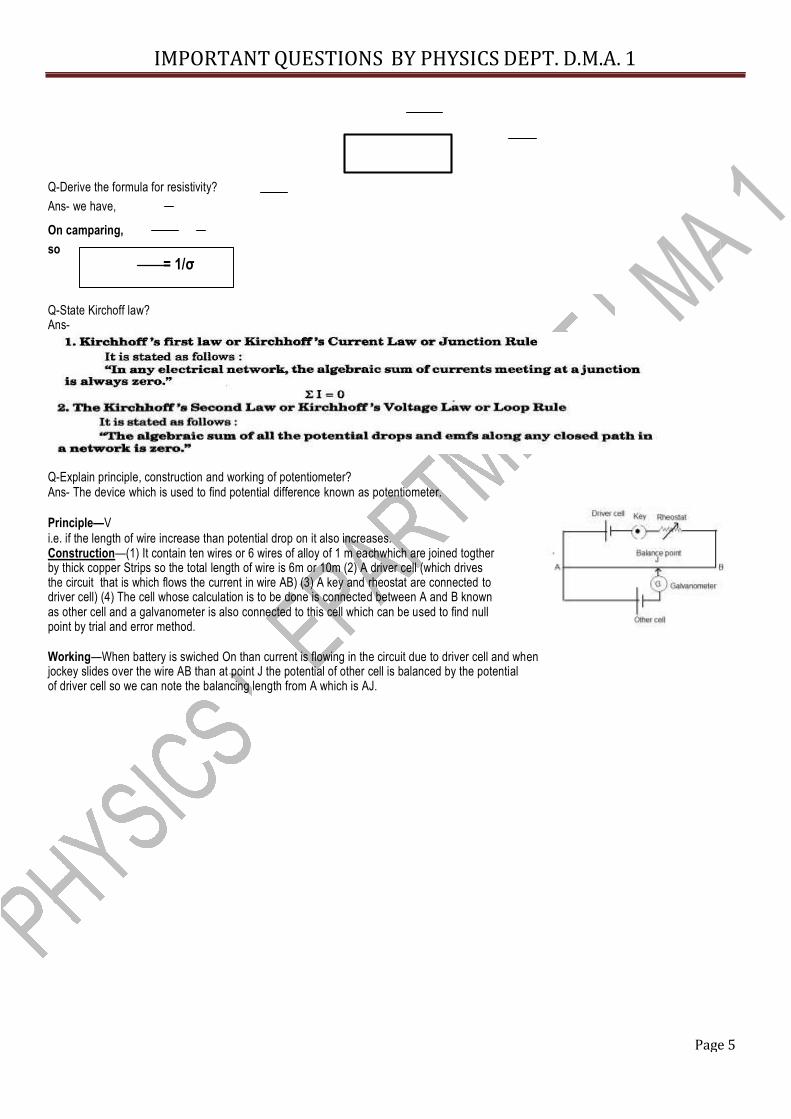
Q-Explain principle, construction and working of potentiometer? Ans- The device which is used to find potential difference known as potentiometer. Principle—V i.e. if the length of wire increase than potential drop on it also increases. Construction—(1) It contain ten wires or 6 wires of alloy of 1 m eachwhich are joined togther by thick copper Strips so the total length of wire is 6m or 10m (2) A driver cell (which drives the circuit that is which flows the current in wire AB) (3) A key and rheostat are connected to driver cell) (4) The cell whose calculation is to be done is connected between A and B known as other cell and a galvanometer is also connected to this cell which can be used to find null point by trial and error method. Working—When battery is swiched On than current is flowing in the circuit due to driver cell and when jockey slides over the wire AB than at point J the potential of other cell is balanced by the potential of driver cell so we can note the balancing length from A which is AJ.
IMPORTANT QUESTIONS BY PHYSICS DEPT. D.M.A. 1
Page 6
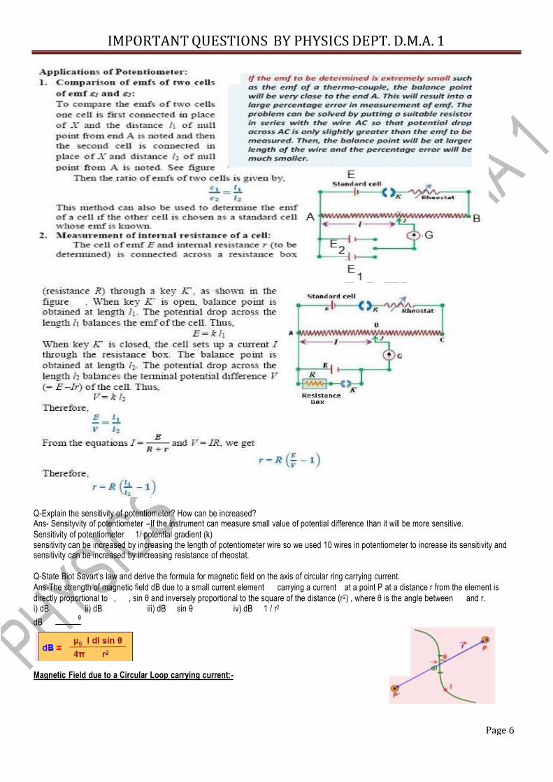
Q-Explain the sensitivity of potentiometer? How can be increased? Ans- Sensityvity of potentiometer –If the instrument can measure small value of potential difference than it will be more sensitive. Sensitivity of potentiometer 1/ potential gradient (k) sensitivity can be increased by increasing the length of potentiometer wire so we used 10 wires in potentiometer to increase its sensitivity and sensitivity can be increased by increasing resistance of rheostat. Q-State Biot Savart’s law and derive the formula for magnetic field on the axis of circular ring carrying current. Ans-The strength of magnetic field dB due to a small current element carrying a current at a point P at a distance r from the element is directly proportional to , , sin θ and inversely proportional to the square of the distance (r2) , where θ is the angle between and r. i) dB ii) dB iii) dB sin θ iv) dB 1 / r2 dB θ
Magnetic Field due to a Circular Loop carrying current:-
IMPORTANT QUESTIONS BY PHYSICS DEPT. D.M.A. 1
Page 7
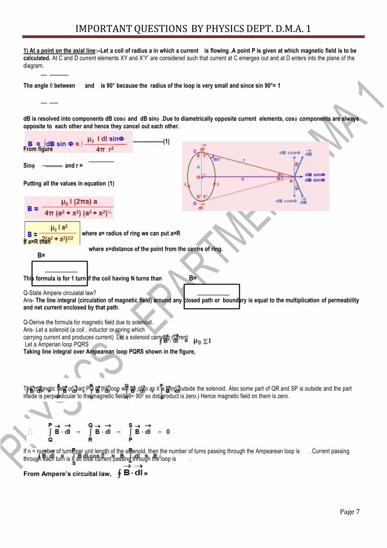
1) At a point on the axial line:--Let a coil of radius a in which a current is flowing .A point P is given at which magnetic field is to be calculated. At C and D current elements XY and X’Y’ are considered such that current at C emerges out and at D enters into the plane of the diagram. The angle θ between and is 90° because the radius of the loop is very small and since sin 90°= 1 dB is resolved into components dB cosϕ and dB sinϕ .Due to diametrically opposite current elements, cosϕ components are always opposite to each other and hence they cancel out each other. From figure Sinϕ and r =
-----------------(1)
Putting all the values in equation (1)
where a= radius of ring we can put a=R If a=R than B=
where x=distance of the point from the centre of ring.
This formula is for 1 turn if the coil having N turns than B= Q-State Ampere circuiatal law? Ans- The line integral (circulation of magnetic field) around any closed path or boundary is equal to the multiplication of permeability and net current enclosed by that path. Q-Derive the formula for magnetic field due to solenoid. Ans- Let a solenoid (a coil , inductor or spring which carrying current and produces current) Let a solenoid carrying current . Let a Amperian loop PQRS Taking line integral over Ampearean loop PQRS shown in the figure,
The magnetic field on part PQ of the loop will be zero as it is lying outside the solenoid. Also some part of QR and SP is outside and the part inside is perpendicular to the magnetic field (θ= 900 so dot product is zero.) Hence magnetic field on them is zero. If n = number of turns per unit length of the solenoid, then the number of turns passing through the Ampearean loop is . Current passing through each turn is I, so total current passing through the loop is . From Ampere’s circuital law, =
IMPORTANT QUESTIONS BY PHYSICS DEPT. D.M.A. 1
Page 8
So so B= Q-Calculate the formula for the force between two parallel current carrying wires and hence define 1 Ampere? Ans- Let two conductors X and Y are parallel to each other and kept at a distance d from each other and current i1 is flowing in X and current i2 is flowing in Y. The direction of current is same. Each conductor produces magnetic field in its surrounding by which the force is working on each wire due to magnetic field of other. The direction of magnetic field is given by right hand palm rule. Magnetic field due to a wire of infinite length at distance r is given by B=
So B1 = is the magnetic field of wire X on Y in downwards direction (By right hand palm rule)
And B2 = is the magnetic field of wire Y on X in outward direction (By right hand palm rule) Now the force on a straight wire of length L in presence of magnetic field B when a current is flowing in the wire is given by (angle is 900 ) So the force on conductor X due to conductor Y is given by F1 = =
And the force on Y due to X is given by F1 = = 1Ampere—If = 1A , and d=1m and = 2X10⁻⁷ Tm/A so from formula
We have F/l =2X10⁻⁷ N/m If two conductors are placed at a distance 1m from each other and the force on unit length of them is 2X10⁻⁷N/m then the current in each
wire is 1A. Q- Define cyclotron?
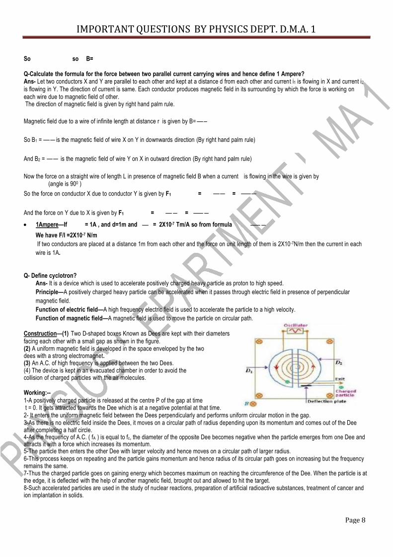
Ans- It is a device which is used to accelerate positively charged heavy particle as proton to high speed. Principle—A positively charged heavy particle can be accelerated when it passes through electric field in presence of perpendicular magnetic field. Function of electric field—A high frequency electric field is used to accelerate the particle to a high velocity. Function of magnetic field—A magnetic field is used to move the particle on circular path. Construction—(1) Two D-shaped boxes Known as Dees are kept with their diameters
facing each other with a small gap as shown in the figure. (2) A uniform magnetic field is developed in the space enveloped by the two dees with a strong electromagnet. (3) An A.C. of high frequency is applied between the two Dees. (4) The device is kept in an evacuated chamber in order to avoid the collision of charged particles with the air molecules. Working:-- 1-A positively charged particle is released at the centre P of the gap at time t = 0. It gets attracted towards the Dee which is at a negative potential at that time. 2- It enters the uniform magnetic field between the Dees perpendicularly and performs uniform circular motion in the gap. 3-As there is no electric field inside the Dees, it moves on a circular path of radius depending upon its momentum and comes out of the Dee after completing a half circle. 4-As the frequency of A.C. ( fA ) is equal to fc, the diameter of the opposite Dee becomes negative when the particle emerges from one Dee and attracts it with a force which increases its momentum. 5-The particle then enters the other Dee with larger velocity and hence moves on a circular path of larger radius. 6-This process keeps on repeating and the particle gains momentum and hence radius of its circular path goes on increasing but the frequency remains the same. 7-Thus the charged particle goes on gaining energy which becomes maximum on reaching the circumference of the Dee. When the particle is at the edge, it is deflected with the help of another magnetic field, brought out and allowed to hit the target. 8-Such accelerated particles are used in the study of nuclear reactions, preparation of artificial radioactive substances, treatment of cancer and ion implantation in solids.
IMPORTANT QUESTIONS BY PHYSICS DEPT. D.M.A. 1
Page 9
) Radius of path-The force acting on the charged particle is Under the effect of this force, the charged particle performs uniform circular motion in a plane perpendicular to the plane formed by v and B.
It shows that the radius of the path depends on velocity which shows that as the radius of path increases the velocity of particle also increase with it so a particle which is moving on circumference having maximum velocity. (3) Putting v = r c, where c is called the angular frequency of the cyclotron, we have
it gives cyclotron frequency, The equation shows that the frequency does not depend on the momentum. Hence on increasing
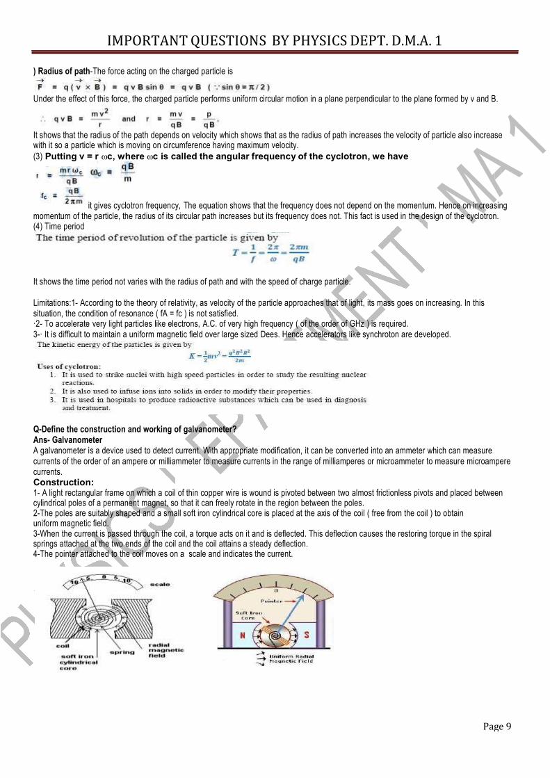
momentum of the particle, the radius of its circular path increases but its frequency does not. This fact is used in the design of the cyclotron. (4) Time period It shows the time period not varies with the radius of path and with the speed of charge particle. Limitations:1- According to the theory of relativity, as velocity of the particle approaches that of light, its mass goes on increasing. In this situation, the condition of resonance ( fA = fc ) is not satisfied. ·2- To accelerate very light particles like electrons, A.C. of very high frequency ( of the order of GHz ) is required. 3-· It is difficult to maintain a uniform magnetic field over large sized Dees. Hence accelerators like synchroton are developed. Q-Define the construction and working of galvanometer? Ans- Galvanometer A galvanometer is a device used to detect current. With appropriate modification, it can be converted into an ammeter which can measure currents of the order of an ampere or milliammeter to measure currents in the range of milliamperes or microammeter to measure microampere currents. Construction: 1- A light rectangular frame on which a coil of thin copper wire is wound is pivoted between two almost frictionless pivots and placed between cylindrical poles of a permanent magnet, so that it can freely rotate in the region between the poles. 2-The poles are suitably shaped and a small soft iron cylindrical core is placed at the axis of the coil ( free from the coil ) to obtain uniform magnetic field. 3-When the current is passed through the coil, a torque acts on it and is deflected. This deflection causes the restoring torque in the spiral springs attached at the two ends of the coil and the coil attains a steady deflection. 4-The pointer attached to the coil moves on a scale and indicates the current.
IMPORTANT QUESTIONS BY PHYSICS DEPT. D.M.A. 1
Page 10
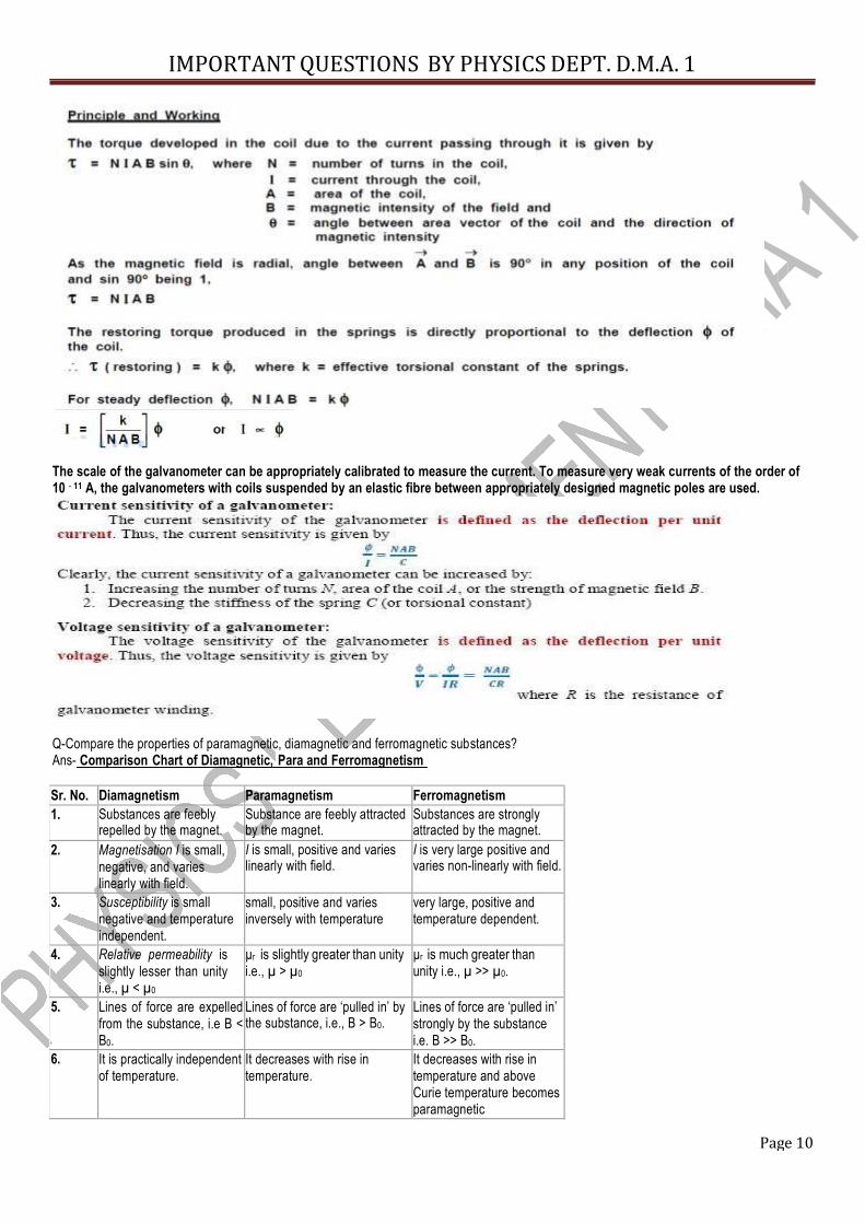
The scale of the galvanometer can be appropriately calibrated to measure the current. To measure very weak currents of the order of 10 - 11 A, the galvanometers with coils suspended by an elastic fibre between appropriately designed magnetic poles are used. Q-Compare the properties of paramagnetic, diamagnetic and ferromagnetic substances? Ans- Comparison Chart of Diamagnetic, Para and Ferromagnetism Sr. No. Diamagnetism Paramagnetism Ferromagnetism 1. Substances are feebly repelled by the magnet. Substance are feebly attracted by the magnet. Substances are strongly attracted by the magnet. 2. Magnetisation I is small,
negative, and varies linearly with field.
I is small, positive and varies linearly with field. I is very large positive and varies non-linearly with field. 3. Susceptibility is small
negative and temperature independent.
small, positive and varies inversely with temperature
very large, positive and temperature dependent.
4. Relative permeability is slightly lesser than unity i.e., µ < µ0
µr is slightly greater than unity i.e., µ > µ0
µr is much greater than unity i.e., µ >> µ0.
5. Lines of force are expelled from the substance, i.e B < B0.
Lines of force are ‘pulled in’ by the substance, i.e., B > B0. Lines of force are ‘pulled in’ strongly by the substance i.e. B >> B0.
6. It is practically independent of temperature.
It decreases with rise in temperature.
It decreases with rise in temperature and above Curie temperature becomes paramagnetic
IMPORTANT QUESTIONS BY PHYSICS DEPT. D.M.A. 1
Page 11
7. Atoms do not have any permanent dipole moment. Atoms have permanent dipole
moments which are randomly oriented.
Atoms have permanent dipole moments which are organised in domains.
8. Exhibited by solids, liquids and gases.
Exhibited by solids, liquids and gases.
Exhibited by solids only that too crystalline.
9. Bi, Cu, Ag, Hg, Pb, water, hydrogen, He, Ne, etc. are diamagnetic.
Na, K, Mg, Mn, Al, Cr, Sn and liquid oxygen are paramagnetic.
Fe, Co, Ni and their alloys are ferromagnetic.
Q-State Faraday’s law Ans- First Law—When the magnetic flux related to a conductor changes an emf is induced in it Second Law---It gives the magnitude of induced emf The magnitude of the emf induced in a conductor or coil is directly proportional to the rate of change of flux linkages i.e. Induced emf, in differential form = N where N=number of turns in the coil
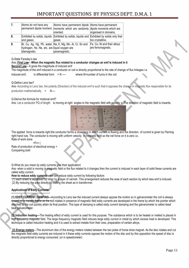
Q-Define Lenz law? Ans- According to Lenz law, the polarity (Direction) of the induced emf is such that it opposes the change in magnetic flux responsible for its production mathematically = N Q-Derive the formula for motional emf? Ans- Let a conductor PQ of length is moving at right angles to the magnetic field with velocity v .The direction of magnetic field is inwards. The applied force is towards right.the conductor forms a close loop in which current is flowing and the direction of current is given by Fleming right hand rule. The conductor is moving with uniform velocity in magnetic field so the net force on it is zero i.e. Rate of work done
=Fv= ( Rate of production of electrical energy = Compairing both Q-What do you mean by eddy currents give their application/ Ans- when a solid is moving in magnetic field or the flux related to it changes then the current is induced in each layer of solid these currents are called eddy current. How to reduce eddy currents—we can reduce eddy current by following factors (1) each sheet is separated by other by a layer of varnish .This arrangement reduces the area of each section by which less emf is induced. (2) By reducing the area directly by cutting the sheet as in transformer. Applications of Eddy Currents: (1) EDDY CURRENT DAMPING—According to Lenz law the induced current always oppose the motion so in galvanometer the coil is always wound on a metallic frame as the coil rotates in presence of magnetic field eddy currents are developed in the frame by which the pointer which attached to the coil quickly attain its final position. This type of damping is called eddy current damping and the galvanometer is called dead beat galvanometer. (2) Induction heating—The heating effect of eddy current is used for this purpose. The substance which is to be heated or melted is placed in high frequency magnetic field. The large frequency magnetic field induces large eddy current in metal by which excess heat is developed. This technique is called induction heating and it is used to extract metals from their ores, preparation of certain alloys. (3) Energy meters—The aluminium disc of the energy meters rotates between the two poles of horse shoe magnet. As the disc rotates and cut the magnetic field eddy currents are induced in it these eddy currents oppose the motion of the disc and by this opposition the speed of disc is directly proportional to energy consumed. (or in speedometer)
IMPORTANT QUESTIONS BY PHYSICS DEPT. D.M.A. 1
Page 12
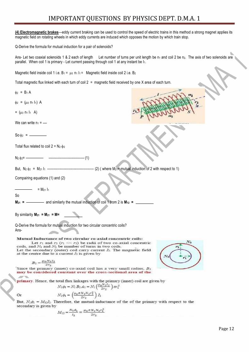
(4) Electromagnetic brakes—eddy current braking can be used to control the speed of electric trains in this method a strong magnet applies its magnetic field on rotating wheels in which eddy currents are induced which opposes the motion by which train stop. Q-Derive the formula for mutual induction for a pair of solenoids? Ans- Let two coaxial solenoids 1 & 2 each of length Let number of turns per unit length be n1 and coil 2 be n2. The axis of two solenoids are parallel. When coil 1 is primary - Let current passing through coil 1 at any instant be I1. Magnetic field inside coil 1 i.e. B1 = 0 n1 I1 = Magnetic field inside coil 2 i.e. B2 Total magnetic flux linked with each turn of coil 2 = magnetic field received by one X area of each turn. 2 = B1 A 2 = (0 n1 I1) A = (0 n1 I1 A) We can write n1 =
So 2 = Total flux related to coil 2 = N2 2
N2 2= ------------------------------- (1) But, N2 2 = M21 I1 ----------------------------------------- (2) ( where M21= mutual induction of 2 with respect to 1) Compairing equations (1) and (2)
= M21 I1 So M21 = and similarly the mutual induction of coil 1 from 2 is M12 = By similarity M21 = M21 = M= Q-Derive the formula for mutual induction for two circular concentric coils? Ans-
IMPORTANT QUESTIONS BY PHYSICS DEPT. D.M.A. 1
Page 13
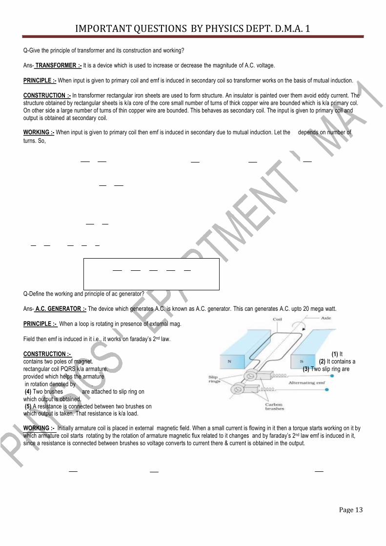
Q-Give the principle of transformer and its construction and working? Ans- TRANSFORMER :- It is a device which is used to increase or decrease the magnitude of A.C. voltage. PRINCIPLE :- When input is given to primary coil and emf is induced in secondary coil so transformer works on the basis of mutual induction. CONSTRUCTION :- In transformer rectangular iron sheets are used to form structure. An insulator is painted over them avoid eddy current. The structure obtained by rectangular sheets is k/a core of the core small number of turns of thick copper wire are bounded which is k/a primary col. On other side a large number of turns of thin copper wire are bounded. This behaves as secondary coil. The input is given to primary coil and output is obtained at secondary coil. WORKING :- When input is given to primary coil then emf is induced in secondary due to mutual induction. Let the depends on number of turns. So, Q-Define the working and principle of ac generator? Ans- A.C. GENERATOR :- The device which generates A.C. is known as A.C. generator. This can generates A.C. upto 20 mega watt. PRINCIPLE :- When a loop is rotating in presence of external mag. Field then emf is induced in it i.e., it works on faraday’s 2nd law. CONSTRUCTION :- (1) It contains two poles of magnet. (2) It contains a rectangular coil PQRS k/a armature. (3) Two slip ring are provided which helps the armature in rotation denoted by . (4) Two brushes are attached to slip ring on
which output is obtained. (5) A resistance is connected between two brushes on which output is taken. That resistance is k/a load. WORKING :- Initially armature coil is placed in external magnetic field. When a small current is flowing in it then a torque starts working on it by which armature coil starts rotating by the rotation of armature magnetic flux related to it changes and by faraday’s 2nd law emf is induced in it, since a resistance is connected between brushes so voltage converts to current there & current is obtained in the output.
IMPORTANT QUESTIONS BY PHYSICS DEPT. D.M.A. 1
Page 14
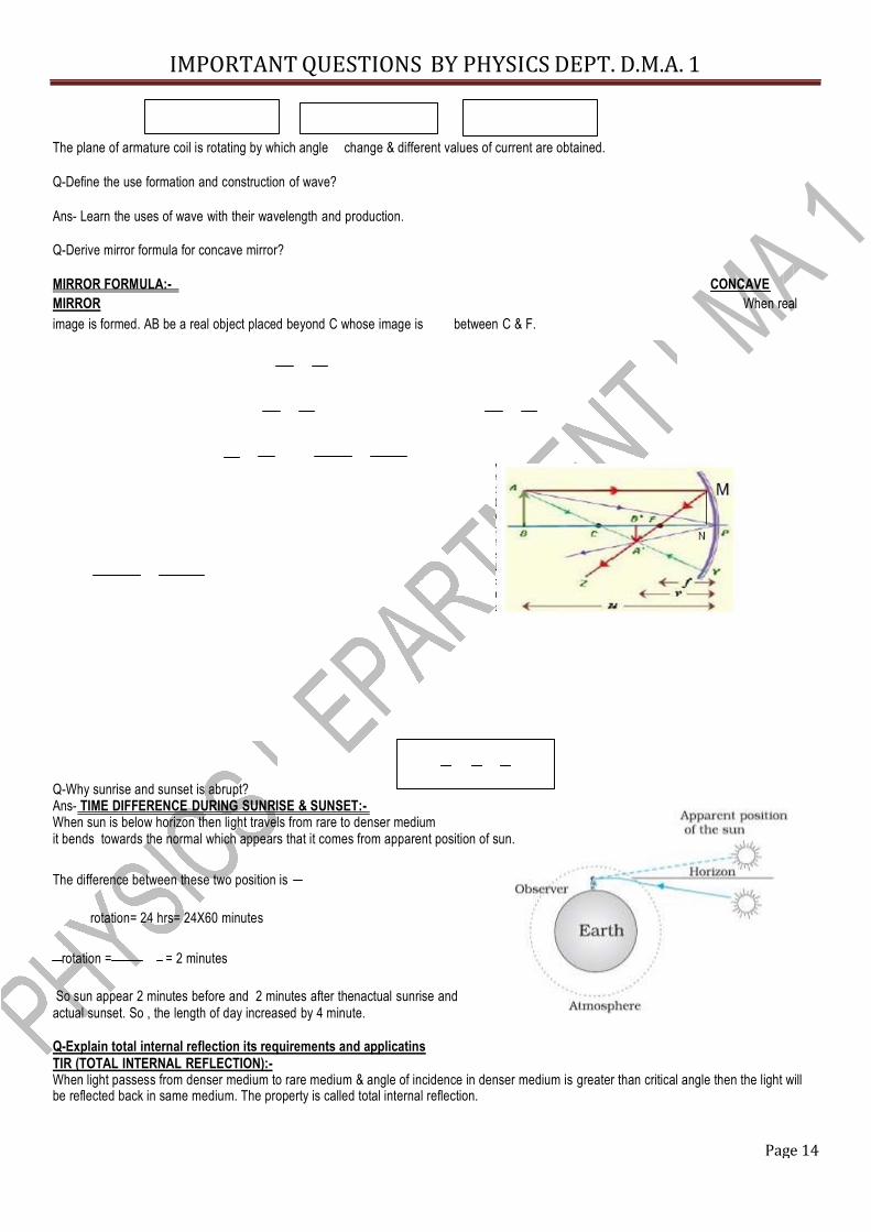
The plane of armature coil is rotating by which angle change & different values of current are obtained. Q-Define the use formation and construction of wave? Ans- Learn the uses of wave with their wavelength and production. Q-Derive mirror formula for concave mirror? MIRROR FORMULA:- CONCAVE MIRROR When real image is formed. AB be a real object placed beyond C whose image is between C & F. Q-Why sunrise and sunset is abrupt? Ans- TIME DIFFERENCE DURING SUNRISE & SUNSET:- When sun is below horizon then light travels from rare to denser medium it bends towards the normal which appears that it comes from apparent position of sun.
The difference between these two position is rotation= 24 hrs= 24X60 minutes
rotation = = 2 minutes So sun appear 2 minutes before and 2 minutes after thenactual sunrise and
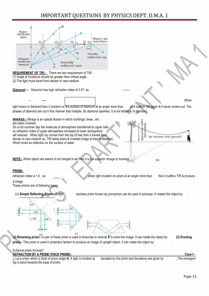
actual sunset. So , the length of day increased by 4 minute. Q-Explain total internal reflection its requirements and applicatins TIR (TOTAL INTERNAL REFLECTION):- When light passess from denser medium to rare medium & angle of incidence in denser medium is greater than critical angle then the light will be reflected back in same medium. The property is called total internal reflection.
IMPORTANT QUESTIONS BY PHYSICS DEPT. D.M.A. 1
Page 15
REQUIREMENT OF TIR:- There are two requirement of TIR:- (1) Angle of incidence should be greater than critical angle. (2) The light must travel from denser to rare medium. Diamond:-:- Diamond has high refraction index of 2.47. so,
When light enters in diamond then it incident on the surface of diamond at an angle more than so it suffers TIR again & it never comes out. The phases of diamond are cut in this manner that multiple. So diamond sparkles. It is k/a briliance of diamond.
MIRAGE:- Mirage is an optical illusion in which buildings ,trees , etc. are seem inverted. On a hot summer day the molecule of atmosphere transferred to upper side so refraction index of upper atmosphere increases & lower atmosphere will reduces. When light ray comes from the top of tree then it travels from denser to rare medium so, TIR takes place & inverted image of tree is obtained. Which looks as reflection on the surface of water. NOTE:- When object are seems to be hanged in air then it is k/a superior mirage or looming. PRISM:- refraction index is 1.5. so, when light incident on prism at an angle more than then it suffers TIR & produce a image. These prisms are of following types:-
(1) Simple Reflecting Prism:- A right isoceles prism known as porroprism can be used in priscope. It rotates the object by . (2) Reversing prism:- A pair of these prism is used in binocular to reverse & to erect the image. It can rotate the object by (3) Erecting prism:- This prism is used in projection lantern to produce an image of upright object. It can rotate the object by .
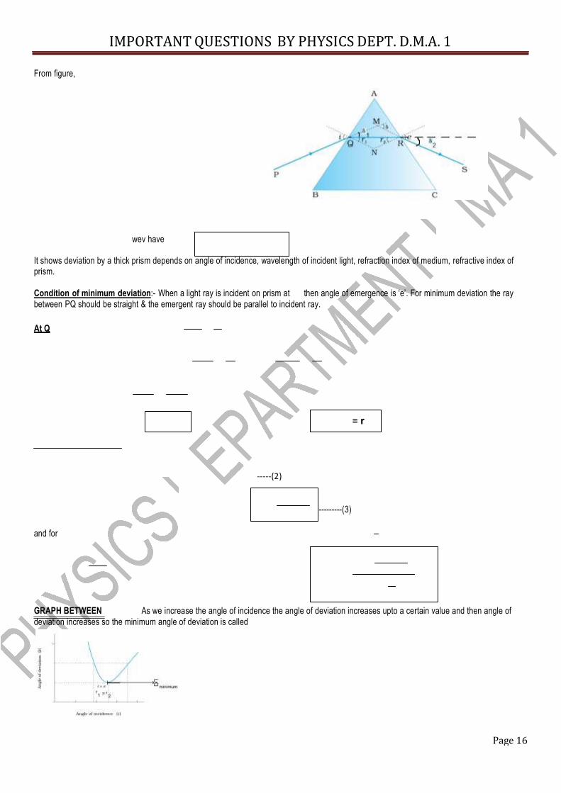
Q-Derive prism formula? REFRACTION BY A PRISM (THICK PRISM):-
Case1:- :- Let a prism which is thick of prism angle A. A light is incident at ray is bend towards the base of prism. deviated by the prism and deviations are given by . The emergent
IMPORTANT QUESTIONS BY PHYSICS DEPT. D.M.A. 1
Page 16
-----
From figure,
wev have It shows deviation by a thick prism depends on angle of incidence, wavelength of incident light, refraction index of medium, refractive index of prism. Condition of minimum deviation:- When a light ray is incident on prism at then angle of emergence is ‘e’. For minimum deviation the ray between PQ should be straight & the emergent ray should be parallel to incident ray. At Q = r
-----(2) ---------(3)
and for GRAPH BETWEEN As we increase the angle of incidence the angle of deviation increases upto a certain value and then angle of deviation increases so the minimum angle of deviation is called
IMPORTANT QUESTIONS BY PHYSICS DEPT. D.M.A. 1
Page 17
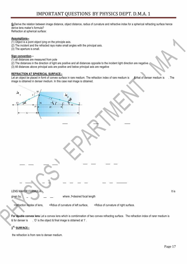
Q-Derive the relation between image distance, object distance, radius of curvature and refractive index for a spherical refracting surface hence derive lens maker’s formula? Refraction at spherical surface: Assumptions-- (1) Object is a point object lying on the principle axis. (2) The incident and the refracted rays make small angles with the principal axis. (3) The aperture is small. Sign convention— (1) all distances are measured from pole (2) The distances in the direction of light are positive and all distances opposite to the incident light direction are negative (3) All distances above principal axis are positive and below principal axis are negative REFRACTION AT SPHERICAL SURFACE-- Let an object be placed in fornt of convex surface in rare medium. The refraction index of rare medium is & that of denser medium is . The image is obtained in denser medium. In this case real image is obtained. LENS MAKER FORMULA:- It is given by, where ,f=desired focal length
=refraction inndex of lens, =Rdius of curvature of left surface, =Rdius of curvature of right surface.
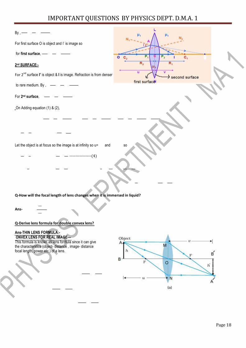
For double convex lens Let a convex lens which is combinnation of two convex refracting surface. The refraction index of rarer medium is & for denser is . ‘O’ is the object & final image is obtained at ‘I’ . 1st SURFACE:- the refraction is from rare to denser medium.
IMPORTANT QUESTIONS BY PHYSICS DEPT. D.M.A. 1
Page 18
By , For first surface O is object and I’ is image so for first surface,
2nd SURFACE:- For 2nd surface I’ is object & I is image. Refraction is from denser to rare medium. By ,
For 2nd surface, On Adding equation (1) & (2),
Let the object is at focus so the image is at infinity so u= and so ---------------(4)
Q-How will the focal length of lens changes when it is immersed in liquid? Ans- Q-Derive lens formula for double convex lens? Ans-THIN LENS FORMULA:- ONVEX LENS FOR REAL IMAGE— This formula is known as lens formula since it can give the characterstics (object- distance , image- distance focal length, power etc.) of a lens.
IMPORTANT QUESTIONS BY PHYSICS DEPT. D.M.A. 1
Page 19
MAGNIFICATION:-
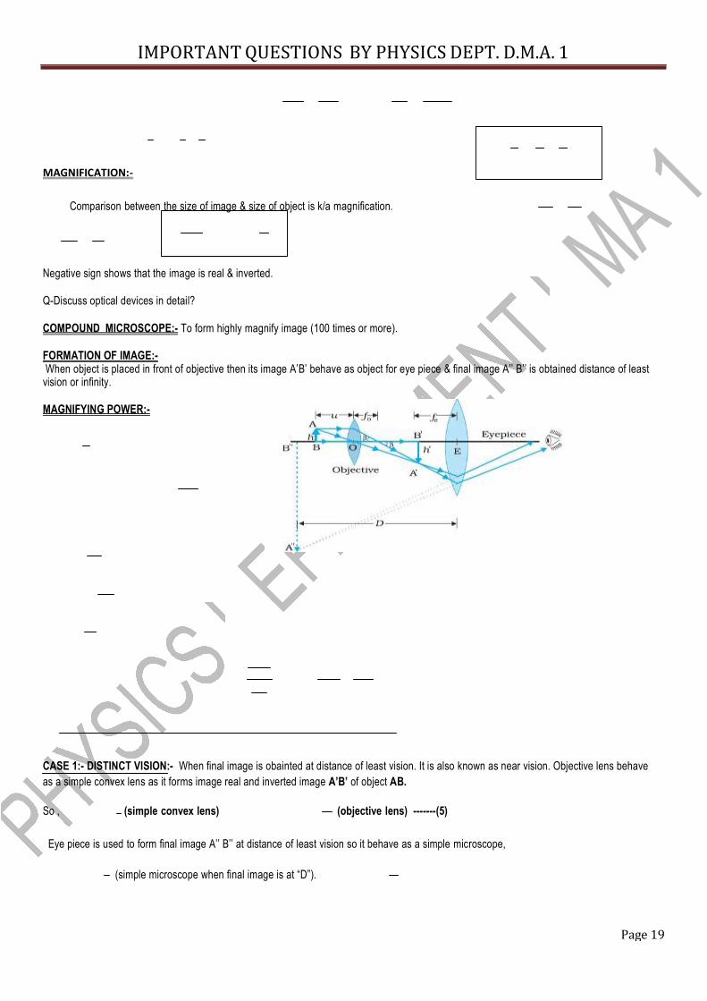
Comparison between the size of image & size of object is k/a magnification. Negative sign shows that the image is real & inverted. Q-Discuss optical devices in detail? COMPOUND MICROSCOPE:- To form highly magnify image (100 times or more). FORMATION OF IMAGE:- When object is placed in front of objective then its image A’B’ behave as object for eye piece & final image A’’ B’’ is obtained distance of least vision or infinity. MAGNIFYING POWER:- CASE 1:- DISTINCT VISION:- When final image is obainted at distance of least vision. It is also known as near vision. Objective lens behave as a simple convex lens as it forms image real and inverted image A’B’ of object AB.
So , (simple convex lens) (objective lens) -------(5)
Eye piece is used to form final image A’’ B’’ at distance of least vision so it behave as a simple microscope, (simple microscope when final image is at “D”).
Page 20
IMPORTANT QUESTION SESSION 2013-14 BY PHYSICS DEPT. D.M.A. 1
So, objective lens should be of smaller focal length for better magnifying power.
CASE 2:- NORMAL VISION:- When final image is obtained at . (simple convex lens)
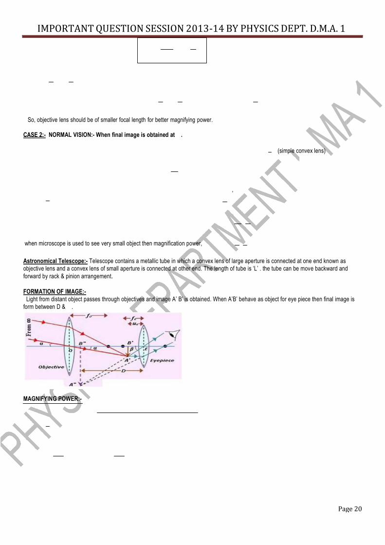
, when microscope is used to see very small object then magnification power, Astronomical Telescope:- Telescope contains a metallic tube in which a convex lens of large aperture is connected at one end known as objective lens and a convex lens of small aperture is connected at other end. The length of tube is ‘L’ . the tube can be move backward and forward by rack & pinion arrangement. FORMATION OF IMAGE:-
Light from distant object passes through objectives and image A’ B’ is obtained. When A’B’ behave as object for eye piece then final image is form between D & . MAGNIFYING POWER:-
Page 21
IMPORTANT QUESTION SESSION 2013-14 BY PHYSICS DEPT. D.M.A. 1
Consider two cases:- Distant vision:- when final image is obtained at distance of least vision. For eye piece ,
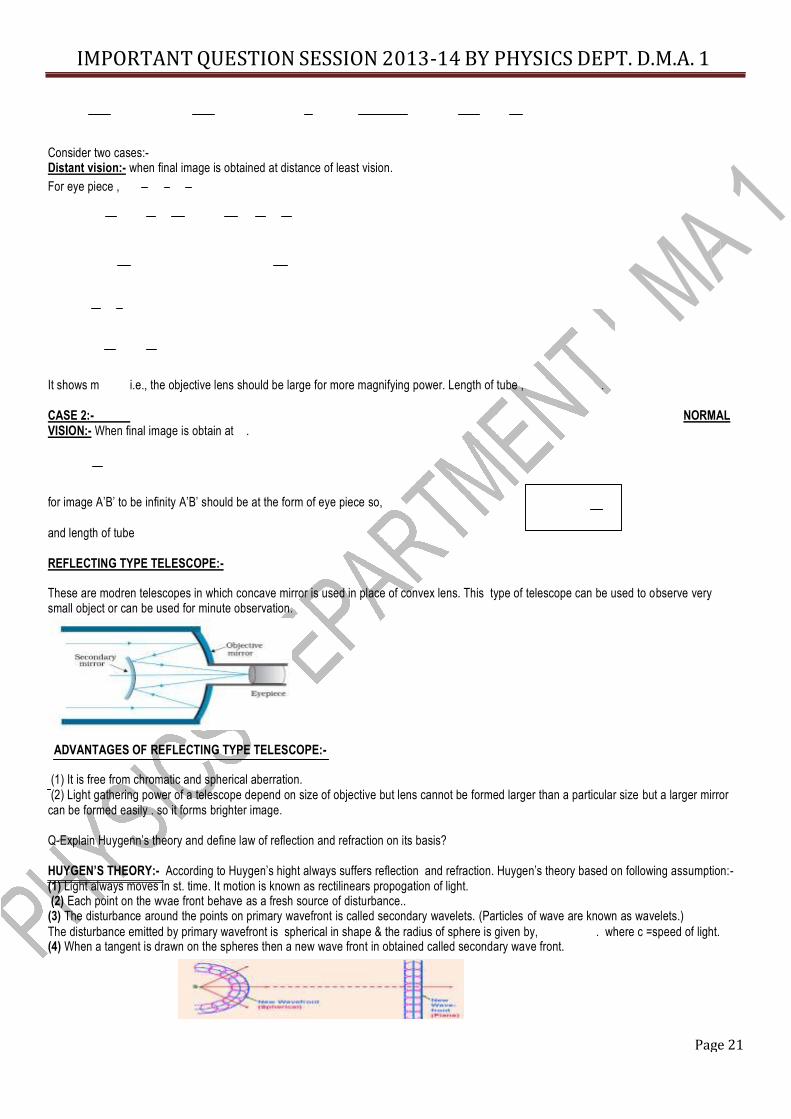
It shows m i.e., the objective lens should be large for more magnifying power. Length of tube , . CASE 2:- NORMAL VISION:- When final image is obtain at . for image A’B’ to be infinity A’B’ should be at the form of eye piece so, and length of tube REFLECTING TYPE TELESCOPE:- These are modren telescopes in which concave mirror is used in place of convex lens. This type of telescope can be used to observe very small object or can be used for minute observation.
ADVANTAGES OF REFLECTING TYPE TELESCOPE:- (1) It is free from chromatic and spherical aberration. (2) Light gathering power of a telescope depend on size of objective but lens cannot be formed larger than a particular size but a larger mirror
can be formed easily . so it forms brighter image. Q-Explain Huygenn’s theory and define law of reflection and refraction on its basis? HUYGEN’S THEORY:- According to Huygen’s hight always suffers reflection and refraction. Huygen’s theory based on following assumption:- (1) Light always moves in st. time. It motion is known as rectilinears propogation of light. (2) Each point on the wvae front behave as a fresh source of disturbance.. (3) The disturbance around the points on primary wavefront is called secondary wavelets. (Particles of wave are known as wavelets.) The disturbance emitted by primary wavefront is spherical in shape & the radius of sphere is given by, . where c =speed of light. (4) When a tangent is drawn on the spheres then a new wave front in obtained called secondary wave front.
Page 22
IMPORTANT QUESTION SESSION 2013-14 BY PHYSICS DEPT. D.M.A. 1
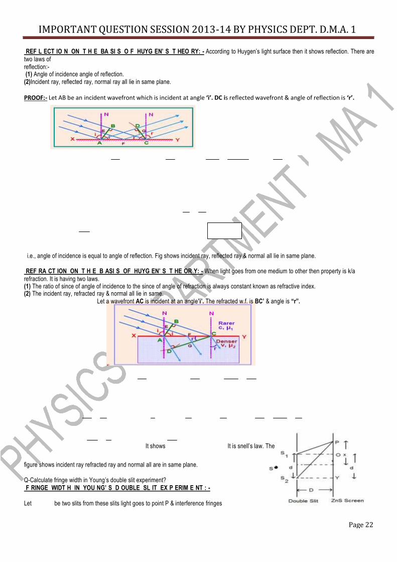
REF L ECT IO N ON T H E BA SI S O F HUYG EN’ S T HEO RY: - According to Huygen’s light surface then it shows reflection. There are two laws of reflection:- (1) Angle of incidence angle of reflection. (2)Incident ray, reflected ray, normal ray all lie in same plane. PROOF:- Let AB be an incident wavefront which is incident at angle ‘i’. DC is reflected wavefront & angle of reflection is ‘r’.
i.e., angle of incidence is equal to angle of reflection. Fig shows incident ray, reflected ray & normal all lie in same plane. REF RA CT ION ON T H E B ASI S OF HUYG EN’ S T HE OR Y: - When light goes from one medium to other then property is k/a
refraction. It is having two laws. (1) The ratio of since of angle of incidence to the since of angle of refraction is always constant known as refractive index. (2) The incident ray, refracted ray & normal all lie in same. Let a wavefront AC is incident at an angle’i’. The refracted w.f. is BC’ & angle is “r”.
It shows It is snell’s law. The
figure shows incident ray refracted ray and normal all are in same plane. Q-Calculate fringe width in Young’s double slit experiment? F RINGE WIDT H IN YOU NG’ S D OUBLE SL IT EX P ERIM E NT : - Let be two slits from these slits light goes to point P & interference fringes
Page 23
IMPORTANT QUESTION SESSION 2013-14 BY PHYSICS DEPT. D.M.A. 1
are obtained. CASE 1:- FOR BRIGHT FRINGE:-
CASE 2:- FOR DARK FRINGE:-
Page 24
IMPORTANT QUESTION SESSION 2013-14 BY PHYSICS DEPT. D.M.A. 1
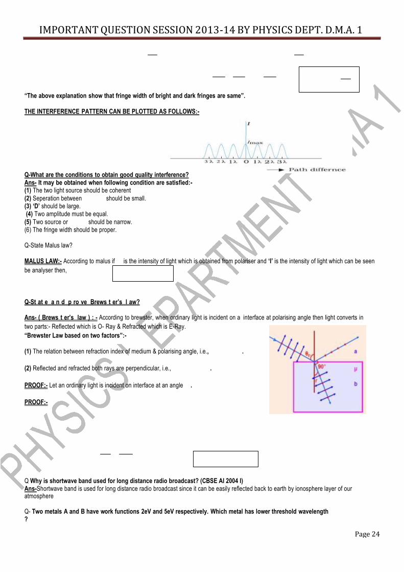
“The above explanation show that fringe width of bright and dark fringes are same”. THE INTERFERENCE PATTERN CAN BE PLOTTED AS FOLLOWS:- Q-What are the conditions to obtain good quality interference? Ans- It may be obtained when following condition are satisfied:- (1) The two light source should be coherent (2) Seperation between should be small. (3) ‘D’ should be large. (4) Two amplitude must be equal.
(5) Two source or should be narrow. (6) The fringe width should be proper. Q-State Malus law? MALUS LAW:- According to malus if is the intensity of light which is obtained from polariser and ‘I’ is the intensity of light which can be seen be analyser then,
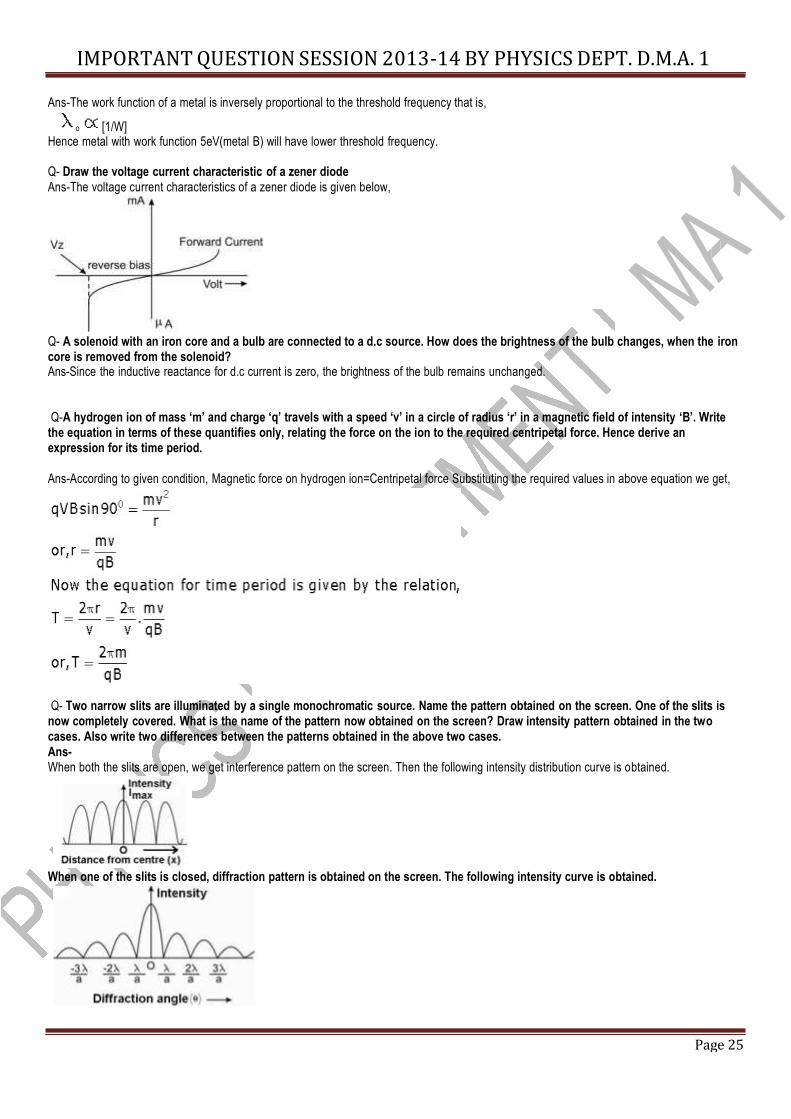
Q-St at e a n d p ro ve Brews t er’s l aw? Ans- ( Brews t er’s law ) : - According to brewster, when ordinary light is incident on a interface at polarising angle then light converts in two parts:- Reflected which is O- Ray & Refracted which is E-Ray. “Brewster Law based on two factors”:- (1) The relation between refraction index of medium & polarising angle, i.e., . (2) Reflected and refracted both rays are perpendicular, i.e., . PROOF:- Let an ordinary light is incident on interface at an angle . PROOF:- Q Why is shortwave band used for long distance radio broadcast? (CBSE AI 2004 I) Ans-Shortwave band is used for long distance radio broadcast since it can be easily reflected back to earth by ionosphere layer of our atmosphere Q- Two metals A and B have work functions 2eV and 5eV respectively. Which metal has lower threshold wavelength ?
Page 25
IMPORTANT QUESTION SESSION 2013-14 BY PHYSICS DEPT. D.M.A. 1
Ans-The work function of a metal is inversely proportional to the threshold frequency that is,
o [1/W] Hence metal with work function 5eV(metal B) will have lower threshold frequency.
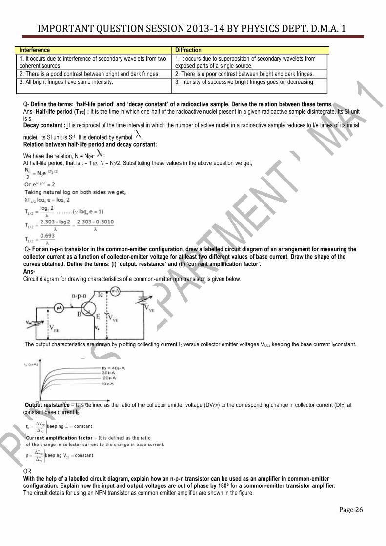
Q- Draw the voltage current characteristic of a zener diode Ans-The voltage current characteristics of a zener diode is given below, Q- A solenoid with an iron core and a bulb are connected to a d.c source. How does the brightness of the bulb changes, when the iron core is removed from the solenoid? Ans-Since the inductive reactance for d.c current is zero, the brightness of the bulb remains unchanged. Q-A hydrogen ion of mass ‘m’ and charge ‘q’ travels with a speed ‘v’ in a circle of radius ‘r’ in a magnetic field of intensity ‘B’. Write
the equation in terms of these quantifies only, relating the force on the ion to the required centripetal force. Hence derive an expression for its time period. Ans-According to given condition, Magnetic force on hydrogen ion=Centripetal force Substituting the required values in above equation we get, Q- Two narrow slits are illuminated by a single monochromatic source. Name the pattern obtained on the screen. One of the slits is now completely covered. What is the name of the pattern now obtained on the screen? Draw intensity pattern obtained in the two cases. Also write two differences between the patterns obtained in the above two cases. Ans- When both the slits are open, we get interference pattern on the screen. Then the following intensity distribution curve is obtained. When one of the slits is closed, diffraction pattern is obtained on the screen. The following intensity curve is obtained.
Page 26
IMPORTANT QUESTION SESSION 2013-14 BY PHYSICS DEPT. D.M.A. 1
Interference Diffraction 1. It occurs due to interference of secondary wavelets from two coherent sources.
1. It occurs due to superposition of secondary wavelets from exposed parts of a single source.
2. There is a good contrast between bright and dark fringes. 2. There is a poor contrast between bright and dark fringes. 3. All bright fringes have same intensity. 3. Intensity of successive bright fringes goes on decreasing.
Q- Define the terms: ‘half-life period’ and ‘decay constant’ of a radioactive sample. Derive the relation between these terms. Ans- Half-life period (T1/2) : It is the time in which one-half of the radioactive nuclei present in a given radioactive sample disintegrate. Its SI unit is s. Decay constant : It is reciprocal of the time interval in which the number of active nuclei in a radioactive sample reduces to I/e times of its initial nuclei. Its SI unit is S-1. It is denoted by symbol . Relation between half-life period and decay constant: We have the relation, N = N0e- t At half-life period, that is t = T1/2, N = N0/2. Substituting these values in the above equation we get, Q- For an n-p-n transistor in the common-emitter configuration, draw a labelled circuit diagram of an arrangement for measuring the
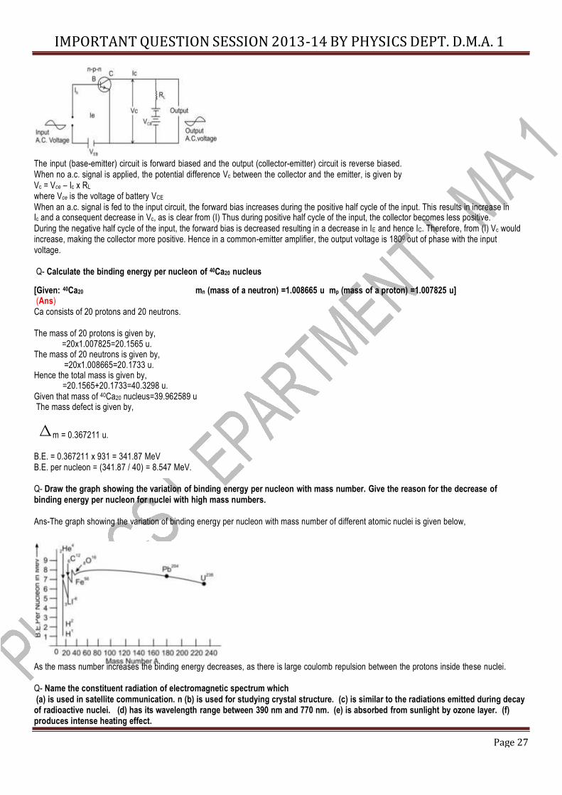
collector current as a function of collector-emitter voltage for at least two different values of base current. Draw the shape of the curves obtained. Define the terms: (i) ‘output. resistance’ and (ii) ‘cur rent amplification factor’. Ans- Circuit diagram for drawing characteristics of a common-emitter npn transistor is given below. The output characteristics are drawn by plotting collecting current Ic versus collector emitter voltages VCE, keeping the base current Ibconstant. Output resistance – It is defined as the ratio of the collector emitter voltage (DVCE) to the corresponding change in collector current (DIC) at constant base current Ib. OR With the help of a labelled circuit diagram, explain how an n-p-n transistor can be used as an amplifier in common-emitter configuration. Explain how the input and output voltages are out of phase by 1800 for a common-emitter transistor amplifier. The circuit details for using an NPN transistor as common emitter amplifier are shown in the figure.
Page 27
IMPORTANT QUESTION SESSION 2013-14 BY PHYSICS DEPT. D.M.A. 1
The input (base-emitter) circuit is forward biased and the output (collector-emitter) circuit is reverse biased. When no a.c. signal is applied, the potential difference Vc between the collector and the emitter, is given by Vc = Vce – Ic x RL where Vce is the voltage of battery VCE When an a.c. signal is fed to the input circuit, the forward bias increases during the positive half cycle of the input. This results in increase in Ic and a consequent decrease in Vc, as is clear from (I) Thus during positive half cycle of the input, the collector becomes less positive. During the negative half cycle of the input, the forward bias is decreased resulting in a decrease in IE and hence IC. Therefore, from (I) Vc would increase, making the collector more positive. Hence in a common-emitter amplifier, the output voltage is 1800 out of phase with the input voltage. Q- Calculate the binding energy per nucleon of 40Ca20 nucleus [Given: 40Ca20 mn (mass of a neutron) =1.008665 u mp (mass of a proton) =1.007825 u] (Ans)
Ca consists of 20 protons and 20 neutrons. The mass of 20 protons is given by, =20x1.007825=20.1565 u. The mass of 20 neutrons is given by, =20x1.008665=20.1733 u. Hence the total mass is given by, =20.1565+20.1733=40.3298 u. Given that mass of 40Ca20 nucleus=39.962589 u The mass defect is given by,
m = 0.367211 u. B.E. = 0.367211 x 931 = 341.87 MeV B.E. per nucleon = (341.87 / 40) = 8.547 MeV. Q- Draw the graph showing the variation of binding energy per nucleon with mass number. Give the reason for the decrease of binding energy per nucleon for nuclei with high mass numbers. Ans-The graph showing the variation of binding energy per nucleon with mass number of different atomic nuclei is given below, As the mass number increases the binding energy decreases, as there is large coulomb repulsion between the protons inside these nuclei. Q- Name the constituent radiation of electromagnetic spectrum which (a) is used in satellite communication. n (b) is used for studying crystal structure. (c) is similar to the radiations emitted during decay
of radioactive nuclei. (d) has its wavelength range between 390 nm and 770 nm. (e) is absorbed from sunlight by ozone layer. (f) produces intense heating effect.
Page 28
IMPORTANT QUESTION SESSION 2013-14 BY PHYSICS DEPT. D.M.A. 1
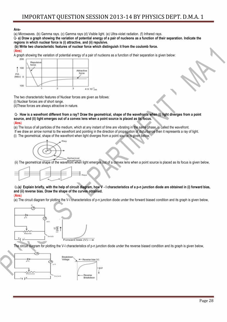
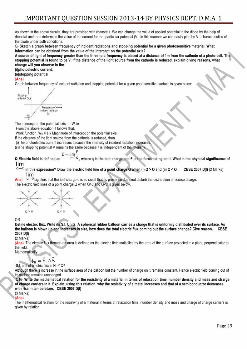
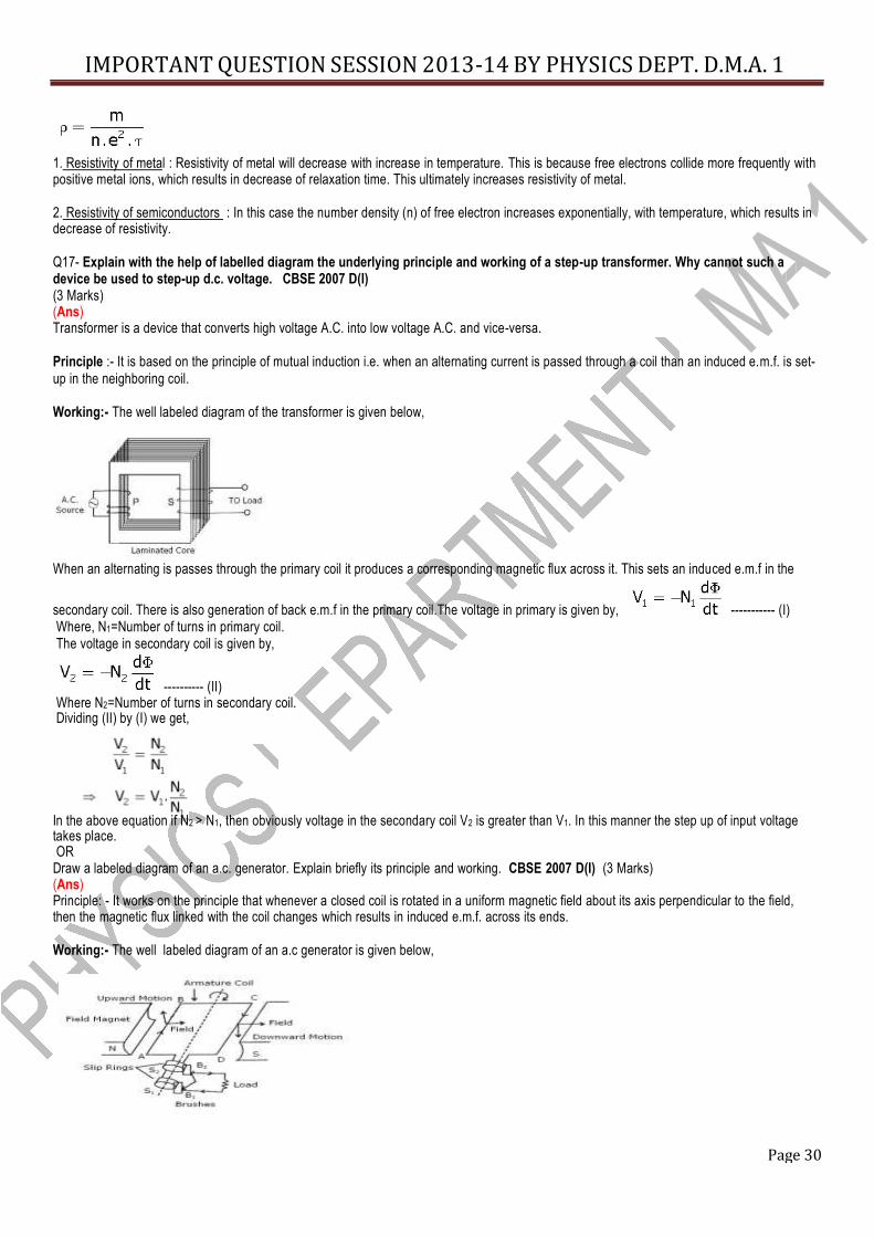
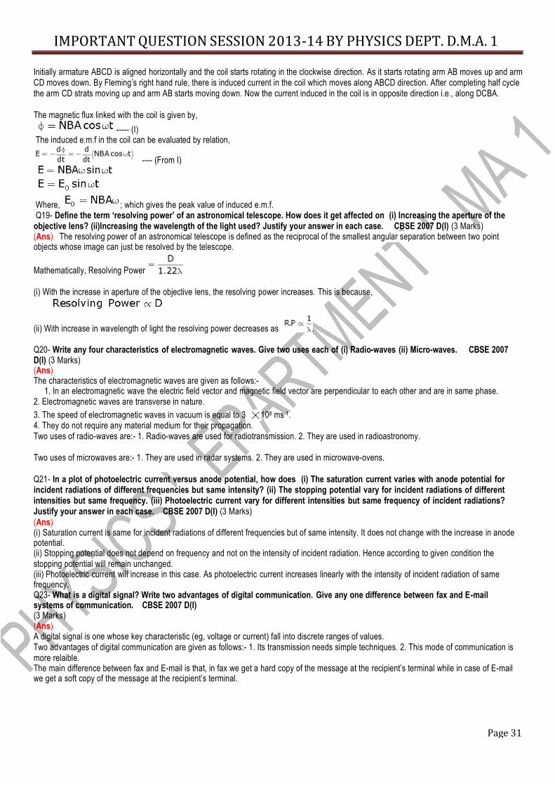
Ans- (a) Microwaves. (b) Gamma rays. (c) Gamma rays (d) Visible light. (e) Ultra-violet radiation. (f) Infrared rays. Q- a) Draw a graph showing the variation of potential energy of a pair of nucleons as a function of their separation. Indicate the regions in which nuclear force is (i) attractive, and (ii) repulsive. (b) Write two characteristic features of nuclear force which distinguish it from the coulomb force. (Ans) A graph showing the variation of potential energy of a pair of nucleons as a function of their separation is given below: The two characteristic features of Nuclear forces are given as follows: (i) Nuclear forces are of short range. (ii)These forces are always attractive in nature. Q- How is a wavefront different from a ray? Draw the geometrical, shape of the wavefronts when (i) light diverges from a point source, and (ii) light emerges out of a convex lens when a point source is placed as its focus. (Ans) (a) The locus of all particles of the medium, which at any instant of time are vibrating in the same phase, is called the wavefront. If we draw an arrow normal to the wavefront and pointing in the direction of propagation of disturbance then it represents a ray of light. (i) The geometrical, shape of the wavefront when light diverges from a point source is given below, (ii) The geometrical shape of the wavefront when light emerges out of a convex lens when a point source is placed as its focus is given below, Q-(a) Explain briefly, with the help of circuit diagram, how V - I characteristics of a p-n junction diode are obtained in (i) forward bias, and (ii) reverse bias. Draw the shape of the curves obtained. (Ans) (a) The circuit diagram for plotting the V-I characteristics of p-n junction diode under the forward biased condition and its graph is given below, The circuit diagram for plotting the V-I characteristics of p-n junction diode under the reverse biased condition and its graph is given below,
Page 29
IMPORTANT QUESTION SESSION 2013-14 BY PHYSICS DEPT. D.M.A. 1
As shown in the above circuits, they are provided with rheostats. We can change the value of applied potential to the diode by the help of rheostat and then determine the value of the current for that particular potential (V). In this manner we can easily plot the V-I characteristics of the diode under both conditions. Q- Sketch a graph between frequency of incident radiations and stopping potential for a given photosensitive material. What information can be obtained from the value of the intercept on the potential axis? A source of light of frequency greater than the threshold frequency is placed at a distance of 1m from the cathode of a photo-cell. The stopping potential is found to be V. If the distance of the light source from the cathode is reduced, explain giving reasons, what change will you observe in the (i)photoelectric current, (ii)stopping potential (Ans) Graph between frequency of incident radiation and stopping potential for a given photosensitive surface is given below:
The intercept on the potential axis = - Wo/e From the above equation it follows that, Work function, W0 = e x Magnitude of intercept on the potential axis.
If the distance of the light source from the cathode is reduced, then (i)The photoelectric current increases because the intensity of incident radiation increases. (ii)The stopping potential V remains the same because it is independent of the intensity. Q-Electric field is defined as , where q is the test charge and F is the force acting on it. What is the physical significance of
in this expression? Draw the electric field line of a point charge Q when (i) Q > O and (ii) Q < O. CBSE 2007 D(I) (2 Marks) Ans) signifies that the test charge q is so small that its presence does not disturb the distribution of source charge. The electric field lines of a point charge Q when Q>0 and Q<0 is given below, OR Define electric flux. Write its S.I. Units. A spherical rubber balloon carries a charge that is uniformly distributed over its surface. As the balloon is blown up and increases in size, how does the total electric flux coming out the surface change? Give reason. CBSE 2007 D(I) (2 Marks) (Ans) The electric flux through an area is defined as the electric field multiplied by the area of the surface projected in a plane perpendicular to the field. Mathematically, S.I. unit of electric flux is Nm2 C-1 Although there is increase in the surface area of the balloon but the number of charge on it remains constant. Hence electric field coming out of its surface remains unchanged. Q16- Write the mathematical relation for the resistivity of a material in terms of relaxation time, number density and mass and charge of charge carriers in it. Explain, using this relation, why the resistivity of a metal increases and that of a semiconductor decreases with rise in temperature. CBSE 2007 D(I) (3 Marks) (Ans) The mathematical relation for the resistivity of a material in terms of relaxation time, number density and mass and charge of charge carriers is given by relation,
Page 30
IMPORTANT QUESTION SESSION 2013-14 BY PHYSICS DEPT. D.M.A. 1
1. Resistivity of metal : Resistivity of metal will decrease with increase in temperature. This is because free electrons collide more frequently with positive metal ions, which results in decrease of relaxation time. This ultimately increases resistivity of metal. 2. Resistivity of semiconductors : In this case the number density (n) of free electron increases exponentially, with temperature, which results in decrease of resistivity. Q17- Explain with the help of labelled diagram the underlying principle and working of a step-up transformer. Why cannot such a device be used to step-up d.c. voltage. CBSE 2007 D(I) (3 Marks) (Ans) Transformer is a device that converts high voltage A.C. into low voltage A.C. and vice-versa. Principle :- It is based on the principle of mutual induction i.e. when an alternating current is passed through a coil than an induced e.m.f. is set- up in the neighboring coil. Working:- The well labeled diagram of the transformer is given below,
When an alternating is passes through the primary coil it produces a corresponding magnetic flux across it. This sets an induced e.m.f in the secondary coil. There is also generation of back e.m.f in the primary coil.The voltage in primary is given by, ----------- (I) Where, N1=Number of turns in primary coil. The voltage in secondary coil is given by,
---------- (II) Where N2=Number of turns in secondary coil. Dividing (II) by (I) we get, In the above equation if N2 > N1, then obviously voltage in the secondary coil V2 is greater than V1. In this manner the step up of input voltage takes place. OR Draw a labeled diagram of an a.c. generator. Explain briefly its principle and working. CBSE 2007 D(I) (3 Marks) (Ans) Principle: - It works on the principle that whenever a closed coil is rotated in a uniform magnetic field about its axis perpendicular to the field, then the magnetic flux linked with the coil changes which results in induced e.m.f. across its ends. Working:- The well labeled diagram of an a.c generator is given below,
Page 31
IMPORTANT QUESTION SESSION 2013-14 BY PHYSICS DEPT. D.M.A. 1
Initially armature ABCD is aligned horizontally and the coil starts rotating in the clockwise direction. As it starts rotating arm AB moves up and arm CD moves down. By Fleming’s right hand rule, there is induced current in the coil which moves along ABCD direction. After completing half cycle the arm CD strats moving up and arm AB starts moving down. Now the current induced in the coil is in opposite direction i.e., along DCBA. The magnetic flux linked with the coil is given by,
----- (I) The induced e.m.f in the coil can be evaluated by relation, ---- (From I) Where, ; which gives the peak value of induced e.m.f. Q19- Define the term ‘resolving power’ of an astronomical telescope. How does it get affected on (i) Increasing the aperture of the objective lens? (ii)Increasing the wavelength of the light used? Justify your answer in each case. CBSE 2007 D(I) (3 Marks) (Ans) The resolving power of an astronomical telescope is defined as the reciprocal of the smallest angular separation between two point objects whose image can just be resolved by the telescope. Mathematically, Resolving Power (i) With the increase in aperture of the objective lens, the resolving power increases. This is because,
(ii) With increase in wavelength of light the resolving power decreases as . Q20- Write any four characteristics of electromagnetic waves. Give two uses each of (i) Radio-waves (ii) Micro-waves. CBSE 2007 D(I) (3 Marks) (Ans) The characteristics of electromagnetic waves are given as follows:- 1. In an electromagnetic wave the electric field vector and magnetic field vector are perpendicular to each other and are in same phase. 2. Electromagnetic waves are transverse in nature. 3. The speed of electromagnetic waves in vacuum is equal to 3 108 ms-1. 4. They do not require any material medium for their propagation. Two uses of radio-waves are:- 1. Radio-waves are used for radiotransmission. 2. They are used in radioastronomy. Two uses of microwaves are:- 1. They are used in radar systems. 2. They are used in microwave-ovens. Q21- In a plot of photoelectric current versus anode potential, how does (i) The saturation current varies with anode potential for incident radiations of different frequencies but same intensity? (ii) The stopping potential vary for incident radiations of different intensities but same frequency. (iii) Photoelectric current vary for different intensities but same frequency of incident radiations? Justify your answer in each case. CBSE 2007 D(I) (3 Marks) (Ans) (i) Saturation current is same for incident radiations of different frequencies but of same intensity. It does not change with the increase in anode potential. (ii) Stopping potential does not depend on frequency and not on the intensity of incident radiation. Hence according to given condition the stopping potential will remain unchanged. (iii) Photoelectric current will increase in this case. As photoelectric current increases linearly with the intensity of incident radiation of same frequency. Q23- What is a digital signal? Write two advantages of digital communication. Give any one difference between fax and E-mail systems of communication. CBSE 2007 D(I) (3 Marks) (Ans) A digital signal is one whose key characteristic (eg, voltage or current) fall into discrete ranges of values. Two advantages of digital communication are given as follows:- 1. Its transmission needs simple techniques. 2. This mode of communication is more relaible. The main difference between fax and E-mail is that, in fax we get a hard copy of the message at the recipient’s terminal while in case of E-mail we get a soft copy of the message at the recipient’s terminal.
Page 32
IMPORTANT QUESTION SESSION 2013-14 BY PHYSICS DEPT. D.M.A. 1
Q24- Explain, with the help of a schematic diagram, the principle and working of a Light Emitting Diode. What criterion is kept in mind
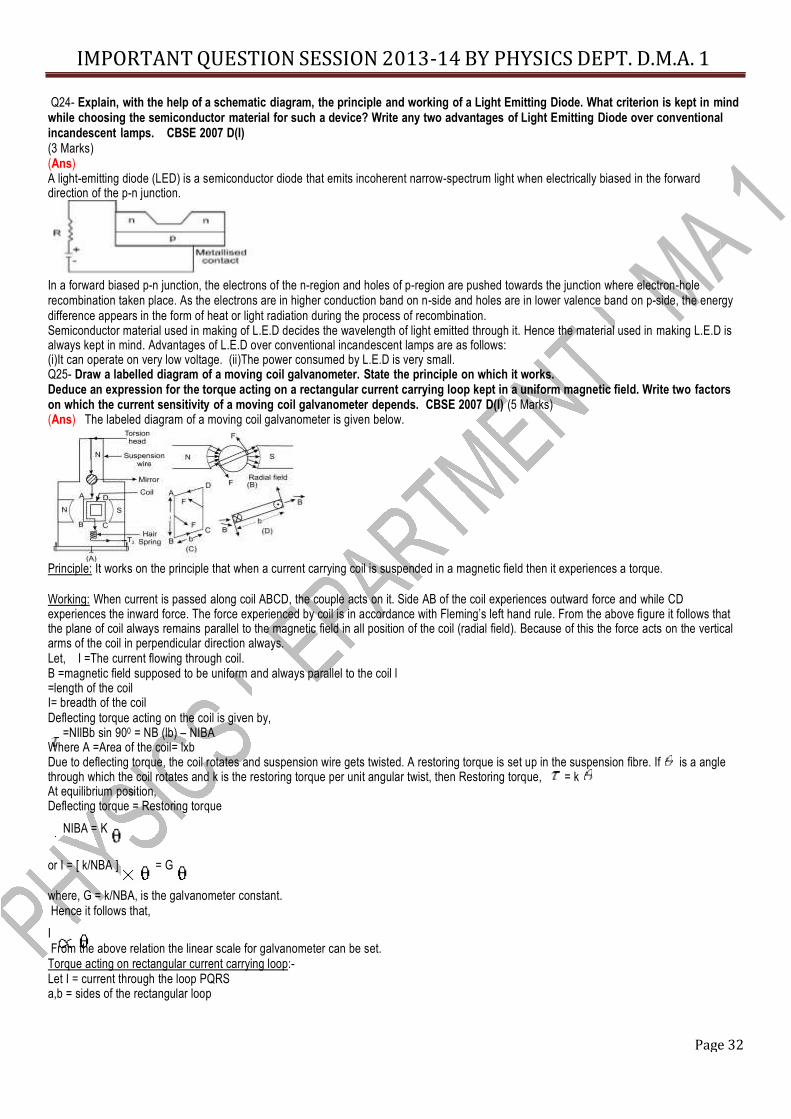
while choosing the semiconductor material for such a device? Write any two advantages of Light Emitting Diode over conventional incandescent lamps. CBSE 2007 D(I) (3 Marks) (Ans) A light-emitting diode (LED) is a semiconductor diode that emits incoherent narrow-spectrum light when electrically biased in the forward direction of the p-n junction.
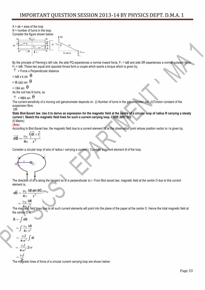
In a forward biased p-n junction, the electrons of the n-region and holes of p-region are pushed towards the junction where electron-hole recombination taken place. As the electrons are in higher conduction band on n-side and holes are in lower valence band on p-side, the energy difference appears in the form of heat or light radiation during the process of recombination. Semiconductor material used in making of L.E.D decides the wavelength of light emitted through it. Hence the material used in making L.E.D is always kept in mind. Advantages of L.E.D over conventional incandescent lamps are as follows: (i)It can operate on very low voltage. (ii)The power consumed by L.E.D is very small. Q25- Draw a labelled diagram of a moving coil galvanometer. State the principle on which it works. Deduce an expression for the torque acting on a rectangular current carrying loop kept in a uniform magnetic field. Write two factors on which the current sensitivity of a moving coil galvanometer depends. CBSE 2007 D(I) (5 Marks) (Ans) The labeled diagram of a moving coil galvanometer is given below. Principle: It works on the principle that when a current carrying coil is suspended in a magnetic field then it experiences a torque. Working: When current is passed along coil ABCD, the couple acts on it. Side AB of the coil experiences outward force and while CD experiences the inward force. The force experienced by coil is in accordance with Fleming’s left hand rule. From the above figure it follows that the plane of coil always remains parallel to the magnetic field in all position of the coil (radial field). Because of this the force acts on the vertical arms of the coil in perpendicular direction always. Let, I =The current flowing through coil. B =magnetic field supposed to be uniform and always parallel to the coil l =length of the coil I= breadth of the coil Deflecting torque acting on the coil is given by, =NIlBb sin 900 = NB (lb) – NIBA Where A =Area of the coil= lxb Due to deflecting torque, the coil rotates and suspension wire gets twisted. A restoring torque is set up in the suspension fibre. If is a angle through which the coil rotates and k is the restoring torque per unit angular twist, then Restoring torque, = k At equilibrium position, Deflecting torque = Restoring torque
NIBA = K or I = [ k/NBA ] = G where, G = k/NBA, is the galvanometer constant. Hence it follows that,
I From the above relation the linear scale for galvanometer can be set.
Torque acting on rectangular current carrying loop:- Let I = current through the loop PQRS a,b = sides of the rectangular loop
Page 33
IMPORTANT QUESTION SESSION 2013-14 BY PHYSICS DEPT. D.M.A. 1
A = ab = area of the loop N = number of turns in the loop. Consider the figure shown below.
By the principle of Fleming’s left rule, the side PQ experiences a normal inward force, F1 = IaB and side SR experiences a normal outward force, F2 = IaB. These two equal and opposite forces form a couple which exerts a torque which is given by,
= Force x Perpendicular distance = IaB x b sin = IB (ab) sin = I BA sin
As the coil has N turns, so = NBA sin The current sensitivity of a moving coil galvanometer depends on (i) Number of turns in the galvanometer coil. (ii)Torsion constant of the suspension fibre. OR State Biot-Savart law. Use it to derive an expression for the magnetic field at the centre of a circular loop of radius R carrying a steady current I. Sketch the magnetic field lines for such a current carrying loop. CBSE 2007 D(I) (5 Marks) (Ans) According to Biot-Savart law, the magnetic field due to a current element Idl at the observation point whose position vector is r is given by,
Consider a circular loop of wire of radius r carrying a current I. Consider a current element dl of the loop. The direction of dl is along the tangent so dl is perpendicular to r. From Biot savart law, magnetic field at the centre O due to this current element is, The magnetic field lines due to all such current elements will point into the plane of the paper at the centre O. Hence the total magnetic field at the centre O is The magnetic lines of force of a circular current carrying loop are shown below:
Page 34
IMPORTANT QUESTION SESSION 2013-14 BY PHYSICS DEPT. D.M.A. 1
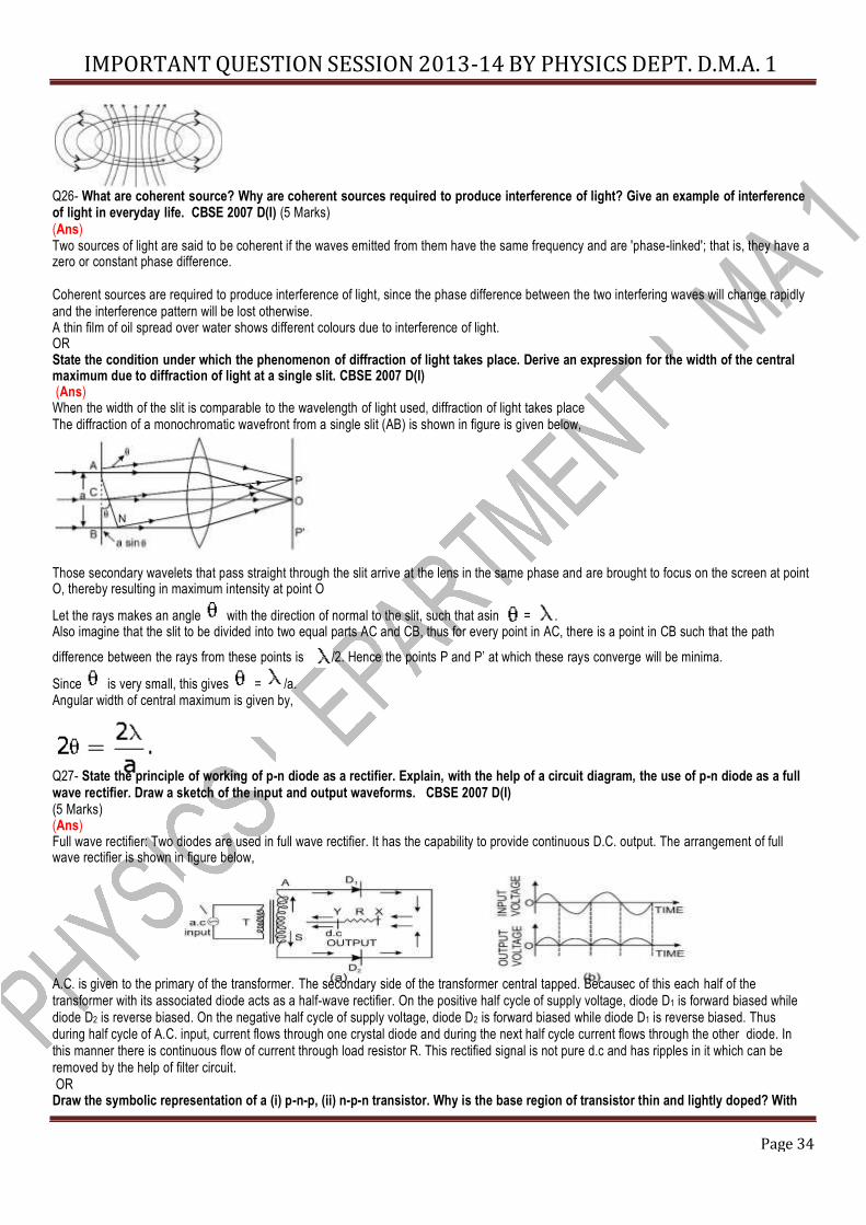
Q26- What are coherent source? Why are coherent sources required to produce interference of light? Give an example of interference of light in everyday life. CBSE 2007 D(I) (5 Marks) (Ans) Two sources of light are said to be coherent if the waves emitted from them have the same frequency and are 'phase-linked'; that is, they have a zero or constant phase difference. Coherent sources are required to produce interference of light, since the phase difference between the two interfering waves will change rapidly and the interference pattern will be lost otherwise. A thin film of oil spread over water shows different colours due to interference of light. OR State the condition under which the phenomenon of diffraction of light takes place. Derive an expression for the width of the central maximum due to diffraction of light at a single slit. CBSE 2007 D(I) (Ans) When the width of the slit is comparable to the wavelength of light used, diffraction of light takes place The diffraction of a monochromatic wavefront from a single slit (AB) is shown in figure is given below, Those secondary wavelets that pass straight through the slit arrive at the lens in the same phase and are brought to focus on the screen at point O, thereby resulting in maximum intensity at point O Let the rays makes an angle with the direction of normal to the slit, such that asin = . Also imagine that the slit to be divided into two equal parts AC and CB, thus for every point in AC, there is a point in CB such that the path difference between the rays from these points is /2. Hence the points P and P’ at which these rays converge will be minima. Since is very small, this gives = /a. Angular width of central maximum is given by, Q27- State the principle of working of p-n diode as a rectifier. Explain, with the help of a circuit diagram, the use of p-n diode as a full wave rectifier. Draw a sketch of the input and output waveforms. CBSE 2007 D(I) (5 Marks) (Ans) Full wave rectifier: Two diodes are used in full wave rectifier. It has the capability to provide continuous D.C. output. The arrangement of full wave rectifier is shown in figure below,
A.C. is given to the primary of the transformer. The secondary side of the transformer central tapped. Becausec of this each half of the transformer with its associated diode acts as a half-wave rectifier. On the positive half cycle of supply voltage, diode D1 is forward biased while diode D2 is reverse biased. On the negative half cycle of supply voltage, diode D2 is forward biased while diode D1 is reverse biased. Thus during half cycle of A.C. input, current flows through one crystal diode and during the next half cycle current flows through the other diode. In this manner there is continuous flow of current through load resistor R. This rectified signal is not pure d.c and has ripples in it which can be removed by the help of filter circuit. OR Draw the symbolic representation of a (i) p-n-p, (ii) n-p-n transistor. Why is the base region of transistor thin and lightly doped? With
Page 35
IMPORTANT QUESTION SESSION 2013-14 BY PHYSICS DEPT. D.M.A. 1
proper circuit diagram, show the biasing of a p-n-p transistor in common base configuration. Explain the movement of charge carriers through different parts of the transistor in such a configuration and show that IE = IC + IB. CBSE 2007 D(I) (5 Marks) (Ans) The symbolic representation for p-n-p and n-p-n transistors is given below.
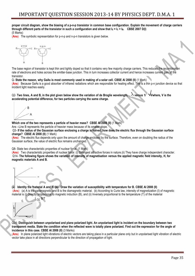
The base region of transistor is kept thin and lightly doped so that it contains very few majority charge carriers. This reduces the recombination rate of electrons and holes across the emitter-base junction. This in turn increases collector current and hence increases current gain of the transistor. Q- State the reason, why GaAs is most commonly used in making of a solar cell. CBSE AI 2008 (II) (1 Mark) (Ans) Because GaAs is a good absorber of infrared radiations which are responsible for heating effect. This is a thin p-n junction device so that incident light reaches easily. Q2- Two lines, A and B, in the plot given below show the variation of de Broglie wavelength, versus 1/ Vwhere, V is the accelerating potential difference, for two particles carrying the same charge. Which one of the two represents a particle of heavier mass? CBSE AI 2008 (II) (1 Mark) Ans --Line B represents the particle of heavier mass because of its smaller slope. Q3- If the radius of the Gaussian surface enclosing a charge is halved, how does the electric flux through the Gaussian surface change? CBSE AI 2008 (II) (1 Mark) (Ans) The electric flux depends only upon the amount of charge enclosed by the surface. Therefore, even on doubling the radius of the Gaussian surface, the value of electric flux remains unchanged. Q8- State two characteristic properties of nuclear force. (1 Mark) (Ans) Two characteristic properties of nuclear force: (i) Strongest attractive forces in nature.(ii) They have charge independent character. Q14- The following figure shows the variation of intensity of magnetisation versus the applied magnetic field intensity, H, for magnetic materials A and B. (a) Identity the material A and B. (b) Draw the variation of susceptibility with temperature for B. CBSE AI 2008 (II) (Ans) (a) A is the paramagnetic and B is the diamagnetic material. (b) According to Curie law, intensity of magnetization (I) of magnetic material is (i) Directly proportional to magnetic induction (B), and (ii) Inversely proportional to the temperature (T) of the material
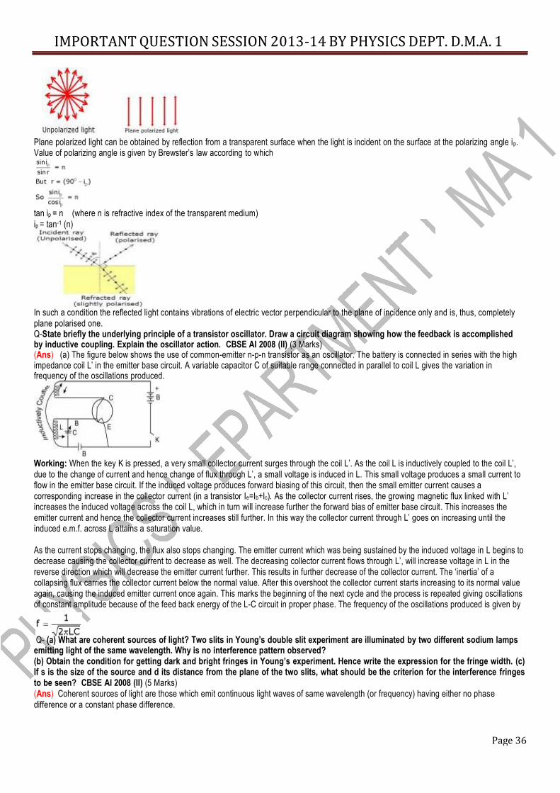
I B/T Q24- Distinguish between unpolarised and plane polarized light. An unpolarised light is incident on the boundary between two transparent media. State the condition when the reflected wave is totally plane polarized. Find out the expression for the angle of incidence in this case. CBSE AI 2008 (II) (3 Marks) (Ans) In plane polarized light vibrations of electric vectors are taking place in a particular plane only but in unpolarised light vibration of electric vector take place in all directions perpendicular to the direction of propagation of light.
Page 36
IMPORTANT QUESTION SESSION 2013-14 BY PHYSICS DEPT. D.M.A. 1
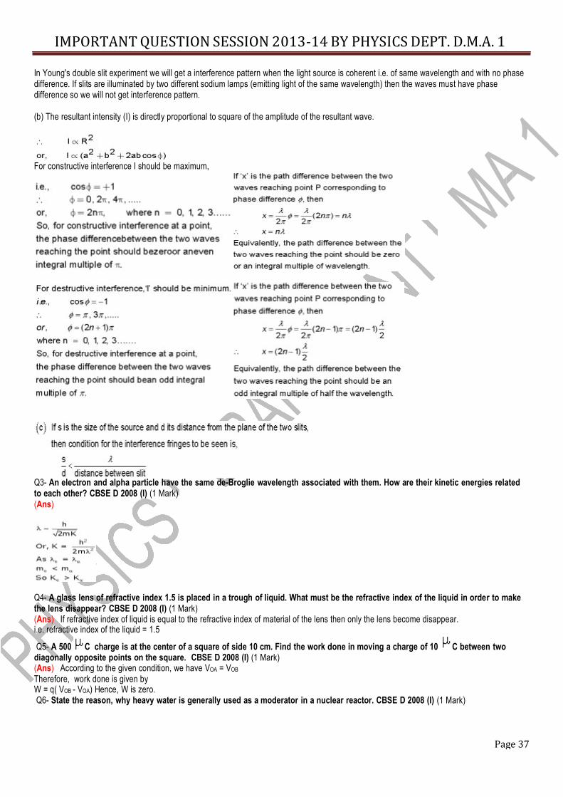
Plane polarized light can be obtained by reflection from a transparent surface when the light is incident on the surface at the polarizing angle ip. Value of polarizing angle is given by Brewster’s law according to which tan ip = n (where n is refractive index of the transparent medium) ip = tan-1 (n) In such a condition the reflected light contains vibrations of electric vector perpendicular to the plane of incidence only and is, thus, completely plane polarised one. Q-State briefly the underlying principle of a transistor oscillator. Draw a circuit diagram showing how the feedback is accomplished by inductive coupling. Explain the oscillator action. CBSE AI 2008 (II) (3 Marks) (Ans) (a) The figure below shows the use of common-emitter n-p-n transistor as an oscillator. The battery is connected in series with the high impedance coil L’ in the emitter base circuit. A variable capacitor C of suitable range connected in parallel to coil L gives the variation in frequency of the oscillations produced.
Working: When the key K is pressed, a very small collector current surges through the coil L’. As the coil L is inductively coupled to the coil L’, due to the change of current and hence change of flux through L’, a small voltage is induced in L. This small voltage produces a small current to flow in the emitter base circuit. If the induced voltage produces forward biasing of this circuit, then the small emitter current causes a corresponding increase in the collector current (in a transistor Ie=Ib+Ic). As the collector current rises, the growing magnetic flux linked with L’ increases the induced voltage across the coil L, which in turn will increase further the forward bias of emitter base circuit. This increases the emitter current and hence the collector current increases still further. In this way the collector current through L’ goes on increasing until the induced e.m.f. across L attains a saturation value. As the current stops changing, the flux also stops changing. The emitter current which was being sustained by the induced voltage in L begins to decrease causing the collector current to decrease as well. The decreasing collector current flows through L’, will increase voltage in L in the reverse direction which will decrease the emitter current further. This results in further decrease of the collector current. The ‘inertia’ of a collapsing flux carries the collector current below the normal value. After this overshoot the collector current starts increasing to its normal value again, causing the induced emitter current once again. This marks the beginning of the next cycle and the process is repeated giving oscillations of constant amplitude because of the feed back energy of the L-C circuit in proper phase. The frequency of the oscillations produced is given by Q- (a) What are coherent sources of light? Two slits in Young’s double slit experiment are illuminated by two different sodium lamps emitting light of the same wavelength. Why is no interference pattern observed? (b) Obtain the condition for getting dark and bright fringes in Young’s experiment. Hence write the expression for the fringe width. (c) If s is the size of the source and d its distance from the plane of the two slits, what should be the criterion for the interference fringes to be seen? CBSE AI 2008 (II) (5 Marks) (Ans) Coherent sources of light are those which emit continuous light waves of same wavelength (or frequency) having either no phase difference or a constant phase difference.
Page 37
IMPORTANT QUESTION SESSION 2013-14 BY PHYSICS DEPT. D.M.A. 1
In Young's double slit experiment we will get a interference pattern when the light source is coherent i.e. of same wavelength and with no phase difference. If slits are illuminated by two different sodium lamps (emitting light of the same wavelength) then the waves must have phase difference so we will not get interference pattern. (b) The resultant intensity (I) is directly proportional to square of the amplitude of the resultant wave. For constructive interference I should be maximum, Q3- An electron and alpha particle have the same de-Broglie wavelength associated with them. How are their kinetic energies related to each other? CBSE D 2008 (I) (1 Mark) (Ans) Q4- A glass lens of refractive index 1.5 is placed in a trough of liquid. What must be the refractive index of the liquid in order to make the lens disappear? CBSE D 2008 (I) (1 Mark) (Ans) If refractive index of liquid is equal to the refractive index of material of the lens then only the lens become disappear. i.e. refractive index of the liquid = 1.5 Q5- A 500 C charge is at the center of a square of side 10 cm. Find the work done in moving a charge of 10 C between two
diagonally opposite points on the square. CBSE D 2008 (I) (1 Mark) (Ans) According to the given condition, we have VOA = VOB Therefore, work done is given by W = q( VOB - VOA) Hence, W is zero. Q6- State the reason, why heavy water is generally used as a moderator in a nuclear reactor. CBSE D 2008 (I) (1 Mark)
Page 38
IMPORTANT QUESTION SESSION 2013-14 BY PHYSICS DEPT. D.M.A. 1
(Ans) Heavy water is rich in hydrogen, which contain more protons (having mass nearly equal to neutrons). Velocities of neutrons get interchanged with these protons. The neutrons are thus slowed down. Therefore heavy water is generally used as a moderator in a nuclear reactor. Q7- How does the fringe width of interference fringes change, when the apparatus of Young’s experiment is kept in a liquid of refractive index 1.3? CBSE D 2008 (I) (1 Mark) (Ans) When the entire apparatus is immersed in a transparent medium of refractive index , then fringe width
' = / ' = /1.3 So fringe width decreases. Prove that an ideal capacitor does not dissipate power. CBSE D 2008 (I) (2 Marks) (Ans) We know average power in an capacitive circuit is given by Q20- A metallic rod of length l is rotated at an constant angular speed , normal to a uniform magnetic field B. Derive expressions for the current induced in the rod, if the resistance of the rod is R. CBSE D 2008 (I) (3 Marks) (Ans)
Emf induced in the rod is given by
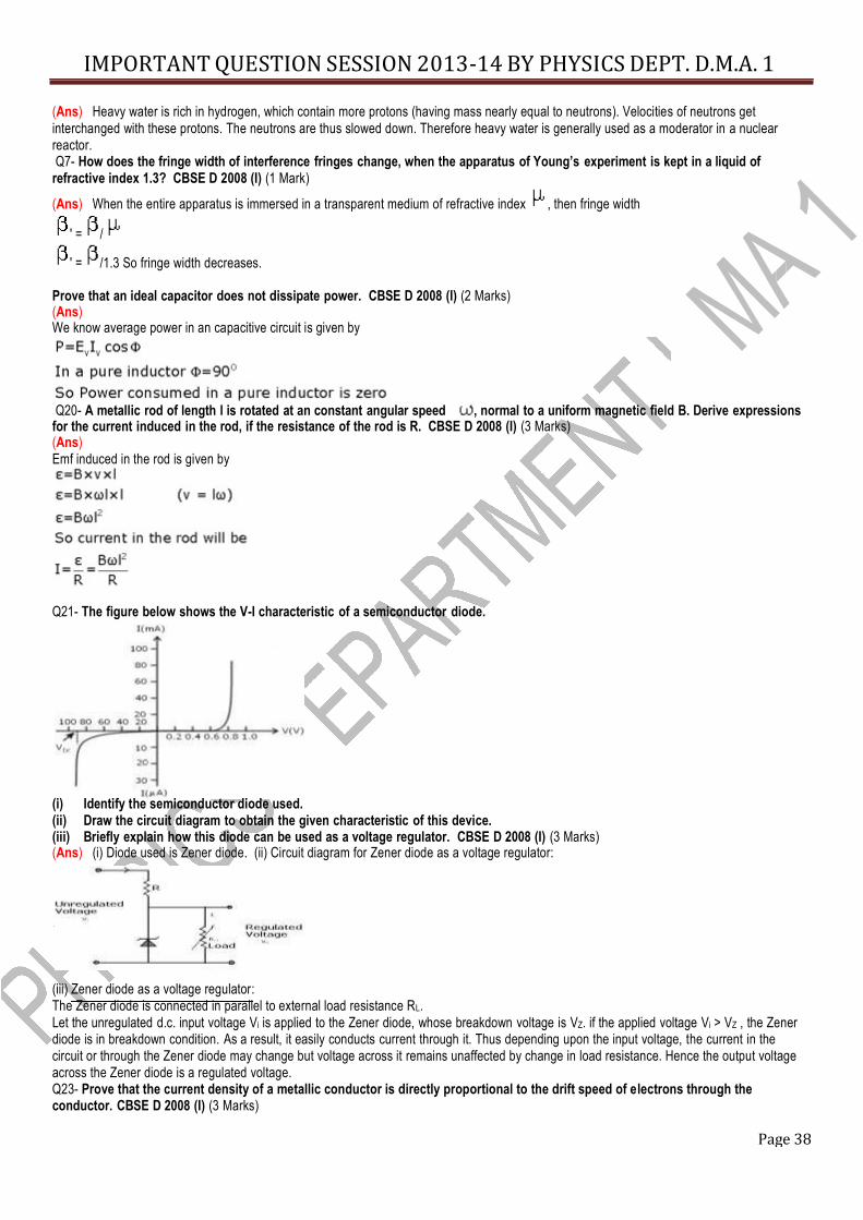
Q21- The figure below shows the V-I characteristic of a semiconductor diode. (i) Identify the semiconductor diode used. (ii) Draw the circuit diagram to obtain the given characteristic of this device. (iii) Briefly explain how this diode can be used as a voltage regulator. CBSE D 2008 (I) (3 Marks) (Ans) (i) Diode used is Zener diode. (ii) Circuit diagram for Zener diode as a voltage regulator: (iii) Zener diode as a voltage regulator: The Zener diode is connected in parallel to external load resistance RL. Let the unregulated d.c. input voltage Vi is applied to the Zener diode, whose breakdown voltage is VZ. if the applied voltage Vi > VZ , the Zener diode is in breakdown condition. As a result, it easily conducts current through it. Thus depending upon the input voltage, the current in the circuit or through the Zener diode may change but voltage across it remains unaffected by change in load resistance. Hence the output voltage across the Zener diode is a regulated voltage. Q23- Prove that the current density of a metallic conductor is directly proportional to the drift speed of electrons through the conductor. CBSE D 2008 (I) (3 Marks)
Page 39
IMPORTANT QUESTION SESSION 2013-14 BY PHYSICS DEPT. D.M.A. 1
(Ans) Current density at a point in a conductor is defined as the amount of current flowing per unit area of the conductor around that point provided the area is held in a direction normal to the current. Let I be the current distributed uniformly across a conductor of cross-sectional area A. The magnitude of the current density for all points on that cross-section of the conductor is J=I/A Current density is vector quantity. Its direction is the direction of motion of positive charge. Hence current density is directly proportional to the drift speed of electrons through the conductor. Q25- An electromagnetic wave of wavelength is incident on a photosensitive surface of negligible work function. If the photo- electrons emitted from this surface have the debroglie wavelength 1 , prove that CBSE D 2008 (I) (3 Marks) (Ans) Given work function 0 = 0. Using Einstein’s photoelectric equation, we have
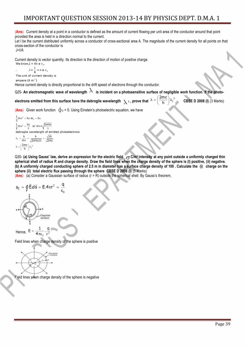
Q30- (a) Using Gauss' law, derive an expression for the electric field C/m2 intensity at any point outside a uniformly charged thin spherical shell of radius R and charge density. Draw the field lines when the charge density of the sphere is (I) positive, (ii) negative. (b) A uniformly charged conducting sphere of 2.5 m in diameter has a surface charge density of 100 . Calculate the (i) charge on the sphere (ii) total electric flux passing through the sphere CBSE D 2008 (I) (5 Marks) (Ans) (a) Consider a Gaussian surface of radius (r > R) outside the spherical shell. By Gauss’s theorem,
Hence, Field lines when charge density of the sphere is positive
Field lines when charge density of the sphere is negative
Page 40
IMPORTANT QUESTION SESSION 2013-14 BY PHYSICS DEPT. D.M.A. 1
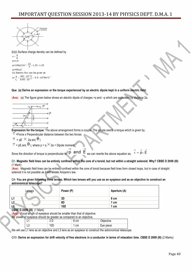
(b)(i) Surface charge density can be defined by
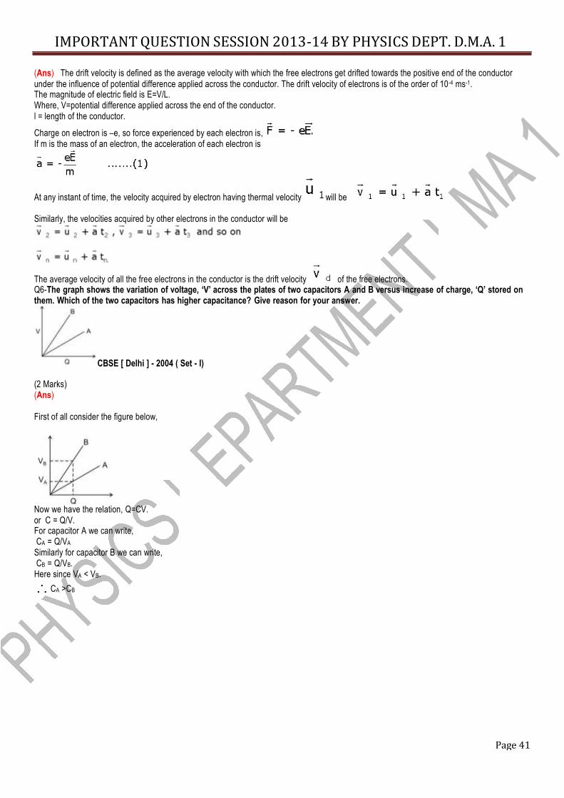
Que (a) Derive an expression or the torque experienced by an electric dipole kept in a uniform electric field. (Ans) (a) The figure given below shows an electric dipole of charges +q and –q which are separated by distance 2a. Expression for the torque: The above arrangement forms a couple. The couple exerts a torque which is given by,
=Force x Perpendicular distance between the two forces = qE 2a.sin( ) = pE.sin( ), where p = q 2a = Dipole moment.
Since the direction of torque is perpendicular to we can rewrite the above equation as, Q1- Magnetic field lines can be entirely confined within the core of a toroid, but not within a straight solenoid. Why? CBSE D 2009 (III) (1 Mark) (Ans) Magnetic field lines can be entirely confined within the core of toroid because field lines form closed loops, but in case of straight solenoid it is not possible as it will violate Ampere’s law. Q4- You are given following three lenses. Which two lenses will you use as an eyepiece and as an objective to construct an astronomical telescope?
Lenses
Power (P)
Aperture (A) L1 3D 8 cm L2 6D 1 cm L3 10D 1 cm CBSE D 2009 (III) (1 Mark) (Ans) Focal length of eyepiece should be smaller than that of objective. So, power of eyepiece should be greater as compared to an objective.
L1 3 D 8 cm Objective L3 10D 1 cm Eye piece
We will use L1 lens as an objective and L3 lens as an eyepiece to construct the astronomical telescope. Q10- Derive an expression for drift velocity of free electrons in a conductor in terms of relaxation time. CBSE D 2009 (III) (2 Marks)
Page 41
IMPORTANT QUESTION SESSION 2013-14 BY PHYSICS DEPT. D.M.A. 1
(Ans) The drift velocity is defined as the average velocity with which the free electrons get drifted towards the positive end of the conductor under the influence of potential difference applied across the conductor. The drift velocity of electrons is of the order of 10-4 ms-1. The magnitude of electric field is E=V/L. Where, V=potential difference applied across the end of the conductor. l = length of the conductor. Charge on electron is –e, so force experienced by each electron is, If m is the mass of an electron, the acceleration of each electron is
At any instant of time, the velocity acquired by electron having thermal velocity will be Similarly, the velocities acquired by other electrons in the conductor will be The average velocity of all the free electrons in the conductor is the drift velocity of the free electrons. Q6-The graph shows the variation of voltage, ‘V’ across the plates of two capacitors A and B versus increase of charge, ‘Q’ stored on them. Which of the two capacitors has higher capacitance? Give reason for your answer.
CBSE [ Delhi ] - 2004 ( Set - I) (2 Marks) (Ans) First of all consider the figure below, Now we have the relation, Q=CV. or C = Q/V. For capacitor A we can write, CA = Q/VA Similarly for capacitor B we can write, CB = Q/VB. Here since VA < VB.
CA >CB
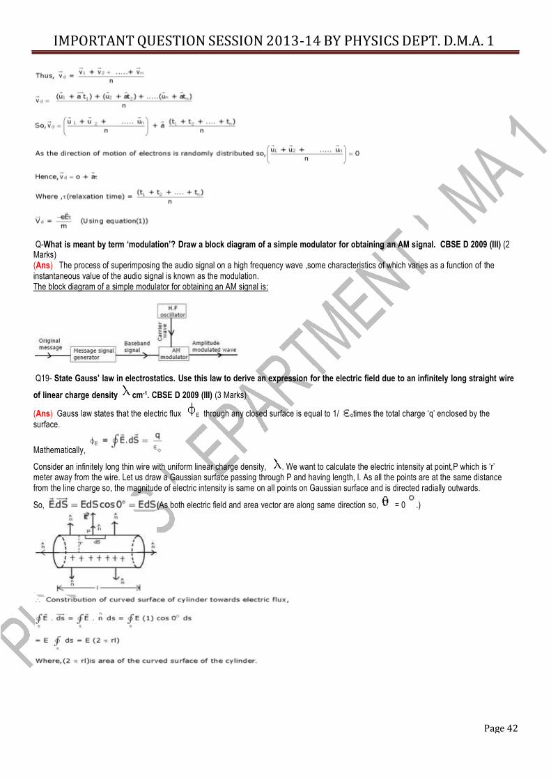
Page 42
IMPORTANT QUESTION SESSION 2013-14 BY PHYSICS DEPT. D.M.A. 1
Q-What is meant by term ‘modulation’? Draw a block diagram of a simple modulator for obtaining an AM signal. CBSE D 2009 (III) (2 Marks)
(Ans) The process of superimposing the audio signal on a high frequency wave ,some characteristics of which varies as a function of the instantaneous value of the audio signal is known as the modulation. The block diagram of a simple modulator for obtaining an AM signal is: Q19- State Gauss’ law in electrostatics. Use this law to derive an expression for the electric field due to an infinitely long straight wire
of linear charge density cm-1. CBSE D 2009 (III) (3 Marks) (Ans) Gauss law states that the electric flux E through any closed surface is equal to 1/ otimes the total charge ‘q’ enclosed by the surface. Mathematically,
Consider an infinitely long thin wire with uniform linear charge density, . We want to calculate the electric intensity at point,P which is ‘r’ meter away from the wire. Let us draw a Gaussian surface passing through P and having length, l. As all the points are at the same distance from the line charge so, the magnitude of electric intensity is same on all points on Gaussian surface and is directed radially outwards. So, (As both electric field and area vector are along same direction so, = 0 .)
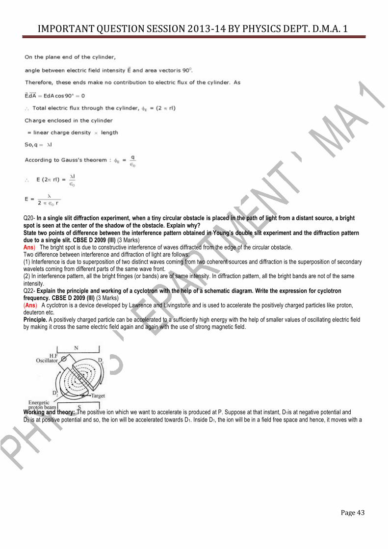
Page 43
IMPORTANT QUESTION SESSION 2013-14 BY PHYSICS DEPT. D.M.A. 1
Q20- In a single slit diffraction experiment, when a tiny circular obstacle is placed in the path of light from a distant source, a bright spot is seen at the center of the shadow of the obstacle. Explain why? State two points of difference between the interference pattern obtained in Young’s double slit experiment and the diffraction pattern due to a single slit. CBSE D 2009 (III) (3 Marks) Ans) The bright spot is due to constructive interference of waves diffracted from the edge of the circular obstacle. Two difference between interference and diffraction of light are follows: (1) Interference is due to superposition of two distinct waves coming from two coherent sources and diffraction is the superposition of secondary wavelets coming from different parts of the same wave front. (2) In interference pattern, all the bright fringes (or bands) are of same intensity. In diffraction pattern, all the bright bands are not of the same intensity. Q22- Explain the principle and working of a cyclotron with the help of a schematic diagram. Write the expression for cyclotron frequency. CBSE D 2009 (III) (3 Marks) (Ans) A cyclotron is a device developed by Lawrence and Livingstone and is used to accelerate the positively charged particles like proton, deuteron etc. Principle. A positively charged particle can be accelerated to a sufficiently high energy with the help of smaller values of oscillating electric field by making it cross the same electric field again and again with the use of strong magnetic field. Working and theory: The positive ion which we want to accelerate is produced at P. Suppose at that instant, D1is at negative potential and D2 is at positive potential and so, the ion will be accelerated towards D1. Inside D1, the ion will be in a field free space and hence, it moves with a
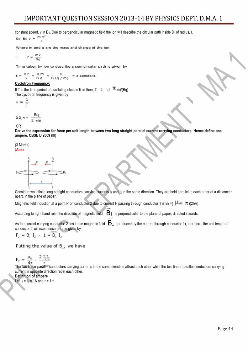
Page 44
IMPORTANT QUESTION SESSION 2013-14 BY PHYSICS DEPT. D.M.A. 1
constant speed, v in D1. Due to perpendicular magnetic field the ion will describe the circular path inside D1 of radius, r.
Cyclotron Frequency: If T is the time period of oscillating electric field then, T = 2t = (2 m)/(Bq) The cyclotron frequency is given by
OR Derive the expression for force per unit length between two long straight parallel current carrying conductors. Hence define one ampere. CBSE D 2009 (III) (3 Marks) (Ans)
Consider two infinite long straight conductors carrying currents I1 and I2 in the same direction. They are held parallel to each other at a distance r apart, in the plane of paper. Magnetic field induction at a point P on conductor 2 due to current I1 passing through conductor 1 is B1 =( 0/4 )(2I1/r) According to right hand rule, the direction of magnetic field is perpendicular to the plane of paper, directed inwards. As the current carrying conductor 2 lies in the magnetic field ;(produced by the current through conductor 1), therefore, the unit length of conductor 2 will experience a force given by The two linear parallel conductors carrying currents in the same direction attract each other while the two linear parallel conductors carrying current in opposite direction repel each other. Definition of ampere Let I1 = I2 = 1A and r = 1m
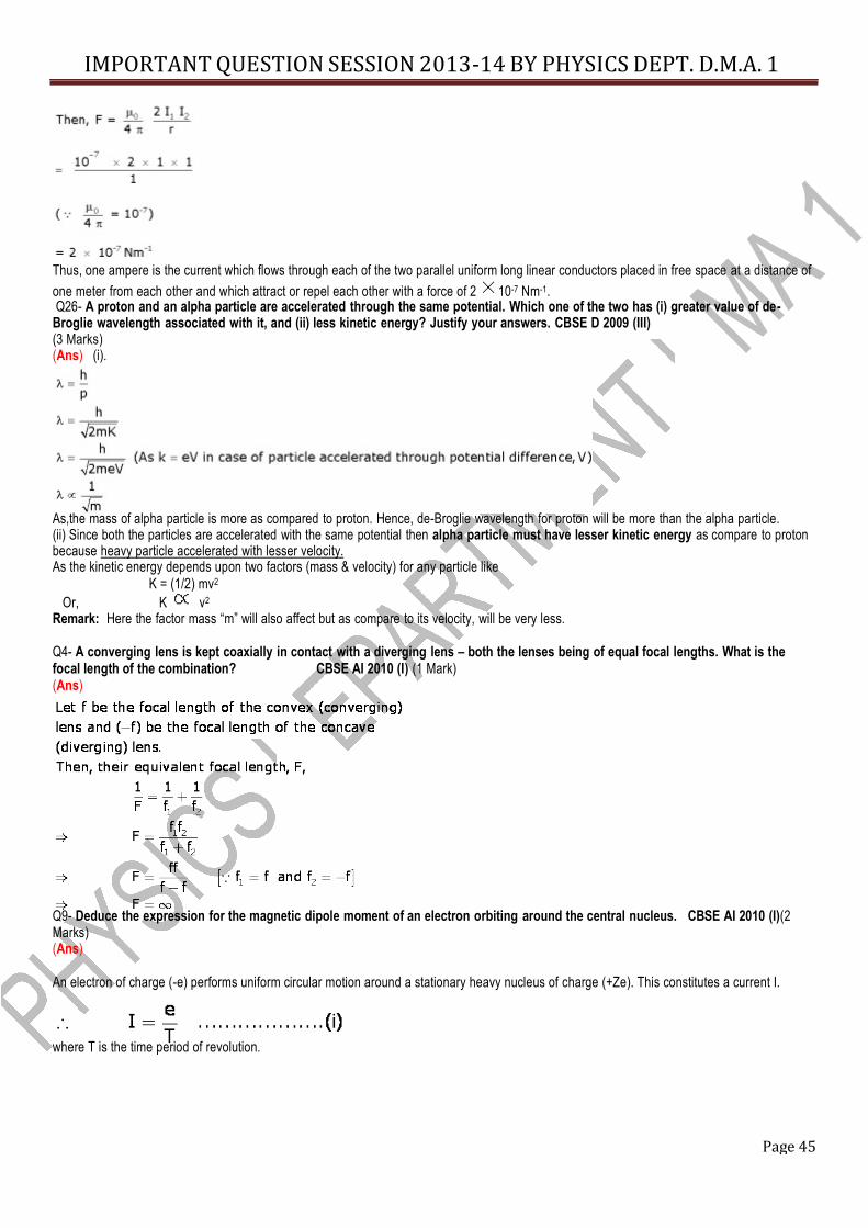
Page 45
IMPORTANT QUESTION SESSION 2013-14 BY PHYSICS DEPT. D.M.A. 1
Thus, one ampere is the current which flows through each of the two parallel uniform long linear conductors placed in free space at a distance of one meter from each other and which attract or repel each other with a force of 2 10-7 Nm-1. Q26- A proton and an alpha particle are accelerated through the same potential. Which one of the two has (i) greater value of de- Broglie wavelength associated with it, and (ii) less kinetic energy? Justify your answers. CBSE D 2009 (III) (3 Marks) (Ans) (i). As,the mass of alpha particle is more as compared to proton. Hence, de-Broglie wavelength for proton will be more than the alpha particle. (ii) Since both the particles are accelerated with the same potential then alpha particle must have lesser kinetic energy as compare to proton because heavy particle accelerated with lesser velocity. As the kinetic energy depends upon two factors (mass & velocity) for any particle like
K = (1/2) mv2 Or, K v2 Remark: Here the factor mass “m” will also affect but as compare to its velocity, will be very less.
Q4- A converging lens is kept coaxially in contact with a diverging lens – both the lenses being of equal focal lengths. What is the focal length of the combination? CBSE AI 2010 (I) (1 Mark) (Ans)
Q9- Deduce the expression for the magnetic dipole moment of an electron orbiting around the central nucleus. CBSE AI 2010 (I)(2 Marks) (Ans) An electron of charge (-e) performs uniform circular motion around a stationary heavy nucleus of charge (+Ze). This constitutes a current I.
where T is the time period of revolution.
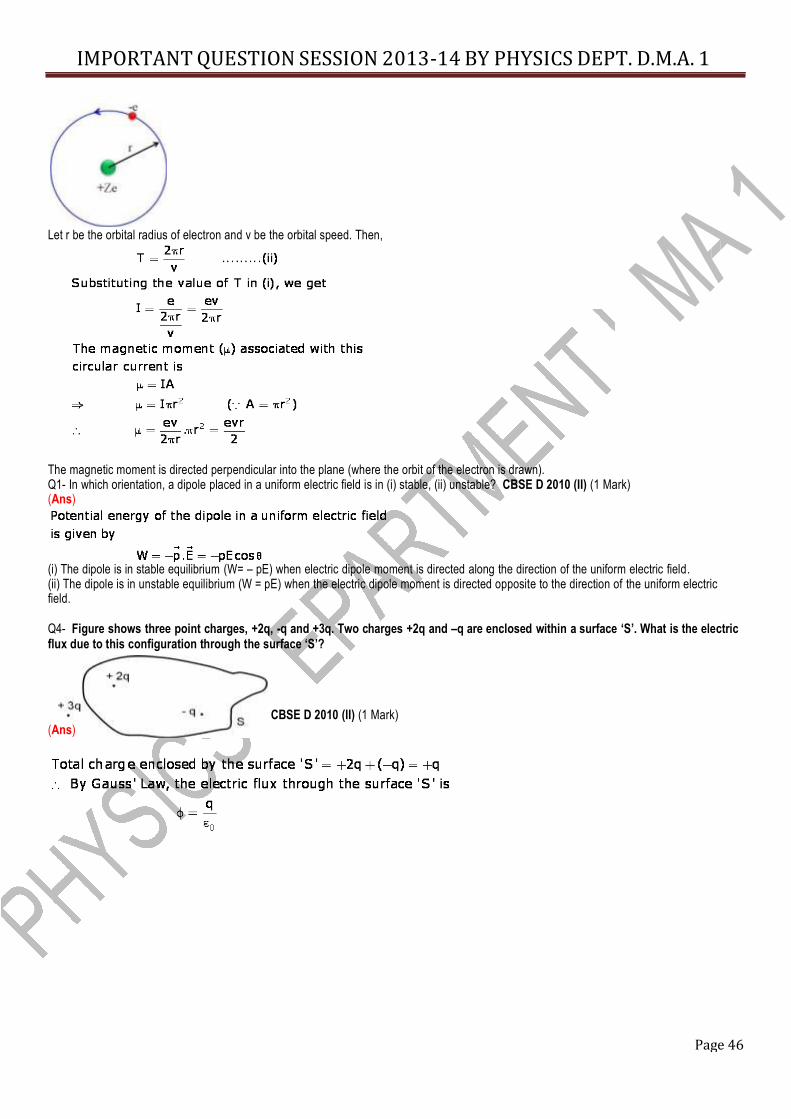
Page 46
IMPORTANT QUESTION SESSION 2013-14 BY PHYSICS DEPT. D.M.A. 1
Let r be the orbital radius of electron and v be the orbital speed. Then, The magnetic moment is directed perpendicular into the plane (where the orbit of the electron is drawn). Q1- In which orientation, a dipole placed in a uniform electric field is in (i) stable, (ii) unstable? CBSE D 2010 (II) (1 Mark) (Ans)
(i) The dipole is in stable equilibrium (W= – pE) when electric dipole moment is directed along the direction of the uniform electric field. (ii) The dipole is in unstable equilibrium (W = pE) when the electric dipole moment is directed opposite to the direction of the uniform electric field. Q4- Figure shows three point charges, +2q, -q and +3q. Two charges +2q and –q are enclosed within a surface ‘S’. What is the electric flux due to this configuration through the surface ‘S’? (Ans) CBSE D 2010 (II) (1 Mark)
IMPORTANT QUESTION SESSION 2013-14 BY PHYSICS DEPT. D.M.A. 1
Page 47
Copyright © 2022 FDOKUMEN