
Implementation of the global maritime distress and safety ...
205
World Maritime University World Maritime University The Maritime Commons: Digital Repository of the World Maritime The Maritime Commons: Digital Repository of the World Maritime University University World Maritime University Dissertations Dissertations 1990 Implementation of the global maritime distress and safety system Implementation of the global maritime distress and safety system in Iran, organizational aspects and training needs in Iran, organizational aspects and training needs Ali Reza Pahlevan Neshan World Maritime University Follow this and additional works at: https://commons.wmu.se/all_dissertations Recommended Citation Recommended Citation Pahlevan Neshan, Ali Reza, "Implementation of the global maritime distress and safety system in Iran, organizational aspects and training needs" (1990). World Maritime University Dissertations. 1327. https://commons.wmu.se/all_dissertations/1327 This Dissertation is brought to you courtesy of Maritime Commons. Open Access items may be downloaded for non-commercial, fair use academic purposes. No items may be hosted on another server or web site without express written permission from the World Maritime University. For more information, please contact [email protected].
-
Upload
khangminh22 -
Category
Documents
-
view
1 -
download
0
Transcript of Implementation of the global maritime distress and safety ...

World Maritime University World Maritime University
The Maritime Commons: Digital Repository of the World Maritime The Maritime Commons: Digital Repository of the World Maritime
University University
World Maritime University Dissertations Dissertations
1990
Implementation of the global maritime distress and safety system Implementation of the global maritime distress and safety system
in Iran, organizational aspects and training needs in Iran, organizational aspects and training needs
Ali Reza Pahlevan Neshan World Maritime University
Follow this and additional works at: https://commons.wmu.se/all_dissertations
Recommended Citation Recommended Citation Pahlevan Neshan, Ali Reza, "Implementation of the global maritime distress and safety system in Iran, organizational aspects and training needs" (1990). World Maritime University Dissertations. 1327. https://commons.wmu.se/all_dissertations/1327
This Dissertation is brought to you courtesy of Maritime Commons. Open Access items may be downloaded for non-commercial, fair use academic purposes. No items may be hosted on another server or web site without express written permission from the World Maritime University. For more information, please contact [email protected].
HGBID MKRTCEMB IKIVERSnY SHECEN
IMETHIEKEailDN OP TOE GICEKL KUSHTIME nrgivt«g ^ND SSEET7
EZS3E! TO TOMI, CBGHarzmOeM. ASEBCIS TOD OBftTOINS wgRTg
ly
in partial satLsfactLon of lie xequirenaeats for lie award of a
llASTOR OF SCITOCE raysiTgR in
MARITIME EDDCAITCIT TOD TOATOTOG (MAUTECAL) .
lie ooateats of this paper reflect ny personal views anH are not necessarily endorsed by the amVEBSTEY.
iU Be?a Bahlevan iieshan
Islamic Republic of Tran
A p^)er suhndtted to tie Eaculty of tie World iferH-Mma Ohiversity
^Qiervised aid assessed by: Co-assessed by:
Jef H. Udders ProfessorWorld Mari time Uoiversity
Captain James L. Fear ManagerMaritime Services OperationsH91ARSATLondon, UK

%
Of “The
IN THE NAME OF GOD
LieT OB' CONTBCNTS
Acknovledgvnsnt i
Abstract . iii
List of acronyms and abbraviations v
CHAPTER ONEPage
INTRODUCTION TO GMDSS
1.1 Introduction 11.2 Coast Earth Station (CES> 31.3 Ship Earth Station <SES> 31.3.1 Standard-A (SES) 41.3.1 Standard-C (SES> 41-4 The World-Wide Navigational Warning
Service <WWNWS) 51.5 Global Maritime Distress and Safety
System (GMDSS>- 6V^l.5.1 Objectives of GMDSS 61.5.2 Earth communication concept
Sea Area (A1, A2, A3, A4> 61.5.3 Radio equipment 91.5.4 Additional requirements for ships (Al) 101.5.5 Additional radio equipment for ships
navigating in Sea Area (Al, A2> 111.5.6 Additional requirements for ships
navigating in Sea Area (Al, A2, A3) 111.5.7 Additional requirements for ships
operating in Sea Area A4 12
1.6 Satellite communication concept 131.6.1 Advantages of satellites 131.6.2 Low orbit satellites 151.6.3 COSPAS SARSAT and its role in GMDSS 151.6.4 Geostationary (G.O.) satellites 171.6.5 INMARSAT and its role in GMDSS 17
CHAPTER TWO
THE PRESENT SITUATION OF MARITIME SAFETY COMMUNICATION
2.1 Introduction 192.2 GMDSS the present status and
future outlook 192.2.1 Assessment of coverage for the GMDSS 212.2.2 Future outlook for the GMDSS 222.3 Maritime safety commxmication in IRAN 232.3.1 The organization of maritime
communication in PSO 242.3.2 Maritime communication facilities 262.4 Evaluation of the existing situation in
maritime safety communication 262.4.1 Internal situation 262.4.2 External situation ^ 31
2.5 Necessary improvements of maritimesafety communication in IRAN 35
2.5.1 Management 352.5.2 Facilities 352.5.3 Personnel and training 362.5.4 Availability 362.5.5 Coverage 36
2.5.6 Promulgation of maritime safety information 37
2.5.7 Search and Rescue organization 372.5.6 Regulations 362.6 Conclusion 38
CHAPTER THREE
PLANNING FOR THE 6MDSS IN IRAN
General 393.1 Assessment of the area which is
to be served by GMDSS 403.1.1 Persian Gulf 403.1.2 Gulf of Oman 413.1.3 Shipping Traffic in the Persian Gulf
and Gulf of Oman 413.2 Delimitation of the GMDSS's areas 463.2.1 Persian Gulf 463.2.2 Gulf of Oman 473.2.3 Number of CRSs in the Persian Gulf 473.2.4 Remote Antenna sites (first choice) 463.2.5 Coastal Antenna sites (second choice) 513.2.6 Number of the CRSs in the Gulf
of Oman 543.2.7 Coastal Antenha sites (second choice) 563.3 Location and function of the CEIS 603.4 Designation of required NAVTEX
stations 603.4.1 Organization 623.5 Possible cooperation with neighboring
countries 633.5.1 Option for cooperation 633.6 Cooperation with national authorities 65
3.7 Assessment of the facilities.personnel and equipment 67
3.7.1 General 673.7.2 Personnel requirement 663.7.3 NAVTEX personnel 693.7.4 Repair and maintenance center 703.7.5 Total personnel 703.8 The links between CES, CRS and RCC 713.9 Cost -evaluation 743.9.1 Advantages of the first choice 773.9.2 Disadvantages of the first choice 77
CHAPTER FOUR
TRAINING OF GMDSS OPERATORS & TECHNICIANS
4.1 General 764.2 Training preparation 614.3 Training program 624.3.1 Ship electronic officers 62
-First class radioelectronic officer 63-Second class radioelectronic officer 65 -General operator 87-Restricted operator 89
4.3.2 Shore operator 91-Technician (level one> 92-Technician (level two) 96-Coast radio station operator 96
CiUPTER FIVE
REPAIR AND MAINTENANCE FACILITY
5.1 Introduction 1005.2 Corrective maintenance 1005.3 Preventive maintenance 1005.4 Need for repair and maintenance center 1005.5 Comparison 1025.5.1 Total expense 1055.6 Demand anticipation 1055.6.1 Ship traffic 1065.6.2 Agreement for Preventive maintenance
vith shipping lines 1065.6.3 Number of ships in the national
shipping lines 1075.6.4 Number of vessels in the local
traf fic 1075.6.5 International shipping traffic 1085.6.6 MTBF of GMDSS equipment 1085.7 GMDSS REPAIR center 1095.8 Necessary equipment 1105.9 Organization of an repair and
maintenance center 1105.9.1 Inventory for spare parts 1115.9.2 Spare control system 1135.9.3 Coding system 114

CHAPTER SIX
CONCLUSIONS S RECOMMENDATIONS
6.1 ConclusionsRscosuDendations
APPENDIXES
1) GMDSS regulations2) Criteria for range calculation .(IMO>3> Range calculations (VHP)4) Availability
BIBLIOGRAPHY
LIST OF TABLE AND FIGURE
117119

A.C KISTO WlL.E:OOME:^T’X'
Before I mention the individual contributors to this dissertation, I acknowledge that all thanks belong to God, who participates in and oversees all human endeavours.
First I would like to show my gratitude to the International Maritime Organization for the establishment of the World Maritime University and for nurturing it to its present academic eminence. I also thank all coxmtries and individual donors without whose assistance WMU would not have reached and maintained its high standards.
In preparation of this dissertation; I am deeply indebted to Professor J.H.Mulders, my Course Professor and Assessor for providing me with information for my dissertation and for his invaluable guidance throughout my studies at World Maritime University.'
I would like to express my profound gratitude to Captain James L. Fear, Manager of INMARSAT Maritime Services Operations for his constructive comments and guidance whilst co-assessing this dissertation.
I am also deeply indebted to engineer Madad, Director General of the Ports and Shipping Organization of the Islamic Republic of Iran for his support, guidance and above all encouragement during my study at WMU.
My profound gratitude to all of the following distinguished resident and visiting professors and lecturers for their dedicated and knowledgeable lectures during the course:
i

Visiting professor Hermann Kaps Visiting professor Andrej Yakushenkov -|- Visiting professor Jurdzinski Lecturer Captain Stephen Cross Lecturer Captain Hans van Walen Visiting lecturer Captain Lars Broedde Captain Jan Horck
My special thanks to Gunther Zade, Vice-Rector and Academic Dean of WMU.
I wish to thank my colleagues in the Ports and Shipping Organization of the Islamic Republic of Iran who have been sending me numerous essential information especially, engineers Bahramy, Abtahi and Akbary as well as Dr. Letafat from the National Iranian Tanker Company.
My special thanks go to Mr. Richard Poisson and all the library staff for their willingness and patience in providing me with proper requested material.
I must express my deepest gratitude to my wife and children, and my wife's undaunted support and encouragement which made it possible for me to continue my studies at WMU.
My most, profound gratitude goes to my dearest mother ^ose prayers and moral support means so much to me.
My sincere thanks and gratitude to my brother.General Ahmad Lalpour, for his ever indispensable guidance in my life.
Finally, I dedicate this dissertation to the memory of my late father. Mohammad Pahlevan Neshan.
ii
j
Maritime transportation has benefited from the communication for the safety of life at sea from the beginning, trhen radio was invented by Gulielmo Marconi in 1895. This is evident especially when the history of the SOLAS convention, chapter IV, is brought under consideration.
The 1974 SOLAS convention, chapter IV, carries the present regulations for maritime distress alerting. These requirements were amended several times. However, the present system of communication cannot cope with the present necessities of shipping and maritime industry as a whole.
One can find many shortcomings in the existing maritime distress and safety communication. Morse radiotelegraphy on 500 KHz and above, radio-telephony on 2182 KHz and 156.6 MHz are among the requirements for distress alerting. The maximum required range is only 100 to 150 miles. Therefore, a ship transmitting a distress message in mid-ocean knows that it may not be received on shore.In other words, the existing system is mainly a ship-to- ship eervice. Manual distress alerting, aural watchkeeping and the limited number of frequencies being allocated for maritime communication are among the other deficiencies in present system.
Global Maritime Distress and Safety System (GMDSS) has been adopted in order to overcome the deficiencies in present system and enhance the long-needed modernization of maritime distress and safety procedures.
The GMDSS is based on the use of new technology within the communications field, and utilizes automatic systems like the Digital Selective Calling system (DSC> and INMARSAT satellite services. The Manual watch on the distress frequencies will be replaced by fully automatic monitoring, the distress communication systems will be coordinated with the equipment for ordinary correspondence and any ship in any area of the world would be able to give alert, receive meteorological and navigational warnings and be within an area of a responsible Search and Rescue (SAR) organization.
The implementation of the GMDSS, in 1992, will essentially influence all the maritime administrations' plans for future establishment of maritime communications services. Hence, a thorough knowledge and understanding of GMDSS is essential for everyone concerned with maritime communications.
The implementation of the GMDSS in the Islamic Republic of Iran, its organizational aspects, and the requirements for training are the main subjects of this ^ dissertation.
Ihe author hopes that this dissertation will contribute to the safety of navigation in the Persian Gulf and Gulf of Oman.
IV
LIST OF ACRONYMS AND ABBREVIATIONS
AOR. Atlantic Ocean Region which is covered by two geo. satellites by INMARSAT. (Atlantic-East, Atlantic-West)
ARPA. Automatic Radar Plotting Aid.(required by IMO on all ships over 10000 grt.
CCIR. International Telephone and Telegraph Consultative Committee.
.—CES. Coast Earth Station is the ground segment of INMARSAT ( see below) which interconnects the satellite system with the world's terrestrial communications networks.
DSC. Digital Selective Calling is used in the GMDSS (see below) for sending the messages ( a digital form of transmission). ' > . '
_COSPAS-SARSAT. An international network that prdvidessatellite detection of emergency transmitters called EPIRBs (see blow). The system uses the Soviet COSPAS and US NOAA satellites.
SGC. Enhanced Group Call. A scheme for addressing satellite calls to a specified group of ships, by ocean area, nationality fleet or other criteria. To be offered by INMARSAT as a worldwide supplement to NAVTEDC (see below).
EPIRB. Emergency Position-Indicating Radiobeacon. An emergency transmitter which emits signals that can be detected by overflying aircraft or satellites. Under the
V
GMDSS (see below), Host ships will be required to carry at least one EPIRB which will be capable of floating free from a sinking vessel and automatically switching itself on.
13E0. Geostationary, the INMARSAT satellites are geostationary satellites.
GHz. Giga Hertz equal 1000 MHz (MHz^lOOO KHz ,KHz«1000 Hz)
GMDSS. Global Maritime Distress and Safety System. A new international scheme for distress alerting and rescue coordination on a worldwide scale, using advanced telecommunications facilities. The GMDSS will bring sweeping chamges in carriage requirements for electronics on ships at sea. It will come into effect in 1992 and be fully effective from 1999.
GPS. Global Positioning System. The new US satellite navigation system, which will provide worldwide continuous position fixing by the early 1991s. Once GPS is fully deployed, it will supersede amd eventually replace other US radio-navigation aids.
HF. High Frequency (3 MHz-30 MHz).
IHO. International Hydrographic Organisation.IMO. International Maritime Organisation (formerly IMCO).
INMARSAT. International Maritime Satellite Organisation. London-based international consortium providing mobile satellite communications to ships, aircraft and land-based users.
vi
IQR. Indian Ocean Region, INMARSAT has a satellite in this region.
1E91. International Radio Regulations Cknown as RR >, proatulgated by the ITU (see below).
ITO. International Teleconuaunications Union.
L-Band. The frequency range in which nany satellite navigation and cooimuni cat ions systems operate ( eg. INMARSAT, GPS, GLONASS) from 1.2 to 1.6 GHz.
LORAN-C. Long Range Navigational System which is used in many part of the world for position fixing.
LUT. Local User Terminal. In the COSPAS"SARSAT system, a ground station which receives satellite distress messages and relays them to the appropriate rescue authorities.
NARECS. Maritime European Communication Satellite.
MARISAT. Maritime Satellite Service.
MCC. Mission Control Center which is a center in connection with LUT <COSPAS-SARSAT).
MF. Medium Frequency (300 KHz-3 MHz).
MSC. Maritime Safety Committee. The senior policy-making group within the IMO regarding safety matters.
MSI. Maritime Safety Information.
MTBF> Meen Time Between Failure

KITR. Mean Time To Repair
MMARC. Mobile World Administr.atiye Radio Conference. Meeting held periodically by ITU (see belonr> to adopt and SLffiend International Radio Regulations <IRR>. This is the body that approves frequency allocations and makes other important decisions regarding mobile radio services.
NAVTUX. An automated shore-based system for broadcasting navigation warnings and safety messages. NAVTEX receivers are compact tmits which provide an automatic printout of any pertinent messages.
NBPP. Narrow Band Direct Printing (telex).
NOAA. National Oceanic and Atmospheric Administration
P^. Pacific Ocean Region.
RCC. Rescue Co-ordination Center. In the GMDSS, a center responsible for management of search and rescue efforts within a geographical area.
BAR. Search And Rescue.
SAR8AT. Search And Rescue Satellite System.
SART. Search And Rescue Transponder. A low-power transmitter which is mounted in a liferaft and emits a homing signal that is displayed on the SAP craft's radar.
SES. Ship E^rth Station. A shipboard INMARSAT satellite communications terminal.
viii
SOLAS. Safety Of Life At Sea Convention. An international agreeaent setting forth detailed requirements for marine safety. Chapter IV of the SOLAS Convention is being revised to provide for the GMDSS.
STCW. Convention on Standards of Training, Certification and Watchkeeping for Seafarers. An international agreeaent vhich contains requirements for radio match-keeping. This convention is being revised to accommodate the new provisions of the GMDSS.
OTC. Coordinated Universal Time.
VTS. Vessel Traffic System. A system for monitoring and controlling the movement of vessels in a harbour or approach, generally using land-based radar installations.
VHF. Very High Frequency (30 MHz-300 MHz).
WMO. World Meteorological Organization.
WWNWS. World Wide Navigational Warning System.
ix

CHARTER ONE
INTRODUCTION TO . C5MDSS

INTRODUCTION TO OMDS5
1.1 XNTEtQDOCTION
Safety of life at sea has been a stain focus of all Baritime affairs since organized measures have been taken internationally. The "Titanic** disaster in 1912 was the first strong impetus in this .regard. In 1914 the first international conference for the Safety of Life at Sea was held. The result of this conference was the adoption of a Convention on the Safety of Life at Sea < SOLAS ). Chapter IV of this convention required, for ships carrying more than 50 passengers, a radiotelegraphy installation having a range of at least 100 nautical miles and continuous radio watchkeeping.
After the second, third and fourth versions of SOLAS in 1929, 1948, and 1960 the present version of SOLAS came into existence in 1974. Chapter IV of the 1974 SOLAS Convention mainly deals with facilities intended for distress and safety purposes.lt does not specifically provide a requirement for equipment intended for public correspondence. The technical requirements of equipment intended for this purpose are covered by the Radio Regulations of the International Telecommunication Onion ( ITU >.
The existing maritime distress and safety system relies on the capability of a ship in distress to alert another ship in the vicinity. Present regulations, in SOLAS 1974 <chapter IV >, require morse radiotelegraphy on 500 KHz and above, radiotelephony on 2162 KHz and 156.6
1
MHz for all passenger ships and ships of 300 gross tonnage and above which Make international voyages. The Maximum required range of radiotelegraphy and radiotelephone •quipment is only 100 to 150 nautical miles. A ship transmitting a distress message in mid-ocean therefore knows that it may not be received on shore. In other words, the existing system is mainly a ship-to-ship service whose effectiveness depends on other ships being within range. Therefore, the present system has many limitations and disadvantages such as short range, manual distress alerting, aural watchkeeping and the limited number of frequencies being allocated for maritime communication.
From the time when the first world communication satellite < TELSTAR ) was put into orbit < 1962 ) , IMO and especially the Maritime Safety Committee took into consideration the possibility of a satellite communication system devoted to maritime purposes. The main reasons, inter alia, for considering such a system were to improve distress and safety communications, reliability, quality and speed of communications, to relieve the existing congestion in the medium frequency (MF> and high frequency (HF) bands and to expand geographical coverage and continuous availability of services.
I ’
In 1973, the IMO Assembly adopted resolution A.305 tVlII), to call a conference to establish an International maritime satellite system. Finally, a.fter three sessions by that conference, in 1976 the convention on the Establishment of the International Maritime Satellite Organization ( INMARSAT > was adopted and on 16 July 1979
2
INMARSAT as an organization came into being.
There are throe essential components of the INMARSAT system, namely the space segment, the land or control segment and the user segment.
In figure 1.1 the simple connection of the space segment sith a Receiving INMARSAT station ( Coast Earth Station > on shore and transmitting INMARSAT station ( Ship Earth Station > aboard ship is shown.
1.2 Coast Earth Station < CES >
Coast Earth Stations are land-based stations of INMARSAT owned by INMARSAT signatories. The CESs interconnect the satellite system with the world's terrestrial communications networks. Each CES has powerful transmitters and receivers working in the C-band of microwave frequencies through a parabolic antenna of between 10 and 13 meters diameter.
CE£s are located in many countries around the world and considered as powerful arms of INMARSAT.
1.3 Ship Earth Station ( SES )
A SES is the ship-board terminal of the INMARSAT system and any INMARSAT equipped ship must have a SES. There are several kinds of ship earth station equipment which make possible the connection of a ship through the satellite to a CES.
3
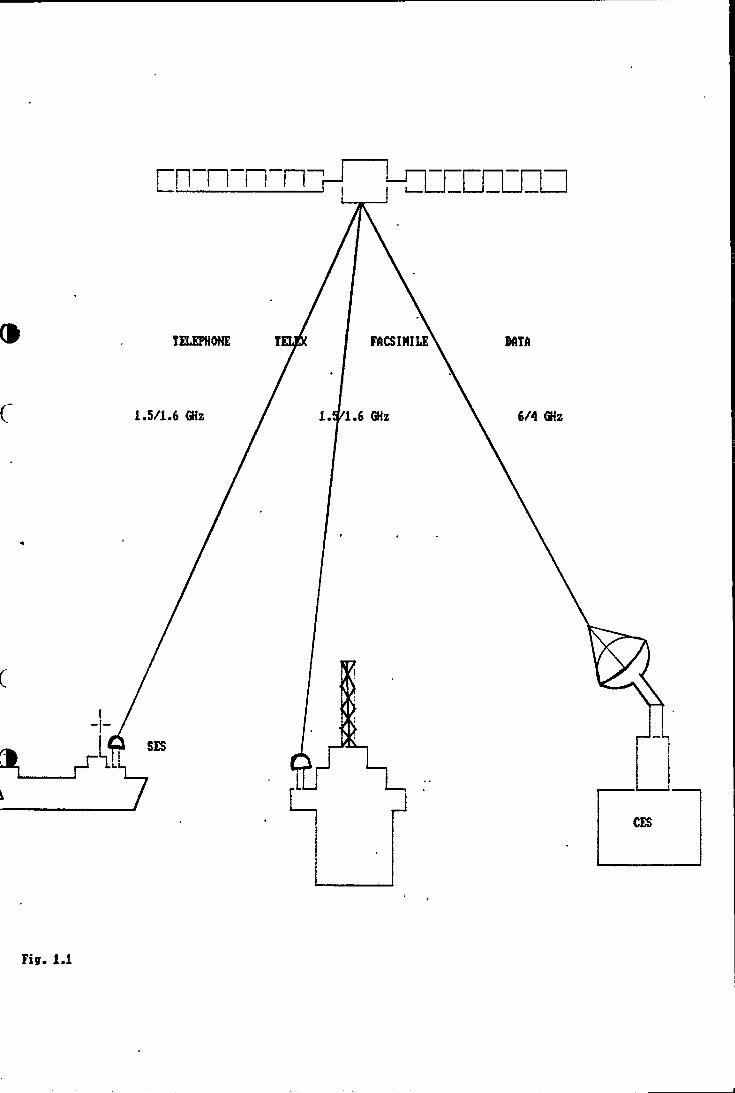
Fig. 1.1
1.3.1 8tandard**A 6BS
This is the shipboard equipment which has mainly two parts. A parabolic antenna is housed in a protective dome Above the deck. The antenna control unit and the comunications electronics used for transmission, reception, access control and signalling, and telephone and telex equipment are below deck. It is also possible to have other options such as facsimile and data equipment.
1.3.2 Standard-C SES
This is a small light weight and low cost ship-board terminal which can offer transmission and reception of messages at an information rate of 600 bits/s. It has an omni-directional antenna ( right-hajid circular polarisation ) which should be installed above the deck. Standard-C doesn't have voice communication capability.
Frequencies Transmit: 1626.5-1645.6 MHz
Receive : 1530.0-1545.0 MHz
1.3.2.1 New development
There are two other major Innovations planned by INMARSAT namely INMARSAT M and INMARSAT B. These new digital services will provide high quality digitized voice communication at relatively low data rates. INMARSAT M has radio telephone-capability and it offers 2400 bits/s data and facsimile services. INMARSAT B will offer higher data speeds than are presently available.
4
1.4 lh» World-Wid9 Navigational Warning Sarvica < WWNWS >
In order to provide nariners with warning aessages* idiich are very important for safety of ships and the personnel, IMO and the International Hydrographic Organization (IHO) established a World Wide Navigational Warning Service. It was adopted by the IMO Assembly in 1977 and a revised system was adopted by the Assembly in 1979.
Onder this system the world's oceans are dividedinto 16 areas ( called NAVAREAS >. The service includes
{/arrangements for disseminating information by regular radio broadcasts.
The WWNWS now incorporates another service designed to improve safety at sea. This is NAVTEX, an automated system for promulgating maritime navigational and meteorological warnings and other safety information in coastal waters up to 350 miles. jBhips receive automatipally printed messages ( in English > from a special NAVTEIX receiver on the frequency 518 KHz. Similar services will be provided over the INMARSAT Enhanced Group Call C EGC } system and on HF frequencies to cover the ocean areas.
« The warning messages may contain:
1 malfunction of.lights, sound signals, bouys and other aids to navigation;
2 the location of wrecks and other hazards;3 the establishment of offshore structures.
5

1.5 Global Mariiiao Distross and Safety Systaai<OMDSS>
In 1979 an international conference on Maritime Search and Rescue was held in Hamburg. The new convention on Maritime Search and Rescue which originated from this conference was the base for development of the Future Global Maritime Distress and Safety System (F6MDSS>. At a later stage the word "future" was omitted.
In November 1'966, in an international diplomatic conference, a new system called Global Maritime Distress and Safety System (GMDSS> was adopted. This led to an amendment which replaced chapter IV of the 1974 SOLAS ^ Convention. Appendix 1 lists the complete GMDSS regulations, which will come into force in 1992 and should be fully operational in 1999.
1.5.1 Objectives of GMDSS
The GMDSS is the culmination of more than 10 years work by the IMO, in particular its Maritime Safety Coiamittee, in cooperation with a number of other bodies such as the International Telecommunication Union^and INMARSAT."^The GMDSS, by taking proper advantage of modern coBoauni cat ions facilities, has achieved a long-needed modernization of maritime distress and safety procedures.
The GMDSS has been designed to ensure a combination of safety and efficiency. Consequently it is a highly automated system and will require ships to carry a range of technically very sophisticated but user friendly equipment.
6
The GMDSS can be classified as:
1 highly automatic2 simple in operation3 providing rapid and reliable distress alerting4 ensuring continuous availability
The GMDSS places emphasis on alerting shore based search and rescue authorities for coordinated assistance and rescue operations. The GMDSS equipment carriage requirements, which will enable ships to perform specified distress and safety communication functions, will be mandatory for all SOLAS convention vessels. It means according to SOLAS regulations all passenger ships and all cargo vessels of 300 gross tonnage and above are required to carry GMDSS equipment on international voyages.^
The requirements of the GMDSS will be mandatory from February 1999. During the 7 year transitional period, from 1992 to 1999, all of the administrations in different countries will require ships under their flag to comply with the GMDSS requirements or, until they are able to do so, with the present safety requirements. Carriage ^
requirements will vary somewhat depending on the areas of operation for the applicable ships. For example, those ships which confine their operations exclusively to areas of recognized VHF and MF coverage will be required to have capabilities for medium and short range communication,, and those navigating in high seas will be required to carry satellite communications or an HF radio installation which includes new automated communications capabilities.
Each ship subject to Chapter IV of the SOLAS ^
7
convention shall be capable of performing the following communication functions in the GMDSS:
1.5.2
1 Ship-to-shore alerting;2 Receiving shore-to-ship alerting;3 Transmitting and receiving ship-to-ship alerting;4 Transmitting and receiving search and rescue
coordination communications;5 Transmitting and receiving on-scene
communications for SAR operations;6 Transmitting and receiving signals for locating
the ship in distress or location of survivors;7 Transmitting and receiving navigational and ^
meteorological warnings and urgent information;6 General communications into shore based
communications systems/networks;9 Bridge to bridge communications.Earth communication concept
In order to perform the foregoing functions at sea in different regions with different equipment, it is necessary to have a division with respect to the sea areas.
With respect to the capabilities and limitations of various communication techniques, the seas of the world have been divided into operational areas as follows:
Sea Area Al-Under the coverage of designated* very high frequency(VHP) coast radio stations (25-30 n.m. range) providing digital selective calling (DSC) alerting.
* A country must designate those of its VHF and /or MF stations which are to be included in the GMDSS.
6
S«a Aroa A2- Under the coverage of designated aedium frequency(MF> coast radio stations (100 n.m.) providing continuous availability of DSC alerting (excluding sea area Al).
Sea Area A3-Under the coverage of INMARSAT*^ geostationary satellites providing for continuous alerting (excluding Sea Area Al and A2>.
Sea Area A4- Outside Sea Areas Al, A2,and A3 under the coverage of HF DSC.
1.5.3 Radio equipment
Any ship subject to the requirements of chapter IV^ of the SOLAS convention must be equipped to fulfill the folloving communication requirements:
.1 VHP radio installation capable of transmitting and receiving DSC on channel (t^ and radio
telephony on channel 6, 13 and 16.^ ^ i?'.2 Radio installation capable of maintaining a
/continuous DSC watch on VHP chajinel 70.
.3 Radar transponder capable of operating in the GHz band.
.4 Receiver capable of receiving International NAVl^SC service broadcasts on 516 KHz, if the ship operates in any area where NAVTEDC is provided.
9
.5 Facility for receiving maritime safety information by the INMARSAT enhanced group call system <Safety-NET service), if on voyages in areas of INMARSAT coverage vhere NAVTEDC is not provided.
.6 Satellite EPIRB (Emergency Position~Indicating Radio Beacon) capable of being manually activated and of floating-free with automatic activation.
1.5.4 Additional requirements for ships navigating exclusively in Sea Area A1:
.1 A radio installation capable of transmitting ship-to-shore distress alerts from the navigating position, either by:
.2 MF using DSC or
.3 HF using DSC or
.4 A satellite EPIRB, or
.5 An INMARSAT ship earth station.
.2 The VHF radio installation shall be capable of general radio communication using radiotelephony.
.3 In lieu of the satellite EPIRB, a float-free EPIRB using DSC on VHF channel 70 for transmitting distress alert signals.
1
10
1.5.5 Additional radio oquipaont for ships navigating inSea Area A1, A2
.1 MF radio equipment capable of transmitting and receiving, for distress and safety purposes, on2187.5 KHz using DSC and on 2162 KHz using radio telephony;
.2 Radio equipment capable of maintaining a continuous DSC vatch on 2167.5 KHz;
.3 Another means of initiating the transmission of ship-to-shore distress alerts from the navigating position by radio services other than MF, either by :
.1 manual activation of a satellite EPIRB;
.2 HF using DSC, or
.3 an INMARSAT ship earth station.
.4 Radio equipment capable of general radiocommunication on working frequencies in the bands between 1,650 KHz and 4000 KHz or between 4000 KHz and 27500 KHz, or an INMARSAT ship earth station.
1.5.6 Additional requirements for ships navigating in Sea Area Al, A2, and A3
.1 MF radio equipment capable of telephony on 2182 KHz and DSC on 2167.5 KHz;
.2 Radio equipment capable of maintaining continuous DSC watch on 2187.5 KHz;
11
.3 IHMARSAT Ship E^rth Station <standard A or C ) or an HF radio installation as required for Sea Area A4;
.4 At least two of the following systems must be available for transmitting the distress alert from the navigating position:INMARSAT ship earth station, manual activation of a satellite EPIE^ or HF radio installation.
1.5.7 Additional requirements for ships operating in SeaArea A4
.1 MF/HF radio installation capable of transmitting and receiving on all distress sind safety frequencies in the band 1605-27500 KHz using DSC, telephony and direct-printing.' It shall also be capable of general communications using telephony or direct-printing*in’ the band 1605- 27500 KHz;
.2 Equipment capable of selecting any of thedistress and safety DSC frequencies in the band 4000-27500 KHz, and maintaining DSC watch on2167.5 KHz, 6414.5 KHz and at least one additional distress and safety DSC frequency in the band.
.3 Capability to initiate a distress alert from the navigating position through the polar orbiting satellite system on 406 MHz <manual activation of a 406 MHz satellite EPIRB).
12
1.6 ccnnnxnication concaptSatellite coamunications opened a new era in the
history of worldwide coinmunications, by providing reliable and long distance conmimications* to areas where earlier aethods could not provide acceptable services. Today almost the entire world including all the aajor seaway routes can be covered by this kind of comaxmication.
The introduction of this new. technology made it possible for maritime communications to keep pace with other improvements in the shipping industry. As such, ship automation has taken on,a.new attraction through the new.communication facilities. . .
> itv-
1.6.1 Advantages of satellitesI
The history of modern* communication started from the time when the first transatlantic telegraph cable was opened for service in 1666, and 61 years later the human voice crossed the ocean through high radio frequency. The propagation of long range radio communication depends on the ionosphere to reflect the radio waves around the earth*. But the ionosphere is not a reliable reflector and has many deficiencies.,
In 1956, the first submarine cable for telephone communications was laid across the Atlantic Ocean. This line had 96 channels, and even in 1964 when there were 4
*Radio waves during passage from transmitter to receiver have ground waves and sky waves. In VLF <very low frequency) there can be many ionospheric reflections,
f Appendix 2 covers more about propagation of radio waves.
13
cables across the Atlantic Ocean, they were limited in their bandwidth and capacity*. Microwaves to some extent have solved the problem of bandwidth and capacity but they can only be used for straight-line paths between points that are within sight of each other.
As such for distances beyond the horizon (not in sight of each other ) several repeaters are needed to relay the signal from point to point ( the maximum distance for two repeaters is between 60-60 km). This is feasible over land but not across the oceans. It means for communication between America and Europe by microwaves a high tower above the Atlantic Ocean would be required and also an enormous amount of energy must be used. A fixed satellite positioned high over the Atlantic Ocean can be considered as a virtual tower that overcomes the limitations of earth-boxmd transmission.
A satellite at 35,766 km altitude in the equatorial plane covers more than one-third of the earth.Consequently three geostationary satellites can cover the earth between about 60 degrees North and about 60 degrees South. There are two basic types of communication satellites, passive-jand active-.—The passive satellite acts as a reflector of signals, i.e. it receives signals, and then simply reflects them back to the earth. In this kind of satellite we need powerful ground transmitters. INMARSAT satellites are active, they are like a bent pipe: receiving, converting from C-band to'L-band frequencies
« Today the fiber optic cables are used for telephone communication across the Atlantic Ocean. The optic cable offers high performance with more bandwidth at low cost. The copper wire cable becomes almost obsolete.
14
and re-iransnitting. They require power which is obtained from solar cells. GPS, Global Positioning System, is a system of polar orbiting satellites in 3 different phases (24 satellites) which provide automatic navigational information.
1.6.2 Low orbit-satellites
At low altitudes, a satellite covers a small portion of the earth, and since the orbital period at lower altitude becomes less the satellite passes a ground station quickly. In this system we need also more satellites and earth stations for more availability of communication.
In the lower altitude satellite, the Doppler rule especially is to be applied. The motion of the satellite at lower altitude introduces large Doppler shifts by variation in path lengths, and irregular periods of mutual visibility between earth stations. In other words, the- relative motion between the satellite and the beacon is used to locate the beacon.
1.6.3 COSPAS-SARSAT and its role in GMDSS ^
COSPAS-SARSAT is a satellite aided search and rescue system. The objective of this system is to achieve international cooperation in search ahd rescue by using equipment carried on satellites in lolir altitude polar orbits to facilitate the detection and location of distress signals. These signals are generated by Emergency Position Indicating Radio Beacons (EPIRBs) on121.5 and 406 MHz ( 406 MHz beacon is only used in the (tMDSS > and carried on marine vessels. The detection and
15
location is acconplished by relaying, via satellite, distress information to Local User Terminals (LUTs> which completes the information processing and transmits a position location of the detected EPIRB signal to the associated MCC (mission control center > and from there to rescue services.
Because the COSPAS SARSAT satellites are in low polar orbit, there may be a delay in relaying the distress message, unless the footprint of the satellite is simultaneously over a monitoring station (LUT or local user terminal).
The National Search and Rescue Secretariat (NSS) of Canada, the Center National d'Etudes Spatiales (CNES) of France and the National Oceanic and Atmospheric Administration (NOAA) of the United States of America are participating in the satellite aided search and rescue program called Search and Rescue Satellite Aided Tracking (SARSAT). The Union of Soviet Socialist Republics (USSR) has a similar program called COSPAS and these four countries are Coordinating their efforts to provide interoperability through the Joint COSPAS-SARSAT program.
COSPAS-SARSAT was established in 1962 and consists of a number of near polar-orbiting satellites ( at altitudes of about 1000 km ) which provide worldwide ^
coverage. Under the GMDSS, satellite EPIRBs will operate either on 1.6 GHz (the geostationary INMARSAT frequency ) or the 406 MHz frequency used by the COSPAS-SARSAT system.
16

1.6.4 6«osi&tiona.ry C G.O.) saivllitvs
According to A.C. Clark, the British scientist who invented the concept of a "geostationary satellite and its possible applications for communication", a satellite in 35,766 km circular orbit in the plane of the equator is stationary relative to the earth's surface and is known as a G.O. satellite.
1.6.5 INMARSAT and its role in GMDSS
INMARSAT (International Maritime Satellite organization } was founded by a conference sponsored by IMO and is funded by its signatories ( participating national communications authorities }. To provide its space segment for global coverage, INMARSAT employs satellite capacity leased under contract from three organizations, two MARECS satellites from the Ekiropean Space Agency."^ three INTELSAT V satellites from the ^International Telecommunications Satellite Organization and the COMSAT General Corporation for the lease of three MARISAT satellites in the three ocean regions for . contingency back-up purposes. Recently. INMARSAT has ordered 4 satellites which have over three times the capacity of the existing satellites.
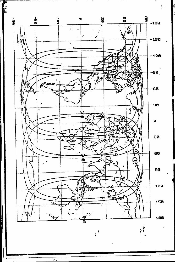
This first generation space segment provides a ministum of one operational and one spare satellite over each of t.he three main ocean regions. With this Cfxifiguration of the three operational satellites the whole world is covered except a small region of the American west coast and the polar regions above 75 degrees latitude in the North and South hemisphere.
17
Due to the very high density of communication traffic in the Atlantic Ocean INMARSAT has recently annotmced that the second operational satellite in the Atlantic Ocean will be moved to a more Westerly position in order to improve global coverage sind will be available for users from the end of 1990. Therefore the shortage of coverage in the west coast of America will also vanish (see figure 1.2>.
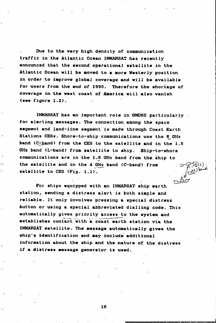
INMARSAT has an important role in GMDSS particularly . for alerting messages. The connection among the space segment and land-line segment is made through Coast Earth Stations CE^Ss. Shore-to-ship communications use the ^GHz band <C;:b.and> from the CES to the satellite and in the 1.5 GHz band (L-band> from satellite to ship. Ship-to-shore communications are in the 1.6 GHz band from the. ship to
For ships equipped with an INMARSAT ship earth station, sending a distress alert is both simple and reliable. It only involves pressing a special distress button or using a special abbreviated dialling code. This automatically gives priority access to the system and establishes contact with a coast earth station via the INMARSAT satellite.. The message automatically gives the ship's identification and may include additional information about the ship and the nature of the distress if a distress message generator is used.
the satellite and in the 4 GHz band (C-band) from satellite to CES (Fig. 1.1>.
16
-60
CHAPTBR TWO THE PRESENT SITUATION OF MARITIME SAFETY
COMMUNICATION
chjvf>te:r two
the: f’hezseint s i tuat i on
OF^ MAH I T I ME SAFETY
COMMONICATION
2.1 INTRODUCTION
The essence of this chapter is to give an overview of the present status and future of the GMOSS and of the present situation of maritime safety communication in
2.2 GMDSS the present status and future outlook
According to the Resolution 1 of the Conference of Contracting Governments to the International Convention for the Safety of Life at Sea, 1974 on the Global Maritime Distress and Safety System the amendments to chapter IV shall enter into force in accordance with the following procedure's:
"a-The amendments shall be deemed to have been accepted on 1 February 1990, unless by that date one third of the Contracting Governments, or Contracting Governments the combined merchant fleets of which constitute not less than fifty per cent of the gross tonnage of the world's merchant fleet, notify the Secretary-General of the IMO that they obdect to the amendments;"
”b-The amendments which are deemed to have been accepted in accordance with the paragraph (a> shall enter
19
into force vith respect to all Contracting Governinents except those which have objected to the anendments under the paragraph (a) and which have not withdrawn such objections, on 1 February 1992."
Since there are not such objections according to the paragraph Ca) the GMDSS regulations shall enter into force on the 1 February 1992 (as it is mentioned in chapter 1 ).
The conditions, chapter IV/1 of the SOLAS convention ere actually designed for early introduction of some elements of the system such as NAVTEDC and satellite EPIRB. Every ship shall comply with such equipment not later than 1 August 1993. Therefore the Contracting Governments should establish the shore facility for sending the NAVTEX messages and receiving the emergency alerts by EPIE^s.
There are many Governments which prepare themselves for the implementation of the system or are already acting as such. According to the IMO document COM 35/2/4 of the sub-committee on Radio-navigation dated 11 November 1966 concerning the report of the Working Group on the Development of a Master Plan of Shore-Based Facilities for the GMDSS there are number of Governments which have established or plan to establish:
1 the different Sea Areas ( A1, A2, A3 and A4 >
2 NAVTEX system
3 INMARSAT facilities
4 COSPAS SARSAT facilities
20
2.2.1 AssessMvnt of covor&ge for the GMDSS
An up to date assessment can be onlyon the present situation which changes every day. However the existing facilities or their planning around the world up* to 11 November 1988 are the following:
North-East European coastal waters extending from Arctic waters north of Norway and the USSR to the vicinity of the Canary Islands, a large portion of, if not all, the Mediterranean and the Black Sea will ultimately be designated sea area A2.
Within this sea area A2, sea areas A1 are expected to be established:
-off the coast of Norway, in the entrances to the Baltic Sea and southwards along the coast of EXirope through the Strait of Gibraltar to the northern Tyrrhenian Sea; and
-in the Mediterranean Sea off the coasts of Cyprus, Greece and Turkey.
Pacific waters around Japan, the Republic of Korea and the USSR and certain other waters of South America are also being planned to become sea areas A1 or A2, or both.
Some Administrations may decide not to establish sea areas A1 and A2 off their coasts. The waters concerned will therefore be designated sea areas A3 or A4, as appropriate like Australia which has only sea area A3 arotmd its coast. Table 2.1 shows the ntimber of countries
21

The following table shows the different sea areas in different countries with the range, number of stations and f requency.
NAME OF THE COUNTRY A1 RANGE A2 RANGE A3 S A4 PRO.
AUSTRALIA (2) 4,6,8,12,16
BELGIUM <2) 30 (2) 113 (1) 8,12
BRAZIL (4> N.I. - (1) 4,8,16
CHILE (5) N.I. (11) N. I. (1) 4,8,12,16
CYPRUS (3) 100,60 (3) >200 (1) 4,6,8,12,16
ISNMARK (17) 30 (2) ■150 (1) 4,6,6,12,16
Farao islands (4) 55 (1) 256
FINLAND (4) TBD (4) 128
FRANCE (36) 25-98 (5) 270
GERMAN D.R. (8) N. I .
GERMAN F.R. (7) 37-45 (2) 123
GREECE (20) 52-106 (4> 200 (1) 4,6,8,12,16
NETHEEUJUroS (12) 18-32 (1) 240
NORWAY (11) 55-65 (11)170-220
SPAIN N. I. N. I .
SWE^N (1) 128
TURKEY (35) N.I. (9) N. I. (1) 8,12
UNITED XINGDAM-------------ud
(6) .150
Table 2.1
Figures in brackets shows the number of stations N.I. means not identified TBD means to be decided

with the CRSs ( Coast Radio Stations > and their ranges.
2.2.2 Future outlook for the 6MDSS
As it is required by the SOLAS convention 1974/86 from 00:01 minutes of 1 February 1999 the system will be fully operational and the morse system for transmission of an emergency alert will be phased out completely.
It is possible to find some coast lines without VHP or MF coast radio stations but it is for sure to say that the SOLAS ships will be equipped by the necessary equipment according to the area of their activities.
Many technical aspects of the system have already been developed. For example the Standard-C is a recent development which is very cheap compared to the Standard-A SES. Although it is not possible to have radio telephony by standard-C, its size, portability and low cost, will enable the users easily to establish a high quality dkta communications link at any time*.
Other applications of standard-C like EX3C ( Enhanced Group Calling for receiving Maritime Safety Information ) and receiving and transmitting alert messages make it a signification contribution to the GMDSS.
It is predictable that in future the satellite equipment has more attraction than terrestrial equipment
«In this regard there are two other new developments namely standard M & B which wer-e explained in the previous chapter.
22
in the GMDSS. Hovever we can not ignore the acknowledged shortcomings ( chapter 1 INMARSAT and its role in GMDSS > of global coverage, namely in polar region for which HF bands has a vital role in the GMDSS.
2.3 Maritime safety commtmication in IRAN
The maritime cosimunication is a part which is separated from other kinds of cosimunication (air, land ) and is entrusted to the Ports S Shipping Organization(PSO> as the responsible and legal authority for all maritime communication affairs.
A very important part of the maritime cosimuni cat ions is safety communication, which together with port communications is done by the ports. The other part of maritime cosimunication ( general cosimunication > which is not for the safety or port communication is done in form of radiotelephony via a terrestrial station in Tehran (the capital of IRAN > and by radiotelegraphy in the port of Bahonar (Port of Abbas).
Our maritime communication services through the ports (for safety and port communication > cover the Persian Gulf and Gulf of Oman areas. These two areas have a very dense traffic which consists mostly of cargo ships, deep-draught tankers, chemical ships, naval ships and a large nximber of small ships, as well as platforms or vessels engaged in exploitation of natural resources and also, hydrography, survey and dredging.
For the purpose of maritime communication each major port has a communication center with its necessary
23
personnel and equipment.
The operation of these centers is under authority of the maritime office of each port, but those activities concerning procedures, legislation and purchasing new equipment are under the authority of the PSO in Tehran.
2.3.1 The organization of maritime communication in PSO
There are two categories of personnel working in the communication affairs in PSO, which are operators and technicians. Operators are working under the authority of head of the operation department and technicians are working imder the head of technical department.
These departments are two out of four main departments in the PSO headquarters which are under the General Manager of the PSO who is the deputy of Ministry ^ of Roads and Transportation.^
There are two other managers under' the head of technical department. One is responsible for purchasing,^ and the other for the maintenance and repair of the communication equipment.
The above organization is the same in the ports except for the purchasing office which is only in Tehran. However, whenever a technical difficulty appears which is not solvable in the ports the technical department of the headquarters must be informed to give advice or assistance.
The operation department in headquarters has the
24
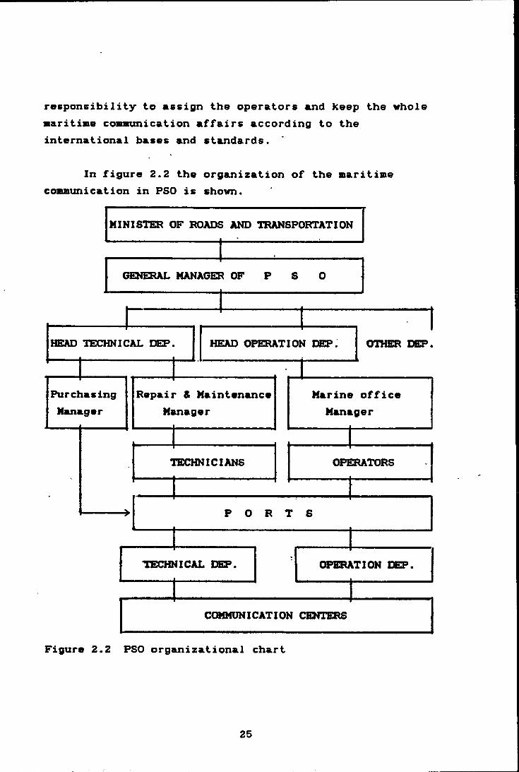
responsibility to assign the operators and keep the whole ■aritiaie conminication affairs according to the international bases and standards.
In figure 2.2 the organization of the maritime communication in PSO is shown.
Figure 2.2 PSO organizational chart
25

2.3.2 Naritiae coaaunication facilities
The aaritine conmunication facilities are located in Tehran and in various Iranian ports.
2.3.2.1 The facility in Tehran consists of two centers which are located inside and outside of the PSO headquarters. The communication center in the PSO headquarters has long range communication equipment to facilitate connection between the different ports and PSO as well as the international telex and facsimile networks for communication with other countries.
The center which is outside the PSO headquarters is a part of communication facility which belongs to the naval force and for commercial usage is tinder the operation of PSO operators. This station has facilities like MF and HF which can provide long-distance radiotelephony communications.
The coverage of this station is in the west up to the east coast of USA and in the east to JAPAN. Normally, this system is used for the general communication of shipping companies, cargo owners, seafarer families and other users.
2.3.2.2 The second part of the maritime communication facilities is situated in the principal ports and harbours in the Persian Gulf, Gulf of Oman and Caspian Sea ( in this case only the Persian Gulf and Gulf of Oman is considered >.
In the chartlet 2.3 the location of these major
26
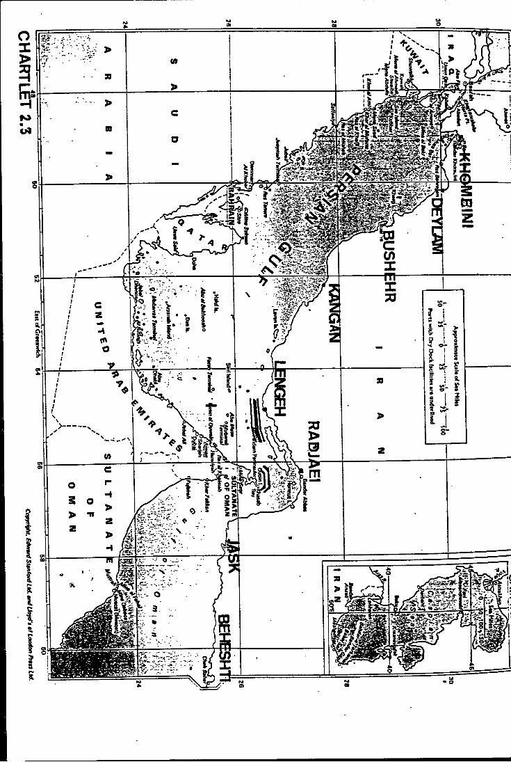
ports which have a cosnaxinication center is shown*.
These ports have their own comiounication facilities such as VHF, MF, HF, telex and facsimile- in order to communicate with ships, other ports, shipping agencies and PSO headquarters in Tehran.
Each port communication center functions as a coast station. They perform watchkeeping according to the International regulations of the Radio Regulations.
We can summarize the routine functions of these coast stations according to the following different activities:
Continuous watchkeeping on frequencies 500 KHz,2162 KHz and VHF channel 16;
Receiving and providing ETTA and ETD;
Pilotage and towage services communications;
Anchorage manoeuvering communications;
Berthing and unberthing communications;
Commxmication with different private andgovernmental'agencies within the port region;
« The Ports of Khorramshahr and Abadan which are located in the Arvand river < Arvand river is a natural boundary between Iran and Iraq in northern west of the Persian Gulf) have no communication facilities as they were completely destroyed in the war.
27
Coamunication vith other ports and the PSOheadquarters in Tehran.
However these coast stations don't provide regular services regarding maritine safety information.
There are some other functions of these co.ast stations which are dealt with occasionally, such as providing the mariners with SAP and Weather Warning messages. The existing situation of the maritime communication services in the Iranian waters is shown in table (2.4).
2.4 Evaluation of the existing situation in maritime safety communication
The existing situation can be divided into two parts. The first part is the "internal situation", which comprises management and financing, facilities, personnel and training and the availability of the safety communication system. The second part is the "external situation" which is formed by the "maritime safety situation " in Iranian waters.
2.4.1 Internal situation
, 2.4.1.1 Management suid financing
As it is already mentioned the operational management of maritime communication in PSO is not concentrated in one department. Therefore the optimal operation of the commtmication system may be sometimes impeded.
26
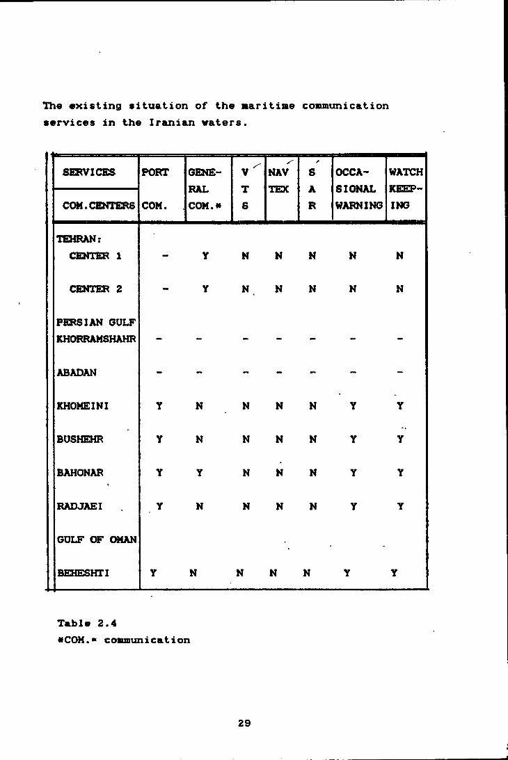
The existing situation of the atari tine coaununicat ion services in the Iranian eaters.
SERVICES PORT
COM.
GENERALCOM. a
VTS
NAVTEX
A
SAR
OCCASIONALWARNING
WATCHKEEPINGCOM.CENTERS
TEHRAN:CEiriER 1 — Y N N N N N
CENTER 2 - Y N N N N N
PERSIAN GULFKHORRAMSHAHR — — — — — — —
ABADAN - - - - - - -
KHOMEINI Y N N N N Y Y
BUSHEHR Y N N N N Y Y
BAHONARi
Y Y N N N Y Y
RADJAEI Y N N N N Y Y
GULF OF OMAN*
BE31ESHTI Y N N N N Y Y
Table 2.4eCOM.s coBBiunication
29

Another difficulty is that the Btaritime safety communication as a safety service can be classified as a section which is not,profit making. Consequently, the realization of allocation of the proper investment in order to keep pace with new developments is very hard or sometimes impossible.
2.4.1.2 Facilities
Compared with other ports the Port of Radjaei has good facilities. With regard to the new equipment the HF and MF telegraphy services are satisfactorily provided in the port. However as it is illustrated in table 2.4 the present equipment can not handle the entire function of the maritime communication services in all ports.
2.4.1.3 Personnel and training
The number of the operators is not sufficient and they mostly had their training years ago. With regard to the new technical development in maritime communication especially safety communication services they are not up to date and updating and refreshing them should be considered.
2.4.1.4 Availability
The existing situation of the maritime communication services in the Iranian waters ( displayed in table 2.4) shows a lack of some vital services. For instance NAVTEX stations for promulgating of the Maritime Safety Information and the Search and Rescue services for SAR alert messages do not exist in the present system. It is
30
also inportant to realize that since there is not an organized Search and Rescue service (SAP) in Iran this inportant part of the 6MDSS should be initiated.
2.4.2 external situation
In the aaritime safety situation there are several navigational dangers which should be considered when a aaritine safety plan has to be initiated.
2.4.2.1 Off-shore hazards ^
Fortunately the entrance of the Persian Gulf (Horauz Strait } has a traffic separation scheme <TSS>. Thereby the safety of the huge traffic of the Hormuz Strait < approximately each 15 minutes one ocean going shipa> is largely improved.
The TSS undoubtedly contributes to safety, however there always remains the possibility of a collision.
There is another traffic separation scheme near (see chartlet 2.3 > the Iranian coast ( between latitude 26 and 27 North and longitude 54 and 56 East) which is regulating the in-coming and out-going traffic around the Northern and Southern part of three Iranian islands (Tanb-e Borzorg, Nabi Tanb and Farur).
2.4.2.2 Grounding
The Persian Gulf is comparatively shallow, with depths of 35 meters in average. The charted depths are not
eVessel Traffic Service by W.KOBURGER;JR
31
always reliable in those parts which are not under the recent survey. In spite of the buoyage system in the shipping routes there are still a lot of islands, islets, oil-fields and other dangers in the routes through the Persian Gulf.
2.4.2.3 Visibility
Bad visibility caused by dust haze may occur in all seasons and is most frequent from May to August, reducing visibility to between two and six miles. Occasionally the visibility may become very bad,'some times less than half a miles. Dust storms and sandstorms occur in'all parts of the Persian Gulf and Gulf of Oman and in all season of the year. They are most frequent during the months of June and July«.2.4.2.4 Submarine pipelines
Submarine pipelines are present at many places in the Persian Gulf. Their positions are charted, but many of these pipelines are not buried and one should allow at least‘2 meters extra tmder—keel clearance when passing over them. Their presence is an additional factor to the navigational hazards in the Persian Gulf.
2.4.2.5 Prolonged and strong winds
Prolonged and strong winds blowing in a constant direction generate surface currents which can lower the sea level in one place and raise it at another. Throughout the winter the winds are predominantly from NW over much *
*The Persian Gulf and Strait of Hormuz by R.K. Ramazani
32
of the Persian Gulf C this wind is called Shamal in the region) in the South store West winds prevail with SW winds < called Suhaili ) over the Hormuz Strait.
January is the most boisterous month with 15 percent of the winds reaching Force 6 and 4 percent Force 6, in February about 2 percent of winds reach Force 6.
In stnnmer there is a contrast between the hot persistent NW winds in the northern part of the Persian Gulf and the cooler winds of the SW Monsoon, east of Gulf of Oman. The W to SW monsoon winds become fully established by mid-summer, reaching Force 5 to 6 on average over the open sea off the Iranian coast (in the Gulf of Oman) and occasionally to gale force, mostly in squalls.
Over the Gulf of Oman winds from North are common whilst to East of this Gulf, over the Iranian coast,' the winter winds are usually from NE.
2.4.2.6 Oil drilling and exploitation platforms
Oil drilling and exploitation platforms can be found in large quantities in the Persian Gulf. Most but not all of them are charted and exhibit lights and sound fog signals. Mariners should be on their guard against encotintering any of these obstructions which may be uncharted, not displaying lights or giving no fog signals.
2.4.2.7 Local crafts ^
Local crafts are foxmd in any part of the Persian Gulf and Gulf of Oman. They consists fishing
33
vessels, tugs, small vooden cargo vessels, etc.Especially at night there is an augmented risk of collision vith them. The concentration of these vessels depends normally on the type of services which they have. The fishing vessels mainly are near the areas vith good fish resources such as Beheshti and Jask (a fishing port) in the Gulf of Oman and Lenkeh and Oelam (tvo fishing and small cargo ports*) and other areas in the Persian Gulf. The traffic of the cargo vessels is mostly concentrated near major ports.
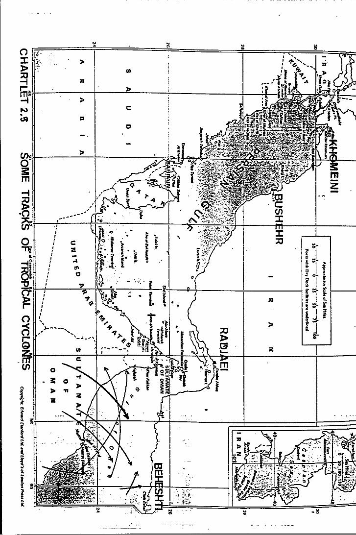
2.4.2.6 Storms
Storms such as tropical cyclones may be encountered over the region to the E^st of the Gulf of Oman. Chartlet (2.5) shows typical tracks over the North Arabian Sea toward the entrance of the Gulf of Oman where most of the recorded storms lose much of their vigour. The months of May and June have the highest frequency. Within 100 miles of these coasts there have been reports of hurricane winds (Force 12) in association with the passage of a tropical cyclone**.2.4.2.9 Shortcomings of the maritime safety communication
systemThe coverage of VHF and MF channels are restricted to
a short range ( VHF 20 and MF 100 miles). Therefore vessels and especially local vessels which may have a VHF or in exceptional cases an MF radio equipment, when navigating out of the range of these stations can not receive/send any messages. For this reason there have been
«ln chartlet 2>3 the location of these ports are shown, a* Persian Gulf Pilot Twelfth edition 1982.
34
cases where a vessel sank due to the bad weather or an accident and nobody was informed about it.
2.5 Necessary improvements of maritime safety communication in IRAN
In order to improve the maritime safety communication in IRAN one should consider the^internal and external situation^of the maritime safety system and deal with factors such as management .'^facility / personnel and training, availability of the necessary services, coverage of the safety communication system, ^promulgation of maritime safety information, search and rescue organization and finally regulations.
2.5.1 Management
.1 lE^AN is the signatory of the International Convention on the Safety of Life at Sea 1960 and the International Telecommunication Union Convention and the Radio Regulations. Thereby more effort should be concentrated in the part of the organization which is responsible for implementation of the adopted international regulations in the SOLAS and ITU conventions.
.2 Certainly a good organization with proper management can provide for optimal .resultsIn order to improve maritime communication, (the integration of its
management in one departmenC^ is recommendable.
2.5.2 Facilities (equipment, building >
To have a reliable and adequate operation sufficient
35
f&ciliiies should be available at any coast station. In purchasing new equipment one should consider the regulations and. the conditions such as’ the temperature and humidity, maintenance and repair ability, user friendly operation of the equipment, MTBF ( Mean Time Between Failure) and MTTR ( Mean Time to Repair) of equipment.
2.5.3 Personnel and training
Regarding manning and training, by establishing proper courses in the two institutes which are owned by PSO in port of Shahid Radjaei and port of Anzali <in the northern part of Iran) a sufficient number of qualified personnel can be trained, refreshed and updated for operation and maintenance of the CRSs.
In chapter IV more information is provided on this subject.
2.5.4 Availability
The maritime safety communication is vital in order to assure the safety of life at sea concept. Therefore the reliability of the equipment should be taken into consideration very carefully in order to provide the availability of necessary safety services. In this regard the duplication of equipment and a proper maintenance and repair system are essential factors.
2.5.5 Coverage
According to the international regulations of IMO and ITU the safety of shipping and personnel should be a
36
%primary objective of any Administration. Therefore the maritime safety communication must cover all the Iranian vaters. In this concept thd new amendment to the regulations of chapter IV of the SOLAS convention is of importance and according to its provisions the Iranian administration should determine the different Sea Areas (Al, A2, A3 and A4> in order to put these areas under the maritime safety communication coverage.
2.5.6 Promulgation of maritime safety information (MSI)
The dissemination of MSI through NAVTEX stations can be considered as a complementary step to the safety of shipping and personnel at sea. In this regard IMO has a panel to help countries to establish this important service. The establishment of NAVTEX service which should be national (in Farsi language > and international (in English language > is very vital in Iranian waters.The international service aids the ocean going vessels and the national service can assist- the local vessels to be aware of the prevailing situation and dangers in the region.
2.5.7 Search and Raacua Organication ( 8AR >
'According to the International Convention on Maritime Search and Rescue, 1979, and article 12(2) of the Convention on the High Seas, 1958 every coastal state shall promote the establishment and maintenance of an adequate and effective search and rescue service regarding safety on and over the sea. Therefore it is a matter of importance for IRAN to establish such an organization.
37
2.5.6 Regulations
The first important step is the legal aspect of the maritime safety communication. In this regard the accession to the International Convention for the Safety of Life at Sea 1974 as amended in 1968 (SOLAS 1974/1966) is the first important step. Our coxmtry is still party to the SOLAS 1960 therefore for legalization of the maritime affairs with new regulations the accession to the SOLAS 1974 is necessary.
2.6 Conclusion
The best way to improve the maritime safety communication in IRAN is the establishment of SAP organization, training of personnel and the shore-based facilities for SMDSS.
From an operational view point we first need to define the different Sea Areas in our coastal area and establish the necessary coast radio stations (CRS) as well as satellite communication facilities which are required in the system. In the next chapters, the full implementation of GMDSS in IRAN is under discussion.
i
%
38
CHARTER TREE
RL.AISININQ ROR THE OHoeS I IM
I RAM
chaf>tb:r t’MR'hie:
I=*i:-ANNINO F'OR the: omdss
General
11ST I HAlSr
Before establishing the 6MDSS system in Iran it is necessary to consider the following subjects:
3.1 assessment of the area which is to be served bythe GMDSS;
3.2 delimitation of GMDSS's areas <A1. A2. A3 andA4>, the location and number of coast radiostations and their transmissions;
3.3 location and function of a coast earthstation;
3.4 designation of the NAVTE3C stations and the areaof responsibility.
3.5 possible cooperation with neighboringcountries;
3.6 cooperation with national authorities;
3.7 assessment of the facilities, personnel and the equipment required for the new system;
3.6 links between CES, CRS and RCC;3.9 cost evaluation.
39

3.1 Ass«ssB«nt of th« aroa vhich is to beaerved by GMDSS;
Iran has two sa^or shipping activities in the North ( Caspian Sea > and in the South ( Persian Gulf and Gulf of Oman > of the country. Although these shipping activities are international in both areas, the size of ship and the amount of cargo are completely different. Normally chips up to 4,000 grt can navigate in the North but it is largely different in the South which can accommodate ships such as VLCC and ULCC.
Since, the implementation of the GMDSS is considered to be in the South, the focus of this area assessment is on the Persian Gulf ( a semi-enclosed sea ) and the Gulf of Oman which leads to the Indian Ocean. The navigational and meteorological aspects of both areas were already mentioned in chapter two but some statistics about the shipping aind dimensions of the two areas are going to be considered here.
3.1.1 Persian Gulf
The Persian Gulf is connected by the Hormuz Strait to the Gulf of Oman and Indian Ocean. Iran is located on the northern part of the Persian Gulf and on the southern part there are countries such as Saudi Arabia, Bahrain Kuwait, the United Arab Emirat and Oman.
Other specifications and dimensions of the Persian Gulf:
LengthWidth
540 NMbetween 107 to 160 NM (except for
Hormuz Strait which is 33 NM width)
40

Area 122,030 eq. NMAverage depth 35 meters-Max. depth 100 meters <around HormuzStrait)-Sea temperature;
in summer 32 to 34 Celsius in winter 15 to 21 C
3.1.2 Gulf of Oman
The entrance of Gulf of Oman can be considered as a straight line between the Ra's A1 Hadd ( Lat. 22 30 N Long. 59 48 E > and the Iran-Pakistan frontier in Gwatar bay <Khalid-e Gwatar) (Lat. 25 10 N Long. 61 33 E). Iran has about 340 miles coast along Gulf of Oman.
Other specifications and dimensions:
Length 340 NMWidth 45-175 NMArea « 32,375 sq. NMMax. depth 3,000 mSea temperature;
in sximmer 27 to 32 Celsius ' in winter 22 tO 23 C
3.1.3 Shipping traffic in the Persian (3ulf and Gulf ofOmanOnfortxmately reliable statistics regarding the
total traffic in the Persian Gulf are not available. In order to estimate this traffic it is better to consider the number of ships that each state in the Persian Gulf has under its flag. Table *3.1 shows the number of ships and to this we should add the number of ships that each
41

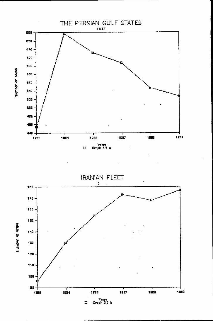
state has under its charter. There are also several international shipping lines which rxzn regular schedules to different ports in the Persian Gulf. However (as the graphs 3.2 aSb depict) the number of ships owned by the Persian Gulf states decreased considerably from 1964 ( mainly due to the war > but the Iranian fleet has a growth trend from 1968.
Table 3.1 the Persian Gulf states merchant and tanker fleet, ships of 300 grt/dwt and above
COUNTRY NAME 1961 1964 1986 1987 1968 1969
IRAN 96 130 154 173 168 177
SAUDI ARABIA 126 262 224 191 166 140
IRAQ 56 52 40 39 39 41
KUWAIT 109 99 85 60 56 ' 53
UAE 50 96 91 93 66 65
QATAR 6 23 21 17 16 16
BAHRAIN 5 14 14 12 9 9
OMAN 4 3 2 3 4
Total 454 678 632 607 547 527
Table 3.1
42
Num
tw of
•hip
* N
i4m
t«r »hlp»
THE PERSIAN GULF STATES
VBin□ Dmaph 3.3 o
IRANIAN FLEET
Vatra□ Ctaph 3.3 b
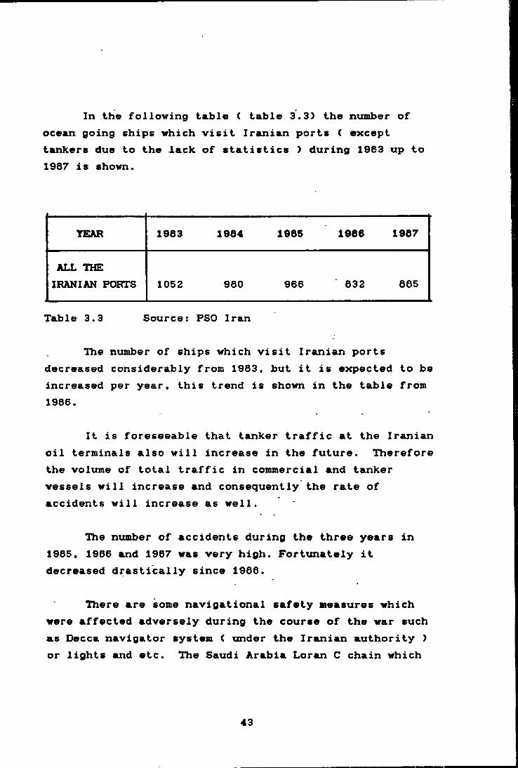
In the following table ( table 3.3> the number of ocean going ships which visit Iranian ports ( except tankers due to the lack of statistics > during 1963 up to 1967 is shown.
TEAR 1963 1964 1965 1966 1967
ALL THEIRANIAN PORTS 1052 960 966 632 665
Table 3.3 Source: PSO Iran
The number of ships which visit Iranian ports decreased considerably from 1963, but it is expected to be increased per year, this trend is shown in the table from 1966.
It is foreseeable that tanker traffic at the Iranian oil terminals also will increase in the future. Therefore the volume of total traffic in commercial and tanker vessels will increase and consequently the rate of accidents will increase as well.
The number of accidents during the three years in 1965, 1966 and 1967 was very high. Fortunately it decreased drastically since 1966.
There are some navigational safety measures which were affected adversely during the course of the war such as Decca navigator system ( under the Iranian authority > or lights and etc. Tlie Saudi Arabia Loran C chain which
43
is now in operation is a good means for navigation and the safety of shipping in the area.
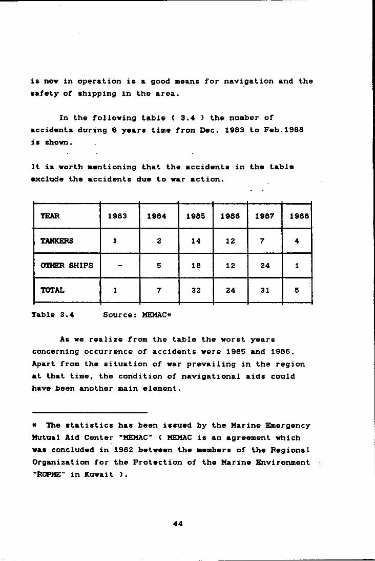
In the following table ( 3.4 > the number of accidents during 6 years time from Dec. 1983 to Feb. 1968 is shown.
It is worth mentioning that the accidents in the table exclude the accidents due to war action.
YEAR 1963 1984 1985 1966 1967 1968
TANKERS 1 2 14 12 7 4
OTHER SHIPS - 5 16 12 24 1
TOTAL 1 7 32 24 31 5
Table 3.4 Source: MEIMAC«
As we realize from the table the worst years concerning occurrence of accidents were 1985 and 1966. Apart from the situation of war prevailing in the region at that time, the condition of navigational aids could have been another main element.
« The statistics has been issued by the Marine Emergency Mutual Aid Center "MEMAC" < MEMAC is an agreement which was concluded in 1982 between the members of the Regional Organization for the Protection of the Marine Environment “ROPME" in Kuwait ).
44
In conclusion on our assessment of the area, there are some points which should be realized and taken into account for future planning:
1 The area is very sensitive concerning saf.ety and pollution due to the huge amoxmt of- transportation of a variety of cargoes especially oil
2 Each country has its own commercial fleet and there is still a considerable potential for rapid increase in the number of ships owned by each country in the area
3 There is high density of shipping traffic especially in some narrow passages such as the Hormuz Strait .
4 The present navigational aids are not completely suitable in the area.
45

3.2 Del ini tat ion of the GMDSS's areas (A1, A2, A3 and A4>t the number of coast radio stations and their transmissions
The basis tipon which the system is being planned is the determination of the necessary areas to be used in the system. After that, the appropriate number of coast radio stations which are to be installed in order to cover such areas can be considered.
3.2.1 Persian Gulf^
As it is mentioned in the area evaluation concerning the specification of the Persian Gulf, the greatest width in the Persian Gulf is around 160 miles and the smallest around 30 miles near the Hormuz Strait. Therefore, the
\/coyerage of the system can be provided by two Sea Areas < A1 and A2 >. Thereby it is a necessary condition for the navigation of local vessels which are confined to the Persian Gulf to have a suitable service by VHF and MF.
3.2.1.1 Sea Area A1 for VHF equipped ships provides the short range service. It uses such frequencies as 156.525 KHz for distress alerts and safety calls by DSC ( Digital^ Selective Calling) and 156.6 MHz^ for distress and safety traffic by radiotelephony
3.2.1.2 Sea Area A2 for MF equipment ships providesmedium range service. It uses the frequencies such as2167.5 KHz for distress alerts and safety calls by 2162 KHz for distress and safety traffic by radiotelephony. ^
DSC, and
46

3.2.2 Th« Gulf of Onan" ^
There can be three Sea Areas i A1, A2 and A3 ) which are necessary in this area to cover the whole region toward the Indian Ocean. Sea areas A1 and A2 with the same specification of those in the Persian Gulf and A^with the MF/HF facilities as an alternative for satellite communication. This applies to those ships which use HF DSC for ship-to-shore transmission of distress alerts.The HF long range service uses the frequencies which have been designated in the 4, 6, 6, 12, and 16 MHz bands to provide transmission and reception of distress alerts.^ .
The reason for having A1 in this area is mainly to provide the possibility for small crafts which are equipped only with VHF to connect with a CRS in case of an emergency. There are plenty of such vessels engaged in fishing in the area, as well as those which are busy with carriage of cargo among small ports. It is obvious that the other ships which have VHF and are navigating near the coast can use this facility also for safety communication.
Those ships which are far from the shore, outside the coverage of A1, can use MF, satellite communication or HF to send their emergency messages.
3.2.3 tiumber of CRSs in the Persian Gulf
The most important part of each CRS which is directly related to the range of a station is the antenna site. The higher the antenna, the longer the range.
Fortunately there are some mountains with good height
47
to be used for installation of the VHP antenna along the Iranian coast line. There stay be some problems^or >/v installation and maintenance of transmitting stations vhich depend on the availability of roads, transportation and buildings. In those places vhich are not inhabited it vili bo very costly to install these antennas. For these cases, the connection of antenna site vith the control station can be done by micro vave link.
However there are two options for implementation of the project, first the usage of mountain sites and the second one, the coastal area for installation of antenna.
3.2.4 Remote An.tenna siie ( first choice >
3.2.4.1 VHF antenna site
Four points are suitable for the VHF antenna sites which are:
1 Lat. 30 02 N Long. 46 54 E
At this point (there is no high land in this area) it is recommended to have an antenna with 100 meters* height which can cover an area with radius of 25 miles**.(the coverage area of this site is shown in chartlet 3.5)
« It is necessary to note that the higher the antenna: -the more expensive the antenna and installation; and -the greater potential for congestion on the frequency due to the large number of transmission which can be received. ** This range is calculated according to the IMP MSC 55/25 ( Appendix two) and other different methods of calculation of VHF range are provided in Appendix three.
46
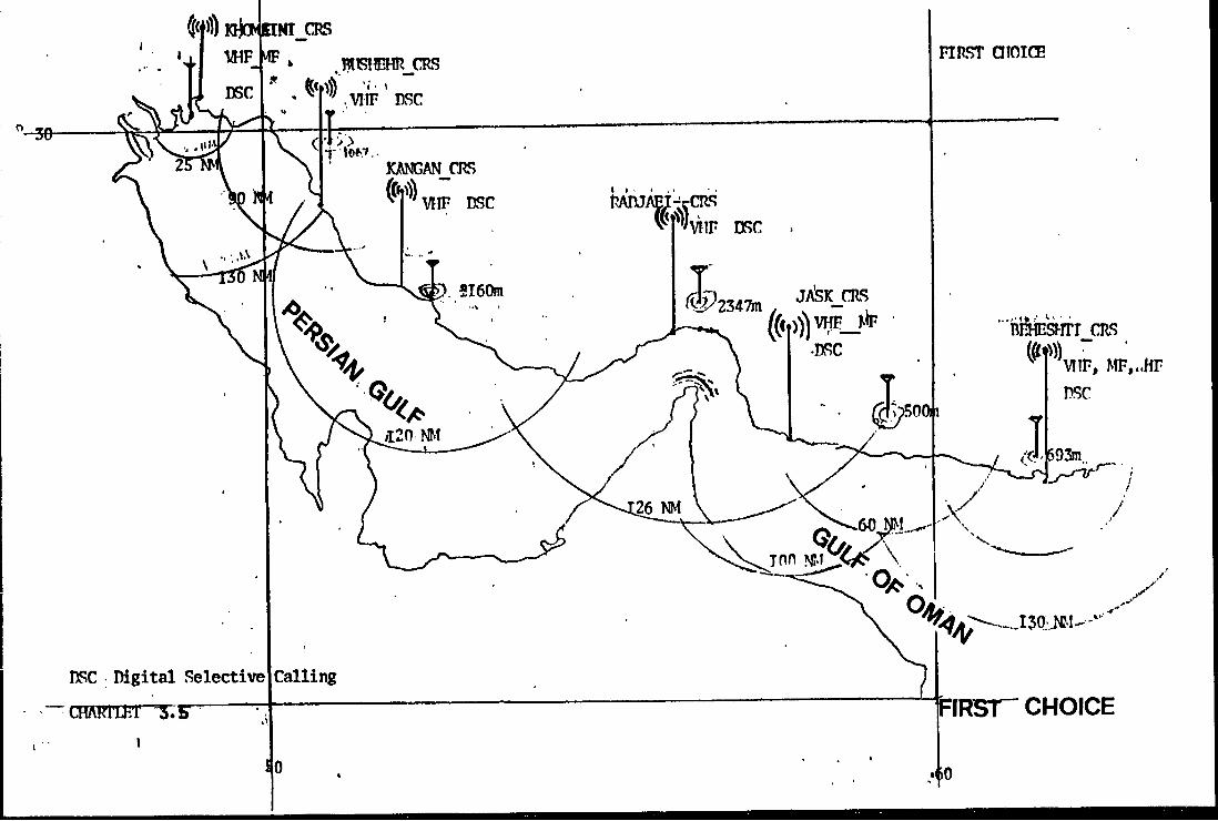
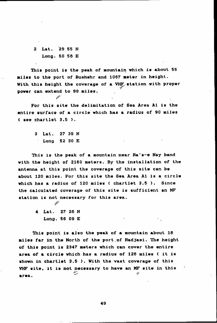
2 Lat. '29 55 N Long. 50 56 E
This point is the peak of mountain trhich is about 55 miles to the port of Bushehr and 1067 meter in height.With this height the coverage of a VR^ station mith proper power can extend to 90 miles.
For this site the delimitation of Sea Area A1 is the entire surface of a circle which has a radius of 90 miles ( see chartlet 3.5 ).
3 Lat. 27 39 NLong 52 30 E
This is the peak of a mountain near Ra's*-e Nay band with the height of 2160 meters. By the installation of the antenna at this point the coverage of this site can be about 120 miles. For this site the Sea Area A1 is a circle which has a radius of 120 miles ( chartlet 3.5 ). Since the calculated coverage of this site is sufficient an MF station is not necessary for this area.
4 Lat. 27 28 NLong. 56 09 E
This point is also the peak of a mountain about 16 miles far in the North of the port of Radjaei. The height of this point is 2347 meters which can cover the entire area of a circle which has a radius of 126 miles ( it is shown in chartlet 3.5 >. With the vast coverage of this VHF site» it is not necessary to have an MF site in this area.
49
3.2.4.2 MF anianna site
Since the coverage of VHF at the eite in position (1) (Lat. 30 02 N « Long. 48 54 E ) is only 25 NM, ships which are navigating further than this distance need an MF station (Sea Area2>. The coverage of this MF site should be 130 NM. For the rest of the Persian Gulf, as it is Mentioned before, it is not necessary to have MF station (see chartlet 3.5).
3.2.4.3 Coast Radio Station (CRS)
For the above sites four CRSs are recommended as follows:
1 Port of Khomeini ( VHF S MF );
2 Port of Bushehr ( VHF )j
3 Port of Kangan ( VHF );
4 Port of Radjaei ( VHF >;
The connection between the sites and CRSs is by means of micro wave antennas. Chartlet 3.5 shows the location of each CRS and its site.
In the following table each CRS with the related • site is shown:
50

CRS KHOMEINI BOSHEHR KANGAN RADJAEI
VHF DSC '30 02 N 29 55 N 27 39 N 27 26 M46 54 E 50 56 E 52 30 E 56 09 E
30 02 N4F DSC 46 54 E
Table 3.6
3.2.5 Coastal antenna sites ( second choice >
In this part, as an alternative, we use the coast area for the antenna sites in order to overcome the costly difficulties for installation and maintenance of the antenna on the peaks of the mountains.
3.2.5.1 VHF antenna site
.In order to cover the coastal waters as Area 1, it is necessary to have 15 sites for installation of 15 antennas. This is possible when the height of each antenna is about 100 meters.
Therefore the range of each antenna is about 25 miles. In chartlet 3.7 the site and range of each antenna is shown.
The situation of the aforementioned sites with respect to the geographical location of each port permits
51
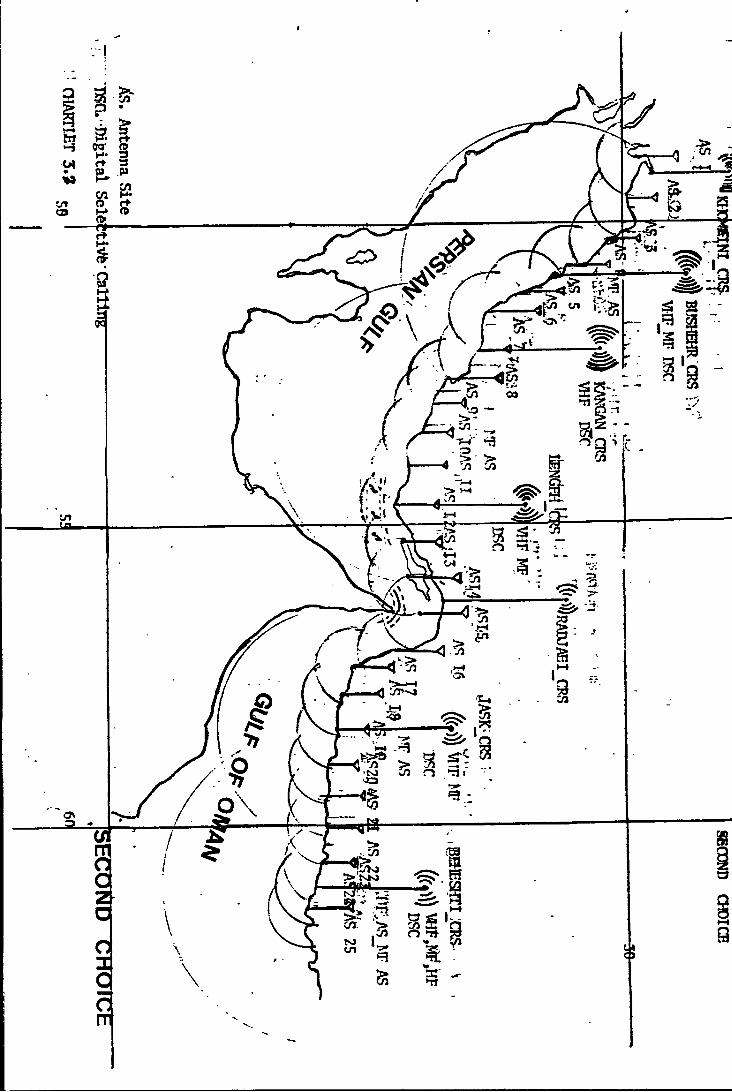
a choice of the following ports as Coast Radio Stations and to allocate 2, 3 or in some cases four antenna sites to each of these CRSs.
These ports are:
1 Khomeini
2 Bushehr
3 Kangan < small port used as fishing port )
4 Lengeh " ”
5 Radjaei
(The location of above ports is shown in chartlet 3.7)
The connection of these sites with the CRSs can be carried out by micro wave links. The connections between CRSs can be done over the national telephone and telex ^ networks.
In the following table each CRS with its site is given.
52
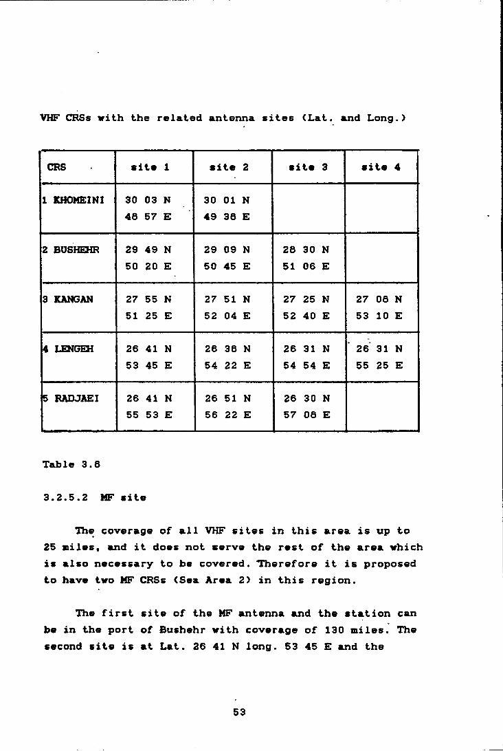
VHF CRSs with the related antexuia sites (Lat. and Long.)
CRS site 1 Site 2 site 3 site 4
1 KHOMEINI 30 03 N 30 01 N46 57 E 49 36 E
2 BUSHEHR 29 49 N 29 09 N 26 30 N50 20 E 50 45 E 51 o 0) E
3 KANGAN 27 55 N 27 51 N 27 25 N 27 06 N51 25 E 52 04 E 52 40 E 53 10 E
4 LENGEH 26 41 N 26 36 N 26 31 N 26 31 N53 45 E 54 22 E 54 54 E 55 25 E
5 RADJAEI 26 41 N 26 51 N 26 30 N55 53 E 56 22 E 57 06 E
Table 3.6
3.2.5.2 MF site
The coverage of all VHF sites in this area is up to 25 Biles, and it does not serve the rest of the area which is also necessary to be covered. Therefore it is proposed to have two MF CRSs (Sea Area 2> in this region.
The first site of the MF antenna and the station can be in the port of Bushehr with coverage of 130 Biles. The second site is at Lat. 26 41 N long. 53 45 E and the
53
related station in the port of Lengeh also with a coverage of 130 stiles. The connection between the site and the^ station is by siicro wave link.
3.2.6 liuMber of the CRSs in the Gulf of Oaan
In this area we can also use the aiountain <first choice > and the coastal area <second choice) for installation of the necessary antennas.
3.2.6.1 Antenna site on the mountain ( first choice'
There are however several siountains which do not have large heights. They may be used as antenna sites. For our purpose two mountains with 500 and 693 meter height are chosen.
3.2.6.2 VHF antenna site
There are two sites which are assumed to be suitable in this area:
1 Lat. 25 50 NLong. 56 30 E
At this point, which has 500 meters height, the range is 60 miles ( chartlet 3.5 ).
2 Lat. 25 40 NLong. 60 05 E
This is a point, with 693 meters height therefore the VHF range is 70 miles (chartlet 3.5).
54
3.2.6.3 MF antvnna sitv
Since the coverage of the above VHF sites is not store than 30 stiles from the coast, there is a necessity to have MF stations for ships navigating at further distances from the coast.
First site for an MF antenna is the port of Jask itself. The coverage of this station can'be 100 miles.
The second site for an MF antenna is at:
Lat. 25 Id N (port of Beheshti>
Long. 60 40 E
The range of this site (MF as Area 2) is 130 NM (see chartlet 3.5).
3.2.6.4 HF antenna site
For ships which are navigating further than 130 miles (Area 3 ) and when they are not equipped with sateLlXite communication facilities, a HF DSC station is necessaury. Therefore at the same point as the second MF site (port of Beheshti) an HF station should be planned. The different antenna sites and stations are shown in chartlet 3.5.
3.2.6.5 Coast Radio Station ((^RS)
For the above sites ( VHF, MF, HF ) two CRSs ( port of Jask and Beheshti > are planned. In the following table the location of the sites for each station is shown.
55

VHFsite
MFsite
HFsiteCRS
JASK Lat. 25 50 N 25 40 N
Long. 58 30 E 57 48 E
BEHESHTI Lat. 25 40 N 25 19 N 25 19 N
Long. 60 05 E 60 39 E* 60 39 E
Table 3.93.2.7 Coastal Antenna sites ( second choice >
3.2.7.1 VHF sites
For coverage of the coastal water with Area 1 ( VHF> it is necessary to have about 10 sites for installation of 10 antennas.
The height of each antenna for a coverage of 25 miles should be 100 sieters. In chartlet 3.7 the location of these sites and the VHF ranges is shown.
3.2.7.2 Coast Radio Station
The Coast Radio Stations which can be connected to these sites are at the following ports:
1 Jask < small port used as fishing port )2 Beheshti
56
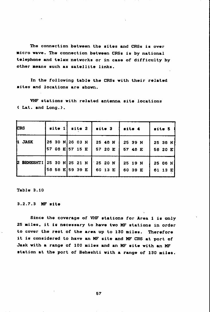
The connection between the sites and CRSs is over aicro wave. The connection between CRSs is by national telephone and telex networks or in case of difficulty by other Beans such as satellite links.
In the following table the CRSs with their related aites and locations are shown.
VHF stations with related antenna site locations ( Lat. suid Long. } .
CRS site 1 site 2 site 3 site 4 site 5 1
1 JASK 26 30 N 26 03 N 25 48 N 25 39 N 25 38 N57 08 E 57 15 E 57 20 E 57 48 E 58 20 E
2 BEHESHTI 25 30 N 25 21 N 25 20 N 25 19 N 25 06 N* 58 58 E 59 39 E 60 13 E 60 39 E 61 13 E
Table 3.10
3.2.7.3 MF site
Since the coverage of VHF stations for Area 1 is only 25 Biles, it is necessary to have two MF stations in order to cover the rest of the area up to 130 Biles. Therefore it is considered to have an MF site and MF CRS at port of Jask with a range of 100 Biles and an MF site with an MF station at the port of Beheshti with a range of 130 Biles.
57
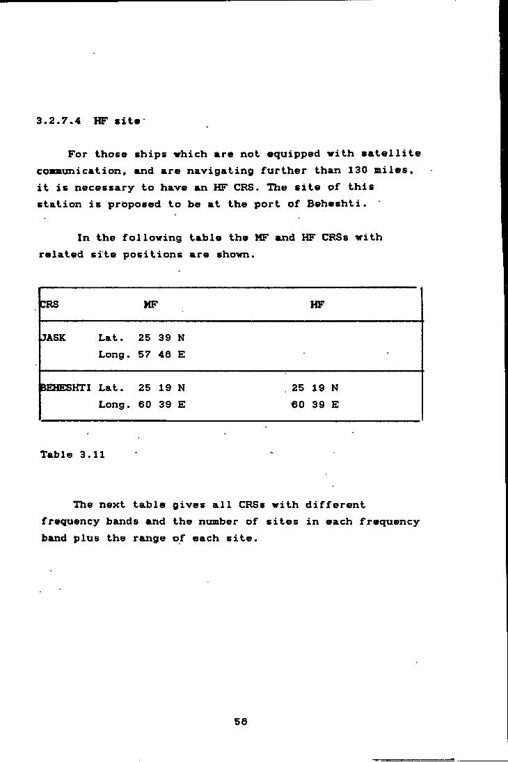
3.2.7.4 HF sits
For those ships irhich mre not equipped with satellite cosoaunication, and are navigating further than 130 miles, it is necessary to have an HF CRS. The site of this station is proposed to be at the port of Beheshti.
In the following table the MF and HF CRSs with related site positions are shown.
CRS ^ . HF
JASK Lat. 25 39 N
Table 3.11 *
The next table gives all CRSs with different frequency bands and the ntnnber of sites in each frequency band plus the range of each site.
Long. 57 48 E
)EHESHTI Lat. 25 19 N Long. 60 39 E
25 19 N 60 39 E
58
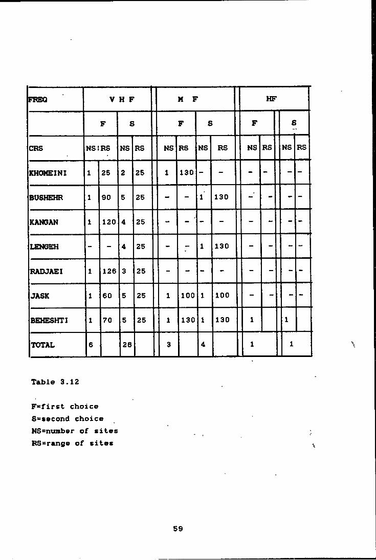
V H F1 M F HFFREX2
F S F S F S
CRS NSiRS NS RS NS RS NS RS NS RS NS RS
KHOMEINI 1 25 2 25 1 130 - - - - - -
BUSHEHR 1 90 5 25 - - 1 130 - - -
KANGAN 1 120 4 25 - - - - - - -
LEN6EH - - 4 25 - - 1 130 - - - -
RADJAEI 1 126 3 25 - - - - - - - -
JASK 1 60 5 25 1 100 1 100 - - - -
BEHESHTI 1 70 5 25 1 130 1 130 1 1
TOTAL 6 28 3 4 1 1
Table 3.12
F=first choice S-second choice NSsnumber of sites BS^range of sites
59
3.3 Location and function of ths Coast Eiarth Station<CES>
AS it is mentioned in chapter 2 the comiaencement of the installation of a CES is in its final stages. This station has access to the INMARSAT Indian Ocean region satellite. The operation of this CES is completely under the authorities of the Iranian National Communication Company. For maritime safety communication, PSO will have access to this CES and its facilities. The special function which is expected to be provided by the CES is the immediate transmission of any emergency message to the nearest CRS.
Other functions such as general communication, data trainsmission, fleet calling and other services which are available can be established between ships < equipped with SESs > and various other users.
3.4 Designation of required NAVTEX stations and the area of responsibility
The fast transmission and reception of distress messages is the most important task of radio at sea in the GMDSS. It is also essential that warnings and forecasting of weather and navigational warnings instruments are ^ transmitted to ships.
In planning a NAVTEX system in an area the most important factor is the high level of local and international co-ordination.
As it is mentioned earlier, NAVTEX is a component of
60

the World-Wide Navigational Warning Service <WWNWS> and Iran is in NAVAREA IX. The area co-ordinator in this area <IX> is in Pakistan, Karachi; therefore, it is necessary to establish co-ordination with this area co-ordinator.
The range of a NAVTEIX transmitter depends on the transmitted power and local propagation conditions.
As it is mentioned in the IMO NAVTEIX manual, according to the acquired experience, the tentatively required range of 250 to 400 nautical miles can often be attained by transmitted power in the range between 100 and 1000 watts during daylight with a 60 per cent reduction during night-time.
There are two stations necessary to cover the whole area. One in the Gulf of Oman and the other one in the Persian Gulf. Since there is already an established NAVTEIX station in Bahrain and it broadcasts MSI in the EInglish language, the Persian Gulf station could have only national service.
Lat. 25 48 N1 Gulf of Oman C ( port of JASK >
Long. 57 36 E
Lat. 26 59 N2 Persian Gulf {
Long. 50 50 E
It is recommendable that the station in the Gulf of Oman be given a priority for establishment.
61
This is proposed here because the weather condition in the area is not stable, especially in the Gulf of Oman. The shipping traffic ( local and international > is also very dense, particularly around the Hormuz Strait. There are also a lot of activities in the area such as fishing, off-shore drilling, maritime research and etc.
3.4.1 Organization
From the organizational point of view, the following is proposed:
The Ports and Shipping Organization <PSO), which is the sole organization in Iran with the responsibility for the entire maritime affairs, can be appointed as National co-ordinator with the responsibility for management of the MSI in general.
The PSO already has responsibility for the SAR operation and navigational aids in the whole area. The meteorological messages co-ordinator should be the national meteorological organization.
The national telephone and telex networks should provide the direct connection between the co-ordinators and the stations at all times.
In chartlet 3.13 the area and the NAVTEIX stations are depicted.
62
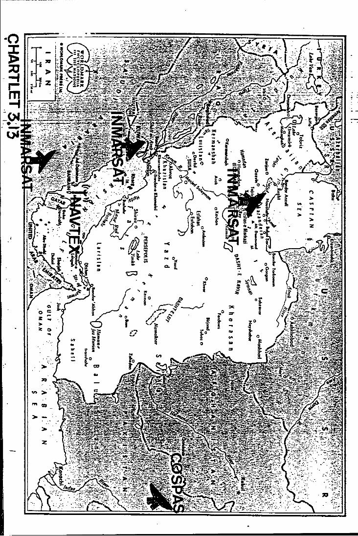
3.5 Possibl* cooperation vith noighboring countries
According to the regulations chapter IV of the SOLAS convention 1974 as amended in 1968, a state ehich is responsible for the provision of GMDSS in a region can jointly decide with one or a number of other states (for economic, geographical or other reasons ) to establish and provide for various Sea Areas <A1, A2 and etc..) in their areas of responsibility.
3.5.1 Option for cooperation
At present there are the following safety communication facilities in the Persian Gulf region :
.1 Iran has facilities which were mentioned in chapter 2 concerning the terrestrial commxmi cat ions ;
.2 the planned Iran Coast Earth Station via INMARSAT Indian Ocean Region (lOR) satellite;
.3 there are already two Coast Earth Stations in the region (Kuwait and Saudi Arabia);
.4 a LOT station in Pakistan (Lahore > commissioning in 1990;
.5 one existing NAVTEX station in Bahrain.
( In chartlet ntimber 3.13 the locations of the above stations are shown >.
63
An agreenent is possible for.joint use of available facilities for the Persian Gulf: an agreement with PaJcistan regarding alert messages through COSPAS-SARSAT satellite system and an agreement with Bahrain to use the existing NAVTEIX station for the English language messages in the Persian Gulf.
Such agreements for co-operation imply that there should be communication links between the GMDSS-centers of the participating coxzntries.
64
3.6 Cooparation vith national authorities
In establishing a GMDSS system in Iran, we should utilize to the fullest extent the existing facilities.The following organizations should participate in and provide assistance to'the system:'
.1 the Search and Rescue organization (xmder PSO> is the main organization which should take isimediate actions in cases of distress alerting. Therefore there must be a direct access to the RCC. The SAR organization can also provide for NAVTEX facilities.
.2 the national telecommunication company which is responsible for the CES should provide direct access to the coastal radio station^ or RCC for transmitting alert messages. The CES operators should be instructed as to the area of responsibility of each coast radio station.
.3 the Meteorological Organization is a very important organization in providing weather forecast and warning information for transmission by the NAVTEX stations. In this case the Meteorological Organization is acting as a national NAVTEX co-ordinator. This service is provided according to a specific agreement which was mentioned in the NAVTEX section in this chapter ( see 3.5 >.
.4 t.he national Health Department can providemedical advice in case of urgency through the
65

terrestrial or satellite communication system.An agreement with this department should be arranged.
.5 the Navigational Aids department which is working xmder the Ports and Shipping Organization will provide necessary information about navigational aids and dangers for transmission by the NAVTEX stations. Since it is also responsible for hydrographic services, it can also help to provide the necessary information regarding hydrographic activities in any area.
.6 there should be an agreement with the Civil - Aviation Administration for necessary cooperation in sending information in case of an accident observed by their pilots or any other news which can be related to safe navigation.
Once the various organizations or departments which can participate in the GMDSS system are determined, necessary agreements for providing co-operation should be made. All of the above organizations and departments or other related organizations should have agreement with the NAVTEX National co-ordinator.
66

3.7 A mt of tho f&cilitios, porsonnol and aquipnent
3.7.1 General
The assessment of the facilities, personnel and equipment depends on the way of implementation -of the GMDSS, choice one or two. However in any case we should look to the following items:
.1 Number of CRSs
.2 Number of antenna sites
.3 Nizmber of NAVTEX stations
.4 Number of CE^s«The work program
.6 Amount of the work in Repair and Maintenance center
As it is mentioned in this chapter in section 3.2 the number of CRSs in the first choice is six stations and in the second choice is seven stations. Some, of these stations can be automatic, without any personnel. But these automatic stations certainly cost too much., Therefore if we have to man all stations for the purpose of the GMDSS functions we need to have at least one person in each station all the time. Since the service of the GMDSS should be 24 hours a day, it means we need three shifts of work per-day. *
* The CES is operated by the ministry of communication so this item is not considered in our evaluation.
67
Hie nain equipment of each CRS depends on the frequency bands of the station <VHF, MF or HF> which could be as follows:
-proper antenna equipment “VHF equipment -VHF DSC receiver -DSC controller & processor -printer and keyboard-MF DSC receiver ( in case of MF station )-MF DSC controller S processor-HF/MF equipment ( in case of HF station >-HF/MF DSC scanning receiver -HF/MF DSC controller and processor -Communication facility with other stations and RCC either with telephone network or by INMARSAT standard C.
-NAVTEX transmitter (in case of NAVTEX station )
Each CRS should be connected to the relaited antenna sites by micro-wave facility. So in addition to the above equipment, there is some other equipment concerning the connection of a CRS with antenna sites as well as the relay equipment.
3.7.2 Personnel requirement
In the following table (3.15) the number of stations in both choices auid the number of personnel are demonstrated.
68

CHOICE NUMBER OF PERSONNEL E)CTRA* TOTALSTATIONS (in 3 shifts)
FIRST CHOICE 6 16 2 20
SECOND CHOICE 7 21 2 23
Table (3.15)
3.7.3 NAVmX personnel**
It is considered to have tvo stations for NAVTEX purposes. In the following table (3.16) the required personnel who should be available in 24 hours per-day (in three shifts) is shown.
STATIONS 3 SHIFTS PERSONNEL EXTRA TOTAL
1 PERSIAN GULF 3 1 4
2 GULF OF OMAN 3 1 4
TOTAL 6 2 6
Table (3.16)
*Extra personnel should be considered for illness or etc..«* Here the operators of the stations are only considered.
69
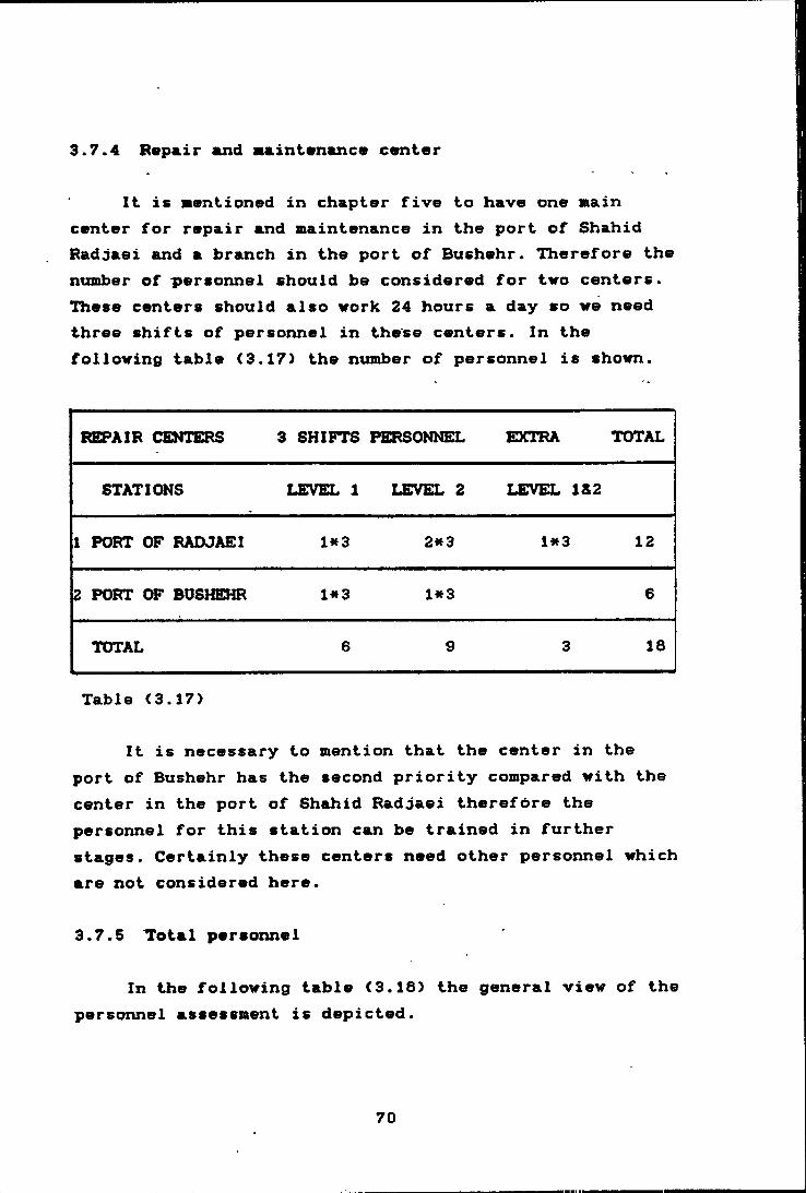
3.7.4 Repair and aaintananc* cvnier
It is Bentxoned in chapter five to have one main center for repair and maintenance in the port of Shahid Radjaei and a branch in the port of Bushehr. Therefore the nuBiber of personnel should be considered for two centers. These centers should also work 24 hours a day so we need three shifts of personnel in these centers. In the following table (3.17) the number of personnel is shown.
REPAIR CENTERS 3 SHIFTS PERSONNEL EXTRA TOTAL
STATIONS LEVEL 1 LEVEL 2 LEVEL 1&2
1 PORT OF RAOJAEI Ht3 2*3 1*3 12
2 PORT OF BOSHEHR 1*3 1*3 6
TOTAL 6 9 3 16
Table <3.17)
It is necessary to mention that the center in the port of Bushehr has the second priority compared with the center in the port of Shahid Radjaei therefore the personnel for this station can be trained in further stages. Certainly these centers need other personnel which are not considered here.
3.7.5 Total personnel
In the following table <3.16) the general view of the personnel assessment is depicted.
70
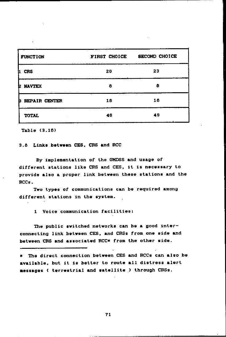
FUNCTION FIRST CHOICE SECOND CHOICE
1 CRS 20 23
2 NAVTEX 6 6
3 I^AIR CENTER 18 18
TOTAL 46 49
Table (3.18)
3.6 Links between CES, CRS and RCC
By implementation of the GMDSS and usage of different stations like CRS and CES, it is necessary to provide also a proper link between these stations and the RCCs.
Two types of communications can be required among different stations in the system.
1 Voice communication facilities:
The public switched networks can be a good interconnecting link between CES, and CRSs from one side and between CRS and associated RCC« from the other side.
a The direct connection between CEIS and RCCs can also be available, but it is better to route all distress alert messages ( terrestrial and satellite ,) through CRSs.
71
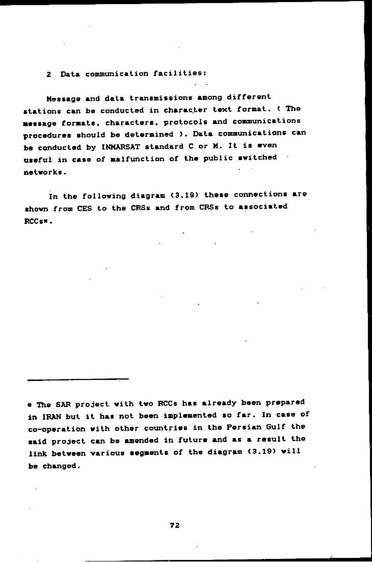
2 Data communication facilities:
Message and data transmissions among different stations can be conducted in charac.ter text format. < The message formats, characters, protocols and cosimuni cat ions procedures should be determined ). Data communications can be conducted by INMARSAT standard C or M. It is even useful in case of malfunction of the public switched
networks.
In the following diagram (3.19) these connections are shown from CES to the CFSs and from CRSs to associated
RCCs«.
« The SAR project with two RCCs has already been prepared in IRAN but it has not been implemented so far. In case of co-operation with other coxmtries in the Persian Gulf the said project can be amended in future and as a result the link between various segments of the diagram <3.19) will
be changed.
72
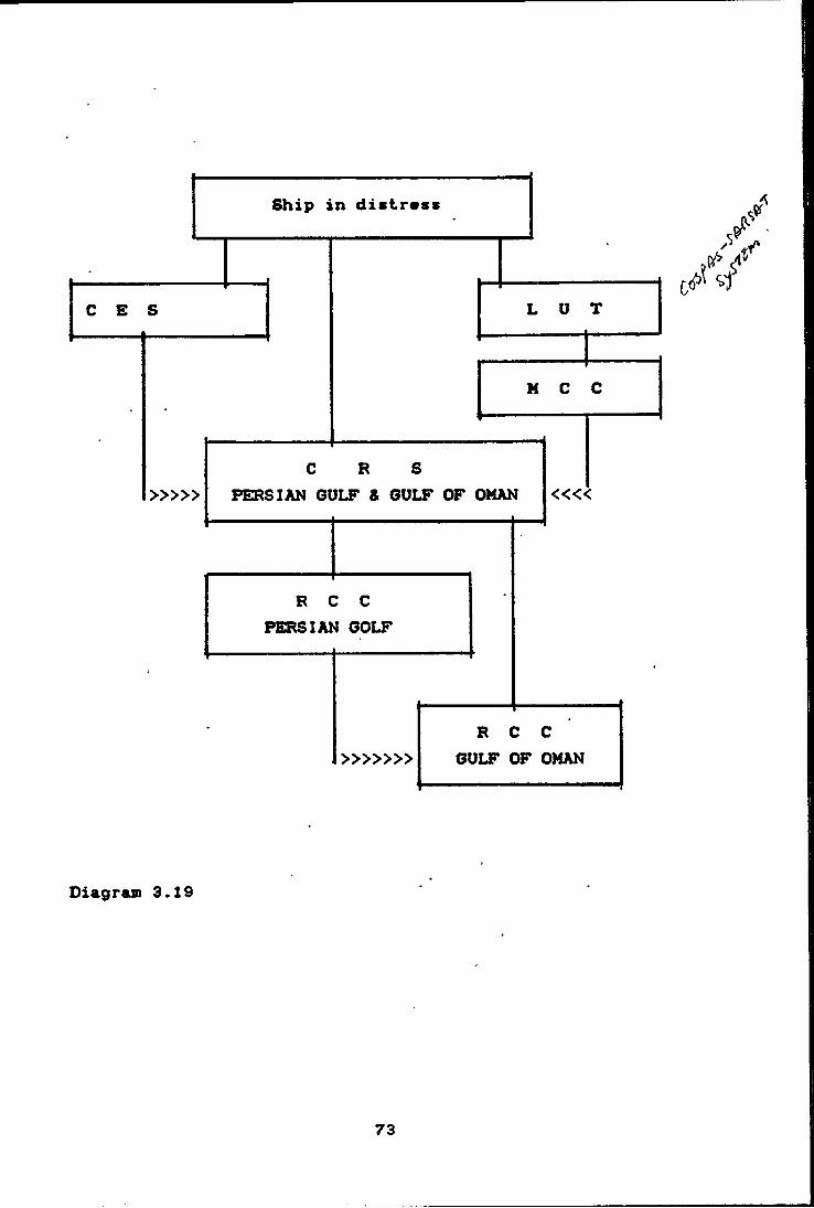
Diagram 3.19
73

3.9 Cost ovaluation
The actual price for the equipment/ with different powers and ranges, the installation, particularly the antenna on mountain or at sea level and other expenses such as micro wave facilities is not available; therefore, for a rough estimation and comparison between the two proposed choices the following prices have been estimated:
-VHF DSC equipment with installation;-receiver, controller and processor-antenna-micro wave-buiIding
Total price with installation on mountain S 1,000,000
*• “ “ " at sea level S 500,000
Total price with antenna at sea level but without building S 400,000
-MF/ HF DSC equipments with installation;-receiver, controller and processor-antenna-micro wave-building
Total price (antenna at sea level) $ 200,000
With the above estimation the difference in costs between the first and second choice can be calculated. In the following table the cost of the first choice is
74
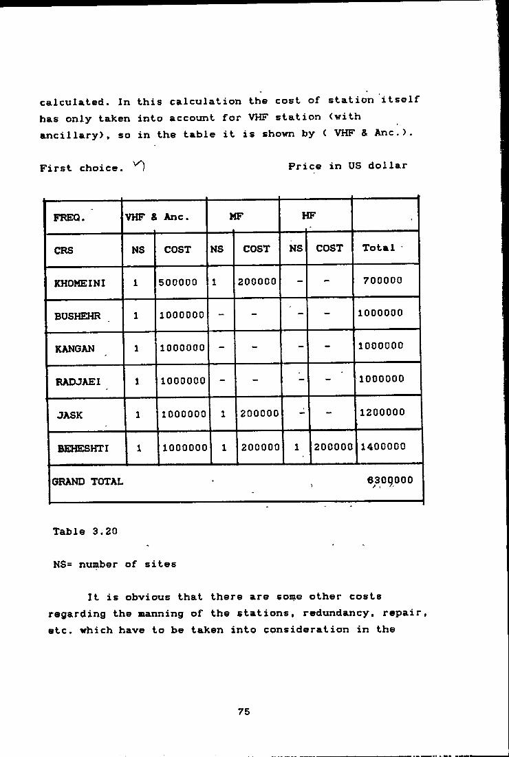
caLlculait@d. In t.his cstlculaition th© cost of station itself has only taken into account for VHF station (with ancillary), so in the table it is shown by ( VHF & Anc.).
First choice. '0 Price in US dollar
FREQ. VHF S Anc. MF HF
CRS NS COST NS COST NS COST Total
KHOMEINI 1 500000 1 200000 - - 700000
BUSHEHR 1 1000000 - - - - 1000000
KANGAN 1 1000000 - - - - 1000000
RADJAEI 1 1000000 - - - - 1000000
JASK 1 1000000 1 200000 - - 1200000
BEHESHTI 1 1000000 1 200000 1 200000 1400000
GRAND TOTAL 6309000
Table 3.20
NS= number of sites
It is obvious that there are some other costs regarding the manning of the stations, redundancy, repair, etc. which have to be taken into consideration in the
75
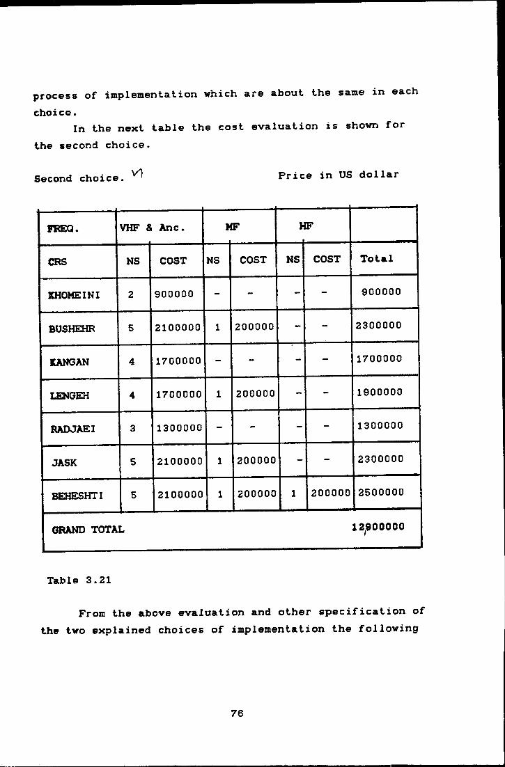
process of implementation which are about the same in each
choice.In the next table the cost evaluation is shown for
the second choice.
Second choice. ^ Price in US dollar
FKEQ. VHF & Anc. MF HF
CRS NS COST NS COST NS COST Total
KHOMEINI 2 900000 - -• - - 900000
BUSHEHR 5 2100000 1 200000 - - 2300000
KANGAN 4 1700000 - - - - 1700000
LENGEH 4 1700000 1 200000 - - 1900000
RADJAEI 3 1300000 - - - - 1300000
JASK 5 2100000 1 200000 - - 2300000
BEHESHTI 5 2100000 1 200000 1 200000 2500000
GRAND TOTAL 12^900000
Table 3.21
From the above evaluation and other specification of the two explained choices of implementation the following
76
advantages and disadvantages can be extracted;
3.9.1 Advantages of the first choice
.1 The cost is much less
.2 The implementation takes less time
.3 The usage of the equipment is less
.4 The number of station is less
.5 The number of personnel is less
3.9.2 Disadvantages of the first choice
.1 The technical aspects of installation are more complex
.2 The repair and maintenance are more costly
.3 The power of the station should be more
However by considering the above reasons it can be stated that the execution of the first choice is more beneficial than the second choice.
77
CHARTERTRA1N1NC3 OR
&TECHNI
RDUR C3MDSS
C I ANSORERATORS
CHAF^TER EOUF?
TRA INI NC3 OE OMDSS OPERATORS
S. TECHN I C I ANS
4.1 General
The heart of good functioning of the GMDSS is training and education. With good training the operation of the system can achieve a very high standard. The GMDSS operators and technicians training is an important part of the new communication system and there is still a lot of discussions on the matter of sufficient and efficient training in IMO and other international and national organizations and institutions.
The arguments about recruitment of, and the necessity for having, a radio electronic officer/operator on board as in the conventional system are still present in recruitment programs. One can find many different policies with regard to this, even considering the fact that the full implementation date of GMDSS is in the year 1999. The author remembers the visit he had on the bridge of a passenger ferry in Nov. 1989 on the way from Sweden to Germany. When he saw the communication room with a satellite ship earth station (standard A) and asked about the radio officer, the captain said we don't need the radio officer any more, and the previous radio officer is now the chief of painters on board the ship*.
* This happened on board a ferry, it may be different on board an ocean going vessel.
78

Regulation 16 of chapter IV of the International Convention on the Safety of Life at Sea (SOLAS 74) as amended in 1966 declares:
"Every ship shall carry personnel qualified for distress and safety conmiunication purposes to the satisfaction of the Administration. The personnel shall be holders of certificates specified in the Radio Regulations as appropriate, any one of whom shall be designated to have primary responsibility for radio communications during distress incidents".
In the above regulation the presence of qualified personnel is emphasized but the meaning of qualified personnel or any other identity regarding the job description or the position of the personnel remains to the consideration of the Administration. Something which is very important in the Article is the condition that requires such personnel shall be holders of certificates according to Radio Regulations. [Article 55 of the Radio Regulations mentions a number of requirements for different classes of Radio Electronic Officers who are qualified fof the new communication systeml.
On the other hand, the concept of availability of the functional requirements specified in GMOSS regulations forces the ocean going ships in sea areas A3 & A4 to have on board a redundant system plus a radio electronic officer or one of these < redundancy and radio electronic
iofficer ) plus external (shore-based) maintenance capability for their GMDSS requirements. While the ships in A1 S A2 can use such methods as redundancy of equipment, shore-based maintenance or at-sea electronic
79
atainienance capability, or a combination of these (regulation 15.6 S 15.7 of chapter IV of the SOLAS convention).
Article 56 of the Radio Regulations stipulates that the personnel of ship stations for which a radio installation is compulsory under international agreements and which use the frequencies and techniques of GMDSS regulations shall, with respect to the provisions of Article 55, include at least:
4.1.1 for stations on board ships which sail within the range of VHF coast stations a holder of:
.1 a First-class Radioelectronic Certificate; or
.2 a Second-class Radioelectronic Certificate;or
.3 a General Operator's Certificate; or
.4 a Restricted Operator's Certificate.
4.1.2 on board ships which sail within the range of MF coast stations a holder of;
.1 a First-class Radioelectronic Certificate; or
.2 a Second-class Radioelectronic Certificate;or
.3 a General Operator's Certificate.
4.1.3 on board ships which sail beyond the range of MF coast stations a holder of:
60

.1 a First-class Radioelectronic Certificate;or
.2 a Second-class Radioelectronic Certificate.
From the aforementioned regulations it can be realized that ocean going vessels in future should rely for availability of their GMDSS equipment on redundancy of their equipment and at-sea electronic maintenance or redundancy of their equipment and external < shore-based > maintenance. In the latter case as far as the regulations dictate there should be qualified personnel ( ship radio electronic officer ) on board with Radio Regulations qualifications. Thereby an apparent contradiction between the provisions of Articles 55 and 56 of the Radio Regulations and the provisions of Regulations 15 and 16 of chapter IV, 1974 convention as amended by the 1988 GMDSS conference is palpable.
4.2 Training preparation
The qualification requirements in Article 55 of the Radio Regulations for the radio operators in the new system have been a basic document for any development in training curricula so far. IMO has held several sessions on this item in the STW Sub-Committee and made available some documents for training purposes.
There are still some uncertainties up to the next World Administrative Radio Conference < WARC > in 1992. WARC 1992 has a mandate to consider the provisions of Articles 55 and 56 of the revised Radio Regulations in order to re-examine the provisions of those articles concerning the mandatory carriage on board ships of
81

personnel certificated for on-board maintenance of shipboard radio and electronic equipment.
However according to the present qualifications for the radio electronic officer, certain curricula and syllabuses should be taken into consideration.
4.3 Training program
The training programs can be divided basically into two major areas:
4.3.1 ship electronic officers/operators
.1 first-class radioelectronic officer
.2 second-class radioelectronic officer
.3 general operator
.4 restricted operator
4.3.2 shore operators
.1 shore-based repair and maintenance center operator
.2 CRS operator
62
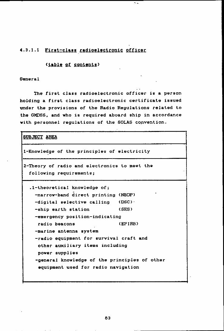
4.3.1.1 First-class radioclectrpnic officer
(l&kJLS 2£ contents)
General
The first class radioelectronic officer is a person holding a first class radioelectronic certificate issued under the provisions of the Radio Regulations related to the GMDSS, and vho is required aboard ship in accordance with personnel regulations of the SOLAS convention.
SUBJECT AREA
1- Knowledge of the principles of electricity
2- Theory of radio and electronics to meet the following requirements;
.1-theoretical knowledge of;-narrow-band direct printing (NBDP)-digital selective calling (DSC)- -ship earth station (SES)-emergency position-indicating radio beacons (EPIRB)
-marine antenna system-radio equipment for survival craft and other auxiliary items including power supplies-general knowledge of the principles of other equipment used for radio navigation
83
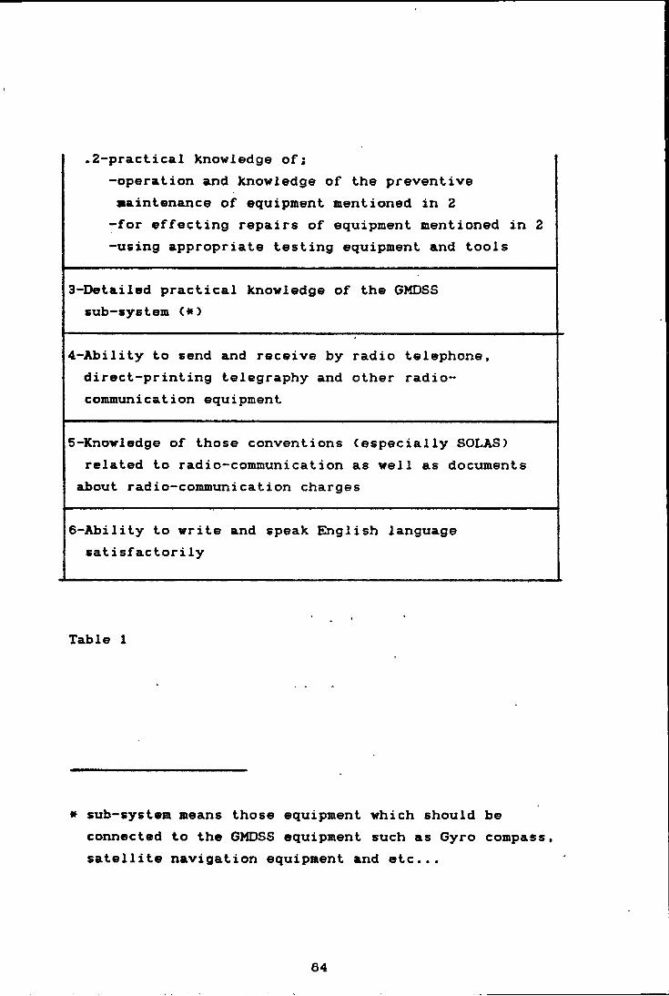
.2-practical knowledge of;-operation and knowledge of the preventive maintenance of equipment mentioned in 2 -for effecting repairs of equipment mentioned in 2 -using appropriate testing equipment and tools
3-Detailed practical knowledge of the GMDSS sub-system (.*}
4-Ability to send and receive by radio telephone, direct-printing telegraphy and other radiocommunication equipment
5-Knowledge of those conventions (especially SOLAS) related to radio-communication as well as documents
about radio-communication charges
6-Ability to write and speak EInglish language satisfactorily
Table 1
« sub-system means those equipment which should beconnected to the GMDSS equipment such as Gyro compass, satellite navigation equipment and etc...
64
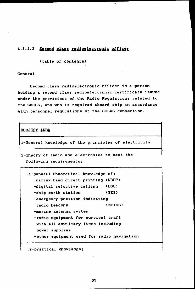
4.3.1.2 Second class radioslvctronic officer
<table s£ contents)
General
Second class radioelectronic officer is a person holding a second class radioelectronic certificate issued under the provisions of the Radio Regulations related to the GMDSS, and who is required aboard ship in accordance -with personnel regulations of the SOLAS convention.
SUBJECT AREA
1-General knowledge of the principles of electricity
2-Theory of radio and electronics to meet the following requirements;
.1-general theoretical knowledge of; -narrow-band direct printing <NBDP> -digital selective calling (DSC)-ship earth station (SES)-emergency position indicating radio beacons (EPIRB)
-marine antenna system -radio equipment for survival craft with all auxiliary items including power supplies-other equipment used for radio navigation
.2-practical knowledge;
85

-operation and knowledge of the preventive maintenance of equipment indicated in 2 -necessary for effecting repairs in equipment indicated in 2
-using appropriate testing equipment and tools
3-Detailed practical knowledge of the operation of all GMDSS sub-systems
4-Ability to send and receive radiotelephone and direct printing telegraphy
5-Knowledge of those conventions (especially SOLAS) related to radio-communication as well as documents about radio-communication charges
6-Ability to write and speak EInglish language satisfactorily
Table 2
66
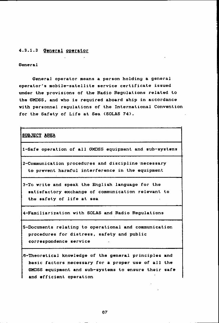
4.3.1.3 Gvnvra1 ogfrator
General
General operator means a person holding a general operator's mobile-satellite service certificate issued under the provisions of the Radio Regulations related to the GMDSS. and who is required aboard ship in accordance with personnel regulations of the International Convention for the Safety of Life at Sea (SOLAS 74).
SUBJECT AREA
1-Safe operation of all GMDSS equipment and sub-systems
2-Communication procedures and discipline necessary to prevent harmful interference in the equipment
3-To write and speak the EInglish language for the satisfactory exchange of communication relevant to the safety of life at sea
4-Familiarization with SOLAS and Radio Regulations
5-Documents relating to operational and communication procedures for distress, safety and public correspondence service
6-Theoretical knowledge of the general principles and basic factors necessary for a proper use of all the GMDSS equipment and sub-systems to ensure their safe and efficient operation
67
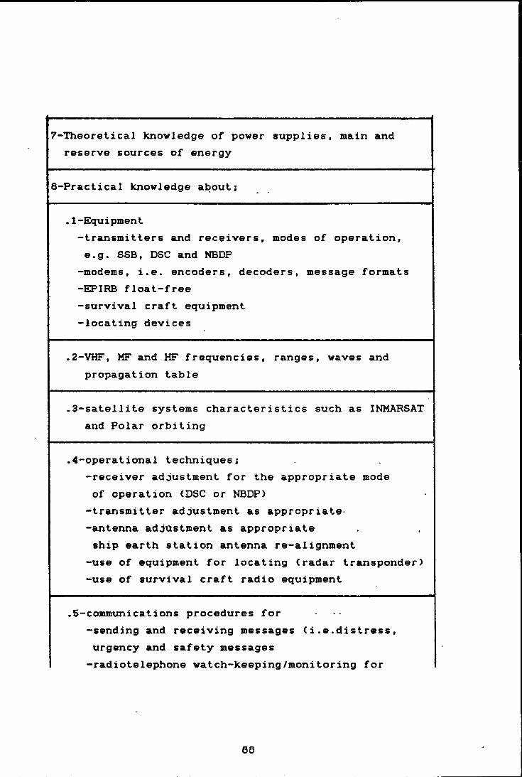
7-Theoretical knowledge of power supplies, main and reserve sources of energy
8-Practical knowledge about;
.1-Equipment-transmitters and receivers, modes of operation, e.g. SSB, DSC and NBDP
-modems, i.e. encoders, decoders, message formats -EPIRB float-free -survival craft equipment -locating devices
.2-VHF, MF and HF frequencies, ranges, waves and propagation table
.3-satellite systems characteristics such as INMARSAT and Polar orbiting
.4-operational techniques;-receiver adjustment for the appropriate mode of operation (DSC or NBDP)
-transmitter adjustment as appropriate*-antenna adjustment as appropriate ship earth station antenna re-alignment
-use of equipment for locating (radar transponder) -use of survival craft radio equipment
.5-communications procedures for-sending and receiving messages (i.e.distress, urgency and safety messages -radiotelephone watch-keeping/monitoring for
68
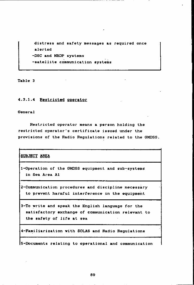
distress and safety messages as required once alerted-DSC and NBDP systems -satellite communication systems
Table 3
4.3.1.4 BSStristS^ operator
General
Restricted operator means a person holding the restricted operator's certificate issued under the provisions of the Radio Regulations related to the GMDSS.
SUBJECT AREA
1-Operation of the GMDSS equipment and sub-systemS in Sea Area A1
2-Communication procedures and discipline necessary to prevent harmful interference in the equipment
3-To write and speak the English language for the satisfactory exchange of communication relevant to the safety of life at sea
4-Familiarization with SOLAS and Radio Regulations
5-Documents relating to operational and communication
69
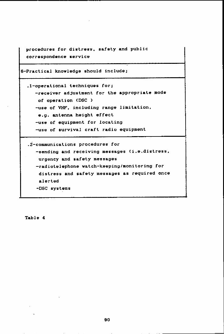
procedures for distress, safety and public correspondence service
6-Practical knowledge should include;
.1-operational techniques for;-receiver adjustment for the appropriate mode of operation (DSC >-use of VHF, including range limitation,«.g. antenna height effect -use of equipment for locating -use of survival craft radio equipment
.2-communications procedures for-sending and receiving messages <i.e.distress, urgency and safety messages —radiotelephone watch-keeping/monitoring for distress and safety messages as required once alerted -DSC systems
Table 4
4.3.2 Sho£S operator
4.3.2.1 Shore-based fiaioignaneg gnd £gESi£ £SQtgr oggrator
General
The availability of equipment for the GMDSS is a crucial point which is still under discussion in IMO and other international and national organs. Regulation 15 paragraph 6&7 of chapter IV of the SOLAS convention determines three methods for availability of the equipment on board ships. One of the methods is shore-based repair and maintenance. A good back up for equipment in the GMDSS requires qualified technicians to cope with the job. The necessity of a good training program becomes obvious. In the following a number of subjects for two levels of technicians are shown;
91
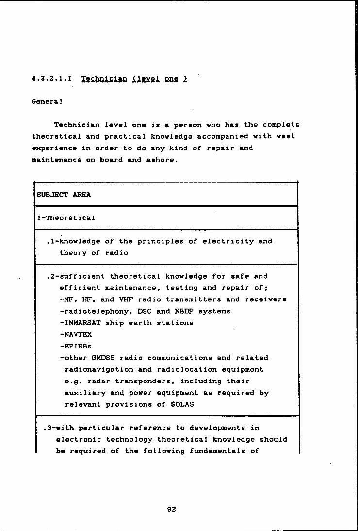
4.3.2.1.1 Technician (level one >
General
Technician level one is a person who has the complete theoretical and practical knowledge accompanied with vast experience in order to do any kind of repair and maintenance on board and ashore.
SUBJECT AREA
1-Theo'retical
.1-knowledge of the principles of electricity and theory of radio
.2-sufficient theoretical knowledge for safe and efficient maintenance, testing and repair of;-MF, HF, and VHF radio transmitters and receivers-radiotelephony, DSC and NBDP systems-INMARSAT ship earth stations-NAVTEX-EPIRBs-other GMDSS radio communications and related radionavigation and radiolocation equipment e.g. radar transponders, including their auxiliary and power equipment as required by relevant provisions of SOLAS
.3-with particular reference to developments inelectronic technology theoretical knowledge should be required of the following fundamentals of
92
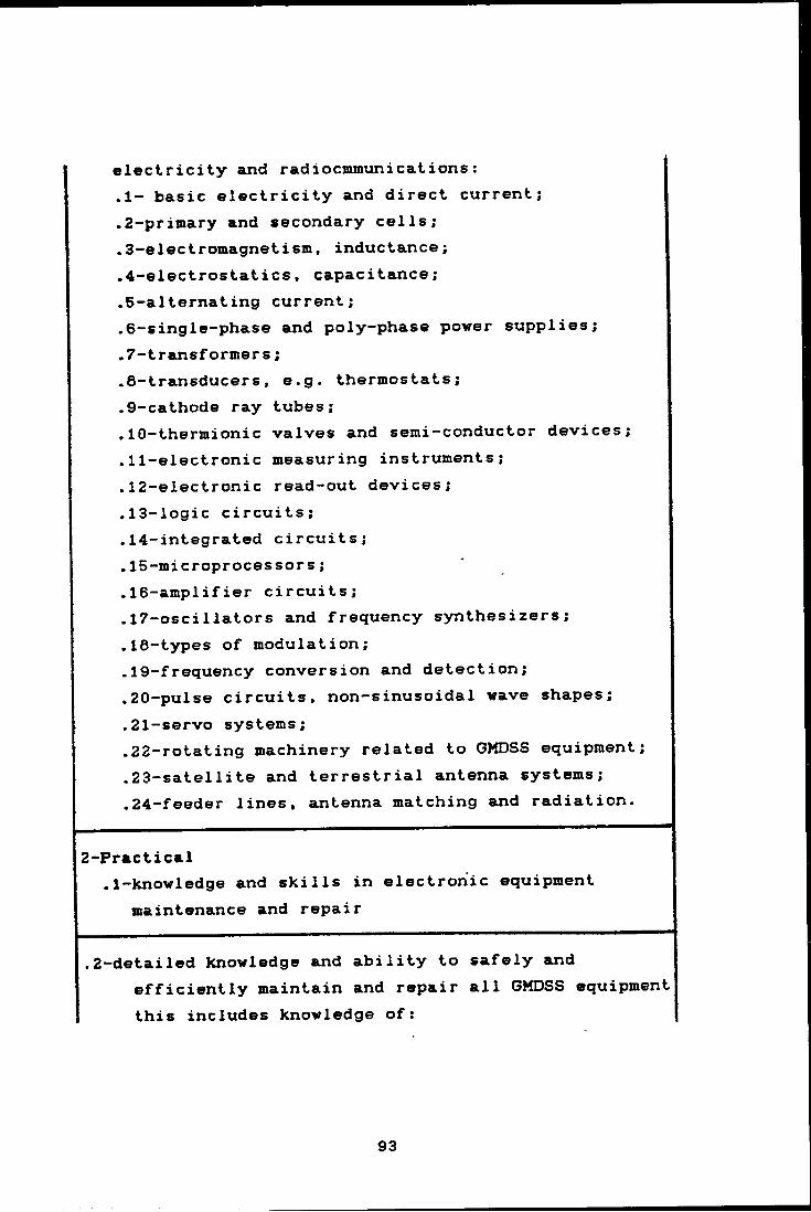
electricity and radiocmnunications:.1- basic electricity and direct current;• 2-priinary and secondary cells;.3-electromagnetism, inductance;.4-electrostatics, capacitance;.5-alternating current;.6-single-phase and poly-phase power supplies;.7-transformers;.8-transducers, e.g. thermostats;.9-cathode ray tubes;.10-thermionic valves and semi-conductor devices;. 11-electronic measuring instruments;. 12-electronic read-out devices;.13-logic circuits;.14-integrated circuits;.15-microprocessors;.16-amplifier circuits;.17-oscillators and frequency synthesizers; .18-types of modulation;.19-frequency conversion and detection;.20-pulse circuits, non-sinusoidal wave shapes; .21-servo systems;.22-rotating machinery related to GMDSS equipment; .23-satellite and terrestrial antenna systems; .24-feeder lines, antenna matching and radiation.
2-Practical.1-knowledge and skills in electronic equipment
maintenance and repair
.2-detailed knowledge and ability to safely andefficiently maintain and repair all GMDSS equipment this includes knowledge of:
93
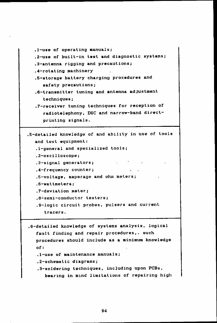
.1-use of operating manuals;
.2-use of built-in test and diagnostic systems;
.3-antenna rigging and precautions;
.4-rotating machinery
.5-storage battery charging procedures and safety precautions;
.6-transmitter tuning and antenna adjustment techniques;
.7-receiver tuning techniques for reception of radiotelephony I DSC and narrow—band direct- printing signals.
.5-detailed knowledge of and ability in use of tools and test equipment:.1-general and specialized tools;.2-oscilloscope;.3-signal generators;.4-frequency counter;.5-voltage, amperage and ohm meters;.6-wattmeters;.7-deviation meter;.6-semi-conductor testers;.9-logic circuit probes, pulsers and current
tracers.
.6-detailed knowledge of systems analysis, logical fault finding and repair procedures,, such procedures should include as a minimum knowledge of:.1-use of maintenance manuals;.2-schematic diagrams;.3-soldering techniques, including upon PCBs,
bearing in mind limitations of repairing high
94

density boards and modules;.4-voltage, current and resistance checks;.5-signal insertion and tracing methods;.6-system alignment methods;.7-neutralization , harmonic and parasitic signal
suppression techniques;.6-methods of alleviating electrical and
electromagnetic interference such as bonding, shielding and bypassing and filtering.
.7-knowledge of principles and practical methods of preventive maintenance.
.8-knowledge of supportive tasks such as:.1 recording of maintenance tests;.2 preparing reports and maintaining records of
repair work done and replacement parts used;
Table 5
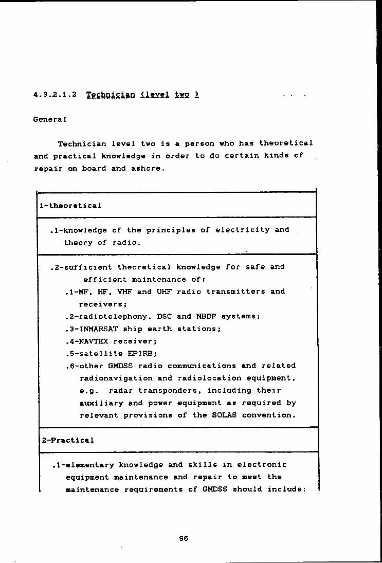
4.3.2.1.2 Technician (.1 evgi tjro 2 ...
General
Technician level two is a person who has theoretical and practical knowledge in order to do certain kinds of repair on board and ashore.
1-theoretical
.1-knowledge of the principles of electricity and theory of radio.
.2-sufficient theoretical knowledge for safe and efficient maintenance of:
.1-MF, HF, VHF and UHF radio transmitters and receivers;
.2-radiotelephony, DSC and NBDP systems;
.3-INMARSAT ship earth stations;
.4-NAVTEX receiver;
.5-satellite EPIRB;
.6-other GMDSS radio communications and related radionavigation and radiolocation equipment, e.g. radar transponders, including their auxiliary and power equipment as required by relevant provisions of the SOLAS convention.
2-Practical
.1-elementary knowledge and skills in electronic equipment maintenance and repair to meet the maintenance requirements of GMDSS should include:
96

.1-knowledge and ability to maintain GMDSSequipment. This should include knowledge of:
.1-use of operator manuals;
.2-performance of routine equipment tests;
.3-use of simple built-in test equipment;
.4-simple antenna repairs and precautions;
.5-storage battery charging procedures and safety precautions;
.6-addustment of operator accessible controls;!
.7-location and repair of simple faults.!
Tab1e 6
97
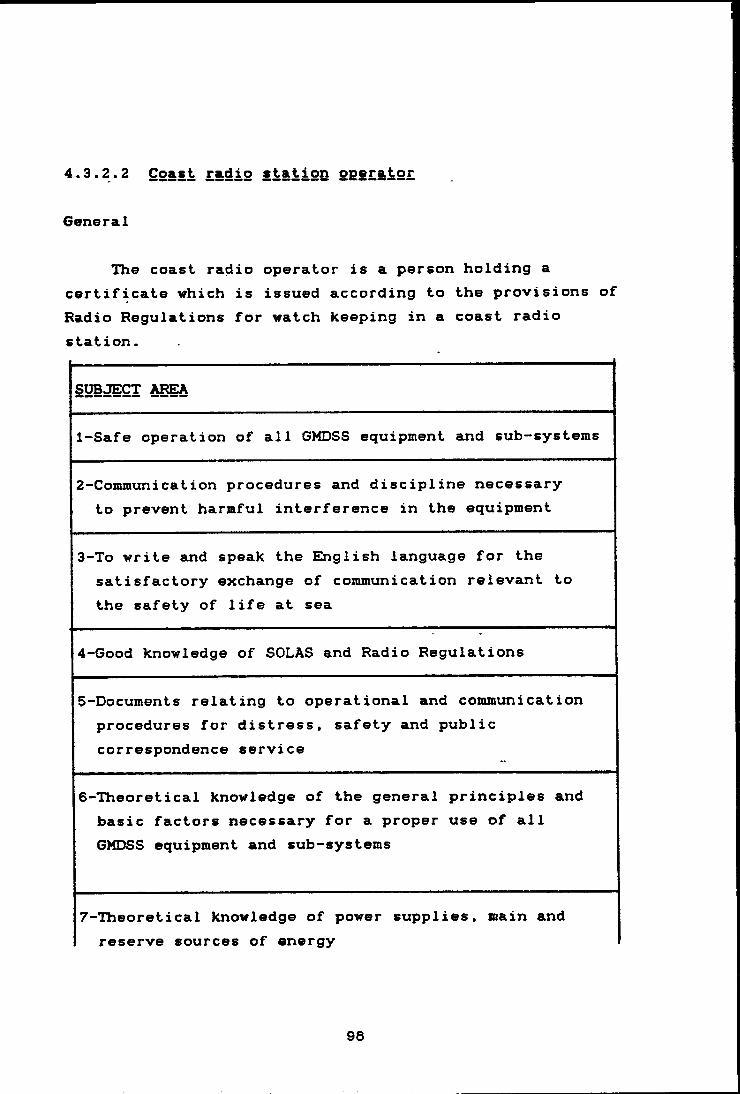
4.3.2.2 Coast radio station operator
General
cF6
The coast radio operator is a person holding a ertificate which is issued according to the provisions of adio Regulations for watch keeping in a coast radiotation.
SUBJECT AREA
1-Safe operation of all GMDSS equipment and sub-systems
2-Communication procedures and discipline necessary to prevent harmful interference in the equipment
3-To write and speak the English language for the satisfactory exchange of coxamunication relevant tothe safety of life at sea
4-Good knowledge of SOLAS and Radio Regulations
5-Documents relating to operational and communicationprocedures for distress, safety and public correspondence service
6-Theoretical knowledge of the general principles and basic factors necessary for a proper use of all GMDSS equipment and sub-systems
7-Theoretical knowledge of power supplies, main and reserve sources of energy
98
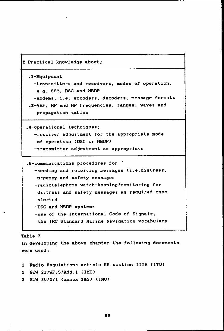
8-Practical knowledge about;
.1-Ekjuipment-transmitters and receivers, modes of operation, e.g. SSB, DSC and NBDP
-modems, i.e. encoders, decoders, message formats ,2-VHF, MF and HF frequencies, ranges, waves and
propagation tables
.4-operational techniques;-receiver adjustment for the appropriate mode of operation (DSC or NBDP)
-transmitter adjustment as appropriate
.5-communications procedures for-sending and receiving messages (i.e.distress, urgency and safety messages -radiotelephone watch-keeping/monitoring for distress and safety messages as required once alerted-DSC and NBDP systems-use of the international Code of Signals, the IMO Standard Marine Navigation vocabulary
Table 7In developing the above chapter the following documents were used:
1 Radio Regulations article 55 section 11lA (ITU)2 STW 21/WP.5/Add.1 (IMO)3 STW 20/2/1 (annex 1&2) (IMO)
99
CHARTER RIVE RERAIR AMD MAIMTEMAMCE
RAC I L_ I TV

chaf»te:fi f' IVE
REF»AIIR AND MAINTENANCE EACILITY
5.1 INTRODUCTION
Repair and maintenance are two important terms which are related to each other very closely., In other words, maintenance can be classified as both corrective and preventive maintenance.
5.2 Corrective maintenance
Corrective maintenance is composed of actions such as repairing, re-conditioning or exchanging which are designed to cure a fault or to bring back a piece of equipment to operation.
5.3 Preventive maintenance
Preventive maintenance is the other main type of maintenance. This alternative to corrective maintenance is based on the prevention of breakdowns by means of periodic inspections, adjustments, reconditioning, replacement or condition monitoring.
5.4 Need for repair and maintenance center (s>
The underlying concept of chapter IV, regulation 15, paragraphs 6 and 7 of GMDSS regulations is *’ availability
100
of equipment *’«. Availability will be realized through the employment of the three distinct methods which are :
5.4.1 Redundancy of equipment;5.4.2 On-board maintenance; and5.4.3 Shore-based maintenance.
Because "Redundancy " and "On-board maintenance " do not prevent a failure of some essential part of GMDSS equipment it is necessary to establish shore-maintenance facilities with qualified technicians and*a proper inventory of spare parts of the equipment in GMDSS at various locations.
By logical deduction, radio navigation availability may also be included in GMDSS regulations. In article 55 of the ITU Radio Regulations, radio navigational equipment is also mentioned.
The availability of shore based maintenance systems is especially important for those ships which do not employ on-board maintenance. E)ue to various reasons, the ^
number of these ships will increase in the future. To give a reason for this opinion, in the following a comparison is made between a ship which has a radio electronic officer on board and a ship which relies on shore-based repair and maintenance instead a radio electronic officer.
a Appendix four covers a thorough study aboutavailability and different options for availability on board ships.
101
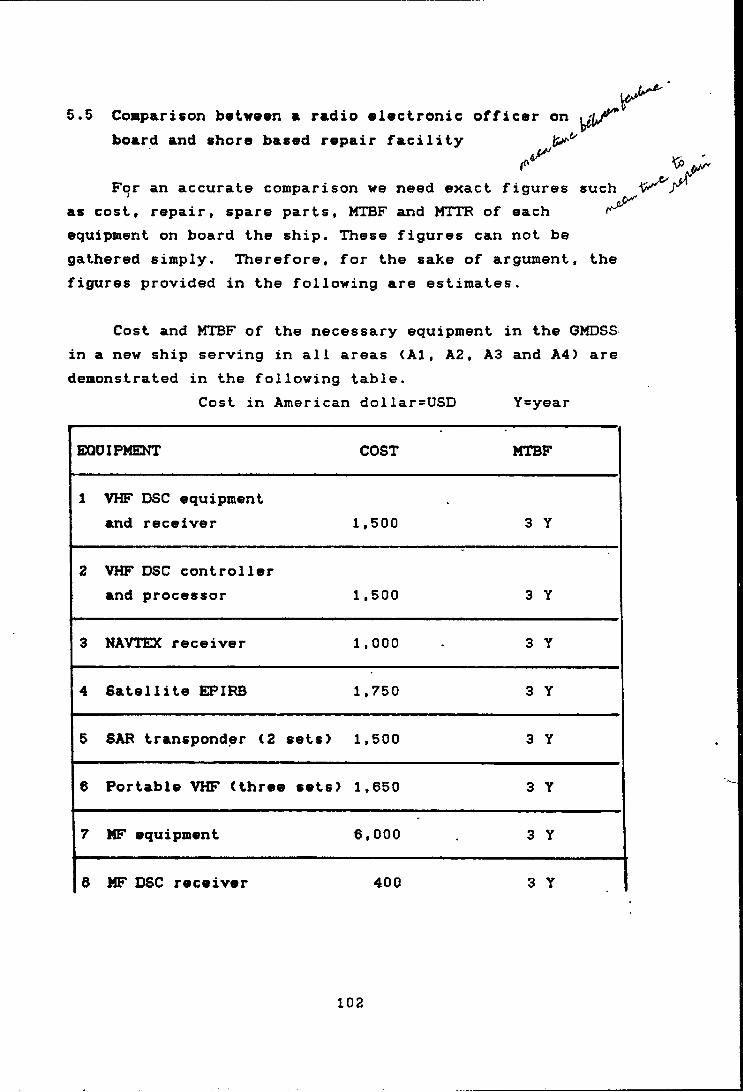
5.5 Conparison baivavn a radio alectronic officer onboard and shore based repair facility
For an accurate comparison we need exact figures as cost, repair, spare parts, MTBF and MTTR of each equipment on board the ship. These figures can not be gathered simply. Therefore, for the sake of argument, figures provided in the following are estimates.
such
the
Cost and MTBF of the necessary equipment in the CMDSS in a new ship serving in all areas (A1, A2, A3 and A4) are demonstrated in the following table.
Cost in American dollar=USD Y=year
EQOIPMENT COST MTBF
1 VHF DSC equipmentand receiver 1,500 3 Y
2 VHF DSC controllerand processor 1,500 3 Y
3 NAVTEX receiver 1,000 3 Y
4 Satellite EPIPB 1,750 3 Y
5 SAP transponder (2 sets) 1,500 3 Y
6 Portable VHF (three sets) 1,650 3 Y
7 MF equipment 6,000 3 Y
6 MF DSC receiver 400 3 Y
102
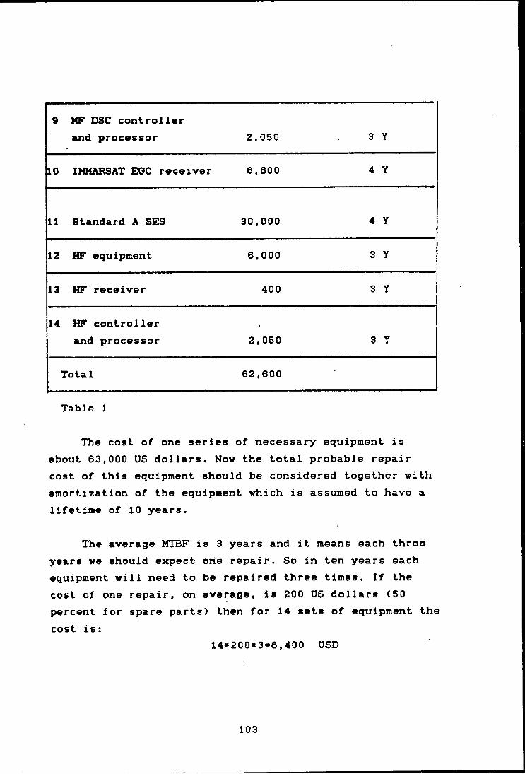
9 MF DSC controllerand processor 2,050 3 Y
10 INMARSAT EGC receiver 6,800 4 y
11 Standard A SES 30,000 4 Y
12 HF equipment 6,000 3 Y
13 HF receiver 400 3 Y
14 HF controllerand processor 2,050 3 Y
Total 62,600 •
Table 1
The cost of one series of necessary equipment is about 63,000 US dollars. Now the total probable repair cost of this equipment should be considered together with amortization of the equipment which is assumed to have a lifetime of 10 years.
The average MTBF is 3 years and it means each three years we should expect oiie repair. So in ten years each equipment will need to be repaired three times. If the cost of one repair, on average, is 200 US dollars (50 percent for spare parts) then for 14 sets of equipment the cost is:
14<»200*3=8,400 USD
103

Now in case of a ship relying on shore-based repair, we need redundancy, so the whole equipment should be duplicated as the GMDS5 regulations dictate. So the above costs should be also doubled.
Two sets of ©quipment=2*63,000= 126,000 USD Repair cost =2w 8,400= 16,600 USD
Amortization (10 years) 126,000 USD
268,800 USDTo the above figure the loss of interest of the extra
investment should be added.10% interest of the investment in 10 years is:
2*(63,000= 126,000 USD
394,600 USD
Now for a ship which relies on a radio electronic officer with one set of equipment, the following costs are expected:One set of the equipment 63,000 USD10% interest in 10 years 63,000 USDSalary per month 3000 $ (including leave, replacement, lodging, food and etc..) and in one year
3000*12= 36,000 USD In ten years the salary is:
36000 * 10 =360,000 USD Spare parts for the same number of repair
14*3*100 = 4,200 USDAmortization (10 years) 63,000 USD
553,200 USD
104
5.5.1 Total •xpanta
In the above simple cost comparison the benefit of the shore-based repair is clearly obvious. In this assessment one should also observe the other difficulties such as:
.1 On board the ship it is not possible to have complete repair for all faults
.2 On board the ship it is not possible to install all the necessary test machines and tools
.3 On board the ship it is not possible to have complete set of spare parts.
By the foregoing discussion it can be concluded that relying on a shore-based maintenance and repair system ( vith redundant equipment > is a good solution for maintaining all the equipment on board the ship safely and economically.
In addition to the above result, one should also notice that the modern digitized equipment has a very high MTBF and Built In Test Equipment (BITE). It means a high availability of the equipment.
5.6 Demand anticipation
In order to assess the need for implementing a shore- based repair and maintenance center in Iran it is necessary to analyse the users demand. Thereby, various factors which are related to the demand anticipation
105
should be considered carefully such as:
5.6.1 Ship traffic;5.6.2 Agreements for preventive maintenance with
shipping lines;5.6.3 Number of ships in the national shipping lines;5.6.4 Number of vessels in the local traffic;5.6.5 International shipping traffic;5.6.6 MTBF and WITH of GMDSS equipment.
5.6.1 Ship traffic
The statistics of ship traffic in the Persian Gulf and Gulf of Oman show that there were, on the average,1,000 ocean going cargo ships ( the tanker statistics are not available > involved in the yearly traffic to and from Iranian ports (from 1963 up to 1967). If we assume that these 1,000 ships are within the Persian Gulf region for about 10 per cent of their operational time, that would be equivalent to 100 ships permanently in the Persian Gulf. To this we should add the number of ships calling at the other ports in the area.
5.6.2 Agreements for preventive maintenance with shipping lines
For those regular trade ships which rely on' shore- based maintenance in order to guarantee the availability of their GMDSS equipment, preventive maintenance is an optimal choice. In this respect a preventive maintenance agreement with a well situated shore-based repair center is desirable.
106
5.6.3 Humber of ships in the national shipping lines
Iran has two national shipping companies mainly for carriage of cargo and oil. According to the International statistics as of January 1st, 1969 the number of Iranian ships are as follows:
44 oil tankers 9 chemical carriers
51 bulk S ore carriers 25 general cargo ships 42 multi-deck cargo carriers 6 ferries
177 *The rapid expansion of the Iranian fleet also should
be considered. This can be determined from the tonnage policy in the short and long term programs of the country.
5.6.4 Number of vessels in the local traffic
There are different types of local vessels which operate continuously in the Persian Gulf and Gulf of Oman such as small and wooden fishing and cargo carrier vessels as well as tug boats and other steel hull made vessels.The radio communication equipment aboard these vessels also varies. At this moment, for instance, many small vessels do not carry VHP, which will change in the future. As VHP equipment also needs maintenance and repair, the center can give service to these vessels as well. The number of local vessels is estimated to be around 3,000.
a Shipping statistics yearbook 1989.
107

5.6.5 International shipping traffic
It is mentioned in chapter two that the traffic in the Strait of Hormuz is very dense, each 24 hours about 100 ocean going ships pass this strategic strait. In addition the southern Persian Gulf countries have the following number of ships in their merchaint fleets:
1- Saudi Arabia 1402- Iraq 41.3- United Arab Einirates 854- Kuwait 535- Qatar 186- Bahrain S7- Oman 4
So the total number of ships owned by the Persian Gulf states is 527. To this figure we should add the number of foreign vessels, especially tankers, which are coming in the area.
The period which the above ships spend in the area is also an important factor. Normally the tankers do not spend more than two or three days but for other types of vessels, like general cargo vessels, it depends on the congestion of the ports, and it can be be about 15 days.
5.6.6 MTBF and MTTR of GMDSS equipment
MTBF and MTTR of are two important parameters for the reliability and availability of equipment. MTBF nowadays is very large in modern communication equipment (e.g. INMARSAT standard C) and MTTR is small with
108
increased use of digital equipment and the application of BITE. As availability equals 1-MTTR/MTBF it is clear that the availability is very high in modern digital equipment.
If ve suppose that MTBF of a VHF set is one year, and the number of ships permanently in the Persian Gulf sjnounts to 100«, the number of estimated repairs for such equipment is 100 per year and this is only for one piece of equipment. Normally this MTBF should be constant during the useful lifetime. The useful lifetime is based on manufacturers advice which can be found in the maintenance requirements of equipment. The-useful lifetime may also be affected by Governmental or international regulations. Experience of the repair centers is another important factor for determining the useful lifetime of the GMDSS equipment, as the useful lifetime of a part in general is inversely related to the repair frequency of that part.
5.7 GMDSS repair center
The best site for such a center could be the port of Faddaei, since it is on the way of all in-going ships toward different ports in the Persian Gulf area. A proper anchorage area or berth should be available for the ships while their radio or electronic equipment is under repair.
There should be a direct connection between the center and the Iranian INMARSAT CES which can either be through the National telephone network or by a INMARSAT *
* Refer to ships traffic (page 7)
109
standard A or C. This facility makes the center able to connect with ships at sea when they need assistance. It is also helpful for riding crew when they are working at sea and encountering a technical problem or they need other assistance.
5.6 Necessary equipment
A list of necessary automated,> computerized test equipment, test digs, specialized automated test programs, and repair facilities for automated computerized test equipment must be developed for all GMDSS equipment requiring such repair techniques.
5.9 Organization of a repair and maintenance.center
The service of the shore-based maintenance facility should be on a continuous basis. The technical personnel of the shore-based maintenance facility should be qualified and it is necessary to provide "riding-crews” to leave port with the vessel while completing repairs.
Therefore there should be enough technicians for twenty four hours a day both in the repair center and the inventory section for spare parts.
Two levels of technicians should be considered for manning the center. Level two is able to do preventive maintenance and a restricted repair dob, and level one has higher ability and experience for repairing any equipment.
Riding crews of the center can mainly be from level one technicians.
110

Because the concentration of local vessels is noraally around the mador ports, it is advisable to have branches of the repair center in other ports for such local vessels C port of Bushehr can be the first branch >.
5.9.1 Inventory for spare parts
GMDSS shore-based repair and maintenance facilities must maintain an inventory of sufficient complete, main units to meet the demand anticipated.
The extent of the necessary spare parts in the stock depends on the demand anticipation on the one hand and the number of equipment which is required in the system on the other hand. In the following, the list of major GMDSS equipment and equipment necessary on board as radio- navigational equipment are mentioned.
Ill
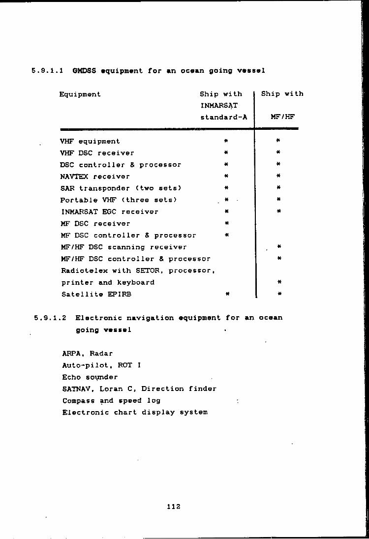
5.9.1.1 GMDSS •quipment for an ocean going vessel
Equipment Ship withINMARSATstandard-A
VHF equipment * VHF DSC receiver * DSC controller & processor * NAVTEDC receiver * SAR transponder (two sets) * Portable VHF (three sets) . * INMARSAT EGC receiver « MF DSC receiverMF DSC controller & processor ^ MF/HF DSC scanning receiverMF/HF DSC controller & processor Radiotelex with SETOR, processor, printer and keyboard Satellite EPIRB
5.9.1.2 Electronic navigation equipment for an going vessel
ARPA, Radar Auto-pilot, ROT I Echo sounderSATNAV, Loran C, Direction finder Compass and speed log Electronic chart display system
Ship with
MF/HF
n*
*M
ocean
112
5.9.2 Spare control system
Repair and maintenance can not succeed without an adequate spare parts control system. Both of them are complementary and require a good stock ordering strategy of the center. If any required spare part is not available in stock it mean loss of money and time which can be very expensive for a ship.
Information about the location of the item, ordering data, e.g. re-order level, quantity, normal stock, ■etc.,specification and name of the spare part is very ^ vital for the control system.
Therefore, all the equipment is identified by means of a code number to which can be added the manufacture's code number in order to facilitate ordering transactions of spare parts.
The system is using cabinets and composed of the following main parts:
-cabinets with drawers-miscellaneous cards for technical data, consumption and stock card -ordered/received cards-labels for identification of spare parts -store issue notes-signals for noticing of spare parts to be ordered,etc.
113
5.9.3 Coding system
There is a decimal coding system which is one of the most suitable for combining management, maintenance and spare control systems.
The system is for example based on six figures, where the first is used to identify the main groups. All equipment is divided according to different capability.For example we can divide the radio and navigational equipment according to the following 8 groups.
.1 VHF DSC
.2 MF DSC
.3 HF DSC
.4 INMARSAT standard A or C and its components
.5 NAVTEX receiver
.6 EPIRB and SAR transponder
.7 ARPA and radar and their components
.8 Other electronic navigation equipment
A Sub-system is a more detailed breakdown of the main groups and is identified by the second figure in this coding system. It means, with this digit, up to ten subheadings might be represented in each group.
The third and fourth figures are for a specified part of a component. Fifth and sixth figures are used for the number of spare parts in the component.
An example of the aforesaid coding system could be as f ollows:
114

VHF DSC receiver
Code number 1/0/04/10Ilf I• • * • . * * ^
Main group------ ! ! ! !Sub-heading-------- 1 *Component------------- ! 'Spare part--------------- i
Therefore we can get necessary information for each spare part such as:
For the above mentioned VHF DSC receiver with the code 1/0/04/10
Spare part 1/0/04/10
1 Name2 Manufacturer ref No.3 Vendor4 Location5 No. on order6 Order date7 No. in stock6 Max No. in stock 9 Min. No. in stock
10 Used last year11 Used this year12 Price13 Currency14 Date
115

The above numbering coding system needs a computerized stock control. In this regard one may use the ready programmed frame-work for the system from the market or it is possible to develop a Data Base program for the system. In the data base each file may contain the specification of one spare part.

CHAPTBR SXXCONCL.USIONS&RECOMMENDATIONS
chaf»te:er s I :x:CONCr-US I ONS & RECOMMENOAT I ONS
6.1 Conclusions
By the advancement of technology and employment of high tech equipment on board ships, the following developments are expected to take place;
-The reduction of crew to a minimum level; and-The increase of safety of navigation and protection ofthe maritime environment at a very high level.
In this process the role of communication on board is very important and it is entrusted to high tech systems such as satellite communication, terrestrial DSC and NBDP. Therefore, it is very essential for the maritime administrations to have a future plan ready for meeting these new trends of automation in every aspect.
The GMDSS, adopted by IMO in 1986, is a dramatic change in the regulations for maritime communication.The participation of coastal states in these new requirements is much more than before. The morse code will be phased out and a new digital system will take over. The conventional radio officer is no longer necessary on board. Equipment redundancy and increasing MTBF will enhance the availability of equipment enormously. Satellite communications will have a major role in maritime communication.
The shores of many countries will be equipped with
117
radio and satellite stations. SAR activity will become more sophisticated and RCC's will be installed in strategic positions.
Maritime Safety Information will be sei)t from the coast to ships by special procedures. ^
The investments, both aboard ships and ashore will be high, but if the management of the amortization is properly adjusted then the result will be very effective and unnecessary expenditures can be avoided. The cooperation among neighboring countries is also very crucial in budgeting for the new requirements.
As it is mentioned in different chapters of this project, a lot of work needs to be done to establish the new requirements of GMDSS in Iran. Therefore, priority should be given to the aspects of safety of navigation in allocating the budget:
1 Division.of coastal water according to therequirement of GMDSS (A1, A2, ...).
2 The establishment of CRSs along the coast of Persian Gulf and Gulf of Oman.
3 The establishment of a Coast Earth Station (CES) near Tehran.
4 Co-operation with the Local User Terminal (LUT) in Pakistan.
5 The establishment of NAVTEX stations for sending Maritime Safety Information (In the Persian Gulf and Gulf of Oman).
6 The establishment of a Repair and Maintenance Center in Port of Shahid Radjaei, and branches in other
116
ports.7 The training of qualified personnel for ships and
the Repair and Maintenance Center.6 The establishment of RCCs.
Regarding the radio officer/operator and his role in our shipping, we should try to find a unified solution for all cargo and tanker ships, taking into consideration that it is not possible to do all repair on board the ship. It is possible to do some maintenance or repair of electronic equipment on board but this is not enough, the shore~based maintenance and repair center can be very helpful or the main solution.
6.2 Recommendations
The following recommendations could be very helpful for maritime safety communication and administration.
1 The use of a shore-based repair and maintenance center as a replacement for the radio electronic officer.This is available when the center can be fully operational and well manned. So it can carry out all the repairs and maintenance of ship equipment. This program is already implemented by some developed countries such as the Netherlands.
2 Use of VHF Direction Finders for determination of positions of ships in the coastal area (VHF D.F.).Every small craft or vessel should have a VHF on board. Then in case of an emergency as soon as a VHF contact is made the RCC, SRCCs and CRS can find the position of the vessel.
119
3 The organization of a repair and maintenance center and its legal entity. There could be a preparatory committee for the establishment of this center which could consist of a few experts from PSO and the satellite section of the telecommunication ministry. , The agenda of this committee could bej
3.1 Legal entity of the center (Governmental or Private)
3.2 Primary investment3.3 Organizational structure3.4 Training, for qualified personnel3.5 Operational structure
4 The ratification of SOLAS and SAP conventions and establishment of RCCs and SRCCs.
5 Co-operation with neighboring countries in terms of using available resources in the region to the benefit of maritime safety. There is a possibility to establish an MRCC ( Master RCC ) for the whole region and RCC in each country around the PersiaP—GaJLX-.- In this case the management of the search and rescue operation should be international, comprising of experts and equipment from all coxmtries in the Persian Gulf. In this way the area can be divided for each area co-ordinator and all efforts can be controlled through a MRCC.
6 A control center for every incoming and outgoing ship for the benefit of safety of navigation and protection of the marine environment. This should contain a reporting system specially for those ships carrying dangerous cargoes.
120

ARREtSJD I X 1.
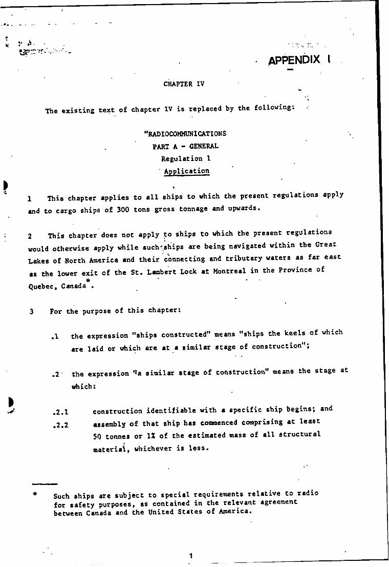
appendix I
CHAPTER IV
The existing text of chapter IV is replaced by the following;
•'RADIOCOMMUNICATIONS PART A - GENERAL
Regulation 1 Application
►1 This chapter applies to all ships to which the present regulations apply and to cargo ships of 300 tons gross tonnage and upwards.
2 This chapter does not apply to ships to which the present regulationswould otherwise apply while such'ships are being navigated within the GreatLakes of North America and their connecting and tributary waters as far eastas the lower exit of the St. Lambert Lock at Montreal in the Province of
* ' *Quebec, Canada .
3 For the purpose of this chapter:
.1 the expression "ships constructed" means "ships the keels of which are laid or which are at a similar stage of construction";
.2 the expression ‘‘a similar stage of construction" means the stage at
which:
.2.1 construction identifiable with a specific ship begins; and
.2.2 assembly of that ship has commenced comprising at least50 tonnes or IZ of the estimated mass of all structural material, whichever is less.
Such ships are subject to special requirements relative to radio for safety purposes, as contained in the relevant agreement Hatween Canada and the United States of America.
1
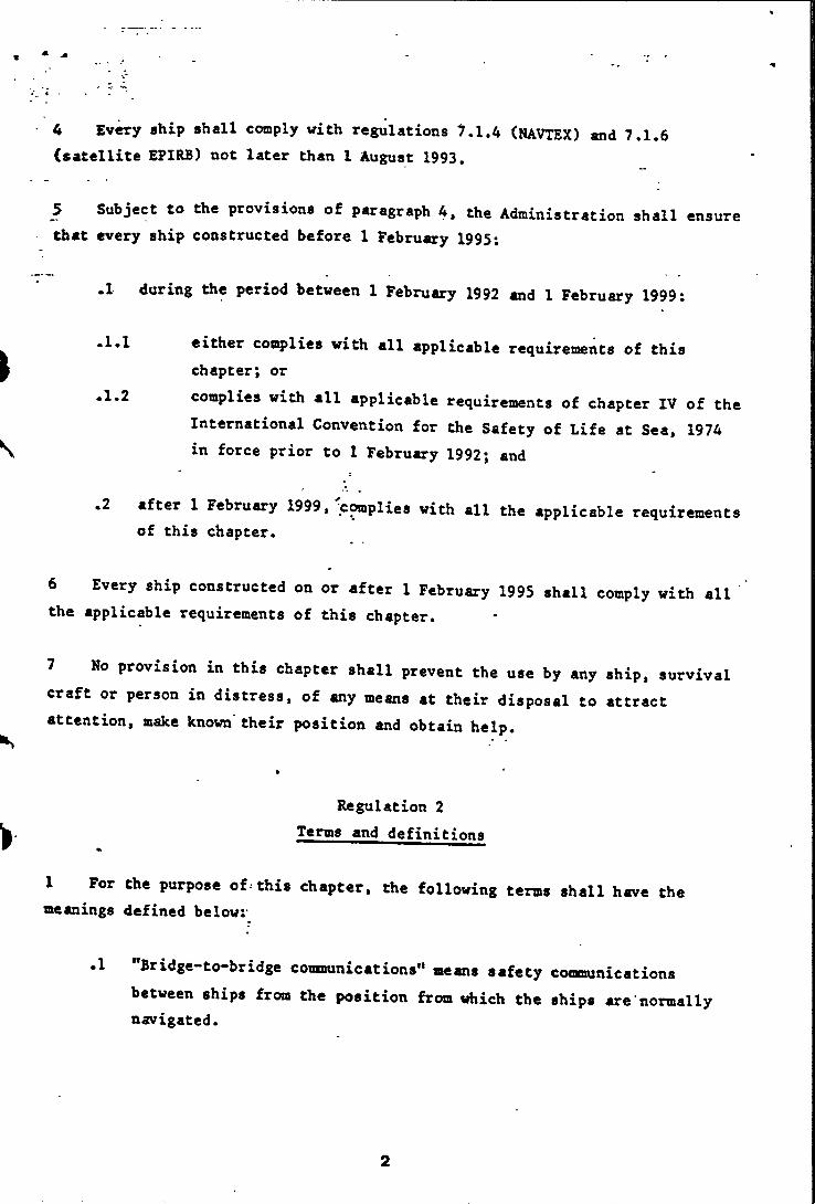
4 Every ship shall comply with regulations ^.1.4 (NAVTEX) and 7.1,6 (satellite EPIRB) not later than 1 August 1993.
5 Subject to the provisions of paragraph 4, the Administration shall ensure Chat every ship constructed before 1 February 1995:
.1 during the period between 1 February 1992 and 1 February 1999:
either complies with all applicable requirements of this chapter; or
.1.2 complies with all applicable requirements of chapter IV of theInternational Convention for the Safety of Life at Sea, 1974 in force prior to 1 February 1992; and
.2 after 1 February 1999, c^plies with all the applicable requirements of this chapter.
6 Every ship constructed on or after 1 February 1995 shall comply with all the applicable requirements of this chapter.
7 No provision in this chapter shall prevent the use by any ship, survival craft or person in distress, of any means at their disposal to attract attention, make known their position and obtain help.
Regulation 2 Terms and definitions
1 For the purpose of•this chapter, the following terms shall have the meanings defined belowv
.1 "Bridge-to-bridge comnunications" means safety comminicationsbetween ships from the position from which the ships are normally navigated.
2

“Continuous watch" roeans that the radio watch concerned shall not be interrupted other than for brief intervals when the ship'If receiving capability is impaired or blocked by its own communications or when the facilities are under periodical maintenance or checks.
"Digital selective calling (DSC)" means a technique using digital codes wliich enables a radio station to establish contact with, and transfer information to, another station or group of stations, and complying with the relevant recommendations of the International Radio Consultative Committee (CCIR).
"Direct-printing telegraphy" means automated telegraphy techniques which comply with the relevant recommendations of the International Radio Consultative Coiraiiittee (CCIR).
"General radiocommunications" means operational and public correspondence traffic', other than distress, urgency and safety messages, conducted by radio.
"INMARSAT" means the Organization established by the Convention on the International Maritime Satellite Organization (INMARSAT) adopted on 3 September 1976.
"International N^VTEX Service" means the co-ordinated broadcast andautomatic reception on 518 kHz of maritime safety information bymeans of narrowband direct-printing telegraphy using the English
*language .
"Locating" means the finding of ships, aircraft, units or persons in distress.
"Maritime safety information" means navigational and-meteorological warnings, meteorological forecasts and other urgent safety related messages broadcast to ships.
Reference is made to the NAVTEX manual approved by the Organization.
3
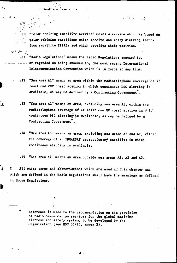
.4
' .-.10 "Polar orbiting satellite service" means a service which is based on ■■ ■ ■■• polar orbiting satellites which receive and relay distress alerts
from satellite EPIRBs and which provides their position.
"Radio Regulations" means the Radio Regulations annexed to, or regarded as being annexed to, the most recent International Telecommunication Convention which is in force at any time.
.12 "Sea area Al" means an area within the radiotelephone coverage of at P least one VHP coast station in which continuous DSC alerting is
available, as may be defined by a Contracting Government*.
.13 "Sea area A2" means an area, excluding sea area Al, within theradiotelephone coverage .of at least one MF coast station in which continuous DSC alerting; is available, as may be defined by a Contracting Government ..
.14 "Sea area A3" means an area, excluding sea areas Al and A2, within the coverage of an INMARSAT geostationary satellite in which continuous alerting is available.
.15 "Sea area A4" means an area outside sea areas Al, A2 and A3.
} 2 All other terms and abbreviations which are used in this chapter andwhich are defined in the Radio Regulations shall have the meanings as defined in those Regulations.
\
Reference is made to the reconnendation on the provision of radiocommunication services for the global maritime distress and safety system, to be developed by the Organization (see MSC 55/25, annex 3).
4 •

Regulation 3 Exemptions
1 The Contracting Governments consider it highly desirable not to deviate from the requirements of this chapter; nevertheless the Administration may grant partial or conditional exemptions to individual ships from the requirements of regulations 7 to 11 provided;
.1 such ships comply with the functional requirements of regulation 4; and
.2 the Administration has taken into account the effect such exemptions may have upon the general efficiency of the service for the safety of all ships.
2 An exemption may be granted under paragraph 1 only:
.1 if the conditions affecting safety are such as to render the full application of regulations 7 to 11 unreasonable or unnecessary;
.2 in exceptional circumstances, for a single voyage outside the sea area or sea areas for which the ship is equipped; or
.3 prior to 1 February 1999, when the ship will be taken permanently out of service within two years of a date prescribed by regulation 1 for the application of a requirement of this chapter.
3 Each Administration shall submit to the Organization, as soon as possible after the first of January in each year, a report showing all exemptions granted under paragraphs 1 and 2 during the previous calendar year and giving the reasons for granting such exemptions.
5
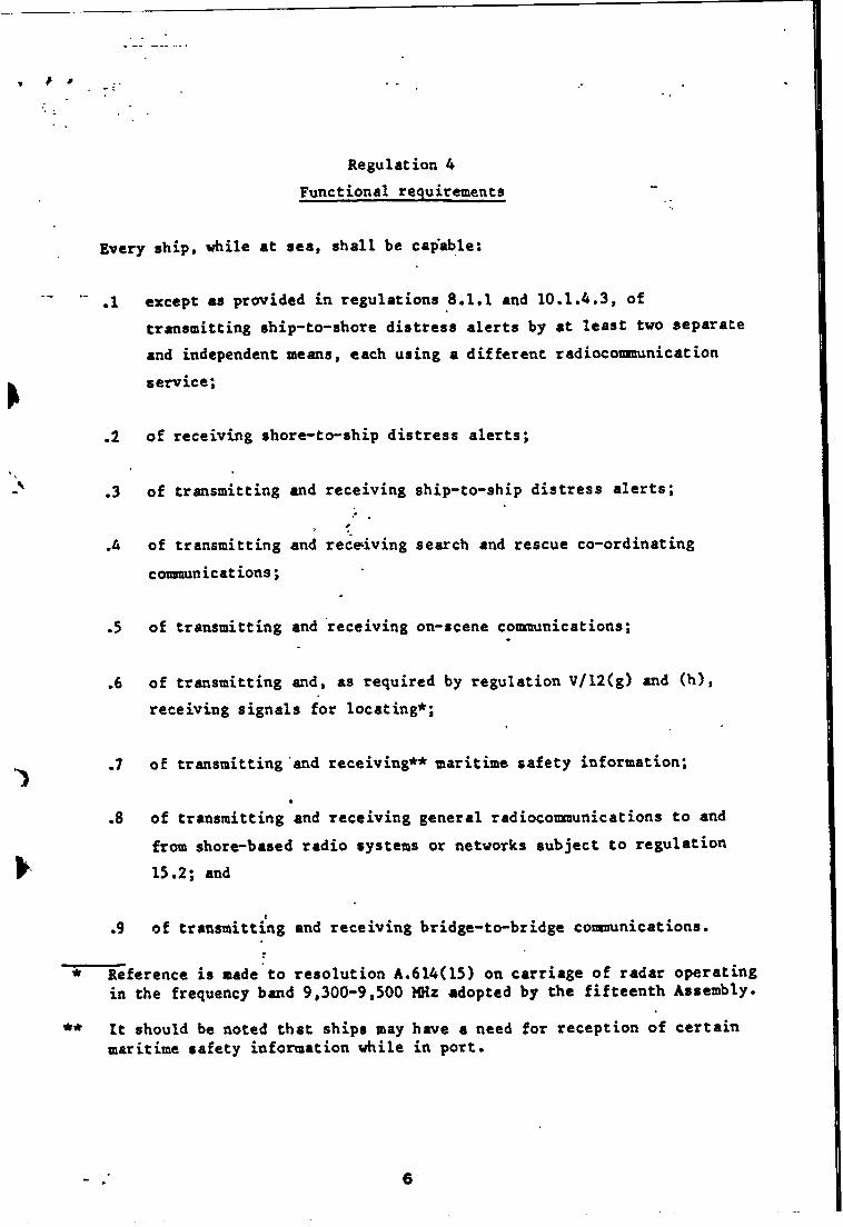
/ »
Regulation 4 Functional requirements
Every ship, while at sea, shall be cap'able:
.1 except as provided in regulations 8.1.1 and 10.1.4.3, oftransmitting ship-to-shore distress alerts by at least two separate and independent means, each using a different radiocoionunication service;
.2 of receiving shore-to-ship distress alerts;
.3 of transmitting and receiving ship-to-ship distress alerts;
.4 of transmitting and rece^iving search and rescue co-ordinatingcommunications;
.5 of transmitting and receiving on-scene communications;
.6 of transmitting and, as required by regulation V/12(g) and (h), receiving signals for locating*;
of transmitting and receiving** maritime safety information;
of transmitting and receiving general radiocommunications to and from shore-based radio systems or networks subject to regulation 15.2; and
of transmitting and receiving bridge-to-bridge communications.
* Reference is made to resolution A.614(15) on carriage of radar operating in the frequency band 9,300-9,500 MHa adopted by the fifteenth Assembly.
** It should be noted that ships may have a need for reception of certain maritime safety information while in port.
6
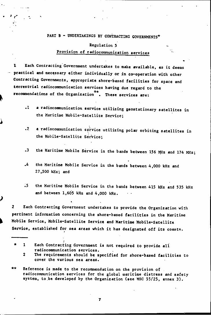
PART B - UNDERTAKINGS BY CONTRACTING GOVERNMENTS*
Regulation 5Provision of radioconirnunication services
«1 Each Contracting Government undertakes to make available, as it deems practical and necessary either individually or in co**operation with other Contracting Governments, appropriate shore-based facilities for space and terrestrial radiocomunication services having due regard to the recommendations of the Organization . These services are;
.1 a radiocommunication service utilizing geostationary satellites in the Maritime Mobile-Satellite Service;
,2 a radiocommunication service utilizing polar orbiting satellites in the Mobile-Satellite Service;
.3 the Maritime Mobile Service in the bands between 156 MHz and 174 MHz
.4 the Maritime Mobile Service in the bands between 4,000 kHz and27,500 kHz; and
.5 the Maritime Mobile Service in the bands between 415 kHz and 535 kHz and between 1,605 kHz and 4,000 kHz. • ■
a ^2 Each Contracting Government undertakes to provide the Organization with pertinent information concerning the shore-based facilities in the Maritime Mobile Service, Mobile-Satellite Service and Maritime Mobile-Satellite Service, established for sea areas which it has designated off its coasts.
* * ' •
* 1 Each Contracting Government is not required to provide allradiocommunication services.
2 The requirements should be specified for shore-based facilities to cover the various sea areas.
■* Reference is made to the recommendation on the provision ofradiocommunication services for the global maritime distress and safety system, to.be developed by the Organization (see MSC 55/25, annex 3).
7
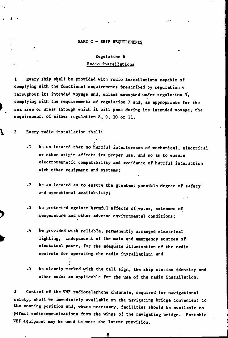
i •
PART C - SHIP REQUIREMENTS
Regulation 6 Radio installations
-1 Every ship shall be provided with radio installations capable of complying with the functional requirements prescribed by regulation 4 throughout its intended voyage and, unless exempted under regulation 3, complying with the requirements of regulation 7 and, as appropriate for the sea area or areas through which it will pass during its intended voyage, the requirements of either regulation 8, 9, 10 or 11.
2 Every tadio installation shall:
.1 be so located that no harmful interference of mechanical, electrical or other origin affects -its proper use, and so as to ensure electromagnetic compatibility and avoidance of harmful interaction with other equipment and systems;
.2 be so located as to ensure the greatest possible degree of safety and operational availability;
.3 be protected against harmful effects of water, extremes of temperature and other adverse environmental conditions;
.4 be provided with reliable, permanently arranged electrical lighting, independent of the main and emergency sources of electrical power, for the adequate illiimination of the radio controls for operating the radio installation; and
.5 be clearly marked with the call sign, the ship station identity and other codes as applicable for the use of the radio installation.
3 Control of the VHF radiotelephone channels, required for navigational safety, shall be isnediately available on the navigating bridge convenient to the conning position and, where necessary, facilities should be available to permit radiocommunications from the wings of the navigating bridge. Portable VHF equipment may be used to meet the latter provision.
8

Regulation 7Radio equipment - General
1 Every ship shall be provided with;
.1 a VHF radio installation capable of transmitting and receiving:
*.1.1 DSC on the frequency 156.525 MHz (channel 70). It shallI
be possible to initiate the transmission of distress alerts on channel 70 from the position from which the ship is normally
icicnavigated *, and
.1.2 radiotelephony on the frequencies 156.300 MHz (channel 6),156.650 MHz (channel 13) and 156.800 MHz (channel 16);
.2 a radio installation capable of maintaining a continuous DSC watchon VHF channel 70 which may be separate from, or combined with, that
**required by subparagraph .1.1 ;
.3 a radar transponder capable of operating in the 9 GHz band, which*.
.3.1 shall be so stowed that it can be easily utilized; and
•3.2 may be one of those required by regulation 111/6.2.2 for aesurvival craft;
.4 a receiver capable of receiving International NAVTEX servicebroadcasts if the ship is engaged on voyages in any area in which an International NAVTEX service is provided;
Digital selective calling (DSC) for all ships and HF direct-printing telegraphy (NBDP) carriage requirements for ships of 300 tons gross tonnage and over but less than 1,600 tons gross tonnage are subject to review in accordance with resolution A.606(15) - Review and evaluation of the GMDSS. Unless otherwise specified this footnote applies to all DSC and NBDP requirements prescribed in the Convention."Certain ships may be exempted from this requirement (see regulation 9.4).
9
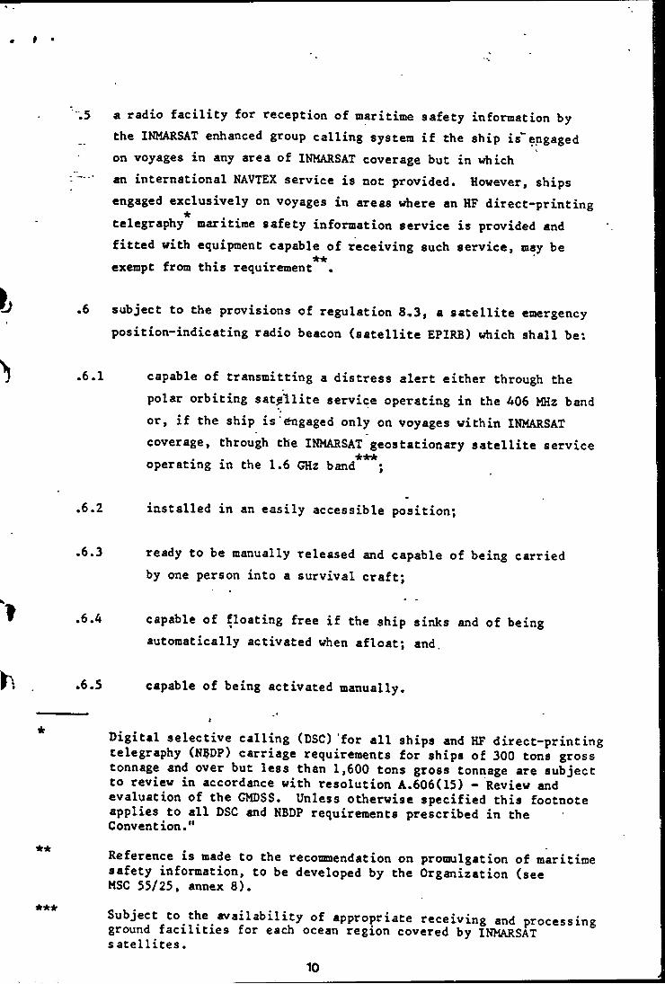
f
b
'l
?h
.5 a radio facility for reception of maritime safety information by the INMARSAT enhanced group calling system if the ship is^engaged on voyages in any area of INMARSAT coverage but in which
- • an international NAVTEX service is not provided. However, shipsengaged exclusively on voyages in areas where an HF direct-printing telegraphy maritime safety information service is provided and fitted with equipment capable of receiving such service, may be exempt from this requirement
.6 subject to the provisions of regulation 8,3, a satellite emergency position-indicating radio beacon (satellite EPIRB) which shall be:
.6.1 capable of transmitting a distress alert either through thepolar orbiting satellite service operating in the 406 MHz band
if the ship is Engaged only on voyages within INMARSAT coverage, through the INMARSAT geostationary satellite service operating in the 1.6 GHz band ;
.6.2 installed in an easily accessible position^
•6.3 ready to be manually released and capable of being carriedby one person into a survival craft;
.6.4 capable of floating free if the ship sinks and of beingautomatically activated when afloat; and.
.6.5 capable of being activated manually.
Digital selective calling (DSC) for all ships and HF direct-printing telegraphy (N?DP) carriage requirements for ships of 300 tons gross tonnage and over but less than 1,600 tons gross tonnage are subject to review in accordance with resolution A.606(15) - Review and evaluation of the GMDSS. Unless otherwise specified this footnote applies to all DSC and NBDP requirements prescribed in the Convention."
Reference is made to the recommendation on promulgation of maritime safety information, to be developed by the Organization (see MSC 55/25, annex 8).
Subject to the availability of appropriate receiving and processing ground facilities for each ocean region covered by INMARSAT satellites.
10
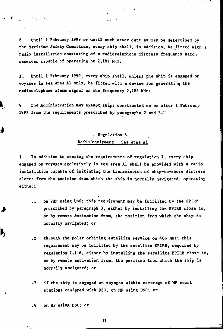
T
2 Until 1 February 1999 or until such other date as may be determined by the Maritime Safety Conmittee, every ship shall, in addition, be Jfitted with a radio installation consisting of a radiotelephone distress frequency watch receiver capable of operating on 2,182 kHz.
3.. Until 1 February 1999, every ship shall, unless the ship is engaged on voyages in sea area A1 only, be fitted with a device for generating the radiotelephone alarm signal on the frequency 2,182 kHz;
4 The Administration may exempt ships constructed on or after 1 February 1997 from the requirements prescribed by paragraphs 2 and 3."
Regulation 8Radio equipment - Sea area Al
1 In addition to meeting the requirements of regulation 7, every ship engaged on voyages exclusively in sea area Al shall be provided with a radio installation capable of initiating the transmission of ship-to**shore distress alerts from the position from which the ship is normally navigatedj operating either:
4.1 on VHF using DSC; this requirement may be fulfilled by the EPIRBprescribed by paragraph 3, either by installing the EPIRB close to, or by remote Activation from, the position from^which the ship is normally navigated; or
.2 through the polar orbiting satellite service on 406 MHz; thisrequirement may be fulfilled by the satellite EPIRB, required by regulation 7.1.6, either by installing the satellite EPIRB close to, or by remote activation from, the position from which the ship is normally navigated; or
.3 if the ship is engaged on voyages within coverage of MF coast stations equipped with DSC, on MF using DSC; or
.4 on HF using DSC; or
11
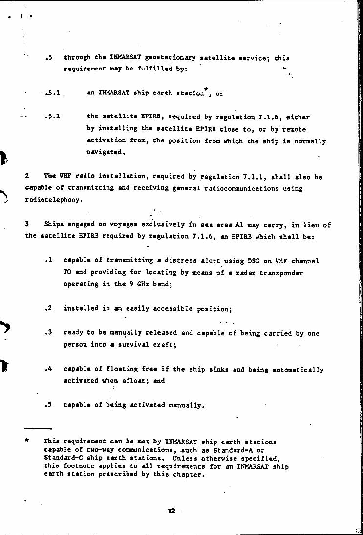
» •
•5 through the INMARSAT geostationary satellite service; this requirement may be fulfilled by;
.5.1 . an INMARSAT ship earth station*; or
.5.2 the satellite EPIRB, required by regulation 7.1.6, eitherby installing the satellite EPIRB close to, or by remote activation from, the position from which the ship is normally navigated.
2 The VHP radio installation, required by regulation 7.1.1, shall also be capable of transmitting and receiving general radiocommunications using radiotelephony.
3 Ships engaged on voyages exclusively in sea area A1 may carry, in lieu of the satellite EPIRB required by regulation 7.1.6, an EPIRB which shall be;
.1 capable of transmitting a distress alert using DSC on VHP channel 70 and providing for locating by means of a radar transponder operating in the 9 GHz band;
.2 installed in an easily accessible position;
.3 ready to be manually released and capable of being carried by one person into a survival craft;
.4 capable of floating free if the ship sinks and being automatically activated when afloat; and
.5 capable of being activated manually.
This requirement can be met by INMARSAT ship earth stations capable of two-way communications, -such as Standard-A or Standard-C ship earth stations. Unless otherwise sp>ecified, this footnote applies to all requirements for an INMARSAT ship earth station prescribed by this chapter.
12
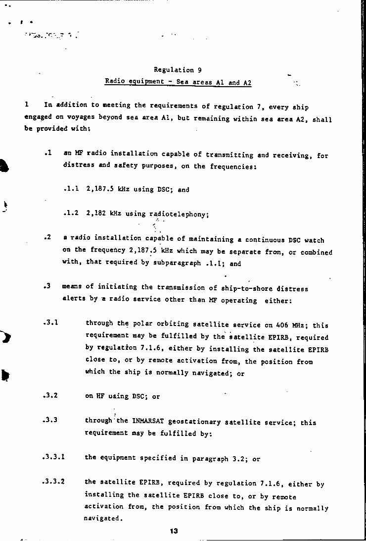
t •
' i/O. r
Regulation 9Radio equipment - Sea areas Al and A2
1 In addition to meeting the recjuirements of regulation 7, every ship engaged on voyages beyond sea area Al, but remaining within sea area A2, shall be provided with:
.1 an MF radio installation capable of transmitting and receiving, for distress and safety purposes, on the frequencies;
.1.1 2,187.5 kHz using DSC; and
.1.2 2,182 kHz using radiotelephony;
.2 a radio installation capable of maintaining a continuous DSC watch on the frequency 2,187.5 kHz which may be separate from, or combined with, that required by subparagraph .1.1; and
.3 means of initiating the transmission of ship-to-shore distress alerts by a radio service other than MF operating either:
.3.1 through the polar orbiting satellite service on 406 MHz; thisrequirement may be fulfilled by the satellite EPIRB, required by regulation 7.1.6, either by installing the satellite EPIRB close to, or by remote activation from, the position from which the ship is normally navigated; or
.3.2 on HF using DSC; or
•3.3 through the INMARSAT geostationary satellite service; thisrequirement may be fulfilled by:
.3.3.1 the equipment specified in paragraph 3.2; or
.3.3.2 the satellite EPIRB, required by regulation 7.1.6, either by installing the satellite EPIRB close to, or by remote activation from, the position from which the ship is normally navigated.
13
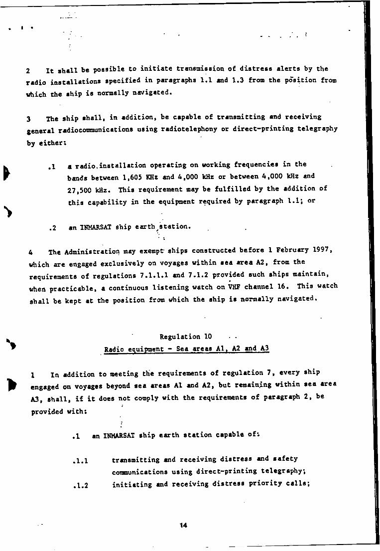
I •
2 It shall he possible to initiate transmission of distress alerts by the radio installations specified in paragraphs 1.1 and 1.3 from the position from which the ship is normally navigated.
3 The ship shall, in addition, be capable of transmitting and receiving general radiocommunications using radiotelephony or direct-printing telegraphy
by either:
,l a radio,installation operating on working frequencies in the bands between 1,605 KHz and 4,000 kHz or between 4,000 kHz and 27,500 kHz. This requirement may be fulfilled by the addition of this capability in the equipment required by paragraph l.l; or
.2 an INMARSAT ship earth ^Station.
4 The Administration may exempt ships constructed before 1 February 1997, which are engaged exclusively on voyages within sea area A2, from the requirements of regulations 7.1.1.1 and 7.1.2 provided such ships maintain, when practicable, a continuous listening watch on VHP channel 16. This watch shall be kept at the position from which the ship is normally navigated.
Regulation 10 • •Radio equipment - Sea areas Al, A2 and A3
1 In addition to meeting thie requirements of regulation 7, every ship engaged on voyages beyond sea areas Al and A2, but remaining within sea area A3, shall, if it does not comply with the requirements of paragraph 2, be
provided with:
.1 an INMARSAT ship earth station capable of:
,1.1 transmitting and receiving distress and safetycommunications using direct-printing telegraphy;
.1.2 initiating and receiving distress priority calls;
14
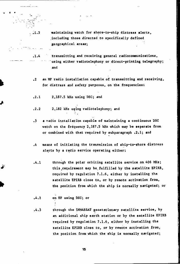
.1.3 maintaining watch for shore-to-ship distress alerts,including those directed to specifically defined geographical areas*,
.1.4 transmitting and receiving general radiocooraunications,......... using either radiotelephony or direct-printing telegraphy;
and
.2 an MF radio installation capable of transmitting and receiving, for distress and safety purposes, on the frequencies:
.2.1 2,187.5 kHz using DSC; and
.2.2 2,182 kHz uqing radiotelephony; and
.3 a radio installation capable of maintaining a continuous DSC watch on the frequency 2,187.5 kHz which may be separate from or combined with that required by subparagraph ,2.1; and
.4 means of initiating the transmission of ship-to-shore distress alerts by a radio service operating either:
.4.1 through the polar orbiting satellite service on 406 MHz;this,requirement may be fulfilled by the satellite EPIRB, required by regulation 7.1.6, either by installing the satellite EPIRB close to, or by remote activation from, the position from which the ship is normally navigated; or
.4.2 on HF using DSC; or
.4.3 through the INMARSAT geostationary satellite service, byan additional ship earth station or by the satellite EPIRB required by regulation 7.1.6, either by installing the satellite EPIRB close to, or by remote activation from, the position from vihich the ship is normally navigated;
15
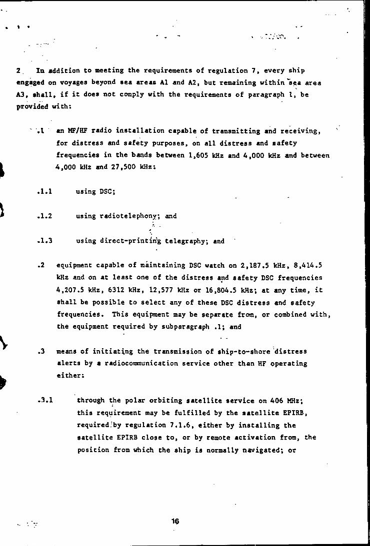
♦ •
< WV ■* *
2, In addition to neeting the requirements of regulation 7, every ship engaged on voyages beyond sea areas A1 and A2, but remaining within'sea area A3, shall, if it does not comply with the requirements of paragraph 1, be provided with:
.1 an MF/HF radio installation capable of transmitting and receiving, for distress and safety purposes, on all distress and safety frequencies in the bands between 1,605 kHz and 4,000 kHz and between4,000 kHz and 27,500 kHz;
.1.1 using DSC;
.1.2 using radiotelephony; and
*
.1.3 using direct-printing telegraphy; and
.2 equipment capable of maintaining DSC watch on 2,187.5 kHz, 8,414.5 kHz and on at least one of the distress and safety DSC frequencies4,207.5 kHz, 6312 kHz, 12,577 kHz or 16,804.5 kHz; at any time, it shall be possible to select any of these DSC distress and safety frequencies. This equipment may be separate from, or combined with, the equipment required by subparagraph .1; and
.3 means of initiating the transmission of ship-to-shore distress alerts by a radioconraunication service other than HF operating either;
.3.1 through the polar orbiting satellite service on 406 MHz;this requirement may be fulfilled by the satellite EPIRB, required.by regulation 7.1.6, either by installing the satellite EPIRB close to, or by remote activation from, the position from \fhich the ship is normally navigated; or
19
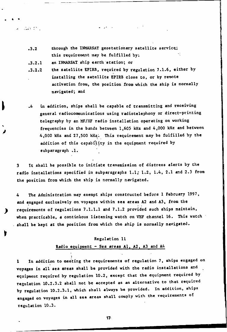
4 •
.3.2 through the INMARSAT geostationary satellite service.'.this requirement may be fulfilled by;
.3.2.1 an INMARSAT ship earth station; or
.3.2.2 the satellite EPIRB, required by regulation 7.1.6, either by installing the satellite EPIRB close to, or by remote activation from, the position from which the ship is normally navigated; and
.4 in addition, ships shall be capable of transmitting and receiving general radioconsnunications using radiotelephony or direct-printing telegraphy by an MF/HF radio installation operating on working frequencies in the bands between 1,605 kHz and 4,000 kHz and between4,000 kHz and 27,500 kHz. This requirement may be fulfilled by the addition of this capability in the equipment required by subparagraph .1.
3 It shall be possible to initiate transmission of distress alerts by the radio installations specified in subparagraphs 1.1,* 1.2, 1.4, 2.1 and 2.3 from the position from which the ship is normally navigated.
4 The Administration may exempt ships constructed before 1 February 1997, and engaged exclusively on. voyages within sea areas A2 and A3, from the requirements of regulations 7.1.1.1 and 7.1.2 provided such ships maintain, when practicable, a continuous listening watch on VHF channel 16. This watch shall be kept at the position from which the ship is normally navigated.
Regulation IIRadio equipment - Sea areas Al, A2, A3 and A4
1 In addition to meeting the requirements of regulation 7, ships engaged on voyages in all sea areas shall be provided with the radio installations and equipment required by regulation 10.2, except that the equipment required by regulation 10.2.3.2 shall not be accepted as an alternative to that required by regulation 10.2.3.1, \rtiich shall always be provided. In addition, ships .ng.t.d on .oy.g.. in .11 ... *r... .h.ll comply »ith the rcgnicment. of
regulation 10.3.
IT
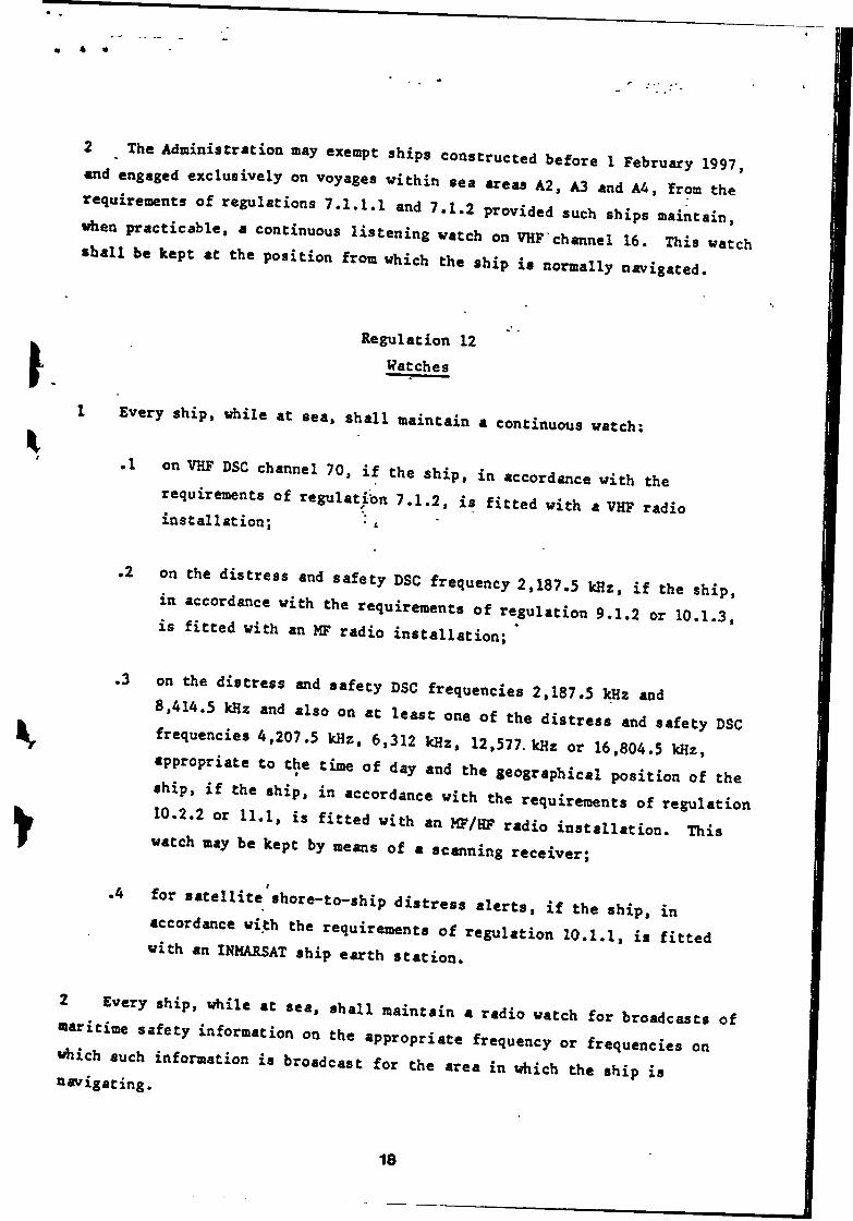
2 Th. Mmni.tr«ion ..y .xe»pt ,hip, construct.d b.for. 1 Febr»«y 1997 «d engaged excln.iv.ly on voyage, within ae. ar.«, A2. A3 «,d A4, from the’ r.,nir..»nt, of regulation. 7.1.1.1 and 7.1.2 provided anch .hip. maintain when practicable, a continnon. liatening watch on VHP channel 16. Thi. watch •hall be kept at the po.ition from which the .hip i. normally n-,igated.
Regulation 12 Watches
I Every .hip, while at ..a, .hall maintain . continnon. watch:
.1 on VHP DSC channel 70, if the .hip, in accord«:ce with therequirement, of regnl.t;on 7.1.2, i. fitted with a VHP radio installation; • i
.2 on the diatre.. and aafety DSC frequency 2,187.5 kHz, if the .hip, in accordance with the requirement, of regulation 9.1.2 or 10.1.3 IS fitted with an MF radio installation; *
on the distress and safety DSC frequencies 2,187.5 kHz and8.414.5 kHz and al.o on at lea.t one of the di.tre.a and aafety DSC frequencie. 4.207.5 kHz. 6,312 kHz. 12.577. kHz or 16,804.5 kHz, zppropriate to the time of day and the geographical po.ition of the •hip. zf the .htp, in accordance with the requir««nt. of regul.tior
.2.2 or U.l, I. fitted with an MP/HF radio In.tallation. Thi. watch nay be kept by neans of a scanning receiver;
for ..t.llit.-.hore-to-.hip diatrea, alert., if the .hip, in accordmice with the requirement, of regul.tion 10.1.1, i. fitted With an INMARSAT ship earth station.
Every ahtp, while at..... hall maintain a radio watch for broadcaat. of^ttxme .afety information on the appropriate frequency or fr.qu.ncie. onwhich auch information i. broadcaat for the are. in which the .hip i. navigating.
18
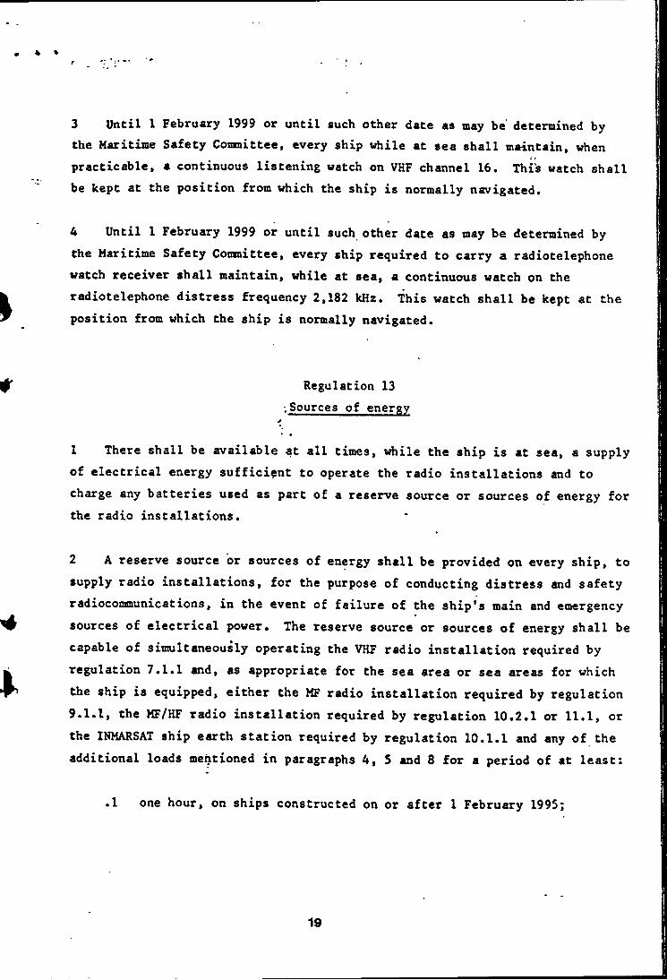
3 Until 1 February 1999 or until such other date as may be determined by the Maritime Safety Committee, every ship while at sea shall maintain, when practicable, a continuous listening watch on VHF channel 16. This watch shall be kept at the position from which the ship is normally navigated.
4 Until 1 February 1999 or until such other date as may be determined by the Maritime Safety Coni&ittee, every ship required to carry a radiotelephone watch receiver shall maintain, while at sea, a continuous watch on the radiotelephone distress frequency 2,182 kHz. This watch shall be kept at the position from which the ship is normally navigated.
Regulation 13 .Sources of energy
1 There shall be available at all times, while the ship is at sea, a supply of electrical energy sufficient to operate the radio installations and to charge any batteries used as part of a reserve source or sources of energy for the radio installations.
2 A reserve source or sources of energy shall be provided on every ship, to supply radio installations, for the purpose of conducting distress and safety radiocommunications, in the event of failure of the ship's main and emergency sources of electrical power. The reserve source or sources of energy shall be capable of simultaneously operating the VHF radio installation required by regulation 7.1.1 and, as appropriate for the sea area or sea areas for which the ship is equipped, either the MF radio installation required by regulation 9.1.1, the MF/HF radio installation required by regulation 10.2.1 or 11.1, or the INMARSAT ship earth station required by regulation 10.1.1 and any of the additional loads mentioned in paragraphs 4, 5 and 8 for a period of at least;
.1 one hour, on ships constructed on or after 1 February 1995;
19

.2 one hour, on ships constructed before 1 February 1995, if the emergency source of electrical power complies fully with “all relevant requirements of regulation II-1/A2 or 43 including the requirements to supply the radio installations; and
.3 six hours, on ships constructed before 1 February 1995, if the emergency source of electrical power is not provided or does not comply fully with all relevant requirements of regulation II-1/42 or 43 including the requirements to supply the radio installations.
The reserve source or sources of energy need not supply independent HF and MF radio installations at the same time.
✓3 The reserve source or sources^of energy shall be independent of the propelling power of the ship and the ship’s electrical system.
4 Where, in addition to the VHF radio installation, two or more of the other radio installations, referred to in paragraph 2, tan be connected to the reserve source or sources of energy, they shall be capable of simultaneously supplying, for the period specified, as appropriate, in paragraph 2.1 or 2.2, the VHF radio installation and;
.1 all other radio installations which can be connected to the reserve source or sources of energy at the same time; or
.2 whichever of the other radio installations will consume the mostpower, if only one of the other radio installations can be connected to the reserve source or sources of energy at the same time as the VHF radio installation,
^ reserve source or sources of energy may be used to supply theelectrical lighting required by regulation 6.2.4.
For guidance, the following formula is recomsended for determining the electrical load to be supplied by the reserve source of energy for each radio installation required for distress conditions; 1/2 of the current consumption necessary for transmission + the current consumption necessary for receiption ♦ current consumption of any additional loads.
20
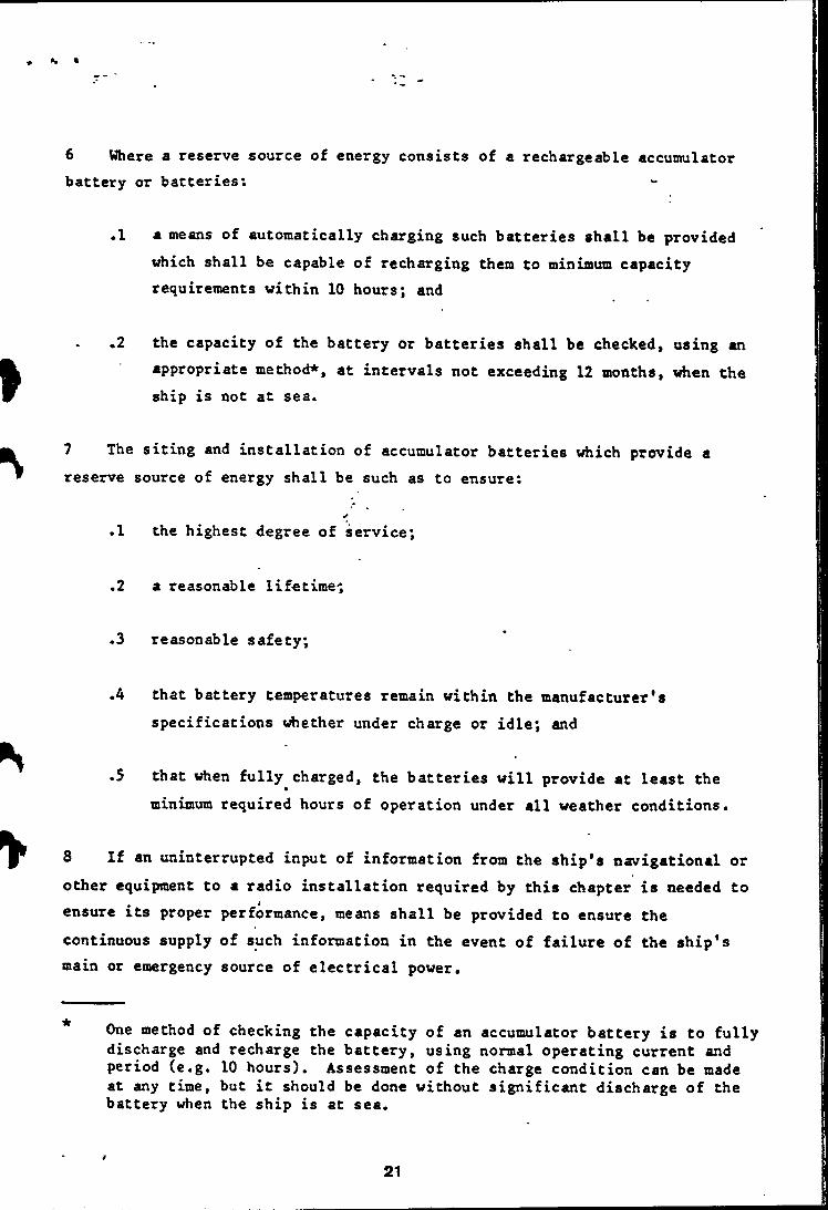
6 Where a reserve source of energy consists of a rechargeable accuntulator battery or batteries:
.1 a means of automatically charging such batteries shall be provided which shall be capable of recharging them to minimum capacity requirements within 10 hours; and
.2 the capacity of the battery or batteries shall be checked, using an appropriate method*, at intervals not exceeding 12 months, when the ship is not at sea.
7 The siting and installation of accumulator batteries which provide a reserve source of energy shall be such as to ensure:
.1 the highest degree of service;
.2 a reasonable lifetime-;
.3 reasonable safety;
.4 that battery temperatures remain within the manufacturer's specifications whether under charge or idle; and
.5 that when fully charged, the batteries will provide at least the minimum required hours of operation under all weather conditions.
8 If an uninterrupted input of information from the ship's navigational or other equipment to a radio installation required by this chapter is needed to ensure its proper performance, means shall be provided to ensure the continuous supply of such information in the event of failure of the ship's main or emergency source of electrical power.
One method of checking the capacity of an accumulator battery is to fully discharge and recharge the battery, using normal operating current and period (e.g. 10 hours). Assessment of the charge condition can be made at any time, but it should be done without significant discharge of the battery when the ship is at sea.
21
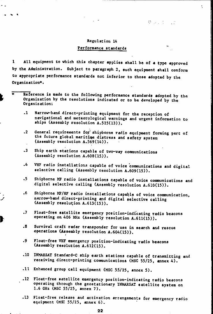
Regulation 14 Performance standards
1 All equipment to which this chapter applies shall be of a type approved by the Administration. Subject to paragraph 2, such equipment shall conform to appropriate performance standards not inferior to those adopted by the Organization*.
* Reference is made to the following performance standards adopted by the Organization by the resolutions indicated or to be developed by the Organization:
.1 Narrow-band direct-printing equipment for the reception ofnavigational and meteorological warnings and urgent information to ships (Assembly resolution A.525(13)).
.2 General requirements fojr shipborne radio equipment forming part of the future global maritime distress and safety system (Assembly resolution A.569(14)).
.3 Ship earth stations capable of two-way communications (Assembly resolution A.608(15)).
.4 VHP radio installations capable of voice coimunications and digital selective calling (Assembly resolution A.609(15)).
.5 Shipborne MF radio installations capable of voice cotmunications and digital selective calling (Assembly resolution A.610(15)).
.6 Shipborne MF/HF radio installations capable of voice consnunication, narrow-band direct-printing and digital seiective calling (Assembly resolutjion A.613(15)).
.7 Float-free satellite emergency position-indicating radio beacons operating on 406 MHz (Assembly resolution A.611(15)).
.8 Survival craft radar transponder for use in search and rescue operations (Assembly resolution A.604(15)).
.9 Float-free VHF emergency position-indicating radio beacons (Assembly resolution A.612(15).
.10 INMARSAT Standard—C ship earth stations capable of transmitting and receiving direct-printing communications (MSG 55/25, annex 4).
.11 Enhanced group call equipment (MSG 55/25, annex 5).
•12 Float-free satellite emergency position-indicating radio beacons operating through the geostationary INMARSAT satellite system on1.6 GHz (MSG 55/25, annex 7).
.13 Float-free release and activation arrangements for emergency radio equipment (MSG 55/25, annex 6). ’
22
2 Equipment installed prior to the dates of application by prescribed regulation 1 may be exempted from full compliance with the appropriate performance standards at the discretion of the Administration, provided that the equipment is compatible with equipment complying with the performance standards, having due regard to the criteria which the Organization may adopt .
in connection with such standards.
Regulation 15 •Maintenance requirements
1 Equipment shall be so designed that the main units can be replacedreadily, without elaborate recalibtation or readjustment.
*
2 Where applicable, equipment shall be so constructed and installed that it is readily accessible for inspection and on-board maintenance purposes.
3 Adequate information shall be provided to enable the equipment to be properly operated and maintained taking into account the recommendations of
the Organization.*
4 Adequate tools and spares shall be provided to enable the equipment to be
maintained.
5 The Administration shall ensure that radio equipment required by this chapter is maintained to provide the availability of the functional requirements specified in regulation 4 and to meet the recommended performance
standards of such equipment.
6 On ships engaged on voyages in sea areas Al and A2, the availability shall be ensured by using such methods as duplication of equipment, shore-based maintenance or at.-sea electronic maintenance capability, or a combination of these, as may be approved by the Administration.
* Reference is made to the recommendation on general requirements for shipborne radio equipment forming part of the future global maritime distress and safety system (resolution A.569(14)).
23

7 On ships engaged on voyages in sea areas A3 and A4, the availability shall be ensured by using a combination of at least two methods such «s duplication of equipment, shore-based maintenance or at-sea electronic maintenance capability, as may be approved by the Administration, taking into account the recommendations of the Organization.
8 While all reasonable steps shall be taken to maintain the equipment in efficient working order to ensure compliance with all the functional requirements specified in regulation A, malfunction of the equipment for providing the general radiocommunications required by regulation A,8 shall not be considered as making a ship unseaworthy or as a reason for delaying the ship in ports where repair facilities are not readily available, provided the ship is capable of performing all distress and safety functions.".
Regulation 16 Radio personnel
Every ship shall carry personnel qualified for distress and safety radiocommunication purposes to the satisfaction of the Administration. The personnel shall be holders of certificates specified in the Radio Regulations as appropriate, any one of whom shall be designated to have primary responsibility for radiocommunications during distress incidents.
Regulation 17 Radio records
A record shall be kept, to the satisfaction of the Administration and as required by the Radio Regulations, of all incidents connected with the radiocommunication service which appear to be of importance to safety of life
at sea.

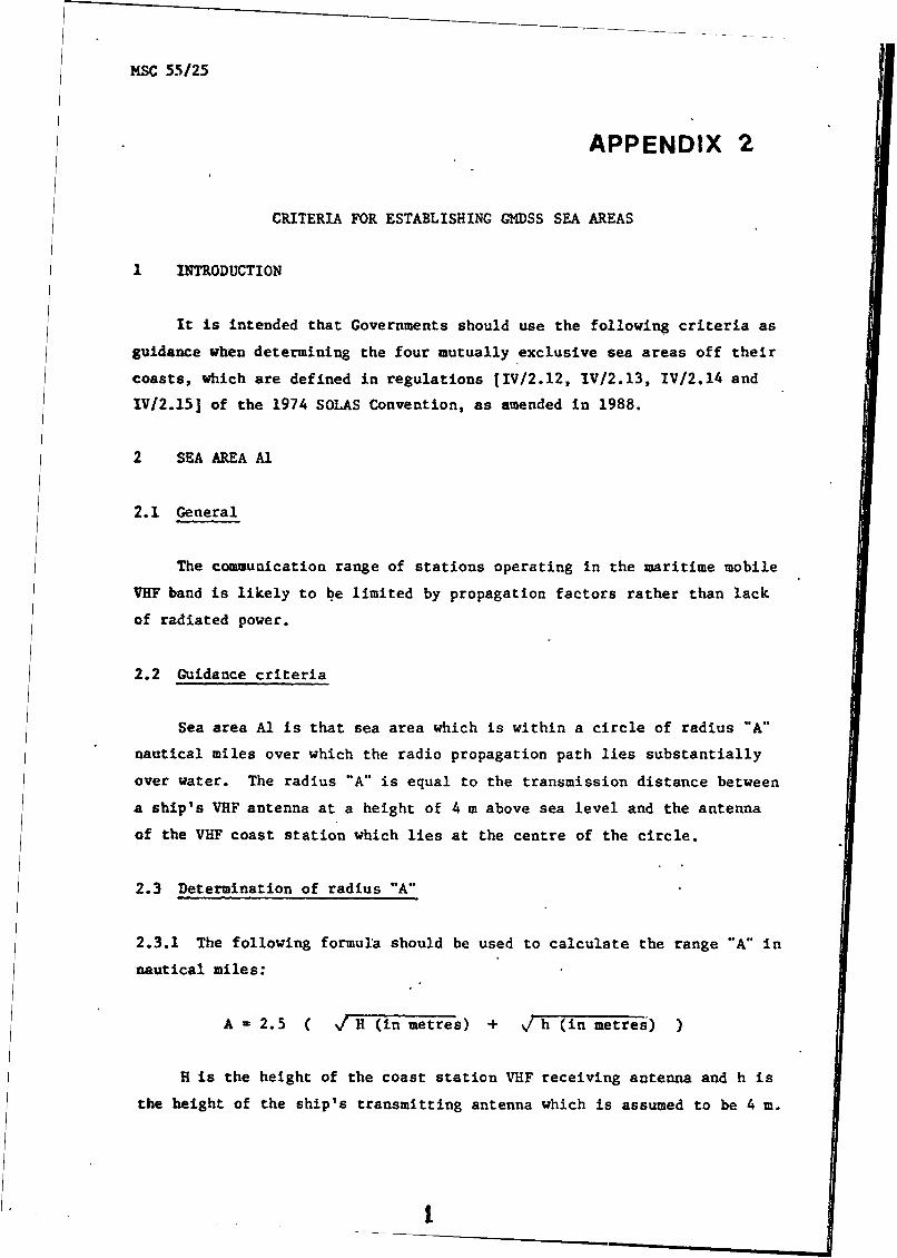
MSC 55/25
APPENDIX 2
CRITERIA FOR ESTABLISHING GMDSS SEA AREAS
1 INTRODUCTION
It is intended that Governments should use the following criteria as guidance when determining the four mutually exclusive sea areas off their coasts, which are defined in regulations [IV/2.12, lV/2.13, IV/2,14 and IV/2.15] of the 1974 SOLAS Convention, as amended in 1988.
2 SEA AREA A1
2.1 General
The communication range of stations operating in the maritime mobile VHF band is likely to be limited by propagation factors rather than lack of radiated power.
2.2 Guidance criteria
Sea area A1 is that sea area which is within a circle of radius "A" nautical miles over which the radio propagation path lies substantially over water. The radius "A" is equal to the transmission distance between a ship's VHF antenna at a height of 4 m above sea level and the antenna of the VHF coast station which lies at the centre of the circle.
2.3 Determination of radius "A"
2.3.1 The following formula should be used to calculate the range "A” in nautical miles:
A * 2.5 ( v/ H (in metres) + \/ h (in metres) )
H is the height of the coast station VHF receiving antenna and h is the height of the ship's transmitting antenna which is assumed to be 4 m.
I
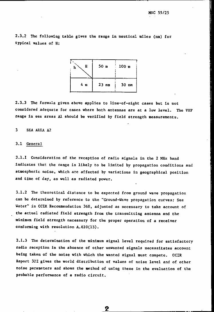
MSC 55/25
2.3.2 The following table gives the range in nautical miles (nm) for typical values of H:
f-.* 'n. h\ H^---------!■
50 m i 100 m111
4 m!
23 nm j 30 nmi
2.3.3 The formula given above applies to line-of-sight cases but is not considered adequate for cases where both antennae are at a low level. The VHF range in sea areas A1 should be verified by field strength measurements.
3 SEA AREA A2
3.1 General
3.1.1 Consideration of the reception of radio signals in the 2 MHz band indicates that the range is likely to be limited by propagation conditions and atmospheric noise, which are affected by variations in geographical position and time of day, as well as radiated power.
3.1.2 The theoretical distance to be expected from ground wave propagation can be determined by reference to the "Ground-Wave propagation curves; Sea Water" in CCIR Recommendation 368, adjusted as necessary to take account of the actual radiated field strength from the transmitting antenna and the minimum field strength necessary for the proper operation of a receiver conforming with resolution A.610(15).
3.1.3 The determination of the minimum signal level required for satisfactory radio reception in the absence of other unwanted signals necessitates account being taken of the noise with which the wanted signal must compete. CCIR Report 322 gives the world distribution of values of noise level and of other noise parameters and shows the method of using these in the evaluation of the probable performance of a radio circuit.
2
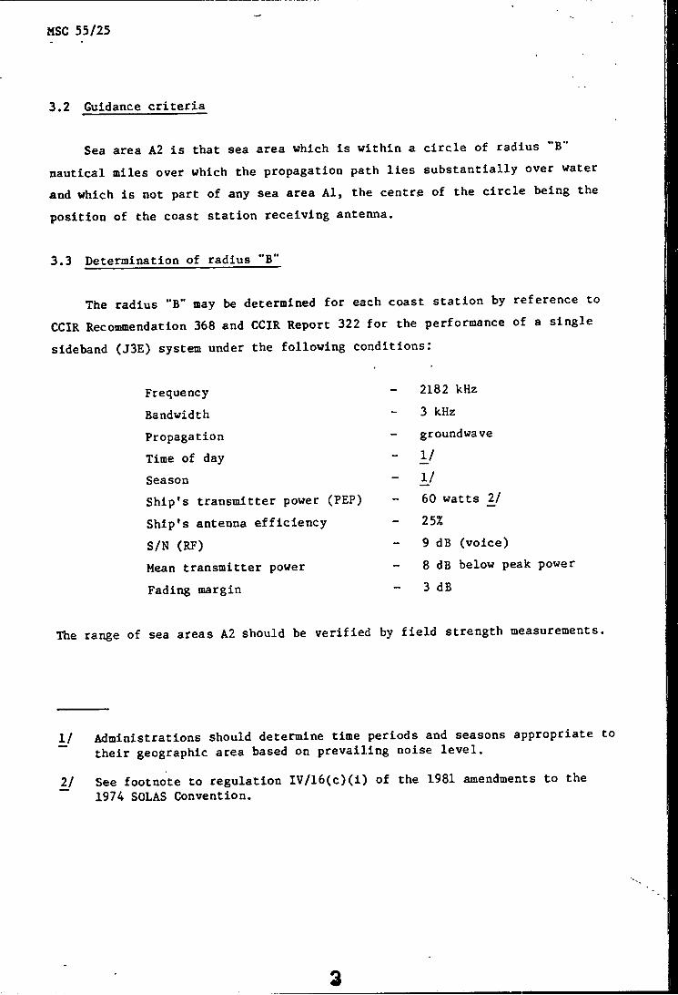
MSC 55/25
3.2 Guidance criteria
Sea area A2 is that sea area which is within a circle of radius "B" nautical miles over which the propagation path lies substantially over water and which is not part of any sea area Al, the centre of the circle being the position of the coast station receiving antenna.
3.3 Determination of radius "B"
The radius "B" may be determined for each coast station by reference to CCIR Recommendation 368 and CCIR Report 322 for the performance of a single sideband (J3E) system under the following conditions:
The range of sea areas A2 should be verified by field strength measurements.
1/ Administrations should determine time periods and seasons appropriate to their geographic area based on prevailing noise level.
_2/ See footnote to regulation IV/16(c)(i) of the 1981 amendments to the 1974 SOLAS Convention.
Frequency Bandwidth Propagation Time of day SeasonShip's transmitter power (PEP) Ship's antenna efficiency S/N (RF)Mean transmitter power Fading margin
2182 kHz 3 kHzgroundwave1/1/60 watts 25%9 dB (voice)8 dB below peak power 3 dB

MSC 55/25
4 AREA A3
4.1 Guidance criteria
Sea area A3 is that sea area of the world not being part of any sea area A1 or A2 within which the elevation angle of an INMARSAT satellite is 5° or XBore.
5 AREA A4
5.1 Guidance criteria
Sea area A4 is that sea area of the world not being part of any sea area Al, A2 or A3.

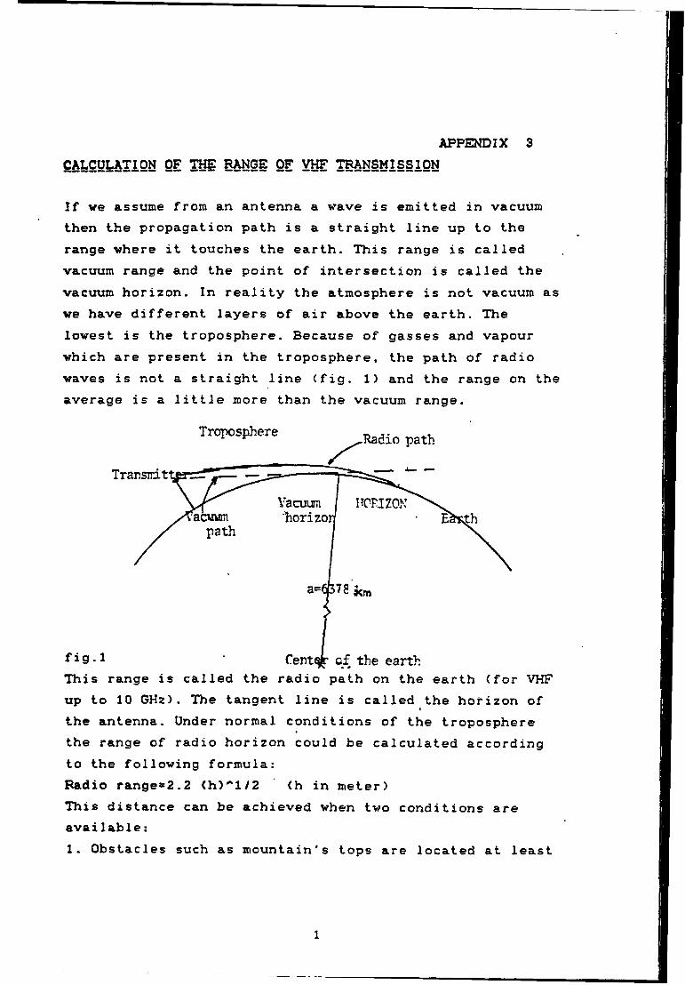
APPENDIX 3CALCULATION OF TOE RANGE OF VHF TRANSMISSION
If we assume from an antenna a wave is emitted in vacuum then the propagation path is a straight line up to the range where it touches the earth. This range is called vacuum range and the point of intersection is called the vacuum horizon. In reality the atmosphere is not vacuum as we have different layers of air above the earth. The lowest is the troposphere. Because of gasses and vapour which are present in the troposphere, the path of radio waves is not a straight line (fig. 1) and the range on the average is a little more than the vacuum range.
This range is called the radio path on the earth (for VHF up to 10 GHz). The tangent line is called the horizon of the antenna. Under normal conditions of the troposphere the range of radio horizon could be calculated according to the following formula:Radio ranges2.2 (h)''l/2 (h in meter)This distance can be achieved when two conditions are available:1. Obstacles such as mountain's tops are located at least
1
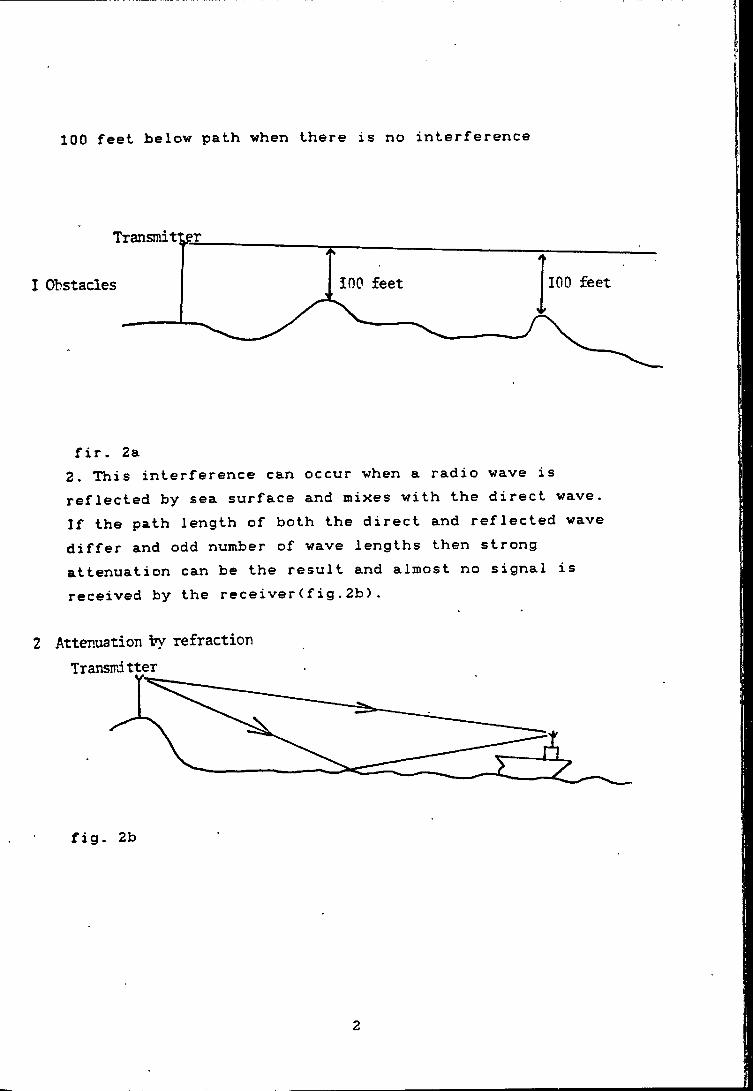
100 feet below path when there is no interference
fir. 2a2. This interference can occur when a radio wave is reflected by sea surface and mixes with the direct wave. If the path length of both the direct and reflected wave differ and odd number of wave lengths then strong attenuation can be the result and almost no signal is received by the receiver(fig.2b>.
2 Attenuation ty refraction Transmitter
IHi CURVATURE OF IHE R^IQ PATH
Since we have different layers in the troposphere the path of radio wave is not straight, as it is refracted. The refraction is characterized by a refractive index and denoted by letter n.
The value of n is :
n=sin i/sin r (i angle of incidence, r angle of ref raction).
So when the radio wave passes from vacuum to a layer, n is:n=l + 10''-6[77.6«p/T+3.73*10''5^te/T''2:
p=pressure in hpa (mili-bar) e=water vapour pressure in hpa T=temperature in Kelvin*
To find n at first we should find the maximum water vapour pressure which is e (max.), in general: e (max. )=6. ll*e''(19.7(t)) / (t-273>The average value of e is found by calculation of 0.9 e (max.) for the average temperature.
Now this e and calculated n is for the surface, however we need n according to the height of antenna. In our case the height can be about 2.1 or 3.3 kilometer for two antenna sites. For calculation of an average "n" for an antenna at
“H" kilometer we can use:
*1 Kelvin=(273+t) (t in Celsius)
3
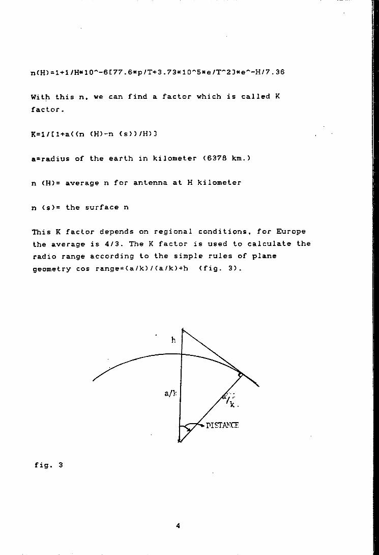
nCH) = l + l/H*lO''-6C77.6*fp/T+3.73«10'‘5<te/T''2 3*e^-H/7.36
With this n, we can find a factor which is called K factor.
K=l/i:i+a<(n (H)-n (s))/H)3
a=radius of the earth in kilometer (6378 km.)
n (H)= average n for antenna at H kilometer
n (s)= the surface n
This K factor depends on regional conditions, for Europe the average is 4/3. The K factor is used to calculate the radio range according to the simple rules of plane geometry cos range=(a/k)/(a/k)+h (fig. 3).
fig. 3
4
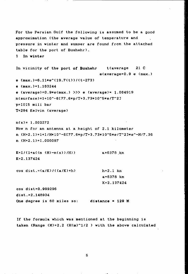
For the Persian Gulf the following is assumed to be a good approximation (the average value of temperature and pressure in winter and summer are found from the attached table for the port of Bushehr).1 In winter
In vicinity of the port of Bushehr t(average 21 Ce(average=0.9 e (max.)
e (max. )=6.1Hte''( 19.7(t) > / (t-273) e (max.)=1.163244e (average) = 0.9*fe(max. ) >>> e (average)= 1.064919 n(surface) = l + 10"‘-6C77.6«p/T+3.73wi0''5we/T'"2 3 p=1015 mili bar T=294 Kelvin (average)
n(s)= 1.000272Now n for an antenna at a height of 2.1 kilometer n (H=2. l) = l + l/H*10^-6C77.6itp/T+3.73<H0^5ite/T'"2D«e^-H/7.36 n (H=2.1)=l.000097
K=l/(l+a((n (H)-n(s))/H)) a=6376 .kmK=2.137424
cos dist.=(a/K)/((a/K)+h) h=2.1 kma=6376 km K=2.137424
cos dist=0.999296 dist.=2.146934One degree is 60 miles so: distance « 129 M
If the formula which was mentioned at the beginning is taken (Range (M)=2.2 (H(m)^l/2 ) with the above calculated
5
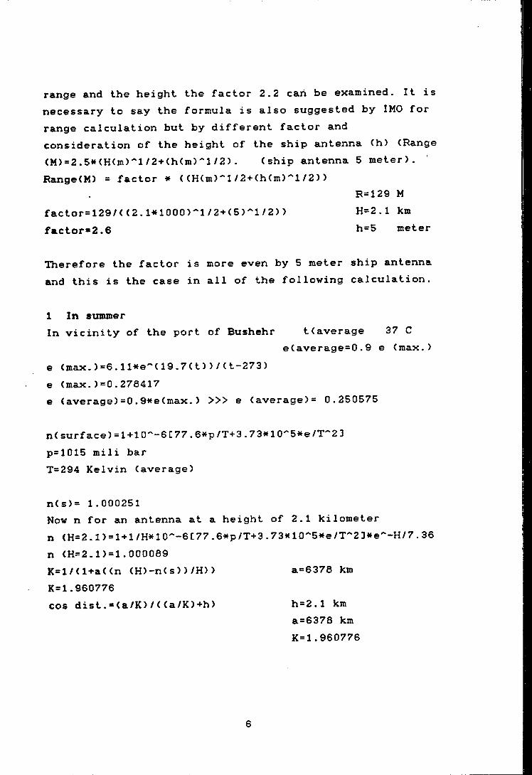
range and the height the factor 2.2 can be examined. It is necessary to say the formula is also suggested by IMO for range calculation but by different factor and consideration of the height of the ship antenna (h) (Range (M) = 2.5*KH(m)^l/2 + (h(m)''l/2) . (ship antenna 5 meter). Pange(M) = factor * ( (H(m)''l /2 + (h(m)'"l/2) )
R=129 Mfactor = 129/( (2. HaOOO)'*!/2+(5>"'l/2) ) H=2.1 kmfactor»2.6 h=5 meter
Therefore the factor is more even by 5 meter ship antenna and this is the case in all of the following calculation.
1 In summerIn vicinity of the port of Bushehr t(average 37 C
e(average=0.9 e (max.)e (max.)=6.11*e''(19.7(t))/(t-273) e (max.)=0.278417e (average) =0.9^te(max. ) >>> e (average)= 0.250575
n(surface) = l + 10''-6C77.6tfp/T+3.73*10''5»e/T''2 3p=1015 mili barT=294 Kelvin (average)
n(s)= 1.000251Now n for an antenna at a height of 2.1 kilometer n <H=2.1) = l + l/H*10^-6C77.6wp/T+3.73»«10''5«e/T'‘2D*te'"-H/7.36 n (H=2.1)=l.000089K=l/(l+a((n (H)-n(s))/H)) a=6378 kmK*1.960776cos dist.*(a/K)/((a/K)+h) h=2.1 km
a®6378 km K=1.960776
6
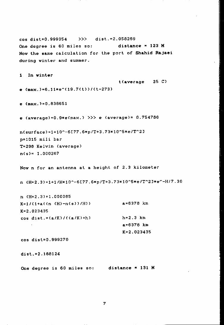
dist. =2.058269cos dist=0.999354 >>>One degree is 60 miles so: distance = 123 MNow the same calculation for the port of Shahid Radaei during winter and summer.
1 In winter
e <max. )=6.1Hfe^<19.7(t) )/(t-273)t < average 25 C)
e (max.)=0.838651
e (average)=0.9«e(max.) >» e (average)® 0.754786
n( surf ace) = l + 10^-6C77.6*p/T+3.73i* 10^5^^e / T''2 3p=1015 mili barT=298 Kelvin (average)n(s)= 1.000267
Now n for an antenna at a height of 2.3 kilometer
n (H=2.3) = 1 + 1 /H*aO^-6C77.6«p/T+3.73«10''5«e/T^2]»e^-H/7.36
n (H=2.3)=1.000085 K=l/(l+a((n (H)-n(s))/H))K=2.023435cos dist.=(a/K)/((a/K)+h)
cos dist=0.999270
dist.=2.188124
One degree is 60 miles so: distance ® 131 M
a=6378 km
h=2.3 km a=6378 km K=2.023435
7
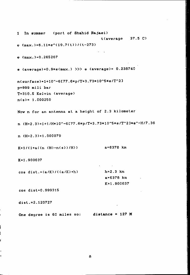
1 In summer (port of Shahid Rajaei)t(average 37.5 C)
e (max. )=6. 19.7( t) > / (t-273)
e (max.)=0.265267
e (average) =0.(max. ) >>> e (average)= 0.236740
n(surface) = l + 10^-6C77.6«p/T+3.73ia0''5»<e/T''2 3p=999 mill barT=310.5 Kelvin (average)n(s>= 1.000250
Now n for an antenna at a height of 2.3 kilometer
n (H=2.3) = 1 + 1 /H«10''-6C77.6*fp/T+3.73«10''5»te/T''2 3ite''-H/7.36
n (H=2.3)=l.000079
K=l/(l+a((n (H)-n(s))/H)) a=6378 km
K=1.900637
cos dist.=(a/K)/((a/K)+h) h=2.3 kma=6378 km K=1.900637
cos dist=0.999315
dist.=2.120727
One degree is 60 miles so: distance ^ 127 M
8
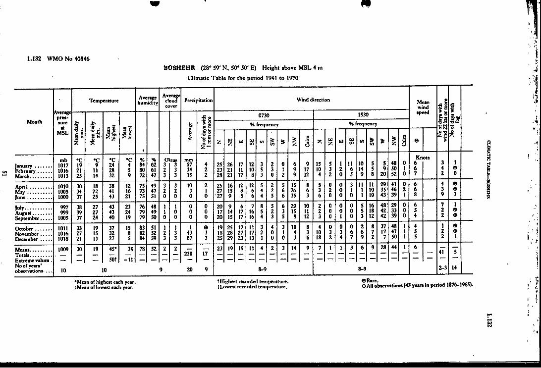
1.132 WMO No 40846BOSHEHR (28“ S9' N, 50* 50' E) Height above MSL 4 m
Climatic Table for the period 1941 to 1970
Month
Temperature Averagehumidity
Averagecloudcover
Precipitation Winddirection Meanwindspeed
No
of d
ays w
ith
win
d 22
ku o
r mor
eN
o of d
ays w
ith
fog
Averagepressure
atMSL
Mea
n da
ily
max
. ^ . •O csi .M
ean
high
est
Mea
nlo
wes
t
1
.Ave
rage
No
of d
ays w
ith1 m
m o
r mor
e 0730 1530
% frequency H frequency
7. iliy. u tl)cn cn >in
>
Calm Z U
Z u Uiin CO in NW
Calm e
mb •c •c •c •c % % O ktas mmKnots
1017 19 9 24 4 84 62 3 3 57 4 25 26 17 12 3 2 0 6 9 15 5 1 11 10 b 5 48 0 o 3 11016 21 11 28 5 80 61 2 3 34 2 23 21 11 10 5 3 1 9 17 10 3 2 6 14 5 9 50 1 6 4
March................ 1013 25 14 32 9 72 47 3 3 15 2 28 21 17 8 3 0 2 9 12 4 2 0 5 9 8 20 52 0 7 Z u
1010 30 18 38 12 75 49 3 3 10 2 25 16 12 12 5 2 5 15 8 5 0 0 3 11 11 29 41 0 6 4 91005 34 22 41 16 73 47 2 2 3 1 27 15 8 6 4 2 6 26 6 3 2 0 1 1 10 35 46 2 6 3 9
June.................. 1000 37 25 43 21 75 51 0 0 0 0 27 9 5 6 4 5 6 35 3 6 0 0 0 1 10 43 39 1 8 9 1
997 38 27 43 23 76 48 1 1 0 0 20 9 6 7 8 5 6 29 10 2 0 0 0 5 16 48 29 0 6 7 1
999 39 27 43 24 79 49 1 0 0 0 17 14 17 16 5 2 3 15 11 2 0 0 0 5 18 42 33 0 5 2 9September........ 1005 37 24 40 19 79 50 0 0 0 0 20 15 17 16 4 3 5 8 12 3 0 1 0 3 12 42 39 0 4 2 9
1011 33 19 37 15 83 51 1 1 1 e 19 25 17 11 3 4 3 10 8 4 0 0 0 2 8 37 48 1 4 1 91016 27 15 32 8 82 52 2 3 43 3 18 28 27 17 2 0 1 4 3 10 3 3 6 6 7 17 4/ 1 5 2 9
December........ 1018 21 11 27 5 84 59 3 3 67 3 25 29 23 13 1 0 0 3 6 18 2 4 7 9 2 7 50 1 5 2 1
Means................ 1009 30 19 45* 3S 78 52 2 2230 17
23 19 15 11 4 2 3 14 9 7 1 1 3 6 9 28 44 1 641 T
Extreme values . __ __ __ 50t -UNo of years' observations ... 10 10 9 20 9 8-9 8-9 W 14
*Meaii of highest each year. .iiMean of lowest each year.
tHighest recorded temperature. (Lowest recorded temperature.
0Rare.e All observations (43 years in period 1876-1965).
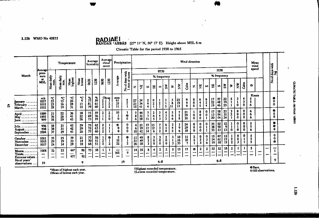
1.126 WMO No 40875^NDAR ‘ABBAS (27° IT N, 56° 17' E) Height above MSL 6 m
Climatic Table for the period 1938 to 1%5
Imuary . February March.
April hMy June
jiiw...August September
October .. November December
*Mean of highest each year. iiMean of lowest each year.
tHighest recorded temperature. }Lowest recorded temperature.
9 Rare, e All observations.
I

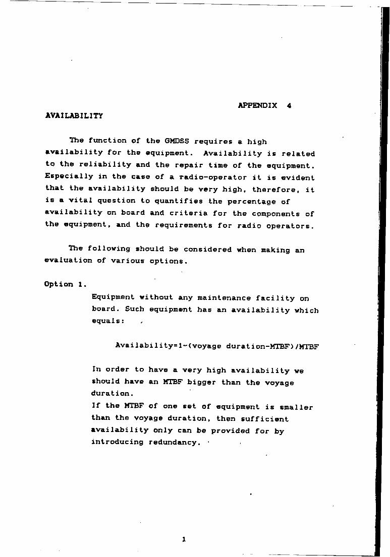
AVAILABILITYAPPENDIX 4
The fxmction of the GMDSS requires a high availability for the equipment. Availability is related to the reliability and the repair time of the equipment. Especially in the case of a radio-operator it is evident that the availability should be very high, therefore, it is a vital question to quantifies the percentage of availability on board and criteria for the components of the equipment, and the requirements for radio operators.
The following should be considered when making an evaluation of various options.
Option 1.Equipment without any maintenance facility on board. Such equipment has an availability which equals:
Availability=l-(voyage duration-MTBF)/MTBF
In order to have a very high availability we should have an MTBF bigger than the voyage duration.If the MTBF of one set of equipment is smaller than the voyage duration, then sufficient availability only can be provided for by introducing redundancy.
1
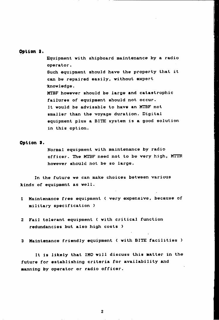
Option a.Equipment with shipboard maintenance by a radio operator.Such equipment should have the property that it can be repaired easily, without expert icnowledge.MTBF however should be large and catastrophic failures of equipment should not occur.It would be advisable to have an MTBF not smaller than the voyage duration. Digital equipment plus a BITE system is a good solution in this option.
Option 31
Normal equipment with maintenance by radio officer. The MTBF need not to be very high, MTTR however should not be so large.
In the future we can make choices between various kinds of equipment as well.
1 Maintenance free equipment < very expensive, because of military specification )
2 Fail tolerant equipment ( with critical function redundancies but also high costs >
3 Maintenance friendly equipment ( with BITE facilities )
It is likely that IMO will discuss this matter in the future for establishing criteria for availability and manning by operator or radio officer.
2
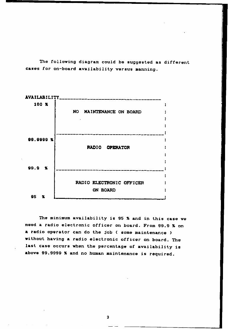
The fo].Iowing diagram could be suggested as different cases for on-board availability versus manning.
AVAILABILITY. 100 %
NO MAINTENANCE ON BOARD
69.9999 XRADIO OPERATOR
99.9 X
RADIO ELECTRONIC OFFICER ON BOARD
95 X
The minimum availability is 95 X and in this case ve need a radio electronic officer on board. From 99.9 % on a radio operator can do the job ( some maintenance ) without having a radio electronic officer on board. The last case occurs when the percentage of availability is above 99.9999 X and no human maintenance is required.
3

BIBLIOaRAPHY
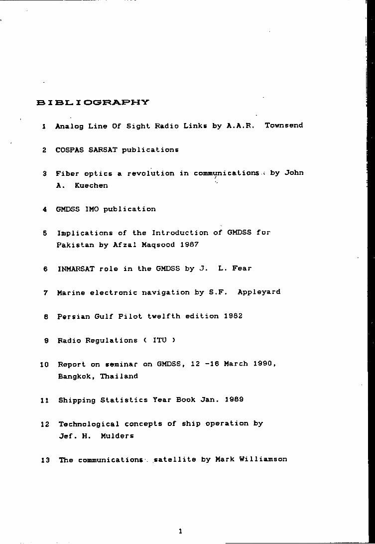
S I BL I OORAF>HY
1 Analog Line Of Sight Radio Links by A.A.R. Townsend
2 COSPAS SARSAT publications
3 Fiber optics a revolution in conuBunications i by John A. Kuechen
4 GMDSS IMO publication
5 Implications of the Introduction of GMDSS for Pakistan by Afzal Maqsood 1987
6 INMARSAT role in the GMDSS by J. L. Fear
7 Marine electronic navigation by S.F. Appleyard
6 Persian Gulf Pilot twelfth edition 1982
9 Radio Regulations ( ITU )
10 Report on seminar on GMDSS, 12 -16 March 1990, Bangkok, Thailand
11 Shipping Statistics Year Book Jan. 1989
12 Technological concepts of ship operation by Jef. H. Mulders
13 The commiinications . satellite by Mark Williamson
1
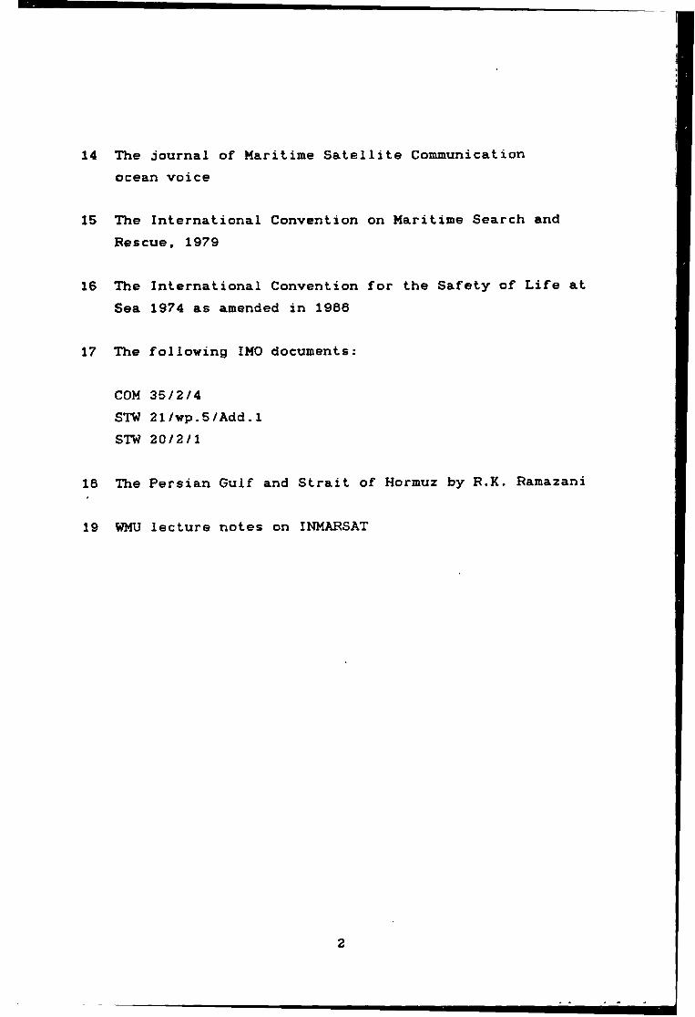
14 The journal of Maritime Satellite Communication ocean voice
15 The International Convention on Maritime Search and Rescue, 1979
16 The International Convention for the Safety of Life at Sea 1974 as amended in 1966
17 The folloving IMO documents:
COM 35/2/4STW 21/wp.5/Add.1STW 20/2/1
16 The Persian Gulf and Strait of Hormuz by R.K. Ramazani
19 WMU lecture notes on INMARSAT
2


LIST OF TABLE AND GRAPH
Chapter two page
1 Table 2.1, Countries with CRSs 212 Table ••
CM Existing communication 29
Chapter three
1 Table 3.1, Number of ships 422 Graph 3.2, Ship owned by states 423 Table 3.3, Ocean going ship visiting
Iranian ports 434 Table 3.4, Number of accident 446 Table 3.6, CRS with site (first choice) 517 Table 3.8, CRS with site (second choice) 536 Table 3.9, Location of site 569 Table 3.10, CRS with site (second choice) 5710 Table 3.11, MF and HF CRS 5811 Table 3.12, CRS in both choices 5912 Table 3.15, CRS personnel 6913 Table 3.16, NAVTEDC personnel 6914 Table 3.17, Repair center personnel 7015 Table 3.18, Total personnel 7116 Table 3.20, Cost (first choice) 7517 Table 3.21, Cost (second choice) 76
Chapter four
16 Table 1. First class radioelectronic 6419 Table 2, Second class radioelectronic 6620 Table 3. General operator 6921 Table 4, Restricted operator 9022 Table 5, Technician level one 95
1

23 Table24 Table
67
Technician level two CRS operator
9799
Chapter five
25 Table 1, Cost comparison 103
2

LIST OF FIGURES AND CHARTLETS
Chapter one page
1 Figure 1.1. INMARSAT satellite segments 32 Figure 1.2, INMARSAT coverage 18
Chapter two
1 Figure 2.2, PSO organizational chart 252 Chartlet 2.3, Location of ports 263 Chartlet 2.5, Tracks of tropical cyclones 34
Chapter three
5 Chartlet 3.5, VHF and MF site (first choice) 496 Chartlet 3.7, Location of port 527 Chartlet 3.13, Location of CES 638 Figure 3.19, Links between CES, CRS and RCC 73
3