Mathematical modelling of supercritical CO2 extraction of volatile oils from aromatic plants
Upload
khangminh22Category
view
0download
0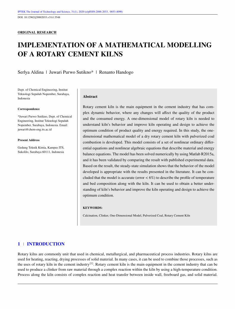
IPTEK The Journal of Technology and Science, 31(1), 2020 (e/pISSN:2088-2033, 0853-4098)DOI: 10.12962/j20882033.v31i1.5548
ORIGINAL RESEARCH
IMPLEMENTATION OF A MATHEMATICAL MODELLINGOF A ROTARY CEMENT KILNS
Serlya Aldina | Juwari Purwo Sutikno* | Renanto Handogo
Dept. of Chemical Engineering, InstitutTeknologi Sepuluh Nopember, Surabaya,Indonesia
Correspondence
*Juwari Purwo Sutikno, Dept. of ChemicalEngineering, Institut Teknologi SepuluhNopember, Surabaya, Indonesia. Email:[email protected]
Present Address
Gedung Teknik Kimia, Kampus ITS,Sukolilo, Surabaya 60111, Indonesia
Abstract
Rotary cement kiln is the main equipment in the cement industry that has com-plex dynamic behavior, where any changes will affect the quality of the productand the consumed energy. A one-dimensional model of rotary kiln is needed tounderstand kiln’s behavior and improve kiln operating and design to achieve theoptimum condition of product quality and energy required. In this study, the one-dimensional mathematical model of a dry rotary cement kiln with pulverized coalcombustion is developed. This model consists of a set of nonlinear ordinary differ-ential equations and nonlinear algebraic equations that describe material and energybalance equations. The model has been solved numerically by using Matlab R2015a,and it has been validated by comparing the result with published experimental data.Based on the result, the steady-state simulation shows that the behavior of the modeldeveloped is appropriate with the results presented in the literature. It can be con-cluded that the model is accurate (error < 6%) to describe the profile of temperatureand bed composition along with the kiln. It can be used to obtain a better under-standing of kiln’s behavior and improve the kiln operating and design to achieve theoptimum condition.
KEYWORDS:
Calcination, Clinker, One-Dimensional Model, Pulverized Coal, Rotary Cement Kiln
1 INTRODUCTION
Rotary kilns are commonly unit that used in chemical, metallurgical, and pharmaceutical process industries. Rotary kilns areused for heating, reacting, drying processes of solid material. In many cases, it can be used to combine those processes, such asthe uses of rotary kiln in the cement industry [1]. Rotary cement kiln is the main equipment in the cement industry that can beused to produce a clinker from raw material through a complex reaction within the kiln by using a high-temperature condition.Process along the kiln consists of complex reaction and heat transfer between inside wall, freeboard gas, and solid material.
2 ALDINA ET AL.
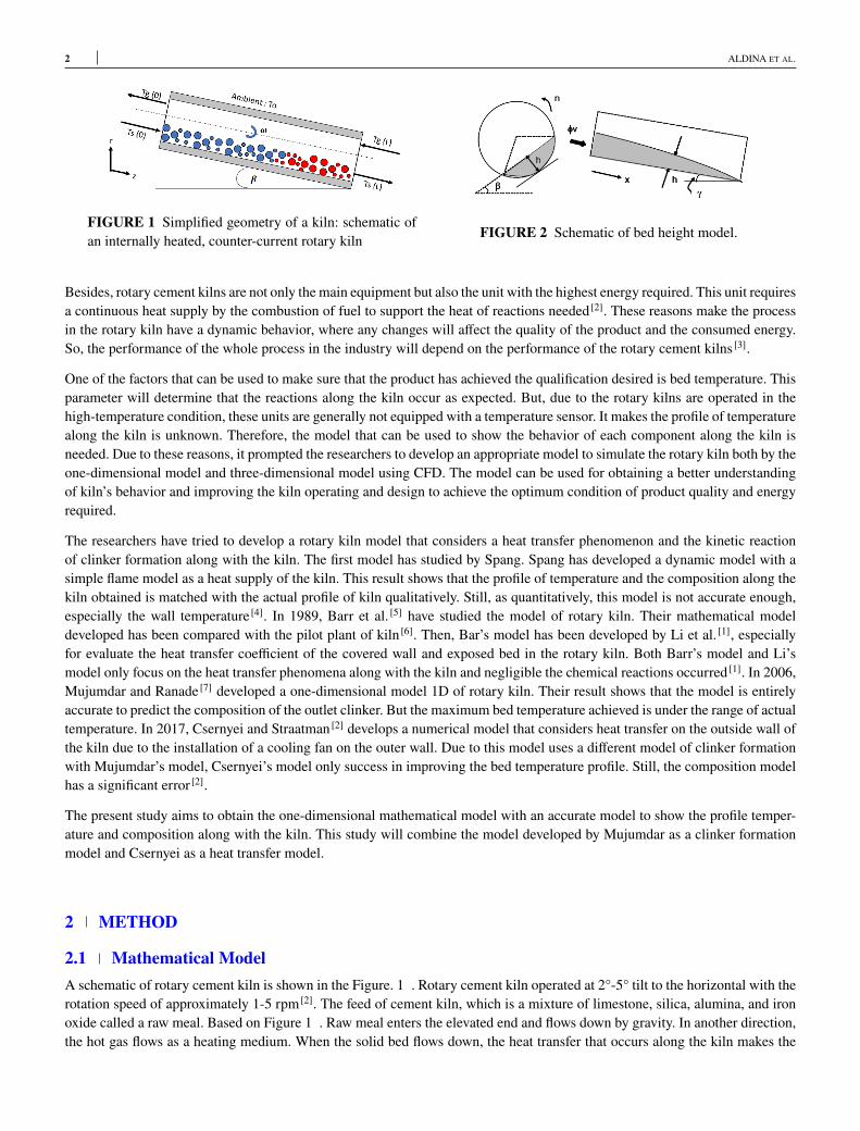
FIGURE 1 Simplified geometry of a kiln: schematic ofan internally heated, counter-current rotary kiln FIGURE 2 Schematic of bed height model.
Besides, rotary cement kilns are not only the main equipment but also the unit with the highest energy required. This unit requiresa continuous heat supply by the combustion of fuel to support the heat of reactions needed [2]. These reasons make the processin the rotary kiln have a dynamic behavior, where any changes will affect the quality of the product and the consumed energy.So, the performance of the whole process in the industry will depend on the performance of the rotary cement kilns [3].One of the factors that can be used to make sure that the product has achieved the qualification desired is bed temperature. Thisparameter will determine that the reactions along the kiln occur as expected. But, due to the rotary kilns are operated in thehigh-temperature condition, these units are generally not equipped with a temperature sensor. It makes the profile of temperaturealong the kiln is unknown. Therefore, the model that can be used to show the behavior of each component along the kiln isneeded. Due to these reasons, it prompted the researchers to develop an appropriate model to simulate the rotary kiln both by theone-dimensional model and three-dimensional model using CFD. The model can be used for obtaining a better understandingof kiln’s behavior and improving the kiln operating and design to achieve the optimum condition of product quality and energyrequired.The researchers have tried to develop a rotary kiln model that considers a heat transfer phenomenon and the kinetic reactionof clinker formation along with the kiln. The first model has studied by Spang. Spang has developed a dynamic model with asimple flame model as a heat supply of the kiln. This result shows that the profile of temperature and the composition along thekiln obtained is matched with the actual profile of kiln qualitatively. Still, as quantitatively, this model is not accurate enough,especially the wall temperature [4]. In 1989, Barr et al. [5] have studied the model of rotary kiln. Their mathematical modeldeveloped has been compared with the pilot plant of kiln [6]. Then, Bar’s model has been developed by Li et al. [1], especiallyfor evaluate the heat transfer coefficient of the covered wall and exposed bed in the rotary kiln. Both Barr’s model and Li’smodel only focus on the heat transfer phenomena along with the kiln and negligible the chemical reactions occurred [1]. In 2006,Mujumdar and Ranade [7] developed a one-dimensional model 1D of rotary kiln. Their result shows that the model is entirelyaccurate to predict the composition of the outlet clinker. But the maximum bed temperature achieved is under the range of actualtemperature. In 2017, Csernyei and Straatman [2] develops a numerical model that considers heat transfer on the outside wall ofthe kiln due to the installation of a cooling fan on the outer wall. Due to this model uses a different model of clinker formationwith Mujumdar’s model, Csernyei’s model only success in improving the bed temperature profile. Still, the composition modelhas a significant error [2].The present study aims to obtain the one-dimensional mathematical model with an accurate model to show the profile temper-ature and composition along with the kiln. This study will combine the model developed by Mujumdar as a clinker formationmodel and Csernyei as a heat transfer model.
2 METHOD
2.1 Mathematical ModelA schematic of rotary cement kiln is shown in the Figure. 1 . Rotary cement kiln operated at 2°-5° tilt to the horizontal with therotation speed of approximately 1-5 rpm [2]. The feed of cement kiln, which is a mixture of limestone, silica, alumina, and ironoxide called a raw meal. Based on Figure 1 . Raw meal enters the elevated end and flows down by gravity. In another direction,the hot gas flows as a heating medium. When the solid bed flows down, the heat transfer that occurs along the kiln makes the
ALDINA ET AL. 3
TABLE 1 Reactions, kinetics, and heat of reaction.Reaction k E(kJ/mol) Δ(kJ/mol)Bed RegionCaCO3 ←→ CaO + CO2 4.55 x 1031 [1/s] 781 16602CaO + SiO2 ←→ C2S 1 x 10⁷ [m3/(kg.s)] 293 - 6033CaO + C2S ←→ C3S 1 x 10⁹ [m3/(kg.s)] 460 4843CaO + Al2O3 ←→ C3A 1x 10⁸ [m3/(kg.s)] 250 - 374CaO + Al2O3 + Fe2O3 ←→ C4AF 1x 10⁸ [m6/(kg2.s)] 188 - 109Gas RegionC + O2 ←→ CO2 1.26 x 10³ [m/s] 99.77 -
temperature of solid bed reach the temperature target. The reaction of clinker formation, both as endothermic and exothermicoccurs. Rotary cement kiln is divided into four stages. They are preheating, calcining, burning, and cooling [8]. Description ofthe model and solution methodology used is described in this chapter.The mathematical model developed in this studied is a complete one-dimensional dry kiln model that includes mass and energybalance for three phases within the rotary kiln: freeboard gas (pulverized coal included), solid bed, and wall. The model willfollow these assumptions: The model developed for a steady-state process. Specific heat, heat transfer coefficient, heat reaction,solid, and gas velocity along the kiln are constant. The mixing effect is neglected. Both the freeboard gas phase and solid bedphase follow the plug flow model. Chemical reactions that occur are simplified to be five main reactions, which described inTable 1 . The Arrhenius equation determines the rate of reactions [7].
2.2 Bed Height ModelIt requires considering the appropriate model to describe the axial flow of solid particles along with the kiln in developing amodel for simulating the unit operation of the rotary cement kiln. The appropriate model of axial motion is essential. It is dueto axial movement having an impact on the calculation of residence time of solid particle and the bed height calculation, wherethe two parameters impact the accuracy of the model that was developed.The calculation of Bed height along the kiln depends on some aspects. They are volumetric flow rate of the solid particle (Φv),angle of inclination of the kiln (γ, radian), repose angle of the solid particle (β, radian), Inner radius of the kiln (R, m) andspeed of kiln rotation (n, rps). These parameters are represented in Figure 2 . One of the models of bed height calculation thatcommonly used is the Kramers model. The Kramers model is represented by Equation 1.
dℎdx
= tan�[
tan tan�
− 3Φv4�nR3
(
2ℎR− ℎ2
R2
)]
(1)
2.3 General Material BalanceThe general rate equation of any compound in a solid phase is given in Equation 2. The amount of that compound flows into theregion is equal to the amount generated or consumed by a chemical reaction in the region.
d(Abvb�b i)dz
= RiAbMi (2)
d(Abvb i)dz
= −RCO2AbMCO2 (3)
Ri =NC∑
i=1
NR∑
j=1ZijMjkojexp
( EjRTb
) NC∏
k=1Ck (4)
4 ALDINA ET AL.
Where Yi is the mass fraction of i compound, Ab is the cross-sectional area of solid bed [m2], vb is the velocity of the solidbed [m∕s], �b is the bulk density of the bed [kg∕m3], Ri is the specific reaction rate [kmole∕m3.s] and the term of Mi is themolecular weight of i compound [kg∕kmole]. By summing the material balance of each component, the overall mass balancecan be expressed by Equation 3. Based on the assumptions above, the reaction rate of each component is shown in Equation 4.According to the reactions in Table 1 , the compounds that include in this model are C , O2, CO2, CaCO3, CaO, SiO2, Al2O3,Fe2O3, Belite (C2S, i.e., 2CaO.SiO2), Alite (C3S i.e., 3CaO.SiO2), tri-calcium aluminate (C3A i.e., 3CaO.Al2O3) and ferritephase (C4AF i.e., 4CaO.Al2O3.F e2O3). Therefore, there is 13 set of a nonlinear ordinary differential equation of the massbalance equation.
2.4 Heat Transfer ModelThe specific energy balance equation of the cement rotary kiln is shown in Equation 5, 6, 7, and 8. The term coefficient heattransfer of each phase was obtained by the previous study [9]. To estimate the temperatures of the inner wall and outer shell, asteady-state heat balance across kiln walls are expressed by the following equations.
ddx
(
Agvg�gCpgTg)
= ℎcgbAeb(Tb − Tg) + ��g�bAeb(T 4b − T4g ) + ℎcgwAew(Tw − Tg)
+��g�wAeb(T 4w − T4g ) + RcombAgΔHcombSCO2
(5)
ddx
(
Abvb�bCpbTb)
= ℎcgbAeb(Tg − Ts) + ��g�bAeb(T 4w − T4b ) + ℎcgwAew(Tw − Tb)
+��g�wAeb(T 4w − T4b ) +
∑
RiAbΔHiSCO2(6)
QSHELL = QLOSS C +QLOSS R (7)
QRGW +QCGW −QRWB −QCW B = QSHELL (8)
The equation was solved by the Newton Raphson method for the nonlinear equation. QRWB and QCW B are the heat transferrates due to radiation and conduction, respectively, between the internal kiln wall and the bed. QRGW and QCGW are the heattransfer rates due to radiation and Conduction, respectively, between the internal kiln wall and the freeboard gas.QSHELL is theheat transfer due to conduction on kiln shell. QLOSS C and QLOSS R are the losses from the outer shell due to convection andradiation.QSHELL is the heat transfer due to conduction on kiln shell.QLOSS C andQLOSS R are the losses from the outer shelldue to convection and radiation.
2.5 Combustion ModelThe fuel that commonly uses the combustion process within the kiln is pulverized coal. In this study, the model of combustionfollows the single reaction bellow (Equation 9).
C(S) + O2(g) ←→ CO2(g) (9)
Based on the reaction between the solid particle of pulverized coal and oxygen, the combustion rate model of rotary kiln can bemodeled by a shrinking core model (SCM). SCM is a model that can be used to describe the reaction between solid particlesand fluid. SCM divided into two types, that is:
1. SCM for a constant spherical particle2. SCM for shrinking spherical particle
ALDINA ET AL. 5
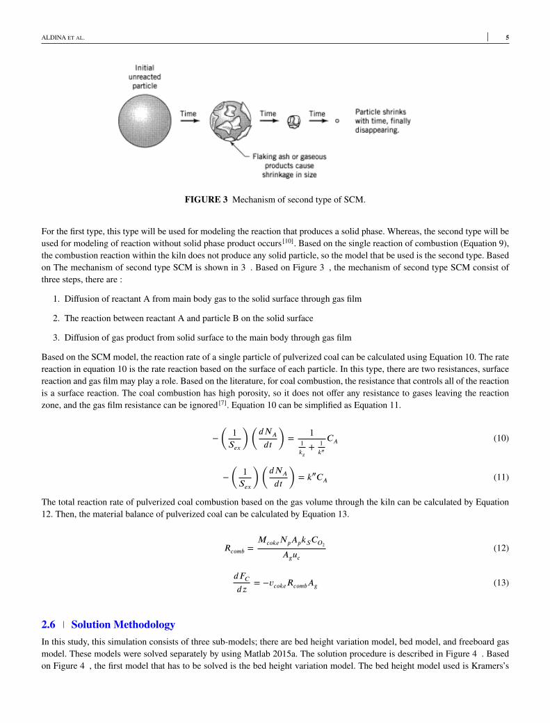
FIGURE 3 Mechanism of second type of SCM.
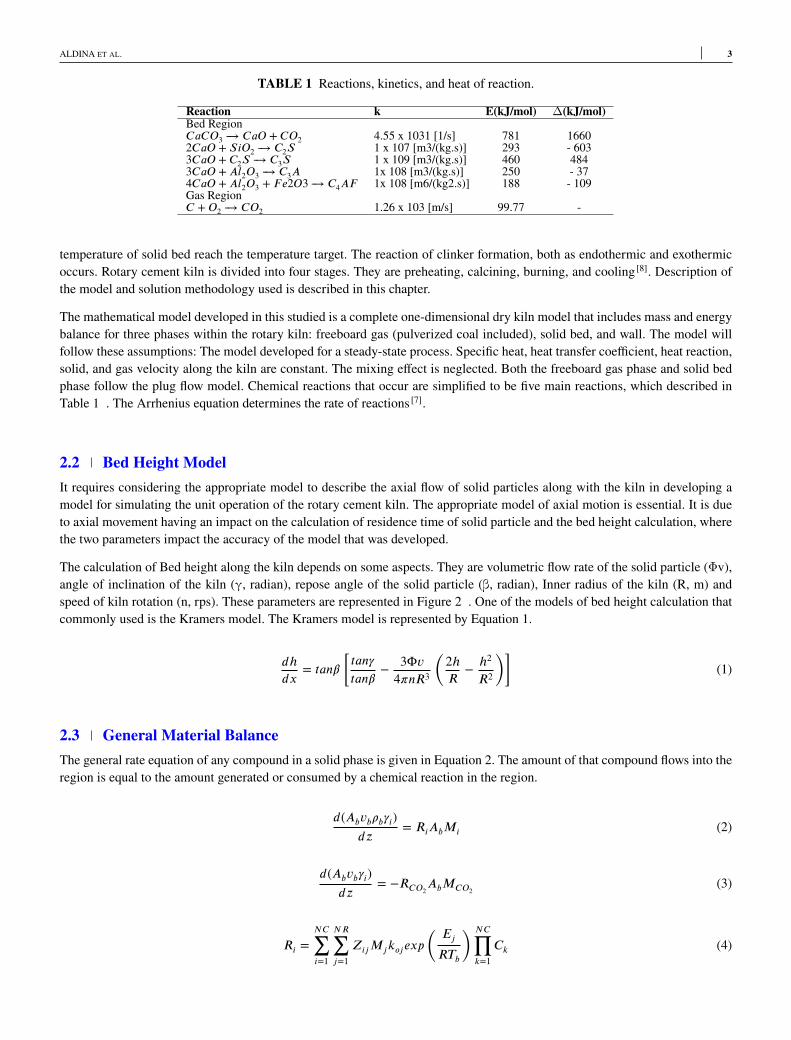
For the first type, this type will be used for modeling the reaction that produces a solid phase. Whereas, the second type will beused for modeling of reaction without solid phase product occurs [10]. Based on the single reaction of combustion (Equation 9),the combustion reaction within the kiln does not produce any solid particle, so the model that be used is the second type. Basedon The mechanism of second type SCM is shown in 3 . Based on Figure 3 , the mechanism of second type SCM consist ofthree steps, there are :
1. Diffusion of reactant A from main body gas to the solid surface through gas film2. The reaction between reactant A and particle B on the solid surface3. Diffusion of gas product from solid surface to the main body through gas film
Based on the SCM model, the reaction rate of a single particle of pulverized coal can be calculated using Equation 10. The ratereaction in equation 10 is the rate reaction based on the surface of each particle. In this type, there are two resistances, surfacereaction and gas film may play a role. Based on the literature, for coal combustion, the resistance that controls all of the reactionis a surface reaction. The coal combustion has high porosity, so it does not offer any resistance to gases leaving the reactionzone, and the gas film resistance can be ignored [7]. Equation 10 can be simplified as Equation 11.
−(
1Sex
)(
dNA
dt
)
= 11kg+ 1
k″
CA (10)
−(
1Sex
)(
dNA
dt
)
= k″CA (11)
The total reaction rate of pulverized coal combustion based on the gas volume through the kiln can be calculated by Equation12. Then, the material balance of pulverized coal can be calculated by Equation 13.
Rcomb =McokeNpApkSCO2
Aguc(12)
dFCdz
= −vcokeRcombAg (13)
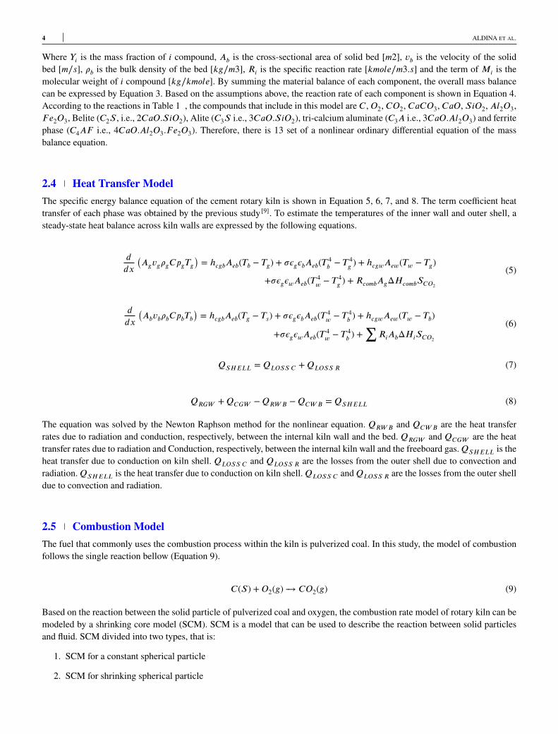
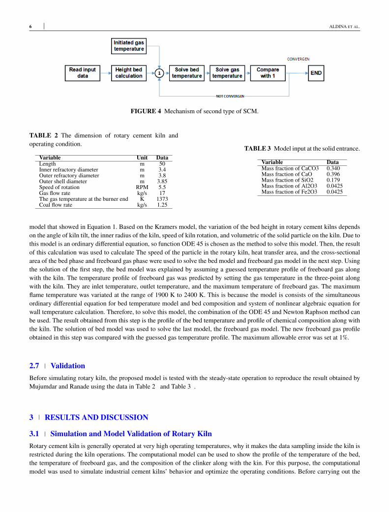
2.6 Solution MethodologyIn this study, this simulation consists of three sub-models; there are bed height variation model, bed model, and freeboard gasmodel. These models were solved separately by using Matlab 2015a. The solution procedure is described in Figure 4 . Basedon Figure 4 , the first model that has to be solved is the bed height variation model. The bed height model used is Kramers’s
6 ALDINA ET AL.
FIGURE 4 Mechanism of second type of SCM.
TABLE 2 The dimension of rotary cement kiln andoperating condition.
Variable Unit DataLength m 50Inner refractory diameter m 3.4Outer refractory diameter m 3.8Outer shell diameter m 3.85Speed of rotation RPM 5.5Gas flow rate kg/s 17The gas temperature at the burner end K 1373Coal flow rate kg/s 1.25
TABLE 3 Model input at the solid entrance.Variable DataMass fraction of CaCO3 0.340Mass fraction of CaO 0.396Mass fraction of SiO2 0.179Mass fraction of Al2O3 0.0425Mass fraction of Fe2O3 0.0425
model that showed in Equation 1. Based on the Kramers model, the variation of the bed height in rotary cement kilns dependson the angle of kiln tilt, the inner radius of the kiln, speed of kiln rotation, and volumetric of the solid particle on the kiln. Due tothis model is an ordinary differential equation, so function ODE 45 is chosen as the method to solve this model. Then, the resultof this calculation was used to calculate The speed of the particle in the rotary kiln, heat transfer area, and the cross-sectionalarea of the bed phase and freeboard gas phase were used to solve the bed model and freeboard gas model in the next step. Usingthe solution of the first step, the bed model was explained by assuming a guessed temperature profile of freeboard gas alongwith the kiln. The temperature profile of freeboard gas was predicted by setting the gas temperature in the three-point alongwith the kiln. They are inlet temperature, outlet temperature, and the maximum temperature of freeboard gas. The maximumflame temperature was variated at the range of 1900 K to 2400 K. This is because the model is consists of the simultaneousordinary differential equation for bed temperature model and bed composition and system of nonlinear algebraic equation forwall temperature calculation. Therefore, to solve this model, the combination of the ODE 45 and Newton Raphson method canbe used. The result obtained from this step is the profile of the bed temperature and profile of chemical composition along withthe kiln. The solution of bed model was used to solve the last model, the freeboard gas model. The new freeboard gas profileobtained in this step was compared with the guessed gas temperature profile. The maximum allowable error was set at 1%.
2.7 ValidationBefore simulating rotary kiln, the proposed model is tested with the steady-state operation to reproduce the result obtained byMujumdar and Ranade using the data in Table 2 and Table 3 .
3 RESULTS AND DISCUSSION
3.1 Simulation and Model Validation of Rotary KilnRotary cement kiln is generally operated at very high operating temperatures, why it makes the data sampling inside the kiln isrestricted during the kiln operations. The computational model can be used to show the profile of the temperature of the bed,the temperature of freeboard gas, and the composition of the clinker along with the kin. For this purpose, the computationalmodel was used to simulate industrial cement kilns’ behavior and optimize the operating conditions. Before carrying out the
ALDINA ET AL. 7
TABLE 4 Model summary statistics: The influence ofthe operating parameter on the energy required.
Model SD R2 Adjusted-R2 PRESSLinear 17.55 0.9744 0.9658 4270.902FI 18.93 0.9751 0.9602 10343.07Quadratic 3.76 0.9994 0.9984 488.05 SuggestedCubic 2.46 0.9999 0.9993 1103.75 Aliased
TABLE 5 Analysis of variance (ANOVA) for thequadratic model of the influcence of the operating param-eter on the energy required.
Source F-valude p-valudeModel 1018.40 <0.0001 significantA-Speed of rotation 1543.50 <0.0001B-Angle of tilt 3425.79 <0.0001AB 3.86 0.1443A2 61.93 0.0043B2 61.93 0.0043
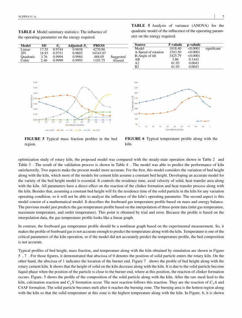
FIGURE 5 Typical mass fraction profiles in the bedregion.
FIGURE 6 Typical temperature profile along with thekiln.
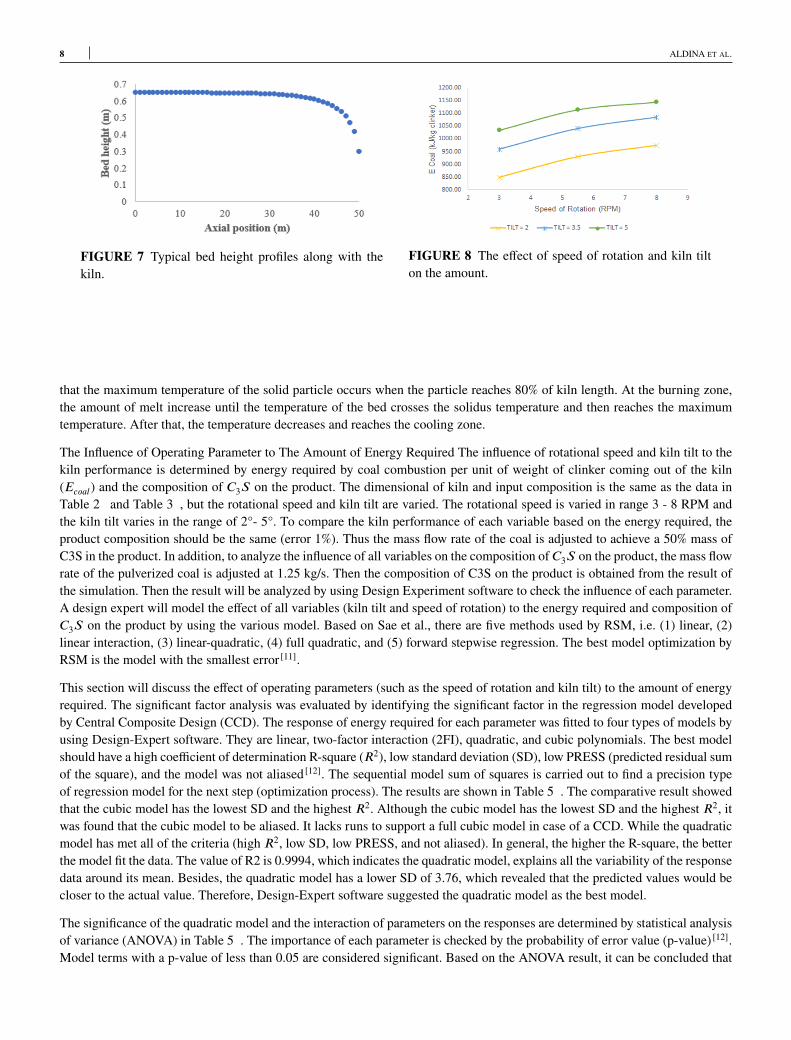
optimization study of rotary kiln, the proposed model was compared with the steady-state operation shown in Table 2 andTable 3 . The result of the validation process is shown in Table 4 . The model was able to predict the performance of kilnsatisfactorily. Two aspects make the present model more accurate. For the first, this model considers the variation of bed heightalong with the kiln, which most of the models for cement kiln assume a constant bed height. Developing an accurate model forthe variety of the bed height model is essential. It controls the residence time, axial velocity of solid, heat transfer area alongwith the kiln. All parameters have a direct effect on the reaction of the clinker formation and heat transfer process along withthe kiln. Besides that, assuming a constant bed height will fix the residence time of the solid particle in the kiln for any variationoperating condition, so it will not be able to analyze the influence of the kiln’s operating parameter. The second aspect is thismodel consist of a mathematical model. It describes the freeboard gas temperature profile based on mass and energy balance.The previous model just predicts the gas temperature profile based on the interpolation of three-point data (inlet gas temperature,maximum temperature, and outlet temperature). This point is obtained by trial and error. Because the profile is based on theinterpolation data, the gas temperature profile looks like a linear graph.In contrast, the freeboard gas temperature profile should be a nonlinear graph based on the experimental measurement. So, itmakes the profile of freeboard gas is not accurate enough to predict the temperature along with the kiln. Temperature is one of thecritical parameters of the kiln operation, so if the model did not accurately predict the temperature profile, the bed compositionis not accurate.Typical profiles of bed height, mass fraction, and temperature along with the kiln obtained by simulation are shown in Figure5 , 7 . For those figures, it demonstrated that abscissa of 0 denotes the position of solid particle enters the rotary kiln. On theother hand, the abscissa of 1 indicates the location of the burner end. Figure 7 shows the profile of bed height along with therotary cement kiln. It shows that the height of solid on the kiln decrease along with the kiln. It is due to the solid particle becomeliquid phase when the position of the particle is close to the burner end, where at this position, the reaction of clinker formationoccurs. Figure. 5 shows the profile of the composition of the solid particle along with the kiln. After the raw meal feed to thekiln, calcination reaction and C2S formation occur. The next reaction follows this reaction. They are the reaction of C3A andC4AF formation. The solid particle becomes melt after it reaches the burning zone. The burning area is the hottest region alongwith the kiln so that the solid temperature at this zone is the highest temperature along with the kiln. In Figure. 6, it is shown
8 ALDINA ET AL.
FIGURE 7 Typical bed height profiles along with thekiln.
FIGURE 8 The effect of speed of rotation and kiln tilton the amount.
that the maximum temperature of the solid particle occurs when the particle reaches 80% of kiln length. At the burning zone,the amount of melt increase until the temperature of the bed crosses the solidus temperature and then reaches the maximumtemperature. After that, the temperature decreases and reaches the cooling zone.The Influence of Operating Parameter to The Amount of Energy Required The influence of rotational speed and kiln tilt to thekiln performance is determined by energy required by coal combustion per unit of weight of clinker coming out of the kiln(Ecoal) and the composition of C3S on the product. The dimensional of kiln and input composition is the same as the data inTable 2 and Table 3 , but the rotational speed and kiln tilt are varied. The rotational speed is varied in range 3 - 8 RPM andthe kiln tilt varies in the range of 2°- 5°. To compare the kiln performance of each variable based on the energy required, theproduct composition should be the same (error 1%). Thus the mass flow rate of the coal is adjusted to achieve a 50% mass ofC3S in the product. In addition, to analyze the influence of all variables on the composition of C3S on the product, the mass flowrate of the pulverized coal is adjusted at 1.25 kg/s. Then the composition of C3S on the product is obtained from the result ofthe simulation. Then the result will be analyzed by using Design Experiment software to check the influence of each parameter.A design expert will model the effect of all variables (kiln tilt and speed of rotation) to the energy required and composition ofC3S on the product by using the various model. Based on Sae et al., there are five methods used by RSM, i.e. (1) linear, (2)linear interaction, (3) linear-quadratic, (4) full quadratic, and (5) forward stepwise regression. The best model optimization byRSM is the model with the smallest error [11].This section will discuss the effect of operating parameters (such as the speed of rotation and kiln tilt) to the amount of energyrequired. The significant factor analysis was evaluated by identifying the significant factor in the regression model developedby Central Composite Design (CCD). The response of energy required for each parameter was fitted to four types of models byusing Design-Expert software. They are linear, two-factor interaction (2FI), quadratic, and cubic polynomials. The best modelshould have a high coefficient of determination R-square (R2), low standard deviation (SD), low PRESS (predicted residual sumof the square), and the model was not aliased [12]. The sequential model sum of squares is carried out to find a precision typeof regression model for the next step (optimization process). The results are shown in Table 5 . The comparative result showedthat the cubic model has the lowest SD and the highest R2. Although the cubic model has the lowest SD and the highest R2, itwas found that the cubic model to be aliased. It lacks runs to support a full cubic model in case of a CCD. While the quadraticmodel has met all of the criteria (high R2, low SD, low PRESS, and not aliased). In general, the higher the R-square, the betterthe model fit the data. The value of R2 is 0.9994, which indicates the quadratic model, explains all the variability of the responsedata around its mean. Besides, the quadratic model has a lower SD of 3.76, which revealed that the predicted values would becloser to the actual value. Therefore, Design-Expert software suggested the quadratic model as the best model.The significance of the quadratic model and the interaction of parameters on the responses are determined by statistical analysisof variance (ANOVA) in Table 5 . The importance of each parameter is checked by the probability of error value (p-value) [12].Model terms with a p-value of less than 0.05 are considered significant. Based on the ANOVA result, it can be concluded that
ALDINA ET AL. 9
both speed-of rotation and kiln tilt have a substantial impact on the amount of energy required (due to the p-value of eachparameter < 0.05). Thus, the model of the amount of energy needed is written by Equation. 14.
Ecoal = 64.4A + 130.4B − 0.98AB − 3.35A2 − 9.30B2 + 466.3 (14)
In Equation 14, the positive sign before the terms specifies the synergistic effect, whereas negative sign specifies the antagonisticeffect. As the rotational speed and kiln tilt increase, the amount of energy requires an increase (see Figure. 8). It is due tothe inclination slope, and rotational speed is inversely proportional to the residence time. As the rotational speed and kiln tiltdecrease, the residence time of bed solid increases. Since solid spends more time in the kiln, re-solidification of the melt is morein the kiln that low rotated and low angle of slope. Moreover, the change of speed rotation and kiln tilt can also change the areaof bed exposed to the freeboard gas. As the increase of kiln rotational speed and angle of tilt, the area of bed exposed to thefreeboard gas decrease (see Figure. 9). Therefore, at higher RPM and angle of the tilt, the heat transfer between freeboard gasand the solid bed isn’t maximized and needs more supply energy from the coal combustion to achieve the target of specificationof product.
4 CONCLUSION
The present study shows that combining a model of reaction clinker formation by Mujumdar and a heat transfer model thatconsiders the installation of a cooling fan on the outside kiln wall can produce the appropriate model with the maximum errorless than 6% (less than another model). So, it can be concluded that the present model is accurate enough, and it can be usedfor obtaining a better understanding of kiln’s behavior and improving the kiln operating and design to achieve the optimumcondition. Besides, by doing the simulation of rotary cement kiln by variation of speed rotation and angle of inclination, it canbe concluded that speed of rotation and angle of kiln tilt significantly influenced both the amount of energy required. Both twoparameters have a synergistic effect on the energy required.
References
1. Li SQ, Ma LB, Wan W, Yao Q. A Mathematical Model of Heat Transfer in a Rotary Kiln Thermo-Reactor. ChemicalEngineering & Technology 2005 dec;28(12):1480–1489. http://doi.wiley.com/10.1002/ceat.200500241.
2. Csernyei C, Straatman AG. Numerical modeling of a rotary cement kiln with improvements to shell cooling. InternationalJournal of Heat and Mass Transfer 2016 nov;102:610–621.
3. Mujumdar KS, Ranade VV. Simulation of rotary cement kilns using a one-dimensional model. Chemical EngineeringResearch and Design 2006 mar;84(3 A):165–177.
4. Spang HA. A dynamic model of a cement kiln. Automatica 1972 may;8(3):309–323.5. Barr PV, Brimacombe JK, Watkinson AP. A heat-transfer model for the rotary kiln: Part I. pilot kiln trials. Metallurgical
Transactions B 1989 jun;20(3):391–402.6. Barr PV, Brimacombe JK,Watkinson AP. A heat-transfer model for the rotary kiln: Part II. Development of the cross-section
model. Metallurgical Transactions B 1989 jun;20(3):403–419.7. Mujumdar KS, Arora A, Ranade VV. Modeling of rotary cement kilns: Applications to reduction in energy consumption.
Industrial and Engineering Chemistry Research 2006;45(7):2315–2330.8. Darabi P. A mathematical model for cement kilns. PhD thesis, The University of British Columbia; 2007.9. Tscheng SH, Watkinson AP. Convective heat transfer in a rotary kiln. The Canadian Journal of Chemical Engineering 1979
aug;57(4):433–443.
10 ALDINA ET AL.
10. Levenspiel O. Chemical Reaction Engineering, 3rd Edition | Wiley. 3rd ed. New York, USA: John Wiley & Sons; 1998.https://www.wiley.com/en-id/Chemical+Reaction+Engineering,+3rd+Edition-p-9780471254249.
11. Samsudin MDM, Don MM, Ibrahim N, Kasmani RM, Zakaria Z, Kamarudin KS. Batch fermentation of bioethanol fromthe residues of elaeis guineensis: Optimisation using response surface methodology. Chemical Engineering Transactions2017;56:1579–1584.
12. Wang Z,Wang TR, YuanMZ,Wang H. Dynamic model for simulation and control of cement rotary kilns. Xitong FangzhenXuebao / Journal of System Simulation 2008;20(19):5131–5135.
How to cite this article: Aldina S., Sutikno J.P., Handogo R. (2020), Implementation of a Mathematical Modelling of a RotaryCement Kilns, IPTEK The Journal of Technology and Science, 31(1):1–10.
Copyright © 2022 FDOKUMEN