Increasing Durability of HMA Pavements Designed with the ...
Impact Quantification of Wide-Base Tire Loadingon Secondary Road Flexible Pavements
Hao Wang, A.M.ASCE1; and Imad L. Al-Qadi, Dist.M.ASCE2
Abstract: There is a need to evaluate the damage caused by the new generation of wide-base tires on low-volume secondary roads because oftheir increased use on trucks. In this study, a three-dimensional (3D) finite-element (FE) model was built to simulate the realistic tire loadingon secondary road pavements. The model allows for predicting pavement responses to loading applied by various tire configurations. Inaddition, the model incorporates the measured 3D tire-pavement contact stresses, models hot-mix asphalt (HMA) as linear viscoelasticmaterial, simulates continuous moving load, and utilizes implicit dynamic analysis. The analyzed pavement structures compriseda 76-mm HMA layer and an aggregate base layer with various thicknesses (203, 305, and 457 mm). The impact of a wide-base tire onsecondary road pavement damage was analyzed using available damage models and was compared to that resulting from conventionaldual-tire assemblies. It was found that the new wide-base tire (455/55R22.5) caused greater fatigue damage, subgrade rutting, andHMA rutting (densification) but less HMA rutting (shear) and base shear failure compared to the conventional dual-tire assembly whencarrying the same load. The findings indicate that wide-base tires’ impact on secondary road pavements depends on the roads’ predominantfailure mechanisms. Hence, calculated combined damage ratios can be used for road usage pricing and pavement design practice whenwide-base tires are used. DOI: 10.1061/(ASCE)TE.1943-5436.0000245. © 2011 American Society of Civil Engineers.
CE Database subject headings: Tires; Highways and roads; Flexible pavements; Finite element method; Damage.
Author keywords: Secondary roads; Flexible pavements; Wide-base tire; Finite-element model; Combined damage ratio.
Background
The trucking industry has, of late, been using wide-base single tiresas an alternative to conventional dual-tire assemblies. Compared tothe conventional dual-tire assembly, it is reported that wide-basetires improve fuel efficiency, reduce emissions, increase payload,exhibit superior braking and comfort, and reduce tire repair, main-tenance, and recycling costs. (Ang-Olson and Schroeer 2002;Al-Qadi and Elsefi 2007). The first generation of wide-base tires(385/65R22.5 and 425/65R22.5) in the early 1980s were foundto cause a significant increase in pavement damage compared todual-tire assemblies. This has led many transportation agenciesto discourage their use. For example, the first generation ofwide-base tires caused 1.5–2.0 times more rut depth and 2.0–4.0times more fatigue cracking than a dual-tire assembly whencarrying the same load (Huhtala et al. 1989; Bonaquist 1992;Akram et al. 1992; Perdomo and Nokes 1993; Myers et al.1999; Siddharthan et al. 2002; Kim et al. 2005). The new gener-ation of wide-base tires (445/50R22.5 and 455/55R22.5) came tomarket in the 2000s to possibly reduce pavement damage and
provide other safety and cost-saving advantages. The new gener-ation of wide-base tires are 15–18% wider than the first generationand do not require high tire inflation pressure owing to their specialwall design (Al-Qadi et al. 2005). Thus, the impact of the newgeneration of wide-base tires on pavement damage needs to beinvestigated.
Results of COST Action 334 (2001) indicated that the newgeneration of wide-base tires would cause approximately the sameprimary rutting damage as a dual-tire assembly on primary roadsand 44–52% more combined damage (20% primary rutting, 40%secondary rutting, and 40% fatigue cracking) on secondary roads.Al-Qadi et al. (2002, 2005) concluded that the new wide-base tirescaused slightly more fatigue damage and less primary rutting dam-age than a dual-tire assembly, based on the comprehensive exper-imental and theoretical studies conducted at the Virginia SmartRoad. Pierre et al. (2003) conducted field measrements and foundthat the wide-base 455/55R22.5 tire caused more distortions at thepavement base in the spring and similar distortions in the summer,compared to the dual tires. The wide-base 455/55R22.5 tire wasalso found to cause less primary rutting than the dual tires. Priestet al. (2005) conducted a study at the NCAT Test Track in Auburn,Alabama, and concluded that the new wide-base tire (445/50R22.5)resulted in a similar pavement fatigue life as the standard dual-tireassembly (275/80R22.5). Al-Qadi andWang (2009a) found that thenew wide-base tire (455/55R22.5) induced greater fatigue damagebut similar or less near-surface cracking and hot-mix asphalt(HMA) rutting (shear flow) potential in perpetual pavements whencompared to dual-tire assemblies. These studies indicate that theimpact of wide-base tires on pavement damage depends on pave-ment structure, the pavement failure mechanism considered, andenvironmental conditions.
The predominant failure mechanisms of secondary roads aredifferent from those of primary roads or interstate highways.Although previous research has achieved significant advances,
1Assistant Professor, Dept. of Civil and Environmental Engineering,Rutgers Univ., Piscataway, NJ 08854 (corresponding author). E-mail:[email protected]; formerly, Graduate Research Assistant, Dept.of Civil and Environmental Engineering, Univ. of Illinois at Urbana-Champaign, IL 61801
2Founder Professor of Engineering and Director, Illinois Center forTransportation, Univ. of Illinois at Urbana-Champaign, IL 61801. E-mail:[email protected]
Note. This manuscript was submitted on January 7, 2010; approved onOctober 29, 2010; published online on November 24, 2010. Discussionperiod open until February 1, 2012; separate discussions must be submittedfor individual papers. This paper is part of the Journal of TransportationEngineering, Vol. 137, No. 9, September 1, 2011. ©ASCE, ISSN 0733-947X/2011/9-630–639/$25.00.
630 / JOURNAL OF TRANSPORTATION ENGINEERING © ASCE / SEPTEMBER 2011
Downloaded 10 Sep 2011 to 192.17.144.236. Redistribution subject to ASCE license or copyright. Visithttp://www.ascelibrary.org
the new wide-base tires’ impact on secondary road pavements hasnot been thoroughly investigated and quantified. This study, there-fore, aimed to quantify the pavement damage on secondary roadscaused by various tire configurations. These research findings willhelp state departments of transportation (DOTs) predict theimpact of the new wide-base tires on the road infrastructure andprovide the basis for reasonable load regulations and fee chargesfor trucking operations. The implementation of appropriate feeregulations will ultimately balance economic benefits (for thetrucking industry) with pavement repair costs (for state DOTsand other agencies).
Objective and Scope
The main objective of this study was to evaluate the impact of newwide-base tires on secondary road pavements. The conventionalpavement design mainly uses the linear layered elastic theory topredict pavement responses under vehicular loading. The layeredtheory assumes a uniform stress distribution within a circularcontact area. Hence, this analytical technique cannot reflect the dif-ference in contact stress distribution patterns between wide-basetires and conventional dual-tire assemblies at the tire-pavementinterface. To overcome these limitations, a three-dimensional (3D)finite-element (FE) model was built to simulate the realistic tireloading on secondary road pavements. The model allows forpredicting pavement responses to loading applied by various tireconfigurations. It incorporates measured 3D tire-pavement contactstresses, models HMA as linear viscoelastic material, simulatescontinuous moving load, and utilizes implicit dynamic analysis.
The analyzed pavement structures were comprised of a 76-mmHMA layer and an unbound aggregate base layer with variousthicknesses (203, 305, and 457 mm). The critical pavement re-sponses under various tire configurations at intermediate and hightemperatures were calculated and compared. The impact of the newgeneration of wide-base tire (455/55R22.5) on damage to secondaryroad pavement was compared to the impact of the conventional dual-tire assembly for the above-mentioned pavement designs. The over-all impact of wide-base tires on road usage pricing and pavementdesign practice was evaluated using the calculated damage ratios.
Tire-Pavement Contact Stress
It has been documented that tire-pavement contact stresseshave three components: vertical, transverse, and longitudinal.These 3D tire contact stresses result in a complex stress state nearthe pavement surface. Drakos et al. (2001) found that the 3D tirecontact stresses increased HMA instability rutting potential.
De Beer et al. (2002) suggested that responses of thin HMA pave-ments are sensitive to vertical load shape and distribution. Park et al.(2005) concluded that the nonuniform contact stresses causedhighly localized strains that could initiate rutting at the flexiblepavement surface. Yoo and Al-Qadi (2008) showed that the verticalshear strain under 3D tire contact stress could be responsible for thedevelopment of near-surface cracking. Wang and Al-Qadi (2009)reported that the 3D tire contact stresses induced greater octahedralshear stress at pavement near-surface, compared to uniform contactstress distribution. Thus, it is necessary to define the realistic tireloading condition to accurately predict pavement responses andperformances.
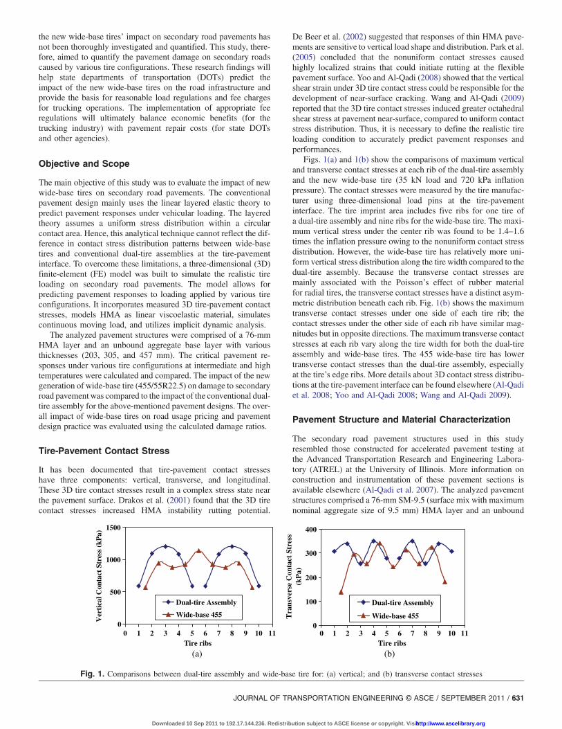
Figs. 1(a) and 1(b) show the comparisons of maximum verticaland transverse contact stresses at each rib of the dual-tire assemblyand the new wide-base tire (35 kN load and 720 kPa inflationpressure). The contact stresses were measured by the tire manufac-turer using three-dimensional load pins at the tire-pavementinterface. The tire imprint area includes five ribs for one tire ofa dual-tire assembly and nine ribs for the wide-base tire. The maxi-mum vertical stress under the center rib was found to be 1.4–1.6times the inflation pressure owing to the nonuniform contact stressdistribution. However, the wide-base tire has relatively more uni-form vertical stress distribution along the tire width compared to thedual-tire assembly. Because the transverse contact stresses aremainly associated with the Poisson’s effect of rubber materialfor radial tires, the transverse contact stresses have a distinct asym-metric distribution beneath each rib. Fig. 1(b) shows the maximumtransverse contact stresses under one side of each tire rib; thecontact stresses under the other side of each rib have similar mag-nitudes but in opposite directions. The maximum transverse contactstresses at each rib vary along the tire width for both the dual-tireassembly and wide-base tires. The 455 wide-base tire has lowertransverse contact stresses than the dual-tire assembly, especiallyat the tire’s edge ribs. More details about 3D contact stress distribu-tions at the tire-pavement interface can be found elsewhere (Al-Qadiet al. 2008; Yoo and Al-Qadi 2008; Wang and Al-Qadi 2009).
Pavement Structure and Material Characterization
The secondary road pavement structures used in this studyresembled those constructed for accelerated pavement testing atthe Advanced Transportation Research and Engineering Labora-tory (ATREL) at the University of Illinois. More information onconstruction and instrumentation of these pavement sections isavailable elsewhere (Al-Qadi et al. 2007). The analyzed pavementstructures comprised a 76-mm SM-9.5 (surface mix with maximumnominal aggregate size of 9.5 mm) HMA layer and an unbound
0
500
1000
1500
Tire ribs
Ver
tica
l Con
tact
Str
ess
(kP
a)
Dual-tire Assembly
Wide-base 455
0
100
200
300
400
0 1 2 3 4 5 6 7 8 9 10 11 0 1 2 3 4 5 6 7 8 9 10 11Tire ribs
Tra
nsve
rse
Con
tact
Str
ess
(kP
a)
Dual-tire Assembly
Wide-base 455
(a) (b)
Fig. 1. Comparisons between dual-tire assembly and wide-base tire for: (a) vertical; and (b) transverse contact stresses
JOURNAL OF TRANSPORTATION ENGINEERING © ASCE / SEPTEMBER 2011 / 631
Downloaded 10 Sep 2011 to 192.17.144.236. Redistribution subject to ASCE license or copyright. Visithttp://www.ascelibrary.org
aggregate base layer with various thicknesses (203, 305, and457 mm for sections A, B, and D, respectively). PG 64-22 binderwas used in the SM-9.5 mix for the HMA layer. Dense-gradedcrushed limestone aggregates were used for the base layer. Thepavement sections were constructed on subgrade having a lowCalifornia bearing ratio (CBR) of 4%.
A linear viscoelastic model was used to simulate HMAbehavior. The HMA relaxation modulus was converted fromlaboratory-determined creep compliance test results through aninterconversion procedure (Park and Kim 1999). The shear and bulkrelaxation moduli were then calculated, assuming a constantPoisson’s ratio, and fitted into a Prony series of the generalizedMaxwell solid model, Eqs. (1) and (2). The temperature dependencyof the HMA modulus was characterized by the time-temperaturesuperposition principle because HMA has been proven to be athermorheologically simple (TRS) material. The time-temperatureshift factor was approximated by the Williams-Landell-Ferry(WLF) function, Eq. (3) (ABAQUS version 6.7)
GðtÞ ¼ G0
�1�
Xni¼1
Gið1� e�t=τ iÞ�
ð1Þ
KðtÞ ¼ K0
�1�
Xni¼1
Kið1� e�t=τ iÞ�
ð2Þ
whereG = shear modulus; K = bulk modulus; t = reduced relaxationtime;G0 andK0 = instantaneous shear and volumetric modulus; andGi, Ki, and τ i = Prony series parameters
logðaTÞ ¼ � C1ðT � T0ÞC2 þ ðT � T0Þ
ð3Þ
where logðaTÞ = log of the shift factor; T0 = reference temperature;T = actual temperature corresponding to the shift factor; and C1 andC2 are regression parameters.
The aggregate base and subgrade were assumed as linear elasticmaterial. The resilient modulus of subgrade was estimated from itsCBR value using the approach in the 2002 Mechanistic-EmpiricalPavement Design Guide (MEPDG) [Applied Research Associates,Inc. (ARA) 2004]. The resilient modulus of the aggregate base wasestimated as the average measured modulus from repeated-load tri-axial tests at five confining pressure levels (21, 35, 69, 104, and138 kPa) in accordance with the AASHTOT307 procedure. Table 1summarizes the material parameters for each pavement layer.
Development of 3D FE Model
The layered elastic theory is usually used to calculate flexiblepavement responses to truck loading owing to its simplicity. In
comparison to the relatively simple layered elastic theory, thefinite-element method (FEM) can be a complex and costly analysistool. However, the application of FE techniques allows for moreaccurate simulation of complex material properties and realistic tireloading. Thus, a 3D FE model was built using ABAQUS version6.7. The 3D FE model is more appropriate, compared to the axi-symmetric or two-dimensional (2D) plane model. It can considerthe measured 3D tire-pavement contact stress distribution undereach rib, as well as the dynamic transient loading associated witha moving vehicle.
Model Geometry
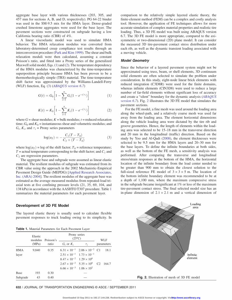
Since the behavior of a layered pavement system might not beapproximated using truss, beam, or shell elements, 3D continuumsolid elements are often selected to simulate the problem underconsideration. In this study, eight-node linear brick elements withreduced integration (C3D8R) were used for the finite domains,whereas infinite elements (CIN3D8) were used to reduce a largenumber of far-field elements without significant loss of accuracyand create a “silent” boundary for the dynamic analysis (ABAQUSversion 6.7). Fig. 2 illustrates the 3D FE model that simulates thepavement sections.
For the FE model, a fine mesh was used around the loading areaalong the wheel-path, and a relatively coarse mesh was used faraway from the loading area. The element horizontal dimensionsalong the vehicle loading area were dictated by the tire rib andgroove geometries. Hence, the length of elements within the load-ing area was selected to be 15–18 mm in the transverse directionand 20 mm in the longitudinal (traffic) direction. Based on thestudy by Yoo and Al-Qadi (2008), the element thicknesses wereselected to be 9.5 mm for the HMA layers and 20–30 mm forthe base layers. To define the infinite boundaries at both sides,as well as the bottom of the FE mesh, a sensitivity analysis wasperformed. After comparing the transverse and longitudinalstress/strain responses at the bottom of the HMA, the horizontallocation of the infinite boundary from the load center needed tobe greater than 900 mm to obtain the closest solution to thefull-sized reference FE model of 3 × 3 × 5 m. The location ofthe bottom infinite boundary element was recommended to be ata depth of 1,100 mm, where the maximum compressive stressin the subgrade became insignificant at 1% or less of the maximumtire-pavement contact stress. The final selected model size has anin-plane dimension of 2:1 × 2:1 m and a vertical dimension of
Table 1. Material Parameters for Each Pavement Layer
Elasticmodulus(MPa)
Poisson’sratio
Prony series(25°C) WLF
parametersGi or Ki τ i
HMA
layer
9,840 0.35 6:31 × 10�1 2:06 × 10�2 C1 18.1
2:51 × 10�1 1:73 × 10�1
8:47 × 10�2 1:29 × 100
2:67 × 10�2 5:35 × 100 C2 164.7
6:66 × 10�3 1:06 × 102
Base 193 0.30 —Subgrade 43 0.40 — Fig. 2. Illustration of mesh of 3D FE model
632 / JOURNAL OF TRANSPORTATION ENGINEERING © ASCE / SEPTEMBER 2011
Downloaded 10 Sep 2011 to 192.17.144.236. Redistribution subject to ASCE license or copyright. Visithttp://www.ascelibrary.org
2.5 m to achieve the balance between computation cost andaccuracy. Only single-axle loading was simulated in this study.Although tandem-axle loading can be simulated in the model, ahigh computation cost would be required because of the increasein model size.
Simulation of Moving Transient Load
Avehicle load applied on a pavement surface is the sum of the staticload and a dynamic tire force. The dynamic tire force is the result ofthe vehicle’s response to the longitudinal unevenness (roughness)of the road surface. To define the dynamic tire force, intensive fieldmeasurements from vehicle axles may be needed. To characterizethe transient local dynamic load without extensive field data, as inthis study, the dynamic loading can be simplified by using themeasured loading amplitude within the tire imprint area on asmooth pavement surface.
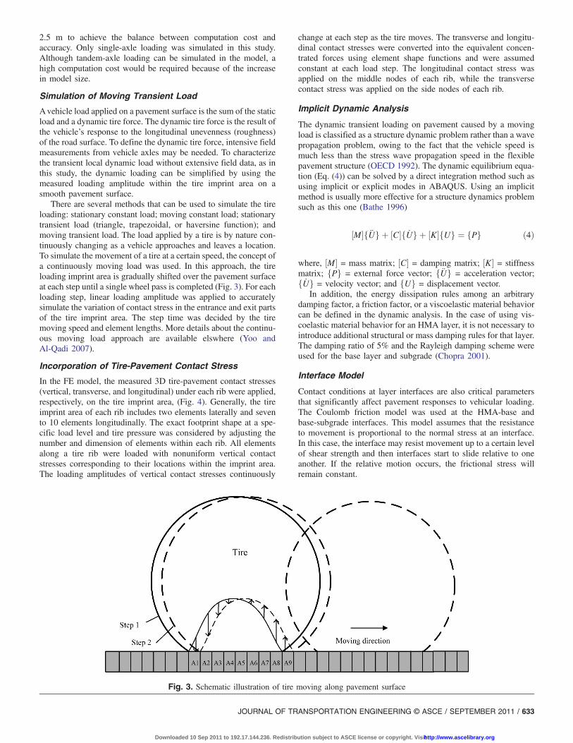
There are several methods that can be used to simulate the tireloading: stationary constant load; moving constant load; stationarytransient load (triangle, trapezoidal, or haversine function); andmoving transient load. The load applied by a tire is by nature con-tinuously changing as a vehicle approaches and leaves a location.To simulate the movement of a tire at a certain speed, the concept ofa continuously moving load was used. In this approach, the tireloading imprint area is gradually shifted over the pavement surfaceat each step until a single wheel pass is completed (Fig. 3). For eachloading step, linear loading amplitude was applied to accuratelysimulate the variation of contact stress in the entrance and exit partsof the tire imprint area. The step time was decided by the tiremoving speed and element lengths. More details about the continu-ous moving load approach are available elswhere (Yoo andAl-Qadi 2007).
Incorporation of Tire-Pavement Contact Stress
In the FE model, the measured 3D tire-pavement contact stresses(vertical, transverse, and longitudinal) under each rib were applied,respectively, on the tire imprint area, (Fig. 4). Generally, the tireimprint area of each rib includes two elements laterally and sevento 10 elements longitudinally. The exact footprint shape at a spe-cific load level and tire pressure was considered by adjusting thenumber and dimension of elements within each rib. All elementsalong a tire rib were loaded with nonuniform vertical contactstresses corresponding to their locations within the imprint area.The loading amplitudes of vertical contact stresses continuously
change at each step as the tire moves. The transverse and longitu-dinal contact stresses were converted into the equivalent concen-trated forces using element shape functions and were assumedconstant at each load step. The longitudinal contact stress wasapplied on the middle nodes of each rib, while the transversecontact stress was applied on the side nodes of each rib.
Implicit Dynamic Analysis
The dynamic transient loading on pavement caused by a movingload is classified as a structure dynamic problem rather than a wavepropagation problem, owing to the fact that the vehicle speed ismuch less than the stress wave propagation speed in the flexiblepavement structure (OECD 1992). The dynamic equilibrium equa-tion (Eq. (4)) can be solved by a direct integration method such asusing implicit or explicit modes in ABAQUS. Using an implicitmethod is usually more effective for a structure dynamics problemsuch as this one (Bathe 1996)
½M�f€Ug þ ½C�f _Ug þ ½K�fUg ¼ fPg ð4Þ
where, ½M� = mass matrix; ½C� = damping matrix; ½K� = stiffnessmatrix; fPg = external force vector; f€Ug = acceleration vector;f _Ug = velocity vector; and fUg = displacement vector.
In addition, the energy dissipation rules among an arbitrarydamping factor, a friction factor, or a viscoelastic material behaviorcan be defined in the dynamic analysis. In the case of using vis-coelastic material behavior for an HMA layer, it is not necessary tointroduce additional structural or mass damping rules for that layer.The damping ratio of 5% and the Rayleigh damping scheme wereused for the base layer and subgrade (Chopra 2001).
Interface Model
Contact conditions at layer interfaces are also critical parametersthat significantly affect pavement responses to vehicular loading.The Coulomb friction model was used at the HMA-base andbase-subgrade interfaces. This model assumes that the resistanceto movement is proportional to the normal stress at an interface.In this case, the interface may resist movement up to a certain levelof shear strength and then interfaces start to slide relative to oneanother. If the relative motion occurs, the frictional stress willremain constant.
Fig. 3. Schematic illustration of tire moving along pavement surface
JOURNAL OF TRANSPORTATION ENGINEERING © ASCE / SEPTEMBER 2011 / 633
Downloaded 10 Sep 2011 to 192.17.144.236. Redistribution subject to ASCE license or copyright. Visithttp://www.ascelibrary.org

FE Model Validation
The accuracy of FE analysis is affected by mesh dimensions,element definitions, element aspect ratios, complexity of thematerial models, and the evaluation location. The level of accuracyof the developed FE model was first checked by comparing the FEsolutions to a closed-form solution using a layered elastic theorybased on general assumptions (e.g., static loading, fully bonded in-terface conditions, uniform circular contact stress, and linear elasticmaterial behavior) (Al-Qadi and Wang 2009a).
The purpose of this study was to compare the pavementresponses under various tire configurations. Table 2 presents thepredicted and measured pavement response ratios. The responseratio is the pavement response to the 455 wide-base tire comparedto that caused by a dual-tire assembly under the same loading con-dition. A good agreement of response ratios was achieved for bothpredicted and measured values for the three sections. Hence, usingrelatively simple material constitutive models (viscoelastic HMAand elastic aggregate base and subgrade) was thought to be accept-able in this study at a reasonable computation cost.
Pavement Response Analysis
In-Depth Strain Distributions
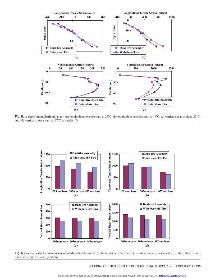
The pavement responses were calculated under the two tire configu-rations at 35.5 kN, 690 kPa, and 8 km=h. The tensile and shearstrains are the two most critical pavement responses within theHMA layer considered by the mechanistic-empirical design pro-cedure. Figs. 5(a) and 5(b) show the longitudinal tensile strain dis-tributions with depth for section D under two tire configurations at25°C and 47°C, respectively. The presented tensile strains are locatedunder the middle rib of one tire in a dual-tire assembly where themaximum vertical contact stress exists. As expected, the longitudi-nal tensile strain distribution is compressive in the upper half ofthe HMA layer and becomes tensile in the lower part of the layer.
The highest tensile strain was obtained at the bottom of the HMAlayer at both intermediate and high temperatures. At both temper-atures, loading through thewide-base 455 tire resulted in greater lon-gitudinal tensile strains compared to that of the dual-tire assembly.
Figs. 5(c) and 5(d) show the vertical shear strain distributionswith depth for section D under two tire configurations at 25°C and47°C, respectively. At 25°C, the greatest shear strain within theHMA is at the middle of the layer, whereas at 47°C the greatestshear strain is in a shallow depth of the layer (around 20 mm belowthe surface). The locations of critical shear strain are consistent withthe locations where the horizontal tensile strain changes fromcompression to tension. At high temperature, the high magnitudeof shear strain at shallow depth of the HMA layer may initiate near-surface shear cracking or may cause unstable shear flow underrepeated vehicular loading. At 47°C, the wide-base 455 tire causesmuch less vertical shear strain than the dual-tire assembly, whileat 25°C, the two tire configurations cause similar vertical shearstrains. At an intermediate temperature, 25°C, the shear strain ismore controlled by the load-induced bending effect, whereas athigh temperature, 47°C, the HMA becomes softer and the effect oflocalized tire contact stresses (vertical and tangential) becomemore significant compared to the bending effect. Therefore, at47°C, the relatively more uniform vertical contact stress and lesstangential stress at the edge of the wide-base 455 tire may resultin less vertical shear strain at the tire edge compared to thedual-tire assembly.
Stresses and Stains under Various Tire Configurations
Figs. 6(a) and 6(b) show the calculated maximum transverse andlongitudinal tensile strains at the bottom of the HMA at 47°C undera dual-tire assembly and a wide-base 455 tire for the three pavementsections. It is clear that the tensile strains decrease as the base layerthickness increases for both tire configurations. The longitudinaltensile strains caused by thewide-base 455 tire are greater than thosecaused by the dual-tire assembly regardless of base thickness,whereas the transverse tensile strains caused by both tire configura-tions are relatively similar. Compared to the dual-tire assembly, thewide-base 455 tire causes slightly greater transverse tensile strains inthe pavement section having the thinnest base layer but causesslightly less transverse tensile strains in the pavement section havingthe thickest base layer. These strain differences between the two tireconfigurations could be a result of the wheel spacing betweenthe tires in the dual-tire assembly; the two tire configurations havesimilar average contact stress under the same load.
Figs. 6(c) and 6(d) compare the calculated maximum verticalshear stresses and strains at the shallow depth of the HMA layerat 47°C under a dual-tire assembly and a wide-base 455 tire forthe three pavement sections. The results show that the wide-base455 tire causes lower vertical shear stresses and strains than thedual-tire assembly, regardless of base thickness. It is noted thatthe maximum tensile strains decrease as the base layer thicknessincreases, whereas the shear strains are insignificantly affectedby the base layer thickness. At high temperature, the maximumshear strain is much greater than the maximum tensile strain.
Fig. 4. Schematic illustration of contact stresses under each rib (onetire in dual-tire assembly)
Table 2. Response Ratios Caused by Wide-Base 455 Tire with respect to Dual-Tire Assembly
Sections A B D
Pavement responses ratios for: Field FEM Field FEM Field FEM
Transverse tensile strain at bottom of HMA 1.12 1.09 1.03 1.01 0.88 0.88
Vertical pressure at bottom of base 1.36 1.24 1.33 1.23 1.16 1.17
Compressive strain on top of subgrade — 1.21 1.17 1.10 1.10 1.07
634 / JOURNAL OF TRANSPORTATION ENGINEERING © ASCE / SEPTEMBER 2011
Downloaded 10 Sep 2011 to 192.17.144.236. Redistribution subject to ASCE license or copyright. Visithttp://www.ascelibrary.org
0
30
60
90
-400 -200 0 200 400
Longitudinal Tensile Strain (micro)
Dep
th (
mm
)Dual-tire Assembly
Wide-base Tire
0
30
60
90
-400 0 400 800 1200Longitudinal Tensile Strain (micro)
Dep
th (
mm
)
Dual-tire Assembly
Wide-base Tire
(a) (b)
0
30
60
90
0 50 100 150 200 250Vertical Shear Strain (micro)
Dep
th (
mm
)
Dual-tire Assembly
Wide-base Tire
0
30
60
90
0 500 1000 1500Vertical Shear Strain (micro)
Dep
th (
mm
)
Dual-tire Assembly
Wide-base Tire
(c) (d)
Fig. 5. In-depth strain distributions for: (a) longitudinal tensile strain at 25°C; (b) longitudinal tensile strain at 47°C; (c) vertical shear strain at 25°C;and (d) vertical shear strain at 47°C at section D
0
500
1000
1500
203mm base 305mm base 457mm baseLon
gitu
dina
l Ten
sile
Str
ain
(mic
ro)
Dual-tire Assembly
Wide-base 455 Tire
0
500
1000
1500
203mm base 305mm base 457mm baseTra
nsve
rse
Ten
sile
Str
ain
(mic
ro)
Dual-tire Assembly
Wide-base 455 Tire
(a) (b)
(c) (d)
0
100
200
300
400
500
Ver
tica
l She
ar S
tres
s (k
Pa)
Dual-tire Assembly
Wide-base 455 Tire
0
500
1000
1500
2000
203mm base 305mm base 457mm base 203mm base 305mm base 457mm base
Ver
tica
l She
ar S
trai
n (m
icro
) Dual-tire Assembly
Wide-base 455 Tire
Fig. 6. Comparisons of maximum (a) longitudinal tensile strains; (b) transverse tensile strains; (c) vertical shear stresses; and (d) vertical shear strainsunder different tire configurations
JOURNAL OF TRANSPORTATION ENGINEERING © ASCE / SEPTEMBER 2011 / 635
Downloaded 10 Sep 2011 to 192.17.144.236. Redistribution subject to ASCE license or copyright. Visithttp://www.ascelibrary.org
This indicates that shape distortion and shear deformation is pre-dominant in the HMA layer at high temperature.
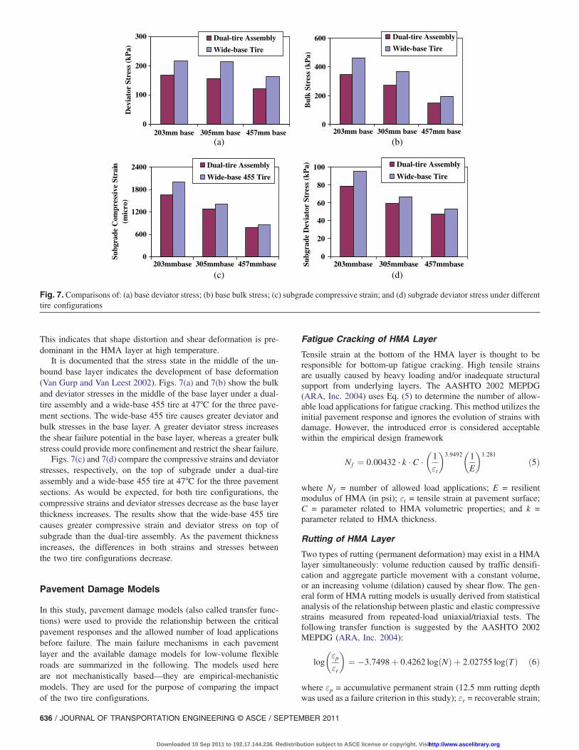
It is documented that the stress state in the middle of the un-bound base layer indicates the development of base deformation(Van Gurp and Van Leest 2002). Figs. 7(a) and 7(b) show the bulkand deviator stresses in the middle of the base layer under a dual-tire assembly and a wide-base 455 tire at 47°C for the three pave-ment sections. The wide-base 455 tire causes greater deviator andbulk stresses in the base layer. A greater deviator stress increasesthe shear failure potential in the base layer, whereas a greater bulkstress could provide more confinement and restrict the shear failure.
Figs. 7(c) and 7(d) compare the compressive strains and deviatorstresses, respectively, on the top of subgrade under a dual-tireassembly and a wide-base 455 tire at 47°C for the three pavementsections. As would be expected, for both tire configurations, thecompressive strains and deviator stresses decrease as the base layerthickness increases. The results show that the wide-base 455 tirecauses greater compressive strain and deviator stress on top ofsubgrade than the dual-tire assembly. As the pavement thicknessincreases, the differences in both strains and stresses betweenthe two tire configurations decrease.
Pavement Damage Models
In this study, pavement damage models (also called transfer func-tions) were used to provide the relationship between the criticalpavement responses and the allowed number of load applicationsbefore failure. The main failure mechanisms in each pavementlayer and the available damage models for low-volume flexibleroads are summarized in the following. The models used hereare not mechanistically based—they are empirical-mechanisticmodels. They are used for the purpose of comparing the impactof the two tire configurations.
Fatigue Cracking of HMA Layer
Tensile strain at the bottom of the HMA layer is thought to beresponsible for bottom-up fatigue cracking. High tensile strainsare usually caused by heavy loading and/or inadequate structuralsupport from underlying layers. The AASHTO 2002 MEPDG(ARA, Inc. 2004) uses Eq. (5) to determine the number of allow-able load applications for fatigue cracking. This method utilizes theinitial pavement response and ignores the evolution of strains withdamage. However, the introduced error is considered acceptablewithin the empirical design framework
Nf ¼ 0:00432 · k · C ·
�1εt
�3:9492
�1E
�1:281
ð5Þ
where Nf = number of allowed load applications; E = resilientmodulus of HMA (in psi); εt = tensile strain at pavement surface;C = parameter related to HMA volumetric properties; and k =parameter related to HMA thickness.
Rutting of HMA Layer
Two types of rutting (permanent deformation) may exist in a HMAlayer simultaneously: volume reduction caused by traffic densifi-cation and aggregate particle movement with a constant volume,or an increasing volume (dilation) caused by shear flow. The gen-eral form of HMA rutting models is usually derived from statisticalanalysis of the relationship between plastic and elastic compressivestrains measured from repeated-load uniaxial/triaxial tests. Thefollowing transfer function is suggested by the AASHTO 2002MEPDG (ARA, Inc. 2004):
log
�εpεr
�¼ �3:7498þ 0:4262 logðNÞ þ 2:02755 logðTÞ ð6Þ
where εp = accumulative permanent strain (12.5 mm rutting depthwas used as a failure criterion in this study); εr = recoverable strain;
0
100
200
300
Dev
iato
r St
ress
(kP
a)
Dual-tire Assembly
Wide-base Tire
0
(a) (b)
(c) (d)
200
400
600
Bul
k St
ress
(kP
a)
0
600
1200
1800
2400
Subg
rade
Com
pres
sive
Str
ain
(mic
ro)
Dual-tire Assembly
Wide-base 455 Tire
0
20
40
60
80
100
203mm base 305mm base 457mm base 203mm base 305mm base 457mm base
203mmbase 305mmbase 457mmbase 203mmbase 305mmbase 457mmbaseSubg
rade
Dev
iato
r St
ress
(kP
a) Dual-tire Assembly
Wide-base Tire
Dual-tire Assembly
Wide-base Tire
Fig. 7. Comparisons of: (a) base deviator stress; (b) base bulk stress; (c) subgrade compressive strain; and (d) subgrade deviator stress under differenttire configurations
636 / JOURNAL OF TRANSPORTATION ENGINEERING © ASCE / SEPTEMBER 2011
Downloaded 10 Sep 2011 to 192.17.144.236. Redistribution subject to ASCE license or copyright. Visithttp://www.ascelibrary.org
N = allowed number of load repetitions corresponding to εp; andT = pavement temperature (°C).
Deacon et al. (2002) and Monismith et al. (2006) correlatedHMA rutting to shear stresses and shear strains in the HMA layerinstead of compressive strain, as shown in Eq. (7). This model wasoriginally developed for Westrack mixes based on repeated simpleshear tests at constant height (RSST-CH)
γ ¼ a · expðbτ sÞγenc ð7Þwhere γ = permanent (inelastic) shear strain (12.5-mm rutting depthwas used as a failure criterion in this study); γe = elastic shearstrain; τ s = corresponding shear stress (in psi); n = number of axleload applications; and a, b, and c are experimentally determinedcoefficients (a ¼ 1:262, b ¼ 0:05, and c ¼ 0:36 were used in thisstudy).
Permanent Deformation of Unbound Base Layer
Permanent deformation of the base layer is caused by the granularmaterial having insufficient stability owing to heavy loading orpoor drainage conditions. This may result in loss of particle-to-particle interlock forces and thus the bearing capacity of base layer(shear failure). It is documented that the stress state in the middle ofthe unbound base layer indicates the development of deformation(Van Gurp and Van Leest 2002). However, few design methodsconsider the cumulative permanent deformation or insufficientstability in the granular base layer as critical.
The South African mechanistic design method (SA-MDM) con-siders the permanent deformation of the base layer. It is related tothe ratio of the working stress to the yield strength of the material,considering that high shear stress can extend into the base layer inthin-surfaced pavements for normal traffic loading, Eqs. (8) and (9)(Theyse et al. 1996)
F ¼ σ3½ktan2ð45þ ϕ2Þ � 1� þ 2kc tanð45þ ϕ
2Þσ1 � σ3
ð8Þ
N ¼ 10ð2:605122Fþ3:480098Þ ð9Þwhere σ1 and σ3 = major and minor principal stresses (compressivestress positive and tensile stress negative); k = constant (k ¼ 0:95for normal moisture condition was used in this study); c = cohesioncoefficient; ϕ = angle of internal friction (c ¼ 0 and ϕ ¼ 30° wereused in this study); and N = allowed load applications until failure.
Subgrade Rutting
Subgrade rutting (secondary rutting) is a longitudinal wheel-pathdepression that occurs when subgrade exhibits permanent deforma-tion caused by compressive or shear stress from repetitive trafficloading. Usually the vertical compressive strain at the top of sub-grade is related to subgrade rutting. The Asphalt Institute (AI)(1982) proposed a rutting damage model, based on roadbed soil
strain with a maximum threshold of 12.5 mm rutting on subgrade,as follows:
N ¼ 1:365 × 10�9ðεvÞ�4:477 ð10Þwhere N = allowed load repetitions until failure, and εv = maximumvertical compressive strain on top of subgrade.
Damage Ratio between Two Tire Configurations
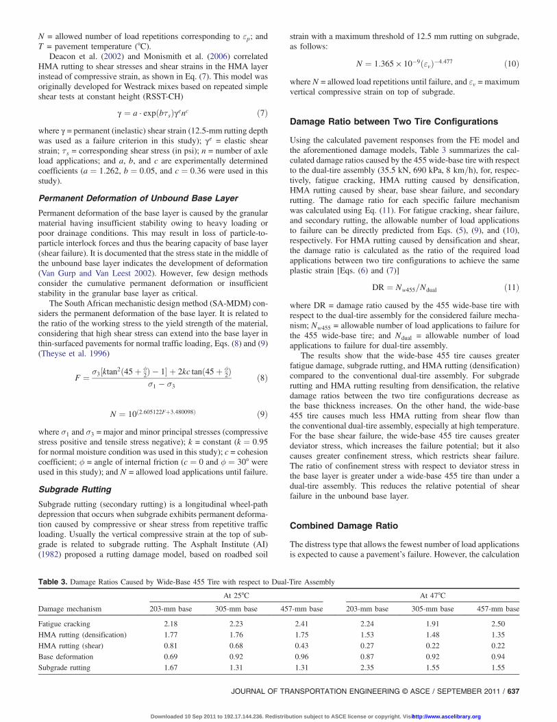
Using the calculated pavement responses from the FE model andthe aforementioned damage models, Table 3 summarizes the cal-culated damage ratios caused by the 455 wide-base tire with respectto the dual-tire assembly (35.5 kN, 690 kPa, 8 km=h), for, respec-tively, fatigue cracking, HMA rutting caused by densification,HMA rutting caused by shear, base shear failure, and secondaryrutting. The damage ratio for each specific failure mechanismwas calculated using Eq. (11). For fatigue cracking, shear failure,and secondary rutting, the allowable number of load applicationsto failure can be directly predicted from Eqs. (5), (9), and (10),respectively. For HMA rutting caused by densification and shear,the damage ratio is calculated as the ratio of the required loadapplications between two tire configurations to achieve the sameplastic strain [Eqs. (6) and (7)]
DR ¼ Nw455=Ndual ð11Þwhere DR = damage ratio caused by the 455 wide-base tire withrespect to the dual-tire assembly for the considered failure mecha-nism; Nw455 = allowable number of load applications to failure forthe 455 wide-base tire; and Ndual = allowable number of loadapplications to failure for dual-tire assembly.
The results show that the wide-base 455 tire causes greaterfatigue damage, subgrade rutting, and HMA rutting (densification)compared to the conventional dual-tire assembly. For subgraderutting and HMA rutting resulting from densification, the relativedamage ratios between the two tire configurations decrease asthe base thickness increases. On the other hand, the wide-base455 tire causes much less HMA rutting from shear flow thanthe conventional dual-tire assembly, especially at high temperature.For the base shear failure, the wide-base 455 tire causes greaterdeviator stress, which increases the failure potential; but it alsocauses greater confinement stress, which restricts shear failure.The ratio of confinement stress with respect to deviator stress inthe base layer is greater under a wide-base 455 tire than under adual-tire assembly. This reduces the relative potential of shearfailure in the unbound base layer.
Combined Damage Ratio
The distress type that allows the fewest number of load applicationsis expected to cause a pavement’s failure. However, the calculation
Table 3. Damage Ratios Caused by Wide-Base 455 Tire with respect to Dual-Tire Assembly
Damage mechanism
At 25°C At 47°C
203-mm base 305-mm base 457-mm base 203-mm base 305-mm base 457-mm base
Fatigue cracking 2.18 2.23 2.41 2.24 1.91 2.50
HMA rutting (densification) 1.77 1.76 1.75 1.53 1.48 1.35
HMA rutting (shear) 0.81 0.68 0.43 0.27 0.22 0.22
Base deformation 0.69 0.92 0.96 0.87 0.92 0.94
Subgrade rutting 1.67 1.31 1.31 2.35 1.55 1.55
JOURNAL OF TRANSPORTATION ENGINEERING © ASCE / SEPTEMBER 2011 / 637
Downloaded 10 Sep 2011 to 192.17.144.236. Redistribution subject to ASCE license or copyright. Visithttp://www.ascelibrary.org
of the allowable number of load applications depends significantlyon the local calibration factors and material parameters used in thepavement damage models. This could cause the predominant fail-ure type to vary for different loading scenarios. Thus, a combineddamage ratio was used to consider the overall effect of differentfailure mechanisms on pavement serviceability caused by thewide-base 455 tire with respect to the dual-tire assembly.
The combined damage ratio was calculated as a logarithmicdamage distribution factor, as shown in Eqs. (12) and (13). Thelogarithmic distribution function was used to balance the effectof each failure mechanism with respect to the overall damage in-duced by the tire. This transformation is commonly used in statis-tics and is recommended when dealing with variables spreadingover several orders of magnitude, as is the case presented in thisstudy (Al-Qadi et al. 2005). In the field, even if one failure mecha-nism is manifested, this does not imply that the other distresses willnot occur throughout the pavement service life. The failure mech-anisms are progressive and contribute together to degrade the pave-ment serviceability. For this reason, a combined damage ratio ismore appropriate and was, therefore, adopted in this analysis
CDR ¼ a1DRfatigue þ a2DRHMA�densification þ a3DRHMA�shear
þ a4DRbase þ a5DRrutting�subgrade ð12Þ
ai ¼1= logðNiÞPnj¼1 1= logðNjÞ
ð13Þ
where CDR = combined damage ratio caused by the 455 wide-basetire with respect to the dual-tire assembly; DRfatigue = damage ratiofor fatigue cracking; DRHMA�densification = damage ratio for HMArutting resulting from densification; DRHMA�shear = damage ratiofor HMA rutting from shear flow; DRbase = damage ratio for baseshear failure; DRrutting�subgrade = damage ratio for subgrade rutting;a1, a2, a3, a4, and a5 = damage distribution factors for differentfailure mechanisms; Ni and Nj = allowable number of load appli-cations for different failure mechanisms; and n = total number ofconsidered failure mechanisms (n ¼ 5 here).
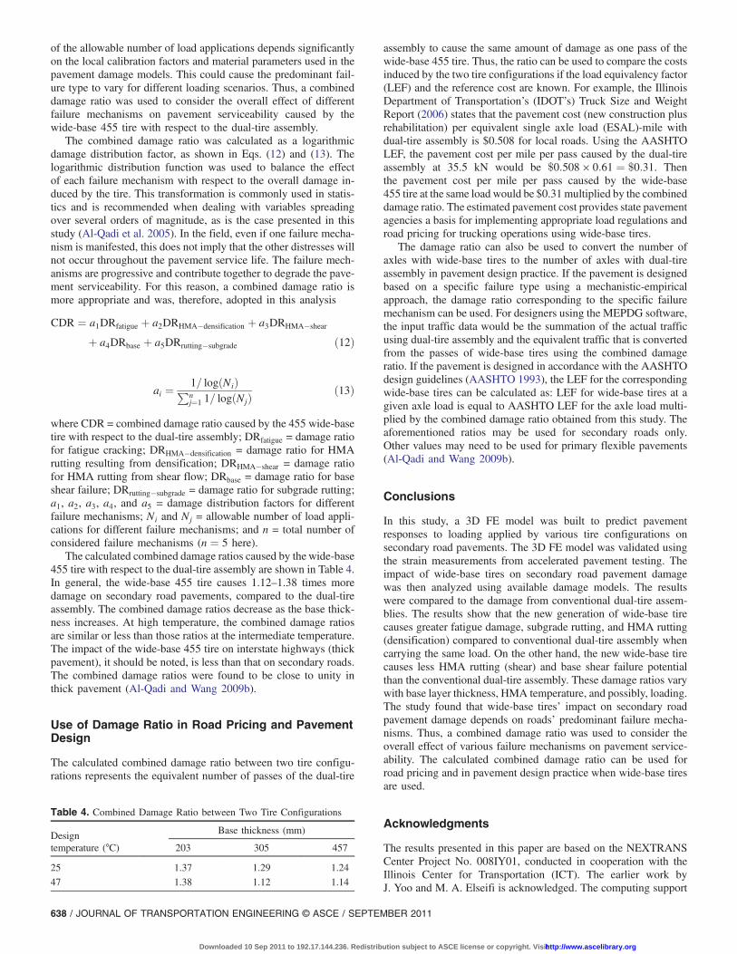
The calculated combined damage ratios caused by the wide-base455 tire with respect to the dual-tire assembly are shown in Table 4.In general, the wide-base 455 tire causes 1.12–1.38 times moredamage on secondary road pavements, compared to the dual-tireassembly. The combined damage ratios decrease as the base thick-ness increases. At high temperature, the combined damage ratiosare similar or less than those ratios at the intermediate temperature.The impact of the wide-base 455 tire on interstate highways (thickpavement), it should be noted, is less than that on secondary roads.The combined damage ratios were found to be close to unity inthick pavement (Al-Qadi and Wang 2009b).
Use of Damage Ratio in Road Pricing and PavementDesign
The calculated combined damage ratio between two tire configu-rations represents the equivalent number of passes of the dual-tire
assembly to cause the same amount of damage as one pass of thewide-base 455 tire. Thus, the ratio can be used to compare the costsinduced by the two tire configurations if the load equivalency factor(LEF) and the reference cost are known. For example, the IllinoisDepartment of Transportation’s (IDOT’s) Truck Size and WeightReport (2006) states that the pavement cost (new construction plusrehabilitation) per equivalent single axle load (ESAL)-mile withdual-tire assembly is $0.508 for local roads. Using the AASHTOLEF, the pavement cost per mile per pass caused by the dual-tireassembly at 35.5 kN would be $0:508 × 0:61 ¼ $0:31. Thenthe pavement cost per mile per pass caused by the wide-base455 tire at the same load would be $0.31multiplied by the combineddamage ratio. The estimated pavement cost provides state pavementagencies a basis for implementing appropriate load regulations androad pricing for trucking operations using wide-base tires.
The damage ratio can also be used to convert the number ofaxles with wide-base tires to the number of axles with dual-tireassembly in pavement design practice. If the pavement is designedbased on a specific failure type using a mechanistic-empiricalapproach, the damage ratio corresponding to the specific failuremechanism can be used. For designers using the MEPDG software,the input traffic data would be the summation of the actual trafficusing dual-tire assembly and the equivalent traffic that is convertedfrom the passes of wide-base tires using the combined damageratio. If the pavement is designed in accordance with the AASHTOdesign guidelines (AASHTO 1993), the LEF for the correspondingwide-base tires can be calculated as: LEF for wide-base tires at agiven axle load is equal to AASHTO LEF for the axle load multi-plied by the combined damage ratio obtained from this study. Theaforementioned ratios may be used for secondary roads only.Other values may need to be used for primary flexible pavements(Al-Qadi and Wang 2009b).
Conclusions
In this study, a 3D FE model was built to predict pavementresponses to loading applied by various tire configurations onsecondary road pavements. The 3D FE model was validated usingthe strain measurements from accelerated pavement testing. Theimpact of wide-base tires on secondary road pavement damagewas then analyzed using available damage models. The resultswere compared to the damage from conventional dual-tire assem-blies. The results show that the new generation of wide-base tirecauses greater fatigue damage, subgrade rutting, and HMA rutting(densification) compared to conventional dual-tire assembly whencarrying the same load. On the other hand, the new wide-base tirecauses less HMA rutting (shear) and base shear failure potentialthan the conventional dual-tire assembly. These damage ratios varywith base layer thickness, HMA temperature, and possibly, loading.The study found that wide-base tires’ impact on secondary roadpavement damage depends on roads’ predominant failure mecha-nisms. Thus, a combined damage ratio was used to consider theoverall effect of various failure mechanisms on pavement service-ability. The calculated combined damage ratio can be used forroad pricing and in pavement design practice when wide-base tiresare used.
Acknowledgments
The results presented in this paper are based on the NEXTRANSCenter Project No. 008IY01, conducted in cooperation with theIllinois Center for Transportation (ICT). The earlier work byJ. Yoo and M. A. Elseifi is acknowledged. The computing support
Table 4. Combined Damage Ratio between Two Tire Configurations
Designtemperature (°C)
Base thickness (mm)
203 305 457
25 1.37 1.29 1.24
47 1.38 1.12 1.14
638 / JOURNAL OF TRANSPORTATION ENGINEERING © ASCE / SEPTEMBER 2011
Downloaded 10 Sep 2011 to 192.17.144.236. Redistribution subject to ASCE license or copyright. Visithttp://www.ascelibrary.org
provided by the National Center for Super Computing Applications(NCSA) at the University of Illinois at Urbana-Champaign isgreatly appreciated. The contents of this paper reflect the viewof the writers, who are responsible for the facts and the accuracyof the data presented here. The contents do not necessarily reflectthe official views or policies of the NEXTRANS, FHWA, ICT, orIDOT. This paper does not constitute a standard, specification, orregulation.
References
AASHTO. (1993). “AASHTO guide for design of pavement structures.”Washington, DC.
ABAQUS version 6.7 [Computer software]. Hibbitt, Karlsson, andSorenson, Inc., Pawtucket, R.I.
Akram, T., Scullion, T., Smith, R. E., and Fernando, E. G. (1992). “Esti-mating damage effects of dual versus wide-base tires with multidepthdeflectometers.” Transp. Res. Rec., 1355, 59–66.
Al-Qadi, I. L., and Elseifi, M. a. (2007). “New generation of wide-basetires: impact on trucking operations, environment, and pavements.”Transp. Res. Rec., 2008, 100–109.
Al-Qadi, I. L., andWang, H. (2009a). “Full-depth pavement responses undervarious tire configurations: Accelerated pavement testing and finiteelement modeling.” J. Assoc. Asphalt Paving Technol., 78, 645–680.
Al-Qadi, I. L., andWang, H. (2009b). “Evaluation of pavement damage dueto new tire designs.” Research Rep. ICT-09-048, Illinois Center forTransportation, Rantoul, IL.
Al-Qadi, I. L., Loulizi, A., Janajreh, I., and Freeman, T. E. (2002). “Pavementresponse to dual tires and new wide-base tires at same tire pressure.”Transp. Res. Rec., 1806, 38–47.
Al-Qadi, I. L., Tutumluer, E., Dessouky, S. H., and Kwon, J. (2007).“Effectiveness of geogrid-reinforcement in flexible pavements: Afull-scale testing.” Final Report to Tensar Earth Technologies, Inc.,University of Illinois, Urbana-Champaign, IL.
Al-Qadi, I. L., Wang, H., Yoo, P. J., and Dessouky, S. H. (2008). “Dynamicanalysis and in situ validation of perpetual pavement response tovehicular loading.” Transp. Res. Rec., 2087, 29–39.
Al-Qadi, I. L., Yoo, P. J., Elseifi, M. A., and Janajreh, I. (2005). “Effects oftire configurations on pavement damage.” J. Assoc. Asphalt PavingTechnol., 74, 921–962.
Ang-Olson, J., and Schroeer, W. (2002). “Energy efficiency strategies forfreight trucking: potential impact on fuel use and greenhouse gasemission.” Transp. Res. Rec., 1815, 11–18.
Applied Research Associates, Inc. (ARA). (2004). “Development of the2002 guide for the design of new and rehabilitated pavements.”NationalCooperative Highway Research Program (NCHRP) Proj. No. 1-37A,Transportation Research Board, Washington, DC.
Asphalt Institute (AI). (1982). “Research and development of the AsphaltInstitute’s thickness design manual (MS-1),” Research Rep. 82-1,9th Ed., College Park, MD.
Bathe, K. J. (1996). Finite element procedures in engineering analysis,Prentice-Hall, Upper Saddle River, NJ.
Bonaquist, R. (1992). “An assessment of the increased damage potential ofwidebase single tires.” Proc, 7th Int. Conf. on Asphalt Pavements,Vol. 3, Int. Soc. for Asphalt Pavements, Lino Lakes, MN, 1–16.
Chopra, A. K. (2001). Dynamics of structures, 2nd Ed., Prentice-Hall,Upper Saddle River, NJ.
COST Action 334. (2001). “Effects of wide single tires and dual tires.”European Cooperation in Science and Technology (COST), Brussels,Belgium.
Deacon, J. A., Harvey, J. T., Guada, I., Popescu, L., and Monismith, C. L.(2002). “Analytically based approach to rutting prediction.” Transp.Res. Rec., 1806, 9–18.
De Beer, M., Fisher, C., and Jooste, F. J. (2002). “Evaluation of nonuniformtire contact stresses on thin asphalt pavements.” Proc., 9th Int. Conf. onAsphalt Pavements (ICAP 2002) (CD-ROM), Int. Soc. for AsphaltPavements, Lino Lakes, MN.
Drakos, C., Roque, R., and Birgisson, B. (2001). “Effects of measured tirecontact stresses on near surface rutting.” Transp. Res. Rec., 1764, 59–69.
Huhtala, M., Philajamaki, J., and Pienimaki, M. (1989). “Effects of tiresand tire pressures on road pavements.” Transp. Res. Rec., 1227,107–114.
Illinois Department of Transportation (DOT). (2006). “Truck size andweight report.” Springfield, IL
Kim, D., Salgado, R., and Altschaeffl, A. G. (2005). “Effects of supersingletire loadings on pavements.” J. Transp. Eng., 131(10), 732–743.
Monismith, C. L., Popescu, L., and Harvey, J. T. (2006). “Rut depthestimation for mechanistic-empirical pavement design using simpleshear test results.” J. Assoc. Asphalt Paving Technol. (CD-ROM), 75,1294–1338.
Myers, L. A., Roque, R., Ruth, B. E., and Drakos, C. (1999). “Measure-ment of contact stresses for different truck tire types to evaluate theirinfluence on near-surface cracking and rutting.” Transp. Res. Rec.,1655, 175–184.
Organization for Economic Cooperation and Development (OECD).(1992). Dynamic loading of pavements: Road transport research,Paris.
Park, S. W., and Kim, Y. R. (1999). “Interconversion between relaxationmodulus and creep compliance for viscoelastic solids.” J. Mater. Civ.Eng., 11(1), 76–82.
Park, D., Martin, A. E., and Masad, E. (2005). “Effects of nonuniformtire contact stresses on pavement response.” J. Transp. Eng., 131(11),873–879.
Perdomo, D., and Nokes, B. (1993). “Theoretical analysis of the effects ofwide-base tires on flexible pavements using CIRCLY.” Transp. Res.Rec., 1388, 108–119.
Pierre, P., Dore, G., and Vagile, L. (2003). “Characterization and evaluationof tire-roadway interface stresses.” Rep. No. GCT-03-03, QuébecMinistry of Transport, Montréal.
Priest, A. L., Timm, D. H., and Barrett, W. E. (2005). “Mechanisticcomparison of wide-base single vs. standard dual tire configurations.”Rep. 05-03, National Center for Asphalt Technology (NCAT),Auburn, AL.
Siddharthan, R. V., Krishnamenon, N., El-Mously, M., and Sebaaly, P. E.(2002). “Investigation of tire contact stress distributions on pavementresponse.” J. Transp. Eng., 128(2), 136–144.
Theyse, H. L., De Beer, M., and Rust, F. C. (1996). “Overview of the SouthAfrican mechanistic pavement design analysis method.” Transp. Res.Rec., 1539, 6–17.
Van Gurp, C., and Van Leest, A. J. (2002). “Thin asphalt pavements on softsoil.” Proc., 9th Int. Conf. on Asphalt Pavements (CD-ROM), Int. Soc.for Asphalt Pavements, Lino Lakes, MN.
Wang, H., and Al-Qadi, I. L. (2009). “Combined effect of moving wheelloading and three-dimensional contact stresses on perpetual pavementresponses.” Transp. Res. Rec., 2095, 53–61.
Yoo, P. J., and Al-Qadi, I. L. (2007). “Effect of transient dynamic loadingon flexible pavements.” Transp. Res. Rec., 1990, 129–140.
Yoo, P. J., and Al-Qadi, I. L. (2008). “Truth and myth of fatigue crackingpotential in hot-mix asphalt: Numerical analysis and validation.” J. Assoc.Asphalt Paving Technol., 77, 549–590.
JOURNAL OF TRANSPORTATION ENGINEERING © ASCE / SEPTEMBER 2011 / 639
Downloaded 10 Sep 2011 to 192.17.144.236. Redistribution subject to ASCE license or copyright. Visithttp://www.ascelibrary.org
Copyright © 2022 FDOKUMEN