
IMPACT OF FADING CORRELATION, POLARIZATION COUPLING AND KEYHOLES ON MIMO DETECTORS FOR V-BLAST...
10
International Journal of Mobile Network Communications & Telematics ( IJMNCT) Vol. 3, No.4, August 2013 DOI : 10.5121/ijmnct.2013.3406 65 IMPACT OF FADING CORRELATION, POLARIZATION COUPLING AND KEYHOLES ON MIMO DETECTORS FOR V-BLAST ARCHITECTURE Bindu. E 1 and B.V.R. Reddy 2 1 Research Scholar, GGSIP University, Dept of ECE, Amity School of Engg and Tech, New Delhi, India 2 Professor, USICT, GGSIP University, New Delhi, India ABSTRACT This paper analyzes the impact of fading correlation, cross polarization coupling and channel degeneracy alias keyhole condition on the error performance of V-BLAST MIMO system that employs detector algorithms like ZF, MMSE and ML with ordering and successive cancellation. Deleterious impact of above mentioned channel impairments on MIMO system capacity is studied. Simulation results show the BER performance of these detectors for different modulation schemes. It is observed that lesser the channel fading correlation and cross polarization coupling values better is the performance of these detectors. Study is extended to see the effect of transmit and receive antenna correlation on Ergodic MIMO capacity. KEYWORDS MIMO, V-BLAST, ZF, MMSE, ML, fading correlation, cross polarization coupling, keyhole effect 1. INTRODUCTION Multiple input multiple output (MIMO) system employs multiple transmit and receive antennas to provide high data rates without using additional bandwidth and power. In a rich scattering environment, the capacity increases linearly with the number of antennas without increasing the transmission power. This results in the possibility of transmitting at a higher data rate, by using spatial multiplexing (SM). Multiplexing gain is defined as the number of sub channels of the MIMO channel asymptotically viewed as a parallel channel. Due to this, the corresponding transmission rate is multiplied by the number of transmit antennas, thereby increasing gain. With N receive antennas for M (where M ≤ N) simultaneously transmitted data streams through independent flat Rayleigh channels, the M streams of data can be separated by using a zero- forcing (ZF) scheme, and d = (N−M+1) path diversity can be achieved by each of the M streams [6]. But in most practical MIMO systems, independent channels are difficult to achieve. Layered Space Time (LST) codes can provide multiplexing gain and are spectrally efficient , hence suitable to realize SM. Channel fading and additive noise are main problems faced by MIMO LST receiver, along with Multistream Interference (MSI). MSI arises due to the interaction of data streams with each other and this interference can be minimized through correct choice of detector algorithms [2]. Bell Lab Layered Space-Time (BLAST) detection algorithms combine linear (interference suppression) and non-linear (serial cancellation) detection methods. Combination of Optimal Ordering with Successive Cancellation (SUC-OO) algorithms with Zero Forcing (ZF), Minimum Mean Square (MMSE) or Maximum Likelihood (ML) receivers can minimize Multi-stream interference [1].
-
Upload
independent -
Category
Documents
-
view
0 -
download
0
Transcript of IMPACT OF FADING CORRELATION, POLARIZATION COUPLING AND KEYHOLES ON MIMO DETECTORS FOR V-BLAST...

International Journal of Mobile Network Communications & Telematics ( IJMNCT) Vol. 3, No.4, August 2013
DOI : 10.5121/ijmnct.2013.3406 65
IMPACT OF FADING CORRELATION, POLARIZATION
COUPLING AND KEYHOLES ON MIMO DETECTORS
FOR V-BLAST ARCHITECTURE
Bindu. E 1 and B.V.R. Reddy 2
1 Research Scholar, GGSIP University, Dept of ECE, Amity School of Engg and Tech, New Delhi, India
2 Professor, USICT, GGSIP University, New Delhi, India
ABSTRACT This paper analyzes the impact of fading correlation, cross polarization coupling and channel degeneracy alias keyhole condition on the error performance of V-BLAST MIMO system that employs detector algorithms like ZF, MMSE and ML with ordering and successive cancellation. Deleterious impact of above mentioned channel impairments on MIMO system capacity is studied. Simulation results show the BER performance of these detectors for different modulation schemes. It is observed that lesser the channel fading correlation and cross polarization coupling values better is the performance of these detectors. Study is extended to see the effect of transmit and receive antenna correlation on Ergodic MIMO capacity.
KEYWORDS MIMO, V-BLAST, ZF, MMSE, ML, fading correlation, cross polarization coupling, keyhole effect 1. INTRODUCTION Multiple input multiple output (MIMO) system employs multiple transmit and receive antennas to provide high data rates without using additional bandwidth and power. In a rich scattering environment, the capacity increases linearly with the number of antennas without increasing the transmission power. This results in the possibility of transmitting at a higher data rate, by using spatial multiplexing (SM). Multiplexing gain is defined as the number of sub channels of the MIMO channel asymptotically viewed as a parallel channel. Due to this, the corresponding transmission rate is multiplied by the number of transmit antennas, thereby increasing gain. With N receive antennas for M (where M ≤ N) simultaneously transmitted data streams through independent flat Rayleigh channels, the M streams of data can be separated by using a zero-forcing (ZF) scheme, and d = (N−M+1) path diversity can be achieved by each of the M streams [6]. But in most practical MIMO systems, independent channels are difficult to achieve. Layered Space Time (LST) codes can provide multiplexing gain and are spectrally efficient , hence suitable to realize SM. Channel fading and additive noise are main problems faced by MIMO LST receiver, along with Multistream Interference (MSI). MSI arises due to the interaction of data streams with each other and this interference can be minimized through correct choice of detector algorithms [2]. Bell Lab Layered Space-Time (BLAST) detection algorithms combine linear (interference suppression) and non-linear (serial cancellation) detection methods. Combination of Optimal Ordering with Successive Cancellation (SUC-OO) algorithms with Zero Forcing (ZF), Minimum Mean Square (MMSE) or Maximum Likelihood (ML) receivers can minimize Multi-stream interference [1].

International Journal of Mobile Network Communications & Telematics ( IJMNCT) Vol. 3, No.4, August 2013
66
For theoretical analysis, the channel is modelled as flat fading Rayleigh independent identically distributed (i.i.d) Gaussian variable. The antennas are assumed to provide independent channels for the received signals. However, in real propagation environment, the fades are not independent due to insufficient spacing between antenna elements. When the fades are correlated, the channel capacity decreases [9]. Presence of Line-of-Sight (LOS) component also makes the channel deviate from Rayleigh i.i.d. Another Theoretical assumption of identical polarization for both transmitting and receiving antenna also fails in practical scenario, due to Cross Polarization effect. This phenomenon can also lead to high bit error rate (BER)[2]. This aspect along with the impact of fading correlation on different detection schemes is studied in this paper. Another channel impediment is channel degeneracy , also known as keyhole (or pinhole) phenomenon [10]. The potential benefits of multiple-antenna systems may be limited by rank deficiency of the channel due to the keyhole effect.[11]. Organization of the paper is as follows: Section II explains the basic MIMO channel model and its capacity along with the effect of fading correlation and cross polarization on the complex channel matrix H. Keyhole effect is described in section III. In section IV, VBLAST architecture with the receiver algorithms like ML, ZF and MMSE, with and without SUC-OO are discussed. Section V discusses the simulation results followed by conclusion in section VI.
2. MIMO CHANNEL MODEL In MIMO system with M transmitting and N receiving antenna, the received signal vector y is y = Hx + n (1)
where H is channel matrix of dimension MxN with complex coefficients for Rayleigh i.i.d flat fading channel and n is a wide sense stationary (WSS) noise vector with i.i.d. components and variance of σ2 .The advantage of using MIMO system is the increased channel capacity it can provide for the same signal conditions. The outage capacity of MIMO system having M=N antennas and for channel unknown to the transmitter is given as [1] C= M log2 (1+ρ) bits/s/Hz (2) where ρ=Eb/No. The capacity of an orthogonal MIMO channel is therefore M times the scalar channel capacity. Performance of MIMO system may deteriorate due to various factors, which influence the channel matrix H. Fading correlation due to closely spaced antenna and presence of LOS component due to poor scattering environment causes deviation of channel model from pure Rayleigh i.i.d. Cross polarization coupling between the antennas can also alter the channel matrix. Correlation problems arise because of the small separation distance between the antenna elements at the Base Station (BS). Fig.1 shows the “one-ring” model [9], which is used to determine spatial fading correlation of H. Due to the kind of geometry, all antennas will receive the same signal, giving rise to correlation between them. The normalized mutual correlation coefficient between any pair of antennas is [6]
j,idJhhEr R
o*jninij
2 (3)
where (·)* denotes complex conjugate, E{·} denotes statistical expectation, J0(·) is the zero order Bessel function of the first kind, λ is the wavelength, and dR(i,j) is the displacement between receive antennas i and j. Because of this, the elements of the channel matrix H become [2]

International Journal of Mobile Network Communications & Telematics ( IJMNCT) Vol. 3, No.4, August 2013
67
1/2tω
1/2r RHR=H (4)
where Rr and Rt are the receive and transmit covariance matrices (positive definite Hermitian matrices) of order NxN and MxM respectively. H is a Rayleigh i.i.d complex Gaussian matrix with zero mean, unit variance entries.
Fig. 1. One-ring model (TA -transmitting antenna, RA- receiving antenna , S(θ)- the scatterer at angle θ, δ-
angle spread, D- the distance from object X to Y) [9]
The correlation matrix R with three receive antenna is
1
1
1
R
3231
2321
1312
rr
rr
rr
(5)
where rij is normalized mutual correlation coefficient between any pair of antenna, r =E{hhH}, where h is channel vector, h=vec[H] [6]. Assuming receiver and transmitter matrix are of full rank, then at high SNR, the capacity can be approximated as
t2r2Hωω2 RdetlogRdetlogHHdetlog ++
M
ρ=C
(6)
As the equation shows, fading channel correlation reduces the outage channel capacity by [log2det(Rr)+ log2det(Rt)] bits/s/Hz. The loss caused by transmit and receive correlation is independent, the loss due to receive correlation is determined by the determinant of the receive correlation matrix and the numbers of receive antenna, and the loss caused by transmit correlated fading is determined by the transmit correlation matrix and the modulation scheme [9]. The use of antennas having orthogonal polarization at the transmitter and receiver leads to a gain and correlation imbalance between elements of H. In reality, perfect polarization cannot be achieved, leading to cross polarization coupling [4]. The coupling factor (0 1) gives a measure of how well the antenna discriminates the polarization from other antenna. Assuming a Rayleigh i.i.d channel, the channel H with cross-polarized antenna can be modelled as [2]
1
1 whereRHR 1/2
tω1/2r
=ββΘ=H (7)
where is Hadamard product. The capacity for a 2x2 system in non-scattering environment is given as
TA1
TA2
Θ
Δ θ
S(θ)
RA1
RA2
D R

International Journal of Mobile Network Communications & Telematics ( IJMNCT) Vol. 3, No.4, August 2013
68
ρ+log=C/ρ+=C α=α= 21 and 212log 2120 (8) 3. KEYHOLE EFFECT For a MIMO system with uncorrelated antennas and Rayleigh i.i.d channel give rise to full rank channel matrix of size MxN. The keyhole effect is characterized by a rank- deficient channel matrix. In presence of keyhole, there may be a rich scattering environment at the proximities of the transmitter and receiver[10,11].
Fig.2 Keyhole effect[2]
However, these advantages are not usable because in between the transmitter and the receiver local environments, there is only one or a reduced number of propagation paths resulting in a low-rank channel matrix as shown in fig.2. Due to keyhole effect, the effective channel matrix becomes
4241
3231TtrHHH
hhhh
hhhh (9)
where Ht = [h1 h2] and Hr = [h3 h4]
T, h1,h2 are channel coefficients for transmitted signals, and h3 h4 are coefficients for receiving antennas. The vectors Hr and Ht are independent, circularly symmetric, zero-mean, complex Gaussian random variables. Since H is constructed from product of two vectors, the realization of channel matrix is rank deficient with rank of 2 and the distribution of H is double Rayleigh with pdf as[11]
0 x422
24
0 4
,dex
)x(f r
x
r
(10)
the channel capacity is
)M
(logC 12 (11)
where M=2, and λ is the solitary eigenvalue. The received signal is
xky H (12) where k is the keyhole attenuation factor.
h1
h2
h3
h4
r1 r2
keyhole
Local scatterers Local scatterers

International Journal of Mobile Network Communications & Telematics ( IJMNCT) Vol. 3, No.4, August 2013
69
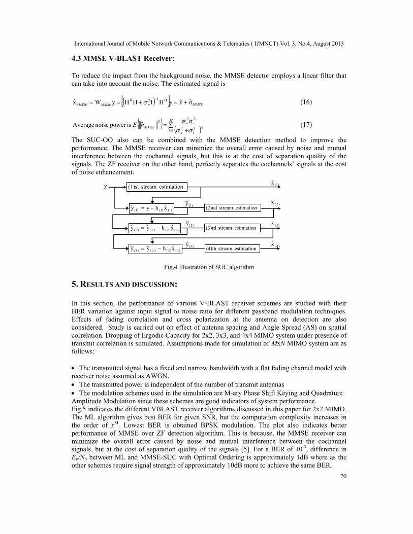
4. LAYERED SPACE TIME RECEIVERS The Vertical BLAST (V-BLAST) architecture is indicated in fig.3, for M transmitter N receiver setup operating coherently at each symbol time T, with transmission organized in bursts of L symbols. LST decoding suffers from Multistream Interference (MSI) in which the multiple streams superimpose over one anther at the receiver, making the detection difficult. So choice of receiver becomes important to exploit the maximum potential of SM through LST. The three most common receivers are ML, ZF and MMSE. These schemes can be combined with non-linear detection schemes such as successive cancellation (SUC) and Optimally Ordered SUC algorithms to enhance the performance. Fig.4 shows SUC algorithm. In SUC-OO , the signal with the strongest SINR is selected for processing at the first stage. This improves the quality of the decision and reduces the chances of error propagation [8].
Fig.3 V-BLAST architecture [7] 4.1 ML Receiver: This is an optimum receiver, which solves for the estimated symbol vector x̂
2Hxyminargx̂ML (13)
by searching through the entire vector constellation for the most probable transmitted signal vector. The computational complexity is very high as M increases (xM) but provides full receiver diversity and zero power losses [2]. 4.2 ZF V-BLAST Receiver: The ZF receiver is a linear receiver. This technique nullifies the interference by using weight matrix WZF as follows [3]
ZFZFZF n~xyyWˆ
HHHx1H (14)
M
i i
nZFn~
12
22
ispower noise Average (15)
This noise in the separated streams are correlated and consequently the SNRs are not independent. The ZF receiver decomposes the link into M parallel streams, each with diversity gain and array gain proportional to N-M+1. Hence, it is sub optimum. Recursive SUC-OO Zero Forcing algorithm, which is based on performing the nulling operation using unitary transformations results in a lower complexity and better numerical stability [2]. The recursion determines the elements of the optimal row, which maximizes the Bit Error Rate (BER).
Vertical encoded data
rich scattering environment
y1
y2
yN
Received Data
V-BLAST signal processing: estimate x and decode
Input Data
Vector Encoder & Mapper
x1
x2
xM
Serial to Parallel converter
Tx
Tx
Tx Rx
Rx
Rx
International Journal of Mobile Network Communications & Telematics ( IJMNCT) Vol. 3, No.4, August 2013
70
4.3 MMSE V-BLAST Receiver: To reduce the impact from the background noise, the MMSE detector employs a linear filter that can take into account the noise. The estimated signal is
MMSEnMMSEMMSE n~x~ˆ
yHIHHyWx H12H (16)
M
iin
inMMSEn~
1222
222
ispower noise Average (17)
The SUC-OO also can be combined with the MMSE detection method to improve the performance. The MMSE receiver can minimize the overall error caused by noise and mutual interference between the cochannel signals, but this is at the cost of separation quality of the signals. The ZF receiver on the other hand, perfectly separates the cochannels’ signals at the cost of noise enhancement.
Fig.4 Illustration of SUC algorithm
5. RESULTS AND DISCUSSION: In this section, the performance of various V-BLAST receiver schemes are studied with their BER variation against input signal to noise ratio for different passband modulation techniques. Effects of fading correlation and cross polarization at the antenna on detection are also considered. Study is carried out on effect of antenna spacing and Angle Spread (AS) on spatial correlation. Dropping of Ergodic Capacity for 2x2, 3x3, and 4x4 MIMO system under presence of transmit correlation is simulated. Assumptions made for simulation of MxN MIMO system are as follows: The transmitted signal has a fixed and narrow bandwidth with a flat fading channel model with receiver noise assumed as AWGN. The transmitted power is independent of the number of transmit antennas The modulation schemes used in the simulation are M-ary Phase Shift Keying and Quadrature Amplitude Modulation since these schemes are good indicators of system performance. Fig.5 indicates the different VBLAST receiver algorithms discussed in this paper for 2x2 MIMO. The ML algorithm gives best BER for given SNR, but the computation complexity increases in the order of xM. Lowest BER is obtained BPSK modulation. The plot also indicates better performance of MMSE over ZF detection algorithm. This is because, the MMSE receiver can minimize the overall error caused by noise and mutual interference between the cochannel signals, but at the cost of separation quality of the signals [5]. For a BER of 10-3, difference in Eb/No between ML and MMSE-SUC with Optimal Ordering is approximately 1dB where as the other schemes require signal strength of approximately 10dB more to achieve the same BER.
(1)(1)(1) xhyy ˆ~
)2()2(1)2( xhyy ˆ~~)(
estimation stream(1)st
estimation stream (2)nd(1)y~
)2(y~
)3(y~
y
)3(x̂
)4(x̂
)2(x̂
(1)x̂
estimation stream(4)th
estimation stream (3)rd
)3()3(2)3( xhyy ˆ~~)(

International Journal of Mobile Network Communications & Telematics ( IJMNCT) Vol. 3, No.4, August 2013
71
Fig.5 Performance comparison of V-BLAST ML, ZF and MMSE Receivers with and without Successive Cancellation and Optimal Ordering for fading correlation=1 and α=0.5
Fig.6 shows how the cross polarization coupling affects the detector performance. ZF SUC detector is considered with BPSK modulation. For very low values of Eb/No, the variation of is not prominent but as Eb/No increases, the effect is more visible. For a BER of 10-2, the difference is in the order of 2-3dB. =1 implies that the antennas fail to discriminate between each other’s signals. This give rise to a downfall in performance as indicated in the result. Numerical results show that for high Cross Polarization Discrimination (XPD) values, single polarized antennas perform better.
Fig.6 V-BLAST ZF Receiver performance for different cross polarization coefficient values (α)
Fig.7 V-BLAST ZF Receiver performance for different correlation coefficient values for BPSK and QPSK modulation, cross polarization coefficient value (α)=0.5
0 5 10 15 20 25 3010
-4
10-3
10-2
10-1
100
Eb/No (dB)
B E
R
ZF BPSK,Corr=0,a=.5ZF BPSK,Corr=.5,a=.5
ZF BPSK,Corr=1,a=.5
ZF QPSK,Corr=0,a=.5
ZF QPSK,Corr=.5,a=.5ZF QPSK,Corr=1,a=.5
BER
0 5 10 15 20 25 3010
-6
10-5
10-4
10-3
10-2
10-1
100
Eb/No(dB)
BE
R
MMSE-SICML
MMSE-OO
MMSE-OO
ZF
ZF-SIC-OOZF-SIC
BER
0 5 10 15 20 25 3010
-4
10-3
10-2
10-1
100
Eb/No (dB)
B E
R
ZF-BPSK,a=.25
ZF-BPSK,a=.5ZF-BPSK,a=.75
ZF-BPSK,a=.99
BER
International Journal of Mobile Network Communications & Telematics ( IJMNCT) Vol. 3, No.4, August 2013
72
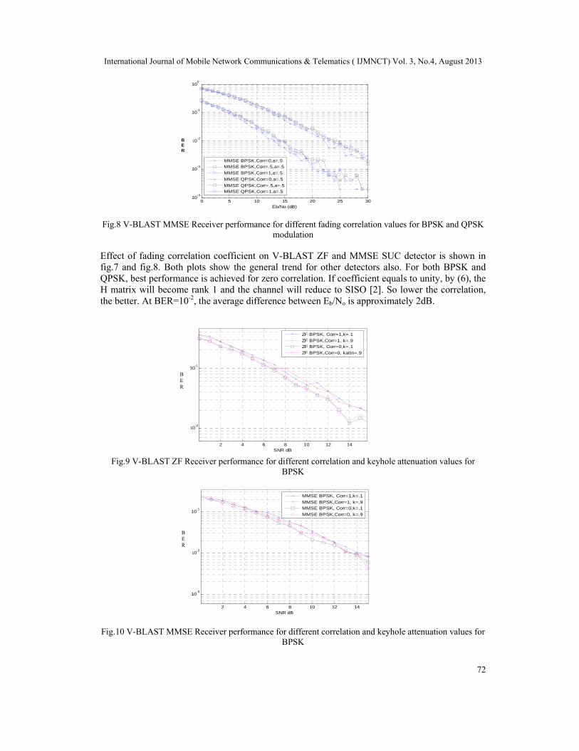
Fig.8 V-BLAST MMSE Receiver performance for different fading correlation values for BPSK and QPSK
modulation
Effect of fading correlation coefficient on V-BLAST ZF and MMSE SUC detector is shown in fig.7 and fig.8. Both plots show the general trend for other detectors also. For both BPSK and QPSK, best performance is achieved for zero correlation. If coefficient equals to unity, by (6), the H matrix will become rank 1 and the channel will reduce to SISO [2]. So lower the correlation, the better. At BER=10-2, the average difference between Eb/No is approximately 2dB.
Fig.9 V-BLAST ZF Receiver performance for different correlation and keyhole attenuation values for BPSK
Fig.10 V-BLAST MMSE Receiver performance for different correlation and keyhole attenuation values for BPSK
0 5 10 15 20 25 3010
-4
10-3
10-2
10-1
100
Eb/No (dB)
B E
R
MMSE BPSK,Corr=0,a=.5MMSE BPSK,Corr=.5,a=.5
MMSE BPSK,Corr=1,a=.5
MMSE QPSK,Corr=0,a=.5
MMSE QPSK,Corr=.5,a=.5MMSE QPSK,Corr=1,a=.5
BER
2 4 6 8 10 12 14
10-3
10-2
10-1
SNR dB
Bit
Error
R
ate
MMSE BPSK, Corr=1,k=.1
MMSE BPSK,Corr=1, k=.9MMSE BPSK, Corr=0,k=.1
MMSE BPSK,Corr=0, k=.9
BER
2 4 6 8 10 12 14
10-2
10-1
SNR dB
Bit
Error
R
ate
on of BER for ZF receiver under key-hole effect, with BPSK modulation and different fading corrilatio
ZF BPSK, Corr=1,k=.1
ZF BPSK,Corr=1, k=.9ZF BPSK, Corr=0,k=.1
ZF BPSK,Corr=0, kattn=.9
BER

International Journal of Mobile Network Communications & Telematics ( IJMNCT) Vol. 3, No.4, August 2013
73
Fig.9,10 indicates the variation in BER for ZF and MMSE receiver in presence of degenerate channel. As the channel become singular, BER increases. Fig.11 shows the variation of spatial correlation coefficient with antenna element spacing (d/λ) for different angular spreads. As seen, power distribution becomes broad over large angle as AS increases, which decreases the correlation coefficient at the same antenna spacing [8]. The dependency of Ergodic MIMO capacity with correlation between transmit and receive antenna is indicated in Fig.12. For 4x4 MIMO at SNR of 20dB, the loss is 3.3bps/Hz, for 3x3 system, loss reduces to 2.2bps/Hz and for 2x2 system, it is 1bps/Hz. At 10dB SNR, the corresponding values are approximately 2, 1, and .6bps/Hz respectively.
Fig.11 Variation of Spatial Correlation Coefficient with d/λ for different angular Spread (AS)
Fig.12 Effect of Correlation on Channel Ergodic Capacity for different MIMO configurations
Fig.13 Effect of Correlation on Channel Ergodic Capacity for different Keyhole attenuation coefficients
0 0.5 1 1.5 2 2.5 3 3.5 4 4.5 510
-4
10-3
10-2
10-1
100
101
d/lambda value
|Rxx
|
Variation of spatial correlation coefficient
AS=10deg
AS=20degAS=30deg
|Rxx|
0 2 4 6 8 10 12 14 16 18 200
5
10
15
20
25
SNR(dB)
Erg
odic
Cap
acity
bps
/Hz
Ergodic Capacity for correlated channel
M=N=4M=N=4, with Rt
M=N=3
M=N=3, with Rt
M=N=2M=N=2, with Rt
Ergodic Capacity
0 5 10 15 20 25 300
2
4
6
8
10
12
14
16
18
SNR dB
Erg
odic
cap
acity
bits
/s/H
z
full rank
k =.2
k =.4k =.6
k =.8Ergodic Capacity

International Journal of Mobile Network Communications & Telematics ( IJMNCT) Vol. 3, No.4, August 2013
74
Fig.13 shows the effect of correlation on channel Ergodic capacity for different Keyhole attenuation coefficients. The capacity increases logarithmically with increasing SNR, although the underlying channel is a MIMO channel. The capacity drops for a degenerate channel as compared to regular channel.
6. CONCLUSION The impact of receiver fading correlation on the error performance of MIMO systems that employ different V-BLAST receiver algorithms are studied in this paper. It is shown that ML detector gives optimum performance with very high computation complexity. MMSE with Successive Cancellation and Optimum Ordering gives lower BER values, but with a trade-off in complexity. ZF with Successive Cancellation has lower computational complexity but require more signal power to deliver same error rate. For all these detectors, lower correlation results in better performance. The study is also extended to the effect of cross polarization coupling on the detectors. It is observed that lower coupling value results in lower bit error rate given by the detectors. It is also observed that the Ergodic MIMO capacity reduction is more prominent for larger dimension of MIMO channel matrix. The effect of keyhole on MIMO channel as well as on detector algorithms are also studied.
REFERENCES
[1] G. J. Foschini and M. J. Gans, “On limits of wireless communications in a fading environment when using multiple antennas,” Wireless personal communications, vol. 6, no. 3, 1998, pp. 311–335
[2] Mohinder Jankiraman, ”Space-Time Codes and MIMO Systems”, Artech House, 2004 [3] Zhongpeng Wang,” Grouped Linear ZF Receiver for Multiple Antenna Systems”, Proceedings of
IEEE International Conference on Communication Software and Networks, 2009, pp 66-68 [4] R.Nabar, H Bolcskei, V Erceg, D Gesbertand A Paulraj, ”Performance of Multiantenna Signaling
Techniques in the Presence of Polarization Diversity”, IEEE Trans. Sig. Proc., Vol 50, Issue 10, 2002, pp 2553-2562
[5] Chien-Jen Huang, Chung-Wen Yu, and Hsi-Pin Ma,” A Power-Efficient Configurable Low Complexity MIMO Detector” IEEE Transactions on Circuits and Systems I, Vol. 56, No. 2, Feb. 2009, pp 485-496
[6] The Huaping Liu, Yongzhong Song, and Robert C. Qiu,” The Impact of Fading Correlation on the Error Performance of MIMO Systems Over Rayleigh Fading Channels”, IEEE Trans. on Wireless Communication, Vol.4, No.5, Sept. 2005. pp 2014-2019
[7] Bindu E, B V R Reddy, ”Performance analysis of Multiple Detector Algorithms with Optimal Ordering for V-BLAST Architecture in MIMO System”, Proceedings of 3rd IEEE IACC, 2013, pp 319-323
[8] Y S Cho, J Kim, W Y Yang, CG Kang, ”MIMO-OFDM Wireless Communications with MATLAB”, John Wiley &Sons, Singapore, 2010
[9] Da-Shan Shiu, Gerard J. Foschini, Michael J. Gans, and Joseph M. Kahn, “Fading Correlation and its Effect on the Capacity of Multielement Antenna Systems”, IEEE transactions on Communications, Vol. 48, No. 3, March 2000, pp 502-513
[10] Amine Maaref and Sonia A¨ıssa, “Impact of Spatial Fading Correlation and Keyholes on the Capacity of MIMO Systems with Transmitter and Receiver CSI “proceedings of ICC 2007, pp 4357-62
[11] H. Shin and J. H. Lee, “Capacity of multiple-antenna fading channels: Spatial fading correlation, double scattering, and keyhole,” IEEE Trans. Inf. Theory, vol. 49, no. 10, Oct. 2003pp. 2636–2647