Impact of Composite Materials on Aerospace Vehicles and ...
352
P191907 N90G1 AGARD-CP-112 AGARD CONFERENCE PROCi -DINGS No. Impact of Composite Materials on Aerospace Vehicles and Propulsion Systems NORTH ATLANTIC TREATY ORGANIZATION DISTRIBUTION AND AVAILABILITY ON BACK COVER
-
Upload
khangminh22 -
Category
Documents
-
view
3 -
download
0
Transcript of Impact of Composite Materials on Aerospace Vehicles and ...

P191907 N90G1
AGARD-CP-112
AGARD CONFERENCE PROCi -DINGS No.
Impact of Composite Materialson Aerospace Vehicles
and Propulsion Systems
NORTH ATLANTIC TREATY ORGANIZATION
DISTRIBUTION AND AVAILABILITYON BACK COVER


AGARD Conference Proceedings No. 112Advisory Group for Aerospace Research andDevelopment, NATOIMPACT OF COMPOSITE MATERIALS ONAEROSPACE VEHICLES AND PROPULSIONSYSTEMSPublished May 1973344 pages
25 papers were presented covering the following maintopics: 1) matrix-reinforcement combinations forhigh performance/high temperature applications, 2)design and failure criteria of advanced compositeprimary structures, 3) manufacturing aspects, 4)application of polymer matrix composites anddirectionally solidified eutectics to gas turbinecomponents.
P.T.O.
AGARD-CP-112629.7.02:66-419.8
Composite materialsAerospace engineeringGas turbine enginesAirframesSpacecraftHeat resistant materialsDesign criteria
AGARD Conference Proceedings No. 112Advisory Group for Aerospace Research andDevelopment, NATOIMPACT OF COMPOSITE MATERIALS ONAEROSPACE VEHICLES AND PROPULSIONSYSTEMSPublished May 1973344 pages
AGARD-CP-112629.7.02:66-419.8
papers were presented covering the following maintopics: 1) matrix-reinforcement combinations forhigh performance/high temperature applications, 2)design and failure criteria of advanced compositeprimary structures, 3) manufacturing aspects, 4)application of polymer matrix composites anddirectionally solidified eutectics to gas turbinecomponents"!"^
T£
Composite materialsAerospace engineeringGas turbine enginesAirframesSpacecraftHeat resistant materialsDesign criteria

Papers presented at the Joint Symposium of the AGARD Structures and MaterialsPanel and Propulsion and Energetics Panel, held at the Ecole Nationale Superieurede 1'Aeronautique et de 1'Espace, Toulouse, France, 20-22 September 1972.
Papers presented at the Joint Symposium of the AGARD Structures and MaterialsPanel and Propulsion and Energetics Panel, held at the Ecole Nationale SupSrieurede 1'Agronautique et de 1'Espace, Toulouse, France, 20-22 September 1972.
Papers presented at the Joint Symposium of the AGARD Structures and MaterialsPanel and Propulsion and Energetics Panel, held at the Ecole Nationale Superieurede 1'Aeronautique et de 1'Espace, Toulouse, France, 20-22 September 1972.
Papers presented at the Joint Symposium of the AGARD Structures and MaterialsPanel and Propulsion and Energetics Panel, held at the Ecole Nationale Superieurede 1'Aeronautique et de 1'Espace, Toulouse, France, 20-22 September 1972.

AGARD Conference Proceedings No. 112Advisory Group for Aerospace Research andDevelopment, NATOIMPACT OF COMPOSITE MATERIALS ONAEROSPACE VEHICLES AND PROPULSIONSYSTEMSPublished May 1973344 pages
25 papers were presented covering the following maintopics: 1) matrix-reinforcement combinations forhigh performance/high temperature applications, 2)design and failure criteria of advanced compositeprimary structures, 3) manufacturing aspects, 4)application of polymer matrix composites anddirectionally solidified eutectics to gas turbinecomponents.
P.T.O.
AGARD-CP-112629.7.02:66-419.8
Composite materialsAerospace engineeringGas turbine enginesAirframesSpacecraftHeat resistant materialsDesign criteria
AGARD Conference Proceedings No. 112Advisory Group for Aerospace Research andDevelopment, NATOIMPACT OF COMPOSITE MATERIALS ONAEROSPACE VEHICLES AND PROPULSIONSYSTEMSPublished May 1973344 pages
25 papers were presented covering the following maintopics: 1) matrix-reinforcement combinations forhigh performance/high temperature applications, 2)design and failure criteria of advanced compositeprimary structures, 3) manufacturing aspects, 4)application of polymer matrix composites anddirectionally solidified eutectics to gas turbinecomponents.
P.T.O.
AGARD-CP-112629.7.02:66-419.8 '
Composite materialsAerospace engineeringGas turbine enginesAirframesSpacecraftHeat resistant materialsDesign criteria
AGARD Conference Proceedings No. 112Advisory Group for Aerospace Research andDevelopment, NATOIMPACT OF COMPOSITE MATERIALS ONAEROSPACE VEHICLES AND PROPULSIONSYSTEMSPublished May 1973344 pages
<^25 papers were presented covering the following maintopics: 1) matrix-reinforcement combinations forhigh performance/high temperature applications, 2)design and failure criteria of advanced compositeprimary structures, 3) manufacturing aspects, 4)application of polymer matrix composites anddirectionally solidified eutectics to gas turbinecomponents. ^ "Trr Q
AGARD-CP-112629.7.02:66-419.8
Composite materialsAerospace engineeringGas turbine enginesAirframesSpacecraftHeat resistant materialsDesign criteria
AGARD Conference Proceedings No. 112Advisory Group for Aerospace Research andDevelopment, NATOIMPACT OF COMPOSITE MATERIALS ONAEROSPACE VEHICLES AND PROPULSIONSYSTEMSPublished May 1973344 pages
25 papers were presented covering the following maintopics: 1) matrix-reinforcement combinations forhigh performance/high temperature applications, 2)design and failure criteria of advanced compositeprimary structures, 3) manufacturing aspects, 4)application of polymer matrix composites anddirectionally solidified eutectics to gas turbinecomponents.
P.T.O.
AGARD-CP-112629.7.02:66-419.8
Composite materialsAerospace engineeringGas turbine enginesAirframesSpacecraftHeat resistant materialsDesign criteria

Papers presented at the Joint Symposium of the AGARD Structures and MaterialsPanel and Propulsion and Energetics Panel, held at the Ecole Nationale Superieure
1'Aeronautique et de 1'Espace, Toulouse, France, 20-22 September 1972.
Papers presented at the Joint Symposium of the AGARD Structures and MaterialsPanel and Propulsion and Energetics Panel, held at the Ecole Nationale Supgrieurede 1'Aeronautique et de 1'Espace, Toulouse, France, 20-22 September 1972.
Papers presented at the Joint Symposium of the AGARD Structures and MaterialsPanel and Propulsion and Energetics Panel, held at the Ecole Nationale Superieurede 1'Aeronautique et de 1'Espace, Toulouse, France, 20—22 September 1972.
Papers presented at the Joint Symposium of the AGARD Structures and MaterialsPanel and Propulsion and Energetics Panel, held at the Ecole Nationale Superieurede 1'Aeronautique et de 1'Espace, Toulouse, France,- 20-22 September 1972.

AGARD-CP-112
NORTH ATLANTIC TREATY ORGANIZATION
ADVISORY GROUP FOR AEROSPACE RESEARCH AND DEVELOPMENT
(ORGANIZATION DU TRAITE DE L'ATLANTIQUE NORD)
AGARD Conference Proceedings No.l 12 .^.Cv
IMPACT OF COMPOSITE MATERIALS ON
AEROSPACE VEHICLES AND PROPULSION SYSTEMS
Papers presented at the Joint Symposium of the AGARD Structures and Materials Panel,and Propulsion and EneTgetics Panel, held at the Ecole Nationale Superieure de 1'Aeronautique
et de 1'Espace, Toulouse, France, 20-22 September 1972.

THE MISSION OF AGARD
The mission of AGARD is to bring together the leading personalities of the NATO nations in the fields ofscience and technology relating to aerospace for the following purposes:
— Exchanging of scientific and technical information;
- Continuously stimulating advances in the aerospace sciences relevant to strengthening the common defenceposture;
— Improving the co-operation among member nations in aerospace research and development;
- Providing scientific and technical advice and assistance to the North Atlantic Military Committee in thefield of aerospace research and development;
— Rendering scientific and technical assistance, as requested, to other NATO bodies and to member nationsin connection with research and development problems in the aerospace field;
— Providing assistance to member nations for the purpose of increasing their scientific and technical potential;
- Recommending effective ways for the member nations to use their research and development capabilitiesfor the common benefit of the NATO community.
The highest authority within AGARD is the National Delegates Board consisting of officially appointed seniorrepresentatives from each member nation. The mission of AGARD is carried out through the Panels which arecomposed of experts appointed by the National Delegates, the Consultant and Exchange Program and the AerospaceApplications Studies Program. The results of AGARD work are reported to the member nations and the NATOAuthorities through the AGARD series of publications of which this is one.
Participation in AGARD activities is by invitation only and is normally limited to citizens of the NATO nations.
The material in this publication has been reproduceddirectly from copy supplied by AGARD or the author
Published May 1973
629.7,02 : 66-419.8
Printed by Technical Editing and Reproduction LtdHarford House, 7-9 Charlotte St. London. W1P 1HD

PREFACE
This Symposium, jointly sponsored by the Structures and Materials Panel and thePropulsion and Energetics Panel of AGARD, with contributions from the Flight MechanicsPanel, represents another event in a long sequence of AGARD activities in fiber-rein-forced composite materials. In the very early '60's, recognizing the impressive potentialof this type of material for aerospace application, the Structures and Materials Panelformed a Committee to analyze, coordinate and cooperate in research and developmentactivities as they existed in NATO countries and, indeed, to provide guidance andstimulation for further activity in this field. After analysis, coordination and exchangeof information, an international cooperative program was organized to check basicprinciples; to determine variables in materials characterization, in fabrication, and inevaluation; and, in general, to investigate reliability of design-type data. The resultsof this program were reported in an AGARD "Symposium on Composite Materials" in 1970,in Paris.
With the rapid advancement in material development, knowledge and understandingdn this field, and with the increasing availability of high performance composites atdecreasing prices, and with a growing background of experience in laboratory and proto-'type component testing, it was logical to inquire next into the acquired experience and(the practical state of the art, primarily from a design point of view; to examine theI potential applications for composites in airframes and engines and the advantagesthereof; and to define the problems and deterrents to broader and more rapid exploita-tion of this type of material. It was in this context that the present Symposium was^organized.
: The Symposium consisted of six sessions: the first, general and introductory,tended to cover broad knowledge and technology; the second and third sessions, comprising
'.'. Section II of these Proceedings, were primarily devoted to airframe structures andconsiderations; the fourth and fifth sessions (Section III) were primarily concerned with
'...propulsion applications; and the sixth session (Section IV) dealt with a general analysis•and retrospective summary of the total Symposium. Discussions have been summarized atthe end of each Section. Every effort was made to insure, within the limits of availabletime, a comprehensive program covering the many aspects of composite materials (property,fabrication, behavior, design, etc.), truly representative of the many NATO countriesactive in this field.
The Symposium was attended by 154 people from 12 countries, and was enthusiasticallyreceived. Appreciative acknowledgement and sincere thanks are extended to the many groupsand individuals who contributed to the success of this meeting: to the French NationalDelegates who hosted this Symposium; to the Planning Committees of both sponsoring Panelsand to the Panel.Chairmen; to many individuals involved in the details of programmingand arrangements, particularly Mr. G. Leomand the Host Coordinator; Mr. R. G. Lane whorepresented the Propulsion and Energetics Panel; Mr. P. Lecompte of the Flight MechanicsPanel; Dipl. Ing. P. Bamberg, Executive of the Structures and Materials Panel; Dr. R. P.Hagerty, Executive of the Propulsion and Energetics Panel; and to the many others listedon the program, especially the authors and the discussers, and to the Staff who soably provided services throughout the meeting.
•Washington, D. C. • ' N. E. Promisel1 February 1973 General Chairman
iii

INTRODUCTION
The development of advanced fiber-reinforced composite materials has been one ofthe most exciting and dramatic materials developments of the past two decades, openingup great, and in many ways unique, opportunities for improving the design, constructionand performance of aircraft and aerospace vehicles, propulsion systems and components.Vast amounts of manpower and money, in many countries, have been invested in thedevelopment and evaluation of this type of material, and in the experimental designand assessment of components made therefrom. It is therefore timely to examine thecurrent status of activity and knowledge, with the objective of accelerating the processof utilizing this material to maximum advantage in important applications.
In a specific sense, the attraction of filamentary composites has been their veryhigh strength-to-weight and stiffness-to-weight ratios. In a more general sense,material engineers and designers have been fascinated by this new opportunity to "tailor-make" a material to meet specific requirements, thus optimizing its application indesign. Of the many possible combinations and permutations of fibers, matrices andfiber-direction options available, attention has become primarily (but not exclusively)focussed, for the superior advanced composites adaptable in the near term, on boron andgraphite fibers in a non-metallic, organic matrix, notably of the epoxy type, witheither unidirectional or a very few selected multidirectional fiber orientations. How-ever, in addition, some metal matrix composites and unidirectionally solidified eutecticalloys have shown impressive promise and advantages, particularly in the temperatureregime beyond the capability of the organic matrices. The above considerations havedictated the materials scope of this Symposium.
Strength and stiffness properties are obviously only one aspect of the broad questionof utilization. Other properties of importance are those related to fatigue, brittleness,damping, thermal and electrical characteristics, and fabricability, to mention only themajor ones. Related to brittleness is the damage threat, in flight, of impact withobjects, particularly those which might be ingested and pass through the aircraft gasturbines. Such foreign object damage could be, in some cases, catastrophic.
With respect to fabricability, the manufacture and production of components andhardware from composites require to a significant degree new approaches or at least newexperience, notwithstanding the extensive experience and success with glass reinforcedplastics over many years, but not necessarily in as critical applications as arecurrently being considered. Molding and winding techniques; the forming of complicatedshapes to sensitive configurations and tolerances; the ever-present problem of jointsand load-transfer mechanisms; the question of built-in or residual stresses; the controlof orientation in multidirectional, multi-ply build-ups; sandwich constructions; andother manufacturing features comprise another set of justified questions and problemsrequiring examination and analysis. Inherent in all of this are the basic requirementsfor reliability, reproducibility, quality control and adequate non-destructive inspectiontechniques.
To the designer, composite materials represent a challenge, with outstandingpotential advantages on the one hand, and design problems accompanied by the need formore experience and therefore more confidence, on the other hand. In designing structureswith composites, an additional degree of freedom becomes available, as compared todesigning with the usual homogeneous material, there being the opportunity to optimizeperformance by careful selection of material combinations, filament orientations,volume fractions of filaments, multi-ply construction, etc. At the same time, however,the very availability of these options requires design sophistication and analyticaldesign methods that must yet be cultivated in most instances, and backed by test andservice experience. Prediction of response of a structure designed from compositematerials, with its complex and intricate interactions of materials, configurations andloads, is very difficult indeed.
Finally, there is the matter of cost. The advanced, high performance fibers arenot inexpensive. Raw material costs run into the hundreds of dollars per kilogram.Special design, fabrication, tooling, control, inspection and testing requirementsadd to this basic cost. Cost-effectiveness must, therefore, be based on an analysisof the system as a whole, to avoid distortion, misleading conclusions and unjustifiedrejection of composites because of original cost. The critical parameter is the"value," to the user, of the weight saved in a structure designed to take full advantageof the composite material; indeed, in some cases, needed performance may be possibleonly through the use of composites, and "cost" becomes a secondary or tertiary considera-tion. Unquestionably, increased usage will continue to result in decreased unit cost.

These are the kinds of inducements, stimuli, advantages, problems, and questionswhich currently beset the materials and design engineers. Obviously, this Symposiumcould not deal with all of these, but the attempt has been made to structure theconference to provide, as a minimum, a definition of what are the important opportuni-ties and considerations in applying composites, and to make available importantexperience, analyses and thinking, developed by many sources. In spite of majorprogress and successes already achieved, certainly some obstacles to full exploitationof composites still exist, but the goals and ultimate "pay-offs" justify strongefforts and approaches on many fronts.

AGARD STRUCTURES AND MATERIALS PANEL OFFICERS
CHAIRMAN: Dr A.J.Barrett, Engineering Sciences Data Unit Ltd, London, UK.DEPUTY CHAIRMAN: Dr Ing.T.Gaymann, Industrieanlagen-Betriebsgesellschaft mbH,
Munich, Germany.
AGARD PROPULSION AND ENERGETICS PANEL OFFICERS
CHAIRMAN: Professor I.Glassman, Princeton University, NJ, USA.DEPUTY CHAIRMAN: Mr F.Jaarsma, National Aerospace Laboratory, Amsterdam,
Netherlands.
PROGRAM COMMITTEE CHAIRMEN FOR JOINT SYMPOSIUM
Mr N.E.Promisel, National Academy of Sciences, Washington DC, USA.(SMP and Overall Chairman)
Mr R.J.Lane, Rolls-Royce (1971) Ltd, Bristol Engine Division, Filtori, UK.(PEP Chairman)
Mr P.Lecomte, Aerospatiale, Toulouse, France.(FMP Contributions)
HOST COORDINATOR FOR JOINT SYMPOSIUM
Mr G.Leomand, Aerospatiale, Chatillon-sous-Bagneux, France.
PANEL EXECUTIVES
Dipl. Ing.P.K.Bamberg (SMP)Dr R.P.Hagerty (PEP)
The Structures and Materials Panel and the Propulsion and Energetics Panelwish to express their thanks to the hosts — the French National Delegates
to AGARD - for the invitation to hold the Symposium at the EcoleNationale Superieure de 1'Aeronautique et de 1'Espace and for the
provision of the necessary facilities and personnel to make theSymposium possible.
vi

CONTENTS
Page
PREFACE iu
INTRODUCTION iv
SYMPOSIUM OFFICIALS vi
The order of the papers has been changed from that shown in the Conference Pre-prints to grouptogether those papers of a similar nature, thereby facilitating their reading.
The positioning and numbering of the papers conforms with the Contents List below.
Reference
SECTION I - GENERAL AND INTRODUCTORY
MECHANICAL PROPERTIES OF HIGH PERFORMANCE PLASTIC COMPOSITESby T.J.Reinhart Jr 1
FIBER REINFORCED MATERIALS FOR APPLICATION IN THE COLD PART OFTURBINE ENGINES
by G.Griininger and R.Kochendorfer 2
CARBON FIBRE COMPOSITES - PROMISES AND PROBLEMSby W.G.Heath 6
PRODUCTION OF FIBROUS METAL COMPOSITES BY POWDER ROLLINGby LCrivelli Visconti, P.Jauch, and C.Voto 25
DISCUSSIONS DI
SECTION II - APPLICATION OF COMPOSITES TO AIRFRAMES.STRUCTURES AND OTHER COMPONENTS (EXCLUDING PROPULSION APPLICATIONS)
DESIGN CONCEPTS FOR THE USE OF COMPOSITES IN AIRFRAMESby LC.Taig 4
DESIGN AND FAILURE CRITERIA OF ADVANCED COMPOSITE PRIMARY STRUCTURESby L.G.Kelly 5
PRESENT AND FUTURE POSSIBILITIES OF HIGH STRENGTH AND STIFFNESS-TO-WEIGHT RATIO COMPOSITES IN PRIMARY STRUCTURES
by U.Hutter 7
APPLICATION OF COMPOSITE MATERIALS FOR AEROSPACE STRUCTURESby F.Och and W.Jonda 13
USE OF COMPOSITES IN HELICOPTERS: ADVANTAGES AND DISADVANTAGESby H.F.Winny 8
LES COMPOSITES DANS LES STRUCTURES D'ENGINS ET LEUR ADAPTATION AUXBESOINS AERONAUTIQUES
par G.Jube' 9
APPLICATION OF COMPOSITES TO THE SELECTIVE REINFORCEMENT OF METALLICAEROSPACE STRUCTURES
by W.A.Brooks Jr, E.E.Mathauser, and R.A.Pride 10
EXPERIENCE WITH COMPOSITES AS OBTAINED FROM GLIDERSby W.F.Thielemann 11
vii

Reference
ADVANCES IN BALLISTICALLY TOLERANT FLIGHT CONTROLSby LE.Figge, Sr 12
INSTABILITY OF LAMINATED COMPOSITE PLATESby G.Z.Harris 14
DESIGN AND MANUFACTURING ASPECTS OF COMPOSITE MATERIALS WITHORGANIC MATRICES FOR APPLICATION AT HIGH TEMPERATURES
by J.J.Cools 17
DISCUSSIONS DII
SECTION III - APPLICATION TO PROPULSION
A LIMITED REVIEW OF THE APPLICATION OF ADVANCED FIBROUS COMPOSITES TOAERO GAS TURBINE ENGINES
by A.W.H.Morris 15
MATERIAL AND STRUCTURAL STUDIES OF METAL AND POLYMER MATRIXCOMPOSITES
by R.A.Signorelli, T.T.Serafmi, and R.H.Johns 16
ELABORATION DE MATERIAUX COMPOSITES REFRACTAIRES PARSOLIDIFICATION ORIENTEE
par M.E1 Gammal 3
DIRECTIONALLY SOLIDIFIED EUTECTICS IN GAS TURBINE DESIGNby L.P.Jahnke, H.J.Brands, and G.D.Oxx, Jr 19
EUTECTIC ALLOYS WITH UNI-DIRECTIONAL SOLIDIFICATION;STUDY ON THEIR USE FOR TURBINE BLADES
by H.Huff and W.Betz 24
POTENTIAL USE OF COMPOSITE MATERIALS FOR GAS TURBINE STATIC STRUCTURESby J.W.Sharp and L.Battezzato 18
APPLICATION DE COMPOSITES A BASE DE FIBRES DE CARBONE ET DE FILS DEBORE AUX AUBES DE COMPRESSEUR
by P.Lescop and R.Chevalier 20
FATIGUE TOLERANCE OF DAMAGED METAL COMPOSITE BLADINGby T.J.Norbut 26
BORON-POLYIMIDE REINFORCED TITANIUM FAN DISKSby H.Stargardter and K.Jakobsen 21
ETUDE DU FRETTAGE DES DISQUES DE COMPRESSEUR PAR DES COMPOSITES A BASEDE FIL DE BORE
par C.Stoltz 22
FAILURE ANALYSIS OF A FIBER REINFORCED COMPOSITE MOTOR CASE USINGDISTORTIONAL ENERGY AND MAXIMUM STRAIN THEORIES OF FAILURE
by R.J.Thompson, J.W.Sofferis, and C.M.Eldridge 23
DISCUSSIONS Dili
SECTION IV - SUMMARY ANALYSIS, CONCLUSIONS AND RECOMMENDATIONS IV-1
Appendix A: Publications of the AGARD Propulsion and Energetics Panel, Categories I and II Al
Vlll

1-1
MECHANICAL PROPERTIES OF HIGH PERFORMANCEPLASTIC COMPOSITES
by
Theodore J. Reinhart, Jr.Nonmetallic Materials Division
Air Force Materials LabAir Force Systems Command
Wright-Patterson AFB, Ohio 45433
SUMMARY
Data and information are presented on high-strength, high-modulus reinforcing fibers andorganic resin composites fabricated from these fibers. Glass, boron, graphite, various metallic,PRD-49-III and silicon carbide fiber and composite properties are discussed. Combined fiber orhybrid composites containing boron and S-glass, and berylium fibers and S-glass are discussed. Theproperties of the various forms of asbestos reinforcements are presented along with the mechanicalproperties of several asbestos reinforced epoxy-resin composites. Fatigue, creep and stress rupturedata are presented where data on similar composite constructions could be found in the literature.
INTRODUCTION
There is presently a bewildering array of fibrous materials that is available for use in thedesign and manufacture of high performance structural composite materials. For the purposes ofthis review a structural composite material will consist of a plastic matrix material of one sort oranother that is reinforced with one or more types or kinds of reinforcing fibers. We are not reallyinterested in the matrix properties here but we shall give a paragraph to this necessary componentof our material a bit later on. The mechanical characteristics of our composite material are largelydetermined by the mechanical properties, the quantity present, the orientation of the fibers and thecoupling or interaction between the reinforcing fibrous and resin matrix material.
Reinforcing fibers are available with a wide range of mechanical properties and in variousphysical forms. The various classes of organic polymer and inorganic fibers developed during the pastfew years can impart unique properties when incorporated into a composite. The polymeric materialsare used in applications throughout the spectrum of working temperatures from rocket exhaust nozzlesto cryogenic environments. Inorganic continuous fibers such as the various glasses, boron, beryllium,steel, PRD-49-III and carbon or graphite are in production at the present time. Although theexploitation of some of these materials was begun comparatively recently they have demonstratedgreat promise and the expansion of their use is likely to continue for many years to come. Anotherclass of reinforcement materials is the short fiber materials such as the whisker. Here we mayinclude materials such as, Alpha (Al2O3> , WC, SiC and many others including the natural fibroussilicates or natures lowly asbestos.
There are several very authoritative publications on inorganic fibers, man made fibers, andceramic and graphite fibers and whiskers. These are listed in the bibliography of this paper. In thefollowing paragraphs we will give a thumbnail sketch of a few of the materials available in each of thepreviously discussed classes of fibers, the mechanical properties of these fibers, the compositeproperties developed and an idea of the potential usage of the material.
Organic Polymer Fibers
Work on the development of high strength, high modulus, heat resistant organic polymers has,in recent years, produced several new and promising materials. Several of these new polymers haveshown outstanding resistance to heat and oxidative degradation, in air, at temperatures up to about600°F.
Also, several of these polymers have been formed into very useful fiber materials. Figure 1depicts the typical chemical structures of organic polymers that have been formed into fibers. The FBIfibers have been utilized very successfully in applications such as fire resistant clothing for flight crews.The polyamide or (NOMEX) fibers are presently finding extensive use in honeycomb structures incommercial aircraft applications. The organic fibers, however, have not yet found extensive use asreinforcements in composites. This was primarily due to their relatively low stiffness characteristics.The recent introduction, however, of PRD-49-III by DuPont may correct this situation in the future.Figure 2 shows the approximate strength and stiffness properties of filaments made from some of thenewer organic polymer materials.
Fibers formed from the polyheterocyclics such as polyimide or polybenzimidazole havedemonstrated excellent hydrolytic stability and very good oxidative and thermal stability. Muchapplication, research on these fibers is presently underway but to date very little information has been

1-2
published concerning the results of this work. These materials are presently being investigated foruse in heat and fire resistant clothing, high temperature decelerators, flexible space structures,precursors for the production of carbon filaments and cloths, heat and fire resistant personnel andcargo parachutes and webbing, high energy absorbing structures and light weight sandwich material foraircraft secondary structural applications.
Figure 3 indicates the short time maximum use temperature of some of the newer organicpolymers. Almost no data are available concerning the use of these materials for much longer timesat lower temperatures.
Inorganic Continuous Fibers
Glass Filaments
The commercial history of glass fibers dates back to about 1938. Recent developmentsby Owens Corning of the HTS and LHTS type finishes that are applied to E or S glass filamentsimmediately after fiber formation have provided materials engineers with very strong and durablefilaments. Typical filament strengths easily obtained using the strand test would be:
Tensile Strength Modulus
E glass 550, 000 psi 1 Oxl 0^ psiS glass 650, 000 psi 12.5xlo6psi
As is well known these high strength filaments have been available in quantity at relatively reasonableprices for quite some time.
When combined with organic matrix materials such as the epoxies these filaments makecomposite materials that have particularly attractive mechanical properties. These completely elasticfilaments impart very high tensile and compressive strengths to the composite. The fatigue strengthand impact resistance of these composites is excellent.
Glass reinforced plastics have found extensive use in the aerospace vehicle in both structuraland non-structural applications.
It seems that the glass filament materials have reached more or less a plateau in theirmechanical properties and it is postulated that only incremental improvements in these properties willbe made using known glass compositions. It is predicted based on current Air Force effort that glassfilaments having 800, 000 psi tensile strength and 16x10^ psi modulus will be available in a year or two,and that tensile strengths of 1x10" psi and moduli of at least 20 million psi are possible.
Several commercial sources are presently producing very high strength quartz filaments foruse as filament and woven reinforcements. High strength quartz filaments and woven cloth are presentlycommercially available items. Albeit quite expensive items at the present time.
Figure 4 shows a listing of the mechanical properties of various filaments that havesignificant potential for use in the reinforcement role in composite materials. The glass filaments areproduced in continuous lengths, directly from the melt by drawing the liquid glass at very high speedthrough a platinum orifice. The production of glass filaments being essentially a continuous, highspeed operation involving for the most part low cost raw materials makes glass fibers the mosteconomical reinforcement material available, for many applications.
Boron Filaments
The second fiber listed on Figure 4, boron, has outstanding mechanical properties combinedwith low specific gravity and chemical and thermal stability. This fiber is presently produced via athermal cracking or chemical vapor deposition process. Continuous boron filaments are manufacturedby drawing an electrically heated 0. 5 mil diameter tungsten wire through a reactor to which is fedBC13 and H2. The BC1. is reduced according to the equation.
2BC13 + 3H2 2B+6HC1
The boron deposits amorphously on the incandescent tungsten filament. The presently available filamentis 4 mils in diameter. Although a fat boron about 6 mils in diameter is now being produced, the processfor producing boron is inherently expensive compared to that for some of the other fibers. Presentcosts are about $200 per pound of fiber depending upon the quantities purchased. Work is presently inprogress to reduce the manufacturing costs for this material. Approaches to this involve elimination ofthe relatively expensive tungsten substrate, the use of a diborane precursor and more efficientreclaiming of unreacted materials for recycling. Cost predictions of less than $100 per pound for thisfilament have been made.

1-3
Carbon/Graphite Filaments
The next five fibers listed on Figure 4 are the relatively new carbon or graphite fibers. Ascan be seen these fibers also possess very excellent mechanical properties. They possess a lowdensity and good thermal and chemical stability. The carbon or graphite fibers are presently producedby a continuous process in which rayon or polyacrylonitrile (PAN) fibers are carbonized and graphitized.Since the process is continuous and utilizes essentially low cost precursor fibers these carbon/graphitefibers have an excellent potential for low cost. Via the use of even cheaper precursors such as coaltar pitch one could estimate that in production these fibers could be very low in cost. The relativelyrecent introduction by DuPont of its organic high strength, high modulus fiber provides a potentially lowcost, easily handled organic fiber that should find significant usage in the aerospace industry. This newfiber has very attractive properties, low density and good electrical characteristics that make itparticularly attractive for radome applications.
Metallic Filaments
Very high strength metallic filaments have been available for quite some time. Due to theirrelatively high density, however, these filaments do not provide the high specific strength and stiffnessvalues that the glass, boron and graphite filaments do. The one exception here is the beryllium metalfilament as shown in Figure 4 the fiber has very good mechanical properties. However, its high cost,toxicity potential, and a low yield strength have prevented its serious consideration for use incomposites.
Figure 5 shows a listing of the properties of various metal alloys tested in wire form. Onlythe high carbon steel is available in any commercial quantity. Its use is relatively small and isapplications very specialized.
Miscellaneous Continuous Inorganic Filaments
In this family of fibers we included Al2Oj (Alumina or sapphire) , SiC, SiN and other specialty,refractory fibers that, as yet, have been produced only in small laboratory or pilot plant batches. Thereisn't room in these few paragraphs to do justice to the efforts being performed in developing .thesefibrous materials.
Perhaps the most promising of the above materials is the alumina or sapphire fiber.Recently single crystal sapphire filaments have been produced via a zone refining-growth from the melttechnique. These fibers have been produced in lengths of hundreds of feet and have outstanding strengthand stiffness properties. In addition the A12O3 fibers retain their mechanical properties to at least1000°C in air.
Figure 6 displays the tensile strength retention of some selected fibers at elevated temperatures.The outstanding characteristics of the A^O^ fibers are evident. It should be noted that the graphitefibers would require protection from oxidation to. perform at the elevated temperatures for any length oftime. Figure 7 shows the affect of temperature on the modulus of these same fibers.
It is interesting to compare the stress, strain characteristics of the various fibers we havebeen talking about, on the same chart. Figure 8 shows typical tensile stress, strain curves for manyof the fibers we have discussed. For comparison purposes the tensile strain characteristics of twocommercially available epoxy resins are also shown. The organic fibers previously discussed wouldfall in the range just about where the epoxy resins are, except, of course for PRD-49-III as can be seen.
Nore the highly unusual plasticity of the beryllium fiber as compared to the extreme elasticityof all of the other fibers.
Combined Filament Composite Systems
Much work has been done in an attempt to utilize two or more filament materials of variousdiameters and lengths in order to combine the most attractive characteristics of each type of filamentin the composite. For example, glass/boron, graphite/glass and glass/beryllium combinations havebeen formed into composites using epoxy resins. An examination of the stress strain criteria shown inFigure 8 can indicate which of the various filament combinations could be utilized with beneficial effectsin unidirectional composites. For example, one would not expect boron or steel and glass to make anefficient combination and experiments verify the fact that they do not.
It can be seen that the glass fiber, in such combinations would not even feel the load until thehigh modulus fibers had failed. This same examination, however, shows that the beryllium wire althoughit does not have the strength of the other filaments it does have two excellent properties. One is adensity lower than many other fibers, the other is that it undergoes plastic deformation prior to failurerather than an essentially linear elastic stress-strain behavior to fracture that is common to all of theother reinforcements in Figure 8. Previous efforts to combine two filament systems, for example,glass and boron, have been tried to overcome a deficiency of the major composite, such as: improvingresin content control, spacing of boron filaments or improvement of interlaminar shear, etc. In this

1-4
case considering the very low ultimate strain of the boron (about . 6%) the glass fibers are not veryhighly stressed at failure of the boron.
However, one should note that when beryllium filaments are added to any of the otherfilaments in a composite, there must exist a mutual sharing of the load due to the plasticity of the Befilament. For example, in a beryllium/glass filament composite both filaments are highly stressed atfailure. Work along these lines has resulted in beryllium/fiberglass/epoxy composites having thehighest flexural strength to density ratios of any composites tested both in the continuous and short fiberform. The lower density of the Be also results in modulus-density ratios of a very competitive nature.Figure 9 shows some of these values. This figure shows the properties of unidirectionally reinforcedbeams, of the listed materials, tested in flexure.
Figure 10 shows the tensile stress strain characteristics of a unidirectional Be/Epoxycomposite and a unidirectional Be/S glass/epoxy composite. The combined composites which incorporateberyllium have the unique capability, among composites, of plastic deformation prior to actualcomposite failure.
For many structural applications the ability of the composite to undergo plastic deformation oryield prior to fracture is very desirable. This added capability should mean that local structuraldiscontinuities such as cut outs, joints or attachments, etc. , should be less critical and more efficient.
Another way to graphically display the properties of materials, which I'm sure everyone hasseen, is shown in Figure 11. Here we have plotted specific modulus vs specific tensile strength ofvarious filaments. For comparison purposes the properties of high strength steel and aluminum alloysare shown. This type of plot always makes the fiber materials look good, as long as one only considersunidirectional tensile strength. When isotropic lay up composites are compared to metals on similarplots the difference, of course, is not so vast as shown here.
The beryllium filament used in the composites was 0. 005 inch diameter drawn wire furnishedby the Air Force Materials Laboratory's Manufacturing Technology Division. The wire was producedunder an Air Force contract with the Beryllium Corporation, Reading, Pennsylvania. Wire drawn fromtwo different starting forms of beryllium was utilized. The starting forms were cast beryllium ingotsand blocks of hot pressed beryllium powder, Pechiney SR grade. Both starting materials were extrudedinto 3/8 inch diameter rod stock by Berylco and drawn into wire by the Astro Metallurgical Corporation.Beryllium wire drawn from these two different starting forms will hereafter be referred to as "cast"and "powder" wire. The wire numbers refer to different drawing runs and are used for identificationonly. The circumference of the powder wire was typically uniform, and that of the cast materialirregular. Of the wire received at the beginning of this investigation, the powder wire had higherstrength and elongation than the cast material. However, later cast wire had equal or higher strengths,though the elongation was still about half that of powder wire. Most of the wire used in this study wasof cast origin because of its availability.
Typical stress-strain curves of the cast and powder beryllium wire are shown in Figure 12.The curves have an initial linear portion, to a proportional limit of less than one-third the ultimatestrength, followed by a decreasing slope to fracture. The cast wire had slightly higher strength andlower ultimate elongation than the powder wire. Chemical analysis of the 3/8 inch diameter rods fromwhich the wire was drawn showed the cast rods had a beryllium oxide content of less than half that ofPechiney SR powder rods (0. 45% versus 0. 97%, respectively) . It was hoped that the lower oxide contentof the cast material would give increased ductility in the wire. This did not generally prove to be true.One of the principal reasons for the lower ductility of the cast material is believed to be the presence ofgross inclusions found in the cast wire, but not in the powder material.
The mechanical properties of the two types of beryllium filaments used in this study are shownin Figure 13.
The most obvious factor was the modulus of elasticity which was lower than has been reportedfor beryllium. Two elastic modulus values are listed for each type of wire. The 39x10° psi valueobtained for both the cast and powder wire is believed to be the most realistic. It was obtained byloading a vertically suspended wire with dead weight and observing, with microscopes having verniereyepieces, the resulting equilibrium positions of two bench marks attached to the filament. The lowervalues were obtained using load cell and crosshead motion measurements. The dead weight loadingmethod was confirmed by measuring the modulus of Type 304 stainless steel wire (5 mils in diameter)at 27.6x10" psi compared with a reference value of 28.3x10° at room temperature.
The modulus of elasticity of bulk beryllium has frequently been reported to be about 44 millionpsi. Also, nominal 5 mil diameter beryllium wire made by a different organization reportedly had anelastic modulus of 44x10° psi and 42. 6x10° psi. However, the modulus of beryllium has not always beenreported to be this high. QMV beryllium hot-rolled plate chemically milled very slightly to removemicrocracks caused by machining was reported to have an elastic modulus of 36.2x10" psi.
The strength and elongation values of beryllium wire listed were obtained on 10 inch gagelength specimens. It was found that tests with a 10 gage length gave slightly lower results than when a

1-5
1. 0 inch gage length was tested. Elongation decreased more than strength. Due to the low slope ofthe stress-strain curve near the upper limit, earlier fractures would be expected to affect elongationmore than strength. Earlier failures with the 10 inch gage length are believed to be due to increased "probability of gross inclusions. The longer length was believed to be more representative of theaverage behavior of the amount of reinforcement in a test specimen. Tests at 20 inch gage lengthsproduced the same properties as at 10 inches.
Composites were fabricated having the beryllium wire oriented in one, two and threedirections. Cast wire was utilized most extensively in the composites. The matrix was a conventionalepoxy resin system. All composites were flat laminated panels except the rings used for unidirectionaltensile property determinations. The panels were composed of twelve unidirectional layers and weresymmetrical about the central plane. The filaments in any two layers equidistant from the central plane,therefore, were parallel. Bi-directional composites had successive unidirectional layers alternatelyat 0° and 90°. Tri-directional composites had filament directions in successive layers rotated by 60°.
The three types of beryllium composites fabricated were mechanically tested in tension,compression, flexure and shearloading modes. Stress-strain curves that are typical of thesecomposites, when loaded in tension and compression, are illustrated in Figure 12 relative to those ofthe beryllium wire and epoxy resin from which they were made.
The composites exhibited the same general stress-strain behavior as the berylliumreinforcement. The curves have an initial linear portion followed by a continuously decreasing slopeuntil buckling (compression) or fracture (tention). The hydro statically loaded unidirectional rings,which avoided premature failures due to stress concentrations at the grips, had about the sameultimate elongation (after fracture) as the beryllium wire (at fracture). The composites were slightlymore rigid when loaded in compression than they were under tensile stress. The cause of this is notknown.
The mechanical properties of all beryllium composites tested are listed in Figure 14.Specific aspects of composite mechanical behavior will be discussed in the following sections.
One of the attractive properties of beryllium as a potential reinforcement is its high modulusto density ratio. While the wire reinforcement used in these composites had a modulus of elasticityless than has been obtained with beryllium, it was important to determine how efficiently the filamentmodulus was translated into composite modulus. To do this, the moduli of elasticity intension,compression, flexure and shear loading modes were calculated from measured reinforcement andmatrix properties and their proportions, assuming elastic behavior.
The measured values vary from 38 to 117 percent of the theoretical. Such a large variationbetween composites was surprising since variations between specimens of the same composites wasgenerally less than 20%. This variation is believed to be due to the method of determining the fibervolume content of the composites. Fiber content was calculated from measured values of compositedensity, fiber density and resin density assuming the fiber and resin density in the composires are thesame as when measured separately and the composites are void free.
If the above interpretation is valid, from 90 to 110 percent of the fiber modulus is realized inthe composites. No explanation of the values greater than 100% can be given, though it is not believedto be due to a synergistic effect.
The theoretical yield and ultimate tensile strengths were calculated for those bi-directionalcomposites which did not contain beryllium of questionable density. The measured values wereexpressed as a percentage of theoretical. The theory assumes the same strain in filament and matrixas the composite, but does not assume elastic behavior. Since the theory was developed forunidirectional composites, it was assumed the transverse filaments contributed nothing to the strengthand were not present.
Composite strength efficiencies of 80 to 110% were obtained, with the higher efficiencies atyield and the lower at ultimate strength efficiencies may be low because the tensile specimens did nothave a test section of reduced width, but had straight sides. Failure occurred at, or near, the grips.
The absence of apparent debonding between the beryllium wire and the epoxy matrix and thehigh calculated shear stress resisted by the composites suggest a good bond was obtained at the interface.Further maximum shear stress was not affected by exposure to boiling water for two hours. The timerequired for boiling water to significantly reduce shear values was not determined.
Apparently the surface of the beryllium wir-e, which resulted when the nickel cladding wasremoved by nitric acid after the final drawing operation, is adequate for wetting and adhesion with theepoxy system used. The only surface preparation utilized was a solution degrease with MEK prior toimpregnation.

1-6
The beryllium wire reinforced plastic composites failed by plastic deformation terminatingin excessive elongation, buckling or fracture. Permanent deformation was most apparent in thetensile ring and flexure and compression panel specimens.
Most of the unidirectional rings hydro statically loaded intension did not fracture. Plasticdeformation increased ring diameter until the loading pressure reached a maximum then decreased.The flat panel specimens fractured across the complete specimen on nearly plane surface perpendicularto the tensile load. There was no evidence of a transverse crack moving longitudinally along theinterface to a point of filament weakness before progressing transversely again, which is characteristicwith some brittle reinforcements.
Compression specimens did not fracture. After becoming unstable, presumably due toplastic deformation since the test length was calculated to avoid buckling of an elastic member, theybuckled into a shape similar to a shallow sine wave of one wave length. This general shape would, ofcourse, be expected of a panel with constrained ends. NoJfracture of filament or matrix was apparentin failed compression specimens.
Unidirectional flexure specimens did not fracture but continued to bend at slowly increasingloads up to 30% deflections. Bi-directional specimens deformed then fractured. The absence ofmicrocracks in the matrix near gross tensile fracture was typical of these composites.
Shear specimens loaded as a simply supported short beam reached a maximum load without avisible fracture plane. Failure was by flexural deformation.
The specific modulus of elasticity of the beryllium composite is second highest of thematerials compared previously. However, above the proportional limit, which for this composite wasabout one-third the ultimate strength, the composite modulus decreased with increasing stress. Arealistic comparison should use the appropriate modulus at the maximum design stress. The type ofmodulus (elastic, tangent or secant) which is appropriate for comparison depends on the application.Some efficiency indices in compression utilize secant modulus and some tangent modulus.
The specific ultimate strength of the beryllium composite would not be applicable to manydesigns because of excessive plastic deformation. However, the specific yield strength at 0. 2% offsetstrain is nearly as high as the specific ultimate strength of the other high specific modulus material(boron composite).
As previously mentioned one characteristic which the beryllium composites possess whichthe others listed do not is the ability to plastically deform prior to fracture. This characteristic maybe advantageous for some applications as a means of decreasing stress concentrations and increasingthe energy required for failure.
Graphite
The bulk of the composite data presented are based upon the use of commercially availablegraphite yarns. Typical data for these various graphite filaments are presented in Figure 15. TheThornel fibers are made by Union Carbide Corporation and are available with tensile moduli as high as70x10° psi. Fibers in the Thornel series are designated Thornel 25, Thornel 40, and Thornel 50 wherethe number is indicative of approximate fiber tensile modulus. The Hitco (H. I. Thompson and Co. )yarns are also available with moduli of 25, 40 and 50 million and are designated HMG-25, HMG-40, andHMG-50, respectively.
The British fibers have been supplied in tow form (a loose bundle of fibers of no twist) byMorganite Ltd. and Courtaulds Ltd. Both companies supply meter long lengths of tow, as well as otherforms as prepregged tow and continuous tows up to 1, 000 feet in length.
Great Lakes Carbon Corporation graphite fibers comprise still another form of graphitereinforcement. Generally, the yarns consist of fibers 7 inches long and are twisted to form thecontinuous one-ply staple yarn.
Prepreg tapes, for subsequent composite fabrication, were formed via filament winding whenpossible. Short length tow material was hand laid up and resin applied by spraying with artists airspray brush to form prepreg tape. The winding proceeds from a take-off reel, through a resin pot, andonto a circular mandrel is usually covered with Teflon coated glass cloth to facilitate prepreg removalfrom the mandrel, as well as to act as a backing substrate to aid in handling and cutting operations.
After the appropriate B-stage, the prepreg tape is removed from the mandrel by making alongitudinal cut with a sharp instrument across its length. The prepreg is then laid flat and issectioned to accommodate the dimensions of a particular mold.
The volume fraction of fibers and in turn thickness per ply of a composite may be affected bydegree of prepreg B-stage, resin pick-up, molding pressures, and yarn or tow diameter. The Englishtows because of the greater number of filaments per tow (10 , 000) compared to the Union Carbide of

1-7
Hitco yarns (1440 in a twisted 2-ply construction) are of much larger diameters. Thickness per ply ofthe English tow composites is usually greater than the composites fabricated with Thornel or HMG by afactor of 2-3. Control of per ply thickness becomes important when considering graphite compositesfor applications requiring minimum gauge thickness and capable of withstanding multidirectional loads.A doctoring step may be included during resin impregnation to flatten the prepreg to less than 5 milsthickness.
As the Thornel series of fibers have been readily available and for a longer time than theother reinforcements mentioned, more data are available pertaining to a variety of composite tests,some of which are discussed in the following section.
Figure 16 depicts the average mechanical properties of unidirectional composites fabricatedfrom Thornel 25, 40, 50 and 50s (UCC treated to improve composite interlaminar shear). Of note arethe increased densities of the composites as the reinforcement modulus increases. This is primarilyattributed to the increase in fiber density. If the volume fraction of one of the constituent materials ina two phase composite is known as well as the densities of both materials, the composite density may becalculated by the rule-of-mixtures equation. A difference between measured and calculated compositedensities may be an indication of voids, improper cure, or inaccurate density measurements of thecomposite components.
The decrease in composite shear strength as reinforcement moduli increases of untreatedfibers is not only apparent for the Thornel series, but has been observed for composites fabricatedutilizing different moduli fiber prepared from the same precursor and under similar graphitizationconditions. Although the reason for this decrease in composite shear strength is still not fullyunderstood, one hypothesis is that sites for bonding or chemical functionality is associated with theedge carbon atoms. As the axial moduli of the filament increases this infers improved orientation, andthus, a decrease in exposed edge atoms. In other words, possible chemical coupling at the fibermatrix interface is reduced.
Mechanical properties of Hitco graphite yarn composites are also shown in Figure 16. TheHMG 25 composite was fabricated with 25x10 modulus reinforcement. Translation of fiber moduli maybe readily observed from the composite properties.
The significance of the HMG 25 composite evaluation was that shear strength values thatexceeded expectations were obtained.
During initial prepreg tape fabrication of the HMG 50 (E80-95 size) with an epoxy resinsystem, it was observed that the prepreg after B-staging at room temperature for approximately 16hours had partially C-staged as surmised from the lack of tack as customarily is in evidence for theepoxy system used. Absence of resin flow during molding and resultant poor composite properties wasattributed to excessive advancement of the resin. Previous to fabrication of the HMG 50 composites, a2-4 hour prepreg B-stage was determined as optimal. Rapid advancement of the prepreg with theE80-95 sized HMG 50 was an indication that the size contained a catalyst or activator which affected therate of cure of the resin system.
Referring to Figure 16, a preliminary evaluation of Hitco1 s HMG 50 yarn with theirproprietary E80-95 finish in an epoxy matrix was conducted. The HMG 50 composites exhibitedcomparable test results between tested panels, good translation of fiber properties to compositeproperties, properties, and again, respectable shear stress values.
The Great Lakes yarn is composed of 7 inch long staple fiber in a continuous single ply formcontaining 700 ends. The yarn has a twist of 2 turns per inch and is epoxy coated.
Composite properties are presented in Figure 16. Flexural moduli are uncorrected,therefore, corrected values can be expected to be somewhat higher. Actually, the flexural propertiesfor composites based on the continuous stapel yarn are quite respectable for GLCC's quoted fibertensile properties of 50x10° psi for modulus and strength, respectively. The above strength isobtained on single fibers with a gauge length of 0. 125 inches. Using a gauge length of 1. 000 inchesthe strength is reported as 300x10 psi.
The Morganite fibers were supplied in a tow form of meter long lengths, as well ascontinuous 1000 foot length of Morganite's high strength tow. Each tow consisted of approximately10, OOO 1 filaments, and although no measurements were made, the tow did not appear to have anyimparted twist.
The fiber designations used by Morganite to differentiate between the two tows are Type Iwhich consisted of filaments of high modulus and intermediate strength treated by a proprietary methodto improve composite interlaminar shear strength, and Type II which consisted of filaments of highstrength and intermediate modulus which were treated to increase interlaminar shear strength.
The mode of failure of the Morganite fiber composites was quite interesting. Typically,whether tested in flexure or by short beam shear, the composites failed in shear, unlike the majority

1-8
of unidirectional graphite reinforced epoxies that have been tested and were observed to fall in acomplex fashion, i .e., combinations of compression, tension, and to a lesser degree, shear. Also,during loading, audible fiber breaks were in evidence similar to what may be heard when testing boron/epoxy composites before ultimate load is reached.
Because the tow contained a multitude of filaments, the prepreg was relatively thick. As aresult, the tow (fibers) did not "nest" as well as expected compared to unidirectional compositesprepared with thinner yarns received from other sources. When loaded past ultimate (flexure andshear), the load-deflection curves displayed breaking loads of the individual plies.
Unidirectional composite properties of both types of fibers are shown in Figure 16.
The Type I composite properties show fairly good agreement and translation of reportedfiber modulus and strength.
The compression strength of the Morganite Type II composite was the highest averagecompression strength we have observed of any graphite fiber/epoxy matrix composite. The. range often tested composites was 129 - 165x10-^ psi.
The compression strength of the Type I composite is less than half that of the Type IIcomposite for approximately the same fiber volume.
Shortly after the Morganite fibers were evaluated in composite form, Courtaulds fiberswere made available for composite property characterization. The fibers were supplied in 1000 ftlengths of tow and were similar to the Morganite fibers in cross-sectional shape (circular), length,number of filaments/tow, and were even graphitized to a high modulus type (HM) as Morganites Type Ireinforcement, and a high strength type (HT), as Morganite Type n reinforcement.
Much data can be found in the literature on boron fiber reinforced epoxy resin composites.This high performance fiber in composite form has been the subject of extensive data generation andaircraft structural component design, fabrication and test programs in the U.S.A. Figure 17 showstypical mechanical properties of unidirectional composites fabricated from two commercially availableprepreg tape materials. These data have been widely publicized and we shall not dwell on.them anylonger here.
Utilizing essentially the same technique vapor deposition on a metal substrate as used inproducing boron, high strength, high modulus silicon carbide filaments have been prepared. Somewhatless sophistication has as yet been achieved in relation to boron filaments, although this isunderstandable in that considerably less effort has, in relation to boron filaments, been expended onsilicon carbide. However, silicon carbide filaments have been prepared in pound quantities whichapproach boron filaments as to absolute mechanical properties.
A series of composites were prepared by the AFML with a nominal 4-ml diameter siliconcarbide monofilament in an epoxy resin matrix. A total of approximately 37, 000 feet, one-half pound,of silicon carbide filament was used in the preparation of composites. This 37, 000 feet consisted of atotal of 25 spools, or batches, representing individual filament preparations. The maximum andminimum average values for the mechanical properties of the individual spools of filaments used inthe preparation of composites and the overall averages of all the spools are shown in Figure 18. Sincevariation was observed in mechanical properties from one spool of silicon carbide to another, allcomposites were made from closely matched spools of material relative to filament diameter, tensilestrength and modulus. The limited data obtained for the unidirectional composites, as shown in Figure19 appears promising in the these initial mechanical property values were roughly equivalent, on anabsolute property basis, to values obtained previously for boron composites. Although a limitedquantity of silicon carbide filament was available during this investigation, a series of unidirectionaland bi-directional composites were prepared using treated and untreated filaments and evaluated.
The compression properties of balanced bi-directional composites using untreated filamentsin shown in Figure 20.
Compressive strength and modulus values were obtained using 16-ply balanced bi-directionalcomposites which were about 0. 080 inches thick. For comparison, a boron reinforced composite withan average of 61 volume percent filament yielded an average compressive strength of about 148, 000psi and an average compression modulus of about 21x10° psi.
Property levels of silicon carbide filament composites were roughly equivalent to previouslydetermined properties of comparable boron filament composites on an absolute basis. However, thedenser silicon carbide filaments and hence composites are about 20 percent lower in mechanicalproperties in comparison to boron filament composites on a specific basis at a composite fiber volumecontent of about 60 percent.

1-9
Silicon carbide filaments have a high thermal and oxidation resistance and therefore afford ahigh promise as reinforcements for future composites utilizing matrix materials of high thermalcapabilities.
Preliminary data have indicated a beneficial effect for surface treatment of silicon carbidefilaments on the mechanical properties of epoxy resin matrix composites. The filament surfacetreatments have generally shown to be effective in the improvement of certain specific mechanicalproperties of the composite systems. It is interesting to observe that these same surface treatmentshave no apparent effect on the modulus values observed for the composite panels.
Whisker Reinforcements
Finally we come to what is to me, perhaps the most fascinating area of reinforcementmaterials, the whisker. Whiskers are normally though of as short single crystal fibers which displaynear theoretical strength and stiffness. Many whisker materials are presently commercially availablein amounts of 5 Ibs. , 10 Ibs. or even larger quantities. The prices do not seem unreasonableconsidering the present production rates.
Such materials as A^Oj (Sapphire), SiC, A1N, BN, and BeO, etc. can presently be grownthat have aspect ratios between 50 and 2000. Work dating as far back as 1962 by researchers fromG. E. demonstrated the potential of these materials. Here again space does not permit a detailedstatement of the whisker utilization efforts presently in progress. We will, however, discuss theproblem areas, in the utilization of these short high performance fibers, that these efforts haveuncovered and have attempted to solve.
It has been found that in order to realize the inherent reinforcing capabilities of thesematerials one must first be able to incorporate a reasonable volume fraction of the fibers into thematrix. It is also imperative that this must be accomplished in such a way that a high degree oforientation is achieved. The fibers must also have the proper aspect ratio in relation to the shearmodulus of the resin. Another factor to be considered is that good bonding between matrix andreinforcement be achieved.
It is well known that the primary role of the matrix in short fiber composites is to transferthe loads through shear at the fiber/matrix interfaces. The efficiency of the composite is limited bythe shear strength and shear modulus of the matrix (as well as several other factors). It has beenpostulated that many of the difficulties involved in obtaining high strength organic resin matrix whiskercomposites could be minimized if the resins had a plastic flow (or yield) capability. Since it isbelieved that organic thermosetting resins having this capability will not be available in the near futureand since many metal matrix materials do possess this characteristic perhaps we should concentrateon the metals in this work.
Work is also being performed to utilize whiskers as a matrix reinforcement in boron andglass fiber composites. The results of these efforts seem to be a bit contradictory to date. Figure 21displays the potential of idealized whisker (short fiber) composites with respect to glass composites.It should be noted that these specific numbers are based on fiber or filament tensile ultimates andcannot be used for selecting materials for design or for basing preliminary structure weightcalculation on1.
Much work has been accomplished over the past years in an attempt to utilize the inherentreinforcing capabilities of the asbestos fibers. Asbestos filaments and fibers impregnated with resinsare utilized throughout the aerospace industry in applications ranging from humble packings and gasketsto high performance rocket fins, combustion chambers and exit cones. The mechanical properties ofthese composites do not reflect the properties reported for these fiber materials.
Figure 22 shows the varieties of asbestos fibers that are available in fiber form. Of these,only the chystotile and crocidolite forms are of commercial interest. The mechanical and physicalproperties of these asbestos materials are shown in Figure 23. As can be seen the mechanicalproperties of these asbestos materials are very respectable.
State-of-the-art usage of asbestos fibers fails to utilize a significant fraction of the availableproperties of asbestos. Considering the relative low cost of asbestos it becomes an attractivereinforcement material. The AFML has worked on the problems involved in the utilization of the highstrength asbestos materials.
To put things in the proper perspective Figure 24 displays the relative diameters of boron,glass and asbestos fibers. We have found that by careful processing, in order to preserve fiber length,and careful orientation it is possible to obtain very high strength asbestos composites.
Figure 25 shows the mechanical properties obtained from unidirectionally reinforcedasbestos/epoxy panels. The only real drawback involved here is the extremely high processingpressures required to get the low resin contents desired.

1-10
There is not room to do justice to the details of this work, however, a few of other problemsinvolved fiber opening techniques, degree of fiber openess, fiber finishing, extremely high fibersurface area and fiber orientation.
PRD-49-1 and PRD-49-III Epoxy Laminates
PRD-49-III is an organic fiber manufactured and supplied by the E.I. Dupont de Nemours andCo. of Wilmington, Delaware. The general filament properties are listed in Figure 2 and Figure 4.The affect of temperature on fiber strength and modulus are shown in Figure 6 and 7. PRD-49-1 wasthe designation of fiber produced from the pilot plant the -III version is the production fiber designation.The -III fiber has a slightly reduced modulus and an increased tensile strength compared to the -I fiber.Since the data on the -III fiber is now being generated and since the -I fiber composite data are not toodifferent from the -III composites only -I fiber composite data will be shown here. PRD fibersprocess easily into composites. Wetting with resin is facilitated by drying the fibers in an oven at 250°Ffor a period of about 4 hours or so. The fiber produces laminates having excellent electricalcharacteristics for radome applications. The dielective constant and loss tangent at 75°F in the drycondition were nearly constant over the range from . 4 GHZ to 10GHZ and were 3. 70 and . 001respectively. These values changed to 3.99 and . 005 respectively after 24 hour water soak at 120°F.Figure 26 shows the tensile stress strain curves for 0° PRD-49-1 and S glass composites. Note theincreased stiffness of the PRD composites as compared to the glass. Figure 27 shows the tensilestress-strain characteristics of +45° crossply composites. Fatigue characteristics are shown infigures 28 and 29 in the form of S-N curves. The PRD fiber composites have superior fatigue resistancewhen compared to fiberglass composites, as shown in Figure 29. Both boron and graphite fibercomposites are superior in fatigue compared to sither PRD or glass fibers. The creep behavior of PRDand S- glass composites is compared in Figure 30. The superior performance of the PRD composite isalso shown in Figure 31 where cyclic short term creep and recovery are presented. Stress rupturedata are shown in Figure 32. These data show the very good static fatigue resistance of the PRD typefibers compared to glass. The PRD fiber composites are very comparable to boron fiber compositesunder static and dynamic tensile load conditions. The compressive properties of PRD fibercomposites, however, are very low in comparison to glass, graphite and boron fiber composites.
As previously mentioned in order to have a fiber reinforced composite one needs a matrix inaddition to the fiber. Figure 33 describes several of the main functions of the resin matrix in a fiberreinforced resin composite. Figure 34 shows the conversion of U. S. Customary Units to SI Units.
CONCLUSION
In the preceding few pages we have seen that there is a fantastic and ever expanding array offibrous materials both organic and inorganic that is available for use in the design and fabrication ofcomposite materials that have unique and very attractive mechanical properties.
In particular the development of a multiplicity of high modulus, high strength fibers has beenmost rapid. The composite properties depicted herein may soon be only of historic interest due tosignificant and rapid improvements in the technology during the next few years.
Prices, too, are approaching levels that are making these fibers more competitive with otherstructural materials. Many producers have claimed a projected cost for graphite fibers of some 20dollars per pound based on a production capacity of 100 tons per year, a far cry from the initial cost ofabout 500 dollars per pound in 1968.
Thus, the future of graphite fiber composites as well as various other fiber reinforced as highperformance aerospace composite materials, is indeed bright.
Rather than become involved in the detailed information available on these materials anattempt has been made to highlight what were believed to be the more important and novel fibers and tobriefly discuss or list the properties and problem areas involved in their utilization. It becomes obviousthat this is a very dynamic technological area which will have strong impact on the designers andmaterials engineers involved in structures for future aerospace vehicles.
BIBLIOGRAPHY
C. Z. Carroll-Porczynski, Inorganic Fibers
C. Z. Carroll-Porczynski, Manual of Man Made Fibers
A. A. Hodgson, Fibrous Silicates
HDBK of Asbestos Textiles, Asbestos Textile Inst.
G. Lubin, HDBK of Fiberglass and Advanced Plastic Composites
T. J. Reinhart, Jr. , "Reinforcing Fibers for Structural Composites", Society of PlasticsIndustry, February 1969

1-11
T.J. Reinhart, Jr. , "Unidirectional Asbestos Composites", SAMPLE Convention 1970
Max E. Waddoups, "Characterization and Design of Composite Materials", CompositeMaterials Workshop, Technomic Publishing Co., p. 254-308, 1968.
J. D. Ray, "Mechanical Properties of High Performance Plastic Composites", AmericanInstitute of Chemical Engineers, Symposium on High Performance Composite Materials, Philadelphia,Pa., March 31-April 4, 1968.
R. B. Lantz, "Boron Epoxy Laminate Test Methods", Journal of Composite Materials, Vol. 3,October 1969.
H. P. Materne, Jr. and R. J. Kuhbander, "Silicon Carbide Filament Reinforced Epoxy ResinComposites", Advanced Fibrous Reinforced Composites, Society of Aerospace Material and ProcessEngineers, Vol. 10, 1966.
H. S. Schwartz, W. Mahieu, andR.T . Schwartz, "Mechanical Behavior of Beryllium WireReinforced Plastic Composites", Advanced Fibrous Reinforced Composites, Society of AerospaceMaterial and Process Engineers, Vol. 10, 1966.
H. S. Schwartz and R. G. Spain, "Structural Plastic Composites Incorporating New HighModulus Fibers", AIAA Journal, Vol. 6, No. 6, June 1968.
J. D. Ray and R. J. Dauksys, "Graphite Fibers: Their Properties and Resin MatrixTechnology", 1969 Western Metal and Tool Conference and Exposition, American Society of Metals,Los Angeles, California, 10-13 March 1969.
R. J. Dauksys and J. D. Ray, "Properties of Graphite Fiber Nonmetallic Matrix Composites",Journal of Composite Materials, Vol. 3, October 1969.

1-12
POLYMER
POLYHETEROCYCLIC
LADDER
POLYAROMATIC
FLUOROCARBON
POLYAMIDE
POLYESTER
CHEMICAL NAME
POLYIMIDE
POLYBENZ1MIDAZOLE
POLYBIS (BENZIMIDAZO)-BENZODIPYRROLIDONE
POLYPHENYLENE
POLYTETROFLUORO-ETHYLENE
POLYETHYLENETERAPHTHALATE
f-~<xx:>-lr<x;xx: >]L H H J
r — "-f^-f^-i\C^N-U U- .
1!- ° J
[-0-]<-CF2-CF2- ,
0 0 ~|
_ HN Q_t ;_ c _ o _ c _ j
0 0 ~|II AA 11
-OCH 2 CH 2 OC <J>-C~J
Figure
F I L A M E N T P R O P E R T
POLYIMIDE
POLYBENZIMIDAZOLE
PYRRONE(FILM)
FLUOROCARBON
POLYAMIDE (NOMEX)
POLYESTER (DACRON)
PRD -49 -TJJ
TENSILE
K PSI
65
80
30
47
100
120
350
ES AT R, T .
MODULUS
xlO"6PSI
1.5
1.9
1.9
—
2.5
1.9
17
PERCENT
ELONGATION
29
25
10
13
17
20
2
Figure 2
N E W O R G A N I C R E S I N S Y S T E M S
POLYIMIDE (PI)
POLYBENZOTHIAZOLE (PBT)
POLYBENZIMIDAZOLE (PBI)
POLYIMIDAZOQUINAZOLINE (PIQ)
POLYQUINOXALINE (PQ)
POLYOXADIAZOLE (PO)
BISBENZIMIDAZO-BENZOPHENANTHROLINE (BBB)
(FUTURE RESINS)
MAX. USE TEMP(IN A IR) (SHORT TIME)
6000F
600°F
600°F
700°F
650°F
650°F
700°F
800°F-1200°F
Figure 3

1-13
B A R E F I B E R P R O P E R T I E S
Fiber
S Glass
Boron
Thornel 25
Thornel 40
Thornel 50
Morganite Type 1
Morganite Type II
Beryllium
Silicon Carbide
P R D - 4 9 - I I I
Density
Ib./cu. in.
.090
.095
.052
.056
.059
.072
.063
.066
.040
.055
Tensile Strength Tensile Modulus
Actual
psi
700, 000
450, 000
180,000
250, 000
285, 000
200, 000
325, 000
180, 000
360, 000
350, 000
Specific
in.
7.78xl06
4.74xl06
3.46xl06
4.46xl06
4.83xl06
2.78xl06
5.16xl06
2.73X10⁶
9.0 xlO6
6.35X10⁶
Actual
psi
12.4xl06
55.0xl06
25.0xl06
40.0xl06
SO.OxlO6
SO.OxlO6
30.0xl06
45.0xl06
61.0xl06
17.0xl06
Specific
in.
138xl06
579xl06
481xl06
714xl06
847xl06
694xl06
476xl06
682xl06
1530xl06
310xl06
Figure 4
P R O P E R T I E S O F D I F F E R E N T A L L O Y S
Coef. of Modulus TS
Allov Corno Densi% Melto Lin-Exp. PSI PSI STR/WT"°y °°mp- Ibs. /in.3 Temp°F 10'6/OF xlO* .006Wire inches
HighCarbonSteel
Tungsten
Molybdenum
Titanium
Copper
Silver
Platinum
Nickel
Aluminum
Aluminum
Rene 41
StainlessSteel
Typical %Carbon .90
99.95%
99.9
13V-llCr-3AI
99.999%
99.999%
99.999%
99.999%
High Purity
56 S Alloy
Super Alloy
302
.278
.697
.369
.164
.324
.379
.775
.322
.097
.095
.298
.278
2800
6170
4760
3300
1981
1761
3224
2651
1220
1220
NotAval.
6.5
2.4
2.7
4.7
9.2
10.9
4.9
7.4
13.3
13.3
6.63
6.6
30
50
50
17
16
11
21
30
10
10
32
29
575, 000
420,000
300, 000
320, 000
60, 000
30,000
57,000
87, 000
24, 000
42, 000
300, 000
347, 000
2,070,000
603,000
814,000
1, 950, 000
185, 000
79, 000
73, 000
270, 000
247, 000
442, 000
1, 005, 000
1, 250, 000
Figure 5

1-14
600
TEMPERATURE °C1400
EFFECT OF TEMPERATURE ON TENSILE STRENGTH
OF VARIOUS FIBERS
Figure 6
60
10Q.•O
x
tO_
QO
AJ203
YM3I GLASS
5-GL
SILICA
TEMPERATURE ° C1400
EFFECT OF TEMPERATURE ON THE MODULUSOF VARIOUS FIBERS
Figure 7

1-15
500
ERLA 0400 EPOXY
E787 EPOXY
STRAIN (%)
Figure 8
A D V A N C E D F I B E R E V A L U A T I O N S
C O N T I N U O U S U N I D I R E C T I O N A L F I B E R S
Material
S Glass
Thornel 25
Boron/ S Glass1/2.18
Boron
Boron/ Scotchply1/1
Beryllium/ S Glass1/2.1
Beryllium/ S Glass1/1.74
Beryllium/ S Glass1/1
Density (pci)
.0796
.0502
.0812
.0831
.0804
.0727
.0714
.0705
Resin Content
Vol Percent
23.1
17.5
22.2
23.0
25.0
25.7
28.0
24.6
Flexural
Strength psi
247,000
70, 000
255,000
107,500
181, 728
257,600
263,000
242, 000
Flexural
Modulus psi
lO.lxlO6
16 xlO6
20.5 xlO6
37 xlO6
19 x 106
15 x 106
16. 5 xlO6
18.6 xlO6
Figure 9

1-16
TENSILE STRESS-STRAIN CURVESBERYLLIUM COMPOSITES
200,0001-
Q.
I<n 100,000 -
169,800
'02%
Be R3 COMPOSITE(IBe* 2.3 FG)
.01STRAIN ~in./in.
Figure 10
1000
€IUJ
oC
O ASBESTOS
X GLASS
OS GLASS
OE GLASS
PRD-49-1O
BORON HMG 50O O
OTHORNEL 25
O BERYLLIUM
OSTEEL
O ALUMINUM
SPECIFIC MODULUS (I06in)
Figure 11
10.00

1-17
200
150
O3100CO(OUJa:to
50
TENSION LOADINGCOMPRESSION LOADINGEXTRAPOLATION TO FAILURESTRESS
X FRACTURE FAILUREY YIELD FRACTURE
BERYLLIUM WIRECAST NO. 646
BERYLLIUM WIREPOWDER NO. 500
UNDIRECTIONAL COMPOS-ITE BERYLLIUM AT 0*TO LOADCAST NO. 610
BIDIRECTIONAL COMPOSITEY BERYLLIUM AT 0° 8 90° TO LOAD
' x CAST NO. 646A..-YTRIDIRECTIONAL COM-
__ Av..x POSITE BERYLLIUM AT
*" — V 0°,+60° 8-60° TO LOADCAST NO. 260
.002 .004 .006 .008
'EP&XY RESINCASTING
.010:01 .03 .05 .07 .0902 .04 .06 .08 OK)
STRAIN (IN/IN)
Figure 12
T E N S I L E P R O P E R T I E S A N D S P E C I F I C G R A V I T Y O F
B E R Y L L I U M W I R E U S E D I N C O M P O S I T E S
Beryllium WireGage Length (inches)Number of Specimens
Modulus of Elasticity (106 psi)
Yield Strength at 0.2%0ffset (103 psi)
Tangent Modulus at0.2%0ffset (10 psi)
Ultimate Strength (103 psi)
Elongation at Fracture (%)3
Density (gm/cm )
Cast No. 64610
Values Average ofFive Specimens
35.5 & 381
133
8.8
169
2.4
1.84
Powder No. 50010
Values Average ofFive Specimens
35.5 & 381
128
7.4
156
7.6
1.84
*38 million modulus obtained with dead weight loading and microscopic extension measurement.
Figure 13

1-18
M E C H A N I C A L P R O P E R T I E S O F B E R Y L L I U M C O M P O S I T E S
TypeComposites
Fiber Orientation
CompositeDesignation
Beryllium Wire
IncludedComposite DensityFiber Volume, %
Tension:Modulus of Elasticity(106psi)Tangent Modulus at0.2% Offset (106 psi)Yield Strength at0.2%0ffset(103psi)Ultimate Strength(103 psi)Elongation afterFailure CWPoisson's Ratio
Compression:Modulus of Elasticity(10 psi)Tangent Modulus atO.»0ffset(106psi)Yield Strength atO.WOffset (1()3 psi) 'Maximum Stress(103 psi)
UnidirectionalQO
Ring Ring Ring Ring Ring Panel Panel Panel376 379 380 381 382 4 5 9
Cast Cast Cast Cast Cast Pej;h~ SR Powder
610 665 665 665 610 500 500 5001.63 1.63 1.62 1.61 1.61 1.58 1.51 1.5565.6 65.6 63.9 62.3 62.3 57.4 45.9 52.5
28.223.6 28.0 27.8(3/1)3 (3/1) (3/1) (1)
11.1(1)
78.2(1)
98.6 99.9101.8 97.8(1) (1) (1) (1)
2.5. ' (1)
.136 .211 .81 .190(3/1) (3/1) (3/1) (1)
16.5(1)
'
34.5(1)
Bidirectional
Panel Panel Panel Panel14 18 19 20
Cast Cast Cast Cast
260 646 646 6461.69 1.50 1.52 1.5675.4 44.3 47.5 54.1
8.03 9.01 9.07(3) (2) (2)
2.10 2.11 1.91(3) (2) (2)
33.7 37.5 41.7(3) (2) (2)
37.5 41.6 43.6(3) (2) (2)
.039 .049 .054(2) (2) (2)
9.53 10.5 10.6(2) (3) (3)
2.84 2.95 3.10(2) (3) (3)
32.1 35.4 38.8(2) (3) (3)
39.3 40.1 42.1(2) (3) (3)
directional0V 60° 8-60°
Panel Panel15 16
Cast Cast
260 2601.57 1.5155.7 45.9
5.59(1)
3.15(1)
22.7(1)
28.3
• <1>
.028(1)
7.46(1)
2.24(1)
24.4(1) ,
34.2(1)
Figure 14
S I N G L E F I L A M E N T P R O P E R T I E S O F G R A P H I T E F I B E R S
Fiber
Thornel 25
Thornel 40
Thornel 50
HMG 25
HMG 40
HMG 50
Great Lakes(continuous staple)
Morganite (Typel)
Morganite (Type II)
Courtaulds (HM)
Courtaulds (HT)
Tensile
Modulus
106psi
25
40
50
25 .
40
50.7
41.3
64.9
38.6
57.5
40
Tensile
Strength
103 psi
180
250
285
150
250
287
130
247
403
346
405
Density
g/cc
1.43
1.56
1.63
1.50
1.70
1.71
1.97
2.0
1.8
1.89
1.74
Figure 15

1-19
A V E R A G E L O N G I T U D I N A L PROPERTIES OF
U N I D I R E C T I O N A L G R A P H I T E EPOXY COMPOSITES
Composite
inornei oThornel 40Thornel 50Thornel SOS
(treated)HMG 25HMG 50
(E80-95 finish)Great Lakes
(staple yarn)Morganite, Type 1 1Morganite, Type 1CourtauldsHT-SCourtauldsHM-S
Densityg/cc
i iA1.J50i /ii1.411.481.51
1.371.52
1.59
1.581 ~1Ai. IH
1.60
1.65
TensileStrength103 psi
107.3121.0
124.4
120.0
180.3
186.7
80.1
TensileModulus10° psi
D n.V
10 9iv.t24.025.6
10.627.8
22.0
21.4•J/l 7y*. i24.6
29.2
FlexuralModulus106 psi
15. i1 7 OLI ,i
23.125.6
8.822.8
25.0
21.8•J1 0jl.V23.3
21.9
FlexuralStrength
10°psi
.0L-4.0114.9144.9
109.0131.7
135.0
218.21 f\A f\1^4.7
171.6
143.0
CompressionModulus106 psi
12.7
23.823.0
9.623.6
20.5
26.041).;)26.8
31.6
CompressiorStrengthKPpsi
74.9
75.088.0
63.676.2
70.0
143.900.9
144.8
89.7
ShortBeamShear10 psi
5.24.73.68.0
5.58.9
7.5
10.8.5
14.1
9.9
Figure 16
B O R O N E P O X Y P R O P E R T Y S U M M A R Y
Property
TensileLongitudinal (0°)
o ultimate, ksi€.psi x 10'6
Transverse (90°)o ultimate, ksi
CompressionLongitudinal (0 )
o ultimate, ksi€.psi x 10"6
Interlaminar Shear *Longitudinal (0°)
Notcho ultimate, ksi
FlexureLongitudinal (0°)
o ultimate, ksi€.psi x 10"6
-67°F
183.30.
12.
454.36.
7.
271.30.
86
7
26
75
33
3MSP
75°F
185.929.6
11.7
443.535.5
8.0
256.629.5
-272
260°F
185.929.2
7.97
272.334.3
4.50
236.627.4
375°F
16229
3
8533
1
15316
.4
.3
.63
.8
.3
.43
.7
.9
-67°F
201.32.
10.
482.35.
5.
266.30.
10
5
37
70
04
Narmco
75°F
208.330.9
8.68
378.034.8
6.07
247.028.5
5505
260°F
191.629.6
6.54
303.034.6
5.16
236.027.6
375°F
167.328.6
3.33
143.932.1
2.45
170.720.6
'Interlaminar Shear Strength as Determined by Short Beam Shear is 15,000 psi.
Figure 17

1-20
S I L I C O N C A R B I D E A V E R A G E S I N G L E F I L A M E N T M E C H A N I C A L P R O P E R T I E S
(For the 25 Spools of Filament Used in Composite Preparation)
Maximum
Minimum
Average
Filament
Diameter
(mils)
4.7
3.6
4.0
Filament
Density
(g/ml)
3.49
3.11
3.24
Tensile
Strength
(psi x 10"3)
461
307
360
Tensile
Modulus
(psi x 10"6)
67.1
54.0
61.0
Figure 18
A V E R A G E U N I D I R E C T I O N A L S I L I C O N C A R B I D E C O M P O S I T E D A T A 1
(2)Composite Shear Tensile Flexural % Fiber Translation
Volume %
Filament
78
70
62
55
50
Average
Density
(g/ml)
2.99
2.59
—
—
—
—
Stress
(psi x 10'3)
10.6
12.5
10.7
11.6
—
—
Strength (3>
(psi x 10"3)
...
...
149
102
94
---
Modulus
(psi x 10"6)
51.9
41.9
32.6
—
—
—
Strength
(psi x 10"3)
272
287
260
---
---
—
Modulus
(psi x 10"6)
37.2
35.4
33.4
—
—
—
Flexural
Strength Modulus
104
109
133
---
---
115
79
82
91
--
--
84
filament tensile strength and modulus were 261 x ID3 psi and 61 x 10<> psi, respectively.(2)
Specimens failed intension.
Tensile strength measurements were made on unidirectional monolayer tapes.
Figure 19
S I L I C O N C A R B I D E B I D I R E C T I O N A L C O M P O S I T E C O M P R E S S I O N T E S T D A T A *
(6.31 Volume-percent Fiber, 2.55 g/ml Composite Density)
Strength Modulus
(psi x 10"3) (psi x 10"6)
152 25.2
157 28.6
176 22.6
168 25.6
153 27.4
Average 161 25.9
* Values given are the totals for individual test specimensprepared with filament having an average tensile strengthand modulus of 362 x 10 psi and 60.3 x 10" psi, respectively.
Figure 20

1-21
VOL % FIBERS
Figure 21
100
SERPENTINES
CHRYSOTILE'WHITE ASBESTOS"
ACTINOLITE
VARIETIES OF ASBESTOS
ASBESTOS
AMOSITE
ANTHODHYLLITE
TREMOLITE
AMPHIBOLES
CROCIDOLITE"BLUE ASBESTOS"
Figure 22

1-22
C O M P A R I S O N O F C R O C I D O L I T E A N D
C H R Y S O T I L E A S B E S T O S F I B E R S
PROPERTY
Max. Tensile Strength
Young's Modulus
Fiber Length
Fiber Diameter
Cross Sectional
Essential Composition
Percentage Water
Hardness, Mohs
PH
Specific Gravity
Heat Resistance
CHRYSOTILE
824, 000 psi
23. 2 xlO6 psi
1/32-1/4 in.
0.03u.
Circular
Hydrous silicateof magnesia
12.0&-15.0&
2.5-4.0
9.2-9.8Highly alkaline
2.4-2.6
Excellent
CROCIDOLITE
1, 000, 000 psi
27.1x10⁶ psi
1/8-3.0 in.
0.1 ji
Flat
Silicate of sodiumand iron with some
water
2.5%-4.5%
4.0
6.02**Slightly acidic
3.2-3.3
Excellent
Figure 23
I t I0 . 0 0 1 , 0 4 0 , 0 0 4
DECIMAL ORDER OF MAGNITUDES
BORON FIBER DIAMETER, 5 MILS
«-IMIL—>\—4~N GLASS FIBER, 0.2 MIL
*- I MICRON
[ASBESTOS FIBER] 0.004 MIL (1/50 th. GLASS FIBER)
ATOMIC SIZES, 10'" TO 10'* MILS (C-C BOND = I.5 A)
Figure 24

1-23
T Y P I C A L P R O P E R T I E S O F
C R O C I D O L I T E * * A S B E S T O S E P O X Y L A M I N A T E S
SR. Wt.% Wt.% Vol.% Vol.% Ult. St.
GR. Fiber Resin Voids Asbestos psi
Modulus
psi x 10
Flexure
2.29 71 29 1.5 99,000106, 000104, 000130, 000
9.209.109.00
10.50
Compression
2.30 73 27 2.0 102,00096, 00092, 00088, 000
9.19.29.09.1
Unidirectional Panel 8x 8x 1/8"
Molded at 3000 psi Den 438 / MNA / BDMA
^Partially opened crocidolite unidirectional mat
Figure 25
200
160
w 120
£ 80(/>
40
STRESS-STRAIN CURVES FOR UNIDIRECTIONAL PRD49-I
(LAID UPATO0), PRD 49-1 143 CLOTH (LAID UP AT 0°TO WARP).
AND COMPARATIVE S-GLASS COMPOSITES
ALL SPECIMENS ARE LAID UP PRD49-I /'AT 0° ~ BP907 RESIN
S-GLASS^^ 10.02 RESIN( I)
S-GLASS I43CLOTHU )-KBP907 RESIN
PRD49-I_I43 CLOTHBP907RESIN(2)
.005 .010 .015 .020 .025STRAIN-IN/IN
.030 .035 .040
Figure 26

1-24
INITIAL STRESS-STRAIN CURVES FOR UNIDIRECTIONAL PRD49-I(LAID UP ATt 45°). PRD 49-1 181 CLOTH (LAID UP AT t 45°TO WARP).
AND COMPARATIVE S-GLASS COMPOSITES
25r
20
iCOtoUJ
CO10
ALL SPECIMENS ARE±45° CROSSPLY
.0025 .0050 .0075 .0100 .0125
STRAIN- IN/IN
.0150 .0175
S-GLASS-* 143 CLOTHBP907 RESIN
( I )_* S-GLASS
1002 RESIN( I )
PRD 49-I181 CLOTH
BP907 RESIN
PRD 49-1BP907 RESIN
.0200
Figure 27
60
50
40
30
to
COCO
(E
CO
QCUJ
<
CO20
10
S-N CURVE FOR PRD 49-1 UNIDIRECTIONAL MATERIAL LAID UP AT 0° TO WARPLAMINATE TYPE SPECIMEN
MEAN OF TEST POINTS
MATERIAL TYPE - UNIDIRECTIONAL/ROVINGSLAY UP- 0* TO WARP (WHITE LABEL)RESIN SYSTEM - BP907STRESS RATIO = .10TEST TEMP. =+75«F
.NO. OF PLIES = 6LOAD RATE = 30 CPS TSTANDARD DEVIATION =4.11 KSI <§> 10COEFFICIENT OF VARIATION = 14.0%RUNOUT-* NOT USED IN DATA ANALYSIS
^•ESTIMATED ALLOWABLE'CURVE
i i i i i ml i i i I ii ill
10' 10* 10* 10* I0" 10*N - CYCLES TO FAILURE
I0r 10*
Figure 28

1-25
cctnUJ
2ft
1200
1000
800
§600UlUJV)
ii 400
oUJ
200
SPECIFIC S-N CURVES FOR UNIDIRECTIONAL PRD 49-1 (LAID UPATO")COMPARED WITH OTHER 0° COMPOSITES~~~ ~
ALL SPECIMENS ARE LAIDUP AT 0°
(I (SPECIFIC FATIGUE STRENGTH ISCALCULATED BY DIVIDING THE "MEAN OFTEST POINTS"LINE FOR EACH COMPOSITE BYTHE DENSITY OF THE COMPOSITE.
10' I02 I03 id410" 10" IOT 10'
N-CYCLES TO FAILURE
Figure 29
COMPARATIVE CREEP BEHAVIOR
P R D - 4 9 - 1 VS. "S"-GLASS
AMBIENT TEMP a RELATIVE HUMIDITY
0.UJUJ
14000 -
120001Co
10000
- 8000
6000
400(
2000.
"S"-GLASS / EPOXY 100 KSI
CREEP-RUPTURE (100 hrs)
PRD-49-1 /EPOXY 100 KSI
'S"-6LASS/ EPOXY 35 KSI
PRD-49-1/ EPOXY 35 KSI
ccUJ
ooUJor
2000-
1000-
0 200 400 600 800 1000 1200
TIME,HOURS
PRD-49-1100 KSI •
PRD-49-I35KSI -
"S" GLASS 35 KSI
Figure 30

1-26
CYCLIC SHORT-TERM CREEP 8 RECOVERY
"S" GLASS/EPOXY
PRD-49-1/EPOXY
21 28 35
TIME, DAYSSTATIC STRESS • 35 ksi
Figure 31
STRESS RUPTURE LIFEALIGNED FIBERS COMPOSITES
65 v/o FIBERS
3.2%
1.4%
42 49
* 22°O
•si 200o.CO
uj 180
fcuj 160CO
UJ
o140
100.01
"E" GLASS/EPOXY(Chioo and Moore)
j_O.I I 10 I02
STRESS RUPTURE LIFE , hoursI03
Figure 32

1-27
R E S I N M A T R I X F U N C T I O N S
It maintains the reinforcing filaments in the proper positionso they can effectively bear the mechanical loads.
It helps to distribute the load evenly among the filaments.
It protects the filaments from bearing, abrasion and damage.
It is the most important factor in the control of electricalproperties and the chemical resistance of the composite.
It provides all of the interlaminar shear strength of thecomposite structure.
Figure 33
C O N V E R S I O N O F U . S . C U S T O M A R Y U N I T S T O S I U N I T S
The conversion factors required for units used herein are drawn from reference 3 andpresented in the following table:
Physical
Quantity
Force
Length
Stress
Temperature
U.S. Customary
Unit
Ibf
in.
ksi=10M
°F
Conversion
factor
4.448
0.0254
6. 895 xlO6
5/9 (F + 459. 67)
SI Unit
newtons (N)
meters (m)
newtons per sauaremeter (N/m2)
degrees Kelvin (°K)
* Multiply value given in U.S. Customary Units byconversion factor to obtain equi-valent value in SI Units.
Prefixes to indicate multiple of units are as follows:
Prefix
giga (G)mega (M)ki lo(k)centi (c)micro (/a)
Multiple
109
106
10310-210'6
Figure 34


2-1
FIBER REINFORCED MATERIALS FOR APPLICATIONIN THE COLD PART OF TURBINE ENGINES
Gerhard GriiningerRichard Kochendorfer
Institut fiir Bauweisen- und KonstruktionsforschungDeutsche Forschungs- und Versuchsanstalt
fiir Luft- und Raumfahrt E.V.7 Stuttgart 80, Pfaffenwaldring 38-40, Germany
The most attractive property of fibre-reinforced materials with plastic or metallic matrix is the remarkablestrength to density ratio o/p. Advanced composites offer additional advantages in stiffness to density ratioE/p, compared to conventional non-reinforced materials.
These highly potential properties of fibrous materials can be exploited with maximum benefit in structureswhich are mainly submitted to uniaxial loads like centrifugal and/or bending loads in rotor components. Forblades or disks of turbine engines the resistance at elevated temperature, long-time and fatigue strengthand the impact behavior are of interest. Furthermore, the necessary amount of torsional stiffness must beachieved.
The paper reviews these properties of various fiber-matrix combinations and the possibility of their appli-cation in the cold part of turbine engines.
Introduction
For years rotating structures, mainly loaded by centrifugal forces, have been considered suitable for amost satisfactory utilization of the potential of composite materials. Already since the middle fifties anumber of GRP rotors gave satisfactory results during testing as well as under practical working conditions.Examples are the rotor of a wind turbine with a diameter of 34 m, propellers, fan blades for cooling towers,helicopter rotors and automobile blowers with a blade tip velocity of 315 m/s, Fig. 1, a to c. The multi-blade ducted fan, Fig. 1, d and e, for a ducted fan test bench already shows a conceptional relationship tofan rotors.
All these structures operate at normal temperatures, thus not requiring heat-resistant matrix materials.
Experiments are being made to employ composite materials in the cold part of turbine engines, particularlyfor compressor blades and disks, with the intention of utilizing the high strength to density ratio inorder to realize higher circumferential velocities, higher stage pressure ratios and smaller hub to tipratios.
The exploitation of these possibilities may result in smaller compressors with fewer stages, and thus anappreciable reduction in engine weight as well as secondary structural weight could be achieved. Mangiapaneet al (1) give the expected weight savings for various compressor configurations, Table 1.
The effects of these weight reductions on the structural weight of the airframe are not considered. • ' - .
Resulting from the operating conditions there are some basic requirements for materials applied to com-pressors of airplane engines:
1. Temperature range -40 to +550 °C
2. Long-time failure limit 10 000 hrs
3. Fatigue endurance limit 10B to 109
4. Impact strength and shock resistance
5. Resistance to corrosion and erosion
Under these conditions the material shall offer high specific strength and high specific modulus.
The most important requirement is the material's behavior at the operating temperatures involved. Bladetemperatures to be expected in the end stages of compressors are about 550°C, Fig. 2. Similar conditionsare valid for disks.
Short-time strength
The specific short-time strengths give a first survey of the composite behavior at elevated temperatures,Fig. 3, and indicate the upper temperature limit of feasible applications. For these tension-loaded uni-directional composites the strength decline is more significant than for the correspondant fibrous rein-forcements, Fig. 4. The fact that many filaments are broken already bar below the ultimate composite loadoffers an explanation. Thus the load transfer length of the fibers decreases with increasing load and thematrix has to compensate more and more the failure areas. The tensile failure of the composite is, therefore,influenced by the temperature behavior of the matrix, even when the load is applied in fiber direction.It may be expected that at stress levels far below composite failure with consequently fewer fiber fracturesthe matrix influence is less significant.
For angle- or cross-ply materials the strength is influenced by the matrix and interface conditions withincreasing angles u, Fig. 5. Therefore, the temperature behavior of the matrix takes a strong effect,Fig. 6. Basically the same is valid for the temperature-dependent shear behavior of the composites, Fig. 7.

2-2
Its dependence on the void content will be dealt with later.
Stiffness
In blade applications the high potential strength of composites can be utilized only if one succeeds tosatisfy the high requirements for flexural and torsional stiffness. Advanced composites with their high-modulus fibers offer suitable composite systems. Their high specific modulus, Fig. 8, results in highernatural bending frequencies than are attainable with conventional metals. The fundamental frequency withinthe operating range is required to be higher than the first harmonic of the engine. This was attained withalready existing compressor blades (2). Small variations of fiber orientation allow an adaptation to thespectrum of frequencies without any alteration of the blade geometry, Fig. 8. It must be considered thatcomposites with resin matrices in particular have a higher dynamic than static modulus of elasticity,especially at elevated temperature. The torsional stiffness is attained by cross plies. Whereas these areabsolutely necessary for blades with polymeric matrices the shear stiffness of the unidirectional layersis reported to be sufficient for Borsic-Al blades at low temperatures (2).
The favorable damping behavior of the composites results in a limitation of the oscillation amplitudeoccurring. Titanium blades need to be stiffened by midspan shrouds which are not necessary for compositeblades. This means a direct saving of weight.
Long-time behavior
The short-time strength values reflect the behavior under temperature influence of a few minutes. For thelong-time behavior these values offer only a general clue.
Besides the actual fiber and matrix properties the temperature-dependent long-time behavior is determinedby chemical and physical processes within the fiber/matrix interface.
From the short-time strength it is apparent that composites with an epoxy or a polyimide matrix cannot beused at temperatures exceeding 170°C and 350°C, respectively. Up to these temperatures the properties ofreinforced fibers do not change significantly so that even at long-time loadings of composites at elevatedtemperatures the matrix would be primarily responsible for failure. This assumption is verified by a com-parison of the weight loss of fibers and composites, Fig. 9. There are no indications of an interactionbetween fibers and plastic matrix at these temperatures.
Considering the influence of thermal aging on the flexural strengths determined at the very same tempera-tures, Fig. 10, it may be seen that the relationships measured at aging periods up to 1000 hrs. justifythe application of low void carbon/polyimide composites to a range of 260°C. However, composites withHT-fibers do yield a slightly bigger drop than HM-fibers, which agrees with the corresponding losses inweight. At higher aging and test temperatures - 315°C - the carbon/polyimide composites investigated showeddistinctive losses in strength from 400 hrs. upwards. These conditions do not allow the use of these com-posites.
In case of more extensive curing and post-curing cycles, as specified for condensation-type polyimides,improvements of temperature stability are possible to some extent.
The addition-type polyimide P13N with Thornel 50 shows a somewhat different temperature behavior. A steepdecrease in strength within the first 200 aging hours is succeeded by a phase of constant strength up to500 hours. Due to the similar behavior of a boron/P13N composite with an aging period up to 1000 hrs. itcan be assumed that this behavior is typical for P13N. However, it should be noted that this was a lami-nate with an extremely low void content of less than one percent.
The fact that these properties are largely influenced by the void content is evident from Fig. 10. Voidcontents exceeding 10 percent normally appear to render a long-time use doubtful.
The assumption that under shear loading the temperature of 260°C gives a limit for application of P-10Ppolyimide laminates is verified in Fig. 11. The sensitivity of shear values to the void content is evident.Several authors already demonstrated the relationship between ILS, void content and fiber fraction at roomtemperature, Fig. 12, (3, 4).
Using metal matrix composites above 300°C, additional chemical reaction in the fiber/matrix interface mayoccur, causing intermetallic phases, oxydation and diffusion problems. It is well known that fiber coatingsacting as diffusion barriers reduce these reactions or shift their beginning to higher temperatures. Butuntil now no coatings are known which block these interactions completely at high temperature levels forlong periods.
Klein and Metcalfe (5) showed how temperature and exposure time influence the interface reactions for B/A1composites. Very roughly estimated, the creation of a reaction zone of equal thickness merely requires onetenth of the time at 560°C than at 505°C. Fig. 13 illustrates the influence of these interface phenomenaon the tensile strength of various unidirectional reinforced B/A1 systems at two exposure temperaturesregarding different matrix conditions. For all combinations investigated there it can be stated that aftera strong initial decrease the strength values would not fall below a certain stability limit even afterprolonged exposure time.
Nevertheless, pronounced interactions at 560°C as well as at 505°C were obtained so that the investigatorswould not take these temperatures as boundary lines for permanent thermal stability. However, these resultssupply valuable information on possible effects in processing and short-time temperature peaks of hardwareunder working conditions.
Kreider, Dardi and Prewo (6) discovered no interaction phenomena in the case of Boron/Al and Borsic/Alcomposites after aging at 370°C for 1000 hrs. Because neither the longitudinal, Fig. 13, nor the trans-verse tensile strength showed any significant slope, this temperature may rather be considered as a limitfor long-time application of these materials.

2-3
Concerning the real long-time stress rupture properties at elevated temperatures, only very few values arequoted. Fig. 14 shows that Borsic/Al stress rupture properties are superior to those measured with non-reinforced titanium alloys (7).
Thermal Cycling
The results of thermal cycling tests indicate the performance of fiber reinforced materials under thermalfatigue. Kreider et al (6) investigated the effect of thermal fatigue - 2 minute cycles from 21°C to 355°C -on the flexural strength of Borsic/Al composites, Fig. 15. The decrease of 13% after 5000 cycles appearsto be small considering the rough testing conditions. The detected considerable surface defects and theincreasing creation of voids within the matrix area together with the decline of composite density after3000 cycles show, however, that the matrix particularly had to suffer damage. Consequences for the material'sperformance under shear loads must be expected. On the other hand, these investigations demonstrate thatthe fibers remained practically undestroyed, verified by the constant dynamic modulus in longitudinaldirection.
Shahinian (8) reports, although for different temperature cycles, a similar behavior for the tensilestrength of B/6061 and Borsic/6061 composites, Fig. 15. Up to temperatures of 300°C no internal damage andonly slight surface roughening were registered. However, at 500°C and exceeding 1000 temperature cyclesconsiderable surface deformation, cracks and/or voids appeared in the matrix area. This is primarily causedby permanent deformations on account of different thermal expansion coefficients. Borsic/Al composites canbe applied to more extended cycling numbers or higher temperatures, respectively, compared to B/A1,possibly in consequence of insignificant fiber/matrix reactions.
All in all, these results exhibit that boronfiber reinforced aluminum indicates a well defined temperaturelimit for long-time application of about 300°C to 350°C.
Titanium is regarded as a particularly interesting matrix material. If Ti-alloys are reinforced with non-coated boron fibers, already after short periods Ti-Ba is created in the interface. This boride has amaximum strain of only 2.5 • 10~3. If the thickness of the boride zone exceeds 1000 A, fractures of boronfilaments occur at this low strain as a result of local overstressing due to boride cracks. Metcalfe andSchmitz (9) found that at a one-second temperature influence of 980°C only reaction zones smaller than200 H are formed. The critical thickness of about 1000 A is then merely reached after about 26 000 hrs. at540°C. That offers a remarkably long service life. Consequently, Metcalfe and Schmitz developed a continu-ous high-speed diffusion process with bonding times less than one second. Thus operating under the desiredfavorable processing conditions.
In the same publication it is shown that SiC reinforcement of titanium presents better conditions regardinginterfacial reactions, mainly because the strain rates of the formed TiSia are significantly higher.
However, the advantages of the B/Ti composite are seen in the possibility to exploit the currently higherstrength of uncoated boron fibers. A comparison of the creep rate of B/Ti and a non-reinforced Ti6A14Vshows the influence of reinforcement on the time-dependent temperature behavior. Fig. 16.
Fatigue Behavior
The previous investigations concerning the fatigue behavior of fiber reinforced materials do not signifiya well defined fatigue resistance as it is proved in the case of metals. However, the drop of the S/N curveis less distinct than with metals.
For most unreinforced materials the ratio between static tensile strength and fatigue strength at 107 cyclesis about 0.2 to 0.5. For fiber reinforced materials - except GRP - the same ratio ranges from 0.5 to 0.9,Table 2. These values as well as the slope of the S/N curve are significantly influenced by the A-ratio -magnitude of cycling stress to mean stress, Fig. 17.
However, for carbon fiber reinforced plastics the shapes of the S/N curves are included very slightly atratios A < 1.0, i.e. as long as the fibers are not compression loaded, (10, 11), Fig. 18. For the sameA-ratios boron/epoxy and boron/al show a somewhat steeper drop of the S/N curves, Fig. 19. Besides thisit is figured in the diagram that the tensile fatigue strength of boron/epoxy at 107 cycles could be in-creased about 100 % by more advanced technologies and improved fiber properties in the sense of higherfiber strengths, less imperfections and, therefore, smaller scatters. Simultaneously, this statement impliesThat a comparing interpretation of different results of cycling tests will only be possible if there is anexact knowledge of the materials and test conditions.
Under bending loads the influence of the matrix on the fatigue behavior is more significant, all the morethan the alternating shear stresses increase. The matrix and interface shear potential is of decisive im-portance. Hybrid materials can be advantageous here. It could be proved in bending fatigue tests carriedout in our Institute that boron/epoxy laminates consisting of bundled boron filaments with wrapped-aroundE-glass fibers showed an increase of the weight-specific fatigue strength at 107cycles of about 60 % aswell as a smaller slope of the S/N curve, Fig. 20. The bundle-composites failed in fiber fracture mode inopposition to the shear failure of the normal boron/epoxy composites. From the cost efficiency point ofview it is interesting that the bundle-laminates contained only 36 vol % boron compared with 55 vol % inthe original boron epoxy laminate (12, 13).
Menke, Toth (14) and Kreider (6) found that the fatigue behavior of UD boron/aluminum composites underaxial loading conditions is also controled by the matrix. The cycling stresses affect fatigue hardening,followed by matrix cracking, delamination and filament debonding. Crack formation and propagation occur ina very late stage of the fatigue history, except first filament ruptures at weak fiber sections. Residualstrength of close-to-failure fatigued specimens showed only a small reduction in ultimate tensile strength.The latter observation coincides with own experiences on tension/compression tested boron/epoxy composites(12).

2-4
The influence of the matrix conditions - annealed or T-6 - likewise points to matrix effects (7). T-6conditions may increase static tensile properties but decrease the endurance limit, Fig. 19. The relationbetween unreinforced and reinforced matrix behavior is obvious.
The application of composite materials mostly requires constituents of cross-ply layers. In general, thefatigue behavior of such laminates shows only a small decrease of the strength during fatigue life, Fig. 21.
Only few publications were made about fatigue tests at elevated temperatures although these investigationssupply necessary data for application in compressors. Unidirectional boron/Al composites (14) show a moredistinct decrease at elevated temperatures than at room temperature, Fig. 22. The influence of testtemperature for boron/epoxy (15) and carbon/epoxy (16) is almost within the scatter of room temperaturetest values.
Impact Behavior
Impact damage may occur on compressor blades when foreign objects enter the turbine inlet during operation.The effects of this extremely critical loading on the blades depend, of course, on the specific material'sbehavior. However, the blade design has a large influence. Testing of specimens can offer only a generalclue on the resistivity of composites with brittle fibers and on influences changing the material perform-ance. As test conditions, such as initial impact load, impact speed, specimen size etc. affect the values,the comparison of literature results is rather aggravated, Fig. 23.
The available values indicate that composites do not attain the impact energies measured with non-rein-forced Al-6061 or Ti6A14V. Merely the more ductile E-glass and PRD-49 fibers reach up to this range.Barker (17) has studied in Charpy-V-tests the effects of temperature, notch depth and notch radius on theimpact strength of carbon/epoxy laminates. He found that notches between 0.25 and 2.0 mm at a 6.5 mmspecimen depth alter the measured impact energies very slightly whereas notch radius (from 0.25 to 1.0 mm)and test temperature showed a distinct influence, Fig. 23. Kreider (6) reports for unidirectional Borsic/6061F that a decrease of the relative notch depth, i.e. remaining notch depth to descending specimen depthstrongly reduces the absorbed impact energy. As cross-ply fiber orientations are possible in the lay-uppattern of blades, these values are also of interest. For all types of composites the impact energy riseswith higher fiber content.
Particularly with carbon fibers the trend is obvious that decreasing fiber modulus and/or increasing fiberstrength results in higher impact toughness of the composite, Fig. 23. If impact energies are correlatedwith the specific work absorbtion
A- - I_ziA 2 E-p
the values of glass, boron and PRD-49/epoxy fit in this relation, Fig. 24.
With carbon fiber laminates an essential influence of surface treatment is observed. Untreated fiber com-posites attain higher impact energies in IZOD and Charpy-V tests. This is due to the assumption that afterthe actual beginning of impact failure the specimen will be finally destroyed by fiber fracture, delaminat-ion and fiber pullout. Micro-photographs of fracture areas indicate that the latter failure modes, whichare essentially energy-absorbing, dominate with untreated fibers. Therefore, this type of notched impacttests cannot deliver satisfactory results concerning the initial failure level.
In ballistic impact tests, reported by Sidey and Bradshaw (18), composites with surface-treated fibersachieved higher energy rates than with untreated reinforcements, except if an extremely brittle matrix isused.
Although single composites approach the impact energy values, of aluminum or titanium alloys, the abovedescribed failure mode indicates why these results of impact bending do not necessarily conform to thebehavior of composite structures under service conditions and additional impact, because the specimensare completely destroyed.
In order to evaluate the behavior under FOD, ballistic impact tests are more instructive. There is amultitude of different test methods which deliver values difficult to compare. At all we suppose, none ofthese techniques can fully represent the actual loading conditions of a blade operating in a compressor.The following test methods are frequently reported:
a. Shooting on unloaded specimens with bullets of different mass at various impact velocities. The damageis determined by measuring the failure zone. The maximum energy absorbed without failure will bedefined (20).
b. Shooting, as described under a. The damage is interpreted by the residual tensile strength (21).c. A tensile loaded specimen is repeatedly bombarded until failure occurs. The cumulative impact energy
is recorded (7).
Comparing the experimental values, particularly the resin bonded composites demonstrate a susceptibilityto ballistic impact (7) which should be overcome by uncomplicated protection schemes.
Hybrid composites open a way to remarkable improvements of the impact behavior. Essentially a combinationof large diameter rigid fibers with smaller diameter ductile fibers, e.g. boron with PRD-49, shows asignificant profit in absorbed impact energy without loss in elastic modulus. That is, because the smalldiameter supplementary fibers are arranged in the former matrix area, Table 3 (22).
Erosion
The impact of small particles, e.g. sand, dust or droplets, over prolonged periods and particularly at highimpact velocities, results in erosion. Mainly affected are fan blades and compressor blades. Extended erosionprocesses lead to geometric contour degradation with consequences to aerodynamic efficiency and materialsperformance.

2-5
Rieger (23) has investigated rain erosion behavior of various materials on a whirling arm erosion test rigdeveloped at Dornier System. For the Thornel 50S/CY209 composite the influence of impact velocity and in-duction period is demonstrated in Fig. 25. Grafil HTS/Erla 4617 has a remarkably smaller weight loss,indicating that type and fabrication process of the composite - mainly of the matrix - is of great import-ance. Coated with a 0.1 mm aluminum foil the improvement is significant. Polyurethane closely matches theproperties of aluminum and seems therefore useful as protective coating. The test conditions were equi-valent to a heavy rainfall which normally has a water volume concentration of 2 to 5 • 10"6.
Grit erosion basically follows the same physical principles. It is also obvious that composites with poly-meric matrices erode more rapidly than those with metal matrix. A decision whether p.e. GRP or CRP resistbetter can only be made if matrix conditions exactly correspond.
In own tests (68) we have blown corundum grits on an 8 mm diameter test area, Fig. 26. At a mass flow of1.5 g/s and an impact velocity of about 50 m/s GRP has shown the highest weight loss. CRP and BRP yieldedbetter values but with a different resin system. No polymeric composite attains the values of metals. Theknee indicated in the Borsic/Al curve is also mentioned by Toth (7) and declared as the point where theerosion of the fibers begins.
At the Boeing Company 1/8" thick laminate bars were eroded in a sandblast. Thornel 40/epoxy was completelyeroded within 5 seconds. In the same interval GRP was abrased up to 60%, PRD-49-1, however, only up to 15%.
Weil (24) has had good experiences with polyurethane coatings and reports that extremely perfect coatedcomposites may exceed the properties of aluminum and titanium, Fig. 27. Metal-protected leading edgescombined with elastically coated blade surfaces seemed to promise satisfactory performances (25). Erosionrates of 0.7 cm3 per kg erodent for a 25 v/o carbon/Al and 1.7 cm3/kg for GRP qualitatively joins theother results (26).
It is a fact that rain and grit erosion represent dangerous conditions for components of turbine engines.However, the previous investigations show, apart from some negative experience, that surface coating andedge reinforcement offer solutions for successful adaptation to service requirements. Further knowledgein erosion behavior of reinforced plastics, especially regarding the influence of various fiber/resin/hardener combinations as well as processing parameters would be useful.
Corrosion
In the cold part of turbine engines mainly water and salt water act as corroding media. Previous experiencehas shown that components made of resin matrix composites are hardly in danger to corrode. Most polymerscan serve as anti-corrosive coatings. Glass-reinforced resins are an exception because the very hygro-scopic glass absorbs traces of moisture penetrating the matrix. This deteriorates considerably the inter-face conditions. PRD-composites may offer a similar behavior.
Menges and Hesselt (27) report for GRP losses in flexural strength of about 10% after 300 days exposure towater. In boiling water the strength loss increases up to 60 or 80%. A 3-years exposure in sea climatedid not show a clear trend to lower strength values. In all of these investigations an influence of matrixtype, void contents and processing cycles was observed.
Pearce (28) quotes that wet-stored glass composites typically lose up to 40% of their strength, whereassoaking and boiling tests on carbon-fiber composites have shown merely a decrease of 5%, which disappearsin the usual scatter.
Metal matrix composites are more subject to corrosive attack. Here the matrix properties play a decisivepart. Kreider et al (6) have exposed bending loaded Borsic/6061 and Borsic/2024 to a sea salt spray. Thebending stress was 700 MN/m2, the test temperature 35°C. For 6061 matrix no influence of the stress levelwas indicated. The 2024 composites, however, showed on the tension surface of the specimen a 1.9 strongercorrosion attack than on the compression side. Greatest corrosion was observed for the 2024-F matrix withan average rate of about 1250 urn after one month exposure, which practically means an almost(totally con-sumed matrix. Polished 2024-T6, 6061-F and 6061-T6 composites were only attacked to about 100 ym depth inthe same interval. Corresponding to this was the effect on the residual flexural strength. 6061-F and6061-T6 kept their strength for periods up to one month. The 2024-T6 composite displayed a decrease ofabout 15% after one month exposure. Composites with the 2024-F matrix did not even allow a loading testafter the same exposure time. The reinforced fibers had no effect, as the tensile strength of extractedBorsic filaments was nearly unaffected.
Evans and Braddick (29) however observed corrosion in the fiber matrix interface or boron and carbon re-inforced aluminum in Oa-saturated 3% NaCl (quoted in (7)). Existing experience indicates, furthermore,that the corrosion may be amplified by galvanic effects (30) if electrically conductive fibers, p.e. carbon,are embedded in metal matrices.
Hardly reproducible by material testing are interactions between corrosion, erosion and impact loads. Thedecisive influence on the structural members in compressors is seen in the mutual attack of these factors.
Design Aspects
The fact that the constituents of a structural material are combined only in the manufacturing process isnowhere as pronounced as with composite materials. Therefore, the utilization of the material propertiesis strongly influenced by technological and design aspects, particularly concerning the attachment areasof the structural members.
Composites are suitable in the cold part of turbines for the following engine components:
1. Blades for fan and compressor (stator and rotor)2. Disks3. Case components

2-6
Housing parts are predominantly subjected to stresses similar to those of airframe structures. Additionalproblems arise from elevated temperatures, internal pressures and from the safety requirements, i.e. tocapture burst particles of rotating engine components. L.W. Toth (31), Turner and Springer (32) reportabout design criteria and already built examples of housings produced of chopped boron and glass fibersusing a high pressure matched-die molding process and local unidirectional stiffeners.
The main activities till now have been concentrated on disks and blades. Mangiapane et al (35) provedweight reductions of more than 20% to be realized by reinforcing disks circumferentially with boron fila-ments .
Already at an early stage suggestions were made for integral blade/disk solutions (35), Fig. 28. Suchdesign concepts are without doubt fiber-conform. However, problems occur in the transition area from air-foil to root section and in the demand to replace badly damaged blades individually. But recently proposalshave been made to cast or coin blades and disk in one piece out of metals (36). These sheetmetal concepts,Fig. 28, are very similar to the solutions proposed for composites. The idea of integral blade/disk con-struction thus seems to become more realistic for practical applications.
The blades so far employed in engines based on substitution of conventional metal by fiber reinforcedmaterial whereas the blade roots are more or less modified types of metal joints. With carbon fibers theoriginally chosen eye loop did not prove a success (24). This type of attachment tends to delaminate at theblade root as a consequence of transverse tensile forces, Fig. 29. Further developments resulted in asingle wedge root similar to successfully proved gripping heads for unidirectional tensile test specimens(37). Tests on GRP blades with one inserted aluminum wedge showed a large interlaminar cracking tendency,starting from the blade root, Fig. 29. The wedge root could be improved considerably by multiple prefab-ricated wedges. The strength of CRP multiple wedges built up by additional stepped prepreg layers, Fig. 29,was investigated as a function of the wedge angle, Fig. 30. The joint efficiency measured in tensile testson specimens with wedges on each end is given by the determined rupture load compared to the calculatedmaximum load of unidirectional composites. At a wedge angle of 40° we found for HTS/epoxy a maximal jointefficiency of 54% and for HMS/epoxy of 50%. This good joint efficiency measured at room temperature willcertainly not be obtained at elevated temperatures. The matrix shear behavior will lead to unfavorablecreep rates at long-term loading. Here profits can be achieved by a correctly shaped loop, which wouldcombine the advantages of production and assembly of simple wedge attachments with the advantages of theloop, Fig. 29. After our first static tests with these bi-loop wedges we would estimate their efficiencyto 45%.
The combination of two blades into one loop attachment permits the application of parallel loops. The highjoint efficiency of these parallel loops, shown by Conen (38) and Hutter (39) for GRP was also proved forcarbon/epoxy in further tests, especially for small diameter ratios da/di, Fig. 30. Such loops with arelatively small curvature are also suitable for composites with large diameter fibers, e.g. for boron orSiC. With first prototypes of such duplex-blades we are testing processing methods, Fig. 31. The inter-mediate locking pieces can be fitted to the disk by unidirectional composite hoops at the same time actingas reinforcement for the disk.
Technological and structural problems are to be solved in connection with improvements of the erosionbehavior. Up to now metallic, ceramic and polymer protective coats have been investigated. Metallic pro-tection of the leading edge and polymeric coating on the blade surface appear to have proved a success.But there are further questions concerning the bond of the metallic protective coating. Neither flame-sprayed coatings nor adherent foils are fully satisfactory, whereas sufficient results are reported forgalvanic coatings as they are feasible with CFR (40).
Another possibility is offered by metal reinforced leading edge and trailing edge, both connected by a foilpassing through the blade in its center plane which is bonded with the composite layers. Fig. 32 shows aBorsic/Al/Ti composite airfoil section before pressing. If the foil stiffness within the blade is welladapted to the blade cross section an additional benefit in impact behavior can be gained.
The problem of thermal expansion shall be mentioned briefly since it may influence the designing of thecomposites as well as their behavior when assembled with metallic materials. The different thermal expansioncoefficients of fibers, matrix materials, laminate layers in dependence on the fiber orientation, Fig. 35,and of metallic materials may cause internal stresses within the material components. Particularly whenpiling up composite layers with different orientations a compensation of such stresses should be achievedby symmetrical and balanced design, if they are not desired as initial stresses against external loads.
Conclusions
The sketched survey of the properties and the behavior of the fiber reinforced materials under conditionscontrolling an application in the cold part of gas turbine engines offers to classify these materials inthree categories.
The first category comprises those composites, the performance of which under the specified conditions arepresented in a multitude of informations and investigations. These materials have progressed extensivelyon the way to hardware application, in some cases this goal has already been reached. We count into thisgroup particularly:
glass /epoxycarbon/epoxyboron /epoxyboron /AlBSiC /Al
Arising problems are less concerned with the material properties than with the designing and technologicalfield. Some practical experience from operational or service tests is already on hand.

2-7
The second group would include material systems whose behavior has not been quite clarified, especiallywith regard to the long-time behavior. However, on the basis of the hitherto known properties and theavailable experience on basic performance of their components they also permit utilization. Into this groupwe would enrol:
carbon/polyimideboron /polyimideBSiC /titaniumSiC /titanium
The reviewed results for both of the above mentioned groups indicate the temperature limits and ranges foradvantageous utilization of these composites, Fig. 34. Epoxy/composites can be applied until 140-160°C,with the higher value mainly valid for epoxy/novolac. Polyimide matrices allow longtime service up to230-250°C, dependent on the type used. The limitation is mainly given by the occurrent weight loss fromthermal degradation. For composites with aluminum matrix a limit is seen at about 300-320°C. The highestpotential is offered by BSiC/titanium and SiC/titanium with a limit at about 500°C. In evaluating theselimitations the weight-related properties are to be considered. Thus, the superiority of the Borsic metalbegins only at those temperatures which other composites do not withstand.
The third category comprises those composites, matrix materials and fibers which promise favorable specificperformances on account of single investigations and reported measurements.
Carbon/aluminum shows problems regarding the wettability as well as the interface reactions. Main activi-ties exist in developing suitable fiber surface coatings. With a 28 v/o Thornel 50 reinforcement Pepper (41)found an average tensile strength of 700 MN/m2, which does not change after 20 cycles between -193°C and500°C. Other experiments (26) promise good impact behavior and resistance against erosion.
As reported by Cunningham et al (42) and Alexander (43) the strength-to-density ratio of B/Mg is superiorto that of all non-reinforced light alloys up to 500°C. It is an important fact that in wetting boron byliquid magnesium interface reactions are not observed. The relatively high shear strength of the Mg-alloytogether with obviously sufficient interface conditions allow to expect satisfactory shear properties ofthe composite.
As to fiber developments, first the attempt shall be mentioned to produce boron fibers with a carbon sub-strate. Diefendorf (67) recently reported that as a consequence of the smooth carbon surface the boronshows fewer surface defects. Thus an average tensile strength of 8.3 GN/m2 was achieved.
Organic fibers such as the DuPont PRD-49 show high density related strength and stiffness and satisfactoryimpact behavior because of their ductility. The temperature resistance, limited up to 150°C, restrictstheir general applicability. For blade design they seem to be an interesting ingredient for hybrid com-posites.
New developments of temperature resistant polymeric matrices, e.g. polyquinoxaline, polythiadiazole etc.were frequently presented in the past years. The relatively pretentious processing methods which are nearlyequal to the requirements of metal processing prevented their general application.
At the present state of the art an assortment of proved composites have become available. Based on theirstrength and stiffness properties weight advantages may be expected if these composites are applied tostructures within the cold part of the engine. Several examples of already built components have verifiedthat these advantages can be realized. The erosion resistance and impact behavior, essentially required forblades, may be improved by protective coatings and structural design concepts. Solutions would be preferredwhich do not only guarantee a short-time cohesion of the blade but permit further service life until thefollowing routine inspection.
Acknowledgements
The authors wish to thank Mr. T.J. Norbut of the AFML for his assistance in supplying recent literature.We record our appreciation to the members of the Institut fur Bauweisen- und Konstruktionsforschung whoassisted in tests, preparation of drawings and translating. We wish to express our gratitude toMrs. H. Roberts for setting the manuscript.
References
1. Mangiapane J.A., Satter S.A., Gray D.F., Timoshenko J.A., Development of Metal-Matrix Composite Bladingfor Gas-Turbine Engines, AIAA Paper No. 68-1037
2. Sattar S.A., Stargardter H., Randall D.G., Development of IT 8 D Turbofan Engine Composite Fan Blades,J. Aircraft. Vol. 8 (1971) No. 8, S. 648-651
3. Petker I., Sakakura R.T., Segimoto M., Low Void Content Polyimide Composites, 23rd Ann. Techn. Conf.,SPI (1968), Sect. 17-B
4. Harakas N.K., Daniels B.K., Fincke J.K., Mechanical Properties of Graphite Fiber Epoxy Resin Composites,26th Ann. Techn. Conf., SPI (1971), Sect. 8-E
5. Klein M.J., Metcalfe A.G., Effect of Interfaces in Metal Matrix Composites on Mechanical Properties,AFML-TR-71-189, Oct. 1971
6. Kreider K.G., Dardi L., Prewo K., AFML-TR-71-204, Dec. 19717. Toth I.J., Brentnall W.D., Menke G.D., A Survey of Aluminium Matrix Composites, TRW Technical Paper
P 71-2-7, Oct. 19718. Shahinian P., Thermal Fatigue of Aluminum-Boron Composites, Sampe Quarterly. Vol.2 (Oct 1970) No.1,p.289. Metcalfe A.G., Schmitz G.K., Development of Filament Reinforced Titanium Alloys, S.A.E. Paper No.670862,
(Oct. 67)10. Owen M.J., Morris S., Fatigue behaviour of orthogonally cross-plied carbon-fibre-reinforced plastics
under axial loading, Int. Conf. on Carbon Fibres, London, Febr. 1971, No.51

2-8
11. Owen M.J., Morris S., An Assessment of the Potential of Carbon Fibre Reinforced Plastics as FatigueResistant Materials, 25th Ann. Techn. Conf., SPI (1970), Sect. 8-E
12. Gruninger G., Kochendorfer R., Jahn H., Verbundwerkstoffe rait neuartigen Faserwerkstoffen unterdynamischer Beanspruchung, Kunststoffe. Bd. 60 (1970), H. 12, S. 1029-1036
13. Kochendorfer R., Jahn H., Uber Belastbarkeit, Technologie und Anwendung borfaserverstSrkter Kunst-stoffe, Kunststoffe, Bd. 59 (1969), H. 12, S.859-864
14. Menke G.D., Toth I.J., The Time Dependent Mechanical Behavior of Metal Matrix Composites, AFML-TR--71-102, Sept. 1971
15. Donat R.C., Fatigue Tests on a Boron-Epoxy Laminate, Journ. of Comp. Materials, Vol.4 (Jan 1970)p. 124-128
16. Niederstadt G., Dappen W., Wieland U., Untersuchungen zur Entwicklung von Druckbehaltern aus KFK,Deutsche Forschungs- und Versuchsanstalt fur Luft- und Raumfahrt e.V., Interner Bericht: IB-085-72/07
17. Barker A.J., Charpy notched impact strength of carbonfibre/epoxy-resin composites, Int. Conf. onCarbon Fibres, London 1971, No. 20
18. Sidey G.R., Bradshaw F.J., Some investigations on carbon-fibre-reinforced plastics under impactloading and measurements of fracture energies, Int. Conf. on Carbon Fibres, London 1971, No. 25
19. Hancox N.L., Izod ijnpact testing of carbon-fibre-reinforced plastics, Composites, March 1971, p.41-4520. Rogers K.F., Sidey G.R., Kingston D.M., Ballistic impact resistance of carbon-fibre laminates,
Composites. Dec. 1971, p. 237-24121. Menke G.D., Toth I.J., Erosion and FOD of Metal Matrix Composites, TRW Internal Rep. TM 4587 (1971)22. Moore J.W., PRD-49, a new organic high modulus reinforcing fiber, 27th Ann. Techn. Conf., SPI 197223. Rieger H., private communication24. Weil J.D.D., Advanced Materials-Application, Symp. on the Mechanical Reliability of Turbo-Machinery
Blading, Derby, April 196825. Keen J.M.S., The use of composite materials in aero engines, S.A.E. Paper No. 670333, 196726. Morris, A.W.H., The fabrication and evaluation of carbon-fibre-reinforced aluminum composites,
Intern. Conf. on Carbon Fibres, London 1971, No. 1727. Menges G., Hesselt F., Beitrag zum Alterungsverhalten von glasfaserverstarkten Kunststoffen,
Kunststoffe. Bd. 58 (1968), H. 1228. Pearce D.G., Understanding CFRP as a design material, Fibre Science and Technology, Vol.3 (Oct 1970)
Nr.2, p.129-14629. Evans J.M., Braddick D.M., Corrosion Behavior of Fiber-Reinforced Al-Composites, Corrosion Science,
Vol.11 (1971), p.61130. Greene N.D. jr., Ahmed N., Filament Reinforced Metallic Composites, Materials Protection, March 1970,
p. 16-18 .31. Toth L.W., Application of Molded Advanced Composites to Engine Components, AIAA Paper No.69-466,
June 196932. Turner D.A., Springer W.E., The Design of Boron/Epoxy Turboprop Reduction Gear Case, S.A.E. Paper,
No. 690666 (1969)33. Mangiapane J.A., Advanced Composites Applied to Gas Turbine Engines, Symp. Braunschweig 1969 (DFVLR)34. Mangiapane J.A., Doughty C.E., Sattar I.A., Uthgenannt E.B., Application of Advanced Filament Rein-
forced Materials to Gas-Turbine Compressor Disks, 12th Nat. Sampe Symp. 1967, IA-135. Structural Design Guide for Advanced Composite Applications AFML, Sept. 196736. Vehicle Technology for Civil Aviation, The Seventies and Beyond, NASA SP-292, (1971) p. 15437. Kossira H., Der Einflufl von Faserdurchmesser und Glasgehalt auf die Festigkeit harzgebundener Glas-
faserstrSnge, Dissertation, Universitat Stuttgart 196338. Conen H., Deformation und Versagen von GFK-Strangschlaufen, Kunststoffe. Bd. 56 (1966) H.9, S.629-63139. Hutter U., Probleme der Krafteinleitung in GFK-Bauteile, Kunststoffe, Bd. 56 (1966), H.12, S.843-84640. Kunzli M., Greenwood J.H., Sommer U., Spat H., Tulner S., Herstellung und Eigenschaften von
Kompressorschaufeln aus kohlenstoffaserverstarkten Kunststoffen, To be published in Kunststoffe,Bd. 62 (1972) H. 12
41. Pepper R.T., Upp J.W., Rossi R.C., Kendall E.G., Aluminum-Graphite Composites, Rep. of AerospaceCorporation, Fl. Segunda, Calif. (AF-T-04701-69-C 0066)
42. Cunningham A.L., Davies L.G., Alexander J.A., The Characteristics of the Mg-B Composite Systems, SAMPE,Vol.14 (1968) p. II-IB-2
43. Alexander J.A., The fabrication of Rod Composite Forms in the Mg-B System, Defense Metals InformationCenter, DMIC Mem. 243 (May 1969)
44. Welz M., Gadke M., in: DFVLR-Jahresbericht 1969, S.14345. Tsai S.W., Strength Characteristics of Composite Materials, NASA CR-22446. Hawley A.V., Ashizawa M., A-4 Flap Design with Graphite and Boron Composites, 5th AIAA Ann. Meet.196847. Krauss H., Schelling H., Mehrachsig beanspruchte Drei-Richtungs-Hickelrohre aus verst3rkten Kunst-
stoff en, Kunststoffe. Bd. 59 (1969) H.1248. Lantz R.B., Baldridge K.G., Angle Plied Boron/Epoxy Test Methods, in: Composite Materials, Testing
and Design. ASTM-SIP 46049. Starks F., Hough R.L., Golf L.C., Surface Finishes for Boron Filaments, AIAA Journal Vol.4 (1966)
No. 10, p. 1818-2150. Overhoff D., private communication51. Hanson M.P., Serafini T.T., Effects of Thermal and Environmental Exposure on the Mechanical Properties
Graphite/Polyimide Composites, Nat.SAMPE Techn. Conf., Oct 71, Vol.3, p.3152. Wetter R., Geeks K., Untersuchungen fiber faserverstarkte Kunststoffe fur hohe Lastwechselzahlen, ein-
schlieBlich Alterung, Messerschmitt-Bolkow-Blohm, Bericht Nr. UD-TNA-D135-5/70, ZTL-Programm 197053. Stratton W.K., Evaluation of Dupont's High Modulus Organic Fiber PRD-49 Type I, 16th Nat. SAMPE Symp.
1971, p. 32554. Forest J.D., Christian J.L., Development and Application of Aluminum-Boron Composite Material,
J. Aircraft, Vol.7, No.2 1970, p.14555. Owen M.J., How fatigue affects glass- and carbonfibre composites, OEM DESIGN, Jan. 1972, p. 4956. Althof W., Dappen W., Statische und dynamische Festigkeitsuntersuchungen an borfadenverstarkten
Kunststoffen, DFVLR-Interner Bericht FD-29, 197057. Hutter, U., Tragende Flugzeugteile aus glasfaserverstarkten Kunststoffen, Luftfahrttechnik 6, No.2,
Febr. 1960

2-9
58. Faller J.G., Freeman R.D., Metallographic Study of Fatigued Uniaxial Boron/Epoxy Composites,Nat'l. SAMPE Techn. Conf., Vol.1, 1969, p. 379
59. Andres I., Stievenard G., Fatigue des stratifies verre-resine, Verre Textile No. 4, 1970, P. 1360. Jarosch E., Stepan A., Fatigue Properties and Test Procedures of Glass Reinforced Plastic Rotor Blades,
25th Ann. Nat. Forum of the American Helicopter Society, May 1969, p. 3361. Antony K.C., Chang W.H., Mechanical Properties of Al-B Composites, Transaction Quarterly, Vol.61, No.3
Sep 196862. Browning C.E., Marshall J.A., Graphite Fiber Reinforced Polyimide Composites, 25th Ann. Techn. Conf.,
SPI 1970, Sec. 19C63. Jones J.F., Vaughan R.W., Burns E.A., A New Polyimide Resin in Boron Reinforced Composites, 15th Nat'l.
SAMPE Symp. (1969), p.16364. Rogers K.F., Kingston-Lee D.M., Heat-resistant carbon-fibre/polyimide-resin composites, Int. Conf. on
Carbon Fibres, London, Febr.1971, No. 3465. Toth I.J., Creep and Fatigue Behavior of Unidirectional and Cross-Plied Composites, Composite Materials:
Testing and Design, ASTM, STP 46066. Althof W., Bestimmung linearer Warmeausdehnungskoeffizienten von KFK mit unterschiedlicher Faser-
orientierung, DFVLR-Interner Bericht FD-44 (1971)67. Diefendorf R.J., Fiber and Matrix Materials for Advanced Composites, AGARD Lecture, Series No. 55 on
Composite Materials, May 197268. Armbrust S., Gruninger G., Schelling H., Sanderosion von faserverstarkten Werkstoffen, (to be published
in the DLR-Mitteilungen)
tnglne
Component
Blades
Effect on Disc
Discs
Stators
Cases
Other
Total
Approximate
LiftTurbofan
7.0
s 9,0
3.5
3.0
3.0
4.5
3o,o
Engine Weight Savings
SubsonicTurbofan
6,0
4.0
2.0
3.0
5.0
5.0
25.0
I
SupersonicTurbofan
1.5
3.0
2.0
2.0
2.5
4.0
15.0
Table 1: Potential Height Reductions by'AppHcatlon ofAdvanced Composites [1],
Hybrid Composite
Boron/Epoxy
Boron/PRD-49-IIIEpoxy
Boron/PRD-49-IIIEnoxy
Boron/PRD-49-IIIEpoxyPRD-49-III/Epoxy
PRD-49
-
15
27
43
60
S Vol.
Boron
51
44
29
11
~
FibersTotal
5159
56
54
60
FlexuralModulusCfl/m2
16119o
147
84
7o
CharpyImpact
KJ/m2
Io8
195*
280
410
538
Typ ofComposite
BORON/EPOXY
CAR30N/EPOXY
pro/ EPOXY
GLASS/EPCXY
33WALUXMUM
G«» i<y£/A3un-stat1c
0,4
0,43
0,93
0,5
0.2
0.7
0,04
0,69
0,82
0.72
0.33
0,38
0.2-0,35
0,270,220,320.2
0,290.20,390,24
O,i30,50,8
0,54
0.70.4
0,5-0,8
fiberAnglo
0°
0°
0^45°
0°
0°
0°
0°
0
o>°
0°
o"
0°
0
0"
i10°
Sv*45'
0°
s
A-Rat1oaxial bending
1
1
0,82
CD
1
1
1
1
0.82
CD
CD
1CD
111
0,67
CD
0,952/3
CD
CD
1CD
0.95
CD
Reference/Re™ rki
[561 61 V/0 RUtanox L02/SL
(58] So V/0 BP9o7 Sandwichbendlno
|15] 50 V/0 5505
(12) 60 V/0 LY556/HZ978Sandwich bending
(12] 55 V/0 LV556/HZ978Shear failure
(55] 60 V/0 H«/Shell 828
(16] 67 V/0 Th75-S/ilovolac
[11] 73 V/0 HM/Shell 828
[11] 7o U/0 HM/Shell 828
[52] 60 V/0 ThSO-S/CY 2o9
[12] 55 V/0 HTS/LY556/ilZ978
[53] PRD-I/BP 9o7
[55] General Information
[59] 7ol E-Glaj»/CV2oS/HT972
[60] 731 E-Glass/LYS56/HT972
[14] 60 V/G 4 mil 0/6061
(61) h V/0 B/llooAL«2o24.M.
[61] 17 V/033 V/0
[54] General Information
Table ?: Endurance limit ratio Gmax lo7/ Gult tutlc for fiber composite material!
•n'alue Interpolated
Table 3: Improved Composite Impact Behavior by 8oron/PRD-49-I.IIHybrid Reinforcement '[22]

2-10
1 0
FIG 1 APPLICATION OF GLASS/EPGXYIN R010R COMPONENTS [57]
FIG. 2 APPROXIMATE TEMPERATURES M THECOOL PART OF A TURBNE ENGINE
0,4
-E-6LASS/EPQXY
.BORON/EPOXV
-CARBON HTS/POLYIHDE
200 WO 600 * °C
FIG 3 SPECIFIC TENSILE STRENGTH VS TEMPERATURElUD-COMPOSnESIi3335.t2.t3!
FIG <• SPECIFIC FIBER STRENGTH VS TEMPERilURE
FIG 6 SHEARMQDULUS VS TEMPERATURE
FIG 8 SPECIFIC FLEXURAL MODULUS
GN/m
FIG.5 COWOSTE TENSILE STRENGTH VS FIBER ORIENTATION ANGLE
MN/m'
100
60
fid orbon/Epoxy
Corbon/Polyimide
Boron/6061 Al
Boron/Epoxy
200 403 500T
FIG.7 SHORT-TIME V1LDES OF SHEAR STRENGTHFOR 00-COMPOSITES VS TEMPERATUREK.33]

2-11
30
200 400 600 800 1000 0aging time -—h
400 600 800 1000aging time -—h
400 600 8001X0agingtime -»— h
WEIGHT LOSS OF FIBERS AND COMPOSITES IN AIR
FIG. 10 FLEXURAL STRENGTH VS THERMAL AGING OF UD-POLYIMIDE-COMPOSITES TESTED AT AGINGTEMPERATURES
355S8: 260°C i TRW P10P.no postcure
200 600 800aging time-
FI6.11 INTERLAMINAR SHEAR STRENGTHVS. THERMAL AGING OF UO -POLYMIDE COMPOSITES TESTEDAT AGING TEMPERATURES
1000h
OT
I*GN/m*
1.050 "A 4,2 mil /
50%.tmif
B/6061-F370° C
aoi 0.1 1.0 10 tooHrs-
1000-Time
Fit 13 EFFECT OF THERMAL AGING ON ROOM-TEMPERATURE TENSILE STRENGTH [5.61(UD-COMPOSIIES)
1 BSIC/6061 <OV/0f 110-500°C
3min cycles
FIG.15
2000 3000 4000 5000—•• number of ttiermal cydes
STRENGTH OF UNIDIRECTIONAL B/AL ANDBSIC/AL COMPOSITES AFTER THERMAL CYCLING
V.vol-
FIG.12 INTERLAWNAR SHEAR STRENGTH VS VOO CONTENTAT ROOM TEMPERATURE [UD-COMPOSITES)
1000
500
200
130
50 V/0 BSIC/AL 300°C
10'2 10"1 1 10 102 103 104
hrs —^- rupture time
FC.K STRESS RUPTURE PROPERTIES OF BSIC/AL 17](UD-COMPOSITES)
FIG.16 CREEP OF UD-METALL MATRIXCOMPOSITES IN TENSION COMFftREDWITH Tl

2-12
4=0.11
10' TO2 103 104 105 106 107
—— number of cycles to failure
FIG.I7 EFFECT OF A-RATIO OH THE AXIAL FATIGUE OF60 V/0 0°-90° CROSS-PLY-COMPOSITES OF 8-6061 ALIK)
GN/m0.1-
0.4
0
Hl-S/tpoiy A = a > | ) 2 )
ID TO 10
50
4020 MN/m
10°number of cycles to failure
FIG.18 FATIGUE BEHAVIOR OF UD-COMPOSITES (60 VOL.'/.)UNDER BENDING LOADS AND SHEAR STRESSING(TQ/Tm-0.8)
1.6
GN/m'
1.2
0.6
0,4
102 104 106
number of cycles to failure
FI6.19 ZERO-TENSION FATIGUE (A.I) OF UNIDIRECTIONALREINFORCED MATERIALS [11.16.54.55.56]
102 10* n6
numtw of cycles to failure
FIG. 21 ZERO-TENSION FATIGUE (A~1) OF CROSS-fU-HA1ERIALS(~SO WO)
0.6
(km/s)'0.4
101 102 103 10' 105 106 107 10s
number o f c y c l e s to fa i lure
FIG. 20 F L E X U R A L F A T I G U E S T R E N G T H OF B O R O N / E P O X YCOMPARED WITH BUNDLED B O R O N / E P C X V 1121IUD-COMPOSITES)
GN/m2
1.2
1.0
0.8-
0.6-
0°B/6061A.a«[K]
0°TH75AA~1 [16] 150
A~1 [15]B/5505
133°C
10Z TO4 106number of cydes to failure
FIG. 22 EFFECT OF TEST TEMPERATURE ON THE AXIAL FATIGUEBEHAVIOR OF COMPOSITE MATERIALS
RG.23 CHARPY-V AND IZOD IMPACT ENERGIESVS TEMPERATURE [6.1718,19][UD-CCMPOSITES]

2-13
M*n iconENEfiCY
KJ/m?
'•XHMO 50
Ml a02 0.03 OD4
3 5 10 2'D 50 100g -—— moss blown to specimen
FIC2S GRIT EfiOSION DAMAGE
Sheet-Metal-Rotor
FIG.26 INTEGRAL BLADE/DISC CONCEPT
wedge
f i t 30 IOIN1 EFF|[|£NLY Of CAfieON/EPOKY MUTIPIE
*EO(iE5 AND PARALLEL LOOPS
Fig. 31 Duplex Blade with
Parallel Loop
Fig 32 Internal Metal Foil Connected wi th
Leading Edge and Trailing Edge- i n
(Jj FIG. 34 APPROXIMATE APPLICATION ZONES OF
FIG 33 COEFFICIENT OF THERMAL EXRVNSION VS RBER COMPOSITES IN THE COOL PART OFORIENTATION ANGLE IN tQJ PATTERN TURBINE ENGINES


/°
6-1
CARBON FIBRE COMPOSITES - PROMISES AND PROBLEMS
by
W.G.HeathChief Structural Engineer
Hawker Siddeley Aviation LimitedWoodfordStockport
Cheshire SK7 1QREngland
SUMMARY
Structures of carbon fibre composite show great promise in reduction of weight andfreedom from fatigue and corrosion. They also permit the designer to tailor the materialto match the applied loading. There are, on the other hand, serious problems to beovercome: the high cost of the material, its brittle nature, its susceptibility to erosionand its lack of robustness, the variability between apparently identical components, andthe difficulty of making joints between sub-assemblies.
This paper examines the promises and problems in turn; it shows how the promisingfeatures might be exploited more fully and seeks solutions to the problems.
LIST OF SYMBOLS
Cf - critical stress
density
P = applied load (per unit width for plates)
b = width of plate
£ = length of strut
E = Young's modulus of material
in = correction factor for plasticity.
1. INTRODUCTION
During the past five years, carbon fibre composites have developed from laboratorycuriosities into components of flying aircraft. After an intensive development programmeduring which the mechanical and physical properties of the material have -been determinedin a wide range of artificial environments, carbon fibre structures are proving theirinitial promise in the most practical way possible - fitment to a service aircraft.
An airbrake has been flying on a Vulcan bomber of the Royal Air Force since June 1971(Fig.l). A torque tube to operate the flaps of an Andover C Mk.l will oe flown in1972 (Fig.2), and a wing tip for the Harrier is being tested and is expected to fly in1973 (Fig.3).
In the civil field, certain components of a BEA Trident have been converted to carbonfibre, and some are already in service. These components include a door strut, the tailbumper fairing, a flap deflector plate, and the main undercarriage leg fairing.
These examples of carbon fibre components on Hawker Siddeley aircraft are parallelledby similar examples produced by other British aerospace companies. However, all theexamples fall into the same category - they are all conversions of existing metalcomponents into carbon fibre. The restraints imposed by their geometry, by the provisionof attachments to the adjacent structure, and by the necessity of matching their stiffnessto the neighbouring components, have prevented the freedom of design which one hopes to seein the future.
The components described above were chosen to develop the various manufacturingtechniques needed for cross-plied laminates, filament wound tubes, honeycomb sandwichassemblies, and so on. Now that these techniques have been mastered, designers must beencouraged to adopt them in new structural concepts rather than in "carbon copies" of theirmetallic counterparts. The strength of a fibrous composite can be disposed in an infinitevariety of patterns to correspond with the directions of the applied forces. Unless thisproperty can be freely exploited, the full potential of the material cannot be achieved.
This situation is not new. When metal began to replace wood as the primary aircraftmaterial, the original concept of a braced framework covered with fabric persisted for sometime. The superior strength and stiffness of metal was not fully exploited until thestressed-skin form of construction was developed.

6-2
Now the designer must discover the "right" form of structure for fibrous composites.In his search, he may well consider (and possibly adopt) forms of structure which hispredecessors built from metal but subsequently rejected as being less efficient than the"conventional" designs of their day.
2. PROMISES
2.1 Weight Saving
In the simplest terms, any potential weight saving may be deduced from a comparison ofthe specific strengths and stiffnesses of candidate materials. For fibrous composites ingeneral, however, even this apparently simple process becomes complex, because the markedanisotropy of the material demands a multi-directional laminate for most practical purposes.Since the direction of the fibres can be varied at will, an infinite range of values ofstrength and stiffness can result. For carbon fibre composites in particular, furthervariations can result from the grade of fibre (at least four grades are in common use) , thetype of resin used for the matrix, and the volume fraction occupied by the fibre.
Some indication of the range of specific values may be obtained by considering a fewpractical cases in comparison with metallic materials, as shown in Table 1.
Much of an aircraft structure is designed with stability (under compression or shearforces) as the criterion. In these cases the structural efficiency (strength/weight ratio)must be evaluated at the appropriate value of the structural index (load/leading dimension).
For a given structural form (e.g. skin-stringer panel, honeycomb sandwich) it may beshown that
C is proportional to /£Y (•»££)' for plate-like construction/« W p
and f is proportional to /Pj\ ( E) for strut-like construction.
Now carbon fibre composites are remarkable for their elastic behavious at extremelyhigh loads. Thus, for most practical purposes ,"7 = 1. For a given structural indextherefore, the structural efficiency is proportional to E' O or E' o , depending on whetherthe construction is plate-like or strut-like. For metals, the plasticity correction factorhas a more marked effect at high stresses, reducing the rate of increase of efficiency withincreasing structural index. Even if this effect is ignored, carbon fibre composites canstill show a marked superiority over metals, as shown in Table 2.
2.2 Freedom from Fatigue
One sometimes wonders how many materials would never have been developed if all theirvices had been determined at the time of their discovery. As time goes on, more and moreproperties must be evaluated before any new material can be released for the designer to use.From a simple measurement of tensile strength as the main guide to a material's usefulness,we have gradually become accustomed to considerations of fracture toughness., stresscorrosion resistance, and an ever-lengthening list of other mechanical, physical, chemicaland electrical properties.
The evaluation of fatigue resistance is a typical example of this trend towards adeeper understanding of material properties. Not many years ago the aircraft designer paidno attention whatsoever to fatigue. His basic materials (wood with steel fittings) werenot particularly fatigue-sensitive; his aircraft flew slowly and had a low utilisation.Very few structural failures could be attributed to fatigue.
Then came the all-metal aircraft; the striving for lower structure weights throughhigher working stresses; stress concentrations in monocoque shells; higher speeds; pressurecabins - the inevitable fatigue failures began to appear. At first the designer was contentto use simple fatigue data based on the testing of plain bars, applying an appropriate stressconcentration factor to the results. Then he realised that the testing of actualstructural components was essential, and that the determination of fatigue life alone wasinsufficient for his purposes. As the fail-safe principles were established, the designercalled for knowledge of crack propagation rates, and of residual strength in the presence ofa crack. Now he is learning to apply fracture mechanics to his structures in the earlydesign stages.
It is therefore natural for the designer to demand an investigation of all theseproperties before he is prepared to use carbon fibre composites for vital structuralcomponents.
In a way, history has gone full circle. In the early days of aviation, the designer,in his blissful ignorance of fatigue, was partly protected from its dangers by his choice ofa fibrous material - wood. Now once again he is looking to a fibrous material - carbonfibre composite - as a basis for his primary structures.
For uni-directional lay-ups loaded along the fibres, the fatigue properties are good,and the fatigue limit may be as high as 75% of the ultimate tensile strength of the laminate.

6-3
(Fig.4). However, the results are less encouraging for multi-directional lay-ups, wherethe matrix and the laminate interfaces are called upon to transmit load. Although goodresults can still be obtained, the scatter is much greater, especially when the tests areconducted with the specimen immersed in water.
A great deal more work must be done before the failure mechanisms are fully understood,so that greater confidence can be placed in the fatigue characteristics.
2.3 Load/Fibre Orientation
The production of sheets of composite with a standardised fibre orientation throughouta set range of thicknesses may appear to be an economical proposition analogous to theproduction of plywood. However, fibre-reinforced composites are unique in that thedirection and quantity of the load-resistant material are arranged during fabrication tomatch the applied load vectors. This facility ensures economy in the use of fibres, andthe maximum strength and stiffness for minimum weight. Indeed, unless this facility isexploited fully, much of the high structural efficiency of carbon fibre composites will belost.
This need to ensure that the direction and quantity of the fibres are matched to theapplied loading brings an increased responsibility to the designer and structural analyst:the applied load vectors must be accurately determined before each component is fabricated.Unlike isotropic materials,fibre composites are not tolerant of shifts in load direction;thestrength and stiffness reduce alarmingly if the load is not aligned accurately with thefibres. (Fig.5). Even loads which do not normally provide design criteria must not beoverlooked. Loads arising from handling during production, assembly or servicing can causedamage. This point is explored further in paragraph 3.6.
2.U New Structural Forms
We have seen that the strength of fibre composites is best exploited when the fibresare in pure tension or compression. Now structures utilising members carrying only tensionor compression are rare in aircraft today. Metal sheets and plates have been developed toact not only as struts and ties, but as beams, shear webs, diaphragms - often fulfillingseveral of these roles simultaneously.
The earliest structures, however, were essentially of the tension-compression trusstype. Must we revert to structures like these in order to exploit the properties of carbonfibre to the full? Not entirely; the fabric skins of these early structures contributednothing to their strength or stiffness. Once a rigid skin was added to improve theaerodynamic performance, the basic function of the braced framework was eliminated and themonocoque structure appeared.
Fibre-reinforced structures will probably owe more to a later development of bracedframework - the geodetic structure. This was used extensively in the Vickers Wellesley andWellington bombers (Fig.6), but then disappeared from the aeronautical scene. If the numberof members is increased whilst their cross section is reduced, the resulting structure is afine network of fibres. Instead of a multitude of joints and a fabric covering, thesefibres may be held in place and made impervious by a resin matrix. It is possibly to thegeodetic structure that we should turn for our inspiration for fibre-reinforced shells.
These monocoque shells may be produced by filament-winding. There is no reason whythey should be circular in cross-section; given suitable machinery, a quasi-ellipticalsection could be wound which would form the leading edge and integral fuel tank of a wing.A light trailing edge structure could be attached to this basic tube, much on the lines ofthe pre-war Kellner-Bechereau wing (Fig. 7), (see Ref. 1.).
Another neglected system of frameworks is that attributed to Michell, (see Ref. 2). Provided noout of plane loads are present, these web-like structures are the lightest known devices fortransmitting forces from one point to another. Whilst the two-dimensional frameworks aretoo ungainly and unstable for most aeronautical application, the Michell control lever (Fig.8) could be developed into a mesh of fibres imbedded in resin.
Some three-dimensional Michell structures may prove more attractive to the aircraftdesigner. The torque tube (Fig.9) is a good example of minimum weight design, providedthat the space is available for its adoption.
The foregoing discussion is based on an important feature of fibre reinforcedstructures - the ability to build them up, if not from individual fibres, at least fromnarrow tapes which can be laid in any direction and laminated to any thickness. Automatedtape-laying machinery will be essential if such structures are to be developed in earnest.
A parallel development will be the production of fibre-reinforced structural elements-principally filament wound tubes - which can be cut to any desired length and assembled intosimple structures such as seats, undercarriage bracings and the like. One can even envisagethe aircraft designer taking a leaf from the backwoodsman's notebook and lashing these tubestogether with fibre strands (Fig.10) rather than developing costly heavy lugs and sockets.

6-4
3. PROBLEMS
3.1 Costs
At the end of the 19th century, aluminium was a laboratory curiosity; itsextraction costs made it appear more valuable than gold or platinum. Today carbon fibreis also regarded in some circles as a laboratory curiosity for similar reasons.
Certainly the price trends have not been helpful. In 1969, with the price of rawcontinuous fibre averaging £85 per Ib, the predicted price in 1972 was around £35 per Ib.Instead, it lies between £65 and £90 per Ib, depending on the type and the supplier.
The anticipated price in 1975, however, is more encouraging. That predicted in 1969was £10 per Ib. Today's prediction is between £10 and £25. Indeed, for large bulk buyingtoday (say 50 tons) prices as low as £16 per Ib are quoted.
In April 1972 prepreg prices averaged around £10 per sq ft for 0.010 inch thick sheetand tape. As a rough guide, the price per Ib of prepreg may be taken as the same as thatof raw fibre.
Compared with aluminium sheet price of £0.35 per Ib, it is clear that drastic pricereductions must occur before carbon fibre composite components are commonplace, even whenallowance is made for the potential weight saving.
3.2 Variability
Composite materials, by their nature and their method of fabrication, cannot beexpected to behave as consistently as homogeneous metallic and non-metallic materials.Small variations in fibre direction, in fibre packing, or in the resin cure, are bound tocause (sometimes disproportionate) variations in the mechanical properties of the finalproduct.
In order to maintain an acceptable level of confidence in the airworthiness ofcomposite components, allowance must be made for these variations by either (a) thedemonstration of an artificially high level of strength, or (b) the derivation of astatistically-based value for the allowable strength of the material.
The first alternative would be achieved by adopting an arbitrary "superfactor" wherebyall applied loads would be increased during a full-scale test on a typical component. Thissuperfactor, established from previous tests on many coupons and components, would be appliedto all carbon fibre composite items, irrespective of size, shape or fibre configuration.The only variation in the superfactor would be with part classification, i.e. the effect onairworthiness in the event of a failure of the component. This procedure is already incommon use in the UK for plastic components of military aircraft.
The adoption of this approach to airworthiness has the merit of simplicity, and thedesigner knows in advance what strength values and hence what weight savings may be expectedthrough the adoption of carbon fibre composites. There are, however, two importantdisadvantages to this approach.
Firstly, the variability between nominally identical items is dependent to a largeextent on the item itself. Uni-directional assemblies may show quite alarming variation instrength for very small variations in fibre direction. In multi-directional assemblies,local variations have a much less significant effect.
Secondly, the environment in which the component will operate may have a more markedeffect on its strength than the fabrication processes. An arbitrary superfactor on theultimate strength cannot allow for variations due to environmental effects (including loadand temperature cycles, erosion, exposure to corrosive fluids) which apply only to aparticular component.
The second alternative - the derivation of statistically-based values for theallowable strength of the composite - would allow for these environmental effects, and themechanical properties would be determined after exposure to the appropriate environment foran appropriate time. Much of this work could be done on small-scale specimens representingcritical regions of the component, but the procedure would clearly prove to be lengthy andexpensive.
Neither of the two alternatives outlined above is a substitute for quality control -surely the most important factor in ensuring consistency. Rigid control procedures,including the material specification, fabrication techniques, cleanliness standards andinspection methods, must all be developed and adopted if composite components are todemonstrate their promised potential. The author has first-hand experience of strengthvariations of 50% due to failure to observe such procedures.
3.3 Brittleness
Attention has already been drawn to the ability of carbon fibre to retain itselasticity up to breaking point. Since this property enables high structural efficienciesto be achieved in compression members, it has been included amongst the "promises",but italso creates special problems.

6-5
Materials with little or no plastic yielding are classed as "brittle", and thedesigner has traditionally fought shy of using them. He has come to depend (perhapssubconsciously) on the yielding of the common metallic materials to get him out ofdifficult situations: stress concentrations at holes and cut-outs, high shear stresses inareas of load diffusion, the sharing of loads amongst rivets in a group- all these rely onplastic deformation preventing local failure. Materials with an elongation of less than 3%are therefore regarded with grave suspicion. How, then, can the designer accept a materialwith an elongation at failure of only 1%?
The answer can only lie in a new approach to structural design. We have seen thatorthodox structural forms do not necessarily retain their usefulness when converted frommetallic to composite materials, and new structural forms must therefore be developed. Aspart of the same development process, ways must be sought for eliminating the regions ofhigh stress mentioned above. These ways might include the replacement of diffusion panelsby braced frameworks, the careful contouring of the fibres around cut-outs, and thereplacement of rivet groups by adhesive-bonded joints.
3.4 Erosion
Fibrous composites are rapidly eroded by rain, sand, etc. Under "standard" testconditions (500 mph speed and 1 in/hour rainfall intensity) a 0.15in thick carbon fibrelaminate will erode through in 15 minutes, whilst a similar copper specimen would take over20 hours.
Various surface treatments will improve this erosion resistance enormously. Thus aO.OlSin thickness of nickel plating will add 2.5-3 hours and 0.02in of neoprene will add3-5 hours.
The coating must fulfil two functions: to provide an erosion-resistant surface, and toabsorb the impact energy of eroding medium. Other factors, such as the adhesion to theunderlying surface and the repairability of the coating also play an important part in thechoice of a suitable material.
3.5 Corrosion
Corrosion is probably the oldest materials problem. The New Testament reminds usthat our earthly treasures are liable to corruption by moth and rust, and these two causessymbolise the two-pronged attack by biological and chemical forces suffered by all materials.Since these forces are always present, the resistance of materials to their attack is ourmain concern.
Carbon fibre composites are resistant to atmospheric corrosion, but their strength iseasily degraded by exposure to various environments.
When subjected to 100% relative humidity at 70°C for 2000 hours, typical testspecimens show reductions of up to 40% in inter-laminar shear strength, 25% in flexuralstrength, and 5% in flexural stiffness.
After soaking in Avtur or Skydrol at 40°C for 2000 hours, corresponding reductions of40%, 20%, and 10% are obtained.
A further problem arises when carbon fibre composites are brought into close contactwith aluminium alloy. In the presence of an electrolyte such as salt solution, corrosionof the metal will occur. Anodising is not a reliable protection, but adhesive-bondedjoints are normally resistant. Paints and jointing compounds tend to delay, but notnecessarily prevent, the onset of corrosion.
3.6 Lack of Robustness
Hit a metal component and it will be dented; hit a composite component hard enough andit will split or shatter. Aeroplanes operate in a harsh environment; not only are theystruck by rain, hail and birds whilst in flight, but they are equally (or more) prone todamage by the human beings who are nominally taking care of them. Collisions with fuelbowsers and baggage trucks, dropped tools, carelessly erected scaffolding, are all everydayoccurrences.
Because of its high strength and stiffness, an optimum design from the minimum weightaspect may be quite unacceptable from the viewpoint of robustness. The torque tubeillustrated in Fig 2 is a stiffness-designed item, and it was natural to choose Type I icarbon fibre for its high modulus and consequent weight saving. The resulting wallthickness was so thin that quite moderate handling could cause damage. The fibre wastherefore changed to Type II, giving an acceptable wall thickness whilst achieving a weightsaving over its metal counterpart of 36%, including the metal end fittings.
Certain vulnerable components - leading edges, windscreen frames - may be quiteimpracticable in carbon fibre composite. Indeed, the conservative designer may decline touse this material for any external surfaces, preferring to shield it from obvious sources ofdamage by using it only for internal structural items.
Here again the need to maintain, service and inspect the interior of the airframerenders even internal structure liable to damage by a careless mechanic. Are compositematerials then quite unacceptable, or must they be confined to the role of reinforcement of

6-6
metal parts, where the metal backing will provide the necessary protection?
Surely not; if the flimsy fabric and bamboo aircraft of yesteryear could surviveground handling, so can modern composite structures. But the same prerequisite isnecessary - the ground crew must be trained to handle them.
A further problem arises if a composite component is damaged - that of repair.The trend in metal designs has also been towards structures which are difficult to repair(sculptured panels, massive forgings) but because of their character these are not easilydamaged. Fibrous composites have the double disadvantage of being easily damaged anddifficult to repair.
3.7 Joints
No matter how a component is constructed, it must eventually be joined to aneighbouring component. Modern techniques applied to metal designs have reduced the numberof components in aircraft structures and this trend will no doubt be continued in compositedesigns. Nevertheless, one cannot conceive a completely integrated design, and engine podswill still need to be attached to wings, wings to fuselages, and so on.
Joints of this kind cannot be adhesive-bonded. Apart from the enormous adhesivestrengths required, the problems of jigging and curing are too great. For the forseeablefuture, major components must be connected by conventional fasteners - bolts, rivets, pins.
These devices necessitate the drilling of holes and require a high bearing strengthnear the edge of the component. Fibrous composites, particularly when the fibres arealigned parallel to the applied load, offer a very weak resistance to fasteners of this type.
One way of increasing the local bearing and bursting strengths is to insert one ormore metal laminae in the composite during the lay-up process. The metal then resists thefastener load, and diffuses this load into the composite by shear stresses in the adhesive.
Filament-wound tubes, used as control rods, bracing members, torque shafts, etc.,usually need end fittings. Here the conventional socket-end can be adhesive-bonded to thetube, provided the socket is of the external, rather than the internal, type. During theadhesive curing cycle, the metal socket expands more than the carbon fibre tube, and the gapfills with adhesive. On cooling, the socket contracts on to the tube providing a verysecure bond. Internal sockets tend to pull away from the tube, destroying the bond.
4. CONCLUSION
The development of carbon fibre composites has given the structural designer thepromise of new goals - greatly reduced structure weights, freedom from fatigue and corrosion,and structures tailored to match the applied loading. He is now designing components whichwill exhibit these desirable characteristics.
Inevitably there are problems to be overcome. Some seem to be so enormous that theywill restrain the designer from the use of carbon fibre composites in certain applications.Others will necessitate the re-training of personnel who will handle these new materials inthe factory and on the airfield.
But whatever the magnitude of these problems, the potential benefits are great enoughto provide the incentive to overcome them. What is needed in the immediate future is thefunding to support this incentive.
5. ACKNOWLEDGEMENT
The author is indebted to the Directors of Hawker Siddeley Aviation Limited, and theMinistry of Defence (Procurement Executive), under whose auspices much of the work describedabove was conducted, for permission to publish this paper. He is also indebted to hiscolleagues in Hawker Siddeley Aviation for their assistance in the preparation of the paper,but wishes to state that the ideas expressed therein are his own, and not necessarily thoseof the Company.
6. REFERENCES
1. Langley, M. "Metal Aircraft Construction", 4th edition. London, Sir Isaac Pitmanand Sons, Ltd, 1941, p.138.
2. Michell, A . G . M . "The Limits of Economy of Material in Frame Structures". Phil. Mag.Vol.8, No.47, November,1904. pp.589-597.

6-7
TABLE 1
Merit Indices - Strength and Stiffness
Fibre
Type I
Type II
Type I
Type II
Type I
Type II
Lay-up
0°
0°
±45°
±45°
0°±60°
0°i60°
. Aluminium alloy7075 - T6
Titanium alloyTi-6A'l-4V
SteelSAE 4340
SpecificTensile Strength
Long
59
100
5
9
21
21
29
33
35
Trans
10
12
17
28
72
66
93
100
94
SpecificShearStrength
11
18
78
100
54
56
41
44
47
Specific Stiffness
Long
100
73
12
10
40
28
33
34
33
Trans
10
10
30
25
100
70
82
85
82
TABLE 2
Merit Indices - Stability
Fibre
Type I
Type II
Type I
Type II
Type I
Type II
Lay-up
0°
0°
i45°
i45°
0°i60°
0°i60°
Aluminium alloy7075 - T6
Titanium alloyTi-6Al-4V
SteelSAE 4340
t^//0
Long
100
89
35
33
64
55
44
36
26
Trans
31
32
54
51
100
86
68
56
41
& l/o
Long
100
93
49
48
74
69
49
36
25
Trans
47
48
67
66
100
93
67
49
33

Fie.l Vulcan air brake.
Fig.2 Andover torque tube.

6-9
Fig.3 Harrier wing tip.
I03 10* JO5 I0& !07 10ENDURANCE
Fig.4 Specific fatigue 'strength of carbon f ibre composi te .

6-10
Fig.5 Polar diagram of strength of 0°, 90° laminate
Fig.6 Wellington bomber fuselages, showing geodetic construction(by courtesy of British Aircraft Corporation).

6-11
Fig.7 Kellner-Bechereau wing,(by courtesy of Marcus Langley, Esq.).
Fig.9 Michell torque tube.
Fig. 8 Michell lever.
Fig. 10 Lashed j.oint.


25-1
PRODUCTION OP FIBROUS METAL COMPOSITESBY POWDER ROLLING
I. Crivelli Visconti*- P. Jauch**- C. Voto**
SUMMARY
In this report the fundamental aspects of powder rolling are considered regardingboth the production of continuous strips starting from metal powder and the productionof fibrous metal composites obtained by contemporary rolling of powder with strong rein-forcing wires.
The method can be applied to a large number of matrix-fibres systems of aeronauti-cal interest.
After a description of the influence of each parameter regulating the physical pro-perties of the green strip, like roll gap, feeding system, type and size of powder, rolldiameter, number of fibres, some of theoretical and experimental properties of systems ofpractical interest are reported.
Prom the results obtained during the entire work on the described method the actualpotential and advantages of this method of metal composites fabrication is discussed inrelation to other similar methods and a few examples of possible applications are given.
Experimental work has been carried out using pilot equipment of Naples University.
1. FOREWORD
A promising process for fabrication of metal composites is presented: the directrolling of both metal powders and fibres of various kind.
The research is still in an initial phase and the aim was to verify the main resultsalready known about composites obtained by other processes.
We have produced continuous strips by which the fundamental principles of unidirec-tional composites have been verified.
The results obtained studying the mechanical and metallographic characteristicshave then been compared with the parameters influencing our particular technology.
2. INFLUENCE OP PARAMETERS DURING ROLLING
The most important factor is the powder-cylinder friction. It is determined by theshape and dimensions of powder grains and by the condition of the rolling surfaces.
The larger the friction, the more the rolling angle 0 grows. This is the anglebetween the line connecting the roll-centres and the line connecting one roll-centre withthe powder compaction starting-point.
For greater rolling angles, it was always observed a better compaction due to in-creased space and time of the action of the rolls. Besides, the apparent (*) rolling angledecreases for greater roll-speeds.
The thickness of the strip is greatly influenced by the roughness of the rolls. Thefeeding system is controlled by the volume and the pressure of the powder. A greaterpressure increases the friction between the powder and the rolls so that we observed abetter compaction. Therefore it is necessary to use forced feeding rolling when the roll--speed increases.
(*) that is, experimental value of do under dynamical conditions.
* Professor of Metal Sciences - Istituto di Tecnologie - University ofNaples - Piazzale Tecchio - 80125 Naples - Italy
** AERITALIA - Ufficio Pesi e Material! - Direzione Uffici ProgettativiNaples - Via Rettifilo al Bravo, 83 - 80022 Arzano Naples-Italy

25-2
It was found that thickness and density are two connected factors, increasing withthe roll-diameter. The presence of fibres influences the above phenomena for the diffe-rent dynamical conditions at the entrance of the compacting zone. It has been found im-portant for each type of couple the investigation of the ratios fibre-diameter/ grain-diameter and fibre-diameter/powder friction coefficient.
The fig. 1 shows the variation in strip density with roll speed for samples produ-ced at various indicated roll-gaps (powder MH 100) [i] . The authors observed a particu-lar behaviour and noticed a limit called "flow transition speed": for large speeds thedensity drops for all the roll gaps indicated.
This phenomenon is caused by the variation in powder flow and by the evolution ofthe air from the powder.
Generally, in order to obtain high density (often connected with low thickness)grains of small size are required.
The influence of roll speed is different according to the various grading of thepowder: the greater the size, the less the density decreases. The fig. 2 shows the densi-ties as a function of strip thickness for several roll speeds [i] . The two parametersare inversely related, so that below some critical levels of density and above some criti-cal thickness, it is not possible to obtain a compact strip.
For a given roll-gap, the thickness decreases when the roll speed grows and this iswell justified by the apparent lower rolling angle which causes a reduction of the compac-ting zone.
In fig. 3 the apparent rolling (or gripping') angle is shown as a function of rollspeed at various indicated roll-gaps. [1]
During compaction between moving rolls, the powder is forced through the roll-gapby the friction actions induced by the rolls. The properties of the green strip are de- -,pendent upon the length of the contact arc where compaction occurs.
Various theories try to correlate the green properties with the rolling angle, butthere is not a complete treatment that shows the relationships between rolling angles,physical properties of the powder and geometrical factors during powder rolling.
A recent model, based on the work done during the initial compaction of the powderat the rolling angle 0(0, shows a relationship between the rolling angle and the powderparamet ers \2\ .
If "d" is the mean powder particle size and "k" the initial bulk modulus of thepowder defined as
V k
(where V is the volume of the powder), the relationship with the rolling angle is:
d'k°= -f- hSccT + 7-)(Hu + *-D cos "•> (2)
where p is the feeding pressure, H the roll-gap, D the roll diameter, f the frictioncoefficient between rolls and powder (fig. 4).
The model can be easily modified when rolling with longitudinal continuous fibresand the above relationship becomes:
P-H° , 1 fcp. . ffe _ + ffP'fcP _ ) (3)
d k°= 2 ( tgoU + sen^oio + 2tg2oJ. 2tg at. ' u;
where f _ is the friction coefficient between fibre and powder.fP
The above expression is valid for low fibre volume fraction, whereas for higher fi-bre volume fraction variations of H should be taken into account. This means that thetotal volume change during compaction is larger considering that the actual roll-gap, fora given H , is H -(1-Vf) if Vf represents the fibre volume fraction. The value of the

25-3
specific weight of the green strip, in absence of fibres, is given by:
H + D .(1-cosd.)
<*>if Y is the powder apparent specific weight, whereas in presence of fibres y" becomes:
Hu(1-Vf)+(D(1-cos( 5)= . Hu(1-Vf)
The above model, although only approximatively, shows the advantages obtainable in'the green properties as far as thickness and density are concerned by the use of rollingwith reinforcing fibres.
Both density and thickness are in fact substantially increased for a given type ofpowder and rolling mill, compared to the case of normal powder direct rolling.
3. GENERAL ASPECTS AND TECHNICAL FACILITIES
The analysis started with the study of the process characteristics: for this onlysake the system formed by the couple steel-iron was used.
Later, the good results obtained in this first phase, led us to test Al matrix-steelfibres system, which for many aspects seems to be rather promising for structural applica-tions.
The rolling operations were always performed in a horizontal mill with particulartypes of rolls.
They had first a circumferential groove, 5 mm deep and 20 mm wide. The total dimen-sions were 86 mm in diameter and 200 mm wide. The roll speed was constant at 20 rpm, cor-responding to 8.9 cm/s.
The compaction was obtained during rolling inside the groove which also impeded la-teral escape of the powder (fig. 5). In this way a continuous production of green strip ofuniform width was obtained.
By this method remarkable was the higher pressure arising on the lateral edges ofthe strip. This caused a local higher density and strong adhesion to the lateral sides ofthe groove.
This drawback often led to a rupture of the strip together with a difficult exitfrom the rolls.
For this reason a slight inclination of the lateral side of the groove was necessary.Moreover we have experimented a different system in order to avoid the inconveniences pro-duced by the lateral higher pressure. This was achieved by rolling the powder between twoiron thin bars dragged by the rolls and passing through two slots circumf erentially cutin both upper and lower roll (fig. 6). At the exit from the rolls the thin elastic barsleave spontaneously the green strip so that it cannot break along the sides for the saidhigher pressure.
In this manner the production of the strip was acceptable although the method can beimproved in view of practical applications.
Due to the horizontal position of the rolling plane, vertical feeding was impossibleand an oblique hopper was adopted within an inclination of 70°.
The lowar part of the hopper was designed to match the rolls while permitting thetransit of the wires through and with the powder to the roll-gap.
It was possible to control the amount of the flowing powder by varying the diameterof an aperture positioned midway in the hopper in order to send a given amount of powderneeded for the strip.
However we often acted in conditions of overfeeding. Overfeeding conditions wereused for two reasons: first, because of the difficulties encountered in measuring the pow-der flow with the great accuracy necessary to obtain high V_ values with consistency.

25-4
Secondly, because it was found that a larger path of the fibres within the powder yieldsbetter uniformity in the fibre distribution.
The tendency of lateral flow of the powder during compaction, can produce a slightincrease in fibre content toward the lateral portion of the strip. To achieve a uniformdistribution of the steel wires, they were coiled on large spools at a distance from therolls and let through a thin sl'it: the aim was to try. to reduce them on a single plane(according to the best theoretical conditions of fabrication).
Slits of different width were used. After rolling, the strips were cut to shortlength, sintered and re-rolled with various thickness reductions. The specific weight ofthe iron matrix has been measured at each stage of the cycle as a function of the numberof wires or fibre volume fraction,- and tensile tests have been performed on a large numberof specimens.
4. STEEL-IRON MODEL SYSTEM
This system made use of Hoganaes MH-100 iron powder and 0.2 mm diameter high stre-ngth steel wires. After the powder rolling, the green is consistent but has no mechanicalstrength.
However, full strength is obtained only by mechanical and thermal treatments sub-sequent to the sintering.
High strength is coupled with high density and to obtain the consequent reductionof porosity a sequence of re-rollings, with intermediate heatings, is necessary.
We carried out two re-rollings with an intermediate heating (fig. 7). The values ofV,., strip density, ultimate tensile strength were measured after testing at stage A and B.
We tried to investigate the expected improvement of the characteristics from A to Bstage: but no substantial improvement of the mechanical strengths of the composites wasnoticed (3$ as average improvement, both for the values of X and V_# from A to B stage).
Vnr. I
The whole cycle includes one or two stages in an electrical furnace at high tempe-ratures.
For the steel-iron system the sintering temperature used was 1150°C in H_ atmosphere.The following rolling was requested to restore the lowered properties of steel wires andto increase the matrix density which is the main indication of the composites quality.
In the re-heating stage, which is present in the flow-chart leading to the B stage,a lower temperature was used: about 600°C.
To obtain the largest possible mechanical properties from the composite strip it isclear that it is necessary to obtain high values of Vf, fibre volume fraction. This can beachieved either by decreasing the roll-gap or increasing the number of fibres.
By reducing the distance between the rolls, that is with a smaller roll-gap, thefibre volume fraction can be only partially increased because the fibres tend to lie inthe middle plane leaving on both sides a large layer of matrix. For instance with a rollgap ^ 0.2 mm strips > 0.6 mm are obtained due to the elastic deformation of the rolls,so that the value of V. is not substantially increased. Effective increase of V_ wouldhave been obtained by a contemporary decrease of powder flow. Fig. 8 shows a typical cross-section of a strip obtained by large overfeeding conditions. The alternative way to in-crease V- is by rolling with a larger number of fibres. The observed relationship betweenVf and the number of fibres is shown in the diagram of fig. 9. The number of fibres hasbeen limited to 100 for covering in a single plane the total width of the strip. From thediagram it is clear that in absence of a control on feeding system, the maximum measuredvalue of V_ was lower than about 20$. This is justified particularly from the remarkablefriction action between wires and powder. This can be considered as an intrinsic limita-tion of the used feeding system. Actually the fibre distribution in the strip is not al-ways identical and the wires tend to either be regularly spaced in one plane, as in fig.10, or crowded in some region of the cross"-section as in fig. 11. However the latter caseis indicative of what the situation can be when the number of fibres is markedly increased:the powder can in fact penetrate into the small interfibre spacings filling completely thecross-section.

25-5
The matrix density variation for various reinforcement volumes at each stage of thetreatments has been followed. As indicated by the theory [2] , the presence of the fibresduring direct rolling increases both the density and the thickness of the strips. Thediagram of fig. 12 shows the variations of matrix specific weight for specimens withoutand with fibres. By an oblique non forced feeding it is difficult to avoid irregular speedof the powder toward the gripping zone, so that the rolling conditions are not perfectlyconstant in time during continuous rolling of a long strip whose properties are thus notperfectly constant. It can be seen that the thickness of the composites fell in the gap0.5 +1.1 mm, while not reinforced strips had a thickness of about 0.3 mm. Although muchcare has been taken to minimize this disadvantage, it can be completely eliminated onlyby vertical rolling. The scatter in the in the diagram of fig. 12, as far as the curve withfibres is concerned, is also explained by the fact that the experimental points refer tovarious values of V~. It is evident that the beneficial effect is due to the fibres.
Due to the slight variations of the matrix specific weight g^,during rolling a pa-rallel increase of V- has been measured. The variation of x during the cycle is reported_. . _ i o/i*in fig. 13.
Tensile tests performed on a large number of specimens show that the reinforcementaction of the high strength steel wires can be expressed by a rule-of-mixture relation-ship. The value of the strength of the wires is of course reduced by the heat treatmentwith respect to the initial value but the rolling of the strip after sintering restoressome of the initial strength of the wires. From the value of the matrix strength the mix-tures rule suggests from fig. 14 the value of the strength of the wires as about 190 kp/mm ,after a reduction of the strip thickness of about 7$.
Fig. 15 shows a characteristic powder's strip (only sintered)with a porous structure:the corresponding measured UTS is about 11 kp/mm . After first re-rolling, the matrix ap-pears by far more compacted with a rise in Y (of 4$) and an UTS of 14 kp/mm2.
Fig. 16 shows the possible interaction between matrix and fibres that may occur fordiffusion of the wire alloying elements toward the matrix. It is to be noticed, however,that the composite steel-iron is only a model system.
Fig. 17 is an example of a possible injury caused to the composite structure by thedisjunction of the matrix from the fibre interface due to a crack running through the spe-cimen.
5. SYSTEM FOR PRACTICAL APPLICATIONS
After the investigations upon the characteristic parameters governing the embeddingof the fibres the efforts have successively been concentrated upon a composite that shouldhave a specific application: Al matrix-steel fibres. In order to reach the best possibleconditions both in processing (powder with good rolling properties) and in the final pro-perties of the material (highest density) we started from the study of two types of Alpowders at our disposal: type 1 (received from Euratom, Ispra), type 2 (Alcoa AB 201).
The first type shows a greater angle of repose than the second, and shows greatervalues of compactability and compressibility.
Its internal friction due to a more irregular grain shape gives a strip quite strongand coherent. On the other hand these same properties are coupled with a troublesome sti-cking to the rolls' surfaces. That's why we studied a few mixtures of the two types ofpowder.
We have then performed an interesting series of measurements of the densities ob-tained with various mixtures before and after the first re-rolling.
Fig. 18 shows the values of densities for the analyzed mixtures. The behaviour issuch to have a maximum in correspondence of about 80 weight percent of the type 1 wherewe found the highest values of the density: about 2.66 g/cm3 (after re-rolling). In factwith two different grain sizes and shapes we obtained a better interpenetration, which isconfirmed by the measured percentual increase of the specific gravity. The increase isgreater where the initial value is lower. Further increases in densities were observedafter the final rolling (stage B): maximum value observed was about 2.7 g/cm3, for a mix-ture of 20$ type 2, 80$ type 1.
In fig. 19 there is the percent grading of the used powders. Fig. 20 shows the stru-

25-6
cture of a sample made by type 2 powder rolled and sintered. Fig. 21 shows the structureof a strip made by a mixture type D, that is with 70 w$ type 1, and 30 w$ type 2, againafter rolling and sintering. In the fig. 22 the structure of a mixture 50 w$ type 1 and50 w$ type 2, is shown, at the end of the complete cycle (stage B).
Although the compaction seems to have improved, there is still porosity in the ma-t erial.
Pig. 23 shows a typical arrangement of the fibres and the presence of flow linesof the matrix during compaction. In this figure a composite made with type 1 powder atstage B is shown.
The total fibre percent Vf which can be reached has been found to _depend upon thedistribution of the fibres within the matrix. Fig. 24 shows a typical arrangement of fi-bres in distinct regions of the cross-section and not uniformely distributed along thewidth. As can be seen in fig. 25, which is an enlargement of the previous specimen, thethickness of the strip is given from the maximum distance normal to the strip plane, thatexists between the fibres.
During the powder rolling, the first re-rolling and the second re-rolling there isthe danger of breaking the reinforcing fibres into short pieces. In this case the reinfor-cement action, as it is well known, is much decreased with respect to the case of conti-nuous fibres.
We have noticed such a phenomenon in all cases where the rolling, or re-rolling, wasperformed with an excessive pressure, which caused friction stresses on the fibres toohigh to be withstood.
Fig. 26 is an interesting example showing the hole in the matrix left by a brokenfibre which has slipped out during further elongation of the specimen. The actual situa-tion is observable in the radiograph shown in fig. 27, which shows a number of samplescorresponding to strips that have undergone total thickness reductions between 20 and 35$.
The shortening of the long fibres into small pieces is also unwanted, for the shortpieces are not regularly distributed in the strip, as shown in the previous figure. Inorder to avoid the broken fibres, it is therefore necessary to roll with very accurateroll gaps and powder feeding.
Pig. 28 shows how it is possible to preserve the integrity, of the wires after a smallpercentage of thickness reduction.
Fig. 29 is a general view of the obtainable Al-steel composite strip.
6. DISCUSSION
The results obtained from the initial tests indicate some interesting points aboutthe usefulness of the direct rolling with fibres technique. Density, thickness and mecha-nical properties show a large improvement in reinforced strips, due to presence of thefibres that influences both the compacting conditions and final properties.
Particularly meaningful is that the matrix properties have not been altered in thosespecimens where the large number of fibres has produced regions of high V_$.
Powder feeding has proceeded without defects in these regions and this indicatesthat thicker strips of higher V_ can be easily obtained using a larger number of fibres.
It is important to note that particular attention is to be paid to the amount ofdeformation imposed after sintering, that is after a good bonding between fibre and matrixhas been established. At large thickness reductions fibre fractures have been found, asshown in fig. 27 even after the intermediate recovery.
In the Al-steel system, moreover, fibre fractures have been sometimes noticed alsoduring powder rolling. This was caused by the strong friction effects between powder andfibres. In order to avoid fibre fractures it was necessary to mantain relatively largevalues of Hu (roll gap), getting thick low density strips with a consequent low value of Vf$.
Subsequent rolling has not remarkably increased the value of Vf, but its main aimis to increase strip density. Values of Vf not larger than 0.06 have been obtained with
\

25-7
the described equipment.
p
The strength of the pure Al matrix has been found to be around 6 kp/mm and thecomposite strength for Vf = 0.05 showed average values of 13 kp/mm2, while the rule ofmixtures, for <•{ = 190 kp/mm2, yields a composite strength of 15 kp/mm2. The gap with thetheoretical value has been justified by a not perfect sintering of the Al matrix and bythe unavoidable presence of some short discontinuous fibres.
On a basis of specific strength, however, the composite strip showed a value as muchas twice the value of the Al-matrix: 4.06-105cm for the composite and 2.20 for Al, being2.95 g/cm3 the composite density (fig. 30).
Comparing the powder direct rolling technique to make composite strips to other pos-sible methods like plasma-spraying, diffusion bonding liquid matrix systems it is apparentthat a more simple equipment is needed in the present case. The maximum temperature atta-ined employing P/M technique is lower than liquid infiltration temperatures, with lessfibre degradation.
The critical points which deserve further experimentation are powder and fibre feedingand rolling pressure control.
It is clear that discontinuous pieces of the green strip could be used to form la-minates with differently oriented laminae and complex structures made by matched die mol-ding techniques.
ACKNOWLEDGEMENTS
The authors wish to express their appreciation for the help given by Mr. A. Taralloof AERITALIA - Naples and the permission of Dr. G. Ciriminna of AERITALIA - Naples to usethe facilities of his Chemical Laboratory. The help in the experimental set up of Ing. M.Naddeo is also acknowledged. Part of the work was supported by CNR.
REFERENCES
J. H. Tundermann, A.R.E. Singer - Powd. Met., V\_, 22, 261, 1968 -
2 I. Crivelli Visconti, Met. Ital. 3, 103, 1971
["3"] I. Crivelli Visconti, G. Tocchetti - Modern Development Powder Metallurgy, 4_,527, Henry H. Hausner Ed. 1971 -
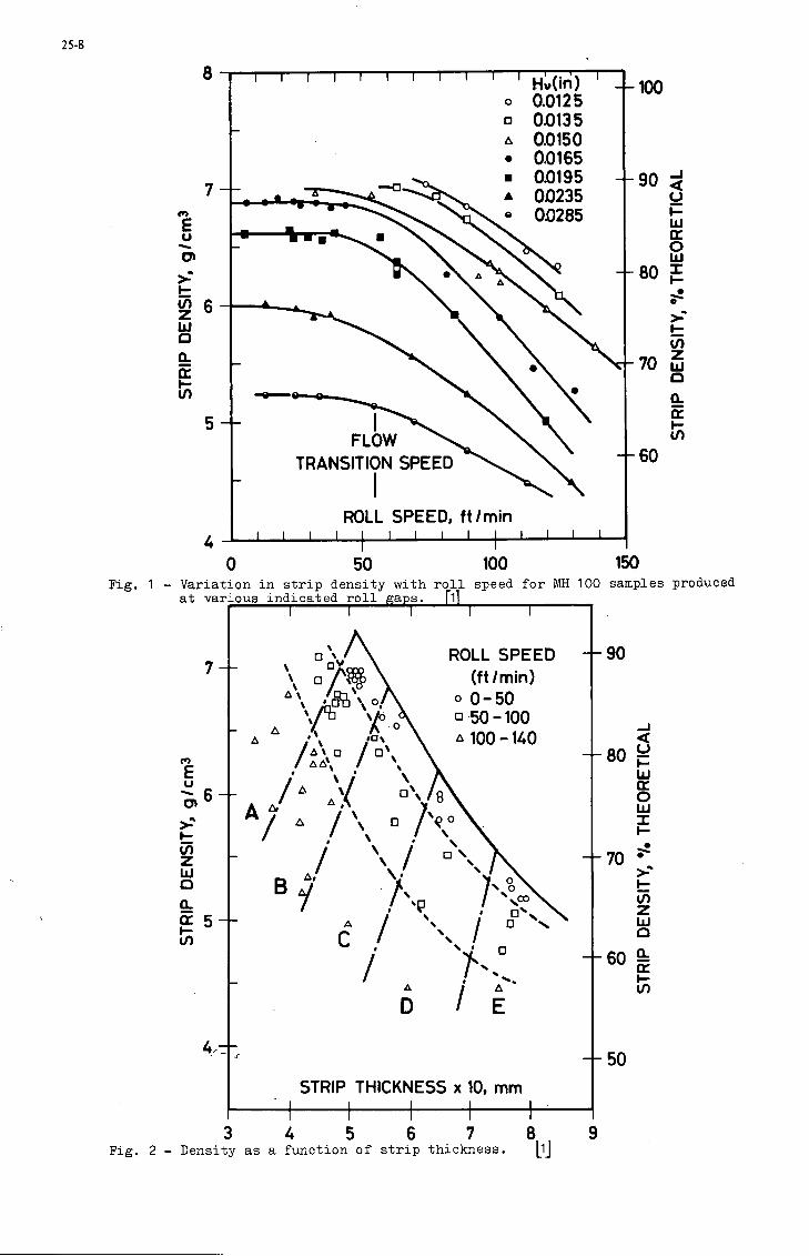
25-8
Fig. 1
Hv(in)0.01250.01350.01500.0165001950023500285
FLOWTRANSITION SPEED
ROLL SPEED, ft/min
Variation in strip density with roll speed for MH 100 samples producedat various indicated roll gaps. [l]
7- -
u6- -
t7)
Ulo
DcNv\ DXofl
\ °f$A 4d.x
Cs. \ A u
I \ /Qx
/^° / D\/A V 0\
J A A
ROLL SPEED(ft/min)0-5050-100100-140
--90
/ \ /R A/ \ Y °>B i /\g /x.
* / \ / oDN./ X> / o X^C / N /
/ >.",A / A
D / E
STRIP THICKNESS x 10, mm
+ 80 £UJcroUJi
--70 ^
U)Z
--60
--50
3 A 5 6 7 8 9Fig. 2 - Density as a function of strip thickness. [l]

25-9
8 -«/>ujUJcroUJa
OZ<oz-a.a.§6
\ \ I I I I I I l l i l i i
FLOWTRANSITION
SPEED
Hu(in)
o 00125 & 0-0135n 00150 & 0-016 5A Q0195• 00235• 00285
i i i i i i i i i i i i i i"0 50 100 150
ROLL SPEED ft/minFig. 3 - Gripping angle, O(o , as a function of roll speed for MH 100 powder
compacted at various indicated roll gaps. [1]
Fig. 4 - Geometric parameters in the vertical direct rolling. [2]

25-10
Fig. 5 - Initial rolling system.
Pig. 6 - The rolls with the guiding bars,

25-11
Fibres
Powder
t Ai
Tensile test
\FIRST
RE -ROL-LING AT 7%
RE- HEAT-ING
AT 500 -C
fA BGE
T
FINALROLLINGAT 7V,
\
ensile test
Fig. 7 - Process diagram
Fig. 8 - Powder overfeeding (magnification 90)

25-12
17
15
1*5 -lo
11
1
•
•
* •
•Q
0
*
9
i
, *
•
•ft
<\
20 40 60 80 100 N° FIBRE
Fig. 9 - Variation of percent fibre volume with fibre number
Fig. 10 - Regular distribution of fibres, low V,, (magnification 50)

25-13
Fig. 11 - Region of higher ¥„ (magnification 50)
%,9/cm
POWDERo COMPOSITE
0.2 0.5 0.8 1.1 Smm
Fig. 12 - Specific weight vs. strip thickness

25-14
i
CM
E 6-•Si75>>j *-\
n l
fc
•
•
$•V •
•, •v• •••.«.- V••••
.Green - Sintering -I Cold roll -II Cold roll
Fig. 13 - Behaviour of during the treatment
60-
*E 40-
J2 0 ;0
.
B.
1
9* *
..
<
:« • i i•*
^^ 1 1 1 110 12 14 16 Vf*/.
Fig. 14 - Tensile results vs. percent fibre volume

25-15
Fig. 15 - Typical structure of sintered powder (magnification 80)
Fig. 16 - Decarburation of steel wires (magnification 130)

25-16
r W^ivC-
Fig. 1? - Crack propagation between contiguous fibres (magnification 100)
g/cm3 f ,
2.7
0
1 >
c<
ct
PowdABrDEF
J
c<
'/..Type 2 powder
100705030200
>
1
s
A rm (°/.)
30105.93.73.59.5
<
4
.'/.-inn
LsoL80
-70
-60
-50
-40
-30
- A)
- in
n
B100 */. TYPE 2
F100 % TYPE 1
• AFTER SINTERING
o AFTER RE-ROLLING
Fig. 18 - Specific gravity of powder mixtures

25-17
Dimension(mm)
> 0.3150.2000.1600.1000.08
0.071
0.063
0.0500.0400.032
0.025
RESIDUAL
TOTAL
•/.WeightTvoe 1
11.4022.9619.8811.18
16.73
3.22
7.951.314.000.85
0.48
0.4
100 •/.
•/.WeightTvoe 2
0.158.01
21.4022.6026.06
5.68
5.640.624.232.77
0.34
2.5
100 •/.
Fig. 19 - Powder's grading
Fig. 20 - Type 2 powder's structure after sintering (magnification 650)

25-18
Fig. 21 - Type D powder's structure after sintering (magnification 650}
Fig. 22 - Type C powder's structure at stage B (magnification 650)

25-19
Fig. 23 - Flow lines of the matrix (magnification 80}
Fig. 24 - Disuniformely embedded fibres (magnification 25}

25-20
Fig. 25 - Fibres embedding defining strip thickness (magnification
Fig. 26 - Fibres rupture and slipping (magnification

25-21
Fig. 27 - Effect of excessive thickness reduction
Fig. 28 - Integer fibres

25-22
Fig. 29 - Al-steel composite strip
Al MATRIXCOMPOSITE(Vf V. = 5)
DENSITY
(g/cm3)2.6 2.95
STRENGTH
(kp/mm2)13
SPECIFICSTRENGTH(x105cm)
2.20 4.06
Fig. 30 - Specific strength

DI-1
DISCUSSION
Referring to Ing. Gruninger's paper, it was emphasized that Figure 25 thereofshould be used with caution because of the influence of specific environmental andphysical conditions on the test results. For example, although it would appear thatglass fiber reinforced material (GRP) would withstand the rain erosion tests only forminutes, tests of actual (GRP) compressor blades withstood rain erosion for about 25hours, because of the different air-flow conditions on the blades as compared to the testspecimens. Practical experience confirmed this, in general. Nevertheless, the testswere useful for relative comparison of competitive materials.
In reply to a question as to joint efficiency (in Figure 30) for carbon fiber wrapp-ed joints for da/di in the region of 2, as differing from the values for glass/epoxy,Ing. Gruninger explained that the joint efficiency for the glass/epoxy was based onexperimental data with a very exact correspondence to the calculated values. This workwas done with respect to helicopter blade joints, where larger da/di ratios are possible.For carbon/epoxy tests, only the smaller values of about 1.15 were used, which were use-ful for blade joint design and preferred because of the higher efficiency. In explainingthe selection of BSiC-Ti for compressor blades, where weight and stiffness advantageswere small or negligible, Ing. Gruninger pointed to the improved behavior at highertemperatures, due to the smaller difference in thermal expansion coefficient betweenfiber and matrix material.
Commenting on parallel loop specimens, Ing. Gruninger said the failure in carbon/epoxyspecimens occurred in the zone of transition from the UD-laminate region into the loopcurvature. The failure mode is caused by normal stresses in the fiber direction at thepoint where the highest stress must be expected. With the former glass/epoxy loops atda/di greater than 2.5, the transverse shear failure sometimes could be observed at theculmination point of the loop.
In connection with Mr. Heath's paper, the question was raised as to the practicalityof using the principle of a geodetic structure for a fuselage due to the size of theautoclave needed. It was pointed out, in reply, that in the early 1940's, the De Havilland"Mosquito" airplane was manufactured of plywood by such methods. It was also stated thatdesigners would still select the more easily fabricated epoxies rather than imides forcomposite aircraft, the latter being deferred until the next generation aircraft. Reply-ing to a question as to lightening problems in carbon composite structures, Mr. Heathindicated that, based on limited experience, this may be less of a problem than originallythought, although more research was needed to permit a definite conclusion. He citedtests on the Vulcan airbrake using both high voltage and high current lightening strikes,with only superficial damage resulting. This may have been partly due to the design ofthe airbrake which features a well.earthed metal frame. With respect to other kinds ofdamage in service, the airbrake had been flying for approximately 15 months, mounted onthe wing lower surface and thus exposed to water and pebbles thrown up by the nose wheeland to rain in flight, without damage. Strict quality control and NOT methods wereneeded in production but it was too early to say which methods were most valuable.


4-1
Design Concepts for the Use of Composites in Airframes
I. C. Taig, Chief Structural Engineer, British Aircraft Corporation Limited,Military Aircraft Division,Warton Aerodrome,Preston, Lancashire.
A philosophy for design of filamentary composite components, emphasising integrity and cost-effective-ness, is outlined. This involves intensive development of a limited number of basic structural concepts.Several such concepts, applicable to airframe structures, are reviewed, starting with a simplifiedassessment of their structural efficiency (measured in terms of mass saving) and including a briefdiscussion of features relating to integrity and fabrication. The review includes composite reinforcementof metal structures, solid rods, tubes and beams, sandwich skin panels and sandwich box structures,stiffened skins and wound tubes and lattices. Particular attention is given to attachments and loadintroduction and a brief section deals with bonded and mechanical joints. The paper concludes withillustrations of structures embodying sons of the concepts described.
Introduction
Many of the factors influencing the selection and exploitation of composite materials for airframeapplications have been discussed in recent papers by the author (refs. 1 ,2 ) . The two principal factorsof concern to the designer are the assurance of integrity of the structure and the economic effectivenessof the application. It is fundamental to the writer's philosophy that integrity should be established bythe development of a limited number of design concepts, each of which may be proven by full scale detailtesting and related by structural analysis to its performance in a complete structure. The selection ofsuitable concepts for development is based on their potential structural efficiency (taking account offabricability and manufacturing economics) as well as on inherent design features which contribute tointegrity.
This paper considers a number of practical concepts from these viewpoints, presenting a highlysimplified indication of their relative structural efficiencies and discussing features which affect theirfabricability and performance.
1. Structural Efficiency and Cost Effectiveness
The high performance modern composites are, at present production levels, expensive materials :the fibre alone costing from £70/Kg (jfeo/lb) to £250/Kg (#290/lb), according to batch size, forboron, carbon and organic materials. The use of such materials can only be justified if there arecompensating cost benefits either in terms of vehicle performance, first cost savings through sizereduction and simplification, lower operating costs or modification cost savings.
Particular examples have been quoted where the installed cost (3) and (installed + maintenance)cost U) are lower for advanced composite components than for their conventional counterparts. Insuch cases the cost effectiveness of the application is easily demonstrated and there is no need foran elaborate cost/perforance trade study. More often one must balance performance improvement.vehicle size reduction etc against the additional component cost. In the case of military aircraft,in particular, it is difficult to quantify size and performance benefits in cost terms, but it isonly by making such estimates that a rational assessment of cost effectiveness is possible.
As in ref. (2a) the index of composite material performance relative to conventional materialsis taken as the structural efficiency ratio R given by:-
R «• Mass of conventional structure replacedMass of composite in component
The value-of R varies according to the type of structural application, the loading conditions and theconstraints on component design. The benefit of mass saving on a particular aircraft is expressed asthe monetary value 7 of unit mass saving where 7 takes account of first cost, operating cost andperformance advantage. This value varies throughout the design and manufacture period, starting at ahigh level in initial design (when the whole aircraft layout and sizing can be varied to exploitspecific mass saving) and reducing as the remainder of the air frame, engine and systems become welldefined. The value may rise again late in the project life if there is a mass-critical short fall inperformance (e.g. in a 7TOL aircraft or a transoceanic transport).
If a component made of conventional materials has a total (installed + mintenance) cost Cj perunit mass and the corresponding cost using advanced materials is C2 then the advanced material iscost effective if C2 satisfies the inequality
C2 J> R C j + C R - O T (1)

4-2
Alternatively, the structural efficiency required to break-even economically is given byt-
+ V.(2)
Equation (2) is often approximated by using only the first costs in establishing Cj and ^2 but changesin component life and maintenance costs may be very significant and should not be overlooked W.
At a given stage in the evolution of an aircraft an economic structural efficiency ratio can beestablished. Break-even values for a typical military aircraft related to today's material costs areshown In fig. 1 (taken from ref. (2a)) and range from 2.5 to over 3 according to the stage of evolution.2.75 is taken as a typical current value. This will reduce, with decreasing material costs to1.4 - 1.7 in 1980.
Strictly speaking it requires a very detailed study of each component in an aircraft to establishthe structural efficiency ratio for the use of a new material. The local loading and environmentmust be taken into account and in the case of composite materials the layup must be matched to theserequirements. However a good approximation, adequate for illustrative purposes, can be made byconsidering some simplified types of structural component with characteristic loading conditions.
2. Design Criteria and Design Philosophy
The advanced composite materials currently being considered for airframe applications have ahigher variability in their mechanical properties than the high quality metals. The traditionaldesign approach for metallic structures is to associate a "specification minimum" material strengthwith an ultimate loading condition incorporating a standard safety factor or to establish a fatiguelife under a representative loading spectrum including a standard factor on the expected service life.It has been suggested that the higher variability of composite materials should be safe-guarded bythe use of an additional, and predetermined,safety factor (similar to the plastics superf actorcommonly stipulated in the U.K. and elsewhere). It is now becoming accepted that this is neither asafe nor an efficient procedure. The preferred approach is to use existing factors in design but toassociate ultimate loads with strength levels derived statistically from representative tests so asto ensure an acceptable probability of survival. This philosophy has some important consequencesarising from the nature of composite materials.
Appendix A shows that the integrity of multi directional laminates must, at the present level ofknowledge, be based on tests of actual composite layups and representative loading conditions. Itdoes not yet appear practical to produce accurate survival statistics for realistic components fromthe basic data obtained from tests of unidirectional laminae or unrelated laminate configurations.
To enable structures to be developed to fulfil a variety of roles with a limited test programmeit is necessary to build them up from standardised elements and standard material layups eventhough this may sacrifice efficiency, (it is shown, by Waddoups (5) that this loss may be small inrelation to the potential mass savings). In the subsequent discussions of component efficiency,attention will be limited to composites comprising layers in any or all of the directions 0°, 90°,± 45° to the reference loading direction.
It is necessary that the progrannie of testing, covering all essential structural features suchas joints and layup changes should be carried out on full size specimens and in sufficient numbersto provide statistically significant strength and life data. Standardisation will therefore beextended to local design details and to joints and edge attachments in particular. The range ofprobable structural configurations may be further reduced by manufacturing feasibility and economics.It will be shown later that it is sometimes necessary to settle for a "second best" structure in theinterests of overall effectiveness.
3. Composite Reinforcement of Metal Structures
Composite materials (in particular carbon and boron-epoxy laminates) may be used very efficientlyfor reinforcing metallic structures either for strength or stiffness purposes \2» 7). This is readilydemonstrated by considering the reinforcement of longitudinally loaded members (e.g. beam flanges,panel stiffeners) by unidirectional composite material.
If a longitudinally loaded strip contains a fraction >ti of composite of modulus EI and coefficientof expansion Cx ^ bonded to a metal of modulus 82 and expansion coefficient*^ 2 then, neglectingPoisaon's ratio effects, the average stress O*which can be sustained by the combined material is thearithmetically lower of the two values
(3a)
~ cr,(d - tf) + fl_^)+ E 6 (<* -o< ) AT (3b)^ * T-i I \ £. i
or
where G~\,O"2 are the strengths (tensile or compressive as appropriate) of the composite and metalrespectively and AT is the difference between the operating temperature and the temperature at whichthere is zero thermal stress in the strip. For carbon and boron-epoxy composites the longitudinalcoefficient of expansion^ j , is much lower than that of ratals, typically ranging from 0 - 3 x 1<Therefore thermal stresses effectively reduce the composite tensile strength when working above thestress-free temperature and reduce the compressive strength below that temperature. The reversesituation occurs in the metal. According to the temperature, the strength of the combined material

4-3
may be limited by either the composite or the metal constituent reaching its acceptable limit eitherin tension or compression. A complex situation therefore exists for determining the efficiency ofutilisation of composites which is best illustrated by a typical example. A type 2 carbon fibre/epoxylaminate is attached to a) aluminium alloy, and b) titanium alloy; the design properties, assumingthe metals to be limited to yield stresses, are given below:-
Material
Tensile strength ^it
Compressive strength O~ie
Longitudinal modulus E^
Longitudinal expansioneoeff t O< i
Composite
1150MN/m2
850 MN/m2
135 GN/m2
0
Al. Alloy
380 MN/m2
380 MN/m2
70 BN/m2
22 r lO'Vc
Ti. Alloy
850 MN/m2
850 MN/m2
110 GN/m2
9 x 10"*/°C
Stress free temperature
Operating temperature range
100°C
•4.0°C.. . to +100 C for maximum loadings, so thatAT ranges from - 140°C to 0.
The limiting stresses for the two compound strips are shown in figs. 2 and 4 and the structuralefficiencies relative to aluminium alloy as a common datum are shown in figs. 3 and 5.
For both metallic substrates the tensile strength is limited by the metal - very seriously so inthe case of aluminium alloy - and the increasing thermal stress in the metal (at low temperatures) asthe fraction of composite increases offsets the direct'improvement in tensile efficiency of the highercomposite fraction.
The behaviour in compression is at first sight most surprising. Here the adverse thermal stress(at low temperatures) is highest in the composite at low composite fractions, and so reduces thepermissible stress in the composite that it precipitates premature failure. The composite fails toreinforce the metal until the composite fraction reaches 0.2 with aluminium alloy and 0.32 withtitanium. This situation would be improved significantly by reducing the stress-free temperature(which is determined by the composite-metal bond cure cycle) and by increasing the compositecompressive strength. These are currently major objectives in carbon fibre composite research anddevelopment.
In the case of carbon-epoxy/aluminium alloy the gap between the tensile limiting stresses in themetal and composite is so large that it should be possible to reduce the stress-free temperature bycontrolled stretching of the strip after bonding so that plastic deformation in the metal would cancelout thermal contraction. This would slightly improve the tensile performance but would make the metalbecome the critical component in compression - particularly at high temperatures.
Boroi/epory composite is rather better as a metal reinforcing material than the carbon/epoxyconsidered above. The compreasive strength is very much superior and the thermal expansion coefficienta little higher (thus reducing the thermal strain difference). Effective compression reinforcement isachieved at all composite fractions.
Composite reinforcement of metal structures was introduced to improve the fatigue performancein the wing pivot region of the F1-11 where a relative efficiency of 3.75 was claimed compared withredesign In steel (2b, 3).
Composites may also be used for stiffening metal structures and the design flexibility given byhigh modulus: weight and controllable orientation is most attractive in this situation. Howeverextreme caution is needed in using the higher modulus, low failing strain materials such as Type 1carbon fibre since the combined material strength limits can be catastrophically eroded, particularlyin compression at low temperatures.
From the cost effectiveness point of view, reinforcement of metal is usually expensive even thoughhigh efficiencies are possible. The full cost of a metal structure Is implied (with some slight savingin material quantity) and the addition of composite necessarily means extra material and processingcost. Even so, direct cost effectiveness benefits can be seen, at current material prices, forreinforcement of titanium alloy in tension and titanium or aluminium alloy in compression at highcomposite fractions. Where modification of existing components is required, addition of compositelayers (3) may be far cheaper than replacement of metal members.
4. Solid Laminate Rods and Beams
Composites can clearly be exploited effectively in components in which there Is a well definedpredominant loading direction such as rods and straight beams. Whilst these do not constitute amajor part of the primary airframe structure there are many items such as floor support structuresand control rods where the working environment is favourable and significant mass savings can be madeat relatively low risk.
At first sight the rod is the most obvious application for a highly anisotropic material, but theachievable efficiency of such members is reduced by the end fittings and the requirements ofstructural stability. If significant compression loads are to be carried, a circular tube is the

4-4
preferred form. It is usually necessary to compromise the direct stress and Euler stabilitycharacteristics of longitudinally oriented material by the provision of other layers to provide localstability. The structural efficiency of tubular struts is conveniently presented in terms of stress :density (or end load : mass per unit length) as a function of loading index P/lo, where P = end loadand 10 = effective pinned length of the strut. At low loading indices the efficiency is determinedprimarily by the material stiffness properties and at high indices by limiting strength. In the caseof composites, the material orientation also changes such that at high loading indices the proportionof longitudinal material (and hence the structural efficiency) increases. Fig. 6 presents sometypical results for Types 1 and 2 carbon fibre/epoxy composites in which an approximate layupoptimisation has been introduced and compares them with a typical aluminium alloy. No specificallowance has been made for end fittings but the composite limiting stresses have been reduced tocompensate for the fact that end fitting penalties (relative to light alloy) will increase from zeroat low loading indices to 40-50$ at high indices. Material properties assumed are tabulated below
Material
E11E22
V l 2
0-. (low loading index)
Q". (high loading index)
Carbon fibre/epoxy
Type 1
230 GN/m2
8 GN/m2
0.35
450 MN/m2
315 "
Type 2
140 GN/m2
10 GN/m2
0.35
850 MN/m2
580 a
Al. Alloy
70 GN/m2
70
0.33
) 380 MN/m2
In the design of composite beams it is logical to incorporate at least two separate layups fortransmission of shear and direct loads in webs and flanges respectively. Two simple designs,appropriate to different shear : end load combinations are shown in fig. 7. These construction formslend themselves to treatment by the standardised element concepts outlined in section 2. Therectangular panel beam v7a) oan be regarded as core-stabilised shear webs, whose edges are limited indirect strain by the attached flanges,and flanges under varying end load with shear strain dictated bythe webs. It is readily shown that * 45° material is the optimum (or very hear optimum) layout forthe webs from both a strength and stability point of view and 0° is optimum for the flanges. Thecharacterisation of these material layups subject to the prescribed strains is relatively simple -the test beam shown in 7a was designed for this purpose.
In the I-beam of fig. 7b the situation is rather more complex since the stability of the flangebecomes critical as end loads increase and the web material may require redesign to provide adequatesupport. The sharp bend in the web material also introduces additional stresses which limit itsshear capability and in fact restrict this design to composites made from the very fine glass andcarbon fibres (2a).
Fig. 8 compares the structural efficiencies (measured by shear load : mass per unit length) forthe two types of beam considered above with aluminium and titanium beams. The reduction in efficiencyof the composite beams at high loading indices is due to additional mass penalties for flangestabilisation and web/flange shear transfer.
5. Sandwich Panel Structures
Composite materials which are built up as cured laminates lend themselves naturally toapplication in the form of bonded sandwich panels. Continuous support by a sandwich core enablesthin composite skins to be worked upto high stress levels and ensures that normal pressures and offsetscan be accommodated without large stress concentrations. The first and most commonly proposed methodof using multilayer laminates is to design skin layups capable of transmitting all components of loadand incorporate these in sandwich panels which will be stable over the required bay surface (fig. 9a).This type of panel is analogous to the metal skinned sandwich except that the skins will retain acertain amount of anisotropy as permitted by the loading system.
A second type of panel which may exploit the material more efficiently is more analogous to thebeam concept of fig. 7a. Here the longitudinal load capability is concentrated in unidirectionalstrips which may be contained within the sandwich core, shear and normal pressure are carried by angleply laminates (usually * 45° layup) and transverse strength is supplemented by a small amount ofadditional unidirectional material (fig. 9b). This type of structure is very efficient if supportedlongitudinally since the longitudinal support members can apply shears directly to the longitudinalstrip material, minimising shear diffusion in the covers, and the sandwich core depth and density canbe greatly reduced compared with the conventional wide panel. There is of course a trade-off betweensupporting structure mass and the above sandwich panel savings. From a manufacturing point of viewthe thin shear carrying sandwich concept is often preferable because variation in skin shears over thesurface is minimised and constant thickness covers and constant depth panels may be used with a smallmass penalty.'
Edge closures and attachments will frequently incorporate bonded metal members suitable forincorporation of bolted joints. In the case of the continuous sandwich skins these will requirecontinuous attachments for transmission of all load components or the inclusion of inserts togetherwith local skin reinforcement for discrete attachments. The thin sandwich concept requires discreteedge attachments for longitudinal loads and continuous shear attachments. The latter can be adapted

4-5
to discrete attachments by appropriate edge member design, often without modification to the skinlayup.
The structural efficiency of sandwich skins is usefully quantified in terms of the mass of acomplete structural box (including support members) as used for aircraft wings and tail surfaces. Itis necessary to make specific assumptions regarding relative magnitudes of different load componentsin order to produce a mass comparison with metal structures. In fig. 10 it is assumed that the skinshear la i and the transverse loading 1/5 of the longitudinal load intensity. These levels aretypical of the values obtained if the longitudinal direction is well chosen in relation to thecritical loading cases in a wing. The datum metal structure is an aluminium alloy stiffened skin/spar/rib box.
Note that in this instance the ratio of composite to metal structural efficiency R does notcorrespond to the relative efficiency R as defined in equation (l) . However for the thin sandwichskinned structure with composite internal members the difference is very small and may be ignored.An alternative form of construction, applicable for example to tailplanes where there is no internalstorage requirement for fuel or equipment is the full depth sandwich. A composite-skinned componentof this type is particularly attractive from the viewpoint of manufacturing economics. The smallnumber and simplicity of parts and the relatively low cost of fabricating complete skin panelsincluding edge reinforcements are such as to offset the high material costs. Indeed, on the basisof large production quantities, the overall cost of such components is estimated to be the same orderas that of conventional metal structures. The full depth core however imposes a severe mass penaltyand the relative structural efficiency is shown in fig. 10 to be well below that of the thin sandwichskinned component. Note that the core may constitute about -J- of the total box mass in which case theefficiency ratio R (equation 1)~ is given by R - 2 R - 1.
It should be noted that the efficiency comparisons include allowances for internal supportingstructure and its attachments but not for attachments to neighbouring components. The root attach-ments in particular can dominate the relative efficiency argument and the careful design of jointsis of paramount importance both as regards integrity and efficiency. For example in a compositeskinned taileron structure with internal pivot bearings, the total mass of metal structure at theroot was found to be more than twice the total mass of composite skins! Some redesign to exploitcomposites further in this critical root region could have saved some of this mass but the costwould have been prohibitive. The overall structural efficiency of this taileron compared with aconventional metal item was 1.20 whereas the relative structural efficiency of composite utilisationIn the box itself was approximately 1.6 on the basis of fig. 10.
6. Stiffened Skin Structures
It is relatively simple to design and layup fibre/resin composite skins with integral stiffeningmembers having either solid or hollow sections. As seen in an early trial component shown in fig. 11 (a)satisfactory consolidation and allowance for fibre movement during contraction in cure are not soreadily achieved. However manufacturing processes can be devised to give good quality skins usingpractical autoclave cure cycles and simple tooling. An interesting feature of thin stiffened skinstructures la that components made of the most brittle composites such as Type 1 carbon fibre/epoxycan tolerate a certain amount of buckling in shear or compression. A compression test piece isshown in fig. 1l(b) which buckled at a relatively low stress and was able to sustain additionalloading without detectable damage upto more than twice the initial buckling load. The extensivebuckles shown in the photograph disappeared completely on load removal after each load increment uptofinal failure.
This type of structure is not particularly efficient since a relatively large mass penalty mustbe carried to stabilise the skins and to carry local pressure loads. Some compensation is obtainedby locating longitudinal material efficiently in stringer flanges. However the efficiency will inalmost all cases be well below that of the thin sandwich skin and this concept is therefore onlylikely to be used where there are special design considerations In its favour.
7. Wound Tube and Lattice Structures
Filament winding is the most widely used method for automatic layup of composites and lendsitself particularly well to the manufacture of torque tubes and a variety of lattice structures. Adifficulty with this technique is the fibre cross over problem which prevents full consolidation andcauses local bending and fibre damage. It also leads, in the case of tubes, to uneven outer surfaceswhich may require machining to match end fittings, with a further loss of effective material at themost critical region. To avoid this, a typical practice is to add local layers of relativelyinexpensive material such as fibre glass which can be machined to match contours.
The theoretical efficiency of wound tubes is high but in practice the achievable strength islimited firstly by the same factors, auoh as matrix cracking, which limit flat angle-ply material inshear and secondly by the cross-over and damage factors mentioned above. A good tube in carbonfibre/resin composite will achieve a usable design shear strength of upto 300 MN/m2 and be abouttwice as efficient as its aluminium alloy counterpart (more where fatigue is the criterion). Endfitting design is vital in determining overall efficiency. Attachment to a metal end fitting iausually required and may involve either adhesive bonding - with a difficult contour - matchingproblem but little mass penalty or mechanical fastening through a locally reinforced structure. Atypical example of the latter Is the fibreglass reinforcement used by Westland Helicopters Ltd. (8)which results in an overall mass saving of 60# for a fatigue-designed tube.
Where distributed loads such as shears are to be transmitted by a basically unidirectionalmaterial, a lattice structure is an obvious alternative to sheet material provided that surface
t?i.ia ??* requir;d' If a 8heet structure is limited by elastic stability rather than materialthen the concentration of material into lattice members must increase the rigidity normal to

4-6
the surface and improve overall buckling efficiency. Lattice structures may therefore be moreefficient than sheet structures at low structural loading indices. This is readily demonstratedfor a shear panel in which - 45° material may either be used in sheet form or lattice form asillustrated in fig. 12. Efficiencies of the two structural forms are also shown in fig. 12 in termsof shear flow/mass perunitarea plotted against loading index. The comparison does not include thepenalties for attachment at the edges of the panel and the lattice is likely to be inferior in thisrespect to the continuous sheet.
Similar results would be obtained for other stability-critical panel and shell structures sothat a fairly wide application for lattices could be justified theoretically. From a manufacturingpoint of view their automated layup is an obvious attraction but they are difficult to consolidatewithout fibre damage and high void content. There is also a severe load transfer problem at latticeintersections as any interlaminar-type shears at panel boundaries can only be transferred throughsmall fibre overlap zones. The exploitation of this type of structure therefore requires consider-able specialised development.
8. Structural Joints
Reference has already been made on several occasions to the key role of structural joints andattachments. Because of low interlaminar shear and through-thickness tensile strengths of fibrouscomposites load introduction is much more critical than in homogeneous isotropic materials. Also thecomposite characteristics (hi^i interfacial bond strength in particular) which yield good interlaminarstrength properties also increase the sensitivity of the composite to stress raisers - a fact pointedout in several recent papers by Morley (e.g. ref. 9) who also proposes an ingenious solution to theproblem.
The preferred method of joining fibre/resin composites either to themselves or to adjacent metalstructures is by adhesive bonding. Often there is a design requirement that jointn should bedismantled and mechanical fastening is needed. There are two distinct philosophies on this point.One, is that composite materials should always be adhesive bonded to conventional materials andmechanical joints made through the latter v1i°/. The second is that special layups and perhaps localreinforcement 15,8) j^y ^ used to permit direct bolted attachments to be made to composite material.
In bonded joints most attention has been given to the tension joint and as regards the loadintensities to be transmitted these are often the most critical. Bonded joints used in final a3semblyof pre-cured parts are more likely to be shear joints such as the beam web-flange joints of fig. 7.Such joints are severely limited in geometry because of the need to prepare matin? surfaces andpermit simple face-to-face junctions. Fig. 13 illustrates a number of types of bonded assemblyjoint : two forms of simple lap joint and single and double buttstrap joints. Structural adhesivesand composite materials themselves are subject to limitations in peak shear stress and tensile 'peel1
strength. Sionle joints as illustrated have severe stress concentrations such that the load capabilityof each type of joint has an upper limit which cannot be exceeded by increasing the lap length. Thestrength asymptotes based on shear alone are indicated for various joint types in fig. 13, ignoringlocal offsets and bending effects. Transmission of higher loads will require the design of morecomplex joints with attendant assembly problems or the use of reinforcement and machanical fasteners.
Bonded joints to edge members and local reinforcements can be built in during layup andconfigurations which are effective over a much wider loading range can be devised. Fig. 14 showssome of the preferred types of edge member joint - the Scarfe joints being theoretically mostefficient and the step-lap joints the best practical approximation. The best joints of these typesachieve from 50 to 70$ of the tensile strength of the composite material adjacent to the joint so thatlocal reinforcement of the composite is required in order to obtain full effectiveness at somedistance from the edge. The shim joint can achieve upto 90# or more of the adjacent compositestrength but loses overall efficiency because metal and composite are carried in parallel oversignificant lengths of structure. It is also not applicable, with high efficiency, to componentswhich require a smooth outer contour.
In all cases, efficient joint design demands careful detail sizing, choice of local materiallayups and suitable adhesives, precision and control of surface matching and high quality in thefinished product (see ref. 10 for example). The joint region is the principal source of potentialfatigue damage in a high-strength composite component and extensive testing of full scale jointswith representative surrounding structure will be an essential part of the integrity demonstration.
9. Concluding Remarks
A number of structural concepts have been discussed and their efficiencies in particular loadingsituations have been assessed relative to a common datum : the conventional aluminium alloy airframestructure. It is useful to compare the different applications and determine which are likely toprove cost-effective at present or in the near future. Fii*. 15 shows in bar chart form, the rangeof relative structural efficiencies obtained from the preceding studies together with those for somespecific structures embodying one or more of the characteristic components. This shows thatreinforcement of metal by unidirectional material and the use of composites in stiffness-designedcomponents are the most effective applications if manufacturing costs are comparable. This is a grosssimplification and in several circumstances other applications may prove cost effective - even atpresent prices. This is particularly true of structures such as full depth sandwich components whichmay be so much simpler than their conventional counterparts that low fabrication coats largely off-set high material prices.
All the concepts and applications illustrated here should prove cost-effective at material priceswhich are anticipated by 1980. The proviso must be made that standards of integrity and consistentperformance can be demonstrated at full scale for large numbers of components. This is only conceiv-able in a relatively short timescale by reducing the near-infinite range of structural and material

4-7
configurations which composites offer to a manageable number of basic functional concepts. Inconclusion, some examples are shown in figs. 16 - 20 of structures designed or built from such basicunits.
Acknowledgements
The author wishes to thank British Aircraft Corporation Limited for permission to publish this paperand also the Ministry of Defence (Procurement Executive) who have sponsored much of B.A.C. 's activity inthis field.
References
1. Taig I. C. "Design of Airframe Components in Carbon-Fibre Composite" in COMPOSITES Jan/Feb 1972.
2. Taig I.C. a) "General Considerations in the Application of Advanced Composites"
b) "Airframe Applications of Advanced Composites" in AGARD Lecture Series No. 55 onComposite Materials. May 1972.
3. Dial D.D. and Howeth M.S. Advanced Composite Cost Comparison in SAMPE Conference Proceeding. Vol. 16Anaheim Conference, Nov. 1971.
4. Anon. Cost Effectiveness of RRCM Carbon Fibre Floor Panels - Rolls Royce Composite Materials Ltd.
5. Waddoups H.E. "Automated Design and Future Design Trends", in AGARD L.S.- 55 on Composite Materials,May 1972.
6. Rao P.N. and Hofer K.E. "Investigation of the Influence of Material Variables on Fatigue Mechanismsin Composites". Final Report under DSN Air Systems Command contract N 0001 9-70-C-0378(IITRI Report D 6058).
7. Oken S. and June R.R. "Analytical and Experimental Investigation of Aircraft Metal StructuresReinforced with Filamentary Composites" NASA CR-1859 Dec. 1971.
8. a) Sanders R.C. "The Effect of Carbon Fibre Composites on Design".
b) Winny H.F. "The Use of Carbon Fibre Composites in Helicopters".
in The Aeronautical Journal, Supplementary Papers Vol. 75/76 Nos. 732/733 Dec 1971/Jan 1972.
9. Morley J.G. Duplex-Fibre Reinforced Composites in NPL Conference Proceedings "The Properties of FibreComposites" IPC Science and Technology Press Ltd. Nov. 1971 and COMPOSITES, Vol 12 P.80 (1971).
10. Lubin G. and Dastin S. First Boron Composite Structural Production Part In Proceedings of 26thAnnual Technical Conference Feb 1971 Society of the Plastics Industry Inc.. Reinforced Plastics/Composites Division.

4-8
oh
oZuouli.LJ
ZU 20-
u
u<*CD
.A - S T R I K E A|C - D E T A I L bCSIGN STAC ESUBSONIC T R A N S P O R T - EARLY DESIGN
r / 70 / Kg
B - STRIKE A j C - P R O J E C T STUDY STAGEVr X I 50 I
C - S U P E R S O N I C TRANSPORT- EARLY DESIGN.300/kg
1972 73 7*4 75 7b 77 7'S 79 80
FIG. 1 EFFICIENCY REQUIRED TO BREAK EVEN ON FIRST COST
80S
606
rJ
-1 400ZI.
h •
ST
RE
SS
IN
C
OM
PO
g ?
a
F£
x'^ ta 40-
X ^COMPO5ITE IN a"
^x T E N S I O N AT IOO°C o
^ < 3 ora
>•uz
M-iIAL IN TENSIOM AT-40eC u 2'°"
u• »• U.
•*- — •t ">rr' s u B5TRATc <3
o'z O-4 o'fo ^ U
C O M P O S I T E F R A C T I O N ^ "
\^COMPOSITE IN
R- COMPRESSION
/
' R- COMPRESION,-
/ f.
^^-^_ / .-'* R- TENSION
..-"T* " " R - TENSION!
/
/
02 O 4 Ob
COMPOSITE F R A C T I O N ^
^S. C O M P R E S S I O N
^\AT - 4O*C.
- -405
METAL IN - »COMPRESSIONAT 100'C.
-6OO
R =MASS Or A t ALLOY STRIP
FIG. 2 LIMITING STRESSES IN STRIP
OF TYPE 2 C/EPOXY WITH Al ALLOY
MASS OF REINFORCED STRIP
R IS DEriNED IN T E X T
FIG.3 RELATIVE EFFICIENCY OFC/EPOXY WITH Al ALLOY

4-9
IPo 400aZou2
utf
-wo"
METAL IN T C N S I O N AT - 4 O C
0 2 04 0 to
COMPOSITE FRACTION ^
COMPOSITE IN COMPRESSIONAT -40*C
METAL IN COMPRESSIONAJ JOO'C.
itt
erf"
•*<Oh 3'Juct
>•u2 2-uoiZikl
-1 i.<wa3»-U3
K 0-M
R - TCNSION
R-COMPRESSION//
X
*//
R - T E N S IO,Kt— -^ "/
• "^^^ 1 *• '
^'-''"/ TC
R ^COMPRESSION,/
/./
o-z. 0 4COMPOSITE /rRACTION
/
f
*/
„• — xx
x."X
ALONE
OUA
MASS OF Al ALLOY STRIP-1-1 "* * MASS or Ti-RCINFORCED STRIP
FIG. V LIMITING STRESSES INSTRIP OF TYPE 2 C/EPOXY WITHTL ALLOY.
FIG.5 RELATIVE EFFICIENCY OFC/^POXY WITH Tl ALLOY.
^^rf-l ^_—_^ TYPE I THEORETICAL LIMIT
A i A L L O Y
* M A S S PER UNIT LENf tTH
IZ O 40 60 80
L O A D I N G INDEX f100 I 2O
(kN/ml)
I 4O
FIG. 6 EFFICIENCIES OF TUBULAR STRUTS

4-10
LIGHTWEIGHT
C O H C -
• U N I O I R C C T I O K I A L *FL A, NQ E S
• S H E A R W E B SM A I N L Y t 45° PLIES
'BOKJb S U R F A C E S
FINITE R A D I IL IMITED BVF I B R E SIZE
a) Rectangular sandwich b) Solid I-sectionFIG 7 COMPOSITE BEAM CONCEPTS
30-
2*
L.,3
10-
u 10
BECTAN6ULAR PANEL(F lC7<x)"C'/tPOXY
* I - B E A M S (Flfi Ib)
J
1
Ld
r
SP*N DEPTHR A T I O * -5
3
I 4 fe
L OA D ING I N D E X
10 14
FIG. 8 EFFICIENCIES OF TWO BEAM CONCEPTS

4-11
T R A N S V E R S E SUPPORT
T R A N S V E R S E S U P P O R T S
T H I C K S A N D W I C H PANEL -"PICTURE FRAME" EDGES
U N I D I R E C T I O N A L
C O M P O S I T ES T R I P S .
FINGER I N S E R T INUNIDIRECTIONALJTRir
F I N G E R INSERT INU N I D I R E C T I O N A LSTRIP.
JKNGLE-PLV SICINSUNID IRECTIONALC O M P O S I T ES T R I P S .
A N C L E - P L Y SKINS
THIN S A N D W I C H PA NEL - M ULTI - SPAR SUPPORT
FIG 9 SANDWICH PANEL CONCEPTS

4-12
NX - LONf i lTUDINAL LOAD INTENSITYm . M A S S / U N I T S U ftPAC E ( 2. SKINS t SUPPORTS)
h t BOX DEPTH
C/EPOXYTYPE 2
S A N D W I C H SK INNED B O X E S
C / E P O X YT Y P E .
C / E P O X YT Y P E I
AL A L L O Y FULL-DEPTH HONEYCOMICORE B O X E S
zo-
L O A D I M G I N D E X
FIG. 10 EFFICIENCIES OF SANDWICH STRUCTURES
a) Manufacturing trial sample b) Compression test elementFIG 11 STIFFENED SKIN PANEL

4-13
SHEET SECTIONL A T T I C E SECTION
• W
W Itc - Zad
•m = pt OR pte - M A S S / U N I T SURFACE
3OO'
E ZOO"
u2
Q «•-— LJ
OPTIMUM L A T T I C E
PLAIN SHEAR. WEB
4 fa 8L O A D . N f i I N D E X -"*•».
b
lo iz 14
J O I N T T Y P E
l). THROUGH L A P J O I N T
V i^* ^^]A k k.1 -^^ b^iko. ^^^ pt,l~L *- LJ. J^^ *A* r *< <*fa
"2) . T E R M I N A L LAP JOINT
(7 r" -^$ tl
^T - ^^Itk
.•Pfc ^X^ '
3). S INGLE B U T T S T R A P
" 1 til 11 4 i »•
1 I'll l t k *
4). D O U B L E BUTT S T R A P
P 1. . . . \\\ Liu f
i *f i* * t1 IJI I f k a
S T R E N G T H A S Y M P T O T E ( I*- Off)
TE NSIONL a > p
-to(5/^1t,ka ^e.1,11
xX G» ti^i
IF E, k, « Et bt
N O T
A P P L I C A B L E
AS T Y P E l).
I, J - 1 0 R Z S U C H
T H A T E,t. £ E tt t
rr0 yi.t.kcf E, t, ^
L.J » 1 OR Z SUCHT H A T E,k, < E lk l
S H E A R . <),
To /G.t.ka. /, C , k , \
/ I r J
IF G, t, jf Gi tr
° / Go. ' t '^v ^|C. Ci ? t*
IF G, t, £ G t kt
A S TYPE l)
i.,j : 1 OR Z SUCH
T H A T G,k, £ Gik,.
ZTo /a.k.k.* / 6,k. \
i, j « i OR z S U C HT H A T G,k. £ G lk l
N O T E S : - a) TENSION FORMULAE APPLY ONLY ir S H E A R is C R I T I C A L .b) to REPRESENTS THE L O C A L S H E A R STRENf tTH OF
A D H E S I V E OR L A M I N A T E .
FIG. 13 BONDED ASSEMBLY JOINTS

4-14
A D H E S I V E F I L M
SINGLE AND DOUBLE SCARF JOINTS
F L E X I B L E A D H E S I V E I N T E R L A V E R .
1 1 IMETALJ ||BE LAMINATED TO ' •
REDUCE STRESS CONCENTRATEIIII MILL III '
STEPPED LAP AND SPLICE JOINTS
mC O M P O S I T E .
R E S I N ORW E D G E S METAL: SHIMS.
SHIM JOINT
FIG. K EDGE MEMBER CONCEPTS

4-15
(Z EFFICIENCYQANGC
° 41h
*
U ,z 3'u —<JL.IA.u z.
J
<
aot- .(J 1 •3Of1-«1
Zop<u3a0.<f
COMP
TENS
-T
1
ij_
2
*-j<
<-.f.
/
irD
Z<H
•-
TENS\vsV
H • HIGH LOADING INDEX
L • LOW LOADIKiq INDEX
1971 BREAK EVEN LEVEL
COMPRW
1
^
L
H H
L
— T
IO
Oz<ina<.
zK
Ua
-^
2O
Uuv>M
H —
_ 1$$
L
H
"rii*iii °I Piaa
/
—iarsl
<(|
a
^v\\
>XOaLJ
n^Ua>>•
Xo0.uo
—
ua>-*•
_l Q
h u Z
¥ j2 w u u —U. T LI V < I/I Ifl
_j ° tf X O L. U fl
Z U " I1" *~ 0) * d ' °
- 5 t f u O u D i n .[j ° < I/I > w O ° J *~ u '
(Ho J Z f lz ' V t t ^ I t j
a ^ 3 * . 1 ->u t-3 u"o Z f f l < * - _ j2 z t f _ 2
2ui 3 u * * 30 01- h <
M A T C R I A L - T Y P E i C/EPOXY U N L E S S S T A T E D
FIG. 15 SUMMARY OF COMPOSITE UTILISATION EFFICIENCY
U N I D I R E C T I O N A L COMPOSITES T R I P B O N D E D T O C O M P R E S S I O NF L A N G E .
0 O O O 0
! l 1 I 11, J 8 m .
a . T E S T B E A M L A Y O U T
C O M P O S I T E IN TtNSIOM C O M P O S I T E IN C O M P R t S S I O N
RT R-T.
r-7///
////
//
/
//////
r™
••'
/////////
[7/////////////^
4C't
RT
/////////////
IT.
7/
^
^
p™
/
////////////
s
///////
/////////
t /u t7///////////////
M E A S U R E D BENOINC MOMENT
C A L C U L A T E D B.M.fpROM COUPONTESTS AND ACTUAL D IMENSIONS)
b T E S T RESULTS
FIG 16 ALUMINIUM ALLOY BEAM -CARBON/EPOXY REINFORCED

4-16
FIG 17 JET PROVOST RUDDER TABS
FIG 18 JAGUAR SPOILER
P L A N V I E W S l M P L l F I E D L A Y E R
A L UMIWUM1 i A D I N b
E D G E
B O R O N SKINSA t - HONEYCOnS
CORE
MAIN SPLICE.
T I T A N I DM
S U P P O R T
S T R U C T U R E
ALUMINIUM T R A I L I N GE D G E .
T I T A N IUM BO RONG L A S S F IBRE028 015 OZO 0 3 0 - 0 3 5 050
l*|.0-J»-l-0—*
040 T H I C K N E S S AT LAST S T E P
S E C T I O N T H R O U G H MAIN S P L I C E .
F I G 19 BORON HORIZONTAL 5TA BILIZ ER (GRUMMAN F.

4-17
I N T E R C O S T A L S T A B I L I S E R N E S T SI N T O C O N T I N U O U S R I B C H A N N E L .BOTH1 AAC ANQLt - PLY WCBBCD
Z BEAMS
B O N D E DI N T E R F A C E
U N I D I R E C T 1 :F L A N G E .
M E T A L E D G E I N S E R T SA T T A C H TO M E T A LL E A D I N G E D G E .
^COMPOSITE.SKINS.
T I T A N I U M .J O I N TP L A T E
T I T A N I U M -R O O TF I T T I N G
U N I D I R E C T I O N A L F L A N G EANGLE- PLV C O M P O S I T E
S K I N S -
S E C T I O N A - A
MAIN S P A R W E B .( C O M P O S I T E S A N D W I C H )
L O N G I T U D I N A LS T A B I L I S E R S .( C O M P O S I T E )
©S E C T I O N B^
FIG 20 CARBON FIN BOX CONSTRUCTION P R I N C I P L E S

4-18
Appendix A. Integrity of Multilayer Laminates.
Because of their extreme anisotropy, the present-day fibre-resin composites are mostly used in multi-directional laminates made up either from woven cloth (moderate-efficiency, glass composites), fromdifferently orientated unidirectional layers or from orientated short-fibre mats. Considering the mostcommonly used form for high-efficiency structures (the multiple unidirectional layer laminate) it iscommonly assumed (either explicitly or implicitly) that the performance of a laminate can be completelydescribed in terms of unidirectional layers. This is true to a large extent of the physical propertiesincluding stiffnesses and thermal expansion coefficients. It is not true of strength and fracturecharacteristics. Two extreme sets of assumptions have commonly been made:-
a) that a multilayer laminate is considered to have failed when the stress in any direction in anylayer exceeds the failing stress for that layer tested as a unidirectional material (i.e. the firstthrough crack in a layer constitutes failure whatever its direction) or when the interlaminarshear within or between layers exceeds the corresponding strength.
b) that a multilayer laminate can tolerate cracks parallel to fibre layers and normal to the laminaeand that failure occurs either when the stress along the fibre direction in any layer exceeds theunidirectional strength or when the interlaminar shear exceeds its limit.
Theory a) has been used to construct failure envelopes for combined stresses applied to many specificlaminate layups (e.g. ref. 8a) and elaborate design theories and computer routines have been built up onthis basis. Frequently these have ignored the thermal shrinkage stresses caused by differentiallongitudinal and transverse contraction following curing (at temperatures usually between 150 and 200 C).Elementary calculations, backed up by distortion measurements in unbalanced laminates and micrographs oflaminate cross sections, show that almost all carbon- and boron-resin multidirectional^omposites sufferresin cracking at temperatures within the normal aircraft exposure range (down to - 50 C or so) withoutany mechanical loads applied. The strength envelope according to theory a) is therefore non-existent : othis does not agree with established facts. For example, the following results were obtained for 0 - 9 0carbon fibre/epoxy laminates cracked initially by thermal shrinkage and subsequently loaded in tensionparallel to the 0° fibres (to 80$ U.T.S.) to extend the cracks in 90° layers.
TABLE Al
Preload
None
80# U.T.S.parallel to0° plies
Result of microscopicexamination after preload
Regularly spaced through-thicknesscracks in core and surface layers
Additional cracking in 90° layersspreading into the interface.More pronounced when loaded parallelto surface plies.
Layersequence
0-90-0
90-0-90
0-90-0
90-0-90
Mean Strengths HN/m^
Compression
449
-
437
-
Shear
22.1
25.5
25.2
23.4
Such results show clearly that a composite need not be degraded as regards static strength (even in modeschosen to be susceptible to matrix cracks) by transverse lamina failures.
However it is unrealistic to assume theory b) at the other extreme since severe matrix cracking mustinfluence composite performance under repeated and reversed loads. For example Rao and Hofer »"/ showedfatigue failures in 0/±45°/90° laminates which resulted from development of matrix cracks leading toeventual delamination. Similar results were obtained for tension, compression and reversed loading (thelatter being the most severe). Furthermore extensive resin cracks will serve as paths for fluid ingresswhich might result in chemical or physical damage to the composite.
The definition of acceptable degradation of multilayer laminates remains, to the author's mind, themost important gap in present knowledge of advanced composite behaviour. More work on the flawed strength,fatigue performance and environmental resistance of laminates with matrix cracks is vitally necessary.

5-1
DESIGN AND FAILURE CRITERIA OF ADVANCED COMPOSITEPRIMARY STRUCTURE
BY
LARRY G. KELLYAFFDL DEPUTY PROGRAM MANAGER
ADVANCED COMPOSITES ADVANCED DEVELOPMENT PROGRAMWRIGHT-PATTERSON AIR FORCE BASE
DAYTON, OHIO 45433
SUMMARY:
The successful design, fabrication, and flight test of a boron/epoxy F-lll stabilizer has demonstratedthe applicability of this composite material to airframe construction and substantiated the ability toachieve significant weight savings. The material allowables and design philosophy utilized in theevolution of this structure are employed as an example of an approach to establishing logical failurecriteria from which efficient designs can be developed with continuous aligned high modulus-high strengthcomposite materials.
One of the outstanding features of filamentary composite materials is their directional propertieswhich provides the ability through crossplying of lamina to tailor a structure which meets specific loadsand/or stiffness requirements with a minimum amount of material and weight. This being so, it followsthat large numbers of individually different crossplied laminates are possible, uniquely distinctive inproperties and characteristics. Experimental evaluation of all feasible orientations would be prohibitivelyexpensive. Thus a more efficient and reliable method of establishing design allowables for all laminatesof interest had to be developed. The approach selected was to experimentally determine the stress-strainresponse of simple unidirectional laminae at the required design temperature and with the aid of amathematical model establish a failure envelope to serve as the designers tool for selection of a suitablelaminate thickness and ply orientation for a given set of load conditions.
STABILIZER COMPONENT CRITERIA DEVELOPMENT:
The boron/epoxy F-lll horizontal stabilizer shown in Figure 1 is composed of four major assemblies;a tip, leading edge and trailing edge which are mechanically attached to a main box structure. The borontail is similar to the aluminum structure, in that, both are full-depth honeycomb sandwich construction.However, the aluminum skin is replaced with a boron/epoxy laminated skin.
The principal Joint is the attachment of the skin to the steel pivot fitting support structure.This is accomplished with a scarfed titanium plate which is integrally cured with the boron laminate.The bending and torsion loads in the boron/epoxy laminate are transferred to the steel substructurethrough the titanium plate by means of mechanical fasteners. The taper in the titanium plate is orientedso that the increase in thickness is towards the outer contour so that the inside of the plate-skinassembly is flat for the critical skin to understructure bond. This arrangement results in the loss ofclose outside contour control and thus the area of the plate has to be matched to contour with filler pliesof glass/epoxy which Is the light colored material over the hub in Figure 1.
The main box boron/epoxy * skin is the material of prime interest here. The laminate orientation andply count is shown in Figure 2. The 0-degree plies are the principal bending material and are concentratedat the region of maximum airfoil thickness and aligned along the 50% chord. The + 45-degree plies areapproximately parallel to the root rib and the - 45-degree plies are thus normal to the root rib. The+ 45-degree plies comprise the principal torsional load skin reaction material and are evenly distributedover the surface since the entire cross-sectional area is effective in torsion. The maximum thicknessof 42 plies (.22 inches) occurs over the outboard bearing.
The resulting boron tail is 140% stiffer than the aluminum tail in spanwise bending, 125% stiffertorsionally at the root and only 25% as stiff in camber bending. A weight breakdown is presented inFigure 3. The composite design box planform area is larger than the aluminum design, and the compositeleading and trailing edges are smaller. The tip in both designs is the same size. The majority ofweight savings (54%) is in the skin and the resulting 2901b. weight savings per ship set corresponds to a25% savings for the overall assembly.
The stabilizer was designed to the load conditions shown in Figure 4, two subsonic high torsion loadsand two supersonic high bending load conditions which are fully reversible. The design temperature resultingfrom the supersonic condition is 270°F. These load conditions result in biaxial tension and compressionstresses in the boron/epoxy laminate. "Limit Loads" or the maximum load expected in service were matchedwith the yield stress of the simple lamina (Figure 5). Thus stresses resulting from limit load are designedto be equal to or less than yield where yield for the material is defined as the onset of inelastic behavior.The isotropic nature of metal would allow the material reaction to these applied loads to be defined by twoof the three basic elastic constants (E, G.-y)- However, a basic unidirectional lamina or any balancedsymmetric laminate is orthotropic in behavior and when applied in any general airframe application the loads
*Boron/epoxy-raw material was 3" wide tape consisting of preimpregnated colllmated 4 mil boron fibersspaced .7 mil apart for 212 fibers/inch width on a 1 mil glass carrier cloth for a per ply thickness of5.3 mils when cured and a density of ,071/lb/in'.

5-2
are not all exactly aligned with the principal axis or fiber direction so that the material is anisotropicin its response , that is; physical properties vary with direction (see Figure 6). To characterize sucha material four independent elastic constants are required; Young's moduli in the two principle directions,shear modulus and Poisson's ratio. A laminate which is not symmetric and is unbalanced about its midplane is called a coupled laminate and should be avoided because the shear stresses and normal stressesinteract and any in-plane applied loads produce an out-of-plane distortion.
Since the properties of the composite laminate of interest do vary with direction, a failure envelopeor 3-dimensional surface (Figure 7) is required to define its load carrying capability. This surface canbe established analytically by any of the several theories which express Hooke's law relationship for 3-dimensional anisotropic materials, that is; relate stress to strain by a constant (E) or modulus. In thiscase, since limit load was established not to exceed the yield point of the material, a maximum strainyield criterion was employed to produce the interaction curves which define the failure envelope or theenvelope of maximum stresses which may be carried without yielding of the laminate. The procedure requiresknowing the tension and compression Young's moduli and yield strains in the two principle directions,longitudinal with and transverse to the primary load direction, together with shear modulus and strain andPoisson's ratio. This requires generating five stress-strain curves; uniaxial tension and compression curvesboth parallel and transverse to the filaments and a shear curve.
Although it is feasible to computerize the equations and obtain through an iterative process an optimumorientation, it is also practical to restrict the number of possibilities to families of laminates whichwill be able to match the typical multiple loading or stiffness requirements of airframe structures.Examples are the 0+45, 90 or 0 + 60 laminates which if employed in equal numbers of each constituent arequasi-isotropic in behavior. For such laminates the in-plane elastic response is isotropic or invariantto angle of orientation. Such laminates form the lower bound of potential composite specific strengthcapability offering an impressive 20% weight savings over aluminum as a result of the density differenceand is a good starting point for the designer. Any laminate with less stiffness or strength need not beconsidered. The upper bound is established by the properties of a laminate with all plies in the samedirection. However most aircraft structure is designed by a biaxial state-of-stress and the laminatemust be tailored to the specific load conditions for adequate structural integrity and maximum efficiency.Laminae can be tailored to the load conditions by aligning the maximum strength or stiffness or both inthe principle load direction and providing just adequate strength or stiffness in the secondary directions.It is always wise to provide a nominal amount of transverse reinforcement to account for any off-axisloading. A rule-of-thumb is to make the number of laminae in the transverse direction equal to 10% of thetotal number of laminae.
In this particular structure the chordwise loads are substantially less than the torsion and spanwisebending loads. Therefore, the transverse strength of a 0 + 45 degree laminate was adequate, and alaminate of approximately 60% 0 degree plies and 40% + 45 degree plies was found to be very efficientachieving a 63% weight savings over the aluminum skin before the load introduction titanium plate is added.The titanium plate (Figure 8) furnishes the isotropic properties needed to best accomplish transfer of themultiple load directions at the root end and affords high bearing allowables necessary for skin to sub-structure attachment. Titanium was selected over steel because of its better strain match with the parti-cular laminate orientation selected and over aluminum because it is a better match in coefficient ofthermal expansion. The local joint details were designed emperically through a series of beam tests todetermine taper rate, bond length,bolt configuration and overall shear load capability. The beam specimensshown in Figure 9, ranged from a series of relatively small scale beams to full-scale sections of thiscritical joint area simulating as closely as possible the boron-titanium skin to steel substructure attach-ment. The leading edge and trailing edge attachment details were designed in the same manner.
As is typical of thin supersonic airfoils, the F-lll horizontal tail is sensitive to dynamic aero-elastic effects and a considerable area of the total tail structure is designed by stiffness requirements,Figure 10. The aluminum tail most efficient strength design is considerably penalized because of materialadded solely for flutter considerations. The change in weight and weight distribution inherent in the boronstabilizer not only affects the balance of the aircraft by virtue of its remote location relative to theaircraft center of gravity and the actuator system requirements to drive the stabilizer but also theoverally vehicle dynamic characteristics. The aluminum design flutter mode shapes indicated the criticalflutter mode to be the coupled span bending-torsion mode with the tip being the critical area. The flutteranalysis for the composite tail showed the boron tail to have the same characteristic behavior. Thedivergence speed for the boron tail was found to be slightly lower than the aluminum tail; however, anadequate margin exists over the full Mach number range of the F-lll (Figure 11).
Ground static fatigue and vibration tests have verified the design analysis and approximately 600 hoursof accumulated flight time has not uncovered any operational problem. Indeed the pilots have indicated nodistinguishable difference between the aluminum and boron tails as far as effects on aircraft trim, maneuver-ability and abrupt roll performance*. The sucess achieved in the design, fabrication and testing of thisstructure has established the applicability of boron/epoxy material to airframe construction and demon-strated a significant weight savings.
The payoff to F-lll aircraft performance as a result of the (300 Ib.) weight savings achieved,however was insignificant; 13 nautical miles increase in ferry range and a 1.0 nautical mile increase indash distance at M =1.2. The reason for this is that the aircraft is fixed in size and the stabilizersupport structure remains the same.
* abrupt roll- full stick detent 2.5" in less than .2 sec.

5-3
It is obvious that to exploit the full potential performance benefits available through the useof composite materials, the material must be incorporated in the preliminary design stage when thevehicle size and configuration is not fixed. For example, in the case of the F-lll aircraft it isestimated that if the boron stabilizer could have been incorporated from the start another 200 Ibs. offuselage bulkhead support structure and pitch control and restraint linkage actuation weight could beremoved and the airplane reduced in size to achieve the same mission capability.
Fig. 1 F-lll Boron stabilizer
7 PLY
3 PLY/'/; 8PLY3 PLY / /; n PLY
I 20PLY
+ 45'
33 PLY
40 PLY ~45i 10 PLY
FIBER ORIENTATION
5 PLY
5 PLY
Fig.2 Skin orientation

5-4
SURFACE FINISH &LIGHTNING PROTECTION
ALUMINUM 11421 b* 6#I?ON 042 I b*F-lll HORIZONTAL TAIL
Fig. 3 Weight summary
LIMIT LOADSSMD5134
5360.2 J
IA/IW
HT-3
HT-4BORON .6M
BORON 1.57M
FHTKJUE*
ancAixuoi!/
50,000
50,000
50000
50,000
60,100
lYlUIYlUIl/IUbX IL/';
2,133
2,107
2,250
2,200
2,212
ll/IVjfUC I I I I / I I A K ll/V
-462-&40-J72-4^7-422
icwr.
RTZA/>RT
Z401F
RT
x92416.67456.158.43
Y
42.7
42.145044.044.2
Fig.4 Design load conditions

5-5
DESIGN ULTIMATE STRESS
1000 2000 3000 4000 5000 6000 70006, STRAIN,yU in./ in
Fig. 5 Design allowables
ISOTFTO•Z&t&RS
ORTHOTKOPIfi
COUPLEP
Fig.6 Composites terminology

5-6
40% @ ±45°60%<2> 0°EX = 190 xlO6
Ey= 5.19 *106
6 =3.75 xlO6
20 40- 60. j60 \00 11O-120 -110 r*100—'60 -60 -40 -2O
Fig. 7 Failure surface
AFT<«AMTEP-RIB
(Titanium)
&IMA- BORON<JOMPOdlTE 6PAR6
FORWARD dANTEP RIB(Titanium)
TITANIUM PLATE(Upper A ttnver)
ROOT RIB(Titanium)
Fig.8 Titanium plate

5-7
Beam - VQ/I Shear 1 f 6
M ,u c 4.
Cr .Y . ' - - • ? -\i fl" n,/*, i. "g £ g. i,1 .-r.. - ,= JJ> TO*
.
~
"
-
~|
HB
_^
1
|c|
Rqmt: 3240
~1 n1
D| |E|
p
F
si
Tension - Bonded Overlap I
O.A.L.
20
10
[ Beam - Plate Material5 20
Beam - Plate Taper
35.0"O.A.L.
Beam - Design Confirmation I 50.8"I O.A.L.
10
0
20
10
0
20
10
0
Rqmt: 16.5 K Ib/in.
A B C D
A B C D E F
tti
IFig. 9 Joint tests
©Strength Critical orStrength Influenced Area
Stiffness Critical Area,Strength Secondary
Minimum Gage (3 Ply) Area
Fig. 10 Skin design requirement

SMD2003
Pass Three - Final WeightsVP vs Mach No.
O ~ g = 0 Boron0 ~ g = .015 BoronD ~ g - .03 Borona „ g = 0 Al Analysis[i „ s = .03 Al AnalysisQ .. g = 0 Al GVTft ~ g = .03 Al GVT<> - Divergence P C .
Mach Number,
Fig.l 1 Flutter analysis
Fig. 12 Flight test airplane

7-1
PRESENT AND FUTURE POSSIBILITIES OF HIGH
STRENGTH AND STIFFNESS-TO-WEIGHT RATIO COMPOSITES IN PRIMARY STRUCTURES.
by
Ulrich HutterProf. Dr.techn.
Universitat Stuttgart, Institut fiir Flugzeugbau, 7000 Stuttgart-80, Pfaffenwaldring 31.Deutsche Forschungs- & Versuchsanstalt f. Luft- & Raumfahrt, 7023 Stuttgart-Flughafen.
"Les torrens et les incendies nous ont fait decouvrir queles terres contenoient des metaux. Quand ils en ont eteune fois separes, il a ete aise de les employer."Charles de Secondat, Baron de La Brede et de Montesquieu.
NOMENCLATURE
Symbol
A
CV
E
G
cmp/iso
cmp/iso
Q
RP
S
W
y
Description
areas of cross section of shell/shell elements
mass comparison factor
factor of influence of shell parameters on structural weight
YOUNG's modulus
shear modulus
torsion / bending moment
transverse force
rate of penalty (in weight saving considerations)
semispan of the wing
weight of structure
coordinate of wing span
'(i)
cDT
e
a
P
v
MD
Indices
i = (1,2,3 ...n}
j = (uu, vv, uv)1
k = {xx, yy, xy}J
thickness of the (ith) layer
coordinates of the layer, related to the axis of orthotropy
coordinates of the layer, related to the shell axes
stress/strain relation matrix of the composite element
stiffness matrix of the shell
transformation matrix
strain (normal/shear)
stress (normal/shear)
density, specific
POISSON's ratio
circumference angle of the single fiber
angle of fiber orientation (reference coordinate x)
angle of main diagonal
fiber volume fraction
factor, regarding the influence of transverse forces
ratio of torsion to bending moment
ratio of any defined in-plane failure-stress(ext., compr., shear, ID) to failure-stress(ext., n)=0) of the unidirectional composite
identification numbers for layers
identification index of stress/strainvector components in the coordinatesystem in consideration

7-2
THE BASIC PROBLEM.
For some years use of advanced composites in shell structures, idealized for testpurposes, has been resulting in a great improvement of strength and/or stiffnesscompared with conventional light alloy structures of same mass, or in a mass reductionat the same strength mostly with improvements in stiffness. Fig 1.
However, the conversion ofthat experience into hardwareapplication proceeds onlyslowly, in small steps, and onsecondary structural items.Fig 2. (1) (2) (3) (4) (5) i.a.
50% 40% 30 <V» JO o/o 10 °/b 0<V0 Ref.:(1X2X3X4M5>
JLockheed C 130 Centerwingbox Al+BFEP14 A H o r i z . S t a b i l i z e r BFEP
ockheed C 5 A Galaxy L.E.Slatsegment BFEPneral Dynamics F 106 A Ent i re aircraft DFAL
eneral Dynamics F 111 Horiz .Stabi l izer BFEPthrop F 5 A Landg.gear cover BFEP
korsky Cll 47 Fuselage tail sect. Al+BFEPnnel Douglas F 4 c Phantom Rudder BFEP
•General Dynamics F 111 W i n g t i p box BFEPWFW-Fo'Kker VFW 614 Spoiler BFEP
ornier AG <rf-Jet Airbrake AL+CFEPWeybridge Div. VC 1O Aileron spar Al+CFEP
ngsby/Glasf lugel T 59 C Kestrel wing spar system CFEP
Examples of composite primary structural weight savings
MBB/BO 105CFEP experimental tail rotor FIGURE 1
The reasons for this tedious progress are manifold:e.g. actual prices of the fibers, uncertainty concerningthe prospective price development, magnitude of strengthvalue scatter, residual stresses caused by production
processes, bird impact problems, rain erosion effects and apprehended difficulties withlightning, i.a.
But as the history of aluminum and titanium introduction demonstrates (Fig 3), the priceproblem will be solved sooner or later by the feedback between price and producedquantities. Permanent quality control andcontinous improvement of processing 197°methods are reliable ways to reduce thestrength value scatter, and applied pro-tective layers on the leading edges canreduce or eliminate impact damage towings or empennages.
PRICE OfALUMINUM
OM/kg IOOO »OOO 40OO 20OO
RELATED TOACTUAL VALUE OF MONEY
WORLD PRODUCTION :MEGATONS PER YEAR
ALFRED WILM
It has been demonstrated by a remarkablenumber of serial experiments that thefatigue behaviour is by no means essen-tially different from that of metallicstructural elements. Up to more than10 power 8 load cycles, the S/N diagramsshow similar distributions of failurelimits for composites and for metals.(6) (7) (8) (9) (10) (11) (12) i.a.
HANS 'CHRISTIAN OERSTED
KOPENHAGEN
SIRHUMPHREY DAVY
LONDON
TONS PER YEAR
W 130 MO 1M
CLAUDIUS DORNIER
HUGO JUNKERS
FIGURE 3
SEPARATION
1800
8*• NAPOLEON 01
FRtEDRICH WOHLERGOTTINGEN
ALUMINUM
Thus it seems to the author that the main obstacle to unlimited application of compositesto primary structures lies within the typical basic technological and mechanical differ-ences between composites and metals which gives rise to unexpected difficulties for thestructural analyst as well as for the designer.
Elastomechanics and failure criteria are well developed for homogeneous and especiallyfor isotropic homogeneous materials. The metallic materials are readily available to thedesigner together with given elasto- and plastomechanic constants and prescriptions forvarious ways of processing.
Fiber/matrix composites are essentially inhomogeneous not only on the microscopic scaleas far as the discrepancies between the elastic constants of fibers and matrix are con-cerned, but also on a higher level. This is so because any competitive composite lightstructure is built from elements of the multilayer type with the directions of axes oforthotropy strongly varying from layer to layer.
Analyst and designer have to decide the constituting parameters of any shell to meetstrength and stiffness requirements at a locally given collective of loads with a mini-mum of mass and making best use of the inherent strength of all fibers of a shell.
Thus not only the type of the structure as a whole, but also the choice of all materialparameters needed locally for the structural .elements applied, will be left to thedesigner's decision.

7-3
COMPOSITE SHELL SYNTHESIS.
Basic composite elements available to the hands of designer and analyst are layers orrods of orthotropic composite consisting of straight running parallel fibers enclosedand imbedded in the matrix material. The aim should be the highest practicable volumefraction of fibers in the composite because, due to the rule of mixture, the highestpossible volume rate of fibers in the composite yields highest «p/p, B/p values.
This is true regardless of the losses caused by the magnitude of strength value scatterresulting from inappropriate processing. This holds also if systematic deviation fromthe straight-forward rule of mixture is the case due to damage of fibers by the processesapplied, e.g., with fibers embedded in metal matrices. Due to the high temperatures inthe vicinity of the metal melting point during the injection process, diffusion betweenfiber and matrix might occur as well as changes in the crystalline structure of thefibers themselves. (13)(14).
Cla«9/Epo«l
value reductionwith respect tothe rule ormixture
fiber volume fraction
80%Boron/Tungsten fibers'in Aluminum alloy
FIGURE 4 20% 40 60 80%
For safety reasons, the lowerlimits of scatter only can beconsidered as a reliabledesign basis. (Fig 4)Regardless of how the mostfavourable values of strength-to-mass ratio o/p of thebasic, orthotropic compositesemiproduct are attained,these elements have to besynthesized optimally withrespect to the given loadcollectives into shell and/or stringers, frames, ribsetc. of the actual structure.The collectives of loads mayconsist of bending and/ortorsion moments, transverseforces, internal or externalpressures, and single localconcentrated forces, loadamplitudes, frequencies, i.a.
This synthesis aims at an adaption of the given orthotropic elements into shells or rodsof qualified anisotropy to enable them to withstand the most adverse combination ofloads within the envelope of the load collective. This does not necessarily imply iso-tropy, which in most cases could not be used completely.
Tu put into reality a complete isotropy in all three space axes in composites, which isonly possible with very short fibers, would mean a loss of some 80% of strength andalmost 70% of stiffness related to the optimum orthotropic composite rod.On the other hand, it is possible to achieve an optimum composite wing box section underbending and torsional moments, with shear flow due to a transverse force and with inter-nal pressure, e.g. due to fuel in the box, with more than 70 to 80% of the load capacityof a similar box built from a hypothetic isotropic material with the optimum orthotropicstrength of the composite considered.This means: the penalty due to anisotropy of the composite material remains below 20%to 30%.
The in-plane elastic constants of a multi-layer composite shell are given by the corres-ponding elastic constants of each of the layers, the related layer thicknesses s. andthe angles «. which the axes of orthotropy of any layer include with the axis 1
of symmetry of the shell.x
As far as delamination of neighbouring layers doesn't axialoccur, the compatibility of strains
= £ki
holds, where
k = £xx, yy, xyj and
i = {1,2,3 .... n}, identifying the layers,
thus relating strains and stresses to the shell axes.FIG 5.
With O . = Cc 6 j and <5-, -
tangential
FIGURE 5

7-4
where j = {uu, vv, uv} refers to the axes of orthotropy of each by definition orthotropic
element of layer and I cr,U; is the transformation matrix related to U. ,
we find the stiffness matrix of the whole shell
n r> x
J) = iZIfSi/'Z*')'
thus: as
This holds under the assumption that
This condition proposed by Puck (15) assumes1.) that none of the layers in compound are delaminated, i.e. that no prefailure
phenomenon can be accounted for by these considerations.2.) that the interlamina deformations are negligible. This is in some cases not possible,
because plasticity effects in the interlamina matrix material have been observed intests, both with flat and with thin-walled tubular specimen.
These limitations do not depreciate the calculation too much, but in contrary proved tobe a most valuable tool to determine the initial, i.e. low load elastic behaviour expe-cially of multilayer shells, and to reveal the possible origins of incipient failurephenomena.
COMPOSITE SHELL "POISSON RATIOS".
For application to aircraft structures, symmetric panels as components of shells are ofparticular interest, where the angles W which two different groups of layers includewith the axis of load and/or the axis of symmetry are:
(odd layer numbers) (even layer numbers)'
40' »«• «>• u
In such shell components, the in-plane POISSON ratio can reach values beyond any experien-ce with isotropic materials. Fig 6 . (16) (17) .
This at first sight astonis hing result is ex-plained by the inhomogeneity of the material.The in-plane transverse contraction or exten-sion is in the limit determined largely by akinematical mechanism formed by the crossed-over relatively extremely stiff fibers.The strain and thus stress state in the matrixis to a large degree prescribed by the kinema-tics of the above-mentioned mechanism. Theactual transverse direct strain in the matrixthus may be both less or greater than zero forprescribed overall in-plane extension in thedirection of an axis of symmetry.
E.g., in-plane contraction of the matrixmaterial is compensated by transverse exten-sion, both together resulting in physicallymeaningful volume changes. Thus the largevalues of the composite shell in-planePOISSON's ratios can only be explained taking into account their total deformation inall three dimensions.
Such behaviour applies e.g. to carbon fibers in epoxi matrix, where YOUNG's moduli ofthe fibers and the matrix material differ by a factor of more than 1OO. (18)(19)(2O).
As large POISSON's ratios indicate large shear distortion in between the fibers ofsymmetric layer systems it is to be expected that additional - we call them "supporting"layers should improve the strength of panels of the symmetric two-groups-of-layers type.These layers are oriented with their axis of orthotropy in the tangential, they-direction. (21)(22). An improvement of strength is expected in spite of the losscaused by the mostly negligible direct contribution of these layers to the axialstrength of such shells.
In fact, an improvement of the specific strength O/'f of two layer shells has been ob-served in strength tests if an adequate portion of total volume for the supportinglayer is taken. The optimum volume ratio of the supporting layers in a shell with
Polssons ratiosot composites
FIGURE

7-5
a given angle ± U of the mainly load bearing layers has been calculated and provedby experiments to be
Ssupporting layers /Z-S an layers = 1/(1+ cmp/ext 7 sin2 W ' cos W ' '
where :
X = CT failure '"' / re failurecmp/ext compression extension*
Symbol ||| indicates: related to the axis of orthotropy.
The supporting elements of a panel not necessarily have to consist of a special group oflayers integrated in the shell, but can as well be designed as discrete elements with thesame cross section area as the total supporting layers.
Strength-tests with tube specimen with discrete elements showed no systematic dependencybetween supporting element distance related e.g. to the tube diameter, and the strengthof the tube under axial extension. Fig 7.
This indicates a certain flexibility or free-dom for an adequate design of compositestructures in a similar manner as it has beenso far with classic metallic structures.This holds especially if position of framesor ribs and the distribution of bucklingstiffeners are concerned.
ENFORCEMENT OF EQUAL LAYER STRAIN. FIGURE 7
In shell structures containing closed cross sections, the tangential compatibilitycondition
6yy = £yy fc
can be enforced almost without interlaminar shear. As tangentialstrains in closed cross sections cause displacement approximately perpendicular to thecircumferential line, tangential strains result in a potential change of the includedcross section area. The figure or form of the cross section thus enforces these simulta-neous equal translations. Therefore we called this phenomenon "FORMSCHLUSS".
As the tangential shear between the layers necessary to maintain equal tangential strainhas proved to be an important strength limiting factor, thin walled tube specimens withcircular cross sections - where this shear is approximately zero - achieved the highestvalues of ultimate stresses for a given layer configuration and a given collective ofloads. (23).
However, as current production and tooling techniques require that structures be subdi-vided into skin, ribs, stiffeners and stringers, the necessary satisfaction of the com-patibility conditions of layers in this case has to be achieved by interlayer shear.
The intensity distribution of the transverse shear flow between "supporting" and_to -layers to enforce the strain compatibilities is certainly influenced by ratio ofpanel width to supporting layer thickness.
The necessary analysis has been found to be already fully developed by civil engineersoccupied with prestressed concrete structures, thus just an adaption of existing theoryhas been necessary. (24)
Sy- ==- P -f- /* •=>=- «=/' *y_ y*a/ ^ shear modulus of
Eyitangential YOUNG's moduliVww. "1 ^ of layers X. and
i = f =] yXi [ POISSON's ratios of' ^---- ' l^v^r-^ •>» and E= X axial direction
main bearing layer; == supporting layer Y tangential direction

7-6
Experiments proved that with panels of high width to wall thickness ratio, the shearstresses reach values beyond negligible magnitudes only in the vicinity of the edges.Thus the failure of supported flat panels starts from those edges causing delaminationof supporting and mainly bearing layers.
The reduction of average strength O* due to unequal longitudinal stress distribution<3i < 'S'xmax f°r large panel width is in general too small to explain the observed dis-
crepancies between filament-wound tubes and flat specimens of the same panel structureFig. g
Thus the panel/tube strength discrepancy very probably appears as a precocial delamina-tion failure beginning at the rim of a panel. This hypothesis is not only supported bythe direct observation of failing flat panels, but also by the observation that panelscarefully clamped at the edges by a number of independent small clamps reach some 15%higher failure limits than the same panels not clamped. Fig 9.
This clamping at the edges improves the panel strength almost to the tube specimenstrength. (Fig 8 ) This could be understood as a valuable hint of how to design thejoints at the edges of panels for optimum strength to mass ratio of a structure.
FIGURE 8
FIGURE 9
On the other hand, tests with sets of flat panel specimens with same shell dimensionsand layer programme show not only clearly the characteristic influence of width tosupporting wall thickness which appears in the argument of the hyperbolic sinus, butalso the fact that already at slenderness ratios £ > 200 the panel strength reaches itsasymptotic maximum. Fig 10.
ow"
40
*
*»
0 40 SO 120 160
CONSEQUENCES OF INCIPIENT INTERFACE CRACKS.
Not directly influenced by the means which effect the strain compatibility between theorthotropic layers of different fiber orientation in a shell are the limitations causedby matrix failure in between the fibers of layers due to extension perpendicular to thefiber axes and/or shear distortion.
In fact, strength tests performed with composite specimen or structural element revealto a careful observer that initial microscopic cracks occur in that material at any con-figuration already at loads far below the ultimate fracture load. (25)(26).

7-7
This particularity is a consequence of1.) the limitation caused by the cohesion and
adhesion between matrix and fibers,2.) the stress peaks in the narrow gaps between
the fibers due to the dense fiber packing.
According to investigations by Roth/Gruninger (27),Puck (15) et alt., under tensile straining perpen-dicular to the fiber the adhesion effect is lost at12 to 25% of the tensile rupture strain of compo-sites in the fiber direction, and at 26 to 46%of the fiber strain under compression appliednormal to the fiber direction under non-hydrostaticpressure. (Fig 11).
Moreover the shear angles, especially in the caseof high-density fiber packages may even under rela-tively small overall shear deformations reachvalues at which cohesion between fiber- and matrixmaterial locally no longer exists. (28).
Comprehensive analytical and experimental investi-gations showed that the liability to low loadinterface crack is a function of the angle 63.between load vector direction and the direc- :
tion of the axis of orthotropy of any individuallayer in a given shell.
The inclination of a certain layer to incipientcracks is indicated by the £ . value at failurestress of the whole shell VV1 under therelated load. The index vv indicates the directionperpendicular to the layers axis of orthotropy.£wtH must not exeed the respective failure limitsvvi
thus:
failurecompression
o
^ p C failure*-vvi vvi extention
At -ICOI. * 45
condition for (GFEP, 50%^vvi complies with the cited
80%) .
1,0
0,5
1,0
20 40 60
compression
Values
S Roth and P.G. Grunlnoer FIGURE 11
+ 2 /
H /•
e,,.. '
f "X
XV
60 ^--~. 1
L ^ M
FIGURE 13
The "supporting" layers however can nevercomply with this requirement, thus beingcertainly submitted to low load cracks.Fig 12 and 13.
This sounds worse than it proves to be inthe compound of multilayer shell, due to thefollowing facts.
1.) a layer, element in a multilayer, multi-angle panel, extended in its vv direc-tion in the plane of the layer showsstatistically a wafern pattern of crackdistribution, thus leaving undestroyedstrands of composite material runningthrough the whole panel. Fig 14.

7-8
•catter of values
As a consequence of the transverse deformation of these interconnected strands, thetotal transverse strain becomes large enough to satisfy the compatibility between thesupporting and the other layers. The bending stiffness of the mentioned undestroyedstrands limits at that state the matrix transverse strain at the ends of any crack.Thus the crack pattern appearing proves to be to a certain extent stable.Only at loads close to the ultimate load the cracks start to increase again tillfailure occurs.
2.) the layer strength in the direction of orthotropy(uu) is almost unimpaired under pure extension,whereas the compressive-failure-strength reductionin that direction is marked but not catastrophi-cal. Fig 15.
Only at great numbers of load cycles the influence of inci-pient cracks becomes large enough to be distinguished fromthe statistical scatter of any composite strength values.
Cracks due to exceeding the matrix failure limits withlocally large shear angles in the matrix, occur initial-ly only at small sections of the circumference of thefibers. There remains a tangential force due to frictionat areas of separation. Thus the uv shear strength of thewhole lamina is reduced, but neither does the ability ofthe embedded fibers to bear compression forces in thedirection of the fibers disappear entirely, nor does theinterface separation tend to spread catastrophically tothe whole lamina. Fig. 16. (28)
FIGURE 15
HYBRID COMPOSITES TO INHIBIT CRACKS.
Considering the high "POISSON" ratios atsymmetric composite panels with16° * |CO.| * 32°, it seems to be near athand to 1 protect orthotropic elements oflayers by wrapping around bundles of -straight-running fibers by such of diffe-rent YOUNG's modulus and/or diameter.The wrapping fibers should run around thebundles with angles of the above-mentionedmagnitude (29).
Composites put together in such a way arecalled hybrid composites, as they have morethan two components. Many types of configu-ration are possible due to the additionalparameters appearing. Load cycling tests,using tight packed bundles of boron fibersconstrained by E glassfiber wrapped aroundthem, showed surprisingly good results(6). Fig 17.
COMPOSITE FAILURE HYPOTHESES.
The identification and listing of the manypossible phenomena which initiate and/orcause failure of composite panels is a tasklong begun and permanently continued. FIGURE 17
As it has been shown in the chapter "consequences of incipient interface cracks", thereexist types of initial interface micro failures which are to a certain extent stable asfar as failure p r o g r e s s is concerned, and therefore non-desastrous even aftera great number of load cycles - but unavoidable even at low rates of load.
In general, however, neither the total failure behaviour at short time single load cycle,nor the long time or the multi cycle load failure are basically different compared withthat of classic metallic materials, as mentioned earlier (6) et al .
By a sophisticated analysis and somewhat tricky, expensive tests, the shell failure limitscan be ascertained within the scope of the chosen shell parameters: f, Co , £ i.a. (22)(23)
As stated already in the mid sixties the failure limits can not be described by a singleequation (Voigt (30), Hill (31) et al .) representing the "failure surface" as an ellip-soid, but needs systems of quadratic equations interconnected by interaction factors \r^as Puppo and Evensen (32) have proposed, of the type:

7-9
r -. t r Pi r •>
l°i}K lX]KWK- N i .with a-
k« ixx.yy, xy}symm.
o,bn}
where JT is the interaction factor
for the layer i.
0
osymm.
axial extension
axial extension
M'MD..,/
maindiagonal
GFK. 60% fiber volume fraction
U-30° axial compression FIGURE 18
COMPOSITE FAILURE LIMIT CHARTS.
As figure 18 indicates, for a three layer shell of a composite with different failurestrength in compression and extension, there would be necessary to describe the failurelimits at least a system of 4 interconnected equations containing 8 constants interdepen-dent on the basic materials physical constants and the parameters of the shell.
J J l
Such a system will never be handy enough to astaff involved e.g. in preliminary designstudies. Thus it seems more practical eitherto use approximations which permit to sim-plify the calculation or to use design chartswhich present the failure limits for a selectednumber of fiber matrix combinations within thescope of a reasonable variation of shell para-meters.
The first way could - with negligible discre-pancies - simplify the calculation of the in-fluence of shear loads relating to given failurelimits with zero shear load. A statistic compa-rison shows that the systematic discrepanciesin this case disappear in the statistic scatterof experimental data. Fig. 19.
i •
oTrraWMMd voaura of UrangVirH>«xj«on
FIGURE 19

7-10
yAc
ultimate= ^ compression
ipr/ext," a ultimatew extension
Is
»0° U)
Necessary values of 8,/Zs to reachmaximum shell strength
tangential
FIGURE 20
COMPRESSION
90"
Failure limits ofIn plane stressesComposite shells
No additional shear
axial
The second way is to prepare design charts forcomposites analogous to those existing foraerodynamic data for a selected number of air-foils with varied parameters like Reynoldsand Mach number, angle of attack, flap deflec-tion etc.. Fig 20 and 21.
FIGURE 21FIGURE 22
OPTIMISATION OF WING BOXES AND FUSELAGE SECTIONS. MT-
If a given wing box or fuselage section is submittedsimultaneously to a most adverse combination of a trans-verse force Q with a torsional moment M and a bendingmoment KL, the necessary wall thickness s, assumed con-stant around the whole circumference decides thetotal cross-sectional area A of the wall. Fig 22.
In addition it might be assumed that a group of axialstringers is concentrated close to the region of maximumcross-section height, and the total stringer cross-section may be A» .
The circumferential wall has to consist of a compositestructure of the multi-layer type. .The compositestringers loaded only in axial direction are entirelyorthotropic.
T,» 0.//3 ISOTROPIC
T/S
COMPOSITE
"•*«
rloB-1+VtV

7-11
For the given loading programme this configuration of cross section may be optimisedfor a composite with a given volume fraction f of fibers in the material in the samemanner as for an isotropic metallic material. The necessary mass per unit of axiallength of the structure shall be compared.
The mass comparison factor
proves to be CCmp/iSe
where Kcmp/,iso is a factor which represents the influence of the choice of the parameters
X= A A/ AQ for both isotropic material and composites, and W only for the composite shell.
If cmp/iso -* 1' the total area ZA = AQ + A^ has to be greater for the composite
structure than for the metallic and vice versa.
The comparison of structural masses per unit length of structures with the same crosssection permits an almost general application of the results of this optimisation to anytypes of sections of primary structures.
In figure 23 the optimum values of K /isQ, and X are plotted (Xfor both materials)It
against a quotient UTB which represents the relation between shear and normal stress in
the structure, where yUTB = IQB • /ATB-
The factor Ai indicates the influence of the transverse force Q on the maximum shearflow. / u
penalty due to ^ „. ., ,„>»» M * " t o •»% V/eadapted anisotropy
70%
cross-section fractionof longitudinal stringers 40°
10° 2 5 10' „* 102
FIGURE 23 FIGURE 24
/JTB is the abbreviation for M^/Mg, where M and
Mg are the actual torsional and bending moment
respectively, thus it represents 2-sZ/sC, theshear flow ratio if A would be equal to zero.Fig 23 and 24.
For usual aspect ratios, the actual values ofLITBare: 0.3 < A* TB *4 2.6 up to some 80% of
semispan.
The contribution of the «* 20% of wingtip regionto the mass of wings may be neglected in thisrough estimate, as JUTB is:
3AR
for a moderately tapered trapezoide wing, whereSi*Y*0, with S for semispan, AR aspect ratio, C average moment and CT average liftcoefficient. m L
Along some 90% of semispan, JUQB remains close to unity.

7-12
If we compare the values of JUTB of figure 24 with the diagrams of figure 23, it seems
obvious that the necessary comparative factor K__/iso deciding structural mass related
to the
ratio remains within the boundaries ofiso
This means that the possible loss due to approaching isotropy from orthotropy only as faras necessary - and not attempting a priori to achieve complete but useless isotropy -implies in cases of practical application a penalty of only 16 to 38% related to the(C/J) HI values of orthotropic composite material, in the direction of fibers at themaximum feasible fiber volume fraction in the matrix.
How much this counts as far as weight savingis concerned, can be read from the diagramfigure 25, which explains the present situa-
, tion as well as the future possibilities ofi -0<H>mass reduction for aircraft primary struc-40 tures by the use of composite material.
The emphasis in figure 25 points in additionto the influence of maximum fiber volumefraction in the orthotropic composite semi-product as well as to the influence of therate of penalty
R? - (l-VKcwp/ ,)ioo%r on thefinal rate of weight saving A W/W which isone of the possible answers to the problemin question.
Mvtng -*-
FIGURE 25
PRESENT AND FUTURE POSSIBILITIES.
As a hint to the present use made of composites for primary structures figure 25 containsa reference to the range of AW/W values of composite structural groups or elements alreadyunder test or flying (see figure 1 and Ref. 1 to 5).The rate of saving structural weight within reach for the near future would mean aremarkable gain e.g. in payload if the whole structure of an aircraft would be convertedinto composites. Fig 26.
To do that or not, is a management decision.Engineering aspects do not imply impedimentson principle.
Whether the potential weight saving should beconverted into more stiffness for higherflutter limits or into better aerodynamicse.g. by increasing the wings aspect ratio and/or the wing section slenderness (33) is adecision of system optimisation.
Safety apprehensions concerning propagationof incipient cracks and fatigue can be eli-minated by the same procedures as with metal-lic structural materials.Solutions for safe induction of concentratedloads have been studied since more thanfifteen years (34) (35) and are successfullyapplied mainly to helicopter rotorblades(see figure 2).
w WVLOAD
at STRUCTURE
8VBTEME8POWERPLANT
FIGURE 26
Methods to compose ductile composite shells or rods from brittle fibers by choosing ad-equate layer parameters (36) i.a. and/or different types of additional fibers or evenmetallic components are topics of concentrated research.Most promising are solutions where in a multi element - hybrid system these elementsare interconnected applying multilink possibilities.

7-13
Such a system will overcome most of the fatigue and fiber brittleness problems and willeven make available failsafe mechanisms using the inherent redundancy of fiber compositematerials.
So far developed special adaptions of elastomechanics, plastomechanics and failuremechanics to composites apply to any combinations of fibers and matrix materials, thusenabling to optimise structural design configurations independent from the specialchoice of component materials.
U. Hutter
REFERENCES
1. E. FINK: New version of Bo 105 in development. Aviation Week & Space Technology,May 1972.
2. P. GARNATZ: Bauweisenentwicklung. VFW-Fokker. Bericht der Vereinigten FlugtechnischenWerke Bremen, Jan. 1972.
3. N.N.: Use of boron composite growing. Aviation Week & Space Technology.Aug.31, 1970. P.48/49.
4. L.C. JENSEN: Graphite-epoxy flight spoiler/design/analysis/fabrication.SAMPE Journal, Vol.7 No.3, May 1971.
5. R.A. PRIDE: Materials Application to civil aircraft structures in the seventiesand beyond. Conference Langley Research Center. Nov.1971.NASA SP-292. P. 193/207.
6. G. GRUNINGER, R. KOCHENDORFER und H. JAHN: Verbundwerkstoffe mit neuartigen Faserwerk-stoffen unter dynamischer Beanspruchung. Kunststoffe Bd.60, Heft 12, 1970,S.1029/1036.
7. R.C. DONAT: Fatigue Tests on a Boron-Epoxy Laminate. Journal of Composite Materials,Bd.4, 1970, Seite 125.
8. J.D. FOREST and J.L. CHRISTIAN. Development and application of aluminum-boron compositematerial. Journal of Aircraft. Vol.7, No.2, March/April 1970. P.145/151.
9. N.N.: First primary structure in CFRP flies. (Slingsby/Kestrel).Composites, Sept.1971, P.131/132, Composite News.
10. L.W. DAVIS: Comparison of Boron-Epoxy and Boron-Aluminum Composites.Materials and Processes for the 70's, Seite 67.Science of advanced materials & process engineering SAMPE proceedings15 th SAMPE SYMPOSIUM, Los Angeles 1969.
11. S.V. KULKARNI and D. FREDERICK: Frequency as a Parameter in Delamination Problems -A Preliminary Investigation.Journal of Composite Material, Bd.5, 1971, Seite 112.
12. G. MENGES und E. DOLFEN: Priifung und Dimensionierung von tragenden Bauteilen aus GFK.Kunststoffe, Bd.59, 1969, Heft 12, Seite 987.
13. E.F. ABRAMS: Filament wound boron in electrodeposited aluminum-matrix.12 th National SAMPE Symposium 1967, AC-16. Advances in structuralcomposites, SAMPE-Journal No. 12.
14. E. FITZER, D. KEHR and M. SAHEBKAR: Beschichtung von Kohlenstoff-Fasern durch Gas-phasen-Abscheidung.Vortrag DECHEMA 25. Juni 1972.
15. A. PUCK: Zur Beanspruchung und Verformung von GFK-Mehrschichten-Verbund-Bauelementen. Kunststoffe, S.284-293, Heft 4. S.573-582, Heft 7.S. 965-973, Heft 12. Munchen 1967.
16. R. BEST: Messung der Querdehnungszahl an GFK-Platten mit verschiedenem v .Studienarbeit Universitat Stuttgart 1970. Y
17. A. LEYH: Messung der Querdehnungszahlen und Elastizitatsmoduli an GFK Flattenmit verschiedener Faserorientierung.Studienarbeit Universitat Stuttgart 1971.
18. E. FITZER, A.K. FIEDLER und D.J. MULLER: Zur Herstellung von Kohlenstoff-Fasernmit hohem Elastizitatsmodul und hoher Festigkeit.Chemie-Ingenieur-Technik, 43. Jahrgang, Heft 16, 1971. S.923/932
19. A.S. HENNEY: Preliminary design of structural components carbon fiber reinforcedplastics and metals.Aircraft Engineering, P.18/24 ,Nov-197O
20. H. JAHN, V. DOLLHOPF, H. SCHELLING: Statische Zug-, Druck- und Torsionsmessungenan gewickelten Kohlenstoffaser Kunststoffproben.DFVLR Forschungszentrum Stuttgart/IBK/Stuttgart-Flughafen, Instituts-bericht 13/1970.
21. U. HUTTER: Optimization of shell structures under bending and torsion loads.Internat. Confer, on the Mechanics of Composite Materials, Philadel-phia 1967.
22. U. HOTTER: Composite-Schalen unter allgemeiner Belastung.Sammlung der Vortrage zum 7. Lehrgang fiir Raumfahrttechnik, Braunschweig10.Oct.1968. DGLR, Deutsche Gesellschaft fiir Luft- und Raumfahrt e.V.,KSln, Heft O3-01. Oct. 1968.
23. H. KRAUSS und H. SCHELLING: Mehrachsig beanspruchte Drei-Richtungs-Wickelrohre ausverstSrkten Kunststoffen.Kunststoffe, Bd.59, Heft 12, 1969. S.911/917.
24. F. LEONHARDT: Spannbeton fUr die Praxis. S.79,80 und 193. Verlag Wilhelm Ernst & Sohn,Berlin 1962.

7-14
25. B.W. ROSEN: Mechanics of Composite Strength. Chapter 3, "Composite Materials".American Society for Metals, Chapman & Hall Ltd., London 1965.
26. C. ZWEBEN: Tensile Failure of Fiber Composites. AIAA-Journal. American Instituteof Aeronautics and Astronautics, New York N.Y., Vol.6, No.12. Dec.1968.
27. S. ROTH, P.G. GRUNINGER: Beitrag zur Deutung des Querzugversagens von Strang-laminaten. Kunststoffe. C. Hanser-Verlag, Munchen. Jg.59, Heft 12.,Dec.1969. P.967 und 971/974.
28. J. HAENER, A. PUPPO and M.Y. FENG: Oblique Loading of Unidirectional Fiber Compo-sites; Shear Loading. USAAVLABS Technical Report 68-81.U.S. Army Aviation Material Laboratories / Fort Eustis, Virginia.Jan.1969. P.16/17.
29. R. KOCHENDORFER, H. JAHN: (Jber Belastbarkeit, Technologie und Anwendung borfaden-verstarkter Kunststoffe. Kunststoffe, C.Hanser-Verlag, Munchen.Jg. 59, Heft 12, Dec. 1969. P.864.
30. W..VOIGT: Theoretische Studien uber die ElastizitSts-VerhSltnisse der Kristalle.Abhandlung d. Akademie d. Wissenschaften. Bd.34 / Gottingen 1887.
31. R. HILL: A Theory of the Yielding and Plastic Flow of Anisotropic Metals.Proceedings of the Royal Aeronautical Society.Series A, Vol.193, 1948. P.281/297.
32. A.H. PUPPO and H.A. EVENSEN: Strength of anisotropic materials under combinedstresses.AIAA Journal, Vol.10, No.4, Apr.1972, P.468/474.
33. W.J. ALFORD jr.: Subsonic-transonic Transport Aircraft Projections.Conference Langley Research Center, Nov.1971. NASA SP-292.P.375/388.
34. U. HOTTER: Glass-fiber reinforced plastics as structural material for the aircraftindustry. Proceedings of the 16 th Technical and Management Conference,Reinforced Plastics Division. SPI, Society of the Plastics Industry, Inc.Chicago 1961, Sect. 13A, P.I.
35. U. HOTTER: The transfer of force in highly stressed monocoque bodies of glass-reinforced plastics.Transactions and Journal. The Plastics Institute. Vol.30, No.85,Febr.1962, p.16/27.
36. M.E. WADDOUPS and P.H. PETIT: A method of predicting the nonlinear behaviour oflaminated composites.Journal of Composite Materials, Vol.3, No.l, Jan.1969.

13-1
APPLICATION OF COMPOSITE MATERIALS FOR
AEROSPACE STRUCTURES
by
F. Och and W. Jonda
Messerschmitt-Bttlkow-Blohm GmbH
Ottobrunn, Germany
SUMMARY
The use of fibre reinforced composite materials for advanced aerospace structuresis rapidly increasing.
Some component developments for the application of various composites, such as glass,carbon and PRD, as well as combinations of glass and carbon are reviewed in this paper.
For all-glass composites we feel a good example to be the high pressure ves-sels for the third stage of the European launcher rocket, a structure where the high spe-cific strength of glass-fibre composites enables a minimum weight design. Tubes for thethrust frame of the apogee-motor for the satellite SYMPHONIE - for which frequency andstrength requirements must be fulfilled - are filament wound, using the ability of com-posite materials to "tailor" the elastic properties to obtain optimum dynamic response andsufficient strength at a minimum of weight. Rotorblades, it could be said, made fromcomposite materials, will become the standard design in the immediate future. It is shownthat successfull development of the rigid rotor "SYSTEM BOLKOW", of which the glass-fibrerotorblades are an essential design feature, is chiefly based on utilising mechanicalproperties, such as high specific static and fatigue strength, high internal damping andfavourable elastic properties, inherent only in composite materials. These advantages, aswell as the flexibility to achieve the desired geometry and the ease of fabrication,offersto designers the ability to produce a high-performance system, which fulfills all aero-dynamic, dynamic and structural requirements.
All-carbon composites are, up to now, generally used for experimental structuressuch as the horizontal stabilizer and tail rotor blades for the BO-105 helicopter and solarpanels for satellites. The research efforts are conducted with the objective to prove,that current technology on carbon-fibre composites allows production of minimum weightstructural components, which have to withstand dynamic loads in high cycle fatigue andwhose natural frequencies must carefully be tuned to avoid resonance conditions. Only thetubes for the zodiacal light experiment of the satellite HELIOS have been developed foruse in the flight configuration.
A new organic fibre, designated PRD-49, was manufactured and supplied by E.J.Dupontde Nemours & Company of Wilmington, Delaware. Having a Young's modulus twice that of glass-fibres and an equal tensile strength at 45% weight reduction, makes this an attractive con-struction material in the aerospace industry. Our testing of this new material has beenorientated towards establishing firm allowables. Although tests have not yet been com-
?leted, an experimental tail rotor blade for the BO-105 helicopter was designed and manu-actured and will now be ground tested.
The combination of various fibres appears to hold the most significant promise foraerospace applications. Some rotor blade developments with mixed fibre systems of glassand carbon are reviewed and show improvements in the stiffness and weight factors comparedto all-glass blades and in the failure mode compared to all-carbon ones. Using mixed-modulus composites, fail-safe characteristics can be verified.
LIST OF SYMBOLS
A stress ratio
E Young's modulus
G shear modulus
M^ bending moment
N cycles to failure
P axial force
b width of bolt bearing specimen
h distance from centre of hole to end of bolt bearing specimen
<XK stress concentration factor
Y specific weight
a ultimate tensile strength
o net area alternating stress
o bearing stress
<(>F fibre volume

13-2
1. INTRODUCTION
Aerospace structures can be divided roughly into three categories since basic re-quirements for each category are generally quite different:
- Structures for the field of missiles and launchers- Structures for space vehicles and satellites- Structures for the wide variety of aircraft.
Since, to all these applications, weight is of vital importance, it follows thatwhat we need to improve the efficiency of aerospace structures is to reduce weight by an im-provement in the specific strength and the specific stiffness of structural materials.
With all structural metals, strengthand stiffness are roughly proportionate to thedensity of the material and there is thereforenot very much to choose between them on thebasis of specific strength and specific stiff-ness. This is illustrated in Fig. 1.
This figure also shows the improve-ments which are offered by unidirectionalfibre reinforced composites.
Our activities in fibre reinforcedcomposites for primary structures began inthe middle 1950s when a high-performance gli-der was designed and fabricated using glassreinforced polyester. Satisfactory resultswith glass reinforced plastic led to develop-ments, where the high specific strength and/or the high elasticity of this material couldbe used. Later on, when high-modulus fibressuch as carbon fibres came into existence,our knowledge in composite fabrication techno-logy enabled us to produce structural compo-nents with ultra high stiffness to weightratios.
"
**'
Fig, Specific strength and specificstiffness for structural materials
2. APPLICATION OF GLASS-FIBRE COMPOSITES
High pressure vessels
From Fig. 1 we can see, that glass reinforced plastic is especially advantageousfor tensile loaded structures. Typical applications are the well known filament wound pres-sure vessels.
For the third stage of the European launcher we developed the high pressure ves-sels, each with a storage capacity of 40 normalcubicmeters for gasous Helium. Our designconsiderations led to a polar wound isotensoid with a short cylindrical section made of S-glass/epoxy (Fig. 2 ).
The volume of the vessel was designedat 135 liters and therefore the working pres-sure became 300 atmospheres with a burst pres-sure of 6OO atmospheres. We realised thispressure vessel with a total weight of 47 kp in-cluding the metal fittings to close the polaropenings; the rubber liner to give a loss rateless than 2 atmospheres a day; the valves andmountings. The weight of the GRP structure was35 kp. The specific tara, i.e. the ratio oftotal weight/storage capacity, compared favour-ably with values of other developments for muchsmaller vessels and the same factor of safety.To our knowledge no other development existedwith such relatively large vessels at such ahigh burst pressure in the early 60s. By havingcompleted more than seventy full-scale testsduring development and certification we couldprove that after 25 cycles from zero to workingpressure and 500 hours exposure at working pres-sure there was a risk smaller than 10"s for thevessel to fail at maximum tankage pressure(320 at). In comparison with a titanium vesselwe had a weight saving of more than 20%.
Fig. 2 High pressure vessel for gasousHelium in the third stage ofthe European launcher(V - 135 Itrs;PB = 600 at;wt = 47 kp)

13-3
Thrust frame of the apogee-motor for the satellite SYMPHONIE
Fig, 3 Tube for the thrust frame ofthe satellite SYMPHONIE(partly cut)
Rotorblades
In early design considerations ourspace division had chosen aluminum tubes tobuild up the thrust frame of the apogee-motorfor the satellite SYMPHONIE. In reviewing thedynamic behaviour of this structure they foundthat the natural frequency of the frame wastoo high, which would lead to high magnifica-tion factors and therefore to high loadingsof the satellite.
To avoid this, glass reinforced pla-stic was selected as the structural materialfor the tubes of the thrust frame. The highstrength and the low stiffness as well as thegood internal damping properties of the mate-rial were the design factors considered neces-sary to overcome these difficulties.
We designed the tubes with a totallength of 450 mm and an outer diameter of 28 mmusing the filament winding technique (Fig. 3).The aluminum alloy attachment fittings werewrapped in by the winding process, so that nosecondary bonding was necessary to completethe tubes.
Theoretical and experimental work over more than ten years has shown that therigid rotor system offers a significant improvement of handling qualities in comparison tothe articulated rotor (1). The praiseworthy flight characteristics of the BO-105 - ourproduction helicopter - can be attributed to the rigid rotor "SYSTEM BOLKOW", of which theglassfibre rotorblades are an essentail design feature. Successfull development of therigid rotor has mainly evolved from utilising mechanical properties inherent only in compo-site materials.
In designing rotorblades, care has to be taken with aerodynamic, dynamic andstructural requirements (2).
It is obvious that when a single blade rotates through a cycle of 360 degrees inforward flight it is subjected to unsteady aerodynamic loadings depending on its positionin the plane of rotation. The blade tip may encounter Mach numbers from less than 0.2 to0.9 or more. Local blade lift coefficients may vary from maximum, or even stall, to ne-gative values. Blade pitch changes occur continually exept in hovering. Aerodynamically,high tip Mach numbers indicate the need for thin sections, and the requirement for highlift coefficients on the retreating side indicate the desirability of blade camber.Ideally it might be desirable to change twist around the cycle and a tapered blade plan-form would provide near-optimum span loading. Production processes have dictated straightconstant section blades with a modest amount of twist for metal rotor blades. Skin thick-ness may be constant or of varying gauges. When using reinforced-plastics for blades itmakes little difference whether the planform is straight or tapered or whether the aero-foil section is continually variable.
Perhaps the greatest advantage ofcomposites is their ability to fulfill the dy-namic requirements. To preclude a highlyamplified response, the natural frequencies ofthe blade must be sufficiently removed frominteger multiples of the rotational frequencywhere the principal alternating exciting forcesoccur. While metals offer essentially no free-dom, composites give a wide range of designflexibility for tuning the rotorblades by tailo-ring the elastic properties to meet the designrequirements. This is illustrated in Fig. 4.
The centrifugal forces acting on therotorblades result in comparatively high ten-sile stresses being applied with each start-stop cycle. Superimposed are consideryblealternating resultant stresses due to vibratoryloading, the main frequency of which is onceper revolution. This will make the rotorbladea "fatigue-critical" structural component.The loads in low as well as in high cycle fa-tigue are additional criteria for structuralmaterial selection.
Fig. 4 Specific Young's modulus andshear modulus for structuralmaterials

13-4
«0-0 A [kp/mm1]
60
CRPMORGANITE HT
GRPCRPTHORNEL 50s •
Tl Al 6V*1 NOTCHEDSTEEL ]«™,
N ^ *
10'CYCLES TO FAILURE
Fig. 5 S-N curves (mean of test points)for structural materials(from long-beam bending tests)
During rotorblade development we con-ducted several thousands of fatigue tests (3)to determine:
- dynamic, unidirectional flexural strengthwith long-beam bending specimens;
- dynamic, unidirectional interlaminarshear strength with short-beam bendingspecimens.
The specimens were mostly cut out ofthe roving portion of production blades inorder to take care of any influence on thequality induced by the manufacturing process.However for fundamental evaluationof material properties, samples were alsospecially produced. Included in this pro-gramme were notched specimens. Some of theresults are as illustrated in Fig. 5.
From Fig. 5 we can see that composite materials yield lighter-weight structuresthan metals when fatigue is the critical design condition. Composites are not onlysuperior to metals when compared by notched fatigue strength to density, they are equalor superior when compared by absolute unnotched fatigue strength. With unidirectionallyreinforced plastics no significant notch sensitivity was found.
In order to satisfy the design requirements, we conducted a thorough theoreticalanalysis. Computer programmes were employed to investigate and determine how far chordand flapwise stiffness, torsional stiffness and resulting stresses,as well as centre ofgravity and centre of elasticity positions,depend on fibre orientation and materialdistribution within the aerofoil sections. The resulting cross section of the productionmainrotorblade is shown in Fig. 6. The various structural parts have the followingfunctions:
- the spar (Pos. 1), made of unidirectionalGRP, produces flapwise (77%) , chordwise(40%), and torsional (32%) stiffness andgives the necessary strength for flexuraland centrifugal loads;
- the skin (Pos. 2), made of glass fabricwith a fibre orientation of ±45° to theblade axis, produces torsional (44%) ,chordwise (52%) and flapwise (14%) stiff-ness and gives the necessary strength forflexural and torsional loads;
- the core (Pos. 3), consisting of modifiedrigid PVC-foam, contributes to the torsi-onal stiffness (12%) and eliminates skinbuckling when flexural and torsional loadsare applied;
- the leading edge strip (Pos. 4) of T1A16V4contributes to torsional (12%) , chordwise(8%) and flapwise (9%) stiffness and pre-vents rain and sand erosion;
- the balanceweight (Pos. 5) of lead allowsa repositioning of the centre of gravityto fulfill aeroelastic requirements.
/-EROSION STRIP t x-NACA 23012
Fig. 6 GRP Mainrotorblade for BO-105(Section A - A)
Production process for this rotorblade is as follows:
The blade skin is first layed-up by hand in two open female moulds. An exact amountof epoxy resin is used in each mould for this purpose. Roving tapes of approximately twicethe blade length are impregnated with resin by special equipment, and are then placed inthe mould, starting at the blade tip. They are then wound around the attachment bush andback towards the blade tip. The tape-layers are pressed together and against the skinwith simple tools. This operation removes any entrapped air, producing a rather homogenousspar which has practically no voids. After laminating all roving tapes, the inside profileof the blade is adjusted and checked by templates guided by milled grooves in the mould face.The foam core and the balance weight are then inserted into the lower mould. The uppermould is placed upon the lower mould and the two are pressed together. The assembly isthen oven-cured and the blade finished by bonding the erosion strip, tip cap and torsioncaps in the attachment area, prior to final machining of the attachment bush.
To evaluate the fatigue strength of our rotorblades we have run multilevel fatiguetests with full-scale blades. The results showed practically unlimited blade life. Thenotch insensitivity and the extremely low crack propagation rate was proved by fatiguetesting a blade which had been shot by gun fire in the attachment area, the spar and thefoam-skin area. After tests corresponding to more than 1OO flight hours at maximum flightload, no visible crack propagation was detectable.

13-5
3. APPLICATION OF CARBON FIBRE COMPOSITES
The relatively low modulus of glass fibres has limited their application in theaerospace industry. With the development of high-strength and high-modulus fibres, suchas carbon and boron fibres, the application of composite materials can be extended to awide variety of aerospace structures.
Horizontal Stabilizer
The critical design requirement forthe horizontal stabilizer of the BO-105 is abending frequency of at least 114 cps.
. , jmn—. Theoretical considerations showed, that thiscould be fulfilled with carbon fibre compo-sites with a thinner aerofoil section andwith less weight than the actual aluminumstabilizer.
-ACRVL FOAM
Fig. CRP Horizontal stabilizerfor BO-105
The minimum weight design for thestabilizer was found to be a sandwich shellwith a spar for bending loads as is illustra-ted in Fig. 7.
The sandwich consists of two sheets,each 0.4 mm thick, filament wound with Thor-nel SOS at a fibre orientation of ±28 to thespanwise direction, and a rigid foam core of5 mm thickness. The spar consists also of afoam core, overwrapped by Thornel SOS, fibreorientation ±45 and unidirectional tapes ofThornel 75S, tapered according to the varyingbending moment.
For the attachment of the stabilizer, ribs are molded from chopped carbon fibres.All parts are pre-fabricated and then bonded together as shown in Fig. 8 to Fig. 11.
Fig. 8 Filament wound CRPlaminate
Fig. 9 Winding of the spar
Fig. 10 Moulds and molded ribfrom chopped carbon-fibres
Fig. 11 Female moulds of the ho-rizontal stabilizer withinserted skin, spar andribs

13-6
\N,\
\ALUMINJM
IKSOOS7!)
CRP
FREQUENCIES WITHOUTOUTBOARD FIN
FL4PWISEBENDING
( l . ' S E C I
1U
125
CHORDWiSEBENDINGl i /SEC)
379
4 7 3
TOH5-QN
i i/sec i
182
ISO
WEIGHT
( K P )
8.15
S.I 8
The results are as illustrated inFig. 12. Although the aerofoil section hadbeen designed smaller (NACA OO125 to NACA OO10)for the CRP stabilizer than for the aluminumdesign (NACA OO20 to NACA 0010), the frequencyrequirements could be fulfilled at a weightsaving of 36 %.
Fig. 12 Frequencies and weights of aluminumand CRP horizontal stabilizers with-out outboard fin for BO-1O5.
1971After static and dynamic tests, a stabilizer was successfully flight tested in
(Fig. 13 and Fig. 14) .
Fig. 13 CRP horizontal stabilizer forBO-105 (Partly completed)
Fig. 14 CRP horizontal stabilizer mountedon a BO-105 for flight testing
TYPE I
TYPE 1
TYPE 3
Fig. 15 Bolt bearing specimens
As a convenient method of taking theload out of a laminated structure like thestabilizer, we suggested the bolt bearingdirectly in the laminate. To prove thedesign method we conducted static and fatiguetests with various bolt bearing specimens, asshown in Fig. 15.
With the finite element method wefound that the following equation was suitable,when the b & h values were only slightlydissimilar, to reduce the results of the threetypes of specimens to one single curve.
Fig. 16 S-N curve for bolt bearing specimens
Fig. 16 shows the test results of the bolt bearing specimens reduced by the aboveequation to type 3 specimens. The solid line represents the mean of test points.
As a result of the successfull development of a horizontal stabilizer for theBO-105 we can say that,for frequency critical structures, carbon fibre composites arewell suitable to provide better aerodynamic cross-sections and weight savings than withother structural materials.

13-7
Tail Rotor Blade
Our research efforts on tail rotor blades have been conducted with the objectiveof proving that current technology on carbon-fibre composites allows production of struc-tural components, which have to withstand dynamic loads in high cycle fatigue and whosenatural frequencies must be carefully tuned to avoid resonance conditions (4). FromFig. 4, where we have plotted the specific Young's modulus against specific torsionalmodulus for composites, we see that carbon fibre composites give a wide range of designflexibility to fulfill the dynamic requirements; and from Fig. 5, where we have plottedthe S-N curves for composites, we find that fatigue strength of unidirectional carbonfibre composites is high and therefore not critical.
By theoretical analysis we found,that a CRP tail rotor blade, as shown inFig. 17, would be superior to the GRP bladeespecially with regard to flapwise, chord-wise, longitudinal and above all to torsionalstiffness, at a reduction in weight. Thevarious structural parts have the same func-tions as those of the main rotor blades, al-ready described in an earlier chapter of thispaper.
Fig. 17 CRP Tail rotor blade for BO-105(Section A - A)
ERJSION 5TRIP[T iAI SKIN (THOHNEL SDl
The production process for this blade was the same as that for the main rotorblades, with the exception of the spar construction in the attachment area and in theconstant section in the filament winding technique.
After measuring the naturalfrequencies of this tail rotor blade,bench-bending tests were conducted onthe BO-105 component test equipment(Fig. 18). The blade is rigidlymounted at the attachment end whilstthe fitting attached to the oppositeend is linked to an eccentric push-rod and cables. A centrifugal forceof approx. two tons is simulated withthe cables where upon the eccentricpush-rod movement produces flapwiseand chordwise bending. The mountingon the attachment end and the fittingon the opposite end can be turned re-lative to the eccentric level, al-lowing either flapwise or chordwisebending, or any desired ratio of flap-wise to chordwise bending to beapplied. The CRP tail rotor blade wassubjected to an alternating flapwisemoment of 2.5 ±10.5 mkp, and a chord-wise moment of 16.O ± 21.0 mkp. Thetest was stopped after 1.5 X 10⁷
cycles without any failure. Theapplied^alternating test loads areabout twice those measured in flight,so that flight tests could be conduc-ted without the slightest risk. TheBO-105 helicopter, (Fig. 19), used fortesting the CRP tail rotor blade, com-pleted the entire flight programme.The test data obtained indicated thatall specified requirements had beenfully satisfied. This is illustratedin Fig. 20.
Fig. 18 BO-105 component test equipment
\, FLAPWISE^\ MODE
\_ 1 ' / S E T 1
GRP BLADE(105 '317111
CRR tiLiDE( D I 3 Z - 2 I 3 )
2*.*
1ST
CHOHDWI5EMODE11 /SEC)
12SO
1305
roRSiONALMODE1 I/SEC }
Iftfl
?503
WEIGHTI K P 1
1015
0'26
Fig. 19 CRP tail rotor blades mountedon a BO-105 for flight tests
Fig. 20 First natural frequencies and weightsof GRP and CRP tail rotor blades forBO-105

13-1
As required, to design specifications we have almost the same frequency forchordwise bending, an amount of approximately 5O% for the first flapwise and 75% forthe torsional frequency, at a weight reduction of about 30%.
By impact tests with CRP tail rotor blades we have found unfavourable failuremodes. As is characteristic of brittle materials, only small energy absorption occursand therefore failures are catastrophic.
Solar Panels
Fig. 21 Inner section ofCRP solar panel
For rigid solar panels carbon-fibrecomposites seem to be well suited, when thespecific properties can be successfullyused.
Solar panels of the first generationwere designed as aluminum sandwich with astructural weight of about 2.O kp/ma. Thisweight can be reduced to about 1.0 kp/m2,when high-modulus fibres are used, main-taining the same natural frequency.
In various studies we found the bestdesign concept to be the building up of thepanels with filament wound rectangular pro-files. These profiles consist of a mesh-£ypestructure with a fibre orientation of ±45 ,the stability of which is not critical. Towithstand the normal forces resulting frombending, tapes of carbon-fibres are bondedto the profiles. At the side, where the solarcells are to be attached, the structure isfitted with a net of carbon-fibres. The innersection of a solar panel is shown in Fig. 21.
Diaphragm Tubes
Amongst other things the satelliteHELIOS is to be used for measurement of zodiacallight. To fix the various diaphragms necessaryfor this, tubes had to be manufactured.Carbon-fibre composites were especiallysuitable for this design because of their highspecific stiffness and strength as well astheir good dampening characteristic comparedto other structural materials.
The tubes have a mean diameter of120 mm and a length of up to 1150 mm with amaximum weight of O.3 kp. They are manufac-tured by a non-linear filament winding tech-nique. The wall thickness of the tubes variesfrom 0.4 mm at the maximum diameter to l.O mmat the minimum diameter. Th^ fibre orienta-tion varies from ±10 to ±25 .
The attachment of the tubes is by acone of glass-fibre composites. The threeforms of the diaphragm tubes are shown inFig. 22.
Fig. 22 Diaphragm tubes forthe satellite HELIOS
We have found that carbon fibre composites are well suited for aerospace struc-tures, where high stiffness is required. If however structures are "strength-critical"or impact loaded, catastrophic failure modes may occur.

13-9
4. APPLICATION OF PRO-FIBRE COMPOSITES
In 1971 E.J.Dupont de Nemours and Company of Wilmington, Delaware, announced anew high-performance organic fibre, designated PRD-49, with twice the Young's modulus ofglass-fibres and equal tensile strength at 45% weight reduction. At present two typesof PRD-49 are supplied:
- Type III, with a Hookean stress/strain curve and 2% elongation at break- Type IV, with a non-Hookean stress/strain curve and 3.3% elongation at break.
PRD-49 Type III, whose inherent advantages make it particularly attractive foraerospace application, is available in the form of yarns, rovings, fabrics and prepregs.
Although the determination of firm allowables is not yet completed, we have de-signed and fabricated a tail rotor blade to prove that our production process is suitablefor PRD-fibres.
The cross-section of the PRD-blade is shown in Fig. 23, and the natural fre-quencies as well as the weights are compared with those of the GRP- and CRP-blades inFig. 24.
-EROSION STRIP
\GRP-BLADE(105 31742)
CRP- BLADE(D132-2I9)
PRD-BLADE(D132-455)
FLAPWISEMODE(I /SEC)
24.6
35.7
30.1
CHORDWISEMODS(I/SEC)
125.0
130.5
121.9
TORCOIMALMODE(I/SEC)
144D
250.3
203.5
WEIGHTIKP)
1.015
0.726
0.840
Fig. 23 PRD tail rotor blade for BO-105 Fig. 24(section A - A)
First natural frequencies andweights of GRP, CRP and PRDtail rotor blades for BO-1O5
The performances are found to lie between those of the glass and carbon blades.The PRD-blade is at present undergoing bench-testing to evaluate the fatigue characte-ristics.
At this stage of testing we expect good results with PRD-fibres for helicopterstructures because of the following:
- higher modulus )- lower weight ) as compared to glass-fibres- better damping )
— lower cost )- higher impact strength ) as <=°»»pared to carbon-fibres
However, there is a disadvantage. The compressive strength of unidirectionalPRD composite is only one fifth of the ultimate tensile strength.
5. APPLICATION OF MIXED-MODULUS COMPOSITES
A great variety of composite materials exists to be used for advanced aerospacestructures. Each of these materials however shows limitations. The combination of themappears to hold the most significant promise for aerospace applications.
Tail Rotor Blades
To avoid stall flutter and to minimize dynamic twist, the torsional stiffness ofa rotor blade must be at a maximum maintaining the same flexural stiffness. As the skinis the portion of the blade which mainly controls torsional stiffness, we substitutedfilament wound carbon laminate for the glass fabric. This resulted in an increase of thetorsional frequency by nearly 30% and a decrease of the total weight of the blade byapproximately 8%.
The tail rotor of a helicopter is of vital importance, therefore fail-safecharacteristics should be verified for its components. The all-carbon tail rotor blades,however, are far from fail-safe characteristics because of their unfavourable failuremodes. From tests with our blades we know, that the critical portion is the spar betweenattachment area and constant section. For-this reason we designed a fail-safe tail rotorblade by combining glass-fibres and carbon-fibres in constructing the spar in this cri-tical region. The cross-section of both the glass-fibres and the carbon-fibres is chosen

13-10
to withstand the maximum loading. Due to the higher modulus of the carbon-fibres,these normally take the whole load. If there is a break in the carbon portion, theglass-fibres remain undamaged and no catastrophic failure occurs, but the stiffnessdecreases and gives a warning by inducing a higher vibration level. The cross sectionsof a fail-safe tail rotor blade are illustrated in Fig. 25.
For comparison^in Fig. 26,the firstnatural frequencies and the weights are givenfor our various tail rotor blades relative tothe corresponding values of the all-glassproduction blade.
^-\^CRP-BIADE( D 1 3 2 - 2 I 9 I
PRD- BLADEID 132-4551
GRP-CRP BLADE1 105-3 I74Z/V2 )
ORP-CRP BLADEIrAIL-SAFEI10132-1111
FLtPWISEMODE
115
122
118
155
CHORDWISEMODE
lOt
097
087
1.13
TORSIONALMODE
1.74
141
129
LSI
WEIGHT
0,71
.082
092
0.73
Fig. 25 Fail-safe tail rotor blade Fig. 26for BO-105 (section A-A and B-B)
First natural frequencies and weightsof various tail rotor blades for theBO-105 relative to the correspondingvalues of the all-glass productionblade
Main Rotor Blades
At present,advanced geometrical main rotor blades for the BO-105, made of mixed-modulus composites are to be flight tested. This application will be reported at a laterdate, when flight test results can be presented.
6. CONCLUDING REMARKS
To summarize, composite materials offer distinct advantages to designers ofaerospace structures:
- flexibility to achieve the desired geometry- ability to "tailor" the elastic properties to obtain optimum dynamic response- high specific fatigue strength.
Since, up to now, non-destructive test methods have not been available to indicatechanges in the desired quality with absolute certainty, the establishment of an intricatecontrol system which covers the entire production cycle must be a major task to enablethorough quality control and to pronounce a part "released for flight-testing".
To conduct thorough theoretical analysis, new methods in both micromechanicsand macro-mechanics must be developed to achieve a better understanding of stress concentra-tions, crack propagation and failure modes.
At this stage of our investigations, however,great promise in working with composite materials.
we feel that there appears to be
7. REFERENCES
1. Reichert, G., Huber, H.: "Influence of Elastic Coupling Effects on the HandlingQualities of a Hingeless Rotor Helicopter", Paper 12 of the 39th AGARD FlightMechanics Panel Meeting on "Advanced Rotorcraft", NASA Langley Research Center,Hampton, Virginia, USA, September 1971.
2. Brunsch, K.: "Filament Winding Techniques for Rotor Blade Application", Paper 19of PI-RPG Conference, Filament Winding II, London, March 1972,
3. Jarosch, E., Stepan, A.: "Fatigue Properties and Test Procedures of Glass Rein-forced Plastic Rotorblades", Paper No. 370 of the American Helicopter Society25th Annual National Forum, Washington, D.C., May 1969.
4. Bongers, B., Brunsch, K., Jonda, W.: "Development and test of carbon epoxy fibrecomposites for helicopter tail rotor applications", Paper 1 of the Seventh Inter-national Reinforced Plastics Conference, Brighton, October 1970.

USE OP COMPOSITES IN HELICOPTERS
ADVANTAGES AND DISADVANTA&ES
Dr. H.F. WinnyHead of Advanced TechnologyWestland Helicopters Limited
Hayes, Middlesex, U.K.
Summary
A survey is given of where fibre composites, such as glass and carboncan be used on helicopters with advantage. A clear picture emerges, that &.R.P.should be used on rotorheads of the semi-rigid types, and rotor blades wherefatigue strength and low stiffness and density are required to save weight.C.F.R.P. on the otherhand have a large field of use on the main structurewhere stiffness and low density will save weight.
A brief summary is given of the strength and stiffness propertieswhich have been obtained for G.R.P. and C.F.R.P. The importance of keepingthe variability low is quantified, together with the need to reduce cost ofcarbon fibre, and the methods of overall fabrication if its use is to beextended.
Details are given of the developments of various C.F.R.P. components,which have been made at Westland Helicopters Limited.
1. INTRODUCTION
It is proposed in this paper to give some basic thinking on composites for helicopter structuresand then to give a brief description with test results on some of the components which have been fabricatedin development programmes at Westland Helicopters Limited.
The two types of composites mainly considered are glass and carbon fibre with an epoxy resin,and this paper is limited to these two, although it is recognised that much of what is said for carboncould be applied to boron.
Unlike fixed wing structures, the helicopter requires a variety of material properties fordifferent components in order to produce minimum weight. For fixed wing structure it is generally truethat high Young modulus, coupled with high allowable strength and low density, are required. It may beargued as to the relative importance of Youngs modulus and strength, but in general it is an advantagefor both to be high, the first benefiting the compressive stability and the second benefiting the statictensile strength. However, for helicopters in the components comprising the head of the semi-rigid typeand blades, a low Youngs modulus may be of advantage by relieving the stress to be carried. When it isremembered that the weight of the blades and head is over 30$ of the total structures of the helicopter,the low stiffness of the glass fibre composite can be used to considerable advantage. On the other hand,carbon fibre composite with its high stiffness and low density will show to advantage on other structures,such as the tailboom and transmission shafts.
2. MECHANICAL PROPERTIES
In order to set the scene for the present survey, it is convenient to put down the basic mechanicalproperties of the materials being considered i.e. glass and carbon fibre composites, and also those for themetal likely to be used i.e. dural, steel and titanium for comparison. These are shown in Table 1. Thevalues quoted can only be regarded as indicative, as the precise values will depend on the particularfabrication process used for the component, the factors required to allow for variability, the environmentalconditions, volume ratio of fibre etc. In the case of fatigue of carbon fibre composite, test resultsare limited and so some gaps appear, but sufficient is thought to be available for the present purpose.

TABLE 1
Materials
Glass Fibre(E glass)
Unidirectional
Carbon Fibre
Type 1Unidirectional
Type 1 AnglePlied (-II/MI-)
Type 1 45°Angle Plied
Type 11Unidirectional
Type 11 AnglePlied (-AAA-)
Type 11 45°Angle Plied
Metals
Dural
Steel
Titanium
Density
?Ib/cu.in.
0.067
0.052
0.052
0.052
0.052
0.052
0.052
0.10
0.30
0.16
YoungsModulusExlO~°Ib/sq.in.
5.5
22(D
12(D
-
16.5(1)
8.5
-
10
30
16
Flexure
StaticStrengthfxio-3Ib/sq.in.
80
120
70<l>
-
165(1)
90
-
60
l/VO
120
f-.xi.o-3(ICP cycleso - ff).Ib/sq.in.
36
(90)
-
-
-
_
-
21.5
71
60
ShearModulus&X10"6
Ib/sq.in.
1.9
-
5.5
-
2.5
4.2
3.8
11.0
6.0
fFE"
x 103
5.4
.
-
-
-
-
-
2.15
2.3
3.7
E
xll-7
8.2
52.
-
-
-
-
-
10.
10
10
^x\03
0.29
(0.14)
-
-
-
-
-
2.1
1.8
0.72
Notes:- (l) All composites are given for volume ratio of fibre of 50$
(2)' All unidirectional properties given along fibre
(3) All angle plied properties given along outer fibres
3. ROTOR BLADES
(a) Normal Blades
The parameters affecting the weight of rotor blades are known to be complicated depending on thedesign concept adopted. However, the effects of material properties can be investigated, bearing in mindthese limitations.
For example, it is known that the blade weight depends on the weight of the trailing edgestructure and when this is designed to give the torsional stiffness of the blade, the weight would beproportional to f/G. Referring to Table 1, carbon fibre laminate cross plied at 45 would therefore showa 65$ for Type 1 and 53$ for Type 11 saving in weight compared with dural or titanium. Where extra leadingedge mass balance weights are employed to bring the centre of mass near to the quarter chord point, aproportional saving on these also will be made.
However, the normal blade spar derives its stiffness against flapping flexure from thecentrifugal force. It has been shown in this case where the spar is designed by fatigue stress that ameasure of the efficiency of the material is fF (3). Referring to Table 1, it is seen that
TTG.R.P. has a clear advantage over metal, especially when it is remembered that the notch and salt watereffect is more detrimental on fatigue in metal than G.R.P.
It is noted that there may be an overall requirement to keep the coning angle below a certainlimit, and this limit may be exceeded by the weight reductions mentioned above. However, it is alwayspossible to retain some of the weight saving and still keep the coning angle down by concentrating weightsat the blade tips.

8-3
(b) A.B.C. Rotor blades
The advancing blade concept (A.B.C.) has been advocated as a means to reduce the overloading ofthe retreating blade by having rigid non flapping blades. An increased load is taken on the advancingblade, and the resulting rolling moment is eliminated by contra rotating rotors. The testing so far doneis promising, but it suggests that a high stiffness in flap is required for the blade. The stiffnesscriterion generally put forward is that the natural frequency of the blade should not be less than 1.3the rotor speed. The fundamental frequency of a beam of a given depth is proportional to l^/f) Tordifferent materials, and a carbon fibre composite Type 1 would therefore show a 100$ improvement infrequency over titanium. However, if one was required to increase the natural frequency of a giventitanium blade by 100$ by increasing the material (titanium) at the root of the blade, one would have toincrease the weight of the spar by considerably more than 100$. In the above, no allowance has been madefor cross plying the C.F.R.P. to take torsion or shear, but allowing for this does not materially affectthe conclusion.
The important strength design case for an A.B.C. rotor is fatigue in bending, since a large changein root bending moment occurs once per revolution. The present testing suggests that carbon fibre compositeshould be much superior to metal e.g. titanium, for this fatigue case.
It would therefore appear that C.F.R.P. has a future application for A.B.C. type rotors wherestiffness is important.
4. NON ARTICULATED ROTOR HEAD (SMI-RI&ID ROTOR)
The elimination of the flapping and lag hinges of the rotor by means of flexing component isattractive, and an example of the simplification which can be achieved in this way is illustrated in Fig. 1.The example chosen is the Lynx rotor head forged in titanium, and giving the required flexibility in flapand fatigue strength. It can readily be shown that for the same basic design, i.e. same stiffness andfatigue strength, the weight depends on the properties of the material chosen and is proportional to? &/fr . Assuming the component would be fabricated in unidirectional glass composite, the weight savingcompared with titanium would be over 5C$. (See Table l). However, there are problems connected with theload transfer at the outer ends, for example creep, and this full weight saving is unlikely to be achieved.The fabrication of a large component in glass fibre composite and the establishing of the airworthiness,require considerable development but the incentive for weight saving is there. There would be the additionaladvantage of the component being non corrodable, and the cost should be less compared with forged titanium,after the initial development stage has been surmounted. A preliminary design study carried out replacingthe titanium of the Lynx head by unidirectional glass composites, cross plied across the centre, indicatedthat considerable weight saving could be achieved.
C F R P Drive shaft
t -Q-IQINS (2.34mm)M.T. FltM«8 Layera
Boon Hellcats Hoop
-AAA- ,l
IS 30 U 30 35 46 *&Angle of haftc*! plies ± a
Figure 1 Figure 2

5. TRANSMISSION SHAFTING
It can be shown that the ideal minimum weight of shafting per unit length to transmit a power P,over a length L is
This expression considers the limitation imposed by whirling of the shaft, as well as instabilityof the thin walled tube in torsion, but assumes that the shear stress can be carried by the material. Itis immediately seen that the low density as well as the high Youngs modulus make carbon fibre compositesparticularly suitable for transmission shafts. Inserting a mean value of 12x10 Ib/sq.in. for the E forcarbon fibre laminate, (see Table l) a weight saving of 60$ should be achieved compared with the lightestmetal shaft in dural.
It was decided to develop the Wasp/Scout intermediate transmission shaft. This shaft transmitsthe full power of 685 hp for the main rotor over a distance of 4-8 inches (122 cm) at 2153 rpm. Due tothe low rpm, short length and comparatively large power, the whirling of the shaft does not enter intoconsideration, although as a corollary of this, it follows that a lighter shaft could have been made hada higher rotational speed been chosen.
Under these conditions, it was necessary to optimise the angle of the plies for torsionalinstability and the ability to take the direct shear stress.
Figure 2 shows estimated strength and stability plotted against the helix angle, assuming eightlayers, the inner and outer layers being assumed to be wound circumfe rent! ally to give torsional stability.It is seen that the maximum torque is taken when the torsional instability has the same value as the shearstrength and this occurs at an angle of helix between 25 and 30 .
A development programme was undertaken with the Ministry of Technology support on winding shaftsfrom prepreg tape. Type 11 carbon fibre was selected, impregnated with an epoxy resin, and in the form of1 inch wide tape. A 3? inch diameter dural tube (figure 3) was used for the winding mandrel which couldbe electrically heated from within for curing the resin. To consolidate the shaft wall, a process (patentpending) has been developed to achieve a fibre/resin volume of 50-50 during actual winding operation.
Figure 3 Figure
The method adopted for taking the torque out at the ends was to wind a glass fabric prepregto the required thickness and length and to allow a double line of bolts at each end. The resin used inthe glass reinforcement is cured at a lower temperature than the carbon composite.
A number of tubes (figures 4- and 5) were made with various lay-up and lengths and were staticallytested in torsion for strength and stiffness, and in bending for stiffness. The general agreement withtheory was encouraging, and a representative number of static torsional strengths are shown in figure 2 astest points of 30 helical winding. From the nature of the failure, it is considered that all the failuresshown were due to material strength and not instability. The mean strength is therefore about 75$ of thetheoretical, and there is some experimental indication that this loss of efficiency may be due to thestress concentration arising from the bolts at the ends. The test results are seen to be close to thetheoretical instability curve and the conclusion from this is that the theoretical instability curve isnot appreciably above the test results. This may be compared with a factor for test to theory of Ql+fofound by G-errard and Becker for isotropic tubes, (see reference 4). The average torsional strengthindicates that a plastic super factor of 1.5 can be obtained on design loads.

Figure 5
Fatigue testing has been carried out on two tubes and figure 6 shows the fatigue fracture of an18 inch tube. The loading carried was from 0-60$ of the ultimate for 24-,000 cycles, and gives a plasticsuper factor of I.A- on the design fatigue loads.
From the ends of the carbon fibre tube, coupon rings were cut and tested to gain experience inproduction control. These have been tested statically and in fatigue by loading in compression diametrically.The results indicate lower static failure stresses in the rings than would be expected from the flatlaminates, but the fatigue strength when loaded from aero to maximum was close to the static strength ofthe rings.
We are about to commence the second phase of this programme in which eleven shafts will bemanufactured to the same design so that extensive testing can be carried out leading to a flying component.
The carbon fibre composite shaft will save 60$ of the weight of the existing shaft, and thissaving includes the weight of the glass end reinforcement, to pick up existing fittings.
Figure 6 Figure 7
6. TAILBOOM
With the normal single rotor helicopter, it is necessary to react the torque by a tail rotor,which is carried on a tailboom. The tailboom is designed to give the necessary static strength, but ingeneral there is also a stiffness requirement, so that rotor resonance frequencies are avoided. If a thinmonocoque shell is considered, and the buckling in compression limits the strength and there is also agiven bending stiffness to meet, then for different materials this weight can be shown to be proportionalto V /E * , where the diameter of the tube is also considered to be varied to meet the different materials.If, however, the diameter is assumed fixed, and one designs only for compression strength, then the weightis proportional to f /E°-5. This suggests (see Table l) that glass fibre composite boom should becomparable in weight to the original metal construction.

8-6
In 1966 Westlands started an exercise to design and fabricate the tailboom of the Wasphelicopter in glass fibre composite. The Wasp was chosen because it was a helicopter intended forNaval use where the non corrodable glass structure would be an advantage in the salt environment, and italso incorporated a folding joint for the vertical cone carrying the tail rotor and tailplane. Thecomplete unit, comprising the horizontal boom, the vertical folding cone and the tailplane were made inglass fibre composite except for the local joints at the forward end, the folding joints and the localtailplane junction. Figure 7 shows the complete assembly with the main shell made of glass cloth in epoxyresin. The complete unit was tested for static strength, and shown to be adequate, but resonance testingon a complete helicopter showed the horizontal boom to be low in stiffness. It was about this time thatcarbon fibres became available and it was decided to transfer the complete exercise into the carbon fibrefield.
The stability of the shell in compression is governed chiefly by the circumferential stiffnessof the laminate. Since also longitudinal stiffness and strength were required as well as the ability totake a moderate shear in the plane of the laminate, the angle plied laminate shown in Table 1 in Type 1carbon fibre was developed. It is seen from Table 1 that the value of ? /EO-5 for carbon fibre compositeis about 50$ of that for dural, and so one would expect considerable saving in weight.
The mandrel, figure 8, used to make the glass fibre boom, was used to fabricate two 30 inchlengths of the forward end of the horizontal boom. One of these is shown in figure 9 with the four forwardattachment areas clearly shown. These forward attachments consist of four female light alloy fittings,which are each bolted through the laminate by six 5/16" bolts.
Figure 8 Figure 9
To locally increase the crushing strength and also to form a protective layer for corrosion onthe light alloy, short glass cloth reinforcements were put on both sides of the carbon fibre laminate.Three of the joints were tested statically, and gave strength values of 24.,000 Ib, 23,000 Ib.and 21,500 Ib.respectively, which are considered completely adequate. --The low scatter of the values was also encouraging,A fourth joint was tested in fatigue and withstood 3x10 cycles from 0 to 8,000 Ib. when the metal lightalloy fitting failed in fatigue. Development of a shorter glass reinforcement finally resulted in aslightly greater static load being taken with a saving of 3$ of the weight of the shell.
Due to problems in winding and consolidation of the 1 inch wide preimpregnated tape which wasused, it was decided to make the next boom in two halves with the cleavage running longitudinally top andbottom of the boom. The two halves have been made and are now being assembled preparatory to testing.The expected weight saving on the boom compared with the corresponding metal structure is estimated at25$, carrying a super plastic factor of 1.3. This represents a weight saving of 1.1 per unit weight ofcarbon fibre.
7. ALI&HTING- &FAR
Although not applicable to large helicopters, a number of the smaller types use skid alightinggears where the energy absorption is provided by one or more tubes in bending. The ideal weight of thesetubes required to absorb a given amount of energy is proportional to (* /f2 Up to -the elastic limit. Ifa proof energy requirement is to be considered, f should be the proof allowable stress, if however anormal landing is considered, an allowable fatigue stress should be used. In either case, it is seenfrom Table 1 that over 50$ of the weight might be saved by the use of G.R.P. compared with light alloy.

8-7
, Figure 10 shows the cross tube of the skid undercarriage of the Lynx helicopter, which takes theform of a hollow light alloy tube of elliptic cross section and graded along its length. A preliminarydesign study showed that approximately 4-0$ of the weight of the tube could be saved by fabricating in G.R.P.The curved centre line of the hollow graded tube presents certain fabrication problems, but it is consideredthat a viable production method can be devised to overcome these problems within a reasonable productioncost. Special attention must be directed to 'creep1 under the steady static load on the ground.Consideration has also to be given to the mode of failure to ensure that severe catastrophic damage doesnot follow a landing slightly above the maximum. It may be necessary to give up some of the potentialweight saving and design to a more severe ultimate case.
8. GEAR BOX, CONTROL LEVERS ETC.
Gear boxes contribute appreciably to the weight of a helicopter, and any means for weightreduction should be explored. The main design consideration is stiffness, with strength requirementsdominating at local attachments. In other parts minimum casting thickness may prevent tiie minimum weightbeing achieved. Carbon fibre composites appear to offer advantages in each of these areas, but the complexshapes usually required present considerable fabrication problems. However, with the advent of alignedchopped carbon fibre in the form of preimpregnated sheet, which is being produced in a 'drappable' form,we are looking for interesting developments in this direction. We would expect to lose some stiffness(say 10$) and strength (say 30$) by the 'chopping1 and the lower volume ratio, compared with continuousfibre but the limited information is encouraging.
Figure 10 Figure 11
It is considered that certain control levers could also be made in this material with correspondingsavings in weight.
9. DE-TUNING OF COMPONENTS
Designers of helicopters are conscious of the need to be able to change the fundamental frequencyof a unit when on flight testing, or other stage of testing, it is found that a fundamental frequencycoincides with an exciting frequency. If one tries to increase the stiffness by adding normal structuralmaterial, the mass increases, so that it is difficult to increase the frequency appreciably.
It is obvious that carbon fibre could be a suitable material to add because of its high stiffnessand low density. '.V.H.L. undertook an exercise to increase the fundamental frequency of the G-.R.P.tailplane for the Wasp helicopter mentioned in paragraph 6, by adding carbon fibre. One form chosen isshown in Figure 11, where a thin layer of Type 1 carbon fibre, O.Olf." thick and 4-" width was bonded to thetop and bottom surface for approximately two thirds of the span. The fundamental frequency was increasedby 20$ for a L$> increase in weight. The unit was subsequently tested for fatigue, and was shown to havemore than adequate strength.
A similar study has been done on the spindle spider control for the Lynx which is designedmainly by stiffness, and for this reason is at present made of steel. By replacing an outer layer of steelby unidirectional Type 1 carbon fibre laminate, a saving of 16$ of the weight can be achieved. Theweight saved per pound of carbon fibre for this case is 5.0 Ib.
10. MISCELLANEOUS COMPONENTS
Tne use of &.R.P. for helicopter fairings etc. has been recognised for some time, mainly becauseof the case of forming double curvature surfaces and its freedom from corrosion.

On the Lynx helicopter this use has been extended to the complete forward glazing structure,figure 12, which can be fabricated with a minimum of joints. The result is a good external and internalfinish with the elimination of bolted joints, and the production cost should be less than the correspondingmetal component, providing the initial numbers justify adequate tooling.
11. COST OF CARBON FIBRE
The high cost of carbon fibre must be reduced if it is to be used extensively. At the same time,its quality must be maintained both as regards variability and mean strength and stiffness, otherwise thestrength factor required on mean strength will be high. Figure 13 has been prepared for the twocomponents of which W.H.L. have most experience, namely Wasp tailboom and transmission shaft, showing theweight saved per unit weight of fibre against the plastic super factor. For an average helicopter, theprice one is prepared to pay for 1 Ib saving in weight may be taken conservatively as £30. Assuming themanufacturing costs are the same for the carbon fibre component as for the corresponding metal, there willbe an overall advantage in making the shaft of carbon fibre with a factor of 1.5 if the fibre (includingimpregnation) is below £33, but with a factor of 1.2 an overall advantage is maintained if the cost isbelow £4.8. This simple example indicates the importance of keeping the factor down if this expensive fibreis to be used extensively.
Effect of plastic super factoron profitability
2-0
VSPtastic super factor
Figure 12 Figure 13
The major factor contributing to a realistic plastic factor would be to have the experience froma larger number of components and presumably this will come in time, but the factor in the meantime mustnot be put too high so that there is not the incentive to produce these components.
The limited tests so far carried out suggest that the scatter on actual components is not asgreat as might have been anticipated from earlier coupon testing. An example of this can be seen from thetested strengths of the joint of the tailboom.
There is also evidence that the variation of stiffness is less than the variation of strength,so that components dependent mainly on structural stability, as for example the shaft and tailboom, shouldnot carry so great a plastic factor as components dependent on fibre strength.
12.
1.
CONCLUSIONS
In helicopter design there are unique places for both G.R.P. and C.F.R.P. to reduce weight.
2. The cost of carbon fibre and the impregnating process must be reduced if it is to be usedextensively.
3. Evidence should be accumulated on actual components in G.R.P. and C.F.R.P. so that unknownproblems can be brought to light, and confidence established.
4-. Along with this, manufacturing techniques must be developed to reduce cost and reduce structuralvariability,
5. The corrosion resistent properties of both G.R.P. and C.F.R.P. offer advantages, especiallyfor Naval use.

8-9
REFERENCES
(1) Winny, H.F. "The Use of Carbon Fibre Composites in Helicopters", The AeronauticalJournal, Vol. 75/76, Deo. 1971/Jan. 1972 p. 880-885.
(2) Beaumont, B.W.R. and Harris, B. "The effect of environment on fatigue andoraok propagation in carbon fibre reinforced epoxy resin", Internation conferenceon Carbon Fibres, their composites and applications, London 1971, Paper No. 49,London, Plastics Institute, p. 49/1-49/9.
(3) Stulen, F.L. "Reinforced Plastic Helicopter Blades", 1961 16th Ann. Mtg. ofReinforced Plastics Div. of the Soo. for the Plastics Industry, Inc. Section 10-A,p. 1-5.
(4) Handbook of Structural Stability, Part 111 NACA TN 3783 Aug. 1957.
The author would like to thank Westland Helicopters Limited and Ministry of Defence for permissionto give this paper, and to the Royal Aeronautical Society for permission to reproduce some of the figures,but must state that any views expressed are his own.


9-1
LES COMPOSITES DANS LES STRUCTURES D'ENGINS ET LEUR ADAPTATIONAUX BESOINS AERONAUTIQUES
G.Jube
Chef du Departement Structures NouvellesAerospatiale
48 Rue de I'Industrie92 Courbevoie, France
Nous avons eu deja 1'occasion d'exposer en detail les divers aspects de 1'application industrielle des materiauxcomposites structuraux aux lanceurs spatiaux ou militaires.
Notre propos, aujourd'hui, est de suggerer, a partir des resultats obtenus et des technologies particulieresutilisees, un certain nombre de principes pouvant venir favoriser le developpement des plastiques armes et notam-ment, des composites a haute rigidite, dans les structures d'avions.
Les propulseurs d'engins a poudre, qui ont constitue 1'un des themes principaux de 1'application des composites,presentent a cet egard un ensemble de facteurs particulierement favorables:
- une forme de revolution depouillee et exempte de graves accidents structuraux,
— un mode de sollicitation relativement simple et bien defini,
- une utilisation parfaitement specifiee et surveillee excluant les aleas rencontres, par exemple, en exploitationcommerciale, 1'element n'etant soumis, en principe, qu'a une sollicitation nominale unique marquant la finde son existence,
- un controle de qualite particulierement perfectionne,
— 1'absence de risque humain en cas de defaillance.
Ces conditions ont permis de pousser jusqu'a 1'extreme 1'utilisation des proprietes du materiau et egalementd'utiliser des techniques d'edification entierement automatisees telles que le bobinage filamentaire.
Le r6sultat s'exprime par une valeur de resistance a rupture qui est actuellement 95 hb rapportee a 1'epaisseurglobale de la paroi d'un propulseur bobinede <j> 1500 mm, en verre R , produit en serie.
Le coefficient de securite de cette structure, par rapport a la charge sure developpee au cours du lancementn'est que de 1,4.
Ces valeurs prennent toute leur signification lorsqu'on les compare a celles generalement admises dans le calculdes stratifies verre-resine courants, et meme pour des elements destines a 1'aeronautique, ou Ton ne se hasarde guereau-dela du quart du resultat expose plus haul.
Elles demontrent que le potentiel de resistance des composites dont la litterature a complaisamment fait etatn'est utilisable que pour autant que Ton ait garanti 1'orientation et la rectitude de 1'armature filamentaire, ce quin'est guere possible que par un precede mecanique et, de preference, continu.
Tous nos efforts consistent actuellement a promouvoir, a partir de la notion du bobinage, des principespermettant d'atteindre des formes variees, beaucoup plus complexes que celles du corps creux tubulaire muni defonds en domes, et pouvant s'integrer a 1'architecture aeronautique.
Ce programme represente un travail de longue haleine et nous ne saurions pretendre que ses resultats pourront6tre generalises.
Le bobinage filamentaire n'est du reste que 1'un des aspects de 1'edification mecanique, et d'autres principespourront s'averer profitables, meme s'ils ne conduisent qu'a un resultat partiel.
L'essentiel est de parvenir a donner au composite aeronautique le caractere de technologic industrielle qui luifait encore si severement defaut.

9-2
L'emploi de materiaux aussi couteux que le bore et le carbone ne se justifie que si Ton peut reellement enreproduire, en production, les performances exceptionnelles et surtout, si leur regularite permet de reduire lescoefficients de securite enormes qui ont handicape le developpement des plastiques armes dans notre profession.
LES COMPOSITES A HAUTE RIGIDITE
Nous pensons que 1'auditoire est suffisamment informe de 1 "existence des filaments de bore et de carbonepour qu'il ne soit pas utile d'en donner ici la description.
Nous nous contenterons de definir, dans un premier tableau, les caracteres essentiels et communs aux compositesfabriques avec ces deux materiaux, utilises comme armatures dans un liant de resine epoxy.
Dans un second tableau, nous essayons de comparer les proprietes respectives des composites de bore et decarbone, vues par 1'utilisateur.
Un certain nombre de remarques resultent de cette confrontation.
— La tendance generate de 1'evolution des prix est en faveur du carbone, lequel d'ailleurs, a l-'encontre du bore,se presente sous une gamme de qualites de plus en plus etendue, assortie d'importants ecarts de prix.
— Mis a part les difficultes d'usinage, le bore permet, par centre, d'obtenir une beaucoup plus grande regularitedes proprietes en production.
Possedant une rigidite propre importante, sa mise en oeuvre souffre moins que pour le carbone de la dispersioninherente a la technologie manuelle.
LES TENDANCES DE LA TECHNOLOGIE MECANISEE
Mode d'emploi du materiau
Avec les deux types de fibres, toute tentative de fabrication mecanisee implique au depart la forme preimpregnee.
La constitution prealable de nappes parallelisees enduites de resine gelifiee est absolument obligatoire pour lebore, lequel est produit sous forme d'un fil unitaire. Moins evidente pour le carbone qui se presente generalementdes 1'origine en rubans assembles de quelques millimetres de largeur, la preimpregnation ne tarde pas a s'imposerdes que Ton pretend fabriquer, comme il est d'usage dans 1'aeronautique, des elements caracterises par une surfaceimportante et une epaisseur relativement faible.
La largeur des nappes de fils paralleles ainsi constitutes sera naturellement variable en fonction de 1'utilisationprevue.
Les precedes de bobinage dont nous parlerons plus loin mettront en oeuvre des rubans dont la largeur varierade quelques millimetres dans la production d'elements complexes, a 50 mm et plus pour des profils tubulaires oucontinus.
La realisation d'elements de grande surface ou de revetements suggere naturellement 1'emploi de nappes aussilarges que possible. On trouve d'ailleurs deja des preimpregnes de fibres de carbone orientees en feuille d'un metrede largeur.
Les tentatives, aujourd'hui assez satisfaisantes, de production de carbone tisse doivent egalement debouchersur un produit utilisable dans les memes conditions que les preimpregnes de tissu de verre actuellement tres repandus.
On doit cependant faire remarquer que 1'usage de nappes de feuilles ou de tissus de grande largeur nousconduit a une technologie analogue a celle des stratifies de verre, demeuree artisanale et handicapee par ladispersion de caracteristiques deja evoquee plus haul. On verifie deja que les qualites obtenues des feuillespreimpregnees du commerce en fibres de carbone sont souvent assez eloignees de celles obtenues sur eprouvettesde faible largeur.
Le premier principe d'une production mecanisee sera done d'utiliser un materiau en nappe de largeur suffisam-ment faible pour qu'on puisse admettre que le parallelisme et la rectitude des filaments n'aient pas ete encorealteres par la manipulation.
Types de structures
Si nombre de bons auteurs incitent les bureaux d'etudes aeronautiques a "penser plastique" et a ne pas secontenter de la simple transposition de materiaux, ils se gardent bien de donner les recettes de la revolutionnecessaire dans la conception et le dessin.

9-3
A part quelques remarquables exemples (pales d'helicopteres notamment), on assiste done le plus souvent a undemarquage pur et simple des structures metalliques, 1'innovation residant essentiellement dans le mode d'assemblageet dans une disposition raisonnee des couches d'armature.
II faut considerer toutefois que 1'adoption du composite s'accompagne souvent d'une mutation de la structureclassique raidie a la solution sandwich, ce qui d'ailleurs fausse quelque peu la signification reelle du gain de masseannonce.
En attendant le jour ou Ton fabriquera directement par bobinage un fuselage complet ou une voilure, nousdevrons done considerer que les structures aeronautiques en composite sont realisees a partir d'elements ou demi-produits representes par:
- des "toles" planes ou en forme d'epaisseur constante ou variable,
— des membrures constitutes d'elements profiles, de section constante ou evolutive.
Nous ne pretendons pas dans cet expose trailer completement le probleme d'industrialisation de ces deuxgenres d'elements, ni meme pretendre en donner les orientations definitives. Nous rappelons qu'il s'agit essentiel-lement de suggerer des adaptations de techniques qui ont fait leurs preuves dans la fabrication des engins.
Drapage mecanise de pieces de grande surface
Nous ne citons que pour memoire, faute de les avoir experimentees, les "machines a draper" utilisees chezcertains avionneurs americains et qui permettent d'edifier mecaniquement des stratifies a partir de bandes de 75 mm.Ces machines sont programmers de maniere a disposer les differentes nappes, selon I'ori'entation desiree.
Nous ne connaissons pas la qualite obtenue par ce materiel qui semble devoir etre surtout utilise pour le bore.
Nous craignons que 1'adaptation du precede au carbone ne soil plus difficile par suite de I'irregularite delargeur des nappes dont on pourrait disposer. Des recouvrements ou des ecarts marginaux seraient alors rencontres,risquant de creer des defauts inadmissibles sur les parties minces.
Le drapage en "tuiles" ou en "iris"
Le stratifie qui a ete considere pendant longtemps comme une structure typiquement bi-dimensionnelle a acquisla troisieme dimension lorsque s'est pose le probleme de renforcement local d'epaisseur qui se rencontre, en particulier,de facon extremement frequente, dans les structures en materiau composite a haute rigidite.
Dans les structures d'engins, notamment les jupes inter-etages, realisees en tissu de verre et egalement dans lesprotections thermiques internes constitutes d'empilages de couches de caoutchouc, des variations continues extreme-ment importantes se presentent ainsi, affectant parfois la decoupe de plusieurs dizaines de couches.
Au debut, ces structures ont effectivement ete fabriquees par edification de strates degressives, chacune necessitantun gabarit de decoupe different.
L'industrialisation du precede a consiste a remplacer cet empilage laborieux par un systeme dans lequel onn'utilise que des elements identiques, disposes a la maniere de tuiles, par recouvrement partiel. La decoupe donneea chacun permet d'obtenir naturellement, par cumul plus ou moins important, une variation naturelle de 1'epaisseur.
La figure 1 decrit mieux qu'une longue explication le principe du precede, pour 1'obtention d'une pentecontinue dans un stratifie a base plane.
L'utilisation de secteurs identiques permet de passer assez facilement a une operation mecanisee dans laquellechacun est preleve et mis en place par un systeme pneumatique, tandis que 1'ouvrage avance d'un pas correspondantaii decalage entre couches.
La figure 2 montre, de meme, comment on obtient un disque d'epaisseur decroissante vers le bord, a partir depetales a decoupe parabolique, systeme remplacant un precede fastidieux de couronnes a diametre decroissant.
De ce systeme appele drapage en "iris", decoule la methode de fabrication de domes d'epaisseur evolutive(fig.3) oil 1'edification se fait par un "sabot" en forme venant, de meme, appliquer chaque couche sur un mandrintournant pas a pas.
Si cette derniere application reste assez specifique des engins, nous voulons insister sur 1'interet du drapage entuiles dans la production de viroles cylindriques ou coniques, d'epaisseur constante ou variable ou, a la rigueur,d'el^ments a forte courbure.

94
Le maintien de la rectitude de 1'armature est, comme nous 1'avons vu, une condition necessaire au rendementstructural du composite. On favorise cet alignement en provoquant une mise en tension du materiau au momentde la polymerisation. Les couches etant drapees en "tuiles" dans un moule femelle, la pression developpee par unevessie interne determine, par reduction de 1'epaisseur, une tension dans chaque element (fig.4). L'interet de ladisposition en tuiles est, alors, de permettre, par glissement relatif, I'elimination des contraintes internes et1'obtention de la compacite desiree, tout en eliminant de 1'armature les plis et ondulations inevitablement produitsa la mise en place.
LES TECHNIQUES DE BOBINAGE OU ENROULEMENT FILAMENTAIRE
Nous venons d'indiquer certaines regies qui permettent d'ameliorer la qualite des pieces relevant de precedesde drapage. Nous avons pu verifier 1'efficacite de ces principes dans plusieurs applications.
Cependant, le niveau de resistance et la regularite ne sont pas comparables a ceux que permet 1'utilisation denappes continues dont 1'alignement est constamment maintenu par une tension mecanique effective et directe, aucours de 1'edification.
Chaque fois que la forme le permet, il est done avantageux de faire appel aux precedes d'enroulement mecanique,pour lesquels les machines a programmation offrent de Ires grandes possibilites de profils.
Capacites sous pression et qualification du materiau
Ce type d'utilisation des composites, assez specifique des engins, offre cependant comme interet general depermettre facilement une bonne evaluation du comportement des fibres sur une machine a bobiner. II permetegalement de disposer d'elements d'essais d'exploitation facile pour des epreuves de qualification du materiau sousdiverses ambiances.
Au stade actuel, on peut dire que moyennant certaines precautions, le filament de bore est parfaitement"bobinable". Entendons par la que les valeurs de resistance obtenues a 1'essai hydrostatique se rapprochent decelles deduites du calcul effectue a partir de .la resistance du filament elementaire. Le rendement avoisine actuellement85%, resultat qu'il est presque impossible d'obtenir sur les structures edifices par drapage.
Avec le carbone, si les valeurs de rigidite apparaissent egalement voisines des previsions, le rendement enresistance reste encore disperse et, probablement affecte par des defauts locaux dont, d'ailleurs, I'eprouvetteutilisee a le tort - ou le merite - de souligner 1'importance. Un rendement de 50% est actuellement obtenu surles carbones dits "haute resistance". Par centre, de bien meilleurs resultats apparaissent avec les qualites dites"secondaires" (MODMOR III, Grafil AS, etc. . . ), ou le rendement qui atteint 80% compense tres largement laperte de resistance initiate de la fibre.
De 1'avis general exprime notamment lors de la conference tenue a Londres mi-avril 72, les progres qu'il estsouhaitable d'obtenir dans la regularite des filaments de carbone doivent en premier lieu permettre de lancer lesapplications bobinees qui pourraient fournir 1'un des debouches tant attendus.
Rappelons cependant que, sur le strict point de vue de la resistance, ni le bore, ni le carbone n'atteignent leniveau du verre, ce qui laisse ce dernier inattaquable dans les applications dimensionnees sous la tenue a la pressioninterne, cas des propulseurs a poudre, par exemple.
Les tubes et les profiles
L'application du bobinage a la production de viroles ou tubes cylindriques est bien evidente, 1'usage desossatures tubulaires, moins generalise que par le passe demeurant cependant frequent en construction aeronautique,sans parler de 1'emploi de tubes dans la transmission de mouvement ou de puissance.
Deux methodes sont actuellement utilisees:
- le bobinage par va-et-vient, a partir d'une nappe continue unique, determinant un aspect de losanges du a1'entrecroisement des fils,
- le bobinage par nappe complete devidee a partir de plusieurs bobines juxtaposees et assurant dans un seuldeplacement la couverture totale de la surface. Ce precede permet de realiser des angles d'helice beaucoupplus faibles que le precedent et meme, de disposer des couches a angle nul, selon les generatrices.
Aucun de ces deux systemes n'est limite a la forme circulaire et la production de profils a facettes est parfaite-ment realisable exigeant cependant, le plus souvent, une polymerisation sous pression externe afin d'eviter 1'effetde "venire" qui se manifeste sur les parlies planes.

9-5
Le profil carre est le plus facile a realiser apres le cercle. II peul, par refendage, fournir des cornieres el desU . II peul aussi elre utilise lei quel et, bien qu'assez peu courant en conslruclion aeronaulique, son efficacitestruclurale en materiau composile caracterisee nolammenl par une slabilite elevee en lorsion esl tres interessante.
Le sectionnement de 1'armature Iransversale ou inclinee provoque par le refendage esl d'ailleurs prejudiciablea la resistance. Celle pralique, qui se Iraduit chaque fois par une sollicilalion du lianl de resine, est d'ailleursconsideree comme heretique en matiere de bobinage ou Ton s'efforce loujours de sauvegarder la continuile desfilamenls.
Les recherches acluelles s'efforcenl precisemenl de mainlenir ce principe qui, seul d'ailleurs, s'accorde avec lanolion de produclion en conlinu.
L'archileclure aeronaulique exigeanl souvenl 1'emploi de profiles non reclilignes et adaptes au galbe, il seranecessaire de prevoir une possibilile de formage consislanl par exemple en une pre-polymerisalion incompletedevant elre achevee dans un oulillage approprie.
Les raidisseurs circulaires
La produclion par bobinage d'elements raidisseurs circulaires pouvant aller jusqu'a des cadres de fuselage releve,en general, de techniques particulieres el notamment du bobinage dit "lorique".
Nous avons ainsi realise experimenlalemenl des lores, anneaux creux donl la seclion circulaire peul, commeci-dessus, elre Iransformee en carre ou en rectangle d'oii Ton peut debiler des raidisseurs a divers profils.
Le bobinage des lores exige cependanl des machines Ires speciales qui differenl des bobineuses de Iransforma-leurs ou des appareils a emballer les pneus par la necessile de prevoir de Ires grands pas d'enroulemenl.
De lels equipemenls n'exislenl pas dans le commerce el sonl de realisation onereuse.
La produclion d'elemenls raidisseurs circulaires peut neanmoins etre realisee sur les machines helicoidalesconventionnelles sous forme de U , avec ame cenlrale a 1'exlerieur (fig.6).
Ce precede realise un compromis parliculieremenl favorable en ulilisanl une nappe unique, sans aucune coupureni disconlinuile et en disposant conslammenl 1'armalure dans le sens langenliel, procuranl le maximum de rigidile.
De plus, la concenlralion des fils aux extremites des ailes du profil conslilue un "boudin" variable a volonleel favorable a la slabilile locale.
L'ebauche peul, nalurellemenl, elre debilee en deux cornieres el Tangle droil n'esl nullemenl obligaloire.
Conclusion
Ceux qui s'inlerrogenl, parfois avec inquielude, pour les "retombees" des techniques mises en oeuvre dans leslanceurs spaliaux el les missiles militaires trouveront peut etre dans cet expose un element de reponse a leurpreoccupation.
Nous avons surtout voulu souligner que le composite ne s'imposera en construction aeronautique que s'il prendune forme induslrielle. Les precedes mecaniques que nous avons decrils sonl, nalurellemenl, difficiles a adapleraux formes complexes el pleines de serviludes que comporlenl les avions. Nous souhailons qu'ils represenlenl desbases de deparl pour le long parcours vers la "lechnologie qui se cherche".

9-6
TABLEAU 1
Propriet6s generates des composites armes de boreet de carbone en filaments
Qualites Defauts Proprietes a ameliorer
Resistance mecanique eieveeprocurahl un rendement structuralintermediaire entre celui des metauxet des composites armes de verre.Superieur a ceux-ci en compressionflambage.
Rigidite specifique tres eievee (3fois superieure aux metaux).
Resistance exceptionnelle a lafatigue.
Mise en oeuvre peu differente decelle des slratifies de verre.
- Faible dilatation -
- Absence de plasticite et deducliliie: manque d'adaplaliondes slructures, tenue mediocreau choc, a I'erosion.
Absence de distorsion des structuressoumises a des echauffementsdifferentiels.
— Conlrainles thermiques, en casd'assemblage a d'autresmateriaux.
- Difficulte de liaison aux melauxpar collage.
- Prix.
— Inflammabilite.
— Precede de metallisation(eieclricite stalique, foudre).
— Tenue a chaud apres vieillissement
- Technologic mal etablie, Iroptributaire de 1'interventionmanuelle, cause de dispersiondans les proprietes.

9-7
TABLEAU 2
Proprietes comparers des composites armes de bore et de carbone
Proprietes Sore Carbone
Prix actuel au kg.
Presentation
Resistance mecanique(1) specifique
hb 10-«o
Rigidite specifique(2)
hb 10-«
Regularite en production
Mise en oeuvre
Courbure
Usinage, percage
Securite du travail
5 000 F
Qualite unique
120unidirectionnel: — = 60
2
croise: f25 000
unidirectionnel: ;— = 12 500
croise:
2
12000
3 000 F
Varieie de caracleristiques
130unidirectionnel: = 93
1,4
croise: = 29
19 000unidirectionnel: r~~= 13 600
-= 6 000 croise:
1,4
i OOP1,4
= 5 700
bonne
Facile grace a la raideur desfibres.
Rayon maximum: 30 mm
Difficile — outils speciauxs'usant rapidement.
Danger de piqures formanlpanaris.
Difficile a obtenir — dispersionencore importante.
Maintien de Falignement difficile.
Aucune difficulle.
Facile.
Sans probleme.
(1) A U 4 G 1 = cjR/6 = 16
(2) AU 4 G 1 = E/8 = 2 500

9-8
REALISATION D'UN STRATIFIE O'EPAISSEUR DECROISSANTE
METHODE
EDIFICATION PAR COUCHES ETAGEES
TOUTES DIFFERENTES
METHODE(D
EDIFICATION "EN TUILES" PAR COUCHES
IDENTIQUES A DECOUPE BIAISE
Figure 1
REALISATION D'UN DISQUE D'EPAISSEUR EVOLUTIVE
Figure 2

9-9
Fig.3 Realisation, par stratification mecanique, d'un dome d'epaisseur evolutive
FABRICATION D'UNE VIROLE CYLINDRIQUE EN STRATIF IE
PflESSIONPNEUMATIQUE EXTERNE PRCSSION PNEUMATIQUE INTERNE-OHAPAGE IRIS
Li rftriciiiimtnt diimitril provoqn* I*for nil ion di plii it di ridii
Im *l*mnnl». m«intinui in tiniion.ii mittuni nn plicipir ghiitminl rilidf
MANDRIN
Figure 4

9-10
Fig.5 Tube en carbone bobine
Fig.6 Cadre circulaire en carbone bobine (precede CYCLOPROFIL)

10-1
APPLICATION OF COMPOSITES TO THE SELECTIVE REINFORCEMENTOF METALLIC AEROSPACE STRUCTURES
by
W. A. Brooks, Jr., E. E. Mathauser, and R. A. Pride*NASA Langley Research CenterHampton, Virginia, U.S.A. 23365
SUMMARY
The use of composite materials to selectively reinforce metallic structures provides a low-costway to reduce weight and a means of minimizing the risks usually associated with the introduction of newmaterials. In this paper, an overview is presented of the NASA Langley Research Center programs toidentify the advantages and to develop the potential of the selective reinforcement approach to the use ofcomposites. These programs have shown that selective reinforcement provides excellent strength andstiffness improvements to metallic structures. Significant weight savings can be obtained in a costeffective manner. Flight service programs which have been initiated to validate further the merits ofselective reinforcement are described.
INTRODUCTION
The development of composite materials for application to aerospace structures is currently beingemphasized in the United States. Increased emphasis is justified due to the growing technological basethat has been developed over the past 10 years and the great potential payoff that current systems studiesare indicating. The subject of most of this attention is the so-called "all-composite" structural component.
Another concept which has received less attention is that of selective reinforcement of metallicstructures with filamentary composite materials. Many consider the selective reinforcement conceptas an evolutionary approach to the all-composite structure. Indeed, selective reinforcement may wellbe the initial approach that airframe manufacturers will employ to gain the benefits of composites inthe near future.
The use of the selective reinforcement concept may be justified for several reasons. Becausesmaller amounts of the new composite materials are required and because design criteria tend to beconservative, the risk is relatively small. Furthermore, the use of smaller amounts of compositematerials can be cost effective in this era when composite materials are still expensive and the increasedinitial cost of all-composite structural components is more than some customers are willing to pay. Anadvantage also exists in manufacturing because existing metal forming and machining technology, productionexperience, and equipment can be used for a major portion of the structure. Laminate construction isreduced to its simplest form, particularly when the fibers are all alined in one direction to take maximumadvantage of their strength and stiffness. Lastly, attachment problems that are encountered with compositematerials can be minimized in the selective reinforcement approach by making transitions to all-metalsections for joining.
Several years ago, the NASA Langley Research Center recognized the many advantages and possibili-ties inherent in the selective reinforcement approach to the use of composites and initiated a technologydevelopment program. The purpose of this paper is to provide a brief overview of the Langley programwhich has shown that significant and cost effective improvements in load-carrying capability can be achieved.(Details are given in References [1] -[14] produced by, or for, NASA Langley Research Center.)
The advantages of the selective reinforcement concept and some of the problems encountered in itsapplication will be discussed. The results of various engineering studies will be presented showing weightsavings,-costs, and comparisons of different concepts. Finally, flight service programs which are necessaryto develop broader acceptance of, and confidence in, composites will be described.
GENERAL CONSIDERATIONS
Reinforced Tubes
Some of the early studies of reinforcing structural elements were conducted using tubular compressionspecimens [1 and 2] . The compressively loaded tube was selected because of convenience and the avail-ability of well-developed analyses. Furthermore, a simple and effective method had been developed forapplying the reinforcing composite [3]. Briefly, this method consists of laying the composite on the metal
Chief, Materials Division.
Head, Materials Application Branch.*Head, Composites Section.

10-2
tube as desired, enclosing the assembly in a heat-shrinkable plastic sleeve, heating to compact theplies, and then curing.
Typical results from Reference [2] are shown in Figure 1. The specific strength and stiffness ofaluminum tubes reinforced with boron-epoxy are shown as a function of the ratio of composite volume tototal volume. These results are for tubes with approximately the same mass and tested in axial com-pression. The effect of using composites is shown quite dramatically by this figure which indicates thatfor the all-composite tube (composite volume/total volume = 1), the specific strength is 10 times and thespecific stiffness is over four times that of the all-aluminum tube. Even small amounts of reinforcementproduce significant changes. Furthermore, the results show that composite-reinforced metal structurescan be tailored to produce particular values of specific strength or stiffness.
In another study of reinforced tubes for truss structures, costs were considered as well as strengthand stiffness. Results from this study [4] are shown in Figure 2. The example considered is a 1.1-metertubular column designed to carry a compressive load of 790 kN. Costs and weights associated with threedesigns are shown: all titanium, 33% boron-epoxy composite and 67% titanium (by mass), and all-composite.The solid curve is based on actual costs and includes boron-epoxy prepreg material at $485 per kg andfabrication at $ 220 per kg. If boron-epoxy were available at $ 220 per kg, the result would be as shownby the dashed curve.
In order to achieve the maximum weight saving (about 65%) for the actual-cost case, the total tubecost increases from $ 400 to $ 1000. This means that the value of each kilogram saved must be greaterthan the $ 200 per kg that the saving costs if the all-composite tube is to be justified. On the other hand,for a column with 33% boron-epoxy reinforcement and 67% titanium, the weight can be decreased 54% witha 50% cost increase and the cost of each kilogram saved is $ 80. Of course, the cost-weight relationshipis sensitive to material and fabrication costs.
The effect of boron-epoxy costs is shown by the dashed curve. As can be seen, for $ 220 per kilogramboron-epoxy prepreg, the maximum weight saving provided by the all-composite tube can be achieved forapproximately the same cost per kilogram of saving as the reinforced tube on the solid curve. However,in this case (the dashed curve) the composite-reinforced tube provides a 54% weight saving with less than10% cost increase.
Reinforced Stiffened Panels
Stiffened panels, such as shown in Figures 3 and 4, have also been studied to determine the effectsof reinforcement. The hat stiffener shown in Figure 4 is generally favored over the Z-stiffener of Figure 3.Z-stiffeners with boron-epoxy composite on the outstanding flanges do not appear to be efficient structuralelements [5] . This results because the composite with all fibers parallel to the stiffener has little twistingstiffness and causes a limiting mode of flange buckling.
An example of reinforced hat stiffeners is shown by Figure 5. In this case, boron-aluminum com-posites with uniaxial fibers have been brazed to the stiffeners of a titanium panel [6]. Experimental andcalculated maximum compressive strength-weight ratios of reinforced and unreinforced titaniumpanels are shown as a function of temperature. As a result of the addition of boron-aluminum, thereinforced panels weigh approximately 9% more than the unreinforced titanium panels. The improvementin strength gained by the use of composites is about 30% for the range of temperatures indicated. Althoughthere is good agreement between calculated and experimental results for the unreinforced panel, the calcu-lated results are high for the reinforced panel. This difference is attributed to the fact that the initialelastic modulus of the bilinear stress-strain curve of boron-aluminum was used in the calculation becausethe secondary modulus was not known.
In yet another study [7], compression-critical composite-reinforced stiffened panels designed to thesame constraints and loads as a current subsonic commercial transport and a proposed supersonic transportwere investigated. Some of the results are shown in Figure 6. The relative weights of various boron-epoxyreinforced panels are shown plotted against load intensity. For a load intensity of approximately 1.4 MN/m,which is representative of the subsonic aircraft, the reinforced panels with boron-epoxy composite locatedas shown by the cross-hatched regions provide a weight saving of approximately 30% when compared tothe all-aluminum structure designed for the same buckling load. For the supersonic case with a loadintensity of 3.2 MN/m, a weight saving of 15% over the all-titanium panel is indicated for the reinforcedtitanium panel.
In the tests which produced these data, skin buckling generally took place before the panels failed.This introduced large peel stresses on the stiffener-skin bond, causing it to separate and initiate panelfailure.
Another selective-reinforcement concept for panels [8] is shown in Figure 7. The photograph inthe lower left of the figure shows the type of construction investigated. Aluminum sections are extrudedwith axial holes; these holes are then filled with epoxy-coated boron fibers. Next, additional resin isinfiltrated and cured in place to form a composite section — much like the RAE "pultrusion" process.Compression panel design studies indicate that configurations such as that shown may be 25% lighter thanoptimally designed all-metal panels.

10-3
The photographs on the right of the figure show a short panel that has been tested in compression.As indicated, the experimental and calculated crippling strengths are in excellent agreement. A panel-instability test was also conducted on a larger panel. However, that panel failed prematurely at 64%of ultimate design load. The premature failure may have been initiated by debonding of the boron-epoxyinserts.
Residual Stresses
One of the major problems associated with composite reinforced metal structures results fromthe different thermal expansion characteristics of the constituents. When the composite, which has alower coefficient of expansion, is joined to the metal at one temperature and is cooled to another tem-perature, a state of thermally induced stress exists.
Elementary residual stresses are given in Figure 8 for an aluminum member uniaxially reinforcedby boron- or graphite-epoxy as shown in the sketch. If all of the aluminum and the composite are assumedto behave like two rods bonded together at 450 K and bending is prevented, the residual stresses thatdevelop during cooling are as shown in the figure, provided that the rods were stress-free at the bondingtemperature. The shaded bands give the range of stresses produced by various composites. The lowestvalues of tensile and compressive stresses result from medium-strength graphite; the intermediatevalues, from boron or high-strength graphite; and the highest values from high-modulus graphite. Themost significant result is that the aluminum contains high residual tensile stresses that could lead toearly fatigue failure in the presence of repeated loads. Furthermore, the reinforced metal componentwill bend to relieve stresses, producing warpage that could present difficulty during assembly.
Relief of residual stresses and minimization of warpage has been the subject of much research(for example, [7] and [9]). In a given combination of composite and metal, the parameters that can bevaried are the cure temperature of the adhesive, the degree of expansion restraint imposed on the metal,and the degree of preextension imposed on the composite.
Some of the techniques investigated are illustrated in Figure 9. The unrestrained autoclave cureat elevated temperatures results in the situation shown in Figure 8. If the adhesive can be cured at alower temperature, stresses at room temperature will be reduced. However, low-temperature-curingadhesives that possess both adequate strength and environmental resistance are not presently available.
During this discussion of cure temperatures, it should be pointed out that the cure temperature isnot necessarily the stress-free temperature [7]. Some adhesive cure cycles require holding at an inter-mediate temperature. Depending upon the adhesive and the temperature level, sufficient cross-polymerization may take place to bond the two materials and resist further differential expansion at thefinal cure temperature. When this happens, the stress-free temperature is the intermediate temperature.
The second method, shown in Figure 9, is the restrained autoclave technique. The sketch shows themetal structure being restrained by stops fastened to the tool which is usually steel. Of course, the steeltool is heated in the autoclave and the restraining force is relieved somewhat by the expansion of the steel.The metal component may alternatively be mechanically fastened to the tool. Furthermore, it has beensuggested that the composite be stretched during autoclaving while the metal is being restrained or com-pressed. Yet another alternative is to mechanically fasten the composite and metal structure beforeautoclaving to cause the stress-free state to be at room temperature. Some of these techniques will notproduce completely satisfactory results.
The last concept shown is called the "cool tool" method [10] . In this method, heating is produced bya heating blanket that is placed between the metal component and a layer of insulation that keeps the toolrelatively cool, thus maximizing the restraint. Pressure is applied to the composite by air bags. If therestraining stops fit snugly against the metal component before heating, this method produces a smallresidual compressive stress in the metal at room temperature. Preloading the stops before heating willproduce a greater residual compressive stress in the metal. Thus, the residual stresses can be selectedfor a particular operating temperature.
Load Transfer Joints
Another significant problem area associated with composite-reinforced metal designs is the transferof load from the composite to the metal component. The basic criterion for designing the load transferregion is to provide equal stiffness load paths to each laminate and fiber. In practice, difficulties areusually encountered in meeting this criterion.
Commonly used concepts for load transfer joints are indicated in Figure 10. The first shown is thestepped concept that has a titanium end fitting. The metal fitting is fabricated with small steps sized toaccommodate one or more plies of the composite. The length of the steps is of the order of 1 cm. Thedesign of the load transition fitting (material and step configuration) can greatly influence the failure modesfor static loading, cyclic loading, and creep.
An alternate approach consists of interleaving metal shims between the stepped-down plies of thecomposite and using mechanical fasteners to transfer the loads to the metal component. As noted, the

10-4
shims are used to increase the bearing strength at the joint. However, another advantage of this conceptis its ability to resist composite peeling failures which can occur in certain buckling modes.
The last concept shown, called "run-out," has been used for designs that were stiffness critical anddid not involve high loading of the metal component. Again, a series of steps in the composite are utilizedto avoid an abrupt change in stiffness. In one case [11] where the composite was boron-epoxy, the transi-tion was made more gradual by the insertion of two layers of unidirectional glass/epoxy, each about 5 cmlong, between the composite and the metal component at the ends of the tapered joints. This modificationreduced the peak shear stress in the adhesive by approximately 50%.
An example of the performance of a composite-reinforced metal panel containing a stepped joint isshown in Figure 11 [12]. The composite-reinforced metal specimen was subjected to fully reversedloading (R = -1) to determine fatigue life. The composite was boron-epoxy unidirectional material witha titanium load transfer fitting and the metal was 7075-T6 aluminum alloy. The solid curve pertains tothe composite-reinforced metal specimen. The dashed curves apply to equal mass 7075-T6 aluminumalloy specimens with a KX (stress concentration factor) of 1.5 (representative of bonded construction)and 4.0 (representative of riveted construction). The advantage of the composite-reinforced metal com-ponent is clear at the lower values of load cycles. At the higher values of load cycles (greater than 105),the composite-reinforced metal component results approach that of the aluminum with K-p = 1.5. However,the fatigue life for the composite-reinforced metal specimens is still considerably greater than that of thealuminum with Kp = 4.0.
The modes of failure observed in these tests were influenced by the transfer fitting design and thecomposite matrix strength. The failures included progressive debonding of the composite and crackingat one of the steps in the metal end fittings. Further research to provide ways to improve the fatigue lifeof the composite-to-metal load transition joints is needed before the performance gain indicated inFigure 11 can be achieved in aircraft structural components.
APPLICATIONS STUDIES
Aircraft Fuselage Panels
In order to extend the development of various reinforced metal concepts and to provide data on per-formance, three types of panels that would simulate the design features of full-scale aircraft componentswere selected for study [13] . The concepts selected had conventional metal-construction counterpartsfor which design and experimental data existed. Thus, straightforward comparisons could be made betweenthe reinforced metal and all-metal components.
The composite-reinforced metal panel, shown in Figure 12, was designed to contain penetrationdamage under internal pressure loading. The design, shown by the sketches, is an aluminum honeycomb-core and skin panel stabilized by aluminum frames. The panel was reinforced with boron-epoxy compositeunder the aluminum skins as shown by the bottom right sketch. The skins and honeycomb core of the panelwere designed to meet the maximum side- and vertical-bending load conditions. The boron-epoxy wasapplied with the fibers in the circumferential direction to increase the panel strength to the point that itwould meet the hoop tension and penetration damage containment requirements. The panel was mountedin a fixture that provided realistic loading, pressurized, and penetrated by a 30-cm steel blade at a framelocation to check damage containment. The penetration produced a catastrophic failure. Subsequentanalysis indicated that residual thermal stresses, which add to the pressure stresses, had not been includedin the panel design. However, the weight saving potential was estimated to be about 20% with proper con-sideration of the residual stresses.
Another panel was designed for application on the pressurized, lower aft fuselage of a supersonictransport. This design, shown in Figure 13, is a titanium skin-stringer panel attached to channel frames.The hat-section stiffeners were reinforced with unidirectional boron-epoxy as shown. The panel wasrequired to carry the loads indicated in the figure and was compression critical. However, elastic skinbuckling was allowed.
Two aft-fuselage panels were fabricated and tested. One of the panels failed prematurely as aresult of faulty bonding of the boron-epoxy reinforcement. However, the second panel failed at 111%of the design ultimate load after being cycled 100 times to limit load. Furthermore, this was accomplishedwith a 34% weight saving over the corresponding all-titanium panel.
The third type of panel was designed, fabricated, and tested to determine the effectiveness of theselective reinforcement concept when applied to cutouts in shear critical structure — the window beltpanel of a commercial transport. This panel, shown in Figure 14, experiences combined shear, hooptension, and side bending tension. Four load cases were considered and the principal loads are givenin the table of Figure 15.
Details of the panel design are given in the sketches in Figure 14. Briefly, the panel consisted ofan aluminum honeycomb-core sandwich panel with titanium face sheets, boron-epoxy composite reinforce-ment between the face sheets, and a reduced depth core around the window. The boron-epoxy, whichterminated on stepped fittings around the windows, is arrayed in the form of longitudinal and circumferential

10-5
doublers. Within the doublers, plies were oriented at 0°, ±45°, and 90° to provide a multidirectionalload-carrying capability.
The panel was tested in pure shear by use of a picture-frame fixture. The most critical load caseis not the pure shear, or vertical bending, load but is the combined load of internal pressure and verticalbending. When this was taken into consideration, the failure shear load was calculated to be 120% of thedesign ultimate (Fig. 15).
The weight of the composite-reinforced window belt panel was calculated to be 25% less than theequivalent metal component. However, the actual weight saving of the composite component was only 12%.This was due to more and heavier adhesives being used and to allowable deviations from the nominaldimensions of the metal parts.
Fuselage Section
Following the investigation of fuselage panels for specific locations, an engineering study [14] wasmade of an entire fuselage section. The section selected and the scope of the study are shown in Figure 16.All of the enumerated components of the 4.6-m-long section were investigated for varying degrees ofcomposite utilization.
The study extrapolated the results of the fuselage section investigation to include the entire fuselage,then went on to include the cascading weight saving for the entire aircraft, and finally considered a simpleeconomic study of an entire fleet to show the benefits of composites. Although the study provided muchdetail, only a brief description is presented in this paper and that concentrates largely on a comparisonof the various degrees of composite utilization.
General design criteria were established to insure that the ultimate strength, fatigue resistance,and damage containment would equal or exceed those of the existing aircraft. A specific requirementwas that the reinforced metal concepts be designed so the metal alone would carry limit load and thecomposite reinforcing would add the margin needed to sustain ultimate load. This criterion is conservativebut does provide design confidence as well as adequate safety. Undoubtedly, more appropriate criteriawill be developed when the total capability of composites is better defined and understood.
Although boron-epoxy, graphite-epoxy, and PRD-49-epoxy were considered for reinforcement, thefinal choice was high-strength graphite-epoxy. The selected material was used in three general concepts:unidirectional reinforcement, uni- and multidirectional reinforcement, and all-composite.
The results of the study projection to the entire fuselage are shown in Figure 17. Weights, weightsaving, and costs are shown for employing each of the three concepts in the shaded portion of the fuselage.The weight savings range from 7.8% for the unidirectional reinforcement to 14.0% for the all-compositedesign. It should be noted that for the fuselage section investigated the weight savings ranged from22 to 28%. When the entire fuselage was considered, the weight savings were not as high because substan-tial areas of the fuselage (door assemblies, wheel wells, windows, bulkheads, etc.) were not redesignedwith composites. In addition, Concept 1 was restricted to the use of a metal skin which for large areasof the fuselage could not be reduced in thickness to gages below that of the baseline design and still meetdamage containment criteria.
The economic portion of the study showed that with graphite cost at $ 130 per kilogram and with thepresent value of future cost and insurance savings based on a 15% annual discount rate, only the unidirec-tional reinforcement concept is cost effective. The all-composite concept becomes cost effective ifgraphite costs are reduced to $ 77 per kilogram.
Space Shuttle Components
In addition to investigating the benefits of selective reinforcement when applied to aircraft, similarstudies have been conducted for structural components of the Space Shuttle [4] and [8]. The selectivereinforcement concept was chosen as it was judged to have the best near-term payoff for shuttle components.This concept also makes weight savings possible without major structural configuration changes and, ifneeded, could be employed to preserve the very small shuttle payload margin.
Five structural components believed to encompass essentially all significant design problems wereselected for investigation. One of the studies [4] was directed toward selective reinforcement of thethrust structure of an early booster configuration. A model of the tubular thrust structure is shown inthe center of Figure 18. A reinforced titanium tube truss was designed with 75% boron-epoxy reinforce-ment and 25% metal by volume. Stepped titanium joint clusters were used to connect the truss members.
Subsequently, the one-third-scale test model, shown on the left, was fabricated with representativecompression and tension members. The truss specimen was loaded and failed at 118% of the designultimate load. A 24% weight saving over the full-scale all-titanium design was established.
Three other studies [8] are depicted in Figure 19. The large frame in the cargo bay has beendesigned with selective composite reinforcement. As indicated by the circled sketch, the frame

10-6
configuration is a titanium I-section and web. The frame caps are reinforced with layers of boron-epoxy which is protected by thin titanium skins. The thickness of the composite is tapered along theframe caps to accommodate the variable bending moments. The weight saving predicted for this designis 29% compared to an optimized all-titanium design. A one-third-scale model of half of the frame isto be built and tested to confirm analytical results and the calculated weight saving.
Shear web configurations for a beam-type thrust structure were also investigated. The selecteddesign is shown at the right of Figure 19. The shear web consists of ±45° plies of boron-epoxy sandwichedbetween two thin sheets of titanium. Aluminum stiffeners reinforced with boron-epoxy were used tostabilize the web. The weight saving of 30% over an all-metal design is also to be verified by a scaledtest model.
The last component, shown at the bottom of Figure 19, is a fuselage panel designed for a light loadcondition. The composite-reinforced panel was designed for representative combined compression andshear loadings in the lower aft fuselage of an early orbiter design. Buckling of the panel skin was notpermitted since this could impair the surface insulation which is bonded directly to the panel skin. Thepanel design selected has titanium skin and boron-aluminum hat-section stiffeners and is attached totitanium frames. The panel was found to be so lightly loaded that the usual selective reinforcement ofmetal stiffeners was ineffective. The weight of the boron-aluminum reinforced panel designed to operateat 590° K was 22% less than the all-aluminum baseline design operating at 295° K. However, due to thehigher operating temperature of the composite-reinforced panel, less external insulation was requiredand the total weight savings over the insulation-protected all-aluminum design was estimated to be 46%.The weight of the reinforced panel is also 35% less than that of an all-titanium panel.
A summary of the shuttle components investigated is shown in Figure 20. Three of the componentdesigns must be confirmed by testing. However, it is evident that the selective reinforcement conceptcan produce substantial weight savings for the shuttle orbiter.
FLIGHT SERVICE PROGRAMS
The results discussed thus far have been obtained from both analytical and experimental ground-test programs. Programs such as these are required to develop technology. Eventually, the need arisesto demonstrate and verify the developed technology. With new materials, flight service programs areusually necessary to develop confidence and to obtain the most realistic service conditions.
One such Langley Research Center program is underway with the CH-54B helicopter shown by thesketch in Figure 21. The original airframe structure was designed for static loads due to flight andground conditions. However, during developmental flight, certain lifting configurations producedundesirable dynamic conditions which required more vertical bending stiffness in the 6-m-long aft fuselage(or tail cone), as shown in the figure. The resulting production design required heavy top and bottom skinscausing the aft fuselage weight to be 175 kg. The manufacturer, working on a joint NASA/U.S. Army pro-gram, designed and fabricated a tail cone that had thinner skins in the top and bottom [11] . These skinswere sufficient to meet the static-strength requirement. Boron-epoxy strips were then bonded to thestringers, as indicated, in sufficient quantity to meet the additional requirement for vertical bendingstiffness under dynamic response conditions. The reinforced design weighs 118 kg, a saving of 30%.
Flight qualification tests have been completed and the tail cone has been installed in a helicopterthat is experiencing routine flight service. The composite material behavior will be monitored closelyfor at least the first 2 years. Thus far, approximately 100 hours of flight service has been accumulatedwith no evidence of problems with the composite.
Another program aimed at obtaining longtime flight service experience with composite materials ina primary structure involves the C-130 center wing box shown in Figure 22. The C-130 transport airplaneshave experienced a rapid accumulation of fatigue damage in the U.S. Air Force service, and a number ofthem have been retrofitted with a strengthened aluminum center wing box to alleviate fatigue problems.A recent study [9] indicated that in place of the strengthened aluminum box, about 230 kg of boron-epoxybonded to the skin and stringers of this 11-m-long box, as shown, can reduce the stress levels and thusincrease the fatigue life as much as the aluminum retrofit design, but with a 13% weight saving.
The joint NASA/U.S. Air Force program currently consists of fabricating three wing boxes, onefor ground testing, and two for installation in airplanes that will be flown in regular Air Force service.The advanced development phase has recently been completed wherein several large components werefabricated and tested as shown in Figure 23. Compression panels, tension panels, and composite-to-metal joints were fabricated and subjected to static and cyclic loading to determine strength and fatiguelife. The test results, which are summarized in Figure 24, indicate that the composite-reinforced metalconcept will perform as anticipated. Currently, the detail design phase is underway. This phase will befollowed by initiation of fabrication in late 1972 and ground testing in early 1973. Flight service is plannedfor mid 19 74.
A number of benefits are expected to be achieved with the C-130 composite-reinforced wing program.The design will demonstrate the means for enhancement of structural performance, in this case an improvedfatigue life. Fabrication of three full-scale wing boxes will prove the feasibility of manufacturing large

10-7
composite-reinforced structures. The flight service program will demonstrate the utility and effective-ness of composites over a long period of time in the real operational environment. The overall benefitis expected to be the longtime flight service experience which will prove the operational capability ofcomposite application at substantial weight savings and will provide confidence for its use in commercialtransports.
CONCLUDING REMARKS
A review has been presented of the technology development programs that have been undertaken toexploit the concept of composite-reinforced metal structures. These programs have shown that applicationof the concept provides excellent strength and stiffness improvements to metal structures and also appearsto offer a cost effective way to utilize composite materials at the present time. Studies have also indicatedthat analytical methods presently used for designing metal structures can be modified for the selectivereinforcement concept with reasonably accurate results. Although more efficient components should resultwith better control over residual stresses and better joint design, the present performance of componentsin ground-based tests indicates significant weight savings over the equivalent all-metal designs. Furthervalidation of the merits of this concept will be obtained when results of planned flight service programsare available. The results are expected to provide much greater confidence in the use of composites foraircraft structures in general and for composite-reinforced metal structures in particular.
REFERENCES
1. Zender, G. W.Dexter, H. B.
2. Dexter, H. B.
3. Davis, J. G., Jr.
4. Corvelli, N.Carri, R.
5. Peterson, J. P.
6. Herring, H. W.Carri, R. L.Webster, R. C.
7. Oken, S.June, R. R.
8. Card, M. F.Davis, J. G., Jr.Shideler, J. L.
9. Petit, P. H.
10. Harvill, W. E.Kays, O. A.Young, E. C.McGee, W. M.
11. Welge, R. T.
12. Blichfeldt, B.McCarty, J. E.
Compressive Properties and Column Efficiency of Metals Reinforced onthe Surface With Bonded Filaments. NASA TN D-4878, November 1968.
Compressive and Column Strengths of Aluminum Tubing With VariousAmounts of Unidirectional Boron-Epoxy Reinforcement. NASA TND-5938,August 1970.
Fabrication of Uniaxial Filament-Reinforced Epoxy Tubes for StructuralApplications. Advanced Techniques for Material Investigation andFabrication. SAMPE, Vol. 14, Soc. Aerosp. Mater. Process Eng., c. 1968.
Evaluation of Boron-Epoxy-Reinforced Titanium Tubular Truss forApplication to a Space Shuttle Booster Thrust Structure. NASA TN D-6778,June 1972.
Structural Efficiency of Aluminum Multiweb Beams and Z-Stiffened PanelsReinforced With Filamentary Boron-Epoxy Composite. NASA TN D-5856,June 1970.
Compressive Behavior of Titanium Alloy Skin-Stiffener SpecimensSelectively Reinforced With Boron-Aluminum Composite. NASA TND-6548, November 1971.
Analytical and Experimental Investigation of Aircraft Metal StructuresReinforced With Filamentary Composites. Phase I — Concept Developmentand Feasibility. NASA CR-1859, December 1971.
Advanced Design Concepts for Shuttle Airframe Structure.X-2570, July 1972.
NASATM
An Applications Study of Advanced Composite Materials to the C-130Center Wing Box. Lockheed-Georgia Company. NASA CR-66979,July 1970.
Program for Establishing Long-Time Flight Service Performance ofComposite Materials in the Center Wing Structure of C-130 Aircraft.Phase I: Advanced Development. Lockheed-Georgia Company. NASACR-112126, 1972.
Application of Boron-Epoxy Reinforced Aluminum Stringers for theCH-54B Helicopter Tail Cone. Phase 1: Design, Analysis, Fabricationand Test. Sikorsky Aircraft, United Aircraft Corp. NASA CR-111929,July 1971.
Analytical and Experimental Investigation of Aircraft Metal StructuresReinforced With Filamentary Composites. Phase II: Structural Fatigue,Thermal Cycling, Creep and Residual Strength. NASA CR-2039,November 1971.

10-8
13. Bryson, L. L.McCarty, J. E.
Analytical and Experimental Investigation of Aircraft Metal StructuresReinforced With Filamentary Composites - Phase HI. NASA CR-2122,1972.
14. Johnson, R. W.June, R. R.
1.5
Feasibility Study for the Application of Advanced Filamentary Compositesto Primary Aircraft Fuselage Structure. The Boeing Company. NASACR-112110, 1972.
COMPOSITE VOLUME
1.0
S l R t N C I HDENSITY
MN-mkg
TOTAL VOLUME 1.0
BORON-EPOXY
6061-T6ALUMINUM
TUBE
50 100ELASTIC MODULUS MN-m
150
DENSITY kg
Figure 1. Specific strength and stiffness of 6061-T6 aluminumalloy reinforced with boron-epoxy composite.
10001- -ALL COMPOSITE
TOTAL
TUBE
COST,
dollars500
7
\
MATERIAL AND FABRICATION COST:
TITANIUM $90 PER kg
BORON-EPOXY $705 PER kg
BORON-EPOXY $440 PER kg
TOTAL TUBE MASS, kg
Figure 2. Cost-weight comparison of composite-reinforcedtubular column.
Figure 3. Aluminum skin-stringer panel selectively reinforcedwith boron-epoxy composite.

10-9
BORON/ALUM NUM ON TITAN UM
Figure 4. Metal hat stiffeners reinforced with resin-matrix and metal-matrix composites.
BORON-ALUMINUMCOMPOSITE
1.0
STRENGTHWEIGHT '
kq
REINFORCED "1-6AI-4V
CALCULATED
O D EXPERIMENT
200 400 600TEMPERATURE, °K
800
Figure 5. Maximum strength of Ti-6Al-4V panel reinforced withboron-aluminum composite compared with maximum strengthof unreinforced titanium panel.
SUBSONIC AIRCRAFT
l.Or
.9
RELATIVEWEIGHT
.7
.6
SUPERSONIC AIRCRAFT
Ti
1 2
LOAD INTENSITY,
Figure 6. Weight saving potential of aluminum and titanium panelsreinforced with boron-epoxy composite.

10-10
Figure 7. Aluminum panel with Y-section stiffeners containinginfiltrated boron-epoxy composite.
100 r
RESIDUAL'100
STRESS,
Mm2 -200
-300
-400
-TENSILE STRESSES(ALUMINUM)
300 350 400
TEMPERATURE, °K
BONDING TEMPERATURE
COMPOSITE VOLUME _1
ATOTAL VOLUME
-COMPRESSIVE STRESSES
(BORON- AND GRAPHITE-EPOXY)
Figure 8. Residual stresses in aluminum components selectivelyreinforced with boron- and graphite-epoxy composites.
AUTOCLAVE CURE
COMPOSITE METAL
AUTOCLAVE CURE (HOT TOOL)
COMPOSITE -\ r METAL
HEAT BLANKET PLUS PRESSURE CURF (COOI TOOL)
RESTRAINT -\ COMPOSITE -^ r METAL
P - T777
TOOL FIXTURE \
INSULATION VHEAT BLANKET
Figure 9. Bonding-techniques for unrestrained and restrained metalcomponents selectively reinforced with composites.

10-11
Ti STEPPED FITTING
ADHESIVE -\STEPPED
l cm (TYPICAL)COMPOSITE
(APPLICABLE TO HIGH STATIC OR CYCLIC LOADING)
SHIMS -]\ ^ LAMINATED SHIMSADHESIVE COMPOSITE
METAL
(FOR HIGH STATIC OR CYCLIC LOADING; RESIST BEARING AND PEEL FAILURES)
1 cm (TYPICAL) —x RUN-OUT /~ COMPOSITE
ADHESIVE
METAL (FOR STIFFNESS CRITICAL DESIGNS, LOW LOADING)
Figure 10. Concepts for composite-to-metal load transfer joints.
.20
STRESSDENSITY'
MN-mkg
.15
.10
.05
TITANIUM-
-REINFORCED ALUMINUM
7075-T6ALUMINUM-A
METAL NxKj = 4.0 \CONSTRUCTION)x
(RIVETED ^-METAL ---.CONSTRUCTION)
i i i
JJli
R - - 1
HONEYCOMBCORE
1060 10 Ifl2 103 104 io5
FATIGUE LIFE, cycles
Figure 11. Fatigue life of 7075-T6 aluminum alloy specimen reinforcedwith boron-epoxy composite for stress ratio, R, equal to -1.
DESIGN PARAMETERS
PRESSURE 64 kN/m2SKINS RESIST SIDE & VERT BENDING LOADSFRAMES PROVIDE STABILITYBORON PROVIDES DAMAGE CONTAINMENT
TEST RESULTS
PANEL FAILED IN BLADE PENETRATION TESTWEIGHT SAVING: 20 PERCENT
7075-T6SKIN
HONEYCOMBCORE
BORON-EPOXYHOOP DIRECTION
FRAME
FRAME AND SANDWICH SHELLFigure 12. Aluminum fuselage panel reinforced with boron-epoxy
composite for tensile (pressurization) test.

10-12
UNIDIRECTIONALBORON-EPOXY TITANIUM
STRINGER
-TITANIUM SKIN
STRINGER CROSS SECTION
DESIGN PARAMETERS
COMPRESSION AXIAL LOAD = 1.22 MN/mIN-PLANE SHEAR LOAD = 118 kN/mELASTIC SKIN BUCKLING PERMITTED
TEST RESULTS
PTEST ~ U1 PDESIGN ULTIMATE
(GENERAL INSTABILITY AFTER100 CYCLES OF P|_|MIT)
WEIGHT SAVING: 34 PERCENT
FUSELAGE PANEL
FRAME CROSS SECTION
Figure 13. Titanium fuselage panel reinforced with boron-epoxycomposite for compression test.
MULTIDIRECTIONAL! J i i i 1 i M I ICOMPOSITE - " " ' " T T T T T T 1
TITANIUMSTEPPED FITTINGS
r-ALUMINUMHONEYCOMB
UNIDIRECTIONAL/i I I I I I I I I I I ICOMPOSITE -V ! M ! ? M M f ! !
PH
T I TAN I UMWINDOW
FRAME
BORON-E POXYCOMPOSITE
SECTION A-A
Figure 14. Titanium window-belt panel reinforced with boron-epoxycomposite for shear test - configuration.
DESIGN PARAMETERS
LOAD CASE
2.0 PJ
1.5 PJ + VB
1.5 PJ + SB
VB*
PH-kN/m
420
315
315
0
PL-kN/m
210
160
590
0
q,kN/m
0
265
180
265
TEST RESULTS
qTEST " L20qDESIGN ULTIMATEWEIGHT SAVING: 25 percent PREDICTED
12 percent ACTUAL
PJ •= MAXIMUM INTERNAL PRESSURE
VB = VERTICAL BENDINGSB = SIDE BENDING (TENSION)VB* - TEST CONDITION
Figure 15. Titanium window-belt panel reinforced with boron-epoxycomposite for shear test - design loads and results.

10-13UPPER
QUADRANT PANEL
BODY FRAMES
FLOOR PANELS
FLOOR BEAMS
KEEL BEAM
-SIDE QUADRANT
PANEL
SCOPE OF STUDY
AIRCRAFT SELECTION (727-200)DESIGN CRITERIA ESTABLISHED
MATERIALS SELECTION
DESIGN CONCEPTSCOST BENEFIT STUDYDEVELOPMENT PROGRAM IDENTIFICATION
Figure 16. Composites application study for fuselage.
727-200
FUSELAGE
GRAPHITE-EPOXY REINFORCEMENT
1. UNIDIRECTIONAL
REINFORCEMENT
2. UNIDIRECTIONAL &MULTIDIRECTIONALREINFORCEMENT
3. ALL COMPOSITE
WT.,kq
4795
4510
4465
WT. S
K9
400
685
730
AVING
7.8
13.1
14.0
INCREASEDPRODUCTION
COST,$
27790
131100
160880
COST PERkg OF WT.
SAVING,
J/kg
70
190
2?0
WT. OFGRAPHITE
COMPOSITE,kg
320
570
1725
GRAPHITE COMPOSITE COST AT $130/kg
Figure 17. Weight saving and estimated costs for graphite-epoxyreinforced fuselage.
1.0 meterCOMPRESSION
MEMBER
0.6 meterTENSION
\BER-
DESIGN PARAMETERS
COMPRESSION MEMBER: AXIAL COMPRESSION PLUS BENDING
TENSION MEMBER: AXIAL TENSION (PIN ENDED)
STEPPED JOINTS: 1.15 MARGIN OF SAFETY
TEST RESULTS
PTEST " UB PDESIGN ULTIMATE
WEIGHT SAVING; 24 PERCENT 01
{TENSION FAILURE)
I TOTAL FULL-SCALE TRUSS
Figure 18. Titanium tubular truss reinforced with boron-epoxy com-posite for space shuttle booster thrust structure.

10-14
B/E
B/AI STRINGERS
FUSELAGE PANEL
Figure 19. Application of composites to the space shuttle.
COMPONENT
FRAME
FUSELAGEPANEL
SHEAR WEB
LANDINGGEARDOOR
TUBULARTRUSS
BASE LINECOMPONENT
DESIGN
Ti I-BEAM
Al SKINSTRINGER
Ti WEB WITHAl T-SECTIONSTIFFENERS
Ti SKINSWITHCHANNELSTIFFENERS
Ti TUBULARTRUSS
COMPOSITECOMPONENT
DESIGN
Ti I-BEAM WITH B/EREINFORCED CAPS
Ti SKIN WITH B/AIHAT STIFFENERS
B/E WEB CLAD WITHTi, B/E REINFORCEDAl T-SECTIONSTIFFENERS
FULL DEPTH AlHC CORE, G/E FACESHEETS**
B/E REINFORCED TiTUBULAR TRUSS
TEST RESULT
(*)
(*)
(*)
PTEST = L6PDESIGN ULT.
PTEST = UPDESIGN ULT.
WT.SAVING,
%
29
46
30
65
24
TO BE TESTED.**ALL COMPOSITE CONSTRUCTION.
Figure 20. Summary of space shuttle component programs.
REQUIREDBENDINGSTIFFNESS
HEAVY SKINS(TOP AND BOTTOM)
ALUMINUMPRODUCTIONDESIGN
CROSS SECTIONS OF TAIL CONEBORON-EPOXY
COMPOSITE-REINFORCEDDESIGN
MASS, 118 kgMASS, 175 kg
Figure 21. Application of boron-epoxy composite in the aluminum tailcone of the CH-54B helicopter.

10-15
WEIGHTALUMINUM: 2230 kgCOMPOSITE-REINFORCED: 1955COMPOSITE MATERIAL: 230 kg
UPPER COVER
I 'COMPOSITEREINFORCEMENT
/COMPOSUL iI METAL = 4
LOWER COVER
Figure 22. Application of boron-epoxy composite in the aluminumcenter wing box of the C-130 transport airplane.
£ AIRPLANE -,r
COMPOSITE TO METALLOAD TRANSFER JOINT
TENSION PANEL(FATIGUE)
Figure 23. Structural specimens tested in advanced developmentprogram on C-130 center wing box.
COMPONENT
COMPRESSION PANEL
TENSION PANEL U)
TENSION PANEL (2)
COMPOSITE-TO-METALLOAD-TRANSFER JOINT
TEST RESULTS
PTEST = °'%PDESIGN ULTIMATE(END FAILURE RATHER THAN COLUMN BUCKLING)
FATIGUE LIFE > 6 LIFETIMESP - 1 09 P
RESIDUAL STRENGTH DESIGN
FATIGUE L IFE> 8 LIFETIMESP = 0 92 P
RESIDUAL STRENGTH DESIGN
FATIGUE LIFE > 8 LIFETIMESPRESIDUAL STRENGTH" L35PoEsiGN
ULTIMATE
ULTIMATE
ULTIMATE
DESIGN CRITERIA: COMPOSITE-REINFORCED ALUMINUM COMPONENTS TOMEET OR EXCEED STATIC STRENGTH, FATIGUE RESISTANCE, AND DAMAGECONTAINMENT OF COMPARABLE ALUMINUM COMPONENTS.
Figure 24. Test results for C-130 wing box reinforced components.

EXPERIENCE WITH COMPOSITES AS OBTAINED FROM GLIDERS
by
W.F. Thielemann
Technische Universitat BraunschweigInstitut fiir Flugzeugbau und Leichtbau
33 Braunschweig (Germany)
SUMMARY
A survey is given on some experiences gained in the design and the manufactureof gliders using glass-fiber and carbon-fiber reinforced plastic composites for primarystructures.
INTRODUCTION
The first airplanes built with fiber reinforced plastic composites in primarystructures were gliders. Already in 1956 designers began to realize the advantages ofthis material for the construction of sailplanes. There were mainly two advantages ofthis material which attracted the interest of the designers:
the possibility of getting very smooth surfaces of high aerodynamic qualityand
the possibility of reducing the fabrication costs by producing large inte-gral structures instead of assembling a lot of prefabricated metallicstructural details.
The long-time experience which the designers had gained from the use of the an-isotropic wooden materials for primary structures in gliders facilitated the transitionto the new anisotropic composites.
Many prototypes of gliders, using glass-fiber reinforced plastics, have beensuccessfully developed, built and flown since that time, and some of them are now pro-duced by industrial firms in considerable numbers.
DESIGN CONSIDERATIONS
The reduction of drag is the outstanding problem in the design of high-perform-ance sailplanes. The smooth surface of the glass-fiber gliders reduces the parasiticdrag of the aircraft, and allows the application of the low-drag laminar airfoils toglider wings as well. These airfoils were not very effective in the "classical" sail-planes due to the relatively high roughness of their surfaces. It has been demonstratedby flight tests, that the parasitic drag of a wooden sailplane could be reduced about30 % by building a similar glider in glass-fiber composites.
Besides the parasitic drag the induced drag of the wing represents a considerablepart of the total drag of a sailplane. At low velocities the induced drag of a high-performance glider is about 50 % of the total drag of the plane. Since the induced dragis proportional to the reciprocal value of the square of the wing-span, increasing thespan is an effective means for a further reduction of the total drag.
However, this possibility of drag reduction is seriously hampered by the low-stiffness properties of glass-fiber composites (GRP) used for primary structures. Dueto this low stiffness properties, modern GRP-gliders with large span exhibit consider-able aeroelastic effects, which may result in a deterioration of the aerodynamic quali-ties and a reduction of safety:
Elastic twist of the wing may increase the induced drag up to 10 % byalteration of the airlift distribution of the wing.
Bending flexibility of the wing may increase the effect of gustloads inturbulent air.
Finally, bending-aileron flutter'of wings with unbalanced ailerons mayoccur at relatively low velocities, due to the low bending frequenciesof the wings.
These aeroelastic effects limit the maximum span of GRP-gliders to values ofabout 20 m .
The relatively low stiffness properties of GRP-structures are demonstrated inFig. 1. The figure shows the deflection of spars of equal height with flanges made ofdifferent materials by applying the same ultimate load. (Assuming linear load-deflection

11-2
characteristics up to the ultimate load.) The deflection is proportional to the ratioof the ultimate stress to Young's modulus. The diagram shows, that the deflection ofthe GRP-spar is more than four times larger than the deflection of spars made of woodand aluminum.
The deflection of a spar with carbon-fiber reinforced plastic flanges is alsoshown in the diagram. The deflection of this spar is quite similar to the deflectionsof the spars made of the classical materials. The diagram demonstrates the improvementof the stiffness which can be obtained by the use of an advanced composite materialinstead of GRP. The high flexibility of glass-fiber wings of high-performance sail-planes is further demonstrated in Fig. 2. The figure shows a large amplitude anti-symmetric bending-aileron vibration mode of the GRP-sailplane SB 9 during a flutterflight test.
Obviously further progress in the performance of gliders by increasing the span-width of the wings beyond the 20 m aeroelasticity barrier can be realized only by theuse of materials with considerably higher stiffness than that of GRP-composites. Thehigh-modulus carbon-fiber reinforced plastic (CRP) composites can be considered to bemost appropriate for this purpose for the following reasons:
the advantages of the GRP-structures with regard to their smooth surfacescan be retained;
the handling of the carbon-fibers is similar to that of the glass-fibers,so that it could be expected that much of the experience gained in themanufacture technique of GRP-gliders during the last 15 years is transfer-able to the production of CRP-gliders;
the decrease of the price of the carbon fibers seems to be promising, sothat an economic production of the new high-performance sailplanes may bepossible.
Sponsored by the German Ministry of Defense the high-performance carbon fiberreinforced plastic sailplane SB 10 with a span of 29 m has been developed and built bythe Academic Glider Group at the Technical University of Braunschweig, in collaborationwith the Institute of Aircraft Structures of the same University during the last twoyears.
Fig. 3 shows a comparison of the span widths between the new CRP-glider and aformer GRP-plane. The improvement of the performance of the SB 10 compared to theSB 7B can be characterized by the increase of the maximum lift to drag-ratio of 37 to53 and of the decrease of the minimum sinking speed from 0,6 m/sec to 0,*»1 m/sec.
It may be noted, that in a first step only the mid-section of the wing with awidth of 8,7 m has been built of carbon-fiber composites. One reason for this restrict-ion was the necessity of saving material of the relatively expensive carbon-fibers, ofwhich 60 kg have been used in the fabrication of the SB 10. Some of the experiencesgained in the development and manufacture of the SB 1O glider is presented in thisreport.
STRUCTURAL PROBLEMS
At the advent of the fiber reinforced materials the designers of sailplanestructures were in the fortunate position to be able to transfer much of the experiencewhich they had gained in the development of wood-material gliders to the new compositematerial sailplanes. The anisotropic character of wood had stimulated the developmentof specific structural concepts, which could be easily transferred to the new structures.
Examples are wing spars using "unidirectional" spruce for the flanges and - k5oriented plywood for the webs or plywood-skinned torsion-boxes. Adhesive-bonding wasa well developed joining technique, and the designers were familiar with the problemsof introduction of high loads into structures built of anisotropic materials. For thesereasons, in glider design the transition to the new fibrious materials was less pro-blematic as the conversion of metal structures into advanced composite structures inengine-driven airplane design.
Fig. 4 shows a typical cross section of a sailplane raonospar wing structure usingcomposite materials. The flanges consist of unidirectional laminates. The torsion boxis a sandwich shell. For the skins of the sandwich shell fabrics or tapes - ^5 orient-ation are used. The core of the sandwich may be either balsa or foam.
Fig. 5 shows a typical solution of a load introduction problem in sailplanedesign. At the disconnection sections of a wing considerable structural difficultiesmay arise, if the high longitudinal endloads have to be transmitted directly from aunidirectional reinforced flange to the root by bolted fittings. To avoid these diffi-culties often two cantilever beams are used to transmit the high horizontal flangeloads into smaller vertical ones. The figure shows the design at the disconnectionbetween the inner carbon-fiber and the outer glass-fiber part of the wing of the SB 10.Experience has shown, that the problems of load introduction can be substantiallyreduced by this kind of design.

11-3
DATA OF MATERIALS USED FOR THE GLIDER SB 10
In the following some datas of the materials used for the primary structures ofthe CRP-part of the wing of the glider SB 10 are presented.
Carbon-fibers
The carbon-fibers Sigrafil, used in the wing of the glider SB 10, are commerc-ially produced by the firm SIGRI Elektrographit GmbH, Meitingen, Germany. They areavailable in the form of tows of continuous length containing 10 000 filaments and inthe form of nonimpregnated tapes with a width of 8 cm (Sigritex). The unidirectionaltapes are kept in line only by some glass-fiber fils.
The properties of the filaments, as given by the producer, are
Young's Modulus 20 000 kp/mm2 (2,85-l07 Ib/sq in)
Tensile strength 232 kp/mm2 (3.31-105 Ib/sq in)
Specific weight 1,71 p/cm3 (0,06l7 Ib/cu in) .
Matrix material
The matrix material used in the fabrication of the wing, was the epoxy resinsystem Rutapox L-02, produced by the firm RUtgerswerke AG, Duisburg, Germany, withthe amin-type hardener SL. The low viscosity of this type of resin is further decreasedby using the very low-visosity hardener SL. Therefore the viscosity of the mixturewhich has a pot-life up to 7 h is as low as about 400 cP. Such low viscosity and longpot-life are necessary for the later on discussed impregnating and fabricating methods.
Carbon-fiber composites
In order to obtain data for the design of carbon-fiber reinforced plastic com-ponents of the wing, specimens of the composite were produced with the same productionmethod as used for the prototype. During the fabrication of the laminates, twistingand misorientation of the tows were carefully avoided in order to reduce as far aspossible the loss of strength and modulus of the fibers. Tensile strength and Young'sModulus were measured on flat unidirectional specimens, the compression strength onunidirectional specimens with cylindrical shape.
The following data for laminates with 5O Vol % content of fibers were determined:
Young's Modulus 10 000 kp/mm2 (l,43'l07 Ib/sq in)
Tensile strength 75 kp/mm2 (1.07-105 Ib/sq in)o c
Compressive strength 75 kp/mm (1,07-10^ Ib/sq in) .
The modulus of the composite corresponds well with the value given by the pro-ducers for the modulus of the fibers. However the strength of the composite is con-siderably lower than expected. The reduction of the strength of the fiber in the com-posite-system may be caused by incorrect orientation of the tows or by other fabric-ation influences.
Since the main aim of the use of carbon-fiber composites was the increase of thestiffness of the wing rather than the saving of weight - which has not the outstandinginfluence on the performance of a sailplane as it has on engine-driven airplanes - thecomposite data were considered as satisfactory for this specific application.
TEST DATA OF CRP-PARTS OF THE GLIDER SB 1O
The shear modulus and the shear strength of the skin of the sandwich shell weredetermined by torsional tests on cylindrical tubes. Again the test specimens werefabricated with the same production-method as the sandwich shell of the wing. The skinconsisted of two crosslaminated carbon fiber types with - 45° orientation. The follow-ing data for 50 Vol % content of fibers in the composite were obtained:
Shear modulus 2 200 kp/mm (0,3l4-10' Ib/sq in)
Shear strength l4 kp/mm2 (0,2 •105 Ib/sq in) .
Fig. 6 shows the results of fatigue tests on rotating rods under bending loads.The specimens were produced by drawing impregnated carbon-fiber tows through glasstubes which were distroyed after curing. For this type of alternating loading theendurance strength of the composite was found to be approximately kO % of the short-time loading strength. Because saving of weight is not the primary aim in glider designa relatively low limit load stress of 20 kp/mm (0,286-10-3 Ib/sq in) for both tensionand compression for the carbon-fiber flanges was chosen in agreement with the airregistration authorities.
In order to check whether the material data obtained from small specimens can beused reliably to determine the stiffness and strength of a structure, a small wingmodel of 2,8 m length has been built with the same design and fabrication method asthe prototype.

11-4
The wing was tested up to 10 cycles of a typical sailplane loading program,which corresponds to about 9 000 flight hours. No fatigue failure was qbserved at thewing, as expected with regard to the low limit load stress of 20 kp/mm mentionedabove. Finally the wing was tested under static loading at an ambient temperature of54°C. The measured shear modulus of 2 000 kp/mm (0,28'lOJL Ib/sq in) of the carbon-fiber skin, and the ultimate stress of 68 kp/mm (0,97'lO:> Ib/sq in) of the flangeswere in good coincidence with the results found from small specimens.
FABRICATION CONSIDERATIONS
Large integral glass-fiber reinforced sailplane structures, as i.e. wings, aregenerally fabricated by the hand lay-up low-temperature, low-pressure productionmethod, which has proved for several years to be an economic fabrication procedure.
In the development of a fabrication method for the prototype of the carbon-fiberreinforced SB 10 wing, it was attempted to make use of this well established methodwith few modifications only.
The lay-up method using preimpregnated tapes, which is widely used in the pro-duction of components for engine-driven aircraft, was excluded with regard to thenecessity of curing these tapes at elevated temperature. The modifications of the handlay-up low-temperature fabrication methods are due to some different properites of thecarbon-fibers as compared to the glass-fibers:
The lower wettability of the carbon-fibers requires the use of very lowviscosity resin systems, as e.g. the Rutapox L-02 and hardener SL-systemmentioned before.
The low ultimate strain of the carbon-fibers requires a careful orientationof the fibers during the lay-up process, in order to ensure uniform strain.
The increased abrasion sensitivity of the carbon-fibers requires speciallydesigned resin content adjustment nozzles.
Experience gained with the SB 10 wing has shown, that the fabrication methoddeveloped for glass-fiber reinforced sailplane wings can be applied to carbon-fiberreinforced components too, provided that the modifications mentioned above, are takeninto account.
Fig. 7 shows schematically the production process for the inner part of the wingof the SB 10 using one mould. The length of this part of the wing is nearly 9 m • Themanufacturing starts with the lay-up of - 45 oriented Sigritex tapes forming the ski iof the upper sandwich shell. Then the balsa core and the glass-fiber inner face of thesandwich are laid up. Prefabricated plywood spar webs and ribs are inserted next.
The following step in the sequence is the lay-up of the carbon-fiber tows tofabricate the flanges of the spar. The next step is the insertion of the prefabricatedpart of the lower sandwich shell, consisting of the glass-fiber skinQand the balsa core.The manufacturing process will be finished by the lay-up of the - 45 oriented carbonfiber tapes to the core, forming the outer face of the lower sandwich shell. Curing ofthe laid up parts takes place at room temperature. A pressure of approximately oneatmosphere is applied by means of the vacuumpressing method.
In the sequence of Fig. 8 - 1 3 photographs of the inner .CRP-part of the wingof the glider SB 10 at different fabrication stages are shown:
The outer skin of the upper sandwich shell is being laid up by the - 45 orientedcarbon-fiber tapes, Fig. 8.
The balsa core of the upper sandwich shell is applied, Fig. 9.
The stage of the fabrication at which the insertion of the webs and ribs and thelaying up of the two flanges is finished, Fig. 10.
Insertion of a prefabricated part of the lower sandwich shell by bonding to theribs, Fig. 11.
The lay-up of the - 45° oriented carbon fiber tapes forming the skin of the lowershell ends the main steps in the fabrication process, Fig. 12.
Finishing of the lower surface of the wing, Fig. 13.
Fig. 14 shows schematically the arrangement for the wetting of the carbon towsused for fabrication of the spar flanges. The tows which are spooled from bobbins anddrawn with constant speed are wetted in a resin-bath. The resin content of the wettedtows is controlled by guiding the tows through glass and rubber nozzles. These typesof nozzles successfully reduced abrasion of the carbon fibers. Composites with approx-imately 50 Vol % of fiber content could be attained with this arragement.
Fig. 15 shows a photograph of the carbon fiber wetting arrangement.
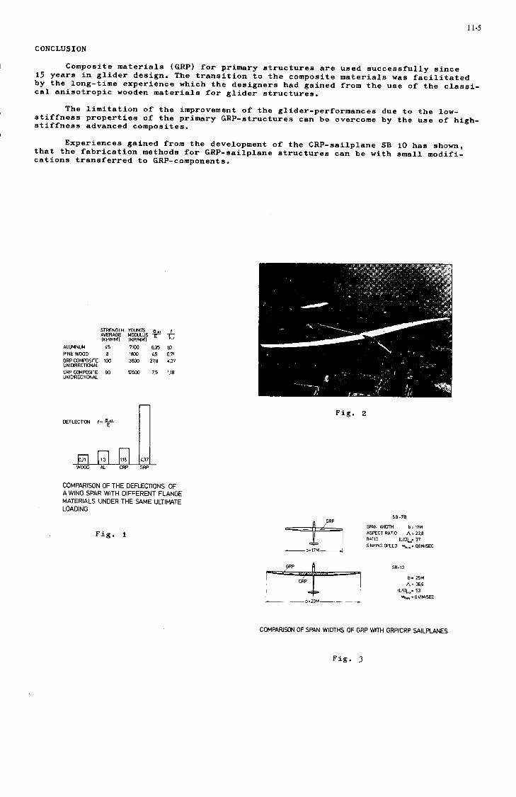
11-5
CONCLUSION
Composite materials (GRP) for primary structures are used successfully since15 years in glider design. The transition to the composite materials was facilitatedby the long-time experience which the designers had gained from the use of the classi-cal anisotropic wooden materials for glider structures.
The limitation of the improvement of the glider-performances due to the low-stiffness properties of the primary GRP-structures can be overcome by the use of high-stiffness advanced composites.
Experiences gained from the development of the CRP-sailplane SB 10 has shown,that the fabrication methods for GRP-sailplane structures can be with small modifi-cations transferred to GRP-components.
STRENGTH YOUNGS o«iAVERAGE MODULUS fIKP/MM'l IKP/MMl
ALUMINUM
PINE WOOD
GRP COMPOSITEUNIDIRECTIONAL
CRP COMPOSITEUNIDIRECTIONAL
45
8100
90
7100
1800
3600
12000
6.35
4.527,6
7.5
"C
to0.71
«.37
1.18
LECTION f- -2p-
Iwi] | i.o | |i.is 1 437
Fig. 2
COMPARISON OF THE DEFLECTIONS OFA WING SPAR WITH DIFFERENT FLANGEMATERIALS UNDER THE SAME ULTIMATELOADING
Fig. 1
SB-7B
SR4N WIDTH b = 17MASPECT RATIO A-22.8RATIO IL/DL,= 37SINKING SPEED »4m = 0.6M/SEC
b= 29M
A= 36.6IL/D^z 53
*.,. * 0.41M/SEC
COMPARISON OF SPAN WIDTHS OF GRP WITH GRP/CRP SAILPLANES
Fig. 3

1-6
SPAR FLANGES/(UNIDIRECTIONAL
/GLASS OR CARBON/ FIBER LAMINATES!
l SANDWICH WING SHELL SKINS OF GLASS FIBERFABRIC OR CARBON FIBER TAPES WITH FIBERORIENTATIONS 145° TO SPAN DIRECTION
TYPICAL CROSS SECTION OF A SAILPLANE WING STRUCTURE (S810I
LAMINATING OF THE UPPER CARBON FIBERSANDWICH SHELL.SET UP OF WEBS AND RIBS
PRECISE BUILDING UP OF CARBON FIBER FLANGES
FINISHING THE WING BY INSERTING THE SALSACORE AND LAMINATING THt LOWER CARBONFIBER SHELL
Fig.PROCESS OF MANUFACTURING A PROTO-TYPE WING USING ONE MOULD (SB 10]
Fig. 7
CONNECTION OF GRP AND CRP WINGSECTtONS
Fig. 5
Fig.
S-N CURVE OF UNIDIRECTIONAL ROTATING CARBON-FIBER-EPOXYRODS UNDER BENDING LOADS •- 45VOL%FIBER TYPE :SIGRAFIL RESIN RUTAPOX L02 HARDENER SL
Fig. 6
Fig. 9

11-7
Fig. 13
Fig. 10
CARBON FIBER BOBBINS GLASS NOZZLES FOR RESINCONTENT ADJUSTMENT RUBBER
NOZZLE
Fig. 11
PLAN VIEW
DEVICE FOR CARBON FIBER IMPREGNATION
Fig. I't
Fig. 12 Fig. 15


12-1
ADVANCES IN BALLISTICALLY TOLERANT FLIGHT CONTROLS
by
I. E. Figge, Sr.Aerospace EngineerStructures DivisionEustis Directorate
US Army Air Mobility Researchand Development Laboratory
Fort Eustis, Virginia 23604
SUMMARY
Combat data indicate that helicopter flight control components are exceptionally vulnerable to cata-strophic failure upon ballistic impact. The ballistic tolerance approach, which is to design the criticalcomponents to function after ballistic penetration, offers a solution to reduce vulnerability. Studieshave shown that this approach can virtually eliminate catastrophic failure while achieving substantialweight saving and reduced production costs. Limited data indicate the approach is also adaptable toflight control bearings and attachments. "Venting" was found to reduce the damage on the exit side ofsandwich structures and "preslotting" was found to prevent delamlnatlon of the exit face in the area ofimpact.
INTRODUCTION
Extensive helicopter service in Southeast Asia has shown that flight control components are vulner-able to small-arms fire. In general, existing components are designed with minimum dimensions to savespace and weight and are often fabricated from notch-sensitive metals. This approach renders these com-ponents exceptionally vulnerable to catastrophic failure upon ballistic impact, with subsequent loss ofaircraft control. Vehicles costing up to $1.5 million have been lost to a 50 bullet. Studies have 1shown that the use of armor plate reduces vulnerability but exacts a very substantial weight penalty.Redundant flight control systems, both with and without armor, decrease vulnerability but also at asignificant weight penalty and at prohibitive cost. Redundant fly-by-wlre is technically feasible buthas not yet been accepted for operational military helicopters.
This paper discusses another solution to the problem of tolerance to small-arms fire. The techniqueis to design the critical components to function after ballistic penetration versus the conventional armorapproach which is to stop the projectile prior to impacting the components. Research programs havedemonstrated the potential of the ballistic tolerance approach to substantially reduce vulnerability and,in some cases, virtually eliminate catastrophic failures while also achieving substantial weight savingsand reduced production cost. The approach has required the development of new design concepts and theuse of advanced materials.
DESIGN CONSIDERATIONS
The basic design philosophy developed at the Eustis Directorate, U.S. Army Air Mobility Researchand Development Laboratory (USAAMRDL), for achieving ballistic tolerance is as follows:
1. Design components to localize damage upon ballistic Impact.
2. Use redundant load path designs.
3. Use notch-Insensitive materials.
Several studies at the Eustis Directorate, USAAMRDL, and under contract >3>^'5 ave been con(juctedto develop ballistically tolerant flight controls. The primary goal of these programs has been todevelop components capable of withstanding at least 2000 fatigue cycles at maximum flight load conditionsafter sustaining two fully tumbled, .30 caliber impacts (arbitrary requirement to achieve 30 minutes offlight time after Impact, which is considered sufficient to get the vehicle back to base or at leastInto safe territory). Secondary design considerations included lighter weight than the existing metalliccounterpart, lower production costs/mass producibllity, operating temperature range of -65°F to +180°F,environmental resistance, interchangeability with existing components, and no secondary damage due tospecimen spall.
MATERIAL SELECTION
Composite materials, because of their high strength-to-weight ratio and ease of fabrication, appearto offer potential. Of the composite materials screened--boron, graphite, and fiberglass—only thefiberglass offered all the desirable characteristics, particularly notch insensitivity and low cost.Both boron and graphite demonstrate notch strength reduction factors ranging from approximately 1.4 to2.2, respectively (see Fig. 1), along with high material costs of $90 per pound and up. Fiberglass, onthe other hand, demonstrated strength reduction factors typically less than 1.2 and costs as low as$.35 per pound. Ballistic tests on fiberglass cloth specimens (see Fig. 2) and chopped fiber specimens(see Fig. 3) Indicated very localized damage upon ballistic impact. Filament-wound specimens, dependingupon the fabrication technique, demonstrated somewhat more damage In the form of unwrapping (see, forexample, Fig. 4).

12-2
NOTCH SENSITIVITY Of f\6BSEP0VY LAMINATE
Fig. 1 Typical Notch Sensitivity ofGlass, Boron, and GraphiteSpecimens
Fig. 2 Ballistic Damage onFour-Ply 120 GlassCloth Specimen; FullyTumbled, .30 CaliberRound
Tig. 3 Ballistic Damage on%-inch-Long ChoppedFiber/Epoxy Specimen;Partially Tumbled, .30Caliber Round
a. Exit b. Entrance
Fig. 4 Ballistic Damage onCommercially AvailableFilament-Wound SleeveBearing

12-3
Chopped Fiber
Studies were conducted to determine the optimum combination of chopped fiber and resin. Theeffects of factors such as type of fiber, type of resin, fiber length, and fiber finish were evaluated.Results indicate that fiber length is the most significant factor, with a %-inch fiber length offeringthe best overall fabrication/ballistic trade-off.
Cloth
It was found that the cloth weave was a critical factor in the ballistic behavior, with fabricsthat have a significantly different ratio of warp-to-fill fibers demonstrating extensive delaminationalong the axis of the greater number of fibers. Fabrics with equal warp and fill demonstrated only localdamage confined to the impact area. Thickness of the individual layers of fabric had no apparent effecton the behavior; therefore, a thicker fabric was used for ease of fabrication. However, finished totalthickness of the specimen does influence the behavior, with the thicker specimen demonstrating moredamage. Therefore, the designer should select concepts which permit the thinnest laminates possible,thus improving the ballistic behavior and resulting in a weight savings.
Filament Winding
Results of ballistic tests of filament-wound fiberglass specimens range from total delamination insingle-wall tubes to only localized damage in prestressed sandwich-type (foam core) fuel tanks (proprietaryprocess by Fiber Science, Inc., Gardena, California). The ballistic behavior of filament-wound structuresis not completely understood. Because of the general tendency of the filaments to unwrap upon impact,this approach must be used with caution,
DESIGN CONCEPTS
The basic design concept is to provide sufficient residual strength after impact such that thecomponent can continue to perform its function. This requires that a reasonable amount of materialremain after impact. Since a fully tumbled, .30 caliber projectile is 1,40 inches long, and since theballistic damage is somewhat greater than the projectile length, depending upon the material, there isclearly a minimum in the size of the components that are adaptable to the ballistically tolerant designapproach. Of necessity, the component design must be redundant. Several approaches have been takendepending upon the component. Flight control components presently under evaluation include CH-47 idlerarms, bell cranks, connecting links, and UH-1 pitch link and quadrants.
Tension/compression members such as the UH-1 pitch link have used a double-tube approach (Fig. 5).Either tube can carry the loads required. In an on-center hit, which severs the central tube, theresidual exterior tube carries the load. After an off-center hit, which cuts away a portion of the outertube, the center tube and remaining outer tube carry the load. As noted before, the diameter of thecomponent must be relatively large to achieve ballistic tolerance.
Fig. 5 Double-Tube BallisticallyTolerant Concept forUH-1 Pitch Link
Bell crank designs (typically triangular in planform) have considered four approaches: a "billiardrack" strap with face sheets;2 tubular/sandwich construction;^ chopped fiber/multi-web construction;5
and Tetra-Core, a three-dimensional filament-wound space structure (see Fig. 6). A detailed view ofTetra-Core is shown in Figure 7.
Idler arms have been fabricated from chopped fiber]? and by using a core-supported filament-woundapproach with ball and socket attachments (see Fig. 8).
ATTACHMENTS/BEARINGS CONCEPTS
In general, only limited effort was made to achieve ballistic tolerance in the attachment areassince it required development of ballistically tolerant bearings. Ballistic tolerance in these areasis obviously significant. Two bearing/attachment designs have been evaluated. The first, a ball andsocket used on both idler arms and bell cranks, has proven to be reasonably acceptable; but thereduced section at the ball end, due to its minimum size, Is still vulnerable, This approach is alsodifficult and costly to fabricate, A tubular fiberglass cloth bearing with multiple attachment fingers(Pig. 9) has proven to be successful.4 The glass cloth bearings demonstrated minimum fraying and complete

12-4
Fig. 6 Bell Crank Concepts
Fig. 7 Detailed View of Tetra-Core
a. Schematic b. Idler Arm
Fig. 8 Foam-Core/Filament-Wound Ball and Socket Concept

12-5
freedom of movement after impact (Fig. 10). It should be noted that this approach is not self aligning,which is a requirement in some applications. Commercially available filament-wound sleeve bearings withTeflon coatings were evaluated; however, due to the filament-winding technique, considerable frayingoccurred that rendered the bearings inoperable after impact (Fig. 4).
Fig. 9 Tubular Push Rod andBearing Attachment
Fig. 10 Glass Cloth Bearings AfterBallistic Impact
I N C H E S
BALLISTIC BEHAVIOR
The components described above were impacted with fully tumbled, .30 caliber rounds at criticalvelocities selected so that maximum damage would occur upon penetration. For the fiberglass materials,this velocity was in the range of 1500-1800 ft/sec. All specimens were preloaded to at least limit loadprior to impact. In general, the components, even with multiple hits, were capable of meeting the designgoals previously discussed.
Pneumatic-Ram Effects
Consistently, the damage on the exit side of the sandwich-type components was significantly greaterthan on the entrance side. It is believed that the damage was partially caused by a "pneumatic-ram"effect. A similar phenomenon has been observed in fuel tanks and is attributed to hydraulic ram. A

12-6
separate research effort was conducted to determine If this pneumatic-ram effect could be eliminated.Four types of glass cloth sandwich construction were studied: (1) foam-filled box, (2) closed boxwithout foam, (3) open-end box, and (4) box with openings of various sizes on one side. Typical entrancedamage for these configurations Is shown in Figure 11. The damage on the entrance side is essentiallythe same for all four designs. In the foam-filled and the closed boxes, the damage on the exit side isquite severe, with considerable "petaling" (see Fig. 12); on the open-end box, the entrance and exitdamage is essentially identical. For the box with various sized openings on one side, it was foundthat a vent as small as 1 inch square was sufficient to reduce the damage on the exit side to an accept-
able level.
Fig. 11 Typical Entrance Damageon Various Types ofSandwich Construction
Fig. 12 Typical Exit Damageon Various Types ofSandwich Construction
Further studies using high-speed photography (18,000 frames per second) with a clear Plexiglas exitface sheet and also with photostress coating indicated that spall caused by the projectile impacting theentrance face sheet had higher initial velocities than the projectile and impacted the exit sheet beforethe projectile. This phenomenon produced observable damage on the exit face prior to the projectileimpact. It is hypothesized that the combination of the spall and the shock wave preceding the projectilechanged the surface energy of this exit face sheet and thus caused a detrimental change in its responsewhen the projectile impacted. Apparently, venting reduces this effect.

12-7
Dynamic Response
In closed sandwich construction, the elastic response of the entrance face sheet caused by Impactresults in a drumming effect that tends to cause gross delamination in the bonds between the exit facesheet and the tubes. Venting tended to reduce this effect. Significant delaminations of the exit facesheet emanating from the impact area also occurred as a result of high-energy transfer when the projectilesimpacted in the tubular or "billiard-rack" portion of the bell cranks. In the case of the "billiardrack" approach tested at 160°F, the delamination produced catastrophic failure of the entire bell crank.
Initial attempts to reduce or eliminate this delamination phenomenon ranged from the use of variousadhesive systems to wraparound face sheets, all to no avail. Finally a system was developed at the EustisDirectorate, USAAMRDL, which solved the problem. It consisted of preslotting the exit face sheet In thetubular area, with the result that damage was confined to those tabs which were impacted (see Fig. 13).In the case of the bell crank, the stresses were sufficiently low that the slotting caused no appreciabledegradation.
These factors, along with a better understanding of the impact phenomenon, will lead to even moreimproved structures.
Fig. 13 Typical FullyTumbled, .30Caliber ExitDamage on SlottedFace Sheet
WEIGHT/COST
The weights of the ballistically tolerant components, In general, were approximately the same asthose of their metallic counterparts primarily due to gross overdesign. In the case of the tubular bellcrank concept studied at the Eustis Directorate, USAAMRDL, a finite element stress design optimizationwas conducted and resulted in a bell crank weighing 1.6 pounds as compared to the weight of 3.4 poundsfor the existing metallic component. Cost of fabrication for this component was reduced from $134.80to $75.00. Cost savings are dependent upon the type of fabrication; hand layup and complex filament-winding patterns are on the high end of the spectrum, with automated chopped fiber/net molding techniqueson the low end.
CONCLUDING REMARKS
Research indicates that ballistically tolerant aircraft flight control components can be designedto accept multiple small-arms impacts, even In the most critical areas, without loss of function. Bothweight and cost savings over the metallic counterparts are achievable. The ballistic tolerance approachdoes, however, require that the components exceed certain minimum dimensions which are a function of theprojected length of the ballistic threat.
Limited data indicates that the ballistic tolerance approach is also adaptable to flight controlbearings and attachments. However, the size limitations of the bearings and attachments make the develop-ment of these components a formidable task. Innovative bearing and attachment concepts must be developedto achieve total ballistic tolerance in flight control components.
Non-brittle composites such as fiberglass/epoxy appear to demonstrate acceptable ballisticallytolerant behavior. Balanced weave fiberglass cloth and chopped fiber approaches appear superior in bothvulnerability and cost to filament winding techniques. "Venting" was found to reduce the damage on theexit side of sandwich structures, and "preslotting" prevents delamination of the exit face in the impactarea.

12-8
Development of the optimum ballistically tolerant designs will require additional research in theareas of ballistic impact phenomena and material response. Although additional research and flightqualification are required, it Is clear that the ballistic tolerance approach to achieve reduced vulner-ability in combat aircraft Is viable.
REFERENCES
1. Gonsalves, J., FLIGHT CONTROLS SURVIVABILITY (U), USAAVLABS Technical Report 67-54, U.S. Army AviationMateriel Laboratories, Fort Eustis, Virginia, December 1967, AD 391238-L (Confidential Report).
2. McArdle, E. H., Jr., INCREASED SURVIVABILITY FOR FLIGHT CONTROL SYSTEMS (U), USAAVLABS TechnicalReport 69-57, U.S. Army Aviation Materiel Laboratories, Fort Eustis, Virginia, November 1969,AD 506695-L (Confidential Report).
3. Whinery, D. G., BALLISTICALLY TOLERANT REPLACEMENT AIRCRAFT.COMPONENTS (U), USAAVLABS TechnicalReport 71-4, Eustis Directorate, U.S. Army Air Mobility Research and Development Laboratory, FortEustis, Virginia, April 1971, AD 516178-L, (Confidential Report).
4. Figge, I. E., Sr., EVALUATION OF TWO BALLISTICALLY TOLERANT FORWARD BELL CRANK CONCEPTS FOR THECH-47 HELICOPTER, USAAMRDL Technical Report 71-63, Eustis Directorate, U.S. Army Air MobilityResearch and Development Laboratory, Fort Eustis, Virginia, November 1971, AD 893206-L.
5. Cully, D. C., Kolarik, R. V., Boiler, T. J., and Conley, W. F., DEVELOPMENT OF BALLISTIC-DAMAGE-TOLERANT FLIGHT CONTROL COMPONENTS MOLDED OF A SHORT FIBER REINFORCED COMPOSITE MATERIAL, USAAMRDLTechnical Report 72-28, Eustis Directorate, U.S. Army Air Mobility Research and DevelopmentLaboratory, Fort Eustis, Virginia.

14-1
INSTABILITY OF LAMINATED COMPOSITE PLATES
by
G. Z. Harris,Section Head, Composites, Analysis and Basic Properties,
Structures Department,Royal Aircraft Establishment,
Farnborough, Hampshire, England.
SUMMARY
The response of general laminated plates to applied loading exhibits a coupling between bending andextensional modes of deformation. Such a laminate will, for example, undergo a bending response whenload is applied in the plane of the laminate. Such coupling may be significant when shear or compressiveloads are applied in-plane, since the additional deformation modes may reduce the buckling load or affectthe post-buckling stiffness of the laminate. The present paper considers the stiffness immediately afterbuckling of two types of panel which undergo bifurcational buckling. The first class of panel consideredis one of angle-ply type. A solution is derived for the initial buckling of a rectangular panel towhich is applied a constant end displacement. The pre-buckling response is one which exhibits no out ofplane displacements, although the initial buckling load is affected by the existence of out-of-planecoupling. The second class of panel is of cross-ply type, the buckling loads being derived for a longpanel having a constant strain edge member and subjected to end load. The pre-buckling response exhibitsout-of-plane displacements, the plate having a curvature in direction orthogonal to the applied load.In each case, numerical examples are given to illustrate the post-buckling stiffness.
NOTATION
a, b length and width of panelA = (A..) matrix of in-plane stiffnesses
B = (B..) matrix of coupling stiffnesses
D = (D..) matrix of bending stiffnesses
a = (a..) matrix of in7plane flexibilities
b = (b..) coupling matrix see Eq (5)
d = (d .) matrix of "reduced bending stiffnesses'
A, B, C, D constants arising in expression for buckling load - see Eqs (19), (28)E., E longitudinal and transverse Young's moduli of a ply
E J J , E]2> E22, E33 non-zero elements of ply stiffness matrix
f half wavelength of buckling modeF middle surface force functionG shear modulus of a ply
G , H , K , L.. , P.,, R.. „. coefficients in virtual work equations - see Eq (32)JK J K J K*
h plate thicknessLj, L2, L^ linear differential operators, defined by Eq (8)
m, n number of half-waves of w in x and y directionsM , M , M bending momentsx y xy 6
N , N , N middle surface forces per unit widthx y xyN mean axial loadN critical value of axial load
N critical load in the absence of coupling termsu, v in-plane displacements in x,y directionsw transverse displacement in z directionx, y, z cartesian coordinateso, 8 constants - see Eq (42)amn* ^mn coefficients in series expansions for transverse displacement and force
function - see Eqs (15) and following (26)Y NY* is the transverse displacement, proportional to the applied load, in
cross-ply plateY. coefficient of generalised coordinate *. in expansion of w - see
Eq (30) 1
E i £„, Y,,,, in-plane strainsx. y K.y6 angle between ply axis and loading direction< , K , < transverse curvaturesx y xyX = na/mbV parameter specifying allocation of material in a cross-plyv Poisson's ratio* initial transverse displacement due to axial loading*. generalised coordinates, taken as buckling modes

14-2
1 INTRODUCTION
The use of composite materials has expanded considerably in recent years, and a considerablenumber of references can now be quoted to illustrate the way in which varying applications have beenpursued over a wide range of technologies. Much of the impetus has come from aerospace applications,where the continuing emphasis has been on the application and exploitation of the stiffer and strongertypes of fibrous reinforcing material. Numerous aircraft structural components now exist, in differingstages of development, which seek to exploit one or other of the available reinforcements and which aretypical of wing structure, fuselage structure, filament wound components and so on. The pursuit of suchapplications has shown the need for development in analytical methods, since the use of compositesusually enables the designer to attempt to make optimum use in some manner of the material at hisdisposal. Additionally, the anisotropic nature of the material necessitates consideration during designof a number of different modes of failure in the material itself, which again adds to the analyticaltask.
The flat laminate, manufactured by assembling a number of unidirectional plies, is an importantcomponent in a number of different types of structure, and the mechanical behaviour of such laminateshas been considered by numerous investigators, many of whom have followed on the early work of Reissner
1 2and Stavsky ' . Generally, the response of a laminate is such that a coupling exists between bending andstretching. Thus, on application of an in-plane load the laminate deflects transversely, while if a purebending moment is applied the plate will undergo in-plane displacements. If the plies are arrangedsymmetrically with respect to the plate middle surface a 'balanced' laminate is achieved in which thiscoupling does not occur. Although balanced laminates are common in current designs, it is evident thatdesigns will occur in which the laminates are not balanced. For example, exercises in the minimum weightdesign of panels could well show thin panels to be desirable, and if these have a small number of pliesthe number of available options may be strictly limited and a balanced laminate impracticable. Situationswill also exist where, for an efficient structure, a variable skin thickness is desired such as occurs,for example, in a wing structure when the skin thickness is reduced towards the tip. A single plyremoved from a balanced laminate may create imbalance and introduce the coupling referred to.
This paper considers the compressive behaviour of initially flat panels when coupling terms arepresent. In general, when in-plane compressive load is applied to such a panel transverse deflectionsoccur immediately; transverse loads then arise due to the applied loads acting in conjunction with thetransverse curvatures. As the applied load is increased the panel should undergo a gradual transitionfrom the initial regime of small deflections to the large-deflection regime. An eigen-value bucklingproblem thus cannot be formulated and it is not possible to identify an instant of buckling. However,
3 4 5some of the work ' ' on unbalanced flat panels suggests that the small-deflection and large-deflectionregimes may in many practical cases be fairly distinct and that the plot of load against deflection willshow a rapid variation, similar to buckling, near one particular load, the behaviour being analogous tothat of an eigen-value buckling problem when a small perturbation or imperfection is introduced. One
approach to such problems has been to use a 'reduced bending stiffness' due to Chamis and to predict thebuckling load of an unbalanced laminate as the bifurcational buckling load of a balanced laminate havingthe reduced bending stiffness. This approach has been successful when the plate axes of synmetry areparallel to the panel edges; in particular, for this type of panel, the reduction in buckling load dueto the unbalanced lay-up is predicted adequately.
The present paper is concerned with the behaviour of panels at the instant of buckling, and inparticular with the possible reduction in panel stiffness at buckling. Two cases of the bifurcationalbuckling of unbalanced laminates are considered. The first case is that of a rectangular angle-ply typeof panel; when initially loaded, no transverse deflections occur and an eigen-value buckling problem maybe formulated giving a buckling load in which the out-of-plane coupling terms appear. The second case isthat of a very long plate in which the ply lay-up is of cross-ply type. In this case transverse deflec-tions occur immediately on loading the panel. Since the plate curvatures associated with these deflec-tions do not induce any transverse loading, an eigen-value buckling problem may again be formulated. Ineach of these cases exact closed form solutions are derived for both the initial plate response and forthe buckling loads. It is thus possible to consider two different types of bifurcational buckling sinceinitial transverse deflections occur in one case and not in the other. As stated above the magnitude ofthe buckling load can be affected by out-of-plane coupling terms; the exact solutions to the two specificbuckling problems may be exploited to enable the behaviour at the instant of buckling to be examined indetail, particular interest obviously lying in the effects, if any, of the coupling terms as well as inthe magnitude of any effect on stiffness.
7 8 9The behaviour of systems at the instant of buckling has been considered by a number of authors ' ' .
In the present analysis, the important result is that which enables the initial post-buckling behaviourto be considered by using the linear buckling mode in a non-linear Rayleigh-Ritz analysis. In the casesconsidered, all the linear buckling modes are known because of the exact solutions derived and it istherefore possible to obtain expressions for the initial post-buckling stiffness. This is clearlyimportant in design since the onset of buckling will obviously be viewed differently if accompanied by asevere reduction in stiffness. Also, since the solutions are exact and out-of-plane coupling termsappear explicitly, an assessment can be made of the relevance of these terms in the context of initialpost-buckling stiffness, at least so far as the particular plates and loadings of the present paper areconcerned.
The basic equations which govern the behaviour of laminated plates are stated in section 2. The
basic form of the equations is that due to Reissner and Stavsky except that in considering transverseequilibrium the transverse component is included of the forces in the plate middle surface, while thesecond order in-plane strains are used in considering compatibility. Section 3 discusses the initialresponse of the two types of plates already referred to, and goes on to derive the appropriate closed formexpressions for the bifurcational buckling load. Using the known form of the deflected shape of the plateat the instant of buckling section 4, after describing the calculation of the post-buckling stiffness,

14-3
derives the appropriate expressions for the relative stiffnesses. Specific numerical examples are givenin section 5, where the significance is also discussed of the solutions which have been derived.
2 BASIC EQUATIONS
A short resume is first given of the basic equations which govern the deformation of an initiallyflat laminated plate which is subjected to both in-plane and bending loads.
The equations which connect stress and moment with strain and curvature are '
(D0-C 00Using a coordinate system 0(x,y,z), the plate lies in the plane 0(x,y); in Eq (I) N and Mdenote the column matrices of stress resultants N , N , N and moments M , M , M , while e and
x y xy x y xy< arise from the middle-surface strains e , e , Y and curvatures < , K , < , withx y xy x y xy
N - /Nv \ , M = /Mv \ , e =/EV \ , < = /<x \ . (2)
Ky
The in-plane stiffness matrix A = (A .), the bending stiffness matrix D = (D. .) and the coupling
matrix B = (B-) are all symmetric and (3x3); in a laminated sheet of thickness h they arise from
equations of the form
h/22
-fi/2 1J
the integration across the plate thickness being performed over each ply in turn.
The curvature and the normal displacement w are related by
The in-plane equilibrium equations are automatically satisfied by using a middle-surface force functionF, defined by
*1.ay2
Eq (1) is frequently used in the partly inverted form
. =
ay2 • * I?
C) (- :• X)(a dash denotes transposition), where the (3 x 3) matrices a, b, d are given by
a = (a.j) = A"1 ,
(b.J = - A~]B ,
(d. .) = D - BA~'B .
Note that a and d are symmetric, whereas b is not. The 'reduced flexural stiffness matrix' d is
frequently used in approximate analyses, particularly of buckling, and appears to give satisfactory
agreement with experimental results in specific cases .
In general, the strains are given by
2 23 u 3 v 3 w 3 w . .= + . _
3x 2 3 X y ' Ey 3y + 2 \J>y ) ' Yxy ~ 3y + 3x 3x 3y '
With the foregoing definitions, the equation of transverse equilibrium may be derived:
T „ T „ 32F 32w , 3^ 32w . 32F 32w ,, ,
" " ' (7a)

14-4
In the case of normal applied load, a pressure term p would occur on the right of this equation. Thecompatibility of strains gives the equation
(7b)
the linear operators Lj, L2> L3 being defined by
34 34T - /I 5 ,. * AH " 4. ifA 4. *M
3x 3x 3y
4 4T - 3 o^ 3 . /*>„ . „
"2 = * 2 2 3x 4 2 3 3x 3 3y ( '2 *33
4 4T - > » ^ + ^ ? K _ > l ^ + ^ KL3 = b2, 3 x 4 + ( 2 b 2 3 V8 j l38 y
+ ( b l
^ 3" , • ,3) 2 2 4d2'
3x 3y
4N 8
' 3x23y2 13
, + b22 - 2b33)
+ (2b,3 - V :
34 + d
3' 11 3 2 2 4
3x3y 3y
^4 43 . , 3
3x3y 3y
23
, 2^ 23x 3y
4 43 h 3
^ 3 1 2 , 4 '
(8)
It will be noted that the out-of-plane couplings (b..) appear in (7a, 7b) only via the linear operatorL3" 1J
When the second order terms on the right-hand sides of (7a, 7b) are ignored, the equations reduce to
L,w -
(9)
In the problems to be considered in the present paper, the initial small-deflection response will begoverned by the linear Eqs (9), while the large-deflection response will be governed by the non-linearEqs (7).
The exact form of the coupled Eqs (7) or (9) will clearly depend critically on the values ofthe coefficients a.., b.., d.., and these in turn will depend on the nature of the plate under considera-
tion, and particularly on the laminating sequence of the separate plies through the plate thickness. Animportant class of laminate is the 'balanced' laminate, in which the laminate thickness and orientationare symmetrical with respect to the laminate middle plane; the couplings (B..) and (b..) are zero in
such cases. Since the purpose of the present paper is to consider possible effects of out-of-planecoupling, attention is focussed on unbalanced laminates which lack mid-plane symmetry. In particular,plates of 'angle-ply' or 'cross-ply' type are considered, in which the coefficients in Eqs (1) and (5)satisfy
A13 = A23 I I B12 - B22 ° B33 - D13 - D23
13 a23 = bll 12 21 b22 ' b33 = d!3 23
(10)
for 'angle-ply' type, and
M3 "23 " "13
'13 "23 " "13
B23 ' D,3
23 31
23
b32 - d!3 23 0 .
(10
for 'cross-ply' type. These assumptions lead to special forms for the linear operators L , L,, L , as
will be immediately evident on inspection of Eq (8). These forms are given in the subsequent analysis(see section 3, Eqs (17), (18), (27)).
*Adopt the convention that, for example (a,6,Y>6) represents a four layer plate with outer plies
at angles a, 6 and inner plies at 6, Y- Then the plates considered here to be of 'angle-ply' type willinclude, for example, such differing types of lay-up as (-30°,30°), (-30°,-60°,60°,30°), (-30°,-606,0°,60°,30°), (900,-300>0
0,30°>900). Plates of 'cross-ply' type will include, for example, (0°,90°)(5
(0°,00,90°), combinations of different fibrous materials at 0 , 90 and combinations of 0 or 90 plieswith isotropic materials.
In the case of unrestrained edges, such plates show differing out-of-plane responses to appliedin-plane loadings; angle-ply plates exhibit a primarily twisting response with negative Gaussiancurvature, while cross-ply plates tend to a bending response with positive Gaussian curvature.
For simplicity equal ply thickness is assumed.

14-5
3 INITIAL RESPONSE AM) INITIAL BUCKLING
3.1 Angle-ply plates
The first case considered is that of an angle-ply type of plate, as already described in section 2.The plate is rectangular, defined by 0<x<a, 0 < y < b and is subjected to a uniaxial load N inthe direction of the x-axis. The edges are assumed to be simply supported, giving the boundaryconditions
On x = 0, a; y = 0, b
On x = 0, a
On y = 0, b
w = 0
b N -d 2^-d i31 xy U 3x2 J2 3y2
23 w
23 w
(12)
from (5) and (10). No in-plane shear load is applied at the boundaries and, additionally, it is requiredthat the displacement normal to each boundary is constant along the boundary. The in-plane boundary con-ditions may thus be written
On x = 0, a; y = 0, b
xy
On x = 0
u = constant
On y = 0
(13)
v - 0
y = b
v • constant
The required solution of Eqs (9), satisfying all the above boundary conditions, is
F - jNy2
w = 0
the constant displacements in (13) being determined so that
(u) = a. ,Na
(v)y=b
nH. I
]2Nb J(14)
It will thus be seen that, despite the presence of the out-of-plane coupling terms, no transverse dis-placement w occurs during the initial loading. Since the plate remains flat, however, a twistingmoment M is present, although the bending moments M and M necessarily vanish.
In the absence of out-of-plane response, the initial buckling will thus be bifurcational. To findthe initial buckling load, a solution is sought having the form
• I I «L L TY
m=1 n=1
. nmxsin — sin niry
r r „ miTxI I Smn cos — cos
m=l n=l
(15)
this already automatically satisfies the boundary conditions (12) for w, M and M and (13), (14)for N , u, v. x y
xy '
The equations (.of. (7)) relevant to initial buckling are
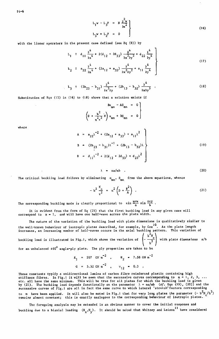
14-6
L,w -3x (16)
with the linear operators in the present case defined (see Eq (8)) by
x—4 + (2a12 + a33} TITT + a l l —43x 3x 3y 3y
(17)
L3 H (2b23-b3)) (2b )3
3x'3y " " 3x3y
Substitution of Eqs (15) in (16) to (18) shows that a solution exists if
B a - A 6 = 0mn mn
a + BBmn mn
(18)
where
B =
( 2 a .2 + a 33 )
(2b ]3 (19)
X = na/mb .
The critical buckling load follows by eliminating a , B from the above equations, whencemn mn
(20)
(21)
The corresponding buckling mode is clearly proportional to sin sin -r*- •
It is evident from the form of Eq (21) that the first buckling load in any given case willcorrespond to n = 1, and will have one half-wave across the plate width.
The nature of the variation of the buckling load with plate dimensions is qualitatively similar to
the well-known behaviour of isotropic plates described, for example, by Cox . As the plate lengthincreases, an increasing number of half-waves occurs in the axial buckling pattern. This variation of
/ b 2N\buckling load is illustrated in Fig.l, which shows the variation of with plate dimensions a/b
for an unbalanced ±60° angle-ply plate. The ply properties are taken to be
207 GN m-2
5.52 GN m-2
'12
7.58 GN m
0.3
-2
These constants typify a unidirectional lamina of carbon fibre reinforced plastic containing highstiffness fibres. In Fig.l it will be seen that the successive curves corresponding to m = 1, 2, 3, ...etc. all have the same minimum. This will be true for all plates for which the buckling load is givenby (21). The buckling load depends functionally on the parameter X = na/mb (of. Eqs (19), (20)) and thesuccessive curves of Fig.l are all in fact the same curve to which lateral 'stretch*factors corresponding
2to m have been applied. It will also be noted in Fig.l that for very long plates the parameter (- b Nc/hremains almost constant; this is exactly analogous to the corresponding behaviour of isotropic plates.
The foregoing analysis may be extended in an obvious manner to cover the initial response and
buckling due to a biaxial loading (N ,N ). It should be noted that Whitney and Leissa have consideredx y

14-7
the above problem, although the form of their analysis is not suited to the subsequent analysis of thepresent paper.
3.2 Cross-ply plates
The second case considered is a plate of cross-ply type, as already described briefly in section 2.Again, the plate is subjected to a uniaxial load N in the direction of the x-axis; the plate isassumed to be of sufficient length for only the boundary conditions at the sides y = 0, b to needconsideration. The plate is simply supported, undergoes no load normal to the edges and is taken to bebounded by edge members which are sufficiently stiff to remain in a state of uniform strain throughoutthe loading process, including the instant of buckling. The boundary conditions at y = 0, b are
- b N - b N + d,,K + d,,K12 x 22 y 12 x 22 y
e = constantx
(22)
from (5) and (11). The required solution of Eq (9), satisfying all the boundary conditions, is
Nb.12
2d22y(y -
(23)
In this case, both in-plane and out-of-plane responses occur, each being proportional to the appliedload. The deflected shape of the plate is such that the only non-vanishing curvature is K ; in fact
K = K = 0x xy
Nb12
K (say) .y d22
The edge strain, which is proportional to the applied load, is
(24)
(25)
The above analysis constitutes only a solution of the small deflection Eqs (9) prior to buckling.However, it is evident from (23) and (24) that the non-linear Eq (7) are also identically satisfied bythis solution, since the right-hand side of each of Eqs (7a, 7b) vanishes exactly; it may be deduced thatthe initial buckling is again bifurcational. The buckling loads are derived by considering Eqs (7) inthe form
3^
2L v - L3F = N i - K _
3x 3x
W - .£3x
K being defined in (24); the terms involving K are retained, since it is they which bring in theout-of-plane coupling effect.
The initial buckling load is found by taking
Nb.
(26)
122d22
y(y-b). I . sin si
CO 00
m= 1 n=1
(which satisfy the boundary conditions (22)) and substituting in (26) with L , L given by (17) and,in the present case,
,2 (27)

14-8
The equations obtained for a , B aremn mn
C + „ , a +>ABi ^, I mn mn\ n " d22/
D +^Ar a - C, ~ 2 "mn " 2 2. "urn\ n * / \ n * d22/
where A, D are defined in (19) and
C = b2)X"2 + <bn * b22 " 2b33) + b!2*2 ' (28)
If a , B are eliminated the critical buckling load is found, being given byfljn mn
b2N , _2
--r - *2-£Trr- • (29)
* A + -3—— C
In deriving (29) the term I-T— ] has been neglected. The shape of the buckling mode is againV 22
. . mirx . rnrproportional to sin sin -r .
It is evident from (29) that the lowest buckling load in any given case will correspond to n • 1,having a single half-wave across the plate width. The buckling load will then be given by minimisingthe right-hand side of (29) as a function of X = na/mb.
4 BEHAVIOUR AT THE INSTANT OF BUCKLING
4.1 General behaviour at buckling
The exact buckling solutions derived in the previous section are to be used in calculating the lossof axial stiffness immediately after buckling has taken place. The general principles to be used have
a qbeen set out by Thompson and by Pope , and are first stated.
The behaviour at the instant of buckling may be characterised by considering the way in which theamplitude yQ of the transverse displacement in the critical mode varies as load is applied. For
bifurcational buckling, of the type considered in the present paper, a plot of(load parameter) versus (amplitude) will be found of the kind shown schematically in Fig.2.
The plot illustrated is symmetrical about the vertical axis. In the case of angle-ply laminates,the initial buckling displacements may take place in either an upward or a downward sense; for the
cross-ply laminate the behaviour can also be seen to be symmetric. In such cases -j— vanishes at
d^ . . °buckling, and the first non-vanishing derivative is the curvature —j . It is evident that immediately
after buckling, the transverse displacement will contain components of all the buckling modes, but thepredominant mode, initially at least, will be the critical mode.
The theorem to be used in the present analysis is that which states that the curvature immediatelyafter buckling of the post-buckling path can be derived by using the linear buckling mode in a non-lineapanalysis of Rayleigh-Ritz type. The analysis used follows that of Ref.9. The normal deflection isexpressed, taking the set of linear buckling modes $. as generalised coordinates, as
oo
w = YN*+ 1 Y-*- (30)i=0 1 1
where * is the transverse displacement due to the applied load before buckling, and yQ, $0 relate to
the initial mode. By substituting in Eq (7b) and integrating, the force function F may be obtained interms of these modal displacement functions. The principle of virtual displacements is then applied usingvirtual displacements Q.&y. in conjunction with Eq (7a) and the known forms of w and F; this gives
Performing this integration leads to an infinite set of simultaneous equations in the modal amplitudesY., of the form

(G1 + NH1 + YHK1)Yi + I I a}k + YNP* )Y.Yk + I H RJk*Y.1 j k JK JK J * j k A Jk J
14-9
(32)
the summations being performed over all values of j, k, i. The coefficients G . H K L P R' jk' jk' jkJ,
are derived as integrals over the plate of specific functions. Consideration of the limiting form ofthis equation near the point of initial buckling gives, at the instant of buckling
Pll = -^OO^*^" ' 03)
c
There is thus considerable simplification in the present instance since the only coefficients which needbe evaluated are H , K° and R°OQ.
In considering the behaviour of a panel under end load, it is most relevant to consider the shapeof the plot of (load) versus (mean axial strain) near buckling, as shown in Fig.3. A Taylor seriesexpansion gives, near N = N ,
since | j— | = 0. Thus, near buckling,
c
(34)
approximately. In sections 4.2 and 4.3, specific expressions (see (37) and (43)) will be derived whichconnect the amplitude YQ with the mean strain; these equations in conjunction with (34) will give the
slope of the (load) versus (axial strain) plot at the instant of buckling.
4.2 Angle-ply
The initial buckling mode shape in this case is
, . nmx . Try ,^,**0 - sin — sin -g. , (35)
the particular value of m depending on the panel geometry in conjunction with the elastic constants.The corresponding middle-surface force function, derived from (7b), is
mirx Try . 1 2 f A 2nnrx _, 1 2Try 1-«•••** n *o |^»- — *-?r ">•-*]•Yn T coe cos VL + Y- £_ cos ±-£± + -^— cos . (36)O
Note that, since n = 1, A = a/mb. It is obvious that this form of F satisfies the boundary conditionof no applied shear N on the boundaries. The displacements (u,v) are derived via the non-linear
strain Eqs (6) together with Eq (5); the conditions of uniform displacement at the edges are thensatisfied, with
On x = 0;
On x = a;
These end displacements may be used to derive an end-strain
In the present case, there is no out-of-plane deformation prior to buckling, so Y ° 0Eqs (30) and (32). The only coefficients needed (of. (33)) are

14-10
H°n
Rooo
2 2 , iIT m b4a
2 f 4, 1= * m b + a i .
64 I 3 .3 f 'l a a u b a 2 2 J
(38)
these are derived from (31), (35) and (36), the requisite integrals being performed over the plate0 < x < a , 0 < y < b .
2Finally, (33), (34) and (38) may be used to eliminate YO from (34) to produce the expression
relating end-strain to load immediately after buckling; it follows that
a,,dT -' : A ~; . (39)
The right-hand side of this equation is the
. . .,, stiffness immediately after bucklingrelative stiffness = —r-r : ,. . .< . , r—, , .° ,stiffness immediately before buckling
since the pre-buckling stiffness is a., (of. (37) when YO = 0)•
A feature of Eq (39) is that the elastic properties only enter via the coefficients a.. and a._.Further, since
ILL 22a22 " Al. '
the only stiffness coefficients affecting the relative stiffness are the coefficients A.., A of the
in-plane stiffness matrix A. However, the buckling loads are affected by the presence of theout-of-plane coupling, so that these relative stiffnesses occur at buckling loads which may dependstrongly on the couplings.
The variation of the relative stiffness given by (39) with the parameter -r- 4 / -7— is shown inmb V 11
Fig.4. It will be noted that a lower limit of 1/3 exists for this parameter, as is evident from the formof (39), while the upper limit of unity arises from the fact that the stiffness would not be expected toincrease after buckling. It must be emphasised that Fig.4 only shows the possible variation of relativestiffness. For any particular plate, the relative stiffness will be given by a segment of this curve;this will be discussed further in section 5.1.
4.3 Cross-ply
The initial buckling mode in this case is
. TTX . iry ,i*\*Q = sin — sin -£• (40)
(i.e. m « n = 1). The corresponding middle-surface force function is
_ C . TTX . TTVF = - Y» T sin — sin -~-'0 A a b
Yo _2rry0
22
32a,, "" a , 2 .2. , TTC.22 l (a - B ) cosb. -r-A
cosh ('-1
, 2 . 2 . , TfB(a - B ) cosh -—cosh 5 (4I)
The positive constants a and B are defined so that the roots of

14-11
a22~ (2al2+
x = - a , a , - 6 , B . . (42)
The above force function satisfies the relevant boundary conditions of (22), since N vanishes at theedge, while the constant strain in the edge members is ^
(•"•4)-- (43)
With the deflections and the force function known, the coefficients H°, K° and R^nn maJ a§ain be
derived by substitution in (31) and subsequent integration; in the present case of a long plate thecritical mode is periodic in the axial direction and the integration is carried out over a complete wave-length. The curvature is thus given by
rr2 f, 2b,2 Cl" 1 a* a5 ^ tanh - B3 tanh
' '" ~ 8 a 2 l ^M FT b^'Ta" TOB(a2 - B2)
from (33). An expression relating load to edge-strain may be derived, and the stiffness at the instantof buckling calculated. The relative stiffness is found to be
4a2 I a,
4a2
(45)
It is evident that the coupling terms appear in this expression; however, a and B depend on the
2b 2 c(a..) alone (see (42)), so the coupling terms enter (44) via the term T- and enter (45) via the
1J h2
d22 A
12term -3— . The magnitude of any effect on relative stiffness will thus depend on the relative magnitude
22
of these terms.
5 RESULTS AND DISCUSSION
It is frequently the case in studies of composite materials that a number of parameters exist sothat a general investigation of all possible parameter variations is not feasible. The elastic constantsof an individual ply may be specified by four parameters which will depend on both the resin/matrix com-bination and on the fibre volume fraction. The cases considered in the present paper focus attention ontwo particular classes of laminate; nevertheless, even with this restriction, the number of elasticconstants (A. .), (B..), (D..) needed to specify the laminate response varies from 10, for plates of
angle-ply type, to 12 for those of cross-ply type. In considering how the elastic constants may arise ina plate of angle-ply type, for example, the number of ply directions ±a, ±6, ... may be varied as maythe individual ply thicknesses. Of course, an advantage exists in deriving exact solutions, since theparameters of interest occur in combination and so reduce the number of possible parametric variations.For these reasons the present analysis proceeds by focussing attention on selected lay-ups and stiffnessesrather than formulating a general approach to cover all possible parameter variations.
5.1 Angle-ply
In this section attention is given to plates of angle-ply type whose individual plies have theelastic properties given in section 3.1. The explicit form for the buckling load has already been givenin Eq (21) and the corresponding variation of buckling load shown in Fig.l for an unbalanced ±60°angle-ply plate with ply properties as already given.
It is well-known that the existence of out-of-plane coupling tends to reduce the buckling load.
Buckling loads calculated ignoring the coupling effect can be too high; Richer and Mandell , for example,quote a specific ±45 unbalanced plate manufactured from Thornel 50 carbon fibre in which the ratio
Nc _ buckling load including coupling _ _ „- buckling load ignoring coupling
Additionally the presence of coupling terms will, in general, affect the wavelength of the buckle pattern.
For plates in which the ratio a/b falls to the right of the_first minimum buckling load (at abouta/b =0.7 for the ±60 angle-ply plate - see Fig.l) the ratio N /N shows only a moderate variation.

14-12
It may be observed in Fig.l that for a large number of half-waves (m > 2) there is little variation inthe buckling load N which lies very close to its asymptotic value; this asymptotic value is the
minimum given by the different segments of the curve. The same is true of the 'no coupling' bucklingload N and the ratio of these two quantities will vary only little for large a/b. As an illustrationFig. 5 shows the variation with ply angle of the limiting value of N /N for large a/b, again con-
sidering plates with the individual ply properties already detailed. The coupling disappears when9=0° or 90° and the buckling loads are thus the same. The symmetry about 9 = 45 is a consequenceof the particular expressions (19), (20), (21) which give the buckling load; the functional forms of theelastic constants are related by equations such as, for example,
(All)9=a+45° = (A22)9=a-45°
and the symmetry follows. It may be noted that the minimum value at 45 corresponds to a reduction inthe buckling load of 65% relative to the 'no coupling' load.
The point has already been made in section 4.2 that the explicit form (39) for the relativestiffness only contains A , A of the elastic terms. The relative stiffness of the ±60° angle-ply
immediately after buckling is also shown in Fig.l; the segments of this plot corresponding tom = 1, 2, 3 etc. are, in fact, the appropriate segments of the reduced stiffness curve plotted in Fig. 4,with a lateral 'stretch' factor of m applied. In the first buckling mode (one half-wave) the relativestiffness varies from 0.33, for very short plates which also have a high buckling load, to 0.76 whena = b. In the second mode (two half-waves) the variation is from 0.41 to 0.65, and the range of variationof the relative stiffness decreases with each subsequent increase in the number of half-waves on the plate.
For very long plates the buckling load will tend to its asymptotic value. The half -wave length fwill then be the length of successive segments of the curve of Fig.l; setting f = a/m in Eq (39) thelimiting value of the relative stiffness is given as
b 22relative stiffness = - -. - • (46)
"Ob a22
The relative stiffness thus tends to a constant limiting value for long plates. The relevantasymptotic value is shown in Fig. 1.
It is arguable that laminates having fibre aligned in only two directions, such as the ±9 angle-plyplate discussed above, may only be of limited application in practice since the lack of a third fibredirection implies the possibility of failure mechanisms which do not involve fibre breakage. Thus, as afurther example, two laminates of angle-ply type are next considered which have fibre directions(-22.5°, -67.5°, 67.5°, 22.5°) and (-67.5°, -22.5°, 22.5°, 67.5°) respectively. Such lay-ups are ofinterest since they correspond, with a 22.5° angular rotation, to unbalanced lay-ups of (0°, -45°, 90 , 45 )and (0°, 45°, 90°, -45°).
Ignoring coupling terms, the in-plane stiffness matrices (A..) of such laminates are elastically
isotropic, so this choice of lay-up gives the opportunity of comparing two unbalanced lay-ups having thesame in-plane stiffness properties.
ry O
The variation of (- b N /h ) with the plate length is illustrated for the two plates in Figs. 6 and
7 respectively; these also show the relative stiffness of these lay-ups at the instant of buckling. Itwill be noted that the buckled half-wavelengths in these cases differ, being 1 . 6b when the 22.5 ply isthe outer and 0.64bwhen the 67.5° ply is the outer. This might be expected since both the bending andcoupling stiffness matrices (B..) and (D..) differ between the two cases. The minimum buckling load,
ij ^-J ohowever, is the same in each case, which follows from the symmetry about 6 = 45 discussed above inrelation to Fig. 5.
Since the in-plane stiffness matrices of the two lay-ups are the same, the factor ,/A22/Al 1 "i11
be the same in the expression (39) for the relative stiffness and the curve corresponding to Fig. 4 willbe the same in each case. However, because the half-wavelengths of buckling differ, the actual relativestiffnesses of the two lay-ups are markedly different. For the first (m = I) mode, for example, thevariation is from 0.33 to 0.92 when the 22.5° ply is the outer (Fig. 6) and from 0.33 to 0.45 when the67.5° ply is the outer (Fig. 7); for the second mode (m = 2) the corresponding variations are 0.55 to0.87 (Fig. 6) and 0.34 to 0.41 (Fig. 7). The main contributory factor to this behaviour is the differingwavelength between the two examples, since it is the wave pattern which determines the segment of Fig. 4which is relevant in a particular case. The same behaviour is observed in calculations on two plateshaving lay-ups of (-30°, -60°, 60°, 30°) and (-60°, -30°, 30°, 60°).
The relative stiffness function (Fig. 4) is a monotonically increasing function, so, for any givennumber of half-waves the relative stiffness increases with the plate length; however, there is animmediate drop in relative stiffness when the transition from m to (m + 1 ) half-waves is made. This
is qualitatively the same behaviour as that observed in isotropic plates . It may be noted from Fig. 6that from a design point of view values of a/b just above 2 with one axial wave are advantageous,combining a buckling load 10% above the minimum with a 90% relative stiffness at the instant of buckling.

14-13
For very long plates, the relative stiffness tends to the asymptotic value given by the bucklingwavelength (see Eq (46)); this asymptotic value is 0.78 when the 22.5° ply is the outer (Fig.6) and0.37 when the 67.5° ply is the outer (Fig.7).
5.2 Cross-ply
Consider first an unbalanced (0 , 90 ) cross-ply plate in which the material allocation is governedby a parameter y, such that the 90° and 0° plies have thicknesses (1 - y)h and yh respectively;the ply properties are again those given in section 3.1. Buckling occurs first at the wavelength whichminimises the expression (29) for the buckling load; the variation of the half-wavelength with theparameter y is shown in Fig.8. It will be noted that the buckling wavelength changes considerably withthe changes in plate anisotropy with, for example, a shorter buckling wavelength when the fibres arepredominantly axial. It may also be noted that when y = 1 the fibre is equally allocated between thetwo directions, and the half-wavelength is b. Fig.8 also shows the behaviour of the relative stiffness,which shows little variation in the range considered.
It is relevant to consider the way in which the coupling terms affect the relative stiffness. Ithas already been pointed out in section 4.3 that the coupling terms affect the relative stiffness only
Via "the expressions (1 + 2b \ 2° /d 22^ and (al + b!2^d22^ in Eqs ^ and (*5 ' c°nsideration ofthese terms in isolation will give an indication of the relative magnitude of the coupling terms; itshould be remembered, however, that coupling may also affect the wavelength.
For the cross-ply plate just considered, where plies of the same material are orientated at 0° and90 , the numerical contribution of the coupling terms in these expressions is small. The contribution
( 2b12C\ 2in the term 1 1 + -=—r— J , for example, is 0.1% and that to the term (a + b /d ) is comparable.V 9 T / \\ \2. 2.2.
If an order of magnitude analysis is carried out in terms of the ply stiffnesses, E , E , E , E ,
with E being assumed larger than the other stiffnesses, it is found that the magnitude of b is* 1 n I 2.
determined by hE /E , while a d2_ is of magnitude h x (order unity). In the present case,
E(2 = O.OllEjj and it follows that bi2/and22 = ° '° ^' the couP1:"-nSs are thus unlikely to contribute
significantly to (.a. + b12/d22^ °r to the relative stiffnesses.
As a further, example, a laminate is considered which contains plies of differing material. In thelight of the previous example, combinations of stiff unidirectional material are avoided and a combina-tion is considered of an elastically isotropic material having
E] = E2 = 68.95 GN m~2 , G = 26.52 GN m~2 , v = 0.3
with the unidirectional material (elastic properties as above) aligned transversely. Such combinationsmight arise, for example, when isotropic material is selectively reinforced in some manner.
The variation of the buckling wavelength and the relative stiffness with the parameter y (no uni-directional material corresponds to y = 0) are shown in Fig.9. It will be noted that the relativestiffness again shows little variation. The wavelength shows less variation than in the other example ofthis section, which would be expected since the fibres are now all aligned in the transverse direction, alay-up which corresponds to a relatively short wavelength.
In this case, the coupling terms play a part in determining the relative stiffness. When y = 0.5,2
for example, the terms of the expression (a . + b /d ) are in the ratio 1:0.042. The relative
stiffness at the same wavelength, calculated ignoring coupling terms, is 0.39; with coupling termspresent, the value is 0.41.
The conditions under which the coupling may play a part are of interest. If the analysis is carriedout in terms of the layer properties (as outlined above) it may be verified that b „ = 0 when the
axial Poisson's ratios of the two ply materials are the same. In the present example of dissimilarmaterials, v = 0.3 (isotropic) and M = 0.011 (anisotropic); the coupling terms become sufficientlylarge to warrant consideration in the solution.
6 CONCLUDING REMARKS
The paper has derived the bifurcational buckling solutions for two different classes of plate, inorder to assess the relevance of out-of-plane coupling to the buckling phenomenon. By deriving exactsolutions for the pre-buckling response, buokling load and relative stiffness at the instant of bucklingit has been possible to examine the combinations of parameters which contribute to the various aspects ofthe problem.
For both types of plate, there is a clear effect on the buckling load and on the wavelength ofbuckling. In the case of the angle-ply type of plate, the coupling terms affect the relative stiffnessmainly via the associated change of wavelength, a longer wavelength (other parameters being unchanged)implying a higher relative stiffness. Very short plates have a very high buckling load, but also thelowest relative stiffness. The highest relative stiffness is associated with the lowest buckling mode;if this is also associated with a long wavelength, the initial reduction in stiffness at buckling can berelatively small.

14-14
For plates of cross-ply type, there seems to be little effect of coupling where two plies of thesame material are arranged at 0° and 90 . For a plate of two different materials having the same axialPoisson's ratio, the plate couplings do not affect the buckling behaviour; a coupling effect does exist,however, when the Poisson's ratios differ and this appears to be large enough to warrant consideration inderiving the relative stiffness.
No. Author
1 E. ReissnerY. Stavsky
Y. Stavsky
3 J.E. AshtonT.S. Love
4 L.A. SchmitG.R. Monforton
5 T.P. RicherJ.F. Mandell
6 J.E. Ashton
7 W.T. Koiter
8 J.M.T. Thompson
9 G.G. Pope
10 H.L. Cox
1 1 J.M. WhitneyA.W. Leissa
REFERENCES
Title, etc.
Bending and stretching of certain types of heterogeneous aeolotropic elasticplates.Journal Appl. Mechanics, 28, 402-408 (1961)
Bending and stretching of laminated aeolotropic plates.Proc. American Soc., Civil Engs., Journal Engg. Mechs. Div., 31-56 (1961)
Experimental study of the stability of composite plates.Journal Composite Materials, J3> 230-242 (1969)
Finite deflection discrete element analysis of sandwich plates and cylindricalshells with laminated faces.AIAA/ASME 10th Structures, Structural Dynamics and Materials Conference,New Orleans, 1969, pp.135-150
A study of the buckling of laminated composite plates.AIAA Journal, £, 605-613 (1971)
Approximate solutions for unsymmetrically laminated plates.Journal Composite Materials, 3 189-191 (1969)
On the stability of elastic equilibrium.Thesis, Delft, 1945 (English translation NASA-TT-F-10833, 1967)
Eigenvalue branching configurations and the Rayleigh-Ritz procedure.Quart. Appl. Maths, 22, 244-251 (1964)
On the bifurcational buckling of elastic beams, plates and shallow shells.Aero Quart., J2> 20-30 (1968)
The buckling of plates and shells.Pergamon (1963)
Analysis of heterogeneous anisotropic plates.Journal Appl. Mechanics, M, 261-266 (1969)
British Crown Copyright, reproduced with the permission of the Controller, Her Britannia Majesty'sStationery Office.

14-15
200
ISO
too
u
so
half waves
3
S1-0
Asymptoticvalue I
"5
0-5
0-5 1-0 1 - 5
a/b2-0 2-5 3-0
Fig.l Buckling load and relative stiffness of a ±6O°angle ply plate
Loadparameter(-N)
Amplitude (V0)
Fig. 2 Form of symmetric curve relating loadand critical mode amplitude

14-16
LoadparamaierC-N)
Deformation (t)
Fig. 3 General form of curve relating load andin - plane deformation
8ac
> 05
amb A,,
2-0 3-0
Fig.4 Relative stiffness of an angle-ply type plate

14-17
I-O
O-S -
Fig.5 Asymptotic reduction in buckling load due to couplingfor an angle ply plate
ISO
\100
so
Asymptoticvalue
S
i-o3rt
5ai
0-5
* I . * f>a/bFig. 6 Buckling load and relative stiffness of a (-22-5? -67-5? 67-5°, 22-5°) plate

14-18
ISO
« loo
zOi
50
Asymptoticvalue
1-0 a/b 2-0
1-0
0 5
o1C
30
Fig.7 Buckling load and relative stiffness of a (-67-5°-22-5°, 22-5° 67-5°) plate
i-t -
1-2
0-8
0-4
• Relative•tlffness
00-1 0-3 0-5 0-7 0-9
Fig. 8 Relative stiffness and wavelength atbuckling of a crossply plate

14-19
1-0
0-5
-Wavelength
Relativestiffness
0-1 0-3 O 5 0-7 0-9
Fig. 9 Relative stiffness and wavelength at bucklingof a plate of composite/isptropic material


17-1
DESIGN AND MANUFACTURING ASPECTS OF COMPOSITE MATERIALS WITHORGANIC MATRICES FOR APPLICATION AT HIGH TEMPERATURES
by
Ir. J.J. CoolsNetherlands Aircraft Factories "FOKKER-VFW"
Schiphol-Oost, the NetherlandsN.V.
ABSTRACT
In this paper some design and manufacturing aspects are presented of the mixed-struc-ture concept which was developed for application in aerospace structures subjected tohigh temperatures. In this concept a HM-composite material with an organic matrix islaminated between metallic faces to combine simultaneously the favourable features ofboth types of materials. The HM-composite material is the main load carrying component.The metallic faces protect the organic matrix against oxidation by air at high temper-atures, provide an electrically conductive surface of the structure and contribute tostabilisation against buckling. The mixed-structure concept can also be applied toaerospace structures, subjected to normal operating temperatures.
INTRODUCTION
The development of organic matrix materials for fibre composites which adhere verywell to the fibres as well as to metals offers the possibility to combine compositematerials and metals in one and the same structural element.As a result of these matrix developments and the experience of Fokker-VFW in thefields of bonded metal- and fibre reinforced plastic structures the philosophy of the"Mixed Structure Concept" was conceived. In this concept a high-modulus composite ma-terial is laminated between thin metallic faces, by which a better overall structuralefficiency is obtained than would be possible with each of the materials separately.A mixed laminate of metallic faces and a core of unidirectional HM-composite^ materialshows the following features:- the composite material, being the main load carrying component, posesses the maximum
possible tensile- and compressive strength because of the parallel fibre orientation.- the low transverse properties of the unidirectional composite core is compensated
by the metallic faces.- the metallic faces provide for an electrically conductive outer surface of the
structure to avoid static electricity problems and protect the fibre compositematerial against erosion due to rain and sand. Furthermore the metallic faces pro-tect the organic matrix against degradation due to moisture absorption and in caseof high temperature applications against oxidation due to a direct contact withthe hot air.
The thermal stresses in a mixed laminate, which result from the combination of materi-als having different coefficients of thermal expansion, must be considered as an un-favourable feature.
In this paper an alaysis is given of the critical buckling strength and the influenceof the thermal stresses on this strength for flat plates composed according to the"mixed structure concept" in comparison with solid metal plates, expecially for oper-ating temperatures of 300°C. These elevated temperatures are, for instance, encounter-ed by the door structure of the cargo bay of the Space Shuttle Orbiter during reentry.Attention will also be paid to some manufacturing aspects of mixed laminated struc-tures. Finally the results of the critical buckling analysis are given of laminatedplates for application in normal aircraft structures which are not subjected to hightemperatures.
APPROACH OF THE BUCKLING ANALYSIS
The elastic, critical buckling load per unit width of an infinitely long orthotropicflat plate, simply supported along its edges, is given by the expression (ref. 1):
in which :
7as a m/f!imum tor QLA*
• d )

17-2
For a solid, isotropic metal plate of thickness tj,, the expression (1) yields to thewell known expression: ,j
Ntff- 3,62.5, -fr ............... (*)
With the assumption that the contribution to the critical load by A./ of a unidirec-tional fibre composite material is very small because of the low value of ^Y*-^Y »the critical buckling load of a plate according to the mixed structure concept can beexpressed by:
in which:
/ metallic /acesv- EC i **' ~£„ = elastic modulus of metallic faces
E, £v = elastic moduli of composite material .,'' Yc in axial resp. transverse direction / J composite core
Gc - shear modulus of composite in xy-plane
When replacing a solid metal plate (thickness=tm ) by a mixed laminated plate (totalthickness=t) at equal critical buckling load and plate width, then the ratio of thesolid- and laminated plate is given by:
and, the weight ratio of the laminated plate (W) and the replaced solid metal plate(W» } by:
K.in which: sg = spec, gravity of laminated plate = Y. ifa + (f'fj- 5//»
sgm ,sgc = spec, gravity of metallic faces, resp. composite core.
By determining the weight ratio as a function of the parameter Y the optimum thick-ness configuration of the laminated plate can be found for maximum weight saving.
3. MECHANICAL AND PHYSICAL PROPERTIES OF SELECTED MATERIALS
For the mixed laminated plates which must be able to sustain operating temperaturesof about 300 "C metallic faces of titanium alloy Ti 6AL 4V have been chosen. As compo-site materials are considered heat resistant polyimide resins reinforced with boronand HT-carbon fibres.Typical mechanical and physical properties of these materials at room temperature andat 300*C have been based on various data from the literature and are given in table I.
Literature information on the compressive strength of polyimide composites, especiallyat elevated temperatures, is very limited. The room temperature compressive strengthfigures in table I are considered to be a fairly good average. The strength at 300°Chas been based on the literature information that:
the compressive- and flexural strength is directly related to the interlaminarshear strength of the composite material (ref. 2)a polyimide matrix developed by the RAE shows flexural strength retention of about85% at 3000C (ref. 3)interlaminar shear strength retention figures of several polyimide resins at 300°Cvary between 40% and 60% (ref. 4)
On basis of these data an optimistic retention of 75% at 300 °C has been used for thecompressive strength of the polyimide composites in table I.
For normal aircraft structures, which are not subjected to high temperatures, mixedlaminates with faces of Al-alloy 7075T6 and a core of epoxy composites are considered.The properties of these materials used for the critical buckling analysis are alsogiven in table I. In general epoxy resins develop a higher shear strength than thepolyimide resins and for this reason the compressive strength of the epoxy compositesis higher than that of the polyimide composites.
4. RESULTS OF THE BUCKLING ANALYSIS OF FLAT PLATES LAMINATED FROM TITANIUM AND POLY-IMIDE COMPOSITES
4.1 Weight Saving
In figure 1 the weight ratio of laminated plates and solid titanium plates is shown asfunction of the parameter y at equal elastic critical buckling load and equal platewidth.For both types of laminated plates the optimum value of JT is about 0,9. At this opti-mum thickness configuration of laminated plates weight savings of about 40% and 45%are achieved.

17-3
For JT-values greater than 0,9 the weight saving decreases because the transverse flex-ural- and the inplane shear stiffnesses of laminated plates decreases rapidly whenapproaching a 100% unidirectional composite plate without metallic faces at IT=1,0.
The weight ratio curves in figure 1 are drawn for the material properties at room tem-perature. However, they can also be applied for the used material properties at 300°C.The weight ratio curves at this temperature are less than 1% different from the RT-curves when V is smaller than 0,95
4.2 Stress Distribution in Mixed Laminated Plates at the Critical Buckling Load and theInfluence of Thermal Stresses
The axial load of a mixed-laminated plate is distributed over the metallic faces andthe composite core in accordance with their proportional axial stiffnesses. Thestresses in the faces and the core, as a result of this load distribution, can bedetermined as function of the parameter X .Typical stress curves at the critical buckling load of a laminated plate, free frominternal stresses due to thermal effects, are shown in figure 2. The b/t-value is re-lated to the width/thickness ratio of the solid metal plate, which is replaced bythe laminated plate at equal critical buckling load.The maximum allowable material stresses which limit the critical buckling stresses areindicated by the horizontal lines. As stresslimit for the composite material has beenused the ultimate compressive strength. For the metallic faces the yield stress hasbeen chosen as a limit. Up to this stresslimit the effect of plasticity of the metalis neglected. In doing so the stresses in the composite material are higher and thosein the faces lower than indicated by the stress curves, when the stresses in themetallic faces exceed the proportional limit. However, for convenience the yieldstress is used as a limit for the elastic stress in the metallic faces.
Materials with different coefficient of thermal expansion are combined in a mixed la-minated plate. When such a plate is subjected to temperatures different from the tem-perature at which the laminate solidifies, thermal stresses are introduced in thecombined materials.
In figure 3 the thermal stresses, which are developed in laminated plates with Ti-facesand boron- and HT-carbon composite cores, are shown as function of the parameter V .The thermal stress curves have been drawn for the material properties at room tempera-ture and at 300°C, and for a temperature differential of aT=1000C.In case the temperature decreases below the solidification temperature of the laminate( 4 T is negative) the thermal stresses load the composite core in compression and themetallic faces in tension. When the temperature increases ( AT is positive) the compo-site core is loaded in tension and the metallic faces in compression.
The composite core and metallic faces must be able to carry the thermal stresses inaddition to the stresses from the external load and the total stresses shall not ex-ceed the allowable material stresslimits.
The influence of the thermal stresses on the compressive stresses in the faces and thecore of a laminated plate at the critical buckling load can be taken into account byconsidering the thermal stresses as an increase or decrease of the allowable materialstresslimits. This approach is shown in figure 2 by the dashed and dotted lines whichrepresent the allowable stresslimits when corrected for thermal effects.At a positive temperature differential the composite core is loaded in tension by thethermal stresses and thus the apparent limit stress is increased. When the temperaturedifferential is negative the stresslimit is decreased.For the metallic faces the correction of the allowable stresslimit for thermal effectsis reversed.
4.2.1 Ti-HT.Carbon/polyimide laminated plates
For Ti-HT.carbon/polyimide laminated plates the critical buckling stress curves for thefaces and core at room temperature are shown in figure 4 as function of V and for threedifferent b/t-ratio's (20, 22,5 and 25) of the solid titanium plate which is replacedby the laminated plate at equal critical buckling load. The allowable material stress-limits have been corrected for a temperature differential of dT=-150°C to take intoaccount the influence of the thermal stresses on the buckling load. This temperaturedifferential has been based on the assumption that polyimide resins, which in generalare cured at 200°C, solidify already at about 175°C and thus result in a AT of -150°Cwhen the laminated plate is loaded at +25°C.
The main conclusion which can be drawn from the graphs is that the buckling stresses inthe composite core are more critical than those in the titanium faces. At an equivalentb/t-ratio of 20 a minimum X -value of 0,95 is required in order to prevent that the"corrected ultimate compressive strength" of the carbon-composite material limits thecritical buckling stress which is inherent to the elastic stability of the laminatedplate. The compressive stress in the titanium faces at !T=0,95 and b/t =20, however, isstill about 40 kg/mm2 lower than the corrected allowable yield stress.Furthermore it is remarked that the !T-value of 0,95 is greater than the optimum valueof 0,9 at which the Ti-HT.carbon/polyimide laminated plates result in the maximumweight saving of 45%. To achieve this maximum weight saving and to avoid that the com-pressive strength of the composite limits the elastic critical buckling stress a mini-mum b/t-ratio of about 22,5 is required.

17-4
The apparent reduction of the ultimate compressive strength of the carbon-compositematerial due to the temperature differential of -150°C is small at Y -values of about0.9. The apparent reduction increases with decreasing If . However, low JT-values are oflittle interest for laminated plates as then the weight saving becomes less important.
Similar stress curves as in figure 4 are shown in figure 5 for an operating temperatureof 300°C. The accompanying temperature differential at this operating temperatureamounts to +125°C and causes thermal compressive stresses in the titanium faces, andthus results in an apparent decrease of the allowable yield stress. Despite this reduc-tion, which increases with increasing value of Jf , the stresses in the composite coreremain more critical than those in the titanium faces. Minimum plate ratio's of aboutb/t=22,5 will be required to prevent that the elastic critical buckling stress is lim-ited by the allowable compressive strength of the carbon-composite core.
4.2.2 Ti-Boron/polyimide laminated plate.s
The stress curves at the critical buckling load for Ti-boron/polyimide laminated platesare shown in figure 6 and 7 for the operating temperatures at R.T. and at 300°C.
Comparison of these curves with those of laminated plates with a core of HT.carbon-com-posite material shows that:
the elastic critical buckling stresses in the boron composite core are at a higherlevel than those in the carbon core, because of the greater modulus of elasticityof the boron composite material.same as for the laminated plates with a carbon core the compressive stresses in theboron composite core are more critical than those in the titanium faces, however,to a much less extent because of the higher ultimate compressive strength of theboron composite material.
From the stress curve in figure 6 at an equivalent b/t-ratio of 20 follows that thecritical buckling stresses in the core- as well as in the face materials are far belowthe allowable stress limits at the optimum Jf-value of 0,9. At this optimum value amaximum weight saving of about 40% is achieved with Ti-boron/polyimide laminatedplates. A solid titanium plate would show elastic buckling at a stress of about 110kg/mm2 as can be read from the lower graph in figure 6 at Jf=0 and b/t=20. However,this buckling stress is about 15% higher than the allowable stress of 95 kg/mm2. Inthis particular case the weight saving of the laminated plate will be more than 40%and is estimated at about 45%.
The apparent reduction of the allowable material stresslimits to cope with the thermalstresses is very small due to the relatively small difference in thermal expansion ofthe titanium and boron composite materials.
4.3 Thermal Shear Stresses
The thermal tensile- and compressive stresses in the component materials of a laminat-ed plate introduce shear forces at the interface of the composite core and the metallicfaces. In figure 8 these shear forces have been plotted as function of If for laminatedplates of 1 mm total thickness and 1 mm width at a temperature differential of AT=100°C.The curves have been drawn for plates with titanium faces and a core of HT.carbon/-and boron/polyimide at the operating temperatures of 25°C and 300°C.The shear forces, which are directly proportional to the total thickness of the lami-nated plate and the temperature differential, show a maximum at a If -value of about0,5. For laminated plates with a carbon composite core the maximum shear forces areabout 2,5x greater compared with a core of boron composite material.
The shear force distribution as shown in figure 8 is not representative for the accom-panying shear stresses as is shown in figure 9. Similar to bonded lap joints the shearstresses at the interface in laminated plates will be concentrated at the edges of thebonded joint. Assuming an even distribution of the shear stresses over a distance of5x the thickness of the metallic faces, the shear stresses increase with increasingvalue of y . For the indicated temperature conditions the shear stress curves areapplicable for any total thickness of the laminated plates, because the shear forcesas well as the metallic face thickness, and thus also the assumed even stress distri-bution over a distance of 5x the face thickness, are directly proportional to thetotal thickness of the plate.In case of laminated plates with a core of HT.carbon/polyimide and the optimum B"-valueof 0,9 the shear stresses amount about 2 and 3 kg/mm2 depending the operating tempera-ture. The interlaminar shear strength of different HT.carbon/polyimide compositesvaries from 4 to 10 kg/mm2 at room temperature and from 2 to 4 kg/mm2 at 300°C (ref.4).Therefore the mentioned interface shear stresses of 2 and 3 kg/mm2 due to thermaleffects are not considered to be detrimental for the integrity of laminated plates,provided the same strength levels are obtained with respect to the adhesion of thepolyimide matrix to the titanium faces.For Ti-boron/polyimide plates the maximum shear stresses at the interface are onlyabout 1 kg/mm2.
5. MANUFACTURING ASPECTS
Polyimide resins, used as heat resistant matrices in composite materials, contain arather high solvent percentage and volatiles are produced during the curing processas a result of the polycondensation reaction.

17-5
These volatiles must be carried-off by bleeding as the void percentage of a laminatehas an unfavourable influence on the mechanical properties. In case of mixed laminatedplates bleeding of the volatiles from the composite core is prevented by the presenceof the metallic faces. Such laminated structures require a two-step manufacturing pro-cess. First the polyimide composite core is cured, allowing vertical bleeding of vola-tiles in the usual manner. In a second operation the cured composite core is bondedbetween the metallic faces. The necessity of a separate adhesive for this bonding op-eration has an unfavourable influence on the weight saving, especially when thin lami-nated structures are applied.Unlike the polyimide resins, epoxy resins contain practically no solvents and do notproduce any volatiles when curing. Therefore mixed laminated structures, in which acore of an epoxy composite is applied, are easier to fabricate. The epoxy compositecore can be cured and bonded between the faces simultaneously without the need of aseparate adhesive.
The weight saving of laminated plates with titanium faces shows a maximum at If =0,9.This implies that the thickness of the faces can only be 5% of the total thickness ofthe laminated plate. As the minimum face thicknesses can be limited due to the availa-bility of the sheetmetal or foil or due to handling requirements in production lowerJr -values than 0,9 have to be used especially in case/of thin plates. However, for ay -value of 0,5, at which the thickness of both faces ,is 25% of the total thickness ofthe laminated plate, weight savings of about 30% can still be achieved.
In the framework of the "Post Apollo Technology Studies" Fokker-VFW made a proposalto ELDO to investigate the applicability of the mixed-structure-concept for the cargobay door of the Space Shuttle Orbiter. The proposed study was carried out in 1971 andthe beginning of 1972 and resulted in the experimental structure shown in figure 10.The skin, transverse I-frames, skin stiffners and longerons were made from a mixedstructure of boron/polyimide core and titanium faces. To limit the thermal shearstresses at the interfaces boron fibres were preferred to carbon fibres.
6. CRITICAL BUCKLING OF FLAT PLATES LAMINATED FROM AL-ALLOY FACES AND EPOXY COMPOSITECORE
The same buckling analysis as carried out for heat resistant mixed-laminated plateshas been made of laminates from Al-alloy faces and epoxy composite cores. The latterlaminates are applicable for normal aircraft structures which are not exposed to hightemperatures and will be subjected to maximum loads at room temperatures and at about-50°C when flying at high altitudes.
The main results of this analysis are given in the figures 11 thru 13.
The weight ratio curves in figure 11 show that maximum weight savings, in comparisonwith solid Al-alloy plates, are obtained at a f -value of about 0,8 and amount 20% incase of a boron/epoxy core and about 30% when a HT.carbon/epoxy core is used. Theseweight savings are less than found for the laminated plates with titanium faces be-cause the specific flexural stiffness of the reference plates from Al-alloy is alreadybetter than that of titanium.
In figure 12 are given the stress distribution curves for laminated plates with Al-faces and a HT.carbon/epoxy core at three different b/t-plate ratio's. The apparentreduction of the allowable material strength has been given for temperature differ-entials of -75°C and -150°C. These differentials have been based on operating tempera-tures of +25°C resp. -50°C and an epoxy resin which cures at 125°C and solidifies at100°C. Same as for the laminated plates with titanium faces, the stresses in the car-bon composite material are more critical than those in the Al-faces, however to a muchsmaller extent. Even solid Al-alloy plates with a b/t-ratio of 20 can successfully bereplaced by laminated plates at a minimum Y -value of about 0,7 and a temperaturedifferential of -150°C.
In figure 13 is shown the graph for the shear stresses at the interface of the epoxycomposite core and the Al-alloy faces. At the optimum X -value of about 0,8 andapplying a core of HT.carbon/epoxy the interface shear stresses reach a maximum of4,5 kg/mm2. Such a stress is very well acceptable for epoxy resins which, in general,show a good adhesion to metals and develop interlaminar shear strength values of about10 kg/mm2 in fibre composites.
7. CONCLUSION
Summarizing it can be concluded that the "mixed-structure-concept" is a feasiblemethod of construction for compression loaded structures. In this concept the specificfavourable characteristics of metals and HM-composite materials are simultaneouslycombined.The use of boron/polyimide cores in laminated plates with titanium faces for high tem-perature applications is preferred to cores of HT.carbon/polyimide, because the allow-able carbon composite strength limits tHe elastic critical buckling strength, especial-ly in case of plates with low width/thickness ratio's. Moreover the interface shearstresses in case of a carbon composite core are about 2,5x greater and may be criticaldepending on the interlaminar shear strength of the polyimide resin and the adhesionproperties to the titanium faces.In laminated plates for normal aircraft applications with Al-alloy faces and epoxycomposite cores the allowable compressive strength of a HT.carbon/epoxy core limitsthe elastic critical buckling stress only to a small extent.

17-6
For these applications HT.carbon/epoxy is preferred for reasons of weight saving whichis about 50% higher than can be obtained with a core of boron/epoxy.
Mixed laminated structures with a core of epoxy composites are the easiest to fabri-cate as such laminates can be made in one operation. Laminates with a heat resistantpolyimide composite core, require an additional bonding operation of the cured corebetween the metallic faces. The necessity of a separate adhesive reduces the theoreti-cal weight savings. The development of heat resistant matrix materials which curewithout the forming of polycondensation volatiles and adhere very well to metals isrecommended.
REFERENCES
T.P. Kicher and J.F. Mandell, "A study of the buckling oflaminated composite plates", AIAA Journal, April 1971.
Ira Petker, "The status of organic matrices in advancedcomposites", SAMPE Quarterly, January 1972.
K.F. Rogers and D.M. Kingston-Lee, "Heat resistant carbon-fibre/polyimide-resin composites", Paper No. 34 presentedat the International Conference on Carbon Fibres, theirComposites and Applications, London 1971.
P. Delvigs, T.T. Serafini and G.R. Lightsey, "Addition-type polyimides from solutions of monomeric reactants",SAMPE Materials Review for 1972, Session IIIB, paper Seven.

17-7
~™«,,,,,
~*^
— 'fit-*ttey 7O/S r&
-~/o~,
,«**
TEHP.
K. T:
3oo ¥
K.r.
300° d
K.r
K.r.
K.r.
K.r.
wL- fy/mm*-
fZOOO
9500
Z/ooo
fffooo
/3000
tzooo
tZOO
600
650
7000
Ziooo
fiooo
1200
6SO
*Z«3650
550
300
ZSO
t?*o
650
K.
*„
*v
O.Z5
O.Z5
°,
0,Z5
O.ZS
^
3
o.os
0,05
3
0,05
0.05
ty/artn*-
6S*
120
9o
70
55
45*
*,
80
*,.
<»
,,,
,..
Z.7S
f.85
f.s
(X.
8,8* .ID'6
5'5*fo-<>
-o.z*
'"**5,Sx ^
-O.Z* ^
Table I Mechanical and physical properties of materialsfor metallic faces and composite core of mixedlaminated plates.
If///k.'m/de
-*'£Weight ratio of mixed laminated- and solidtitanium plates at equal critical bucklingload and plate width.
unidirectionalcomposite core.
met all/c /aces

17-8
vft
5!
C£ corrected
Fig. 2 Typical stress curves for composite core and metallicfaces of laminated plates at equal elastic criticalbuckling load as function of J".Effect of thermal stresses in component materials istaken into account by adapting the allowable materialstresslimits.
-S
"A T negative"
0 0,2 O,f 0.6 0.8 1.0
positive"
*> Ti-
0 0.2 O.# O,6 • 0,8 1.0
Fig. 3 Thermal stresses in laminated plates from titaniumfaces and HT.Carbon- and Boron composite cores forthe material properties at R.T. and 3oo°C.

0.2. 0,4f 0,6 0.8 f.o
Fig. 4 Stresses at R.T. and influence of aT=-l50°C onallowable material compressive stresslimits.
Q"f correc ied. for &r= •*•/2Sacf. C0lt O
O.Z 0,6 0.8 t.o
Fig. 5 Stresses at 300°C and influence of AT=+I25°C onallowable material compressive stresslimits.
Ti 6AL 4V - HT.CARBON/POLYIMIDE LAMINATED PLATES.Stress curves at critical buckling load for Ti-faces and .Thermal effects on buckling stresses have been takenHT.Carbon composite core at room temp, and 300°C. into account by correcting the allowable material.The b/t-values are related to width/thickness ratio of atresslimits Oi,,, and °a.z .solid Ti-pjates, replaced by laminated plates at equal .Zero thermal stress condition assumed at-!75°C.elastic critical buckling load.

corrected jor A T* -fSO°d
Herm.
0,6 0,8 1.0
Fig. 6 Stresses at R.T. and influence of AT=-I50°C onallowable material compressive stresslimits.
corrected tor &T= + 1ZS**
--J
o
0,2. 0,8 l.o
Fig. 7 Stresses at 300°C and influence of AT=+I25°C onallowable material compressive stresslimits.
Ti 6AL 4V - BORON/POLYIMIDE LAMINATED PLATES.Stress curves at critical buckling load for Ti-faces and .Thermal effects on buckling stresses have been takenBoron composite core at room temp, and 300°C. . into account by correcting the allowable material.The b/t-values are related to width/thickness ratio ofsolid Ti-plates, replaced by laminated plates at equalelastic critical buckling load.
stress! i mi ts <J and ..Zero thermal stress condition assumed at I75°C.

17-11
f mm
_-— p
o.Z
Shear forces at interface of polyimide composite core andTi-faces of 1mm thick laminated plates per ^T=IOO°C.
3,0-
V,
0
Fig. 9
0,8 1,0
25°? i'-fSO°dj
rInterface shear stresses in laminated plates from Ti-faces andpolyimide composite core at indicated operating temp, and <^T.Zero thermal stress condition assumed at I75°C,
Skin stiffener
Hinge bracket, modifiedfor testing purposes
Fig. 10 Experimental structure for cargo door of Space Shuttle Orbitermade ace. to mixed~structure~concept. (Ti-faces, Boron/polyimide core).

Fig. I I
0,2
Weight ratio of mixed laminated- and sojidAl-alloy plates at equal critical bucklingload and plate width.
-H [— •£*&*£/
I
= -so°cf
f)L- Boren/e/boxy
0,6 0,8 1.0
Fig. 13 Interface shear stresses between Al-faces andcomposite core at indicated temp, conditions.Zero thermal stress conditions assumed at IOO°C.
<£„„. fa* */>erm.
corrected Jor
1.0
Fig. 12 Stress curves for Al-faces and HT.Carbon/epoxy core oflaminated plates, replacing solid Aj-alloy 7075-T6plates with indicated b/t-plate ratio's at equalelastic critical buckling load.Influence of thermal stresses on buckling stresses atT=25°C (aT=-75°C) and T=-50°C (AT=-I50°C) takeninto account by correcting the allowable materialstresslimits.Zero thermal stress condition assumed at IOO°C.

DIM
DISCUSSION
The discussion of Mr. Kelly's paper on failure criteria raised questions on therelationship between multidirectional failure envelopes and unidirectional failure data.Mr. Kelly explained that the failure surface in Figure 7 had indeed been constructedfrom unidirectional data. Limiting strains are derived from uniaxially loaded uni-directional laminate tests. In a multidirectional laminate loaded multiaxially, thelimiting strength envelope is defined when any of these limiting strains are reached inany ply. The laminate can continue to carry loads in some circumstances far beyond thislimit in spite of internal fracture of the matrix. However, this derived envelope is aconservative design tool and to allow for strengths in excess of this still awaits testvalidation. With respect to thermal shrinkage stresses in multidirectional laminates,graphite and boron multidirectional laminates are being made and used that havesatisfactory strength envelopes and do not have flaws induced by thermal strains fromthe cure cycle. However, if ply stacking sequencing guidelines are violated, delamina-tion can be induced, for example in a 0°/90° laminate with all 0° in one half of thelaminate and 90° in the other half.
Referring to the effect of test specimen curvature on test results, Professor Huttercalled attention to Figures 8 and 10 in his paper, where the effect of tube curvaturecould be deduced to a certain extent. In the range of 26 mm and 64 mm diameter tubes,the effect is negligible. Greater discrepancies occur if multisectional cross-sectionsor single flat, or moderately curved, panels are compared with thin walled shells embody-ing closed cross-sections. The actual values of strength depend more on the strengthof the panel joints (refer to Figure 9) than on panel curvature. When a filament-wound .tube is slit and opened up into a flat sheet, the surface is not "quilted," when the •mandrel diameter is large (e.g., 200 mm) compared to skin thickness (e.g., 0.4 mm), basedon Ing. Och's experience.
Ing. Och, referring to his paper, explained that filament winding had been used-inpreference to laminates of pre-impregnated sheets or tapes for these reasons: bettercompatibility of curing requirements with their fabrication process, closer control overfiber-resin ratio, lack of prepreg material using the flight-certified epoxy resin,better symmetry of laminates in their thin skins and improved handling quality of thelaminates due to cross-over of the fibers. Cross-over of fibers did not affect stiffnessbut did slightly reduce strength. Amplifying on some of his figures, Ing. Och statedthat in his Figure 12, the flapwise bending frequency dropped mainly because of thesmaller aerofoil section of the CRP unit and the weight saving was due to the higherstiffness/weight ratio for CRP as compared with aluminum. In Figure 16, the bolt-bearingspecimens (Figure 15) failed in fatigue tests due to edge failure of the laminates. InSwedish Air Force tests, a carbon fiber/epoxy panel, using either steel or titanium bolts,failed in a randomly loaded fatigue test (up to 100% limit load) due to bolt failure(through the bolt head), the panel remaining intact after more than 18,000 hours. Withreference to Figure 26, the all-carbon tail rotor blade was made from Thornel 50 S becauseof the moderate brittleness of this high-stiffness fiber. For the "fail-safe" blade, themore brittle but higher stiffness Thornel 75 S was used, resulting in a higher frequencystructure in all modes with only a small increase in weight.
Replying to a question (re Figure 5 of Mr. Brooks'paper) as to method and criteriaused for calculating buckling stress of titanium panels with hat-shaped stiffeners thatresulted in such close agreement with experimental values, Mr. Brooks stated a detaileddescription was contained in his Reference 6. Initial compressive buckling is alsocalculated and compared with experimentally determined buckling values in Reference 6,with results quite similar to the maximum strength comparisons presented in Figure 5 ofthe Brooks paper. Initial buckling was obtained with a computerized critical bucklingload of stiffened panels composed of orthotropic laminated elements. The elasticrestraints of one element on another were fully considered. Maximum compressivestrengths were calculated as an area-weighted average of the crippling stresses of thevarious plate elements. Crippling stresses were calculated from equations of the form7P = c £ fc </ n
" b i s cy/where the coefficient C takes on different values for various plate boundary conditions.
The influence of test temperature may be accounted for in both buckling and maximumstrength calculations by using values of modulus and compressive yield strength determinedfrom material stress-strain tests conducted at the appropriate temperatures for bothtitanium and boron-aluminum.
Considerable discussion arose on the subject of weight-saving. Commenting on thesimilarity of weight saving in his paper for composite structures as compared withcomposite reinforced metal structures, Mr. Brooks pointed out that these savings are quitesensitive to the design criteria, magnitude and combinations of loading, and complexityof the structural component. Generally for any given design situation, an all-composite
DI1-2
design will show a greater weight saving than its composite-reinforced counterpart. Twoexamples of this were cited in the paper: a simple tubular compression column shown inFigure 2 for which weight savings of 65 and 54 percent were shown for all-composite andreinforced designs, respectively; and the 727 transport fuselage study, Figures 16-17,for which weight savings of 14 and 8 percent were shown for the all-composite andcomposite-reinforced designs, respectively, applied to the entire fuselage, or weightsavings of 28 and 22 percent for a 4.6 meter long study section of the fuselage. Ineach case, although the weight savings are greater for the all-composite design, thecomposite-reinforced design has a much greater effectiveness factor as defined by theratio of weight saved to weight of composite used. At the current high costs ofcomposite materials, novel manufacturing techniques for all-composite structures have alarge cost factor to overcome in order to be as effective. However, the latter pointwas not supported by British Aircraft Corporation figures, which indicated that addingcomposite to metal structure increased the cost of both the metal parts and the composites,whereas the all-composite concept offered opportunities for manufacturing cost savings.Westland Helicopter saved 50% of weight using a complete carbon fiber composite trans-mission shaft. There was general agreement that complete redesign for composites resultsin greater weight saving than the direct substitution approach. Mr. Brooks stated thatthe weight savings for the 727 transport fuselage were based on substitution, whereasa Boeing complete study (his Reference 14) showed an overall weight saving factor of 2being attainable.
Further discussion of Mr. Brooks' paper emphasized that newly designed structureshowed greater cost savings per unit weight than redesigned existing structures; alsothat there is a difference between value of weight saved as opposed to savings in cost,the former depending on the type of aircraft and conditions. Thus, Hawker SiddeleyAviation showed a value to the operator of $60 per kg for a small twin turbo-prop air-craft, as compared to $600-$1200 per kg in an aircraft like the Concorde. HawkerSiddeley also showed differences in weight saving between an all-composite structure(30-40%) as compared with a 15-20% saving for a composite reinforced metal structure inthe Brooks paper.
Mr. Simpson of Dunlop Limited called attention to weight savings similar to thosereported by Mr. Brooks for the 727 fuselage (Figure 17) through the use of carbon-fiber-in-carbon composites] e.g., 500 kg on the Concorde. The current composite uses lowmodulus fiber but superior fibers are being considered. Tires also represented acomposite: organic fiber, steel fiber and rubber matrix. The feasibility and cost-effectiveness of carbon fibers in tires has already been assessed in full scale laboratorytesting.
In reply to other questions, Mr. Brooks stated that inspectability of compositereinforcement inside metal components is generally considered to be adequate. The compos-ite laminate is fully inspected for voids and delaminations prior to closing up the metalstructures. Subsequent inspection of bondline integrity is performed from the metal sideof the structure. This has been satisfactory to date on the flight-service hardware ofthe helicopter tail cone, Figure 21, and the advanced development panels for the C-130center wing box, Figure 23. Fatigue testing on the boron-epoxy reinforced tail cone ofthe CH-54B helicopter, Figure 21, has not been conducted on the flight-service component.The aircraft was given a ground vibration test to experimentally determine naturalfrequencies which were found to be above the design requirements. The aircraft was alsoflown through an instrumented test program to measure strain and acceleration responsesto discrete flight maneuvers for comparison with previous flight test data. During thedevelopment phase, Reference 11, fatigue tests were performed on skin and stringer panelsat two levels of cyclic tensile loading corresponding to ground-air-ground and to in-flight vibratory strains. Testing to more than seven lifetimes was conducted beforeevidence of bond weakness began to be detected. Even if complete disbonding should occurin this application, static strength would still exceed design ultimate requirements.
With respect to bonding composite reinforcement to metal components, in the "heatedtool" process, the metal sheet is restrained to the tooling conformation by vacuum bagand autoclave pressures applied laterally to the metal surface. In the "cool tool"process, the components are constrained to the tooling conformation by lateral pressureapplied from a series of air bags inflated against a restraining channel, Reference 10.
Professor Thielemann responded to several questions concerning materials and designin his glider paper. Concerning distortion of the aerodynamic surface of mixed wood-reinforced plastic wings due to differences in humidity effects in wood and resins,Professor Thielemann stated that the wing surfaces, formed by sandwich shells of glassreinforced plastic over balsa-wood cores, exhibited, over a service period of 2 years,only a very small, scarcely measureable waviness, easily removed by refinishing. Nofurther change occurred after 3 more years, suggesting that waviness was due to causesother than humidity. Discussing the selection of epoxy resins for sailplanes, he said

DII-3
the main reason was their good mechanical properties, especially under fatigue loading.The fabrication procedure is not complicated: procuring occurs after 2-4 hours withoutapplication of pressure (System Rutapox 22/Hardner SL), followed by postcuring at 70°Cwithout pressure, to obtain sufficient strength at 54°C, which is reached during sail-plane operation. Aging tests of the Rutapox 202 in combination with the acid-anhydridehardner showed this system to be superior to other epoxy-resins over a 5 year atmosphericexposure at an altitude of 2000 m. Professor Thielemann agreed that his comparisonshowing the wood and carbon fiber composites structures having roughly equally deflec-tions was based on the main design criterion of stiffness and that if weight were theprimary criterion, wood would be inferior.
Mr. Figge, in response to questions, agreed that the ballistic-tolerant concepthad space problems, being size-limited to components larger than the maximum projectedlength of the ballistic threat. Fit and function become designer requirements. All thecomponents included in his paper fitted within the dimensional constraint envelope.Referring to his three design criteria - localized damage, redundant design and notchinsensitive materials - he indicated that these provide a high degree of residualstrength, and that in his work the residual strength was equal to the initial strengthminus the strength of the material removed by the projectile.
Dr. Harris, on request, furnished buckling formulae in connection with his paperon laminated plates. The minimum buckling load for a +_ 60° angle-ply plate is given by
2~b Nc = 109.2 GN m~2h3
while for the corresponding (0°, 90°) cross-ply plate
-b2Nc = 81.8 GN m~2
h3
the ply properties being given in Section 3.1 of the paper.
He added that although the numerical examples he had used relate to uniaxially load-ed panels, it is possible, for the simply-supported plate of angle-ply type, to extendthe analysis to include a biaxial loading (N , N ); because of the more complicatedbuckling mode-shape, it is doubtful if an extension could be made to cover shear loadsN .xy
Amplifying on some of his examples, Dr. Harris said that in the examples consideredit might well be expected that allowing for transverse shear deformability, for example,would have an effect on the buckling behaviour and in particular would affect thecritical buckling load. However, Reference 3 and Reference 5 of his paper reportexperimental exercises on the buckling of composite plates where out-of-plane couplingterms are present; in neither case is transverse shear deformability accounted for, andgood agreement is shown between experiment and theoretical results based on the "reducedbending stiffness" approach. Should it be desirable to account for shear deformabilityin the present case, it would be possible to modify the analysis of the paper to includethis effect.
With reference to bifuracational buckling, Dr. Harris said his solutions wereessentially true only in the case of such buckling. However, the experimental evidenceof References 3 and 5 suggests that an acceptable approximation to the buckling load innon-bifurcational buckling may be given in some cases if the bifurcational problemassociated with the "reduced bending stiffness" is considered. It might be possible touse the method of the paper to predict non-bifurcational buckling loads if the out-of-plane coupling terms could be regarded as a small perturbation of a bifurcationalproblem.
For clarification of some points in his paper, Dr. Cools stated that the experimentalstructure in his Figure 10 contained plate elements of which both sides were simplysupported as well as plate elements with one side free. For the latter type of plateelements, the given analysis is not applicable; however, a similar analysis could be made.
Regarding the dimensions of the structure in Figure 10, the local buckling strengthof plates (both sides supported or one side free) having a length equal to five times thewidth is already practically the same as for infinitely long plates. He also indicatedthat the difference in coefficients of thermal expansion in the transverse direction ofthe mixed laminated plates had not been taken into account since the induced thermalstresses in the transverse direction will be very low and, therefore, will have nonoticeable effect on the axial buckling strength.


15
A LIMITED REVIEW OF THE APPLICATION OF ADVANCEDFIBROUS COMPOSITES TO AERO GAS TURBINE ENGINES
by
A W H Morris
Procurement Executive, Ministry of DefenceNational Gas Turbine EstablishmentPyestock, Farnborough, Hants, UK

15
SUMMARY
A review of fibre reinforced composite material relevant to aero gas turbine engine applicationis presented for systems both commercially available and projected. Emphasis has been placed on thosemechanical property requirements and fabrication problems which are peculiar to gas stream components.Although high strength and high elastic modulus composites are available in organic and inorganicmatrices for low temperature application, these materials exhibit extremely poor impact and erosioncharacteristics which may limit use where foreign object damage is prevalent. Several engineeringsolutions to the problem are discussed. The application of composites in the high temperature turbinestage is thwart with difficulties such as fibre stability and thermal fatigue and is considered to bevery impractical. The development of directionally solidified eutectics, which can loosely be describedas composites, offers more encouragement as the next generation turbine material.

15-1
1.0 Introduction
The continued development of aero gas turbine engines (AGTE) to increase thrust-to-weight ratiosis creating more stringent conditions which may only be met by the development of newer and more complexmaterials. Properties such as higher specific strength, lower density and higher elevated temperaturecapability are increasingly important. The precise combination of properties, including corrosion anderosion resistance, impact strength, thermal fatigue and fatigue characteristics, and the applicabilityof a new material are determined by the intended function of the engine, viz civil or military; subsonicor supersonic; cruise, lift or shaft power.
The new generation of materials called composites in which the high intrinsic strength of materialin fibrous form is utilised offers a unique opportunity to improve AGTE performance. Glass fibre rein-forced plastic composites are far from new but the real impetus for the application of composites to thejet engine has been the more recent development of high modulus, high strength fibres of carbon and boron.The application of these advanced "structural" composites to the AGTE is still very much in a develop-mental stage and a dearth of knowledge of their behaviour in critical components such as blades and vanesremains. Considerable experience has been gained by Rolls-Royce in the use of glass reinforced epoxy inthe RB.162 VTOL engine1 and the development of the Hyfil* fan blade for the RB.211 engine2. Research anddevelopment in the United States reported openly indicates considerable activity with both carbon andboron reinforcement in organic and metallic matrices-^.
The great attribute of a composite is that it can be designed to accommodate the principal stressesin the component being considered. Because of the multitude of combinations of fibre, matrix, fibreorientation and lay-up (cross-ply construction), there is a dearth of mechanical property data for par-ticular systems. Although characteristic properties for a selected group or family of composites areavailable in many cases, these data can only be used as a guide to attainable properties and to thesuccess of particular fabrication procedures. It is essential that advanced composites be designed fora particular application and then fully characterised to meet the required specification.
This meeting is intended to inform the engineer of the current applicability, availability andpotential of advanced composite materials for use in the aero gas turbine engine. This introductorypaper will attempt to summarise the state-of-the-art in composite materials, both commercially availableand projected, as applied to the jet engine. The opinions expressed are those of the author based onpersonal experience and appraisal of the open literature, the data cited being taken from the referencesquoted. Later papers will undoubtedly be more specific in detail and perhaps give more recent data inthe development of composites for given engine applications.
After discussing the general characteristics of composite systems, mention will be made of theproblems and deficiencies of composites associated with the service environment of the AGTE. Somereference will be made to fabrication and joining problems.
2.0 Advanced composite materials
A composite material can be described as the result of combining or bonding two or more componentstogether such that each component retains its integrity. At least one of the components must be particu-late, laminar or fibrous. The term composite has also been applied to structures in which discrete,macro components are bonded together, e.g. honeycomb sandwich structure. In the present context refer-ence will be made only to fibre reinforced composite materials because of the tremendous potentialadvance in AGTE performance and capability that their use in structural components offers.
The basic concept of fibre reinforcement is the utilisation of the high intrinsic strength andelastic modulus exhibited by materials in whisker, filamentary or fibrous form. This is achieved byembedding a suitably dispersed array of fibres in a matrix material which serves to (a) provide shapeto the item, (b) protect the fibres from mechanical and chemical damage, (c) act as a stress transfermedium between fibres, and (d) separate fibres so that a crack cannot propagate across the compositeentirely in the brittle phase (fibres, with the exception of metal wires, are invariably very brittle).
Some basic considerations in selecting the components of a composite are shown schematically inFigure 1. The initial selection would essentially be made at the matrix stage, being controlled basic-ally by the temperature range of application. Having selected a matrix material, the fibre is selectedon the basis of chemical compatibility, strength and/or elastic modulus and cost. Other factors, suchas density, are important in engine applications and must be considered along with cost and ease ofcomposite fabrication if known. Erosion and impact behaviour of the composite, although influenced bythe matrix, are essentially composite properties and must be determined as such. Properties such asshear strength and interlaminar shear depend not only on matrix characteristics but also on the bondbetween matrix and fibre. In addition strength, elastic modulus and torsional rigidity of the compositecan be determined or designed by varying the volume fraction reinforcement, lay-up and fibre type. Thisconstitutes a considerable attribute of advanced composite materials.
2.1 Fibres
Currently available potential reinforcements for use in AGTE applications are given in Table Itogether with approximate figures typical of cost, strength, elastic modulus, density and form. Highspecific strength and/or elastic modulus coupled with low weight is a predominant requisite property inaero engine applications and consequently the low density, non-metallic fibres are of most significance.The glass fibres, type E and S, are characterised by a low elastic modulus and this generally restrictstheir use to non-structural components. There are however important exceptions viz the use of glassfibre reinforced epoxy in compressor blades, vanes and casings used by Rolls-Royce in lift engineapplications. The more recent advanced reinforcements, carbon fibre and boron filament, have very high
*Registered Trade Mark for carbon reinforced resin, Rolls-Royce Ltd., UK

15-2
elastic moduli and are of much greater interest particularly for large blades and vanes where highstructural stiffness can eliminate the need for mid-span supports, etc.
Presently the other reinforcements cited have limited potential mainly at elevated temperature orunder conditions in which boron, carbon or glass would degrade rapidly. Whiskers, whilst possessing thehighest strengths (approaching theoretical values), are very difficult to handle and significantly theircost is high and supply limited. Basically the problem in growing whiskers is that the usable yield,i.e. whiskers with greater than minimum aspect ratio (length/diameter), is very small. Whilst processingtechniques have been improved^ and low melting point matrices such as aluminium have been successfullyreinforced^, cost makes such composites very unattractive.
The cost of fibres is very important in considering their application in AGTE because this con-stitutes the major material cost. Obviously either the cost of composite material components must becompetitive with conventional materials or considerable advantage gained in their use. Projected costsfor boron (Borsic*) or carbon differ widely according to the degree of optimism voiced. The cost mustreflect tonnage which can only be achieved by widespread acceptance of fibre reinforced composites andleads to the proverbial circularity situation. Figures of £33 per kg for continuous carbon fibres and£88 per kg for boron are typical costs projected for the year 1975. Currently, it is reported that a newfibre, PRD 49-1 by Du Font, is being offered at the low price of approximately £45 per kg.
2.2 Composite systems
Presentation of data typical of strength and elastic modulus values obtained for composite systemswill be beneficial prior to a discussion of their application in the gas turbine engine. The multi-plicity of fibre, matrix and lay-up combinations precludes an in-depth survey and consequently the fol-lowing remarks will refer to uni-directional, continuous reinforcement except where otherwise stated. Forclarity composites will be grouped according to the scheme shown in Figure 2. The matrix type is selectedas the main classification criterion because in the engine application temperature range of use is ofprime importance and this is essentially controlled by the matrix.
2.2.1 Resin matrices
Three basic resin groups are available, polyester, epoxy (epoxide) and polyimide, of which poly-ester accounts for ~90 per cent of the matrix resins largely due to extensive use in non-structural"fibre-glass". However, the epoxy resins are technologically superior to the polyesters such that inimportant structures in aerospace hardware this more expensive resin is used more or less exclusively.The continued quest for higher operating temperatures has stimulated the development of polyimide resinswhich have a temperature capability of up to ~300°C.
Typical specific strength and specific modulus data for several resin composite systems are shownin Table II together with data for Ti-6AA-4V alloy. Significant improvements in strength are apparentbut a note of caution is necessary because uni-directional composites are very anisotropic. For exampleB-epoxy (Narmco 5505) (Reference 7) has a room temperature strength of 1460 MN/m2 in the longitudinal(fibre) direction but only 50 MN/m2 in the transverse direction. Laminating, i.e. fibres in layers atvarious orientations, can reduce the anisotropy but only at the expense of lower maximum strength. Thismethod also gives increased torsional rigidity. Another significant problem with resin matrix compositesis the low interlaminar shear strength which, again for the boron-epoxy system, is as low as 42 MN/m2 atroom temperature and 17 MN/m2 at 190°C. This latter figure is very important if the composite is to beused at such temperatures because it will control transfer of load into the component (i.e. the root ofthe blade). Low interlaminar shear strength is characteristic of most resin matrix composite systems.In carbon-polyimide^ systems involving surface treated high modulus (type I) and high strength (type II)fibres the interlaminar shear strength was 44 MN/m2 and 90 MN/m2 respectively ( 50 per cent fibre).
The variation of specific tensile strength with temperature for various composite systems is shownin Figure 3 together with base line data for Ti-6AJ,-4V. The need for careful selection of the matrix foruse at the application temperature is clearly demonstrated. Cost, ease of fabrication and sundry proper-ties such as erosion and impact should be considered in each application. The relatively high temperaturecapability of the polyimides has been clearly demonstrated as indicated by Table Ilia and b taken from(Reference 8). The polyimide is designated QX13 and is manufactured by ICI Ltd (developed by RAE). Thesystem showed excellent retention of strength and resistance to oxidation. Other new polyimide resinsreinforced with graphite or carbon fibres^ have exhibited excellent retention of flexural strength,flexural modulus and shear strength after up to 1,000 hours exposure in air at 260°C. However, afterexposure at 316 C for 300 to 400 hours properties were degraded significantly. Long term exposure toambient temperature and humidity was reported to have shown no significant effect.
In summary, resin matrix composites are relatively easy to produce in void free form and exhibitvery high specific strengths but are characterised by very low interlaminar shear properties. Thequestion arises as to the relative merit and performance of carbon and boron in resin matrices. Withthe development of handling techniques there is little merit in the argument of ease of fabrication inthe case of boron. The cost of carbon fibre is now, and is projected to be, lower than that of boron andthere is tentatively some evidence to suggest that carbon fibre composites are more capable of maintainingacceptable high temperature strength levels. Lastly, little information has been published on the longterm weathering of resin matrix composites in moist atmospheres when using carbon or boron reinforcements.
2.2.2 Metal matrices
The choice of metal matrix system is simplified by the dearth of feasible systems. Only one metalmatrix system is in commercial production and of interest here, namely boron or Borsic reinforcedaluminium. The matrix can be an age hardenable alloy if low temperature (below over-ageing temperature)application is envisaged and additional transverse or shear strength is required.
^Registered Trade Mark for silicon carbide coated boron filament, United Aircraft Corp., USA

15-3
Before dealing with B-A1 some mention should be made of the other metallic matrix systems. Forlow temperature use, i.e. below 600°C, three systems have been considered, namely stainless steel rein-forced aluminium, carbon-aluminium and boron-titanium. Stainless steel wire is dense and hence com-posites using the same are dense and simply non-competitive in comparison with boron-aluminium for bladeor vane use. The feasibility of the fabrication of carbon reinforced aluminium has been demonstratedlObut long term chemical stability in air is very suspect. Specimens stored in air in the laboratory for12 months disintegrated due to extensive oxidation! The basic problem with boron-titanium is one offabrication because at the temperatures involved the two components interact. A successful fabricationroute has been demonstratedll involving essentially very high temperature for minimum time to precludediffusion and interaction. However, the incompatibility of the system does preclude use at temperatureswhere use would provide maximum benefit. Present interest involves silicon carbide coated boron (Borsic)in titanium and results are encouraging. However, a note of caution because there is some doubt as tothe stability of silicon carbide in titanium. Thermodynamic data indicates unacceptable stabilityl2 andmore recently brittle reaction products have been found after exposure to temperatures as low as 650 C(Reference 12). Any contemplated use of Titanium-Borsic composites at relatively high temperatures(~400 C to 500 C) prompts the question of stability of the barrier coating of silicon carbide. Crackingof the coating or chemical breakdown would result in excessive degradation of the boron fibre withattendant loss of composite strength. In the later section on the application of composites to theturbine stage thermal fatigue is discussed and this problem should certainly be examined extensively inthe Ti-Borsic system.
Boron reinforced aluminium and more recently Borsic-aluminium composite systems are commerciallyavailable and well characterised. The essential feature in the use of silicon carbide coated boron isthe ability to use higher fabrication temperatures without fibre degradation. This permits lower dif-fusion bonding pressures or times. Also the coating will ensure stability of the fibre at operatingtemperatures up to 500 C although long term creep tests, 700 hours at ~430 C, revealed little evidenceof fibre-matrix interaction^. Typical tensile properties of aluminium-boron composites are given inTable IV and are compiled from data obtained from References 15, 16, 17 and 18. The retention of tensilestrength is good even up to 400 C (see also Figure 3) and the higher shear strength cf resin matrixsystems is also notable and is of significance in root fixing designs. The other feature to note is thetransverse strength which is much lower than that in the longitudinal direction. The transverse strengthcan be increased by using a heat treatable alloy or by cross-plying, i.e. 0 to 90 lay-up. The densityof Al-50T/o B is approximately 2.8 x 10 kg/m3 which is higher than that obtained in resin matrix com-posites of the same fibre loading (cf B-Epoxy = 1.8 x lo3 kg/m3).
The excellent, creep and stress-rupture characteristics of boron fibres is manifest in the extremelygood corresponding properties of aluminium matrix composites^'^. However, the problem of gripping ortransferring load into the fibres becomes increasingly dominant because of the reduction in shear strengthof the matrix with increasing temperature. This aspect will be important in root fixing designs forelevated temperature application.
Considerable effort has been expended on the development of metal matrix composite systems for usein the turbine stage temperature range but with conspicuous lack of success. The principal problems havebeen fabrication and matrix-fibre compatibility under envisaged operating conditions. For high temper-ature application the matrix must afford good oxidation and corrosion resistance, together with someintrinsic strength at the operating temperature. The reason for the latter will become apparent in laterdiscussion. These requirements dictate that the matrix should be either nickel, cobalt or chromium basealloy materials.
In the development of high temperature composites much of the work reported deals with modelsystems involving pure nickel or copper matrices. The very high temperatures involved in liquid metalinfiltration and temperature/pressure combination in hot pressing leads to severe fibre damage bothchemically and mechanically and represents formidable fabrication problems. Of the available potentialreinforcements listed in Table I for use in superalloy matrices carbon20, boron^l and molybdenum" havebeen reported to exhibit excessive fibre-matrix interaction. Silicon carbide is relatively stable innickel up to 700°C, cf boron21, but Reference 22 indicates excessive reactivity at application temper-atures of the order of 1100°C. In any event all the brittle, non-metallic reinforcements, includingwhiskers, have been shown to break up extensively in fabrication processes which involve high temper-ature and/or pressure. Electrodeposition of the matrix, extensively used in model systems of Ni and Cu,invariably leads to a porous matrix and weak fibre matrix bond. The elimination of these defects wouldnecessitate a further consolidation stage involving high temperature and pressure, undoubtedly leadingto fibre damage.
The refractory metals tungsten, molybdenum and niobium in wire form have been examined exten-sively as reinforcements for superalloys22,24,25,26. However, only tungsten, either pure, alloyed withrhenium, or thoriated, shows an acceptable degree of stability. Figure 4 shows a tungsten-Nimocast 713Cinterface after 1,000 hours at 1100°C. Alumina is the only other potential reinforcement to exhibitstability in superalloy matrices. Some degree of interaction has been observed at temperatures of1200°C, typically a reaction zone 6um width was observed using electron microprobe analysis23. Experi-ments on the incorporation of alumina single crystal fibres into Nimocast 713C by liquid metal infil-tration^ resulted in extensive internal cracking of the fibres. The chances of finding a successfulalternative fabrication route to produce sound composites without fibre damage are considered negligible.
The feasibility of improving the high temperature creep-rupture strength of nickel base super-alloys by reinforcement with tungsten, tungsten-SVo rhenium and thoriated tungsten wire has been clearlydemonstrated (see for example References 22 and 24 to 27). Typically at 1000°C the 100 hour rupturestrength of Nimocast 713C and 20Vo W-Re is 230 MN/m
2 cf 180 MN/m2 for Mar M246.. However, on a specificstrength basis the advantage is negligible because of the high density of tungsten. Further, with thenew technology of directional solidification the 100 hour rupture strength of Mar M246 can be increasedto 130 MN/m2 at 1040°C.

15-4
There is considerable speculation on the development and use of diffusion barrier coatings foruse with the unstable fibres, particularly the low density reinforcements. Three systems have shown somepromise as viable coatings, tungsten metal, alumina and yttria. All have severe problems as indeed doesthe concept of barrier layers. To gain approval as a turbine material a composite employing coated re-active fibres would have to engender a very high degree of confidence. The possibility of catastrophicfailure, as witnessed in coated niobium blades, casts grave doubts on their acceptability. To date, noreliable coating has been found. Indeed the use of a brittle coating such as alumina or yttria maysignificantly enhance already known problems in the thermal fatigue of superalloy matrix composites.A further objection, if any is needed, is the increased cost which may be prohibitive.
A considerable research effort is being expended on directional solidification of eutectics whichcan be described as composites, the reinforcing phase being.grown "in situ". The problem is to find aeutectic or pseudo-eutectic which can be grown with the desired fibrous or lamellar structure and whichhas good oxidation/corrosion resistance. Whisker or rod phases tend to occur only at low volume frac-tions ~10 to 15 per cent whilst lamellar structures are grown up to 50 per cent, the precise morphologybeing determined to a degree by control of the growth parameters. The systems of technological interesttend to contain either carbide or intermetallic as the strong phase, with the reinforcement tending to befibrous and lamellar respectively. Two systems exemplify the potential of this approach to new turbinematerials. Carbide reinforced Co-Cr alloy has been produced by the directional solidification of themonovariant ternary eutectic (Co, Cr) - (Cr, Co)7 C3 (28). The tensile and creep-rugture properties ofthis system were markedly superior to the cobalt base superalloy Mar M302 up to ~1040 C. The secondsystem is the Ni3Al-Ni3Nb pseudo-binary eutectic system
2^ which has a tensile strength of 690 MN/m2 at1093°C compared with 276 MN/m2 for B1900 alloy. The creep rupture strength is also superior to that ofany current alloy ~2.5 x that of B1900 but unfortunately the system is prone to oxidation. A consider-able research effort is being expended in this area with perhaps better chances of success than mechani-cally incorporated fibre composites. Basic advantage over the latter is the metallurgical stability ofthe fibrous phase which forms a low energy boundary with the matrix. The most significant problem isobtaining a product of the desired oxidation and corrosion resistance.
2.3 Other relevant properties of composites
2.3.1 Anisotropy
Marked anisotropy is characteristic of uni-directional fibre reinforced composites. The effecton tensile strength of varying the angle ($) between the applied stress and fibre direction in uni-directional composites has been treated theoretically30,31 and verified experimentally1*4,32. Thebehaviour is characterised by a precipitous fall off in strength at <£ >5 . The use of cross-ply con-struction can enable high tensile strength to be retained to higher values of <#>, but only at the expenseof lower maximum tensile strength (assuming same fibre volume fraction).
Of significant interest in high temperature applications is the behaviour in creep-rupture underoff-axis stresses. It has been reported1^ that the minimum creep rate exhibited by uni-directional B-A1composites increased significantly at 20° off-axis loading (Figure 5). This is clearly very importantand can impose restrictions on the temperature of use due to the decrease of matrix shear strength withtemperature. Whilst cross-ply construction improves matters somewhat, the problem of shear strength ina root attachment remains. Creep testing of composites is characterised by the need for excessivelylong grip lengths to ensure transfer of stress into the fibre and fracture in the gauge Iengthsl4. Itis notable in Figure 5 that ±45° ply construction gave very high secondary creep rates.
2.3.2 Impact resistance
Whilst several hints are available in the literature concerning the brittle nature of compositesinvolving brittle fibres such as glass, boron and carbon, there is a dearth of information specificallydevoted to this problem. Two recent papers clearly demonstrate the problems of very low impact resis-tance of several composite systems including glass fibre reinforced resins, boron and carbon rein-forced aluminium10.33 and carbon reinforced epoxy34. Table V gives typical values of impact energiesfor several composite systems and data for titanium and aluminium alloys for comparison. The compositesare all characterised by very low impact resistance and this is probably intrinsic in the use of veryfine brittle fibres33.
In examining the ballistic impact behaviour of composites, the criterion of determining failureby detection of first cracking on the rear face (used for metals) is invalid. Indeed the results areover optimistic. Figure 6 shows the result of impacts of various energies on glass fibre reinforcedpolyester. The important feature is the large zone of delamination within the specimens which showminimal front surface damage, Figure 6a. This damage reduces bend strength and tensile strength quiteconsiderably as shown in Figure 7. Similar internal damage, mainly in the form of broken fibres, hasbeen demonstrated in Al-B composites at very low impact energy levels associated with minimum surfacedamage. The detrimental influence of such damage on tensile strength has been demonstrated. It is alsobelieved that this type of impact damage would seriously adversely affect fatigue and creep-rupturecharacteristics.
The ballistic impact behaviour of carbon fibre composites using two resins, one strong and toughERLA (Union Carbide) and one of lower strength, lower elongation LY558 (Ciba Geigy), has been studiedusing surface treated and untreated fibres34. The results are shown in Table VI and show that ERLAwith treated fibre gives the highest impact strength and the highest interlaminar shear strength. How-ever, the improvement in impact resistance is minimal when compared with the levels associated withtitanium alloys. Delamination at low impact levels similar to that seen in GRP has been observed incarbon systems but is not as readily discernable optically.

15-5
2.3.3 Erosion
Little published information is available on the erosion behaviour of composite materials but thatwhich is available10'35 suggests a problem in certain aero engine applications. Limited investigationsof the sand erosion behaviour of carbon and boron fibre reinforced aluminium indicates a higher wearrate than that observed for un-reinforced matrix. The authors of Reference 34 conclude on the limiteddata available that composites are generally very poor. Nylon, which is quoted as one of the best plastics,deteriorates by about 4/1 when reinforced with glass or carbon fibres. It is very clear that for environ-ments inducive to erosion, some protection must be given to composite materials. Metallic films such asnickel appear to afford the greatest protection.
2.3.4 Fatigue
Composites embodying both low modulus and, more particularly, high modulus fibres have been shownto be exceedingly strong in both axial and flexural fatigue loading. The fatigue behaviour of composites,both with metallic and organic matrices, is characterised by an extremely flat S/N curve (stress versuscycles to failure) and exhibit typically endurance limits (107 cycles) of 50 to 90 per cent of the ulti-mate tensile strength, cf 20 to 50 per cent for most structural materials. Since the detailed behaviourof a composite is dependent on the form of the fatigue loading it is impossible to give more than anindication of performance in this review. Also the behaviour is dependent on lay-up,v/o fibres and fibreaxis-stress axis relationships. The good fatigue characteristics of composites are demonstrated inFigure 8 (References 14 and 19) which shows typical curves for axial tension-tension fatigue of boronreinforced aluminium as a function of matrix. The reverse bending cantilever beam fatigue of 6061-A1-Bis also very good!8 and it was noted that the heat treatment condition of the matrix had little influ-ence on the behaviour. Extensive matrix cracking and interface cracking was however noted.
The axial fatigue behaviour of 0 to 90° cross-plied high modulus carbon fibre - Epikote 828 hasbeen reported as excellent especially when compared with metals on a specific stress basis36. Again, veryshallow S/N curves are noted in both zero-tension and zero-compression stressing modes. As a furtherexample of another familg of composites, boron reinforced epoxy has also been shown to exhibit excellentfatigue properties at 68 F and 270 F in axial-tension fatigue, R (min a/maxa) = 0.1 (Reference 37). Thebehaviour is typified by a flat S/N curve with a slightly greater slope at the higher temperature. Overa very narrow stress range the life could vary between 10* cycles and 107 cycles.
3.0 Discussion
The application of composite materials to the AGTE can be divided into gas stream components, bladesand vanes and components outside the gas stream such as casings, discs etc. The common factor is reducedengine weight accruing from the use of low density high strength composites. Blade and vane designs whichutilise the full potential of composite material strength and modulus can also reduce component weight,i.e. by elimination of mid-span supports in large compressor blades, and can improve aerodynamicefficiency. The development and application of composite materials to the turbine stage could theoretic-ally permit higher turbine entry temperatures.
For reference the temperature and present material profile of a typical three spool engine isshown in Figure 9 together with projected applications of various composite systems. Resin matrix com-posites can, despite the labour intensive stage of hand lay-up, be very cheap because of the ability toprecision mould to close tolerances. Conversely, metal matrix systems will probably never be economic-ally competitive cf resins because of the higher temperature, pressure and time required in diffusionbonding fabrication processes which necessitate the tie-up of large, high capital cost equipment. Hencein ascribing projected use, the metal matrix systems B-A1 and Borsic-Ti are shown for use at temperatureswhich are beyond the capability of the organic matrix systems. This does not mean that metal systemscannot be used at lower temperatures if they offer some advantage, i.e. ease of root fixing. The feas-ibility of producing hardware in the commercially available systems of resin matrices and aluminiummatrices has been clearly demonstrated by engine manufacturers (1, 2 and 4), the most significant appli-cation being in large fan and compressor blades. However it has been manifestly demonstrated that theimpact behaviour and sand erosion behaviour of composite materials are very inferior to metals to thedegree that foreign object damage constitutes a major problem in applying composites to the front com-pressor stages of the engine. The rain and sand erosion deficiency can be accommodated relatively easilyby the development of coatings. However, the solution to the impact problem is much more difficult orrather complex. It is contended that composites involving fine brittle reinforcements are intrinsicallybrittle and that the variation of matrix type and ductility will have little significant effect. Thus,it appears that the solution must lie in some engineering concepts which will increase cost and detractfrom the advantages of composites.
The seriousness of the FDD problem is obviously dependent on the engine application, it beingmore serious for cruise than for lift engines. Indeed the successful application of glass fibre rein-forced epoxy resin composites to compressor blades, vanes and casings is clearly demonstrated in theRolls-Royce RB162 VTOL engine. This engine uses composite material for lightness, specific strength andcorrosion resistance. The use of low cost glass fibre in preference to more expensive high modulusfibres is a good example of cost effectiveness, the stiffness of the resulting composite being more thanadequate.
The low impact strength of composite materials is highlighted in Table V cf monolithic metalsystems. Thus, composites will be used only in the fan and compressor stages if the level of impactresistance is adequate. This probably rules out the use of "monolithic" composite blades. Many solu-tions have been contemplated including leading and trailing edge metal spines and fibre stitching in thethird dimension. However, all of these solutions increase the complexity of manufacture and hence cost.The use of a duplex structure may introduce further problems of adhesion, composite to metal, and offatigue due to the mis-match of properties of composite and spine. The increase of fracture toughnessby the deliberate introduction of weak fibre-matrix bonds has been considered. On impact, energy isabsorbed by fibre pull out and by debonding but the cost is low tensile strength which cannot be tolerated.

15-6
The alternative to monolithic composite blades is the concept of selective reinforcement of the aerofoilby composite panels, either organic or inorganic matrix, bonded to the recessed surfaces. A character-istic of composites is low shear strength which leads to root fixing problems. Therefore the selectivereinforcement of the aerofoil offers the additional advantage that the root of the aerofoil is in a standardalloy i.e. titanium. Other basic ideas to solve root fixing problems are based on splaying the 'fibresout in the dovetail or fir tree section. Root fixings on resin and aluminium matrix composite fan bladeshave been successfully rig and engine tested. However, the necessity to splay the fibres in a controlledmanner has led to fabrication difficulties, i.e. uncontrolled movement of the reinforcement, particularlyin metal matrix systems. Further, the root fixing problem may be more acute at higher temperaturesrelative to the matrix melting point due to the decreased shear strength. This is conjecture because asthe temperature increases, i.e. later stages of the compressor, the size or mass of the blade reducesmarkedly and hence the root loadings are lower.
The use of composite material in the IP compressor stages is theoretically feasible to reduce com-ponent weight marginally but the economics of the operation are questionable. The blades in these stagesare short with minimum thickness and small leading and trailing edge radii. This may well limit thevolume fraction of fibre to a maximum value which is too low to give significant strengthening. Furtherproblems which may prove significant in metal matrix composites B-A1 and Borsic-Ti when used at elevatedtemperature are thermal stability and thermal fatigue. Severe warpage has been observed in B-A1 com-posites after elevated temperature exposure. In the case of resin matrices, the occurrence of shrinkagecracking, thermal fatigue behaviour and long term engine environmental stability have not been sufficientlywell characterised. Currently there is no well characterised composite for use above ~350 C.
In discussing the application of composites to the fan and compressor stages, the developments inpresent material technology cannot be ignored particularly when cost and weight are the prime consider-ations. Two technologies in the fabrication of titanium have changed or will change the picture markedly.These are the development of diffusion bonded hollow titanium hardware and precision investment castingof titanium. Obviously, if the stiffness of such blades is inadequate a system employing composites maybe necessary. However, where composites are used for lightness, the hollow titanium should prove veryserious competition particularly if the composite has to be protected from FOD.
The development of composites for turbine stage application has received considerable attentionbut with little of practical significance resulting. Systems showing high temperature reinforcementinvolve the dense transition metal tungsten (p = 19.0 x 1°3 kg/m3). Assuming a maximum rotor bladematerial density of 9.0 x 10³ kg/m3 the volume fraction of tungsten wire reinforcement is ~0.10 at whichlevel no significant strength advantage is shown over conventional unreinforced superalloys. The use ofless dense fibres is precluded by interaction or fabrication problems. In these cases the use of barriercoatings to prevent inter-diffusion whilst theoretically feasible, is considered impractical. In additionto the weight problem there are two other factors which essentially eliminate composites from furtherconsideration. Firstly the differential expansion of fibre and matrix has been shown to seriously Q
adversely affect the thermal fatigue properties of the matrix, i.e. in cycling between 550 C and 1050 C,Nimocast 713C showed no cracking in 200 cycles, cf Nimocast 713C + 20v/o W which cracked extensively in4 cycles. Secondly, geometric constraints imposed by the necessity to use blade cooling and to providea protective matrix envelope round the fibres will severely restrict the volume fraction of fibres to animpractically low level. The retention of blade cooling is necessary because of the significant advancein TET its use permits and the unlikelihood of a composite offering the otherwise necessary strength andtemperature capability.
Directionally solidified eutectics, in which the fibrous or lamellar phase is grown in situ, offera composite system of considerable thermal stability. The basic problem is finding a eutectic or pseudo-eutectic system which is intrinsically oxidation/corrosion resistant, and gives the desired morphology.Because of the anisotropic nature of such a system, transverse strength and torsional stiffness will begoverned by the matrix properties. Any stressing problems which this may present in root or shroudsections must be solved by design. The work on NiaAl-NiaNb in the USA has yielded the strongest materialto date, being considerably stronger than current superalloys. Unfortunately the oxidation/corrosioncharacteristics are poor and consequently the material would require coating in service. It must be notedthat DSE is developmental and not yet fully characterised. The question of the thermal fatigue behaviourmust be posed particularly in those systems in which fibre and matrix have markedly different expansioncoefficients.
Outside the gas stream the future for composites is appreciably more promising. The concept ofreinforced discs for the compressor stages has been mooted. The simplest design is circumferential rein-forcement by a bonded strip of composite in a groove in the disc. This is feasible with organic matricesbut fabrication problems may preclude the use of metallic systems. A more advanced design concept isthat of a reinforced tubular drum rotor.
Another potential application is in engine casings, particularly in large fan casings which havebeen known to distort in flight due to lack of stiffness. Casings could be made from composite materialor from conventional light alloys with composite material stiffeners bonded to the metal. The latterraises the question of the degree of knowledge of the behaviour of such bonded straps whilst the formerraises the question of the influence of bolt holes, fixings and cut outs on the behaviour of compositesin structures. Also, unless an all composite engine is designed, there is the problem of joining com-posites to other materials and to themselves. In fabricating a structure the tolerances must be tightif extraneous stresses are not to be generated because of the lack of ductility in composites. For examplein ductile metal components any slight misalignment can be accommodated readily by judicial use of force.A further use of composites could be for duct liners or walls for sound attenuation. Here in additionto desired sound attenuation properties, low density would be advantageous. In all these casing or linerapplications the success would be dependent on adequate erosion resistance and environmental stabilitywhich, as indicated, is sometimes questionable.

15-7
4.0 Conclusions
Commercially available composite materials have been developed to the point where they can beseriously considered for AGTE application. Outside the gas stream the extent of use appears to be limitedby the ingenuity of the designer and by present day costs. However, for blade and vane applications seriousmaterial deficiencies exist in impact and erosion characteristics and these may preclude straightforward usein applications where FOD is a problem. The solutions lie in engineering concepts because it is arguedthat brittle composites are inherent in the use of fine brittle fibres. Another problem area is the lowshear strength of composites which has created difficulties in root design. In this respect the metalmatrix systems have an advantage over resin matrices. At present composite systems are available for lowtemperature application only, i.e. fan and IP compressor stages. The desirability of developing a systemfor the temperature range 300 to 600°C, HP compressor, is questionable, whilst the use of reinforced materialin the turbine stage is considered impractical with the possible exception of directionally solidifiedeutectics.. Particulate material, thoria dispersion strengthened, may find application in flame cans in thecombustion stage.
For the future the main considerations must be cost reduction, reliability, reproducibility andfabrication of complex structures. At present the fibre cost is the dominant factor and whilst costs willundoubtedly fall only graphite fibre is likely to achieve figures below ~£40/kg. Pre-preg tape of graphitemay ultimately rival glass fibre tape in cost. However, whatever else the finished component cost must beas low as for presently used material. The reduction in materials costs must be accompanied by reductionsin fabrication costs and increased reliability. The development of handling and processing equipment shouldprovide the solutions. A further necessary development will be that of adequate quality assurance techniquesparticularly for non-destructive testing.
Whilst the need to protect against FOD may detract from the use of composites in cruise engine bladesand vanes, uses outside the gas stream are highly likely. The base for extensive use of composites in VTOLengines has already been laid. Confidence must be engendered in the long term stability of composite systemsin a gas turbine environment. Prospects for the development of mechanically incorporated composite materialsfor the turbine stage are very poor, particularly because of the compatibility and thermal fatigue problems.However, directionally solidified eutectics do show promise for use in the turbine stage.

15-8
REFERENCES
1. H E Gresham and C G Hannah, J Roy Aeronautical Soc., 71, 1967, 355
2. J I Goatham, Proc. Roy Soc., A, 319, 1970, 45
3. G P Peterson, Paper 70-GT-120, ASME Gas Turbine Conf., Brussels, May 1970
4. S A Sattar, H Stargardter and D G Randall, J Aircraft, £, 1971, 648
5. G E G Bragg, M E N Evans and A W H Pryde, Composites, 1 , 1969, 97
6. N J Garratt, Private Communication, 1972
7. J D Ray, Paper 29, Inter. Conf. on "Carbon Fibres, their composites and applications" London, 1971
8. K F Rogers and D M Kingston-Lee, Paper 34, 1 bid
9. M P Hanson and T T Serafini, NASA TN D-6604, December 1971
10. A W H Morris, Paper 17, Inter. Conf. on "Carbon Fibres, their composites and applications"London, 1971
11. A G Metcalfe and G K Schmitz, Paper 69-GT-l, ASME Gas turbine Conf., Cleveland, March 1969
12. H E Bates, F Wald and M Weinstein, SAMPE, 10, 1966,.E41
13. J A Snide, F A Ashdown and J R Myers, Fibre science and technology, _5, 1972, 61
14. A W H Morris, Unpublished work, TRW Inc., Cleveland, 1967
15. Composite material data sheet, Hamilton Standard Div., UAC, USA
16. J D Forest and J L Christian, Paper 68-975, AIAA, 5th Annual meeting and technical display,Philadelphia, October 1968
17. K Krieder and M Marciano, T AIME, 245. 1969, 1279
18. P W Jackson, A A Baker and D M Braddick, J Mat. Science, £, 1971, 427
19. I J Toth, ASTM, STP460, 1969, 236
20. P W Jackson and J R Marjoram, J Mat. Science, J>, 1970, 9
21. R F Schneidmiller and J E White, SAMPE, 10_, 1966, E53
22. A W H Morris and A Burwood-Smith, Fibre science and technology, 3_, 1970, 53
23. J E Restall, A Burwood-Smith and K F A Walles, Metals and materials, November 1970, 467
24. A V Dean, J Inst. of Metals, 95_, 1967, 18
25. R H Baskey, Clevite Corp. Tech. Rep. AFML-TR-67-196, September, 1967
26. D W Petrasek, R A Signorelli and J W Weeton, NASA TN D-4787, September 1968
27. A W H Morris and A Burwood-Smith, AGARD Conf. Proc. 73, High Temperature Turbines, 1971, Paper 19
28. E R Thompson, D A Koss and J C Chesnutt, Met. Trans. 1_, 1970, 2807
29. E R Thompson and F D Lemkey, T.ASM, £2, 1969, 140
30. A Kelly and G J Davies, Met. Rev. 10, 1965, 1
31. E Z Stowell and T S Liu, J Mech. Phys. Solids, £, 1961, 242
32. P W Jackson and D Cratchley. 1 bid, 14_, 1966, 49
33. A W H Morris and R S Smith, Fibre science and technology, 3, 1971, 219
34. K F Rogers, G R Sidey and D M Kingston-Lee, composites, 2_, 1971, 237
35. G P Tilly and Wendy Sage, Wear, 16_, 1970, 447
36. M J Owen, Paper 51, Inter. Conf. on "Carbon fibres, their composites and applications",London, 1971
37. R C Donat, J of Composite materials, 4_, 1970, 124

15-9
TABLE I
Typical data for candidate reinforcements
Fibre
Carbon Type I
Carbon Type II
Boron
Borsic
"E" glass
"S" glass
Silicon carbide
Tungsten
Molybdenum
Steel
Beryllium
Aljp3 whisker
Si3N4 whisker
Single crystalAlumina •*
SiC whisker
PRD-49-1 /
Diameterum
8
8
ca 100
ca 100
10
10
76
various
various
various
various
3 to 10
few
25
TensilestrengthGN/m13
2.1
2.7
2.7
2.7
3.5k.-\
3.5
4.0
2.2
4.1
1.2
->20
-»io2.7
-»20
2.3
ElasticModulusGN/m2
410
270
380
380
7387480
407360165240
4?0
380480
470158
Densitykg/m3 x 10~3
1.9
1.8
2.72
2.78
2.552.50
3-3
19.4
10.2
7.74
1.83
3-963.183.96
3.21
-
Approximateprice* £/kg
£44 to £199
dependingon length
£370
£500
£0.46
£0.91
£3140
£556
£495£31
£4200
£7000
NK
£25,400
£2700
£45
Availability
Readily
Readily
Readily
Readily
Readily
Readily
not nowcommerciallyavailable
Readily
Readily
Readily
Limited
Limited
very limited
Limited
Limited
commerciallyavailable
* Some prices will vary with "bulk" buying** Tyco Laboratories Inc., USA/ Du Font
TABLE II
Typical specific strength data for several unidirectional composites
Material
Reference T1-6A1-4V
Epoxy - 65 v/o C(II)ERLA 4617/DDM
Epoxy - 65 v/o C(I)ERLA 4617/DDM
Epoxy - 50 v/o BNarmco 5505
Polyimide - 65 v/o C(I)P13N
Pcfljimide - 65 v/o C(II)P13N
Polyester - ?0 v/o glass
Aluminium - 50 v/o B
Specific strengthx 10'3 m2/s2
226
927
413
805
414
860
~620
394
Specific elastic Modulusx 10-" ma/s2
260
840
1210
1140
1120
733
241
?40

15-10
TABLE Ilia
Carbon-fibre/polyimide laminates: Flexural strength and modulusat room temperature after heat-ageing in air
Ageingtemperature
°C(Room)
200
300
Ageingtime
h0
251001000
251001000
High-modulus fibre*
Strength
MN/m2
810
822816796
782764617
Modulus
GN/ma
153
151144156
145148125
High-strength fibre /
Strength
MN/mB
1290
134013901570
13601340
Modulus
GN/m8110
115112106
113109
* Surface treated, Morganite, volume fraction 0.52/ Surface treated, Courtaulds, volume fraction 0.50
TABLE Illb
Carbon-fibre/polyimide laminates: Flexural strength atageing temperature after heat-ageing in air
Ageingtemperature
°C200
300
Ageingtime
h2510010001553
2510010001774
High-modulus fibre*
Flexural strength
MN/m2
714
725
336
High-strength fibre/
Flexural strength
MN/m2
121011401260
10901010683
* Surface treated, Morganite, volume fraction 0.52/ Surface treated, Courtaulds, volume fraction 0.50
• TABLE IV
Some properties of Boron-Aluminium composites
Material
A1(6061) 50 v/o BUnidirectional
A Unidirectional Al-50v/° BB 0-90° Crossply 45v/o BC ±30° Crossply 50v/o B
ABC
Temperature
RT300°C400°C500°CRTRTRTRTRTRT
Tensile strengthMN/m8
11009507035651075 (D405 (D305 (D104 (T)290 (T)103 (T)
Elastic ModulusGN/ma
207
235 (L)120 (L)137 (L)148 (T)145 (T)122 (T)
Shear strength of A at RT is 128 MN/m2
Shear strength of B at RT is 90 MN/m2
AK6061) 50v/o as received" " heat treated
RTRT
110 (T)148 (T)
109116
L indicates longitudinal property
T indicates transverse property

15-11
TABLE V
Comparison of miniature Charpy impact and bailisticimpact strength of some low temperature materials
Material
RR58 aluminiumheat treated
Ti-6Al-4v
Carbon fibre (40 v/o)Epoxy
Glass fibre - Polyester70 v/o glass
Glass fibre - Epoxy70 v/o glass
Aluminium - 18 v/o Boron
Aluminium - 25 VA> Carbon
SAP (13# oxide)
Beryllium
UTSMN/m8
457
1003
725
318
318
680208
355603
Densitykg/m8
2.?4 x 10³
4.43 x 10⁸
1.5 x 10s
2.05 x 10⁸
1.98 x 10a
--
-
-
Impact energy J
Ballisticimpact'*
19.8
25-70.20
6.36
6.10
2.71
2.5
5-0
1.08
MiniatureCharpy
5.42
>13.56
-
1.12
0.95
0.27
0.05
1.15-
All composites are unidirectionally reinforced
** Energy for first cracking on the rear face
TABLE VI
Comparison of ballistic impact behaviour ofcarbon-epoxy composites (Reference 34)
Material
Untreated C/LY558
" /ERLA
Treated CAY558
" /ERLA
Volumefractionfibre
0.65
0.70
0.72
0.68
Energy forfirst crackingrear face
J
0.19
0.35
0.35
1.52
Thicknessmm
3.23
2.97
2.92
2.97
Interlaminarshear strength
MN/m*
51.6
62.5
>83.0
107-3
Balls 3-175 mm diameter, velocities to 274 m/s
I

15-12
I APPLICATION
FIBREMotetatStrengthTemperotim
ranoe
\Con
\
|
/
Compatibility
tlnuousdiscontinuous
kMATRIX
DensityCorrosion erosionMelting pointShear strengthLower modulus
than fibre
/
FABRICATIONFibre lay-UB/fcrlentatlonVolume tractionFabrication method
TfrSTINSStrengthImpactFatigue Low and HighErosion CycleEnvironment
| COMPOSITE 1
11
IORGANICI IINORGANC!
QUALITY CONTROL
Reproduclbility
nccir-.w t rnupTI
ONE NT/STING
1I I I
IPOLYESTER! IEPOXY 1 IPOLYIMIDE 1
TYPE OF RESIN, CURING AGENT
— FIBP.E
LAY-UP
METAL
— LAY-UP
Fig. 1 Schematic of the stages in fibrecomposite fabrication
Fig. 2 Classification of composite systems
IUJIu
IOOO
9OO
8OO
7OO
600-
5OO
4OO
3OO-
2OO-
J/5 IOO
cN - EPOXY-65%
C(n) - POUYIMIDE - 65%
B-EPOXY- 50%
-EPOXY-SOv/o
,0j) -POLYIMIDE- 50»fe
'RSIC-AI-SOvfe
SC-TI-SOyt,
IOO 2OO 3OO 4OOTEMPERATURE °C
5OO
Fig. 3 Variation of tensile strength with temperature for selected composite systems

I 5-13
Fibre
Matrix
o
Z
CCH
Q.UJLJCCU
l4S«C-Pf m 91 5 MN/-2
2O° U-Da = 124 MN/.2
,O 2O 3O 4O SO 6O 7O 8O »O IOO
TIME - HOURS
Fig. 4 Nimocast 713C-tungsten wireinterface after 1000 hours at1100°C
Fig. 5 Typical creep behaviour of boron-aluminium
composites
1.0 2.0 3-0IMPACT ENERGY, JOULES
Front Rear3.25J
Front11.4J
Fig. 6 Example of the ballistic impactbehaviour of glass fibre-polyester resincomposites 70 per cent fibre,parallel ply
Fig. 7 Tensile strength and bend strength^ofglass fibre-polyester resin compositesafter ballistic impact

15-14
60O
01>s6 5OO
4OO
UJCC 300
too
IOO
6O6I Al -25 v /o B
MOO Al • 25v/o B
2O24 AI - 2O"/o B
10* 10° I07
NUMBER OF CYCLES TO FAILURE
Fig. 8 Typical fatigue behaviour of boron-aluminium composites
A*: ^
RATURE
NTTERIAL
5SITE
AMBIENT
HOLLOW
TITANIUM ALLOY
CARBON 1
3AGANIC MATRIX
ISO'C-42S«C
TITANIUM
ALLOY
CARBOWOLYIMIDG
~ JOO'C
IORON ALUMINIUM
~ JSO'C
423«C- 6OO°C
NICKEL
ALLOY
BOPSIC-TITANIUM
4SO°C
750"C-»5O'C pt«>-l05<?C
NICKEL ALLOY
MCKEL BASE
Fig. 9 Profile of a typical aero gas turbine engine

16-
MATERIAL AND STRUCTURAL STUDIES OF METAL AND POLYMER MATRIX COMPOSITES
Robert A. Signorelli, Tito T. Serafini and Robert H. JohnsLewis Research CenterCleveland, Ohio 44135
SUMMARY
Research at the MASA Lewis Research Center directed toward the application of fiber compositesto aeronautical and space vehicle systems indicates the following: It appears quite probable that resin/fiber composites can be developed for service at 315° C (600° F) for several thousand hours and at 370° C(700° F) for a few hundred hours. The retention of resin/fiber strength at these high temperatures can beachieved by modifying the polymer molecular structure or by developing new processing techniques, or both.Carbon monofilament with attractive strength values has been produced and fabrication studies to reinforcealuminum with such monofilaments have been initiated. Refractory wire-superalloy composites have demon-strated sufficiently high strength and Impact.values to suggest that they have potential for applicationto turbine blades at temperatures to 1200° C (2200° F) and above. Application of composite materials tohardware requires the development of structural analysis methods to assist in selecting the proper fiber-matrix combination, optimize the laminate configuration and predict failure. Significant progress hasbeen made in developing and applying such structural analysis techniques.
INTRODUCTION
Fiber-reinforced composites and design analysis methods for these materials are being developed atthe NASA Lewis Research Center because of the vast potential of composites for decreasing weight and/orincreasing use temperature capability in aerospace systems. These composites have potential for use inairbreathing engine components as well as aeronautical and space vehicle structures. Refractory wire-superalloy composites for use up to 1200° C (2200° F) or more and metal-matrix composites for lower tem-perature applications such as aerospace structures and turbojet fan and compressor blades are underinvestigation and are discussed.
The development of a number of resin systems, including the polyimides and polyphenylquinoxalines, isdescribed and their potential for use at temperatures approaching 315° C (600° F) is indicated. Variousmolecular modifications that improve processability and/or increase thermal and oxidative resistance ofthe resins are also described.
Finally, structural analysis methods are discussed for determining the stresses and deformations incomplex composite systems. Consideration is also given to residual stresses resulting from the curingprocess and to the foreign object damage problem in fan blade applications.
POLYMER MATRIX COMPOSITES
At temperatures up to 260° C (500° F) most thermoplastic and thermoset organic polymers undergoreversible or irreversible changes and exhibit a general loss of mechanical properties. In recent years,numerous polymers have been synthesized which have potential use temperatures of 315° C (600° F) or above(ref. 1). The most noteworthy of the high temperature polymers synthesized to date are the polyimidesand the polyphenylquinoxalines. In addition to being noted for their thermooxidative stability, hightemperature polymers are difficult to process into useful articles.
The key to synthesizing high temperature polymers is to incorporate aromatic, heteroaromatic andheterocyclic structural units in the polymer molecular structure. These ring structures are able toabsorb thermal energy and contain a minimum number of oxidizable hydrogen atoms. Polymers having a multi-plicity of stable structural units result from the use of monomers containing aromatic, heteroaromatic andheterocyclic rings and from polymerization reactions forming such ring structures. The inherent stiffnessof the therniooxidatively stable ring structures and the condensation polymerization reactions leading totheir formation are responsible for the inferior processing characteristics of high temperature polymers.The infusible nature of ring stiffened polymer molecular structures prevents or limits polymer flow andconsolidation. Volatilization and entrapment of the condensation reaction byproducts leads to the forma-tion of voids in the finished article. The presence of these voids seriously degrades both the mechanicalproperties and the long term thermooxidative stability.
Addition-Type Polyimide Composites
One of the recent breakthroughs in high temperature polymer chemistry was the NASA sponsored develop-ment of a novel class of polyimides which cure by an addition reaction (ref. 2). The approach uses lowmolecular weight amide-acid prepolymers end-capped with reactive alicyclic rings that polymerize into ther-mooxidatively stable cross-linked polyimides without the evolution of by-products. The molecular structureof a commercially available A-type amide-acid prepolymer known as P13N is shown in Fig. l(a). The pre-polymer has a formulated molecular weight of 1300 and is supplied as a 40 percent by weight solids solutionin dimethylformamide. Following impregnation of the reinforcing fibers with the prepolymer solution theprepreg is heated at temperatures up to 205° C (400° F) to cause imide ring formation and solvent removal(fig. l(b)). Final polymerization occurs at elevated temperatures and pressures through the end groups.
Thermooxidative stability. - Fiber reinforced P13N A-type polyimides are able to retain useful prop-er tie s~aT3l5 ~C~( 00 1:')~ina:i-r for about 100 hours. An A-type polyimide known as P10P having improvedthermooxidative stability at 315° C (600° F) was developed in the work reported in Ref. 3. Prepolymer

16-2
P10P differs from P13N in the following two respects: (1) P10P has a formulated molecular weight of 1000compared to 1300 for P13N, and (2) the dianhydride used in P10P is pyromellitic dianhydride (PMDA) ratherthan 3, 3', 4, 4'-benzophenonetetracarboxylic dianhydride (BTDA). The weight loss of unreinforced, com-pletely cured P10P after 300 hours exposure in air at 315° C (600° F) was 4.5 percent compared to 10.5 per-cent for P13N tested under identical conditions.
A major short coming of A-type amide-acid prepolymer solutions, particularly P10P prepolymer solutions,is that they exhibit variable shelf-life characteristics. In our composites studies with P10P we haveobserved the presence of gel and/or precipitate in solutions containing 40 percent solids within two daysof prepolymer synthesis. Of course, this gelation/precipitation phenomenon can be minimized by dilutingthe solution to lower the solids content. Another method to assess solution stability is to monitor thevariation of solution viscosity with time. As it can be seen in the upper curve of Fig. 2, the solutionviscosity of a 20 percent solids P10P solution markedly decreased during the first two hundred hours.This viscosity decrease can be attributed to cleavage of the amide carbon-nitrogen bond resulting in pre-polymers of lower molecular weight. The variable shelf-life characteristics of addition-type amide-acidprepolymer solutions detracts from their usefulness as impregnating solutions. Another shortcoming ofthe addition-type amide-acid prepolymer approach is that toxic, high boiling solvents such as dimethyl-formamide (DMF) are required. At the temperatures required to effect solvent removal it is possible forthe solvent to form relatively stable complexes with the prepolymer. These complexes can either preventimide ring formation, lowering the thermooxidative stability or volatilize during the final cure formingvoids in the end-use item.
Studies performed at the NASA Lewis Research Center by one of the authors and his co-workers (ref. 4)have demonstrated a new approach to synthesize processable addition-type polyimides. In this approacha mixture of appropriately modified anhydride and dianhydride monomers together with an aromatic diaminewas placed into solution rather than synthesizing end-capped amide-acid prepolymers. The structures ofthe modified anhydride and dianhydride reactants are shown in Fig. 3. It can be seen in Fig. 3 that themodification consists of forming the monomethyl and dimethyl esters of the respective dicarboxylic andtetracarboxylic acids. Because these esters have limited reactivity at room temperature with amines,stable solutions of the esters and aromatic diamines can be formed. The variation of solution viscosityfor what we call monomeric reactant solutions is shown by the lower curve of Fig. 2. In contrast to thebehavior of the end-capped amide-acid prepolymer solution (upper curve of fig. 2) the viscosity of themonomeric solution shows a small increase. The increase in solution viscosity can be attributed to theformation of low molecular weight oligomers which do not appreciably alter viscosity and shelf-life. Forcomparison purposes the data reported in Fig. 2 for the monomeric reactant and prepolymer solutions werefor 20 percent solids in DMF. However, it is not necessary to use DMF as the solvent for the monomericmixture. Methanol is the solvent routinely employed in our studies (ref. 5). Methanol solutions withsolids contents in the range of 60 to 70 percent can be easily formed and used for impregnating advancedfibers such as graphite.
Several important processing considerations for addition-type monomeric reactant and prepolymer, andcondensation-type polyimide resin are summarized in table I. As may be seen from table I, the monomeric ,reactant approach avoids the problems encountered with condensation-type and prepolymer addition-typepolyimides. Two additional advantages of the monomeric reactants approach are that: (l) monomericreactant solutions can be prepared, as needed, by relatively unskilled personnel—compared to the currentpractice of using highly trained polymer chemists to conduct prepolymer synthesis and, (2) materialshandling logistics are greatly simplified--only the monomer powders need to be shipped and/or stored.
The increased thermooxidative stability of P10P compared to P13N can be attributed to the use ofPMDA instead of BTDA as the dianhydride moiety. Another approach to increase the thermooxidative stabilityof addition-type polyimides is to decrease the alicyclic content of the cured polymer. A-type prepolymerscontaining PMDA and having formulated molecular weights (FMW) greater than 1000 were reported to possessinadequate resin flow and had lower thermooxidative stability (ref. 3). Moreover, solutions of higherFMW A-type prepolymers are viscous and have the stability problems previously described. The monomericreactants approach affords a convenient method of investigating the effect of varying the chemical compo-sition and/or stoichiometry of monomeric reactant solutions on composite thermooxidative stability. Theresults of a preliminary investigation using monomeric reactant solutions differing in chemical composi-tion and/or stoichiometry are summarized in table II. The data have been taken from Ref. 4. SamplesA and B; and C and D were formulated to have the chemical composition of P10P and P13N, respectively.Their stoichiometries were adjusted to approximate prepolymers having formulated molecular weights ofA = 1000, B = 1750, C = 1500 and D = 3000. The 600-hour, 315° C (600° F) composite weight loss data forsamples A and B (18 percent) compare favorably with the 500-hour, 315° C (600° F) weight loss (14 per-cnet) for P10P-T50S graphite fiber composites (ref. 3). The composite weight loss data of sample C waslower than anticipated. The superior thermooxidative stability of the polyimide composite made withBTDA as the dianhydride moiety, compared to that made with the PMDA moiety (weight loss sample C less thanweight loss sample A) appears to be contradictory to the findings of Ref. 3 which were previously discus-sed. Apparently in the studies reported in Ref. 3, the greater thermooxidative stability of PMDA comparedto BTDA overshadowed the higher alicyclic content of P10P (30 percent higher than for P13N). However,for sample C the further reduction of alicyclic content (13 percent lower alicyclic content than forP13N) enhanced the thermooxidative stability to a greater extent than did the inclusion of PMDA in P10P.A comprehensive investigation was conducted at NASA Lewis (ref. 5) which in part was directed towardestablishing the validity of the above finding. The composite weight loss characteristics of monomericreactant polyimides (chemically similar to P13N but having lower alicyclic contents) HTS graphite fibercomposites at 315° C (600° F) as a function of exposure time in air were reported in Ref. 5 and areshown in Fig. 4 of this report. The formulated molecular weights of samples 1 to 3 are 1500, 1750, and1900, respectively. Sample 6 is chemically and stoichiometrically similar to P10P and was included forcomparative purposes. It can be seen in Fig. 4 that the composite weight loss for samples 1 to 3 wasconsiderably lower than that of sample 6. Because of the vagaries of isothermal analysis, it is difficultto attach too much significance to the weight loss differences, among samples 1 to 3. However, it issignificant to note that the average composite weight loss for samples 1 to 3 after 600 hours was 39 per-cent lower than the weight loss for sample 6. These results clearly substantiate the finding thatreducing the alicyclic content of A-type polyimides containing BTDA as the dianhydride moiety can result

16-3
in a signficiant improvement in thermooxidative stability.
Interlaminar shear strength. - Figure 5 shows the variation of interlaminar shear strength forsamples 1 to 3, and 6 after exposure at 315° C (600° F) as a function of exposure time. Also presentedare the room temperature and short time 315° C (600° F) properties. The room temperature values aresomewhat higher than those previously reported for A-type polyimide/HTS graphite fiber composites (ref. 6).The large difference between the room temperature and short time 315° C (600° F) values of interlaminarshear strength appears to be a phenomenon associated with intermediate modulus graphite fibers derivedfrom polyacrylonitrile (PAN) fibers.
Because the interlaminar shear strength of samples 1 to 3 increased during exposure at 315° C (600° F),it appears that these samples underwent a postcure, whereas the interlaminar shear strength decrease forsample 6 can be attributed to oxidative degradation. The important fact to note is that the interlaminarshear strength of samples 1 to 3 remained nearly constant from 100 to 600 hours. After 600 hours ofexposure at 315° C (600° F) the average interlaminar shear strength of samples 1 to 3 was approximately35 percent higher than that of sample 6. To the authors' knowledge the data for samples 1 to 3 representthe best interlaminar shear strength retention for A-type or C-type polyimide graphite fiber compositesreported to date. The interlaminar shear strengths of samples 2 and 3 began to decrease after reachingmaximum values after 200 hours of exposure. These results are somewhat contrary to the expected improve-ment in thermooxidative stability that should have resulted for samples 2 and 3 which have lower alicycliccontents than sample 1. It should be pointed out that the composite weight loss data (fig. 4) and inter-laminar shear strength data (fig. 5) were obtained from laminates fabricated according to a procedurewhich had been optimized for A-type amide-acid prepolymer solutions rather than monomeric reactant solu-tions. Further work is currently in progress to determine if the interlaminar shear strength retentioncharacteristics of samples 2 and 3 can be improved by optimizing the fabrication process for monomericreactant solutions.
It is entirely possible that optimization of the fabrication process will enable addition-type polyi-mides to be used which have formulated molecular weights in the range of 4000 to 6000. The thermooxidativestability of these addition-type polyimides should make it possible to extend the use time for A-typepolyimide graphite fiber composites at 315° C (600° F) to several thousand hours.
Polyphenylquinoxalines for composites. - Another class of high temperature polymers which have thepotential of extending the continuous use temperature-time limits of resin/fiber composites are the poly-phenylquinoxalines (PPQ's). Polyquinoxalines were synthesized by workers in France and the United Statesat about the same time (refs. 7 and 8). Polyquinoxalines cannot withstand continuous exposure for timesgreater than 400 hours in air at temperatures of 315° C (600° F) and above. The pyrazine hydrogen atomof the quinoxaline ring is thought to be the reaction site for thermooxidative degradation. In an attemptto improve the thermooxidative stability of polyquinoxalines, modified polyquinoxalines in which aphenyl group was substituted for the pyrazine hydrogen atom were synthesized (ref. 9).
NASA Lewis Research Center is sponsoring research (ref. 10) to develop PPQ1 s for use as matrix mate-rials in high temperature resin/fiber composites. A number of different PPQ' s based on the repeat unitsshown in Fig. 6 have been synthesized. The 315° C (600° F) weight loss characteristics of a low molecularweight (LMW) PPQ-I, an intermediate molecular weight (IMW) PPQ-II, and random and block PPQ copolymers forvarious polymer film thicknesses are summarized in table III. The low and intermediate molecular weightversions of PPQ-I and PPQ-II correspond to inherent viscosities (T)., 0.5$, HgS04 at 25° C) of less than1.0 and 1.0 to 2.0 dl/g, respectively. The stoichiometric ratios of monomers I, II, and III were 1.0:0.25:0.75. The initial weight loss which occurred during the first 25 hours can be attributed to the lossof residual solvent (m-cresol) and unreacted monomers. It can be seen from the data of table III thatthe PPQ1 s based on monomers I, II and III are quite resistive to thermooxidative degradation at 315° C(600° F). It appears that these PPQ's have excellent potential for extending the use temperature-timeperformance limits of polymer matrix composites to 370° C (700° F) for a few hundred hours.
METAL MATRIX COMPOSITES
One of the advantages of fiber reinforced composites is that the component materials can be selectedto meet specific service requirements. Polymer matrix composites are superior for some applications andmetal matrix composites for others. Metals are generally preferred where a tougher, more temperatureresistant matrix is required. However, the higher temperatures generally required for fabrication aredisadvantageous. Fiber-matrix reactions are one of the problems associated with the higher fabricationtemperatures and steps must be taken to minimize the property loss that could otherwise result. Somesteps that can be considered are: coating of fibers to form a diffusion barrier, selection of relativelycompatible fiber -matrix combinations and modification of processing variables to reduce diffusion rates.Fiber diameter is another variable that might be used to facilitate composite fabrication, reduce theextent of reaction and improve composite properties. Such is the case for carbon filaments used for metalmatrix composites.
Carbon-Aluminum Composite Development
Carbon filaments obtained by pyrolysis of organic fibers have excellent properties which are usedeffectively in polymer matrix composites. Unfortunately, these small diameter, 6-8 micrometer, fibers arenot well suited for metal matrix composites because of fiber-matrix reaction and fabrication problems. Alarger diameter monofilament would be advantageous because it could more easily be coated with a diffusionbarrier and the smaller number of fibers for a given volume fraction fiber content would make fabricationof a composite specimen easier.
Since large diameter monofilaments were not available, NASA Lewis Research Center has undertaken acontract program to develop methods to produce them. One of the methods studied was, chemical vapor de-position on a heated carbon substrate. Process conditions were evolved which enabled the production of

16-4
monofilaments on 33 micrometer (1.3 mil) diameter carbon substrate using various ratios of borane andethylene gases. The tensile properties of large diameter carbon base monofilaments produced by the CVDprocess technique developed (refs. 11 and 12) compare favorably with the properties of other filaments.Figure 7 shows the density normalized strength of 80 micrometer (3.5 mil) diameter carbon monofilamentrelative to boron monofilament and small diameter, 6-8 micrometer, carbon multifiber yarn. The data ofFig. 7 were obtained at room temperature, but the relative values shown would be expected to apply attemperatures to 480° C (900° F). Increased strength of the CVD carbon monofilament compared with thoseindicated in Fig. 7 is expected with improved understanding and control of production variables.
While improvements in monofilament production are anticipated the current material is satisfactoryfor initial composite studies. Over 40,000 meters (130,000 ft) of the CVD monofilament has been producedand initial composite fabrication process development for carbon-aluminum composites has begun. It isexpected that process techniques similar to those developed for the production of boron-aluminum compositescan be adapted to the production of carbon monofilament-aluminum. Aluminum matrix carbon composites offerthe potential for a lower density composite than boron-aluminum which may be applied to fan and compressorblades as well as other structural components.
Tungsten Wire-Superalloy Composite Development
Metal matrix composites also offer the potential for application to high temperature components suchas advanced aircraft engine turbine blades. Refractory metal wire-superalloy composites which have beeninvestigated at a number of laboratories (refs. 13-17) have the potential of combining the high temperaturestrength of a refractory metal with the oxidation resistance, toughness and ductility of a superalloy.Several problems must be overcome, however, to achieve the desired combination of properties. Inter-diffusion and reaction at the fiber-matrix interface can degrade fiber properties and thereby the compositeproperties. Also, tungsten, one of the principal refractory metals considered as a reinforcement fiber,loses much of its ductility below the ductile brittle transition temperature (150-370° C, 300-700° F fortungsten wire). For aerospace use, the high density of most refractory metal alloys must also be accom-modated. These problems have been recognized and progress has been made in overcoming them. The currentstatus of development of refractory wire-superalloy composites will be reviewed in the following portionof this paper with a particular view toward their potential for application to turbine blades for advancedaircraft gas turbine engines.
Refractory wire development. - The need for refractory alloy fibers with improved strength wasrecognized early in the superalloy composite program at the Lewis Research Center and a continuing effortto fabricate and evaluate stronger alloy wire was initiated as part of the composite program. Alloys ofmolybdenum, tantalum, columbium, and tungsten have been fabricated into wire for use in composites aspart of this program (refs. 18-22). The wire properties shown in Fig. 8 indicate the stress/densityvalues for 100 hour rupture life at 1090° C (2000° F) for some of the wires developed as part of thateffort. The data for 218 alloy lamp filament wire and for conventional bulk superalloys are included forcomparison. The high strength achieved for the wires developed is readily apparent with about a threefold stress/density advantage for the W-Re-Hf-C alloy wire (W-4.1Ee-0.38Hf-0.021C) over the 218 wire.The difference in stress/density between the W-Hf-C wire (W-0.33Hf-0.042C) and the W-Re-Hf-C wire is atleast in part due to thermomechanical fabrication differences and off-optimum composition. The B-88columbium alloy wire is superior to the 218 wire at 1090° C (2000° F) and is primarily intended for useat temperatures below 1090° C (2000° F) where it has a potential advantage. The very high strength ofthese wires indicates a potential for achieving high composite properties where the fiber strengths canbe realized within the superalloy matrix. Additional improvement in wire fabrication processing can beexpected which should further increase strength and productivity at reduced cost. The refractory metalalloys which were included in the wire development program had been developed for rod or sheet applicationsat higher use temperatures than currently proposed for refractory wire-superalloy composites. The ruptureproperties of the wires in most cases were superior to those for sheet, rod, or foil at the composite usetemperatures. It is believed, however, that there is considerable opportunity for further refractoryalloy composition development, which coupled with improved thermomechanical fabrication processing canproduce wire with strength optimized for use in superalloy composites.
Composite rupture strength. - Composites with excellent rupture strength can be achieved if wireproperties such as those in Fig. 8 can be realized within the superalloy matrix. However, except for afew systems, metal fibers react with metal matrices thereby causing varying degrees of property loss.Interdiffusion, reaction and recrystalization can reduce wire strength and ductility. Therefore, controlof matrix-fiber interaction is necessary during composite fabrication and throughout the service lifetime.Diffusion barrier coatings on the wire are a potentially effective way to achieve such control. Unfor-tunately techniques attempted in the past have not resulted in reproducible and successful barrier coatingsfor refractory alloy wires. Since diffusion barriers are not presently available alternate methods havebeen used to control reactions. Thus, specific fabrication processing variables have been selected tominimize the extent of interaction for most refractory wire-superalloy composite systems. Many investiga-tors (refs. 15, 23-25) have used solid state processing, either powder metallurgy, or foil-wire compaction.Other investigators have used liquid phase or casting techniques (refs. 14, 16 and 26) and some attemptshave been made to limit fiber-matrix reaction.
The refractory wire-superalloy composite program at the Lewis Research Center used a combination offactors, including fabrication processing, matrix alloy composition, and fiber diameter to control matrixfiber reaction (refs. 27 and 28). The fabrication process was developed to limit reaction during compositefabrication while matrix composition and fiber diameter were selected to control service exposure reaction.A slip casting-hot pressing process was used to take advantage of the lower diffusion rates of solid statesintering rather than the more damaging liquid phase methods. Furnace sintering was conducted in a hydro-gen atmosphere at a relatively low temperature, 815° C (1500° F) to remove surface impurities on the powderand to partially densify the body. Removal of impurities was intended to reduce the extent of reactionfrom rapidly diffusing surface contaminants. Two stage hot pressing was used to obtain as dense a body aspossible before exposing the composite to high temperature because the higher density body would havelower diffusion rates than a porous body. Matrix alloy compositions were selected to reduce the tendencyfor solute diffusion into the fiber. These alloys contained high weight percentages of refractory metals

16-5
to reduce diffusion penetration kinetics and recrystallization. Titanium and aluminum, additions to thematrix were made to form intermetallic compounds which could further reduce the diffusion of nickel andincrease matrix strength. The final step taken to maximize retained composite strength was to select wirediameter to increase the size of the unreacted wire core. The depth of penetration of reaction is essen-tially the same for a 0.20 mm (8 mil) diameter fiber as for a 0.50 mm (20 mil) diameter. By using largerdiameter wire the percentage of unreacted fiber core was increased. However, smaller diameter wires areusually stronger so a balance must be achieved between the two effects'. The larger diameter wire 0.38-0.50 mm (15-20 mil) was superior for service times of 100 hours or more (ref. 27).
Composite specimens have been fabricated using the techniques described and data for several refrac-tory wire-superalloy composites are shown in Fig. 9. Data for conventional superalloys and directionallysolidified eutectic composites are also included for comparison. The data are normalized for densityvariation to permit cross-comparison. The nickel base alloy (Ni-25W-16Cr-2Al-2Ti) developed to reducematrix-fiber reaction was used as the matrix for all three refractory wire composites. The data for218 wire composites and W-2Th03 wire composites (refs. 27 and 28), compare favorably with those for super-alloys and eutectics.
The W-Hf-C wire composites contained wire recently produced as part of our continuing wire develop-ment program. The W-Hf-C composite has about 2540 m (100,000 in.) or over four times the strength/densityvalue of superalloys and over twice those of the best published values for directionally solidifed eutec-tics. This advantage in specific strength may be used to increase service life or operating temperatureor both. This comparison was based on data obtained from composites containing wires without diffusionbarriers. As such, composite data were influenced by matrix-fiber reaction. Matrix element diffusioninto the wire casued about 30 percent reduction in wire stress rupture strength compared to that withoutmatrix-fiber reaction. The reduction was attributed (ref. 27) to diffusion triggered recrystallizationof an outer layer of the wire. Based on limited metallographic data (ref. 29) diffusion barrier coatingsare expected virtually to eliminate such losses. A problem to be overcome is the development of methodsto reproduclbly and uniformly apply well bonded barriers. The author is optimistic that barrier coatingswill be achieved soon and this will serve to increase both strength and use temperature.
Figure 10 Illustrates a projection of the properties that might be achieved with diffusion barriercoated refractory alloy wire composites and directionally solidified eutectics. The property plotted isdensity normalized 1000 hour rupture strength at 1090° C (2000° F). The refractory wire-superalloy com-posite strengths shown are from four to six times those for the eutectics. The composite data were calcu-lated using wire data from Fig. 8 assuming negligible matrix strength contribution and a 5 percent loss inwire strength from fiber-matrix reaction. Such a reactivity loss could result from localized breakdown ofthe diffusion barrier. It is evident from the comparisons in Figs. 9 and 10 that refractory wire-superalloy composites have excellent rupture strength and that there is potential for further increases.These comparisons also suggest that such composites have excellent potential for use in turbine bladesat operating temperatures higher than those currently used.
Impact strength. - Materials must display other properties in addition to high rupture strength to besuitable for turbine blade use. One such property is the ability to resist impact failure from foreignobjects and fragments from failed components that may pass through the engine. The impact resistancenecessary for turbine blades is not clearly related to laboratory impact data. Simulated engine testswith rotating components or actual engine service experience are necessary to fully prove a material forturbine blade application however experimental materials which displayed limited impact strength inpendulum impact tests also have been operated successfully as turbine blades in engine tests. Alloys withminiature Izod pendulum test impact values less than 1.7 joules (15 in. Ib) have been successfully run asturbine blades (refs. 30 and 31). Based on this information the value of 1.7 joules was taken as a mini-mum standard value for miniature Izod impact test data to indicate if a material has promise for furtherevaluation leading to turbine blade use.
Pendulum impact strength of refractory wire-superalloy composites has been measured (refs. 28 and 32).Miniature Izod data obtained for composites over a range of temperatures are shown in Fig. ll(a). Charpyimpact test data obtained for composites at 1090° C (2000° F) and for conventional superalloys at 870° C(1600° F) are shown in Fig. ll(b). The composites were slipcast and hot pressed using 218 lamp filamentwire and a matrix of the nickel alloy designed for compatibility (ref. 27). The miniature Izod impactstrength values of the composite above the ductile-brittle-transition temperature (DBTT) of the tungstenwire, which is about 260° C (500° F), were well above the minimum standard for turbine blades. The Charpytest values for the composite at 1090° C (2000° F) were well above those for the conventional superalloysat their normal operating temperature in turbines. Thus, the composite impact values can be consicteredacceptable for turbine blade use above the DBTT of the tungsten wire where plastic deformation of the wirecan contribute significantly to the composite impact strength. At temperatures below the DBTT of the wirehowever the miniature Izod data for the as-hot-pressed composite was below the minimum standard. However,as shown in Fig. 12, the composite impact strength can be improved to meet or exceed turbine blade require-ments. The room temperature data of Fig. 12 show that the impact strength of the as-hot pressed compositeis below the minimum standard. Heat treatment for 100-250 hours at 1090° C (2000° F) or hot rolling thecomposite increased the room temperature impact strength to values well above the minimum standard.
The improved impact strength was related (ref. 32) to improved matrix impact strength. Scanningelectron micrographs of fracture surfaces showed increased bonding of matrix powder particles and evidenceof plastic deformation of the matrix after rolling or heat treatment. Similar fracture micrographs of as-hot-pressed composite specimens showed much less bonding and very little matrix deformation. Secondarydeformation of powder metallurgy matrix composites can readily be accomplished by hot forming in closeddies. However it is expected that blade airfoils will be fabricated using diffusion bonding of foil-wirelay-ups. Excellent matrix toughness could be achieved by this method without the need for secondaryfabrication.
Oxidation. - Relatively little data have been obtained to determine the relative oxidation resistanceof composites and further research is necessary to more fully evaluate them. Most of the data that havebeen obtained have been sufficiently encouraging to justify additional research. Oxidation data have been

16-6
obtained for slow moving furnace air exposure for times to 500 hours at temperatures of 1090° C (2000° F).No visible oxidation of the tungsten wire was found when it was protected by a few tenths of a millimeterof superalloy matrix (ref. 14). Similar results have been obtained (ref. 14) for composite specimensexposed to 1090° C air moving at 1.85 m/sec (6 ft/sec). When tungsten fiber ends were exposed to 1090 Cair moving at 1.85 m/sec (6 ft/sec) for 100 hours, only a 2.5 mm (0.1 in.) length of the approximately1 mm diameter wire was oxidized. This very slight depth of oxidation below the surface of the exposedwire end is encouraging since it suggests that local defects in the protective matrix coating would notcause a large loss of fiber. Such defects in the coating can occur from blade fabrication processing orfrom foreign object damage during engine service. There remains the task of determining the oxidativebehavior of composites when they are exposed to erosive high velocity gas streams and cyclic temperatureoperation that is typical of aircraft engine service conditions. This represents a more sever require-ment than has been evaluated in laboratory tests to date, since temperature cycles can cause spalling ofprotective oxide films and the erosive scrubbing action of the high velocity gas stream also removesmaterial.
Oxidation protection will be a critical requirement to achieve composite turbine blade operatingtemperatures above 1090° C (2000° F). Superalloy composition for the airfoil can be selected to provideductility and erosion and oxidation resistance, particularly where fiber-matrix reaction control is pro-vided by a diffusion barrier. For composites with uncoated wire, the matrix composition can be variedto provide an oxidation resistant outer layer and a more compatible composition near the fibers.
Mechanical and thermal fatigue. - A limited number of high cycle fatigue studies of refractory wire-superalloy composites have been conducted. Additional laboratory data are needed to evaluate the quanti-tative behavior of the material and to estimate their potential for turbine blade service. High cyclefatigue resistance of Hastelloy X and Nimocast 258 reinforced with tungsten wire was improved relative tounreinforced Hastelloy X and Nimocast 258 (refs. 14 and 33). However, tungsten wire reinforcement did notincrease the fatigue strength of Nimocast 713C (ref. 26). The lack of improvement in the fatigue strengthin Ref. 26, in constrast to the results of Refs. 14 and 33, was attributed to low resistance to crackpropagation in the relatively brittle 713C alloy matrix, and the poor crack stopping ability of the largediameter wi,res used in Ref. 26. The small number of large diameter, 0.13 cm (50 mil), wires used inRef. 26 would be expected to be less effective as a crack stopper compared with the smaller diameter,0.025 cm (10 mil) wires used in Refs. 14 and 33. Increased matrix ductility which might increase resistanceto crack initiation also would be advantageous in enhancing fatigue resistance.
Thermally induced low cycle fatigue requirements may be critical for aircraft turbine balde applica-tion of composites. Stresses may be generated by the thermal gradient between different portions of theblade during transient temperature operation as well as by the thermal expansion difference between therefractory wire and the superalloy matrix. It will be necessary to use ductil matrix materials whichhopefully can relieve such induced stresses by plastic deformation. Some variation in results wereobtained for the very few data points published for thermally cycled refractory wire composite specimens(refs. 16 and 26). Matrix cracking has been observed with cylindrical specimens of tungsten wire-castInco 713C composites heated in fluidized beds. Similar specimens containing 20 v/o wire (l or 1.3 mmdiam.) showed no cracking after several hundred fluidized bed heating cycles between 550° and 1050° C(1020° and 1920° F) (ref. 26). While matrix cracks were observed after as few as two thermal cyclestensile tests conducted on specimens thermally cycled and cracked showed no strength loss.
Further testing is necessary to indicate the seriousness of this failure mode and to evaluate possiblecorrective measures. Ability to resist thermal fatigue failure may be critical for aircraft engine service,but may be of little concern for blades used in gas turbine powered electric power generation systems.Continuous or very long time periods of operation are the norm for base load power generating plants.These advanced power systems also require very high turbine inlet temperatures and refractory wire-superalloy composites may be well suited for such service.
Density. - A persistent concern held about tungsten wire-superalloy composites has been that there is aweight penalty associated with their use despite the superior strength/density values of the materialcompared with superalloys. However, turbine blade weight for a solid blade of tungsten wire-superalloycomposite need not exceed that for a similar blade of conventional superalloy if reasonable measures aretaken in design and fabrication of composite. Two variables can be used to overcame the high density ofthe refractory alloy wire. The fiber content can be varied along the blade span so as to tailor strengthto that needed, and the blade airfoil thickness near the base can be slightly reduced compared with asuperalloy blade because of the improved strength/density properties of the composite.
Fiber content variation, or selective reinforcement, can reduce the average fiber content significantly.Sample blade density calculations made to illustrate the effectiveness of selective reinforcement areshown in table IV. Calculations were made for both uncoated and diffusion barrier coated refractory wirecomposites. The airfoil matrix alloy for the uncoated wire was the NASA nickel base alloy developed forcompatibility with tungsten wires (ref. 27). A 30 percent wire strength loss was assumed to occur frommatrix-fiber reaction. This value is about that observed for the composite data obtained thus far inLewis Research Center studies (refs. 27 and 28). A conventional superalloy IN 100 was selected as thematrix for the diffusion barrier coated wire composite calculations. A 5 percent wire strength loss wasassumed for the wire with a diffusion barrier. Blade bases of both composites were assumed to be ofIN 100 alloy. Calculations of composite blade fiber content and density were made for a range of bladeuse temperatures.
The calculation was made for a standard solid blade geometry and the centrifugally induced stressesthat would be generated at about midspan in the airfoil of such a blade. Midspan stresses in a typicalsolid superalloy blade were taken (ref. 13) as a range from 103 to 138 MN/m2 (15,000 to 20,000 psi). Sincethe stresses generated in rotating blades are density dependent, a stress/density value was used. Thestress/density value at midspan in a blade made of a typical superalloy with a density of 8.3 gm/cc(0.3 lb/in.3) would range from 1270 to 1695 m (50,000 to 66,700 in.). The stress/density value used forthe calculations was taken as 1525 m (60,000 in.), about the middle of that range.

16-7
The 'density values in table IV for varied fiber content fiber composite blades ranged from 8.8 to10.2 gm/cc (0.32 to 0.37 lb/in.3). High strength superalloys which have about a 980° C (1800° F) usetemperature limit as turbine blades have densities as high as 8.97 gm/cc (0.325 lb/in.3), (ref. 16).Thus, the blade density values in table IV for the varied fiber content blades ranged from within thedensity range for superalloys to about 20 percent above that for superalloys. The relatively low densityvalues for the composite were possible because the average fiber content was 15 volume percent or less.The maximum fiber content at any one cross section of the blade was less than 35 volume percent for allfour composite calculations. The low average fiber content means that little reduction in blade airfoilthickness near the base is required to reduce overall blade weight to values equal to those for super-alloys.
According to blade designers, reductions in blade thickness or taper, is aerodynamically acceptableand may be advantageous. Blade geometry design is a compromise between aerodynamic and material consid-erations. Material limitations sometimes lead to blade thicknesses near the airfoil base that result inaerodynamic penalties, and usually result in tapers greater than are aerodynamically necessary. Materialwith higher stress/density values, such as the refractory wire-superalloy composites, may permit a bettercompromise in blade geometry design which can produce a blade of equivalent weight and at the same timemay permit increased temperature use.
Advanced Aircraft Gas Turbine Blade Application
Figure 13 shows the possible aircraft engine blade use temperature range of refractory wire-superalloy and directionally solidified eutectic composites along with those for superalloys based on thedata from Figs. 9 and 10. Rupture strength data for 1000 hour life have been normalized for density.The horizontal band represents a range of stress/density, values that might be required for turbineblades in advanced aircraft gas turbine engines. The blade use temperature range of the refractory wirecomposite is 1150° to 1260° C (2100° to 2300° F) or about 165° to 280° C (300° to 500° F) above that ofsuperalloys. The eutectic composites had 40° to 80° C (70° to 150° F) higher use temperatures than thesuperalloys. The lower portion of the refractory wire composite use temperature band can be achievedwith uncoated wire reinforced composites while the higher portion will probably require diffusion barriercoated wire.
The increased use temperature which may be possible through the application of solid blades ofrefractory wire-superalloy composites is significant, however turbine engine designers want to take ad-vantage of the higher efficiencies gained by going to flame temperatures, over 1650° C (3000° F). Turbineblade cooling will be required to operate with any superalloy or superalloy composite blades at thesevery high flame temperatures. Several blade types have been studied for such cooling. Convection cooledblade designs are simple and more readily fabricated, but require higher cooling air flow rates becauseof lower cooling efficiency. Film cooled blades are more complex but require less cooling air flow toreach tolerable blade material temperatures. However, as can be seen in Fig. 14 (ref. 34) operation atturbine blade material temperatures of 1150° to 1200° C (2100° to 2200° F) with a convection cooled blademight permit turbine inlet temperatures over 1650° C (3000° F). Further it can be seen, Fig. 14, thatcooling flow requirements for such a convection cooled composite blade would be equal to or less thanthose required for superalloy blades film cooled to 980° C (1800° F), about the operational limit ofsuperalloys.
Previous discussion has suggested that refractory wire-superalloy composites have potential foroperation at 1150° to 1200° C (2100° to 2200° F). It may be possible to use convection cooled blades atthis higher operating temperature and thereby gain the benefit of the simpler blade design and fabricationwhile maintaining an equal or lower cooling flow.
Refractory wire-superalloy composites have demonstrated sufficiently high rupture strength and impactvalues to suggest that they have considerable potential for application to turbine blades at increasedoperating temperatures. Successful development and application of such composites to turbine blades couldpermit blade use temperatures as high as 1150° C (2100° F) without the use of diffusion barrier coatedfibers, and as high as 1250° C (2300 F) with diffusion barriers. Turbine blade material temperatures of1150° to 1200° C for a relatively simple convection cooled composite blade might permit gas turbine opera-tion at turbine inlet temperatures over 1650° C (3000° F).
Turbine blade weight for a solid blade of tungsten wire-superalloy composite need not exceed that forconventional superalloys if reasonable measures are taken with the composite. Two variables can be usedto overcome the high density of the refractory fiber. The fiber content can be varied along the bladespan so as to tailor strength to that needed, and the blade thickness can be slightly reduced near thebase as permitted by the improved strength/density properties of the composite.
STRUCTURAL ASPECTS OF COMPOSITES
The first part of this paper has dealt with the material technology aspects of resin and metal matrixcomposites research at NASA-Lewis Research Center. However, in addition to the material technology, theuser or designer must have suitable analysis and design methods available to obtain optimum component orstructural designs.
Fiber composite materials require unique analysis methods to determine internal stresses and strainsarising from various loading conditions. Because of the nature of the material, conventional stressanalysis techniques normally used on homogeneous materials cannot be applied to fiber composite materials.Components made from fiber composites are usually built up using many layers of unidirectional plies.The individual plies can be oriented at any angle to the structural axes. This feature, in effect, per-mits designing the material for a given application at the same time the component is being designed forstructural considerations. Thus, a wide variety of possible internal material configurations and prop-erties are available.
In addition to varying the individual ply orientation angles, the ply stacking sequence and the number

16-8
of plies, the fiber content can also be varied from ply to ply. This would normally be done over onlynarrow limits since the designer usually requires the greatest strength or stiffness with the least weight.However it might be advantageous to vary the fiber content from ply to ply for reasons such as the needto minimize internal stresses resulting from the fabrication process used to make the composite.
Another interesting feature recently being considered is the use of hybrid composites. These aremade by using more than one type of fiber within a given laminate or component. Thus, one might includehigh-strength, low-modulus fibers such as glass or PRD-49 for toughness and impact resistance and at thesame time use high strength, high modulus fibers such as boron or graphite for stiffness and primary loadcarrying capability. Only very limited data are available for such systems but preliminary indicationsare that the use of hybrid composite components may be very desirable, indeed necessary, for certainapplications. For instance, the foreign object damage (FOD) problem, which has been a barrier to the useof resin matrix fiber composite fan blades in advanced turbojet engines, might be alleviated by a judiciouscombination of fibers in an appropriate matrix.
It can be seen therefore that the many new design variables, the many unique material characteristicsof such preferentially oriented anisotropic materials, and the many possible failure modes require noveland sophisticated analysis techniques. These will permit the most effecient use of laminated fiber com-posite materials for advanced structural applications.
Laminate Design
The ensuing deals with the major factors involved in the development of a practical laminated compositedesign for application to a complex component. One example of a complex component made using fiber com-posites is a fan or compressor blade such as shown in Fig. 15. Only the airfoil section of the blade isshown in the figure. The goal is to design a blade of minimum weight within the required constraints, andwhich can withstand applied and induced steady-state and transient loads imposed during engine operationfor thousands of hours. The applied loads are those due to centrifugal force, gas pressure bending, dynam-ic loads such as transient vibrations and local impact from foreign objects, and environmental such as arecaused by thermal gradients. The blade configuration is usually determined by aerodynamic and geometricalconstrains and only minor changes, if any, are permissible for structural purposes. Within practical limita-tions the variables available to the designer are the choice of fiber and matrix, ply orientations, fibercontent and number of plies.
Some of the constraints within which the designer must operate, in addition to the geometrical config-uration, are the material properties including strengths and stiffnesses, bending and torsional resonantfrequencies, untwist and tip deflections, and the flutter speed. In the case of resin matrix composites,a wide variety of fibers and matrices are available for fan and early stage compressor blades. In general,within the available resin-matrix composite systems, the strength necessary to carry the usual loads suchas centrifugal, gas pressure, and vibratory is readily available. However, as will be discussed later,the impact strength necessary to survive the impact of foreign objects such as ice-balls and birds is aproblem.
Figure 16 is a schematic of part of a cross section of a laminated fiber composite. The orientationof the individual unidirectional plies is determined by strength and stiffness considerations. Forinstance, in the fan or compressor blade application, radial or near-zero degree plies are needed to carrycentrifugal and gas bending loads and maximize bending resonant frequencies. The off-angle plies areneeded to minimize untwist and to provide adequate torsional stiffness to avoid torsional flutter problems.
An example of a possible blade layup and stacking sequence taken from Ref. 35 is shown in table V.The problem was to design a high-tip-speed compressor blade having a tip speed of 670 m/sec (2200 ft/sec), atip radius of approximately 0.72 m (28 in.) and a hub-tip ratio of approximately 0.8. A high modulusgraphite fiber in a polyimide matrix with 50 volume percent fiber was selected as the material. The bladelayup configuration and operating temperatures are shown for five stations along the span.
Note that the blade cross-section has continuous ±30° plies at the surface for torsional stiffness. Italso has continuous +15° transitional plies which contribute to the torsional stiffness and tend to mini-mize interlaminar shear stresses due to applied loads and residual stresses introduced during fabrication.The blade also has radial plies at the core to carry most of the centrifugal load. The radial or zerodegree plies are, of course, discontinuous to allow for the taper of the blade and the reduced centrifugalstresses in the outer span of the blade.
Figure 17 shows an example of the transverse stresses in one ply of the laminate. The transversestress is illustrated here because of possible transply cracking resulting from the curing process alone.The linear laminate theory used to determine the stresses is given in Ref. 36. The ply used for illustra-tive purposes is the +30° surface ply. If the stresses based only on the external load are calculated, thecurve marked M is obtained, indicating a maximum stress of about 2800 N/cm2 (4 ksi) tensile. If thestresses due to the thermal gradient are included, the curve marked M + T is obtained. This would appearto reduce the stress level to a maximum of about 1400 N/cm2 (2 ksi) tensile. The curve marked R shows theinitial stress state resulting from the curing process. This stress results solely from the assumed 150° C(300° F) cool-down temperature differential from the curing condition. It can be seen that this stress issignificantly greater than that resulting from either the mechanical or mechanical plus thermal loadingconditions. The transverse ply residual stress calculated for this curing condition is about the samemagnitude as the transverse ply strength of the material itself. Figure 17 thus illustrates what has beenobserved during manufacture, namely, that transply cracking can result from the curing process alone.Finally, the curve marked R + M + T gives the total transverse stress in the ply. As expected, themaximum total stress is greater than any of its components and about equal to the transverse strength ofthe composite.
Residual Stresses
The effects of symmetry and ply layup sequence on residual stresses are illustrated in Fig. 18. In

16-9
this case, ply transverse residual stress is plotted as a function of orientation angle between plies fora 55 percent by volume boron fiber/epoxy matrix composite subjected to a 150° C (300° F) temperaturereduction from the cure condition. The three laminates illustrated have the same total number of pliesand the same number of plies oriented in a given direction. The difference is in the stacking sequence.It can be seen by the lower two curves that there is little difference in the residual stresses if theplies are regularly interspersed, irrespective of whether the laminate is symmetric, 8[4(±0),4(TO)],or unsymmetric, 8(±0). However, it can be seen that if the plies are not interspersed, 8[4(+0),4(-9)],the residual stresses can be much larger. In this case the increase is more than 50 percent.
The full significance of ply residual stresses resulting from the curing condition has not beendetermined at this time. Reference 35 indicates that ply residual stresses are largely a function of:
1. Elastic properties of the constituent materials2. Thermal properties of the constituent materials3. Fiber volume ratio4. Ply distance from reference plane5. Ply orientation relative to composite structural axis6. Difference between ply temperature and cure temperature
Additional factors includlng-possible creep effects and thermal cycling, in some applications, will probablytend to reduce significantly the magnitudes of the residual stresses. In this connection it should alsobe noted that it is still not evident how seriously the overall composite strength or stiffness is affectedby transply cracks.
Strength Criteria
After a composite system has been selected and a component designed, failure criteria are necessary todetermine the structural integrity of the component. A method for determining the strength of a compositeunder a combined state of stress has been developed at the NASA Lewis Research Center (ref. 37). Itinvolves a two-level, linear, semiempirical theory to predict the failure envelope for a unidirectionalfilamentary composite subjected to a general biaxial stress condition. The uniaxial strengths of a plyare determined using the first level theory and the properties of the constituent materials. The firstlevel theory is based on a modified rule of mixtures relation and includes empirical factors to relatetheoretical predictions with experimental results. The second-level theory is used to predict the failurestrength of a ply under a combined stress state and is based on a modified distortion energy principle.This theory contains a correlation coefficient to relate theory and experiment including fabrication processfactors. A typical plot of combined stress failure envelopes is shown in Fig. 19.
The von Mises distortion energy theory is a well-known yield criterion for homogeneous metals. Thecriterion is also frequently used to predict failure and is familiar to many as a single ellipse inclinedabout 45° to the axis for homogeneous, isotropic materials when plotted as in Fig. 19. The curves shownin the figure for a high modulus graphite/epoxy composite are considerably distorted from ellipses,primarily because of the large difference between the transverse tensile and compressive strengths. Notethat there is a series of failure envelopes, the outer one being for the case in which there is no shearon the principal material planes. As the applied shear stress increases, the size of the envelope de-creases. If a shear stress equal to the shear strength of the composite is applied to the material, itwill fail without the application of any normal stresses parallel or perpendicular to the fiber direction.For this case the failure envelope degenerates to a point at the origin. This failure criterion is appliedto the stress state at the ply level. In the case of multidirectional laminates, a laminate analysissuch as that presented in Ref. 37 is necessary to find the stress state in each ply before the previouslymentioned failure criteria can be applied to the individual plies. In addition, the interlaminar shearstresses must also be calculated and compared with the interlaminar shear strength of the composite.
Impact
One of the most serious problems associated with the use of graphite fiber/resin matrix composites forfan blade applications is the relatively low impact resistance of these materials. Figure 20 shows someimpact data obtained at the NASA Lewis Research Center (ref. 38) for unidirectional composites made from awide variety of fibers embedded in an epoxy resin matrix. It can be seen that the miniature Izod impactenergy for the graphite/epoxy specimens tested under longitudinal impact varied by a factor of three fromthe lowest to the highest value. Specimens utilizing the high modulus organic fiber, PRD-49, had aslightly higher impact energy than the best graphite/epoxy tested, while the S-glass/epoxy system had threetimes higher impact resistance than the best graphite/epoxy. Results for some hybrid composites are alsoshown in the figure. It is interesting to note that the impact strength for a hybrid can be greater thanthat for either of its individual systems as shown by the results for the HTS/Thornel 50-S combination.Data now being obtained by NASA under contract using a different epoxy resin tend to confirm the samerelative trends for a series of graphite, glass, PRD-49, and boron fibers embedded in an epoxy matrix.
The laboratory Izod and Charpy data described were obtained at relatively low impact speeds comparedto the high velocities encountered under impact from foreign objects on fan blades of advanced turbineengines. In the latter case the relative velocities are 300 to 450 m/sec (1000 to 1500 ft/sec). Highervelocity impact studies, are presently being conducted with static and simulated-blade dynamic impact testsin the range of 270 to 450 m/sec (900 to 1500 ft/sec). Five cm by 23 cm (2 in. by 9 in.) static specimensand 7.6 cm by 25.4 cm (3 in. by 10 in.) simulated blades are being impacted by ice, gelatin and steelspheres of various diameters at three different velocities.
Stacking sequence, impact location and impact angle will be varied. Titanium specimens will also betested for reference and comparison purposes. Finally an analysis will be made to evaluate the results.
Impact resistance for a fiber composite results primarily from fiber breakage and fiber pullout.Reference 38 indicates that the impact strength is proportional to the square of the fiber strength andInversely proportional to the modulus of the fiber and the interface shear strength. Since interlaminarshear strength is a measure of interface shear strength, the impact strength is inversely proportional tothe interlaminar shear strength also.

16-10
Reference 39 presents a method for determining the stress waves induced in anisotropic plates bytransverse, short-duration impact forces. The analysis presented is related to the problem of the impactof small objects such as gravel, ice balls, and small nuts, bolts, and rivets on laminated fiber compositeblades. The anisotropy is related to the fiber properties and the layup angles of the individual plies.The magnitudes of the wave velocities in different directions are calculated for graphite/epoxy plates aswell as boron/aluminum and glass/epoxy for various layup configurations. The shapes of the wave frontsdue to point impact are also presented.
Theoretical as well as experimental work is continuing to relate the design of a fiber composite bladeto the foreign object damage problem in advanced turbine engines for aircraft. Composite properties, lay-up configuration, leading edge protection scheme, and characteristics of the impacting objects are beingconsidered.
CONCLUDING REMARKS
Fiber composite research at the NASA Lewis Research Center directed toward the application of com-posites to aeronautical and space vehicle systems indicates the following: Significant improvements inthe elevated temperature property retention characteristics of high temperature resin/fiber composites canbe achieved by modifying the polymer molecular structure, by developing new processing techniques, or byusing a combination of both approaches. Considerable success was attained using the combined approach.Polyimide/graphite fiber composites were developed that did not exhibit any loss of 315° C (600° F) flex-ural and interlaminar shear strengths after 600 hours of exposure at 315° C (600° F). It appears quiteprobable that resin/fiber composites that can withstand exposure at 315° C (600° F) for several thousandhours and at 370° C (700° F) for a few hundred hours can be developed.
Carbon monofilament with attractive strength values has been produced and is being used in fabrica-tion studies to reinforce aluminum for applications to 482° C (900° F).
Refractory wire-superalloy composites have demonstrated sufficiently high strength and impact valuesto suggest that these composites have potential for application to turbine blades operating at temperaturesto 1200° C (2200° F) and above. Turbine blade weight for a solid blade of tungsten wire-superalloy neednot exceed that for conventional superalloys if selective fiber reinforcement is used along the span and ifthe blade taper is slightly reduced near the base.
Structural analysis methods are available for designing and analyzing structural components madefrom fiber composite materials. A finite element method was combined with laminate analysis techniquesto determine internal loads and stresses. Residual stresses resulting from the curing process wereincluded. A failure criteria based on a semiemperical theory can be used to predict failure at the plylevel. These results can be used for modifying and optimizing the laminate configuration. The problemof impact in composites was considered. Izod and Charpy data indicate that S-glass/epoxy has about threetimes the impact strength of PRD-49/epoxy or the best graphite/epoxy. Theoretical and experimental programsto improve the impact resistance of fiber composite blades are underway.
REFERENCES
1. Marvel, C. S : J. Macromolecular Sci., vol. Al, no. 1, 1967, pp. 7-28.
2. Burns, E. A.; Lubowitz, H. R.; and Jones, J. F.: Investigation of Resin Systems for Improved AblativeMaterials. Rep. THW-05937-6019-RO-00, TRW Systems Group (NASA CR-72460), Oct. 1, 1968.
3. Burns, E. A.; Jones, R. D.; Vaughan, R. W.; and Kendrick, W. P.: Thermally Stable Laminating Resins.Rep. TRW-11926-6013-RO-00, TRW Systems Group (NASA CR-72633), Jan. 17, 1970.
4. Serafini, T. T.j Delvigs, P.; and Lightsey, G. R.: J. Appl. Polymer Sci., vol. 16, no. 4, Apr. 1972,pp. 905-916.
5. Delvigs, P.; Serafini, T. T.; and Lightsey, G. R.: Addition-Type Polymides from Solutions of Mono-meric Reactions, Presented at the 17th National Symposium of the Society of Aerospace Material andProcess Engineers, Los Angeles, Calif., Apr. 11-13, 1972.
6. Hanson, M. P.; and Serafini, T. T.: Effects of Thermal and Environmental Exposure on the MechanicalProperties of Graphite Polymide Composites. Space Shuttle Materials. Vol. 3 of National SAMPETechnical Conference. Western Periodicals Co., 1971, pp. 31-38.
7. deGaudemaris, G. P.j and Sillion, B. J.: J. Polymer Sci., Pt. B, vol. 2, no. 2, 1964, pp. 203-207.
8. Stille, J. K.; and Williamson, J. R.: J. Polymer Sci., Pt. B, vol. 2, no. 2, 1964, pp. 209-211.
9. Hergenrother, P. M.; and Levine, H. H.: J. Polymer Sci., Pt. A-l, vol. 5, no. 6, 1967, pp. 1453-1466.
10. NASA Contract No. NAS 3-15547, "Development of Polyphenylquinoxaline Graphite Composites."
11. McDanels, D. L.: A Review of Carbon Fiber Reinforced Metal Matrix Composites: The Potential of Large-Diameter Carbon-Base Monofilaments. NASA TM X-52922, 1970.
12. Hough, R. L.: Development of Manufacturing Process for Large-Diameter Carbon-Base Monofilaments byChemical Vapor Desposition. Hough Lab. (NASA CR-72770), Nov. 11, 1970.
13. Ault, G. M.: Current Status and Opportunities for Improved High-Temperature Materials for AdvancedTurbojet Engines. Paper 65-741, AIAA, Nov. 1965.

16-11
14. Dean, A. V.: The Reinforcement of Nickel-Base Alloys with High Strength Tungsten Wires. Rep. R-266,National Gas Turbine Establishment, England, Apr. 1965.
15. Baskey, R. H.: Fiber Reinforcement of Metallic and Nonmetallic Composites. Clevite Corp. (ASD-TDR-63-619), July 1963.
16. Glenny, R. J. E.: Proc. Roy. Soc. (London), Ser. A, vol. 319, no. 1536, Oct. 6, 1970, pp. 33-44.
17. Kotov, V. F.J Fonshtein, N. M.; and Shvarts, V. I.: Metalloved. Term. Obrab. Metal., no. 8, 1971,pp. 20-22.
18. McDanels, D. L.; and Signorelli, R. A.: Stress-Rupture Properties of Tungsten Wire from 1200° to2500° F. NASA TN D-3467, 1966.
19. Petrasek, D. W.; and Signorelli, R. A.: Stress-Rupture and Tensile Properties of Refractory-MetalWires at 2000° and 2200° F (1093° and 1204° C). NASA TN D-5139, 1969.
20. Amra, L. H.; Chamberlin, L. F.j Adams, F R.; Tavernelli, J. G.; and Polanka, G. J.: Development ofFabrication Process for Metallic Fibers of Refractory Metal Alloys. General Electric Co. (NASA CR-72654), Oct. 28, 1970.
21. King, C. W.: Development of Wire Drawing Processes for Refractory Metal Fibers. Westinghouse ElectricCorp. (NASA CR-120925), Jan. 1972.
22. Petrasek, D. W.: High Temperature Properties of Ultra High Strength Refractory-Metal Wires and Con-siderations for Applications to Metallic Composites. Proposed NASA Technical Note.
23. Robinson, R. K.: Fiber Reinforced Metal Matrix Composite Studies. Rep. BNWL-SA-550, Battelle-Northwest (AEC Rep. CONF-661031-1), Oct. 25, 1966.
24. Ellison, E. G.; and Harris, B.: Appl. Mat. Res., vol. 5, no. 1, Jan. 1966, pp. 33-40.
25. Frantsevich, I. N.; Karpinos, D. M.; Bespyatyi, V. A.; and Golenevich, V. A.: Soviet Powder Met.,Metal Ceramics, no. 6, June 1969, pp. 491-493.
26. Morris, A. W. H.; and Burwood-Smith, A.: Fibre Strengthened Nickel-Base Alloy. High TemperatureTurbines. AGAED-CP-73-71, Jan. 1971.
27. Petrasek, D. V.; Signorelli, R. A.; and Weeton, J. W.: Refractory-Metal-Fiber-Nickel-Base-Alloy Com-posites for Use at High Temperatures. NASA TN D-4787, 1968.
28. Petrasek, D. W.j and Signorelli, R. A.: Preliminary Evaluation of Tungsten Alloy Fiber Nickel-Base-Alloy Composites for Turbojet Engine Applications. NASA TN D-5575, 1970.
29. Westfall, L. J.: Unpublished data.
30. Signorelli, R. A.,- Johnston, J. R.; and Weeton, J. W.: Preliminary Investigation of Guy Alloy as aTurbojet-Engine Bucket Material for Use at 1650° F. NACA RM E56KL9, 1956.
31. Waters, W. J.; Signorelli, R. A.; and Johnston, J. R.: Performance of Two Boron-Modified S-816 Alloysin a Turbojet Engine Operated at 1650° F. NASA Memo 3-3-59E, 1959.
32. Winsa, E. A.; and Petrasek, D. W.: Pendulum Impact Resistance of Tungsten Fiber/Metal Matrix- Composites.Composite Materials: Testing and Design. Spec. Tech. Publ. No. 497, ASTM, 1972, pp. 350-362.
33. Baskey, R. H.: Fiber-Reinforced Metallic Composite Materials. Clevite Corp. (AFML-TR-67-196, AD-825364)Sept. 1967.
34. Esgar, J. B.: Turbine Cooling: Its Limitations and Its Future. High Temperature Turbines. AGARD-CP-73-71, Jan. 1971.
35. Chamis, C. C.: Lamination Residual Stresses in Cross-Plied Fiber Composites. Proceedings of the26th Annual Society of the Plastics Industry Conference, 1971, sect. 17-D.
36. Chamis, C. C.: Computer Code for the Analysis of Multilayered Fiber Composites - Users Manual. NASATN D-7013, 1971.
37. Chamis, C. C.: Failure Criteria for Filamentary Composites. NASA TN D-5367, 1969.
38. Chamis, C. C.j Hanson, M. P.; and Serafini, T. T.: Designing for Impact Resistance with UnidirectionalFiber Composites. NASA TN D-6463, 1971.
39. Moon, F. C.: Wave Surfaces Due to Impact on Anisotropic Fiber Composite Plates. NASA TN D-6357, 1971.
40. Chamis, C. C.: Design and Analysis of Fiber Composite Structural Components. Aerospace StructuralMaterials. NASA SP-227, 1970, pp. 217-228.

16-12
TABLE I. - CHARACTERISTICS OF POLYIMIDE RESINS
Solventrequirements
Solubility,(Solids Con-tent. %)
Viscosity
SolutionStability
Processability
Condensationtype
High boilingpolar solvent,toxic
20-40
Medium to High
Good
Very poor
Addition type
Prepolymer
High boiling,polar solvent,toxic
20-40
Medium
Fair to poor
Excellent
Monomer
Low boilingalcoholsnontoxic
60 - 70
Low
Excellent
Excellent
TABLE II. - PROPERTIES OF VARIOUS 1.27- BY 12.4-CENTIMETER (1/2- BY 4|-IN.) POLYIMIDE -GRAPHITE-FIBER COMPOSITES MADE FROM MONOMERIC SOLUTIONS
Sample
ABCD
Monomericsolution
composition
III/I/IVIII/I/IVIII/I/IIIII/I/II
Mole ratio ofreactants
2/2.34/1.342/4.32/3.322/3.09/2.092/6.19/5.19
Interlaminar shear*5
at 24° 'C (75° F)
N/m2
74.47
105.49
psi
10 800
15 300
Interlaminar shear13
at 315° C (600° F)
N/m2
42.7534.3041.3735.44
psi
6200497560005140
Composite weight loss0
after 600 hours in airat 315° C (600° F),
percent
17.617.89.528.0
I, 4, 4' -methylenedianiline; III, monomethyl ester of 5-norbornene-2, 3-dicarboxylic acidjIV, 2, 5-dicarbomethoxyterephthalic acid; II dimethyl ester of 3, 3', 4, 4' -benzophenonetetra-carboxylic acid.
bAverage of two to four tests.cAverage from two composites.
TABLE III. - WEIGHT LOSS PPQ-I and PPQ-IIEXPOSED TO AIR AT 315° C (600° F)
Polymer type
LMW PPQ-I
IMN PFQ-II
Random
Block
LMW PPQ-I
IMW PPQ-I
Random
Block
Filmthicknessa
mm
0.051
0.036
0.030
0.043
0.051
0.096
0.074
0.079
mils
2.0
1.4
1.2
1.7
2.0
3.8
2.9
3.1
Weight loss (%)after time (hr)at 600° F in air
25
5.7
6.1
6.6
6.9
4.9
7.4
8.5
6.6
403
6.8
6.6
7.3
7.5
6.2
8.4
9.5
7.7
1076
15.6
8.6
10.1
9.5
11.0
11.9
14.0
11.8
aFilms were prepared from solutions whichhad been stored at ambient conditions for90 days.

TABLE IV. - EXAMPLES OF BLADE DENSITY CALCULATED BY USING SELECTIVE
REINFORCEMENT WITH STANDARD SOLID BLADE GEOMETRY
[Calculation based on 1525-m (60 000-in.) stress/density in middle of blade span (criticalzone) for 1000-hr rupture failure J
Composite
Matrix
Nickel- basesuperalloy
IN 100superalloy
Wire
UncoatedW-Re-Hf-C
Diffusion-barrier-coatedW-Re-Hf-C
Use temperature
°C
10901150
11501200
°F
20002100
21002200
Blade density
g/cm
9.810.2
8.89.4
lb/in. 3
0.35.37
0.32.34
Maximum wirecontent,vol. %
2634
1827
Average wirecontent,vol. %
1115
712
TABLE V. - HIGH-TIP-SPEED COMPOSITE COMPRESSOR BLADE
Thornel-50/Polyimide at 50$ FVR; density ^ 15 gm/cm3
(0.054 lb/in.3); tip speed = 670 m/sec (2200 ft/sec);tip radius = 72 cm (28 in.); hub/tip ratio =0.81(ref. 35).
Station (percentblade length)
Blade temperature (°C)
Number of plies atmaximum thickness
Surface
Transitional
Core
7.9
100
17
4(±30)
4(±15)
9(0)
26.6
118
16
4(±30)
4(±15)
8(0)
50.0
148
14
4(±30)
4(±15)
6(0)
73.1
182
11
4 (±30)
4(±15)
3(0)
95.5
226
8
4(±30)
4(±15)
0(0)
0
C-OH
C-NH.
0
0 0 0
-^O^-CH2-^O^-NH-C ^^C-OH
0 0
(al AMIDE-ACID PREPOLYMER.
0
- c/N
0
f o i "/C v. ' ^C
0 0
n - L 7
HO-C ^3
£>CH2-<0>N^^Q)
n- L7
(b) IMIDIZED PREPOLYMER.
Figure L - PUN prepolymers.
O P10P AMIDE ACID PREPOLYMER SOLUTIONA MONOMERIC SOLUTION A
5.20
IOO 400 500200 300
TIME, HR cs-58168Figure 2. - Viscosity changes of P10P amide-acid
and monomeric solution A. Solutions preparedin DMF at room temperature; solids content.
20 weight percent
C-OH
6
HI
0Mef>C
W
II
Figure 3. - Structures of modified carboxytic reactants.

16-14
S!i
COMPOSITES MADE FROM:
A SAMPLE 1
o SAMPLE 2D SAMPLE 3
o SAMPLE 6
SPECIMENS CUT FROM7.62 BY 25.4 CM (3 BY
10 IN.) LAMINATES
100 200 300 400 500 600TIME, HR
Figure 4. - Percent weight loss of polyimide/HTS graphite fiber composites exposed In
air at 315° C 1600° Fl.
INTERLAMINAR
SHEAR
STRENGTH,PSI
, 130ItolQ3
16
14
8'
6
4
120'
— S~E no
£2 IOO1
-P" i
|l *>'
10*
—
~" SOLID SYMBOLS: ROOM TEMPERATURE
TESTS
S PECIMENS CUT FROM 7. 62 BY 25. 4 CM
(3 BY 10 IN. I LAMINATES
S<£=~*= s — •=-*^ W^T^1 1 K-
1— 0 100 200 300 400TIME. HR
=e
• I t
COMPOSITES MADE FROM:
a SAMPLE 1
p SAMPLE 2
D SAMPLE 3
« SAMPLE 6
500 600CS-t2!89
Figure 5. - Interlaminar shear strength of polylmide/HTS graphite fiber compositesexposed and tested In air at 315° C (600° Fl.
.COCO
H2N
IIINH2
PPQ-I AND ISOMERS
PPQ-II
Figured - General synthetic scheme for PPQ-I and PPQ-II.
-
C R ON BORON L.A> ' MUI
[ •RANGE
RBONTIFIBER
MONOFILAMENTS
Figure 7. - Relative strength of filaments.
300X.103 7.5xlO:
B 250
1 «iI
z- lOOxlO3 e 2.5xl03
6.0-
4.5-
nCONVEN- LAMP W-Th02 B88 W-Hf-C W-RE-
TIONAL FILAMENT- Cb Hf-C
SUPER- 218 IMPROVED REFRACTORY WIREALLOYS DEVELOPED
Figure 8 - 100-Hour stress-rupture properties of refractory alloy libers
at 1090° C (2000° Fl.
W R
UP
TU
RE
, IN
S
!
1 6°oe
£ 0
_.. E — -
oe
- i 1.5• !'•«
ST
RE
SS
/DE
N
-
-
TI
- [RANGE
SUPER- EUTECTICS
ALLOYS
— 1
218 W-Th02 W-Hf-C
REINFORCEMENT
MATERIAL
70-VOL.-X-'REFRACTORY-
WIRE - SUPERALLOYCOMPOSITES
Figure 9. - 1000-Hour stress-rupture properties of refractory-wire -
superalloy composites at 1090° C (2000° Fl.

16-15
250xl03
150
100
6x10'
Sfc
EUTECTICS W-Hf-C W-Re-Hf-C
REINFORCEMENT,. MATERIAL
70-VOL. -X-REFRACTORY-WIRE-
SUPERALLOYCOMPOSITES
Figure 10. - Projected 1000-hour composite rup-ture properties with diffusion barriers at1090° C 12000° Fl.
3t
oI 15
MINIMUMSTANDARD-
nROOM 371° C (700° Fl 760° C 11400° F)
IMPACT TEST TEMPERATURE
la) MINIATURE IZOD SPECIMEN TESTS.
40r- I—I
-. 30
COMPOSITE UDIMET 500 INCO 7\K
& *r™»»
IMPACT TEST TEMPERATURE
(b) CHARPY SPECIMEN TESTS.
Figure 11. - Impact strength of tungsten-lamp-filament-wire - superalloy composites for several test temper-atures. Composite 60 volume percent wire.
'5r
t-. 15- !-.
4
-• 35iS 2CO
CL.
2 1
0
MINIMUM—STANDARD-,
~
| |
—
80 10
60
AS- HEAT-FABRICATED TREATED
60 45WIRE, VOL. X
HOT-
WORKED
Figure 12.- Improved room-temperature impactstrength of tungsten-lamp-tilament-wire -superalloy composites. Miniature Izod tests.
20L
SUPERALLOYS
r §1.0-
1050 1100 1150
TEMPERATURE, °C1250 1300
1700 1900 2100
TEMPERATURE, °F2300
Figure 13. - Potential dlade use temperatures for 1000-hour life.
CONVECTION COOLING; BLADETEMPERATURE. 109? to 1204° C(2000° to 2200° Fl; COMPOSITE BLADE
FILM COOLING; BLADE TEMPERATURE,982° C (180CP Fl; SUPERALLOY BLADE
1100 1375 1650 1925
LOCAL TURBINE-INLET TEMPERATURE, °C
2000 2500 3000 3500LOCAL TURBINE-INLET TEMPERATURE, °F
Figure 14. - Effect of blade temperature on cooling airflow requirements.
TRAILING EDGE
TIP
LEADING EDGE
FIBER COMPOSITE BLADE
LOADS CONSTRAINTS DESIGN VARIABLES
CENTRIFUGAL MATERIAL STRENGTH FIBER & MATRIX TYPESGAS PRESSURE RESONANT FRE9S FIBER CONTENTDYNAMIC UNTWIST & TIP DEFL'S NO. OF PLIESENVIRONMENTAL FLUTTER SPEED PLY ORIENTATIONS
DESIGN GOAL: MINIMUM BLADE WEIGHT
Figure 15. - Definition of turbine blade optimization problem. (Ref. 40.1

16-16
48r-
r90° PLY1 r (-) 9° PLY
(+) 9° PLY
(-0° PLY
Figure 16. - Typical cross-section of multllayered fiber composite. (Ref. 40. >Figure 17. - *30° Surface ply transverse stress of a high-
tip-speed composite compressor blade (See table V forcomposite and loading conditions. I (Ref. 35.)
E2S
60-
48-
8 4(tei, 41-ei8 i±6)8 41+8), 4(T8I
0 30 60 90PLY ORIENTATION ANGLE. 6. DEC
Figure 18. - Ply transverse residual stress in outer ply due tocuring for boron/epoxy composites. (Fiber volume ratio •0.55; Tcure-1900C(375°F).l (Rel. 35.)
-250-1000 -500 0 500
LONGITUDINAL STRESS, 0(11, MN/m
10002
1500
-100 -50 0 50 100 150LONGITUDINAL STRESS, oin, KSI
200
Figure 19. - Combined-stress strength-criterion for Thornel-50 -epoxy composite. (Ret. 37.)
HYBRIDCOMPOSITES
THORNEL -505THORNEL-50 (POLY-VINYL ALCOHOL)HTSMODMOR-I
S-GLASS
PRD-49
C HTS /THORNEL -505
< HMS/MODMOR-I
LHMS/PRD-49ERL 2256-ZZL0820RESIN
l AVERAGE1 INDIVIDUAL IESI
=™ D LONGITUDINAL IMPACT
mDD
1 1 2 3 4 5 6 7MINIATURE IZOD IMPACT ENERGY, CM-Ni i i i i i
) 10 20 30 40 50 60
8xl(T
j70
MINIATURE IZOD IMPACT ENERGY, IN. -LB
Figure 20. - Miniature Izod Impact energy of flber/ERL2256-ZZL0820 composites. (Ref. 38.1

3-1
ELABORATION DE MATERIAUX COMPOSITES REFRACTAIRES PAR SOLIDIFICATION ORIENTEE
par
Maurice EL GAMMALDirecteur Soientifique des Materiaux
O.N.E.R.A.92320 - Chatillon
Prance
RESUME
Apres un bref rappel des caracteres qui distinguent les eutectiques des autres alliages, onexpose le prinoipe de la solidification orientes, qui permet de donner a beaucoup d'alliagea euteotiquesla structure d'un materiau composite, lamellaire ou fibreux. Certains euteotiques pseudo-binaires et desalliages plus complexes, qui peuvent egalement aoquSrir une structure de materiau composite, pr£s«ntentdes oaraoteristiques mfioaniques 51evees a haute temperature. On donne un apercu des proprietes de oesmat riaux nouveaux, afin de permettre d'apprSoier les perspectives d'utilisation dans les aubages de tur-bine. Les problemes qu'il imports de rSsoudre pour parvenir a ce type d'application sont evoques en con-clusion.
ELABORATION OP REFRACTORY COMPOSITE MATERIALS USING DIRECTIONAL SOLIDIFICATION
SUMMARY
After recalling briefly the characters specific to euteotios as compared to other alloys, thepaper gives the principles of directional solidification, which permits to obtain with many eutectic al-loys a composite structure, lamellar or fibrous. Some pseudo-binary eutectics, and more complex alloyswhich may also acquire a composite structure, show a high mechanical strength at elevated temperature.The properties of these new materials are outhined, in view to examine the prospects of their use forturbine blades and vanes. As a conclusion, the problems still to be solved for this type of applicationare mentioned.
« « » * * »
On connait depuis fort longtemps de nombreux alliages de deux metaux, entierement misoibles a1'etat liquid*, qui pr£sentent pour une certaine composition, appalee composition euteotique, les parti-oularites suivantes :
- ces alliages, comme les metaux purs, mais a la difference de la plupart des alliages, ont une tem-perature de solidification unique
- une fois solidifies, ils sont constitute de deux phases qui sont des solutions solides respeotive-ment riches en chacun des deux metaux constituents. En general, oes phases sont finement divis eset ne peuvent etre distinguiSes qu'a I1 aide d'un microscope
- la temperature de solidification de 1'alliage eutectique est inferieure a celle des phases qui lecomposent, ainsi qu'a la temperature de solidification commen9ante de tous les alliages dont lacomposition est voisine, mais differente, de la composition euteotique.
II existe egalement des eutectiques entre composesdifferents de deux elements, ainsi que deseuteotiques entre un nombre plus eieve de corps simples ou composes.
L'interCt qui se manifests depuis quelques armies pour les alliages euteotiqaes deooule d'uneconstatation faite par Webb et Porgeng [l] : les aiguilles de chrome presentes dans un euteotique ouivre-chrome poasedent une limite d'eiasticite aussi eiev6e que les whiskers prepares par des voies entierementdiff£rentes. Ce fait a ete observe depuis dans de nombreux autres oas.
D'autre part, les travaux de Kraft et coll. [2] ont montre que la solidification orientee d'al-liages eutectiques fournit des materiaux dont la microstruoture presente, dans de nombreux oas, une regu-larite tres remarquable ; oes materiaux, dont la structure est le plus souvent, soit lamellaire,soit fi-breuse, sont des materiaux composites, que 1'on pourrait qualifier de naturels, puisque ils sont obtenuaen une scale operation de solidification et que les phases formees sont tres proohes de 1'equilibre ther-modynamique.
On dispose ainsi d'une methode elegante pour preparer des composites tres varies, qui peuventpresenter dee proprietes physiques ou m^caniques interessantes [3]. De nombreuses etudes ont ete entre-prises en vue d'obtenir par oette voie des materiaux oapables de resister au fluage a haute temperature ;il paralt en effet raisonnable d'esperer que des composites oomportant des whiskers inclus dans une ma-trice aveo laquelle ils sont chimiquement compatibles, pourront presenter des oaraoteristiques meoanicruestres eievees.

3-2
ELABORATION DES COMPOSITES EUTECTIQUES
Comme les eutectiques se solidifient a une temperature unique, dans les conditions proches de1'equilibre qui sont realisees dans les appareils de solidification orientee, le front de solidificationest une surface isotherme ; en general, les fibres ou les lamelles croissent perpendiuulairement au frontde solidification. On cherche done a obtenir une surface isotherme plane, qui devra se deplacer paralle-leraent a elle-meme, par rapport au materiau que 1'on elabore.
En pratique, la composition de 1'alliage n'est jamais exactement eutectique, soit parce que desimpuretes sont presentee - il ne peut etre envisage d'utiliser des materiaux ultra-purs, en raison de leurprix, que pour des recherches a caractere fondamental -, soit parce qu'une composition modifiee a pu sereveler avantageuse. La solidification se produit alors, non plus a une temperature unique, mais dans unintervalle qui n'interdit pae d'obtenir une structure orientee s'il est suffisamment etroit — quelquesdizaines de degres au maximum.
Dans ces conditions, le liquide presente a proximite du front de solidification une compositiondifferente de la composition moyenne de 1'alliage solidifie ; ce liquide se trouve enrichi en elements quiabaissent la temperature de fusion. Leur concentration varie, conformement aux lois de la diffusion, defa9on exponentielle en fonction de la distance au front de solidification, dans son voisinage immediat.La forme plane du front n'est stable que si, en avant de celui-ci, la temperature du liquide est partoutsuperieure a la temperature de fusion, qui depend de la composition locale. Pour que oette condition soitsatisfaite, il faut que le rapport du gradient thermique dans le liquide a la vitesse de solidificationsoit sup£rieur a une certaine valeur critique, fonction de la composition de 1'alliage [4], [5], [6]iCette valeur est haliituellement comprise entre 10 et 100°C.h/cm2.
Enfin, le diametre des fibres, ou 1'epaisseur des lamelles formees lors de la solidificationsont, approximativement, pour un alliage de composition donnee, inversement proportionnels a la racinecarrie de la vitesse de solidification [3], [?], [8], [9]. L'obtention d'une structure reguliere exigedone une vitesse de solidification oonstante. Dans la mesure ou il est possible d'obtenir un gradientthermique satisfaisant a la condition mentionnee au paragraphe precedent, il est avantageux d'operer a lavitesse de solidification la plus grande possible, oar les caraoteristiques mecaniques sont d'autant pluselevees que la microstructure est plus fine.
La plupart des dispositifs de laboratoire utilises pour 1'orientation des alliages eutectiquespeuvent etre represent^ schematiquement par la figure 1 : un creuset mobile, d'axe vertical, ee deplacea vitesse constante vers le bas, entre un dispositif de chauffage fixe et un refroidisseur fixe, ou soli-daire du creuset.
Le dispositif de chauffage peut etre unfour a resistance, ou un inducteur a haute frequencemuni d'un suscepteur, generalement en graphite. Dansles deux cas la chaleur parvient a 1'alliage parrayonnement entre le dispositif de chauffage et lecreuset, et conduction thermique a travers oe der-nier. On peut aussi utiliser le chauffage par induc-tion directs de 1'alliage ; la chaleur est alorsfournie directement a la surface de oelui-ci.
Le refroidisseur comporte, soit un bainliquide maintenu a temperature constante, soit undispositif de refroidissement par projection d'eauou de jets gazeux. La distance entre le refroidis-seur et le dispositif de chauffage etant fixe, ilest possible, si la puissance de celui-ci est conve-nablement reglee, d'obtenir une vitesse de solidifi-cation constante, egal« a la vitesse de deplacementdu oreuset, et un gradient thermique constant. Le pa-ralieiisme des lignes de flux thermique dans la zonede solidification exige I'annulation du flux thermi-que traversant le creuset ; 1'isolant represente surle schema n'est pas indispensable si 1'apport dechaleur produit par le dispositif de chauffage a ceniveau y equilibre les pertes thermiques.
Le gradient thermique realisable est limi-te par les conditions suivantes, qui decoulent deconsiderations geometriques imposees notamment parle desir d'obtenir un front de solidification plan : Figure 1 - Schema d'un dispositif de
solidification orientee.- la distance entre le front de solidification etla zone d'extraction de ohaleur doit etre aumoins egale a deux fois le diametre du creuset ;le gradient thermique est done au plus 6ggl a la difference entre la temperature de solidification etla temperature du refroidisseur, divisee par une distance de 1'ordre du diametre du creuset.
- la distance du dispositif de chauffage au front de solidification ne peut guere etre inferieure audiametre ; le creuset atteint done une temperature egale a la temperature de solidification, augmen-tee du produit du gradient thermique par une longueur de 1'ordre du diametre. La temperature du creu-set ne doit evidemment pas depasser une valeur compatible aveo son inertie chimique au contact de1'alliage fondu, et avec les tensions thermiques qui lui sont imposees.
O
Creuset mobile
Isolant thermique
•*= Refroidisseur

3-3
Pour un appareillage de conception donnee, et en utilisant des creusets de meme nature et dememe e"paieseur, le gradient thermique realisable est, «n premiere approximation, inversement proportion-nel au diametre du barreau que 1'on veut obtenir. Les appareilB aotuellement en service pennettent d'ob-tenir, dans le cas d'alliages qui se solidifient vers 1300°C, et en utilisant dee creusets en alumine dehaute purete", des gradients thermiques compris entre 200 et 400°C/cm. Dans ces conditions, les vitessesde solidification maximales admissibles varient, selon les alliages, entre quelques centiaetres et quel-ques dizaines de centimetres par heure.
Le type d'appareillage qui a ete decrit ci-dessus pent etre utilise" en fusion de zone ; la lon-gueur orientee peut en principe etre aussi grande que 1'on veut ; cependant, on prefere ge"ne*ralement fon-dre la totality du metal contenu dans la partie superieure du creuset. La longueur des barreaux obtenusde cette fajon atteint couramment dix centimetres.
II exists des dispositifs plus simples, ou le refroidisseur est solidaire du creuset ; le gra-dient thermique decroit a mesure que la solidification progresse ; ce type d'appareillage est neanmoinssuffisant dans de nombreux oas, si 1'on ne desire pas obtenir dee barreaux de grandes dimensions.
On utilise egalement des dispositifs a zone fondue flottante, ou le chauffage est souvent obte-nu au moyen d'un canon a lleotrons. Ces dispositifs perrnettent d'obtenir dee gradients thermiques tresSieve's et de s'affranchir des problemes souleve"s par la compatibility chimique des creusets avec des al-liages tres reactife.
Quel que soit le type d'appareillage utilise, le chauffage et le refroidissement doivent etresoigneusement regules, et le displacement du creuset doit se faire sans irregularites. Une variation pro-gressive de la vitesse de solidification se traduit par une modification des dimensions transversales deslamelles^ou des fibres, qui doivent done se diviser ou converger, a moins que certaines d'entre ellesn'apparaissent ou disparaissent ; dans tous les cas, les proprietes mecaniques du composite se trouventdSgradees. Une variation brutale de vitesse de solidification provoque la formation d'une bande ou 1'eu-teotique, ayant perdu completement sa structure fibreuse ou lamellaire , ne possede plus que les pro-prietes, generalement sans interet, de 1'eutectique non orients. Divers autres types de defauts peuventaffecter les eutectiques orientes i grains parasites non orientes, fibres de forme aberrante, precipitesmassifs, etc... Leur mecanisme de formation n'est pas toujours bien compris ; il faut souvent de longstatonnements pour parvenir a un mode operatoire qui permet de les eviter.
STRUCTURE DES EUTECTIQUES ORIENTES
Les diagramrnes d'equilibre binaires, generalement bien etablis, fournissent de nombreux exem-ples d'eutectiques biphases. Beauooup d'alliages ternaires presentent, soit des eutectiques a trois pha-ses solides, dont les proprietee £ 1'etat orients n'ont pas fait 1'pbjet de tres nombreuses etudes jus-
a present, soit des eutectiques pseudo-binaires, qui ne comportent que deux phases solides j celles-cipeuvent etre, comme dans le cas des eutectiques binaires, des solutions solides ou des composes. Des al-lages beaucoup plus complexes peuvent Egalement acquerir, par solidification orientee, une structure de
type eutectique ; alors que les donnees sur les diagrammes d'equilibre temaires sont encore nombreuses,bien qu'incompletes, les diagrammes d'ordre superieur sont generalement inconnus ; cela impose un carac-tere assez empirique a la recherche d'eutectiques comportant plus de trois elements principal.
Les microstructures des alliages eutectiques biphases relevent souvent de deux types princi-
microstructure lamellaire, ou chaque phase s« presente sous forme de lamelles ou de rubans, alter-nees et paralleles a 1'interieur d'un meme grain. Les lamelles peuvent etre continues dans la direc-tion de solidification, mais il existe de nombreuses irregularites dans le sens perpendiculaire ; cefait, joint a 1'existence frequente, dans une meme section, de plusieurs grains ayant seulement encommun une direction cristallographique parallele a la direction de croissance, impose de considererces materiaux comme des composites unidirectionnels.
microstructure fibreuse ; la section des fibres est, selon les alliages, polygonale (figure 2) oucurviligne (figure 3). Cette microstructure se rencontre dans des eutectiques ou 1'une des phasesoccupe un volume inferieur a 30 % du volume total. La forme de la section des fibres depend souvent
la vitesse de croissance ; elle peut etre modifiee par de legeres variations de composition chi-mique. Certains alliages, lamellaires lorsqu'ils sont solidifies a faible vitesse, prennent unestructure fibreuse pour une vitesse de solidification plus grande.
paux
Figure 2 Alliage (Ni-Cr)-TaC Figure 3 : Alliage (Co, Cr) TaC
Fibres mises en relief par dissolution de la rnatrice

3-4
La direction de solidification coincide presque toujours aveo une direction cristallographiquede baa indice de chacune des deux phases ; a 1'interieur d'un meme grain, on observe des relations preci-ses, et generalement simples, entre les directions cristallographiques des deux phases. Dans le cas de laplupart des eutectiques lamellaires, et des eutectiques a fibres de section polygonale, les interfacessont des plans cristallographiques, egalement de bas indice ; il peut y avoir epitaxie lorsque les reseauxcristallins des deux phases le permettent. Chaque grain d'alliage eutectique oriente constitue ainsi unesorte de monocristal biphase, presentant souvent un haut degre de perfection.
Le tableau ci-dessous donne quelques exemples d'orientations obeervees dans divers autectiques.
TABLEAU I
Compositionchimiqueglobale
Structurede
1' euteotique
Compositionohimique dela phase I
Structurecrystallinede la phase I
Direction decroissance
de la phase I
Plans d1 in-terface dela phase I
Compositionchimique dela phase II
Structureoristalline
de la phase II
Directionde croissancede la phase I]
Plans d' in-terface de laphase II
Relationsd' orienta-tion entrephases
References
Co - 135ii p.TaC
Fibres de TaC( phase l)
Ta °0,98
Cubique NaCl
111
110, 121
Co
C.F.C.(h.c. a bassetemperature)
111
110, 121
Reseaux paralleles
(10) (11) (12)
Co-10$ p.Cr-13$ p.TaC
Fibres de TaC(phase l)
TaCo,95
Cubique NaCl
100
110, 100
Co, Cr
C.F.C.(h.c. a bassetemperature )
100
110, 100
Reseaux paralleles
P (12) , (13)
Ni,Al - 68$ p NijNb
Lamelles de Ni,Nb(phase I ) et Ni^Al(phase II) J
Ni, 22at.5bNb, 3at.#Al
Orthorhombique
100
010
Ni,17at.$Al,8a-t.5& Nb
cubique (type Cu,Au)
110
T11
Ol2 (l)/j^Tl1 (II)
ou 010 (iX^Tl! (II)
(14)
Co-41$ p.Cr-2,4$ p.C
Fibres de (Cr, Co)7C.(phaae l) ' J
Cr, 155tp.Co, 9$ p.C
Hexagonale
0001
iToo
Co, 28$sp.Cr, 0,1$ p.C
C .F.C .(h.c. a bassetemperature)
211
pas d'orientationsimple
pas de relationsimple
15
ALLIAGES A STRUCTURE EUTECTIQUE, UTILISABLES A HAUTE TEMPERATURE
On se borne ioi a considerer les perspectives d1application a moyen terme des alliages de typeeutectique a la fabrication d'aubes fixes ou mobiles de turbine. Les alliages qui pourraient convenirdoivent posseder principalement :
- une temperature de fusion nettement superieure a 1200°C
- une densite inferieure, ou peu superieure a celle des superalliages aotuels, et en tout cas inferieu-re a 10
- une resistance au fluage sup&rieure a celle des superalliages aotuels, sous des oontraintes de 1'or-dre de 10 a 30 hectobars
- une resistance acceptable aux chocs aooidentels
- une bonne resistance intrinseque a 1'oxydation et a la corrosion a chaud ; 1'utilisation d'un revSte-ment proteoteur sera vraisemblablement indispensable, mais 1'alliage de base ne doit pas presenter decorrosion oatastrophique si ce revStement se trouve endommage
- une resistance a la fatigue meoanique et thermique au moins egale a celle des alliages actuels.

3-5
Dans 1'etat actuel des connaissances, il semble que seuls les alliages a base de fer, de cobaltou de nickel, comportant une teneur assez importante en chrome ou en aluminium, peuvent presenter une re-sistance suffisante a la corrosion. Comme les eutectiques binaires, bien connus, qui existent entre cesdeux groupes de metaux ne paraissent pas presenter de caracteristiques mecaniques tres eievees a hautetemperature, on doit s'interesser a des alliages plus complexes.
Parmi les alliages a structure eutectique qui ont ete etudies jusqu'a present, trois groupesparaissent satisfaire, totalement ou en grande partie, les conditions qui ont ete enoncees ci-dessus:
- les eutectiques pseudo-binaires entre le cobalt, le nickel ou le fer, et les monocarbures a haute tem-perature de fusion [10, 16]. L'euteotique cobalt-carbure de tantale presente deja une bonne resistance aufluage et une ductilite satisfaisante, mais il est tres oxydable. A partir de cet alliage, il a ete possi-ble d'obtenir des materiaux a structure euteotique, renforces par des carbures de tantale, de niobium,etc..., dont la matrioe est un alliage de cobalt ou de nickel qui contient une proportion importante dechrome [13] ; le materiau presente alors, dans son ensemble, une resistance a 1'oxydation et la corrosiona ohaud comparable a celle des superalliages aotuels. A partir de la, on a pu obtenir [12, 13, 1?] unetres vaste famille de materiaux composites fibreux, dont la matrice est un alliage de structure cubique afaces centrees de fer, cobalt, nickel, chrome et ou les fibres sont constituees de monocarbures simples oumixtes tels que TiC, HfC, NbC, TaC. On a pu egalement inclure de 1'aluminium dans la matrice de ces al-liages, ce qui ameliore la resistance a la corrosion a chaud, ainsi que du titane, et obtenir, dans le casdes matrices riches en nickel, un durcissement par precipitation de Ni..(Ti,Al) [18J. Un durcissement de lamatrice par incorporation de molybdene, de tungstene, ou d'un exces du metal formant le monocarbure estegalement possible [19].
- 1'eutectique pseudo-binaire (Co,Cr)-(Cr,Co)_C,, egalement connu sous la denomination PW73C, [15]| pre-sente une structure a fibres de earbure, de forme irreguliere. II peut etre modifie par addition d'alumi-nium ; la grande facilite avec laquelle cet alliage peut etre oriente permet de lui imposer des vitessesde solidification tres eievees, qui ameliorent sa resistance au fluage, qui reste neanmoins inferieure acelle des euteotiques a monocarbures [20, 21].
- I'eutectique pseudo-binaire lamellaire Ni,Al-Ni,Nb [14] est constitue de deux phases intermetalliques,dont la premiere est ductile ; il est relatlvemen't facile a orienter, et sa resistance au fluage est ex-ceptionnellement eievee. La duotilite globale de ce materiau est faible a la temperature ordinaire, maisdevient assez eievee a haute temperature. Sa resistance intrinseque a 1'oxydation est mauvaise. La compo-sition de oe type d'alliage peut etre modifies, mais, semble-t-il, dans une moindre mesure que celle desalliages comportant des monocarbures.
PROPRIETES DES ALLIAGES A STRUCTURE EUTECTIQUE ORIENTEE
Les proprietes qui presentent le plus d'importance, en vue d'une application eventuelle aux au-bages de turbine vont maintenant Stre exposees, dans le cas d'alliages representatifs des trois typesd'eutectiques qui ont ete decrits ci-dessus.
TABLEAU II - Proprietes physiques.
Composition
Temperature de solidification,•C
Rapport gradient/vitesse cri-tique, •C.h/cm2
Densite
References
Co, Cr, Ni-TaC
1350
70
9
19
Co,Cr-(Cr,Co)_C,
1300
7
8
15,21
Ni Al - Ni,Nb
1280
23
8,5
14
Resistance en traction. Cette propriete n'est pas d'un interet primordial, en ce qui concerne lesconditions auxquelles sont soumises les aubes de turbine ; neanmoins, les essais de traction ont 1'avan-tage de permettre une premiere selection rapide des alliages qui meritent une etude plus approfondie ; ilsfournissent aussi des renseignements sur I'anisotropie des materiaux ; la mesure de 1'allongement donneune estimation approximative de leur capacite a supporter des chocs ; enfin, la mesure du module eiastici-te, qui obeit aveo une bonne precision a la loi des melanges, est importante pour les oalculs de vibrations.
A la temperature ordinaire, les alliages (nickel, cobalt, chrome)-monocarbure, dont la matriceest resistante et ecrou'issable, ont une courbe de traction analogue a celle des aciers doux ; elles presen-tent un crochet de traction, particulierement net dans le eas des alliages riches en cobalt, qui correspondau debut de la rupture des fibres, puis un palier, au cours duquel la zone contenant des fibres rompuess'etend par un mecanisme macroscopiquement semblable a celui de la formation de bandes de Piobert-Luders,et enfin une phase de consolidation due a 1'ecroulssage de la matrice, renforoee par les fragments de fi-bres, qui se rompent en tron9ons de plus en plus courts. Le comportement global est celui d'un materiauhomog&ne, 1'allongement de rupture est grand. A temperature plus eievee, la contribution des fibres a laresistance du materiau devient relativement plus importante, I'ecrouissage de la matrice joue un role de-croissant et I'allongement a rupture diminue. Dans tous les cas, la surface de rupture presente des cupu-les qui entourent les fibres cassees [17]. La precipitation de NiUl, dans les alliages riches en nickelcontenant de 1'aluminium, apporte un renforcement appreciable [18]. La resistance d'eprouvettes prelevees

perpendiculairement a la direction des fibres est evidemment plus faible que celles des eprouvettes d'axeparallele a la direction de croissance, surtout a haute temperature F2Pl.
L'euteotique Co,Cr-(CrtCo)yC3 presente un allongement de rupture faible, qui peut etre attri-bue a une proportion volumique de fibres (30?o) superieure a celle des alliages precedents. La liraite d'e-lasticite en compression est tres superieure a la limite d'elasticite en traction, sans doute en raisonde tensions internes importantes. Les proprietes mecanicjues subissent I1 influence de la transformationallotropique que la matrice presente vers 800°C [20],
La. resistance de I'eutectique Ni^Al-NiiNb augmente avec la finesse de la structure, gouverneepar la vitesse de solidification [21J. La phase Ni^Al presente une ductilite notable, qui augmente avecla temperature. La phase Ni3Nb est semi-fragile, mais se deforme cependant par maclage. La ductilite glo-bale du materiau est faible a la temperature ordinaire, elle augmente a haute temperature ou 1'on observeapres rupture, une striction de la phase Ni^Al, et des clivages interfaciaux. La charge de rupture resteeievee a 1200°C, c'es*-a-dire a 80°C seulement de la temperature de fusion [14]. Le tableau ci-dessousrassemble quelques uns des nombreux resultats publics au sujet des alliages qui viennent d'etre mention-nes.
TABLEAU III
Alliage
Co 20Cr 10NiJTaC
(Co,Cr)-(Cr,Co) Cl j
Hi,Al - Ni,Nb
Temperatured'essai °C
2020
800800
1000
252525
816816816
109310931093
2581610931093
Angle entre 1'axede 1 'eprouvette et
la directionde croissance
090
090
0
04590
04590
04590
0000
Charge derupture hb
10787
7039
43
1408575
905146
371010
120926681
Allongementa rupture $
324
79
4
1,71,50,5
0,66103
References
1822
1822
18
20
20
20
14
Resistance au choc. La diversite des types d'essais rend malaisee une comparaison des differentessortes d'alliages ; il apparait dans tous les cas une influence importante de I'anisotrope des materiauxa structure eutectique orientee ; la resilience, ou 1'energie absorbee en flexion lente [24], est maxi-male lorsque la longueur de 1'eprouvette est parallele a la direction de solidification, minimale lorsqueles conditions d'essais sont telles que la fissure se propage dans cette direction.
Les alliages Co,Cr,Ki-TaC presentent uneresilience eievee lorsque les fibres sont parallelesa 1'axe de 1'eprouvette. Des eprouvettes cylindri-ques non entaillees, essayees au mouton-penduleCharpy, subissent sans rompre des flexions de 60 de-gres a la temperature ordinaire, et de plus de 100degres a 1000°C, bien que 1'allongement de rupturemesure dans un essai de traction a cette temperaturesoit assez faible - figure 4 -• L'energie absorbeeest superieure a 21 daJ/cm2 [23]. Ce comportementresulte de la ductilite eievee de la matrice, et dela proportion volumique faible (105») des fibres. j
Les resultats publies sur les eutectiques fCo,Cr-(Cr,Co)7C3 et Ni3Al-Ni3Nb [14], [24] qui por- jtent, pour la plupart, sur des eprouvettes entail- }lees, semblent indiquer un comportement nettementplus fragile.
Resistance a la fatigue mecanique; Cette re-sistance est bonne dans le cas des trois types d'al—liages examines ici. Le tableau (page suivante) in-dique quelques uns des resultats publies.
; Flexion par choc du composite de soIidificaHon' " - '"' '." " ' . COTAC.3
:%/ v20'C 700'C
0 t 2 3emt . i . T . i
1000'C
Figure 4

TABLEAU IV
3-7
Alliage
Co,Cr,Ni-TaC
Co,Cr,Al-(Cr,Co)7C,
Ni3Al - Ni3Nb
Typed'essai
Flexion rotativeu n
u n
n n
Traction onduiee
Traction onduiee
Traction onduiee
Flexion alternee
Eprouvette
Lisse
Lisse,fibrescasseespar trac-tion prea-lable
Entailiee
Lisse
Lisse
Lisse
Lisse
Lisse
Sens
LongM
H
Travers
Long
Long
Long
Long
Temperature«C
20n
it
i,
800
24
24870
Limite defatigue
hb, 107 cycles
±65i 50
±45±45
+2 -r 50
+6" + 63
+7 + 70
±44
Reference
1922
22
22
19
21
21
21
L'alliage Ni.Al-Ni,Nb est pratiquement insensible a 1'effet d'entaille.
Resistance au fluage. Cette propriete est d'une tres grande importance, surtout dans le cas desaubes mobiles. La figure 5 permet de comparer la resistance au fluage des trois types d'alliages oonsi-deres ici a celle de 1'un des meilleurs superalliages actuels. L'alliage Co,Cr,Al-(Cr.Co)- oriente atree grande vitesse se situe entre 1'alliage sans aluminium et les alliages (Co,Cr,Ni)-TaC. Dans la par-tie gauche se trouvent deux oourbes qui donnent des exemples de relations entre contrainte et temperatu-re qui sont imposees le long de deux types d'aubes mobiles de turbine. Si 1'on admet que 1'augmentationde la temperature des gaz et les modifications qu'elle entraine dans la conception du moteur ont pourseul effet de translator ces courbes vers la droite, ce qui est evidemment une hypothese un peu tropschematique, on peut avoir une estimation grossiere du gain de temperature qui serait permis par le rem-placement d'un alliage classique par un alliage a. structure eutectique, en admettant que les autres pro-prietes de ces materiaux ne fassent pas obstacle a leur emploi.
Les resultats representes par la figure 5 ont ete obtenus par 1'intermediaire du parametre deLarson-Miller P = T (20 + logt), ou T est la temperature absolue en degres Kelvin, et t la dureede vie avant rupture, en heures. Les valeurs de ce parametre, interpoiees a partir de resultats experi-mentaux publies qui se rapportent pour la plupart a des essais executes depuis plus de deux ans, sontindiquees dans le tableau oi-dessous.
TABLEAU V - Parametre de Larson-Miller
AlliageContrainte
hb
40
30
20
15
10
References
Co,Cr,Ni-TaC
25,5
28,1
29,8
32,2* - 31,7
19
Co,Cr— (Cr,Co)_C,
24
25,2
27
28,2
30
20
NLJU - Ni^Nb
26,6
28,1
29,9
30,8
31,9
14
* Eprouvette protegee centre 1'oxydation par chromaluminisation.

3-8
I
' ""
CTD 1000-J? hb
Aubemobile *basse press/or*o talon -»/
(Co, Cr,N;).TaC
Aube mobilehaute pressionsans talon
0
Figure 5Resistance au fluage (rupture en 1000 heures) rapportee a la densite
Stabilite thermique. Le principe meme de la solidification eutectique, dans des conditions tresproches de 1'equilibre thermodynamique local, implique que les phases solides en presence sont stables,en composition et en proportion, au voisinage de la temperature de fusion. Les composites obtenus par so-lidification ne presentent done pas, a haute temperature, les phenomenes d'incompatibilite chimiques ren-contres tres frequemment dans les composites a matrice metalliques elabores par d'autres voies. Cependant,rien ne prouve a priori que la microstructure des eutectiques orientes soit stable ; dans certains cas, unmaintien de longue duree amene une disparition de certaines fibres aux depens des plus grosses, ou unerupture des fibres en troncons spheroidaux. Dans d'autres cas au contraire, et notamment lorsque les in-terfaces sont des plans cristallins bien definis, les microstructures orientees sont remarquablement sta-bles [25, 26] ; c'est le cas de= alliages (Co,Cr,Ni)-TaC [12] et Ni,Al-Ni3Nb [14].
La Stabilite des phases en presence a la temperature de solidification n'exclut pas la possibi-lite de transformations aux temperatures inferieures j il se produit toujours une variation de la solubi-lite reciproque, souvent trop faible pour etre observable, lorsque la temperature varie ; il peut aussiapparaitre des transformations allotropiques (cas des composites fibreux a matrice riche en cobalt, sansnickel) ou des reactions plus complexes (par exemple, precipitation de Ni,Al dans les alliages (Ni,Cr,Al)-TaC, ou precipitation de carbure dans 1'alliage Co,Cr-(Cr,Co)_C, [15]«
Enfin, des tensions internes importantes apparaissent dans les alliages eutectiques dont lesphases possedent des coefficients de dilatation tres differents. Dans un alliage (Co,Cr,Ni)-TaC, par exem-ple, les contraintes d'origine thermique calculees atteignent 1'ordre de grandeur de 200 hectobars dansles fibres, et environ 100 hectobars dans la matrice supposes elastique, au voisinage des fibres. Unetransformation allotropique de la matrice donne egalement naissance a des tensions internes importantes.
Les phenomenes decrits ci-dessus peuvent conduire a un endommagement des alliages euteotiqueslorsqu'ils sont soumis a de nombreux cyeles de temperature et de contrainte, comme ce serait le cas dansun turboreacteur . Une deterioration grave de 1 'eutectique Ni-NbC, soumis a 1800 cycles thermiques entre

3-9
400 et 1120°C a ete signalee [21], tandis que des essais analogues, mais ou la temperature maximale nedepassait cependant pas 1070°C, executes sur des alliages (Co, Cr,Ni)-TaC, ont donne des resultats sa-tisfaisants [19].
Alors que les proprietes les plus simples des alliages eutectiques commencent a etre bienconnues, 1'etude de la Stabilite thermique prendra sans doute un role des plus importants dans la ca-racterisation des alliages deja connus, et dans la recherche d'alliages ameliores.
Resistance a 1'oxydation On decrira seulement ici la resistance a 1'oxydation des alliages de lafamille (Fe, Co, Ni, Cr, Al)-monoearbure, qui presentent un interet particulier en raison du grand nom-bre des compositions chimiques realisables, et du fait que certains d'entre eux presentent une resistan-ce a 1'oxydation et a la corrosion a chaud superieure a celle des superalliages classiques. Tous lesmonocarbures, a I'etat massif, sont tres oxydables, mais, comme le diametre des fibres, de 1'ordre dumicron, est tres inferieur a 1'epaisseur de la couche d'oxyde qui se forme sur les euteotiques orientesen quelques heures de maintien a haute temperature, ces materiaux se comportent essentiellement, du pointde vue de 1'oxydation a chaud, comme s'ils etaient homogenes. Les alliages riches en chrome ont une oxy-dation d'allure parabolique ; ceux qui sont renforces par le carbure de tantale s'oxydent moins rapide-ment que ceux qui contiennent du carbure de niobium. Le tableau ci-dessous indique les valeurs du gainde poids de divers alliages apres maintien de 20 heures a 1000°C en air calme [19].
TABLEAU VI
Alliage
Gain depoids en
SOh-mg/cra2
(Co,20Cr,10Ni)-NbC
4,7
(Co,20Cr,10Ni)-TaC
0,7
(Fe,Cr,Ni)-TaC
0,3
(Ni,Co,Cr,Al)-TaC
0,1
L'oxyde forme sur ces alliages ne s'ecaille pas au refroidissement, et le gain de poids enre-gistre lorsque le chauffage consiste en plusieurs cycles de 5 heures est peu different de celui qui re-suite d'un chauffage continu. L'application d'un traitement de chromaluminisation par le precede ONERA[27] a permis d'obtenir des resultats aussi satisfaisants que ceux qui sont observes sur les superallia-ges classiques dans des essais cycliques de corrosion par des gaz de combustion [19].
CONCLUSION
Les alliages a structure eutectique orientee constituent une nouvelle famille de materiauxcomposites, dont certains paraissent presenter un ensemble de caracteristiques qui permettront de lesutiliser pour fabriquer des aubes de turbine capables de supporter une -temperature nettement superieure acelle qui est permise par 1'emploi des alliages actuels. Le grand nombre d'alliages realisables donnetout lieu de croire que des oaracteristiques mecaniques superieures a celles qui ont deja ete publieespourront etre obtenues. Cependant, une connaissance plus approfondie des mecanismes de fluage et de de-gradation par fatigue thermique devra etre recherchee, car la comprehension des mecanismes physioo-chi-miques mis en jeu est loin d'avoir atteint le niveau des connaissances acquises sur les materiaux classi-ques. D'autre part, 1'utilisation industrielle des alliages de type eutectique ne sera avantageuse que si1'on parvient a mettre au point des precedes de fabrication adaptes, n'impliquant pas de prix de revientexcessifs, et des methodes sures de controle non destructif.
REFERENCES
[I] W. WEBB et W. FORGENG, Acta Met, 6, 1958, p. 462.
[2] R.W. KRAFT et D.L. ALBRIGHT, Trans. A.I.K.E., 221, 1961, p. 95.
[3] F.D. LEKKEY, R.W. HERTZBERG et J.A. FORD, Trans. A.I.M.E., 233, 1965, p. 334.
[4] W.A. TILLER, K.A. JACKSON, J.W. RUTTER et B. CHALMERS, Aota Met, 1, 1953, p. 428.
[5] G.A. CHADWICK, Eutectic Alloy Solidification, dans Progress in Materials Science, 12, 1965, p. 97.
[6] R.F. KOLLARD et M.C. FLEMINGS, Trans. A.I.K.E., 239, 1967, p. 1010.
[7] W.A. TILLER, Liquid Metals and Solidification, A.S.M., Cleveland, 1958, p. 271.
[8] A.S. YUE, Trans A.I.M.E., 224, 1962, p. 1010.
[9] G.A. CHADWICK, J.I.K., 91, 1963, p. 169.
[10] H. BIBRING et G. SEIBEL, C.R. Ac. So., 268C, 1969, p. 144.
[II] J.P. TROTTIER et R. GRAF, C.R. Ac. So., 268B, 1969,.p. 1831.
[12] H. BIBRING, J.P. TROTTIER, M. RABINOVITCH et G. SEIBEL, Mem. Sc. Rev. Met, 68-1, 1971, p. 23.
[13] H. BIBRTJJG, M. RABINOVITCH et G. SEIBEL, C.R. Ac. So. 268C, 1969, p. 1666.

13-10
[H] E.R. THOMPSON et F.D. LEMKEY, Trans. A.S.M., 62, 1969, p. 140.
[15] E.R. THOMPSON et F.D. LEMKEY, Met. Trans., 1, 1970, p. 2799.
[16] F.D. LEMKEY et E.R. THOMPSON, Met. Trans. 2, 1971, p. 1537.
[17] H. BIBRING, G. SEIBEL et M. RABINOVITCH, J.L. MARTIN, C.R. Ac. So., 270C, 1970, p. 1937.
[18] H. BrBRTJJO, G. SEIBEL et M. RABINOVITCH, C.R. Ac. So., 271C, 1970, p. 1521.
[19] H. BIBRJJJQ, G. SEIBEL et M. RABJJJOVITCH, Mem. So. Rev. Met., 69-5, 1972, p. 341.
[20] E.R. THOMPSON, D.A. KOSS et J.C. CHESTNUTT, Met. Trans, 1, 1970, p. 2807.
[21] E.R. THOMPSON, Direotionally Solidified Eutectic High Temperature Alloys, Conference BUT les mate-riaux composites - Constance - 17 Mars 1972.
[22] H. BIBRING - Communication presentee a : International Conference of In Situ Composites, 1972,Lakeville, Connecticut.
[23] R. BRUNETAUD et coll. - Communication privee.
[24] E.R. THOMPSON. J. Composite Mat, 5, 1971, P. 235.
[25] B. BAYLES, J. FORD et M. SALKIND, Trans A.I.M.E., 239, W, P. 844.
[26] H.E. CLINE, AotaMet., 19, 1971, p. 481.
[27] P. GALMICHE - Mat. and. Met - Aug 1968 - p. 241.
REMERCIEMENTS
Nous remercions la Direction des Recherches et Moyens d'Essais, qui a soutenu les etudes de1'ONERA sur les eutectiques orientes, d'avoir autorise la publication de oet expose, ainsi que M. HerveBIBRING, pour 1'aide precieuse qu'il a apportee a ea redaction.

19-1
DIRECTIONALLY SOLIDIFIED EUTECTICS IN GAS TURBINE DESIGN
by
L.P. Jahnke, H.J. Brands and G.D. Oxx, Jr.General Electric CompanyCincinnati, Ohio 45215
SUMMARY
Composite structures consisting of. high strength fibers or plates in ductile matrices with out-standing high temperature properties are achievable in directionally solidified eutectics. This new classof materials represents a major innovation in gas turbine blade technology.
The advantages and limitations of the two more promising eutectics systems and the relationship ofthese properties to turbine blade design is discussed. Innovations in design and further property im-provements will be required to successfully exploit these materials in engine hardware. It is concludedthat the payoff offered by this technology fully justifies a major investment of resources to achieve apractical system.
INTRODUCTION
During the past three decades permissible turbine blade metal operating temperatures have increasedat a steady rate of about 15°F per year. This improvement, shown in Figure 1, has resulted from theperiodic introduction of new compositions continually more highly alloyed and more difficult to produce.The principals of alloy development, once highly empirical, have increased in sophistication to the pointwhere elaborate computer analyses are used for composition refinement. Over this thirty-year period,major innovations have included the introduction of nickel-base alloys (e.g. M252) which offered highstrength and lower cost than cobalt-base alloys (S8l6); exploitation of the gamma prime strengtheningmechanism (Ni Al) in alloys such as Udimet 50O; and the increased use of castings rather than forged com-ponents (Rene* 80, Rene1 100). Undoubtedly the most significant innovation during this period was the de-velopment of the vacuum melting and casting process. This permitted the addition of reactive elementssuch as aluminum and titanium at much higher levels than could be achieved by melting in air under a slag.As shown in Figure 1, the improved flexibility in composition selection and control resulted in a changein slope of the growth curve that has served us well for the past 15 to 20 years.
The growth curves in Figure 1 suggests that further improvements in turbine blade materials by thetraditional approach are becoming difficult to envision. The current "best" alloys (Rene1 120, Mar-M-2OO,etc.) are essentially saturated with gamma prime forming elements. They contain over 5O% soluble gammaprime. While another 25 to 50°F improvement may be possible by use of a most elaborate refinement process,it is not likely that the applications of conventional development techniques can maintain the 15°F peryear growth rate for the next one to two decades. It is concluded that another major innovation, equiva-lent to the vacuum melting impact is needed and is imminent. This innovation is believed to be — direc-tional eutectics.
The past improvement in turbine blade alloys has required the maintenance of a large research anddevelopment establishment, and continual investment of substantial government and private funding. It re-sulted in the growth of a new metals industry serving the gas turbine need for these materials. Furtherimprovements via the development of an entirely new materials concept such as directionally solidifiedeutectics will be equally demanding of the industry's resources. The benefit for such an effort must re-present a major improvement in gas turbine technology to justify the cost of the required developmentprograms and new facilities.
PROGRESS IN TURBINE BLADE MATERIALS
2000
1800
1600
1400
1200
YEAR OF INTRODUCTIONFIGURE 1

19-2
PAYOFF
The decade of the 6o's produced engine technology which had an impressive impact on the history ofmanned flight. A cornerstone of this technology has been the development of high temperature turbines re-sulting in engine cycles capable of delivering enormously greater thrust from smaller packages and at amuch lower rate of fuel consumption. Figure 2 illustrates this point. Shown below is a General ElectricJ4? turbojet, a development of the late 1940"s and early 50's. It was the workhorse powerplant for theF86 series of fighters and the B4? bomber. Pictured also is the GE1 engine, a product of higher tempera-ture technology of the early 6o's. Note the comparisons in volume, weight, length and SFC for the samethrust level. GE1 technology was the basis for the core engine design for the TF39 and CF6 dual spoolturbofau engines now in service with the Military and Airlines as powerplants for the C5A and DClO respec-tively. The successful development of the high temperature, cooled turbine capable of operation at gastemperatures in the range of 2400°F into the high pressure rotor, along with the higher overall cyclepressure ratios, were the keys which led to the introduction and success of these high by-pass ratio fanengines.
Figure 3 shows the growth trend in cycle temperature versus year of qualification through the 6o's.Such a trend will clearly continue into the "70's. Three factors have been most influential in this growth.They are:
0 Design0 Materials0 Manufacturing
2400
2200
2000
1800
1600
1400
12001940
FIGURE 3
1950 I960YEAR OF QUALIFICATION TEST
GROWTH TRENDS IN ENGINE CYCLE TEWERATURE
1970
Development of turbine blade designs with increasingly sophisticated air cooling, resulting in lowmetal temperatures and thermal gradients has been the contribution of design Coupled with new manufacturingcapabilities. Starting with simple radial flow convection cooled blades in i960, the technology has ad-vanced through various stages leading to airfoils, utilizing film cooling, which are capable of operatingin gas stream temperature environments of over 2500°F, while,maintaining the average metal temperature be-low l8OO°F. Figure 4 shows several steps in this evolution.
UNCOOLED CONVECTION FILM/CONVECTION FILM/CONVECTION/IMPINGEMENT
FIGURE 4 TURBINE BLADE AIRFOIL COOLING EVOLUTION
,

19-3
Studies of advanced aircraft systems for operational deployment in the 19oO's and beyond emphasizea demand for even more efficient propulsion systems. An elementary review of thermodynamics would pointout the need for even higher cycle temperatures in order to meet these requirements. However, when therequirements are reviewed in light of th« present state of technology a disturbing fact emerges: the cycleadvantages of higher temperature diminish rapidly as larger quantities of cooling air are employed to main-tain relatively low component temperatures. Some studies have suggested that anything beyond present daytemperature levels would result in no net improvement. It becomes clear, therefore, that advancements onall fronts are necessary.
CHOICE OF EUTECTICS
The alternatives to directional eutectics as candidate materials for achieving the next major stepin turbine blade materials are (l) the refractory metals and (2) ceramics. Refractory metals have beenthe subject of much development work in the past and only limited success has been achieved in improvingoxidation resistance, the principal problem, by various coatings. While these systems offer short lifecapability at high temperatures, the prognosis for long life (i.e. over 100O hours) seems unfavorable. Anunforeseen innovation is needed. Since virtually all major aircraft engines are required to operate forthousands of hours, the potential applications for refractory metals become relatively unimportant. Forceramics, lack of ductility is, of course, the major deterrent. Their potential in low stress, non-rotat-ing components is good, but the problems in highly stressed turbine blades for aircraft applications seeminsoluble. Current exploratory programs in this area must, however, be watched with interest. For in-stance, combustor liners and turbine stator vanes may indeed be feasible with the modern ceramics.
The most obvious immediate concern in the choice of composites for application at high temperatureis the.thermodynamic compatibility of the matrix and fiber. Work on systems, such as Nickel/SiC or Nickel/Al 0 , has shown that matrix-fiber incompatibility is the barrier problem. But, since eutectic systems
jare thermodynamically in equilibrium even at the melting point, they offer a unique solution to the fiber-matrix compatibility problem, and, thus, begin their development with the largest handicap removed.
A possible objection to the choice of eutectics as the area of major thrust for future turbine bladematerials is their melting point. To avoid the oxidation problem inherent with the refractory metals, andalso to avoid intolerably high cost, an iron, nickel or cobalt matrix is desirable. Since the eutecticmust melt lower than the matrix, its melting point would be about 25OO°F at best or not much better thanpresent superalloys. Fortunately, for the alloy developer the trend in high pressure turbine blade designhas been to higher stresses — and, therefore, lower allowable temperatures. This is a consequence of theincreased centrifugal stresses associated with the trend in engine design to higher turbine tip speeds andthe superimposed thermal stresses that result from the complex air cooling designs illustrated in Figure 4.The conditions shown in Figure 1 are in the range of limiting stresses in current turbine blade hardware,i.e. 30,OOO psi and 1&OO to 1700°F for current alloys. Thus, there is room for increased temperatureswithout concern for facing the melting point ceiling.
STRUCTURE-PROPERTIES
The fiberous or composite morphology is achieved by directionally solidifying a homogeneous melt ofthe eutectic compositions under appropriate solidification rates and temperature gardients. Both lamellarand rod-like structures have been produced and investigated. The two systems which have the most potentialare Ni Al/Ni Cb, (a lamellar structure consisting of alternate parallel plates of Ni Al and Ni Cb) andCobalt/TaC , (a rod-like structure consisting of TaC fibers in a cobalt matrix). In the latter sys-tem, the cobalt matrix may be rather extensively alloyed to improve matrix properties.
Ni Al/Ni Cb
The two phases in this system are the familiar gamma prime (Ni Al) of the superalloy and Ni Cb,which solidify to form a lamellar structure (Figure 5)- The rupture strength is shown in Figure 6 com-pared to two modern conventional superalloys. These strengths represent a major step forward. The differ-ence between Rene1 80 and Rene1 120, about 50 Fj is considered an important improvement worthy of consider-able investment of technical resources. The eutectic is 2OO°F better than Rene1 80 at the 30,OOO to35,OOO psi stress level and will justify the even greater resources necessary to make it a production real-ity, if it were not for three serious disadvantages.
Hi Al - Ni Cb Eutectic
FIGURE 5
(620X Mag) Co - TaC Eutectic
SEM PHOTOMICROGRAPHS OF ETCHED ROD AND LAMELLAR EUTECTICS
(700X Mag)

19-4
60
50
40
30
20
10-
- Ni3Cb
1200 1400 1600 1800 2000
Figure 6 - 1000 Hour Rupture Strengths of Co-TaC andEutectics Compared to Rene' 80 and Rene' 120
At elevated temperatures, the Ni Cb phase does not form a protective oxide scale and, since the sys-tem contains 40% Ni Cb, the alloy has relatively poor oxidation resistance. This problem can be solved witha coating, of course, but it has been found unwise to rely wholly on a coating for environmental resistancewhen hardware geometry is as complex as previously shown in Figure 4. Also, the probability of coating dam-age and penetration during service is quite high.
The second and greater concern with this system is lack of ductility and impact resistance at lowtemperatures. This is important because stresses are high and stress concentrations are unavoidable. Theunnotched impact strength at room temperature has been reported in the range of 5 foot pounds. Superalloyscurrently in use exhibit about 20 foot pounds even after long time exposure at elevated temperature (whichcauses loss of ductility). Impact strength is required to resist foreign object puncture of the thin air-foil cross sections illustrated in Figure 4. It is also a desirable property to prevent loss of all theblades in the event of a severe tip rub or loss of a single blade from other causes.
A third less obvious limitation to this system is the lack of flexibility in composition. It ha^been found that elements, such as chromium and cobalt, have low solubility in the two phase structure.The alloy developer has few options available to achieve further improvements in properties or to attemptto correct the difficiencies discussed above.
Co-TaC
In this alloy system, the structure (Figure 5) consists of about 13% TaC in a cobalt matrix. Simi-lar structures have been achieved with carbides in a nickel matrix, but the best properties to date havebeen achieved with cobalt. In the data presented here , the alloy also has additions of chromium so thatthe final system contains 13% TaC in a matrix of Co + 15% Cr. As noted previously, the TaC is present asfibers with a diameter of about one micron as in Figure 5«
The rupture strength of this system, at its present stage of development, is not as high as theNi Cb/Ni Al eutectic or even conventional superalloys at lower temperatures (Figure 6). However, at thecrltical^airfoil stresses of 30 to 35,OOO psi, it is very much better than the superalloy. This low tem-perature weakness is an important design limitation;however.
The physical properties of the carbide fibers become a concern since they are the primary strength-ening phase of the system. The oxidation resistance of the monocarbides are generally poor. Excessivefiber oxidation has not been observed and does not appear to be a limitation, but this must be aation in future development work.
consider-The other potential barrier problem is the large difference in coeffi-
cient of expansion x"v"'of the carbide (3.8 x 10" /°F) and the matrix (about 8.7 x 10~ /°F). Preliminarythermal fatigue results suggest that this also is not a major problem, but it should be studied in greater
detail.

19-5
The Co-TaC eutectics have important advantages, however, which tend to offer greater long rangepromise for success. They are ductile (in the range of 10-20% RA at room temperature) and resistant toimpact damage (V notch Charpy above 10 foot pounds). It has also been shown that the cobalt matrix isalloyable with elements, such as chromium; thus, it seems possible to develop reasonable oxidation resis-tance.
Regardless of which system (and perhaps others will be discovered that have fewer handicaps) issuccessful, special considerations will be required in the design of turbine blading. It is too early inthe evolution of this technology to define fully such a design, but some of the important factors can bediscussed.
DESIGN CONSIDERATIONS
The design of a turbine blade may be divided into two distinct areas, the airfoil and the attach-ment. Characteristically, the airfoil operates in a high temperature environment at a moderate level ofmechanical stress and is profoundly influenced by thermal and high and low frequency vibratory stresses.The attachment, generally a dovetail type connection to the disk rim, operates at lower temperatures butat considerably higher levels of mechanical stress, particularly in the dovetail fillet zone, which isimposed in a cyclic manner.
Consider first the airfoil. Figure 7 shows a typical cross section of a hollow, cooled high pre-sure turbine airfoil. Significant stresses act upon this airfoil, both in the spanwise and chordwisedirections. The various elements of the total state of stress which exist in an airfoil at any given pointare:
Centrifugal stress due to rotation — principally spanwise in nature and a function ofrotational speed squared.
Spanwise bending stress due to the gas loading on the blade, which is highest at maximumengine pressure conditions.
Thermal stress due to temperature gradients in the airfoil. This stress is usually highestduring transient situations, such as a rapid acceleration or deceleration of the engine, andmay be quite high in either direction.
High cycle vibratory stress, resulting from impulses upon the blade due to pressure disturb-ances in the engine, such as nozzle vane wakes. This stress can peak at quite a high levelif the blade natural frequency, either a basic flexural or higher mode, is resonant with thenumber of impulses per revolution of the exciting force.
In addition to these stresses, the effects of stress concentrations, such as exist around coolingholes, must be considered in the design and in determination of the life of the airfoil.
Now let us consider the predominant failure mechanisms for an airfoil:
Fatigue — resulting primarily from high vibratory stress, usually associated with aresonance condition.
Stress Rupture — a function of time, temperature, and average net spanwise stress -heavily effected by alloy density and wheel speed.
Low Cycle Fatigue — a function of repeated application of a high level, combinedmechanical and thermal stress at a local point on the airfoil.
In reality, none of the above failure mechanisms occur independently of each other. That is, certain fail-ures may occur which are identified metallurgically as high cycle fatigue, but they could only occur, atthe level of vibratory stress acting upon the blade, in the presence of some significant level of steadystate mechanical and thermal stress. Also, it has been shown that the number of cycles to failure in lowcycle fatigue is affected by the level of high cycle vibratory stress present.
AIRFOIL STRESSES
^SPANWISE
FILM
COOLING HOLES
^CHORD-WISE
SPANWISE
FIGURE 7

19-6
Much has been accomplished, both analytically and experimentally, toward the determination of repre-sentative criteria of failure for airfoils operating under these complex combinations of stress. In tur-bine blading, most of this work has been based on the theory of a homogeneous material with no directionalproperties. The emergence of composite material structures, principally for lower temperature use (to6OO0F), has resulted in a high level of activity on the development of analytical techniques which considerhighly directional characteristics in a non-homogeneous material structure. Development of high temperaturecomposite systems with these characteristics demands that these techniques be further sophisticated toaccount accurately for the complex state of a turbine blade, particularly as related to differential creepstrength and coefficients of expansion.
A convenient and reasonably accurate method of representing airfoil life and design margin understeady state operating conditions is the Goodman Diagram, as shown in Figure 8. It is a plot of vibratoryversus steady state stress with curves of constant life and is generated by testing laboratory specimensat various "A" ratios, (i.e. the ratio of vibratory to steady state stress). Point B on the diagram re-presents the state of combined stress at some limiting location on an airfoil. The steady state stress,shown in this example as 25,OOO psi, is analytically determined and is a combination of centrifugal, gasbending, and thermal stress at that point. The vibratory stress is an assumed maximum value in preliminarydesign and is later established conclusively by strain gage measurements in engine test. Appropriatestress concentration factors are applied in regions of discontinuities, such as cooling holes. When thedirection being examined is the spanwise direction, the steady state stress will be largely mechanical,i.e., centrifugal and gas bending, and the vibratory stress will usually be a basic beam type flexuralmode. In a high temperature hollow or semi hollow blade, however, significant chordwise stresses alsodevelop due to thermal gradients and higher order "panel" vibratory modes, most often created by the nozzlevane wakes. Computerized analytical techniques are used to determine the various elements of the steadystate stress and the identification of natural frequencies in the blade. These are augmented by bench teststo verify frequency and nodal patterns and engine tests to establish levels of vibratory peaks. Each ele-ment of the airfoil from root to tip is, thus, checked to determine the life limiting point.
Characteristics of superalloy eutectics which will significantly affect and enlarge this procedureare directionality of strength (chordwise and spanwise Goodman criteria), modulus (effect on the finiteelement method of determining thermal and pressure stresses), conductivity (establishment of gradients forthermal stress distribution) and coefficient of thermal expansion.
VIBRATORYSTRESSKSI
TEMPERATURE = (X) °F = CONSTANT
10 HOURS LIFE
IOO HOURS LIFE
1000 HOURS LIFE
10 •
10 20 30 40 50
STEADY STATE S T R E S S . KSI
FIGURE 8
60
Using a primary design failure mechanism, stress rupture, Figure 9 shows the difference in lifedistribution along the airfoil for a high pressure turbine blade of the advanced superalloy, Rene1 120,and a projected Co/TaC eutectic. A requirement of IOO hours was set for the life limiting point on theairfoil, and a simple, single point mission was used. Stress distribution was presumed to be the same,i.e., no density correction was applied. Therefore, holding minimum life and stress constant, allowabletemperature was allowed to fall out as a variable. A characteristic temperature profile was maintained,with no attempt made to redistribute the profile to take maximum advantage of the eutectic strength-temperature characteristics. Note that the difference in strength-temperature characteristics between theeutectic and the conventional superalloy results in a shift in the life limiting section of the airfoilfrom approximately 5O% span to the root region. Figure 10 shows the resultant effect on heat transfer con-siderations, with the maximum required cooling effectiveness now being at the root of the blade, whereasfor the conventional alloys the pitch zone is highest. A detailed design effort would take further advan-tage by changing the burner profile to favor the eutectic, but care must be taken not to adversely affectother components or cycle performance.
Basically then, this figure shows a potential 82°F higher allowable temperature for the airfoil.This further projects to a reduction in cooling flow of l.O%, which is in turn convertible to improvedcycle performance.

19-7
TIP
TEWERATURE, °F1600 1700 1800
PITCH-.
ROOT 10 20
STRESS, KSI
lOT
FIGURE 9
1000 2000 3000
LIFE, HOURS
4000
CoolingEffectiveness
(XIOO (Percent)
Rene1 120 Desi\ PoirJt (Pitch
0 50 100(Root) (Pitch) (Tip)
% Blade SpanHP TURBINE COOLING EFFECTIVENESS REQUIREMENTS
FIGURE 10
Design of the attachment is another matter. Here, higher strength at moderate temperatures is re-quired (Figure 11). Today's superalloys are stressed to .2% yield in local areas of the dovetail, whichfor Rene' 12O (blades) is over 100 ksi and Rene' 95 (disks) is closer to 200 ksi in high pressure turbinesystems. Therefore, the approach to designing a high pressure blade in the Co/TaC or Ni Al/Ni Cb eutecticwill in all probability require new complications in blade construction. The low strength of f3o/TaC inthis temperature range would demand a more massive dovetail than now used and even higher stress in thedisk dovetail. The Ni Al/Ni Cb, because of its low ductility, raises the question of notch sensitivityand overall reliability at sdch stress levels. Material property improvements in both cases or a designinnovation is sorely needed.
Much gain can also be achieved in the forward, low pressure turbine stages of a turbofan engine.As inlet temperatures increase, cooling requirements in the low pressure turbine also increase. Theeutectics offer the possibility of eliminating cooling entirely from one or more rotor stages, thus pro-viding significant cycle advantages and greatly simplifying the engine systems. A most important consider-ation here is that the low pressure turbine normally runs at lower RPM and tip speed, thus allowing designto lower dovetail stress. There is not the pressing need for a dovetail design or fabrication innovationhere.

19-8
.CENTRIFUGAL (KSI)
0 10 20 30 40 50 60 70
1100 1200 1300 1400 1500 1600 1700 1000
METAL TFJ.yERATU;€ (°F)
FIGURE 11CONCLUSIONS
Metallurgical science and engineering have provided the gas turbine approximately 15°F per year in-crease in metal temperature capabilities for the past three decades. Repeatedly, it seemed incredible tocontinue this contribution. Repeatedly new possibilities have become reality.
Now we have reached the end of promise of the conventional wisdom. Again, a new concept is arisingwhich is capable of extending our grasp a few 'hundred degrees. This concept is — directionally solidifiedeutectics — structures which have immensely strong and thermodynamically stable fibers which reinforce aductile and corrosion resistant matrix. Of the various paths to the next generation of turbine bladematerials (i.e. ceramics, refractory metals, synthetic composites), the directional eutectics seem clearlythe most attractive. The non-isotropic properties of such materials, the attachment of blade to disk, andthe attainment of adequate environmental resistance represent problems which will engage us for most of the
decade ahead.
However, the cycle benefits which result from improvements in the high temperature capabilities ofblade materials justify a concerted effort on the part of material producers, the gas turbine industry andthe government — all of which will be required to realize the potential offered by this materials
innovation.
REFERENCES
(1) M.C. Hemsworth "CF6-6 Design Development" ATA Engineering Maintenance Conference, Los Angeles
Dec. 1971(2) S.N. Suciu "High Temperature Turbine Design Considerations" AGARD Propulsion and Energetics
Panel, Paper Reference No. 15, Florence, Sept. 1970(3) C.A. Calow and A. Moore, Journal of Materials Science 7 (1972) p. 543-558(4) E.R. Thompson and F.D. Lemkey. Trans. ASM Vol 62, 19&9, P. l40(5) E.R. Thompson, F.D. George, and E.H. Kraft. Report J910868-4 United Aircraft Research Labs
Contract NOOO19-70-C-OO52, 1970(6) ' H. Bibring, M. Rabinovitch and C. Seibel, Courtes Rendus, Series C. 268 p 1666, 1969(7) "Engineering Properties of Selected Ceramic Materials" American Ceramic Society, 1967(8) Cobalt Monograph, Cobalt Information Center, Brussels, I960

19-9
HESE ENGINES ABE INTHE SAME THRUST CLASS


24-1
EUTECTIC ALLOYS WITH UNI-DIRECTIONAL SOLIDIFICATION: STUDY ON THEIRUSE FOR TURBINE BLADES
H. Huff Dr., W. Betz Dr.MTU Munchen GmbH8 Munchen 50Dachauer Str. 665
BRD
Summary:
The principle of directional solidification of eutectic alloys is briefly shown andthe influence of temperature gradient, solidification rate and impurities is described.Using a list of the most important demands on turbine blade materials the merits anddemerits of directionally solidified eutectics for this purpose are discussed. It seemsthat there are good chances for utilising this compound material for gas turbines.There will be, however, a lot of further investigations necessary especially withrespect to casting technology.
It is a common truth that the efficiency of gas turbines rises rapidly with the tem-perature of the working medium. This is the spur to the engineer's perennial searchfor means of implementing ever higher gas temperatures. It means that, aside from im-proved cooling system, materials must be found or adapted to meet these requirements.Apparently the capacity of today's super-alloys for hot section turbine applications,such as in stator and rotor blades, is very much exploited. A breakthrough is nowexpected from compound materials. In this category, directionally solidified eutecticshold particular promise for very high temperature uses. These are fiber or lamellaereinforced compounds which are under proper solidification condition growing directlyfrom the melt. The present paper proposes to investigate the desirability of this groupof materials for use in turbine blades and gives a brief outline of the present stateof the art as we can see it.
For a start, let us briefly review the basic mechanism of directional solidification ofeutectic alloys, (see Figure 1).
Take alloy systems which solidify from the melt in two or more phases. Unidirectionaldissipation of the heat from the melt causes a solidification front to form and travelthrough the melt at a velocity v. In this, the various phases of the solid build upvertically to the solidification front and, depending on the alloy system and suitablesolidification conditions a fibrous or laminar structure takes shape. For good align-ment of the solidifying phases, the temperature gradient G in the melt must be a maximumat the solidification front. The velocity v of the traveling solidification front alsohas an effect on the structure in the making. High velocities produce short phasedistances d, that is, the distances between fibers or lamellae will be short. Low veloci-ties inversely cause these distances to grow, (see Figure 2). When G and v are consideredin relationship, it is noted that the higher the ratio of G/v, the smaller the chancethat deviation of the solidifying alloy from the eutectic composition will impair thedirectional structure. The relationship equally shows that at a given ratio of G/v, theimpurities of the starting material should not exceed a certain degree U if the com-pound structure is still to be directional. At the solidification conditions normallyachieved this is to say that the starting metals must have an extreme purity of betterthan 99-9%. Impurities are also the cause of cellular structures, where areas of suffi-ciently directional laminar or fibrous structure are separated by walls exhibiting amore or less deranged structure. The impurities aggregate in these partition. Cellularstructure occurs when solidification velocities are high. The diameter D of the un-afflicted areas relates to the velocity of solidification. The higher the velocity, thesmaller the diameter of the orderly arranged cells. At a given temperature gradientG and a given purity of the material, alignment of the structure becomes impossibleonce a certain velocity v is exceeded, and dendrite formations will then occur.There are a number of publications on the subject of directionally solidified eutectics.The majority of these deal with aluminum alloys, because these make a very well suitedmodel substance. The materials considered for use in turbine blades are chiefly eutecticson Ni, Co and Nb base, where the matrix consists of solid solutions or intermetallicphases of the above elements. Serving as a reinforcing phase are normally carbides(e.g. Co,Cr-(Cr,Co)7C,) or intermetallic phases (such as Ni,Al-Ni,Nb) and occasionallyagain solid solutions-^such as NiAl-Cr). These exemplified system?are more frequentlyencountered in the literature. There are investigations on a number of other possiblehigh temperature alloys, but regrettably none of the systems has been accorded thethorough investigational attention that the aluminum alloys have enjoyed, so thatdevelopment is here still in the beginning.
An attempt is now made to assess the value of directionally solidified eutectics asturbine blade materials against the body of the pertinent literature that has come toour attention.
The principal tests in this assessment are:
1. Sufficient mechanical strength for a structural material

24-2
2. Toughness, that is, resistance against cracking and crack propagation
3. Threat from thermal fatigue
4. Thermal stability as a requisite to continuous service
5. Resistance against hot gas corrosion and oxidation
6. Manufacturing problems
a) with respect to properties depending on shaping and treatingb; with respect to economical tenability
7. Suitability for non-destructive testing.
Let us view these aspects one after the other to obtain the following picture.
Important considerations mechanically are chiefly creep strength and fatjgue strength.In current design practice, specific creep strength requirements at 1000 C run in theorder of 2km for an elongation of 0.2% in 100 hrs. While these figures are still beingmet by materials like IN 100, they are equaled or slightly bettered by the directionallysolidified eutectics Co, Cr-TaC, NiAl-Cr'and Ni,Al-Ni,Nb in test bars, (see Figure 3).A slight deviation of the direction of the Ioad5from the direction of the fiber, though,drastically reduces the results. Also, the strength of directionally solidified_eutectics rests heavily, through the compound structure, on solidification conditionsand the purity of the material. Finer structures, which are faster to solidify, givebetter strength. Whereas cellular structures as a result of excessively rapid solidi-fication or deficient purity will impair strength specifically at elevated tempera-tures. In this aspect, optimising of solidification conditions and the advent of yetother alloy systems may give better strength, or the same amount of strength undermore heat in service. Anticipations are that the tolerance of the material can beboosted 50 C if not more, which would be a remarkable stride ahead.
Apart from the static load, turbine blades are also under fatigue load. The cast metalsfinding use in modern turbine work generally possess fatigue strengths ranging up to20 kp/mm , or roughly 20% their tensile strength. Yet the dearth of published resultsfrom fatigue tests on directionally solidified eutectics prevents conclusive comparisonwith conventionally cast materials. In a study by Hoover and Hertzberg /_2&_7 the fatiguestrength of notched specimens of Ni-Ni,Nb is in the vicinity of 40 kp/mm , which amountsto approximately one-half the tensile strength of smooth specimens. There is reasonableground to believe, then, that the fatigue strength of directionally solidified eutecticsis, if anything, as good or better than that of conventional cast alloys.
A good index of the toughness of a material is its capability to relieve local stresspeaks by plastic deformation, and the energy it absorbs in the process. Turbine bladematerials need a certain amount of this toughness to prevent stress peaks, causedperhaps by incipient cracks or foreign object damages from catapulting into total losses.
For comparative interest, let us take rupture strain as a measure of toughness. Today'sminimum requirement for cast alloys is about 3% in all temperature ranges. Now whilemost of the directionally solidified eutectics will satisfy this requirement, at highertemperatures they frequently drop to 0.5% and less at room temperatures. Consideringthe thermal shock loads when then gas turbine is cut in and out, this may well leadto critical situations, and there is a necessity for improvement in this direction.
Another consideration is the anisotropy of the toughness of directionally solidifiedeutectics. Notch impact tests have demonstrated that toughness is a maximum in adirection normal to the direction of fiber, but that is of little help in practicewhere the direction of load is difficult to predict.
The abrupt changes in temperature common in gas turbines and the attendant cyclic stressesare the cause of thermal fatigue in the materials. In the case of compound materials, thesituation is aggravated by additional stresses from the conflicting expansion ratesof the various phases. The pertinent literature seems to provide no statistics on theinjurious effect of these phenomena. In illustration of the impact of conflicting ex-pansion rates we might add, though, that for (CoCr)-(CrCo)7C, the yield point undercompressive test load is, at room temperature, more than twice that under tensile testload. This is attributed to latent internal stresses. In directionally solidifiedeutectics these stresses moderate at elevated temperatures for the reason that thestress-free condition occurs near the melting point as a result of the particularprocess of manufacture. To avert the threat of thermal fatigue, then, preference willhave to go to alloy systems the components of which have either low or else maximallycomparable coefficients of thermal expansion.
Item 4-, thermal stability, is a paramount consideration for all high temperature ma-terials. In this aspect, directionally solidified eutectics have their merits. Owingto the manner of their origin they are in nearly perfect balance thermodynamically atthe temperature levels encountered in service. The interface energy will neverthelesscoarsen the structure to some degree, and especially where fiber is used, there is therisk of constriction. In the case of finely dispersed starting conditions, there is astronger tendency towards coarseness while structures having certain minimum phasedistances are comparatively stable. In CoCr -(Cr,Co),-,C, g phase segregation has also

24-3
been noted. Here, too, comprehensive testing will have to precede the use of an alloysystem as a blade material to determine the impact of these changes on notably themechanical properties. One possible solution may be offered by suitable heat treatmentto promote the stability of the structures.
The resistance to hot gas corrosion and oxidation is assisted by directional solidi-fication in that the absence of grain boundaries vertically to the direction of loadprecludes dangerous grain boundary corrosion. But since the alloy system is conditionedby its eutectic composition, the use of corrosion inhibiting alloy constituents isdiscouraged. Eutectics on Ni and Co bases occasionally still have sufficient resistanceagainst corrosion, whereas the mechanically otherwise welcome alloys on Nb base arehere disqualified unless protected by some suitable coating. It is realized that theproblem of exploiting the full potential of directionally solidified alloys revolvesabout exactly such protective coatings inasmuch as at the attempted elevated tempera-tures, Ni, Co and Cr will likewise lack the necessary immunity to corrosive attack.
With reference now to manufacturing practice, it must be ensured that the finishedproduct exhibits the necessary properties throughout, which means that it must havesuitable structures. The problems that still go unresolved in this direction are these:
1. It is necessary to generate adequate and suitably directed temperature gradients.Accordingly, means must be found to suitably guide the thermal flow by heating orcooling.
2. As is the case with all other anisotropic compound materials, a solution must befound to the problem of properly guiding the flow of the imposed load. In thetransition between the blade root and the airfoil, for one, the fibers should pre-ferably transfer asymtotically from the heavy cross-section to the lighter cross-section. This perhaps may be achieved as well by suitably directing the flow ofheat.
3. The time in production and the structure must be interrelated for maximum benefit.Brief cooling times make for greater economy and fewer problems from reactions ofthe melt with the mould material. But short cooling times may equally produce acellular structure or else a too fine structure which then coarsens rapidly: bothphenomena adversely affect the strength under high temperatures.
The most desirable method of manufacturing the blade would be investment casting. Inthis, the advantages of the casting process and of producing a compound piece all inone are fully utilized. It is realized, however, that this places the emphasis onthe problem of guiding the thermal flow, which admittedly is a tricky one to solveespecially since it will be necessary to produce cooled blades which will show a com-plicated shape. Another problem may be posed by disturbance from the reactions betweenthe melt and the mould material, and this disturbance may assume significant proportionsconsidering the large interface between mould and melt.
These disadvantages are avoided when another method of manufacture is preferred, wherethe eutectic melt is first allowed to solidify directionally into a block which isthen shaped, ECM or otherwise, by removing material. This method of course is the morecircumstantial and the fibers may at places be interrupted.
In comparison with conventional investment casting and even with directional solidifi-cation of presently practiced super-alloys, the manufacture of turbine blades fromdirectionally solidified eutectics is a complex and expensive proposition. This isattributed to the necessary higher purity, and higher cost, of the basic material.Also, the normal practice in investment casting of simultaneously casting a largenumber of blades in clusters cannot be followed here. And in the ultimate analysis,the rate of solidification cannot be regulated at will but is dictated by the structurethat it is intended to achieve. Under present conditions a solidification time of 1hour per blade would be about average, which means that the output of the costlyequipment would be very modest. The poor cost effectiveness would then have to becompensated by a commensurate gain in service temperature and its resultant advantages.
Developments in this direction have not progressed sufficiently far to permit quanti-tative data on the economical feasibility. Also, other turbine parts would have to enterinto these considerations as well.
We have now arrived at the ultimate aspect of assessment, namely, suitability for non-destructive testing.
The major consideration here is the compound structure. As yet, no process is known fortesting the structure directly and especially in the interior of the part. Surface etchtests are still the only workable way that permits conclusions as to conditions in theinterior. Inasmuch as the compound structure is an essential determinant of mechanicalproperties, this is much regretted, especially so with respect to the inevitable in-spection tests once the part is in service. Obviously detailed analyses will be neededof the relationship between surface structure and internal structure.
For further indications, crack and cavity detection tests may be performed much asfor the present super-alloys. Inspection procedures for components of specificallydirectionally solidified eutectics have not been evolved to date, the attempts to

24-4
actually manufacture turbine blades of these materials having been few and far between.Disclosures have been restricted to a few photographs of the blades and these wererather unassuming configurations. No reports have been received as to their properties.
In sum, then, these are the merits and demerits of directionally solidified eutectics:
Their specific strength and promising thermal stability are commendable. Another meritis that a compound part can be manufactured in a single operation.
No improvement is expected over super-alloys in the matters of thermal fatigue, hot gascorrosion and oxidation; these problems remain the same in both groups of materials.
Not commendable are the lack of toughness at room temperature, the problems in con-junction with manufacture and non-destructive testing, and the substantially highermanufacturing cost over conventionally cast alloys.
On balance, directionally solidified eutectics lend themselves sufficiently well touse as turbine blade materials, and they properly constitute a step ahead especiallywhen it is allowed that their above-cited negative features can be alleviated bycontinued development.
In the ultimate, it may appropriately be said that the materials group of directionallysolidified eutectics has by no means advanced to the very last stage in the developmentof their material properties. It is in our estimation nevertheless desirable to vigor-ously tackle the manufacture of parts now at this early stage and try to implementexperimentally deduced properties in turbine blades or related parts.
Bibliography:
/~1_7 E.R. Thompson, F.D. George
/~2_7 E.R. Thompson, F.D. Lemkey
/~3_7 J.L. Walter, H.E. Cline
/~4_7 H. Bibring, G. Seibel
Z'6_7
S.A.E. Transactions £8 (1969) 2283/88
Trans ASM 62 (1969) 140/54
Metall. Trans. 1. (1970) 1221/29
Communication at the Journees d'Antonme de laMetallurgie, Paris 1969
E.R. Thompson, D.A. Koss,. J.C. Chesnutt Metall. Trans. 1. (1970) 2807/13
W.R. Hoover, R.W. Hertzberg Metall. Trans. 2 (1971) 1289/92

24-5
Principle of Directional eutecticsolidification
liquid
V » A solidification rate
solid
d-phase distance
Vheat flow
6 /X /
6= temperature gradient
fii.i
Ef fec t of Parameters v,G,U
if
solidification rate vis increasing
then
phase distance dis decreasing
v a ve > ver j tsolidification rate vc
is increasing
conformat ioncell diameter
is decreasing
dentri tesi loss ofcompound structure
temperature gradient Gis increasing
impurity content Uis decreasing
and vmai
are increasing
fig. 2

24-6
Specific strength of someeutectic alloys
u
i
5 -
km4 -
3 -
2 -
1 -
IN 100
[d 0,2/IOO h
Ni3AI-Ni3Nb (tf1t0/iooh) [1]
Ni3AI-Ni3Nb [d0,5/ioob) [2]
NiAI-Cr (do.a/iooh Mtrapoi) [3]
Co 15 Cr13 Ta C (d0>2 /120h) [4]
Co, Cr-1 Cr, Co )7 C3 Id,0/100h) [5]
<V»^
'O»
900 1000 1100 1200
Temperaturefig. 3

18-1
POTENTIAL USE OF COMPOSITE MATERIALS FOR GAS TURBINE STATIC STRUCTURES
by
J. W. Sharp L. BattezzatoROLLS-ROYCE (1971) LIMITED FIAT, D.A.(Bristol Engine Division) Ufficio Tecnico Motor! Avio
P.O. Box 3 Corso Marche 41Filton, Bristol Torino,
England Italy
SUMMARY
The applications of composite materials on a number of static gas turbine components and assessmentof these components have shown that they can be made lighter than their metal design equivalent. Costsavings in some cases could also be expected although some improved manufacturing techniques are necessary.The materials considered are primarily glass and carbon fibre reinforced structures with a workingtemperature up to 250°C. Experience with such composite structures are reviewed including failures andsuccesses.
1. INTRODUCTION
Composite materials as used in gas turbine static structures, has in general left a trail ofbitterness, disappointment and frustration when used in the prime moving gas turbines for major units, buta high degree of success in gas turbines designed for highly specialised activities. The reason for thismay be that the use of composite structures in, for example, specialised lift engines (RB.162) had to besuccessful since the project concept depended upon an order of magnitude improvement in thrust to weightratio at an acceptable cost over that being achieved by conventional material and structure concepts.Whereas in the main propulsion field the steady improvement in thrust to weight ratio and engine weightsplus fuel consumed parameters offered by cycle improvements using other technology gave a productdevelopment sufficient for most commercial objectives, thus not creating for the designers and projectcontrollers sufficient incentive to exploit the use of composite materials but rather consider them asalternatives which could offer a "bonus" if proved successful. Few programmes have considered compositestructures as the principal choice and have tended to stay shy of the technical unknowns and validationcosts that could be incurred. In short, a Public Relations activity is required in engineering terms onthe use the composite structures and the necessity to build up a steady increase in technical knowhowfrom the design board to the shop floor.
Current development engines have always to meet existing demands on performance timescale and cost.The inclusion of new techniques, such as the extensive use of reinforced plastic components, into suchengines can be faced only when there is an adequate basis of knowhow and physical resources available tothe industry to meet the new demands. However, this is a matter in the first instance as to whether theadvantages and likely benefits to engine performance and economics and the manufacturing and supplyaspects of introducing say, reinforced plastic components into gas turbine engines can be justified.
Designers of aero engines are always seeking materials having a high strength density ratio for themain highly stressed structural components. There are a number of materials which have greatly enhancedstrengths when they are produced in a fine filament form. If high strength is accompanied by low densitythen a powerful competitor to the high strength metal alloys results. Reinforced plastics are accreditedas such a competitor using a strong fibre or filament element as the main stress carrying component of thecomposite material. There are a number of ways in which these fine filament forms of many materials maybe produced, including "whisker" crystals which can have extremely high tensile strengths, however, thetechnology of these "whisker" substances has not yet advanced to a point where their application ispossible. The most important fibre materials at present available are glass fibre, carbon fibre, andboron fibre. For the European industry the most important are glass and carbon due to availability.
In order to make use of these strong fibres, they have to be embedded in a suitable matrix so thatthe product can have rigidity and accuracy of form. Reinforced metal composites have not yet qualifiedfor engineering applications owing to technical difficulties and at the present time the synthetic resinplastics dominate the field. An extensive worldwide technology has grown up mainly in the use of glassreinforced plastics.
Typical mechanical properties for a glass fibre reinforced epoxy resin structure are :-
2Tensile strength 90,000 PSI (63 Kg/mm )Flexural strength 60 - 70,000 PSI (42-49 Kg/mm )Young's Modulus 3.5 x 10⁶ PSI (2.5 x 10³ Kg/mm2)Specific gravity 2.0
and for carbon fibre equivalent :-
Tensile strength 105,000 PSI (74 Kg/mm2)Flexural strength 75 - 80,000 PSI (53-56 Kg/mm2)Young's Modulus 22 to 25 x 106 PSI(15-17 x 102 Kg/mm2)Specific gravity 1.5 to 1.6

18-2
Thus it can be seen that the glass fibre composite has high strength and low weight but suffers from aserious lack of stiffness (about 35% of aluminium alloys). The carbon fibre material is greatly superiorin this respect and has a stiffness comparable with that of steel.
Further in considering the applications in gas turbines of the reinforced plastics, the otherprincipal characteristics apart from low density, high strength and high stiffness (carbon fibres) are lowshear strength, directional (anisotropic) mechanical properties, high surface finish, freedom fromcorrosion, limited resistance to high temperatures, and a certain vulnerability to erosion.
Therefore in general the fibre composite materials have excellent mechanical properties for componentswhere the principal stress directions are well defined. Such components would be casings, bearinghousings and diaphragms but the temperature limitations of the resin matrix rule out the hot end of theengine and restrict their use to the low pressure end of the engine, where the operating temperatureswould be below 250°C. This temperature limitation also virtually restricts the use of the presentsynthetic resin plastic matrix material, for primary components to subsonic engines.
New resins are under development, aiming mainly at higher strengths at temperature, such as silicones,polyphenylenes and polyimides. Many of these are being developed by United States firms and are not alleasily available in Europe yet.
It is interesting to note some of the experience and applications to date which have been made usingcomposite materials for static structures.
2. REVIEW OF EXPERIENCE TO DATE
2.1 THE ROLLS-ROYCE RB.162 LIFT ENGINE
When there was a requirement to design a lightweight pure jet lift engine for a EuropeanVTOL aircraft, it was decided that this engine, the RB.162 (FIG.I) would be an ideal first vehicle intowhich composites could be incorporated from the very start of the project. A combined team was formedfrom design, manufacture and test to concentrate on this composite application and established sufficientprogress in the technology of this field to achieve practical and reliable engines. Savings in weightwere substantial and, even on a hand made basis the cost saving is of the order of 50% compared with anall metal equivalent for the composite parts in series production.
Early manufacturing investigations showed that matched die moulding of pre-impregnatedmaterials would give the best quality control and finish allowing the highest mechanical propertiesavailable from these materials to be realised. The material primarily used being glass reinforcedcomposite. Close attention was paid to designing components which were simple in form to minimisemachining and could be moulded in single acting closed cavity dies. The exception to this was the nosebullet and its struts, which because they are of such deep, double curvature shape that it wouldhave been necessary to break them down into smaller components and bond the parts together, a hand lay upsystem was chosen.
It is not proposed to look in detail at all the engine composite components in this paper asthis has been covered in other Rolls-Royce published documents (see Ref.l) but it is sufficient to saythat this engine has been used extensively and successfully in military and civil applications (HawkerSiddeley Trident) for some years now.
2.2 THE PEGASUS COLD NOZZLE
The Rolls-Royce vertical lift engine known as the Pegasus, is an unmixed ducted fan enginehaving four rotating nozzles adjustable to the mode of flight demanded for the Hawker Siddeley HarrierVTOL aircraft. The front two nozzles placed on either side of aircraft fuselage are fed by the bypassair coming from the LP compressor.
The original design of this nozzle was a hand lay up glass reinforced plastic version asshown in FIG.2. This design was subjected to several hundred hours of development testing and validation.However, a structural failure of the nozzle in flight resulted in a loss of the aircraft and this designwas replaced by a steel one. Subsequent thorough investigation revealed that the cause of the failurewas a defect in the material resulting fron incorrect manufacture where fibres had been cut.
These events occurred about ten years ago but if we look at some typical defects whichoccurred in these nozzles during manufacture we can see the need for meticulous quality control in theprocess. Several nozzles which had been bench tested were sectioned. This showed that general qualityand conformity to laminate lay up from the evidence of the vane to shell interlacing sections was notparticularly good, as large voids exist in many of these areas. Long cracks in these areas indicateddelamination under loading. Cracking from the corner of the flange spot faces shown in FIG.3, observedin several cases was, we think, connected with the detailed lay up technique. The bond between the tubecolumns and bosses was complete in the majority of sections examined although many imperfections wereobserved in the tube and resin rich areas adjacent (FIG.4).
The lack of confidence in maintaining a satisfactory quality control procedure and thereliability of non-destructing testing of the final unit still persists, although a recent designre-examination of the nozzle in glass reinforced composite was made against the existing design and atitanium design with detachable aluminium honeycomb filled vanes. The assessment is summarised in thetable as follows.

18-3
TABLE 1
Nozzle Type
Basic StandardStainless Steel
Titanium vanesfilled withAluminium Honey-comb
Glass ReinforcedComposite
RelativeWeight/Pair
1.0
0.5
0.77
TemperatureLimitations
550°C
350°C(for titanium)
2500C(for adhesive)
250°C(for resin)
Relative Cost/PairDevelopment
1.0
1.85
1.1
Production
0.55
1.1
0.44
TABLE 2
Nozzle Type
Basic Standard
Titanium andHoneycomb
Glass ReinforcedComposite (GRC)
DevelopmentProblemsEnvisaged
Fatigue cracksfrom vanes onearly nozzlessolved
Manufactureof honeycombstructureskincracking
Delaminationcracking
ProductionProblemsEnvisaged
Achieving andmaintainingthroat area.
Maintenance ofManufacturingtolerances
Establishingmanufacturingtechniques ,maintenance oftolerances
Inspection
Dye penetrantRadiography
Dye penetrantRadiography
Dye penetrantUltrasonicRadiographyProof loadtest on finalmanufacture
Repair
Weld repairssatisfactoryand economic
As above ,vanes can bechanged
Not repairablegenerally
Modificationetc.
Possible tochange throatareas
As above ,vanes easilychanged
Tooling cheap,new nozzles canreadily be made,not easily ableto modifyexisting
These results show that glass reinforced composite is competitive but as to whether it ismore cost effective than the titanium alternative is debatable as it depends largely on the relativeimportance of weight and confidence in the processes concerned. The recommendation of this particularstudy was to go for the titanium proposal.
2.3 THE FIAT G222 POWERPLANT INTAKE
An application of special interest made using plastic materials reinforced by glass fibresis the air Intake duct for the engine T.64 Installed in the FIAT G222 aircraft.
The air intake duct is shaped to capture the air flow at the bottom of the gearbox and bringit up to the engine's inlet by a smooth change in the shape of the duct up to the final shape of thecircular inlet to the engine. As it can well be realized, the forming of this piece would be particularlydifficult to be obtained with sheet, due to the continuous change in sections and to the double curvatureof the item (see FIG. ). Therefore, it was preferred to make the duct of reinforced plastic materialswhich guarantee an easy shaping on the model. The types of materials used, as shown in FIG. 6, whichrepresents the second portion (the more complicated one) of the duct are :-
a) phenolic resin reinforced by glass fabric, type 181 (1)
b) epoxy resin reinforced by glass fabric, type 181.
To the aim of increasing the flexural strength, the structure was finalized by using two sets of compositematerials layers separated by a plastic material honeycomb having a suitable thickness (5 mm). Thefixing of the structure to the flange is achieved by simple bonding of resin layers onto a lamina attachedto the flange itself, since the loads transferred are, anyway, quite low. Worthy of note is the fittingwithin the inside layers of the duct, of a set of sprayed electrical resistances which permit therequirement for anti-icing of the structure. This has compelled the choice, for these layers, of the useof phenolic resin rather than the epoxy resin because of its better higher temperature properties. Thespecifications quote for such a resin a possible normal operation rating of 250°C with transients up to5000C.

18-4
3. EXAMINATION OF REINFORCED PLASTIC MATERIALS ON STATIC STRUCTURES OF MODERN TURBO-ENGINES
The use of composite materials is currently more relevant to structures in the cold engines and, inparticular, the static elements, i.e. inlet ducts, and bypass ducts of turbo-fan engines.
These structures, in fact, present the advantage of having an envelope not too complicated, and more orless symmetrical, and in general not requiring extensive machining, so they appear as an ideal field ofapplication for the types of materials under review.
Also, any poor accuracy obtained while forming these materials does not adversely affect the engineperformance as the possible larger gap that could occur at the tip of compressor or fan blades tends tobe a minimal portion of the blade's height. So, we are able to have a clear positive opinion on theapplication of the materials under review to the structures of the gas turbine cool ducts, a fan casing andbypass duct.
Generally there are problems using the composites under review for all static parts of the engine'scool area, in particular the basic load carrying parts and vanes. What concerns these parts, for instancethe bearing supports, is the likely material structure high distortion value and, even more, due to thepresent machining technique, difficulty in obtaining a suitable fibre orientation within the structure andthe risks of interrupting the said fibres by the machining necessary in producing these elements. Withreference to the vanes, because it is very difficult to obtain tight tolerances, it is usually moreconvenient to produce them in standard materials that better guarantee and better define their geometryand safeguard the compressor's efficiency. Only for those engines which must operate for a reduced periodof time (lift engines) and for which the lightness is more important than the high efficiency, thesolution in composite materials could be more viable. Further considering the dimensions of compressorduct which are decreasing towards the high pressure end, the possible geometrical variations would affectmore and more the stage efficiency along the compressor; this means that even if it were decided to adoptcomposite materials for first stage vanes, it would certainly be necessary to adopt standard materialstowards the high pressure end of the compressor (and this does not take account of the increasing of thetemperature along of the compressor which could discourage and limit the use of composite materials).Let us now consider two typical engine component designs in composite materials.
3.1 FRONT FAN CASING, PROPOSED MATERIAL: GLASS FIBRE REINFORCED RESIN
3.1.1 Imposed External Loads
A typical front portion of the fan casing is shown clearly in FIG.7.The functions this elemsnt must carry out are :-
1. to support the vanes of the first stage positioned at the connection flange/intermediate casing.
2. to guarantee the containment of the fan first rotor should the blades fail
3. to bear the sealing ring on the air intake duct.
4. to resist to the inner and outer overpressures which at various operatingconditions may reach the value of 24 psi (1.7 Kg/cm2) and 4 psi (0.3 Kg/cm2)respectively. The maximum operating temperatures in the conditions givinghighest inner pressure values are about 150°C.
5. to support the inertial loads given by accelerations imposed on the engine.
3.1.2 Description of the Type of the Structure Obtained for the Solutionin Epoxy Resin Reinforced by Glass Fibre
The cylindrical casing is made of say, 9-10 layers of glass fibre reinforcedresin (see FIG.8). To give the capability of supporting all the types of imposed loads, the layers aregiven a suitable fibre orientation. The preferred direction of the inner and outer layers iscircumferential, since this would, among other things, give good resistance to possible internal bendingmoments on the structure.
The intermediate layers would, on the contrary, have the fibres directed axiallyand at + 45o with respect to the structure's axis. At the plane of the first rotor disk of the fan thecontainment structure is obtained by means of stacked layers having a total thickness of about 10 mm.Stacked on the layers there is a hoop winding of the same material, which guarantees a better adherence ofthe sub-layers and withstands better in the conditions of high stress that may occur in a case of bladefailure.
The set of layers making the basic circular casing is bonded onto rear of the ringthat supports the first stage vanes and constitutes the attachment flange to the intermediate casing.
3.1.3 Stress Determination
The load conditions originated by the internal overpressure, according to what wassaid at 3.1.1 produce the mean stress into the layers with fibres circumferentially positioned, as under :-
^ z\ p • R—*r - ~i r
U -* / n t +£2

18-5
(M) The formula has been drawn in the hypothesis that :-
a. each fibre of the structure reacts only to the component of deformationin its own direction;
b. the plastic material alone reacts negligibly to the shear deformation andto the elongation;
c. the density of the glass fibres (number of fibres per unit of frontalarea) is constant for the various layers;
d. practically, is possible to admit that every layer with fibres directedat - 45° with respect to the engine axis can be considered as two setsof fibres directed perpendicularly to each other.
where :
/IP = max internal overpressure (Kg/mm2)
R = casing inner radius (mm)
s = layer thickness (about 0.28 mm)
nj = number of layers with fibres circumferentially positioned (nt = 2)
n2 = number of layers with fibres directed at - 45° with respect to the engineaxis (n2 = 5)
= mean stress in each n\ layer (Kg/mm2)
In the present case the application of (1) allows us to obtain the value of thestress corresponding to the max. overpressure :-
=6.7 Kg/mm2
These stresses are typical of this type of application.
On the other hand the check-out of the structure stability shows it to be acceptablefor an outer overpressure much higher than the effective one due to the stiffening effect resulting fromthe presence of the casing for the blade containment.
3.1.4 Blade Containment
The structure under review must be provided with reinforcement in the plane of thefan rotor disc able to support the parts detached from the rotor in case of a failure.
In our case the requirement is to contain a blade, the detachment of which occursin the following way (see references 2.3 and 2.4)
1) the blade, moving tangentially, hits the casing at a certain angle with itsown tip, where interaction with the blade casing causes fracture due tobending. The interaction occurs along a certain arc where the detachedblade is pushed by the remaining rotor parts in movement and by its ownkinetic energy. Correspondingly the casing is partially distorted.
2) When the blade has been fractured due to its interaction with the casing, thefragments will move round an arc of the casing during which their residualkinetic energy is absorbed by distortion, or possibly fracture, of the casing.
The containment capacity of the structure under review is established by comparingthe kinetic energy of the blade when just detached to the energy absorbed during the blade/casing inter-action in the following ways :-
a) to have the blade fractured
b) to distort the casing
c) for the possible casing's failure
According to the method of calculation we normally use, we can say that if the sum of energies a), b) andc) is higher than blade's initial kinetic energy we have containment
The energies required for obtaining blade's fragmental breakdown and casing'sfailure are calculated from the formula :-
E = (M.T.) x Volume 2)
where:
(M.T.) = Modulus of Toughness = Y.S. + U.S.————^—— X E„ m

18-6
( blade (4,8:i04 mm3)Volume(
( casing = tw x PW x WE (1.84.106 mm3)
Y.S. = Yield stress (Blade = 84 Kg/mm2, Casing = 65 Kg/mm2)
U.S. = Ultimate tensile strength (Blade = 91 Kg/mm2,Casing = 73 Kg/mm2)
E = Max material elongation (Blade = 10%m Casing = 3%)
fr* }) are the thickness, perimeter and the axial width of the
P ) part of the casing which yields as a result of beingw ) struck by the blade.
W E >
From the criterion just shown we can see that a total containment can be reachedby using the proposed configuration (see FIG.8)
3.1.5 Fitting of Flanges and Bosses onto Composite Material Casing
The structure under review, having to perform the functions listed in 3.1.1, must befitted with particular parts which require the solution of some technical problems of particular interest.Among these there is the bonding of the composite material portion to the casing supporting the firststage vanes and the flange. The size of the metal abutment surface, defined by the vane's width, makesthe problem much simpler as it reduces the shear stress at the attachment area to very low values. FIG.9shows then the possible solution to be adopted for front support for the sealing ring. Vlte have tried toproduce a connection of the stops to the basic casing to give the maximum shear and bending strength. Inparticular the rear stop which has to withstand the effect of the pressure acting on the front portion ofthe sealing ring attachment requires a reinforcement of the anchoring device and a decreasing in the freecantilever length. This is obtained by means of a further winding of glass fibre material on thecylindrical casing.
The problem of fitting the bosses into the structure has been solved as per theFIG.10. The stress deriving from external loads applied to the boss is completely absorbed as a shear bythe fin around the attachment section to the boss and as a tension and shear by above layers.
3.1.6 Weight and Cost
The weight saving of the glass reinforced structure over the metal equivalent designis about 15%. A cost saving in production should be achieved 30%-40% over a metal equivalent.
3.1.7 Method of Manufacture
The most likely method which would be adopted would be by a wet lay up and windingtechnique but for this process there still appears to be limited number of resins which would be compatibleto the design requirements, temperature in particular, without a significant loss in properties or erodingthe weight advantage.
The component shape would also give rise to potential difficulties in consolidatingthe component uniformly under contact moulding. This would give rise to quality control problems andstrength reduction. Tolerancing would be double that of the metal equivalent.
3.2 BYPASS DUCT PROPOSED MATERIAL: CARBON FIBRE REINFORCED RESIN
3.2.1 Imposed External Loads
The bypass duct connects the outer part of the fan to the rear of the engine, insome cases to a reheat duct and or thrust reverser. FIG.11 shows the shape of the component for atypical turbofan under study.
For such a structure, good stiffness and strength characteristics are required as itmust transfer the high loads imposed by the nozzle rear portion and possibly a thrust reverser to theintermediate frame attachment flange on the intermediate frame on which trunnions are located. The ducthas to bear the internal pressure (fan discharge pressure) and the internal bending and shear loads in thestructure of the engine's outer casing. In particular, the value of the overpressure of the air in thebypass duct with respect to the outside reaches 2.8 Kg/cm2 max, while the temperature reaches 220<>c.
A particular feature of the structure under review would be to permit the fittingfrom the outer to the inner of the engine of the following pipes :-
- fuel pipe to combustion chamber;
- lubricating oil to the several bearings supporting the rotor andall the scavenge pipes;
- bleed air from the compressor that will be used for operationsof the various components involved with engine control.

18-7
Of course, this contributes to complication for parts of the structure configuration;however, this problem has potentially an easy solution by the adoption of metal flanges introduced atpoints affected by pipe fittings. We point out that said points should never act as application pointsof particular loads since to take account of possible relative movements, each duct should be fitted withsuitable joints and sliding elements which accommodate to the two connecting points, i.e. the casing underreview relative to the engine's inner structure should move freely without any forcing on the attachments.
To size of the structure under consideration we review typical imposed externalloads at the front flange :-
Shear : 4100 KgBending Moment : 230000 Kg/cmAxial : 12500 Kg
Such a value of the axial load is typical of that obtained when a thrust reverser is ON: in normaloperating conditions the maximum value of the axial load is reduced down to 2400 Kg, mostly due to thepressure on the nozzle's petals. Similarly at rear flange the imposed loads are :-
Shear : 4100 KgBending moment : 120000 Kg/cmAxial : 12500 Kg (with T/R on)
2400 Kg (nozzle imposed load)
3.2.2 Description of the Type of Structure Obtained for the Solutionof Polyimide Resin Reinforced by Carbon Fibres
The choice of a different type of material from that of the intake duct is mainlydue to the need for :-
- a higher ultimate strength- a higher stiffness- resistance to higher temperature.
It is necessary to have these characteristics on the basis of the high loads imposed on the structure,accepting the consequent higher cost than the glass fibre reinforced materials adopted for the intakeduct.
The structure in our case is made of 9 layers of reinforced resin, each with a fibredirection suitably chosen. Typical fibre directions could be chosen from the inner towards the outer asfollows :-
- 1 layer in axial direction- 1 layer with fibres at - 45° to the duct axis- 1 layer in axial direction- 3 layers in hoop direction- 1 layer in axial direction- 1 layer with fibres at -45° to the duct axis- 1 layer in axial direction.
The advantage obtained by such a type of orientation is to give a higher limit of the structure stabilityunder bending moments which is the only load which may possibly give instability. In fact there is norisk of instability in the hoop direction because the internal pressure in the structure under review,generated by the fan discharge stabilises the structure in the direction. The layers with fibres at- 45° help, on the other hand, to withstand the shear stress generated in the structure by loads transverseto the axis of the engine, mainly due to the engine weight itself and the moment of the engine's thrustwhich is increased by the accelerations imposed during aircraft's manoeuvres.
3.2.3 Determination of Stresses
In preceding paragraph 3.2.1 we have listed the loads applied to the structure underreview. As already seen for the calculations performed for the intake duct, we assume that each fibrereacts to the only component of the imposed distortion in its own direction. We also make the assumptionsas in Note (x) page 5 concerning the intake duct structure.
We say now :-
S.J Total thickness of layers with axially directed fibres (=0.127 cm)
Total thickness of layers with hoop directed fibres (0.072 cm)2
S3 Total thickness of layers with fibres directed at - 45° to the structureaxis (=0.051 cm)
By analogy with equation (1) we can now write :-
- axial tension stress:

18-8
with
F = axial tension load
r = structure mean radius
- hoop stress:
—2 1 +12.'2 4
as defined in 3.1.3 page 5.
- stress due to the bending moment:
4)
5)
where:
M = bending moment
The stress tf must be added to the stress
- shear stress due to the shear load:
Z~=°
6)V R 3
where :
T = max shear load acting on the structure.
_^ Assuming that the only fibres oriented at - 45° respect to the engine axis carry theshear stress 0 by tension or compression stresses^, we can deduce : t = 2 £• 7)
Considering the values of the loads imposed on the structure as in 3.2.1 we candeduce the effective values of the stresses :
22 ' \i-** = 4,2 Kg/mm fj ^ = 4, 5 Kg/mm
2y- = 12,0 Kg/mm r" = 15,0 Kg/mm
3.2.4 Instability Problems and Alternate Solution Proposed for the Structure
Particular attention should be attached to the structure stress under effect ofbending moment alone with no tension loads and no internal pressure: such a condition may result when theengine is not operating and receives a high transverse acceleration (shock). A local instability can risein the structure. which we can estimate by use of the factor £ l]:
(1-V2) Mf 8)K - ER ( jdj2)2^
where di is the distance between the outside and the inside layers having the fibres axially directed.
The condition for stability is that K ^ 2 , 4 . Using the bending moment applied tothe structure and bearing in mind paragraph 3.1.1, the structure considered until now reaches the instability
limit.
The analysis of the formula 8 shows that it is possible to reduce consistently thevalue of K factor by increasing the value of dj , further, that it is possible to obtain this in the mostsimple way by interposing a honeycomb core between the two sets of layers with axially directed fibres, asolution adopted on the air intake duct for G.222 aircraft engine. A short calculation tells usimmediately that a honeycomb having a few mm thickness is enough to decrease by 2 or even 3 times thevalue of K, allowing us to obtain a very stable stiff structure, with an insignificant weight penalty.
3.2.5 Fitting of Flanges and Bosses on the Casing of the Structure.
In paragraph 3.1.5 a method is described for fitting the bosses. This is acceptablealso for the bypass duct structure as the bosses have practically no load imposed, so any method assuringa good locking without affecting the fibre flow, is acceptable. The only notable feature here is theprocess by which the end of flanges have been obtained.

18-9
Here, as already said, we have high tension and flexural loads applied on the flangestherefore it could be dangerous to attribute, to the bonding between the reinforced materials layers and ametal plate attached to the flange, the task of supporting the loads (for instance such a method is usedfor the fixing flange of the G.222 aircraft engine air intake, shown in FIG.6)
Consequently, we preferred to persist with the composite materials layers up to theflange form, getting a good continuity between the structure forming the casing and the flanges (see FIG.12).To obviate the inconvenience of trying to eliminate the excessive flexibility of the flanges made ofplastic material we have thought to fit a metal backing plate which, moreover, contributes to distributesufficiently wide on the flange surface the compression load originating from the connecting bolts.
3.2.6 Weight and Cost
Weight saving of the carbon fibre structure is significant, possibly as much as 30%over an equivalent titanium design but cost difference may be marginal. Cost of carbon fibres on aproduction basis are about double that of glass fibres.
3.2.7 Method of Manufacture
The use of pre-impregnated carbon fibre strip laid up in an orientated pattern on amale former and cured under a vacuum bag would probably be the preferred method. The carbon fibre flangemouldings, titanium bosses, and local carbon fibre reinforcement around cutouts would be added insubsequent operations.
The likely need to use a polyimide resin and the basic characteristics of thepre-impregnated sheet will require the use of high moulding pressures. However, insufficient developmentof this manufacturing technique with these materials has been undertaken to resolve process problems andascertain how much of the design mechanical properties can be realised by the process.
4. CONCLUSION
Foregoing paragraphs of this paper have outlined some applications of reinforced plastic materialsand some basic conclusions can be drawn.
1. The materials can offer savings in weight and cost but are currently restricted to the coldend of the engine (250°C).
2. Glass fibre reinforced epoxy resins are already well established and are superior to metalsfor many uses although somewhat deficient in stiffness. Carbon fibres are stronger andlighter than glass and have adequate stiffness but the manufacturing processes are still tobe fully developed.
3. The technology of these composites is still young and substantial advances in materialproperties and design skill are expected. Although the necessary impetus has still to becreated to maintain sufficient research and development back up.
4. The potential of the composites can only be realised where a properly co-ordinated effortinvolving design, manufacture and application is established. Designs should not be mirrorimages of the metal equivalent but reflect the properties, characteristics and limitationsof the composite.
5. More progress needs to be made into improving the manufacturing processes with respect toquality control and inspection techniques.
References
1. Blackhurst, R.V. - Reinforced Plastics Design Rolls-Royce RB.162 Lift Engines - SAE - 6.10.1969
2. Roark, R.J. "Formula for Stress and Strain" - McGraw-Hill
3. McCallum, R .B . , Leech, J .W., and Witmer E.A. - Progress in the Analysis of Jet Engine Burst - RotorContainment Devices - NASA - MIT, ASRL TR 154-2, 8.1969
4. Huth, J.H., Thompson, J.S., van Valkenburg, M.E. - Data on High Speed Impact Phenomena - Journalof Applied Mechanics - 3.1957
5. Moore, C.V. - "Design of Barricades for Hazardous Systems" - Nuclear Engineering and Design 5 (1967)- North Holland Publishing Company, Amsterdam.
Acknowledgments
The authors would like to acknowledge the help received from their colleagues at Rolls-Royce and Fiatwith special reference to Mr. B. Ward.

18-10
.List of Figures
FIG.l RB.162 shewing parts made from compositesFIG, 2 Pegasus cold nozzleFIG.3 Cross-section of Pegasus nozzle flangeFIG.4 Cross-section of Pegasus mounting bossFIG.5 Layout of the Fiat G.222 powerplant intakeFIG.6 Types of material used in Fiat G.222 intakeFIG.7 Typical intake duct layoutFIG.8 Blade containment arrangementFIG.9 Front seal arrangementFIG.10 Typical bossing arrangementFIG.11 Typical bypass duct arrangement
a) Air Intake Structure
b) Front Bearing Housing
c) Compressor Casing andStators
d) Five of the SixCompressor RotorStages
FIG.l RB.162 Engine Section
FIG.2 Pegasus Cold Nozzle - original composite design

18-11
FIG.3 - Cross-section of Pegasus Nozzle Flange
FIG.4 - Cross-section of Pegasus Mounting Boas

18-12
Section BD
Section AA
FIG.5 - Layout of the Fiat G.222 Powerplant Intake
ALUMINIUM ALLOY
3 LAYERS OF EPOXY RESIN GLASS FIBRECOMPOSITE. TOTAL THICKNESS O75MM.
PHENOLIC TYPE CEMENT ~-
XXXKXXX
5 LAYERS OF PHENOLIC RESIN GLASS HONEYCOMB
FIBRE COMPOSITE. TOTAL THICKNESS 125MM.
FIG.6 Types of Material used in Fiat G.222Intake

18-13
BLADE CONTAINMENT
INTAKEPISTON RINGSEAL
ATTACHMENTFLANGE
ABRADABLECOATING
FIG. 7 - Typical Intake Duct Layout
BLADE CONTAINMENTHOOP WINDINGS
LAMINARLAYUP
ABRADABLE COATINGSTATORBLADE
PISTON RING SEALFIG.8 - Blade Containment Arrangement
LAMINATIONS
HOOP WINDINGS
FIG.9 - Front Seal Arrangement
LAMINAR LAYUP

18-14
BOSS INSERTLAMINATIONS
FIG.10 - Typical Bossing Arrangement
FLANGE
METAL FACING PLATE
METAL BOSSINSERT
FIG. 11 - Typical Bypass Duct Arrangement

20-1
APPLICATION DE COMPOSITES A BASE DE FIBRES DE CARBDNE
ET DE FILS DE BORE AUX AUBE5 DE CDMPRES5EUR
P. LESCOP et R. CHEVALIER
Society Nationale d'Etude et de Construction de Moteurs d'Avistion
91101 CORBEIL ESSONNES
RESUME
Aprea avoir sommairement expose les criteres de conception des aubes de corapresseur en materiauxibetalliques, au niveau Bureau d'Etudes et en particulier ceux relatifs a la resistance mecanique, auxcaracteriatiques vibratoires ainsi qu'a la tenue aux agents agreasifs exterieprs, les proprietes fonda-mentales correspondantes de trois matfiriaux composites : carbone-e'poxyde, bore-epoxyde et bore-aluminium,sont examinfies. Bien que donnant largement satisfaction sur de nombreux points et notamment en essaissur moteurs, le developpement de ces mate'riaux reste actuellement freine par 1"action nocive des agentsexterieurs tels que la pluie ou le sable et surtout par les impacts de corps Strangers : grSlons,oiaeaux ....
1. INTRODUCTION
La conception d'aubea mobiles de compresseur de turboreacteurs doit rSpondre a des criteres tresvaries qui doivent tenir compte de 1'ae'rodynamique, de la resistance mecanique, dea phenomenes vibra-toires, de la tenue en fatigue, sans oublier les problemes relatifs a I'allegement, a la bonne tenueen corrosion, en erosion ou aux impacts de corps Strangers.
Apres avoir precise en premier lieu les divers elements a prendre en consideration, on examinesuccessivement les points suivants :
- Proprietes des matSriaux composites a base de fibres de carbone et filsde bore avec diverses matrices organiques ou metalliques.
- Application de ces materiaux pour la realisation d'aubes en precisant lesavantages ainsi que les inconvenients qui en resultent.
2. ELEMENTS A PRENDRE EN CONSIDERATION POUR LA DEFINITION D'UNE AUBE MOBILE DE CDHPRES5EUREN HATERIAUX HETALLIQUES
2.1. Criteres de conception
La geometrie finale d'une aube results de compromis successifs entre lea exigences agrodynamiqueset mecaniquea.
2.1.1. Criteres aerodynamioues
Les aerodynamiciens demandent principalement un debit d6fini par un pas relatif B :c
distance entre aubes/longueur de corde constant et un profil de 1'extrados. Dans les moteursactuelleraent en production, pour des questions de masse et d'encorabrement, il est preferedes aubes a faible corde, par consequent nombreuses avec un grand eiancement, done tresflexibles.
2.1.2. Criteres de resistance mgcanioue
La contrainte de traction due a le force centrifuge est en general faible, car la sectiona la base eat largement dimensionne'e par les imperatifs de rigidite en flexion et par lapossibility de pouvoir superposer sans risque une contrainte module's due aux vibrations.
2.1.3. Criteres de masse
La masse specifique du materiau a intSrSt a Stre la plus faible possible pour rSduire non
seulement la masse des aubes, mais surtout 1'effort centrifuge exerce sur le disque. Le
gain de masse sur la partie vive des diaques est directement proportionnel a la masse spe-cifique de 1'aube.
Par eilleurs, les carters, qui doivent tenir a la rupture accidentelle d'aubes, peuventStre alleges.
2.1.4. Criterea vibratoires et resistance a la fatigue
La aouci des ingSnieurs est d'avoir des aubes qui ont une frequence propre de vibration laplus eievee possible en flexion et en torsion pour eiiminer les possibility's d'excitation,notamment a des frequences sous multiples de la Vitesse de rotation.
Pour des aubes de geometrie identique, la frequence de vibration eat peu diffSrente avecles materiaux classiquea. En effet, elle depend du rapport E qui eat pratiquemant une
dconstante pour lea materiaux ra6talliques utilises a la confection des aubes. La modificationsensible de le frequence n'est done pas possible par changement de matiere.

20-2
Pour augmenter la frequence de vibration, il faut accrottre les epaiaseurs tout en conser-vent le profil extrados, ou pour les aubes longues et a grand eiancement, changer le modede vibration par des artifices mecaniques tels que lea "nageoires" (figure 1) ou des"talons" au sommet de pales. Ces compromis ont 1'inconvenient d'abaisser le rendement ducompresseur et d'augroenter les coQts de fabrication.
MalgrS les precautions prises, il est difficile d'eiiminer toute entree en resonance deseubea, aussi est-il n6cessaire qu'elles possedent une bonne resistance a la fatigue pourtraverser, sans dommage, les regimes critiques.
Pour la tenue en fatigue des aubes qui sont excitees ae'rodynamiquement, une autre proprietedu materiau intervenant comme auto-limitatrice de 1'amplitude vibratoire et par suite de lacontrainte de fatigue est I'amortissement interne, caracteristique qui est proportionnellea 1'energie diasipee par cycle vibratoire. Cette amplitude est d 'autant plus faible queI'amortissement interne est plus eleve.
2.1.5. Critere de temperature
La temperature augmente d'environ 30SC par etage. La temperature de 1'stage de tSte estvoisine de 20'C pour les moteurs subsoniques et de 150a pour les aupersoniques a Hach 2.
2.2. Criteres relatifs a 1'environnement
Les elements les plus importants de 1'environnement exterieur a retenir sont les suivants :
- Les risques de corrosion atmospherique, surtout avec les problemesde condensation a 1'arrSt.
- La tenue a 1'impact de corps strangers absorbes : graviers, grSlons et oiseaux.Les normes de sScurite en vigueur definissent des essais d'ingestion auxquels lesmoteurs pour avions commerciaux doivent satisfaire afin d'obtenir leur qualifica-tion. Ces essais comportent des tirs a vitesse eievee de grSlons, de petits oiseaux,d'oiaeaux moyens, de gros oiseaux, en specifiant les performances a maintenirapres ceux-ci.
3. PRDPRIETE DES HATERIAUX COMPOSITES AVEC FIBRES DE CARBONE DU BORE A HAUTES CARACTERISTIQUES 5PECIFIQUES
3.1. InterSt des fibres de carbone et de bore - rigidite specifioue
Precedemment, il a ete indique que les frequences de vibration ne pouvaient Stre modifiees notable-ment parce que la rigidite specifique est pratiquement une constante avec les materiaux metalliquesusuels.
Par centre, d'autres materiaux tels que les elements simples beryllium, carbone et bore ou dea com-poses chimiques comme le carbure de silicium ont une rigidite specifique d ' un niveau 6 a 8 foisplus eieve (figure 2 ) . L'interSt de ces materiaux pour les applications vibratoires, entre autres,est considerable.
Pour des pieces de geometrie identique, la frequence de vibration serait multipliee par environ2,5. Dans la pratique, cette performance extrSme ne peut pas Stre tenue, car il n'est pas possibled'utiliser CBS materiaux a 1'etat massif mais uniquement sous la forme filamentaire qui seule per-met d'obtenir de hautes caracteristiques specifiques.
Pour realiser des pieces avec de telles fibres et donner une cohesion au produit, il faut utiliserun liant ou matrice qui solidarise les fibres et qui repartit les efforts entre elles. La matriceintervient en general pour 40 a 50 % en volume, ce qui conduit a diluer dans la mSme proportion lescaracteristiques Plastiques de base.
La densite de la matrice doit Stre la plus faible possible. Pour des applications jusqu'a 2508, lesresines organiques peuvent Stre utilisees ; au-dela, il faut passer aux alliages d'aluminium ou detitane.
3.2. Caracteristiques de base des composites unidirectionnels avec fibres de carbone ou bore
Les figures 3 et 4 donnent les valeurs du module d'eiasticite et de resistance a la rupture enflexion ainsi que la resistance au cisaillement interlaminaire induit et la masse specifique pourles composites a base de fibres de carbone ou de bore.
Lea fibres de carbone se trouvent sous trois types dont les caracteristiques sont les suivantea :
1»/ - Module d'eiasticite faible et bonne resistance a la traction mais avec uncoQt inferieur aux deux suivants.
2S/ - Module d'eiaeticite moyen et resistance a la traction eievee ( H R ) .
3»/ - Module d'eiasticite 6iev6 et faible resistance a la traction ( H M ) .
La resine ne joue pas un r81e determinant pour 1'obtention des caracteristiques presentees.
Pour les composites en Borsic (1) evec matrice en alliage d'aluminium 6061, le volume fibres et lescaract6ristiquent varient suivant la technique d'Elaboration (figure 5).
(1) Marque commerciale de U N I T E D A I R C R A F T Corp. ; le Borsic est un fil de bore revStu de carburede silicium empSchapt la reaction de diffusion avec I1aluminium au cours de 1'elaboration ducomposite ou en utilisation a chaud.

20-3
L'evolution comparative, en fonction de la temperature, de la resistance a la traction de divers
composites et de materiaux metalliques pr£sent£e sur la figure 6, met bien en evidence la superio-
rite des materiaux composites sur les materiaux me'talliques.
- Resistance a la fatigue
La resistance a la fatigue des materiaux composites est definie differemment de celle des mate-
riaux mStalliques. Alors que pour ceux-ci on determine le nombre de cycles conduisant a la rup-
ture, dens le cas des composites, compte tenu de leur structure et des methodes d'essai particu-
lieres, on determine en flexion alternee le nombre de cycles pour lequel apparalt la deteriora-tion de la premiere couche.
4 7Le tableau ci-dessous donne les limites d'endommagement a 10 et 10 cycles de differents compo-sites. De facon gene rale, la tenue de ces materiaux est bonne.
TABLEAU 1 - FATIGUE EN FLEXION ALTERNEE
Materiaux
Carbone HR/DEN 43B
Carbone HM/DEN 438
Bore/epoxyde NARMCO 5505
Borsic/6061
- Volume fibres : 55 %- Croisement : + 10 %
Limite d'endommagementen hbar
410 cycles
! 50
!3 9
: 46
.-
107 cycles
* 27
!29
I 35
: soIt
- Amortissement interne
Les valeurs d'amortissement interne donnees sur la figure 7 sont mesurees comparativement auxmateriaux metalliques pour des amplitudes vibratoires eievees correspondant a des contraintesvoisines de la limite d'endurance.
Pour les materiaux composites, I'amortissement interne n'atteint des valeurs interassantes quedans les configurations ou les couches sont croise'es.
4. APPLICATION DES MATERIAUX COMPOSITES POUR LA FABRICATION DES AUBES MOBILES DE COMPRESSEUR
4.1. Avantages des materiaux composites
La masse des aubes est tres faible surtout avec les materiaux a matrice organique et le gain depoids par repercussion sur les disques et les carters ne devant pas eclater en cas de ruptured'aubes est important.
En cas d'accident, le materiau se desagrege aisement et les morceaux de'teriorent peu le restant dela machine.
- L'avantage principal est cependant I'accroissement de la frequence de vibration et I'excellentetenue en fatigue. Sur une aube en carbone en fibre type HR avec matrice en resine epoxyde etcomportant des croisements definis, le module longitudinal est, par exemple, de 1'ordre de12 000 hbar et le nodule de toraion de 3 000 hbar. La frequence de vibration longitudinals estdouble's et la frequence de torsion augmentse de 50 %. La perte par rapport a la fibre de baseest certes considerable, mais le gain final reste tres appreciable et il est mgme possible, surles grandea aubes, d'eiiminer les nageoires, simplification qui a 1'avantage d'ameiiorer 1'ecou-lement de 1'air dans le compresseur et d'augmenter son rendement.
- Sur aubes avec les systernes de croisement de fibres necessaires pour 1'obtention d'un minimum deproprietes transversales, I'amortissement interne est d'un ordre de grandeur supSrieur a celuides materiaux metalliques. Dans les essais de fatigue d'aubes sur table vibrante, 1'absorptioninterne d'snergie est telle qu'il est difficile de donner une deflexion suffisante pour atteindrela limite d'endurance a quelques milliers de cycles.
Un tel comportement a ete vSrifie sur compresseur. Des essais de decrochage qui sont en quelquessecondes catastrophiques pour les aubes metalliques n'affectent nullement,,pendant plusieura mi-nutes, des aubea en composites carbone.
- La tenue en corrosion atmospherique ne pose pas de problemes particuliers pour les materiauxcites dans le present expose, car lea protections contre 1'Srosion donnees au § 4.3.2. tellesque peintures polyurSthanes sur composites a matrice organique ou nickel sur composite bore-alu-minium jouent egaleraent le rflle de couches protectrices contre la corrosion Sventuelle.

20-4
4.2. Limitation d'ordre technologique
Les petites aubes des etages supSrieurs du compresseur ont des bords d'attaque et de fuite finset aiguises. L1utilisation de fibre de bore qui ont un diametre de 0,1 mm deja superieur a i'6-paisseur de 1'aube eat impassible et est illusoire avsc les fils de carbone, car a la limite ilne faudrait plus qu 'une couche de fibres qui n'aurait aucune cohesion transversals.
La temperature de fonctionnement eat rapideraent une limitation d'emploi des resinss organiquessur les moteurs supersoniques. Les composites Borsic-aluminium ne peuvent Stre utilises a destemperatures dSpassant 400!C environ.
4.3. Suietions a 1'emploi des materiaux composites
Les probleraes sont de deux ordres et concernent :
- Le prix Sieve des materiaux composites ;
- La tenue a 1'erosion et aux impacts.
4.3.1. Le premier point ne sera pas traits ici. II faut toutefois signaler 1'intSrSt des techni-ques permettant de liroiter la mise au mille qui, avec ces materiaux, a des repercussionsinusuellea. Les precedes de mise en oeuvre, comme le pressage sous vide pour le bore.alu-minium, sont a I'echelle du prix du materiau, c'sst-a-dire tres coQteux.
4.3.2. La solution des problemes concernant le second point et relatifs a la tenue a 1'erosionet aux impacts est imperative.
4.3.2.1. Erosion oar le aable et les poussieres
La tenue a 1'erosion des composites carbone est tres faible, celle des compositesa base de bore ou carburs de silicium est par contre excellente. II est possiblede prevoir la mise en place sur composites carbone d'une couche superficielle abase de bore par exemple pour en assurer la protection, celle-ci etant completespar 1'application d 'une finition par peinture anti-erosion ( 1 ) .
Des revStements divers ont ete essayes pour proteger les aubes en composites. Lafigure B donne des resultats comparatifs d'essais d1erosion de laboratoire sui-vant la norme anglaise BS 1615. Compte tenu de leur masse volumiqus, les peinturespolyurethanes sont celles qui donnent les meilleurs resultats.
4.3.2.2. Erosion par la pluie
L'action de la pluie est differente de cslle du sable et peut etce plus dSgradante.Alors que les particules lourdss et solides telles que le sable attaquent 1'aubeen arriere du bord d'attaque, les gouttes d 'eau frappent directement 1'arSte eigueet delicate du bord d'attaque.
La figure 9 montre une aube experimental sssay6s a 200 m/s avec un taux de prSci-pitation de 20 ram/h.
La deterioration est importante malgre le faible vitesse relative et la finessedes gouttes d 'eau utilisees dans cet essai.
4.3.2.3. Impacts par ingestion de corps atranqsrs
Comme pr6c6demment indiquS au § 2.2., les normes de securite definissent a partird'easais effectuea sur moteurs en fonctionnement le maintien des performances aconserver apres ingestion de grSlons de 50 mm de diametre ou oiseaux dont le nombrevarie en fonction de leur poids et de la surface frontale du moteur. Ces essaissont evidemment tres coOteux et une selection prSalable doit Stre faite a partird'essais de laboratoire-.
Un des moyens les plus commodes est 1'easai de resilience. La figure 10 montreles valeurs obtenues dans differentes configurations avec eprouvettes lisses.
On remarque que compares a dea valeurs sur materiaux metalliques, bien que celles-ci correspondent a des eprouvettes entailiees, les raateriaux composites ont unetres faible Snergie de rupture qui rests du mSms ordre de grandeur pour les fibresde carbone ou de bore avec metrics en resine organique ou en aluminium.
Un autre moyen d'essai est 1'examen du comportement du composite a 1'impact deprojectiles, d'Snergie variable, tires a des vitesses qui correspondent aux vi-tesses relatives entre les aubes et les corps Strangers. Quantitativement, onmasure la vitesse de percement.
Les Sprouvettes sont obligatoirement a couches croisSes pour Sviter la rupturetransversals.
L'examen des facies de la rupture apporte dea renseignements prScieux. La figure 11montre I1aspect de quelques Sprouvettes deteriorSes apres tir.
(1) Brevet francais S .N.E .C .M.A. n» 70.20286 du 5 juin 1970.

20-5
Comparativement aux mate'riaux me'talliques, les caracte'risations d1impact sont in-
ferieures, mSme a celles de 1'alliage leger AU 2 GN, qui n'est prficisfiment plus
utilis^ parce qu'il ne eatisfait pas aux Normes de sficuritfi.
Des essais de tir de projectiles solides ou d'oiseaux sur aube s au repos ont
confirm^ les essais de laboratoire. Les aubes en composites ne donnent pas lesm§me3 garanties de se'curite que les aubes en titane.
5. COMCLU5IONS
La fabrication et 1'essai sur moteur d'aubes en materiaux composites & base de carbone ou de boreont montrfi que les caracteristiques de base, prometteuses sur fiprouvettes, pouvaient §tre tenues.
Le gain de masse est considerable ; les problemes vibratoires sont agrfiablement surmontes et lerendement a^rodynamique est inSme amfilior^ lorsqu'il y a Elimination d'aubes a nageoires.
En dehors du probleme du prix, le point critique de ces materiaux est leur fragilite. II est nfices-saire de trouver une solution S cette question soit par IB mate'riau lui-mfime, soit par la conception de
la piece pour arriver a une application sur moteur avec la fiabilitfi nficessaire.
RIGIDITE SPECIFIQUE
0,25 05 1
Acier
Base Nickel
Base Cobalt
Titane. TA6V
Aluminium. AU2GN
Magnesium. ZT1
Verre
BerylliumCarboneBoreSiC
[J
Carbone. epoxyBore, epoxyBore. Aluminium
Figure 1
Aube titane avec nageoiresAube composite sans nageoirss
Figure 2
COMPOSITES CARBONE
Volume fibre : 60 %
Fibre
Grafil A
Nuance HR
Nuance HM
Resine
e'poxyde
e'poxydepolyimide
e'poxydepolyimide
FlexionE. hbar
10000
1350014000
21500
19000
R. hbar
145
160160
9080
Cisa m-nt
Z. hbar
5,8
7,58,0
5,55,5
Densite
1,53
1,55
1,65
Figure 3

20-6
COMPOSITE BORE.EPOXY
Volume fibres _ 65 %
Masse volumique: d = 2,100 kg/dm3
Cisaillement interlaminaire : Z = 10 hb.
Traction : Essai a 20 °C E = 25 000 hb.
Flexion: Essai a 20°C
Essai a 150 °CApres 500 h.a 150 °C Essai & 150°C
E.hb
20000
18500
18 800
h )
200
170
195
Figure 4
Figure 5
COMPOSITES BORE ALUMINIUM
Projection an chain
Borsic.6061+ clinquant 6061
Borsic. 6061+ clinquant 713
Borsic. 6061
Mode depressage
Diffusion
Brasage
Phase liquide
VfX
45
55
60
FlexionLong.
E. hbar
22500
27000
27000
R.hbar
155
175
185
Trans.
R. hbar
19
19
21
fortune* ipadfique
1 10' <m/s)2 RESISTANCE SPECIFIQUE EN TRACTION
Carbons HR polyimide
Bora polyimide
Figure 6
400 T«mp*ta!ui» C

20-7
AU2C
AMORTISSEMENT INTERNE
i N traite
TAeV recuit
Z12C13 FMOOhbar
Bore- Epoxy
Carbone- Epoxy
o- hbar
10255050
15 hbar
15hbar
£10 -3
13816
20
50[ Variable dans la proportion del,-i MI supvant crnisemeiits] valeurs mesurees sur aubes
Figure 7
ESSAIS D'EROSION
Coefficient deroaion specifipue
Coefficient d Erosion
0 2,0 4.0
10,3
6,7
8B35
64
206
100119
Masse specifiQue
190
AU2GN
Depot de Niaameiiaira>
Composite carbone
Composite bore
Composite Sic
Neoprene
Peinture epoxyde
.Polyurethane A
IPolyurethane B
Figure 8 Figure 9

RESILIENCE
section eprouvette 4x2
VERRE daj/cm
tissus 181 Narmco 570 1,2
roving resine epoxy 3
CARBONE H.R.
resine epoxy Narmco5505 0.1
DEN 438 0,5
ERLA4617 0,7
polyimide 0,5
matrice aluminium 0,25
BORE
resine epoxyde
matrice aluminium
0,5
030
ESSAIS D'IMPACT
MODMOR . 2 Resine.A Resine.B
Bille:0,35g.V: 95 m/S II
MODMOR. 2 Resine .THORNEL. 40A
Pro]. 3g.
V:200m/s
BORE ALUMINIUM
70 m/s
Bille:0,35g.
Figure ID Figure 11

26-1
FATIGUE TOLERANCE OP DAMAGED METAL COMPOSITE BLADING
T.J. NorbutAir Force Aero Propulsion LaboratoryWright-Patterson AFB, Ohio 1»5U33
SUMMARY
The successful exploitation of the lightweight high specific strength and modulus features of metalmatrix composite systems in turbine engine blading rests heavily on the realistic assessment of the materialsinherent tolerance to sustain damage from foreign objects ingested into the engine. The spectrum of foreignobject debris typically contained in military and commercial engine specifications is summarized to obtaina perspective of the debris characteristics a turbine engine is expected to ingest and reliably tolerate.The scope of these specifications served as the basis for the development of a damage simulation techniquefor a specific class of foreign object debris. 1*03 stainless steel and Ti 6A1-UV blades damaged with thistechnique were compared to typical field damage blades and found to correlate favorably. The technique wassubsequently utilized to damage representative Boron/Aluminum airfoil specimens for evaluation of fatiguestrength degradation effects. It was concluded that Boron/Aluminum possessed a considerably lower notchsensitivity in high cycle fatigue when compared to the notched fatigue characteristics of homogeneousblade materials.
INTRODUCTION
The high specific strength and stiffness of advanced composite materials, such as Graphite/Epoxy andBoron/Aluminum, possess attractive characteristics when considered for application to turbomachinery blading.The potential derivative cascading effects become more alluring when these properties are translated intohigher tip speed fan and compressor designs to derive an increase in average stage pressure ratio andultimately a reduction in the number of compression stages. While these high specific properties providethe designer with a strong application incentive from consideration of fundamental design criteria, moresevere criteria must be satisfied as application to blading approaches reality. High cycle fatiguestrength must be well characterized to provide assurance that the blade can reliably endure the millions oflow amplitude vibrations it encounters in performing its aerothermodynamic compression function. Similarly,inherent impact resistance and fatigue after impact must also be assessed.
The foreign object debris spectrum, a typical engine can be expected to experience in its exposure toan uncontrolled operational environment, is quite broad as illustrated in tabular form in Figure 1.Experience with contemporary metals, such asstainless steel and titanium, suggests thatthe degree of damage severity inflicted bythese objects on the airfoil can vary consid-erably from a condition of localized deforma- TYPE S|ZE
tion to complete material separation. Thelocalized damage produced by small body SMALL BODYimpacts generally result in a reduction infatigue strength while complete material or °"1000 MICRONS
airfoil separation produced by large body ROCKS 1/2" OR WRGER
impacts result in either rotor unbalance RIVETS "4" " '"requiring a reduction in engine speed or B°LTS 1/4" x i"complete shutdown. The initial evaluation ICE BALLS UP TO ?'of diffusion bonded Boron/Aluminum wasaccomplished in recognition of these dis-tinctly separate categories of damage. lMec- BODY
ICE SLAB 6" x 4" x 1"
SMALL BIRDS 3 - 4 OZ.
IMPACT EVENT ANALYSIS MEDIUM B I R O S "2 ' M'2 LBS-LARGE BIRDS 2 - 4 LBS
The comparative evaluation of Boron/Aluminum impacted fatigue strength with thatof homogeneous metals necessitated thederivation of as close a simulation of actualimpact conditions as possible. Engine component FOREIGN OBJECT DEBRIS SPECTRUMtest and field survey data were reviewed as theinitial preparatory step to creation of test FIGURE 1condition simulation to provide an engineeringunderstanding of the nature, frequency andseverity of compressor blade foreign object damage (F.O.D.).
Blade impact damage caused by small debris, such as aluminum or steel rivets, nuts and bolts, orstones and stack deposits from aircraft carriers, occurs most frequently while the aircraft is on the run-way. Damage by hail and birds occurs mainly in flight. The effect of aircraft speed on relative F.O.D.impact was determined by assuming the particle speed is traveling at a magnitude equivalent to aircraftrelative air speed. This assumption neglects particle velocity air entrainment effects and was utilizedrecognizing that a conservative relative impact velocity would result at zero relative aircraft air speed.However, a compensatory effect is considered to be introduced as relative aircraft speed is increased. Therelationship of aircraft velocity to F.O.D. velocity was derived on a relative basis from analysis of

26-2
velocity vectors for a spectrum of contemporary engine designs. Standard day take-off and maximum operatingengine speeds featured in Figures 2 and 3 illustrate the minor influence of engine speed on relative F.O.D.velocity. Over the range of 130 to 175 mph, the relative impact velocity increases only slightly betweenblade and foreign object particle, while with increasing relative air speed, hailstone and bird impactvelocities are affected considerably.
TAKE-OFF
SPEED1600
PITCH
HUB
TAKE-OFF
200 hOQ 600
RELATIVE AIR SPEED, MPH
STANDARD DAY TAKE-OFF RELATIVE
FOD IMPACT VELOCITY
1800
1*100
PITCH
1000
0 200 liOO 600
RELATIVE AIR SPEED, MPH
MAXIMUM OPERATING SPEED RELATIVE
FOD IMPACT VELOCITY
FIGURE 2 FIGURE 3
Primary impact damage due to foreign object particles occurs most frequently on the leading edge regionof typical blading at locations above the pitchline. Conditions governing angularity differences betweenthe blade leading edge and foreign object particle were also analyzed. Figure k illustrates the variationof particle impact incidence angle (Y) as a function of relative aircraft speed for hub, pitch and tipsections for a spectrum of contemporary engine blading. During flight, the particle strike angle at theleading edge is strongly Influenced by aircraft speed.
90
0 200 itOO 600RELATIVE AIR SPEED, MPH
STANDARD DAY TAKE-OFF FOD IMPACT ANGLE
FIGURE 1*
BORON/ALUMINUM AIRFOIL SPECIMEN
FIGURE 5
IMPACT TEST CORRELATION
The J-79 stage-1 compressor rotor blade was selected for damage correlation because extensive serviceexperience data was available for this blade in both 1(03 stainless steel and Ti 6A1-W. Constant pitchsection Boron/Aluminum J-79 stage-1 airfoils presented in Figure 5 were selected as the configuration for

26-3
comparison to both types of monolithic blading. This geometry was selected to economically facilitate theconsolidation of oriented Boron/Aluminum (2Q2k) laminates by typical diffusion bonding parameters of 950°F5000 psi for 30 minutes.
The airfoil pitchline location was selected as the Impact site as a compromise between the simulationof high Impact velocities at the low stress region of the tip and lower impact velocities at the highstress region of the root. Examination of the blades strain distribution revealed that this locationexperienced 60% of the maximum blade stress and therefore possessed the advantage of being located in anarea of sufficiently high dynamic stress to induce failure in the impacted area.
Eighteen 1;03 stainless steel and sixteen TI 6AL-UV J-79 stage-1 compressor blades were impacted underthese conditions. Figure 6 illustrates the statistical distribution of the chronographically measured Impactvelocities for the total population of blades. In spite of the limited number of blades, a normal appearingdistribution was achieved having a mean velocity of 1032 ft/sec.
12
960 looo loko 1080IMPACT VELOCITY {FT/SEC)
1403SS & Ti 6-U IMPACT VELOCITY DISTRIBUTION
FIGURE 6
TI 6A1-UV SHALLOW AND HEAVY
SIMULATED LEADING EDGE DAMAGE
FIGURE 7
After careful examination and dimensional analysis, it became apparent that the severity of damageproduced by the simulation technique varied as a function of indentation depth as measured by the distancefrom the undisturbed section of leading edge to the bottom of the Impact impression. Consequently, thedegree of Indentation was categorized according to shallow or heavy damage modes. Figure 7 Illustrates thetwo distinctively different forms of damage severity. The heavily damaged stainless steel and titaniumblades were characterized by average Indentation depths of .253 and .373 inches respectively while theshallow damage indentations averaged .208 and .183 Inches respectively. Comparison of blades damaged underthese conditions to field service damaged blades shown in Figure 8 revealed that remarkably close simulationhad been realized.
Based upon these results, eight Boron/Aluminum constant pitch section airfoils were impact damaged withthis method. The distribution of impact velocities Is presented in Figure 9. The distribution profile isof particular significance because Its resemblance approachs that of the previously impacted monolithicblades and encompassed the same range of velocities.
12
960 looo loUo 1080
IMPACT VELOCITY (FT/SEC)
1120
FIELD SERVICE DAMAGED 1;03SS COMPRESSOR BLADING
FIGURE 8
BORON/AL IMPACT VELOCITY DISTRIBUTION
FIGURE 9

26-4
Examination of the resulting impact damage revealed that in all cases the leading edges were severelyIndented and manifested the same shear-type damage as the stainless steel and titanium blades. Figure 10illustrates the damage characteristics produced in the Boron/Aluminum airfoil specimens. The Impactpenetration varied in depth from a minimum of .187 Inches to a maximum of .687 and averaged .1*25 inches,thereby placing the severity of damage in the heavy category. Cracks or excessive filament breakage adjacentto the Impact damaged areas could not be detected upon visual observation.
TYPICAL SIMULATED IMPACT DAMAGE OF
ALUMINUM BOROH AIRFOIL SPECIMENS
FIGURE 10FATIGUE TESTING APPARATUS
FIGURE 11
UNDAMAGED FATIGUE STRENGTH EVALUATION
Experimentation was continued to establish the fatigue strength relationship of undamaged blades tothat of the previously impact damaged blades. High cycle fatigue was Imposed by mounting the blades on amagnetic shake table and vibrating them in the first bending mode. The apparatus utilized in this phaseof the effort is presented in Figure 11. The number of cycles to failure was measured electronically withan electromagnetic counter and peak to peak tip deflection was controlled by a Robert Shaw Capacitancetype proximity meter installed In the control loop.
A baseline of undamaged fatigue strength was established initially for comparison to the damagedblades. Fatigue strength of undamaged *i03 stainless steel and Ti 6Al-*iV blades was obtained from previoustests on these materials. The average endurance strength was reported to be 82,000 psi and 72,000 psisingle amplitude at 10° cycles, respectively. The corresponding fatigue strength for Boron/Aluminum was70,900 psi as determined from fatigue tests on eight separate constant section airfoils. Gross failure ora 10% drop in frequency was employed as the failure criterion. Boron/Aluminum airfoils exposed to thistest are presented in Figure 12, where the residual dye penetrant inspection fluid reveals crack formationon the trailing edge.
DAMAGED FATIGUE STRENGTH EVALUATION
The impact damaged fatigue strength of monolithic and constant sectionBoron/Aluminum airfoils were evaluated in the same apparatus. The methodof determining the stress at the damage location consisted of measuringthe strains of an undamaged blade at the impact location and applyingHeywood-Nueber stress concentration factors calculated from measurementsof the impact Impressions. The strain distribution analysis of theundamaged blade also included the simultaneous measurement of a referenceposition at the high stress location on the convex surface. The strainsproduced at these locations were calibrated as a function of tip amplitudefor the purpose of controlling the amount of stress introduced into theblade during fatigue testing. The staircase method of fatigue testingwas employed wherein each blade is stressed successively higher afterinitially surviving 10" cycles at a lower stress level.
The results of fatigue testing the damaged blades and airfoilspecimens are presented in tabular form in Figure 13. The mean fatiguestrength for the heavily damaged U03 stainless steel blading could notbe ascertained as a consequence of a wide variation In stressconcentration factors which ranged from 3.l8 to T.lk. The shallowdamage notches, however, were more consistent and averaged 2.6l. Thestress concentration produced in the titanium were nearly identicalfor both heavy and shallow damage averaging 2.93 and 2.91*, respectively.These stress concentrations, typical of the type experienced In fielddamaged blades, served to effectively reduce the fatigue strength ofU03 stainless steel by i*7.5JE and Ti 6AL-UV by a comparable percentage.
UNDAMAGED FATIGUE TESTINGBORON/ALUMINUM AIRFOIL SPECIMENS
FIGURE 12

26-5
The fatigue strength degradation of 36%for the Boron/Aluminum composite system,however, was not nearly so substantialby comparison.
The ability of Boron/Aluminum com-posite to retain a higher fraction ofits fatigue strength is attributed tothe Boron fibers' capacity to absorbthe load at the front of the propagatingcrack. The Boron fiber therefore can beconsidered to be a crack arresting elementproviding resistance to further crackformation and propagation.
Airfoil Material
4 0 3 S S
Ti 6AI - 4V
B o r o n / A l u m i n u m (2024)
F A T I G U E S T R E N G T H - P S I
106 CYCLES - SINGLE AMPLITUDE
Mon-lmpacted
72 .000
82.000
70,900
HeavyImpact Damage
41.800
5 5 , 7 0 0
ShallowImpact Damage
18.000
41.800
-
CONCLUSIONSIMPACT DAMAGE FATIGUE STRENGTH
FIGURE 13
From the results of these tests it was concluded that the shear-type impact mode could be reproducedreliably in the test cell using steel balls as projectiles. Realistic and reliable levels of Impact energyand velocities were achieved by controlled loading of shotgun shells. Impact location and damage of bladingwas sufficiently consistent for most cases to determine fatigue strength of blades damaged by a prescribedmode of foreign object damage.
Comparing the fatigue strength retention capability of homogeneous blade materials like U03 stainlesssteel or Ti 6AL-I»V with Boron/Aluminum indicated a considerably lower notch sensitivity for the Boron/Aluminum composite.
REFERENCES
1. "Advanced Composite Material Structural Hardware Development & Testing Program," Technical ReportAFML-TR-70-lltO, Vol I & II, J.H. Young and R.G. Carlson, July 1970.
2. "Designing by Photoelasticity," R.B. Heywood, Chapman and Hall, Ltd., 1952.
ACKNOWLEDGEMENTS
The research effort reported in this document was performed under contract to the United States AirForce, sponsored cooperatively by the Air Force Materials Laboratory and Air Force Aero Propulsion Laboratory.
APPENDIX
A first approximation of the fatigue.stress at the damaged.location was derived from strainmeasurements of an undamaged blade at the impact location and degraded for the notched effect withapplication of Heywood-Nueber stress concentration factors calculated from measurements of theimpact impressions. The strain distribution analysis of the undamaged blade also included thesimultaneous measurement of a reference position at the high stress location on the convex airfoilsurface. The strains produced at these locations were calibrated as a function of tip amplitudefor the purpose of controlling the amount of stress introduced into the blade during fatigue testing.All blades submitted to fatigue testing were strain gauged at this reference location. This tech-nique, when used in conjunction with the leading edge impact site strain distribution, facilitatedcalculation of the stress concentration factor by ratio of the undamaged to damaged fatigue strengthfor an equivalent number of bending fatigue cycles.


21-1
BORON-POLYIMIDE REINFORCED TITANIUM FAN DISKS
by
Hans Stargardter, Project EngineerKarl Jakobsen, Senior Test Engineer
Pratt & Whitney AircraftUnited Aircraft Corporation
400 Main StreetEast Hartford, Connecticut 06108
United States of America
Abstract:
The design, ^"cation and testing of boron-polyimide reinforced titanium fan disks having a temperature capability of 600°F are describedThe rngh modulus and low density of this material allow for a redesign of the fan disk with a reduction in weight of 36% compar d to heconventional design Processmg techniques involving filament winding and resin curing were developed on 10 inch diameter hoops Two full-scale disks were fabricated and evaluated through spin testing to 600°F. uiameier noops. i wo lull
Introduction and Summary:
The boron-polyimide reinforced titanium fan disk was developed as a part of the Advanced Composite Engine (ACE) Program by Pratt &Whitney Aircraft under the joint sponsorship of the Composites Division of the Air Force Materials Laboratory and the Air Force Aero-propulsion Laboratory.
This paper reports the design, analysis, fabrication, and testing of boron-polyimide reinforced FlOO-PW-100 third-stage composite com-pressor disks. As with the other engine components, the objective for this development was greater engine weight savings. In an earlierP&WA program, this concept was shown to be feasible at lower temperatures with a weight savings of 30 to 40%. For the FIDO applica-tion, utilizing composite blading, a weight savings of 39% was predicted. Boron filament, manufactured by the Hamilton Standard Divi-sion of United Aircraft, and polyimide (P13N) resin were selected for the initial development.
Design, analysis, fabrication, and testing of 10 inch diameter hoop specimens confirmed design allowables and established fabricationmethods for the full-scale disk. A total of fourteen polyimide hoop specimens were fabricated and tested, and a burst strength of 199,000psi at 350°F was obtained.
Two boron filament reinforced composite disks were fabricated for evaluation. One disk was proof spun in a vacuum spin pit to 105% ofdesign speed at temperatures to 600°F and then low cycle fatigue and burst tested. The second disk was also proof spun in a vacuum spinpit to 105% of design speed at temperatures to 600°F. This disk was then used in the aeromechanical rig test where it accumulated sevenhours of running time, of which approximately five hours were above 95% of design speed. An acceleration to-l 10% of design speed or10,500 rpm was accomplished successfully.
Design and Analysis:
Stress and vibrational analyses of the boron-polyimide reinforced titanium FlOO-PW-100 third-stage disk were conducted to satisfy the de-sign criteria for burst, yield, creep, and low cycle fatigue. A burst strength of 180,000 psi and a maximum temperature of 600°F were usedas strength criteria. A comparison between the titanium disk and the boron-polyimide reinforced titanium disk is presented in Figure 1.The composite disk was sized using BORSIC®-aluminum blade loads, while the titanium disk was sized to support titanium blade loads.A summary of the weight savings achieved with these schemes is presented in Table I. If the titanium disk were designed to supportBORSIC®-aluminum blades, the weight of the disk could be reduced from 25.7 to 20.2 pounds, resulting in a 22% weight saving. Using theredesigned titanium disk as a baseline, an additional 4.5 pounds can be saved by using a boron-polyimide reinforced titanium disk, resultingin a further weight savings of 22%. The finalized boron-polyimide reinforced titanium disk is 39% lighter than the Bill-of-Material titaniumdisk.
TABLE I
Disk Design
Bill-of-Material (Titanium)Conventional Construction (Titanium)Boron-Polyimide Reinforced Titanium Disk
WEIGHT SAVINGS SUMMARY
Blade PullUsed for Design
TitaniumBORSIC®-aluminumBORSIC®-aluminum
Disk Weight(Ibs)
25.720.215.7
WeightSavings (%)
22
2239
Fan disks are designed to withstand a combination of hoop, bending and radial stresses caused by: (1) inertia loads due to rotation (2)blade loads, (3) disk dead rim load, and (4) thermal loads due to temperature gradients.
Composite reinforced disks encounter additional thermal stresses due to the difference in coefficient of thermal expansion between the com-posite and disk substrate material on which the composite is wound. The disk must be designed with sufficient out-of-plane stiffness to en-sure that all coupled blade/disk vibratory design criteria are satisfied. A typical composite reinforced disk configuration is shown in Figure 2.
The design procedure for a composite reinforced fan disk requires a greater number of iterations than a disk designed with monolithicmaterials. The relative amounts of composite and substrate material in the disk design must be balanced to ensure that all stress and vibra-tory design criteria are satisfied and that the final configuration results in the greatest possible weight savings. A typical design logic diagramfor a composite reinforced fan disk is shown in Figure 3.
The design criteria for stress in the composite reinforcing rings requires that the maximum hoop stress encountered during engine operationbe less than a percentage of the ultimate strength of the composite material to withstand an overspeed condition due to an engine malfunction.The homogeneous material substrate must also satisfy the burst criterion requirement and, in addition, a yield criterion requirement. Themaximum substrate hoop stress is limited to a percentage of the yield strength of the substrate material to minimize dimensional changes thatwould effect concentricity and interchangeability.

21-2
PRESENT TITANIUM DISK COMPOSITE DISK
COMPOSITE BLADE
BLADE LOCK
BORON-POLYIMIDEWOUND DISK
METAL CONEATTACHMENT
METALSUBSTRATE^
COMPOSITE HOOPS
Figure 1 Third-Stage Fan Disk Comparison Figure 2 Typical Composite Disk Configuration
YES YES
AERODYNAMICDESIGNREQUIREMENT -
DISKENVIRONMENT
MATERIALSYSTEMSSELECTION
t
-FILAMENTCONTENT -
STRENGTHELASTICPROPERTIES
^
DISK DISK/BLADEDISK -»• COUPLEDGEOMETRY FREQUENCIES
L J
NO
-STRESS
NO
-
CREEPLCF
NO
Figure 3 Design Logic Diagram for a Composite Disk
In the design of a composite disk the localized bending stresses in the substrate must be kept within acceptable limits. These localizedstresses are maximum in the substrate material under the composite rings and adjacent to the main body of the disk.
The composite ring's width and the substrate thickness under the composite ring must be balanced to ensure that the substrate bendingstresses are not excessive. In addition, the substrate bending deformation must be investigated to ensure that the composite material is usedefficiently. The hoop stress in the composite ring varies axially due to bending deformation of the substrate and radially due to the thick-ness of the ring.
The stress variation in the composite hoop must be determined by sizing the composite's width and thickness, as well as substrate thickness,so that the composite strength is utilized in the design. The design criterion requires that the hoop stress variation in the composite ring beheld below 15%.
Stress levels in the two rings during engine operation must be nearly equal. A cone (Figure 2) is attached to one side of the disk. To mini-mize the stress imbalance between the two composite rings and the disk out-of-plane rotation, the two composite rings do not have thesame geometry, but are sized for maximum composite strength. In addition, the composite and substrate stresses must be checked toensure that low cycle fatigue life and creep requirements are satisfied.
The out-of-plane stiffness of a fan disk is important in determining the coupled blade/disk bending frequency response. The disk must bedesigned to have sufficient out-of-plane stiffness so that all coupled blade/disk frequency design criteria are satisfied.
Fabrication and Testing:
Fabrication was divided into the manufacture of boron-polyimide reinforced 10 inch diameter hoop specimens and titanium disks. Hoopmanufacturing and subsequent testing established the winding techniques, substantiated analytical stress distributions, and developed cureprocedures for boron-polyimide radially-compressed molded disks. Fabrication development highlights are summarized below:
Process
1. Single filament winding2. Multifilament winding3. Narrow vs. wide slot4. Fiber tension5. Vacuum bag molding procedure6. Compression molding procedure7. Resin solids in winding8. Pressure sensitivity in molding9. Heat-up rates
10. Step winding
Highlights
Fiber cross-over causes low strengthLittle fiber cross-over gives higher strength and allows faster windingMakes no differencePermits winding with high viscosity resinInsufficient pressure for resin cureSufficient pressure for resin cureGives fiber spacingCompression causes buckling and limits cure pressure of resinComplicates cure tooling because of resin sensitivityAllows cure pressure without fiber buckling and wash in cure

21-3
Initial 10 Inch Diameter Hoops
Initially, six hoop specimens were fabricated by the wet winding technique, shown schematically in Figure 4, using 4 mil diameter boronfilament and P13N resin. A typical hoop of this design is shown in Figure 5. These hoops were single-filament wound and vacuum-bag cured
FIBER SPOOL
HOOP.HOOP REMOVED FROM
LATHE AND PLACED -~IN CURING OVEN
DRIVE MOTORAND SHAFTING
HOOP CONTINUOUSLYCURING OVEN ROTATED DURING
CURE CYCLE
Figure 4 Wet Wind Hoop Fabrication Cycle
— 0.560 ±0.001 IN. —-
0.100 ±0.001 IN.
SIDES OF GROOVE TO BE SQUARES\V[ TO <£ WITHIN 0.001 F.I.R.
+0.000.025 -0.005 IN. RAD. (4 PLACES)
n „. +0.00Ull"b -0.005 IN. (2 PLACES)
THESE DIAMETERS TO BECONCENTRIC AND SQUARE
Figure 5 Third-Stage Disk Static Test Specimen
Hoop burst tests were conducted in the rig shown in Figure 6. This program was conducted by loading the ID of the hoop through 40 loadpads which allowed maximum surface contact approaching a uniformly distributed burst load. The low ultimate burst strengths of 104-123ksi noted in Table II were attributed to the effects of filament cross-over associated with single-filament winding and the degree of resin cure.
BORON-POLYIMIDE HOOP SUMMARY
Hoop No.
1
Fabrication Technique
Wet wind using 40 wt % P13NSingle filament wound
Cure: 6 hours at 180°F per min to 400°F,hold for one hour, 2**F per min to 600°Fwithout vacuum bag, hold for I hour.
Same as Hoop No. 1
Same as Hoop No. 1 except glass die usedto size resin coating
Test
500°F Burst Test
500°F Burst Test
Results
Ultimate Burst Strength113,000 psi
Ultimate Burst Strength123,000 psi
Specimens destructively testedfor pretest filament strength anddistribution
Wet single filament wind with precoaled10 wt%4707 dried in 10 ft tube furnace at300°F followed by 40 wt% tack coat and wounddirectly onto hoop.
Cure: 15 min at 250°F and vacuum bag 5°Fper min to 200°F, hold at 290°F for 30 min,raise to 350°F at I°F per min, hold for 2 hours.
Post-Cure: 2 hours at 400°F, 2 hours at 450°F,4 hours at 500°F,4 hours at 550°F,4 hours at600°F,and4hoursal650°F.
Wet single filament wind with glass die forsizing, resin coat using 40 wt%P13N,
Cure: 6 hours al I80°F, 2°F per min to 400°F,hold for 1 hour, 2°F per min to 600°F, hold forI hour.
Same as Hoop No. 1
Wet wind using EPON 828 NMA epoxy, multi-filament wound.
Cure: 2 hours at 250*F in three step cures,followed by 2 hours at 400°F.
Wet single filament wind, four step cure atmaximum tension of 0.25 Ibs at ID to 1.0 Ib atOD, single filament wind 1000 psi - 550°Ftapered slot walls.
Wet wind, multifilament wind 1000 psi - 550°F.
Same as Hoop No. 9 except resin-gas bleedholes enlarged in die.
Same as Hoop No. 9 except resin-gas bleed holesenlarged over Hoop No. 10.
Same as Hoop No. 9 except glass scrim added toOD with Skybond 703 resin.
Wet wind using P13N, - 63 wt % resin lolidi,three step cure
Wet wind using PI3N and 63 wt % resin solids,three step cure.
500°F Burst Test Ult imate Burst Strength104,000 psi
RT Burst Test
600°F Burst Test
600"F Burst Test
600°F Burst Test
600°F Burst Test
600°F Burst Test
350°F Burst Test
600°F Proof Test350'F Burst Test
Ultimate Burst Strength117,000 psi
Ult imate Burst Strength114,000 psi
Ultimate Burst Strength184,000 psi
Ultimate Burst Strength127,000 psi
Ult imate Burst Strength162,000 psi
Ultimate Burst Strength145,000 psi
Ult imate Burst Strength140,000 psi
Ultimate Burst Strength135,000 psi
Ultimate Burst Strength180,000 psi
120,000 psiUltimate Burst Strength199,000 psi

21-4
Hoops No. 1 and 2 were examined metallographically after burst testing at 500°F. This temperature, rather than 600°F, was chosen toensure greater survivability of the strain gages used to record strains to failure. Results were 113 and 123 ksi, respectively. Microexamin-ations showed both hoops had similar filament packing with high filament volume loading near the hoop ID and general filament loosen-ing near the hoop OD, as shown in Figure 7. The average filament content, determined midway between the slot ID and OD, was 70.6%for Hoop No. 1 and 68.9% for Hoop No. 2. Post-test examinations of boron filaments mechanically extracted from the hoop showed lowstrength. As a result of this testing, an untested hoop was destructively inspected as-fabricated, and fibers were mechanically extracted andtested. Results of this testing were inconclusive, and it could not be determined if fiber quality was responsible for the low burststrengths in the early hoops.
Figure 6 Hoop Test Rig With Four Load Arms Attached
Figure 7 Section of Boron-Polimide Hoop No. 2After Burst Test at 500°F
Hoop No. 6, burst tested at room temperature, failed at 114 ksi. Figure 8 shows the filament distribution in this hoop after testing. Thishoop was fabricated with a single full disk slot width, shown in Figure 9, to determine if better filament distribution could be attained ina wider slot using the single-filament w i n d i n g method.
NARROW SLOT(TYPICAL OF 10 INCH HOOPS]
0.300
Figure 8 Post-Test Filament Distribution in Hoop No. 6
- o.ioo —I °-270 p-
Figure 9 Comparison of Narrow and Wide Slot of Same Depth
To minimize the filament cross-over found in the first six hoops, a multif i lament winding technique, shown in Figure 10, was used on HoopNo. 7. The fi lament was closely inspected before winding, wound on individual two inch diameter spools at very low tension, and discardedif excessive breakage or wind ing diff icul t ies were found. Twenty-four f i laments were pulled from the spools and through a teflon collimator,and simultaneously wound on the hoop. The hoop was turned by the lathe shown in the figure. An epoxy resin, EPON 828, was used inplace of the polyimide to e l iminate resin curing as a variable. As noted in Table 11, an ultimate strength of 184.000 psi, which exceeded the180,000 psi design requirement, was obtained. The influence of the reduced filament cross-over was evident, and ail future specimen windingused the mul t i f i l ament technique.
Dense f i lament packing and a low density interface between the step winds can be seen in an untested x-ray of the hoop, Figure 11. Thearea of low density at the step interface was caused by a resin fillet from the previous step wind. A photomicrograph of Hoop No. 7 afterburst testing (Figure 12) revealed step wind interfaces and zones of composite hoop failure.

21-5
LIGHT AREAS INDICATE STEP WIND INTERFACES
Figure 10 Hoop Muftifi lament Winding Equipment Figure 11 X-Ray of Hoop No. 7 Before Testing
A comparison of the burst strengths obtained from Hoops No. 9, 10, 11 , and 12 which were fabricated by the multifilament winding tech-nique and polimide resin showed an improvement over Hoops No. !, 2, 4, 5, 6 and 8, which were single-filament wound. This increase inburst strength was attributed to improved filament distribution from ID to OD and less filament cross-over. The use of either a narrow orwide slot of the same depth, shown in Figure 9, did not appear to have any significant effect on hoop burst strength. A comparison ofburst strengths for Hoop No. 6 (wide slot) and those fabricated with two narrow slots showed essentially the same values (Table II).
Since the vacuum bag procedure did not provide sufficient load to cure the PI 3N resin in the initial hoops, compression molding tooling,shown in Figure 13, was used to apply a radial pressure to the hoop windings. The burst strengths of these hoops increased to 162,000psi; however, this was still inadequate. The hoops were metallographically examined after burst testing and were found to lack resin be-tween the boron filaments. This was caused by the displacement of the solids, due to retained solvent and reaction volatities, and the lackof resin transfer during the cure cycle. Fabrication of additional 10 inch diameter hoops was postponed until adequate PI 3N parameterscould be developed.
SEALS
ALUMINUM SPACERS
HOOP HOLDING FIXTURE
Figure 1 2 Photomicrograph of Hoop No. 7After Testing
4 Inch Diameter Hoops
Figure 13 Hoop Winding and Cure Tool
To minimize the time and material required for cure trials, an existing 4 inch diameter mold was used. This mold approximated the func-tions of the 10 inch diameter mold shown in Figure 13. Eight trials were conducted to develop cure parameters for PI 3N resin. Resultsof this program, presented in Table 111, indicate that separate curing of each of several winding increments (step cures) allowed good resincure and little filament wash.
The 4 inch diameter trials showed that improved resin distribution could be attained by adding small amounts of solid fillers, less than 2 wt.>f resin solids. The filler increases resin viscosity while maintaining increased fiber-to-fiber spacing, thus placing more resin solids be-
tween fibers. Fiber tension was adjusted accordingly to overcome the increased viscosity.
Fiber tension was limited by the fiber spacing to provide adequate resin content. This tension, however, was inadequate to prevent hoopbuckling under the radial cure pressure.
Pressures were incrementally lowered to minimize fiber wash and buckling, but an adequate cure could not then be obtained in the 0 300inch depth of hoop.
Step winding was then found as an answer. Dividing the cure into three separate step cures of nominal 0. 1 00 inch each allowed a com-promise between tension and cure pressure that allowed resin curing with little fiber distortion.

21-6
TrialNo. System
S wt. % AsbestosinP13N
5 wt. % Asbestos,5 wt.% Silica in PUN
S wt. % Asbestos,5 wt.% Silica in P13N
5 wt. % Asbestos,5 wt.% Silica in P13N
5 wt. % Asbestos,5 wt. % Silica with104 scrim in P13N
5 wt. % Asbestos,with 104 scrim in P13N
S wt. % Asbestos,5 wt. % Cabosil with104 scrim in P13N
5 wt. % Asbestos,5 wt.% Cabosil in P13N
TABLE III
SUMMARY OF HOOP CURE TRIALS (4 INCH DIAMETER)
MultifilamentWinding Technique Cure Cycle
24 ends, 4 to 5 Ibs. total tension,resin applied by brush
24 ends, 4 to 5 Ibs. total tension,resin applied by air gun
24 ends, 8.25 to 8.50 Ibs. totaltension, resin applied by air gun
25 ends, 12 Ibs. total tension,resin applied by air gun
22 ends, 12 Ibs. total tension,resin applied by air guri
22 ends, 12 Ibs. total tension,resin applied by air gun
22 ends, 18 Ibs. total tension,resin applied by air gun
22 ends, 12 Ibs. total tension,resin applied by air gun
5 hours at 180°F8 hours at 250°F2000 psi,550°F,1 hour
5 hours at 180°F8 hours at 250°F4700 psi,600°F, 1 hour
5 hours at 180°F8 hours at 250°F4700 psi,600°F, 1 hour
5 hours at 180°F8 hours at 250°F500 psi,600°F, 1 hour
5 hours at 180°F8 hours at 250°F2000 psi,600°F, 1 hour
5 hours at 180°F8 hours at 250°F1000 psi,600°F, 1 hour
500 hours at 180°F8 hours at 250°F100 psi,600°F, 1 hour,Hoop vacuum bagged
500 hours at 180°F8 hours at 250°F500 psi,600°F, 1 hourHoop vacuum bagged
Remarks
Poor resin cure, loose filaments
Good resin cure, filaments fracturedduring cure to within 0.070 inch of ID
Fair resin cure, apparent excessivetrapped gas in steel mold, filamentsfractured to within 0.100 inch of ID
Poor resin cure, no filament fracture
Good resin cure, filament fracture
Step cure 0.150 inch first step good resincure, filament fracture
Poor resin cure, no filament fracture
3 step cure, fair cure in outer step, IDstep showed some loose filaments
After completing the P13N resin cure trials with the 4 inch diameter hoops, a test hoop was cured to apply the 4 inch diameter hoop cureparameters to the 10 inch diameter mold. The fabrication parameters of 500 psi and 600°F determined in the 4 inch diameter cure trialswere used for these hoops; however, the resin cure was inadequate as a slow heat-up rate, excessive thermal gradients in the composite, andexcess resin prevented simultaneous curing of both the hoop and resin. Heating coils with independent controls were then installed insidethe mold to reduce the thermal gradients and increase the heat-up rate enough for curing of the 10 inch diameter hoops.
Final Hoops:
Hoops No. 13 and 14 were wound and cured in three steps using a 12 pound filament bundle tension. A P13N resin mixture, with additionalP13N resin solids added prior to winding, was placed in the slot by an air gun. The composite bundles were cured in three steps using thefinalized temperature/time cycle while applying pressure in a closed die.
Hoop No. 13, a step wound and cured P13N polyimide hoop, was cured with the parameters established from the 4 inch diameter hoopcure trials. The hoop was burst tested at 350°F and reached 180,000 psi before failure. Hoop No. 14, tested at 600°F to simulate the hightemperature speed conditions of the engine, reached 120,000 psi. Later the specimen temperature was reduced to 350°F, which is the nom-inal engine condition, and the load was increased to failure at 199,000 psi. This value exceeded the engine 15% overspeed design strengthrequirement at 12,100 rpm by 10,000 psi. Post-test examination of the P13N hoop showed that the composite carried a more uniformlydistributed load than Hoop No. 13. As shown in Figure 14, the failure was confined to a more local area of the composite, indicating apredominance of tensile failure. This contrasts with the previous lower strength failure of Hoop No. 13, shown in Figure 15, where theinner third of the composite failed, followed by extensive circumferential shear and subsequent step tensile failures of the hoop OD. Theincreased strengths shown by the P13N polyimide hoops established the fabrication and tooling techniques required for full-scale disks.
Disks:
The scale-up to the 18 inch diameter disk duplicated as much as possible tooling techniques and cure parameters used on the successful 10inch diameter hoops. Initial deviations included an increase in spool diameter from 2 to 4 inches on the winding fixture to minimize fiberstress and breakage during the winding operation. A double force in the disk compression mold was also used to minimize the quantity ofpolyimide powder required for each cure cycle and to reduce the amount of heat and pressure necessary to cure the larger volume of poly-imide. A thermal analysis was then performed to determine the final cure tooling design (Figure 16).
The quantity of polyimide powder used to charge one side of the disk mold was approximately the same used in fabricating the 10 inchdiameter hoops. The slot surface area-to-volume ratio and the force-die gap tolerance were also the same for both the 10 inch diameterhoop and the disk.

21-7
RHHBI
Figure 14 Section of Hoop No. 14 After Failure at 199,000 psi Figure 15 Section of Hoop No. 13 After ID Tensile Failure
Filament Winding:
The winding apparatus for full-scale disk hardware is shown in Figure 17. The rewound 4 inch diameter spools of boron were arranged tofeed into the disk. Tension on each spool was adjusted as required for even winding with a wing nut/spring brake on each spool shaft. Asthe filaments were pulled from the spools, they were gathered and guided by the comb and wheels, and pulled by the rotating disk in thelive chuck of the lathe. The required amount of resin was applied with an air gun during the winding operation.
After each winding step was completed, the disk was oven-dried in a forced-air oven for eight hours at 1 80°F and assembled in the compres-sion mold, shown in Figure 18. Dried, uncured polyimide resin powder, used as the pressure transfer medium from the mold punch to thecomposite, was loaded at the periphery of the disk.
TOPPUNCH
INTERNAL/HEATERS
18-INCH DISK
EXCESS RESIN
DIE
Figure 16 Disk Molding Fixture Figure 17 Disk Winding Set-Up
Cure Trials:
Cure trials and initial results for Step No. I showed good agreement with analytical predictions of thermal gradients and correlation withcured resin results from 10 inch diameter hoop experience. Power input to the mold, required for proper P13N curing by thermal analyses,was increased continually to 600°F during the cure cycle. A heat-up rate of 8.3°F per minute was attained, and a gradient of 12°F and35°F was found between Points A and B, and Points A and C, respectively (Figure 16). Visual examination of the resin in the compositeshowed that the aft slot was not as uniformly cured as the forward slot. This was attributed to less uniform powder packing densi ty priorto curing in the aft slot. Seven cold spots in the mold where the heater terminals leave the mold caused a nonuniformity of cure aroundthe circumference of the grooves. The effect of these cold spots was multiplied because both the inner and outer mold pieces were alignedwith the terminal ends of several heaters located at the same point on the disk circumference.
A second step was wound over Step No. 1 after the cold spots found in the first cure trial were minimized by reindexing the mold detailsto allow the maximum distance between heater terminals. More stringent resin packing sequences were also used in this step. This secondtrial produced uniformly cured resin in both the fore and aft grooves. Removal of the cured resin and fiber along a local area of the diskshowed no tendency of the composite to part along the interface between the first and second winding steps.

21-8
Final Disk Fabrication:
Disk No. 1 - With the cure parameters established, manufacture of the first disk was initiated. A total of five cures of a nominal 0.112inch cure thickness per step was planned to complete a disk. The appearance of the first two steps was good. Figure 19 shows that theactual heat-up rates were quite close to analytical predictions. An overall view of the first disk and a close-up of the cured first step areshown in Figure 20. After curing the third step, fiber wash was noted and, from experience of the 10 inch diameter hoops, was found tobe unacceptable. This step was removed by grinding with a diamond wheel. To prepare for the next wind and cure cycle, the interface be-tween each step wind was ground to provide a fiat, concentric surface. The third and fourth steps were then wound with the cure pressurelowered from 500 to 400 psi nominal. The resulting cure and fiber alignment was good. The final step was wound and cured at 400 psi;however, fiber wash, as seen in Step No. 3, was noted.
Since fiber wash was apparently quite sensitive to the pressure-to-diameter ratio, the final disk step was wound in two steps of 0.050 inchnominal thickness each. This two-step technique proved to be successful.
HEATER TERMINAL (TYPICAL AT 7 LOCATIONS)
; 40
UJ
O 30
Uin 20(CDO 10
£> OD OF STEP NO. 1
O RESIN AT BASE OF PUNCH
-O OD OF SURFACE OF STEP NO. 1 (ANALYTICAL)
-O RESIN AT BASE OF PUNCH (ANALYTICAL)
— 8.25°F PER MINUTE
8.0Q°F PER MINUTE
STEPWINDING \PUNCH
PLATE TORQUE BOLTS
100 400
Figure 18 FlOO-PW-100 Third-Stage Disk Mold
200 300
TEMPERATURE~°F
Figure 19 Heat-Up Rates for Cure Step No. 1
600
Disk No. 2 - Disk No. 2 was also wound using two 0.050 inch winds in the last step. All cures and fiber alignment were acceptable.
Disk No. 3 - During the pressure application cycle on the first step cure, a hydraulic pressure regulator valve failed in the press, and theresulting uncontrolled force closed the die with excessive pressure. After removing the disk from the mold, it was found that the titaniumslot flanges which retained the composite hoops were bent out-of-plane with the disk. Fabrication was discontinued.
Disk Testing:
Disk No. 1 was successfully proof tested at the following conditions:
• 77°p ._ 10,500 rpm for five minutes and 11,000 rpm for one minute (5% overspeed)
• 350°F - 10,000 rpm for five minutes and 1 1,000 rpm for one minute (5% overspeed).
• 600°F - 8600 rpm for two hours.
Dummy blading, as shown in Figure 21, was used to provide blade pulls equal to the composite third-stage blading. Dimensional inspec-tion of the disk after proof spinning indicated no change from as-machined dimensions.
AFT GROOVE
Figure 20 Third-Stage Composite Disk After Cure Step No. 1 Figure 21 Third-Stage Composite Disk With Dummy Blades
The following stress survey was conducted on Disk No. 2:
• Ambient and 350°F stress survey in 1000 rpm increments to 10,500 rpm, speed then raised to 11,000 rpm (5% overspeed), and
• 600°F stress survey in 1000 rpm increments to 8600 rpm.
Results of this survey indicated that the stress determined experimentally were within 10% of those predicted analytically.

21-9
Gage and thermocouple locations on the composite reinforced disk are shown in Figure 22. Figure 23 plots one representative strain gagerecord from the spin test. Analytical and experimental results are compared in Table IV. Gage readings departed from linearity during theheatup from 350°F to 600°F and during the following stepped acceleration at 600°F. Also, the gages did not function after the speed of thedisk exceeded 5000 rpm. These gage malfunctions were due to the degradation of the cement which covered the gage lead wires and fixedthem to the composite. No changes in disk dimensions were noted after testing.
CIRCUMFERENTIAL ON COMPOSITEGAGE NO. 13(0°), NO. 14(180°)
THERMOCOUPLE
NO. 7(0°), 8(180'DISK ID AXIALGAGE NO. 3(0°), NO. 4(180C
THERMOCOUPLE
NO.SIO°).6I180(
BROACH SLOT CIRCUMFERENTIALGAGE NO. 1 (0°), NO. 2 (180°
CENTER OF GAGE GRID IN LINE WITHEDGE OF COMPOSITE MATERIAL
AXIAL ON TITANIUM'GAGE NO. 1510°), NO. i6(iso°)
0 AMBIENT STRESS SURVEY
D 350°F STRESS SURVEY
2000 4000 6000 8000 10,000 12,0001000 3000 5000 7000 9000 11,000
SPEED - RPM
Figure 23 Typical Strain Gage Record of Acceleration
TABLE IV
COMPARISON OF ANALYTICAL AND EXPERIMENTAL STRESS RESULTS
Speed = 10,500 RPM Temperature = 3SODF
Analytical Experimental
Max. Stress (composite) 137,000 psi 126,000 psi
Figure 22 Composite Disk Strain Gage and Thermocouple Locations Max. Stress (titanium) 68,000 psi 73,000 psi
Following the stress survey, Disk No. 2 was subjected to low cycle fatigue (LCF) testing at cycles from idle (5000 rpm) to sea level take-off (10,200 rpm). Testing was conducted at 350°F/40 cycles per hour to 4000 cycles. Testing was interrupted at 2000 and 3000 cyclesfor dimensional inspection and/or visual inspection. Post-test inspections including visual, dimensional, x-ray, and zyglo showed no diskdeterioration.
After completion of the LCF program and post-test inspection, Disk No. 2 was remounted on the spin arbor and submitted for ambientburst testing. Testing was conducted with a five minute hold at each of the following speeds: 10% overspeed (11,500 rpm), 15% overspeed(12,000 rpm), 18% overspeed (12,400 rpm), and 21% overspeed (12,700 rpm). Inspection after each run indicated no dimensional growth.
This disk was then remounted in the rig, raised to 13,000 rpm (24% overspeed), and held for five minutes. The speed was then raised to13,400 rpm and held an additional five minutes. While raising the speed to the next hold position, failure occurred at 13 476 rpm (approxi-mately 28% overspeed).
Analyses had predicted a 15% overspeed based on the 180 ksi ultimate burst strength established by the 10 inch diameter hoop specimentests. The increase in burst margin indicates that improvements in fabrication techniques raised the ultimate strength in excess of 220 ksiFigure 24 shows the reconstructed disk after bursting.
Disk No. 1 was bladed with 46 BORSIC®-aluminum blades, as shown in Figure 25, and tested in a three-stage fan rig. A total of sevenhours of running time was accumulated of which approximately five hours were above 95% of design speed. An acceleration to 10,500rpm was successfully accomplished. Testing was terminated due to the third-stage blade failure. No growth, dimensional distortion, orx-ray change from pretest conditions were evident in the disk.
Figure 24 Reconstructed Composite Disk Figure 25 Bladed Composite Disk

21-10
Conclusions:
1. Reinforcing the titanium disk with boron fibers in a polyimide matrix reduces the disk's weight 17% or more for strength-limitedconfigurations.
2. Disk burst during spin test occurred at 28% overspeed rather than the predicted 15% overspeed. This indicates that additional weightcould be saved.
3. Improved fabrication techniques should be developed. Separately molded composite hoops later joined to the substrate should beused.
Acknowledgements:
Guidance provided by K.G. Boll and G. Peterson is gratefully acknowledged. Contributions by W.J. Schultz, T.J. Norbut,and L.A. Freidrich are credited.

22-1
ETUDE DU FRETTAGE DES DISQUES DECOMPRESSEUR PAR DES COMPOSITES
A BASE DE FIL DE BORE
par Claude STOLTZDepartement Resistance des Materiaux
S. N. E .C.M.A. - VILLAROCHE77 - MOISSY-CRAMAY EL
FRANCE
RESUME
Une 6tude theorique est presentee, montrant le principe general du frettage et soninterSt^quant aux perspectives d'obtention de gain de masse et d1 augmentation de vitessesp£riph6riques. L'influence de quelques parametres est examinee. Quelques realisations,ayant donne lieu a des essais d'endurance et d'Sclatement sont presentees. Les resultatssont compares aux provisions.
1. INTRODUCTION
L'un des rSles essentiels, pour le mecanicien, d'un disque tournant d'une turbo-machine aveine axiale est de transmettre une energie cinetique a un certain nombre d'aubes situ£es sur sap6ripherie. Le disque est soumis, d'une part, a une force centrifuge peripherique introduite parl'interm£diaire des attaches, d'autre part a des forces massiques, provenant de sa matiere propre.
Trois types d'action pourront done conduire a la reduction de masse d'un etage mobile :
- r£duire la force centrifuge s'exer9ant sur la periph£rie du disque(par exemple grand nombre d'aubes, ou aubes en mate'riau composite)
- reduire les forces massiques s'exersant dans le disque m6me, par utilisationcomplete de materiau ayant une resistance specifique amelioree
- enfin utiliser les matOriaux a hautes caracteristiques specifiques en associationavec le materiau classique de base, qui n'est autre que la technique du frettage.
Cet expos6 est consacre a cette troisieme methode avec, comme type de mat^riau composite£tudi€, le composite de bore matrice resine organique.
n est divise en deux parties principales. La premiere est thSorique et permet, apres avoirdggagg le principe general du frettage, d'aborder des cas reels d'6tude de frettage, et de mention-ner, a cette occasion, 1'influence de quelques parametres sur le dimensionnement. La deuxiemepartie, plus concrete, traite de resultats d'essais obtenus sur des anneaux frettes, permettant uneconfrontation des resultats de calculs avec 1'experience.
2. ETUDE THEORIQUE
2. 1. Principe general du frettage :
La figure (1) represente le principe simplifie' du frettage de disques tournants, de hauteurfaible par rapport au rayon.
La force centrifuge extSrieure F est introduite dans 1'anneau en materiau dit "classique" desection ST1 masse sp£cifique PT' de module d1 Young E_.
Cette masse est frette'e par un anneau en mat^riau composite de section Sc, masse spe'cifiquePmodule d1 Young Ec. . »c
En bas a droite figurent les deux relations fondamentales, d'^quilibre des efforts et decompatibilite des deplacements, valables lorsqu'il y a effet de frettage c'est a dire lorsque :
* 8-
inegalit^ toujours v6rifi^e puisque
Ces deux relations permettent d'exprimer la relation existant entre les masses Mc, MT, Mj1
de composite, de metal dans la version "disque frettS", et de metal dans la version non frettee :
w (|-v>T *(fc-v> c . (^-V I )M;Supposons que le taux de travail dans le mStal soit identique dans les deux versions "non frette'e"

22-2
Iet "frettee" c'est a dire Q . = CTT et definissons le gain de masse obtenu par le frettage par :
A = 1 .M'T
f/r ( i - ^r*- \ H'
on obtient : , (j- \
(?) A = —£——(Z\Vf)c •
ce qui conduit aux remarques importantes suivantes :
a) La relation (1) montre qu'une solution non frett^e devient irr£alisable au dessus d'une certainevitesse (ici, dans notre cas simple, pour : V^* — ( — \
par contre, une solution frett^e est encore possible si ( p ) c ^\P /T
, la vitesse etant alors recul£e jusqu'a : Vp s t — )
La figure (2) montre comment se situe a ce point de vue le composite de bore matrice organique.
b) D'apres la relation (2), valable pour V V£le gain de masse est d'autant plus important que :
- V sera grandM
_ sera faible^donc que la section ST sera faible
) sera grand.
Nous venons de voir, d'une maniere globale, et sur un schema simplified I'inte'rSt que 1'on peuttirer du frettage d'un disque, sous 1'angle d'une amelioration des performances et/ou de la masse,et de d£gager 1'influence de certains parametres fondamentaux sur I'efficacit6 du frettage.
La partie suivante, est consacree a l'£tude de cas reels, avec toutes les servitudes qu'ilscomportent.et a 1'influence de quelques parametres.
2. 2. Cas reels - Influence de quelques parametres :
Le schema simplifie (figure 1) se complique profond£ment par 1'apparition d'un certain nombrede "contraintes" a respecter, dont les principales sont enumOre'es ci-apres :
a) Nous avons vu pre'ce'demment que la gain de masse est d'autant plus grand que la section ST estfaible.
Malheureusement, une certaine section S™ minimum sera necessaire pour transferer la chargecentrifuge provenant des aubes, du rayon ext^rieur, sous le mate'riau composite.
b) Les contraintes 0 , et 5y. doivent raster acceptables en tout point dans la section Sj, en particulierau rayon exterieur du disque ou, du fait des alveoles, les contraintes tangentielles acceptablesrestent faibles.
c) La prise en compte, lors du dimensionnement, d'une survitesse accidentelle conduira a limiterle taux de travail admissible du mate'riau composite a environ 60% de sa contrainte de rupture.
d) La largeur de la jante du disque est imposee et ne peut 8tre reduite (considerations liees audimensionnement de 1'attache des aubes.
e) Si, dans le materiau composite, les fibres de bore sont dirigees circonferentiellement demaniere a permettre un taux de travail dans le sens tangentiel le plus elevg possible, le compositede bore matrice organique pr^sente deux defauts majeurs, imputables d'ailleurs a la matrice deliaison qui est une resine organique : faible contrainte radiale admissible en compression( <J , W 6 hb) et faible module d'Young dans la direction radiale .(Er # 500 hb).
2. 2. 1. Influence
En reprenant le schema primitif des deux anneaux frett^s, on peut montrer que la contrainteradiale a la jonction est de la forme : c __ z-i
rr Pc&clClVV J*. VA
avec h largeur de frettage.
Une faible valeur admissible de , conduit done a de grandes largeurs de frettage.
2. 2. 2. Influence de Er :
L'influence du faible module radial est illustrOe sur la figure (3) ou sont represente'es, pour

22-3
un mat^riau isotrope et pour le composite de bore, les valeurs comparers des rigidites de disques/d'epaisseur constante et de rapports de moyeu 0,7 et 0,85, la rigidite £tant definie comme le rapportentre la force exercee a 1'alesage et le deplacement provoque en ce meme alesage soit F
TJLNous en tirons les remarques suivantes :
a) A section constante S, 1'efficacite de frettage est toujours amelioree en augmentant la largeurde frettage (colonnes 1 et 2). Quantitativement, une largeur deux fois plus grande entraine unaccroissement de rigidite de 80% dans un anneau en composite de bore, et seulement de 17% dansun anneau en materiau isotrope. La faible valeur du module dans le sens radial (Er) ne permet pasen effet un transfert efficace des charges vers les fibres externes de 1'anneau.
La figure (4) presente les rgsultats obtenus lors d'une etude de frettage. A m6mes sections STet Sc la diminution de hauteur de 50 % conduit a i
- une augmentation de la participation du composite a la reprise des efforts de 42%
- une diminution des contraintes tangentielles maximales de 20%, tant dans le composite quedans le Titane
- enfin et surtout une diminution de 30% sur la contrainte radiale de compression dans lecomposite
- enfin un 16ger gain de poids de 1'anneau composite.
2.2.3. Influence de la section metallique ST :
La figure (5) montre 1'evolution de forme d'un disque frette en fonction de la section metalli-que Titane retenue.
Dans cette etude^toutes les contraintes sont gardees constantes depuis le rayon exterieurjusqu'au rayon de frettage. La variable est la largeur de frettage L et le rayon d'alesage.On remarque que :
- 1'encombrement axial du disque frette diminue avec le rayon d'alesage Ra
- la section Titane ST (MT.) augmente rapidement lorsque Ra decroit
- la masse du disque frettg diminue lorsque le rayon d'alesage augmente (tendance inverseepour un disque classique)
- seule la contrainte de flexion dans les ailes fixera une limite superieure au rayon d'a!6sage.
2.2.4. Influence de la temperature :
Lors de tout dimensionnement, le calcul des sollicitations doit tenir compte du niveau detemperature maximum atteint au cours des missions de 1'avion.
La faible valeur du coefficient de dilatation du composite de bore matrice organique (de1'ordre de 5. 10-° mm/mm x"c) par rapport aux coefficients de dilatation des materiaux habituels(Titane : 9. 10-°; Acier : 12. 10-°; Alu : 21. 10-6) entraine la naissance de contraintes d'originethermique, diminuant ainsi 1'efficacite du frettage.
Je voudrais, pour terminer cette partie theorique, vous presenter (figure 6) la synthese d'uneetude effectuee sur un disque de compresseur d'un de nos moteurs, ou 1'on peut constater que legain de poids est de 50% pour un poids de composite de 1 Kg. Les contraintes tangentielle etradiale dans le composite au rayon de frettage sont egales aux valeurs limites admissibles :85 hb et 6 hb.
3. REALISATIONS ET ESSAIS
Je citerai deux realisations concernant le frettage de disque par composite de bore matriceorganique, dont le but etait, d'une part la determination des charges de rupture (essais a eclatement),permettant de confirmer soit les gains de masse calcules (a performance egale), soit les gains deperformance (a masse donnee), d'autre part 1'etude des caracteristiques de fatigue lente sous1'action de cycles repetes de mise en charge.
3. 1. Essais en pression :
La figure (7) montre le schema d'une installation d'essais sous pression d'un anneau frette.La pression interne s'exerce sur 1'alesage du disque en TA 6V par I'intermediaire d'une chambreen caoutchouc mise en pression par huile.
Le matSriau composite se presente sous forme de ruban constitue de fils de bore paralleleset pre-impregnes de resine epoxyde pre-polymerisge. La largeur du ruban est de 3, 17 mm, sonepaisseur 0, ' "* "' • " * •au cours du
j--—6--~~ — ~ ->,w»..^ x,fw.n.jr uv. f** ^ — f/\j± y me A iDcc. j-ici .LcLigcui uu ^uucLii eat ae j, it mm, s on0, 12 mm, avec 26 fils de bore de diametre 0, 102 mm. Une tension croissante est appliquee
du bobinage puis I'opgration de polymerisation est effectuee.

22-4
Les essais d'eclatement realises sur 6 anneaux frettgs, permettent de degager les principalesconclusions suivantes :
- Faible dispersion des pressions d'6clatement (310 bars +_ 10 bars).
- Un ecart de 7% est releve entre les resultats de mesure et le calcul, semhlant indiquer unmanque de frettage initial de 1'anneau de frettage, consecutif a la polymerisation. Cette hypotheseest confirmee par les rgsultats de mesures provenant des comparateurs et jauges de contraintes.
- Gain de masse, a performance egale (m8me pression d'eclatement) de 30%.
- L'aspect de 1'une des ruptures est represents sur la figure (8). On constate un delaminage im-portant des couches de composite. La rupture est extrgmement brutale et d'apparence fragile.
3.2. Essais en fosse de survitesse :
La deuxieme realisation que je citerai a pour but 1'etude du comportement de disques frettesen composite de bore matrice epoxy sous 1'action du champ centrifuge. La figure (9) montre unevue d'ensemble de ces anneaux frettes et du montage permettant de faire 1'essai en fosse desurvitesse.
Le disque support, en Titane TA 6V, est en forme de H. II est frette exterieurement parplusieurs couches de composite de bore. L'action centrifuge des aubes du disque est simulee^pardes masselottes en acier disposers dans la rainure interieure de 1'anneau et fix6es chacune a1'anneau par une goupille (figure 10).
L'entrainement du disque est realise' par l'interm£diaire d'une virole, elle-mSme solidaired'un plateau d'entrainement. La figure (11) vous montre le mobile pr8t aux essais.
Sur la figure (12) est repr^sentSe Involution de la masse totale du disque en fonction durapport section composite divis£e par section de Titane pour diff^rentes iso-vitesses d'eclatement.En (1) et (2) sont indiques les points representatatifs d'un anneau, decoulant des resultats d'essaiet de calculs. L'ecart est de 6, 5 %. A masse egale, par rapport a une solution entierement Titane,1'augmentation de vitesse d'eclatement est d e 2 7 % . Enfin, le gain de masse a mgrne vitessed'eclatement, toujours par rapport a un disque entierement en Titane se situe a 45%.
La figure (13) montre 1'etat dans lequel a ete retrouve 1'un des mobiles apres eclatement.
* L'anneau en Titane est completement detruit. Les enroulements de bore, eux, sontpulverises.
Les vitesses d'eclatement presentent d'autre part une tres faible dispersion.
Certains anneaux ont 6te soumis a des cycles repetes de mise en charge, de maniere aetudier la tenue du composite de bore en fatigue lente.
La vitesse de rotation etait cyclge entre une vitesse minimum de 1000 t/rnn et une vitessemaximum correspondant a 90% de la vitesse d'eclatement , sans temps de maintien a ces deuxregimes. La duree d'un cycle etait 30 secondes. Le programme d'essais prevoyait la realisation de5000 cycles a froid sur des disques ayant et6 soumis prealablement a differents vieillissementsthermiques a I'air.
Aucune baisse de caracteristiques n'a et6 observee, aussi bien sur la tenue en fatigue lente(tous les disques ont subi avec succes les 5000 cycles) que sur les vitesses d'eclatement, mesurfiesensuite sur chacun des anneaux.
La vitesse d'eclatement a egalement 6te mesuree a chaud (150°C). Aucune baisse decaracteristiques n'a 6te observee.
CONCLUSION :
L'utilisation de composite de bore matrice organique comme moyen de frettage de^disquestournants de compresseur permet d'envisager des reductions de poids de 1'ordre de 40 a 50%.Les essais ont permis de mettre en Evidence, d'une part une faible dispersion concernant lescaracteristiques du composite, d'autre part une bonne concordance avec les resultats de calcul.
L'introduction de ce composite dans un moteur est toutefois conditionnee par bien d'autresfacteurs, tels que tenue sous 1'action de cycles r6p6t6s de mise en charge, pour laquelle unepremiere rgponse favorable a etO obtenue par nos essais, definition de criteres d'acceptation dedSfauts qui ne peut rgsulter que de la connaissance de 1'influence des defauts sur la durge de vie,developpement de precedes de contrfile non destructifs, et surtout, diminution du prix.
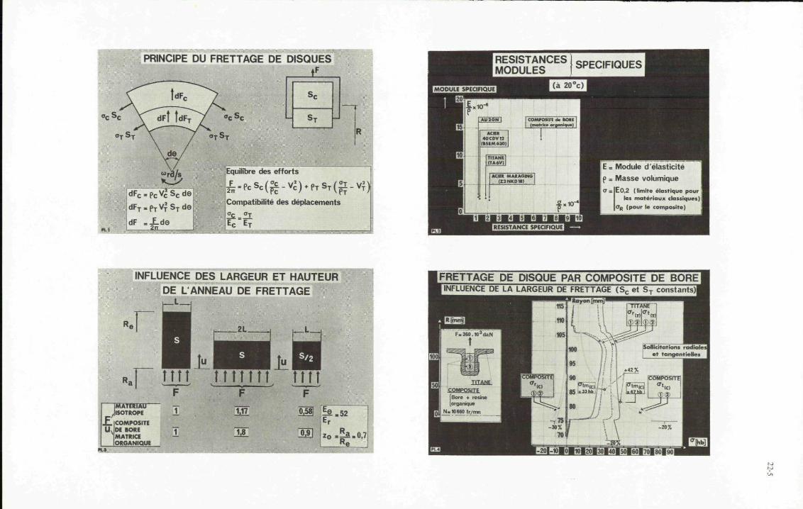
22-5

MASSE DU DISQUEEN FONCTION DU RAYON D'ALESAGE
ESSAIS EN PRESSION, DISPOSITIF D ESSAI
FRETTAGE DE DISQUE, SOLUCITATIONS ET MASSES
Masse disque 100% TASVj 12,4 kgMasse disque frette : 6,2 kgMasse composite : 1 kg
ESSAI EN PRESSIONASPECT APRES ECLATEMENT

22-7

ESSAi EN FOSSE DE SURVITESSE•BBBBRHMRBMHOBllllBIOMHBBSil ^ ^ ^ ^ ^ ^ ^WH^ ^ ^M^ ^wroB^WBMWww*
MOBILE APRES ECLATEMENT

23-1.
FAILURE ANALYSIS OF A FIBER REINFORCED COMPOSITE MOTOR CASE USING DISTORTIONAL ENERGYAND MAXIMUM STRAIN THEORIES OF FAILURE
by
Richard J. ThompsonJohn W. Sofferis
Charles M. EldridgeGround Equipment and Materials Directorate
Directorate for Research, Development, Engineeringand Missile Systems Laboratory
U.S. Army Missile CommandRedstone Arsenal, Alabama 35809
SUMMARY
In this paper, a method of determining the failure condition of a fiber reinforced compositestructure is extended for application to an actual design and analysis problem. The original method usesthe distortional energy and maximum strain theories of failure. A finite element stress analysis programwas modified for application to fiber composites.
This work extends the failure program to include helical tubes. The method of calculation ofwrap angle is altered after first stage yielding as pressure increments are increased.
Provision was made to automatically update the displacement field. After each loading increment,the displacement field is calculated and the new values are added to the old ones.
-HOOP WINDING
C^— INNER SHELL
OUTER SHELL —
Figure 1
1 . INTRODUCTION
Fiber reinforced composites have received considerable attention during recent years as a meansof reducing weight in structures while maintaining good strength properties. One area of the design andanalysis of these bodies that is currently receiving attention is that of failure criteria.
This effort is an extension of a method presented by Fulton [1] to determine yielding and ultimatefailure in a fiber reinforced composite motor case. The case is shown in Figure 1. Satisfactory results
were obtained for a cross ply composite or anangle ply with hoop windings over the outside ofthe case. Basically, it is an adaptation of anexisting finite element stress analysis programfor use with fiber composites. The stressescalculated in the program are transformed fromthe global coordinate system to the direction ofthe fibers. The physical properties of aunidirectional composite are then used to deter-mine the state of stress in the fiber composite.Tsai's [2] distortional energy failure criteriaand St. Venant's theory are then applied topredict when failure will occur.
Failure is considered to occur in two stages. The ; first stage is the initial yield which isconsidered to occur when "crazing" or cracking of the matrix material begins. The element which hasexperienced first stage yielding is then considered to be able to carry load, mainly in the direction ofthe fiber, with certain "degradation"! factors applied in the other orthogonal directions. With this newdegraded stiffness, the element is considered to support load until the fiber breaks.
2. APPLICATION TO MOTOR CASE DEVELOPMENT
a. Helical Tube
To apply this procedure to an actual motor case development, several modifications were made tothe program. One of the primary objectives of this work is to provide for the capability jit analyzinga helical tube. It was desired to substantiate the analytical results by an actual test of an angleply tube .
Attempts to analyze helical tubes with the failure analysis program resulted in extremely largedisplacements. This was attempted using degradation factors of 0, 0.001, and 0.01. All cases gaveunsatisfactory results.
The results showed that the radial displacements were becoming extremely large as pressureincrements were increased after first stage yielding. The wrap angle was determined by the equation
sin'1
where rQ is the polar opening radius and R is the radial coordinate of the element in question.
For the open-ended helical tube, as the pressure increases, the radial displacement increasesand the tube shortens longitudinally. The program showed that the angle of wrap was decreasing (since R

23-2
is increasing). Intuitively, one would think that the angle should increase. It was concluded that thisequation was not valid after first stage yielding. Some other method of determining wrap angle afterfirst stage yielding was necessary. A method of calculating the new wrap angle, based on the wrap anglea0, for the previous pressure increment and the strains eQ and ez was derived. This new angle can be
expressed as
-1tan [C1 tan °o
0- + 0- 0- + £e) tan aob. Automatic Recycling by Pressure Increments
To determine the pressure at which yielding begins, it was necessary to apply the load inincrements. When the failure criteria indicate that an element has failed (yielded), the appropriateelements in the compliance matrix are degraded to allow for the weaker condition in these directions.Under a multiaxial stress state, the relatively low transverse strength of the unidirectional compositecan result in cracks developing in the resin along the filament direction early in the loading historyof the structure (Figure 2). This mode of yielding can result from transverse normal stress and/or
longitudinal-transverse shear stress acting on the composite.In the formation of these cracks along the direction of thefibers, certain stresses and strains appearing in the constitutive
03 relationship for the unidirectional composite become eithercompletely or partially uncoupled. To reflect this uncoupling,the appropriate elements in the compliance matrix are multipliedby a degradation factor 6, where 0 S 5 < 1.
After crazing occurs, it is necessary to obtain a newstate of stress which reflects the new degraded stiffness. Thesestresses are calculated by the equation
Figure 2 where P. = pressure increments, P = total design pressure, and
a = calculated stress on the element at the total design load.
This results in a higher stress along the direction of the fibers.the matrix is new carried by the fiber due to the uncoupling.
Some of the load previously carried by
Provision has been made to automatically update the displacement field. After each incrementof loading, the displacement field is calculated and the new values are added to the old ones. The gridcoordinates are changed as a result of this. This helps to offset the effects of large radial deformationsin the shell. The capability of making manual changes still exists. This is especially helpful ininstances where the boundary conditions change.
Because the requirement existed for integrally winding the pole piece and nozzle (which were madeof monolithic materials) with the fiber glass, some provision had to be made to include failure criteriafor a continuum element. Discontinuities exist at the point where the two different materials meet.Naturally, the displacements occurring in the monolithic material would influence the stresses in thefiber composite. Therefore, it was necessary that the program deal with both materials.
The program prints out the stress in various directions. It will give the maximum and minimumstresses, the displacements, coordinates of the degraded elements, and the material number and properties.The program has the capability of starting and stopping at any pressure increment. The tapes are auto-matically saved. It is not necessary to run all pressure increments consecutively. If results are notdesired for certain pressures, the program can skip these for more significant results.
An allowance was made for plastic deformation in a continuum element. Data from a piece-wiselinear stress-strain curve were inserted. The program interpolates the necessary information from thesedata including the ultimate limit. After ultimate is reached, a hypothetical, rubber-like material isadded which allows the forces to be transferred to the continuum model.
One area which proved to be troublesome during the development was the model for the bondingagent between the two shells. The shear stress along the motor case is relatively small in the centerof the case and rises extremely high at the ends of the inner and outer shells. Initially, only onecontinuous bonding agent was considered with typical physical properties obtained from slow rate tensiletests. This resulted in an unrealistic strength in the bonds at the shell ends which erroneously causeda load smaller than the actual one to be taken in the continuous shell (i.e., the shell which did notterminate at the point in question) .
To correct this deficiency, the bonding agent was considered to be divided into three parts.The middle portion was unaltered, whereas the two outside sections, corresponding to the high shearstresses, were made weaker which forced the load to be distributed more realistically in the continuousshell. This raised the stress somewhat in this shell.
c. Results
The computer code has been used to analyze small diameter pressure vessels and solid propellantmotor cases. The design parameters for the motor cases were characterized by high pressures, high

23-3
accelerations, and high loading rates. A test fixture was designed and approximately 50 high rate bursttests were conducted using water as the pressurizing medium. The computer code gave excellent results inpredicting the failure mode and location and the mean burst pressure.
The effect that filament crossovers have on the strength of the helical tube was experimentallyinvestigated. Figure 3 shows the average results of tests of tubes having four different crossover
configurations. These values are compared withthe program predictions using degradation factors
1.90 of 0.01 and 0.04.
NO. OF CROSSOVERSON TEST SPECIMEN
40 DEGREE HELIX
PREDICTED
0.04
The variations in the predicted curvesand the experimental curves in the upper stagesare believed to be the result of interlaminarshear effects and crossover effects being omittedfrom the program. Also, a better method ofdescribing the degraded stiffness matrix isdesired. The schedule of the program necessitatedthe omission of these items in the originalprogram. Effort is presently underway to includethese in the analysis.
Figure 4 shows the burst pressuresversus crossovers per diameter. Future plansalso include a better definition of the crossovereffect.
1.403000
UJcc
1U!CCQ.
CCDm
2400
2200
2000
1800
1600(
o
^\
\
\1/o
°//°
//
/&^-— -"
40I
5EGREE HE .IX
* 2 4 6 8 1 0 1 2 M
1000 2000
PRESSURE, PSI
Figure 3
CROSSOVERS PER DIAMETER
Figure 4
The pressure vessel tests are being used to establish material properties which are used as inputdata to the program as well as a means of determining the degree of uncoupling and the role of interlaminarshear.
REFERENCES
1. Fulton, James F., Structural Design and Analysis of Filament Wound Rocket Motor Cases. RedstoneResearch Laboratory, Huntsville, Alabama, Rohm and Haas Company, Report No. S-267, November 1970.
2. Tsai, S. W., Strength Characteristics of Composite Materials. Philco Corporation, Newport Beach,California, for National Aeronautics and Space Administration, NASA CR-224, April 1965.


DIII-1
DISCUSSION
Dr. Morris1 paper on propulsion systems evoked discussion on both materials andapplication advantages. With respect to the former, a question was raised as to therelative temperature limitation of Borsic-Al and Borsic-Ti, in his Figure 3, whichappeared to be somewhat surprising. Dr. Morris explained that, firstly, the graph wasbased on published data which gave tensile strength values at temperatures up to 500°C(for instance, see his Reference 17). The limitations on the use of Borsic-Al atelevated temperature are basically twofold: (a) the transfer of the load into thecomposite requires excessively long shear lengths due to the reduced shear strength ofthe matrix as temperature increases; the required length may be impractical] and (b)the fiber-matrix long term stability. In practical applications, service temperatureswill be much lower than 500°C. Secondly, the figure shows specific strength so that,because of the lower density of Borsic-Al, the Borsic-Ti curve comes relatively lower.Further, the data refer to materials produced at a time when Borsic-Ti fabricationtechnology was in its infancy and lower percentage theoretical strength levels werebeing achieved as compared with Borsic-Al. Borsic-Ti properties were now improved, withthe improved material available at about $1000Ag. Borsic-Al, some experience showed,could be comfortably used at 250°C, with a limit, for extended periods, of 325°C.
United States engine producers seemed more optimistic about applications usingcomposites. The remarkable potential pay-offs warranted continued activity on a numberof fronts. The blade problem was probably the most difficult, although the second andthird stages represented easier problems. Also, there were important static structureapplications with even smaller engineering problems. Another kind of advantageous useof composites was to reinforce blades to provide dynamic damping and this kind of appli-cation had been highly successful. Dr. Morris agreed that there were many engine hard-ware examples of good pay-off through the use of composites, but considered the majorpay-off to be in the large fan blades. There was agreement that foreign object damagewas the major problem, with some opinion being expressed that this problem was solvable,although not necessarily with graphite fiber composites. The Shirley Institute inEngland had been working to improve impact resistance by the development of 3-dimensionallaminates. Dr. Morris said this work was essentially limited to reinforcement in thethird dimension by stitching. Results reported in 1972 implied a successful solution tothe bird ingestion problem, based on the damage being restricted to the actual impactedzone of the blades and not becoming excessive through cumulative impacts. The problemof the effect of even limited ballistic damage on strength, stiffness, fatigue, etc.still remained.
Mr. Signorelli responded to several questions concerned with composite blade fabri-cation and thermal effects, as related to his paper. Concerning the maintenance offiber distribution and orientation, he said that composite components could be fabricatedby closed-die, diffusion bonding of a stack of monolayer tape plies. Fiber contentvariation along the blade span would be achieved by varying the respective geometry ofthe fiber-free superalloy tape portion and the fiber-containing superalloy compositemonolayer tape portion of each ply. Distortion when exposed to thermal cycles would beavoided by using symmetrical arrays of fibers about the blade axis, which could beachieved with the diffusion bonding process. This is entirely consistent with existingdiffusion bonding methods of fabrication of aluminum matrix and titanium matrix composites.Such composites need not have localized concentrations of fibers to cause bending momentsthat distort the component. Commenting on the possible essentiality of cooling even withcomposites and the resultant need to restrict fiber contents to unacceptably low values,he said that while it is highly desirable that cooled blades be used for the first stageturbine, it is also desirable to eliminate the need for cooling of second or third stageturbine blades by increasing the temperature capability of the material. Directionallysolidified eutectic or refractory wire/superalloy composites probably will be developedfirst for use as solid uncooled blades, that can be substituted for cooled superalloyblades. The problems to be solved to permit service demonstrations for such blades aremuch easier than that of developing cooled blades. The substitution of uncooled com-posite blades for cooled superalloy blades is desirable in that it increases the availableair for cooling the first stage blades. Thus, the introduction of uncooled second andthird stage blades could permit an increase in turbine temperature with an efficiencygain. Further, the experience gained in the development of solid blades would serve topromote the development of cooled blades. The development of cooled blades is much moredifficult for both of the candidate high temperature composites, eutectic and refractorywire. The thin sections and hollow configurations of cooled blades are more difficultto fabricate, more prone to thermal fatigue failure, and require better oxidation coatingtechniques for the complex internal and external surfaces. The need for low fibercontent for cooled blades does not appear to be the limiting problem based on the lowfiber contents indicated for refractory wire composites in Table IV of the paper.

DI1I-2
Commenting on the effect of thermal cycling on the mechanical property retentioncharacteristics of high temperature resin/graphite fiber composites, Mr. Signorellistated that this has not been investigated. Thermal cycling of the composites would, inhis opinion, adversely affect the elevated temperature retention of mechanical properties.The effect would probably be quite small for unidirectional fiber composites. However,for angle ply composites, intraply cracking could occur which would lead to lower mechani-cal properties retention because (1) the cracks would increase the surface area and leadto increased thermo-oxidation degradation; and (2) the cracks would obviously act asdefects and result in lower mechanical properties.
Mr. Stargardter expanded on several items in his paper, in response to questions.Referring to Figure 13 of his paper, graphite coating of the tool prevented adhesion ofthe resin to the tool very effectively. Pre-impregnation of tapes was not used becausetechniques using the 500°F (260°C) resin were not available.
The discs involved were stress-limited so that dynamic problems, related to blade-disc combinations, were not a consideration. For vibration-limited discs, other approacheswould be needed. With respect to the boron polyimide rings, where radial stress gradientsexisted on the one hand, and, on the other hand, possible peeling of the surface layerat maximum radius could be an ultimate stress limiting factor, Mr. Stargardter statedthat peeling was never observed; that in well made rings failure was rapid and in tension,without evidence of location of failure initiation; and faulty rings failed in inter-laminar shear.

1V-1
Section IV - SUMMARY, ANALYSIS, CONCLUSIONS AND RECOMMENDATIONS
As indicated in the Preface, this Symposium was organized to examine the state ofthe art of this quite advanced and special field of materials and the accumulatedexperience therein, primarily from a design and application point of view, with emphasison both problems and opportunities, relative to optimizing aerospace vehicles, propulsionsystems and pertinent equipment and components. The Symposium successfully achievedthis over-all objective, and well demonstrated the extensive progress that had been madein this field, the broad and diversified experience that had been accumulated, and theimpressive understanding and production know-how that had been attained. This is notto say that all problems have been solved to general satisfaction, or that all thenecessary design and test data are available, or that cost has reached a desirable low-level, or that the properties have been fully optimized, etc.; but clearly there has beenenough successful and diversified experience to permit categorizing these compositematerials as production, engineering materials for many applications, with demonstrablebenefits in weight, performance and sometimes cost, among other advantages.
The papers and discussions in this Symposium covered a very wide scope, were wellprepared, manifested excellent expertise and competence, and were interesting andstimulating. They were well received, although not necessarily evoking unanimous agree-ment in all cases. The interest in the subject was evidenced by the number ofrepresentatives from many countries continually in attendance and by the livelydiscussion. The coverage, although diversified and broad, could certainly not beconsidered comprehensive or all-embrasive, nor was it intended to be; practicalitydictated that the focus be primarily on the advanced graphite and boron/organic matrixcomposites, and special metallic composites, in selected but representative applications.An attempt to treat cost effectiveness and engineering effectiveness as a special isolatedtheme did not prove feasible, but these subjects run as implicit, and sometimes explicit,considerations through many papers; one could, indeed, design a special seminar on thesetopics alone.
It had been arranged that two teams would be particularly alert to the presentationsand discussions from the point of view of presenting, at the end of the Symposium, anoverall summary and perspective. The team for aerospace vehicles consisted of G. Leomand,G. Peterson and U. Hutter. The propulsion team consisted of A. Morris, L. Jahnke andT. Norbut. Much of the content of this Section is based on the presentations of theseteams and the ensuing discussions.
With respect to applications in aerospace vehicles, the Symposium illustrated quiteclearly that the major thrust of advanced composites is in stiffness-critical high-performance primary and secondary structures, or in special applications where necessaryperformance improvement justifies the generally higher cost. Definitely included as acategory of vehicles benefitting from composites is the helicopter, perhaps mainly inthe rotor blades but certainly with potential in many other areas, such as the fuselage.Of course, although emphasis in this meeting was on the newer and advanced composites,certainly other composites, such as the glass fibre type, also serve to advantage.Currently, the major means of introducing composites is either through direct substitu-tion of the composite for previously used materials or as a selective reinforcement forconventional metallic structures as described in the Brooks paper. Resulting experiencehas demonstrated that composites can perform satisfactorily and can meet designer'srequirements. Accordingly, two general paths of further progress are open: (1) todevelop a near-term market using substitution technology for a broad spectrum ofapplications, from sailplanes to fighter wings and fuselages; and (2) to accelerateconceptual design of new structural forms or modified specific structures that permitusing the advantages of composites to the maximum, simultaneously attempting to minimizetheir disadvantages. The overall advantage would be, of course, improved performanceand reliability with no weight penalty - possibly even weight decrease.
To attain maximum benefits, however, it was emphasized that the second approachmentioned above, admittedly longer-ranged, deserved major attention, much more than hadbeen given it to date. New design concepts, new fabricating techniques and new structuralforms should be pursued aggressively, for these were still essentially in the developmentstage. Reliability and reasonable cost should be simultaneous objectives.
The advantages of composites revealed and discussed during this Symposium are, onthe whole, the following: (1) weight reduction from 20 to 30 percent in a wide varietyof structures; (2) improved stiffness and advantageous shift of flutter limits; (3)fatigue resistance superior to that in metals with the potential for longer life - infact, fatigue was tending to become a rare cause of failure in advanced composites withthe indication, it was said, that it would no longer be a design limitation; nevertheless,more data were needed on fatigue life under various spectra of stress cycles; (4)increased damping capability; (5) under proper conditions and with suitable development,

IV-2
possibility of advantageous resistance to projectiles; (6) capability of being designedto be fail-safe, by inclusion in composite structures of redundant load paths andeffective crack-stoppers.
The disadvantages and potential problems in composites, and deterrents to expandedusage, were identified as the following: (1) brittleness, an inherent characteristic,although the structure itself need not behave in a brittle manner, particularly ifimproved configuration concepts and optimum combinations of materials are introduced;(2) difficulty of designing reliable joints; (3) cost, with respect to both the materialitself and the manufactured structure; (4) variability (reliability) of product, whichcould be improved by concentrating on fewer material combinations and by the improvedprocessing mentioned in the previous item; (5) poor resistance to erosion, requiringspecial protection at leading edges; (6) degradation in high humidity environments andthe corrosion hazard, as in carbon-aluminium composites; (7) lack of adequate data base;(8) lack of confidence on the part of designers.
With respect to cost, this item clearly was one of major importance, perhaps trans-cending weight saving, at least in some cases. Hybrid material of boron and carbonwould increase volume use and decrease material cost. Increased volume demand formaterial, improved manufacturing procedures, training of personnel, new design concepts,improved process control and non-destructive inspection could reduce component cost.However, even certain cost disadvantages, currently generally the case in designing bysubstitution, should be tolerated at this stage because of the need to build an experienc-ed, healthy industry; to educate users in the use of this type of material; and to gainservice experience and confidence in this use. Actually, in some new aircraft, costanalysis showed advanced composites to be cheaper than certain expensive metal componentsand parts, even at today's prices, because of savings in manufacturing costs, due toless costly tooling, lower scrap, reduced number of sub-components, mechanized operations,etc. Thus more extensive applications could be introduced with resultant build-up ofconfidence. There was indication, furthermore, that with large increase in demand,carbon fibres could be dropped to about $50 per kilogram, with simultaneous improvement(decrease) in variability. Capacity already existed but was hardly being used. Unitvolume could be increased by concentrating, as previously stated, on fewer compositesystems and by standardizing on thicknesses, sizes, forms, etc. However, certainlymaterials should not be used beyond their performance capability as a means of costreduction.
Weight saving per se was not considered an over-riding consideration. For example,manufacturing simplicity, reliability, reproducibility and lower cost could be of greaterimportance. It was suggested, in fact, that weight saving is just a yard stick bywhich to measure the quality and degree of improvement and could be traded with orconsidered in the same light as improvements in stiffness, performance, safety, lift-to-drag ratio, etc. In another sense, it could be equated to gain in payload. In anycase, the total system of technical factors, producibility, inspectability, performanceadvantages, trade-offs, reliability, maintainability, economics, etc. must be consideredfor optimization of vehicle and for maximum cost effectiveness.
In connection with structural analysis and the problem of characterizing the failureof these composite materials, there were, as Professor HUtter had pointed out, a multi-plicity of equations to represent failure limits, with, however, the possibility ofintroducing simpler approximations. This should simplify the handling of failure analysisby engineers and provide a guide for minimal collection of proper data.
The close interdependence of design, structure and these materials was frequentlystressed; indeed, sometimes it is difficult to determine when something should be termeda material and when a structure, as in a filament wound case. Thus different routes -via weight or mass - are afforded for achieving the same objective.
The papers and discussions covering propulsion applications covered primarily therotating components of gas turbines, although some other applications were also included.Obviously, many of the comments and conclusions made in relation to the vehicles (e.g.airframes) were also applicable to propulsion components. Several countries, andcompanies within a country, overlapped somewhat in their topics with generally goodagreement, - very heartening in view of the broad distribution of speakers. Neverthe-less, quite clearly the United States was significantly more optimistic about the useof composites in aircraft turbines than were some European countries; for example, theUnited Kingdom.
On the cautionery and less optimistic side, there was emphasis on the fabricationproblem and the great effort that must be expended in applying these composite materials

IV-3
to turbine applications such as the turbine disks covered in Mr. Stargarder's paper.Rotating blades, the large fan and compressor blades, were considered the area ofgreatest pay-off, but here there was still the very significant problem of impact andforeign object damage, particularly in cruise engines as compared with lift engines. Bycareful selection of application, this hazard could be minimized, as in the Rolls RoyceVTOL engine. The over-all problem, however, requires design innovation, since, asdiscussed above, brittle behavior was inherent in the materials likely to be used. Othercritical aspects in the use of composites for turbines have already been mentioned:quality control, reproducibility of properties, reliability, non-destructive inspectiontechniques, the need for proper designing from the beginning instead of duplicatingthe metallic component, the need for accumulating data on the long term environmentalstability of composites under turbine operating conditions, etc. Applications outsidethe gas stream were more likely to avoid problems and could be a more logical startingpoint; indeed, many composites are successfully in use already in this area. Also,the low temperature regime seemed most suitable for the near-term use of composites.Two approaches presented during the Symposium, if successful, promised such advantagesfor high temperature service that continued development work should be aggressivelypursued to improve them and to solve current problems. These approaches are': (1) theincorporation of refractory metal wires into a metal base, and (2) directionallysolidified eutectics, particularly the latter in the opinion of some. For compressorblading, there seemed little need for composite systems in the 200°C - 400°C range. Theimportance of developing specific machining and handling techniques for composites wasemphasized. Clearly, there was still need for extensive research and development inmany areas.
The United States participants leaned toward greater optimism with respect to thebroader use of composites in propulsion systems. It was noted that approximately 5percent of the weight of the modern jet engine is made from composites, albeit thesecomposites are primarily glass reinforced epoxies and the applications are mainlysecondary structures. Interestingly, and contrary to the usual expectation, thesecomposite applications have yielded simultaneous weight and cost reductions, in theorder of 30 to 40 percent each over their metal counterparts, in contrast to the willing-ness to pay $100-300 more for each pound of weight saved. It must be recognized, also,as already stated above, that weight savings, particularly in advanced composites,have not been maximized due to lack of originally designing for composites and to theneed for cautious approach until a high confidence level is achieved.
A number of opportunities were envisioned. In the over-all sense, compositesoffered substantial assistance in achieving reliable and efficient thrust in a minimizedpackage, as required to reduce installation drag losses and weight in aircraft. Forexample, composite fan blades have the potential for either reducing engine inlet sizefor a given thrust or increasing thrust for a given installation size by increasingairflow; also, a higher turbine blade temperature capability could produce significantthrust improvement or, alternatively, longer blade life. Successful demonstration ofcomposites in static engine structures (e.g. front engine frames) was foreseen withinthe next 2 to 3 years on a development basis, again with a promise of 25 to 30 percentsimultaneous weight and cost reduction. There was much promise in the use of hybridcomposites using fibre combinations of glass, boron, graphite and PDR42, but using themore expensive fibre additions only as necessary. If made available, stronger orientedgraphite molding compounds (epoxy and polyimide) could increase engine usage ofcomposites by 50 percent by substituting for titanium and aluminium in applications forsmall structural parts such as brackets, lube tanks and gear box casings. Graphitereinforced epoxy fan blades, if successful, could yield a 40 percent over-all weightsaving, as compared with titanium, and also could be substantially cheaper. An addition-al inducement in this case would be the following: lighter blades would permit lighterdisks and, with the above composites, probably the elimination of metal rings to containthe blades in the event of failure. In contrast to metal blades, the plastic blades,in the event of failure, would be expected to fray and fragment into small pieces thatwould not penetrate fuel tanks, wings, fuselages, etc. Thus, cumulative weight savingcombined with greater safety and reliability would be expected. This weight savingin the fan blade area would be a very important adjunct to weight saving in the turbineblades (e.g. through the use of directionally solidified eutectics), contributing tooptimum advantage in the redesign of an engine. With respect to the turbine blade, thevalue of an increase in temperature capability of about 100°C is so great as to probablyexceed the total advantages obtained in the front portion of the engine, thus emphasizingonce again the importance of pursuing aggressively the further developments ofdirectionally solidified eutectics and the refractory metal reinforcements described byMr. Signorelli, since there are so few approaches available for improving the temperatureperformance of turbine blade materials.
With respect to the problems remaining, the following were cited: (1) cost must bereduced; (2) more sophisticated and extensive design data and practices must be developed;

1V-4
(3) practical resin systems, of broad applicability, particularly in thicknesses overabout 1.5 mm, must be developed for temperatures over about 200°C, having processability,quality and reliability equivalent to epoxies; under certain conditions and limitations,certain imides could be used now to 250° or 300°C; (4) quality control, uniformity andnon-destructive inspection methods must be improved for fibres, prepregs and compositeparts. Solutions to all of these problems would be aided, as has been mentioned before,by concentrating on fewer composite systems (for example, for engines, graphite-epoxy,graphite-polyimide, boron-epoxy and boron-aluminium). The major problem is, however,the threat of foreign object damage to blades, particularly from ingestion of birds,since composite blades are never expected to equal metal blades in energy absorptioncapability. The blades must be capable of sustaining multiple impact by small birdssuch as starlings,(about 100 gms each) since they are likely to be encountered near theground. For larger birds, in the kilogram range, two courses are open: develop birdretardation devices or design with materials to give clean, single blade, non-catastrophicfailure. In any case, the solution must be economical. Even if an adequate solutiondoes not prove feasible for the first stage fan blade, and major development here shouldcertainly continue, the probabilities of using composites are much greater for thesecond and third stages, for the booster blades and for first stage compressor blades,and the incentive in these areas is still very great. This assumes that materials withadequate impact resistance are built into the first stage and that enough resistancecan be built into subsequent stages to sustain impact from smaller objects such as bolts,nuts, pebbles, etc.
Salient Conclusions and Recommendations
1. Composites are already contributing much to aerospace vehicles and propulsionsystems in terms of performance, weight savings and even, in some cases, cost reductions.The opportunities for the future are great in terms of added benefits and broadeningof the range of applications, the magnitude of these depending, obviously, on thesolution of problems and the filling of gaps which still exist to a significant degree.For example, one projection for subsonic engines envisions, by the 1980's, compositescomprising 15-20 percent (by weight) of the engines, primarily as polymeric composites,with cost and weight advantages, as compared with metallic alternatives, of about 5percent each. The limiting factor in the rate of introduction of improved and advancedcomposites in the future may indeed be the availability of new vehicles, engines,components, etc. rather than limitations in technology. Some major deterrents are costand lack of confidence, and lack of impact resistance.
2. Composite materials as currently used are mainly the result of substitutionin existing designs or as reinforcements of conventional structures, and do not involvenew designs based specifically on the new materials. There is a need for the latter,a need for new design concepts and a design philosophy not constrained by previousexperience with metals. New structural techniques and forms should also be pursued.
3. It is important that effort and resources be concentrated on fewer compositesystems. By so doing there would be efficient use and conservation of critical resources,more rapid progress, more extensive knowledge of a given system, higher volume demandper system leading to lower cost, more extensive service experience, and other advantages.In addition, this would facilitate availability of properly controlled materials andtheir adequate.and precise characterization for design and production utilization, andshould aid in the establishment of necessary standardization, in the development of morereproducible manufacturing processes, and in better product evaluation under serviceand broad environmental conditions.
4. In engines, major hardware-oriented efforts should continue on the developmentand testing of composites in rotating applications (such as fan blades) as well as instatic structures, with more attention to the latter than hitherto.
5. It is extremely important that better non-destructive inspection techniquesbe developed and demonstrated, in order to improve and establish reliability andconfidence in the composites and in the processing operations.
6. More precise simulation techniques for assessing foreign object damage inengines must be developed, hopefully leading to standardization. These must correlateclosely with engine service conditions and must be economical to perform.
7. Research and development on the directionally solidified eutectics and therefractory fibre reinforced metals should be pursued vigorously, since there are so fewapproaches available for increasing the vitally needed high temperature capability ofmetals, - even recognizing certain possibilities in ceramics, refractory metals,intermetallic compounds, etc. With respect to the eutectics, the "metals industry"

IV-5
rather than the "composites industry" should be the focal point. Furthermore, both ofthe present major contending systems (i.e. Co/Ni-TaC and Gamma-Delta) deserve support,since neither is clearly superior to the other, and effort should be continued todevelop even better systems, e.g. with superior oxidation resistance.
8. Exploratory development of promising filaments, matrices and systems shouldbe continued to provide a base for meeting future requirements. Also included shouldbe consideration of coatings for oxidation and erosion resistance and means for buildingsuch resistance intrinsically into the composites.
9. Attention must be given to improving the temperature capability of resins.Although some resins, such as certain polyimides, have some capability to about 250°C or300°C, they are not equivalent in processability, quality, reproducibility, etc. to theepoxies at the latter's lower temperature operating range. Thus, for some applications,and in the minds of some users, the practical temperature limit for resins is currentlynearer 200°C.
10. There is a strong need for more reliable and comprehensive data on composites,in sufficient depth to promote reliability, credibility and confidence, especially underoperating conditions, over a temperature range commensurate with the temperaturecapability of the material. These data include physical and mechanical properties,including fracture toughness and fatigue life under various spectra of stress cycles,and reaction to environment, e.g. humidity, temperature, oxidizing atmosphere, etc.Recognizing the effort and cost that are entailed in generating adequate data for design-ing with confidence, prior analysis of what is really required is necessary and advantageshould be taken of using structural equations, similar to those provided at thisSymposium, to minimize the task.
11. In addition to the data needed as described above, the major deterrents toexpanded usage of composites are cost, lack of credibility and confidence, facile andeconomic ability to fabricate into production parts and techniques for resisting foreignobject damage in engines. Accordingly, more attention should be given to improvingproducibility and manufacturing techniques and'every effort should be exerted throughexpanded use to build up experience, educate potential designers and users and createconfidence. Confidence will also be enhanced by providing a solid design base usingsimulated service tests, actual service experience and correlated accelerated tests andevaluation.
12. Communication should be promoted between those responsible for vehicle andpropulsion system requirements and those responsible for materials development andreadiness for application.
13. Reference should be made to the NATO Defence Research Group Study of May 1972entitled "Long-Term Scientific Study on Non-Metallic Materials" for additional discussionand recommendations on composite materials.
14. Consideration should be given to establishing an information compilationand storage center, to avoid undue repetition of effort and to put forth responsibleexperience information, reliable data and other facts. There should be promoted anexchange of information covering the state of the art and existing technology, and suchinformation should be incorporated in some form of design manual to serve as a guide(and not as a rigid, mandatory document) to designers and potential users of composites.
15. AGARD should continue to provide a mechanism for the above information-exchange,for the sharing of experiences and resultant data, for the delineation of problems en-countered in the use of composites and the solutions developed and the mistakes to avoid.Such an AGARD activity could also assist in the preparation of the above manual, intraining personnel, and in broadening pertinent knowledge and skill.


Al
APPENDIX A
AGARD PROPULSION AND ENERGETICS PANEL
CATEGORY I PUBLICATIONS - PUBLISHED FOR SALE THROUGH COMMERCIAL OUTLETS: LIMITEDNUMBERS OF COPIES PURCHASED BY AGARD AND DISTRIBUTED TONATIONAL DISTRIBUTION CENTRES LISTED ON BACK COVER.
No AGARD serial number
AGARDograph 4
AGARDograph 7
AGARDograph 8
AGARDograph 9
No AGARD serial number
AGARDograph 15
AGARDograph 27
No AGARD serial number
AGARDograph 31
AGARDograph 37
No AGARD serial number
No AGARD serial number
No AGARD serial number
AGARDograph 41
- "Selected Combustion Problems - Fundamentals and Aeronautical Applications".Combustion Colloquium, Cambridge University, England, December 1953.Butterworths Scientific Publications, London, 1954.
- "Spontaneous Ignition of Liquid Fuels" by B.P.Mullins. Butterworths ScientificPublications, London, 1955.
- "Introduction to the Study of Chemical Reactions in Flow Systems" by S.S.Penner.Butterworths Scientific Publications, London, 1955.
— "Theory of Combustion Instability in Liquid Propellant Rocket Motors" byLuigi Crocco and Sin-I Cheng. Butterworths Scientific Publications, London, 1956.
- "Combustion Researches and Reviews 1955". Combustion Panel Meetings,Scheveningen, Netherlands, May 1954, and Paris, November 1954. ButterworthsScientific Publications, London, 1955.
- "Selected Combustion Problems II - Transport Phenomena; Ignition; AltitudeBehaviour and Scaling of Aeroengines". Combustion Colloquium, Liege, Belgium,December 1955. Butterworths Scientific Publications, London, 1956.
- "Combustion Researches and Reviews 1957". Butterworths Scientific Publications,London, 1957.
- "Air Intake Problems in Supersonic Propulsion". 11th AGARD Combustion andPropulsion Panel Meeting, Paris, December 1956. Editor J.Fabri. Pergamon Press,London, 1958.
- "Combustion and Propulsion. Third AGARD Colloquium. Noise - Shock Tubes -Magnetic Effects - Instability and Mixing". Combustion Colloquium, Palermo,Sicily, March 1958. Editors M.W.Thring, J.Fabri, O.Lutz and A.H.Lefebvre.Pergamon Press, London, 1958.
- "Explosions, Detonations, Flammability and Ignition" by S.S.Penner andB.P.Mullins. Pergamon Press, London, 1959.
- "Advanced Aero Engine Testing". Joint Meeting of AGARD Combustion andPropulsion and Wind Tunnel and Model Testing Panels, Copenhagen, Denmark,October 1958. Editors A.W.Morley and Jean Fabri. Pergamon Press, London,1959.
- "The Chemistry of Propellants". Meeting of AGARD Combustion and PropulsionPanel, Paris, June 1959. Editors S.S.Penner and J.Ducarme. Pergamon Press,Oxford, 1960.
- "Combustion and Propulsion. Fourth AGARD Colloquium. High Mach NumberAir-Breathing Engines". Milan, April 1960. Editors A.L.Jaumotte, A.H.Lefebvreand A.M.Rothrock. Pergamon Press, Oxford, 1961.
- "Advanced Propulsion Techniques". AGARD Combustion and Propulsion PanelMeeting, Pasadena, California, August 1960. Editor S.S.Penner. Pergamon Press,Oxford, 1961.
- "Fundamental Data Obtained from Shock-Tube Experiments". Editor A.Ferri.Pergamon Press, Oxford, 1961.

A2
AGARDograph 47
No AGARD serial number
No AGARD serial number
No AGARD serial number
AGARDograph 75
AGARDograph 81
AGARDograph 86
AGARDograph 88
AGARDograph 96
AGARDograph 101
AGARDConference Proceedings No.l
AGARDograph 116
AGARDograph 120
AGARDograph 129
AGARDConference Proceedings No.38
"Gas Sampling and Chemical Analysis in Combustion Processes" by G.Tine.Pergamon Press, Oxford, 1961.
"Experimental Methods in Combustion Research". Manual. Editor'J.Surugue.Pergamon Press, Oxford, 1961.
"Combustion and Propulsion. Fifth AGARD Colloquium. High TemperaturePhenomena". Braunschweig, April 1962. Editors R.P.Hagerty, O.Lutz,A.L.Jaumotte and S.S.Penner. Pergamon Press, Oxford, 1963.
"Supersonic Flow, Chemical Processes and Radiative Transfer". Editors D.B.Olfeand V.Zakkay. Pergamon Press, Oxford, 1964.
"Nonsteady Flame Propagation". Editor George H.Markstein. Pergamon Press,Oxford, 1964.
"Combustion and Propulsion. Sixth AGARD Colloquium. Energy Sources andEnergy Conversion". Cannes, France, March 1964. Editors H.M.DeGroff, J.Fabri,R.F.Hoglund, T.F.Nagey and M.E.Rumbaugh Jr. Gordon and Breach SciencePublishers, New York, 1967.
"Low Temperature Oxidation". Editor W.Jost. Gordon and Breach SciencePublishers, New York, 1965.
"Physics and Technology of Ion Motors". Technical Meeting of Combustion andPropulsion Panel, Athens, Greece, July 1963. Editors Frank E.Marble and JeanSurugue. Gordon and Breach Science Publishers, New York, 1966.
"Instrumentation for High Speed Plasma Flow" by A.E.Fuhs. Gordon andBreach Science Publishers, New York, 1965.
"Nuclear, Thermal and Electric Rocket Propulsion - Fundamentals, Systems,and Applications". Editors R.A.Willaume, A.Jaumotte and R.W.Bussard. Gordonand Breach Science Publishers, New York, 1967.
"Advances in Tactical Rocket Propulsion". Editor S.S.Penner. TechnivisionServices, Maidenhead, England, August 1968.
"Fundamental Aspects of Solid Propellant Rockets" by F.A.Williams, M.Barrereand N.C.Huang. Technivision Services, Slough, England, October 1969.
"Supersonic Turbo-Jet Propulsion Systems and Components". Editor J.Chauvin.Technivision Services, Slough, England, August 1969.
"The Performance of Chemical Propellants" by I.Glassman and R.F.Sawyer.Technivision Services, Slough, England, January 1970.
"New Experimental Techniques in Propulsion and Energetics Research". EditorsDavid Andrews and Jean Surugue. Technivision Services, Slough, England,October 1970.

A3
AGARD PROPULSION AND ENERGETICS PANEL
CATEGORY II PUBLICATIONS - NOT ON COMMERCIAL SALE: FOR AVAILABILITY SEE BACK COVER.
AGARDograph 89 - "V/STOL Aircraft". Proceedings of a Meeting held at NATO Headquarters, Paris,September 1964. (Two volumes).
AGARDograph 98 - "Graphical Methods in Aerothermodynamics" by O.Lutz and G.Stoffers. November1967.
AGARDograph 117 - "Behaviour of Supercritical Nozzles under Three-Dimensional Oscillatory Conditions"by L.Crocco and W.A.Sirignano. 1967.
AGARDograph 122 - "Selected Topics in Electrofluid Dynamic Energy Conversion". Editors M.Lawsonand F.Wattendorf. December 1968.
Publication Hors-Serie - "Properties of Air and Combustion Products with Kerosine and Hydrogen Fuels",(contact AGARD). Editor R.W.McIntyre. (13 volumes). 1967.
Conference Proceedings 8 - "Fundamental Studies of Ions and Plasmas". Editor H.Dean Wilsted. Proceedingsof the PEP 26th Meeting held in Pisa, September 1965. (Two volumes).
Conference Proceedings 9 - "Gas Turbines". Papers presented at the PEP 27th Meeting held in Paris, April1966. (Two volumes).
Conference Proceedings 12 - "Recent Advances in Aerothermochemistry". Editor I.Glassman. Selected paperspresented at the PEP 28th Meeting (7th Colloquium) held in Oslo, May 1966.(Two volumes).
Conference Proceedings 21 - "Performance Forecast of Static Energy Conversion Devices". Editors G.W.Shermanand L.Devol. Proceedings of the PEP 29th Meeting held in Liege, June 1967.
Conference Proceedings 31 - "Helicopter Propulsion Systems". Editor R.P.Hagerty. Proceedings of the PEP31st Meeting held in Ottawa, June 1968.
Conference Proceedings 34 - "Advanced Components for Turbojet Engines". Editor R.P.Hagerty. Proceedingsof the PEP 32nd Meeting held in Toulouse, September 1968. (Two volumes).
Conference Proceedings 42 - "Aircraft Engine Noise and Sonic Boom". Editors R.Barth and R.P.Hagerty.Proceedings of the Joint FDP/PEP (33rd Meeting) held in St.Louis, France, May1969.
Advisory Report 22 - "Technical Evaluation Report on AGARD Specialists' Meeting on Aircraft EngineNoise and Sonic Boom" by W.R.Sears. January 1970. (Primarily treats sonicboom).
Advisory Report 26 - "Technical Evaluation Report on AGARD Specialists' Meeting on Aircraft EngineNoise and Sonic Boom" by J.O.Powers and M.Pianko. June 1970. (Primarilytreats engine noise).
AGARDograph 123 - "Space Power Systems". Editor G.C.Szego. Lecture Series held in October 1967.(Two volumes). November 1969.
AGARDograph 135 - "Fluidic Controls Systems for Aerospace Propulsion". Editor R.J.Reilly.XXXV Lecture Series. September 1969.
Conference Proceedings 52 - "Reactions between Gases and Solids". Editor R.P.Hagerty. February 1970.Proceedings of PEP 34th Meeting held in Dayton, Ohio, October 1969.
Advisory Report 32 - "Technical Evaluation Report on AGARD Propulsion and Energetics Panel's 34thMeeting (8th Colloquium) on Reactions between Gases and Solids" by S.S.Pennerand P.G.Atkinson Jr. February 1971.

A4
AGARDograph 108
AGARDograph 141
Lecture Series 39
Conference Proceedings 64
- "Combustibles, Lubrifiants et Fluides Auxiliaires pour 1'Aviation Supersonique"by G.J.Souillard, J.Ducarme and T.H. de Menten. June 1970.
- "Propergols Hautement Energetiques" by P.Tavernier, J.Boisson and B.Crampel.August 1970.
- "Advanced Compressors". Editor J.Chauvin. August 1970.
- "Advanced Technology for Production of Aerospace Engines". Editor R.P.Hagerty.September 1970. Proceedings of PEP 35th Meeting held in London, England,April 1970.
Conference Proceedings 73 -
Advisory Report 29 -
Lecture Series 46 -
Conference Proceedings 84 -
Advisory Report 36 -
AGARDograph 148
Conference Proceedings 91 -
Advisory Report 41 -
Advisory Report 40 -
Advisory Report 44 -
Lecture Series 53
Advisory Report 50
AGARDograph 164
Conference Proceedings 104
"High Temperature Turbines". Editor R.P.Hagerty. January 1971. Proceedings ofPEP 36th Meeting held in Florence, Italy, September 1970.
"Technical Evaluation Report on AGARD Technical Meeting on High TemperatureTurbines" by J.B.Esgar and R.A.Reynolds. February 1971.
"Small Gas Turbines for Helicopters and Surface Transport". Editor J.Fabri.May 1971.
"Aircraft Fuels, Lubricants, and Fire Safety". Editor R.P.Hagerty. August1971. Proceedings of PEP 37th Meeting held in The Hague, Netherlands, May 1971.
"Report of the AGARD Ad Hoc Committee on Engine-Airplane Interference andWall Corrections in Transonic Wind Tunnel Tests". August 1971.
"Heat Transfer in Rocket Engines" by H.Ziebland and R.C.Parkinson. September1971.
"Inlets and Nozzles for Aerospace Engines". Editor R.P.Hagerty. December 1971.Proceedings of PEP 38th Meeting held in Sandefjord, Norway, September 1971.
- "Technical Evaluation Report on Propulsion and Energetics Panel 38th Meetingon Inlets and Nozzles for Aerospace Engines" by D.N.Bowditch and R.Monti.February 1972.
- "Atmospheric Pollution by Aircraft Engines and Fuels - A Survey" by R.F.Sawyer.March 1972.
- "Technical Evaluation Report on Propulsion and Energetics Panel 37th Meeting onAircraft Fuels, Lubricants, and Fire Safety" by R.B.Whyte and L.Gardner.May 1972.
- "Airframe/Engine Integration". Editor A.Ferri. May 1972
- "Technical Evaluation Report on the 39th Propulsion and Energetics PanelMeeting on Energetics for Aircraft Auxiliary Power Systems", byR.H.Johnson, C.E.Oberly and R.E.Quigley, Jr. November 1972.
- "Boundary Layer Effects in Turbomachines". Editor J.Surugue. December 1972.
"Energetics for Aircraft Auxiliary Power Systems". Editor A.E.Fuhs. December1972.
Conference Proceedings 112 — "Impact of Composite Materials on Aerospace Vehicles and Propulsion Systems".May 1973.

NATIONAL DISTRIBUTION CENTRES FOR UNCLASSIFIED AGARD PUBLICATIONS
Unclassified AGARD publications are distributed to NATO Member Nationsthrough the unclassified National Distribution Centres listed below
BELGIUMCoordonnateur AGARD^- VSLEtat-Major de la Force AerienneCaserne Prince BaudouinPlace Dailly, 1030 Bruxelles
CANADADirector of Scientific Information ServicesDefence Research BoardDepartment of National Defence - 'A' BuildingOttawa, Ontario
DENMARKDanish Defence Research Board0sterbrogades KaserneCopenhagen 0
FRANCEO.N.E.R.A. (Direction)29, Avenue de la Division Leclerc92, Chatillon-sous-Bagneux
GERMANYZentralstelle fur Luftfahrtdokumentationund InformationMaria-Theresia Str. 218 Munchen 27
GREECEHellenic Armed Forces CommandD Branch, Athens
ICELANDDirector of Aviationc/o FlugradReykjavik
ITALYAeronautica MilitareUfficio del Delegato Nazionale alPAGARD3, Piazzale AdenauerRoma/EUR
LUXEMBOURGObtainable through BELGIUM
NETHERLANDSNetherlands Delegation to AGARDNational Aerospace Laboratory, NLRP.O. Box 126Delft
NORWAYNorwegian Defense Research EstablishmentMain Library,P.O. Box 25N-2007 Kjeller
PORTUGALDireccao do Service de Materialda Forca AereaRua de Escola Politecnica 42LisboaAttn of AGARD National Delegate
TURKEYTurkish General Staff (ARGE)Ankara
UNITED KINGDOMDefence Research Information CentreStation Square HouseSt. Mary CrayOrpington, Kent BR5 3RE
UNITED STATESNational Aeronautics and Space Administration (NASA)Langley Field, Virginia 23365Attn: Report Distribution and Storage Unit .
If copies of the original publication are not available at these centres, the following may be purchased from:
Microfiche or Photocopy
National TechnicalInformation Service (NTIS)5285 Port Royal RoadSpringfieldVirginia 22151, USA
Microfiche
ESRO/ELDO SpaceDocumentation ServiceEuropean SpaceResearch Organization114, Avenue Charles de Gaulle92200, Neuilly sur Seine, France
Microfiche
Technology ReportsCentre (DTI)Station Square HouseSt. Mary CrayOrpington, Kent BR5 3REEngland
The request for microfiche or photocopy of an AGARD document should include the AGARD serial number,title, author or editor, and publication date. Requests to NTIS should include the NASA accession report number.
Full bibliographical references and abstracts of the newly issued AGARD publications are given in the followingbi-monthly abstract journals with indexes:
Scientific and Technical Aerospace Reports (STAR)published by NASA,Scientific and Technical Information Facility,P.O. Box 33, College Park,Maryland 20740, USA
United States Government Research and DevelopmentReport Index (USGDRI). published by theClearinghouse for Federal Scientific and TechnicalInformation, Springfield, Virginia 22151, USA
Printed by Technical Editing and Reproduction LtdHarford House, 7-9 Charlotte St, London. WJP IHD