Comparing Strategic IT Alignment versus Process IT Alignment in SMEs
Upload
khangminh22Category
view
1download
0
IMMPROVMENT OF SELF ALIGNMENT FOOTING SYSTEM FOR
MOTOR-PUMP ROTATING SHAFT
MAGED ABDULLAH AHMED ALKHANBASHI
MASTER OF MANUFACRUING ENGINEERING (QUALITY
SYSTEM ENGINEERING)
2019

IMPROVEMENT OF SELF ALIGNMENT FOOTING SYSTEM FOR PUMP-
MOTOR ROTATING SHAFT
MAGED ABDULLAH AHMED ALKHANBASHI
A report submitted in fulfilment of the requirements for the degree of Master of
Manufacturing Engineering (Quality System Engineering)
Faculty of Manufacturing Engineering
UNIVERSITI TEKNIKAL MALAYSIA MELAKA
2019

DECLARATION
I declare that this report entitled “Improvement of self-alignment footing system for pump-
motor rotating shaft” is the result of my own research except as cited in the references. The
report has not been accepted for any degree and is not concurrently submitted in candidature
of any other degree.
Signature : ....................................
Name : Maged Abdullah Alkhanbashi
Date : ....................................
APPROVAL
I hereby declare that I have read this dissertation/report and in my opinion this
dissertation/report is sufficient in terms of scope and quality as a partial fulfillment of Master
of Manufacturing Engineering (Quality Engineering System).
Signature :……………………………………...
Supervisor Name: Dr. Mohammed Shahir
Date :………………………………………...

Dedication
To my beloved father and mother
i
ABSTRACT
This project described the development of motorized shaft alignment system to be used in
motor-pump machineries. Shaft alignment is vital to ensure the equipment able to operate for
longer duration. It was well known that poor alignment causes the bearing failures, coupling
wear or failure, increase energy consumption, bearing housing damage and bent rotors or
crankshafts. In the past, misalignment issues were solved manually by using shims, however,
this method having problematic issue such as skill requirement and time consuming.
Alternatively, the shimless footing system were introduced to overcome this problem. This
project described the improvement of current shimless design by introducing motorized
system. It was notified the root causes of the previous design problems due to manufacturing
quality (t-slot and normal screw that used). A new motorize self-alignment system was
developed along with fabricate a new footing system. A new feature will be added to overcome
delay response time, backlash, not accurate positioning, and ease for maintenance. A linear
bearing and backlash free screw are the major component to solve the backlash problem,
reducing response time needed to settle down the misalignment correction, and become more
precise. The new design of block was fabricated with size of 100 mm x 200 mm x 100 mm.
The drawing of the prototype is done by using solidworks software. The block made of
aluminum and machined by CNC milling machine. Vibration sensor was added to measure the
response of misalignment. The PID controller will do correction by controlling shaft position
by mean of step motor drive. Finally, the test on the fabricated system will be done by using
test rig. As expected the project got improved in terms of response time with more accurate
position. The lowest record score 7 seconds to correct the misalignment in shaft speed 100
RPM, while it took 86 second for correction in shaft speed 1000 RPM.
ii
ABSTRAK
Projek ini menggambarkan perkembangan sistem penjajaran aci bermotor yang akan
digunakan di jentera pam motor. Penjajaran shaft sangat penting untuk memastikan peralatan
dapat beroperasi untuk tempoh yang lebih lama. Adalah diketahui bahawa penjajaran yang
buruk menyebabkan kegagalan galas, pakai gandingan atau kegagalan, meningkatkan
penggunaan tenaga, menyebabkan kerosakan perumahan dan rotor bengkok atau crankshafts.
Pada masa lalu, isu-isu misalignment telah diselesaikan secara manual dengan menggunakan
shims, bagaimanapun, kaedah ini mempunyai masalah bermasalah seperti keperluan
kemahiran dan memakan masa. Sebagai alternatif, sistem pijakan tak berkilau diperkenalkan
untuk mengatasi masalah ini. Projek ini menggambarkan peningkatan reka bentuk tanpa
sinaran semasa dengan memperkenalkan sistem bermotor. Ia telah diberitahu penyebab utama
masalah reka bentuk sebelumnya disebabkan oleh kualiti pembuatan (t-slot dan skru normal
yang digunakan). Sistem penjajaran diri bermotor baru telah dibangunkan bersama-sama
dengan mengarang sistem pijakan baru. Ciri baru akan ditambah untuk mengatasi masa
tindak balas kelewatan, tindak balas, kedudukan tidak tepat, dan kemudahan untuk
penyelenggaraan. Garis lurus linear dan backlash percuma adalah komponen utama untuk
menyelesaikan masalah tindak balas balik, mengurangkan masa tindak balas yang diperlukan
untuk menyelesaikan pembetulan misalignment, dan menjadi lebih tepat. Reka bentuk baru
blok dibuat dengan saiz 100 mm x 200 mm x 100 mm. Lukisan prototaip dilakukan dengan
menggunakan perisian solidworks. Blok yang diperbuat daripada aluminium dan dimesin oleh
mesin pengilangan CNC. Sensor getaran telah ditambah untuk mengukur tindak balas salah
jajaran. Pengawal PID akan melakukan pembetulan dengan mengawal kedudukan aci dengan
min memandu pemanduan. Akhir sekali, ujian pada sistem fabrikasi akan dilakukan dengan
menggunakan rig ujian. Seperti yang dijangka projek itu bertambah baik dari segi masa tindak
balas dengan kedudukan yang lebih tepat. Skor rekod paling rendah 7 saat untuk membetulkan
salah jajaran dalam kelajuan aci 100 RPM, sementara ia mengambil masa 86 saat untuk
pembetulan dalam kelajuan aci 1000 RPM.

iii
Acknowledgment
In preparing this report, I was in contact with many people, researchers, academicians and
practitioners. They have contributed towards my understanding and thought. In particular, I
wish to express my sincere appreciation to my main project supervisor, Dr.Mohd Shahir Bin
Kasim, for encouragement, guidance critics and friendship. I am also very thankful to the lab
technician En.Mohd Hanafiah for his help in fabrication and measuring guidance, advices and
motivation. Without their continued support and interest, this project would not have been
same as presented here.
iv
TABLE OF CONTENTS
PAGE
DECLARATION
DEDICATION
ABSTRACT i
ABSTRAK ii
ACKNOWLEDGEMENTS iii
TABLE OF CONTENTS iv
LIST OF TABLES vii
LIST OF FIGURES ix
LIST OF ABBREVIATIONS xi
CHAPTER
1. INTRODUCTION 1
1.1 Background of Study 1
1.2 Problem Statements 2
1.3 Research Objective 2
1.4 Scope of Work 3
2. LITERATURE REVIEW 4
2.1 Introduction 4
2.2 Shaft Alignment 4
2.3 Shaft Misalignment 5
2.4 Type of Misalignment
2.4.1 Parallel Misalignment
2.4.2 Angular Misalignment
6
6
6
2.5 Cause of Misalignment 7
v
2.6 Effect of Misalignment 7
2.7 Current Method of Correction Misalignment 8
2.7.1 Traditional Method 8
2.7.1.1 Dial Indicator 8
2.7.1.1.1 Rim Face Method 9
2.7.1.1.2 Reverse Indicator Method 10
2.7.1.2 Laser Alignment 10
2.7.2 Current Method of Correction 12
2.7.2.1 Shim 12
2.7.2.2 Shimless Alignment 13
2.8 Alignment Tolerance 14
2.9 Linear Bearing 15
2.10 Backlash Free Screw 16
2.11 Control System 17
2.11.1 Controller System 18
2.11.2 PID Controller 18
3. METHODOLOGY 19
3.1 Research Methodology 19
3.2 Flow Chart 19
3.3 Gant Chart
3.4 Selection Required Criteria and Specification
3.4.1 Determination of the criteria for concept selection list
21
21
21
3.5 Concept Generation 21
3.5.1 Pugh concept selection method
3.5.2 Prepare the selection matrix
3.5.2.1 Rating the concept
3.5.2.2 Ranking the concept
3.5.3 Concept Scoring
3.5.3.1 Prepared of selection matrix
3.5.3.2 Rating the concept
22
22
23
23
23
24
25
vi
3.5.3.3 Ranking the concept
3.5.3.4 Select one or more concept
3.6 Fabrication of The Product
3.6.1 Technical Drawing
3.6.2 Material
3.6.3 Fabrication Process
3.7 Tuning Testing of Self-Alignment
3.7.1 Shaft RPM Measuring
3.8 PID Controller System
3.8.1 Components
3.8.2 Coding System
3.9 Shaft-Alignment Footing System Comparison
3.10 Testing
3.10.1 Test Rig
3.10.2 Vibration Meter
3.10.3 Experimental setup
4. RESULT AND DISCUSSION
4.1 Determine List of Criteria for Concept Generation and Selection
4.2 Conceptual Design
4.3 Concepts Selection Method
4.3.1 Concept screening phase
4.3.2 Concept scoring
4.3.3 Discussion of concept selection method
4.4 Vibration Testing
4.5 Response Time Testing
4.6.4 PID Controller Graph
4.6 Comparing the performance in Both systems
4.7 Vibration Validation
25
25
25
26
29
30
32
35
35
36
38
42
43
43
44
45
47
47
42
49
49
50
52
52
53
54
55
56

vii
5. CONCLUSION AND RECOMMENDATION
5.1 Conclusion
5.2 Recommendation
REFERENCES
APPENDIXS
57
57
58
59
63
viii
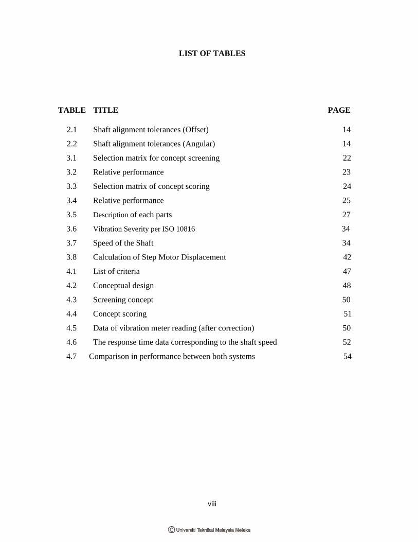
LIST OF TABLES
TABLE TITLE PAGE
2.1 Shaft alignment tolerances (Offset) 14
2.2 Shaft alignment tolerances (Angular) 14
3.1 Selection matrix for concept screening 22
3.2 Relative performance 23
3.3 Selection matrix of concept scoring 24
3.4 Relative performance 25
3.5 Description of each parts 27
3.6 Vibration Severity per ISO 10816 34
3.7 Speed of the Shaft 34
3.8 Calculation of Step Motor Displacement 42
4.1 List of criteria 47
4.2 Conceptual design 48
4.3 Screening concept 50
4.4 Concept scoring 51
4.5 Data of vibration meter reading (after correction) 50
4.6 The response time data corresponding to the shaft speed 52
4.7 Comparison in performance between both systems 54

ix
LIST OF FIGURES
FIGURE TITLE PAGE
2.1 Required Alignment for a Shaft 5
2.2 Parallel Misalignment 6
2.3 Angular Misalignment 7
2.4 Dial Indicator 9
2.5 Rim and Face Indicator Setup 9
2.6 Reverse Dial Indicator Method 10
2.7 The Overview of Laser Alignment 11
2.8 Scheme of a Laser Measuring System 11
2.9 Exhibits a Precut Stainless Steel Shim 12
2.10 Shimless Aligner 13
2.11 Alignment Tolerance Chart 15
2.12 (a) Linear Bearing (b) Linear Bearing with t-slot guide 16
2.13 Backlash Free Screw 17
2.14 Process Under Control 17
2.15 PID Controller 18
3.1 Project Flow Chart 20
3.2 Exploded View of the Footing System Parts 26
3.3 Dimension of the self-alignment footing system 28
3.4 variable elevation of the system 29
3.5 Footing System fabricated by Aluminum 29
3.6 5-axis CNC Milling machine 30
3.7 Flow chart of fabrication 31
3.8
Final prototype
32

x
3.9
3.10
3.11
3.12
3.13
3.14
3.15
3.16
3.17
3.18
3.19
4.1
4.2
4.3
4.4
Graph of ISO 7919 Mechanical vibration severity
Tachometer device
PID Controller system diagram
Accelerometer Sensor with Controller
System components (a) Motor drive (b) Stepper motor
Automated system of PID controller
Footing system (a) Motor drive (b) Stepper motor
Test Rig
Vibration Meter
System Installation
Machine controller
Graph Correction of vibration against shaft speed
Graph of response time against shaft speed
Graph of PID automated system for 600 RPM of shaft speed
Validation of product
33
35
36
36
38
39
43
44
45
45
46
53
54
53
56

xi
LIST OF APPENDICES
APPENDIX TITLE PAGE
A Gant Chart of MPII 63
xii
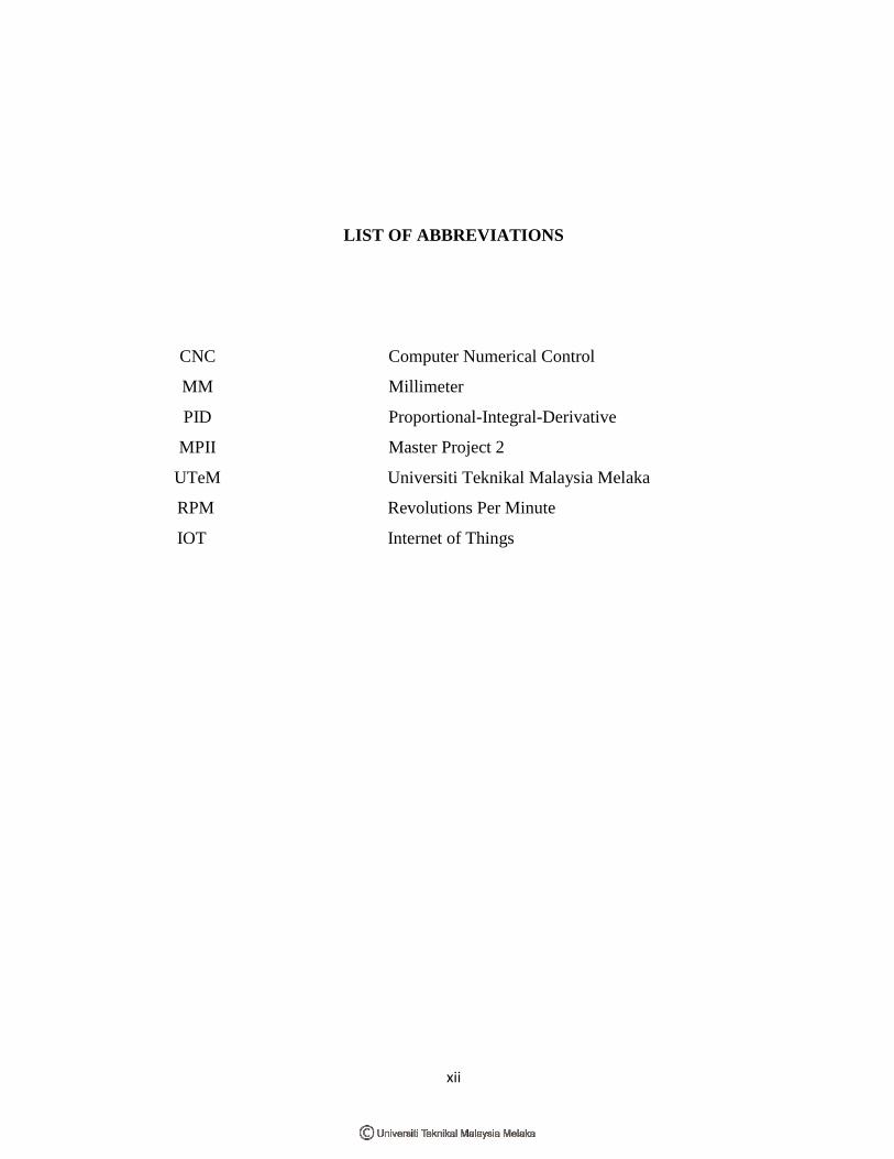
LIST OF ABBREVIATIONS
CNC Computer Numerical Control
MM Millimeter
PID Proportional-Integral-Derivative
MPII Master Project 2
UTeM Universiti Teknikal Malaysia Melaka
RPM Revolutions Per Minute
IOT Internet of Things
1
CHAPTER 1
INTRODUCTION
This particular chapter will describe shaft alignment in rotary machinery. This chapter
covers the background of the study, objectives of study, problem statement, scope of the project
and chapter overviews.
1.1 Background of Study
Nowadays, our daily life is surrounded by rotating dynamic machinery. After unbalance,
misalignment is accepted as the second most commonly observed disturbance source in rotor
systems (Patel and Darpe, 2009). Negligence of machine alignment is consuming 30% of the
machine’s downtime (Hariharan and Srinivasan, 2011). Misalignment happens when
centerlines of the motor and the driven device shafts are not positioned in the same axis.
Misalignment problem may cause up to 70% of the vibration problems observed in rotating
machines (Luis et al., 2014) Misalignment of rotating shaft generate, noise, coupling,
exaggerated vibrations, bearing temperature increases, and premature bearing, or shaft failure.
Poorly aligned shafts may cause serval machine problems: studies have shown that
misalignment of the shaft is the cause for around half of machine breakdowns. Thus, proper
shaft alignment affecting the smooth, effectiveness transportation of generating power to the
driven equipment via the motor. Attaining a correct shaft alignment when installing rotating
mechanical systems is essential apart.
2
1.2 Problem Statement
Misalignment is considered one of the main common problem in the machinery
industry. Over the years, a lot of researches have been done just to understand the rotor
dynamics phenomena. Shaft alignment is considered one of the most common form of
alignment performed on rotating machines(Lin et al., 2010). The alignment of the shaft by
using shim are difficult because of a pre-cut shim has its standard size, tolerances, and time
consuming, moreover it’s not accurate method to align the shaft due to the skills needed to
perform the alignment process. Therefore, using shimless footing system is implemented in
this project. There are two issues to be rectified. On the mechanical part, the quality of shimless
footing system was inadequate to do alignment task. The T-slot dependent in sliding motion
and ordinary screw were the major contribution to the backlash issue. It was proposed by this
project to improve new design for high accuracy sliding rack to replace current T-slot to
enhance the response time, along with backlash free screw for settling down the backlash issue.
Second issue is the controller itself which to introduce smart system (PID) that accommodate
with mechanical parts. Some controller need to be fine-tuned so that the system can performed
as desired.
1.3 Research Objective
The objectives are as follows:
i. To design an improve motorize self-alignment system by using PID controller.
ii. To fabricate a system with smooth tuning and could reduce vibration during the
shaft alignment process.
iii. To check the performance in terms of response time, and accuracy for motorize
self-alignment system.
3
1.4 Scope of Work
This project is to study and analyses the current design of shimless footing
system. This report explains in details the design and development of self-alignment
horizontal (Z axis) and vertical (Y axis) for rotating motor-pump shaft. The correction
done by this device only limited to 3 mm. The scope for the project as follows
It was proposed by this project to introduce high accuracy sliding rack to replace
current T-slot.
The common screw to control motion to be replaced with the backlash free type lead
screw.
The self-alignment footing product that made of aluminum is fabricated using
machining processes to form the final product.
The motorize system is then implemented and integrated with PID controller to
validate the performance during rotating shaft machinery.
4
CHAPTER 2
LITERATURE REVIEW
This chapter will explain about the literature review from the research regarding of shaft
misalignment, type of misalignment, causes and effects of misalignment, methods of alignment,
and methods of misalignment, PID controller system and the components involved in shaft
alignment.
2.1 Introduction
This session of the study will investigate more in the effect of misalignment on the
vibration and noise emission of the rotating speed machinery. This chapter reviews and
explains about the previous studies that have been done. Literature review examines
respectively to the source and describes to justify the statement with proof of research or study
in related field.
2.2 Shaft Alignment
Shaft is defined as a rotating machine element used to transfer the power from one part
to another. Shafts place members like gears or pulleys in their specific positions, torque will
transmit along with members when it is connecting together. Shaft alignment is the process
where two machines are positioned in collinear such that the power transferred from one shaft
to another (A Practical Guide to Shaft Alignment. 4th edn, 2002).
Shaft alignment is a coupling machine shaft-to-shaft alignment consisting of driver and
driven machine. The driver machine, such as electric motors, turbine or reciprocating machine,
has been designed to provide the driven machine with a coupling to rotate mechanical power.

5
The driven machine like a generator, a ventilator or a pump that generated power (Wowk,
2002).
The driver was transmitting power to the driven motor by connecting the two shafts to
each other. Both shafts ‘centerlines must remain in one straight line as they are coupled
together and rotate under their standard operating conditions. The main goal of shaft alignment
is to expand the operating life span of the dynamic rotating machine.(Al-Hussain and
Redmond, 2002).
The perfect alignment of the shaft will reduce the excessive axial and radial forces on
the bearings in order to protect the rotor's longer life and stability under its standard operating
conditions and reduce the amount of shaft bending due to the transfer of power from one
connection to another (Tsiafis et al., 2015). Figure 2.1 show the perfect alignment.
Figure 2.1: Required Alignment for a Shaft
2.3 Shaft Misalignment
Shaft misalignment is the deviation of the relative shaft position from the rotational
axis measured at the power transmission points during normal operation (Baer et al., 2013).
Failure to align shaft is liable for 50 percent of machine downtime and machine damage cost.
Implementing proper shaft alignment can prevent a large number of damage to machinery and
reduce downtime that causes loss to company and production. The alignment required is done
by adjusting the machine correctly by moving its feet (Gairola, 2004). The main reason for
alignment during rotation is to obtain coaxial centerlines. Company and machine downtime
cost increase dramatically if the shaft or belt on rotating components not matching, causes seals
and coupling damage (Luedeking, 2012c). Any misalignment between the centers of the
shaft’s rotation can cause vibration and additional loads that can result in premature wear,

6
catastrophic failure of the bearings, seals, the coupling itself and other machine components
when the shaft of tow rotating machine is coupled directly by fixable coupling (Bloch, 2004).
2.4 Type of Misalignment
Failure to align shaft is liable for 50% of machine downtime and machine damage cost.
Implementing proper shaft alignment can prevent a large number of damage to machinery and
reduce downtime that causes loss to company and production. There are two types of
misalignment parallel misalignment and angular misalignment (Huang, Zhou and Yang, 2011).
2.4.1 Parallel Misalignment
Offset or parallel misalignment occurs at the gap between two shafts centerlines.
Parallel misalignment can occur in horizontal and vertical direction. Offset that present in the
horizontal plane in which the movement will be left or right, and vertical plane that positioned
at different level up and down (Huang, 2005). Figure 2.2 shows the parallel misalignment
between the driver shaft and driven machine.
Figure 2.2: Parallel Misalignment (Mark et al., 2008)
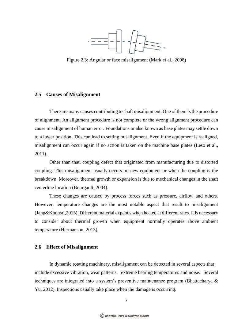
2.4.2 Angular Misalignment
The angular misalignment is occurring when the shaft motor is set in an angle to the
driven machine (not parallel). This type of misalignment may cause serious damage of the
driven equipment and the motor shaft due to the difference in slope. Figure 2.3 shows an
angular or face misalignment.
7
Figure 2.3: Angular or face misalignment (Mark et al., 2008)
2.5 Causes of Misalignment
There are many causes contributing to shaft misalignment. One of them is the procedure
of alignment. An alignment procedure is not complete or the wrong alignment procedure can
cause misalignment of human error. Foundations or also known as base plates may settle down
to a lower position. This can lead to setting misalignment. Even if the equipment is realigned,
misalignment can occur again if no action is taken on the machine base plates (Leso et al.,
2011).
Other than that, coupling defect that originated from manufacturing due to distorted
coupling. This misalignment usually occurs on new equipment or when the coupling is the
breakdown. Moreover, thermal growth or expansion is due to mechanical changes in the shaft
centerline location (Bourgault, 2004).
These changes are caused by process forces such as pressure, airflow and others.
However, temperature changes are the most notable aspect that result to misalignment
(Jang&Khonsri,2015). Different material expands when heated at different rates. It is necessary
to consider about thermal growth when equipment normally operates above ambient
temperature (Hermanson, 2013).
2.6 Effect of Misalignment
In dynamic rotating machinery, misalignment can be detected in several aspects that
include excessive vibration, wear patterns, extreme bearing temperatures and noise. Several
techniques are integrated into a system’s preventive maintenance program (Bhattacharya &
Yu, 2012). Inspections usually take place when the damage is occurring.
Copyright © 2022 FDOKUMEN