IMECE2014-39991 COMBUSTION CHARACTERISTICS OF JOJOBA METHYL ESTER AS AN ALTERNATIVE FUEL FOR GAS...
10
1 Copyright © 2014 by ASME ASME 2014 International Mechanical Engineering Congress & Exposition IMECE 2014November 14-20, 2014, Montreal, Canada IMECE2014-39991 COMBUSTION CHARACTERISTICS OF JOJOBA METHYL ESTER AS AN ALTERNATIVE FUEL FOR GAS TURBINE Ali M.A. Attia Mechanical Engineering Department, Benha Faculty of Engineering, Benha University 13512 - Benha, Qalubia, Egypt Radwan M. El-Zoheiry Mechanical Engineering Department, Benha Faculty of Engineering, Benha University 13512 - Benha, Qalubia, Egypt Hesham M. El-Batsh Mechanical Engineering Department, Benha Faculty of Engineering, Benha University 13512 - Benha, Qalubia, Egypt Mohamed S. Shehata Mechanical Engineering Department, Benha Faculty of Engineering, Benha University 13512 - Benha, Qalubia, Egypt ABSTRACT The strengthened requirements of new emission norms and the limited fuel resources are the major challenges for researchers over the world. The use of biofuels produced from vegetable oil will be a promising solution. In this case, Jojoba oil comes from very surprising plant as its seed contains 40-60% of its weight as raw oil and grows in desert. The trans-esterification process is used to convert jojoba oil into a Jojoba Methyl Ester (JME). This study aims to characterize the flame of JME as an alternative fuel in the gas turbines. Using of the premixed flame resulted in higher combustion efficiency and low emissions. The premixed flames for liquid fuels can be realized via use of lean premixed pre-vaporized (LPP) combustion method. In this work the jet fuel and blends of jet-JME fuel (with JME volume faction of 10, and 20%) are burned with LPP technique keeping the same equivalence ratio as it is used for burning the base jet fuel to determine the possibility to use the fuel mixture without any modifications in a specific LPP combustor. The main results indicate that, as volume content of JME increase the NOx emissions decrease to be lower than 10 ppm in case of B20. Moreover, the CO emission in case of B20 is higher than that of the jet fuel but at the end of the test section it does not exceed 0.15 %. In the same way, B20 produces higher UHC emissions than the jet fuel; however, at the end of the test section it does not exceed 80 ppm. So it can be concluded that blended Jojoba biodiesel can be used as an alternative fuel for jet fuel. Key Word: Jojoba oil, trans-esterification, lean premixed pre-vaporized flames, temperature distribution, emissions. 1. INTRODUCTION The necessity to protect human life throughout a continuously improving of the emission standards against the use of fossil fuels is faced with two major challenges for any nation; including the fast depletion of fossil fuel resources, and the accumulative environmental pollution [1]. At the same time, the gas turbine is widely used in different sectors including power generation, transportation and industrial applications where a large amount of fossil fuel is burned. These systems emit daily different toxic emissions as nitrogen oxides (NOx), carbon monoxide (CO), unburned hydrocarbons (UHC) in addition to tons of carbon dioxides (CO2); the major reason for greenhouse phenomenon. For reducing the level of toxic emissions, it is necessary to improve the fuel-air mixing as well as the combustion quality of the reactants. While to reduce the whole amount of CO2 emissions it is necessary to replace the high carbon content fuels with those containing lower carbon contents. The first target can be realized by the use of low NOx burners, and increasing the premixed part of the combustion process, while the second can be realized by use of those fuels based on renewable resources. In this case, the use of biofuel is a promising solution as an environmental friendly renewable substitute’s fuel with a closed life cycle so that the cumulative CO2 content will be null [2]. Different biodiesels have been recommended as gas turbine fuels [3, 4, and 5]. The liquid biofuels are commonly called biodiesel; as their physical properties approach those of petrol diesel. The biodiesel price depends mainly on the cost of the feedstock which represents
Transcript of IMECE2014-39991 COMBUSTION CHARACTERISTICS OF JOJOBA METHYL ESTER AS AN ALTERNATIVE FUEL FOR GAS...
1 Copyright © 2014 by ASME
ASME 2014 International Mechanical Engineering Congress & Exposition IMECE 2014November 14-20, 2014, Montreal, Canada
IMECE2014-39991
COMBUSTION CHARACTERISTICS OF JOJOBA METHYL ESTER AS AN ALTERNATIVE FUEL FOR GAS TURBINE
Ali M.A. Attia Mechanical Engineering Department, Benha
Faculty of Engineering, Benha University 13512 - Benha, Qalubia, Egypt
Radwan M. El-Zoheiry Mechanical Engineering Department, Benha
Faculty of Engineering, Benha University 13512 - Benha, Qalubia, Egypt
Hesham M. El-Batsh Mechanical Engineering Department, Benha
Faculty of Engineering, Benha University 13512 - Benha, Qalubia, Egypt
Mohamed S. Shehata Mechanical Engineering Department, Benha
Faculty of Engineering, Benha University 13512 - Benha, Qalubia, Egypt
ABSTRACT
The strengthened requirements of new emission norms and the limited fuel resources are the major challenges for researchers over
the world. The use of biofuels produced from vegetable oil will be a promising solution. In this case, Jojoba oil comes from very
surprising plant as its seed contains 40-60% of its weight as raw oil and grows in desert. The trans-esterification process is used to
convert jojoba oil into a Jojoba Methyl Ester (JME). This study aims to characterize the flame of JME as an alternative fuel in the gas
turbines. Using of the premixed flame resulted in higher combustion efficiency and low emissions. The premixed flames for liquid
fuels can be realized via use of lean premixed pre-vaporized (LPP) combustion method. In this work the jet fuel and blends of jet-JME
fuel (with JME volume faction of 10, and 20%) are burned with LPP technique keeping the same equivalence ratio as it is used for
burning the base jet fuel to determine the possibility to use the fuel mixture without any modifications in a specific LPP combustor.
The main results indicate that, as volume content of JME increase the NOx emissions decrease to be lower than 10 ppm in case of B20.
Moreover, the CO emission in case of B20 is higher than that of the jet fuel but at the end of the test section it does not exceed 0.15 %.
In the same way, B20 produces higher UHC emissions than the jet fuel; however, at the end of the test section it does not exceed 80
ppm. So it can be concluded that blended Jojoba biodiesel can be used as an alternative fuel for jet fuel.
Key Word: Jojoba oil, trans-esterification, lean premixed pre-vaporized flames, temperature distribution, emissions.
1. INTRODUCTION
The necessity to protect human life throughout a
continuously improving of the emission standards against the
use of fossil fuels is faced with two major challenges for any
nation; including the fast depletion of fossil fuel resources, and
the accumulative environmental pollution [1]. At the same time,
the gas turbine is widely used in different sectors including
power generation, transportation and industrial applications
where a large amount of fossil fuel is burned. These systems
emit daily different toxic emissions as nitrogen oxides (NOx),
carbon monoxide (CO), unburned hydrocarbons (UHC) in
addition to tons of carbon dioxides (CO2); the major reason for
greenhouse phenomenon. For reducing the level of toxic
emissions, it is necessary to improve the fuel-air mixing as well
as the combustion quality of the reactants. While to reduce the
whole amount of CO2 emissions it is necessary to replace the
high carbon content fuels with those containing lower carbon
contents. The first target can be realized by the use of low NOx
burners, and increasing the premixed part of the combustion
process, while the second can be realized by use of those fuels
based on renewable resources. In this case, the use of biofuel is
a promising solution as an environmental friendly renewable
substitute’s fuel with a closed life cycle so that the cumulative
CO2 content will be null [2]. Different biodiesels have been
recommended as gas turbine fuels [3, 4, and 5]. The liquid
biofuels are commonly called biodiesel; as their physical
properties approach those of petrol diesel. The biodiesel price
depends mainly on the cost of the feedstock which represents
2 Copyright © 2014 by ASME
more than 75% of the biodiesel total cost [2, 5, 7, and 8].
Therefore, the selection of the suitable feedstock for biodiesel
production is a very important step to make biodiesel applicable
in the commercial mode. In general, biodiesel feedstock can be
divided into four main categories; including edible vegetable
oils (such as canola, soybean, peanut, sunflower, palm and
coconut oil), nonedible vegetable oils (such as Jojopa and
Jatropha curcas), waste or recycled oils, and the animal fats ([6]
and [8]). Traditionally, biodiesel has been produced from edible
oils due to their low free fatty acids. However, the use of edible
oils as feedstock for biodiesel production results in additional
nutrition problems related to the food versus fuel issues leading
to food crises. On the other hand, the use of non-edible oils
may significantly reduce the cost of biodiesel production
especially in poor countries which can barely afford the high
cost of edible oils [5 and 7]. Moreover the oils from the non-
edible resources are, as a rule, unsuitable for the human usage
due to the presence of toxic compounds [5]. Thus, focus should
be shifted towards the use of non-edible resources as biodiesel
feedstocks. These oils are not only suitable for human nutrition
but also can grow in the barren lands and/or need waste water
[2, 5 and 7]. Jojoba oil appears to be one of these recommended
vegetable oils for biodiesel production [9]. Jojoba plant is a
shrub that grows very well in deserts and its cake is the solid
part produced upon processing of the jojoba seeds for oil
extraction [10]. Moreover, Jojoba plant lives for more than one
hundred and fifty years and has unique properties as its seeds
contain about 40 – 50 wt. % as raw oil–wax [10-12]. For these
features of jojoba oil, it is expected to be an attractive feedstock
for biodiesel production [12 and 17]. In this direction, the
Egyptian jojoba oil (GREEN GOLD) seems to be a proper
choice for biodiesel production due to its availability in Egypt,
its low prices (0.8 €/kg), and its low chemical reactivity [14].
The modern gas turbines have two major challenges for
development; including improving their thermal efficiency and
reducing their emission level of CO and NOx [3]. Thermal
efficiency can be improved by considering the fuel combustion
to reduce the energy loss due to incomplete mixing of fuel with
air that usually burns in a diffusion mode. In this case, the use
of premixed combustion will ensure the best economic use of
the available fuel and so the maximum thermal efficiency.
Regarding the reduction of emission level, different methods to
prevent the formation of high temperature spots and to improve
the fuel-air mixing have been recommended [3]. Among of
these methods, the use of Lean Premixed Pre-vaporization
(LPP) concept realizing at the same moment both the use of
premixed flame as well as the use of lean mixture and so it
represents the ultimate solution in this regard [3]. The LPP
concept is based on operating the combustor at low equivalence
ratio and supplying the combustor with a homogeneous
combustible mixture. As a result of that, the combustion
process proceeds at a uniformly low temperature, eliminates the
droplet combustion and very little NOx is formed [3]. For this
reasons the LPP will be used in this research.
Generally, the behavior of the NOx emission in the
biodiesel combustion is not clear. There are many researches
recorded a NOx reduction with the use of biodiesel [5, 17, 18,
and 19]. On the other hand, other researches cited that the NOx
emission increases with the use of biodiesel [4, 15, and 16].
Therefore, a study on the flame structure and the combustion
characteristics of the biodiesel is necessary to get better
understanding about this discrepancy. At the same time, the
research regarding the combustion of the biodiesel in the LPP
combustors has a shortage especially for biodiesel produced
from jojoba oil. Therefore, this study is conducted in a LPP
combustor.
This work is directed to study the effect of JME as a blend
on the flame structure of jet fuel in a laboratory research lean
premixed pre-vaporized combustor.
2. MATERIALS AND METHODS
The first step in this study is the preparation of the
biodiesel from the raw jojoba oil. After that, JME is mixed with
jet fuel and burned within a lean premixed pre-vaporized
combustor with a swirl burner tip to study the combustion
characteristics of the predefined fuel blend. The combustion
characteristics have been determined as a function of
temperature and emission distribution across the flame zone.
The raw Jojoba oil is converted to Jojoba Methyl Ester (JME)
via a trans-esterification process; a chemical reaction between
methanol and raw Jojoba oil in the presence of catalyst of
calcium hydroxide (KOH). The following section will explain
the trans-esterification process of the JME.
2.1. Trans-esterification process
The raw Jojoba oil used in the present work is
commercially produced by the Egyptian Natural Oil Company
and supplied with technical specifications in comparison with
the corresponding values reported in the literature as presented
in Table 1 [31]. The methanol used in the preparation process of
purity > 99.8% is supplied by Gomhoria Co and the catalyst
used (KOH) has a purity > 85%.
The alcohol and catalyst concentrations and procedure
used in the trans-esterification process are attained from the
previous works to receive JME with minimum viscosity and
acceptable yield [12-14]. In the present work, JME is received
via trans-esterification following this procedure:
1- An l liter of raw jojoba oil is slowly heated within a water
bath up to 60 °C while it is stirred mechanically with 600
rpm.
2- A 0.5 wt. % KOH from the raw oil is solved within 300 ml
methanol forming methoxide. The amount of methanol used
in this process will give the methanol to raw oil molar ratio
of 6:1.
3- After that the prepared methoxide is added to the heated oil
in two stages while stiring at a speed of 600 rpm. Firstly
75% of the solvent was added while the remaining amount
is added after 10 minutes. During the reaction time, the
mixture temperature is held constant at 60±1 °C.
4- After 2 hours from the starting of the reactants, the product
is left in a separating funnel for 12 hours. During this period
3 Copyright © 2014 by ASME
the product is separated in two layers; the upper layer
contains JME and the lower contains glyceride with
remaining impurities of catalyst.
5- To accelerate the separation process, the product is washed
with warm water from 4 to 5 times until a clean water is
observed.
6- Finally the produced methyl ester was heated up to 100 ˚C
in order to eliminate the remaining non-reacted methanol or
washing water.
After that, the physical and chemical properties of the
produced JME and the jet fuel that will be used in the present
work have been determined as tabulated in Table 2.
Table 1 Technical specifications of the used jojoba oil compared
with that used by Surname [8]
Characteristic Current
Jojoba oil
Oil used
by [8]
Specific gravity at 25 º C 0.863 0.861
Flash point CS cc 9a-48, º C 295 275
Freezing point, º C 10.6 – 7.0 ***
Melting points, º C 6.8 – 7.0 ***
Boiling point at 1 am under N2, º C 398 ***
Kinematic viscosity at
- Cannon-Fenske, 25 º C, cSt.
- Cannon-Fenske, 100 º C, cSt.
50 cSt
27 cSt
***
**
Viscosity index 232 ****
Iodine value, g/100g 82 81
Average molecular weight, kg/K.mole 606 ***
Heat of fusion by calorimatry, cal/g 21 ***
Fire Point, °C 338 322
Cetane number 53.5 ***
Table 2 Properties of the JME and those of jet fuel
Property Test method JME Jet
Specific gravity at 15°C ASTM D-1298 0.8645 0.797
Viscosity at 40°C, cSt ASTM D-445 11.72 1.08
Calorific value, MJ/kg ASTM D-240 44.866 43.465
Molecular weight, kg/kmol **** 350.73 148.025
Elemental analysis, % by mass:
Carbon content PerkinElmer 2400
Series II CHNS/O
Elemental
Analyzer
76.01 86.51
Hydrogen content 10.05 13.48
Sulfur content 0.3 Nil
Oxygen content 13.64 Nil
Nitrogen content Nil Nil
Boiling point at 1 atm ASTM D-86 350 163
2.2. Experimental apparatus
The experiments have been conducted in a lean premixed
pre-vaporized (LPP) combustor (See Figures 1 – 3). In this
experimental setup, cold air is supplied from a screw
compressor through a pressure accumulator of 2 m3 capacity.
The compressor is allowed to switch on as the pressure fall
between 8 and switch off when the pressure reaches 10 bar.
Moreover, the air flow rate is adjusted by means of the gate
valve while the upstream pressure is kept constant by means of
the pressure regulator installed on the compressor oulet. This
air is preheated using two Omega-AHPF inline air heaters. The
supplied voltage to heaters is regulated by variable AC
transformer (variac) to control the temperature of the pre-
defined flow rate. The fuel is supplied from a pressurized fuel
tank through a pressure atomizer nozzle (Delvan, 0.5 gph,
30°W). The fuel flow rate is regulated by controlling the tank
pressure. In this way the fuel tank is pressurized by the
compressed air and the pressure is controlled by the pressure
regulator. The fuel nozzle is calibrated against the tank pressure
to define the nozzle fuel flow rate for both base fuel and
blended fuels. Furthermore the fuel flow rate is measured by a
calibrated Dwyer-DR (model DR224632) rotameter in addition
to the previous calibration of the fuel nozzle at the specific
operating pressure. The fuel is injected into the stream of
preheated air throughout a steel mixing pipe. Then a free length
of 1 m of this pipe before burner is used to achieve good
mixing between air and injected fuel and to ensure fuel fully
vaporization before their combustion. To stabilize the
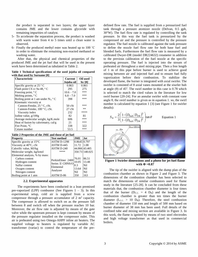
developed flame, the burner is integrated with axial swirler. The
swirler is consisted of 8 axial vanes mounted at the siwrler hub
at angle (θ) of 45°. The swirl number in this case is 0.78 which
is selected to match the cited values in the literature for low
swirl burner [20-24]. For an annular swirler with constant vane
angle θ, the swirl number is given as in equation 1. so, the swirl
number is calculated by equation 1 [3] (see Figure 1 for swirler
details):
tan
1
1
3
22
3
SWhub
SWhubN
DD
DDS Equation 1
Figure 1 Swirler dimensions and a photo for jet fuel flame
with Φ =0.87
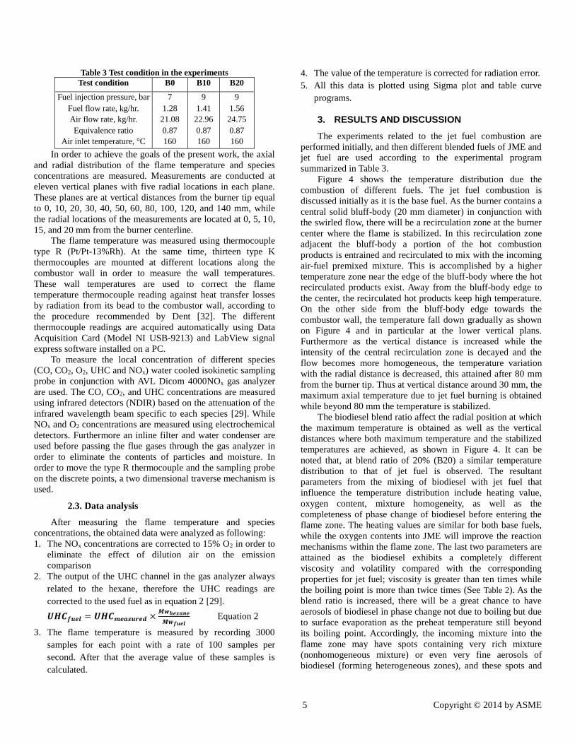
The tip of the swirler is aligned with the dump plan of the
combustion chamber as shown in Figure 2 and Figure 3. The
dimensions of the combustion chamber has been selected to
match the dimensions of similar combustors used for flame
study in the literature [25-28]. It can be concluded from these
materials that, the combustion chamber diameter is four times
that of the burner (DC.C. = 4 DB) and the length of the
combustion chamber is greater than ten times the burner
diameter (LC.C. > 10 DB). Therefore, the steel combustion
chamber of diameter 150 mm and length of 500 mm based on
burner diameter of 38 mm has been used. Full details of the
confined tube and mixing section are available in Figure 3. In
this work, the flame is ignited by means of two steel electrodes
and high voltage transformer as that used in commercial
boilers.
4 Copyright © 2014 by ASME
DAQ
PC
GAS ANALYZER
132 4
7 8
9
5
6
25
12
11
13
14
16
15
17
18
19
20
21
2322
27
24
1026
26
27
27
Symbol / Abbreviation Description
1 Screw compressor
2 Ball valve
3 Pressure Accumulator
4 Pressure Regulator
5 Gate Valve
6 Pressure Gauge
7 Fuel Tank
8 Fuel Rtoameter
9 Air Rotameter
10 Inline Air Heater
Mixing Steel Pipe
Pressure Atomizer
Burnner
Spark Electrodes
Type R Thermocouple
Sampling Probe
Filter
Condensate Water filter
Gas Analyzer
Data Acquisition
Personal Computer
Cooling Water In
Cooling Water Out
Transformer
Switch
Voltage Variac
Electrical Source
Type K Thermocouple
11
12
13
14
15
16
17
18
19
20
21
22
23
24
25
26
27
28
28
29 29
30
Digital Thermometer29Combustion Chamber30
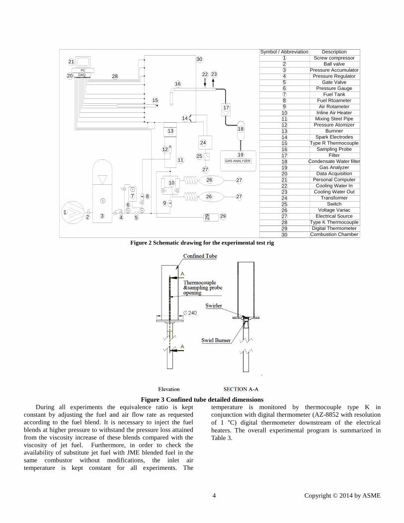
Figure 2 Schematic drawing for the experimental test rig
Figure 3 Confined tube detailed dimensions
During all experiments the equivalence ratio is kept
constant by adjusting the fuel and air flow rate as requested
according to the fuel blend. It is necessary to inject the fuel
blends at higher pressure to withstand the pressure loss attained
from the viscosity increase of these blends compared with the
viscosity of jet fuel. Furthermore, in order to check the
availability of substitute jet fuel with JME blended fuel in the
same combustor without modifications, the inlet air
temperature is kept constant for all experiments. The
temperature is monitored by thermocouple type K in
conjunction with digital thermometer (AZ-8852 with resolution
of 1 °C) digital thermometer downstream of the electrical
heaters. The overall experimental program is summarized in
Table 3.
5 Copyright © 2014 by ASME
Table 3 Test condition in the experiments
Test condition B0 B10 B20
Fuel injection pressure, bar 7 9 9
Fuel flow rate, kg/hr. 1.28 1.41 1.56
Air flow rate, kg/hr. 21.08 22.96 24.75
Equivalence ratio 0.87 0.87 0.87
Air inlet temperature, °C 160 160 160
In order to achieve the goals of the present work, the axial
and radial distribution of the flame temperature and species
concentrations are measured. Measurements are conducted at
eleven vertical planes with five radial locations in each plane.
These planes are at vertical distances from the burner tip equal
to 0, 10, 20, 30, 40, 50, 60, 80, 100, 120, and 140 mm, while
the radial locations of the measurements are located at 0, 5, 10,
15, and 20 mm from the burner centerline.
The flame temperature was measured using thermocouple
type R (Pt/Pt-13%Rh). At the same time, thirteen type K
thermocouples are mounted at different locations along the
combustor wall in order to measure the wall temperatures.
These wall temperatures are used to correct the flame
temperature thermocouple reading against heat transfer losses
by radiation from its bead to the combustor wall, according to
the procedure recommended by Dent [32]. The different
thermocouple readings are acquired automatically using Data
Acquisition Card (Model NI USB-9213) and LabView signal
express software installed on a PC.
To measure the local concentration of different species
(CO, CO2, O2, UHC and NOx) water cooled isokinetic sampling
probe in conjunction with AVL Dicom 4000NOx gas analyzer
are used. The CO, CO2, and UHC concentrations are measured
using infrared detectors (NDIR) based on the attenuation of the
infrared wavelength beam specific to each species [29]. While
NOx and O2 concentrations are measured using electrochemical
detectors. Furthermore an inline filter and water condenser are
used before passing the flue gases through the gas analyzer in
order to eliminate the contents of particles and moisture. In
order to move the type R thermocouple and the sampling probe
on the discrete points, a two dimensional traverse mechanism is
used.
2.3. Data analysis
After measuring the flame temperature and species
concentrations, the obtained data were analyzed as following:
1. The NOx concentrations are corrected to 15% O2 in order to
eliminate the effect of dilution air on the emission
comparison
2. The output of the UHC channel in the gas analyzer always
related to the hexane, therefore the UHC readings are
corrected to the used fuel as in equation 2 [29].
𝑼𝑯𝑪𝒇𝒖𝒆𝒍 = 𝑼𝑯𝑪𝒎𝒆𝒂𝒔𝒖𝒓𝒆𝒅 ×𝑴𝒘𝒉𝒆𝒙𝒂𝒏𝒆
𝑴𝒘𝒇𝒖𝒆𝒍 Equation 2
3. The flame temperature is measured by recording 3000
samples for each point with a rate of 100 samples per
second. After that the average value of these samples is
calculated.
4. The value of the temperature is corrected for radiation error.
5. All this data is plotted using Sigma plot and table curve
programs.
3. RESULTS AND DISCUSSION
The experiments related to the jet fuel combustion are
performed initially, and then different blended fuels of JME and
jet fuel are used according to the experimental program
summarized in Table 3.
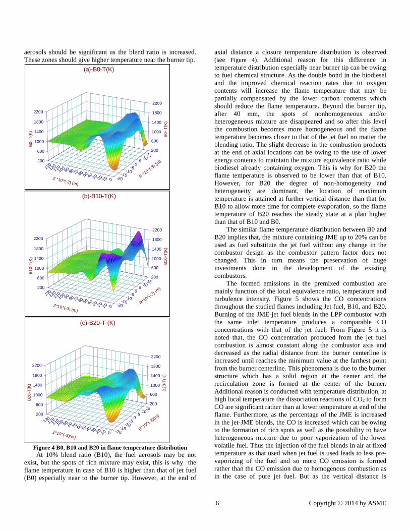
Figure 4 shows the temperature distribution due the
combustion of different fuels. The jet fuel combustion is
discussed initially as it is the base fuel. As the burner contains a
central solid bluff-body (20 mm diameter) in conjunction with
the swirled flow, there will be a recirculation zone at the burner
center where the flame is stabilized. In this recirculation zone
adjacent the bluff-body a portion of the hot combustion
products is entrained and recirculated to mix with the incoming
air-fuel premixed mixture. This is accomplished by a higher
temperature zone near the edge of the bluff-body where the hot
recirculated products exist. Away from the bluff-body edge to
the center, the recirculated hot products keep high temperature.
On the other side from the bluff-body edge towards the
combustor wall, the temperature fall down gradually as shown
on Figure 4 and in particular at the lower vertical plans.
Furthermore as the vertical distance is increased while the
intensity of the central recirculation zone is decayed and the
flow becomes more homogeneous, the temperature variation
with the radial distance is decreased, this attained after 80 mm
from the burner tip. Thus at vertical distance around 30 mm, the
maximum axial temperature due to jet fuel burning is obtained
while beyond 80 mm the temperature is stabilized.
The biodiesel blend ratio affect the radial position at which
the maximum temperature is obtained as well as the vertical
distances where both maximum temperature and the stabilized
temperatures are achieved, as shown in Figure 4. It can be
noted that, at blend ratio of 20% (B20) a similar temperature
distribution to that of jet fuel is observed. The resultant
parameters from the mixing of biodiesel with jet fuel that
influence the temperature distribution include heating value,
oxygen content, mixture homogeneity, as well as the
completeness of phase change of biodiesel before entering the
flame zone. The heating values are similar for both base fuels,
while the oxygen contents into JME will improve the reaction
mechanisms within the flame zone. The last two parameters are
attained as the biodiesel exhibits a completely different
viscosity and volatility compared with the corresponding
properties for jet fuel; viscosity is greater than ten times while
the boiling point is more than twice times (See Table 2). As the
blend ratio is increased, there will be a great chance to have
aerosols of biodiesel in phase change not due to boiling but due
to surface evaporation as the preheat temperature still beyond
its boiling point. Accordingly, the incoming mixture into the
flame zone may have spots containing very rich mixture
(nonhomogeneous mixture) or even very fine aerosols of
biodiesel (forming heterogeneous zones), and these spots and
6 Copyright © 2014 by ASME
aerosols should be significant as the blend ratio is increased.
These zones should give higher temperature near the burner tip.
Figure 4 B0, B10 and B20 in flame temperature distribution
At 10% blend ratio (B10), the fuel aerosols may be not
exist, but the spots of rich mixture may exist, this is why the
flame temperature in case of B10 is higher than that of jet fuel
(B0) especially near to the burner tip. However, at the end of
axial distance a closure temperature distribution is observed
(see Figure 4). Additional reason for this difference in
temperature distribution especially near burner tip can be owing
to fuel chemical structure. As the double bond in the biodiesel
and the improved chemical reaction rates due to oxygen
contents will increase the flame temperature that may be
partially compensated by the lower carbon contents which
should reduce the flame temperature. Beyond the burner tip,
after 40 mm, the spots of nonhomogeneous and/or
heterogeneous mixture are disappeared and so after this level
the combustion becomes more homogeneous and the flame
temperature becomes closer to that of the jet fuel no matter the
blending ratio. The slight decrease in the combustion products
at the end of axial locations can be owing to the use of lower
energy contents to maintain the mixture equivalence ratio while
biodiesel already containing oxygen. This is why for B20 the
flame temperature is observed to be lower than that of B10.
However, for B20 the degree of non-homogeneity and
heterogeneity are dominant, the location of maximum
temperature is attained at further vertical distance than that for
B10 to allow more time for complete evaporation, so the flame
temperature of B20 reaches the steady state at a plan higher
than that of B10 and B0.
The similar flame temperature distribution between B0 and
B20 implies that, the mixture containing JME up to 20% can be
used as fuel substitute the jet fuel without any change in the
combustor design as the combustor pattern factor does not
changed. This in turn means the preservation of huge
investments done in the development of the existing
combustors.
The formed emissions in the premixed combustion are
mainly function of the local equivalence ratio, temperature and
turbulence intensity. Figure 5 shows the CO concentrations
throughout the studied flames including Jet fuel, B10, and B20.
Burning of the JME-jet fuel blends in the LPP combustor with
the same inlet temperature produces a comparable CO
concentrations with that of the jet fuel. From Figure 5 it is
noted that, the CO concentration produced from the jet fuel
combustion is almost constant along the combustor axis and
decreased as the radial distance from the burner centerline is
increased until reaches the minimum value at the farthest point
from the burner centerline. This phenomena is due to the burner
structure which has a solid region at the center and the
recirculation zone is formed at the center of the burner.
Additional reason is conducted with temperature distribution, at
high local temperature the dissociation reactions of CO2 to form
CO are significant rather than at lower temperature at end of the
flame. Furthermore, as the percentage of the JME is increased
in the jet-JME blends, the CO is increased which can be owing
to the formation of rich spots as well as the possibility to have
heterogeneous mixture due to poor vaporization of the lower
volatile fuel. Thus the injection of the fuel blends in air at fixed
temperature as that used when jet fuel is used leads to less pre-
vaporizing of the fuel and so more CO emission is formed
rather than the CO emission due to homogenous combustion as
in the case of pure jet fuel. But as the vertical distance is
-20-15
-10-5
05
1015
R *10^(
-3) (
m)
0102030405060708090100110120130
Z *10^(-3) (m)
200
200600
6001000
10001400
14001800
18002200
2200
B0
- T
(K)
B0
- T
(K)
(a)-B0-T(K)
-20-15
-10-5
05
1015
R*10^(
-3) (
m)
0102030405060708090100110120130
Z*10^(-3) (m)
200
200600
6001000
10001400
14001800
18002200
2200
B1
0-T
(K)
B1
0-T
(K)
(b)-B10-T(K)
-20-15
-10-5
05
1015
R*10^(
-3)(m
)
0102030405060708090100110120130
Z*10^(-3)(m)
200
200600
6001000
10001400
14001800
18002200
2200
B2
0-T
(K)
B2
0-T
(K)
(c)-B20-T (K)

7 Copyright © 2014 by ASME
increased, the mixture homogeneity is improved and the local
temperature is reduced and so CO emissions are decreased
approaching the concentrations obtained from jet fuel
combustion. This CO can be reduced by simply increase the
inlet temperature to be closer to the boiling point of the JME.
Figure 5 B0, B10 and B20 in flame CO concentrations distribution
The UHC concentration throughout the flame is controlled
by good mixing of reactants (gas mixture homogeneity), the
fuel degradation mechanism as well as the mixture strength. Its
level will be high for nonhomogeneous, rich mixture
combustion of heavy fuels. As the UHC are usually formed
during fuel cracking, the high temperature will play a great
influence on their oxidation to form non-pollutant emissions.
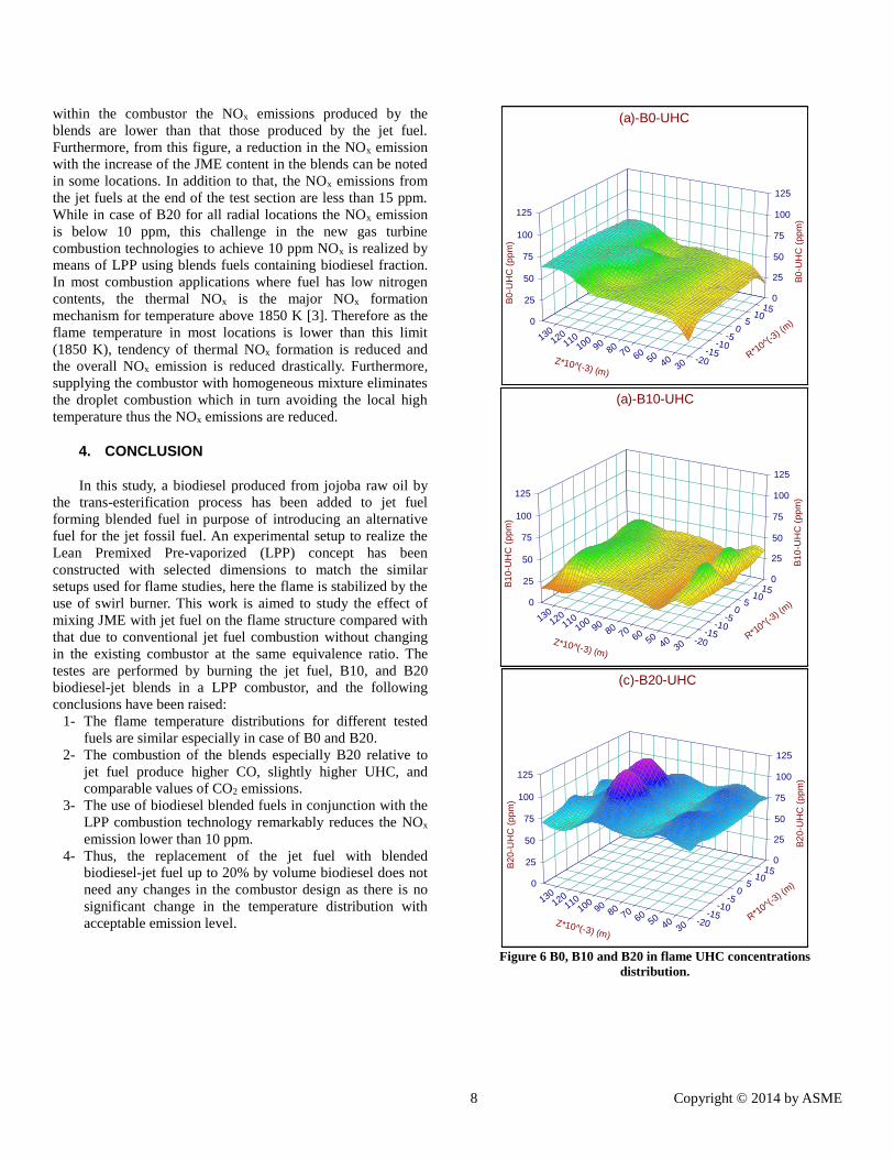
Figure 6 shows the UHC emissions distribution for the jet fuel
and blends. This figure reveals that the UHC emission from the
jet fuel combustion is increased with the vertical distance above
the burner tip due to the effect of temperature. On the other
hand, in case of B10, the UHC emissions are increased with
vertical distance till reaches the maximum value in most radial
locations after 110 mm from the burner tip due to the non-
homogeneity and the possibility to have a heterogeneous
mixture. After that, the UHC takes to decrease with the vertical
distance to reach the minimum value at the end of the test
section.
In case of B20 and in the flame core, the UHC behaves as
in case of B10 as shown in Figure 6. Far away from the flame
core, the UHC in case of B20 almost constant along the test
section length at each radial location. Furthermore, Figure 6
revealed that, the UHC produced from B10 combustion is
lower than that in case of B0 and B20. This decrease of the
UHC in case of B10 can be owing to the positive effect of the
oxygen content that competes the negative effect of mixture
non-quality. The oxygen contents generally improve the
reaction kinetics and so improving the combustion process
leading to a remarkable reduction of the UHC formation. While
in case of B20 the negative effects are higher leading to
increase the UHC formation than that of B10. These effects
include the poor mixing of reactants as well as the increase of
carbon double bonds in case of B20 compared with the case of
B10 and B0. From another point of view, at the end of the test
section and in the worst case, the UHC produced from B20 was
higher than that of B0 by not more than 15 ppm which is not a
big difference. Furthermore as the UHC in case B0 increases
with the vertical distance and in case of B20 remains constant
or falls down, it is observed that at higher levels the UHC from
B20 is lower than that of B0.
The results presented in Figure 7 revealed that, the CO2
emissions from the blends and that from the jet fuel have the
same behavior. Furthermore it is noted that, at the farthest point
from the burner the percentage of CO2 produced from the
blends are very close to that from the jet fuel combustion. But
in contrast to the fossil fuels such as the jet fuel, the use of
biodiesel does not add any CO2 to the atmosphere, it just
recycles what was already there. So the use of biodiesel as a
blend with the fossil fuel actually reduce the net value of the
CO2 added to the atmosphere and so reduces the greenhouse
effect.
Figure 8 represents the NOx distributions in case of jet fuel
and JME-jet fuel blends. In this figure, the NOx is referenced to
15% oxygen on a dry basis in order to remove ambiguity during
the comparison of the different sets of experimental data. The
results presented in this figure reveals that, in most locations
-20-15
-10-5
05
1015
R*10^(
-3) (
m)
30405060708090100110120130
Z*10^(-3) (m)
0
00.05
0.050.1
0.10.15
0.150.2
0.20.25
0.25
B0
-CO
%
B0
-CO
%
(a)-B0-CO
-20-15
-10-5
05
1015
R*10^(
-3) (
m)
30405060708090100110120130
Z*10^(-3) (m)
0
00.05
0.050.1
0.10.15
0.150.2
0.20.25
0.25
B1
0-C
O %
B1
0-C
O %
(b)-B10-C0
-20-15
-10-5
05
1015
R*10^(
-3) (
m)
30405060708090100110120130
Z*10^(-3) (m)
0
00.05
0.050.1
0.10.15
0.150.2
0.20.25
0.25
B2
0-C
O %
B2
0-C
O %
(c)-B20-CO
8 Copyright © 2014 by ASME
within the combustor the NOx emissions produced by the
blends are lower than that those produced by the jet fuel.
Furthermore, from this figure, a reduction in the NOx emission
with the increase of the JME content in the blends can be noted
in some locations. In addition to that, the NOx emissions from
the jet fuels at the end of the test section are less than 15 ppm.
While in case of B20 for all radial locations the NOx emission
is below 10 ppm, this challenge in the new gas turbine
combustion technologies to achieve 10 ppm NOx is realized by
means of LPP using blends fuels containing biodiesel fraction.
In most combustion applications where fuel has low nitrogen
contents, the thermal NOx is the major NOx formation
mechanism for temperature above 1850 K [3]. Therefore as the
flame temperature in most locations is lower than this limit
(1850 K), tendency of thermal NOx formation is reduced and
the overall NOx emission is reduced drastically. Furthermore,
supplying the combustor with homogeneous mixture eliminates
the droplet combustion which in turn avoiding the local high
temperature thus the NOx emissions are reduced.
4. CONCLUSION
In this study, a biodiesel produced from jojoba raw oil by
the trans-esterification process has been added to jet fuel
forming blended fuel in purpose of introducing an alternative
fuel for the jet fossil fuel. An experimental setup to realize the
Lean Premixed Pre-vaporized (LPP) concept has been
constructed with selected dimensions to match the similar
setups used for flame studies, here the flame is stabilized by the
use of swirl burner. This work is aimed to study the effect of
mixing JME with jet fuel on the flame structure compared with
that due to conventional jet fuel combustion without changing
in the existing combustor at the same equivalence ratio. The
testes are performed by burning the jet fuel, B10, and B20
biodiesel-jet blends in a LPP combustor, and the following
conclusions have been raised:
1- The flame temperature distributions for different tested
fuels are similar especially in case of B0 and B20.
2- The combustion of the blends especially B20 relative to
jet fuel produce higher CO, slightly higher UHC, and
comparable values of CO2 emissions.
3- The use of biodiesel blended fuels in conjunction with the
LPP combustion technology remarkably reduces the NOx
emission lower than 10 ppm.
4- Thus, the replacement of the jet fuel with blended
biodiesel-jet fuel up to 20% by volume biodiesel does not
need any changes in the combustor design as there is no
significant change in the temperature distribution with
acceptable emission level.
Figure 6 B0, B10 and B20 in flame UHC concentrations
distribution.
-20-15
-10-5
05
1015
R*10^(
-3) (
m)
30405060708090100110120130
Z*10^(-3) (m)
0
025
2550
5075
75100
100125
125
B0
-UH
C (
pp
m)
B0
-UH
C (
pp
m)
(a)-B0-UHC
-20-15
-10-5
05
1015
R*10^(
-3) (
m)
30405060708090100110120130
Z*10^(-3) (m)
0
025
2550
5075
75100
100125
125
B1
0-U
HC
(p
pm
)
B1
0-U
HC
(p
pm
)
(a)-B10-UHC
-20-15
-10-5
05
1015
R*10^(
-3) (
m)
30405060708090100110120130
Z*10^(-3) (m)
0
025
2550
5075
75100
100125
125
B2
0-U
HC
(p
pm
)
B2
0-U
HC
(p
pm
)
(c)-B20-UHC

9 Copyright © 2014 by ASME
Figure 7 B0, B10 and B20 in flame CO2 concentrations
distribution.
Figure 8 B0, B10 and B20 in flame NOx concentrations
distribution.
REFERENCES
[1] Mujeebu M. A., Abdullah M.Z., Abu Bakar M.Z., Mohamad
A.A., Muhad R.M.N., Abdullah M.K. Combustion in porous
media and its applications – A comprehensive survey. Journal
of Environmental Management 2009; 90: 2287–2312.
-20-15
-10-5
05
1015
R*10^(
-3) (
m)
30405060708090100110120130
Z*10^(-3) (m)
0
01
12
23
34
45
56
67
78
8
B0
-CO
2 %
B0
-CO
2 %
(a)-B0 CO2
-20-15
-10-5
05
1015
R*10^(
-3)(m
)
30405060708090100110120130
Z*10^(-3)(m)
0
01
12
23
34
45
56
67
78
8
B1
0-C
O2
%
B1
0-C
O2
%
(b)-B10 CO2
-20-15
-10-5
05
1015
R*10^(
-3)(m
)
30405060708090100110120130
Z*10^(-3)(m)
0
01
12
23
34
45
56
67
78
8
B2
0-C
O2
%
B2
0-C
O2
%
(c)-B20 CO2
-20-15
-10-5
05
1015
R*10^(
-3)(m
)
30405060708090100110120130
Z*10^(-3)(m)
0
05
510
1015
1520
2025
2530
30
B0
-NO
x (
pp
m)
B0
-NO
x (
pp
m)
(a)-B0-NOx
-20-15
-10-5
05
1015
R*10^(
-3)(m
)
30405060708090100110120130
Z*10^(-3)(m)
0
05
510
1015
1520
2025
2530
30
B1
0-N
Ox (
pp
m)
B1
0-N
Ox (
pp
m)
(b)-B10-NOx
-20-15
-10-5
05
1015
R*10^(
-3)(m
)
30405060708090100110120130
Z*10^(-3)(m)
0
05
510
1015
1520
2025
2530
30
B2
0-N
Ox (
pp
m)
B2
0-N
Ox (
pp
m)
(c)-B20-NOx
10 Copyright © 2014 by ASME
[2] Demirbas A. Political, economic and environmental
impacts of biofuels: A review. Applied Energy 2009; 86: S108-
S117.
[3] Lefebvre A.H., Ballal D.R. Gas turbine combustion. Third
edition.
[4] Bolszo C.D., McDonell V.G. Emissions optimization of a
biodiesel fired gas turbine. Proceedings of the Combustion
Institute 2009; 32: 2949-2956.
[5] Habib Z., Parthasarathy R., Gollahalli S. Performance and
emission characteristics of biofuel in a small-scale gas turbine
engine. Applied Energy 2010; 87: 1701-1709.
[6] Rutz D., Janssen R. Biofuel technology handbook. 2007
[7] Atabani A.E., Mahlia T.M.I., Masjuki H.H., Badruddin I. A.
A comparative evaluation of physical and chemical properties
of biodiesel synthesized from edible and non-edible oils and
study on the effect of biodiesel blending. Energy 2013; 58: 296-
304.
[8] Mofijur M., Atabani A.E., Masjuki H.H., Kalam M.A.,
Masum B.M. A study on the effects of promising edible and
non-edible biodiesel feedstocks on engine performance and
emissions production: A comparative evaluation. Renewable
and Sustainable Energy Reviews 2013; 23: 391-404.
[9] Selim M.Y.E., Radwan M.S., Elfeky S.M.S. Combustion of
jojoba methyl ester in an indirect injection diesel engine.
Renewable Energy 2003; 28:1401-1420.
[10]Al-Widyan M.I., Al-Muhtaseb M.A. Experimental
investigation of jojoba as a renewable energy source. Energy
Conversion and Management 2010; 51:1702-1707.
[11] Selim M.Y.E. Reducing the viscosity of Jojoba Methyl
Ester diesel fuel and effects on diesel engine performance and
roughness. Energy Conversion and Management 2009; 50:
1781-1788.
[12] Radwan M.S., Ismail M.A., Elfeky S.M.S., Abu-Elyazeed
O.S.M. Jojoba methyl ester as a diesel fuel substitute:
Preparation and characterization. Applied Thermal Engineering
2007; 27: 314-322.
[13] Shah S.N., Sharma B.K., Moser B.R., Erhan S.Z.
Preparation and evaluation of jojoba oil methyl esters as
biodiesel and as a blend component in ultra-low sulfur diesel
fuel. Bioenerg. Res. 2010; 3: 214-223.
[14] Abdel Fatah M., Farag H.A., Ossman M.E. Production of
biodiesel from non-edible oil and effect of blending with diesel
on fuel properties. IRACST – Engineering Science and
Technology: An International Journal (ESTIJ), ISSN 2012; 2:
2250-3498.
[15] Ng H.K., Gan S. Combustion performance and exhaust
emissions from the non-pressurised combustion of palm oil
biodiesel blends. Applied Thermal Engineering 2010; 30: 2476-
2484.
[16] Lin Y., Wu Y.G., Chang C.T. Combustion characteristics of
waste-oil produced biodiesel/diesel fuel blends. Fuel 2007; 86:
1772-1780.
[17] Jaime A.E.Jr., Parthasarathy R., Gollahalli S. Atomization
and combustion of canola methyl ester biofuel spray. Fuel
2010; 89: 3735-3741.
[18] Ghorbani A., Bazooyar B., Shariati A., Jokar S.M., Ajami
H., Naderi A. A comparative study of combustion performance
and emission of biodiesel blends and diesel in an experimental
boiler. Applied Energy 2011; 88: 4725-4732.
[19] Hashimoto N., Ozawa Y., Mori N., Yuri I., Hisamatsu T.
Fundamental combustion characteristics of palm methyl ester
(PME) as alternative fuel for gas turbines. Fuel 2008; 87: 3373-
3378.
[20] Gupta A. K., Lewis M. J., Daurer M. Swirl Effects on
Combustion Characteristics of Premixed Flames. Journal of
Engineering for Gas Turbines and Power 2001; vol. 123/621.
[21] Kim K.T., Santavicca D.A. Interference mechanisms of
acoustic/convective disturbances in a swirl-stabilized lean-
premixed combustor. Combustion and Flame 2013; 160: 1441-
1457.
[22] De A., Acharya S. Parametric study of upstream flame
propagation in hydrogen-enriched premixed combustion:
Effects of swirl, geometry and premixedness. International
journal of hydrogen energy 2012; 37: 14649-14668.
[23] Tunçer O., Kaynaroğlu B., Karakaya M.C., Kahraman S.,
Yıldırım O.Ç., Baytas C. Preliminary investigation of a swirl
stabilized premixed combustor. Fuel 2014; 115: 870-874.
[24] Owaki T., Umemura A. Premixed swirl combustion
modes emerging for a burner tube with converging entrance.
Proceedings of the Combustion Institute 2007; 31: 1067-1074.
[25] Sinha A., Ganguly R., Puri I.K. Control of confined
nonpremixed flames using a microjet. International Journal of
Heat and Fluid Flow 2005; 26: 431-439.
[26] Birbaud A.L., Durox D., Ducruix S., Candel S. Dynamics
of confined premixed flames submitted to upstream acoustic
modulations. Proceedings of the Combustion Institute 2007; 31:
1257-1265.
[27] Palies P., Duroxa D., Schuller T., Morentonb P., Candel S.
Dynamics of premixed confined swirling flames. C. R.
Mecanique 2009; 337: 395-405.
[28] Cuquel A., Durox D., Schuller T. Scaling the flame
transfer function of confined premixed conical flames.
Proceedings of the Combustion Institute 2013; 34: 1007-1014.
[29] AVL DiCom 4000. Operating Manual. Edition 03/2001.
[30] Turns S.R. An introduction to combustion concepts and
applications. Second edition.
[31] N. El Moguy, Jojoba: The Green Gold Hope for the
Egyptian Desert Development United Nations: Economic and
Social Commission for Western Asia, Report of the Experts
Group Meeting Manama (Bahrain), June2002.
[32] Dent T.J., Mesoscale power generation incorporating heat-
recirculation, porous inert media, and thermoelectric modules.
PhD thesis. The University of Alabama, Department of
Mechanical Engineering. 2012