Illustrating Time's Shadow
404
Illustrating Time's Shadow Simon Wheaton-Smith This book addresses small indoor sundials of wood, glass, and PVC, as well as outside garden dials of glass, clay, tile, and common building materials. Less common dial features such as the inclined decliner and calendar or declination curves, are covered, as well as the astrolabe, other altitude dials and azimuth time keepers. This book uses empirical, geometric, trigonometric, CAD (computer aided design) both 2d and 3d, spreadsheet, procedural programming, tabular methods, and other techniques. Tables are provided. Illustrating Time’s Shadow completely replaces Illustrating Shadows and Illustrating More Shadows which were merged into one book, Illustrating Time’s Shadow, after combining both original books, deleting duplicate material and less frequently used methods, while adding much new information.
-
Upload
khangminh22 -
Category
Documents
-
view
1 -
download
0
Transcript of Illustrating Time's Shadow

Illustrating Time's Shadow
Simon Wheaton-Smith
This book addresses small indoor sundials of wood, glass, and PVC, as well as outside garden dials of glass, clay, tile, and common building materials. Less common dial features such as the inclined decliner and calendar or declination curves, are covered, as well as the astrolabe, other altitude dials and azimuth time keepers. This book uses empirical, geometric, trigonometric, CAD (computer aided design) both 2d and 3d, spreadsheet, procedural programming, tabular methods, and other techniques. Tables are provided.
Illustrating Time’s Shadow completely replaces Illustrating Shadows and Illustrating More Shadows which were merged into one book, Illustrating Time’s Shadow, after combining both original books, deleting duplicate material and less frequently used methods, while adding much new information.

1
ILLUSTRATING TIME’S SHADOW
Incorporating Illustrating Shadows and Illustrating More Shadows
a book by Simon Wheaton-Smith
a lino cut print
ISBN 978-0-9960026-0-8 Library of Congress Control Number: 2014904839
Simon Wheaton-Smith www.illustratingshadows.com
(c) 2004-2014 Simon Wheaton-Smith All rights reserved. June 20, 2018

2
THE ILLUSTRATING SHADOWS COLLECTION
Illustrating Shadows provides several books or booklets:- Simple Shadows Build a horizontal dial for your location. Appropriate theory. Cubic Shadows Introducing a cube dial for your location. Appropriate theory. Cutting Shadows Paper cutouts for you to make sundials with. Illustrating Times Shadow
the big book Illustrating Times Shadow ~ Some 400 pages covering almost every aspect of dialing. Includes a short appendix.
Appendices Illustrating Times Shadow ~ The Appendices ~ Some 180 pages of
optional detailed appendix material.
Supplement Supplemental Shadows ~ Material in the form of a series of articles, covers more on the kinds of time, declination confusion, other proofs for the vertical decliner, Saxon, scratch, and mass dials, Islamic prayer times (asr), dial furniture, and so on!
Programming Shadows A book discussing many programming languages, their systems and how to get them, many being free, and techniques for graphical depictions. This covers the modern languages, going back into the mists of time. Legacy languages include ALGOL, FORTRAN, the IBM 1401 Autocoder and SPS, the IBM 360 assembler, and Illustrating Shadows provides simulators for them, including the source code. Then C, PASCAL, BASIC, JAVA, Python, and the Lazarus system, as well as Octave, Euler, and Scilab. And of course DeltaCAD and its Basic variant, Python as in FreeCAD and Blender CAD systems, VBS and Java Script as in NanoCAD, programming TurboCAD (VBS and parametric script), and LISP as in the ProgeCAD system. And so on!
Illustrating Shadows provides a variety of software tools:- CAD DeltaCAD ~ macros for almost all dialing needs in BASIC NanoCAD ~ dial macros written in VBS and Java Script FreeCAD ~ dial macros written in Python Powerdraw ~ dial macros in a Pascal subset ProgeCAD ~ dial macros written in LISP TurboCAD ~ dial macros written in VBS, and parametric part scripts also Blender ~ dial macros written in Python Languages Programs in the languages are discussed in Programming Shadows Spreadsheets illustratingShadows.xls simpleShadows.xls cubicShadows.xls
Updates Check for general updates and corrections at:- www.illustratingshadows.com/reference or scan the QR code to the left which takes you there.

1
ILLUSTRATING TIME’S SHADOW
introduction a walk around the garden and a simple horizontal dial project chapter 1 the universe and how the stars revolve chapter 2 the solar system and how the Earth and sun interact chapter 3 the planet Earth and its tilted axis and the seasons, solar declination chapter 4 the evolution of the sundial chapter 5 the equation of time or EOT, orbits and the tilted axis chapter 6 methods of finding north chapter 7 geometry and math for sundials chapter 8 general interest about sundials chapter 9 the basic hour angle dials, equatorial, armillary, and case study chapter 10 polar dials, and a case study chapter 11 meridian dials are like polar dials in many ways chapter 12 the horizontal dial chapter 13 the vertical true south/north dial chapter 14 the general model for almost all hour angle dials chapter 15 the vertical recliner, common on pyramid faces and roofs chapter 16 the vertical decliner, common on walls, facing mostly the equator or pole chapter 17 the vertical great decliner, facing mostly east or west chapter 18 the inclined decliner part 1, introduction, and the steep inclined decliner chapter 19 the inclined decliner part 2, the shallow inclined decliner chapter 20 cube dials chapter 21 altitude dials chapter 22 azimuth dials chapter 23 dial furniture ~ calendar or declination curve chapter 24 dial furniture ~ Italian, Babylonian, and day of length dial furniture chapter 25 dial furniture ~ the Analemma, and the use of “DL” chapter 26 other interesting hour angle dials, ceiling, polarized, etc chapter 27 night time dials chapter 28 glass, brass, and paper dials chapter 29 buying dials, and then making them work correctly chapter 30 programming or use of ~ 3D-CAD, vrml, and spreadsheets chapter 31 programming or use of ~ 2D-CAD, and other languages chapter 32 older methods ~ DL, the Nomogram, Slide rule, and Dialing scales chapter 33 extra thoughts and additional information appendices the appendices for this book are printed separately, and are free on www.illustratingshadows.com however, some key tables are in some chapters, and an abbreviated appendix is also contained herein.
Declination table (chapter 3) EOT Table (chapter 5) Noon Transit Table (chapter 6) (c) 2004-2014 Simon Wheaton-Smith All rights reserved. However limited selections may be copied provided credit is given to this book, author, and web site, no fee charged beyond copying costs, and the author advised at: [email protected] Please check: www.illustratingshadows.com/reference every now and then for updatesor clarifications. An all purpose Excel spreadsheet covering most dialing functions is available. DeltaCAD and other CAD system’s macros are provided for almost all dialing needs.

2
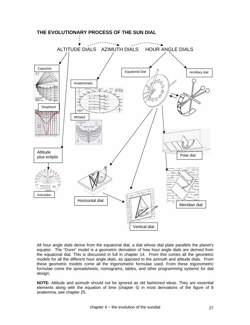
INTRODUCTION There are many books on sundials that provide a wealth of information, some may be hard to follow, and sometimes the math lacks a clear explanation. I had grown up with sundials and clocks. When I was a teenager I was given a portable sundial, and later I acquired an astrolabe. In the east end of the lawn of the house I grew up in during the 1950s there was an old sundial, pictured to the right. The objective of this book is to show clearly several methods for making sundials. This book merges Illustrating Shadows and its sequel Illustrating More Shadows, adds new material, covers the theory, geometry, trigonometry, tabular and empirical methods of sundial design, as well as covering media for small and large dials. Advanced dial types which as one author has said "are a problem of the diallist's own making and thus easily avoided" are covered, as well as matters of general interest. I loved mathematics in school and college where I studied for a degree in Physics, and thus trigonometry was not hard for me to understand, nor geometry. This book makes no assumptions, and the math is extremely simple. In one of my professions I was a software designer from 1967 to 1997. I designed the SHADOW teleprocessing control program, co-designed Manage-IMS, and designed the ITT Courier DOOMSDAY quality control system. In my other profession I started flying in 1963 and had flown part time since the mid 1970s, later full time with the airlines, lastly America West on the B737, then the Federal Aviation Administration as an Operations Inspector from whence I retired. Most sundials have a shadow casting edge whose angle is usually the latitude and usually aligned true north/south, and a dial plate which marks the hours. Corrections are needed for longitude as well as the "equation of time" (EOT). The words "usually", and "nearly always", and "most", and "as a rule" are used because some types of dials may use special techniques. This book has ease of use as its core value. Thus text will normally refer to figures that are on the same page, even if that means duplicating some figures. Unless a figure or pictorial is clearly intended to be to scale such as in the templates, it should not be assumed that scale is used in explanatory diagrams. In many clarifying pictorials, angles are exaggerated so that the diagram is easier to follow and less cluttered. The term "LAT" means Local Apparent Time, and "lat" is the abbreviation for latitude. Illustrating Time’s Shadow came from the 4th edition of Illustrating Shadows and the 2nd edition of Illustrating More Shadows combined, while deleting duplicate or less frequently use methods, but adding a substantial amount of new material. Simon Wheaton-Smith FRI, MBCS, CITP Member of the North American Sundial Society Member of the British Sundial Society [email protected] www.illustratingshadows.com

3
A WALK AROUND THE GARDEN
Where I live there are a fair number of sundials. In no particular order, they are summarized below. There are a number of ways of telling the time from the sun. One such method is to use the sun's azimuth, which means how far east or west of the north south line the sun is. This is latitude dependent. The azimuth for any given hour varies dramatically from winter to summer. Below is an azimuth dial.
One azimuth dial that is sometimes found in public recreation areas is the analemmatic dial. The one to the left is 16 feet east to west, and great for recreation centers for children during school breaks. The photo is taken from the west north west to the east south east. Another method of determining the time from the sun is to use the sun's altitude, or
how high up in the sky the sun is, just like the mariner's sextant. This is latitude dependent. The altitude for any given hour varies dramatically from winter to summer. To the right is an altitude dial known as a Shepherds Dial. The third method is to use the angle that the sun makes around the Earth's rotational axis, the sun's hour angle. This is always assumed to be 15 degrees an hour and is latitude independent. What makes dials that use the hour angle latitude dependent is the display of data on the face of the dial, or dial plate, or surface which has, among other things, the marks telling the time, or the hour lines. Hour angle dials are by far the most common.
azimuth dial
altitude dial
analemmatic azimuth dial
a sundial garden

4
A very simple example of an hour angle dial showing the 15 degrees per hour is the armillary dial sometimes found in parks and plazas. Usually the gnomon or shadow casting device parallels the north south polar axis. In the example to the right, the gnomon is a rod whose tip (nodus) establishes both the time and the calendar information. The armillary dial is so called as the dial plate is like a bracelet for the arm, the dial plate parallels the polar axis. Usually other "bracelets" exist and when they do, they model the solar system to some extent.
Whereas the armillary dial plate paralleled the polar axis, the equatorial dial, sometimes called an equinoctial dial again works on the same 15 degrees per hour philosophy, however the dial plate parallels the equator, hence its name. (Sometimes armillary dials are called equatorial, and vice versa.) Just like the armillary dial above, the equatorial dial to the left is also longitude corrected.
A mirror image of the armillary and equatorial dials is the globe dial shown to the right and uses a movable shadow caster, or gnomon, which is turned until the shadow vanishes, and the time then read by the position of that movable gnomon. At the risk of being highly repetitive, for hour angle dials (as opposed to altitude or azimuth dials), the hour lines on a dial plate are always based on 15° per hour, but may not
be 15° themselves. The hour line angles for such dials are latitude and hour dependant; plate orientation dependant; and the longitude may also be a factor if standard time is used.
globe hour angle dial
equatorial dial
armillary dial

5
Perhaps the next most common dial is the horizontal dial, often seen in garden, and often sold in garden centers. Sadly, they are often designed for a generic latitude as opposed to the latitude of the dial's final resting place, so while they use those same 15 degrees per hour basis, they display the results incorrectly because of the latitude difference, in other words how far one is from the equator or pole. Their owners turn the sundial in circles hoping the time will be correct, they bend the shadow casting device, or gnomon, to set the time, and neither of these are correct. Tilting the dial will help a lot, unless the dial is completely ill-designed. However sun dial readers still need to make two corrections. One correction is for longitude, and is a fixed amount based on where the dial resides. That is because the sun dial tells the local time, or local apparent time, or L.A.T., unless designed otherwise. Some dials have longitude correction built in, many do not. Portable dials do not so that they can be used anywhere. Permanent dials often, but not always, have the difference between local sun time and the legal time zone factored in. Another correction is to enable the pocket watch to match the endless motions of the solar system, a correction that varies by the day. This is a plus or minus 16 minutes correction often provided to the sundial user as a graph or table. This factor is called the Equation of Time, or EOT. With those two corrections, a sun dial and pocket watch may live in harmony.
Sundials that use hour angles often have an edge that casts a shadow, that edge is called the style, and is set at an angle equal to the dial's latitude. Some dials add interest by having a rod set at any angle, and whose tip, called a nodus, points to the time. In olden days the hour lines were drawn from such a column's base, and they were not equal hours. However, if the center of those lines, or dial center, is displaced, then the hours displayed are even all year round. Such a dial with a virtual style, is shown to the left.
In fact much of the delight of gnomonics is the depiction of hour lines on surfaces not immediately obvious to the observer. Instead of being horizontal, a sundial can be vertical, as on a wall. Sundials may be made from transparent as opposed to reflective mediums, for example stained glass. To the right is a dial designed for latitude 32 north intended to be placed on a south facing window's sill. In the southern hemisphere such a dial would have the hours reversed, morning for afternoon, and would face north as opposed to south.
horizontal dial
vertical dial
horizontal dial

6
Sundials can be designed to face true east or west and be vertical. One such dial is shown to the right and intended to rest of a west facing window's sill, while the dial to the left was similarly designed but intended to hang in that west facing window. Both of these dials have two added features. One feature enables the reader to determine the date. This works because for any given date, the sun is orbiting at a certain angle north or south of the equator, that angle is called the declination of the sun.
As a rule there are two dates for each declination the exception being the shortest and longest days, or the solstices. The equinoxes are days when day and night are equal, and they share the same declination, namely zero degrees of declination, as the sun is orbiting over the equator. Another feature in both of the dials above is the ability to determine how long it will be until sunset. The lines that provide sunset information are called Italian lines. Italian hour lines are totally latitude dependent and to be pedantic show the number of hours since the last sunset. Common usage is to have them show time until the next sunset however. Other special hours exist, such as Babylonian hours which tell the time since the last sunrise, however neither of the dials above show them. Glass dials may be transparent as above, or they can be reflective. The glass must throw a good shadow, so test it before you use it. Cube dials have multiple faces, often declining. To the right is a cube dial, offset 45 degrees from true north. The face on the left is for the afternoon hours, the face on the right is for the morning. Vertical dials that face true north or south are the complement of dials that are horizontal and aligned on the true north south line. While horizontal dials are aligned on a true north south line, the same is not always true for vertical dials, they are often off a few degrees and the wall they are on is said to decline. Wall declination has nothing in common with the sun's declination mentioned earlier. Same word, different meaning and context.
meridian dial meridian dial
A west and east vertical declining dial built by the author. Valley Garden Center, Phoenix AZ. Part of the Arizona Centenary project.
7
In fact, true east or true west facing walls are rare, thus while a portable vertical dial such as a glass vertical dial is straight forward, ones on walls are a little more involved. Declining vertical dials with large declinations are sometimes called great decliners since they decline a lot. The hour lines slope, and in the picture to the left, converge above the dial. Compare this to the glass vertical dial an the preceding page where the hour lines parallel each other because that dial is designed for true west orientation. These dials when facing true east or west are often called meridian dials because their dial face or plate parallels the meridian. The meridian being the north south line connecting the poles running through a location.
Related to the meridian dial, is the polar dial, one whose dial plate parallels the north south Earth's rotational axis. These dial plates slope at the latitude of the dial's location. The polar dial to the right has an unusual feature in that it is read by the shadows of both the gnomon as well as the dial plate on a surface. That surface can be of any shape or orientation. It was mentioned earlier that one of the joys of dialling was to produce dials on surfaces that are just not aligned on a natural orientation. In other words dials that are both declined (not on a north, south, east, or west orientation) and inclined also. Such inclining decliners, or reclining
decliners, are as one author wrote "a problem of the diallist's own making and thus easily avoided." None the less, they exist, roof dials being one such common case, and to the left is one inclined by 20 degrees from the horizontal and declining by 50 degrees from the south towards the west. If masonry, glass, clay, and copper seem to be used in many of these dials, it is because the author was trained in those media over the years. In fact many of the dials in this section are easily made from common clay brick, common concrete blocks, copper wiring, and glass available at stained glass shops. There is no complex engraving, although the artwork on the glass does get into that kind of work. The author has no skills in metal work and thus the wonderful metal dials do not appear in this book. The intent was to enable the reader to build these dials for their own location, easily, and in a short time frame.
almost a meridian dial this is great decliner
inclined decliner
a polar dial, this one also projects onto a wall

8
It was mentioned earlier that pocket watches do not track the daily movements of the heavens, however they do a very good job of counting the seconds. So how do you set a pocket watch accurately. While in the digital age that may be less of a problem, a hundred years ago it was a genuine concern. The result was the noon dial which is not a straight line but a distorted figure of eight. It is the depiction on a dial plate of the equation of time, or difference between clock and solar system time. To the left is the December through June half of such a dial, next to it but not shown is a dial for June through December. For a given date, when the tip of the shadow crosses the curved line it is legal standard noon time. Usually both dials are combined into one figure of eight dial. In fact some dials have figure of eights all over the place, instead of straight hour lines. Those dials when corrected for longitude then show standard legal time. Except for summer time when one hour has to be added, a folly of politicians, which nature chooses not to observe. Summer time is less meaningful as the traveler journeys towards the equator, and yet the political engine dictates summer time for all latitudes of the country, a folly caused by politicians who reside in northerly latitudes and whose brains do not seem to thaw out, especially when considering the rules they make to govern one and all. Few states have
the courage to say enough is enough, Arizona being one of the few. Most have fallen in line with the federal system. But enough of politics. I am referring to the USA in particular, however other countries like lemmings seem to have adopted this folly, intended since its inception to save energy, whale oil for lighting, and so on. None of which does it do. THE PARTS OF A SUNDIAL Below are horizontal, and vertical but declining dial layouts. They have a dial plate upon which things are inscribed or placed, such as hour lines and declination (calendar) lines, called furniture. The shadow casting assembly is called a gnomon, its angled edge which casts the shadow is the style. The bottom of the gnomon attached to the dial plate is the sub-style. An optional notch or blob is called a nodus usually used to show calendar or other information. The 6am and 6pm hour lines are 90° to the noon line for non longitude corrected dials.
noon legal time dial
Dial center is where hour lines meet
Declination lines are hyperbolic
The equinox line is straight
Hour lines come from dial center and are straight
sub style
Vertical declining dial (offset from the cardinal points)
Horizontal dial SD style distance SH style height (angle from vertical) (angle from dial plate) gnomon linear height (linear, not angular)
Nodus Style

9
A QUICK HANDS ON PROJECT ~ ~ ~ BUILD IT FIRST – FIX IT NEXT
The next two pages offer a simple "go ahead and build it" horizontal sundial, then see what needs to be done to make it accurate. The rest of the book is the other way around, theory to understand what is going on, then build it. These two pages help you build a horizontal dial and is a good prelude to the rest of the book. NOTE: Please use the separately printed appendices. 1. What is your latitude (how far north or south are you from the equator). Many maps show this, and so does a GPS. Appendix 2 (separate book) may help with latitude data. my latitude is: 2. EITHER download the Microsoft Office Excel spreadsheet at: www.illustratingshadows.com/illustratingShadows.xls (works in Open Office) then on the worksheet named "h dial with all figures", enter the latitude. OR go to tables
in the appendix 3, look at the latitude at the top of the columns, then find the angles for the hours you wish marked.
6 7 8 9 10 11 noon morning hours 6 5 4 3 2 1 noon afternoon hours 3. Mark the lines on the template "A DRAFTING SHEET FOR HORIZONTAL DIALS" from the appendices. The end result should look
roughly like the fan of lines to the right. Noon is going to be on the north south line
and the 6 am and 6 pm lines will be at 90 degrees to that, The other lines will fan out, and their angles depend on your latitude.
4. Transpose the hour lines to wood, PVC,
copper, glass, concrete, clay, or any other medium. This is called the dial plate.
5. Build a shadow casting device, called a gnomon, it is a triangle whose angle from the dial
plate is equal to the latitude. The angle is important, the length is not, unless you want to add other information related to the time of year or sunset, discussed in the main part of the book. NOTE: the gnomon should be thin. If thick as shown above, then the am and pm hours should be separated at noon to account for it, there would be two noon lines.
6. Affix the gnomon to the dial plate, the latitude angle end rests on top of where the hour
lines converge (dial center), and it lies on the north south line, or the noon line. nodus gnomon style
latitude
dial plate
gnomon
to the equator
to the pole
dial center
dial center

10
7. Take the dial plate, its affixed gnomon on the noon line and place it in the sun. 8. Align the noon line with north/south, and the gnomon's end placed on dial center (where
it meets the hour lines), should point to the equator, south in the northern hemisphere or north in the southern hemisphere. True north is meant, not compass magnetic north. To find true north, first find magnetic north by using a compass but keep away from metal. Then find your location's magnetic variation, or declination as sun dial people call it.
If it is an easterly declination you must back away from north to the west. If it is a westerly declination, you must back away from north to the east. Magnetic declinations are often found on maps, and a table and a map in the appendix
has declination information. my magnetic declination: E W Appendix 2 may help. 9. With the dial plate level, the angled part of the gnomon pointing north south, the dial will
now read sun-time, or local-apparent-time or L.A.T. for short. It is still not clock accurate. There are two corrections to make. One is to correct for your distance from your time zone's reference longitude, the other is for the fact the sun is predictably slow or fast (compared to man made watches) as the year progresses, this correction is called the equation of time or EOT for short.
10. Find your longitude, it is on your GPS unit, or on a map of your area. Aviation and
geological survey maps work, but road maps may not. Once you know your longitude, and your time zone, find your time zone's reference longitude.
my longitude is: Appendix 2 may help.
my time zone reference is: Appendix 2 may help. difference between the two is: times 4 is: minutes
If your longitude is greater than the reference longitude, ADD the difference times 4, these are the minutes to add to correct for your location.
If your longitude is less than the reference longitude, then SUBTRACT the difference times 4 to correct for your location. plus [ ] or minus [ ] _ _ _ minutes to correct for location. 11. We now have a dial built for your latitude, aligned north/south, and corrected for your
location's distance from the time zone's reference longitude. However it may still be off by plus or minus up to 16 minutes due to the fact the sun's orbit around the Earth varies during the year, and because the sun also moves north or south of the equator. There is a table of corrections for this equation of time or EOT by the day in the appendices.
12. That is it! You now have a working horizontal sun dial. To delve into it more, read on . . . .

11
CHAPTER ONE
THE UNIVERSE
The universe is the collection of all the galaxies or collections of stars. And surrounding stars are planets. And other things go on as well. Planet Earth orbits a star called the sun, which is in a galaxy called the milky way, but distances out there are somewhat large. To an observer on planet Earth, we can see several things. The moon which orbits our planet. The sun which we orbit but to a sundial the sun orbits us. The planets which also orbit the sun, as do the comets which have very large elliptical orbits. The stars which are far far away, and with the exception that the Earth wobbles, are essentially fixed in the sky, as if they were on a sphere of enormous dimensions. In fact it is called the celestial sphere. The Earth spins and the polar axis of that spinning wobbles in a cycle of 25800 years roughly. So, those fixed stars actually appear to collectively wobble over that time-span.
The Earth wobbles somewhat slowly in a 25,800 year cycle, causing the "precession of the equinoxes", and causes the constellations to move around.
One measurement of time is sidereal time, based on a star's position.
This relative stability allows star charts to be meaningful, and allows the time to be measured by the star's angular position around the Earth's rotational axis, or polar axis. In the northern hemisphere the north star Polaris is very close to that polar axis, now. That will change over the 25800 year cycle which results in the "precession of the equinoxes", because seasons will correspondingly change. The stars in the northern hemisphere seem to rotate around the north star, Polaris. They revolve about 360 degrees in a day. And for any given time of night, they rotate 360 degrees in a year.
chapter 1 ~ the universe
Polaris
our universe
our solar system

12
This all means that a 360 degree map of the stars can be drawn, and throughout the year some stars come into view, others leave. And similarly, in the evening, the stars for the season rotate 360 degrees in a day. Approximately. This means that should one know the month, then the time can be approximated, and this is the basis for a nocturnal dial. The nocturnal dial is described in chapter 27 on “Night Time Dials”. To be pedantic, we must add something to the model of the universe to explain why we see different stars in the winter from those of the summer. The reason is that the Earth orbits the sun once in a year, which is about 365 days. So when the Earth is on one side of the sun, the stars behind the sun are not visible, and so the visible stars come and go over a year's time. The bright sun will block out different stars in the winter than the summer. In fact every day the relative position of the sun and Earth have moved a bit and some stars come into sight at a given time and some become no longer visible. Adding to that, the Earth is tilted by about 23.5 degrees as it orbits the sun. The Earth's orbital plane is called the ecliptic. The ecliptic does not affect the nocturnal dial, but the planets for the most part lie close to the Earth's orbital plane, the ecliptic. The ecliptic is not essential to understand for most normal sundials. It is used in the “ecliptic” dial, and in the astrolabe.
In the study of sundials, sometimes the Earth will be considered to orbit the sun, as for example to explain the seasons, and the sun's changing declination. Sometimes the sun will be considered to orbit the Earth, as for example to explain the changing star patterns throughout the year, this is shown in the picture above. It is all relative, it is not a mistake. Chapter 27 has a simple yet very accurate clock that uses, in the northern hemisphere, Polaris as an axis of rotation, and a specific star in one of three constellations, it is called a nocturnal dial. And the templates are in appendix 9.
chapter 1 ~ the universe
a nocturnal dial
the sun
Polaris
Earth

13
CHAPTER TWO
THE SOLAR SYSTEM The solar system is comprised of planets in elliptical orbits orbiting the sun, asteroids, and the occasional comet. For the most part, the planets orbit the sun in the same orbital plane as the Earth, they are off by a few degrees. And they go the same way round. The Earth's orbital plane is called the ecliptic. The ecliptic is the plane made by the Earth's orbit around the sun, and if a dial plate was placed on it and moved with the Earth as it orbits the sun, then in one year the shadow of the gnomon would rotate about 360 degrees. About, because things are not that tidy. Because it would take one year for the gnomon's shadow to rotate around that dial plate, and since that is one calendar cycle, it is possible to build a calendar dial using the ecliptic, as opposed to using declination lines. The Earth's orbit is 23.44 degrees, or 23.5 for simplicity, from the Earth's polar axis. The pictorial below to the left shows several dial plates around the Earth's annual orbit as viewed from above the north.
Above to the right, the northern hemisphere is viewed from above the north and looking down, and the southern hemisphere is viewed from below the south while looking up.
gnomon for the dial plate on the ecliptic dial plate resting on the ecliptic Earth's polar axis offset by 23.5 degrees, and this will rotate around the ecliptic gnomon daily. These are approximations due to the factors that generate the equation of time, and so on.
23.5°
northern hemisphere
southern hemisphere
The shadow is of course not a triangle, it would be an infinitely long box in the direction away from the sun. The triangle is used to more clearly indicate "a shadow”
chapter 2 ~ the solar system

14
There are some interesting results that come from such dynamics. First, how the intersection of the ecliptic varies throughout the day and the year. Second, how to construct a simple device to indicate the ecliptic and thus the date. Third, an understanding of the ecliptic, useful for locating the moon and the planets based on the seasons. The ecliptic plane slices the Earth, however, the slice angle varies by the second. The slice in the morning differs from the evening, and they both differ from noon. It differs by the season. In the context of a full moon, in the December January time frame or year end, the full moon is effectively above the extended equator, so the full moon rises from the northeast and sets in the northwest. Mid year in June at full moon the moon is effectively below the extended equator, so the full moon rises in the southeast and sets in the southwest. For full moons at the March and September equinoxes, moonrise and moon set happens from the east to the west, the moon is effectively on the extended equator. The full moon path differs in the winter, summer, and equinoctial times. For full moons, the lunar path is almost the same as the sun's path 6 months in the past or future. The first quarter moon's apparent path varies from the full moon. For example look at the first quarter moon in the December January timeframe. The moon rises during the daytime from the east, sets in the west, as the moon is effectively on the extended equator. The lunar orbit is actually offset by about 5° from the ecliptic, which can add to the variation, thus the above pictorial is stylistic as well as not to scale. Some time can be well spent on the pictorial above to see how the apparent lunar orbit varies by the month as well as by the season for several selected hours. The planets are mostly in the same plane as the Earth with respect to the sun, thus the planets apparent path in the sky will also vary seasonally.
chapter 2 ~ the solar system
full moon year end solstice
full moon mid year solstice
Earth's orbit around the sun is offset about 23.44° from the polar axis
moon's orbit around the Earth, it is offset about 5° from the ecliptic
first quarter
last quarter
last quarter Earth's rotation
full moon equinox
full moon equinox
extended equator
Earth's north pole
JANUARY
MARCH
JUNE
SEPTEMBER

15
From this daily and seasonal variation of the ecliptic intersection with the planet Earth, comes an explanation of lunar activity, as well as the method for designing a calendar dial using the ecliptic. The remaining question is how to build an ecliptic dial. On a polar axis alignment such as the style of an hour angle gnomon, a canted device is built that rotates 23.5 degrees around the polar axis. In the picture below, PVC tubing was employed. To the 23.5 degree canted rotating tube is affixed a plate, in this case from an unused computer CD.
When the date wheel is affixed, June 21 is at one end, and December 21 is at the other. Of course, the winter solstice is when the sun's declination is lowest in the sky, and the summer solstice is when the sun's declination is highest. In the northern hemisphere, December 21 would be at that low point, June 21 would be at the high. In the southern hemisphere, December 21 would be at the high point, June 21 would be at the low. A normal rotating gnomon is used to indicate the time on a linear plate. And the canted section is rotated around the polar axis until the dial plate casts a flat shadow. A rotating cursor is moved until the ecliptic gnomon casts a shadow as shown above, and the other end points to the date. There are usually two locations at any time when the ecliptic dial plate casts a null shadow, this matches the two dates for any given sun declination, the solstices being the exception. Some degree of awareness about the probable month is likely to be beneficial at this point. Just as the equation of time exists for the minutes to adjust a time dial, similarly an equation of day exists for the date. This is a sine wave indicating about plus or minus a couple of days, this is subtracted in the first half of the year from the indicated date, added for the second half. The ecliptic is not essential to understand for most normal sundials. However, it is used in the “ecliptic” dial (above), and in the planispheric astrolabe described in chapter 21 on “Altitude Dials”.
23.5° canted tube connection
flat shadow
lever to help rotate the ecliptic plane for a null shadow
December 21 and June 21 are at the low and high points of the canted slope.
chapter 2 ~ the solar system
ecliptic gnomon and its shadow and date indicator at its other end

16
CHAPTER THREE
THE PLANET EARTH The Earth is a planet and from history we know it orbits the sun. Back in medieval times the sun was believed to orbit the Earth. Galileo and others nearly got burned at the stake when they said it was the other way round, however it is pretty much accepted now that the Earth orbits the sun. And by the way, the Earth is no longer flat either, it is a sphere in space.
The polar axis is what the Earth's surface spins around, or in essence, around which the sun apparently rotates.
The planet Earth's polar spinning axis is tilted about 23.5°, or 23.44° to be more precise, compared to its orbit around the sun. That causes the seasons to vary. The equator is at 90 degrees to that polar spinning axis and mid way between the poles. Looking at the figure below, when the sun is below the equator (bottom left in the figure below), the southern hemisphere has summer while the northern has winter. And when the sun is above the equator (top right in the figure below), it is winter in the southern but summer in the northern hemisphere. The Earth orbits the sun in an ellipse and that together with the Earth's tilt, are two reasons why day length varies and why the sun's hours appear to vary somewhat, and hence why the "equation of time" was developed which corrects the sun for being slow or fast when compared to the watches and clocks which are set based on an Earth day averaged through the year. The pictorial below shows the Earth spinning on its axis, and the sun in four different positions. equinox
tropics winter solstice in England is summer solstice
in Australia December 21 approx While the Earth rotates around the sun, to a sundial it is as if the sun goes around the Earth's polar axis. So for simplicity, we will assume it is before the days Galileo. When the sun is over the equator, top left and bottom right in the picture above, it is the equinox, and the days are equal to the nights in duration, late March and September. By the way, every day on the equator is an equinox, their days are always the same length as their nights. When the sun is over the tropics, i.e. latitude plus or minus 23.44 degrees, it is the solstices, late June and December.
Sun
Earth
We call the line running around the middle of the Earth the equator, it is perpendicular to, and mid way between the poles.
Jan
Jun
Mar
Sep
chapter 3 ~ the planet earth
Polar axis
equinox
equator
note how the sun is below, on, or above the equator.
summer solstice in England is winter solstice in Australia June 21 approx

17
Now let us define a few things that are needed in order to understand location on planet Earth. The pole around which the Earth spins is tilted by about 23.5°, 23.44° to be more precise, and perpendicular to it is the plane called the equator, see figure immediately below.
polar axis 23.5°
If the Earth looks bigger than the sun, it is because the sun looks small to us here on planet Earth, and the Earth looks big to us. Referring to the figure below, the Earth is sliced into sections parallel to the equator, those slices are measured by their angle to the center of the Earth. Those angles are called latitude and Ø is its common symbol.
The latitude tells you how far north or south of the equator you are. It is measured in degrees, the equator's latitude is 0° while the north pole is 90°, and one degree of latitude is about 60 nautical miles on the surface, that is how nautical miles came into being. The equator is an obvious slice for latitude references, as it is 90° to the polar axis, but there is no such obvious place for the left-right position, so England graciously agreed to define Greenwich near London as the reference point.
Referring to the figure below and left, longitude determines how far you are east or west of Greenwich England. However as you go further north or south of the equator, the linear distance between one longitude degree varies. Whereas a degree of latitude is 60 nautical miles anywhere, for longitude the distance gets smaller as you travel north or south of the equator. Longitude has one fixed relationship however, one degree of longitude always accounts for 4 minutes of time in the mean motion of the sun.
90 degrees of longitude
Greenwich UK is 0 degrees of longitude
equator
23.44°
sun
earth
Ø
latitude
longitude
polar axis
23.44°
chapter 3 ~ the planet earth

18
Positions on the planet are identified by latitude (north or south of the equator), and by longitude (east or west of Greenwich England). Because the Earth rotates on its axis, some places see the sun later and some earlier. As there are 24 hours in a day, and there are 360 degrees of longitude, 15 degrees equates to one hour, so standard longitudes are established every 15 degrees, but for political reasons they may zigzag around the place. Those longitudes in essence define legal standard time. Since 15° is one hour or 60 minutes, then one degree is 4 minutes. Those 15 degrees are split in half for those legal time zones, thus Greenwich is 0° of longitude, and 7.5° west to 7.5° east marks the legal time zone. Lets put this into the real world.
Silver City 32.75° N 108.2° W mag var 10.6° E SVC mst is at 105° SVC is 3.2 from mst i.e. 12 mins 48 secs from mst Phoenix 33.5° N 112.0° W mag var 11.8° E PHX mst is at 105° PHX is 7.0° from mst i.e. 28 minutes from mst Scottsdale 33.6° N 111.9° W mag var 11.8° E SDL mst is at 105° SDL is 6.9° from mst i.e. 27 mins 36 seconds from mst 110° west 105° west Silver City Phoenix ARIZONA 33° NEW MEXICO 32° 105 west is the mountain standard time reference longitude. Things of interest to note are that when it is solar noon sun time on the 105 meridian (local apparent time or L.A.T.), it will be appear to be earlier in Silver City and earlier still in Phoenix, as far as sun time goes. Indicated sun time is called local apparent time, or L.A.T. When it is solar noon on the Silver City meridian, L.A.T. (local apparent time) it is later at the 105 meridian and earlier on the 112 meridian of Phoenix, sun time wise. One degree of longitude is 4 minutes of L.A.T. difference, which derives from the fact there are 360° going around the entire planet and there are 24 hours in the day or 1440 minutes.
To a sundial, the sun moves east to west.
chapter 3 ~ the planet earth

19
SUN'S DECLINATION
It has been shown that throughout the seasons, the sun moves north and south of the equator. The angle the sun's rays make compared to the center of the Earth, is called the sun's declination.
SUN'S DECLINATION Simplified formula: DEGREES = (23.45*sin(radians(0.9678(j-80)))) where J = 1 to 365, the day of the year, see below. SUNS DECLINATION More complex formula Day number, J J=1 on 1 January, J=365 on 31 December. February is taken to have 28 days. Jan Feb Mar Apr May Jun 0 31 59 90 120 151 Jly Aug Sep Oct Nov Dec
181 212 243 273 304 334 Day angle: da = 2 * pi * ( j-1 ) / 365 (in radians, is an intermediate figure) Sun Declination: decl = degrees (0.006918 – 0.399912*cos(da) + 0.070257*sin(da) – 0.006758*cos(2*da) + 0.000907*sin(2*da) – 0.002697*cos(3*da) + 0.001480*sin(3*da) A declination table is included in the appendices as well as at the end of this chapter.
equator
23.44° +
sun
earth
polar axis
23.44° –
chapter 3 ~ the planet earth
from the north hemisphere's perspective

20
LONGITUDE AND EQUATION OF TIME CORRECTIONS ARE NEEDED A dial’s indicated time is called Local Apparent Time (L.A.T.), and when corrected for the Equation Of Time or EOT (see chapter 5), the result is Local Mean Time. When longitude is factored in, the result is “standard mean time”. The word “mean” is often omitted. L.A.T. local apparent time, time indicated by a sundial (sometimes also called true time) EOT equation of time for the day, if the sun is fast compared to a clock (or the virtual or mean
sun), then there is a minus correction, and if slow, there is a plus. Some tables show fast as plus, slow as minus. They are not wrong, they are designed by people who while otherwise normal, use a different convention. Many astronomers fall into this category.
Converting local apparent time to standard time is used when reading a dial:- legal time or = LAT + EOT.corr + west.long.corr + 1 if standard time eg Nov –15 – east.long.corr summer or clock time eg Feb +12 add if west of standard meridian subtract if east of standard meridian reference for Phoenix time zone is 105° Phoenix 112° Fig 3.3 Phoenix AZ is at a longitude of 112° and is west of the standard time meridian for Phoenix time which is at 105°. When reading a dial with no built-in longitude correction in Phoenix, the longitude correction must be added because it is later at the 105° standard time longitude than in Phoenix at 112°. In other words, if west then add the longitude difference times 4 minutes per degree. If east you subtract. Since Phoenix is 7° west of the reference longitude, being 112 minus 105, and remembering one degree equates to 4 minutes, that makes Phoenix show four times seven, or 28 minutes earlier than the legal time, so you add those 28 minutes. It is 28 minutes later on the 105°. For purposes of repetitive learning, all of October, November, and May the sun is fast so the EOT is negative, and in all of January, February, March, July, and August the sun is slow so the EOT is positive. There are four days when the EOT is effectively zero, they are somewhere near April 15, June 15, September 1, and December 25. The extreme values of the EOT are around February 11th when the sun is slow and the EOT is +14 minutes 12 seconds, and early November when it is fast and the EOT is now – 16 minutes 22 seconds. Other peak values are near May 13th and 14th when the sun is fast, so the EOT is –3 minutes 39 seconds, and July 25th and 26th when the sun is slow with an EOT of +6 minutes 30 seconds.
Actually, this is a more accurate depiction...
The Sun
chapter 3 ~ the planet earth

21
Night Day
THE EARTH AND SUN INTERACT - EQUINOXES AND SOLSTICES On the equator, at 0 degrees of latitude, every day is an equinox, that is to say that every day of the year has equal hours for day and night, regardless of whether the sun is overhead, north, or south of the equator. In the three pictures below the dashed arrow shows the Earth's rotation. The pictures show the Earth rotating on its axis, they suggest the Earth tilts back and forth yearly. In fact the Earth doesn't tilt back and forth as shown during the year, it only appears to do that because the Earth retains its axis as it orbits around the sun, and that orbit around the sun is what causes the sun to appear to move above and below the equator.
Looking at figure 3.4 the picture depicts summer in the northern hemisphere when the sun is north of the equator. As the sun's rays are parallel, the equatorial ray in the picture gets to travel the great circle around the equator. Because each place on the equator gets that ray, days and nights are of equal length. With northern visits of the sun, the sun always shines on the arctic, so the arctic has days with no night, and the bottom ray misses out on the Antarctic whose nights are dark, with no sun.
Figure 3.5 shows summer in the south, the Arctic is in permanent night, the Antarctic in permanent day, and the rays hitting the equator travel the great circle, so the equator still has days and nights of equal length. Figure 3.6 shows March and September, when everywhere on Earth has days equal to nights. The equinox happens around March 21 and September 23, plus or minus a bit. The extremes of the sun moving north and south of the equator by 23.5 degrees are the solstices, December and June 21, shown in figures 3.4 and 3.5 respectively.
The three figures have a line 90 degrees to the sun's rays, left of it is dark night time, right is bright day time. Assuming there are no clouds. The equator is always bisected, it is the north and south hemispheres that have an uneven division of time when the sun is not directly above the equator. The equator is thus in a permanent equinox. Notice the arrows in the summer pictures, they show how one pole endures a long night time, while the other basks in warmer temperatures.
Summer solstice in the north
Summer solstice in the south
March or September ~ the equinoxes
Fig 3.4
Fig 3.5
Fig 3.6
chapter 3 ~ the planet earth

22
DECLINATION OF THE SUN BY THE DAY
DEGREES = (23.45*sin(radians(0.9678(jd-80)))) alternative formula agrees within half a degree Different declination charts may disagree, factors affecting them would be leap year approximations, and the formula employed. Many formulae are approximations.
Jan Feb Mar Apr May Jun Jly Aug Sep Oct Nov Dec
1 -23.1 -17.3 -7.9 4.2 14.8 21.9 23.2 18.2 8.6 -2.9 -14.2 -21.7
2 -23.0 -17.1 -7.5 4.6 15.1 22.1 23.1 18.0 8.2 -3.3 -14.5 -21.8
3 -22.9 -16.8 -7.1 5.0 15.4 22.2 23.0 17.7 7.8 -3.6 -14.8 -22.0
4 -22.8 -16.5 -6.7 5.4 15.7 22.3 23.0 17.5 7.5 -4.0 -15.1 -22.1
5 -22.7 -16.2 -6.3 5.8 16.0 22.5 22.9 17.2 7.1 -4.4 -15.5 -22.3
6 -22.6 -15.9 -6.0 6.2 16.3 22.6 22.8 16.9 6.7 -4.8 -15.8 -22.4
7 -22.5 -15.6 -5.6 6.5 16.6 22.7 22.7 16.6 6.4 -5.2 -16.1 -22.5
8 -22.3 -15.3 -5.2 6.9 16.9 22.8 22.6 16.4 6.0 -5.6 -16.4 -22.6
9 -22.2 -14.9 -4.8 7.3 17.1 22.9 22.5 16.1 5.6 -6.0 -16.7 -22.7
10 -22.1 -14.6 -4.4 7.7 17.4 23.0 22.4 15.8 5.2 -6.3 -16.9 -22.8
11 -21.9 -14.3 -4.0 8.0 17.7 23.0 22.2 15.5 4.9 -6.7 -17.2 -22.9
12 -21.8 -14.0 -3.6 8.4 17.9 23.1 22.1 15.2 4.5 -7.1 -17.5 -23.0
13 -21.6 -13.6 -3.2 8.8 18.2 23.2 22.0 14.9 4.1 -7.5 -17.8 -23.1
14 -21.4 -13.3 -2.8 9.1 18.4 23.2 21.8 14.6 3.7 -7.8 -18.0 -23.2
15 -21.3 -13.0 -2.4 9.5 18.7 23.3 21.7 14.3 3.3 -8.2 -18.3 -23.2
16 -21.1 -12.6 -2.0 9.8 18.9 23.3 21.5 14.0 3.0 -8.6 -18.6 -23.3
17 -20.9 -12.3 -1.6 10.2 19.1 23.4 21.3 13.7 2.6 -9.0 -18.8 -23.3
18 -20.7 -11.9 -1.3 10.5 19.4 23.4 21.2 13.4 2.2 -9.3 -19.1 -23.4
19 -20.5 -11.6 -0.9 10.9 19.6 23.4 21.0 13.0 1.8 -9.7 -19.3 -23.4
20 -20.3 -11.2 -0.5 11.2 19.8 23.4 20.8 12.7 1.4 -10.1 -19.5 -23.4
21 -20.1 -10.8 -0.1 11.6 20.0 23.5 20.6 12.4 1.0 -10.4 -19.8 -23.4
22 -19.9 -10.5 0.3 11.9 20.2 23.5 20.4 12.0 0.6 -10.8 -20.0 -23.4
23 -19.6 -10.1 0.7 12.3 20.4 23.5 20.2 11.7 0.2 -11.1 -20.2 -23.4
24 -19.4 -9.7 1.1 12.6 20.6 23.4 20.0 11.4 -0.1 -11.5 -20.4 -23.4
25 -19.2 -9.4 1.5 12.9 20.8 23.4 19.8 11.0 -0.5 -11.8 -20.6 -23.4
26 -18.9 -9.0 1.9 13.3 21.0 23.4 19.6 10.7 -0.9 -12.2 -20.8 -23.4
27 -18.7 -8.6 2.3 13.6 21.2 23.4 19.4 10.3 -1.3 -12.5 -21.0 -23.3
28 -18.4 -8.3 2.7 13.9 21.3 23.3 19.2 10.0 -1.7 -12.9 -21.2 -23.3
29 -18.2 3.1 14.2 21.5 23.3 18.9 9.6 -2.1 -13.2 -21.4 -23.3
30 -17.9 3.5 14.5 21.7 23.2 18.7 9.3 -2.5 -13.5 -21.5 -23.2
31 -17.6 3.9 21.8 18.5 8.9 -13.9 -23.1
DEGREES(0.006918 - 0.399912*COS(((2*3.1416*(jd-1)) / 365)) + 0.070257*SIN(((2*3.1416*
(jd-1)) / 365)) - 0.006758*COS(2*((2*3.1416*(jd-1)) / 365)) + 0.000907*SIN(2*((2*
3.1416*(jd-1)) / 365)) - 0.002697*COS(3*((2*3.1416*(jd-1)) / 365)) + 0.00148*SIN(3*
((2*3.1416*(jd-1)) / 365)))
SUN'S DECLINATION
chapter 3 ~ the planet earth

23
CHAPTER FOUR
THE EVOLUTION OF THE DIAL Since the earliest days of the human race, it was important to know when to plant, when to hunt, and a calendar was needed and developed. The sun's angle in the sky compared to the horizon, is its altitude, and early Egyptians employed such dials.
The sun woke up and climbed, ran out of energy in mid day, and becoming tired, descended into the arms of Morpheus. The early Egyptians built a simple dial that could be turned toward the sun, and its angle at mid day cast a shadow of decreasing length as the climate became warmer. An altitude dial was in use 3600 years ago. Later in this book in chapter 21 several altitude dials are shown. One is the Capuchin dial, so called as part of the dial plate looks like the hood worn by the monks of than name. Another is the shepherd's dial which is cylindrical, and could be carved on a walking stick. A third is a horizontal dial that needs no compass
alignment which measures the sun's altitude. A fourth is the ogee dial. For all altitude dials, north south alignment is not used but the date must be known if the one is to tell the time. Altitude dials can be vertical like a wall, like a column, or they can be horizontal like a flat surface. A vertical altitude dial like the capuchin or ogee dial doesn't need a gnomon of a specific length, all it needs is a shadow. But the shepherd's cylinder dial and the horizontal altitude dial measure the sun's altitude by the angle the sun makes with the tip of a rod (gnomon) thus requiring a precise length for this shadow casting object when the time of day is being measured. If that gnomon's length is not accurate, then the time displayed will similarly be in error. Next developed a sundial that measured the azimuth of the sun, its angle compared with true north or south. Such early dials often divided daylight into pieces, yet those pieces were not always of equal duration, sometimes they were just arbitrary divisions. As time became more important than the calendar, the Arabs (who did much early development of the sundial), early Greeks, and Romans had business to conduct, and advances in dial design were made. Azimuth dials do not required a gnomon of a calculated height. The line of the shadow aligns with hour lines, or points to hour points, and if anything, the height of the gnomon only becomes relevant when measuring the calendar. Of course, gnomon height, time, altitude, and azimuth are all somewhat related. And a definitive study of dial history may not show such a sequenced development because different areas of the world evolved differently. The objective is to provide a general blended overview of dial development.
Early altitude dial
Early azimuth dial
chapter 4 ~ the evolution of the sundial

24
We shall discuss dials using the sun's angle around the Earth's polar axis in many later chapters, hour angle being the third method of sun time telling, and the one most used now-a-days. However these "hour angle dials" evolved from the early scientific work of the Arabs. While the hour angle dial evolved from azimuth and altitude dials, the reality is that both altitude and azimuth are derived from the hour angle of the sun as well as the latitude of the location, with the sun’s declination taken into account. The declination of the sun is the angle the sun's rays make compared to the center of the Earth. With the exception of Sir Charles Wheatstone's polarized sun clock, sundials need clear cloudless sunlight. For obscured sun and nighttime use, water clocks were used alongside sun dials but ran slower as the water froze, and hour glasses ran faster as their sand eroded the connecting orifice. Even the moon was used for half the month however its hour lines do not match the sun's hour lines, and the moon is a somewhat less predictable satellite. And a once common instrument, the astrolabe, was frequently designed to measure time by both the sun's altitude as well as by a star's altitude, both a day and a night clock. See chapter 21. Additionally, a "nocturnal" or star clock was used, that used the rotation of the stars by the year and the hour. See chapter 27. But by now sundials were fairly accurate and dials using the sun's hour angle with the polar axis were commonplace. As the horse and carriage produced rapid transportation people needed common time keeping as well as equal hours. With the steam locomotive railway there came a clear and absolute necessity for a legal standard time, and so it happened. This need was so that people would not arrive late and thus miss the railway schedule. The reader may have noticed that the sun runs slow or fast depending on the day of the year. Sun dials use the solar position as the basis for date and for time. The Earth orbits the sun, however not by an exact number of days, and even those days vary in an annual cycle. Even city slicker watches are not synchronized as well as their owners might think. Is the synchronization with the Earth's daily rotation relative to the sun, the averaged annual rotation around the sun, or with the fixed stars? Some planets have days longer than their years! Venus has a solar orbit of 225 days, but its own rotation is 243 of our days. Four and a half billion years ago the Earth's day was 13.5 hours long based on geological deductions, and 900 million years ago it had lengthened to 18 hours and 10 minutes. Now the moon is receding from Earth by 2 inches a year according to laser measurements, so while our days may continue to get longer, it may not be noticeable to those among us who are mortal humans. MAJOR MILESTONES FOR SUNDIAL DESIGN
unknown maker, 15th C BCE, Thutmose III era, Egypt, oldest sundial marking daily passage of time with some form of hours. Except, earlier dials keep being found!
Ibn al-Shatir, 1371, Damascus, the earliest example of a sundial with a gnomon style aligned with true north.
unknown maker, 1446, Germany, earliest European dial known with a polar aligned style always remember that history changes as new finds are discovered!
chapter 4 ~ the evolution of the sundial

25
THE THREE WAYS TIME CAN BE DETERMINED USING THE SUN In reviewing the sun's motion, the Earth rotates on its own axis and the Earth itself rotates around the sun, to the dialist we can consider that the sun rotates around the polar axis of the Earth.
The gnomon's shadow producing edge (called a style) for hour angle dials should point to true north or south and be parallel to the Earth's polar axis. From the picture above, it can now be seen that there is a simple geometrical relationship between the sun's motion around the Earth, and the angles produced between the gnomon's style and also the sun's shadow. That geometry is for the most part simple and from that geometry also comes the trigonometric method as an alternative method for building sundials. The figure above shows on the right pictorial two gnomons, one east and one west, and why the shadow differs depending on location. This is the basis of longitude correction. One degree of longitude results in a 4 minute difference. This all translates into simple geometry. Most sun dials use the sun's "hour angle", the angle the sun makes as it appears to go around the Earth's polar axis. Some dials use the sun's altitude, how high up it is, and not its hour angle, so they don’t need alignment with true north. This would include the shepherd's dial (whose gnomon length is critical), and the ogee and capuchin dials (whose gnomon length is not critical). For various practical reasons these tend to be less accurate than hour angle dials. Some dials use the sun's azimuth, how far east or west the sun is of the noon day shadow. They use vertical gnomons as a rule and thus the gnomon has no north south alignment, however the dial plate with hour markings must be aligned properly with the north south line (meridian). Azimuth dials don't need a gnomon of an accurate length. For various practical reasons these tend to be less accurate than hour angle dials. And, simple geometry translates into simple trigonometry (sine, cosine, tangent). And, simple trigonometry translates into formulae for programs, spreadsheets, and nomograms.
winter solstice
spring & fall equinoxes summer solstice
polar axis
December spring and fall June solstice equinoxes solstice
the sun's movement on the equator
the sun's movement about 30 degrees north of the equator
polar axis
chapter 4 ~ the evolution of the sundial

26
While the Earth orbits the sun, to a sundial it is the other way round, and there are three ways a dial can display information. In general, the first historical method was altitude ~ the angle the sun makes with the horizon, measured by the distance of a shadow from the base of a pole.
Ignoring equation of time (EOT) issues in chapter 5, hour lines drawn at the same time over a period of months are not straight when using azimuth, but are straight when using the hour angle of the sloped edge, or style, of a gnomon. Azimuth and altitude methods have a practical tendency to produce less accurate results than hour angle dials. Altitude angles for January and June are shown, notice that the angles differ dramatically.
SOLAR DECLINATION FOR TWO DAYS AND HOURLY SOLAR ALTITUDE
THIS TABLE IS FOR LATITUDE: 32 am altitude Date decl 600 700 800 900 1000 1100 1200 Julian
1/1 -23.1 -12.0 -0.3 10.5 20.1 27.9 33.1 34.9 1 6/1 21.9 11.4 23.7 36.3 49.0 61.6 73.3 79.9 152
Azimuth angles for January and June are shown, notice that the angles differ dramatically.
SOLAR DECLINATION FOR TWO DAYS AND HOURLY SOLAR AZIMUTH
THIS TABLE IS FOR LATTITUDE: 32
am azimuth Date decl 600 700 800 900 1000 1100 1200 Julian
1/1 -23.1 70.2 62.7 54.1 43.9 31.4 16.5 0.0 16/1 21.9 108.9 102.0 95.1 87.3 76.8 56.7 0.0 152
Sundials using solar hour angles on a latitude sloped edge tend to have more accuracy, however, calculating the hour lines will use differing techniques depending on dial plate orientation.
*** SOLAR HOUR ANGLES ~ one hour of time is 15 degrees ~ true all the time time 6am 7 8 9 10 11 12 1pm 2 3 4 angle 90 75 60 45 30 15 0 15 30 45 60
The 15 degrees per hour around the polar axis is deceptively simple. The actual hour lines on the dial plate are separated by angles that vary based on both latitude as well as time. Accuracy involves some work! More on this later, just be aware that three methods exist to tell the time, and hour angle is the primary method employed for its accuracy, consistency, and other benefits. Also, azimuth and altitude are all derived from the hour angle, latitude, and solar declination.
1 altitude
Method 1 altitude
Method 3 hour angle
Method 2 azimuth
chapter 4 ~ the evolution of the sundial
The second method was azimuth ~ the angle the sun makes compared with true south. The shadow of a pole shows azimuth by the angle it makes with true south. The third more common method is the hour angle, the shadow the sun makes as it rolls around a sloped edge (style of a gnomon) which is parallel to the Earth's north to south polar axis which is perpendicular to the equator. Altitude, azimuth, and hour angle are all inter related.
2
azimuth
3 hour angle
27
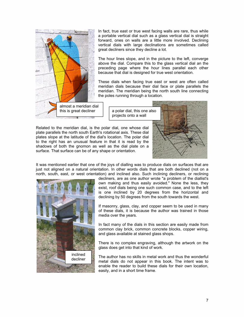
THE EVOLUTIONARY PROCESS OF THE SUN DIAL
ALTITUDE DIALS AZIMUTH DIALS HOUR ANGLE DIALS
All hour angle dials derive from the equatorial dial, a dial whose dial plate parallels the planet's equator. The “Durer” model is a geometric derivation of how hour angle dials are derived from the equatorial dial. This is discussed in full in chapter 14. From this comes all the geometric models for all the different hour angle dials, as opposed to the azimuth and altitude dials. From these geometric models come all the trigonometric formulae used. From these trigonometric formulae come the spreadsheets, nomograms, tables, and other programming systems for dial design. NOTE: Altitude and azimuth should not be ignored as old fashioned ideas. They are essential elements along with the equation of time (chapter 5) in most derivations of the figure of 8 analemma, see chapter 25.
Equatorial Dial Armillary dial
Meridian dialHorizontal dial
Vertical dial
Polar dial
Capuchin
Shepherd
Analemmatic
Winged
chapter 4 ~ the evolution of the sundial
Altitude plus ecliptic
Astrolabe

28
CHAPTER FIVE
THE EQUATION OF TIME THE ECCENTRICITY EFFECT The Earth's solar orbit is almost a circle, but it is still elliptic. Hence it speeds up and slows down as it is closer to or further from the sun. That means the Earth must rotate a bit more, or a bit less, each day for a fixed location to once again point directly at the sun. This generates an annual variation in the form of one complete sine wave. star sun Earth's orbital speed varies thus a day based on solar noon at a fixed location varies also. Earth THE OBLIQUITY EFFECT THE EQUATION OF TIME (EOT) The equation of time is the summing of those two sine waves, and other lesser waves as well, and enables the real sun to be adjusted to the fictitious virtual or mean sun, and hence correlate to pocket watches.
The earth's tilt results in the sun moving not only "westwards" but except for at the equinoxes and solstices, a northward or southward motion as well. That north or south motion means that the sun travels a little more or a little less each day. This generates two sine waves a year of variation.
difference east to west caused by north south travel of the sun (exaggerated)
chapter 5 ~ the equation of time or EOT
if you assume the lengths of these arrows were equal then the equator line would go further west than the west north west line which has some south to north travel. This is the basis for the EOT.

29
To repeat and review, as the Earth orbits the sun in an ellipse, it goes faster approaching the sun and slower when receding. The Earth has two segments; leaving the sun when it slows down, and turning back when it speeds up. The Earth takes more days on one half, less days on the other. This gives the sun an apparent variation of plus or minus about 7.64 minutes between clock and solar time in one full annual sine wave which has one upper and a lower half. This is called the eccentricity effect. Also, the Earth is tilted by about 23.5 degrees to its orbit around the sun creating the two solstices and equinoxes. At the solstices the sun moves neither north nor south but reverses its north/south direction, and moves from increasing latitudes to decreasing ones. At the equinoxes the sun is on the equator and moves from decreasing latitudes to increasing ones. When the sun is moving south or north, some angular movement shifts from the north-south travel to the sun's westward travel, or vice versa, meaning the sun moves westward slower or faster which in turn makes the sun appear slower or faster. Between the equinox and solstice points, solar and clock time differ by about plus or minus 9.86 minutes in two full annual sine waves. This is called the obliquity effect. One sine wave – is 7.64 minutes peak to peak variation. Two sine waves – is 9.86 elliptical orbit minutes peak to peak. ecliptic tilt resulting equation of time four uneven parts in the final cycle January - - - - - - - - - - - - - - - - - - - - - - - - - - - - - - - - - December These two variations added together give the equation of time curve, or EOT, which varies by plus or minus about 16 minutes. The equation of time corrects apparent sun time so it matches a virtual perfect sun, or mean sun, which flows at the same rate as a clock. The appendices have several formulae and tables for the equation of time. USING THE EQUATION OF TIME EOT Here are some uses for the equation of time (EOT):-
To correct a sundial reading To build a sundial using the
shadow to mark hour points To locate true north or south
There are four days when the EOT is effectively zero, they are roughly April 15, June 15, September 1, and December 25. The extreme values of the EOT are around February 11th when the sun is slow and the EOT is +14 minutes 12 seconds, and early November when it is fast and the EOT is then – 16 minutes 22 seconds. Other peak values are May 13th and 14th when the sun is fast, the EOT is –3 minutes 39 seconds, and July 25th and 26th when the sun is slow with an EOT of +6 minutes 30 seconds. Those dates are approximate because of leap years, approximations, and other things.
chapter 5 ~ the equation of time or EOT
Feb Apr Jun Sep Nov Dec
1 13:34 3:49 -2:09 0:02 -16:21 -10:52
3 13:48 3:14 -1:50 -0:41 -16:22 -10:06
11 14:12 1:01 -0:20 -3:24 -15:54 -6:39
13 14:10 0:30 0:04 -4:07 -15:38 -5:43
15 14:05 0:00 0:29 -4:49 -15:19 -4:46
25 13:00 -2:03 2:39 -8:21 -12:55 0:08

30
One depiction of the equation of time (EOT) is the figure of eight. Don't forget that for sundials to be accurate, longitude must be considered in addition to the equation of time, the longitude correction is a fixed number for a given place. Chapter 25 discusses this figure of 8 for many sundial types. Sometimes the figure of eight chart may be seen on the hour lines of a sundial, this is called an analemma and is intended to provide graphical equation of time correction. Its presence can however make a dial look rather confusing. There are a number of formulae available for predicting the EOT. Some are simple, others are astronomically accurate. A TWO SINE WAVE FORMULA (where d = 1 to 365) E = 7.36*Sin(2*3.1416*(d-4.21)/365) + 9.92*Sin(4*3.1416*(d+9.9)/365) other formulae are used for different spreadsheets and tables, see below A THREE SINE WAVE FORMULA (where d = 1 to 365) E = -1*(9.84*SIN(RADIANS(2*(360*d-81)/365))) – 7.53*COS(RADIANS(360*(d-81)/365)) – 1.5*SIN(RADIANS(360*(d-81)/365))) – 0.3 ANOTHER THREE WAVE FORMULA (where d is 1 to 365) E = 7.5*SIN(RADIANS(d-5)) – 10.2*SIN(RADIANS(1.93*(d-80))) + 0.5*SIN(RADIANS(1.5*(d-62))) Every approximation is just that, and this book uses several methods for the EOT to demonstrate the real world of approximations, with their benefits as well as drawbacks. Even established published tables vary by almost a minute. Part of this is explained by the year within a leap year cycle, part by the decade the table was printed, and so on. The most accurate formulae use the astronomical Julian day. This is somewhat involved described next.
chapter 5 ~ the equation of time or EOT

31
ASTRONOMICAL FORMULA FOR THE EQUATION OF TIME
The most accurate formulae use astronomical elements. The astronomical Julian day is first calculated, and then other elements build up to a very accurate EOT formula. "Astronomical Formulae for Calculators" by Jean Meeus is referred to below, fourth edition, ISBN 0-943396-02-6. Its page 24 derives the Julian Day, page 90 derives the equinoxes and solstices for a given year. Do not mix formulae among different books, they may use different baseline epochs, these formulae use Jan 1, 1900 as their epoch, however the formulae work back a couple of thousand years and well into the future. The Julian day discussed here is noon at Greenwich, England. Julian Day =INT(365.25*(4716+(IF((IF(MM>2,1,0))=0,YYYY-1,YYYY))) +INT(30.6001*((IF((IF(MM>2,1,0))=0,MM+12,MM))+1))) +DD -1524.5 +(2-INT((IF((IF(MM>2,1,0))=0,YYYY- 1,YYYY))/100) +INT(INT((IF((IF(MM>2,1,0))=0,YYYY-1,YYYY))/100)/4)) where: yyyy = eg 2005, mm=01 to 12, and dd=01 to 31 March equinox: =1721139.2855+365.2421376*YYYY+0.0679190*ZZ*ZZ-0.0027879*ZZ*ZZ*ZZ
June solstice: =1721233.2486+365.2417284*YYYY-0.053018*ZZ*ZZ+0.009332*ZZ*ZZ*ZZ
September equinox: =1721325.6978+365.2425055*YYYY-0.126689*ZZ*ZZ+0.0019401*ZZ*ZZ*ZZ December solstice: =1721414.392+365.2428898*YYYY-0.010965*ZZ*ZZ-0.0084885*ZZ*ZZ*ZZ where yyyy = eq 2005, and zz = yyyy/1000 Page 79 provides four ingredients, T, L, M, e. Page 81 provides another two, Obliq and "y". Page 91 deriving the final EOT which is the astronomically accurate EOT in radians, which you convert to degrees, then to hours and minutes. T =(jd-2415020)/36525 A date conversion for the Jan 1, 1900 epoch L =279.69668+(36000.76892*T)+(0.0003025*T*T) Geometric mean longitude of the sun M =358.47583+(35999.04975*T)-(0.00015*T*T)+(0.0000033*T*T*T) Sun mean anomaly E =0.01675104-(0.0000418*T)-(0.000000126*T*T) Earth eccentricity Obliq =23.452294-(0.0130125*T)-(0.00000164*T*T)+(0.000000503*T*T*T) Ecliptic obliquity Y =TAN(RADIANS(OBLIQ/2))*TAN(RADIANS(OBLIQ/2)) EOT =(Y*SIN(RADIANS(2*L))) - (2*E*SIN(RADIANS(M)))+ (4*E*Y*SIN(RADIANS(M))*COS(RADIANS(2*L)))- (0.5*Y*Y*SIN(RADIANS(4*L))) - ((5/4)*E*E*SIN(RADIANS(2*M))) mm.mm EOT is the EOT above in radians converted to degrees, divided by 15, and multiplied by – 60 (to get from astronomical EOT to sundial EOT). The above are employed in the astronomical EOT spreadsheets and all that is needed is for the year to be entered once. The spreadsheet then provides the EOT values for that year, the year's Julian day for the solstices and equinoxes, the high and low peak values, as well as a five year review of the EOT for the 15th of the month, and finally a highly detailed daily EOT listing. Appendix 2 has EOT values for several years in several centuries. An equation of time (EOT) table is included in the appendices as well as at the end of this chapter.
chapter 5 ~ the equation of time or EOT

32
NET CORRECTIONS TO A SUNDIAL To correct a sundial reading to find legal clock time, add the EOT (equation of time) to the indicated or local apparent time (L.A.T.). If the EOT is +5, then add 5 minutes to the dial's indication because the sun is slow. If the EOT were –3, you would subtract 3 minutes from the reading because the sun is fast. Then consider longitude and summer time.
Local apparent time (what a simple sundial shows) + EOT provides Local Mean time (the word “mean” is often omitted) + longitude correction provides Standard Mean Time (the word “mean” is often omitted) + 1 if summer and where applicable provides Standard Summer time
CAUTION: some almanacs show the equation of time with opposite signs to those used here. To a dialist, a minus means the sun is running fast and needs the minus to "slow it down". To an astronomer, a minus means the sun is "slow" or "minus" and thus needs a plus to correct it. Neither is right, neither is wrong, it is just that astronomers and dialists have different perspectives. NOTE: Many private sundial designers build a longitude correction into their dials, a few also include the “analemma” to incorporate the EOT. Local Apparent Time (L.A.T.) is solar time shown by the real sun at a particular place, the time most simple sundials show. It needs two corrections before legal standard mean time is known. One correction is the difference in longitude between the dial's location and the standard time meridian. The other correction comes from measuring time using the real sun which results in days of varying length. Instead of the real sun, we use an imaginary or “mean” sun that moves at a constant speed equal to the average annual speed of the real sun. Thus we need to correct for the difference between the real sun and the mean sun. This way sundials can match clocks, this is the purpose of the Equation of Time (EOT). Local Mean Time (LMT) is solar time corrected for the Equation of Time but not yet for longitude, which is why it is called "local". The difference between the Local Mean Time and the Local Apparent time is the Equation of Time, i.e. the Equation of Time (EOT) is the difference between Local Apparent Time (apparent solar time) and Mean Solar Time at the same place. So: Mean Solar Time = Apparent Solar Time + EOT, and Standard legal time = Mean Solar Time + longitude correction. Mean Solar Time and Apparent Solar Time match four times a year, i.e. when the EOT is zero. The leap year and the other three years are often averaged into one EOT table. L.A.T. (local apparent time) + EOT eg: + longitude correction + 1 if it is LEGAL or solar time as shown on Nov –15 – if E of legal meridian summer STANDARD the dial Feb +12 + if west of it MEAN TIME is what you see gets local gets legal standard time is what mean time you get
chapter 5 ~ the equation of time or EOT

33
NOTHING WRONG WITH TAKING A YEAR TO BUILD A DIAL How about building a dial over time. This particular dial will indicate accurately the legal standard time at noon, assuming no daylight savings time. A major benefit to such a slow method is the involvement of the entire family over an extended period of time, and the direct blending of the seasons, the sun's shadow, and the weather as a family event. A sundial will live for many, many years, and the entire family can look back at the fun and excitement of those earlier times when the dial was built. Any dial can be built this way. The process is simplicity itself. A place on a vertical wall was selected, but any surface could be used. The surface can be at any angle or alignment, however, a surface should be selected that will be around as the family matures. In fact the surface does not even need to be flat! Then a gnomon was built. It can be a rod, it can be any rigid object that will last a long time. It does not need to be set accurately, it just exists in space, attached to the surface. The nodus, or the tip of the gnomon is all that is being used in this example, which is a noon time dial.
actual measured points for legal standard noon time
predicted analemma figure of 8, offset for clarity, showing winter solstice and the equinox.
A piece of copper sheet was cut and fashioned and its tip being sharp, a brass washer was soldered to it. This not only makes it safer, but also makes the nodus shadow easier to see. The gnomon was not set at latitude and not aligned with true north or south. The straight edge of the style was not used, only the shadow tip, enhanced by the nodus washer. It was affixed to the wall with epoxy and secured with screws, and tile. Of course, a gnomon could be set at latitude and aligned true north-south, but since this dial only displays legal standard noon time, that is academic. The hour line is a distorted figure of eight. Every few days, the first and middle of the month, or every ten days, the shadow is marked at the selected hour, noon in this example. The result is a dot for a specific legal standard time (noon here) on a specific date. As time progresses, the hour line, actually a figure of eight, is completed and annotated with calendar data. While six months can hold the entire range of solar movement, the equation of time has an annual cycle, hence why a full year is used.
Part of the figure of eight analemma is shown offset above to the right, the marked points on the left match the analemma curve well. To the left is a close-up of the rapidly changing EOT at the December solstice. This is one of two such sister dials. This covers June through December, its sister covers December through June. As the family matures, children and grandchildren can remember fondly the dial being built, learn about the passing seasons and the sun's movement across the sky. What better way to unite a family.
nodus ring
chapter 5 ~ the equation of time or EOT

34
Equation of Time (EOT) mm.ss The mm.ss average of four years of astronomically accurate EOTs using 2010, 11, 12, and 13 1 2 3 4 5 6 7 8 9 10 11 12 Jan Feb Mar Apr May Jun Jly Aug Sep Oct Nov Dec
1 3.15 13.31 12.26 3.59 -2.51 -2.14 3.47 6.22 0.09 -10.10 -16.27 -11.082 3.44 13.39 12.14 3.41 -2.58 -2.05 3.58 6.18 -0.10 -10.30 -16.28 -10.453 4.11 13.46 12.01 3.24 -3.05 -1.55 4.09 6.13 -0.29 -10.49 -16.29 -10.224 4.39 13.52 11.49 3.06 -3.11 -1.45 4.20 6.08 -0.49 -11.08 -16.29 -9.585 5.06 13.58 11.35 2.49 -3.16 -1.35 4.31 6.03 -1.08 -11.26 -16.27 -9.346 5.33 14.03 11.22 2.32 -3.21 -1.24 4.41 5.56 -1.28 -11.44 -16.26 -9.097 5.59 14.07 11.07 2.15 -3.25 -1.13 4.51 5.50 -1.49 -12.02 -16.23 -8.438 6.25 14.10 10.53 1.58 -3.29 -1.02 5.01 5.42 -2.09 -12.19 -16.19 -8.179 6.50 14.13 10.38 1.41 -3.32 -0.50 5.10 5.34 -2.30 -12.36 -16.15 -7.51
10 7.15 14.14 10.23 1.25 -3.35 -0.39 5.19 5.26 -2.51 -12.53 -16.10 -7.2411 7.40 14.15 10.07 1.09 -3.37 -0.27 5.27 5.16 -3.12 -13.09 -16.04 -6.5712 8.03 14.15 9.51 0.54 -3.38 -0.14 5.35 5.07 -3.33 -13.24 -15.57 -6.2913 8.26 14.14 9.35 0.38 -3.39 -0.02 5.42 4.56 -3.54 -13.39 -15.49 -6.0114 8.49 14.13 9.19 0.23 -3.40 0.11 5.49 4.46 -4.15 -13.54 -15.40 -5.3215 9.11 14.11 9.02 0.08 -3.39 0.23 5.56 4.34 -4.36 -14.08 -15.31 -5.0416 9.32 14.08 8.45 -0.06 -3.39 0.36 6.02 4.22 -4.58 -14.21 -15.20 -4.3517 9.52 14.04 8.28 -0.20 -3.37 0.49 6.07 4.10 -5.19 -14.34 -15.09 -4.0618 10.12 13.60 8.10 -0.34 -3.35 1.02 6.12 3.57 -5.41 -14.46 -14.57 -3.3719 10.31 13.55 7.53 -0.47 -3.33 1.15 6.17 3.44 -6.02 -14.58 -14.44 -3.0720 10.50 13.49 7.35 -0.60 -3.30 1.28 6.21 3.30 -6.23 -15.09 -14.30 -2.3821 11.08 13.42 7.17 -1.12 -3.26 1.41 6.24 3.15 -6.45 -15.19 -14.15 -2.0822 11.25 13.35 6.60 -1.24 -3.22 1.54 6.27 3.00 -7.06 -15.29 -14.00 -1.3823 11.41 13.27 6.42 -1.36 -3.17 2.07 6.29 2.45 -7.27 -15.38 -13.44 -1.0824 11.56 13.19 6.24 -1.47 -3.12 2.20 6.30 2.29 -7.48 -15.47 -13.27 -0.3925 12.11 13.10 6.05 -1.58 -3.07 2.33 6.31 2.13 -8.09 -15.54 -13.09 -0.0926 12.25 13.01 5.47 -2.08 -3.01 2.46 6.32 1.57 -8.30 -16.01 -12.51 0.2127 12.38 12.50 5.29 -2.17 -2.54 2.58 6.32 1.40 -8.50 -16.07 -12.32 0.5028 12.50 12.40 5.11 -2.27 -2.47 3.11 6.31 1.22 -9.11 -16.13 -12.12 1.2029 13.01 4.53 -2.35 -2.39 3.23 6.29 1.04 -9.31 -16.17 -11.51 1.4930 13.12 4.35 -2.43 -2.31 3.35 6.27 0.46 -9.51 -16.21 -11.30 2.1831 13.22 4.17 -2.23 6.25 0.28 -16.24 2.47 3.15 NOTE: The appendices have tables for the four years of the leap year cycle and in different centuries as well. NOTE: This table comes from the “EOTandLONG” worksheet as a by-product, which is in the main spreadsheet: illustratingShadows.xls with no longitude consideration.
chapter 5 ~ the equation of time or EOT
EQUATION OF TIME
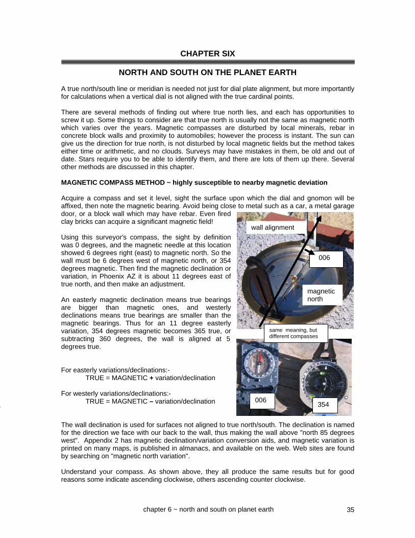
35
CHAPTER SIX
NORTH AND SOUTH ON THE PLANET EARTH A true north/south line or meridian is needed not just for dial plate alignment, but more importantly for calculations when a vertical dial is not aligned with the true cardinal points. There are several methods of finding out where true north lies, and each has opportunities to screw it up. Some things to consider are that true north is usually not the same as magnetic north which varies over the years. Magnetic compasses are disturbed by local minerals, rebar in concrete block walls and proximity to automobiles; however the process is instant. The sun can give us the direction for true north, is not disturbed by local magnetic fields but the method takes either time or arithmetic, and no clouds. Surveys may have mistakes in them, be old and out of date. Stars require you to be able to identify them, and there are lots of them up there. Several other methods are discussed in this chapter. MAGNETIC COMPASS METHOD ~ highly susceptible to nearby magnetic deviation Acquire a compass and set it level, sight the surface upon which the dial and gnomon will be affixed, then note the magnetic bearing. Avoid being close to metal such as a car, a metal garage door, or a block wall which may have rebar. Even fired clay bricks can acquire a significant magnetic field! Using this surveyor's compass, the sight by definition was 0 degrees, and the magnetic needle at this location showed 6 degrees right (east) to magnetic north. So the wall must be 6 degrees west of magnetic north, or 354 degrees magnetic. Then find the magnetic declination or variation, in Phoenix AZ it is about 11 degrees east of true north, and then make an adjustment. An easterly magnetic declination means true bearings are bigger than magnetic ones, and westerly declinations means true bearings are smaller than the magnetic bearings. Thus for an 11 degree easterly variation, 354 degrees magnetic becomes 365 true, or subtracting 360 degrees, the wall is aligned at 5 degrees true. For easterly variations/declinations:- TRUE = MAGNETIC + variation/declination For westerly variations/declinations:- TRUE = MAGNETIC – variation/declination The wall declination is used for surfaces not aligned to true north/south. The declination is named for the direction we face with our back to the wall, thus making the wall above "north 85 degrees west". Appendix 2 has magnetic declination/variation conversion aids, and magnetic variation is printed on many maps, is published in almanacs, and available on the web. Web sites are found by searching on "magnetic north variation". Understand your compass. As shown above, they all produce the same results but for good reasons some indicate ascending clockwise, others ascending counter clockwise.
magnetic north
wall alignment
chapter 6 ~ north and south on planet earth
006 354
006
same meaning, but different compasses
7

36
TRUE NORTH – THE ASTRO COMPASS WAY ~ method one ~ all done with time The astro-compass can be used as an accurate solar compass. It fits into a base, not supplied, which can be made from a 2.25 inch long PVC sprinkler pipe couplings whose inner diameter is 1.9 inches, and whose outer diameter is 2.25 inches. Two slits will need to be cut into it. For accurate time measurement, a clock showing hours, minutes, and seconds updated by an atomic clock such as the one in Colorado is needed. However, understand its use of summer time and that such clocks may drift substantially if the update fails. In this case we switch formula elements around, we need the L.A.T. (local apparent time) to calculate the sun's hour angle:
L.A.T. = standard time – [corrections] = L.A.T. The astro compass is placed on a surface and leveled with the leveling knobs. Leveling only works when the compass is in its base. Then set the lowest adjustment (azimuth) so the lubber line marker is on N for north or S for south. Set the second adjustment up to your latitude. Set the third adjustment up (hour angle) until the sight is pointing roughly at the sun. Set the top adjustment (declination) to the sun's declination to enhance the shadow. Then calculate the corrections valid for the day. HINT: Don't use summer time. EXAMPLE ACTUAL LONGITUDE CORRECTION: your location: 108.2 reference location: 105.0 difference: 3.2 times 4° + 12m 48s EOT CORRECTION: Sept 26
appendix 2 – 8m 41s NET CORRECTION + 4m 7s NOTE: we will reverse the sign when we apply this to clock time - 4m 7s Next: select a time about 5 minutes hence and calculate the L.A.T. for that clock time: For September 26, longitude 108.2, the net correction is + 4 minutes, 7 seconds which is subtracted from the clock indicated time because we desire L.A.T. Simplify work by using standard time. Then: calculate the hour angle from noon for the L.A.T., this is 15° per hour, and 1° for four minutes (table A2.3).
Standard clock (not summer) for reading: 9:30 clock to L.A.T. correction: - 4m 7s L.A.T. (clock – correction): 9:26 L.A.T. from noon 12:00 2h 34m Degrees from noon: 38.5°
Set the astrocompass hour angle dial, third adjustment up, in this example to 38.5 degrees from noon, or 321.5 which is 360-38.5. Last: derive true north: At exactly the selected clock time, 10:30 in this example, slowly rotate the entire device until the sun's shadow is indicated in the declination adjustment's shadow box. The device is set, and the bottom or azimuth ring indicates true north or south. Appendix 2 has the above boxed work areas replicated several times as an easy to use work sheet. HINT: simplify your life and use standard time even in the summer, it saves confusion.
azimuth
lha
decl
shadow
latitude
The astrocompass rests on a PVC column on a wood base.
chapter 6 ~ north and south on planet earth

37
ASTRO COMPASS TRUE NORTH DETERMINATION ~ method two ~ done with degrees This uses the same theory as backing off or advancing the clock time for a sighting, but instead of adjusting the time of the sighting, the hour angle is adjusted by advancing it or retarding it based on a degree equivalent (as opposed to a time equivalent) of the sum of the longitude and equation of time (EOT) corrections. Also, standard time is used, rather than considering daylight saving time in mid-calculation. EOT mm.ss First, find the equation of time for the day, the EOT is in appendix 2. For March 27, this is +5.37 (mm.ss), meaning that this is added to a sundial reading. Convert this to degrees, using 4 minutes per degree. This is 5m 37s, or 5.6 minutes and that becomes 1.4 degrees, positive when divided by four. Next, derive the longitude correction for the dial's location, which is the location's longitude minus the legal time zone's meridian longitude. For a dial at location W108.2 and a legal time zone meridian of W105, the number is 3.2 degrees. A positive number. Next, add the EOT in degrees and longitude correction in degrees giving 3.2 plus 1.4, in other words 4.6 degrees positive. Next, look at your accurate watch and pick the nearest time whose minutes is a multiple of 4. In this case it was 12:43 daylight savings, thus this is 11:43 standard time. The 11:48 daylight saving time simplifies calculations. This was 12 minutes before noon, or at 4 minutes per degree, this was 357° (3° before noon). Finally, the sun's hour angle (in this case 357° or 3° before noon) is adjusted by the total EOT and longitude correction. Since the time was before noon, the 3 degrees is backed off by (has subtracted from it) the 4.6 degrees. This results in 7. 6 degrees as the correct solar hour angle for 12:48. Note: 7.6° is less than 3° when you consider them to be 352.4° and 357° respectively. The astro compass having been set, it is used as described on the previous page. Appendix 2 and the master spreadsheet illustratingShadows.xls make this process very simple. Longitude
– Legal Meridian
= Location correction
108.2 w – 105 w = + 3.2° EOT for the day mm.ss
EOT for the day mm.mm
EOT/4 Total correction
+ 5m 37s + 5.6 = + 1.4° + 4.6°
Mar Apr May
1 12.31 4.06 -2.48
2 12.19 3.49 -2.56
3 12.07 3.31 -3.02
25 6.13 -1.54 -3.10
26 5.55 -2.04 -3.04
27 5.37 -2.14 -2.57
28 5.19 -2.23 -2.50
29 5.00 -2.32 -2.43
30 4.42 -2.40 -2.35
31 4.24 -2.27
Time of day astro compass final hour angle 1248 summer, 1148 mst 352.4° (or 7.6 from noon on morning side) do several times
chapter 6 ~ north and south on planet earth
1 Calculate the correction in degrees 2. Pick a time whose minutes are a multiple of 4 3. Calculate the hour angle from noon 4. Set the astro compass to the hour angle from noon in step 3, but subtract the correction from step 1
DATE: Mar 27 good for the day

38
SOLAR METHOD ~ WHEN THE SUN IS EXACTLY AT SOLAR NOON ~ very effective The longitude, equation of time, and summer time corrections for converting local apparent time (L.A.T.) into legal standard time can be used to identify true north. For accurate time measurement, a clock showing hours, minutes, and seconds updated by an atomic clock such as the one in Colorado may be purchased for less than $20 USD, and its alarm can remind one when to take readings. However, understand its use of summer time, and recall that there are sometimes political moves to adjust the dates of summer time. Also, some such clocks do not always synchronize very well and thus drift, so check them with an internet synchronized clock. Even cell phone clocks are not as accurate as one would wish them to be. L.A.T. (local apparent time) + EOT eg: + longitude correction + 1 if it is LEGAL or solar time as shown on Nov –15 – if E of legal meridian summer STANDARD the dial Feb +12 + if west of it MEAN TIME is what you see gets local gets legal standard time or standard mean time mean time and daylight saving time if relevant Solar noon indicates true north because the sun is at its highest point. Thus a shadow produced at solar noon will point to true north. Solar noon happens when the local apparent time (L.A.T.) is 12:00:00 and the legal standard time that matches it is found as follows:- 12:00:00 + EOT + 1 (if summer) + longitude correction legal standard time for solar noon Silver City NM is longitude 108.2 west, and is thus 3.2 degrees west of the legal time meridian for its mountain standard time zone (mst) which is 105 degrees west. At 4 minutes per degree, the 3.2 degrees becomes in clock terms 12m 48 seconds west of the legal time meridian. To find the legal time for when the sun is at high noon for Silver City, we add 12m 48s (we are west of the meridian), thus getting 12:12:48 on the clock. That takes care of the longitude correction. However we must also correct for a slow or fast sun using the equation of time, or EOT. And summer time if appropriate. On November 12 which was when this experiment was performed, the equation of time shows the correction to be "–15:46" which is minus because the sun is running fast by 15 minutes and 46 seconds. We subtract the 15:46 correction so our time synchronizes with the sun. legal noon on the 105 degree meridian: 12:00:00 longitude correction: + 00:12:48 we are west so we add result = 12:12:48 equation of time correction – 00:15:46 use EOT table's sign result = 11:57:02 summer time correction + 00:00:00 not in November result = 11:57:02 To simplify this method, a “transit” table of noon plus the appropriate equation of time (EOT) can help, and the spreadsheets provided with this book can add in the longitude correction which further simplifies this method. Appendix 2 has a noon transit table for each day of the year so you only need to add in the longitude correction, it is also included in this chapter.
chapter 6 ~ north and south on planet earth

39
TRUE NORTH BY COMPARING ACTUAL TO CALCULATED AZIMUTH ~ very effective c c h y h p x front view side view v Distance xp is measured, this happens to equal distance yc. And since angle hcy is a right angle, and since the sun's azimuth from the wall's perpendicular (ch) is angle chy, then the azimuth from the wall's perpendicular at the time must be: azimuth at the noted time = atan (yc / ch) y c When a wall's perpendicular is true south, i.e. ch points true south then life is simple, however few walls are so aligned. h top view If we have the standard time, we can convert it to local apparent time (L.A.T.) using the formula: standard time = L.A.T. + EOT + long.corr + summer.time thus L.A.T. = standard.time – ( + EOT + long.corr + summer.time ) NOTE: When empirically marking a dial, the hour line's time has the EOT added to it. For example to mark the 11:00 am line, with an EOT of +10, the line would be marked at 11:10, because when the shadow is on the 11:00 hour line, it would be 11:10, there is no sign reversal. In this case however, we are reversing the signs of the EOT, longitude correction, and summer time since we are now going the other way. HINT: forget summer time, use standard time. Then, given the L.A.T. and the date, we can calculate the sun's azimuth from true south (formula A8.4 in the appendices). First, the L.A.T. must be converted to a local hour angle (LHA)(table A2.2 or 1 degrees per 4 minutes), the latitude must be known, and finally the sun's declination (formula A8.2a or A8.2b or appendix 2) suns azimuth = ATAN{ SIN(lha) / [as calculated] ( (SIN(lat)*COS(lha))–(COS(lat)*TAN(decl)) ) } Once we have the sun's azimuth from true south calculated, and the sun's azimuth from the wall's perpendicular measured, the difference in azimuth's will be the wall's declination from true south. There are a number of steps, and the spreadsheet illustratingShadows.xls has a worksheet dedicated to facilitating this reverse azimuth process. The steps are: (1) measure an actual azimuth at (2) a legal standard time, then (3) calculate the L.A.T. or local apparent time and (4) calculate the azimuth for that L.A.T. and date, and (5) the difference in azimuths is the wall declination. Multiple readings increase the final accuracy. The spreadsheet makes this so simple.
A flat board has a nail inserted perpendicularly into it at point "c" and its length from board surface to tip is "ch". A vertical line "cx" is drawn and a perpendicular "cy" is drawn, and a plumb line "cv" attached to the nail so that the plate when attached to a wall can be set so that "cy" is horizontal. The standard time is noted, and the tip of the shadow "p" is drawn.
chapter 6 ~ north and south on planet earth
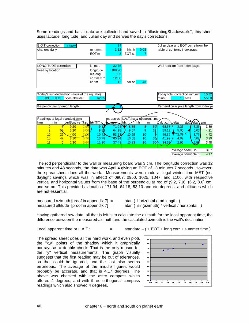
40
Some readings and basic data are collected and saved in "illustratingShadows.xls", this sheet uses latitude, longitude, and Julian day and derives the day's corrections. E O T correction 4/4/2007 94 Julian date and EOT come from thechanges daily mm.mm 3.12 hh.hh 0.05 table of contents index page:
EOT m 3 EOT ss 7
LONGITUDE correction latitude 32.75 Wall location from index page:
fixed by location longitude 108.20ref long 105corr m.mm 12.80cor m 12 cor ss 48
Today's sun declination (n-/s+ of the equator) Today total correction mm.mm 15.925.395 DECL noon altitude: 62.65 mins 15 secs 55.00
Perpendicular gnomon length: 3 Perpendicular pole length from index pa
Readings at legal standard time measured L.A.T. locat apparent timehour min horizontavertical hh.hh azimuth hh.hh hh mm calc azi delta abs.delta avg
9 7 9.20 7.90 9.12 71.94 8.85 8 51 68.58 3.36 3.36 3.369 50 6.20 8.00 9.83 64.18 9.57 9 34 59.12 5.06 5.06 4.21
10 25 4.00 7.00 10.42 53.13 10.15 10 9 49.36 3.77 3.77 4.4210 47 3.10 6.70 10.78 45.94 10.52 10 31 41.92 4.02 4.02 3.9011 6 2.30 6.60 11.10 37.48 10.83 10 50 34.53 2.95 2.95 3.480 0 0.00 0.00 0.00 0.00 -0.27 -1 44 6.40 -6.40 -6.40 -1.72
average of all 5 is: 3.87average of middle 3 4.17
The rod perpendicular to the wall or measuring board was 3 cm. The longitude correction was 12 minutes and 48 seconds, the date was April 4 giving an EOT of +3 minutes 7 seconds. However, the spreadsheet does all the work. Measurements were made at legal winter time MST (not daylight savings which was in effect) of 0907, 0950. 1025, 1047, and 1106, with respective vertical and horizontal values from the base of the perpendicular rod of (9.2, 7.9), (6.2, 8.0) cm, and so on. This provided azimuths of 71.94, 64.18, 53.13 and etc degrees, and altitudes which are not essential. measured azimuth [proof in appendix 7] = atan ( horizontal / rod length ) measured altitude [proof in appendix 7] = atan ( sin(azimuth) * vertical / horizontal ) Having gathered raw data, all that is left is to calculate the azimuth for the local apparent time, the difference between the measured azimuth and the calculated azimuth is the wall's declination. Local apparent time or L.A.T.: = standard – ( + EOT + long.corr + summer.time ) The spread sheet does all the hard work, and even plots the "x,y" points of the shadow which it graphically portrays as a double check. That is the only reason for the "y" vertical measurements. The graph visually suggests that the first reading may be out of tolerances, so that could be ignored, and the last also seems erroneous. The average of the middle figures would probably be accurate, and that is 4.17 degrees. The above was checked with the astro compass which offered 4 degrees, and with three orthogonal compass readings which also showed 4 degrees.
chapter 6 ~ north and south on planet earth

41
SOLAR METHOD ~ THE SUN CROSSES AN ARC BOTH AM AND PM
The compass method uses simple math, a compass and is quick, but the compass can be swayed by nearby metal, such as wall reinforcements, and it is easy to make a mistake in the math unless you draw pictures (see appendix 2 for charts, tables, and some useful aids). This solar method is slower, and requires a level surface. The figure to the left is a photo of a dial plate with a vertical pin, except circles are drawn around the pin. The surface is leveled with bits of wood between the upturned bucket
and the dial plate. The compass is not used except as a rough and ready quick start to get the dial plate roughly pointing in the right general direction. You begin before lunch, and note when the tip of the sun's shadow crosses an arc. And you come back in the afternoon and see when it crosses it again. The sun crosses the circle at x and y. You draw a line from the center to x and to y, then bisect the angle. The bisected arc's center points to true north. The equation of time has nothing to do with this as it doesn’t matter if the sun is slow today or fast. The sun orbits around the Earth's polar axis and that is what is actually being measured, not the time. In reality you do several circles and average the results, and several circles reduces the chances of a cloud shadowing things and ruining your afternoon.
x y
True north
chapter 6 ~ north and south on planet earth

42
STELLAR METHOD ~ THE NORTH STAR ~ POLARIS The skies at night may be used. The southern hemisphere has the southern cross and another marker, the northern hemisphere has the north star or Polaris which can be found by locating some constellations. Locate the pole star and from you to it is the north south line. This method is less accurate the further north you are since the altitude of the star increases. And the north star is not exactly where the celestial pole is, but off by a little bit. Cassiopeia – an upside down "W" in this pictorial is a marker for Polaris, the north star. Ursa Minor – little dipper is a marker also Ursa Major – big dipper is also a marker December sky around 9 pm in the northern hemisphere looking north
west December east west March east
west June east west September east Anyone using the stars to locate true north might search the web for "star maps", and some web sites are listed in appendix 10. One such web site might be:- http://www.skymaps.com/downloads.html The method of drafting the meridian is to use two suspended plumb lines one or both of which are rotated until both verticals coincide with the north star.
Cassiopeia
Ursa Major
Ursa Minor
All of these pictures are at 9pm looking north.
Looking north, sky rotates east to west above the pole star, west to east below it, as the hours as well as months progress.
Polaris
chapter 6 ~ north and south on planet earth

43
IMPORTANT CONSIDERATIONS WHEN DETERMINING WALL DECLINATION ASTRO COMPASS USAGE: The astrocompass method consists of placing the astro compass on a board whose edge is against the wall in question. For a wall S 4° W, the astro compass will be rotated counter clockwise (left) when correctly set up as it points to the polar axis, true north. perpendicular to the wall true north S 4° W SURVEYOR COMPASS USAGE: The compass points to magnetic north, and the true north is found by considering the magnetic declination (or variation as navigators and pilots call it). Same house viewed from above 0 354 (surveyors compasses have the perpendicular to the wall numbers marked opposite to normal) magnetic north 090 270 With the compass aligned perpendicular to the wall, the same house would show the compass needle deflected clockwise (to the right) reading 354 magnetic with 10° easterly variation. This translates to a 364° true bearing, or 004°. This might seem to be contrary to the astro compass, however it is not. True north is still deflected to the left. 004° 360° or 0° if the alignment is 004°, then north is to the left and we still have the same alignment as the astro compass. It is easy to become disoriented in the heat of field measurements. Work out the rough alignment first with a compass, then estimate some astro compass or wall-declination-by-azimuth figures next, then perform the actual final measurements. The spreadsheet: illustratingShadows.xls will take the guess work and frustration out of the scenario. When using a magnetic compass, consider taking three readings, one east, one west, and one south of the wall, several readings from different places will reduce errors due to rebar or minerals.
A house viewed from above
chapter 6 ~ north and south on planet earth

44
NORTH AND SOUTH HEMISPHERE DIFFERENCES Most books that discuss sundials, this one included, select a hemisphere and work from its perspective. The benefit is that a fixed system is used, as opposed to being more abstract. These are the differences and similarities when looking at a different hemisphere
Comparing the north and south hemispheres, winter and summer are reversed, summer in the north means winter in the south, short shadows in the north mean long shadows in the south. While the sun moves from east to west in all cases, looking at the equator, the sun moves from left to right in the northern hemisphere, and right to left in the southern hemisphere. The celestial pole is north in the northern hemisphere, south in the south hemisphere. When a gnomon points to the equator, that means north in the southern hemisphere, and south in the northern hemisphere. Some things that stay the same, all formulae are the same, hour line angles are the same, the equation of time is the same. However, the hours on a dial plate themselves are reversed. For example, below are two horizontal and vertical dials, one for each hemisphere. Horizontal dial in England Horizontal dial in Australia North South 9am 9 am Vertical dial in England Vertical dial in Australia I am looking north I am looking south See also chapter 25 for notes on the north south hemisphere differences, especially when considering the analemma.
A shorter shadow in the northern hemisphere means a longer one in the southern hemisphere, and vice versa.
For similar dials, the U shaped declination line in the northern hemisphere is a ∩ declination line in the southern hemisphere, and vice versa.
nodus dial center
chapter 6 ~ north and south on planet earth

45
The table above shows the time of noon transit corrected for the equation of time. The time shown must be corrected for the difference between the dial’s longitude and the legal meridian. If the dial is WEST of the meridian, noon happens later, so ADD the minutes difference which is 4 times the longitude difference. If the dial is EAST of the meridian, noon happens earlier, so SUBTRACT the minutes difference which is 4 times the longitude difference.
NOON TRANSIT FOR A SPECIFIED LOCATION hhmm.mLongitude of design dial: 0.00 Longitude of standard time: 0.00 Diff in degrees: 0.00 mins: 0
1 2 3 4 5 6 7 8 9 10 11 12Jan Feb Mar Apr May Jun Jly Aug Sep Oct Nov Dec
1 1203.31 1213.32 1212.27 1204.01 1157.50 1157.85 1203.45 1206.22 1200.12 1149.92 1143.74 1148.892 1203.78 1213.40 1212.16 1203.44 1157.43 1157.94 1203.56 1206.18 1159.93 1149.73 1143.72 1149.523 1204.25 1213.47 1212.03 1203.26 1156.96 1158.43 1204.08 1206.14 1159.74 1149.54 1143.71 1149.754 1204.71 1213.53 1211.50 1203.09 1156.90 1158.53 1204.19 1206.09 1159.54 1148.95 1143.71 1149.995 1205.16 1213.59 1211.37 1202.51 1156.85 1158.64 1204.29 1206.03 1158.94 1148.76 1143.72 1150.636 1205.60 1214.04 1211.24 1202.34 1156.80 1158.74 1204.40 1205.57 1158.74 1148.58 1143.74 1150.887 1206.04 1214.08 1211.09 1202.17 1156.75 1158.85 1204.50 1205.50 1158.54 1148.40 1143.77 1151.548 1206.47 1214.11 1210.55 1202.00 1156.71 1158.96 1204.59 1205.43 1157.94 1147.83 1143.80 1151.799 1206.89 1214.13 1210.40 1201.44 1156.68 1159.48 1205.08 1205.35 1157.73 1147.66 1143.84 1152.46
10 1207.30 1214.15 1210.25 1201.27 1156.65 1159.60 1205.17 1205.27 1157.52 1147.49 1143.90 1152.7311 1207.71 1214.15 1210.09 1201.11 1156.63 1159.71 1205.26 1205.18 1156.91 1146.93 1143.96 1153.0012 1208.10 1214.15 1209.54 1200.56 1156.62 1159.84 1205.34 1205.08 1156.70 1146.78 1144.42 1153.6813 1208.49 1214.14 1209.37 1200.40 1156.61 1159.96 1205.41 1204.58 1156.49 1146.63 1144.50 1153.9614 1208.86 1214.13 1209.21 1200.25 1156.60 1200.09 1205.48 1204.47 1155.88 1146.48 1144.59 1154.6415 1209.22 1214.11 1209.04 1200.10 1156.60 1200.21 1205.55 1204.36 1155.66 1145.94 1144.68 1154.9216 1209.58 1214.08 1208.47 1159.96 1156.61 1200.34 1206.01 1204.24 1155.45 1145.80 1144.78 1155.6117 1209.92 1214.04 1208.30 1159.82 1156.62 1200.47 1206.06 1204.12 1154.84 1145.68 1144.90 1155.9018 1210.25 1213.59 1208.13 1159.68 1156.64 1200.60 1206.11 1203.59 1154.62 1145.55 1145.42 1156.6019 1210.56 1213.54 1207.55 1159.55 1156.67 1201.13 1206.16 1203.45 1154.41 1145.43 1145.54 1156.8920 1210.87 1213.48 1207.38 1159.42 1156.70 1201.26 1206.20 1203.31 1153.80 1144.92 1145.68 1157.5921 1211.16 1213.42 1207.20 1158.89 1156.73 1201.39 1206.23 1203.17 1153.58 1144.82 1145.83 1157.8822 1211.44 1213.35 1207.02 1158.77 1156.77 1201.52 1206.26 1203.02 1152.97 1144.72 1145.98 1158.5823 1211.71 1213.27 1206.44 1158.66 1156.82 1202.05 1206.28 1202.47 1152.76 1144.63 1146.54 1158.8824 1211.97 1213.18 1206.26 1158.54 1156.87 1202.18 1206.30 1202.31 1152.55 1144.55 1146.71 1159.5825 1212.21 1213.09 1206.08 1158.44 1156.92 1202.31 1206.31 1202.15 1151.94 1144.47 1146.88 1159.8726 1212.44 1212.60 1205.50 1157.94 1156.98 1202.44 1206.32 1201.59 1151.73 1144.00 1147.47 1200.1727 1212.65 1212.49 1205.32 1157.84 1157.45 1202.56 1206.32 1201.42 1151.52 1143.94 1147.66 1200.4728 1212.86 1205.14 1157.75 1157.52 1203.09 1206.31 1201.24 1150.92 1143.88 1147.86 1201.1629 1213.04 1204.55 1157.66 1157.59 1203.21 1206.30 1201.07 1150.72 1143.83 1148.46 1201.4530 1213.22 1204.37 1157.67 1206.28 1200.49 1143.79 1202.14
BLACK time is at or after legal noon standard time [no summer time correction] If a leap year then after February
BLUE before legal noon standard time [no summer time correction] 28 use the next day's value
NOON TRANSIT
chapter 6 ~ north and south on planet earth

46
CHAPTER SEVEN
Geometry and Trigonometry, a refresher If one excluded empirical dial design, and focused on planned dial design, then geometry would be the first line of attack. The following is for flat surfaces, not curved surfaces such as a globe. However, for most purposes we can assume that this works on the surface of the planet. GEOMETRY Geometry for simple dials, is a simple process. For example, the polar dial derived from the 15° per hour radials is not involved. A circle is draw, this represents an equatorial dial, and the 15° radials extended to a horizontal line, this represents the dial plate, in particular, the equinoctial line. As an aside, the 60° radial shows a distance of 5.2 inches from the bottom of the circle with a radius of 3 inches. The distance along that horizontal line is the trigonometric tangent of the angle, times the radius. Geometry gets slightly more complicated when three dimensions are involved. Something needs to be folded to make the geometric figure two dimensional. The above polar dial can be used, especially when it comes to lines (equinox) or curves (declination or calendar data). The hour lines are simple enough and were drafted using a flat two dimensional surface. But for the sun's declination to be depicted, a third dimension is added because the rays can hit the gnomon at angles ranging from -23.44 (winter), to 0 (the equinoxes), and +23.44 at the summer solstice. There are two lines which are 23.44 degrees from the vertical and show the range of the nodus shadow from the winter to summer solstice, with the equinoxes sharing the straight center line. How can the three dimensional picture above be converted into a two dimensional flat drawing, such that all the relationships are retained. The triangle representing the shadow range can be rotated flat. After the gnomon has been rotated flat, then the rays of light are projected from the nodus now on the dial plate. This shows what happens for the solstice range for noon.
angle 60.00
radians 1.05
tan 1.73
times 3 5.20
45°
3.00 in
3.00 in
5.20 in
chapter 7 ~ geometry and trigonometry
the gnomon has been rotated flat

47
For different hours, that triangle of rays is from the nodus to the hour point on the equinox line. In this case, two hours from noon (30 degrees from the vertical), results in a nodus to dial plate distance that is longer than the one for the preceding noon example. The end result is that where the + and – 23.44 degree lines intercept the associated hour line, will form a plot that is hyperbolic. Convert the above three dimensional pictures into a flat drawing where relationships are retained, the polar dial uses a simple geometric construction, or a simple trigonometric formula. t d th = rh ath = time from noon hrd = declination r a h As an aside, the trigonometric formulae also derive from that picture:- tan ( hrd ) = dh / rh = dh / th, thus dh = th * tan (declination ) and:- cos ( ath ) = ta / th thus th = ta / cos ( ath ) so given: dh = th * tan (declination ) then:- dh = ta * tan (declination) / cos (time ) The distance up the hour line for the point on which the declination (calendar) line will lie is equal to the style linear height times the tangent of the declination all divided by the cosine of the time. This is repeated for several of the hour lines, then the points joined to form a hyperbolic curve for the solstices, or a straight line for the equinox.
the gnomon has been rotated flat
chapter 7 ~ geometry and trigonometry

48
TRIGONOMETRY Geometry cannot be used as is in programs or spreadsheets. So, the geometric relationships must be converted into things that programs and spreadsheets can use, and that something is trigonometry. Accurate geometric figures can be used when developing trigonometric formulae, or, they can be stylized. The same diagram as above can be stylized, as shown below.
Trigonometry, as used in this book, uses what are called circular functions.
Ø
n
h-dial
d=decl
style
v-dec dial center
h-dial center
latitude
v-dec dial
h
h = h-dial hr line
n = v-dec hr line angle
Stylized diagram for a vertical decliner has fewer steps, relationships are not retained, but with a little imagination, it is simpler to see how trigonometric formulae are
Pure diagram for a vertical decliner retains relationships but has more steps.
chapter 7 ~ geometry and trigonometry

49
Circular functions are sin, cos, and tan. They relate the sides of a right angle triangle that is contained in a circle. hypotenuse is opposite radius a adjacent side The tangent of that angle, abbreviated "tan": tan(a) = opposite / adjacent The above functions enable lengths of sides of a triangle to be calculated if the angle "a" is known and the length of one of the sides. The sentence "the old aunt, sat on her, coat and hat" helps remind people of those relationships. Certain standard relationships exist:- tan = sin / cos And for any triangle, whether or not it is a right angled triangle, a C B b c A the law of sines says:- A / sin(a) = B / sin(b) = C / sin(c) While normal humans use the "degree" which is 1/360 of a circle, the "radian" is more appropriate for mathematicians, there are 2 * 3.1416 radians in a circle. The sin, cos, and tan can be calculated from a series sin = x – (x**3)/3! + (x**5)/5! – (x**7)/7! + . . . cos = 1 – (x**2)/2! + (x**4)/4! – (x**6)/6! + . . . tan = x + (x**3)/3 + 2*(x**5)/15 + . . . The opposite of sin, cos, and tan are called arcsin, arccos, and arctan, often abbreviated to asin, acos, and atan, or sin
-1, cos-1, and tan-1, or even asn, acs, or atn.
the vertical in this triangle constrained in a circle is the "sine" of the angle times the hypotenuse, sine is abbreviated to "sin". the horizontal in this triangle constrained in a circle is the "cosine" of the angle times the hypotenuse, cosine is abbreviated to "cos". the cosine is the complement of the sine. The other way of looking at things is that the:- sin(a) = opposite / hypotenuse cos(a) = adjacent / hypotenuse
chapter 7 ~ geometry and trigonometry

50
The arcsin and arccos can be developed simply from the following:- asin = atan(x/sqrt(1-x*x)) acos = (3.1416/2) – asin (x) however, atan is more involved. There are two series often found, one only works for a value of up to 1, which is 45°, which is not very helpful. The other is:- atan = (x/(1+x*x)) * ( 1 + (2/3)*(x*x/(1+x*x)) + ((2*4)/(3*5))*(x*x/(1+x*x))*(x*x/(1+x*x)) ...
see the Appendices for notes on the series. see Supplemental Shadows for notes on the series including
iterative methods.
Thus, if a sundial can be reduced to geometry using the projections discussed earlier, then they can be converted to trigonometry. Most such conversions are straight forward. Some are complex. Different people use different parts of a geometric figure to develop a trigonometric formula. For example, the standard formula for the hour line angles of an inclined decliner differs from the formula derived in this series of books. The results are the same for all ranges of numbers. In fact, one formula can be converted to the other. In the context of sundials, all hour angle dials derive from the equatorial dial, a dial whose dial plate parallels the planet's equator. The “Durer” model was a geometric derivation of how dials are derived from the equatorial dial. From this stem all the geometric models for all the different hour angle dials, as opposed to the azimuth and altitude dials. From those geometric models stem all the trigonometric formulae used. From those trigonometric models stem the spreadsheets and other programming systems for dial design. This entire series of books, booklets, and supplements, was developed with no spherical trigonometry. In spherical trigonometry, biangles can have angles (other than 0°), and angles in a triangle do not add up to 180 either. Other functions exist that compare to the circular functions of sin, cos, and tan. There are hyperbolic functions called sinh, cosh, and tanh. They use a hyperbolic curve rather than a circular arc. They are useful in electronics, some sundial authors use them for exotic dial plate furniture, however, they are not used in this series of books.
chapter 7 ~ geometry and trigonometry

51
CHAPTER EIGHT
General Interest There is a well known observatory in India at a place called Jaipur. The Jaipur Observatory was established by the local ruler in the 1700s, and has been modeled by Illustrating Shadows using virtual reality markup language (VRML). With a browser plug-in from one of several sources, for example Parallel Graphics provides the Cortona plug-in, you can bring up this observatory and walk around it in full 3d. For interest, Illustrating Shadows also provides some other worlds. Some have an animation of the moon revolving around the earth which in turn orbits the sun. Appendix 10 discusses virtual world viewing software, along with issues related to different Windows variants such as XP, and Vista both 32 and 64 bit.
A virtual world in VRML, built using the Parallel Graphics software scene builder ISB, animated with their ISA animator, of the Jaipur Observatory in India, and other places. Animated models are in those worlds which are on this book's web site. Further, some of the dials designed for pictures in this series of books were themselves saved in VRML form, and using the Cortona web browser plug-in, the viewer can move those CAD generated sundial models and study them by rotating them and seeing how they are built.
Jaipur virtual world
chapter 8 - general interest

52
SUN DIAL STAMPS Many countries have issued postage stamps with sundials on them, one of my favorites depicts an observatory of many sundials in Jaipur, India. Another depicts a dial in the Dominican Republic.
SUN DIAL ADVERTISEMENTS
Some advertisements from the 1950s, for beer, liquor, and soft drink products used a sundial to send a message of gentle tranquility. The author has several in his collection.
SUN DIAL CHINA
Here are some examples of china ware depicting sundials.
SUN DIAL MEMORABILIA
Here are two examples of old biscuit tins in which biscuits were purchased. Cookies to an American.
SUN DIAL POSTCARDS In the author's collection of several hundred postcards are some of sundials in interesting places. One is of Jaipur, an interesting solar observatory established in the 1700s. SUN DIAL COLLECTORS CARDS In the early 1900's companies issued collector's cards. In particular a series from a cigarette company, depicted various sun dials is in his collection. This one is of a "mass" dial.
some of the sundials at Jaipur
chapter 8 - general interest
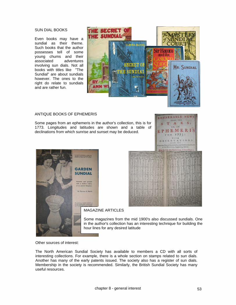
53
SUN DIAL BOOKS Even books may have a sundial as their theme. Such books that the author possesses tell of some young chums and their associated adventures involving sun dials. Not all books with titles like "The Sundial" are about sundials however. The ones to the right do relate to sundials and are rather fun. ANTIQUE BOOKS OF EPHEMERIS Some pages from an ephemeris in the author's collection, this is for 1773. Longitudes and latitudes are shown and a table of declinations from which sunrise and sunset may be deduced.
MAGAZINE ARTICLES Some magazines from the mid 1900's also discussed sundials. One in the author's collection has an interesting technique for building the hour lines for any desired latitude
Other sources of interest: The North American Sundial Society has available to members a CD with all sorts of interesting collections. For example, there is a whole section on stamps related to sun dials. Another has many of the early patents issued. The society also has a register of sun dials. Membership in the society is recommended. Similarly, the British Sundial Society has many useful resources.
chapter 8 - general interest

54
DIAL MOTTOES
There are thousands of mottoes used on dials that help make up the dial furniture. Many are well known, however, some less well known ones are reproduced below. Many have a theme of doom and gloom, reminding all who stop to read of graveyard epitaphs. Sometimes written in Greek, often in Latin, these add a subtle charm for the passer by. Latin, in the far off distant mists of time was written with no gaps between the words. Equally interesting is the Roman numbering system, one of the few with no
weighting, and it had no zero. Julius Caesar introduced the idea of using a dot to identify the first letter of a word, thus making reading more practical. This evolved into a dot between the words, and later a space was used. From the author's collection are some books of sundial mottoes etc between 1903 and 1919. Let there be light. Each one wounds, the last one kills ~ OMNES VULNERANT ULTIMA NECAT As time and hours pass away, so doth the life of man decay Time has been, is, and IS TO be. ~ TEMPVS RERVM ET ERIT The sun returns but not so time At my back I always hear Times winged chariot drawing near The greatest maxim I can give, is make the most of how you live I know mine hour, dost thou know thine The time thou killest shall in time kill thee Serene I stand amidst the flowers to tell the passing of the hours The last is hidden so that we have to watch them all ~ ULTIMA LATET UT OBSERVENTUR OMNES Use them don't count them ~ UTERE NON NUMERA Beware of one of them ~ EX IIS UNAM CAVE One of these will be your last ~ UNA EX HIS ERIT TIBI ULTIMA The hour is slow but the years run quickly ~ LENTE HORA CELERITER ANNI Life's but a shadow, Man's but dust, This diall says, Dy all we must No man can call again the past time [pun] Whilst Phoebus on me shines, view my shades, view my lines Common sources for mottoes come from scriptural works such as the psalms, and from classical works such as Chaucer and Shakespeare.
chapter 8 - general interest

55
Harking back to a time when sundials were popular and dialing was a daily functional activity, stereoscopes were used for a casual past time. For interest only, some 3D pictures are provided which may be viewed by placing a cardboard between the two photos and letting the eyes relax.
A horizontal and vertical dial with an equatorial, after Albrecht Durer.
A gnomon on an east facing declining vertical dial in 3D.
A large Shepherd’s dial
chapter 8 - general interest

56
CHAPTER NINE
The basic equatorial and armillary hour angle dials
This chapter introduces sun dials that use simple hour angle principles, the hour angle of the sun as it rotates around the polar axis of the Earth. The sun rotates around the polar axis 15 degrees per hour. Thus, should a gnomon or in this case, a style be parallel to the polar axis and thus set to point to the pole, and, if the dial plate paralleled the equator, then hour lines would be 15 degrees apart. This is true for the armillary dial as well as the equatorial dial.
The equatorial dial has a polar pointing gnomon in the form of a rod, however the dial plate is flat and parallels the equator. Winter hours appear on the side facing the Earth, and summer hours appear on the side facing the sky. Hours of the equinox are not readily available. The seasons are indicated by the length of the shadow cast from a nodus, and the sun describes circles on the dial plate. Hour lines are drawn as straight lines from the center, and calendar lines are circles surrounding the center as well.
The same principle applies to the armillary dial except the dial plate is not a flat surface paralleling the equator, rather it is a curved dial plate, whose radius is constant from the gnomon or style which in turn parallels the north south polar axis.
Hour lines are also drawn 15 degrees apart, or they can be measured linearly. Calendar lines are straight lines, indicated by a nodus on the gnomon or style, and parallel each other. The equatorial dial, or the armillary dial, can be the basis for designing almost any other type of sun dial that uses the 15 degree per hour solar rotation around the Earth's polar axis. While the polar dial is not quite as simple as the equatorial and armillary dial, it is easily derived from
them. The dial plate is angled for the latitude, but is flat. And like the armillary and equatorial dials, the gnomon is aligned to true north/south and sloping at the latitude angle. The hour lines are made by projecting the 15 degree lines to the flat dial plate, thus the hour line separation is not constant. A polar dial is an armillary dial whose dial plate has been flattened. The polar dial is the next step in the evolution in understanding dial design, and thus is introduced here, but discussed in detail in the next chapter.
hypotenuse opposite side angle adjacent side
Polar dial
equator
pole
chapter 9
Equatorial dial
pole
Armillary dial
summer sun
winter sun
pole
summer sun
winter sun

57
THE EQUATORIAL DIAL ~ HOUR LINES THEMSELVES ARE 15° APART The armillary and equatorial dials are very similar. In the armillary dial the hours were inscribed on a band, and the gnomon or style created a shadow on that band. The hours were 15 degrees apart, and summer or winter, reading the dial was easy. The equatorial dial, named as the dial plate parallels the equator, is designed rather like an armillary dial. Whereas the armillary dial can find you using distances instead of degrees to lay out the time scale, with an equatorial dial it is simpler to use just the 15 degree angles. This is because the armillary used a curved band to hold the hour lines, but an equatorial dial uses a flat, often circular, plate. That plate parallels the equator, hence the name "equatorial" dial. The gnomon is pointing to true north/south angled at the location's latitude. Summer sun Winter sun Summer hours read on this side of the dial pole plate which is uppermost Winter hours read on the back or lower side of the dial plate 1 pm line noon line 11 am line Style or gnomon aligned with the Earth's polar axis Longitude adjustment is made by rotating the dial, as was done for the armillary. Equation of time is usually managed with a table. However both the armillary as well as the equatorial dial can have a device to rotate the dial based on the date. This method of handling the equation of time works with armillary and equatorial dials because they are dials whose hour lines are separated by a constant number of degrees. The armillary or equatorial dial can be used as the basis for all other hour angle dials in existence, they can all be derived from it. However, for those other dials, adjusting for longitude is more involved. NOTE: An equatorial dial can be built on a square or oblong and fitted with a protractor, and then fitted onto the gnomon of almost any other type of sundial, and the equatorial dial's hour lines projected using a cotton thread from the equatorials dial's center to the dial plate on the new dial. A small laser pointing device may be fitted so it can rotate on the equatorial dial, and this might be easier than using a cotton thread. When used in this fashion, the auxiliary equatorial dial may be called a trigon. NOTE: If the gnomon's rod is of appreciable thickness then the hour lines must be adjusted to consider that thickness.
chapter 9
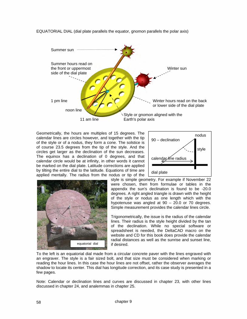
58
EQUATORIAL DIAL (dial plate parallels the equator, gnomon parallels the polar axis) Summer sun Summer hours read on the front or uppermost Winter sun side of the dial plate 1 pm line Winter hours read on the back or lower side of the dial plate noon line Style or gnomon aligned with the 11 am line Earth's polar axis Geometrically, the hours are multiples of 15 degrees. The calendar lines are circles however, and together with the tip of the style or of a nodus, they form a cone. The solstice is of course 23.5 degrees from the tip of the style. And the circles get larger as the declination of the sun decreases. The equinox has a declination of 0 degrees, and that calendar circle would be at infinity, in other words it cannot be marked on the dial plate. Latitude corrections are applied by tilting the entire dial to the latitude. Equations of time are applied mentally. The radius from the nodus or tip of the
style is simple geometry. For example if November 22 were chosen, then from formulae or tables in the appendix the sun's declination is found to be -20.0 degrees. A right angled triangle is drawn with the height of the style or nodus as one length which with the hypotenuse was angled at 90 – 20.0 or 70 degrees. Simple measurement provides the calendar lines circle. Trigonometrically, the issue is the radius of the calendar lines. Their radius is the style height divided by the tan of the declination. While no special software or spreadsheet is needed, the DeltaCAD macro on the website and CD for this book does provide the calendar radial distances as well as the sunrise and sunset line, if desired.
To the left is an equatorial dial made from a circular concrete paver with the lines engraved with an engraver. The style is a fair sized bolt, and that size must be considered when marking or reading the hour lines. In this case the hour lines are not offset, rather the observer averages the shadow to locate its center. This dial has longitude correction, and its case study is presented in a few pages. Note: Calendar or declination lines and curves are discussed in chapter 23, with other lines discussed in chapter 24, and analemmas in chapter 25.
nodus 90 – declination style calendar line radius dial plate
equatorial dial
chapter 9
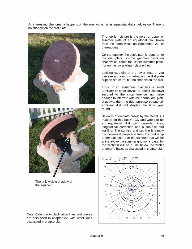
59
An interesting phenomena happens on the equinox as far as equatorial dial shadows go. There is no shadow on the dial plate.
The top left picture is the north or upper or summer plate of an equatorial dial, taken from the north west, on September 22, or thereabouts. On the equinox the sun's path is edge on to the dial plate, so the gnomon casts no shadow on either the upper summer plate, nor on the lower winter plate either. Looking carefully at the lower picture, you can see a gnomon shadow on the dial plate support structure, but no shadow on the dial. Thus, if an equatorial dial has a small armillary or other device to detect shadows secured to the circumference, not large enough to interfere with the normal dial plate shadows, then the dual purpose equatorial-armillary dial will display the time year round. Below is a template drawn by the DeltaCAD macros on this book's CD and web site for an equatorial dial with calendar lines, longitudinal correction and a sun-rise and set line. The sunrise and set line is simply the horizontal projection from the nodus tip to the dial plate. For the summer that will be a line above the summer gnomon's base, for the winter it will be a line below the winter gnomon's base, as discussed in chapter 22.
chapter 9
The only visible shadow at the equinox.
Note: Calendar or declination lines and curves are discussed in chapter 22, with other lines discussed in chapter 23.

60
THE ARMILLARY DIAL ~ HOUR LINES THEMSELVES ARE 15° APART In olden times, many centuries ago, the first sundials used vertical poles, or obelisks. They drew hour lines from the bottom of the pole and the end result was that the hours were variable length day after day. As time went on, people wanted constant hours and they also found that the sun appears to rotate around the polar axis of the Earth.
a vertical pole with hour lines radiating from a pole sloped to parallel the Earth's polar axis, the base does not indicate hours of the same perpendicular to the equator, with lines drawn duration day to day. from its base will indicate hours whose duration is the same from day to day. The idea of using a pole that was parallel to the Earth's rotational axis, not perpendicular to the Earth's surface, i.e., slanted to match the latitude, resulted in a shadow line which with a bit of calculation provided lines for hours (hour lines) whose duration would be constant hour to hour, day to day, and all year round. So the slanted pole gnomon (the shadow casting edge is called a style) is used for time telling when the sun's angle around the Earth's poles is used. The line of the shadow indicates the time, its tip or other "nodus" such as a notch or blob, indicates the date. The date is ambiguous except for the solstices (June and December). For example the sun is over the equator in both September and March.
The armillary dial is a hemisphere or part of a circle of constant radius, and each hour is 15 degrees of arc. It derives its name from the Latin for "arm bracelet". At solar noon, the 12 o'clock line is always on the same place on the circular dial. If the style or gnomon has a nodus then its point up or down the dial plate will also tell the date. NOTE: If the gnomon's rod is of appreciable thickness then the hour lines must be adjusted to consider that thickness. Note: Calendar or declination lines and curves are discussed in chapter 22, with other lines discussed in chapter 23.
sun's motion
chapter 9
Summer sun
Winter sun
pole
gnomon, or in this case just a style, parallels the polar axis
The sun around 2 pm summer and winter

61
The hours indicated are solar local apparent time (L.A.T.) hours. They need some corrections, one for longitude, one for the equation of time, and some for summer time if desired. The latitude can be adjusted by adjusting the slope of the style and dial plate. This should always be the latitude of the place where the sundial is located. It goes without saying that the style should also point true north/south. True north is not magnetic north except on a specific meandering line where such is true. Finding true north was addressed earlier. The longitude correction is very simple in the case of armillary and equatorial dials. The dial has 12 o'clock directly below the style when the sundial is on the longitude associated with the legal meridian or time. But if you are west of it, the dial plate must be rotated to show a later time than it would otherwise do, and if you are east of it, it should show an earlier time. Why? Because if it is 12 noon on the legal longitude, say 105 degrees, the sun will be almost vertical above the 12 mark, but at the very same instant at for example the 108 degree longitude, the sun will not have reached the vertical yet. And so on for any other hour. 108° degree longitude where I am located 105° degree legal time longitude west east The above picture shows why the sun reads an earlier time at 108 degrees of longitude than it does on the 105 degree line. For an armillary or equatorial dial, the adjustment for longitude is simple ~ rotate it.
The picture to the left is a modern permanent dial. The latitude is adjustable but needed a device to measure the angle because the scale was not marked. Also, this dial has no longitude adjustment, so a fixed amount must be added or subtracted depending on its location. Similarly the equation of time must be considered. If you think this dial isn’t working because there is no shadow of the style on the dial plate, fear not, the sun was not shining when the photograph was taken. However it does raise the point that shiny surfaces such as this can make it hard to read a shadow. If the style, the rod thing looking like an arrow, had a notch or other mark on it such as a blob (nodus)
then declination lines could be drawn on the circular band or dial plate so that it would provide calendar information as well as the time, although this particular armillary band would not be wide enough. In this chapter, examples are shown of armillary dials made from PVC as well as with other materials.
chapter 9
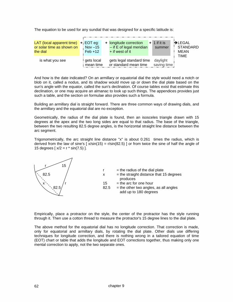
62
The equation to be used for any sundial that was designed for a specific latitude is: LAT (local apparent time) + EOT eg: + longitude correction + 1 if it is LEGAL or solar time as shown on Nov –15 – if E of legal meridian summer STANDARD the dial Feb +12 + if west of it MEAN TIME is what you see gets local gets legal standard time daylight mean time or standard mean time saving time And how is the date indicated? On an armillary or equatorial dial the style would need a notch or blob on it, called a nodus, and its shadow would move up or down the dial plate based on the sun's angle with the equator, called the sun's declination. Of course tables exist that estimate this declination, or one may acquire an almanac to look up such things. The appendices provides just such a table, and the section on formulae also provides such a formula. Building an armillary dial is straight forward. There are three common ways of drawing dials, and the armillary and the equatorial dial are no exception. Geometrically, the radius of the dial plate is found, then an isosceles triangle drawn with 15 degrees at the apex and the two long sides are equal to that radius. The base of the triangle, between the two resulting 82.5 degree angles, is the horizontal straight line distance between the arc segment. Trigonometrically, the arc straight line distance "x" is about 0.261 times the radius, which is derived from the law of sine's [ x/sin(15) = r/sin(82.5) ] or from twice the sine of half the angle of 15 degrees [ x/2 = r * sin(7.5) ]. r 15 r = the radius of the dial plate 82.5 x = the straight distance that 15 degrees produces x r 15 = the arc for one hour 82.5 82.5 = the other two angles, as all angles add up to 180 degrees Empirically, place a protractor on the style, the center of the protractor has the style running through it. Then use a cotton thread to measure the protractor's 15 degree lines to the dial plate. The above method for the equatorial dial has no longitude correction. That correction is made, only for equatorial and armillary dials, by rotating the dial plate. Other dials use differing techniques for longitude correction, and there is nothing wrong in a tailored equation of time (EOT) chart or table that adds the longitude and EOT corrections together, thus making only one mental correction to apply, not the two separate ones.
chapter 9

63
INTRODUCING THE POLAR DIAL ~ HOUR LINES ARE PARALLEL The next sun dial in the complexity chain is the polar dial, named because the dial plate parallels the polar axis. Whereas the armillary dial and the equatorial dial had hour lines 15° apart …
… the polar dial hour lines increase in distance the further away from the style they are.
In the polar dial, the dial plate and the style are both angled to match the location's latitude, they are both aligned with the polar axis, hence the dial's name. The style is a certain distance above the dial plate. Because the dial plate is flat, the hour lines are no longer evenly spaced. They can simply be deduced from the equatorial dial, or by simple trigonometry. And whereas a calendar was easy to draw on an armillary or equatorial dial where the lines of the sun's declination were parallel to each other, it is a bit more involved here. The equinox line is straight but the other lines such as the solstices will be hyperbolic curves. Just as the equatorial dial had three ways of making it, so does the polar dial. Geometrically, we can draw a triangle that matches the dial plate and the style, the apex of the triangle is 15, or 30, or some other multiple of 15 degrees. And this diagram provides the distance from the sub-style (the point the style is directly over on the dial plate) for the appropriate hour line. The protractor can be rotated flat onto the dial plate and the style's linear height used as a point for drawing angles if desired, this is called projecting the protractor and style's linear height. style the 15° angle is
not to scale protractor c 15° y sub style dial plate x Trigonometrically, using the above figure, tan(15)=x/y, thus the distance from the sub style "x" is given by: x=y*tan(15), or, hour line distance = style height * tan(hours*15). One hour would be 15 degrees, two hours would be 30 degrees and so on. The appendix reviews trigonometry and has a table of tangents. Empirically, a protractor can be placed on the style, just as with the equatorial dial, and then using a cotton thread "c", the hour lines drawn. You get a single point and that is all that is needed because the hour lines are parallel to the style and sub style. The above method for the polar dial has no longitude correction. That correction is made by rotating the protractor or adding or subtracting from the 15 degree angles, etc before the hour lines are drawn. It cannot be made by sliding the plate left or right under the style, doing that would not take care of the ratios that exist between the hour lines and the base of the style, the sub-style. Expanded details of the polar dial's design are covered in the next chapter.
chapter 9

64
AN EQUATORIAL DIAL dial plate summer gnomon winter gnomon equinox sunrise/set rays lines 23.5 solstice rays one month from solstice ~ May/July or November/January 21 decl is about 19.8 two months from solstice ~ April/August or October/February decl is about 11.2 Also, sunrise and sunset are the intersection of the calendar arc and a horizontal line drawn as the intersection of a horizontal line from the nodus to the dial plate; above for the summer side, below for the winter side. This is latitude dependant. The distance to that horizontal line is = tan(latitude) * gnomon linear height. For latitude 32 the distance is 0.62. The CAD drawing below
was placed between two plexi glass sheets and shown in use, above right. Summer time was not used in the real dial as it was to be used in Phoenix AZ where there is no summer time switch. Note: Calendar or declination lines and curves are discussed in chapter 23, with other lines discussed in chapter 24, and analemmas in chapter 25.
chapter 9
The hour lines are a simple 15 degrees. The calendar (declination lines) are arcs whose radius is:- gnomon linear height radius = tan(declination) DECLINATION RADIUS solstice 6/21 23.5° 2.30 * gnomon month from 19.8° 2.78 * gnomon two from 11.2° 5.06 * gnomon three months is an equinox ~ infinity Table A3.4 has all these figures as well as the sunset/rise horizontal line data for most latitudes.
Sunrise/set horizontal line

65
AN ARMILLARY DIAL A 4.5 inch PVC pipe cap-end was cut and used, the radius was thus 2.25 inches,, being thusly the gnomon to dial plate distance. gnomon winter solstice 23.5 2.25 inches dial plate summer equinox solstice 1 month from solstice 2 months from solstice Using a CAD program, a dial plate was laid out 7.1 inches east to west (6am to 6pm), and 2 inches north to south (twice the solstice to equinox distance). Hour lines are 7.0686/12 inches apart, namely 0.58905 or 0.59 inches. The sloping lines are Italian lines (see later) and show the time until sunset, however those lines make the dial latitude dependant.
The dial shows 2:10 pm winter time in October, just over 3 hours to sunset. Sunset lines, or Italian lines, are covered later, as are calendar or declination lines, they enhance the usefulness of the dial over the common pocket watch. For a location with no summer time differential, the summer hours would not be one plus the winter hours. In the above example, summer time is considered when the sun is above the equator. If the metal used is magnetic, then it will deviate a magnetic compass, so alignment must be done before magnetic nuts and bolts are used.
Note: Calendar or declination lines and curves are discussed in chapter 23, with other lines discussed in chapter 24, and analemmas in chapter 25.
KEY DATES AND diameter 4.5 solstice to equinox
DISTANCES radius 2.25 distance inches
1/20 5/20 7/20 11/20 0.82
2/20 4/20 8/20 10/20 0.45
3/20 9/20 0.00 equinox
20-Jun 20-Dec 0.97 solstice
6am - 6pm: distance 7.0686 and /12:- 0.58905
The hour lines are a simple 15 degrees, or 3.1416*diameter/24, i.e. 3.1416*4.5/24 = 0.58905 inches apart. Useful when using CAD to draw a template. Appendix 1 may help here. The calendar (declination lines) are lines whose distance from the equinox line is:- = gnomon : plate distance * tan(sun's declination)
0.59in
7.07 in
1.94 in
chapter 9

66
CASE STUDY ~ AN EQUATORIAL DIAL WITH CALENDAR CIRCLES This dial will be for Silver City, NM, whose coordinates are: location lat: 32.75° N location long: 108.2° W magnetic declination: 10.6° E A concrete paver from a garden supply shop was acquired and a hole drilled in dead center with a masonry bit. Into that hole was inserted a threaded rod as the gnomon, its length was cut to be 5 cm on each side, and the paver itself was 4 cm thick, making a total length of 14 cm. From that center were drawn 15 degree radials for the hours, and since this dial would be longitude corrected, another mark was drawn 3.2 degrees offset from noon, and when installed, that offset mark would be the vertical.
Then the sun's declination was established for the calendar lines. Dec solstice –23.5 Jan Nov –20 Feb Oct –12 Mar Sep 0 Apr Aug +12 May Jly +20 Jun solstice +23.5 Given the sun's declination angle and the height of the gnomon, the distance for the calendar circle was established, and the appendices have it tabulated or the formula can be used:-
calendar circle radius = gnomon linear height tan(declination) The design notes were all of one page, and the only geometric or trigonometric work was limited to:-
how long the gnomon was to be in order to have reasonable calendar circles
what is the radius of those circles The radials and the calendar circles appear on the upper (summer) side as well as the lower (winter) side. They were first scribed with a Dremel engraver. The hour lines were scribed against a straight edge, the calendar lines were scribed using a 1/4 piece of wood with some holes in it to act as a rotating rule. One hole fitted over the gnomon, the other two were set to the calendar circle radius and were large enough to accommodate the Dremel engraver but with no slack. The wooden radial rule was rotated, and all lines were engraved well. Then a Dremel rotary tool was used with the masonry circular disks to refine those lines.
chapter 9

67
While little dust may be thrown up by the engraver, there is still some. And the rotary cutter will clearly create clouds of the stuff. There is a health risk of silicosis, thus this operation should be well ventilated or outside, and a tight, not loose, fitting face mask should be worn, as well as eye protection. The clothes will become saturated with dust as well. To the right is shown the brick support mechanism, it limits winter hours somewhat, but not excessively.
The picture to the left shows the solstice circle and one month after that. Two months after that was in fact the periphery of the paver. The third month after was the equinox and that radius is of infinite size. The backing of the dial, the winter side, was supported by clay bricks cut with a masonry saw at co-latitude, so the paver paralleled the equator and the rod paralleled the polar axis. Two holes were drilled in the paver and in the bricks into which rods were inserted to add stability. One hole was coincidently on an hour line, the other was not, this was because the dial plate was rotated to correct for the dial's longitude difference from the legal time meridian.
The final touches were to mortar the entire dial in place. This dial was placed on one of the columns of the analemmatic dial. This dial took one day from start to finish, and if 1/4 inch copper tube was used in place of the threaded bolt, the entire dial would look rustic and a wonderful addition to a country garden. To the right is the equatorial dial in place on the 6 am column of the analemmatic dial. Note: Calendar or declination lines and curves are discussed in chapter 23, with other lines discussed in chapter 24, and analemmas in chapter 25.
chapter 9

68
CASE STUDY ~ AN ARMILLARY DIAL WITH CALENDAR LINES This dial will be for Silver City, NM, whose coordinates are: location lat: 32.75° N location long: 108.2° W magnetic declination: 10.6° E
A clay flue liner from a building supply store was acquired and cut into circles one of which was cut into two semicircles, one of which became the dial plate. It wasn't a pure circle, however it was outlined onto a sheet of paper and the mid point of the two ends identified, and from thence were drawn 15 degree arcs. Another line was drawn which was the longitudinal offset from the dial's location and the legal time meridian. This was offset by 3.2 degrees, being the dial's location (108.2) minus the legal time zone's meridian (105).
Being west of the legal meridian, the dial would show earlier times than the legal time, so the dial plate is rotated to show a later time, in this case by 3.2 degrees. Were the dial east of that legal time zone meridian then the dial would show a later time, and would be rotated to display an earlier time. The hour lines were scribed and so was the longitude correction line, a Dremel engraver was used.
longitude correction line and its mate on the brick that would hold this armillary dial plate.
mid point
108.2105
apparent time at 108.2° is earlier than at 105°
chapter 9
0
12
20 23.5
Declination line locations
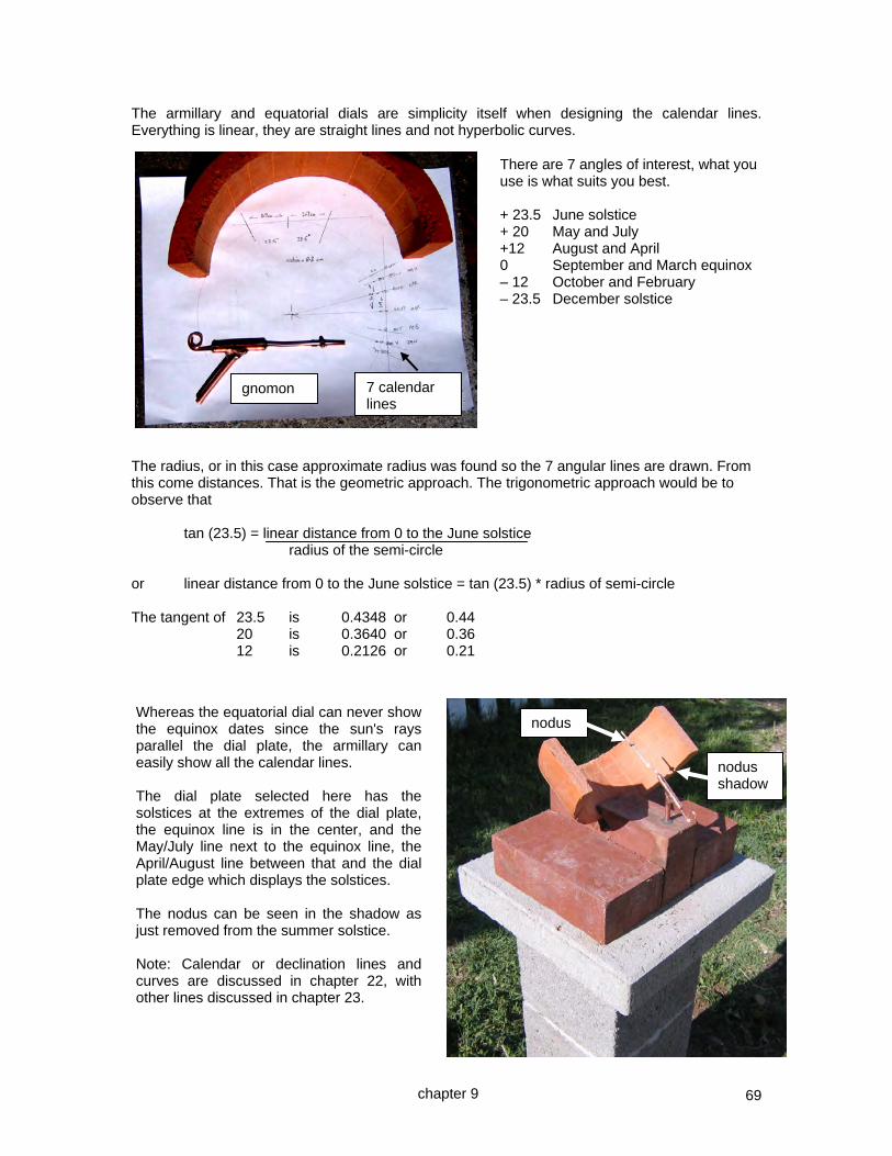
69
The armillary and equatorial dials are simplicity itself when designing the calendar lines. Everything is linear, they are straight lines and not hyperbolic curves.
The radius, or in this case approximate radius was found so the 7 angular lines are drawn. From this come distances. That is the geometric approach. The trigonometric approach would be to observe that tan (23.5) = linear distance from 0 to the June solstice radius of the semi-circle or linear distance from 0 to the June solstice = tan (23.5) * radius of semi-circle The tangent of 23.5 is 0.4348 or 0.44 20 is 0.3640 or 0.36 12 is 0.2126 or 0.21
There are 7 angles of interest, what you use is what suits you best. + 23.5 June solstice + 20 May and July +12 August and April 0 September and March equinox – 12 October and February – 23.5 December solstice
7 calendar lines
gnomon
Whereas the equatorial dial can never show the equinox dates since the sun's rays parallel the dial plate, the armillary can easily show all the calendar lines. The dial plate selected here has the solstices at the extremes of the dial plate, the equinox line is in the center, and the May/July line next to the equinox line, the April/August line between that and the dial plate edge which displays the solstices. The nodus can be seen in the shadow as just removed from the summer solstice. Note: Calendar or declination lines and curves are discussed in chapter 22, with other lines discussed in chapter 23.
nodus shadow
nodus
chapter 9

70
The gnomon is made from 1/4 inch copper tubing commonly found in hardware stores, soldered to establish the latitude, and a 10 or 12 gauge copper wire soldered into that. This was inserted into a hole drilled into the brick with a masonry bit. Grid powered electric drills are better for this sort of work than the portable battery drills because portable drills tend to go at slower speeds. The gnomon support shaft was coated with epoxy and inserted in the hole after carefully verifying the level and angular sections.
Then the copper wire was displaced with two small bends to accurately align it, this corrects any errors when its support was stabilized with epoxy. The copper wire then received a blob of solder after accurately determining the correct place, being 90 degrees or perpendicular from the equinox line on the dial plate. The whole was copper plated with a mix of water and copper sulfate. The dial plate was not truly circular, this means that those calendar lines would not in a pure world be straight lines, however for a garden dial they are close enough.
The dial plate was fixed with epoxy into a slice cut from the brick with a circular masonry cutting blade. After a number of days the dial was mortared into place and mortar used to fill the gaps where needed. The final resting place for the dial was on one of three columns of a large garden analemmatic dial.
chapter 9

71
CASE STUDY ~ TWO GNOMON-LESS ARMILLARY DIALS SIDE BY SIDE SOMETIMES KNOWN AS AN OPEN BOOK DIAL This dial will be for Silver City, NM, whose coordinates are: location lat: 32.75° N The dial plate from 7 am to 5 pm will be location long: 108.2° W a maximum of 16 inches east to west magnetic declination: 10.6° E and 8 inches top to bottom (approximately) First, a few notes on how these dial work. An armillary dial can use the edges of the armillary as the gnomon, there would be one edge for the a.m. hours, the east edge, while the west edge would be the p.m. hours. The geometric figure below might suggest that calculating the angles would be difficult. However, simplicity itself reigns! The 15 degree lines are drawn from one edge. Where they intersect the semi-circle is where the hour lines would be. A set of lines from the semi-circle's center drawn to those intercepts shows that the angles of the hour lines from the center are actually 30 degrees. This is "The Half Angle Theorem". This is explained simply since each is an isosoles triangle. Since an angle at the base is 75 degrees, being 90 degrees minus the 15, and since the other base angle must be the same as both are on the circumference, and both go to the semi-circle's center, then they total 150 degrees, leaving 30 when subtracted from 180. Thus, 30 degree radials from the dial center are drawn, which can easily be translated into linear distances once the radius of the semicircle is known.
A nodus can be added for calendar information, both edges would then need that nodus. However, those calendar lines might look somewhat confusing as they would diverge since the nodus to dial plate point of impact increases with the time from noon. The armillary must be set at latitude. The edges must be pure, thus also aligned to latitude, and be exactly where the 6 am or 6 pm lines, or the noon lines, are. However, such a dial can be rotated, and can be longitude corrected. This system can be analyzed in more detail, and a 3 inch radius or 6 inch diameter will be used as a basis for that study.
90–15 75
15
chapter 9

72
What is the width of the armillary dial plate? Using geometric projections whereby we rotate a view from the top sideways, so the plan view is rotated to the profile view. For a three inch radius semi-circle, or a six inch diameter semi-circle, the maximum spread for the 23.5 degree declination would be twice 2.58 inches, or 5.2 inches. Or in more general terms, the solar declination spread is a bit under the diameter.
However, this assumes a nodus is used. It must be remembered that the gnomon-less dial has two styles, and if declination lines or calendar lines will not be used, then all that is needed is to ensure that the style's shadow is always on the dial plate. So the southernmost tip of the style can be used for the winter shadow, and the northernmost tip for the summer shadow.
In this case, we can halve the length of the style, and thus dial plate. Thus a six inch diameter semi-circle need only have a width of 2.58 inches, or in more general terms, the width of the dial plate, summer to winter, is 2.58/6 inches or 0.48 times the diameter. Or in very loose terms, the dial plate is about as wide as its radius. Alternatively, the dial plate has a breadth from 6 am to noon, or noon to 6 pm of 3.1416 (pi) times the radius. Thus a 6 inch diameter semi-circle would have a dial plate whose breadth of the hour span was 9.428 inches. And 2.58 divided by 9.428 yields 0.27 which we shall verify next. The above figures were based on empirical CAD (computer aided design). How well does that match a trigonometric approach? The tangent of 23.5 is 0.4348, and that times 6 is 2.61. Obviously 2.61 is the more accurate number to use, however the use of CAD adds to an understanding of what is going on. Using 2.61 as the true figure of the minimum style's length in order to keep the shadow on the dial plate, the ratio of dial plate (6 am to noon) to summer-winter range is: 2.61 to 9.428, or 0.276, which again is close to the empirical 0.27.
chapter 9

73
Solar ray examples and notes on hour line accuracy
To the left are shown 1 degree lines from the opposite style which is to the right, and 2 degree lines from the semi-circle center which is from the top. The sun's lines intersect perfectly, they are close to perpendicular with the dial plate, so accuracy is highest. To the right are shown 1 degree lines from the style
which is to the right, and 2 degree lines from the semi-circle center which is from the top. The sun's lines intersect perfectly, they are about 45 degrees with the dial plate, so accuracy is still good.
To the left are shown 1 degree lines from the style which is to the top right, and 2 degree lines from the semi-circle center which is from the top left. The sun's lines intersect perfectly, they are close to flat with the dial plate, so accuracy is lowest. The accuracy, or rather sensitivity, decreases around noon. For the perfectionist, a small polar dial can be added for an hour either side of noon.
On the left the complete picture of 1 degree solar rays and their intersection with the 2 degree radials from the semi-circles center can be seen, and the three boxes correspond to the three expanded pictures above. All these pictorials were done with TurboCAD. The above pages lay the foundation for the dual gnomon-less armillary to be placed on a column, which will be described in the following pages.
sun's rays
sun's rays
radial from semi-circle center
radial from semi-circle center
radial from semi-circle center
sun's rays
chapter 9
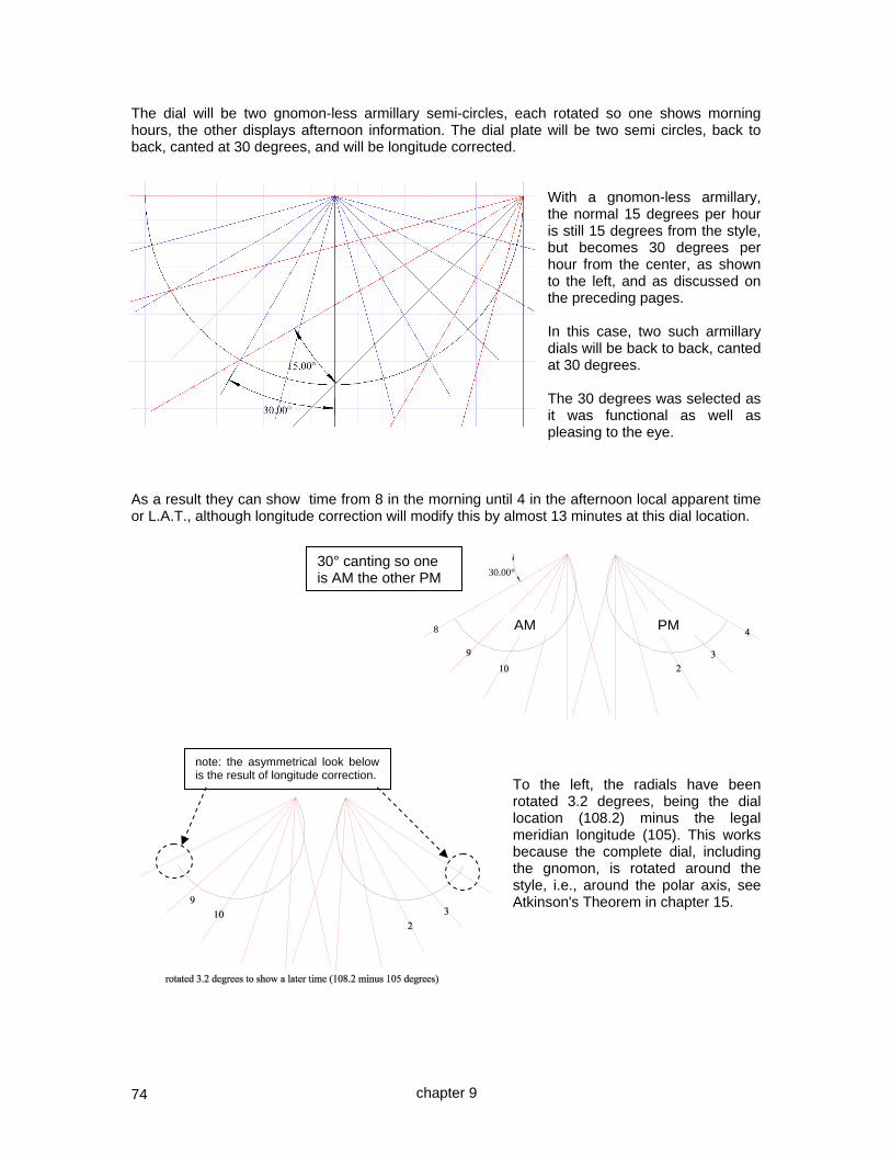
74
The dial will be two gnomon-less armillary semi-circles, each rotated so one shows morning hours, the other displays afternoon information. The dial plate will be two semi circles, back to back, canted at 30 degrees, and will be longitude corrected.
With a gnomon-less armillary, the normal 15 degrees per hour is still 15 degrees from the style, but becomes 30 degrees per hour from the center, as shown to the left, and as discussed on the preceding pages. In this case, two such armillary dials will be back to back, canted at 30 degrees. The 30 degrees was selected as it was functional as well as pleasing to the eye.
As a result they can show time from 8 in the morning until 4 in the afternoon local apparent time or L.A.T., although longitude correction will modify this by almost 13 minutes at this dial location.
To the left, the radials have been rotated 3.2 degrees, being the dial location (108.2) minus the legal meridian longitude (105). This works because the complete dial, including the gnomon, is rotated around the style, i.e., around the polar axis, see Atkinson's Theorem in chapter 15.
30.00°
8
note: the asymmetrical look below is the result of longitude correction.
30° canting so one is AM the other PM
AM PM
chapter 9
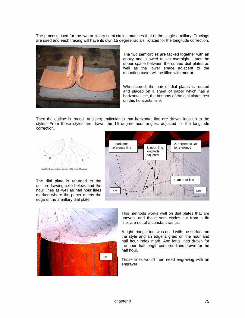
75
The process used for the two armillary semi-circles matches that of the single armillary. Tracings are used and each tracing will have its own 15 degree radials, rotated for the longitude correction.
The two semicircles are tacked together with an epoxy and allowed to set overnight. Later the upper space between the curved dial plates as well as the lower space adjacent to the mounting paver will be filled with mortar. When cured, the pair of dial plates is rotated and placed on a sheet of paper which has a horizontal line, the bottoms of the dial plates rest on this horizontal line.
Then the outline is traced. And perpendicular to that horizontal line are drawn lines up to the styles. From those styles are drawn the 15 degree hour angles, adjusted for the longitude correction.
The dial plate is returned to the outline drawing, see below, and the hour lines as well as half hour lines marked where the paper meets the edge of the armillary dial plate.
This methods works well on dial plates that are uneven, and these semi-circles cut from a flu liner are not of a constant radius. A right triangle tool was used with the surface on the style and an edge aligned on the hour and half hour index mark. And long lines drawn for the hour, half length centered lines drawn for the half hour. Those lines would then need engraving with an engraver.
1. horizontal reference line
2. perpendicular to reference 3. noon line
longitude adjusted
4. an hour line
am pm
pm
chapter 9

76
Two small "T"s were made, one had the half and quarter hour detents, these were small nails in the 1/4 inch wood. A second template was needed for the hours. The dial plate was engraved with a Dremel engraver. Again, a face mask was used, as were glasses as a precaution. The two dial plates were then given a small amount of epoxy to affix them to the concrete paver. When set on their supporting column, then mortar would be added. Building the column this dial would rest on was standard procedure. Except that after the 2 inch by 1 foot square, base paver was set, the author was distracted by another work project and Alfonzo the contractor who was working on re-stuccoing the barn, decided that the base paver should align with the fence, and not with true north. Positive intentions, but not discovered when the author returned to complete the column.
So the column was built up, but part way up it was time for a cup of tea. After the cup of tea, work resumed however the author mistakenly didn't alternate one layer of bricks. So when it was finished, the final paver used to rest the dial plate was no longer correctly aligned, and one set of bricks looked out of place. The resolution was to align the final dial plate by offsetting it from the paver it rested on. To the left the realigned dial plate can be seen, and below the dial rests in a serene part of the garden. It was tested and found to be within a couple of minutes.
chapter 9
mini "T"
nail detents

77
CHAPTER TEN
The polar dial in detail
AN OVERVIEW OF THE THREE TECHNIQUES FOR A POLAR DIAL. We have discussed the armillary and equatorial dials. This chapter revisits the polar dial. The polar dial to the right is engraved on a ceramic tile and shows about 9:00 am standard time as it is longitude corrected, but not mean time as there is no EOT correction. Designed by the author for Somerset, England. Hour angle dials use gnomons whose style parallels the Earth's rotational axis. For polar dials, the dial center is actually an infinite distance away! Usually the style is an indicator of the time and the nodus an indicator of the date. In early times, the date was often a major function of some dials. Whereas the armillary and equatorial dials have hour lines evenly spaced every 15 degrees, the polar dial has line spacing based on the trigonometric tangent of the hour difference from noon. Dials are designed for a specific latitude or distance from the equator, and the hour lines should be adjusted for the longitude of the dial's location, or a fixed adjustment must be mentally made when reading the time. Like the armillary and equatorial dials, the polar dial works at any latitude as long as the dial plate and style are set at latitude. The sun runs slow or fast and a correction must be mentally made to account for it, the correction being the equation of time, or EOT. Most dials have no longitude correction built into the hour lines, but instead that time difference is folded into a tailored equation of time for that longitude.
There are several methods of designing sun dials. And there are many types of sundials as well. Dials may be designed for horizontal use, or vertical facing due the equator, east, or west, and the polar region. And dials can be designed for walls that don't quite face true south, east, west, or north, in other words dials that decline. The word "decline" has several different meanings, three to be precise. Magnetic (variation), sun angle from the equator (varies plus or minus 23.44 degrees over the year) which should not be confused with the sun's altitude, and, finally a wall's angular offset from true north or south is also called a
declination. And dials can be designed that lean back or forward, dials that incline or recline. This chapter focuses on the polar dial where the dial plate and the gnomon's style parallel the Earth's polar axis. There are three general methods of designing a dial once the type has been selected. One method is to build the gnomon and do the rest by empirical methods, i.e. "practical geometry". The picture above is a "trigon" which is a custom built protractor. The word trigon comes from the same base as the word trigonometry. This trigon was used to get points on the equinox line for the hour lines for a vertical almost south facing dial discussed in a later chapter.
chapter 10

78
EOT
A truly empirical sundial would have the gnomon placed in position, and the hour lines built from hour points, longitude correction would thus be implied. This was discussed earlier. Simple math is done with an accurate clock and the equation of time, abbreviated to EOT. To build a sundial using the sun's shadow to mark the hour points, an accurate standard time clock is used. This could be a cell phone with the time set by the provider, however often seconds are omitted. A watch set by the computer whose clock is corrected by the internet is a practical means of getting the accurate time. And cheap clocks which reset themselves daily based on a radio atomic clock may be had at department stores. The formula for time is:- dial indicated time + EOT => standard time thus we can deduce:- standard time – EOT => dial indicated time Notice that the longitude difference between the dial's longitude and the legal meridian is not computed. A byproduct of using this technique to calibrate a dial is that the longitude correction is implicit, this is because you are using the standard time, and the dial location's L.A.T., which is why the difference in longitude between the dial and the legal standard meridian was not computed. To get a 1200 hour point therefore on November 10th when the EOT is –16:00 we would:- clock time – EOT has to be => 1200 thus clock time – – 16 has to be => 1200 thus clock time + 16 has to be => 1200 ( – – is a plus ) clock time is thus => 1200 – 16 => 1144 So, with an EOT of – 16 minutes, at a standard clock time of 1144 pm a dial should show 1200 as the sun is fast by 16 minutes. In other words, when the shadow is on the "12" and the EOT is minus 16 minutes, the time is 1144. So the hour mark is made in this case 16 minutes early on the clock time. If the EOT was positive, the opposite would be the case. TO MARK A SUNDIAL SO IT WILL WORK ON ANY DAY USING THE EOT, PUT THE HOUR MARK WHERE THE SHADOW IS WHEN THE CLOCK READS THE STANDARD TIME ADJUSTED BY ADDING THE EOT Some more examples:- hour point + EOT legal time to make the observation 12:00 + – 8 11:52 ( eg December 8 ) 12:00 + +13 12:13 ( eg February 15 ) It is very well worth the time to draw some hour lines, some shadows, and then play around with the numbers. Before doing this with a real dial under construction, draft a table of time that you will mark the hour points. It is easy to make a mistake otherwise.
Feb Apr Jun Sep Nov Dec
1 13:34 3:49 -2:09 0:02 -16:21 -10:52
2 13:42 3:32 -1:59 -0:22 -16:22 -10:29
3 13:48 3:14 -1:50 -0:41 -16:22 -10:06
4 13:54 2:57 -1:39 -1:01 -16:22
-9:42
10 14:11 1:16 -0:32 -3:03 -16:00 -7:07
11 14:12 1:01 -0:20 -3:24 -15:54 -6:39
12 14:11 0:45 -0:08 -3:46 -15:46 -6:11
13 14:10 0:30 0:04 -4:07 -15:38 -5:43
14 14:08 0:15 0:16 -4:28 -15:29 -5:15
15 14:05 0:00 0:29 -4:49 -15:19 -4:46
25 13:00 -2:03 2:39 -8:21 -12:55 0:08
chapter 10

79
dial plate
The second method is to use geometric methods. The trigon above was used for empirical purposes, but could have been made more accurate and anyway, we can use its concept as the basis for geometric methods. Geometric methods convert the three dimensional dial into a two dimensional figure and then use that figure to generate appropriate angles and lines of appropriate length. The polar dial for example took a real equatorial dial and rotated the nodus of the style or gnomon flat so that drawings could be made. A picture is worth a thousand words, so look below. a protractor we would use empirically the style a constructed protractor whose
radius is the style's height is rotated 90 degrees to lie flat on the dial plate several 15 degree lines
geometrically produced distance from the noon line to the hour line The third method is to use trigonometric methods. The trigonometric method uses the geometric model so that trigonometric functions can be used to create formulas that can then be used on the dial plate. s nh = dist to hour line from sub-style ns = style linear height n h nh = tan (time) * ns
11am and 1pm = 15 degrees off center, tan (15) = .2679 nh = 0.2679 style height 10am and 2pm = 30 degrees off center, tan (30) = .5774 nh = 0.5774 style height 9am and 3pm = 45 degrees off center, tan (45) = 1.000 nh = sh and of course the morning hours would be west of the style, with afternoon hours east. All methods can use longitude correction. The geometric method simply rotates the protractor or adds or subtracts the adjustment to the hour angles before marking the point. The trigonometric method adds or subtracts the angle similarly before the tangent is calculated. The dial plate cannot be slid left or right however as hour line ratios would no longer be correct. The equation of time is factored in mentally, otherwise the dial gets more complicated. Empirical, geometric, and trigonometric methods can also be used for calendar information.
sub-style
chapter 10

80
THE EMPIRICAL METHOD FOR A POLAR DIAL USING A TRIGON First build the dial plate and the gnomon with its style, there are no markings at this point. Then attach a protractor to the top of the style and decide what the longitude correction is to be, if any. For Phoenix AZ at 112 degrees using the 105 degree legal time meridian, the protractor must be turned 7 degrees. From personal experience, write down which way, or write down all the new angles to be used. Fail to do that and you will screw some of them up. Alternatively, no correction is made, and instead it is folded into the EOT table. Then attach a cotton thread from the tip of the style or the center of the protractor and holding it over the appropriate hour angle on that protractor, see where the cotton line touches the dial plate. And mark that point. And repeat it for the other hour lines. Laser pointers may also be used. actual style cotton thread W E For the angle, you use the time in hours multiplied by 15 and then add or subtract the number of degrees by which the dial's longitude differs from the legal time meridian assuming you desire built-in longitude correction. In the case of Phoenix AZ, the hours must be shifted to the west, or left in the above picture. That way noon will happen earlier than when the sun is actually overhead which is the correct adjustment for longitude when the dial is west of the legal meridian. Personal experience shows that when making a dial it is easy to forget which way to correct a protractor, or if using trigonometry, it is easy to forget whether you are adding or subtracting the longitude correction. When making a sundial empirically, the hour lines, and declination lines if they are used, should be penciled in, and then you go outside and wait for the sun with the sun dial in situ to fine tune the results. Then use the equation of time and wait. If the equation of time is -15 (as in October) then that means that at 2pm you would subtract 15 minutes. So, at 15 minutes to 2 the styles shadow should be on the 2 o'clock hour line. You can double check this by using reverse logic. Again, from experience, rushing out every hour to do this calibration has the ability to cause confusion. So write it down, and set an hourly alarm on your PDA (personal digital assistant), and then you will not make as many mistakes. As always, the polar dial under construction must be in place, and tilted to the latitude, both dial plate and style. And the style must point to true north and south. Longitude correct can be omitted from the above, and instead it can be folded into an EOT table which then allows one mental arithmetic operation to account for both longitude as well as EOT. This is a wise approach especially if the dial may be relocated to another location at a later date.
finger
chapter 10

81
THE GEOMETRIC METHOD FOR A POLAR DIAL First establish how far above the dial plate the style is (style linear height). Then on the 12 o'clock line draw a protractor of the same radius as the style's distance from the plate. Then proceed around the protractor at 15 degree increments and project those lines to the dial as shown. No longitude correction employed in this example height of the style above the dial plate Morning hours west 12 1 2 3 4 Afternoon hours east Where the 15 degree line intercepts the dial plate, there is the 1pm line, or if on the other side, the 11am line. The three o'clock pm (or 9 o'clock am) line is the 45 degree angle (3 times 15 degrees per hour, and its distance from noon is always equal to the style's distance from the dial plate which is a clue to the trigonometric method, the tangent of 45 degrees is 1. Latitude is managed by the dial plate and the style being tilted so they make an angle with the planet's surface equal to the latitude. Longitude is corrected so that indicated solar time, properly called local apparent time, or L.A.T., reflects the solar time at the standard time longitude or meridian. That is done by rotating the protractor by an amount equal to the difference between the sun dial's location and the reference meridian, or more often, a fixed number may be applied to the indicated time. The dial plate cannot simply be slid or shifted however, because the hour line ratios would no longer be correct. For example in Phoenix AZ the longitude is 7 degrees west of the standard. Phoenix 33.5° N 112.0° W mag var 11.8° E PHX mst is at 105° PHX is 7° 0' from mst i.e. 28 minutes from mst A Phoenix dial's protractor would be rotated 7 degrees if the longitude correction was to be built in. Unlike the equatorial and armillary dials, for a polar dial one cannot slide the dial plate a certain amount, because the line ratios would no longer be correct, instead the protractor employed is rotated. This is shown below, and notice that the 12 o'clock noon line is offset, in this case to the left or west. With longitude correction 12 1 2 3 4 So 12 o'clock will be indicated earlier than it would normally be, because the legal 105 degree meridian gets to 12 o'clock before it does at the 108 degree meridian.
chapter 10
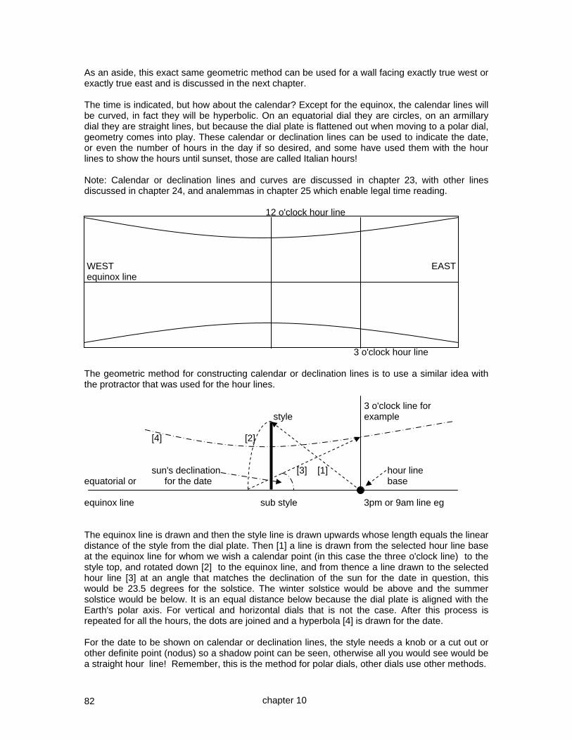
82
As an aside, this exact same geometric method can be used for a wall facing exactly true west or exactly true east and is discussed in the next chapter. The time is indicated, but how about the calendar? Except for the equinox, the calendar lines will be curved, in fact they will be hyperbolic. On an equatorial dial they are circles, on an armillary dial they are straight lines, but because the dial plate is flattened out when moving to a polar dial, geometry comes into play. These calendar or declination lines can be used to indicate the date, or even the number of hours in the day if so desired, and some have used them with the hour lines to show the hours until sunset, those are called Italian hours! Note: Calendar or declination lines and curves are discussed in chapter 23, with other lines discussed in chapter 24, and analemmas in chapter 25 which enable legal time reading. 12 o'clock hour line WEST EAST equinox line 3 o'clock hour line The geometric method for constructing calendar or declination lines is to use a similar idea with the protractor that was used for the hour lines. 3 o'clock line for style example [4] [2] sun's declination [3] [1] hour line equatorial or for the date base equinox line sub style 3pm or 9am line eg The equinox line is drawn and then the style line is drawn upwards whose length equals the linear distance of the style from the dial plate. Then [1] a line is drawn from the selected hour line base at the equinox line for whom we wish a calendar point (in this case the three o'clock line) to the style top, and rotated down [2] to the equinox line, and from thence a line drawn to the selected hour line [3] at an angle that matches the declination of the sun for the date in question, this would be 23.5 degrees for the solstice. The winter solstice would be above and the summer solstice would be below. It is an equal distance below because the dial plate is aligned with the Earth's polar axis. For vertical and horizontal dials that is not the case. After this process is repeated for all the hours, the dots are joined and a hyperbola [4] is drawn for the date. For the date to be shown on calendar or declination lines, the style needs a knob or a cut out or other definite point (nodus) so a shadow point can be seen, otherwise all you would see would be a straight hour line! Remember, this is the method for polar dials, other dials use other methods.
chapter 10

83
TRIGONOMETRIC METHOD FOR A POLAR DIAL HOUR LINES: style t The angle equals hours from noon times 15 plus or minus the longitude correction angle in degrees, if you correct for longitude. equatorial line a h The equatorial line is along "ah", and the style is "t", where "at" equals the linear height of the style above the dial plate. The angle "ath" is the time in hours from noon times 15 (there are 15 degrees in an hour). we see that:- tan (ath) = ah / at, thus ah = at * tan (ath) ( 1 ) in other words the distance along the equatorial or equinox line to the hour line is equal to the style height times the tangent of the time. And the angle can be adjusted for longitude by adding or subtracting the difference between the dial's location and the standard time meridian in degrees before calculating the tangent. Or it can be omitted and then deferred to an EOT table specific to the dial's longitude. EQUINOX, OR ANY OTHER CALENDAR DECLINATION LINES (such as length of day): Note: Calendar or declination lines and curves are discussed in chapter 23, with other lines discussed in chapter 24, and analemmas in chapter 25. t d th = rh ath = time from noon hrd = declination r a h we see that:- tan ( hrd ) = dh / rh = dh / th, thus dh = th * tan (declination ) and:- cos ( ath ) = ta / th thus th = ta / cos ( ath ) so given: dh = th * tan (declination ) then:- dh = ta * tan (declination) / cos (time ) ( 2 ) in other words the distance up the hour line for the point on which the declination (calendar) line will lie is equal to the style height times the tangent of the declination all divided by the cosine of the time. This is repeated for several of the hour lines.
chapter 10
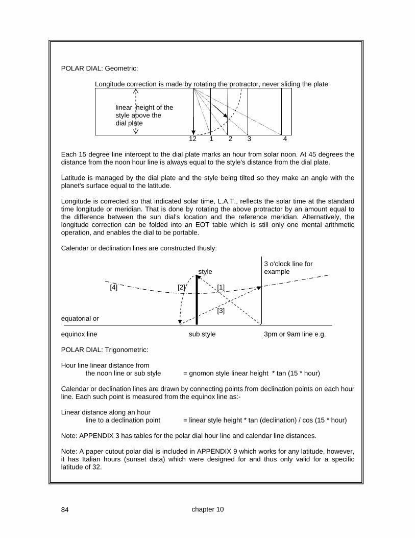
84
POLAR DIAL: Geometric: Longitude correction is made by rotating the protractor, never sliding the plate linear height of the style above the dial plate 12 1 2 3 4 Each 15 degree line intercept to the dial plate marks an hour from solar noon. At 45 degrees the distance from the noon hour line is always equal to the style's distance from the dial plate. Latitude is managed by the dial plate and the style being tilted so they make an angle with the planet's surface equal to the latitude. Longitude is corrected so that indicated solar time, L.A.T., reflects the solar time at the standard time longitude or meridian. That is done by rotating the above protractor by an amount equal to the difference between the sun dial's location and the reference meridian. Alternatively, the longitude correction can be folded into an EOT table which is still only one mental arithmetic operation, and enables the dial to be portable. Calendar or declination lines are constructed thusly: 3 o'clock line for style example [4] [2] [1] [3] equatorial or equinox line sub style 3pm or 9am line e.g. POLAR DIAL: Trigonometric: Hour line linear distance from the noon line or sub style = gnomon style linear height * tan (15 * hour) Calendar or declination lines are drawn by connecting points from declination points on each hour line. Each such point is measured from the equinox line as:- Linear distance along an hour line to a declination point = linear style height * tan (declination) / cos (15 * hour) Note: APPENDIX 3 has tables for the polar dial hour line and calendar line distances. Note: A paper cutout polar dial is included in APPENDIX 9 which works for any latitude, however, it has Italian hours (sunset data) which were designed for and thus only valid for a specific latitude of 32.
chapter 10

85
ACTUAL DESIGN NOTES POLAR DIAL: Trigonometric: A polar dial with calendar curves was designed for latitude 51 degrees north. The hour lines needed due to building shading were 10 am to 4 pm. The dial was to be 12 inches wide. 10 11 1 2 3 4 First, 10 am to noon consumes two morning hours, and at 15 degrees each, that is 30 degrees, and similarly from noon to 4pm consumes 4 hours, or 60 degrees. The total width was style height * (tan(30) + tan(60)), or 2.3 times style height. Next, 12 inches must equal style linear height * 2.3 so style linear height is 12/2.3 or 5.1 inches. Geometrically, we can verify this, in this case CAD (computer aided design) was used.
Hour line linear distance from the noon line or sub style = gnomon style linear height * tan (15 * hour) Calendar or declination lines were drawn by connecting points from declination points on each hour line using the formula:- Linear distance along an hour line to a declination point = linear style height * tan (declination) / cos (15 * hour) The latitude was only relevant in setting the dial in place, it does not affect hour or calendar lines for this dial type. It would affect optional Italian hour lines however, discussed elsewhere. Note: APPENDIX 3 has tables for the polar dial hour line and calendar line distances. Note: A paper cutout polar dial is included in APPENDIX 9 which works for any latitude, however, it has Italian hours (sunset data) which were designed for and thus only valid for a specific latitude of 32.
chapter 10

86
CASE STUDY ~ A POLAR DIAL WITH CALENDAR CURVES AND ITALIAN HOUR LINES This dial will be for Silver City, NM, whose coordinates are: location lat: 32.75° N The dial plate from 7 am to 5 pm will be location long: 108.2° W a maximum of 16 inches east to west magnetic declination: 10.6° E and 8 inches top to bottom (approximately) Hour lines will be shown and also Italian hour lines. Italian hour lines indicate the time since the last sunset, however common practice is to use them to show the time until the upcoming sunset. Italian hour lines, and their cousin the Babylonian hour lines showing time since sunrise, are latitude specific. In other words the trick of tilting a dial plate will correct the time of day hours for a latitude shift but such is not the case for Italian and Babylonian hour lines that rely on the geometry of the Earth's curvature which makes them latitude specific. A spreadsheet was constructed as below, using the trigonometric formulae, however this data is also available for a gnomon relative linear height of 1 in the appendices.
POLAR DIAL - hour line distances, and below that the calendar points on the hour lines
GNOMON HT ~ HOUR LINE DISTANCE
hour degrees radians tan 1 1.5 1.75 2 2.25
1 15 0.2618 0.2679 0.27 0.40 0.47 0.54 0.60
2 30 0.5236 0.5774 0.58 0.87 1.01 1.15 1.30
3 45 0.7854 1.0000 1.00 1.50 1.75 2.00 2.25
4 60 1.0472 1.7321 1.73 2.60 3.03 3.46 3.90
5 75 1.3090 3.7321 3.73 5.60 6.53 7.46 8.40
hour line distance = style linear height * tan(15*time)
Gnomon height 1.75 Hours from noon
calendar data: decl radians 0 1 2 3 4 5
June solstice 23.50 0.4102 0.76 0.79 0.88 1.08 1.52 2.94
May and July 20.00 0.3491 0.64 0.66 0.74 0.90 1.27 2.46 August and April 12.00 0.2094 0.37 0.39 0.43 0.53 0.74 1.44
September and March equinox 0.00 0.0000 0.00 0.00 0.00 0.00 0.00 0.00
October and February -12.00 -0.2094 -0.37 -0.39 -0.43 -0.53 -0.74 -1.44
November and January -20.00 -0.3491 -0.64 -0.66 -0.74 -0.90 -1.27 -2.46
December solstice -23.50 -0.4102 -0.76 -0.79 -0.88 -1.08 -1.52 -2.94
calendar height on hour line = style linear height * tan (declination) / cos (15*time )
chapter 10

87
The spreadsheet shows that a 1.75 inch gnomon linear height would generate a dial plate of 6.53 length on either side of noon, or 13.1 inches which fits easily in the 16 inch limitation. Additionally, the largest calendar line spread would be twice 2.94 inches or 5.8 inches which also fits within the 8 inch limitation. However, the above does not consider longitude corrections, which is about 13 minutes. Those 13 minutes came from 4 minutes per degree of longitudinal distance from the dial (longitude 108.2 west) and the legal time meridian's longitude of 105. The distance is thus 3.2 degrees, placing the actual correction at 12.8 minutes or 12 minutes 48 seconds. The spreadsheet below shows the new hour distances.
GNOMON HT ~ HOUR LINE DIST 1.75 long corr 12.8 long corr dec hrs 0.21
hour degrees radians tan AM hour degrees radians tan PM
1.21 18.2 0.3176 0.3288 0.58 0.79 11.8 0.2059 0.2089 0.37
2.21 33.2 0.5794 0.6544 1.15 1.79 26.8 0.4677 0.5051 0.88
3.21 48.2 0.8412 1.1184 1.96 2.79 41.8 0.7295 0.8941 1.56
4.21 63.2 1.1030 1.9797 3.46 3.79 56.8 0.9913 1.5282 2.67
5.21 78.2 1.3648 4.7867 8.38 4.79 71.8 1.2531 3.0415 5.32
hour line distance = style linear height * tan(15*time)
Similarly the calendar line distances on each hour line would be different, and the spreadsheet could accommodate that also. However, the geometric method is worth addressing and will be used in this case study, with the spreadsheet as a cross check. The geometric method will be implemented using CAD as a drafting tool.
chapter 10

88
The geometric methods which used CAD as a drafting tool, agreed with the spreadsheet on hour distances. A benefit of CAD is that the final drawing may be printed and used as a template for the actual dial.
An hour line is selected, in this case 1 pm legal time. A line is drawn from the base to the top of the style. That line is rotated, an arc was used, down to the dial plate. From where that arc intercepted the dial plate, a line was drawn at the declination, 23.5 in this case, and where that line intersected the original hour line, there is the point for that calendar line for that declination.
To the right is a close-up of the above, except that lines have been drawn for 12 and 20 degrees, and for completeness the 0 degree equinox has a circle on it, albeit somewhat superfluous. The CAD system used was TurboCAD whose deluxe version is available for around $100, and also provides 3d modeling. This system allows lines to be grouped, and this facilitates the rest of the calendar lines because once those declination lines have been drawn, their base can be moved and calendar points drawn quickly, it saves re measuring those calendar based declination angles.
The results of shifting the group of declination angles is shown to the left.
chapter 10

89
The morning hour calendar lines have been added. An arc is shown for 0800 standard legal time, together with the 0800 three calendar declination angle lines.
The calendar dots are drawn with a curve drawing function, in this case the Bezier function. And the entire upper half was selected and mirror copied around the equinox line.
chapter 10

90
Italian lines for the hours until sunset need to be added. Italian lines are actually hours since the last sunset, however in the real world they are used to show hours until the next sunset. This is latitude 32.75, and either the formulae may be used or the tables in the appendix. Hour angle of rising/setting sun: hsr = arccos( tan(lat) * tan(decl) ) from noon where Sun Declination: decl = degrees (0.006918 – 0.399912*cos(da) + 0.070257*sin(da) – 0.006758*cos(2*da) + 0.000907*sin(2*da) – 0.002697*cos(3*da) + 0.001480*sin(3*da) where da = Day angle: da = 2 * pi * ( j-1 ) / 365 (in radians, is an intermediate figure) where J is the day of the year J=1 on 1 January, J=365 on 31 December. February being 28 days. Jan Feb Mar Apr May Jun 0 31 59 90 120 151 Jly Aug Sep Oct Nov Dec
181 212 243 273 304 334 alternative formula: decl = DEGREES = (23.45*sin(radians(0.9678(jd-80)))) source: Claude Hartman
Or the spreadsheet may be used. Babylonian and Italian values by latitude. Times are hh.mm Local Apparent Time Solstice Sunrise and Sunset (equinox is 6am/pm). No longitude correction. No EOT correction. Winter solstice: Declination: -23.5
Summer solstice: Declination: +23.5
Lat Rise Set Day length hrs Lat Rise Set Day length hrs 30 6.58 17.02 10.04 30 5.01 18.59 13.58
31 7.00 17.00 10.00 31 4.59 19.01 14.02
32 7.03 16.57 9.54 32 4.56 19.04 14.08
33 7.05 16.55 9.50 33 4.54 19.06 14.12
Either way, sunset is local apparent time of:- 1655 winter solstice standard time 1906 summer solstice time Sunset times are local apparent time. With a dial that is not longitude corrected, i.e. showing L.A.T., then there is no problem. However if the hour lines are longitude corrected then those hour lines cannot be used as the foal points for the Italian lines unless the sunset times are also longitude corrected. Since the hour lines were longitude corrected, the sunset times for the dial's location will be later as the dial is west of the legal time meridian.
chapter 10

91
The correction is 12.8, almost 13 minutes. So the legal time for sunset will need adjusting:- 1708 winter solstice standard time (being 1655 + 13) 1919 summer solstice time (being 1900 + 13) The sunset time at the equinox is 1800 (6 pm) local time, but that also needs adjusting, so it is now 1813 March or September equinox (being 1800 + 13) A line is drawn from 1708 winter, through 1813 on the equinox to 1919 on the summer solstice line, this is the sunset time. That sunset line will not fit on this dial plate. So now it is backed off one hour to:- 1608 1713 1819 for the 1 hour to sunset Italian line 1508 1613 1719 for the 2 hour to sunset Italian line 1408 1513 1619 for the 3 hour to sunset Italian line 1308 1413 1519 for the 4 hour to sunset Italian line 1208 1313 1419 for the 5 hour to sunset Italian line
The CAD version is then printed out and the dial plate and gnomon constructed. A key point about Italian lines that can never be repeated too many times is that they are latitude dependent. While a polar dial, or any hour angle based dial, can be tilted to correct for a dial's actual latitude compared to its design latitude, this is not true for Italian or Babylonian hour lines. They work for one latitude only. These Italian lines were adjusted to accommodate the longitude. They result in exactly the same placement were no longitude correction applied to both them and the dial plate hour lines. This is because they are indicating the time right now, here, until the next sunset
chapter 10

92
The dial plate was constructed. This dial plate was to be copper wire attached to a paver. The ends were of small copper pipe, each of those two end pipes had a 10 gauge copper wire attached to it, and these were set in holes drilled in the concrete paver.
However, before that the hyperbolic calendar lines and the straight equinox line were cut from copper wire and shaped. Similarly with the hour lines, and the Italian lines. If the calendar lines are closest to the concrete paver then the hour lines would rest above them, and to keep proportions, the gnomon linear height would be from the top of those hour line wires. The shadow of the gnomon and the hour lines would be read on the concrete paver. Alternatively, the hour lines could be closest to the concrete paver with the calendar lines above them, in which case the gnomon linear height would be from those lines just above the concrete paver.
The dial was secured by four copper rods to holes in the concrete paver. The final dial rested on the 12 o'clock pillar of a large garden analemmatic dial. Foot note: because the tangent of 45 is 1, and because the 3 pm or 9 am line is 45 degrees, for non longitude corrected dials one of the rules of thumb is that the gnomon linear height is the same as the sub-style to 3 pm or 9 am distance. If the dial is longitude corrected, as this one is, then the 3 pm and 9 am rule of thumb does not apply. So, printing the gnomon on the CAD layout is helpful here, especially if the layout is rescaled later.
To the right is a similarly constructed polar dial except it is suspended in mid air. The time is read by the shadows of both the gnomon as well as the hour lines on a wall. The sun face was a commonly available clay figure, and its borders were pieces of ceramic floor tile. This dial shows about 3:00 pm standard time as it is longitude corrected, but not mean time as there is no EOT correction. Designed by the author for central Phoenix, Arizona.
chapter 10
Italian hour lines
Regular hour lines

93
CHAPTER ELEVEN
Meridian dials are like polar dials in many ways DIALS FACING TRUE EAST OR WEST
While a true east or true west dial is less common than a horizontal sundial, it is the next step in the evolution of understanding the art and science of building and designing sundials, and they are found on many cube dials. A true west facing wall shows the time between noon and 6pm or thereabouts. Solar noon can never show because the gnomon's shadow would parallel the wall. And times after 6pm may happen in the summer when the sun moves across the east-west line. The point is that you should establish what hours you want to display first and then decide on the dial plate's size, and from that you can establish how far the gnomon's style must be from the dial plate. The methods are the same as the polar dial, there is no difference, except that the equatorial line slants at an angle equal to the co-latitude (90 degrees minus the latitude) of the dial location, the hour lines also now slant because they are perpendicular to the equinox line. And calendar curves slant also. Further, a true east facing wall is the same as a true west wall, the slope looks the opposite to an observer but exactly the same as a west dial if it were painted on glass. A meridian dial is formed when a polar dial is rotated around its style by 90 degrees. The design for the dial's latitude is to slope it. Like the polar dial the hour lines themselves are not latitude dependant. Longitude correction is the same as for a polar dial. Empirical, geometric, or trigonometric methods may be used. The gnomon is angled at the latitude, and a protractor with a plumb-line shown in the picture to the right or an inclinometer that you have calibrated may be used to ensure correct latitude alignment.
Note how the gnomon stops half way so there is a right angle which can function as a nodus, and thus indicate solstice or declination lines. co latitude latitude nodus the equatorial (equinox) line solstice and solar declination lines
an hour line To the right is a true west vertical dial, designed for latitude 32 degrees north and a longitude of 108 degrees west. Direct east and direct west facing dials are universal, they can be moved to other latitudes and merely tilted to adjust for the change. This is because the hour lines are not a function of latitude. Of course longitude corrections if used will complicate such a movement.
style
pole
chapter 11
the equatorial or equinox line is at co latitude

94
In the above picture, the style and the nodus were projected to the dial plate as can be seen by the line with little circles at each end. This projected style line then has a line drawn perpendicular to it from the nodus projection and proceeding down and to the left, this is the equatorial line, and depicts the equinoxes. The nodus shadow is a bit on the winter side of the equinox. Geometric methods were used for the hour lines, and you will note that the projection of the style is about a quarter of an inch above the 6pm (winter) 7pm (summer) hour line of this west facing northern hemisphere dial. In fact it represents about 12 minutes being the solar time difference between the dial's longitude and that of the legal standard time meridian. This is the result of the longitude correction. Like the polar dial, the hour lines themselves cannot just be shifted. This dial has 15-minute or quarter-hour lines shown between the hour lines, and not only the equinox and the solstice lines are shown but so are the other dates, so all months are represented. Of course all but December and June share declination lines. So July shares a line, actually a hyperbola, with May, and so on. actual style line used for geometrical construction 6pm line (winter) 7pm (summer) 5pm winter and 6pm summer hour line June 21st solstice solar declination line July 21 and May 21st declination line August 21 and April 21st declination line Equinox line, March 21 and September 23 Winter solstice line, December 21st Instead of astronomical declination lines, some people like to have declination lines for the number of hours in the day, and chapter 24 covers this.
Nodus and one end of the style's projection. Other end of the style to sub-style projection. A protractor is drawn centered here for a radius of the style's linear height.
projection of nodus
equinox line
The nodus shadow is on the winter side of the equinox.
an afternoon west facing dial in the northern hemisphere or an east facing morning dial in the southern hemisphere
chapter 11

95
GEOMETRIC METHOD FOR TRUE EAST OR WEST MERIDIAN DIALS First establish how far from the dial plate the style will be, or figure out how big the dial plate must be, and work backwards to establish style's linear height. On the 6 o'clock line where the sub-style is, draw a protractor of the same radius as the style's linear distance from the plate. Then proceed around the protractor at 15 degree increments and project those lines to the dial as shown. No longitude correction 6am 7am 8am 9am 10am 6pm 5pm 4pm 3pm 2pm If there is no longitude correction built in, where the 15 degree line intercepts the dial plate, there is the 5pm line (west facing), or the 7am line if east facing. Then the three o'clock pm (or 9 o'clock am) line is the 45 degree angle (3 times 15 degrees per hour), and its distance from 6am or 6pm is equal to the style's linear distance from the dial plate, a clue to the trigonometric method since the tangent of 45 degrees is 1. Latitude is managed by the style and the dial plate being rotated so they make an angle equal to the latitude and co-latitude respectively. Longitude is corrected so that indicated solar time, called local apparent time or L.A.T., reflects the legal time at the standard time longitude or meridian (if the EOT were applied). This is done by rotating the above protractor an amount equal to the difference between the sun dial's location and the reference meridian, so for example in Phoenix AZ the longitude is 7 degrees west of the standard. Alternatively a fixed mental correction may be applied, or the longitude correction may be folded into the dial's EOT chart or table. Phoenix 33.5° N 112.0° W mag var 11.8° E PHX mst is at 105° PHX is 7° 0' from mst i.e. 28 minutes from mst To adjust the dial for Phoenix longitude, the dial must be rotated 7 degrees. One cannot slide the dial plate a certain amount, because the hour line spacing ratios would no longer be accurate. This is shown below, and notice that the 6am, 6pm line is offset so that12 o'clock will be shown earlier than it should be … With longitude correction 6am 7am 8am 9am 10am 6pm 5pm 4pm 3pm 2pm …because the legal 105 degree meridian gets to 12 o'clock before it does at the 108 degree meridian.
chapter 11
not to scale

96
By the way, this exact same geometric method is used for a wall facing exactly true west (occidental) as well as exactly true east (oriental). DECLINATION LINES: Adding calendar lines is simple. The calendar lines will be curved hyperbolae except for the equinox line which is straight. On an equatorial dial they were circles, on an armillary they were straight, but because the dial plate is now flat, geometry comes into play. 6 o'clock hour line either am or pm equinox line 3 pm hour line 9 am hour line The geometric method for constructing them is to use a similar idea with the protractor that was used for the hour lines and again, is the exact same method used for the polar dial. [4] style 3 o'clock line for example [2] [1] [3] equatorial or equinox line The equinox line is drawn and then the style is drawn upwards whose length equals the distance of the style from the dial plate, the style linear distance. Then [1] a line is drawn to the style from the selected hour line (in this case the three o'clock line) and rotated down [2] to the equinox line, and from thence a line drawn to the selected hour line [3] at an angle that matches the declination for the sun for the date in question, this would be 23.5 degrees for the solstice. The winter solstice would be above and the summer solstice would be below. It is an equal distance below because the dial plate is aligned with the Earth's polar axis perpendicular to the equator. After this process is repeated for all the hours, and the dots are joined and then a hyperbola [4] is drawn. For the date to be shown, the style needs a knob or a cut out notch (nodus) so the location can be seen, otherwise all you would see would be a straight line. In the photo, the gnomon is cut short so the tip clearly makes the time and date visible.
chapter 11

97
TRIGONOMETRIC METHOD FOR TRUE EAST OR WEST MERIDIAN DIALS (this is the same method as for a polar dial) HOUR LINES: style t 6 o'clock equatorial line a h The equatorial line is along "ah", and the style is "t", where "at" equals the linear height of the style above the dial plate. The angle "ath" is equal to the time in hours from 6 (am or pm) times 15 (there are 15 degrees in an hour). Longitude corrections, if any, are applied here. we see that:- tan (ath) = ah / at therefore:- ah = at * tan (ath) ( 1 ) The distance along the equatorial or equinox line to the hour line is equal to the style linear height times the tangent of the time difference from 6 o'clock. The angle can be adjusted for longitude by simply adding or subtracting the difference between the dial's location and the standard time meridian before performing the tangent calculation. If this formula looks quite different from some other published formulae, that is because the base hour in this book is 6 am or pm, whereas some other formulae use noon as the base hour. DECLINATION, EQUATORIAL, SOLSTICE, OR LENGTH OF DAY LINES: t d th = rh ath = time from 6am/pm hrd = declination r a h we see that:- tan ( hrd ) = dh / rh = dh / th thus:- dh = th * tan (declination ) and:- cos ( ath ) = ta / th thus:- th = ta / cos ( ath ) so given: dh = th * tan (declination ) then:- dh = ta * tan (declination) / cos (time ) ( 2 ) The distance up the hour line for the point on which the declination (calendar) line will lie is equal to the style linear height times the tangent of the declination all divided by the cosine of the time difference from 6 o'clock. This is repeated for several of the hour lines.
Whereas the polar dial had noon at its sub-style, meridian dials have 6am or 6pm at the sub-style, and these formulas in this book use 6am or 6pm as their baseline. Some authors use noon at infinity as their base.
chapter 11

98
COOK BOOK SUMMARY MERIDIAN DIAL: Geometric: Longitude correction if desired is made by rotating the protractor height of the style above the dial plate 6am 7am 8am 9am 10am 6pm 5pm 4pm 3pm 2pm Each 15 degree line intercept to the dial plate marks an hour from solar 6 o'clock (am or pm). At 45 degrees the distance from 6 o'clock is always equal to the style's linear distance from the dial plate. Latitude is managed by the dial plate and the style being tilted so they angled at latitude. A plumb-line and protractor or a calibrated inclinometer that you have verified may assist here. Longitude is corrected so that indicated solar time, L.A.T., reflects the solar time at the standard time longitude or meridian. That is done by rotating the protractor by an amount equal to the difference between the sun dial's location and the reference meridian. Alternatively the longitude correction may be folded into a tailored EOT table. Calendar or declination lines are constructed thusly: style 3 o'clock line for example [4] [2] [1] [3] equatorial or equinox line sub style 3pm or 9am line e.g. MERIDIAN DIAL: Trigonometric [the time base line is 6 o'clock, not noon] Hour line linear distance from the 6am/pm line = gnomon style linear height * tan (15 * hour) Calendar or declination lines are drawn by connecting points from declination points on each hour line. Each such point is measured from the equinox line as:- Linear distance along an hour line to a declination point = linear style height * tan (declination) cos (15 * hour difference from 6 o'clock) NOTE: If these formula differ radically from other formulae, this book uses 6 o'clock (am or pm as appropriate) as the time base line, and some other published formulae use noon. Note: APPENDIX 3 has tables for the meridian dial hour line and calendar line distances.
chapter 11

99
A STAINED GLASS MERIDIAN DIAL To the right is a vertical meridian dial of stained glass. There were several firings and a sandblasting phase so the gnomon's shadow would stand out. The tracing black for the hour lines, calendar lines, and the Italian hour lines (discussed elsewhere) used the same pigments used in the 13th century and was fired at 750 degrees C. On the reverse side is a silver stain of the type used in the 14th century was fired at 1250 degrees F which produces a glorious golden yellow transparent color. The hour display area was sand blasted so the gnomon's shadow would stand out. When sandblasting glass, or any compound with silica, great care must be taken to avoid the dust. The health risk is silicosis and a mask and blasting cabinet are recommended. The dial shows about 3:00 in the afternoon summer time which when corrected for longitude and EOT was correct, and the nodus was on May, this was correct also. The Italian hours, show just under 5 hours until sunset, which again was spot on.
A CERAMIC MERIDIAN DIAL To the left is a true west facing meridian dial in Phoenix, Arizona. It is longitude corrected and shows standard time as a result. There is no EOT correction so it is not mean time, in other words, not clock time. Arizona does not use summer time or daylight saving time, however this dial does have summer hours marked on the summer solstice curve just in case Arizona ever elects to participate in the daylight saving time folly. This dial was ceramic fired to cone 6, using slips for the color. In summary… The vertical east and west facing dials are simple to design.
chapter 11
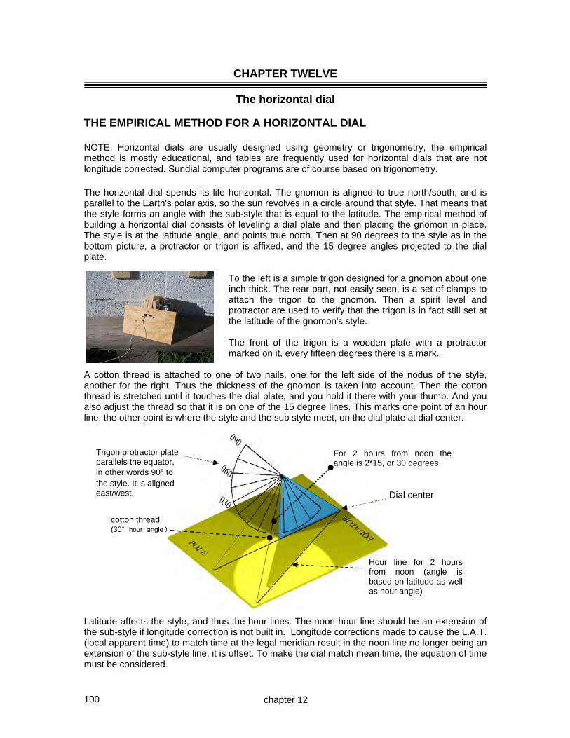
100
cotton thread (30° hour angle)
CHAPTER TWELVE
The horizontal dial THE EMPIRICAL METHOD FOR A HORIZONTAL DIAL NOTE: Horizontal dials are usually designed using geometry or trigonometry, the empirical method is mostly educational, and tables are frequently used for horizontal dials that are not longitude corrected. Sundial computer programs are of course based on trigonometry. The horizontal dial spends its life horizontal. The gnomon is aligned to true north/south, and is parallel to the Earth's polar axis, so the sun revolves in a circle around that style. That means that the style forms an angle with the sub-style that is equal to the latitude. The empirical method of building a horizontal dial consists of leveling a dial plate and then placing the gnomon in place. The style is at the latitude angle, and points true north. Then at 90 degrees to the style as in the bottom picture, a protractor or trigon is affixed, and the 15 degree angles projected to the dial plate.
To the left is a simple trigon designed for a gnomon about one inch thick. The rear part, not easily seen, is a set of clamps to attach the trigon to the gnomon. Then a spirit level and protractor are used to verify that the trigon is in fact still set at the latitude of the gnomon's style. The front of the trigon is a wooden plate with a protractor marked on it, every fifteen degrees there is a mark.
A cotton thread is attached to one of two nails, one for the left side of the nodus of the style, another for the right. Thus the thickness of the gnomon is taken into account. Then the cotton thread is stretched until it touches the dial plate, and you hold it there with your thumb. And you also adjust the thread so that it is on one of the 15 degree lines. This marks one point of an hour line, the other point is where the style and the sub style meet, on the dial plate at dial center. Latitude affects the style, and thus the hour lines. The noon hour line should be an extension of the sub-style if longitude correction is not built in. Longitude corrections made to cause the L.A.T. (local apparent time) to match time at the legal meridian result in the noon line no longer being an extension of the sub-style line, it is offset. To make the dial match mean time, the equation of time must be considered.
For 2 hours from noon the angle is 2*15, or 30 degrees
Dial center
Hour line for 2 hours from noon (angle is based on latitude as well as hour angle)
chapter 12
Trigon protractor plate parallels the equator, in other words 90° to the style. It is aligned east/west.

101
Longitude is easily accounted for by rotating the trigon's protractor or by displacing the cotton thread by the same number of degrees by which the dials location differs from the legal meridian. So for example in Silver City there is about a 3.2 degree difference. Looking at the trigon's protractor, displace the cotton thread by 3.2 degrees. So the noon hour line would no longer be 90 degrees, but now it would be altered by 3.2 degrees. Similarly with all other hours. This is the case where noon is no longer north south, it is now deflected somewhat. The picture below is what we would see if we were looking from the pole, facing the equator standing at and looking at the trigon's protractor. Normal noon Noon line corrected for hour line would a place west of the legal be 90 degrees time meridian is displaced west by the But we are west number of degrees of the legal time difference between our meridian, so we longitude, and the are earlier sun legal time meridian. time wise, so we must make the sun In other words when west of the time look later. We do that by having legal meridian, displace the 15 the noon line point to the sun earlier degree arcs west. And if east, by a factor based on the 3.2 degrees. displace them east. Vertical south facing dials use the same rule, displace the hour lines west if west of the legal time meridian. However if you haven’t figured out east and west yet, then it is a bit more complicated. West on the protractor of a horizontal dial is a shifting to the right because you are facing south. For a vertical dial we are facing north, so shifting the angle lines west means displacing them to the left. The real point to remember is that it is easy to get confused, so write down your corrections before you do them. This process adjusts the dial for longitude. Note that the longitude correction cannot be made by rotating the dial plate, even if you retained the gnomon's north alignment. This book has a template for horizontal dials so you may experiment with a paper dial before making the real one. All that is left is the equation of time correction. A table is usually provided for that, although some dials have figure of 8 curves to enable a visual correction. Some dials have the longitude correction folded into al location specific equation of time table. When the hour lines have been penciled in, you can verify they are correct. On a sunny day, check the shadows hourly. To do this, look at the equation of time. If, as on November 10th, the EOT value is -16 degrees, then the sun is running fast. So you would subtract 16 minutes from the indicated time. So, at 16 minutes to the hour, the shadow should be on the hour line, because the sun is running fast. This allows the empirical hour lines to be verified before being finalized. All along, we have discussed hour lines, these are based on the 15 degree measurements of a protractor. Hour lines themselves are not 15 degrees apart except for equatorial and armillary dials, and the bi-filar dial. Half hour lines can be drawn, they would be every 7.5 degrees on the protractor, and quarter hour lines can be drawn using 3.75 degrees on the protractor. To beat a dead horse, the protractor has 15 degree lines, the dial plate does not. The dial plate's hour lines are a function of latitude, and of time, but they are not the simple 15 degrees per hour.
this is the trigon protractor and its lines, and not the dial plate's final lines.
chapter 12

102
On a horizontal dial, the east and west lines are the 6pm and 6am lines. Offset of course if longitude corrections were made. But what about hours before 6am or after 6pm? The 6am and earlier lines or 6pm and later lines cannot be drawn with a simple trigon, that is because the trigon's angles would parallel the dial plate. A geometrical or trigonometric approach is easier in that case. All dials whose gnomon is of appreciable thickness, must take into account that thickness. Two results come from this. One is that the dial plate becomes split, i.e. noon has two hour lines, one for just before, and one for just after the noon hour, or it has a single but thick one! A horizontal dial with a wide gnomon has 2 noon hour lines 12 1 2 3 4 5 6pm 7pm 8pm The other result is that when hour lines are included for before 6am or after 6pm, then the base of those hour lines is switched to the other side of the gnomon. The black circles show where the sun hits the style and thus why the hour line uses a different base. The dial has two dial centers! Solar hour angle dials have hour lines based on 15 degrees per hour but they are not 15 degrees themselves. Their intra-hour-line angle varies, and increases as they depart from noon, the exception being the equatorial, armillary, and bi-filar dials. This is easily seen in the geometric method of dial construction, and readily apparent when trigonometry is employed. Some of the old sundials were used perhaps more for the date than for the time. The sun is above or below the equator by an amount called the sun's declination. Not to be confused with magnetic declination (which pilots and mariners who use it all the time call magnetic variation), nor should it be confused with a vertical wall's displacement from true north or south, also called declination. To paraphrase Mark Twain's comments on spelling, "it is a poor language that cannot find many uses for the same word". In fact the 500 most common words in the English language average about 28 different meanings each. But that is a digression. Look back at the trigon, it used an oblong or square protractor. It was set at 90 degrees to the style, and if extended would meet the dial plate as a straight line. The 90 degree angle was used because this is when the sun is on the equator, it is also 90 degrees from the polar axis i.e. our latitude-angled style. So, the line where the trigon based hour-points were drawn is a straight line, and is where the tip of the gnomon's shadow will be at the equinox. The east-west line resulting from connecting those dots is a calendar or declination line, and in this case it is called the equinoctial or equinox line.
chapter 12

103
Trigon protractor plate aligned with the style, north to south, set at latitude, with a 23.5 degree line for the solstices. It swings out to meet the other hour lines.
The trigon's protractor plate could be turned sideways, and then lines marked up and down by 23.5 degrees for the winter and summer solstices. For simplicity, the above is for a horizontal dial with no longitude correction. While the solstice lines of longest and shortest day and the equinox lines where the daytime equals nighttime are most common, other declinations can be used. For example the first, tenth, and twentieth of each month might be noted, or the fifth, fifteenth, and twenty fifth could be used. If the dial became too cluttered, then that calendar information might just be marked on the noon line. Most declinations have two dates associated with them, the equinox is a perfect example because March 21 and September 23 or thereabouts, share that line. Lines of declination might be drawn for the day's length. Namely, identify what declination is associated with a 5 hour day, a 6 hour day, a 7 hour day and the like. In this case the declination lines would not be marked with a date, but the day's length. Other lines might be drawn, however they don’t usually use a trigon. Such lines would be the Italian hour lines, which in essence indicate how many hours remain until sunset. To the purist they indicate how many hours since the last sunset, but most dialists subtract that value from 24 and provide helpful information for gardeners, namely how long before one must put away the tools and retire to the kitchen for a cup of tea. Babylonian lines may also be drawn, they indicate how long since sunrise. The variations are endless. On one of my vertical dials I have a secondary dial that indicates when to plant tomatoes, corn, and peppers. When the last and first frost is, when is a bad time for pollen sufferers, and roughly when summer time comes into play. Are there other empirical methods that can be used to build a horizontal sundial? Yes, hour points or lines can be marked when the shadow falls there based on the formula:- hour point on an hour line + EOT => legal time to make the mark Thus, if the EOT is say -5, then at L.A.T. (sundial time) 1200, the time will be 1155. So Subtract the EOT from the standard clock time, set the alarm, and rush outside and mark the hour points.
Dial center
Summer solstice line is curved Winter solstice line is curved, Equinox line is straight
Hour line for the hour in question, in this case noon
chapter 12

104
THE GEOMETRICAL METHOD FOR A HORIZONTAL DIAL Consider a dial plate ABCD. Draw a noon local apparent time line XY. From X draw a line XZ that makes an angle with XY equal to the latitude. In essence this is the gnomon's style rotated 90 degrees lying flat on the surface of the dial plate as if the wind blew it over, resting peacefully. Draw a line perpendicular to the style that goes to Y, that point on the style is labeled Z, or, from Y draw a line to Z, the angle XYZ being the co-latitude, and thus intercepts the style at 90 degrees. Our gnomon is WXZ when rotated back vertically. ZY is the path the sun's rays travel at the equinox at solar noon. ZY would be where the trigon we used in the empirical method would lie. Rotate YZ to the top as YR, and then draw a semi-circular protractor LYM centered on R.
nodus style gnomon
Then mark off 15 degree marks on the protractor LYM, rotating them by the longitude difference is so desired, and extend the protractor's 15 degree lines to AB. A longitude correction with the protractor rotated west or clockwise is shown. One rotates the protractor west (clockwise) when the dial's location is west of the standard legal time meridian. Finally, the hour lines are drawn from the dial center up to where the protractor lines meet the west to east line AB. Notice that the noon line is offset to the west because the longitude correction was for a location west of the standard meridian. Another way of verifying this is that noon on the legal standard meridian happens before noon on the dial's meridian when the dial is west of the standard. So, noon must be shown before solar noon where the dial is installed. Finally, the equation of time, EOT, is managed mentally by a printed table for the sundial observer to consider. As always, the longitude correction need not be incorporated as above, but could instead be blended into an EOT table that would then be location specific.
chapter 12
noon is rotated in this example to correct for longitude This is a north hemisphere dial
L R M
10 am 11 12 1
Y
Xto south
ZW
west eastlatitude
A B
C D
23

105
One technique for marking hours further away from noon The previous geometric method works well, however it can be seen that when the hour line is three or four, or more, hours from noon, the angles from the protractor get unwieldy. And 6 o'clock is unmanageable. There are a couple of techniques that take this into account. One technique for hours some time off from noon is summarized below. To simplify the pictorial, no longitude correction is shown, otherwise it is the same example as on the previous page. An oblong extends east to west covering only the three hours either side of noon. From point Y (the 12 o'clock local apparent time point) to the bottom right, point D a line is drawn. Then three intersections appear, they are labeled E, F, and G. Then centered on G, measure GF, and in the opposite direction mark point FF the same distance from G. Thus GF equals GFF. And draw a line from dial center through it, this is the 4 o'clock line. And similarly measure GE and define point EE such that GE equals GEE, this is the 5 o'clock line. And similarly for the opposite side, morning hours. Appendix 9 has a template to facilitate this method.
chapter 12
L R M
10 am 11 am 12 1
Y
Xto south
west east
A
B
C D
9 am
2
3
E
F
GFF
EE
4 o'clock
5 o'clock

106
Another technique for marking hours further away from noon Extend the 45 degree line RB and the plate bottom line CD so they meet at J, similarly on the other side to meet at K. Or, make lines XK and XJ equal in length to XR. Drop perpendiculars from A to C and from B to D so that intersections for the early and late hours can be drawn on lines AC and BD. At those new centers K, and J, draw a protractor and mark off the 15 degree arcs and have them intercept BD and AC.
The protractor process is done on both sides. Or it could be done on one side and horizontal lines drawn parallel to CD to transfer the points from BD to AC if no longitude correction is desired. This provides the 4, 5, and 6pm lines, even 7pm and 8pm. Similarly the 4am, 5am, 6am, 7am, and 8am lines. As will be seen later, the horizontal dial methods work for the pure vertical true south facing dial. This technique has the benefit of being able to draw hour lines whose distance along "AB" would be excessive using the simple single protractor approach. Appendix 9 has a template to facilitate this method.
chapter 12
L R M
10 am 11 am 12 1
Y
Xto south
west east
AB
C D
9 am
2
3
4 pm
5 pm
KJ
7 pm

107
Another geometrical method for a horizontal dial A method discussed by Sundials And Roses Of Yesterday by Alice Morse Earle in the early 1900's uses a technique of interest. C 10 am hour line latitude A B 10 am hour line 30° length AB length AC A 30° Two circles are drawn on the dial plate center "A" where the gnomon is based, one has a radius of the style's length AC, the other of the sub-style's length AB. From A draw 15 degree lines, these are not the hour lines, they are construction lines only. Then draw horizontal construction lines on the outer circle where the radial lines meets it, and draw vertical lines on the inner circle where the radials meets it, as shown in the offset to the lower left above. Where the horizontal and vertical construction lines meet is the hour line point, a line from which is then drawn to dial center, point A. In the example above, 30 degrees left of noon is drawn which represents 10am, since there are 15 degrees per hour. Of course, the left hour lines must be shifted left, the right shifted right, to account for the gnomon's thickness. Longitude corrections are made by selecting an angle smaller or larger than 15 degrees, or its multiple, the change being the number of degrees of longitude separation between the dial and the legal standard time's reference longitude. For all sundials, the dial plate may indicate only the hours, or it may indicate other information, called dial furniture. Lines that show the sun's declination are helpful for they show the dates for that declination. Declination lines can show the length of the day, when to sow, plant, reap, and when to get allergy medicine! To find the declination for a specific date you might use a table such as in appendix 2. It may also be calculated using a formula discussed in appendix 8 covering formulae.
C B
chapter 12

108
Declination or calendar curves for the horizontal dial using geometry. A horizontal dial with three hour lines shown is shown below. Equinox winter solstice C summer C solstice noon hour line nodus a a b b c c 10 23.5 12 11 23.5 First, draw a gnomon for the dial center "C". From the nodus draw the equinox line (90 degrees to the style), and from that the solstice lines (approx 23.5 degrees on either side).The three lines (equinox and the solstices) intersect the gnomon's base line extended, or the noon line, at points a, b, and c. These three points whose distances from the dial center are Ca, Cb, and Cc are then transcribed to the dial plate (right pictorial to left pictorial). C C a Distances Cd b and Ce are Equinox line a drawn with a b d e c ruler or a e drafting c compass on 10 the equinox line. 12 11 The equinox line is then drawn perpendicular to the noon line, and it produces equinox intercepts for those additional hour lines, d and e. Distances Cd and Ce are then located from the left dial plate to the right hand picture on its equinox line. This produces two more hour lines on the right hand side picture, Cd and Ce. Those hour lines on the right hand side do not have angles that match their hour lines on the dial plate, and this is because this is a projection.
chapter 12
d

109
Now that there are two more hour lines, or as many as you choose, this produces intercept points for the solstice lines, namely points f, g, h and i, see below. C C a h b Equinox line a i b d e c e c f 10 g 12 11 Points f, h, g, and i are now transferred back to the dial plate, from the right projection pictorial to the left picture. C C i h h Equinox line a d i b d e e c f f g g 12 When this process is completed for as many hour lines as desired, the dots are connected and then the declination lines drawn. Horizontal dial: summer solstice [ Vertical dial: winter solstice ] Equinox line Horizontal dial: winter solstice [ Vertical dial: summer solstice ]
chapter 12
d
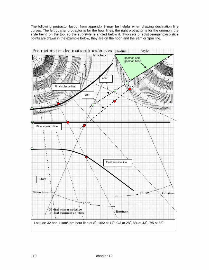
110
The following protractor layout from appendix 9 may be helpful when drawing declination line curves. The left quarter protractor is for the hour lines, the right protractor is for the gnomon, the style being on the top, so the sub-style is angled below it. Two sets of solstice/equinox/solstice points are drawn in the example below, they are on the noon and the 9am or 3pm line.
Latitude 32 has 11am/1pm hour line at 8˚, 10/2 at 17˚, 9/3 at 28˚, 8/4 at 43˚, 7/5 at 65˚
11am
noon
gnomon and gnomon base
Final equinox line
3pm
Final solstice line
Final solstice line
chapter 12

111
THE TRIGONOMETRICAL METHOD FOR HORIZONTAL DIAL HOUR LINES Consider CSP to be the gnomon, CS being the style, CP the sub-style. From S extend a perpendicular to a new point Q on the East-West line. As the sun moves by "ha" degrees from noon, a new hour line is drawn whose angle is H. S equator Earth axis West y ha lat Q C P North x H East z (distance CQ) (1) tan (ha) = x/y tan of hour angle ( 15 degrees * hour ) (2) x = y * tan (ha) thusly (3) tan (H) = x/z tan of the hour line angle (4) sin (lat) = y/z sin of latitude or Ø (5) y = z * sin (lat) thusly (6) H = atan (x/z ) = atan ( (y * tan (ha)) / z ) = atan ( ( z * sin (lat) * tan (ha) / z ) ) = atan ( sin (lat) * tan (ha) ) So, to calculate any hour line from the sub style: H = arctan ( sin (lat) * tan (ha) ) The hours used in the hour line formula may be adjusted for longitude. If you use a spreadsheet then trigonometric functions use radians, and must be converted back using degrees. The formula is then something like:- DEGREES(ATAN(TAN(RADIANS(15*time))*SIN(RADIANS(latitude)))) Tables and nomograms can be used which are trigonometric in nature Appendix 3 has tables with hour line angles calculated for various latitudes, it also has nomograms for hour line angles. The next chapter which covers the vertical true north/south dial, and this book’s introduction also showed the use of tables to design a dial that is not corrected for longitude. Either the tables or nomograms in appendix 3, or the spreadsheet provided with this book will provide tables of hour angle by latitude. As mentioned, nomograms may be used and are included in the appendices, and chapter 32 discusses such earlier methods for dial design.
chapter 12

112
Declination or calendar curves for the horizontal dial using trigonometry. The following technique can also use simple geometry. Winter solstice for example D Equinox T Summer solstice for example C SUN'S ALTITUDE METHOD: The distance from the foot of the style, point T, and not from the dial center C, to a given hour line's declination point (TD) is determined by:- distance TD = style height * cotan (sun's altitude) sun's altitude = arcsin ( sin (dec) * sin (lat) + cos (dec) * cos(lat) * cos(time) ) How is the declination found? The tables in appendix 2 may be used, or their formula can be used directly:- Sun Declination: decl = degrees (0.006918 – 0.399912*cos(da) + 0.070257*sin(da) – 0.006758*cos(2*da) + 0.000907*sin(2*da) – 0.002697*cos(3*da) + 0.001480*sin(3*da) where: da = 2 * pi * ( j-1 ) / 365 (Day angle: in radians, is an intermediate figure) SUN'S AZIMUTH METHOD: An alternative to using the sun's altitude hence nodus shadow distance which relies on the nodus height, the sun's azimuth can be used from the foot of the style, point T, and not from the dial center C, to a given hour line. The intersection is the declination point for that azimuth and hour line. ADDITIONAL THOUGHTS Supplemental Shadows has some expanded notes on this topic. The nodus indicates the calendar lines, the style indicates the hour line shadow. A nodus allows a larger gnomon that would otherwise work on a dial plate. Dial plates and gnomons must be aligned as discussed. Turning a dial plate or bending a gnomon to correct a horizontal (or vertical dial) will upset all the angular relationships. However, a horizontal dial may be tilted if the dial was for a different latitude. A wedge that tilts the dial plate north or south has the effect of making the dial act as if it were at another latitude, thus old antique dials may be thusly made to believe they are at their old latitude, and once again live to see the sunlight. Chapters 23 and 24 cover calendar and other lines in detail, with analemmas discussed in chapter 25. Chapter 20 shows a ceramic horizontal dial as part of an 8 inch cube dial.
chapter 12

113
COOK BOOK SUMMARY HORIZONTAL DIAL: Geometric Hour lines: A A lat B B C 4pm 5pm 6pm C Calendar or declination lines: see chapter 23 HORIZONTAL DIAL: Trigonometric Hour lines: hour line angle = arctan ( sin (latitude) * tan (15 * hour) ) Calendar or declination lines: see chapter 23 HORIZONTAL DIAL: Tabular Appendix 3 tables A3,1a, A31.b, A3.1c provide the hour lines by latitude. NOTE: Horizontal dials are usually designed using geometry or trigonometry, the empirical method is mostly educational, and tables are frequently used for horizontal dials that are not longitude corrected. Sundial CAD programs are of course based on trigonometry. NOTE: the photo to the right of a horizontal dial has a deliberately wide gnomon to show how gnomon width is managed. NOTE: arctan is the angle whose tangent is, sometimes written as atan, atn, or tan -1 Appendix 9 has a template for laying out a horizontal dial, and on the next page that template is used to facilitate drawing the dial plate.
chapter 12

114
HORIZONTAL DIAL: Method: Using Tables: [appendix 9 has the template used here]
Appendix 3 table A3.1b for latitude 40 provides the following hour line angles assuming no longitude correction. 8am and 4pm 48.07 degrees 9am and 3pm 32.73 degrees 10am and 2pm 20.36 degrees 11am and 1pm 9.77 degrees etc The hour lines before and after noon are drawn. The gnomon is drawn and moved to dial center. The longitude correction of 4 degrees (at 4 minutes per degree) is 16 minutes, and is west of longitude 105 thus we must add the time. The longitude correction of 16 minutes is added to the equation of time, producing a longitude corrected revised EOT table:- Jan Feb Mar Apr May Jun Jly Aug Sep Oct Nov Dec +25 +30 +25 +16 +13 +16 +22 +20 +11 +2 +1 +11 The dial is aligned to true north, and the shadow mentally corrected with the revised equation of time (EOT). Alternatively the hour lines could be adjusted individually for longitude, however the dial would be less portable. If the hour lines were longitude adjusted, they would not simply be rotated, but the angle re-calculated for the longitude offset one hour line at a time. The equinox line is derived by extending the gnomon from the nodus to the sub-style line extended, and perpendicular to the style. See the longitude corrected ceramic dial to the right. Longitude corrections of more than 4 degrees cause the resulting combined EOT table to always have the same sign. That is because 4 degrees is 16 minutes, which is the maximum EOT deviation.
9am 10am 11am 1pm 2pm 3pm
home 8am
40
40 degrees N
109 degrees W
16 mins
Equinox Line
style
nodus sub style
actual shadow
4pm
chapter 12

115
CHAPTER THIRTEEN
The vertical dial facing the equator (or the pole) Assuming the dial faces true south (or true north in the southern hemisphere), as in small cube dials, then all the methods of the horizontal dial apply, the exception is that the method uses the co-latitude, rather than the latitude. If the dial declines somewhat east or west from the north south meridian, as on building walls, then refinements are needed which are covered in the "vertical decliner" and "great decliner" chapters 16 and 17. The geometrical or the trigonometric methods discussed so far for horizontal dials are used as-is for the true south vertical dial, the sole exception is to use co-latitude (90-latitude) in place of latitude. Since the methodology is the same, there is no point in duplicating those methods here. However, there are tables and nomograms for hour lines in appendix 3 should you choose the trigonometric method, and it may save much time. One such table is extracted here...
HOUR LINE ANGLES Horizontal or vertical dial hour line angle DEGREES(ATAN(TAN(RADIANS(15*time))*SIN(RADIANS(lat))))
hour line angle H = atan ( sin(lat) * tan (ha) )
HORIZONTAL DIAL LATITUDE TIME 30 31 32 33 34 35 36 37 38 39
12 0.00 0.00 0.00 0.00 0.00 0.00 0.00 0.00 0.00 0.00 noon
0.25 1.88 1.93 1.99 2.04 2.10 2.15 2.21 2.26 2.31 2.36 11.75
0.50 3.77 3.88 3.99 4.10 4.21 4.32 4.42 4.53 4.63 4.74 11.50
0.75 5.68 5.85 6.02 6.18 6.35 6.51 6.67 6.83 6.98 7.14 11.25
1 7.63 7.86 8.08 8.30 8.52 8.74 8.95 9.16 9.37 9.57 11
1.25 9.63 9.92 10.20 10.47 10.75 11.02 11.28 11.55 11.80 12.06 10.75
4.50 50.36 51.19 51.99 52.75 53.47 54.16 54.83 55.46 56.07 56.65 7.50
4.75 55.83 56.61 57.36 58.07 58.74 59.38 59.99 60.57 61.13 61.66 7.25
5 61.81 62.51 63.18 63.80 64.40 64.96 65.49 66.00 66.48 66.94 7
5.25 68.31 68.88 69.43 69.94 70.42 70.87 71.30 71.71 72.10 72.46 6.75
5.50 75.25 75.66 76.05 76.41 76.75 77.07 77.38 77.66 77.93 78.18 6.50
5.75 82.53 82.75 82.95 83.14 83.31 83.48 83.64 83.78 83.92 84.05 6.25
6 90.00 90.00 90.00 90.00 90.00 90.00 90.00 90.00 90.00 90.00 6
60 59 58 57 56 55 54 53 52 51
VERTICAL DIAL LATITUDE The chart above covers horizontal dials of latitudes 30 to 39 or vertical dials of 51 to 60 degrees. This means that latitude 32 of a horizontal dial has hour lines that spread out which match a vertical dial's hour lines for latitude 58 ~ this is because of the latitude/co-latitude relationship between the vertical and the horizontal dial. Don’t work on vertical dials when the ground is wet beneath you, if the style is at a height that might cause impalement. I merely mention this fact without my reasons for such knowledge. Having designed your sundial, you might choose to use software such as SHADOWS to simulate the shadow's movement by the hour or through the year. Of course, SHADOWS can also design the sundial for you, however the hand crafted design work is more satisfying, is it not?
Horizontal Dial Data
Vertical Dial Data
chapter 13

116
Proof a vertical dial design matches a horizontal design for the co-latitude Consider the following diagram of the planet Earth. At latitude 20 degrees for example there is a vertical dial plate. For simplicity, the polar axis is shown as vertical. A horizontal dial w d desired vertical dial x e latitude a c b Earth's rotation Earth's Polar Axis Angle ecb is the latitude, and we set angle dce to 90 degrees, so angle acd is the co-latitude. The angle x is the vertical dial's dial-plate angle with the sun. In the horizontal dial, angle w is also by definition equal to x. Thus the hour lines for the vertical dial at latitude x match those of a horizontal dial of latitude 90-x. By definition the reverse is also true. The lower figure is the same as the upper figure except that the horizontal dial is now rotated around the polar axis to be at the same time or longitude as the vertical dial, angle bcd being the co-latitude. w A horizontal dial d A vertical dial x e latitude a c b Earth's rotation Earth's Polar Axis This is why a horizontal dial may be used for a vertical dial at the co-latitude. However, as the next page shows, this similarity is only skin deep.
chapter 13
12
3

117
Problems with a vertical dial design matching a horizontal design The only things a vertical and horizontal dial have in common is the relationship between latitude and co-latitude and the hour line angles for dials not corrected for longitude. There are more issues not in common than there are similarities. First, in the northern hemisphere, the shadow moves clockwise for a horizontal dial, counter clockwise for a vertical. In the southern hemisphere the reverse is the case. This also means that hour line numbering must also be reversed.
Second, if longitude is considered when designing a dial, a horizontal dial’s offset for an hour line is opposite to a vertical dial’s offset, this is for the same reason as the change in rotation of the shadow between the two dials mentioned above. If the dial was west of the legal time meridian then in the northern hemisphere both horizontal and vertical dial hour lines would deviate to the west by varying degrees so the shadow would hit an hour line earlier. However if you took the horizontal dial plate and rotated it to be a vertical dial, that hour line correction would now be in the wrong direction.
Third, for a horizontal dial the winter calendar curves are farther away from dial center than the summer curves, whereas for a vertical dial, the winter curves are closer to dial center. Chapter 23 discusses this. Fourth, if a figure of eight analemma was placed on the plate, the analemma would thus have to be reversed left to right about its axis because of the second reason above. And because of the third reason above, the analemma would also have to be flipped top to bottom. Chapter 25 discusses this. In essence a 180˚ rotation of the analemma. Not excessively relevant to the above discussion, but an interesting special case for two matching horizontal dials that ought to be in the book somewhere While we have shown that a horizontal dial has the same design as a vertical dial for the co-latitude, the case of the reclining dial facing the equator introduces an interesting twist should you have two horizontal dials sitting around doing nothing. Chapter 15 discusses reclining dials. If you have two horizontal dials that do not have longitude corrections applied, and do not yet have the hour lines labeled, then you can place them such that they are aligned as shown to the right, and both will read the same time.
chapter 13
vertical horizontal
H dial

118
Declination (calendar) lines for a vertical dial. The geometrical processes described for the horizontal dial in chapter 12 are applied directly to the vertical dial. The horizontal dial's summer solstice line becomes the vertical dial's winter solstice line, and the horizontal dial's winter solstice line becomes the vertical dial's summer solstice line. When using the protractor layout template from appendix 9, please double check that the sub-style and style are correctly placed on the top right hand side of the template. In the enthusiastic burst of energy arising from completing the declination lines, it is possible to mistakenly place the sub-style where the style is supposed to be on that template. Should this be done, and the declination lines completed erroneously, then that enthusiasm will be replaced by feelings of distress. I merely mention this without further comment. Relevant thought for vertical recliners The concept of a vertical dial being the same as a horizontal dial for the co-latitude and vice versa, namely that a horizontal dial design matches the design of a vertical dial for the co-latitude, is important. First, it allows one table, or one spread sheet to work for both dial types. Second, when vertical dials that face pure south are reclined, or tilted backwards or forwards, three simple special cases result, these are discussed elsewhere.
sub-style
To the right is a vertical dial of stained glass. There were three firings and a sandblasting phase so the gnomon's shadow would stand out. The dial shows about 3:45pm between the winter solstice and the equinox and when the EOT and longitude corrections were added, this was correct.
chapter 13

119
A VERTICAL DIAL FACING THE POLE (in this case North) Some dials on columns have a dial on their north facing surface. Some north facing walls also have them. However they do not work for six months in the year, and then only for hours before 6am or after 6pm. The gnomon’s style points upwards and parallels the north south polar axis. in the northern hemisphere it points very close to Polaris, the north star. L R M latitude A Q B H co-latitude 4am 5am 6am K C X D J The gnomon is drawn first as XBQ, and QHX being 90 degrees, a circle with radius RQ is then drawn to match the length QH [QH because co-latitude is used here]. Then lines RK, RJ are drawn to intercept the extension of CD. A line AB is drawn parallel to KJ, and perpendiculars AC and BD drawn where points A and B intercept RK and RJ. These perpendiculars are to hold intersection points for the early and late hours drawn from points J and K. The rest of the process uses those 15 degree lines radiating from J and K, or any other vertical dial design discussed thus far.
parallels north south polar axis This is where latitude angle is
There is no 12 o'clock hour line, for it would be midnight. North facing dials show hours from summer sunrise for a few hours, then nothing until a few hours before sunset. Dials placed at the poles would be an exception.
chapter 13
A true north facing dial. The hours are marked with circles within the body of a skink, a cross between a lizard and a snake.

120
A VERTICAL DIAL FACING THE EQUATOR Draw a gnomon as shown below the right, take distance CB as a distance to dial center, and draw a circle of radius AB as shown below left. This process is exactly the same as the horizontal dial design in chapter 12 except this uses co-latitude for dial center whereas the horizontal dial used latitude. Also, the Calendar or Declination lines use the same method used for horizontal dials, except winter and summer are reversed. C C co lat lat X A B B These 15 degree lines are not drawn to scale. A VERTICAL DIAL FACING THE EQUATOR: Trigonometric Hour lines: hour line angle = arctan ( cos (latitude) * tan (15 * hour) ) Calendar or declination lines: Except winter and summer are reversed, use horizontal dial techniques. VERTICAL DIAL FACING THE EQUATOR: Tabular
Appendix 3 tables A3,1a, A31.b, A3.1c provide the hour lines by latitude. Vertical dials are on the bottom of the chart because of the co-latitude relationship. A worksheet or template such as is used on the next page can simplify dial layout, and can actually be put together and tested with the sun before completing the final dial.
NOTE: arctan is the angle whose tangent is, sometimes written as atan or tan -1 NOTE: declination lines for a vertical dial have the winter solstice nearest the dial center, whereas they are furthest from dial center on a horizontal dial. Similarly a vertical dials summer solstice line is farthest from dial center whereas it is closest on the horizontal dial. Appendix 9 has the template for laying out a vertical dial which is demonstrated on the next page.
chapter 13

121
sub-style
VERTICAL DIAL: Method: Using Tables:
Appendix 3 table A3.1c for latitude 40 (vertical dials use the bottom not top index of those tables) provides the following hour line angles assuming no longitude correction. 8am and 4pm 53.0 degrees 9am and 3pm 37.5 degrees 10am and 2pm 23.9 degrees 11am and 1pm 11.6 degrees etc The hour lines before and after noon are drawn. The gnomon is drawn and will be moved to dial center. The longitude correction of 4 degrees (at 4 minutes per degree) is 16 minutes, and is west of longitude 105 thus we must add the time. The longitude correction of 16 minutes is added to the equation of time, producing:- Jan Feb Mar Apr May Jun Jly Aug Sep Oct Nov Dec +25 +30 +25 +16 +13 +16 +22 +20 +11 +2 +1 +11 The dial plate is vertical, the gnomon style is true north and at latitude and note that the style:sub-style angle is thus co-latitude for a vertical dial. The shadow is mentally corrected with the revised equation of time (EOT). Alternatively the hour lines could be adjusted for longitude, the lines cannot just be rotated, but an angle must be used for a time corrected by 16 minutes for each hour line individually. The equinox line is derived by extending the gnomon from the nodus to the sub-style line extended, and perpendicular from the style. Longitude corrections of more than 4 degrees cause the resulting combined EOT table to always have the same sign. That is because 4 degrees is 16 minutes, the maximum EOT deviation. This paper dial can be tested in the actual sun, before the final dial is built. IMPORTANT NOTE. While a vertical dial derives easily from a horizontal dial, some points must be observed. First, if you rotate a horizontal dial to become a vertical dial, the shadow rotation reverses, thus the shifting of hours to correct for longitude and for EOT also reverse. Second, the solstices also reverse. This becomes important when a calendar line or an analemma is considered, chapters 23 and 25 respectively have to consider this.
40 N 109 W 16 mins +
11 E home
8 am 4 pm
9 am 3 pm
10 am 2pm
11 12 1
equinox line
style
nodus
chapter 13
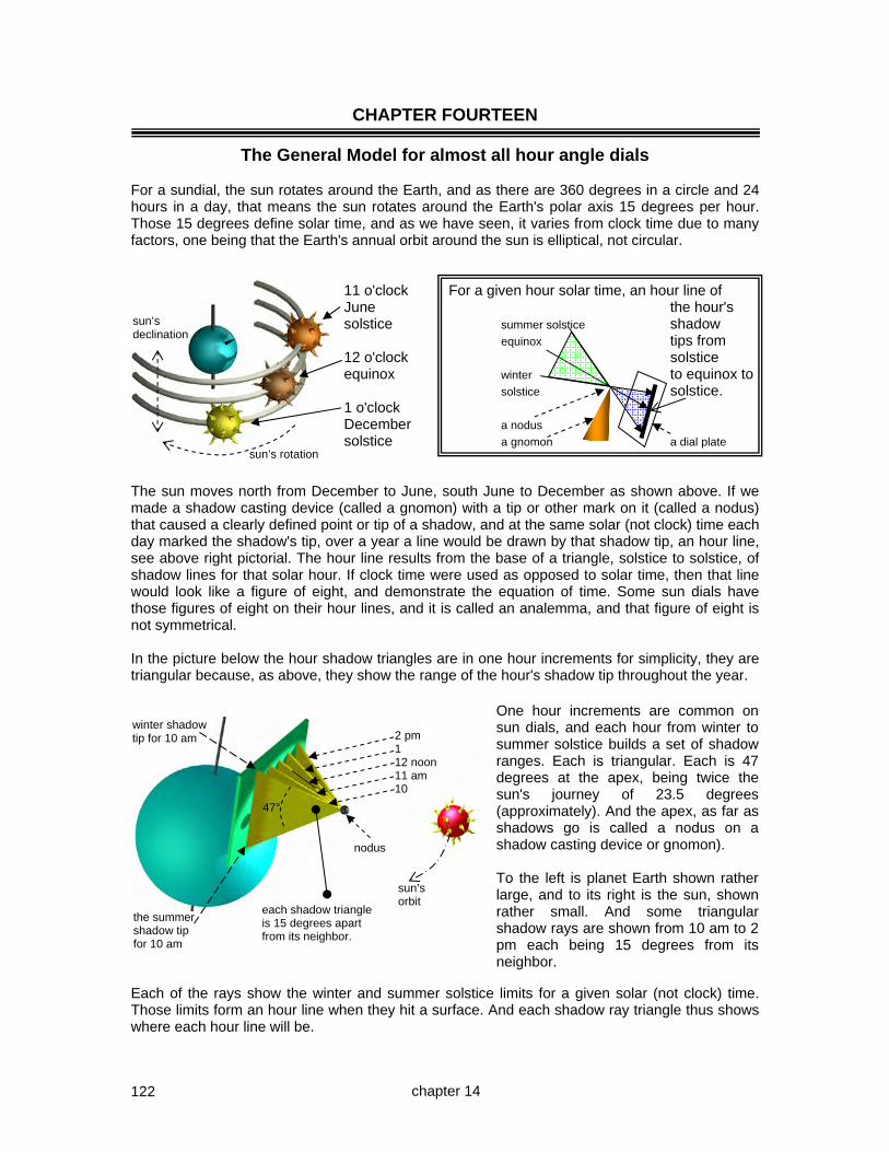
122
CHAPTER FOURTEEN
The General Model for almost all hour angle dials For a sundial, the sun rotates around the Earth, and as there are 360 degrees in a circle and 24 hours in a day, that means the sun rotates around the Earth's polar axis 15 degrees per hour. Those 15 degrees define solar time, and as we have seen, it varies from clock time due to many factors, one being that the Earth's annual orbit around the sun is elliptical, not circular.
11 o'clock For a given hour solar time, an hour line of June the hour's solstice summer solstice shadow equinox tips from 12 o'clock solstice equinox winter to equinox to solstice solstice. 1 o'clock December a nodus solstice a gnomon a dial plate
The sun moves north from December to June, south June to December as shown above. If we made a shadow casting device (called a gnomon) with a tip or other mark on it (called a nodus) that caused a clearly defined point or tip of a shadow, and at the same solar (not clock) time each day marked the shadow's tip, over a year a line would be drawn by that shadow tip, an hour line, see above right pictorial. The hour line results from the base of a triangle, solstice to solstice, of shadow lines for that solar hour. If clock time were used as opposed to solar time, then that line would look like a figure of eight, and demonstrate the equation of time. Some sun dials have those figures of eight on their hour lines, and it is called an analemma, and that figure of eight is not symmetrical. In the picture below the hour shadow triangles are in one hour increments for simplicity, they are triangular because, as above, they show the range of the hour's shadow tip throughout the year.
Each of the rays show the winter and summer solstice limits for a given solar (not clock) time. Those limits form an hour line when they hit a surface. And each shadow ray triangle thus shows where each hour line will be.
winter shadow tip for 10 am
the summer shadow tip for 10 am
each shadow triangle is 15 degrees apart from its neighbor.
47°
nodus
chapter 14
sun’s rotation
sun’s declination
2 pm 1 12 noon 11 am 10
One hour increments are common on sun dials, and each hour from winter to summer solstice builds a set of shadow ranges. Each is triangular. Each is 47 degrees at the apex, being twice the sun's journey of 23.5 degrees (approximately). And the apex, as far as shadows go is called a nodus on a shadow casting device or gnomon). To the left is planet Earth shown rather large, and to its right is the sun, shown rather small. And some triangular shadow rays are shown from 10 am to 2 pm each being 15 degrees from its neighbor.
sun’s orbit
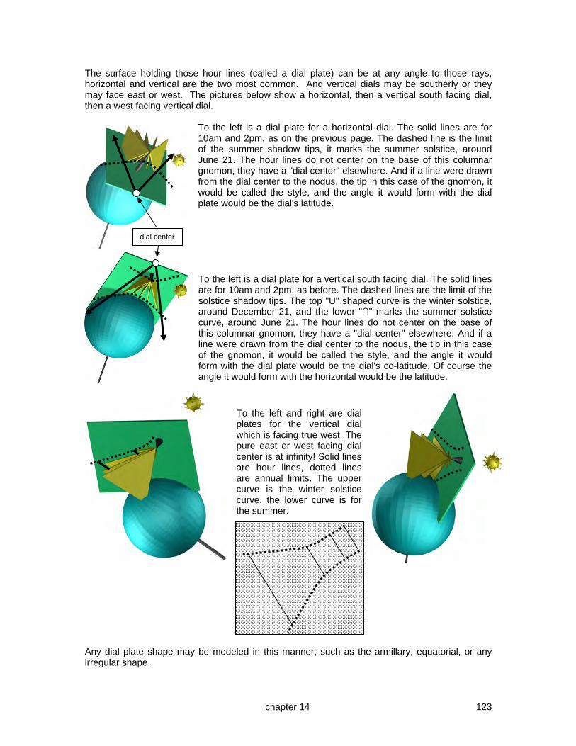
123
The surface holding those hour lines (called a dial plate) can be at any angle to those rays, horizontal and vertical are the two most common. And vertical dials may be southerly or they may face east or west. The pictures below show a horizontal, then a vertical south facing dial, then a west facing vertical dial.
To the left is a dial plate for a horizontal dial. The solid lines are for 10am and 2pm, as on the previous page. The dashed line is the limit of the summer shadow tips, it marks the summer solstice, around June 21. The hour lines do not center on the base of this columnar gnomon, they have a "dial center" elsewhere. And if a line were drawn from the dial center to the nodus, the tip in this case of the gnomon, it would be called the style, and the angle it would form with the dial plate would be the dial's latitude. To the left is a dial plate for a vertical south facing dial. The solid lines are for 10am and 2pm, as before. The dashed lines are the limit of the solstice shadow tips. The top "U" shaped curve is the winter solstice, around December 21, and the lower "∩" marks the summer solstice curve, around June 21. The hour lines do not center on the base of this columnar gnomon, they have a "dial center" elsewhere. And if a line were drawn from the dial center to the nodus, the tip in this case of the gnomon, it would be called the style, and the angle it would form with the dial plate would be the dial's co-latitude. Of course the angle it would form with the horizontal would be the latitude.
To the left and right are dial plates for the vertical dial which is facing true west. The pure east or west facing dial center is at infinity! Solid lines are hour lines, dotted lines are annual limits. The upper curve is the winter solstice curve, the lower curve is for the summer.
Any dial plate shape may be modeled in this manner, such as the armillary, equatorial, or any irregular shape.
dial center
chapter 14

124
C
C
A GENERAL GEOMETRIC MODEL OF THE PREVIOUS DIALS We have now seen the geometric methods for designing the armillary and equatorial dial, the polar and meridian dials (true east or true west), as well as the vertical (true south) and the horizontal dial. We can blend all those concepts into one easy to remember model. This is intended to show a natural symmetry in geometric dial design. C A circle is not needed, but a radius is. It is AC VERTICAL DIAL nodus A A D co-latitude y y D latitude AM 12 PM 8 9 10 11 1 2 3 4 5 C x B The radius of this circle, which is an AUXILIARY EQUATORIAL C DIAL is the orthogonal line from A POLAR the style's nodus to the style DIAL base. A circle is needed because we draw 15 degree arcs. It is CD 8 9 10 11 1 2 3 4 5 AM 12 PM C x D latitude While a circle is not needed as such, a radius is needed for the center of the hour lines. The radius is BC B C HORIZONTAL DIAL The above general geometrical model shows a symmetry in the design of the polar, vertical, and horizontal dials in the context of their gnomon's style. For a polar or a meridian dial, CD is the linear height of the style's nodus above the dial plate. In this model, CD does different things depending on dial type. For a horizontal dial, this model is based on the ratio of the DC to CB. For a vertical dial the ratio is based on DC to CA. In all cases, DC is the equinoctial ray going to the dial plate at C from nodus D.
D
chapter 14

125
The model on the previous page was developed by Albrecht Durer in 1525 and is pictured to the right in perspective. The sun is at the top left, the planet Earth is at the bottom right showing the polar axis and equator, with the dials shown in between. Any dial not susceptible to the methods described here can be designed because that dial has a horizontal or vertical dial that matches it somewhere else on the planet. The French dialists Sagot and Savoie developed such a model.
Dials may be designed for portability, or for a specified location. Latitude adjustments can be simplified by tilting a dial. Longitude adjustments can be made by either considering the longitude difference when the hour lines are designed, or the difference can be included into a tailored equation of time. Portable dials should not have the longitude correction built in since it would limit their portability. If a dial has no longitude correction built into it, then it is simpler to design, and it can be relocated. The correction for the EOT is simply modified to include the longitude correction.
e.g. EOT Jan Feb Mar Apr May Jun Jly Aug Sep Oct Nov Dec +9 +14 +9 =0 -3 =0 +6 +4 -5 -14 -15 -5 The longitude correction of say – 8 minutes that would have been built in to the dial, now becomes one correction table when you deduct the fixed 8 minutes from each EOT entry. e.g. EOT Jan Feb Mar Apr May Jun Jly Aug Sep Oct Nov Dec +1 +6 +1 -8 -11 -8 -2 -4 -13 -22 -23 -13
chapter 14
sun
Earth

126
A review of the common hour angle dials other than the decliner and the inclined decliner which are covered in their own chapters. Additionally, appendix 1 in the separate appendices shows the planet with several of each dial types on it at several latitudes, latitude 0, 30, 60 and 90˚.
Regardless of where a dial is, in space or on the planet, when the sun's rays shine they will make shadows, and the west to east range tells the time, while the north to south direction shows the date. To the left is shown the sun and it's light hitting a conical gnomon, and 5 different hours are shown as five triangular shadows. They are triangles because of the solstice through equinox to solstice annual solar travel. This pictorial shows the north or south shadow extremes reflecting the date, and the west to east range reflecting the time. The time comes
from the sun's angle, or hour angle, around the polar axis. The date comes from the sun's declination above or below the equator. The pictorial above thus shows how both the date and the time are determined. ARMILLARY DIALS The armillary dial to the right, named for the likeness to arm bracelets, uses the 15 degrees per hour directly. The picture shows the sun's rays for several hours, and for each of those hours the solstice extremes are shown. The dial plate parallels the north south polar axis. The date has a tangent relationship and the complete annual cycle can be seen on the dial plate.
EQUATORIAL DIALS The equatorial dial has a dial plate at 90 degrees to the armillary, thus it parallels the equator. Just like the armillary dial, there is no complicated geometry. It is 15 degrees per hour for the time. The date gets a little out of hand at the equinoxes, in fact at the equinox, the shadow recedes to infinity. Like the armillary, this is a tangent relationship, however the alignment of the dial plate is what causes the problem at the equinox.
chapter 14

127
MERIDIAN The meridian dial to the left has a dial plate coming from the polar axis proceeding out and beyond. The hour lines begin close in at 6 am or 6 pm, but as the time moves from those points, the hour lines increase rapidly away. They recede based on the tangent of the time in hours from 6 am or 6 pm, multiplied by 15. That 15 being the 15 degrees per hour rotation of the sun around the Earth. POLAR
The polar dial to the right is like the meridian dial however the dial plate is rotated 90 degrees from it, it parallels the north south polar axis. The hour lines are also based on the tangent of the hour multiplied by 15, from noon.
HORIZONTAL The horizontal dial to the left has a dial plate that lies flat on the Earth's surface. For clarity that plate has been lifted up a bit. VERTICAL The vertical dial to the right is like a horizontal dial except it is 90 degrees to the surface. The vertical and horizontal dials have a latitude to co-latitude relationship.
In all these cases the 15 degrees per hour applies. Geometry comes into play when the display on a dial plate is considered. As a rule polar and equatorial dials are a simple 15 degrees, and the rest of these hour angle dials have hours lines based on the tangent of the hour angle. And if latitude is used, then a factor based on the sine (or cosine) of the latitude. To clarify the pictures on this and the preceding page, the gnomons on these two pages are cones in space, whose tip is the shadow caster. In other words, there are no styles nor sub-styles depicted.
chapter14

128
CHAPTER FIFTEEN
The vertical recliner INCLINING OR RECLINING DIALS
Facing true north, south, east, or west South
First case: a vertical recliner directly facing the equator. The vertical recliner exists on slopes such as roofs, or, on walls where I live that were not quite vertical! There are three generic types, and all three have simple solutions.
Cases where the roof's pitch is the same as the latitude. Cases where the roof's pitch is the less than the latitude. Cases where the roof's pitch is the more than the latitude.
Second case: a true east or west facing dial that reclines, this has a simple conversion to a vertical decliner. In the pictorial below, there is one dial plate on the left which shows how an inclined dial at latitude 20 becomes a decliner at latitude 70. As another example, the other two separate dials show a dial plate on the equator or latitude 0 that is inclined about 50°, and it becomes vertical at the pole or latitude 90, but now declines by that inclination angle. NOTE: after studying this chapter, look at chapter 13 section “problems with a vertical dial design matching a horizontal design” which has an interesting case for two horizontal dials with no longitude correction.
chapter 15
The dial on the equator or latitude 0° reclines backwards by about 40°, (inclines 50°) and ... at latitude 90 that same dial plate is now no longer inclining or reclining backwards and it is now vertical but declining by 50°.
This vertical dial at latitude 20° reclines backwards by about 25°, and
... becomes a vertical dial at latitude 70° with a declination of 65°

129
A VERTICAL RECLINER, FACING THE EQUATOR To clarify a few terms reclines A slope reclines backwards backwards inclines upwards A slope inclines upwards And a slope that leans forwards “proclines”. Vertical recliners facing the equator typically exist on the roofs of buildings aligned on true north. In many housing areas, this doesn’t happen often. There are three classes of vertical recliners whose dial plate faces the equator. 1. the slope's angle is the same as the location's latitude, this is a polar dial. 2. the slope's angle is the less than the location's latitude, then this is a horizontal dial for a
latitude equal to the difference between the latitude and the slope's pitch. For example, a 20° pitched roof in latitude 30° calls for a dial designed for 10°.
3. the slope's angle is more than the latitude, then this is a vertical dial for a latitude equal to the co-latitude of the roof and latitude angular difference. Vertical and horizontal dials share a co-latitude relationship already discussed.
The slope's pitch is the same as the latitude ~ use a polar dial When the slope's pitch is the same as the latitude, this is exactly what polar dials live for, the hour lines are based solely on the time, not latitude, as a result these are universal dials since they can be moved to any latitude and merely tilted, the hour lines don't get upset by latitude shifts. Hour lines are based on the tangent of the hour multiplied by 15. c style protractor 15° y sub style dial plate x Trigonometrically, using the above figure, tan(15)=x/y, thus the distance from the sub style "x" is given by: x=y*tan(15), or, hour line distance = style height * tan(hours*15). One hour would be 15 degrees, two hours would be 30 degrees and so on. Longitude correction can be made by adding or subtracting the dial's longitude from the legal time's longitude and adding or subtracting that difference from the 15 degree radials, however the dial is then no longer universal because location has been factored in.
chapter 15

130
gnomon 30
Slope's pitch is the less than latitude ~ use horizontal dial of lesser latitude It was mentioned earlier that a horizontal dial designed for another latitude can be used at a new latitude by the simple application of a wedge. That wedge causes the gnomon to once again be parallel to the Earth's polar axis. A roof is no different, except of course that a roof that does not decline, i.e., one that has its ridge running true east to true west, is perhaps not common. The design is merely a construction using methods already discussed. For example, a roof of 40 degrees pitch in latitude 70 is shown exaggerated below, this calls for a dial designed for 30°.
design for latitude 30 a horizontal dial roof 40
latitude 70
Design a gnomon whose style height is equal to latitude (70) minus roof-pitch (40), in other words a style angular height of 30, pointing north parallel to the Earth's polar axis. The hour lines are then designed for a latitude of the dial's angular style height, in other words the gnomon's angle (30) when placed upon the slope. Longitude could be considered as usual. Slope's pitch is the more than latitude ~ use vertical dial of greater latitude
roof 40 latitude here is 10
In this case we use a vertical dial with a style height of roof pitch (40) minus the latitude (10), being a 30 degree style height. For vertical dials, the style height is the co-latitude, so, the vertical dial's design latitude would be 60°. A vertical dial and a horizontal dial share a co-latitude relationship. Thus this is the same as a horizontal dial for latitude 30, except the dial center points to the pole, not the equator.
use horizontal-dial designed for: roof – latitude (reverse am/pm hours, and reverse or longitude correction) use vertical-dial designed for: 90 – (roof – latitude) (normal am/pm hours and normal longitude correction)
chapter 15

131
A VERTICAL RECLINER, FACING TRUE EAST OR TRUE WEST Recall that a horizontal dial at latitude "x" has the same design as a vertical dial at latitude "90-x" (the co-latitude), with am and pm hours switched, in other words the dial rotated around the vertical axis. Similarly, a vertical true east/west meridian dial has the same design as a vertical south dial at the co-latitude. And a reclining meridian becomes a declining vertical. A vertical dial 2 that declines is the new 3 design dial The actual vertical dial that slopes latitude 1 Earth's Earth's rotation Polar Axis The actual lines of one dial are the design lines of the other dial when moved to a new location 90° away. The inclination of one is the declination of the other. A sloping true east or west dial at one latitude is the same as a declining dial facing north or south at a latitude equal to 90° plus the original dial's latitude. Since that takes one over 90°, we rotate the design-dial 180° around the pole, which produces the formulae: The latitude of the "design dial" is:- = 90 – the latitude of the actual dial and The declination of the "design dial" is:- = 90 – the reclination of the actual dial or = the inclination of the actual dial and The dial plate was rotated 90° in latitude, so on the new dial noon is horizontal, not vertical and The dial was rotated 180° around the pole, so on the new dial the hours lines are mirror imaged Thus the simple formula for converting true east or true west facing sloping dials to a dial that is true south or north facing but declining facilitates such a dial design. And the "design" then obviously uses the vertical decliner techniques. Some cross checks are in order. First, the noon line is horizontal. Second the dial center is towards the equator. Always build a model to validate your calculations, the case study that follows shows this process. Remember the rules for the definition of a declining dial:- N 85° W N 30° W N 60°E N 0° W N 0° E S 60° W S 30°E
90° plus dial latitude
90° minus dial latitude
first, the actual dial is moved, not rotated, to the design dial's latitude (90 minus actual latitude)
second the new design dial is rotated around the pole
chapter 15
reclines 30˚ inclines 60˚

132
An example of a CAD empirical design for a reclining dial for latitude 33 north. Front south facing design: Here a pyramid has been made. The front face is a south facing recliner. The face angles are 30˚ from vertical or 60˚ from the horizontal. The final gnomon style is set at 33˚ for the dial's actual latitude. Using the techniques from chapter 30, we design a vertical dial for the co-latitude of 27˚ (60-33), i.e. 63˚. And for a design latitude of 63˚ we derive from the formulae or spreadsheet the following hour line angles. Latitude 63 Hour line angles for
TIME OF DAY simple dials am pm VERTICAL
12.00 12.00 0.00 11.00 1.00 6.94 10.00 2.00 14.69
9.00 3.00 24.42 8.00 4.00 38.18 7.00 5.00 59.45 6.00 6.00 90.00
The dial plate reclines 30˚ from vertical at latitude 33˚. Using the formulae from the preceding page, this generates a design dial that is vertical, at latitude 57˚ (90-33) that declines S 60˚ E (being 90 – 30). Or more simply, the design dial's declination is the actual dials inclination. Using the spreadsheet for vertical decliners, the following figures are produced.
Lat 57˚ -DEC SxxE
hh Dec 60˚
6.00 -36.9
7.00 -32.3
8.00 -28.2
9.00 -23.9
10.00 -18.9
11.00 -11.9
12.00 0.0
13.00 25.5
14.00 75.6
15.00 -67.4
16.00 -51.2
17.00 -42.6
18.00 -36.9
SD -29.4
SH 15.8
The table to the left is used for the south face. Of course for the southern hemisphere, this would be a north facing dial plate, with the same hour line angles, however the am and pm hours would be reversed. The side east facing dial reclines and thus needs to be converted to a south facing declining design-dial, with its final dial center pointing south (for northern hemispheres) and with the noon line horizontal.
The final noon line is horizontal, morning hours are above it, afternoon hours below. Use the am and pm hour line angles directly from the spreadsheet. The west facing dial is an opposite of the east dial plate. Below are the south and the east facing dial plates seen perpendicularly from the plate. The SD specifies where the sub-style will lie and the SH gives the angle from the sub-style for the resulting gnomon. Use software such as SHADOWS to double check, and always make a model to verify your resulting deductions.
South East
25.5
-11.9
SD style distance -29.4
The east facing recliner
75.6
The south facing recliner
6.94
-18.9
14.69
chapter 15
reclines 30˚ inclines 60˚

133
Some observations and rules of thumb In the picture below, there are two sets of sun rays covering 0600 hourly until noon. The noon line, the lowest of all the lines, is horizontal. The matching sun ray lines are connected with dashed lines, and they converge at the dial center, which in this case is not on the dial plate.
Some rules of thumb:
One question sometimes asked is that the resulting SD or SH do not seem to reflect the final dial's actual latitude. In this case the dial is at latitude 33, but the SD is 29.4 and the SH is 15.8, surely this cannot produce a style aligned with the poles at latitude 33. It does, because both the SD and the SH are used together, in math terms, a vector addition. The SD angles the sub-style up from the noon line, and the SH being perpendicular to the dial plate, which is sloped, makes the style itself even further up. The result is a style correctly set at latitude. Before making the final dial, a paper dial plate and gnomon mockup was made and the result was sun tested. The styles in the mockup photo to the right are parallel.
NOTE: Vertical reclining dials are usually designed using geometry or trigonometry, the empirical method is less frequently used. Sundial programs are of course based on trigonometry.
For an east facing dial, the following are rules of thumb. For a shallow slope, less than 45˚, the upper hour lines (0600) are spread out, becoming closer at the lower end (1200). For steep slopes, more than 45˚, the upper hour lines (0600) are more tightly packed than the lower ones (0600). For 45˚ slopes, the lines are spread out at the 0600 and 1200 end, and more compact in the middle, 0900. Similarly for a west facing slope. The noon line, the lowest of all the lines, is horizontal.
The same picture but with angles measured on the 60 degree slope using CAD, that are very close to those calculated by the spreadsheet. Another example that using CAD to derive complicated angles is practical.
chapter 15

134
COOK BOOK SUMMARY FOR DIALS FACING THE EQUATOR OR EAST/WEST VERTICAL RECLINER whose slope is the same as the latitude use a polar dial Hour line linear distance from the noon line = gnomon style linear height * tan (15 * hour) Linear distance along an hour line to a declination point = linear style height * tan (declination) / cos (15 * hour) VERTICAL RECLINER whose slope is less than the latitude use a horizontal dial of lesser latitude = latitude minus slope hour line angle = arctan ( sin (latitude) * tan (15 * hour) ) or use the tables in appendix 3 tables A3,1a, A31.b, A3.1c – horizontal index VERTICAL RECLINER whose slope is more than the latitude use a vertical dial of co-latitude = 90-(slope – latitude) (normal am/pm hours, and longitude correction) or a horizontal dial of latitude = slope – latitude with dial center to the pole (but reverse am/pm hours, and longitude correction) hour line angle = arctan ( cos (latitude) * tan (15 * hour) ) or use the tables in appendix 3 tables A3,1a, A31.b, A3.1c – vertical index EAST AND WEST RECLINERS The latitude of the "design dial" is:- = 90 – the latitude of the actual dial and The declination of the "design dial" is:- = 90 – the reclination of the actual dial or = the inclination of the actual dial and The dial plate is rotated 90° in latitude, so on the new dial noon is horizontal, not vertical and The dial is rotated 180° around the pole, so on the new dial the hours lines are mirror imaged Atkinson's Theorem It has been mentioned that a horizontal dial designed for a latitude other than the dial's location can be corrected by rotating the dial up or down on the east west axis line, for example by placing a wedge at the north end or the south end. And, just as this was the basis for the south facing reclining dials, the question arises about longitude corrections. It has been emphasized that rotating hour lines does not correct for longitude except in the case of the equatorial and armillary dials. All other dials that need a longitude correction to derive standard time, need their hour angles to be adjusted before the design is done, and this is done hour by hour. Atkinson's Theorem states that a longitude correction can be made by rotating a dial around the polar axis, in other words, rotating the entire dial around the style of the gnomon.
chapter 15

135
CASE STUDY ~ AN INCLINING MERIDIAN DIAL, LONGITUDE CORRECTED The objective of this dial was to have a true east, true west meridian dial that inclined up, or reclined back. This dial was for latitude 33° degrees, and longitude corrected for longitude 108.2° with a legal meridian of 105°. A DeltaCAD macro was used and its results tested against other programs such as the Excel spreadsheets.
An inclining true east/west dial has the same design hour line angles as a vertical decliner
whose latitude is the co-latitude of the meridian dial, whose declination is the inclination of the meridian dial, whose dial plate is rotated by 90 degrees so noon is horizontal not vertical, whose vertical axis is rotated so the am hours of one are the pm hours of the other
So, these dials for about latitude 33°, inclined up by 45°, should match a vertical dial for latitude 57° with a declination of 45°.
Above to the left is the DeltaCAD programmed drawing for the 45 degree incliner at latitude 32.7, and above to the right is a vertical decliner for latitude 57.3 declining 45 degrees. The vertical decliner hour line angles from vertical match the inclining meridian dial's hour line angles from horizontal. This is the results of the latitude:co-latitude relationship. The hour lines are mirrored around noon, this is because the dial when moved 90° of latitude is on the other side of the planet, or 180° and thus mirrored. The noon line is a bit above the horizontal line for the east facing dial as this dial is west of the legal meridian, so noon must be indicated earlier. The dial plates were printed on normal 8 1/2 by 11 inch paper and cut out, and the dial center part ignored so that the dial plate area would be better used.
chapter 15
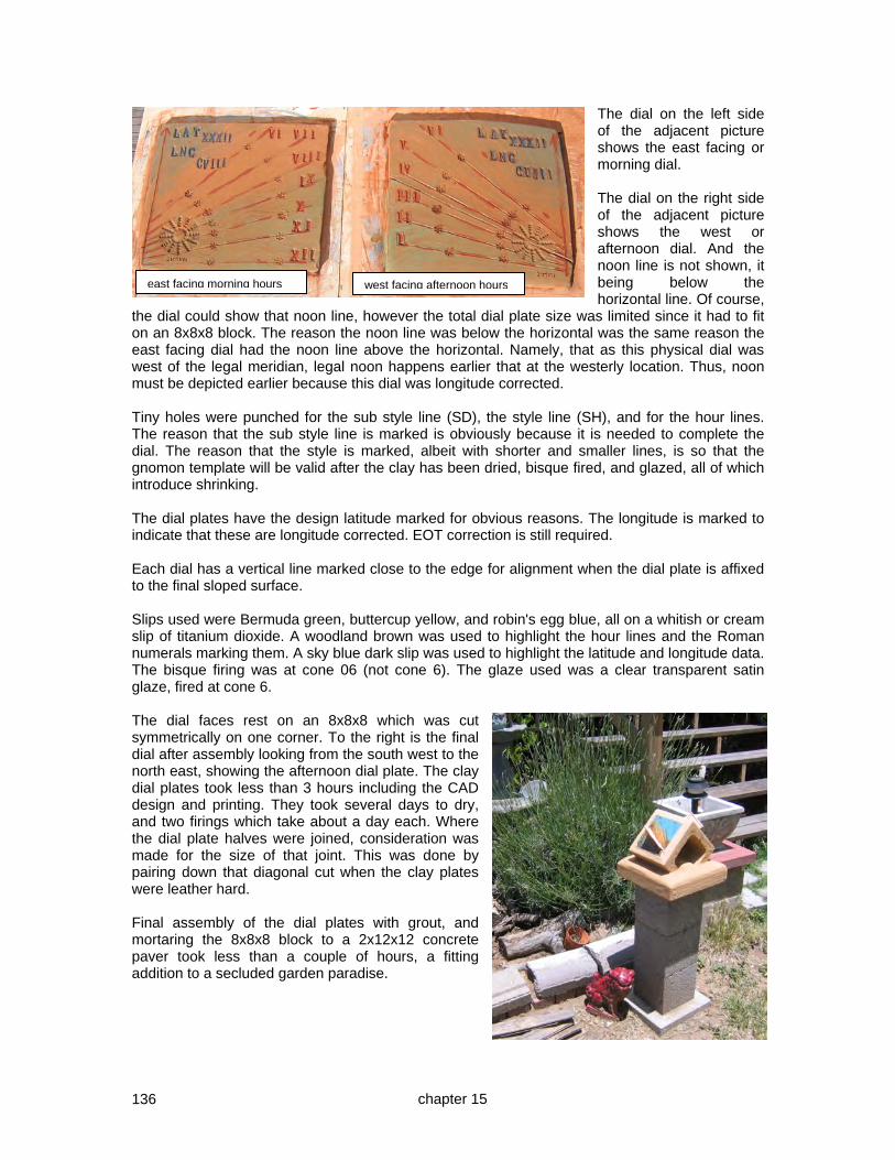
136
The dial on the left side of the adjacent picture shows the east facing or morning dial. The dial on the right side of the adjacent picture shows the west or afternoon dial. And the noon line is not shown, it being below the horizontal line. Of course,
the dial could show that noon line, however the total dial plate size was limited since it had to fit on an 8x8x8 block. The reason the noon line was below the horizontal was the same reason the east facing dial had the noon line above the horizontal. Namely, that as this physical dial was west of the legal meridian, legal noon happens earlier that at the westerly location. Thus, noon must be depicted earlier because this dial was longitude corrected. Tiny holes were punched for the sub style line (SD), the style line (SH), and for the hour lines. The reason that the sub style line is marked is obviously because it is needed to complete the dial. The reason that the style is marked, albeit with shorter and smaller lines, is so that the gnomon template will be valid after the clay has been dried, bisque fired, and glazed, all of which introduce shrinking. The dial plates have the design latitude marked for obvious reasons. The longitude is marked to indicate that these are longitude corrected. EOT correction is still required. Each dial has a vertical line marked close to the edge for alignment when the dial plate is affixed to the final sloped surface. Slips used were Bermuda green, buttercup yellow, and robin's egg blue, all on a whitish or cream slip of titanium dioxide. A woodland brown was used to highlight the hour lines and the Roman numerals marking them. A sky blue dark slip was used to highlight the latitude and longitude data. The bisque firing was at cone 06 (not cone 6). The glaze used was a clear transparent satin glaze, fired at cone 6. The dial faces rest on an 8x8x8 which was cut symmetrically on one corner. To the right is the final dial after assembly looking from the south west to the north east, showing the afternoon dial plate. The clay dial plates took less than 3 hours including the CAD design and printing. They took several days to dry, and two firings which take about a day each. Where the dial plate halves were joined, consideration was made for the size of that joint. This was done by pairing down that diagonal cut when the clay plates were leather hard. Final assembly of the dial plates with grout, and mortaring the 8x8x8 block to a 2x12x12 concrete paver took less than a couple of hours, a fitting addition to a secluded garden paradise.
chapter 15
east facing morning hours west facing afternoon hours
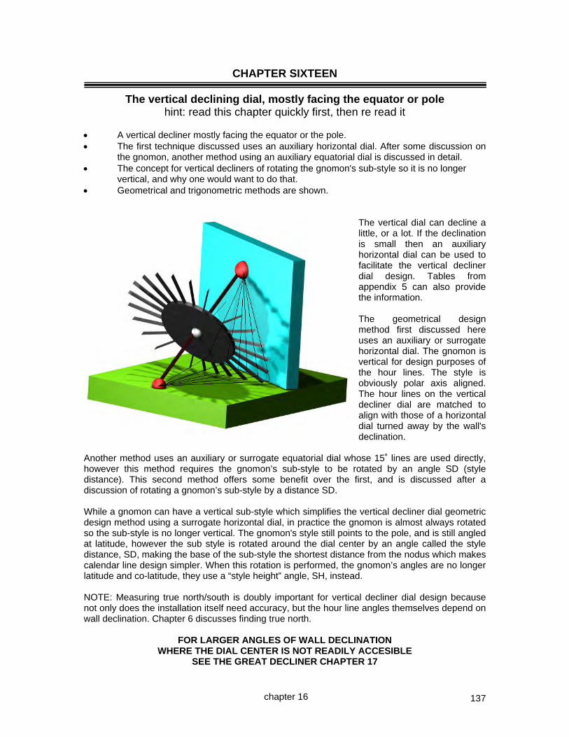
137
CHAPTER SIXTEEN
The vertical declining dial, mostly facing the equator or pole hint: read this chapter quickly first, then re read it
A vertical decliner mostly facing the equator or the pole. The first technique discussed uses an auxiliary horizontal dial. After some discussion on
the gnomon, another method using an auxiliary equatorial dial is discussed in detail. The concept for vertical decliners of rotating the gnomon's sub-style so it is no longer
vertical, and why one would want to do that. Geometrical and trigonometric methods are shown.
The vertical dial can decline a little, or a lot. If the declination is small then an auxiliary horizontal dial can be used to facilitate the vertical decliner dial design. Tables from appendix 5 can also provide the information. The geometrical design method first discussed here uses an auxiliary or surrogate horizontal dial. The gnomon is vertical for design purposes of the hour lines. The style is obviously polar axis aligned. The hour lines on the vertical decliner dial are matched to align with those of a horizontal dial turned away by the wall's declination.
Another method uses an auxiliary or surrogate equatorial dial whose 15˚ lines are used directly, however this method requires the gnomon’s sub-style to be rotated by an angle SD (style distance). This second method offers some benefit over the first, and is discussed after a discussion of rotating a gnomon’s sub-style by a distance SD. While a gnomon can have a vertical sub-style which simplifies the vertical decliner dial geometric design method using a surrogate horizontal dial, in practice the gnomon is almost always rotated so the sub-style is no longer vertical. The gnomon's style still points to the pole, and is still angled at latitude, however the sub style is rotated around the dial center by an angle called the style distance, SD, making the base of the sub-style the shortest distance from the nodus which makes calendar line design simpler. When this rotation is performed, the gnomon’s angles are no longer latitude and co-latitude, they use a “style height” angle, SH, instead. NOTE: Measuring true north/south is doubly important for vertical decliner dial design because not only does the installation itself need accuracy, but the hour line angles themselves depend on wall declination. Chapter 6 discusses finding true north.
FOR LARGER ANGLES OF WALL DECLINATION WHERE THE DIAL CENTER IS NOT READILY ACCESIBLE
SEE THE GREAT DECLINER CHAPTER 17
chapter 16

138
80
70
60
50
40
302010
Latitude
V-dial10
20
30
40
50
607080
H-dial
11.00 01.00
10.00 02.00
09.00 03.00
08.00 04.00
07.00 05.00
Hour around noon
AM PM
10
20
30
40
50
60
70
80
Dial Plate's hour line angle
Horizontal and Vertical dial platewww .illustratingshadow s.com
latitude is log(sin(lat)) so scale decreases vertically
longitude is log(tan(lng)) so scale decreases first then increases
hour line angle is log(tan(hla)) so scale decreases first then increases
First, mark latitude on the left vertical lineNext, mark the desired time on the right vertical lineThen, read hour line angle on the center vertical line
SELECT A DESIGN METHOD ~ the following pages describe most of these options Use a surrogate horizontal dial and optionally rotate the gnomon
benefit is easy design deriving style distance SD, and style height SH replacing co-latitude, there are gnomon and furniture benefits
Rotate the gnomon first and then use a surrogate equatorial dial
this method requires a rotated gnomon
which derives style distance SD and style height SH replacing co-latitude in the gnomon Use tables or a spreadsheet
trigonometric basis Use a nomogram
trigonometric basis Use a program
trigonometric basis empirical with a trigon now make it
HORIZONTAL DIAL LATITUDE
TIME 50 51 52 53 54 55 56 57 58 59
12 0.00 0.00 0.00 0.00 0.00 0.00 0.00 0.00 0.00 0.00 noon
0.25 2.87 2.92 2.96 3.00 3.04 3.07 3.11 3.15 3.18 3.22 11.75
0.50 5.76 5.84 5.92 6.00 6.08 6.16 6.23 6.30 6.37 6.44 11.50
0.75 8.66 8.79 8.91 9.03 9.14 9.25 9.36 9.47 9.57 9.68 11.25
1 11.60 11.76 11.92 12.08 12.23 12.38 12.52 12.67 12.80 12.94 11
1.25 14.58 14.78 14.98 15.17 15.36 15.54 15.72 15.89 16.06 16.22 10.75
1.50 17.60 17.84 18.08 18.30 18.53 18.74 18.95 19.16 19.35 19.55 10.50
1.75 20.70 20.97 21.24 21.50 21.75 22.00 22.24 22.47 22.70 22.91 10.25
2 23.86 24.17 24.46 24.75 25.04 25.31 25.58 25.84 26.09 26.33 10
2.25 27.11 27.44 27.77 28.09 28.39 28.69 28.98 29.27 29.54 29.80 9.75
2.50 30.45 30.81 31.16 31.50 31.83 32.15 32.46 32.76 33.05 33.33 9.50
2.75 33.89 34.28 34.65 35.01 35.36 35.69 36.02 36.33 36.64 36.93 9.25
3 37.45 37.85 38.24 38.61 38.97 39.32 39.66 39.99 40.30 40.60 9
3.25 41.14 41.55 41.94 42.32 42.69 43.05 43.39 43.72 44.04 44.35 8.75
3.50 44.95 45.36 45.76 46.15 46.51 46.87 47.21 47.54 47.86 48.17 8.50
3.75 48.90 49.31 49.70 50.08 50.45 50.80 51.13 51.46 51.77 52.06 8.25
4 53.00 53.39 53.77 54.14 54.49 54.82 55.15 55.46 55.75 56.04 8
4.25 57.23 57.60 57.96 58.31 58.64 58.95 59.25 59.54 59.82 60.09 7.75
4.50 61.60 61.94 62.27 62.59 62.89 63.18 63.45 63.72 63.97 64.21 7.50
4.75 66.10 66.40 66.69 66.97 67.24 67.49 67.73 67.96 68.18 68.40 7.25
5 70.72 70.98 71.22 71.45 71.67 71.89 72.09 72.28 72.47 72.64 7
5.25 75.44 75.64 75.83 76.01 76.19 76.35 76.51 76.66 76.80 76.94 6.75
5.50 80.25 80.39 80.52 80.64 80.76 80.87 80.98 81.08 81.18 81.27 6.50
5.75 85.11 85.18 85.25 85.31 85.37 85.43 85.48 85.53 85.58 85.63 6.25
6 90.00 90.00 90.00 90.00 90.00 90.00 90.00 90.00 90.00 90.00 6
40 39 38 37 36 35 34 33 32 31
VERTICAL DIAL LATITUDE
chapter 16
gnomon uses co-latitude
co-latitude is not found in the gnomon
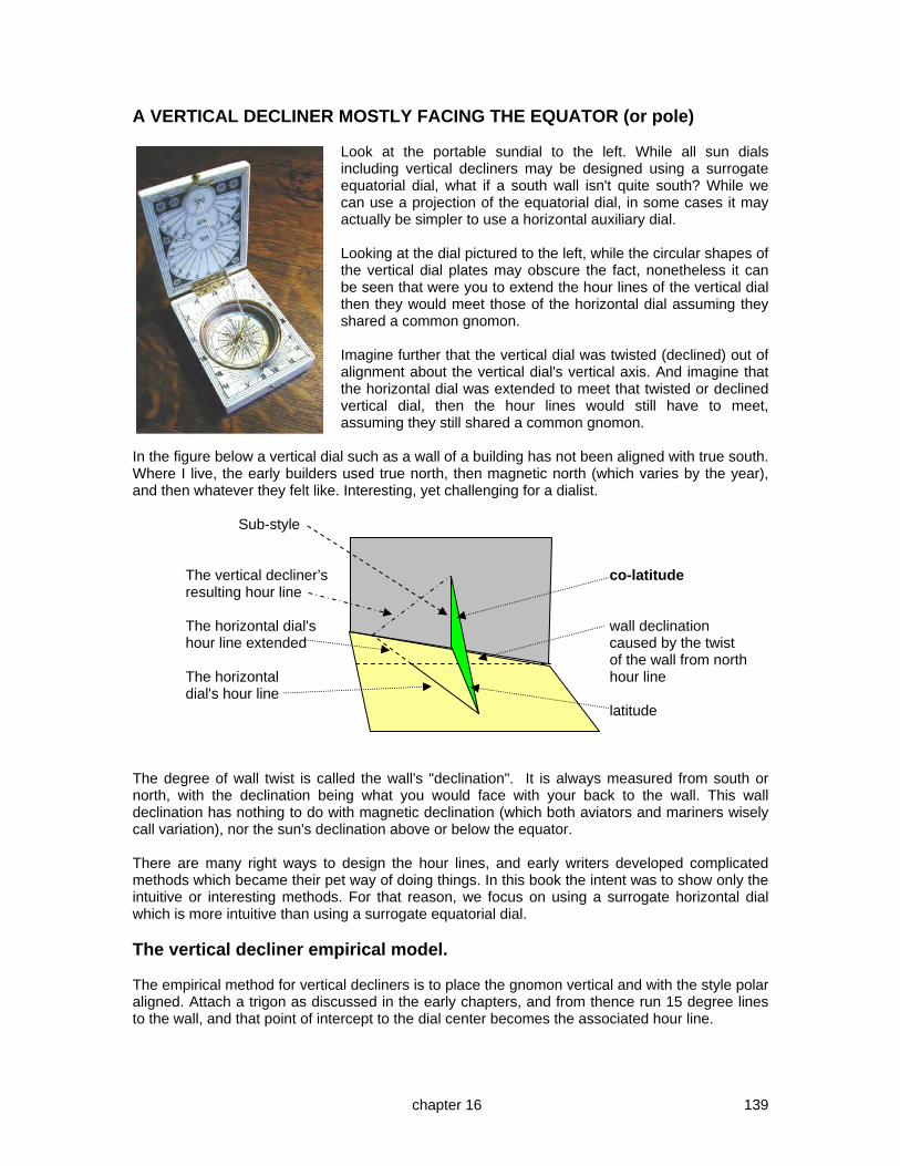
139
A VERTICAL DECLINER MOSTLY FACING THE EQUATOR (or pole)
Look at the portable sundial to the left. While all sun dials including vertical decliners may be designed using a surrogate equatorial dial, what if a south wall isn't quite south? While we can use a projection of the equatorial dial, in some cases it may actually be simpler to use a horizontal auxiliary dial. Looking at the dial pictured to the left, while the circular shapes of the vertical dial plates may obscure the fact, nonetheless it can be seen that were you to extend the hour lines of the vertical dial then they would meet those of the horizontal dial assuming they shared a common gnomon. Imagine further that the vertical dial was twisted (declined) out of alignment about the vertical dial's vertical axis. And imagine that the horizontal dial was extended to meet that twisted or declined vertical dial, then the hour lines would still have to meet, assuming they still shared a common gnomon.
In the figure below a vertical dial such as a wall of a building has not been aligned with true south. Where I live, the early builders used true north, then magnetic north (which varies by the year), and then whatever they felt like. Interesting, yet challenging for a dialist. Sub-style The vertical decliner’s co-latitude resulting hour line The horizontal dial's wall declination hour line extended caused by the twist of the wall from north The horizontal hour line dial's hour line latitude The degree of wall twist is called the wall's "declination". It is always measured from south or north, with the declination being what you would face with your back to the wall. This wall declination has nothing to do with magnetic declination (which both aviators and mariners wisely call variation), nor the sun's declination above or below the equator. There are many right ways to design the hour lines, and early writers developed complicated methods which became their pet way of doing things. In this book the intent was to show only the intuitive or interesting methods. For that reason, we focus on using a surrogate horizontal dial which is more intuitive than using a surrogate equatorial dial. The vertical decliner empirical model. The empirical method for vertical decliners is to place the gnomon vertical and with the style polar aligned. Attach a trigon as discussed in the early chapters, and from thence run 15 degree lines to the wall, and that point of intercept to the dial center becomes the associated hour line.
chapter 16
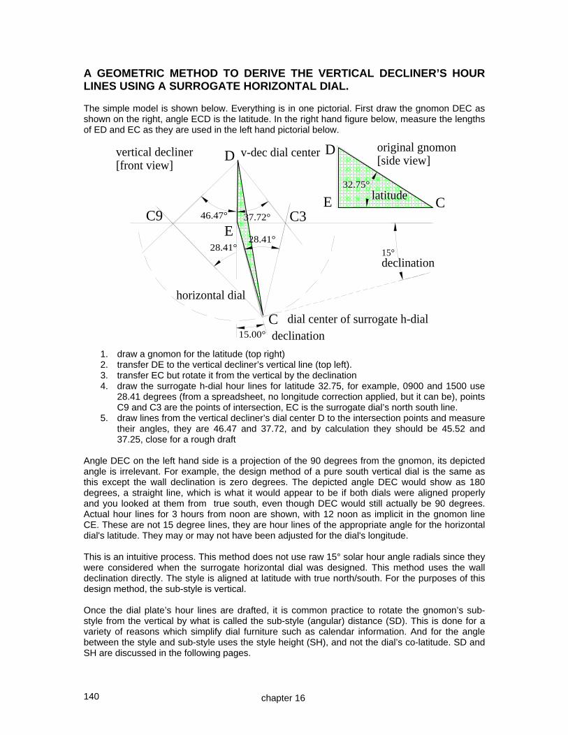
140
A GEOMETRIC METHOD TO DERIVE THE VERTICAL DECLINER’S HOUR LINES USING A SURROGATE HORIZONTAL DIAL. The simple model is shown below. Everything is in one pictorial. First draw the gnomon DEC as shown on the right, angle ECD is the latitude. In the right hand figure below, measure the lengths of ED and EC as they are used in the left hand pictorial below.
1. draw a gnomon for the latitude (top right) 2. transfer DE to the vertical decliner’s vertical line (top left). 3. transfer EC but rotate it from the vertical by the declination 4. draw the surrogate h-dial hour lines for latitude 32.75, for example, 0900 and 1500 use
28.41 degrees (from a spreadsheet, no longitude correction applied, but it can be), points C9 and C3 are the points of intersection, EC is the surrogate dial’s north south line.
5. draw lines from the vertical decliner’s dial center D to the intersection points and measure their angles, they are 46.47 and 37.72, and by calculation they should be 45.52 and 37.25, close for a rough draft
Angle DEC on the left hand side is a projection of the 90 degrees from the gnomon, its depicted angle is irrelevant. For example, the design method of a pure south vertical dial is the same as this except the wall declination is zero degrees. The depicted angle DEC would show as 180 degrees, a straight line, which is what it would appear to be if both dials were aligned properly and you looked at them from true south, even though DEC would still actually be 90 degrees. Actual hour lines for 3 hours from noon are shown, with 12 noon as implicit in the gnomon line CE. These are not 15 degree lines, they are hour lines of the appropriate angle for the horizontal dial's latitude. They may or may not have been adjusted for the dial's longitude. This is an intuitive process. This method does not use raw 15° solar hour angle radials since they were considered when the surrogate horizontal dial was designed. This method uses the wall declination directly. The style is aligned at latitude with true north/south. For the purposes of this design method, the sub-style is vertical. Once the dial plate’s hour lines are drafted, it is common practice to rotate the gnomon’s sub-style from the vertical by what is called the sub-style (angular) distance (SD). This is done for a variety of reasons which simplify dial furniture such as calendar information. And for the angle between the style and sub-style uses the style height (SH), and not the dial’s co-latitude. SD and SH are discussed in the following pages.
chapter 16
D
E C32.75°
E
C
D
latitude
declination15.00°
C9 C337.72°46.47°
vertical decliner[front view]
horizontal dial
v-dec dial center
dial center of surrogate h-dial
28.41°28.41° 15°
original gnomon[side view]
declination

141
A GEOMETRIC METHOD TO ROTATE THE SUB-STYLE BY THE STYLE (ANGULAR) DISTANCE, SD. (Optional for surrogate h-dial method. ) B B BA is style stays Q C C moves BC is sub style A A stays The method shown above develops the sub style's rotation (style distance) from the vertical by moving C to Q. The benefit is simpler dial furniture construction later on. Pictured to the right, draw the gnomon (side view left). Show the top view (right) angled by the declination CBD. This process moves point C to Q so Q is the shortest distance from nodus point A. CQ=XY is the horizontal displacement used, and angle CBQ is the gnomon rotation angle (SD). Our objective is to rotate the gnomon so the sub-style is no longer vertical by placing the nodus the shortest distance from the dial plate (moving point C to point Q), retaining the style's polar alignment, and creating a gnomon with no need for chamfering on the edge BC.
1. draw a normal gnomon, style AB, e.g. latitude 32.75, side view is left side 2. draw the wall's declination as BD, e.g. declination 15, top view is right side 3. mark on BD point Y such that BY = AC, this is the horizontal part of the gnomon that is
neither the style nor sub-style 4. from Y draw a line YX where YX meets BC extended at 90 degrees, this is the linear
horizontal displacement needed. 5. take line XY, the horizontal displacement, back to the original horizontal line of the
gnomon as CQ, not because will alter the nodus to dial pate line, but rather because it, along with the vertical, will form the angle of gnomon rotation, or style distance SD
6. draw a line from B through Q, and this angle is the style angular distance of rotation, SD. Measure it, it shows 21.55 degrees of rotation. The actual result should be 21.92, close for a quick drafting. BQ is in fact the new sub-style.
If you rotate the gnomon which most people do, then you must also derive new angles in place of the latitude and co-latitude, the new angle needed is the style height or SH discussed next.
chapter 16
Q
chamfered sub-style when the sub-style is vertical
no chamfering, the sub-style has been rotated and is no longer vertical
A
B
declination 15˚
latitude 32 75˚
SD becomes

142
A GEOMETRIC METHOD TO FIND THE STYLE HEIGHT (SH), THE ANGLE BETWEEN THE STYLE AND THE SUB-STYLE. This is no longer co-latitude. If you developed the style distance (SD), then this part is mandatory. This style height derivation is part and parcel of rotating the gnomon’s sub style by a distance SD. If you rotate the gnomon’s sub style from the vertical line, by the previously derived angle SD, then you must also adjust the gnomon’s angles such that latitude and co-latitude are no longer used. Consider the figure below:-
Having rotated the gnomon from the vertical, by an amount called the SD, or style distance, the gnomon’s geometry is changed. Latitude and co-latitude used in a normal gnomon no longer apply. In their place a new angle is needed, this is called the style height, an angular measure, abbreviated to SH. Line BQ is now the new sub-style, angle QBC is the style distance or SD.
1. Draw a line from Q whose length is equal to BX to a new point R until it touches the semi-circle, in fact angle BQR will be 90˚ and if not, you made a mistake.
2. Angle QBR is the new style (angular) height, "SH" and is the angle between the style
(polar latitude aligned) and the sub-style (wall attachment). This angle replaces what was previously the co-latitude. This shows 54.27˚, which compares well to a calculated 54.33˚
3. Line BR is the new style, and BQ is the sub-style attached to the wall, offset from vertical
by linear distance QC, giving the previously derived style distance SD, angle QBC. For latitude 32.75, declination 15, the derived SD of 21.55 and SH of 54.27 are very close to the calculated SD of 21.92 and SH of 54.33 That is all there is to the gnomon rotation.
lat 32.75 decl 15SD 21.92 SH 54.33
chapter 16
new rotated gnomon ~ as viewed from above, not used in this part of process
new rotated gnomon
old unrotated gnomon
declination 15˚ SD
SH

143
A GEOMETRIC METHOD OF USING AN EQUATORIAL DIAL 15˚ RADIALS TO DEVELOP THE VERTICAL DECLINER’S HOUR LINES. This technique requires a gnomon rotated by SD and with SH in place of co-latitude. Drawing the hour lines is as follows. First, BN is the part of the gnomon, sub-style, attached to the vertical yet declining wall. Angle NBZ is the style angular height, termed style height or "SH". MBN is the style angular distance termed style distance or "SD". Here, height and distance are angular, whereas in some other cases they may sometimes be linear. SH B SD Z noon SH = Style Height = NBZ N M BZ = style BN = sub-style K J noon SD = Style distance = NBM 15° S F 1. Having established the rotated gnomon NBZ, draw a line from N (an equinox ray of light),
towards BZ, intercepting it at 90˚ at place E. So, BE is a style. 2. Draw a line ZNF perpendicular to line BN, BN is the extension of the sub-style. This new
line ZNF is the equinox line if one is desired. 3. From N take the line NE and rotate the point E around N to intercept the extension on BN
at point J. 4. Draw a circle meeting the line ZNF at point N, whose radius is JN which is equal to EN.
This is an equatorial dial. 5. Draw a line from the circle's center to meet the noon vertical line (BM extended to K), this
is the line JK. Line JK is the base line for noon on the circle or equatorial dial. You may now adjust JK for longitude correction if so desired.
6. Draw 15 degree lines on either side of JK, these being 11 am and 1 pm hour points when extended to meet line ZNF, which in turn provide the hour lines when connected to the dial center "B".
7. The 1pm line is shown. Noon line on the circle is JK, thus 15 degrees forward is JS, and the line SB is the hour line for 1pm for the vertical decliner. Other hour lines are found similarly.
The above wall is declining east which is why the gnomon is set to the west part of the dial. The hour line angles may be checked with a table or spreadsheet and they will be found to match closely.
chapter 16
E
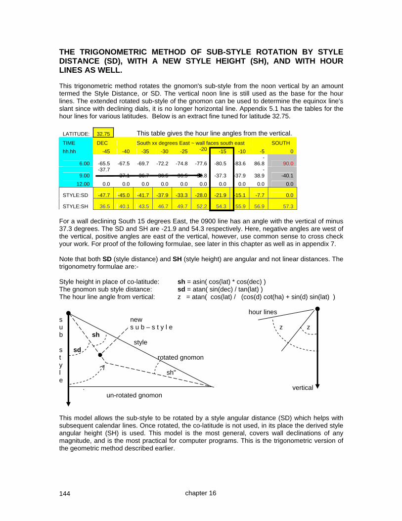
144
THE TRIGONOMETRIC METHOD OF SUB-STYLE ROTATION BY STYLE DISTANCE (SD), WITH A NEW STYLE HEIGHT (SH), AND WITH HOUR LINES AS WELL. This trigonometric method rotates the gnomon's sub-style from the noon vertical by an amount termed the Style Distance, or SD. The vertical noon line is still used as the base for the hour lines. The extended rotated sub-style of the gnomon can be used to determine the equinox line's slant since with declining dials, it is no longer horizontal line. Appendix 5.1 has the tables for the hour lines for various latitudes. Below is an extract fine tuned for latitude 32.75.
LATITUDE: 32.75 This table gives the hour line angles from the vertical.
TIME DEC South xx degrees East ~ wall faces south east SOUTH
hh.hh -45 -40 -35 -30 -25 -20 -15 -10 -5 0
6.00 -65.5 -67.5 -69.7 -72.2 -74.8 -77.6 -80.5 -83.6 -
86.8 90.0
9.00 -37.7
-37.1 -36.7 -36.5 -36.5 -36.8 -37.3 -37.9 -
38.9 -40.1
12.00 0.0 0.0 0.0 0.0 0.0 0.0 0.0 0.0 0.0 0.0
STYLE:SD -47.7 -45.0 -41.7 -37.9 -33.3 -28.0 -21.9 -15.1 -7.7 0.0
STYLE:SH 36.5 40.1 43.5 46.7 49.7 52.2 54.3 55.9 56.9 57.3
For a wall declining South 15 degrees East, the 0900 line has an angle with the vertical of minus 37.3 degrees. The SD and SH are -21.9 and 54.3 respectively. Here, negative angles are west of the vertical, positive angles are east of the vertical, however, use common sense to cross check your work. For proof of the following formulae, see later in this chapter as well as in appendix 7. Note that both SD (style distance) and SH (style height) are angular and not linear distances. The trigonometry formulae are:- Style height in place of co-latitude: sh = asin( cos(lat) * cos(dec) ) The gnomon sub style distance: sd = atan( sin(dec) / tan(lat) ) The hour line angle from vertical: z = atan( cos(lat) / (cos(d) cot(ha) + sin(d) sin(lat) ) hour lines s new u s u b – s t y l e z z b sh style s sd t rotated gnomon y l sh" e . vertical un-rotated gnomon This model allows the sub-style to be rotated by a style angular distance (SD) which helps with subsequent calendar lines. Once rotated, the co-latitude is not used, in its place the derived style angular height (SH) is used. This model is the most general, covers wall declinations of any magnitude, and is the most practical for computer programs. This is the trigonometric version of the geometric method described earlier.
chapter 16

145
PROOF OF DECLINER/GREAT DECLINER SD & SH ANGLE (Tables A5.1, A5.2) In the proof and pictorial that follows, please note where the right angle is. Also, in the math that follows, "dec" (wall declination) is the normally defined wall declination using the SxxxW terminology. T TCB is a vertical SD gnomon whose SH style is latitude N E and north/south. lat Q TQB is a rotated dec gnomon whose B style is latitude C dec and north/south. W S [SD] tan (SD) = CQ / TC Style Distance thus SD = style distance = atan (CQ / TC) and tan (lat) = TC / CB thus TC = CB * tan (lat) and sin (dec) = CQ / CB thus CQ = CB * sin (dec) and given SD = style distance = atan (CQ / TC) then SD = atan ( CB * sin(dec) / CB * tan (lat) ) so SD = atan ( sin(dec) / tan(lat) ) (formula A.22) [SH] sin (SH) = QB / TB Style Height thus SH = style height = asin ( QB / TB ) and cos (lat) = CB / TB thus TB = CB / cos(lat) and cos (dec) = QB / CB thus QB = CB * cos (dec) and given SH = style height = asin ( QB / TB ) then SH = asin ( CB * cos (dec) / (CB / cos(lat)) ) so SH = asin ( cos (dec) * cos(lat) ) (formula A.23) NOTE: The above is the Illustrating Shadows derivation of the hour angle and SD and SH for a vertical decliner. This formula differs from the more common formula on the next page which summarizes the vertical decliner techniques, however the results are the same.
chapter 16

146
PROOF OF ONE FORMULA FOR DECLINING DIAL HOUR LINE ANGLES In the stylized figure to the right below, the triangle "h-dial" has sides "b", and "c" and angle "h". Side "b" is the horizontal dial's sub-style and a selected horizontal dial's hour line angle "h". Triangle "v-dec dial" has two named sides, with angle "n" being the vertical decliner's equivalent hour line angle that is associated with the horizontal dial's angle "h". Both dials share a style that connects the h-dial and v-dec dial centers, shown by a depicted dashed line. The vertical decliner's sub-style is not depicted in the figures below, and their "SD" and "SH" (style angular distance and angular height) are derived elsewhere. Declination is "d" and "Ø" is latitude.
a = b * tan (Ø) [ 1 ] tan(n) = e / a thus ... n = atan ( e / a ) [ 2 ] desired so n = atan ( e / b * tan (Ø) ) [ 3 ] e / sin( h ) = b / sin ( 180 – ( h + ( 90 + d ) ) ) [ 4 ] law of sines so e / sin( h ) = b / sin ( 90 – h – d ) thus e = b * sin ( h ) / sin ( 90 – h – d ) [ 5 ] n = atan ( e / a ) = atan b * sin ( h ) / sin ( 90 – h – d ) b * tan ( Ø ) [ using 2, 5, 1 ] so n = atan b * sin (h) sin ( 90 – h – d ) * b * tan ( Ø ) sin ( h ) thus n = atan sin( 90 – h – d ) * tan ( Ø ) [ 6 ]
chapter 16
(stylized)

147
and using h = atan (sin ( Ø ) * tan (sun hour angle)) [ for h-dial ] and since from the prior page n = atan ( sin ( h ) / tan ( Ø ) * sin( 90 – h – d ) ) [ from 6 ] then using the sun's hour angle as opposed to a surrogate horizontal dial's hour line angles then sin( atan( sin ( Ø ) * tan (sun hour angle) ) ) n = atan tan ( Ø ) * sin( 90 – d – atan (sin ( Ø ) * tan (sun hour angle) ) ) [ 7 ] Hence, considering a spreadsheet or a procedural program implementation of a vertical dial that declines, it has hour line angles "n" equal to:- i.e. n = DEGREES(ATAN( SIN(RADIANS((DEGREES(ATAN( TAN (RADIANS(15*(12-hr)+d.long))*SIN(RADIANS(lat)) ))))) / (TAN(RADIANS(lat))*SIN(RADIANS(90-dec- (DEGREES(ATAN( TAN(RADIANS(15*(12-hr)+d.long))*SIN(RADIANS(lat)) )))))) )) where the hour itself, and longitude corrections are all considered. The results match the formula usually published which is:- n = atan ( cos( Ø ) / (cos(dec) cot(ha) + sin(dec) sin( Ø ) ) The Illustrating Shadows formula derived above is used in one of the vertical decliner sheets in:- illustratingShadows.xls and the standard common formula is also used in another vertical decliner sheet. The index of sheets as well as the individual sheets themselves clearly state which formula is used.
chapter 16

148
PROOF OF DECLINER/GREAT DECLINER DL ANGLE (Tables A5.1, A5.2, A5.3) DL has not been discussed until now, and this is somewhat jumping ahead, and is not used in this chapter. It is included here for subsequent completeness. The preceding pages developed SD and SH for a vertical decliner. In this context, SD is the angle from the gnomon base to local noon, and relates to “DL” which is an equivalent difference in longitude that would generate a dial plate shift, as discussed in chapter 25. SD is in essence the place where a surrogate horizontal dial’s local noon line would be aligned. And as such is an offset for that surrogate horizontal dial’s hour lines so that the hour lines of the surrogate horizontal dial would match those of the vertical decliner. Along with that procedure comes the correct alignment of declination or calendar curves, and also the analemma, this is discussed in chapter 25. Given that for a vertical decliner:- SD = atan ( sin(dec) / tan(lat) ) (formula A.22) and SH = asin ( cos (dec) * cos(lat) ) (formula A.23) where SH is the latitude for a surrogate horizontal dial, and SD is an angle between the surrogate horizontal dial’s local noon and the desired noon placement. The surrogate horizontal dials hour lines are thus: shdhr = atan ( sin(SH) * tan (hour angle) ) and for local noon on the vertical decliner, which is some unknown hour on the surrogate horizontal dial:- SD = atan ( sin(SH) * tan (hour angle) ) substituting SD we get:- atan ( sin(dec) / tan(lat) ) = atan ( sin(SH) * tan (shd hr angle) ) thus we can remove atan on both sides, thus:- sin(dec) / tan(lat) = sin(SH) * tan (shd hr angle) substituting SH we get:- sin(dec) / tan(lat) = sin( asin ( cos (dec) * cos(lat) ) ) * tan (shd hr angle) thus:- tan (shd hr angle) = sin(dec) / tan(lat) sin( asin ( cos (dec) * cos(lat) ) ) = sin(dec) sin( asin ( cos (dec) * cos(lat) ) ) * tan(lat) thus: shd hr angle = atan sin(dec) sin( asin ( cos (dec) * cos(lat) ) ) * tan(lat)
chapter 16

149
given:- shd hr angle = atan sin(dec) sin( asin ( cos (dec) * cos(lat) ) ) * tan(lat) and that the hour angle (shd hr angle ) is equal to the difference in longitude that would cause this surrogate horizontal dial to displace the local noon so it would match the original vertical decliner’s local noon. In other words, one hour (15 degrees) of hour angle is also the same as 15 degrees of longitude difference:- DL = atan sin(dec) sin( asin ( cos (dec) * cos(lat) ) ) * tan(lat) DL = atan sin(dec) cos (dec) * cos(lat) * tan(lat) DL = atan tan(dec) / ( cos(lat) * tan(lat) ) but since sin / cos = tan then tan(lat) = sin(lat) / cos(lat) thus cos(lat) * tan(lat) = cos(lat) * sin(lat) / cos(lat) = sin(lat) so DL = atan ( tan(dec) / sin(lat) ) Vertical decliner equinox line SD of vertical decliner local noon of vertical decliner local noon of surrogate horizontal dial NOTE: The above formula “DL” will ensure that local noon on a surrogate dial will be overlay local noon on the vertical decliner. If legal noon is desired, then the vertical decliner and the surrogate horizontal dial must consider dial longitude, so, the dial longitude difference from the legal meridian would be considered in both cases, as discussed in chapter 25. NOTE: The DeltaCAD macro that draws analemmas for a dial has a limited range of analemmas, so if that DeltaCAD macro is used, you should reduce the absolute value of DL so that DL is: 15 < DL > – 15 and this is only to ensure the DeltaCAD produced analemmas are usable, and for no other purpose. In other words it manages a weakness in our DeltaCAD analemma macro. Again, this is discussed in chapter 25.
chapter 16
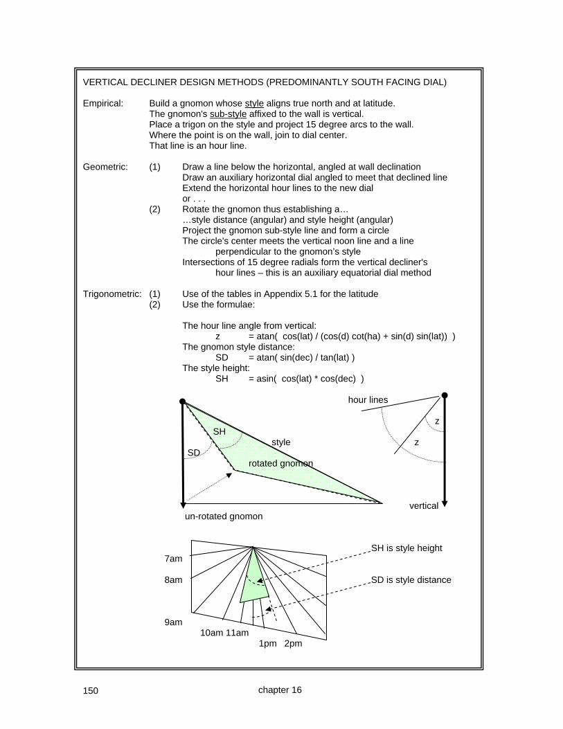
150
VERTICAL DECLINER DESIGN METHODS (PREDOMINANTLY SOUTH FACING DIAL) Empirical: Build a gnomon whose style aligns true north and at latitude. The gnomon's sub-style affixed to the wall is vertical. Place a trigon on the style and project 15 degree arcs to the wall. Where the point is on the wall, join to dial center. That line is an hour line. Geometric: (1) Draw a line below the horizontal, angled at wall declination Draw an auxiliary horizontal dial angled to meet that declined line Extend the horizontal hour lines to the new dial or . . . (2) Rotate the gnomon thus establishing a… …style distance (angular) and style height (angular) Project the gnomon sub-style line and form a circle The circle's center meets the vertical noon line and a line perpendicular to the gnomon’s style Intersections of 15 degree radials form the vertical decliner's hour lines – this is an auxiliary equatorial dial method Trigonometric: (1) Use of the tables in Appendix 5.1 for the latitude (2) Use the formulae: The hour line angle from vertical: z = atan( cos(lat) / (cos(d) cot(ha) + sin(d) sin(lat)) ) The gnomon style distance: SD = atan( sin(dec) / tan(lat) ) The style height: SH = asin( cos(lat) * cos(dec) ) hour lines z SH style z SD rotated gnomon vertical un-rotated gnomon SH is style height 7am 8am SD is style distance 9am 10am 11am 1pm 2pm
chapter 16

151
CASE STUDY ~ A SOUTH DECLINING WEST VERTICAL DIAL A predominantly south facing wall was in need of a vertical dial so that the passers by could determine the time. The dial location was 32.75° north, and west 108.2° with a legal time meridian of 105°. The first objective was to determine the wall's declination, and three methods were selected. Astro-compass determination of wall declination The process is simple, the sun's hour angle assuming 15° per hour was calculated for the time of observation. Then the longitude correction plus the EOT set to degrees (EOT divided by four) was subtracted from that sun's hour angle. This is the opposite of the correction made when reading a sundial. The astro-compass was set, and placed on a plane such as a wooden plank. The astro-compass was rotated until the shadow was centered. The angle of the astro-compass axis was projected onto the wood, I used a projection of the leveling mechanism. The angle that the projected line made with the wooden plank's edge paralleling the wall determined the wall declination. In practice the illustratingShadows.xls spreadsheet or the table A2.2a in the appendices simplifies this process. For the wall in question several readings showed a wall declination of S 5°W. Chapter 6 expands on this method of true north determination.
Magnetic compass determination of wall declination The magnetic compass was placed on a plane such as a wooden plank, in this case some concrete pavers were used since they were there. The compass was set to project a perpendicular line to the wall being measured. The compass needle showed about 355 degrees. The dial location had a magnetic declination (variation to navigators and pilots) of 10.2 degrees easterly. Thus the true bearing of the wall's perpendicular was 365 or 005 degrees. The reciprocal bearing of 005° is 185°. Thus the wall declined S 5° W. An earlier chapter expands on this method of true north determination. This agreed with the astro-compass method.
355
chapter 16

152
Measured versus calculated azimuth method
The illustratingShadows.xls spreadsheet allows a time in hours and minutes to be entered together with a nodus shadow x and y coordinates. The "x" coordinate is used to derive the detected azimuth. If desired, the "y" value is used for a graphical display of the shadow tip as a double check. Chapter 6 expands on this method of true north determination. This method showed a little under 5°, which was in general agreement with both the astro-compass method as well as the magnetic compass process.
Points to consider when determining wall declination Chapter 6 provides some insights on matters that can cause confusion when determining wall declination. In essence, it is good practice to make calculations before hand, develop a script, and follow it. It is possible to confuse the sense of a wall declination if care is not taken to ensure magnetic declination is understood. The final decision was made to assume a South 5° West wall declination. The next step was to determine the hour line angles and the SD (style distance) and SH (style height). The illustratingShadows.xls spreadsheet does this, so do various programs on this book's web site. Programs on the web site cover DeltaCAD, C, FORTRAN, Pascal, Visual Basic, Basic, and java. And all of them have free compilers available which the website directs you to, except for DeltaCAD. In this case a DeltaCAD macro was used.
chapter 16

153
To the right is shown the DeltaCAD depiction using the vertical decliner macro. The hour lines are shown as well as SD and SH. The next step was to make a mockup dial, and affix it to the proposed wall, and test it.
The dial tested correctly. This test is a wise idea because it is somewhat disheartening to build a dial and find out that there was an "opportunity for improvement" after hours of dial plate construction.
Next, a DeltaCAD macro was used to draw the calendar curves. This program is nothing more than the horizontal dial with calendar curves, except it is tailored just to calendar information. The "latitude" is replaced with the style height (SH). There is no longitude correction. And the style height is taken from the first dial plate. The drawing has some hour lines which are meaningless, except they can be used with their intersection points on calendar curves, to transcribe those points to the final dial. Here the "noon" line of those calendar lines is aligned with the style distance (SD) or the regular dial plate, as seen on the next page.
chapter 16

154
Then, the real dial plate is transcribed to a final sheet of paper, and the calendar depiction is rotated so that its noon line matches the style distance of the first plate, and that information transposed also.
SD on the actual dial plate
"noon" on the calendar curve depiction.
The hour lines on the calendar plate are meaningless as far as hour lines go. However, they are very useful in transcribing as well as rescaling the calendar curves. When transcribing those curves, remember that the "hour lines" on the calendar depiction do not match hour lines on the actual dial plate. Note that the nodus location is critical and specific to the depicted calendar curves. The gnomon (style) may be of a different size provided the nodus is marked with a notch or other means of depicting the nodus shadow on a calendar line. The main thrust of this web site and these books is educational, the focus is on showing the "how" of dial design. If you desire a more turnkey operation, consider using SHADOWS (which while not affiliated with this web site and series of books) which provides an excellent depiction of final dial plates.
gnomon to scale for the calendar lines
chapter 16
NOTE: The two dials are merged at their dial centers, and aligned on SD. [ Compare to the subsequent S85E dial where there is no accessible dial center, thus SD and SH are used for those dial alignments instead. ]

155
The end result is a paper sheet the size of the final dial plate. This will be used to make impressions upon the soft clay. This dial plate will fit in a surround of miscellaneous pieces of clay that were fired but for one reason or another never used.
A slab of clay was cut from supplies and rolled. This dial plate area measured 11 inches vertically, and 15 inches horizontally.
The upper half of the dial plate has a diagonal cut along the style distance. The lower half has the diagonal cut along the noon line. Then some extra pieces were cut so they would look nice while fitting with kiln firing dimensions. The equinox line, hour lines, and Italian lines will, along with their lettering, be made with a slip or an under-glaze.
For aesthetics, a strip and a crown would be added.
chapter 16

156
The Italian lines were drafted based on two data points, which is conventional. One data point was that sunset happens on the equinoxes at 6 pm local apparent time (L.A.T.), and that the solstice times may be found in the appendices. This dial plate was longitude corrected, the dial being at longitude 108.2W and the legal time meridian being at 105W, the difference was 3.2 degrees or 12 minutes 48 seconds. Since the dial plate was longitude corrected, the sunset times should also be longitude corrected. Thus the equinox sunset time would be 6:12 pm. And the winter solstice time of 5:57 pm would become 5:09 pm. Fro these two times the sunset line is drafted, and those times backed off by an hour form the 1 hour before sunset time Italian hour line. And so on for the other hours. The bisque or slip firing was done at around 1800°f. After the glaze firing which was over 2000°f, but less than cone 6, the assembly was placed on foam board with foam board adhesive and the same adhesive used to fix the board to the wall. Stucco was then applied.
It just didn't look right however, this was because the foam board was offset out from the wall. The solution was to distract the eye. So a vine was painted as a surround, this added cohesion to the objects on the wall, and removed the effect of the foam board pushing out those tiles from the wall.
chapter 16

157
THE SAME VERTICAL DECLINER BUT NORTH FACING ~ S 175°E or N5°E The north side of the same building can be used for a vertical dial, useful during the summer months. In the northern hemisphere the EOT for a pure north dial would be in the range of +/– 7 minutes. The relationship of the S 5° W and N 5° E vertical decliners is shown below. VERTICAL DECLINERS Gnomon points up, hour lines radiate from bottom POLE FACING N 5 E gnomon hours clockwise in northern hemisphere northern hemisphere note that the final VERTICAL DECLINERS hours are counter SD is of an opposite SOUTH FACING clockwise sign S 5 W gnomon Gnomon points down, hour lines radiate from top A variation of the vertical declining DeltaCAD program was used, this dial declines S 175° E or N 5° E, the latitude and longitude being the same.
The program modifications removed animation, modified the prompts and defaults, added showing hour line angles from horizontal, rotated the dial plate 180 degrees to force the gnomon to the top, the sign of SD was changed, and a few other trivia. This modified program simplifies dial plate orientation and construction, however, the normal vertical decliner methods can be used with minor human manipulation.
chapter 16

158
The angles of the hour lines to the horizontal were measured using DeltaCAD's measurement tool showing how they match the displayed hour line angle data. Those angles also match other available software popular with diallists, such as SHADOWS and ZW2000.
To the left is shown a CAD vertical dial with the equator facing plate on the lower half, the pole facing plate on the upper. This shows how the SD is deflected to the right (for this wall's declination) for both plates when viewed looking at the plate from the sun's side and how noon or midnight hour line is deflected to the left (for this longitude) for both plates when viewed looking at the plate from the sun's side. The plate was tested in the morning and afternoon hours and was correct. Then the print out was placed on a slab of clay, and lines traced into the clay with a blunt pencil. The plate was fired as before.
57° 57°
chapter 16
The earliest and latest hours would be sunrise and set, see the appendices. The latest morning and earliest afternoon hours would be when the azimuth at the summer solstice crosses the east west line, tables A4.2 book 1. For latitude 32 that would be 0500 to 0900 mst and 1500 to 1900 mst. Although daylight savings time might be better choice, the author has a bias towards standard time. Wall declination and shading of course affect the useful hours displayed. To the right is “The Skink Dial”, between a lizard and a snake, showing 4pm winter time being of course 5pm daylight saving time, a north vertical declining dial.

159
CHAPTER SEVENTEEN
Vertical great decliners, face mostly east or west great decliners are ones who declination angle is large
and frequently have a dial center that is not easily available
This chapter covers the following topics: The great decliner What they are The gnomon design process The hour lines
The great decliner is the vertical dial more closely aligned true east or west than south. Rather than calculate just where else on the planet this dials might exist as a true cardinal dial, or be truly vertical or horizontal, a method is shown of calculating just how to design the gnomon and the hour lines. As the wall declination approaches a direct east or direct west facing, an auxiliary horizontal dial becomes less and less practical for designing the dial, and an auxiliary equatorial dial becomes more and more practical for constructing hour lines. The dial center moves away, far away, and special techniques are needed to calculate the hour lines to be placed on the dial plate.
The extreme case is when the dial is true east or true west, and that uses exactly the same methods as the polar dial, namely an auxiliary equatorial dial. The great decliner uses exactly the same techniques as the normal vertical decliner in so far as the gnomon angles go, namely style distance (from vertical) and style height (style to sub-style). However the dial center itself may be miles away from the actual dial, infinity miles if the dial plate faces true east or true west. Thus the only new technique needed is how to project those hour lines and the gnomon from that far away place, the dial center.
NOTE: Vertical declining dials are usually designed using geometry or trigonometry, the empirical method is sometimes used. Sundial programs are of course based on trigonometry.
chapter 17

160
GREAT DECLINERS ~ dial center often not accessible What if the walls declination is excessive, an obvious case would be the meridian dial, namely an oriental or occidental dial facing true east or true west that is off by just a little bit. Celestial pole true north wall orientation wall is off a bit latitude gnomon gnomon Wall viewed from side Wall viewed from above The method of using an auxiliary horizontal dial becomes impractical. One method is to build a dial for true east or west and use a wedge to align it with true north. Another method is to build the style, then use a trigon and empirical methods to complete the task. The style installation requires alignment on the wall, at a slope that is less than or equal to the latitude. In the figure below are shown two gnomons. The upper one is aligned with true north and with latitude. The lower one is a projection, and would be the same gnomon were this dial on the equator. As the angle of latitude increases, the various angles with the wall vary proportionally. Simply put, a style's angle when fabricated with a wall is not the same as the wall's declination. It depends on the wall's declination as well as the latitude. Similarly with its slope. We must be very specific about the wall’s declination angle when we construct formulas. The walls below are N 0° W, N 0° E, and N 85 W, and also N 30 W, S 60 W, N 60 E, and S 30 E. The declination is named for the direction we face with our back to the wall. N 85° W N 30° W N 60°E N 0° W N 0° E S 60° W S 30°E
wall N85°W
true north
However, when developing our own formulas from first principles, it may be more expedient to use the 15° rather than the 85° angle, not because of the size, but because that angle may simplify the math in the formulae, and thus reduce the chances of errors.
chapter 17

161
TRIGONOMETRIC OR TABULAR CONSIDERATIONS The tables in appendix A5.2 use exactly the same formulae as in appendix A5.1, the sole difference is that their declination angles are greater than 45 degrees. Some rules of thumb are:- VERTICAL DECLINERS NORTH FACING Gnomon points up, hour lines radiate from bottom gnomon gnomon N 45 W hours N 45 E clockwise in northern hemisphere VERTICAL DECLINERS SOUTH FACING northern hemisphere hours are counter S 45 W clockwise S 45 E gnomon gnomon Gnomon points down, hour lines radiate from top
South 86 degrees east so hour lines diverge from the top the style needs adjustment as its shadow is not quite paralleling the hour lines North 86 degrees west or S94˚W so hour lines diverge from the bottom
A design for South xx degrees East provides figures usable for the other three quadrants. The afternoon NxxW uses SxxE pm hours, and the morning NxxE uses SxxW am hours. If longitude correction is applied, care must be applied as hour lines shift. The North facing decliner gnomons are inverted, and the vertical is midnight. Also hours are clockwise when north declining, whereas they are anti clockwise when south declining. Normal vertical decliner methods, formulae and tables are usable with no change, merely larger angles are used, hence why table A5.2 exists which is otherwise exactly the same as A5.1 The sole complication with a great decliner is that the dial center may literally be miles away from the actual dial plate. Since a dial of such size would increase a person's property taxes, there needs to be a simple way of constructing only a part, a useful part of a vertical great decliner. The great decliner design can be truly mathematical or geometric, using the methods or formulae of the normal vertical decliner.
equator pole
chapter 17
S 86˚ E N 86˚ W

162
THE GREAT DECLINER WHOSE DIAL CENTER IS NOT ACCESSIBLE THE GENERAL, CORRECT, AND ACCURATE METHOD. The process in overview is straight forward, merely more time consuming than previous dials. The other factor in the design of a great decliner is that human judgment is needed in order to select the dial plate dimensions, this judgment cannot easily be made into a specific procedure. 1. Define the latitude and the wall's declination. 2. Use tables in Appendix 5, such as 5.1 or 5.2 (or formula A8.21 to A8.24) and develop a. the hour line angles b. the style distance (the angle the sub-style is rotated from the vertical noon hour, just as with a declining dial) c. the style height (the angle between the style and sub-style (part affixed to the wall or surface just as with any declining dial) 3. Draft a dial such as in the lower figure on the next page 4. Determine where in that larger picture the final dial plate will be You may find that a spreadsheet can simplify the repetitive work of deriving hour line coordinates. 5. Determine the endpoints on the final dial plate of the gnomon's sub-style. This uses very simple trigonometry. 6. Using Pythagoras's theorem as well as trigonometry, determine the dimensions of the gnomon that sticks out of the wall, Pythagoras provides the direct distance from the unreachable dial center, although trigonometry could have been used. And knowing that distance from dial center, trigonometry can be used to find the two distances separating the style from the sub-style. 7. Determine the endpoints of each hour line, just as you did for the gnomon in step 5, this uses very simple trigonometry. This can be done before step 5 if desired. NOTE: Pythagoras's Theorem, contrary to the scarecrow's words in the Wizard of Oz, states that for a right angled triangle the square of the hypotenuse is equal to the sum of the squares of the two remaining sides. hypotenuse 3 units 4 units In the above, hypotenuse squared = 3 squared plus 4 squared, or 9 plus 16, or 25, thus the hypotenuse itself is the square root of that 25, in other words 5. The scarecrow got it wrong, he said it was an isosceles triangle, useful trivia (Wizard of OZ). The following values are derived using standard vertical decliner methods of chapter 16. The appendix tables A5.1 can be used for wall declinations of about 45 degrees, and tables A5.2 can be used for wall declinations of more than 45 degrees, ones that approach true east or true west.
chapter 17

163
STEP 1: For example, a south 85 degrees west wall, latitude 32 degrees north, derive figures.
LATITUDE: 32 hour line angles from the vertical.
TIME PURE S TIME
hh.hh 0 45 85
12.00 0.0 0.0 0.0 12.00
13.00 12.8 15.7 44.8 13.00
14.00 26.1 27.9 51.3 14.00
15.00 40.3 38.1 54.0 15.00
16.00 55.8 47.3 55.7 16.00
17.00 72.5 56.4 57.0 17.00
18.00 90.0 66.2 58.1 18.00
STYLE:SD 0.0 48.5 57.9 SD
STYLE:SH 58.0 36.8 4.2 SH
STEP 2: All needed information is provided. Since the wall faces mostly west, the am hours were dropped. On a large piece of paper, or using a CAD program, draw the gnomon and hours lines. STEP 3: Near the dial center the hour lines are very bunched up, and the gnomon would be very long if we built the entire complete dial. However, if just a part of the dial were selected, then all would be well with the world. This is where a paper or CAD drawing helps out. Visually select a section of the dial that you believe would be usable. STEP 4: Here is a visually selected area that we will work with for the final dial.
chapter 17

164
From the dial center, we selected an area about 8 units to the right of, and about 5.5 units below the dial center. Each hour line, and the gnomon sub-style also, can be defined as two points. So, for each line, all we need is those two points. STEP 5: THE GNOMON COORDINATES The gnomon's sub-style is at an angle SD (style distance) of 57.9 degrees from the vertical. Looking at the chart, about 9 units to the right of dial center. DIAL x = horizontal CENTER angle 57.9 y = vertical 57.9 x=12, y=5.5 x=8, y=5.5 57.9 tan (angle) = horiz / vert vert = horiz / tan (angle) horiz = vert * tan(angle) x=8, y=10 x=12, y=10 Assume the gnomon's sub-style begins say 9 units horizontally from the dial center (1 unit from our selected dial plate area), an arbitrary starting point, the vertical distance for the gnomon's sub-style, for the first point will be:- vert = 9 / tan( 57.9 ) = 5.65 coordinate thus = horiz=9 vert=5.65 as the top left dial plate coordinates are horiz=8 and vert=5.5, the relative position of the first gnomon sub-style coordinate is found by subtracting 8 and 5.5 respectively, thus:- 1 unit right from the top left (the 9 units minus 8 units) 0.15 units down from the top left (the 5.65 units minus the 5.5 units) Similarly we select the lower right part of our gnomon's sub-style. Taking a horizontal value of, say, 10.5 units, the vertical drop would be: 10.5 / tan(57.9) or 6.59 units down. Thus the relative position from the top left of our selected dial plate area is thus found by subtracting "8, 5.5", giving:- 2.5 units right from the top left (the 10.5 units minus 8 units) 1.09 units down from the top left (the 6.59 minus 5.5 units) Hence the sub-style can be drawn. And the style will protrude from that sub-style making an angle with the wall of SH (style height), namely 4.21 degrees. It will be then pointing true north and parallel to the Earth's polar axis. However, the rest of the linear dimensions of the gnomon are still needed. The above figures match closely the figures on the spreadsheet in a couple of pages that can aid the dialist. Remember, different calculators and spreadsheets may produce slightly different figures due to rounding and other approximations.
note: the x and y box dimensions are not drawn to scale.
chapter 17
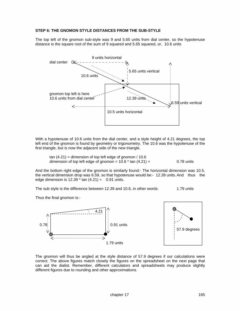
165
STEP 6: THE GNOMON STYLE DISTANCES FROM THE SUB-STYLE The top left of the gnomon sub-style was 9 and 5.65 units from dial center, so the hypotenuse distance is the square root of the sum of 9 squared and 5.65 squared, or, 10.6 units 9 units horizontal dial center 5.65 units vertical 10.6 units gnomon top left is here 10.6 units from dial center 12.39 units 6.59 units vertical 10.5 units horizontal With a hypotenuse of 10.6 units from the dial center, and a style height of 4.21 degrees, the top left end of the gnomon is found by geometry or trigonometry. The 10.6 was the hypotenuse of the first triangle, but is now the adjacent side of the new triangle. tan (4.21) = dimension of top left edge of gnomon / 10.6 dimension of top left edge of gnomon = 10.6 * tan (4.21) = 0.78 units And the bottom right edge of the gnomon is similarly found:- The horizontal dimension was 10.5, the vertical dimension drop was 6.59, so that hypotenuse would be:- 12.39 units. And thus the edge dimension is 12.39 * tan (4.21) = 0.91 units. The sub style is the difference between 12.39 and 10.6, in other words: 1.79 units Thus the final gnomon is:- 4.21 0.78 0.91 units 57.9 degrees 1.79 units The gnomon will thus be angled at the style distance of 57.9 degrees if our calculations were correct. The above figures match closely the figures on the spreadsheet on the next page that can aid the dialist. Remember, different calculators and spreadsheets may produce slightly different figures due to rounding and other approximations.
chapter 17

166
STEP 7: THE HOUR LINE COORDINATES Each hour line is similarly found by selecting two points, and connecting those points. In fact, a simple spreadsheet can be made that looks at the points for each hour line and the gnomon:-
TOP LEFT of final horizontal 8 BOTTOM RIGHT of 12 Lat 32
dial plate is: vertical 5.5 final dial plate is: 10 Dec 85
HOUR LINE AND GNOMON SUB-STYLE ANGLE: DERIVED FIGURES
HOUR LINE TIME PM or Relative x Absolute x Absolute down Relative Down
ANGLE sub-style SD start end start end start end start end
57.9 SD 1 2.5 9 10.5 5.65 6.59 0.15 1.09
44.8 13.00 0 2 8 10 8.05 10.06 2.55 4.56
51.3 14.00 0 2 8 10 6.40 8.00 0.90 2.50
54.0 15.00 0 3 8 11 5.80 7.98 0.30 2.48
55.7 16.00 1 3 9 11 6.14 7.50 0.64 2.00
57.0 17.00 1 4 9 12 5.85 7.80 0.35 2.30
58.1 18.00 1 5 9 13 5.60 8.09 0.10 2.59
SH 4.2 Adjust relative horizontal start and end to get positive relative-down figures
GNOMON DISTANCES BETWEEN THE STYLE AND SUB-STYLE
SUB STYLE LENGTH: 1.77
top left end top left end distance bottom right end top left end distance
radial distance between style radial distance between style
from dial center and sub-style from dial center and sub-style
10.62 0.79 12.39 0.92
EQUINOX LINE ANGLE: 32.1 from the vertical 57.9 from horizontal
This spread sheet was built by entering the horizontal coordinates of the selected final dial plate on the wall, and entering the hour line angles and their associated times from the great decliner tables, and the "down units" formula was simple trigonometry (using tan hour or gnomon SD angle), or Pythagoras's Theorem (for radial distance from the far away dial center). To avoid negative vertical or down figures, the spread sheet lets you displace a horizontal position, such as for the 3, 4, and 5pm lines. The gnomon sub-style was also displaced. An east facing great decliner can use this spreadsheet, however you pretend you are using a mirror. This 7-step technique is the most general, and works for all cases of great decliners. If the dial is North declining east or west, then the vertical line is not noon, but midnight, and the gnomon points upwards not downwards. Remember, different calculators and spreadsheets may produce slightly different figures due to rounding and other approximations. The spreadsheet is available on the web site in the reference page.
chapter 17

167
COOK BOOK SUMMARY GREAT DECLINER – SOMEWHAT EAST OR WEST DIAL Determine the latitude and the wall's declination. The latitude established the gnomon's style angle with the horizontal, the wall's declination affects the sub-style angle with the wall as well as with the horizontal. If the wall's declination is trivial, and if you are not feeling energetic, then you may empirically design the dial beginning with the gnomon first. If the wall's declination is still mostly easterly or westerly, then the formula or tables for a normal vertical decliner are used. They are in appendix A5.2 for large angles such as these, and use exactly the same formula as in A5.1, the sole difference being the wall's declination angle. Calculate two points for each hour line and for the gnomon, based on the final dial plate's distance from the far far away dial center. Connect the dots for each hour line and thus draw the final hour lines. If calendar lines will be used then obviously the hour lines extend from the solstices with the equinox calendar line in between. You may find that a spreadsheet can simplify the repetitive work of deriving hour line coordinates and gnomon shape. 1. Define the latitude and the wall's declination. 2. Use tables in Appendix 5, such as 5.1 or 5.2 and develop a. the hour line angles b. the style distance (the angle the sub-style is rotated from the vertical noon hour, just as with any declining dial) c. the style height (the angle between the style and sub-style, just as with any declining dial) 3. Draft a dial plate that has a dial center 4. Determine where in that larger picture the final dial plate will be 5. Determine the endpoints of the gnomon's sub-style. This uses very simple trigonometry. 6. Using Pythagoras's theorem as well as trigonometry, determine the dimensions of the gnomon that stick out of the wall, Pythagoras provides the direct distance from the unreachable dial center, although trigonometry could have been used. And knowing that distance from dial center, trigonometry can be used to find the two distances separating the style from the sub-style.. 7. Determine the endpoints of each hour line, and for the gnomon. This uses very simple trigonometry. This can be done before step 5 if desired. Declination lines are discussed in chapter 23.
chapter 17

168
VERTICAL DECLINER: Trigonometric based tables A vertical decliner is to be built for Phoenix, Arizona. The wall is south 85 degrees west.
If we use table A5.2b in appendix 5 for latitude 32 degrees, we find that for S85W:- 1pm 44.8 2pm 51.3 3pm 54.0 4pm 55.7 5pm 57.0 The gnomon can be cut, it has an angle of 4.2 degrees, and set on the wall, at an angle of 57.9 degrees from vertical. Use trigonometry to get gnomon dimensions between sub-style and style. An equation of time table is needed, which could include a longitude correction of 28 minutes, gleaned from the city tables. North 5pm 4pm 3pm 2pm 1pm While declination lines may take more thought for great decliners, if the gnomon is properly designed and the style correctly set at latitude pointing to true north, then the shadow of the style will parallel the hour lines. This fact simplifies cross checking additional declination or calendar lines. Declination or lines are discussed in chapter 23. NOTE: Another value, DL, is sometimes calculated, this is a “difference in longitude” and is a value used when special features are added such as the analemma (chapter 25), and provides for alignment of special features with the vertical decliner dial’s hour lines.
Table of cities with useful data
North is positive
West is positive
City Country, State, City Hemi- Lat Long Mag
Time Long
id sphere +n -s +w -e var ref corr
UK Weymouth N +ve 50.6 2.5 3.4w 0 10
PHX USA AZ Phoenix N +ve 33.5 112.0 11.8e 105 28
57.9 SD
4.2 SH SD: style distance: is 57.9 degrees (note: close to co-latitude) SH: style height: is 4.2 degrees (note: close to wall co-declination)
chapter 17

169
CASE STUDY ~ A VERTICAL GREAT DECLINER – S 85° East (Rather like an arrow head) Since the building already has a S 5° W and S 175°E (N 5° E) vertical decliner on the south and north walls respectively, the decision was made to add an east facing vertical decliner as well. Using the DeltaCAD macro for the vertical great decliner, the layout [1] below was generated. It provided a style distance (SD), a style height (SH) and the hour lines. The SH was 4.2° so next the calendar curve DeltaCAD macro was used to generate calendar curves for an SH of 4.2°, as shown in picture [2] below.
The SD line was extended from the top right figure [1], as was the SH line, using good rulers. Next, the calendar curve layout [2] was moved until its SD and SH lines matched, as shown in the picture [3] above. Then the hour lines were extended [3] using a metal ruler from the hour line picture to the calendar picture. At the same time, some vertical and horizontal grid lines were transferred as well. Alternatively, the calendar curves can be produced with 1° angled lines, and the actual hour line angles minus the style distance can be used to transpose those lines.
1
2
3
chapter 17
NOTE: These two plates are matched by SD and SH because there is no common accessible dial center. [ Compare with the S5°W south decliner discussed earlier, those plates did have accessible dial centers. ]
NOTE: the equinox line doesn't start at the base of the gnomon. It starts where the perpendicular from the style intercepts the sub-style line. Immediately below is a magnified extract of the above calendar curves. The points are the same for SH=0, and diverge with increasing SH.
SH
SD
equinox
horizontal

170
The resulting dial plate was cross checked with other software such as SHADOWS (not affiliated with this web site). Since it matched, a mock dial plate was created and taped to the wall, aligned vertically or horizontally, and with a gnomon added. This was checked the next morning by using times adjusted for the EOT. The dial plate mockup was found to be off. This is why a mock dial as a cross check is beneficial. The correct shadow for the times (EOT adjusted) was marked on the mock dial, and the decision made to re-calculate the wall declination which showed that the building was not square. The correct declination for the east facing wall was S 84° E, in other words one degree of error. This resulted in about a 1° difference in the 1000 hour line, and about a 2° difference in the 1100 hour line. This matched the mock dial's marked 1000 and 1100 hour line. The mock dial paid for itself. So, contrary to this section's heading, this is a South 84° East dial, not South 85° East one! The new SH was 5.0° (not 4.2), the new SD was 57.1° (not 57.2) and the hour lines angles changed by about 2° at 1100 am. When making the final clay dial plate, as always remember that when the clay tile is cut and later set, the joints will have a width larger than the transposed drawing. In other words, ensure that cut lines in the clay remove some clay equal to the eventual grouted gaps. The dial plate shape suggested an arrow as an outline, appropriate for a south western cultural heritage. Then the dial plate was made from clay using slip for the dial furniture, as discussed in the earlier case studies. The clay dial plate was bisque fired first, glazed next, and then the copper gnomon was attached as usual to a clay piece with an epoxy. When the clay piece with the epoxied gnomon was cured, the entire dial plate was set on the wall with an exterior mastic (Versabond) to act as a clay sealer as well as to hold the pieces in place. Then grout was applied, two coatings to minimize cracks, and then sealed.
A question often asked is why go to all the bother of using two pictorials for one dial when available software has both pictorials, calendar and time, merged. The answer is that the focus of the Illustrating Shadows series of books is not just at the rote, understanding, or application level of learning, but rather at the correlation level. The whole point is to correlate calendar curves to the style nodus, and all of that to the dial plate with its hour lines. The intent is not simply a turnkey rote activity.
chapter 17
corrected mock dial showing 0900

171
CHAPTER EIGHTEEN
THE INCLINED DECLINER ~ DIALS THAT FACE ANY WHICH WAY
PART 1 ~ INTRODUCTION, AND THE STEEP DIAL
There are two classes of inclined decliners. One is the steep inclined decliner whose slope exceeds design latitude, more like a vertical dial, and is shown to the left. The dial center is on the upper part of the slope, and hour lines radiate out from the pole towards the equator. The other is a shallow inclined decliner whose slope is less than latitude, more like a horizontal dial, and is shown below. The dial center is on the lower part of the slope, and hour lines radiate out from the equator towards the pole.
Actually, the difference between steep and shallow dials is more a test of latitude compared to the slope of the dial plate/gnomon intercept, in other words where the dial center is. Shallow dials have the dial center below, steep dials the dial center above. Steep inclined decliners are shown first, and shallow inclined decliners next. The methods of designing inclined decliners, or reclined decliners, or proclined declined dials, are discussed using techniques such as:
A CAD designed declining recliner as an introduction using CAD – this time a more involved version using available software programs for the same dial using trigonometry – the formulae using spreadsheets for the same dial which use the trigonometric formulae using geometry for the same dial in step by step mode A review of the geometric method in larger steps Modifications to geometry to consider longitude Actual construction of the final dial
Various models exist for dials that incline while declining. The real world dial of this sort would be a roof on a building not aligned with the cardinal points of the compass.
chapter 18

172
THE STEEP INCLINED DECLINER The steep inclined decliner is closer to the vertical dial than the horizontal. The dial center is towards the top of the dial plate. The pitch of the inclination exceeds the design latitude. Angle CSD is the latitude, and object CSD" is the gnomon actually seen on the roof, being what is visible if a full gnomon CSD constructed that actually went through the roof. D is the perpendicular drop from the top of the style (dial center) down to the base surface below the roof. Thus hour lines can be drawn from D, for example 3pm above, 1pm to 3pm below.
The pictorials above and to the left are the STEEP inclined decliner, the simplest variant, because the hour line intersections with the roof bottom are simple. They use a surrogate horizontal dial. The only major issue is the gnomon and its dial center being the point of intersection “C”. The STEEP inclined decliner is demonstrated first. And like the vertical decliner variant that used a surrogate horizontal dial, the gnomon here also does not need to be rotated using SD and SH.
The SHALLOW variant is more involved. It is examined after the simpler STEEP inclined decliner. Geometric, 3d-CAD, and trigonometric methods are demonstrated.
chapter 18
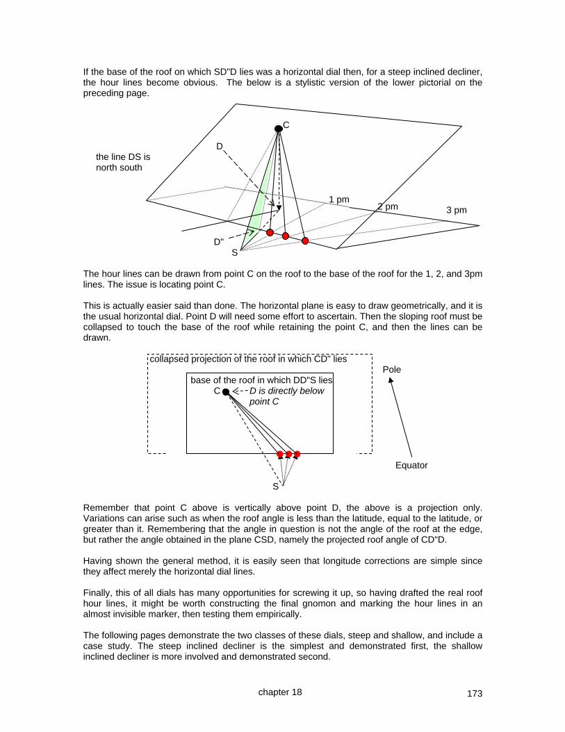
173
If the base of the roof on which SD"D lies was a horizontal dial then, for a steep inclined decliner, the hour lines become obvious. The below is a stylistic version of the lower pictorial on the preceding page. C D the line DS is north south 1 pm 3 pm D" S The hour lines can be drawn from point C on the roof to the base of the roof for the 1, 2, and 3pm lines. The issue is locating point C. This is actually easier said than done. The horizontal plane is easy to draw geometrically, and it is the usual horizontal dial. Point D will need some effort to ascertain. Then the sloping roof must be collapsed to touch the base of the roof while retaining the point C, and then the lines can be drawn. collapsed projection of the roof in which CD" lies Pole base of the roof in which DD"S lies C D is directly below point C Equator S Remember that point C above is vertically above point D, the above is a projection only. Variations can arise such as when the roof angle is less than the latitude, equal to the latitude, or greater than it. Remembering that the angle in question is not the angle of the roof at the edge, but rather the angle obtained in the plane CSD, namely the projected roof angle of CD"D. Having shown the general method, it is easily seen that longitude corrections are simple since they affect merely the horizontal dial lines. Finally, this of all dials has many opportunities for screwing it up, so having drafted the real roof hour lines, it might be worth constructing the final gnomon and marking the hour lines in an almost invisible marker, then testing them empirically. The following pages demonstrate the two classes of these dials, steep and shallow, and include a case study. The steep inclined decliner is the simplest and demonstrated first, the shallow inclined decliner is more involved and demonstrated second.
chapter 18
2 pm

174
GEOMETRICALLY DESIGN A STEEP 65° INCLINED 45° DECLINER
Consider the preceding case of a steep incline of 65 degrees, and a declination of 45 degrees. This method uses a surrogate horizontal dial whose benefit is that the inclination, declination and latitude are used as is in the geometry. This method works when the slope exceeds the actual latitude, i.e. a steep slope. It requires that there be a new dial center on the upper part of the inclined declining surface "C", that can be connected to the horizontal surrogate dial's center "S". The first phase has six steps:- 1. draw the roof profile, i.e. the sloped surface BC inclined (65° in this case) at angle NBC 2. draw a line which is the declination (45° in this case) of the base of the roof, radiating from N
in the direction of what will be point S (S is not yet located) 3. from N draw a line at 90˚ from line SN which will meet the arc in the next step at A which is
not yet located 4. rotate the point C on the roof (inclined decliner's dial center) using an arc radius NC through
to NA (now locating point A) so the vertical drop from the roof to its floor is projected, NA=NC 5. from point A (the projected inclined decliner's dial center laid flat), draw a line at co-latitude
from NA to intersect the declination line NS at point S (now locating point S), the surrogate horizontal dial’s center. "S" is now located, and a gnomon built, in this case for 32°
6. connect the surrogate dial center S to the bottom of the roof B, this provides an intermediate angle NSB measuring 14.88° in this case, and used in the next figure on the next page.
We have taken the 3d model of the inclined declining object and generated three triangles. The gnomon is SNA, its style is SA, and point A is the projection of point C. The roof profile is NBC. Important figures that will be used in the next diagram are:-
angle NSB – the difference from noon line SN (surrogate dial center to the north) and SB which is the line from the surrogate dial center to the place on the bottom of the inclined declining slope where the shortest line from the inclined decliner's dial center meets the bottom of that slope.
SB – the direct line from surrogate dial center to the base of the roof B BC – the shortest distance direct line from the base of the roof B to the new dial center C
chapter 18
65°
45.00°
14.88°
32°
roof pitchinclination
style
declination
C
N
A
S
B
pole
a common gnomon
latitude
NOTE: SBC is not a straight line
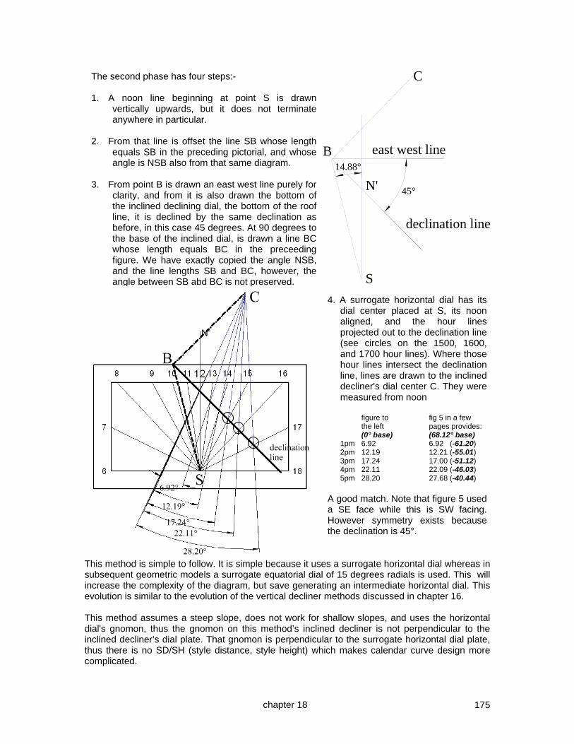
175
This method is simple to follow. It is simple because it uses a surrogate horizontal dial whereas in subsequent geometric models a surrogate equatorial dial of 15 degrees radials is used. This will increase the complexity of the diagram, but save generating an intermediate horizontal dial. This evolution is similar to the evolution of the vertical decliner methods discussed in chapter 16. This method assumes a steep slope, does not work for shallow slopes, and uses the horizontal dial's gnomon, thus the gnomon on this method’s inclined decliner is not perpendicular to the inclined decliner’s dial plate. That gnomon is perpendicular to the surrogate horizontal dial plate, thus there is no SD/SH (style distance, style height) which makes calendar curve design more complicated.
chapter 18
The second phase has four steps:- 1. A noon line beginning at point S is drawn
vertically upwards, but it does not terminate anywhere in particular.
2. From that line is offset the line SB whose length
equals SB in the preceding pictorial, and whose angle is NSB also from that same diagram.
3. From point B is drawn an east west line purely for
clarity, and from it is also drawn the bottom of the inclined declining dial, the bottom of the roof line, it is declined by the same declination as before, in this case 45 degrees. At 90 degrees to the base of the inclined dial, is drawn a line BC whose length equals BC in the preceeding figure. We have exactly copied the angle NSB, and the line lengths SB and BC, however, the angle between SB abd BC is not preserved.
4. A surrogate horizontal dial has its dial center placed at S, its noon aligned, and the hour lines projected out to the declination line (see circles on the 1500, 1600, and 1700 hour lines). Where those hour lines intersect the declination line, lines are drawn to the inclined decliner's dial center C. They were measured from noon
figure to fig 5 in a few the left pages provides: (0° base) (68.12° base) 1pm 6.92 6.92 (-61.20) 2pm 12.19 12.21 (-55.01) 3pm 17.24 17.00 (-51.12) 4pm 22.11 22.09 (-46.03) 5pm 28.20 27.68 (-40.44)
A good match. Note that figure 5 used a SE face while this is SW facing. However symmetry exists because the declination is 45°.
N'
B
C
S
east west line
N'
declination line
45°
14.88°

176
3D CAD EMPIRICAL DESIGN OF A STEEP 65° INCLINED 45° DECLINER These were once common as a demonstration of skill. Some diallists suggest an empirical approach by locating the horizontal line, align a horizontal plate along it, establish the gnomon, drop the gnomon's points to the inclined declined surface below, build that gnomon, and mark the hours as the sun shines. Others offer a geometric or trigonometric technique. One author suggests this is a problem for the diallist entirely of their own making and easily avoided. Rather than repeat by rote such alternatives, the suggestion here is to use CAD by applying equatorial dial radials to the surface.
We could use the same method used in chapter 30 with the wine glass using the 3d intersect tool, however, for flexibility, we shall use the 3d subtract tool instead. Figure 1 above has a style set at latitude oriented to the pole, and two sets of radials. There are 7 radials, covering noon to 6, each being 15 degrees apart and perpendicular to the style. In CAD this is done by making one radial and then radial copying it. The two radial sets and the style are combined with 3d-add. Two sets of radials are needed in order to draft hour lines. This dial is sloped 25° off vertical, declining exactly 45°.
Then build the slope, here a 65° recliner that declines 45°, i.e. South 45° East. This is shown in figure 2. Then additional radials perpendicular from the dial plate to the style, that will establish the style distance and height angles in a later step. This is done by setting the work plane to the sloped surface, also visible in figure 2, drawing two cylinders and bringing them up to the style. They are not 3d-added to the style because when the 3d subtract happens it would complicate drafting the hour lines in a subsequent step.
The next step is to use the 3d subtract tool to subtract the hour lines from the dial plate. Figure 3 shows the dial plate and the resulting holes. Then, with the work plane on the slope of the dial plate, draw a horizontal line and then lines from each pair of pair of holes made by the equatorial radials, as shown in figure 4. Understanding work-planes is crucial in CAD work such as this.
Fig 1
Fig 3
Fig 2
Fig 4
6 am baseline
facing SE
facing SE
facing SE
chapter 18
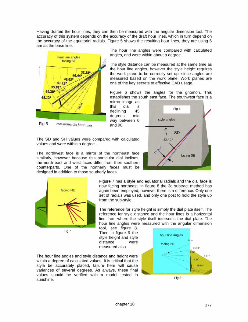
177
Having drafted the hour lines, they can then be measured with the angular dimension tool. The accuracy of this system depends on the accuracy of the draft hour lines, which in turn depend on the accuracy of the equatorial radials. Figure 5 shows the resulting hour lines, they are using 6 am as the base line.
The hour line angles were compared with calculated angles, and were within about a degree. The style distance can be measured at the same time as the hour line angles, however the style height requires the work plane to be correctly set up, since angles are measured based on the work plane. Work planes are one of the key secrets to effective CAD usage. Figure 6 shows the angles for the gnomon. This establishes the south east face. The southwest face is a mirror image as this dial is declining 45 degrees, mid way between 0 and 90.
The SD and SH values were compared with calculated values and were within a degree. The northwest face is a mirror of the northeast face similarly, however because this particular dial inclines, the north east and west faces differ from their southern counterparts. One of the northerly faces must be designed in addition to those southerly faces.
Figure 7 has a style and equatorial radials and the dial face is now facing northeast. In figure 8 the 3d subtract method has again been employed, however there is a difference. Only one set of radials was used, and only one post to hold the style up from the sub-style. The reference for style height is simply the dial plate itself. The reference for style distance and the hour lines is a horizontal line from where the style itself intersects the dial plate. The hour line angles were measured with the angular dimension tool, see figure 8. Then in figure 9 the style height and style distance were measured also.
The hour line angles and style distance and height were within a degree of calculated values. It is critical that the style be accurately placed, failure here will cause variances of several degrees. As always, these final values should be verified with a model tested in sunshine.
Fig 5
Fig 6
Fig 7
Fig 8
SD
hour line angles
facing NE
facing SE
style angles
hour line angles facing SE
facing NE
chapter 18

178
Thus, the north faces have been designed, they mirror each other because of the declination being 45 degrees. The set of four faces may then be applied to a base, this would be one with 65° slopes. A spreadsheet was used to compare the CAD derived values with those produced by other means, such as by calculation or by using software designed for sundial design. The only purpose of this spreadsheet was to show the accuracy obtainable.
A completed dial is pictured below, and it truly is a problem of the diallists own making and easily avoided! SOME RULES OF THUMB Some useful rules of thumb are that in the northern hemisphere, north facing dials indicate clockwise, south facing dials indicate counter-clockwise.
While in the real world, such a CAD technique may not be used very often, it does show the power of CAD systems, and demonstrates yet again the equatorial dial basis for most hour angle dials.
SOUTH EAST FACE
math CAD DIFF
12 67.1 68.1 -1.0
11 60.1 61.2 -1.1
10 55.4 55.9 -0.5
9 49.8 51.1 -1.3
8 45.9 46.0 -0.1
7 40.3 40.4 -0.1
6 32.8 32.4 0.4
fig 5
SD 51.43 52.3 -0.9
SH 17.7 17.8 -0.1
fig 6
NORTH EAST FACE
math CAD DIFF
6 22.6 23.2 -0.6
7 11 10.8 0.2
8 1.2 1.6 -0.4
9 14.7 15.6 -0.9
10 30.2 30.4 -0.2
fig 8
SD 22.34 22.3 -0.1
SH 50.1 50.1 0.1
fig 9
style angles
SH SD
facing NE
Fig 9
chapter 18

179
CHAPTER NINETEEN
THE MORE INVOLVED SHALLOW INCLINED DECLINER This dial plate will be designed using several techniques. First, using CAD, or computer aided design. The 3d CAD systems are nothing more than computerized reality, a computerized version of what people did on the good old days when they used trigons, protractors, and leaded weights on strings. Of course, a CAD derived dial is only as good as the measurements that went into using it, and three of those measurements are: dial alignment with the cardinal points dial plate declination (how far off from true north etc) dial plate inclination (how far off from the horizontal) Another key point is the definitions and what is intended or really meant by some words. declination – here the rotation about the vertical axis of a dial plate, the term S 10 W means look south, and turn 10 degrees west. N 85° W N 30° W N 60°E N 0° W N 0° E S 60° W S 30°E inclination – some texts mean the movement from the vertical, some mean the movement from the horizontal. For standardization purposes, this text will mean inclined up from the horizontal, which is the complement of... reclination – the angle made backwards from the vertical. reclining back 70° reclining 20° back inclining up 20° inclining 70° up shallow steep And, software such as SHADOWS will be reviewed and how it can verify a dial design. Also, the use of spreadsheets will be examined, a very useful tool but one needing some degree of intuition. And, a geometric method will be reviewed, step by step. Also, the trigonometric formulae will be portrayed in normal form as well as in Excel format for the typical spreadsheet, and finally a DeltaCAD macro will be demonstrated. What do the masters say of this dial? Mayall had but one enquiry in twelve years and presents a geometric solution. Rohr shows a geometric and a trigonometric method. Drinkwater says this is a problem of the diallist own making and easily avoided, and continues with a long discussion of why these dials should be avoided. Waugh focuses on getting the gnomon correct, and then, considering the equation of time, mark the hours on the hour and getting on with your life. Some books may have a typographical misprint, so double check the formulae before relying on them.
chapter 19

180
3D CAD EMPIRICAL DESIGN ~ SHALLOW INCLINED 20˚ S45W DECLINER In the example in the first few pages of this chapter the 3d TurboCAD deluxe program was used. In this example, TurboCAD Professional was used. The difference as far as dial design goes is that one can draw lines on a work-plane on a surface depicted in solid color and with intersecting radials hidden at their point of intersection. In other words, one can skip the 3d intersect or the 3d subtract phase and do things even more visually. First, select a work plane and build a very thin yet tall cylinder. This will be a radial. Then do a radial copy to get, in this example, 6 morning and 6 afternoon hours. Then do a 3d add so they are one object, you could also do a "group" which has the advantage that group members can have different colors, however it has the disadvantage that a 3d subtract or intersect operation may not do what you want. These are the radials at the equinox, and a set can be built for any declination of the sun using the same process, they become cones either side of the equinox whose radials form a plane.
This is the starting place. A gnomon is added, and an angular measure also. Another advantage of TurboCAD professional is that text and text attached to angular measures, and so forth, all appear in 3d rendered mode without the need to "explode" them and make the text specific 3d objects. If the measure looks as if it is not measuring the slope of the gnomon fear not, the angular measure was done a little bit to this side of the gnomon for clarity. In the next picture, the final dial plate was inclined by 20 degrees.
Then rotated. But that rotation would be problematic because as soon as it is declined, the axes change. So to counter that, a new cube was created and selected with the tilted dial plate, this resets the rotational axes, and the two together can be declined, and the temporary cube is then deleted. In addition to the final dial plate being rotated (declined) and tilted (inclined), the style and its radials were also tilted to latitude. NOTE: The next three pages may make less sense unless you have and use TurboCAD.
equatorial radials
the style perpendicular to the radials
dial plate
reference plate aligned north or south.
chapter 19

181
At this point the benefits of the TurboCAD professional program allow some steps to be skipped. In the first example at the start of this chapter the 3d subtract or intersect operation was employed to clearly see just where the equatorial radials intersected with the dial plate. With TurboCAD professional, the model can be rendered as you work which means that you do not see the radials below the dial plate. Thus the hour lines can be drawn directly and they will be seen because such lines are rendered in the professional version of this software even though they are not solid objects. All this is done by first setting the work plane to the sloped rotated (inclined declined) dial plate, using the work-plane by facet function. Then lines are simply drawn from the dial center to the place where the equatorial radials vanish into the dial plate. The work-plane can then be set to the gnomon, using the "by facet" function, and the style to sub-style angle determined. That is the height of the style from the sub-style for this vertical gnomon, which is why the words "style height" were not used. Style height is a term typically reserved for a gnomon perpendicular to a dial plate, and at this point the gnomon is perpendicular to the horizon. While it is not normal, there is nothing wrong with using a vertical gnomon except that for some declining inclining plates it just isn't practical. A gnomon perpendicular to the dial plate is simpler to construct and stronger. So, how is the style distance (SD) and the final style height (SH) determined?
With the work-plane set to the dial plate, a cylinder is drawn and pulled up. The entire figure manipulated until the bottom and top circles of that cylinder are merged, this means that the observer is perfectly perpendicular to the dial plate. At this point, a line can be drawn from the dial center following the style, which is truly the sub-style of normal parlance. Again, simple with TurboCAD Professional. With the more common version the process uses an extra step or two and requires the dial center point and the equatorial radial points, and the sub-style intersection line to be made visible by using the 3d subtract tool.
A gnomon can be drawn from the place where the style distance line appears and the final style height measured angularly. Other techniques exist also.
4.56
chapter 19
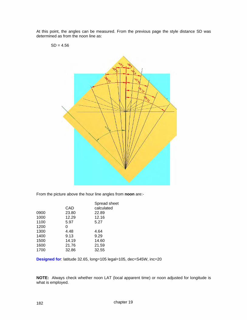
182
At this point, the angles can be measured. From the previous page the style distance SD was determined as from the noon line as: SD = 4.56 From the picture above the hour line angles from noon are:- Spread sheet CAD calculated 0900 23.80 22.89 1000 12.29 12.16 1100 5.97 5.27 1200 0 1300 4.48 4.64 1400 9.13 9.29 1500 14.19 14.60 1600 21.76 21.59 1700 32.86 32.55 Designed for: latitude 32.65, long=105 legal=105, dec=S45W, inc=20 NOTE: Always check whether noon LAT (local apparent time) or noon adjusted for longitude is what is employed.
chapter 19

183
The final verification is for the style distance and height, SD and SH. In this case the CAD method measured SD from noon. The CAD provided The spreadsheet deduced SD 4.56 SD 4.55 SD being from noon SH 18.50 SH 17.76 Why was the style height off? Because it was the SH for a vertical gnomon whereas we need the SH for a gnomon adjusted by the style distance. The technique to measure the SD for the adjusted gnomon was simple. The work-plane was set to the dial plate, a cube placed on it, and that cube rotated to parallel the style distance line. Then the work plane was switched to the vertical surface, so angular measures would truly measure the gnomon perpendicular to the surface rather then the gnomon that was vertical to the horizon. The angle was then measured properly, and found to be: The CAD provided The spreadsheet deduced SD 4.56 SD 4.55 SD being from noon SH 17.41 SH 17.76
17.41°
32.65°18.50°
chapter 19

184
The SD (style distance) and the hour line angles were from noon.
The CAD system measured the noon to horizontal distance to be: 47.37 degrees The spreadsheet calculated that angle to be:
Noon:v LAT -43.2 Vertical & noon LAT line difference
Noon:h LAT 133.2 46.8 Horizontal & noon line difference (90+ and 90-) 46.8 degrees SD may be calculated from the vertical as opposed to the horizontal. In this case the SD value of 4.56 from noon when added to the 47.37 degrees noon is from the horizontal provides a SD from horizontal of: 51.93 SD from horizontal 38.07 SD from vertical At this point, all data has been deduced and found to match closely values from a spreadsheet. The next step would be the paper mock up to validate the design. The final step would be the actual dial plate design itself. The lessons learned using CAD are a good understanding of using work planes and their coordinate systems.
47.37°
chapter 19

185
CASE STUDY ~ declining dial – S 45°W inclined a SHALLOW 20° [software] There are a number of software programs available for sun dial design. One in particular is called SHADOWS which is not affiliated with this book. The SHADOWS system was provided the longitude, latitude, declination and inclination.
The data plate showed a style distance of:- SD = 38.57 however, this was measured from the vertical. The CAD system provided a style distance from noon of 4.56 degrees, and when the angle of the noon line was considered, SD from horizontal was 51.93, and its complement was 38.07 which is within half a degree of the SHADOWS calculated version. The SHADOWS style showed a 25mm long style and a 17 and 25 mm high style. This means that the vertical distance was 8 mm compared to a horizontal distance of 25 mm. This provides the angle using simple trigonometry of the SH. SH = atan ( 8/25 ) = 17.74 And this compares well to the spreadsheet as well
as the CAD derived data. Finally the hour lines must be evaluated. CAD XLS SHADOWS 0900 23.80 22.88 23.26 1000 12.29 12.16 12.32 1100 5.97 5.27 5.44 1200 0 0 0 1300 4.48 4.64 4.48 1400 9.13 9.29 9.62 1500 14.19 14.60 14.47 1600 21.76 21.59 21.96 1700 32.86 32.55 32.85 NOTE: While SHADOWS asks for the dial's longitude, it does not consider that longitude when generating hour lines unless specifically instructed to consider it.
Thus far, the dial plate for a dial declining 45 degrees to the west, inclined upwards by about 20 degrees matches closely with CAD modeling, with spreadsheet usage (which is trigonometric), and with available software such as SHADOWS. SHADOWS is available from www.shadowspro.com
SD 38.57
chapter 19

186
A declining dial – S 45°W inclined a SHALLOW 20° – [trigonometry] Formulae for inclining decliners may be found on the British Sundial Society (BSS) web site, as well as in a few other publications. Some books may need careful review by the reader before reliance is placed on the formulae espoused. Before producing the formulae here, they were tested and debugged, the mechanism being through a spreadsheet. NOTE: There are limitations on these formulae, so a reasonableness check is warranted, as well as validation by a model in the real sun, before proceeding to a final design implementation. Style Distance from noon SDn = atan( ( sin(dec) * sin(inc) * ( (sin(inc) *cos(dec) – tan(lat)*cos(inc) ) / (cos(inc) + tan(lat) * cos(dec) *sin(inc)) ) ) ) Style Height SH SH = asin( (cos(lat) * sin(inc) * cos(dec) ) – (sin(lat) * cos(inc)) ) The SD and hour line angles are from the noon line. They are adjusted with the angle from the horizontal to noon distance, and the resulting number subtracted from 90 degrees provides the same data with the vertical as a reference. Vertical to noon = atan( tan(dec) * cos(inc) ) The hour line angles from the vertical are:- = atan( ((( (cos(lat)*sin(inc)) – sin(lat)*cos(inc)*cos(dec))*tan(ha))+ cos(inc)*sin(dec)) / ( cos(dec) + sin(dec)*sin(lat)*tan(ha)) ) NOTE: Always check whether noon LAT (local apparent time) or noon adjusted for longitude is what is employed.
chapter 19

187
A declining dial – S 45°W inclined a SHALLOW 20° – [spreadsheet] The spreadsheet of choice was Excel. Excel has its rules and quirks. The spreadsheet discussed here is nothing more than an implementation of the formulae for declining incliners. Since the spreadsheet has been discussed in the CAD and SHADOWS discussions of declining incliners, this section will focus on the spreadsheet and its formula. The spreadsheet is available on the CD that accompanies this book, and is kept current on the web site as:- www.illustratingshadows.com/illustratingShadows.xls Excel and Open Office The spreadsheet begins with raw data.
Declination [ +SW - SE ] 45 < 90 SOUTH WEST
Inc fr horiz 20.00 < lat SHALLOW (reclined from vertical) 70.00
Lat 32.65 Long 105.00 Legal 105
The dial plate declination is entered, positive being in this case South West. The inclination from horizontal is entered next, and finally the latitude. The spreadsheet then deduces trigonometric values for the angles, and derives the inclination from the vertical. Recall that Excel needs radians as opposed to degrees. Conditional formatting was used to highlight some useful information, such as confirming the declination as southwest, and the inclination as shallow.
SOUTH WEST
SHALLOW which measures the inclination to 45 degrees. The words SHALLOW or STEEP confirm the nature of the slope as a human double check. This spreadsheet highlights a declination of 90 degrees as inappropriate also using conditional formatting, for which the solution is to use the east or west decliner system. The spreadsheet then provides the style distance (SDn) from noon but more importantly, from the vertical also. And the style height SH is also provided. In this case 38.7 and 17.7 degrees.
SDn 4.6 SDn (style distance) => angle from NOON
SDv -38.7 USE THIS SDv + noon angle => angle from VERTICAL
SDh 128.7 SDh + noon angle => angle from HORIZONTAL
SH -17.7 USE THIS SH (regular angular style height)
chapter 19

188
The spreadsheet takes the SD from noon, and the noon from horizontal values and derives several figures. This is in essence a simple addition of the horizontal to noon, and noon to SD as well as their complement. Rather than provide highly complex formulae, several figures are produced, and it is left to the wisdom of the user to select the most likely usable information. SD 38.67 SDn + noon angle 51.33 complement
SDv -38.7 USE THIS SDv + noon angle => angle from VERTICAL A table of hour line angles is produced, there are two sets, one for hours before, and one for hours after noon. Again, the human has some selecting to do to determine the hours to use.
HOUR LINE ANGLE FROM VERTICAL angle from angle from
HR
AM HOURS
hr.ln.angl horizontal noon
6 10.47 79.53 53.69
7 52.31 37.69 95.53
8 -86.63 176.63 -43.41
9 -66.10 156.10 -22.89
10 -55.38 145.38 -12.16
11 -48.49 138.49 -5.27
12 -43.22 133.22 0.00
USE THESE HOUR LINE ANGLE FROM VERTICAL angle from angle from
HR
PM HOURS
hr.ln.angl horizontal noon
12 -43.22 46.78 0.0013 -38.58 51.42 4.6414 -33.93 56.07 9.2915 -28.62 61.38 14.6016 -21.63 68.37 21.5917 -10.67 79.33 32.5518 10.47 100.47 53.69 The formulae used in the spreadsheet are:- Style Distance from noon SDn = DEGREES(ATAN((sin(dec)*sin(inc) * ((sin(inc)*cos(dec) – tan(lat)*cos(inc)) / (cos(inc)+tan(lat)*cos(dec)*sin(inc)))))) Style Height SH = DEGREES(ASIN((cos(lat)*sin(inc)*cos(dec))-(sin(lat)*cos(inc)))) Horizontal to noon = DEGREES(ATAN(tan(dec) * cos(inc))) The hour line angles from the vertical are:- = DEGREES(ATAN( ((( (cos(lat)*sin(inc)) – sin(lat)*cos(inc)*cos(dec))*tan(ha))+cos(inc)*sin(dec)) / ( cos(dec) + sin(dec)*sin(lat)*tan(ha)) ) And as mentioned earlier, these formulae do have some limitations.
chapter 19

189
PRELUDE TO A CASE STUDY ~ A southwest declining dial ~ S 45°W inclined up a SHALLOW 20° using geometry ~ step by step first [STEP 1] TO DETERMINE BY GEOMETRIC CONSTRUCTION THE ANGLE BETWEEN THE NOON LINE AND THE HORIZONTAL.
THE NOON LINE AND ITS OFFSET: First [1] a vertical line (ab) is drawn, and then second [2] a horizontal line (fe) is drawn, which can be the approximate linear height of the proposed style, but that is not important. Third [3] a line (eg) is drawn downwards at the angle of the dial plate's inclination up from the horizontal. Downwards for gently reclining slopes, but upwards if the dial proclines which is very uncommon. That reclining line (eg) meets the vertical line at (g). And fourth a [4] perpendicular to that slope is drawn a line which meets that original vertical line at (J), and it has a length. That line is rotated [5] until it meets the vertical line at the top (k) from whence a line is drawn down at an angle equal to the dial plate's declination [6] where it will intersect with a horizontal line drawn (LJ). This intersection (L) has a line (Lg) drawn from it [7] down to point (g) on the original vertical line (ab). And that line (Lg) makes an angle equal to the angle of the noon line with the horizontal, and it was measured as:- geometric 47.33 degrees the spreadsheet provided: 46.78 CAD 47.37 SHADOWS 47.10 Which places all figures in the ball park. This line from point "L" to and beyond point "g" is the noon line on the final dial plate.
[1]
[2]
[3]
dial plate inclination
[4]
[5]
[6]
[7]
to find angle between noon and the horizontal
noon line
chapter 19

190
[STEP 2] TO DETERMINE BY GEOMETRIC CONSTRUCTION THE DIAL CENTER.
THE DIAL CENTER: From point (f) draw line (fm) which is perpendicular to line (Lg). This line will later be extended. On the vertical line (ab), make line (fo) equal to line (fm), an arc is used for this. Then draw a line from point (o) to the earlier point (e) as line (oe). See expanded insert below to the left.
From point (m), extend the line away from point (f) to a new point (p) where the length of (mp) is equal to the length of line (oe). Connect point (p) to earlier point (L) making a new line, (Lp), best seen in the picture above. Back off from line (pL) by the latitude of the dial, and draw that new line extended, so it meets the extension of line (Lg) at a new point (C) which is the dial center.
Depending on the values of inclination and declination, the dial center may be above to the left as opposed to the bottom and right, or in fact any where.
latitude 32.65°
noon line
chapter 19

191
[STEP 3] TO FIND THE SUB-STYLE, AND THUS SUB-STYLE DISTANCE (SD) To determine by geometric construction the style distance (SD) and style height (SH), from the dial center point (C) draw a line through the existing point (f). This line (Cf) is the sub-style, and when measured from vertical it was found to be 38.97 degrees which is within one tenth of a degree of other figures.
[STEP 4] TO FIND THE STYLE HEIGHT (SH), through point (f) draw a line (xy) which is perpendicular to the recently drawn sub-style. Make a line (fs) along line (xy) equal to the existing line (fe), an arc was used for this. Finally draw line (Cs) which is the style, the angle between (Cs) and (Cf) was measured at 16.95 degrees which is within a degree of the other values derived in this section, this is the style height (SH). Note that line (Cs) is not associated with line (Je), their closeness is coincidental. Note that line (xy) is not associated with line (fmp), their closeness is coincidental. This suggests great care with geometric constructions, as confusion can generate errors.
y
style noon line
chapter 19
x
gnomon

192
[STEP 5] TO FIND THE HOUR LINES by geometric construction the hour lines and their angles. On the line (Cs) draw a line (fn) perpendicular to it from point (f). The intersecting point is (n), the "n" signifying the nodus.
Extend the line (Cf) to point (t) such that the length (ft) equals the length of line (fn). An arc was used, however the arc centered on point (f) through points (nt) is not associated with the arc centered on point (f) through point (s), their proximity is co-incidental. This in essence is taking the circle of radials and projecting them from the nodus to the dial plate. Centered on point (t) draw an arc to hold the radials, this arc is of any size. A line is drawn from the center (t) to where the noon line intersects the line (xy), point (m) on the (LC) line. And beginning with the line (tm), draw a set of 15 degree hour angle depictions from the sun.
chapter 19

193
The radials from the center of the circle with the 15 degree hour lines are extended to ensure they meet the line (xy). From the dial center (C), lines are drawn and these are the final hour line for the dial plate. Finally the hour line angles are measured, for consistency they were measured from noon. Of course the angle of the noon line with the horizontal or vertical was previously determined on the first of the geometric worksheets.
CAD XLS SHADOWS GEOMETRIC 0900 23.80 22.88 23.26 20.30 1000 12.29 12.16 12.32 10.76 1100 5.97 5.27 5.44 4.84 1200 0 0 0 0 1300 4.48 4.64 4.48 4.34 1400 9.13 9.29 9.62 8.75 1500 14.19 14.60 14.47 13.51 1600 21.76 21.59 21.96 20.28 1700 32.86 32.55 32.85 31.03 angles measured from noon
The hour lines agreed closely on the afternoon side, less so on the morning hours. This particular combination of declination and inclination was such as to produce a number of angles that were small making for longer distances on some lines which in turn can increase the errors. However in spite of those drafting errors, the method can be seen to have significant merit. Having decided on a dial whose plate inclined by 20 degrees while declining 45 degrees to the west, it became apparent that a declining dial of 50 degrees would be more pleasing for the final location. This meant recalculating the angles, and the geometric method was again used, albeit condensed so the "big picture" would be more apparent. The major phases in the geometric method are:-
dial center and noon line style distance and height hour lines
chapter 19

194
CASE STUDY ~ A southwest declining dial ~ S 50°W inclined up a SHALLOW 20° ~ using geometry three major steps ~ noon and dial center, SD/SH, and the hour lines NOON LINE AND ITS OFFSET: A vertical line (ab) is drawn, and then a horizontal line (fe) is drawn, which can be the approximate linear height of the proposed style, but that is not important. Then a line (eg) is drawn downwards at the angle of the dial plate's inclination up from the horizontal. Downwards for gently reclining slopes. That reclining line (eg) meets the vertical line at (g). And then a perpendicular to that slope is drawn a line which meets that original vertical line at (J), and it has a length. That line is rotated until it meets the vertical line at the top (k) from whence a line is drawn down at an angle equal to the dial plate's declination where it will intersect with a horizontal line drawn (LJ). This intersection (L) has a line (Lg) drawn from it down to point (g) on the original vertical line (ab). And that line (Lg) makes an angle equal to the angle of the noon line with the horizontal, and it was measured as 41.86, or 48.14 back from the vertical.
DIAL CENTER: From point (f) draw line (fm) which is perpendicular to line (Lg). This line will later be extended. On the vertical line (ab), make line (fo) equal to line (fm), an arc is used for this. Then draw a line from point (o) to the earlier point (e) as line (oe). From point (m), extend the line away from point (f) to a new point (p) where the length of (mp) is equal to the length of line (oe). Connect point (p) to earlier point (L) making a new line, (Lp). Back off from line (pL) by the latitude of the dial, and draw that new line extended, so it meets the extension of line (Lg) at a new point (C) which is the dial center.
chapter 19

195
SUB STYLE AND THUS SUB STYLE DISTANCE (SD): from the dial center point (C) draw a line through the existing point (f). This line (Cf) is the sub-style, and when measured from noon it was 5.43 degrees or 47.29 from horizontal, or 42.71 from vertical since the noon line was 41.86 from horizontal or 48.14 from the vertical, which is within one tenth of a degree of some other figures.
STYLE HEIGHT (SH): through point (f) draw a line (xy) which is perpendicular to the recently drawn sub-style. Make a line (fs) along line (xy) equal to the existing line (fe), an arc was used for this. Finally draw line (Cs) which is the style, the angle between (Cf) and (Cs) is the style height (SH) and was measured at 18.43 degrees which is within a degree of the other values derived in this section. Note that line (xy) is not associated with line (fmp), their closeness is coincidental.
chapter 19
gnomon
x
y
5.43°
18.43°

196
HOUR LINES: On the line (Cs) draw a line (fn) perpendicular to it from point (f). The intersecting point is (n), the "n" signifying the nodus. Extend the line (Cf) to point (t) such that the length (ft) equals the length of line (fn). An arc was used, however the arc centered on point (f) through points (nt) is not associated with the arc centered on point (f) through point (s), their proximity is co-incidental. This in essence is taking the circle of radials and projecting them from the nodus to the dial plate. Centered on point (t) draw an arc to hold the radials, this arc is of any size. A line is drawn from the center (t) to where the noon line intersects the line (xy), point (m) on the (LC) line. And beginning with the line (tm), draw a set of 15 degree hour angle depictions from the sun. The radials from the center of the circle with the 15 degree hour lines are extended to ensure they meet the line (xy). From the dial center (C), lines are drawn and these are the final hour line for the dial plate.
Finally the hour line angles are measured, for consistency they were measured from noon. Of course the angle of the noon line with the horizontal or vertical was previously determined on the first of the geometric worksheets.
chapter 19
t

197
The hour lines were measured as shown and were:- 1pm 2pm 3pm 4pm 5pm 6pm 0900 1000 1100 1200 1300 1400 1500 1600 1700 1800 geometric 24.26 12.74 5.31 0 4.86 10.11 15.93 23.36 33.79 53.20 spreadsheet 25.01 13.24 5.70 0 4.98 9.91 15.46 22.63 33.55 53.63 And these are in very close agreement. Some of the angles were larger thus having points of intersection closer in, which allowed for increased accuracy compared to a 45 degree declining 20 degree inclined dial. Reiterating the prior data:- noon line from horizontal 41.86 from vertical 48.14 SD 5.43 from noon 47.29 42.71 SH 18.43 Longitude considerations A major question is whether to design this dial to consider the longitude of the location, compared to the location of the legal time meridian. As a rule, dials that are portable, or may be relocated later, should not have the longitude correction built into the dial plate, rather, there should be a tailored equation of time that blends the equation of time (EOT) with the difference in time between the dial design location and that legal meridian. However for large dials that are designed and built in place, with no intention of subsequent movement, then the longitude correction can be built in. The choice is left to the diallist. However if there are several dials on the property, it may be simplest to have them all designed the same way. The next section shows how the geometric method easily accommodates the longitudinal correction. There is no change to the location of the noon line for that is the local noon, and similarly the angles from the noon line to the vertical and horizontal do not change. The dial center does not change, nor does the style distance or style height. All that is needed is a simply rotation of the 15° radials and the re-drafting of those final hour lines themselves.
chapter 19

198
CASE STUDY CONTINUED ~ A southwest declining dial ~ S 50°W inclined up a SHALLOW 20° using geometry ~ longitude considered HOUR LINES CONSIDERING LONGITUDE: the process is exactly the same as in the last step with one exception. That exception is that while the original noon line is retained since that is local solar noon and the basis for all construction of hour lines, the 15° radials and consequently their associated hour lines are affected. Those 15° radials are rotated using a very simple algorithm.
In the northern hemisphere the 15° radials are rotated clockwise when west of the legal time zone, counter clockwise if to the east. The opposite direction for the southern hemisphere. The amount of the rotation is the longitudinal difference. For the design location for this dial that meant a clockwise rotation of 3.2 degrees.
chapter 19
47.80°30.46°
20.62°13.95°
8.86°4.10°
1.44°6.68°
14.50°
28.41°

199
Finally the hour line angles are measured, for consistency they were measured from noon. Of course the angle of the noon line with the horizontal or vertical was previously determined on the first of the geometric worksheets. Reiterating the prior data that did not change with a longitudinal consideration:- local noon line from horizontal 41.86 from vertical 48.14 SD 5.43 from noon 47.29 42.71 SH 18.43 The hour lines were affected by longitudinal considerations, the new angles were:- 1pm 2pm 3pm 4pm 5pm 6pm 0900 1000 1100 1200 1300 1400 1500 1600 1700 1800 geometric 28.41 14.50 6.68 1.44 4.10 8.86 13.95 20.62 30.46 47.80 - - - - - - - - - - - - - - - - - - left right - - - - - - - - - - - - - - - - - - - - - - - - - - - - - - These angles show a displacement that is appropriate, and the new noon will happen earlier than solar noon, which is correct. The angles can be checked by using the spreadsheet, as before, except that the base time would need to be adjusted by the longitudinal difference, being 1° for 4 minutes. In this case, the SHADOWS software was used and the angles found to be in close agreement. Since the geometric method uses the local solar noon as the base, and SHADOWS does not, it is important to add into the SHADOWS depiction the local solar noon, and measure angles from thence. A cardboard dial plate and gnomon were made, and the site prepared. The column to the right of normal clay brick, was put together without mortar, but the top had been leveled and the dial plate set with a compass after considering magnetic declination. The style alignment and dial plate inclination was also checked. One common level available in hardware stores has a magnetic base thus when compass readings are taken, it must be removed.
chapter 19

200
Every hour the shadows were checked on the cardboard dial plate, with consideration to the equation of time. If for example the EOT table said 10 minutes was to be added to sun time, then on the hour it would actually be 10 minutes past, so the dial would be checked 10 minutes after each hour. The mock dial plate worked so the final dial plate was constructed. Copper wire 12 gauge was used and straightened by rolling with a block of wood, then placed on the mockup dial plate and soldered. The gnomon was soldered to the dial plate, and the entire plate then secured to the concrete slab with an epoxy that would survive the elements.
The site for the dial just looked a bit too close to the picket fence, so it was moved a couple of feet, and then the column built. The slope was managed by cutting an 8x8x8 block at 20 degrees.
location long: 108.2° W location lat: 32.65° N magnetic declination: 10.6° E (variation) Dial declines S 50 W inclines 20 S 50 W true is S 39.4 W mag 230 true 220 magnetic
To get the final dial plate declining 50 degrees to the west, 230° magnetic, the 8x8x8 sloped cap was rotated with a compass until the alignment read a tad short of 220° magnetic. That wedge was secured with mortar placed in the wedge, and with some excess mortar, the final dial plate was mounted. The top and bottom of the dial plate was checked for level and alignment with the cap it rests on, as well as with the magnetic alignment. When cured, some quarter round wood was cut and secured with epoxy on the upper part of the wedge and the dial plate's underneath, this would secure the dial plate from accidental jarring. The dial shows local sun time corrected for the longitudinal difference to the legal standard time meridian, thus all that is needed is the EOT correction. For winter months, the gnomon's position or style's length may be such that the shadow is too far north of the dial plate for its shadow to touch the hour lines furthest from noon. You may need to extend the gnomon or style towards the equator to better show those hours. This is an artistic or aesthetic decision.
0° mag 0° true
chapter 19

201
A shallow inclined decliner – S 50°W inclined a SHALLOW 20° – DeltaCAD A DeltaCAD macro was built using some of the code and functions from the horizontal dial macro. The formulae from the spreadsheet: illustratingShadows.xls on this book's CD and web site were coded, and with a few refinements, the inclined decliner macro became functional.
The same parameters were used as for the final inclined decliner just constructed.
The program shows a pictorial of the final dial plate. The style distance from the vertical is 42.9 degrees, compared to 42.71 in the preceding construction. The Style height is 18.9 degrees compared to 18.43 degrees in the previous method.
chapter 19
These extremes actually make sense, but easier for a human to evaluate than for a computer to have endless special code. That is the difference between a tool, and a finished product.

202
The hour lines are shown both from noon as well as from the vertical. The DeltaCAD macros offered the following values from the noon line. 0900 1000 1100 1200 1300 1400 1500 1600 1700 and a spurious line 28.5 15.3 7.1 1.1 3.9 8.8 14.2 20.9 30.7 Whereas the preceding geometric method provided the following information from noon:- 1pm 2pm 3pm 4pm 5pm 6pm 0900 1000 1100 1200 1300 1400 1500 1600 1700 1800 28.41 14.50 6.68 1.44 4.10 8.86 13.95 20.62 30.46 47.80 The difference of the noon line and noon as depicted is that one is L.A.T. (local apparent time), whereas the other is longitude corrected. Thus the DeltaCAD program seemed to provide meaningful results. Programs sometimes provide output that is less easily explained. Some call these bugs, others call them features. It depends on whether you are the buyer or the seller. DeltaCAD, Excel/Open Office, and Shadows Expert software compared for example Latitude 33.5, longitude 112.2, legal meridian 105, inclined 20°, declining S50W
The Excel/Open Office sheets agreed with the DeltaCAD macro, with an: SD=42.7°, SH=19.6°, and the hour line angles from the vertical also agree. Compared to Shadows Expert, the values were within 1/10 of a degree to just over a degree or so. Of note, the Excel and Open Office sheets provide graphical guidance as well. It is guidance only due to aspect and other issues.
chapter 19

203
CHAPTER TWENTY
Cube dials The cube dial is a hybrid of other dials, when one face loses its accuracy another face takes the lead. The disadvantage to them is that all dial faces need to be coherent and say the same things at the same time. Two common cube dials exist, one is not tilted and has the meridian, horizontal and vertical dials available. The other is tilted and has a polar and two equatorial dials as well as the two meridian dials. And in between the tilted and un-tilted dials there can be other variations.
There is little to add as far as design or construction
goes. Small dials might use nails for gnomons, with a virtual style, and screws for the protective plexi-glass cover. If they are not of brass then be aware that they may cause a magnetic compass to read erroneously. The pictures on this page as well as the entire body of this book should make details somewhat superfluous, however the next page will provide general clues to the titled dial's construction. The un-tilted dial should by now be self explanatory.
Screw placement and when to do what drilling are things to consider. In the tilted dial on the meridian face the plexi-glass retaining screws should be switched 90 degrees because the screw is too close to the gnomon. Plan in advance all screw holes before doing any drilling. The drill holes for the gnomons should be drilled before the plexi-glass faces are applied, then the retaining screw holes should be drilled, and only then should the plexi-glass cover be married to the dial plate. If you screw the plexi-glass first and then try and drill the hole for the gnomon, Mr. Murphy will pay a visit and ensure that the gnomon hole is off center. Also see: chapters which discuss pyramid dials that incline, decline.
Tilted cubes use one standard set of dial plates, level cubes usually have dial plates that are latitude specific.
chapter 20

204
BUILDING THE TILTED CUBIC DIAL
A cube of wood cut from a 4 by 4 inch beam is the cube in this example. A template is in the appendix. The template is cut and may be glued to the cube using Elmer's glue or PVC pipe glue. Remember that glue fumes may be toxic. A base is cut from a 1 inch thick 4 by 4 inch plank. A hole is drilled in the base, and a hole in the cube. The hole in the cube is on the cube face that faces the pole and faces the ground. If it has anything on it, it would be just data. The cube polar dial facing the equator equatorial dial for summer equatorial dial for winter co-latitude latitude A dowel The Base Pencil alignment marks on an east or west face and on the winter equatorial face will help when drilling the hole for the dowel support.
east and west faces have meridian dials
polar dial – the one that looks like a bow tie and it faces the noonday sun
equatorial dial for the summer – it is circular – and faces the sky towards the pole
equatorial dial for the winter – it is circular – and faces the ground towards the equator
west facing meridian dial – it looks like an early space capsule
east facing meridian dial – it looks like an early space capsule
chapter 20

205
CASE STUDY ~ A CLAY CUBE DIAL This project was a cube dial, on an 8 by 8 by 8 cinder clock, with the faces or dial plates in clay. This dial will be for Silver City, NM, whose coordinates are: location lat: 32.75° N location long: 108.2° W magnetic declination: 10.6° E Four dial plates were to be constructed, DeltaCAD produced. Chapter 31 discusses DeltaCAD programming in a BASIC like language. The four dial plates.
chapter 20

206
While programming using spreadsheets such as Excel or DeltaCAD (using an adaptation of the BASIC programming language) is discussed in chapter 31, there are a number of different ways of designing the standard dials such as the meridian, vertical true south/north, and horizontal dials used in this case study. Some of those different ways are:-
geometric trigonometric spreadsheet software CAD
The horizontal dial and vertical dial share a co-latitude relationship. Thus a horizontal dial for latitude 30 would have the same layout as a vertical dial for latitude 60, with some exceptions. The exceptions are that calendar lines are reversed, and the direction of rotation of the hour lines for longitude correction is also reversed. And similarly the marking of the hours themselves. The east and west meridian dial similarly are almost a mirror of each other. However longitude correction causes the hour lines to move up on one face, and down on the other. Thus only two dial plates need be reviewed, the horizontal and the meridian. And the diallist must then remember to handle longitude correction appropriately, name calendar lines appropriately, and mark the hour lines appropriately. The horizontal and vertical dial hour lines are based only on the angle of the style with the sub-style (latitude if true north or south). The linear height of the nodus is only used for calendar information. The two are independent, and when the tip of a style is used as the nodus, the benefit of a longer style is lost, and that benefit is accurate hour line reading. A meridian dial that does not decline uses the linear height of the style from the sub-style as the entire basis for the hour lines, and any part of that style can be used to mark the calendar data
Assuming no longitude correction. Assuming hour lines only, and no calendar lines. MERIDIAN HORIZONTAL GEOMETRIC TRIGONOMETRIC linear distance angular distance from sub-style from sub-style =glh * tan(hours) = atan(sin(lat) * tan (lha) ) [hours is from 6 am or 6 pm] [lha is 15*hours from noon] [glh is gnomon linear height] SPREADSHEET tan uses (radians) tan & sin use (radians) SOFTWARE for hr = 7 to 11 step 1 for hr = 6 to 18 step 1 ' or 1 pm to 5 pm etc ' d=glh * tan(rad(hr)) a=deg(atan(sin(lat) * tan (lha))) ' calc x1,y1 x2,y2 ' calc end x,y point ' draw line ' draw line next hr next hr CAD DeltaCAD use macro DeltaCAD use macro TurboCAD draw lines TurboCAD draw lines
chapter 20

207
The DeltaCAD dial plates when printed on 8 1/2 by 11 inch paper were perfect for a dial plate for an 8x8x8 concrete block. Holes were punched on the hour lines and other key places, and for the east and west meridian dials, the paper was cut along the calendar lines. While the horizontal and the vertical dial use an angled gnomon, and in this case no calendar lines were present, this was not true for the meridian dials which had calendar lines, and in addition the gnomon style paralleled the dial plate and thus the critical dimension for the gnomon was its linear height above the sub-style. For this reason the DeltaCAD macro also shows the gnomon linear height, style to sub-style. This line would be inscribed on the meridian dial plate because clay shrinks, so this line should shrink similarly in the correct ratio. In fact the line was inscribed twice to show the linear contraction, about 11% in the case of this terra-red clay. USING CLAY AND MAKING SLIPS
Clay can be purchased at ceramics and pottery supply stores. In this case a clay designed for cone 6 (a measurement of heat) which is about 2230 degrees F (a measurement of temperature). Heat and temperature are not the same thing. Cone 6 clay was chosen because of the need for stoneware, in other words a need for something that could withstand the freeze thaw cycles of the seasonal extremes. A section of clay was cut from the slab and pressed to the approximate size. The clay surface was prepared by passing a wooden flat sheet over the clay surface, with a small amount of water. This removed scratch and other marks. The paper printout from DeltaCAD was placed on the clay surface and the holes punched on key points was transcribed to the clay. The dial center, the tips of the hour lines, and the line that for a non longitude corrected dial would be 6 am to 6pm was marked. This is critical for subsequent dial alignment.
The noon line was offset because of longitude correction, and a cutout was made after the slip had been applied for the colored texture, but before firing. Bisque firing is a bit above 1800 degrees F and fixes the slip and clay. They are not waterproof, but they are fixed and glaze is used over the bisque dial plates to waterproof them and to bring the dial plate to life.
chapter 20

208
The bisque firing is not done for several days because the moisture must leave the clay body and its slip. Do not move the clay pieces while drying as if you do the clay can remember and curve up. After the bisque firing and the subsequent cool down period, the glaze can be added. The three pieces can easily be seen, along with the gnomon style cutout, and the alignment piece at the bottom of the two dial plate halves. The preceding pictures show the horizontal dial plate, below is the vertical dial plate, again before the gnomon sub-style cutout was incised.
The gnomons were set in place with epoxy, and as it dried the dial plates were set in place temporarily to ensure the gnomon was placed correctly on the block, otherwise you could have a nicely oriented gnomon but a dial plate that didn't fit on the block. When all plates were cured, then bisque fired, then cooled, then glazed, then fired at cone 6 or 2230 degrees F, the dial plates were next affixed to the 8x8x8 concrete block. The medium used was Versabond, designed for exterior use. When the gnomons were
rigid, then the dial plate fixing medium (Versabond exterior) was used to affix the dial plates to the block. Protractors were used to ensure the gnomons were aligned at latitude, and that the meridian dial equinox line was correct. A pair of dividers was used to pick up the meridian dial linear height from the incised lines for just that purpose, and thus the gnomons were of the correct length. When all was secure then a sand grout was applied of an adobe color, which is somewhat standard in New Mexico.
The grout was wiped clean off the dial plates with a damp sponge, and when the grout was almost firm, then the same sponge was used to texture the grout. Above to the right is the finished dial taken from the southeast, and below to the left is the same dial design but in a slightly different motif. These two dials were accurate, and certainly a welcome addition to the garden. These dials were fired at the vitrification point, and sealed with a clear beeswax paste. After many freeze thaw cycles with intermittent moisture, they showed no signs of deterioration.
chapter 20

209
VERTICAL DECLINING DIALS AND THE CUBE DIAL
This section deals with the cube dial that declines a little or a lot, however it is not tilted, it does not incline, recline, or procline.
using available software programs using trigonometry – the formulae using spreadsheets which use the trigonometric formulae using geometry in step by step mode Actual construction of two final cube dials
NOTE: A design for South xx degrees East provides figures usable for the other three quadrants. The afternoon NxxW uses SxxE pm hours, and the morning NxxE uses SxxW am hours. The North facing decliner gnomons are inverted, and the vertical is midnight. If longitude correction is applied, care must be applied as hour lines shift.
cube dial with dial plates almost east, south and west cube dial with dial plates almost southwest and southeast
NOTE: Gnomons for declining dials are usually rotated by an angle called the style distance (SD) and the sub-style to style angle is called the style height (SH). It is worth reviewing SD and SH. Vertical almost south decliners can also use gnomons that are not rotated, they are in essence the gnomon that would exist if the dial were true south, only the hour angles would be different. This works well but loses the other benefits of using SD and SH, and is thus less common. Both methods are discussed extensively in this book.
chapter 20
The style of the declining dial’s gnomon still parallels the polar axis as it is an hour angle dial. However unlike the true north, south, east, and west facing vertical dials, the declining dial’s plate itself is not aligned with the true cardinal points. The dial plate is at an angle to the north/south meridian (longitude) line or the east/west latitude line.
a vertical declining dial

210
CASE STUDY ~ CUBE DIAL ON A COLUMN ~ ALMOST CARDINAL POINTS Many years ago, I lived with a lovely cube dial on a pedestal, and the time had come to recreate it as best I could.
In the background of the picture used as the cover for this book is the old dial. It stood towards the east of our lawn, its gnomons were missing however the remains of the hour lines were visible. This dial will be for Silver City, NM, whose coordinates are: location lat: 32.75° N location long: 108.2° W magnetic declination: 10.6° E
Using TurboCAD, a model of the dial was built, only a south facing gnomon was shown, and the solar mesh used for detecting the sun's shadow at any date and time was added. The 3d stereogram shows the shadow at 10 o'clock for latitude 33, not corrected for longitude nor the equation of time.
A location was selected, and then a square base area was dug to just below the frost line, and the base made to parallel the road and wooden picket fence. This would mean that all dial plates would be decliners because the road was not aligned with true north. The photo is taken from the east looking slightly north of west. In these case studies, SD (style distance) and SH (style height) are the angular measures for vertical declining dials.
chapter 20

211
PEDESTAL DAY 1: The square base area is shown to the right, and was dug down deeper to the frost line, then a concrete base was poured. No rebar was used so if a magnetic compass was used for determining the cube's declination, magnetic disturbance would be minimized. The alignment with the road was done by first verifying that the picket fence paralleled the road, and then that the base paralleled the picket fence. Concrete was poured and a layer of blocks positioned and set level. Alignment was ensured by using a string paralleling the picket fence and touching the blocks. All in all four courses were added, and the top course had a mesh inserted in the four holes of those two upper blocks, and some concrete poured in filling the holes about half way up. Then all was allowed to set.
Those holes would be used when the rest of the column was added. DAY 2: The column was built. This used 8 of the 8 by 8 by 16 inch concrete block, and a sack of mortar. DAY 3: An 8 by 8 by 8 inch block was added along with some decorative mortar work. And a 4 inch 12 by 12 inch capping block was then added. This capping block would allow mortar or concrete to secure the 8 by 8 by 8 and the 4 inch tall 12 by 12 and be a firm base for the last 4 blocks that would form the cube that would rest on this column. Because of the holes in the block and because of the layering, some wood was used to stop the mortar or concrete from seeping out, which in no way reducing the strength of the column. Again, no rebar was used. The decorative mortar work has radials on it, they
are to make the column more interesting, and to deflect the eye from certain unevenness.
chapter 20

212
DAY 4: The cube itself was assembled on the column. The top four blocks were predrilled with a concrete bit, each hole being 1.5 inches from the top or bottom, and the side. These holes could be later used to affix the dial plates, each of which would be a little larger than one square foot. Also, wood dowels were used in the concrete used to affix the top cube, this would add to lateral and torsional strength while avoiding metal rebar. Since those dowels would be completely encased, the chance for rot was substantially reduced. The cube had four faces that were predominantly north, south, east, and west. The top could be used but giants are few and far between, so the more visible faces would only be used. The street was not true north aligned nor was the pedestal, and the cube was off a bit as well. So the next step was the determination of the south facing vertical surface's declination. And then what medium would be used for the dial plate. ALIGNMENT DAY 5: The alignment of the cube had to be measured. There are several techniques. One takes all day and measures the intersection of the sun's shadow on some circles. Another measures the sun's azimuth several times and uses an accurate clock. Another uses the astrocompass. And many people use a magnetic compass. Because there was no rebar, a Brunton surveyor's compass was used. The method used was to position oneself south of the cube, and aligned such that the east face was just no longer visible, then a bearing taken of the east edge of the south facing surface of the cube. It measured 355°. The process was repeated for the east and the west alignments, they were 265° and 085° so they agreed. This was not done for the north facing surface as a nearby parked car would have upset the magnetic field. Since three of the faces all agreed and the observer was a distance of about 20 feet from the dial, this reading would probably be accurate. South facing surface: 355° magnetic from the south 0° magnetic is 10.6 true 355° magnetic is 365.6 true with a 10.6° E mag 5.6° true which is also 5.6 true declination
location lat: 108.2° W location long: 32.75° N magnetic declination: 10.6° E (variation)
0° mag
0° true
chapter 20
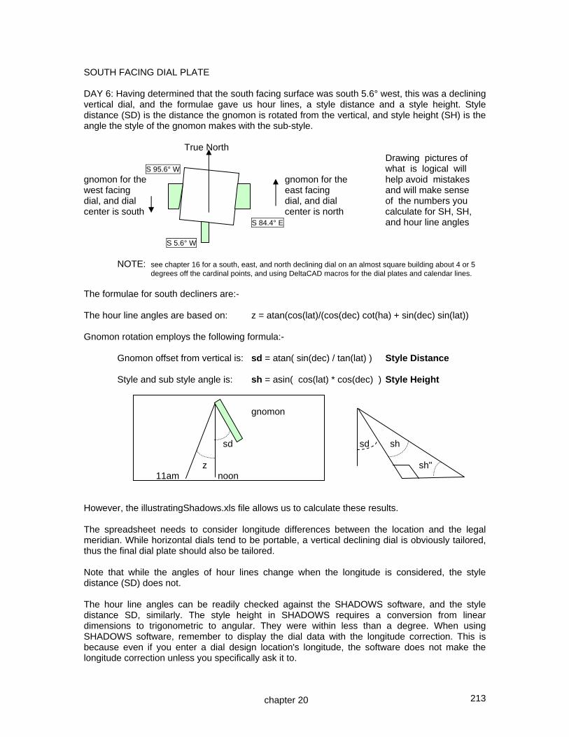
213
SOUTH FACING DIAL PLATE DAY 6: Having determined that the south facing surface was south 5.6° west, this was a declining vertical dial, and the formulae gave us hour lines, a style distance and a style height. Style distance (SD) is the distance the gnomon is rotated from the vertical, and style height (SH) is the angle the style of the gnomon makes with the sub-style. True North Drawing pictures of S 95.6° W what is logical will gnomon for the gnomon for the help avoid mistakes west facing east facing and will make sense dial, and dial dial, and dial of the numbers you center is south center is north calculate for SH, SH, S 84.4° E and hour line angles S 5.6° W
NOTE: see chapter 16 for a south, east, and north declining dial on an almost square building about 4 or 5 degrees off the cardinal points, and using DeltaCAD macros for the dial plates and calendar lines. The formulae for south decliners are:- The hour line angles are based on: z = atan(cos(lat)/(cos(dec) cot(ha) + sin(dec) sin(lat)) Gnomon rotation employs the following formula:- Gnomon offset from vertical is: sd = atan( sin(dec) / tan(lat) ) Style Distance Style and sub style angle is: sh = asin( cos(lat) * cos(dec) ) Style Height gnomon sd sd sh z sh" 11am noon However, the illustratingShadows.xls file allows us to calculate these results. The spreadsheet needs to consider longitude differences between the location and the legal meridian. While horizontal dials tend to be portable, a vertical declining dial is obviously tailored, thus the final dial plate should also be tailored. Note that while the angles of hour lines change when the longitude is considered, the style distance (SD) does not. The hour line angles can be readily checked against the SHADOWS software, and the style distance SD, similarly. The style height in SHADOWS requires a conversion from linear dimensions to trigonometric to angular. They were within less than a degree. When using SHADOWS software, remember to display the dial data with the longitude correction. This is because even if you enter a dial design location's longitude, the software does not make the longitude correction unless you specifically ask it to.
chapter 20
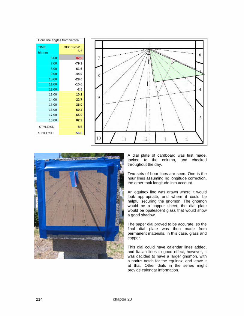
214
Hour line angles from vertical.
TIME DEC SxxW
hh.mm 5.6
6.00 82.9
7.00 -79.3
8.00 -61.6
9.00 -44.9
10.00 -29.6
11.00 -15.6
12.00 -2.5
13.00 10.1
14.00 22.7
15.00 36.0
16.00 50.3
17.00 65.9
18.00 82.9
STYLE:SD 8.6
STYLE:SH 56.8
chapter 20
A dial plate of cardboard was first made, tacked to the column, and checked throughout the day. Two sets of hour lines are seen. One is the hour lines assuming no longitude correction, the other took longitude into account. An equinox line was drawn where it would look appropriate, and where it could be helpful securing the gnomon. The gnomon would be a copper sheet, the dial plate would be opalescent glass that would show a good shadow. The paper dial proved to be accurate, so the final dial plate was then made from permanent materials, in this case, glass and copper. This dial could have calendar lines added, and Italian lines to good effect, however, it was decided to have a larger gnomon, with a nodus notch for the equinox, and leave it at that. Other dials in the series might provide calendar information.

215
DAY 7: The actual glass plate is constructed.
An iridescent white glass was used for the dial plate, it showed a good shadow, and the shadow reflection was tested at many angles. The noon line was the only hour with a marker. The segments were assembled with 1/4 inch copper foiled, soldered, and copper plated. The border was 1/4 inch copper tube. The dial plate was affixed using an adhesive suitable for tile and concrete block. One piece of glass was not cut as well as I normally cut them. No excuse for it, but since this was a textured iridescent glass, a new piece would have upset the look. The technique was to add a brass dragonfly to distract the eye from the hour line being slightly offset. It can be seen on the 10 am hour line just above the equatorial line. The lead lines (soldered copper foil) on the dial plate cannot be too tall as because they themselves can cause shadows at extreme solar angles.
Another distracter for the eye was added on the lower right corner, a glass jewel. Similarly a glass jewel was added where the hour lines converge. Care must be taken that such a jewel does not confuse the hour line shadow. DAY 8: EAST FACING DIAL PLATE Just as the south facing plate was a decliner, so also was the east and the west facing plates, in this case it was a great decliner. Again, no calendar lines would be designed in since the object was to emulate a cube dial from ones youth. Since the south dial was S 5.6 W, the west facing dial would be S 95.6 W, which is more than 90 degrees. It is also North 84.4 West. It uses the same spreadsheet as would be used for S 84.4 E. Using S 84.4 E in the illustratingShadows.xls spreadsheet, and using the S...E column, the style distance (SD) was found to be –57.1 degrees.
West facing East facing And as a double check for reasonableness, the angle from horizontal should be close to latitude for a great decliner such as this. And 90-57.1 is 32.9, so the SD was reasonable.
57.1 57.1
chapter 20

216
Longitude corrected
Legal L.A.T. -DEC S84,4E
hh.hh hh.hh -84.4
6.00 5.8 -57.6 7.00 6.8 -56.4 8.00 7.8 -55.0
9.00 8.8 -53.3
10.00 9.8 -50.7 11.00 10.8 -45.1
12.00 11.8 -19.3 13.00 12.8 -84.6 14.00 13.8 -67.6
15.00 14.8 -62.9 16.00 15.8 -60.5 17.00 16.8 -58.9 18.00 17.8 -57.6
SD -57.1 SH 4.7
The next step was to derive the hour lines themselves. Since this was a great decliner, the hour lines would be angled with a convergence point some distance from the dial itself. Pure east and west dials have hour lines that are parallel and meet at infinity TurboCAD was used to draw the hour lines, and also a square around the usable area, and even the style was drawn by projecting it, i.e. rotating it by 90 degrees so it was flat on the dial plate. The biggest problem was figuring out how to tell TurboCAD ~ OPTIONS ~ ANGLE to work. That tool is not intuitive and you may have to try several times before you get it to work for you.
The style height was 4.7 degrees, so the style would look something like... east facing west facing And a reasonableness check for a great decliner such as this would be that this should be close to the dial's declination from south. And 4.7 degrees is close to the 5.6 declination, so this was reasonable. The SD and SH reasonableness checks are for great decliners only just a bit off from the cardinal points. When the SOUTH FACING DIAL shown above was designed (day 6), the orientation of all gnomons was drawn. This helped orient which gnomon went where, and, where the dial centers would be for the east and west dials. The dial center is where the extended style of the gnomon eventually meets the extended dial plate.
chapter 20
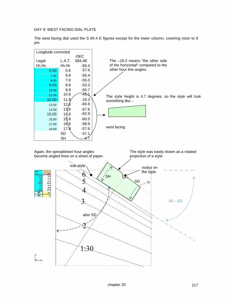
217
DAY 9: WEST FACING DIAL PLATE The west facing dial used the S 84.4 E figures except for the lower column, covering noon to 6 pm. Longitude corrected
Legal L.A.T. -DEC S84,4E
hh.hh hh.hh -84.4 6.00 5.8 -57.6
7.00 6.8 -56.4 8.00 7.8 -55.0
9.00 8.8 -53.3 10.00 9.8 -50.7 11.00 10.8 -45.1
12.00 11.8 -19.3 13.00 12.8 -84.6
14.00 13.8 -67.6 15.00 14.8 -62.9
16.00 15.8 -60.5 17.00 16.8 -58.9 18.00 17.8 -57.6
SD -57.1 SH 4.7
Again, the spreadsheet hour angles The style was easily drawn as a rotated become angled lines on a sheet of paper. projection of a style.
The style height is 4.7 degrees, so the style will look something like... west facing
SD SH
nodus on the style
sub-style
The –19.3 means "the other side of the horizontal" compared to the other hour line angles.
chapter 20
also SD
90 – SD

218
Having drafted the lines for the hours, and the style distance (SD) and style height (SH), they were printed out. While TurboCAD was used, any low cost drafting package would work. After the lines were drafted, then a surrounding containing box was placed where the dial plate looked more satisfying. Then the print out was placed in the middle of a cardboard mockup, and every line drawn to extend over the cardboard, remembering to use a different color for the SD and SH, Of course a leveling line was be included, visible at the top. Then the cardboard dial plates were placed on the dial vertical surfaces.
The east facing cardboard dial plate (pictured to the left) worked well on the actual dial. The west facing cardboard dial plate was tacked up tested, see below. When the cardboard dial plates were validated, then they would be converted to the final materials, of glass and copper. A large flower pot or other similar impediment to walking too close to the gnomons is a good idea. This protects the gnomons as well as the arms of passers by.
90-SD
SH
chapter 20
leveling line

219
While these dial plates were not made to display calendar lines, there is some benefit to an equinoctial line. If desired, the equinoctial line can be drawn easily. It is perpendicular to the sub-style line, which was drawn using SD. Its distance from the selected nodus is determined by projection and geometry, or by simple trigonometry. An exaggerated view of the gnomon is shown to the right. (1) style The equinox range of movement of the sun is on gnomon a disk perpendicular to the style. A line is drawn perpendicular from the style until it intercepts the sub-style, see (1). sub-style (2) Then, perpendicular to the sub-style (2) from that equinoctial line point of intersection, is drawn the equinoctial line. With glass and copper dial plates, an equinoctial line can be helpful as an additional anchor for the gnomon. When any calendar line exists, there must be a nodus. While for a predominantly east or west dial, a north or south edge of the gnomon can be used, for a south facing dial plate to have a long shadow, the style may need to be considerably longer than normal. Thus the style might need a nodus somewhere in the middle of the style. If an equinoctial line is drawn first at a place that is aesthetically pleasing or helpful in supporting the gnomon, reversing the above process will locate the required nodus. DAY 10: FINAL DIAL PLATE CONSTRUCTION As before, an iridescent glass that shows the shadows clearly would be used, 1/4 inch copper foil, and the final plate would be affixed with a tile adhesive.
For the final dial plate, the print out was placed in the middle of the glass and every line drawn to extend over the surface. A different color was used for the SD and SH lines, and for the leveling line which was also included. The glass was cut and foiled. Because some glass pieces were rather small, 7/32 and 3/16 foil was also used. Always pick glass that will show the shadow from usable angles, some glasses may not be suitable. Some rules of thumb: these gnomons are offset from a nearby hour line and are not
rectangular. The way to tell if they are correctly aligned (not necessarily correctly set) is to rotate the dial plate and see if the style parallels each hour line. This ensures correct alignment, however as stated, it does not protect from lateral and vertical gnomon errors, only rotational errors.
chapter 20
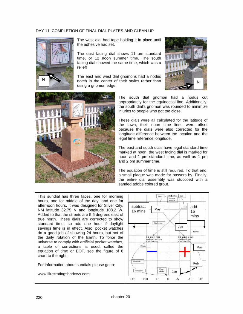
220
DAY 11: COMPLETION OF FINAL DIAL PLATES AND CLEAN UP
The west dial had tape holding it in place until the adhesive had set. The east facing dial shows 11 am standard time, or 12 noon summer time. The south facing dial showed the same time, which was a relief! The east and west dial gnomons had a nodus notch in the center of their styles rather than using a gnomon edge.
The south dial gnomon had a nodus cut appropriately for the equinoctial line. Additionally, the south dial's gnomon was rounded to minimize injuries to people who got too close. These dials were all calculated for the latitude of the town, their noon time lines were offset because the dials were also corrected for the longitude difference between the location and the legal time reference longitude. The east and south dials have legal standard time marked at noon, the west facing dial is marked for noon and 1 pm standard time, as well as 1 pm and 2 pm summer time. The equation of time is still required. To that end, a small plaque was made for passers by. Finally, the entire dial assembly was stuccoed with a sanded adobe colored grout.
This sundial has three faces, one for morning hours, one for middle of the day, and one for afternoon hours. It was designed for Silver City, NM latitude 32.75 N and longitude 108.2 W. Added to that the streets are 5.6 degrees east of true north. These dials are corrected to show standard time, so add one hour if daylight savings time is in effect. Also, pocket watches do a good job of showing 24 hours, but not of the daily rotation of the Earth. To force the universe to comply with artificial pocket watches, a table of corrections is used, called the equation of time or EOT, see the figure of 8 chart to the right. For information about sundials please go to: www.illustratingshadows.com
add 15 mins
subtract 16 mins
Jan
Feb
Mar
Apr
May
+15 +10 +5 0 -5 -10 -15
N N
chapter 20

221
CASE STUDY ~ A CUBE DIAL ON A COLUMN ~ mostly SW/SE points
This dial was to be a similar design to the previous example, but to be primarily SE and SW as opposed to mostly South and mostly East and West. The design method was the spreadsheet. This dial would be for Silver City, NM, whose coordinates are:
location lat: 32.75° N location long: 108.2° W magnetic declination: 10.6° E In these case studies, SD (style distance) and style height (SH) are the angular measures for vertical declining dials.
The column was built like the previous dial column using 12 of the 8x8x16 concrete blocks, a sack of pre mix concrete and some sacks of mortar. The pedestal was built to blend with surrounding construction angles. When finished, the declinations were measured with two different compasses from several directions. The southwest facing vertical surface faced magnetic 213 degrees, and the southeast vertical faced magnetic 123 degrees. With an almost 11 degree magnetic declination to the east of true north this meant that the magnetic declination had to be added to the magnetic bearing to get the true bearing. Thus the faces were 224 degrees true and 134 degrees true respectively. Now 224° is southwest, subtracting 180 for south we get S 44° W for the southwest dial plate. And 134° is southeast which when subtracted from 180 gives S 46° E for the southeast facing dial plate. N 44 E N 46 W S 46 E S 44 W
chapter 20
It was not the hoped for 45 degrees, but the exercise was worth that 2 degree difference.

222
SOUTH FACING DIAL PLATES Having determined that the south facing plates were S 44°W and S 46° E, the hour line angles must be deduced, as well as the sub-style, and style height. Also, the longitude is 108.2° which is 3.2° west of the legal time 105° meridian, that makes about a 12 minute difference. The formulae for south decliners are:- The hour line angles are based on: z = atan(cos(lat)/(cos(dec) cot(ha) + sin(dec) sin(lat))) Gnomon rotation employs the following formula:- Gnomon offset from vertical is: sd = atan( sin(dec) / tan(lat) ) Style Distance Style and sub style angle is: sh = asin( cos(lat) * cos(dec) ) Style Height gnomon sd sd sh z sh" 11am noon However, the illustratingShadows.xls file allows us to calculate these results. The spreadsheet needs to consider longitude differences between the location and the legal meridian. While horizontal dials tend to be portable, a vertical declining dial is obviously tailored, thus the final dial plate should also be tailored. To make the tables simpler to follow, in the tables for the four faces that follow a correction of 12 minutes is used rather than 12.8. The tables that follow use decimal hours (hh.hh) as opposed to hours and minutes (hh.mm). Always check to see whether decimals or normal time is being used. Note that while the angles of hour lines change when the longitude is considered, the style distance (SD) does not. The hour line angles can be readily checked against the SHADOWS software, and the style distance SD, similarly. The style height in SHADOWS requires a conversion from linear dimensions to trigonometric to angular. They were within less than a degree. When using SHADOWS software, remember to display the dial data with the longitude correction. This is because even if you enter a dial design location's longitude, the software does not make the longitude correction unless you specifically ask it to.
chapter 20

223
For the SOUTHWEST (noon to tea time) face we derived the following data.
ENTER minutes correction to a normal dial This shifts hour lines appropriately
12
ENTER A LATITUDE Legal L.A.T.
Hour line angles from vertical.
32.75 TIME (decimal ) TIME (decimal) DEC SxxW
hh.hh hh.hh 44 ENTER A WALL DECLINATION
hours and decimals of hours
44
SxxW is positive
12.00 11.80 -3.6
12.50 12.30 5.1
LEGAL 13.00 12.80 12.6 NOON 13.50 13.30 19.3 14.00 13.80 25.2 L.A.T. 14.50 14.30 30.6 NOON 15.00 14.80 35.6 15.50 15.30 40.3 16.00 15.80 44.9 16.50 16.30 49.5 17.00 16.80 54.1
17.50 17.30 58.8
18.00 17.80 63.8
STYLE:SD 47.2
STYLE:SH 37.2
Cross checking with other systems we found the style distance and style height were within tolerances. The 12:00 line (used 11.8 not 12.0 because of longitude correction) was -3.6 and so on. The lines to be drawn, including SD, are copied below in order. 12:00 12:30 13:00 14:00 15:00 1600 SD 17:00 18:00 -3.6 5.1 12.6 25.2 35.6 44.9 47.2 54.1 63.8 The dial plate is shown to the right for 12 through 6 pm. The style is the short line between 4 pm and 5 pm. The style height is shown by the shaded gnomon.
6
4
212
chapter 20
1
3
5

224
Similarly for the SOUTHEAST (breakfast to lunch time) face we derived the following data.
ENTER minutes correction to a normal dial This shifts hour lines appropriately
12
ENTER A LATITUDE LEGAL L.A.T.
32.75 TIME (decimal ) TIME (decimal) -DEC SxxE
hh.hh hh.hh -46 ENTER A WALL DECLINATION 6.00 5.80 -67.2
46 SxxW is positive 6.50 6.30 -62.2 SxxE is negative 7.00 6.80 -57.5 7.50 7.30 -52.9 8.00 7.80 -48.5 8.50 8.30 -44.1 9.00 8.80 -39.7 L.A.T. NOON 9.50 9.30 -35.0 10.00 9.80 -30.0 10.50 10.30 -24.5 LEGAL NOON 11.00 10.80 -18.4 11.50 11.30 -11.5 12.00 11.80 -3.5
STYLE:SD SD -48.2
STYLE:SH SH 35.7 Cross checking with other systems we find the style distance and style height are within tolerances. The 12:00 line (used 11.8 not 12.0 because of longitude correction) was -3.5 and so on. The schematic for the dial plate is to the right. In this case the sub-style and 0800 line was within 0.3 degrees of each other and thus essentially co-located.
chapter 20
1211 10
9
8
7
SD

225
The next step was to decide what would be on the dial plates, and where. By drawing the sub-style by using the style distance (SD), and the style height (SH), and thus the style, it was easy to decide what lines to have on the final dial plate, and what the gnomon would be like. Two boxed areas, shaded above, looked appropriate for the dial plates. The next step was to make the cardboard mockups.
It turned out that there was a protractor drafting error on the hour lines for the SE morning mockup plate. Not a math error, only a drafting mistake. This emphasized the need for care. Better to receive a wake up call and get the final plate correct than have to remove and redo it. A picture of the SE mockup is shown to the left, and it tested well, as did the SW mock plate, thus the final dial plates were constructed. The final SE plate is shown to the right shortly before it was mounted.
SE morning plate SW afternoon plate
SE mockup
SE actual
chapter 20

226
The preceding page showed the southeast dial plate in both mockup and final glass form before mounting.
To the left is the south west dial plate as a glass sheet before cutting. The hour lines have been sketched out as well as the sub-style line (style distance).
To the right is the final southwest plate cut and soldered. The major lines were cut in the glass, however some hour lines and the roman numerals were crafted with awg 14 copper wire. That copper wire will expand and contract with temperature, so to ensure rigidity each was soldered along its length and the ends held in place with a wooden dowel as each part was soldered. Before the gnomon was rigidly soldered to the dial plate, both the new dial plate and the paper mockup were affixed to a board so that each was parallel to the other. This board was then rotated to observe the indicated hours. They matched. However if they had not then there was time to redo the gnomon or the hour lines made using wire. Foiled lines where glass was cut obviously could not easily be corrected. The gnomon was marked on copper sheet, both the sub-style to the style, as well as another triangle which was the triangle made by the sub-style and the nearest hour line. That technique generates a rigid gnomon that is strong and less likely to bend over the years. The calendar lines of which there were two, the winter solstice and the equinox, were drawn with a laser trigon and simple geometry respectively. The laser technique is discussed towards the end of chapter 23.
chapter 20
circle for dial plate strength winter solstice calendar line equinox line

227
The NORTHEAST facing plate gets the sun also, so we may use the southwest plate's figures albeit mirrored.
ENTER minutes correction to a normal dial This shifts hours lines appropriately
12
ENTER A LATITUDE LEGAL L.A.T.
Hour line angles from vertical.
32.75 TIME (decimal hours) TIME (decimal) DEC SxxW
hh.hh hh.hh 44 ENTER A WALL DECLINATION 6.00 5.80 63.8
44 SxxW is positive 6.50 6.30 69.2
SxxE is negative 7.00 6.80 75.2
7.50 7.30 81.8
8.00 7.80 89.4
8.50 8.30 -82.0
9.00 8.80 -72.1 9.50 9.30 -61.0
10.00 9.80 -49.0
10.50 10.30 -36.6
11.00 10.80 -24.6
11.50 11.30 -13.5
12.00 11.80 -3.6 12.50 12.30 5.1
13.00 12.80 12.6
STYLE:SD 47.2
STYLE:SH 37.2
SD 47.2 SH 37.2 The hour line angle sign's change. What this means is that they passed through the horizontal. A depiction of the dial plate is shown to the right, and it may be tested, made, then installed on the northeast face. The northwest facing plate process was the same.
SH0600
0700
0800
0900
1000
chapter 20

228
The NORTHWEST facing plate got the sun also, so we used the southeast plate's figures albeit mirrored.
VERTICAL GREAT DECLINER Assumed longitude and legal time meridian This shifts hours lines appropriately Your longitude: 108.20 Legal meridian: 105
Minutes applied
12
*** NW/SE and NE/SW not symmetrical is long corr
Assumed latitude
Legal L.A.T. Hour line angles from vertical.
32.75 TIME (dec) TIME (dec) DEC SxxW
hh.hh hh.hh 46ENTER A WALL DECLINATION 12.00 11.80 -3.5
46 SxxW is positive 12.50 12.30 5.7 SxxE is negative 13.00 12.80 16.3 13.50 13.30 28.1 14.00 13.80 40.8 14.50 14.30 53.5 15.00 14.80 65.6 15.50 15.30 76.4 16.00 15.80 85.8 16.50 16.30 -86.1late early 17.00 16.80 -79.0pm am 17.50 17.30 -72.8136 134 18.00 17.80 -67.2
STYLE:SD 48.2 SD
pm am STYLE:SH 35.7 SH 46 44
The hour line angle sign's change. What this means is that they passed through the horizontal. A depiction of the dial plate is shown to the right, and it was tested, made, then installed on the northwest face.
chapter 20

229
The first dial plate constructed was the NORTHEAST facing plate. This used an iridescent white glass that threw a good shadow. The dial plate was cut, each piece of glass foiled with 7/32 inch foil, tacked, and the back then soldered, and again the front. The gnomon was cut and applied, and roman numerals added. The gnomon was cut with the 90° at the style, thus the equinox line was in this case at the gnomon's base, at right angles to the style distance line extended. With part of the gnomon construction on the rear side of the plate, that meant more places to solder to the gnomon, increasing its durability. Copper foil can alter the relative distances on the dial plate, especially when soldered. So the final glass plate was attached to a board along with the original model. The two being secured, they were rotated at various angles to the sun, here they show about 9:30 am. All the hour lines matched the model providing assurance that so far the final dial plate was correct. The equinox line looks strange, it is in fact correct, and the semi-circle is not a calendar line, it merely marks half hours. Both of those features are conversation pieces. That plate was affixed to the appropriate place on the cube on top of the column using a mastic, and along the top an epoxy. Mastic is not a perfect adhesive for glass but possible slightly better than thin set mortar in this instance. Either way, the final cube would have a surround of grout or stucco enhancing adhesion by reducing water drainage behind the dial plate. The equinox line for the north east face looks out of place especially since there were no solstice curve lines drawn. This particular face would only be seen by persons standing at the front door. The final dial is shown to the right looking from the east towards the west.
chapter 20
extended SD line
equinox line
half hour curve, not a calendar curve.

230
CHAPTER TWENTY ONE
Altitude Dials
It was mentioned earlier in chapter 4 that there were three methods of telling the time from the sun, they were by measuring its:- altitude (how high the sun is), or azimuth (how far east or west the sun is), or hour angle (the sun’s angle around the north south polar axis) The altitude of the sun is its angular height above the horizon, it is latitude dependent, and is not corrected by tilting a dial as can be done with hour angle dials without considering other factors such as north south alignment which defeats the altitude dial's benefit of not needing a compass. The altitude of the sun at any time is determined by the date, time and the sun's declination. ALTITUDE: The sun's altitude is its angle when looked at face on in degrees alt = degrees( ASIN( SIN(decl) * SIN(lat) + COS(decl) * COS(lat)*COS(lha) ) ) lha local hour angle of the sun lat angular direction north or south of the equator ~ do not confuse with LAT or L.A.T. (uppercase) meaning Local Apparent Time decl declination of the sun which is date dependent DECLINATION: = (23.45*sin(radians(0.9678(jd-80))) jd julian day of the year being 1 to 365 Jan Feb Mar Apr May Jun 0 31 59 90 120 151 Jly Aug Sep Oct Nov Dec
181 212 243 273 304 334 alternatively, the declination can be found by = degrees (0.006918 – 0.399912*cos(da) + 0.070257*sin(da) – 0.006758*cos(2*da) + 0.000907*sin(2*da) – 0.002697*cos(3*da) + 0.001480*sin(3*da) da day angle = 2 * pi * ( jd-1 ) / 365 (in radians, is an intermediate figure)
NOTE: The tables printed in this chapter are for illustration purposes, for actual dial design you should use the tables in the appendices, or print your own using the spreadsheets.
NOTE: Some pictorials have curves that do not seem to be smooth or perfect, and not up to the standards used in this book. The point was to portray the software mentioned as it actually works, and not to pretty it up. Thus such pictorials are true to the software used. Some pictorials are deliberately not to scale and a note states that fact. However, specific templates are of course accurate.
chapter 21

231
THE CAPUCHIN DIAL (An altitude dial) A Capuchin dial design begins with a horizontal line so that verticals can be drawn. A vertical is then drawn so that a semicircle may be drawn. The semicircle then has 15 degree arcs drawn and where those arcs hit the circumference of the semicircle, then verticals are drawn. These are the hour lines. 1. a horizontal line 2. a vertical is drawn 3. a hemisphere is drawn 4. the 15° lines 5. the vertical hour lines Where the top of the semicircle meets the horizontal line on the left, then is drawn a line up and to the right, at an angle equal to the dial's latitude. And, where that latitude line meets the original vertical, a line perpendicular to that latitude line is drawn, this is the calendar line. 6. latitude line 7. line perpendicular to latitude line 8. solstice lines latitude angle are drawn 12 and each 1 is 23.5° 2 from that 3 latitude line 4 5 6 pm June and July's angles with the sun are about the same, and December and January share similar angles also. These angles are called declination angles. One can be more precise and use the angles in the table below to make the calendar lines above and below the latitude line.
Date declination Date declination Date declination Date declination 1/1 -23.1 2/1 -17.3 3/1 -7.9 4/1 4.2 5/1 14.8 6/1 21.9 7/1 23.2 8/1 18.2 9/1 8.6 10/1 -2.9 11/1 -14.2 12/1 -21.7
One can also use the tables in the appendices, calculate them yourself using the formulas in the appendix, or build a spreadsheet using the techniques in the appendix on formulae. You can also measure the sun's angle with the horizon when it is at its highest point (solar noon) and subtract that from the co-latitude (90 degrees minus the latitude). You could also choose to use the middle of the month, whereas in the short table above, the first of the month was selected.
This is the first part of the design, and is nothing more than the hour line construction. There are 5 added vertical lines, 6 if you include the very first vertical, and those 6 lines together with the place where the semicircle meets the horizontal on the left form the hour lines, 12 noon on the left and then 11am and 1pm next, then 10am and 2pm, etc.
Then lines are drawn for the solstices, their angle is always 23.5 degrees, which is the amount the sun appears to move below and above the equator. The lines are thus 23.5° above the latitude line, and 23.5° below it. The top left line is the Winter solstice, December and January in the north hemisphere, the lower right line is the summer solstice, June July in the northern hemisphere.
chapter 21

232
9. draw the rest of the month lines. 12 1 2 June and 3 July arc 4 5 6 pm December and January arc 10. For each date on the calendar line, draw an arc from the 12 o'clock point towards the right. The dial is almost complete, holes are drilled in the calendar line, one hole per month point. And a wire or weighted thread is placed in the appropriate hole for the date, and the dial is ready for use. Its usage is described after the following notes on the use of computer aided design (CAD). The following are the steps used with a computer aided design program (CAD), in fact, they were drawn with CAD (computer aided design) software.
This was drafted using CAD and the construction lines are also shown. The left edge of the semicircle has drawn from it the latitude line and using the sun's declination from the tables or from a formula, a spreadsheet is shown for just this in the appendix, then date or calendar lines are drawn plus and minus from that latitude line. CAD makes this very easy to do. To use the dial, a pin is placed in the center of the semicircle. The dial plate is then pointed towards the sun and rotated until the pin's shadow meets the horizontal. Thus the sun's altitude is measured. A pendulum swings from the date in the slanted line and where it intersects its dated arc, then the time is read by the vertical hour
lines. Longitude corrections, equation of time (EOT) corrections, and summer time corrections are applied. The dial is less accurate towards noon. Of interest, the arcs associated for the dates show the sunrise and sunset times. The time of sunset or sunrise is where a vertical line drops from the date on the slanted line until it meets the date's associated arc. CAD systems can export the figure with construction lines, or a screen capture program can be used.
The monthly lines are drawn above the latitude line for the minus declinations (October through February in the northern hemisphere), and below the latitude line for positive declinations (April through September in the northern hemisphere). In the southern hemisphere the angles are switched. One point per month causes one arc to be drawn per month, see pictorial on the left, where only the summer and winter solstice arc are drawn.
chapter 21

233
The printed sheet can be placed on a sheet of wood, covered with a plexi-glass cover and stop drilled so that tacks will hold the dial plate in place. Then, holes are drilled on the slanted calendar line for each date. Somewhere a pin is needed to align its shadow with a horizontal line, in the home made wood example, that pin is a nail to the right of dial plate center. A copper wire pendulum is placed in the date hole nearest to the date, and then a reading taken. The indicated time should be corrected for longitude, and for the equation of time.
Studying the Capuchin dial provides understandings of the sun's northward journey in the European summer, its southward journey as Australia enters warmer times, and on how sunrise and its associated sunset may be deduced. The shepherd's dial discussed next provides clear evidence of how the sun's altitude limits are less in winter, more in summer. And for good measure shows how a dial can tell the time with no need for north south orientation. In the wood dial to the right, the pendulum is in the November hole. So, the pendulum is read where it intersects the November arc, which is at 8 am or 4 pm. Care must be taken not to read from the top or bottom arc, but only from where the pendulum intersects its own date arc. A capuchin dial is named after the Capuchin monks who wore hoods shaped like the arcs if inverted. The dial uses the sun's altitude only hence no compass is needed. These dials are less accurate in the winter, less accurate as noon approaches, and have a tough time with hours near sunrise and sunset. A DeltaCAD macro provided on the CD with this book will draft Capuchin dials, as will a FreeCAD Python macro.
chapter 21

234
THE SHEPHERD'S DIAL (An altitude dial) The shepherd's dial, like the capuchin, is an altitude dial and thus has no north orientation issues. It is simple to design yet may be more time consuming. The sun's altitudes must be derived. This can be done using a spreadsheet such as are in the appendices, and summarized below.
SOLAR DECLINATION FOR EVERY TEN DAYS AND HOURLY SOLAR ALTITUDE THIS TABLE IS FOR LATITUDE: 32
am altitude
Date declination 600 700 800 900 1000 1100 1200 Julian
1/1 -23.1 10.5 20.1 27.9 33.1 34.9 11/10 -22.1 0.2 11.2 20.9 28.8 34.1 35.9 101/20 -20.3 1.3 12.3 22.2 30.3 35.8 37.7 20
2/1 -17.3 3.0 14.3 24.5 32.9 38.6 40.7 322/10 -14.6 4.5 16.1 26.5 35.2 41.2 43.4 412/20 -11.2 6.5 18.2 29.0 38.1 44.5 46.8 51
3/1 -7.9 8.3 20.3 31.4 40.9 47.6 50.1 60 Some spreadsheets can produce charts, and the chart tempts us to use it directly for a shepherd's dial. However, the altitude lines are evenly spaced, whereas a protractor's angles, when extended to a line are not linear, they are the tangent of the angle. The solution is to modify the formula in the spreadsheet to be the tangent of the angle.
The chart above was produced by using a spreadsheet to produce a chart. The chart needs reversing to make it upside down, the axis needs marking, then it can be printed and used as-is. The dates need reversing also because of the chart rotation. The size of the gnomon is the distance from the top line (where the tan of the hour is 0) to the bottom of the noon line (where the tan of the hour is its largest), divided by the tan of largest noon altitude. The hour lines above are not smooth but some spreadsheets can draw smooth lines using CUSTOM charting, draw SMOOTH line options. This altitude dial is highly sensitive to the gnomon's length which must be accurate. An alternative to using a spreadsheet is to use a CAD program. The CAD technique is merely the same technique that you would use if you were using a ruler and a protractor. But it allows the drawing to be saved and later modified.
Note: the angle of the sun at solar noon is equal to the co-latitude (90 – latitude) plus the declination. And vice versa. E.G. 90 minus 32 is 58, minus 7.9 (March 1 declination) is 50.1, the noon altitude.
chapter 21

235
The gnomon should probably be designed first. To do this, the dial plate would be as wide as is the circumference of the cylinder. Then an appropriate height is selected. Then the steepest solar altitude is identified from the chart, and for latitude 32 that is 81.4 degrees, then from the bottom of the chart a line is drawn of that angle, and a horizontal line is drawn on the top, which is the sunrise and sunset line, and where they meet is where a protractor is laid. Then the altitudes are drawn to the dial plate's side, and horizontal lines extended from that point across all the months. If you use lettering in some CAD systems, you may find that font size on the screen does not scale linearly with the pictorials as you zoom out, although options exist to correct this. It is helpful to copy and paste from the spreadsheet into the CAD drawing, then a suitable zoom selected and then all drawing can be done without having to switch back and forth between spreadsheets and drawings. CAD files saved with pasted objects may take a lot of disk space.
In the above, a box of 6 by 6 inches was selected, the 81.4 degree line drawn from the bottom left of that box upwards until it intercepted a horizontal line extended along the top, and a protractor drawn at that point. Solar altitudes were measured from that protractor to the left vertical of the box, from whence horizontal lines were drawn to the month that had that solar altitude. One such angular line with its horizontal is shown for 10am or 2pm for July. The gnomon length is equal to the distance from the top left of the box to the center of the protractor, and when in use, the gnomon is exactly on the sunrise and sunset horizontal line, which obviously has 0 degrees from the protractor. The computer printed dial plate is protected with standard clear contact paper. To use the dial, the dial is set level and the gnomon style is set over the date in question, and rotated until the shadow falls vertically below the gnomon at which time the time is read. Longitude corrections are shown for Los Angeles, Phoenix, and Silver City, and approximate equation of time (EOT) values shown. The EOT values were mid month. In a perfect world the hour lines would have used the mid month also, however that is a learning opportunity for the next time.
81.4 was largest solar altitude
81.4
chapter 21

236
IMPROVEMENT FOR WINTER MONTHS
The winter months have hour lines that are more tightly packed together than the summer months, and to increase accuracy of the dial, two gnomons can be used and the chart split into two halves. One half, "U" shaped, covers the winter months, and the other half is "∩" shaped covering the summer months. To the right is a shepherd's dial using reclaimed waste water pipe material. The CD and website for this book have DeltaCAD macros that can build a shepherd's dial using several line drawing techniques, can provide the dual gnomon dial plate, and provide animation of the hour curves over a latitude range. Similarly, the FreeCAD Python program can draft Shepherd’s dials as well.
To the left is a DeltaCAD macro depiction, and above is that of the FreeCAD Python program.
chapter 21

237
THE O-G DIAL WITH FIXED GNOMON (An altitude dial)
11am 1pm
10am 2pm
9am 3pm
8am 4pm
Mar Oct
LAX -8
PHX +28
SVC +12Designed for
latitude 32
(c) Illustrated Shadows 2004
www.geocities.com/illustratingshadows
Simon Wheaton-Smith
70
60
50
40
30
2010
1/8
noon
7am 5pm
6am 6pm
Apr Sep
May Aug
Feb Nov
Jan Dec
8am 4pm
9am 3pm
10am 2pm
Jun Jly
7am 5pm
NOTE: the hour curves look somewhat wobbly, this was a function of the software, and this book intends to show the real results of software, weak and strong. For a final dial, use a flexible curve, or use more points to smooth the curve. There are many variants of the altitude dial, some are somewhat self designing such as the Capuchin, some requiring calculations, such as the Shepherd, and the O-G dial here.
This dial was constructed using CAD, and has little required structure. A gnomon at the top right casts a shadow on a horizontal line just like the capuchin dial, thus detecting the sun's altitude. For added benefit a protractor has been added. Attached to that gnomon is a string or other cursor which tells the time by virtue of it intersecting some date lines. The altitudes for each month came from the altitude tables for the latitude, and included on the dial plate is an EOT table as well as the longitude corrections for some cities. This dial requires altitudes for every hour for each month, hence the need for tables, whereas the Capuchin dial was self designing provided the sun's declination was established by tables, trigonometry, or noon time observation during the year. Accuracy is marginal in the noon hours, This dial is sometimes called an O-G dial for historical reasons, namely the curves likeness to the ogee form in architecture.
chapter 21

238
THE HORIZONTAL ALTITUDE DIAL (An altitude dial) A dial can be made that is horizontal yet is still based on altitude. It thus does not need compass alignment, it is rotated to align the shadow with the month in question.
This process is simple, the altitude table for the latitude is taken, and the entire table subtracted from 90 degrees. This will make line drawing a lot easier. A box is drawn, and 30 degree lines drawn from an off-center center, the center is somewhat to the left in this
case. The 30 degree lines facilitate construction of the month hour lines. Months lines are drawn, the solstices are on the horizontal, and the other five months occupy the 30 degree lines. From the center, an arc is drawn above the box that will have as its radius the gnomon's height. Every month line, the two that make up the horizontal, and the other five, have a 90 degree perpendicular drawn, and it intersects the arc. The February October line has a perpendicular shown. Where that perpendicular meets the arc, whose radius is the gnomon's height, lines are drawn whose angle equals the sun's altitude subtracted from 90 degrees. The table to the upper right is nothing more than a copy of the altitude table for the latitude, and each cell was subtracted from 90 degrees. The process is repeated for each calendar line. By using 30 degree separations, it is easier to construct the entire dial plate. CAD software was used for the process. The biggest problem was setting the CAD program's angle baseline. Of course a rule and protractor will work very well also. CAD software's bezier line drawing was used to connect the hour points to the nautilus shaped line. To use the dial, align the shadow of the gnomon with a month line, and read the time on the curved hour line. No compass alignment is needed. This dial just isn’t practical for hours close to 6 or 7am or 6 or 5pm, and not very accurate around noon. In this dial, the gnomon's height is of course critical.
chapter 21

239
THE PLANISPHERIC ASTROLABE (An altitude dial using the ecliptic)
Of old, the astrolabe was used for various astronomical and astrological calculations, In particular, it could also be used to determine the time from the sun's altitude, which when corrected for the equation of time and longitude, would provide the legal standard time. Unlike the altitude devices discussed elsewhere, this device is directly based on the ecliptic, and since the Earth and
the sun are always on the ecliptic, and since the ecliptic moves by the second, minute, and hour, the sun's altitude pinpoints an ecliptic point, and together with the rest of the magic of the astrolabe, the time is hence derived. Most astrolabes not only have the ecliptic, they also include the stars. The planispheric astrolabe, described here, uses a "projection" of the Earth and the celestial sphere to the equator. Another variant uses the Saphea projection onto a vertical plane. The theory is that projecting onto a circular slice of a globe perpendicular to a projection focal point, results in circles on the surface being preserved on the projection plane, angles similarly. projection plane projection focal point latitude 33° circles
latitude 90° circles latitude 0° circles
There are more rigorous proofs, mathematical and geometrical, however this explains the principle of stereographic projection as it is called. Another key point is that the celestial sphere, stars and the ecliptic will exist on the surface of the globe. The third key point is that the ecliptic will be a plane slicing through the globe as a great circle whose angle of slice will be 23.5 degrees, being the Earth's polar axis offset from the plane of orbit, the ecliptic.
A circle is placed on the globe at latitude 33° for example, and lines drawn from the perimeter to the south pole in this case as a projection focal point. Those lines will intersect the equatorial plane and still form a circle. If several circles are projected, then several circles are the result, however, their centers on the equatorial plane may not be co-located, they may be offset. If those circles were at latitude 90, it is obvious that the projection would be circles, and in that specific case they would also have a common center.
If the circles were on the equator, and projected to the equatorial plane, i.e. a 90 degree projection, they would still be circles. The secret is to look at the projecting lines as a cone, and the projection is always the same angle of slice on that cone as are the original circles.
A half Dinar note from Iraq with an astrolabe portrayed
chapter 21

240
Astrolabes consist of pieces. The part that holds everything together is the mater, from the Latin for mother. Resting in or on the mater is a plate having projected circles depicting altitudes from the horizon, called almucanters. They are part of the time telling secret. And rotating on the almucanter plate, sometimes called a climate plate, is what is called the rete. The rete has the ecliptic circle on it, and sometimes the stars. Using the astrolabe is simplicity itself. The sun's altitude is measured, usually by a simple protractor system on the back of the astrolabe. And then the rete which has dates on the ecliptic circle, is rotated until the date touches the sun's altitude circle (almucanter) and their intersection when extended to the outer circle on the mater from the center, depicts the local apparent time. First, a climate plate must be constructed for the desired latitude.
To the right is the planet Earth with the equator, and part way up the globe is a cylinder depicting 80° of altitude, or 10° from the observer's vertical. Those angles are altitudes seen by an observer on the surface of the planet at the center of all those circles. The picture to the right simplifies this by placing the observer in the Earth's center. The planispheric astrolabe only uses two key concepts in its design. First those cylinders of altitude which are circles on the surface of the planet, are reduced to projected circles on the equator, and they become the climates or the plate with the almucanters, or altitude circles. These are sometimes confused with latitudes and they are not, however, each almucanter of n° is 90-n° from the observer on the observer's meridian or line of longitude. Second, the ecliptic is reduced to scale using the same globe profile as for the climate or almucanter plate, on a movable plate called the rete. The next pages discuss this transformation.
A circle is drawn representing a vertical slice of the planet, a north south line and an equator line are drawn. Then a line for the desired latitude, 33° in this case. Then circles of altitude are drafted, depicted by two limiting lines, in this case they are 10 degrees apart. Two or five degree separation is more practical. These are circles depicting altitude. The altitude they depict inversely matches their north/south distance from the observer. So 0° from the observer is the 90° altitude almucanter, 90° south of the observer is the 0° almucanter, etc.
altitudes when viewed from planet's center
This is a profile view of the globe below to the right.
chapter 21

241
The profile of the planet is drawn, as shown on the previous page. This has the altitude circles or cylinders, called almucanters. Then they are projected to the equator, as shown below.
When all altitude circles are completed, i.e. their lines projected to the equator, then those limits are used to draw the final circles for the climate plate. Above only the 10° increments are shown, with 2° being more common. This is done by drawing a circle, placing its left side on one of the projected circle's limits, and its right side similarly. All the desired circles are drawn and then printed onto a dial plate, the climate plate, ready for use. A point is drawn on the altitude circle or almucanter at the altitude equal to the latitude of the observer, or the dial plate or climate plate's design location. That point will be the center of the final climate plate, and around which the ecliptic rete plate will revolve. Hour lines of 15° radiate from that center on the climate plate, and will be the final hour lines, they usually exist on the mater however.
This is the 80° altitude circle, cylinder, or almucanter on the surface of the planet.
This is the 80° altitude cylinder's limits when projected onto the planet's equator.
observer
chapter 21

242
To the right is the final layout for the climate plate holding the almucanters. Hours can then be marked on 15 degree radials from the almucanter matching the latitude of the observer, not from the zenith, or they can be added to the mater plate later. The scale for the climate plate almucanters and the scale for the second and last plate, the rete which holds the ecliptic, must be the same. The center of the 15 degree radials, which is the almucanter matching the observer's latitude, will also be the center of the rotating rete. Next, draft the latitude independent rete.
The same circle used for initially projecting and drafting the altitude lines, is copied retaining the scale. From the center of that new circle is drawn a line at 23.5° line from the equator, being the ecliptic. For the northern hemisphere, the upper part that intersects the circle is the June solstice. When projected, this will be the June 21st date on the rete, or projected ecliptic.
The lower intersection will be the December solstice. In the pictorial above, the ecliptic plane is projected to the equatorial line, a rete plate center located, and the limits of what will be the ecliptic circle are identified. Just as for the climate plate, and retaining the scale, the ecliptic circle is drawn. This is a circle and not an ellipse, the ecliptic being a collection of ecliptic intersections on the globe or planet, which forms a great circle, hence why a circle is used. The final rete plate, whose scale is retained, is then printed onto a final plate. Note that its center of rotation is offset. Just as hours were added to the 15 degree radials on the climate plate, dates are added to the rete. The June solstice is June 21, the December solstice is December 21st. Scale is critical, however some editorial resizing occurred in the above drawings.
12
93
projected December solstice
rotational center of the rete plate
projected June solstice
6
December solstice
June solstice actual ecliptic
projected ecliptic
chapter 21
center of the planet

243
Here the dates have been added in. Of course, the dates are symmetrical, thus March and September and their intervening dates can be swapped should you so wish. Most astrolabes use the zodiac calendar on the rete plate, and the back side of the astrolabe has a conversion from the calendar in fashion at the time, to the zodiac. So take the "21" of the month, as shown, with a pinch of salt. Similarly, the hours on the mater plate are traditionally shown clockwise, however they can be reversed. It all depends on how you make your rete rotate to intersect with a solar altitude curve or almucanter.
The final rete is cut and mostly consists of empty space so the almucanters can be seen.
Above are both the climate plate on the left and the rete on the right, scale retained. All that is needed is for the hours to be marked on the 15° radials of the climate plate, they will be projected to the rim of the mater. From the rotational center of the climate and rete plates is usually attached a rule so the intersection of the sun's altitude with the date can be projected to the outer scale displaying the L.A.T.. The back of the astrolabe usually has an altitude measuring protractor, and often a conversion from the normal calendar to the zodiac. An equation of time table may be added, and a table of longitude differences for places on the design latitude similarly.
September 23
rotational centers of the climate plate (left) and for the rete plate (right)
chapter 21

244
The circle of the rete and its rotational point are copied to the climate plate because the rete's center is located on the almucanter associated with the climate plate's design latitude. Then, a circle is drawn from the rotational center to the limit of the rete, this last circle is the final climate limiting circle, and outside of that will be the mater. And hours are added as 15 degree radials from the rotational center. That mater's outer circle can be bigger than the rete's limits, not smaller. If bigger then it is easier to see where the rete is in relation to the almucanters.
The back of the astrolabe The rete is latitude The outer periphery is the has date conversions, the independent and mater, enclosing the climate EOT, and altitude protractor has the dates or almucanter plate of the sun's altitude lines The above is the mater (outer area with the hours marked), within which is placed the climate or almucanter plate, which is fixed, and on that is the rete which rotates. Its date is set to the sun's altitude on an almucanter arc, and a line projected from the rotational center indicates the local apparent time on the mater. All that is needed is a rule to help point the time, and on the back, a protractor and alidade, the alidade is the name for the altitude measuring rule. The equation of time may be added, and other dial furniture.
chapter 21
tangential lines for the rotational limits of the rete

245
The completed astrolabe in use is shown below. The altitude was found using the back, and the date and altitude made to intersect on the front. When that intersection was projected to the mater it indicated the time. After building an astrolabe, check some date/altitude intersections and their resulting time with the altitude tables or formula to verify the astrolabe's accuracy.
Sunset can be determined by moving the date on the rete to intersect with the 0 degree altitude line or almucanter. That intersection when extended to the mater from the rotational center will provide the L.A.T. for sunset, or sunrise. There is little written on astrolabe design. The appendices of this book take the preceding geometric figures and convert them to trigonometry suitable for a spreadsheet or a DeltaCAD macro. This book's website and CD have such a spreadsheet and DeltaCAD macro. There is a good article on stereographic projection for the climate plate at:- http://www.math.ubc.ca/~cass/courses/m309-01a/montero/math309project.html An astrolabe generator is available at::- http://www.uwsp.edu/physastr/rislove/astrolabe/resource.htm or on the CD and web site associated with this book as a DeltaCAD macro Another set of excellent resources on astrolabes is at Mr. Morrison's web site:- http://www.astrolabes.org/links.htm http://www.astrolabes.org/theastrolabe.htm [Mr. Morrison's definitive work on astrolabes] Commercially available astrolabes can be acquired from:- Norman Greene, 1215 4th St., Berkeley, CA, 94710 http://www.puzzlering.net/astrolabe.html While the Norman Greene astrolabes are smaller and less detailed than some others, and while many commercial astrolabes suffer from a bright climate plate or plates with hard to read markings, the Norman Greene astrolabe is possibly one of the most practical commercial astrolabes to use overall. Until the TSA screeners at airports became suspicious of mine, I used to travel with it for many years.
To the left is the alidade showing 35 degrees of sun altitude. To the right, the rete's date is rotated to the almucanter for the 35 degree sun altitude. The intersection when extended shows the L.A.T. and when longitude and EOT are considered, the legal standard time.
chapter 21
This astrolabe consistently provides the time within 4 minutes when corrected for longitude and EOT.

246
CHAPTER TWENTY TWO
Azimuth Dials It was mentioned earlier in chapter 4 that there were three methods of telling the time from the sun, they were by measuring its:- altitude (how high the sun is), or azimuth (how far east or west the sun is), or hour angle (the sun’s angle around the north south polar axis) The azimuth of the sun is its angular distance from true south, it is latitude dependent. The azimuth of the sun at any time is determined by the date, time and the sun's declination. AZIMUTH: azi = ATAN( SIN(lha) / ( (SIN(lat) * COS(lha)) – (COS(lat) * TAN(decl))) DECLINATION: = (23.45*sin(radians(0.9678(jd-80))) jd julian day of the year being 1 to 365 Jan Feb Mar Apr May Jun 0 31 59 90 120 151 Jly Aug Sep Oct Nov Dec
181 212 243 273 304 334 alternatively, the declination can be found by = degrees (0.006918 – 0.399912*cos(da) + 0.070257*sin(da) – 0.006758*cos(2*da) + 0.000907*sin(2*da) – 0.002697*cos(3*da) + 0.001480*sin(3*da) da day angle = 2 * pi * ( jd-1 ) / 365 (in radians, is an intermediate figure) There are a number of common azimuth dials. Two of note are the Winged Azimuth dial, and the so called Analemmatic dial. So called “analemmatic” dials are “so called” since they have nothing to do with the analemma.
chapter 22
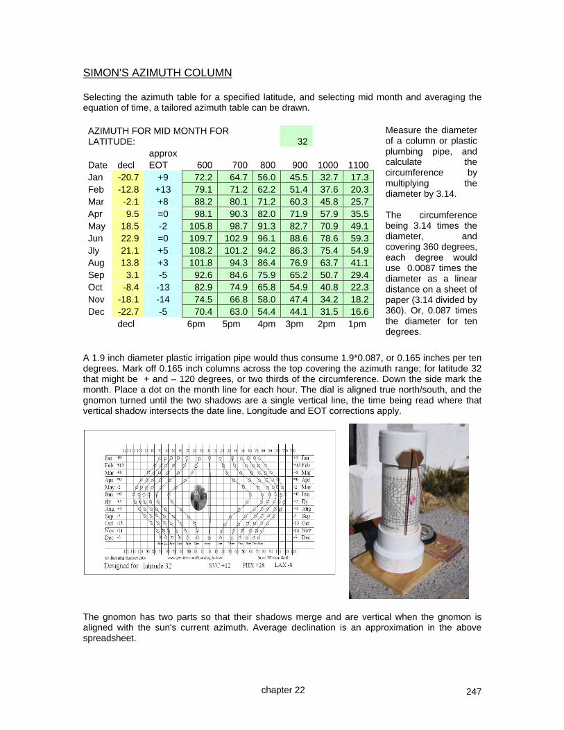
247
SIMON'S AZIMUTH COLUMN Selecting the azimuth table for a specified latitude, and selecting mid month and averaging the equation of time, a tailored azimuth table can be drawn. AZIMUTH FOR MID MONTH FOR LATITUDE: 32 approx Date decl EOT 600 700 800 900 1000 1100Jan -20.7 +9 72.2 64.7 56.0 45.5 32.7 17.3Feb -12.8 +13 79.1 71.2 62.2 51.4 37.6 20.3Mar -2.1 +8 88.2 80.1 71.2 60.3 45.8 25.7Apr 9.5 =0 98.1 90.3 82.0 71.9 57.9 35.5May 18.5 -2 105.8 98.7 91.3 82.7 70.9 49.1Jun 22.9 =0 109.7 102.9 96.1 88.6 78.6 59.3Jly 21.1 +5 108.2 101.2 94.2 86.3 75.4 54.9Aug 13.8 +3 101.8 94.3 86.4 76.9 63.7 41.1Sep 3.1 -5 92.6 84.6 75.9 65.2 50.7 29.4Oct -8.4 -13 82.9 74.9 65.8 54.9 40.8 22.3Nov -18.1 -14 74.5 66.8 58.0 47.4 34.2 18.2Dec -22.7 -5 70.4 63.0 54.4 44.1 31.5 16.6 decl 6pm 5pm 4pm 3pm 2pm 1pm
A 1.9 inch diameter plastic irrigation pipe would thus consume 1.9*0.087, or 0.165 inches per ten degrees. Mark off 0.165 inch columns across the top covering the azimuth range; for latitude 32 that might be + and – 120 degrees, or two thirds of the circumference. Down the side mark the month. Place a dot on the month line for each hour. The dial is aligned true north/south, and the gnomon turned until the two shadows are a single vertical line, the time being read where that vertical shadow intersects the date line. Longitude and EOT corrections apply.
The gnomon has two parts so that their shadows merge and are vertical when the gnomon is aligned with the sun's current azimuth. Average declination is an approximation in the above spreadsheet.
Measure the diameter of a column or plastic plumbing pipe, and calculate the circumference by multiplying the diameter by 3.14. The circumference being 3.14 times the diameter, and covering 360 degrees, each degree would use 0.0087 times the diameter as a linear distance on a sheet of paper (3.14 divided by 360). Or, 0.087 times the diameter for ten degrees.
chapter 22

248
AZIMUTH DIALS – Table A4.2 cover latitudes 30 to 60 The azimuth of the sun varies hourly for any given date. Azimuth is the angle left or right of noon, as opposed to altitude which is the angle up from the horizon. And they are both different from the hour angle of the sun, which is measured around a polar axis aligned style.
to the left is the DeltaCAD macro depiction below is the FreeCAD Python program depiction
One type of azimuth dial is shown above. Arcs of any convenient size are drawn, one for each month, and using an azimuth table, the azimuth angles are drawn for each hour on the monthly lines. June and December have their own lines, as they hold the solstices, other month lines are used for two months. The azimuth degrees are close enough. This top left chart was drawn using DeltaCAD macros, and to the right is the same using FreeCAD Python programs, all provided with this book. The hour curves near the summer solstice seem to differ, this is because the programs use different methods to determine the radius for a given solar declination, and also slightly different declinations. Both are correct! The dial above was read on December 10, and the displayed time is about 4:15 in the afternoon, to which 12 minutes is added for longitude correction, and 5 minutes subtracted for the equation of time, making it tell 4:22 pm. It was fairly close. Lessons learned were to choose a thinner gnomon pole, and not to press too hard on the Plexiglas, otherwise it would crack. It might seem obvious that the summer months should be closer to the gnomon, the winter months on the outer periphery. It may seem more logical, however this wise idea should be balanced with the need for better resolution of the hours in the May through September months.
chapter 22

249
A common question is that the azimuth dial hour points do not form a straight line from anywhere, so it must be wrong. The azimuth points are just directions from a gnomon and not a dial center they are not distances, not lines. Thus the azimuth points and the curve they live on are not intended to be points from which an hour line could be drawn from a dial center. The angles they represent are all they represent, and it is those angles that would exist on an hour line for an hour angle chart, and those angles would actually be calendar points for the hour in question!
The figure to the left shows the shapes when the summer months are drawn closest to the gnomon and the winter months further away. It just doesn’t look impressive, in fact it looks depressed!
chapter 22

250
AZIMUTH DIAL ~ but in clay Another dial that uses azimuth only has arcs for the sun's declination, and points on those separate arcs that indicate the hour in question. To the right, drawn with DeltaCAD using a program on the CD accompanying this book, and also available on the web site, is a dial plate for an azimuth dial. Here the gnomon is fixed and doesn't move. An animated version is available showing how the hour lines vary with latitude. This dial type was fully discussed elsewhere and is offered here to show it worked in clay. For portability reasons, a paper azimuth dial was printed with no longitude correction. A slab of clay was rolled into a circle, and a drafting compass used to draw an outer circle and then the three declination arcs to scale. If portability is not a factor then the DeltaCAD program can produce such a dial with longitude correction. The paper dial was cut at the 5 am (left) mark, following the curves to the 7 pm arc. The paper dial was placed on the dial plate after the slip had been applied and dried for a couple of hours.
Then a scribe was used to mark those two hour curves. The paper dial was removed and the next pair of hours was cut, then scribed, and so on until the entire dial was complete. The equation of time (EOT) was marked on the outer circle with monthly average numbers, and the latitude inscribed. No longitude was marked as this dial was not longitude corrected. After the picture was taken it was noticed that the solstice and equinox arcs were not marked, so they were added before the clay dried. The clay dial plate was then left to dry, and in so doing the clay shrank about 10% or more as it dries.
chapter 22

251
The picture to the right shows the clay plate after it dried. The clay has nicely separated itself. Do not manually separate the clay yourself before it has dried, if you do so then the clay may curl up at the edges. Let it do its own thing. The dial plate was then placed in a kiln and given a bisque firing, that is around 1800 degrees F. Kilns need clearance from combustible walls and floors, and should be vented. Venting is important because some materials used can be somewhat toxic during the firing process.
After the bisque firing, the clay was allowed to cool down, and then a glaze applied. The glaze looks somewhat opaque, as seen to the left. However when fired to cone 6 (heat) or to 2230 F (temperature), it then becomes transparent and melts, and fuses with the clay itself, becoming stoneware. Clay being bisque fired can be stacked on top of other items in the kiln, see right. This is because the clay has dried. So has the slip, and
slip is nothing more than clay, water, and pigment. The mixing of a coloring pigment with the clay being used makes a colored clay that expands or contracts with the clay material beneath it. Thus when dried, the slip coloring is in essence the same as the underlying clay. And it is not a glaze. That is why items being bisque fired can be stacked.
However, when glaze is added and fired, the glaze becomes in essence molten glass. Thus a glaze firing cannot be done by stacking as the glasses would merge. To the left is the plate after the glaze firing. Glaze was liberally applied, and the kiln held at cone 6 for some time in order to ensure the resulting stoneware would not be damaged by freezing moisture in the winter. When multiple pieces of clay are glaze fired, they are separated by kiln shelves or furniture. Those shelves should be coated with kiln wash. Kiln wash is a powder that creates a barrier between the item being fired and the firing shelves, should the glaze run.
The glaze firing being complete and cooled down, the dial plate was removed. A vertical gnomon such as a brass rod was located in the center of the circular concrete paver, secured with epoxy. Then an exterior tile adhesive was used to affix the clay plate pieces to a concrete paver which also reinforced the seal on the unglazed lower side and edges of the clay tile. Sanded grout was applied when the adhesives had dried. After a few days of curing, a second grout application may be needed to resolve residual cracks. When fully cured, the grout should be sealed, otherwise moisture can seep in and cause tile damage on a subsequent deep freeze. And... to the right is the finished dial.
chapter 22

252
THE ANALEMMATIC DIAL The analemmatic dial is an azimuth dial with no hour lines, only hour points, to which the extension of the shadow points, and the gnomon moves with date. The gnomon is not polar axis aligned, it is simply a vertical pole, sometimes a person in a garden area, however the ellipse of hour points is true north or south aligned.. h m x M A J O R A X I S M C h' M I N O R A X I S The ellipse has a major axis left to right (west to east) and a minor axis up and down (north down to south). The semi major axis (M) is used in the formulae, being half of the east west major axis. The semi minor axis (m) is: m = M sin ( lat ) semi minor axis is sin of latitude times major axis (at latitude 32, m = 0.53 times major axis M, or, if M=6 units wide then "m" is 3.18 units deep) Should you wish to draw an ellipse, set a drafting compass to match the semi-major radius M, i.e. C~ML. Move the drafting compass point to point "mt" and draw two short arcs at "a" and "b". h ~ a point on the ellipse mt a b C h' ML MR mb Insert a pin at "a", "b", and "mt", connect with a taught thread, place a pencil at "mt", then run the circumference to draw the ellipse. For a large dial such as in the following case study, a length of string may be used in place of the drafting compass and a taught thread.
chapter 22

253
If you do not wish to draw an ellipse because it is impractical, as for example for a dial on a lawn, then an hour points location is defined by:- hour point's horizontal distance:- hour point's vertical distance:- Ch' = M * sin ( 15 * hours) hh' = M * sin ( lat ) * cos ( 15 * hours ) or to get an hour point by angle from C assuming an ellipse has been drawn x = arctan ( tan( t ) / sin ( Ø ) )
HOUR HOUR ANGLE arctan ( tan( hour from noon * 15) / sin ( latitude ) ) Lat: 30 32 34 36 38 40 45 50 55
12 12 0.0 0.0 0.0 0.0 0.0 0.0 0.0 0.0 0.0
11 13 28.2 26.8 25.6 24.5 23.5 22.6 20.8 19.3 18.1
10 14 49.1 47.5 45.9 44.5 43.2 41.9 39.2 37.0 35.2
9 15 63.4 62.1 60.8 59.6 58.4 57.3 54.7 52.5 50.7
8 16 73.9 73.0 72.1 71.3 70.4 69.6 67.8 66.1 64.7
7 17 82.4 81.9 81.5 81.0 80.6 80.2 79.3 78.4 77.6
6 18 90.0 90.0 90.0 90.0 90.0 90.0 90.0 90.0 90.0
5 19 -82.4 -81.9 -81.5 -81.0 -80.6 -80.2 -79.3 -78.4 -77.6
4 20 -73.9 -73.0 -72.1 -71.3 -70.4 -69.6 -67.8 -66.1 -64.7
am pm negative angles are simply below the east west line. Notice that the hour points are points and there are no hour lines. The next calculation is the gnomon, and this is north of the ellipse center in summer and south of it in winter. The analemmatic points for the gnomon calendar are placed to put the gnomon as follows:- z = M * tan (dec) * cos ( lat ) gnomon distance +up -down on N/S axis M * cos ( lat ) * tan (dec) Date Avg decl 30 32 34 36 38 40 45 50 55 60
Jan -20.3 -0.32 -0.31 -0.31 -0.30 -0.29 -0.28 -0.26 -0.24 -0.21 -0.18 1.00
Feb -12.5 -0.19 -0.19 -0.18 -0.18 -0.17 -0.17 -0.16 -0.14 -0.13 -0.11 1.00
Mar -1.6 -0.02 -0.02 -0.02 -0.02 -0.02 -0.02 -0.02 -0.02 -0.02 -0.01 1.00
Apr 9.6 0.15 0.14 0.14 0.14 0.13 0.13 0.12 0.11 0.10 0.08 1.00
May 18.4 0.29 0.28 0.28 0.27 0.26 0.25 0.24 0.21 0.19 0.17 1.00
Jun 22.5 0.36 0.35 0.34 0.34 0.33 0.32 0.29 0.27 0.24 0.21 1.00
Jly 20.9 0.33 0.32 0.32 0.31 0.30 0.29 0.27 0.25 0.22 0.19 1.00
Aug 14.1 0.22 0.21 0.21 0.20 0.20 0.19 0.18 0.16 0.14 0.13 1.00
Sep 3.8 0.06 0.06 0.06 0.05 0.05 0.05 0.05 0.04 0.04 0.03 1.00
Oct -7.4 -0.11 -0.11 -0.11 -0.11 -0.10 -0.10 -0.09 -0.08 -0.07 -0.06 1.00
Nov -17 -0.26 -0.26 -0.25 -0.25 -0.24 -0.23 -0.22 -0.20 -0.18 -0.15 1.00
Dec -22.1 -0.35 -0.34 -0.34 -0.33 -0.32 -0.31 -0.29 -0.26 -0.23 -0.20 1.00
The dial may be constructed using a CAD system, and the angles may be proved by drawing a line from a calendar point to an hour point and checking the azimuth tables in the appendix for that latitude, date, and hour. Appendix 4.3 provides these values. Average declination is an approximation in the above spreadsheet.
chapter 22
Semi major axis "M" is 1.00

254
An analemmatic dial drafted in CAD is shown, together with a real dial printed from CAD, with a gnomon inserted, displaying the correct time when longitude and EOT corrections are made.
chapter 22

255
CASE STUDY ~ AZIMUTH DIAL ~ analemmatic dial for a garden The local recreational center, where children on school breaks of vacations spend their time doing constructive things, is an ideal place for what is called the analemmatic dial. In essence it is an azimuth dial where there are no hour lines, only points on an ellipse, and there is no fixed gnomon, it moves north or south based on the month. Constructing such a dial on the order of 20 feet across takes about an hour and in this example uses eleven 2x12x12 pavers and 8 bricks. The method is simple. A north south line is constructed with a compass after considering magnetic variation or declination. Then the spreadsheet: illustratingShadows.xls from the main Illustrating Shadows web site or on the CD that comes with the book is opened, and the latitude entered along with the east to west dimension of the ellipse. The result is a set of calendar points for the gnomon positioning which will have the winter solstice closest to the equator, and the summer solstice closest to the pole, on a north to south line. Additional results are the horizontal and vertical distances for the hour points.
ENTER latitude 32major ellipse east to west distance 16.00
gnomon distance up/down north/south based on ellipse center = z = M * cos ( lat ) * tan (dec)
Avg Latitude
Date decl 32 Jan -20.3 -2.51 -2.95Feb -12.5 -1.50 total
Mar -1.6 -0.19 north to
Apr 9.6 1.15 south
May 18.4 2.26 distance is
Jun 22.5 2.81 5.90
Jly 20.9 2.59 assuming
Aug 14.1 1.70 plus and
Sep 3.8 0.45 minus
Oct -7.4 -0.88 23.50
Nov -17 -2.07 extremes
Dec -22.1 -2.75 2.95
With the latitude and east west dimension entered, the spreadsheet provided the north and south distances for the base of the gnomon. In this example of latitude 32 and a 16 foot wide ellipse, the January to June distances of the gnomon base range from minus 2.51 to plus 2.81, and for June to December the range is 2.81 to minus 2.75.
chapter 22

256
The spreadsheet also shows the north south dimensions of the ellipse.
Major ellipse axis (east-west diameter) 16.00
in feet or other units
north-south radius
m = 4.24
m = M * sin(lat)
M = 8.00
(east-west radius) M
minor ellipse axis
north-south
8.48
The above ellipse is not drawn to scale, the pictorial is simply to help orient the diallist. At this point an ellipse can be drawn and the angles from the ellipse center used to identify the hour points. Alternatively the east west and the north south coordinates of the points can be used to locate the hour points. horizontal and vertical distances from ellipse center to the hour point for a semi major radius of 8.00
Latitude 0 Latitude 32
HOUR HOUR horizontal vertical
am pm Ch' hh'
12 12 0.00 4.24
11 13 2.07 4.09
10 14 4.00 3.67
9 15 5.66 3.00
8 16 6.93 2.12
7 17 7.73 1.10
6 18 8.00 0.00
5 19 7.73 -1.10
4 20 6.93 -2.12
am pm
x and y distance from center to hour point on ellipse hour point's vertical distance:- hh' = M * sin(lat)*cos(15*hours from noon) Ch' = M * sin (15 * hours from noon)
hour point's horizontal distance:-
chapter 22
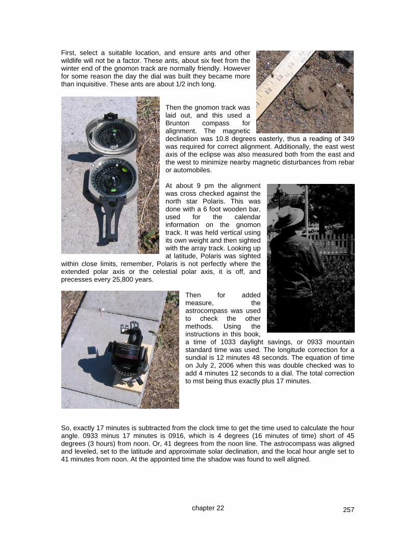
257
First, select a suitable location, and ensure ants and other wildlife will not be a factor. These ants, about six feet from the winter end of the gnomon track are normally friendly. However for some reason the day the dial was built they became more than inquisitive. These ants are about 1/2 inch long.
Then the gnomon track was laid out, and this used a Brunton compass for alignment. The magnetic declination was 10.8 degrees easterly, thus a reading of 349 was required for correct alignment. Additionally, the east west axis of the eclipse was also measured both from the east and the west to minimize nearby magnetic disturbances from rebar or automobiles. At about 9 pm the alignment was cross checked against the north star Polaris. This was done with a 6 foot wooden bar, used for the calendar information on the gnomon track. It was held vertical using its own weight and then sighted with the array track. Looking up at latitude, Polaris was sighted
within close limits, remember, Polaris is not perfectly where the extended polar axis or the celestial polar axis, it is off, and precesses every 25,800 years.
Then for added measure, the astrocompass was used to check the other methods. Using the instructions in this book, a time of 1033 daylight savings, or 0933 mountain standard time was used. The longitude correction for a sundial is 12 minutes 48 seconds. The equation of time on July 2, 2006 when this was double checked was to add 4 minutes 12 seconds to a dial. The total correction to mst being thus exactly plus 17 minutes.
So, exactly 17 minutes is subtracted from the clock time to get the time used to calculate the hour angle. 0933 minus 17 minutes is 0916, which is 4 degrees (16 minutes of time) short of 45 degrees (3 hours) from noon. Or, 41 degrees from the noon line. The astrocompass was aligned and leveled, set to the latitude and approximate solar declination, and the local hour angle set to 41 minutes from noon. At the appointed time the shadow was found to well aligned.
chapter 22

258
Armed with this information the dial was laid out. An excellent project for the youth of the country.
There is a 6 foot wooden rod with dates marked on it, and a gnomon is placed on the north south line where the date indicates.
The gnomon casts a shadow and in this case the date rod is used to project the shadow to the hour point, it shows about ten minutes past 1 in the afternoon. The equation of time must be factored in, 3 minutes to be added in this case, making it 1:13 pm. And summer time must be added in making it 2:13 pm.
Longitude was not considered in this dial, although the spreadsheet can easily accommodate times on either side of the hour. In this case the dial was at longitude 108.2 and the legal time zone meridian was 105, making about 12 minutes to be added. Making the final correct time about 2:25 in the afternoon, which was quite close.
chapter 22

259
The formulae are straightforward:- lat = latitude M = major axis (east to west) radius dec = declination for the calendar date gnomon distance up/down north/south based on ellipse center = z = M * cos ( lat ) * tan (dec) north-south radius m = M * sin(lat) angle from dial center to the hour point x = arctan ( tan( hour from noon * 15) / sin ( latitude ) ) hour point's vertical distance from dial center north/south) hh' = M * sin(lat)*cos(15*hours from noon) hour point's horizontal distance:- Ch' = M * sin (15 * hours from noon) The sun's declination used for the calendar displacement can be found in tables or calculated. The simplest formula is possibly: dec = (23.45*sin(radians(0.9678(jd-80)))) this formula agrees within half a degree of a more accurate formula which is found in the appendices. where jd = julian day of the year. Not only does appendix 4 provide ready made tables for analemmatic dials, it also provides nomograms for their design. The completed analemmatic dial with additional dials on columns at the 6 am, 6 pm, and noon markings is shown below.
chapter 22

260
CHAPTER TWENTY THREE
dial furniture ~ calendar or declination curves
Declination lines have been addressed several times. Sometimes for specific cases, sometimes in more general terms. Declination lines appear as dial furniture on a number of dials, they indicate the approximate date, albeit with ambiguouity except at the solstices. This is because two dates will share the same declination. To an observer, the sun orbits the polar axis of the planet, and moves towards the pole in the summer, the opposite in the winter. Another means of determining the date is to use the ecliptic dial, however, blending that concept which requires moving the dial, with a stationary dial plate is inconsistent, and thus not reviewed further here. Below is a mesh showing the sun's travel as seven arcs in the sky. The extremes are June and December, the solstices. And in between are January through May, and July through November. As an aside, the 3d mesh displayed below is on the web site as well as the CD that comes with this book. It can be used in TurboCAD to generate accurate shadows for a date and time. Chapter 30 has details on how to snap the light and its target using snap to facet.
But are there perhaps more methods available to address sun dials such as the decliners, and are there other methods of locating the declination lines. There are indications that the seasons were of more interest to early sun dial users, and that the calendar might have been more important than the time of day. The spreadsheet associated with this book has a section on declination line data, and provides methods using both altitude as well as azimuth. The DeltaCAD macros accompanying this book can also provide a graphical depiction of calendar curves with many options, and these can then be transposed to any hour angle type of dial plate. NOTE: For declination or calendar lines on a horizontal or vertical dial, a template is available in appendix 9 to facilitate this process whose use is described in chapter 12. NOTE: The term “gnomon linear height” will be used, it is the shortest distance from the style’s nodus directly to the dial plate.
chapter 23

261
There are indications that the seasons were of more interest to early sun dial users, and that the calendar might have been more important than the time of day. The sun appears to oscillate annually from minus 23.5 degrees when it is over the southern tropics, to plus 23.5 degrees when it is over the northern hemisphere tropics. This angle made with the equator is called the declination. Many of the tables show the declination for various days in the year. In particular appendix 2 shows the sun's declination for each day of the average year. This book shows two formulae, and one is:- DEGREES(0.006918 - 0.399912*COS(((2*3.1416*(jd-1)) / 365)) + 0.070257*SIN(((2*3.1416* (jd-1)) / 365)) - 0.006758*COS(2*((2*3.1416*(jd-1)) / 365)) + 0.000907*SIN(2*((2* 3.1416*(jd-1)) / 365)) - 0.002697*COS(3*((2*3.1416*(jd-1)) / 365)) + 0.00148*SIN(3* ((2*3.1416*(jd-1)) / 365))) where "jd" is the day in the year 1 to 365
The declination plus the co-latitude provides the sun's altitude at noon. There are a number of methods for drafting calendar or declination lines. Many dials have on their dial furniture just three lines or curves. They are the winter solstice (shortest day), summer solstice (longest day), and the two equinoxes, when day and night time are equal. Some dials have seven such lines, of which two are the solstices, leaving five, and those five account for the ten remaining months since all but the solstice months share a declination. However any calendar line may be drawn. This chapter may repeat in summary form information in other preceding chapters so that the information is all in one place. Additional information not expressed in preceding chapters is explained more fully. ARMILLARY DIALS The equinox line of an armillary dial runs as a straight line in the center of the dial plate. Solstice lines parallel the equinox line. The equinox line is perpendicular to the style and dropped from the nodus. In other words a notch or blob or other nodus is needed to show the calendar information. The solstice lines are above and below the equinox line by 23.5 degrees, and simple trigonometry can be used to calculate the linear distance above and below the equinox line. Since the tangent of 23.5 degrees is 0.43, the linear distance above and below the equinox line is 0.43 times the radius of the armillary dial plate. Winter solstice line 23.5 Equinox line radius – nodus to dial plate Summer solstice line This linear distance is 0.43 times the the radius of the dial, the distance from the nodus to the dial plate. The above shows the circular dial plate, albeit it depicted as flat.
chapter 23

262
EQUATORIAL DIALS The equatorial dial has its dial plate paralleling the equator, perpendicular to its polar axis aligned style. The calendar lines are circles surrounding the gnomon. Their linear distance from the base of the gnomon is the co-tangent of the declination times the gnomon's linear height. solstice line or circle solstice line for winter is on the other for summer side, and would be the same size if the gnomon's linear heights were the same nodus for winter calendar lines 23.5 degrees the radius of the calendar line, circle in this case, is the cotangent of the declination times the nodus linear height, however some spreadsheets may not support the cotan function so it is also:- radius of calendar circle = nodus linear height / tan(declination) and for the solstices, the cotan of 23.5 is the reciprocal of the tan, namely 1 / 0.43, or 2.3 times the nodus height. The winter calendar lines are on the equatorial plate's lower surface, the summer lines on the upper. There is no equinox line since at equinox, the declination is zero, placing the equinox circle at infinity. If the gnomon is used to support the dial plate, then there needs to be a clear nodus on the lower part of the gnomon in order to cast a calendar indicating shadow. An equatorial dial can show the times of sunrise and sunset, appendix 6 addresses this. Appendix 3 provides all the calendar data for equatorial dials including sunrise/set data. summer solstice date nearer to equinox horizon intersects dial surface H calendar circle and hits an hour line H horizon line latitude for summer 15 degree hour lines C C A B Gnomon winter horizon line S S 23.5 degrees V V co-latitude summer plate A horizon line is drawn from the nodus as shown above, and it crosses the 15 degree hour lines and the declination circles. For any date, the declination circle is found, and sunrise or set is the intersection of that declination circle with the hour line. Winter would use the lower nodus.
chapter 23
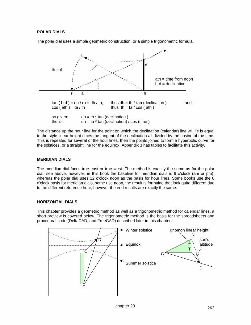
263
POLAR DIALS The polar dial uses a simple geometric construction, or a simple trigonometric formula. t d th = rh ath = time from noon hrd = declination r a h tan ( hrd ) = dh / rh = dh / th, thus dh = th * tan (declination ) and:- cos ( ath ) = ta / th thus th = ta / cos ( ath ) so given: dh = th * tan (declination ) then:- dh = ta * tan (declination) / cos (time ) The distance up the hour line for the point on which the declination (calendar) line will lie is equal to the style linear height times the tangent of the declination all divided by the cosine of the time. This is repeated for several of the hour lines, then the points joined to form a hyperbolic curve for the solstices, or a straight line for the equinox. Appendix 3 has tables to facilitate this activity. MERIDIAN DIALS The meridian dial faces true east or true west. The method is exactly the same as for the polar dial, see above, however, in this book the baseline for meridian dials is 6 o'clock (am or pm), whereas the polar dial uses 12 o'clock noon as the basis for hour lines. Some books use the 6 o'clock basis for meridian dials, some use noon, the result is formulae that look quite different due to the different reference hour, however the end results are exactly the same. HORIZONTAL DIALS This chapter provides a geometric method as well as a trigonometric method for calendar lines, a short preview is covered below. The trigonometric method is the basis for the spreadsheets and procedural code (DeltaCAD, and FreeCAD) described later in this chapter. Winter solstice gnomon linear height N D sun’s Equinox altitude T T C Summer solstice D C
chapter 23

264
The distance from the foot of the style, point T, and not from the dial center C, to a given hour line's declination point (TD) is determined by:- distance TD = style or gnomon linear height / tan (sun's altitude) sun's altitude = arcsin ( sin (dec) * sin (lat) + cos (dec) * cos(lat) * cos(time) ) The declination is found in several tables in the appendices. Appendix 2 has the declination tabulated by the day, the altitude spreadsheets on the CD or web site may be used for each hour, or their formula can be used directly. Alternatively, the azimuth may be used from T, however this does not work for noon. VERTICAL SOUTH DIALS (true south or north) The vertical dial is drawn exactly the same as a horizontal dial, but the dial is designed for the co-latitude. Thus a vertical dial for latitude 40 degrees would be the same as a horizontal dial for latitude 50 degrees. Note that a vertical dial’s summer solstice is the horizontal dial’s winter solstice, and the vertical dial’s winter solstice is the horizontal dial’s summer solstice. VERTICAL DECLINERS (not true north, south, east, or west) Vertical decliners have an equivalent dial that is not declining and is horizontal somewhere else on this planet. Find that location and the virtual horizontal dial with its declinations lines may be drafted, and then used by matching that horizontal dial's noon line with the vertical decliner's extended sub style line. The term style height, SH, an angular and not a linear distance is used in this book, and more defined in chapters 16, and 17. SH is the latitude to use for a “horizontal” dial to have calendar lines, and the noon of that calendar “horizontal” dial will align with the SD, style distance, of the actual dial, see next page. While this is an insight, some other insights exist that facilitate vertical decliner calendar lines. A key insight is that at the equinox, day time equals night time, thus 6 am and 6 pm solar local apparent time is when the sun rises and sets. Thus the intersection of a horizontal line from the base of the sub-style towards a reachable 6 o'clock hour line defines one point of the equinox line. From that point, moving perpendicular to the sub-style line (of a rotated gnomon), the equinox line is thus drawn. This only works for gnomons rotated using the SD technique horizontal because the sub-style line when extended provides the 6pm line angle of the equinox line because that equinox line is SD equinox line perpendicular to SD, the style distance line extended. For the derivation and use of sub-style extended SD and SH see chapter 16 as noon well as chapter 17.
chapter 23

265
Thus the equinox line is simply drafted as long as a 6 o'clock line is in place. Another technique can be used for a vertical decliner's calendar lines. Again, the extended sub-style line is used, along with a horizontal auxiliary dial. This technique assumes the gnomon has been rotated using the Style Distance techniques discussed in chapters 16 and 17. vertical decliner Vertical dial's winter solstice SD is the horizontal dial's summer solstice calendar lines of the auxiliary slide up horizontal dial horizontal auxiliary dial noon line for the auxiliary horizontal dial this auxiliary dial's gnomon matches the physical dimensions of the vertical decliner dial's gnomon, its style:sub-style angle is SH (style height) and not the latitude. A horizontal dial is built whose latitude is the vertical dial's style height and not the actual latitude, and the associated horizontal dial's gnomon dimensions equal those of the vertical dial's gnomon. The entire set of lines from the auxiliary dial is slid up such that its equinox line overlays the equinox line for the vertical decliner drawn using the methods of the previous page, or the horizontal dial is slid up so its gnomon blends with the rotated vertical dial's gnomon, same end result. The vertical dial's winter solstice is the horizontal dial's summer solstice, and the vertical dial's summer solstice is the horizontal dial's winter solstice. Thus a vertical decliner at latitude 32, where the wall is South 10 degrees West would provide the data shown to the right. SD is 15.5 degrees, and the noon line of the auxiliary sundial will merge with the extended sub-style line. SH is 56.6 degrees, thus the horizontal dial is designed for latitude 56.6 degrees. The physical dimensions of the vertical decliner's rotated gnomon are exactly used as-is on the auxiliary horizontal dial. Consider double checking your design using software such as the DeltaCAD macros that Illustrating Shadows. ANOTHER TECHNIQUE for the vertical decliner projects the azimuth and altitude (for each solar hour for a given declination) from the nodus, using the point on the sub-style “below” (i.e. horizontal to) the nodus as a base point. The FreeCAD vertical declining dial program does this. Many methods and techniques exist. Whichever method you select, double check it with other software or methods, and consider making a mockup cardboard dial to verify it in practice.
chapter 23
15.5 SD
56.6 SH

266
Declination lines for the horizontal (or vertical) dial using geometry. This section shows how to draw calendar lines on a horizontal or vertical dial, step by step, and a template is available in appendix 9 to facilitate this process whose use is described in chapter 12. A horizontal dial with three hour lines shown. Equinox winter solstice C summer C solstice noon hour line nodus a a b b c c 10 23.5 12 11 23.5 First, draw a gnomon for the dial center "C". From the nodus draw the equinox line (90 degrees to the style), and from that the solstice lines (approx 23.5 degrees on either side).The three lines (equinox and the solstices) intersect the gnomon's base line extended, or the noon line, at points a, b, and c. These three points whose distances from the dial center are Ca, Cb, and Cc are then transcribed to the dial plate (right pictorial to left pictorial). C C a Distances Cd b and Ce are Equinox line a d drawn with a b d e c ruler or a e drafting c compass. 10 12 11 The equinox line is then drawn perpendicular to the noon line, and it produces equinox intercepts for those additional hour lines, d and e. Distances Cd and Ce are then located from the left dial plate to the right hand picture on its equinox line. This produces two more hour lines on the right hand side picture, Cd and Ce. Those hour lines on the right hand side do not have angles that match their hour lines on the dial plate, and this is because this is a projection.
chapter 23

267
e
d
Now that there are two more hour lines, or as many as you choose, this produces intercept points for the solstice lines, namely points f, g, h and i. C C a h b Equinox line a d i b d e c e c f 10 g 12 11 Points f, h, g, and i are now transferred back to the dial plate, from the right projection pictorial to the left picture. C C i h h Equinox line a i b d e c f f g g 12 When this process is completed for as many hour lines as desired, the dots are connected and then the declination lines drawn. NOTE: The horizontal and vertical dials have the months reversed compared to dial center. dial center Horizontal dial: summer solstice Vertical dial: winter solstice Equinox line Horizontal dial: winter solstice
Vertical dial: summer solstice
chapter 23

268
Declination lines using trigonometry. Horizontal dial ~ calendar or declination curve logic The simplest approach for a horizontal dial is to select a solar declination such as 23.44, –23.44, or 0, and run the hours from morning to afternoon. Running the hours means using LAT (local apparent time), and for each time increment, derive the sun’s azimuth and altitude. That part of the process is the same for the vertical, horizontal, and vertical declining dial. Assume “glh” is the gnomon linear height:- For the horizontal dial, distance “d” is:- d = glh / tan(altitude) thus x = d * sin(azimuth) and y = d * cos(azimuth) The very first calculation is the first point of a declination or calendar curve, and thus no line or curve segment is drawn, but the “x,y” coordinates are saved. The hour is bumped up to the next time and a new “x,y” coordinate calculated, and this time a line segment is used because we have the previous “x,y” pair. This is repeated until the end of the time frame. This process can be repeated for all desired declinations. The “x,y” coordinates are relocated by the coordinates of the base of the nodus, “NODUSY, NODUSY”, and not from dial center. /*####################################################################################### ' # MAIN LOOP # the solar declinations in this example is –23.44 # ‘ # # makeLine is a function to draw a line segment, see “functions.js” # ' ####################################################################################### */ /* this uses NODUSX,Y from the gnomon drawing earlier */ wx = 9999 /* these, when 0, tell the calendar */ wy = 9999 /* line draw to draw nothing */ for (hr=7; hr < 17; hr=hr+0.25) { /* get an altitude and azimuth for this one hour at this SOLAR declination */ al = altitude( hr, lat, -23.44 ) /* degrees altitude */ d = glh / Math.tan(al*2*3.1416/360) /* radial distance: nodus base to cal curve */ az = azimuth( hr, lat, -23.44 ) /* degrees azimuth */ xxx= d * Math.sin(2*3.1416*az/360) yyy= d * Math.cos(2*3.1416*az/360) if ( wx<9999 && wy<9999 ) { if ( Math.abs(nodusx+wx)<150 && Math.abs(nodusx+xxx)<150 ) { if ( Math.abs(nodusx+wx)<130 && Math.abs(nodusx+xxx)<130 ) { // above code keeps the curve within reasonable bounds makeLine( nodusx + wx,nodusy + wy , nodusx + xxx, nodusy + yyy ) } } } wx = xxx wy = yyy }
The logic is shown above, this is written in Java Script as used in the free NanoCAD program. The azimuth and altitude formula are the standard formulae, see the appendices. Some of the Illustrating Shadows CAD programs may use a different algorithm.
nodusx nodusy
dial center
style
chapter 23

269
Vertical dial ~ calendar or declination curve logic As for the horizontal dial, the approach for a vertical dial is to select a solar declination and run the hours from morning to afternoon. Running the hours means using LAT (local apparent time), and for each time increment, derive the sun’s azimuth and altitude. That part of the process is the same for the vertical, horizontal, and vertical declining dial. Assume “glh” is the gnomon linear height:- For the vertical dial:- x = glh * tan(azimuth) and, distance “d” is:- d = glh / cos(azimuth) which is needed for the “y” ordinate:- y = d * tan(altitude) = tan(altitude)*glh / cos(azimuth)
' ####################################################################################### ' # MAIN LOOP # the solar declinations in this example is –23.44 # ' ####################################################################################### '# this uses NODUSX,Y from the gnomon drawing earlier wx = 0 '# these, when 0, tell the calendar wy = 0 '# line draw to draw nothing hr = 7 '# start at 0700 am (1st seg not drawn) while hr < 17 '# end at 1700 '# get an altitude and azimuth for this one hour at this SOLAR declination az = azi( hr, latr, -23.44 ) ' degrees azimuth xxx= glh * tan(2*3.1416*(az)/360) al = alt( hr, latr, -23.44 ) ' degrees altitude yyy= glh * tan(2*3.1416*al/360) / cos((2*3.1416*(az)/360)) if wx<>0 and wy<>0 then xl=nodusx+wx yl=nodusy-wy xn=nodusx+xxx yn=nodusy-yyy ptb = CStr(xl)+","+CStr(yl)+","+CStr(0) pte = CStr(xn)+","+CStr(yn)+","+CStr(0) if abs(xl) < 130 and abs(xn)<130 then ' all x values in range? if yl > -130 and yl<0 then ' last Y in range ? if yn > -130 and yn<0 then ' last Y in range ? Set lineObj = ThisDrawing.ModelSpace.AddLine(ptb,pte) end if end if end if end if wx = xxx wy = yyy hr = hr + 0.25 wend
The process is similar to the horizontal dial process, and uses the base of the nodus and not dial center. The above code is written in Visual Basic Script as used in the free NanoCAD program. Some of the Illustrating Shadows CAD programs may use a different algorithm.
chapter 23

270
Vertical Declining dial ~ calendar or declination curve logic As for the horizontal dial, the approach for a vertical declining dial is to select a solar declination and run the hours from morning to afternoon. Running the hours means using LAT (local apparent time), and for each time increment, derive the sun’s azimuth and altitude. That part of the process is the same for the vertical, horizontal, and vertical declining dial. Assume “glh” is the gnomon linear height. For the vertical declining dial, the process is similar to the vertical dial, except the vertical dial plate, or wall, has a declination which is factored in. As before, the nodus base point is located at “nodusx,nodusy” So: x = glh * tan(azimuth + wall declination) And:- d = glh / cos(azimuth) which is needed for the “y” ordinate:-
so: y = d * tan(altitude) = glh * tan(altitude) / cos(azimuth+wall declination) ######################################################################################## # MAIN LOOP # the solar declinations in this example is –23.44 # ######################################################################################## # this uses NODUSX,Y from the gnomon drawing earlier # set the summer and winter x,y coordinates to 0 to begin with wx = 0 # these, when 0, tell the calendar wy = 0 # line draw to draw nothing hr = 7 # start at 0700 am (1st seg not drawn) # keep "decl" useful for azimuth on the dial plate decl = dec if dec >0: decl = -1 * dec while hr < 19 : # end at 1700 or 5pm # get an altitude and azimuth for this one hour at this winter SOLAR declination al = alt( hr, lat, -23.44 ) az = azi( hr, lat, -23.44 ) xxx = glh * math.tan(math.radians(az+decl)) yyy = glh * math.tan(math.radians(al)) / math.cos(math.radians(az+decl)) if dec > 0: xxx = -1 * xxx if abs(xxx)< 3 and abs(yyy)<2 : if wx<>0 and wy<>0: c = Part.makeLine((nodusx+xxx, nodusy-yyy,0),(nodusx+wx, nodusy-wy, 0)) Part.show(c) wx = xxx wy = yyy #
The process is similar to the vertical dial process, and uses the base of the nodus and not dial center. The above code is written in Python as used in the free FreeCAD program. Some of the Illustrating Shadows CAD programs may use a different algorithm. Python uses indentation rather than an approach using braces {…} as in Java Script, or some other code block terminator such as IF…END IF, or WHILE…WEND as used in Visual Basic.
Illustrating Shadows provides:- functions.py, functions.js, functions.vbs to aid programming.
chapter 23

271
The Java Script produced horizontal dial with calendar curves created in NanoCAD:- The Visual BASIC Script (vbs) produced vertical dial created in NanoCAD:- The vertical declining dial using Python as in FreeCAD:- FreeCAD and NanoCAD are CAD programs available at no cost. FreeCAD is open source, and NanoCAD while free, requires a serial number (immediately available by email), and registration (immediately provided online). Both install easily, work first time, and do not need extra software to be downloaded. They have been tested on Windows 8 and earlier editions. Being free, documentation is limited, so Programming Shadows on the Illustrating Shadows web site or CD is essential for anyone programming in those systems. Supplemental Shadows has more information on declination curve methods.
chapter 23
272
Some key insights about flat dial calendar lines The following two notes are critical to understanding the relationship between the "virtual dial" used to draft calendar or declination lines, and the "real" dial that will show the time. You do not have to use "the" hour lines
You can use the actual hour lines, although it is an extra step if the dial is longitude corrected. However, you can use any hour lines you like when drafting the calendar or declination lines. You could use one hour and three or four hours on either side of "noon". While it is tempting to use 10 degrees and 30 or 40 degrees on either side of the extended sub-style, it is not that simple. This is because you would have to work back from the angle with the sub-style, from whence the azimuth or altitude are readily found, back to the time that would produce those azimuth and altitude figures.
The "noon" and the hour lines on declining dials are NOT real noon and hour lines
When designing a declining dial, or even an inclining declining dial, the calendar lines use "noon" for the dial that is appropriate for a horizontal dial whose latitude is the style height. In other words, "noon" for calendar line design on declining dials is the sub-style line extended, and not noon for the real dial's location. So, for those dials, the calendar lines will obviously use "hour lines" that are not those that will finally be displayed on the dial. The "noon" for calendar lines is the sub-style extended, the "noon" for the real dial will be a vertical line dropped from dial center (for vertical dials), or a true north-south line passing through dial center (for horizontal dials). And those real noon lines may be displaced if the dial is longitude corrected.
The following two notes are critical to understanding the relationship between date and hour.
The nodus is for solar declination (calendar date information), the style is for the hour. There is a recent tendency to use a rod as the gnomon, the tip being the nodus, and that tip
serving a dual purpose. One purpose is to indicate the solar declination, in other words the date. And, where the nodus shadow falls on an hour line is also the time.
Anything that is dual purpose usually has somewhere in it a compromise. The compromise is the ease or accuracy of reading the hour. With a style, there is a long shadow, and the eye can parallel that style shadow with an hour line and thus increase readability, and thus accuracy. With a rod as the dual purpose shadow caster, the ability to read the time depends on one shadow tip, and on a more perfectly aligned gnomon.
The corollary is that sometimes ridiculously small gnomons exist on dial plates, because the style tip is used for marking the calendar declination lines, and thus the dial plate has hour lines contained within the area bounded by the winter solstice and the dial center. What on Earth, or in the solar system, is wrong with having a long style and using all the dial plate area for those hour lines, and treating them separately from the nodus, which would be part way up the style, and have the nodus for just the calendar lines or curves?
Be bold. Use all the dial plate for the hour lines. Use the maximum effective area for the calendar
lines and curves, and mark the nodus at an appropriate place somewhere along the style.
chapter 23

273
The practical laser trigon for calendar lines Just because we live in a scientific age with things to the nano second, the micro nano millimeter, and digital this and that, doesn't mean that other methods do not have a place. In days of old, a device called a trigon was often employed with a protractor and a thread.
To the left is a more modern trigon made from copper plate and a conference presenter's laser pointer. The laser is held in this case by one of two plates angled at plus and minus 23.5 degrees, secured to a rigid copper wire of awg 10 size, inserted into a copper tube that is itself secured to a vice of two copper plates which is placed on the gnomon's style.
Such a device can be made in a few minutes, and the vice can be a pair of plates such as is shown for placing on a gnomon of copper plate, or it can be two copper plates at right angles such as would be used for a thick gnomon. The variations are endless. Of course, the laser angles need calibrating, and to the right is a pager cutout of a gnomon with the winter solstice, the equinoxes, and the summer solstice shown. The laser is depressed and the angle of the light verified against the solstice line, as shown. While the declination angle is thus measured, it is important that the rotational plane of the laser be correct. This can be tested by marking three points on the extended sub-style line which result from three angles from the nodus, -23.5, 0, and +23.5. If the laser strikes both at the correct predicted distance then the rotational plane is probably correct. Also, the axis around which the laser rotates must parallel the style.
To the left is an actual dial plate with the paper gnomon placed showing a solstice line and the equinox line. This simple device is useful for dial plates that are not flat, such as an S-shaped roofing tile, or any other irregular surface for that matter.
Good declinations to use, considering month ambiguity, might be:-
GOOD DECLINATIONS TO USE FOR REASONABLE SYMMETRY FOR THE AMBIGUOUS MONTHS
23.44 20 10 0 or 19 or 18 or 11 or 12 Jun, Dec Jan, May Feb, Apr Mar, Sep Jly, Nov Aug, Oct
chapter 23

274
CHAPTER TWENTY FOUR
dial furniture ~ Italian, Babylonian, and day of length dial furniture LINES THAT ARE NOT HOUR LINES AS SUCH There are some lines or curves that appear as dial furniture that are not time of day hours, and yet they indicate a time of sorts. Yet, they appear as furniture which places them in common with calendar lines. For that reason, these lines and curves are discussed here. LENGTH OF DAY LINES (DAYLIGHT HOURS): The declination can be used not only for certain traditional dates, but also to indicate the length of a day. Looking at sunrise and sunset tables will show days of say 8, 9, or any other number of hours. Then for the dates associated with those day lengths, the sun's declination may be found. Using the techniques for declination lines in this book, curves can be drawn such that when the nodus shadow is on that curve, then the day-length is indicated. If L is the difference between the hours in the day and 12, multiplied by 15 (degrees in an hour) then:- declination = arctan( sin(L/2) * cot (latitude) ) or declination = arctan( sin(L/2) / tan (latitude) ) Thus, work out for your latitude the declination for an 8, 10, 12, 14 hour day, for example, and since you now have the sun's declination, you may now use it with the empirical, geometrical or trigonometric methods for the drawing declination lines. Instead of labeling them with a date, label them with the day's duration. For example, consider a 14 hour day at latitude 57. the difference between 14 and 12 is 2, so... L is 2*15, so L/2=15, and cot(57)=0.6494, thus declination = arctan ( ( sin(15) * cot(57) ) ) or arctan ( 0.2588 * 0.6494 ) = arctan ( 0.1681 ) = 9.5 degrees This provides four dates, two for 14 hours (14 – 12 is 2), and two for 10 hours (12 – 10 is 2), and using tables, they are Feb 24, Oct 19, and Apr 15 and Aug 29 for the specified latitude. A number of tables in the appendices have the declination for a given day. Using this declination, declination lines can be drawn using the same methods used for equinox and solstice lines. UNEQUAL, TEMPORARY, or BIBLICAL HOURS The unequal hours, temporary hours, or biblical hours are simply a given day’s daylight (see above) divided into 12 equal parts. Those parts vary from day to day, shorter in winter, longer in summer, one hour during the equinoxes. They are drawn by deriving the length of day at the winter solstice (for vertical dials) or summer solstice (for horizontal dials), dividing that duration by 12, and marking those times from noon on the solstice curve. At the equinox mark the times in 1 hour increments from noon. Connect the two points for each of the 12 “parts” and extend the lines. The result is a set of “hour” lines indicated by the nodus. Not much use these days, but of historical interest, and as such they can be found on some European dials.
chapter 24

275
LENGTH OF DAY TRANSITIONING TO SUNRISE AND SET TIMES To determine the L.A.T. (local apparent time) of sunrise or sunset for any day of the year, the hour angle when the sun is on the horizon is used. The formula for that hour angle, with no longitude or EOT correction is:- hsr = arccos( tan(latitude) * tan(declination) ) The declination is determined by:- declination = degrees (0.006918 – 0.399912*cos(da) + 0.070257*sin(da) – 0.006758*cos(2*da) + 0.000907*sin(2*da) – 0.002697*cos(3*da) + 0.001480*sin(3*da) Where "da" the "day angle" (in radians, an intermediate figure), is determined by [ j = Julian day ] da = 2 * 3.1416 * ( Julian day of the year – 1 ) / 365 For the winter and summer solstice, the sunrise and sunset times from the equator to latitude 65 are depicted below, and generated using a DeltaCAD program on the CD and web site. The appendices also have a nomogram to determine sunrise and set times built with DeltaCAD.
A solstice sunset time, together with the equinox sunset time of 6 pm (longitude not considered, nor EOT), provide a means of determining the number of hours to sunset, or of course the number of hours since sunrise, discussed on the next page as Italian and Babylonian hours.
10°
20°
30°
40°
50°
60°
noon
chapter 24
6 am 6 pm
daylight winter
daylight summer

276
BABYLONIAN AND ITALIAN LINES Once a dial is built, and solstice and equinox lines drawn, then all sorts of options exist for additional clutter (dial furniture) on the dial. Calendar information was often helpful, when to plant, sow, and reap in a then unhurried pace. In particular, some other interesting "hours" were used. Babylonian hours showed the time from sunrise. The Italian hours showed the time from sunset. In practice the Italian hours were massaged to show the number of hours until sunset, a figure helpful to the gardener or worker toiling in the fields. The technique for drawing Italian hour lines is simplicity itself. The time of sunset is noted for the solstices and the equinoxes. The appendix has approximate formulae for this calculation, and many online almanacs have readily available accurate times. Some free software available consists of spreadsheets which are very accurate. Appendix 6 may be helpful. NOTE: If the dial is neither longitude nor EOT corrected, then use sunset times with no longitude or EOT correction. If the dial has longitude corrections built in, then use sunset times with a longitude but no EOT correction. If you use the spreadsheets on the web site, you can effect this by setting the reference longitude to the location's longitude, and the EOT can be set to zero by changing the EOT multiplier from 1 (normal) to 0 (no correction desired). Appendix 6 provides true (L.A.T.) sunrise, sunset, and day-length for many latitudes. For a vertical dial, mark on the winter solstice calendar line the time when sun sets, and one hour before that, and two, and three, and so on. Then for the equinox perform the same operation (sunset is 6 pm L.A.T.), and similarly for the summer solstice if shown. Some dials may not have room for both solstice curves, so use just one solstice and the equinox. Simply connect the sunset time's dots on the solstice and equinox lines and draw a straight line. Mark that line as "sunset". Then connect the dots for one hour before sunset, and mark the resulting line "1 hour to sunset", and proceed for all the desired Italian hours. Take care with summer time adjustments when marking the hour points. Babylonian hours, while less useful, follow a similar process. The process is similar for horizontal or other dials. CAUTION: Italian and Babylonian hours are latitude specific. Tilting an hour angle dial for a new latitude will correct the normal hours but not the Italian or Babylonian lines. While hour lines use the hour angle around the style, Italian and Babylonian lines are latitude and geometry based, detecting when and where the sun crosses the horizon. That geometry is latitude dependent as it uses the curvature of the Earth for a specific latitude and is thus not correctable by tilting. A VERTICAL DIAL WITH SOME ITALIAN HOUR LINES winter solstice on a sunset vertical dial 1 hour to sunset 2 hours to equinox line sunset hour line for 9am summer solstice on a vertical dial
chapter 24
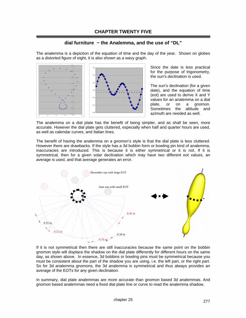
277
CHAPTER TWENTY FIVE
dial furniture ~ the Analemma, and the use of “DL”
The analemma is a depiction of the equation of time and the day of the year. Shown on globes as a distorted figure of eight, it is also shown as a wavy graph.
Since the date is less practical for the purpose of trigonometry, the sun’s declination is used. The sun’s declination (for a given date), and the equation of time (eot) are used to derive X and Y values for an analemma on a dial plate, or on a gnomon. Sometimes the altitude and azimuth are needed as well.
The analemma on a dial plate has the benefit of being simpler, and as shall be seen, more accurate. However the dial plate gets cluttered, especially when half and quarter hours are used, as well as calendar curves, and Italian lines. The benefit of having the analemma on a gnomon’s style is that the dial plate is less cluttered. However there are drawbacks. If the style has a 3d bobbin form or bowling pin kind of analemma, inaccuracies are introduced. This is because it is either symmetrical or it is not. If it is symmetrical, then for a given solar declination which may have two different eot values, an average is used, and that average generates an error.
If it is not symmetrical then there are still inaccuracies because the same point on the bobbin gnomon style will displace the shadow on the dial plate differently for different hours on the same day, as shown above. In essence, 3d bobbins or bowling pins must be symmetrical because you must be consistent about the part of the shadow you are using, i.e. the left part, or the right part. So for 3d analemma gnomons, the 3d analemma is symmetrical and thus always provides an average of the EOTs for any given declination. In summary, dial plate analemmas are more accurate than gnomon based 3d analemmas. And gnomon based analemmas need a fixed dial plate line or curve to read the analemma shadow.
chapter 25
0.000
0.200
0.400
0.600
0.800
1.000
1.200
1.400
1.600
-0.200 -0.150 -0.100 -0.050 0.000 0.050
-0.30
-0.20
-0.10
0.00
0.10
0.20
0.30
1 3 5 7 9 11 13 15 17 19 21 23 25 27 29 31 33 35 37
0.12 in
0.76 in
0.45 in
0.55 in
0.34 in
December sun with large EOT
June sun with small EOT

278
The solution is to have a flat and not a 3d gnomon analemma. While this does allow an asymmetrical analemma, it also requires that the analemma be rotated to be perpendicular to the suns rays. The conclusion about analemma depiction on sundials is thus: An analemma on the dial plate is easy to make accurate works directly only for the hours it is associated with requires interpretation for other hours clutters the dial plate when other furniture is there A 3d bobbin on the gnomon’s style has to be symmetrical is thus an average of EOTs for the same solar declination is harder to make than an analemma on a dial plate is harder to make than a 3d analemma is easy to read for any hour needs a fixed dial plate line or curve to read the analemma shadow A 2d analemma on the gnomon’s style can be asymmetrical thus has accurate EOT depiction is easier to make than a 3d bobbin but it requires you to rotate it needs a fixed dial plate line or curve to read the analemma shadow A table or chart of EOTs is easy to use requires only one simple addition or subtraction does not clutter the dial plate or gnomon but requires it to be placed somewhere in easy reach and it can incorporate longitude corrections Illustrating Shadows provides Excel spreadsheets with X and Y values facilitating graph paper depiction of an analemma. This is more accurate then polar coordinates (angle and distance) since the angles are rather small thus errors can easily creep in. analemma.xls Also, DeltaCAD programs provide a pictorial of the analemma, as well as X and Y coordinates. And the standard v-dial and h-dial DeltaCAD macros depict the analemma, and in addition a single DeltaCAD macro: analemma.bas The diallist must choose whether to place an analemma on a dial plate, or use the gnomon’s style with a 3d bobbin, or a 2d template, or whether to use a table or graph of EOTs. NOTE: Always double check the EOT analemma template and make sure the analemma is oriented properly. NOTES ON TECHNIQUE FOR THE VARIOUS DIAL TYPES: The armillary and equatorial dials use the declination and EOT directly. The armillary is a special case as the gnomon and dial plate analemma formula are symmetrical. The equatorial dial full plate uses polar coordinates whereby the EOT is converted to degrees with the hour and longitude difference added which then becomes the angle, and the declination is used as the radius, and these two are then converted to X:Y coordinates. The polar and meridian dials use declination and EOT directly. The horizontal, vertical, and vertical decliner dials require solar altitude and azimuth to be derived.
chapter 25
1121
31
41
51
61
71
81
91
101
111
121131
141
12

279
ARMILLARY DIAL The analemma is on the gnomon style. There are some assumptions and approximations.
tan(decl) = y / r tan(eot/4) = x / V y thus thus
y=r.tan(decl) x x=V.tan(eot/4)but V = r/cos(decl)thus
r "x" cross section of V x=r.tan(eot/4)/cos(decl) decl boggin gnomon eot
Vcx
cos(decl)=r/V so boggin gnomonV=r/cos(decl) intersection of equinox line
and hour line an hour line
VIEWED SIDEWAYS FROM EAST OR WEST VIEWED FROM THE EQUATOR LOOKING TO THE POLE The formula for Y (north or south along the style of the gnomon) and Y (east or west parallel to the earth) for an analemma is derived as shown above, and is:- eot = 7.5 * Sin(RAD(jd-5))-10.2*Sin(RAD(1.93*(jd-80)))+0.5*Sin(RAD(1.5*(jd-62))) decl = 23.45 * Sin(rad(0.9678*(jd-80))) y = r * Tan( rad(decl) ) and since: V = r / Cos( rad(decl) ) x = V * Tan( rad(eot/4) ) r * Tan(rad(eot/4) / Cos( rad(decl) ) There is an approximation even still, in the above. It assumes the plane of the analemma is perpendicular to the line from the hour line up to the analemma’s bobbin center. Of course, instead of a bobbin in 3d, a 2d plate can be used which is rotated to parallel the dial plate surface where the hour line is located. Excel .spreadsheets exist:- analemma.xls And a DeltaCAD macro is also available:- analemma.bas Scaling is important if you use DeltaCAD, and aspect ratio as well as scaling if you use Excel or Open Office. For DeltaCAD the OPTIONS, DRAWING SCALE, and VIEW SC, must be 1 and in addition, FILE, SET PRINT REGION, PRINT SCALE must be 1. For spreadsheets, the data is more useful than the pictorial display since spreadsheets make little pretence at retaining aspect ratio when graphics are displayed. After printing the DeltaCAD analemma gnomon, verify the north and south X and Y distances and compare it to the Excel range. The DeltaCAD macro supports gnomon based analemmas for armillary dials.
chapter 25

280
ARMILLARY DIAL The analemma is on the dial plate.
There are some assumptions and approximations.
As with the bobbin (3d shaped gnomon) or 2d rotatable analemma, all on the gnomon style, the formula for the analemma on the dial plate turns out to be substantially the same. eot = 7.5 * Sin(RAD(jd-5))-10.2*Sin(RAD(1.93*(jd-80)))+0.5*Sin(RAD(1.5*(jd-62))) decl = 23.45 * Sin(rad(0.9678*(jd-80))) y = r * Tan( rad(decl) ) and since: V = r / Cos( rad(decl) ) x = V * Tan( rad(eot/4) ) = r * Tan(rad(eot/4) / Cos( rad(decl) ) Actually, almost the same. Whereas the larger EOT swing is to the south on an analemma built in to the gnomon, it is to the north when the analemma is on the dial plate itself. This is shown pictorially below. Also, not only is the analemma rotated about the east west axis as mentioned above, the picture on the right also shows that it must be rotated about the north south axis as well. That rotation about the east west axis is critical because the end of the year EOT swing is some 16 minutes whereas the mid year swing is about half that, there is no symmetry. Most 3d analemma gnomons assume there is symmetry of the + and – swings, but even that is not true. The end of year swing is 14.15 to -16.29, a difference of some two minutes, the mid year swing is 6.32 to -3.40, a difference of almost three minutes. The lobe location relative to south is valid for both hemispheres, that is why the term end of year and mid year were used, not summer and winter. The DeltaCAD macro supports a single detailed dial plate analemma, and a full dial plate for armillary dials to be used as is.
EOT 2009 mm.ss
end of year mid year
MAJOR PEAKS MINOR PEAKS
MAX MIN MAX MIN
14.15 -16.29 6.32 -3.40
chapter 25

281
EQUATORIAL DIAL The analemma is on the gnomon style, There are some assumptions and approximations. In this case, “d” is a fixed radius from the base of the gnomon rod, and falls on an hour line or some other time division that will be corrected by the gnomon. As usual, we need X and Y, and we also have the EOT and Declination. Assuming that the distance from “p” to the base of the gnomon, known as “x” is substantially the same as from “p” to point “t”, which is not correct, but is almost the same, then:- tan(decl) = y / d thus y = d * tan(decl) and assuming that EOT as shown is the same angle on the slope, as it would be between line “d” and the line “pt”, which is not correct, but is almost the same, then:- tan(eot) = x / d thus x = d * tan(eot) and again, these are assumptions that are close but not perfect. The rule of a 2d rotatable analemma on the gnomon still applies, it is more accurate and easier to make than a 3d bobbin. The DeltaCAD macro supports gnomon based analemmas.
chapter 25

282
EQUATORIAL DIAL The analemma is on the dial plate. There are some assumptions and approximations.
For a point on top of the gnomon, the nodus, a shadow will be drawn whose tip is based on the sun’s declination, and whose displacement from a given hour line will be based on the equation of time, EOT. If the linear height of the gnomon rod is “R” inches then the following applies. tan(decl) = R / y thus y = R / tan(decl) and sin(decl) = R / V thus V = R / sin(decl) and tan(EOTm/4) = x / V thus x = V * tan(EOTm/4) = tan(EOTm/4) * R / sin(decl) For the northern hemisphere, the summer or mid year surface uses late March through late September, and the winter surface uses late September to late March 20. And the same dates but the opposite surface are of course used for the southern hemisphere. However, at the equinoxes the shadow tip is at an infinite distance, thus a more practical range for analemmas is when the declination is not from 0˚ but say from 10˚, to 23.44 degrees. end of year Oct 22 – Feb 23 JD 295-365, and 1-54 mid year Apr 15 – August 28 JD 105-240 The best solution in fact would be where the value of Y is less than equal the radius of the dial plate, DR. NOTE: Northern hemisphere: mid year (summer) is facing sky, end year (winter) faces ground. NOTE: Southern hemisphere: mid year (winter) is facing ground, end year (summer) faces sky. NOTE: If the sun is slow, i.e. the EOT is positive, the analemma point is to the west so it gets hit
earlier. If the sun is fast, i.e. the EOT is negative, the analemma point is to the east so it gets hit later.
The DeltaCAD macro supports a single detailed dial plate analemma, and a full dial plate for summer and winter equatorial dials to be used as is.
chapter 25
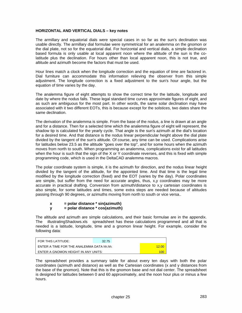
283
HORIZONTAL AND VERTICAL DIALS – key notes The armillary and equatorial dials were special cases in so far as the sun’s declination was usable directly. The armillary dial formulae were symmetrical for an analemma on the gnomon or the dial plate, not so for the equatorial dial. For horizontal and vertical dials, a simple declination based formula is only usable at local apparent noon where the altitude of the sun is the co-latitude plus the declination. For hours other than local apparent noon, this is not true, and altitude and azimuth become the factors that must be used. Hour lines match a clock when the longitude correction and the equation of time are factored in. Dial furniture can accommodate this information relieving the observer from this simple adjustment. The longitude correction is a fixed adjustment to the sun's hour angle, but the equation of time varies by the day. The analemma figure of eight attempts to show the correct time for the latitude, longitude and date by where the nodus falls. These legal standard time curves approximate figures of eight, and as such are ambiguous for the most part. In other words, the same solar declination may have associated with it two different EOTs, this is because except for the solstices, two dates share the same declination. The derivation of the analemma is simple. From the base of the nodus, a line is drawn at an angle and for a distance. Then for a selected time which the analemma figure of eight will represent, the shadow tip is calculated for the yearly cycle. That angle is the sun's azimuth at the dial's location for a desired time. And that distance is the nodus linear perpendicular height above the dial plate divided by the tangent of the sun's altitude. Of course, any time can be used. Complications arise for latitudes below 23.5 as the altitude "goes over the top", and for some hours when the azimuth moves from north to south. When programming an analemma, complications exist for all latitudes when the hour is such that the sign of the X or Y coordinate reverses, and this is fixed with simple programming code, which is used in the DeltaCAD analemma macros. The polar coordinate system is simple, it is the azimuth for direction, and the nodus linear height divided by the tangent of the altitude, for the appointed time. And that time is the legal time modified by the longitude correction (fixed) and the EOT (varies by the day). Polar coordinates are simple, but suffer from the need for accurate angles, thus, x,y coordinates may be more accurate in practical drafting. Conversion from azimuth/distance to x,y cartesian coordinates is also simple, for some latitudes and times, some extra steps are needed because of altitudes passing through 90 degrees, or azimuths moving from north to south or vice versa.. x = polar distance * sin(azimuth) y = polar distance * cos(azimuth) The altitude and azimuth are simple calculations, and their basic formulae are in the appendix. The illustratingShadows.xls spreadsheet has these calculations programmed and all that is needed is a latitude, longitude, time and a gnomon linear height. For example, consider the following data:
FOR THIS LATITUDE: 32.75
ENTER A TIME FOR THE ANALEMMA DATA hh.hh: 12.00
ENTER A GNOMON HEIGHT IN ANY UNITS: 100
The spreadsheet provides a summary table for about every ten days with both the polar coordinates (azimuth and distance) as well as the Cartesian coordinates (x and y distances from the base of the gnomon). Note that this is the gnomon base and not dial center. The spreadsheet is designed for latitudes between 0 and 60 approximately, and the noon hour plus or minus a few hours.
chapter 25

284
Assumed latitude (0-90) 32.75 Assumed longitude (0-180 + or -) 108.20
Assumed time zone's reference longitude 105.00 12.8 LEGAL
You can change the time TIME FOR THE ANALEMMA DATA hh.hh: 12.00 12.00 (8.00 9.00 10.00 11.00 12.00 13.00 14.00 15.00 16.00)NODUS HEIGHT IN ANY UNITS: 1
C A R T E S I A N A N A L E M M A C O O R D I N A T E S ~ ~ HORIZONTAL DIALCartesian coordinates (x and y distances from the base of the For vertical dial, reverse d.long and use co-latitude
gnomon). Note that this is the gnomon base and not dial center. For vertical decliner, SH as latitude, but hours are more involved.
FINAL CARTESIANPOLAR COORDINATES COORDINATES
Date Julian decl eot net mm.m Alt DIST Azi x y1/1 1 -23.1 3.1 15.9 34.06 1.48 4.42 -0.114 1.475
1/10 10 -22.1 7.1 19.9 34.97 1.43 5.63 -0.140 1.4231/20 20 -20.3 10.7 23.5 36.65 1.34 6.87 -0.161 1.3342/1 32 -17.3 13.5 26.3 39.52 1.21 8.15 -0.172 1.200
2/10 41 -14.6 14.3 27.1 42.20 1.10 8.86 -0.170 1.0902/20 51 -11.2 13.9 26.7 45.59 0.98 9.38 -0.160 0.9673/1 60 -7.9 12.2 25.0 48.94 0.87 9.45 -0.143 0.859
3/10 69 -4.4 10.1 22.9 52.45 0.77 9.39 -0.125 0.7583/20 79 -0.5 7.2 20.0 56.46 0.66 9.07 -0.105 0.6554/1 91 4.2 3.6 16.4 61.24 0.55 8.52 -0.081 0.543
4/10 100 7.7 1.1 13.9 64.70 0.47 8.08 -0.066 0.4684/20 110 11.2 -1.3 11.5 68.33 0.40 7.66 -0.053 0.3945/1 121 14.8 -3.0 9.8 71.94 0.33 7.66 -0.043 0.323
5/10 130 17.4 -3.6 9.2 74.52 0.28 8.25 -0.040 0.2745/20 140 19.8 -3.4 9.4 76.89 0.23 9.79 -0.040 0.2296/1 152 21.9 -2.1 10.7 78.94 0.20 13.04 -0.044 0.190
6/10 161 23.0 -0.4 12.4 79.83 0.18 16.39 -0.051 0.1726/20 171 23.4 1.7 14.5 80.16 0.17 19.84 -0.059 0.1637/1 182 23.2 4.0 16.8 79.74 0.18 22.20 -0.068 0.168
7/10 191 22.4 5.5 18.3 78.84 0.20 22.41 -0.075 0.1827/20 201 20.8 6.4 19.2 77.33 0.22 20.89 -0.080 0.2108/1 213 18.2 6.3 19.1 74.85 0.27 17.61 -0.082 0.258
8/10 222 15.8 5.2 18.0 72.56 0.31 14.59 -0.079 0.3048/20 232 12.7 3.2 16.0 69.63 0.37 11.27 -0.073 0.3649/1 244 8.6 -0.3 12.5 65.65 0.45 7.51 -0.059 0.449
9/10 253 5.2 -3.3 9.5 62.41 0.52 5.11 -0.047 0.5219/20 263 1.4 -6.9 5.9 58.63 0.61 2.83 -0.030 0.60910/1 274 -2.9 -10.6 2.2 54.38 0.72 0.94 -0.012 0.716 NOTE: For most cases, the final data is the most frequently usable.
10/10 283 -6.3 -13.2 -0.4 50.92 0.81 -0.16 0.002 0.812 In some cases, the final data here may be less usable,10/20 293 -10.1 -15.4 -2.6 47.19 0.93 -0.94 0.015 0.926 the test is the graph above. 11/1 304 -13.9 -16.5 -3.7 43.38 1.06 -1.24 0.023 1.058 If the graph above looks inappropriate, whereas the raw
11/10 314 -16.9 -16.0 -3.2 40.30 1.18 -1.01 0.021 1.179 data graph to the right looks appropriate, then in that11/20 324 -19.5 -14.1 -1.3 37.72 1.29 -0.39 0.009 1.293 case use the raw data information.12/1 335 -21.7 -10.6 2.2 35.56 1.40 0.63 -0.015 1.399
12/10 344 -22.8 -6.8 6.0 34.39 1.46 1.68 -0.043 1.46012/20 354 -23.4 -1.9 10.90 33.78 1.49 3.01 -0.078 1.493
NOTE: These figures are in close agreement with other systems. However, each system uses different EOT formulaeas well as declination formulae, so this data may be slightly different from other programs.
NOTE: design latitude is from 0 degrees to 66 degrees
0.000
0.200
0.400
0.600
0.800
1.000
1.200
1.400
1.600
-0.200 -0.150 -0.100 -0.050 0.000 0.050
The graph to the right is the graph of the x and y coordinates of the point that the nodus tip will impact a horizontal dial for a given legal time at the dial's latitude and longitude. While Italian hour lines convey useful information, the analemma figure of eight tends to clutter the dial, and still requires the ambiguous month for it to work correctly, so it does not save much observer time for the added cluttering of the dial plate. Some ingenious diallists have made gnomons whose shape is a double pear drop or 3d bobbin like figure of eight where the approximation is that the figure of eight is symmetrical, which it is not. And other ingenious variations on that theme exist. A number of dials use these figures of eight, however the majority do not, either from ignorance, or from the provision of an EOT and longitude correction chart. Most of the author's dials are longitude corrected so only an EOT chart is needed. Since many diallists use DeltaCAD, Illustrating Shadows provides integrated analemmas on vertical and horizontal dials complete with calendar (declination) curves, for most latitudes and longitude corrections. That same DeltaCAD macro also provides equatorial and armillary analemma support.
chapter 25

285
Horizontal Dial – analemma on dial plate – DeltaCAD program Program: analemma.bas which is also a choice of the standard: MAIN-h-dials.bas NOTE: regardless of hemisphere, the summer part of the analemma is closer to dial center, the winter part of the year farther from it. winter in the northern hemisphere is end of and beginning of the year. Vertical Dial – analemma on dial plate – DeltaCAD program Program: analemma.bas which is also a choice of the standard: MAIN-v-dials.bas NOTE: regardless of hemisphere, the winter part of the analemma is closer to dial center, the summer farther from it. winter in the northern hemisphere is end of and beginning of the year. NOTE: Chapter 23 covers the geometric and trigonometric methods of deriving calendar or declination points, and thus the basis for the horizontal, vertical, and vertical decliner dial analemmas. These dials use the sun’s altitude and azimuth. The formulae can be seen by looking at the above named DeltaCAD macros or the Illustrating Shadows spreadsheets. For the southern hemisphere, the analemma is reversed top to bottom. The DeltaCAD macro supports a full dial plate for horizontal, vertical, and vertical decliner dials. The DeltaCAD SELECT and COPY followed by a PASTE into a WORD file sometimes has issues with the vertical dial due to the DeltaCAD object rotation feature used.
v-dial and calendar using gnomon linear heightLat: 57.3 d.Long: -03.2
18-86.2
Hours above horizontal use the 90 reference line below horizontal.
17-68.6
Hours above horizontal use the 90 reference line below horizontal.
16-52.1
Hours above horizontal use the 90 reference line below horizontal.
15-36.9
Hours above horizontal use the 90 reference line below horizontal.
14-23.0
Hours above horizontal use the 90 reference line below horizontal.
13-10.0
Hours above horizontal use the 90 reference line below horizontal.
1202.7
Hours above horizontal use the 90 reference line below horizontal.
1115.5
Hours above horizontal use the 90 reference line below horizontal.
1028.8
Hours above horizontal use the 90 reference line below horizontal.
943.2
Hours above horizontal use the 90 reference line below horizontal.
859.0
Hours above horizontal use the 90 reference line below horizontal.
776.1
Hours above horizontal use the 90 reference line below horizontal.
6-86.2
Hours above horizontal use the 90 reference line below horizontal.
18
17
16
1514131211109
8
7
6
1q
3q
4q1q
3q
4q
h-dial and calendar using gnomon linear heightLat: 32.8 d.Long: 03.2
684.1
Hours below horizontal use the 90 reference line below horizontal.
6
7-68.9
Hours below horizontal use the 90 reference line below horizontal.
7
8-47.0
Hours below horizontal use the 90 reference line below horizontal.
8
9-31.2
Hours below horizontal use the 90 reference line below horizontal.
9
10-19.5
Hours below horizontal use the 90 reference line below horizontal.
10
11-10.1
Hours below horizontal use the 90 reference line below horizontal.
11
12-01.7
Hours below horizontal use the 90 reference line below horizontal.
12
1306.4
Hours below horizontal use the 90 reference line below horizontal.
13
1415.3
Hours below horizontal use the 90 reference line below horizontal.
14
1525.8
Hours below horizontal use the 90 reference line below horizontal.
15
1639.6
Hours below horizontal use the 90 reference line below horizontal.
16
1758.7
Hours below horizontal use the 90 reference line below horizontal.
17
1884.1
Hours below horizontal use the 90 reference line below horizontal.
18
1q
2q3q
4q1q
2q3q
4q
chapter 25

286
Vertical Declining Dial – analemma on dial plate For vertical decliners, the normal dial can be created as a decliner, then a horizontal dial with a latitude equal to the vertical decliner dial’s SH can be slid over the vertical decliner’s dial plate such that 12 noon local apparent time on the pseudo horizontal dial plate matches the SD on the real vertical decliner. The process above is discussed in chapter 23 covering calendar or declination curves. For the analemmas however, problems arise. The hour lines on the real vertical decliner, and the hour lines on the pseudo horizontal surrogate dial will not normally match. And thus nor will the analemma figures. At this point a philosophical point comes into play. Either you have one master analemma, and put that on the noon local apparent time of the pseudo surrogate horizontal dial, which results in a single analemma on the SD line of the real vertical decliner, or, generate pure analemmas for the final dial plate. The first option is simple and easy, and reduces clutter on the dial plate. The second option requires adjusting the hour lines on the surrogate plate to match those on the vertical decliner. This is done by using a longitude adjustment. That adjustment has little to do with the real vertical decliner’s design longitude. It is a value that will simulate a longitude that will enable the surrogate dial’s hour lines, and thus analemmas, to match the real dial. The surrogate dial’s latitude is of course SH (style height). This magical longitude difference is called “DL” or difference in longitude, and is derived from a simple formula from the vertical decliner. The “v-dec mostly facing the equator” choice of the vertical dial DeltaCAD macro provides that DL, as does a “v-dec dial calculator” choice of the analemma DeltaCAD macro, as does the master spreadsheet: illustratingShadows.xls the formula is very simple, and its proof is in chapter 16 along with a short discussion:- DL = Atn( Tan(dec) / Sin(lat) ) + v-dec longitude – legal meridian longitude Use this DL as the surrogate dial’s longitude but reduce its magnitude by 15 degrees if it was larger than 15, until the result is less than 15 degrees. Then use a legal meridian of 0 in the horizontal dial plate generator. The resulting hours will produce hour lines that match the real vertical decliner, and thus the analemma figures will also align. But while the analemmas will align, as discussed on the next page, they need to be rotated left to right and top to bottom. KEY POINT: One analemma anywhere on a dial is just as useful as well aligned analemmas on many hour lines, as they are only directly usable for their hour line. MORAL: Only place one analemma on a dial plate, it is uncluttered and still gets the message across. Or place a chart or table on the dial. Keep it simple. However, for the perfectionist, the next two pages show a full set of analemmas for a vertical decliner. The DeltaCAD macro supports a full dial plate for vertical decliner dials with no extra work. The DeltaCAD SELECT and COPY followed by a PASTE into a WORD file sometimes has issues with the vertical decliner due to the DeltaCAD object rotation feature used.
chapter 25

287
h-dial for v-dec: calendar using gnomon linear heightLat: 36.5 d.Long: -04.8
6-82.0
6
7-58.8
7
8-40.6
8
9-26.7
9
10-15.6
10
11-06.1
11
1202.9
12
1312.1
13
1422.4
14
1535.1
15
1651.6
16
1773.1
17
18-82.0
18
1q
2q
3q
4q
Consider a vertical decliner for latitude 32.75, facing S 45˚ W, or in this DeltaCAD program, –45˚. The vertical dial DeltaCAD macro creates the vertical decliner dial plate shown below to the left.
DL, or difference in longitude, is a value that in essence says how much of a longitude shift would be needed in order for a surrogate horizontal dial to be designed, and have its hour lines match those of the vertical decliner, when the horizontal dial is superimposed on the vertical decliner’s sub-style. Chapter 16 discusses DL, and chapter 23 shows the calendar curve process for vertical decliners. The process that works for calendar curves also works for the analemma.
The DL (effective difference in longitude) is –64.8˚ because the raw DL is actually –61.6˚ (not shown in the above dial plate since the math is done for you) minus the v-dec dial’s longitude from the meridian of 3.2˚. It is minus the “vertical decliner’s longitude from the legal meridian difference” because the signs reverse when going from a vertical to a horizontal dial design, see chapter 13. DL will be the surrogate horizontal dial’s effective longitude difference from a legal meridian of 0. But as shown on the next page, there is a problem with the analemma of a horizontal dial when used in a vertical plane, however that problem is also easily solved. A longitude difference exceeding 15 degrees can be unwieldy, so one approach is to keep reducing the 64.8 degrees magnitude by 15 degrees while adjusting the hour label by one for each 15˚ since 15 degrees is one hour. So 64.8 minus 4 hours would be a new DL of 4.8 degrees, and we have to remember the shift of 4 hours. This is reviewed on the next page. The SH (style height) is 36.5 degrees which is used as the latitude for the surrogate horizontal dial with calendar data. And note that the SD is where the surrogate horizontal dial’s true noon (not longitude corrected) will be positioned in the next step. If only calendar or declination curves were needed, then a horizontal dial for a latitude equal to 36.5 would be used as described in chapter 23. The next page shows the horizontal dial superimposed on the real vertical decliner.
SD
SH
Sh
Hour and hour line angle VERTICAL DECLINER DL= -64.8
Lat: 32.8 Long: 108.2 Dec: -45 SW *\SD: 47.7 SH: 36.5
6
63.4
7
74.4
8
88.3
8
9
-73.5
9
10
-50.3
10
11
-25.4
11
12
-03.9
12
13
12.6
13
14
25.3
14
15
35.6
15
16
44.9
16
17
53.8
17
18
63.4
18
chapter 25
see next page
see next page
This SH becomes the surrogate horizontal dial’s latitude
This latitude is the vertical decliner’s SH

288
h-dial for v-dec: calendar using gnomon linear height
Lat: 36.5
d.Long: -04.8
6-82.0
6
7-58.8
7
8-40.6
8
9-26.7
9
10-15.6
10
11-06.1
11
1202.9
12
1312.1
13
1422.4
14
1535.1
15
1651.6
16
1773.1
17
18-82.0
18
1q
2q3q
4q
Since analemmas are required, the horizontal dial with analemmas choice of the analemma DeltaCAD macro would be used but there is a problem as mentioned on the last page. The analemma for a horizontal dial needs to be (1) rotated top to bottom and (2) left to right because the (1) solstice curves for the two types are reversed, and (2) the hour lines rotate in opposite directions. A special choice of the DeltaCAD analemma macro derives the correct DL and also invokes the surrogate horizontal dial while specially triggering those analemma reversals. That choice derives a latitude of 36.5, (SH from vertical decliner) and a longitude of -64.8 (DL from the vertical decliner) with a legal reference meridian of 0. As mentioned on the previous page, a longitude 64.8 presents problems for the program since the span exceeds normal time zone references, so reducing that by 15 until the result is 15 or less works better. So –4.8 is the result. And the reduction was 60 degrees, or at 15 degrees per hour, the resulting shift is 4 hours.
To the right is shown another option of the DeltaCAD macros for the analemma and the vertical dial. It matches the results of the steps above, which it fully automates. The intent of this and the previous page is to show the process used to design calendar curves and analemmas for a vertical decliner. And also the tweaking a horizontal dial needs when used in the vertical plane. The Illustrating Shadows DeltaCAD macros provide full automation for those dials while still retaining the knowledge of those steps involved.
SD
SH
Sh
8
9
10
11 12 13 14 15 16
17
18
SD
To cross check, from the previous page, using the vertical decliner’s SD of 47.7 minus the 1400 (2pm) hour angle of 25.3, we get 22.4, and the 1400 hour is 3 hour lines from SD; 2pm was chosen randomly. Looking at its matching horizontal dial on the previous page, 3 hour lines from local noon, (coincidentally 1400), it is 22.4 degrees. Those figures are circled. Thus this is the correct surrogate dial for a vertical decliner and can be slid along the decliner’s SD line as discussed in chapter 22. In fact, as long as the surrogate is rotated to align with the real dial’s SD, it can be used as-is as long as the hour numbers are adjusted to match.
chapter 25
Original v-dec parms are:-
Lat: 32.8 Long: 108.2 Dec: -45 SW *\
SD: 47.7 SH: 36.5 DL= -64.8
If original DL exceeded +/- 15, hour labels were adjusted by ADDING: 4 hours
This dial has considered dial vs legal longitude.
Final hour line angles from SD are (i.e. adjust by SD):-
22
-82.0
21
-58.8
20
-40.6
19
-26.7
18
-15.6
17
-06.1
16
02.9
15
12.1
14
22.4
13
35.1
12
51.6
11
73.1
10
-82.0
21
20
1918
171615
14
1312
11
10
1q
2q
3q
4q
1q
2q3q
4q
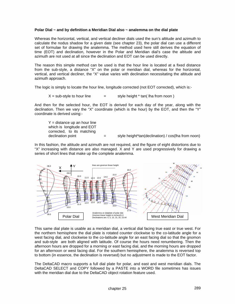
289
Analemma on dialplate of polar dial.Gnomon linear height in inches:01.0Declinations are: 0, 5, 10, 15, 20, 23.44
1121
31
41
51
61
71
81
91
101
111121131141
112131415161718191101111121131141
112131415161718191101111121131141
112131415161718191101111121131141
112131415161718191101111121131141
112131415161718191101111121131141
112131415161718191101111121131141
112131415161718191101111121131141
1121
31415161718191101111121131141
08.0
09.0
09.0
10.0
10.0
11.0
11.0
12.0
12.0
13.0
13.0
14.0
14.0
15.0
15.0
16.0
16.0
17.0
lines are gnomon linear height
Polar Dial ~ and by definition a Meridian Dial also ~ analemma on the dial plate Whereas the horizontal, vertical, and vertical decliner dials used the sun’s altitude and azimuth to calculate the nodus shadow for a given date (see chapter 23), the polar dial can use a different set of formulae for drawing the analemma. The method used here still derives the equation of time (EOT) and declination, however in the Polar and Meridian dial’s case the altitude and azimuth are not used at all since the declination and EOT can be used directly. The reason this simple method can be used is that the hour line is located at a fixed distance from the sub-style, a distance “X” on the polar or meridian dial, whereas for the horizontal, vertical, and vertical decliner, the “X” value varies with declination necessitating the altitude and azimuth approach. The logic is simply to locate the hour line, longitude corrected (not EOT corrected), which is:- X = sub-style to hour line = style height * tan( lha from noon ) And then for the selected hour, the EOT is derived for each day of the year, along with the declination. Then we vary the “X” coordinate (which is the hour) by the EOT, and then the “Y” coordinate is derived using:- Y = distance up an hour line which is longitude and EOT corrected, to its matching declination point = style height*tan(declination) / cos(lha from noon) In this fashion, the altitude and azimuth are not required, and the figure of eight distortions due to “X” increasing with distance are also managed. X and Y are used progressively for drawing a series of short lines that make up the complete analemma. This same dial plate is usable as a meridian dial, a vertical dial facing true east or true west. For the northern hemisphere the dial plate is rotated counter clockwise to the co-latitude angle for a west facing dial, and clockwise to the co-latitude angle for an east facing dial so that the gnomon and sub-style are both aligned with latitude. Of course the hours need renumbering. Then the afternoon hours are dropped for a morning or east facing dial, and the morning hours are dropped for an afternoon or west facing dial. For the southern hemisphere, the analemma is reversed top to bottom (in essence, the declination is reversed) but no adjustment is made to the EOT factor. The DeltaCAD macro supports a full dial plate for polar, and east and west meridian dials. The DeltaCAD SELECT and COPY followed by a PASTE into a WORD file sometimes has issues with the meridian dial due to the DeltaCAD object rotation feature used.
chapter 25
YX
Polar Dial West Meridian Dial
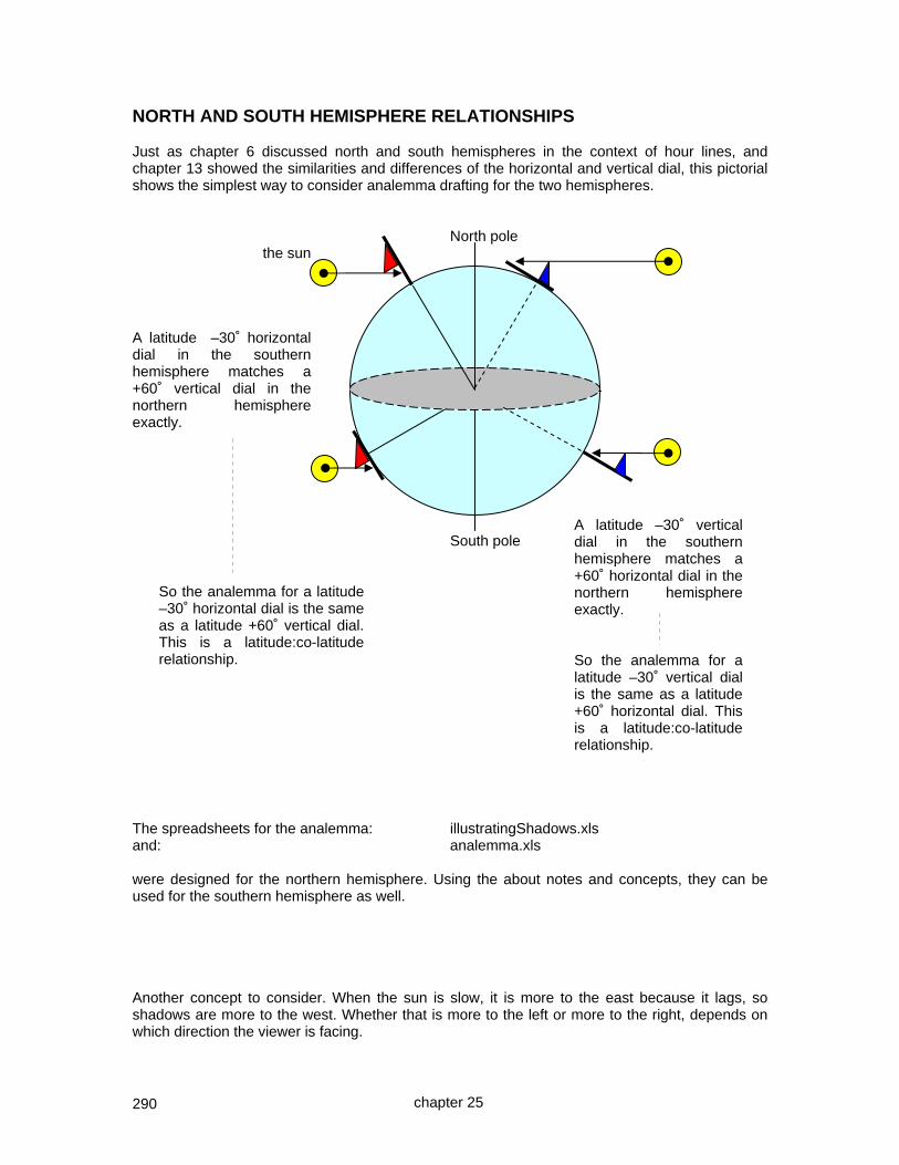
290
NORTH AND SOUTH HEMISPHERE RELATIONSHIPS Just as chapter 6 discussed north and south hemispheres in the context of hour lines, and chapter 13 showed the similarities and differences of the horizontal and vertical dial, this pictorial shows the simplest way to consider analemma drafting for the two hemispheres. North pole the sun A latitude –30˚ horizontal dial in the southern hemisphere matches a +60˚ vertical dial in the northern hemisphere exactly. South pole
So the analemma for a latitude –30˚ horizontal dial is the same as a latitude +60˚ vertical dial. This is a latitude:co-latitude relationship.
The spreadsheets for the analemma: illustratingShadows.xls and: analemma.xls were designed for the northern hemisphere. Using the about notes and concepts, they can be used for the southern hemisphere as well. Another concept to consider. When the sun is slow, it is more to the east because it lags, so shadows are more to the west. Whether that is more to the left or more to the right, depends on which direction the viewer is facing.
chapter 25
A latitude –30˚ vertical dial in the southern hemisphere matches a +60˚ horizontal dial in the northern hemisphere exactly. So the analemma for a latitude –30˚ vertical dial is the same as a latitude +60˚ horizontal dial. This is a latitude:co-latitude relationship.

291
CHAPTER TWENTY SIX
Other Interesting Hour Angle Dials
GLOBE DIALS The globe dial is as simple as the armillary or equatorial dial in design. Globes can be found in masonry supply facilities as globe finials. A globe dial needs an axis that matches the polar axis of our planet, namely set at the latitude. The latitude angle was marked on the globe using a laser on a tripod, the laser was tilted to latitude, and raised until the laser line bisected the globe. This was marked with a pencil after verifying the red laser light again for latitude. The process was repeated on the other half, and the two laser guided half circles then joined up. Later a 1/4 inch copper tube will circle around those pencil lines. Two holes can now be drilled in the globe at its poles and copper rods inserted. Now semicircles of copper tubing are affixed to those two rods to provide a full circle – pole to east to pole to west and back to pole. A copper plate then spans the equator of the globe and should be as thin a copper sheet as possible. Then, using a protractor, lines are marked every 15 degrees on the equatorial band, and adjustments made for longitude if so desired, however that would limit the globe dial to this location. In this example the 15 degrees were marked by measuring the band where the hours would be displayed, and dividing that length into twelve equal segments, this was in place of using a protractor.
When using the laser to aid in drawing the latitude line which will be the 6 am and 6 pm hour line also, care must be taken to ensure that the lines thus marked are truly bisecting the globe. Take care not to look into the laser light. A movable gnomon, a copper fin, is finally added that can rotate around the polar axis.
Time is read by rotating the thin plate until the shadow reaches minimum size. The figure above to the left is not correct as the shadow is large, the movable gnomon needs to be turned away from the shadow. The figure to the right, is correct as it has a minimum shadow. The equation of time is applied along with the longitude factor, and summer time also if appropriate. In this case the L.A.T. shows 2:20 pm, the longitude correction was plus 12 minutes, the EOT was plus 2 minutes (June 22) which means plus 1 hour for summer time also. The legal standard time was thus 3:34 pm, which was within a few minutes of the time on the author's atomically set clock.
correctly aligned
11
noon
2:20 LAT local apparent time
1
chapter 26
incorrectly aligned
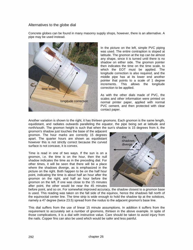
292
Alternatives to the globe dial Concrete globes can be found in many masonry supply shops, however, there is an alternative. A pipe may be used instead.
In the picture on the left, simple PVC piping was used. The entire contraption is sloped at latitude. The gnomon at the top can be almost any shape, since it is turned until there is no shadow on either side. The gnomon pointer then indicates the time on the time scale, to which the EOT must be applied. The longitude correction is also required, and the middle pipe has at its lower end another pointer that points to a scale of 1 degree increments. This allows the longitude correction to be applied. As with the other dials made of PVC, the scales and other information were printed on normal printer paper, applied with normal PVC cement, and then protected with clear contact paper.
Another variation is shown to the right, it has thirteen gnomons. Each gnomon is the same length, equidistant, and radiates outwards paralleling the equator, the pipe being set at latitude and north/south. The gnomon height is such that when the sun's shadow is 15 degrees from it, the gnomon's shadow just touches the base of the adjacent gnomon. The hour marks are correctly 15 degrees apart. The quarter hours are shown as equidistant however this is not strictly correct because the curved surface is not concave, it is convex. Time is read in one of two ways. If the sun is on a gnomon, i.e. the time is on the hour, then the null shadow indicates the time as in the preceding dial. For other times, it will be seen that there will be a place where the shadows diverge, as is emphasized in the picture on the right. Both happen to be on the half hour point, indicating the time is about half an hour after the gnomon on the right, and half an hour before the gnomon on the left. If one was close to the 15 minutes after point, the other would be near the 45 minutes before point, and so on. For somewhat improved accuracy, the shadow closest to a gnomon base is used. This reading was taken on the fall side of the equinox, hence the shadows fall north of the equinoctial center line. The time strip is wide enough to hold the shadow tip at the solstices, namely a 47 degree (twice 23.5) spread from the nodus to the adjacent gnomon's base line. This dial suffers from the use of linear 15 minute assumptions. In addition it suffers from the requirement to accurately set a number of gnomons, thirteen in the above example. In spite of those complications, it is a dial with instructive value. Care should be taken to avoid injury from the nails. Copper fins can also be used which would be safer and less painful.
the shadows diverge
pole
time scale
longitude correction
equator
chapter 26
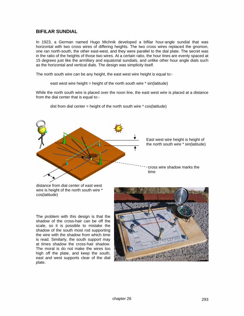
293
BIFILAR SUNDIAL In 1923, a German named Hugo Michnik developed a bifilar hour-angle sundial that was horizontal with two cross wires of differing heights. The two cross wires replaced the gnomon, one ran north-south, the other east-west, and they were parallel to the dial plate. The secret was in the ratio of the heights of those two wires. At a certain ratio, the hour lines are evenly spaced at 15 degrees just like the armillary and equatorial sundials, and unlike other hour angle dials such as the horizontal and vertical dials. The design was simplicity itself. The north south wire can be any height, the east west wire height is equal to:- east west wire height = height of the north south wire * sin(latitude) While the north south wire is placed over the noon line, the east west wire is placed at a distance from the dial center that is equal to:- dist from dial center = height of the north south wire * cos(latitude)
The problem with this design is that the shadow of the cross-hair can be off the scale, so it is possible to mistake the shadow of the south most rod supporting the wire with the shadow from which time is read. Similarly, the south support may at times shadow the cross-hair shadow. The moral is do not make the wires too high off the plate, and keep the south, east and west supports clear of the dial plate.
cross wire shadow marks the time
distance from dial center of east west wire is height of the north south wire * cos(latitude)
East west wire height is height of the north south wire * sin(latitude)
chapter 26

294
POLARIZED LIGHT AND THE SUN DIAL Clearly the sundial provides a measure of the time when the sun shines on the gnomon. A lunar dial can provide the time at night for a couple of weeks in a month, and for when the moon shines not, a nocturnal can provide the time from a few select stars on moonless nights. But what about determining the time when the sun is below the horizon and the moon or stars are insufficient for use? What about when a cloud limits the light to a gnomon? Around 1848, Sir Charles Wheatstone used the polarizing effect of light coming from the celestial pole. Light from the sun reflected by the sky becomes polarized. Light coming through clouds tends to de-polarize. The alignment of this polarized light varies with the sun's position, the observer's position, and the part of the sky being observed. While the most polarizing effect does not always come from the celestial pole or polar axis extended, measuring the polarization from thence does provide a linear hour angle measurement. Sir Charles used a polarizer which he rotated, the result was the observed sky became brighter or darker. The observer seeks the darkest light from the sky as it is a narrower region. As the sun orbits, so does the place where the polarizer provides the darkest light. And by using the celestial pole, that angle varies linearly and directly with the sun. In true Illustrating Shadows form, four pieces of PVC piping were used, a mirror, and a lens from a cheap pair of polarized sun glasses. A long tube points to the polar axis extended to infinity, the celestial pole. At its end is a rotating collar in which has been placed a circular cutout of one lens from a pair of polarized sunglasses. The lens was removed and cut using a Dremel rotating saw. At the base of the long tube is a 90 degree union, in which is placed part of a mirror angled at 45 degrees. This enables the light to be viewed from the polar axis easily. Without that 90 degree bend it would be hard to see the light from the sky because your eye would have to be below dial level. The perimeter of the long tube has a paper collar divided evenly into 24 hours, and time is indicated by a pointer attached to the rotating collar containing the polarizer. The pointer is set by seeking the darkest light and affixing a pointer to indicate the L.A.T. on the paper collar of hours, backed off by the equation of time (EOT). For fine tuning, the paper collar can be adjusted and then set rigid with a piece of masking tape. This technique means longitude corrections are automatically applied, and of course EOT must be considered. From then on, whenever the time is required the long tube is pointed to the celestial pole and the polarizing collar rotated back and forth around the darkest light, until the darkest orientation is found. The EOT is applied and the time then read. Other polarizers can be used, however camera polarizers seem to be less satisfactory. This dial can read the time as long as the sun is illuminating the extended pole and as long as that extended pole is blue sky. Thus, before sunrise until after sunset, the time may be read, similarly if the observer's location has no well formed shadows. This is not an all inclusive guide on polarizing dials, rather a starting point from which to work, and that starting point is a working polarizing dial.
rotating polarizer
hour scale or collar
90° union with mirror at 45°
pointer
to the celestial pole
eyepiece
chapter 26

295
REFLECTING OR CEILING DIALS Ceiling dials are not common, Sir Isaac Newton and Christopher Wren both built them, and having an unused ceiling in my barn, I decided to follow suit.
The dial has hour lines, a meridian line depicted by sun declination markers, and the equinox and solstice curves. The pictures above show the time approaching 1 pm.
Having a habit of forgetting key information, a data plate shows the latitude and longitude of design, the declination (why the meridian is offset), and the distance from the ceiling to the mirror (CTM).
Care must be taken with ceiling dials, stepping backwards off the step ladder while marking the ceiling is a real danger. When working with ladders it is easy to become disoriented, especially when wearing glasses.
chapter 26

296
With a reflecting dial, or ceiling dial, a mirror is placed on a surface such as a window sill, of course it is set level. The sun is reflected from the mirror at point "m", and for this example, the equinox is assumed. The reflected ray displays a reflection of the sun on the ceiling, a spot, and this is at point "n". Because the following uses the equinox, angle "Cmq" is a right angle.
The sun comes through "q" to "m" and is reflected to "n". If this were a true horizontal dial, the gnomon would be "BmC", where "Bm" is the style linear height, and this matches the height of the ceiling above the little mirror, "mb". (NOTE: lat = lat2 = lat3, subscripts are order of derivation). Angle "BCm" is the latitude, so also is "bcm" and "nmb". Since nmb = latitude, tan (lat) = nb / bm thus nb = mb * tan(lat) [ 1 ] Since bcm= latitude, tan (lat) = mb / bc thus bc = mb / tan (lat) thus, distance from equinox point on meridian to the dial canter "c" is nc = nb + bc hence nc = mb * tan(lat) + mb / tan(lat) = mb * ( tan(lat) + 1/tan(lat) ) [ 2 ] [The conventional formula is = 2*mb /sin(2*lat) ] Thus we have a dial plate, with a meridian line (L.A.T. noon) and an equinox point on it, thus the equinox line can be drawn.
chapter 26

297
Similarly, we have the dial center, it is located from the equinox point "n" at a distance:- = mb * ( tan(lat) + 1/(tan(lat) ) derived formula [ 2 ]
The dial plate on the ceiling is reversed, otherwise it is a normal horizontal dial. The morning hours are to our right as we look up at the ceiling, whereas looking down on a normal horizontal dial, they are to the left. With this in mid, the dial layout is a normal horizontal dial for the design latitude and longitude, except we reverse the sense of the angles.
Ceiling dials have a dial center that is not in existence, but it is used to locate the hour line angles. For example, 2pm, the "h14" line will have an hour line angle of some value "x". Since the dial center "c" is not in physical existence, we use the distance from point "n", hour point on equinox line h14 from "n" nh14 = tan(hour line angle) *nc = tan(hour line angle) * mb * ( tan(lat) + 1/(tan(lat) ) and at point h14, a line is drawn of 90-hour line angle. Hence the hour lines can be drawn. Calendar curves can also be drawn using the same techniques covered elsewhere. A key point to remember is that these dials can get rather large, reducing the mirror's height from the ceiling will make the dial smaller. REFLECTING OR CEILING DIALS Distance from mirror to ceiling (style linear height)
1 nb = mb * tan(lat) [1] nc=mb*(tan(lat)+1/tan(lat)) [2] Latitude Distance from point
above mirror to equinox point on the meridian line
Distance from meridian equinox point to dial center
Latitude Distance from point above mirror to equinox point on the meridian line
Distance from meridian equinox point to dial center
30 0.5774 2.3094 46 1.0355 2.0012
31 0.6009 2.2651 47 1.0724 2.0049
32 0.6249 2.2252 48 1.1106 2.0110
33 0.6494 2.1893 49 1.1504 2.0197
34 0.6745 2.1571 50 1.1918 2.0309
35 0.7002 2.1284 51 1.2349 2.0447
36 0.7265 2.1029 52 1.2799 2.0612
37 0.7536 2.0806 53 1.3270 2.0806
38 0.7813 2.0612 54 1.3764 2.1029
39 0.8098 2.0447 55 1.4281 2.1284
40 0.8391 2.0309 56 1.4826 2.1571
41 0.8693 2.0197 57 1.5399 2.1893
42 0.9004 2.0110 58 1.6003 2.2252
43 0.9325 2.0049 59 1.6643 2.2651
44 0.9657 2.0012 60 1.7321 2.3094
45 1.0000 2.0000 61 1.8040 2.3584
hour line angle angle from equinox line
dial plate as seen if lying on the floor
chapter 26

298
First, a place was estimated about where to place a mirror. Then in this case a cross piece was affixed to both sides of a window frame. This was level in all exes.
Then a point on the ceiling was selected, and a small hook located there, and a plumb line dropped.
A small piece of wood was placed on the cross piece, and a reflective surface added. Again, it was leveled in all axes. The distance from the reflective surface to the ceiling was measured and found to be 48.5 inches. The illustratingShadows.xls spreadsheet was run with the design latitude of 32.75 and longitude of 108.2, and the vertical distance of 48.75 entered. The date was November 30, 2008, the sun was fast so the EOT was negative, being – 10:59 minutes : seconds Also, the sun would be slow due to the longitude separation from the legal meridian, and 108.2 – 105.0 is some 3.2 degrees, or +12:48 minutes : seconds The total correction being: + 1:48 minutes / seconds
So at 12:00, plus the final correction of +1:48 minutes/secs, the light spot is finally marked on the ceiling at 1201:48 and then a line was drawn from that spot light to the point directly above the mirror, this was the noon meridian line. The spreadsheet estimated a distance from the point above the mirror, to the light spot for the 11/30/08 date using the calculated sun's declination of -21.69 degrees as 67.85 inches. The actual distance was measured at 67.0" thus the calculations were matching the observations within less than an inch. NOTE: The correction for longitude and EOT used the astronomical EOT. A “noon transit” of the sun table can be used, such as in the appendices or in chapter 6. Additionally, the spreadsheet on the CD that comes with this book as well as on the web site has a noon transit table corrected for the dial’s longitude, this makes locating the meridian even easier.
chapter 26

299
The main spreadsheet has all the data on the first section, see immediately below.
48.5 Distance from mirror to ceiling taken from main spreadsheet gnomon linear height
Todays EOT/Diff.Long correction: 2.39 nb = mb * tan(lat) nc=mb*(tan(lat)+1/tan(lat)) Latitude Distance from point
above mirror to equinox point on the meridian line
Distance from meridian equinox point to dial center
Distance from point above mirror to summer solstice point on the meridian line
Distance from point above mirror to today's decl point on the meridian line
Distance from point above mirror to winter solstice point on the meridian line
32.75 31.1962 106.5979 7.951 67.847 72.421
Today's decl
DESIGN LONGITUDE 108.20 -21.6913
DESIGN LEGAL MERIDIAN 105.00 11/30/08
Then the summer solstice, equinox, and winter solstice points were marked, they were derived from the spreadsheet as: 8 inches (7.951), 31.2 inches (311962), and 72.4 inches (72.421) respectively. A line perpendicular to the meridian line was drawn at the equinox point on the meridian line, being at 31.2 inches. The distance from the meridian line, along the equinoctial line for hour points and, repeated, are the inverse hour line angles at those hour points,
Latitude
hour line angle at the hour point on the equinoctial line on the meridian ~ taken from above inverse hour line angles
Distance from meridian equinox point to dial center
Distance along equinoctial line from meridian line
32.75 106.5979 am to pm angle
6.0 5.90 1031.446 7.0 21.12 276.035 8.0 43.04 114.161 9.0 58.82 64.497
10.0 70.51 37.736 11.0 79.91 18.960 12.0 88.27 3.224 13.0 83.55 12.047 14.0 74.72 29.130 15.0 64.19 51.560 16.0 50.42 88.124 17.0 31.29 175.394 18.0 5.90 1031.446
chapter 26

300
The last section of the spreadsheet identifies hour line distances along the equinoctial line from the meridian. It also copies the inverse hour line angles at those hour points. The hour points along the equinox were marked. At those hour line points, inverse hour line angles were drawn. Then the hour lines themselves can be completed, they would meet at the dial center which is of course outside the building. The equinox line is used since it is straight. Any other declination other than 0 produces a hyperbolic line. This dial used empirical methods to draw the north south meridian line, albeit using calculated time shifts for the EOT and longitude differences. Calculations were used for the equinox point, and the day's spot was cross checked with its calculated position on the meridian (north south) line. Hour lines were drawn using calculated hour point distances along the equinoctial line, and angles using inverse hour line angles, those all being calculated distances and angles.
equinox point on the meridian line 1300, 1200, and 1100 all marked meridian line summer solstice on the meridian line
All required information is provided by: The main spreadsheet: illustratingShadows.xls The PDA spreadsheet: a small spreadsheet exists for PDAs And a tabular spreadsheet: a general tabular spreadsheet exists And a DeltaCAD program, choice 7: MAIN-h-dials.bas The main spreadsheet also has within it an almanac and a sun's transit table. The transit table only needs the longitude correction to be converted to minutes and added (if west of the meridian) or subtracted (if east of the meridian). The longitude difference is multiplied by 4 to convert from degrees to minutes. Thus using the November 30th example, the noon transit time for this location (longitude 108.2) and for this time zone (105) is 3.2 degrees, or 12.8 minutes. The 1148.46 and 12.8 thus added become 1201.6 hhmm.m or 1201:36 as hhmm:ss which is within a few seconds of the calculation for the meridian earlier, the above table for transit time is a middle of the four year span using an astronomically correct EOT, thus the 12 seconds difference is surprisingly accurate. To the right is a DeltaCAD plate for a ceiling dial.
chapter 26

301
CALENDAR CURVES AND THE CEILING DIAL (or large horizontal) The CAD program can be used to measure distances from the point on the ceiling above the mirror to calendar points on the hour lines. To the left are CAD measurements of the ceiling point above the mirror to the summer and winter solstices, and the equinox, on the north south meridian (not the noon line). The measurements are less than an inch off which is fair given the size of the dial plate. Measurements for each calendar curve are made, in the case to the left, the winter solstice was used. These distances allow a point to marked on each hour line for the several calendar curves, thus allowing the calendar curves to be drawn.
chapter 26

302
FINAL DIAL COMPLETION Wood molding was used to mark the significant points, wood trim was used for the hour lines and for calendar curve segments. And a stucco used to fill in the areas. The mirror was enhanced, this was not simple because of the need for perfect alignment with the prior mirror so that the hour lines and calendar curves would still be accurate. The plan was simple. A laser was set up to send a dot of light off the original mirror and mark that point on the ceiling. Then the old mirror would be removed and replaced with the one to the right. The new mirror would be fine tuned so that the spot would be at the same place as with the original mirror. This works because of the law of reflection. The laser was set up, and work resumed on the wood for the dial plate borders, and trim for the hour lines and calendar curves. At this point, some wood fell down and that was the end of the original mirror. What to do? The benefits of that original meridian line sprang to mind. Not only does the meridian line indicate the declination of the walls of the building housing the ceiling dial, not only does the meridian line indicate the central point for the calendar curves, not only does it provide the line from which the equinoctial line stems perpendicular to it, but it also provides the means of calibrating a mirror. If the sun's noon transit is measured, using the noon transit data from the spreadsheet, or from the time of noon corrected for EOT and longitude, then at noon the sun must be reflected onto that north south meridian line. And since the distance from the mirror to the ceiling is known, and the day's solar declination, then the distance from the ceiling point above that mirror, to the center of the sun's reflected spot on the ceiling can be deduced. The ceiling dial spreadsheet has this table in one degree steps. And for a distance of 48.5, and a solar declination of -23.13 shows the spot to be 71.58 inches from the reference point. Thus tragedy was averted. The dial works well, however at lower latitudes the sun’s altitude is such that no spot is reflected up, and of course morning and afternoon hours are inhibited due to the suns azimuth being excessive. DECLINATION POINTS ALONG THE MERIDIAN AS MEASURED FROM THE CEILING POINT ABOVE THE MIRROR FOR A LINEAR DISTANCE OF: 48.50
-23.44 72.42 25-Dec -23 71.23 -22 68.63 today's decl: -21 66.15 -23.13-20 63.78 today's spot -19 61.52 71.58-18 59.36
chapter 26

303
CHAPTER TWENTY SEVEN
Night time dials A LUNAR DIAL There are several techniques that allow the time to be read from the moon. This also brings into light the definition of being a purist; is a purist someone who in this context seeks the most accurate timepiece, or is a purist one who uses just the moon, albeit empirically, and excludes references to the sun. Three techniques spring to mind, they are:-
A lunar dial using a sundial and a correction table A lunar dial using the moon but with solar associations in its mathematics A lunar dial using just the moon
A lunar dial using a sundial and a correction table – some old dials may have this table A sundial itself can be used, however some adjustments are required. First, an Earthling's hour is marked by about 14.5° of lunar orbit around the Earth's polar axis, compared to 15° for the sun. Thus solar hours would be larger by half a degree, in other words 2 minutes. In 24 hours, that accounts for 12 degrees, or in Earthling terms, 48 minutes. Thus a table can be drafted such that the moon's phase indicates the time to be added to or subtracted from the sundial's 12 o'clock midnight baseline time. Of course those 2 minutes per hour must also be considered for the hours on either side of 12 o'clock. In the mid 1700's such a table was used that assumed a 30 day lunar cycle, however there are other variables that make this method somewhat impractical. At 15 days after the new moon, i.e. a full moon, 12 hours is added to the dial, thus 12 noon means 12 midnight. Again, this was an approximation. Before and after full moon one must remember to subtract or add as appropriate. This system works with a little effort, and requires the date of the new or full moon to be known. Of course, it still needs some fine tuning since full moon happens at a specific date, time, and place and that may not be over your dial. Lunar dials are not known for their accuracy. A lunar dial using the moon but with solar associations in its mathematics The most accurate method is to use the moon's orbital information in conjunction with that of the sun's apparent Earthly orbit, and from thence, derive an accurate system. Here is a method of determining new moon, first quarter, full moon, and last quarter for any date. The following formulae are approximations of approximations, and are drawn from chapter 32 p159 of Astronomical Formulae for Calculators, Jean Meeus. Some of the formulae in that book have been simplified elsewhere in this book. The formulae use an epoch base of 1900 which is somewhat academic, however it emphasizes the need for formulae not to be mixed from author to author, or article to article. Many books use the year 2000 as the epoch base. Additionally, these figures are for the mean lunar cycle. That is 29 days, 12 hours, 44 minutes, 3 seconds, or 29.5305891203704 days, however interaction with the sun can vary this by about 6 hours on either side.
30 day Days Days Hours to
before after adjust
full moon
full moon
dial L.A.T.
7 7 6.4 6 6 7.2 5 5 8.0 4 4 8.8 3 3 9.6 2 2 10.4 1 1 11.2 0 0 12.0
chapter 27

304
Intermediate figures M23 = mm/12 N23 = (dd/30)/12 O23 = (mm+N23)/12 P23 = O23+yyyy k = (P23-1900)*12.3685 int~of~k = INT(k) T = k/1236.85 Julian date for new moon, first quarter, full moon, third quarter, nearest to the specified date. =2415020.75933 + 29.53058868 * (int~of~k + 0.00) + 0.0001178*T*T - 0.000000155*T*T*T =2415020.75933 + 29.53058868 * (int~of~k + 0.25) + 0.0001178*T*T - 0.000000155*T*T*T =2415020.75933 + 29.53058868 * (int~of~k + 0.50) + 0.0001178*T*T - 0.000000155*T*T*T =2415020.75933 + 29.53058868 * (int~of~k + 0.75) + 0.0001178*T*T - 0.000000155*T*T*T Julian date you can use as a base for the above dates =INT(365.25 * (4716 + (IF((IF(mm>2,1,0))=0, yyyy-1, yyyy))) + INT(30.6001*((IF((IF(mm>2,1,0))=0, mm+12, mm))+1))) + dd-1524.5 + (2-INT((IF((IF(mm>2,1,0))=0, yyyy-1, yyyy))/100) + INT(INT((IF((IF(mm>2,1,0))=0, yyyy-1, yyyy))/100)/4)) It is emphasized that these formulae are approximations, and should be treated in that light. These formulae are in the generalized spreadsheet on this book's web site. The same spreadsheet also has the formulae to convert mean lunar phase data to true lunar phase data. A lunar dial using just the moon The lunar dial discussed here does not require the above formulae, it is simply set on the first quarter of the moon, and rotated each day by 12.2 degrees eastward. This lunar dial uses just the moon itself, and is simpler to use and more practical than a sundial with a table of corrections, The sun's maximum declination is 23.5 degrees and the moon has a 5 degree orbital offset from the ecliptic, thus its declination range is 28.5 degrees. A dial plate designed for 14.5 degree hour angles and an adjustment for 12.2 degrees per day can be used based on the observation of the phase of the moon. An armillary dial can also be used, as can an equatorial dial, all of these will require a daily rotational adjustment around the polar axis, be that mechanical or mathematical. Because the moon's apparent orbit around the Earth is a bit slower than the sun's, an hour uses less lunar degrees around the Earth's polar axis than does the sun. Since the moon retards about 2 minutes per Earth hour, that is in polar axis hour angles 1/2 a degree since 1 degree represents 4 minutes. Thus a lunar hour is indicated by about 14.5° and not 15 which is used for the sun. Because a mean lunar month is about 29.5 days (a true lunar month may vary from the mean by 6 hours), and because this must account for 360 degrees of rotation before the moon is back in synchronization with itself, this means a daily rotation backwards of about 12.2 degrees is required. An analysis of almanacs over many years shows that the actual daily shift can be as little as 9.5 or as much as 14.6 degrees, and the daily variation may be as much as 1 degree. There are a couple of waves of this variation throughout a lunar month. This dial needs to be set on the first usable day (first quarter) and may need fine tuning over the next two weeks which is the life of the usable shadow. Two weeks of lunar data from March 2003 follows showing the moon's GHA (Greenwich Hour Angle) at 0000 GMT from the first to the last quarter. The daily shift range is –12.42° to –14.22° (compared to 12.2°), the daily difference in that shift varies from –0.58° to +0.32°. For that entire lunar cycle those figures were –9.77° to –14.22°, and –0.62° to +0.86°.
chapter 27

305
2003 almanac phase
gha°.°° 0000z
Daily shift
Daily shift
3/11 1st qtr 92.90 diff 3/12 1 80.48 -12.42 3/13 2 67.48 -13.00 -0.583/14 3 54.12 -13.37 -0.373/15 4 40.65 -13.47 -0.10
3/16 5 27.35 -13.30 0.173/17 6 14.37 -12.98 0.32
3/18 full 1.67 -12.70 0.283/19 1 349.13 -12.53 0.173/20 2 336.60 -12.53 0.003/21 3 323.83 -12.77 -0.23
3/22 4 310.67 -13.17 -0.40
3/23 5 297.02 -13.65 -0.483/24 6 282.97 -14.05 -0.40
3/25 lst qtr 268.75 -14.22 -0.17 Because of the need for a daily dial adjustment, and the baseline to start the two weeks of good lunar use varies, this dial is easy to use. To the left is a picture of the dial. The top rotating section is a moving gnomon, using a null shadow. That null shadow causes the extension of the gnomon to show the time on the next rotating section down. The 12 o'clock hour line on the second rotating section has an arrow pointing down, which is set to the day from the first quarter, the days are numbered 0-14, or as 0-9, and A-E. For people who go to bed early, days 0 through 9 work well, for late night people, all 14 days are usable.
That two week lunar span section is also rotated around the lowest or first section to calibrate the time against a standard time watch. This corrects for lunar variations up to the first quarter, and the dial's longitude. And the hour section is rotated one detent each day. Because of the many and less easily predictable variations in the lunar orbit, by the day, month, and year, these dials are not excessively accurate, and probably need recalibration every few days, maybe set once on the first quarter, and again on the full moon. Appendix 9 has a template for this dial, it was designed for a 2.25 outer diameter PVC pipe, however you can enlarge or shrink it to suit your purposes. This is not an all inclusive guide to lunar dials, rather a starting point from which to work, and that starting point is a working lunar dial.
set as a bias on the first quarter
moved one position (12.2°) each day as the days grow after the first quarter
this gnomon is rotated to read the time
The four sections of the dial
chapter 27
- 16 . 0 0
- 14 . 0 0
- 12 . 0 0
- 10 . 0 0
- 8 . 0 0
- 6 . 0 0
- 4 . 0 0
- 2 . 0 0
0 . 0 0
1 3 5 7 9 11 13 15 17 19 2 1 2 3 2 5 2 7 2 9
dai
ly G
HA
sh
ift
at 0
000z
0°
usable shadow
-16°

306
THE NOCTURNAL OR STAR CLOCK
The stars in the northern hemisphere seem to rotate around the north star, Polaris. They revolve about 360 degrees in a day. And for any given time of night, they rotate 360 degrees in a year. This all means that a 360 degree map of the stars can be drawn, and throughout the year some stars come into view, others leave. And similarly, in the evening, the stars for the season rotate 360 degrees in a day. Approximately. This means that should one know the month, then the time can be approximated, and this is the basis for a nocturnal dial. In fact, chapter 6 covering true north direction determination showed such a star map. This section is not intended to be anything more than an overview of how a nocturnal time piece may be designed. Of course, the southern hemisphere has similar rules, however there is no Polaris, only an empty place which is however pointed to by some constellations. Some nocturnal dials use Ursa major and Ursa minor, some use Cassiopeia, this section uses Ursa Minor and Cassiopeia for good annual coverage. All the stars visible for this date, or season … rotate daily and completion one rotation annually
The bigger picture of the solar system and its planets shows that the planets move close to the ecliptic. Hence the planets and the moon generally are in the same line in the night sky. And that line is roughly on the ecliptic, or within about 10 degrees of it. The planets move on their own orbits, thus their locations appear to move compared to the stars which are considered to be fixed. The first four planets from the sun are:- Mercury, Venus, Earth, then Mars. The stars are everywhere and appear to rotate around the Earth's poles. As the Earth orbits the sun, different stars close to the ecliptic become visible in different seasons because they are seen on the night side of the Earth away from the sun. star visible in September on the extended ecliptic
Polaris ~ the north star, within a degree of the Earth's extended north polar axis, visible all year in the northern hemisphere, and is nowhere near the ecliptic, it is perpendicular to and north of it.
a star visible at year end on the extended ecliptic
a star visible mid year on the extended ecliptic
LOOKING NORTH
star visible in March on the extended ecliptic
June
The June view is rotated 180 degrees from the December view.
Polaris
December
Stars rotate east to west above Polaris as the night passes – they rotate 360 degrees approximately in a 24 hour time frame. Stars rotate west to east below Polaris as the night passes.
Cassiopeia
Polaris
chapter 27
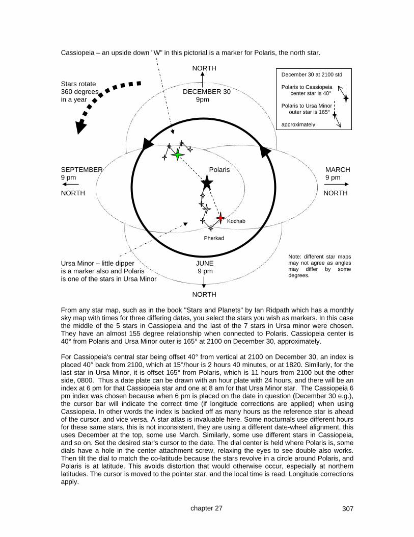
307
Cassiopeia – an upside down "W" in this pictorial is a marker for Polaris, the north star. NORTH Stars rotate 360 degrees DECEMBER 30 in a year 9pm SEPTEMBER Polaris MARCH 9 pm 9 pm NORTH NORTH Ursa Minor – little dipper JUNE is a marker also and Polaris 9 pm is one of the stars in Ursa Minor NORTH From any star map, such as in the book "Stars and Planets" by Ian Ridpath which has a monthly sky map with times for three differing dates, you select the stars you wish as markers. In this case the middle of the 5 stars in Cassiopeia and the last of the 7 stars in Ursa minor were chosen. They have an almost 155 degree relationship when connected to Polaris. Cassiopeia center is 40° from Polaris and Ursa Minor outer is 165° at 2100 on December 30, approximately. For Cassiopeia's central star being offset 40° from vertical at 2100 on December 30, an index is placed 40° back from 2100, which at 15°/hour is 2 hours 40 minutes, or at 1820. Similarly, for the last star in Ursa Minor, it is offset 165° from Polaris, which is 11 hours from 2100 but the other side, 0800. Thus a date plate can be drawn with an hour plate with 24 hours, and there will be an index at 6 pm for that Cassiopeia star and one at 8 am for that Ursa Minor star. The Cassiopeia 6 pm index was chosen because when 6 pm is placed on the date in question (December 30 e.g.), the cursor bar will indicate the correct time (if longitude corrections are applied) when using Cassiopeia. In other words the index is backed off as many hours as the reference star is ahead of the cursor, and vice versa. A star atlas is invaluable here. Some nocturnals use different hours for these same stars, this is not inconsistent, they are using a different date-wheel alignment, this uses December at the top, some use March. Similarly, some use different stars in Cassiopeia, and so on. Set the desired star's cursor to the date. The dial center is held where Polaris is, some dials have a hole in the center attachment screw, relaxing the eyes to see double also works. Then tilt the dial to match the co-latitude because the stars revolve in a circle around Polaris, and Polaris is at latitude. This avoids distortion that would otherwise occur, especially at northern latitudes. The cursor is moved to the pointer star, and the local time is read. Longitude corrections apply.
December 30 at 2100 std Polaris to Cassiopeia center star is 40° Polaris to Ursa Minor outer star is 165° approximately
Kochab
Pherkad
chapter 27
Note: different star maps may not agree as angles may differ by some degrees.

308
THE NORTHERN HEMISPHERE START CHART AND A NOCTURNAL DIAL It would be educational to validate the hour points for the two indices for Cassiopeia and Ursa Minor. Locate a star map such as above, and prove they are correct. Also, develop another star's cursor from scratch. Note: different star maps may not agree as angles may differ by some degrees. The nocturnal dial to the right is set for Cassiopeia, December 20th and shows a time of 8:30 pm standard time, to which the longitude correction is applied. The dial must be held vertical but tilted at co-latitude, because this is an hour angle dial. The template for this dial is in appendix 9, and was designed with a computer CD in mind for the larger dial plate.
chapter 27
Cassiopeia index at December 20
Ursa Minor index not being used on this reading
Time read from cursor that points to the index or pointer star.

309
CHAPTER TWENTY EIGHT
The use of stained glass for a sun dial and
other media of interest such as popup and paper dials
This chapter covers the following topics… THE USE OF OPAQUE GLASS as in reflected light dials THE USE OF TRANSPARENT GLASS where light and shadow are transmitted through the glass THE USE OF PAPER MODELS FOR DIALS transparent (as in the meridian dials) opaque as in the horizontal, polar, and armillary (and part time equatorial) 3d cutout and fold popup dials AND BRASS ENGRAVED DIAL PLATES. This is not intended to be a treatise on stained glass or any other medium, but rather a few pointers to consider when constructing a dial using glass. Glass may provide for a matte surface such that the shadow is seen by reflection, as with any common sundial made of other opaque materials. While horizontal dials produce few challenges, a vertical reflective glass dial indoors requires consideration in placement, and may prove impractical since the dial must be on the other side of the observer compared to the sun. Glass allows transparency and thus may allow a shadow to be seen through the glass, such as is seen in stained glass windows. This would tend not to be practical for horizontal dials but produces splendid results for the vertical dial which would be between the observer and the sun. Doing so, however, introduces some things to think about. First, the dial plate would be drawn using a mirror image template. Second, the gnomon needs rigidity which may take extra thought for declining dials. Third, the techniques for marking a vertical dial plate may use more advanced skills for the glazier. Fourth, the nodus linear height is to the frosted surface upon which it typically resides, and not to the front or non weather side of the glass dial.
chapter 28

310
GLASS DIALS Sun dials may be made in almost any media, and glass has been one of them used down through the centuries. Historically, glass sun dials were of the painted and stained variety, both of which are processes requiring kiln firing. And they used the property of the light coming through the glass as opposed to being reflected by it. However, the non transparent and more opaque of the glasses may be used on a dial plate where the observer looks at the gnomon's shadows on that glass which are then reflected towards the observer as on the left side of the pictorial below.
Opaque glass
Transparent glass
A translucent dial where light and A reflective dial where light and shadow are seen through the glass, it shadow are reflected by the dial plate, would reside at the window itself. it would reside away from the window or in this example outside. Reflecting dial plates need little explanation since most dials are of that type. The question becomes what is different with glass dials where the glass dial is transparent, as on the right side of the pictorial above. A transparent dial such as a vertical meridian dial pictured above would reside in a window, and receive the sun some of the morning (if facing east) or some of the afternoon (if facing west). If a glass reflecting meridian dial were used, then it would have to reflect light which means it could not be in the window itself, but rather on the wall receiving light from the window with the observer in between. And that lighted area will move dramatically making the indoor reflecting dial less practical. Thus for indoor use of vertical dials, transparent glass is much more effective than a reflective dial of an opaque glass. The same would apply to a vertical south facing dial. For indoor use transparent glass serves best. But how does one see a shadow on transparent glass? The shadow is hard to see on all but the opaque glasses and in a weak light no shadow would be seen. The solution uses a clear glass with a frosted surface, either by an etching cream or a sand blasted process both of which have safety considerations. The markings may be painted, and there are modern methods not requiring a kiln, however the author prefers a tracing black and brown matte such as were used in the 13th centuries, and fired around 750 degrees Celsius. The pigments are mixed with a flux, each of which has differing benefits. While water may be used, the paint or matte can flake off. Oil of cloves, anise, and other mediums make a very firm bonding with the glass.
chapter 28

311
The tracing black is used for the hour lines, calendar lines, and numerals indicating the time. Lettering is often done best by the negative technique: a matte covers the area and the lettering done by removing matte material. Traditionally they are drawn on the non weather side of the glass which makes writing much simpler. For true meridian and true south dials the process is simple, but for a declining dial care must be used in making the template which will be held below the glass, and above which the dial plate will be drawn in. Care is needed because the hour lines are no longer symmetrical. The template used should thus be a mirror image print of the declining dial because we will be looking south through the glass and not be looking north from a southerly position. Some printing software can print mirror images. The firing is done and the glass cooled, and for texture a matte may be added with texturing from a brush. That would be a second firing. If the fluxes used for the first firing were effective, then the matte could be applied before that second firing, and thus both would be fired in one step. The lines and indications need to stand out, and this may use the same technique that is used to make the gnomon's shadow stand out, or they may be marked on a dark matte as in a negative. The weather side of the glass traditionally holds stains and sometimes frosting. The tradition goes back to the fact that silver stains (producing the wonderful golden yellow textures of the 14th century, weather well and last hundreds of years, whereas the paints and mattes have a much shorter life when exposed to the elements. If an etching cream is used then all safety precautions must be observed. While the author has had some success with this, more success has come from a silicon carbide grit in a sand blasting box under the pressure of a compressor. Here again safety must be paramount. At this point we have lines on the room side of the glass, and a frosted texture on the weather side. In between the paint firing and the frosting may come a stain firing, the wonderful golden yellow stain is derived from silver compounds, fired around 1250 Fahrenheit for a longer period of time. This stain process is on the weather side of the glass, and by doing it before the frosting process, any stain found in unwanted areas may be rectified by sand blasting. The gnomon must be rigid, and to ensure that, it is best if it lies on a lead or foil line. Simple for the meridian dial and the south facing dial, but some creative thinking may be needed for a decliner. The author uses 1/4 inch copper pipe commonly used for refrigerator ice making lines as the frame. If the dial is to hang, then stress must be considered to avoid glass separation from the frame, as in any hanging window or panel. If the panel is to stand on a surface such as shown on the prior page, then a stand must be able to sustain jarring forces. The author uses pyramids with large glass marbles touching the surface. Three marbles create stability. The glass pyramid has three panels of 45 or more degrees at the bases. By not beveling the edges, a very sturdy solder line is formed that is structurally sound, and for decoration, solder buttons are applied. The entire panel is cleaned, then its border brushed with copper sulfate, a caustic material with safety considerations. Then washed and dried. SUMMARY The templates used are mirror image of a template that would be used for a reflective dial, especially important for declining dials. Chemical and other safety considerations exist. However the end result is a wonderful delight to behold. A resource for stained glass dials is: www.stainedglasssundials.com
chapter 28

312
POPUP AND PAPER DIALS Sun dials may be made in almost any media, and paper is certainly no exception, though less practical in humid climates or when a storm is overhead, or quantities of termites thrive. Paper dials fulfill a valuable role. For example, they can be used to validate a design. To that end, some paper templates are included in appendix 9. They are instructive. They are fun. The templates in appendix 9 cover:-
a horizontal dial template with all the protractor data included a vertical dial template with all the protractor data included a template for generating declination lines a protractor and graph paper to facilitate declining dial design
additionally, appendix 9 includes some paper cutout dials such as:-
an armillary dial which is also an equatorial one in the summer months a meridian dial for east and west facing situations, using paper transparency a polar dial a horizontal dial
however, paper sun dials may be designed using popup methods popular in the late 19th century.
a latitude 32 popup 3d paper dial with both horizontal and vertical dial plates Designed for latitude 32, this dial only needs the equinox line and the hour lines to be altered to match a new latitude. To adjust to another latitude for the horizontal part of the dial, on paper rotate the gnomon 90 degrees, find the new dial center by running a line at co-latitude down to intercept the 12 noon hour line at latitude. That is the new dial center. Another line at 90 degrees to the new style from the nodus goes up to intercept the noon line, and that is where the new equinox line goes. A similar process would be used for the vertical dial. new point for new equinox line new dial center If the description on how to generate information for another latitude seems somewhat brief, it is because the entire essence of this book is just that! The next page has the template for this dial, and CAD was used in its design. This template is included in appendix 9 even though it is for only one latitude. The template can of course be tilted using the same technique used for the dials in appendix 9. If the hour lines do not appear to meet on the vertical and horizontal dial plates, that is because the gnomon's were of a differing size and the vertical dial is displaced forward over the horizontal dial. A good book discussing these techniques is "The Pop-Up Book" by Paul Jackson.
chapter 28
latitude
co-latitude

313
A PORTABLE ENGRAVED BRASS HORIZONTAL DIAL Since the engraver was lying around, and there was spare engraver's brass, this project was an engraved dial, horizontal, longitude adjusted dial, designed for placing on a window sill. This dial will be for Silver City, NM, whose coordinates are: location lat: 32.75° N location long: 108.2° W magnetic declination: 10.6° E The spreadsheet: illustratingShadows.xls which is on the www.illustratingshadows.com web site was used to provide the longitude corrected hour line angles. The engraving system used was a Roland EGX-20 which is the bottom of the line, attached by a parallel port to a lap top using Windows XP. As this was indoor dial, engraver's brass was used. Using a CAD system, a dial plate was drawn up. The CAD image is shown to the right. Dr Engrave software was then used, and the CAD picture was pasted in as a model. It can be moved, and with shift plus the mouse, it can also be resized. Then a dial plate with gnomon was designed over the CAD image, even though images as such can be imported into Dr Engrave. When the final dial plate looked appropriate, the original CAD image was discarded.
The Dr Engrave image is shown to the left. A piece of engraver's brass was placed in the EGX-20 printer, and then the dial plate engraved. After engraving the dial plate looks anemic. Engraver's brass has a coating which the engraving process cuts through as it cuts into the metal. The rotating bit doesn't just scrape, it has a diamond bit which cuts or burnishes into the brass. This exposes freshly ground brass.
A brass blackening solution is used resulting in the lines and letters standing out. The solution has no affect on the coated parts of the brass, but those where the cutter has traveled become oxidized and blackened. Holes were drilled for the extremes of the sub-style, and on the back of the dial plate, a straight line was cut with a Dremel rotating blade. The gnomon was cut, bent at the bottom, then with some epoxy on the bent base, the gnomon was pushed through the dial plate cut, and thus the gnomon was fastened. For added measure a compass was added, which was unaffected by the brass. The final dial is shown to the right, taken from the north looking south. The author is in no way adept at engraving, this was a by product of the author's desire to have engraved data plates and engraved EOT charts for use with his garden dials. Dial plates can be engraved by other means, such as the photo resist method using an acid bath. Some truly beautiful dial plates result.
chapter 28

314
CHAPTER TWENTY NINE
Buying dials and making them work WHAT TO DO BEFORE BUYING ~ WHAT NOT TO BUY There has been an increase in the number of portable sundials for sale on web based auction sites, and buyers have asked questions as to why their portable sundials do not work. Sundials can be as accurate as a second or two, true the location must be exact and the predictable equation of time must be applied somehow. The equation of time enables watches to be corrected to reflect the sun's time as indicated on Earth, although nowadays it is used to correct the sundial to the watch. Many simple sundials can be built in a matter of an hour or two that are accurate to within 2 minutes. Remembering that web sites come and go, these urls or ones like them should be searched for keywords such as "buying sundials" and other variations. The following web sites have useful information for purchasers. http://www.wiz.to/sundials/ This website has a few simple rules about what to look for before buying any sundial. Web site managed by Mike Shaw. http://www.mysundial.ca/sdu/sdu_check_a_dial.html This website has a few simple rules about what to look for before buying any sundial. Web site managed by Carl Sabanski. http://www.illustratingshadows.com This chapter has a section on reverse engineering store bought sundials, and the generic spreadsheet on the CD with this book or this book's web site has a sheet for simplifying that operation, allowing the best design latitude to be deduced, from whence those notes explain how to set the sundial. Those notes are condensed in this book and follow in a few pages. WHAT NOT TO BUY There are some fine dials on the auction sites, however there are a number that cannot work. LATITUDE ADJUSTABLE ARMILLARY/EQUATORIAL The armillary dial to the right looks nice, however, the latitude index is not accurate. It looks nice, works if you use an external protractor and plumb line, but it is not functional out of the box. This dial was set to latitude 35 using an external protractor. The latitude guide has two problems. First it shows about 8 to 10 degrees, secondly the line of the armillary dial plate isn't even parallel to the lines on the protractor of the dial.
chapter 29

315
The dial to the left comes with a level, it is a plumb line and it can only move in one axis. A dial plate when leveled should be level in all axes, which is why the plumb line should be a thread, or why two spirit levels used.
LATITUDE ADJUSTABLE HORIZONTAL The dial to the right is fairly well made, however in this case the latitude index is so far off that it is useless. In one case the dial plate it tilted in the wrong direction. This dial is interesting, it is hard to tell whether it is a horizontal dial or an equatorial dial. The gnomon suggests a horizontal dial made portable by a tilting mechanism. With the style of the
gnomon set level the protractor should show 0 degrees, it shows somewhere from 10 to 20 degrees. And even more interesting, its dial plate to the left has hour lines about 17 degrees apart, between 16 and 18 degrees when the angles are measured from the center of the circular dial plate. This suggests a poorly designed equatorial dial, yet the sloped gnomon contradicts that. If it were a horizontal dial as its gnomon suggests, then the noon and 6 am and 6 pm hours should meet at the base of the complete slope of the gnomon which they do not. In fact, measuring the hours from the gnomon's base, or dial center, suggests no real dial design.
TRIANGULAR LATITUDE ADJUSTABLE HORIZONTAL To the right is a dial whose latitude index has no connection with real life. At latitude 14 on the protractor, the gnomon is at 55 degrees. At latitude 8 the gnomon's style is at 90 degrees. The center of the protractor is not the tilting dial plate's center of rotation. What is the direction of, say, the 6 o'clock lines? Where the arrows point to, or, from the VI to the dial center? At latitude 32 the gnomon is too small to cast any shadow at all in the summer. A nice dial for the coffee table, but unable to offer the time of day. As they say, this dial plus a dollar gets you that dollar cup of coffee.
chapter 29

316
A CIRCULAR LATITUDE ADJUSTABLE DIAL
Ignoring the rather painful patina, the dial on the left has a dial plate that might work. However at protractor latitude 10 the style is at latitude zero. While the center of the protractor and the center of the dial plate rotation do coincide, the gnomon size is such that no shadow is visible due to the cutouts in the dial plate. These are reproductions of dials, bearing the names of manufacturers that seem legitimate. Some look nice on the coffee table as long as the room is not well lit. Telling the time is not their forte.
One portable multi faceted sundial sold on the web has no gnomons, and its text even says that it is turned so all shadows say the same time, when it is now aligned correctly. Not true except in the rare cases where different modes are used to determine the time, and that dial "ain't one of them". Multi faceted dials will always show the same time on all faces regardless of how they are oriented. A 7 AM TO 5 PM ANTIQUED BRASS PORTABLE HORIZONTAL "COLUMBUS" DIAL
I asked this dealer why 6 am and pm were not perpendicular to noon, the response was he never had a complaint, he had these items made for over 25 years. He just sells and does not understand much about any of the items he sells.
LILY PAD DIALS, AND THE LIKE FOR GARDENS Many dials can be made to work by calculating their design latitude and then being tilted. The next section explains this, as does chapter 15 on inclined surfaces. However, some dials have the noon mark correct but the 6 am and 6 pm below the dial center, so they do not work. Some beautiful armillary dials for gardens have no latitude adjustment, and the dial plate where the time is read is so polished that no shadow may be seen. Web based auction sites dealers are as a rule an honest group, but they are not diallists. Be very wary of dials for sale on auction sites. Some are excellent, but you get what you pay for. Educate yourself.
Study the links to buyer's guides on this book's web site as well as the NASS and BSS. Study closely the dial you want and ask what guarantee exists for its accuracy. When you get the dial, check and verify your dial, and return it asap if it cannot work. Check the NASS and the BSS web sites for ideas and reputable diallists, this book's web
site has links to NASS and BSS web pages.
chapter 29

317
REVERSE ENGINEERING STORE-BOUGHT GENERIC DIALS Have you ever purchased a delightful sun dial for your garden, but found it does not work. No problem. Take a photograph of the plan view and the profile, and on the plan view mark the noon and 6 o'clock lines, thus providing the dial center. Then measure the angles of the hour lines, and average the pairs, thus 11am and 1pm are averaged, 10am and 2pm, and so on. Then select the
hour angle tables in the appendix for horizontal dials, and see if any latitude column comes close to those hour line angles. Measuring the gnomon's style angle may confirm the latitude for which the dial was designed. Assuming a dial design latitude was found, then adjust the gnomon to that latitude. Then place the dial on a surface with a wedge so that while the gnomon points true north, the style is adjusted by that wedge to match your location's latitude. A few artistic dials are simply incorrect. The 6 am to 6 pm hour line may not be straight, not 90 degrees to noon, there may be no apparent dial center, the gnomon latitude may
be incorrect, and where it meets the dial may not be at dial center. Sadly, success is not readily to hand. Keep it out of the sun and enjoy its art work. Time telling is not its forte!
HORIZONTAL DIAL LATITUDE TIME 50 51 52 53 54 55 56 57 58 59
12 0.00 0.00 0.00 0.00 0.00 0.00 0.00 0.00 0.00 0.00 noon
1 11.60 11.76 11.92 12.08 12.23 12.38 12.52 12.67 12.80 12.94 11
2 23.86 24.17 24.46 24.75 25.04 25.31 25.58 25.84 26.09 26.33 10
3 37.45 37.85 38.24 38.61 38.97 39.32 39.66 39.99 40.30 40.60 9
4 53.00 53.39 53.77 54.14 54.49 54.82 55.15 55.46 55.75 56.04 8
5 70.72 70.98 71.22 71.45 71.67 71.89 72.09 72.28 72.47 72.64 7
6 90.00 90.00 90.00 90.00 90.00 90.00 90.00 90.00 90.00 90.00 6
40 39 38 37 36 35 34 33 32 31
HORIZONTAL DIAL LATITUDE TIME 40 41 42 43 44 45 46 47 48 49
12 0.00 0.00 0.00 0.00 0.00 0.00 0.00 0.00 0.00 0.00 noon
1 9.77 9.97 10.16 10.36 10.54 10.73 10.91 11.09 11.26 11.43 11
2 20.36 20.75 21.12 21.49 21.85 22.21 22.55 22.89 23.22 23.54 10
3 32.73 33.27 33.79 34.29 34.79 35.26 35.73 36.18 36.62 37.04 9
4 48.07 48.65 49.21 49.75 50.27 50.77 51.25 51.71 52.16 52.58 8
5 67.37 67.78 68.18 68.55 68.91 69.25 69.57 69.88 70.17 70.45 7
6 90.00 90.00 90.00 90.00 90.00 90.00 90.00 90.00 90.00 90.00 6
50 49 48 47 46 45 44 43 42 41
chapter 29
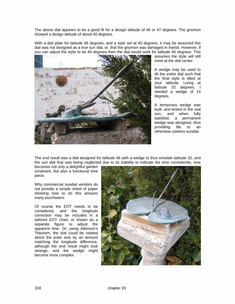
318
The above dial appears to be a good fit for a design latitude of 46 or 47 degrees. The gnomon showed a design latitude of about 40 degrees. With a dial plate for latitude 46 degrees, and a style set at 40 degrees, it may be assumed this dial was not designed as a true sun dial, or, that the gnomon was damaged in transit. However, if you can adjust the style to be 46 degrees then the dial would work for latitude 46 degrees. This
assumes the style will still meet at the dial center. A wedge may be used to tilt the entire dial such that the final style is tilted at your latitude. Living at latitude 32 degrees, I needed a wedge of 14 degrees. A temporary wedge was built, and tested in the real sun, and when fully satisfied, a permanent wedge was designed, thus providing life to an otherwise useless sundial.
The end result was a dial designed for latitude 46 with a wedge to thus emulate latitude 32, and the sun dial that was being neglected due to its inability to indicate the time consistently, now becomes not only a delightful garden ornament, but also a functional time piece. Why commercial sundial vendors do not provide a simple sheet of paper showing how to do this amazes many purchasers. Of course the EOT needs to be considered, and the longitude correction may be included in a tailored EOT chart, or shown as a separate figure to adjust the apparent time. Or, using Atkinson's Theorem, the dial could be rotated about the polar axis by an amount matching the longitude difference, although the end result might look strange, and the wedge might become more complex.
chapter 29

319
Alternatively, a spread sheet can be used that reverses the hour line angle formula REVERSE ENGINEERING H = atan ( sin(lat) * tan (lha) )
thus lat = asin ( tan(hour line angle) / tan(hour * 15) )
or... lat = DEGREES(ASIN(TAN(RADIANS(C7)) / TAN(RADIANS(15*C5))))
12 1 2 3 4 5 6 12 11 10 9 8 7 6 angle 0 11.90 22.66 37.28 51.82 68.93 90.00 0 11.73 22.38 35.34 51.81 70.68 90.00 lat a xxx 51.9 46.3 49.6 47.2 44.1 xxx lat b xxx 50.8 45.5 45.2 47.2 49.8 xxx avg a & b 51.3 45.9 47.4 47.2 47.0 Final average 47.8 hla 0 11.22 23.14 36.51 52.05 70.10 90 delta a xxx 0.68 0.48 0.77 0.23 1.17 xxx delta b xxx 0.51 0.76 1.17 0.24 0.58 xxx Max error 1.17 degrees
And when the hours are plugged in for times other than 6 o'clock and 12 o'clock (which for a dial not corrected for longitude) are 0 degrees and 90 degrees regardless of latitude, we see the average latitude for the hour line angles for each hour, and the average latitude for all the hours. In this case, latitude 47.8 is suggested. This agrees with the use of the tables above, however, the gnomon clearly was designed for latitude 40, and those 7 degrees of difference between the gnomon design latitude and the hour line angle design latitude is significant. The gnomon needs to be adjusted to reflect 7 more degrees while keeping the extension of the style's line such that it intercepts dial center. And the dial is then tilted to cause the resulting gnomon angle to match your latitude. The above spreadsheet is on the website as: illustratingShadows.xls From chapter 15 it may be recalled that reclining dials were discussed. The example here is of a latitude 50 dial reclined by 18 degrees producing a style with a resulting angle of 32 degrees, and the picture to the right shows the two. The upper dial was designed for latitude 32, the lower for latitude 50. They both agree on the time. The latitude 50 paper dial is reclined by virtue of two protractors that have been cut to recline the dial by 18 degrees. Appendix 9 has cutout paper dials.
chapter 29

320
CHAPTER THIRTY
programming or use of ~ 3D-CAD, vrml, and spreadsheets
THE USE OF CAD, OR COMPUTER AIDED DESIGN, AND VRML ON THE WEB 3D object modeling. Light manipulation in a CAD 3D dial Generating VRML files from 3D CAD entities. Also see Appendix 10 for viewing VRML Also see chapters 15 and 18 for 3D CAD techniques on declined and reclined surfaces Also see chapter 31 for 2D drawing and programming of DeltaCAD Also see chapter 31 for 2D VBS and Parametric Script programming of TurboCAD
THE USE OF SPREADSHEET PROGRAMS (Open Office is free and very similar to Excel) Converting formulae used in math to formulae usable in a spreadsheet Using graph functions for altitude curves and hour lines Spreadsheets are software programs that allow data to be stored in individual cells, or in columns, or in rows, and for manipulation of that data to take place. This seems simple enough, however there a few traps along the way. NOTE: The “illustratingShadows.xls” spreadsheet is in Microsoft Office Excel format. Open Office is a free package that is compatible with Microsoft Office, and it opens the Illustrating Shadows spreadsheets with no trouble. Similarly, Kingsoft has a free and a purchased spreadsheet program that works well with Microsoft Excel spreadsheets.
chapter 30
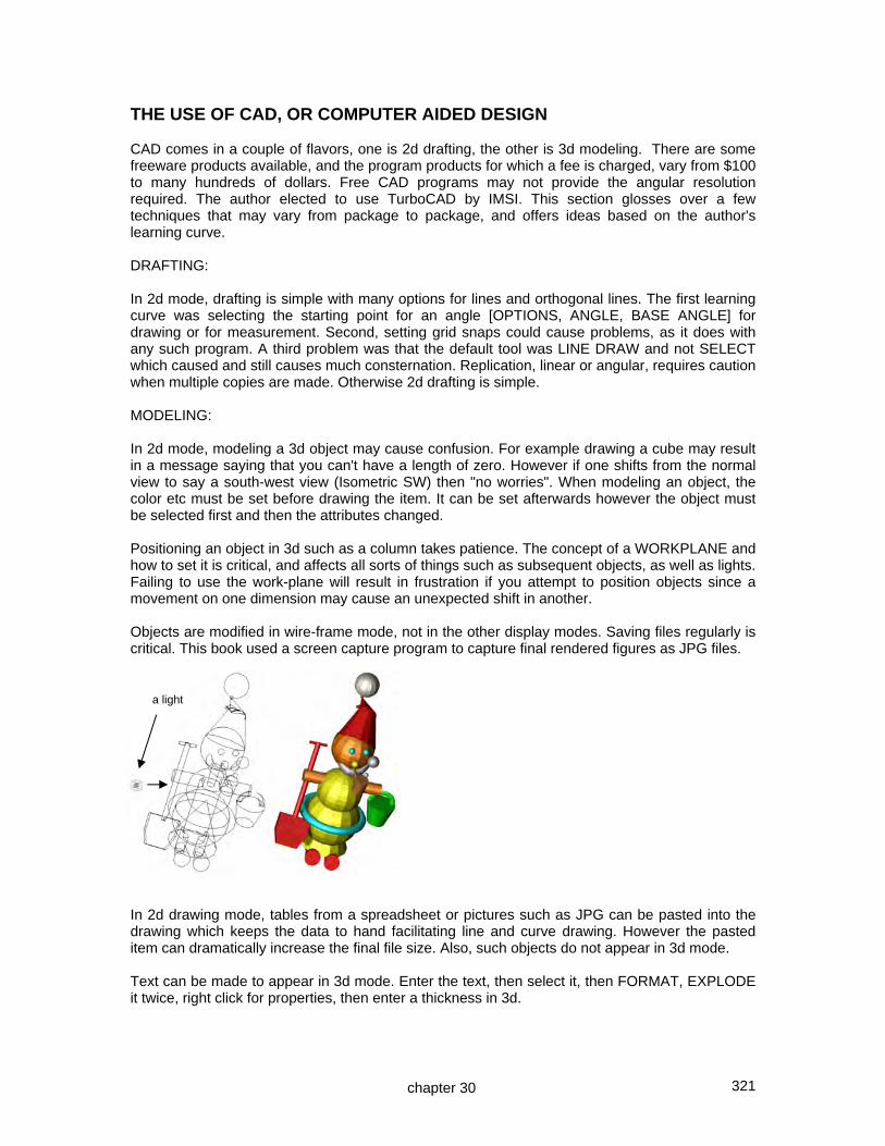
321
THE USE OF CAD, OR COMPUTER AIDED DESIGN CAD comes in a couple of flavors, one is 2d drafting, the other is 3d modeling. There are some freeware products available, and the program products for which a fee is charged, vary from $100 to many hundreds of dollars. Free CAD programs may not provide the angular resolution required. The author elected to use TurboCAD by IMSI. This section glosses over a few techniques that may vary from package to package, and offers ideas based on the author's learning curve. DRAFTING: In 2d mode, drafting is simple with many options for lines and orthogonal lines. The first learning curve was selecting the starting point for an angle [OPTIONS, ANGLE, BASE ANGLE] for drawing or for measurement. Second, setting grid snaps could cause problems, as it does with any such program. A third problem was that the default tool was LINE DRAW and not SELECT which caused and still causes much consternation. Replication, linear or angular, requires caution when multiple copies are made. Otherwise 2d drafting is simple. MODELING: In 2d mode, modeling a 3d object may cause confusion. For example drawing a cube may result in a message saying that you can't have a length of zero. However if one shifts from the normal view to say a south-west view (Isometric SW) then "no worries". When modeling an object, the color etc must be set before drawing the item. It can be set afterwards however the object must be selected first and then the attributes changed. Positioning an object in 3d such as a column takes patience. The concept of a WORKPLANE and how to set it is critical, and affects all sorts of things such as subsequent objects, as well as lights. Failing to use the work-plane will result in frustration if you attempt to position objects since a movement on one dimension may cause an unexpected shift in another. Objects are modified in wire-frame mode, not in the other display modes. Saving files regularly is critical. This book used a screen capture program to capture final rendered figures as JPG files.
In 2d drawing mode, tables from a spreadsheet or pictures such as JPG can be pasted into the drawing which keeps the data to hand facilitating line and curve drawing. However the pasted item can dramatically increase the final file size. Also, such objects do not appear in 3d mode. Text can be made to appear in 3d mode. Enter the text, then select it, then FORMAT, EXPLODE it twice, right click for properties, then enter a thickness in 3d.
a light
chapter 30

322
Rotating a 3d object around the X axis is done by grabbing the Y axis of the model, rotating a 3d object around the Y axis is done by grabbing the Z axis of the model, and rotating a 3d object around the Z axis is done by grabbing the X axis of the model, The work-plane axis can be displayed if desired by OPTIONS, PREFERENCE, SHOW WORLD CS, it shows three little arrows in the bottom left of the screen showing where the X, Y, and Z axes are, which is critical when rotating an object, especially given the possibility of confusion when rotating an object. Direction, point, and spot lighting are treated as objects, thus when a light is created, it goes on the work-plane, and its direction is adjusted using the same method as any other 3d object. Using four tiled windows with top, left, right, and southwest views facilitates object manipulation. Different TuboCAD releases may not read their .TCW files. Use .DXF formats for compatibility, however colors may not be adjustable once saved in that format. Should you use the free CAD program mentioned in this book for dial design, ensure you set SNAP to none, other wise line angles will not be suitable for dial plates. MANAGING A CAD FILE AS AN INTERNET VIEWABLE VRML OBJECT A CAD file may be saved for viewing on the web in very simple steps. There are three steps depending on how your computer system is established. For people who only wish to view 3d, not generate it, steps 2 and 3 would apply. For people with a VRML browser plug-in already installed, step 3 only would apply. For designers, all three steps would apply. 1. Building a VRML (WRL) file for others to see (TurboCAD or Parallel Graphics ISB) 2. Installing the VRML browser plug-in if you do not have one 3. Viewing any 3d VRML file on the internet (WRL file suffix). BUILDING A 3D WEB PICTURE FOR ANYONE ON THE WEB FROM TURBOCAD In TurboCAD save as WRL: The SETUP option in the SAVE panel should be version 2.0, do not save as WRZ, it may have browser problems on the internet. In ISB, use PUBLISH. STEP 1: SETTING UP TO VIEW 3D PICTURES ON THE WEB (For designers) Find out what plug-ins will work for you, there is a web site to advise you of your options. VRML browser detect: http://cic.nist.gov/vrml/vbdetect.html STEP 2: INITIAL BROWSER PLUGIN INSTALLATION (First time viewers) Download manually a browser plug-in such as Cortona Cortona VRML browser plug in http://www.cortona3d.com/cortona STEP 3: VIEWING A 3D PICTURE ON THE WEB Open a VRML file (WRL) e.g. there are several on the web site for this book. IF Internet Explorer gives a cautionary notice, accept it and let ACTIVE-X do its thing. Netscape and Internet Explorer both run Cortona well, and Cortona also works on Mozilla. the picture may be tiny, so zoom it by clicking FIT then PLAN to zoom back a bit then you may then manipulate the view with STUDY! OTHER OPTIONS: Appendix 10 covers Windows Vista, and it also offers other options for viewing vrml worlds as well as smaller objects.
chapter 30

323
USING CAD AS THE ACTUAL MODELING TOOL ITSELF Create a triangle with an apex angle of 47 degrees (2 times 23.5) representing the extremes of a light ray from winter to summer solstice. Perform a radial copy so there are about 12 of them, maybe more. And create a gnomon, in this case latitude 32 degrees. Rotate the light rays by 32 degrees similarly to match the gnomon's style angle.
Then place the radiation point of the light rays on the nodus of the gnomon, and add a dial plate.
Then use the 3d intersect tool to cause just the intersection of the radiating rays and dial plate to remain behind. Then another plate is re-added thus obtaining a sun dial. Having completed this task, rotate the model and draw lines from the dial center to the places where the light rays intersect the dial plate and measure them with the dimension tool, thus providing the hour line angles. The extremes of the intersecting rays on the dial plate form hyperbolic curves, they are the calendar lines for the solstices.
The angles from the noon line showed 8.1, 17.9, 27.9, 43, and 62.2, compared to the latitude 32 tables (appendix ~ A3.1a) offering 8.1, 17, 27.9, 42.6 and 63.2 which shows a close agreement. The objective of this section is to show how a CAD program can not only be used for drafting dial plates, but can also be used as a direct tool to deduce hour lines and calendar lines. And decliners and recliners can be thusly modeled.
See also chapter 15 and 18 for additional examples of this technique.
the gnomon continued below the dial plate, this is where the gnomon base intersected the plate.
gnomon
rays of light
chapter 30

324
Another example of a more complex kind consists of a wine glass used as a sundial. In earlier centuries, a silver or gold wine goblet was sometimes used as a sundial. FIRST: A 2-d poly-line was created. Then if needed to get x/y/z axes shown when it is selected,
use properties to give it a 3d width. Then it is rotated or lifted up around its X axis into the vertical plane so it can be transformed into a wine glass by rotating that poly-line around the Z-axis.
Rotating that poly-line is done by INSERT, 3D OBJECT, REVOLVE, and the wine glass may then be rendered. A copy of this glass is made, because it will be destroyed when we do a 3d-intersect with the solar rays in a couple of steps, just as for the horizontal dial on the previous page. SECOND: A single solar ray is created – it is a triangle about 47 degrees at its apex, and this
time a radial copy is performed. The solar rays are added together with the 3d-add. Thus there are now two objects. One is the glass and its copy, the other is the solar rays. A small sphere was added at the focal point of the rays as a nodus to help with placing the rays on the wine glass, and to solve a 3d-add problem that sometimes happens (see below). A similar small sphere or nodus was also added to the wine glass rim to facilitate placing the rays on the rims consistently.
THIRD: The rays and one of the wine goblets are then used in the 3d-intersect operation, leaving just the places where the rays intersected that wine glass, which is why we made copies of the wine glass. FOURTH: The result of the intersection is moved back to the wine glass copy.
NOTE: Sometimes during a 3d-intersect or a 3d-add operation a message will say that the resulting surface was degenerated, meaning there was nothing left after the intersect or it could not add the objects. This happened in the above example. That was one of two reasons why a ball was added to the solar rays. For this method to be of practical use, the wine cup or other object to be used as the curved dial plate has to be modeled accurately, along with reference points, an activity somewhat easier said than done, however a digital photo can be taken and inserted into the CAD drawing, then the poly-line drawn around the photo.
the 3d intersect
X
chapter 30

325
FAIRLY ACCURATE LIGHTING IN CAD FOR HOUR LINES TurboCAD lighting can be rather tiresome. TurboCAD lights are normally placed on the work-plane, and for a directional or a spot light this is useless. And while VIEW and LIGHTS will show the light’s parameters, it doesn't provide for a lighting vector setting. The secret is to use a mesh of arcs made by the arc command, turned into 3d, and saved as a group. This is the solar travel mesh on the TurboCAD page of this book's website:- “solarMesh.tcw”
This mesh depicts solar travel, and just the mesh can be copied and pasted into a CAD dial drawing, its center placed on the nodus, and then rotated for your latitude. Alternatively, the mesh has a small dial plate and a conical gnomon whose tip is a nodus, and you may use them as a guide, or delete them and replace them with your own dial and gnomon. For example, a dial plate was laid out, with a latitude 32.97° gnomon in this case. The work-plane was set horizontal and level with the nodus (not the dial plate) before pasting the mesh model into place, and consequently before adjusting it. The solar mesh CAD model was opened, selected, and copied, and then pasted into the dial's drawing.
Alternatively you can move the mesh center to the nodus x, y, and z coordinates. You reset any undesired coordinates manually in the inspector area. "Selector 3d properties" lets you turn on an objects coordinates in the inspector area, the coordinates may be visible there unless you do it. By now, the center of the solar mesh matches the nodus point so the solar-travel mesh is easily tilted to match the dial’s latitude. Then a light is selected, such as the directional light, and with the mouse anywhere, use a right click, select "local snap", then "nearest on facet". Move the cursor to the intersection of the hour line and the month, and wait for a mini work-plane to show that the snap is working and do a left click to anchor it. The light source is anchored on that time and date. Now do another right click, select "local snap", and select "nearest on facet". This time move the mouse to the nodus of the gnomon, wait for the mini work-plane and left click. Now the center of the light as well as the direction have been set. Don't forget to set the light color to white. You may delete the mesh also.
In the picture to the left, the light is anchored near 9 o'clock close to the summer solstice. The light was placed on a facet of the mesh, its target on a facet on the nodus, and with the light selected, full rendering was used. This shows a spotlight and the shadow cast by the gnomon and nodus. This technique allows rapid light placement accurate for a month and hour. The light used here was a spotlight. The light may be selected and changed to a directional light in its properties, if so desired.
summer
winter
noon
central nodus cube
chapter 30
326
THE USE OF SPREADSHEETS ~ FORMULAE CONVERSION Describing a formula or set of formulae (English) or formulas (American) is easier said than actually getting them into a spreadsheet for real usage. The following points all relate to a common spreadsheet, the one used for this book. ANGULAR MEASURE Angular measures are commonly in degrees, 90 degrees being a right angle and there are 360 degrees in a circle. However, spreadsheets use radians, which are different to degrees. There are 2 * pi radians in a circle of 360 degrees. Thus, every formula that uses degrees needs the measure to be converted to radians. =RADIANS(360) would return 6.283 Thus the trigonometric functions SIN, COS, TAN, COTAN, and so on, need the radian conversion first. =TAN(RADIANS(45)) would return 1.0 Similarly, any function that returns an angular measure, such as ATAN, ACOS, ASIN, or ARCTAN, ARCOS, ARCSIN, also printed as TAN-1, COS-1, SIN-1, would need to be converted back to degrees, and this is done using the DEGREES function. =DEGREES(6.283) would return 359.984 or 360.0 depending on precision Which raises another issue, that of rounding and precision. The number of significant digits on the fractional side not only determines accuracy, it also controls rounding. Thus when the above function is given one decimal position, the results is 360.0 rather than 359.9. ROUNDING The number of significant digits after the decimal point is controlled by the FORMAT, CELLS, NUMBER option. Some functions do rounding of their own, and in some surprising ways. =INT(5.1) =INT(5.9) =INT(-5.1) =INT-(5.9) returns 5 5 -6 -6 The INT (integer) function returns the integer part of a number on the left side of the decimal point, rounds down. And the number below 5.9 is 5, however the number below -5.1 is -6 because this is already in the negative scale. However, the ABS (absolute) function which removes the sign may be used if the above rounding down on the negative side is not desired. =INT(ABS(5.5)) =INT(ABS(-5.5)) returns 5 5 If the sign must be retained, then the SIGN function can be used. Assume that cell B3 has a value of 5.5 and cell B4 has value of -5.5 then the following results can be obtained: =SIGN(B3)*INT(ABS(B3)) =SIGN(B3)*INT(ABS(B3)) returns 5 -5
chapter 30

327
TIME CONVERSION Second, they show the use of methods to convert "hh.mm" for example to "hh.hh". Assume cell B3 has a value of 4.30 meaning a time but in a decimal cell, meaning to us humans, four thirty, and we wish the time in hours and decimals of hours then: =((100*b3-INT(100*b3/100)*100)/60)+INT(100*b3/100) returns 4.5
Sun's apparent hour angle LHA=local hour angle
Time From LHA Radians sin cos tan cot PM PM
hhmm hh.hh midday hh.hh hhmm
4.00 4.00 8.00 120.0000 2.0944 0.8660 -
0.5000 -
1.7321 -
0.5774 8.00 8.00
4.15 4.25 7.75 116.2500 2.0289 0.8969 -
0.4423 -
2.0278 -
0.4931 7.75 7.45
4.30 4.50 7.50 112.5000 1.9635 0.9239 -
0.3827 -
2.4142 -
0.4142 7.50 7.30
The above extract from a spreadsheet shows this conversion, hh.mm is in the left most column, and hh.mm is in the second column. In this case, the hh.hh is the local hour angle: lha=15*hours from noon
CONVERTING DECIMAL MINUTES TO MINUTES AND SECONDS Always test functions that you use. For example, the integer function =INT(value) is not what you might expect. The integer of 10.1 and -10.1 is commonly held to be 10, and -10 however the actual INT function in some spreadsheets is the integer after rounding down. Thus the integer of -10.001 may be -11 and not -10. For example, assume cell C7 is m.mm or –m.mm (such as the plus or minus EOT values in decimal):- =IF(C7<0, -1*(INT(ABS(C7)) + (ABS(C7)-INT(ABS(C7)))*0.6 ), INT(C7) + (C7-INT(C7))*0.6) 3.40 ( 3.40 minutes) results in 3.24 (3 minutes 24 seconds) -3.40 (-3.40 minutes) results in -3.24 (3 minutes 24 seconds) This formula tests the cell's sign, uses the integer of the absolute (positive) value to get around the round down, and thus converts plus or minus minutes in decimal to minutes and seconds. And if you wished the absolute value then you could use =ABS(. . .) or =SIGN(C7)*( . . .), yes it is permissible to code: =ABS(IF . . . ) or =SIGN(C7) * ABS(IF . . . ) It is possible to end up with 6:60 meaning 7:00, that is life after computers. BLANKS IN FORMULAE Some spreadsheets sometimes get upset on long formulae if blanks are used, sometimes they do not. It may say they are erroneous when all that is problematic is those blanks.
chapter 30
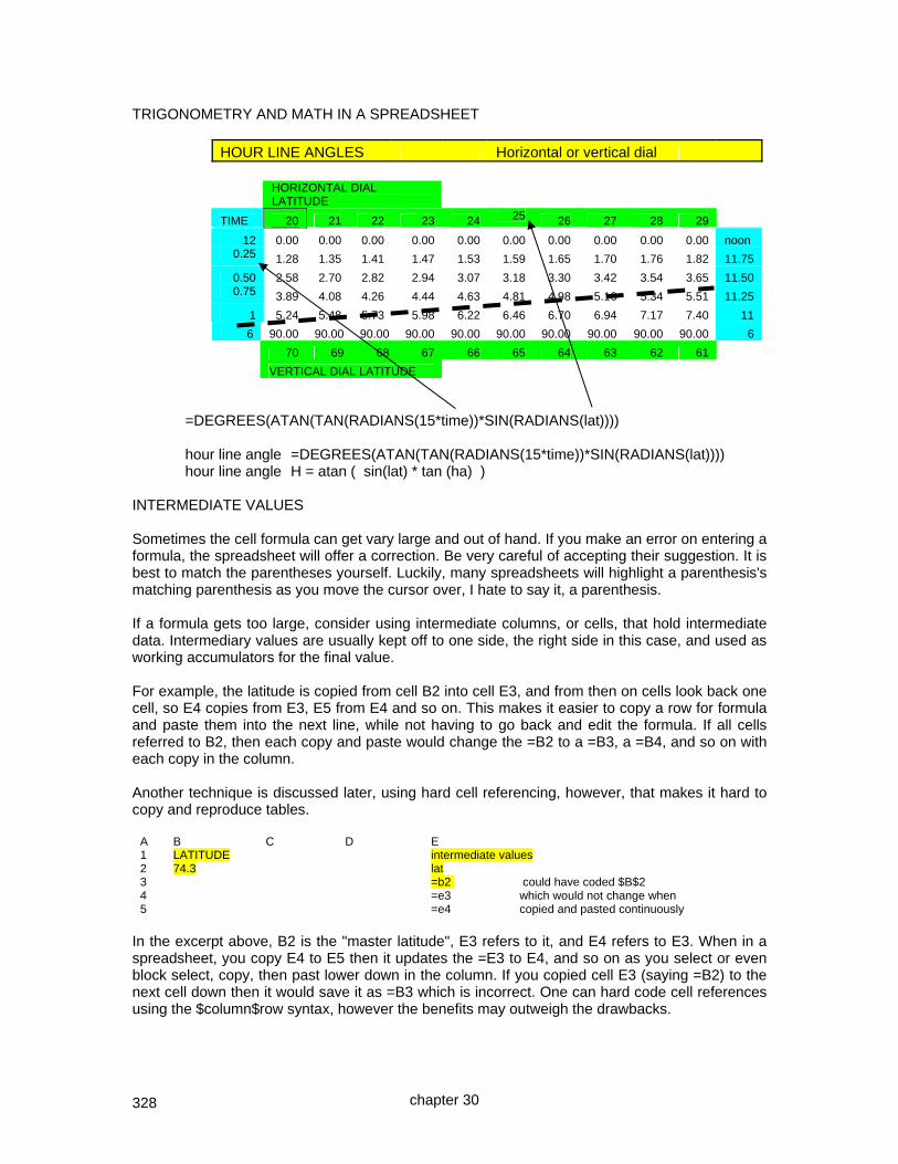
328
TRIGONOMETRY AND MATH IN A SPREADSHEET
HOUR LINE ANGLES Horizontal or vertical dial
HORIZONTAL DIAL LATITUDE
TIME 20 21 22 23 24 25 26 27 28 29
12 0.00 0.00 0.00 0.00 0.00 0.00 0.00 0.00 0.00 0.00 noon 0.25 1.28 1.35 1.41 1.47 1.53 1.59 1.65 1.70 1.76 1.82 11.75
0.50 2.58 2.70 2.82 2.94 3.07 3.18 3.30 3.42 3.54 3.65 11.50 0.75 3.89 4.08 4.26 4.44 4.63 4.81 4.98 5.16 5.34 5.51 11.25
1 5.24 5.48 5.73 5.98 6.22 6.46 6.70 6.94 7.17 7.40 11
6 90.00 90.00 90.00 90.00 90.00 90.00 90.00 90.00 90.00 90.00 6
70 69 68 67 66 65 64 63 62 61
VERTICAL DIAL LATITUDE =DEGREES(ATAN(TAN(RADIANS(15*time))*SIN(RADIANS(lat)))) hour line angle =DEGREES(ATAN(TAN(RADIANS(15*time))*SIN(RADIANS(lat)))) hour line angle H = atan ( sin(lat) * tan (ha) ) INTERMEDIATE VALUES Sometimes the cell formula can get vary large and out of hand. If you make an error on entering a formula, the spreadsheet will offer a correction. Be very careful of accepting their suggestion. It is best to match the parentheses yourself. Luckily, many spreadsheets will highlight a parenthesis's matching parenthesis as you move the cursor over, I hate to say it, a parenthesis. If a formula gets too large, consider using intermediate columns, or cells, that hold intermediate data. Intermediary values are usually kept off to one side, the right side in this case, and used as working accumulators for the final value. For example, the latitude is copied from cell B2 into cell E3, and from then on cells look back one cell, so E4 copies from E3, E5 from E4 and so on. This makes it easier to copy a row for formula and paste them into the next line, while not having to go back and edit the formula. If all cells referred to B2, then each copy and paste would change the =B2 to a =B3, a =B4, and so on with each copy in the column. Another technique is discussed later, using hard cell referencing, however, that makes it hard to copy and reproduce tables.
A B C D E 1 LATITUDE intermediate values 2 74.3 lat 3 =b2 could have coded $B$2 4 =e3 which would not change when 5 =e4 copied and pasted continuously
In the excerpt above, B2 is the "master latitude", E3 refers to it, and E4 refers to E3. When in a spreadsheet, you copy E4 to E5 then it updates the =E3 to E4, and so on as you select or even block select, copy, then past lower down in the column. If you copied cell E3 (saying =B2) to the next cell down then it would save it as =B3 which is incorrect. One can hard code cell references using the $column$row syntax, however the benefits may outweigh the drawbacks.
chapter 30

329
Columns can be used for intermediate values needed in complex formulae, and this is the equivalent to using accumulators in an old computer (1960's vintage) or to intermediate values in the scientific calculators. AN EXAMPLE OF INTERMEDIATE VALUES IN COLUMNS OFF TO THE RIGHT
The gnomon:chart ratio on the top right of the chart is the ratio and reciprocal of the ratio of the style length to the distance from the top of a chart of altitude curves, to the bottom on the lowest hour shown, typically about June 20, noon time.
SOLAR DECLINATION FOR EVERY TEN DAYS AND HOURLY SOLAR ALTITUDE THIS TABLE IS FOR LATITUDE: 30 Gnomon:chart ratio: 0.11 8.70
am altitude
Intermediate values
Date decl 600 700 800 900 1000 1100 1200 Julian td lat 1/1 -23.1 -11.3 0.6 11.7 21.6 29.6 35.0 36.9 1 0 30
1/10 -22.1 -10.8 1.1 12.3 22.3 30.5 36.0 37.9 10 0.155145 30 1/20 -20.3 -10.0 2.1 13.5 23.6 32.0 37.7 39.7 20 0.327529 30
2/1 -17.3 -8.6 3.7 15.3 25.8 34.5 40.5 42.7 32 0.534389 30 conditional formatting to hide negative td=(2*3.1416*(jul.day-1)) / 365 numbers julian=use hard coded dates = previous =DEGREES(ASIN(SIN(RADIANS(decl))*SIN(RADIANS(lat))+ cell COS(RADIANS(decl))*COS(RADIANS(lat))* above COS(RADIANS(15*(12-(timeofday/100)))))) i.e. = asin(sin(decl)*sin(lat)+cos(decl)cos(lat)cos(time)) =DEGREES(0.006918 - 0.399912*COS(td) + 0.070257*SIN(td) - 0.006758*COS(2*td) + 0.000907*SIN(2*td) - 0.002697*COS(3*td) + td is the intermediate 0.00148*SIN(3*td)) value above.
Notice the use of radians instead of degrees, and the use of accumulators to the right for "td" which is an intermediate value, and how the latitude is replicated down the column on the right also, this means that the use of absolute cell references, $column$row is avoided. Sometimes absolute cell references are helpful, sometimes they are not. It is a question of technique. The Julian date was hard coded because there was a problem with the DATEVALUE function in the version of spreadsheet the author used. Always double check formulae as you proceed. NOTE: Open Office provides a compatible Excel replacement, the spreadsheet syntax is slightly different from Excel but it converts Excel spreadsheets correctly.
DECLINATION by day and ALTITUDE by day/hour
chapter 30

330
SUNRISE AND SUNSET SPREADSHEET DECLINATION by day and APPROX SUNRISE/SUNSET time STANDARD
LATITUDE LONG ref:long Tables are based on the LATITUDE, LONG and time zone
51.5 0.50 0 reference in the boxes to the left. EOT is used and is
London UK the 3 wave approximation. Summer time not considered.
STD TIME Daylight Sunrise Date Julian decl eot rise set duration azimuth
1/1 1 -23.1 3.4 8.15 15.56 7.45 51.0 First intermediate figures are EOT and declination components and the local sunrise hour angle.
Intermediate values LOCAL SUNRISE DATA
eot td lat ha hhmm
3.4 0.00000 51.5 122.4 8.09 The next intermediate values work sunrise to completion, then sunset to completion, and each separately make the longitude then the EOT adjustment. EOT uses formula: -1*(9.84*SIN(RADIANS(2*(360*(julday-81)/365))) - 7.53*COS(RADIANS(360*(julday-81)/365)) - 1.5*SIN(RADIANS(360*(julday-81)/365)))-0.3 where the Julian day in the second final data column was entered as-is, it did not use a formula. The LOCAL hhmm of sunrise was derived using: (100*INT(localha/15)+INT(60*((localha/15-INT(localha/15)))))/100 where The local hour angle of sunrise was based on: DEGREES(ACOS(TAN(RADIANS(latitude))*TAN(RADIANS(declination))))
sun rise time sun set time
std time intermediate std time intermediate STD rise rise plus STD set plus daylengthha h.hh eot h.hh set h.hh eot h.hh h.hh
122.9 8.19 8.25 15.9 15.93 7.74 The STD ha was equal to the LOCAL ha in the preceding intermediate value section, plus the difference of the user's longitude and the reference longitude. Times were kept decimal until the final conversion using: INT(T8)+0.6*(T8-INT(T8)) where T8 was a decimal time. Sunset was a similar process, sunset h.hh was found by 24-sunrise.h.hh and this must be calculated before the EOT or longitude corrections are applied. The EOT shown above is in mm.mm (decimal), it may be converted to mm.ss with a formula such as:- =IF(L8>0,INT(L8)+0.6*(L8-INT(L8)),-1*(INT(ABS(L8))+0.6*(ABS(L8)-INT(ABS(L8))))) where L8 is the time in decimal minutes (mm.mm)
chapter 30

331
USING A SPREADSHEET GRAPHING FUNCTION TO DRAW HOUR LINE ANGLES Using a formula or raw data from a table in the appendix, it is possible to generate a chart using the spreadsheet’s charting function so that hour lines can be drawn for a dial plate.
A B C D E F G H I J
2 Enter the latitude 32
3
4 To have a spreadsheet generate a chart of hour line angles, eg, latitude 32 horizontal dial
5 first get the hour line angles (from the tables or from calculation):-
6
7 pm time 12 1 2 3 4 5 6
8 angle 0 8.08 17.01 27.92 42.55 63.18 90
9
10 Then generate a set of differences or steps
11
12 difference 0 8.08 8.93 10.91 14.63 20.63 26.82
13 [formula] =0 =D8-C8 =E8-D8 etc etc etc =I8-H8
14
15 Then we need to bring the angles up to 360 degrees so we can have a pie chart of 360
16 degrees. To do this we add a trailing number of 360-the sum of the steps:
17
18 difference 0 8.08 8.93 10.91 14.63 20.63 26.82 270
19 =360-SUM(C18:I18)
20
21 Select the cells from the left to right and INSERT, CHART, PIE to get a true angular chart. The spreadsheet chart was captured as a JPG file, imported into a CAD program, and INSERT, MEASUREMENT, ANGULAR, options were used to measure the angles which as can be seen are well within reading tolerances. This method has as the benefit that the aspect ratio is correct. Another option is to convert hour line angles to x,y pairs, then use insert chart, then X:Y SCATTER, then data points connected by lines. The main spreadsheet provided with this book uses that technique for horizontal and vertical dials, and the analemma depiction is another example, see chapter 25. Such spreadsheet graphs do not maintain aspect ratios, so angles must be verified, and the h-dial and other spreadsheet graphs show one technique for doing this. This chapter reviews numerical and other methods for effective spreadsheet usage. Spreadsheets are available on the web site named at the beginning of this book and help with most sundial tasks from the simple to the complex:- illustratingShadows.xls
chapter 30

332
CHAPTER THIRTY ONE
programming or use of ~ 2D-CAD, and other languages
SOME NOTES ON PROGRAMMING DELTA-CAD Many projects in this book used Delta CAD macros whose resulting dial plates were printed, cut out, and used as templates. The reason for using Delta CAD was because it is popular, and programmable. The author uses glass, clay, and copper on his outside dials. The author's first career before winding up as an airline pilot was in programming computers. Some work was commercial, but most work was in operating system software. The first system he programmed was an IBM 1401 in Autocoder. Then an IBM 360 in BAL (Basic Assembler Language), with a bit of PL/I, and FORTRAN. All his work on the IBM 370 and later machines was in BAL and on some other machines he used C and C++. Operating systems used were BOS, MFT, and MVT on the IBM 360s, and VS1 and MVS on the IBM 370s, and GCS under VM. One pet peeve the author has is that documentation for languages is drawn up by programmers as language specifications, and the human interface is covered is somewhat academic. This tendency became worse when object oriented programming became the standard because the novice is faced with several struggles. Thus the examples in this section for the BASIC macro language for Delta CAD are intended to be "conversational" as opposed to transaction oriented. In other words less object oriented and more of a natural flow. As background, the author designed FIDO and PATCHES which were early spooling systems on IBM 360 mainframes in the 1970s, and TOTO and later SHADOW which were teleprocessing programs running under DOS and MVS on the IBM 370 and later ranges which were sold worldwide from 1972 until 1997. SHADOW in particular made over $55m in sales before the author lost track and interest. Older style conversational programs had a natural flow, assumed a sequence of events, and were less well suited to random events controlling the program flow. The next development was transaction oriented programs which used discrete pieces of code invoked when things happened. Less natural, more adaptable to random events controlling program flow, and could still easily be made to look conversational if so desired. Then came object oriented code, here "objects" were defined which had "methods" associated with them which handled "things" that affected the objects. Objects were defined by "classes" with an inheritance structure, and inter-relationships between objects. Thus one simple change here would trigger many "methods" in many "objects" resulting in lots of activity. Hard to make conversational, but highly generalized and ideally suited for random events coming in (a screen input, an interrupt from an outside source), but clearly not a simple natural program flow. USING A CAD SYSTEM and USING CAD MACROS A CAD system is a computer program that draws, usually better than the average human. The 2d systems such as Delta CAD are simple to use and provide professional draftings. The author prefers TurboCAD deluxe which is a full 3d modeling system used for most of the pictorials in this series of books. It also has excellent after the fact dimensioning tools. DeltaCAD leads TurboCAD in having the computer do all of the work by a simple programming system akin to BASIC. TurboCAD programming is only available in the Professional edition. Computers do what they are told and thus special techniques are needed to do simple things a human can intuitively do, such as constraining a line to the boundaries of a box. This is a summary of Delta CAD and its associated macro language with a few pointers to help write macros. Writing macros for DeltaCAD is within reach of any computer literate person. To simplify concepts, code in this chapter is extracted and reduced from the programs on the CD or website and thus may not handle some special cases. Also programmable is FreeCAD using Python, and NanoCAD using Java Script and Visual Basic Script. FreeCAD and NanoCAD are free.
chapter 31

333
This section extracts some code and explains what it is doing, and shows final resulting dial plates. There are many macros available for Delta CAD which are well worth exploring. The author has his own versions of Delta CAD macros on the web site for those who are interested, and these complement the spreadsheets which are also made available. However, these spreadsheets and macros which are fully functional are aimed at education first and foremost, and as a tool second. They are not polished works, they are not intended to produce final polished products, nor are they intended to compete with the excellent macros available. Programs usually begin with initial setup, then they define variables to hold information being worked on, and they also ask humans what they want, and finally they produce the results. ' ********************************************************************* ' A horizontal dial macro for Delta CAD but in conversational mode as ' opposed to the more modern object oriented mode, but with notes ' page numbers refer to Manual.pdf or Basic.pdf provided with delta cad ' ********************************************************************* Sub Main() ' main procedure is required ' ********************************************************************* ' Initial house keeping - clear the screen - set the drafting area unit ' ********************************************************************* ' select all objects that may exist on the screen - p223 of Manual ' then erase them all - page 189 of Manual If (dcSelectAll) Then dcEraseSelObjs End If ' set the entire future drafting area to inches or centimeters, etc ' page 43 of the Manual: 1.0 generates inches, and 2.54 is cm dcSetDrawingScale 0.80 At this point, a few thoughts on hard coded numbers, specific dimensions and programming practice are relevant. Good program practice is not to code numbers inline in a program, rather, those numbers should be in a data definition area. This makes the program easier to change, however, it also makes the program a little harder to understand. It is similarly bad practice to define display areas, as this program does, of say 0,0 to 1,1 however, if the end result is scalable there is little harm, however good practice would still use symbolic numbers, with those defined in the data definition area. Programming practice has been for many years to use structured coding techniques, that is IF-END IF, DO-END DO, FOR NEXT, and the like, and never to use the GOTO statements. Another more recent architecture of programming systems has been to move towards object oriented methods, where an object not only holds the data, but also the methods for altering or reading it. And further, all objects can have inter-relationships, so if something changes that might affect one object, then that and other objects will find out and act accordingly. For example, in Windows bring up two displays of the same folder, and in one display, delete an entry. Object oriented methods are what cause the other folder display to update itself and reflect the first display's changed status. While BASIC as supplied with Delta CAD is not fully object oriented, it does use some of its concepts, for example the structures needed to talk with humans. Next some programming structures are needed for human interaction. These are not difficult, neither are they quite as simple as elementary BASIC.
chapter 31

334
' ********************************************************************* ' A generic definition is required for a screen input area ' ******************************************************************** ' ' Here a box on the screen for user dialog is structurally defined, ' it is only a definition of the generic area, it does not create it ' ..... Dialog aaaaa ' ' To create the area, there must be a Dim statement making a label ' relate to this definition ' ..... Dim bbbbb as aaaaa ' ' To use bbbbb there must be a ..... yyy = Dialog(xxxxx) which causes ' human interaction. So... ' ' create an area on the screen starting at x=20, y=20 ' whose size is 200 left to right and 100 top to bottom ' whose title is "Location" - where 0,0 is top left Begin Dialog aaaaa 20, 20, 200,100, "Location" ' the first text string starts at x=5,y=15 on the screen ' and the text string itself starts at x=60 for a height of 10 Text 5, 15, 60,10, "Enter latitude" ' the input area starts at x=65 (further right) y=15 (same height) for a ' size of x=50, y=10 TextBox 65, 15, 50, 10, .mylat ' the second text string starts at x=5 but now y=30, i.e. lower down ' and the text string itself starts at x=60 for a height of 10 Text 5, 30, 60, 10, "Enter longitude" ' and the input area starts at x=65 (further right) y=30 ' (same height) for a size of x=50, y=10 TextBox 65, 30, 50, 10, .mylng ' the third text string starts at x=5 y=45 ' and the text string itself starts at x=60 for a height of 10 Text 5, 45, 60, 10, "Enter ref longitude" ' and the input area starts at x=65 y=30 for a size of x=50, y=10 TextBox 65, 45, 50, 10, .myref ' and two buttons for what the user means, location first, button size ' next – and all such boxes must have at least one button by the way OKButton 65, 65, 40, 10 CancelButton 65, 85, 40, 10 End Dialog
At this point, a few comments might be helpful. The Begin Dialog has nothing to do with a dialog. It is an encyclopedia definition of what you might wish to actually create. It is created with the Dim statement. ' ******************************************************************** ' The generic definition must then be generated with a name ' ******************************************************************** ' ' this defines "bbbbb" as an instance of aaaaa dialog Dim bbbbb As aaaaa
And used later..... ' ******************************************************************** ' Now define the initial general working variables ' ******************************************************************** ' ' define a lat and a long, and a reference longitude Dim lat As single Dim lng As single Dim ref As single
... continued on the next page
chapter 31

335
... continued from the last page ' ******************************************************************** ' Now get the lat, long, and reference longitude ' ******************************************************************** ' first set the defaults - here bbbbb.mylat uses the structure ' from aaaaa bbbbb.mylat = "32.75" bbbbb.mylng = "108.2" bbbbb.myref = "105.0"
........., in fact here it is being used! ' here the dialog is invoked and the button results returned to ccccc ' page 20 and 24 etc of Basic discusses the Dialog function ccccc = Dialog(bbbbb) ' which causes the answer to be returned lat = bbbbb.mylat lng = bbbbb.mylng ref = bbbbb.myref ' CANCEL button returns 0 ' OK button returns -1 ' you can determine the button with - Print ccccc, lat, lng, ref HORIZONTAL DIAL The rest of the program is straight forward. ' ********************************************************************* ' ok, what was returned? if "ok button" then do the program itself ' ********************************************************************* ' ccccc = -1 means the ok button was used and not the cancel button If ccccc = -1 Then ' ****************************************************************** ' this is the main program to draw the horizontal dial itself ' ****************************************************************** ' calculate hour line angles next, but first define them Dim h, hx, hy As Single ' Delta CAD is fussy about data attributes ' the formula is... hourlineangle = atan ( sin(lat) * tan (lha) ) ' almost all systems us radians ' the formula also needs adjustment for longitude displacement ' line color is 0 is black ' line type is dcsolid ' line weight is dcnormal ' set the text color, font, size, etc also dcSetTextParms dcBLACK,"Ariel","Bold",0,8, 20,0,0 ' p321 of Manual dccreatetext -1.25, -0.3, 0, "Hour and hour line angle H-DIAL" dccreatetext -1.25, -0.9, 0, "Lat: " dccreatetext -0.8, -0.9, 0, Int(lat) dccreatetext 0.0, -0.9, 0, "Long: " dccreatetext 0.3, -0.9, 0, Int(lng) For hr = 6 To 18 Step 1 ' ================================================================= ' for the hour (hr) calculate the hour line angle (h) h = deg(Atn(Sin(rad(lat))*Tan(rad((hr*15) +(ref-lng))))) ' show the time in hours dcSetTextParms dcBLACK,"Ariel","Bold",0,8, 21,0,0 ' p321 Manual dccreatetext (-1.2+((hr-6)/5)), -0.5, 0, Abs(hr) ' show the angle dcSetTextParms dcBLACK,"Ariel","Bold",0,6, 21,0,0 ' p321 Manual dccreatetext (-1.2+((hr-6)/5)), -0.7, 0, Int(h)
chapter 31

336
If hr < 12 Then ' ------------------------------------------------------------ ' morning hours ~ NOTE code for keeping lines in a boxed area ' ------------------------------------------------------------ dcsetlineparms dcblue,dcsolid,dcthin ' page 228 Manual If Abs(h) < 45 Then ' lines touch top of box dcSetTextParms dcBLACK,"Ariel","Bold",0,8,21,0,0 ' p321 hx = Tan(rad((h))) dccreateline 0, 0, hx, 1 dccreatetext (hx), 1.1, 0, Abs(hr) ' page 187 of Manual Else ' lines touch side of box dcSetTextParms dcBLACK,"Ariel","Bold",0,8, 20,0,0 ' p321 hy = Tan(rad((90-h))) dccreateline 0, 0, -1, -hy dccreatetext -1.1, -hy, 0, Abs(hr) ' page 187 of Manual End If ElseIf hr = 12 Then ' ------------- ' noon hours ' ------------- ... similar code which is straight forward Else ' --------------- ' afternoon hours ' --------------- ... similar code except the sign of the angle goes –ve if 90 End If ' ================================================================ Next h
The program concludes with drawing a couple of boxes. ' draw a box around everything dccreatebox -1, 0, 1, 1 ' page 184 Manual dccreatebox -1.2, -.2, 1.2, 1.2 ' page 184 Manual dcviewbox -1.1, -1.1, 1.1, 1.3 ' page 225 Manual End If ' ********************************************************************* ' *** this ends the entire program ' ********************************************************************* End Sub
And after the end of the program, there are the DEGREES and RADIANS functions. ' *********************************************************************** ' Useful routines or functions - Functions must be defined at the end ' after the main program which is sub(xx) ... end sub ' ********************************************************************* ' Convert degrees to radians Function Rad ( n As single ) As single ' page 83 basic.pdf for functions Rad = (n * 2 * 3.14159) / 360 End Function ' Convert radians to degrees Function Deg ( n As single ) As single ' page 83 basic.pdf for functions Deg = (360 * n) / (2 * 3.14159) End Function The actual code on the web site may differ and have code to correct for certain situations, however, the objective here has been to step through most of the procedural coding. There are some coding violations, however they have been somewhat intentional in order to make the process of a complete macro, when accompanied by DeltaCAD's two books, MANUAL.PDF and BASIC.PDF, more understandable. NOTE” The Windows VISTA version of DeltaCAD has a few differences, these are covered in appendix 10.
chapter 31

337
MERIDIAN DIAL The horizontal dial and vertical dial methods are simple and straight forward. However, the meridian dial, uses distances along an equinox line rather than angles. And just as the horizontal and vertical dial have commonalities and differences, so do the east and west non declining meridian dials. Distance calculations use a gnomon linear height. Things increase in complexity if calendar lines are added, and a bit more complex if those calendar lines are to terminate the hour lines. While the horizontal and vertical dials had code to constrain the hour lines within a boundary box, this was less of a concern in the meridian dial, however, hours lines in this case would be constrained between solstice curves. The meridian dial logic allows the user to specify a gnomon linear height, and since it does, the hour lines can be far away, and exceed any boundary box. So, this meridian dial logic will not focus on constraining those hour lines and calendar lines within a box, but instead will focus on the conversion from trigonometry to sequential programming, and also show how the hour lines are constrained inside the calendar curves. The process is straightforward. ' First, lets gather the x,y for the solstice lines for L.A.T. 6pm ' this will be used for the solstice curves ' the distance from the equinox line to a solstice line is ' found from: tan(23.5) = dist.fr.gnomon.base / glh ' thus: dist.fr.gnomon.base = glh * tan(23.5) ' and we can use the same method for finding the x,y of ' the summer and the solstice points for 6pm L.A.T. ' ' ' * winter solstice shadow point for 6pm L.A.T. ' \ ' \ <-- the linear distance from gnomon base to solstice ' \ shadow tip for 6pm L.A.T. is simply ' * gnomon base gnomon linear height * tan(23.5) ' \ [23.5 is solstice solar declination] ' \ ' \ ' * summer solstice shadow point for 6pm L.A.T. winterx = - lat6distsolstc * Cos ( rad(lat)) ' minus as left of 1,1 wintery = lat6distsolstc * Sin ( rad(lat)) ' plus as above 1,1 summerx = lat6distsolstc * Cos ( rad(lat)) ' plus as right of 1,1 summery = - lat6distsolstc * Sin ( rad(lat)) ' minus as below 1,1 ' the above four lines prime an x,y difference from 1,1 which is ' the top right which is the gnomon base and the top right of the ' boundary box ' the above four are differences from 1,1 so we need to remember ' that before we use them, and for fun lets put circles at those ' points which will show how the x and y differences from 1,1 ' are used winterx = 1 + winterx wintery = 1 + wintery summerx = 1 + summerx summery = 1 + summery dccreatecircle winterx, wintery, 0.01 ' page 154 Manual dccreatecircle summerx, summery, 0.01 ' page 154 Manual
The logic above takes the gnomon base at x=1, y=1 and derives the x,y coordinates for the solstice calendar points, summer and winter, and draws a couple of circles at those points, and then saves those points for the adjacent hour line. Not for the hour line location, but for (a) the end points of the hour line which will be centered on the equinox line, and (b) so a line can be drawn from 6 pm L.A.T. to the hour line, being the start of the calendar line.
chapter 31

338
That is how the calendar lines are drawn, and how the hour lines are constrained. Rather then duplicate the code which is well commented, please refer to the web site: www.illustratingshadows.com And from thence to the free DeltaCAD section which has all the code in current form. This has not been intended to be an exhaustive treatise on Delta CAD macros, nor the BASIC language it uses, rather it is a summary of the human interface method, and the conversion from trigonometry to procedural code. These dial plates are produced with the DeltaCAD macros available on the web site.
Note how the meridian dials clearly show the sub-style line, and how they also clearly show the style's linear height above the sub-style. A model style is especially important when working with clay dial plates, since clay shrinks approximately 10%
chapter 31

339
The vertical dial is similar to the horizontal dial, however, the dial with calendar data, and the equatorial dial have interesting logical methods. CALENDAR HORIZONTAL DIAL The logic is not that different from the horizontal dial already discussed, however the addition of calendar lines brings up some dilemmas. Should hour lines be bounded by the solstice curves? This brings to the fore the reason that styles sometimes have a nodus, and sometimes they do not. Meridian dials do not face this dilemma, horizontal and vertical dials do. The nodus is for calendar indications. The style is for hour line accuracy. Some horizontal dials have a tiny gnomon because of the perceived need to have the calendar lines fit on a dial plate,that is the tail wagging the dog. The two are not related. The logic used in the calendar dial has phases. One phase draws longitude corrected hour lines, bounded by a box. And thus uses a healthy long style, the longer the better for ease of reading. The calendar curves use local apparent time and do their own thing, independent of the hour lines. They are two independent elements, not related, and yet a lot of software goes to a great deal of trouble to accommodate a nexus that never really existed.
EQUATORIAL DIAL On the face of it, what could be difficult programming a dial whose hour lines are a fixed 15 degrees apart. Well, first, those line have to be drawn and limited to a circle or a box. That immediately employs special logic depending if the lines drawn from the boundary center, located at 0,0 hit the top, left, right, or bottom side. Then comes the circles for the calendar data, followed by the sunrise and sunset line, and like the meridian dials, the gnomon length is critical. And finally, the rotation of the south facing plate is the opposite of the north facing plate, and similarly the numbers go clockwise for one, counter clockwise for the other.
Chapter 22 discusses the logic and thus those pages are not repeated here except for some key pointers. In particular how do you limit the calendar line size compared to the rest of the dial plate? Several ideas are... Draw each calendar line segment
and whenever an "x" or "y" ordinate exceeds the boundaries, then derive a new pair that starts at a boundary.
The method used in the program provided with this book is not to draw any line segment if any of the x or y coordinates of a line exceeds any boundary
Use limiting hours And so on.
chapter 31
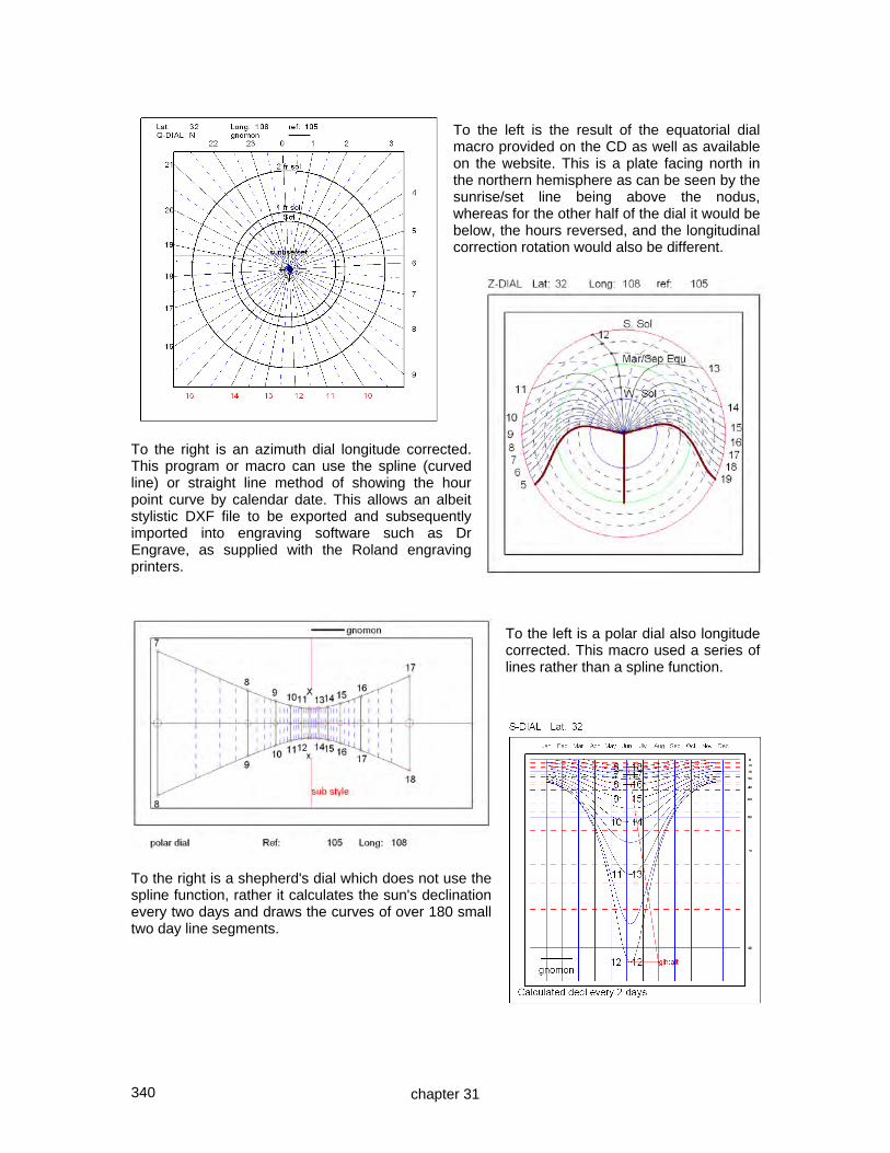
340
To the left is the result of the equatorial dial macro provided on the CD as well as available on the website. This is a plate facing north in the northern hemisphere as can be seen by the sunrise/set line being above the nodus, whereas for the other half of the dial it would be below, the hours reversed, and the longitudinal correction rotation would also be different.
To the right is an azimuth dial longitude corrected. This program or macro can use the spline (curved line) or straight line method of showing the hour point curve by calendar date. This allows an albeit stylistic DXF file to be exported and subsequently imported into engraving software such as Dr Engrave, as supplied with the Roland engraving printers.
To the left is a polar dial also longitude corrected. This macro used a series of lines rather than a spline function.
To the right is a shepherd's dial which does not use the spline function, rather it calculates the sun's declination every two days and draws the curves of over 180 small two day line segments.
chapter 31

341
The sample DeltaCAD programs or macros, available on the CD accompanying this book, as well as on the web site, also provide for animation. For example some dial macros allow
the hour lines and calendar lines to be animated as the latitude changes, or the gnomon shadow is animated through the day for a given declination.
DeltaCAD was not designed for animation, but the results of these macros available on the CD and web site can be highly educational. So, how can one make animation work in DeltaCAD? One way would probably be to use drawing layers. One layer might hold the hour lines, and another layer hold the shadow of the gnomon. The gnomon shadow holding layer could be deleted and re-generated with the next shadow. However that is easier to do by hand on the work surface than by programming since the layer must be empty before deletion if done programmatically. Alternatively, one layer per shadow could be used, with all but the desired active layers turned off. However, that would be expensive in terms of resources. Another method would be to redraw the shadow lines with a null color thus deleting a line's pixels, all work would then be done in one shadow layer separate from the hour line layer, but there is no null color available. Another approach would be to redraw the shadow lines in white, but that would still obliterate the underlying lines, unless a separate layer were used. Or, the shadow lines could be unique, and then all objects that held that uniqueness could be deleted, leaving only the permanent lines. And so on... Regardless of the method used, it appears that actual drawing and displaying are asynchronous with the dc-commands or functions. Hence lines still seem to be clobbered, sometimes the drawing stops until the end if the computer is busy. And that can happen if any programs are open even if they are not doing anything. So, "yer pays yer money and takes yer choice". The simple fact is that animation can be an enormous benefit in understanding how a dial changes with latitude or by time of day. As a reminder, these are conversational programs and do not use object oriented features, they are as simple as they can be. In keeping with this book, these DeltaCAD macros or programs are for their educational benefit more than for being polished stellar examples of a finished product. However the dial plates they produced were actually used by placing the paper dial plates on clay, and thus were fashioned the clay dials seen in this book. If you use any software by anyone at all for actual dial plate design, always double check the resulting dial plate, angular, and linear measurements for appropriateness. NOTE: The command STOP causes a BASIC SCRIPT ERROR, use EXIT FUNCTION or some equivalent instead. NOTE: DeltaCAD for Windows Vista formalized some syntax that was looser in prior versions. For example function calls require parameters not required in prior versions. Also, sloppy coding of DeltaCAD features, such as DCCREATETEXT no longer works, rigid parameter coding is required. These changes are simple and enforce better programming methods.
chapter 31

342
PRINTING TECHNIQUES ~ ~ ~ FOR DIAL PLATES LARGER THAN PRINT PAPER SIZE Once you have a DeltaCAD macro executed and a dial plate depicted, printing is easy. FILE PRINT SETUP select printer select properties landscape or portrait OK FILE SET PRINT REGION check portrait or landscape set print scale so that the result is the final size you want, recall that paper is often 8.5 x 11 inches. The left used a print scale of 0.1 and needed 12 sheets, this would be a big dial, the right used a scale of 0.3 and used 2 sheets and the final dial plate size can be visually estimated. FILE PRINT The above process can be used to print dial plates using DeltaCAD for dials larger than the print paper size. CAUTION: Some screen capture programs do not accurately preserve aspect ratios, so be careful if you use a screen captured layout and paste it into a word processor.
chapter 31

343
PRINTING TECHNIQUES ~ ~ ~ PRINTING A SMALL PART OF A DIAL PLATE Vertical declining dials facing almost east or west often need a method of printing just a part of a dial depiction. Once you have the dial plate drawn, as shown to the right, use DeltaCAD VIEW (top row, not third row of tabs in DeltaCAD) and then zoom to get the area you desire. If you use screen capture programs, be aware that some capture programs may distort DeltaCAD angles (aspect ratios). The angles in DeltaCAD are correct as tabulated. Because of hour line bunching, use the following print technique: VIEW (third row, not top row) then... VIEW OBJECT IN RECTANGLE and draw its rectangle FILE then SET PRINT REGION and in that box... in PRINTAREA do SET TO CURRENT WINDOW you may enter print scale numbers also FILE then PRINT PREVIEW and then you may print VIEW on top row
OBJECT IN RECTANGLE VIEW on third row The above process can be used to print dial plates using DeltaCAD for dial plates smaller than the displayed size. CAUTION: Some screen capture programs do not preserve aspect ratios.
NanoCAD, FreeCAD, and Powerdraw: NanoCAD is free but licensed, and programmed using Java Script and Visual Basic Script. FreeCAD is an open source CAD program available at no cost, programmed using Python. Powerdraw is free and uses a Pascal variant. The book Programming Shadows discusses programming in these systems. Available macros may include horizontal, vertical, vertical declining, polar, meridian, shepherd, winged azimuth, and Cappucin dials, calendar/declination curves, and an almanac. These macros are on the website, and on the CD.
chapter 31

344
SOME NOTES ON PROGRAMMING IN BASIC [In this case JustBASIC] Available at www.justbasic.com is a free BASIC true IDE (integrated development environment). A more extensive version called Liberty Basic is available for a small fee. This system is used in some of the programs on this book's web site as well as on the CD provided with these books. This BASIC system is different from DeltaCAD, but very close. What follows is a simple program to display data for a simple horizontal dial. ' ======================================================================== ' A simple horizontal dial with longitude correction ' by definition it can be a vertical dial for co-latitude ' ======================================================================== ' Ask for longitude and latitude and the longitude for the legal time zone print "---------------------H-DIAL------------------------" print "If run as an .EXE file, please read [please Read JB.txt]" print " sws-bas-h-dial.bas -or-- sws-bas-h-dial.tkn" print " Last revision: Jan 27, 2007 0932 mst" print "---------------------------------------------------" print " " input "Enter design latitude: [eg 32.75] " ; zla input "Enter design longitude: [eg 108.2] " ; zln input "Enter legal meridian longitude: [eg 105] " ; zle ' if null input then setup defaults if zla = 0 then zla=32.75 if zln = 0 then zln=108.2 if zle = 0 then zle=105 ' Calculate the correction due to longitude, and display the correction cor = zln-zle ' This is the correction in degrees print "Lat: " , zla print "long: ", zln, "Ref: ", zle print "corr: ", 4*cor, "minutes" ' This is the correction in minutes print "---------------------------------------------------" ' Loop the range of hours and show the hour and its angle print " " print "If the sign for the earlier hours differ from the later hours" print " then it means the hour line went past 90, adjust accordingly." print " " print "Hr: ", "no corr: ", "long corr: " for n=05 to 19 step 1 ' Start with am on left, to pm on right zhr = n - ( 4*cor/60 ) ' This is the correction in hours ' One could use IF, ELSEIF, etc however JustBASIC does not support ElseIF if n < 12 then if n = 11 then print n, shrink(hdial(zla,zln,12-n)), shrink(hdial(zla,zln,12-zhr)), "+ve is to the left" else print n, shrink(hdial(zla,zln,12-n)), shrink(hdial(zla,zln,12-zhr)) end if end if
chapter 31

345
if n = 12 then print "- - - - -" if zln >= zle then print n, shrink(hdial(zla,zln,12-n)), shrink(hdial(zla,zln,12-zhr)), "to the left of sub style" else print n, shrink(hdial(zla,zln,12-n)), shrink(hdial(zla,zln,12-zhr)), "to the right of sub style" end if print "- - - - -" end if ' if n > 12 then if n = 13 then print n, shrink(hdial(zla,zln,12-n)), shrink(hdial(zla,zln,12-zhr)), "-ve is to the right" else print n, shrink(hdial(zla,zln,12-n)), shrink(hdial(zla,zln,12-zhr)) end if end if ' repeat the loop next n print "Hr: ", "no corr: ", "long corr: " print " " print "If the sign for the later hours differ from the earlier hours" print " then it means the hour line went past 90, adjust accordingly." [dial] print "---------------------------------------------------" input "end - hit ENTER to terminate"; zzz end ' define a function for returning n hour angle ' H = atan ( sin(lat) * tan (lha) ) function hdial(lat,long,hr) hdial = atn((sin(lat*2*3.1416/360) * tan(hr*15*2*3.1416/360)))*360/(2*3.1416) end function ' Shrink to 2 significant digits function shrink(a) shrink = int(a*100)/100 end function ' *** END ***
chapter 31

346
SOME NOTES ON PROGRAMMING IN "C" (CPP or C++) There is a free C or C++ compiler and IDE available with which this program has been tested.
http://www.windows8downloads.com/win8-dev-c--wdoxnrth/ http://sourceforge.net/projects/orwelldevcpp/?source=dlp
The release works well on Windows 8: Dev-Cpp 5.5.3 TDM-GCC x64 4.7.1 Setup.exe A program for horizontal dials is shown below. This is a conversational program and does not use graphics nor a GUI (graphic user interface). This does not use object oriented features, it is as simple as it can be. Object oriented code is available on the website. #include <stdio.h> #include <math.h> // http://www.bloodshed.net/devcpp.html about the C products // http://www.bloodshed.net/dev/devcpp.html download options #define degtorad ((2 * 3.1416) / 360) #define radtodeg (360 / (2 * 3.1416)) int main () // main procedure { int i , ii ; // working integers float j; // working float float lat; // latitude and float sinlat; // and sin of latitude float hlat ; // hour line angle float lng; // longitude float ref; // reference meridian float corh; // correction for longitude float hla; // hour line angle printf ("*------------ Horizontal Dial ------------*\n"); printf ("www.illustratingshadows.com cpp-hdial.cpp\n"); printf ("*----------- March 7, 2007 0838 ----------*\n"); printf ("Enter latitude "); scanf ("%f", &lat) ; printf ("Enter longitude "); scanf ("%f", &lng); printf ("Enter legal meridian "); scanf ("%f", &ref); printf ("Design latitude: %7.2f \n", lat); printf ("Design longitude: %7.2f \n", lng); printf ("Reference meridian: %7.2f \n", ref); corh = (4*(lng-ref)) / 60 ; printf ("Correction to shadow %7.2f hours \n", corh); printf ("Correction to shadow %7.2f minutes \n", corh*60); printf ("\n"); printf ("Corrected hour line angles \n" ) ; printf ("morning hours first\n");
chapter 31

347
for (i = -6 ; i <7 ; i++ ) { if (i==0) {printf ("\nnoon\n");}; if (i==1) {printf ("noon\n\n"); }; sinlat = sin( degtorad*lat ) ; // get the hour angle of the sun ii = (-1)*i ; j = 15 * (ii+corh) ; /* get the resulting hour line angle ~ atan(sin(lat)*tan(hr*15) */ hlat = sinlat * tan(degtorad*j) ; /* get the hour line angle back to degrees */ hla = radtodeg*( atan(hlat) ) ; printf ("Hour: %3i hour angle: %6.2f Angle: %6.2f \n", i, j, hla ); } printf ( "afternoon hours last\n" ); printf ( " \n"); printf ( "*** END *** (enter any letter and return to quit)\n") ; scanf ("%f", &ref); // a pause using any old variable return 0; }
"C" was the original language in the "C" series of languages. It was structured, in that the IF THEN program flow was strongly supported, and the GOTO was diminished. As programming moved from sequential code towards event driven code, the concept of "objects" as opposed to simple variables or structures of variables came into play. And further, the concept came into existence of building code into the object to handle standard work that these objects might need done for them. These code segments, directly tied to the objects, were known as methods. This concept was used for many years in the IBM mainframe world where interrupt driven code was not new. However, as the UNIX world moved into more mainstream activity, the UNIX community considered these to be new concepts. Be that as it may, the development of objects and their methods was formalized as a concept in the development of C++, a language derivative of "C". The object and its methods were abstracted further into classes. A class was a definition of an object, or rather what it would be like. Thus a class was more of a dictionary, and the objects themselves were constructed from that dictionary. This was seen in the DeltaCAD definition of a human interaction window, and its subsequent generation or construction, and its subsequent use. However, in a true object oriented system, the methods became inter-related. That interaction allowed simple events to cause the updating of many objects. One example is the Windows display of a folder of files, and how that display is updated automatically when in another window a file is added or dropped from that folder.
chapter 31

348
SOME NOTES ON PROGRAMMING IN FORTRAN A free FORTRAN compiler/ linker is available at:: http://gcc.gnu.org/fortran/ And notes about it are available at: http://gcc.gnu.org/wiki/GFortran And the compiler download link is at: http://gcc.gnu.org/wiki/GFortranBinaries click on the INSTALLER link The compiler is about 14mb, and is a compiler and a linker, based on command line options. A good language manual is available at: http://h21007.www2.hp.com/dspp/files/unprotected/Fortran/docs/lrm/dflrm.htm Place the source in "C:\Documents and settings\user name" otherwise the RUN, COMMAND will not be able to access the directory, unless placed in the drive's root folder, such as C:\ZFTN In windows XP do RUN, COMMAND, and do a compile first, the following .BAT file is a poor man's IDE:-
edit program.txt [allows you to edit the code] gfortran -c -x f95 program.txt [ compiles an object file .o] pause [ lets you see compiler notes] gfortran -o executable program.o [ makes executable from .o ] program [ run it ] edit fort.1 [ look at the output ]
The program output for a certain dial was:- The program output that was tested was in a file called "fort.1" and is shown below:-
Latitude: 32.75 Longitude: 108.20 Reference: 105.00 hour.corr: 0.21 hour hr.ang line.angle morning hours -6 -93.20 84.10 -5 -78.20 -68.88 -4 -63.20 -46.96 -3 -48.20 -31.18 -2 -33.20 -19.49 -1 -18.20 -10.09 noon 0 -3.20 -1.73 noon 1 11.80 6.45 2 26.80 15.28 3 41.80 25.81 4 56.80 39.58 5 71.80 58.71 6 86.80 84.10 afternoon hours www.illustratingshadows.com
chapter 31
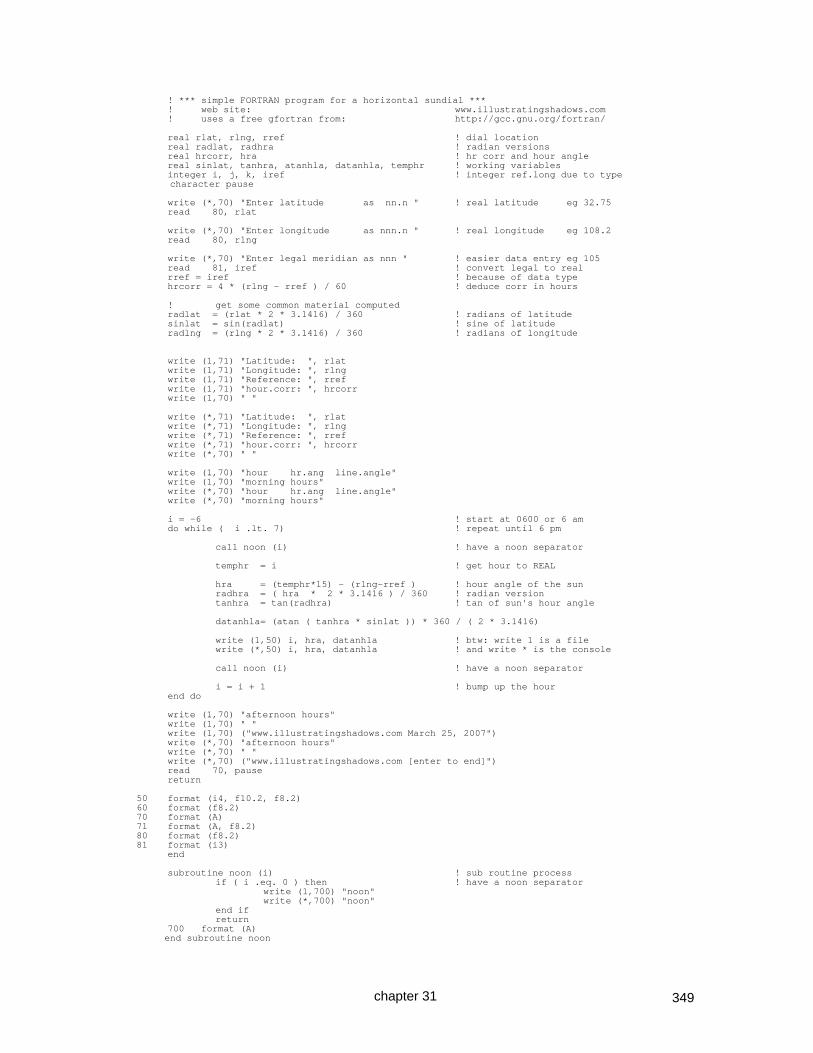
349
! *** simple FORTRAN program for a horizontal sundial *** ! web site: www.illustratingshadows.com ! uses a free gfortran from: http://gcc.gnu.org/fortran/ real rlat, rlng, rref ! dial location real radlat, radhra ! radian versions real hrcorr, hra ! hr corr and hour angle real sinlat, tanhra, atanhla, datanhla, temphr ! working variables integer i, j, k, iref ! integer ref.long due to type character pause write (*,70) "Enter latitude as nn.n " ! real latitude eg 32.75 read 80, rlat write (*,70) "Enter longitude as nnn.n " ! real longitude eg 108.2 read 80, rlng write (*,70) "Enter legal meridian as nnn " ! easier data entry eg 105 read 81, iref ! convert legal to real rref = iref ! because of data type hrcorr = 4 * (rlng - rref ) / 60 ! deduce corr in hours ! get some common material computed radlat = (rlat * 2 * 3.1416) / 360 ! radians of latitude sinlat = sin(radlat) ! sine of latitude radlng = (rlng * 2 * 3.1416) / 360 ! radians of longitude write (1,71) "Latitude: ", rlat write (1,71) "Longitude: ", rlng write (1,71) "Reference: ", rref write (1,71) "hour.corr: ", hrcorr write (1,70) " " write (*,71) "Latitude: ", rlat write (*,71) "Longitude: ", rlng write (*,71) "Reference: ", rref write (*,71) "hour.corr: ", hrcorr write (*,70) " " write (1,70) "hour hr.ang line.angle" write (1,70) "morning hours" write (*,70) "hour hr.ang line.angle" write (*,70) "morning hours" i = -6 ! start at 0600 or 6 am do while ( i .lt. 7) ! repeat until 6 pm call noon (i) ! have a noon separator temphr = i ! get hour to REAL hra = (temphr*15) - (rlng-rref ) ! hour angle of the sun radhra = ( hra * 2 * 3.1416 ) / 360 ! radian version tanhra = tan(radhra) ! tan of sun's hour angle datanhla= (atan ( tanhra * sinlat )) * 360 / ( 2 * 3.1416) write (1,50) i, hra, datanhla ! btw: write 1 is a file write (*,50) i, hra, datanhla ! and write * is the console call noon (i) ! have a noon separator i = i + 1 ! bump up the hour end do write (1,70) "afternoon hours" write (1,70) " " write (1,70) ("www.illustratingshadows.com March 25, 2007") write (*,70) "afternoon hours" write (*,70) " " write (*,70) ("www.illustratingshadows.com [enter to end]") read 70, pause return 50 format (i4, f10.2, f8.2) 60 format (f8.2) 70 format (A) 71 format (A, f8.2) 80 format (f8.2) 81 format (i3) end subroutine noon (i) ! sub routine process if ( i .eq. 0 ) then ! have a noon separator write (1,700) "noon" write (*,700) "noon" end if return 700 format (A) end subroutine noon
chapter 31

350
SOME NOTES ON PROGRAMMING IN PASCAL There are three free Pascal compilers available with which the Illustrating Shadows programs have been tested and work. Both of these systems have been used with the programs on this web site as well as on the CD provided with these books. www.bloodshed.net/devpascal.html an 8mb downloadable fully integrated development environment (IDE) whose windows are more compatible with Widows www.freepascal.org/download.var a 28mb downloadable fully integrated development environment (IDE) whose windows are more compatible with DOS. This has some useful documentation files usable in both versions of the Pascal IDE. rtl.pdf Run time library Has the functions and the required "uses" for them ref.pdf Reference Has the language structures such as IF... and so on Some trigonometric functions need the MATH library, some use the default or SYSTEM library. This is why the program says "uses math;", however the default "SYSTEM" library has no such "uses" statement since it is implied. An excellent online tutorial is found at http://www.taoyue.com/tutorials/pascal/contents.html This has better examples of some of the useful things not well explained in RTL.PDF or REF.PDF A GUI Pascal system with programmable forms is Open Source and called Lazarus. The “alldials” program as well as the IBM 1401 and 360 simulators were written using Lazarus. The vertical dial which is longitude corrected and supports wall declination, somewhat stripped down, is shown below. There are some complex IF statements whose syntax is critical. This is a conversational program and does not use graphics nor a GUI (graphic user interface). This does not use object oriented features, it is as simple as it can be. program VerticalDial; { Educational purposes only } uses math; var lng : single ; ref : single ; corh: single ; lat : double ; dsw : single ; dec : single ; zhr : single ; sd : single ; sh : single ; hla : float ; { hour line angle itself } var xxx : string ; var i : integer ; ii : integer ; j : float ;
chapter 31

351
begin writeln ('*------------ Vertical (dec) Dial ------------*'); writeln ('www.illustratingshadows.com v-dec-dial-pgm.pas'); writeln ('*------------ March 6, 2007 0903 -------------*'); writeln ('Enter latitude '); readln (lat); writeln ('Enter longitude '); readln (lng); writeln ('Enter legal meridian'); readln (ref); writeln ('Enter declination (+ve S..W, -ve S..E)'); readln (dsw); writeln ('Design latitude: ', lat:6:2); writeln ('Design longitude: ', lng:6:2); writeln ('Reference meridian: ', ref:6:2); writeln ('Correction to shadow ', 4*(lng-ref):6:2, ' minutes.'); corh := (4*(lng-ref)) / 60 ; writeln ('Correction to shadow ', corh:6:1, ' hours.'); writeln (' '); { a complex IF statement } { display the style distance SD and style height SH } if dsw = 0 then begin sd := 0 ; sh := 0 ; writeln ('non declining dial') ; end else begin sd := radtodeg(arctan(sin(degtorad(dsw))/tan(degtorad(lat)))) ; sh := radtodeg(arcsin(cos(degtorad(lat))*cos(degtorad(dsw)))) ; writeln ('this is a vertical declining dial') ; writeln ('SD [style distance from vertical]: ' , sd:5:2); writeln ('SH [style height fr vertical dialplate]: ' , sh:5:2); end ; { end of the IF statement } lat := 90 - lat ; { make co-latitude } writeln ('Latitude set to co-latitude as vertical dial: ',lat:6:2); writeln ( 'Corrected hour line angles follow' ) ; writeln ( 'morning hours first' ); for i := -6 to +6 do begin if i=0 then writeln ('noon'); if i=1 then writeln ('noon'); { get the hour angle of the sun } ii := - 1*i ; j := 15 * (ii+corh) ; { Vertical decliner dial function } { complex IF } dec := dsw * -1 ; zhr := i - corh ; if zhr = 0 then begin hla := 0 ; end else begin hla := radtodeg(arctan((cos(degtorad(90-lat)) / (sin(degtorad(dec))*sin(degtorad(90- lat))+(cos(degtorad(dec))/tan(degtorad(15*(12-zhr)))))))) ; end ; { end of complex IF } writeln ('Hour: ', i, ' hour angle: ' , j:6:2 , ' Angle: ', hla:6:2 ); end ; writeln ( 'afternoon hours last' ); writeln (' '); writeln ( '*** END ***') ; readln (xxx); end.
chapter 31

352
LAZARUS ~ OPEN SOURCE VARIANT OF DELPHI (A PASCAL IDE) Lazarus is a Pascal IDE (Integrated Development Environment), open source, running on multiple operating systems. Applications can be based on user defined forms. Lazarus site: www.lazarus.freepascal.org/ wiki link: wiki.lazarus.freepascal.org/ download link: select: Lazarus Windows 32 bits use the Win32 file: lazarus-0.9.26-fpc-2.2.2-win32.exe and NOT: lazarus-qt-0.9.26-fpc-2.2.2-win32.exe as you will get very frustrated trying to locate: qtcore4.dll The download is one single file, and it installs and runs first time. Lazarus executable programs can be very large as they have debugging information stored in them. For Windows Vista win64 systems the only compression available is to use Winzip or a similar program. For win32 versions which run on Windows Vista win64 as well as on 32 bit systems, STRIP and UPX together will reduce an executable’s size from around 12mb to under 1mb. STRIP and UPX will not compress a win64 executable. Sometimes Lazarus waits after RUN on Vista (32 bit version), click RUN, RESET DEBUGGER and it will work the next time. Lazarus can be compared to DELPHI, which is 332 mb, and the pre-reqs another 234 mb. Delphi can be found at: http://www.turboexplorer.com/delphi Lazarus is an Open Source system, based on PASCAL, and is somewhat compatible with Delphi. One of the shortcomings of modern object oriented languages is their type conversion issues. The graphical program for sundials highlights this problem, namely converting from floating point (graphical coordinate calculations) to integer (graphical package needs) requires an intermediate string conversion! Harking back to IBM's PL/I language, some lessons that the new language developers could learn emerge. First: PL/I had as one of its values the concept that if a programmer could write something that made sense to him or her, then the PL/I compiler should also be able to make sense of it also. All these newer languages or language adaptations are very weak on real world needs of commercial programmers, and seem to be more suited to those who delight in getting around complexities of a language. LAZARUS is no exception, and the documentation is designed for those who already know the system. Second: PL/I had the ability for almost any data type to be converted implicitly either at compile or at execution time, so that a programmer could take in a string of characters that contained numbers and implicitly convert them to an integer, or floating point number, and vice versa. Illustrating Shadows has several programs written using Lazarus. The IBM 1401 and IBM System 360 simulators, language assemblers, and debugging aids were written using Lazarus. An “ALLDIALS.EXE” program was also written using Lazarus. The CD with the Illustrating Shadows books has detailed notes on programming with Lazarus, and the general principles are similar to Visual Basic. Lazarus code is more portable than the Visual Microsoft products. ALLDIALS is a good example of graphics programming in Lazarus.
chapter 31
Horizontal of vertical dial

353
SHORT REVIEW ON PROGRAMMING Excel SPREADSHEETS IMPORTANT NOTE: Open Office is a free Microsoft Office equivalent. In the case of Excel, the syntax for formulae and the conditional formatting are not the same. Angular measure uses radians, there are 2 * pi radians in a circle of 360 degrees. The trigonometric functions SIN, COS, TAN, COTAN, and so on, need the radian conversion first. Any function that returns an angular measure, such as ATAN, ACOS, ASIN, also printed as TAN-1, COS-1, SIN-1, would need to be converted back to degrees using the DEGREES function. The number of significant digits after the decimal point is controlled by the FORMAT, CELLS, NUMBER option. Some functions do rounding of their own. The INT (integer) function returns the integer part of a number on the left side of the decimal point, rounds down. And the number below 5.9 is 5, however the number below -5.1 is -6 because this is already in the negative scale. However, the ABS (absolute) function which removes the sign may be used if the above rounding down on the negative side is not desired. If the sign must be retained, then the SIGN function can be used. Sometimes the cell formula can get vary large and out of hand. If you make an error on entering a formula, the spreadsheet will offer a correction. Be very careful of accepting their suggestion. It is best to match the parentheses yourself. If a formula gets too large, consider using intermediate columns, or cells, that hold intermediate data. Intermediary values are usually kept off to one side, the right side in this case, and used as working accumulators for the final value. One can hard code cell references using the $column$row syntax. And finally, when you choose a formula, from whatever source, always test it at extreme as well as in between values. For example, there are two versions of the formulae for azimuth in publication, only one works for all hours. Bellow a simple spreadsheet is depicted with comments.
This cell is D16 =DEGREES(ATAN(TAN(RADIANS(15*C16))* SIN(RADIANS($F$8))))
$F$8 being latitude C16 being the time for this row
Dial's latitude 32.75
Dial's longitude 108.20
legal time zone longitude 105.00
B11 C11 D11 12.8 long corr
B12 C12 D12 E12 F12
B13 C13 Hour line
Horizontal hour line
TIME DAY h-dial angles w long corr
am pm angles am pm
12.00 12.00 0.00 1.73 -1.73
11.50 0.50 4.07 5.84 2.33
11.00 1.00 8.25 10.09 6.45
10.50 1.50 12.63 14.59 10.73
10.00 2.00 17.35 19.49 15.28
9.50 2.50 22.54 24.95 20.26
9.00 3.00 28.41 31.18 25.81
8.50 3.50 35.18 38.42 32.17
8.00 4.00 43.14 46.96 39.58
7.50 4.50 52.56 57.08 48.34
7.00 5.00 63.65 68.88 58.71
6.50 5.50 76.32 82.09 70.75
6.00 6.00 90.00 -84.10 84.10
no longitude These have
correction longitude correction
=DEGREES(ATAN(TAN(RADIANS((15*C22)+ ($F$9–$F$10)))*SIN(RADIANS($F$8)))) =DEGREES(ATAN(TAN(RADIANS((15*C22)– ($F$9–$F$10)))*SIN(RADIANS($F$8))))
$F$8 being latitude C22 being the time for this row $F$9-$F$10 being long-ref.long
The hours depicted match those of the JustBASIC program on the preceding page, as well as those produced by the DeltaCAD macro results.
In the above, the top left cell is B8, the top right cell is B12. Cells B11~D11, B12~F12, and B13~B14 are shown in italics purely for reference.
chapter 31

354
SOME MORE NOTES ON DRAWING AND BUILDING WITH TURBOCAD TurboCAD as such does not have a readily available programming system, its strength lies in its 3d abilities. These notes review key concepts that trip up new users. First, a review of 3d. With TurboCAD, a key concept is the work plane. Things happen on THE work plane. For example, if you wished to place an object on the slope of the wedge, you could use the original work plane, create the object, tilt it, move it higher above the original plane, and hope. Or you could change the work plane to match the facet, i.e. the slope, and then use the new work plane.
The WORKSPACE, WORK PLANE, BY FACET was used with the mouse going close to the slope, and upon clicking the facet, the work plane and the grid lines changed. The new object, a cylinder, was built and it aligned perfectly with that slope.
Another confusion point is moving an object, and which coordinates are used. The cylinder object was selected and moved along the X axis, the default is that the entire system's coordinates are used. Thus the cylinder displaces along the entire system's X axis and not on the object's X axis. The shift was achieved with the POS-X field on the bottom of the TurboCAD screen while the object itself was selected.
Another confusion point is rotating an object. Rotating around the X axis is done by grabbing the Y axis handle and rotating. The Y-axis uses the Z, and rotating around the Z uses the X axis handle. Lighting in 3d is another problem area. With nowhere to "hang" a light, it is very hard to provide good lighting. Key points are that a light when added is not white, it is grey. Second, a light can
be anchored to an object such as a solar mesh as depicted to the right, with LOCAL SNAP and ANCHOR ON FACET, and the light's focus can also be anchored somewhere. The result is calendar and time accurate lighting. Use:- solarMesh.tcw shown to the right.
chapter 31
solarMesh.tcw

355
Several chapters in this book cover much more extensively the advanced 3d techniques such as 3d subtract, intersection, and 3d add. Of course, 3d add should not be confused with a similar beneficial concept of the group, and both should be thoroughly understood. TurboCAD 2d drafting is simplicity itself. The system does not have a programmable interface such as DeltaCAD. However its final drawings are very well formed. And 2d pictorials can be converted to solid 3d objects and rotated in 3d. The only area of confusion lies in specifying a base for an angular measure and the direction that angle will take. This applies when drawing lines at an angle from a base line, which itself may be at any angle. Measuring angles is simplicity itself with DIMENSION, ANGULAR MEASURE, and then enter ALT-a and then place the mouse at the intersection of the two lines, and then select each of those two lines, and the angle is displayed. Drawing (as opposed to measuring) a line at an angle to another requires that the angle base as well as direction be established. OPTIONS and then ANGLE opens the control panel for setting the system's defaults. Assuming a base line from which others will be measured is at say 15° then the system is given that as a base, and in this example a direction of clockwise. From then on, lines can be drawn from that angled base line. Drawing lines clockwise is now simple, and done by completing the line while observing the displayed angle. To draw angles counter clockwise, the OPTIONS, ANGLE panel is used and the counter clockwise box is checked.
A line then drawn at a steeper angle from the original line will show as an angle starting from 0. This simple method allows any base line to be used, and then any lines to drawn offset by a simple angle, without the need for subtracting the desired angle from 360. This simple process saves much frustration. Alternatively lines can be rotated, which has the benefit that an angle can then be typed in. Another problem area is selecting and resizing any object. The aspect ratio must be set and double checked by a right click on the selected object. Otherwise hours of frustration may ensue.
The manual provided with TurboCAD is extremely thorough, however the above insights may make it a lot easier to use the system. Sadly, that same book has little on their SDK (programming system), see the next two pages.
Ignore ORTHO section for this process.
● Clockwise
● Counterclockwise
chapter 31

356
SOME NOTES ON PROGRAMMING TURBOCAD USING THE SDK (VBS) TurboCAD, like DeltaCAD, offers a programming methodology. However, rather than use one third party system as does DeltaCAD, TurboCAD elected to use the set of languages available from Microsoft. Further, the interface is only available with the Professional version, not with the more affordable Deluxe installation. Thus, DeltaCAD is likely to remain the CAD system of choice for the average diallist, and has probably passed critical mass for that reason. The TurboCAD VBS (Visual Basic Script) macros are to be stored in:- c:\Program Files IMSI\TCWP11 or later release, such as TCWP12 SDK\Samples\VBS\WshScriptPack (Wsh means: GUI Windows Script Host ) In current versions of TurboCAD Professional (version 11 and later), folders are found for:- C#, CPP, DELPHI, VB NET, VBASIC, VBS, vc, and finally vcnet Several problems come to light at this juncture. 1. Microsoft languages come and go, and the languages themselves are not stable as they are enhanced, and some features are dropped. 2. Most have either an involved build processes or collections of libraries that must go with the program, VBS (visual basic script) is luckily an exception. 3. While TurboCAD has an excellent book for the hands on CAD user, the two or three pages referring to their SDK are in no way enlightening. 4. The computer readable documentation is of use to someone already knowing the system. There is no obvious cross reference between simple CAD functions and their calls, functions, or methods. Thus finding how to draw a line is not intuitively obvious. 5. Luckily there are some third party web sites that are a great help. While VBS is the slowest interface, it does not require a host of installation libraries, nor a complex build. Instead, a simple text editor (WordPad for example) can build the program and save it in the appropriate folder, and in TurboCAD Professional, clicking the MACRO tool allows the user to then click on FILE FOLDERS, and from thence the VBS program (script) may be run. These scripts are executed by loading TurboCAD Professional, with a NEW drawing area, and clicking on the macro tool (if visible), or if not visible, by clicking on VIEW, MacroRecorderPalette. Then locate the file folder, and if needed, set the file type to VBS (so you can see the scripts or macros). which brings up a sub panel, click on files
chapter 31

357
and then click on the file you wish to run. NOTE: the drawing area must exist, so do a NEW when bringing up TurboCAD, otherwise the following Windows Script Host message appears. Useful references sources are:- http://msdn2.microsoft.com/en-us/library/ms950396.aspx http://www.tyharness.co.uk/tcvbacrashcourse/tcvbacrashcourse.htm http://www.tyharness.co.uk/cad.htm
tcsdk.chm in the Docs folder of the TurboCAD SDK, is not without merit. Cryptic at times but it can provide clues. And the SEARCH function, once a function or method has been identified, is very helpful.
VBS IN TURBOCAD – KEY POINTS TO KNOW The implementation is object oriented. Thus a graphics area is acquired, and things added to that area, or, object within that area. And objects have methods (eg: drawing a line) and properties (eg: methods to alter the appearance of a line) InputBox get a line of input (forms are more involved) AddLineRectangle adds a rectangle AddCircleCenterAndPoint adds a circle AddLineSingle adds a line AddText adds text into the drawing graphic elements built, such as a line, have methods (properties) that can be invoked Properties("Penstyle").Value = "DASHED" Properties("Pencolor").Value = RGB(0, 255, 0) Other functions exist including trigonometric functions, however ASN (arcsin) has to be programmed by the programmer, as does the "to" and "from" degrees/radians. This is a common deficit in many BASIC based systems. The CD with this book, and this book's web site have functioning dial plate TurboCAD scripts.
chapter 31

358
TURBOCAD PRO AND THE “PARAMETRIC PART SCRIPTING” TurboCAD has several programmable options. One uses VBS (Visual Basic Script). The current versions of TurboCAD (not 15.1 nor earlier), supports Parametric Script entities. In essence, a script is written that inserts an entity into a drawing, and from then on, that entity may be selected and its parameters may be modified to generate a whole new layout. The Parametric Script language is interesting in that the "Output" statement is executed last, and other statements wherever they may be, are executed first. Case is critical, thus "output" is not executable, "Output" is the correct spelling. Trigonometric functions use degrees, however there is no INT nor ABS provided. Some documents are important to have. As happens with IMSI, documentation is not made obvious. Searches of the internet are essential for clues to a new feature, and the parametric scripting feature is no exception. Essential notes on parametric script building: This explains how the editor marks syntax errors:- http://www3.turbocadcommunity.com/tiki-index.php?page=PPM+Scripting http://www3.turbocadcommunity.com/tiki-index.php?page=PPM+Scripting+Reference Useful but incomplete notes on parametric scripts:- http://downloads.imsidesign.com/HelpFiles/Scripting%20Parametric%20Parts%20Feb%2029,%202008.pdf It is only through the above two documents that scripts can easily be written. The Parametric Script Editor is invoked by "VIEW" and then "Parametric Script Editor Palette", and the script can be easily typed, or loaded from a file in any folder. The Editor uses color coding: black variables brown text blue reserved words magenta is an error The status line of the palette indicates the error reason for the error. green comments write a new program use this folder to open a program save this program (script)
chapter 31

359
"Output(plate);" has "plate" in magenta and thus says "plate" is wrong. Plate has a syntax error in that two ")" are missing. Once corrected, then "Output(plate);" will show in normal text. A fabulous feature of these script created objects is that once a parametric part has been built on the drawing area, it can be selected (as with any entity) and then VIEW, SELECTION INFO will enable you to see and change those parameters (set with the "Parameter" statement).
The parameters were changed from lat 52, long 108.2 and 105 to a new set of 32.75, 101.3 and 105. And the entire drawing redrew itself.
chapter 31

360
Typical output from a script, and accuracy The TurboCAD Parametric Script included here generated the following dial layout. The hour line angles were measured with INSERT, DIMENSION, ANGULAR, then right click and select ANGLE NODE and then follow the prompts.
The angles are very close to the same dial plate's hour line angles produced by another CAD system, DeltaCAD.
h-dial and calendar using gnomon linear heightLat: 32.8 d.Long: 03.2
684.1
Hours below horizontal use the 90 reference line below horizontal.
6
7-68.9
Hours below horizontal use the 90 reference line below horizontal.
7
8-47.0
Hours below horizontal use the 90 reference line below horizontal.
8
9-31.2
Hours below horizontal use the 90 reference line below horizontal.
9
10-19.5
Hours below horizontal use the 90 reference line below horizontal.
10
11-10.1
Hours below horizontal use the 90 reference line below horizontal.
11
12-1.7
Hours below horizontal use the 90 reference line below horizontal.
12
1306.4
Hours below horizontal use the 90 reference line below horizontal.
13
1415.3
Hours below horizontal use the 90 reference line below horizontal.
14
1525.8
Hours below horizontal use the 90 reference line below horizontal.
15
1639.6
Hours below horizontal use the 90 reference line below horizontal.
16
1758.7
Hours below horizontal use the 90 reference line below horizontal.
17
1884.1
Hours below horizontal use the 90 reference line below horizontal.
18
chapter 31
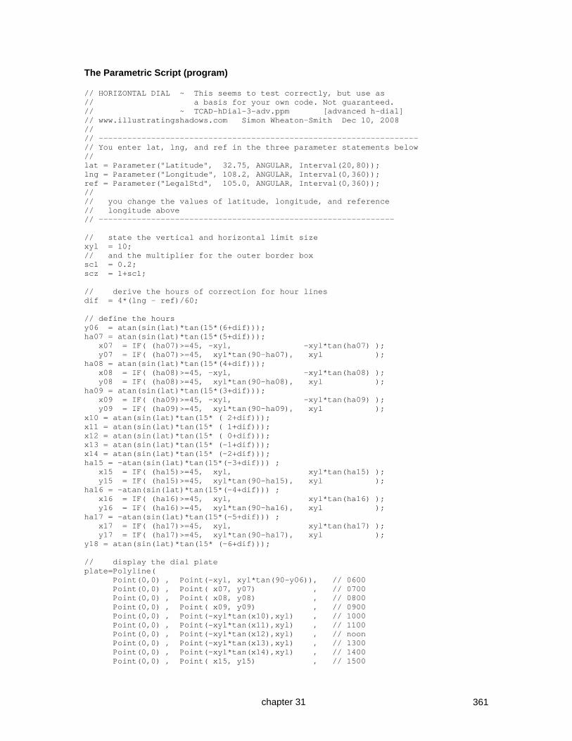
361
The Parametric Script (program) // HORIZONTAL DIAL ~ This seems to test correctly, but use as // a basis for your own code. Not guaranteed. // ~ TCAD-hDial-3-adv.ppm [advanced h-dial] // www.illustratingshadows.com Simon Wheaton-Smith Dec 10, 2008 // // ------------------------------------------------------------------- // You enter lat, lng, and ref in the three parameter statements below // lat = Parameter("Latitude", 32.75, ANGULAR, Interval(20,80)); lng = Parameter("Longitude", 108.2, ANGULAR, Interval(0,360)); ref = Parameter("LegalStd", 105.0, ANGULAR, Interval(0,360)); // // you change the values of latitude, longitude, and reference // longitude above // -------------------------------------------------------------- // state the vertical and horizontal limit size xyl = 10; // and the multiplier for the outer border box scl = 0.2; scz = 1+scl; // derive the hours of correction for hour lines dif = 4*(lng - ref)/60; // define the hours y06 = atan(sin(lat)*tan(15*(6+dif))); ha07 = atan(sin(lat)*tan(15*(5+dif))); x07 = IF( (ha07)>=45, -xyl, -xyl*tan(ha07) ); y07 = IF( (ha07)>=45, xyl*tan(90-ha07), xyl ); ha08 = atan(sin(lat)*tan(15*(4+dif))); x08 = IF( (ha08)>=45, -xyl, -xyl*tan(ha08) ); y08 = IF( (ha08)>=45, xyl*tan(90-ha08), xyl ); ha09 = atan(sin(lat)*tan(15*(3+dif))); x09 = IF( (ha09)>=45, -xyl, -xyl*tan(ha09) ); y09 = IF( (ha09)>=45, xyl*tan(90-ha09), xyl ); x10 = atan(sin(lat)*tan(15* ( 2+dif))); x11 = atan(sin(lat)*tan(15* ( 1+dif))); x12 = atan(sin(lat)*tan(15* ( 0+dif))); x13 = atan(sin(lat)*tan(15* (-1+dif))); x14 = atan(sin(lat)*tan(15* (-2+dif))); ha15 = -atan(sin(lat)*tan(15*(-3+dif))) ; x15 = IF( (ha15)>=45, xyl, xyl*tan(ha15) ); y15 = IF( (ha15)>=45, xyl*tan(90-ha15), xyl ); ha16 = -atan(sin(lat)*tan(15*(-4+dif))) ; x16 = IF( (ha16)>=45, xyl, xyl*tan(ha16) ); y16 = IF( (ha16)>=45, xyl*tan(90-ha16), xyl ); ha17 = -atan(sin(lat)*tan(15*(-5+dif))) ; x17 = IF( (ha17)>=45, xyl, xyl*tan(ha17) ); y17 = IF( (ha17)>=45, xyl*tan(90-ha17), xyl ); y18 = atan(sin(lat)*tan(15* (-6+dif))); // display the dial plate plate=Polyline( Point(0,0) , Point(-xyl, xyl*tan(90-y06)), // 0600 Point(0,0) , Point( x07, y07) , // 0700 Point(0,0) , Point( x08, y08) , // 0800 Point(0,0) , Point( x09, y09) , // 0900 Point(0,0) , Point(-xyl*tan(x10),xyl) , // 1000 Point(0,0) , Point(-xyl*tan(x11),xyl) , // 1100 Point(0,0) , Point(-xyl*tan(x12),xyl) , // noon Point(0,0) , Point(-xyl*tan(x13),xyl) , // 1300 Point(0,0) , Point(-xyl*tan(x14),xyl) , // 1400 Point(0,0) , Point( x15, y15) , // 1500
chapter 31
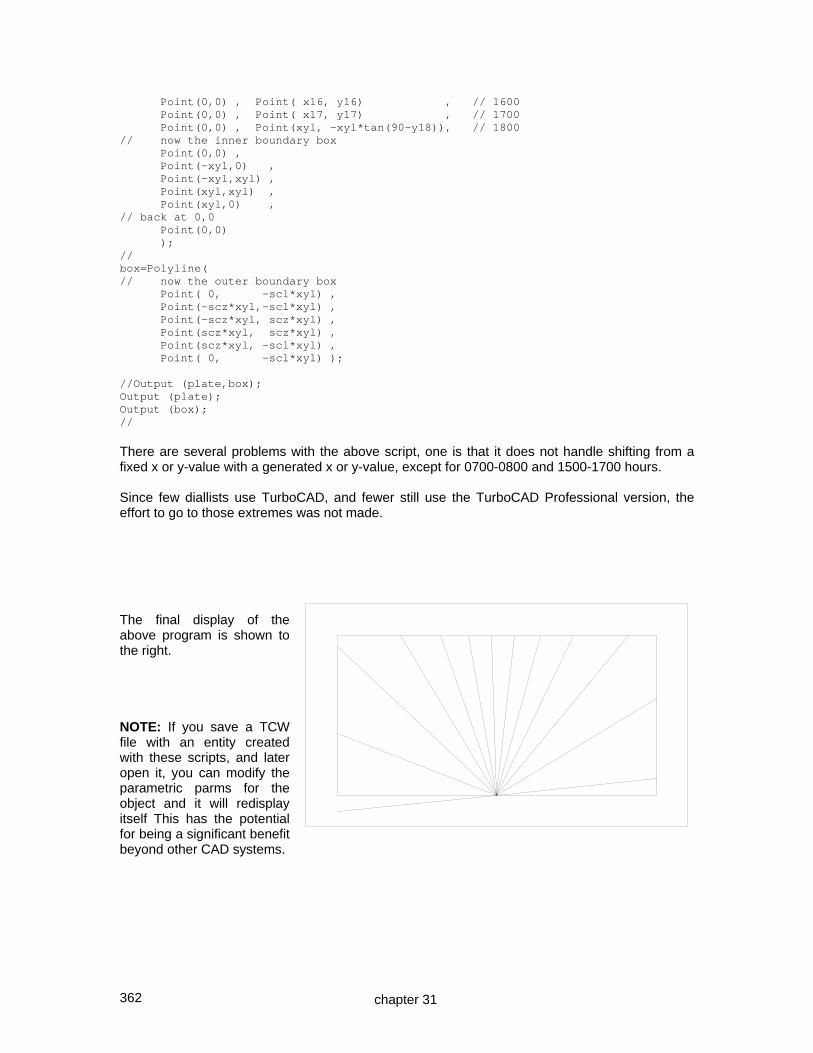
362
Point(0,0) , Point( x16, y16) , // 1600 Point(0,0) , Point( x17, y17) , // 1700 Point(0,0) , Point(xyl, -xyl*tan(90-y18)), // 1800 // now the inner boundary box Point(0,0) , Point(-xyl,0) , Point(-xyl,xyl) , Point(xyl,xyl) , Point(xyl,0) , // back at 0,0 Point(0,0) ); // box=Polyline( // now the outer boundary box Point( 0, -scl*xyl) , Point(-scz*xyl,-scl*xyl) , Point(-scz*xyl, scz*xyl) , Point(scz*xyl, scz*xyl) , Point(scz*xyl, -scl*xyl) , Point( 0, -scl*xyl) ); //Output (plate,box); Output (plate); Output (box); // There are several problems with the above script, one is that it does not handle shifting from a fixed x or y-value with a generated x or y-value, except for 0700-0800 and 1500-1700 hours. Since few diallists use TurboCAD, and fewer still use the TurboCAD Professional version, the effort to go to those extremes was not made. The final display of the above program is shown to the right. NOTE: If you save a TCW file with an entity created with these scripts, and later open it, you can modify the parametric parms for the object and it will redisplay itself This has the potential for being a significant benefit beyond other CAD systems.
chapter 31

363
CHAPTER THIRTY TWO
Older methods ~ DL, Nomograms, Slide rules, and Dialing scales The long forgotten “DL” or difference in longitude of the vertical decliner In some earlier books the term DL was derived for the vertical decliner. Such books were written when calculators weren’t around but slide rules and nomograms were. It made sense to display a formula in logarithm form. Logarithms, or logs, are a means whereby multiplication is done by addition, and division by subtraction. The horizontal dial formula for an hour line’s angle (hla):- hla = atan( sin(lat) * tan(hour angle) ) which is also… tan(hla) = sin(lat) * tan(hour angle) becomes when using logs… log tan(hla) = log sin(lat) + log tan(hour angle) Logs make nomograms easy to develop for sundials, and help people who have no calculators use simple addition or subtraction in place of multiplication and division. Tables are used to get the log of a number, and its reverse the anti-log as well. The vertical decliner can be created using a formula based on a surrogate equatorial dial, the most common formula in use is:- hla = atan( cos(lat) / (cos(dec) * cot(ha) + sin(dec) * sin(lat)) ) a formula producing the same results but based on a surrogate horizontal dial’s hour lines is:- hla = atan( sin ( hdialsHla ) / sin( 90 – hdialsHla – dec ) * tan (lat ) ) or hla = atan sin( atan( sin ( lat ) * tan ( lha ) ) ) tan ( lat ) * sin( 90 – dec – atan (sin ( lat ) * tan ( lha ) ) ) But another alternative exists. A horizontal dial with a latitude equal to the vertical decliner dial’s SH can be slid over the vertical decliner’s dial plate such that 12 noon local apparent time on the surrogate horizontal dial plate matches the SD on the real vertical decliner. This process is discussed in chapter 16 (vertical decliner), chapter 23 (calendar or declination curves), and chapter 25 (the analemma). The hour lines on the real vertical decliner, and the hour lines on the pseudo horizontal surrogate dial will not normally match. However they can be made to match by adjusting the hour lines on the surrogate dial plate to match those on the vertical decliner, this is performed by using a longitude adjustment. That adjustment has little to do with the real vertical decliner’s design longitude. It is a value that will simulate a longitude enabling the surrogate dial’s hour lines to match the real dial. The surrogate dial’s latitude is of course SH (style height). This magical longitude difference is called “DL” or difference in longitude, and is derived from a simple formula from the vertical decliner (see derivation in chapter 16). NOTE: SD is an hour line angle, and DL is a surrogate equatorial dial’s hour angle that produces that DL. DL = Atan( Tan( dec ) / Sin( lat) ) + vDecLongitude – legalMeridianLongitude Use this DL as the surrogate dial’s longitude and reduce its magnitude by 15 degrees if it was larger than 15, until the result is 15 degrees or less. And each reduction of 15 degrees will require the hour line labels to be adjusted by one hour, since one hour is represented by 15 degrees. Then use a legal meridian of 0 in the horizontal dial plate process. Since the hours on a horizontal dial rotate in the opposite direction to a vertical dial (chapter 13), the sense of the angles must be reversed. The resulting hours will then produce hour lines that match the real vertical decliner. The nomogram for a vertical decliner uses this method since the “DL” formula has two terms compared to many more for the other formulae. “DL” is an almost forgotten value, and yet it still has a use and should be remembered. NOTE: a vertical dial of latitude “90 – SH” can be used in place of a horizontal dial, when the sense of the hours would not need reversing.
chapter 32

364
The nomogram and the sun dial (sundial nomograms are in the appendices) The nomogram, popularized in 1880 by Philbert d'Ocagne, has many forms. The simplest is two variables represented by vertical lines left and right, with the solution represented by a vertical line mid way between the two (method 1a below). There are a number of web sites that discuss nomogram theory and design. The JAVA alternative Python has software for drafting nomograms. Illustrating Shadows provides DeltaCAD and Lazarus/Pascal nomogram aids for dialing needs. Nomograms are graphical solutions to mathematical problems. The problem inputs and the solution are represented by values placed along lines or curves. The derivation of the shapes and the marking of values on the lines are based on rules of triangles. For the purposes of sundials and other simple problems, certain nomogram shapes are best for certain kinds of formulae. For the purposes of explanation, “L” means the left line, “R” the rightmost line, and these are both inputs, while “C” represents the central line which provides the solution. method 1a method 1b method 2 method 3 method 4 0 L a b a =b 0 0 = = R C 0 L C L C R L C R L C 0 R 0 0 0 R 0 C = L + R C = L + R C = L / R C = L x R 1/C = 1/L+1/R can multiply and divide with logs logs not needed logs not needed logs not needed The method 1 nomograms above do not show multiplication. Since multiplication can be done by adding the “log” or logarithm of the numbers, method 1 can perform multiplication if log values are used. Similarly division can be done by subtracting the log of the numbers so again method 1 can be used. Method 2 does not use logs since division is implied, and method 3 implies multiplication, so again, logs are not used. The Illustrating Shadows DeltaCAD macro “nomogram.bas” uses natural or Naperian logs based on 2.71828 since the base 10 log function did not perform as the documentation suggested, the Lazarus/Pascal version uses base 10. Method 1a: A horizontal dial, two inputs (latitude and time), one solution (hour line angle): the nomogram’s general formula: C = L + R hour line angle = atan ( sin(lat) * tan(hour angle) ) so log tan (hla) = log sin lat + log tan hour angle In the example to the right, the horizontal dial nomogram was derived manually. The left scale is the logarithm of the sine of the latitude, the right is the logarithm of the tangent of the hour from noon (times 15 of course), with the center vertical line being the logarithm of the tangent of the hour line angle on the dial plate, compressed by a factor of two. The axes are labeled with latitude, hour, and hour line angle (functional scales) and not their logarithmic equivalents (natural scales). The end result is a nomogram whereby a line can be drawn from the latitude (left) to the hour from noon (right) and the dial plate’s hour line angle read in the middle. A sample line for latitude 32 and 0900 or 1500 is shown, and the hour angle in the middle is seen to be close to 27.92 degrees which it should be.
LATITUDE
hour line angle
10
30
5
15
20
40
2
50
1145 1215
1130 1230
1115 1245
1100 1300
1030 1330
1000 1400
0900 1500
0800 1600
0700 1700
HOUR
5
10
1520253035404550
chapter 32
L C R left center right

365
This is not longitude corrected, you make the longitude correction before using the tool by converting the longitude difference to an hour angle adjustment. The Hour Line Angle and the Hours From Noon scales get smaller from the bottom as you move up, but then get bigger again. This is because initially the TAN is slowly increasing while the log decreases more rapidly, however later, the TAN increases far more than the log decreases. The first step in building nomogram is to look at the extremes of the three variables because they must be placed on the nomogram’s vertical lines. Their magnitudes should be reasonable and should be selected so that extremes are omitted if the nomogram scales would be impractical. “L” line “R” line “C” line
“L” left line: INPUT 1: The practical latitude range is: 0.00 to -1.76 “R” right line: INPUT 2: The practical hour range from noon is: -1.18 to 0.57 “C” center line: RESULT: The practical dial plate’s hour line angle range is -1.76 to 1.06 NOTE: The “C” scale is actually compressed in half, see NOTE below. NOTE: log TAN(hour line angle) is used, see the formula development below. hla = atan( sin(lat) * tan(hour angle) ) thus tan(hla) = sin(lat) * tan(hour angle) thus log tan(hla) = log sin(lat) + log tan(hour angle) The next step is to build a set of three parallel lines, equidistant for simplicity, with equally spaced number scales (natural scales) that cover the ranges of the inputs and the output. Thus a nomogram with three lines ranging from -1.76 to 1.06 would be appropriate. All three have 0 in the same place. BUT NOTE: The center line, when equidistant between the other two lines, has its scale compressed in half, i.e. the center solution scale can accommodate numbers twice as large as can the other scales. This is because the center scale is the sum of the two outer scales. NOTE: The natural scale is linear, and we use the log of our value on that line, make a marker for that logarithm, but label it with the original number (input) or final number (result), i.e. 30 for latitude 30, being the functional scale.
0
1
2
3
0
1
2
3
0
2.0
4.0
6.0
log sin(lat) best range is -1.76 to 0 log tan (lha)
best range is -1.18 to 0 to 0.57
log tan (hour angle )best range is -1.76 to 0 to 1.06
-1
-2
-1
-2
-3
-2.0
-4.0
-6.0
chapter 32
LATITUDE log sin(lat) HOURS FRlog tan(hr) HOUR LINE ANGLE log(tan) of resulting hour line angle0 #NUM! 0.00 #NUM! 0 #NUM!1 -1.76 0.25 -1.18 1 -1.762 -1.46 0.50 -0.88 5 -1.065 -1.06 0.50 -0.88 10 -0.75
10 -0.76 0.75 -0.70 15 -0.5715 -0.59 1.00 -0.57 20 -0.4420 -0.47 1.25 -0.47 25 -0.3325 -0.37 1.50 -0.38 30 -0.2430 -0.30 1.75 -0.31 35 -0.1535 -0.24 2.00 -0.24 40 -0.0840 -0.19 2.50 -0.12 45 0.0045 -0.15 3.00 0.00 50 0.0850 -0.12 3.50 0.12 55 0.1555 -0.09 4.00 0.24 60 0.2460 -0.06 5.00 0.57 65 0.3365 -0.04 6.00 16.21 70 0.4470 -0.03 75 0.5775 -0.02 NOTE: log (0) is something you 80 0.7580 -0.01 never get 85 1.0685 0.00 versus 90 16.2190 0.00 NOTE: a log(1) results in 0
the center scale is compressed to half the left and right scales

366
00
01
02
03
04
05
06
07
08IN #1
00
01
02
03
04
05
06
07
08IN #2
04050607080910111213141516
IN#1 + IN#2
Starts at 4 only to show how alllines always have same base of 0
Some key points must be re-emphasized at this time. First, for these type1 and type 1a nomograms, they all have a raw data baseline of 0 starting at the same horizontal place on all three lines. This is shown to the right. Second, the center scale is compressed in half when equidistant between the left and right lines. Third, when looking at the horizontal, vertical, or any other nomogram, why does “0” not seem to be in the same place on all the lines? The answer was given on the preceding page, however it will be reiterated. The label on a point on a line may not be the data point itself. For example, assume the input is for “latitude”. Latitude 0 becomes sin(lat) which is also 0, but the logarithm of 0 is unusable. So a latitude is selected of say latitude 1. The sin(1) becomes 0.017452. And the log of that is usable. In the case of DeltaCAD and the macros using natural logs, the log base 2.71828, and the key point is to use logs, not what their base is. And the log is what is used along the vertical scales, because it is the logs we want to add, and we want to add the logs because that is how we multiply. Even so, we do not print the log value as that is useless, what we print is the original latitude, or whatever. So the nomogram appears as if the zero values are not in alignment, when in reality they are. This is shown to the right.
0 on the center solution line would still be here
10.0
20.0
30.0
40.0
50.060.070.0
Latitude 2 degree increments
10
20
30
40
50
60
70
80Hour line angle in 1 degree increments
01.00
02.00
03.00
04.00
05.00HORIZONTAL DIAL www.illustratingshadows.com
chapter 32
0
The above linear scales are the “natural scales”, they share the common “0”. These scales are seldom displayed. The below non linear scales are the “functional scales” which do not share “0” except by formula coincidence. Functional scales are actually displayed and used.
starts at 4 only to demonstrate that its 0 is still with the other scale’s 0.
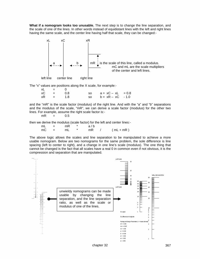
367
What if a nomogram looks too unusable. The next step is to change the line separation, and the scale of one of the lines. In other words instead of equidistant lines with the left and right lines having the same scale, and the center line having half that scale, they can be changed:- xL xC xR a b mR is the scale of this line, called a modulus. mC and mL are the scale multipliers of the center and left lines. left line center line right line The “x” values are positions along the X scale, for example:- xL = 0 xC = 0.8 so a = xC – xL = 0.8 xR = 1.8 so b = xR – xC - 1.0 and the “mR” is the scale factor (modulus) of the right line. And with the “a” and “b” separations and the modulus of the scale, “mR”, we can derive a scale factor (modulus) for the other two lines. For example, assume the right scale factor is:- mR = 0.5 then we derive the modulus (scale factor) for the left and center lines:- mL = mR * a / b mC = mL * mR / ( mL + mR ) The above logic allows the scales and line separation to be manipulated to achieve a more usable nomogram. Below are two nomograms for the same problem, the sole difference is line spacing (left to center to right), and a change in one line’s scale (modulus). The one thing that cannot be changed is the fact that all scales have a real 0 in common even if not obvious, it is the compression and separation that are manipulated.
chapter 32
10
20
30
40
50607080
LATITUDE
LATITUDE
1
2
34
10
20
30
40
50
60
DL angle
DL difference in longitude
Nomogram Design Parameters (=> means derived)
ml => 0.55
mc => 0.28
mr = 0.55
a => 0.50
b => 0.50
xl = -0.50
xc = 0.00
xr = 0.50
1
2
3
4
5
678910
20
30
40
50
60
WALL DECLINATION
10
20
30
40
50
60
70
80
LATITUDE
LATITUDE
1
2
3
4
10
20
30
40
50
60
1
2
3
4
5
6
7
8
9
10
20
30
40
50
60
WALL DECLINATION unwieldy nomograms can be made usable by changing the line separation, and the line separation ratio, as well as the scale or modulus of one of the lines.

368
Be creative when designing a nomogram with a complex formula. Consider the vertical decliner, one way would be to use one of the vertical decliner formulae:- hour line angle = atan(cos(lat) / (cos(dec) * cot(ha) + sin(dec) * sin(lat)) However a nomogram to deduce the vertical decliner’s hour line angles would be a very busy nomogram because of the many terms, in essence several nomograms would be combined. Interestingly, the vertical decliner dial hour lines can be derived another way. One such way is to take the SH (style height), and use that as the latitude of a surrogate horizontal dial. If that is done, then how do the surrogate horizontal dial hour lines become adjusted so they are correct? The horizontal dial’s hour lines are adjusted by an assumed longitude of “DL”. This technique is discussed earlier in this chapter and proved in chapter 16. To summarize the analemma notes of chapter 25, “a surrogate h-dial is provided with a latitude of SH and a longitude of DL from the vertical decliner derived figures, with a legal reference meridian of 0, to be aligned along the vertical decliner’s SD. Longitudes greater than 15 are reduced by 15 until the result is 15 or less, while adjusting the hour line labels by 1 for each 15 degrees.”
Since a nomogram for a vertical decliner dial’s hour line angles would be somewhat involved due to the many terms in the formula, and since “DL” only has two terms, this method can easily be employed. The nomogram to the left derives this “DL”, and the vertical decliner dial plate so derived, is duplicated below from chapter 25 which discusses the concept in more detail, as does the beginning of this chapter.
Original v-dec parms are:- Lat: 32.8 Long: 108.2 Dec: -45 SW *\
SD: 47.7 SH: 36.5 DL= -64.8If original DL exceeded +/- 15, hour labels were adjusted by ADDING: 4 hours
This dial has considered dial vs legal longitude.
Final hour line angles from SD are (i.e. adjust by SD):-
22
-82.0
21
-58.8
20
-40.6
19
-26.7
18
-15.6
17
-06.1
16
02.9
15
12.1
14
22.4
13
35.1
12
51.6
11
73.1
10
-82.0
21
20
1918
171615
14
1312
11
10
1q
2q
3q
4q
1q
2q3q
4q
10
20
30
40
50607080
LATITUDE
LATITUDE
1
2
34
10
20
30
40
50
60
DL angle
DL difference in longitude
1
2
3
4
5
678910
20
30
40
50
60
WALL DECLINATION
chapter 32
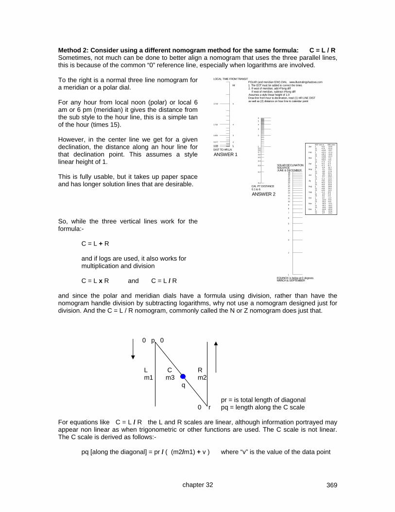
369
Method 2: Consider using a different nomogram method for the same formula: C = L / R Sometimes, not much can be done to better align a nomogram that uses the three parallel lines, this is because of the common “0” reference line, especially when logarithms are involved. To the right is a normal three line nomogram for a meridian or a polar dial. For any hour from local noon (polar) or local 6 am or 6 pm (meridian) it gives the distance from the sub style to the hour line, this is a simple tan of the hour (times 15). However, in the center line we get for a given declination, the distance along an hour line for that declination point. This assumes a style linear height of 1. This is fully usable, but it takes up paper space and has longer solution lines that are desirable. So, while the three vertical lines work for the formula:- C = L + R and if logs are used, it also works for multiplication and division C = L x R and C = L / R and since the polar and meridian dials have a formula using division, rather than have the nomogram handle division by subtracting logarithms, why not use a nomogram designed just for division. And the C = L / R nomogram, commonly called the N or Z nomogram does just that. 0 p 0 L C R m1 m3 m2 q pr = is total length of diagonal 0 r pq = length along the C scale For equations like C = L / R the L and R scales are linear, although information portrayed may appear non linear as when trigonometric or other functions are used. The C scale is not linear. The C scale is derived as follows:- pq [along the diagonal] = pr / ( (m2/m1) + v ) where “v” is the value of the data point
00.00010.268
20.577
31.000
41.732
53.732
LOCAL TIME FROM TRANSIT
DIST TO HR.LN
ANSWER 1
HrPOLAR (and meridian E/W) DIAL www.illustratingshadows.com1. The EOT must be added to correct the times2. If west of meridian, add 4*long diff If east of meridian, subtract 4*long diffAssumes a style linear height of 1.0Draw line from hour to declination, read (1) HR LINE DISTas well as (2) distance on hour line to calendar point
0.1
0.2
0.3
0.4
0.5
0.60.70.80.91
2
3
4
5
6
CAL PT DISTANCE0.1 to 6
ANSWER 2
1
2
3
4
5
6
7
8
9
10
11
12
131415161718192021222324
SOLAR DECLINATIONSOLSTICEJUNE & DECEMBER
EQUINOX is below at 0 degreesMARCH & SEPTEMBER
EOT mm.m DEC dd.dJan 1 +3.2 -22.8
11 +7.4 -21.621 +10.8 -19.7
Feb 1 +13.1 -17.311 +14.1 -14.421 +13.9 -11.0
Mar 1 +12.5 -7.411 +10.2 -3.621 +7.3 0.4
Apr 1 +4.1 4.311 +1.1 8.121 -1.4 11.7
May 1 -3.1 15.011 -3.8 17.821 -3.6 20.1
Jun 1 -2.5 21.911 -0.7 23.021 +1.4 23.4
Jly 1 +3.6 23.211 +5.3 22.421 +6.4 20.9
Aug 1 +6.6 18.811 +5.8 16.221 +3.9 13.1
Sep 1 +1.1 9.611 -2.3 5.921 -6.1 2.0
Oct 1 -9.7 -2.011 -12.9 -5.921 -15.2 -9.6
Nov 1 -16.3 -13.111 -16.1 -16.221 -14.6 -18.8
Dec 1 -11.8 -20.911 -8.1 -22.421 -3.7 -23.2
chapter 32

370
NOTE: the m2 and m1 are the scale multipliers, not the range of numbers, nor the tan or cos of a value. So for dist=tan(dec)/cos(hr) with dec=0 to 24, hr=0 to 6, neither the 24 nor 6 are used, nor the tan(24) nor cos(6 hours), but rather the scale multipliers if any. In the DeltaCAD macro the left scale was multiplied by 4, the right scale multiplied by 2, so m2/m1 would be 2/4 in this case. NOTE: the left side scales have 0 at their vertex, and the diagonal connects the 0 of both vertical scales. The 0 is for the value used in the formula. So if R were say cos(value), then that 0 would be cos(value) (i.e. represent 90 degrees) and not “value”.
Another point of interest. In using the three parallel vertical line nomogram, type 1, the declination began at 1. This was because the formula for the meridian or polar declination point on an hour line is:- calendar point on an hour line is = sh * tan ( dec ) / cos ( lha ) and because this has division, the three parallel line nomogram uses logs. And log for a declination 0 is unusable, so the declination had to start at 1. With the N or Z nomogram, logs are not used, so the declination can start at zero.
012345678910111213141516171819202122
23
24
SOLAR DECLINATIONSOLSTICEJUNE & DECEMBER
EQUINOXMARCH & SEPTEMBER
01.000 0.00010.966 0.268
20.866 0.577
30.707 1.000
40.500 1.732
50.259 3.732
60.000
HOURS FROM TRANSIT
DIST TO HR.LN
ANSWER 1
cos Hr tan
POLAR (and meridian E/W) DIAL www.illustratingshadows.com1. The EOT must be added to correct the times2. If west of meridian, add 4*long diff If east of meridian, subtract 4*long diffAssumes a style linear height of 1.0Draw line from hour to declination, read (1) HR LINE DISTas well as (2) distance on hour line to calendar point
0.0
0.1
0.2
0.3
0.4
0.50.6
0.70.80.91.0
2.0
DIST ALONG HR.LN
ANSWER 2
EOT mm.m DEC dd.dJan 1 +3.2 -22.8
11 +7.4 -21.621 +10.8 -19.7
Feb 1 +13.1 -17.311 +14.1 -14.421 +13.9 -11.0
Mar 1 +12.5 -7.411 +10.2 -3.621 +7.3 0.4
Apr 1 +4.1 4.311 +1.1 8.121 -1.4 11.7
May 1 -3.1 15.011 -3.8 17.821 -3.6 20.1
Jun 1 -2.5 21.911 -0.7 23.021 +1.4 23.4
Jly 1 +3.6 23.211 +5.3 22.421 +6.4 20.9
Aug 1 +6.6 18.811 +5.8 16.221 +3.9 13.1
Sep 1 +1.1 9.611 -2.3 5.921 -6.1 2.0
Oct 1 -9.7 -2.011 -12.9 -5.921 -15.2 -9.6
Nov 1 -16.3 -13.111 -16.1 -16.221 -14.6 -18.8
Dec 1 -11.8 -20.911 -8.1 -22.421 -3.7 -23.2
chapter 32

371
Method 3: Consider using a different nomogram method for the same formula: C = L x R A circular nomogram handles multiplication without logs, so using an h-dial as an example. tan(hla) = sin(lat) * tan(ha) this is the standard h-dial formula from xL the x value for the top HOUR ANGLE (HA is 0 to 90, and 1 hour is 15 degrees) circle is:- x = S / ( 1 + tan**2(ha) ) see: THE NOMOGRAM by Allcock and Jones from xL the x value for the lower LATITUDE circle is:- x = S / ( 1 + sin**2(lat) ) see: THE NOMOGRAM by Allcock and Jones from xL the x value for the horizontal HOUR LINE ANGLE line is:- x = S / ( 1 + tan(hla) ) note: not tan2 Developing a usable x and y for the circle: Having an "x" value along the horizontal line is nice, but how do we get a “y” value where a vertical line extended at "x" meets the circle’s perimeter. by definition, the scale "S" is the semi-circle's diameter so the radius is S/2, thus:- bigX = S/2 – x where bigX is the X from the semicircle center and where x is the value derived above S xL is the starting reference point for “x” for all “x” variables S/2 y xL 0 x S/2-x bigX from the semi circle's center we have an x value of "bigX", and we have the radius which is "S/2" thus by Pythagoras Theorem (S / 2) * (S / 2) = bigX * bigX + y * y now re-arrange the terms y * y = (S / 2) * (S / 2) – bigX * bigX but bigX = S/2 – x, so y = sqrt ( S * S/4 - bigX * bigX ) then y = sqrt ( S*S/4 - (S/2 - x)*(S/2 - x) ) then multiply parentheses y = sqrt ( S*S/4 - (S*S/4 - S*x/2 - x*S/2 + x*x) ) y = sqrt ( S*S/4 - (S*S/4 - 2*S*x/2 + x*x) ) y = sqrt ( S*S/4 - (S*S/4 - S*x + x*x) ) y = sqrt ( S*x - x*x) ) y = sqrt ( S*x - x*x ) final answer for “y” DeltaCAD and Lazarus have an h-dial using this method. Yes, nomograms still have life in them. Supplemental Shadows has additional information on nomograms.
chapter 32

372
The slide rule and the sun dial The sad reality is that the slide rule has become a way of the past. I still have two modern rules from my college days, my two wood and ivory ones having long since sprouted wings. Little is to be gained by pages of slide rule usage, however, the design of a horizontal dial with a slide rule may be of interest. Assume a latitude of 32.75 degrees (lat), and the sun’s local hour angle of 15 degrees (lha). The hour line angle (hla) formula is:- hla = atan( sin(lat) * tan (lha) ) On most slide rules the lower fixed part has the “X” scale first, then the “SIN” next, and the “TAN” below that. To the right, above 32.75 is found the SIN value of 0.54, and this number has to be remembered. Then the cursor is moved to above the tangent of the local hour angle for say 11 am or 1 pm, i.e. 15 degrees in this case, the right side of the lower picture. And the 10 (representing 1) is placed above the tan(15). see right side below. Then go to the remembered sin of the latitude of 32.75, namely 0.54, upper left below, and look down to the “TAN” scale which is by definition now acting as ATAN, showing 8.25 degrees.
And a spreadsheet confirms the result with 8.2478 degrees to the slide rule’s 8.25. The process is repeated with other hours and with longitude correction.
latitude radians32.75 0.5716 0.5410 sin(lat)
15 0.2618 0.2679 tan(lha)atan(sin(lat)*tan(lha) 0.1440degrees is 8.2478
hour angle is 8.25˚ NOTE: divisions are 1/6 and not 1/10 on trigonometric scales.
chapter 32

373
The Dialing Scales and the sun dial latitude scale
hour scale Frank Cousins popularized the scales made by E. C. Middleton which were based on Samuel Foster's work in 1638, made practical by George Serle in 1657. These scales may be used to design vertical, horizontal, polar, meridian, and declining dials. Horizontal dial design A dial plate is drawn with the 6 am/pm and noon line, establishing a dial center. The latitude scale is placed with 0 degrees latitude at dial center, and the new dial's latitude marked along the 6 am line, latitude 40 in this case, and copied an equal distance on the other half of the dial, 6 pm. future gnomon The hour scale is placed with the 6 am point on the 6 am line where the latitude was marked, and the noon point on the noon line, or the 6 pm point may be placed on the 6 pm line with the noon point on the noon line. Hour lines are drawn from dial center to the hour point on the hour scale. Vertical dial design A vertical dial is drawn using the co-latitude. The hour line angles of a horizontal dial match the angles for a vertical dial at the co-latitude, and vice versa. Thus, proceed as above, however in place of latitude, use 90-latitude. Of course, the co-latitude is the angle between the style and the sub-style. Polar and Meridian (true east or true west) dial design
lat 40
1 pm
am hours
If the latitude scales were unfolded to be two sides of a triangle, the time scale being the third, then the hour marks would each be 15 degrees from where the two latitude scales meet. In this case a simple protractor may be easier!
12 1 2 3 4
latitude scales hour scale hours
1 pm
chapter 32
6pm
noon pm hours

374
These are not drawn to scale, and displayed figures may not match calculated figures, this is so the flow of logic will be more easily followed.
the gnomon will be to the west for a wall declining east and vice versa
looking face on at the dial
Vertical decliner design A vertical decliner has the gnomon rotated by an amount called the style-distance based on the latitude and wall declination. Assume a latitude 30 dial with 10 degrees east wall declination. Style Distance: SD = atan( sin(dec) / tan(lat) ) – 16.7 Style Height: style and sub style angle is: SH = asin( cos(lat) * cos(dec) ) + 58.5 Having calculated the style height (SH) and style distance (SD), draw a dial plate for the vertical decliner as shown below, the dashed line being angled from the vertical noon line by SD. At 90 degrees to that, draw another line as shown. [See Tables A5.1, A5.2 and formulae A8.22, A8.23.] SD is 16.7
Using the two dashed lines, pretend they are noon and the 6 am and 6 pm lines (which they are not). But in so pretending, use the dialing scales as for the vertical dial design, except use SH instead of the co-latitude (SH is the co-latitude when the wall declination is zero). The dialing scales create construction points. Then use the hours scale and draw the two edges as shown below. Note that the latitude used is the Style Height (SH). SH is the co-latitude if the wall declination was zero. Note where the real noon or vertical line intercepts the hours scale, and note the time difference from noon. These pictorials are not drawn to scale. Below, the real noon is at 1:15 from the "lets pretend" noon based on SD, style distance.
The pretend noon on the extended sub-style line
The real noon intercepts the clock scale at about 1:15pm in this pictorial. This is not drawn to scale so 1:15 may not be correct for the specified latitude and wall declination.
chapter 32
+ 58.5 i.e. SH

375
Again, assuming that the 1:15 time on the clock scale represents the real noon, then 2:15 on the clock scale will represent 1 pm, 3:15 on the clock scale represents 2 pm, and so on, at least on that side of the scale. However, on the other side of noon, backing off one hour places 11 am (real) at 12:15 on the dialing scale. So 10:00 am would be at the 11:15 on the dialing scale, 9 am real would be at 10:15 on the dialing scale, and so on. This shows the symmetry of a declining dial around the extended sub-style.
1 pm
2 pm
noon 11 am
the real and final hour lines
chapter 32

376
CHAPTER THIRTY THREE
EXTRA THINGS
SHADOW DEFINITIONS The shadow cast by a gnomon to a dial plate may be sharp or ill defined.
gd=diameter Full light Pen-umbra Full shadow
If the ratio of the gnomon diameter (gd) to the distance of the gnomon from the dial plate (pd) is less than 0.01 then the shadow will be almost unusable, and if the ratio is better than 0.04 then the shadow will be well defined. A plate as opposed to a rod has the benefit of increasing the size of the full shadow which in turn avoids two penumbras approaching and thus making shadow lines less fuzzy. ERRORS IN SUN DIALING Just as shadow fuzziness can generate errors, so can other factors. The spreadsheet integer (INT) function rounds down, thus -5.7 becomes -6 whereas 5.7 becomes 5. A dial plate not level introduces errors that may be quite substantial, and North south alignment errors, especially on a vertical dial can be significant. Altitude dials whose gnomon length is used (Shepherd but not Capuchin) may introduce errors. The number of significant digits of a result can be significant, 1 digit versus 2 digits can have a significant effect on a result. Any formula that is an approximation or series (EOT, Declination), and data derived from them (azimuth, altitude) can produce differing results, aggravated by leap year and other approximations. Hence why different authors have different tabular data. This book uses two differing algorithms and thus may seem self inconsistent! SOME FIGURES OF THE UNIVERSE AND SOLAR SYSTEM The Earth is tilted from its orbit by 23.5 degrees, and wobbles around with a cycle of 25,800 years, which as a result cycles through a different constellation about every 2150 years. The moon and the sun both have a diameter of about 0.5 degrees from the Earth. The moon's orbit around the Earth is actually offset by about 5 degrees from the ecliptic which is the plane of the Earth's orbit around the sun and is discussed more thoroughly in chapter 27. The Earth's polar axis is offset by about 23.5 degrees from its orbit around the sun.
pd=gnomon to dial plate
chapter 33

377
IMPORTANT DATES FOR THE DIALIST, and thus a few rules of thumb:- February 11th EOT max: sun is slow and the EOT is +14 minutes 12 seconds March 21 vernal equinox April 15 EOT = 0 May 13th and 14th an EOT peak: sun is fast, so the EOT is –3 minutes 39 seconds June 15 EOT = 0 (some use June 14) June 21 summer solstice July 25th and 26th an EOT peak: sun is slow with an EOT of +6 minutes 30 seconds. September 1 EOT = 0 September 23 autumnal equinox (some use September 21 by convention) early November EOT max: sun is fast and the EOT is then – 16 minutes 22 seconds December 21 winter solstice (some use December 22) December 25 EOT = 0 (some use December 24) The use of the 21st for the solstices and equinoxes is often used as an approximation, and easy to remember. However the actual date may vary based on the year, leap year, and so on. In the year 1246 the EOT smaller deviations were both 4 minutes 58 seconds, and the maxima were both 15 minutes 39 seconds. The February minimum is shrinking about 12 seconds a century, the May maximum is shrinking by about 9 seconds a century, the July minimum is growing about 13 seconds a century, and the November maximum is growing by about 5 seconds a century. LIMITING, UNUSABLE AND USABLE HOURS ON A DIAL PLATE
There are limiting or unusable hours, so when designing a sundial there is no point in marking up lines that can't be used. If the dial is large then time and materials are wasted as is real estate on the dial plate because the shadow of the style or nodus will never touch those unusable hours or calendar information. For all dials, it is better to eliminate unusable space and increase the size of the remaining hour lines and calendar information, thereby increasing their accuracy. Displayable hours depend on latitude and dial type. For example, on the equator every day is an equinox thus the most a dial can display is 6 am to 6 pm local apparent time (L.A.T.). At the poles, night lasts months, day last months, or somewhere in between. Thus a horizontal dial can display 24 hours. Software with shadow simulators can help visualization of usable shadow, one such example is SHADOWS, a software program sometimes used by the author but not affiliated with this book. Alternatively, chapter 30 has a CAD solar-travel mesh that can help visualize hours of use. In summary form, with times being local apparent time, the rules of thumb are:- Armillary can display from sunrise to sunset, however, an armillary Equatorial dial plate can interfere with itself near the equinox, and Horizontal equatorial dials may indicate nothing at the equinox Ceiling no early or late hours, no summer hours at low latitudes Vertical facing the equator 6 am to 6 pm Vertical facing the pole 6 pm to 6 am but not after the latest sunset nor before the earliest sunrise Vertical decliner 12 hours maximum not hours above the horizontal line for the nodus roughly one hour shift for each 15 degrees of wall declination Recliners requires deep thought Meridian east facing – sunrise to noon, west facing – noon to sunset Polar dials 6 am to 6 pm, unless you also use the underneath part. Astrolabe, Shepherd, Capuchin, Ogee, and other altitude dials: sunrise to sunset
chapter 33
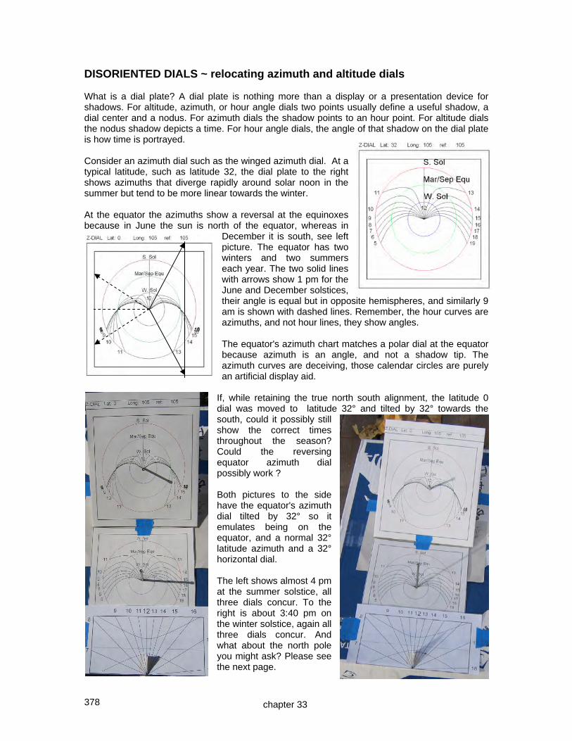
378
DISORIENTED DIALS ~ relocating azimuth and altitude dials What is a dial plate? A dial plate is nothing more than a display or a presentation device for shadows. For altitude, azimuth, or hour angle dials two points usually define a useful shadow, a dial center and a nodus. For azimuth dials the shadow points to an hour point. For altitude dials the nodus shadow depicts a time. For hour angle dials, the angle of that shadow on the dial plate is how time is portrayed. Consider an azimuth dial such as the winged azimuth dial. At a typical latitude, such as latitude 32, the dial plate to the right shows azimuths that diverge rapidly around solar noon in the summer but tend to be more linear towards the winter. At the equator the azimuths show a reversal at the equinoxes because in June the sun is north of the equator, whereas in
December it is south, see left picture. The equator has two winters and two summers each year. The two solid lines with arrows show 1 pm for the June and December solstices, their angle is equal but in opposite hemispheres, and similarly 9 am is shown with dashed lines. Remember, the hour curves are azimuths, and not hour lines, they show angles. The equator's azimuth chart matches a polar dial at the equator because azimuth is an angle, and not a shadow tip. The azimuth curves are deceiving, those calendar circles are purely an artificial display aid.
If, while retaining the true north south alignment, the latitude 0 dial was moved to latitude 32° and tilted by 32° towards the south, could it possibly still show the correct times throughout the season? Could the reversing equator azimuth dial possibly work ? Both pictures to the side have the equator's azimuth dial tilted by 32° so it emulates being on the equator, and a normal 32° latitude azimuth and a 32° horizontal dial. The left shows almost 4 pm at the summer solstice, all three dials concur. To the right is about 3:40 pm on the winter solstice, again all three dials concur. And what about the north pole you might ask? Please see the next page.
chapter 33

379
At the north pole, the azimuth chart becomes an equatorial dial, a set of 15 degree arcs. The azimuth and hour angle all clearly relate because when indicated on a dial plate, the dial plate is merely a display screen to hold an image of the sun on a gnomon, nodus, or style. Clearly the pole's azimuth dial, being an equatorial dial, works at all latitudes! So an azimuth dial can be tilted to work at a new latitude, however that tilt must be in the north south direction. This is why the azimuth can be used for a declining dial. A declining dial simulates a dial at another latitude, and that latitude is the style height or SH.
Think a little further out, about 93 million miles, for that is where the sun is in relation to Earth. And put a dial somewhere on planet Earth, It shows a time. Remove planet Earth, and the dial still works as it has no knowledge of latitude or longitude. What it does have is a set of angles defining its orientation to the sun. Take this a stage further, latitude does not really mean latitude, but rather an angle, or rather a co-angle, from a rod in space that happens to be parallel to the Earth's polar axis.
Azimuth dials can be ported from one latitude to another, the requirement is that they be tilted, and that the tilt be towards or from the north south line. There is some discussion that this is not true, so what cannot be tilted and why? The Italian and Babylonian hour lines, or any line depicting the sunrise or sun set, cannot be corrected by tilting. The reason is that in their case, latitude does not just mean an orientation in space but it also means its position with respect to the horizon and location from whence the sun will rise or set. Sunrise and sunset related lines are fiercely latitude dependant because they depend on the spherical geometry, or horizon circle, to determine whether the sun is or is not visible. In conclusion, an azimuth dial can be latitude corrected provided the tilt to correct it is towards the north or south. If an hour angle dial and an azimuth dial can be tilted for latitude correction, what about an altitude dial?
chapter 33

380
For any given day at the pole, the sun's altitude does not vary by more than half a degree.
What would happen if such a dial were moved south from the north pole to another latitude. One extreme would be to the equator where it would be on its side. You would set the gnomon to the month as usual,
and rotate the cylinder until the shadow paralleled the rotation axis of this horizontal dial, as usual. And the nodus shadow would always be on that month's part of the curve. Regardless of the time, on any given day of the year on the equator the sun has a fixed altitude compared to a north south line. The sun is moving in a cone around that horizontal north south line. Let us take another extreme, an altitude dial for the equator and move it somewhere else. To the right is an altitude chart for the equator, it shows some interesting things. In March and September the sun's altitude goes to 90 degrees, they have two summers there. And in December and June the sun is at its lowest, they have two winters there. This is because the sun moves from –23.5 to the +23.5 declination. If this dial were moved to another latitude, such as latitude 32, how could it possibly work. The answer is that it must be titled, and like the azimuth and hour angle dial it must be tilted towards the true south or true north. And that north/south alignment now removes the key benefit of an altitude dial, namely, no compass needed. Failure to do that alignment will cause the dial to be in error, and hence the belief that altitude dials cannot be latitude corrected by tilting. So at latitude 32 this dial would tilt to the south by 32 degrees. And it must is turned around its own rotational axis, and while being so turned it retains a fixed tilt to the south of 32 degrees. This dial still works! For the summer at latitude 32, the sun will be orbiting in a cone whose center is this dial and the shadows will only appear on its upper side. For the winter the reverse is true. Just as for an equatorial dial. And taking another extreme, that same dial at the north pole would be horizontal. And yet it would still work! It works because the horizontal shepherds dial when rotated on its now horizontal axis will be using the north pole's azimuth of the sun to generate an equivalent equatorial altitude. You might think that this fails for the winter when there is no sun, but no, the Earth itself is blocking the sun, but those altitudes still exist were the Earth to vanish, it is the Earth's curvature causing that sun blocking. Do not confuse azimuth and altitude with sunrise and sunset and the Italian Babylonian times which are not thusly portable. In summary, all this is why a declining dial's calendar lines can use another latitude's altitude and azimuth.
altitude is constant during any one day
chapter 33

381
THE APPENDICES
The full appendices are located in the appendix supplement to: Illustrating Time's Shadow available on: http://www.illustratingshadows.com however critical selections of key information follow
Appendix 1 Geometry and trigonometry Trigonometric functions and geometrical rules and circular measures Tables of trig values – sin, cos, and tan Appendix 2 Tables independent of latitude or longitude Julian day Declination of the sun by the day The equation of time, generic and astronomical, and century comparisons Sun's apparent hour angle, and standard time to hour angle Longitude to time Aids to locating north, compass correction and astro compass, noon transit time Latitude, Longitude, Magnetic declination information Appendix 3 Location dependant ~ miscellaneous dial hour line data Hour line angles for horizontal and vertical dials latitude 30 to 60 Reflecting or ceiling dial information. Polar and Meridian dial tables because they are not latitude dependant Equatorial calendar line radii and sunset line distance data Appendix 4 Location dependant ~ Tables of altitude, azimuth, and calendar data Table for analemmatic dials – angle to hour point, and analemma Tables for calendar lines for flat dials lat 0-65, declinations 23.5, 0, -23.5 Conversion of style linear length and linear height for several latitudes Appendix 5 Location dependant ~ Vertical decliners, and miscellaneous useful data Mostly south facing decliner hour line angles and SD and SH Mostly east or west facing great decliner hour line angles Tables for the great decliner (vertical), east/west gnomon adjustment Appendix 6 Sunrises and sunsets ~ for some longitudes and latitudes. Several ways of finding sunrise and sunset. Sunrise, sunset, day-length for Italian and Babylonian etc lines - many latitudes Appendix 7 Proofs and derivations ~ Geometric, trigonometric, and etc Durer geometrical model for many hour angle dials Vertical decliner hour lines, SD and SH, calendar curves, and DL Altitude/azimuth pole determination, reflecting dials Derivation of the planispheric astrolabe geometrically and trigonometrically Southern hemisphere considerations, Appendix 8 Formulae Constants and variables Spreadsheet formulae issues Actual and apparent inconsistencies in the three "classic books" on sundials Appendix 9 Templates ~ for various dial construction methods Paper cut out dials Paper popup dials Appendix 10 Bibliography ~ and cross references Books, software, other references, sundial parts, sundial numerals often used Miscellaneous dates, Limiting hours by dial type Trivia, Safety tips
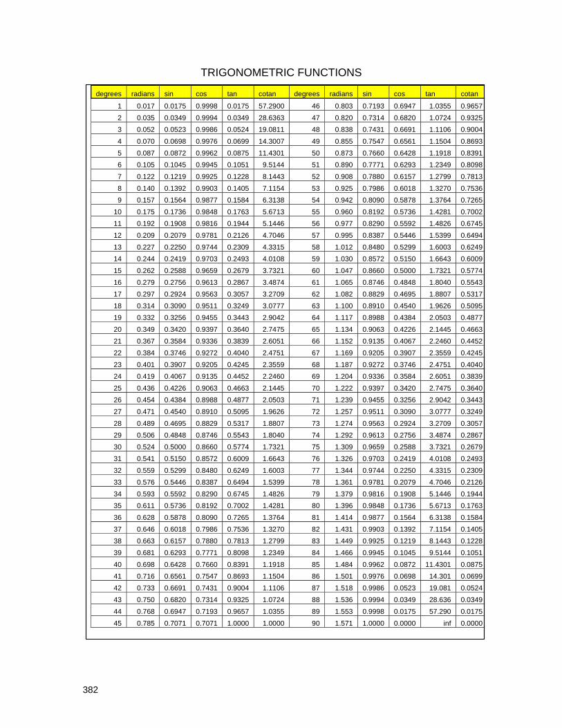
382
TRIGONOMETRIC FUNCTIONS
degrees radians sin cos tan cotan degrees radians sin cos tan cotan
1 0.017 0.0175 0.9998 0.0175 57.2900 46 0.803 0.7193 0.6947 1.0355 0.9657
2 0.035 0.0349 0.9994 0.0349 28.6363 47 0.820 0.7314 0.6820 1.0724 0.9325
3 0.052 0.0523 0.9986 0.0524 19.0811 48 0.838 0.7431 0.6691 1.1106 0.9004
4 0.070 0.0698 0.9976 0.0699 14.3007 49 0.855 0.7547 0.6561 1.1504 0.8693
5 0.087 0.0872 0.9962 0.0875 11.4301 50 0.873 0.7660 0.6428 1.1918 0.8391
6 0.105 0.1045 0.9945 0.1051 9.5144 51 0.890 0.7771 0.6293 1.2349 0.8098
7 0.122 0.1219 0.9925 0.1228 8.1443 52 0.908 0.7880 0.6157 1.2799 0.7813
8 0.140 0.1392 0.9903 0.1405 7.1154 53 0.925 0.7986 0.6018 1.3270 0.7536
9 0.157 0.1564 0.9877 0.1584 6.3138 54 0.942 0.8090 0.5878 1.3764 0.7265
10 0.175 0.1736 0.9848 0.1763 5.6713 55 0.960 0.8192 0.5736 1.4281 0.7002
11 0.192 0.1908 0.9816 0.1944 5.1446 56 0.977 0.8290 0.5592 1.4826 0.6745
12 0.209 0.2079 0.9781 0.2126 4.7046 57 0.995 0.8387 0.5446 1.5399 0.6494
13 0.227 0.2250 0.9744 0.2309 4.3315 58 1.012 0.8480 0.5299 1.6003 0.6249
14 0.244 0.2419 0.9703 0.2493 4.0108 59 1.030 0.8572 0.5150 1.6643 0.6009
15 0.262 0.2588 0.9659 0.2679 3.7321 60 1.047 0.8660 0.5000 1.7321 0.5774
16 0.279 0.2756 0.9613 0.2867 3.4874 61 1.065 0.8746 0.4848 1.8040 0.5543
17 0.297 0.2924 0.9563 0.3057 3.2709 62 1.082 0.8829 0.4695 1.8807 0.5317
18 0.314 0.3090 0.9511 0.3249 3.0777 63 1.100 0.8910 0.4540 1.9626 0.5095
19 0.332 0.3256 0.9455 0.3443 2.9042 64 1.117 0.8988 0.4384 2.0503 0.4877
20 0.349 0.3420 0.9397 0.3640 2.7475 65 1.134 0.9063 0.4226 2.1445 0.4663
21 0.367 0.3584 0.9336 0.3839 2.6051 66 1.152 0.9135 0.4067 2.2460 0.4452
22 0.384 0.3746 0.9272 0.4040 2.4751 67 1.169 0.9205 0.3907 2.3559 0.4245
23 0.401 0.3907 0.9205 0.4245 2.3559 68 1.187 0.9272 0.3746 2.4751 0.4040
24 0.419 0.4067 0.9135 0.4452 2.2460 69 1.204 0.9336 0.3584 2.6051 0.3839
25 0.436 0.4226 0.9063 0.4663 2.1445 70 1.222 0.9397 0.3420 2.7475 0.3640
26 0.454 0.4384 0.8988 0.4877 2.0503 71 1.239 0.9455 0.3256 2.9042 0.3443
27 0.471 0.4540 0.8910 0.5095 1.9626 72 1.257 0.9511 0.3090 3.0777 0.3249
28 0.489 0.4695 0.8829 0.5317 1.8807 73 1.274 0.9563 0.2924 3.2709 0.3057
29 0.506 0.4848 0.8746 0.5543 1.8040 74 1.292 0.9613 0.2756 3.4874 0.2867
30 0.524 0.5000 0.8660 0.5774 1.7321 75 1.309 0.9659 0.2588 3.7321 0.2679
31 0.541 0.5150 0.8572 0.6009 1.6643 76 1.326 0.9703 0.2419 4.0108 0.2493
32 0.559 0.5299 0.8480 0.6249 1.6003 77 1.344 0.9744 0.2250 4.3315 0.2309
33 0.576 0.5446 0.8387 0.6494 1.5399 78 1.361 0.9781 0.2079 4.7046 0.2126
34 0.593 0.5592 0.8290 0.6745 1.4826 79 1.379 0.9816 0.1908 5.1446 0.1944
35 0.611 0.5736 0.8192 0.7002 1.4281 80 1.396 0.9848 0.1736 5.6713 0.1763
36 0.628 0.5878 0.8090 0.7265 1.3764 81 1.414 0.9877 0.1564 6.3138 0.1584
37 0.646 0.6018 0.7986 0.7536 1.3270 82 1.431 0.9903 0.1392 7.1154 0.1405
38 0.663 0.6157 0.7880 0.7813 1.2799 83 1.449 0.9925 0.1219 8.1443 0.1228
39 0.681 0.6293 0.7771 0.8098 1.2349 84 1.466 0.9945 0.1045 9.5144 0.1051
40 0.698 0.6428 0.7660 0.8391 1.1918 85 1.484 0.9962 0.0872 11.4301 0.0875
41 0.716 0.6561 0.7547 0.8693 1.1504 86 1.501 0.9976 0.0698 14.301 0.0699
42 0.733 0.6691 0.7431 0.9004 1.1106 87 1.518 0.9986 0.0523 19.081 0.0524
43 0.750 0.6820 0.7314 0.9325 1.0724 88 1.536 0.9994 0.0349 28.636 0.0349
44 0.768 0.6947 0.7193 0.9657 1.0355 89 1.553 0.9998 0.0175 57.290 0.0175
45 0.785 0.7071 0.7071 1.0000 1.0000 90 1.571 1.0000 0.0000 inf 0.0000

383
from appendix 2
Different declination charts may disagree, factors affecting them would be leap year approximations, and the formula employed. Many formulae are approximations.
Jan Feb Mar Apr May Jun Jly Aug Sep Oct Nov Dec
1 -23.1 -17.3 -7.9 4.2 14.8 21.9 23.2 18.2 8.6 -2.9 -14.2 -21.7
2 -23.0 -17.1 -7.5 4.6 15.1 22.1 23.1 18.0 8.2 -3.3 -14.5 -21.8
3 -22.9 -16.8 -7.1 5.0 15.4 22.2 23.0 17.7 7.8 -3.6 -14.8 -22.0
4 -22.8 -16.5 -6.7 5.4 15.7 22.3 23.0 17.5 7.5 -4.0 -15.1 -22.1
5 -22.7 -16.2 -6.3 5.8 16.0 22.5 22.9 17.2 7.1 -4.4 -15.5 -22.3
6 -22.6 -15.9 -6.0 6.2 16.3 22.6 22.8 16.9 6.7 -4.8 -15.8 -22.4
7 -22.5 -15.6 -5.6 6.5 16.6 22.7 22.7 16.6 6.4 -5.2 -16.1 -22.5
8 -22.3 -15.3 -5.2 6.9 16.9 22.8 22.6 16.4 6.0 -5.6 -16.4 -22.6
9 -22.2 -14.9 -4.8 7.3 17.1 22.9 22.5 16.1 5.6 -6.0 -16.7 -22.7
10 -22.1 -14.6 -4.4 7.7 17.4 23.0 22.4 15.8 5.2 -6.3 -16.9 -22.8
11 -21.9 -14.3 -4.0 8.0 17.7 23.0 22.2 15.5 4.9 -6.7 -17.2 -22.9
12 -21.8 -14.0 -3.6 8.4 17.9 23.1 22.1 15.2 4.5 -7.1 -17.5 -23.0
13 -21.6 -13.6 -3.2 8.8 18.2 23.2 22.0 14.9 4.1 -7.5 -17.8 -23.1
14 -21.4 -13.3 -2.8 9.1 18.4 23.2 21.8 14.6 3.7 -7.8 -18.0 -23.2
15 -21.3 -13.0 -2.4 9.5 18.7 23.3 21.7 14.3 3.3 -8.2 -18.3 -23.2
16 -21.1 -12.6 -2.0 9.8 18.9 23.3 21.5 14.0 3.0 -8.6 -18.6 -23.3
17 -20.9 -12.3 -1.6 10.2 19.1 23.4 21.3 13.7 2.6 -9.0 -18.8 -23.3
18 -20.7 -11.9 -1.3 10.5 19.4 23.4 21.2 13.4 2.2 -9.3 -19.1 -23.4
19 -20.5 -11.6 -0.9 10.9 19.6 23.4 21.0 13.0 1.8 -9.7 -19.3 -23.4
20 -20.3 -11.2 -0.5 11.2 19.8 23.4 20.8 12.7 1.4 -10.1 -19.5 -23.4
21 -20.1 -10.8 -0.1 11.6 20.0 23.5 20.6 12.4 1.0 -10.4 -19.8 -23.4
22 -19.9 -10.5 0.3 11.9 20.2 23.5 20.4 12.0 0.6 -10.8 -20.0 -23.4
23 -19.6 -10.1 0.7 12.3 20.4 23.5 20.2 11.7 0.2 -11.1 -20.2 -23.4
24 -19.4 -9.7 1.1 12.6 20.6 23.4 20.0 11.4 -0.1 -11.5 -20.4 -23.4
25 -19.2 -9.4 1.5 12.9 20.8 23.4 19.8 11.0 -0.5 -11.8 -20.6 -23.4
26 -18.9 -9.0 1.9 13.3 21.0 23.4 19.6 10.7 -0.9 -12.2 -20.8 -23.4
27 -18.7 -8.6 2.3 13.6 21.2 23.4 19.4 10.3 -1.3 -12.5 -21.0 -23.3
28 -18.4 -8.3 2.7 13.9 21.3 23.3 19.2 10.0 -1.7 -12.9 -21.2 -23.3
29 -18.2 3.1 14.2 21.5 23.3 18.9 9.6 -2.1 -13.2 -21.4 -23.3
30 -17.9 3.5 14.5 21.7 23.2 18.7 9.3 -2.5 -13.5 -21.5 -23.2
31 -17.6 3.9 21.8 18.5 8.9 -13.9 -23.1
SUN'S DECLINATION

384
from appendix 2
EQUATION OF TIME TABLE EOT minutes:seconds
Jan Feb Mar Apr May Jun Jul Aug Sep Oct Nov Dec
1 3:09 13:34 12:17 3:49 -2:54 -2:09 3:51 6:17 0:02 -10:21 -16:21 -10:52
2 4:07 13:42 12:05 3:32 -3:01 -1:59 4:03 6:13 -0:22 -10:40 -16:22 -10:29
3 4:34 13:48 11:52 3:14 -3:07 -1:50 4:14 6:08 -0:41 -10:59 -16:22 -10:06
4 5:02 13:54 11:39 2:57 -3:13 -1:39 4:25 6:03 -1:01 -11:17 -16:22 -9:42
5 5:28 13:59 11:26 2:39 -3:18 -1:29 4:35 5:57 -1:21 -11:35 -16:20 -9:17
6 5:55 14:03 11:12 2:22 -3:23 -1:18 4:45 5:51 -1:41 -11:53 -16:18 -8:52
7 6:21 14:06 10:58 2:06 -3:27 -1:07 4:55 5:43 -2:01 -12:10 -16:15 -8:27
8 6:46 14:09 10:43 1:49 -3:30 -0:56 5:04 5:36 -2:22 -12:27 -16:11 -8:00
9 7:11 14:10 10:28 1:33 -3:33 -0:44 5:13 5:27 -2:43 -12:43 -16:06 -7:34
10 7:35 14:11 10:13 1:16 -3:35 -0:32 5:22 5:19 -3:03 -12:59 -16:00 -7:07
11 7:59 14:12 9:57 1:01 -3:37 -0:20 5:30 5:09 -3:24 -13:15 -15:54 -6:39
12 8:22 14:11 9:42 0:45 -3:38 -0:08 5:37 4:59 -3:46 -13:30 -15:46 -6:11
13 8:44 14:10 9:25 0:30 -3:39 0:04 5:44 4:48 -4:07 -13:44 -15:38 -5:43
14 9:06 14:08 9:09 0:15 -3:39 0:16 5:51 4:37 -4:28 -13:58 -15:29 -5:15
15 9:27 14:05 8:52 0:00 -3:38 0:29 5:57 4:26 -4:49 -14:12 -15:19 -4:46
16 9:48 14:01 8:35 -0:13 -3:37 0:42 6:03 4:13 -5:11 -14:25 -15:09 -4:17
17 10:08 13:57 8:18 -0:27 -3:36 0:55 6:08 4:01 -5:32 -14:37 -14:57 -3:48
18 10:27 13:52 8:01 -0:40 -3:34 1:08 6:13 3:48 -5:53 -14:49 -14:45 -3:19
19 10:45 13:47 7:43 -0:53 -3:31 1:21 6:17 3:34 -6:15 -15:00 -14:31 -2:49
20 11:03 13:40 7:25 -1:06 -3:27 1:34 6:20 3:20 -6:36 -15:10 -14:17 -2:19
21 11:20 13:33 7:08 -1:18 -3:24 1:47 6:23 3:05 -6:57 -15:20 -14:02 -1:50
22 11:36 13:26 6:50 -1:30 -3:19 2:00 6:26 2:50 -7:18 -15:29 -13:47 -1:20
23 11:52 13:18 6:32 -1:41 -3:14 2:13 6:28 2:34 -7:39 -15:38 -13:30 -0:50
24 12:06 13:09 6:14 -1:52 -3:09 2:26 6:29 2:18 -8:00 -15:46 -13:13 -0:20
25 12:20 13:00 5:56 -2:03 -3:03 2:39 6:30 2:02 -8:21 -15:53 -12:55 0:08
26 12:33 12:50 5:37 -2:12 -2:57 2:51 6:30 1:45 -8:41 -15:59 -12:36 0:38
27 12:45 12:39 5:19 -2:22 -2:50 3:04 6:29 1:28 -9:02 -16:05 -12:17 1:07
28 12:57 12:28 5:01 -2:31 -2:43 3:16 6:28 1:10 -9:22 -16:09 -11:57 1:37
29 13:07
4:43 -2:39 -2:35 3:28 6:26 0:52 -9:42 -16:14 -11:36 2:06
30 13:17 4:25 -2:47 -2:27 3:40 6:24 0:34 -10:01 -16:17 -11:14 2:35
31 12:26 4:07 -2:18 6:21 0:16 -16:19 3:03
EQUATION OF TIME

385
80
70
60
50
40
302010
Latitude
V-dial10
20
30
40
50
607080
H-dial
11.00 01.00
10.00 02.00
09.00 03.00
08.00 04.00
07.00 05.00
Hour around noon
AM PM
10
20
30
40
50
60
70
80
Dial Plate's hour line angle
Horizontal and Vertical dial platewww .illustratingshadow s.com
latitude is log(sin(lat)) so scale decreases vertically
longitude is log(tan(lng)) so scale decreases first then increases
hour line angle is log(tan(hla)) so scale decreases first then increases
First, mark latitude on the left vertical lineNext, mark the desired time on the right vertical lineThen, read hour line angle on the center vertical line
Use the h-dial line for both v and h dial marking
HORIZONTAL and VERTICAL HOUR LINE ANGLES from appendix 3

386
ITALIAN AND BABYLONIAN HOUR LINES from appendix 6
Babylonian and Italian values by latitude. Times are hh.mm Local Apparent Time Solstice Sunrise and Sunset (equinox is 6am/pm). No longitude correction. No EOT correction. Winter solstice: Declination: -23.5
Summer solstice: Declination: +23.5
latitude Rise Set Day length hrs latitude Rise Set Day length hrs 30 6.58 17.02 10.04 30 5.01 18.59 13.58
31 7.00 17.00 10.00 31 4.59 19.01 14.02
32 7.03 16.57 9.54 32 4.56 19.04 14.08
33 7.05 16.55 9.50 33 4.54 19.06 14.12
34 7.08 16.52 9.44 34 4.51 19.09 14.18
35 7.10 16.50 9.40 35 4.49 19.11 14.22
36 7.13 16.47 9.34 36 4.46 19.14 14.28
37 7.16 16.44 9.28 37 4.43 19.17 14.34
38 7.19 16.41 9.22 38 4.40 19.20 14.40
39 7.22 16.38 9.16 39 4.37 19.23 14.46
40 7.25 16.35 9.10 40 4.34 19.26 14.52
41 7.28 16.32 9.04 41 4.31 19.29 14.58
42 7.32 16.28 8.56 42 4.27 19.33 15.06
43 7.35 16.25 8.50 43 4.24 19.36 15.12
44 7.39 16.21 8.42 44 4.20 19.40 15.20
45 7.43 16.17 8.34 45 4.16 19.44 15.28
46 7.47 16.13 8.26 46 4.12 19.48 15.36
47 7.51 16.09 8.18 47 4.08 19.52 15.44
48 7.55 16.05 8.10 48 4.04 19.56 15.52
49 8.00 16.00 8.00 49 3.59 20.01 16.02
50 8.04 15.56 7.52 50 3.55 20.05 16.10
51 8.09 15.51 7.42 51 3.50 20.10 16.20
52 8.15 15.45 7.30 52 3.44 20.16 16.32
53 8.20 15.40 7.20 53 3.39 20.21 16.42
54 8.27 15.33 7.06 54 3.32 20.28 16.56
55 8.33 15.27 6.54 55 3.26 20.34 17.08
56 8.40 15.20 6.40 56 3.19 20.41 17.22
57 8.48 15.12 6.24 57 3.11 20.49 17.38
58 8.56 15.04 6.08 58 3.03 20.57 17.54
59 9.05 14.55 5.50 59 2.54 21.06 18.12
60 9.15 14.45 5.30 60 2.44 21.16 18.32
Sunset (true time or local apparent time) occurs the same number of hours after noon that sunrise happens before. An 0605 sunrise is 5 hours 55 minutes before noon, thus sunset is 5 hours 55 minutes after it, or 1755. Except for on the hour or half hour, the minutes do not match. For standard time, then the time is shifted by the longitude correction and then by the equation of time, thus the March and September equinoxes do not match due to differing EOT values. Italian hour lines are commonly used to indicate the number of hours until sunset. For Italian hour lines, exclude the EOT. And exclude the longitude correction unless the dial already has considered longitude in its design. The spreadsheets on the web site allow you to do this, and of course, the above table provides all the data needed for Italian and Babylonian lines. The equinox is not shown since true sunrise and sunset occurs at 6am and 6pm L.A.T..

387
COLLECTION OF FORMULAE
COMMON ABBREVIATIONS ARE:- The sun's declination is "dec", the latitude is “lat”, the sun’s local hour angle is “lha” being 15 times the hour from noon (or 6 am or 6pm for meridian dials), and “hla” is the hour line angle on a dial, “sh” is style height usually angular, “sd” is style distance. SUNS DECLINATION FOR ANY GIVEN DAY OF THE YEAR Source: http://eande.lbl.gov/Task21/C2/algo1/1-11.html Day number, J J=1 on January 1, 365 on 31 December, February has 28 days, “pi” is 3.14159 Jan Feb Mar Apr May Jun 0 31 59 90 120 151 Jly Aug Sep Oct Nov Dec
181 212 243 273 304 334 Day angle: da = 2 * pi * ( j - 1 ) / 365 (is an intermediate figure in radians) Sun Declination: dec = degrees (0.006918 – 0.399912*cos(da) + 0.070257*sin(da) – 0.006758*cos(2*da) + 0.000907*sin(2*da) – 0.002697*cos(3*da) + 0.001480*sin(3*da) alternative formula: dec = (23.45*sin( (0.9678( j-80 )))) source: Claude Hartman SUNS ALTITUDE AND AZIMUTH ON ANY GIVEN HOUR GIVEN THE SUNS DECLINATION The sun's declination is "dec", and the latitude is “lat”, and the sun’s local hour angle is “lha”. ALTITUDE: The sun's altitude is its angle when looked at face on alt = ASIN( SIN( dec ) * SIN( lat ) + COS( dec ) * COS( lat ) * COS( lha ) ) AZIMUTH: azi = ATAN( SIN( lha ) / ( (SIN( lat ) * COS( lha )) – (COS( lat ) * TAN( dec ))) note: Some authors present two different formulae. They agree in all aspects except for 6am and thus also 6pm, when using the author's spreadsheet. SUNRISE AND SUNSET TIME FORMULA The sun's declination is "dec", and latitude is “lat”. The sun’s local hour angle is “lha”. For the setting or rising sun, the azimuth and the sun’s hour angle from noon are:- aziRiseSet = 180 – arccos ( sin(dec) / cos(lat) ) lhaRiseSet = arccos( tan(lat) * tan(dec) )
A8.1
A8.2a
A8.3
A8.4
A8.6
A8.2b
A8.5

388
EQUATORIAL DIAL CALENDAR AND SUNRISE/SUNSET LINE DATA Calendar lines are arcs whose radius = gnomon linear height / tan( dec ) Horizontal sunrise/set line from gnomon distance = gnomon linear height * tan( lat ) HORIZONTAL DIAL HOUR LINE ANGLE hla = atan ( sin( lat ) * tan ( lha ) ) also the reverse: lha = atan( tan(hla) / sin(lat) ) POLAR DIAL Times are from noon. “sh” = style linear height. from style to hour line = sh * tan ( lha ) distance up an hour line to calendar line = sh * tan ( dec ) / cos ( lha ) MERIDIAN DIAL ~ EAST/WEST VERTICAL NON DECLINING DIAL “lha” time here is from 6am or 6pm, not from noon. “sh” = style linear height. from style to hour line = sh * tan( lha from 6pm or 6am ) distance up an hour line to calendar line = sh * tan ( dec ) / cos ( lha ) SOUTH VERTICAL NON DECLINER HOUR LINE ANGLE hla = atan ( tan ( lha ) * sin ( 90 - lat ) ) angle hour line makes with 12 o'clock line hla = atan ( tan ( lha ) * cos ( lat ) ) since cos 0 = sin 90 etc ANALEMMATIC DIAL “lat” is latitude, “lha” is the sun’s local hour angle from noon (15 times the hour from local noon) m = M * sin ( lat ) m = semi minor axis, you select the “M” value h an hour point's horizontal distance:- m x Ch' = M * sin ( lha ) M C h' to get an hour point's vertical distance:- hh' = M * sin ( lat ) * cos ( lha ) or to get an hour point by angle from C assuming an ellipse has been drawn x = arctan ( tan( lha ) / sin ( lat ) ) to get the analemmatic points for the gnomon up or down the "m" scale z = M * tan ( dec ) * cos ( lat )
A8.9
A8.13
A8.14
A8.15
A8.16
A8.17
A8.18
A8.10
A8.11
A8.12
A8.7
A8.8

389
STANDARD TIME FROM L.A.T. (Local Apparent Time, do not confuse L.A.T. with “lat”) legal time = L.A.T. + EOT.corr + west.long.corr + 1 if summer or standard – east.long.corr time STANDARD TIME TO MARK AN HOUR LINE (as in calibrating hour lines using empirical dialing) dial hour point = clock time for that hour point + EOT i.e. legal time to = desired L.A.T. + EOT mark This is not inconsistent. If the EOT were –10 minutes, then when the dial reads 1400, the legal time would be 1350. So, at 1350, with an EOT of – 10, the sun's shadow will indicate the 1400 hour point. This may appear inconsistent with the rules of algebra, however it is correct. Because of this apparent inconsistency, the dialist is advised to draft a table of times and the hour point they would thus indicate before marking a dial empirically. SOLAR TIME FROM STANDARD TIME (as in finding true north) Legal time = L.A.T. + ( + west.long.corr + EOT.corr + 1 if summer ) – east.long.corr Solar noon indicates true north because the sun is at its highest point. Thus the shadow produced at solar noon will point to true north. Solar noon happens at the standard time adjusted as follows:- legal time = 12:00:00 + EOT +1 (if summer) + longitude correction for solar noon This is not inconsistent. It may appear that signs should be reversed, however we are in fact achieving the correct arithmetic rules. 12:15 12:10 12:05 12:00 11:55 11:50 11:45 11:40
Equation of tim e
-20
-15
-10
-5
0
5
10
15
20
1 15 29 43 57 71 85 99 113 127 141 155 169 183 197 211 225 239 253 267 281 295 309 323 337 351 365
Day of the year
Plu
s is
su
n s
low
, min
us
is s
un
fas
t
Time when the sun will be on the standard noon meridian
A8.19
A8.20

390
VERTICAL DECLINER ~ HOUR LINE ANGLES & GNOMON ANGLES The hour line angles are: hla = atan(cos(lat) / (cos(dec) * cot(lha) + sin(dec) * sin(lat))) or, see appendix 7: hla = atan(sin ( hs ) / sin( 90–hs–dec ) * tan ( lat ) }
where “hs” is a surrogate h-dial’s hour line angle Gnomon rotation simplifies calendar and analemma drafting, and uses the following formula:- Gnomon offset from vertical is: sd = atan( sin(dec) / tan(lat) ) Style Distance Style and sub style angle is: sh = asin( cos(lat) * cos(dec) ) Style Height gnomon style sd sd sh style sub style line z 11am noon A design for South xx degrees East provides figures usable for the other three quadrants. The afternoon NxxW uses SxxE pm hours, and the morning NxxE uses SxxW am hours. If longitude correction is applied, care must be applied as hour lines shift. The North facing decliner gnomons are inverted, and the vertical is midnight.
DL, “Difference in Longitude” derived for vertical decliners, is a “longitude” for a surrogate horizontal dial of latitude SH, which then enables this surrogate dial’s analemma and other features to be placed on the original vertical decliner. DL = – ( Atan( Tan( dec ) / Sin( lat )) ) – ( lng – ref ) VERTICAL EAST OR WEST DIAL THAT SLOPES OR INCLINES/RECLINES The latitude of the "design dial" is:- = 90 – the latitude of the actual dial and The declination of the "design dial" is:- = 90 – the reclination of the actual dial or = the inclination of the actual dial BIFILAR SUNDIAL There are variations on this dial design that make it universal. However, the following two formula are for the bifilar dial designed for a specific latitude. The north south wire can be any height, the east west wire height is equal to:- east west wire height = height of the north south wire * sin( lat ) While the north south wire is placed over the noon line, the east west wire is placed at a distance from the dial center that is equal to:- dist from dial center = height of the north south wire * cos( lat ) reference: http://www.de-zonnewijzerkring.nl/eng/index-bif-zonw.htm Beware that the shadow of the cross-hair can be off the dial plate for early hours or winter hours.
A8.21
A8.22
A8.24
A8.23
A8.27
A8.28
A8.25
A8.26
reclines 30˚ inclines 60˚
A8.21a

391
EQUATION OF TIME A formula derived from Frans Maes from data by Savoie producing the EOT in minutes and using two sine waves is used for some spreadsheets, e.g. A2.1b, A2.1c. The values in the sin(...) function result in radians, so the formula is spreadsheet ready as-is. Value d = 1 to 365 E = 7.36*Sin(2*3.1416*(d-4.21)/365) + 9.92*Sin(4*3.1416*(d+9.9)/365) Another formula using the sum of three sine waves is used for some spreadsheets, e.g. A2.1d, A2.1e. The sin(...) values result in degrees hence the required indicated radian conversion. E = -1*(9.84*SIN(RADIANS(2*(360*(mm1+dd-81)/365))) – 7.53*COS(RADIANS(360*(mm1+dd-81)/365)) – 1.5*SIN(RADIANS(360*(mm1+dd-81)/365))) – 0.3 where: mm1 is the number of days prior to this month's day 1, So Jan is 0, Feb is 31, Mar is 59, April is 90, etc, assuming a non leap year. For leap years add 1 for March to December.
Jan Feb Mar Apr May Jun Jly Aug Sep Oct Nov Dec
0 31 59 90 120 151 181 212 243 273 304 334 dd is the day of the month, being 1 to 31 i.e. mm1+dd is the Julian day of the year Another three wave formula is: E = 7.5*SIN(RADIANS(d-5)) – 10.2*SIN(RADIANS(1.93*(d-80))) + 0.5*SIN(RADIANS(1.5*(d-62))) Another formula derived from the work of Frank Cousins uses the sum of seven sine waves, produces the EOT in seconds, however this book does not use it in any programs:- E=-(-97.8*SIN(SL)-431.3*COS(SL)+596.6*SIN(2*SL)-1.9*COS(2*SL)+4*SIN(3*SL)+19.3*COS(3*SL)- 12.7*SIN(4*SL)) where "SL" is the solar longitude, being SL=(-1*((356/365.2422)*360-270)) + julian day of year the values in sin(...) result in degrees, so the RADIANS( ) function (not shown) is required for a spreadsheet. Every approximation is just that, and this book uses several methods for the EOT to demonstrate the real world of approximations, with their benefits as well as drawbacks. Even established published tables vary by almost a minute. Part of this is explained by the year within a leap year cycle, part by the decade the table was printed, and so on. The most accurate formulae use the astronomical Julian day. This is somewhat involved and discussed in more detail in the earlier part of this book. Please refer to appendix 10 which has some other sources of formulae. NOMOGRAM STYLES AND ASSOCIATED FORMULAE method 1a method 1b method 2 method 3 method 4 0 L a b a =b 0 0 = = R C 0 L C L C R L C R L C 0 R 0 0 0 R 0 C = L + R C = L + R C = L / R C = L * R 1/C = 1/L+1/R can multiply and divide with logs logs not needed logs not needed logs not needed
A8.29d
A8.29b
A8.29a
A8.29c

392
DIALING SCALES (Foster , Serle, Middleton) For a unit length on the hours scale of 10, the distances from 9 am or 3 pm (1500) are:-
Time h.hh Dist Time h.hh Dist
6.00 12.00 5.00 9.00 15.00 0.00
6.25 12.25 4.38 9.25 15.25 -0.33
6.50 12.50 3.84 9.50 15.50 -0.66
6.75 12.75 3.34 9.75 15.75 -0.99
7.00 13.00 2.89 10.00 16.00 -1.34
7.25 13.25 2.47 10.25 16.25 -1.70
7.50 13.50 2.07 10.50 16.50 -2.07
7.75 13.75 1.70 10.75 16.75 -2.47
8.00 14.00 1.34 11.00 17.00 -2.89
8.25 14.25 0.99 11.25 17.25 -3.34
8.50 14.50 0.66 11.50 17.50 -3.84
8.75 14.75 0.33 11.75 17.75 -4.38
9.00 15.00 0.00 12.00 18.00 -5.00
dist = scale[i.e. 10] * tan ( 15 * hours) And the distances for latitude are:
Latitude Distance Latitude Distance Latitude Distance
0 0.00 28 4.24 57.50 6.38
2 0.35 30 4.46 60.00 6.48
4 0.70 32 4.66 65.00 6.65
6 1.04 34 4.86 70.00 6.80
8 1.38 36 5.04 75.00 6.91
10 1.71 38 5.21 80.00 7.00
12 2.04 40 5.37 85.00 7.05
14 2.35 42 5.52 90.00 7.07
16 2.66 44 5.66
18 2.95 46 5.79
20 3.23 48 5.91
22 3.50 50 6.02
24 3.76 52.50 6.15
26 4.01 55.00 6.27
dist = scale[i.e. 10] * sin(lat) / sqrt(1+sin2(lat)) A spreadsheet to calculate the scales is available in:- illustratingShadows.xls Note: sin2(lat) means:- sin(lat) * sin(lat) Note: Dialing scales can be used not only for horizontal, vertical, and vertical decliner, but also for polar and meridian dials.
A8.30
A8.31

393
INCLINED DECLINERS ~ HOUR LINE ANGLES & GNOMON ANGLES Style Distance from noon SDn = atan( ( sin( dec ) * sin( inc ) * ( (sin(inc) * cos(dec) – tan(lat) * cos(inc) ) / (cos(inc) + tan(lat) * cos(dec) * sin(inc)) ) ) ) Style Height SH = asin( (cos(lat) * sin(inc) * cos(dec) ) – (sin(lat) * cos(inc)) ) The SD and hour line angles are from the noon line. They are adjusted with the angle from the horizontal to noon distance, and the resulting number subtracted from 90 degrees provides the same data with the vertical as a reference. Horizontal to noon = atan( tan( dec ) * cos( inc ) ) The hour line angles from noon are:- = atan( ((( (cos( lat ) * sin( inc )) – sin(lat) * cos(inc) * cos(dec)) * tan(lha))+ cos(inc)*sin(dec)) / ( cos(dec) + sin(dec) * sin(lat) * tan(lha)) ) hour lines from noon line SH SDn horizontal to noon for longitude corrected dials, angles are still from local apparent noon The formulae used in the spreadsheet are:- Style Distance from noon SDn = DEGREES(ATAN((sin(dec)*sin(inc) * ((sin(inc)*cos(dec) – tan(lat)*cos(inc)) / (cos(inc)+tan(lat)*cos(dec)*sin(inc)))))) Style Height SH SH = DEGREES(ASIN((cos(lat)*sin(inc)*cos(dec))-(sin(lat)*cos(inc)))) Vertical to noon = DEGREES(ATAN(tan(dec) * cos(inc))) The hour line angles from the vertical are:- = DEGREES(ATAN( ((( (cos(lat)*sin(inc)) – sin(lat)*cos(inc)*cos(dec))*tan(ha))+cos(inc)*sin(dec)) / ( cos(dec) + sin(dec)*sin(lat)*tan(lha)) )
A8.32
A8.33
A8.35
A8.34
A8.36
A8.37
A8.38
A8.39

394
CALENDAR LINE/CURVE FORMULAE (Declination curves, Date curves) see the page preceding table A4.4 these pages have the descriptive text see the page preceding table A4.5 and pictorials CEILING DIALS but also usable for large horizontal dials (even with inaccessible dial center) Assume that: vd = vertical distance from the mirror to the ceiling or vd = gnomon linear height, from the nodus to the dial plate immediately below horizontal dial nodus dial center meridian line winter sol equinox summer sol an hour line equinox line mirror ceiling dial distances below are measured from here Then from a point on the ceiling immediately above the mirror, or a point on the dial plate immediately below the nodus of a horizontal dial to a point on the north south meridian line would be:- ceiling above mirror to winter solstice or below nodus to winter solstice = vd * tan(lat+23.44) ceiling above mirror to equinox or below nodus to equinox = vd * tan(lat) ceiling above mirror to summer solstice or below nodus to summer solstice = vd * tan(lat-23.44) ceiling above mirror to dial center o below nodus to dial center = vd * ( tan(lat) + 1/tan(lat) ) And the distance from the north south meridian line, along the equinox line, for an hour line, given an hour line angle is:- hr.dist = tan(hour line angle) * vd * ( tan(lat) + 1/(tan(lat) ) NOTE: distance "vd" is depicted at distance "mb" in the appendix of proofs and derivations.
A8.41a
A8.41b
A8.41d
A8.41c
A8.41d
A8.40

395
A
altitude, 1, 3, 23, 24, 25, 26, 27, 40, 42, 50, 77, 112, 230, 231, 232, 233, 234, 235, 237, 238, 239, 240, 241, 242, 243, 244, 245, 246, 248, 260, 261, 263, 264, 265, 268, 269, 270, 272, 277, 278, 283, 285, 289, 302, 320, 329, 376, 377, 378, 379, 380, 381, 387
analemma, 27, 30, 32, 44, 117, 121, 122, 148, 149, 168, 246, 277, 278, 279, 280, 281, 282, 283, 284, 285, 286, 287, 288, 289, 290, 363, 368, 381, 390
analemmatic, 3, 67, 70, 92, 246, 252, 253, 254, 255, 259, 381, 388
animation, 51, 157, 236, 341 Antarctic, 21 Arctic, 21 armillary, 1, 4, 56, 57, 61, 62, 63, 68, 69, 71, 72, 73,
74, 75, 77, 81, 82, 96, 101, 102, 123, 124, 126, 134, 261, 278, 279, 280, 283, 284, 291, 293, 304, 309, 312, 314, 316, 377
astro-compass, 36, 151, 152 astrolabe, 2, 12, 15, 24, 239, 240, 243, 244, 245, 381 Atkinson, 74, 134, 318 Australia, 16, 44, 233 azimuth, 1, 3, 23, 24, 25, 26, 27, 36, 39, 40, 43, 50,
112, 152, 212, 230, 246, 247, 248, 249, 250, 252, 253, 255, 260, 264, 265, 268, 269, 270, 272, 277, 278, 283, 285, 289, 302, 330, 340, 343, 353, 376, 378, 379, 380, 381, 387
B
Babylonian, 1, 6, 86, 90, 91, 103, 274, 275, 276, 379, 380, 381, 386
BASIC, 2, 205, 206, 271, 332, 333, 336, 338, 341, 344, 357
biblical hours, 274 bifilar, 293, 390
C
C++, 332, 346, 347 CAD, 2, 1, 51, 64, 65, 72, 85, 87, 88, 91, 92, 132, 136,
158, 171, 172, 176, 177, 178, 179, 180, 182, 183, 184, 185, 187, 189, 206, 232, 234, 235, 238, 253, 254, 268, 269, 270, 271, 301, 312, 313, 320, 321, 322, 323, 324, 325, 332, 333, 335, 338, 343, 356, 360, 362, 377
calendar lines, 56, 58, 66, 69, 70, 71, 72, 82, 85, 88, 89, 92, 96, 99, 112, 144, 153, 167, 168, 206, 207, 213, 215, 219, 226, 231, 232, 260, 262, 263, 264, 265, 266, 272, 273, 274, 311, 323, 337, 338, 339, 341, 380, 381
Capuchin, 23, 231, 233, 237, 376, 377 Cassiopeia, 42, 306, 307, 308 clay, 7, 9, 35, 67, 68, 119, 136, 155, 158, 170, 199,
205, 207, 208, 250, 251, 332, 338, 341 clouds, 21, 35, 67, 294
co-latitude, 67, 93, 95, 104, 115, 116, 117, 118, 119, 120, 121, 123, 124, 127, 129, 130, 131, 132, 134, 135, 137, 138, 139, 140, 141, 142, 143, 144, 174, 204, 206, 231, 261, 262, 264, 283, 289, 290, 307, 308, 312, 344, 351, 373
correction, 5, 10, 20, 30, 32, 36, 37, 38, 62, 63, 77, 80, 84, 87, 90, 91, 93, 95, 98, 101, 103, 114, 117, 121, 125, 129, 136, 151, 197, 200, 206, 213, 222, 223, 224, 227, 250, 257, 275, 276, 283, 292, 298, 299, 303, 328, 340, 344, 346, 353, 361, 379, 381, 386
cylinder, 23, 180, 181, 235, 240, 354, 380
D
daylight saving, 33, 37, 38, 40, 257 declination, 2, 1, 6, 8, 10, 12, 13, 15, 19, 22, 24, 26,
35, 36, 39, 40, 43, 46, 47, 58, 61, 62, 63, 64, 65, 66, 67, 72, 77, 80, 82, 83, 84, 85, 86, 88, 89, 93, 94, 96, 97, 98, 102, 103, 107, 109, 110, 112, 113, 118, 120, 126, 131, 132, 134, 135, 137, 139, 140, 141, 142, 145, 148, 150, 151, 152, 158, 159, 160, 161, 162, 167, 168, 170, 174, 178, 179, 180, 185, 187, 189, 190, 194, 211, 212, 221, 230, 231, 232, 234, 246, 247, 248, 250, 253, 255, 257, 259, 260, 261, 262, 263, 264, 265, 267, 268, 269, 270, 272, 273, 274, 275, 277, 278, 282, 283, 284, 285, 286, 287, 289, 295, 298, 300, 302, 304, 312, 330, 337, 340, 341, 350, 351, 363, 369, 370, 374, 377, 380, 381, 383, 387, 390
decline, 6, 7, 77, 130, 137, 203, 206 decliner, 2, 1, 50, 115, 126, 128, 131, 135, 137, 139,
140, 143, 145, 146, 147, 148, 149, 150, 153, 157, 159, 161, 162, 167, 168, 169, 171, 172, 173, 174, 175, 187, 201, 209, 215, 264, 265, 278, 285, 286, 287, 288, 289, 311, 351, 363, 368, 374, 377, 381, 390
DeltaCAD, 2, 1, 58, 135, 149, 152, 153, 157, 158, 169, 179, 201, 202, 205, 206, 207, 213, 233, 236, 245, 248, 250, 260, 263, 265, 275, 278, 279, 280, 281, 282, 283, 284, 285, 286, 287, 288, 289, 300, 320, 332, 336, 338, 341, 342, 343, 344, 347, 355, 356, 360, 364, 366, 370, 371
dial center, 5, 9, 10, 71, 77, 100, 104, 105, 107, 108, 112, 114, 117, 120, 121, 123, 130, 131, 133, 134, 135, 137, 139, 140, 143, 146, 150, 159, 160, 161, 162, 164, 165, 166, 167, 171, 172, 174, 181, 190, 191, 193, 194, 195, 196, 197, 207, 249, 259, 264, 266, 267, 268, 269, 270, 272, 283, 285, 293, 297, 299, 300, 307, 312, 315, 316, 317, 318, 319, 323, 373, 378, 390, 394
dial furniture, 2, 1, 54, 107, 140, 141, 170, 244, 260, 261, 274, 276, 277
dial plate, 2, 3, 4, 6, 7, 8, 9, 10, 13, 15, 23, 25, 26, 27, 35, 41, 44, 46, 47, 50, 56, 57, 58, 59, 61, 62, 63, 64, 65, 67, 68, 70, 71, 72, 73, 74, 75, 76, 77, 79, 80, 81, 82, 83, 84, 86, 87, 88, 91, 92, 93, 94, 95, 96, 97, 98, 100, 101, 102, 104, 107, 108, 109, 112, 113, 114, 121, 122, 123, 124, 126, 127, 128, 129, 131, 132, 133, 134, 135, 136, 140, 141, 148, 153, 154, 155, 156, 157, 159, 161, 162, 164, 166, 167, 170, 171,

396
172, 175, 176, 177, 179, 180, 181, 183, 184, 185, 187, 189, 192, 193, 194, 196, 197, 199, 200, 201, 203, 205, 206, 207, 208, 209, 210, 212, 213, 215, 216, 218, 219, 221, 222, 223, 224, 225, 226, 227, 228, 229, 232, 233, 235, 236, 238, 241, 250, 251, 260, 261, 262, 266, 267, 270, 272, 273, 277, 278, 279, 280, 282, 283, 284, 285, 286, 287, 289, 293, 296, 297, 301, 302, 304, 308, 309, 310, 311, 313, 314, 315, 316, 318, 322, 323, 324, 325, 331, 332, 333, 338, 339, 341, 342, 343, 357, 360, 361, 363, 364, 365, 368, 373, 374, 376, 377, 378, 379, 390, 394
difference in longitude, 32, 78, 148, 149, 168, 286, 287, 363
DL, 1, 148, 149, 168, 277, 286, 287, 288, 363, 368, 381, 390
Durer, 27, 50, 55, 125, 381
E
ecliptic, 12, 13, 14, 15, 29, 239, 240, 241, 242, 260, 304, 376
ellipse, 16, 29, 242, 252, 253, 255, 256, 259, 388 empirical, 2, 46, 72, 77, 78, 79, 100, 101, 103, 104,
113, 132, 133, 138, 139, 159, 160, 176, 274, 300, 389
EOT, 1, 2, 5, 10, 20, 26, 28, 29, 30, 31, 32, 34, 36, 37, 38, 39, 40, 62, 77, 78, 80, 83, 84, 90, 95, 98, 99, 101, 103, 104, 114, 121, 125, 136, 151, 157, 170, 197, 200, 232, 235, 244, 247, 250, 254, 275, 276, 278, 280, 281, 282, 283, 284, 289, 291, 292, 294, 298, 299, 300, 302, 313, 318, 327, 330, 376, 377, 384, 386, 389, 391
equal hours, 5, 21, 24 equation of time, 1, 2, 8, 10, 15, 16, 20, 26, 27, 28, 29,
30, 31, 32, 37, 38, 41, 44, 45, 57, 61, 62, 77, 78, 79, 80, 100, 101, 104, 114, 121, 122, 125, 168, 179, 197, 200, 210, 220, 232, 233, 235, 239, 243, 244, 247, 248, 250, 257, 258, 277, 282, 283, 289, 291, 294, 314, 381, 386
equatorial dial, 4, 27, 46, 50, 56, 57, 58, 59, 61, 62, 63, 67, 69, 77, 79, 82, 96, 124, 126, 127, 137, 138, 139, 143, 150, 159, 175, 176, 178, 203, 204, 262, 278, 282, 283, 291, 304, 315, 339, 340, 363, 377, 379, 380
equinoctial dial, 4 equinox line, 47, 63, 70, 77, 82, 83, 84, 89, 92, 93, 96,
97, 98, 102, 103, 108, 114, 121, 143, 144, 149, 208, 229, 261, 262, 264, 265, 266, 273, 276, 296, 297, 300, 312, 337, 394
Excel, 1, 9, 135, 179, 187, 202, 206, 278, 279, 320, 329, 353
F
FORTRAN, 2, 152, 332, 348, 349 FreeCAD, 2, 233, 236, 248, 263, 265, 270, 271, 332,
343
G
geometrical, 25, 94, 102, 107, 115, 118, 124, 137, 239, 274, 381
gnomon, 4, 5, 7, 8, 9, 10, 13, 15, 23, 24, 25, 26, 33, 35, 44, 46, 55, 56, 57, 58, 60, 64, 65, 66, 70, 71, 72, 73, 74, 77, 78, 79, 80, 84, 85, 86, 87, 91, 92, 93, 96, 98, 99, 100, 101, 102, 104, 107, 108, 110, 111, 112, 113, 114, 119, 120, 121, 122, 123, 124, 126, 130, 132, 133, 134, 136, 137, 138, 139, 140, 141, 142, 143, 144, 145, 148, 150, 157, 159, 160, 161, 162, 164, 165, 166, 167, 168, 170, 171, 172, 173, 174, 175, 176, 177, 179, 180, 181, 183, 199, 200, 203, 207, 208, 209, 210, 213, 219, 220, 222, 223, 225, 226, 229, 234, 235, 236, 238, 247, 248, 249, 250, 251, 252, 253, 254, 255, 257, 258, 259, 260, 262, 263, 264, 265, 266, 268, 269, 270, 272, 273, 277, 278, 279, 280, 281, 282, 283, 289, 291, 292, 293, 294, 296, 299, 305, 309, 310, 311, 312, 313, 315, 316, 317, 318, 319, 323, 325, 329, 337, 339, 341, 373, 374, 376, 379, 380, 381, 388, 390, 394
great decliner, 1, 7, 115, 159, 161, 162, 166, 168, 169, 215, 216, 381
Greenwich, 18, 31, 304
H
horizontal dial, 2, 1, 5, 6, 9, 23, 82, 100, 101, 102, 103, 106, 107, 108, 112, 113, 115, 116, 117, 118, 120, 121, 123, 124, 127, 128, 129, 130, 131, 134, 137, 138, 139, 140, 146, 147, 148, 149, 150, 153, 159, 160, 171, 172, 173, 174, 175, 201, 206, 208, 213, 222, 264, 265, 266, 268, 269, 270, 271, 272, 274, 284, 286, 287, 288, 290, 296, 297, 309, 312, 315, 317, 324, 331, 333, 335, 337, 339, 344, 346, 363, 364, 368, 372, 373, 377, 378, 380, 390, 394
hour angle, 1, 3, 4, 5, 15, 24, 25, 26, 27, 36, 37, 39, 50, 56, 57, 75, 79, 80, 91, 111, 122, 126, 127, 134, 140, 145, 147, 148, 149, 151, 178, 192, 196, 209, 217, 230, 246, 248, 249, 257, 260, 275, 276, 283, 293, 294, 304, 308, 317, 327, 330, 345, 347, 349, 351, 363, 364, 365, 372, 378, 379, 380, 381, 387, 388
hour lines, 3, 5, 6, 7, 8, 9, 10, 23, 24, 26, 30, 46, 47, 56, 57, 58, 60, 63, 66, 68, 71, 75, 77, 78, 80, 82, 83, 85, 86, 90, 91, 92, 93, 94, 96, 97, 99, 100, 101, 102, 103, 104, 106, 107, 108, 109, 110, 113, 114, 115, 116, 117, 120, 121, 122, 123, 124, 125, 127, 129, 130, 134, 135, 136, 137, 139, 140, 143, 144, 148, 150, 153, 157, 158, 159, 161, 167, 168, 169, 170, 171, 172, 173, 176, 177, 181, 185, 192, 193, 194, 196, 197, 198, 199, 200, 202, 206, 207, 209, 210, 213, 215, 216, 222, 223, 224, 225, 226, 229, 231, 232, 234, 235, 236, 238, 241, 250, 252, 253, 255, 262, 263, 266, 267, 272, 276, 284, 286, 287, 288, 290, 293, 295, 297, 300, 301, 302, 311, 312, 315, 317, 320, 323, 331, 337, 338, 339, 341, 361, 363, 368, 377, 378, 379, 381, 386, 389, 390, 393

397
I
IBM 1401, 2, 332, 350, 352 IBM 360, 2, 332 incline, 77, 171, 174, 203, 209 incliner, 135 inclining, 7, 135, 179, 181, 186, 272 Italian, 1, 6, 65, 82, 84, 85, 86, 90, 91, 92, 99, 103,
156, 274, 275, 276, 277, 284, 379, 380, 381, 386
J
Jaipur, 51, 52 JAVA, 2, 364 JustBASIC, 344
K
kiln, 251, 310
L
L.A.T., 5, 10, 18, 20, 32, 36, 38, 39, 40, 61, 74, 77, 78, 81, 84, 90, 95, 98, 100, 103, 156, 202, 216, 217, 223, 224, 227, 228, 230, 243, 245, 275, 276, 291, 294, 296, 303, 337, 377, 386, 389
LAT, 2, 20, 62, 182, 184, 186, 230, 268, 269, 270 latitude adjustment, 316 Lazarus, 2, 350, 352, 364, 371 lighting, 8, 322, 325, 354 limiting, 244, 377 local apparent time, 5, 18, 20, 32, 36, 38, 39, 40, 61,
62, 74, 81, 90, 95, 100, 156, 182, 186, 202, 240, 244, 264, 268, 269, 270, 275, 286, 339, 363, 377, 386
local time, 5, 91, 307 logarithm, 363, 364, 365, 366 longitude correction, 5, 20, 25, 30, 32, 37, 38, 39, 40,
58, 61, 62, 63, 68, 74, 75, 77, 78, 79, 80, 81, 83, 84, 87, 90, 91, 93, 94, 95, 98, 100, 101, 102, 103, 104, 105, 114, 117, 121, 125, 128, 130, 134, 140, 143, 147, 151, 153, 161, 168, 173, 197, 206, 207, 209, 213, 222, 223, 224, 248, 250, 257, 276, 278, 283, 284, 291, 292, 294, 300, 307, 308, 318, 330, 344, 365, 372, 386, 389, 390
lunar dial, 294, 303, 304, 305
M
magnetic, 10, 23, 35, 36, 37, 40, 41, 43, 65, 108, 151, 152, 171, 199, 200, 203, 211, 212, 230, 233, 238, 250, 252, 255, 257, 266, 313, 380, 381
magnetic declination, 10, 35, 43, 66, 68, 71, 86, 102, 139, 151, 152, 199, 200, 205, 210, 212, 221, 257, 313
magnetic variation, 10, 35, 102, 255 mass dial, 2 mean sun, 20, 28, 29, 32
mean time, 20, 32, 38, 62 meridian, 1, 7, 18, 20, 25, 32, 35, 37, 38, 42, 45, 61,
62, 67, 68, 74, 78, 80, 81, 83, 84, 87, 90, 93, 94, 95, 97, 98, 99, 100, 101, 104, 115, 117, 124, 127, 131, 135, 136, 149, 151, 156, 160, 197, 200, 202, 203, 206, 207, 208, 213, 222, 228, 240, 258, 263, 278, 286, 287, 288, 289, 295, 296, 297, 298, 299, 300, 301, 302, 309, 310, 311, 312, 337, 338, 339, 343, 344, 346, 349, 351, 363, 368, 369, 370, 373, 387, 394
Middleton, 373 minutes of time, 257 moon, 11, 14, 24, 51, 294, 303, 304, 305, 376 mottoes, 54
N
NanoCAD, 268, 269, 271, 332, 343 nocturnal, 12, 24, 294, 306, 308 nodus, 4, 5, 8, 9, 33, 46, 47, 56, 58, 60, 61, 62, 64, 71,
72, 77, 79, 82, 93, 94, 96, 99, 100, 108, 112, 114, 121, 122, 123, 124, 137, 141, 152, 170, 192, 196, 206, 219, 220, 260, 261, 262, 265, 266, 268, 269, 270, 272, 273, 274, 282, 283, 284, 289, 292, 309, 312, 323, 324, 325, 339, 340, 377, 378, 379, 380, 394
nomogram, 138, 275, 363, 364, 365, 366, 367, 368, 369, 370, 371
north pole, 378, 379, 380 north star, 11, 42, 119, 257, 306, 307
P
PASCAL, 2, 350, 352 perpendicular, 17, 26, 39, 40, 43, 60, 70, 73, 75, 93,
94, 96, 104, 108, 111, 114, 121, 133, 143, 150, 151, 172, 175, 176, 181, 183, 189, 190, 191, 192, 194, 195, 196, 219, 231, 238, 239, 261, 262, 264, 266, 278, 279, 283, 299, 302, 316
pillar, 92 plane, 12, 13, 14, 17, 151, 173, 176, 177, 180, 181,
183, 239, 242, 273, 279, 287, 288, 321, 322, 324, 325, 354, 376
polar axis, 4, 11, 13, 15, 16, 17, 24, 25, 26, 41, 43, 56, 57, 58, 60, 63, 67, 74, 77, 82, 96, 100, 102, 116, 119, 122, 125, 126, 127, 130, 134, 137, 164, 230, 239, 246, 248, 252, 257, 260, 262, 291, 294, 303, 304, 318, 376, 379
polar dial, 1, 7, 46, 47, 56, 63, 73, 77, 79, 80, 81, 82, 84, 85, 91, 93, 94, 96, 97, 127, 129, 134, 159, 204, 263, 289, 312, 340, 369, 378
Polaris, 11, 12, 42, 119, 257, 306, 307 polarized, 1, 24, 294 projection, 94, 108, 109, 139, 140, 151, 160, 173, 174,
217, 219, 239, 245, 266, 267 proof, 2, 40, 144, 145, 286 protractor, 57, 62, 63, 77, 79, 80, 81, 82, 84, 93, 95,
96, 98, 100, 101, 102, 103, 104, 105, 106, 110, 118, 129, 225, 234, 235, 238, 240, 243, 244, 273, 291, 312, 314, 315, 316

398
R
radians, 19, 22, 31, 46, 49, 86, 87, 90, 111, 112, 187, 230, 246, 259, 270, 275, 326, 329, 335, 336, 349, 353, 357, 387, 391
reclination, 131, 134, 179, 390 recline, 77, 209, 319 recliner, 1, 128, 132, 171, 176 reclining, 7, 117, 131, 132, 133, 134, 179, 189, 194,
319 rules of thumb, 92, 133, 161, 178, 219, 377
S
shepherd, 23, 25, 233, 234, 236, 340, 343 slide rule, 363, 372 slip, 136, 156, 170, 207, 208, 250, 251 solstice line, 91, 94, 103, 108, 109, 118, 120, 231, 261,
262, 266, 267, 273, 274, 337 spreadsheet, 2, 1, 9, 31, 34, 37, 39, 40, 43, 58, 86, 87,
88, 90, 111, 132, 138, 140, 143, 147, 151, 152, 162, 164, 165, 166, 167, 178, 179, 183, 184, 185, 186, 187, 188, 189, 197, 199, 201, 206, 213, 215, 217, 221, 222, 231, 232, 234, 235, 245, 247, 253, 255, 256, 258, 260, 283, 286, 298, 299, 300, 302, 304, 313, 314, 319, 320, 321, 326, 327, 328, 329, 331, 353, 372, 376, 387, 391, 393
stained glass, 5, 7, 99, 309, 311 standard time, 18, 20, 24, 32, 33, 36, 37, 38, 39, 62,
78, 81, 83, 84, 90, 91, 94, 95, 97, 98, 107, 134, 200, 220, 239, 257, 283, 291, 305, 308, 381, 386, 389
style distance, 137, 138, 141, 142, 143, 144, 145, 150, 152, 153, 154, 159, 162, 164, 165, 167, 169, 175, 176, 177, 181, 182, 183, 184, 185, 187, 191, 197, 201, 209, 210, 213, 215, 218, 221, 222, 223, 224, 225, 226, 229, 264, 351, 374, 387
style height, 58, 63, 79, 83, 84, 85, 98, 112, 129, 130, 134, 137, 138, 140, 141, 142, 143, 144, 145, 150, 152, 153, 159, 162, 164, 165, 167, 169, 175, 177, 181, 183, 187, 191, 195, 197, 209, 210, 213, 218, 221, 222, 223, 224, 225, 264, 265, 272, 286, 287, 289, 351, 363, 368, 374, 379, 387
sub-style, 8, 63, 79, 92, 95, 100, 102, 107, 110, 111, 114, 118, 121, 127, 133, 137, 140, 141, 142, 143, 144, 146, 150, 159, 162, 164, 165, 166, 167, 168, 177, 181, 191, 195, 206, 207, 208, 209, 213, 219, 222, 224, 225, 226, 264, 265, 272, 273, 287, 289, 313, 338, 373, 375
sunrise, 6, 53, 58, 64, 86, 103, 119, 232, 233, 235, 245, 262, 274, 275, 276, 294, 330, 339, 340, 377, 379, 380, 381, 386, 388
sunset, 6, 9, 53, 58, 64, 65, 82, 84, 85, 86, 90, 91, 99, 103, 119, 156, 232, 233, 235, 245, 262, 274, 275, 276, 294, 330, 339, 377, 379, 380, 381, 386
T
TCW, 322, 362 temporary hours, 274 time zones, 18 trigon, 57, 77, 79, 100, 101, 102, 103, 104, 138, 139,
150, 160, 226, 273 trigonometry, 2, 25, 48, 50, 63, 77, 80, 100, 102, 112,
113, 133, 144, 159, 162, 165, 166, 167, 168, 171, 185, 186, 209, 219, 245, 261, 268, 277, 337, 338, 381
trivia, 157, 162 TurboCAD, 2, 73, 88, 180, 181, 210, 216, 218, 260,
320, 321, 322, 325, 332, 354, 355, 356, 357, 358, 360, 362
U
unequal hours, 274 unusable, 366, 367, 370, 376, 377 Ursa, 42, 306, 307, 308
V
variation, 14, 15, 28, 29, 35, 43, 77, 139, 151, 157, 200, 212, 292, 304
vertical dial, 6, 7, 8, 35, 44, 55, 93, 101, 103, 112, 115, 116, 117, 118, 119, 120, 121, 123, 124, 125, 127, 128, 129, 130, 131, 132, 134, 135, 137, 139, 140, 147, 151, 157, 158, 159, 171, 172, 203, 206, 207, 208, 213, 260, 264, 265, 266, 267, 269, 270, 271, 272, 274, 276, 283, 285, 286, 287, 288, 289, 290, 293, 309, 310, 312, 328, 337, 339, 344, 350, 351, 363, 373, 376, 381
virtual, 5, 20, 28, 29, 32, 51, 203, 264, 272 Visual Basic, 152, 269, 270, 332, 343, 352, 356, 358 vrml, 1, 320, 322
W
wedge, 112, 130, 134, 160, 200, 317, 318, 354
Z
zone, 5, 10, 18, 20, 37, 38, 68, 198, 258, 288, 300, 330, 344

The completion of this journey
DIFFERING SUN DIAL TYPES AND EXAMPLES
ALTITUDE DIALS AZIMUTH DIALS HOUR ANGLE DIALS
Equatorial Dial
Meridian dial Horizontal dial
Polar dial
Capuchin
Shepherd
Analemmatic
Winged
Vertical dial
Armillary dial
Astrolabe

SUGGESTIONS FOR CHANGES Suggestions, corrections or other comments on this book should be emailed to:- [email protected] those suggestions become the property of Illustrating Shadows, and may be incorporated into revisions. Be specific with recommended changes, say what you liked, and what you would improve. Comments will be reviewed, and answered. The majority of change ideas result in the change being applied as recommended, a minority result in a change albeit in a less obvious form or place, and remarkably few do not result in a change. This book tries to break paradigms, for example the base line for polar and meridian dials breaks with tradition, resulting in the same formula for both. Another example is the use of latitude as opposed to co-latitude for dials on inclined or reclined surfaces, which simplifies the theory as well as the math. Without an extremely strong argument, such things will not change. If you even think you might wish to suggest a change then do it! (c) 2004-2014 Simon Wheaton-Smith All rights reserved. However limited selections may be copied provided credit is given to this book, author, and web site, no fee charged beyond copying costs, and the author emailed for informational purposes at: [email protected] Please check: www.illustratingshadows.com www.illustratingshadows.com/reference regularly for articles, updates, templates, or spreadsheets. An all purpose spreadsheet covering many dialing functions is available there in Microsoft Excel (.xls) format). Software for diallists is on the CD and website in many languages, with the executables, and source code fully available as open source. The programs have been tested on Windows XP (win32), Vista (win64), and Windows 7, and Windows 8. In particular, many DeltaCAD, NanoCAD and FreeCAD programs are provided.

This book addresses small indoor sundials of wood, glass, and PVC, as well as outside garden dials of glass, clay, tile, and common building materials. Less common dial features such as the inclined decliner and calendar or declination curves, are covered, as well as the astrolabe, other altitude dials and azimuth time keepers. This book uses empirical, geometric, trigonometric, CAD (computer aided design) both 2d and 3d, spreadsheet, procedural programming, tabular methods, and other techniques. Tables are provided. Illustrating Time’s Shadow completely replaces Illustrating Shadows and Illustrating More Shadows which were merged into one book, Illustrating Time’s Shadow, after combining both original books, deleting duplicate material and less frequently used methods, while adding much new information.
Simon Wheaton-Smith ISBN 978-0-9960026-0-8
Library of Congress Control Number: 2014904839


![Business Trends Overview: Illustrating the Future from the Lens of Mozilla Corporation [2014]](https://static.fdokumen.com/doc/165x107/632add667d5c4d0368082d14/business-trends-overview-illustrating-the-future-from-the-lens-of-mozilla-corporation-1679929008.jpg)