iii Millerfi
60
iii Millerfi September 1991 FORM: OM-1584A Effective With Serial No. KB1 231 43 I MODEL: DS-12 DS-16 OWNERS MANUAL IMPORTANT: Read and understand the entire contents of both this manual and the power source manual used with this unIt, with speclai emphasis on the safety material throughout both manuals, before InstallIng, operating, or maintaining this equipment. This unit and these instructions are for use only by persons trained and experienced in the safe operation of welding equip ment. Do not allow untrained persons to install, operate, or maintain this unit. Contact your distributor if you do not fully understand these instructions. MILLER ELECTRIC Mfg. Co. A Miller Group Ltd., Company P.O. Box 1079 Appleton, WI 54912 USA Tel. 414-734-9821 SC-142 595-A PRINTED IN U.S.A.
-
Upload
khangminh22 -
Category
Documents
-
view
0 -
download
0
Transcript of iii Millerfi

iii Millerfi September 1991 FORM: OM-1584A
Effective With Serial No. KB1 231 43 I
MODEL: DS-12
DS-16
OWNER�S MANUAL
IMPORTANT: Read and understand the entire contents of both this manual
and the power source manual used with this unIt, with speclai emphasis on
the safety material throughout both manuals, before InstallIng, operating, or
maintaining this equipment. This unit and these instructions are for use onlyby persons trained and experienced in the safe operation of welding equipment. Do not allow untrained persons to install, operate, or maintain this unit.
Contact your distributor if you do not fully understand these instructions.
MILLER ELECTRIC Mfg. Co.A Miller Group Ltd., Company
P.O. Box 1079
Appleton, WI 54912 USA
Tel. 414-734-9821
SC-142 595-A PRINTED IN U.S.A.

�j I�
�r
LIMITED WARRANTY
EFFECTIVE: AUGUST 6, 1990
L�
This warranty supersedes all previous MILLER warranties and is exclusive with no other guarantees or warranties expressed or implied.
LIMITED WARRANTY � Subject to the terms and conditions
hereot. MILLER Electric Mfg. Co., Appleton, Wisconsin war
rants to its Distributor/Dealer that all new and unused
Equipment furnished by MILLER is tree trom defect in
workmanship and material as of the time and place of deliveryby MILLER. No warranty is made by MILLER with respect to
engines, trade accessories or other items manufactured byothers. Such engines, trade accessories and other items are
sold sublect to the warranties of their respective manufacturers,
if any. All engines are warrantied by their manufacturer for two
years from date of original purchase, except Deutz engineswhich have a one year. 2000 hour warranty.
Except as specified below, MILLER�s warranty does not applyto components having normal useful life of less than one (1)year, such as spot welder tips, relay and contactor points,MILLERMATIC parts that come in contact with the welding wire
including nozzles and nozzle insulators where failure does not
result from defect in workmanship or material.
MILLER shall be required to honor warranty claims on war
ranted Equipment in the event of failure resulting from a defect
within the following periods from the date of delivery of
Equipment to the original user:
1, Arc welders, power sources, robots, and 1 year
components2. Load banks 1 year
3. Original main power rectifiers 3 years
(labor � 1 year only)4. All welding guns, feeder/guns and torches
. . .
90 days5. All other MILLERMATIC Feeders 1 year
6. Replacement or repair parts, exclusive of labor 60 days7. Batteries 6 months
provided that MILLER is notified in writing within thirty (30) daysof the date of such failure.
As a matter of general policy only, MILLER may honor claims
submitted by the original user within the foregoing periods.
In the case of MILLER�s breach of warranty or any other dutywith respect to the quality of any goods, the exclusive remedies
therefore shall be. at MILLER�s option (1) repair or (2) replacement or, where authorized in writing by MILLER in appropriatecases, (3) the reasonable cost of repair or replacement at an
authorized MILLER service station or (4) payment of or credit
for the purchase price (less reasonable depreciation based
upon actual use) upon return of the goods at Customers risk
and expense. MILLER�s option of repair or replacement will be
F.O.B., Factory at Appleton. Wisconsin. or FOB. at a MILLER
authorized service facility, therefore, no compensation for
transportation costs of any kind will be allowed. Upon receipt of
notice of apparent defect or failure, MILLER shall instruct the
claimant on the warranty claim procedures to be followed.
ANY EXPRESS WARRANTY NOT PROVIDED HEREIN
AND ANY IMPLIED WARRANTY, GUARANTY OR REPRE-.
SENTATION AS TO PERFORMANCE, AND ANY REMEDY
FOR BREACH OF CONTRACT WHICH, BUT FOR THIS
PROVISION, MIGHT ARISE BY IMPLICATION. OPERATIQNOF LAW, CUSTOM OF TRADE OR COURSE OF DEALING,INCLUDING ANY IMPLIED WARRANTY OF MERCHAN
TABiLITY OR OF FtTNESS FOR PARTICULAR PURPOSE.
WITH RESPECT TO ANY AND ALL EQUIPMENT
FURNISHED BY MILLER IS EXCLUDED AND DISCLAIMED
BY MILLER.
EXCEPT AS EXPRESSLY PROVIDED BY MILLER IN
WRITING, MILLER PRODUCTS ARE INTENDED FOR
ULTIMATE PURCHASE BY COMMERCIAL/INDUSTRIAL
USERS AND FOR OPERATION BY PERSONS TRAINED
AND EXPERIENCED IN THE USE AND MAINTENANCE OF
WELDING EQUIPMENT AND NOT FOR CONSUMERS OR
CONSUMER USE. MILLER�S WARRANTIES DO NOT
EXTEND TO, AND NO RESELLER IS AUTHORIZED TO
EXTEND MILLER�S WARRANTIES TO, ANY CONSUMER.
UUI

OM-1584A - 9/91
RECEIVING-HANDLING
Before unpacking equipment, check carton for any dam- Use the following spaces to record the Model Designaage that may have occurred during shipment. File any tion and Serial or Style Number of your unit. The infor
claims for loss or damage with the delivering carrier. mation is located on the data card or the nameplate.Assistance for filing or settling claims may be obtained
from the distributor and/or the equipment manufactur- Model_________________________________________
er�s Transportation Department.Serial or Style No.
_____________________________
When requesting information about this equipment, al
ways provide the Model Description and Serial or Style Date of Purchase_____________________________
Number.
TABLE OF CONTENTS
Section No. Page No.
SECTION 1 � SAFETY RULES FOR OPERATION OF ARC WELDING POWER SOURCE
1-1. Introduction 1
1-2. General Precautions 1
1-3. Arc Welding 4
1-4. Standards Booklet Index 5
SECTION 2 � SAFETY PRECAUTIONS AND SIGNAL WORDS
2-1. General Information And Safety 6
2-2. Safety Alert Symbol And Signal Words 6
SECTION 3� SPECIFICATIONS
3-1. DESCRIPTION 7
SECTION 4- INSTALLATION OR RELOCATION
4-1. Location 8
4-2. Base And Boom Assembly 8
4-3. Installation Of Control Box To Base 10
4-4. Installation Of Wire Support 10
4-5. Installation Of Wire Guide Extension 10
4-6. Wire Guide And Drive Roll Installation 10
4-7. Welding Gun Connections 11
4-8. Connections From Boom To Control Box 12
4-9. Shielding Gas Connection 13
4-10. Welding Power Source Connections To Control Box And Boom 13
4-11. Motor Start Control 14
4-12. DIP Switches 15
4-13. Voltage Sensing Connection (Optional) 18
4-14. Run-In Control Connections (Optional) 18
4-15. Synergic Connections (Optional) 18
4-16. Welding Wire Installation 18
4-17. Safety Collar Removal 18
4-18. Boom Adjustments 19
4-19. Welding Wire Threading 19
4-20. Changing From Standard Digital Voltage Control To MILLER Inverter
Digital Voltage Control 20

Section No. Page No.
SECTION 5�OPERATOR CONTROLS
5-1. Power Switch 21
5-2. Wire Speed Controls 21
5-3. Jog/Purge Switches 21
5-4. Voltage Control(s) (Optional) 22
5-5. Digital Voltage Control(s) (Optional) 22
5-6. Burnback Control(s) (Optional) 22
5-7. Preflow Control(s) (Optional) 22
5-8. Postflow Control(s) (Optional) 22
5-9. Trigger Hold Switch(es) (Optional) 22
5-10. Spot/Continuous Switch(es) And Spot Time Control(s) (Optional) 23
5-11. Digital Meter (Optional) 23
5-12. Run-In Control(s) (Optional) 23
5-13. Dual Schedule Control(s) (Optional) 23
5-14. Digital Dual Schedule Control(s) (Optional) 24
SECTION 6� SEQUENCE OF OPERATION
6-1. Gas Metal Arc Welding (GMAW) And Flux Cored Arc Welding(FCAW) 24
6-2. Shutting Down 25
SECTION 7� MAINTENANCE & TROUBLESHOOTING
7-1. Routine Maintenance 25
7-2. Reinstallation Of Hub Assembly 26
7-3. Brush Inspection And Replacement 27
7-4. Overload Protection 27
7-5. Circuit Board Handling Precautions 28
7-6. Troubleshooting 28
SECTION 8� ELECTRICAL DIAGRAMS
Diagram 8-1. Circuit Diagram For Wire Feeder 31
Diagram 8-2. Circuit Diagram For Wire Feeder With Optional Equipment 32
Diagram 8-3. Wiring Diagram For Wire Feeder 34
SECTION 9� PARTS LIST
Figure 9-1. Main Assembly 36
Figure 9-2. Support, Hub & Reel 39
Figure 9-3. Control Box 40
Figure 9-4. Boom Assembly 44
Figure 9-5. Wire Drive Assembly 46
Figure 9-6. Panel, Front w/Components 48
Figure 9-7. Control Panel 50
Optional Equipment 52
LIST OF CHARTS AND TABLES
Table 3-1. Specifications 7
Table 3-2. Options Compatibility 8
Table 7-1. Maintenance Schedule 25
Table 7-2. Troubleshooting 29
Table 9-1. Drive Roll And Wire Guide Kits 43

SECTION 1 � SAFETY RULES FOR PLASMA ARC CUTTING (PAC)
1-1. INTRODUCTION
We learn by experience. Learning safety through per
sonal experience, like a child touching a hot stove, is
harmful, wasteful, and unwise. Let the experience of oth
ers teach you.
Safe practices developed from experience in the use of
welding and cutting are described in this manual. From
research, development, and field experience have
evolved reliable equipment and safe installation, operation, and servicing practices. Accidents occur when
equipment is improperly used or maintained. The rea
son for the safe practices may not always be given.Some are based on common sense; others may requiretechnical volumes to explain. It is wiser to follow the
rules.
Read and understand these safe practices before at
tempting to install, operate, or service the equipment.Comply with these procedures as applicable to the par
ticular equipment used and their instruction manuals for
personal safety and for the safety of others.
Failure to observe these safe practices may cause seri
ous injury or death. When safety becomes a habit, the
equipment can be used with confidence.
These safe practices are divided into two Sections:
1-General Precautions, common to arc welding and cut
ting; and 2-Plasma Arc Cutting (PAC).
Reference standards. Published Standards on safetyare also available for additional and more complete procedures than those given in this manual. They are listed
in the Standards Index in this manual. ANSI Z49. 1 is the
most complete.
The National Electrical Code, Occupational Safety and
Health Administration, local industrial codes, and local
inspection requirements also provide a basis for equipment installation, use, and service.
1-2. GENERAL PRECAUTIONS
Different metals and metal coatings can producedifferent fumes, gases, and radiation levels. In addi
tion to the information in this manual, be sure to
consult the manufacturers� Material Safety Data
Sheets (MSDS5) for specific technical data and pre
cautionary measures concerning any materials or
coatings on materials cut with this equipment.
A. Burn Prevention
Wear protective clothing�gauntlet gloves designed for
use in welding or cutting, hat, and high safety-toe shoes.Button shirt collar and pocket flaps, and wear cuffless
trousers to avoid entry of sparks and slag.
Wear helmet with safety goggles or glasses with side
shields underneath and appropriate filter lenses or
plates (protected by clear cover glass). This is a MUST
for welding or cutting (and chipping or grinding) to protect the eyes from radiant energy or flying metal. Re
place cover glass when broken, pitted, or spattered. See1 -3A.2.
Avoid oily or greasy clothing. A spark may ignite them.
Hot metal, such as the workpiece, should never be han
dled without gloves.
Medical first aid and eye treatment. First aid facilities and
a qualified first aid person should be available for each
shift unless medical facilities are close by for immediate
treatment of flash burns of the eyes and skin burns.
Ear plugs should be worn when working overhead or in a
confined space. A hard hat should be worn when others
work overhead.
Flammable hair preparations should not be used by persons intending to weld or cut.
B. Toxic Fume Prevention
Severe discomfort, illness, or death can result from
fumes, vapors, heat, or oxygen enrichment or depletionthat welding or cutting may produce. Prevent this with
adequate ventilation as described in ANSI Standard
Z49.1 listed in Standards Index. NEVER ventilate with
oxygen.
Lead-, cadmium -,zinc-, mercury-, and beryllium-bearing and similar materials, when welded or cut, may pro
duce harmful concentrations of toxic fumes. Adequatelocal exhaust ventilation must be used, or each person in
the area as well as the operator must wear an air-supplied respirator. For beryllium, both methods must be
used.
Metals coated with or containing materials that emit toxic
fumes should not be heated or cut unless coating is re
moved from the work surface, the area is well ventilated
or, if necessary, while wearing an air-supplied respirator.
Work in a confined space only while it is being ventilated
and, if necessary, while wearing an air-supplied respirator.
Gas leaks in a confined space should be avoided.
Leaked gas in large quantities can change oxygen con
centration dangerously. Do not bring gas cylinders into a
confined space.
When leaving a confined space, shut OFF gas supply at
source to prevent possible accumulation of gases in the
space if downstream valves have been accidentallyopened or left open. Check to be sure that the space is
safe before reentering it.
Vapors from chlorinated solvents can be decomposed
by the heat of the arc to form PHOSGENE, a highly toxic
gas, and other lung and eye irritating products. The ultra-
OM.1584 Page 1

violet (radiant) energy of the arc can also decompose
trichloroethylene and perchioroethylene vapors to form
phosgene. DO NOT WELD OR CUT where solvent va
pars can be drawn into the welding or cutting atmos
phere, or where the radiant energy can penetrate to at
mospheres containing even minute amounts of
trichioroethylene or perchioroethylene.
C. Fire and Explosion Prevention
Causes of fire and explosion are as follows: combus
tibles reached by the arc, flame, flying sparks, hot slag,or heated material; misuse of compressed gases and
cylinders; and short circuits.
BE AWARE THAT flying sparks or falling slag can pass
through cracks, along pipes, through windows or doors,and through wall or floor openings, out of sight of the
goggled operator. Sparks and slag can travel great dis
tances.
To prevent fires and explosion:
Keep equipment clean and operable, free of oil, grease,and (in electrical parts) of metallic particles that can
cause short circuits.
If combustibles are in the area, do NOT weld or cut.
Move the work, if practicable, to an area free of comb
ustibles. Avoid paint spray rooms, dip tanks, storage ar
eas, and ventilators. If the work cannot be moved, move
combustibles at least 35 feet away out of reach of sparksand heat; or protect against ignition with suitable and
snug-fitting, fire-resistant covers or shields.
Walls touching combustibles on opposite sides should
not be welded on or cut. Walls, ceilings, and floor near
work should be protected by heat-resistant covers or
shields.
Fire watcher must be standing by with suitable fire extin
guishing equipment during and for some time after weld
ing or cutting if:
a. appreciable combustibles (including buildingconstruction) are within 35 feet
b. appreciable combustibles are further than 35
feet but can be ignited by sparks
c. openings (concealed or visible) in floors or walls
within 35 feet may expose combustibles to
sparks
d. combustibles adjacent to walls, ceilings, roofs,
or metal partitions can be ignited by radiant or
conducted heat.
Hot work permit should be obtained before operation to
ensure supervisor�s approval that adequate precautionshave been taken.
After work is done, check that area is free of sparks,glowing embers, and flames.
An empty container that held combustibles, or that can
produce flammable or toxic vapors when heated, must
never be welded on or cut, unless container has first
been cleaned as described in AWS Standard F4.l,listed
7 in Standards Index. This includes a thorough steam or
caustic cleaning (or a solvent or water washing, depending on the combustible�s solubility) followed by purgingwith nitrogen or carbon dioxide, and using protective
equipment as recommended in F4.l.
A container with unknown contents should be cleaned
(see preceding paragraph). Do NOT depend on sense of
smell or sight to determine if it is safe to weld or cut.
Hollow castings or containers must be vented before
welding or cutting. They can explode.
Explosive atmospheres. Never weld or cut where the air
may contain flammable dust, gas, or liquid vapors (suchas gasoline).
0. Compressed Gas Equipment
Standard precautions. Comply with precautions in this
manual, and those detailed in CGA Standard P-i, SAFEHANDLING OF COMPRESSED GASES IN CYLIN
DERS, listed 11 in Standards Index.
1. Pressure Regulators
Regulator relief valve is designed to protect only the
regulator from overpressure; it is not intended to protect
any downstream equipment. Provide such protectionwith one or more relief devices.
Never connect a regulator to a cylinder containing gasother than that for which the regulator was designed.
Remove faulty regulator from service immediately for re
pair (first close cylinder valve). The following symptomsindicate a faulty regulator:
External gas leaks.
Excessive Creep.If delivery pressure continues to rise with downstream
valve closed.
Faulty Gauge.If gauge pointer does not move off stop pin when pres
surized, nor returns to stop pin after pressure release.
Repair.Do NOT attempt to repair. Send faulty regulators for re
pair to manufacturer�s designated repair center, where
special techniques and tools are used by trained person-
nel.
2. Cylinders
Cylinders must be handled carefully to prevent leaks and
damage to their walls, valves, or safety devices.
Avoid electrical circuit contact with cylinders includingthird rails, electrical wires, and welding or cutting cir
cuits. They can produce short circuit arcs that may lead
to a serious accident. (See 1 -3C.)
ICC or DOT marking must be on each cylinder. It is an
assurance of safety when the cylinder is properly handled.
Identifying gas content. Use only cylinders with name of
gas marked on them; do not rely on color to identify gascontent. Notify supplier if unmarked. NEVER DEFACE
or alter name, number, or other markings on a cylinder. It
is illegal and hazardous.
OM-1584 Page 2

Empties: Keep valves closed, replace caps securely,mark MT, keep them separate from FULLS, and return
promptly.
Prohibited use. Never use a cylinder or its contents for
other than its intended use, NEVER as a support or
roller. Never cut on a cylinder.
Locate or secure cylinders so they cannot be knocked
over.
Passageways and work areas. Keep cylinders clear of
areas where they may be struck.
Transporting cylinders. With a crane, use a secure sup
port such as a platform or cradle. Do NOT lift cylinders off
the ground by their valves or caps, or by chains, slings,or magnets.
Do NOT expose cylinders to arcs, excessive heat,
sparks, slag, flame, etc., that may cause rupture. Do not
allow contents to exceed 130°F. Cool with water spray
where such exposure exists.
Protect cylinders, particularly valves, from bumps, falls,
falling objects, and weather. Replace caps securelywhen moving cylinders.
Stuck valve. Do NOT use a hammer or wrench to open a
cylinder valve that cannot be opened by hand. Notifyyour supplier.
Mixing gases. Never try to mix any gases in a cylinder.
Never refill any cylinder.
Cylinder fittings should never be modified or exchanged.
3. Hose
Prohibited use. Never use hose other than that designedfor the specified gas. A general hose identification rule is
as follows: red for fuel gas, green for oxygen, and black
for inert gases.
Use ferrules or clamps designed for the hose (not ordi
nary wire or other substitute) as a binding to connect
hoses to fittings.
No copper tubing splices. Use only standard brass fit
tings to splice hose.
Avoid long runs to prevent kinks and abuse. Suspendhose off ground to keep it from being run over, steppedon, or otherwise damaged.
Coil excess hose to prevent kinks and tangles.
Protect hose from damage by sharp edges, and bysparks, slag, and open flame.
Examine hose regularly for leaks, wear, and loose con
nections. Immerse pressurized hose in water; bubbles
indicate leaks.
Repair leaky or worn hose by cutting area out and splic
ing (1-2D3). Do NOT tape.
4. Proper Connections
Clean cylinder valve outlet of impurities that may clogorifices and damage seats before connecting regulator.Except for hydrogen, crack valve momentarily, pointingoutlet away from people and sources of ignition. Wipewith a clean lintless cloth.
Match regulator to cylinder. Before connecting, check
that the regulator label and cylinder marking area, and
thatthe regulator inlet and cylinder outlet match. NEVER
CONNECT a regulator designed for a particular gas or
gases to a cylinder containing any other gas.
Tighten connections. When assembling threaded con
nections, clean and smooth seats where necessary.
Tighten. If connection leaks, disassemble, clean, and
retighten using properly fitting wrench.
Adapters. Use a CGA adapter (available from your sup
plier) between cylinder and regulator, if one is required.use two wrenches to tighten adapter marked RIGHT-
and LEFT-HAND threads.
Regulator outlet (or hose) connections may be identified
by right-hand threads for oxygen and left-hand threads
(with grooved hex on nut or shank) for fuel gas.
5. Pressurizing Steps
Drain regulator of residual gas through suitable vent be
fore opening cylinder (or manifold valve) by turning ad-
lusting screw in (clockwise). Draining prevents exces
sive compression heat at high pressure seat by allowingseat to open on pressurization. Leave adjusting screw
engaged slightly on single-stage regulators.
Stand to side of regulator while opening cylinder valve.
Open cylinder valve slowly so that regulator pressure in
creases slowly. When gauge is pressurized (gaugereaches regulator maximum), leave cylinder valve in fol
lowing position: For oxygen and inert gases, open fullyto seal stem against possible leak. For fuel gas, open to
less than one turn to permit quick emergency shutoff.
Use pressure charts (available from your supplier) for
safe and efficient recommended pressure settings on
regulators.
Check for leaks on first pressurization and regularlythereafter. Brush with soap solution (capfull of Ivory Liquid* or equivalent per gallon of water). Bubbles indicate
leak. Clean off soapy water after test; dried soap is corn-
bustible.
E. User ResponsibilitIes
Remove leaky or defective equipment from service im
mediately for repair. See User Responsibility statement
in equipment manual.
F. Leaving Equipment Unattended
Close gas supply at source and drain gas.
G. Rope Staging-Support
Rope staging-support should not be used for welding or
cutting operation; rope may burn.
*Tradernark of Proctor & Gamble.
OM-1584 Page 3

1-3. PLASMA ARC CUTTiNG (PAC)
Comply with precautions in 1-1, 1-2, and this section.
Plasma Arc Cutting, properly done, is a safe process, but
a careless operator invites trouble. The equipment carries high currents at significant voltages. The arc is very
bright and hot. Sparks fly, fumes rise, ultraviolet and in
frared energy radiates, workpieces are hot, and com
pressed gases may be used. The wise operator avoids
unnecessary risks and protects himself and others from
accidents. Precautions are described here and in stan
dards referenced in index.
A. Burn Protection
Comply with precautions in 1-2.
The electric arc used in cutting is intense and visiblybright. Its radiation can damage eyes, penetrate lightweight clothing, reflect from light-colored surfaces, and
burn the skin and eyes. Skin burns resemble acute sun
burn; those from gas-shielded arcs are more severe and
painful. DON�T GET BURNED; COMPLY WITH PRE
CAUTIONS.
1. Protective Clothing
Wear long-sleeve clothing in addition to gloves, hat, and
shoes (1-2A). As necessary, use additional protectiveclothing such as leather jacket or sleeves, flame-proofapron, and fire-resistant leggings. Avoid outer garmentsof untreated cotton.
Bare skin protection. Wear dark, substantial clothing.Button collar to protect chest and neck, and button pockets to prevent entry of sparks.
2. Eye and Head Protection
Protect eyes from exposure to arc. NEVER look at an
electric arc without protection.
A proper welding helmet or shield containing a filter plateshade according to ANSI Z49. 1 and ANSI Z87. 1 must be
used when cutting. Place over face before beginning to
Cut.
Protect filter plate with a clear cover plate.
Cracked or broken helmet or shield should NOT be
worn; radiation can pass through to cause burns.
Cracked, broken, or loose filter plates must be replacedIMMEDIATELY. Replace clear cover plate when broken,
pitted, or spattered.
Flash goggles with side shields MUST be worn under the
helmet to give some protection to the eyes should the
helmet not be lowered over the face before cutting is
started. Looking at an arc momentarily with unprotectedeyes (particularly a high intensity gas-shielded arc) can
cause a retinal burn that may leave a permanent dark
area in the field of vision.
3. Protection of Nearby Personnel
Enclosed cutting area. For production cutting, a separate room or enclosed bay is best. In open areas, sur
round the operation with low-reflective, non-combusti
ble screens or panels. Allow for free air circulation, particularly at floor level.
Viewing the cut. Provide proper face shields for all per
Sons who will be looking directly at the cut.
Others working in area. See that all persons are wearingproper flash goggles.
Before starting to Cut, make sure that screen flaps or baydoors are closed.
B. Toxic Fume Prevention
Comply with precautions in 1 -2B.
Generator engine exhaust must be vented to the outside
air. Carbon monoxide can kill.
C. Fire and Explosion Prevention
Comply with precautions in 1 -2C.
Equipment�s rated capacity. Do not overload arc cuttingequipment. It may overheat cables and cause a fire.
Loose cable connections may overheat or flash and
cause a fire.
Never cut on a cylinder or other pressure vessel. It can
cause a violent rupture or lead to such a rupture under
rough handling.
D. Compressed Gas Equipment
Comply with precautions in 1-2D.
E. Shock Prevention
Exposed hot conductors or other bare metal in the cut
ting circuit, or in ungrounded, electrically-HOT equipment can fatally shock a person whose body becomes a
conductor. DO NOT STAND, SIT, LIE, LEAN ON, OR
TOUCH a wet surface when cutting without suitable pro-tection.
To protect against shock:
Wear dry insulating gloves and body protection. Keepbody and clothing dry. Never work in a damp area with
out adequate insulation against electrical shock. Stay ona dry duckboard or rubber mat when dampness or sweat
cannot be avoided. Sweat, sea water, or moisture be
tween the body and an electrically HOT part or groundedmetal reduces the electrical resistance, and could en
able dangerous and possibly lethal currents to flow
through the body.
A voltage will exist between the cutting torch electrode
and any conducting object in the work circuit. Examplesof conducting objects include, but are not limited to,
buildings, electrical tools, work benches, power source
cases, workpieces, etc. Never touch the cutting torch
electrode and any metal object unless the powersource is OFF.
1. Grounding the Equipment
Plasma arc cutting equipment must be grounded ac
cording to the National Electrical Code, and the work
must be grounded according to ANSI Z49.1, �Safety In
Welding And Cutting.� Locate grounding terminal or
grounding lead (green or green with yellow stripe). This
is the first connection that should be made.
OM-1584 Page 4

When installing, connect the frames of each unit, such
as power source, control, worktable, and water circula
tor to the building ground. Conductors must be adequateto carry ground currents safely. Equipment made electri
cally HOT by stray current-may shock, possibly fatally.Do NOT GROUND to electrical conduit, or to a pipe car
rying ANY gas or flammable liquid such as oil or fuel.
Three-phase connection. Check phase requirements of
equipment before installing. If only 3-phase power is
available, connect single-phase equipment to only two
wires of the 3-phase line. Do NOT connect the equipment ground to the third (live) wire, or the equipment will
become electrically HOT�a dangerous condition that
can shock, possibly fatally.
Before cutting, check ground for continuity. Be sure con
ductors are touching bare metal of equipment frames at
connections.
If a line cord with a ground lead is provided with the
equipment for connection to a switchbox, connect the
ground lead to the grounded switchbox. If a three-prongplug is added for connection to a grounded mating re
ceptacle, the ground lead must be connected to the
ground prong only. If the line cord comes with a three-
prong plug, connect to a grounded mating receptacle.Never remove the ground prong from a plug, or use a
plug with a broken off ground prong.
2. Plasma Cutting Torches
Fully insulated torches should be used. Do NOT use
torches with protruding screws.Do NOT use torches with
cracks on pieces missing or with loose or missingscrews.
3. Cables
Frequently inspect cables for wear, cracks, and dam
age. IMMEDIATELY REPLACE those with excessivelyworn or damaged insulation to avoid possibly lethal
shock from bared cable. Cables with damaged areas
may be taped to give resistance equivalent to original cable.
Keep cable dry, free of oil and grease, and protectedfrom hot metal and sparks.
4. Terminals And Other Exposed Parts
Terminals and other exposed parts of electrical units
should have insulating covers secured before operation.
5. Cutting Torch Disassembly
Even though there are several safety shutdown devices
provided as standard equipment on the cutting torch, it is
still a recommended safe practice to turn off the power
source before touching any torch parts.
Power sources used for the Plasma Arc Cutting (PAC)
process normally are equipped with devices that permiton-off control of the cutting power output. As a result, the
cutting torch electrode and tip become electrically HOT
whenever the power source is ON and the cutting torch
switch is closed (pressed).
Never touch the torch tip or electrode and any conduct
ing object in contact with the cutting circuit unless the
power source is OFF.
6. Safety Devices
Safety devices, such as interlocks and circuit breakers,should not be disconnected or shunted out.
Before installation, inspection, or service of equipment,shut OFF all power, and remove line fuses (or lock or
red-tag switches) to prevent accidental turning ON of
power. Disconnect all cables from power source, and re
move all 115 volts line-cord plugs from receptacles.
Do not open power circuit while cutting. If, in an emer
gency, it must be disconnected, guard against shock,
burns, or flash from switch arcing.
Never leave equipment unattended. Always shut OFF
and disconnect all power to equipment before leaving.
Power disconnect switch must be available near the
plasma cutting power source.
1-4. STANDARDS BOOKLET INDEX
For more information, refer to the following standards or
their latest revisions, and comply as applicable:
1. ANSI Standard Z49.1, SAFETY IN WELDING
AND CUTTING, obtainable from the American
Welding Society, 550 N.W. LeJeune Rd. Miami,FL 33126.
2. NIOSH, SAFETY AND HEALTH IN ARC WELD
ING AND GAS WELDING AND CUTTING, ob
tainable from the Superintendent of Documents,
U.S. Government Printing Office, Washington,D.C. 20402.
3. OSHA, SAFETY AND HEALTH STANDARDS,29 CFR 1910, obtainable from the Superintendent of Documents, U.S. Government PrintingOffice, Washington, D.C. 20402.
4. ANSI Standard Z87.1, PRACTICE FOR OCCU
PATIONAL AND EDUCATIONAL EYE AND
FACE PROTECTION, obtainable from the Ameri
can National Standards Institute, 1430 Broad
way, New York, NY 10018.
5. ANSI Standard Z41 .1, STANDARD FOR MEN�S
SAFETY-TOE FOOTWEAR, obtainable from the
American National Standards Institute, 1430
Broadway, New York, NY 10018.
6. ANSI Standard Z49.2, FIRE PREVENTION IN
THE USE OF CUTTING AND WELDING PROC
ESSES, obtainable from the American National
Standards Institute, 1430 Broadway, New York,
NY 10018.
OM-1584 Page 5
7. American Welding Society Standard AWS F4.1,
RECOMMENDED SAFE PRACTICES FOR THE
PREPARATION FOR WELDING AND CUTTING
OF CONTAINERS THAT HAVE HELD HAZARD
OUS SUBSTANCES, obtainable from the Ameri
can Welding Society, 550 N.W. LeJeune Rd, Mi
ami, FL 33126.
8. NFPA Standard 51, OXYGEN-FUEL GAS SYS
TEMS FOR WELDING, CUTTING, AND ALLIED
PROCESSES, obtainable from the National Fire
Protection Association, Batterymarch Park,
Quincy, MA 02269.
9. NFPA Standard 70, NATIONAL ELECTRICAL
CODE, obtainable from the National Fire Protec
tion Association, Batterymarch Park, Quincy, MA
02269.
10. NFPA Standard 518, CUTTING AND WELDING
PROCESSES, obtainable from the National Fire
Protection Association, Batterymarch Park,
Quincy, MA 02269.
11. CGA Pamphlet P-i,SAFE HANDLING OF COMPRESSED GASES IN CYLINDERS, obtainable
from the Compressed Gas Association, 1235 Jef
ferson Davis Highway, Suite 501, Arlington, VA
22202.
12. GSA Standard W117.2, CODE FOR SAFETY IN
WELDING AND CUTTING, obtainable from the
Canadian Standards Association, Standards
Sales, 178 Rexdale Boulevard, Rexdale, Ontario,Canada M9W 1 R3.
13. NWSA booklet, WELDING SAFETY BIBLIOG
RAPHY, obtainable from the National WeldingSupply Association, 1900 Arch Street, Philadel
phia, PA 19103.
14. American Welding Society Standard AWS C5.2,
RECOMMENDED PRACTICES FOR PLASMA
ARC CUTTING, obtainable from the American
Welding Society, 550 N.W. LeJeune Rd, Miami,FL 33126.
15. ANSI Standard Z88.2, PRACTICE FOR RESPI
RATORY PROTECTION, obtainable from the
American National Standards Institute, 1430
Broadway, New York, NY 10018.
OM-1584 Page 6
SECTION 3� SPECIFICATIONS
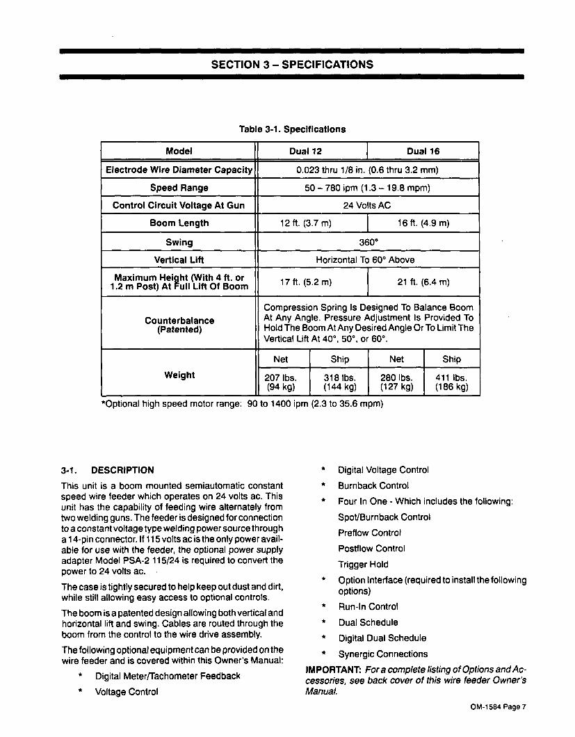
Table 3-1. Specifications
Model Dual 12 Dual 16
Electrode Wire Diameter Capacity 0.023 thru 118 in. (0.6 thru 3.2 mm)
Speed Range 50 � 780 ipm (1.3 � 19.8 mpm)
Control Circuit Voltage At Gun 24 Volts AC
Boom Length 12 ft. (3.7 m) 16 ft. (4.9 m)
Swing 360°
Vertical Lift Horizontal To 60° Above
21 ft. (6.4 m)17ft. (5.2m)
Compression Spring Is Designed To Balance Boom
At Any Angle. Pressure Adjustment Is Provided To
Hold The Boom At Any Desired Angle Or To Limit The
Vertical Lift At 40°, 50°, or 60°.
Maximum Heiaht (With 4 ft. or
1.2 m Post) At pull Lift Of Boom
Counterbalance
(Patented)
Weight
Net I Ship Net Ship
280 lbs. I 411 lbs.
(127 kg) (186 kg)207 lbs.
I318 lbs.
(94 kg) (144 kg)
*Optional high speed motor range: 90 to 1400 ipm (2.3 to 35.6 mpm)
3-1. DESCRIPTION
This unit is a boom mounted semiautomatic constant
speed wire feeder which operates on 24 volts ac. This
unit has the capability of feeding wire alternately from
two welding guns. The feeder is designed for connection
to a constant voltage type welding power source througha 1 4-pin connector. If 115 volts ac is the only power avail
able for use with the feeder, the optional power supply
adapter Model PSA-2 115/24 is required to convert the
power to 24 volts ac.
The case is tightly secured to help keep out dust and dirt,while still allowing easy access to optional controls.
The boom is a patented design allowing both vertical and
horizontal lift and swing. Cables are routed through the
boom from the control to the wire drive assembly.
The following optional equipment can be provided on the
wire feeder and is covered within this Owner�s Manual:
* Digital Meter/Tachometer Feedback
* Voltage Control
* Digital Voltage Control
* Burnback Control
* Four In One - Which includes the following:
Spot/Burnback Control
Preflow Control
Postflow Control
Trigger Hold
* Option Interface (required to install the followingoptions)
* Run-In Control
* Dual Schedule
* Digital Dual Schedule
* Synergic Connections
IMPORTANT: For a complete listing of Options andAc
cessories, see back cover of this wire feeder Owner�s
Manual.
OM-1584 Page 7

Table 3-2. Options Compatibility - -
The table below should be used to determIne the options that can be used together on a wire feeder. Use the column on the left side of the
table to choose the desired option and follow the line across to see which options are compatible.
DESIRED OPTION�-
Burn-
back
Control
4-~-1
OptIon
DIgItalMeter/
Tech
Feedback
Olaltal
~Control
VoltageControl
Run-In
Control
DIgItalDual
Scheduli
Dual
Schedule
Control
Remote
Pendant
Control
Cord
#137 552
(For
RCSP-45)
Burnback Control � No Yes Yes Yes Yes Yes Yes Yes Yes
4-IN-i Option (Includes preflowlpostflow,spotlburnback, and trigger hold Control)
No � Yes Yes Yes Yes Yes Yes Yes Yes
Digital Meter/Tach Feedback Yes Yes � Yes Yes Yes Yes No Yes Yes
Digital Voltage Control (DVC) Yes Yes Req�d � No Yes Yes No Yes No
Voltage Control Yes Yes Yes No � Yes No No No No
Run-In Control
(Option Interface Required)
Yes Yes Yes Yes Yes � Yes Yes Yes Yes
Digital Dual Schedule
(Option Interface Required)
Yes Yes Req�d Reqd No Yes � No No No
Dual Schedule Control
(Option Interface Required)
Yes Yes No No No Yes No � No No
Remote Pendant Control
(Option Interface Required)
Yes Yes Yes Yes No Yes No No � No
Cord #137 552 (For RCSP-45)(Option Interface Required)
Yes Yes Yes No No Yes No No No �
SECTION 4� INSTALLATION OR RELOCATION
4-1. LOCATION
The service life and efficiency of this unit and associated
components are reduced when they are subjected to
high levels of dust, dirt, moisture, corrosive vapors, and
extreme heat.
A suitable location for this unit will allow room for the
boom to swing horizontally in the desired arc and to pivotupward to the desired angle. Proper placement will also
provide sufficient clearance from obstruction at the wire
support end of the unit when the boom swings. The
structure to which the unit is being installed should be of
sufficient construction to support the weight of the unit
when the boom is in the horizontal position.
4-2. BASE AND BOOM ASSEMBLY (Figure 4-1)
1. Existing Support (Customer Supplied)
a WARNING: FALLING BOOM can cause serI
ous personal injury and equipment damage.� Use 5 in. (127 mm) diameter, Schedule 40
pipe (wall thickness of 0.258 in. or 6.6mm) as
support pipe for 16 foot (4.9 m) booms.
a. Uncrate and remove all packing material from
the unit.
b. Mount post support to the desired structure.
OM-i 584 Page 8

Wire Guide Fitting
a WARNING: FALLING BOOM can cause seri
ous personal injury and equipment damage.� Securely mount unit to a structure that can
support the weight of the unit when the boom
is in the horizontal position.
c. Complete Steps c thru g in Subsection 2. Post
Support.
2. Post Support (Optional)
a. Uncrate and remove all packing material from
the unit.
b. Mount post support to desired structure.
a WARNING: FALLING BOOM can cause serious personal injury and equipment damage.� Securely mount unit to a structure that can
support the weight of the unit when the boom
is in the horizontal position.
c. Remove yoke pin, nut, washers, and bolt from
yoke and swivel plates.
Hole in Yoke
Yoke
Cotter Pin
Screw
Lock Washer
a WARNING: RELEASE OF SPRING PRESSURE WITHOUT BOOM ATTACHED can
cause serious personal Injury and equipment damage.� Perform installation exactly as outlined in fo!
lowing step-by-step instructions.
� Do not remove safety collar until instructed to
do so.
d. Insert swivel into post.
e. Place the boom base plate between the two
swivel plates.
f. Slide washer onto bolt and insert through appropriate hole in swivel plates (see inset portion of
Figure 4-1). Slide washer onto bolt and install
nut onto bolt. Tighten nut; then back off nut 1/2
turn.
g. Insert pin through yoke, hole, and install cotter
pin through pin.
CAUTION: EXCESSIVE FRICTION can dam
age equipment.� Every six months lubricate swivel to preventwear
Excessive lubrication is not required or recom
mended.
Wire Support
Swivel Base
Nut
Washer
Post Support
Figure 4-1. Base And Boom Assembly
SB-142 598.A
OM-1 584 Page 9

3. Base Support (Optional) remaining end of monocoil liner is flush with end
IMPORTANT: If an optional base support was pur-of tube.
chased with the unit, mounting holes are provided for 3. Tighten bolt to secure monocoil liner. Be sure not
fastening the base support to the floor, to crush the liner.
~ WARNING: FALLING BOOM can cause seri
ous personal injury and equipment damage. 4-6. WIRE GUIDE AND DRIVE ROLL INSTALLA
� For mounting base support use, as a mini- lION (Figure 4-2)
mum, 1/2 in. (12.7 mm) diameter, S.A.E.Upon initial installation, or as a result of changes in wire
grade 5 bolts.size and type, it is necessary to install the required drive
� Use equivalent strength, non-corrosive bolts rolls and wire guides. Select drive rolls according toif unit is mounted in an extremely damp envi- Table 9-1.ronment.
IMPORTANT: All directions for wire guide and drive rolla. Uncrate and remove all packing material from
installation such as left and right, are with respect to thethe unit.
operator facing the front of the drive assembly.b. Fasten base support to the floor.
c. Complete Steps c thru g in Subsection 2. Post IMPORTANT: All adjustments are made usinga3/l6in.
Support. Follow all precautionary data. alien wrench, which is included with this unit.
4. Swingpak Base (Optional)After obtaining the appropriate drive rolls and wire
a. Uncrate and remove all packing material from guides, proceed as follows:the Swingpak base.
A. Wire Guide Installation
A~ WARNING: FALLING BOOM can cause seri
ous personal injury and equipment damage. 3. Open drive assembly cover.
� Mount welding power source on Swingpak4. Remove drive rolls if applicable.base before mounting Swingarc.5. Loosen the wire guide screw and wire guide re
b. Uncrate and remove all packing material fromtamer.
the Swingpak unit.
6. Place wire guide with arrow pointing down, intoc. Complete Steps c thru g in Subsection 2. Post
Support. Follow all precautionary data. guide holder seat.
7. Secure wire guide by tightening wire guide screw,4-3. INSTALLATION OF CONTROL BOX TO BASE
making certain that wire guide retainer is posi(Figures 4-1 And 43) tioned in groove on guide holder seat. Do not
The control box is shipped with four (4) screws partially overtighten.installed into bottom side of control box. To secure con
trol box to base proceed as follows:8. Install remaining wire guide by repeating Steps 2
through 5.1. Set control box onto base with the four screws
protruding through the four keyhole shaped holes B. Drive Roll Installation
in base plate.1. Close spring shaft carrier.
2. Slide control box forward, so that screws are in
slotted portion of keyholes, and tighten the four2. Turn drive roll nut on each drive roll carrier coun
terclockwise until the three lobes of each nut linescrews.
up with the three lobes of each drive roll carrier.
4-4. INSTALLATION OF WIRE SUPPORT3. Open spring shaft carrier.
(FIgure 4-1)
1. Remove the securing screws and lock washers 4. Slide a drive roll over drive roll nut onto drive roll
from the swivel base. carrier.
2. Place the wire support over the holes in the swivel 5. Repeat Step 4 for all drive rolls.
base.6. Close spring shaft carrier, and turn each drive roll
3. Insert securing screws with lock washers and nut clockwise until tight. Do not overtighten.tighten.
C. Drive Roll Pressure Adjustment4-5. INSTALLATION OF WIRE GUIDE EXTENSION
(Figure 43)The drive roIl pressure indicator is located on the topfront side of the spring shaft carrier. The scale on the in-
1. Locate supplied wire guide extension. dicator is a relative scale only, and does not indicate ac
2. Loosen bolt on wire guide fitting, and insert end of tual drive roll pressure. Increase drive roll pressure bymonocoil liner near cable tie into fitting. Be sure rotating the pressure adjustment knob clockwise.
OM-1584 Page 10

FIgure 4-2. Wire Guide And Drive Roll Installation
4-7. WELDING GUN CONNECTIONS
A. Gun Connector To Drive Assembly (ProvidesWeld Power And Shielding Gas) (Figure 4-2)
IMPORTANT: The outlet guide is provided as part of the
gun or gun adapter assembly.
1. Loosen the gun/feeder connector securing knob.
IMPORTANT: The outlet guide should be installed so
that tip of guide is as close to the drive rolls as possiblewithout touching.
2. Insert the gun/feeder connector, or gun/feederadapter if required, which includes installed outlet
guide, into drive assembly opposite inlet guide.
3. Tighten gun/feeder connector securing knob.
B. Gun Trigger (Figure 4-3)
a WARNING: ELECTRIC SHOCK can kill.
� Do not touch live electrical parts.
� Do not touch electrode wire when gun triggeris pressed.
The welding wire and all metal parts in contact
with it carry weld output when the welding powersource contactor is energized.
Two 4 socket free-hanging receptacles extend Out of the
motor end of the boom for connecting the gun triggerplugs to the wire feeder. Connect the left gun to the free-
hanging receptacle labeled LEFT, and the right gun to
the remaining free-hanging receptacle. To make con
nections, align keyways, insert plug, and rotate threaded
collar fully clockwise.
Set Screw
Liner
Wire Guide
Weld CableTerminal
Drive Roil
Carrier
Drive RollPressure indicator
pring Shaft Carrier
(Shown Open)
Drive Roll
Nut
~One PieceDrive Roll
Pressure
AdjustmentKnobGun/Feeder
Connector
OpeningGun/FeederConnector
Securing Knobs
Guide HolderSeat.
Wire
Guide
Wire GuideRetainer
WireScrew
Guide HolderSeat Groove
SA-142 597
SA�137 391-A
OM-1584 Page 11

C. Shielding Gas (If Applicable) ARCING can damage weld cable terminal.
An integral gas input fitting is provided on the wire drive
assembly for guns utilizing this type of connection. If the
gun requires a separate shielding gas connection, dis
connect the hose from the gas fitting on drive assembly,install proper fittings or connectors, and connect to gas
hose from gun. --
0. Weld Cable (If Applicable)
WARNING: ELECTRIC SHOCK can kill.
_____ � Do not touch live electrical parts.
� Shut down wire feeder and welding powersource anddisconnect inputpoweremployinglockout/tagging procedures before makingweld cable connections.
Lockout/tagging procedures for the wire feeder
consist of disconnecting interconnecting cord,and for welding power source consist of padlocking line disconnect switch in open position,removing fuses from fuse box, or shutting off and
red-tagging circuit breaker or other disconnect
ing device. Stop engine, and disconnect negative (�) battery cable from battery on weldinggenerators.
� Clean weld cable terminal before connectingweld cable if necessary.
� Tighten terminal nut securely.
Loose or dirty connections can cause erratic
weld output.
Connect the weld cable from the gun, if applicable, to the
weld cable terminal on the drive assembly.
4-8. CONNECTIONS FROM BOOM TO CONTROL
BOX (Figure 4-3)
A. Gun Trigger
Two receptacles, labeled TRIGGER RECEPTACLE,
are provided on the front of the control box. Connect the
left gun trigger control plug from the boom, labeled
LEFT, to control box left TRIGGER RECEPTACLE. Con
nect remaining gun trigger control plug to matching re
ceptacle. To make connections, align keyways, insert
plug, and rotate threaded collar fully clockwise.
Ref. SD-I 42 598-A
Control Motor ControlBox Plugs
TriggerControl
Plugs
GasHoses
WeldCables
Wire Guide
FitlIng
WeldCable
Liner
Gun TriggerPlugs
Figure 4-3. Control Box And Boom ConnectIons
OM-1584 Page 12

10 ft. (3 m) Gas Hose with Extension
Adapter (supplied with feeder)
10 ft. (3 rn) 24 VAC and ContactorCord (supplied with feeder)
10 ft. (3 m) Weld Power Cable (supplied with feeder)
Standard or
Deluxe Model
10 ft. (3 m) Gas Hose with Extension
Miller electrically Adapter (supplied with feeder)controlled CV and
CCICV power source
with a 14-pin lOft. (3 m) 24 VAC and Contactor I I Standard Deluxe orreceptacle and 24 VAC Cord (supplied with feeder) ~ k Super Deluxe ModelSupply_______________________________________________________________
lOft. (3 m) Weld Power Cable (supplied with feeder)
Optional PSA-2 Control (allows 60 Series Feeders to be used with power sources
having only 115 VAC available � can be mounted at power source or feeder. Refer
to OPTIONAL CONTROLS AND ACCESSORIES section for detailed information.)
lOft. (3 m) Gas Hose with Extension
�Adapter (supplied with feeder) \
1/10 ft. (3 m) Weld Power Cable (supplied with feeder)
IMPORTANT: If using the SS or DS feeder with a power source having only 115 VAC supply, the PSA-2 (Power Source Adapter) is required.
Refer to OPTIONAL CONTROLS AND ACCESSORIES section.
Figure 4-4. Typical Connections To Welding Power Source
S-0534
B. Motor Control
Two motor control receptacles are provided on the rear
of the control box for making motor control connections.
Connect the left motor control plug from boom, labeled
LEFT, to control box left motor control receptacle. Con
nect remaining motor control plug to matching recep
tacle. To make connections, align keyways, insert plug,and rotate threaded collar fully clockwise.
4-9. SHIELDING GAS CONNECTION (Figure 4-3)
The shielding gas hoses extend lOft. (3 m) from the rear
of the boom. If necessary, obtain extension for hoses.
Route and connect end of gas hose to regulator/flowmeter at gas supply.
4-10. WELDING POWER SOURCE CONNECTIONS
TO CONTROL BOX AND BOOM (Figures 4-3
thru 4-5)
A. 14-Pin Plug Connection
The 14-pin plug PLG lOon the end of the interconnectingcord provides a means for connecting the wire feeder to
a welding power source (see Figure 4-6). This connec
tion provides 24 volt ac power, contactor control, and optional voltage control when used with a constant voltage(CV) welding power source with a 14-socket receptacle.To make connections, align keyway, insert plug, and ro
tate threaded collar fully clockwise.
The pins on plug PLG1O are defined in relation to both
the power source and wire feeder. The welding power
source provides six functions to the wire feeder. The pinsare designated as follows:
FIgure 4-5. Front View Of 14-Pin PlugWith PIn Locations
Ret. S-0512
Miller CV power source
equipped with a 14-pinreceptacle and 24 VAC
supply
Optional 115 VAC and Contactor Cord
or Control Cord from existing 50 Series
feeder installation (cord connects to 4-pinconnector on cord from PSA-2 Control)
EXTENSION CORDS
loft. 3m) #122 972
25 ft. 7.6 m) #122 973
SOft. 15m (#12297475ft. 23m (#122975
Can be added to the standardlOft. (3 m) cord to extend feederfarther from power source.
Miller CV or competitiveCV power source with
115 VAC power or
competitive power source
requiring contact closure
for coritactor control
4-Pin PlugStandard or
J LDeluxe Model
OM-1 584 Page 13

Pin A: Up to 10 amperes of 24 volts ac, 60 Hz, with re
spect to socket G (circuit common); protected
by fuse in welding power source.
Pin B: 24 volts ac input power to energize the weld
contactor. The feeder sends back 24 volts ac bymeans of a contact closure from Pin A to Pin B.
Pin C: +10 volts dc with-respect to Pin D.
Pin D: Control circuit common from power source.
Pin E: Input command signal from wiper of remote
control potentiometer, 0 volts equals machine
minimum; +10 volts equals machine maximum.
Pin G: 24 volts ac circuit common; also connected to
welding power source chassis.
Pin H: Reserved for future use.
IMPORTANT: The remaining pins in the plug are not
used by the feeder.
B. Weld Cable
4~ ELECTRIC SHOCK can kill.
_____ � Do not touch live electrical parts.
� Shut down wire feeder and welding powersource anddisconr7ectinputpoweremployinglockout/tagging procedures before makingweld cable connections.
Lockoutltagging procedures for the wire feeder
consist of disconnecting interconnecting cord,and for welding power source Consist of padlocking line disconnect switch in open position,removing fuses from fuse box, or shutting off and
red-tagging circuit breaker or other disconnect
ing device. Stop engine, and disconnect negative (�) battery cable from battery on weldinggenerators.
ARCING can damage weld cable terminal.
� Clean weld cable terminal before connectingweld cable if necessary
� Tighten terminal nut securely.
Loose or dirty connections can cause erratic
weld output.
Two 10 ft. (3 m) weld cables extend Out of the boom for
making weld output connection to the welding power
source.
For Electrode Positive/Reverse Polarity connections
proceed as follows:
1. Route and connect both weld cables extendingout of the control box end of the boom to the Posi
tive (+) weld output terminal on welding power
source (see power source Owner�s Manual). If
necessary, use a weld cable extension of ade
quate size and capacity to reach power source. If
cable extension is used, securely bolt and insu
late connection point.
2. Route and connect another weld cable of ade
quate size and capacity from the Negative (�)weld output terminal (see power source Owner�s
Manual) to workpiece.
IMPORTANT: For Electrode Negative/Straight Polarityconnections, reverse cable connections to weld outputterminals; electrode becomes negative.
4-11. MOTOR START CONTROL (Figure 4-6)
a ELECTRIC SHOCK can kill.
� Do not touch live electrical parts.
� Shut down wire feeder and welding powersource anddisconnect inputpoweremployinglockout/tagging procedures before openingcontrol box wrapper.
Lockout/tagging procedures for the wire feeder
consist of disconnecting interconnecting cord,and for welding power source consist of padlocking line disconnect switch in open position,removing fuses from fuse box, or shutting off and
red-tagging circuit breaker or other disconnect
ing device. Stop engine, and disconnect negative (�) battery cable from battery on weldinggenerators.
ELECTROSTATIC DISCHARGE (ESD) can
damage circuit board components.� Put on properly grounded wrist strapBEFORE handling circuit boards.
� Perform work only at a static-safe work area.
The Motor Start Control potentiometer R70, located on
the motor control board PCi, provides the ability to se
lect wire feed speed acceleration at the be~inning of wire
feed up to the rate set on the Wire Speed control.
The Motor Start Control is factory set to provide requiredarc starting characteristics with a wide range of weldingpower sources.
To adjust the Motor Start Control, proceed as follows:
1. Remove wrapper.
2. Remove screws from nameplate and side panels,and lower hinged front panel.
3. Adjust R70 using a non-conductive screwdriver.
Rotating the potentiometer clockwise increases
the amount of time it takes the motor to ramp up to
speed.
4. Secure hinged front panel lowered in Step 2.
5. Reinstall and secure wrapper removed in Step 1.
OM-1584 Page 14

4-12. DIP SWITCHES (Figure 4-7)
It may be necessary to change DIP switch positions if dif
ferent options are added, or if different functions are de
Rear
Panel
Wire Clamp
sired. Follow the procedure in Subsection A when
changing DIP switches.
A. Procedure For Changing DIP Switches
To change switch positions, proceed as follows:
a WARNING: ELECTRIC SHOCK can kill.
� Do not touch live electrical parts.
� Shut down wire feeder and welding power
source, and disconnect interconnecting cord
from the welding power source before reset
ting DIP switches.
1. Remove wrapper.
2. Locate DIP switches and remove protective coat
ing if necessary.
3. Reposition appropriate DIP switch using a non-
conductive pointed tool, such as the edge of a
small screwdriver.
4. Reinstall wrapper.
DIgital Meter Circuit Board
PC6O And Digital Meter
Functions DIP Switch
Ret. SB.131 819.8
Figure 4-6. Motor Start Control On Motor Control
Board PCi
Left Side View
Optional Interface CircuitBoard PC7O And Remote
input/Run-in Voltage SenseDIP Switch
Tachometer Conversion
Circuit Board PC5O
Motor Board PCi And
Motor Start ControlPotentiometer R70
4-in-i Circuit Board
PC3O or Burnback
Circuit Board PC1O
Digital Voltage Control
Circuit Board PC4ORelay Circuit
Board PC3
Hinged Front Panel
Figure 4-7. Circuit Board And DIP Switch Locations
SC.142 110
OM-1584 Page 15

B. DIP Switch Description
1. Digital Meter Functions DIP Switch (Optional)(Figures 4-7 And 4-8)
The digital meter function DIP switches are located on
digital meter circuit board PC6O (see Figure 4-7 for cir
cuit board location). Figure 4-8 shows correct switch po
sitioning for the different modes available. See Section
5-11 for description of a desired mode.
2. Spot Time DIP Switch (Optional) (Figure 4-7)
The spot time DIP switch is located on 4-In-I board
PC3O. The DIP switch comes factory set to operate in
the 0 to 5 second (LONG) range. If it is desired to oper
ate wire feeder in the 0 to 2.5 second range, change DIP
switch to the (SHORT) position. See Section 5-10 for a
description of the control functions.
Inches/Minute
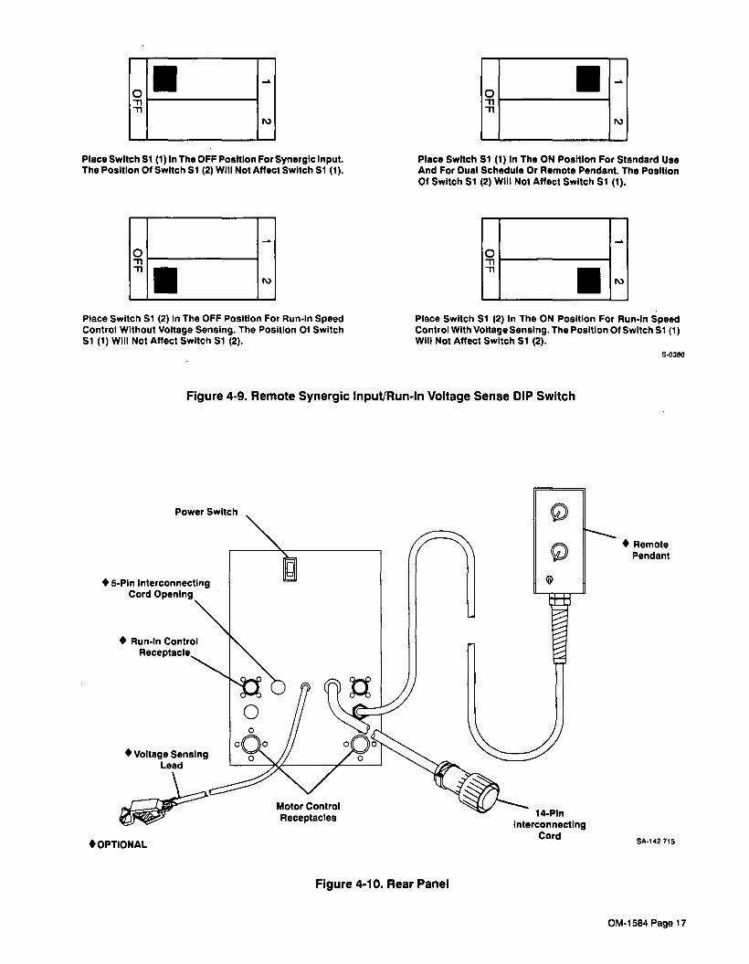
3. Remote Input/Run-In DIP Switch (Optional) (Figures 4-7 And 4-9)
The remote input/run-in DIP switch is located on optioninterface board P070. The DIP switch consists of two
switches, 1 and 2. Both switches come factory set in the
ON position.
Switch 1:
To interface wire feeder with a synergic control, placeswitch I in the OFF position.
For standard use or for use with dual schedule or remote
control, place switch 1 in the ON position.
Switch 2:
For RUN-IN SPEED control with voltage sensing, placeswitch 2 in the ON position.
For RUN-IN SPEED control without voltage sensing,place switch 2 in the OFF position.
Figure 4-8. Digital Meter Functions DIP Switch
U,
C,,
� High Speed Motor
U
U
I
� High Speed Motor
Meters/MInute
I~
Meters/Minute
U
I
I
I
e Moni br
U,
Voltat
be in either position.
� The voltage hold function can be used in conjunction with
the following modes: high speed motor, meters/minute,
and high speed motor-meters/minute.
� � Do not use the high speed motor, or high speed motor-
meters/minute modes unless unit is equipped with a
high speed motor.Ref. S-0399
OM-1584 Pa9e 16
~I :Place Switch Si (1) In The OFF Position For Synergic input.The Position Of Switch Si (2) WIll Not Affect Switch Si (1).
0-nm
r�)
Place Switch Si (2) in The OFF Position For Run-In SpeedControl Without Voltage Sensing. The Position Of Switch
Si (1) WIll Not Affect Switch Si (2).
Place Switch Si (I) in The ON Position For Standard Use
And For Dual Schedule Or Remote Pendant. The Position
Of Switch Si (2) Wili Not Affect Switch Si (1).
0mm
IPlace Switch Si (2) in The ON Position For Run-in SpeedControl With Voltage Sensing. The Position Of Switch Si (i)Will Not Affect Switch Si (2).
S-0360
Figure 4-9. Remote Synergic Input/Run-In Voltage Sense DIP Switch
Motor Control
Receptacles
� OPTIONAL
Figure 4-10. Rear Panel
� Remote
Pendant
SA.142 715
Power Switch
� 5-Pin interconnecting
� Voitage SensingLead
i4-Pln
interconnectingCord
OM-1584 Page 17

4-13. VOLTAGE SENSING CONNECTION (Optional)(Flgure 4.10)
A 35 ft. (12.4 m) voltage sensing lead is provided with
several options. Connect the voltage sensing lead to the
workpiece.
4-14. RUN-IN CONTROL CONNECTIONS (Option.al) (FIgure 4-10)
a ELECTRIC SHOCK can kill.
� Do not touch live electrical parts.
� Shut down wire feeder and welding powersource anddisconnect inputpoweremployinglockout/tagging procedures before installingreed relay.
Lockoutltagging procedures for the wire feeder
consist of disconnecting interconnecting cord,and for welding power source consist of padlocking line disconnect switch in open position,removing fuses from fuse box, or shutting off and
red-tagging circuit breaker or other disconnect
ing device. Stop engine, and disconnect negative (�) battery cable from battery on weldinggenerators.
When the optional Run-In control is provided, the weld
cable from the boom must be routed through the reed
relay before going to the welding power source. Proceed
as follows:
1. Install the reed relay to the front or rear control
box mounting arm. Holes are provided in the
mounting arms near the boom.
2. Connect the plug from the reed relay to the
matching receptacle on the rear of the control box
as follows: align keyways, insert plug, and rotate
threaded collar fully clockwise.
3. Route the weld cable from the boom, through the
reed relay, and to the welding power source out
put terminal.
4-15. SYNERGIC CONNECTIONS (Optional)
Aloft. (3.1 m) cord can be provided for connections to
the RCSP-45 synergic control. Route the cord from the
wire feeder to the synergic control and make connec
tions as follows: align keyway, insert plug into matchingreceptacle, and rotate threaded collar fully clockwise.
4-16. WELDING WIRE INSTALLATION
A. Installation Of Spool-Type Wire
1. Remove retaining ring.
2. Slide spool of wire onto hub so that wire feeds off
top of spool.
3. Rotate spool until hole in spool aligns with pin in
hub. Slide spool onto hub until it seats againstback flange of the hub.
4. Reinstall retaining ring onto hub.
B. Installation Of Optional Wire Reel And Reel-
Type Wire (Figure 4-11)
1. Remove retaining ring and, if applicable, wire reel
assembly from hub.
2. Lay wire reel assembly flat on a table or floor.
3. Remove spanner nut from wire reel assembly.
4. Remove wire retainer, and install wire onto wire
reel. Be sure that wire feeds off top of reel.
5. Reinstall wire retainer and spanner nut onto wire
reel.
6. Slide wire reel assembly onto hub, and rotate as
sembly until hub guide pin is seated in reel.
7. Reinstall retaining ring onto hub.
� OPTIONAL SC-143 478
Figure 4-11. Optional Wire Reel And Reel-TypeWire Installation
C. Adjustment Of Hub Tension
Check the hub tension by slowly rotating the wire spoolor reel. The wire should unwind freely, but hub tension
should be sufficient to keep wire taut and prevent back
lash when the wire feed stops. If adjustment is required,loosen or tighten the hex nut on the end of the hub sup
port shaft accordingly.
4-17. SAFETY COLLAR REMOVAL (Figure 4-1)
a WARNING: RELEASE OF SPRING PRES
SURE WITHOUT BOOM ATTACHED can
cause serious personal injury and equipment damage.� Perform installation exactly as outlined in the
following step-by-step instructions.
� Do not remove safety collar until instructed to
do so.
� Retain safety collar for future disassemblyuse.
A safety collar is provided on top of the post to maintain
spring pressure and prevent vertical movement duringinstallation. The collar is required whenever the boom is
disassembled or relocated. To remove the safety collar,
proceed as follows:
� Wire Retainer
7� Spanner Nut
RetainingRIng
OM-1584 Page 18

1. Grasp boom and pull down slightly. The boom
should be pulled down only far enough to remove
the pressure which is applied to the safety collar.
2. Remove the safety collar, and retain for future
use.
3. The boom should now balance in any positionfrom horizontal to 60 degrees above horizontal. If
the boom does not balance properly, proceed to
Section 4-18.
4-18. BOOM ADJUSTMENTS (Figure 4-12)
A. Weight Lift Adjustment
a WARNING: FALLING BOOM can cause seri
ous personal injury and equipment damage.
� Maintain full threads on adjustment rod
through the yoke.
The amount of weight which the boom can retract into
the upright position when released can be varied by ad
justing the jam nut and adjustment rod located at the
base of the boom. If a heavier gun is installed on the end
of the boom making it necessary to increase the amount
of weight that the boom can lift, loosen the jam nut and
rotate the adjustment rod so that the adjustment rod
threads into the yoke. When the proper adjustment is ob
tained, tighten the jam nut against the base of the yoke. If
a lighter gun is used, rotate the adjustment rod so that
the adjustment rod threads out of the yoke.
EFigure 4-12. Boom Adjustments
B. Locking Knob
Yoke
Jam Nut
AdjustmentRod
SA.142 599�A
By rotating the Locking Knob, located on the side of the
swivel plate, in a clockwise direction, the boom may be
held in any desired position. Rotating the Locking Knob
in a counterclockwise direction will permit the boom to
free travel. Changing the position of the Locking Knob to
the other threaded holes provided along the side of the
swivel plate limits the lift of the boom to 50 degrees or 40
degrees respectively during free travel.
4-19. WELDING WIRE THREADING
a WARNING: ELECTRIC SHOCK can kill;MOVING PARTS can cause Injury.� Do not touch live electrical parts.
� Keep away from moving parts.
� Do not energize welding powersource or wire
feeder until instructed to do so.
The welding wire and all metal parts in contact
with it are energized while welding.
WELDING WIRE can cause puncturewounds; HOT SURFACES can burn skin.
� Do not press gun trigger until instructed to do
so.
� Do not point gun toward any part of the body,any conductive surface, or other personnelwhen threading welding wire.
� Allow gun to cool before touching.
a CAUTION: LOOSE WELDING WIRE can
cause Injury.� Keep a firm hold on the wire during installa
tion, removal, and threading operations.-
Spooled wire has a tendency to unravel rapidlywhen loosened from the spool.
1. Install the wire as instructed in Section 4-16.
2. Cut off any portion of the free end of the wire
which is not straight. If necessary, straighten wire
to remove cast. Be sure that the cut end is free
from rough surfaces to permit proper feeding.
3. Adjust hub tension according to Section 4-16C if
necessary.
4. Manually route the wire through the wire guidetube on the side of the boom, over the wire pulley,and to the drive assembly.
5. Lay gun cable assembly out straight (no coils in
the cable/conduit).
6. Energize the welding power source.
7. Place the wire feeder Power switch in the ON
position.
8. Push the JOG switch up (see WARNING block at
beginning of this Section). Wire feeds if drive roll
pressure is properly adjusted to prevent slippage.If wire slippage is noticed, turn pressure adjustment knob clockwise in 1/4 turn increments until
wire slippage stops. If excess pressure is re
quired, check gun contact tube and gun liner for
correct size or obstructions. Release the JOG
switch when welding wire extends approximately1 in. (25 mm) out of gun tip.
9. Shut down wire feeder and welding power
source.
OM-1584 Page 19

4-20. CHANGING FROM STANDARD DIGITAL
VOLTAGE CONTROL TO MILLER INVERTER
DIGITAL VOLTAGE CONTROL
WARNING: ELECTRIC SHOCK can kill.
� Do not touch live electrical parts.
� Shut down wire feeder and welding power
source, and disconnect input power employing lockout/tagging procedures before
making internal adjustments.
Lockoutltagging procedures for the wire feeder
consist of disconnecting interconnecting cord,and for welding power source consist of padlocking line disconnect switch in open position,removing fuses from fuse box, or shutting off and
red-tagging circuit breaker or other disconnect
ing device.
CAUTION: ELECTROSTATIC DISCHARGE
(ESO) can damage circuit boards.
� Put on properly grounded wrist strap BEFORE handling circuit boards.
� Transport circuit boards in proper static-
shielding carriers or packages.
� Perform work only at a static-safe work area.
INCORRECT INSTALLATION or misalignedplugs can damage circuit board.
� Be sure that plugs are properly installed and
aligned.
EXCESSIVE PRESSURE can break circuit
board.
� Use only minimal pressure and gentle movement when disconnecting or connectingboardplugs and removing or installing board.
A. Electrical Connections
When optional Digital Voltage Control is used with a
MILLER inverter-type power source, it is necessary to
make reconnections to digital voltage control board
PC4O. To make reconnections, proceed as follows (seeFigure 4-8 for circuit board location):
1. Remove wrapper.
2. Remove securing hardware from upper left cor
ner of nameplate and side panels, and open
hinged front panel.
3. Disconnect plug PLG82 from receptacle RC42.
4. Connect plug PLG82 to receptacle RC44.
5. Disconnect jumper plug PLG6I from receptacleRC45.
6. Disconnect plug PLG43 or PLG44, as applicable,from receptacle RC41.
7. Connect plug PLG43 or PLG44 to RC45.
8. Connect jumper plug PLG61 to RC41.
9. Close and secure hinged front panel.
10. Reinstall wrapper.
B. Digital Meter Recalibratlon
IMPORTANT: If this wire feeder is being used with a
MILLER inverter-type power source that has a voltagerange of 10 to 35 volts in the CV mode, no dig/ta/meterrecalibration is required.
If this wire feeder is being used with a MILLER inverter
type power source that has a voltage of other than 10 to
35 volts in the CV mode, recalibrate the digital meter as
follows:
1. Place the digital meter WIRE SPEEDNOLTAGE
switch in the VOLTAGE position (see Figure 5-1
for switch location).
2. Rotate the SCHEDULE A or B Voltage Control,whichever is active, to the maximum position (see
Figure 5-1 for control location).
3. Remove securing hardware from upper left cor
ner of nameplate and side panels, and open
hinged front panel.
a WARNING: ELECTRIC SHOCK can kill.
� Do not touch live electrical parts.
4. Energize the wire feeder.
5. Adjust potentiometer R31 located on PC4O, until
the digital meter displays a voltage equal to the
maximum voltage listed on the AmperageNoltage control of the welding power source
6. Close and secure hinged front panel.
a
This procedure requires the unit to be energized.Only qualified persons familiar with and follow
ing standard safety practices are to perform this
procedure.
OM-1 584 Page 20�
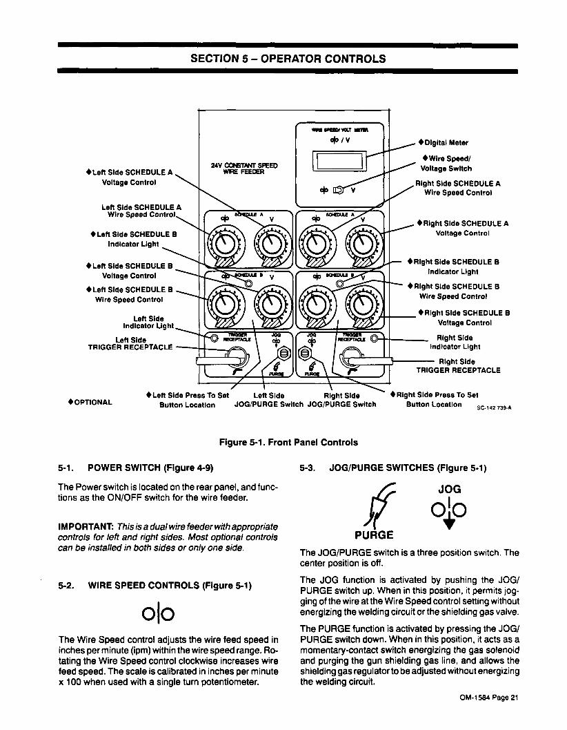
SECTION 5� OPERATOR CONTROLS
�Left Side SCHEDULE A
Voltage Control
Left Side SCHEDULE A
Wire Speed
�Left Side SCHEDULE B
indicator Light
�Left Side SCHEDULE B
Voltage Control
�Left Side SCHEDULE B
Wire Speed Controi
Left Sideindicator Light.
Left SideTRIGGER RECEPTACLE
� OPTIONAL
Figure 5-1. Front Panel Controls
�Digital Meter
�WIre Spe.d/
Voltage Switch
Right Side SCHEDULE A
Wire Speed Control
�Right Side SCHEDULE A
Voltage Controi
�Rlght Side SCHEDULE B
Indicator Light
�Right Side SCHEDULE B
Wire Speed Control
�Right Side SCHEDULE B
Voltage Control
Right Side
Indicator Light
Right Side
TRIGGER RECEPTACLE
�Right Side Press To Set
Button LocationSC-142 739-A
5-1. POWER SWITCH (Figure 4-9)
The Power switch is located on the rear panel, and functions as the ON/OFF switch for the wire feeder.
IMPORTANT: This is a dual wire feeder with appropriatecontrols for left and right sides. Most optional controls
can be installed in both sides or only one side.
5-2. WIRE SPEED CONTROLS (Figure 5-1)
oloThe Wire Speed control adjusts the wire feed speed in
inches per minute (1pm) within the wire speed range. Ro
tating the Wire Speed control clockwise increases wire
feed speed. The scale is calibrated in inches per minute
x 100 when used with a single turn potentiometer.
5-3. JOG/PURGE SWITCHES (Figure 5-1)
IPURGE
The JOG/PURGE switch is a three position switch. The
center position is off.
The JOG function is activated by pushing the JOG/
PURGE switch up. When in this position, it permits jogging of the wire at the Wire Speed control setting without
energizing the welding circuit or the shielding gas valve.
The PURGE function is activated by pressing the JOG/
PURGE switch down. When in this position, it acts as a
momentary-contact switch energizing the gas solenoid
and purging the gun shielding gas line, and allows the
shielding gas regulator to be adjusted without energizingthe welding circuit.
�Left Side Press To Set Left Side Right Side
Button Location JOG/PURGE Switch JOG/PURGE Switch
JOG
qjo
OM-1584 Page 21

5-4. VOLTAGE CONTROL(S) (Optional) (Figure5.1)
VThe Voltage control provides a means of setting arc volt
age. Rotating the control clockwise increases arc volt
age. The scale is calibrated 0 to 100 percent when used
with a single turn potentiometer.
5-5. DIGITAL VOLTAGE CONTROL(S) (Optional)(Figure 5-1)
The Digital Voltage Control is a ten-turn potentiometerwhich provides a means of presetting the arc voltage.Rotating the control clockwise increases the arc voltage.
When the optional Digital Voltage Control is used with
MILLER inverter-type welding power sources, the con
trol functions as a remote digital control and allows the
operator to preset arc voltage.
The optional Digital Voltmeter displays the output volt
age to the nearest tenth of a volt. Before the gun trigger is
depressed, the meter displays the preset voltage as set
by the control. When the trigger is depressed, and before
an arc is struck, the meter displays the welding power
source open-circuit voltage. After an arc is struck, the
meter displays actual voltage.
5-6. BURNBACK CONTROL(S) (Optional) (Figure5-2)
The burnback circuitry in this control keeps the weldingwire from sticking to the workpiece after the gun trigger is
released. The burnback capability in this wire feeder
keeps weld output present on the welding wire from 0 to
0.25 seconds after the wire has stopped feeding, de
pending on the setting of the Burnback control. This
delay action permits the welding wire to burn back to a
point where it neither sticks to the workpiece nor the con
tact tube. If the welding wire sticks to the workpiece, ro
tate the BURNBACK control clockwise.
5-7. PREFLOW CONTROL(S) (Optional) (Figure5-2)
When the gun trigger is closed the PREFLOW control
provides 0 to 5 seconds of gas flow before the weld out
put contactor and wire drive motor are energized. The
scale is calibrated in seconds. Rotating the control
clockwise increases the length of time gas flows.
5-8. POSTFLOW CONTROL(S) (Optional) (Figure5-2)
The POSTFLOW control provides 0 to 5 seconds of gasflow after completion of the BURNBACK cycle. The
scale is calibrated in seconds. Rotating the control
clockwise increases the length of time gas flows.
5-9. TRIGGER HOLD SWITCH(ES) (Optional)(Figure 5-1)
The TRIGGER HOLD function allows the operator to
continually feed wire without holding in the gun trigger.To use TRIGGER HOLD, place TRIGGER HOLD switch
in the up position. Making momentary contact with the
gun trigger while the switch is in the up position will acti
vate the TRIGGER HOLD function. After the PREFLOW
cycle has timed out, wire will continue to feed until the
gun trigger is again depressed, thereby terminatingTRIGGER HOLD. After TRIGGER HOLD is terminated,BURNBACK and then POSTFLOW circuitry will begin to
time out.
The TRIGGER HOLD function is inoperable while unit is
in the SPOT mode.
S8-143 878
Figure 5-2. Inner Control Panel (Right Or Left Side)
TRIGGERHOLD SPOT
CONTINUOUS
PREFLOW 2 SPOT 3
150:4BURNBACK
.050.2POSTFLOW
0
OM-1584 Page 22

5-10. SPOT/CONTINUOUS SWITCH(ES) AND
SPOT TIME CONTROL(S) (Optional) (Figure5-2)
When the SPOT/CONTINUOUS switch is in the CON
TINUOUS position, the circuitry provides continuous
welding capability after the PREFLOW cycle has timed
out. When the gun trigger is released, BURNBACK, and
then POSTFLOW circuitry begin to time out.
If it is desired to use wire feeder in the SPOT mode, placethe SPOT/CONTINUOUS switch in the SPOT position.Two ranges of SPOT control time are available
,0 to 2.5,
or 0 to 5 seconds (see IMPORTANT Block for informa
tion on changing SPOT control time range). Rotating the
SPOT control dial clockwise increases SPOT time.
IMPORTANT: This wire feeder comes factory set to op
erate in the 0 to 5 second range. If required to operateunit in the 0 to 2.5 second range, see Section 4-12 for in
structions on how to change DIP switch position.
After the PREFLOW cycle has timed out, the spot weld
timer begins to time out the selected period of time set on
the SPOT time control. When the time set on the SPOT
time control has elapsed, or the trigger is released,
BURNBACK, and then POSTFLOW timer circuitry be
gin to time out.
5-11. DIGITAL METER (Optional) (Figure 5-1)
olo /vBy placing the Wire SpeedNoltage switch in the Voltageposition, the meter functions as a weld voltage meter.
The voltmeter is connected to the welding circuit bymeans of the wire drive assembly and the voltage sense
clamp at the workpiece. The voltmeter indicates the dc
voltage at the wire feeder and will vary slightly from actual arc voltage due to cable resistance, poor connec
tions, etc.
The unit comes factory set to operate in the VoltageHold/Inches Per Minute mode. While in the VoltageHold/Inches Per Minute mode, the meter holds the dis
play as follows: approximately 5 seconds after the trigger is pulled, the circuitry will automatically hold the volt
age value displayed at that time. This value will be main
tained on the meter display for the duration of the weld
and approximately 15 seconds after the trigger is re
leased. When the 15 seconds have elapsed, the meter
will clear to actual power source output (zero volts, or
open-circuit voltage, if present). Repulling the trigger before the 15 seconds has elapsed resets the meter to read
arc voltage, after 5 seconds it will then automaticallyhold the voltage value displayed at that time.
If desired, the digital meter functions DIP switches (seeSection 4-12) can be positioned to operate meter in the
Voltage Monitor mode. While in the Voltage Monitor
mode the meter will continuously display the existingvoltage values of the welding operation. When the arc is
broken, the meter will display zero volts (or open circuit
voltage, if present).
By placing the Wire SpeedNoltage switch in the Wire
Speed position, the meter functions as a wire speed meter.
The unit comes factory set to operate in the VoltageHold/Inches Per Minute mode which displays the rate of
wire feed in inches per minute (50 to 790 ipm). If desired,the unit can be operated in the Meters/Minute mode
which displays the rate of wire feed in meters per minute
(1.3 to 20.3 mpm). See Section 4-12 for instructions on
changing DIP switches.
If the unit is equipped with a high speed motor, the DIP
switches come factory set to operate in the High SpeedMotor mode which displays the rate of wire feed for the
high speed motor (90 to 1470 ipm), or if desired, the DIP
switches can be positioned in the High Speed Motor Me
ters/Minute mode to display high speed motor wire feed
speed in meters per minute (2.3 to 37.3 mpm). To
change DIP switches, see Section 4-12.
5-12. RUN-IN CONTROL(S) (Optional) (FIgure 5-2)
The RUN-IN SPEED control provides a means of select
ing the rate at which welding wire will feed after preflowand before arc initiation. After arc initiation, the wire feed
speed is governed by the Wire Speed control. Duringrun-in, the selected RUN-IN SPEED will be displayed bythe Wire Speed Meter if unit is so equipped. Rotating the
RUN-IN SPEED control clockwise will increase wire
feed speed. The RUN-IN SPEED scale is calibrated in
inches per minute.
IMPORTANT: Unit is equipped with a Remote Input!Run-In Voltage Sense DIP switch located on option in
terface circuit board PC7O. The DIP switch Si consists
of two switches, (1) and (2). Both switches come factoryset in the ON position.For RUN-IN SPEED control with voltage sensing, placeswitch SI (2) in the ON position (see Section 4- 12B).For RUN-IN SPEED control without voltage sensing,place switch Si (2) in the OFF position (see Section
4-128).
5-13. DUAL SCHEDULE CONTROL(S) (Optional)(Figure 5-1)
olo V
The Dual Schedule controls allow the use of two weldingschedules (A dual schedule switch is required for use
with this option, but is not provided. Obtain a proper dual
schedule switch, and install switch according to its in
structions.)
The SCHEDULE A and B Wire Speed controls are one
turn potentiometers which are used to set wire speed.SCHEDULE A or SCHEDULE B Wire Speed control will
be active depending on the position of the dual schedule
switch. When SCHEDULE B is active, SCHEDULE B in-
OM-1584 Page 23

dicator light will be illuminated. When the indicator lightis off, SCHEDULE A is selected. Rotating the dial clock
wise increases wire feed speed.
The SCHEDULE A and B Voltage controls are one-turn
potentiometers which are used to set arc voltage.SCHEDULE A or SCHEDULE B Voltage control will be
active depending on theposition of the dual schedule
switch. When SCHEDULE B is active, SCHEDULE Bin
dicator light will be illuminated. When the indicator lightis off, SCHEDULE A is selected. Rotating the dial clock
wise increases voltage.
5-14. DIGITAL DUAL SCHEDULE CONTROL(S)(Optional) (Figure 5-1)
olo V
The Digital Dual Schedule controls allow the use of two
welding schedules, (A dual schedule switch is requiredfor use with this option, but is not provided. Obtain a
proper dual schedule switch, and install switch accord
ing to its instructions.)
The SCHEDULE A and B Wire Speed controls are ten-
turn potentiometers which are used to set wire speed.SCHEDULE A or SCHEDULE B Wire Speed control will
be active depending on the position of the dual schedule
switch. When SCHEDULE B is active, SCHEDULE B in
dicator light will be illuminated. When the indicator lightis off, SCHEDULE A is selected.
Placing the Wire SpeedNoltage switch in the Wire
Speed position allows the meter to function as a wire
speed meter. The meter will display wire feed speed for
SCHEDULE A or SCHEDULE B, depending on the position of the dual schedule switch.
The SCHEDULE A and B Voltage controls are ten-turn
potentiometers which are used to set arc voltage.SCHEDULE A or SCHEDULE B Voltage control will be
active depending on the position of the dual schedule
switch. When SCHEDULE B is active, SCHEDULE B in
dicator light will be illuminated. When the indicator lightis off, SCHEDULE A is selected.
Placing the Wire SpeedNoltage switch in the Voltageposition allows the meter to function as a voltage meter.
The meter will display voltage for SCHEDULE A or
SCHEDULE B, depending on the position of the dual
schedule switch. Before the gun trigger is depressed,the meter will display the preset value. When the triggeris depressed, and before and arc is struck, the meter dis
plays the welding power source open-circuit voltage. After an arc is struck, the meter displays dc voltage at the
wire feeder, which will vary slightly from actual arc volt
age due to cable resistance, poor connections, etc. The
meter will display voltage to the nearest tenth of a volt.
PRESS TO SET buttons allows the operator to presetSCHEDULE B voltsge and/or wire feed speed while in
SCHEDULE A. To preset left side SCHEDULE B voltageand/or wire feed speed, depress left side PRESS TO
SET button, and adjust control(s), follow the same pro
cedure to preset right side SCHEDULE B voltage and/or
wire feed speed.
SECTION 6� SEQUENCE OF OPERATION
6-1. GAS METAL ARC WELDING (GMAW) AND
FLUX CORED ARC WELDING (FCAW)
a WARNING: ELECTRIC SHOCK can kill;MOVING PARTS can cause serious injury;EXPOSURE TO ENVIRONMENT can damageInternal parts.� Do not touch live electrical parts.
� Keep away from moving parts.
� Keep case closed while operating.
Warranty is void if the wire feeder is operatedwith any portion of the outer enclosure open or
removed.
ARC RAYS, SPARKS, AND HOT SURFACES
can burn eyes and skin; NOISE can damagehearing.� Wear correct eye, ear, and body protection.
FUMES AND GASES can seriously harm
your health.
� Keep your head out of the fumes.
� Ventilate to keep from breathing fumes and
gases.
� If ventilation is inadequate, use approvedbreathing device.
HOT METAL, SPATTER, AND SLAG can
cause fire and burns.
� Watch for fire.
� Keep a fire extinguisher nearby, and know
how to use it.
� Do not use near flammable materials.
� Allow work and equipment to cool before
handling.MAGNETIC FIELDS FROM HIGH CURRENTS
can affect pacemaker operation.� Wearers should consult their doctor before
going near arc welding, gouging, or spot welding operations.
WELDING WIRE can cause puncturewounds.
� Do not point gun toward any part of the body,any conductive surface, or other personnel.
See Section 1 - Safety Rules For Operation Of
Arc Welding Power Source for basic weldingsafety information.
Install and connect unit according to Section 4.
2. Energize the welding power source.
3. Place the Power switch in the ON position.
OM-1 584 Page 24

4. Rotate Wire Speed control to the desired position
(see Section 5-2).
5. Wear dry insulating gloves and clothing.
6. Connect work clamp to clean, bare metal at work-
piece.
7. Select and obtain proper welding wire, and thread
as instructed in Section 4-19.
8. Turn on shielding gas at the source, if applicable.
9. Press PURGE switch down for one minute, if
applicable.
10. Wear welding helmet with proper filter lens ac
cording to ANSI Z49.1.
11. Hold the tip of the gun approximately 1/2 in. (13
mm) from the workpiece.
a WARNING: ELECTRIC SHOCK can kill.
� Do not touch live electrical parts.
� Do not touch electrode wire when gun triggeris pressed.
The welding wire and all metal parts in contact
with it carry weld output when the welding powersource contactor is energized.
12. Press the gun trigger. Gas flows and wire feeds if
drive roll pressure is properly adjusted to prevent
slippage. If wire slippage is noticed, adjust drive
roll pressure according to Section 4-6C.
6-2. SHUTTING DOWN
1. Stop welding.
2. Place Power switch in the OFF position.
3. Shut down the welding power source or genera
tor.
4. Turn off shielding gas at source, if applicable.
a WARNING: HIGH CONCENTRATION OF
SHIELDING GAS can harm health or kill.
� Shut off gas supply when not in use.
SECTION 7� MAINTENANCE & TROUBLESHOOTING
7-1. ROUTINE MAINTENANCE (Table 7-1)
IMPORTANT: Every six months inspect the labels on
this unit for legibility. All precautionary labels must be
maintained in a clearly readable state and replacedwhen necessary. See Parts List for part number ofpre
cautionary labels.
a WARNING: ELECTRIC SHOCK can kill.
� Do not touch live electrical parts.
� Shut down wire feeder and welding power
source, and disconnect input power employing lockout/tagging procedures before in
specting, maintaining, or servicing.
Lockout/tagging procedures for wire feeder con
sist of disconnecting interconnecting cord, and
for welding power source consist of padlockingline disconnect switch in open position, remov
ing fuses from fuse box, or shutting off and red-
tagging circuit breaker or other disconnectingdevice. Stop engine, and disconnect negative(�) battery cable from battery on weldinggenerators.
MOVING PARTS can cause serious injury.� Keep away from moving parts.
HOT SURFACES can cause severe burns.
� Allow cooling period before servicing.
Maintenance to be performed only by qualifiedpersons.
Table 7-1. Maintenance Schedule
Frequency* Maintenance
Every Month Units in heavy service environ
ments:
Check labels, hoses, and cables;clean internal parts and drive
rolls.
Every 6 Months Check all labels (see IMPORTANT block, Section 7-1). Inspectgun and cables (Section 7-1 B).Clean drive rolls (Section 7-iC).
*Frequency of service is based on units operated 40
hours per week. Increase frequency of maintenance if
usage exceeds 40 hours per week.
A. Internal Cleaning
a WARNING: Read and follow safety informa
tion at beginning of entire Section 7-1 before
proceedIng.
Every six months, blow out or vacuum dust and dirt from
the inside of the wire feeder. Remove the outer enclo
sure, and use a clean, dry airstream or vacuum suction
for the cleaning operation. If dusty or dirty conditions are
present, clean the unit monthly.
B. InspectIon And Upkeep
a WARNING: Read and follow safety Information at beginning of entire Section 7-1 before
proceedIng.
OM-1584 Page 25

Every six months, inspect the gun, hoses, and cables. If
dusty or dirty conditions are present, inspect the unit
monthly. Inspection should consist of the following:
1. Inspect gun for broken areas, cracks, and loose
parts; tighten, repair, and replace as required.
2. Repair or replace, as required, all hose and cable;
give particular attention to frayed and cracked in
sulation and areas where hose and cables enter
equipment.
3. Remove grease and grime from components,moisture from electrical parts and cable.
a CAUTION: FLYING DIRT AND METAL PARTI
CLES can injure personnel and damageequipment.� Point gun liner only in a safe direction away
frompersonnel and equipment when cleaningwith compressed air.
4. Blow out the gun wire guide liner with com
pressed air when changing wire. This will remove
any metal chips and dirt that may have accumu
lated.
It is necessary to remove the drive rolls for proper clean
ing of the wire grooves (see Section 4-6B for removal
and installation instructions). Use a wire brush to clean
rolls.
IMPORTANT: Failure to properly maintain the drive rolls
can result in a buildup of wire particles which decreases
the efficiency of the wire feeding operation.
7-2. REINSTALLATION OF HUB ASSEMBLY (Figure 7-1)
WARNING: ELECTRIC SHOCK can kill.
� Do not touch live electrical parts.
� Shut down wire feeder and welding power
source, and disconnect input power employing lockout/tagging procedures before in
specting, maintaining, or servicing.
Lockout/tagging procedures for wire feeder consist of disconnecting interconnecting cord, and
for welding power source consist of padlockingline disconnect switch in open position, removing fuses from fuse box, or shutting off and red-
tagging circuit breaker or other disconnectingdevice.
C. Cleaning Of Drive Rolls
a WARNING: Read and follow safety information at beginning of entire Section 7-1 before
proceeding.
MOVING PARTS can cause serious injury.� Keep away from moving parts.
HIGH ROTATIONAL SPEED may cause dam
age to drive rolls and injure personnel.
If it becomes necessary to replace any part of the as
sembly, obtain part and proceed as follows to reinstall
the assembly.
1. Remove hub assembly from hub support and dis
assemble, discarding worn or broken parts.
2. Slide the following items onto the hub supportshaft in order given:
a. Fiber Washer
b. Brake Washer
Fiber Washer
Keyed Washer
SpringFlat Washer
Nut Retaining Ring
SB-142 109
Figure 7-1. Reinstallatlon Of Hub Assembly
� Do not allow drive rolls to rotate at high speedifcompressed air is used for cleaning the drive
roll assembly.
Fiber Washer
Washer
Hub
Brake Washer
OM-1 584 Page 26

c. Hub
d. Brake Washer
e. Fiber Washer
f. Keyed Washer
g. Spring
h. Flat Washer
3. Install hex nut onto hub support shaft. Tighten hex
nut until a slight drag is felt white turning hub.
4. Install welding wire according to 4-16.
7-3. BRUSH INSPECTION AND REPLACEMENT
(Figure 7-2)
� Shut down wire feeder and welding power
source, and disconnect input power employing lockout/tagging procedures before in
specting, maintaining, or servicing.
Lockout/tagging procedures for wire feeder con
sist of disconnecting interconnecting cord, and
for welding power source consist of padlockingline disconnect switch in open position, remov
ing fuses from fuse box, or shutting off and red-
tagging circuit breaker or other disconnectingdevice. Stop engine, and disconnect negative(�) battery cable from battery on weldinggenerators.
CAUTION: DISASSEMBLY OF THE MOTOR
FIELD MAGNETS can result in personal in
jury and equipment damage.
� Limit drive motor repairs to brush replacement.
The field magnets are very strong. If disassem
bly is attempted, injury to fingers and hands mayresult from the rotor being drawn back into the
motor. The field magnets are matched sets, and
operation may be affected if the magnets are
tampered with. Warranty is void if the motor is
tampered with.
Remove the two brush caps.
2. Remove brushes.
3. Examine brushes. Replace brushes if they be
come chipped or broken or if less than 1/4 in. (6.4
mm) of brush material is left. Do not include the
spring boss as part of the 1/4 in. measurement.
4. Install brushes, and secure with caps.
WARNING: ELECTRIC SHOCK can kill.
� Do not touch live electrical parts.
� Shut down wire feeder and welding power
source, and disconnect input power employing lockout/tagging procedures before in
specting, maintaining, or servicing.
Lockout/tagging procedures for wire feeder con
sist of disconnecting interconnecting cord, and
for welding power source consist of padlockingline disconnect switch in open position, remov
ing fuses from fuse box, or shutting off and red-
tagging circuit breaker or other disconnectingdevice. Stop engine, and disconnect negative(�) battery cable from battery on weldinggenerators.
IMPROPER FUSE can damage unit.
� Be sure replacement fuse is same size, type,and rating (see Parts List).
A. Circuit Breaker CB1 (Figure 5-2)
a WARNING: Read and follow safety information at beginnIng of entire SectIon 7-4 before
proceeding.
Circuit breaker CB1 provides protection to the feeder
motor. CB1 is located on the inner control panel behind
the left side access door (see Figure 5-2). If the motor
should overload, the breaker would trip and shut down
the wire feeder.
Should a motor overload occur and trip CB1, proceed as
follows:
1. Check for jammed wire or clogged gun liner, and
correct problem. If motor overload happens often,
repair or replace the motor or liner.
2. Check for binding drive gear or misaligned drive
rolls, and correct problem.
Cape (2)
f~ WARNING: ELECTRIC SHOCK can kill.
_____ . Do not touch live electrical parts.
Motor End Cap
SA.137 390�A
Figure 7-2. Brush Inspection And Replacement
7-4. OVERLOAD PROTECTION
OM-1584 Page 27
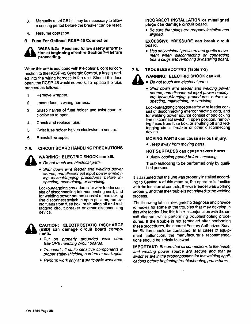
3. Manually reset CB1; it may be necessary to allow
a cooling period before the breaker can be reset.
4. Resume operation.
B. Fuse For Optional RCSP-45 Connection
a WARNING: Read and follow safety information at beginning of entire Section 7-4 before
proceeding.
When this unit is equipped with the optional cord for con
nection to the RCSP-45 Synergic Control, a fuse is add
ed into the wiring harness in the unit. Should this fuse
open, the RCSP-45 would not work. To replace the fuse,
proceed as follows:
1. Remove wrapper.
2. Locate fuse in wiring harness.
3. Grasp halves of fuse holder and twist counter
clockwise to open.
4. Check and replace fuse.
5. Twist fuse holder halves clockwise to secure.
6. Reinstall wrapper.
7-5. CIRCUIT BOARD HANDLING PRECAUTIONS
ft_ WARNING: ELECTRIC SHOCK can kill.
_____ � Do not touch live electrical parts.
a
� Shut down wire feeder and welding power
source, and disconnect input power employing lockout/tagging procedures before in
specting, maintaining, or servicing.
Lockout/tagging procedures for wire feeder con
sist of disconnecting interconnecting cord, and
for welding power source consist of padlockingline disconnect switch in open position, remov
ing fuses from fuse box, or shutting off and red-
tagging circuit breaker or other disconnectingdevice.
CAUTION: ELECTROSTATIC DISCHARGE
(ESD) can damage circuit board components.
� Put on properly grounded wrist strapBEFORE handling circuit boards.
� Transport all static-sensitive components in
proper static-shielding carriers or packages.
� Perform work only at a static-safe work area.
INCORRECT INSTALLATION or misalignedplugs can damage circuit board.
� Be sure that plugs are properly installed and
aligned.
EXCESSIVE PRESSURE can break circuit
board.
� Use only minimal pressure and gentle movement when disconnecting or connectingboard plugs and removing or installing board.
7-6. TROUBLESHOOTING (Table 7-2)
a WARNING: ELECTRIC SHOCK can kill.
� Do not touch live electrical parts.
� Shut down wire feeder and welding power
source, and disconnect input power employing lockout/tagging procedures before in
specting, maintaining, or servicing.
Lockout/tagging procedures for wire feeder con
sist of disconnecting interconnecting cord, and
for welding power source consist of padlockingline disconnect switch in open position, removing fuses from fuse box, or shutting off and red-
tagging circuit breaker or other disconnectingdevice.
MOVING PARTS can cause serious injury.
� Keep away from moving parts.
HOT SURFACES can cause severe burns.
� Allow cooling period before servicing.
Troubleshooting to be performed only by qualified persons.
It is assumed that the unit was properly installed accord
ing to Section 4 of this manual, the operator is familiar
with the function of controls, the wire feeder was working
properly, and that the trouble is not related to the welding
process.
The following table is designed to diagnose and provideremedies for some of the troubles that may develop in
this wire feeder. Use this table in conjunction with the cir
cuit diagram while performing troubleshooting proce
dures. If the trouble is not remedied after performingthese procedures, the nearest Factory Authorized Serv
ice Station should be contacted. In all cases of equipment malfunction, the manufacturer�s recommenda
tions should be strictly followed.
IMPORTANT: Ensure that all connections to the feeder
and welding power source are secure and that all
switches are in the proper position for the welding applications before beginning troubleshooting procedures.
OM-1584 Page 28

Table 7-2. Troubleshooting
TROUBLE PROBABLE CAUSE REMEDY
Wire feeds, shielding gas flows,but electrode wire is not ener-
gized.
Contactor control connection
(Interconnecting cord).
Check interconnecting cord connections. If se
cure, check cord for continuity and repair or re
place.
Welding power source. See Troubleshooting Section in welding powersource Owner�s Manual.
Wire does not feed. Circuit breaker CB1. Reset CB1 (see Section 7-4).
Loose or improperly made gun
trigger connection
Check gun trigger connection (see Section 4-7).
Gun Trigger. See gun Owner�s Manual.
Motor. Replace motor.
Motor control board PCi. See Section 7-5 and contact nearest Factory Authorized Service Station.
Wire feeds erratically. Pressure on drive rolls is insuffi-
cient.
Rotate pressure adjustment knob clockwise in
1/4 turn increments until the wire stops slipping(see Section 6-1).
Drive rolls wrong size for wire
size used.Change to correct size drive roll (see Section
4-6).
Drive rolls worn. Replace drive rolls (see Section 4-6B).
Dirt in drive rolls. Clean drive rolls (see Section 7-iC).
Incorrect size contact tube or
liner.
Check and replace necessary parts.
Obstruction in gun contact tube
or liner.
Clear obstruction in gun contact tube or gun liner.
Motor control board PCi. See Section 7-5, and contact nearest FactoryAuthorized Service Station.
Motor runs slowly. Low line voltage. Correct low line voltage.
Obstruction in gun contact tube
or liner.
Clear obstruction in gun contact tube or gun liner.
Gun nozzle opening restricted. Weld spatter or foreign matter
accumulation.Carefully remove any weld spatter or foreignmatter which may accumulate around the nozzle
opening. Use a hardwood stick, never a metal
tool.
Wire does not feed until triggeris pulled, but continues to feed
after trigger is released, and
trigger hold is not on.
Welding gun is shorted be-
tween one of the trigger leads
and weld cable.
Replace welding gun.
The gas valve in the feeder is
rattling loudly along with possi-ble erratic or slow wire feed
speed.
Welding gun is shorted be-
tween one of the trigger leads
and weld cable.
Replace welding gun.
Unit does not switch out of
RUN-IN-SPEED.
Unit is not receiving current
sensing or voltage sensingsignal.
Install, reconnect, or replace reed relay or volt
age sensing leads.
Wire feeder power is on, meter
lights up, but unit is inoperable.Trigger lead is open. Replace welding gun.
4-In-i circuit board PC3O. Turn off power to unit for 30 seconds. Turn power
back on to reset unit.
OM-1584 Page 29

NOTES
OM-1 584 Page 30

PCI
RDTOABOARD
PCI
/PLGI RC2/P102 RC3/P103
P03-B>:
RC4/P104
P03-9>>
RC0/PU~ P03/9166
P03-10>>~
P03-Il)>
a
~
a
�
R03-I2>>
_v_v_v_v_v_vI
�i~
i~
T~
L
Tkl
i�~
�A-U~-A-A ~R
~
P036-3>) P036-2>)
PC7
P036-I>)
.AS~RBOARD P033,91003
~
22
P034-B)111
P0361PLG06
U) Ill C)-I 0 z mIrn C)-4 C) I 0 C) U)
PLOIOA
/
<<RCAI
___________________________I
I
_<<RCA-O
0
<
MIT
~:
<<BC6-4/0
<<RC6-2
PLG7R <3
E<~0
<2
C(acw
PLGI9
~
<
MIT,&K
-
PLG27
RC3O
PLOI
2
&X
59%�
9
9
6<
>6
>
-<6<
(~)I
<RCA-b
1P101
L~~__<i
II
I
PL626
P1029
P1037
RC4O
r-~-�<6<~)6>
�
<6
(~~RIl34T
OAI0I
____
�
P1017
P1036
P1039
P03PflAYBOARD P032/91092 PC93/Pt.693 PCO4/PIG9A PC9B/PIG9O PC96�91G96 PC99/PLG99
BlOAT
LEFT
TRIGI~R
TRIGGER
I
23
4
I
2
3
4
P1026
P1034
IlL3
TIlL
I
234
I
2
3
4VRC9
yRce
VV
ILEDI
I
-,
I
_____
I�~
____
______
5
172
______
/9
22
2/
172
______
J7
22
______
/
I
I
~
~
ho
~
�
I
AAA~AA
A
RC3-I>>-
<<RC94-I2
R
R
~
~
BC9J-I>~
.0
.0
0
.0
�
______
~
~~�~?�?
~RC92-I>)�~
RC3-2>>
<<RC94-6
�
�
0
-
(S
�
�
�
I
a
C,
o
a
�
RC3-3>>
<<RC94-7
�9
RC3-4>>
<<Rt94-I4
RC4-2>>
<<RC94-8
/0
RCA-3>>
<<RC9&-I3
�
2
6C4-4>>
<<RC94-I0
�
6
RC4-2>>
�<<
RC94-4
�
22
RC4-7>>�
<<RC94-I6
10
RCA-b
>>�
<<RC94-2
RCI-I>>
RCI-2>>
RCI-3>> PCI-A>> RCI-0>)
RCI-6>>
PCI-I>> PCI-B>> P03-I>> P03-2>> P03-3>> R03-4>) P03-6>> 903-7>>
8
88
0 00 03 -P. -u 03 03 C.)
CircuitDiagramNo.
SC-142857-B
Diagram8-1.
CircuitDiagramFor
Wire
Feeder

V~TAGE SEP~E 12
RIGHT LEAP (~TIGHAL)Ii
70BUSS
14
LEFT
>2W -
~,0
�~
PC 1-3)
CI~6>>~PCI-B> I
-
~c-~>--k >_Z~~
PCI-I >~>~J >~z~:~
PCI-A I >�~-�
RCI-2)>�~4 >-~-
PCI-P >>~~J >�~-
RC2-4 >>~<< RCP3-4__
RC2-5 >>~<< RC53-5 ~L~ER BOARO
RCS3/PLGP3
P03-2 >)�<< P033-2
BC2-6 >)~<< BC53-6 O~
PC2-I >>-~<< P033-I
P03-3 >)-Z:< 5033-3
i-i 8
7~7
1~j~OS�
P101
84 5
P1027A A A
t~ I~ I~v~ i~ i~
PLG2B~ 4� 4�BA 5
Wl�N DIGITAL V~7AGE C347R~. -
IS USED WITH A CGHVENTIGHALPOWER SQllCE WAKE Tl~ FDLOWDG
CD��CTIGHS AT PC4O~
RCA I -P1.041PCA2-PL042PC43-PL043PCA4-NICRC45-P1.06
Wl�EN DIGITAl.. VO.TAGE CGHTP~..IS USED WITH AN INVERTER
POWER EDPCE MARE 71� F~LOWI~COPl�CTI~�S AT PCAO~
RCA �-P1.061RC42-N/C
RC43-P10435C44-PL042RC45-P164
PLO27 P030 Pt.G12
J~<6~6 >~f(A~ Ff<CR101
MI ~
>-~< ( t
ptc�i P1.028 P1.029
P1037 RCAO
A~.�P eqS� ~P1.018
r~<6E~6 ).�(6
M2 IICR101
5(A~ ,
P1.017 P1.036 PLG39 1~)
~C6
P1.010CR�
~K~ /
~
A A APLG3�
I~ I~ I~lc~ i~ I~4� 4, 4�Pl~G38RaP
V V VRC4O
~ ~ /�~P1.039
845A 4� 4�PLGI8
/0 I� -
I I II �t�1�+
P1.019
u (~
-<
C (~
~allY
S C
8Rca-A
PCDOP1.012
Rc53/PLGP3 ~ >~
R034/P1.004
Pc56/PLG56 R~a-3
_____
1~ ,E ~ 1~ I5~ ITADOETER BOARD I
(OPTtD~AL) I
I A-A-A�AAAA.~A~P034-A >~~<PC9B-9 ~
�0 ~ �0~ ~Rt54-5>)~~<RC9B-3 ~ ?01 � CR a � a � tu 01 � 0PCI
______
~~~RC51-2_>>�~<<RC9B-6
RC 1/91.01 ~<<RC96-2 RELAY 80450~ f,o�1��~2lC96 I
~
69
I I 70
RC9I /91.0915C3/PLG3 I I
RCA/P1.04 �Jf �J~ P1.012 �1~pC_GII RC9G/P1.092PC93/P1.093
pC5,pt_o~ 3 2 7 3 2 ~RC94/P1.094
RC6/P106 V~ y VP1.029 V V V 91.039 RC9D/P1.G95
0 I~ I~ I~ i~ RC96/PLG96A ARC3O A A APCAO3 2 7 3 2 ~ PC98/P1.098
4~ 1q~ �~PLG28A~ 4�~ A P1.038 �(<RC94-6 5C99/P1.099
1~ 1~ 1~ hi~ZRC6-I 3�~ 2�~ ~ 4�C �l�P1037
7 3 2 7 �<<RC9A-14
y VPLGIIV \~ vP1017
~ i~ ~ I<RC94-8
~RC6-3 4,P1.05I4� 4� *91.0070 l�p
32 I 32 I
- ~ ~V P1.057 V V P1.057
~RC6-4 � �j�~ ~ ~ ~ V.V.V.V.V.V_V.V.V V V____________
RC6-2 I PCDI I I P002 I /0
P04-9 ITAC}~�7ER I I TACIOCTEP IIii
_,
I LEFT �I RIGHT I LI,I Y/aY-~Y Y 141I ~I0i~ ! I I I LED� RC9A A A ALED2 ~A
4321 1321
RC3-l >>
P1020~ ~ P10234�
RC3-3 >>�~ P1.0264 3 2 I
P1.024
2
~ I LEFT RIGHT
RC4-2 >>�~TRI00ER TRIGGER
PC3-2))-~-
T_______P04-5 >>~PC4-7 _______________________________
I I,~QLjj~ I
RC4-3>>-~ /0
RCA- ~ RIGHTI
RC4-4>>-~
~_____
P00-8>)-~�/0 /0 z
�P00-A >>~ . 29 ~
_____________
____________________________________
~ I ~r�LJ~______________
_____________________________
� I~g~ .oIP00-P________________________________________________
:�
~FT I I WETEP451 42 OPTIGHJUU
P1044
L
p031 >)-~� <<RC62-3P034� > >~<< RC43-6 ~
_____
~AL ??~~IP00 2
I55 ~< P043-5 o
- 01__________
P064-2> >�<- -<< RC62-2 01 -
I CONTRQ. PC4I
p~ 3 ~> .~a PC6O p034.3 > )�(< RC43-4 (OPTIONAL)- << P062-4
PC62IP1.062< PC43-3
FOP PC/PIG C~9ECTIGHS PC42-2>~o�I I P034-A> >.~.<_______________
SEE ICTESP042-3>>�P05-6 >>�~- <<5062-I RC63/P1.063
I Rt64/P1064 p0345 >)~~ >~<< P043-2PC4~- I>>�505-7 >>~- ~<< RC62~5
DIGITAL PETER< P043-I
a
______
BOARD IOPTI~AL) PC64-6 >)�~ )�<I_________________________
I ~ P041-A>
40
OM-1584 Page 32
Diagram 8-2. Circuit Diagram For Wire Feeder With Optional Equipment
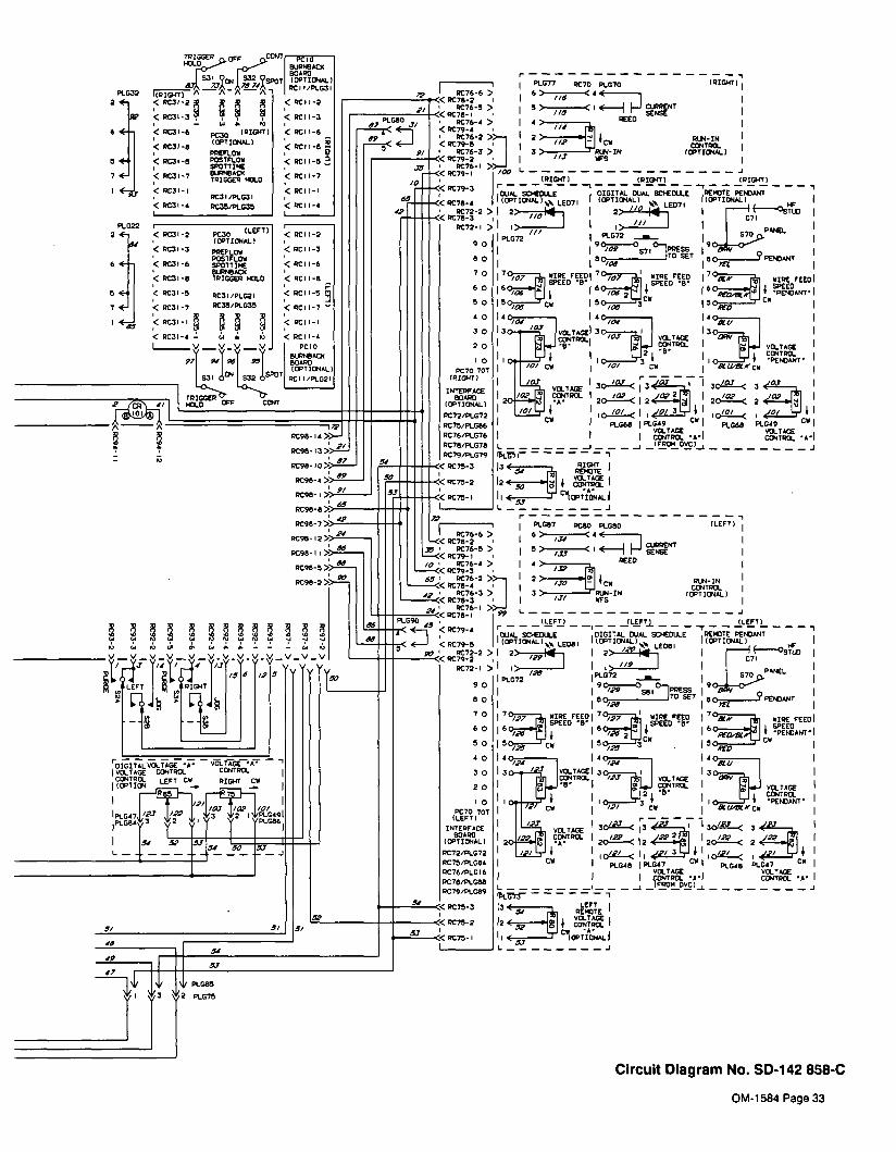
TRIGGER ~CONY
;9c1~ PLJRPC6CRI BOARD
SPOT� IOPTIONA1_)
_________
I P01 �P1031IIPIONTI
�
A A I
<POl-1 ~ <P011-S
<P011-3<P031-3
<P031-6 IPIQ4TI <5011-6P030IONTIONAL)
c PCI-I<P031-II POEFLOW
< P031-S POSTFLOW <P0Ii-sA
SPOTTI1E
<P031-7 PINPOACK <P011-7TRIGGER 10.0
P031-I <Poll-IRC3I/P1031
<P031-4 5035/P1030 <POll-�
<P011-2
<P011-3
<P011-6
<Roll-P
<P011-5
<P011-7
<POll-I
<Poll-A
r
P1077 P070 P1070 IPIONTI
6>-
5)-,,~
CI.E�j FJ~g~!jNT________
PEED
I 2>-~
PIN-INCONTRa.
3)- P1)4-IN IONTIONALISt
L
15101411 IPI01IT) IPIOWTI
OVAL SCIEOLLE DIGITAL DiAL 5C1EOLLE REMOTE PEcCANT
IlONTIONAl.1~,.~ LED7IlONTI~W.l
~ LED7IIIONTIDIIALI
l2>,,~14I 2)~t~4 E°s~tvI i
___
///
P1.072 I P1072 ...a. ,I 870
9o�o 0RESS~ P71___________ITO SET ?PE1C80/09
7Cy~~, ~~0rEEo~ 707~y~ WIPE FEED ~°a, ~ WIPE FEE0ISPEED P
60� ��1-~I � SPEEDI6~~j~ ~ I .6PD~ftA~~ PEMOANTI5p TCW~S
,~ ~ ~ IAID
I40~ I40/~,f 140*0/ I
I~Ica4TROLI~,o.,4Q JVOLTAOEI 3~~jJ VOLTAGE
VOLTAGE
�I/0/
~ , CONTPO_1 P51~ANT3 I
LOGE CAOW
Il/ar___
~VQ_TAGE
/02.~
CONTROL I /02, 24L.1~1 20a_< 22 A 20�<
/0/ 1______jO/ ~ I0~�~_.< I
P1066 PLOIP 0W1 P1086 P1019 OW1VOLTAGE VOLTAGEI CONTROL A1 CONTRa. 6l
L� � �
~ _l~OND~l~1P15~i 7
13� P1014?5� REMOTE
___
VOLTAGE12 ~ �It~ i
II C
J
P1017 POlO P1080 ILEFT)
6)-/J4~<4C
~~-Ci4----�j ~ aPRENT
WOE
___________
PEED
14>/~7 ~2> wIwl
/20 �i owPIN-INCONTROL
3 )- ~PIN-IN IOPTIONAII/2/ ~
L J
(LEFT) ILEFTj IIEFTIr
DiAL SC1�OLLE DIGITAL DiAL SCI-�DI.LE ,PEICTE PEcCANT
lCPTID4AL1~~ LEOIIIONTIONA1I
2> /flI4 II 2> ~ LEDII
(ONTIONALI
~>~-I I)~~~�
ØPAVEL
~ ~PPESS
/nP1072
P1072 S7
/29 ~ Ito SET 9 PEcCANTI ID/a I 8°?fl
7~WIRE FEEo~~ WIPE FEEO 70~.v * WIRE FEEDISPEED 816a SPEEOP
60 ,1-j1SPEEO16,~ a 1%2a.-aA1j
PEICANTI
~ OW~ ~5p
ow
AID
I4c~- 14°,,, I4o~~
I ~I CONTROL
I 3o�.t...�~L IVOLTAGEI~ VOLTAGE 3~1.j VOLTAGECONTROL I
:iorI_,?~ct �I V I I .PEPCANT. I3 I
I OW
11/23 13a_<3en3a_< 3?~I ?-~ VOLTAGE
~ CCNTPQ I 2a-< 2 a-$J 120a< 2
L~Lb-�1 l0~~< I~ º�~ II 0~~< ~I P1048 P1047
~ I P1048 k047 ow
VOLTAGE VOLTAGECONTROL A~I CONTROL �A
L ~ lF~N_0~l~
13< LEFT I51 PEIIOTE
__________
VOLTAGE12Csp catAlPa.1__ow
Circuit Diagram No. SD-i 42 858-C
P1032
P1022
2
6
S
7
<P031-2
<5031-3
<P031-6
<P031-I
P031-S
<P031-7
< P031-I
< P031-A L
P030(LEFT)
(ONTIONVL(
PPEFLOWPOST FLOWSPOTT IcCPLPMOACXTRIOGEP lc~O
PC3I/PL02l
PC3S/P1035
P
ca a
90
80
70
60
50
U
11
POlO
8LRtADIBOARDIONTIONVL,
PCI l/P1121
P098-IA:
P091-13:
PC9I- ID:
P098-A:
P098- I:
P098-I:
P098-7:
P098-2:
Roll-Il
P091-5:
P098-2:
C
~1047j,,27~, ~J,�c:~---1P1084113 ~ ~y1 ~3 y2
P1085
P1075
OM-1 584 Page 33

42A)P~C-SEMSE LEAD)
ISA I P1092-4
, l3A)Pt092-3
93 (~
A�
/ 4A)PI
BA)PLG93-4)
1~IOA(P1G92- 3)
1~
L__{__tT~ fi )\~J
RC&t~~oA)ptGq2. IS
44A)PIG 2-5)
4~AEPL.GI~-W)
35e)PLG.4-7
I6A)P~G3-
I9B)Pt,634)
08 (P104-3)
4)A)CP 101�A)
25) CR 101-B)
2B(
20)P1.GI8-4
CA~T~ IOH)Pt.092- I)
26A)PL092- 12)
LED I
RRP1(PLG7A-4) 376)PtG92-R)
38A)LEI
I~)LE)
I9A)~I
I~)LE
RE1
-
I)
RED(P1G26-3)
9lJ()Pt.026-I) : ~
PLG25
IOD)R2-CCW)
CC)296)PLG9S-3)
CW 8A)R2-CW>
24A )PLGR2-e)
36)PtG92- IA)Rc9
l2A)PLG92-I)
B) ,£ lAA)PLG92-2
S2
________
3A)PLG93-3)A
5A)PLG93-l
l0(PL093-2)
-~ ~-dAIS A-~
274)
~JRC9ORc99 2
PLG99~__
RC92/PLG92
~G4~I0)2~Il~L~)I9
RC94RC93/PLG93
PLC94
1 ~T7~296)9) N PC3
__
11/11…B~ 4 30A)92:W
Rc91PC95 PLG96__________
PL695 RC96__________
~ 5 I
BRN)PL624-A)
_________________
)
iJ!!~I) I)~LwHTlPt024~2 �~~�G23
1 1~ 1~~~: ~ ~h
PLG~SEI2 3
PLC26_____
43A)PLG99-2) ~I
-~ ; )Ti) ~cIRc~o�S~ ?
�
~69A)P1096-2
_LQ�~ ~ç40-2 ~ 6 7Q)Rç4Q-~) I00f~G%-~) ~ii1~ )
{~J69C)RC4O-7)
___________________
l)C40-I I) 6B)RC4O-S) I IA)cpl0I-I~]~
- B8)PtG94-~)~jPLG39
PLC I 8
CATI~ I0JIPt.092-I4
38A (PLG92-9)
LED 2
2F ) OS I
44B)LEFT BUS BAR) Ic~OB(#LG5I _
LEFT
g~ ~:r:~::::E3� 44B)PLGII-6)
~~II IOVIPLGII-2) ~
70B)PLGII-7) J
PLG5 I
WIlT) PI~Gl - I)
704 )P1096-3 I44A)PL099-l) I
2C30-3)
~70C)9C30-71)
1 LI~1 68A)PLGS6-3)
C30-�) fj~ 44C)RC3O-6) ~~2C)PLG9I- I)I
RC30-22 6
98)RC30-6)
~IOP)PtG56-2) ~
__________________
7C)SPLIcE)C3C-I I~
S0(RC30-5)
SS(PL.G94-RPLG29______________
121 ~.,M-7)
PLC 12
I ABCIPIGSI-3) I~t~1?4r
WIlTIllI)
cLAN)) PLCI IJ~lSC)PLGII-5)
2F)PLGJ I�i)
LEFT
!REX(
8.U/21K)PLG2~-2)
I~N)PLG28-II
--
RLK)P1028-S)
BPtl)PL028-6)
PLC27
V~l 121 It1~-7l
LEFT
Il-B)
PIGIITBUSSAP
RIGHT
1~)6 ~U/Bu()PLG3a-21
~N)PLG38-I I)
RED/RIX (P1038-3]
~N)Pt.G3O-6(
PLG37
OM-1 584 Page 34
Diagram 8-3. Wiring Diagram For Wire Feeder

~4(CI-C21(
~l9I0
2A(PLG6-4)�
IOA(P166-2)U)
OAD(C2
I�.
~
___________ IR(P1G6-I
~~
35A(PLG6-3
II
I-)
8
nm
11
~
H
284(101
-cGH)(~J1717A(ICE
3~8(PLG94-I6
___________
RED
-u
~
(C(~O
___________
______________
(
rC)
40A)P1G94-9�
~
AC(P1G94-4
C)
I-n
35O)PLG~~
25A)P1GI-
3DE(PLGI-7
___________
RIGHT
2RA(PLGI-
I-
C,JC~) (,J
___________
164(P1694-
IRA
( 198)P1G94-141
II~1~j~7AIP1~4-6i-u;u I_n G~)
(~)I�)
32A(PLG53-2-~
3-34(PLGR3--5)
I
OC(PLGDO-3) 3~C)PL093-I��
�~
34A(P1053-4(
-u
___________________
C,
-u-u IC) 001 (JI
27A(PLG9R-5~
loc(R2-cc~
�
88(R2-CW)
22A(PLGD4-5) ~A(PLG54-41
~
-u C-)
n.
~-o
I~-~-I--Jg
L~l~
C)
L2L~
(ii
~I~l9IQI~~
____
~i~ji�
L~l~I~I~i~k1~I~
001 01O~ 0�
(1)0
.
0�I o
o orn�I 1-4(J) o
ni zz >0) 1rn I
IB(~I-AC)
1~~JWI-
2A
1W
I-AC)
-~-u-u,,-_~I)
C)
�:r~JiCi
0�
-~I0�
a
�
U
�
�
-o I C~)
4�
-u
7
I
~
Ci -J
0
�/0
~
/
rob
U :1 A0
419 Ua 9
~0I C~) �0
C) (,1 0
I
U)
C-)
�
~
I

0 Ui -u C.) a)
(I) mC,-I 0z CD -IU) r Cl)-I
1
Fig9-3
2
456
10
18 19
Fig9-4
33
15~3 20
1 21
3231
3029
28
14.
26
25
24
23
22
SD-142305-D
27
�
Fig9-5
Figure9-1.
Main
Assembly
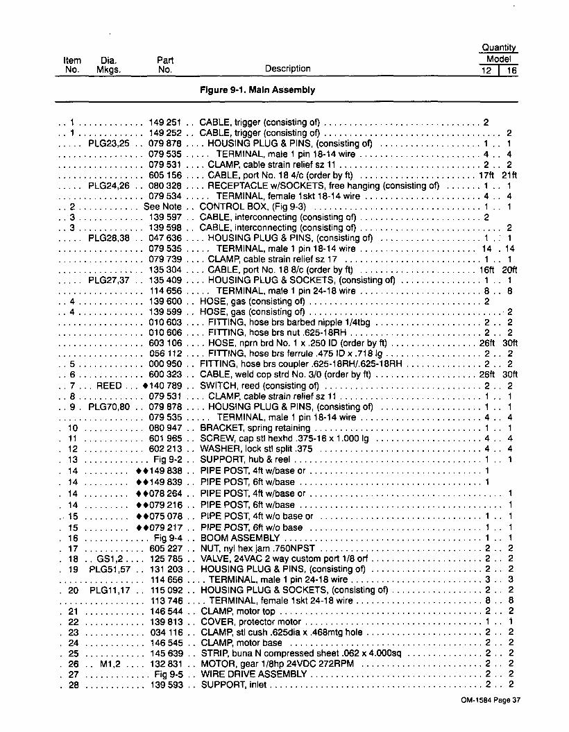
1.149251
1.149252
PLG23,25..
079 878
079535
079531
605156
PLG24,26..
080 328
079 534
SeeNote
139597
139598
PLG28,38. .
047 636
079 535
079739
135304
PLG27,37..
135409
114656
139600
139599
010603
010606
603106
056112
000950
..6 600323
7... REED... �140789
..8 079531
9.PLG7O,80 ..
079 878
079 535
10 080947
11 601965
12 602213
13 Fig9-214 ��149838
14 ��149 839
14 ��078264
14 ��079 216
15 ��075078
15 ��079217
16 Fig9-417 605227
18..
GS1,2.... 125785
19 PLG51,57 ..131 203
114656
20 PLG11,17..
115092
113746
�21 146544
22 139813
�23 034116
24 146545
25 145639
26.. M1,2 132831
27 Fig9-528 139593
QuantityModel
12 I 16
CABLE, trigger (consisting of) 2
CABLE, trigger (consisting of) 2
HOUSING PLUG & PINS, (consisting of) 1..
I
TERMINAL, male 1 pin 18-14 wire 4. .
4
CLAMP~ cable strain relief sz 11 2..
2
CABLE, port No.184/c (order byft) l7ft 2lft
RECEPTACLE w/SOCKETS, free hanging (consisting of) 1..
1
TERMINAL, female lskt 18-14 wire 4..
4
CONTROL BOX, (Fig 9-3) 1..
1
CABLE, interconnecting (consisting of) 2
CABLE, interconnecting (consisting of) 2
HOUSING PLUG & PINS, (consisting of) 1 .: 1
TERMINAL, male 1 pin 18-14 wire 14.
14
CLAMP, cable strain relief sz 17 1. .
1
CABLE, port No. 18 8/c (order by ft) 16ff 20ff
HOUSING PLUG & SOCKETS, (consisting of) 1..
1
TERMINAL, male 1 pin 24-18 wire 8. .
8
HOSE, gas (consisting of) 2
HOSE, gas (consisting of) 2
FITTING, hose brs barbed nipple 1/4tbg 2..
2
FITTING, hose brs nut .625-18RH 2..
2
HOSE, nprn brd No. 1 x .250 ID (order by ff) 26ff 30ff
FITTING, hose brs ferrule .475 ID x .718 Ig 2..
2
FITTING, hose brs coupler .625-18RH/.625-18RH 2..
2
CABLE, weld cop strd No. 3/0 (order by ft) 26ff 30ff
SWITCH, reed (consisting of) 2..
2
CLAMP, cable strain relief sz 11 1..
1
HOUSING PLUG & PINS, (consisting of) 1..
1
TERMINAL, male 1 pin 18-14 wire 4. .
4
BRACKET, spring retaining 1. .
1
SCREW, cap stl hexhd .375-16 x 1.000 Ig 4..
4
WASHER, lock stl split .375 4..
4
SUPPORT~ hub & reel 1..
1
PIPE POST, 4ff w/base or 1
PIPE POST, 6ff w/base 1
PIPE POST, 4ff w/base or 1
PIPE POST~ 6ff w/base 1
PIPE POS1 4ff w/o base or 1..
1
PIPE POST, 6ff w/o base I..
1
BOOM ASSEMBLY 1..
1
NUT, nyl hex jam .75ONPST 2..
2
VALVE, 24VAC 2 way custom port 1/8 orf 2..
2
HOUSING PLUG & PINS, (consisting of) 2..
2
TERMINAL, male 1 pin 24-18 wire 3..
3
HOUSING PLUG & SOCKETS, (consisting of) 2.. 2
TERMINAL, female lskt 24-18 wire 8..
8
CLAMP~ motor top 2..
2
COVER, protector motor 1..
1
CLAMP~ stl cush .625dia x .468mtg hole 2..
2
CLAMP, motor base 2..
2
STRIP, buna N compressed sheet .062 x 4.000sq 2..
2
MOTOR, gear 1/8hp 24VDC 272RPM 2..
2
WIRE DRIVE ASSEMBLY 2.. 2
SUPPORT, inlet 2.. 2
CM-I 584 Page 37
Item Dia.
No. Mkgs.PartNo. Description
Figure 9-1. Main Assembly

Note: When ordering Control Box contact factory service department for proper number.
�Part of Optional 132 131 Run-In Control RH/i 38 530 Run-In Control LH
��OPTIONAL
BE SURE TO PROVIDE MODEL AND SERIAL NUMBER WHEN ORDERING REPLACEMENT PARTS.
Quantity
Model
12 I 16
Item Dia.No. Mkgs.
PartNo. Description
�29
�30
31
�32
�33
Figure 9-1. Main Assembly (Continued)
602 177�.
SCREW, set stl sch .250-20 x .25Oknr cup point 2..
2
146 800..
BUSHING, insulator 2..
2
139 591�. GUIDE, wire inlet 2
�.2
604 612�.
SCREW, set stl sch 8-32 x .125 cup point 2�.
2
082 050..
LINER, monocoil inlet wire 2�.
2
OM-1584 Page 38

Description Quantity
Figure 9-2. Support, Hub & Reel (Fig 9-1 Item 13)
� OPTIONAL
BE SURE TO PROVIDE MODEL AND SERIAL NUMBER WHEN ORDERING REPLACEMENT PARTS.
Item Part
No.
1 058 427..
RING, retaining spool 2
2 136 684..
NUT, stl sfflkg hex reg .625-11 w/nyl insert 2
3 605941.. WASHER,flatstl.640lDx1.0000Dxl4gathk .
2
4 010 233..
SPRING, cprsn .97000 x .120 wire x 1.250....
2
5 057 971..
WASHER, flat sti keyed 1 .500dia x .1 25thk 2
6 010191..
WASHER,fbr.65610x1.5000Dx.l25thk 4
7 058 628..
WASHER, brake stl 4
8 058428.. HUB, spool 2
9 080 393..
SUPPORT, reel 1
10 �108 008..
REEL, wire 60 lb (consisting of) 2
11 124 900. . ..
SUPPORT, reel spool 1
12 124 905.. .. RETAINER, spool support 1
13 124904.... NUT,spannerspoolsupport 1
1
5
10
87
6
9
Figure 9-2. Support, Hub & Reel
SC-08t 760
OM-1 584 Page 39

1
Fig9-7
SC-142307
2
3
4
4
21136536_~~35~
22
24
23
28
2
6
29
30
27
F1g9-6�33
32
Figure9-3.
ControlBox

Figure 9-3. Control Box (Fig 9-1 Item 2)
item Dia.
No. Mkgs.Part
No. Description Quantity
3
6
2
3
�
1 140 010..
PANEL, side lower 1
2 PLG1,29,39,53,95
.. ..115 092
..HOUSING PLUG & SOCKETS, (consisting of) 5
113746. . . . TERMINAL, female lskt24-l8wire 8
3.... PC2....
134 994..
CIRCUIT CARD, tach jumper 1
3...
PC5O...
�132 370..
CIRCUIT CARD, tach converter 1
PLG51,57 .�131 203
..HOUSING PLUG & SOCKETS, (consisting of) 1
114 656. . .. TERMINAL, male 1 pin 24-18 wire 3
4. PLG2,54,93 .
115 093..
HOUSING PLUG & SOCKETS, (consisting of)113 746
. . .. TERMINAL, female lskt 24-18 wire
5. PLG56,96 ..
131 204..
HOUSING PLUG & SOCKETS, (consisting of)113 746
. . .. TERMINAL, female lskt 24-18 wire
6.PLG12,18
..135 409
..
HOUSING PLUG & SOCKETS, (consisting of) 2
114 656. . . . TERMINAL, male 1 pin 24-18 wire 8
7.. RC7O,80 ��048 282
..RECEPTACLE w/SOCKETS, (consisting of) 2
079534. . . . TERMINAL, female lskt 18-l4wire 4
8. .
RC3O,40... 047 637..
HOUSING RECEPTACLE & SOCKETS, (consisting of) 2
079 534. . .. TERMINAL, female lskt 18-14 wire
....14
9 139 231..
CASE SECTION, bottom/rear 1
.10
�.PLG4
....115 091
..HOUSING PLUG & SOCKETS, (consisting of) . . . .
1
113 746. . .. TERMINAL, female lskt 24-18 wire
. ..10
.11
.PLG3,99... 115 094
..HOUSING PLUG & SOCKETS, (consisting of) . .. .
2
113 746. . .. TERMINAL, female lskt 24-18 wire
. . . .4
.
12..
PLG5....
130 203..
HOUSING PLUG & SOCKETS, (consisting of) . .. .
1
113746. . . . TERMINAL, female lskt 24-18 wire
. . .
12
.13
..PLG6
....136810
..HOUSING PLUG & SOCKETS, (consisting of)
114 066. . .. TERMINAL, female lskt 20-14 wire
.14
...PCi
....131 818
..CIRCUIT CARD, motor control
.15 089 899
.. LATCH, slide flush
.16 140008
..
WRAPPER
134 464. . LABEL, warning general precautionary
.
17...
CB1....
083 432..
CIRCUIT BREAKER, man reset 1 P 1 OA 250V
.18
...Si 111 997
..SWITCH, rocker SPST 1OA 25OVAC
.19 010 325
..BUSHING, strain relief .840 ID x .875mtg hole
.20 110 015
..CABLE, port No. 18 7/c (order by ft)
.21 079 739
..CLAMP, cable strain relief sz 17
.22
..PLG1O
...141 162
..HOUSING PLUG & PINS, (consisting of)
134 731. . ..
TERMINAL, male 1 pin 18-14 wire
PLG19...
052 309�.
HOUSING, term plug nyl lcont female 1
009418. .
TERMINAL, female lskt 20-14 wire 1
PLG75...
131 204..
HOUSING PLUG & SOCKETS, (consisting of) 1
113 746. . .. TERMINAL, female lskt 24-18 wire 3
���132 131. .
RUN-IN CONTROL, RH (consisting of) 1
���138 530..
RUN-IN CONTROL, LH (consisting of) 1
.23 601 222
. . ..CLAMP, univ 50A 1
.24 603 106
. . ..HOSE, nprn brd No. 1 x .250 ID (order by ft) lft
.25 600 399
. . ..WIRE, lead mot l4ga (order by ft)
.26 138 044
. . ..BUSHING, strain relief .120/.150 ID x .500mtg hole
C61....
147 853. . ..
CAPACITOR
R71/81...
121 771. . ..
POTENTIOMETER, c sltd sft 1/1 1W 10K ohm
R77/87...
115 093. . ..
HOUSING PLUG & SOCKETS, (consisting of)113746 TERMINAL,female lskt24-l8wire 6
048 144. . . . TERMINAL, male 1 pin plug keying 1
.23 �601 222
..CLAMP, univ 50A
.24 �603 106
..HOSE, nprn brd No. 1 x .250 ID (order by ft)
.25 �600 399
.. WIRE, lead mot i4ga (order by ft)
.26 �138 044
..BUSHING, strain relief .120/150 ID x .500mtg hole
1
4
1
1
1
1
1
1
lift
14
35ft
ift
35ft
OM.1584 Page 41

Figure 9-3. Control Box (Fig 9-1 Item 2) (Continued)
�Part of Optional 138 544 Digital Meter wfrach Feedback
��Part of Optional 132 131 Run-In Control RH/i 38 530 Run-In Control LH
�� �OPTIONAL
÷Not part of Control Box AssemblyBE SURE TO PROVIDE MODEL AND SERIAL NUMBER WHEN ORDERING REPLACEMENT PARTS.
Item Dia.
No. Mkgs.PartNo. Description Quantity
.27 134201
..STAND-OFF SUPPORT, PC card .312 12
.
28.. Ci,2
. . . .
147 856..
CAPACITOR ASSEMBLY 1
.29
...SRi
... .035 704
..RECTIFIER, integ 40A 800V 1
.30
. .CR101
. . .
072 817..
RELAY, end 24VAC DPOT 1
.31 057 357
.. BUSHING, snap-in nyl .937 lOx 1.l2Smtg hole 2
.
32 +145 948.. BRACKET, mtg control box 1
.
33 Fig 9-6.. PANEL, front w/components 1
.
34 045 852.. CLIP, component .687dia mtg adh back 1
.35
...PC3
. . . .
138 060..
CIRCUIT CARD, relay control I
.36 PLG92,94 . .
131 052..
HOUSING RECEPTACLE & SOCKETS, (consisting of) 2
113746. . . . TERMINAL, female lskt24-18 wire 16
.
37 Fig 9-7..
CONTROL PANEL 1
120 304. . BLANK, snap-in nyl .25Omtg hole 5
119 951. . BLANK, snap-in nyt .437mtg hole 6
107 983. . BLANK, snap-in nyl .500mtg hole 1
024 103. . BLANK, snap-in nyl .75Omtg hole 1
000 527. .
BLANK, snap-in nyl .875mtg hole 4
OM-1584 Page 42

Table 9-1. Drive Roll And Wire Guide Kits
Wire Size
Wire,~~.auiue
V-GROOVE U-GROOVE V-KNURLED U-COGGED
Fraction Metric
Drive
Roll
Kit*
Drive~ ~
�
Drive
Roil
Kite
Drive~ ,,riO�
Drive
Roil
Klt*
DriveD ~~�
Drive
Roll
KIr
Drive
~
.023-.025 in. 0.6mm 132 740 140 915 087 130
.030 in. 0.8 mm 132 740 140916 053 695
.035in. 0.9mm 132740 140917 053700 140927 072000 140943 132958
.045in. 1.1 mm 132739 140918 053697 140928 053701 140944 132957 140961 083489
.052 in. 1.3 mm 132739 140919 053698 140929 053702 140945 132956 140962 083490
1/l6in. (.062 in.) 1.6 mm 132757 140920 053699 140930 053706 140946 132955 140963 053708
.068-.072in. 1.8mm 132757 140947 132959
5/641n.(.079in.) 2.0mm 132757 140931 053704 140948 132960 140964 053710
3/32 in. (.094 in.) 2.4mm 132738 140932 053703 140949 132961 140965 053709
7/64 in. (.110 in.) 2.8 mm 132738 140933 053705 140950 132962 140966 053711
1/Sin. (.125 in.) 3.2mm 138012 140934 053707 140951 132963 140967 053712
*Each kit includes 2 wire guides and 4 drive rolls. S.0549
CM-i 584 Page 43

C�) F~ 0)0 C~1
o ~- c~ c~) ~~. 1~ !~ ~
C,
a
F-
(0
c~1
(~1
C.)C�
In.
EQ(I)(I)
4
E00
0)
C)
U-
/
C�)
OM-1 584 Page 44
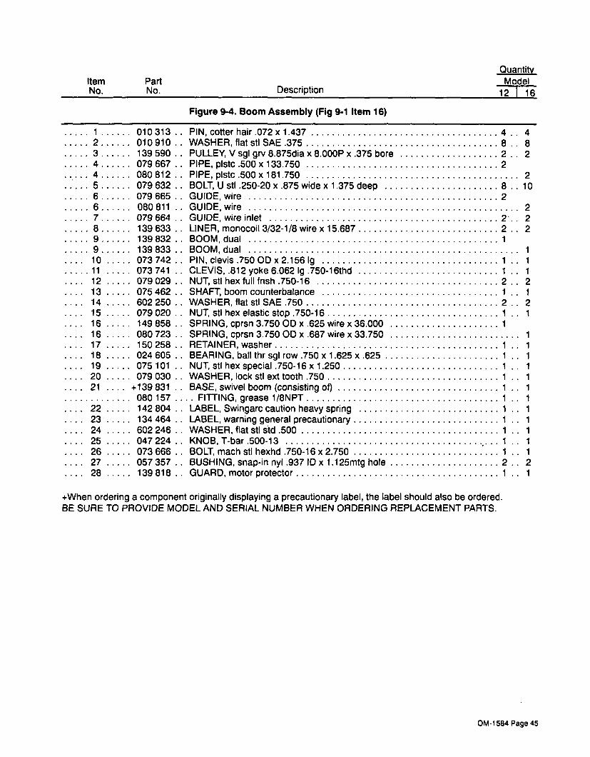
+When ordering a component originally displaying a precautionary label, the label should also be ordered.
BE SURE TO PROVIDE MODEL AND SERIAL NUMBER WHEN ORDERING REPLACEMENT PARTS.
Quantity
Model
12 I 16
Item
No.
Part
No. Description
Figure 9-4. Boom Assembly (Fig 9-1 Item 16)
1 010313.. PIN, cotter hair .072x1.437 4
..
4
2 010 910. . WASHER, flat sti SAE .375 8
..8
3 139 590. . PULLEY, V sgl grv 8.875d1a x 8.000P x .375 bore 2
. .
2
4 079 667. .
PIPE, plstc .500 x 133.750 2
4 080 812. . PIPE, plstc .500 x 181 .750 2
5 079 632. . BOLT, U stl .250-20 x .875 wide x 1.375 deep 8
. .10
6 079 665.. GUIDE, wire
.2
6 080811.. GUIDE, wire 2
7 079 664.. GUIDE, wire inlet
. . .2.. 2
8 139 633. .
LINER, monocoil 3/32-1/8 wire x 15.687. . .
2. .
2
9 139832.. BOOM, dual. . .
1
9 139833.. BOOM, dual 1
..10 073 742
.. PIN, clevis .750 OD x 2.156 Ig 1..
1
11 073 741. .
CLEVIS, .812 yoke 6.062 Ig .750-l6thd 1. .
1
..
12 079 029.. NUT, sti hex full fnsh .750-16 2
. .
2
...13 075 462
.. SHAFT, boom counterbalance 1..
1
...14 602 250
..WASHER, flat sti SAE .750 2
..2
..15 079 020
..NUT, sti hex elastic stop .750-16 1
..
1
..16 149 858
.. SPRING, cprsn 3.75000 x .625 wire x 36.000 1.
...16 080 723
..SPRING, cprsn 3.750 OD x .687 wire x 33.750 1
..
17 150258..
RETAINER,washer 1..
1
...18 024 605
..BEARING, ball thr sgl row .750 x 1 .625 x .625 1
..
1
..
19 075 101.. NUT, sti hex special .750-16 x 1.250 1
..
1
...20 079 030
..WASHER, lock sti ext tooth .750 1
..
1
..21
....+139 831
..BASE, swivel boom (consisting of) 1
..
1
080 157. . . . FITTING, grease 1/8NPT 1
. .
1
...22 142 804
.. LABEL, Swingarc caution heavy spring 1..
1
...23 134 464
.. LABEL, warning general precautionary 1..
1
...24 602 246
.. WASHER, flat stl std .500 1..
1
...25 047 224
..KNOB, T-bar .500-13 I
..
1
...26 073 666
..BOLT, mach sti hexhd .750-16 x 2.750 1
..
1
...27 057357
..BUSHING, snap-in nyl .937 ID x 1.l25mtg hole 2
..
2
...28 139 818
..GUARD, motor protector 1
..
1
OM-1 584 Page 45

46
20
SeeTable9-1
For
DriveRoll&
WireGuideKits 28
SC-146271
11
10
7
2
14
1
15 16
7
6
I
I
~
I
�
_%
32
40
29
Figure9-5.
WireDrive
Assembly

Description Quantity
Figure 9-5. Wire Drive Assembly (Fig 9-1 Item 27)
Item
No.
PartNo.
..
1. . . .
132 742. . KNOB, spring shaft .375 ID x .625 ID 1
..2
. . . .133 739
. . WASHER, flat teflon .375 ID x .625 OD x .O62thk.
1
..3
. . . .132 747.. CARRIER, shaft 1
..4
. . . .078 671
. . PIN, spring CS .093 x .500 1
..5
. . . .132 824
.. SHAFT, spring 1
..6
. .. .145 635
. .SHIM, al .562 00 x .390 ID x .O2Othk (RH only) 2
..7
. . . .132 746.. BUSHING, spring 2
..8
. . . .133 603
. . SPRING, cprsn .72400 x .082 wire x 1.125 2
..9
. .. .132 823
. .RETAINER, spring 2
..10
. . . .137 248
. .SPRING, indicator 1
..
11. .. .
604 772. .
WASHER, flat stl SAE No. 8 1
..
12... .
602 200. . WASHER, lock stl split No. 8 1
..13
. . . .602 082
. .SCREW, mach stl rdh 8-32 x .500 1
..
14. . . .
133 493. .
RING, retaining ext .250 shaft x .O25thk 2
..15
. .. .133 350
. .PIN, hinge 1
..16.... 139346.. HINGE,cover 1
..17
. .. .602 008
. . SCREW, cap stl sch .250-20 x 1.000 2
..18
. . . .
141 044.. PIN, rotation pressure arm 2
..19
. . . .132 750
. .ARM, pressure 2
..20...
.133494.. HOLDER, guide 2
..21.... 133604.. CAP,guide 2
..22
. . . .145 072.. SCREW, cap sti sch .250-20 x .375 2
..
23. . . .
602 009.. SCREW, cap sti sch .250-20 x 1.250 4
..24
. .. .145 641
.. SCREW, retaining arm pressure 2
..25
. . . .
140 048. . WASHER, drive roll 4
..26
. . . .133 393.. CARRIER, drive roll quick release 4
..27
. . . .140 771
. . SCREW, shld stl sch .250-20 x .312 x .800 shld 4
..28.
.. .132 982
. .NUT, drive roll 4
..29
. . . .
139 347. .
COVER, drive roll 1
..
30. . . .
133 530. . DRIVE, pinion 1
..31
... .133 308
. .RING, retaining ext .375 shaft x .O25thk 1
..32
. . . .133 417
. . KEY, stl .125/.126 x .375 1
..33
. . . .601 965
. .SCREW, cap sti hexhd .375-16 x 1.000 1
..34
. . . .602 243
. .WASHER, flat sti std .375 2
..35.
. . .602 213
. .WASHER, lock stl split .375 1
..36...
.601 872
. .NUT, sti hex full fnsh .375-16 1
..37
... .136 674
. .WASHER, flat fbr .265 ID x .750 OD x .O62thk 2
..38
. . . .602 241
. .WASHER, flat sti SAE .250 3
..39
. . . .602 004
. .SCREW, cap stl sch .250-20 x .750 1
..40
. .. .145 636
. .KNOB, clamp bus bar 2
..
41... .
145 640. .
WASHER, shldr nyl .500 OD x .266 ID x .375 dia shldr 2
..42
. . . .
136 665. .
BUS BAR, interconnecting (LH only) 1
..42
. . . .139 221
. .BUS BAR, interconnecting (RH only) 1
..43
. . . .121 271
. .SCREW, cap stl sch .250-20 x .500 2
..44
. . . .
132 748. .
BLOCK, gun 1
..45
. .. .138 193
. .FITTING, brs barbed M 3/l6tbg x .250-20 1
..46..
. .134 834
. .HOSE, SAE .18710 x .410 OD (order by ft) 2ft
..
47... .
136 673. .
PLUG, insulating .568 hex x .22Othk 2
..48
. . . .145 637
. . STUD, lock bus bar 2
136 701. .
WRENCH, hex .187 short 1
BE SURE TO PROVIDE MODEL AND SERIAL NUMBER WHEN ORDERING REPLACEMENT PARTS.
OM-1 584 Page 47

4
10
*See Option that Is applicable
Figure 9-6. Panel, Front w/ComponentS
SC143 227
*
* 3
r
12
11
*
-.
�
��
�
�
~ �
-� ��
* 8 76
OM-1 584 Page 48

FIgure 9-6. Panel, Front w/Components (Fig 9-3 Item 33)
1... R1,2 ....
073562
..2 139225..
136339
�138548
..5... RC8,9.... 048282
079534
134846..
134842..
..8 112061..
9.. LED1,2 ...
089768
�134 379
�138 532
..8 112061
9.LED71/81
..089768
PLG72...
131 054
113746
R72-74/R82-84 073 562
097 922
604 645
�134684
�138536
8 112061
9.LED71/81
..089768
PLG72...
131 054
113746
R76,77/86,87 .603 856
097922
604 645
10 097922
11 604645
12
POTENTIOMETER, C sltd sft l/T 2W 10K ohm
PANEL, front
Part Of Optional 138 544 Digital Meter wlrach Feedback
COVER, opening meter
DIGITAL VOLTAGE CONTROL
RECEPTACLE w/SOCKETS, (consisting of)TERMINAL, female lskt 18-14 wire
SWITCH, tgl SPTT 15A 125VAC
NUT, brs hex .468-32
CLIP, LED mtgLED, 5053 1 .7V I 5MA red
DUAL SCHEDULE, RH (consisting of)DUAL SCHEDULE, LH (consisting of) .
CLIP, LED mtgLED, 5053 1 .7V 1 5MA red
HOUSING RECEPTACLE & SOCKETS, (consisting of)TERMINAL, female lskt 24-18 wire
POTENTIOMETER, C sitd sft l/T 2W 10K ohm
KNOB, pointerNUT, stl hex .375-32
DIGITAL DUAL SCHEDULE, RH (consisting of)DIGITAL DUAL SCHEDULE, LH (consisting of)CLIP, LED mtgLED, 5053 1 .7V 1 5MA red
HOUSING RECEPTACLE & SOCKETS, (consisting of)TERMINAL, female lskt 24-18 wire
POTENTIOMETER, WW sitd sft 10/T 2W 10K ohm
KNOB, pointerNUT, stl hex .375-32
KNOB, pointerNUT, sti hex .375-32
NAMEPLATE, (order by model and serial number)
.2
�OPTIONAL
BE SURE TO PROVIDE MODEL AND SERIAL NUMBER WHEN ORDERING REPLACEMENT PARTS.
Item Dia.
No. Mkgs.Part
No. Description Quantity
2
1
1
1
1
1
4
2
2
2
1
1
4
1
1
OM-t 584 Page 49

1 2
6
FIgure 9-7. Control Panel
SB.146 340
IT
8-
3
7
L
>
6
OM-1584 Page 50

Figure 9-7. Control Panel (Fig 9-3 Item 37)
SWITCH, tgl SPOT 6A I25VAC 2
OPTION INTERFACE, RH (consisting of) 1
OPTION INTERFACE, LH (consisting of) 1
CIRCUIT CARD, option interface 1
STAND-OFF, No. 6-32 x .750 Ig 4
HOUSING PLUG & SOCKETS, (consisting of) 3
TERMINAL,female lskt24-l8wire 6
HOUSING PLUG & SOCKETS, (consisting of) 2
TERMINAL, female lskt 24-18 wire 4
HOUSING PLUG & SOCKETS, (consisting of).
1
TERMINAL, female lskt 24-18 wire 10
HOUSING PLUG & PINS, (consisting of) 1
TERMINAL, male 1 pin 24-18 wire 10
HOUSING PLUG & SOCKETS, (LH only) (consisting of) 3
TERMINAL, female 1 skt 24-18 wire 3
HOUSING PLUG & PINS, (LH only) (consisting of) 1
TERMINAL, male 1 pin 24-18 wire 3
HOUSING RECEPTACLE & SOCKETS, (consisting of) 1
TERMINAL, female lskt 24-18 wire 14
BURNBACK CONTROL, RH (consisting of) 1
BURNBACK CONTROL, LH (consisting of) 1
STAND-OFF, No. 6-32 x 1.500 Ig 2
CIRCUIT CARD, burnback 1
KNOB, pointer 1
HOUSING PLUG & SOCKETS, (consisting of)TERMiNAL, female I skt 24-18 wire
HOUSING PLUG & SOCKETS, (consisting of)TERMINAL, male 1 pin 24-18 wire
HOUSING PLUG & SOCKETS, (consisting of)TERMINAL, female lskt24-18 wire 3
HOUSING PLUG & SOCKETS, (consisting of) 1
TERMINAL, female lskt 24-18 wire 6
SPOT/BURNBACK PREFLOW/POSTFLOW, RH (consisting of) 1
SPOT/BURNBACK PREFLOW/POSTFLOW, LH (consisting of) 1
STAND-OFF, No. 6-32 x 1.500 Ig 2
CIRCUIT CARD, 4-in-i timer 1
KNOB, pointer 4
PLATE, control 1
PANEL, face I
HOUSING PLUG & SOCKETS, (consisting of) 3
TERMINAL, female lskt 24.18 wire 8
HOUSING PLUG & SOCKETS, (consisting of) 2
TERMINAL, male 1 pin 24-18 wire 8
HOUSING PLUG & SOCKETS, (consisting of) 1
TERMINAL,female lskt24-l8wire 4
HOUSING PLUG & SOCKETS, (consisting of) 1
TERMINAL,female iskt24-l8wire 3
HOUSING PLUG & SOCKETS, (consisting of) 1
TERMINAL, female lskt 24-18 wire 6
BLANK, snap-in nyl .25Omtg hole 1
PLATE, control 2
PANEL, face 2
� Part of Optional 138 542 SpotlBurnback, Preflow/Postflow RH
�Part of Optional 138 547 SpotlBurnback, Preflow/Postflow LH
� �OPTIONAL
BE SURE TO PROVIDE MODEL AND SERIAL NUMBER WHEN ORDERING REPLACEMENT PARTS.
Item Dia.
No. Mkgs.PartNo. Description Quantity
1.. . S31,32 ..
�121 893
�~133305
��138528
..2... PC7O....
133071
115443
PLG16,54,76.115093
113746
PLG78,88 . .115 094
113746
PLG79,89 ..115091
113746
PLG8O,90 . .135 531
114656
PLG84,86,97.
131 204
113746
PLG85...
131 203
114656
PLG98...
131 056
113746
�~i38 546
��138 540
..5... PC1O....
PLG1,21,31
PLG22,32
PLG9O
PLG91
126 689
146 857
093551
115 092
113 746
135 409
114 656
131 204
113 746
115 093
113 746
��138542
�~138 547
3
8
2
8
..5... PC3O....
..6
PLG1,21,31
PLG22,32
PLG35
PLG9O
PLG91
..8
126 689
132 595
093 551
141 983
133 344
115 092
113 746
135409
114 656
115 094
113 746
131 204
113 746
115 093
113 746
120 304
141 982
133 344
OM-1584 Page 51

.138544
�132611
C61 147853
PLG5 130203
113746
PC5O 132370
PC51,52 133515
PC6O 135460
PLG62 131 055
113746
PLG63 138045
081 378
PLG64 084198
081 378
PLG95 115092
113746
R3,4 603856
115443
098691
138044
119261
138548
PC4O 134538
PLG41,61....
115094
113746
PLG42,84,86,97 .131 204
113746
PLG43,44. . . .
084 198
081 378
PLG47,49,85 �..131 203
114656
R75,85 603 856
097 922
604 645
132131
138538
108008
134379
138532
134684
138536
133305
138528
138546
138540
138542
138 547
DIGITAL METER w/TACH FEEDBACK (consisting of) 1
OPTICAL ENCODER, disc 1
CAPACITOR 1
HOUSING PLUG & SOCKETS, (consisting of) 1
TERMINAL, female lskt 24-18 wire 12
CIRCUIT CARD, tach converter (Fig 9-3 Item 3) 1
CIRCUIT CARD, digital tach 1
CIRCUIT CARD, meter kit 1
HOUSING RECEPTACLE & SOCKETS, (consisting of) 1
TERMINAL, female lskt 24-18 wire 5
HOUSING PLUG & SOCKETS, (consisting of) 1
TERMINAL, female 1 skt 22-18 wire 2
HOUSING, term hdr 6 pin 1
TERMINAL, female lskt 22-18 wire 6
HOUSING PLUG & SOCKETS, (consisting of) 1
TERMINAL, female lskt 24-18 wire 8
POTENTIOMETER, WW sltd sft 10/T 2W 10K ohm 2
STAND-OFF, No. 6-32 x .750 lg 2
STAND-OFF, No. 6-32 x .500 Ig 4
BUSHING, strain relief .120/.150 ID x .500mtg hole 1
WASHER, flat nyl .140 ID x .312 OD x .O32thk 10
See Fig 9-3 & 9-6 for additional parts 1
DIGITAL VOLTAGE CONTROL, (consisting of) (Fig 9-7 Item 4) 1
CIRCUIT CARD, control voltage digital 1
HOUSING PLUG & SOCKETS, (consisting of) 2
TERMINAL, female lskt 24-18 wire 4
HOUSING PLUG & SOCKETS, (consisting of) 1
TERMINAL, female lskt 24-18 wire 3
HOUSING, term hdr 6 pin 2
TERMINAL, female lskt22-l8wire 6
HOUSING PLUG & PINS, (consisting of) 1
TERMINAL, male 1 pin 24-18 wire 3
POTENTIOMETER, WW sltd sft bIT 2W 10K ohm 1
KNOB, pointer 2
NUT, sti hex .375-32 2
RUN-IN, control RH, (see Fig 9-1 & 9-3) 1
RUN-IN, control LH (see Fig 9-1 & 9-3) 1
REEL, wire 60 lb (see Fig 9-2) 1
DUAL SCHEDULE, RH (see Fig 9-6) 1
DUAL SCHEDULE, LH (See Fig 9-6) 1
DIGITAL DUAL SCHEDULE, RH (see Fig 9-6) 1
DIGITAL DUAL SCHEDULE, LH (see Fig 9-6) 1
OPTION INTERFACE, RH (see Fig 9-7) 1
OPTION INTER FACE, LH (see Fig 9-7) 1
BURNBACK CONTROL, RH (see Fig 9-7) 1
BURNBACK CONTROL, LH (see Fig 9-7) 1
SPOT/BURNBACK PREFLOW/POSTFLOW, RH (see Fig 9-7) 1
SPOT/BURNBACK PREFLOW/POSTFLOW, LH (see Fig 9-7) 1
BE SURE TO PROVIDE MODEL AND SERIAL NUMBER WHEN ORDERING REPLACEMENT PARTS.
Dia.
Mkgs.Part
No. Description
Optional Equipment
Quantity
OM-1 584 Page 52

OPTIONS AND ACCESSORIES
EXTENSION CORDS
Provides 14-pin, 24 VAC, contactor
and remote power source voltagecontrol.
Can be added to the standard 10 ft.
(3 m) feeder cord to extend feeder
farther from power source.
INTERCONNECTING CORD
10 ft. (3 m) (#143 284)Includes 4-pin Amp connector for
connecting to PSA-2 control and
Hubbell connectors on older-styleMILLER CV power sources.
EXTENSION CORD
25 ft. (7.6 m) (#047 813)Extends Interconnecting Cord
(#143 284).
MOUNTING EQUIPMENT
FOR BOOM
One of the following is required for
mounting the Swingarc Booms:
� Swingpak Base
� CBC Cart (for use with 12ff. (3.7m) model only)
� Pipe Post
SWINGPAK BASES
SWINGPAK-1 2
(#085 276)For 12 ft. (3.7 m) boom
SWINGPAK-1 6
(085 934)For 16 ft. (4.9 m) boom
Note: A pipe post with a base plate Is
required and must be ordered separately.
PIPE POSTS
The Swingpak base will
accommodate a power source,
SwingarcTM feeder system, MPG395B Grid, Radiator 1A or 2A water
coolant system, gas cylinder, and
the AFT-i 00 Flux Tank for
Submerged Arc Welding. The base
plate is solid to help better organizecomponents and cables. A locker
with three compartments offers a
convenient place to store helmets,
gloves, tools, etc. The entire unit
can be moved with a fork lift truck.
CBC CARTS
CBC-8 Cart
CBC-8HD Cart
For 12 ft. (3.7 m) boom onlyThe CBC Cart is designed to
provide mobility and a neat, orderlyarrangement of welding equipment.The CBC-8 is the standard model
with 8 in. (203 mm) diameter by 2
in. (51 mm) wide wheels. A CBC
8HD heavy-duty model is designedfor use on rough or uneven
surfaces and features 12 in. (305mm) diameter by 3 in. (76 mm) wide
wheels.
Both models will accept a power
source, 12 ft. (3.7 m) Swingarcfeeder system, and two gas
cylinders or the AFT-i 00 flux tank
for Submerged Arc Welding.
The 16 ft. (4.9 m) Swingarc feeder
system cannot be mounted on a
CBC Cart.
Note: To mount a 12 ft (3.7 m) Swlngarcfeeder system on a CBC-8 Cart, a 6 ft
(1.8 m) Pipe Post Is required (#079 215).
PIPE POSTS
For 12 ft. Boom (3.7 m)18 In. (457 mm) Base Plate
For 16 ft. (4.9 m) Boom24 In. (610 mm) Base Plate
4 ft. (1.2 m) no base
4 ft. (1.2 m) with base
6 ft. (1.8 m) no base
6 ft. (1.8 m) with base
(#075 390)
(#079 591)
(#079215)
(#079 214)*
(#075 078)
(#078 264)
(#079 217)
(#079 216)
A pipe post with a base plate is required and must be ordered separately.
10 ft. (3 m)25 ft. (7.6 m)50 ft. (15 m)75 ft. (23 m)
(#122 972)(#122 973)(#122 974)(#122 975)
(#086 327)(#105 675)
1/91

OPTIONS AND ACCESSORIES
OPTIONS TO CONTROLS
(Refer to the OPTION
COMPATIBILITY matrix for
combinative options.)
Note: The Option Interface is requiredwhen ordering the Dual Schedule Control,
Digital Dual Schedule Control, Remote
Pendant Control, Run-In Control or the
Interconnecting Cord for the RCSP-45
controL
BURNBACK CONTROL
(#138 540 Factory) left side only
(#138 546 Factory) right side only(#138 541 Field) left or right side
A 0 (zero) to 0.25 second timer which
allows the welding wire to burnback at
the completion of the weld.
VOLTAGE CONTROL
(#133 425 Field only) right side
(#138 527 Field only) left side
Installs in front panel of feeder to allow
remote voltage control of Miller
electrically controlled CV or CC/CV
power sources having a 14-pinreceptacle.
4-IN-i OPTION
Includes: spot/burnback, preflow,postf low, and trigger hold control.
(#138 547 Factory) left side only(#138 542 Factory) right side only(#138 543 Field) left or right side
This control is mounted on an inside
panel and includes 0 (zero) to 5 second
gas preflow and postf low control, up to
5 seconds of spot weld time, and up to
0.25 seconds of burnbad~ control. A
trigger hold control is also included,which allows the operator to make
extended welds without having to hold
the gun trigger.
DIGITAL METER WITh MOTOR
TACHOMETER FEEDBACK
(#138 544 Factory) both sides
(#138 545 Field) both sides
Allows the wire feed speed to be
precisely preset (via a ten-turn
potentiometer) on a Digital Meter and
accurately maintained (regardless of
changes in arc or load condition)compensating for line variations up to
~10%. The meter will also monitor and
display arc voltage, and it will hold the
voltage reading for 15 seconds after
completbn of the weld. The meter utilizes
a back-lit LCD and is easy to read in
virtually any lighting condition.
Note: For presettable voltage capability,refer to th. optional Digital Voltage Control.
HIGH SPEED MOTOR
(#132 130 Factory only) right side
(#132 129 Factory only) left side
The High Speed Motor has a wire feed
speed range of 90 to 1400 inches per
minute (2.3 to 35.6 rn/mm.).
Note: The high speed motor Is not
recommended for wire sizes larger than
5/64 In. (2.0 mm) diameter.
Note: If a standard speed motor and highspeed motor are used In combination on
this model, the optional Digital Metercannot be used.
PSA-2 CONTROL
(#141 604)Required when using the wire feeder
with power sources having only 115
VAC available. The PSA control can be
conveniently mounted on the wire
feeder or positioned at the power
source. The control is equipped with a
14-pin receptacle for direct connection
of the wire feeder control cord. A short
cord with a 4-pin Amp plug is hard-wired
to the control and will accept the control
cord of an existing 115 VAC Swingarcfeeder installation. If a compatible
mating control cord is not available,order the inter-connecting cord and
extension cord for required length(listed below). The PSA control can
also be used with competitive power
sources requiring a contact closure for
contactor control.
Note: If using the PSA with old-styleDeltaweldfi 450 and 650 power sources
and remote voltage control at the feeder
Is required, optional 5-pin Remote VoltageControl Cord (#136 267) Is required.
INTERCONNECTiNG CORD
10 ft. (3 m) (#143 284)Includes 4-pin Amp connector for
connecting to PSA-2 control and
Hubbell connectors on older-styleMILLER CV power sources.
EXTENSION CORD
25 ft. (7.6 m) (#047 813)Extends Interconnecting Cord (#143284).
5-PIN REMOTE VOLTAGE CONTROL
CORD
(#136 267 Field only)This cord is connected inside the 60
Series feeder and provides a 5-pinAmphenol plug for connecting to
DeltaweIdfi 450 and 650 power
sources that have 5-pin remote control
receptacles. This cord is required whenone of the following options are
installed in the wire feeder: Remote
Voltage Control, Digital Voltage Control,Dual Schedule Control, Digital Dual
Schedule Control, or the Remote
Pendant Conrol.
Note: The PSA-2 control must also be used.
EXTENSION CORD
25 ft. (7.6 m) (#041 294)Used to extend 5-pin Remote VoltageControl Cord (#136 267).
WIRE REEL ASSEMBLY
(#108 008)For 60 lb. (27 kg) coil of wire.
POLARITY REVERSING ISOLATiON
CONTROL
(#041 894)A dual-function control designed for use
with the dual wire feeder or any-
application where electrical isolation
and/or polarity reversing capabilities are
required. For example, one wire of the
feeder can be electrically cold while
welding with the other wire. The wires
can also be run on opposite or the
same polarity (straight or reverse). Both
functions can be performed at the same
time.
DUAL SCHEDULE SWITCHES
(For use with dual schedule
controls)DSS-8
(#079 691 Field)For 10 ft. (3 m) gun
(#079 693)For 15 ft. (4.6 m) gun
A two-position trigger switch which
attaches to the gun handle and is used
in place of the standard trigger.
DSS-9
(#071 832 Field only)For 10 ft. (3 m) gun
(#071 833 Field only)For 15 ft. (4.6 m) gun
A two-position slide switch which
attaches to the gun handle and is used
to select the desired welding condition
when two programs are used togetherfor dual schedule purposes. The
standard gun trigger operates the power
supply contactor.
1/91

OPTIONS AND ACCESSORIES
ADJUSTABLE SPOOL CARRIER
(#096 075 Field only)Designed for use with 6 ft. (1.8 m) pipepost only. Replaces the standard spoolassembly, allowing the spools or coils
of wire to be positioned lower for easier
loading and unloading. Not
recommended for use with Swingarc~feeder system mounted on CBC-8 cart.
LOCKING COVERS
(#134 989 Field only)
Secures the front panel controls to
assure that the pro-selected weldingconditions are not changed.
Note: Padlock not Ineluded.
EXTENSION CORDS
Provides 14-pin, 24 VAC, contactor and
remote power source voltage control.
10 ft. (3 m) (#122 972)25 ft. (7.6 m) (#122 973)50 ft. (15 m) (#122 974)75 ft. (23 m) (#122 975)
Can be added to the standard 10 ft. (3m) feeder cord to extend feeder farther
from power source.
WATER COOLANT SYSTEMS
For use with water-cooled guns.
(#042 492)Radiator 1A 115 VAC
(#042 494)Radiator 1A 115 VAC 100 Hz
(#042 493)Radiator 2A 230 VAC
(#042 495)WatermateTM 1A 115 VAC
(#042 496)Watermate~ 2A 230 VAC
(#042 288)Coolmate~ 4115 VAC
(#042 289)CoolmateTM 4230 VAC
Refer to Literature Index No. AW7.2 for
additional coolant system information.
DIGITAL VOLTAGE CONTROL
(#138 548 Factory) bothsides
(#138 549 Field) both sides
The Digital Voltage Control (DVC)allows the arc voltage to be preciselypreset (via a ten-turn potentiometer) to
the nearest 1/10 volt on the digital meter
and accurately monitors and maintains
this voltage while welding. The DVC is
designed for use with Miller electricallycontrolled CV or CC/CV power source
having a 14-pin receptacle.
Note: When the Digital Voltage Control is
used with Miller Inverter-type powersources, the control functions as a
remote digital control, allowing the arc
voltage to be preset and displayed onthe feeder digital meter.
Note: To install and use the DVC, the
optional Digital Meter with Tach Feedback
Is required.
OPTION INTERFACE
(#133 305 Factory) right side
(#133 306 Field) right side
(#138 528 Factory) left side
(#138 529 Field) left side
The Option Interface is required when
installing the Dual Schedule Controls,Run-In Control, Remote Pendant
Control, or the Interconnecting Cord for
the RCSP-45 control.
Note: Only one Option Interface is
required for any combination of
compatible options requiring the Optioninterface. Refer to option matrix.
Note: if any options that requir. the Optioninterface are to be installed on both
sides of a dual model, the Optioninterface is required for both sides.
DIGITAL DUAL SCHEDULE
CONTROL
(#134 684 Factory) right side
(#134 685 Field) right side
(#138 536 Factory) left side
(#138537 Field) left side
Allows two separate welding conditions
(voltage and wire feed speed) to be
used on one wire. The parameters can
be accurately preset (via ten-turn
potentiometers) on the digital meter.
Note: The Digital Meter with Tach
Feedback, Digital Voltage Control, and
Option interface control are required to
install the Digital Dual Schedule Control.
Refer to the OPTIONAL CONTROLS AND
ACCESSORIES section for appropriatedual schedule switches.
DUAL SCHEDULE CONTROL
(#134379 Factory) right side
(#134380 Field) right side
(#138 532 Factory) left side
(#138533 Field) left side
This is a non-digital dual schedule
control which includes three single-turn
potentiometers to allow two separate
welding conditions (voltage and wire
feed speed) to be used on one wire.
Note: if the Dual Schedule Control ii used
only on one side of the dual model), the
opposite side must have the optionalRemote Voltage Control Installed.
Note: The Option Interface is required to
install the Dual Schedule Control. Refer
to the OPTIONAL CONTROLS AND
ACCESSORIES section for appropriatedual schedule switches.
REMOTE PENDANT CONTROL
Includes 31 ft. (9.4 m) cord for
connection to wire feeder control.
(#133 304 Field only) right side
(#138 538 Field only) left side
Allows the voltage and wire feed speedto be adjusted remote from the main
feeder control. Also includes a two-
position switch to allow the operator to
select parameters set on the feeder
control or the pendant control. Three
single-turn potentiometers are included
� two installed in the pendant and one
for the feeder control.
Note: if the Remote Pendant Control Is
used only on one side of the dual model,the opposite side must have the optionalRemote Voltage Control, Dual Schedule
Control, or Digital Dual Schedule Control
Installed.
Note: The Option interface Is required to
Install the Remote Pendant Controi. Refer
to the OPTIONAL CONTROLS AND
ACCESSORIES sectIon for appropriatedual schedule switches.
RUN-IN CONTROL
(#132 131 Factory) right side
(#132 132 Field) right side
(#138 530 Factory) left side
(#138 531 Field) left side
An adjustable wire run-in start control
that allows the run-in wire feed speed to
be set higher or lower than the actual
welding speed. This control can also be
used as a touch start control by simplyturning the run-in control to 0 (zero).
Note: The Option Interface I. required to
install the Run-In ControL
t/9 I