
i)®:iagsEFarhE',e|:iEhri:s - ECP Solutions
48
INSTRUCTION MANUAL FOR OVEF2CURF=ENT F=ELAY BE1 -50/51 M B®=r..h'F,rndE,I.,;Lri:. ® ® TIME INSTwANii^LTnippicKiil.HAtlu^L TRlp ©© O.,OKU, ©© ®+as@giMS§E8FT9T®+KS ® ovEBRE5-u5R°R/E§#-]R°E4LAy © ® D114+01 5-11-a2 i)®:iagsEFarhE',e|:iEhri:s Publication.: 9 2520 00 990 Revision: C
-
Upload
khangminh22 -
Category
Documents
-
view
3 -
download
0
Transcript of i)®:iagsEFarhE',e|:iEhri:s - ECP Solutions

INSTRUCTION MANUAL
FOR
OVEF2CURF=ENT F=ELAY BE1 -50/51 M
B®=r..h'F,rndE,I.,;Lri:. ® ®TIME INSTwANii^LTnippicKiil.HAtlu^L TRlp
©© O.,OKU, ©©
®+as@giMS§E8FT9T®+KS® ovEBRE5-u5R°R/E§#-]R°E4LAy © ®
D114+015-11-a2
i)®:iagsEFarhE',e|:iEhri:sPublication.: 9 2520 00 990
Revision: C

a
a
0
INTRODUCTION
Tliis manual provides information concerning the operation andinstallation of the BE1-50/51 M Overcurrent Relay. To accomplish tliis,the following is provided.
I Specifications
I Functional description
• Mounting information
I Setting procedure/example.
First Printing: April 1992
Printed in USA
June 1993
•'`:I,-;'<-;:,=->-.I:;'.,::.-..,`-=`,`.';'''.,.,,,.:`1
..I . I . . . -
S,+'
?.;,'i'i`E::?.:.'.;, +`6,ri?;i:`fi`'E'6'b`€*:
':,:ijis,`b`E6Qri,.i'E:.3'S``E``b: .^!£j`rifiAd`givEB.`'bF|.Bi%.EprAL.€,T6.`:
` :i:::;:¥S:,;:,::::
•.:i:i.:,;`..:;,:...;::......i.....',....1S
`:.i,,-`., ,1¥`.::;.i.-..`-; ``
lt is not the intention of this manual to cover all details and variationsin equipment, nor does this manual provide data for every po§siblecontingency regarding installation or operation. The availability anddesign of all leatures and options are subject to modilication withoutnotice. Should further information be required, contact Basler ElectricCompany, Highland, Illinois.
BASLER ELECTRIC, BOX 269 HIGHLAND, lL 62249 USA
PHONE 618-654-2341 FAX 618-654-2351
a
a
a
a
a
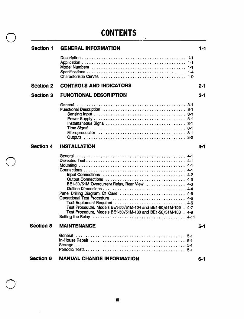
CONTENTS
Section 1 GENEIIAL INFORMATION
DescriptionApplicationModel NumbersSpecificationsCharacteristic Curves
Section 2 CONTROLS AND INDICATORS
Section 3 FUNCTIONAL DESCRIPTION
GeneralFunctional Description
Sensing InputPower SupplyInstantaneous SignalTime SignalMicroprocessorOutputs...........................................
Section 4 [NSTALLATION
General....Dielectric TestMOuntinoConnections
Input connections ..Output ConnectionsBE1 -50/51 M Overcurrent F]elay, Rear ViewOutline Dimensions
Panel Drilling Diagram, CI CaseOperational Test Procedure . . .
Test Equipment PlequiredTest Procedure, Models BE1-50/51 M-104 and BE1 -50/51 M-logTest Procedure, Models BET-50/51 M-100 and BE1 -50/51 M-108
Setting the Relay
Section 5 MAINTENANCE
Generalln-House RepairStoragePeriod ic Tests
Section 6 MANUAL CHANGE INFOFtMATION 6-1

a
®
®
SECTION 1
GENERAL INFORIVIATION
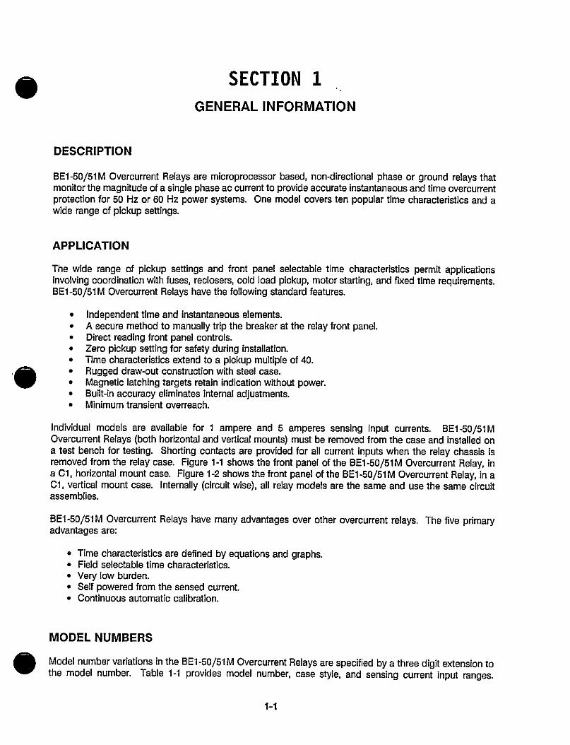
DESCRIPTION
BE1-50/51M Overcurrent Relays are microprocessor based, non-directional phase or ground relays thatmonitor the magnitude Of a §ingle phase ac current to provide accurate instantaneous and time overcurrentprotection for 50 Hz or 60 Hz power systems. One model covers ten popular time characteristics and awide range of pickup settings.
APPLICATION
The wide range of pickup settings and front panel selectable time characteristics permit applicationsinvolving coordination with fuses, reclosers, cold load pickup, motor starting, and fixed time requirements.BE1 -50/51 M Overcurrent Plelays have the following standard features.
• Independent time and instantaneous elements.• A secure method to manually trip the breaker at the relay front panel.• Direct reading front panel controls.• Zero pickup setting for safety during installation.• Time characteristics extend to a pickup multiple of 40.• Rugged draw-out construction with steel case.• Magnetic latching targets retain indication without power.• Built-in accuracy eliminates internal adjustments.• Minimum transient overreach.
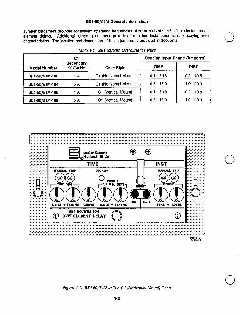
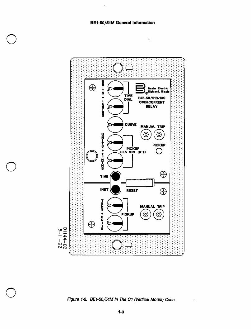
Individual models are available for 1 ampere and 5 amperes sensing input currents. BE1-5o/51MOvercurrent Belays (both horizontal and vertical mounts) must be removed from the case and installed ona test bench for testing. Shorting contacts are provided for all current inputs when the relay chassis isremoved from the relay case. Figure 1-1 shows the front panel of the BE1-50/51M Overcurren[ Belay, ina C1, horizontal mount case. Figure 1-2 shows the front panel of the BE1-50/51M Overcurrent Relay, in aC1. vertical mount case. Internally (circuit wise), all relay models are the same and use the same circuitassemblies.
BE1-50/51M Overcurrent Relays have many advantages over other overcurrent relays. The five primaryadvantages are:
• Time characteristics are defined by equations and graphs.• Field selectable time characteristics.• Very low burden.• Self powered from the sensed current.• Continllous automatic calibration.
MODEL NUIVIBERS
Model number variations in the BE1-50/51 M Overcurrent Relays are specified by a three digit extension tothe model number. Table 1-1 provides model number, case style, and sensing current input ranges.
iEj
BET-50/51 M General Information
Jumper placement provides for system operating frequencies of 50 or 60 hertz and selects instantaneouselement delays. Additional jumper placement provides for either instantaneous or decaying resetcharacteristics. The location and description of these jumpers is provided in Section 2,
Table 1-1. BE1-50/51M Overcurrent Relays
Model Number
CTSecondary50/60Hz
Case Style
Sensing Input Range (Amperes)
TIME INST
BE1-50/51M-100 1A C1 (Horizontal Mount) 0.1 -3.18 0.2 -19.8
BE1-50/51M-104 5A C1 (Horizontal Mount) 0.5 -15.9 1.0 - 99.0
BE1-50/51M-108 1A CI overtical Mount) 0.1 -3.18 0.2 -19.8
BE1-50/51M-109 5A CI overtical Mount) 0.5 -15.9 1 .0 - 99.0
E}®=rg.EF,rhdE,I.,fi[:i;8 ® ©TIME
ES
lNSTW^NtJ^L TFtlp PIcl{UP WAHu^L Tl]lp
©© O p,CKUP ©©asas®as"®g
FT?T®K®
LINIT6 + TERTNS CURVE UNITS + TENTIJS TENS + uNIT€
© OVEBRE:-u5R°R/E{¥-JR°E4LAv © ©
D11tho15-11-a2
Figure 1-1. BE1-50/51M In The C1 (Horizontal MolJnt) Case
1-2
BE1-50/51M General Information
e]Epge]AL
CURVE
Bqlr EbetrfeNthied tilhoi.
BE1-50/51B-loo0YEFtcuRRENT
RELAY
©AL©PPICKUPI MIN. SET'
PICKUPa
Figure 1-2. BE1-50/51M In The Cl ryertical Mount) Case
I-3

BET-5o/51M General lnformatjon
SPECIFICATIONS
BE1-50/51MOvercurrentBelaysareavailablewiththefollowingfe;iuresandcapabilities.
Current §en§ing Input(1 Ampere Unit)
(5 Ampere Unit)
TIME PICKUP Flange
(1 Ampere Unit)
(5 Ampere Unit)
TIME DropoLrt
TIME PICKUPAccuracy
Frequency Ftesponse
TIME DIAL l]ange(1 Ampere Unit)
(5 Ampere Unit)
lNST PICKUP F]ahge
(1 Ampere Unit)
(5 Ampere Unit)
lNST DropoLrt
lNST PICKUPAccuracy
FreqL[ency Fte§ponse
]NST Transient F]e§poh§e
Burden(1 Ampere Unit)
(5 Ampere Unit)
Contlnuous curl.ent: 2.8 amperes. One second current: 80 amperes.
Continuous current: 14 amperes. One Second current: 400 amperes.
Settings below minimum pickup ranges (0.1 on the 1 ampere unit and 0.5on the 5 ampere unit) place the relays ln the most sensitive State and areused as a safety setting.
0.1 to 3.18 amperes in 0.02 ampere steps.
0.5 to 15.9 amperes in 0.1 ampere steps.
Dropout occurs at not less than 95% of pickup value.
±2% at settings Of 0.1 amperes or more on the 1 ampere unit and 0.5 ormore on the 5 ampere unit.
A change Of ±5 hertz from the nominal 50/60 hertz current causes lessthan o.5% change in the curl.ent required for pickup.
0.0 to 9.9, in 0.1 steps.
0.0 to 9.9, in 0.1 steps.
Settings below minimiim pickup ranges (0.2 on the 1 ampere unit and 1.0on the 5 ampere un.rf) place the relays in the most sensitive state and areused as a safety setting.
0.2 to 19.8 amperes in 0.2 ampere steps.
1 to 99 amperes ]n 1 ampere steps.
Dropout occurs at 95% of pickup.
± 2% at settings of 0.2 amperes or more on the 1 ampere unit and 1.0 ormore on the 5 ampere unit.
A change of ±5 hertz from the nominal 50/60 hertz current causes lessthan 0.5% change in the current required for pickup.
Less than 10% overreach with system time constants up to 40 milliseconds
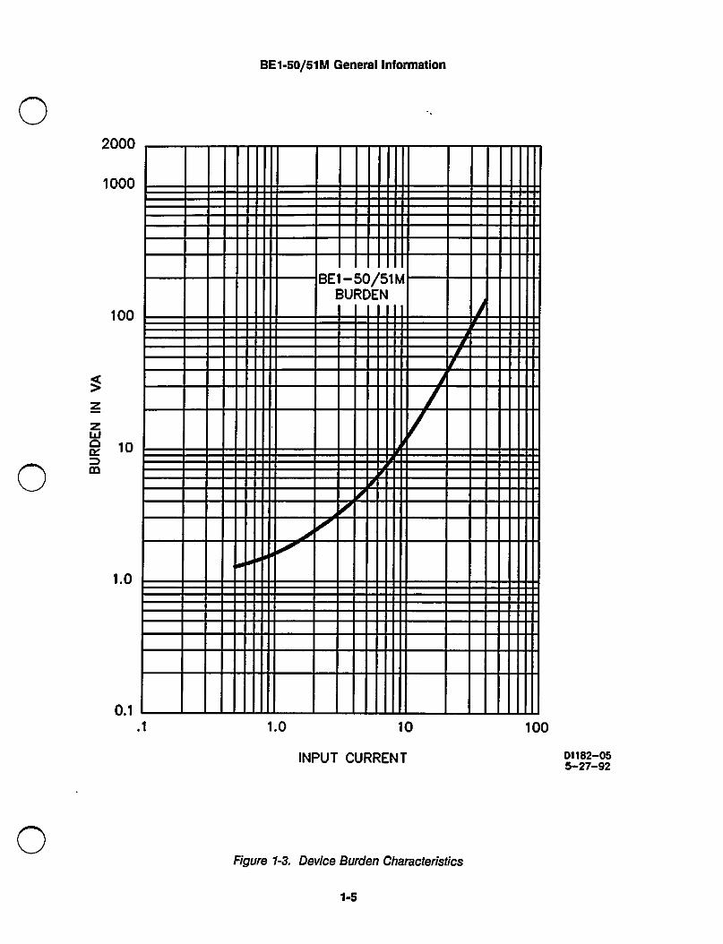
Burden is nan-linear. figure 1 i3 Illustrates the device burden.)AI 0.1 amperes, Z = 120 ohms. AI 1.0 ampere, Z = 5 ohms.
AI 0,5 amperes. Z = 4,8 ohms. AI 5.0 amperes, Z = .2 ohms.
1-4
a
BE1-§O/51M General Information
I III I. I I II I
BEU
5N 1 M
I.
II II
/-
II 11 .I I
II II
1.0 10 loo
INPUT CURRENT
Figure 1-3. Device Burden Characteristics
I-5
D''82-055-27-92
Harmonic F]esponse
PICKUPINZ0F
SETTING
PICKUPIN%
OFSEIThNG
D1150-065-22-,2
BET-50/51 M General Information
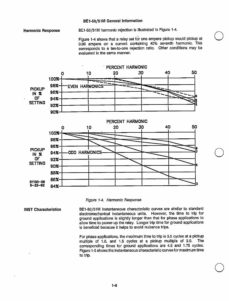
BE1-50/51M harmonic rejection is illustrated in Figure 14.
Figure 14 shows that a relay set fa`r one ampere pickup would pickup at0.96 ampere on a current containing 40°/o seventh harmonic. Thiscorresponds to a ten-to-one rejection ratio. Other conditions may beevaluated in the same manner.
• PERCENT HARMONIC
o 10 20 30 40 5000%9a%96%94%92%90%
I
----_E:VENHARMONIC
ai
__--_lIIL=`-- ---`
PERCENT HARMONIC
0 10 20 30 40 500098%96%94%92%90%88%86%84%
O753
Ill-ODD HARM ONICS-- -
]NST Characteristics
Figure 1-4. Harmonic Response
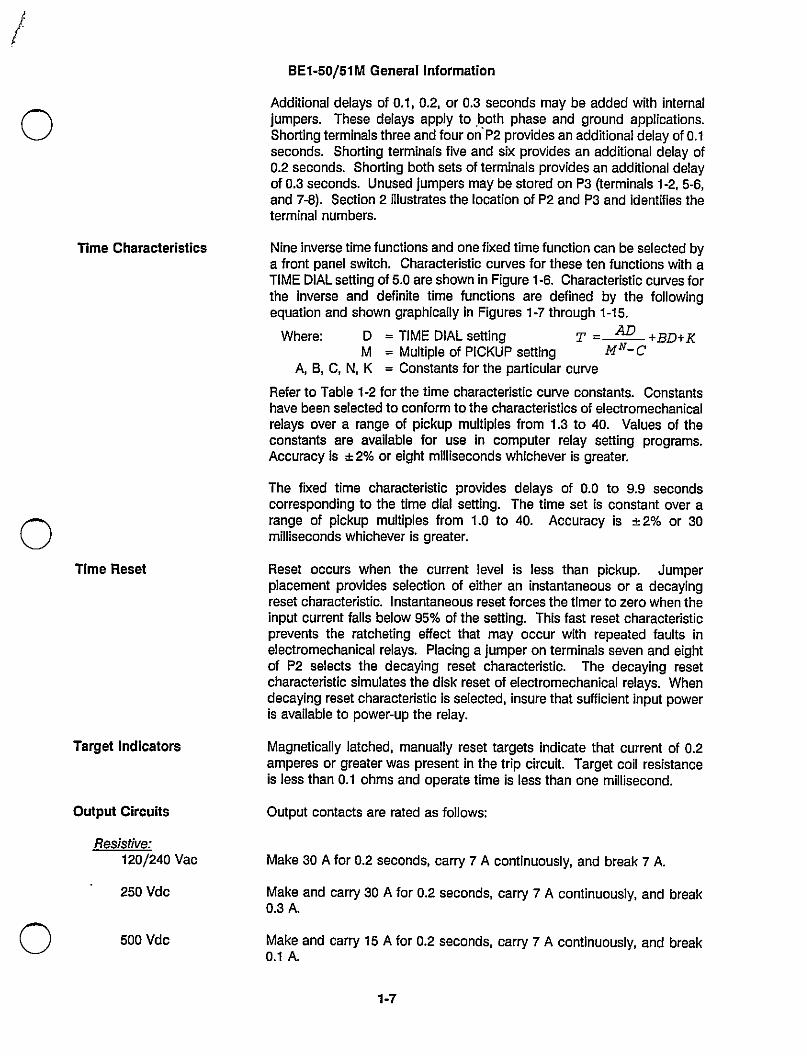
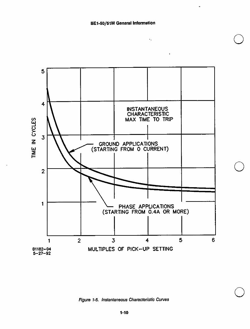
BE1 -50/51 M instantaneous characteristic curves are similar to standardelectromechanical instantaneous units. However, the time to trip forground applications is slightly longer than that for phase applications toallow time to power-up the relay. Longer trip time for ground applicationsis beneficial because it helps to avoid nuisance trips.
For phase applications, the maximum time to trip is 3.5 cycles at a pickupmultiple of 1.0, and 1.5 cycles at a pickup multiple of 3.0. Thecorresponding times for ground applications are 4.5 and 1.75 cycles.Figure1-5showstheinstantaneouscharacteristiccurvesformaximumtimeto trip.
1-6
Time Characteristics
Time Reset
Target Indicators
Output Circuits
Resistive:1 2o/240 Vac
250 Vdc
500 Vdc
a
BE1-50/51 M General Information
Additional delays of 0.1, 0.2. or 0.3 seconds may be added with internal
jumpers. These delays apply to .both phase and ground applications.Shorting terminals three and four on-P2 provides an additional delay of o.1seconds. Shorting terminals five and six provides an additional delay of0.2 seconds. Shorting both sets of terminals provides an additional delayof 0.3 seconds. Unused jumpers may be stored on P3 (terminals 1-2, 5-6,and 7-8). Section 2 illustrates the location of P2 and P3 and identifies theterminal numbers.
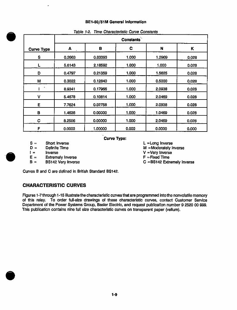
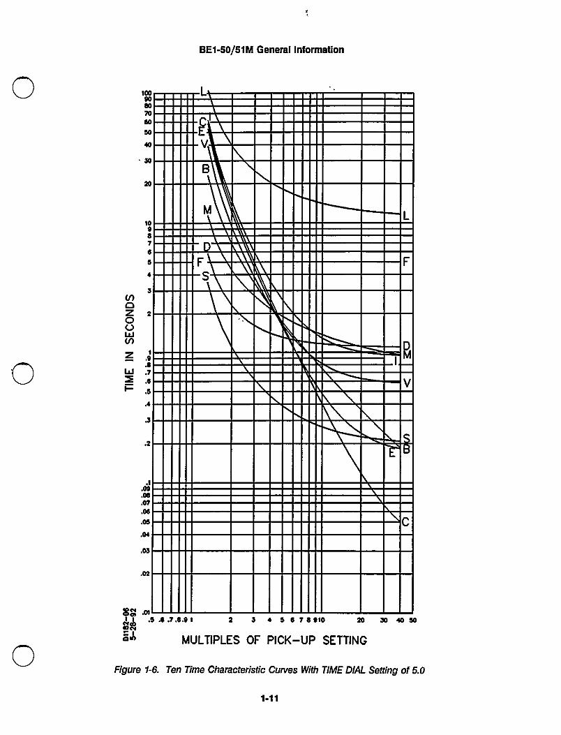
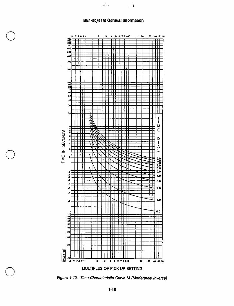
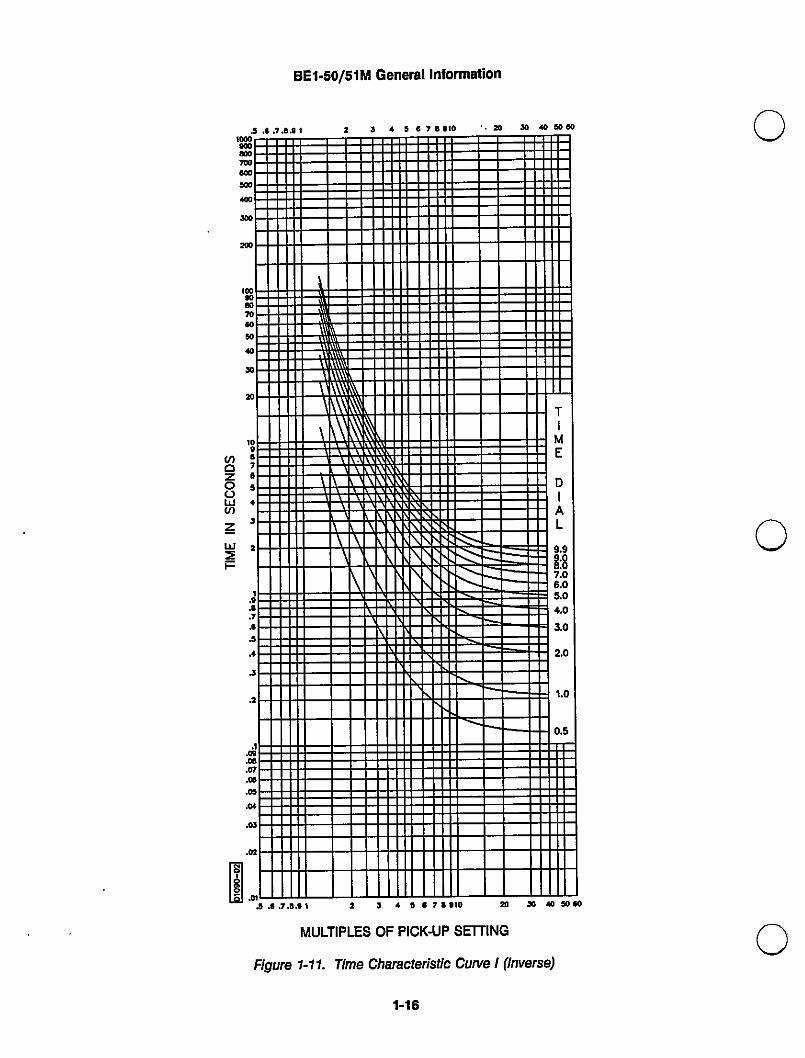
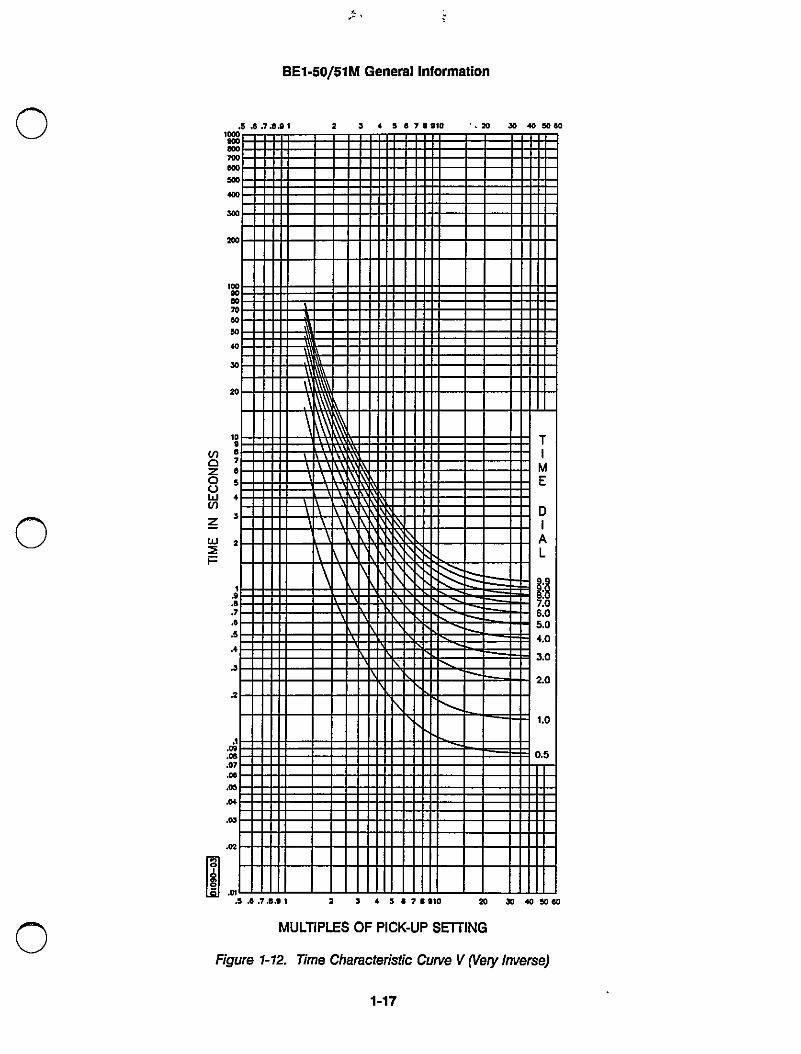
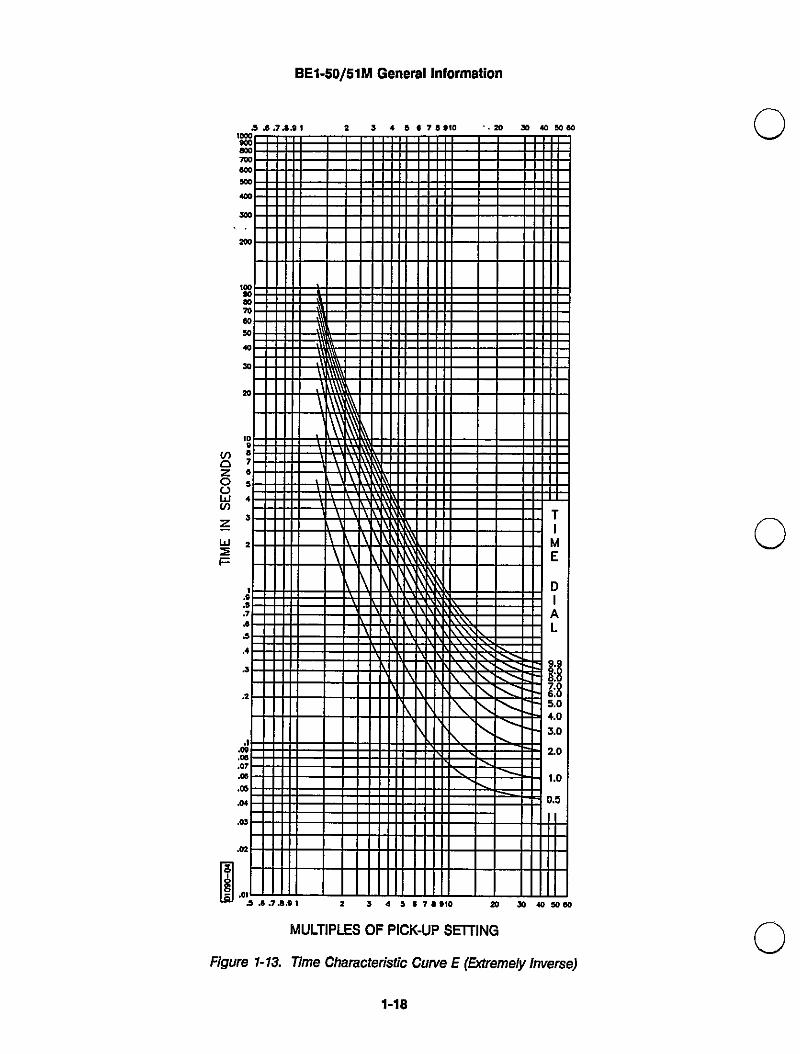
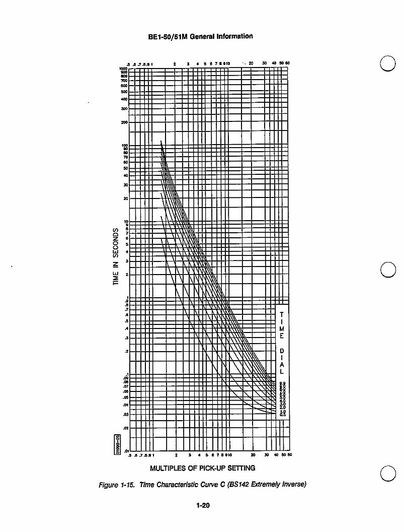
Nine inverse time functions and one fixed time function can be selected bya front panel switch. Characteristic curves for these ten functions with aTIME DIAL setting of 5.0 are shown in Figure 1-6. Characteristic curves forthe inverse and definite time functions are defined by the followingequation and shown graphically in Figures 1-7 through 1-15.
Where: E =##ppe':t::#ugpsett:ng I =#c+8°+K
A, 8, C, N, K = Constants for the particular curve
Refer to Table 1-2 for the time characteristic curve constants. Constan{shave been selected to conform to the characteristics of electromechanicalrelays over a range of pickup multiples from 1.3 to 40. Values of theconstants are available for use in computer relay setting programs.Accuracy is ±2% or eight milliseconds whichever is greater.
The fixed time characteristic provides delays of 0.0 to 9.9 secondscorresponding to the time dial setting. The time set is constant over arange of pickup multiples from 1.0 to 40. Accuracy is ±2°/o or 3omilliseconds whichever is greater.
Reset occurs when the current level is less than pickup. Jumperplacement provides selection of either an instantaneous or a decayingreset characteristic. Instantaneous reset forces the timer to zero when theinput current falls below 95°/o of the setting. This fast reset characteristicprevents the ratcheting effect that may occur with repeated faults inelectromechanical relays. Placing a jumper on terminals seven and eightof P2 selects the decaying reset characteristic. The decaying resetcharacteristic simulates the disl( reset of electromechanical relays. Whendecaying reset characteristic is selected, insure that sufficient input poweris available to power-up the relay.
Magnetically latched, manually reset targets indicate that current of 0.2amperes or greater was present in the trip circuit. Target coil resistanceis less than 0.1 ohms and operate time is less than one millisecond.
Output contacts are rated as follows:
Make 30 A for 0.2 seconds, carry 7 A continuously, and break 7 A.
Make and carry 30 A for 0.2 seconds, carry 7 A continuously, and break0.3 A.
Make and carry 15 A for 0.2 seconds, carry 7 A continuously, and break0.1 A.
1-7
BET-50/51 M General Information
Output Circuits - Continued
Inductive:120/240 Vac,125/250 Vdc
Isolation
Surge Withstand Capability
Fast Transient
Impulse Test
F]adio FrequencyInterference (I]Fl)
UL F]ecognized/CSA Certified
Temperature
Shock
Vibration
Weight
Make ancl carry co A for 02 seconds, carry 7 A continuously, and break0€ A. urn = 0.04).
2000 Vac at 50/60 Hz for one minute (1500 Vac for one minute acrossopen contacts) in accordance with lEC 255-5 and ANsl/FEE C37.9o-19890 ielectrie Test).
QualifiedtoANSI/EEEco7.9o.1-ig89SwhardscArgewny7sfardcapab/rty(SWC) Tests for Protective Relays and Relay Systems.
Qualified to ANsl/EEE Cre7co.1 -1 g89.
Qualified to IEC 255-5.
Fielcl tested using a five watt, hand held transceiver operating at randomfrequencies centered around 144 Mhz and 440 Mhz, with the antennalocatecl six inches from the relay in both horizontal and vertical planes.
UL F}ecognized per Standard 508, UL File No. E97033. CSA Certified perStandard CAN/CSA-C22.2 No.14-M91, CSA File No. LR 23131. Note:Output contacts are not UL Recognized/CSA Certified for voltages greaterthan 250 volts.
oDeratina Plancre40°C (40°F) to 700C (|580F)
Recommended Storacie Rancle-5ooC (-58oF) to 5ooC (i22oF). Parts are ratecl to 125°C es7°F),however, the recommended storage range is as shown.
15 g in each Of three mutually perpendicular planes.
2 g in each Of three mutually perpendicular planes swept over the rangeOf 10 to 500 Hz for a total Of six sweeps,15 minutes each sweep.
52 pounds.
1-8
BE1-50/51M General Information
Table 1-2. Tlme Characteristic Curve Constants
Curve Type
Constant8.`
A. 8 C N K
S 0.2663 0.03393 1.000 1.2969 0.028
L 5.6143 2.18592 1 .000 1.000 0.028
D 0.4797 0.21359 1.000 1 .5625 0.028
M 0.3022 a.12840 1.000 0.5000 0.028
I- 8.9341 0.17966 1 .000 2.0938 0.028
V 5.4678 0.10814 1 .000 2.0469 0.028
E 7.7624 0.02758 1.000 2.0938 0.028
8 1.4636 0.00000 1.000 1 .0469 0.028
C 8.2506 0.00000 1 .000 2.0469 0.028
F 0.0000 1.00000 0.000 0.0000 0.000
•®
Curve Type:S = Short InverseD = Definite TimeI = InverseE = Extremely Inverse8 = BS142 Very Inverse
Curves 8 and C are defined in British Standard BS142.
L =Long InverseM =Moderately InverseV =Very InverseF =Fixed TimeC = BS142 Extremely Inverse
CHARACTERISTIC CURVES
Figures 1 -7 through 1 -15 illustrate the characteristic curves that are programmed into the nonvolatile memoryof this relay. To order full-size drawings of these characteristlc curves, contact Customer SewiceDepartment of the Power Systems Group, Basler Electric, and request publicatlon number 9 2520 00 999.This publication contains nine full size characteristic curves on transparent paper (vellum).
1-9
BE1-50/51M General Information
INSTANTANEOUSCHARACTERISTIC
MAX TIM IE TO TRIP
GROUINDAPPLICATIONS
(STARTIN G F.ROM 0 CURRENT)
(STAPHASE AP LICATIONS
E)RTING FROM 0.4A OR MO
1
D1182-045-27-92
234MULTIPLES OF. PICK-UP SETTING
Figure 1-5. Instantaneous Characteristic Curves
1-10
56
BE1-50/51M General Information
!§
L.`loocOcO70cOsOcOcOae'0®e7¢e,32,.,J.,.e.e.,,J.2.I.09.co,a,.0¢.00.a,,0,.02.a,\ I\ I
i\[\`\\I
a,\\
M\\ Iiiii=LI--I I I I
\\ \\\ I I I\ \\\\ I I I
D\ \\\ IFs:\\` \\V I I F\\ \\ L\
\I -
R\ I\ I -\V\ \\\Sa
I I I I \I I I \I IC
..... 7.®..i 2 3 . 9 e 7e.io ae so co so
=J' MULTIPLES OF. PICK-UP SETTING
Figure 1-6. Ten Time Characteristic CIJrves With TIME DIAL Setling of 5.0
iEil
BE1-50/51M General Information
II I11I
I11
I I I I II-I I
IIII I
I I I\\\\\\
11
\ I I I IITIMEDIALi:5.,.3.2I0.
i0000.0.a5
\\ \\ I\\ \\\.\ \\ I\ t\
I \ N I . I II I\\ \ I
\ \\ \ \ I\ \ iii=\
\ III
I II I I II
£ ...7.a..I 2 } . 5 . 7e.Io 2o co co 5oco
MULTIPLES OF PICK-UP SETTING
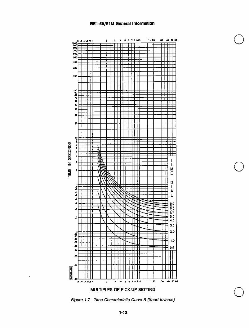
Figure 1-7. Time Characteristic Curve S (Short lrlverse)
1-112
BE1-50/51M General Information
'tcoinae I7cO ICoo500 I I I I I I IeesO
II I I I I2cO'cOcOcO70cOsO10sO20'0,e7,5,J21.a.e.,,J'.,i.2.'.00cO
88765432Ia.
TIMEDIAL:8.a.0.a.a.a.0.0.05R
I I EN I - . I -I I I I I I I II I I I I I\\\ \\ I\ \\ \I I I. II \ \ \ II \\ \ \\ \\
\
I I I.,I I I I I\ I\I II II III \II I I
I I I I I I I II I II I II I
I 11I 11I 1111
I I I I I I I I11 11 I I 11070¢ 11 11 1111 11 1109 !1
.a+a, 11 11 11 I I I1111 11 11 1111 11 I 11 11
02
11 11 11 1111 11 11 11
.0'
11
•,e.7,e..i 2 3 . 5 . 7e.Io 2o co co so.a
MULTIPLES OF PICK-UP SETTING
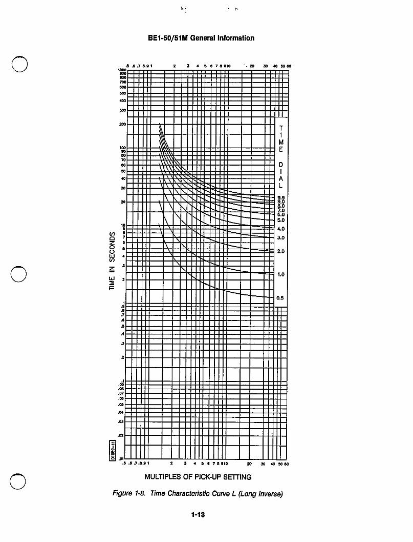
Figure 1-8. Time Characteristic Curve L (Long lrIverse)
11-]3
BE1-50/51M General Information
.5i},7i)41 2 3 . !e7e.io `.ae so rococo'acormae7tl)cOsOcOSea2cOloocOco70cOsO«sOae,.aE I
11= 11 11
11 11 1111 11 I`i Ii 'i
11 I11 .I 11I
11 I
-I-I II 1111 TIMEDIALi:i7.06.05.04.03.a2.0I.00.5
\\\\\\\\ I I I . I\\\\\ \
\ \\\ \\
. \ \ III\
\ \I
\ II I
I I
II I
54.7J}.I a S . a .7..10 20 JO cosoco
MULTIPLES OF PICK-UP SETTING
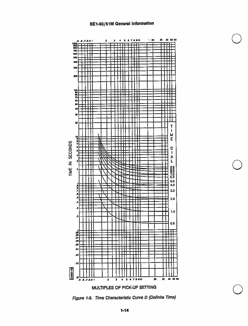
Figure 1-9. Time Characterlstic Curve D (Definite Time)
11-14
?,
BET-50/51M General Information
'OcOae
cOTOO I I I II I ICOO
ae IunsO I I IZOOloocOcO70cO50cOsO20'0,87e§,52I.a,e.7I,5.,i.2.,.a,.Oe.07
I I I IIII I
II\"i
8876543210
TIMEDIAL:i.a.0.0.0.0.0.5
"\ \\\ \ I
\ \\ \\ \ \
I II- \ II \ \ \
\I.11 Ill II11 \ 111, 11-11 \11 IE=|] I11 Ill,-11I11 \ Ill II11 i=III11 Ill
111
.I Ill I11 Ill11 Ill11 Ill I.cO11 Ill.05JW
OJ
11 Ill11 111
.02.0'
11 Ill11 Ill
i l.7.e..I 2 S . 9 I 7..io so so co soco
MULTIPLES OF PICK-UP SETTING
Figure 1-10. Time Characteristic Curve M (Moderately lrverse)
1-15
BE1-50/51M General Information
i...7.e..I 2 3 . 5 e7e.io ..ae so rococoX'I)X}ro....ro•,•.00cOcO70cOsOcOsOZO'8,7,9+32.`.,.7Je£.ai.2.Iin.cO.07.Oe
11 11I I: `i 11 II 'i ..
11 II 'i11 II 'i .11 11
i.
\
\\\\\\\I - _. 11 I II .
A I\\\\\\\\
I .\ \\\\ -I
\ L\+1 1\ 11\ \ N 11 TIMEDIAL9.98:87.a6.a5.04.a3.a2.a1.0a.5
\ \\.
\\ I
\ \ \I \I \ \ \
\ \
I I I I\
I I I=
I.05.a+.0®.02.01
2 J 9 7 I,'0 20 JO co so co
MULTIPLES OF PICK-UP SETTING
FIgure 1-11. Time Characteristic Curve I (Inverse)
1-16
BE1-50/51M General Information
1000ae
eco7cO I Iecoae IcO
sO
ae
loocOcO70cO50cOsOsO'0,,7e5+S2,.9.e.,.®5.,i.2.1.a,cO
I_, I\\\
\\\ \.\\ \\
in \\\\\ \\\T\\ Lt\N
\ Lj(
i6543210
TIMIDIAL:i.a.0.0.0.0.a.5\ \\ \\ \\ '111I \ \\ \\ I\ \ \ \ I-I \ \ I
\ \ \ I\ \ \ \
\\\
I -\
07 I.cO.09
I.0+
.OJ
.02in
.3 ...7...I 2 . . 5 . 7..io ae sO cO sOcO
MULTIPLES OF PICK-UP SETTING
Figure 1-12. Time Characteristic Curve V Nery Inverse)
1-17
BE1-50/51M GeTteral Information
'000sOae===::= I
7cO .11 I 111111111 111Cooae I
cO
se I Iae
I
00rocO70cOsOcOsO20'00e7,5+S2.tJB.7J,J.,i.2.I.a,.cO.a,0, II .\\ I
.\\ I\\`\ \\\\ I\ \\\\\.\ LTT\X
\ \\ L\
\ »"'I.III \ \ \ \ II- \ \ \ \\I \ \ \ I I-I ILl
ii5+521a.
TIMEDIAL:i.0.0.I).a.05- \ \ \`II \ \ \ 11
\ \I I II LI `\ \I I \ \ \\I Ill \\\ I\ \ \\ I
\ \ -II I \\ \ -\ \ \\\I I I
11 II, I\ I0®"
.a,02
11
.0'i,®.7J}..I 2 3 a . .7..io so co co soeo
MULTIPLES OF PICK-UP SETTING
FIgure 1-13. Time Characteristic; Curve E (Extremely Inverse)
1-18

1S- i{¥,.
BET-5o/51M General lnformalion
'000aeae7cOeco500cOroZOOloocOcO70cO50cOsOae'0®,7,3,J2I.OI,.7I,5.,i.2.I.a,.Oe.07.0®.05 .
II I I
I., I\\\ I I I
\W
\\ "\\ 1\\ ELill
\ \\ \\ I I I I\ \\ \ \ I
\ \ \ 1` II II
TIMEDIALi:i6.05.0,.a3.a2.aI.a0.5\ \ \ \.I
\ \ \\
I I I. I-+1 II\ \\ \\\ \ \\ \ II\ \\ \ \\
IllI \ \ \\\ \ \\II
I I -.0, IIa, I I
E': •`''..MULTIPLES OF PICK-UP SETTING
Figure 1-14. Time Characteristic Curve a (BS142 Very Inverse)
1-19
BE1-50/51 M General Information
£jB.7j!..I 2 3 . a e7..IO ..sO sO cOcOcOX'..X'I...„•.»•,20'0Oe7®a452I.0.e.7J,J5.,i.2.Ia,Oea,0®05a+a,02.a,
II
I\\\W\\ I
A
\\\\1 11\\ \\\\\\ \\\\(
\ \\t( A
\ \\ 1\\ \ \ "
\ \I
\\ \ \
\ I 1111
\I,\ \\
\ \\\ \ lN
\I
\\\TIMEDIAL-iA
;i•8
I \ \\\ \\\\\\\
\\\\\ \\\ r\\\ RIT|\ X \
.\ tr\11111 11\1I \\\ \ \
- - I5J.7.e... 2 ] . 5 .7e.Io so Jo co soco
MULTIPLES OF PICK-UP SETTING
Figure 1-15. Time Characteristic Curve C (BS142 Extremely Inverse)
1-20
SECTION 2
CONTROLS AND INDICATORS
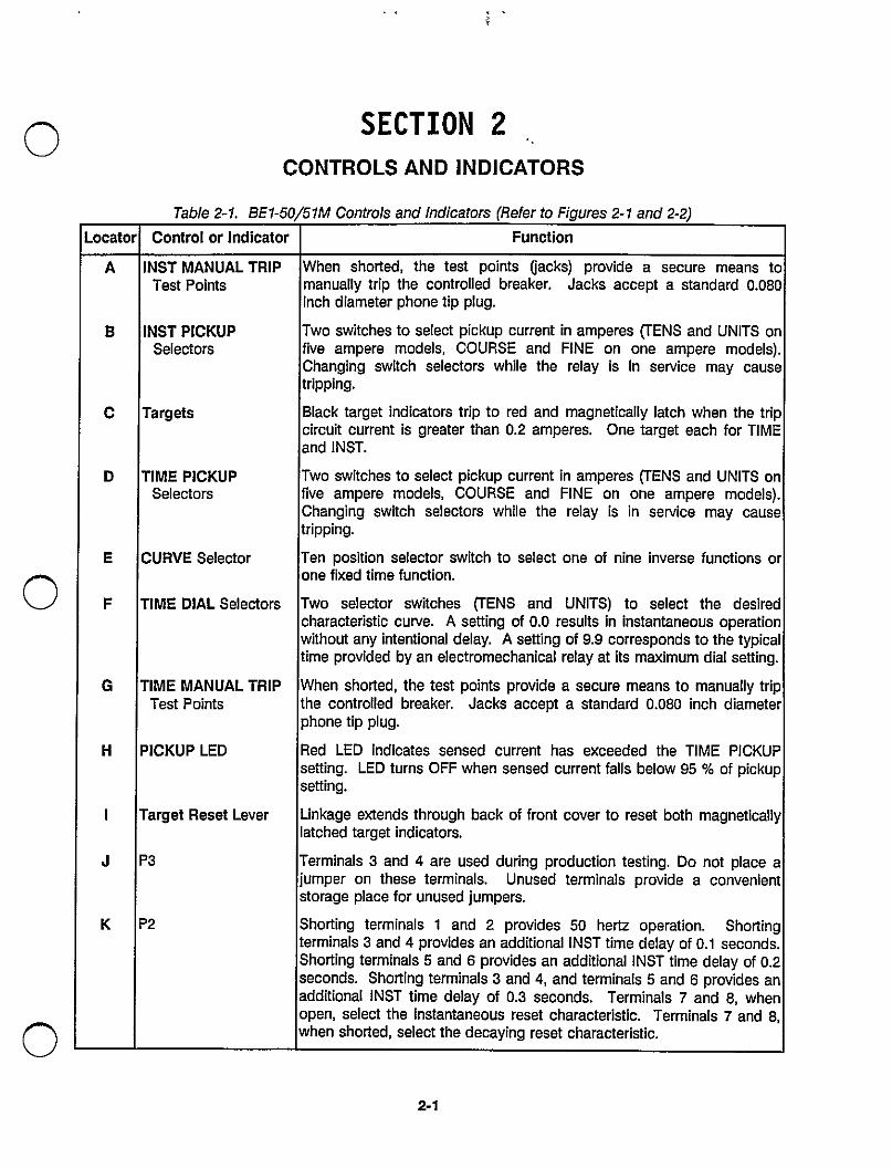
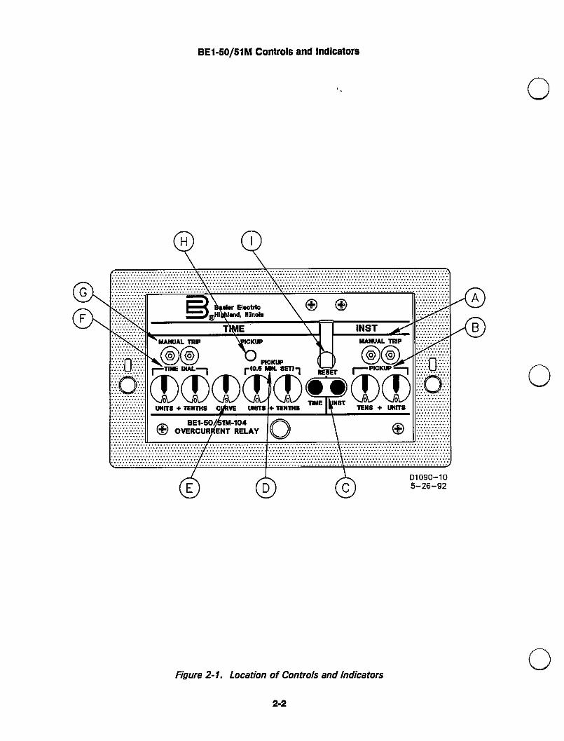
Table 2-1. BE1-50/51M Controls and Indicators (Rofer to Figures 2-1 and 2-2)
Locator Control or Indicator Function
AaCDEFaHIJK lNST MANUAL TRIP When shorted, the test points a.acks) provide a secure means toTest PointsINSTPICKUP manually trip the controlled breaker. Jacks accept a standard o.o8o
inch diameter phone tip plug.
Two switches to select pickup current in amperes ITENS and UNITS onSelectorsTargetsTIMEPICKUP five ampere models, COUPSE and FINE on one ampere models).
Changing switch selectors while the relay is in service may causetripping.Blacktarget indicators trip to red and magnetically latch when the trip
circuit current is greater than 0.2 ampere§. One target each for TIMEand lNST.
Two switches to select pickup current in amperes ITENS and UNITS onSelectorsCUFIVESelectorTIMEDIALSelectorsTIMEMANUALTFilp five ampere models, COURSE and FINE on one ampere models).
Changing switch selectors while the relay is in Service may causetripping.
Ten position selector switch to select one of nine inverse functions orone fixed time function.
Two selector switches ITENS and UNITS) to select the desiredcharacteristic curve. A setting of 0.0 results in instantaneous operationwithout any intentional delay. A setting of 9.9 corresponds to the typicaltime provided by an electromechanical relay at its maximum dial setting.
When shorted, the test points provide a secure means to manually tripTest PointsPICKUPLEDTargetReset LeverP3P2 the controlled breaker. Jacks accept a standard 0.080 inch diameter
phone tip plug.
Red LED indicates sensed current has exceeded the TIME PICKUPsetting. LED turns OFF when sensed current falls below 95 a/o of pickupsetting.
Linkage extends through back of front cover to reset both magneticallyatched target indicators.
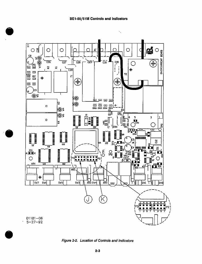
Terminals 3 and 4 are used during production testing. Do not place ajumper on these terminals. Unused terminals provide a convenientstorage place for unused jumpers.
Shorting terminals 1 and 2 provides 50 hertz operation. Shortingterminals 3 and 4 provides an additional lNST time delay of 0.1 seconds.Shorting terminals 5 and 6 provides an additional lNST time delay of 0.2seconds. Shor[ing terminals 3 and 4, and terminals 5 and 6 provides anadditional lNST time delay of 0.3 seconds. Terminals 7 and 8, whenopen, select the Instantaneous reset characteristic. Terminals 7 and 8,when snorted, select the decaying reset characteristic.
2-1
BE1-50/51M Controls and Indicators
9QGF A8
B®\#dypl#ch \© ©TtwE. \ I lNST`©^g €twneto ©Aldp
D
asas®r,Oob*S!:tFT!RT©+rm®quiT€ +TENTNs ciAVE un.IT.
® OVIBRE:-u#/#¥-`R°E'IAv ©\©
6d d %'_02960_-S8
Figure 2-1. Location of Controls and Indicators
2-2
BE1-50/51M Controls and Indicators
D1181 -065-27-92
®
Figure 2:2. Location Of Controls and Indicators
2-3

SECTION 3FUNCTIONAL DESCRIptloN
GENEFtAL
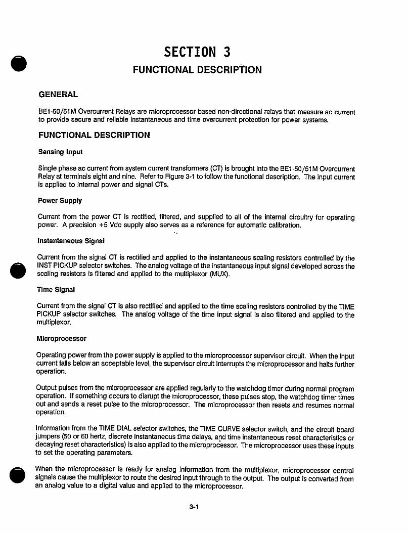
BET -50/51 M Overourrent Relays are microprocessor based non-directional relays that measure ac ourrentto provide secure and reliable instantaneous and time overcurrent protection for power systems.
FUNCT.ONAL DESCRIPTION
Sensing Input
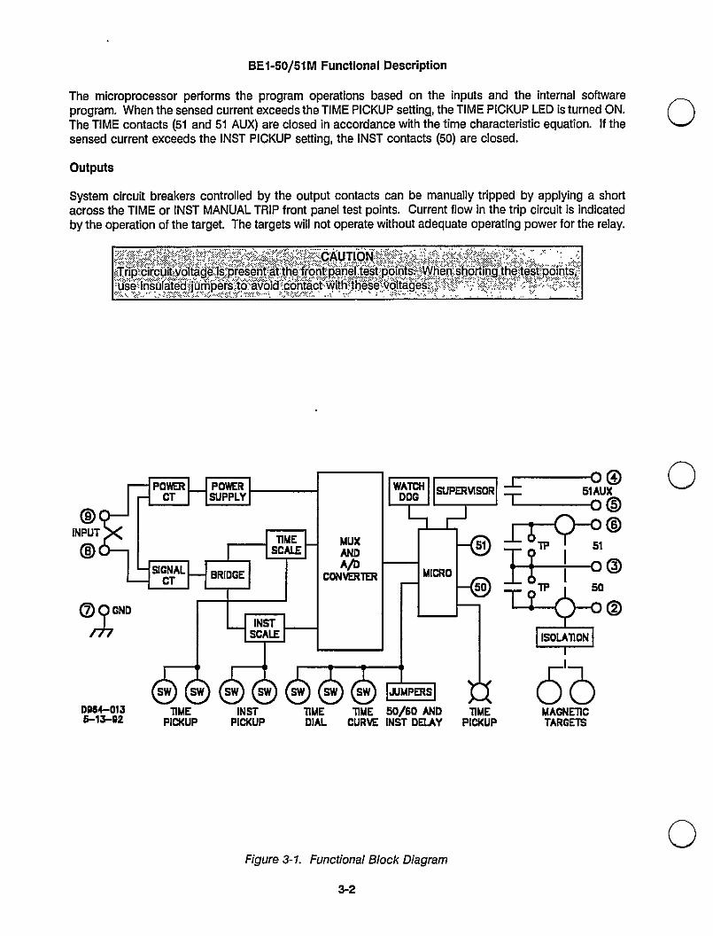
Single phase ac current from system current transformers (CT) is brought into the BE1 -50/51 M OvercurrentRelay at terminals eight and nine. Plefer to Figure 3-1 to follow the functional description. The input currentis applied to internal power and signal CTs.
Power Supply
Current from the pctwer CT is rectified, filtered, and supplied to all of the internal circuitry for operatingpower. A precision +5 Vdc supply also serves as a reference for automatic calibration.
Instantaneous Signal
Current from the signal CT is rectified and applied to the instantaneous scaling resistors controlled by thelNST PICKUP selectcir switches. The analog voltage of the instantaneous input Signal developed across thescaling resistors i§ filtered and applied to the multiplexor (MUX).
Time Signal
Current from the signal CT is also rectified and applied to the time scaling resistors controlled by the TIMEPICKUP selector switches. The analog voltage of the time input signal i§ also filtered and applied to themultiplexor.
Microprocessor
Operating power from the power supply is applied to the microprocessor supervisor circuit. When the inputcurrent falls below an acceptable level, the supervisor circuit interrupts the microprocessor and halts furtheroperation.
Output pulses from the microprocessor are applied regulariy to the watchdog timer during normal programoperation. If something occurs to disrupt the microprocessor, these pulses stop, the watchdog timer timesout and sends a reset pulse to the microprocessor. The microprocessor then resets and resumes normaloperation.
Information from the TIME DIAL selector switches, the TIME CURVE selector switch, and the circuit board
jumpers (50 or 60 hertz, discrete instantaneous time delays, apd time instantaneous reset characteristics ordecaying reset characteristics) is also applied to the microprocessor. The microprocessor uses these inputsto set the operating parameters.
When the microprocessor is ready for analog information from the multiplexor, microprocessor controlsignals cause the multiplexor to route the desired input through to the output. The output is converted froman analog value to a digital value and applied to the microprocessor.
3-1
BE1-50/51 IVI Functional Description
The microprocessor performs the program operations based on the inputs and the internal Softwareprogram. When the sensed current exceeds the TIME PICKUP Setting, the TIME PICKUP LED is turned ON.The TIME contacts (51 and 51 AUX) are closed in accordance with the time characteristic equation. If thesensed current exceeds the lNST PICKUP setting, the lNST contacts (50) are closed.
Outputs
System clrcuit breakers controlled by the output contacts can be manually tripped by applying a shortacross the TIME or lNST MANUAL TRIP front panel test points. Current flow in the trip circuit is indicatedby the operation of the target. The targets will not operate without adequate operating power for the relay.
-
*r,p:,c,rcuit.:,VQltage`:I.acres.en.i.,.at.,th.e,.fvrQpt:pap?I.Lt.g`stp.o.I`nts;.;.:.vyhen.;SbQrtlpg.,t.h.e>te•St.;PLO,.nt§i--,t`ti.;J5`:;,I.Fi\..
§`.a.rji'!i;`€.:`jj`.q`ii'p;?S:€:}'?:'-:if!?',?'id::€'§;fi:tjii6+.t`:wiifii`i:b:6§'e::tie.I;t.^?`§;6S`;;::.:.i;-:<'€`:S:;:t{```.:ft;``:'`;*;.;t.:...;:3::`;:;.i,:'.::€`?¥'t;`.'.:`'.:;T>,:`.z`t`>..``\.\ ,*.` \.``{`,>,-`t`>-.C-` -Xl`,`,--`+,..-,. .>..,- `. ^`'.,,..,^``.- ..i
D,8+0'35-1J-02 T"E l"E 50/60 MD TIWE
Dl^L CuRVE INST I)EIJ\Y PICKUP
Figure 3-1. Functl.onal Block Diagram
3-2
5'bN^CNEllcT^RCETS
SECTION 4
INSTALLATION
GENERAL
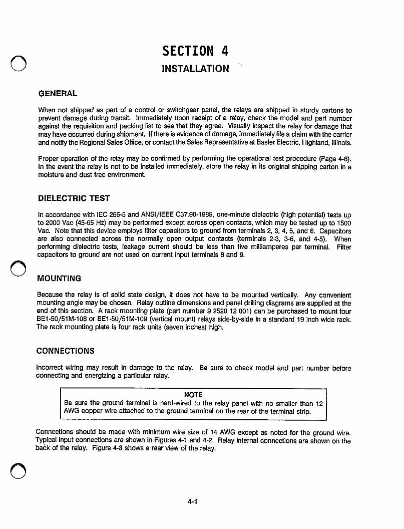
When not shipped as part of a control or switchgear panel, the relays are shipped in sturdy cartons toprevent damage during transit. Immediately upon receipt of a relay, check the model and part numberagainst the requisition and packing list to see that they agree. Visually inspect the relay for damage thatmay have occurred during shipment. If there is evidence of damage, immediately file a claim with the carrierand notfty the Regional Sales Office, or contact the Sales f]epre§entative at Basler Electric, Highland, Illinois.
Proper operation of the relay may be confirmed by performing the operational test procedure (Page 4-6).In the event the relay is not to be installed immediately, store the relay ln its original shipping carton in amoisture and dust free environment.
DIELECTRIC TEST
ln accordance with lEC 255-5 and ANsl/lEEE C37.90-1989, one-minute dielectric (high potential) tests upto 2ooo Vac (45J55 Hz) may be performed except across open contacts, which may be tested up to 15ooVac. Note that this device employs filter capacitors to ground from terminals 2, 3, 4, 5, and 6. Capacitorsare also connected across the normally open output contacts (terminals 2-3, 3-6, and 4-5). Whenperforming dielectric tests, leakage current should be less than five milliamperes per terminal. Filtercapacitors to ground are not used on current input terminals 8 and 9.
MOUNTING
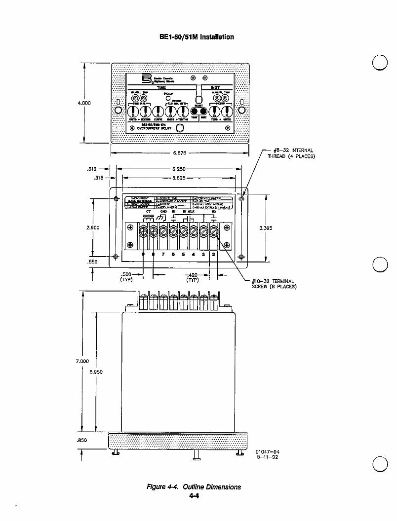
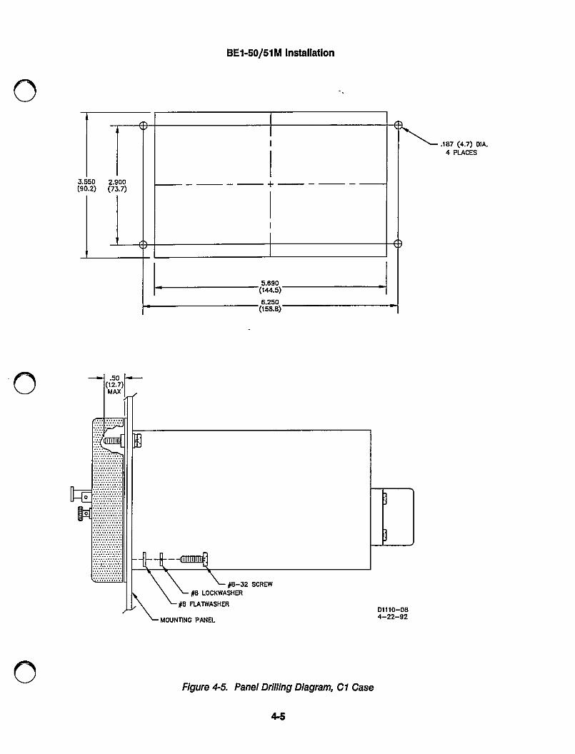
Because the relay is of Solid state design, it does not have to be mounted vertically. Any convenientmounting angle may be chosen. Relay outline dimensions and panel drilling diagrams are supplied at theend of this section. A rack mounting plate (part number 9 252012 001) can be purchased to mount fourBET-50/51M-108 or BE1-50/51M-109 (vertical mount) relays side-by-side in a standard 19 inch wide rack.The rack mounting plate is four rack units (seven inches) high.
CONNECTIONS
Incorrect wiring may result in damage to the relay. Be sure. to check model and part number beforeconnecting and energizing a particular relay.
NOTEBe sure the ground terminal js hard-wired to the relay panel with no smaller than 12Awe copper wire attached to the ground terminal on the rear of the terminal strip.
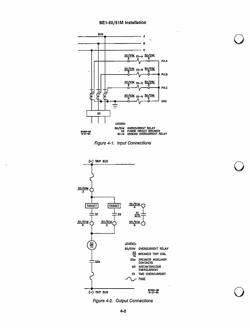
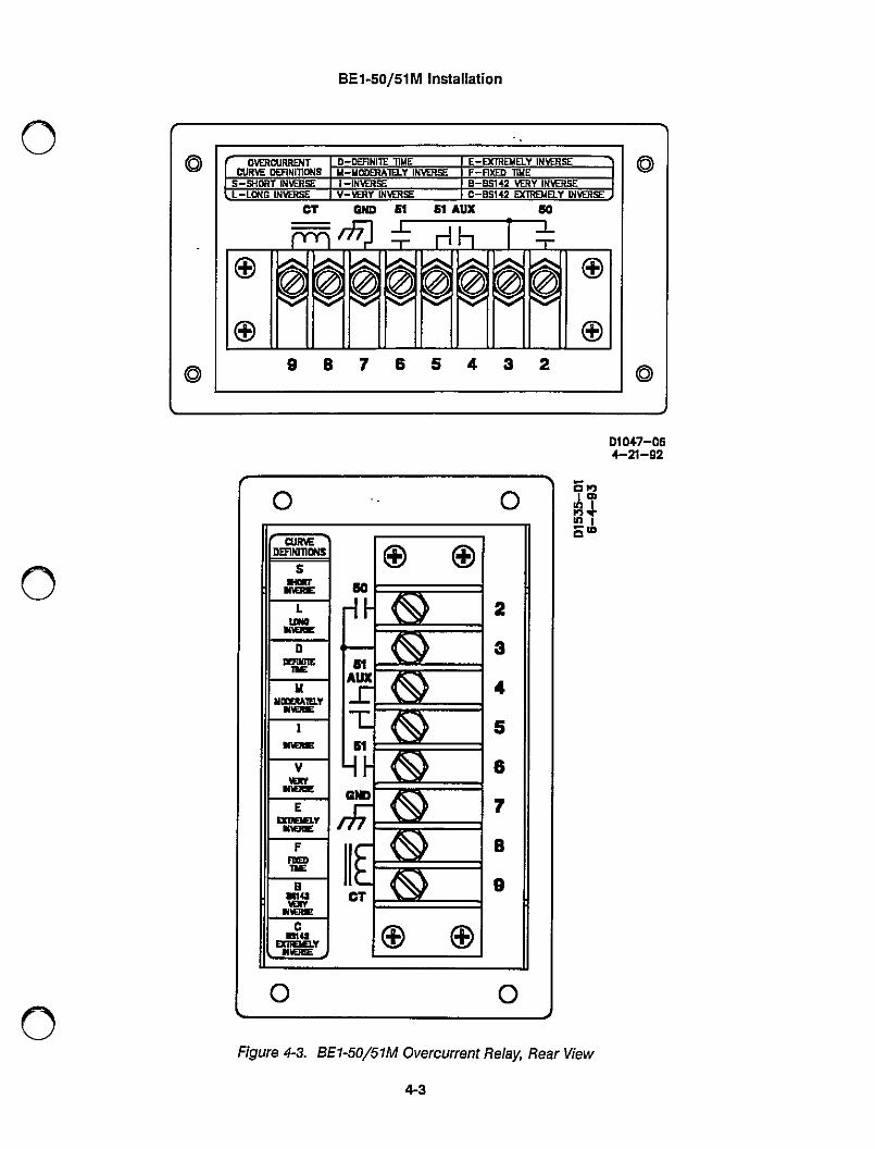
Connections should be made with minimum wire size of 14 Awe except as noted for the ground wire.Typical input connections are shown in Figures 4-1 and 4-2. Relay internal connections are shown on theback of the relay. Figure 4€ shows a rear view of the relay.
4-1
BET-50/51 M Installation
BUSAa
C
E# 5,-A #
. #5,-B#Tj=jiiii=iiiiiiil
E9ff 5i-c #Iiiiiiiiiiiiiiiiiiiiiiiii,-Liiiiiiiiiiiil
# 5,-N #_iI IJ=GEND:152
5o/5i!gova]maRCu5FRE[TRE#YAiffi
51-N GROUND OVERCuRRENT RELAY
Figure 4-1. Input Connections
(+) TRIP EIUS
LEGEND:
50/51W OVERCURRENT RELAY
# BREAl<ER TRIP COIL52a BREAKER AIJxluARY
CONT^CTS§0 INSTANTANEOUS
t]macuFiRENT5111WE OVERCURRENT
RE(-) 1R'P I)US
D'ceo"iz'-02
Figure 4-2. Output Connections
4-2
BE1-50/51 M Installation
©© ©©VERCURRE»T I D-DEFINITE llWE I I-EX"EIIELV INVERSEOuFtvI DEFINITIONS I N-lloDERATELY IN \ffls= I F-Fi)aD TiwE
I s-sHoftT iNVEFis= I I-iN\fflsE I B-Bsi42 \mv lNVER5EL-LOwC INVERSE I v-`mv INVEFtsE I C-BS142 EXTF!EuEl.Y lNVERSE:
cT eno 61 61 ^tix co
ryT i I L1IT
©®Z2! [ee3 Z2! Z2! [@3 Z2! [@3 Ez3!3
©©
98765432
DID+7-064-21-02
Figure 4-3. BE1-50/51M Overcurrent Relay, Rear View
4-3
BET-50/51M Installation
•. - 0 0T"E I I Hat
ifem a- 0 ire-©.©@trs@g©T@© ov=ffi{:+Ply © ©
.312
#THF(I
1' /a£FS#EL! I 8:='±NH
5. 952TE2. 00
tF-I-EZ-HEJCTomdutAUXpiiii ± rl Ll1L
©© ©©
7e543 2 \.550 \#10-5
+2(TYP)(TYP)
Figure 44. Outline Dimensions44
8-52 lNTEFiNALEAD (4 PLACES)
SCREW (8 PLACE:S)
D1047-045-11-92
BE1-50/51 M Installation
3.5(90 50 2.900•2)(73.7)
II
+-II
115.690('44.S)
6.250(15 a.8)
a
Figure 4-5. Panel Drilling Diagram, CI Case
4-5
.187 (4.7) DIA.4 PLACES
BE1-50/51 M Installation
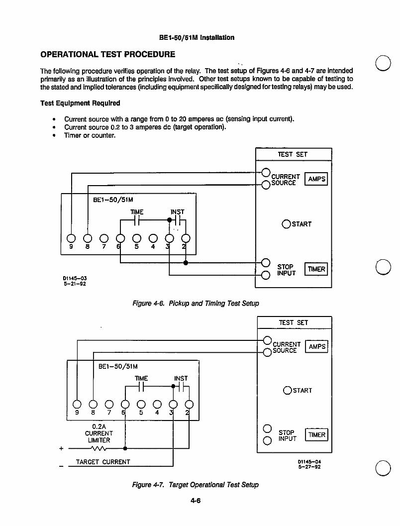
OPEFZATIONAL TEST PFtocEDURE
The following procedure verifies operation of the relay. The test setup of Figures 4€ and 4-7 are Intendedprimarily as an illustration of the principles involved. Other test setups known to be capable of testing tothe stated and implied tolerances (including equipment specifically designed fortesting relays) may be used.
Test Equipment F]equired
• Current source with a range from o to 20 amperes ac (sensing input current).• Current source o.2 to 3 amperes dc (target operation).• Timer or counter.
TEST SET
8S85R5ET EOSTARTa,sNTpOuPTEEniiiiiiiiiiiiiiiEBE1-50/51M
TIME 'NSTI_I11
000754
I iD„45-035-2'-92
Figure 4-6. Pickup and Timing Test Setup
TEST SET
8§85R5¥T EOSTART8FNTp°uPTEBE1-50/51M
T'ME lNSTI_I
'1
0007 54
0.2ACURRENTLIM'TER
TARGET CURRENT I)''45-a+5-27-92
Figure 4-I. Target Operational Test Sctup
4.6
BE1-50/51M Installation
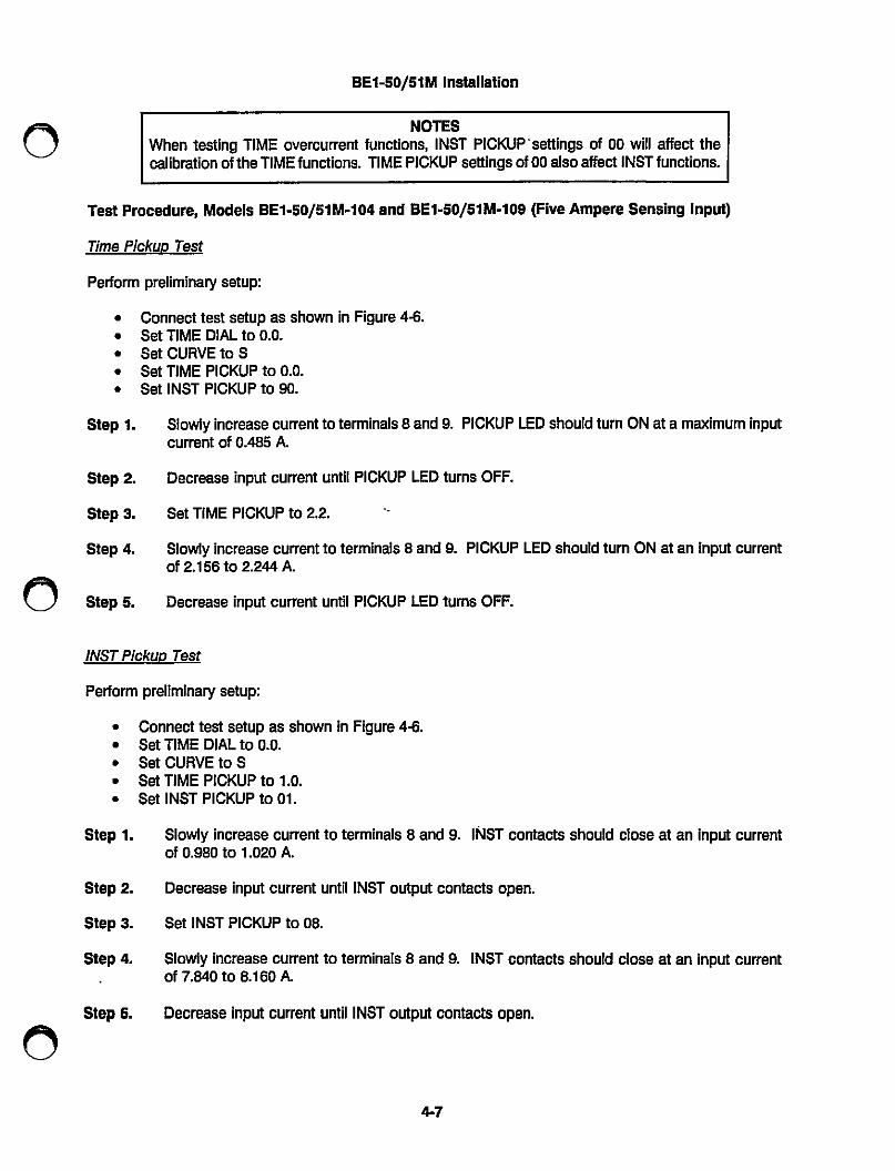
NOTESWhen testing TIME overcurrent functions, lNST PICKUP.settings of 00 will affect thecalibration of the TIME functions. TIME PICKUP settings of 00 also affect lNST functions.
Test Procedure, Models BE1-50/51M-104 and BE1-50/51M-109 (Five Ampere Seh3ing Input)
Time Pickup Test
Perform preliminary setup:
• Connecttest setup as shown in Figure 46.• SetTIME DIALtoo.0.• setcinetos• SetTIMEPICKUptoo.0.• SetlNST PICKUpto90.
Step 1. Slowly increase current to terminals 8 and 9. PICKUP LED should turn oN at a maxirnun inputcurrent Of 0.485 A.
Step 2. Decrease input ourrent until PICKUP LED tLJrns OFF.
Step 3. Set TIME PICKup to 2.2.
Step 4. Slowly increase currentto terminals 8 and 9. PICKUP LED should turn oN at an input currentOf 2.156 to 2L244 A.
Slep 5. Decrease input current until PICKUP LED turns OFF.
INST PlokuD Test
Perform preliminary setup:
• Connect test setup as shown in Figure 46.• SetTIME DIALtoo.o.• SetcuRVEtos• SetTIME PICKLJpto 1.0.• Set lNSTPICKUptoo1.
Step 1. Slowly increase current to terminals 8 and 9. Il\lsT contact§ should close at an input currentOf orm to 1.o2o A.
Step 2. Decrease input current until lNST output contacts open.
Step 3. Set lNST PICKup to o8.
Step 4. Slowly increase current to terminals 8 and 9. INST contact§ should close at an input currentOf 7,840 to 8.160 A.
Slop 5. Decrease input current until lNST output contacts open.
4-7
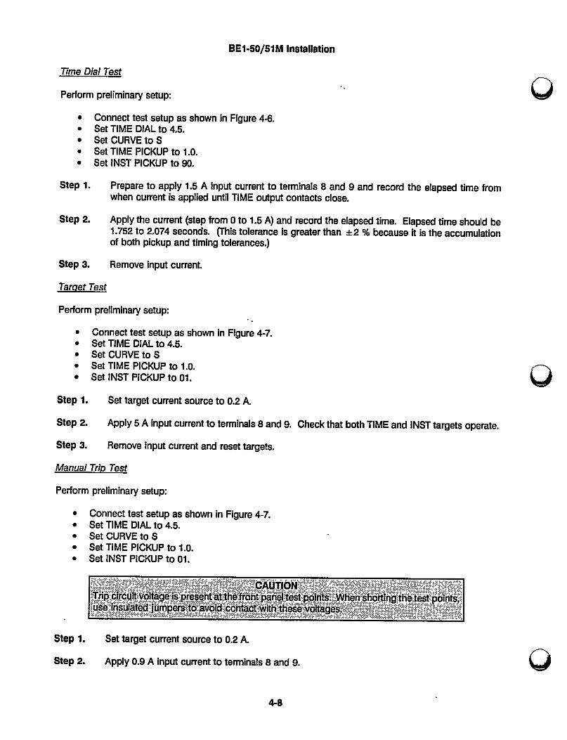
BET-50/51M ln§tallation
Time Dial Test
Perform preliminary setup:
• Connecttest setup as shown in Figure 4i5.• SetTIMEDIALto4£• SetcuREtos• SetTIME PICKUpto 1.0.• SetlNSTPICKUpto90.
Step 1. Prepare to apply 15 A input current to terminals 8 and 9 and record the elapsed time fromwhen current is applied until TIME output contacts close.
Step 2. Applythe ourrent (step from oto 15 AI and record the elapsed time. Elapsed time should be1.752 to 2.074 seconds. ("s tolerance is greater than ±2 % because it is the accumulationOf both pickup and timing tolerances,)
Step 3. Remove input cument.
Taraet Test
Perform preurninary setup:
• Connecttest setup as shown in Figure 4-7.• SetTIME DIALto4.5.• SetouREtos• SetTIME PICKUpto 1.0.• SetlNST PICKUptoo1.
Step 1. Settarget current source to o.2 A.
Step 2. Apply 5 A input current to terminals 8 and 9. Checkthat both TIME and lNST targets operate.
Step 3. Remove input current and resettargets.
Manual Trio Test
Perform preliniinary setup:
• Connecttest setup as shown in Figure 4-7.• SetTIME DIALto45.• SetcuRVEtos• SetTIME PICKUpto lro.• SetlNST PICKUptoo1.
CAUTIONTp I 1g p [tihl Ipa li ip Wli hnglhi ip I
I(flimprs d tclw[hlh I(g
Step 1. Set target current source to o.2 A.
Step 2. Apply o.9 A Input current to temlnals 8 and 9.
4-8
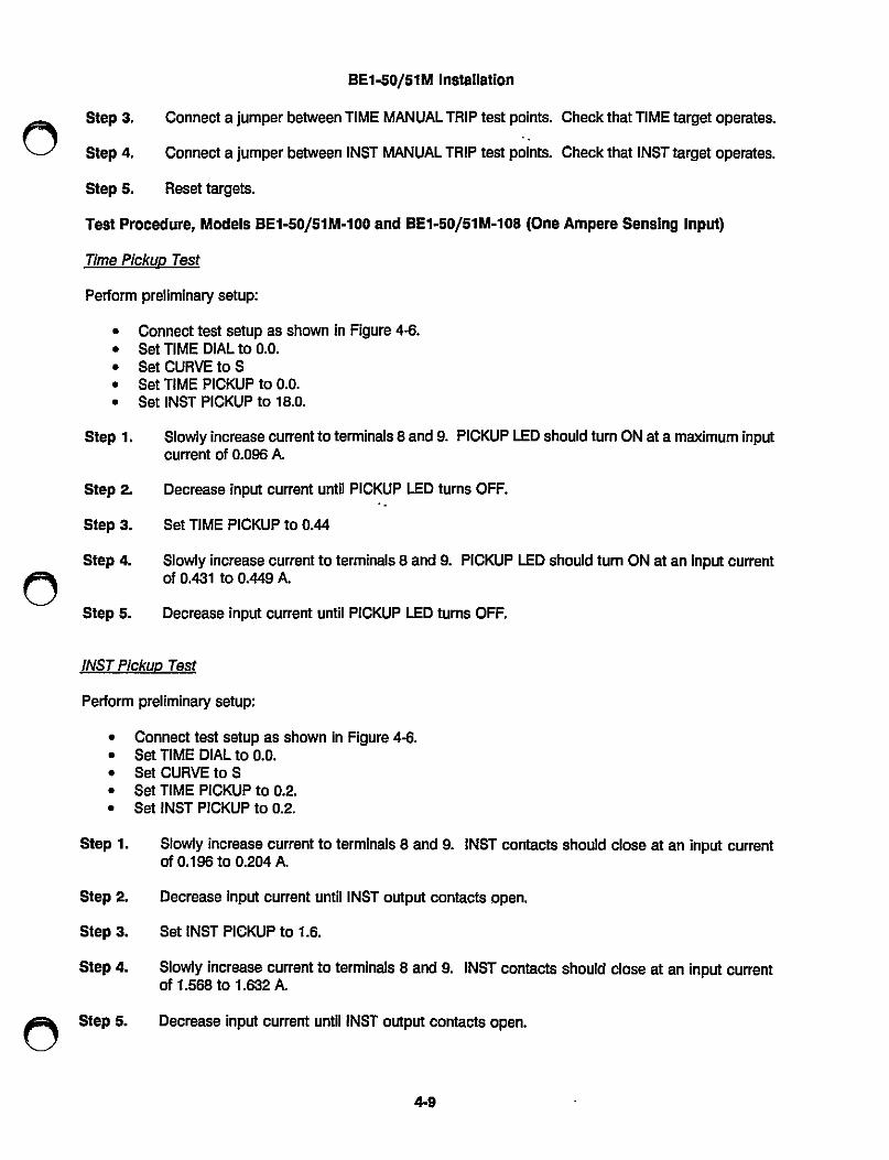
BElco/51M In8tallrfu
Step 3. Connect a jumper between TIME MANIIAL "lp test points. Check that TIME target operates.
Step 4. Connect a jumper between lNST MANUAL "lp test points. Checkthat lNSTtarget operates.
Step 5. Reset targets.
Test Procedtire, Models BElio/51M-100 and BE1-50/51 M-108 (One Ampere Sensing lnpirty
Time PlckuD Test
Perform preliminary setup:
• Connecttest setup as shown in Figure 46.• SetTIME DIALtoo.0.• SetcuRVEtos• SetTIME PICKUptoo.0.• Set lNSTPICKUpto 18.0.
Step 1. Slowly iricrease currentto terminals 8 and 9. PICKUP LED should turn oN at a maxinun inputcurrent Of 0.096 A.
Step 2. Decrease input ourrent until PICKUP LED turns OFF.
Step 3. Set TIME PICKUp to o.44
Step 4. S]owly irorease ourrent to terminals 8 and 9. PICKUP LED should turn oN at an input currentOf 0.431 to 0.449 A.
Step 5. Decrease input current until PICKUP LED turns OFF.
INST Pickup Test
Perform preliminary setup:
• Connect test setup as shown in Figure 4i5.• SetTIME DIALtoo.o.• SetcIREtos• SetTIME PICKUpto02• SetlNST PIcl<Upto02
Step 1. Slowly increase current to terminals 8 and 9. INST contacts should close at an input currentOf 0.196 to 0" A.
Step 2. Decrease input current until lNST output contacts open.
Step 3. Set lNST PICKup to 1.6.
Slep 4. Slowly increase current to terminals 8 and 9. INST contacts should close at an input currentOf 1.568 to 1.632 A.
Step 5. Decrease input current until lNST output contacts open.
4-9
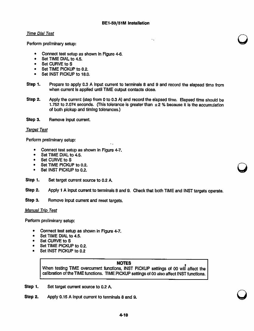
BE1-50/51M Installation
Time Dial Test
Perform preliminary setup:
• Connect test setup as sho\m in Figure 4i5.• SetTIME DIALto45.• SetcIREtos• SetTIME PICKUpto02.• SetlNST PICKUpto 18.0.
Step 1. Prepare to apply 0.3 A input current to terminals 8 and 9 and record the elapsed time fromwhen current is applied until TIME output contacts close.
step 2. Applythe current (step from o to 03 A) and record the elapsed tlme. Elapsed time should be1.752 to 2.074 seconds. (This tolerance is greater than ± 2 % because it is the accumulationOf both picloup and timing tolerances.)
Step 3. Remove Input current.
Target Test
Perform preliminary setup:
• Connecttest setup as shown in Figure 4-7.• SetTIME DIALto4r5.• SetcuRVEtos• SctTIME PICKiJpto02.• SetlNSTPICKUpto02.
Step 1. Set target current source to 02 A.
Step 2. Apply 1 A inpiit ourrent to terminals 8 and 9. Check that both TIME and lNST targets operate.
Step 3. Remove input current and reset targets.
Manual Trio Test
Perform preliniinary setup:
• Connecttest setup as shown in Figure 4-7.• SetTIME DIALto45.• SetouREtos• SetTIME PICKUpto02• SeHNSTPICKUpto02
NOTESWhentestingTIMEovercurrentfunctions,lNST PICKUP settings of 00 wilt affect the
calibration of the TIME functions. TIME PICKUP settings of 00 also affect lNST func(ions.
Step 1. Set target current source to o.2 A.
Step 2. Apply o.15 A input current to terminals 8 and 9.
4-10
BE1-50/51M Installation
Step 3. Connect a jumper between TIME MANUAL"lp test points. Checkthat TIME target operates.
Step 4. Connect a jumper between lNST MANUAL TRIp test poiht§. Check that lNST target operates.
Step 5. Pleset targets.
SEITING THE RELAY
Select the desired relay Settings before pLltting the relay into service. Changing pickup current settings whilethe relay is in service may cause tripping.
4-11


SECTION 5
IVIAINTENANCE
GENEFIAL
BE1 -50/51 M Ovei.current Plelay requires no preventive maintenance. However, periodic tests should beperformed according to scheduled practices. A recommended periodic test is provided [n this Section. Ifthe relay fails to function property and in-house repair i§ considered, consult the Service Manual (publicationnumber 9 2520 00 620). If factory repair is desired, contact the Customer Service Department of the PowerSystems Group, Basler Electric, for a return autliorlzation number prlor to shipplng.
IN-HOUSE REPAIR
ln-hoiise replacement of individual components should be performed by qualmed technicians.
0
lf in-house repair !s to be attempted, component values may be obtained from the schematics or the partslist of the Service Manual. Replacement parts may be purchased locally. The qualfty of replacement partsmust be at least equal to that of the original components.
Where special components are involved, Basler Electric part numbers may be obtained from the numberstamped on the component or assembly, the schematic, or parts list. These parts may be ordered directlyfrom Basler Electn.c. When complete bcrards or assemblies are needed, the following information ls required.
1. Relay model number
2. Plelay serial number
STOFtAGE
This protective relay contains long life aluminum electrolytic capac.rtors. Life in excess of 20 years may beexpected if the storage temperature does not exceed 40°C (72°F).
PER.ODIC TESTS
General
AIl relays should be tested periodically to identfty and correct any problems that are foiind.
Single phase relays such as the BE1-50/51M-104 are normally used in groups of four (three phase andground) on the protected circuit. Only three are required at any one time to provide complete protection.The fourth one assures that protection is maintained even if one relay failed.
This protection scheme also allows one unit at a time to be withdrawn for testing purposes without loosingprotection during the test. Refer to Section 4 for recommended test setups.
5-1
BE1-50/51 M Maintenance
Periodic Test
Periodic testing should consist of the following procedures.
STEP 1. Verify thatthe lnstantaneou§ pickup is within ±2% Of the value set on the dlals. Plckup occurswhen the lNST output contacts close.
STEP 2. Verftythat thetime plckup ls within ±2°/a of the value set on the dials. Pickup occurswhen theLED turns ON.
STEP 3. Verfty that the time to trip forthe curve and time dial settings at a multiple of six ls the same asthe time given on the characteristic curve. Refer to Section 1 for the characteristics curves.
STEP 4. Verftythat the time to trip forthe Instantaneous element at a pickup multiple of 2 is not greaterthan the time given on the instantaneous characten.stic curve. Refer to Section 1 for theinstantaneous characteristic curve.
STEP 5. Verfty that the 51 AUX contacts close when the time overcurrent element trips.
STEP 6. Verfty that the targets operate with 200 milliamperes of trip current in the trip circuits and thatthey can be reset using the PIESET LEVEF`.
This completes the periodic test.
5-2
a

r®SECTION 6
MANUAL CHANGE iNFORndATION
Substantive changes in this manual to date are summarized below.
Revision Summary ol Changes
A Changed manual title to BE1-50/51M and incorporated engineering changesaccordingly.
8 Changed the following pages.1-1. Application, deleted reference to dust tight cover.14. Specifications, TIME Dropout to not less than 95°/a of pickup
value.1-7. Specifications, Time F3eset, added statement to insure sufficient
power to power-up relay when using decaying characteristic.1-8. Specifications, corrected Storage flange Temperature degrees F.1-9. Defined British Standard curve types.2-1. lNST and TIME PICKUP selectors, added statement that
changing selectors while relay is in service may cause tripping.4-7. Time Pickup Test, Step 1., Changed 0.45 A to 0.485 A.4-9. Time Pickup -Test, Step 1., Changed 0.09 A to 0.096 A.4-
11.Added paragraph SETTING THE PIELAY6-1. Added Section 6.
C Added column for CT secondary to Table 1-1 and UL Becognition and CSACertification to specifications. Changed the following pages.
3-2 Deleted "or reset" from last sentence in paragraph Outputs.Changed from 'The targets will not operate or reset ..." to 'Thetargets will not operate..."
4-1 Corrected dielectric test leakage current per terminal andchanged rack mounting plate part number from "9 2520 00 024"to "9 252012 001".
4-3 Added BE1-50/51M, vertical model rear view to Figure 4-3.
6-1

a