IFC elects president, other officers - Duke Digital Collections
Upload
khangminh22Category
view
0download
0
This document is downloaded from DR‑NTU (https://dr.ntu.edu.sg)Nanyang Technological University, Singapore.
IFC (Industry Foundation Classes) ‑basedintegration of architectural design and structuraldesign
Wan, Caiyun
2006
Wan, C. Y. (2006). IFC (Industry Foundation Classes) ‑based integration of architecturaldesign and structural design. Doctoral thesis, Nanyang Technological University,Singapore.
https://hdl.handle.net/10356/12202
https://doi.org/10.32657/10356/12202
Nanyang Technological University
Downloaded on 14 Jan 2022 06:38:09 SGT

IFC (Industry Foundation Classes) -basedIntegration of Architectural Design
and Structural Design
Submitted by
WANCAIYUN
SCHOOL OF CIVIL & ENVIRONMENTAL ENGINEERINGNANYANG TECHN"OLOGICAL UNIVERSITY
A Thesis Submitted to Nanyang Technological Universityin fulfillment of the Requirements
for the Degree of Doctor of Philosophy
JANUARY 2006
ATTENTION: The Singapore Copyright Act applies to the use of this document. Nanyang Technological University Library

I would like to express my sincere gratitude, first and foremost, to my supervisor,
Associate Professor Robert Tiong Lee Kong, for his patient, generous and liberal
guidance, continuous inspiration and encouragement during the course of this study.
I would like to extend my gratitude to Assistant Professor Chen Po Han for his
valuable advice and patience, and continuous support and encouragement to pursue
this research. I am equally fortunate for the exchange of ideas with research students
and SIMTech fellows, such as Dr. Yang Qizhen and Dr. Cui Lu. I would like to
acknowledge their kind assistance and support.
I would also like to thank Ms Maey Leow from T. Y. Lin Internati~nal Pte. Ltd.
(Singapore), who provided me with constructive advice on deciding the aim and
objectives of the research. She also provided me with insights into the real-world
practice and softwares used in structural engineering and design office.
I am fortunate to have been a research scholar in the School of Civil and~ ..........-
Environmental Engineering (CEE), Nanyang Technological University (NTU), and
my experience as a graduate student at NTU has been pleasurable and stimulating,
thanks to its remarkable people and the outstanding academic environment. It would
not have been possible to finish this research work without the love and tremendous
support of all my friends in and outside of NTU.
Finally, I would like to thank my family in China for their patience, understanding
and support while I took my time completing this chapter of my life.
- 1 -
ATTENTION: The Singapore Copyright Act applies to the use of this document. Nanyang Technological University Library
Acknowledgements i
Table of Contents ii
Abstract ix
List of Figures ' xi
List of Tables xv
List of Abbreviations xvii
Chapter 1 Introduction 11.1 Background '. 2
1.1.1 Limitations of Current Information Exchange Mechanism in Building DesignProcesses 2
1.1.2 Collaborative Efforts in AEC/FM Industry 5
1.2 Challenges Faced When Using IFC Models 7
1.2.1 Lack of Assessment of the Capability of IFC Models for Structural Analysis andDesign R
1.2.2 Lack of Effective Methodology for Information Modeling and IFC ExtensionsDevelopment 9
1.2.3 Trends and Future Directions of IFC-based Interoperability 10
1.3 Scope and Objectives of Research 12
1.4 Relationships with Other ST Projects 14
1.5 Research Methodology 15
1.6 Organization of The Thesis 16
Chapter 2 Literature Review -192.1 Organization of Literature Review 19
2.2 Basics of Information Modeling and Product Model 19
- ii -
ATTENTION: The Singapore Copyright Act applies to the use of this document. Nanyang Technological University Library
TABLE OF CONTENTS
2.3 Efforts of Information Modeling and Product Models for AEC Industry 20
2.4 Standard Exchange of Product Model Data (STEP) and Collaborative Efforts......................................................................................................................... 22
2.4.1 CIMsteel Integration Standards 23
2.4.2 Architecture Methodologies and Tools for Computer Integrated Large ScaleEngineering (ATLAS) 23
2.4.3 Computer-Integrated Object-oriented product Modeling Framework for theBuilding Industry (COMBI) 24
2.4.4 COmputer Models for the Building Industry in Europe (COMBINE) 24
2.4.5 Building Construction Core Model (BCCM) 24
2.4.6 Industry Foundation Classes (IFC) 25
2.4.7 Conclusion 25
2.5 IFC Models and Structural Engineering 26
2.5.1 IFC Model Architecture 26
2.5.2 Steel Frame Constructions (ST-1) 28
2.5.3 Reinforced Concrete Structures and Foundation Structures (ST-2) 28
2.5.4 Precast Concrete Construction (ST-3) 29
2.5.5 Structural Analysis Model and Steel Constructions (ST-4) 29
2.6 IFC Related Efforts 30
2.6.1 Towards a Concurrent Engineering Environment in the Building and EngineeringStructures Industry (ToCEE) 30
2.6.2 Virtual Enterprises using Groupware tools and distributed Architectures (VEGA).............................................................................................................................. 30
2.6.3 Building Lifecycle Interoperable Software (BLIS) 31
2.6.4 Intelligent Services and Tools for Concurrent Engineering (ISTforCE) 31
2.6.5 Information Networking in the Construction Process (Vera) 32
2.6.6 Simple Access to the Building Lifecycle Exchange (SABLE) 32
2.6.7 Other IFC-based Computer Integrated System 33
2.7 Needs of Integrated Building Design System 35
2.7.1 Need for IFC Models Based 35
2.7.2 Need for Assessment of the Capability of IFC Models for Structural Analysis andDesign ~ 35
2.7.3 Need for Better Information Modeling Methodology 36
2.8 Existing Process Modeling Representations 36
2.9 Existing Information Modeling Techniques 46
2.10 Summary 49
- iii -
ATTENTION: The Singapore Copyright Act applies to the use of this document. Nanyang Technological University Library
TABLE OF CONTENTS
Chapter 3 Research Methodology and Processes 503.1 Selection of Research Methodology 50
3.1.1 Literature Review 50
3.1.2 Model Developing 51
3.1.3 Prototyping 52
3.2 Definition of Research Domain and Research Procedures 52
3.2.1 Definition of Research Domain 52
3.2.2 Research Procedures 53
3.3 Information Model Developing 56
3.3.1 Review of Existing Modeling Methodologies 57
3.3.2 Developing Process-oriented Information Modeling (PoIM) Methodology 57
3.3.3 Information Modeling for Structural Analysis Domain 57
3.3.4 Assessment of IFe Models 58
3.3.5 Developing IFC Extensions 58
3.4 System Development and Prototype Implementations 58
3.4.1 Development Process 58
3.4.2 Requirements Analysis 59
3.4.3 System Architecture and Design 60
3.4.4 Implementation 60
3.4.5 Verification and Test 60
3.4.6 Maintenance and Deployment. ~ 61
3.4.7 System Modeling Tools-UML 61
3.5 Case Study ~62
Chapter 4 Process-oriented Information Modeling (PoIM) 634.1 Introduction 63
4.2 Necessity to Integrate Process Model and Information Mode1. 64
4.3 Selection of Process Modeling Method 65
4.3.1 Comparison of Existing Process Modeling Representations 65
4.3.2 Selection of IDEFO 68
4.3.3 Basic Concepts of IDEFO Process Modeling 70
4.4 Selection of Information Modeling Method 74
4.4.1 Comparison of Existing Information Modeling Methods 74
4.4.2 Selection of IDEF1 74
4.4.3 Necessity to Enhance IDEF1 ~ 76
- iv -
ATTENTION: The Singapore Copyright Act applies to the use of this document. Nanyang Technological University Library
TABLE OF CONTENTS
4.5 Augmented IDEF1 methodolody 77
4.5.1 Entity Class 78
4.5.2 Domain Class ~ 78
4.5.3 Attribute Class 79
4.5.4 Relationships 80
4.6 Process-oriented Information Modeling (PoIM) Methodology 86
4.6.1 Principle of the Integration of IDEF1 and IDEFO 87
4.6.2 Requirements for IDEFO ModeL 92
4.6.3 Procedures to Develop Information Model from IDEFO Process Model throughPolM Methodology 93
4.6.4 Mapping Tables and Information Model 95
4.7 Developing IFC Extensions based on the PolM Methodology 99
4.7.1 Work Processes for IFC Extensions Development 99
4.7.2 Traditional IFC Extensions Development 101
4.7.3 Flow for IFC Extension Development 104
4.7.4 Ways to Develop IFC Extensions 105
4.7.5 Basic Rules for IFC Extension Development ~ 107
4.8 Summary 108
Chapter 5 Information Modeling for Structural Analysis 1095.1 Introduction 109
5.2 The Design Process 110
5.2.1 Building Design Process 110
5.2.2 Structural Engineering Process 116
5.3 Proposed Generic Process Model for Structural Analysis 119
5.3.1 Basis of Structural Analysis 119
5.3.2 Structural Idealization 122
5.3.3 Applying Loads 125
5.3.4 Performing Structural Analysis 127
5.4 Proposed Information Model for Structural Analysis 129
5.4.1 Information Models for Each Level of Process Models 129
5.4.2 Combined Information Model for Structural Analysis ~ 137
5.4.3 Relationships between Architectural Design and Structural Design 138
5.5 Assessment of Current Release IFC 2x2 Addendum 1 140
5.6 Summary 142
- v-
ATTENTION: The Singapore Copyright Act applies to the use of this document. Nanyang Technological University Library
TABLE OF CONTENTS
Chapter 6 IFC Extension Development for Structural Analysis Process .. 1436.1 Introduction 143
6.2 General Procedures of Structural Analysis and Design Software 144
6.2.1 Define Default Parameters 149
6.2.2 Set up Structural Model 149
6.2.3 Define Properties 151
6.2.4 Assign Properties 156
6.2.5 Define Analysis Options 160
6.2.6 Run Analysis and Display / Output the Results 161
6.3 Identification of Information Requirements for SAP2000 163
6.4 Assessment of IFC Models 165
6.4.1 Geometry 167
6.4.2 Load 169
6.4.3 Material Property 171
6.4.4 Section Property of Member 172
6.4.5 Analysis Options 175
6.4.6 Structural Responses 175
6.5 Generality Study of Information Gaps 175
6.5.1 Geometry 187
6.5.2 Load 188
6.5.3 Material 190
6.5.4 Member Section 191
6.5.5 Structural Responses 192
6.6 Recommendations for Further Development of the IFC Extens~on Model forStructural Analysis 192
6.7 Summary 200
Chapter 7 IFC-based Web-enabled Integrated Building Design System 2027.1 Introduction 202
7.2 System Development Methodology 203
7.2.1 Development Lifecycle 203
7.2.2 The Unified Modeling Language (UML) 205
7.3 Requirement Analysis 207
7.3.1 Use Cases 208
7.3.2 Functional Requirements 209
- VI -
ATTENTION: The Singapore Copyright Act applies to the use of this document. Nanyang Technological University Library

TABLE OF CONTENTS
7.3.3 Non-functional Requirements 211
7.4 System Architecture and Design 212
7.4.1 Architecture of the IFC-based Web-enabled Integrated Building Design System....................................................................................................................................... 213
7.4.2 Mechanics 218
7.5 Modular Design and Implementation 220
7.5.1 Related Technologies 221
7.5.2 User-interaction Module 222
7.5.3 Action Controller Component 228
7.5.4 Core Processing Module ; 230
7.5.5 Data Access and Data Storage Module 234
7.6 Implementation of Extended IFC Models in System ~ 239
7.6.1 IFCsvr.R200 240
7.6.2 IFC Models Implementation 241
7.6.3 Implementation of Proposed IFC Extensions 243
7.7 Summary 247
Chapter 8 Prototype Application and Case Studies 2498.1 Introduction 249
8.2 Case Study I: Seven - Storey Building 250
8.2.1 Uploading IFC File 250
8.2.2 Viewing and Editing 3D Structural Idealization Model. 252
8.2.3 Downloading the Agreed Model File 254
8.2.4 Information and Data Transformation 255
8.3 Case Study II: Erection of a 2-storey Comer Terrace Dwelling House 261
8.3.1 Defining Material 263
8.3.2 Assigning Loads 264
8.3.3 Exporting S2K File 265
8.3.4 Uploading and Saving SA Results 269
8.3.5 Viewing Whole Model 269
8.4 Assessment of Prototype's Implementation and System Architecture 270
8.5 Summary 275
Chapter 9 Conclusion and Recommendations 2779.1 Conclusion 277
9.2 Limitations of the Research 282
- vii -
ATTENTION: The Singapore Copyright Act applies to the use of this document. Nanyang Technological University Library
TABLE OF CONTENTS
9.2.1 The Scope 282
9.2.2 The Evolving of IFC Standard and Models 282
9.2.3 Limitations of the System 283
9.3 Future Directions of the Research 284
9.3.1 Further Prospect of Methodology 284
9.3.2 IFC Extension Development 285
9.3.3 Future Development of the Proposed Integrated System 285
References 287
Publications 308
Appendices 309Appendix A: Database Structure of SAP2000 309
Appendix B: Information Modeling for Structural Analysis 3!3
Appendix C: Comparison of Information Requirements with Current IFC Models....................................................................................................................... 332
Appendix D: Expressions of IFC Extensions Development by EXPRESS 344
- viii -
ATTENTION: The Singapore Copyright Act applies to the use of this document. Nanyang Technological University Library
Abstract"/ ~~'
The success of a building design process is highly dependent upon effective
coordination among the diverse design teams involved, such as architects, structural
and service engineers, project managers and other specialists. The traditional 'human
interpreted' communication system is very time consuming and requires extensive
effort in coordination. The aim of this research is to develop an IFC-compliant
information model for building design processes and an integrated building design
system to improve the capability of interoperation and the efficiency of information
communication.
In this research, the process-oriented information modeling (PoIM) methodology is
developed as a creative way to analyze information requirements and develop IFC
extension models. Through the integration of the IDEFO process models and the
enhanced IDEFI information models, the information requirements can be easily
identified and derived from the process models. The information derived from the
PolM is process-related, and is a general one which intends to characterize the flow of
design information. It is not tied to any specific design process model. It provides a
comprehensive view of the information and makes communication more effective and
efficient. In addition, a set of standard transformation procedures and mapping tables
is also designed to help the modeller quickly and easily identify elements,
corresponding information, and relationships. Furthermore, the new process for IFC
extension development based on the methodology is also proposed in this research.
The proposed PoIM methodology is used to build the generic information model for
structural analysis and design domain. The model captures important aspects and
essence of structural analysis. The gaps between the information requirements and
existing IFC models are identified, and the usefulness of IFC to meet the needs. of
structural analysis is assessed. The assessment is conducted from two levels and
- IX -
ATTENTION: The Singapore Copyright Act applies to the use of this document. Nanyang Technological University Library

ABSTRACT
perspectives: 1) a generic and conceptual level from the knowledge gathered from
structural engineering professionals; 2) the detailed requirements of structural analysis
applications by investigating into the relevant softwares. The necessary IFC
extensions for these information gaps are then developed. The proposed extensions
improve the ability of the integrated system to provide better services on the
integration of architectural design and structural analysis.
Finally, an IFC-based web-enabled integrated building design (IWIBD) system is
developed, which provides a collaborative environment whereby the participants can
perform online collaboration via the web. In this system, a model server is utilized to
support both IFC-based data integration and transaction-based interoperation between
architectural design and structural analysis processes by taking advantage of the
Internet, distributed computing and other advanced network technologies. The
overview of requirements, the framework of architecture and modular design for this
integrated system are provided in the research.
A prototype system has been implemented to demonstrate its validity and feasibility.
The prototype implements the developed process and data models in the context of
distributed, model-based, integrated system architecture. Two case studies are carried
out to demonstrate the capabilities of generating and exchanging information with
IFC extensions and providing online services to maximize the interoperability and re
usability of design objects. The first case tests the interoperability with architectural
design, as well as the approach on how to extract the information in architectural
design and to deduce structural information. The second demonstrates the data
transfer to, and interoperability with structural analysis and design software. The data d~ta
exchange and sharing between two different disciplines and different applications
based on IFC models is successfully executed. This research thus shows the feasibility
and practicability of the collaboration between architects and structural engineering. It is
hoped that with the services provided by this integrated system, the performance and
productivity of architectural and structural design activities can be significantly
improved.
- x-
ATTENTION: The Singapore Copyright Act applies to the use of this document. Nanyang Technological University Library

.If
Figure 1.1 The Research Scope: Integration of Architectural Design and Structural
Analysis 13
Figure 1.2 Relationships with Other IFC Structural Projects 15
Figure 2.1 IFC Release 2X2 Addendum 1 Model Architecture (IAI, 2004) ~ 27
Figure 2.2 The SABLE Framework Proposed Architecture 33
Figure 3.1 The Research Procedures ~ 54
Figure 3.2 Processes for Information Model Development. 56
Figure 4.1 IDEFO Functions 71
Figure 4.2 Decomposition of IDEFO Diagrams 72
Figure 4.3 An Enhanced IDEF1 Diagram ~78
Figure 4.4 Representation of Composition Relationship 81
Figure 4.5 Representation of Generalization Relationship 83
Figure 4.6 Representation of Dependence Relationship 84
Figure 4.7 Representation of Non-specific Relationship 86
Figure 4.8 IDEFO Process Model within a Level of Abstraction 89
Figure 4.9 IDEFO Model between Levels of Abstraction 90
Figure 4.10 PolM - From IDEFO Model to IDEF1 Model: The Eight Conversion
Steps 94
Figure 4.11 Combined Information Model for IDEFO Model 99
Figure 4.12 Work Processes for IFC Extension Development 100
- xi -
ATTENTION: The Singapore Copyright Act applies to the use of this document. Nanyang Technological University Library
LIST OF FIGURES
Figure 4.13 Traditional Processes of IFC Extension Development. 102
Figure 4.14 Integrated Process and Information Modeling Flow 105
Figure 5.1 Building Design Processes 111
Figure 5.2 IDEFO Node Tree of Building Design Process 115
Figure 5.3 Process Model for Structural Engineering 116
Figure 5.4 Process Model for Structural Analysis 121
Figure 5.5 Process Model for Idealization 124
Figure 5.6 Process Model for Applying Loads 126
Figure 5.7 Process Model for Performing Structural Analysis 128
Figure 5.8 Information Model for Idealization 135
Figure 5.9 Information Model for Applying Loads 136
Figure 5.10 Information Model for Performing Structural Analysis 136
Figure 5.11 Combined Information Model for Structural Analysis 137
Figure 6.1 Process Model for Doing Structural Analysis by SAP2000 147
Figure 6.2 IDEFO Node Tree of Structural Analysis Process by SAP2000 148
Figure 6.3 Process Model for Setting up Structural Model 150
Figure 6.4 Process Model for Defining Properties 152
Figure 6.5 Process Model for Assigning Properties 157
Figure 6.6 Process Model for Assigning Frame Static Loads 157
Figure 6.7 Process Model for Assigning Shell Static Loads 158
Figure 6.8 Process Model for Defining Analysis Options 161
Figure 6.9 Process Model for Running Analysis 163
Figure 6.10 Information Requirements of SAP2000 for Structural Analysis 164
Figure 6.11 Expressions of Structural Items in IFC 194
- xii -
ATTENTION: The Singapore Copyright Act applies to the use of this document. Nanyang Technological University Library
LIST OF FIGURES
Figure 6.12 Expressions of Restraints or Releases and End Offsets Information by
Property Sets 195
Figure 6.13 Expression of "Angle" by New Derived Attribute ' 196
Figure 6.14 Expression of "Type of Material" by New Attribute 197
Figure 6.15 Extension of "Types of Load Combination" by New Attribute 197
Figure 6.16 New Attribute for "Spacing" of Composite Profiles 198
Figure 6.17 New Class for "Prestress Load" 199
Figure 7.1 Software Development Lifecycle 204
Figure 7.2 Use Case Diagram of the Integrated System 209
Figure 7.3 Structure of IFC-based web-enabled Integrated Building Design (IWIBD)
System 214
Figure 7.4 The Architecture of the Integrated System 216
Figure 7.5 The Mechanics of The Integrated System 218
Figure 7.6 Model-view-controller (MVC) Architecture 223
Figure 7.7 Class Diagram for Interfacing 225
Figure 7.8 Action Controller Component 229
Figure 7.9 The Illustration of Idealized Structural Elements and Joint of Two'
Structural Prism 231
Figure 7.10 Class Diagram of Core Processing Module 234
Figure 7.11 Sample Classes and Related Components of Data Storage 236
Figure 7.12 Samples of XML File and Its DTD 238
Figure 7.13 IFCsvr. R200 Object Model 240
Figure 7.14 IFC-compliant Java Classes for Geometry Information 242
Figure 7.15 Java Classes for Material and Load Information 243
Figure 7.16 Part Definition of StructLinearElement Class 245
- xiii -
ATTENTION: The Singapore Copyright Act applies to the use of this document. Nanyang Technological University Library

LIST OF FIGURES
Figure 8.1 The Architecture of 7-storey Building as Input Data 250
Figure 8.2 Fragment of Building's IFC File 251
Figure 8.3 Screenshot of Architect Logging in JSP Page 251
Figure 8.4 Screenshot of Architect Uploading IFC File 252
Figure 8.5 The Screenshot of Structural Engineer Logging in Server and Adds some
information to Idealized Structural Model 253
Figure 8.6 The Screenshot of Final JSP Page that Allows Architect and Structural
Engineer to Download Files 254
Figure 8.7 Definition of Beam#2138 in IFC File 256
Figure 8.8 TreeView of the Value ofBeam#2138 256
Figure 8.9 The Screenshot of Engineer Viewing Information of Selected Element. 258
Figure 8.10 Definition of Beam#2138 in XML File 259
Figure 8.11 Related Structural Information for Beam#2138 in S2K File 259
Figure 8.12 Architectural Design in ArchiCAD 262
Figure 8.13 Screenshot of JSP Page for Engineer's Operations 263
Figure 8.14 Define Material Properties 264
Figure 8.15 Selecting Element and Assigning Loads 265
Figure 8.16 Case II Exchange S2K File Fragment 267
Figure 8.17 Structural Models Imported to SAP2000 268
Figure 8.18 Viewing Structural Analysis Information 269
- xiv-
ATTENTION: The Singapore Copyright Act applies to the use of this document. Nanyang Technological University Library
Table 4.1 Comparison of Existing Process Modeling Methods 66
Table 4.2 Comparison of Existing Information Modeling Methods 74
Table 4.3 Conversion between IDEF1 and IDEFO 88
Table 4.4 Possible Relationships for The IDEFO Diagram in Figure 4.8 89
Table 4.5 Standard Mapping Tables 98
Table 5.1 Sub-processes of Structural Engineering 113
Table 5.2 Mapping Table of IDEFO and IDEF1 130
Table 5.3 Comparison with Current Release IFC 2x 2 Addendum 1 140
Table 6.1 Overall Information Gaps between SAP2000 Requirements and IFC 2x2
Addendum1 166
Table 6.2 Expressions for "Outside Width" and "Back to Back Distance" 174
Table 6.3 Structural Engineering Software Survey 177
Table 6.4 Comparison of Structural Engineering Software Products 178
Table 6.5 Generality Study of the Information Gaps between SAP2000 and Other
Software 184
Table 6.6 Mapping of Load Directions between SAP2000 and IFC Model. 189
Table 7.1 Use Case Descriptions of Eight Use Cases 210
- xv-
ATTENTION: The Singapore Copyright Act applies to the use of this document. Nanyang Technological University Library
LIST OF TABLES
Table 7.2 List of Non-functional Requirements 212
Table 7.3 Example of Load Denotation in S2K File and Corresponding
IfcStructuralAction Class 246
Table 8.1 Primary Values of Entity StructLinearElement for Beam#2138 257
Table 8.2 Comparison of Three Definitions for Beam#2138 261
Table 8.3 Comparison between Conventional Practice and the IFC-based Integrated
Building Design System 272
Table 8.4 The Benefits and Respective Examples Resulting from the IFC-based Web-
enabled Integrated Building Design System 273
- xvi-
ATTENTION: The Singapore Copyright Act applies to the use of this document. Nanyang Technological University Library
Abbreviation Term
AECIFM Architecture, Engineering, Construction! Facility Management
AECO Architecture, Engineering, Construction and Operation
API Application Programming Interface
APs Application Protocols
ARMs Application Reference Models
BCCM Building Construction Core Model
BLIS Building Lifecycle Interoperable Solutions
BSI British Standard Institute
C.I.B. International Council for Research and Innovation in Building
and Construction
CAD
CAFE
CASE
CGI
CIFE
CIM
COMBI
Computer Aided Design
Computer-Aided Fabrication Environment
Computer-Aided Software Engineering
Common Gateway Interface
Center for Integrated facility for Engineering, Stanford
University
Computers in Manufacturing
Computer-Integrated Object-Oriented Product Modeling
Framework for the Building Industry
- xvii -
ATTENTION: The Singapore Copyright Act applies to the use of this document. Nanyang Technological University Library

Abbreviation
COMBINE
CPM
CSCW
CSI
DFDs
DTD
DWF
eCAADe
ELSEWISE
FFDB
FIPS
GAN
GARM
HTML
HTTP
IAARC
IAI
ICAM
ICOMs
ICT
IDEF
IDEFO
LIST OF ABBREVIATIONS
Term
COmputer Models for the Building Industry in Europe
computer-based Integrated Building Design System (IBDS)
Critical Path Method
Computer-supported Collaborative Working
Computers and Structures, inc.
Data Flow Diagrams
Document Type Definition
Drawing Web Format
Education in Computer Aided Architectural Design in Europe
European Large Scale Engineering Wide Integration Support
Effort
Functional Flow Block Diagrams
Federal Information Processing Standards
Generalized Activity Network
General Architecture, Engineering, and Construction (AEC)
Reference Model
HyperText Markup Language
HyperTexxt Transmission Protocol
International Association for Automation and Robotics In
Construction
International Alliance for Interoperability
Integrated Computer-Aided Manufacturing
inputs, outputs, controls, and mechanisms
Information and Communication Technology
Integrated Computer-Aided Manufacturing (ICAM) definition
Integration Definition for Function Modeling
- xviii -
ATTENTION: The Singapore Copyright Act applies to the use of this document. Nanyang Technological University Library
Abbreviation
IFC
ISO
ISS
ISSI
IT
JSP
LPM
LSE
MVC
NIAM
NIST
OMG
PAR
PDES
PDT
PERT
PFR
PMBOK
PalM
PRS
REI
RISA
SABLE
SADT
LIST OF ABBREVIATIONS
Term
Industrial Foundation Classes
International Organization for Standardization
Integrated Structural Software
International Software Systems, Inc.
Information Technology
Java Server Pages
Logical Product Model
Large Scale Engineering
Model-view-controller
Nijssen's Information Analysis Method / Nijssen's Information
Analysis Modeling
National Institute of Standards and Technology
Object Management Group
Product-Activity-Resource Model
Product Data Exchange using STEP
Product data technology
Program Evaluation and Review Technique
Process Flow Representation
Project Management Body of Knowledge
Process-oriented Information Modeling
Procedural Reasoning System
Research Engineers International
Rapid Interactive Structural Analysis
Simple Access to the Building Lifecycle Exchange
Structured Analysis and Design Technique
- xix-
ATTENTION: The Singapore Copyright Act applies to the use of this document. Nanyang Technological University Library
Abbreviation
SAMM
SAX
SIPE-2
SRC
STEP
ToCEE
UML
URI
URL
VEGA
Vera
VPML
VRML
WISPER
WWW
XML
LIST OF ABBREVIATIONS
Term
Systematic Activity Modeling Method
Simple API for XML
System for Interactive Planning and Execution Monitoring
Steel Reinforced Concrete
Standards for the Exchange of Product data
Towards a Concurrent Engineering Environment in the Building
and Engineering Structures Industry
Unified Modeling Language
Uniform Resource Identifier
Uniform Resource Locators
Virtual Enterprises using Groupware tools and distibuted
Architecture
Information Networking in the Construction Process
Visual Process Modeling language
Virtual Reality Modeling Language
Web-based IFC Shared Project EnviRonment
World Wide Web
Extensible Markup Language
- xx-
ATTENTION: The Singapore Copyright Act applies to the use of this document. Nanyang Technological University Library
Design for the built environment is probably the most multidisciplinary practice in all
of the design professions. Now, more than ever before, architects, structural and
building services engineers, quantity surveyors, construction managers, landscape
architects, and other specialists are required to work with a high level of integration
during the design and development of schemes. The success of this process is highly
dependent upon effective coordination among the diverse design teams involved. To a
greater or lesser extent, these various professions are experiencing a number of
pressures. There are pressures to reduce lead-time, to reduce costs, to reduce defects,
to lower environmental impact, and to increase client satisfaction. In addition, there
are pressures to improve communication with colleagues and to establish consistency
in tools and procedures. Simultaneously, Architecture, Engineering, Construction, and
Facilities Manageme~t (AECIFM) are information intensive industries, and are
increasingly dependant upon effective information technologies (IT) (Froese, 2003).
Therefore, there are pressures to adopt computer-based working - partly so as to
address the above issues (Gamer and Mann, 2003).
There are various computer tools that are used to support building design tasks
(Froese, 2003), such as CAD, Structure Computing software, etc. Under such
circumstances, the traditional cross-discipline communication is increasingly
manifested as an issue of data exchange and data sharing between different software
applications.
In recent years, IFC (Industry Foundation Classes) has become the most popular and
most promisingly accepted standard data model by AEC/FM industry. As an evolving
international information exchange standard, the model for structural analysis and
- 1 -
ATTENTION: The Singapore Copyright Act applies to the use of this document. Nanyang Technological University Library

CHAPTER 1 INTRODUCTION
design domain was just completed last year. Even with much combined effort being
put into the implementation of IPC by Scherer (2000), Liebich (2003), Froese and
Hassanain etc. (2001 and 2003), the integration for the whole building design life
cycle is not complete, at least for the case of architectural design and structural
analysis. And most of projects only implement data interoperability, but not integrated
system. Interoperability represents the ability for tools to exchange data. The data
exchange through interoperability alone does not support the ability to manage the
collective body of information since each tool works with only a limited view. The
"business logic" associated with each view resides in different tools and can't
interact. Under this circumstance, this research has been initialised in order to explore
the integration and interoperability among the building design processes based on the
IPC standards and product models. This research is a part of collaborative research
project (CRP), Feasibility Study and Concept Proof of IFC-Compliant Building
Information Modeling and Model Server Technologies, carried out by Nanyang
Technological University and Singapore Institute of Manufacturing Technology
(SIMTech).
1.1 Background
1.1.1 Limitations of Current Information Exchange Mechanism in BuildingDesign Processes
Information represents the meaning that a human assigns to data by means of the
known conventions used in their representation. It expresses facts, data, or
instructions in any medium or form. Information exchange has been a major problem
area in building design system. The increased complexity of buildings and of the
organization of construction process has made the transmission and sharing of
information more difficult as there is a growing amount of information to be
consolidated, distributed, and exchanged (Jagbeck, 1998). Unfortunately, most of the
software tools used to generate this information cannot interoperate.
- 2-
ATTENTION: The Singapore Copyright Act applies to the use of this document. Nanyang Technological University Library
CHAPTER 1 INTRODUCTION
In the whole building design, the processes of architectural design and structural
design are most important. They are the base of all the following works in the whole
life cycle of building. And the workload for this part is the biggest. \
Presently, the work of architect and structural engineer is basically separated. The
main communication between them is by documents and email. Although most of
structural analysis software has the function of importing DXF file which can be
exported by CAD (Computer Aided Design) software during architectural de~ign,
most of structural engineers do not use this function because of its inconvenience.
First, the DXF files should be generated according to certain rules so as to be
imported by structural analysis software. Secondly the accuracy of importing cannot
be assured. If the engineer chooses to import the files directly, it still will incur
additional work. Practically, engineer would rather do all the work by himself,
starting from basics of structural analysis and design software.
During the building design process, the information is passed from one software
forward to the next person via paper-based or electronic documents, who must re~
enter relevant information into the next computer software. This manual data re
interpretation and entry is a non-value- adding activity. It can often introduce errors
into the project which may dramatically hamper the duration, quality and cost of the
building process, and inhibits the use of better computational tools (Froese, 2003).
Furthermore, in the future this situation will quickly get worse when more and more
computer support becomes available and more electronic information is produced.
Garner and Mann (2003) carried out a study into the current exploitation of computer
supported collaborative working (CSCW) in design for the built environment in the
UK. The survey confirms that team working is increasing, and there are very real
pressures to increase team efficiency and team output quality. The findings also
confirm that in this field of design for the built environment, teams now involve a
wider range of specialist, and communication between these specialists has increased.
Therefore, the capability of software applications to interoperate has become
increasingly important.
- 3 -
ATTENTION: The Singapore Copyright Act applies to the use of this document. Nanyang Technological University Library
CHAPTER 1 INTRODUCTION
The main pitfalls existing in traditional "human-interpreted" communication system
include:
1. Different views of the same objects. The same data has different meanings or
semantics for different participants. Each participant re-translates the data in
his own point of view, which results in non-integrity of data, work adding and
time wasting.
2. Information lost or misunderstood during transfer. Problems of reworking
may occur due to conflicting information and information not received in time
to the parties concerned.
3. Less collaboration and low integration of design with software. A high
percentage of the IT system solutions (software) that are available today focus
on specific tasks such as architectural design, structural analysis, beam design,
etc. These isolated applications have resulted in a broad spread of stand-alone
applications packages with no or "fixed" communication links.
The major reason which causes these pitfalls is the lack of consistency in the flow of
information between the different parties involved in the building design. First, a
standardised platform for information exchange is lacking. The incompatibility
between different data formats has raised serious "technical" problems, which have
prevented design participants to easily access and exchange the information. These
problems are caused by the lack of standardisation of information that can facilitate
the flow of information between incompatible formats. In addition, the industry lacks
an integrated comprehensive system, which facilitates the smooth flow of information
between the various stages of the building design.
As a conclusion, an integrated system, which provides a standardized platform and
supports exchange of information without human interference, can cater to this need.
This system changes human-interpreted communication to computer-interpreted
communication. All data are stored in their most essential meaning no matter how
they are viewed by any user.
- 4-
ATTENTION: The Singapore Copyright Act applies to the use of this document. Nanyang Technological University Library

CHAPTER 1 INTRODUCTION
1.1.2 Collaborative Efforts in AEC/FM IndustrySome of the general characteristics of integrated systems are that they cluster many
functional views around an overall task of building and adopting a model-based
approach. Generally, the product model (the physical components of the built facility)
plays a central role (Froese, 2003). Product modeling has been recognized as a basis
for computer integrated engineering since the late 1980s. Product modeling standards
seek to facilitate effective communication and seamless inter-working between
disparate professionals by providing common terminologies, technologies, and ways
of expressing and communicating information. They utilise an open data model,
which provides common data representations to enable external programs to read and
manipulate data. These models form the basis for automation, customisation, rich
searching, and alternative interfaces (Myers, 1998). Standardization enables
integration not only throughout a single computer system, but also throughout the
industry in general. This provides the motivation and the justification for adopting an
industry-wide product-modeling standard (Owolabi et aI, 2003).
In this decade many product models have been designed and proposed. Eastman
(1999) divided current building product modeling efforts into two categories: aspect
models that address a specific domain in the building industry, and framework models
that address the whole structure of a building. Some building aspect'models that make
use of several STEP technologies, such as the Logical Product Model (LPM) in
CIMsteel project (Watson and Crowley, 1995), the central building model (IDM) in
COMBINE (Dubois and Flynn, 1995) and Part 225, the STEP AP that describes the
building elements using explicit shape representation (ISO, 1999). The framework
model is like Part 106, the STEP Building Core Construction Model (BCCM) (Wix,
ISO, 1996).
Various prototype product model environments have also been developed to prove the
validity and effectiveness of these approaches, including ATLAS, CIMSteel, COMBI,
and COMBINE etc. The COMBI (Computer-Integrated Object-Oriented Product
Modeling Framework for the Building Industry) (Scherer, 1995) carried out the
exchange of data between the different product representations· used by the separate
- 5 -
ATTENTION: The Singapore Copyright Act applies to the use of this document. Nanyang Technological University Library
CHAPTER 1 INTRODUCTION
design tools. The objective of COMBINE was the development of future intelligent
integrated building design systems (IIBDS) through which the energy, services and
other performance characteristics of a planned building can be analysed. CIMsteel
project aims to facilitate the sharing and the management of engineering information
relating to steel building frames.
However, as listed above, different product models were developed and only adopted
in the early stage of these projects. In this point, this kind of integration is just
implemented and limited in the scope of projects. Out of the projects, the problem of
incompatibilities between applications still exists. Starting from a set of model that is
widely used and accepted is a good solution to improve the extensibility and
compatibilities of integrated systems, which should be at industry-wide level, not at
the level of individual firms.
As the world's largest developer of standards, the International Standards
Organization's (ISO) STandard for the Exchange of Product model data (STEP) effort
is undoubtedly a major international effort to establish standards for communicating
product data (Warthen, 1988). STEP (ISO 10303) is a large, complex standard that
was designed to support the needs of many different industries and disciplines to
exchange product data. The US equivalent of STEP is called Product Data Exchange
using STEP (PDES), which is the project within American National Standards
Institute (ANSI) (Mitchell, 1996). Three major classes of products are defined:
mechanical products, Electrical & Electronical products, and products of the AEC
industries (Gielingh 1988a and 1988b, Gielingh et al. 1991).
On 8 November 2002, ISO announced acceptance of the Industry Foundation Classes
(IFC) standard - used as a common language and an international standard in
construction - as an ISOIPAS 16739 (IAI-NA, 2002). The IFC is an effort of
International Alliance for Interoperability (IAI) to provide data structures for the
AECIFM industry shared project model and seeks to enable data sharing across
heterogeneous applications by representing building products and their information
requirements in a neutral computer language - the EXPRESS modeling language (IAI,
- 6-
ATTENTION: The Singapore Copyright Act applies to the use of this document. Nanyang Technological University Library

Iii
CHAPTER 1 INTRODUCTION
2003). IFC is consistent with and adopts a number of specifications from STEP
(Daley et aI., 1999).
Currently, IFC is the most widely accepted and supported standard data model by the
AEC/FM industry. From the point of view of the basic technical ability to exchange
AEC/FM information, it can be said that the IFCs have now been established as a
viable interoperability technology. Significant portions of the IFCs are now mature,
stable standards and numerous prototype and early commercial systems have
demonstrated their extensive information exchange capabilities (Froese, 2003). De
facto standards are quite as important and the IFCs are the best hope for modeling
buildings at present, with the BLIS (1999) project for software interoperability
showing how many firms are producing software (Howard and Andresen, 2001).
Even though standardization addresses the problem of incompatibility of data formats
by providing industry-wide syntax and semantic, it is still unavoidable that some
people may doubt that standardisation limits design freedom. For example, Stouffs
and Krishnamurti (2001) argued that standardisation is not the solution to data
exchange, particularly in the design process, because it attempts to impose a common
semantic model for all to adhere to with attendant restriction to possibly better
solutions and impedance to creative new approaches to specific problems. However, it
is just like what Howard and Andresen (2001) likening the notion to saying the
alphabet limits literary expression. Adopting Stouffs and Krishnamurti (2001)' s
propositions would do little to improve the existing complicated, highly-fragmented
communication among the project team members with the accomp~nying omissions,
repetitions, confusions, misunderstandings, errors, delays and litigations.
1.2 Challenges Faced When Using IFCModeis
The IFCs, initiated in 1994, have now undergone four major releases. The latest
version IFC 2x Edition 2 and its addendum_has been released whose domain coverage
includes Architecture,. HVAC (Heating, Ventilation & Air Conditioning), FM,
- 7 -
ATTENTION: The Singapore Copyright Act applies to the use of this document. Nanyang Technological University Library
CHAPTER 1 INTRODUCTION
Construction Management, Building Controls, Plumbing Fire Protection, Structural
Elements, Structural Analysis and Electrical Domain (IAI, 2003, 2004).
As the substantial progress of IFC, many design software companies have
implemented file exchange capabilities of IFC-based product models (such as
Autodesk's Architectural Desktop, Graphisoft's ArchiCAD, Nemetschek's Allplan,
Microsoft's Visio, and Timberline Precision Estimator). Simultaneously, there are a
large number of finished or ongoing research projects related to IFC models in recent
years. Some extended the IFC models or developed IFC-compliant models for
different domains (Weise et al. 2000, Kim et al. 2003, Hassanain et al. 2001). Also
many studies have been carried out with the aim of integrating the various building
life-cycle phases based on IFC models, such as the information exchange between
architects and precast concrete designers (Ronneblad and Olofsson, 2003), the
integrated asset management system (Hassanain, Froese and Vanier, 2003), the
Building Lifecycle Interoperable Software (BLIS, 1999), ToCEE (Towards a
Concurrent Engineering Environment) (Scherer, 2000), and Vera (Information
Networking in the Construction Process) (Froese, 2002).
However, IFC is still in its early stage of development. Only recently have IFC
compatible software applications started to become commercially available, and, as
yet, IFC has almost no actual use in industry (Froese, 2003). There are still some
challenges and problems facing the current implementation of IFC models.
1.2.1 Lack of Assessment to the Capability of IFC Models for StructuralAnalysis and DesignMost of above projects and almost every paper on IFC modeling deal with either the
development of domain extensions or the application of IFC models in a certain
domain. There has been virtually no assessment and validation of how well the IFC
can support various domains' requirements, such as structural analysis and design.
The information requirements of architectural design and structural design are
different. Therefore the gaps as well as the reasoning mechanisms and the
transformation between them need to be analyzed in order to integrate these two
- 8 -
ATTENTION: The Singapore Copyright Act applies to the use of this document. Nanyang Technological University Library
CHAPTER 1 INTRODUCTION
processes. So far IFC gives a very comprehensive expression for architectural design
domain and many general architectural design softwares provide the support for IFC
models (ArchiCAD, ADT, Bently, etc.). However, the IFC extensions for structural
analysis domain is formally just released in 2003 in the version 2x Edition 2. It is
seldom that a project would involve the integration of architectural design and
structural analysis and it is also seldom for commercial structural analysis and design
application to provide the support of IFC. Very little work has been done on
specifying a mapping from the IFC into structural analysis and design tools.
In addition, since a number of programs are required for engineering design, the
absence of standardization and the lack of coordination among software developers
can result in difficulty in data communication from one program to another. Therefore,
a good representation which is easily communicated within a project must not only
cover the requirements of industry professionals, but also cover the requirements of
the wide range of design tools and CAD systems utilized in the industry (Amor et aI.,
2002a). Thus, the assessment need to be conducted both from the view of
professionals and from the perspective of analysis and design tools in order to give the
comprehensive evaluation on the usefulness of IFC models.
1.2.2 Lack of Effective Methodology for Information Modeling and IFCExtensions DevelopmentProduct and process modeling paradigms as well as many models have been
developed over the last decade for specific sub-processes. The traditional process of
IFC extensions development is based on an iterative process. However, the efforts on
IFC are still on-going and evolving. The changing modeling base and environment
increase the needs for more effective modeling methodology. There are few published
papers or guides that cover the detailed methodology of developing IFC extensions.
Therefore, there is a strong thread arguing for the need for flexible and extensible
models in contrast to the traditional product modeling approach. An advanced
information analysis and modeling method for modeling the requirements is an
essential requirement to achieve the ultimate goal of a full scale integrated building
design system.
- 9-
ATTENTION: The Singapore Copyright Act applies to the use of this document. Nanyang Technological University Library
CHAPTER 1 INTRODUCTION
In past years, quite a few process and information modeling methods have been
developed, such as the generic process description methods like IDEF (ICAM
Definition language) and PetriNets, the information models like EXPRESS data
specification language, and other process activity or functional models, simulation
model, etc (Karstila et al. , 2000). These information modeling languages provide
various ways of formally representing an information model. However, there has been
a noticeable lack of development on integrated models and integrated project
databases with the preferred approach for all possible mappings. Currently these
modeling methods are independent. Each one describes or models a system from its
own perspective and concentrates on a relatively narrow set of relationships and
system characteristics comprising a particular viewpoint of the overall system. The
methodologies/tools are not completely integrated to each other, thus causing
inefficiencies in the development process. None of the methodologies or tools
provides a comprehensive environment that can be used for the information system
design from start to finish. The methodologies and tools are incomplete, and are
inconsistent with each other. Usually a system should be pictured by different models
in order to get a full picture of the system. In this case the modeling process may be
very time-consuming and involves a tremendous amount of wasteful effort because
essentially they capture the same data. Open questions seem to centre around how to
use them more effectively and efficiently and how to get a flexible and extensible
models. That is, developing a generic integrated methodology has become one of
most important areas which would be considered in this research. The study of
methodology for information modeling to support the standard model development is
proposed in order to help improve the effectiveness and efficiency of model
development and avoid any duplicate work during the future model development.
1.2.3 Trends and Future Directions of IFC-based InteroperabilityThere are currently two major trends in IT for AECIFM: the model-based systems and
web-based collaboration, which is also the future direction for IFC-based
interoperability. Model-based integrated systems are central to the next generation of
IT support for the AEC/FM industry. Web-based collaboration is another major IT
- 10-
ATTENTION: The Singapore Copyright Act applies to the use of this document. Nanyang Technological University Library
CHAPTER 1 INTRODUCTIOI\i
trend. It is important that these vital technologies should not be developed in isolation
of each other. Model-based systems and interoperability should be integrated with
important web-based technologies such as document management, workflow
management, knowledge management, and e-commerce applications (Froese, 2003).
In 2000, Faraj developed a web and IFC-based distributed computer integrated
environment, namely Web-based IFC Shared Project EnviRonment (WISPER), within
the construction domain. Abidemi Owolabi et aI. (2003) identified key requirement
for IFC-based online product libraries and presented an architecture, which is aimed
at supporting present and emerging industry practices in the production and
consumption of product information. An Internet-based distributed building
simulation quality control system was developed by Robert Amor et aI. (2002b). An
experimental Internet-enabled system that integrates Building and Facilities
Management Systems has been development and tested (Shengwei Wang et aI., 2002).
To date, web applications have proven their value for promoting communication and
publishing. The open standards and wide accessibility of the Internet mean that it is
fast evolving into a powerful environment for supporting distributed and collaborative
group work (Faraj, 2000).
Thus, it can be summarized that generally in current changing environment several
mechanisms need to be developed to meet the practical needs for an integrated
building design system. Firstly, the system should follow an industry-wide standard
data exchange format (IAI/IFC), namely a model-based integrated system. It is
estimated that the technology of standard-base approach could bring about up to 30%
cost savings in AEC project development (Drogemuller, 2000). In design, it is
estimated that reduction of 10%-35% of design time and cost are achievable (Liebich
and Wix, 1998a). Secondly, the system should be integrated with web-based
technologies in order to provide a much powerful, flexible and extendible integrated
environment. The online services maximize the interoperability and re-usability of
design objects, and in exchanging and sharing the extended models data among life
cycle processes. Consequently, an IFC based web server for the collaborative building
design system is developed in this research.
- 11 -
ATTENTION: The Singapore Copyright Act applies to the use of this document. Nanyang Technological University Library
CHAPTER 1 INTRODUCTION
1.3 Scope and Objectives of Research
The main focus of this research is to develop the integrated methodology for
information requirements analysis, assess the capability of IFC to support the
integration of structural analysis and architectural design and to develop the prototype
implementation of the interoperation between these two domains. The research has
the following objectives:
a. To select and develop appropriate modeling methodology to support industry
needs and requirements for the integrated building design system, which aims to
improve the efficiency of modeling and make it easier for users to understand and
use.
b. To introduce the new process of IFC extensions development based on the
proposed modeling methodology and develop a generic information model for the
structural analysis and design process. The model should also capture important
aspects of the. essence of structural analysis from the conceptual level to the
detailed practical level.
c. To assess the usefulness of IFC to meet the practical needs of structural analysis,
not only from professionals' knowledge but also from software's point of view,
through the analyzing of the information gaps by the mapping and comparison
between the information requirements and IFC models.
d. To develop the IFC extensions through appropriate approaches based on
generality study of the information gaps so as to give a supplement for the
standard product model to structural analysis domain. This building product
model will provide an infrastructure for structural analysis information and be
used as a basic information structure for the use of IT within structural design.
e. To propose the framework and architecture design of an integrated system, and to
develop an IFC-based web-enabled integrated building design (IWIBD) system
for the integration and interoperability of architectural design and structural design.
- 12-
ATTENTION: The Singapore Copyright Act applies to the use of this document. Nanyang Technological University Library
CHAPTER 1 INTRODUCTION
f. To develop a prototype implementation for the system and demonstrate the
functionality of the integrated system's architecture by using two cases.
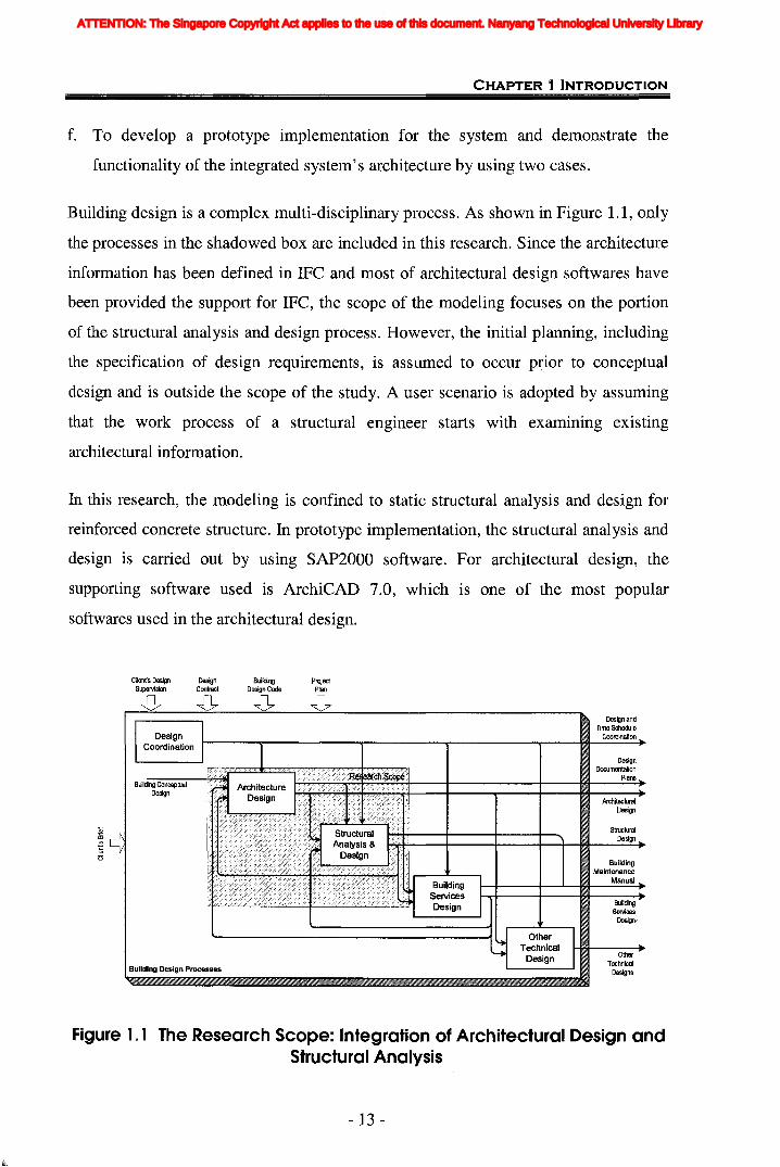
Building design is a complex multi-disciplinary process. As shown in Figure 1.1, only
the processes in the shadowed box are included in this research. Since the architecture
information has been defined in IFC and most of architectural design softwares have
been provided the support for IFC, the scope of the modeling focuses on the portion
of the structural analysis and design process. However, the initial planning, including
the specification of design requirements, is assumed to occur p~ior to conceptual
design and is outside the scope of the study. A user scenario is adopted by assuming
that the work process of a structural engineer starts with examining existing
architectural information.
In this research, the modeling is confined to static structural analysis and design for
reinforced concrete structure. In prototype implementation, the structural analysis and
design is carried out by using SAP2000 software. For architectural design, the
supporting software used is ArchiCAD 7.0, which is one of the most popular
softwares used in the architectural design.
Cllenfs Design DesignSupervision Contract
-0 -0
Building Design Processes
BuildingDesign Code
-0ProjectPlan
-0Design and
Time ScheduleC;oordination
DesignDocumentation
Plans
ArchitecturalDesign
StructuralDesign
BuildingMaintenance
Manual
BuildingServices
Design/
OtherTechnical
Designs
Figure 1.1 The Research Scope: Integration of Architectural Design andStructural Analysis
- 13 -
ATTENTION: The Singapore Copyright Act applies to the use of this document. Nanyang Technological University Library
CHAPTER 1 INTRODUCTION
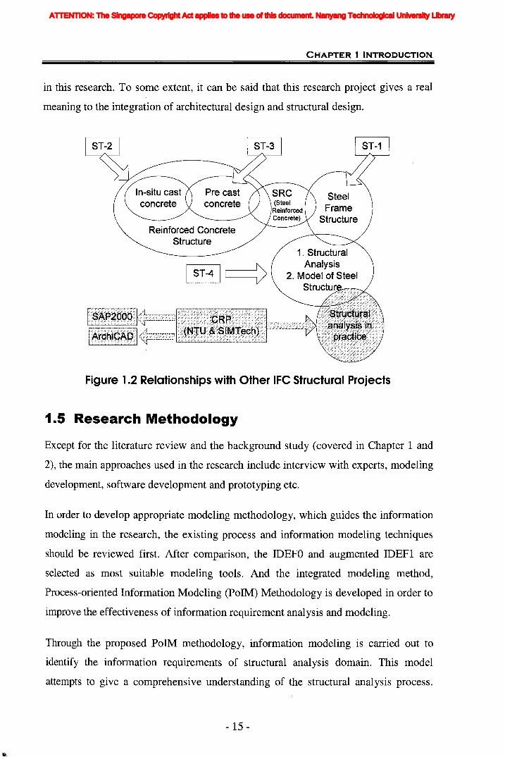
1.4 Relationships with Other ST Projects
The modeling emphasis of the research is based on structural analysis and design
process. There are four IFC projects which are related to the structural field, the steel
frame constructions model development project ST-1, ST-2 (Yasaka and Furukawa,
2002) for the basic structural design and structural execution design, the precast
concrete structural model project ST-3 (Karstila, 2002) and ST-4 (Liebich et aI., 2002)
for the structural analysis and model of steel constructions. Figure 1.2 illustrates the
relationships between this collaborative research project and these four IFC projects.
Basically, this research project is completely different from ST-1, ST-2 and ST-3
projects. Firstly, the focus is on different domains. This project's focus is mainly on
the process from architectural design to structural analysis and design, while ST-3
project is mainly concerned with the whole life cycle of precast concrete construction,
from design, manufacture to installation. Secondly, the research covers different types
of structure and different types of material. Precast concrete construction was mainly
involved in ST-3 project and steel frame structure was studied in ST-1, while
reinforced concrete for in-situ construction is the primary study subject of this project.
Last but not least, different processes are studied. ST-2 involved structure design and
structural execution design. The primary aim of this project is to integrate structural
analysis with architectural design. Therefore, this project will not duplicate the work
of ST-l, ST-2 and ST-3 projects and there is no direct relationship between them. It
will however use the IFC extensions developed by these three projects.
The most relevant project to this research is the ST-4 project. They both cover the
modeling for structural analysis domain. The only difference lies on the final level of
implementation. The IFC models of ST-4 are developed much more from experts'
perspective rather than from the actual software operation. There should be some
deficiencies existed in the current models for the real application. Among the 10
specific scenarios listed in Vol. 0 of ST-4 project documentations (Horenbaum, 2002),
the data sharing between architect and structural engineer is not included. This is just
the reason of producing the assessment of IFC models for structural analysis domain
- 14-
ATTENTION: The Singapore Copyright Act applies to the use of this document. Nanyang Technological University Library
CHAPTE~ 1 INTRODUCTION
in this research. To some extent, it can be said that this research project gives a real
meaning to the integration of architectural design and structural design.
In-situ castconcrete
SteelFrame
StructureReinforced Concrete
Structure1. Structural
Analysis2. Model of Steel
Figure 1.2 Relationships with Other IFC Structural Projects
1.5 Research Methodology
Except for the literature review and the background study (covered in Chapter 1 and
2), the main approaches used in the research include interview with experts, modeling
development, software development and prototyping etc.
In order to develop appropriate modeling methodology, which guides the information
modeling in the research, the existing process and information modeling techniques
should be reviewed first. After comparison, the IDEFO and augmented IDEFI are
selected as most suitable modeling tools. And the integrated modeling method,
Process-oriented Information Modeling (PoIM) Methodology is developed in order to
improve the effectiveness of information requirement analysis and modeling.
Through the proposed PolM methodology, information modeling is carried out to
identify the information requirements of structural analysis domain. This model
attempts to give a comprehensive understanding of the structural analysis process.
- 15 -
ATTENTION: The Singapore Copyright Act applies to the use of this document. Nanyang Technological University Library
CHAPTER 1 INTRODUCTION
Then, the capability of current IFC models supporting structural analysis is assessed
by identifying the information gaps through the mapping and comparison of the
proposed information model with the existing IFC models. And new extensions to
current IFC models are developed to complete model of structural analysis domain.
Following the software development lifecycle, the architecture of the integrated
building design (IWIBD) system is developed and designed. Prototyping is used to
develop and implement a prototype system as a test model to prove and implement the
concept of the integration of architectural design and structural analysis design.
Finally, two case studies are used to validate and test the prototype system. One case
illustrates the information exchange and sharing between architect and engineer
through the integrated system's server. The other case demonstrates the
communication with engineers.
1.6 Organization of The Thesis
This thesis consists of nine chapters and is organized as follows:
Chapter 1 Introduction provides an introduction to the thesis by describing the
current building design situation, its general context and highlighting the problems
and challenges faced. It also describes the scope and the phases of this research. The
objectives and the methodology used in the research are also included.
Chapter 2 Literature Review reviews existing research trends in related fields. It
includes an introduction to information modeling and product models. The previous
studies on information model and standards for AEC industry, especially STEP and
IFC related efforts are presented. The existing process modeling and information
modeling methods would also be reviewed as the basis of proposed methodology.
Chapter 3 Research Methodology and Processes describes the methodologies used to
develop the research results. The steps and procedures of the model development are
presented. In addition, literature review, information modeling and software
development are presented in detail in this chapter.
- 16 -
ATTENTION: The Singapore Copyright Act applies to the use of this document. Nanyang Technological University Library
Iii
CHAPTER 1 INTRODUCTION
Chapter 4 Process-oriented Information Modeling (PoIM) proposes an integrated
method for information analysis, Process-oriented Information Modeling (Po1M)
methodology. It is a new methodology to model process-related information through
integrating IDEFO process models and enhanced IDEF1 information models. The new
process and procedures for developing IFC extensions based on this methodology are
described in this Chapter. Some rules for IFC extension development are also
specified so as to minimize conflict and confusion for organizations that will
implement the extension model.
Chapter 5 Information Modeling for Structural Analysis presents the general
information model for structural analysis domain developed in this research.
Currently the information is collected from professionals' literatures and the modeling
is constructed through using the PolM methodology. The relationships between
architectural design and structural design are also discussed to prove the necessity and
feasibility of their integration. Then the capability of current IFC models to support
structural analysis is assessed. It is found that in a conceptual level most of the
information for structural analysis can be explicitly supported by current IFC models.
Chapter 6 IFC Extension Development for Structural Analysis Process focuses on
analyzing the detailed information requirements for structural analysis domain from
the software's point of view. After the comparison with current IFC extensions, the
usefulness of IFC models and standards to support practical structural analysis is
assessed. It is found that most of the information for structural analysis can be
explicitly supported by current IFC. However there is still some information missing.
Some may be inferred from the data existing in IFC. Therefore, the necessary
extensions for the missing information are developed.
Chapter 7IFC-based Web-enabled Integrated Building Design System presents a
description of the architecture design for this internet-enabled open software
framework. By taking advantage of the Internet, Model-view-controller (MVC)
architecture, and other advanced computer technologies, such as J2EE, the modular
design of system and interactions among the modules are investigated. The
implemented of a prototype system is also described.
- 17 -
ATTENTION: The Singapore Copyright Act applies to the use of this document. Nanyang Technological University Library

CHAPTER 1 INTRODUCTION
Chapter 8 Prototype Application and Case Studies uses two case studies to illustrate
and validate the functionality of the system architecture which demonstrates how
design information can be integrated and communicated between architect and
engineers.
Chapter 9 Conclusion and Recommendations summarizes the works finished and
primary contributions of this research, as well as the limitations currently existed. The
recommendations on the area for future research work are also proposed.
- 18 -
ATTENTION: The Singapore Copyright Act applies to the use of this document. Nanyang Technological University Library
2.1 Organization of Literature Review
Design standards together with process and information modeling, has been active
research areas for several decades. This chapter begins with a review of the basics of
information modeling and product models, followed by an overview ·of existing
information modeling and product models in the AEC industry. The STEP and IFC
related efforts are especially reviewed, as they lay the foundation for this research.
After reviewing the current efforts from different perspectives, the needs for an
integrated building design system can be distinguished in section 2.7. Section 2.8 and
section 2.9 then give brief descriptions on process modeling and information
modeling methods which are utilized to analyze their characteristics for the
developing of the process-oriented information modeling (PoIM) methodology.
Finally, section 2.10 concludes in a summary.
2.2 Basics of Information Modeling and ProductModel
Models have existed for a long time and have been used in many different ways. The
purpose of a model is to depict something existing or planned in a simplified way.
Information modeling is a technique for specifying the data requirements that are
needed within the application domain (Lee, 1999). It is a way to formulate concise
descriptions of real world artefacts and ideas so that they may be processed and
communicated efficiently (Zamanian and Pittman, 1999). Product data technology
(PDT) is a unified perspective for information modeling of products and all associated
life cycle processes, with the aim to share that information within and across
engineering disciplines (Eastman and Augenbroe, 1998). A product model is a digital
-19 -
ATTENTION: The Singapore Copyright Act applies to the use of this document. Nanyang Technological University Library

CHAPTER 2 LITERATURE REVIEW
representation of a real world object held to facilitate the unambiguous transfer of the
information between computer systems and to support information sharing (Eastman,
1999). Turk (2004) defined product model as "Totality of all information required of
product through its entire life cycle".
The goal of product modeling and data exchange is to make the exchange and sharing
of information among multiple applications easy and an everyday occurrence
(Eastman and Augenbroe, 1998). Product models have become a common
information technology artefact. They define the vocabulary and semantic structure of
the engineering and design products within particular business domains, allowing this
information to be unambiguously exchanged, communicated and sometimes
generated electronically. Product models facilitate automation of activities, electronic
communication and reengineering of engineering processes (Eastman and Sacks,
2002). Product modeling has been recognised as a basis for computer integrated
engineering since the late 1980s.
2.3 Efforts of Information Modeling and ProductModels for AEC Industry
During the past twenty years, there have been numerous efforts in the area of
information modeling and information sharing protocols for the AEC domain
(Gielingh 1988a, Turner 1990, Eastman etc. 1991, Powell and Abdalla 1991, Howard
et al. 1992, Bjork 1992, Zamanian 1992, Hakim 1994, Wix 1996, Arnold et al. 1996).
These researches seek to facilitate effective communication and seamless inter
working between disparate professionals of the AEC domain by providing common
terminologies, technologies, and ways of expressing and communicating information.
Early efforts to apply the data exchange technology include the General AEC
Reference Model (GARM) (Gielingh, 1988), RATAS (Bjork, 1989 and 1992) and
Engineering Data Model (EDM) (Eastman, 1991), Semantic Modeling Extension
(SME) (Clayton, Kunz and Fischer, 1996).
- 20-
ATTENTION: The Singapore Copyright Act applies to the use of this document. Nanyang Technological University Library
CHAPTER 2 LITERATURE REVIEW
The GARM methodology viewed the product model as functional units associated
with a functional requirement, and a matching set of one or more technical solutions.
Furthermore, a technical solution can be decomposed into a set of lower order
functional units, and the decomposition can be repeated for a technical solution
associated with a functional unit as necessary.
The RATAS building product model was developed as part of a large effort by the
Technical Research Center of Finland (VTT) to establish a standard CAD
environment for the Finnish national construction industry. The organization of
entities in this model was modelled via an abstraction hierarchy with five levels: (1)
building, (2) system, (3) sub-system, (4) part, and (5) detail.
Developed by Eastman et al. (1991), EDM was perhaps the most formal data model
for the representation of engineering information. The major focus of EDM has been
on the design stage of the product model lifecycle and the development of appropriate
data modeling concepts and tools for this task. A major contribution of Eastman's
work was the generalization of the concept of instantiation to design refinement
(Zamanian and Pittman, 1999).
In contrast to many other AEC information models, Clayton et al. (1996) referred to
SME as a "virtual product model" since it arose dynamically as a result of the user's
actions while designing a building. SME was intended to capture functional and
behavioural information about the building components in addition to the traditional
geometry-centered, physical information, thus providing richer content for
information sharing by various AEC disciplines across different phases of a project.
RATAS, EDM, and SME created a general framework for modeling various
abstractions of an evolving AEC project. They tended to offer more flexible
approaches for dealing with evolving, less-structured information pertaining to more
general abstractions used in AEC projects. After twenty years of product modeling
development -- first in the area of building modeling and in the last ten years
primarily centred around the ISO-STEP efforts (ISO, 1994), but more recently
- 21 -
ATTENTION: The Singapore Copyright Act applies to the use of this document. Nanyang Technological University Library

CHAPTER 2 LITERATURE REVIEW
augmented by the JAJ, therefore the following section would like to review the
primary efforts related to STEP and IFC.
2.4 Standard Exchange of Product Model Data (STEP)and Collaborative Efforts
STEP is an international product modeling standardization effort. The objectives of
STEP include the incorporation of object-oriented programming concepts and formal
specifications of the defined structures, separation of the data model and the physical
file format, supporting subsets of the total model, and the sharing of reference models
among these subsets.
The STEP Committee defines the Application Protocols (APs) (the subsets) first, and
the APs are later incorporated into the total model. An AP has two parts:
• The Application Reference Model (ARM) that represents the requirements of an
application using the IDEF1X (IDEF1X, 1985), NIAM (Nijssen's Information
Analysis Method) (Nijssen and Halpin, 1989), and EXPRESS-G models (Schenk
and Wilson, 1994)
• The Application Interpreted Model (AIM) that uses EXPRESS (ISO, 1994) to
specify the structure of the ARM data
Building-industry related APs include Part 225 (building elements), Part 228 (HVAC),
and Part 230 (steelwork). Interpreted (shared) Resources include Part 41, the
application context, and Part 42, geometric representation.
Many of current product modeling projects use the concepts from the International
Standards Organization (ISO) Standard for the Exchange of Product Model Data
(STEP) effort. Numerous organizations worldwide are developing STEP to provide a
computer-interpretable representation and exchange of model data in the AEC
industry.
- 22-
ATTENTION: The Singapore Copyright Act applies to the use of this document. Nanyang Technological University Library
CHAPTER 2 LITERATURE REVIEW
2.4.1 CIMsteellnteg~ration StandardsThe central objective of CIMsteel project was to facilitate the- sharing and the
management of engineering information relating to steel building frames (Waston and
Crowley, 1995). It has provided the first stable implemented AEC industrial strength
model: CIMsteel Integration Standards (CIS). It aimed to establish open standards for
th~ management and exchange of product data which address all types of steel frames
and which are coincident with STEP standards. The LPM (Logical Product Model)
for the steel frame of building was developed and has been validated progressively
through a sequence of demonstrator prototypes.
CIS/2 (CIMsteel Integration Standards Release 2) is an extended and enhanced
second-generation release of the CIMsteel Integration Standards (CIS). CIS/2
substantially extends the engineering scope of CIS/1, and introduces advanced data
management capabilities to enable data sharing. CIS/2 is intended to create a seamless
and integrated flow of information among all parties of the steel supply chain
involved in the construction of steel framed structures. It has been adopted by the
American Institute of Steel Construction as their format for Electronic Data
Interchange (EDI).
2.4.2 Architecture Methodologies and Tools for Computer Integrated LargeScale Engineering (ATLAS)The ATLAS project aimed at the development, demonstration, evaluation and
dissemination of architectures, methodologies, and tools for computer-integrated
large-scale engineering (Tolman et aI., 1994). This model formed three layers on
general STEP resource models and can be specialized for different engineering
sectors such as buildings or process plants. The model is also intended for
specialization of different views, i.e., for use by different project participants such as
the architect, project managers, etc. (Froese, 1996).
- 23 -
ATTENTION: The Singapore Copyright Act applies to the use of this document. Nanyang Technological University Library

CHAPTER 2 LITERATURE REVIEW
2.4.3 Computer-Integrated Object-oriented product Modeling Frameworkfor the Building Industry (COMBI)The European Union ESPRI III research and development project, COMBI (Scherer,
1995), carried out an exchange of data between different design tools by a common
communication medium. This common communication medium consists of a set of
product model schemata (the generic product model), a project context data base (the
instantiated product model) and a control mechanism (the design process model).
2.4.4 COmputer Models for the Building Industry in Europe (COMBINE)This projects were among the first international projects with relevance for the
building industry to adopt the then emerging ISO STEP standard for data exchange of
product model data. COMBINE was a major EC funded research project, which was a
multiple-participant integrated AEC systems project based on common project models
(http://erg.ucd.ie/combine.html and Augenbroe 1995). Its objective was the
development of future intelligent integrated building design systems (IIBDS) through
which the energy, services and other performance characteristics of a planned
building can be analysed.
COMBINE's integrated data model (IDM) provided the standard STEP interface for
six performance tools covering HVAC, internal space planning, thermal simulation,
energy analysis, energy-economic design, geometric modeling, and designing external
building elements. However, IDM focuses on building design tasks and does not
emphasize the construction process portion of the project scope (Froese, 1996).
2.4.5 Building Construction Core Model (BCCM)As the proposed ISO-10303 Part 106 standard in the STEP initiative, BCCM was an
international effort to define a "lowest common denominator" information model for
the building industry (Wix, 1996). In addition to its main objective for enabling
information exchange across different AEC disciplines, BCCM was intended to
facilitate the creation of consistent Application Reference Models (ARMs) and
provided the basis for the interoperability of Application Protocols (APs) in this
industry. The primary information modeling constructs used in BCCM included: (1)
- 24-
ATTENTION: The Singapore Copyright Act applies to the use of this document. Nanyang Technological University Library

CHAPTER 2 LITERATURE REVIEW
products as tangible items, (2) processes as activities resulting in products, (3)
resources enabling the processes, and (4) controls for constraining the products,
processes and resources.
2.4.6 Industry Foundation Classes (IFC)Currently, there is an effort by the International Alliance of Interoperability (IAI), to
develop standards for a three-dimensional project model that enables interoperability
between applications by different software vendors. The lArs effort includes defining
a set of objects called Industry Foundation Classes (IFC) that conform to current
object-oriented philosophy (IAI, 1997). The IFC model adopts terminology from the
British Standard Institute (BSI) and external sources from STEP. IFC is a high-level,
object-oriented data model for the AECIFM industry. The IFC models all types of
AECIFM project information such as parts of a building, the geometry and material
properties of building products, project costs, schedules, and organizations, etc.
2.4.7 ConclusionAs mentioned in Chapter 1, the building aspect models, such as CIMsteel, COMBINE,
only addressed a specific domain in the building industry. Even thpugh a significant
amount of work has been done in these areas, most of the efforts have been performed
independently and for specific objectives. The framework models, such as BCCM and
IFC models, address the whole structure of a building. They captured various levels of
content and organization of a completed AEC project created by multiple disciplines.
They are useful for well-established information content and organizations in routine
AEC projects, such as manufacturers parts libraries and parameterized design entities.
Recently IFC has become the leading standard within the domain of product models
for AEC/FM industry. IFC is the most widely accepted and supported standard data
model by the AECIFM industry. To improve the extensibility and compatibilities of
integrated systems, IFC based is a much more appropriate solution to the consequent
collaborative efforts. Therefore, IFC is separately described in Section 2.5.
- 25-
ATTENTION: The Singapore Copyright Act applies to the use of this document. Nanyang Technological University Library
CHAPTER 2 LITERATURE REVIEW
2.5 IFe Models and Structural Engineering
2.5.1 IFe Model ArchitectureFigure 2.1 illustrates the decomposition of the IFC model architecture. The IFC model
architecture provides a modular structure for the development of model components,
the 'model schemas'. There are four conceptual layers within the architecture, which
use a strict referencing hierarchy. Within each conceptual layer a set of model
schemas is defined. The lowest layer, the Resource Layer, defines resources such as
units of measure, geometric representation, and other fundamental types. These
classes are used by classes in the higher levels. The second conceptual layer provides
a Core project model, containing the Kernel and several Core Extensions. The Kernel
contains objects that are not AECIFM-specific such as the I fcProduct,
IfcProcess, IfcModelingAid, and IfcDocument objects. The Core
Extensions include AECIFM-specific extensions to the Kernel objects. The third
conceptual layer is the Interoperability Layer and provides a set of modules defining
concepts or objects common across multiple application types or AEC industry
domains. Finally, the fourth and highest layer is the Domain/Application Layer. It
provides further detail in specific domains such as Architecture and Facilities
Management.
- 26-
ATTENTION: The Singapore Copyright Act applies to the use of this document. Nanyang Technological University Library
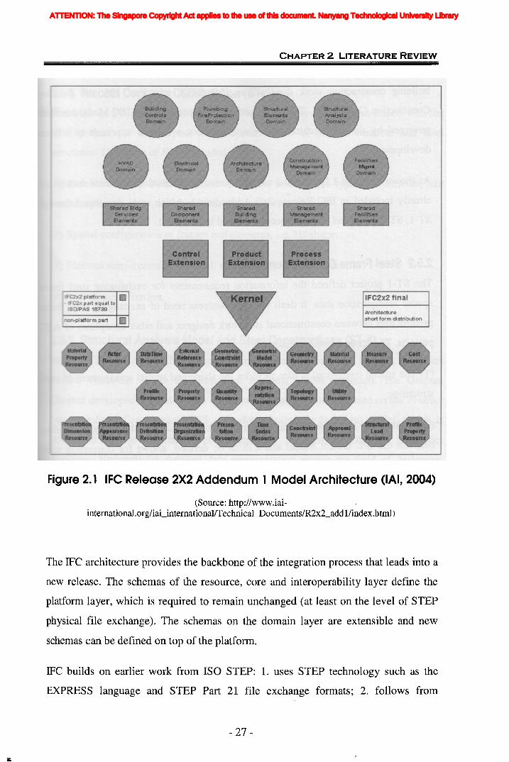
CHAPTER 2 LITERATURE REVIEW
IFC2x2 platform IIJ. IFC2x part equal to
ISO/PAS 16739
non-piatfor m part III
iFC2x2 final
Architectureshort for m di stri buti on
Figure 2.1 IFC Release 2X2 Addendum 1 Model Architecture (IAI, 2004)
(Source: http://www.iaiinternational.org/iai_internationallTechnical_DocumentsIR2x2_addl/index.html)
The IFC architecture provides the backbone of the integration process that leads into a
new release. The schemas of the resource, core and interoperability layer define the
platform layer, which is required to remain unchanged (at least on the level of STEP
physical file exchange). The schemas on the domain layer are extensible and ne\v
schemas can be defined on top of the platform.
IFC builds on earlier work from ISO STEP: 1. uses STEP technology such as the
EXPRESS language and STEP Part 21 file exchange formats; 2. follows from
- 27 -
ATTENTION: The Singapore Copyright Act applies to the use of this document. Nanyang Technological University Library
CHAPTER 2 LITERATURE REVIEW
building construction work done within ISO STEP e.g., Part 106, the Building
Construction Core Model. The specification development of the IFC Model has been
governed by the IFC architecture, which lays out a layered approach to schema
development.
As shown in Figure 2.1, structural analysis domain and structural elements domain are
already included in IFC Release 2x2 Addendum 1, which were developed through
ST-l, ST-2, ST-3 and ST-4 projects mentioned in Chapter 1.
2.5.2 Steel Frame Constructions (ST-1)The ST-l project defined the information requirements for exchanging steel frame
spatial configuration data. It dealt with the business need of exchanging steel frame
product data between constructional steelwork designer and other disciplines of AEC
projects. The scope of work included:
(1) The spatial configuration data includes the shape and spatial arrangement of steel
structures;
(2) A mapping specification for converting steel frame spatial configuration data
between the IFC Object Model and CIS to be defined, allows for converting steel
design baseline from building designers from the IFC form, into CIS form for steel
designer;
(3) And steel design from steel designer from the CIS form to be converted back into
the IFC form for building design coordination and visualization.
2.5.3 Reinforced Concrete Structures and Foundation Structures (ST-2)ST-2 emphasized modeling the basic structural design and structural execution design.
The scope of the work included:
(1) Structural design scheme, Structural execution, Allowable stress;
(2) Decision of member shape, and Ultimate strength design.
- 28 -
ATTENTION: The Singapore Copyright Act applies to the use of this document. Nanyang Technological University Library

CHAPTER 2 LITERATURE REVIEW
2.5.4 Precast Concrete Construction (ST-3)The work of ST-3 linked and expand the work done by ST-2. It also linked with the
ST-1 project for the purpose of co-operative use of precast concrete and steel
structures. The scope of ST-3 included:
(1) Precast conctere building frame structures, and various types of elements, like
beams, columns, slabs, and facade the elements, etc;
(2) Spatial configuration of frames and elements, Le. 3D shape;
(3) Element reinforcement, material, and other quality properties;
(4) And element fixtures.
2.5.5 Structural Analysis Model and Steel Constructions (ST-4)Project ST-4 has two different parts. One is Steel Construction Domain extension
model. The other is the IFC Structural Analysis Model extension. The German
Chapter developed IFC extensions on structural analysis domain based on the Product
Inteiface Steel Construction (PSS - Produktschnittstelle Stahlbau) model, which is
developed by the German Steel Construction Association (DStV - Deutscher
Stahlbau- Verband) for detailed data representation within the field of designing,
dimensioning and manufacturing steel constructions in 2000. In ST-4 project, many
new entities and data types were proposed to be included in IFC 2x2 for structural
analysis domain. They are mainly made from following four respects:
(1) Defining planar and spatial structural analysis models;
(2) Specification of loadings including point, line planar and temperature loads and
the assignment to load groups, load cases and load combinations;
(3) Specification of different structural analysis models;
(4) Description of analysis result by force and displacement.
- 29-
ATTENTION: The Singapore Copyright Act applies to the use of this document. Nanyang Technological University Library
CHAPTER 2 LITERATURE REVIEW
2.6 IFe Related Efforts
IFC is getting popular as a standard product data model. Information integration based
on IFC models with other computer-based tools, such as the Internet, database
technologies, is today the focus for many research projects on a national level (VERA
1997, Froese 2002) and on an intemationallevel (BLIS 2002, SABLE 2002).
2.6.1 Towards a Concurrent Engineering Environment in the Building andEngineering Structures Industry (ToCEE) *
The goal of ToCEE (Amor et aI., 1997), an EC-ESPRIT funded project, running from
1996 until December 1998, was the development of systems of information exchange
in support of a concurrent engineering environment.
A client multi-tier server system for concurrent engineering, considering the specific
needs of the construction industry, has been developed. It was designed to support any
kind of distributed, extended or virtual enterprises for design, construction planning,
construction management and facility management. It followed the STEP
methodology and is based on IFC-Vl.5. One of the advantages of the system was that
technical, business; product and process models are considered together and
integrated by a common object oriented meta model.
2.6.2 Virtual Enterprises using Groupware tools and distributedArchitectures (VEGA)
The VEGA project aimed to integrate business and technical processes
(http://cic.sop.cstb.fr/ILC/ecprojec/vega). It targeted the Large Scale Engineering
(LSE) industry, particularly in communication and information supply. In these
sectors, distributed teams carry out concurrent activities. VEGA will contribute
towards solving some of the problems by developing models and tools within a
Computer Integrated Construction (CIC) environment. To implement CIC in virtual
enterprises, distribution and workflow technologies are required for information
sharing and to manage the sharing process. The VEGA Platform is designed to
- 30-
ATTENTION: The Singapore Copyright Act applies to the use of this document. Nanyang Technological University Library
CHAPTER 2 LITERATURE REVIEW
support any data model/specification defined in EXPRESS and is thus a schema
independent (late bound) implementation. The applications that have been integrated
into the VEGA Platform support the IFC release 1.5. Mappings to other application
schemas such as AP225 and the VABI schema have also been made:
2.6.3 Building lifecycle Interoperable Software (BlIS)BLIS is a coordination project -- coordinating the implementation efforts of vendors
seeking to support IFC R2.0 in applications that shipped in 2001. Its goals include: (1)
delivering increasing levels of application interoperability through semantic model
sharing and implementation collaboration by sub-groups working to support specific
BLIS 'views', (2) 'Jump start' IFC support in shipping applications and IFC based
interoperability, and (3) validating any proposed extensions to IFC through software
implementation.
Currently the end user 'use cases' supported by the BLIS model 'Views' of IFC
included: Design ~~ Design (geometry view); Client briefing/space planning ~
Architectural design; Architectural design ~~ HVAC design; ArchlHVAC Design
~ Quantities take off / cost estimating; ArchlHVAC Design ~Thermal load
calculations / HVAC system design; and Arch/HVAC Design ~ Construction
management/scheduling. The BLIS project is growing quite rapidly now. The BLIS
project concept has proved to be quite successful in transforming the concept of IFC
into real interoperable software for the AEC industry.
2.6.4 Intelligent Services and Tools for Concurrent Engineering (ISTforCE) t
ISTforCE, was a European 5th Framework Information Society Technologies project
(2001-2003). In ISTforCE a novel, user-centred services platform for concurrent
engineering has been developed. The substantial novelties in ISTforCE were that (1)
it provided a personalised human-centred environment, enhancing current, less
flexible project-centred approaches, (2) it set up an open collaboration platform where
* Available at: http://wwwcib.bau.tu-dresden.de/tocee/t Available at: http://www.istforce.coln/
- 31 -
ATTENTION: The Singapore Copyright Act applies to the use of this document. Nanyang Technological University Library
CHAPTER 2 LITERATURE REVIEW
new services and tools may be easily integrated as long as these servers fulfill some
specifications developed in the project, and where providers of engineering
information, services and tools meet project managers, engineers and architects, (3) it
made flexible and customisable object-level data exchange possible, and (4) it
provided an infrastructure for on-line e-business by integrating seamlessly legal and
financial transactions, at all system levels.
2.6.5 Information Networking in the Construction Process (Vera) *
Vera is a technology programme of Tekes, the National Technology Agency of
Finland. In the Vera technology programme construction processes and information
systems are being developed simultaneously. The vision of the Vera Technology
Programme was management of information through the entire life cycle of the built
environment. The four central goals identified to achieve the vision of the Programme
were: (1) integrated information management among all participants in the
construction project, (2) efficient use of information networks, (3) efficient and wide
utilization of information and communication technology (ICT), and (4) development
of design, construction and FM processes to provide efficient and flexible support for
client needs, sustainable development and value networks.
2.6.6 Simple Access to the Building Lifecycle Exchange {SABLE)tThis project aims to deal with the definition, the development and the implementation
of a simple AEC-domain specific language to communicate with IFC model servers.
This language, called interface, aims to be AEC-domain specific, to be defined using
standard technology, to be free to use and to facilitate the access to IFC model servers
from a client application whatever the technology used by this application. Figure 2.2
shows the architecture of the SABLE framework.
* Available at: http://cic.vtt.filvera/english.htmt Available at: http://www.blis-proiect.orgl·,,sable/
- 32-
ATTENTION: The Singapore Copyright Act applies to the use of this document. Nanyang Technological University Library
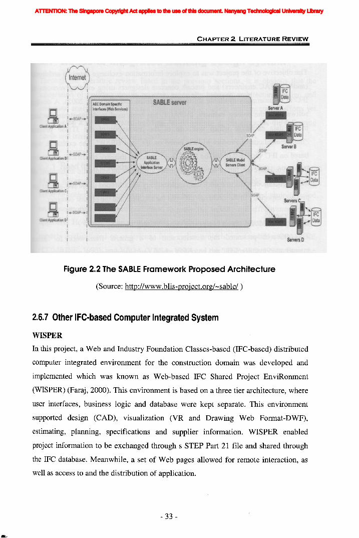
ii
CHAPTER 2 LITERATURE REVIEW
ClfiMAWl!i:~ooD!I
I
I
Figure 2.2 The SABLE Framework Proposed Architecture
(Source: http://www.blis-project.org/-sable/ )
2.6.7 Other IFC-based Computer Integrated System
WISPER
In this project, a Web and Industry Foundation Classes-based (IFC-based) distributed
computer integrated environment for the construction domain was developed and
implemented which was known as Web-based IFC Shared Project EnviRonment
(WISPER) (Faraj, 2000). This environment is based on a three tier architecture, where
user interfaces, business logic and database were kept separate. This environment
supported design (CAD), visualization (VR and Drawing Web Format-DWF),
estimating, planning, specifications and supplier information. WISPER enabled
project information to be exchanged through s STEP Part 21 file and shared through
the IFC database. Meanwhile, a set of Web pages allowed for remote interaction, as
well as access to and the distribution of application.
- 33 -
ATTENTION: The Singapore Copyright Act applies to the use of this document. Nanyang Technological University Library
CHAPTER 2 LITERATURE REVIEW
Product Model for Precast Concrete Constructions (IMPACT)
The objective of the project was to explore information exchange between architects
(and/or HVAC engineers) and precast concrete designers using existing versions of
IFC in commercially available software (Ronneblad and Olofsson, 2002). A design
software for the precast industry, IMPACT, has been used to demonstrate product
model data exchange which was one of the prototypes of the ITBoF project
"Implementations of Product Models based on IFC and BSAB". The exchange was
based on IFC version 2.0 and the Swedish construction industry classification system
BSAB 96. However, future development must also focus on automatic adjustment of
the product model data to reduce the supplementary work needed in the precast design
process, especially in the exchange between the architect and the precast designer.
Distributed, Model-based Integrated Asset Management System
This research presented the development of a generic framework for asset
maintenance management, and an object model for the maintenance management of
roofing systems as a case study to demonstrate the applicability of the framework
(Hassanain et aI., 2003). The model built upon the IFC to define object requirements
and relationships for the exchange and sharing of maintenance information between
applications. A distributed, model-based integrated system was developed to explore
the implementation of the developed maintenance management models. A three-tiered
reference architecture was proposed for integrated distributed systems and the Jigsaw
Distributed System (JDS) was developed as the implementation environment of the
reference architecture, which aimed at creating tools to support both project model
based data integration and transaction-based application interoperability. Finally
Asset Management Tool (AMT), a prototype integrated application that can initiate
data exchanges with a number of data servers (including MicroROOFER, Microsoft
Project, and files that can be used by several other applications), was used to
demonstrate software interoperability in the Facilities Management (FM) domain.
- 34-
ATTENTION: The Singapore Copyright Act applies to the use of this document. Nanyang Technological University Library

i
CHAPTER 2 LITERATURE REVIEW
2.7 Needs of Integrated Building Design System
Through the literature review listed in the previous sections, it is obvious that the
integration of building design process, especially between architectural design and
structural analysis domain, has not been covered in current implementation efforts yet.
To develop a new integrated building design system in this research, the following
needs and trends can be distinguished.
2.7.1 Need for IFC Models BasedMany information models and standards are currently available for developing
building integrated system. And also a number of research works and projects based
on these models have been performed to prove the validity and effectiveness of the
approach. However, as the most popular models and standards in latest years, the IFC
models is also based on experience from earlier projects, most notably, COMBINE
(COMBINE, 1995), and VEGA (VEGA, 1999) and the STEP (ISO, 1994). From the
point of view of the basic technical ability to exchange AECIFM information, it can
be said that the IFCs have now been established as a viable interoperability
technology. Significant portions of the IFCs are now mature, stable standards and
numerous prototype and early commercial systems have demonstrated their extensive
information exchange capabilities (Froese, 2003). As more and more IFC-compatible
software applications become commercially available, any efforts on developing new
building design integrated system had better be based on IFC models.
2.7.2 Need for Assessment of the Capability of IFC Models for StructuralAnalysis and DesignMost of above mentioned projects related IFC models deal' with either the
development of domain extensions or the application of IFC models in a certain
domain. There has been virtually no assessment and validation of how well the IFC
can support various domains' requirements, especially for structural analysis and
design domain. That is because the IFC models for structural engineering domain
were just started in 2000 by ST series projects (Horenbaum etc., 2002) and formally
released in IFC 2x Edition 2 (IAI, 2003). Currently even no any structural analysis
- 35 -
ATTENTION: The Singapore Copyright Act applies to the use of this document. Nanyang Technological University Library
CHAPTER 2 LITERATURE REVIEW
and design software provides the full and native support for IFC models. In order to
enable not only the different participants but also different application software to
communicate, the assessment needs to be conducted from these two perspectives
respectively.
2.7.3 Need for Better Information Modeling MethodologyBeing knowledgeable about design is the precondition for assessing IFC models. That
is, information requirements of structural analysis and design are needed. Therefore it
is further needed for an advanced modeling methodology. In the past years, many
existing modeling techniques are developed to modeling the design processes, and
each technique is of its own disadvantages and advantages for this specific situation.
Their current forms seem to have matured and be in fairly widespread use. However,
recently there has been a noticeable lack of presentation on integrated models and
integrated project databases with the preferred approach seemingly being to utilize
bespoke translators for all possible mappings (Amor et aI, 2002a).
The following sections would like to review the existing process and information
modeling representations, which lays the foundation for the development of integrated
modeling methodology in Chapter 4. All of these modeling techniques have
similarities in that they have successfully been used within organizations the world
over. However with all of the elements that these models have in common, they also
have a great number of differences. It is these differences which make all of the stated
process both unique and potential methods for the use of modeling at this research.
2.8 Existing Process Modeling Representations
Here the term "representation" is used as an all-encompassing term to include
languages, methodologies, tools, standards, etc. In general, a representation is an
approach to specifying process models. This may include semantic definitions,
methods, and/or syntax (which may be textual, graphical, or both).
- 36-
ATTENTION: The Singapore Copyright Act applies to the use of this document. Nanyang Technological University Library
CHAPTER 2 LITERATURE REVIEW
This review is not intended to be an exhaustive list of every process representation
currently available. It does, however, represent a sample of representations that
provide some insight into different ways of representing process information.
ACT *
ACT (Wilkens & Myers, 1995) was created at the SRI International Artificial
Intelligence Center as part of research into systems that select and execute appropriate
actions for achieving goals in dynamic and uncertain environments. The ACT
formalism is a language for representing the knowledge required to support both the
generation of complex plans and reactive execution of those plans in dynamic
environments. ACT has been used as the interchange language in an implemented
system that links a previously implemented planner (System for Interactive Planning
and Execution Monitoring (SIPE-2) (Georgeff & Ingrand, 1989)) with a previously
implemented executor (Procedural Reasoning System (PRS) (Wilkens, 1984)).
The basic unit of representation is an Act, which can be used to encode both plan
fragments and standard operating procedures (SOPs). An Act describes a set of
actions that can be taken to fulfill some designated purpose under certain conditions.
Action specifications are called the plot, and consist of a partially ordered set of
actions and sub-goals. The environmental conditions and plots are specified using
goal expressions, each of which consists of one of a predefined set of meta-predicates
applied to a logical formula. The meta-predicates permit the specification of many
different modes of activity, including goals of achievement, maintenance, and testing.
ACT can be used to build a very strong model of the relationships between actions,
temporal requirements, and resources.
ACT is intended to serve as a general-purpose representation language that could be
used to share knowledge between many different execution and planning systems.
The representational and computational adequacy of ACT has been validated by
implementing the Cypress system (Wilkens and Myers, 1995), which uses ACT as an
interiingua to enable runtime interactions between planning and execution subsystems.
* Available at: http://www.ai.sri.coml·...actlact-formalism.html
- 37 -
ATTENTION: The Singapore Copyright Act applies to the use of this document. Nanyang Technological University Library
CHAPTER 2 LITERATURE REVIEW
ACT focuses on a practical, yet sufficiently expressive representation that can address
a variety of needs.
Data Flow Diagrams (DFDs)
DataFlow Diagrams (Orr & Gane et aI., 1989) provide a view of the data flows in a
system and the various data stores and processes/functions to/from which they flow.
This is a popular method in software and information system design, and appears
often in Computer-Aided Software Engineering (CASE) tools (Grady 1993, Scotti
1994). It is generally used to determine the information contained within a system. It
can be decomposed hierarchically as in IDEFO, with the attendant benefits, but does
not clearly show the process flow in a manufacturing system. It does not incorporate
any constraints in the data and data relationships. They are primarily used as a tool for
performing structured systems analyses to explore the relationships between processes
and the data that they transform or create.
DFDs represent the flow of data throughout a process or between processes, depicting
a system from a data perspective (of those who use the data), as opposed to a control
perspective (of those who act upon the data), or a resource perspective (what is
needed by whom and why, to do what). DFDs include specifications of the boundaries
of a system, sources and destinations of data, flows of data, transformation processes,
and stores of data for later use. DFDs are a graphical/diagrammatic representation
with processes rendered as circles, or "bubbles." Directed arcs indicate that data move
from one process to another with the name of the data labeling the arc. For each
process element (bubble) in a DFD, an engineer must identify all of the inputs
required, all of the outputs that the bubble must produce, and the data stores the
bubble must access.
Functional Flow Block Diagrams (FFBD)
Functional Flow Block Diagrams (FFBDs) (DSMC 1986, Grady 1993, Scotti 1994)
are a fundamental representational tool within the systems engineering community. It
is used to define and illustrate graphically the functions that must be performed by a
system as well as the sequential relationships among the functions. They are used in
functional analysis to gain, in an organized way, insight into what a system (or system
- 38-
ATTENTION: The Singapore Copyright Act applies to the use of this document. Nanyang Technological University Library
/
CHAPTER 2 LITERATURE REVIEW
element) is required to do and in what sequence it must be done. Systems engineers
have traditionally used FFBDs to provide a graphical view of system behavior as
sequences, selections, and concurrences of functions. An FFBD is perceived as an
analog of actual system operation where a function is performed by a set of system
resources that are not yet fully specified.
The primary benefit of FFBDs is their ability to support analyses of the process flow
or behavior of a system with respect to time. However, while they do show all the
possible sequences of system behavior, they ignore data flows, including those that
trigger a transition from one behavior state to another. As well, FFBDs are like IDEFO
diagrams (Wisnosky & Batteau, 1990) in that they are not intended to show the time
duration of activities/functions, nor do they convey the time between functions.
Equally importantly, from a process modeling perspective, FFBDs are not, by
definition, resource- or equipment- oriented. That is, they identify "what" must
happen and do not assume a particular answer to "how" a function will be performed.
Behavior Diagrams
Behavior Diagrams (Ballard 1989, Alford 1990) combine the features of Functional
Flow Block Diagrams and Data Flow Diagrams, capturing data flows (functional
interfaces) as well as control transitions and sequences. These diagrams are used to
describe the functional behavior of a system design with a time sequence of functions
indicating functional inputs and outputs, strict precedence relationships, control flow
and data flow, as well as completion conditions for purposes of time-based simulation
and analysis.
Behavior diagramming provides a number of basic constructs and features that can be
used to model functional behavior. As is the case with many other process-related
representations, Behavior Diagrams are hierarchically decomposable. The elements of
the diagrams (particularly function blocks) can also be linked to related textual
documents that contain detailed information about such things as performance
requirements, requirements traceability, and so on.
- 39-
ATTENTION: The Singapore Copyright Act applies to the use of this document. Nanyang Technological University Library
CHAPTER 2 LITERATURE REVIEW
Behavior Diagrams were designed, and best suited, for the behavioral modeling of
physical artifacts (Le., the operational behaviors of well-defined physical systems) as
oppose to capturing the more abstract and complex programmatic elements (such as
nonmachine, human activities like design) that are seen in the product realization
process modeling and workflow domains.
Gantt Charts
Named for its developer, Henry Laurence Gantt, the Gantt chart (also known as a bar
chart) (Avallone & Baumeister 1987, PMI 1996) provides a graphic display of
schedule related information, including the relative and absolute durations and
start/finish of activities. They can be used to schedule resources as well as activities.
In the typical Gantt chart, activities or other project elements are listed down the left
side and dates or other suitable time intervals are shown across the top. In the area
formed between these two axes, individual activities or project elements are shown as
bars. Each bar has a length corresponding to the duration of its corresponding activity,
and is placed on the diagram in a location consistent with its designated start or finish
time.
Gantt charts are a simple but effective means to convey schedule-related information
graphically. They allow a recognition of the tasks that must be performed sequentially
and those that may be performed in parallel. They also provide an easily
understandable description of the workflow throughout an entire project.
IDEFO
The ICAM (Integrated Computer-Aided Manufacturing) Definition (IDEF) Language
was developed in the U.S. Air Force IeAM Program during the 1976 to 1982
timeframe. The IDEFO described in this section and the following IDEF2, IDEF3,
IDEF1 are all included in this language.
IDEFO (Wisnosky & Batteau, 1990) is a standard for functional modeling derived
from the Structured Analysis and Design Technique (SADT) (Soffech, 1981). The
IDEFO methodology (Bravoco et aI., 1985a) is a top-down hierarchical method which
provides a description of functions and processes in manufacturing. It has similarities
- 40-
ATTENTION: The Singapore Copyright Act applies to the use of this document. Nanyang Technological University Library
V CHAPTER 2 LITERATURE REVIEWiii
f to flow-charting in that there is a series of processes/functions arranged sequentially.
The hierarchical breakdown allows for defining the system in any number of levels of
detail, down to the level required for analysis. This makes it easier to understand
complex manufacturing systems. It does have a capacity to incorporate constraints.
Today, IDEFO is being used in both the public and private sectors for the modeling of
a wide range of enterprises and application domains, and has been formally
standardized in Federal Information Processing Standards 183 (NIST, 1993). FIPS
183 describes the IDEFO modeling language (semantics and syntax) and associated
rules and techniques for developing structured graphical representations of a system
or enterprise.
As described in an analysis of the strengths and weaknesses of IDEFO by Knowledge
Based Systems, Incorporated: "The primary strength of IDEFO is that the method has
proven effective in detailing the system activities for function modeling, the original
structured analysis communication goal for IDEFO. Activities can be described by
their inputs, outputs, controls, and mechanisms (IeOMs). Additionally, the
description of the activities of a system can be easily refined into greater and greater
detail until the model is as descriptive as necessary for the decision-making task at
hand. In fact, one of the observed problems with IDEFO models is that they often are
so concise that they are understandable only if the reader is a domain expert or has
participated in the model development."
IDEF2
The IDEF2 methodology (Bravoco et aI., 1985b) provides a description of the
dynamic aspects of a system--the resources used to produce a product (e.g. factory
facilities), the paths an entity can take and the resources needed along that path (e.g.
the path of an automobile through a factory); status of resources (machine use,
forklifts, etc.), depending on system status; and controls on activities.
IDEF3
The IDEF3 methodology (Mayer et aI., 1995) is designed to capture the knowledge of
the area expert about how a particular process, event, or system works. The IDEF3
- 41 -
ATTENTION: The Singapore Copyright Act applies to the use of this document. Nanyang Technological University Library

CHAPTER 2 LITERATURE REVIEW
methodology is capable of providing different user views of temporal precedence and
causality relationships via two main diagram types, or "description modes." One, the
Process Flow Network (PFN), provides a process-centered view of a system, while
the other, the Object State Transition Network (OSTN), allows an object-centered
view.
It is more of a description of what a system is doing than a model, a language for the
organization and expression of process descriptions. This has the intended effect of
enabling a domain expert to intuitively express his knowledge of the operation of a
particular system or organization. It incorporates constraints in the processes, and it
does have a hierarchical decomposition similar to IDEFO. The resulting descriptions
that are captured by the IDEF3 can then be used to facilitate the construction of
analytical and design models. The methodology stops short of providing the ability to
construct predictive simulation-based models; rather, it is a method to obtain
structured descriptions of what a system actually can or will do in practice.
OZONE
OZONE (Smith & Becker, 1997) is a toolkit for configuring constraint-based
scheduling systems developed at The Robotics Institute, Carnegie Mellon University.
A central component of OZONE is its scheduling ontology, which defines a reusable
and extensible base of concepts for describing and representing scheduling problems,
domains and constraints. The OZONE ontology provides a framework for analyzing
the information requirements of a given target domain, and a structural foundation for
constructing an appropriate domain model. Through direct association of software
component capabilities with concepts in the ontology, the ontology promotes rapid
configuration of executable systems and allows concentration of modeling efforts on
those idiosyncratic aspects of the target domain. The OZONE ontology and toolkit
represent a synthesis of extensive prior work in developing constraint-based
scheduling models for a range of applications in manufacturing, space and
transportation logistics.
OZONE adopts an activity-centered modeling viewpoint. There are five basic
concepts of the ontology - Demand, Activity, Resource, Product, and Constraint. The
- 42-
ATTENTION: The Singapore Copyright Act applies to the use of this document. Nanyang Technological University Library
,ii
CHAPTER 2 LITERATURE REVIEW
ontology also defines specific inter-relationships and properties for these entities.
Scheduling is defined as a process of feasibly synchronizing the use of resources by
activities to satisfy demands over time, and application problems are described in
terms of this abstract domain model. OZONE has a powerful architecture that permits
a domain modeler to focus on those items that are special for a specific instance. The
use of constraint managers assists in rapid identification of aspects to consider.
PAR2
PAR2 (Product-Activity-Resource Model for Realization of Electro-Mechanicc;ll
Assemblies: Version 2) was developed by M.R. Duffey and J.R. Dixon in the late
1980s (Duffey, 1993) at the Mechanical Design Automation Laboratory of the
University of Massachusetts as a proof-of-concept object-based implementation
designed to explore representational issues related to the interdependencies of product,
process, and resource representations within the domain of electro-mechanical design.
Additionally, PAR2 was designed to explore the modeling of cash flow uncertainty
for the product realization process for electro-mechanical assemblies using activity
network simulation. PAR2' s process representation includes an activity-on-arc
representation based on the Generalized Activity Network (GAN) model of Salah
Elmaghraby that allows stochastic branching and other features that enable iteration.
According to Duffey, "the implementation of PAR2 uses crude but effective object
based representations and an associated simulation engine written in common lisp. It
included a (now extinct) Sun\Tiew graphical interface for 1) hierarchical
decomposition of product instance, activity class, and resource class representations, 2)
relational matrices for product-activity and activity-resource relationships, 3) a Gantt
type chart of activity subgroups that could be manipulated to explore effects of
overlapping/concurrency alternatives, and 4) a cash flow diagram dynamically created
during the process simulation."
Duffey contends that "PAR2 is not meant to be a robust language, but was a doctoral
research experiment. It is quite ad-hoc in its modeling of stochastic networks and
lacks rigorous grounding in mathematical formalisms." Nonetheless, it features a
- 43 -
ATTENTION: The Singapore Copyright Act applies to the use of this document. Nanyang Technological University Library
CHAPTER 2 LITERATURE REVIEW
number of important elements that can be of use in future modeling of the
relationships between products, processes, resources, and even requirements.
Part 49
Part 49 (Process structure and properties) is an integrated generic resource of STEP
(Standard for the Exchange of Product model data) (ISO, 1995). An integrated generic
resource is a group of context independent resource constructs used as the basis for
future information. Part 49 includes the information necessary to specify the actions
or potential actions to realize a process. This includes the relationships between the
actions or potential actions in the process and the relationships between the processes
that are used to realize a product. This part does not specify any particular process,
but defines the elements to exchange process information. This part is applicable to all
types of process definitions that can be represented in a discrete manner.
The constructs define the structure for specifying: relationships between processes,
when a process is used, the properties of a process, the resources required for the
process, the properties of the resource, the representation of process, the
representation of the resource, and the relationship of the process to the product.
Together, these constructs can be combined to create a process plan.
Part 49 is captured in the EXPRESS language (ISO, 1994). EXPRESS is a formal
data specification language that provides the mechanism for the normative description
of information while allowing a complete description of the data and constraints
applicable to that information. EXPRESS permits the definition of resource constructs
from data elements, constraints, relationships, rules, and functions.
Process Flow Representation (PFR)
PFR was designed as an extensible, computer- and human-readable language for
describing semiconductor processing. It was created at the Massachusetts Institute of
Technology to be used with the Computer-Aided Fabrication Environment (CAFE)
(Boning & McIlrath et aI., 1992). PFR was developed to explore some ideas about
process modeling, design synthesis, and manufacturing. The PFR language is a text
language with a parenthesis grammar adapted from Lisp and is intended to be read
- 44-
ATTENTION: The Singapore Copyright Act applies to the use of this document. Nanyang Technological University Library
CHAPTER 2 LITERATURE REVIEW
and possibly interpreted (executed) by various programs for the purpose of simulation,
manufacturing, or analysis. In most cases today, such programs run in CAFE, which
is used to operate the MIT semiconductor fabrication facilities and includes an object
oriented database. PFR includes a turing-complete programming language (adapted
loosely from scheme). It also includes an extension language for accessing the
environment of the executing program (e.g., the CAFE database).
Visual Process Modeling Language (VPML)
VPML is the underlying language for the ProSLCETM Process Editor and the Process
Simulator. ProSLCSETM is a software package developed by ISSI (International
Software Systems, Inc.). Its goal is to help a company perform process engineering,
which is defined as a long-term, whole system approach to help identify, analyze, and
improve a business's key processes. The hopeful result is a streamlined organization
able to respond quickly and effectively to the changing business environment. This
will entail a totally integrated, process-driven environment composed of tools and
services to support process capture, analysis, refinement, enforcement/enactment, and
improvement.
VPML is a graphical language for defining process. Within VPML, a process is
defined as a set of partially ordered steps toward meeting a goal. The components of a
process diagram are activities, products, resources, and the connections between them.
Activities represent work that is performed in a process and is the central focus of
VPML. Products represent items (information) that are used, created, modified, and
transferred among activities in a process. Resources are real-world resources that are
required to perform an activity. Connections are used to establish relationships
between constructs, pass product information between activities, and coordinate the
scheduling of activities.
Systematic Activity Modeling Method (SAMM)
The SAMM modeling methodology (NASA, 1977) is similar to IDEFO in that it is a
top down hierarchical method. It uses a system of nodes and branches, each node
being represented by an activity diagram. This method represents both the activity
flows as well as data flows along with the amount of data being exchanged. The
- 45-
ATTENTION: The Singapore Copyright Act applies to the use of this document. Nanyang Technological University Library
CHAPTER 2 LITERATURE REVIEW
relations between the activity diagrams are the data flows (and quantities of data).
This method was applied to modeling the design process in the IPAD studies.
2.9 Existing Information Modeling Techniques
Quite a few information modeling languages have been developed or are under
development. These information modeling languages provide various ways of
formally representing an information model. In general, the languages are presented
in two forms: graphical form and textual form. The former uses diagrams that are
formed by graphic symbols. The latter uses a specific context-free grammar that
includes formal language syntax and semantics. The graphical form is designed
primarily for humans, while the textual form is for both humans and computers. This
research concentrates on six modeling languages: Entity-Relationship Model, the
Integrated Computer Aided Manufacturing (ICAM) Definition Language 1 (IDEFl)
(Mayer, 1992), Nijssen's Information Analysis Modeling (NIAM), Semantic Nets and
the EXPRESS Language (ISO, 1994), and the Unified Modeling Language (UML)
(Harmon and Watson, 1998). The reason these languages are chosen is three-fold:
they are formal languages, they are either standardized or in the public domain, and
they are the most frequently used in current manufacturing areas.
Entity Relationship Model (E-R)
The Entity-Relationship model was originally proposed by P. Chen in 1976 as a way
to unify the network and relational database views. Entity Relationship diagram
provides a view of data entities and their associated relationships. This model allows
one to model information and data that may be conceptualized as having components
that are inter-related. Moreover, the relations among components are captured as well
as their respective components and attributes. In the E-R model, data components are
represented as entities. These entities may have relationships with other entities.
Furthermore, the mapping cardinalities of these relationships may be one-to-one, one
to-many, many-to-one, and many-to-many. Entities can be denoted weak or strong. A
weak entity is one whose existence is solely dependent on a strong entity that has a
relationship with the weak entity. This construct is particularly useful for consistency
- 46-
ATTENTION: The Singapore Copyright Act applies to the use of this document. Nanyang Technological University Library
CHAPTER 2 LITERATURE REVIEW
maintenance of a database. Attributes may be associated with each entity, usually
representing the properties of the component represented by the entity. Furthermore,
these attributes provide one with a mechanism to identify each of the entities uniquely.
The beauty of this method is its simplicity, and its representation of information
entities in a "real world" way. Also, it is relatively straightforward to map ER
diagrams into a relational database design. The E-R model has been widely used in
information systems design, especially in systems involving relational databases
IDEFl
The IDEF1 method (Mayer, 1992) can be viewed as a method for both analysis and
communication in establishing Computers in Manufacturing (CIM) requirements.
However, IDEF1 is primarily focused on support of the task of establishing the
requirements for what information is or should be managed by an enterprise. It is
similar to ER conceptually, but are different graphically, and more complicated
semantically, thus making them more difficult to use than entity-relationships. It is a
graphical representation and is designed using the ER approach and the relational
theory. It is used to represent the "real world" in terms of entities, attributes, and
relationships between entities. Normalization, that eliminates redundancy and
arranges a collection of data according to its inherent logical structure, is enforced by
KEY Structures and KEY Migration. The language identifies property groupings to
form complete entity definitions.
NIAM
The NIAM (Nijssen's Information Analysis Modeling) methodology (Bray, 1988) is
another data modeling method, showing objects and their relationships; constraints,
however, can be modeled in this method. It, like ER, is simple to learn and use, and
can be mapped into a relational database design.
Semantic Nets
A semantic net is a formalism for representing facts and relations between facts with
binary relations (Amble, 1987). Semantic nets are extensively used in artificial
intelligence applications. Each object modeled is represented as a node in the network
- 47-
ATTENTION: The Singapore Copyright Act applies to the use of this document. Nanyang Technological University Library

CHAPTER 2 LITERATURE REVIEW
and these networks can become quite large. These can model data abstractions as IS
A and ISPART- OF relationships. Ternary relations are not supported.
EXPRESS
Express was created as ISO 10303-11 for formally specifying the information
requirements of a product data model. The language is part of a suite of standards
informally known as the STandard for the Exchange of Product model data (STEP)
and was first introduced in the early 1990s (ISO, 1994, Schenk & Wilson, 1994).
EXPRESS is a textual representation. In addition, a graphical subset of EXPRESS
called EXPRESS-G is available. EXPRESS is based on programming languages and
the 0-0 paradigm. EXPRESS consists of language elements that allow an
unambiguous object definition and specification of constraints on the objects defined.
It uses the SCHEMA declaration to provide model's partitioning, and it supports
specification of data properties, constraints, and operations.
UML
The Unified Modeling Language (UML) is a relatively new modeling language for
specifying, visualizing, constructing, and documenting the artifacts of software
systems, as well as for business modeling and other non-software systems. The UML
represents a collection of the best engineering practices that have proven successful in
the modeling of large and complex systems (Hamilton, 1999). The UML formalism
organizes models into logical packages. Each package groups a collection of classes
or objects closely related to each other. It was conceived originally by Grady Booch,
James Rumbaugh, and Ivar Jacobson (1999). UML was approved by the Object
Management Group (OMG) as a standard in 1997. It could be argued that UML is the
most successful standard from the OMG. It is the way the world models not only
application structure, behavior, and architecture, but also business process and data
structure.
It is a graphical representation. The language is based on the objected-oriented
paradigm. UML contains notations and rules and is designed to represent data
requirements in terms of 0-0 diagrams. UML organizes a model in a number of
views that present different aspects of a system. The contents of a view are described
- 48 -
ATTENTION: The Singapore Copyright Act applies to the use of this document. Nanyang Technological University Library
CHAPTER 2 LITERATURE REVIEW
in diagrams that are graphs with model elements. A diagram contains model elements
that represent common 0-0 concepts such as classes, objects, messages, and
relationships among these concepts (Harmon and Watson, 1998).
All above methods can be used to create a conceptual model, and each has its own
characteristics. Although some may lead to a natural usage (e.g., implementation), one
is not necessarily better than another. In practice, more than one language may be
required to develop all information models when an application is complex. In fact,
the modeling practice is often more important than the language chosen.
2.10 Summary
The literature review indicates that existing research falls short in providing an
integrated model and system for managing the design information for architectural
design and structural analysis. Some existing systems, however, are developed for
specific uses and cover a narrow scope of the information system. The need for
detailed analysis of current practices and the development of a framework are derived
from the review.
Further, as is evident from this literature review, there are a number of different
process and information modeling techniques in use in organizations and institutions
all over the world. It must be realized that just because one process modeling
technique was a success in one organization or institution similar to the one in
question, it does not mean that the same modeling technique will work for the
situation in this research. Therefore the task before to use these methods is to
determine which one is the appropriate one to this research as well as how to use it
effectively. The main motivation of chapter 4 is based on this. The literature review
has been continuously performed in parallel to the development.
- 49-
ATTENTION: The Singapore Copyright Act applies to the use of this document. Nanyang Technological University Library

3.1 Selection of Research Methodology
In this thesis the research design aims to select appropriate methods for modeling data
exchange between architectural design and structural analysis involved in structural
engineering design and development. There are a number of research methods to do
so. In choosing research methods, consideration was given to: (1) an ideal study is one
that combines both processes as a whole; (2) it is a complex system; (3) the
methodology should fit the issues to be studied, rather than structuring the issues to fit
a preferred method; and (4) the methodology should reflect the environment in which
the activities of architectural design and structural analysis are operated.
Based on above consideration, literature review, model developing, software
development and prototyping, as well as case study are chosen as research
methodology.
3.1.1 Literature ReviewThe literature review aims to build a theoretical foundation upon which the research is
based. A good literature review will not only place the research into a scientific
perspective, but also avoid duplication of effort, and identify conceptual and
procedural problem, related to theories, research methods and data analyses (Dane,
1990).
Cooper (1988) argued that "... a literature review uses as its database reports of
primary or original scholarship, and does not report new primary scholarship
itself. The primary reports used in the literature may be verbal, but in the vast
- 50-
ATTENTION: The Singapore Copyright Act applies to the use of this document. Nanyang Technological University Library
CHAPTER 3 RESEARCH METHODOLOGY AND PROCESSES
majority of cases reports are written documents. The types of scholarship may be
empirical, theoretical, critical/analytic, or methodological in nature. Second a
literature review seeks to describe, summarise, evaluate, clarify and/or integrate the
content of primary reports." The review's purpose is to provide the background to and
justification for the research undertaken (Bruce, 1994).
According to Bourner (1996) there are good reasons for spending time and effort on a
review of the literature before embarking on a research project. These reasons include:
to identify gaps in the literature, to avoid reinventing the wheel, to increase your
breadth of knowledge of your subject area, to identify information, ideas and methods
that may be relevant to your project, etc.
This inter-disciplinary research covers building standards, information model as well
as the modeling methodologies. These thus form the scope of literature review
conducted in this research. Together with the existing process and information
modeling technologies, literature related to the subjects of information model and
standards for AEC industry is reviewed. Especially the two most popular building
product models (STEP and IFC), as well as their applications in projects, related
collaborative efforts and web-based integration systems, are also reviewed.
3.1.2 Model DevelopingAs per the objectives listed in Chapter 1, one of tasks of this research is to assess the
usefulness of IFC models to meet the practical needs of structural analysis. The pre
requisite is to analyze and model the information requirements which should be
sufficiently detailed to describe the data needs of the application. In order to obtain an
information model that is independent of any physical implementation, an integrated
methodology, process-oriented information modeling (Po1M) methodology is
developed to get the general information model as the basis to define standard product
model. This generic information modeling technology and tools, aims to improve the
efficiency of modeling, and supports industry need and requirements for the
integrated building design system.
- 51 -
ATTENTION: The Singapore Copyright Act applies to the use of this document. Nanyang Technological University Library
CHAPTER 3 RESEARCH METHODOLOGY AND PROCESSES
Based on the general information model and concept of IFC models, the information
gaps can be identified and necessary extensions to current IFC models can be '
developed. A more completed IFC models for structural analysis domain will be
proposed. This standard product model will be the role of integration between the
architectural design and structural analysis.
3.1.3 PrototypingResearch can be classified into work which discovers and describes existing reality
(explorative research) or which aims at creating a new reality (e.g. new technology or
processes) which needs to be evaluated and justified (Svensson, 1998). The research
in this thesis aims at developing appropriate information structures for architecture
design and structure analysis, and using it to develop an integrated building design
system for the information exchange and sharing between the above two processes.
An important methodology used in this research is thus prototyping.
Prototyping is a research process which includes conceptualization. In this type of
research prototyping is used as an approach for constructing and evaluating models
and other information structures. Generally, prototyping could be defined as a design
process for products. In the research, it includes four steps:
1. Defining a 'conceptual model' .
2. Identifying possible technical solutions.
3. Prototype development.
4. Testing.
3.2 Definition of Research Domain and ResearchProcedures
3.2.1 Definition of Research Domain
The initial phase for any research starts with the definition of the scope of research
domain. The scope specifies the domain of discourse and the processes that are to be
supported by the information model. It is a bounded collection of processes,
- 52-
ATTENTION: The Singapore Copyright Act applies to the use of this document. Nanyang Technological University Library
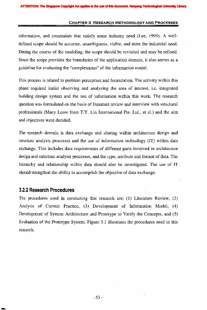
CHAPTER 3 RESEARCH METHODOLOGY AND PROCESSES
information, and constraints that satisfy some industry need (Lee, 1999). A well
defined scope should be accurate, unambiguous, viable, and meet the industrial need.
During the course of the modeling, the scope should be revisited and may be refined.
Since the scope provides the boundaries of the application domain, it also serves as a
guideline for evaluating the "completeness" of the information model.
This process is related to problem perception and formulation. The activity within this
phase required initial observing and analyzing the area of interest, i.e. integrated
building design system and the use of information within this work. The research
question was formulated on the basis of literature review and interview with structural
professionals (Maey Leow from T.Y. Lin International Pte. Ltd., et al.) and the aim
and objectives were decided.
The research domain is data exchange and sharing within architecture design and
structure analysis processes and the use of information technology (IT) within data
exchange. This includes data requirements of different parts involved in architecture
design and structure analysis processes, and the type, attribute and format of data. The
hierarchy and relationship within data should also be investigated. The use of IT
should strengthen the ability to accomplish the objective of data exchange.
3.2.2 Research ProceduresThe procedures used in conducting this research are: (1) Literature Review, (2)
Analysis of Current Practice, (3) Development of Information Model, (4)
Development of System Architecture and Prototype to Verify the Concepts, and (5)
Evaluation of the Prototype System. Figure 3.1 illustrates the procedures used in this
research.
- 53 -
ATTENTION: The Singapore Copyright Act applies to the use of this document. Nanyang Technological University Library
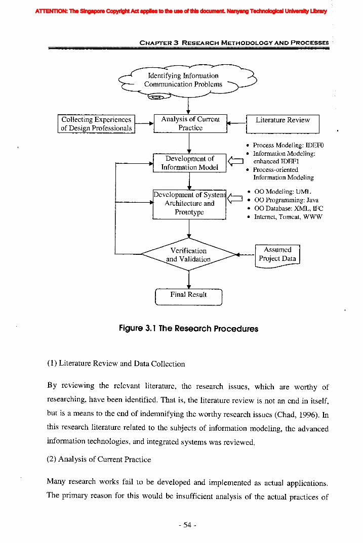
CHAPTER 3 RESEARCH METHODOLOGY AND PROCESSES
Identifying InformationCommunication Problems
• Process Modeling: IDEFO• Information Modeling:
¢::J enhanced IDEFI• Process-oriented
Information Modeling
Literature Review
• 00 Modeling: UML• 00 Programming: Java• 00 Database: XML, !FC• Internet, Tomcat, WWW
eveloprnent of SysteArchitecture and
Prototype
Collecting Experiencesof Design Professionals
Figure 3.1 The Research Procedures
(1) Literature Review and Data Collection
By reviewing the relevant literature, the research issues, which are worthy of
researching, have been identified. That is, the literature review is not an end in itself,
but is a means to the end of indemnifying the worthy research issues (Chad, 1996). In
this research literature related to the subjects of information modeling, the advanced
information technologies, and integrated systems was reviewed.
(2) Analysis of Current Practice
Many research works fail to be developed and implemented as actual applications.
The primary reason for this would be insufficient analysis of the actual practices of
- 54-
ATTENTION: The Singapore Copyright Act applies to the use of this document. Nanyang Technological University Library

CHAPTER 3 RESEARCH METHODOLOGY AND PROCESSES
the industry. During this research, emphasis is placed upon attempting true and
accurate investigations of current communication practice between architect and
structural engineer. Constant feedback and updates from the industry practitioners
should be observed until a complete picture is constructed.
(3) Development of Information Model
The development of information model is one of the most important outcomes of this
research. Based on the results from the steps above, the process-oriented information
modeling (PoIM) methodology would be developed. The methodology is used to
model the information requirements of structural analysis process. The step. is
followed by the assessment of current IFC models to support structural analysis.
Consequently the new IFC extensions for the information gaps are developed.
(4) Development of System Architecture and Prototype Implementation
In this phase of research the framework and architecture design of an IFC-basedweb
enabled integrated building design (IWIBD) system is proposed. An implementation
prototype is also developed using object-oriented programming languages and
network communication applications. A prototype means an experimental design of
the whole or part of a product used for illustration or testing purposes (The Usability
Company, 2004 ). A prototype could provide an operational model of the application
system, a basis for further system development, and an evaluation (of the user
interface) of the application system (Budde et aI., 1992)
(5) Validation and Verification of System framework (Test of Protot/ype System)
Two case studies are used to test the prototype system developed based upon the
proposed architecture, and to check whether it is capable of providing integrated
exchange between architectural design and structural analysis. The performance of the
model is also evaluated and assessed. The concept of software interoperability
through the use of IFC models has been demonstrated.
- 55 -
ATTENTION: The Singapore Copyright Act applies to the use of this document. Nanyang Technological University Library

CHAPTER 3 RESEARCH METHODOLOGY AND PROCESSES
3.3 Information Model Developing
The AEC industry is on the edge of the information society. The need for exchange of
more and more complex information has successively grown. As identified by Arnor
(2002a), one of key current themes is the modeling of processes and products, as well
as the integration of this with visualization and standardization of information life
cycles. This is concerned with the creation of a representation of buildings and
projects which is easily communicated within a project. An information model is a
representation of concepts, relationships, constraints, rules, and operations to specify
data semantics for a chosen domain of discourse. The advantage of using an •
information model is that it can provide sharable, stable, and organized structure of
information requirements for the domain context. IFC is selected as the basis of the
research. Considering the challenges when using IFC models (as described in Chapter
1), the processes for model development are schematically described as an IDEFO
model in Figure 3.2. The detailed explanations on each process are given in the
following paragraphs.
g
IFC specificationsSRelatedprojects cope 0
development Selection of modelingReview the researchProcess and guide method
------.~ InformationModeling
Methodologies
1
Process-oriented~ Integrate Information Modellin
Process and MethodologyInformationModelling
12Data andinformation Developcollection from Information Information model forindustry experts Model for structural analysis
StructuralAnalysis
3
Latest IFC Assess IFC Information gap
models L.-. Models byComparison
4
IFCYDevelop IFe I extensionExtensions
sr
Figure 3.2 Processes for Information Model Development
- 56-
ATTENTION: The Singapore Copyright Act applies to the use of this document. Nanyang Technological University Library
CHAPTER 3 RESEARCH METHODOLOGY AND PROCESSES
3.3.1 Review of Existing Modeling MethodologiesIn Chapter 2, the various modeling techniques such as the ACT, Gantt charts, PFR etc.
for process modeling, and entity-relationship model, EXPRESS, NIAM and IDEF etc.
for information modeling, have been discussed. Considering the possibility of
integration and ease-of-use to end users, the IDEFO and IDEFI are selected as the
process modeling and information modeling methods respectively.
3.3.2 Developing Process-oriented Information Modeling (PoIM)MethodologyInformation models are needed in addition to process models to provide a
comprehensive view of the information that makes effective and efficient
communication possible. Therefore, the problem of how to model process-related
information effectively is addressed. An integrated methodology, i.e. the process
oriented information modeling methodology, is developed to integrate the IDEFO
process model and enhanced IDEFI information model so as to gbtain the general
information model as the basis to define standard product model. The methodology is
explained in detail in Chapter 4.
3.3.3 Information Modeling for Structural Analysis DomainThere is no standard method for collecting information requirements. However, the
information may be collected from the following sources: literature survey, standards
surveys, domain experts' interviews, industrial data reviews, current industry
practices, traditional practices, and near-future trends.
The information collected is then transformed into a conceptual model by using
process-oriented information modeling (Po1M) methodology proposed in this research.
The information model is independent of any physical implementation and should be
sufficient!y detailed to describe the data needs of the application.
- 57 -
ATTENTION: The Singapore Copyright Act applies to the use of this document. Nanyang Technological University Library
· CHAPTER 3 RESEARCH METHODOLOGY AND PROCESSES
3.3.4 Assessment of IFC ModelsThe information requirements in proposed information models would be mapped with
latest IFC model and standards, IFC 2x Edition 2 and its addendum. The capability of
IFC models to support structural analysis is assessed and the information gaps are
identified.
3.3.5 Developing IFC ExtensionsAccording to IFC 2x Extension Modeling Guide (IAI, 2001), different approaches of
extension development can be applied to different scenarios. For the sake of
classifying the scenarios for identified information gaps, their generalities are studied
through generality study by investigating other ten versatile and most popular
structural analysis and design software. Whereafter, the necessary extensions are
developed.
3.4 System Development and PrototypeImplementations
The term prototype is often referred to as a single application that is developed prior
to developing a complete application. It is also referred as any of several
approximations that is redeveloped in order to gradually expand and enhance a core
application into a full-blown application (Harmon, 1998). In this research an IFC
based web-enabled integrated building design system would be developed. The
prototyping part of the research work aims to implement the conceptual model and
conceptual framework, to verify the integration of architectural design and structural
analysis.
3.4.1 Development Process
It is important to choose appropriate development lifecycle process to the project at
hand because all other activities are derived from the process. A more typical software
life cycle includes at least five well defined stages:
- 58 -
ATTENTION: The Singapore Copyright Act applies to the use of this document. Nanyang Technological University Library
CHAPTER 3 RESEARCH METHODOLOGY AND PROCESSES
• Requirements analysis
• System architecture and design
• Implementation
• Validation and verification
• Maintenance and deployment
The first activity, requirement definition, is the most important of the five in the
development process. It affects and colors all the rest (Fox, 1982). Design here is the
software design, not the system design of which the software is but a part. In this
phase, the architecture of system and modules are developed. During the
implementation, or coding stage of a software development project, software
engineers complete detailed level designs. Testing or verification as it is now
frequently being called is a critical and difficulty activity. Maintenance of service
development and deployment is the last phase in the software lifecycle.
3.4.2 Requirements AnalysisThis is where every software project starts. Requirements serve many purposes for a
software development project. For starters, requirements define what the software is
supposed to do. The requirement will become the basis for all the future architecture
definition and design, coding, and testing that will be done on the project (Hamilton,
1999). Quality requirements are broken up into two kinds: functional and non
functional (Wiegers, 1999). Requirement engineering acts as the bridge between the
real world needs of users, customers, and other constituencies affected by a software
system, and the capabilities and opportunities afforded by software-intensive
technologies. Typically, requirements start out as high-level general statements about
the software's functionality as perceived by the users of the software. Non-functional
requirements describe the performance and system characteristics of the application.
It is important to gather them because they have a major impact on the application
architecture, design, and performance.
- 59-
ATTENTION: The Singapore Copyright Act applies to the use of this document. Nanyang Technological University Library
" CHAPTER 3 RESEARCH METHODOLOGY AND PROCESSES
3.4.3 System Architecture and DesignThe architecture provides a high-level view of the system and its component parts
make it possible for a large number of participants to evaluate the feasibility of the
architecture. This workflow occurs at two levels. First, the top-level architecture is
produced by using the software system engineering work products. Choosing the
appropriate architecture for an application is key. Second, the subsystem-level
analysis and design is performed to meet the specification from the top-level
architecture. In addition, the subsystem-level effort will undoubtedly uncover
problems or even mistakes in the top-level architecture.
Even with a good architecture it is still possible to have a bad design. Many
applications are either over-designed or under-designed. The two basic principles here
are "Keep it Simple" and information hiding (Perks, 2003). For many projects, it is
important to perform Object-Oriented Analysis and Design using UML. Reuse is one
of the great promises of 00, but it is often unrealized because of the additional effort
required to create reusable assets.
3.4.4 Implementation
The top-level architecture and subsystem-level architectures are input to the
implementation workflow. The tasks of implementation include writing the codes and
combining, interconnecting parts of programs. Construction of the code is a fraction
of the total project effort, but it is often the most visible. The process of writing a
program is an iteration of write, run, and correct. Correct because the program is
rarely without errors the first time (Fox, 1982). The software architect must ensure the
resulting implementation matches the top-level and subsystem-level architecture for
each of the iterations. Implementation will also uncover areas of the software
architecture that need to be modified.
3.4.5 Verification and Test
Testing tells the state of what has already been built and shows where to go in and fix
a problem. Verification helps to avoid having the error getting in there in the first
- 60-
ATTENTION: The Singapore Copyright Act applies to the use of this document. Nanyang Technological University Library

CHAPTER 3 RESEARCH METHODOLOGY AND PROCESSES
place. An error in a program can be many things, from a miscoded statement that will
cause the entire system to stop, to something as trivial as a column error on a printout.
An error can be caused by misstatements in requirements, in design, or in coding. It
can come from a mistake, an ambiguity, a void, or a confusion. Even state-of-the art
development techniques cannot eliminate 100 percent of software bugs but proper
software validation and testing can go a long way toward detecting most bugs before
software is released to end users (Hamilton, 1999).
3.4.6 Maintenance and DeploymentThe maintenance phase deals with changes that need to be made to the service over its
lifetime because of new of changed requirements. Deployment is the process of
releasing an application for users. The software architect at this point is involved in
communicating the architecture to the end users, and potentially to the sales staff, so
that the benefits of this architecture over others can be easily seen.
3.4.7 System Modeling Tools-UMLToday, a software architect almost always uses some sort of system modeling tool to
graphically represent the architecture of a software system. Just as good blueprints are
important for constructing an office building, have a model of your software system
before you actually start writing code is equally important. Having a model helps you
decompose complex software systems into individual pieces that are easier to
comprehend (Hamilton, 1999).
Among many modeling techniques, the Unified Modeling Language (UML) is used
for development of system model. As one of the most common modeling languages in
use, UML is an industry-standard language for specifying, visualizing, constructing,
and documenting a software system. With UML, a system architect creates a
"blueprint" for construction (design and coding) of the system. UML represents a
collection of "best engineering practices" that have proven successful in the modeling
of large and complex systems (Hamilton, 1999). The detailed descriptions about UML
are provided in Chapter 7.
- 61 -
ATTENTION: The Singapore Copyright Act applies to the use of this document. Nanyang Technological University Library

CHAPTER 3 RESEARCH METHODOLOGY AND PROCESSES
3.5 Case Study
Case study research excels at bringing us to an understanding of a complex issue or
object and can extend experience or add strength to what is already known through
previous research. Case study, like experiment, is an alternative way for collecting
primary data. They allow for the identification of variables that were not identified in
archival analysis. It is a systematic way of looking at what is happening, collecting
data, analyzing information, and reporting the results. The most important is that case
study can be used for pattern-matching, time-series analysis, and their combination.
Program implementation case studies help discern whether implementation is in
compliance with its intent. These case studies are also useful when concern exists
about implementation problems. Extensive, longitudinal reports of what has happened
over time can set a context for interpreting a finding of implementation variability
(Webster Dictionary). Two case studies are carried out in this research which aims at
testing the architecture and functionality of prototype system.
- 62-
ATTENTION: The Singapore Copyright Act applies to the use of this document. Nanyang Technological University Library
CHAPTER 5 INFORMATION MODELING FOR STRUCTURAL ANALYSIS
! 'j 11111: InIIJ
4.1 Introduction
This chapter compares the existing methodologies used to develop process and
information model with each other and explains the reason to choose the IDEF
methodologies. The current research works deal mostly with how to use IDEF
methods in different application areas. Each type of IDEF methods is a description of
the same system from its own perspective. Therefore, they should have consistency,
to a certain degree, with each other. But very little research h/as dealt with the
integration of these methodologies. In this research a generic method, i.e. the process
oriented information modeling (PoIM) methodology, is developed. This method aims
to improve the effectiveness and efficiency of information requirements analysis by
integrating the IDEFO and IDEFI.
Process-oriented information modeling (PoIM) methodology is an integration of
process model and information model. This information model is obtained from
process models and all the information is process related.
The chapter is organized as follows:
• Section 4.1 gives a brief description of the content and structure of the chapter.
* Part of this chapter has been published in the paper "Augmented IDEF1-Based Process-Oriented
Information Modeling" in November 2004 on the Journal of Automation in Construction, Vol. 13, No.
6, pp. 735-750, Elsevier Ltd, UK (Please see Publications (Page 308) for details).
- 63 -
ATTENTION: The Singapore Copyright Act applies to the use of this document. Nanyang Technological University Library
CHAPTER 4 PROCESS"ORIENTED INFORMATION MODELING (PalM)
• Section 4.2 explains the necessity to integrate process model and information
model.
• Section 4.3 is a comparison of the existing process modeling methods and it
explains how and why the IDEFO methodology is finally selected.
• Section 4.4 does the comparison among the existing information modeling
methods and the IDEFI methodology is finally selected. Considering the nature
of IDEFI and current usage environment, this section proposes that some
enhancements to IDEFI are needed.
• Section 4.5 provides the basic concepts of selected methodologies as well as the
enhancements to IDEFI method.
• Section 4.6 provides the detailed description of the process-oriented information
modeling methodology.
• Section 4.7 introduces the new processes for IFC extension development based
on process-oriented information modeling methodology.
• Section 4.8 concludes with a summary for the chapter.
4.2 Necessity to Integrate Process Model andInformation Model
Process models have many applications and have been used for several years to
describe and manage enterprises. As the arguments issued by Eriksson and Penker
(2000), the process model can give a better understanding of an existing business, and
it can act as the basis for creating suitable information systems that support the
business. The model facilitates improvement of the current structure and operation
and an innovated structure can be presented by means of a process model.
Information modeling is a technique for specifying the form and content of
information requirements that are needed within the application domain. An
- 64-
ATTENTION: The Singapore Copyright Act applies to the use of this document. Nanyang Technological University Library
I)iiii
CHAPTER 4 PROCESS"ORIENTED INFORMATION MODELING (POIM)
III information model specifies how information is logically arranged. The model defines
the information entities within a system or process and specifies the interrelationships
among the entities.it
g
e
Oliver et al. (1997) provided insight into the relationship between information models
and process models. An information model is used to provide a greater understanding
of the information needed by the engineering process. Thus, a process model, together
with an information model, defines what is the "right" information. Information
models are needed in addition to process models to provide a comprehensive view of
the information that makes effective and efficient communication possible.
Therefore, defining an information model based on processes should be a necessary
and effective way in the information analysis. However, organizations rarely create
one. One reason is that there has been little published work on how to create an
information model of a systems engineering process and what notations provide the
best approach. This research addresses the problem by developing a generic
methodology for modeling process-related information. The methodology will be
used to build an information model for the benefit of the developing of integrated
building design system.
In order to develop such kind of generic methodology, it is necessa~y to undertake an
investigation into the different types of modeling techniques available, so as to enable
the assessment of which techniques would be best for this specific situation, as
described in Section 4.3 and Section 4.4. Based on these, the process-oriented
information modeling methodology is proposed as a new approach for information
requirements analysis.
4.3 Selection of Process Modeling Method
4.3.1 Comparison of Existing Process Modeling RepresentationsHow to choose the most suitable method? Godwin and his associates (1989) have
done work on creating a methodology to assess systems development tools. Fulton et
- 65 -
ATTENTION: The Singapore Copyright Act applies to the use of this document. Nanyang Technological University Library

~'{
CHAPTER 4 PROCESS-ORIENTED INFORMATION MODELING (PalM)
al. (1999) has also created a set of requirements to modeling tools and methodologies
for integrated manufacturing information systems. In this research a key subset of the
requirements is adopted as the basis on which the process modeling methods are '
compared. The comparison of process modeling methodologies is presented in Table
4.1.
Table 4.1 Comparison of Existing Process Modeling Methods
~CZJCZJ ~
~§~ CZJ C\1 ~ CZJ CZJ ........
>-. CZJ
~o~
CZJ § CZJ (J) !=l o..~ '£Q)0._ ~ ~(J) !=l d CZJ ~.~ U ~ .- ~~
~ ;§ .~ o~ 8'.0 ~ ~ S ..o~r:n U ~ o ~ '-0 53 r:n .- ~@:-ro .- ~ l;j d U~§
~'~(J) ~ ro 0 ~ CZJ !=l o ~ d ~>~
~(J) ~ ~ 0 CZJ 0..> (J) ro r:n .- .g ~(J) CZJ ~
fi: >u !=l 8~ &2 (J) ::i ·c Q)
=ECZJ
~8~< ro 0~
~g ~~
~ u (J) !=l ~< :>CI)""""" ~ ~
~
ACT x
Behavior x x xDiagrams ,;\
FFBD x -- x-~ Gantt Charts x x x x --'\j0
~ IDEFO x x x x x x --~ IDEF2
i'0 x X x -- x
~ IDEF3 x x x -- ;.
CZJOZONECZJ x x x
~U PAR20 x x x x~ Part 49 x
PFR x x -- X J
VPML -- -- -- --DFD x x x x --SAMM x x x x --
(Note: 'x' means the corresponding method can satisfy the requirement shown in the columncompletely. ' •• ' means it can satisfy the requirement partially.)
(i
An explanation of various requirements is given below.
(a) Levels of Abstraction
This is the ability of the model to describe levels of detail. The ERlEER, IDEFI have
the capability to do this via abstraction hierarchies; the other methods have no vehicle
to do this.
- 66-
ATTENTION: The Singapore Copyright Act applies to the use of this document. Nanyang Technological University Library
CHAPTER 4 PROCESS"ORIENTED INFORMATION MODELING (PoIM)
(b) Hierarchy
This is the ability of the model to break down hierarchically into a more detailed
description. IDEFO, DFD, SAMM and IDEF3 all have a hierarchical breakdown from
a general level to a more detailed description.
(c) Ease of Use
This is the ease of learning, using, and interpreting/communicating the method.
IDEFO, DFD, ERIEER, and NIAM are relatively easy to learn, use, and read, while
the others increase in complexity.
(d) Versions Control
This is the ability to maintain a history of versions of the model, and regulate changes.
None of the methods have this capability.
(e) Constraints
This is the ability to describe and incorporate any process and information constraints
that exist. IDEFO incorporates constraints, and IDEF3 has a way of detailing
constraints with a language; but the others can not.
CD Exceptional Events
This is the ability to incorporate events such as human error, mechanical failures,
electrical failures, start-ups, and shut-downs. All of the methods a~e generally suited
for steady-state, success-oriented situations, but do not account for unusual events.
(g) Sequences and Interactions
This is the ability to describe the sequence in which events occur, the timing of the
events, and the interactions events have with other events. This really does not apply
to the data models; all of the process models can do this, except for DFD, which only
shows the flows but not the interactions and sequences.
- 67 -
ATTENTION: The Singapore Copyright Act applies to the use of this document. Nanyang Technological University Library
CHAPTER 4 PROCESS-ORIENTED INFORMATION MODELING (POIM)
(h) Flows and Quantities
This is the ability to describe the flows of material and information and the quantities
of the flows. The process models, except IDEF3, can do this; the data models all lack
this, being weak in the dynamic aspects of modeling.
(0 Resource Requirements
This is the ability to describe the resources required -- manpower, machines & tools,
computer hardware, and materials. IDEFO and IDEF2 require that the resources
supporting the processes and events be included; SAMM generates amount of data,
allowing computer resource requirements to be estimated; the other methods are
lacking in this regard.
0) Relationships and Aggregates
This is the ability to describe groupings of information and materials (bundles, kits, et
at.) and relationships between information and materials. All the data models can do
this, which is useful for implementing on a database; applicability to the process
models is questioned.
(k) Verifiable/Testable
This is the ability to verify and test that the model is essentially a correct
representation of reality. IDEF2 is implementable on computers, and dependency
diagrams can be rigorously checked, but the others are weak in this--the correctness of
the model depends on the creator's knowledge of/familiarity with the method and his
implementation of it.
4.3.2 Selection of IDEFO
The requirement for an appropriate method is that it can satisfy the basic function
requirements. Generally all the above methods have this function which has already
been validated during past years. As can be seen in Table 4.1, none of the methods is
comprehensive. Some areas are not addressed at all. At this time, the ease of use
- 68-
ATTENTION: The Singapore Copyright Act applies to the use of this document. Nanyang Technological University Library
CHAPTER 4 PROCESS-ORIENTED INFORMATION MODELING (PoIM)
should be considered as one of key decision criteria in order to increase the usability
of this method, even for person who has never been involved in any modeling
activities and has little knowledge about this area. A user-friendly modeling method
should be selected when it could achieve the primary functions.
On the other hand, during the long history of IFC development since 1995, IAI has
formed a set of standards, conventions, rules and guidelines for the IFC models
development. And a set of languages and modeling tools are preferred to support the
IFC extensions development, which is explained in Section 4.7. Traditionally, the
developer provides the definition of domain processes through the IDEFO process
models which are formal descriptions of the tasks undertaken to complete a defined
industry process and set them into a sequence. As an easy-to-understand process
modeling method, IDEFO has already been proposed for the future IFC releases. The
IDEFO process model is taken for granted as the basis for identification of the object
model scope.
The two points mentioned above make IDEFO a preferred model to others. In addition,
when compared with another modeling method in the same system, IDEF3, the use of
IDEFO is also preferable. This is because the objective of this research is not to
consider the sequencing of the activities in a process, nor to highlight their eventual
simultaneity, but to direct attention to the objects that participate in the process, such
as control, input, output or mechanism.
The primary strength of IDEFO is that the concise method has proven effective in
detailing the system activities for process modeling. Also, the description of the
activities of a system can be easily refined into greater details until the model is as
descriptive as necessary for the decision-making task at hand.
The advantage of IDEFO modeling is that the method fits well with the sequential
process of construction decision making. The structure of the input, output,
constraints and support mechanism of each process is also easily understood by
people without prior modeling skills. Of all methodologies discussed above, the
Integrated Definition (IDEF) methodology is perhaps the simplest to use and the
- 69-
ATTENTION: The Singapore Copyright Act applies to the use of this document. Nanyang Technological University Library
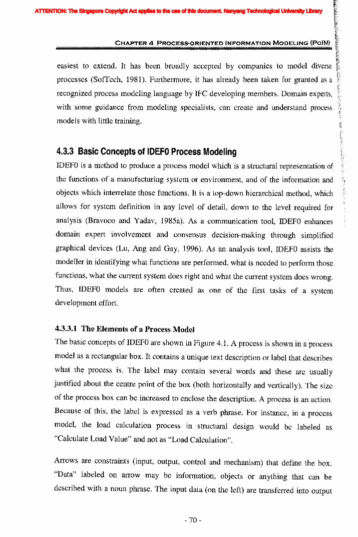
CHAPTER 4 PROCESS-ORIENTED INFORMATION MODELING (POIM)
easiest to extend. It has been broadly accepted by companies to model diverse
processes (SoITech, 1981). Furthermore, it has already been taken for granted as a
recognized process modeling language by IFC developing members. Domain experts,
with some guidance from modeling specialists, can create and understand process
models with little training.
4.3.3 Basic Concepts of IDEFO Process ModelingIDEFO is a method to produce a process model which is a structural representation of
the functions of a manufacturing system or environment, and of the information and
objects which interrelate those functions. It is a top-down hierarchical method, which
allows for system definition in any level of detail, down to the level required for
analysis (Bravoco and Yadav, 1985a). As a communication tool, IDEFO enhances
domain expert involvement and consensus '. decision-making through simplified
graphical devices (Lu, Ang and Gay, 1996). As an analysis tool, IDEFO assists the
modeller in identifying what functions are performed, what is needed to perform those
functions, what the current system does right and what the current system does wrong.
Thus, IDEFO models are often created as one of the first tasks of a system
development effort.
4.3.3.1 The Elements of a Process Model
The basic concepts of IDEFO are shown in Figure 4.1. A process is shown in a process
model as a rectangular box. It contains a unique text description or label that describes
what the process is. The label may contain several words and these are usually
justified about the centre point of the box (both horizontally and vertically). The size
of the process box can be increased to enclose the description. A process is an action.
Because of this, the label is expressed as a verb phrase. For instance, in a process
model, the load calculation process in structural design would be labeled as
"Calculate Load Value" and not as "Load Calculation".
Arrows are constraints (input, output, control and mechanism) that define the box.
"Data" labeled on arrow may be information, objects or anything that can be
described with a noun phrase. The input data (on the left) are transferred into output
- 70-
ATTENTION: The Singapore Copyright Act applies to the use of this document. Nanyang Technological University Library
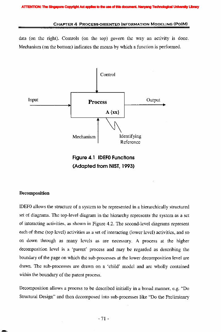
CHAPTER 4 PROCESS-ORIENTED INFORMATION MODELING (POIM)
data (on the right). Controls (on the top) govern the wayan activity is done.
Mechanism (on the bottom) indicates the means by which a function is performed.
Control
Input Process
A {xx}
Output
Mechanism IdentifyingReference
Decomposition
Figure 4. 1 IDEFO Functions
(Adapted from NIST, 1993)
IDEFO allows the structure of a system to be represented in a hierarchically structured
set of diagrams. The top-level diagram in the hierarchy represents the system as a set
of interacting activities, as shown in Figure 4.2. The second-level diagrams represent
each of these (top level) activities as a set of interacting (lower level) activities, and so
on down through as many levels as are necessary. A process at the higher
decomposition level is a 'parent' process and may be regarded as describing the
boundary of the page on which the sub-processes at the lower decomposition level are
drawn. The sub-processes are drawn on a 'child' model and are wholly contained
within the boundary of the parent process.
Decomposition allows a process to be described initially in a broad manner, e.g. "Do
Structural Design" and then decomposed into sub-processes like "Do the Preliminary
- 71 -
ATTENTION: The Singapore Copyright Act applies to the use of this document. Nanyang Technological University Library
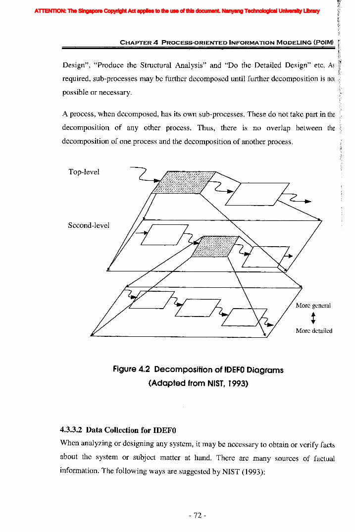
CHAPTER 4 PROCESS·ORIENTED INFORMATION MODELING (PalM)
Design", "Produce the Structural Analysis" and "Do the Detailed Design" etc. As
required, sub-processes may be further decomposed until further decomposition is not
possible or necessary.
A process, when decomposed, has its own sub-processes. These do not take part in the
decomposition of any other process. Thus, there is no overlap between the
decomposition of one process and the decomposition of another process.
Top-level
Second-level
More general
:More detailed
Figure 4.2 Decomposition of IDEFO Diagrams
(Adapted from NIST, 1993)
4.3.3.2 Data Collection for IDEFO
When analyzing or designing any system, it may be necessary to obtain or verify facts
about the system or subject matter at hand. There are many sources of factual
information. The following ways are suggested by NIST (1993):
- 72-
ATTENTION: The Singapore Copyright Act applies to the use of this document. Nanyang Technological University Library

CHAPTER 4 PROCESS-ORIENTED INFORMATION MODELING (POIM)
• Read existing documents, using each table of contents and index to locate needed
information.
• Observe the system in operation, if it already exists.
• Survey a large group of people, through questionnaires or other such means.
• Talk to one or more experts who possess the desired knowledge.
• Use whatever is already known by the author.
• Guess or invent a hypothetical description, and ask readers to help bring it closer
to reality.
Requirements capturing is carried out through case studies and interview techniques.
It involves the researchers identifying several previous and on-going projects and
collecting project information. Interviews with the key professionals help to define the
main project processes and the decision-making sequences.
Of all these methods, the most important is face-to-face interaction with an expert.
Seldom will all existing information be written. Preconceived notions that are
reflected in questionnaires are often faulty.
The purpose of an interview is to gather information from an individual who
possesses an expertise and is considered important to the analytical effort. There are
four types of interviews that might be conducted during the course of performing the
analysis phase of an IDEF project (NIST, 1993):
(a) Fact finding for understanding current operations. This type of interview is used to
establish the content of a current operations model or to help understand the existing
environment.
(b) Problem identification to assist in the establishment of future requirements. This
type of interview is used to validate the current operations model and to provide the
foundation for a future operations model.
- 73 -
ATTENTION: The Singapore Copyright Act applies to the use of this document. Nanyang Technological University Library

CHAPTER 4 PROCESS-ORIENTED INFORMATION MODELING (POIM)
(c) Solution discussion regarding future system capabilities. This type of interview is
used to establish the content of a future operations model.
(d) IDEF author-reader talk session. This type of interview is used to resolve
problems which have surfaced during the construction of an IDEF model.
4.4 Selection of Information Modeling Method
4.4.1 Comparison of Existing Information Modeling MethodsUsing the same comparison parameters in Section 4.3.1, Table 4.2 shows the
difference among the existing information modeling methods reviewed in Chapter 2.
Table 4.2 Comparison of Existing Information Modeling Methods
~'JJt'-J ~
~§a) t'-J - ~ 'JJ 'JJ ........
>-. t'-J t'-J_ ~c!j
t'-J § t'-J a) ~ ~a) ~~0._
~~
a)~ 0 d ~ erJ. ~.~ C,) a)
:E~~ :0 .~ o~ a)._ ;.... S .J:J,.r:;;erJ. U ~ .9 l:l 'P 5 C,)~ t'-J .--c!j 0 '>< l:l d U
~§::i a) ~ a) ~~
~l:l'JJ d o ;....
~a) a) [) 0 erJ. ~> a) ~ t'-J.- .g E._ rJ:J
a) erJ. a)
~d ~~ &a) a) g l-< Q)
tE 'JJ >u ~8 a)~~..o c!j 0~< ~ u ~ ~~
~a) ~< >~ 0
~- ERlEER x x x -- x0"0
IDEFI0 x x x x -- x~ NIAM x x x x~
--.9 Semantic x x x x~
c!jNetsS;....Expressc.8 x x x X
d UML x x x~ --(Note: 'x' means the corresponding method can satisfy the requirement shown in the columncompletely. ' •• ' means it can satisfy the requirement partially.)
4.4.2 Selection of IDEF1
Based on Table 4.2 and consider the possibility of integration with IDEFO, IDEF1 is
selected as the preferred method because both of them belong to the same family. The
IDEF family has about 14 methods, each of which is used to describe or model a
system from its own perspective. Each type of model or description focuses on a
-74 -
ATTENTION: The Singapore Copyright Act applies to the use of this document. Nanyang Technological University Library

CHAPTER 4 PROCESS"ORIENTED INFORMATION MODELING (PoIM)
relatively narrow set of relationships and system characteristics comprising a
particular viewpoint of the overall system. They describe different information and
knowledge of the same system. Therefore, each type of model cannot be converted or
generated from another type of model directly and automatically.
However, as these models are the models of the same system they should have
consistency, to a certain degree, with each other. Some rules can be found to ensure
consistency among various types of models. Secondly, these models should share
some common information or data sources although the models describe different
characteristics or relationships of common data.
Therefore, the integration of IDEF methods, in which various types of IDEF models
are created, is necessary and feasible on the basis of these two points mentioned
above. Additional, considering that the IDEF methodology is more integrated within
itself (IDEFO, IDEF1, and IDEF2) than the other methodologies, the IDEFI method
was finally chosen.
IDEFI is a method to establish the requirements about what and where information is
used or should be managed by the enterprise (Mayer, 1992). IDEFI is generally used
to 1) identify what information is current!y managed in the organization, 2) determine
which of the problems identified during the needs analysis are caused by lack of
management of appropriate information, and 3) specify what information will be
managed in the TO-BE implementation. It is designed to assist in discovering,
organizing and documenting the information image of physical and conceptual objects
(e.g. people, places. things, ideas, etc.) found in the real world.
IDEFI has proven to be an effective method for documenting;the informational
requirements of an enterprise. The IDEFI modeling exercise provides a foundation
for database design, gives a definition of the information structure, and provides a
requirements statement reflecting the basic information needs. IDEFI uses a
disciplined, structured technique to uncover the information and business rules used
by an organization. This gives needed rigor to the method for untangling the complex
- 75 -
ATTENTION: The Singapore Copyright Act applies to the use of this document. Nanyang Technological University Library
CHAPTER 4 PROCESS-ORIENTED INFORMATION MODELING (PoIM)
challenge of modeling the information of the organization. Finally, information
models are useful throughout the life-cycle of the enterprise.
4.4.3 Necessity to Enhance IDEF1However, IDEF1 is too simple to be used for representing information. It only reflects
that some kinds of relationship may exist, but cannot clarify the kind of relationship
that exists, such as the relationship of hierarchy. To support the development of an
integrated approach and model the information requirements completely and clearly,
enhancements to the well-established IDEFI information model are deemed necessary.
Moreover, most modem systems contain a significant amount of software, and efforts
to develop them must successfully integrate systems and software engineering. A
process that integrates systems and software engineering should use an information
modeling technique that is compatible with both disciplines. Object-oriented
techniques are good candidates because they have been used by the software
community for years and are coming to be used by systems engineers (Oliver,
Kelliher, and Keegan 1997). The overwhelming popularity of object-oriented analysis
and design has been witnessed in recent years. This phenomenon is evidenced by the
number of articles and papers published in various journals, conference proceedings,
books, and other forms. The object-oriented modeling methodology is one in which
the data are grouped into packages which occur "naturally"; this makes it compatible
with the way people think about the real world (Kilov and Ross, 1994). It allows for
data abstraction, inheritance, information hiding, and dynamic binding.
Correspondingly, reusability is consistently presented as one of the key benefits of
object oriented software development. Meyer (1987) stated, "object-oriented design is
the most promising technique now known for attaining the goals of extensibility and
reusability." Meyer (1988) and Booch (1994) also said that the use of the object
model encourages the reuse not only of software but of entire designs, leading to the
creation of reusable application frameworks. Object-oriented techniques yield
structures that are more readily reused than other design techniques (McGregor and
Sykes, 1992). It (object-oriented development) was intended to promote future reuse
- 76-
ATTENTION: The Singapore Copyright Act applies to the use of this document. Nanyang Technological University Library
CHAPTER 4 PROCESS-ORIENTED INFORMATION MODELING (PoIM)
and reduce downstream errors and maintenance (Rumbaugh et aI., 1991). These
positive comments have confirmed the importance of object-oriented concepts and
trend for popular use in future.
In this research an enhanced IDEF1 methodology conforming to object-oriented
concepts is developed in order to not only specify detailed information and let the
model have good extensibility, but also for it to be easy to be used. The detailed
concept of this enhanced methodology will be explained in the following section.
These enhancements to IDEF1 allow additional classes of knowledge. The additional
enhancements include: introduction of domain class, and supplements of types of
relationship between entity class.
4.5 Augmented IDEF1 methodolody
The basic concepts of enhanced IDEFl are very similar to IDEFl. But in respect of
relationship and entity types, some new thoughts are synthesized within the concept
of IDEF1.
Since the augmented IDEFI inherits all the functions and notations of IDEFl and is
enriched by more relationship characteristics, it should have all the advantages IDEFl
has and with other additioanl benefits. Enhanced IDEFl enforces a modularity that
eliminates the incompleteness, imprecision, inconsistencies and inaccuracies found in
the modeling process. An enhanced IDEF1 information model is a reflection of the
entire system and provides a baseline definition of its informational needs, gives a
definition of the information structure and provides a requirement statement reflecting
the basic information needs. It ensures that the information can be shared and that the
information system is integrated.
The components of this model include: entites, domains, attributes and relationships,
as shown in Figure 4.3. Entity class and attribute class are represented by a
rectangular box, and domain class is represented by a grey shadowed box. The
relationships between entities are represented by the arrows around the box. The
-77 -
ATTENTION: The Singapore Copyright Act applies to the use of this document. Nanyang Technological University Library

CHAPTER 4 PROCESS-oRIENTED INFORMATION MODELING (PalM)
following sections will give the detailed discriptions for these components
respectively.
Figure 4.3 An Enhanced IDEFl Diagram
4.5.1 Entity ClassAn IDEFI entity may be thought of as an object, either real or abstract, that has
common properties or characteristics. An entity class refers to a collection of entities
or the class of information kept about objects in the real world. Entities have
characteristic attributes associated with them. The term attribute class refers to the set
of attribute-value pairs formed by grouping the name of the attribute and the values of
that attribute for individual entity class members (entities). An entity is represented as
a box divided into two compartments shown in Figure 4.3 with the name in the upper
compartment. The entity name is a noun phrase that describes the set of things the
entity represents. The noun phrase is in singular form, not plural. And the entity name
must be meaning full and consistent throughout the modeling.
4.5.2 Domain ClassA domain is a set of all possible values from which an attribute of an entity draws its
values. It is not an association between entities. Domains are defined separately from
entities in order to permit their reuse and standardization throughout the model. For
example, "Load Type" would be considered as a domain, where the set of allowable
- 78 -
ATTENTION: The Singapore Copyright Act applies to the use of this document. Nanyang Technological University Library

CHAPTER 4 PROCESS-ORIENTED INFORMATION MODELING (POIM)
values for the domain would satisfy the definition of a load type (e.g. Dead Load,
Live Load, Earthquake Load, etc.). Similarly a domain is represented as a gery
shadowed box shown in Figure 4.3 with the name in the upper layer and domain's
value listed in the lower layer. The value list defines the set of all acceptable instance
values for a domain. A dash line is used to connect a domain and the entity whose
attribute will draw values from the domain.
Most systems support trivial domains equivalent to base types: integers, reals, strings,
and sometimes Booleans, date, and time. User-defined domains provide not just better
property checking, but also better understanding of the information model, in
particular, by getting rid of redundant and inconsistent property definitions (Kilov,
1989).
Domains are considered immutable classes whose values do not change over time. In
contrast, entities are time-varying classes; their instance data varies over time as the
data is modified and maintained.
Domains are a primary notion with respect to properties: property values belong to a
user-defined type, and this type is a domain. Therefore, it is recommended to define
domains first and always include a domain name in a property definition. Domain
names (unlike property names) should be unique within an application.
4.5.3 Attribute Class
An attribute represents a type of characteristic or property associated with a set of real
or abstract things (people, objects, places, events, ideas, combinations of things, etc.).
Attributes are associated with specific entities and defined in the lower compartment
of entity class (see Figure 4.3). An "attribute instance" is a specific characteristic of
an individual member of the set. An attribute instance is defined by both the type of
characteristic and its value, referred to as an "attribute value." An instance of an entity,
then, will usually have a single specific value for each associated attribute.
-79 -
ATTENTION: The Singapore Copyright Act applies to the use of this document. Nanyang Technological University Library
CHAPTER 4 PROCESS-ORIENTED INFORMATION MODELING (POIM)
4.5.4 RelationshipsA relation class can be thought of as the template for associations that exist between
entity classes. Relationships are used to represent associations between entities. In
enhanced IDEFl, the relationships existing between two entities are classified into
four types: dependency relationships, composition relationships, generalization
relationships and non-specific relationships. Composition relationships are used to
represent an entity "consists of' (in other words, is an "aggregate of') other entities
referred as component entities. Generalization relationships are used to represent
structures in which an entity is a "type" (category) of another entity. Dependency
relationships are used to represent existence dependence between entities. Non
specific relationships are used in high-level Entity-Relationship views to represent
many-to-many associations between entities.
(i) Composition Relationships
A composite entity "consists of' (in other words, is an "aggregate of') component
entities. A component mayor may not exist independent of the composite entity. A
composite entity mayor may not exist without components. Attributes of a composite
are not inherited by components. A component entity may belong to zero or more
than one type of composite entity. For example, the relationship between "Structural
Model" and "Structural Connection", "Structural Member" would be composition
relationship. Structural model is composed of more than one structural members and
connections. In IDEFl diagram, as shown in Figure 4.4, this type of relation is
represented by a line drawn between composite entity and the component entity with
a diamond at the component end of the line.
- 80-
ATTENTION: The Singapore Copyright Act applies to the use of this document. Nanyang Technological University Library
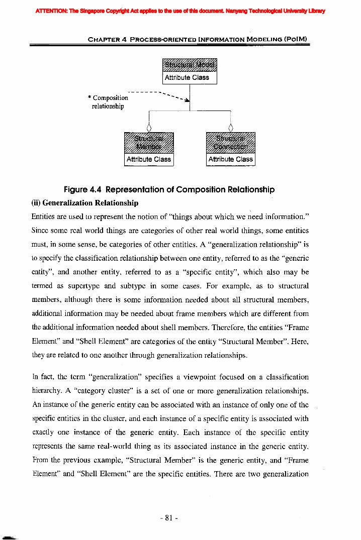
CHAPTER 4 PROCESS-ORIENTED INFORMATION MODELING (POIM)
* Composition- - - - - - - -
relationship
Figure 4.4 Representation of Composition Relationship
(ii) Generalization Relationship
Entities are used to represent the notion of "things about which we need information."
Since some real world things are categories of other real world things, some entities
must, in some sense, be categories of other entities. A "generalization relationship" is
to specify the classification relationship between one entity, referred to as the "generic
entity", and another entity, referred to as a "specific entity", which also may be
termed as supertype and subtype in some cases. For example, as to structural
members, although there is some information needed about all structural members,
additional information may be needed about frame members which are different from
the additional. information needed about shell members. Therefore, the entities "Frame
Element" and "Shell Element" are categories of the entity "Structural Member". Here,
they are related to one another through generalization relationships.
In fact, the term "generalization" specifies a viewpoint focused on a classification
hierarchy. A "category cluster" is a set of one or more generalization relationships.
An instance of the generic entity can be associated with an instance of only one of the
specific entities in the cluster, and each instance of a specific entity is associated with
exactly one instance· of the generic entity. Each instance of the specific entity
represents the same real-world thing as its associated instance in the generic entity.
From the previous example, "Structural Member" is the generic entity, and "Frame
Element" and "Shell Element" are the specific entities. There are two generalization
- 81 -
ATTENTION: The Singapore Copyright Act applies to the use of this document. Nanyang Technological University Library
CHAPTER 4 PROCESS·ORIENTED INFORMATION MODELING (PalM)
relationships in this cluster, one between "Structural Member" and "Frame Element"
and the other one between "Structural Member" and "Shell Element".
The associations between a generic entity and its specific entities give rise to two
orthogonal constraints: the "exclusiveness" and the "exhaustiveness" of the specific
entities.
The exclusiveness refers to whether or not a given generic entity instance can belong
to more than one subtype. If it can, the subtypes are overlapping; if not, the subtypes
are disjoint. By default, generalization symbolizes an exclusive decomposition. That
is, an instance of a generic entity can only be an instance of one of the specific entities.
However, a generic entity may be specialized according to several simultaneous
criteria. In this case, the specific entities defined under one criterion are not mutually
exclusive with those under others. For example, "Structural Member" could be a
generic entity in a second category cluster with "Line Member" and "Face Member"
as the category entities. An instance of "Structural Member" could be associated with
an instance of either "Frame Element" or "Shell Element" and with an instance of
either "Line Member" or "Face Member".
The exhaustiveness refers to the participation of all generic entity instances in the
subtyping hierarchy. Constraint "complete" indicates every instance of the generic
entity is associated with an instance of a specific entity, i.e., the generalization is
finished, and it is no longer able to add specific entities. Conversely, "incomplete"
constraint specifies an extensible generalization. An instance of the generic entity can
exist without being associated with an instance of any of the category entities, i.e.,
some categories are omitted.
Sometimes a class may be specialized according to several simultaneous criteria. Each
generalization criterion could be indicated in the diagram by associating a
discriminator with the generalization relationship. The value of the discriminator
determines the category of an instance of the generic. In the previous example, the
discriminator for the cluster including the line members and face members categories
- 82-
ATTENTION: The Singapore Copyright Act applies to the use of this document. Nanyang Technological University Library

CHAPTER 4 PROCESS"ORIENTED INFORMATION MODELING (POIM)
might be named "Member Shape". If a cluster has a discriminator, it must be distinct
from all other discriminators.
A specific entity inherits the properties of its generic entity. This relationship is
represented by a circle underlined, as shown in Figure 4.5.
is one of....... ....... * Generalization
relationship
Figure 4.5 Representation of Generalization Relationship
(iii) Dependency Relationships
The existence of an entity instance may be declared to depend on the existence ()f
another entity instance: if the latter is deleted, then the former must disappear as well.
And there is no composition or generalization relationships existing between these
two entities. This construct represents a dependency association between a parent
entity and a dependent entity. Properties of a parent entity do not depend upon
properties of its dependent entity.
A dependent entity instance is not necessarily automatically deleted when its parent
instance has to be deleted: sometimes the deletion of a parent instance is not permitted
if dependents exist. On the other hand, a dependent instance cannot be created unless
a parent instance already exists.
For example, in Figure 4.6, a dependency relationship would exist between the
entities "Structural Analysis Model" and "Structural Response Model", if no analysis
- 83 -
ATTENTION: The Singapore Copyright Act applies to the use of this document. Nanyang Technological University Library
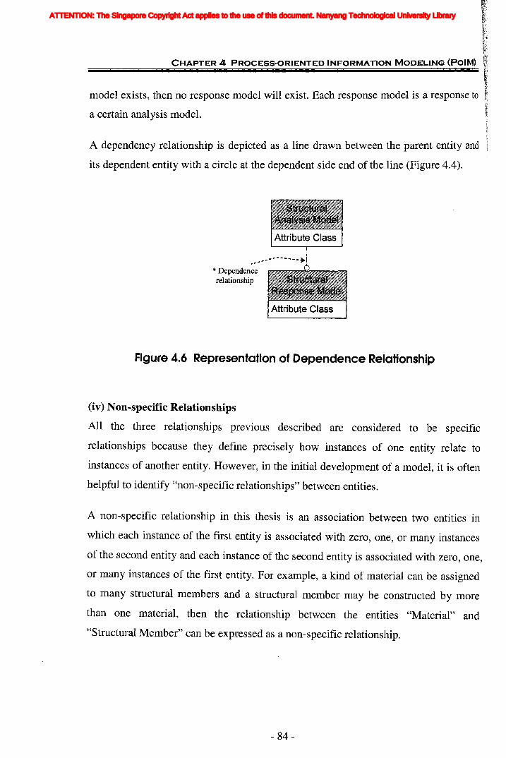
CHAPTER 4 PROCESS-ORIENTED INFORMATION MODELING (PalM)
model exists, then no response model will exist. Each response model is a response to
a certain analysis model.
A dependency relationship is depicted as a line drawn between the parent entity and
its dependent entity with a circle at the dependent side end of the line (Figure 4.4).
Figure 4.6 Representation of Dependence Relationship
(iv) Non-specific Relationships
All the three relationships previous described are considered to be specific
relationships because they define precisely how instances of one entity relate to
instances of another entity. However, in the initial development of a model, it is often
helpful to identify "non-specific relationships" between entities.
A non-specific relationship in this thesis is an association between two entities in
which each instance of the first entity is associated with zero, one, or many instances
of the second entity and each instance of the second entity is associated with zero, one,
or many instances of the first entity. For example, a kind of material can be assigned
to many structural members and a structural member may be constructed by more
than one material, then the relationship between the entities "Material" and
"Structural Member" can be expressed as a non-specific relationship.
- 84-
ATTENTION: The Singapore Copyright Act applies to the use of this document. Nanyang Technological University Library
CHAPTER 4 PROCESS-ORIENTED INFORMATION MODELING (POIM)
A non-specific relationship can not be represented only by a line. The third party is
introduced to deal with this kind of relationship, which is explained in detail in the
following Section "Location of Attributes According to Multiplicity Values".
(v) Relationship Naming
Each relation except for non-specific relationships may be named. A relationship is
given a name, expressed as a verb or verb phrase placed beside the relationship line.
The name of each relationship between the same two entities must be unique, but the
relationship names need not be unique within the model. The relationship name for a
dependency relationship is usually expressed in the parent-to-dependent direction,
such that a sentence can be formed by combining the parent entity name, relationship
name, multiplicity value, and dependent entity name. Because a relationship can be
named from the parent perspective and dependent perspective as well, in this research
all the relationship are stated from the parent perspective. As to non-specific
relationships, a third entity will be introduced to as relation class, so it is not
necessary to give a name to the line. For generalization relationship, the name of
relationship is always "is-one-of' from generic perspective and "a-kind-of' from
specific perspective. For composition relationship, the name is always "Has-a" from
composite perspective and inversely "Part-of' from component perspective. So in this
research these two relationships need not be stated in diagram in order to make
diagram concise. The reader can explicitly get information from the type of line.
(vi) Multiplicity of Associations
Each role of an association has a multiplicity value that indicates how many instances
of the given entity may be linked to an instance of the other entity. In some cases, it is
represented by word "Cardinality". The relationship may be further defined by
specifying the cardinality of the relationship.
The default component cardinality is zero, one or many. No any character is placed
beside the diamond to indicate a cardinality of one or more. If the cardinality is an
exact number, a positive integer number is placed beside the diamond. If the
cardinality is a range, the range is placed beside the diamond. Cardinality is not
specified for the generalization entity since it is always of zero or one. By convention,
- 85 -
ATTENTION: The Singapore Copyright Act applies to the use of this document. Nanyang Technological University Library
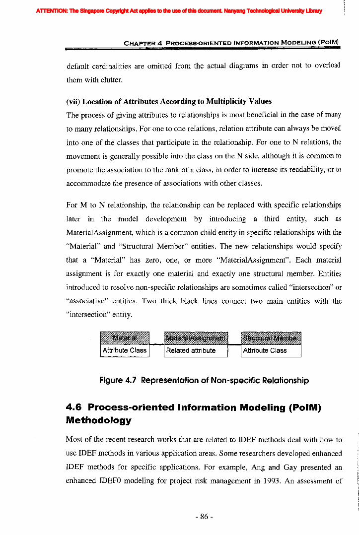
CHAPT·ER 4 PROCESS-ORIENTED INFORMATION MODELING (POIM)
default cardinalities are omitted from the actual diagrams in order not to overload
them with clutter.
(vii) Location of Attributes According to Multiplicity Values
The process of giving attributes to relationships is most beneficial in the case of many
to many relationships. For one to one relations, relation attribute can always be moved
into one of the classes that participate in the relationship. For one to N relations, the
movement is generally possible into the class on the N side, although it is common to
promote the association to the rank of a class, in order to increase its readability, or to
accommodate the presence of associations with other classes.
For M to N relationship, the relationship can be replaced with specific relationships
later in the model development by introducing a third entity, such as
MaterialAssignment, which is a common child entity in specific relationships with the
"Material" and "Structural Member" entities. The new relationships would specify
that a "Material" has zero, one, or more "MateriaIAssignment". Each material
assignment is for exactly one material and exactly one structural member. Entities
introduced to resolve non-specific relationships are sometimes called "intersection" or
"associative" entities. Two thick black lines connect two main entities with the
"intersection" entity.
Figure 4.7 Representation of Non-specific Relationship
4.6 Process-oriented Information Modeling (PoIM)Methodology
Most of the recent research works that are related to IDEF methods deal with how to
use IDEF methods in various application areas. Some researchers developed enhanced
IDEF methods for specific applications. For example, Ang and Gay presented an
enhanced IDEFO modeling for project risk management in 1993. An assessment of
- 86-
ATTENTION: The Singapore Copyright Act applies to the use of this document. Nanyang Technological University Library
CHAPTER 4 PROCESS-ORIENTED INFORMATION MODELING (POIM)
IDEF notations was done by Godwin, Gleeson and Gwillian (1989). Comparison with
other tools has been studied in 1988 by Maji. The integration of IDEF methods has
been studied and its CASE tools were developed by other researchers (Godwin 1989,
Sanvido et al. 1989). System Modeling Corp. tried to integrate SIMAN simulation
tools with the IDEFO model. However, most of them only developed tools for the
integration of IDEFO model with the IDEF2 model or other simulation models. Very
little research has dealt with the methodology for the integration of IDEF1 with
IDEFO. Only a simple integration of them for CIM information systems design has
been studied by Linzhi Lu, Ang Cheng Leong and Robert K. L. Gay in 1996.
In this research, the study would proceed further with the integration of IDEFO model
and augmented IDEF1 information model. Consequently process-oriented information
modeling (PoIM) methodology is proposed as a new approach for information
requirements analysis. The methodology is an integration of process models and
information models. The information model is obtained from process models and all
the information is process-related. Through this methodology, the information
requirements can be easily identified and analyzed through the corresponding process
models. The integration of information model and process model provides a
comprehensive view of the information which makes communication more effective
and efficient. Besides the principle of integration, some tools are also developed
during the methodology in order to assist the modeller in quickly identifying the
information.
4.6.1 Principle of the Integration of IDEF1 and IDEFOIn the proposed methodology, each IDEFO diagram will be converted to a
corresponding IDEF1 diagram according to the conversion rules listed in Table 4.3.
These conversion rules are found out after examining the basic concepts of both
IDEFO models and augmented IDEF1 models. The integration begins from the
relative bottom level IDEFO diagrams. This is a bottom-up analysis method.
- 87 -
ATTENTION: The Singapore Copyright Act applies to the use of this document. Nanyang Technological University Library
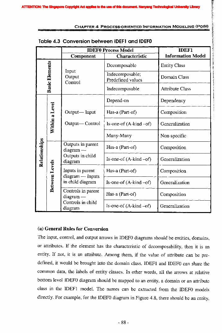
r'>.
CHAPTER 4 PROCESS-ORIENTED INFORMATION MODELING (PalM)
Table 4.3 Conversion between IDEFl and IDEFO
IDEFO Process Model IDEFIComponent Characteristic Information Model
\I..l.. Decomposable Entity Class=~fuput5 Indecomposable;-- Output Domain Class
~ Predefined values~ Control...-\I..l
Indecomposable Attribute Class~
==
-- Depend-on Dependency~
>~
Has-a (Part-of) Composition~ Output- fuput~
=...- Output- Control Is-one-of (A-kind -of) Generalization~..~
Non-specificMany-Many\I..l~
Outputs in parent...-~ Has-a (Part-of) Composition\I..l diagram-=0
Outputs in child...-~ Is-one-of (A-kind -of) Generalization-- \I..l diagram~
~~ >
~ Inputs in parent Has-a (Part-of) Composition~
= diagram - Inputs~
~ in child diagram Is-one-of (A-kind -of) Generalization..~
== Controls in parentHas-a (Part-of) Compositiondiagram-
Controls in childIs-one-of (A-kind -of) Generalizationdiagram
(a) General Rules for Conversion
The input, control, and output arrows in IDEFO diagrams should be entities, domains,
or attributes. If the element has the characteristic of decomposability, then it is an
entity. If not, it is an attribute. Among them, if the value of attribute can be pre-
defined, it would be brought into the domain class. IDEFl and IDEFO can share the
common data, the labels of entity classes. fu other words, all the arrows at relative
bottom level IDEFO diagram should be mapped to an entity, a domain or an attribute
class in the IDEFl model. The names can be extracted from the IDEFO models
directly. For example, for the IDEFO diagram in Figure 4.8, there should be an entity,
- 88 -
ATTENTION: The Singapore Copyright Act applies to the use of this document. Nanyang Technological University Library
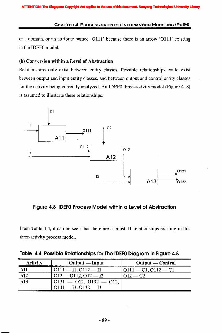
CHAPTER 4 PROCESS-ORIENTED INFORMATION MODELING (PoIM)
or a domain, or an attribute named '0111' because there is an arrow '0111' existing
in the IDEFO model.
(b) Conversion within a Level of Abstraction
Relationships only exist between entity classes. Possible relationships could exist
between output and input entity classes, and between output and control entity classes
for the activity being currently analyzed. An IDEFO three-activity model (Figure 4. 8)
is assumed to illustrate these relationships.
C1
11
12
A11
0111
0112
13
C2
A12
012
0131
A13 0132
Figure 4.8 IDEFO Process Model within a Level of Abstraction
From Table 4.4, it can be seen that there are at most 11 relationships existing in this
three-activity process model.
Table 4.4 Possible Relationships for The IDEFO Diagram in Figure 4.8
All 0111- 11,0112 - 11 0111- C1, 0112 - C1Al2 012 - 0112,012 - 12 012-C2Al3 0131 - 012, 0132 - 012,
0131- 13,0132 - 13
Activity Output - Input
- 89-
Output - Control
ATTENTION: The Singapore Copyright Act applies to the use of this document. Nanyang Technological University Library

CHAPTER 4 PROCESS·ORIENTED INFORMATION MODELING (POIM)
The characteristics of these outputs, inputs and controls are used to identify the types
of relationships. Generally, the type identification is governed by the following rules:
Rule 1: If these two elements are both entities, the dependency relationship is most
likely to exist between them.
Rule 2: If one of elements belongs to a domain class or an attribute class, there is no
relationship between them.
Rule 3: Sometimes, a cycle may exist between the output and input of two activities.
For instance, B and A could be the input and output of activity 1 and, at the
same time, A and B can be the input and output of activity 2. A cycle is
formed in this case and, generally, a very weak relationship is thought to exist
between A and B, which can be neglected when converted to an IDEFl
information model.
(c) Conversion between Levels of Abstraction
Besides conversion of information within a particular level of abstraction,
relationships among information may also exist between different levels of abstraction,
or a parent activity and its child diagram, as shown in Figure 4.9.
Cll C12
Parent Activity at(i-l/h level
Child Diagramat ith level
III
112
1112
01122
Figure 4.9 IDEFO Model between levels of Abstraction
- 90-
ATTENTION: The Singapore Copyright Act applies to the use of this document. Nanyang Technological University Library

CHAPTER 4 PROCESS-ORIENTED INFORMATION MODELING (PoIM)
There are five major types of conversion between levels of abstraction, which can be
identified as follows:
Rule 1: The composition and generalization relationships most possibly exist between
the outputs of a parent activity and the outputs of its child diagram if all
outputs are entities.
For example, in Figure 4.9, 'All' is a parent activity with two outputs, 0111
and 0112, and has four final outputs in its child diagram, 01111, 01121,
01131 and 01132. Then the relationship existing between them is that the
union of all the contents of 01111, 01121, 01131 and 01132 constitutes the
contents of 0111 and 0112. After further analysis, the detailed relationships
between them may be divided in such a way that 0111 is the union of 01111
and 01121, and 0112 is the union of 01131 and 01132. The corresponding
IDEF1 model then comprises two sets of relationships. One is between 0111
and 01111, and 01121; and the other is between 0112 and 01131, and
01132.
Rule 2: The way Rule 1 works is also applicable to identifying the relationships
between the inputs of a parent activity and all the inputs in its child diagram,
and between the controls of a parent activity and all the controls in its child
diagram.
Rule 3: If all the elements in a child diagram are not entities, but attributes or
domains, its corresponding parent element should be an entity which has the
attributes with the same names as that of the elements in the child diagram.
But normally, it is not suggested to break down the process model to such a
detailed level.
Rule 4: If an element appears in several levels without any change, this element
should be only considered in the top level. That is, this element can only
appear once in the developed information model and only the relationships
between this element and top-level elements should be considered.
- 91 -
ATTENTION: The Singapore Copyright Act applies to the use of this document. Nanyang Technological University Library
CHAPTER 4 PROCESS-ORIENTED INFORMATION MODELING (PalM)
For example, in Figure 4.9, if the input 1111 of the child diagram is
completely identical to the parent input Ill, 1111 and its relationships with
other elements in the child diagram are not necessary to be considered
because it has been included by III in the parent activity.
Rule 5: Intermediate outputs in a child diagram will be only considered in the
conversion within a level of abstraction. For example, the output 01122 of
activity 'A112' in the child diagram is an intermediate output and can be
omitted during the conversion between levels.
4.6.2 Requirements for IDEFO ModelAlthough from previous studies it can be clearly demonstrated that IDEFO is well
accepted by those who have themselves participated in a modeling exercise using
IDEFO, there are still some problems with the IDEFO method. One is that the
diagrams can easily become fairly complex. However, if a model's structure is too
simplistic, it tends to become trivial, without much explanatory content left. Also, the
pure hierarchical tree structure of diagrams forces developers to compromise in
choosing the model structure sometimes. Comprehensive IDEFO models are often
found to be difficult to understand by people who do not directly participate in the
model development.
According to the original IDEF definitions, arrows are constraints that define the
boxes. Arrows may be information, objects or anything that can be described with a
noun phrase. Therefore arrows of the IDEF diagrams at the relative bottom level may
not be entities.
In order to integrate the IDEFt model with the IDEFO model successfully, the
following requirements should be met in the IDEFO model:
• The IDEFO model should be decomposed to a relative bottom level at which every
input and output should not be bigger than an entity class.
- 92-
ATTENTION: The Singapore Copyright Act applies to the use of this document. Nanyang Technological University Library

iii
s
b
j
CHAPTER 4 PROCESS-ORIENTED INFORMATION MODELING (POIM)
• For the information modeling which aims to carry out the interoperability between
different software applications, like this research, the decomposition of IDEFO
process model should be from the software applications' perspective. It can be
found that the information entered by users can generally be regarded as an
attribute to a certain entity. In this circumstance, the meaning of "relative bottom
level" mentioned in first requirement can be considered as the layer which is one
level higher than the layer for user-entered information. This defines that the
IDEFO model should be decomposed to the level which gives the general
classifications of user- entered information. In addition, sometimes the choice
values for a parameter is provided by the software, users only select the
corresponding value directly in a pulldown menu. Then this parameter can be
mapped to a domain class.
• To keep in line with the elements in a parent diagram, the difference between final
outputs and middle outputs in the child diagrams should be identified as final
outputs constitute the output of the whole diagram.
4.6.3 Procedures to Develop Information Model from IDEFO Process Modelthrough PolM MethodologyThe previous section describes the corresponding IDEFI representation of a single
IDEFO activity. However, most IDEFO diagrams, other than the top-most level,
contain more than one IDEFO activity. For an IDEFO diagram with multiple activities,
each activity can be converted, respectively, to an IDEFI model, followed by linking
all IDEFI models to form a complete IDEFI diagram.
The flow diagram for the integration of IDEFI with IDEFO through PolM
methodology is shown in Fig 4.10. The flow is theoretically based on the principle
mentioned above. There are 8 steps that will be carried out to convert the IDEFO
models into an IDEFl model, which will be explained in details in Section 4.6.4.
- 93 -
ATTENTION: The Singapore Copyright Act applies to the use of this document. Nanyang Technological University Library

Figure 4.10 PolM - From IDEFO Model to IOEFl Model: The EightConversion Steps
N
EntityClass
RelationClass
DomainClass
InformationModel
y
N
End
8. Refine the IDEFI model
Compile into IDEFl diagram
Analyze relationships between the parentactivit and current child dia ram
5. Search the corresponding parent activity
Read entity classes around box j 0=1, 2, ... , n)
Start
1. Read Information from an IDEFO Diagram atrelative bottom level (the ith level)
CHAPTER 4 PROCESS-ORIENTED INFORMATION MODELING (PalM)
2. Identify entity, domain classes and Input their ~=======I===1attribute classes
7. Move up to the (i-I) th level IDEFO diagram(parent diagram)
Compile relation classes and entity classes into acorresponding IDEFt diagram 1-----11-_.....--
3. Analyze relation classes between output entityclass and input, control entity classes around box j ~=======tl
by both user and computer
y
y
- 94-
ATTENTION: The Singapore Copyright Act applies to the use of this document. Nanyang Technological University Library

CHAPTER 4 PROCESS-ORIENTED INFORMATION MODELING (POIM)
4.6.4 Mapping Tables and Information ModelDuring the conversion, a set of mapping tables is designed to complete the above
eight steps. The purpose of the mapping tables is to guide the modeler to identify
elements, corresponding information and relationships quickly. The development of
this set of mapping tables will give a clear picture for the information involved which
can assist modelers to minimize the errors made.
A set of mapping tables usually comprises two types of differen( tables, which are
very similar in structure but different in content. The first type shows the mapping
within the same level. The other type shows the mapping between a parent activity
and its child diagram. The standard table formats are show in Table 4.5, where the
information is extracted from the IDEFO models in Figure 4.9.
In the following section, the entire eight steps in the mapping process shown in Figure
4.10 to obtain the PolM information model is described. The process models in Figure
4.9 are used as the example and all the mapping results are listed in Table 4.5. The
mapping begins with the activities in child diagram at ith level of Figure 4.9 because
they are at the bottom-level of the process model. Table 4.5A and 4.5B present the
same-level mappings for the two respective process models in Figure 4.9. Table 4.5C
is the mapping between the parent activities and their child diagrams. The focus here
is on the procedures to develop information model from IDEFO model. Therefore, all
elements in the example are expressed by abstract symbols and all the relationships
are also assumed just for the sake of illustration.
Step 1
Select an IDEFO activity at the relative bottom level. It is recommended to start with
the activity at top-left comer and proceed diagonally downwards. Here the modeling
begins with the activity 'AlII' in Figure 4.9, which is shown in the first column of
Table 4.5A.
Step 2
For every Input, Control and Output interface to the selected IDEFO activity, add
corresponding elements according to their characteristics, which could be an entity, an
- 95 -
ATTENTION: The Singapore Copyright Act applies to the use of this document. Nanyang Technological University Library
CHAPTER 4 PROCESS-ORIENTED INFORMATION MODELING (PalM)
attribute, or a domain. The name in IDEFI can be the same name as in IDEFO. For
activity 'AlII', there are totally one output '01111', one input '1111' and one control
'Cll1'. The information is listed in the second and forth columns of the first mapping
table (Table 4.5A). The types of corresponding IDEF1 elements are also confirmed in
the third and fifth columns, respectively.
Step 3
Identify the relationships between the input and output, as well as the relationship
between the control and output, followed by adding them to the IDEF1 diagram. Here,
it is supposed that there is a dependency relationship existing between '01111'
and '1111'. The relationship information is expressed in the sixth and seventh
columns. The same relationship exists between '01111' and 'C111 '.
Step 4
Check if any other activity exists in this diagram. If yes, repeats Steps 1 to 3 until all
IDEFO activities have been analyzed. If no, go to Step 5 directly. In Figure 4.9, there
are three activities. Similarly, all the inputs, outputs to the other two activities 'Al12'
and 'A1l3' should be analyzed. After that, the conversion within a level for the
bottom level process model can be considered complete.
Step 5
Use the bottom-up method to find the parent activity in the parent diagram for each
bottom level diagram, and add the corresponding IDEF1 elements to the information
model. Then identify the relationships between the elements of the parent activity and
the elements in its child diagram, as Step 3.
Activity 'All' in Figure 4.9 is the parent activity. Suppose the inputs to activity
'All', '111' and '112', are identical to the inputs of its child diagram, '1111' and
'1112'. Then there is no relationship between the inputs. And when considering the
within-level conversion in Steps 3 and 4, the elements '1111' and '1112", and
relationships involved should be omitted because they are included in parent level.
The second row of Table 4.5A is made grey to show the essential omission of related
relationships, which is actually deleted in the final mapping tables. However,
- 96-
ATTENTION: The Singapore Copyright Act applies to the use of this document. Nanyang Technological University Library
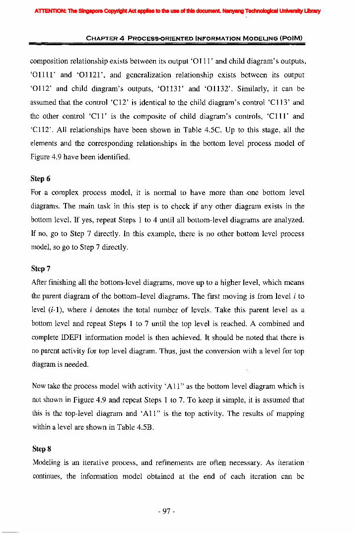
CHAPTER 4 PROCESS-ORIENTED INFORMATION MODELING (POIM)
composition relationship exists between its output '0111' and child diagram's outputs,
'01111' and '01121', and generalization relationship exists between its output
'0112' and child diagram's outputs, '01131' and '01132'. Similarly, it can be
assumed that the control 'C12' is identical to the child diagram's control 'Cl13' and
the other control 'C11' is the composite of child diagram's controls, 'C111' and
'C112'. All relationships have been shown in Table 4.5C. Up to this stage, all the
elements and the corresponding relationships in the bottom level process model of
Figure 4.9 have been identified.
Step 6
For a complex process model, it is normal to have more than -one bottom level
diagrams. The main task in this step is to check if any other diagram exists in the
bottom level. If yes, repeat Steps 1 to 4 until all bottom-level diagrams are analyzed.
If no, go to Step 7 directly. In this example, there is no other bottom level process
model, so go to Step 7 directly.
Step 7
After finishing all the bottom-level diagrams, move up to a higher level, which means
the parent diagram of the bottom-level diagrams. The first moving is from level i to
level (i-I), where i denotes the total number of levels. Take this parent level as a
bottom level and repeat Steps 1 to 7 until the top level is reached. A combined and
complete IDEF1 information model is then achieved. It should be noted that there is
no parent activity for top level diagram. Thus, just the conversion with a level for top
diagram is needed.
Now take the process model with activity 'All" as the bottom level diagram which is
not shown in Figure 4.9 and repeat Steps 1 to 7. To keep it simple, it is assumed that
this is the top-level diagram and 'All" is the top activity. The results of mapping
within a level are shown in Table 4.5B.
Step 8
Modeling is an iterative process, and refinements are often necessary. As iteration
continues, the information model obtained at the end of each iteration can be
- 97 -
ATTENTION: The Singapore Copyright Act applies to the use of this document. Nanyang Technological University Library

CHAPTER 4 PROCESS-ORIENTED INFORMATION MODELING (PalM)
presented to the users to obtain further feedback. Based on the feedback, either
another iteration will start or the information model is finished. In this step, the main
tasks include checking if all necessary entity classes are listed, if there are any relation
classes missing or any wrong relation classes shown, and if the relation classes are
applied correctly in both directions.
Table 4.5 Standard Mapping Tables
IDEFOActivity
(A
AlII
Al12
IDEFOOutput
01111
01121
Correspon-ding
IDEFtElement
Entity
Entity
RelativeInput &Control
C112
Correspon-ding
IDEFtElement
Entity
RelationshipType
Dependency
RelationshipName &
Multiplicity
Based on
01111 Entity Non-specific Entity: Rl
01132 Entity
Non-specific Entity: R3
A113
(B)All
(C
ParentActivity
All
01122
01131
0111
0112
ParentElement
0111
Entity
Entity
Entity
Entity
Correspon-ding
IDEFtElement
Entity
C112
111
112
III
112
C12
ChildElement
01111
01121
Entity
Entity
Entity
Entity
Entity
Entity
Correspon-ding
IDEFtElement
Entity
Entity
Dependency
Dependency
Dependency
Dependency
Dependency
RelationshipType
Composition
Composition
Based on
Based on
Based on
Based on
Based on
RelationshipName &
Multiplicity
Has-a
Has-a
0112 Entity 01131
01132
Entity
Entity
Generalization (Has-a) Is-one-of
Generalization (Has-a) Is-one-of
C11 Entity C111
C112
- 98-
Entity
Entity
Composition
Composition
Has-a
Has-a
ATTENTION: The Singapore Copyright Act applies to the use of this document. Nanyang Technological University Library
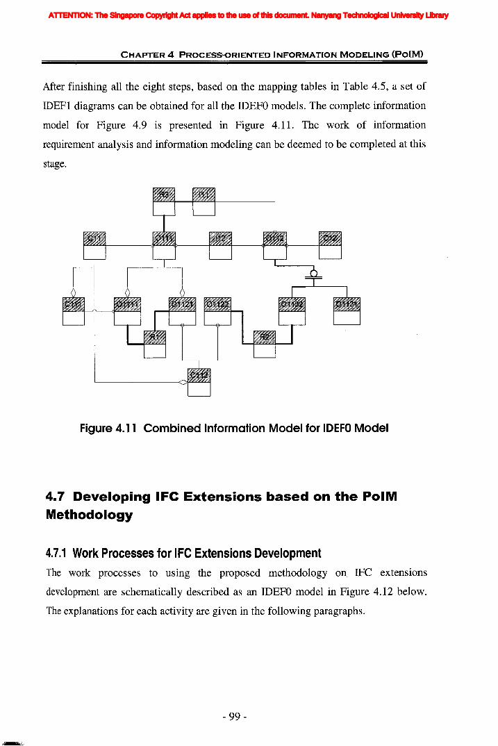
]
CHAPTER 4 PROCESS-ORIENTED INFORMATION MODELING (PoIM)
After finishing all the eight steps, based on the mapping tables in Table 4.5, a set of
IDEFI diagrams can be obtained for all the IDEFO models. The complete information
model for Figure 4.9 is presented in Figure 4.11. The work of information
requirement analysis and information modeling can be deemed to be completed at this
stage.
Figure 4.11 Combined Information Model for IDEFO Model
4.7 Developing IFe Extensions based on the PolMMethodology
4.7.1 Work Processes for IFC Extensions DevelopmentThe work processes to using the proposed methodology on IFC extensions
development are schematically described as an IDEFO model in Figure 4.12 below.
The explanations for each activity are given in the following paragraphs.
- 99-
ATTENTION: The Singapore Copyright Act applies to the use of this document. Nanyang Technological University Library
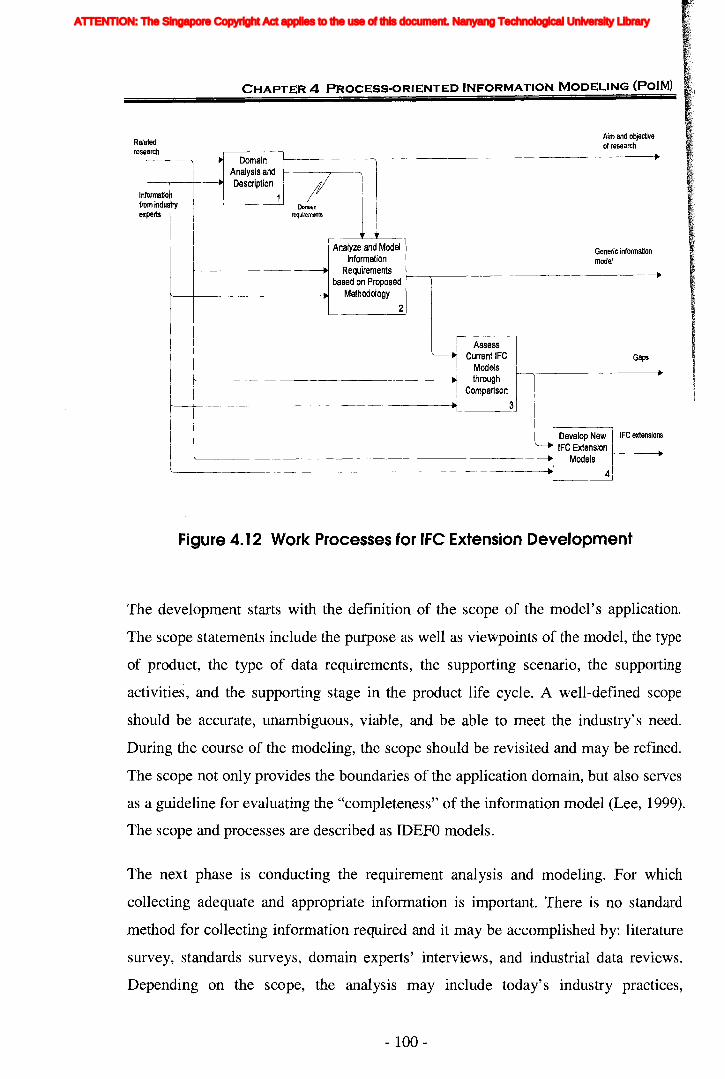
CHAPTER 4 PROCESS-ORIENTED INFORMATION MODELING (PalM)
Aim and objectiveof research
arc --.DomainAnalysis and
;I.. Descriptionformatio~ 1mindu~itrY Domainperts requirements
Analyze and Model Generic informationInformation model.. Requirements ..
based on Proposed.. Methodology
2
Assess~ Current IFC Gaps
Modelsthrough
Comparison.. 3
Develop New IFe extensions'------. IFC Extension
Models
'" 4
Infroex
Relatedrese h
Figure 4. 12 Work Processes for IFC Extension Development
The development starts with the definition of the scope of the model's application.
The scope statements include the purpose as well as viewpoints of the model, the type
of product, the type of data requirements, the supporting scenario, the supporting
activities, and the supporting stage in the product life cycle. A well-defined scope
should be accurate, unambiguous, viable, and be able to meet the industry's need.
During the course of the modeling, the scope should be revisited and may be refined.
The scope not only provides the boundaries of the application domain, but also serves
as a guideline for evaluating the "completeness" of the information model (Lee, 1999).
The scope and processes are described as IDEFO models.
The next phase is conducting the requirement analysis and modeling. For which
collecting adequate and appropriate information is important. There is no standard
method for collecting information required and it may be accomplished by: literature
survey, standards surveys, domain experts' interviews, and industrial data reviews.
Depending on the scope, the analysis may include today's industry practices,
- 100-
ATTENTION: The Singapore Copyright Act applies to the use of this document. Nanyang Technological University Library
CHAPTER 4 PROCESS-ORIENTED INFORMATION MODELING (POIM)
traditional practices, and near-future needs. The PolM methodology will be used to
develop the information models, to extract all the information requirements, and to
express them in an augmented IDEF1 model. The information model is intended to be
independent of any physical implementation and be sufficiently explicit to fully
describe the data needs of the application. It can be the basis to define a standard
product model.
After comparing the information model with the existing IFC models, the capabilities
of IFC product models to support domain of discourse at multiple levels of detail can
be assessed and the information gaps can be identified. Then a fully standard product
model for the domain will be proposed.
This methodology changes the traditional IFC extensions development processes
which would be explained in Section 4.7.2. It is proposed as a new approach for
information requirement analysis and to support the standard model development so
as to improve the effectiveness and efficiency of IFC extension development.
4.7.2 TraditionallFC Extensions DevelopmentDuring the long history of IFC development from the foundation year of IAI in 1995,
JAJ has formed a set of standards, conventions, rules and guidelines for IFC extension
development. Referring to IFC 2x Extension Modeling Guide (IAI, 2001) and the
major development steps highlighted by Liebich and Wix (1998b), the traditional
cycle of one IFC release would comprise the following nine steps:
1. Definition of user requirements;
2. Definition of domain processes;
3. Test by usage scenarios;
4. Specification of domain models;
5. Integration into current release of IFC;
6. Review of new release of IFC;
- 101 -
ATTENTION: The Singapore Copyright Act applies to the use of this document. Nanyang Technological University Library

CHAPTER 4 PROCESS-ORIENTED INFORMATION MODELING (POIM)
7. Final documentation;
8. Conformance class definition;
9. Implementation support.
In addition, IAI prefers a set of languages and modeling tools to support the IFC
extension development. Figure 4.13 shows the traditional processes of IFC extension
development as well as the corresponding language and modeling tools used in the
whole process.
DescriptionLanguage
Work with project members and others todefine information requirements
DL.---IDEFO_I c::=>
DEXPRESS-G
IFC ExtensionModels
Prepare process model.Capture detailed information requirements.
Prepare draft extension model.
Review process model, informationrequirements, and draft extension model.
Satisfactoryreview
Prepare extension model ducumentation
Further workrequired
Figure 4. 13 Traditional Processes of IFe Extension Development
(Adapted from IAI, 2001)
Traditionally, the developer will give the definition of domain processes through
process models which are the formal descriptions of the tasks. Based on these process
models, the object model scope is identified and the information requirements are
captured, analyzed and described by EXPRESS-G. The draft IFC extension model
expressed by EXPRESS is then developed. EXPRESS is a textual language to
- 102-
ATTENTION: The Singapore Copyright Act applies to the use of this document. Nanyang Technological University Library

CHAPTER 4 PROCESS-ORIENTED INFORMATION MODELING (PoIM)
formally specify the information requirements of a product data model and the
EXPRESS-G is a subset of EXPRESS (ISO 1993, Schenk et al. 1994). The
development of IFC extension models is an iterative process, as refinements are often
necessary. All the previous tasks require the active participation of many contributors.
The IFC 2x Extension Modeling Guide provides the modus operandi for the
collaboration. But it does not require the scope definition and requirements capture
which are necessary activities prior to model development.
-In recent years the research and implementation activities related to IFC models are
actively carried out in different research projects. Most of them emphasize on the
development of representations of buildings and the implementation environment for
such representations in the integrated system. Very few publications covered the
detailed methodology for developing IFC extensions, especially for information
requirement analysis. Little research has dealt with the modeling methodology and
their integration. For example, a new modeling approach, Process Matrix is proposed
by Wix and Liebich et al. in 2002. The approach is based on a modified application of
the Generic Process Protocol (GPP), coupled with a dedicated usage of the UML
technique. The essence of the approach is in recognising user requirements and use
cases (scenarios) in the context of the real building construction process, identifying
the actors and actor roles for each individual activity and at any level of detail, and
associating these activities with information and communication requirements. The
methodology builds upon a formalised specification based on the idea of a reference
process matrix which enables its consistent use in downstream ICT (Information and
Communication Technology) developments - starting with a general survey of end
user requirements to continuously refine these to the level of UML diagramming
where the actual software realisation can start. In that respect, this methodology can
be seen to support the feasibility and outline design phases of ICT development for
AEeO (Architecture, Engineering, Construction and Operation). In simple terms, it
can be seen as a multi-dimensional table that sets down a series of reference activies
and, for each activity, identifies the project participants (actors) sending and receiving
information. Its emphasis is placed on the process of sender to send and receiver to
receive the information. It gives a detailed illustration to this process, including the
- 103 -
ATTENTION: The Singapore Copyright Act applies to the use of this document. Nanyang Technological University Library
CHAPTER 4 PROCESS-ORIENTED INFORMATION MODELING (POIM)
actors, activities and the content of activities. But for the material content of
information, it does not give an intuitionistic display.
With the maturity of IFC, the subsequent model development will not be the "writing
on a blank paper" any more. If the traditional developing process is followed, it is
unavoidable to do some repeated work with the finished project. In this situation the
traditional developing process is not efficient and effective any more. Therefore in
order to avoid any duplicate work and to improve the effectiveness and efficiency of
model development, a new IFC extension development based on process-oriented
information modeling methodology is proposed in this research.
4.7.3 Flow for IFC Extension DevelopmentFigure 4.14 shows the integrated process and information modeling flow for the
model development of IFC extensions. The development starts with the definition of
the scope of the model's applicability. The scope specifies the domain of discourse
and the processes that are to be supported by the information model which are
expressed through IDEFO models. A second step of the requirement analysis and
modeling is conducted. On the basis of the information collected, the process-oriented
information modeling (PoIM) methodology is used to abstract the information
requirements and to express them in enhanced IDEFI models. By comparing the
modelled information with the latest IFC release, the usefulness of present IFC
models is assessed and the gaps between these two concepts can be identified. When
an information gap represents a general requirement for the domain, it is necessary for
an IFC extension to be developed. Otherwise, different ways could be used to solve
the issue of missing information. Therefore some objective rules are expected to guide
the extension development process. In fact, this information modeling process can be
the basis to define any standard product model, i.e. this methodology is not limited to
the use in IFC extension development.
- 104-
ATTENTION: The Singapore Copyright Act applies to the use of this document. Nanyang Technological University Library
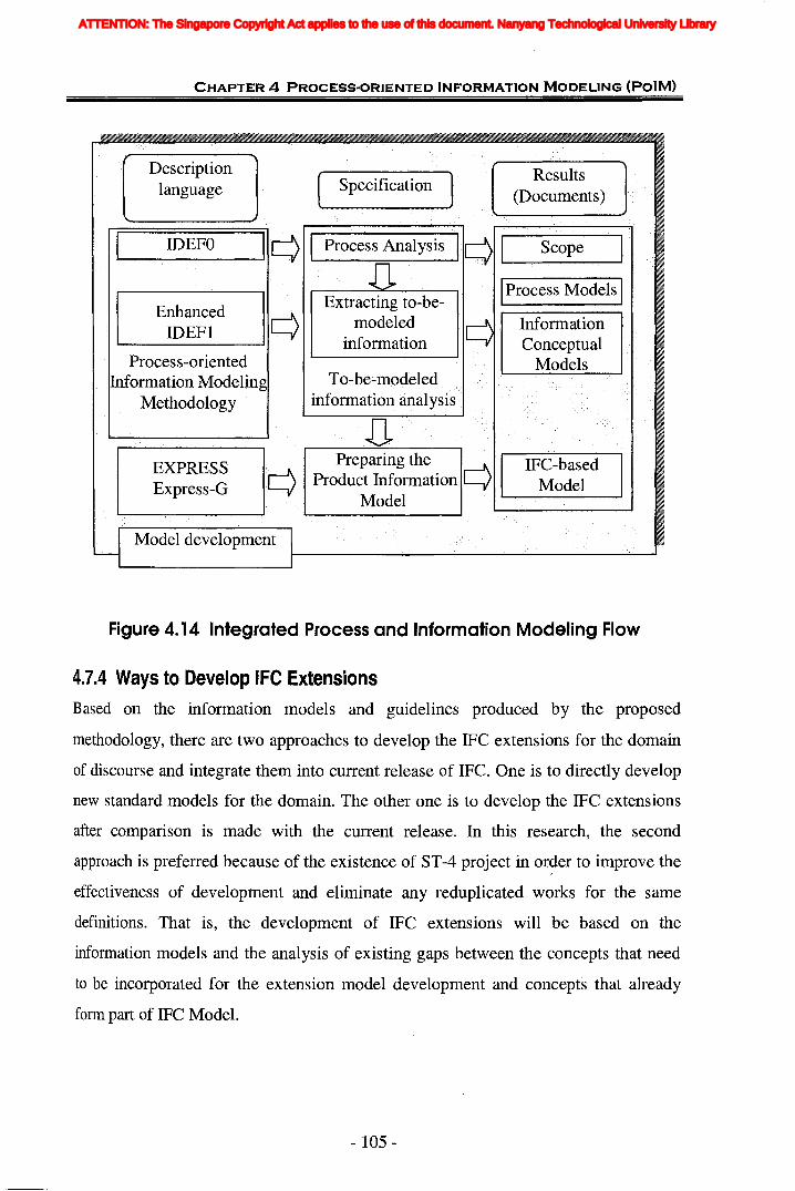
CHAPTER 4 PROCESS-ORIENTED INFORMATION MODELING (POIM)
Results(Documents)
IProcess Models I
InformationConceptual
Models
( specification]
To-be-modeledinformation analysis
q I Process Analysis IqlL.-......-..__S__c__o__p__e--...-~
Descriptionlanguage
I IDEFO I
EnhancedIDEFI
Process-orientedInformation·Modeling
Methodology
EXPRESSExpress-G q
Figure 4. 14 Integrated Process and .Information Modeling Flow
4.7.4 Ways to Develop IFC ExtensionsBased on the information models and guidelines produced by the proposed
methodology, there are two approaches to develop the IFC extensions for the domain
of discourse and integrate them into current release of IFC. One is to directly develop
new standard models for the domain. The other one is to develop the IFC extensions
after comparison is made with the current release. In this research, the second
approach is preferred because of the existence of ST-4 project in or~er to improve the
effectiveness of development and eliminate any reduplicated works for the same
definitions. That is, the development of IFC extensions will be based on the
information models and the analysis of existing gaps between the concepts that need
to be incorporated for the extension model development and concepts that already
form part of IFC Model.
- 105 -
ATTENTION: The Singapore Copyright Act applies to the use of this document. Nanyang Technological University Library
CHAPTER 4 PROCESS"ORIENTED INFORMATION MODELING (POIM)
According to IFC 2x Extension Modeling Guide (IAI, 2001), various approaches may
be adopted for different scenarios to extend the IFC Model and three scenarios may be
observed from gap analysis:
1. Concepts that exist in the IFC Model,
2. Concepts that extend the IFC Model, and
3. New Concepts.
Concepts existing in the IFC Model imply that the classes required by the extension
model development already exist in the IFC Model and the attributes of these classes
can fully capture the information requirements.
Additional information requirements determined by the extension can be captured by
additional property sets, or implementation agreements (locally or globally specified).
Concepts extending the IFC Model mean that the classes required by the extension
model development already exist within the IFC Model. But they need extension to
fully capture additional information requirements.
Extended information requirements determined by the extension can be captured by:
(1) new classes that are subtypes of existing classes or that are related to existing
classes, (2) additional property sets, or (3) implementation agreements (locally or
globally specified).
New concepts mean that the extension model development specifies information
requirements that are not captured by classes at the interoperability layer or domain
layer within the IFC Model. Therefore, new classes need to be specified that get
support from the fundamental ideas within the resource layer and the core layer. The
classes, relationships and attributes for new concepts need to be fully defined,
including the connection to the other parts of the IFC Model.
New concepts determined by the extension can be captured by new classes that are
subtypes of existing classes, or additional property sets.
- 106-
ATTENTION: The Singapore Copyright Act applies to the use of this document. Nanyang Technological University Library
CHAPTER 4 PROCESS-ORIENTED INFORMATION MODELING (POIM)
4.7.5 Basic Rules for IFC Extension DevelopmentFor different scenarios, different approaches are adopted to extend the IFC models,
such as additional new classes developed for new concepts. In some scenarios, more
than one kind of approaches can be adopted. Additional information requirements can
be captured by creating new classes, or adding additional attributes to existing classes
or additional property sets. The extension developer has to evaluate which approach is
most suitable. Adding new classes or additional attributes to existing classes means
change to the corresponding schema. It is open-and-shut for end user to understand
what information is required for this domain. But for current works on IFC
implementation, whether they have been developed or are under development, this
will address the problem to modify current program in order to comply with the new
schema. It will impact exchange of files previously generated. Therefore, difficulties
or additional iterative works are unavoidably induced for the on-going or finished
IFC-implementation activities. However if all missing information is bridged by the
way of defining additional property sets, there would not have any influence upon
current implementation projects. IFC Property Set provides the capability for dynamic
extension.
Therefore the basic rules for IFC extension model development are proposed.
Extension model developer should generally try to use the same attribute names and
definitions as already exist within the IFC Models to express the same or a similar
idea. Adding new classes are minimized to the best of one's abilities. This minimizes
conflict and confusion for organizations that will implement the extension model.
IFC Property Set provides the capability for dynamic extension. Referring to IFC 2x
Extension Modeling Guide (IAI, 2001), an IFC Property Set is a container that holds
collections (or sets) of properties. A property set is (normally) defined externally to
the IFC Model. In Section 10.2 of the Guide, the following circumstances are
presented as suggestions as to when it may be appropriate to consider using a data
driven property set rather than defining a class with attributes within the IFC Model.
• Where a class has a lot of properties that resolve to simple data types,
- 107 -
ATTENTION: The Singapore Copyright Act applies to the use of this document. Nanyang Technological University Library
CHAPTER 4 PROCESS-ORIENTED INFORMATION MODELING (PalM)
• Where attributes can be grouped in particular ways that express functional
data requirements (for instance, to express different data requirements at
various stages of the project lifecycle) and where the same property may need
to be repeated in several property sets,
• Where attributes or properties may be used in a particular view, discipline,
lifecycle phase or other subset purpose of the object description,
• Where attributes or properties can be used in regional extensions in addition to
the international IFC specifications.
4.8 Summary
In this chapter, process-oriented information modeling methodology is proposed as a
new approach to analyze information requirements and develop IFC extension models.
This methodology provides the principles to integrate process models with
information models. With this ·methodology, the information requirements can be
easily identified and analyzed through the corresponding process models. In addition,
a set of standard transformation procedures and mapping tables is designed to help the
modeller quickly identify elements, corresponding information, and relationships. The
development of the set of mapping tables has provided a clear picture of information.
Furthermore, the new process for IFC extensions development based on this
methodology is also proposed.
This methodology will be used to catch the information requirements as the basis for
model development and consequently for system development. In the following two
chapters, the general information flow and model of structural analysis and design
process from different perspectives are analyzed by this methodology. In this way, the
comprehensiveness of the IDEFO and IDEFI enhancement, as well as the
effectiveness and ease-to-use of the methodology is also demonstrated. From industry
user's viewpoint, this research aims at developing methods, IT-based tools and
reusable models for information analysis and planning. From an academic viewpoint
the research aims at making an original contribution to design and IT research in the
sub-domain of design information modeling.
- 108 -
ATTENTION: The Singapore Copyright Act applies to the use of this document. Nanyang Technological University Library

CHAPTER 5 INFORMATION MODELING FOR STRUCTURAL ANALYSIS
,'j [III [: !nIU
In the previous chapter, the process-oriented information modeling (PoIM)
methodology is proposed as a new modeling approach. This chapter shows the
application of this methodology in the structural analysis domain. The purpose is to
provide a generic framework for the structural design process in a higher level by (a)
definition of the scope of the model's applicability; (b) analysis of process models for
structural design; and (c) identifying the information requirements for structural
analysis and design. The information in this chapter was obtained mainly from the
literature survey and interviews. It represents a conceptual model for the flow of
design information which is not tied to any specific analysis process model. The
modeling is based on the classical books on structural engineering and design (Fraser
1981, Biggs 1986, Sriram1986, Maher et al 1988, Payne 1989, Addis 1990, Arbabi
- 109-
The IFC specifications are developed from the research projects undertaken by many
experts and researchers. The necessary standard of requirements can be achieved by:
(1) AEC/FM experts define the requirements; (2) technical experts formalize and
integrate the requirements into the specification; and (3) software vendors implement
the requirements (IAI, 1999). In this case, the assessment to IFC specifications is also
necessary to be concerned with both AECIFM experts and software vendors.
Therefore, in the following two chapters, the information requirements are modeled
from the perspective of AECIFM experts and software' vendors. The IFC
specifications are evaluated and subsequently new possible extensions are developed
and integrated into the specifications.
5.1 Introduction
ATTENTION: The Singapore Copyright Act applies to the use of this document. Nanyang Technological University Library

CHAPTER 5 INFORMATION MODELING FOR STRUCTURAL ANALYSIS
1991, Christiano and Au 1993, Kassimali 1993, West et al. 1993, Rajan 2001, Leet
and Dang 2004).
The chapter is organized as follows:
• Section 5.1 gives a brief description of the content and structure of the chapter.
• Section 5.2 gives an introduction to the building design process.
• Section 5.3 proposes the process models for structural analysis as the basis to
information model developing.
• Based on the process models constructed in section 5.3 and using the conversion
rules of the PolM method presented in Chapter 4, the generic information
requirements for structural analysis are modelled and developed in section 5.4.
The relationships between the information of architectural design and structural
design are also discussed in order to prove the necessity and feasibility of their
integration.
• The capability of current IFC Release 2x Edition 2 and its addendum to support
structural analysis is assessed by the comparisons in section 5.5.
• Section 5.6 concludes the chapter with a summary.
5.2 The Design Process
This section provides a broad description of the general building design process, with
emphasis on structural design. The design process is based on fundamental concepts,
and composed of a few fundamental strategies and operations.
5.2.1 Building Design Process
Building design is a complex multidisciplinary process. It involves not only structural
engineering, but also mechanical and electrical systems, architecture, aesthetics,
economics, and politics etc.
- 110-
ATTENTION: The Singapore Copyright Act applies to the use of this document. Nanyang Technological University Library

CHAPTER 5 INFORMATION MODELING FOR STRUCTURAL ANALYSIS
Design andtimeschedulcoordination
Structural design
Design documentationlans
Buildingmaintenance manual
Architectural design
NO.: 2
AS
OtherProduce Other technical
Technical designs
Design
Design Software
Do Building Design
Structuraldesigner
Figure 5. 1 Building Design Processes
Design Teams
Main designerProduce
Building BUilding servicesServices Design design
~------t---+---+--+-----t--t----+---I----~ A4 r----~--+-==.::,:;!!:.:.-----.
Client's ~~sign Design contracts ~~~I~~ng design Project plans
supervision ~=============+==;::=========l=======~~==================::::-J
- 111 -
a. Design Coordination
This is the stage during which client's brief and requirements are established. To
enable Clients to specify project functions and permissible costs, Architects,
The success of building design depends on its coordination with other construction
activities and building services. For example, structural frames have to be designed
and built in collaboration with the other disciplines and services. Plumbing lines and
heating, ventilating, and air-conditioning ducts pass through or below floor framing.
Electrical conduit is buried in concrete. Walls, doors, and windows are attached to the
concrete frame. Owners will insist that the structural frame accommodate other parts
of the building with ease.
The main processes involved are shown in Figure 5.1. The introduction to each
process is provided below. The shaded boxes in Figure 5.1 show the two processes
that are included in this research.
ATTENTION: The Singapore Copyright Act applies to the use of this document. Nanyang Technological University Library
CHAPTER 5 INFORMATION MODELING FOR STRUCTURAL ANALYSIS
Engineers, Quantity Surveyor, and other members of the design team assist and
interpret Client's wishes and provide cost estimates (Seren 2002, Merritt 2001).
b. Architectural Design
Architectural design is a process to plan a building in advance with help of models.
The functions of architectural design include carrying out feasibility studies on site,
user information and local conditions, in order to (1) establish facts about boundaries,
rights of way, rights of light, easements, etc., (2) make preliminary enquiries with
Local Authority, Local Planning Authority, etc., (3) obtain outline planning consent.
The architect does the overall planning of the building and incorporates the output of
consultants into the contract documents. Services include evaluation, design, drawing,
and specifications. The architect determines what internal and external spaces the
client needs, the sizes of these spaces, their relative locations, and their
interconnections. The results of this planning are shown in floor plans, which also
diagram the internal flow, or circulation, of people and supplies. Major
responsibilities of the architect are enhancement of the appearance inside and outside
of the building and keeping adverse environmental impact of the structure to a
minimum. The exterior of the building is shown in drawings, called elevations. The
location and orientation of the building is shown in a site plan. The architect also
prepares the specifications for the building. These describe in detail the materials and
equipment to be installed in the structure. In addition, the architect, usually with the
aid of an attorney engaged by the client, prepares the construction contract (Merritt,
2001).
c. Structural Engineering
The term structural engineering is very wide in scope and refers to the design of any
system the purpose of which is to resist and transmit forces. It cuts across the
traditional fields of engineering, such as civil, mechanical, and aeronautical
engineering (Biggs, 1986). Structural engineering is essentially a trial and error
procedure. Various experts divided the process of structural engineering to different
sub-processes, as shown in Table 5.1 (Fraser 1981, Sriram1986, Addis 1990, Arbabi
1991, Christiano and Au 1993, Kassimali 1993, West et al. 1993, Rajan 2001, Leet
- 112-
ATTENTION: The Singapore Copyright Act applies to the use of this document. Nanyang Technological University Library

CHAPTER 5 INFORMATION MODELING FOR STRUCTURAL ANALYSIS
and Dang 2004). From the table it can be concluded that typically the structural
engineering process consists of four interacting primary stages: conceptual design,
preliminary design, analysis, and detailed design (Fraser 1981, Maher et al. 1988,
Payne 1989).
Table 5. 1 Sub-processes of Structural Engineering
'" Sub-processes
'"FunctionsEstablishing Simple Modeling the structure Selection and
~functional calculation & and determine its proportioning of therequirements, tentative responses to external structural componentsselection configurations effects
Experts structure types
Fraser 1981 Conceptual Structural analysis Proportioning &design detailed design
Sriram 1986 Preliminary Analysis Detailed designdesign
Biggs 1986 Conceptual & Preliminary Rigorous analysis and Designpanning design design design
Addis 1990 Client's brief Scheme design Detailed Finaldesign design
Arbabi 1991 Planning & Conceptualization Analysis Design
Christiano 1993 Planning Analysis Designand AuWest et 1993 Conceptual Preliminary Selection of Structural Finalal. design design preliminary analysis design
designKassimali 1993 Planning Preliminary Estimation Structural Safety Revised
structural design of loads analysis etc. structuralcheck design
Rajan 2001 Need Preliminary Intermediat Final design (analysisstructural design e design & design changes)
Leet and 2004 Conceptual Preliminary Analysis of Redesign FinalDang design structural design preliminary of the design &
structural structures analysisdesign
A project begins with a specific need of client. The conceptual design usually
involves the recognition of functional requirements of the proposed structure and
clients' need, and consideration of the possible types of structures that may be feasible
and the types of materials to be used (Fraser 1981, Biggs 1986, Kassimali 1993, West
et al. 1993).
- 113 -
ATTENTION: The Singapore Copyright Act applies to the use of this document. Nanyang Technological University Library
CHAPTER 5 INFORMATION MODELING FOR STRUCTURAL ANALYSIS
In the preliminary structural design stage, the engineer conceives the various
structural systems that might be appropriate, and selects or synthesizes a feasible
structural configuration that provides the intended structural function, sizes their main
components (Leet and Dang 2004, Sriram 1986, West et al. 1993).
The third stage of structural engineering, analysis, involves the transformation of the
feasible structural scheme into a mathematical model to estimate the forces and
external effects acting on the components of the structure (Maher et aI, 1988). It is this
area, the structural analysis of the system, which is examined in detail in latter
research.
The fourth and last stage, detailed design, involves the proportioning of components
or members of the structural system, such that all applicable constraints are satisfied
(Christiano and Au, 1993).
d. Building Services Design
Building services design includes mechanical and electrical design, as well as the
design on heating, ventilation, and air conditioning (HVAC).
e. Other Technical Design
This refers to any other designs needed, such as the design of external fa9ade.
Figure 5.2 shows the top level processes of building design which set the direction to
do further decomposition and analysis. The model in Figure 5.2 provides a basic
structure on which a particular system, together with its applications, could be built as
a layered architecture. This model should facilitate the endeavor towards integration
of the structural design process and systemization of the structural design information.
The main focus of this research lies on the process of structural analysis and design.
As shown in Figure 5.2, only the activities in shaded boxes have been analyzed in the
research.
- 114-
ATTENTION: The Singapore Copyright Act applies to the use of this document. Nanyang Technological University Library

~B
uild
ing
Des
ign
A-O
o :t » ~ rrt ~ (J'I Z ." o ~ ~ ~ (5 Z ~ o C rrt r- Z Gl ." o ~ (1)
..; ~ C o ..; c ~ r- » z » ~ iii
Pre
pare
Bui
ldin
gH
ando
ver
task
s(S
truc
tura
l)A
36
Do
Dra
ftin
gan
dA
ppro
veD
esig
nA
35
Pro
duce
Oth
erT
echn
ical
Des
ign
AS
Pro
duce
Bui
ldin
gS
ervi
ces
Des
ign
A4
Pro
duce
Det
aile
dS
truc
tura
lDes
ign
A34
Pro
duce
Str
uctu
ral
Eng
inee
ring
A3
Figu
re5.
2ID
EFO
No
de
Tree
ofB
uild
ing
Des
ign
Pro
cess
Pro
duce
Arc
hite
ctur
alD
esig
nA
2
Pro
duce
Pre
lim
inm
yS
truc
tura
lDes
ign
A32
Do
Des
ign
coor
dina
tion
Al
Pro
duce
Con
cept
ual
Des
ign
A31
~
1
IId
enti
fy~Ofl
II
Sel
ect
IIPro
duce
prel
imin
aIy
~V
anou
sS
truc
tura
lU
l.R
equi
rem
ents
Str
uctu
ral
Sys
tem
Str
uctu
ralA
naly
sis
A31
1S
yste
ms
A31
2A
321
A32
2
Def
ine
the
~fueS_1
IE_
Typ
eso
fo
fStr
uctu
ral
Qua
ntit
ies
and
Mat
eria
lsM
embe
rsC
osts
A31
3A
323
A32
4
ATTENTION: The Singapore Copyright Act applies to the use of this document. Nanyang Technological University Library

CHAPTER 5 INFORMATION MODELING FOR STRUCTURAL ANALYSIS I:
5.2.2 Structural Engineering ProcessStructural engineering is the science and art of planning, designing, and constructing
safe and economical structures that will serve their intended purposes (Kassimali,
1993). Figure 5.3 represents the process model of structural engineering. Six activities
are involved in the whole process of structural engineering. Among them, the most
important sub processes are the first four steps: conceptual design, preliminary design
(scheme design), structural analysis and detailed design.
••
Structuralscheme designs
Clientrequirements
Type of structureand material
Design plansDesign and timeschedulcoordination
Building designcodes r-+----------c-------j--+-----..;---j--l-----..---f--+----~,--+-----------
ArChitectur~designs
~'*------+--+---+------+-4-------.
Othelrtec1iillci~rgn
Building servicesdesign Structural
Engineer
Design Software
StructuralEngineer
Third-party(StructuralEngineer)
() ()
Drafter
Structuralresponse model
Structural detaileddesign
Structural designdocumentations &
Approval for design
StructuralHandover
support
Maintenanceguidelines for
structures
Design TeamsStructuralEngineer
NODE:A3 TITLE: Produce Structural Engineering NO.: 3 .....
Figure 5.3 Process Model for Structural Engineering
a. Conceptual Design
During the conceptual planning stage, the specific needs are identified and the
objectives are carefully articulated to meet these needs. These objectives must be
consistent with the desires of the client and the interests of other involved parties
(West et aI., 1993). This stage requires input from the client, architects, the engineer,
- 116 -
ATTENTION: The Singapore Copyright Act applies to the use of this document. Nanyang Technological University Library

CHAPTER 5 INFORMATION MODELING FOR STRUCTURAL ANALYSIS
planners, the public (in the case of government project and represented by elected
officials, governmental regulatory agencies or civic organizations). The conceptual
design requires the recognition of the constraints and parameters relevant to the
project, and the devising of a type of structure to comply with the demands of the
constraints (Fraser, 1981). The conceptual stage should bring forth a plan that
maximizes the satisfaction of the stated objectives while minimizing any
objectionable features of the project.
b. Preliminary Structural Design (Scheme Design)
The plan that emerges from the conceptual stage frequently includes several
alternatives that are to be investigated through the preparation of individual
preliminary design. In this step, the framing scheme, /~e general layout and
dimensions of the key elements of the structure such as column are established. The
selection of a suitable structural form for a given situation is one of the most
important steps in structural analysis. The form that a structure is to take is dependent
on many considerations, such as the functional requirements, aesthetic requirements,
etc. The development of structural forms is also influenced by the properties of new
materials (Christiano and Au, 1993). For a reinforced concrete frame preliminary
design is the selection and delineation of a framing scheme and member outlines. The
purpose of a preliminary design is to allow the final design to proceed in an orderly
manner, especially when it is performed by several individuals and when the
structural frame affects the work of other team members (Fling, 1987).
This stage is regarded as the most creative stage in structural design (Harty and
Danaher, 1994). Here, rules of thumb and experience are the basis of decision. And
comparing with subsequent stages, this stage has greater effect on the quality of a
structure. This is because generally the activities of latter stages are based on the
constraints imposed by the preliminary design and aim to satisfy them.
c. Structural Analysis
"Structural analysis is the process by which the structural engineer determines the
response of a structure to specified loads or actions. This response is usually measured
by establishing the forces and deformations throughout the structure. A given method
- 117 -
ATTENTION: The Singapore Copyright Act applies to the use of this document. Nanyang Technological University Library
CHAPTER 5 INFORMATION MODELING FOR STRUCTURAL ANALYSIS
of structural analysis is commonly expressed as a mathematical algorithm." (West et
aI., 1993)
Structural analysis is an integral part of any structural engineering project, its function
being the prediction of the performance of the proposed structure (Kassimali, 1993).
The primary objective of structural analysis is to determine the response of a structure
in order to satisfy essential requirements of function, safety, economy and sometimes
aesthetics. The responses include the reactions, internal forces of members and
displacements of the structures. This stage involves the transformation of the feasible
structural scheme into a mathematical model to estimate the forces and external
effects acting on the components of the structure (Maher et aI., 1988). Section 5.3
describes the procedures and information requirements in structural analysis phase.
The analysis process can be a part of preliminary design, final design, or construction,
as was described in the preceding section.
d. Detailed Design
The detailed design stage involves determining the sizes of the individual members
belonging to a structure in order to ensure a safe, serviceable, and economical design.
It also involves the proportioning of components such that all applicable constraints
are satisfied.
It should be observed that design is almost inseparable from analysis. The exact sizes
of structural members can be determined only after a complete analysis of the
structure. On the other hand, there are certain items in analysis that depend on the
results of design. Hence, the procedure of analysis and design may involve cycles of
successive corrections.
e. Draft, Checking and Documentation
After structural analysis and design are completed, it is necessary to transfer the
concept and details of the engineer to the contractor who will actually build the
structure. Without the proper execution of contract documents, a structural design is
useless or dangerous if the builder misinterprets the intention of the engineer.
Preparation of clear documents is an essential part of the design.
- 118 -
ATTENTION: The Singapore Copyright Act applies to the use of this document. Nanyang Technological University Library

CHAPTER 5 INFORMATION MODELING FOR STRUCTURAL ANALYSIS
The results of detailed design are capsulated in a set of complete design drawings,
which gives a graphic portrayal of the details of the entire system. These are generally
accompanied by written specifications that stipulate the materials to be used, the
quality of workmanship, the pertinent codes to be employed, and many other items.
5.3 Proposed Generic Process Model for StructuralAnalysis
5.3.1 Basis of Structural AnalysisTaking the objective of structural design as a starting point, a generic structural
analysis process model is developed. The model is described below, at different levels
of detail, with IDEFO notation.
Structural analysis is the process of modeling the selected structural configuration and
determining its response to external effects. Analysis may be viewed as the
satisfaction of the functional constraints of equilibrium, compatibility and material
stress-strain relationships. It includes the analysis of the loading conditions and the
structural response to those conditions. This response is usually measured by
establishing the forces and deformations throughout the structure.
For different types of structures, such as planar structures and non-planar structure, as
well as planar truss and truss-type space framework, various criteria for statical
classification of the structure are applied. Based on the statical classification,
including both external classification and internal classification, different analysis
method is used and different response is obtained. Differen!simplification methods
and equations of equilibrium are used. Generally, structural response includes the
reactions at the support points, the member forces (internal forces) in trusses, and the
member forces (shear forces and bending moments) in beams and frames (West et aI.,
1993). For serviceability requirements, elastic deflections of structures are needed by
the computation of deformation quantities. To carry out the analysis, different
methods are used, such as complementary virtual work method for the truss
deflections, integration method, moment-area method, elastic load method, the
- 119-
ATTENTION: The Singapore Copyright Act applies to the use of this document. Nanyang Technological University Library
CHAPTER 5 INFORMATION MODELING FOR STRUCTURAL ANALYSIS
conjugate beam method, energy method for the beam and frame deflections. For a
static determinate and stable structure, equations of static equilibrium are used to
calculate reactions.
For structures as a whole, there is an important distinction between statically
determinate and indeterminate systems. For statically determinate cases, the forces
can be determined by considering static equilibrium alone, and the deformations are
then determined as a function of these forces. Each member deforms according to its
own force-deformation relationships, and the overall deformation of the structure will
result from the accumulation of the individual member effects. However, for statically
indeterminate situations, the determination of forces and deformations must be
coupled since they are mutually dependent through the combined requirements of
static equilibrium and compatibility. It requires systematic synthesis of the member
force-deformation relationships. In either statically determinate or indeterminate
structures, the member force-deformation relationships must be known.
The classical methods mentioned above provide exact answers, but only for simple
structural models. Presently, a more general approach to structural analysis, matrix
methods, is developed. It can handle structures of any size and complexity, but are
approximations. Matrix methods model a structure as an assembly of small elements
with varying forms of connection between elements. The first matrix methods were/
frame analyses with individual beams and columns used as elements. More advanced
matric methods, usually referred to as "finite element analysis" break an entire
structure into small elements and can be used on structures (such as a pressure vessel)
with no inherent divisions. Commercial computer software for frame analysis
typically uses matrix methods.
However, irrespective of what type of structures and what analysis method is used, the
procedure of structural analysis should consist of the following three steps: modeling
structural systems (idealization), loading assessment, and performing structural
analysis, which is illustrated in Figure 5.4.
- 120-
ATTENTION: The Singapore Copyright Act applies to the use of this document. Nanyang Technological University Library

Structuralresponse models
0.: 5
Structural AnalysisSoftware
Structuralanalysis models
Do Structural Analysis
StructuralEngineer
Material properties&
member size
- 121 -
Figure 5.4 Process Model for Structural Analysis
Structuralscheme design
Buildingdesign codes
CHAPTER 5 INFORMATION MODELING FOR STRUCTURAL ANALYSIS
The aim of this chapter is to develop a generic model for the process of structural
analysis. Considering the differences and complexity in different analytical methods,
the process models will be decomposed only to a high level in order to show the basic
analytical procedure which is applicable for any type or geometry of structural system------------------
designed with its own type of member. The modeling is primarily concerned with the
inputs and final results of structural analysis, but not any intermediate output
generated during the process using different method. In addition currently most
modem methods of analysis require the use of computer for their practical application
and most engineers usually use structural analysis and design software to reduce their
hand calculations and improve the accuracy of calculations. The detailed requirements
for the process of running structural analysis are much more from software's points of
view, vis-a-vis hand calculation. Therefore, the emphasis of this chapter is not to
discuss the information needed for structural analysis in great detail but rather to
model the process of structural analysis in a generic level, and to assess the capability
of IFC definitions to support structural analysis from professionals' knowledge in the
notional level. The assessment at the detailed level is carried out in Chapter 6 from
software's viewpoint.
ATTENTION: The Singapore Copyright Act applies to the use of this document. Nanyang Technological University Library
CHAPTER 5 INFORMATION MODELING FOR STRUCTURAL ANALYSIS
As mentioned before and shown in Figure 5.4, the process of structural analysis
consists of three sub processes: idealization, loading application, and performing
structural analysis. First is the process of structural idealization, which means to
transform the structural configuration from a real structure to an analytical model.
Then it requires the representation of the real structure and the loading as well as other
conditions to which it is subjected by one or more simplified analytical models, which
is then analyzed. These three parts are further described below.
5.3.2 Structural Idealization
For purposes of analysis it is usually appropriate and necessary to simplify or idealize
the actual structure. An analytical lllodel is illustrated by a line diagram which is a
simplified representation, or an ideal, of a real structure that allow us to calculate
forces, stresses, displacements, and strains due to given arrangements of loads or
imposed deformations. The objective of the model is to simplify the analysis of a
complicated structure. The analytical model represents, as accurately as practically
possible, the behavioral characteristics of the structure of interest to the analyst, while
discarding much of the detail about the members, connections, and so on, that is
expected to have little effect on the desired characteristics (Biggs 1986, Kassimali
1993).
The idealization process is necessary because the human mind, the analytical
capabilities of the computer, and the time which can be devoted to the solution of any
one problem are all finite, in contrast to the infinite complexity of th.eobject to be
analyzed.
Establishment of the analytical model is one of the most important steps of the
analysis process~ it requires experience and knowledge of design practices in addition
to a thorough understanding of the behavior of structures. In structural engineering,
the choice of model has important consequences for many aspects of the analytical
process. In particular, the choice of model often has a controlling effect on the choice
of the method of analysis to be used (Gauvreau, 2003). And the structural response
predicted from the analysis of the model is valid only to the extent that the model
- 122-
ATTENTION: The Singapore Copyright Act applies to the use of this document. Nanyang Technological University Library
CHAPTER 5 INFORMATION MODELING FOR STRUCTURAL ANALYSIS
represents the actual structure. Thus the importance of proper modeling is evident. It
is the responsibility of the analyst to make sure that the model adequately reflects the
true structural behaviour.
Process Model for Idealization
Structural analytical models generally can be considered as an assembly of
components with the purpose of transmitting external loads to the surrounding
environment or foundation (Gauvreau, 2003). The makeup of a structural system is
rife with details at least concerning three fundamental distinct components-members,
connections, and supports. The nature or characteristics of the members, connections,
and supports dictate how effectively the system will support the applied loads.
Therefore the structural idealization involves four processes as shown in Figure 5.5.
First the overall information of the structure should be identified. A set of consistent
units must be selected and general information about structure such as the material
properties should be given. Then the nature and characteristics of members (also often
referred as elements in the technical literature), connections (also often referred to as
nodes) and supports should be defined.
- 123 -
ATTENTION: The Singapore Copyright Act applies to the use of this document. Nanyang Technological University Library

CHAPTER 5 INFORMATION MODELING FOR STRUCTURAL ANALYSIS
Building design
codes 11-- ---.-- ---,- -----,
Structural _I Ischeme design Define OverallInformation Ii-------/----r-----------
"I A3311
Materialinformation
I IStructural memberDefine Structure ...
t'------+-----~ Members rl.--~----l----------+--------.
~I A3312
Structural cormection~ Define
Structuralt--------+--------+----~... Connections
A3313
,. BoWldary conditions
-' Define supports'r'"-------l---------+-------+----~-I A3314
Structural engineer
INODE: A331 ITITLE: Do Idealization
Figure 5.5 Process Model for Idealization
WO.: 6
(i) Structural Members
The primary load-bearing components of a structural system are the members. The
typical structural members to be considered include beam members which are
subjected to bending moments or flexure, truss members which are subjected to axial
force only and columns which are subjected to both bending moments and axial forces
(McCormae et al. 1988, Kassimali 1993).
(ii) Connections
Connections or joints are used to tie different structural members together. There are
several types of connections, such as the more common ones: rigid connection,
flexible, or internal hinged connection. The types of connectors that are commonly
used in making joints can be characterized as either point connectors, line connectors,
or surface connectors.
- 124-
ATTENTION: The Singapore Copyright Act applies to the use of this document. Nanyang Technological University Library

CHAPTER S INFORMATION MODELING FOR STRUCTURAL ANALYSIS
(iii) Supports (Boundary conditions)
The applied loads on a structure are finally transmitted to the supports through the
members and connections. The types of supports include rocker, roller, pin, fixed. In
structural analysis applications, the defining process is very similar with the definition
of connection. The natures of simplified supports are also very similar with natures of
simplified connections. The details concerning how a structure connects to its
supports are enumerated by boundary conditions. Some boundary conditions are
related to constraints that the supports provide on movement and are referred to as
displacement boundary conditions. Other boundary conditions express conditions
relative to the forces that can be developed at a support point. These are referred to as
force boundary conditions (West et aI., 1993).
5.3.3 Applying LoadsEstablishment of the loads that act on a structure is one of the most difficult and yet
important steps in the overall process of design. The computer has made it possible to
analyse structure that could not be analysed a mere decade ago, but the accuracy of
the results of the analysis is directly dependent on the accuracy of the loads used.
The main objective of applying loads is to identify how many and what type of loads
are acting on the structure and to define the manner in which the imposed loads filter
through the structure. The loads on structures may be classified in different ways. For
example, the loads can be of the following three different types (West et aI., 1993).
Concentrated loads are those that are applied over a relatively small area. Line loads
are distributed along a narrow strip of the structure. Surface loads are loads that are
distributed over an area. The loads on a warehouse floor and the snow load on a roof
are examples of surface loads. If divided by the source of action, the loads can be
grouped according to three categories: dead loads, live loads, and environmental
loads (Arbabi 1991, Christiano and Au 1993). Dead loads are those that act on the
structure as a result of the weight of the structure itself and of the component of the
system that are permanent fixtures. Live loads include only loads that produced
through the construction, use of occupancy of the structure and not to include
- 125 -
ATTENTION: The Singapore Copyright Act applies to the use of this document. Nanyang Technological University Library

CHAPTER 5 INFORMATION MODELING FOR STRUCTURAL ANALYSIS
environmental or dead loads. These loads are dynamic in character in that they are
fixed in neither magnitude nor position. Environmental loads are numerous loading
conditions that a structure experiences as a result of the environment in which it exists.
These categories can be further divided according to the specific nature of the loading,
such as snow and ice load, rain loads, wind load, earthquake loads, earth or water
pressures and temperature loads are all included in environmental loads. In addition,
loads can be classified as (a) those caused by gravity and (b) lateral loads. Dead, live
and snow loads are examples of gravity-induced loads whereas wind and earthquake
loads are lateralloads.
Process Model for Applying Loads
How to model the loading conditions in the structural analytical model is one of the
most important parts of structural analysis. It also constructs the main task of this
stage. The procedure of applying loads includes the following steps: estimation of
loads, assigning loads, grouping loads and determination of load combinations (see
Figure 5.6).
Building designcores
Structuralscheme design J 1 r Basic load
] Estimate Loads
-~-+--~~ A3321StructuralAnalytical
model
~ 1 Load assignmentI'------+-------I----!-~J Assign Loads 1r------r-----+---------lI>
'1 A3322
Load groupspecification
I1 Group Loads
I'-----+-------+----~ ...I A3323
Load combinationl J Define Load I
'-----+------+---------1-----,-..1 Combinations ll----~~'I A3324
Structural engineer
NODE: A332 TITLE: Apply Loads 0.: 9
Figure 5.6 Process Model for Applying Loads
- 126-
ATTENTION: The Singapore Copyright Act applies to the use of this document. Nanyang Technological University Library
CHAPTER 5 INFORMATION MODELING FOR STRUCTURAL ANALYSIS
Perhaps the most important and most difficult task faced by the structural designer is
the accurate estimation of the loads that may be applied to a structure during its life.
After loads are estimated the next problem is to assign these loads to appropriate
structural members and connections. Next, group different loads based on the source
of action in order to determine the worst possible combination of the loading
condition that might occur at anyone time. The last question which is of critical
importance in determining design loads is whether or not all of these loadings act on
the structure simultaneously. Dead loads by definition always act on a structure. The
variability is in the live load or combination of live loads. The final design of a
structure must be consistent with the most critical combination of loads that the
structure is to support. However, some judgment is necessary in selecting loading
conditions that can reasonably be combined. Obviously, the maximum effects of all
loading conditions should not be combined because it is unlikely that they will all
occur simultaneously. In fact, certain combinations are highly unlikely: full snow load
is not likely to occur with full wind load; likewise,·an earthquake is unlikely to occur
at the instant that the structure is subjected to full wind load. In recognition of this, the
load combinations that must be considered are normally specified by the governing
codes (BS, ACI, etc.); in some cases, designers must exercise their judgment, many
codes or regulations allow specific reductions in design loadings when certain load
combinations are present.
5.3.4 Performing Structural AnalysisIn structural analysis, the values of the loads are used to carry out an analysis of the
structure in order to determine the stresses or stress resultants in the members and the
deflections at various points of the structure.
The objective is to compute the maximum moment, shear, torsion, and axialload at
each critical section. Normally, only moment and shear are computed for flexural
members because small axial load does not affect the design. Likewise, only axial
load and moment are normally computed for columns (and frequently only axial load)
because small moment and shear do not affect the design.
- 127 -
ATTENTION: The Singapore Copyright Act applies to the use of this document. Nanyang Technological University Library

Supp.ort Support
......---'--__r~ea~:n displacement
Calculate ~\ d
External ~Reactions ~
A3332
CHAPTER 5 INFORMATION MODELING FOR STRUCTURAL ANALYSIS
Structural response contains: (1) the displacements at the nodes; (2) the element nodal
forces, the min-max internal forces in every member etc., including shear, moment,
rotation; and (3) support reactions. Deformed shape, shear force, and bending moment
diagrams can be displayed (Holzer, 1985).
Process Model for Performing Structural Analysis
Figure 5.7 describes the processes involved in performing structural analysis. Actually,
when structural analysis software is used to compute these responses, it seems they
are produced simultaneously to user and there is no strict sequence about their
generation. So the current process model shown is in accordance with traditional
computing order. Of course the most important information concerned is the results of
the analysis, rather than the sequence of generation.
Structuralanalysis model J Select Method l
I of Analysis ll--""",~------------------
A3331 Analysis~ method
Internal force
Calculate ~Internal Forces
-.. & Deformations TA3333
Internaldeformation
CompileStructuralResponse
Model
A3334
Structuralresponse
model
NODE: A33-3 ITITLE:
Structural engineer I Structural analysissoftware
Perform Structural Analysis INO.: 12
Figure 5.7 Process Model for Performing Structural Analysis
- 128-
ATTENTION: The Singapore Copyright Act applies to the use of this document. Nanyang Technological University Library
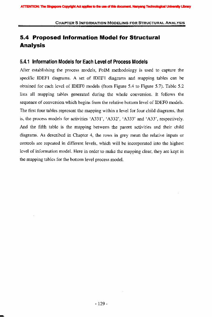
CHAPTER 5 INFORMATION MODELING FOR STRUCTURAL ANALYSIS
5.4 Proposed Information Model for StructuralAnalysis
5.4.1 Information Models for Each Level of Process ModelsAfter establishing the process models, PolM methodology is used to capture the
specific IDEFI diagrams. A set of IDEFI diagrams and mapping tables can be
obtained for each level of IDEFO models (from Figure 5.4 to Figure 5.7). Table 5.2
lists all mapping tables generated during the whole conversion. It follows the
sequence of conversion which begins from the relative bottom level of IDEFO models.
The first four tables represent the mapping within a level for four child diagrams, that
is, the process models for activities 'A331', 'A332', 'A333' and 'A33', respectively.
And the fifth table is the mapping between the parent activities and their child
diagrams. As described in Chapter 4, the rows in grey mean the relative inputs or
controls are repeated in different levels, which will be incorporated into the highest
level of information model. Here in order to make the mapping clear, they are kept in
the mapping tables for the bottom level process model.
- 129-
ATTENTION: The Singapore Copyright Act applies to the use of this document. Nanyang Technological University Library

Tab
le5.
2M
ap
pin
gT
able
of
IDEF
Oa
nd
IDEF
l
(a)
A33
1D
oId
ealiz
atio
n
A33
12D
efin
eIS
truc
tura
lmem
ber
IEnt
ity
stru
ctur
em
embe
rs
Def
me
IB
ound
ary
cond
itio
ns
~ w o
IDE
FOA
ctiv
ity
A33
11D
efin
eov
eral
lin
form
atio
n
A33
13D
efin
est
ruct
ural
conn
ecti
ons
A33
14su
ppor
ts
IDE
FOO
utp
ut
Mat
eria
lin
form
atio
n
Str
uctu
ral
conn
ecti
on
Cor
resp
ond
ing
IDE
Ft
Ele
men
t
Ent
ity
Ent
ity
Ent
ity
Rel
ativ
eIn
pu
t&
Con
trol
o ~ ~ lTI~ en Z "T
l o ;tJ ~ ~ o z ~ o o fit i' Z Gl "Tl o ;tJ ~ ;tJ C o -I C ~ i' » Z > !< en iii
ATTENTION: The Singapore Copyright Act applies to the use of this document. Nanyang Technological University Library
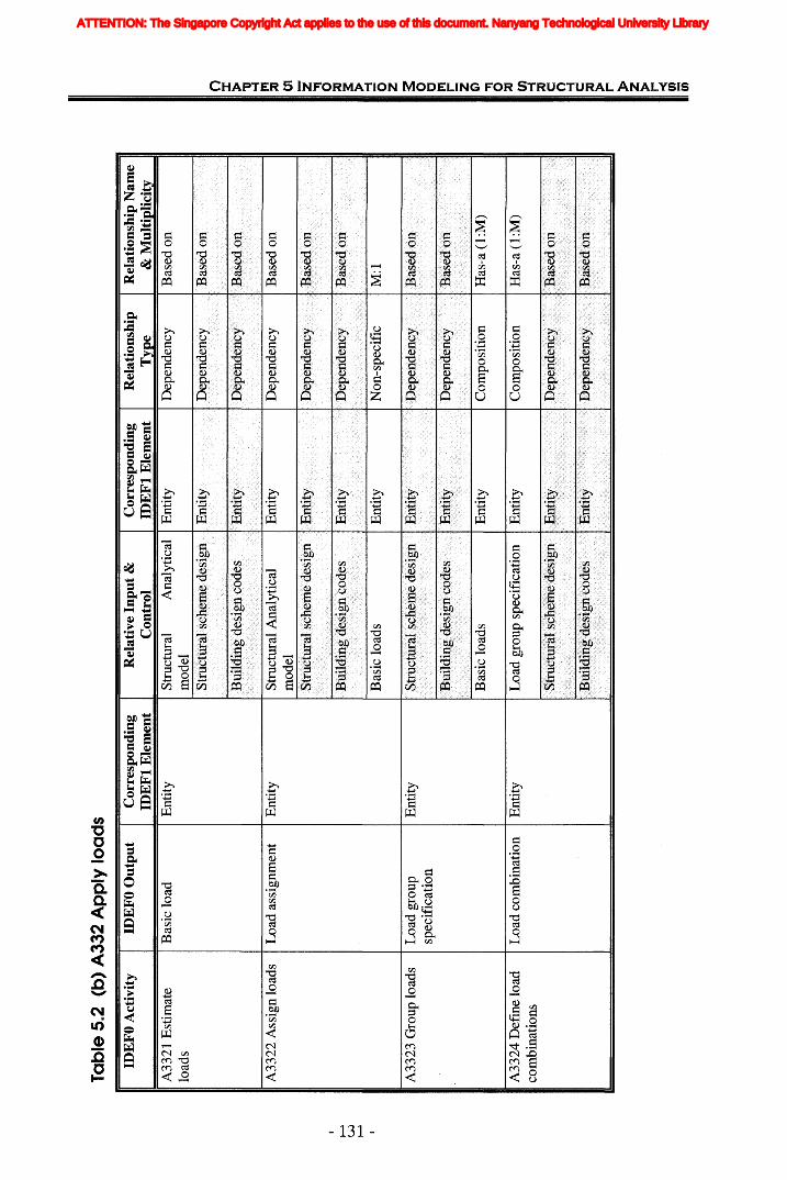
EdJ
£isit,
,£!
£Ii2
2L2J
22
21L
22t11
112
1111
111'
IfIT
'T
un.u
nlil
nnIf
'..
milT
nil
jIII
I.,C
00H
00
Tab
le5.
2(b
)A
332
Ap
ply
load
s
IDE
FOA
ctiv
ity
IDE
FOO
utp
ut
Cor
resp
ondi
ngID
EF
IE
lem
ent
Rel
ativ
eIn
pu
t&
Con
trol
Cor
resp
ondi
ngID
EF
IE
lem
ent
Rel
atio
nshi
pT
ype
Rel
atio
nshi
pN
ame
&M
ulti
plic
ity
A33
21E
stim
ate
load
sB
asic
load
Ent
ity
Str
uctu
ral
Ana
lyti
cal
mod
elE
ntit
yD
epen
denc
yB
ased
on
o :t » :!t ITI ::0 U1 Z "'11 o ::0 ~ ~ o z ~ o C ITI r- Z (i) "'11 o ::0 en -I ::0 C n -I C ~ r- » z » ~ (I) iii
Bas
ed01
1
Bas
edon
Has
-a(l
:M)
M:l
Bas
edon
Has
-a(l
:M)
Bas
edo
n
...
Non
-spe
cifi
c
Dep
ende
ncy
Com
posi
tion
Dep
ende
ncy
Dep
ende
ncy
Depend~ncv
Com
posi
tion
n
-J
Ent
ity
Ent
ity
....
..-.
.t Ent
ity
Ent
ity
Ent
ity
Pn
+':
h:'
.........u
Ul)
'·h
pn
1ptlp~lan
:r-t
:Str
uctl
lral
sche
me
desi
gn
Bas
iclo
ads
Bas
iclo
ads
Str
uctu
ralA
naly
tica
lm
odel
Loa
dgr
oup
spec
ific
atio
nIE
ntit
y
Bui
ldin
g.de
sign
code
s
Bui
ldin
gde
sign
code
s
Str
uctu
rals
chel
lle
desi
gn
Ent
ity
Ent
ity
Ent
ity
Loa
das
sign
men
t
Loa
dco
mbi
nati
on
Loa
dgr
oup
spec
ific
atio
n
A3
322
Ass
ign
load
s
A33
24D
efin
elo
adco
mbi
nati
ons
A33
23G
roup
load
s
~ w ~
ATTENTION: The Singapore Copyright Act applies to the use of this document. Nanyang Technological University Library
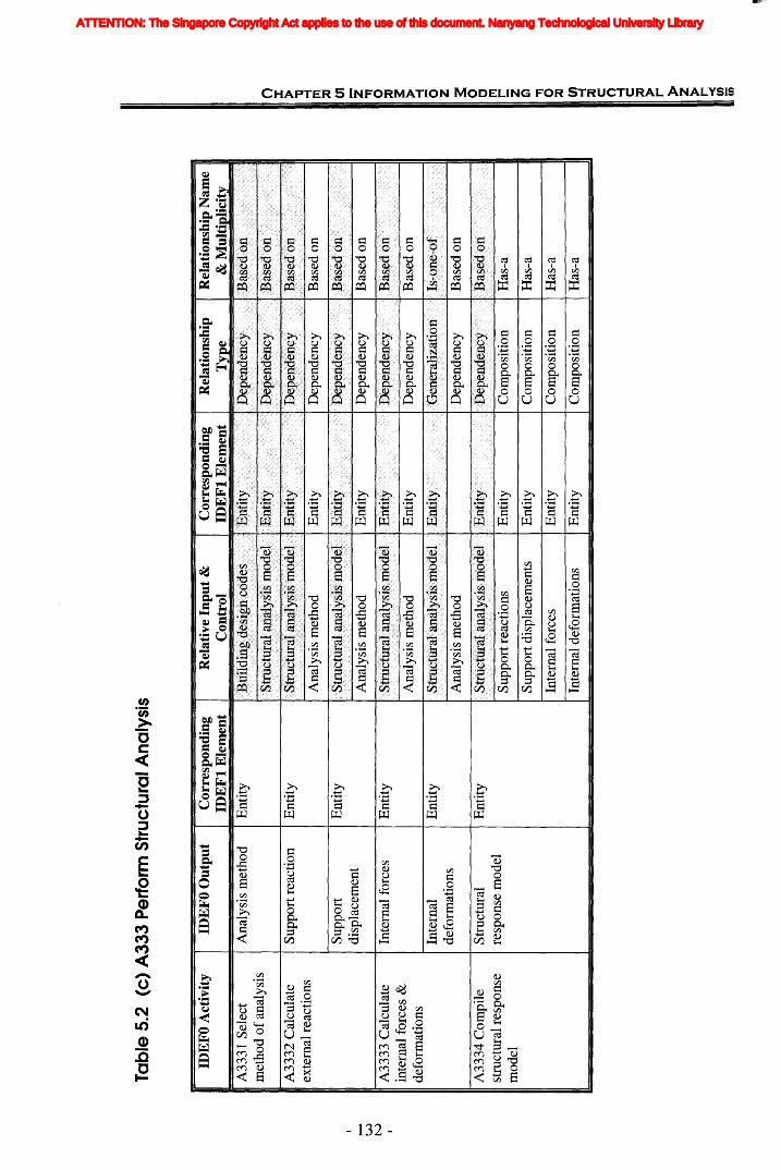
Tab
le5.
2(c
)A
33
3P
erfo
rmS
tru
ctu
ral
An
alys
is
IDE
FO
Act
ivit
yID
EF
OO
utp
ut
Cor
resp
ond
ing
IDE
Ft
Ele
men
tR
elat
ive
Inp
ut
&C
ontr
olC
orre
spon
din
gID
EF
tE
lem
ent
Rel
atio
nsh
ipT
ype
Rel
atio
nsh
ipN
ame
&M
ult
ipli
city
Sup
port
IEnt
ity
~I.
Idi
spla
cem
ent
w tvI.
A33
33C
alcu
late
IInt
erna
lfo
rces
IEnt
ity
inte
rnal
forc
es&
defo
rmat
ions
Inte
rnal
Ent
ity
defo
rmat
ions
A33
34C
ompi
leS
truc
tura
lE
ntit
yst
ruct
ural
resp
onse
resp
onse
mod
elm
odel
Ana
lysi
sm
etho
dIE
ntit
yID
epen
denc
yI
Bas
edon
Sup
port
reac
tion
sE
ntit
yC
ompo
siti
onH
as-a
Sup
port
disp
lace
men
tsE
ntit
yC
ompo
siti
onH
as-a
Inte
rnal
forc
esE
ntit
yC
ompo
siti
onH
as-a
Inte
rnal
defo
rmat
ions
Ent
ity
Com
posi
tion
Has
-a
o X )- 1J -I rrt :;a U1 Z '1l o :;a ~ ~ o z ~ o C rrt ,.. Z G) -rt o :;a en -I :;a C o -I C ~ ,.. > Z )- S en
Bas
edon
Bas
edon
Dep
ende
ncy
Dep
ende
ncy
IB
ased
on
Dep
ende
ncy
Dep
ende
ncy
Ana
lysi
sm
etho
dIE
ntit
y
Ana
lysi
sm
etho
dIE
ntit
y
Ana
lysi
sm
etho
d
Ent
ity
Ent
ity
Ana
lysi
sm
etho
d
Sup
port
reac
tion
A33
31S
elec
tm
etho
do
fana
lysi
s
A33
32C
alcu
late
exte
rnal
reac
tion
s
ATTENTION: The Singapore Copyright Act applies to the use of this document. Nanyang Technological University Library
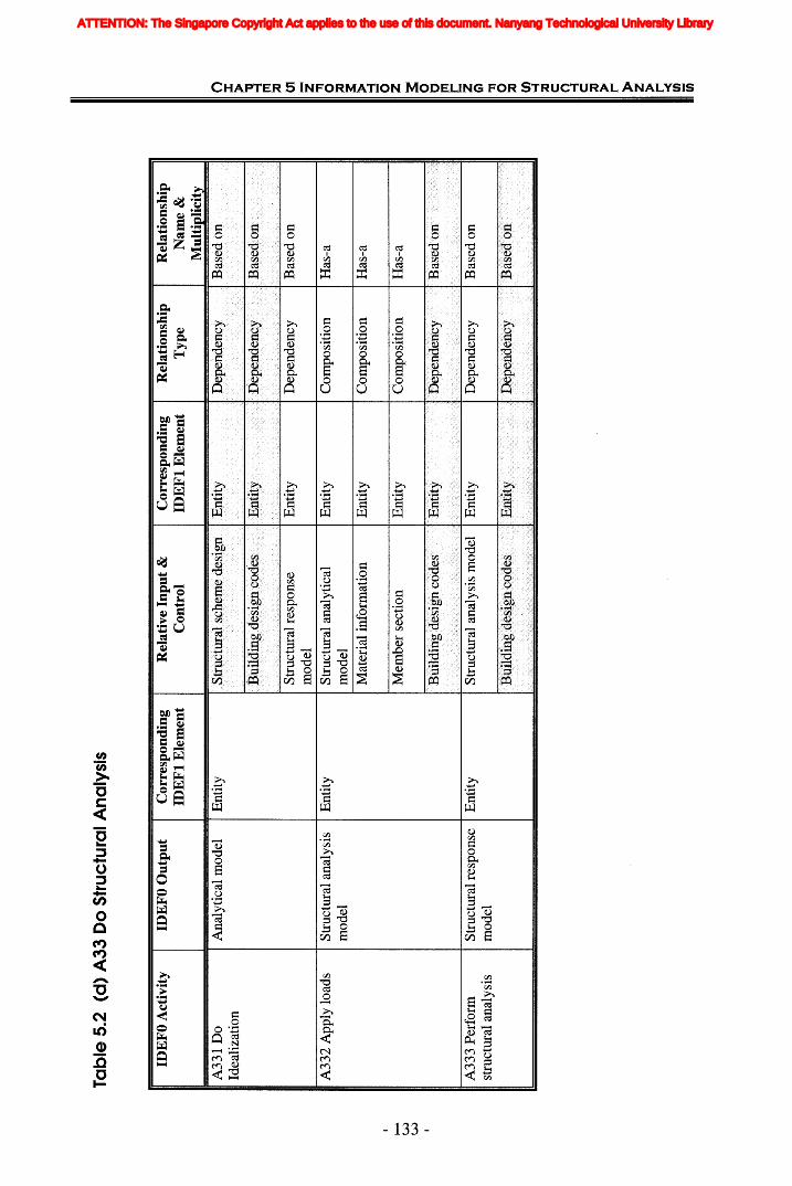
Tab
le5.
2(d
)A
33D
oS
tru
ctu
ral
An
alys
is
n :I: > ~ rrt ~ Ul Z '11 o ~ i: ~ o z 3: o C rrt i' Z Gl '11 o ~ en -I ~ c: o -I c: ~ i' > Z > !< (I) in
Str
uctu
ralr
espo
nse
IEnt
ity
mod
elA
333
Per
form
stru
ctur
alan
alys
is
IDE
FO
Act
ivit
yI
IDE
FO
Ou
tpu
tI
Cor
resp
ond
ing
Rel
ativ
eIn
pu
t&
Cor
resp
ond
ing
Rel
atio
nsh
ipID
EF
tE
lem
ent
Con
trol
IDE
Ft
Ele
men
tT
ype
A33
1D
oA
naly
tica
lm
odel
Ent
ity
Idea
liza
tion
Str
uctu
ralr
espo
nse
Ent
ity
IDep
ende
ncy
IB
ased
onm
odel
A33
2A
pply
load
sS
truc
tura
lana
lysi
sE
ntit
yS
truc
tura
lan
alyt
ical
Ent
ity
Com
posi
tion
IH
as-a
mod
elm
odel
Mat
eria
linf
orm
atio
nE
ntit
yC
ompo
siti
onI
Has
-a
,.......
III
II M
embe
rse
ctio
nE
ntit
yC
ompo
siti
onI
Has
-aw w
ATTENTION: The Singapore Copyright Act applies to the use of this document. Nanyang Technological University Library
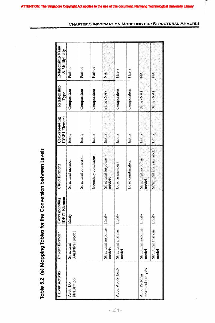
Tab
le5.
2(e
)M
ap
pin
gT
able
sfo
rth
eC
on
vers
ion
be
twe
en
Leve
ls
o X > ~ m ;:0 UI Z 'TJ. o ::0 ~ ~ o z ~ o c m r- Z (il 'TJ. o ::u en -I ::0 C o -I C ::0 > r- » z > !< (I) iii
Par
ent
Act
ivit
yIP
aren
tEle
men
tIC
orre
spon
ding
Chi
ldE
lem
ent
Cor
resp
ond
ing
Rel
atio
nshi
pR
elat
ions
hip
Nam
eID
EF
tE
lem
ent
IDE
Ft
Ele
men
tT
e&
Mu
ltio
lici
t
A33
1D
oIS
truc
tura
lIE
ntit
yIS
truc
tura
lmem
ber
IEnt
ity
ICom
posi
tion
IPar
t-of
idea
liza
tion
Ana
lyti
cal
mod
elI
I Str
uctu
ralc
onne
ctio
nE
ntit
yC
ompo
siti
onIP
art-
of
Bou
ndar
yco
ndit
ions
Ent
ity
Com
posi
tion
IPar
t-of
IS
truc
tura
lres
pons
eIE
ntit
ym
odel
sjo
-t.
IIA33
2A
pply
load
sIS
truc
tura
lana
lysi
sIE
ntit
yV
JIL
oad
assi
gnm
ent
IEnt
ity
ICom
posi
tion
IH
as-a
~
mod
el
ILoad
com
bmat
ion
IEnti
tyl:
:0sit
ion
IH
as-a
A33
3P
erfo
rmS
truc
tura
lres
pons
eIE
ntit
yst
ruct
ural
anal
ysis
mod
el
Str
uctu
rala
naly
sis
Ent
ity
mod
el
ATTENTION: The Singapore Copyright Act applies to the use of this document. Nanyang Technological University Library

CHAPTER 5 INFORMATION MODELING FOR STRUCTURAL ANALYSIS
Based on the mapping tables, the corresponding information model for these diagrams
can be achieved which has been illustrated by Figure 5.8 to Figure 5.11. In these
information diagrams, the attributes represent conceptual properties of the entities,
rather than the forms in reality. Figure 5.8 shows the information model for the
bottom level diagram, the process model for the activity 'A331' of 'Do Idealization'.
The IDEFI helped define a set of attributes of information of interest. This created a
data dictionary for the system.
Connection nameConnection locationRestraints
Figure 5.8 Information Model for Idealization
By using the same procedure, the information models for applying loads (Figure 5.9)
and performing structural analysis (Figure 5.10) can be attained.
- 135 -
ATTENTION: The Singapore Copyright Act applies to the use of this document. Nanyang Technological University Library
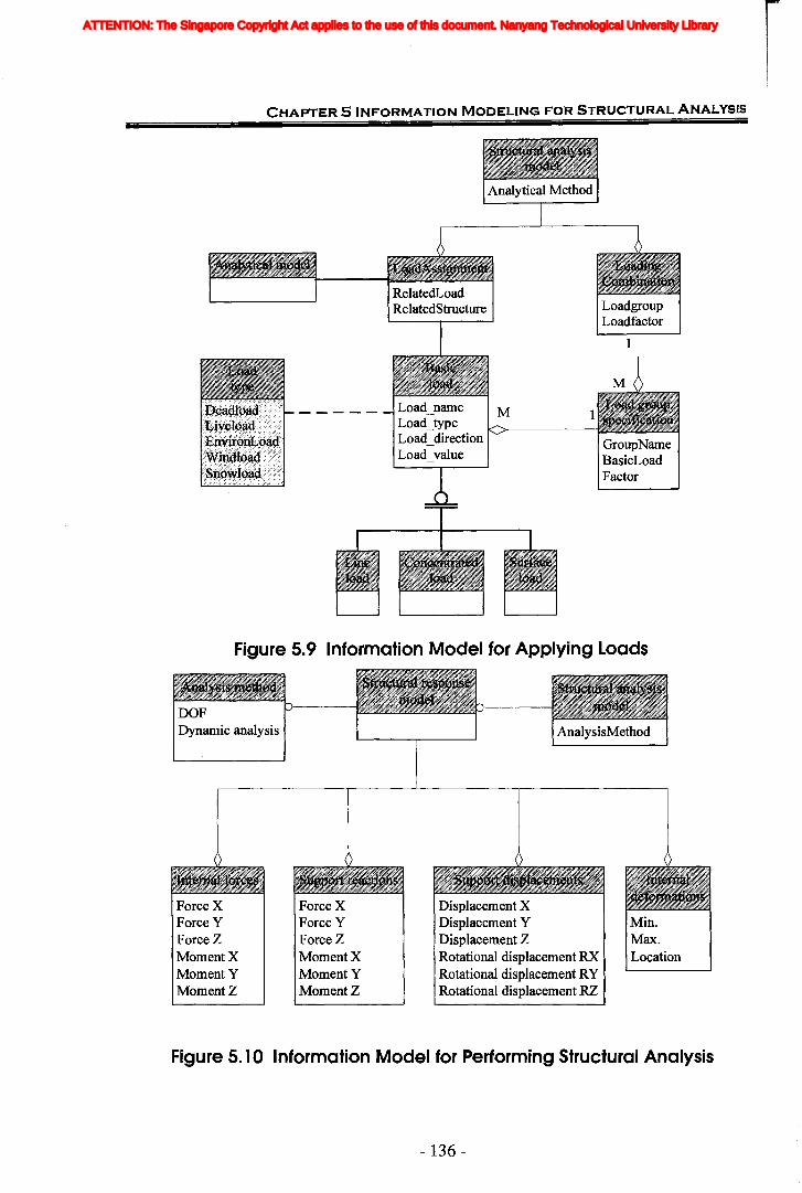
CHAPTER S INFORMATION MODELING FOR STRUCTURAL ANALYSIS
Load_name MLoad_typeLoad_directionLoad_value
GroupNameBasicLoadFactor
Figure 5.9 Information Model for Applying Loads
DOFDynamic analysis
Force XForce YForce ZMoment XMomentYMomentZ
Force XForce YForceZMoment XMomentYMomentZ
Displacement XDisplacement YDisplacement ZRotational displacement RXRotational displacement RYRotational displacement RZ
Min.Max.Location
Figure 5.10 Information Model for Performing Structural Analysis
- 136 -
ATTENTION: The Singapore Copyright Act applies to the use of this document. Nanyang Technological University Library
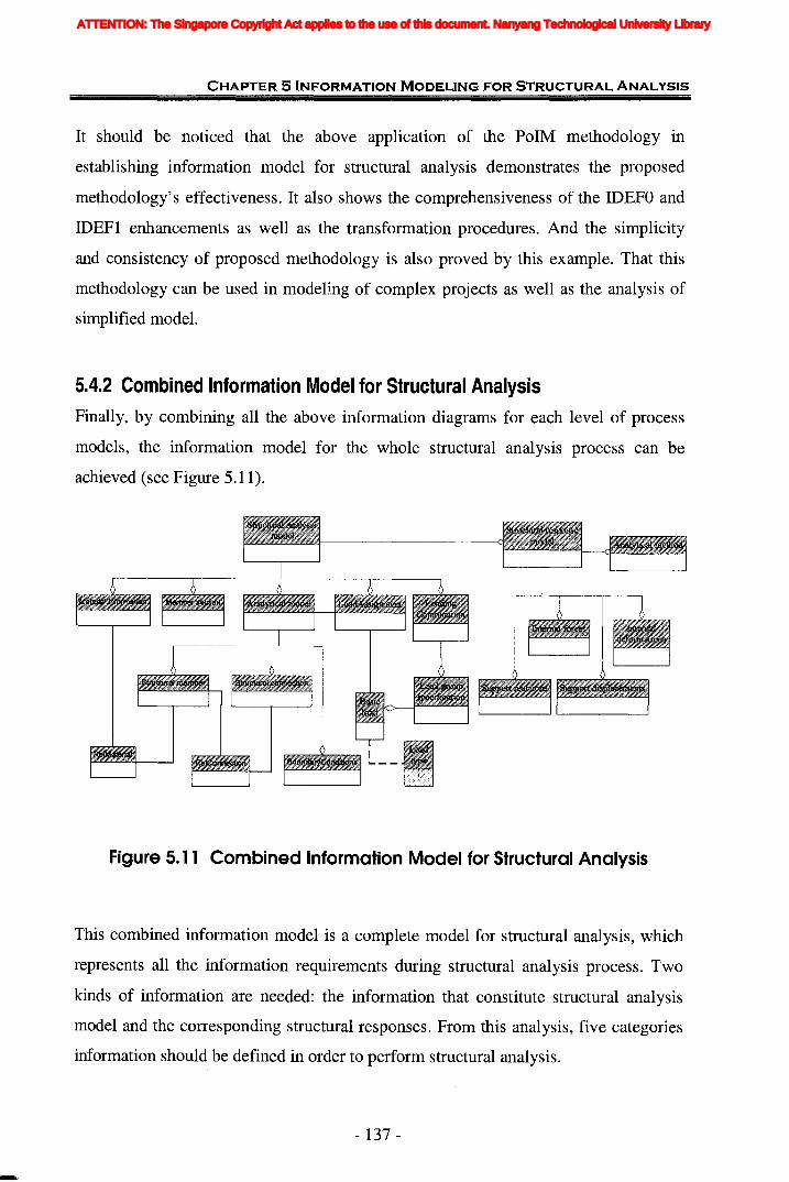
CHAPTER 5 INFORMATION MODELING FOR STRUCTURAL ANALYSIS
It should be noticed that the above application of the PolM methodology in
establishing information model for structural analysis demonstrates the proposed
methodology's effectiveness. It also shows the comprehensiveness of the IDEFO and
IDEF1 enhancements as well as the transformation procedures. And the simplicity
and consistency of proposed methodology is also proved by this example. That this
methodology can be used in modeling of complex projects as well as the analysis of
simplified model.
5.4.2 Combined Information Model for Structural AnalysisFinally, by combining all the above information diagrams for each level of process
models, the information model for the whole structural analysis process can be
achieved (see Figure 5.11).
Figure 5. 11 Combined Information Model for Structural Analysis
This combined information model is a complete model for structural analysis, which
represents all the information requirements during structural analysis process. Two
kinds of information are needed: the information that constitute structural analysis
model and the corresponding structural responses. From this analysis, five categories
information should be defined in order to perform structural analysis.
- 137 -
ATTENTION: The Singapore Copyright Act applies to the use of this document. Nanyang Technological University Library
CHAPTER 5 INFORMATION MODELING FOR STRUCTURAL ANALYSIS
1. Topology information for each structural component, including member,
connection and support.
2. Material information.
3. Geometry information, including sectional information.
4. Load information, including not only the information about basic load cases, but
also load combinations.
5. Relating the above information to structural components, including the
relationships between material information, sectional information and structural
members or connections.
5.4.3 Relationships between Architectural Design and Structural DesignActually, at this phase, there is no direct relationship between the structural and
architectural design information model. That is because before doing structural
analysis, a preliminary design of structural scheme should be done in order to choose
the basic plans. In the preliminary design stage engineers have already completed the
task of identifying the related information in architectural design and transforming the
information in architectural design to usable information which will be used by
structural design.
Although no direct relationship between information models for architectural design
and structural design, some information, which is required by structural analysis,
comes from architectural design, or it is determined in architectural design. From
Figure 5.11, as to the 'Material Information' entity, the selection of a material may be
done in architectural phase by the architect, so at least part of material's information
comes from architectural design.
Therefore through identifying the source of information, the relationship between
information models for architectural design and structural design can be achieved.
Generally there are three kinds of structural information is related to architectural
design.
- 138 -
ATTENTION: The Singapore Copyright Act applies to the use of this document. Nanyang Technological University Library

CHAPTER 5 INFORMATION MODELING FOR STRUCTURAL ANALYSIS
1. Geometry and topology information. When doing structural idealization, part of
geometry information is based on architectural design. Engineers often use
idealizations of the geometry and behavior of a structure to simplify and reduce the
size of a mechanical analysis problem (Haber, 2000). For example, in architectural
design, column is more usually considered as a 3D solid object. Correspondingly, in
structural design, it should be simplified from a solid object to a line between two
nodes. It is obvious that there are still connections between these two different
representations to a same object. The length of line is related to the length of coluIThl
and the space height of building. How to transform this information to the useful
information for structural design is also the part of work of integration.
2. Part of load information. Architect may define the live load in architectural design
in accordance with the requirements of clients. Some loads may be given in
architectural design drawings directly and some can be derived from geometric
information.
3. Material information. The structural properties of material are comparatively
constant. So the focus is on the material selection. Generally the material selection is
carried out in architectural design phase. At least it should be decided that the
building is in steel structure or reinforced concrete structure etc. because this has
direct effect on the architectural design of building.
The above describes that part of structural information need come from architectural
design. The design of structural scheme should influence architecture by making it
more rational and efficient, but it should not dictate architecture. Architects need the
knowledge of structures to ensure that the practical expressions of their architecture
are both rational and efficient. The structural system that enables buildings to
withstand the loads imposed on them and the materials of construction, if properly
chosen, help further the expression of architects' ideas rationally and economically
(Gauld 1984, Benjamin 1984). Since embedded relationships exist between the two
design phases, the integration is necessary and possible.
- 139 -
ATTENTION: The Singapore Copyright Act applies to the use of this document. Nanyang Technological University Library
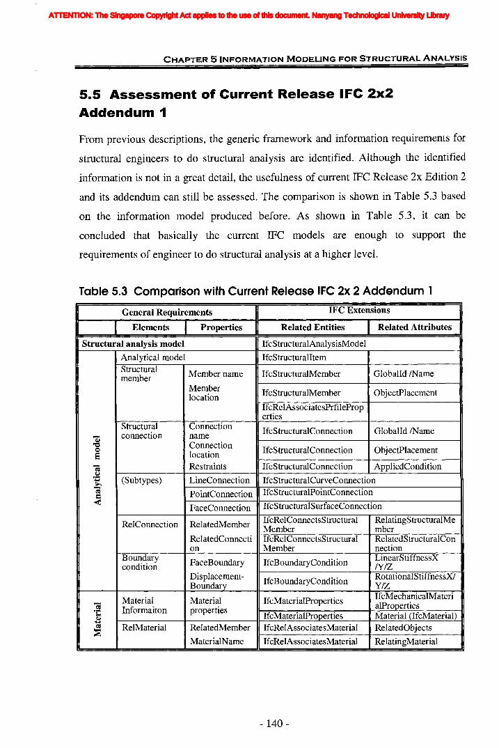
CHAPTER 5 INFORMATION MODELING FOR STRUCTURAL ANALYSIS
5.5 Assessment of Current Release IFC 2x2
Addendum 1
From previous descriptions, the generic framework and information requirements for
structural engineers to do structural analysis are identified. Although the identified
information is not in a great detail, the usefulness of current IFC Release 2x Edition 2
and its addendum can still be assessed. The comparison is shown in Table 5.3 based
on the information model produced before. As shown in Table 5.3, it can be
concluded that basically the current IFC models are enough to support the
requirements of engineer to do structural analysis at a higher level.
Table 5.3 Comparison with Current Release IFC 2x 2 Addendum 1
General Requirements IFC Extensions
Elements Properties Related Entities Related Attributes
Structural analysis model IfcStructuralAnalysisModel
Analytical model IfcStructuralItemStructural Member name IfcStructuralMember Globalld /Namemember
Member IfcStructuralMember ObjectPlacementlocationIfcRelAssociatesPrfileProperties
Structural Connection IfcStructuralConnection Globalld /Nameas connection name"0 Connection~ IfcStructuralConnection ObjectPlacement8 locatione; Restraints IfcStructuralConnection AppliedConditiono~ (Subtypes) LineConnection IfcStructuralCurveConnection~
~-; PointConnection IfcStructuralPointConnection=< FaceConnection IfcStructuralSurfaceConnection
RelConnection RelatedMember IfcRelConnectsStructural RelatingStructuralMeMember mber
RelatedConnecti IfcRelConnectsStructural RelatedStructuralConon Member nection
Boundary FaceBoundary IfcBoundaryCondition LinearStiffnessXcondition IY/Z
Displacement- IfcBoundaryCondition RotationalStiffnessXlBoundary Y/Z
Material Material IfcMaterialProperties IfcMechanicalMateri-;
Informaiton properties alProoerties°C IfcMaterialProoerties Material (IfcMaterial)~~
= RelMaterial RelatedMember IfcRelAssociatesMaterial RelatedObjects~
MaterialNarne IfcRelAssociatesMaterial RelatingMaterial
- 140-
ATTENTION: The Singapore Copyright Act applies to the use of this document. Nanyang Technological University Library

CHAPTER 5 INFORMATION MODELING FOR STRUCTURAL ANALYSIS
Table 5.3 <Continued>
t = IfcProfilePropertiesIfcStructuralProfilePrope
,.QQ Member Section rtiesa~ section PropertiesQj ~ ProfileDefinition~~ IfcProfileProperties (IfcProfileDef)
Load LoadGroup IfcStructuralLoadGroup IsGroupedBy
= CombinationsQ LoadFactor IfcStructuralLoadGroup Coefficient
"'=~~ ~ Load group GroupName IfcStructuralLoadGroup Gioballd !NameQ ••
speciflcation~,.Qa Basicload IfcStructuralLoadGroup IsGrouptedByQ~
Factor IfcStructuralLoadGroup Coefficient
Load RelatedLoad IfcRelConnectsStructural- RelatedStructuralActivityAssignment ActivityRelated- IfcRelConnectsStructural- RelatingElementStructure Activity
Basic loads Load_name IfcStructuralAction Gioballd !Narne
....- Load_type IfcStructuralAction=Qj
a Load IfcStructuralAction GlobalOrLocal &= direction ProiectedOrTrue.~~
Load_value IfcStructuralAction AppliedLoad~
-<"'= IfcStructuralPointAction AppliedLoadeu ConcentratedQ (Subtypes) (IfcStructuralLoadSingle~ load Force)
IfcStructuralLinearAction AppliedLoadLine load (IfcStructuralLoadLinear
Force)
IfcStructuralPlanarAction AppliedLoadSurface load (IfcStructuralLoadPlanar
Force)
Structural response model IfcStructuralResultGroup ResultForLoadGroup
Analysis IfcStructuralResultGroup TheoryTypemethod
IfcAnalysisTheoryTypeEnumInternal forces
ForceXNIZ IfcStructuralReaction AppliedLoad
QS Moment IfcStructuralLoadSingle- ForceXNIZ;"'= XNIZ Force MomentXNIZQa SupportQj Displacemen~ displacements IfcStructuralPointReaction AppliedLoad= tXNIZQc.. Displacement XJYI Z;~
IfcStructuralLoadSingle-QjJ,.c RX/Ry/RZ RotationalDisplacementR"; Displacement XlRY/RZJ,.c
= Support....- ForceXNIZ IfcStructuralPointReaction AppliedLoad~ reactions=J,.c....-Moment IfcStructuralLoadSingle- ForceXNIZ;rJJ.
XNIZ Force MomentXNIZInternal
IfcStructuralReaction AppliedLoaddeformations
IfcStructuralLoadDisplacement
- 141 -
ATTENTION: The Singapore Copyright Act applies to the use of this document. Nanyang Technological University Library

CHAPTER 5 INFORMATION MODELING FOR STRUCTURAL ANALYSIS
In order to ensure a successful implementation of integration between architectural
design and structural design, it is not enough to consider it only from the general
perspective; the more detailed assessment is done in Chapter 6.
5.6 Summary
Based on the methodology proposed in Chapter 4, a set of generic process model for
structural engineering design and information model for structural analysis are
achieved. This application demonstrates the comprehensiveness of the IDEFO and
IDEFI enhancements as well as the transformation procedures. The simplicity and
consistency of proposed methodology is also shown by this example.
This information model is a generic model which intends to characterize the flow of
design information and not tied to any specific analysis process model. The
information model distinguishes itself from any specific analysis method and structure
type, with that it concentrates on the information that flows among individual design
activities regardless of the activities' particular sequence and requirements. So this
model appears to lend itself to implementation that can support a variety of
development strategies.
On the other hand, the necessity and feasibility of the integration of architectural
design arid structural design is shown through the discussion of the relationships
between their information. The capability of latest IFC models to support structural
analysis is evaluated through the comparison betwe~n the generic requirements and
current IFC extensions. At this stage, the model is capable of establishing a
foundation for developing base-level representations to capture, store and retrieve
design information. Further research is still going on until the complete information
model for structural analysis process is obtained. The detailed assessment of the
application at implementation level would be done in next chapter.
- 142-
ATTENTION: The Singapore Copyright Act applies to the use of this document. Nanyang Technological University Library
IR~" ,
!.'.: ~
",' IX
ll' ~ ,IX ~ ,r&' "'., ,ll' " ,ll'
6.1 Introduction
In Chapter 5 the PolM methodology is applied to obtain a generic information model
for structural analysis process which proves the effectiveness of the methodology on
information modeling. The generic information model proposed and the assessment to
IFC extensions in Chapter 5 primarily comes from professionals' knowledge in a
higher level. However, during the implementation of the integration between
structural design and architectural design, to a great extent it is much more from
structural analysis and design software's point of view. Therefore, the information
requirements are also needed to be modelled involving the implementation in
software. In this chapter, the information modeling based on the detailed computer
software's mechanism for structural analysis is further developed. The gaps between
the detailed requirements and IFC models are analyzed so as to assess the usefulness
of IFC to meet the practical needs of structural analysis in this chapter.
The chapter is organized as follows:
• Section 6.1 gives a brief description of the content and structure of the chapter.
* Part of this chapter has been published in the paper " Assessment of IFCs for Structural AnalysisDomain", on the Electronic Journal of Information Technology in Construction in ITcon Vol. 9 2004,pp. 75-95, which is available at http://www.itcon.org/2004/5.
- 143 -
ATTENTION: The Singapore Copyright Act applies to the use of this document. Nanyang Technological University Library

CHAPTER 61FC EXTENSION DEVELOPMENT FOR STRUCTURAL ANALYSIS PROCESS
• Section 6.2 introduces the procedures of structural analysis using SAP2000
and shows the corresponding process models.
• Based on the process models in Section 6.2, the information requirements of
SAP2000 to perform structural analysis are identified and modelled in Section
6.3.
• The capabilities of current IFC models to support structural analysis are
assessed in Section 6.4. It is found that most of the information for structural
analysis can be explicitly supported by current IFCs. However there is still
some information missing. And some need to be inferred from the data
existing in IFC.
• In order to decide the approach to developing IFC extensions, the
commonalities of information gaps are confirmed by the generality study in
Section 6.5 which investigates into another ten structural analysis and design
softwares.
• The necessary extensions for the missing information are developed in section
6.6 in accordance with IFC 2x Extension Modeling Guide and rules specified.
• Finally section 6.7 summarizes the works finished in current stage. The
problems currently existed and future works are also proposed.
6.2 General Procedures of Structural Analysis andDesign Software
After investigating software like SAP2000, ETABS etc., the procedures to structural
analysis and design generally includes the following steps:
a. Choosing the units and defining the basic information for the project.
b. Setting up geometry.
c. Defining material and member section properties.
- 144-
ATTENTION: The Singapore Copyright Act applies to the use of this document. Nanyang Technological University Library
CHAPTER 61FC EXTENSION DEVELOPMENT FOR STRUCTURAL ANALYSIS PROCESS
d. Assigning member section properties and element releases.
e. Defining load cases.
f. Assigning load magnitudes.
g. Assigning restraints.
h. Run Analysis
1. Displaying the deformed shape.
j. Displaying the member forces.
k. Printing the results.
1. Designing the structural members and checking the safety of a design.
m. Modifying the structure and trying again.
Since basically all structural engineering computer programs follow the same
procedure, SAP2000 is selected as the representative software for modeling the
practical processes of structural analysis. SAP2000 is an integrated software for
structural analysis and design developed by Computers and Structures, Inc. (CSI,
USA). For nearly 30 years, CSI has been the leader in the development of innovative
numerical methods and software for structural & earthquake engineering. CSI
software has been used for the analysis and design of major project by thousands of
users in over 100 countries. The products offered by CSI (SAP2000, ETABS and
SAFE) are often highlighted in many engineering software guides or magazines, like
Modern Steel Construction (1998, 2003) and Structure (2004). Therefore, all of the
following models are from SAP2000's requirements and referring to the Analysis
Reference of SAP2000 (CSI, 2002), and all information is named with SAP2000's
notations.
The above procedure involves a total of 13 steps. However, some steps can be carried
out simultaneously and some follow the same working styles, such as steps 'c' and 'e'
both belong to 'Define' activity. Therefore, the whole procedure can also be defined
in seven processes: Define default parameters, Set up structural model, Define
properties, Assign properties, Define analysis options, Compile whole model and Run
analysis, which is shown in Figure 6.1. Figure 6.1(a) is the top model of activity "Do
- 145 -
ATTENTION: The Singapore Copyright Act applies to the use of this document. Nanyang Technological University Library
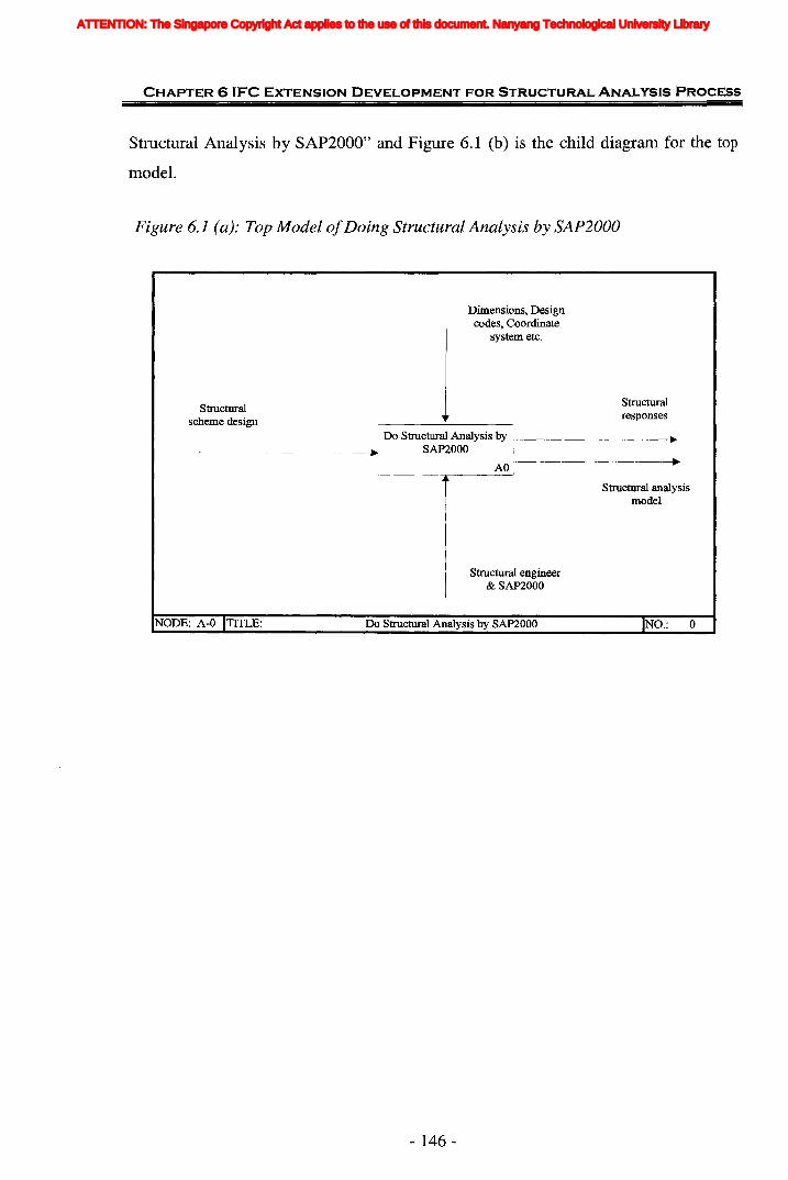
CHAPTER 6 IFC EXTENSION DEVELOPMENT FOR STRUCTURAL ANALVSIS PROCESS
Structural Analysis by SAP2000" and Figure 6.1 (b) is the child diagram for the top
model.
Figure 6.1 (a): Top Model ofDoing Structural Analysis by SAP2000
Dimensions, Designcodes, Coordinate
system etc.
structuralresponses
Do Structural Analysis by f-----------...~
SAP2000
Structuralscheme design
......AO
Structural engineer& SAP2000
...
Structural analysismodel
NODE: A-O ITITLE: Do Structural Analysis by SAP2000
- 146-
IND.: 0
ATTENTION: The Singapore Copyright Act applies to the use of this document. Nanyang Technological University Library
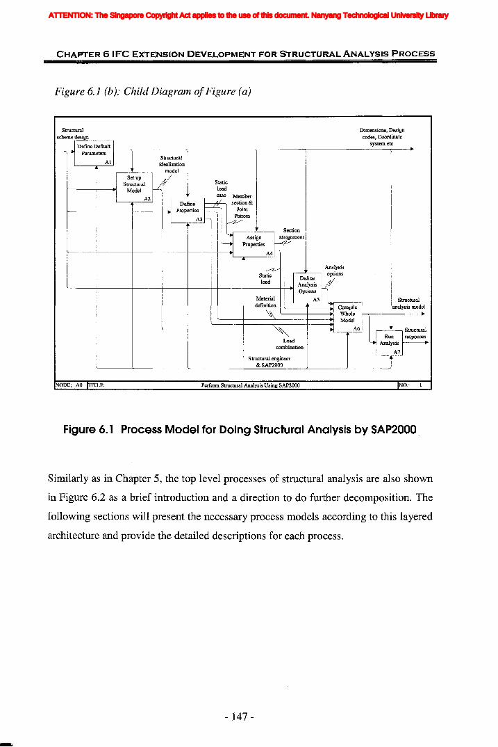
CHAPTER 6 'FC EXTENSION DEVELOPMENT FOR STRUCTURAL ANALYSIS PROCESS
Figure 6.1 (b): Child Diagram ofFigure (a)
Dimensions, Designcodes, Coordinate
system etc.
Structuralidealization
model
-/SetupStructural
Model
A2
Staticloadcase Member
I Define .~ section &r----+-----+-----I--.l.1 Properties Joint
'1 A3 ~em
Structuralscheme r-des---'=ig=-n__--,
rl Define Default I
- Parameters I
Al
Section
. '1 Assign ~SignmentJ Properties vr----+------+-----t----t---~---.I A4
....--zStaticload
~""Loadcombination
Analysis,----L.----. options
~~~~s rr'----+------+-----t----t---~---_t_---_+_+___.I Options
Material L--~_A5---'l....~__--, Structuraldefmition '--_-1--__-.1- Compile analysis model~ '----+---.1 Whole I---r--+------.
Model
A6
Structural engineer& SAP2000
NODE: AO TITLE: Perform Structural Analysis Using SAP2000 NO.:
Figure 6. 1 Process Model for Doing Structural Analysis by SAP2000
Similarly as in Chapter 5, the top level processes of structural analysis are also shown
in Figure 6.2 as a brief introduction and a direction to do further decomposition. The
following sections will present the necessary process models according to this layered
architecture and provide the detailed descriptions for each process.
- 147-
ATTENTION: The Singapore Copyright Act applies to the use of this document. Nanyang Technological University Library
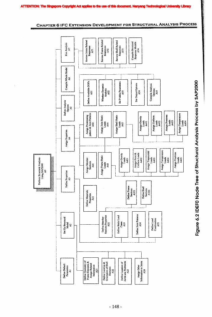
Fig
ure
6.2
IDE
FON
od
eT
ree
of
Str
uc
tura
lA
na
lys
isP
roc
es
sb
yS
AP
20
00
o X > :!I fit ::u 0) :;; o rrt ~ fit Z (I) (5 Z o fit < fit r o 1J ~ fit Z -I -rt o ::u en -I ::u C o -I C ~ r- » z > !< (I) U; -0 ::u o n ['It
(J)
m
T IlR
un
Ana
lysi
sA
7
Rev
iew
Join
tsR
elat
edR
espo
nses
A71
IC
ompi
leW
hole
Mod
elA
6
1
Whe
ther
Dyn
amic
Rev
iew
Fra
me
Rel
ated
Ana
lysi
sR
espo
nses
A52
A72
Rev
iew
She
llR
elat
edS
etP
-del
taP
aram
eter
sR
espo
nses
AS3
A73
Com
pile
Str
uctu
ral
Set
Out
putO
ptio
nsH
Res
pons
eM
odel
s
AS
4A
74
---
---
Com
pile
Ana
lysi
sO
ptio
ns~
ASS
Def
ine
Ava
ilab
leD
OP
sA
SI
ITD
efin
eA
naly
sis
Opt
ions
AS
Ass
ign
Pre
stre
ssL
oads
A45
3
Ass
ign
Tem
pera
ture
Loa
dsA
454
Ass
ign
Join
tSta
tic
Loa
dsA
44
Ass
ign
Pre
stre
ssin
gpa
tter
n&
Join
tPat
tern
sA
42
Ass
ign
Pro
pert
ies
A4
Ass
ign
Mem
ber
Sec
tion
sA
41
Ass
ign
Fra
me
Sta
tic
Loa
dsA
43
~I
Ass
ign
She
llS
tati
c
1
Loa
ds
A4
5I
Def
ine
Pro
pert
ies
A3
Def
ine
Mat
eria
lsP
rope
rtie
sA
31III
Set
Up
Str
uctu
ral
Mod
elA
2
Def
me
Def
ault
Par
amet
ers
Al -
~D
efin
eG
eom
etry
of
Fra
me
Ele
men
ts&
Ass
ign
Rel
ated
Info
rmat
ion
A21
Def
ine
Loc
atio
n&
Ori
enta
tion
ofS
hell
I---
Ele
men
tsI-
-lI
A22
~ 00
ID
efin
eL
ocat
ion
of
Join
tsan
dR
estr
aint
sI----
A23 --
--
Ass
ign
Oth
erIn
form
atio
nto
Join
tsl---
A24
ATTENTION: The Singapore Copyright Act applies to the use of this document. Nanyang Technological University Library
CHAPTER 6 (FC EXTENSION DEVELOPMENT FOR STRUCTURAL ANALYSIS PROCESS
6.2.1 Define Default ParametersBefore carrying out structural analysis, SAP2000 has built-in tolerances and default
values for some parameters and Design Codes. It is possible to change most of the
default values by editing them in the three tabs under the menu "Preference", namely
'Dimensions', 'Steel and Concrete Design Codes' and 'Parameters'.
In addition, coordinate systems are also defined which are used to locate different
parts of the structural model and to define the directions of loads, displacement,
internal forces, and stresses.
All coordinate systems in the model are defined with respect to a single, global X-y-z
coordinate system. Each part of the model (joint, element, or constraint) has its own
local 1-2-3 coordinate system. All locations in the model are ultimately defined with
respect to a single global coordinate system.
Each component of the model (joint, frame element, shell element, etc.) has its own
local coordinate system used to define properties, loads, and response for that
component. The axes of each local coordinate system are denoted 1, 2, and 3 in
SAP2000.
6.2.2 Set up Structural ModelThe first important step to structural analysis is to develop the idealization model of
the structure. SAP2000 analyzes and designs the structure using a model that is
defined with the graphical user interface.
- 149-
ATTENTION: The Singapore Copyright Act applies to the use of this document. Nanyang Technological University Library
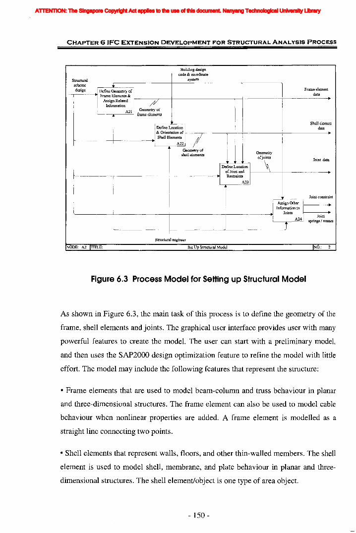
CHAPTER 61FC EXTENSION DEVELOPMENT FOR STRUCTURAL ANALYSIS PROCESS
Building designcode & coordinate
systemStructuralschemedesign Define Geometry of Frame element
-,------..1 Frame Elements & data ...Assign Related 1----/f/---r--I---------........--+------+---------.
Information / f/
A21 Geometry of'-----,.-----' frame elements
Shell elementdataDefine Location
& Orientation of I-----r---------,---t--t---------j----------.
r-------+------~Shell Elements IA22
Geometry ofshell elements
Define Locationof Joint andRestraints
A23
Geometry
ofiO\ Joint data
Joint constraint
Assign OtherInformation to
JointsJoint
j A24 springs / masses
'---------+----------'--------~
Structural engineer
NODE: A2 ITfTI..,E: Set Up Structural Model IND.: 2
Figure 6.3 Process Model for Setting up Structural Model
As shown in Figure 6.3, the main task of this process is to define the geometry of the
frame, shell elements and joints. The graphical user interface provides user with many
powerful features to create the model. The user can start with a preliminary model,
and then uses the SAP2000 design optimization feature to refine the model with little
effort. The model may include the following features that represent the structure:
• Frame elements that are used to model beam-column and truss behaviour in planar
and three-dimensional structures. The frame element can also be used to model cable
behaviour when nonlinear properties are added. A frame element is modelled as a
straight line connecting two points.
• Shell elements that represent walls, floors, and other thin-walled members. The shell
element is used to model shell, membrane, and plate behaviour in planar and three
dimensional structures. The shell element/object is one type of area object.
- 150-
ATTENTION: The Singapore Copyright Act applies to the use of this document. Nanyang Technological University Library

CHAPTER 6 'FC EXTENSION DEVELOPMENT FOR STRUCTURAL ANALYSIS PROCESS
• Joints that represent the points of connections between the elements. They are the
primary locations in the structure at which the displacements are known or are to be
determined.
• Restraints and springs that support the joints and other properties with respect to
frame elements. The displacement components (translations and rotations) at the
joints are called the degrees of freedom. If the displacement of a joint along any of its
degrees of freedom has a known value, either zero (e.g., at support points) or non-zero
(e.g., due to support settlement), a restraint must be applied to that degree of freedom.
6.2.3 Define PropertiesDefining properties is used to create named entities that are not part of the geometry
of the model. These entities include material properties, frame and Shell section
properties, static load cases, joint pattern for temperature and pressure loading, and
load combinations. SAP2000 also provides the definition of properties for response
spectrum analysis, time history analysis and static pushover analysis (such as
response-spectrum functions, time-history cases, and hinge properties et al.) which are
out of this research's scope and are not included when modeling this process.
Defining these entities does not require a prior selection of objects. The first three
types of entities will be assigned to selected objects in the next step, which are the
primary properties should be defined, as shown in Figure 6.4. Figure 6.4b represents
that sections defined include the sections for frame members and the sections of shell
members. The remaining entities apply to the model as a whole and are not assigned
to objects.
- 151 -
ATTENTION: The Singapore Copyright Act applies to the use of this document. Nanyang Technological University Library

CHAPTER 6 IFC EXTENSION DEVELOPMENT FOR STRUCTURAL ANALYSIS PROCESS
(a) Building design code
Material definitionStructural I Define Materials I
scheme design Properties If--------~~---t~~~~~~~_!_~~~~~~-------__+---~-_.
'I A31
Member sectionL..I Defme ~ember IJ Section
r--------if------~---+I·I propertie~211--~~~-I-~~~~~~~~~-~~~-I-~~~~~+
Static load case_r Defme Static l
t'----~I__------_+_----~~I Load Cas:3
rl--~~~~~~~~~~-+~~-~~~
~I
DefmeJointPatterns I
A341
Joint patterns'name
I DefmeLoad'--------+------+1.
1Combination
l A35
Loadcombination
Structural engineer
NODE: A3 ITITLE: Defme Properties IND.:
(b) Building design code I
Frame section.1 Define Frame l'1 Sectios I
-------.,----I-----~I A3211'----------l------------..
Material defInition
Structuralscheme design
Shell sectionI Define Shell I
'----~~------+-----------~l Sections II----~-----..l A322
Structural engineer& SAP2000
NODE: A32 ITITLE: DerIDe Member Section Properties INO.: 4
Figure 6.4 Process Model for Defining Properties
- 152-
ATTENTION: The Singapore Copyright Act applies to the use of this document. Nanyang Technological University Library
CHAPTER 6 IFC EXTENSION DEVELOPMENT FOR STRUCTURAL ANALYSIS PROCESS
(1) Material Property
The material properties are always linear elastic. They may be defined as being
isotropic, orthotropic or anisotropic. Isotropic behavior is usually assumed for steel
and concrete, although this is not always the case. The behavior of an isotropic
material is independent of the direction of loading or the orientation of the material. In
addition, shearing behavior is uncoupled from extensional behavior and is not affected
by temperature change. How the properties are actually utilized depends on the type
of element. Each material that user defines may be used by more than one element or
element type. For the Frame element, the Materials are referenced indirectly through
the Section properties. The material properties include:
• The modulus of elasticity, el, for axial stiffness and bending stiffness;
• The shear modulus, g12, for torsional stiffness and transverse shear stiffness; this is
computed from el and the Poisson's ratio, n12;
• The mass density (per unit of volume), ID, for computing element mass;
• The weight density (per unit of volume), W, for computing Self-Weight Load;
• The Coefficient of Thermal Expansion;
• The design-type indicator, ides, that indicates whether elements using this Section
should be designed as steel, concrete, or neither (no design).
(2) Section Property
Sections are defined independently of the elements, and then are assigned to the
elements. Six basic general properties of frame section are used, together with the
material properties, to generate the stiffnesses of the Section. These are:
• The cross-sectional area, a. The axial stiffness of the Section is given by a-a1;
• The moment of inertia, i33, about the 3 axis for bending in the 1-2 plane, and the
moment of inertia, i22, about the 2 axis for bending in the 1-3 plane. The
corresponding bending stiffnesses of the Section are given by i33 e e~ and i22.ee1;
- 153 -
ATTENTION: The Singapore Copyright Act applies to the use of this document. Nanyang Technological University Library
CHAPTER 6 IFC EXTENSiON DEVELOPMENT FOR STRUCTURAL ANALYSIS PROCESS
• The torsional constant, j. The torsional stiffness of the Section is given by j • g12;
• The shear areas, as2 and as3, for transverse shear in the 1-2 and 1-3 planes,
respectively. The corresponding transverse shear stiffnesses of the Section are given
by as2. g12 and as3. g12.
As for the other six properties, section modulus, S33 and S22, the plastic modulus,
Z33 and Z22, the radius of gyration, R33 and R22, can be computed from the six
basic properties.
In SAP2000, the section properties may be specified directly, computed, or read from
a specified property database file. The user can add a frame section by defining the
physical dimensions of the section and accepting the section properties automatically
computed from specified dimensions by software. This way is generally applicable to
such sections in specific types as I1Wide Flange, Channel, Tee, or Angle etc. The
other one is to give the section properties directly for general section types. Thus for
each Section, the shape type, sh, is also specified by the user to determine the way of
generating properties:
• If sh =G (general section), the six geometric properties must be explicitly specified
• If sh =R, P, B, I, C, T, L, or 2L, the six geometric properties are automatically
calculated from specified Section dimensions.
• If sh is any other value (e.g., W27X94 or 2L4X3XI/4), the six geometric properties
are obtained from a specified property database file.
(3) Static Load Case
A Load Case is a specified spatial distribution of forces, displacements, temperatures,
and other effects that act upon the structure. The Load Cases form the basis for most
of the loading used by the different types of analyses that can be performed by the
program. For static analysis, the program automatically computes the linear response
to each Load Case unless steady-state analysis has been requested.
- 154-
ATTENTION: The Singapore Copyright Act applies to the use of this document. Nanyang Technological University Library
CHAPTER 6 IFC EXTENSION DEVELOPMENT FOR STRUCTURAL ANALYSIS PROCESS
User can define as many named Load Cases as user like. Typically user would have
separate Load Cases for dead load, live load, wind load, snow load, thermal load, and
so on. Loads that need to vary independently, either for design purposes or because of
how they are applied to the structure, should be defined as separate Load Cases.
(4) Joint Pattern
Joint Pattern is used to describe complicated spatial distributions of loads and
properties over the structure, such as joint spring and mass properties, Joint force and
displacement loads, Pressure-type loads for shell elements, and Temperature-type
loads for frame and shell elements.
The use of Patterns is optional and is not required or simple problems. Joint Pattern
does not affect the location of the joints, or have any other effect upon the structure
except as utilized in the specification of loads and properties. In this process, only the
names of Patterns are defined and their detailed properties are assigned to selected
joints in next process.
(5) Load Combination
In SAP2000, a Combo can be a combination of the results from Loads, Modes, Specs,
Histories, Moving Loads, and/or previously-defined Combos. Combo results include
all displacements and forces at the joints and internal forces or stresses in the elements.
User may specify any number of Combos. Each Combo produces a pair of values for
each response quantity: a maximum and a minimum. In this research only the Load
Combination under static analysis case is considered. With respect to Load
Combination, the following properties should be defined: (1) combination name, (2)
load combination type (ADD, ENVE, ABS, SRSS), (3) description of load combo
which is optional, (4) selection of Load Case name from the Case Name drop down
list box, and (5) typing in the multiplier in the Scale Factor edit box.
- 155 -
ATTENTION: The Singapore Copyright Act applies to the use of this document. Nanyang Technological University Library
CHAPTER 6 IFC EXTENSlON DEVELOPMENT FOR STRUCTURAL ANALYSIS PROCESS
6.2.4 Assign PropertiesAssignment is used to assign properties and loads to one or more selected objects. The
properties assigned to frame members mainly include section properties, releases,
local axes, end offsets, output segments, prestressing patterns, P-delta forces,
pushover hinges and loads. Only section properties and local axes are assigned to
shell members. The properties assigned to joints mainly include restraints, constraints,
springs, masses, local axes, joint patterns and loads.
In fact, most of properties should be considered during setting up the structural
idealization model, like frame releases, local axes, end offsets, output segments and
joint restraints, constraints, springs, local axes. Therefore this part of assignments is
included in the process of "Set up Structural Model" and is not included in this
process. In addition, P-delta forces and pushover hinges is only concerned with P
delta analysis and static pushover analysis, and joint masses is used during dynamic
analysis which both are out of the research scope in this phase. Thereby, the left
properties need to be assigned in this step only include assigning section properties
defined before, prestressing pattern, and static loads to frame elements or shell
element, as well as assigning loads and joint patterns to joints. More information
about prestreesing pattern is introduced in the description for "Prestress Load". Figure
6.5 shows all the related activities in this process.
The most important task in this step is to assign static loads to selected elements and
joints. Loads represent actions upon the structure, such as force, pressure, support
displacement, thermal effects, ground acceleration, and others. Force load and
displacement load normally applies the concentrated forces or moments, and ground
displacement to joints. For frame elements, six types of static loads can be assigned,
gravity load, point load, uniform load, prestress load, temperature load and
trapezoidal span load, as shown in Figure 6.6. Similarly, only gravity load, pressure
load, uniform load and temperature load could be assigned to shell elements which are
modelled as Figure 6.7. Different static loads have different properties needed to
specify. The following section describes the primary static loads in detail.
- 156-
ATTENTION: The Singapore Copyright Act applies to the use of this document. Nanyang Technological University Library
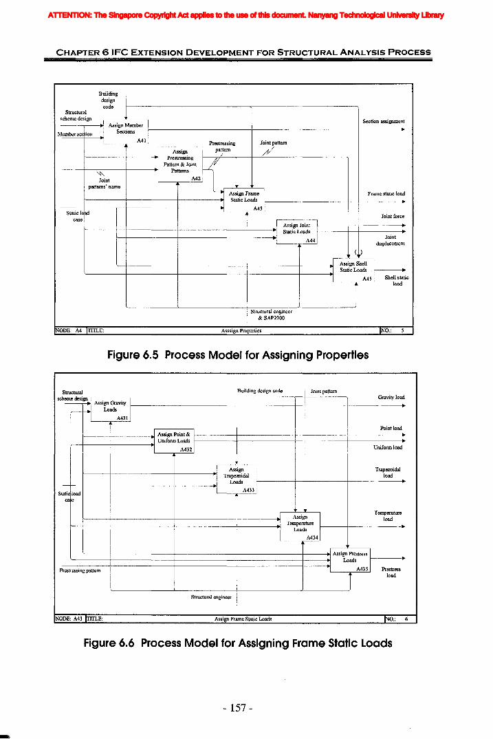
CHAPTER 6 IFC EXTENSION DEVELOPMENT FOR STRUCTURAL ANALYSIS PROCESS
Building Idesigncode 1----------------- -------------_____
Joint force
Jointdisplacement
Frame static load
Section assignment
~Joint
patterns' name
-' Assign Joint II-----+---t------..r------+---+-------+-----------!----.l~1Static Loads 1
I A44
Structuralscheme design---..----.1,1 Assign Member I
.1 Sections 11---------------+---------------+------·
I A41 Prestressing Joint pattern
Assign pattern /Prestressing 1------,~/-----...----1f---"'------------___.,
Pattern & Joint ~Patterns
A42
r----L--.....x----,
Assign Frame I
'I Static Loads 1--------------11---+--------.---+--------,--1------1--------.1.1 A431
Static loadcase
Member section
( )
'----!-------I----------i----------1---~.1 Assign Shell 1
Static Loads '11-----.'I A45 Shell static
load
Structural engineer& SAP2000
!NODE: A4 ITITLE: Asssign Properties INO.:
Figure 6.5 Process Model for Assigning Properties
Gravity load
Uniform load
Joint patternBuilding design code
Point load1'--__-+- --.11 Assign Point & 11-------+---------1---+------+---------.
'I Uniform Loads Ir--+-----+------.l'1 A432
Structuralscheme deSi
R· . I
---. ASSIgn GraVIty
r-- Loads IA431
Static loadca e
AssignTrapezoidal
Loads
A433
Trapezoidalload
AssignTemperature
Loads
A434
Temperatureload
'-----t-----------I--------+----------+-----.;~: Assign Prestress I
:I Loads 11-------.P-re-str-e-ss-in-g-p-att-e-m--t---------+---------f---------+---Jol'1 A435 Prestress
load
Structural engineer
NODE: A43 ITITLE: Assign Frame Static Loads INO.:
Figure 6.6 Process Model for Assigning Frame Static Loads
- 157 -
ATTENTION: The Singapore Copyright Act applies to the use of this document. Nanyang Technological University Library
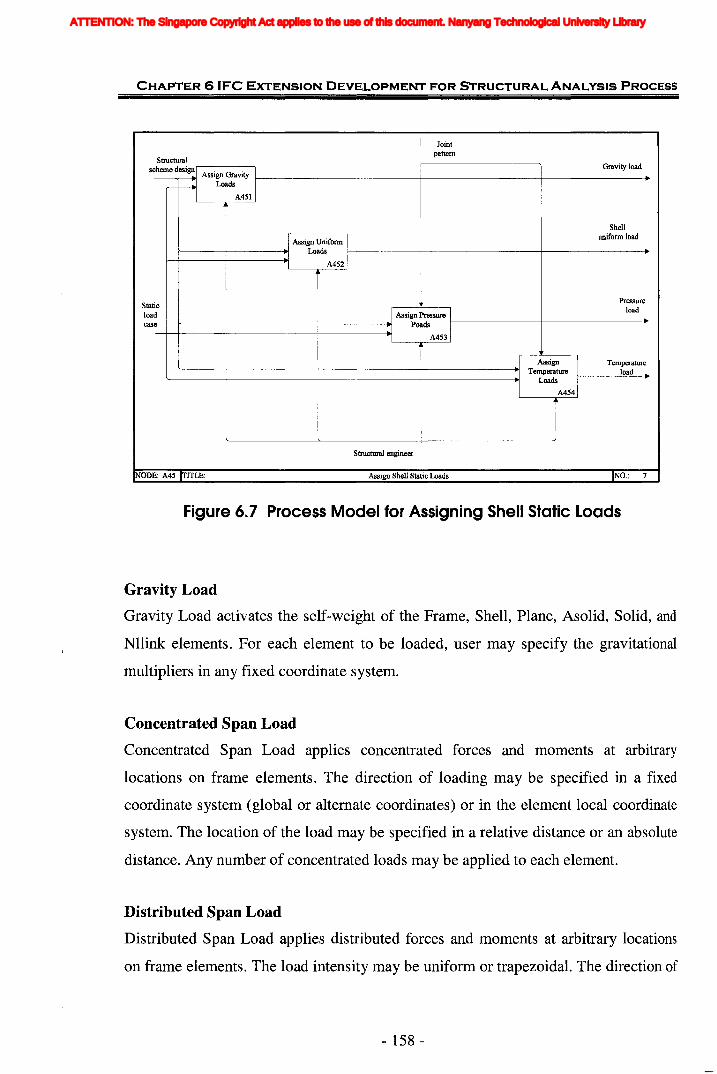
Jointpattern
Shellunifonn load
CHAPTER 6 IFC EXTENSION DEVELOPMENT FOR STRUCTURAL ANALYSIS PROCESS
Structuralh d· II I Gravity load
sc erne eSlgn.l Assign Gravity 1-------------1----------1------.,.-H LoadSA451
I
.1 Assign Unifonn Ir----~------.lJ Loads 11-------+----------+---------.
I A452
Pressureload
Staticloadcase
IAssign Pressure I1'-----1-------1------.1] Poads II--------t----------.
I A453
AssignTemperature
'------I------------1I---------j--------.t Loads
A454
Structural engineer
Temperatureload
NODE: A45 ITITLE: Assign Shell Static Loads INO.: 7
Figure 6.7 Process Model for Assigning Shell Static Loads
Gravity Load
Gravity Load activates the self-weight of the Frame, Shell, Plane, Asolid, Solid, and
Nllink. elements. For each element to be loaded, user may specify the gravitational
multipliers in any fixed coordinate system.
Concentrated Span Load
Concentrated Span Load applies concentrated forces and moments at arbitrary
locations on frame elements. The direction of loading may be specified in a fixed
coordinate system (global or alternate coordinates) or in the element local coordinate
system. The location of the load may be specified in a relative distance or an absolute
distance. Any number of concentrated loads may be applied to each element.
Distributed Span Load
Distributed Span Load applies distributed forces and moments at arbitrary locations
on frame elements. The load intensity may be uniform or trapezoidal. The direction of
- 158 -
ATTENTION: The Singapore Copyright Act applies to the use of this document. Nanyang Technological University Library
CHAPTER 61FC EXTENSION DEVELOPMENT FOR STRUCTURAL ANALYSIS PROCESS
loading may be specified in a fixed coordinate system or in the element of local
coordinate system. The load intensity is a force or moment per unit of length. The
intensity is measured per unit of element length. For each force or moment component
to be applied, a single load value may be given if the load is uniformly distributed.
Two load values are needed if the load intensity varies linearly over its range· of
application (a trapezoidal load).
Prestress Load
Any of the frame elements in the model can be subjected to the forces and moments
produced by one or more prestressing cables. This load always acts in the local 1-2
plane of the element. For each element user may specify a scale factor, which
multiplies the effect of all cables that act on that element. The scale factors are
additive.
In SAP2000, the precondition for defining "Prestress Load" is to define the "Frame
Prestressing Pattern". The prestressing pattern comprises the information about cable
tension, the cable eccentricities at start, middle and end points respectively. ST-4 has
no definition for this information.
Uniform Load
Uniform Load is used to apply uniformly distributed forces to the midsurface of shell
elements. The direction of the loading may be specified in a fixed coordinate system
or in the element local coordinate system. Load intensities are given as forces per unit
area. The total force acting on the element in each local direction is given by the total
load intensity in that direction multiplied by the area of the midsurface.
Surface Pressure Load
Surface Pressure Load applies an external pressure to any of the outer faces of the
shell elements. The load on each face of an element is specified independently.
Surface pressure always acts normal to the face. Positive pressures are directed
toward the interior of the element.
- 159-
ATTENTION: The Singapore Copyright Act applies to the use of this document. Nanyang Technological University Library
CHAPTER 6 IFC EXTENSION DEVELOPMENT FOR STRUCTURAL ANALYSIS PROCESS
Temperature Load
Temperature Load creates thermal strains in the frame and shell elements. These
strains are given by the product of the Material coefficients of thermal expansion and
the temperature change of the element. The temperature change is measured from the
element Reference Temperature to the element Load Temperature.
6.2.5 Define Analysis OptionsAfter a complete structural model is created using the operations above, user can
analyze the model to determine the resulting displacements, stresses, and reactions.
Before analyzing, analysis options need be set. Figure 6.8 shows that the options
consist of:
1. Available degrees of freedom for the analysis;
2. Modal analysis parameters if a Dynamic Analysis is required;
3. P-Delta analysis parameters if P-Delta analysis is performed;
4. Which analysis results to be written to the output file if user want to have any
analysis results saved to an output file;
5. The amount of memory (RAM) to be used in Kilobytes (KB).
- 160-
ATTENTION: The Singapore Copyright Act applies to the use of this document. Nanyang Technological University Library

CHAPTER 6 IFC EXTENSION DEVELOPMENT FOR STRUCTURAL ANALYSIS PROCESS
,.--------1 Building design code
Structural Degree ofscheme design freedom
~.........---.t.l Define"I Available DOFs
I ASl
Dynamic=:; ~/parameters
,---~_AS--,2 P-delta.-----X----------,
.1 Set P-delta ~ parameters'-----+----+---+------~"I Parameters
I AS3
I
Set OutputOptions
AS4
Output options
'----. Compile'----------+----~ Analysis
Options
ASS
JStructural engineer
Analysisoptions
E: Define Analysis Options 0.: S
Figure 6.8 Process Model for Defining Analysis Options
6.2.6 Run Analysis and Display I Output the ResultsFinishing all above works, the analysis is started simply by click the "Run Analysis"
button on the SAP2000's main toolbar. Three kinds of displaying are provided to
view the model and the results of the analysis, graphical displays, tabular displays,
and function plots.
Analysis results that can be graphically displayed include deformed shapes; vibration
mode shapes; frame-element force, moment, and influence-line diagrams; and shell
element force, moment and stress contour plots. Tabular display is used to reveal the
detailed analysis results in a special text window for a single joint or element at a time.
Function plots are graphs of one variable against another. These include response
spectrum curves, pushover curves and time-history traces, all of which are generated
from the results of a time-history analysis. In current research scope, only the first two
types of display are used and the function plots are not applicable.
- 161 -
ATTENTION: The Singapore Copyright Act applies to the use of this document. Nanyang Technological University Library
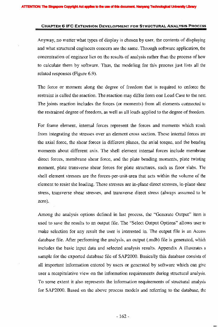
CHAPTER 6 IFC EXTENSION DEVELOPMENT FOR STRUCTURAL ANALYSIS PROCESS
Anyway, no matter what types of display is chosen by user, the contents of displaying
and what structural engineers concern are the same. Through software application, the
concentration of engineer lies on the results of analysis rather than the process of how
to calculate them by software. Thus, the modeling for this process just lists all the
related responses (Figure 6.9).
The force or moment along the degree of freedom that is required to enforce the
restraint is called the reaction. The reaction may differ form one Load Case to the next.
The joints reaction includes the forces (or moments) from all elements connected to
the restrained degree of freedom, as well as all loads applied to the degree of freedom.
For frame element, internal forces represent the forces and moments which result
from integrating the stresses over an element cross section. These internal forces are
the axial force, the shear forces in different planes, the axial torque, and the bending
moments about different axis. The shell element internal forces include membrane
direct forces, membrane shear force, and the plate bending moments, plate twisting
moment, plate transverse shear forces for plate structures, such as floor slabs. The
shell element stresses are the forces-per-unit-area that acts within the volume of the
element to resist the loading. These stresses are in-plane direct stresses, in-plane shear
stress, transverse shear stresses, and transverse direct stress (always assumed to be
zero).
Among the analysis options defined in last process, the "Generate Output" item is
used to save the results to an output file. The "Select Output Options" allows user to
make selection for any result the user is interested in. The output file is an Access
database file. After performing the analysis, an output (.mdb) file is generated, which
includes the basic input data and selected analysis results. Appendix A illustrates a
sample for the exported database file of SAP2000. Basically this database consists of
all important information entered by users or generated by software which can give
user a recapitulative view on the information requirements during structural analysis.
To some extent it also represents the information requirements of structural analysis
for SAP2000. Based on the above process models and referring to the database, the
- 162-
ATTENTION: The Singapore Copyright Act applies to the use of this document. Nanyang Technological University Library
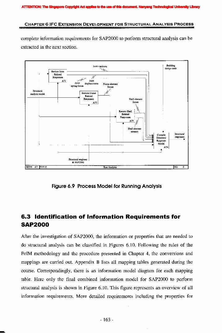
CHAPTER 6 (FC EXTENSION DEVELOPMENT FOR STRUCTURAL ANALYSIS PROCESS
complete information requirements for SAP2000 to perform structural analysis can be
extracted in the next section.
turalnses-.
Joint reactions Building
~design code
Review Joint~ Related
Responses IIIA71 ~ Joint
Joint displacements Frame elementspring forces forces
StructfJral Janalysis model Review FrameRelated
Responses Shell elementAn forces
Review ShellRelated
R..ponses ?_'A73
Shell elementstresses
~Compile Struc
Structural respo
ResponseModel
A74
j
Structural engineer& SAP2000
NODE: A7 TIlLE: Run Analysis NO.: 9
Figure 6.9 Process Model for Running Analysis
6.3 Identification of Information Requirements forSAP2000
After the investigation of SAP2000, the information or properties that are needed to
do structural analysis can be classified in Figures 6.10. Following the rules of the
PolM methodology and the procedure presented in Chapter 4, the conversions and
mappings are carried out. Appendix B lists all mapping tables generated during the
course. Correspondingly, there is an information model diagram for each mapping
table. Here only the final combined information model for SAP2000 to perform
structural analysis is shown in Figure 6.10. This figure represents an overview of all
information requirements. More detailed requirements including the properties for
- 163 -
ATTENTION: The Singapore Copyright Act applies to the use of this document. Nanyang Technological University Library

CHAPTER 6 'FC EXTENSION DEVELOPMENT FOR STRUCTURAL ANALYSIS PROCESS
each entity are shown in the respective information diagram for each level of process
model in Appendix B.
Figure 6.10 Information Requirements of SAP2000 for Structural Analysis
Two important parts of information constitute the whole requirements of SAP2000 to
analyze structure. One is the part of information to set up structural analysis model.
The other part is the structural responses, the results of analysis. And the information
about structural analysis model can be classified into 5 different categories by their
functions: (1) geometry information; (2) material information; (3) load information,
involving static loads and load combinations; (4) member section information; (5)
analysis options. A total of six categories can be identified with respect to the whole
information requirements for SAP2000, the five types of information mentioned
above and structural responses. The advantage of these classifications can make
information more clear because they have similar functions and they should have
some common characteristics. The assessment of IFC models performed in next
section also complies with these classifications.
- 164-
ATTENTION: The Singapore Copyright Act applies to the use of this document. Nanyang Technological University Library

CHAPTER 61FC EXTENSION DEVELOPMENT FOR STRUCTURAL ANALYSIS PROCESS
6.4 Assessment of IFe Models
In order to review the capabilities of IFC product models to support structural analysis
at multiple levels of detail, comparison between the information requirements and
current IFC models has to be done. After a series of comparison, shown in Appendix
C, our initial findings with respect to the suitability of the IFC Release 2x Edition 2
Addendum 1 (IAI, 2004) to support structural analysis processes are as follows:
• For a simple frame structure, most of the mechanical features and properties
necessary for static structural analysis can be found in current IFC release.
• Some information need to be deduced from the data in IFC.
• However, the only items IFC does not support include prestress load,
description for stresses and types of load combinations, etc.
In the following section, the gaps are summed up and explained in detail under
different categories. Table 6.1 lists the overall gaps between the information
requirements of SAP2000 and current IFC extensions in Release 2x Edition 2
Addendum 1. Not only is the missing information given, it is also classified into
different scenarios according to IFC 2x Extension Modeling Guide (IAI, 2001). As
described in Chapter 4, there are three scenarios that may be observed from gaps
analysis: (1) concepts exist in the IFC model, (2) concepts extend the IFC model, and
(3) new concepts. For different scenarios, various approaches are considered to be
adopted for the development of IFC extensions. The possible approaches are also
listed in Table 6.1. Extension is based on analysis of the gaps that exist between
concepts needed to be incorporated for the extension model development and
concepts that already form part of the IFC Models.
- 165 -
ATTENTION: The Singapore Copyright Act applies to the use of this document. Nanyang Technological University Library
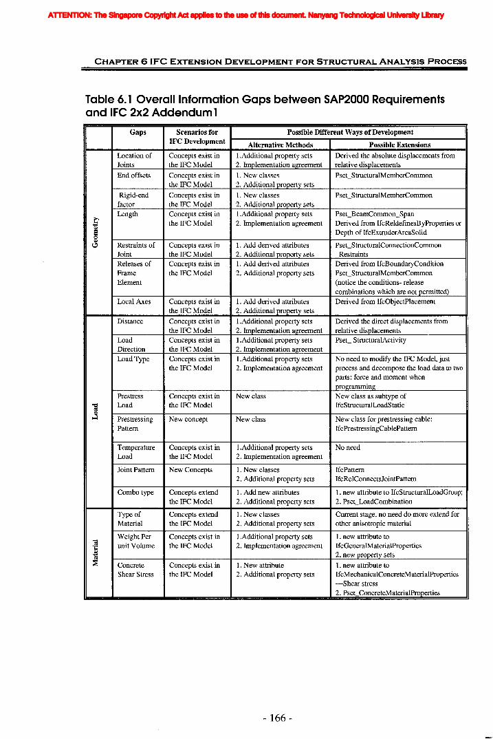
CHAPTER 6 IFC EXTENSioN DEVELOPMENT FOR STRUCTURAL ANALYSIS PROCESS
Table 6. 1 Overall Information Gaps between SAP2000 Requirementsand IFC 2x2 Addendum 1
Gaps Scenarios for Possible Different Ways of DevelopmentIFe Development Alternative Methods Possible Extensions
Location of Concepts exist in I.Additional property sets Derived the absolute displacements fromJoints the IFC Model 2. Implementation agreement relative displacements
End offsets Concepts exist in 1. New classes PseCStructuralMemberCommonthe IFC Model 2. Additional property sets
Rigid-end Concepts exist in 1. New classes PseCStructuralMemberCommonfactor the IFC Model 2. Additional property sets
ELength Concepts exist in I.Additional property sets PseCBeamCommon_Span
the IFC Model 2. Implementation agreement Derived from IfcReldefinesByProperties or
~ Depth of IfcExtruderAreaSolid~
Restraints of Concepts exist in 1. Add derived attributes PseCStructuralConnectionCommon~
Joint the IFC Model 2. Additional property sets RestraintsReleases of Concepts exist in 1. Add derived attributes Derived from IfcBoundaryConditionFrame the IFC Model 2. Additional property sets PseCStructuralMemberCommonElement (notice the conditions- release
combinations which are not permitted)Local Axes Concepts exist in 1. Add derived attributes Derived from IfcObjectPlacement
the IFC Model 2. Additional property sets
Distance Concepts exist in I.Additional property sets Derived the direct displacements fromthe IFC Model 2. Implementation agreement relative displacements
Load Concepts exist in I.Additional property sets PseC StructuralActivityDirection the IFC Model 2. Implementation agreementLoad Type Concepts exist in I.Additional property sets No need to modify the IFC Model, just
the IFC Model 2. Implementation agreement process and decompose the load data to twoparts: force and moment whenprogramming
Prestress Concepts exist in New class New class as subtype of"Cl Load the IFC Model IfcStructuralLoadStatic~0
I...:l Prestressing New concept New class New class for prestressing cable:Pattern IfcPrestressingCablePattern
Temperature Concepts exist in I.Additional property sets No needLoad the IFC Model 2. Implementation agreement
Joint Pattern New Concepts 1. New classes IfcPattern2. Additional property sets IfcRelConnectsJointPattern
Combo type Concepts extend 1. Add new attributes 1. new attribute to IfcStructuralLoadGroup;the IFC Model 2. Additional property sets 2. PseCLoadCombination
Type of Concepts extend 1. New classes Current stage, no need do more extend forMaterial the IFC Model 2. Additional property sets other anisotropic material
Weight Per Concepts exist in I.Additional property sets 1. new attribute to-;
unit Volume the IFC Model 2. Implementation agreement IfcGeneralMaterialProperties'C
~ 2. new property sets~ Concrete Concepts exist in 1. New attribute 1. new attribute to
Shear Stress the IFC Model 2. Additional property sets IfcMechanicalConcreteMaterialProperties-Shear stress2. Pset ConcreteMaterialProperties
- 166-
ATTENTION: The Singapore Copyright Act applies to the use of this document. Nanyang Technological University Library
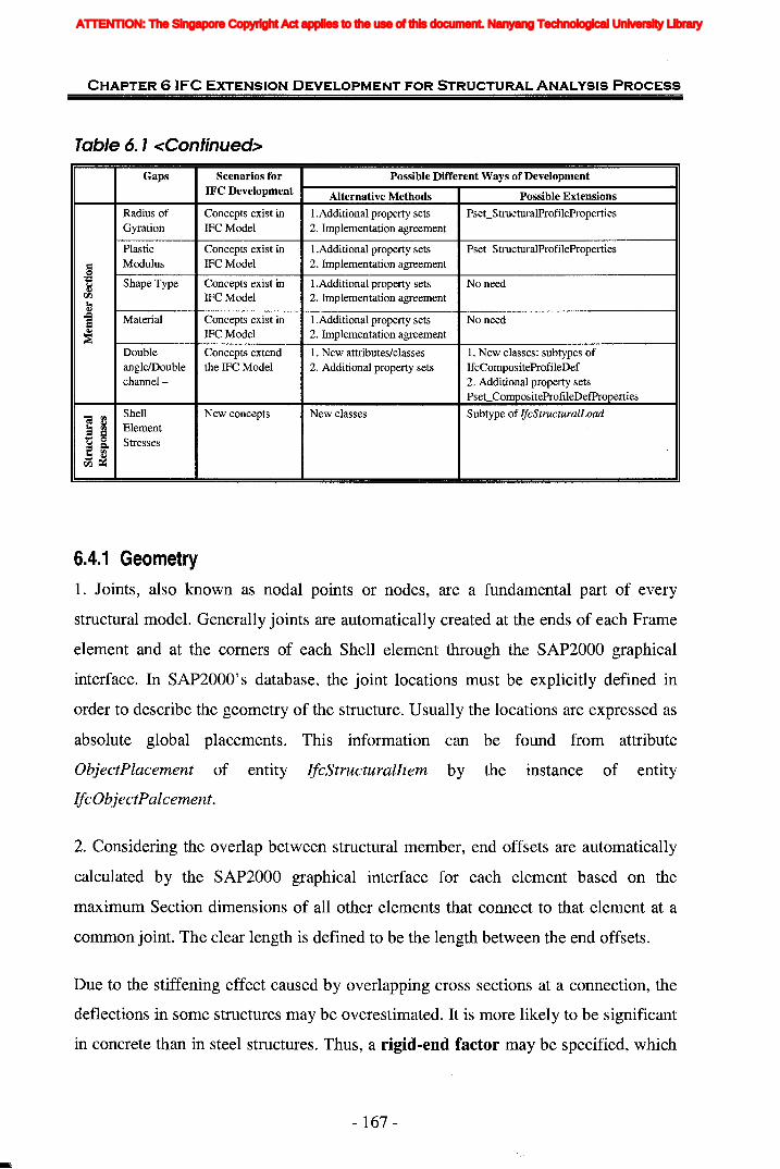
CHAPTER 61FC EXTENSION DEVELOPMENT FOR STRUCTURAL ANALYSIS PROCESS
Table 6. 1<Continued>
Gaps
Radius ofGyration
PlasticModulus
Shape Type
Scenarios forIFC Development
Concepts exist inIFC Model
Concepts exist inIFCModel
Concepts exist inIFC Model
Possible Different Ways of Development
Alternative Methods Possible Extensions
I.Additional property sets PseCStructuralProfileProperties2. Implementation agreement
I.Additional property sets PseCStructuralProfileProperties2. Implementation agreement
I.Additional property sets No need2. Implementation agreement
Material
Doubleangle/Doublechannel-
ShellElementStresses
Concepts exist inIFCModel
Concepts extendthe IFC Model
New concepts
I.Additional property sets2. Implementation agreement
1. New attributes/classes2. Additional property sets
New classes
No need
1. New classes: subtypes ofIfcCompositeProfileDef2. Additional property setsPset CompositeProfileDefProperties
Subtype of lfcStructuralLoad
6.4.1 Geometry1. Joints, also known as nodal points or nodes, are a fundamental part of every
structural model. Generally joints are automatically created at the ends of each Frame
element and at the comers of each Shell element through the SAP2000 graphical
interface. In SAP2000's database, the joint locations must be explicitly defined in
order to describe the geometry of the structure. Usually the locations are expressed as
absolute global placements. This information can be found from attribute
ObjectPlacement of entity IfcStructuralltem by the instance of entity
IfcObjectPalcement.
2. Considering the overlap between structural member, end offsets are automatically
calculated by the SAP2000 graphical interface for each element based on the
maximum Section dimensions of all other elements that connect to that element at a
common joint. The clear length is defined to be the length between the end offsets.
Due to the stiffening effect caused by overlapping cross sections at a connection, the
deflections in some structures may be overestimated. It is more likely to be significant
in concrete than in steel structures. Thus, a rigid-end factor may be specified, which
- 167 -
ATTENTION: The Singapore Copyright Act applies to the use of this document. Nanyang Technological University Library

CHAPTER 6 'FC EXTENSION DEVELOPMENT FOR STRUCTURAL ANALYSIS PROCESS
gives the fraction of each end offset that is assumed to be rigid for bending and shear
deformation. The flexible length Lf of the element is given by: L f= L - rigid (ioff+
joff). The default rigid-end factor is zero. The engineering judgment is used to select
the appropriate value for this parameter. Typically its value would not exceed about
0.5.
3. Length can be inferred from the geometry information of two joints.
4. The "Restraints" of Joint in SAP2000 are represented by TrueIFalse in Ul/2/3 &
R1/2/3, which can be inferred from IfcBoundaryNodeCondition for
IfcStructuralConnection.AppliedCondition. When the value of attribute
LinearStiffness or RotationalStiffness of IfcBoundaryNodeCondition equals to infinite,
then the corresponding displacement is restrained (its value equals to "Y").
5. Many combinations of end releases may be specified for a Frame element provided
that the element remains stable; this assures that all load applied to the element is
transferred to the rest of the structure. Similarly, the "Release" of frame elements can
be inferred from IfcBoundaryNodeCondition for IfcRelConnectsStructuralMember.
AppliedCondition. When the value of Property LinearStiffness or RotationalStiffness
of IfcBoundaryNodeCondition equals to zero, then the corresponding end of frame is
released (its value is equal to "I" which means it is released in joint I).
6. Each part (joint, element, or constraint) of the structural model has its own local
coordinate system used to define the properties, loads, and response for that part. In
SAP2000, the axes of the local coordinate systems are denoted 1, 2, and 3.
Normally the joint local 1-2-3 coordinate system is the same as the global X-Y-Z
coordinate system. However, user may define any arbitrary orientation for a joint
local coordinate system by specifying two reference vectors and/or three angles of
rotation. For Frame and Shell elements, two methods are provided by SAP2000 to
define the element local coordinate system. One is through the default orientation,
where one of the local axes is first defined by the geometry of the individual element
and the remaining two axes is determined by the relationship between the first axis
- 168-
ATTENTION: The Singapore Copyright Act applies to the use of this document. Nanyang Technological University Library

CHAPTER 6 'FC EXTENSION DEVELOPMENT FOR STRUCTURAL ANALYSIS PROCESS
and the global Z axis. The other way is to specify a single angle of rotation to define
element orientations that are different from the default orientation.
In current IFC models, the entity IfcLocalPlacement defines the relative placement of
a product in relation to the placement of another product or the absolute placement of
a product within the geometric representation context of the project. The
IfcLocalPlacement allows that an IfcProduct can be placed by this IfcLocalPlacement
(through the attribute ObjectPlacement) within the local coordinate system of the
object placement of another IfcProduct, which is referenced by the PlacementRelTo.
If the PlacementRelTo is not given, then the IfcProduct is placed absolutely within the
world coordinate system. The geometric placement that defines the transformation
from the related coordinate system into the relating is defined by IfcAxis2Placement,
which is referenced by the RelativePlacement. This transformation normally is
defined in terms of a point and orientations of an axis in 2D or two axes in 3D. The
angle can be derived from the orientation of axes. The orientation is defined in a
general direction vector in two or three dimensional space. The angle can be
calculated from the direction ratios of vector.
6.4.2 Load1. When the user defines the location of given point loads and trapezoidal span loads
to frame elements, the parameter of "Load Distance" is needed and often refers to the
relative distance. Even though the "Absolute distance form end-I" is entered by
engineer rather than "Relative distance form end-I", SAP2000 will change it to
relative distance when saving the information in database. In IFC models, the location
of action is denoted by the topology representation of IfcStructuralPointAction by the
attribute Representation or the attribute VaryingAppliedLoadLocation of entity
IfcStructuralLinearActionVarying. Finally the items IfcVertex or IfcVertexPoint and
IfcCartesianPoint, or IfcPointOnCurve are used to give the location at which the
actions act upon the structural items.
2. About "Load Direction", there are totally 11 kinds of direction in SAP2000, Local
1/2/3, Global x/y/Z, Global x/y/Z projected, Gravity and Gravity Projected. The
- 169-
ATTENTION: The Singapore Copyright Act applies to the use of this document. Nanyang Technological University Library
CHAPTER 6 'FC EXTENSION DEVELOPMENT FOR STRUCTURAL ANALYSIS PROCESS
loads can be applied in different coordinate systems, global system or local system,
projected or true, which are specified by the attributes GlobalOrLocal /
ProjectedOrTrue of IfcStructuralAction in IFC models. The detailed directions are
implied in the value of IfcStructuralLoad. For instance, if there is an
IfcStructuralLoadSingleForce (10, 0, 0, 0, 0, 0), then it only applied 10 units of force
in x-direction. Consequently, the "Load Type" will be "Force" and direction is Global
X or Local 1.
3. The value of "Load Type" can be "Force" and "Moment" which is defined when
engineers input the static loads to various structural elements. In SAP2000, the force
and moment should be assigned separately. However, in IFC models the entity
IfcStructuralLoad contains the definitions both on forces and on moments. Since
SAP2000 can only save either Force or Moment for every input, it is possible that
some load definitions for the same element at the same position in SAP2000 may
correspond to one IfcStructuralLoad Entity. By contraries, the value of each
IfcStructuralLoadStatic should be decomposed in order to make it usable for
SAP2000. Accordingly the value for "Load Type" is known. That is to say its value
can be inferred from the status of value of IfcStructuralLoad.
4. As "Prestress Load" is out of the scope of project ST-4, there is no definition in
current IFC models. As the precondition for defining prestress loads, the "Prestressing
Pattern" is also missing.
5. In SAP2000 the definitions that are most different with IFC models are the
definitions for temperature loads assigned to frame or shell elements, and for pressure
loads assigned to shell elements. Besides in giving the change of temperature or
pressures directly which are uniform over an element's surface, engineers can specify
the variation of temperature or pressures which are interpolated from pressure values
given by "Joint Pattern", which involves predefining "Joint Pattern".
In current IFC models, the entity IfcStructuralLoadTemperature is used to define
actions which are caused by a temperature change, and DeltaT-Y & DeltaT-Z
- 170-
ATTENTION: The Singapore Copyright Act applies to the use of this document. Nanyang Technological University Library
CHAPTER 61FC EXTENSION DEVELOPMENT FOR STRUCTURAL ANALYSIS PROCESS
represent the values for the outer fibre of the positive Y and Z directions. Their way
of expression is different.
6. In SAP2000, four types of load combinations are available. In current IFC models,
the type of load combination is always set as additive by default (where the value is
"ADD" in SAP2000). The other three types are ENVE, ABS and SRSS. For different
types of Combo, the responses are calculated in different ways.
• Additive type: The Combo value is an algebraic linear combination of the maximum
/ minimum values for each of the contributing cases.
• Absolute type: The Combo value is the sum of the larger absolute values for each of
the contributing cases.
• SRSS type: The Combo value is the square root of the sum of the squares of the
larger absolute values for each of the contributing cases.
• Envelope type: The Combo maximum is the maximum of all of the maximum
values for each of the contributing cases. Similarly, Combo minimum is the minimum
of all of the minimum values for each of the contributing cases.
ENVE is used for moving loads and any analysis case where the load producing the
maximum or minimum force/stress is required. ABS and SRSS are used for lateral
loads.
6.4.3 Material PropertyGenerally speaking, nearly all properties of material can be found in current IFC
extensions. The primary entity is IfcMechanicalMaterialProperties. By and large, it
contains all properties which are independent of the actual material type. Properties
for different material types, such as concrete or steel, are extracted as its subtypes
IfcMechanicalSteelMaterialProperties and IfcMechanicalConcreteMaterialProperties.
However, some micro aspects still need to be considered.
- 171 -
ATTENTION: The Singapore Copyright Act applies to the use of this document. Nanyang Technological University Library

CHAPTER 6 (Fe EXTENSION DEVELOPMENT FOR STRUCTURAL ANALYSIS PROCESS
1. The value for two properties, Weight per unit volume and Type of material, are
required by SAP2000, but not included in current IFC Release. In current IFC Release
only isotropic materials are allowed for.
2. Shear strength, one of the design properties used for concrete, does not have the
corresponding IFC definitions. In fact, different algorithms are used to calculate the
shear strength of concrete under different design codes. For example, according to
"British Standards Institute's Structural Use of Concrete (BSI BS8110, 1997)", the concrete
shear strength is equal to 5N/mm2 or O.8~feu' which is less and where 'feu' is the
characteristic strength of concrete.
6.4.4 Section Property of MemberBasically, most of the information can be found in current IFC extensions, directly or
indirectly. However, the following three aspects still need to be considered.
1. Some information about member's section as defined in SAP2000 need to be
derived from the existing information in IFC models.
At first, there are twelve general section properties that are required to be defined in
SAP2000. But only the first eight general properties that must be explicitly specified;
the other four can be calculated from given properties according to the following
formulae:
a) Radius of Gyration: r == if;b) Plastic modulus: Z == ACYl + Y2 ) or Z == f x S , where, 'f is shape Factor.
2
In the above formulae, '[' stands for the moment of inertia, and 'A' stands for the area
of cross section. Under fully plastic conditions, the neutral axis divides the cross
section into two equal areas. And' Yl ' and' Y2 ' are the distances from the neutral
axis to the centroids of these two areas respectively.
- 172-
ATTENTION: The Singapore Copyright Act applies to the use of this document. Nanyang Technological University Library

CHAPTER 6 IFC EXTENSION DEVELOPMENT FOR STRUCTURAL ANALYSIS PROCESS
In current IFC models, Moment of inertia 'I' and area of section 'A' are defined as
attributes of entity IfcStructuralProfileProperties. Shape factor 'f is included as
attributes 'PlasticShapeFactorY/z' in entity IfcStructuralSteelProfilePropertie". Two
distances, ' Yl ' and' Y2 " can be derived from the properties of entity IfcProfileDef
and its subtypes. It has already been noted in IFC that "The radii of gyration are not
given explicitly but can be derived from moment of inertia and section area".
However, the value of one operand to compute plastic modulus should come from
another class, it cannot be extended by the way of adding derived attributes.
Secondly, in SAP2000 there is a very important parameter named "Shape Type" that
is used to determine the means about how to obtain the section properties (see Section
6.2.3). There is no explicit definition for this information in IFC models. But it is
implied in the names of related entities. In IFC models, IfcProfileDef is used to define
a cross section by the profile definition within the swept surfaces or swept area solids,
which is the supertype of all definitions of standard and arbitrary profiles within IFC,
such as IfcIShapeProfileDef, IfcLShapeProfileDef, IfcCircleProfileDef, etc. It is
obviously that their Shape Types are I, L, and C respectively from the name of
profiles.
2. In SAP2000, users donot need to define material type for each structural element.
The assignment of material type to structure is through the assignment of section. In
IFC models, they are two independent parts which are connected by the common
assigned structural member. Two association relationships,
IfcRelAssociatesProfileProperties and IfcRelAssociatesMaterial, are used to specify
the objectified relationships between non geometric profile properties and elements to
which these properties apply, as well as between a material definition and elements or
element types to which this material definition applies (IAI, 2004).
3. For special types of sections (e.g. "Double Angle" and "Double Channel"
sections) , most defining parameters can be found their corresponding IFC definitions
except the properties "Outside width" and "Back to back distance". In IFC models,
the IfcCompositeProfileDef defines the profile by composition of at least two other
- 173 -
ATTENTION: The Singapore Copyright Act applies to the use of this document. Nanyang Technological University Library

CHAPTER 6 (FC EXTENS'ION DEVELOPMENT FOR STRUCTURAL ANALYSIS PROCESS
profile definitions (IAI, 2004). The dimensions of composite profile are determined
by the dimensions of its component profiles. No any new definition for the dimension
of composite profile is introduced in current IFC.
Double angle and Double channel can be treated as the composition of two angles and
two channels respectively. The "Outside width" and "Back to back distance" can be
calculated based on the defining parameters of component profiles,
IfcUShaperProfileDef or IfcLShapeProfileDef Their relationships are illustrated in
Table 6.2.
Table 6.2 Expressions for "Outside Width" and "Back to Back Distance"
Example
Pattern
Double Angle Double Channel
Back to back
distance
Outside
width
Distance between the position of Distance between the position of
two composite L-shaped two composite V-shaped
sections - the sum of two sections - the sum of two
locations of centre of gravity in locations of centre of gravity in
X or Y axis which depends on X axis
the side to be composed
the sum of width or depth the sum of flange width of two
(which depends on the side to be composite U-shaped sections +
composed) of two composite L- Back to back distance
shaped sections + Back to back
distance
- 174-
ATTENTION: The Singapore Copyright Act applies to the use of this document. Nanyang Technological University Library
CHAPTER 6 IFC EXTENSION DEVELOPMENT FOR STRUCTURAL ANALYSIS PROCESS
6.4.5 Analysis OptionsThe dynamic analysis is outside of the scope of current IFCmodels. The setting of
output options to saved file is entirely for the convenience of the operations of
software which cannot be regarded as an information requirement for structural
analysis. Referring to the scope of this research, the analysis options on dynamic
analysis, P-delta analysis and output options would not be considered in this thesis.
Another analysis option is the definition of the appropriate degrees of freedom (Ul,
U2, U3, Rl, R2, R3) to be available for structural model. Alternatively, in SAP2000
the available degrees of freedom may be automatically checked by clicking on the
four fast DOF's options Le. Space Frame, Plane Frame, Plane Grid and Space Truss.
In fact, this part of information is implied during setting up of the structural
idealization model.
Thus, Appendix C will not include the comparison of this part of information
requirements with IFC models. Accordingly the information about SAP2000's
analysis options will not be discussed in the subsequent study.
6.4.6 Structural ResponsesIn current IFC Release, only the output results for forces and displacements are
considered. The outputs, like stresses and strains, are out of the scope of ST-4 project.
There are no definitions for shell element stresses so far.
6.5 Generality Study of Information Gaps
As described in Chapter 4.7, different approaches will be adopted in different
scenarios for IFC extension development. Thus the new problem faced is how to
identify the character of information and make the decision on whether this
information should be included in the IFC models by amending the current schema.
This question cannot be answered without abstracting the common information
requirements of popular structural analysis soft packages and comparing it with
current IFC schema. Thereby in order to confirm whether it is necessary to add new
- 175 -
ATTENTION: The Singapore Copyright Act applies to the use of this document. Nanyang Technological University Library

CHAPTER 6 IFC EXTENSION DEVELOPMENT FOR STRUCTURAL ANALYSIS PROCESS
classes or make any change to current schema, a generality study is carried out to
investigate into other ten different structural analysis software in this research.
In 1998, Modem Steel Construction magazine published the results of a survey of
practicing structural engineers. In the survey (as shown in Table 6.3), these engineers
were asked to rate the quality of the programs they used. Whereas this survey was
conducted nearly seven years ago, it is obviously and unavoidable that current status
has changed. Nowadays this survey can only be an assistant reference to select
appropriate software.
Furthermore, in January 2003, the Modem Steel Construction magazine highlighted
32 structural engineering software products and some product case studies were also
provided. In August 2004, the STRUCTURE magazine also gave a software guide for
structural engineers whereby around 60 kinds of general or specific engineering
software were listed and their characteristics are also given, such as the functions,
types of structures in point, materials involved etc. Based on this highlights and the
guide, Table 6.4 extracts 35 kinds of structural engineering software and makes a
comprehensive view on the applicability of these software for different design cases,
such as the design of different structures, different materials, different analysis
methods etc.
- 176-
ATTENTION: The Singapore Copyright Act applies to the use of this document. Nanyang Technological University Library
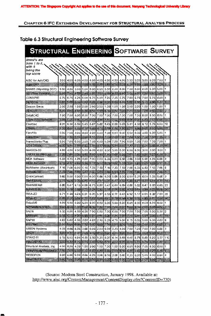
CHAPTER 6 (FC EXTENSION DEVELOPMENT FOR STRUCTURAL ANALYSIS PROCESS
Table 6.3 Structural Engineering Software Survey
STRUCTURAL ENGINEERINGResults arefrom 1 it).· S~with 8being thetop 5Cf)f'e
AISC for .AutoCAD
SOFTWARE SURVEY'
(Source: Modern Steel Construction, January 1998. Available at:http://www.aisc.org/ContentManagement/ContentDisplay.cfm?ContentID=730)
- 177 -
ATTENTION: The Singapore Copyright Act applies to the use of this document. Nanyang Technological University Library

Tabl
e6.
4C
ompa
riso
nof
Str
uctu
ral
Eng
inee
ring
Sof
twar
eP
rodu
cts
II0 :I:
Ana
lysi
sI~
> :!IM
etho
dITI
~::u
~0
)So
ftw
are
Tit
leI
I·~
eIJ
Qj
~Q
j~
Des
crip
tion
"Cl
•..
..=:;;
==
Qj=
Qj
e~
"""'"
~..
e't
eIJ
•~
=0
eIJ
"Cl
Qj
=~
Qj
.."""
'"..
"Cl
~.-
~
="""
'"~
="'C
l"I.l
.-=
=Q
jJT
l=
Qj
=..
0=
~~
0•
••
~~
~<
~==
~~
==~
r.I'l
~~
Ur.I
'lm Z (/
) 0 Z C m < m~
II~....
.J0
0~ ITI Z -I "T
l 0
8.W
inST
RU
DL
Fin
ite
elem
entp
rogr
amX
XX
!X..•....
XX
X::u
-X.•.•...
en9.
S-F
RA
ME
Pow
erfu
l2D
/3D
anal
ysis
soft
war
eX
XiX
.....
-I.......
....>
::u10
.Mul
tiF
ram
e2D
/3D
stat
ican
ddy
nam
ican
alys
iso
ffra
med
XX
.....•..
........
.......•
....X
Xc
......••
•••.•••....
i(n
stru
ctur
es-I
........
.
C11
.LG
BE
AM
ER
Col
dfo
rmed
stee
lfra
min
gde
sign
X/X
::u12
.Str
uctu
ral
Mul
ti-p
urpo
sean
alys
isan
dX
XX·
·····)~X
••..•..> r-
Exp
ert
Seri
esde
sign
prog
ram
s>
....•••
••Z
(SE
S)
<>
13.R
STA
B3D
anal
ysis
soft
war
eon
lyfo
rfr
ame
stru
ctur
eX
XX
))XX
X!<
14.D
r.So
ftw
are
Rea
l-ti
me
stru
ctur
alm
odel
ine:
soft
war
eI·
XX
X(/
).....
.iii -0 ::u 0 0 JT
l(I
)fI
)
ATTENTION: The Singapore Copyright Act applies to the use of this document. Nanyang Technological University Library
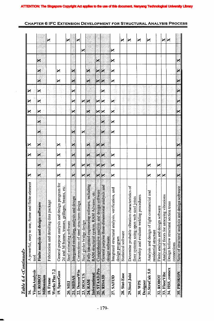
Tab
le6.
4<
Con
tin
ued
>
~~16
.A
pow
erfu
l,ea
syto
use,
fram
ean
dfi
nite
-ele
men
tto
ol-f IT
t ::0
18.F
ram
eF
abri
cati
onan
dde
tail
ing
data
pack
age
....X
I~W
ork
sP
lus
7.2
.........
..
19.S
pace
Gas
sG
ener
alpu
rpos
ean
alys
isan
dde
sign
prog
ram
for
XX
XX
XX
~ ITt Z (I) 0 Z C ITt < ITt r- 0 "1J
~3:
-.J
ITt
\0Z
I-f
Inte
grat
edst
ruct
ural
anal
ysis
,ver
ific
atio
n,an
dX
X"'I
t 0de
sin
rora
m::0
28.S
tat-
Eas
eS
tati
stic
also
ftw
are
X(I
)-f
29.S
teel
Jois
tD
eter
min
epr
obab
levi
brat
ion
char
acte
rist
ics
of
X::0 C n -f
30.W
PS
Dev
elop
and
eval
uate
wel
ding
proc
edur
esX
I!D
esig
ner
31.S
tru
Cal
c5.
0A
nalv
sis
and
desi
2:n
ofl
i2:h
tcom
mer
cial
and
XX
Xz >
32.R
OB
OT
Fin
ite
anal
ysis
and
desi
gnso
ftw
are
XX
r>/·
</
....... 1
<\
I!33
.Flo
orV
ibe
Ana
lysi
so
ffl
oors
for
anno
ying
vibr
atio
nsX
x>
»/
.../'/
.....•..
X.
../,
//
I>•.•....•
....
34.H
SS
_con
nex
Des
ign
holl
owst
ruct
ural
sect
ion
trus
s......
X...
::0 0 n ITt
(I)
(I)
ATTENTION: The Singapore Copyright Act applies to the use of this document. Nanyang Technological University Library
CHAPTER 6 IFC EXTENSION DEVELOPMENT FOR STRUCTURAL ANALYSIS PROCESS
In order to choose most appropriate software for the generality study, some criteria
need be specified. Considering the characteristic of SAP2000 and for improving the
comparability with the information definitions of other structural analysis and design
applications, three criteria of selection are complied with:
(1) They should be the most comprehensive and versatile structural analysis and
design software systems available and commonly used in the industry.
(2) They should be integrated and general purpose analysis and design software which
can be applicable to any types of structures, buildings, bridges, etc., and are not
software specially for the design of bridges, or the design of standard steel sections,
etc.
(3) They should have been developed and used for many years.
Besides Tables 6.3 and 6.4, the author also searched the Internet and found out some
evaluations of various structural engineering softwares. The most comprehensive and
useful forum is Eng-Tips forum (http://www.eng-tips.com). which covers almost all
aspects of engineering and where many engineers post their comments and
suggestions on structural engineering softwares. As a result of the above investigation
and using the three criteria, ten structural analysis and design software were finally
selected. They are:
(1) Computers and Structures, Inc. (CSI), which specializes in structural and
earthquake engineering software. The products offered by CSI (SAP2000, ETABS
and SAFE) cover a wide range of structural applications from high rise buildings to
multi-use one- and two-story structures (industrial structures, hospitals) and bridges
(suspension and cable stayed bridges, multi-span bridges) to transmission towers. For
nearly three decades, CSI software has been used for the analysis and design of major
projects in over 100 countries (CSI, 2004).
(2) STAAD.Pro is the world standard for structural analysis and design software with
the most intuitive modeling environment, support for most international design codes,
multi-material design, automatic load generation (seismic, gravity, wind, wave and
- 180-
ATTENTION: The Singapore Copyright Act applies to the use of this document. Nanyang Technological University Library
CHAPTER 6 IFC EXTENSION DEVELOPMENT FOR STRUCTURAL ANALYSIS PROCESS
moving) and extremely user-friendly reports and result presentations (REI, 2004). As
mentioned in Modem Steel Construction (2003), STAAD.Pro is the choice of 46 out
of 50 leading Structural Engineering firms, 46 out of 50 state DOTs and 7 out of the
top 10 engineering universities. STAAD.Pro features a state-of-the-art user interface,
visualization tools, powerful analysis and design engines with advanced finite element
and dynamic analysis capabilities.
(3) RISA·3D is a general purpose three-dimensional analysis and design software
developed to model, solve and optimize 3D structures as fast and easily as possible.
Analysis may be done on structures constructed of any material or combination of
materials. Design of hot rolled steel, concrete, cold formed steel, and wood is fully
supported. The truly interactive nature of RISA-3D is its primary strength. RISA-3D
also performs elaborate error checking, and provides context sensitive help every step
of the way.
(4) STRAP (STRuctural Analysis Programs) is one of the most comprehensive and
versatile structural analysis and design software systems available on the market
today (MSC, 2003). It's easy to use, due to its superb graphic user interface (GUI) and
advanced context-sensitive help system. It offers the engineer a powerful but
affordable tool for analysis and design of a wide range of skeletal and continuum
structures such as buildings, bridges, shells, towers and more (ATIR, 2004).
(5) GT STRUDL is a world class computer-aided structural engineering software
system for assisting engineers in the structural analysis and design process (Georgia
Tech - CASE Center, 2004). It integrates graphical modeling and result display,
frame and finite static, dynamic, and nonlinear analysis, finite element analysis,
structural frame design, graphical result display, and structural database management
into a powerful menu driven information processing system.
In over 29 years of use, GT STRUDL has become one of the most widely accepted
programs for the structural analyst and structural design engineer. GT STRUDL is
used on a regular basis by thousands of engineers in over 30 countries.
- 181 -
ATTENTION: The Singapore Copyright Act applies to the use of this document. Nanyang Technological University Library

CHAPTER 61FC EXTENSION DEVELOPMENT FOR STRUCTURAL ANALYSIS PROCESS
(6) RAM International has products for every type of project, for every building
material, and for every budget. RAM Structural System includes RAM Steel, RAM
Concrete, RAM Frame, and RAM Foundation, which provides a fully integrated suite
of building design, analysis and drafting software RAM Advanse is a full-featured,
general purpose 3D finite element analysis and design software system for wood, steel,
cold-formed steel and concrete. It is suitable for analysis and design of any type of
structure or structural component.
(7) ROBOT Millennium is the state-of-the-art finite element structural engineering
software. It is a recognized system in the analysis and design of various structures
including buildings, bridges, industrial facilities, civil and mechanical engineering.
The software performs static/dynamic analysis of 2D/3D projects using beams, plates,
shells and solids elements. ROBOT Millennium evolved over 20 years of innovative
and extensive developments and improvements, as well as a precise study of users'
needs and experience of ROBOT V6 and ROBOT 97 (ISS, 2004).
(8) MIDAS Programs for Integrated Modeling, Analysis & Design of Civil/Bridge &
Building Structures will change the way of engineering practice (MSC, 2003).
MIDAS/Gen is a Windows-based, general-purpose structural analysis and optimal
design system (MIDASoft, 2004). MIDAS/Gen offers conventional analysis
capabilities as well as other analyses such as Geometric nonlinear analysis reflecting
Large Displacement, Boundary nonlinear analysis, Pushover analysis, Construction
simulated analysis reflecting time dependent material properties, Heat of hydration
analysis, etc. MIDAS/Gen has been used for over 10 years and applied to over 4,000
projects successfully, thereby, exhibiting its credibility and stability.
(9) REAL3D-Analysis is a comprehensive frame and finite element structural
analysis program that provides accuracy, reliability and ease of use to structural
engineers (CGI, 2002). It incorporates the latest technologies from the fields of finite
element analysis, numerical computation and computer graphics. It is a true 32-bit,
fully integrated Windows program that allows user to visually analyze any practical
2D & 3D structures reliably, in an unsurpassed user-friendly manner.
- 182-
ATTENTION: The Singapore Copyright Act applies to the use of this document. Nanyang Technological University Library
CHAPTER 6 (FC EXTENSION DEVELOPMENT FOR STRUCTURAL ANALYSIS PROCESS
(10) The PROKON suite of structural analysis and design software is developed by
engineers for engineers. It is a large collection of modular engineering programs
covering structural analysis, steel design, concrete design, geotechnical analysis and
other general calculations including gutter design and wind pressure on buildings.
Used worldwide in more than eighty countries, the suite provides quick and reliable
answers to everyday structural and geotechnical engIneerIng problems
(http://www.prokon.com).
For all the missing information and some derived information identified in previous
sections (as shown in Table 6.1), their definitions in above ten kinds of software are
investigated and compared with SAP2000's. Table 6.5 shows the results of generality
study. In Table 6.5, the "tick" symbol, ''.1'', means that the information in the software
is expressed in the same way as SAP2000. For those defined in different ways, its
brief definition is given. Consequently the generality of the definition in SAP2000
for the missing information can be judged. Then the corresponding solutions of IFC
extension development are also decided. The detailed explanations are specified in the
section following the table.
- 183 -
ATTENTION: The Singapore Copyright Act applies to the use of this document. Nanyang Technological University Library
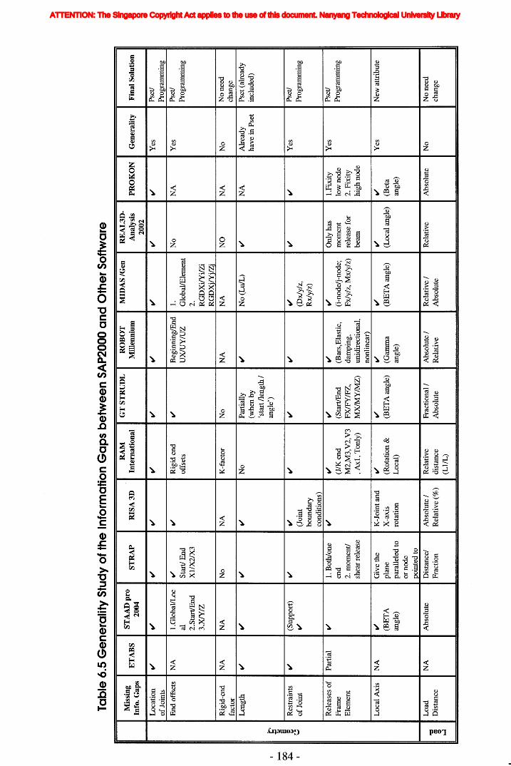
~ 00~
Tab
le6.
5G
en
era
lity
Stu
dy
of
the
Info
rmat
ion
Ga
ps
be
twe
en
SA
P20
00a
nd
Oth
erS
oft
war
e
Mis
sing
ST
AA
Dp
roR
AM
GT
ST
RU
DL
RO
BO
TM
IDA
S/G
enR
EA
L3D
-E
TA
BS
ST
RA
PR
ISA
3D
Inte
rnat
iona
lM
ille
nniu
mA
naly
sis
PR
OK
ON
Gen
eral
ity
Fin
alS
olut
ion
Info
.G
aps
2004
2002
Loc
atio
nII
'II
'II
'II
'II
'II
'II
'II
'II
'II
'Y
esP
set!
ofJ
oint
sP
rogr
amm
ing
End
offs
ets
NA
I.G
loba
l/L
ocII
'II
'R
igid
end
II'
Beg
inni
nglE
nd1.
No
NA
Yes
Pse
t!
alS
tart
!E
ndof
fset
sU
XlU
Y/u
ZG
loba
llE
lem
ent
Pro
gram
min
g
2.S
tart
lEnd
XI/
X2/
X3
2.3
.XIY
/ZR
GD
Xi/
Yil
Zi
RG
DX
ilY
i/Z
i
Rig
id-e
ndN
AN
AN
oN
AK
-fac
tor
No
NA
NA
NO
NA
No
No
need
fact
orch
ange
Len
gth
II'
II'
II'
II'
No
Par
tial
lyII
'N
o(L
ulL
)II
'N
AA
lrea
dyP
set(
alre
ady
(whe
nby
have
inP
set
incl
uded
)'s
tart
/len
gth
/
t-an
gle'
)... Q
J §R
estr
aint
sII
'(S
uppo
rt)
II'
II'
II'
II'
II'
II'
II'
II'
Yes
Pse
t!Q
J
~o
fJoi
ntII
'(J
oint
(Dx/
y/z,
Pro
gram
min
g
boun
dary
Rx/
y/z)
cond
itio
ns)
Rel
ease
so
fP
arti
alII
'1.
Bot
h/on
eII
'II
'II
'II
'II
'O
nly
has
I.F
ixit
yY
esPs
et!
Fra
me
end
(J/K
end
(Sta
rtlE
nd(B
ars,
Ela
stic
,(i
-nod
e!j-
node
;m
omen
tlo
wno
deP
rogr
amm
ing
Ele
men
t2.
mom
ent!
M2,
M3,
V2,
V3
FX
lFY
IFZ
,da
mpi
ng,
Fxl
y/z,
Mx/
y/z)
rele
ase
for
2.F
ixit
ysh
earr
elea
se, A
xI,
Ton
ly)
MX
lMY
IMZ
)un
idir
ecti
onal
,be
amhi
ghno
deno
nlin
ear)
Loc
alA
xis
NA
II'
Giv
eth
eK
-Joi
ntan
dII
'II
'II
'II
'II
'II
'Y
esN
ewat
trib
ute
(BE
TA
plan
eX
-axi
s(R
otat
ion
&(B
ET
Aan
gle)
(Gam
ma
(BE
TA
angl
e)(L
ocal
angl
e)(B
eta
angl
e)pa
rall
eled
toro
tati
onL
ocal
)an
gle)
angl
e)or
node
poin
ted
to
Loa
dN
AA
bsol
ute
Dis
tanc
e!A
bso
lute
/R
elat
ive
Fra
ctio
nal/
Abs
olut
e/R
elat
ive
/R
elat
ive
Abs
olut
eN
oN
one
ed"'C
SD
ista
nce
Fra
ctio
nR
elat
ive
(%)
dist
ance
Abs
olut
eR
elat
ive
Abs
olut
ech
ange
~ 0 1..'.1
(LI/
L)
ATTENTION: The Singapore Copyright Act applies to the use of this document. Nanyang Technological University Library
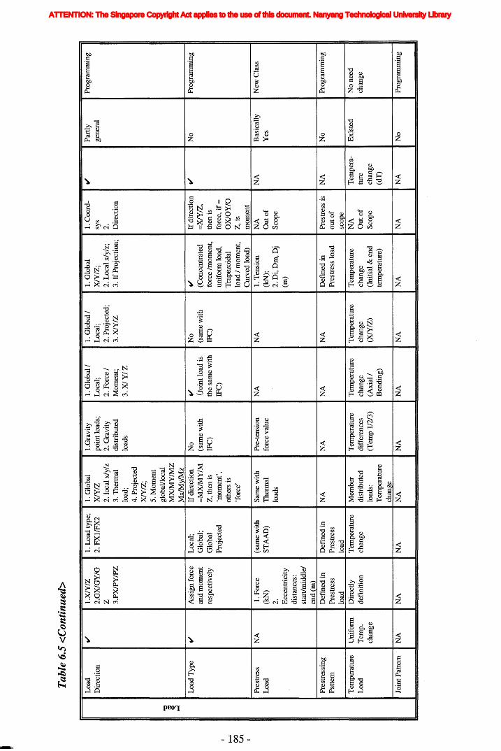
to--
00
U1.
Tab
le6.
5<
Con
tinu
ed>
Loa
dII
'I.
XlY
IZ1.
Loa
dty
pe;
1.G
loba
lI.
Gra
vity
1.G
loba
l11.
Glo
bal1
1.G
loba
l1.
Coo
rd-
II'
Par
tly
Pro
gram
min
gD
irec
tion
2.G
XlG
Y/G
2.F
XII
FX
2X
lYIZ
poin
tloa
ds;
Loc
al;
Loc
al;
XlY
IZ;
sys
gene
ral
Z2.
loca
lx1y
lz2.
Gra
vity
2.F
orce
12.
Pro
ject
ed;
2.L
ocal
x1y/
z;2.
3.P
XlP
YIP
Z3.
The
rmal
dist
ribu
ted
Mom
ent;
3.X
lYIZ
3.If
Pro
ject
ion;
Dir
ecti
onlo
ad;
load
s3
.XlY
/Z4.
Pro
ject
edX
lYIZ
;5.
Mom
ent
"0gl
obal
lloc
ald
MX
lMY
IMZ
0 ~M
x!M
ylM
zL
oad
Typ
eII
'A
ssig
nfo
rce
Loc
al;
Ifdi
rect
ion
No
II'
No
II'
Ifdi
rect
ion
II'
No
Pro
gram
min
gan
dm
omen
tG
loba
l;=
MX
lMY
IM(s
ame
wit
hO
oint
load
is(s
ame
wit
h(C
once
ntra
ted
=X
lYIZ
,re
spec
tive
lyG
loba
lZ
,th
enis
IFC
)th
esa
me
wit
hIF
C)
forc
eIm
omen
t,th
enis
Pro
ject
ed'm
omen
t',IF
C)
unif
orm
load
,fo
rce,
if=
othe
rsis
Tra
pezo
idal
OX
lOY
/O'fo
rce'
load
1m
omen
t,Z
,is
Cur
ved
load
)m
omen
t
Pre
stre
ssN
A1.
For
ce(s
ame
wit
hS
ame
wit
hP
re-t
ensi
onN
AN
A1.
Ten
sion
NA
NA
Bas
ical
lyN
ewC
lass
Loa
d(k
N)
ST
AA
D)
The
rmal
forc
eva
lue
(kN
);O
uto
fY
es2.
load
s2
.Di,
Dm
,Dj
Sco
peE
ccen
tric
ity
(m)
dist
ance
s:st
art/
mid
dle!
end
(m)
Pre
stre
ssin
gD
efin
edin
Def
ined
inN
AN
AN
AN
AD
efm
edin
Pre
stre
ssis
NA
No
Pro
gram
min
gP
atte
rnP
rest
ress
Pre
stre
ssP
rest
ress
load
outo
flo
adlo
adsc
ope
Tem
pera
ture
Uni
form
Dir
ectl
yT
empe
ratu
reM
embe
rT
empe
ratu
reT
empe
ratu
reT
empe
ratu
reT
empe
ratu
reN
AT
empe
ra-
Exi
sted
No
need
Loa
dT
emp.
defm
itio
nch
ange
dist
ribu
ted
diff
eren
ces
chan
gech
ange
chan
geO
uto
ftu
rech
ange
chan
gelo
ads:
(Tem
p11
213)
(Axi
al1
(XlY
IZ)
(Ini
tial
&en
dS
cope
chan
geT
empe
ratu
reB
endi
ng)
tem
pera
ture
)(d
T)
chan
geJo
intP
atte
rnN
AN
AN
AN
AN
AN
AN
AN
AN
AN
AN
oP
rogr
amm
ing
ATTENTION: The Singapore Copyright Act applies to the use of this document. Nanyang Technological University Library
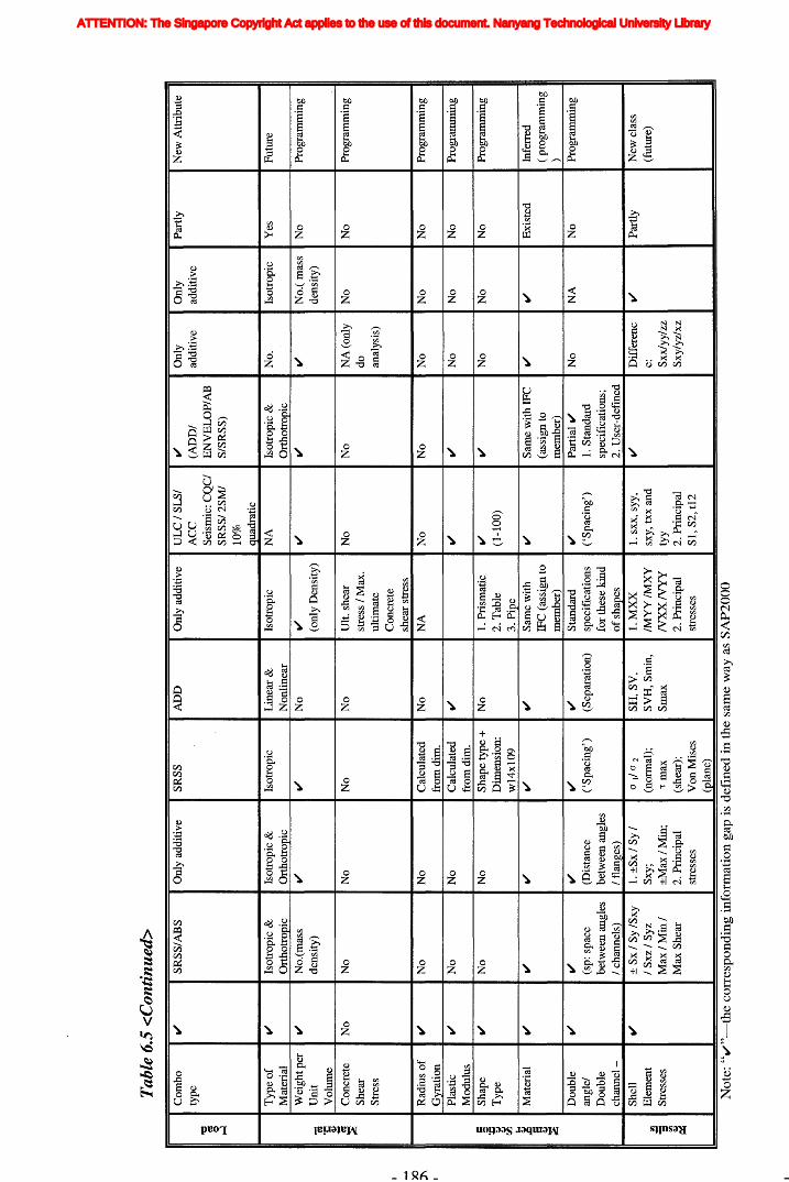
X)
J\
Tab
le6.
5<
Con
tin
ued
>
Com
bo'"
SR
SS
/AB
SO
nly
addi
tive
SR
SS
AD
DO
nly
addi
tive
UL
CI
SLSI
'"O
nly
Onl
yP
artl
yN
ewA
ttri
bute
type
AC
C(A
DD
Iad
diti
vead
diti
ve"0
Sei
smic
:CQ
CI
EN
VE
LO
P/A
B~ Q
SR
SS
/2S
MI
SISR
SS)
~
10%
quad
rati
c
Typ
eo
f'"
Isot
ropi
c&
Isot
ropi
c&
Isot
ropi
cL
inea
r&
Isot
ropi
cN
AIs
otro
pic
&N
o.Is
otro
pic
Yes
Fut
ure
Mat
eria
lO
rtho
trop
icO
rtho
trop
icN
onli
near
Ort
hotr
opic
Wei
ghtp
er'"
No.
(mas
s'"
'"N
o'"
'"'"
'"N
o.(
mas
sN
oP
rogr
amm
ing
"aU
nit
dens
ity)
(onl
yD
ensi
ty)
dens
ity)
·CV
olum
e~ ~
Vlt
.sh
ear
Pro
gram
min
g~
Con
cret
eN
oN
oN
oN
oN
oN
oN
oN
A(o
nly
No
No
~S
hear
stre
ssIM
ax.
doS
tres
sul
tim
ate
anal
ysis
)C
oncr
ete
shea
rst
ress
Rad
ius
of
'"N
oN
oC
alcu
late
dN
oN
AN
oN
oN
oN
oN
oP
rogr
amm
ing
Gyr
atio
nfr
omdi
m.
Pla
stic
'"N
oN
oC
alcu
late
d
'"'"
'"N
oN
oN
oP
rogr
amm
ing
Mod
ulus
from
dim
.§
Sha
pe
'"N
oN
oS
hape
type
+N
o1.
Pri
smat
ic'"
'"N
oN
oN
oP
rogr
amm
ing
;:T
ype
Dim
ensi
on:
2.T
able
(1-1
00)
~ ~ 00w
14x1
093.
Pip
eJ-4 ~
Mat
eria
l
'"'"
'"'"
'"S
ame
wit
h
'"S
ame
wit
hIF
C'"
'"E
xist
edIn
ferr
ed"5
IFC
(ass
ign
to(a
ssig
nto
(pr
ogra
mm
ing
~m
embe
r)m
embe
r))
Dou
ble
'"'"
'"'"
'"S
tand
ard
'"P
arti
al'"
No
NA
No
Pro
gram
min
gan
glel
(sp:
spac
e(D
ista
nce
('S
paci
ng')
(Sep
arat
ion)
spec
ific
atio
ns('
Spa
cing
')1.
Sta
ndar
dD
oubl
ebe
twee
nan
gles
betw
een
angl
esfo
rth
ese
kind
spec
ific
atio
ns;
chan
nel
-I
chan
nels
)I
flan
ges)
of
shap
es2.
Use
r-de
fmed
She
ll'"
±S
xl
Sy
ISxy
1.±
Sx
/S
yI
atI
O2
SH
,SV
,1
.MX
X1.
sxx,
syy,
'"D
iffe
renc
'"P
artl
yN
ewcl
ass
~E
lem
ent
IS
xzI
Syz
Sxy;
(nor
mal
);S
VH
,Sm
in,
IMY
YIM
XY
sxy,
txx
and
e:(f
utur
e)
=S
tres
ses
Ma
x/M
inl
±M
axIM
in;
Tm
axS
max
NX
XN
YY
tyy
Sxxl
yy/z
zl:I
.l~
Max
She
ar2.
Pri
ncip
al(s
hear
);2.
Pri
ncip
al2.
Pri
ncip
alSx
y/yz
lxz
=:st
ress
esV
onM
ises
stre
sses
Sl,
S2,t
I2(p
lane
)
Not
e:".
,I"-
the
corr
espo
ndin
gin
form
atio
nga
pis
defi
ned
inth
esa
me
way
asS
AP
2000
ATTENTION: The Singapore Copyright Act applies to the use of this document. Nanyang Technological University Library

CHAPTER 6 IFC EXTENSION DEVELOPMENT FOR STRUCTURAL ANALYSIS PROCESS
6.5.1 Geometry1. Basically the location of joint or element in the databases and input tables
generated by all software is shown as absolute global displacement. The user has three
ways to create a joint: (1) by directly providing the coordinates as input values, (2) by
referring to the grid intersection, and (3) by defining the frame or shell elements. Then
the software calculates and saves the absolute coordinates automatically. Similarly in
IFC models, by IfcObjectPlacement the object placement can either be given (1)
absolute (relative to the world coordinate system), (2) relative (relative to the object
placement of another product), or (3) by grid reference (the virtual intersection and
reference direction given by two axes of a design grid).
The current view of IFC models is more coincident with reality. So here no extension
is considered. Since it is needed by all softwares, a piece of program could be written
to generate the inputs.
2. Regarding the end offsets about frame elements, six out of ten softwares have this
function. In SAP2000, the offsets on'!, and 'J' joints are directly specified by user.
But some software require more detailed information including the direction (Global/
Local), the joint assigned (Start/End), and offsets (X N/Z).
3. Almost all the database files of every software would include the information of the
frame element's length. However, this value is mostly calculated by the software
automatically unless the user selects to define the frame element by giving its starting
point, its length and angle, such as in GT STRUDL. Therefore, although it is a general
requirement, it is not necessary to modify current IFC models.
4. Basically, the way to define supports and restraints of joints or releases of frame
elements are the same in all softwares. Normally, if the check box is checked, it
means that the joint is restrained and vice versa. For each end of frame element, six
types of release are specified individually. In SAP2000, they are Axial, Shear Force 2
(Major), Shear Force 3 (Minor), Torsion, Moment 22 (Minor) and Moment 33
(Major). Each kind of release includes Start and End two ends. In SAP2000, the
- 187 -
ATTENTION: The Singapore Copyright Act applies to the use of this document. Nanyang Technological University Library

CHAPTER 6 IFC EXTENSION DEVELOPMENT FOR STRUCTURAL ANALYSIS PROCESS
values for each type of release are either "I" (released in "Start" end), or "J" (released
in "End"), or "IJ" (released in both ends). In other software, maybe the value is
expressed by 0 or 1. Regardless of what kind of value is used, the essential meaning is
the same. As mentioned in Section 6.4.1, this part of information can be inferred from
the attribute AppliedCondition for IfcStructuralConnection or
IfcRelConnectsStructuralMember. An instance of IfcBoundaryNodeCondition is used
to define the joints properties. So this information can be considered add into current
IFC models by Pset.
5. Usually the default local axes are given automatically when an element is defined.
The local axis is needed only when the section of element rotates about its axes. In
this case, six out of ten kinds of software define an angle named Beta angle or Gamma
angle to express the difference from the default local axes. STRAP is different by
given the plane local axis paralleled to or node local axis pointed to. Anyway, IFemodels provide sufficient definition to this information which is implied and can be
calculated by the direction ratios of IfcDirection (please see Section 6.4.1). Anyway a
derived attribute can be considered to entity IfcDirection to express the angles of the
direction vector. And a function is also developed to calculate the angles. Please see
Section 6.6 and Appendix D for the details.
6.5.2 Load
1. Basically, most software provide users two ways to enter the location of load either
by relative distance or by absolute distance, for the users' convenience, like STRAP,
RISA 3d, RAM, GT STRUDL, ROBOT and MIDAS. However, this parameter is not
applied to all load cases. Only the point loads and trapezoidal loads to frame elements
have this property. Furthermore, it can be concluded that basically current IFC models
provide explicit definition for the location of point action and linear action as
described in Section 6.4.2. Thus no change is needed and translation during the
implementation is enough.
2. Referring to Table 6.5, by and large, "Load Direction" includes three parts of
information. One is coordinate system, local or global. The other one is the detailed
- 188 -
ATTENTION: The Singapore Copyright Act applies to the use of this document. Nanyang Technological University Library
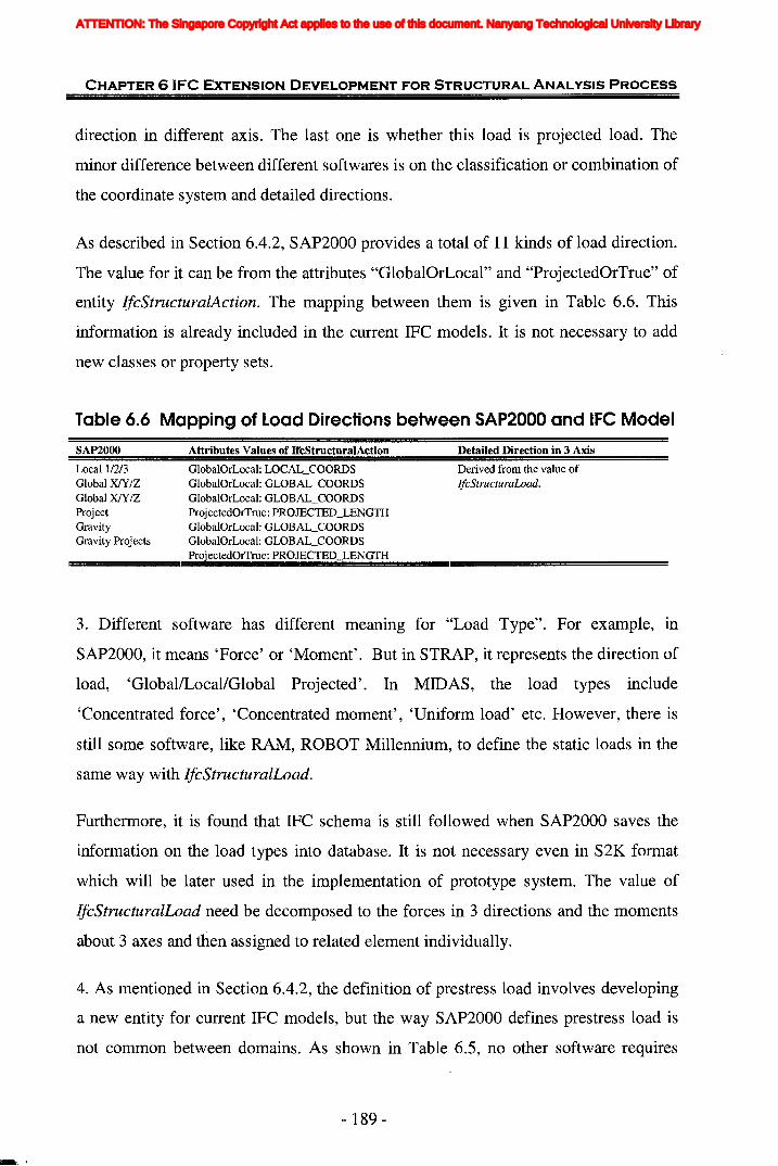
CHAPTER 6 'FC EXTENSION DEVELOPMENT FOR STRUCTURAL ANALYSIS PROCESS
direction in different axis. The last one is whether this load is projected load. The
minor difference between different softwares is on the classification or combination of
the coordinate system and detailed directions.
As described in Section 6.4.2, SAP2000 provides a total of 11 kinds of load direction.
The value for it can be from the attributes "GlobaIOrLocal" and "ProjectedOrTrue" of
entity IfcStructuralAction. The mapping between them is given in Table 6.6. This
information is already included in the current IFC models. It is not necessary to add
new classes or property sets.
Table 6.6 Mapping of Load Directions between SAP2000 and.IFC Model
SAP2000
Local 112/3Global XlY/ZGlobal XlY/ZProjectGravityGravity Projects
Attributes Values of IfcStructuralAction
GlobalOrLocal: LOCAL_COORDSGlobalOrLocal: GLOBAL_COORDSGlobalOrLocal: GLOBAL_COORDSProjectedOrTrue: PROJECTED_LENGTHGlobalOrLocal: GLOBAL_COORDSGlobalOrLocal: GLOBAL_COORDSProjectedOrTrue: PROJECTED LENGTH
Detailed Direction in 3 Axis
Derived from the value oflfcStructuraLoad.
3. Different software has different meaning for "Load Type". For example, in
SAP2000, it means 'Force' or 'Moment'. But in STRAP, it represents the direction of
load, 'Global/Local/Global Projected'. In MIDAS, the load types include
'Concentrated force', 'Concentrated moment', 'Uniform load' etc. However, there is
still some software, like RAM, ROBOT Millennium, to define the static loads in the
same way with IfcStructuralLoad.
Furthermore, it is found that IFC schema is still followed when SAP2000 saves the
information on the load types into database. It is not necessary even in S2K format
which will be later used in the implementation of prototype system. The value of
IfcStructuralLoad need be decomposed to the forces in 3 directions and the moments
about 3 axes and then assigned to related element individually.
4. As mentioned in Section 6.4.2, the definition of prestress load involves developing
a new entity for current IFC models, but the way SAP2000 defines prestress load is
not common between domains. As shown in Table 6.5, no other software requires
- 189-
ATTENTION: The Singapore Copyright Act applies to the use of this document. Nanyang Technological University Library

CHAPTER 6 IFC EXTENSION DEVELOPMENT FOR STRUCTURAL ANALYSIS PROCESS
defining "Frame Prestressing Pattern", whose definition is directly contained in the
definition of prestress load, such as STAAD pro, STRAP, MIDAS. There is no need
to add new class for "Frame Prestressing Patten", and further detailed study is needed.
Some new classes may be developed directly, such as the subtypes of entity
IfcStructuralLoadStatic. The details are given in next section.
5. Similarly, for the way that SAP2000 defines "Temperature Load" by "Joint
Pattern", it does not represent the generic method in other software. From Table 6.5, it
can be found that the more generic way is to define the value of temperature change
directly. At this point, the existing definition for temperature load in IFC is sufficient.
Accordingly, the concept of "Joint Pattern" is only specific to SAP2000. It is not
necessary to give a new class for this concept. This information can be translated and
processed during programming.
6. Besides SAP2000, other softwares, such as MIDAS, STAAD pro, RISA 3D,
ROBOT Millennium, also have more than one type of load combination to choose.
These four softwares represent the most popular and powerful structural analysis and
design software. Considering the future use of IFC model, this new information can
be added by attribute to entity IfcStructuralLoadGroup.
6.5.3 Material
1. In Table 6.5, half of the softwares listed can define isotropic or orthotropic material.
The orthotropic material is inevitable to be used in some types of structure. As the
usage of IFC models increases, orthotropic or anisotropic materials and their usage
should be considered in future release. It means that the extension is needed. In this
research, the new attribute to the existing class IfcMaterial will be developed.
2. Mass per unit volume is used for dynamic analysis. While weight per unit volume
is used for self weight gravity loading. Normally they are related by the value of
gravitational acceleration (386.4in/s2, 9810mmls2). It does not matter which one is
needed by the software, as long as one of them is defined and the input value is
- 190-
ATTENTION: The Singapore Copyright Act applies to the use of this document. Nanyang Technological University Library
CHAPTER 6 IFC EXTENSION DEVELOPMENT FOR STRUCTURAL ANALYSIS PROCESS
entered. Here there is no necessity to extend any new information about this to current
IFC models.
3. Most softwares do not require the definition of concrete shear stress. It is processed
and calculated from the input data during analysis.
6.5.4 Member Section1. As described in Section 6.4.4, "Radius of Gyration" and "Plastic Modulus" can be
direct!y derived or calculated from the six basic attributes of
IfcStructuralProfileProperties. In other softwares, it is not necessary for them to be
defined. Therefore, any new attribute or property set is not needed. Just calculate this
information during generating the inputs for SAP2000.
2. Similarly, "Shape Type" is not a generic property needed by all structural analysis
software. It is not qualified to be a new attribute for IFC models. It only can be
considered as a special requirement of SAP2000.
3. Although most structural analysis softwares require the material property for the
sections of structural elements to be defined. In IFC models, they are two independent
parts which can be connected by the common assigned structural member. It is very
easy to infer the material property of section in current IFC models. From the concept
of object-oriented, IFC definitions are more logical and reasonable.
4. In other softwares, the specifications of some composite sections like "Double
Angle" and "Double Channel" come from either the standard database or users' input.
Regardless of the approach, the "Back to back distance" is always needed which is
known as "Spacing" or "Distance between angles" in RISA 3D, STRAP and ROBOT
millennium. However, as "Double Angle" and "Double Channel" usually consist of
two symmetrical angles or channels, their specification depends on the dimension of
one angle or channel and the distance between angles or channels. Generally this
approach is adopted by almost all softwares including ETABS, STAAD pro 2004,
STRAP, RISA 3D, ROBOT Millennium, and MIDAS. This means that "Outside
width" is not one common requirement for defining these special sections. And as
- 191 -
ATTENTION: The Singapore Copyright Act applies to the use of this document. Nanyang Technological University Library

CHAPTER 6 'FC EXTENSION DEVELOPMENT FOR STRUCTURAL ANALYSIS PROCESS
shown in Table 6.2, it can be easily computed by the basic dimension and the distance
between angles or channels. Thus new attribute for the property "Back to back
distance" can be considered. The property "Outside width" is just calculated for
SAP2000 during programming.
6.5.5 Structural ResponsesBasically all softwares provide the function to calculate the stress of shell element. It
is obviously that the new classes will be needed in a future extension of the model.
Although we have done the analysis on information requirements for shell elements
and identified the missing information, considering the complexity on the express of
elements' stresses, the new extensions related to the stresses results will not be
proposed in current stage.
6.6 Recommendations for Further Development of theIFe Extension Model for Structural Analysis
From the generality study in Table 6.5 and the investigations carried out in last
section, it can be concluded that the different extensions to IFC models need to be
developed for the following information:
1) New Pset for:
• End offsets to frame elements;
• restraints of joints and releases of frame elements;
2) New attributes for:
• Angles of local axis;
• Types of load combination;
• Types of material;
- 192-
ATTENTION: The Singapore Copyright Act applies to the use of this document. Nanyang Technological University Library
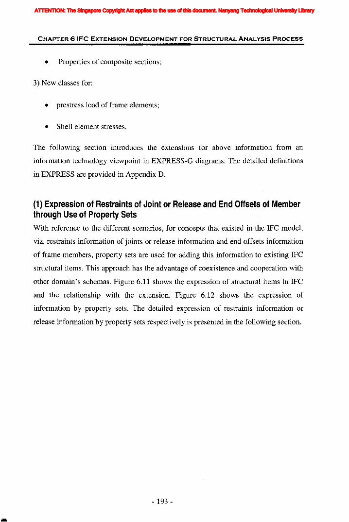
CHAPTER 6 IFC EXTENSION DEVELOPMENT FOR STRUCTURAL ANALYSIS PROCESS
• Properties of composite sections;
3) New classes for:
• prestress load of frame elements;
• Shell element stresses.
The following ·section introduces the extensions for above information from an
information technology viewpoint in EXPRESS-G diagrams. The detailed definitions
in EXPRESS are provided in Appendix D.
(1) Expression of Restraints of Joint or Release and End Offsets of Memberthrough Use of Property SetsWith reference to the different scenarios, for concepts that existed in the IFC model,
viz. restraints information of joints or release information and end offsets information
of frame members, property sets are used for adding this information to existing IFC
structural items. This approach has the advantage of coexistence and cooperation with
other domain's schemas. Figure 6.11 shows the expression of structural items in IFC
and the relationship with the extension. Figure 6.12 shows the expression of
information by property sets. The detailed expression of restraints information or
release information by property sets respectively is presented in the following section.
- 193 -
ATTENTION: The Singapore Copyright Act applies to the use of this document. Nanyang Technological University Library
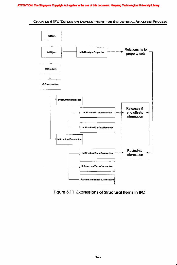
CHAPTER 6 'FC EXTENSION DEVELOPMENT FOR STRUCTURAL ANALYSIS PROCESS
IfcRoot
1IfcObject
IfcProduct
IfcStructualltem
Relationship toIfcRelAssignsProperties -----------------.
property sets
--c IfcStructuralMemeber
Releases &IfcStructuralCurveMemeber ------- ~ end offsets .--
information
IfcStructuralSurfaceMemeber
L-.c IfcStructuralConnection
RestraintsIfcStructuralPointConnection ------- ~ .-
information
f------(1 IfcStructuralCurveConnection
'------alfcStructuraISurfaceConnection
Figure 6. 11 Expressions of Structural Items in IFC
- 194-
ATTENTION: The Singapore Copyright Act applies to the use of this document. Nanyang Technological University Library
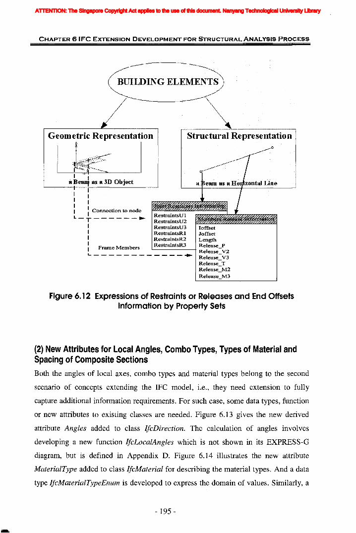
CHAPTER 6 'FC EXTENSION DEVELOPMENT FOR STRUCTURAL ANALYSIS PROCESS
BillIDING·ELEMENTS
Structural.Representation
III
I II Connection to nodeRestraintsUl
L - T - - - - - -.... RestraintsU2
I RestraintsU3 IoffsetI RestraintsRl JoffsetI RestraintsR2 LengthI F M b RestraintsR3 Release_PI rame em ers '--------i Release_V2L. - - - - - - - - - - - - ...... Release_V3
Release_TRelease_M2Release_M3
Figure 6. 12 Expressions of Restraints or Releases and End OffsetsInformation by Property Sets
(2) New Attributes for Local Angles, Combo Types, Types of Material andSpacing of Composite SectionsBoth the angles of local axes, combo types and material types belong to the second
scenario of concepts extending the IFC model, i.e., they need extension to fully
capture additional information requirements. For such case, some data types, function
or new attributes to existing classes are needed. Figure 6.13 gives the new derived
attribute Angles added to class IfcDirection. The calculation of angles involves
developing a new function IfcLocalAngles which is not shown in its EXPRESS-G
diagram, but is defined in Appendix D. Figure 6.14 illustrates the new attribute
MaterialType added to class IfcMaterial for describing the material types. And a data
type IfcMaterialTypeEnum is developed to express the domain of values. Similarly, a
- 195 -
ATTENTION: The Singapore Copyright Act applies to the use of this document. Nanyang Technological University Library
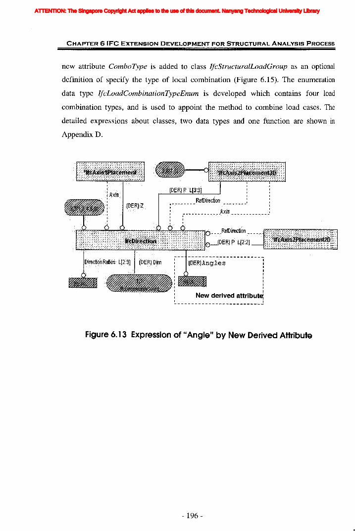
CHAPTER 6 IFC EXTENSION DEVELOPMENT FOR STRUCTURAL ANALYSIS PROCESS
new attribute ComboType is added to class IfcStructuralLoadGroup as an optional
definition of specify the type of local combination (Figure 6.15). The enumeration
data type IjcLoadCombinationTypeEnum is developed which contains four load
combination types, and is used to appoint the method to combine load cases. The
detailed expressions about classes, two data types and one function are shown in
Appendix D.
IIIIIIIIII
New derived attribute:~------------ J
Figure 6.13 Expression of "Angle" by New Derived Attribute
- 196-
ATTENTION: The Singapore Copyright Act applies to the use of this document. Nanyang Technological University Library
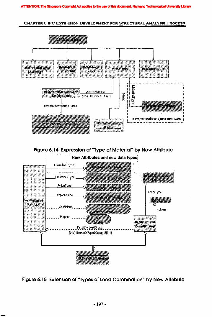
CHAPTER 6 'FC EXTENSION DEVELOPMENT FOR STRUCTURAL ANALYSIS PROCESS
~
1"';,1->.",..,,,,,,. .... -" ""'" "_ ....._"#~*"'*"', -/."',..,-- '''''''"'''II ~ '~'...,
~J~i';~.....••.•.·..·.lla.•.'.:,'~l~ .~:,1.1J.<..:;::.~..>" l~ ~
" ~
I;r1
:.N~~1%~titJ~~a~d:newdJt.!i:tvPe5 .~~/..-·~/V·~'·~/ ~"""/.'~'~":~"'~/.,:""",, ,.""../..,:~,:~~-,.~"",.".,./ ,mm-"~'~ ~
Figure 6. 14 Expression of "Type of Material" by New Attribute1-------------------------------------------,: New Attributes and new data types:I I
: ComboTV'Pe :II
_I
Figure 6. 15 Extension of "Types of Load Combination" by New Attribute
- 197 -
ATTENTION: The Singapore Copyright Act applies to the use of this document. Nanyang Technological University Library
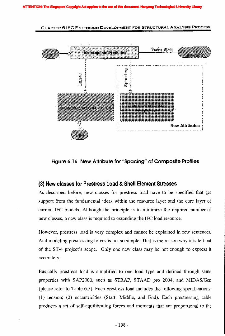
CHAPTER 6 'FC EXTENSION DEVELOPMENT FOR STRUCTURAL ANALYSIS PROCESS
---------------_._.-.-._._.-._._.-._._.--_._.-.--_.
Figure 6. 16 New Attribute for "Spacing" of Composite Profiles
(3) New classes for Prestress Load &Shell Element StressesAs described before, new classes for prestress load have to be specified that get
support from the fundamental ideas within the resource layer and the core layer of
current IFC models. Although the principle is to minimize the required number of
new classes, a new class is required to extending the IFC load resource.
However, prestress load is very complex and cannot be explained in few sentences.
And modeling prestressing forces is not so simple. That is the reason why it is left out
of the ST-4 project's scope. Only one new class may be not enough to express it
accurateIy.
Basically prestress load is simplified to one load type and defined through same
properties with SAP2000, such as STRAP, STAAD pro 2004, and MIDAS/Gen
(please refer to Table 6.5). Each prestress load includes the following specifications:
(1) tension; (2) eccentricities (Start, Middle, and End). Each prestressing cable
produces a set of self-equilibrating forces and moments that are proportional to the
- 198 -
ATTENTION: The Singapore Copyright Act applies to the use of this document. Nanyang Technological University Library

CHAPTER 6 'FC EXTENSION DEVELOPMENT FOR STRUCTURAL ANALYSIS PROCESS
cable tension, such as tensile forces acting on joints and the moments acting on joints
that are proportional to the drapes respectively, etc. The sum of these forces and
moments for all prestressing cables acting on a frame element form the unscaled
prestress load for that element.
According to the definition in software, one new class is enough to model prestress
load as the subtype of IfcStructuralLoadStatic to support the practical need. Figure
6.17 shows the definition suggested for prestress load. This is only a tentative
extension. The details will be left for further study in the research.
- ------------------------------------------------------,
PtestJ:e 5S Force
ECGer.J.trici~ies
New class I-- J
Figure 6.17 New Class for "Prestress Load"
In IFC2x Edition 2 and its addendum, the definition of actions (such as forces,
displacement, etc) and reactions (supports and deformations) are combined as the
subclasses of abstract entity IfcStructuralActivity which are specified by using the
- 199-
ATTENTION: The Singapore Copyright Act applies to the use of this document. Nanyang Technological University Library
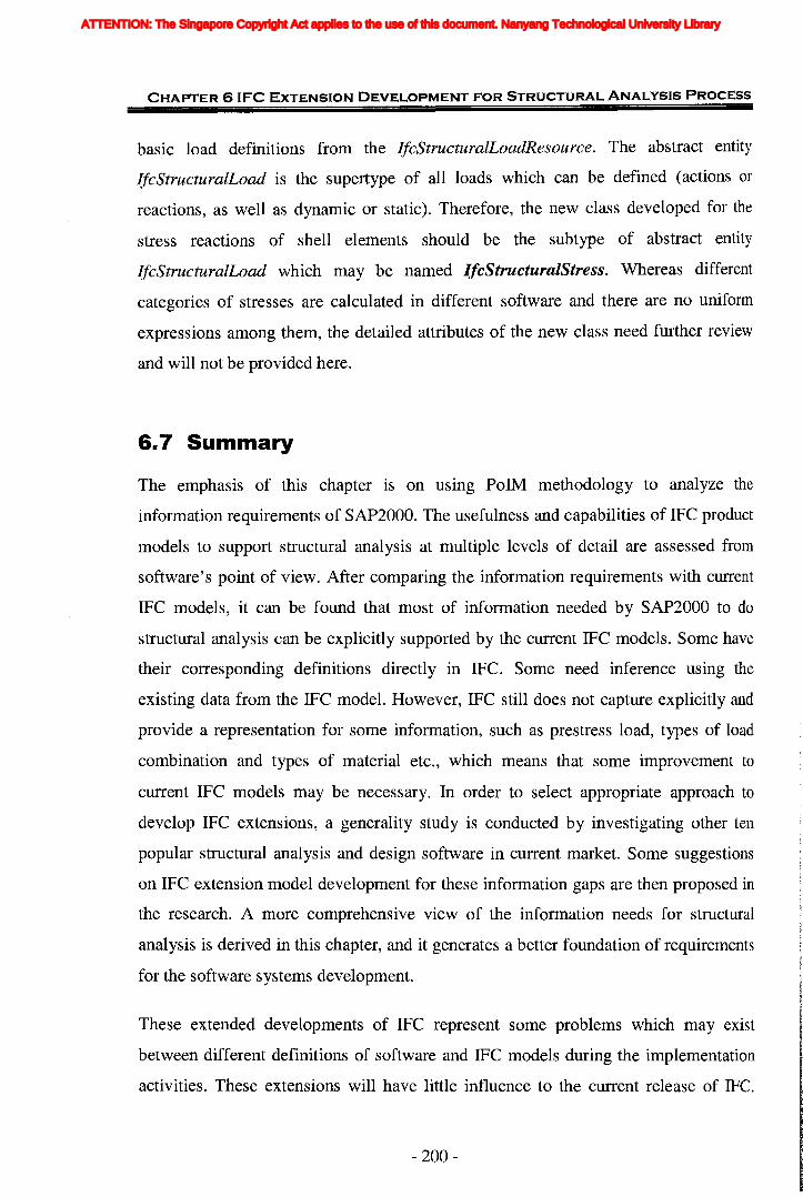
CHAPTER 6 IFC EXTENSION DEVELOPMENT FOR STRUCTURAL ANALYSIS PROCESS
basic load definitions from the IfcStructuralLoadResource. The abstract entity
IfcStructuralLoad is the supertype of all loads which can be defined (actions or
reactions, as well as dynamic or static). Therefore, the new class developed for the
stress reactions of shell elements should be the subtype of abstract entity
IfcStructuralLoad which may be named IfcStructuralStress. Whereas different
categories of stresses are calculated in different software and there are no uniform
expressions among them, the detailed attributes of the new class need further review
and will not be provided here.
6.7 Summary
The emphasis of this chapter is on uSing PolM methodology to analyze the
information requirements of SAP2000. The usefulness and capabilities of IFC product
models to support structural analysis at multiple levels of detail are assessed from
software's point of view. After comparing the information requirements with current
IFC models, it can be found that most of information needed by SAP2000 to do
structural analysis can be explicitly supported by the current IFC models. Some have
their corresponding definitions directly in IFC. Some need inference using the
existing data from the IFC model. However, IFC still does not capture explicitly and
provide a representation for some information, such as prestress load, types of load
combination and types of material etc., which means that some improvement to
current IFC models may be necessary. In order to select appropriate approach to
develop IFC extensions, a generality study is conducted by investigating other ten
popular structural analysis and design software in current market. Some suggestions
on IFC extension model development for these information gaps are then proposed in
the research. A more comprehensive view of the information needs for structural
analysis is derived in this chapter, and it generates a better foundation of requirements
for the software systems development.
These extended developments of IFC represent some problems which may exist
between different definitions of software and IFC models during the implementation
activities. These extensions will have little influence to the current release of IFC.
- 200-
ATTENTION: The Singapore Copyright Act applies to the use of this document. Nanyang Technological University Library

CHAPTER 61FC EXTENSION DEVELOPMENT FOR STRUCTURAL ANALYSIS PROCESS
And some of them are much more from software's perspective and only supporting
the requirement of real applications, such as the new class development for prestress
load. Therefore to some extent they are only some recommendations which need IAI
members to have a further review.
- 201 -
ATTENTION: The Singapore Copyright Act applies to the use of this document. Nanyang Technological University Library

7.1 Introduction
This chapter describes the development of an IFC-based web-enabled integrated
building design (IWIBD) system where a model server is developed to support both
IFC-based data integration and transaction-based interoperability between
architectural design and structural analysis processes by taking advantage of the
Internet, distributed computing and other advanced network technologies. All IFC
based information is managed and stored in an online server.
This chapter provides an overview of the requirements and the framework for this
integrated system. The descriptions about its modular design and the interactions
among the modules are provided. The user interaction interfaces are then presented
with example usage. Details of core component modules will be described in
subsequent sections.
This chapter is organized as follows:
• Section 7.1 gives a brief description of the content and structure of the chapter.
• Section 7.2 introduces the methodology used in developing the system, including
the development life cycle and UML diagrams.
* Part of this chapter has been published in the paper "Implementation of IFC-Based Web Server for
Collaborative Building Design between Architects and Structural Engineers", in January 2005 on the
Journal of Automation in Construction, Vol. 14, No.1, pp. 115-128, Elsevier Ltd, UK (Please see
Publications (page 308) for details.
- 202-
ATTENTION: The Singapore Copyright Act applies to the use of this document. Nanyang Technological University Library
CHAPTER 7 IFC-BASED WEB-ENABLED INTEGRATED BUILDING DESIGN SYSTEM
• Section 7.3 mainly produces functional requirement analysis of the system,
expressed by use case diagram and use case description. The non-functional
requirements are also described.
• Section 7.4 gives an overview of the integrated system. The architecture and
mechanics of the integrated framework are presented in this section.
• Section 7.5 introduces the modular design of the integrated system. The
integrated framework consists of four distinct component modules. The
functionalities of the component modules, the interactions among them and their
implementation are briefly discussed.
• Section 7.6 gives the detailed illustration about the implementation of domain
related models (Le. the extended IFC models for structural analysis domain) in
the prototype system.
• Finally section 7.7 concludes this chapter with a summary.
7.2 System Development Methodology
7.2.1 Development LifecycleThe development lifecycle of an object-oriented application, shown in Figure 7.1, is
similar to the lifecycle of any software system development. It goes through the
following phases: requirement analysis, system architecture and design,
implementation, validation and test, and maintenance. And depending on the
complexity of the application, it may go through many cycles or iterations.
- 203-
ATTENTION: The Singapore Copyright Act applies to the use of this document. Nanyang Technological University Library

CHAPTER 7 IFC-BASED WEB-ENABLED INTEGRATED BUILDING DESIGN SYSTEM
RequirementAnalysis
•
"
...II
Iterate
Validationand Test
Iterate
System ArchitectureandDeSi~ !
Implementation
L....---or--.----11IIIIIIIII
Iterate
IIIIIII
IterateI •I I I I
~---------------~--------------~-----------~-----Maintenance
Figure 7. 1 Software Development Lifecycle
(Adapted from Hamilton, 1999)
i) Requirement Analysis - Gathering and agreeing on requirements is fundamental to
a successful project. This does not necessarily imply that all requirements need to be
fixed before any architecture, design, and coding is done, but it is important for the
development team to understand what needs to be built (Wiegers, 1999). The software
requirements serve as the basis for all the architecture definition, the future design,
coding, and testing that will be done on the project (Hamilton 1999, Garland and
Anthony 2003). Each top level requirement is assigned to one or more subsystems
within an application. Subsystem level requirements are further refined and allocated
to individual modules. As this process points out, requirements definition is not just a
process that takes place at the start of a development project, but is an ongoing
process (Hamilton, 1999).
ii) System Architecture and Design - The focus of this phase is to design an ideal or
logical system that satisfies the requirement statement without being overly concerned
with implementation considerations. In this phase, the software's overall structure and
its nuances are defined. In architecture, developers describe the system at a high level,
and decompose the system into smaller parts, such as subsystems. Technology
selections are clearly shown as part of the architecture. During design and
- 204-
ATTENTION: The Singapore Copyright Act applies to the use of this document. Nanyang Technological University Library
CHAPTER 7 IFC-BASED WEB-ENABLED INTEGRATED BUILDING DESIGN SYSTEM
implementation, the architecture serves as an invaluable high-level guide to
developers as they struggle to understand the system as a whole (Arrington and
Rayhan, 2003). Analysis and Design are very crucial in the whole cycle. Any glitch in
the design phase could be very expensive to solve in the later stage of the software
development. Much care is taken during this phase (Raiser, 2003).
iii) Implementation - In this phase, the main task is just writing code. Once the design
is complete, it serves as a valuable foundation for implementation. Developers are
free to focus their efforts on the details of the implementation technologies, without
constantly worrying whether their efforts will fit within the larger system (Arrington
and Rayhan, 2003). Different high level programming languages like C, ,C++, Pascal,
Java are used for coding. With respect to the type of application, the right
programming language is chosen (Raiser, 2003).
iv) Validation and Test - Once the code is generated, the program testing begins. This
phase involves testing the code you have developed to see if it functions properly.
v) Maintenance - Software will definitely undergo change once it is delivered to the
customer. There are many reasons for the change. In addition, the changes in the
system could directly affect the software operations. The maintenance phase deals
with changes that need to be made to the service over its lifetime because of new of
changed requirements.
7.2.2 The Unified Modeling Language (UML)Developing a model for an industrial-strength software system prior to its
construction or renovation is as essential as having a blueprint for a large building.
Good models are essential for communication among project teams and to assure
architectural soundness. We build models of complex systems because we cannot
comprehend any such system in its entirety. As the complexity of systems increases,
so does the importance of good modeling techniques (OMG, 2004)
The UML is now a well-recognized graphical modeling language for Object-Oriented
software engineering. UML has been widely used by software engineers for the
- 205-
ATTENTION: The Singapore Copyright Act applies to the use of this document. Nanyang Technological University Library
CHAPTER 7 IFC-BASED WEB-ENABLED INTEGRATED BUILDING DESIGN SYSTEM
specification, construction and documentation of software systems. It was based on
the work of three most reputable modeling experts: Grady Booch, Ivar Jacobson and
James Rumbaugh on Object-Oriented software engineering over the past decade.
UML provides a systematic way of describing a system's architecture, capturing its
static, functional and dynamic views in detail. Using UML, system analysts, designers
and programmers can build and maintain a complex software system much more
easily and, at the same time, ensure that the system will hold up to
requirement change (Visual Paradigm, 2002).
There are twelve standard diagram types defined in UML, Class Diagram, Object
Diagram, Component Diagram, Deployment Diagram, Use Case Diagram, Sequence
Diagram, Activity Diagram, Collaboration Diagram, Statechart Diagram, and three
model management diagrams including Packages, Subsystems, and Models (OMG,
2004). They can be divided to different groups which offer different ways of looking
at the same problem (Booch, Rumbaugh and Jacobson, 1999). These diagrams
provide multiple perspectives of the system under analysis or development. The
underlying model integrates these perspectives so that a self-consistent system can be
analyzed and built. In this research the use case diagram and static structure diagram
are used.
Use case diagrams are used to provide a functional description of a system and its
major processes, the interactions between the processes (use cases) and place a
boundary on the problem to be solved. It also provides a graphic description of
external systems or individuals who will use the system, called actors, and what kinds
of interactions they can expect to have with system. Use case diagrams address the
static use case view of a system. These diagrams are especially important in
organizing and modeling the behaviours of a system.
A complete set of UML static structure diagrams is made up of class diagrams and
object diagrams. A class diagram shows a set of classes, interfaces, and collaborations
that will be included in your application and their relationships. This diagram is the
most common diagram found in modeling object-oriented systems. Class diagrams
address the static design view of a system. An object diagram shows a set of objects
- 206-
ATTENTION: The Singapore Copyright Act applies to the use of this document. Nanyang Technological University Library
CHAPTER 7 IFC-BASED WEB-ENABLED INTEGRATED BUILDING DESIGN SYSTEM
and their relationships. Object diagrams represent static snapshots of instances of the
things found in class diagrams. These diagrams address the static design view or static
process view of a system as so class diagrams, but from the perspective of real or
prototypical cases. UML does not define a specific object diagram but, in fact, uses
informal object diagrams. In some cases you create object diagrams to show the
interaction of a set of objects. In other cases, objects are added to class diagrams to
show how specific objects will be used within the context of the overall class model.
7.3 Requirement Analysis
Quality requirements are broken up into two kinds: functional and non-functional
(Wiegers, 1999). The functional requirements relate to the way the object-oriented
system will fulfill the business need. Checking the identity and authorization of user
is an example of functional requirements. Nonfunctional requirements are technical in
nature. Nonfunctional requirements describe the performance and system
characteristics of the application (Perks, 2003). It often means: how well some
behavioral or structural aspect of the system should be accomplished (Malan and
Bredemeyer, 1999). A requirement to state that a response must be returned to the
consumer within two seconds is an example of a nonfunctional requirement.
A good way to document requirements is using use cases. It is important to gather
them because they have a major impact on the application architecture, design, and
performance (Perks, 2003). Use cases are becoming more mainstream as a method for
capturing requirements, as evidenced by the endorsement of big companies and
methodologists such as Booch, Rumbaugh, and Coad. One benefit of use cases is that
each one encapsulates a set of requirements. This encapsulation lets you easily
manage and track the use cases individually and provides a better alternative to prose
requirements (Wyder, 1996). In use case modeling, entities outside the problem area
that are going to use the application are called actors. An actor describes types of
users, which may be a person, another software application, or a hardware device. All
are represented by a little stick figure of a person. Processes that occur within the
application area are called use cases. The use case itself is represented by an oval. The
- 207-
ATTENTION: The Singapore Copyright Act applies to the use of this document. Nanyang Technological University Library
CHAPTER 7 IFC-BASE'D WEB-ENABLED INTEGRATED BUILDING DESIGN SYSTEM
name of the use case is written inside the oval (or, sometimes, below the oval). A use
case is not a class or object. It is a generic process that satisfies some need of the user.
A line connects the actors and the use cases they interact with.
The following section describes the requirements of the IFC-based web-enabled
integrated building design (IWIBD) system for architect and structural engineer. A
use case diagram shows the relationship among use cases within the system and their
actors. It provides an overview of its functional requirements and nonfunctional
requirements.
7.3.1 Use CasesA use case diagram provides the main processes in the system and the interactions
between processes. An application can have one or more use cases. Figure 7.2
provides a high-level use case diagram for the IFC-based web-enabled integrated
building design system. An initial use case diagram is an abstract model of the system.
Use case diagram can go beyond simply representing isolated processes and can show
relationships between processes.
- 208-
ATTENTION: The Singapore Copyright Act applies to the use of this document. Nanyang Technological University Library
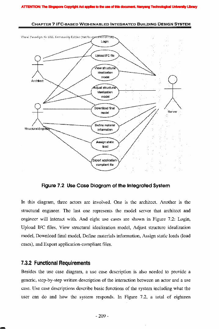
CHAPTER 7 IFC"SASED WES..ENASLED INTEGRATED BUILDING DESIGN SYSTEM
Figure 7.2 Use Case Diagram of the Integrated System
In this diagram, three actors are involved. One is the architect. Another is the
structural engineer. The last one represents the model server that architect and
engineer will interact with. And eight use cases are shown in Figure 7.2: Login,
Upload IFC files, View structural idealization model, Adjust structure idealization
model, Download final model, Define materials information, Assign static loads (load
cases), and Export application-compliant files.
7.3.2 Functional RequirementsBesides the use case diagram, a use case description is also needed to provide a
generic, step-by-step written description of the interaction between an actor and a use
case. Use case descriptions describe basic functions of the system including what the
user can do and how the system responds. In Figure 7.2, a total of eighteen
- 209-
ATTENTION: The Singapore Copyright Act applies to the use of this document. Nanyang Technological University Library

CHAPTER 7 IFC..BASE·D WEB-ENABLED INTEGRATED BUILDING DESIGN SYSTEM
interactions are included: three between architect and three use cases, seven between
structural engineer and seven use cases, and the server with all eight use cases. These
eighteen interactions represent the functional requirements of the system. Table 7.1
illustrates the use case descriptions for all interactions shown in the use case diagram.
Table 7. 1 Use Case Descriptions of Eight Use Cases
Step I Description
U load IFC file
login
View structural model
The· Architect or Structural engineer connects the webpagethrough .theURLof the Server.The Architect or Structural Engineer enters the usemame andpassword.The.·Jogin··.function should .. check the.···clientuser's. ID andautorotation. If the .. useris not acceptable, he will be refused toenter.
The··Architect requests to.upload IFC.file.The architectural design is accepted and saved on the Server.The Server .reads the architectural information, find thetopological information among those elements and generatestructural·.analysis model.The Server saves the structural analysis model information inXMLformat.
TheStructuralengineerrequests to view the structural model.The Server invokes the application and displays the 3Dstructural model in a web browser for the user on client side byJava applet.The. Structural .. engineer •. selects the structural element and theServer can ex.tract andsnow its· detailed structural information ofelement.
1Use case name:
2
Use case name:1
2
3
Adjust structure modelThe Structural engineer is allowed to give· the comments on theselected element and entering the name and value of proposedproperty.The server should add the comments and additional informationsubmitted by the Structural engineer in property set to the IFCfile.The Server can feedback to the Architect.
- 210-
ATTENTION: The Singapore Copyright Act applies to the use of this document. Nanyang Technological University Library
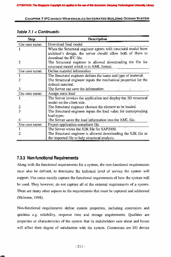
CHAPTER 7 IFC-BASED WEB-ENABLED INTEGRATED BUILDING DESIGN SYSTEM
Table 7. 1 < Continued>
StepUse case name:1
2
Use case name:12
3Use case name:1
23
4Use case name:12
I DescriptionDownload final model
architect's design, the..server should allow both of them todownload theCmC file.The Structural engineer is allowed downloading the file forstructural model which is in XML format.Define material informationTheStructural··••engineer•.defines.··.the •• nal11e·.andtype ••offuaterial •.The Structural engineer inputs the mechanical properties for thedefined material.
The Structural engineer is allowed downloading the S2K file asthe imported file to help structural analysis.
7.3.3 Non-functional RequirementsAlong with the functional requirements for a system, the non-functional requirements
must also be defined, to determine the technical level of service the system will
support. Use cases merely capture the functional requirements of how the system will
be used. They however, do not capture all of the. external requirements of a system.
There are many other aspects to the requirements that must be captured and addressed
(Mcbreen, 1998).
Non-functional requirements define system properties, including constraints and
qualities e.g. reliability, response time and storage requirements. Qualities are
properties or characteristics of the system that its stakeholders care about and hence
will affect their degree of satisfaction with the system. Constraints are I/O device
- 211 -
ATTENTION: The Singapore Copyright Act applies to the use of this document. Nanyang Technological University Library
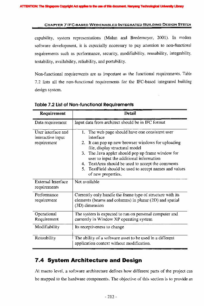
CHAPTER 7 IFC-BASED WEB-ENABLED INTEGRATED BUILDING DESIGN SYSTEM
capability, system representations (Malan and Bredemeyer, 2001). In modem
software development, it is especially necessary to pay attention to non-functional
requirements such as performance, security, modifiability, reusability, integrability,
testability, availability, reliability, and portability.
Non-functional requirements are as important as the functional requirements. Table
7.2 lists all the non-functional requirements for the IFC-based integrated building
design system.
Table 7.2 List of Non-functional Requirements
Requirement Detail
Data requirement Input data from architect should be in IFC format
User interface and 1. The web page should have one consistent userinteractive input interfacerequirement 2. It can pop up new browser windows for uploading
file, display structural model3. The Java applet should pop up frame window for
user to input the additional information4. TextArea should be used to accept the comments5. TextField should be used to accept names and values
of new properties.
External Interface Not availablerequirements
Performance Currently only handle the frame type of structure with itsrequirement elements (beams and columns) in planar (2D) and spatial
(3D) dimension
Operational The system is expected to run on personal computer andRequirement currently in Window XP operating system
Modifiability Its receptiveness to change
Reusability The ability of a software asset to be used in a differentapplication context without modification.
7.4 System Architecture and Design
At macro level, a software architecture defines how different parts of the project can
be mapped to the hardware components. The objective of this section is to provide an
- 212-
ATTENTION: The Singapore Copyright Act applies to the use of this document. Nanyang Technological University Library

CHAPTER 7 IFC-BASED WEB-ENABLED INTEGRATED BUILDING DESIGN SYSTEM
overview of the system's architecture, its modular design and the interaction among
the modules. The user interaction interfaces are then presented with example usage.
Details of the core component modules will be described in subsequent sections.
7.4.1 Architecture of the IFC-based Web-enabled Integrated BuildingDesign SystemThe IFC-based web-enabled integrated building design system is designed to provide
architects and structural engineers with easy access to a model server to improve their
collaboration by facilitating the information exchange and sharing. The current design
collaboration between architects and structural engineers has not fully utilized the
existing technologies to gain the maximum advantages. The structural engineer still
needs to manually input the geometric information of structure analysis model, which
indeed can be deduced from the geometric information in the 3D architecture model.
Now an integrated system is utilized as a common platform for architects and
engineers to communicate, exchange ideas, and download useful files. In this system,
architects and engineers can have direct access to a model server and upload data file
by using a web browser. The information can be extracted and deduced from the IFC
file forwarded by architect to the structural engineer. If the structural engineer is not
satisfied with the structural model, the server can be used as the medium of
interaction between structural engineer and architect. When engineer is finally
agreeable with the structural model, the server will list the final architect file in IFC
format and structural model file in XML format. For the convenience of engineer to
do structural analysis, inputting structural related information for selected elements· is
allowed and the model server provides a set of application compliant file to download.
The structure of the IFC-based web-enabled integrated building design (IWIBD)
system is schematically depicted in Figure 7.3. It involves the following six parts: (a)
Model sever; (b) Architectural design application; (c) Structural analysis application;
(d) IFe standards and product models; (e) Information editor; and (f) Web-based
Interface.
- 213 -
ATTENTION: The Singapore Copyright Act applies to the use of this document. Nanyang Technological University Library

CHAPTER 7 IFC-BASED WEB-ENABLED INTEGRATED BUILDING DESIGN SYSTEM
(f) Web-based Interface
(b) Architectural DesignApplication
(e) Information Editor
(a) Model Server
(c) Structural AnalysisApplicationIFC FileXML
(d) IFC standards andproduct models
Figure 7.3 Structure of IFC-based web-enabled Integrated BuildingDesign (IWIBD) System
As shown in Figure 7.3, through the online services and interfaces provided by the
system, the user can upload and edit the information to the server. The server is
responsible for the generating and saving of all architectural and structural
information based on IFC standard and models. File transfer is supported by the
server in order to achieve the communication between architectural design and
structural analysis application. Accordingly, the real integration between these two
processes is achieved.
- 214-
ATTENTION: The Singapore Copyright Act applies to the use of this document. Nanyang Technological University Library
CHAPTER 7 IFC-BASED WEB-ENABLED INTEGRATED BUILDING DESIGN SYSTEM
The overall framework and architecture of the IFe-based web-enabled integrated
building design system is schematically depicted in Figure 7.4. The architecture
defines the dependency and the interaction among the participants. It follows the Java
2 Enterprise Edition standard three-tier model: client, server and data storage. In a
three - tier software architecture, the application is broken down into three layers, the
data storage on one tier, the business logic in a second tier, and the user interface in a
third. The main advantage of three-tier architecture is that it becomes simpler to
modify the user interface, business logic, or data storage components without
affecting other components. Another advantage is scalability. Since the data storage
and business logic are separated, they can each be hosted on their own server.
- 215 -
ATTENTION: The Singapore Copyright Act applies to the use of this document. Nanyang Technological University Library
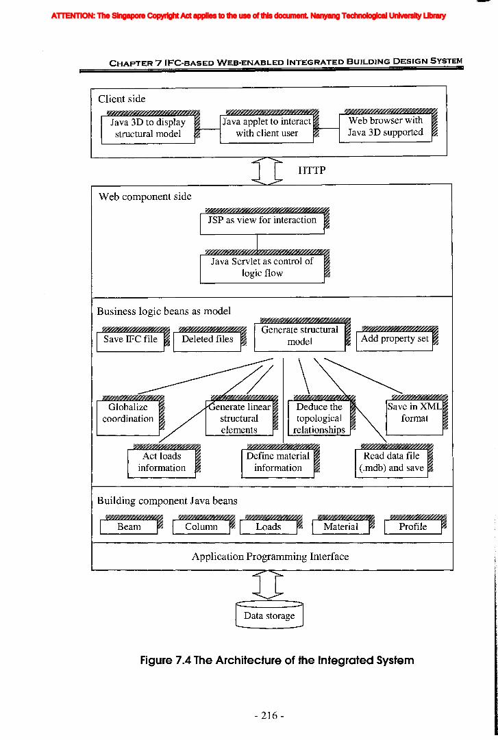
CHAPTER 7 I FC"BASED WEB"ENABLED INTEGRATED BUILDING DESIGN SYSTEM
Client side
Java 3D to display~
Java applet to interact I- Web browser withstructural model with client user ~
Java 3D supported
HTTP
Web component side
JSP as view for interaction II
Java Servlet as control oflogic flow
Business logic beans as model
Save IFe file Deleted filesGenerate structural
model Add property set
Globalizecoordination
enerate linearstructuralelements
Deduce thetopological
relationshi s
Save inXMLformat
Act loadsinformation
Building component Java beans
Define materialinformation
Read data file(.mdb) and save
Beam Column Loads Material Profile
Application Programming Interface
Figure 7.4 The Architecture of the Integrated System
- 216-
ATTENTION: The Singapore Copyright Act applies to the use of this document. Nanyang Technological University Library
CHAPTER 7 IFC-BASED WEB-ENABLED INTEGRATED BUILDING DESIGN SYSTEM
Currently, the client tier only supports Java 3D enabled web browsers. Inside the
server, there are three layers, the data access layer, business logic layer and web
component layer.
• The data access layer has two sub-layers to achieve data storage independent
and IFC release version independent. The application programming interface
is to read the data in the data storage. It offers a stable interface for other
components in web container to read, write and modify IFC data without
knowing how the data are stored. If the data storage method is changed, the
only code that needs to be changed is the implementation of the programming
interface. The IFC EXPRESS schema is undergoing some major changes at
the moment. To protect the re-usable code from those changes, the properties
of building component are encapsulated in Java Beans, which are initiated by
reading the IFC data via application programming interface layer.
• Business logic beans read the encapsulated information only from those
building component Java Beans without knowing about IFC schemas. Thus if
the IFC EXPRESS schema has changed, it will only affect the initiation
method in those building components Java Beans. Business logic beans
contain all the algorithms on processing geometric information. It can idealize
the three-dimensional load-bearing building components and deduce
connections from spatial locations. It can also integrate the deduced
topological information with the adjusted information returned from the end
user to generate a final report in the XML format. The topological logic beans
are indeed standard independent. Even if the IFC EXPRESS schema has
changed, the coding remained in this layer will not be changed.
• Web component layer consists of Java Servlet and JSP. It is in charge of
receiving and dispatching the request from the client to the classes on the
server side and transmitting the calculation results from server back to the
client.
- 217 -
ATTENTION: The Singapore Copyright Act applies to the use of this document. Nanyang Technological University Library

CHAPTER 7 IFC"BASED WEB"ENABLED INTEGRATED BUILDING DESIGN SYSTEM
7.4.2 Mechanics
LoginUser -Interaction
Interface
6. View data
2. Send1----- request
Action ControllerComponent
Web-basedClient
7. View & givecomments
ProcessingCore
Data Storage &Management
3. Call handle
Figure 7.5 The Mechanics of The Integrated System
The mechanics of the IFC-based web-enabled integrated building design (IWIBD)
system is illustrated in Figure 7.5, which shows the essential procedures to access the
server and to perform integrated operations over the Internet. The architect first builds
the architectural design on the client side. After logging in the web site, the architect
is assigned a certain role by the server which allows the architect to upload IFC files.
Architect can submit the IFC file to the server via a web browser, using the Internet as
a communication channel. The core processing applications on the server receives the
file and saves on the server. After finding the connectivity of structure elements and
idealizing those elements, the core processing applications generate a structural
idealization model and save the model in the XML format on the server side.
The structural engineer can query and view the model using a web browser. The
process follows almost the same procedures as the uploading of IFC file by the
- 218 -
ATTENTION: The Singapore Copyright Act applies to the use of this document. Nanyang Technological University Library
CHAPTER 7 IFC-BASED WEB-ENABLED INTEGRATED BUILDING DESIGN SYSTEM
architect. First the engineer signs in the server from a client machine. The core
processing applications on the server read the structural idealization model's related
information from the database and send back to the engineer. The Java applets and
related applications are downloaded on the client side to receive the information and
display the 3D structural idealization model by the Java3D technology. The engineer
can also check the detailed information by clicking on the idealized structural
elements. A window will pop up to let the engineer view the geometric information
about selected element and the location of the joints. If the engineer finds
discrepancies, he can add new properties and comments to the specific element. After
finishing the modification, the engineer can send the feedback to the server. The
server receives the feedback, and makes corresponding modification· on the IFC
models by adding property sets.
After the architect reviews the changes proposed by the engineer, he might review and
modify the architectural design. The server can then generate updated structural
model for engineer to review. This process ends when the engineer and the architect
finally agree with the design. The server then publishes the structural model file in
XML format and architecture file in IFC format. Since currently few structural
analysis and design applications provide the supports for the IFC formats, the adaptor
for specific application is provided by the server. In current prototype implementation
only the S2K file, which can be imported by SAP2000, is generated. At this time, the
engineer could download the S2K file and directly import it into SAP2000 for
structural analysis. The structural analysis model is automatically generated.
Besides the idealized structural elements and their mechanical connectivity, support
conditions, mechanical properties and loadings should also be included in the
structural model of building for structural analysis (Horenbaum, 2003). Only the
idealized structural elements and connectivity information could be deduced from the
3-D geometric information of an architectural model. In order to improve the future
extensibility of the server, other functions are incorporated into the server which
could assist engineer in performing additional structural analysis. Four kinds of
operations are provided if the engineers want to do more preparations for structural
- 219-
ATTENTION: The Singapore Copyright Act applies to the use of this document. Nanyang Technological University Library
CHAPTER 7 IFC-BASED WEB-ENABLED INTEGRATED BUILDING DESIGN SYSTEM
analysis. The primary aim of this part of effort is to provide the foundation for the
future incorporation of structural analysis software on the server side even if its
benefit is not so distinct in current stage. According to the 3D model of structure, the
material and load information is assigned by engineer via the Internet and saved to the
server. The new S2K file with material and load information can be generated and
downloaded. After performing the structural analysis, engineer can upload the data
file of structural analysis results to the server. The server can retrieve the results, like
forces and displacements, and save into XML formats. Similarly any authorized user
to the server can query and view all related information including the analysis results
about structural elements via a browser.
Besides the mechanics, Figure 7.5 has already presented that the IFC-based web
enabled integrated building design system consists of four distinct modules: User
Interaction Interface, Action Controller Component, Core Processing module and
Data Access and Data Storage module. The details about modular design and
implementation are described in the following section.
7.5 Modular Design and Implementation
As illustrated in Figure 7.5, this system consists of four distinct modules:
• The User-interaction module provides an interface to facilitate the access to
and interaction with the software platform for the users and developers.
• The Action Controller Component is provided for online application services
to register to the core so that these services can be found and accessed, and
routing the incoming request to an appropriate command object that knows
how to handle the request.
• The Core Processing module is the main part to process the data, including
reading and writing of IFC data, retrieving and manipulating the geometric
and structural related information of structural members, storing and querying
the data file etc.
- 220-
ATTENTION: The Singapore Copyright Act applies to the use of this document. Nanyang Technological University Library

CHAPTER 7 IFC-BASED WEB-ENABLED INTEGRATED BUILDING DESIGN SYSTEM
• Currently the Data Access and Data Storage module is mainly responsible to
process XML related data because in this phase all data are saved as flat files
in XML format. As the developing of the system and more and more data
generated, a database is needed. At that time, this module is built to link with a
database, which can provide efficient data access and facilitate post processing
tasks. Project management and version control are also supported by the data
management system.
This section documents the modules in terms of its context in the system described in
the architectural design. It describes the context, in which the modules will be used,
and the services (i.e. functionality) they provide. It also discusses the issues related to
the detailed design and implementation in a prototype. The related technologies used
during the implementation are also briefly introduced.
7.5.1 Related TechnologiesFor the prototype implementation and testing in this research work, Java is employed
as the programming language to implement most parts of the system architecture.
Java's well-designed object-oriented structure and platform independence are the
influencing factors in using it. The wide proliferation of the Internet can be attributed
to the ease of World-Wide Web access, so taking advantage of this environment is
appropriate. When interaction is needed within the Web browser environment, Java
applets could be seamlessly integrated into the Java-written distributed architecture.
Although the use of a web browser is not mandatory for the functionalities of the
integrated framework, using a standard browser interface leverages the most widely
available Internet environment, as well as being a convenient means of quick
prototyping.
In order for the server to process the HTTP requests from the client, Apache Tomcat
4.0, which is built on Java Servlet based technologies, is employed as the entry point
of server's process. In the prototype implementation, Java's Servlet is chosen to
handle communication for the distributed element services over the Internet. Java
Servlets are Java technology's answer to CGI (Common Gateway Interface)
- 221 -
ATTENTION: The Singapore Copyright Act applies to the use of this document. Nanyang Technological University Library
CHAPTER 7 IFC-BASE'D WEB-ENABLED INTEGRATED BUILDING DESIGN SYSTEM
programming. They are programs that run on a web server and build web pages. Java
Servlets are designed to extend and to enhance web servers. Servlets provide a
component-based, platform-independent method for building web-based applications,
without the performance limitations of CGI programs. Servlets have access to the
entire family of Java APls (Application Programming Interface), including the JDBS
API to access databases. Thus, Servlets have all the benefits of the mature Java
language, including portability, performance, reusability, and crash recovery. Java
Servlets are more efficient, easier to use, more powerful, more portable, and cheaper
than traditional CGI and other alternative CGI-like technologies.
Java Server Pages (JSP) is a technology that permits mixing of regular, static HTML
with dynamically-generated HTML. Many Web pages that are built by CGI programs
are mostly static, with the dynamic part limited to a few small locations (Hall, 1999).
But most CGI variations, including Servlets, make the user generate the entire page
via the user's program, even though most of it is always the same. JSP lets the user
create the two parts separately. The user simply writes the regular HTML in the
normal manner, using whatever Web-page-building tools he normally uses. He then
encloses the code for the dynamic parts in special tags, most of which start with
"<%"and end with"%>".
JSP is so easy and convenient that it is quite feasible to augment HTML pages that
only benefit marginally by the insertion of small amounts of dynamic data. Previously,
the cost of using dynamic data would preclude its use in all but the most valuable
instances (Hall, 1999). The dynamic part is written in Java, not Visual Basic or other
MS-specific language, so it is more powerful and easier to use. And it is portable to
other operating systems and non-Microsoft web servers.
7.5.2 User-interaction ModuleThe User-interaction module provides an interface to facilitate the access to the IFC
based model server for the architects and engineers. Currently the server can be
accessed only by a web-based interface.
- 222-
ATTENTION: The Singapore Copyright Act applies to the use of this document. Nanyang Technological University Library

CHAPTER 7 IFC-BASED WEB-ENABLED INTEGRATED BUILDING DESIGN SYSTEM
The architecture of the integrated system shown in Figure 7.3 implies the essence of
model-view-controller (MVC) architecture to some extent. MVC architecture is a
popular software architecture used to structure web applications, which separates the
application's core business model functionality from the user interface and control
logic (Moller and Schwartzbach, 2002-2003). Such separation allows multiple views
to share the same data model, which makes supporting multiple clients easier to
implement, test, and maintain. It is easier support for new types of clients. To support
a new type of client, one simply writes a view and some controller logic, and wires
them into the existing application.
Generally the JSP and Servlets are used together to deploy web applications that
conform to MVC architecture, as shown in Figure 7.6. The using of JSP makes it
easier to develop and maintain the HTML content. Java Servlet technology is
employed to implement the server interface, which serves as the wrapper to the core
system. Through the combination of JSP and Servlets, a single request will result in
multiple substantially different-looking results. It can process complicated data, but
with relatively fixed layout (Hall, 2003-2004).
View(JSP)
Controller(Servlet)
User Interface
Handler
& ModelDatabase
Figure 7.6 Model-view-controller (MVC) Architecture
- 223-
ATTENTION: The Singapore Copyright Act applies to the use of this document. Nanyang Technological University Library

CHAPTER 7 IFC-BASED WEB-ENABLED INTEGRATED BUILDING DESIGN SYSTEM
Following the pattern, a set of JSP pages and Servlets are developed as the interactive
interface with clients and to control program flows.
The JSP is considered as the View. The view primarily concerns with presentation
and formatting of Model objects which have been placed in scope by the controller (or
its delegate) (Hanley, 2004). The Model represents the business logic of an
application. It contains all data and operations which are implemented as Java classes.
Encapsulating business rules into components facilitates testing, improves quality,
and promotes reuse.
The controller is represented by the Servlet. The controller acts as the point of entry
into the application, and delegates to various worker classes to fulfil a request. In
particular, the controller is a user of Model and View objects (Hanley, 2004). The
controller translates interactions with the view into actions to be performed by the
model. In a stand-alone GUI client, user interactions could be button clicks or menu
selections, whereas in a web application, they appear as GET and POST HTTP
requests. The actions performed by the model include activating business processes or
changing the state of the model. Based on the user interactions and the outcome of the
model actions, the controller responds by an appropriate view. The Servlet plays an
important role in this architecture because it takes care of parameter retrieval,
instantiation, and bean handling~ but it can also handle transfers to different JSPs in
terms of user type, carry out processing in relation to user actions, etc. Obviously, this
architecture offers better separation of the user interface with regard to processing.
In this prototype implementation, the model part is contained in core processing
module, the detailed descriptions of which are in the next section. The focus of this
section lies on the view and controller as user interactive interface to implement the
server interface and control the logic flow of system. Apache Tomcat is customized to
serve as the Servlet server, which is a middleware to enable the virtual link between
the web browser and server. Since Servlets have built-in supports for web applications,
the communication between the web browser and the Servlet server follows the HTTP
protocol standards, which is a fairly straightforward process. And this system aims to
facilitate the collaboration between architect and structural engineer; it is obvious that
- 224-
ATTENTION: The Singapore Copyright Act applies to the use of this document. Nanyang Technological University Library
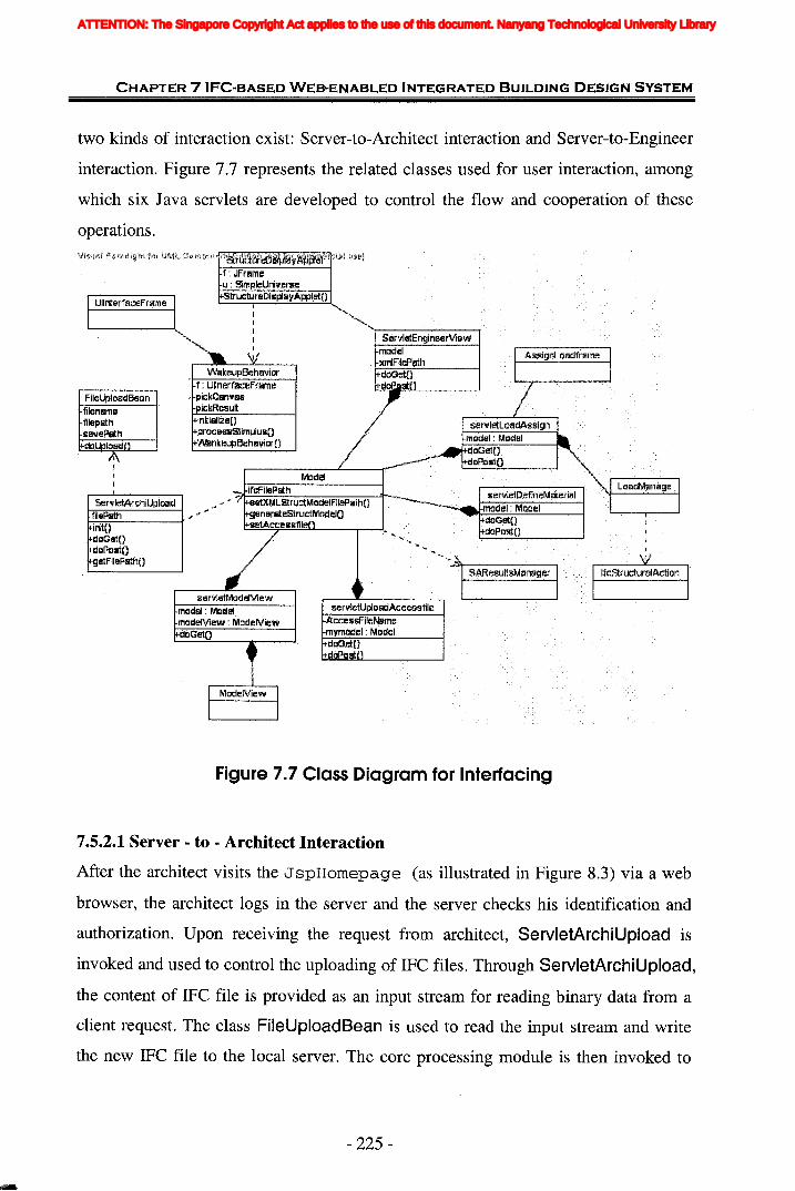
CHAPTER 7IFC-BASED WEB-ENABLED INTEGRATED BUILDING DESIGN SYSTEM
two kinds of interaction exist: Server-to-Architect interaction and Server-to-Engineer
interaction. Figure 7.7 represents the related classes used for user interaction, among
which six Java servlets are developed to control the flow and cooperation of these
operations.
UML e,mmmd !t~r~ffifirebrip1~y~tJ~fe¥1 r~~i2i1, MJ;~l
f; JFrameu:· Sil'l'lpleUniverse
Madel
StrudureDisplayAppl,etOJ
IIII
, IL,
initiallze()processStimulusOWankeupBehaviarO
initOdoGelOdOPDstOgetFileP8thO
Servle1:ArchiUploadfilePlfth
model: MadelmodelView : MadelViewdaGetO
f: UllnerfaceFramepickCanvaspickResult
V'<JakeupBehavior
senile1:MDdeiView
Figure 7.7 Class Diagram for Interfacing
7.5.2.1 Server - to - Architect Interaction
After the architect visits the J spHomepage (as illustrated in Figure 8.3) via a web
browser, the architect logs in the server and the server checks his identification and
authorization. Upon receiving the request from architect, ServletArchiUpload is
invoked and used to control the uploading of IFC files. Through ServletArchiUpload,
the content of IFC file is provided as an input stream for reading binary data from a
client request. The class FileUploadBean is used to read the input stream and write
the new IFC file to the local server. The core processing module is then invoked to
- 225-
ATTENTION: The Singapore Copyright Act applies to the use of this document. Nanyang Technological University Library
CHAPTER 7 IFC-BASED WEB-ENABLED INTEGRATED BUILDING DESIGN SYSTEM
construct the structural idealization model and save it on the server in a file of XML
format by the method setXMLStructModelFilePath () of Model class.
The status of process is prompted by the message on the right of webpage. After the
architectural design file is successfully submitted, the message is changed to
"Architect has uploaded the file. Engineer can view the file now.", so the engineer can
log in the server and view the structural idealization model.
7.5.2.2 Server-to-Engineer Interaction
As mentioned above, the engineer can choose to view the model according to the
message on the right of homepage. Similarly after verifying the authorization
information of engineer, ServletEngineerView is called. In the servlet, the Java
applet class StructuralDisplayApplet is invoked to show the structural model in 3
dimension by Java3D on the client side in a browser. When the engineer picks up a
specific element from structural model, WakeupBehavior is invoked and the Swing
JFrame UlinterfaceFrame is responsible for the displaying of basic geometric
information of selected element and allows the engineer adding new properties or
comments to the element. The additional properties are sent back to the servlet and
added to the architectural IFC data file by the core processing module.
Similarly the architect is notified that structural engineer asks for changes in the
design by the message. The server allows the architect downloading the modified IFC
file to view the feedback from engineer and make decision on the design modification.
Then the architect resubmits the design in IFC format to the server. Another cycle is
started.
Until the consensus is achieved, the server generates the application compliant file,
such as S2K file, and provides the downloading to the engineer. The link to
JspOperations is provided on the right of JspHomepage. Some additional
functions are provided to the engineer through this JSP webpage in order to make the
server more powerful and extensible for future functions (e.g. integrating structural
analysis software) and help engineer to perform analysis. After visiting this page, the
engineer can download the S2K file and import the S2K file directly to SAP2000 to
- 226-
ATTENTION: The Singapore Copyright Act applies to the use of this document. Nanyang Technological University Library

CHAPTER 7 IFC-BASED WEB-ENABLED INTEGRATED BUILDING DESIGN SYSTEM
do structural analysis. At this point, the integration of architectural design and
structural analysis is basically achieved because the communication of geometric
information is implemented with the engineer.
Therefore, besides the downloading of application compliant files, other add-on
functions are also provided in the prototype, including the operations of defining
material information, assigning load information, uploading structural analysis results,
and viewing the whole structural model with analysis results.
the engineer define~ the material ~ro~ertie~ through set\l\e\De\\neMa\et\a\. U~on
receiving the request of assigning load by engineer, the servletLoadAssign invokes
StructuralDisplayApplet to let engineer choose the structural member which is going
to be loaded. The load information is entered b)' engineer through the web browser
built up by AssignLoadFrame class at client side. Then the connection to
servletLoadAssign is reconstructed and the object about load is sent to the servlet
using serialization in compressed stream. Each input instantiates a new
IfcStructuralAction instance. The IfcStructuralAction class is provided object
serialization which makes its instances can be serialized. It aims to use
ObjectOutputStream and ObjectlnputStream to write and read objects. The key to
writing an object is to represent its state in a serialized form sufficient to reconstruct
the object as it is read. Thus reading and writing objects is a process called "object
serialization". Java object serialization has simplified the issues involved with
formatting responses. With both applets and servlets written in Java, it's only natural
that they should communicate by exchanging Java objects. Therefore, the loads
assigned are represented as a Vector of IfcStructuralAction instances and sent to the
servletLoadAssign.
After structural analysis is completed, most of structural analysis and design software
can export data file to save the input and output for structural analysis, such as the
Access file exported by SAP2000. Current trend sees that the commercial database
industry is shifting to use the Internet as the preferred data delivery vehicle (Peng,
2002). Considering the collaboration with structural analysis programs and improving
the amount of information sharing in the server, the function of receiving and saving
- 227-
ATTENTION: The Singapore Copyright Act applies to the use of this document. Nanyang Technological University Library
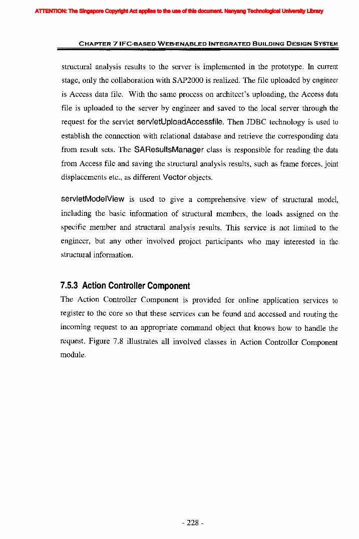
CHAPTER 7 IFC-BASED WEB-ENABLED INTEGRATED BUILDING DESIGN SYSTEM
structural analysis results to the server is implemented in the prototype. In current
stage, only the collaboration with SAP2000 is realized. The file uploaded by engineer
is Access data file. With the same process on architect's uploading, the Access data
file is uploaded to the server by engineer and saved to the local server through the
request for the servlet servletUploadAccessfile. Then JDBC technology is used to
establish the connection with relational database and retrieve the corresponding data
from result sets. The SAResultsManager class is responsible for reading the data
from Access file and saving the structural analysis results, such as frame forces, joint
displacements etc., as different Vector objects.
servletModelView is used to give a comprehensive view of structural model,
including the basic information of structural members, the loads assigned on the
specific member and structural analysis results. This service is not limited to the
engineer, but any other involved project participants who may interested in the
structural information.
7.5.3 Action Controller Component
The Action Controller Component is provided for online application services to
register to the core so that these services can be found and accessed and routing the
incoming request to an appropriate command object that knows how to handle the
request. Figure 7.8 illustrates all involved classes in Action Controller Component
module.
- 228-
ATTENTION: The Singapore Copyright Act applies to the use of this document. Nanyang Technological University Library
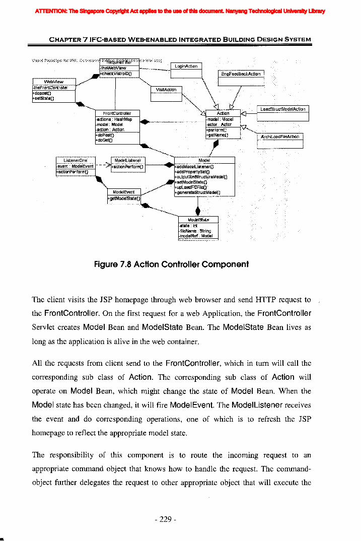
CHAPTER 7 IFC-BASED WEB-ENABLED INTEGRATED BUILDING DESIGN SYSTEM
WebViewtheFrontControJlerdopoBtnsetStateO
frontCorrtrollerBctiDns: HBshMapmodel:·MD~elBdipn : ActiondoPo$l:OdeGeiD
Limener0neevent: ModelEvent - ~~~~::;::::=;;;-1--------'IIlat:::;::;;::;::;::i77.:Z:-::::;;----l
BctionPerformO
Figure 7.8 Action Controller Component
The client visits the JSP homepage through web browser and send HTTP request to
the FrontControlier. On the first request for a web Application, the FrontControlier
Servlet creates Model Bean and ModelState Bean. The ModelState Bean lives as
long as the application is alive in the web container.
All the requests from client send to the FrontController, which in tum will call the
corresponding sub class of Action. The corresponding sub class of Action will
operate on Model Bean, which might change the state of Model Bean. When the
Model state has been changed, it will fire ModelEvent. The ModelListener receives
the event and do corresponding operations, one of which is to refresh the JSP
homepage to reflect the appropriate model state.
The responsibility of this component is to route the incoming request to an
appropriate command object that knows how to handle the request. The command
object further delegates the request to other appropriate object that will execute the
- 229-
ATTENTION: The Singapore Copyright Act applies to the use of this document. Nanyang Technological University Library
CHAPTER 7 IFC-BASED WEB-ENABLED INTEGRATED BUILDING DESIGN SYSTEM
appropriate business logic on Model Bean. The Model Bean has the event-firing
mechanism that can fire the event according to the state change. The event listeners
that are attached to the model will behave accordingly.
The ModelState Bean is the object that controls access of web application. It might
be necessary to incorporate more complicated pattern to control the access if there are
more than one architect or engineer involving in the design process. But as a
prototype, it only considers one architect and one engineer.
7.5.4 Core Processing ModuleThe Core processing module is the main part to process the data, including retrieving
the geometric data from uploaded IFC file, computing and generating the basic
information of structural members and connections, as well as processing the data
input by the engineer, reading and querying the structural analysis results from
database file.
7.5.4.1 Algorithm of Constructing Structural Models
In order to construct the structural model, the deduction is needed from geometric
representations of building elements (beams and columns etc.) in architectural design
to topological representations of structural elements as lines or points following some
algorithm. CuiLu et al. (2003) carried out the study on how to deduce the topological
relationship from the geometric representation of product in IFC. In this research,
Cui's algorithm is utilized to generate structural model.
- 230-
ATTENTION: The Singapore Copyright Act applies to the use of this document. Nanyang Technological University Library
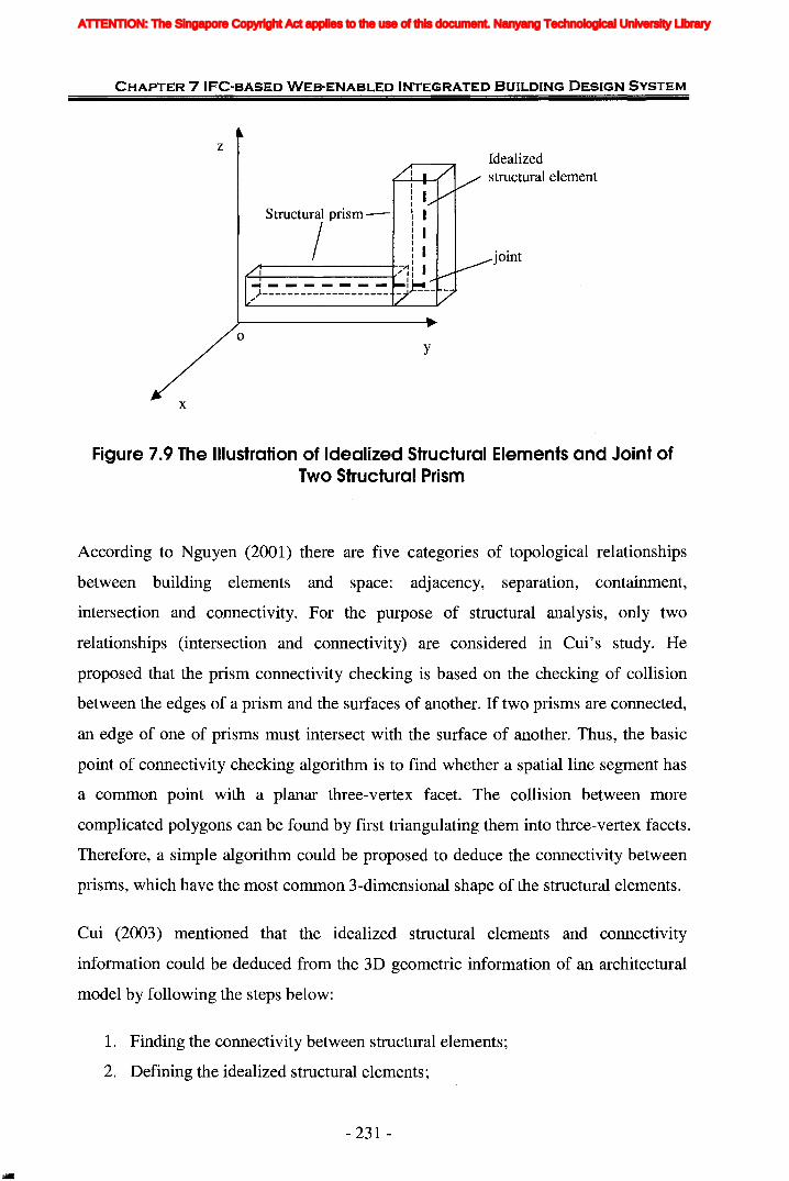
CHAPTER 7 IFC-BASED WEB-ENABLED INTEGRATED BUILDING DESIGN SYSTEM
zIdealizedstructural element
x
o
structurl prism-
I 7: I... - - - - - - - l~~)-------------------- - ----
y
joint
Figure 7.9 The Illustration of Idealized Structural Elements and Joint ofTwo Structural Prism
According to Nguyen (2001) there are five categories of topological relationships
between building elements and space: adjacency, separation, containment,
intersection and connectivity. For the purpose of structural analysis, only two
relationships (intersection and connectivity) are considered in Cui's study. He
proposed that the prism connectivity checking is based on the checking of collision
between the edges of a prism and the surfaces of another. If two prisms are connected,
an edge of one of prisms must intersect with the surface of another. Thus, the basic
point of connectivity checking algorithm is to find whether a spatial line segment has
a common point with a planar three-vertex facet. The collision between more
complicated polygons can be found by first triangulating them into three-vertex facets.
Therefore, a simple algorithm could be proposed to deduce the connectivity between
prisms, which have the most common 3-dimensional shape of the structural elements.
Cui (2003) mentioned that the idealized structural elements and connectivity
information could be deduced from the 3D geometric information of an architectural
model by following the steps below:
1. Finding the connectivity between structural elements;
2. Defining the idealized structural elements ~
- 231 -
ATTENTION: The Singapore Copyright Act applies to the use of this document. Nanyang Technological University Library
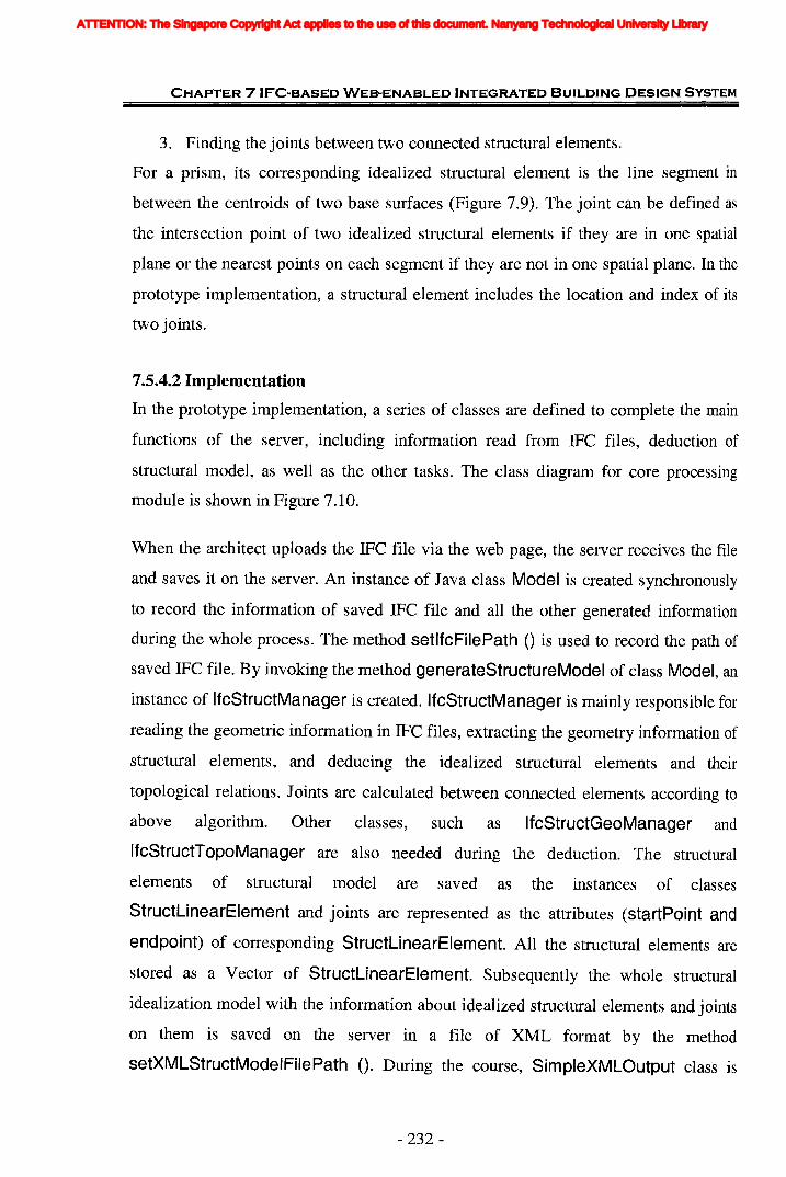
CHAPTER 7 IFC-BASED WEB-ENABLED INTEGRATED BUILDING DESIGN SYSTEM
3. Finding the joints between two connected structural elements.
For a prism, its corresponding idealized structural element is the line segment in
between the centroids of two base surfaces (Figure 7.9). The joint can be defined as
the intersection point of two idealized structural elements if they are in one spatial
plane or the nearest points on each segment if they are not in one spatial plane. In the
prototype implementation, a structural element includes the location and index of its
two joints.
7.5.4.2 Implementation
In the prototype implementation, a series of classes are defined to complete the main
functions of the server, including information read from IFC files, deduction of
structuJ;al model, as well as the other tasks. The class diagram for core processing
module is shown in Figure 7.10.
When the architect uploads the IFC file via the web page, the server receives the file
and saves it on the server. An instance of Java class Model is created synchronously
to record the information of saved IFC file and all the other generated information
during the whole process. The method setlfcFilePath () is used to record the path of
saved IFC file. By invoking the method generateStructureModel of class Model, an
instance of IfcStructManager is created. IfcStructManager is mainly responsible for
reading the geometric information in IFC files, extracting the geometry information of
structural elements, and deducing the idealized structural elements and their
topological relations. Joints are calculated between connected elements according to
above algorithm. Other classes, such as IfcStructGeoManager and
IfcStructTopoManager are also needed during the deduction. The structural
elements of structural model are saved as the instances of classes
StructLinearElement and joints are represented as the attributes (startPoint and
endpoint) of corresponding StructLinearElement. All the structural elements are
stored as a Vector of StructLinearElement. Subsequently the whole structural
idealization model with the information about idealized structural elements and joints
on them is saved on the server in a file of XML format by the method
setXMLStructModelFilePath (). During the course, SimpleXMLOutput class is
- 232-
ATTENTION: The Singapore Copyright Act applies to the use of this document. Nanyang Technological University Library
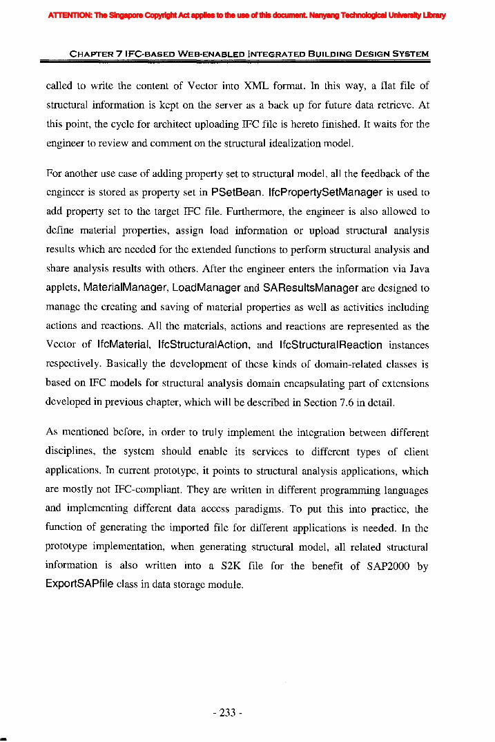
CHAPTER 7 IFC-BASED WEB-ENABLED INTEGRATED BUILDING DESIGN SYSTEM
called to write the content of Vector into XML format. In this way, a flat file of
structural information is kept on the server as a back up for future data retrieve. At
this point, the cycle for architect uploading IFC file is hereto finished. It waits for the
engineer to review and comment on the structural idealization model.
For another use case of adding property set to structural model, all the feedback of the
engineer is stored as property set in PSetBean. IfcPropertySetManager is used to
add property set to the target IFC file. Furthermore, the engineer is also allowed to
define material properties, assign load information or upload structural analysis
results which are needed for the extended functions to perform structural analysis and
share analysis results with others. After the engineer enters the information via Java
applets, MaterialManager, LoadManager and SAResultsManager are designed to
manage the creating and saving of material properties as well as activities including
actions and reactions. All the materials, actions and reactions are represented as the
Vector of IfcMaterial, IfcStructuralAction, and IfcStructuralReaction instances
respectively. Basically the development of these kinds of domain-related classes is
based on IFC models for structural analysis domain encapsulating part of extensions
developed in previous chapter, which will be described in Section 7.6 in detail.
As mentioned before, in order to truly implement the integration between different
disciplines, the system should enable its services to different types of client
applications. In current prototype, it points to structural analysis applications, which
are mostly not IFC-compliant. They are written in different programming languages
and implementing different data access paradigms. To put this into practice, the
function of generating the imported file for different applications is needed. In the
prototype implementation, when generating structural model, all related structural
information is also written into a S2K file for the benefit of SAP2000 by
ExportSAPfile class in data storage module.
- 233 -
ATTENTION: The Singapore Copyright Act applies to the use of this document. Nanyang Technological University Library
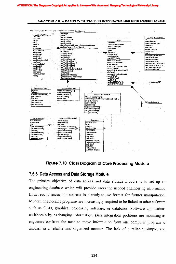
CHAPTER 7 IFC-BASED WEB-ENABLED INTEGRATED BUILDING DESIGN SYSTEM
IfcProperlySel:MamagerinmodifiedEntiliesmadi1iedEntities veeobjDr=sign -objlFCsvroutputlfc:DeaignpSetBeans
~1IIlo------------I xlTIlFile'-1=rc=lJr-op-e-rt--:ys=-et=M=-an-a-ge-r(::"'")-f
anddPSetBean()readXMLPSetFileOsRlfePraper1vSetOadd(pSelBelln : PSeta.elln)adqPSet(pSetBean : PSel...fjndMadifl$:lEnI~ies()
f1rrdRequestEnl~eBO
Model
sddPrcpertVSetoddPropel'tySetBelilnO
clearAIlFiles{}enginll/erA,rchttectAgree(}getifcFilePa!hOaulp\.lt::<MLSlructureMadel()fileEvent()generateStruetureModel()apenlFCFileOgetObjDesignOgel:ObjSvrO;etSap2COaFilePlilthOetXmIPSel:FllePalhO
ifcFilePlJthxmlstructModelFilePathSlrl..lctureMl.lnegermodelstsleoajSvr
1-=....,.....;...IiI>l-~~:eM~~~ger)tmIPSetFileP&thsBP20COFiJeP&th
.lfcStruclTopoMantager
IIIIIII
\t
IfcStruclTopoManagerOdidConnecl(ele1: struetLlnearElell1enl, ele2: ...gBtJplntLQcmian(}selstrue.tJointOp~I:lDistance()
poly2CircieCannectOrec2cfrcieConnectOrec2polyCanneetOrec2recConnec;tO
It'cStruclManf.lgerOfinqJoiflts()getlfcFileName(}g~ObjDesignO
gelObjSvrOgel$truetElemenls()elV.,cS!rudBelilm()
gmYQc$truclC6lumnOgelVec;StruclSlablOgelVecstruclWlillOopehlfcFile(f1leName : Slrjng)setlfcFileName()writePSelOglobalizeSlruclElems(}glab&l.lizr=JtructLinearElems{)r'lilldlfcstfudEles
\fii~J,,~.f f;a.!'~~i~,~r:,:,_,rQr:,Uf~~!~}~~tr;~:n~frt~:~~'~,*fH?: ',f~ ,~H_~r. :;~_('?;~r{iN1~((t! r4~Etrnager
abjDesignobjSvrvecS!r:l.JClBel.lmvecstru~Coh ..mnvecStructSlabvecSlhJctWaUthelfcStruetGeaMlilnBger: ·lfestrYctGeoMan~gerheSlrucEI~menl : StrumElemenl
em::IPointCoordSlartPoirnCoor
~~~..,....,.,.--=~-I""'I;:'·--""""1:v,;;::.e;.;:.cJ:;.;:o,:;..:il1t:;.;:·8,=",,"",.....,..,=--.--=::--IStructuralCurvedMeml:lerOsddJcinl(jcini :.PoinlCanecU...QIltE"clPoirrtCoord(}getStar1PainlCoorOgel:VecJointsOsetEndPCinlCaard()setstar1PoinlCaor()
Figure 7. 10 Class Diagram of Core Processing Module
7.5.5 Data Access and Data Storage ModuleThe primary objective of data access and data storage module is to set up an
engineering database which will provide users the needed engineering information
from readily accessible sources in a ready-to-use format for further manipulation.
Modem engineering programs are increasingly required to be linked to other software
such as CAD, graphical processing software, or databases. Software applications
collaborate by exchanging information. Data integration problems are mounting as
engineers confront the need to move information from one computer program to
another in a reliable and organized manner. The lack of a reliable, simple, and
- 234-
ATTENTION: The Singapore Copyright Act applies to the use of this document. Nanyang Technological University Library

CHAPTER 7 IFC"BASED WEB-ENABLED INTEGRATED BUILDING DESIGN SYSTEM
universally deployed data exchange model has long impaired effective interoperations
among heterogeneous software applications.
The handling of data shared between disparate systems requires the definition of
persistent and standard representations of the data, and corresponding interfaces to
query the data. Data must be represented in such a manner that they can facilitate
interoperation with humans or mechanisms that use other persistent representations.
XML format is thus selected as the standard representation for the data. In the system,
the data storage supports only a flat file system and the primary responsibility of this
module is to process XML files.
7.5.5.1 Data Representation
In the data access sub-system, Extensive Markup Language (XML) is chosen as the
standard for representing data in a platform independent manner for the data exchange
between collaborating applications. XML is an emerging protocol that allows devices
to exchange data efficiently. XML was enthusiastically adopted by programmers who
needed a robust, extensible, standard format for data (Harold, 2002). XML is a textual
language quickly gaining popularity for data representation and exchange on the Web
(Goldman et aI., 1999). Unlike HTTP, XML defines a class of data objects called
XML documents and partially describes the behaviour of computer programs which
process them. XML lets developers define complex data structures and developers can
share this information across a variety of applications, clients and servers. Using the
XML parser, developers can create applications that enable their web server to
exchange XML-formatted data. XML provides an effective means for the data
exchange of different applications and accessing the database on the Internet. XML
can alleviate many programming problems associated with data conversion.
XML is a set of rules for defining semantic tags that break a document into parts and
identify the different parts of the document. It is a meta-markup language that defines
a syntax used to define other domain-specific, semantic, structured markup languages
(Harold, 1999). An XML element is made up of a start tag, an end tag, and content in
between. The start and end tags describe the content within the tags, which is
- 235-
ATTENTION: The Singapore Copyright Act applies to the use of this document. Nanyang Technological University Library
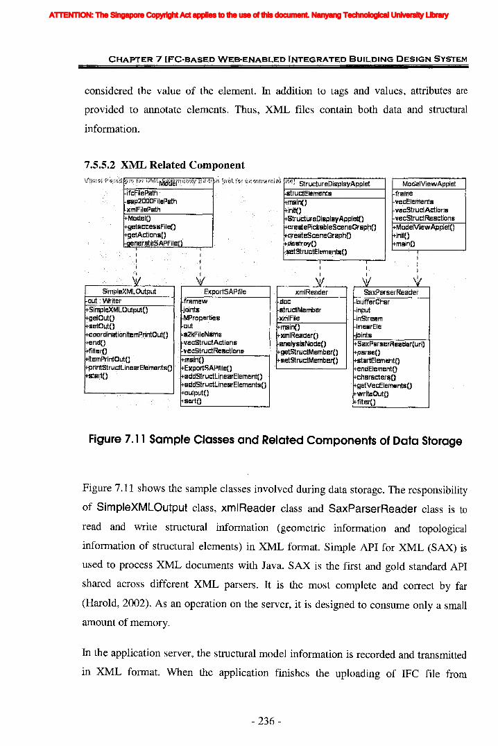
CHAPTER 7 IFC-BASED WEB-ENABLED INTEGRATED BUILDING DESIGN SYSTEM
considered the value of the element. In addition to tags and values, attributes are
provided to annotate elements. Thus, XML files contain both data and structural
information.
7.5.5.2 XML Related Component
docmrudMemberxrfJlFilemainOxmlRefiderO~nalysi~NOdeo
getStrudMernberOsetstruc;tMernberO
ModelViewApplmframeveeElementsvecritructAdicms
f.vecStrudReadions~MQdelViewAppletn
l+initOI+rnainO
SaxParserReaderbufferCharinputinStreamJinearElejointsSaxPlrserReader[url)parse.n .startElementC)endElernentOcharactersO
. .getVecElementsO. writeOutO
filter{)
Figure 7.11 Sample Classes and Related Components of Data Storage
Figure 7.11 shows the sample classes involved during data storage. The responsibility
of SimpleXMLOufpuf class, xmlReader class and SaxParserReader class is to
read and write structural information (geometric information and topological
information of structural elements) in XML format. Simple API for XML (SAX) is
used to process XML documents with Java. SAX is the first and gold standard API
shared across different XML parsers. It is the most complete and correct by far
(Harold, 2002). As an operation on the server, it is designed to consume only a small
amount of memory.
In the application server, the structural model information is recorded and transmitted
in XML format. When the application finishes the uploading of IFC file from
- 236-
ATTENTION: The Singapore Copyright Act applies to the use of this document. Nanyang Technological University Library
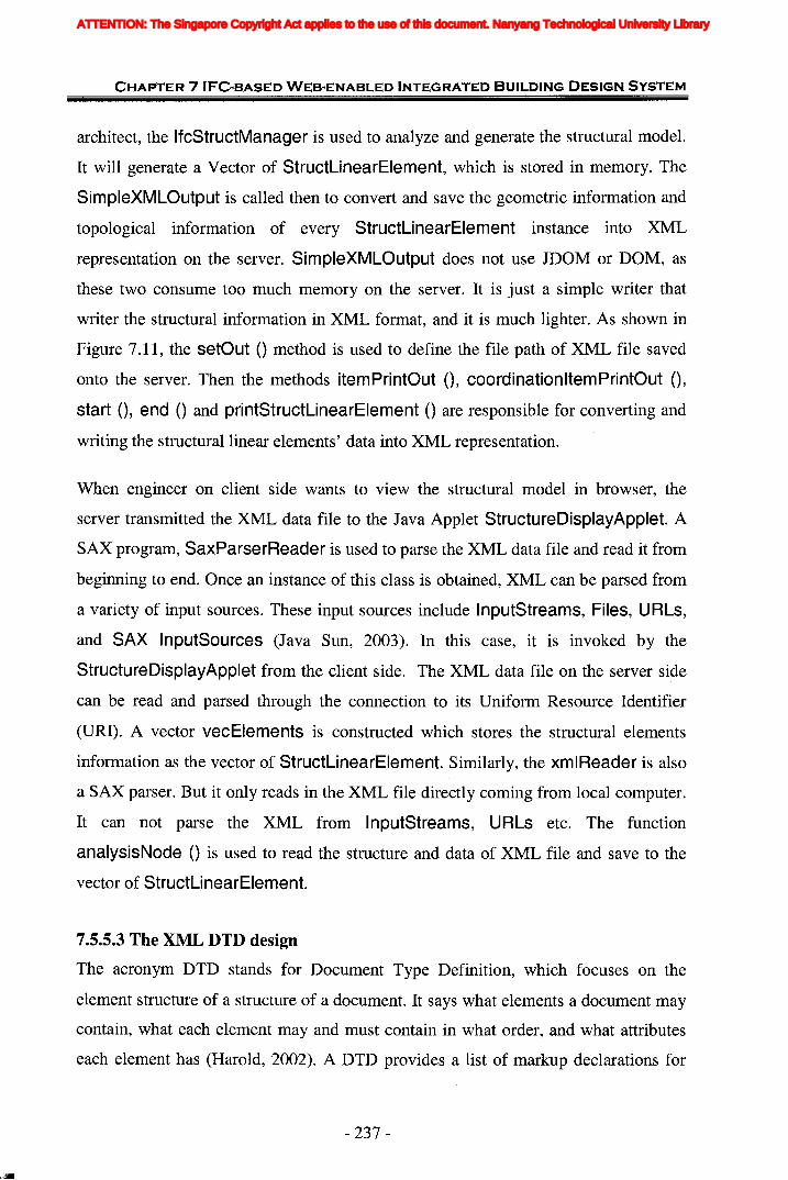
CHAPTER 7 IFC-BASED WEB-ENABLED INTEGRATED BUILDING DESIGN SYSTEM
architect, the IfcStructManager is used to analyze and generate the structural model.
It will generate a Vector of StructLinearElement, which is stored in memory. The
SimpleXMLOutput is called then to convert and save the geometric information and
topological information of every StructLinearElement instance into XML
representation on the server. SimpleXMLOutput does not use JDOM or DOM, as
these two consume too much memory on the server. It is just a simple writer that
writer the structural information in XML format, and it is much lighter. As shown in
Figure 7.11, the setOut () method is used to define the file path of XML file saved
onto the server. Then the methods itemPrintOut (), coordinationltemPrintOut (),
start 0, end () and printStructLinearElement () are responsible for converting and
writing the structural linear elements' data into XML representation.
When engineer on client side wants to view the structural model in browser, the
server transmitted the XML data file to the Java Applet StructureDisplayApplet. A
SAX program, SaxParserReader is used to parse the XML data file and read it from
beginning to end. Once an instance of this class is obtained, XML can be parsed from
a variety of input sources. These input sources include InputStreams, Files, URLs,
and SAX InputSources (Java Sun, 2003). In this case, it is invoked by the
StructureDisplayApplet from the client side. The XML data file on the server side
can be read and parsed through the connection to its Uniform Resource Identifier
(URI). A vector vecElements is constructed which stores the structural elements
information as the vector of StructLinearElement. Similarly, the xmlReader is also
a SAX parser. But it only reads in the XML file directly coming from local computer.
It can not parse the XML from InputStreams, URLs etc. The function
analysisNode () is used to read the structure and data of XML file and save to the
vector of StructLinearElement.
7.5.5.3 The XML DTD design
The acronym DTD stands for Document Type Definition, which focuses on the
element structure of a structure of a document. It says what elements a document may
contain, what each element may and must contain in what order, and what attributes
each element has (Harold, 2002). A DTD provides a list of markup declarations for
- 237-
ATTENTION: The Singapore Copyright Act applies to the use of this document. Nanyang Technological University Library
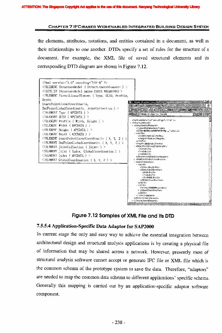
CHAPTER 7 IFC-BASED WEB-ENABLED INTEGRATED BUILDING DESIGN SYSTEM
the elements, attributes, notations, and entities contained in a document, as well as
their relationships to one another. DTDs specify a set of rules for the structure of a
document. For example, the XML file of saved structural elements and its
corresponding DTD diagram are shown in Figure 7.12.
<?xml version=Hl.OH encoding=HUTF-8H ?><!ELEMENT StructureModel (StructLinearElement+ ) ><!ATTLIST StructureModel xmlns CDATA #REQUIRED ><!ELEMENT StructLinearElement ( Type, GUID, Profile,Depth,StartPointGlobalCoordinatin,EndPointGlobalCoordinatin, JointCollection) ><!ELEMENT Type ( #PCDATA ) ><!ELEMENT GUID ( #PCDATA ) ><!ELEMENT Profile ( Width, Height) ><!ELEMENT Width ( #PCDATA ) ><!ELEMENT Height ( #PCDATA ) ><!ELEMENT Depth ( #PCDATA ) ><!ELEMENT StartPointGlobalCoordinatin ( X, Y, Z ) ><!ELEMENT EndPointGlobalCoordinatin ( X, Y, Z ) ><!ELEMENT JointCollection ( Joint+ ) ><!ELEMENT Joint ( Index, GlobalCoordination ) ><!ELEMENT Index ( #PCDATA ) ><!ELEMENT GlobalCoordination ( X, y, Z ) >
Figure 7. 12 Samples of XMl File and Its OlD
7.5.5.4 Application-Specific Data Adaptor for SAP2000
In current stage the only and easy way to achieve the essential integration between
architectural design and structural analysis applications is by creating a physical file
of information that may be shared across a network. However, presently most of
structural analysis software cannot accept or generate IFC file or XML file which is
the common schema of the prototype system to save the data. Therefore, "adaptors"
are needed to map the common data schema to different applications' specific schema.
Generally this mapping is carried out by an application-specific adaptor software
component.
- 238-
ATTENTION: The Singapore Copyright Act applies to the use of this document. Nanyang Technological University Library
CHAPTER 7 IFC-BASED WEB-ENABLED INTEGRATED BUILDING DESIGN SYSTEM
SAP2000 works around a central database created for the structural model. The
database is maintained in a binary format and does not operate with text input files.
However, text input files may be read or written using the ImportlExport facility. The
supported formats mainly include text file, DXF file and Enhanced Metafile. The
DXF file import is intended to facilitate importing model geometry from AutoCAD
and other DXF compatible programs. However, only the DXF for AutoCAD r12, r13
and r14 is supported. The Enhanced Metafile is a vector file format that can be read
by many graphics programs as well as some office tools like word processors. A text
file with an extension "S2k" is saved at the same time as the model database is saved
(as a file with .SDB extension). This text file is good for analysis purposes. The
analysis and design information provided in the SDB file is also saved in the S2K file.
This gives the user the ability to modify the model using a text editor like WordPad.
The text file provides a feasible way for the system to interact with SAP2000, since it
is easiest to generate. Thus the adaptor for SAP2000 is implemented to write S2K text
file and provide the link of download via Internet to engineer as the input of structural
analysis. In this implementation, one class is enough for one kind of application. It
can be noticed that in Figure 7.11 another class ExportSAPfile is used except the
SimpleXMLOutput to write the whole structural model, including the structural
geometric and topological information, even material properties and load information
assigned by engineer, to a text file in accordance with the format of the S2K file.
7.6 Implementation of Extended IFe Models in System
The prototype implements the augmented IFC models in the context of distributed,
model-based, integrated AECIFM system architecture. When the core processing
module reads IFC file, IFCsvr ActiveX component is used which is an off-the-peg
ActiveX component for handling IFC data. IFCsvr is a software component for the
development of IFC compliant application with Visual Basic, Visual Basic for
Application (VBA), VC++, and so on. IFCsvr has IFC model data input/output
function as STEP Part21 file or XML file and provides additional operations, such as
IFC object searching, changing, and creating.
- 239-
ATTENTION: The Singapore Copyright Act applies to the use of this document. Nanyang Technological University Library

CHAPTER 7 IFC-BASED WEB-ENABLED INTEGRATED BUILDING DESIGN SYSTEM
Till now IFCsvr has transited from version R200 to the latest R300. The new features
of R300 include the support to IFC 2x and strengthening XML import and export
function (BLIS-XML stream with MSXML or string data). Whereas R300 is still
under improvement and most of IFC compliant CAD architectural design software
can successfully provide IFC R151 or R2.0 file and a few can support IFC 2x,
IFCsvr.R200 is more stable by contrast with R300 and is selected to be used in current
prototype implementation.
7.6.1 IFCsvr. R200
Figure 7.13 gives the object model of IFCsvr. R200. The IFCsvr.R200 object is a
root object of IFCsvr, which can load the IFC model data from following formats:
STEP Part 21, BLIS XML format, ROSE binary, and ROSE ascii. The Design object
manages IFC model data file. Design object can write the IFC model data. This object
has also instantiating and searching Entity object functions. The Entities object is a
collection of Entity object. The Entity object manages IFC object instances defined
by EXPRESS. Each Entity object contains its ENTITY TYPE name and a pointer to
its own attributes. The Attributes object is a collection of Attribute object. The
Attribute object can set and get values of each attribute which are contained by an
Entity object. More detailed information is available at
http://cic.vtt.fi/projects/ifcsvr/ifcsvrr200/obj r200.html.
Figure 7.13 IFCsvr. R200 Object Model
(Source: http://cic.vtt.fi/projects/ifcsvr/ifcsvn"200/obj r200.html)
- 240-
ATTENTION: The Singapore Copyright Act applies to the use of this document. Nanyang Technological University Library

CHAPTER 7 IFC-BASED WEB-ENABLED INTEGRATED BUILDING DESIGN SYSTEM
7.6.2 IFC Models ImplementationThe data structure of IFC models is complicated and has to be represented in Java
objects to fully utilize the advantages of object-oriented approach. During the
implementation of prototype system, a set of Java classes is designed to represent the
geometric information from IFC architectural design file, as shown in Figure 7.14.
Any object in IFC with a geometric representation has two attributes:
ObjectPlacement and Representation. ObjectPlacement, which has the type of
IfcObjectPlacement, stores the placement information of an object. Representation,
which has the type of IfcProductRepresentation, stores the shape representations of
the object. Its location is defined within the context of ObjectPlacement. Each
Entity read by IFCsvr such as IfcBeam, IfcColumn and so on, are stored as one
instance of class IfcProduct. The values of attributes ObjectPlacement and
Representation of each Entity are extracted and saved into corresponding attributes
of the IfcProduct by types of IfcLocalPlacement and IfcProductRepresentation.
- 241 -
ATTENTION: The Singapore Copyright Act applies to the use of this document. Nanyang Technological University Library
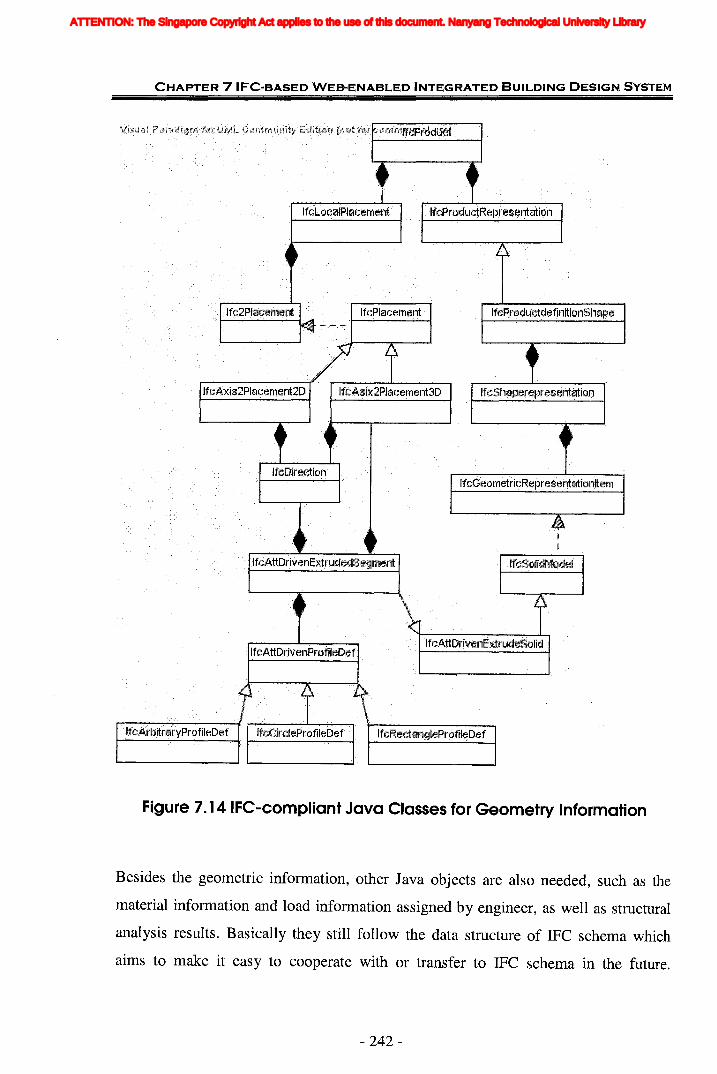
CHAPTER 7 IFC-BASED WEB-ENABLED INTEGRATED BUILDING DESIGN SYSTEM
Figure 7. 14 IFC-compliant Java Classes for Geometry Information
Besides the geometric information, other Java objects are also needed, such as the
material information and load information assigned by engineer, as well as structural
analysis results. Basically they still follow the data structure of IFC schema which
aims to make it easy to cooperate with or transfer to IFC schema in the future.
- 242-
ATTENTION: The Singapore Copyright Act applies to the use of this document. Nanyang Technological University Library

CHAPTER 7IFC-BASED WEB-ENABLED INTEGRATED BUILDING DESIGN SYSTEM
Because of limitation of IFCsvr R200, presently the system cannot write these kinds
of information into original IFC file after the server get them from engineer. In the
future, it can be considered to write this information into the original IFC architectural
design file and provide a more complete file to download for query and view. As
more and more applications provide the support for IFC models, a complete IFC file
is a more useful and effective way for future communication and information sharing.
Figure 7.15 illustrates the developed Java classes for material and load information. It
is apparent that it is very similar with the data structure of latest IFC Release 2x
Edition 2 and its addendum.
StrudurfZllLoadTemperal:ure
Figure 7. 15 Java Classes for Material and Load Information
7.6.3 Implementation of Proposed IFC ExtensionsAs described in previous chapters, current IFC models cannot support complete
requirements of structural engineering software to perform structural analysis.
According to Table 6.5 in Chapter 6, some new extensions are developed. Small
revision is necessary in some minor respects or some information need deduction.
However, these new extensions to IFC models proposed in this research cannot be
- 243-
ATTENTION: The Singapore Copyright Act applies to the use of this document. Nanyang Technological University Library
CHAPTER 7 IFC-BASED WEB-ENABLED INTEGRATED BUILDING DESIGN SYSTEM
written into IFC files before they are finally incorporated into the new Release of IFC
models.
New property set can be included in IFC files at any time and it has already been
implemented in the prototype system by PSet beans. With regard to other information,
no matter the new extensions or new attributes to objects, their Java classes which are
basically compliant with IFC data structure are developed in the prototype
implementation. On the other hand, new classes or new attributes for the information
that applications require are also incorporated and processes. In the prototype, the
following respects are implemented to process the related information gaps with IFC
Release 2x Edition 2 and its addendum which can be referred in Table 6.5.
(1) For the gaps on geometry information, referring to the sample of the definition for
StructLinearElement class in Figure 7.16 and its XML representation in Figure 7.12,
it can be investigated that the global locations of joints are always provided. In class
StructLinearElement, the attribute vecJoints is inherited from class StructElement
to save the related joints by the type of StructJoint. In XML, The information of
joints is included under the child element JointColiection of element
StructLinearElement. For each joint, its Index and GlobalCoordination are saved.
Moreover, the length of the structural element is represented in the child element
Depth.
- 244-
ATTENTION: The Singapore Copyright Act applies to the use of this document. Nanyang Technological University Library
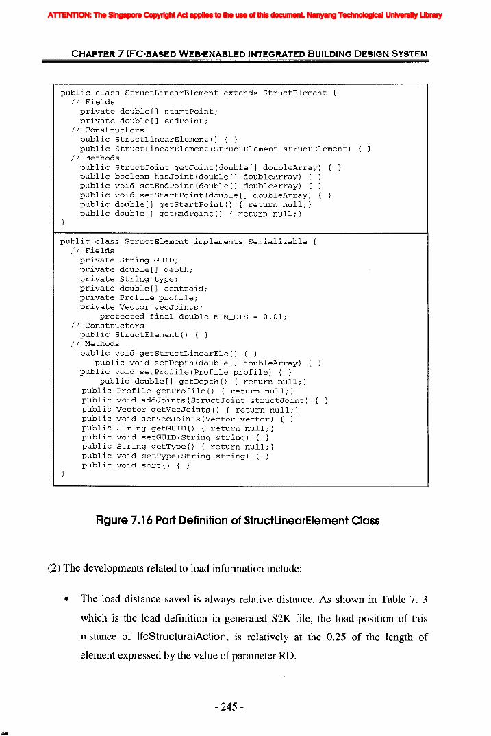
CHAPTER 7 IFC-BASED WEB-ENABLED INTEGRATED BUILDING DESIGN SYSTEM
public class StructLinearElement extends StructElement {II Fields
private double[] startPointiprivate double[] endPointi
II Constructorspublic StructLinearElement() { }public StructLinearElement(StructElement structElement) { }
II Methodspublic StructJoint getJoint(double[] doubleArray) { }public boolean hasJoint(double[] doubleArray) { }public void setEndPoint(double[] doubleArray) { }public void setStartPoint(double[] doubleArray) {public double[] getStartPoint() { return nulli}public double[] getEndPoint() { return nulli}
public class StructElement implements Serializable {II Fields
private String GUIDiprivate double[] depthiprivate String typeiprivate double[] centroidiprivate Profile profileiprivate Vector vecJointsi
protected final double MIN_DIS O.OliII Constructors
public StructElement() { }II Methods
public void getStructLinearEle() { }public void setDepth(double[] doubleArray)
public void setProfile(Profile profile) { }public double[] getDepth() { return nulli}
public Profile getProfile() { return nulli}public void addJoints(StructJoint structJoint) { }public Vector getVecJoints() { return nulli}public void setVecJoints(Vector vector) { }public String getGUID() { return nulli}public void setGUID(String string) { }public String getType() { return nulli}public void setType(String string) { }public void sort() { }
Figure 7. 16 Part Definition of StructLinearElement Class
(2) The developments related to load information include:
• The load distance saved is always relative distance. As shown in Table 7. 3
which is the load definition in generated S2K file, the load position of this
instance of IfcStructuralAction, is relatively at the 0.25 of the length of
element expressed by the value of parameter RD.
- 245-
ATTENTION: The Singapore Copyright Act applies to the use of this document. Nanyang Technological University Library

CHAPTER 7 I FC"BASE'D WEB-ENABLED INTEGRATED BUILDING DESIGN SYSTEM
• As described in Chapter 6.5.2, 'Load Type' is not needed to be described in
S2K file. Only the values of IfcStructuralLoad should be wrote into S2K file
separately. In S2K file, the 'TYPE' of load stands for the kind of load assigned,
concentrated load or distributed load etc.
• The load values in different directions or axes are divided and wrote
respectively into S2K file by ExportSAPfile. For example,
StructuralLoadSingleForce has six values for three forces in different
directions and three moments about different axis. If all values are not equal to
zero, then they will be expressed to six loads in 'TYPE' of "Concentrated
Span" respectively in S2K file. As shown in the following example (Table 7.3),
in fact these six values just represent a point action acted on a structural
element named 28. And the assigned load is a StructuralLoadSinglForce
with the value (3, 4, 5, 6, 7, 8). The value of 'Load Direction' is implied in the
left operand expressed by 'UX, UY, UZ, RX, RY, RZ' etc.
• As shown in Figure 7.15, the attribute ComboType of entity
IfcStructuralLoadGroup reflects the combination types. The default value is
"ADD".
Table 7.3 Example of Load Denotation in S2K File and CorrespondingIfcStructuralAction Class
LOADNAME=DL SW=l CSYS=O
TYPE=CONCENTRATEDSPANADD=28 RD=.25 UX=3ADD=28 RD=.25 UY=4ADD=28 RD=.25 UZ=5ADD=28 RD=.25 RZ=6ADD=28 RD=.25 RY=7ADD=28 RD=.25 RX=8
public class IfcStructuralActivity implementsSerializable {
private String GUID;private String GlobalOrLocal;private IfcStructuralLoad AppliedLoad;private String LoadCase;private String AssignedtoElement;private String Position;private String Name;public IfcStructuralActivity() {}
}
public class IfcStructuralAction extendsIfcStructuralActivity{
private Boolean DestablizingLoad;private String ProjectOrTrue;
- 246-
ATTENTION: The Singapore Copyright Act applies to the use of this document. Nanyang Technological University Library
CHAPTER 7 IFC-BASED WEB-ENABLED INTEGRATED BUILDING DESIGN SYSTEM
(3) Regarding the types of material, the new attribute materialType to class
IfcMaterial is developed as shown in Figure 7.15. Although it provides the choices of
types for the engineers currently, it is still recommended that isotropic material is used.
Moreover, the material properties "weight per unit volume" and "mass per unit
volume" are currently both defined in the class IfcMaterialProperties which aims to
support different requirements for different software. As long as one value is provided,
the other one can be calculated during generating the application-specific file, such as
the S2K file generated by class ExportSAPfile.
(4) On section information, "Shape Type" is deduced by the value of attribute Profile
of class StructLinearElement. For example, if its value is an. instance of
RectangleProf I then the value of "Shape Type" in S2K file equals to "R".
Following the IFC schema, material is assigned to the selected structural elements.
Through this, the relationship between section and material can be inferred.
(5) Whereas the conditions and definitions for the Prestress load and the elements'
stresses are a little complicated, and the shell elements have not been included in this
simple prototype implementation in this stage.
In conclusion, in the prototype system, for those information required to be processed
during programming and no new corresponding extensions developed, they are
computed or deduced from the existing values of classes during the writing of S2K
file through the class ExportSAPfile, such as Shape Type and profile properties of
member sections, etc. Other new extensions are realized during the classes generated.
However, it can not represent the final implementation. As the possible development
of IFC for these gaps, the structure or extensions have to be adjusted accordingly.
7.7 Summary
This chapter presents the development of the IFC-based web-enabled integrated
building design (IWIBD) system, which provides a collaborative environment
whereby the diverse participants can perform online collaboration via the web. It aims
to support the communication and cooperation of architects and structural engineers,
- 247-
ATTENTION: The Singapore Copyright Act applies to the use of this document. Nanyang Technological University Library
CHAPTER 7 IFC-BASED WEB-ENABLED INTEGRATED BUILDING DESIGN SYSTEM
and to facilitate the incorporation of their design into the framework. The integrated
framework can offer users access to the core server, as well as the associated
supporting services via the Internet. An overview of the system architecture
framework is provided. The architecture follows a three -tier software architecture
and consists of four distinct modules. The detailed design and implementation of
modules are described in this chapter. This system is based on the internationally
recognized IFC models and the implementation of extended IFC models is also
illustrated.
A prototype system has been implemented to prove the validity and concept. It
provides web-enabled services for practical use of this framework in representation,
exchange and sharing of interoperable design information between architectural
design and structural engineering applications. It is capable of importing and
exporting IFC information. For the prototype implementation and testing in this
research work the J2EE technology is utilized as the basis. A standard World Wide
Web browser is employed to provide the user interaction with the core server. Apache
Tomcat 4.0 is employed to process the HTTP requests from the client. Java's Servlet
is used to handle communication for the distributed element services over the Internet.
The prototype system is designed and implemented as a generic prototype application
for the purpose of demonstrating software interoperability through the use of IFC data
standards. It provides a means of integrated services in a modular and systematic way.
The modular service model helps the integration of legacy code as one of the modular
services in the infrastructure. Each component of the system can be added or updated
without substantial amount of modification to the existing system. The application is
not limited to architectural design and structural analysis only. Similar scenarios can
be generated for demonstrating data exchange among the whole life cycle processes.
The utilization of standard query language and popular query interfaces, as well as the
deployment of the Internet for delivering data, makes the system flexible and
extendible.
- 248-
ATTENTION: The Singapore Copyright Act applies to the use of this document. Nanyang Technological University Library
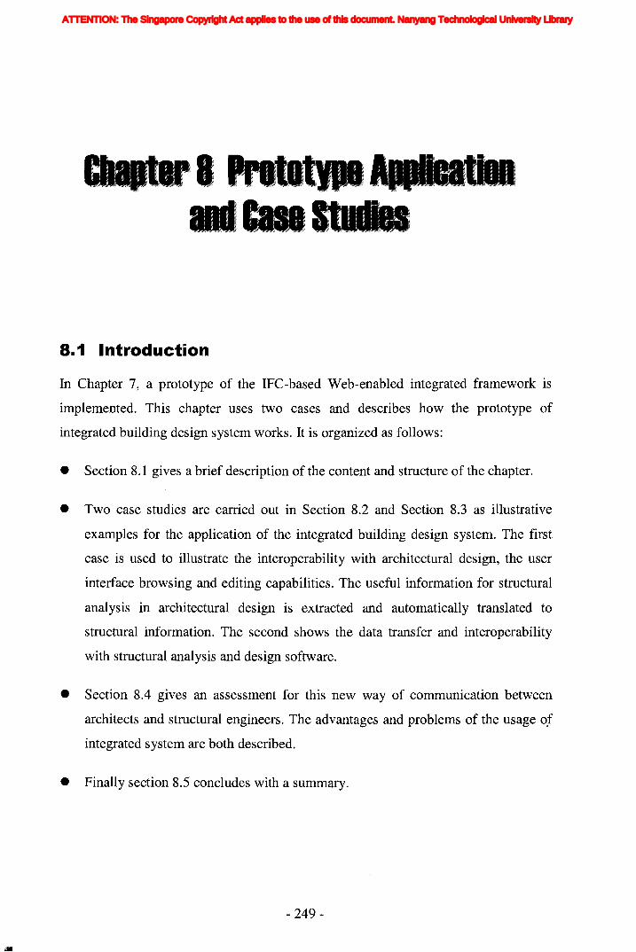
l1li
8.1 Introduction
In Chapter 7, a prototype of the IFC-based Web-enabled integrated framework is
implemented. This chapter uses two cases and describes how the prototype of
integrated building design system works. It is organized as follows:
• Section 8.1 gives a brief description of the content and structure of the chapter.
• Two case studies are carried out in Section 8.2 and Section 8.3 as illustrative
examples for the application of the integrated building design system. The first
case is used to illustrate the interoperability with architectural design, the user
interface browsing and editing capabilities. The useful information for structural
analysis in architectural design is extracted and automatically translated to
structural information. The second shows the data transfer and interoperability
with structural analysis and design software.
• Section 8.4 gives an assessment for this new way of communication between
architects and structural engineers. The advantages and problems of the usage of
integrated system are both described.
• Finally section 8.5 concludes with a summary.
- 249-
ATTENTION: The Singapore Copyright Act applies to the use of this document. Nanyang Technological University Library
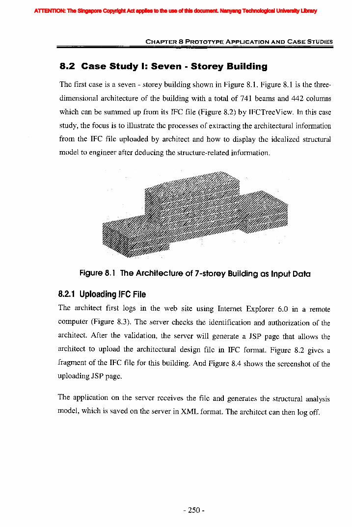
CHAPTER 8 PROTOTYPE ApPLICATION AND CASE STUDIES
8.2 Case Study I: Seven - Storey Building
The first case is a seven - storey building shown in Figure 8.1. Figure 8.1 is the three
dimensional architecture of the building with a total of 741 beams and 442 columns
which can be summed up from its IFC file (Figure 8.2) by IFCTreeView. In this case
study, the focus is to illustrate the processes of extracting the architectural information
from the IFC file uploaded by architect and how to display the idealized structural
model to engineer after deducing the structure-related information.
Figure 8.1 The Architecture of 7-storey Building as Input Data
8.2.1 Uploading IFC File
The architect first logs in the web site using Internet Explorer 6.0 in a remote
computer (Figure 8.3). The server checks the identification and authorization of the
architect. After the validation, the server will generate a JSP page that allows the
architect to upload the architectural design file in IFC format. Figure 8.2 gives a
fragment of the IFC file for this building. And Figure 8.4 shows the screenshot of the
uploading JSP page.
The application on the server receives the file and generates the structural analysis
model, which is saved on the server in XML format. The architect can then log off.
- 250-
ATTENTION: The Singapore Copyright Act applies to the use of this document. Nanyang Technological University Library
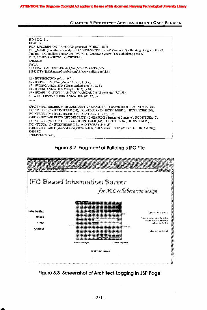
CHAPTER 8 PROTOTYPE ApPLICATION AND CASE STUDIES
ISO-I0303-21 ;HEADER;FILE_DESCRIPTION «'ArchiCAD generated IFC file.'), '2;1');FILE_NAME ('For Strucure analysis.IFC', '2003-01-24TI3:30:45', ('Architect'), ('Building Designer Office'),'PreProc - IFC Toolbox Version 2.0 (99/07/01)', 'Windows System', 'The authorising person.');FILE_SCHEMA «'IFC20_LONGFORM'»;ENDSEC;DATA;#100036=IFCADDRESS($,0,$,$,$,$,('555-87654321 '),('555-12345678'),(Jiri.hietanen@solibrLcom'),$,.www.solibri.com•• $.$);
#2 = IFCDIRECTION «0., 1.,0.»;#6 = IFCPERSON ('FamilyName', $, $, $, $, 0, 0);#7 = IFCORGANIZATION ('OrganizationName', 0, 0, $);#8 = IFCORGANIZATION ('Graphisoft', 0, 0, $);#9 = IFCAPPLICATION ('ArchiCAD', 'ArchiCAD 7.0 (Graphisoft)', '7.0', #8);#10 = IFCPERSONANDORGANIZATION (#6, #7,0);
#51004 = IFCTABLEROW «IFCDESCRIPTIVEMEASURE ('Concrete Block'), IFCINTEGER (0),IFCINTEGER (65), IFCINTEGER (34), IFCINTEGER (20), IFCINTEGER (8), IFCINTEGER (20),IFCINTEGER (34), IFCINTEGER (65), IFCINTEGER (-128», .F.);#51005 = IFCTABLEROW «IFCDESCRIPTIVEMEASURE ('Structural Concrete'), IFCINTEGER (0),IFCINTEGER (2), IFCINTEGER (32), IFCINTEGER (14), IFCINTEGER (68), IFCINTEGER (0),IFCINTEGER (17), IFCINTEGER (64), IFCINTEGER (-24», .F.);#51006 = IFCTABLE ('d?n'<vE4-YQeDWuB?8Pb', 'Fill-Material Table', (#51003, #51004, #51005»;ENDSEC;END-ISO-I0303-21;
Figure 8.2 Fragment of Building's IFC File
Introduction
There18:119 file. currently on theserver, Achitectuteshould
upload the file first
Figure 8.3 Screenshot of Architect Logging in JSP Page
- 251 -
ATTENTION: The Singapore Copyright Act applies to the use of this document. Nanyang Technological University Library

CHAPTER 8 PROTOTYPE ApPLICATION AND CASE STUDIES
Figure 8.4 Screenshot of Architect Uploading IFC File
8.2.2 Viewing and Editing 3D Structural Idealization ModelThe structural engineer involved in the project can then, at another location, log in the
server. After successfully logging in, the engineer can view the 3D idealized structural
model in his browser. Though he cannot directly change the structural model, he can
pick any element and add new properties or comments (Figure 8.5). Figure 8.5
presents the overall picture of the model viewing and editing.
The structural idealization model in Java applet (on the left of Figure 8.5) allows the
client engineer to rotate, zoom in, zoom out and walk through the structural model to
have a close view. The pop-up window (on the right of Figure 8.5) shows the basic
information of selected element, including the dimension, the location of the idealized
structural element and joints. Currently the information of element comes from the
XML file saved in the server.
Besides the basic information, the system also allows the structural engineer to add
new properties to the selected element as name-value pairs. For example, if the
- 252-
ATTENTION: The Singapore Copyright Act applies to the use of this document. Nanyang Technological University Library

CHAPTER 8 PROTOTYPE ApPLICATION AND CASE STUDIES
engineer has some suggestions about the location or dimension of the element, he can
add the comments in the TextArea. These are written back to the server after clicking
feedback button and are saved as Property Sets into the IFC data file on the server,
after clicking the save button. After receiving the feedback from engineer, the server
generates the JSP page that gives notice to the architect and allows him to log in and
download the adjusted IFC data file with the property sets added by the engineer.
After downloading, the architect can use his CAD software to view and edit the
design. After editing, the architect logs in the web and once more uploads the revised
architectural design as an IFC data file again. The server receives the file and
automatically generates a structural idealization model and a JSP web page that only
allows the engineer to log in and view the revised model.
Click on the structure element to makeadjUl';t
Go back
Figure 8.5 The Screenshot of Structural Engineer Logging in Server andAdds some information to Idealized Structural Model
- 253 -
ATTENTION: The Singapore Copyright Act applies to the use of this document. Nanyang Technological University Library

CHAPTER 8 PROTOTYPE ApPLICATION AND CASE STUDIES
8.2.3 Downloading the Agreed Model FileIf the engineer is satisfied with the structural model, the server will generate a web
page to close the information feedback process and allow the architect and structural
engineer to download the architectural model as an IFC data file and the structural
idealization model as a XML format file (the message is shown on the right of Figure
8.6). If the engineer is still not satisfied with the structural model, he can feedback his
suggestion and server will repeat the above process until the agreement is achieved.
Figure 8.6 The Screenshot of Final JSP Page that Allows Architect andStructural Engineer to Download Files
As the output is in XML format, it can be easily transferred to the other data formats
required by the structural analysis software. The IFC2.0 Release does not include the
structural analysis domain. Thus, the structural analysis information and analysis
results generated by structural engineering software cannot merge with the IFC model
at the moment. It would be changed in the near future with the coordinated in
- 254-
ATTENTION: The Singapore Copyright Act applies to the use of this document. Nanyang Technological University Library

CHAPTER 8 PROTOTYPE ApPLICATION AND CASE STUDIES
improving on the IFCsvr ActiveX component and the capabilities of structural
engineering software to support IFC.
8.2.4 Information and Data TransformationThe above sections provide the general picture of the whole process of the
collaboration between architect and engineer. They also illustrate that how their
communications are implemented by the model server via the web.
However, they cannot show the information transformation during the process and
cannot prove that the information is exchanged consistently. In this section, one beam
element labelled "Beam#2138" in IFC file is selected as an example to show the
process of information and data transformation. For the same element's information,
differ~nt definitions are generated during the different phases. Some definitions are
visible for users, such as IFC file, XML file, while some are invisible which are only
generated during the running of program and act as kind of transitional results.
There are four kinds of formats for the definition of the element. Starting from the
definition in IFC file, it is then extracted, deduced and saved as the instance of
StructLinearElement class. As the backup saved in the server, the data is saved into
XML format. In order to support the use of SAP2000, the information is finally
written into S2K file. The following section investigates into these four different
formats of information.
Figure 8.7 shows the original definition of Beam#2138 in the IFC file uploaded by
architect. It is a text file and all related information is in textual representations.
Figure 8.8 is the browsing of the #3044 IfcBeam object by IFCTreeView. This tool
can show the object reference diagrams on a tree view and is an application for a
programmer who implements IFC compatible software. From the tree view, it can be
shown that the geometry-related information in IfcBeam's definition lies on the value
of Representations and LocalPlacement.
- 255-
ATTENTION: The Singapore Copyright Act applies to the use of this document. Nanyang Technological University Library
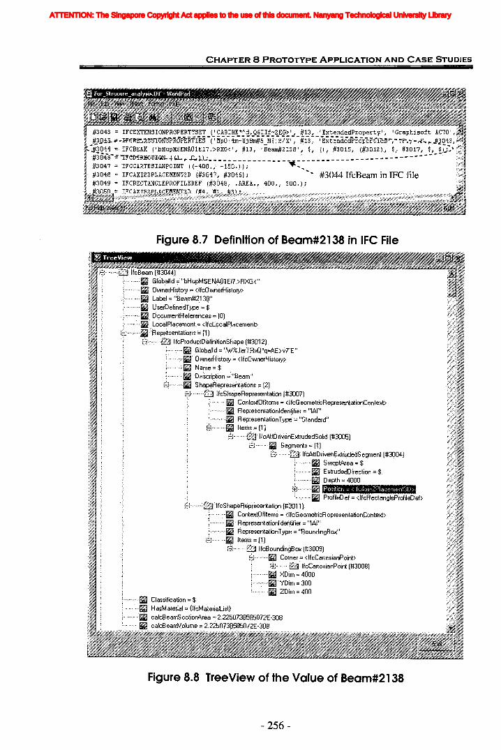
CHAPTER 8 PROTOTYPE ApPLICATION AND CASE STUDIES
#3043 .'= IFCEXTEN5IONPROPER!!S~!_ C~~8]~E_"A"~ S,..Q§II..f:~Eg~'-, _!1}", _'~E~~e_n~:'d!rOpertV'i ' GraphisoftAC70 Ii"",#3.01.5. ~-H'€~ELlS'ST'GJI1S'PROPERTIES ('MpO 14m"'Uj8m#SN$jS!XI ,#13, I ExtendedPrOl:iett'i"es"',-·':"F'".-;-..F.. ,..J:J0'l3,~
.....;3044.=;>..· IFCBEAM ('bHupMSENA01E17.>RXG<',#13, IBeoon#2138', $, 0,#3015, (#3012), $, #3017,$,$[;:\ t~~~i304-6- ;; ""I'l"eD-lRK.=foiGN- -t'-L ...~ >4)..,;- ~ _ ' . - - - - - - - - - - - - - - - ;';;f#3047' = IFCCARTESIANPOINT «-'100.,-150 .r); ~....;::~;~#3048=; IFCAXIS2PLACEMENT2D (#3047,#3046); ..... #3044 IfcBeam in IFe file'd~;;'.
';;-;~d~#30"l9# IFGREGTANGLEPROFILEDEF (#3048,.AREA., 400., 300.);
Figure 8.7 Definition of Beam#2138 in IFC File
Figure 8.8 TreeView of the Value of Beam#2138
- 256-
ATTENTION: The Singapore Copyright Act applies to the use of this document. Nanyang Technological University Library

CHAPTER 8 PROTOTYPE ApPLICATION AND CASE STUDIES
After the server receives the IFC file, it can extract the geometric information of
IfcBeam and deduce the topological information of corresponding structural element.
The deduced structural element is saved as one instance of StructLinearElement
class. According to the definition shown in Figure 7.15, Table 8.1 lists the values of
attributes deduced.
Table 8.1 Primary Values of Entity StructLinearElement for Beam#2138
ValueData TypeAttribute Name I
GUID String bHupMSENAOIEI7.>RXG<
depth[ ] double (4000.0,0.0,0.0)
type String IfcBeam
centroid double[ ] (-20000.0, 2.4442670110147446E-12, 2500.0)
vecJoints Vector Two instances of StructJoint
startPoint double[ ] (-20000.0, 2.4442670110147446E-12, 2500.0)
endPoint double[ ] (-16000.0,2.4442670110147446£-12,2500.0)
profile Profile An instance of RectangleProf-
~ centroid double[ ] (-20000.0, 2.4442670110147446E-12, 2500.0)~..
Heightwidth Double [] (300.0,400.0)
~ Criticallength double 250.0
Figure 8.9 is the close view of engineer's viewing on the selected element, which is
the 'zoom-in' of the example in Figure 8.5. Here the element selected is just the same
element as the example element which is used to explain the information
transformation, Le. Beam#2138. This beam is located in the middle of first storey as
indicated on the left of Figure 8.9. After the engineer clicks the beam, a window is
popped up as the right picture of Figure 8.9. It can be found that all the basic
information of selected element is shown in the window, including the dimension of
the element, the location of the idealized structural element and deduced joints. From
the pop-up window, it can be seen that the basic information is identical with the
values of previously-generated instance of StructLinearElement class (Table 8.1).
- 257-
ATTENTION: The Singapore Copyright Act applies to the use of this document. Nanyang Technological University Library
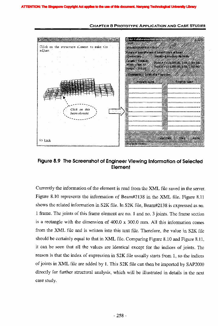
CHAPTER 8 PROTOTYPE ApPLICATION AND CASE STUDIES
'lLl!:::jf...,O-~-V·.,,:,............ - ...... -......." . Click on this.·· ", I\ beam element ,, ~.... .,........... _.. '-
Figure 8.9 The Screenshot of Engineer Viewing Information of SelectedElement
Currently the information of the element is read from the XML file saved in the server.
Figure 8.10 represents the information of Beam#2138 in the XML file. Figure 8.11
shows the related information in S2K file. In S2K file, Beam#2138 is expressed as no.
1 frame. The joints of this frame element are no. 1 and no. 3 joints. The fram.e section
is a rectangle with the dimension of 400.0 x 300.0 mm. All this information comes
from the XML file and is written into this text file. Therefore, the value in S2K file
should be certainly equal to that in XML file. Comparing Figure 8.10 and Figure 8.11,
it can be seen that all the values are identical except for the indices of joints. The
reason is that the index of expression in S2K file usually starts from 1, so the indices
of joints in XML file are added by 1. This S2K file can then be imported by SAP2000
directly for further structural analysis, which will be illustrated in details in the next
case study.
- 258-
ATTENTION: The Singapore Copyright Act applies to the use of this document. Nanyang Technological University Library
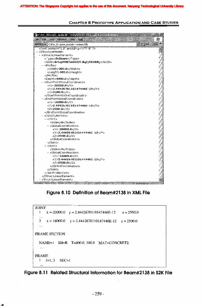
CHAPTER 8 PROTOTYPE ApPLICATION AND CASE STUDIES
_ is ~ revised,XML<?Xm. v:F~jb;;j;2;t'i:'o;t;';h;~~;drh'~;;;(fUff:~f~;~i;;;;;;;;i;~;;;;;;W;i;~;;;;;;;;;;j'" ,
.~. <S'truc,tur8MOd~l>-, .. <:StrUctLinearElemant>
<Type>lfcBeam</Tvpe> '. . .<CiUID>bHupMSENAOlE17.&yltRXG<t</GlJlD>
~ <Profile><Vvidth>300 .O</Wiqth><Height5400.0<!Height>
<!PrClfiJej:.><Depth>4000.O</Dspth>
..,. .<Startf:)ointtlilob.;JICpordinatin><><>-20000.0</><><Y>2.4442670110147446E-12</Y><2>2500.0</2>
</8 tartp QintGlobalcoordinatin>_.. <EnclppintGlobaICoorclinatin>
<><>-16000.0.<1><><-V>2 .4442670110147446E-12</\{j:.><2>2500.0</2>
</EndPJjjntGIobaltoordin~tin>
~... <JointCollection>..... ·<Joint>
Figure 8.10 Definition of Beam#2138 in XML File
JOINT1 x =-20000.0 y = 2.4442670110147446E-12 z = 2500.0
3 x =-16000.0 y = 2.4442670110147446E-12 z = 2500.0
FRAME SECTION
NAME=1 SH=R T=400.0,300.0 MAT=CONCRETE
FRAME1 J=I,3 SEC=1
Figure 8.11 Related Structural Information for Beam#2138 in s2K File
- 259-
ATTENTION: The Singapore Copyright Act applies to the use of this document. Nanyang Technological University Library

CHAPTER 8 PROTOTYPE ApPLICATION AND CASE STUDIES
Table 8.2 contrasts the different definitions of related information for Beam#2138 in
IFC file, by StructLinearElement class, and in XML file respectively (Figure 8.8,
Table 8.1, and Figure 8.10). The expression in S2K file is not covered in this table
because this part of information directly comes from XML file without any change. It
can be seen that the basic information of the beam, such as aUlD, element type, and
profile information, is extracted and saved in a consistent way during the whole
course. However, the values of GUID have some minor differences in XML format.
This is because some symbols are reserved for a certain format, such as "<" and ">"
symbols to XML format. Therefore, modification is needed for these symbols. The
information of element's joints is deduced from the Representations and
LocalPlacement of IfcBeam in the IFC definition according to the algorithm
described in Chapter 7.5.4.1. Although Table 8.2 cannot show the correctness of
deduction, it can be basically illustrated from the 3D model constructed (Figure 8.9).
Therefore, it can be concluded that the architectural definition for Beam#2138 has
been successfully transformed to its corresponding structural element. The topological
information of structural element is accurately deduced from the beam's geometry
information. The information and data transformation during the whole process is thus
found to be consistent and accurate.
- 260-
ATTENTION: The Singapore Copyright Act applies to the use of this document. Nanyang Technological University Library
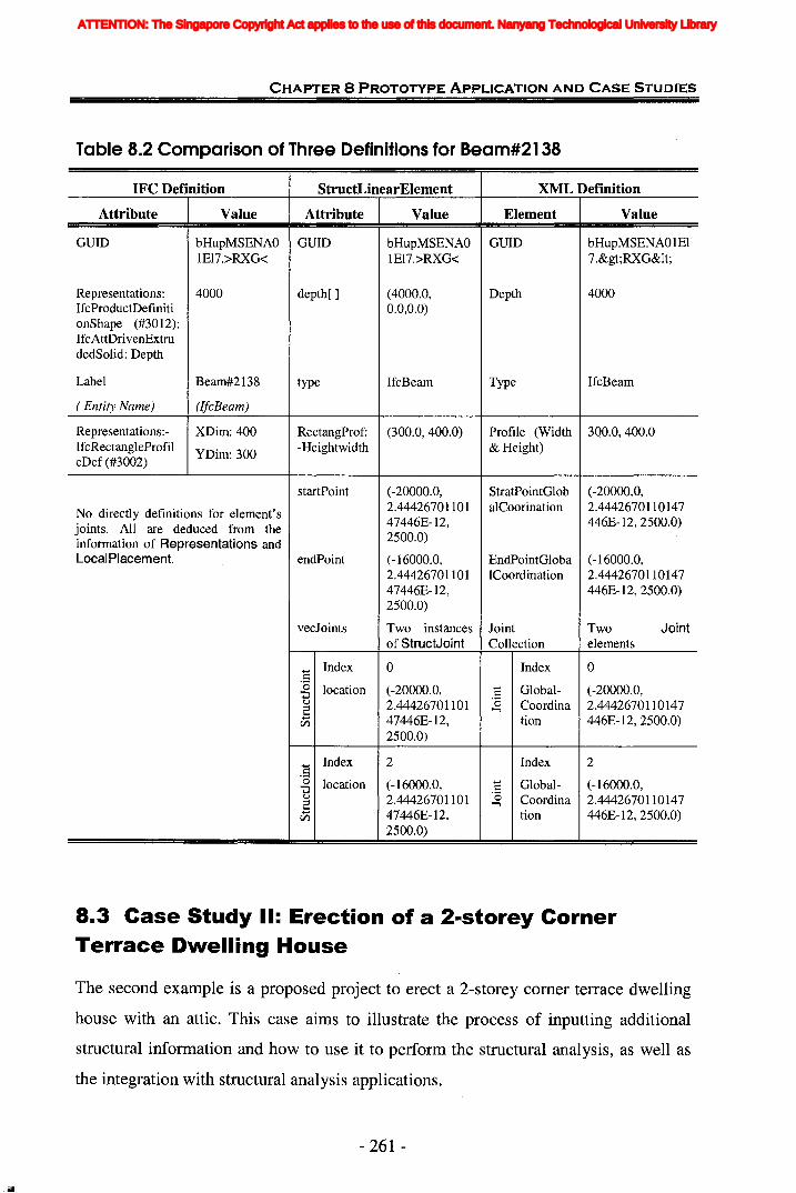
CHAPTER 8 PROTOTYPE ApPLICATION AND CASE STUDIES
Table 8.2 Comparison of Three Definitions for Beam#2138
IFC Definition StructLinearElement XML Definition
Attribute Value Attribute Value Element
GUID bHupMSENAO GUID bHupMSENAO GUIDlEI7.>RXG< lE17.>RXG<
Representations: 4000 depth[ ] (4000.0, DepthIfcProductDefiniti 0.0,0.0)onShape (#3012):IfcAttDrivenExtrudedSolid: Depth
Label Beam#2138 type IfcBeam Type
Value
bHupMSENAOIEI7.>RXG&1t;
4000
IfcBeam
( Entity Name)
Representations: IfcRectangleProfileDef (#3002)
(IfcBeam)
XDim: 400
YDim: 300
RectangProf: (300.0, 400.0)-Heightwidth
Profile (Width 300.0, 400.0& Height)
startPoint
No directly definitions for element'sjoints. All are deduced from theinformation of Representations andLocalPlacement. endPoint
(-20000.0,2.4442670110147446E-12,2500.0)
(-16000.0,2.4442670110147446E-12,2500.0)
StratPointGlob (-20000.0,alCoorination 2.4442670110147
446E-12, 2500.0)
EndPointGloba (-16000.0,ICoordination 2.4442670110147
446E-12, 2500.0)
vecJoints Two instances Jointof StructJoint Collection
Twoelements
Joint
Index.S~ locationu
.5tZl
Index.S~ locationu
.5tZl
o(-20000.0,2.4442670110147446E-12,2500.0)
2
(-16000.0,2.4442670110147446E-12,2500.0)
Index
GlobalCoordination
Index
GlobalCoordination
o(-20000.0,2.4442670110147446E-12, 2500.0)
2
(-16000.0,2.4442670110147446E-12, 2500.0)
8.3 Case Study II: Erection of a 2-storey CornerTerrace Dwelling House
The second example is a proposed project to erect a 2-storey comer terrace dwelling
house with an attic. This case aims to illustrate the process of inputting additional
structural information and how to use it to perform the structural analysis, as well as
the integration with structural analysis applications.
- 261 -
ATTENTION: The Singapore Copyright Act applies to the use of this document. Nanyang Technological University Library
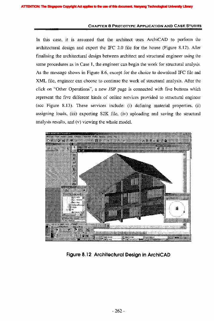
CHAPTER 8 PROTOTYPE ApPLICATION AND CASE STUDIES
In this case, it is assumed that the architect uses ArchiCAD to perform the
architectural design and export the IFC 2.0 file for the house (Figure 8.12). After
finalising the architectural design between architect and structural engineer using the
same procedures as in Case 1, the engineer can begin the work for structural analysis.
As the message shows in Figure 8.6, except for the choice to download IFC file and
XML file, engineer can choose to continue the work of structural analysis. After the
click on "Other Operations", a new JSP page is connected with five buttons which
represent the five different kinds of online services provided to structural engineer
(see Figure 8.13). These services include: (i) defining material properties, (ii)
assigning loads, (iii) exporting S2K file, (iv) uploading and saving the structural
analysis results, and (v) viewing the whole model.
Figure 8. 12 Architectural Design in ArchiCAD
- 262-
ATTENTION: The Singapore Copyright Act applies to the use of this document. Nanyang Technological University Library

CHAPTER 8 PROTOTYPE ApPLICATION AND CASE STUDIES
Other operations include:a. Download IFC file; b..Download XML file :c. Add material information; d.Assign loads to structural elements:e. Uploadstructllral analysis results; f. View the whole model;
Figure 8. 13 Screenshot of JSP Page for Engineer's Operations
8.3.1 Defining MaterialFor the purpose of structural analysis, the properties of the material need to be defined.
By clicking on the "Define Material" button (Figure 8.13), a window is popped up for
the engineer to input the properties online. As shown in Figure 8.14, a type of
concrete material named "Cont1" is defined. The material information is then saved to
sever and later used to export SAP2000 compatible files. It should be noted that the
choices of material types are provided. It reflects the new attribute MaterialType
extended to IfcMaterial (Figure 6.14). Although the structural engineering softwares
usually provide two choices of isotropic and orthotropic to the value of MaterialType,
here the choices are decomposed to more detailed level, such as concrete and steel etc.,
which aims to provide more convenience to the engineer. For each choice, the default
values of the material properties are given.
- 263-
ATTENTION: The Singapore Copyright Act applies to the use of this document. Nanyang Technological University Library
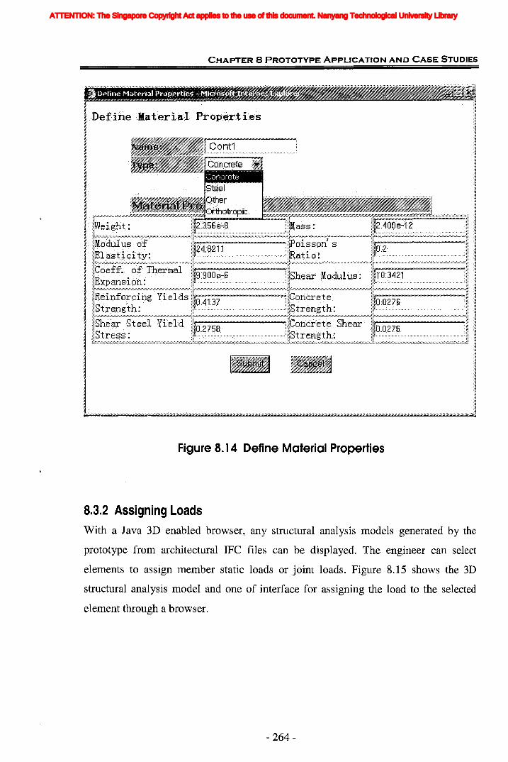
CHAPTER 8 PROTOTYPE ApPLICATION AND CASE STUDIES
Figure 8.14 Define Material Properties
8.3.2 Assigning LoadsWith a Java 3D enabled browser, any structural analysis models generated by the
prototype from architectural IFC files can be displayed. The engineer can select
elements to assign member static loads or joint loads. Figure 8.15 shows the 3D
structural analysis model and one of interface for assigning the load to the selected
element through a browser.
- 264-
ATTENTION: The Singapore Copyright Act applies to the use of this document. Nanyang Technological University Library
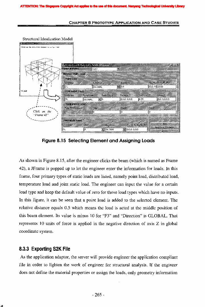
CHAPTER 8 PROTOTYPE ApPLICATION AND CASE STUDIES
Structural Idealization Model
Click on the structure element to assign lOlld
Go bllck
,,,,",J----- ...
" Click on the '\~ "Frame 42" ,., ,... ,
... _------
Figure 8. 15 Selecting Element and Assigning Loads
As shown in Figure 8.15, after the engineer clicks the beam (which is named as Frame
42), a JFrame is popped up to let the engineer enter the information for loads. In this
frame, four primary types of static loads are listed, namely point load, distributed load,
temperature load and joint static load. The engineer can input the value for a certain
load type and keep the default value of zero for those load types which have no inputs.
In this figure, it can be seen that a point load is added to the selected element. The
relative distance equals 0.5 which means the load is acted at the middle position of
this beam element. Its value is minus 10 for "F3" and "Direction" is GLOBAL. That
represents 10 units of force is applied in the negative direction of axis Z in global
coordinate system.
8.3.3 Exporting S2K FileAs the application adaptor, the server will provide engineer the application compliant
file in order to lighten the work of engineer for structural analysis. If the engineer
does -not define the material properties or assign the loads, only geometry information
- 265-
ATTENTION: The Singapore Copyright Act applies to the use of this document. Nanyang Technological University Library
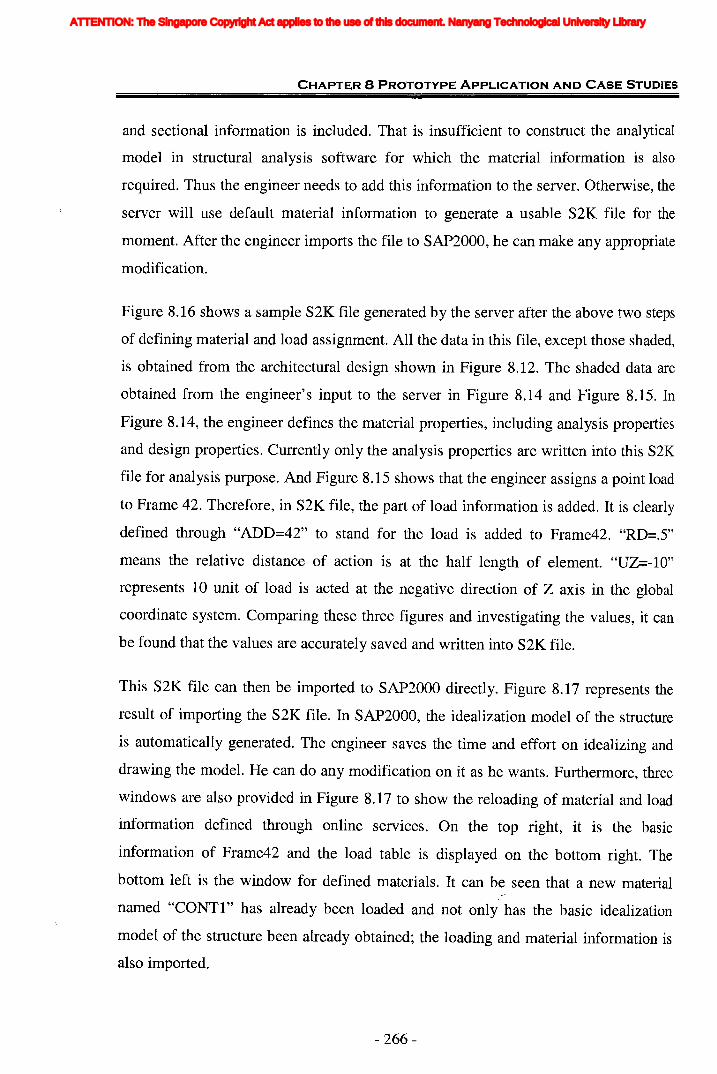
CHAPTER 8 PROTOTYPE ApPLICATION AND CASE STUDIES
and sectional information is included. That is insufficient to construct the analytical
model in structural analysis software for which the material information is also
required. Thus the engineer needs to add this information to the server. Otherwise, the
server will use default material information to generate a usable S2K file for the
moment. After the engineer imports the file to SAP2000, he can make any appropriate
modification.
Figure 8.16 shows a sample S2K file generated by the server after the above two steps
of defining material and load assignment. All the data in this file, except those shaded,
is obtained from the architectural design shown in Figure 8.12. The shaded data are
obtained from the engineer's input to the server in Figure 8.14 and Figure 8.15. In
Figure 8.14, the engineer defines the material properties, including analysis properties
and design properties. Currently only the analysis properties are written into this S2K
file for analysis purpose. And Figure 8.15 shows that the engineer assigns a point load
to Frame 42. Therefore, in S2K file, the part of load information is added. It is clearly
defined through "ADD=42" to stand for the load is added to Frame42. "RD=.5"
means the relative distance of action is at the half length of element. "UZ=-10"
represents 10 unit of load is acted at the negative direction of Z axis in the global
coordinate system. Comparing these three figures and investigating the values, it can
be found that the values are accurately saved and written into S2K file.
This S2K file can then be imported to SAP2000 directly. Figure 8.17 represents the
result of importing the S2K file. In SAP2000, the idealization model of the structure
is automatically generated. The engineer saves the time and effort on idealizing and
drawing the model. He can do any modification on it as he wants. Furthermore, three
windows are also provided in Figure 8.17 to show the reloading of material and load
information defined through online services. On the top right, it is the basic
information of Frame42 and the load table is displayed on the bottom right. The
bottom left is the window for defined materials. It can be seen that a new material
named "CONTI" has already been loaded and not only has the basic idealization
model of the structure been already obtained; the loading and material information is
also imported.
- 266-
ATTENTION: The Singapore Copyright Act applies to the use of this document. Nanyang Technological University Library
CHAPTER 8 PROTOTYPE ApPLICATION AND CASE STUDIES
SAPCON EXAMPLE - 3D FRAME - STATIC LOADS - ACI318-89
; File D:\SimplyVilla6.S2k saved 13/1/2005 15:7:59 in KN - mmSYSTEM
DOF=UX,UY,UZ,RX,RY,RZ LENGTH=mm FORCE=KN
JOINT500023 X=4303.425073905688 Y=4136.102403158708 Z=5750.0500016 X=4283.30276153106 Y=4135.761285761072 Z=5750.0
2 X=2931.1425427810045 Y=4133.722308369695 Z=2750.01 X=8459.157954743609 Y=4143.1238424485555 Z=2750.0
FRAME SECTION
Name=sectionl MAT=Contl SH=R T=300.0,300.0Name=section13 MAT=Contl SH=R T=300.0,200.0Name=section31 MAT=Contl SH=R T=250.0,500.0
FRAME1 J=13,500013 SEC=sectionl2 J=II,500011 SEC=sectionl
70 J=28,30 SEC=section3171 J=27,30 SEC=section31
OUTPUT; No Output Requested
END; The following data is used for graphics, design and pushover analysis.; If changes are made to the analysis data above, then the following data; should be checked for consistency.END SUPPLEMENTAL DATA
Figure 8. 16 Case II Exchange S2K File Fragment
- 267-
ATTENTION: The Singapore Copyright Act applies to the use of this document. Nanyang Technological University Library

CHAPTER 8 PROTOTYPE ApPLICATION AND CASE STUDIES
- 268-
oooND.«(/)
.2"0(I)toa.Eeni"0o~
C...:J..o:J......U)
I'....cO(I)...:J0)u:
ATTENTION: The Singapore Copyright Act applies to the use of this document. Nanyang Technological University Library

CHAPTER 8 PROTOTYPE ApPLICATION AND CASE STUDIES
8.3.4 Uploading and Saving SA ResultsSometimes users from different design disciplines need to view the results of
structural analysis. Or other engineer may want to check the results and investigate
the structures of buildings. After performing structural analysis, the server allows the
engineer to upload the outputs through Internet and saves in the server's repository.
Currently, only Access database file is allowed which is applicable for SAP2000. The
uploading process is very similar as the uploading of IFC files by architect. The server
can extract and save the analysis and design results, and then provide for other project
participates to query and view.
8.3.5 Viewing Whole ModelThe online services allow the engineer to query and view the structural analysis
results for the whole structural model. Similarly as in "Assign Loads", the structural
analysis model is displayed to user through a Java 3D enabled browser. The user can
select the element concerned and its related information will be extracted and shown
online by the server through a browser (Figure 8.18).
Structural Analysis Model1111----·;.··B'§••~~
Click. on the structure elem"nt to view its r"late.;l analysisinformation
Information for Selected Element
Figure 8. 18 Viewing Structural Analysis Information
- 269-
ATTENTION: The Singapore Copyright Act applies to the use of this document. Nanyang Technological University Library
CHAPTER 8 PROTOTYPE ApPLICATION AND CASE STUDIES
8.4 Assessment of Prototype's Implementation andSystem Architecture
Through the two case studies carried out in previous section, the functionalities of the
IWIBD system have been demonstrated. It shows the feasibility and practicability of
the collaboration between architects and structural engineers. The first case tests the
interoperability with architectural design, the user interface browsing, and editing
capabilities. The useful information for structural analysis in architectural design is
extracted and automatically translated to structural information. The second shows the
interoperability with structural analysis and design software. The data exchange and
sharing between two different disciplines and different applications based on IFe
models is successfully executed. In addition, through the investigation on the
processes of data transformation, the information is proven to be transformed and
transferred accurately and consistently.
Furthermore, it proves the capability of IFC models to allow project participants to
share project information across different application packages and building upon
existing data, while eliminating the inefficiencies and inconsistencies associated with
conventional practices of data re-entry. It must be stressed that the focus of the
implementation is not to develop software with features already available in
commercially available software. The focus is rather to implement a web-based
integrated prototype application that is capable of exchanging and transforming data
based on IFC standard models.
With respect to level of integration, there are three stages identified on the way to a
full integration: data exchange, data integration and process integration (Sun and
Lockley, 1995). Data exchange is the first stage where design tools still operate
independently. At this level, data can be exchanged between the tools when the user
decides to do so. The next target is to carry out the data integration where several
design tools are incorporated into one system. Each tool interacts with this model
when invoked by the system, and the interaction between the tool and the model is
seamless. The highest level of integration is process integration when the system will
have sufficient knowledge on the built environment and the design process, which is
- 270-
ATTENTION: The Singapore Copyright Act applies to the use of this document. Nanyang Technological University Library
CHAPTER 8 PROTOTYPE ApPLICATION AND CASE STUDIES
used to provide intelligent support to designers. In this research the lowest level of
integration, data exchange, has been implemented.
The model-based system and architecture combine both data interoperability and
system integration. Interoperability is defined as the ability for tools to exchange data,
and it offers one solution to the problem of integration. Integrated system is defined as
multi-purpose tools that combine many different views (both data and functionality)
(Froese, 2003). With interoperability, it is difficult to manage the collective body of
information since each tool works with only a limited view in its specialized domain.
Furthermore, the "business logic" associated with each view resides in different
tools and cannot interact. This would be possible within integrated systems, yet no
integrated system can support all the views and users required for an AECIFM project.
It would be difficult to impose one specific system on all projects users, or to enter all
the necessary information within one tool. Therefore, the IFC-based integrated system
is one general and better effective solution for the integration. The interoperability is
provided by the adoption of IFC, a standard data model approach. Through the
integrated system, existing applications are able to exchange information through the
data exchange standards, while new integrated tools are used for overall information
management and functional integration.
Although only two disciplines and two kinds of applications are involved in current
prototype implementation, the concept of model-based integrated system has been
successfully validated. It not only provides a platform for the information exchange
between different users. It also incorporates the information transformation into
information exchange which is its special feature. It implements the real integration
and shows that the structural model can be derived programmatically from
architectural model. The use case, Architectural design ~ -7 Structural analysis
and design is carried out in this integrated system which is not fully considered in
other existing IFC - related collaborative implementation projects, such as BLIS,
Intelligent Services and Tools for Concurrent Engineering (ISTforCE), eConstruct,
VERA, iCSS, CORNET, and so on. For example, the use cases supported for the
project BLIS include: Architectural design ~ -7 HVAC design, Arch/HVAC Design
- 271 -
ATTENTION: The Singapore Copyright Act applies to the use of this document. Nanyang Technological University Library
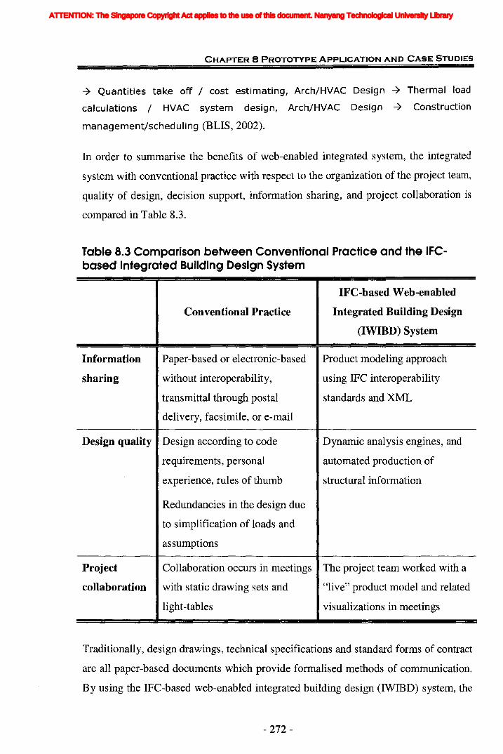
CHAPTER 8 PROTOTYPE ApPLICATION AND CASE STUDIES
-7 Quantities take off / cost estimating, Arch/HVAC Design -7 Thermal load
calculations / HVAC system design, Arch/HVAC Design -7 Construction
management/scheduling (BLIS, 2002).
In order to summarise the benefits of web-enabled integrated system, the integrated
system with conventional practice vvith respect to the organization of the project team,
quality of design, decision support, information sharing, and project collaboration is
compared in Table 8.3.
Table 8.3 Comparison between Conventional Practice and the IFCbased Integrated BUilding Design System
IFC-based Web-enabled
Conventional Practice Integrated Building Design
(IWIBD) System
Information Paper-based or electronic-based Product modeling approach
sharing without interoperability, using IFC interoperability
transmittal through postal standards and XML
delivery, facsimile, or e-mail
Design quality Design according to code Dynamic analysis engines, and
requirements, personal automated production of
experience, rules of thumb structural information
Redundancies in the design due
to simplification of loads and
assumptions
Project Collaboration occurs in meetings The project team worked with a
collaboration with static drawing sets and "live" product model and related
light-tables visualizations in meetings
Traditionally, design drawings, technical specifications and standard forms of contract
are all paper-based documents which provide formalised methods of communication.
By using the IFC-based web-enabled integrated building design (IWIBD) system, the
- 272-
ATTENTION: The Singapore Copyright Act applies to the use of this document. Nanyang Technological University Library
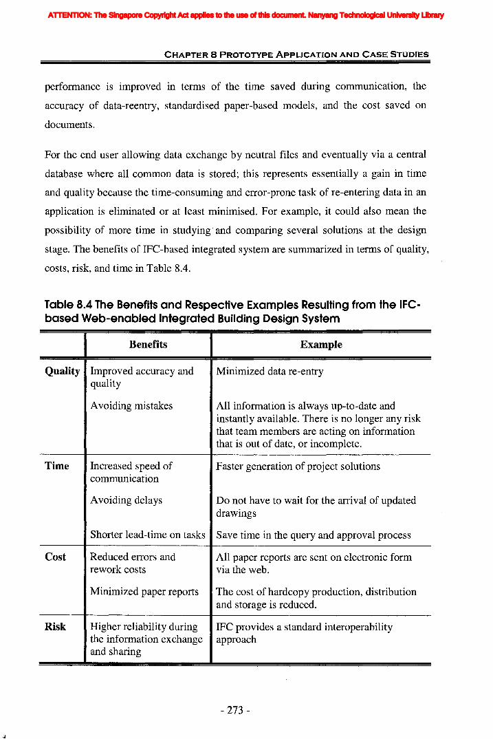
CHAPTER 8 PROTOTYPE ApPLICATION AND CASE STUDIES
performance is improved in terms of the time saved during communication, the
accuracy of data-reentry, standardised paper-based models, and the cost saved on
documents.
For the end user allowing data exchange by neutral files and eventually via a central
database where all common data is stored; this represents essentially a gain in time
and quality because the time-consuming and error-prone task of re-entering data in an
application is eliminated or at least minimised. For example, it could also mean the
possibility of more time in studying and comparing several solutions at the design
stage. The benefits of IFC-based integrated system are summarized in terms of quality,
costs, risk, and time in Table 8.4.
Table 8.4 The Benefits and Respective Examples Resulting from the IFCbased Web-enabled Integrated Building Design System
Benefits Example
Quality Improved accuracy and Minimized data re-entryquality
Avoiding mistakes All information is always up-to-date andinstantly available. There is no longer any riskthat team members are acting on informationthat is out of date, or incomplete.
Time Increased speed of Faster generation of project solutionscommunication
Avoiding delays Do not have to wait for the arrival of updateddrawings
Shorter lead-time on tasks Save time in the query and approval process
Cost Reduced errors and All paper reports are sent on electronic formrework costs via the web.
Minimized paper reports The cost of hardcopy production, distributionand storage is reduced.
Risk Higher reliability during IFC provides a standard interoperabilitythe information exchange approachand sharing
- 273 -
ATTENTION: The Singapore Copyright Act applies to the use of this document. Nanyang Technological University Library

CHAPTER 8 PROTOTYPE ApPLICATION AND CASE STUDIES
This kind of system synthesizes the advantage of IFC model to improve the
information quality and the advantage of Internet to speed information
communication and support distributed operations. The information transformation is
also incorporated into the system which increases the accuracy of information transfer
and reduces the errors caused by human translation. Table 8.4 has shown that the
system is potentially able to save the cost and time, improve the design quality and
decrease the risk by the application of an IFC-based web-enabled integrated system.
They are able to achieve this saving or improving through the following means:
1. The use of IFC models eliminates the inefficiencies and inconsistencies associated
with conventional practices of data-reentry. It minimizes data re-entry and improves
accuracy and quality. The integrated communication process promotes more accurate
information transfer as illustrated by the description in section 8.2.4. Through the
speedy and accurate transfer of information, the efficiency is improved. Efficiency
and accuracy allows the project team to explore more alternatives early in the project
and conduct life-cycle analyses to help choose the best alternative.
2. The errors during information transfer are decreased because the structural
information is directly deduced from architectural design. In addition, mistakes are
avoided because the relevant information is always up-to-date and instantly available.
There is no longer the risk that team members would be acting on information that is
out of date, or incomplete.
3. The time in the structural idealization process is saved by generating the idealized
structural model on server. And the drawing time is also saved by providing the
application compliant input to the engineer.
4. Even compared with the email attachment, the speed and quality of communication
is also improved. The integrated system is open for all participants which have the
rights to download required information from the same database. From one database,
the information always keeps up-to-date and the consistency of information can be
made sure when different participants require the same part of information. It can be
guaranteed that the same information is transferred to different participants. The
- 274-
ATTENTION: The Singapore Copyright Act applies to the use of this document. Nanyang Technological University Library

CHAPTER 8 PROTOTYPE ApPLICATION AND CASE STUDIES
errors caused by the misoperation or omission during sending more than one email
with attachments are eliminated. And the amount of sending email is decreased.
Possibly before the engineer needs to send the same document to different parties by
different emails, but now what he needs to do is only to upload the file to the server
once.
5. The using of network technologies substantially increases the speed of
communicating which results in shorter lead-time on tasks. And expedited design
coordination results in faster generation of building solutions.
6. Because of the time saved on some no value-adding works (e.g. drawing etc.) and
the improved design accuracy, some of the engineer's efforts can be shifted from
producing traditional outputs (e.g. construction drawings) to more value-adding work
(e.g., buildability or value engineering studies).
7. As any other electronic data interchange system, the direct cost on communication
is saved through the Internet as compared to phone calls or courier services as well as
the decrease on hardcopy production and the reduction of distribution and storage for
paper work. In addition, the much greater savings are potentially achieved through
reduction in mistakes and reworks and by the increased accuracy of communications.
Although communication problems have been basically addressed through the above
evaluation, the current prototype implementation for integrated building design
system over the web has its weaknesses. For example, currently the communication is
by the way of document-based exchanges. Initially, the exchange of IFC-based files
was satisfactory. As the extension of system, an integrated database management
system would be needed to provide a better environment for exchanging data.
8.5 Summary
In this chapter two case studies are carried out to illustrate the process of the
collaboration and data exchange between architects and engineers. They demonstrate
the feasibility and capabilities of generating and exchanging design information with
- 275-
ATTENTION: The Singapore Copyright Act applies to the use of this document. Nanyang Technological University Library
CHAPTER 8 PROTOTYPE ApPLICATION AND CASE STUDIES
IFC extensions, as well as providing online services to maximize the interoperability
and re-usability of design objects.
In addition, the process of information transform and transfer is also illustrated
through the investigation of generated data in different running phases, Le. in IFC file,
in running program of background, in XML file, and in S2K file. Thereby, the
consistency and accuracy during information transfer is proven.
The prototype implements the developed process and data models in the context of
distributed, model-based, integrated system architecture. Via the services provided by
IFC-based web-enabled integrated building design (IWIBD) system, the performance
of architectural and structural design activities is improved in terms of the time-saving
during communication, the accuracy associated with conventional practices of data
reentry, standardised paper-based models.
- 276-
ATTENTION: The Singapore Copyright Act applies to the use of this document. Nanyang Technological University Library
~ I j Il HII ~:1-11 :I,
11 : j HIIIII111 : j III ~ ~ -1111 ~:-
Building design is a process which involves diverse parties having different
professional skills and interests. Yet the process requires that these parties co-operate
and exchange information in order to complete the building project. This research
aims to improve the communication and inter-operation among different participants
during building design process, mainly between architect and structural engineer. The
research attempts to change the traditional "human-interpreted" communication,
decrease the amount of misunderstanding or loss of the information during transfer
and minimise the rework in design. This concluding chapter provides a brief summary
and discusses some key features of the research. Furthermore, certain limitations of
the research and directions for future works are discussed.
9.1 Conclusion
In this research, an IFC-compliant information model for building design processes
and an integrated building design system are developed. IFC standards and models act
as the common language of the integrated system for information exchange and
sharing. It assessed the capability of IFC to support the integration of structural
analysis and architectural design and necessary extensions are developed as the
supplement for models. Whereafter, the framework for an IFC-based web-enabled
integrated building design system is proposed that would allow engineers and users to
easily access a model server and exchange design information. A prototype system is
also developed and implemented to carry out the inter-operation and integration
between these two domains.
- 277-
ATTENTION: The Singapore Copyright Act applies to the use of this document. Nanyang Technological University Library

CHAPTER 9 CONCLUSION AND RECOMMENDATIONS
This research shows that it is feasible and effective to integrate architectural design
and structural analysis. The development opens up the possibility of exchanging and
sharing interoperable information throughout the building lifecycle. The whole
processes of research, including the information modeling, assessment of IFC
standard models and development of the integrated system, also applies to and can be
expanded to other domains till the full integration and inter-operation during the
building lifecycle is achieved. The primary contributions lie on the following three
aspects as described below.
a. Introduction of the Process-oriented Information Modeling (PoIM)MethodologyThe first contribution of this research is the introduction of the process-oriented
information modeling (PoIM) methodology. It is proposed as a new approach to
analyze information requirements and develop IFC extension models in order to
improve the effectiveness and efficiency of information requirement analysis. The
initiative of PoIM is to find an effective and easy-to-use methodology to carry out
information requirement analysis and get a general information flow and models for
structural analysis and design processes for the benefit of the information sharing in
building design process. This methodology is an integration of process models and
information models. Through this methodology, the information requirements can be
easily identified and analyzed through the corresponding process models. All the
information is process-related. The model is generic, not tied to any specific design
process model and is intended to characterize the flow of design information. In
addition, a set of standard transformation procedures and mapping tables is also
designed to help the modeller quickly and easily identify elements, corresponding
information, and relationships. The mapping tables aim to provide a clear picture of
information.
In addition, the new process for development of IFC extensions based on the
methodology is also proposed in this research. The information requirements are
extracted through this methodology and used to develop IFC extensions, which are
then used for the integrated system development.
- 278-
ATTENTION: The Singapore Copyright Act applies to the use of this document. Nanyang Technological University Library

CHAPTER 9 CONCLUSION AND RECOMMENDATIONS
In this research, this methodology is later used to capture and identify the information
requirements for the comparison and mapping with IFC models. The
comprehensiveness of the IDEFO and IDEFI enhancements as well as the use of
proposed transformation procedures and mapping tables is shown in this application.
The simplicity and consistency of the methodology are also demonstrated.
The value and benefit of this methodology is that it can contribute towards the
development of the industry and enhance knowledge for further academic research.
From an industry users' viewpoint, this methodology provides an effective and easy
to-use approach to develop reusable models for information analysis and planning ·in
the sub-domain of building design process. From an academic viewpoint,. the research
develops a methodology to integrate process model with information model.
b. Assessment of IFC Models for Structural Analysis Domain andContribution to the Effort in Establishing Industry StandardThe structural analysis domain knowledge was just incorporated into the Release
IFC2x Edition 2 in May, 2003. At the time of that, this research was carried out.
There has not been any well-documented assessment and validation of how well the
IFC models can support structural analysis. No structural analysis and design software
provides the support for IFC models to date. This gap is intended to be filled in by
this research.
The assessment of IFC models' for structural analysis is conducted from two levels
and perspectives. The information requirements from these two different perspectives
are analyzed and modelled by the proposed PolM methodology. First, a generic and
conceptual model, i.e. not limiting to any specific analytical method, or structural type,
is developed with the knowledge gathered from professionals. It concentrates on the
information that flows among individual design activities regardless of the activities'
sequence and requirements. Secondly, at a much detailed level, the requirements of
structural analysis software are modelled. In this research SAP2000 is used for such
purposes. Subsequently the capability of current IFC models to support structural
- 279-
ATTENTION: The Singapore Copyright Act applies to the use of this document. Nanyang Technological University Library
CHAPTER 9 CONCLUSION AND RECOMMENDATIONS
analysis is evaluated through the comparison between requirements and IFC
extensions.
Basically the current IFC models are enough to support the requirements of an
engineer to do structural analysis at the conceptual level. Most of information needed
by SAP2000 to do structural analysis can also be explicitly supported by the current
IFC models. However, IFC models still do not capture explicitly and provide a
representation for some information, such as prestress load and types of load
combination etc. In order to confirm whether it is necessary to change current IFeschema, a generality study is carried out by investigating ten different popular
structural engineering softwares in this research. It shows that some gaps are not
limited to SAP2000 and are considered as "commonly missing" for structural analysis.
The appropriate extension approach is then selected and some suggestions on
development of IFC' extensions for these information gaps are proposed in the
research to complement the standards.
As a whole, the key issues addressed in this research attempt to solve the main
obstacles for the development of an IFC-based integrated building design system.
First, the capability of IFC models to support structural analysis at multiple levels of
detail is thoroughly assessed. Secondly, the assessment from the requirements of the
softwares currently available in market are helpful in solving the difficulty in data
communication from one program to another which is resulted from the absence of
standardization and the lack of coordination among software developers.
c. Development of IFC-based Web-enabled Integrated Building Design(IWIBD) SystemAn IFC-based web-enabled integrated building design (IWIBD) system is designed
and its prototype system is implemented. A model server is developed to support both
IFC-based data integration and transaction-based interoperability between
architectural design and structural analysis processes by taking advantage of the
Internet, distributed computing and other advanced computing technologies. An
overview of the requirements, architecture and modular design for this integrated
- 280-
ATTENTION: The Singapore Copyright Act applies to the use of this document. Nanyang Technological University Library

CHAPTER 9 CONCLUSION AND RECOMMENDATIONS
system is provided. The prototype implements the developed processes and models·in
the context of distributed, model-based, integrated system architecture.
Two case studies are carried out to demonstrate the capabilities of generating and
exchanging information with IFC extensions, as well as providing online services to
maximize the interoperability and re-usability of design objects. The first case is used
to illustrate the interoperability with architectural design, the user interface browsing
and editing capabilities. The useful information in architectural design is extracted
and automatically translated to structural information for structural analysis. The
second case shows the data transfer to, and interoperability with structural analysis
and design software. The data exchange and sharing between two different disciplines
and different applications based on IFC models is successfully executed.
In addition, the process of information transformation and transfer is also illustrated
through the investigation of generated data in different running phases, i.e. in IFC file,
in running program of background, in XML file, and in S2K file. Thereby, the
consistency and accuracy during information transformation is achieved. The
efficiency of design process can be improved by using the network technology. And
Java technology has been proven to be suitable to offer the desirable functionalities
required by the collaboration design process. It not only provides a platform for the
information exchanging between different users like other systems, but it also
incorporates the information transformation into exchange, making it the most
advanced feature of this system. It shows that the structural idealization model can be
derived directly from the architectural model.
The platform provides a means of integrated services in a modular and systematic
way. The application is not just limited to the building design processes and similar
scenarios can be generated for various processes in the whole lifecycle. By
introducing a standard data representation and a modular infrastructure, every
component of the system can be added or updated without substantial amount of
modification to the existing system. The utilization of standard data representation
(XML) and the deployment of the Internet for delivering data is another factor that
makes the system flexible and extendible.
- 281 -
ATTENTION: The Singapore Copyright Act applies to the use of this document. Nanyang Technological University Library
CHAPTER 9 CONCLUSION AND RECOMMENDATIONS
With regard to the level of integration, it implements the combination of data
interoperability and integrated systems. As mentioned in last chapter, the lowest level
of integration, data exchange, has already been implemented. The current system
provides the foundation for the implementation of data integration, especially for
structural analysis domain and structural analysis applications. Basically, all related
structural information has already been processed and saved on current system. It also
is a starting point to move to higher level of integration. By developing an interface
between the structural design tools and the system, the data integration with structural
design will be achieved.
9.2 Limitations of the Research
As described in previous section, this research has basically fulfilled its goals for a
feasible development of an IFC-based collaboration framework to integrate
architectural design and structural analysis. However, there are still a number of
issues that must be addressed.
9.2.1 The ScopeThe focus of the research is on the information exchange between CAD design and
structural analysis. It is only the start of the research on integration of structural
analysis and architectural design. More research on more complicated structures and
structural analysis results need be studied. The structural model tested only include
the column and beam. The integration with other structural elements and building
design processes has not been considered.
9.2.2 The Evolving of IFC Standard and ModelsThe .major hindrances to utilizing IFC models for the implementation of a prototype
system are the immaturity of the model and the lack, or limited availability of
software tools that can facilitate rapid application prototyping. The IFC model is fast
evolving and has good prospects for industry acceptance. With more and more IFC
versions released, there may be incompatibility in exchanging data among different
applications developed on different IFC versions.
- 282-
ATTENTION: The Singapore Copyright Act applies to the use of this document. Nanyang Technological University Library
CHAPTER 9 CONCLUSION AND RECOMMENDATIONS
9.2.3 Limitations of the SystemDue to limited time and other resources, a prototype system is implemented to
demonstrate the validity and concept of information exchange and sharing between
architectural design and structural engineering domains based on IFC extensions in
this research.
Although the prototype system demonstrates a very convenient and flexible way of
information exchange and sharing, performance of the integrated framework remains
to be a key challenge for the wide adoption of the integrated system for engineering
practice. In conclusion, the limitations of proposed prototype system are:
• Support to Latest IFC Release: Currently, only the file in format of IFC 2.0
is accepted by prototype system due to the usage of IFCsvr R200. The
development of IFCsvr Active X component has not caught up with the
evolving of IFC models.
• Data Storage in the Integrated System (File Transfer): Presently, the data
storage for structural analysis models primarily relies on file systems and the
information is based on document-based exchanges. However, there are many
intrinsic drawbacks associated with the direct usage of file system for storing
large volume of data, because it does not support efficient random data-access,
a query language to access the data in files or data integrity in the case of
concurrent access.
• Application-specific Input/Output: Currently only the support for SAP2000
is provided by the prototypic system. Each application has its own specific
disciplinary requirements and specific application view that requires an
irreversible application-specific transformation. Undoubtedly as the
developing of IFC standard models continues, structural analysis software will
in future provide the functions for IFC models like some of the present CAD
design software. When that time comes, the direct application-application
communication can be considered.
- 283 -
ATTENTION: The Singapore Copyright Act applies to the use of this document. Nanyang Technological University Library
CHAPTER 9 CONCLUSION AND RECOMMENDATIONS
• Lack of Security Etc.: The proposed prototype system only provides a simple
mechanism to identify users and projects, and to enforce access control. That
is why only one user can access the server at a certain time. Since an
integrated system should generally support multiple software services and a
number of users, the authentication of these parties and the security of the
communication are important to guarantee the integrity of the system.
9.3 Future Directions of the Research
There are many possible research and development works based on this research. First,
the scope of the information modeling and IFC model assessment can be expanded to
include other building design processes through the whole building lifecycle. The
methodology can be further optimized upon the expansion. Next, the new extensions
and some complex information gaps need further review. Finally, new research and
developments are needed to further enhance the robustness and functionalities of the
system framework. The following enlists a selected few of the research tasks that
could be considered for future investigation.
9.3.1 Further Prospect of MethodologyCurrently, the methodology uses enhanced IDEFI as information modeling approach.
As IFC extensions are finally expressed by EXPRESS-G and EXPRESS, the
integration with EXPRESS-G and EXPRESS may be further studied in future based
on existing process-oriented information modeling. It will make the methodology be
more acceptable by IFC developers and more compatible to IFC extensions
development.
Furthermore, tthe methodology is designed only for IFC model development. It can be
extended to accommodate wider applications. Whether and how to connect this
methodology with the standard product model development in an effective way could
be topics of future research. Additionally, as the development of knowledge-based
system, the modeling procedure could even be completed by a computerized
integrated knowledge-based system, to provide the knowledge for identifying the
- 284-
ATTENTION: The Singapore Copyright Act applies to the use of this document. Nanyang Technological University Library
CHAPTER 9 CONCLUSION AND RECOMMENDATIONS
modeling elements and their properties. It will overcome the major problems of
manual generation of the information models and makes it easier, faster and more
convenient for users to build the information models.
9.3.2 IFC Extension DevelopmentAfter the assessment of several softwares, some new IFC extensions have been
developed for the missing information for structural analysis domain. For those
complex problems which are out of the current scope of information modeling and
unsolved, continuing research work on the modeling and assessment based on the
approach proposed in this research is needed.
9.3.3 Future Development of the Proposed Integrated SystemThe system is conceptually mature, but only tentatively implemented. The server is
extensible and applies itself to an open collaboration environment for the whole
building process. This is a very extensive and time consuming work which needs to
be done in future. To fully achieve the integration of building design process, the
following tasks could be carried out in the future.
1. Building up an IFC compliant database: Instead of directly using the file systems to
store the data, an object-oriented database management system would allow certain
structure for the saved data, allow the users to query and modify the data, and help
manage very large amounts of data and many concurrent operations on the data.
2. Developing the interface to structural analysis program: The interface would allow
structural analysis program to be incorporated into the central server as a compute
engine. More than one structural analysis programs can connect to the server and
perform different computation according to the requirements and preference of the
engineer. Consequently, the data integration and process integration can be finally
carried out. The research can go on and focus on the study for higher level integration
until the full integration is achieved.
- 285-
ATTENTION: The Singapore Copyright Act applies to the use of this document. Nanyang Technological University Library
CHAPTER 9 CONCLUSION AND RECOMMENDATIONS
In addition, future study is recommended for extending the application to support the
collaboration between other disciplines in AECIFM. The principle of application is
not limited to architectural design and structural design processes only. Similar
scenarios can be generated for demonstrating data exchange for diverse processes in
the whole life cycle. Further consideration of the security issues needs to be addressed
in the network level. Ultimately the system can in future be developed into a generic
purpose data management system for the whole lifecycle of building project instead of
remaining as a data translation model server.
- 286-
ATTENTION: The Singapore Copyright Act applies to the use of this document. Nanyang Technological University Library
Addis W., (1990), "Structural Engineering: the Nature of Theory and Design", New
York: Ellis Horwood.
Alford M., (1990), "Strengthening the Systems Engineering Process", Ascent Logic
Corporation, San Jose, CA.
Amble T., (1987), "Logic Programming and Knowledge Engineering",
AddisonWesley, pp. 158-163.
Amor R., Betts M., Coetzee G., and Sextion M., (2002a), "Information Technology
for Construction: Recent Work and Future Directions", Electronic Journal of
Information Technology in Construction, ITcon Vol. 7, pp. 245-258.
Amor R., Clift M., Scherer R., Katranuschkov P., Turk Z., and Hannus M., (1997), "A
Framework for Concurrent Engineering - ToCEE", European Conference on Product
Data Technology, PDT Days 1997, CICA, Sophia Antipolis, France, 15-16 April, pp.
15-22.
Amor R., Lu S., and Donn M., (2002b), "An Internet-based Building Simulation
Quality Assurance System", International Council for Research and Innovation in
Building and Construction CIB w78 conference 2002, Aarhus School of Architecture,
June, pp.12-14.
Ang C. L. and Gay R. K. L., (1993), "IDEFO Modeling for Project Risk Assessment",
Computers in Industry, Vol. 22, June, pp. 31-45.
Arbabi F., (1991), "Structural Analysis and Behaviour", New York: McGraw-Hill.
- 287-
ATTENTION: The Singapore Copyright Act applies to the use of this document. Nanyang Technological University Library
REFERENCES
Arnold I.A. and Teicholz P., (1996), "A knowledge Based Information Model for
Components in the Process Industry", Proceedings of the Third Congress on
Computing in Civil Engineering, ASCE, Anaheim, CA.
Arrington C.T. and Rayhan S., (2003), "Enterprise Java with UML", Wiley
Publishing, Inc.
ATIR, (2004), "About STRAP (STRuctural Analysis Programs)", ATIR Engineering
Software Development Ltd. Available at: http://www.atirsoft.com/atimew/
strap base.htm.
Augenbroe G., (1995), "An Overview of the COMBINE Project", Proceedings of
Product and Process Modeling in the Building Industry, Balkema, Rotterdam, pp.
547-554.
Avallone E. A. and Baumeister T., (1987), "Standard Handbook for Mechanical
Engineers", ninth Edition, McGraw-Hill Inc.
B.S. Benjamin, (1984), "Structures for Architects", Van Nostrand Reinhold Company.
Ballard C. W. (1989), "Basics of Behavior Diagrams", Ascent Logic Corporation, San
Jose, CA.
Biggs J. M., (1986), "Introduction to Structural Engineering: Analysis & Design",
Prentice-Hall, Englewood Cliffs, NJ 07632.
Bjork B. C., (1989). "Basic Structure of a Building Product Model", Computer-Aided
Design, Vol. 22, pp.71-78.
Bjork B. C., (1992), "A Unified Approach for Modeling Construction Information",
Building and Environment, Vol. 27, No.2, pp.173-194.
BLIS, (1995-2002), "Building Lifecycle Interoperable Software", Available at:
http://www.blis-project.org/index2.html
- 288-
ATTENTION: The Singapore Copyright Act applies to the use of this document. Nanyang Technological University Library
REFERENCES
BLIS, (1999), "Project Brief', Building Lifecycle Interoperable Solutions, Available
at: http://www.blis-project.org/index2.html.
Booch G., (1994), "Object Oriented Analysis and Design with Applications", Second
Edition, Benjamin/Cummings Publishing Co.
Booch G., Rumbaugh J. and Jacobson I., (1999), "The Unified Modeling Language
User Guide", Addison-wesley.
Bourner T., (1996), "The Research Process: Four Steps to Success", In Greenfield, T.
(ed), Research methods: guidance for postgraduates, Arnold, London.
Bravoco R. R. and Yadav S. B., (1985a), "Requirement Definition Architecture-An
Overview", Computer in Industry, Vol. 6, pp. 237-251.
Bravoco R. R. and Yadav S. B., (1985b), "A Methodology to Model the Dynamic
Structure of an Organization", Information Systems, Vol. 10, No.3, pp. 299-317.
Bray O. H., (1988), "CIM-The Data Management Strategy", Digital press.
Bruce C., (1994), "Supervising Literature Reviews", Quality in Postgraduate
Supervision - issues and processes, edited by Ortrun Zuber-Skerritt and Yoni Ryan,
Kogan Page, London, pp. 165-178.
BSI (British Standards Institute), (1997), "Structural Use of Concrete. Part 1, Code of
Practice for Design and Construction", London: BSI.
Budde R., Kautz K., Kuhlenkamp K. and Zullighoven H., (1992), "Prototyping - An
Approach to Evolutionary System Development", Springer-Verlag, Berlin, Germany,
March 1st.
CGI, (2002), "REAL3D-Analysis", Computations & Graphics, Inc. Available at:
http://www.cg-inc.coml
Chad P., (1996), "How to Write a Doctoral Thesis", Dphil, pp. 1-6.
- 289-
ATTENTION: The Singapore Copyright Act applies to the use of this document. Nanyang Technological University Library

REFERENCES
Chen P. P., (1976), "The Entity-Relationship Model- Towards a Unified View of
Data", ACM Transactions on Database Systems, Vol. 1, No.1, March.
Christiano P. and Au T., (1993), "Fundamentals of Structural Analysis", Englewood
Cliffs, N.J: Prentice Hall.
Clayton M. J., Kunz J.C. and Fischer M.A., (1996), "Rapid Conceptual Design
Evaluation Using a Virtual Product Model", Engineering Applications of Artificial
Intelligence, Vol. 9 No.4, pp. 439 - 451.
Cooper H. M., (1988), "The Structure of Knowledge Synthesis", Knowledge in
Society, Vol. 1, pp. 104-126.
CSI (Computers and Structures), (2002), "SAP2000 Linear and Nonlinear Static and
Dynamic Analysis and Design of Three-dimensional Structures: Basic Analysis
Reference", Computers and Structures, Inc. Berkeley, California, USA. June.
Available at: http://www.csiberkeley.com/support downloads.html.
CSI, (2004), "CSI Products", Computers and Structures, Inc. (CSI). Available at:
http://www.csiberkeley.com/
Cui L., Yang Q., Chen P.-H., Ting S. K., Tiong R. L. K., (2003), "Development of an
IFC-based Information Server for Collaborative Design", Conference: the Ninth East
Asia-Pacific Conference on Structural Engineering and Construction, Bali, Indonesia,
16-18 December.
Daley W.M., Bachula G. R., and Kammer R. G., (1999), "STEP: The Grand
Experience", US Department of Commerce, Technology Administration, National
Institute of Standards and Technology, edited by Sharon J. Kemmerer.
Dane F. C., (1990), "Research Methods", Cole Publishing Company, USA.
Drogemuller R., (2000), "Innovation: Progress to the New World Language for
Building & Construction", Building Innovation & Construction Technology, No. 11,
- 290-
ATTENTION: The Singapore Copyright Act applies to the use of this document. Nanyang Technological University Library

February, Available at:
innovation noll febOO.pdf.
REFERENCES
http://www.cmit.csiro.au/innovation/2000-02/pdf/
DSMC, (1986), "Systems Engineering Management Guide", Defense Systems
Management College (DSMC), December.
Dubois A.M., Flynn J., Verhoef M. H. G. and Augenbroe G. L. M., (1995),
"Conceptual Modeling Approaches in the COMBINE Project", edited by R.J. Scherer,
Proceedings of Product and Process Modeling in the Building Industry, Balkema,
Rotterdam, pp. 555-565.
Duffey M. R. and Dixon J.R., (1993), "Managing the Product Realization Process: A
Model for Aggregate Cost and Time-to-Market Evaluation", Concurrent Engineering:
Research and Applications, London, UK no. 1, Vol. 1.
Eastman C. and Augenbroe F., (1998), "Product Modeling Strategies for Today and
the Future", Design Computing and Building Technology, Georgia Institute of
Technology, Atlanta, GA USA. Available at: http://itc.scix.net/data/works/att/w78
1998-20.content.pdf
Eastman C., (1999), "Building Product Models: Computer Environments Supporting
Design and Construction", CRC Press, Boca Raton FL.
Eastman C., Bond A. H. and Chase S. C., (1991), "Application and Evaluation of an
Engineering Data Model". Research in Engineering Design 2, pp. 185-208.
Eastman C., Lee G., and Sacks R., (2002) "Deriving a Product Model from Process
Models", Concurrent Engineering, Cranfield University, July 27-29.
Faraj I., Alshawi M., Aouad G., Child T. and Underwood J., (2000), "An Industry
Foundation Classes Web-based Collaborative Construction Computer Environment:
WISPER", Automation in Construction, Vol. 10, pp. 79-99.
Fling R. S., (1987), "Practical Design of Reinforced Concrete", New York: Wiley.
- 291 -
ATTENTION: The Singapore Copyright Act applies to the use of this document. Nanyang Technological University Library

REFERENCES
Fox J. M., (1982), "Software and Its Development", Prentice-Hall, Inc. Englewood
Cliffs, M.J. 07632.
Fraser D. J., (1981), "Conceptual Designs and Preliminary Analysis of Structures",
Marshfield, Mass, Pitman Pub.
Froese T., (1996), "Models of Construction Process Information", Journal of
Computing in Civil Engineering, ASCE, New York, N.Y.
Froese T., (2002), "Final Programme Evaluation Report: Vera-Information
Networking in the Construction Process", A TEKES Technology Programme.
University of British Columbia, Available at: http://cic.vtt.fi/vera/english.htm.
Froese T., (2003), "Future Directions for IFC-based Interoperability", Electronic
Journal of Information Technology in Construction, ITcon Vol. 8, pp. 231-246.
Fulton R.E., Chadha B., Jazbutis G., and Wang C. Y., (1999), "An Appraisal of
Modeling Tools and Methodologies for Integrated Manufacturing Information
Systems", School of Mechanical Engineering, Georgia Institute of Technology,
Atlanta, Georgia. http://eislab.gatech.edu/me6754/chapter5-3.pdf.
Furukawa S. and Yasaka A., (2002), "Overview of the IFC Reinforced Concrete
Structural Model Specification Proposal", ICCCBE-IX. The 9th International
Conference on Computing in Civil and Building Engineering Final Program Taiper,
Taiwan, April 3-5.
Garland J. and Anthony R., (2003), "Large-scale Software Architecture: A Practical
Guide Using UML", John Wiley & Sons, Ltd.
Garner S. and Mann P., (2003), "Interdisciplinarity Perceptions of the Value of
Computer-supported Collaborative Work in Design for the Built Environment",
Automation in Construction 12, pp. 495- 499.
Gauld B. J. B., (1984), "Structures for Architects", Longman Scientific & Technical.
- 292-
ATTENTION: The Singapore Copyright Act applies to the use of this document. Nanyang Technological University Library
REFERENCES
Gauvreau P., (2003), "Fundamentals of Structural Modeling", Lecture notes for
course CIV 214S: Structural Analysis I. Available at:
http://www.ecf.utoronto.ca/apsc/courses/civ214/2003%20CIV%20214S%20Website/
Lectures/Fundamentals%200f%20Structural%20Modeling/Fundamentals of Structur
at Modeling.htm.
Georgeff M. P. and Ingrand F. F., (1989), "Decision-Making in an Embedded
Reasoning System", Proceedings of the 1989 International Joint Conference on
Artificial Intelligence, American Association for Artificial Intelligence, Menlo Park,
CA.
Georgia Tech - CASE Center, (2004), "GT STRUDL-The Fully Integrated Software
System for General Structural Engineering Design & Finite Element Analysis",
Available at: http://www.gtstrudl.gatech.edu/.
Gielingh W. and Tolman F.P., ,(1991), "Information Integration in the Building and
Construction Industries", Microcomputers in Civil Engineering, Vol.6, No.4, pp.329
334.
Gielingh W., (1988a), "General AEC Reference Model (GARM)", ISO TC
184/SC4/WG1 doc. 3.2.2.1, TNO report Bi-88-150, Delft, Netherlands, October.
Gielingh W., (1988b), "General AEC Reference Model (GARM) -- An Aid for the
Integration of Application Specific Product Definition Models", IBBC-TNO, The
Netherlands. Available at: http://itc.scix.net/data/works/att/w78-1988-165.content.pdf
Godwin A. N., Gleeson J. W., and Gwillian D., (1989), "An Assessment of the IDEF
Notations as Descriptive Tools", Journal of Information Systems, Vol. 14, pp. 13-28.
Goldman R., McHugh J. and Widom J., (1999), "From Semistructured Data to XML:
Migrating the Lore Data Model and Query Language", Proceedings of WebDB '99:
the Second International Workshop on the Web and Databases, Philadelphia, PA, pp.
25-30.
Grady J. 0., (1993), "System Requirements Analysis", New York: McGraw-Hill.
- 293 -
ATTENTION: The Singapore Copyright Act applies to the use of this document. Nanyang Technological University Library
REFERENCES
Haber B., (2000), "Connects and Disconnects Between Architectural and Engineering
Design", Meeting of the Danish Center for Integrated Design (DCID). Available at:
http://www.mat.dtu.dklpeople/M.P.Bendsoe/haber.pdf
Hakim M., (1994), "Modeling Evolving Information about Engineering Design
Products", Ph.D thesis, Department of Civil Engineering, Carnegie Mellon University,
Pittsburgh, PA.
Hall M., (1999), "A Tutorial on Java Servlets and Java Server Pages (JSP)", Available
at: http://www.ap1.jhu.edu/-hall/iava/Servlet-Tutorial/
Hall M., (2003-2004), "Integrating Servlets and JSP: The Model View Controller
(MVC) Architecture", The MVC Architecture in JSP: Training Course Slides.
Available at: http://courses.coreservlets.com/Course-Materials/html/csaisp2/14
MVC files/frame.htm
Hamilton M., (1999), "Software Development-Building Reliable Systems", Prentice
Hall PTR, Upper Saddle River.
Hanley J. 0', (2004), "Use Model-View-Controller Framework", Collected Java
Practices. Available at: http://www.javapractices.com/Topic108.cjp
Harmon P. and Watson M., (1998), "Understanding Unified Modeling Language",
San Francisco, CA: Morgan Kaufmann Publishers.
Harold E. R., (1999), "XML Bible", IDG Books Worldwide Inc.
Harold E. R., (2002), "Processing XML with Java: A Guide to SAX, DaM, JDOM,
JAXP, and TrAX", Addison-Wesley Professional, November 5.
Harty N. and Danaher M., (1994), "A Knowledge-Based Approaches To Preliminary
Design of Buildings", Proceedings of Institution of Civil Engineers: Structures and
Buildings, Vol. 104, pp. 135-144.
- 294-
ATTENTION: The Singapore Copyright Act applies to the use of this document. Nanyang Technological University Library

REFERENCES
Hassanain M. A., Froese T. M., and Vanier D. J., (2001), "Development of a
Maintenance Management Model Based on IAI Standards", Journal of Artificial
Intelligence in Engineering, Elsevier Science, Vol. 15, No.2, pp. 179-195.
Hassanain M. A., Froese T. M., and Vanier D. J., (2003), "Implementation of A
Distributed Model-based Integrated Asset Management System", Electronic Journal of
Information Technology in Construction, ITcon Vol. 8, pp. 119-134.
Holzer S. M., (1985), "Computer Analysis of Structures: Matrix Structural Analysis
Structured Programming", Elsevier.
Horenbaum C., Lehrstuhl Stahl and Leichtmetallbau, (2003), "IAI Project St-4:
Structural Analysis Model and Steel Constructions", University Karlsruhe (TH),
Germany.
Horenbaum C., Stahl Lehrstuhl fur and Leichtmetallbau, (2002), "Model Extensions
of IFC2x Volume 0 - Application Scenarios", University Karlsruhe, Germany.
Howard R. and Jan Andresen L., (2001), "Classification of Building Information
European and IT Systems", International Conference: IT in Construction in Africa,
pages 9-1 to 9-14, organized by CSIR, Building and Construction Technology.
Available at: http://buildnet.csir.co.za/constructitafrica/authorslPapers/w78-012.pdf.
Howard. H. C., Abdala J. A., and Phan D. H. D., (1992), "Primitive-Composite
Approach for Structural Data Modeling", Computing in Civil Engineering, ASCE,
Volume 6, Number 1, January, pp. 19-40.
IAI, (1997), "Model Architecture Guide", International Alliance for Interoperability,
Washington D.C.
IAI, (1999), "IFC Specification Development Guide", International Alliance for
Interoperability. Available at: http://cic.vtt.fi/niai/technical/IFC 2.0/specifications/
printable/iso a4/IFC R2 SpecificationsDevelopmentGuide A4.pdf.
- 295-
ATTENTION: The Singapore Copyright Act applies to the use of this document. Nanyang Technological University Library
REFERENCES
IAI, (2001), "IFC 2x Extension Modeling Guide", edited by Jeffrey Wix, International
Alliance for Interoperability. Available at: http://www.iai
international.org/iai international/Technical Documents/documentation/lfc2x EMG/
EMG-Base.htm.
IAI, (2003), "IFC2x2 Final (Online Documentation)", International Alliance for
Interoperability. Available at: http://www.iai-intenlational.org/iai international/
Technical Documents/R2x2 final/index.html
IAI, (2004), "Industry Foundation Classes: IFC2x Edition 2 Addendum I",
International Alliance for Interoperability, Model Support Group (MSG). Available at:
http://www.iai-intemational.org/iai international/Technical Documents/R2x2 add1/
index.html
IAI-NA (International Alliance for Interoperability, North America), (2002),
"Interoperability in Building Industry Moves Forward with ISO Ballot", IAI-NA
News, Published online at http://www.iai-na.org/news/121802.php.
IDEFIX, (1985), Integrated Information Support System. "Volume V: Common Data
Model Subsytem. Mantech Technology Transfer Center", WLIMTX, Wright
Patterson AFB, Ohio; also D. Appleton Company Inc., 1986, IDEF1X manual, USAF
Integrated Computer-Aided Manufacturing Program, EI Segundo, CA.
IMPACT, (2002). Available form Internet: http://www.strusoft.com/impact
ISO, (1994), "Industrial Automation Systems and Integration - Product Data
Representation and Exchange- Part 11: The Express Language Reference Manual",
ISO 10303-11.
ISO, (1994), "ISO 10303, STandard for the Exchange of Product Model Data (STEP),
Part 1- Overview and Fundamentals Principles", ISO TC 184/SC4.
ISO, (1995), "Product Data Representation and Exchange: Part 49: Integrated Generic
resources: Process Structure and Properties", ISO Standard 10303-49.
- 296-
ATTENTION: The Singapore Copyright Act applies to the use of this document. Nanyang Technological University Library
REFERENCES
ISO, (1996), "Product Data Representation and Exchange, Part 106: Integrated
Resources: Building Core Construction Model (Draft)". ISO 10303-11, International
Standards Organization, Geneva, Switzerland.
ISO, (1999), "Industrial Automation Systems and Integration--Product Data
Representation and Exchange, Part 225: Application Protocol: Building Elements
using Explicit Shape Representation", ISO 10303-225, International Standards
Organization, Genera, Switzerland.
ISS, (2004), "Overview of ROBOT Millennium", Integrated Structural Software Inc.
Available at: http://robot-structures.com/usaJproducts.php?PCategory=15.
ITBoF, (2002), Swedish R&D program, IT Construction & Real Estate 2002, Home
page, Available from Internet: http://www.itbof.com
Jagbeck A., (1998), "IT Support for Construction Planning: A System Design Based
on Integrated Information", Ph.D. Thesis, Royal Institute of Technology, Stockholm,
Sweden.
Java Sun, (2003), "Javavm 2 Platform Std. Ed. V1.4.2", Java 2 SDK SE Developer
Documentation-Class SAXParser. Sun Microsystems, Inc. Available at:
http://java.sun.com/j2se/1.4.2/docs/api/javax/xml/parsers/SAXParser.html.
Karstila K., (2002), "Precast Concrete Construction -IFC: Interoperability for
AECIFM and Precast Concrete", Presentation on BIBM.
Karstila K., Karhu V. and Bjork B. C., (2000), "Development of Process Modeling
Tools for the Construction Industry", Proceedings of Product and Process Modeling in
Building and Construction, edited by Gon~alves, Steiger-Gar~ao & Scherer, Balkema,
Rotterdam. pp. 179-186.
Kassimali A., (1993), "Structural Analysis", Boston: PWS-Kent.
KilovH. and Ross J., (1994), "Information Modeling: An Object-Oriented Approach",
PTR Prentice Hall, Englewood Cliffs, New Jersey 07632.
- 297-
ATTENTION: The Singapore Copyright Act applies to the use of this document. Nanyang Technological University Library
REFERENCES
Kilov H., (1989), "An Approach to Conceptual Schema Support in a Relational
DBMS Environment", Proceedings of the IV Jerusalem Conference on Information
Technology, IEEE Computer Society Press, pp. 347-349.
Kim I., Liebich T., and Kim S. S., (2003), "Development of a Two Dimensional
Model Space Extensfion for IAIIIFC 2.X2 ND Model", Electronic Journal of
Information Technology in Construction, ITcon Vol. 8, pp. 219-230.
Lee Y. T., (1999), "Information Modeling: From Design to Implementation",
Proceedings of the Second World Manufacturing Congress, International Computer
Sciences Conventions, Canada/Switzerland, pp. 315- 321, September 27- 30.
Leet K. M. and Uang C. M. (2004), "Fundamentals of Structural Analysis", Boston:
McGraw-Hill.
Liebich T. and Wix J., (1998a), "Industry Foundation Classes: Some Business
Questions Examined", Proceedings of ECPPM'98- The Second European Conference
on Product and Process Modeling in the Building Industry BRE, UK. 19-21 Oct.98,
pp. 553-560. Available at: http://www.iai-na.org/technical/questions ifc.pdf
Liebich T. and Wix J., (1998b), "Highlights of the Development Process of Industry
Foundation Classes", Proceedings of Product and Process Modeling in the Building
Industry, Amor (ed.), pp. 327-336. Building Research Establishment Ltd, Watford,
Available at: http://www.iai-na.org/technical/highlights ifc.pdf.
Lu L., Ang C. L. and Gay R. K. L., (1996), "Integration of Information Model (IDEF1)
with Function Model (IDEFO) for CIM Information Systems Design", Expert Systems
with Applications, Vol. 10, No. 3/4, pp. 373-380.
Maher M. L., Fenves S. J., and Garrett J. H., (1988), "Expert System for Structural
design", Expert Systems in Construction and Structural Engineering, edited by H
Adeli, Chapman and Hall, pp. 85-120.
Maji R.K., (1988), "Tools for Development of Information Systems in CIM",
Advanced Manufacturing Engineering, Vol. 1, October, pp. 26-34.
- 298-
ATTENTION: The Singapore Copyright Act applies to the use of this document. Nanyang Technological University Library
REFERENCES
Malan R. and Bredemeyer D., (1999), "Functional Requirements and Use Cases",
June. Available at: http://www.bredemeyer.com/papers.htm
Malan R. and Bredemeyer D., (2001), "Defining Non-Functional Requirements",
August. Available at: http://www.bredemeyer.com/papers.htm.
Mayer R. J., (1992), "IDEFI Information Modeling", A Reconstruction of the
Original Air Force Wright Aeronautical Laboratory Technical Report AFWAL-TR
81-4023. http://www.idef.com/idefl.html.
Mayer R. J., Menzel C. P., Painter M. K., deWitte P. S., and Perakath T. B. B., (1995),
"Information Integration for Concurrent Engineering IDEF3 Process Description
Capture Method Report", Knowledge Based Systems, Incorporated, September.
McBreen P., (1998), "Using Use Cases for Requirements Capture", Available at:
http://www.uml.org.cn/ReguirementProject/pdf/UseCaseNotes.pdf
McCormae J. and Elling R. E., (1988), "Structural Analysis: A Classical & Matrix
Approach", Harper & Row, Publishers, New York.
McGregor J. D. and Sykes D. A., (1992), "Object Oriented Software Development:
Engineering Software for Reuse", New York: Van Nostrand Reinhold.
McIlrath M. B., Troxel D. E., Heytens M. L., Penfield P., Jr., Boning D. S., and
Jayavant R., (1992), "CAFE - The MIT Computer-Aided Fabrication Environment",
IEEE transactions: Computers, Hybrids, and Manufacturing Technology, pp. 353-360,
June.
Merritt F. S., (2001), "Building Design and Construction Handbook", New York:
McGraw-Hill Book Company.
Meyer B., (1987), "Reusability: The Case for Object-Oriented Design", IEEE
Software, Vol. 4, No.2, March, pp. 50-64.
Meyer B., (1988), "Object-Oriented Software Construction", Prentice-Hall,
Englewood Cliffs, New Jersey.
- 299-
ATTENTION: The Singapore Copyright Act applies to the use of this document. Nanyang Technological University Library

REFERENCES
MIDASoft, (2004), "Overview of MIDAS Products", MIDASoft Inc. Available at:
http://eng.midasuser.com/products/genw/genwl.htm
Mitchell M. J., (1996), "Capabilities for Product Data Exchange", Manufacturing
Standards Methods Group, National Institute of Standards and Technology.
Gaithersburg, MD. Available at: http://www.mel.nist.gov/msidlibrary/doe/
mitcheIl96/stepalb2.htm
Moller A. and Schwartzbach M. I., (2002-2003), "Model-View-Controller. Interactive
Web Services with Java", Available at: http://www.brics.dk/-amoeUer
IWWW/jsp/mvc.html
MSC (Modem Steel Construction), (1998), "Structural Engineering Software Survey",
Modem Steel Construction, January. Available at: http://www.aisc.org/
ContentManagement/ContentDisplay.cfm?ContentID=730
MSC (Modem Steel Construction), (2003), "Structural Engineering Software
Products", Modem Steel Construction, January. Available at: http://www.aisc.org/
Content/ContentGroups/Modem Steel Construction3/January 2003/2003 01 produe
ts.pdf
Myers B. A., (1998), "The Case for an Open Data Model: Technical Report CMU
CS-98-153", Human Computer Interaction Institute, School of Computer Science,
Carnegie Mellon University, Pittsburgh, USA. Available at: http://reports
archive.adm.cs.cmu.edu/anon/1998/CMU-CS-98-153 .pdf
NASA (1977), "Integrated Information Processing Requirements (D6-IPAD-70012
D)", Development of Integrated Programs for Aerospace-Vehicle Design (IPAD),
NASA, June.
Nguyen T. H. and Oloufa A. A., (2001), "Computer-Generated Building Data:
Topological Information", Journal of Computing in Civil Engineering, Vol. 15,
October, No.4, pp. 268-274.
- 300-
ATTENTION: The Singapore Copyright Act applies to the use of this document. Nanyang Technological University Library
REFERENCES
Nijssen G. M. and Halpin T., (1989), "Conceptual Schema and Relational Database
Design: A Fact-oriented Approach", Prentice Hall, London.
NIST (National Institute of Standards and Technology), (1993), "Announcing the
Standard for Integration Definition for Function Modeling (IDEFO)", Federal
Information Processing Standards Publication 183. December 21. Available at:
http://wwwjdef.comJDownloads/pdf/idefO.pdf.
Oliver D. W., Kelliher T. P. and Keegan J. G., (1997), "Engineering Complex
Systems with Models and Objects", New York, NY: McGraw-Hill.
OMG (Object Management Group), (2004), "Introduction .to OMG's
Unified Modeling Language™ (UML®)", Object Management Group, Inc. 1997
2004. Available at: http://www.omg.org/gettingstarted/what is uml.htm, Last
updated Thursday, August 19.
Orr K., Gane C., Yourdon E., Chen P. P. and Constantine L. L., (1989),
"Methodology: The Experts Speak", Byte, Vol. 4, April, pp. 221-233.
Owolabi A., Anumba C. J, and Ashraf EI-Hamalawi, (2003), "Architecture for
Implementing IFC-based Online Construction Product Libraries", Electronic Journal
of Information Technology in Construction, ITcon Vol. 8, July, pp. 201-218.
Payne P. N., (1989), "Structural Design using Intelligent Objects", Artificial
Intelligence Techniques and Applications for Civil and Structural Engineers, edited
by BHV Topping, Civil-Comp Press, pp. 177-187.
Peng J., (2002), "An Internet-enabled Software Framework for the Collaborative
Development of a Structural Analysis Program", Ph.D thesis for Stanford University.
Penker M. and Erriksson H. E., (2000), "Business Modeling with UML: Business
Pattern at Work", New York: John Wiley & Sons, Inc.
- 301 -
ATTENTION: The Singapore Copyright Act applies to the use of this document. Nanyang Technological University Library
REFERENCES
Perks M., (2003), "Best Practices for Software Development", Solution Architect,
IBM Software Services for WebSphere, 16 June. Available at: http://www
l06.ibm.comJdeveloperworks/websphere/library/techarticles/0306 perks/perks2.html
PMI Standards Committee, William R. Duncan, Director of Standards, (1996), "A
Guide to the Project Management Body of Knowledge", Project Management
Institute, Upper Darby, PA, Also available on-line http://www.pmi.org/
pmi/publictn/pmboktocl.htm
Powell G.H. and Abdalla G.A., (1991), "Object Management in an Integrated Design
System", Computing in Civil Engineering, ASCE, pp. 556-563.
Prokon Software Consultants, (2004), "PROKON-Structural Analysis & Design",
Available at: http://www.prokon.com/.
Raiser C., (2003), "Software Development Life Cycle", Stylus Systems Pvt. Ltd.
Available at:
http://www.stylusinc.com/Common/Concerns/SoftwareDevtPhilosophy.php.
Rajan, S. D., (2001), "Introduction to Structural Analysis & Design", Arizona State
University, New York: John Wiley & Sons.
RAM International, (2004), "Overview of RAM International Products", Available at:
http://www.ramint.com/products.jsp.
REI (Research Engineers International), (2004), "STAAD.Pro 2004", REI, a division
of netGuru, Inc. Available at: http://www.reiworld.comlProductlProlPro.asp.
RISA Technologies, (2004), "RISA 3D • Easy 3D Structural Engineering Analysis &
Design Software", Available at: http://www.risatech.com/.
Ronneblad A. and Olofsson T., (2002), "Application of IFC in Design and Production
of Precast Concrete Constructions", Electronic Journal of Information Technology in
Construction, ITcon Vol. 0, pp. 167-179.
- 302-
ATTENTION: The Singapore Copyright Act applies to the use of this document. Nanyang Technological University Library

REFERENCES
Rumbaugh J. R., Blaha M. R., Premerlani W., Eddy F., and Lorensen W., (1991),
"Object- Oriented Modeling and Design", Englewood Cliffs, N.J.: Prentice Hall.
SABLE, (2002), "Simple Access to the Building Lifecycle Exchange", Available at:
http://www.blis-project.org/-sable/
Sanvido V. E., Kumara S. and Ham I., (1989), "A Top-down Approach to Integrating
the Building Process", Engineering with Computers, Vol. 5, no.2, pp. 91-103.
Schenk D. and Wilson P., (1994), "Information Modeling with EXPRESS Way",
Oxford University Press, New York.
Scherer R. J., (1995), "EU-project COMBI-Objectives and Overview", Proceedings
of Product and Process Modeling in the Building Industry, Balkema, Rotterdam, pp.
503-527.
Scherer R. J., (2000), "A Multi-tier Client-Server System for Concurrent Engineering",
Final Report of ToCEE, Dresden University of Technology, Institute of Applied
Informatics in Civil Engineering, Dresden, Germany. Available at:
http://wwwcib.bau.tu-dresden.de/tocee/final/20000905 tocee shortfinal rjs.zip.
Scotti R., (1994), "Lecture Notes for Engineering Management 281 (Systems
Engineering and Management)", The George Washington University, Washington,
DC.
Seren K., (2002), "Information Requirements Specification - [ST-3] Precast Concrete
Construction", IFC R3 Extension Project Documentation.
Smith S. F. and Becker M., (1997), "An Ontology for Constructing Scheduling
Systems", Working Notes of 1997 AAAI Symposium on Ontological Engineering,
Stanford, CA, March, AAAI Press.
Soffech Inc., (1981), "Integrated Computer Aided Manufacturing (ICAM)
Architecture Part II, Volume IV-Function Modeling Manual (IDEFO)," U.S. Air Force,
- 303 -
ATTENTION: The Singapore Copyright Act applies to the use of this document. Nanyang Technological University Library
REFERENCES
Air Force Materials Laboratory, Wright-Patterson AFfB, OR 45433, AFWAL-tr-81
4023.
Sriram D., (1986), "Knowledge-based Approaches for Structural Design", Pittsburgh,
Pa: Carnegie-Mellon University.
Stouffs R. and Krishnamurti R., (2001), "Standardization: A Critical Review", In
International Conference on IT in Construction in Africa, pp. 42-1 to 42-10, CSIR,
Building and Construction Technology. Conference website and papers at
http://buildnet.csir.co.za/constructitafrica.
STRUCTURE, (2004), "The Structural Engineer's Software Guide", STRUCTURE
magazine, pp. 46-51, August. Available at: http://www.structuremag.org/archives
/2004/august/Software%20Guide.pdf
Sun M. and Lockley S. R., (1995), "Modeling Requirements for Integrated Building
Design Systems", Proceedings of Product and Process Modeling in the Building
Industry, edited by Scherer, Balkema, Roterdam, pp. 395-401.
Svensson K., (1998), "Integrating Facilities Management Information: A Process and
Product Model Approach", Ph.D thesis, construction Management and Economics,
Royal Institute of Technology.
The Usability Company (2004), "Glossary: Prototype Definition", The Usability
Company 2004. Available at: http://www.theusabilitycompany.com/resources/
glossary/prototype.html
Tolman F., Bakkeren W., and Bohms M., (1994), "Atlas LSE Project Type Model",
ESPRIT Project 7280-ATLASIWPI/Task 1500 Document D106-Ic, TNO. Deft, the
Netherlands.
Turk Z., (2004), "CMIT 558: Information Systems for Construction Management
Product Modeling", Available at: htt.p://www.zturk.com/edu/zagreb/podiplomski/
slides/04-product-modeling.pdf.
- 304-
ATTENTION: The Singapore Copyright Act applies to the use of this document. Nanyang Technological University Library
REFERENCES
Turner J., (1990), "AEC Building Systems Model", ISO TC184/SC4IWGI, Document
3.2.2.4.
VEGA, (1999), "Virtual Enterprises using Groupware Tools and Distributed
Architectures", Available at: http://cic.sop.cstb.fr/ILC/ecproiec/vega.
Vera, (1997), Available at: http://akseli.tekes.filResource.phx/rapu/vera/en/index.htx.
Visual Paradigm, (2002-2004), "Visual Paradigm for UML 3.0", Available at:
http://www.visual-paradigm.com/vpuml.php.
Wang S. and Xie J., (2002), "Integrating Building Management System and Facilities
Management on the Internet", Automation in Construction, Vol. 11, pp. 707-715.
Warthen B., (1988), "PDES-A CAD Standard for Data Exchange", UNIX World,
December, pp. 103-104.
Watson A. and Crowley A., (1995), "CIMSTEEL Integration Standards", Proceedings
of Product and Process Modeling in the Building Industry, edited by Scherer,
Balkema, Rotterdam, pp. 491-494.
Webster Dictionary, "Case Study - Definition of Case Study by Webster's Online
Dictionary". Available at: http://www.webster-dictionary.orgldefinition/
Case%20study.
Weise M., Katranuschkov P. and Liebich T., (2002), "IAI Project ST-4: Structural
Analysis Model and Steel Constructions: Volume III - Structural Analysis Domain",
Technische Universitat Dresden, Germany.
Weise M., Katranuschkov P., and Scherer R. J., (2000), "A Proposed Extension of the
IFC Project Model for Structural Systems", Proceedings of Product and Process
Modeling in Building and Construction, edited by Ricardo Gons;alves, Adolfo Steiger
Gars;ao and Raimar Scherer, Balkema, Rotterdam, pp. 229-237.
- 305-
ATTENTION: The Singapore Copyright Act applies to the use of this document. Nanyang Technological University Library
REFERENCES
West H. H. and Geschwindner L. F., (1993), "Fundamentals of Structural Analysis",
John Wiley & Sons, Inc.
Wiegers K. E., (1999), "Writing Quality Requirements", Process Impact.716-377
5110, Software Development, May. Available at: http://www.processimpact.comJ
articles/qualreqs.html
Wilkens D. E. and Myers K. L., (1995), "A Common Knowledge Representation for
Plan Generation and Reactive Execution", Joumal of Logic and Computation 5(6), pp.
269-301.
Wilkens D.E., (1984), "Domain-independent Planning: Representation and Plan
Generation", Artificial Intelligence, Vol. 22, pp.269-301.
Wisnosky Dennis El. and Batteau A. W., (1990), "IDEF in Principle and Practice",
Gateway, May/June, pp. 8-11.
Wix J., (1996), "Building Construction Core Model", Proposed ISO 10303 part 106,
version s5.1.
Wix J., Liebich T., Katranuschkov P. and Gehre A., (2002), "Defining the Matrix of
Communication Processes in Construction to Support IFC Model Development",
Proceedings of the European Conference on Information and Communication
Technology Advances and Innovation in the Knowledge Society, 18-21 November,
Part A, pp. 209-218.
Wyder T., (1996), "Capturing Requirements with Use Cases", February. Available at:
http://www.sdbestpractices.com/documents/s=8701/sdm9602a19602a.htm
Zamanian M. K. and Pittman J. H., (1999), "A Software Industry Perspective on AEC
Information Models for Distributed Collaboration", Automation in Construction, Vol.
8, Issue 9, February, pp. 237-248.
Zamanian M.K., (1992), "Modeling and Communicating Spatial and Functional
Information about Constructed Facilities", Ph.D thesis, Published as EDR 02-22-92
- 306-
ATTENTION: The Singapore Copyright Act applies to the use of this document. Nanyang Technological University Library

REFERENCES
research report, Engineering Design Research Center, Carnegie Mellon University,
Pittsburgh, PA.
- 307-
ATTENTION: The Singapore Copyright Act applies to the use of this document. Nanyang Technological University Library
Journal Papers:
• Wan C.Y., Chen P - H, Tiong R. L. K. (2004), "Assessment of IFCs for
Structural Analysis Domain", Electronic Journal of Information Technology in
Construction, ITcon Vol. 9, pp. 75-95, http://www.itcon.org/2004/5
• Chen, P.H., Wan, C. Y., Tiong, R.L.K., Ting, S.K., and Yang, Q. (2004),
"Augmented IDEF1-Based Process-Oriented Information Modeling",
Automation in Construction, Vol. 13, No.6, November 2004, pp. 735-750.
• Chen, P.H., Cui, L., Wan, C. Y., Yang, Q., Ting, S.K., and Tiong, R.L.K.
(2005), "Implementation of IFC-Based Web Server for Collaborative Building
Design between Architects and Structural Engineers", Automation in
Construction, Vol. 14, No.1, January 2005, pp. 115-128. (SCI)
Conference Papers:
• Wan, C. Y., Tiong, R.L.K., Chen, P.H., Ting, S.K., and Yang, Q. (2003),
"IFC-compliant Integration of Architectural Design and Structural Design",
PDT Europe Conference, Manchester Conference Centre, UMIST, Manchester,
25-27 November, 2003.
• Wan, C. Y., Tiong, R.L.K., Chen, P.H., Ting, S.K., and Yang, Q. (2003), "A
Framework for the Integration of Architectural Design and Structural Design",
Conference: the Ninth East Asia-Pacific Conference on Structural Engineering
and Construction, Bali, Indonesia, 16-18 December 2003.
- 308-
ATTENTION: The Singapore Copyright Act applies to the use of this document. Nanyang Technological University Library
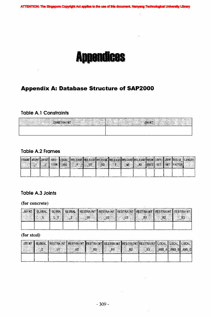
Appendix A: Database Structure of SAP2000
Table A. 1 Constraints
Table A.2 Frames
Table A.3 Joints
(for concrete)
(for steel)
- 309-
ATTENTION: The Singapore Copyright Act applies to the use of this document. Nanyang Technological University Library
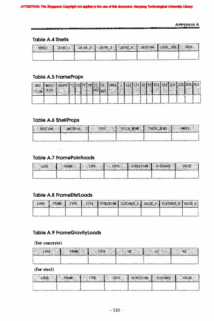
Table A.4 Shells
ApPENDIX A
Table A.5 FrameProps
Table A.6 ShellProps
Table A.7 FramePointloads
Table A.8 FrameDistLoads
Table A.9 FrameGravityLoads
(for concrete)
(for steel)
- 310-
ATTENTION: The Singapore Copyright Act applies to the use of this document. Nanyang Technological University Library
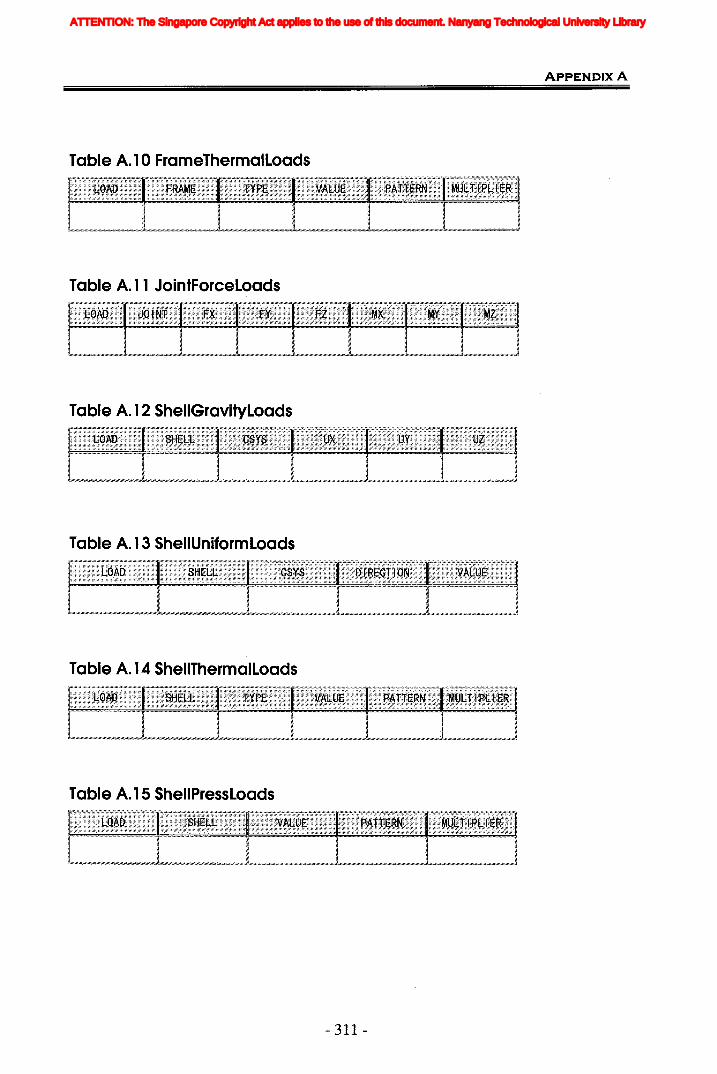
Table A. 10 FrameThermalLoads
Table A. 11 JointForceLoads
Table A. 12 SheliGravityLoads
Table A. 13 SheliUniformLoads
Table A. 14 SheliThermalLoads
Table A. 15 SheliPressLoads
- 311 -
ApPENDIX A
ATTENTION: The Singapore Copyright Act applies to the use of this document. Nanyang Technological University Library
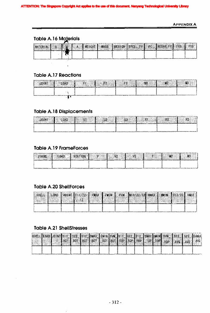
ApPENDIX A
Table A. 17 Reactions
Table A. 18 Displacements
Table A. 19 FrameForces
Table A.20 SheliForces
Table A.21 SheliStresses
- 312-
ATTENTION: The Singapore Copyright Act applies to the use of this document. Nanyang Technological University Library

Ap
pe
nd
ixB
:In
form
ati
on
Mo
de
lin
gfo
rS
tru
ctu
ral
An
aly
sis
8.1
Map
ping
Tabl
esfo
rthe
Stru
ctur
alA
naly
sis
bySA
P200
0
Tabl
eB.
1A
32D
efin
eM
emb
erS
ectio
nP
rope
rtie
s
IDE
FO
Act
ivit
yID
EF
OO
utp
ut
Cor
resp
ond
ing
IDE
FI
Ele
men
t
A32
1D
efin
efr
ame
IFra
me
sect
ion
IEnt
ity
sect
ions
III
w ~ W III
A32
2D
efin
esh
ell
IShe
llse
ctio
nIE
ntit
yse
ctio
ns
Mat
eria
ldef
init
ion
-31
3-
Ent
ity
Com
Dos
ition
Has
-a(M
:1)
> "1J "1J [11 Z C >< m
ATTENTION: The Singapore Copyright Act applies to the use of this document. Nanyang Technological University Library
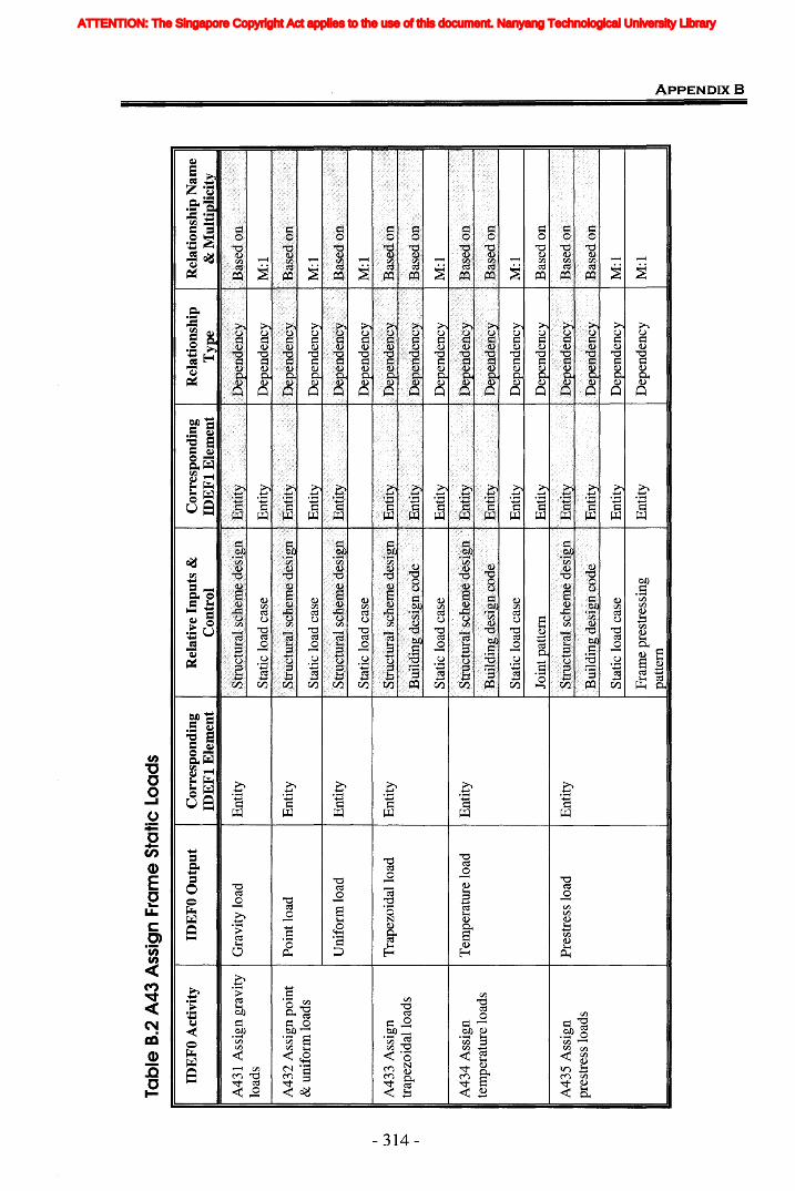
Ent
ity
IDep
ende
ncy
Dep
ende
ncv
IM
:1
Rel
atio
nshi
pN
ame
&M
ult
ipli
city
M:l
M:l
M:l
Rel
atio
nshi
pT
ype
Dep
ende
ncy
........
.
Dep
ende
ncy
Cor
resp
ondi
ngID
EF
lE
lem
ent
Ent
ity
Ent
ity
I..
..:J
llU
.lY
Rel
ativ
eIn
puts
&C
ontr
ol
Sta
tic
load
case
Sta
tic
load
case
Sta
tic
load
case
Sta
tic
load
case
Tabl
eB
.2A
43A
ssig
nFr
ame
Sta
ticLo
ads
IDE
FOAct~EFO
Out
put
IC
orre
spon
ding
IDE
Fl
Ele
men
t
A43
1A
ssig
ngr
avit
yG
ravi
tylo
adIE
ntit
ylo
ads
A43
2A
ssig
npo
int
Poi
ntlo
adE
ntit
y&
unif
orm
load
sI I
Uni
form
load
Ent
ity
I wA
433
Ass
ign
Tra
pezo
idal
load
Ent
ity
I--l
-
+::-.
trap
ezoi
dal
load
s
A43
4A
ssig
nT
empe
ratu
relo
adE
ntit
yte
mpe
ratu
relo
ads
Sta
tic
load
case
Ent
ity
Dep
ende
ncy
M:l
Join
tpat
tern
Ent
ity
Dep
ende
ncy
Bas
edon
A43
5A
ssig
npr
estr
ess
load
sP
rest
ress
load
Ent
ity
Str
lict
ural
sche
me
desi
gn
Bui
ldin
gde
sign
code
Ent
ity
Ent
ity
Dep
ende
ncy
Dep
ende
ncy
Bas
edo
n
Bas
edo
n
Sta
tic
load
case
Ent
ity
Dep
ende
ncy
M:l
Fra
me
pres
tres
sing
patt
ern
Ent
ity
Dep
ende
ncy
M:l
» 1J 1J lTl Z C >< m
ATTENTION: The Singapore Copyright Act applies to the use of this document. Nanyang Technological University Library
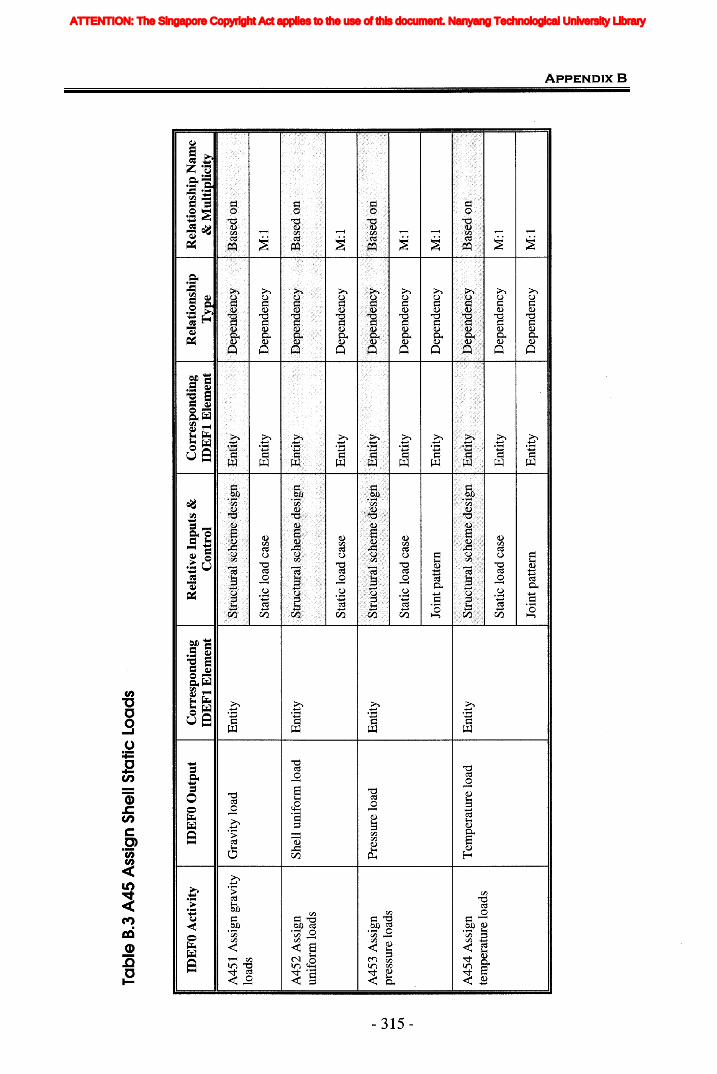
Tabl
eB
.3A
45A
ssig
nS
hell
Sta
ticLo
ads
IDE
FO
Act
ivit
yI
IDE
FO
Ou
tpu
t
A45
1A
ssig
ngr
avit
yIG
ravi
tylo
adlo
ads
A45
2A
ssig
nI
She
llun
ifor
mlo
adun
ifor
mlo
ads
M:l
Dep
ende
ncy
Ent
ity
Sta
tic
load
case
Cor
resp
ond
ing
IDE
Ft
Ele
men
t
Ent
ity
Ent
ity
Ent
ity
Ent
ity
Tem
pera
ture
load
Pre
ssur
elo
ad
A45
4A
ssig
nte
mpe
ratu
relo
ads
A45
3A
ssig
npr
essu
relo
ads
w ~ Ul
Join
tpat
tern
Ent
ity
Dep
ende
ncy
M:l
» 11 11 rrt Z C >< OJ
ATTENTION: The Singapore Copyright Act applies to the use of this document. Nanyang Technological University Library
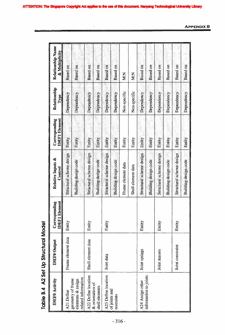
Tab
le8.
4A
2S
etU
pS
truc
tura
lM
od
el
IDE
FOA
ctiv
ity
A21
Def
ine
geom
etry
off
ram
eel
emen
ts&
assi
gnre
late
din
form
atio
n
A22
Def
ine
loca
tion
&or
ient
atio
no
fsh
elle
lem
ents
IDE
FOO
utpu
t
Fra
me
elem
entd
ata
She
llel
emen
tdat
a
Cor
resp
ondi
ngID
EF
tE
lem
ent
Ent
ity
Ent
ity
Rel
ativ
eIn
puts
&I
Cor
resp
ondi
ngC
ontr
olID
EF
tE
lem
ent
Rel
atio
nshi
pT
vpe
Rel
atio
nshi
pN
ame
&M
ulti
plic
ity
w ~ 0\
A23
Def
ine
loca
tion
ofj
oint
san
dre
stra
ints
A24
Ass
ign
othe
rin
form
atio
nto
join
ts
Join
tdat
a
Join
tspr
ings
Ent
ity
Ent
ity
Fra
me
elem
entd
ata
She
llel
emen
tdat
a
Ent
ity
Ent
ity
Non
-spe
cifi
c
Non
-spe
cifi
c
M:N
M:N
Join
tmas
ses
Ent
ity
Bui
ldin
gde
sigl
l,co
de
Ent
ity
Ent
ity
Bas
efio
n
Bas
edon
:
Join
tcon
stra
int
Ent
ity
Bui
ldin
g'de
sign
,cod
e
I.E
ntit
y
Ent
ity
Dep
ende
ncy
IDep
ende
ncy
'IB
ased
on
» 1J 1J lTI Z C >< OJ
ATTENTION: The Singapore Copyright Act applies to the use of this document. Nanyang Technological University Library
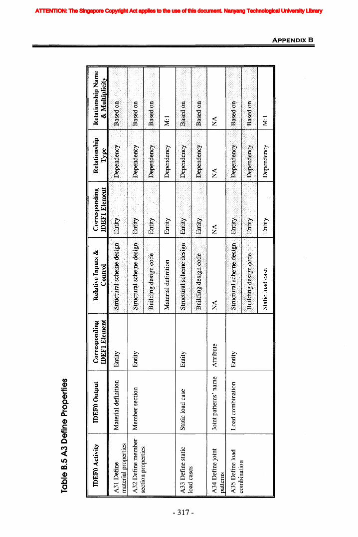
Tab
le8.
5A
3D
efin
eP
rop
erti
es
IDE
FO
Act
ivit
yID
EF
OO
utp
ut
Cor
resp
ond
ing
IDE
Ft
Ele
men
tR
elat
ive
Inp
uts
&C
ontr
olC
orre
spon
din
gID
EF
tE
lem
ent
Rel
atio
nsh
ipT
ype
Rel
atio
nsh
ipN
ame
&M
ult
ipli
city
A31
Def
ine
mat
eria
lpro
pert
ies
A32
Def
ine
mem
ber
sect
ion
prop
erti
es
Mat
eria
ldef
init
ion
Mem
ber
sect
ion
Ent
ity
Ent
ity
AO
C<1
n-h
Ent
ity
'J
~"I
..:1.
Dep
ende
ncy
M:l
NA
NA
Mat
eria
ldef
init
ion
Ent
ity
UJ
IIA33
Def
ine
stat
icIS
tati
clo
adC
ase
IEnt
ity
~ -....,J
load
case
s
A34
Def
ine
join
tJo
intp
atte
rns'
nam
eA
ttri
bute
atte
rns
A35
Def
ine
load
Loa
dco
mbi
nati
onE
ntit
yco
mbi
nati
on
Sta
tic
load
case
Ent
ity
Dep
ende
ncy
M:l
> "tI "tI [It Z C >< [II
ATTENTION: The Singapore Copyright Act applies to the use of this document. Nanyang Technological University Library

Tabl
e8.
6A
4A
ssig
nP
rope
rtie
s
IDE
FOA
ctiv
ity
IID
EFO
Out
put
Cor
resp
ondi
ngID
EF
tE
lem
ent
Rel
ativ
eIn
puts
&I
Cor
resp
ondi
ngI
Rel
atio
nshi
pI
Rel
atio
nshi
pN
ame
Con
trol
IDE
Ft
Ele
men
tT
ype
&M
ulti
plic
ity
A41
Ass
ign
mem
ber
ISec
tion
assi
gnm
ent
sect
ions
Dom
ain
Mem
ber
sect
ion
Ent
ity
Dep
ende
ncy
Bas
edo
n
Join
tpat
tern
'sna
me
IAtt
ribu
teN
AIN
A
~
A42
Ass
ign
IJoi
ntpa
tter
nIE
ntit
ypr
estr
essi
ngpa
tter
n&
join
tpat
tern
sP
rest
ress
ing
patt
ern
IEnt
ity
I wA
43A
ssig
nfr
ame
Fra
me
stat
iclo
adIE
ntit
y"""
""'"0
0st
atic
load
s
Sta
tic
load
case
Ent
ity
Dep
ende
ncy
Bas
edo
n
Join
tpat
tern
Ent
ity
Dep
ende
ncy
Bas
edo
n
Pre
stre
ssin
gpa
tter
nE
ntit
yD
epen
denc
yB
ased
on
A43
Ass
ign
join
tJo
intf
orce
Ent
ity
stat
iclo
ads
Join
tdis
plac
emen
tE
ntit
y
A44
Ass
ign
shel
lIS
hell
stat
iclo
adE
ntit
yst
atic
load
s
.·Str
uctll
ials
chel
11ed
esig
n
Str
uctu
rals
chem
ede
sign
Sta
tic
load
case
Str
uctu
rals
chem
ede
sign
Bui
ldin
gd
esig
nco
de
Sta
tic·
]oad
case
Join
tpat
tern
Ent
ity
Ent
ity
Ent
ity
Ent
ity
Ent
ity
Ent
ity
Ent
ity
Ent
ity
Dep
ende
ncy
Dep
ende
ncy
Dep
ende
ncy
Dep
ende
ncy
Dep
ende
ncy
Dep
ende
ncy
Dep
ende
ncy
Dep
ende
ncy
Bas
ed.o
n
Base
d011
Bas
edo
n
M:l
Bas
edo
n
Bas
ed01
1
M:l
Bas
edo
n
» 11 11 rrt Z C >< m
ATTENTION: The Singapore Copyright Act applies to the use of this document. Nanyang Technological University Library
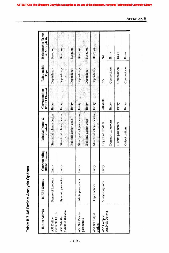
Tabl
eB.
7A
SD
efin
eA
naly
sis
Opt
ions
IDE
FO
Act
ivit
yID
EF
OO
utp
ut
Cor
resp
ond
ing
IDE
Ft
Ele
men
t
AS1
Def
ine
Deg
ree
off
reed
oms
Ent
ity
avai
labl
eD
OF
s
A52
Whe
ther
Dyn
amic
para
met
ers
Ent
ity
dyna
mic
anal
ysis
III
w ~ \0--
A53
Set
P-d
elta
P-d
elta
para
met
ers
IEnt
ity
para
met
ers
A54
Set
outp
utO
utpu
topt
ions
Ent
ity
opti
ons
A55
Com
pile
IAna
lysi
sop
tion
s~ty
Ana
lysi
sO
ptio
nsD
egre
eo
ffre
edom
Dyn
amic
para
met
ers
P-d
elta
para
met
ers
Out
puto
ptio
ns
Att
ribu
te
Ent
ity
Ent
ity
Ent
ity
NA
Com
posi
tion
Com
posi
tion
Com
posi
tion
NA
Has
-a
Has
-a
Has
-a» " "ITt Z C >< m
ATTENTION: The Singapore Copyright Act applies to the use of this document. Nanyang Technological University Library
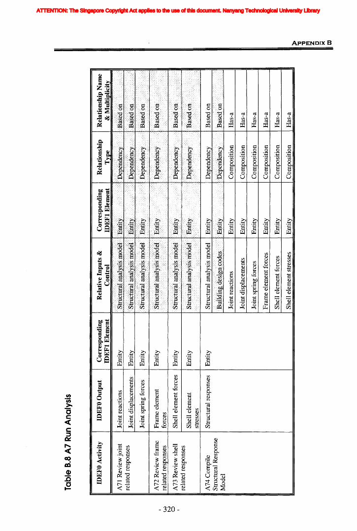
Tabl
e8.
8A
7R
unA
naly
sis
Str
uctu
ral
anal
ysis
mod
elIE
ntit
y
Rel
atio
nshi
pN
ame
&M
ult
ipli
city
Bas
edon
-.1
:
Rel
atio
nshi
pT
ype
~ Dep
ende
ncy
Dep
ende
ncy
-
Cor
resp
ond
ing
IDE
Ft
Ele
men
t
t.tl
lllt
y
I.y.
..,;.
~
Rel
ativ
eIn
puts
&C
ontr
olID
EFO
Ou
tpu
tC
orre
spon
din
gID
EF
tE
lem
ent
Join
trea
ctio
nsE
ntit
y
Join
tdis
plac
emen
tsE
ntit
y
Join
tspr
ing
forc
esE
ntit
y
Fra
me
elem
ent
Ent
ity
forc
es
She
llel
emen
tfor
ces
Ent
ity
-S
hell
elem
ent
Ent
ity
stre
sses
Str
uctu
ralr
espo
nses
Ent
ity
A71
Rev
iew
join
tre
late
dre
spon
ses
IDE
FOA
ctiv
ity
A72
Rev
iew
fram
ere
late
dre
spon
ses
A73
Rev
iew
shel
lre
late
dre
spon
ses
A74
Com
pile
Str
uctu
ralR
espo
nse
Mod
el
UJ
N o
Join
trea
ctio
nsI
Ent
ity
Com
posi
tion
Has
-a
Join
tdis
plac
emen
tsIE
ntit
yC
ompo
siti
onH
as-a
Join
tspr
ing
forc
esIE
ntit
yC
ompo
siti
onH
as-a
Fra
me
elem
entf
orce
sI
Ent
ity
Com
posi
tion
Has
-a
She
llel
emen
tfor
ces
IE
ntit
yC
ompo
siti
onH
as-a
She
llel
emen
tstr
esse
sI
Ent
ity
Com
posi
tion
Has
-a) 1J 1J rrt Z C >< OJ
ATTENTION: The Singapore Copyright Act applies to the use of this document. Nanyang Technological University Library
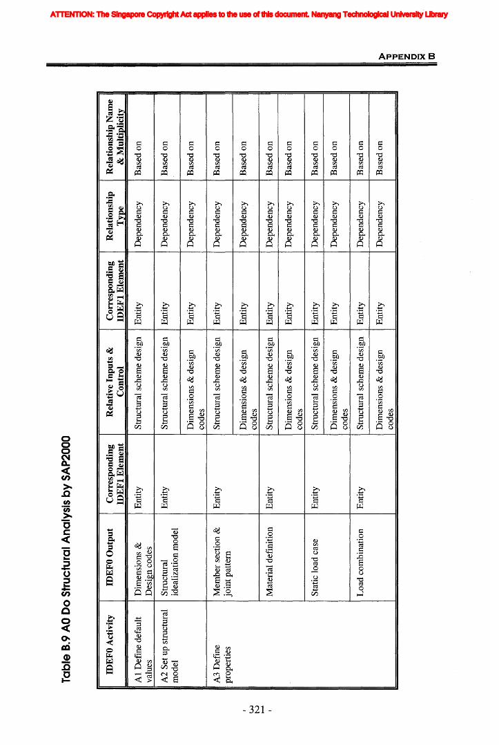
!..JJ N ~
Tabl
e8.
9AO
Do
Str
uctu
ralA
naly
sis
by
SA
P20
00
IDE
FOA
ctiv
ity
IDE
FOO
utp
ut
Cor
resp
ondi
ngR
elat
ive
Inpu
ts&
Cor
resp
ond
ing
Rel
atio
nshi
pR
elat
ion
ship
Nam
eID
EF
tE
lem
ent
Con
trol
IDE
Ft
Ele
men
tT
ype
&M
ult
ipli
city
A1
Def
ine
defa
ult
Dim
ensi
ons
&E
ntit
yS
truc
tura
lsc
hem
ede
sign
Ent
ity
Dep
ende
ncy
Bas
edon
valu
esD
esig
nco
des
A2
Set
upst
ruct
ural
Str
uctu
ral
Ent
ity
Str
uctu
rals
chem
ede
sign
Ent
ity
Dep
ende
ncy
Bas
edon
mod
elid
eali
zati
onm
odel
Dim
ensi
ons
&de
sign
Ent
ity
Dep
ende
ncy
Bas
edon
code
s
A3
Def
ine
Mem
ber
sect
ion
&E
ntit
yS
truc
tura
lsc
hem
ede
sign
Ent
ity
Dep
ende
ncy
Bas
edon
prop
erti
esjo
intp
atte
rn
Dim
ensi
ons
&de
sign
Ent
ity
Dep
ende
ncy
Bas
edon
code
s
Mat
eria
ldef
init
ion
Ent
ity
Str
uctu
rals
chem
ede
sign
Ent
ity
Dep
ende
ncy
Bas
edon
Dim
ensi
ons
&de
sign
Ent
ity
Dep
ende
ncy
Bas
edon
code
s
Sta
tic
load
case
Ent
ity
Str
uctu
ral
sche
me
desi
gnE
ntit
yD
epen
denc
yB
ased
on
Dim
ensi
ons
&de
sign
Ent
ity
Dep
ende
ncy
Bas
edon
code
s
Loa
dco
mbi
nati
onE
ntit
yS
truc
tura
lsc
hem
ede
sign
Ent
ity
Dep
ende
ncy
Bas
edon
Dim
ensi
ons
&de
sign
Ent
ity
Dep
ende
ncy
Bas
edon
code
s» "0 "0 JT
I Z C >< m
ATTENTION: The Singapore Copyright Act applies to the use of this document. Nanyang Technological University Library
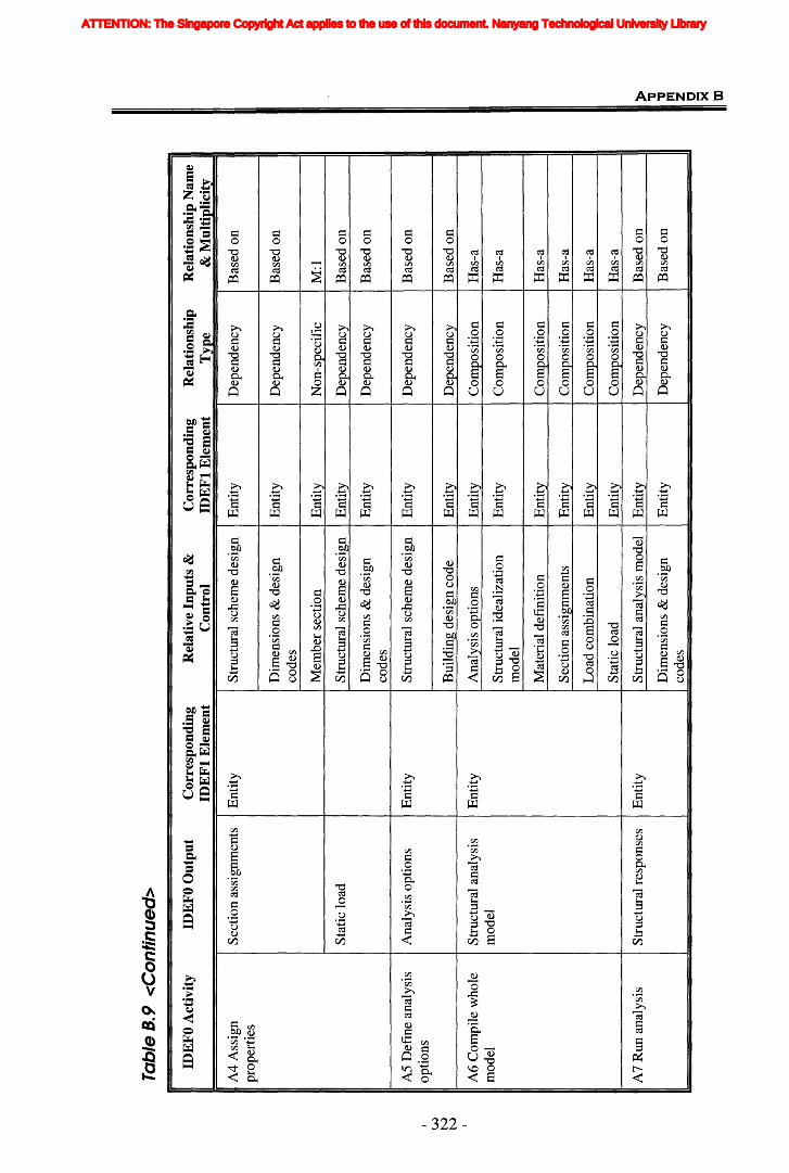
W N N
Tab
leB
.9<
Co
nti
nu
ed>
IDE
FO
Act
ivit
yID
EF
OO
utp
ut
Cor
resp
ond
ing
Rel
ativ
eIn
pu
ts&
Cor
resp
ond
ing
Rel
atio
nsh
ipR
elat
ion
ship
Nam
eID
EF
tE
lem
ent
Con
trol
IDE
Ft
Ele
men
tT
ype
&M
ult
ipli
city
A4
Ass
ign
Sec
tion
assi
gnm
ents
Ent
ity
Str
uctu
ral
sche
me
desi
gnE
ntit
yD
epen
denc
yB
ased
onpr
oper
ties
Dim
ensi
ons
&de
sign
Ent
ity
Dep
ende
ncy
Bas
edon
code
s
Mem
ber
sect
ion
Ent
ity
Non
-spe
cifi
cM
:l
Sta
tic
load
Str
uctu
ral
sche
me
desi
gnE
ntit
yD
epen
denc
yB
ased
on
Dim
ensi
ons
&de
sign
Ent
ity
Dep
ende
ncy
Bas
edon
code
s
AS
Def
me
anal
ysis
Ana
lysi
sop
tion
sE
ntit
yS
truc
tura
lsch
eme
desi
gnE
ntit
yD
epen
denc
yB
ased
onop
tion
s
Bui
ldin
gde
sign
code
Ent
ity
Dep
ende
ncy
Bas
edon
A6
Com
pile
who
leS
truc
tura
lana
lysi
sE
ntit
yA
naly
sis
opti
ons
Ent
ity
Com
posi
tion
Has
-am
odel
mod
elS
truc
tura
lide
aliz
atio
nE
ntit
yC
ompo
siti
onH
as-a
mod
el
Mat
eria
ldef
init
ion
Ent
ity
Com
posi
tion
Has
-a
Sec
tion
assi
gnm
ents
Ent
ity
Com
posi
tion
Has
-a
Loa
dco
mbi
nati
onE
ntit
yC
ompo
siti
onH
as-a
Sta
tic
load
Ent
ity
Com
posi
tion
Has
-a
A7
Run
anal
ysis
Str
uctu
ralr
espo
nses
Ent
ity
Str
uctu
ral
anal
ysis
mod
elE
ntit
yD
epen
denc
yB
ased
on
Dim
ensi
ons
&de
sign
Ent
ity
Dep
ende
ncy
Bas
edon
code
s
» "'0 "'0 rrt Z C >< m
ATTENTION: The Singapore Copyright Act applies to the use of this document. Nanyang Technological University Library
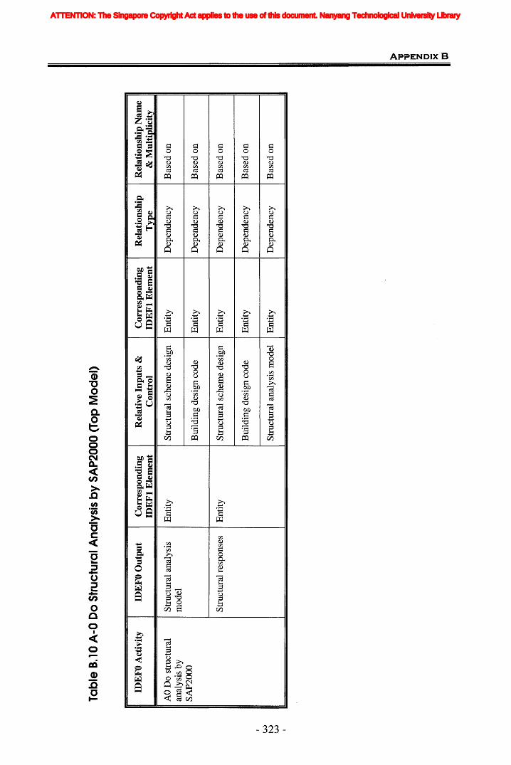
w N w
Tabl
eB.
10A
-OD
oS
truc
tura
lAna
lysi
sb
yS
AP
2000
(Top
Mo
del
)
IDE
FOA
ctiv
ity
IDE
FOO
utp
ut
Cor
resp
ondi
ngR
elat
ive
Inpu
ts&
Cor
resp
ond
ing
Rel
atio
nsh
ipR
elat
ion
ship
Nam
eID
EF
IE
lem
ent
Con
trol
IDE
FI
Ele
men
tT
ype
&M
ult
ipli
city
AO
Do
stru
ctur
alS
truc
tura
lana
lysi
sE
ntit
yS
truc
tura
lsch
eme
desi
gnE
ntit
yD
epen
denc
yB
ased
on
anal
ysis
bym
odel
SA
P20
00B
uild
ing
desi
gnco
deE
ntit
yD
epen
denc
yB
ased
on
Str
uctu
ralr
espo
nses
Ent
ity
Str
uctu
ral
sche
me
desi
gnE
ntit
yD
epen
denc
yB
ased
on
Bui
ldin
gde
sign
code
Ent
ity
Dep
ende
ncy
Bas
edo
n
Str
uctu
ral
anal
ysis
mod
elE
ntit
yD
epen
denc
yB
ased
on
» "'0 "tI ITt Z C >< m
ATTENTION: The Singapore Copyright Act applies to the use of this document. Nanyang Technological University Library
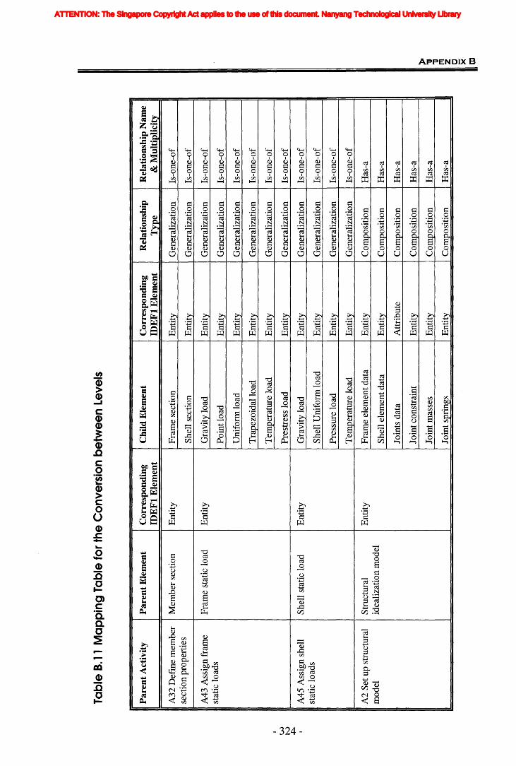
w N ~
Tabl
eB.
11M
app
ing
Tabl
efo
rth
eC
onve
rsio
nb
etw
een
Leve
ls
Par
ent
Act
ivit
yP
aren
tEle
men
tC
orre
spon
ding
Chi
ldE
lem
ent
Cor
resp
ondi
ngR
elat
ions
hip
Rel
atio
nshi
pN
ame
IDE
Ft
Ele
men
tID
EF
tE
lem
ent
Typ
e&
Mul
tipl
icit
y
A32
Def
ine
mem
ber
Mem
ber
sect
ion
Ent
ity
Fra
me
sect
ion
Ent
ity
Gen
eral
izat
ion
Is-o
ne-o
fse
ctio
npr
oper
ties
She
llse
ctio
nE
ntit
yG
ener
aliz
atio
nIs
-one
-of
A43
Ass
ign
fram
eF
ram
est
atic
load
Ent
ity
Gra
vity
load
Ent
ity
Gen
eral
izat
ion
Is-o
ne-o
fst
atic
load
sP
oint
load
Ent
ity
Gen
eral
izat
ion
Is-o
ne-o
f
Uni
form
load
Ent
ity
Gen
eral
izat
ion
Is-o
ne-o
f
Tra
pezo
idal
load
Ent
ity
Gen
eral
izat
ion
Is-o
ne-o
f
Tem
pera
ture
load
Ent
ity
Gen
eral
izat
ion
Is-o
ne-o
f
Pre
stre
sslo
adE
ntit
yG
ener
aliz
atio
nIs
-one
-of
A45
Ass
ign
shel
lS
hell
stat
iclo
adE
ntit
yG
ravi
tylo
adE
ntit
yG
ener
aliz
atio
nIs
-one
-of
stat
iclo
ads
She
llU
nifo
rmlo
adE
ntit
yG
ener
aliz
atio
nIs
-one
-of
Pre
ssur
elo
adE
ntit
yG
ener
aliz
atio
nIs
-one
-of
Tem
pera
ture
load
Ent
ity
Gen
eral
izat
ion
Is-o
ne-o
f
A2
Set
upst
ruct
ural
Str
uctu
ral
Ent
ity
Fra
me
elem
entd
ata
Ent
ity
Com
posi
tion
Has
-am
odel
idea
liza
tion
mod
elS
hell
elem
entd
ata
Ent
ity
Com
posi
tion
Has
-a
Join
tsda
taA
ttri
bute
Com
posi
tion
Has
-a
Join
tcon
stra
int
Ent
ity
Com
posi
tion
Has
-a
Join
tmas
ses
Ent
ity
Com
posi
tion
Has
-a
Join
tspr
ings
Ent
ity
Com
posi
tion
Has
-a
» "'D "'D ITI Z C >< to
ATTENTION: The Singapore Copyright Act applies to the use of this document. Nanyang Technological University Library

w N Ul
Tab
leB.
11<
Co
nti
nu
ed>
Par
ent
Act
ivit
yP
aren
tE
lem
ent
Cor
resp
ond
ing
Ch
ild
Ele
men
tC
orre
spon
din
gR
elat
ion
ship
Rel
atio
nsh
ipN
ame
IDE
Ft
Ele
men
tID
EF
tE
lem
ent
Typ
e&
Mu
ltip
lici
ty
A4
Ass
ign
Sec
tion
assi
gnm
ent
Ent
ity
Sec
tion
assi
gnm
ent
Ent
ity
Sam
e(N
A)
NA
prop
erti
es
Sta
tic
load
Ent
ity
Fra
me
stat
iclo
adE
ntit
yG
ener
aliz
atio
nIs
-one
-of
Join
tfor
ceE
ntit
yG
ener
aliz
atio
nIs
-one
-of
.
Join
tdis
plac
emen
tE
ntit
yG
ener
aliz
atio
nIs
-one
-of
She
llst
atic
load
Ent
ity
Gen
eral
izat
ion
Is-o
ne-o
f
AO
Do
Str
uctu
ral
Str
uctu
ralA
naly
sis
Ent
ity
Str
uctu
rali
deal
izat
ion
Ent
ity
Com
posi
tion
Has
-aan
alys
isby
mod
elm
odel
SA
P20
00M
embe
rse
ctio
nE
ntit
yC
ompo
siti
onH
as-a
prop
erti
es
Mat
eria
lpro
pert
ies
Ent
ity
Com
posi
tion
Has
-a
Bas
iclo
adca
ses
Ent
ity
Com
posi
tion
Has
-a
Sec
tion
assi
gnm
ents
Ent
ity
Com
posi
tion
Has
-a
Loa
das
sign
men
tsE
ntit
yC
ompo
siti
onH
as-a
Ana
lysi
sop
tion
sE
ntit
yC
ompo
siti
onH
as-a
Str
uctu
ralr
espo
nses
Ent
ity
Str
uctu
ralr
espo
nses
Ent
ity
Sam
e(N
A)
NA
> 1J 1J rrt Z C >< m
ATTENTION: The Singapore Copyright Act applies to the use of this document. Nanyang Technological University Library
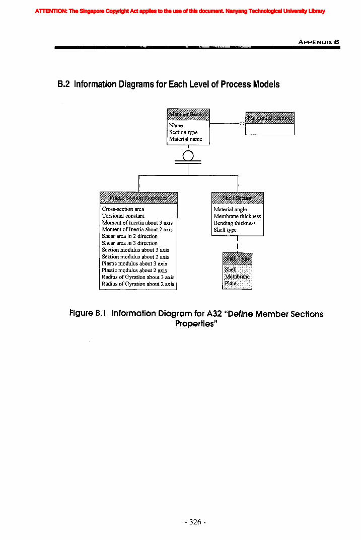
ApPENDlxB
B.2 Information Diagrams for Each Level of Process Models
Cross-section areaTorsional constantMoment of Inertia about 3 axisMoment of Inertia about 2 axisShear area in 2 directionShear area in 3 directionSection modulus about 3 axisSection modulus about 2 axisPlastic modulus about 3 axisPlastic modulus about 2 axisRadius of Gyration about 3 axisRadius of Gyration about 2 axis
Material angleMembrane thicknessBending thicknessShell type
Figure B. 1 Information Diagram for A32 "Define Member SectionsProperties"
- 326-
ATTENTION: The Singapore Copyright Act applies to the use of this document. Nanyang Technological University Library
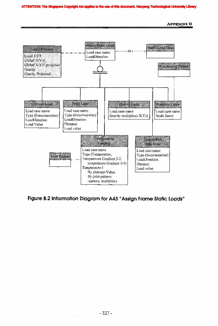
ApPENDIX B
I---M:l
Load case nameType (Force/member)LoadDirectionLoad Value
Load case nameType (force/member)LoadDirectionDistanceLoad value
Load case nameType (Temperature,Temperature Gradient 2-2,
temperature Gradient 3-3)Temperature (
By element-Value,By joint pattern-pattern, multiplier)
Load case nameType (force/member)LoadDirectionDistanceLoad value
Figure B.2 Information Diagram for A43 "Assign Frame Static loads"
- 327-
ATTENTION: The Singapore Copyright Act applies to the use of this document. Nanyang Technological University Library
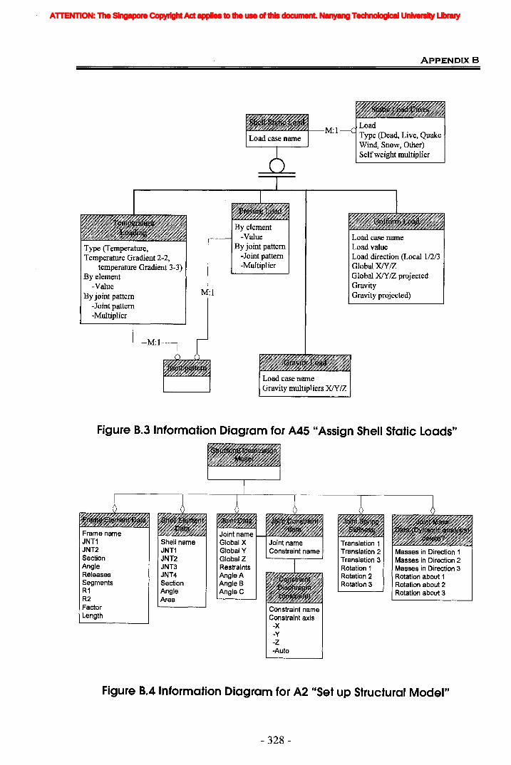
ApPENDIXB
Type (Temperature,Temperature Gradient 2-2,
temperature Gradient 3-3)By element
-ValueBy joint pattern
-Joint pattern-Multiplier
M:l
By element-Value
By joint pattern-Joint pattern-Multiplier
M:lLoadType (Dead, Live, QuakeWind, Snow, Other)Selfweight multiplier
Load case nameLoad valueLoad direction (Local 1/2/3Global XIY/ZGlobal XIY/Z projectedGravityGravity projected)
M:l
Figure 8.3 Information Diagram for A45 "Assign Shell Static Loads"
Masses in Direction 1Masses in Direction 2Masses in Direction 3Rotation about 1Rotation about 2Rotation about 3
Translation 1Translation 2Translation 3Rotation 1Rotation 2Rotation 3
Constraint nameConstraint axis-X-y-z-Auto
Shell nameJNT1JNT2JNT3JNT4SectionAngleArea
Frame nameJNT1JNT2SectionAngleReleasesSegmentsR1R2FactorLength
Figure 8.4 Information Diagram for A2 "Set up Structural Model"
- 328-
ATTENTION: The Singapore Copyright Act applies to the use of this document. Nanyang Technological University Library
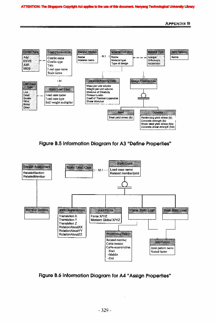
ApPENDIXB
Reinforcing yield stress (fy)Concrete strength (fc)Shear steel yield stress (fys)Concrete shear strength (fcs)
Mass per unit volumeWeight per unit volumeModulus of ElasticityPoisson's ratioCoeff of Thermal ExpansionShear Modulus
Combo nameCombo typeTitleLoad case nameScale factor
l:M
Load case nameLoad case typeSelfweight multiplier
Figure 8.5 Information Diagram for A3 "Define Properties"
Related memberCable tensionCable eccentricities-Start-Middle-End
M:l
Translation XTranslation YTranslation ZRotationAboutXXRotationAboutYYRotationAboutzZ
Figure 8.6 Information Diagram for A4 "Assign Properties"
- 329-
ATTENTION: The Singapore Copyright Act applies to the use of this document. Nanyang Technological University Library
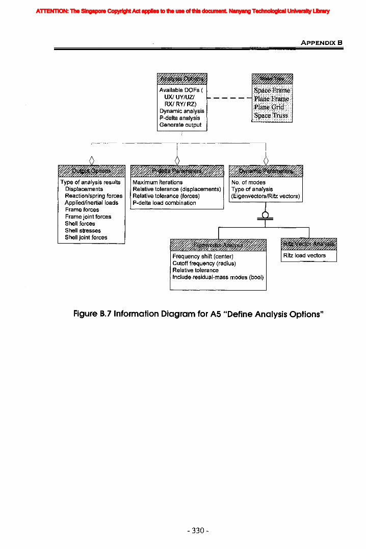
ApPENDIXB
Available DOFs (UX/ UY/UZIRX/ RY/ RZ)
Dynamic analysisP-delta analysisGenerate output
Frequency shift (center)Cutoff frequency (radius)Relative toleranceInclude residual-mass modes (booI)
Type of analysis resultsDisplacementsReaction/spring forcesApplied/inertial loadsFrame forcesFrame joint forcesShell forcesShell stressesShell joint forces
Maximum iterationsRelative tolerance (displacements)Relative tolerance (forces)P-delta load combination
No. of modesType of analysis(Eigenvectors/Ritz vectors)
Figure B.7 Information Diagram for AS "Define Analysis Options"
- 330-
ATTENTION: The Singapore Copyright Act applies to the use of this document. Nanyang Technological University Library

ApPENDIX B
Joint Joint Frame Shell Shell JointLoad Load Load Load Load LoadFI VI Station Joint Joint FIF2 V2 P Fll SII-BOT F2F3 U3 V2 F22 S22-BOT F3MI RI V3 FI2 SI2-BOT MIM2 R2 T FMAX SMAX-BOT M2M3 R3 M2 FMlN SMlN-BOT M3
M3 FVM SVM-BOTMll Sll-TOPM22 S22-TOPMI2 SI2-TOPMMAX SMAX-TOPMMlN SMlN-TOPV13 SVM-TOPV23 S13-AVGVMAX S23-AVG
SVMAX-AVG
Figure B.8 Information Diagram for A7 "Run Analysis"
Figure B.9 Information Diagram for AD
- 331 -
ATTENTION: The Singapore Copyright Act applies to the use of this document. Nanyang Technological University Library

Appendix C: Comparison of Information Requirementswith Current IFe Models
Table C. 1 Geometry Information
Software Requirements IFe Extensions
GeomeElements
Data Entities I Attributestry type
Joint Data
Basic Joint name Text IfcStructuralConnection Globalld (IfcGloballyUniqueId)
Global_X No. IfcStructuralConnectionRepresentation
= (IfcProductRepresentation)Q..... Representations.....-
Global_Y No. IfcProductRepresentation=Co) (IfcRepresentation)Q
~ IfcRepresentation Items (IfcPoint)Global_Z No.
IfcPoint Coordinates [1] /[2] /[3]
Restraints_UlText
IfcStructuralConectionAppliedCondition (OPTIONAL
(YIN) IfcBoundaryCondition)
Restraints_U2 ditto IfcStructuralConectionAppliedCondition (OPTIONALIfcBoundaryCondition)
rJ:.l AppliedCondition (OPTIONAL.....-Restraints_U3 ditto IfcStructuralConection=.; IfcBoundaryCondition)
l-4.....- AppliedCondition (OPTIONALrJ:.l Restraints_R1 ditto IfcStructuralConection~
~ IfcBoundaryCondition)
Restraints_R2 ditto IfcStructuralConectionAppliedCondition (OPTIONALIfcBoundaryCondition)
Restraints_R3 ditto IfcStructuralConectionAppliedCondition (OPTIONALIfcBoundaryCondition)
e; ~Local Ang_A Inferred from ObjectPlacement (IfcLocaIPlacement)
Co) ~ No. IfcLocalPlacement RelativePlacement~< /B/C
IfcAxis2Placement RefDirection
Frame Element data
Frame Text IfcStructuralCurveMember Globalld (IfcGloballyUniqueId)
.~rJ:.l RelatedStructuralConnection= JNT-l Text IfcRelConnectsStructuralMember~ (IfcStructuralConnection)
JNT-2 Text IfcRelConnectsStructuralMemberRelatedStructuralConnection(IfcStructuralConnection)
rJ:.l IfcRelAssociatesProfilePropertiesRelatingProfileProperties
=.s Section Text(IfcProfileProperties)
.....-Co)~ IfcStructuralProfileProperties ProfileNarne (IfcLabel)rJJ.
LocalLocal Angle No. Inferred from ObjectPlacement (IfcLocaIPlacement)
Axes
- 332-
ATTENTION: The Singapore Copyright Act applies to the use of this document. Nanyang Technological University Library
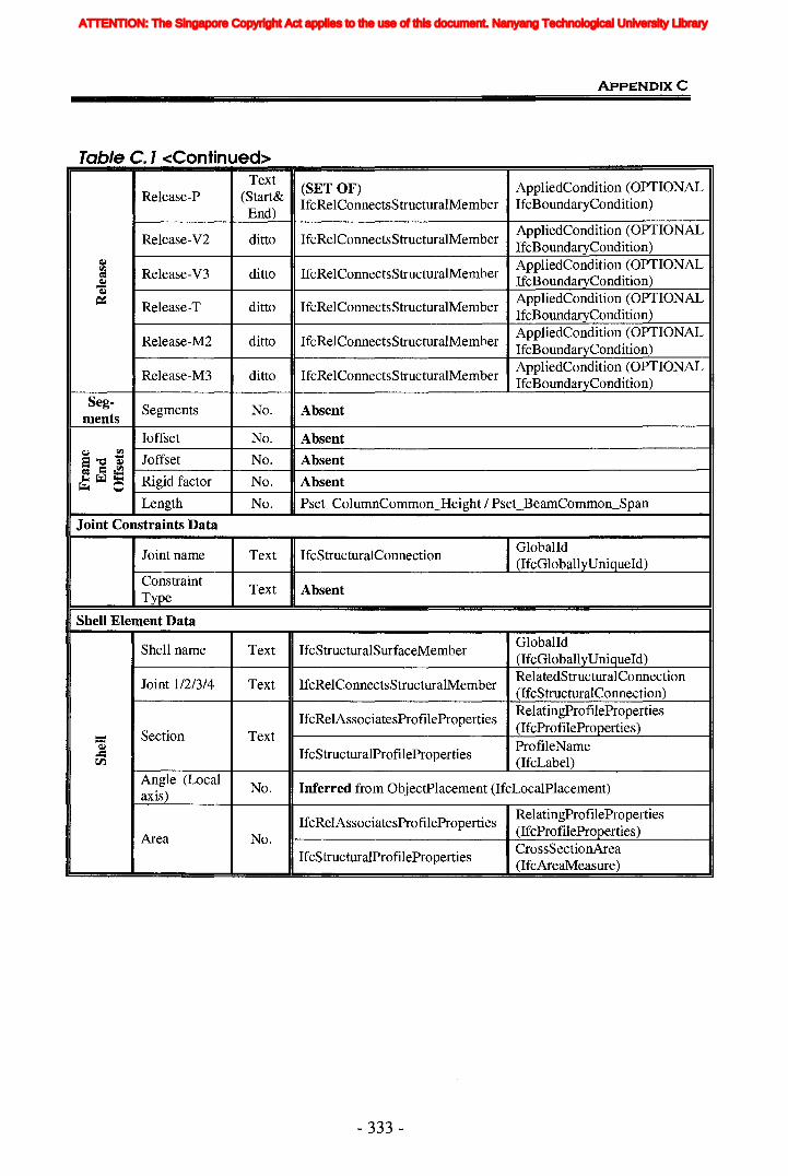
ApPENDIXC
Table C.l <Continued>Text
(SET OF)Release-P (Start&
AppliedCondition (OPTIONAL
End)IfcRelConnectsStructuralMember IfcBoundaryCondition)
Release-V2 ditto IfcRelConnectsStructuralMemberAppliedCondition (OPTIONAL
CIJ
IfcBoundaryCondition)l"I.l Release-V3
AppliedCondition (OPTIONALj ditto IfcRelConnectsStructuralMemberCIJ
IfcBoundaryCondition)=: Release-T ditto IfcRelConnectsStructuralMember
AppliedCondition (OPTIONALIfcBoundaryCondition)
Release-M2 ditto IfcRelConnectsStructuralMemberAppliedCondition (OPTIONALIfcBoundaryCondition)
Release-M3 ditto IfcRelConnectsStructuralMemberAppliedCondition (OPTIONAL
Seg-IfcBoundaryCondition)
mentsSegments No. Absent
Ioffset No. AbsentCIJ l"I.l
a"O~ Joffset No. Absent~ =~~~~ Rigid factor No. Absent~ 0
Length No. Pset ColumnCommon Height / Pset BeamCommon Span
Joint Constraints Data
Joint name Text IfcStructuralConnection IGlobalId
Constraint(IfcGloballyUniqueId)
Type Text Absent
Shell Element Data
Shell name Text IfcStructuralSurfaceMemberGioballd(IfcGloballyUniqueId)
Joint 1/2/3/4 Text IfcRelConnectsStructuralMemberRelatedStructuralConnection(IfcStructuralConnection)
IfcRelAssociatesProfilePropertiesRelatingProfileProperties
- Section Text(lfcProfileProperties)
~..= IfcStructuralProfileProperties
ProfileNarnerJ:J.
Angle (Local(IfcLabel)
axis)No. Inferred from ObjectPlacement (IfcLocaIPlacement)
IfcRelAssociatesProfilePropertiesRelatingProfileProperties
Area No.(IfcProfileProperties)
IfcStructuralProfilePropertiesCrossSectionArea(IfcAreaMeasure)
- 333 -
ATTENTION: The Singapore Copyright Act applies to the use of this document. Nanyang Technological University Library
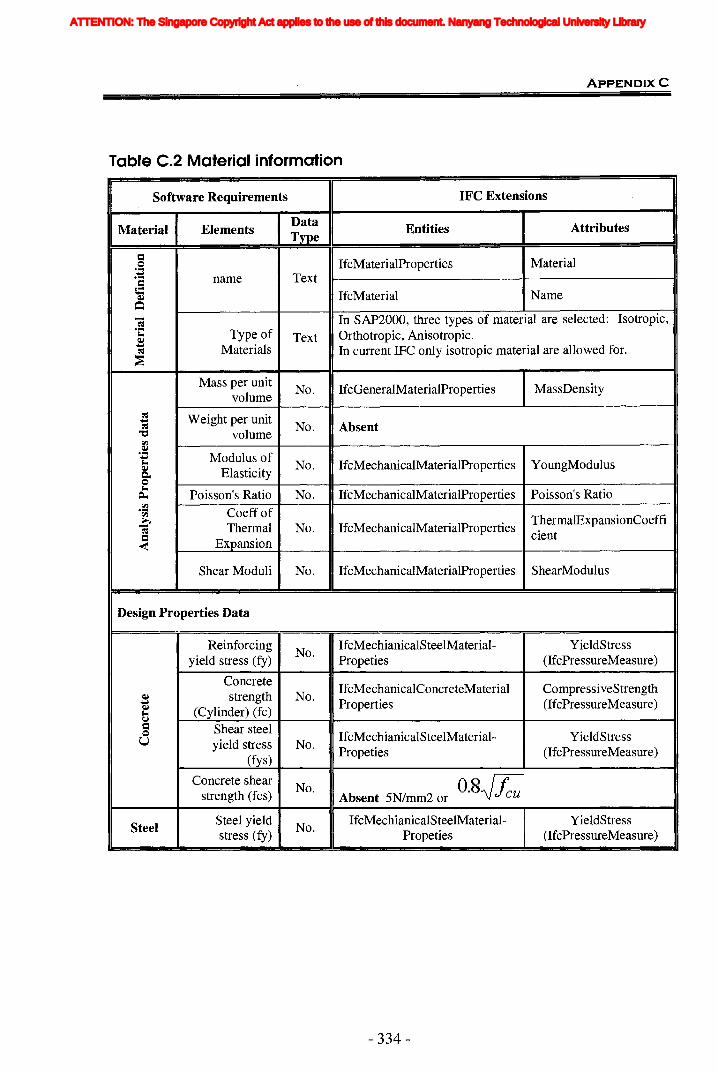
Table C.2 Material information
ApPENDIXC
Software Requirements IFC Extensions
Material ElementsData Entities AttributesType
= IfcMaterialProperties Material.~~ Text..... name=C IfcMaterial NameellQ-; In SAP2000, three types of material are selected: Isotropic,·C Type of Text Orthotropic, Anisotropic.ell~ Materials In current IFC only isotropic material are allowed for.~
~
Mass per unitNo. IfcGeneralMaterialProperties MassDensity
volume~ Weight per unit~
No. Absent~"'C volume
t:I.:l
.~Modulus of~
~ No. IfcMechanicalMaterialProperties YoungModulusell ElasticityC-40~
Poisson's Ratio No. IfcMechanicalMaterialProperties Poisson's Ratio~
.~ Coeffoft:I.:lThermalExpansionCoeffib Thermal No. IfcMechanicalMaterialProperties~ cient= Expansion-<
Shear Moduli No. IfcMechanicalMaterialProperties ShearModulus
Design Properties Data
ReinforcingNo.
IfcMechianicalSteelMaterial- YieldStressyield stress (fy) Propeties (lfcPressureMeasure)
ConcreteIfcMechanicalConcreteMaterial CompressiveStrength
ell strength No.~ Properties (lfcPressureMeasure)ell (Cylinder) (fc)~CJ= Shear steel0 IfcMechianicalSteelMaterial- YieldStressU yield stress No.
(fys)Propeties (lfcPressureMeasure)
Concrete shearNo. O.8.)fcustrength (fcs) Absent 5N/mm2 or
SteelSteel yield
No.IfcMechianicalSteelMaterial- YieldStress
stress (fy) Propeties (IfcPressureMeasure)
- 334-
ATTENTION: The Singapore Copyright Act applies to the use of this document. Nanyang Technological University Library
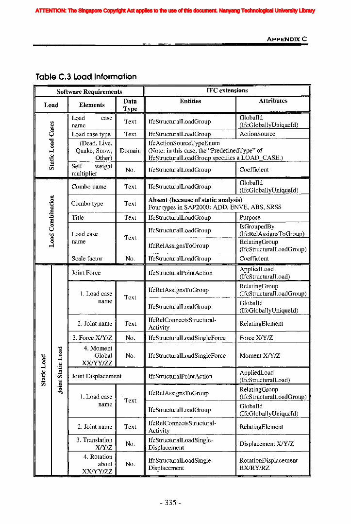
Table C.3 Load Information
ApPENDIXC
Software Requirements IFC extensions
Load ElementsData Entities AttributesType
Load caseText IfcStructuralLoadGroup
Globalldr'-l (lfcGloballyUniqueId)~ namer'-l~
Load case type Text IfcStructuralLoadGroup ActionSourceU"'C (Dead, Live, IfcActionSourceTypeEnum~0~ Quake, Snow, Domain (Note: in this case, the "PredefinedType" of.~ Other) IfcStructuralLoadGroup specifies a LOAD CASE.).....~
Self weight.....rJ'l No. IfcStructuralLoadGroup Coefficient
multiplier
Combo name Text IfcStructuralLoadGroupGloballd(lfcGloballyUniqueId)
= Absent (because of static analysis).s Combo type Text.....Four types in SAP2000: ADD, ENVE, ABS, SRSS~
=:E Title Text IfcStructuralLoadGroup Purposee0 IsGroupedByU IfcStructuralLoadGroup
"'C Load case (lfcReIAssignsToGroup)= Text
RelatingGroup0 name~ IfcRelAssignsToGroup
(lfcStructuraILoadGroup)
Scale factor No. IfcStructuralLoadGroup Coefficient
Joint Force IfcStructuralPointActionAppliedLoad(IfcStructuralLoad)
IfcRelAssignsToGroupRelatingGroup
1. Load caseText
(lfcStructuraILoadGroup)name Globalld
IfcStructuralLoadGroup(lfcGloballyUniqueId)
2. Joint name TextIfcRelConnectsStructural-
RelatingElementActivity
3. Force X/Y/Z No. IfcStructuralLoadSingleForce Force x/y/Z
"'C 4. Moment~
"'C 0 Global No. IfcStructuralLoadSingleForce Moment XIY/Z~ ~0
.~ XXlYY/ZZ~ ......~ ~ AppliedLoad.....
Joint Displacement IfcStructuralPointAction..... rJ'l~ (IfcStructuralLoad)..... .....
rJ'l =.~ RelatingGroup0IfcRelAssignsToGroup~
1. Load caseText
(IfcStructuralLoadGroup)name Globalld
IfcStructuralLoadGroup(IfcGloballyUniqueId)
2. Joint name TextIfcRelConnectsStructural-
RelatingElementActivity
3. TranslationNo.
IfcStructuralLoadSingle-Displacement X/Y/Zx/y/Z Displacement
4. RotationIfcStructuralLoadSingle- RotationDisplacement
about No.XXlYY/ZZ
Displacement RXlRY/RZ
- 335-
ATTENTION: The Singapore Copyright Act applies to the use of this document. Nanyang Technological University Library
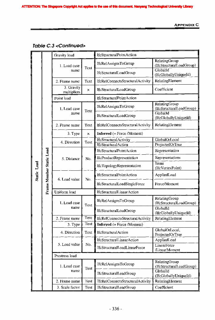
Table C.3 <Continued>
ApPENDIXC
Gravity load IfcStructuralPointAction
IfcRelAssignsToGroupRelatingGroup
1. Load case (IfcStructuraILoadGroup)Text
GloballdnameIfcStructuralLoadGroup (IfcGloballyUniqueId)
2. Frame name Text IfcRelConnectsStructuralActivity RelatingElement
3. Gravity x IfcStructuralLoadGroup Coefficientmultipliers
Point load IfcStructuralPointAction
IfcRelAssignsToGroupRelatingGroup
1. Load case Text(IfcStructuraILoadGroup)
nameIfcStructuralLoadGroup
Globalld(IfcGloballyUniqueId)
2. Frame name Text IfcRelConnectsStructuralActivity RelatingElement
3. Type x Inferred (= Force /Moment)
4. Direction TextIfcStructuralActivity GlobalOrLocalIfcStructuralAction ProjectedOrTrue
"eIfcStructuralPointAction Representation=0
~IfcProductRepresentation Representations.~ 5. Distance No.
"e ......= Items= ......
IfcTopologyRepresentationQ rJ'l(IfcVertexPoint)~ ~
QJ.~ ,.Q
IfcStructuralPointAction AppliedLoad...... S=...... QJ6. Load value No.rJ'l ~
QJ IfcStructuralLoadSingleForce Force/Moment5=~ Uniform load IfcStructuralLinearAction~
IfcRelAssignsToGroupRelatingGroup
1. Load caseText (IfcStructuralLoadGroup)
name GlobalIdIfcStructuralLoadGroup
(IfcGloballyUniqueId)
2. Frame name Text IfcRelConnectsStructuralActivity RelatingElement
3. Type Text Inferred (= Force /Moment)
4. Direction Text IfcStructuralActionGlobalOrLocal,ProjectedOrTrue
IfcStructuralLinearAction AppliedLoad5. Load value No. LinearForce
IfcStructuralLoadLinearForce/LinearMoment
Prestress load
IfcRelAssignsToGroupRelatingGroup
1. Load caseText (IfcStructuraILoadGroup)
nameIfcStructuralLoadGroup
GlobalId(IfcGloballyUniqueId)
2. Frame name Text IfcRelConnectsStructuralActivity RelatingElement
3. Scale factor Text IfcStructuralLoadGroup Coefficient
- 336-
ATTENTION: The Singapore Copyright Act applies to the use of this document. Nanyang Technological University Library
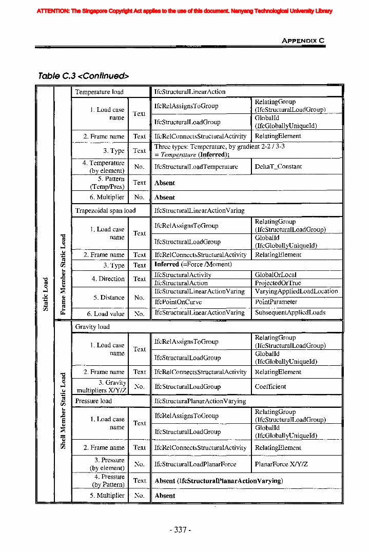
Table C.3 <Continued>
ApPENDIXC
Temperature load IfcStructuralLinearAction
IfcRelAssignsToGroupRelatingGroup
1. Load caseText
(IfcStructuraILoadGroup)name
IfcStructuralLoadGroupGlobalId(IfcGloballyUniqueId)
2. Frame name Text IfcRelConnectsStructuralActivity RelatingElement
3. Type TextThree types: Temperature, by gradient 2-2/ 3-3= Temperature (Inferred);
4. TemperatureNo. IfcStructuralLoadTemperature DeltaT_Constant
(by element)5. Pattern
Text Absent(TemplPres)
6. Multiplier No. Absent
Trapezoidal span load IfcStructuralLinearActionVaring
IfcRelAssignsToGroupRelatingGroup
1. Load case (IfcStructuraILoadGroup)"C1 Text
Gioballd~name
IfcStructuralLoadGroupQ (IfcGloballyUniqueId)~
.~ 2. Frame name Text IfcRelConnectsStructuralActivity RelatingElement;.l
~;.l
3. Type Text Inferred (=Force /Moment)rI).J-j~ IfcStructuralActivity GlobalOrLocal,.Q 4. Direction Text"C1 e IfcStructuralAction ProjectedOrTrue~
Q ~
~ ~ IfcStructuralLinearActionVaring VaryingAppliedLoadLocation.~ ~ 5. Distance No.;.l e IfcPointOnCurve PointParameter~;.l ~rI). J-j
IfcStructuralLinearActionVaring SubsequentAppliedLoads~ 6. Load value No.
Gravity load
IfcRelAssignsToGroupRelatingGroup
1. Load caseText
(IfcStructuraILoadGroup)name
IfcStructuralLoadGroupGlobalId(lfcGloballyUniqueId)
"C1 2. Frame name Text IfcRelConnectsStructuralActivity RelatingElement~Q 3. Gravity~ No. IfcStructuralLoadGroup Coefficient.~ multipliers XlY/Z;.l
~ Pressure load IfcStructuraPlanarActionVarying;.lrI).J-j
RelatingGroup~
IfcRelAssignsToGroup,.Q
e 1. Load case (IfcStructuraILoadGroup)~ Text
GlobalId~name
IfcStructuralLoadGroup- (lfcGloballyUniqueId)-~..c::IfcRelConnectsStructuralActivity ReiatingEIementrI). 2. Frame name Text
3. PressureNo. IfcStructuralLoadPlanarForce PlanarForce XN/Z(by element)
4. PressureText Absent (IfcStructuralPlanarActionVarying)(by Pattern)
5. Multiplier No. Absent
- 337 -
ATTENTION: The Singapore Copyright Act applies to the use of this document. Nanyang Technological University Library
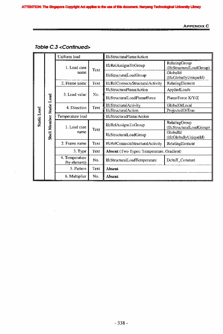
Table C.3 <Continued>
ApPENDIXC
Uniform load IfcStructuraPlanarAction
IfcRelAssignsToGroupRelatingGroup
1. Load case (IfcStructuraILoadGroup)TextGloballdname
I~oadGroup (IfcGloballyUniqueld)
2. Frame name Text IfcRelConnectsStructuralActivity RelatingElement
IfcStructuraPlanarAction AppliedLoads"'C 3. Load value No.~ IfcStructuralLoadPlanarForce PlanarForce XJY/Z=~
.~4. Direction Text
IfcStructuralActivity GlobalOrLocal"'C .....~ ~ IfcStructuralAction ProjectedOrTrue= .....~
rJ'J.~ Temperature load IfcStructuralPlanarAction
.~ Q,)
..... ..c~ a RelatingGroup..... IfcRelAssignsToGrouprJ'J. Q,)
1. Load case (IfcStructuraILoadGroup)~ Text- name Globalld1S IfcStructuralLoadGroup..c: (IfcGloballyUniqueId)rJ'J.
2. Frame name Text IfcRelConnectsStructuralActivity RelatingElement
3. Type Text Absent (Two Types: Temperature, Gradient)
4. TemperatureNo. IfcStructuralLoadTemperature DeltaT_Constant(by element)
5. Pattern Text Absent
6. Multiplier No. Absent
- 338-
ATTENTION: The Singapore Copyright Act applies to the use of this document. Nanyang Technological University Library

Table C.4 Member Section Information
General Information about Frame Section
ApPENDIXC
Software Requirements IFC Extensions
Section Elements Data Entities Attributestype
General Frame Section Information (Frame Properties)
Relating section Text IfcRelAssociatesProfile- RelatingProfileProperties8 = Properties (lfcProfileProperties)
ol"'"! C>ll~ ol"'"!
Relating member Text IfcRelAssociatesProfile- RelatedObjectsc:.J rI.:l~ rI.:lrJJ-< Properties (lfcStructuralItem)
~ = Name Text IfcProfileProperties ProfileNarne~ oS Material Text Absent (derived from IfcRelAssociatesMaterial)e~~ c:.J
~~ Type (Shape) Text Absent (derived)
Cross-sectionNo.
IfcProfilePropertiesCrossSectionArea
(axial) area (Area) (lfcStructuraIProfileProperties)Torsional IfcProfileProperties
TorsionalConstantXconstant (J) No. (lfcStructuraIProfileProperties)Moment of Inertia IfcProfileProperties
MomentOflnertiaYabout 3 axis (133) No. (lfcStructuraIProfileProperties)Moment of Inertia IfcProfileProperties
MomentOflnertiaZabout 2 axis (122) No. (lfcStructuraIProfileProperties)
rI.:l Shear area in 2 IfcProfileProperties ShearDeformationAreaZ~
No.ol"'"!
direction (A22) (lfcStructuraIProfileProperties) (ShearAreaZ)~
~~
Shear area in 3 IfcProfileProperties ShearDeformationAreaY~0 No.~ direction (A33) (lfcStructuraIProfileProperties) (ShearAreaY)=..= Section modulus IfcProfileProperties MaximumSectionModulusY
oS about 3 axis (S33) No. (lfcStructuraIProfileProperties) MinimumSectionModulusY~
c:.J~ Section modulus IfcProfileProperties MinimumSectionModulusZrJJ~ about 2 axis (S22) No. (lfcStructuraIProfileProperties) MaximumSectionModulusZa
/ ~Plastic modulusabout 3 axis (Z33) No. Absent (derived)
Plastic modulusabout 2 axis (Z22) No. Absent (derived)Radius ofGyration about 3 No. Absent (derived)
axis (R33)Radius ofGyration about 2 No. Absent (derived)axis (R22)
- 339-
ATTENTION: The Singapore Copyright Act applies to the use of this document. Nanyang Technological University Library

ApPENDIXC
Special Member Section
It3 It2 Itf I tw t2b tfb I dis
I1wideflan~e
''i'-I~ .
Outside TopheIght width
flange Top flangethickness
Web Bottom Bottom flangethickness flange width thickness
FI;...... ,:"'T~r"':I","'.""'" "'We~Thr~krlACll:
OutsideChannel depth
Outsideflange width
Flangethickness
Webthickness
IfcUShapeProf i JeDef .;Depth,. FliulgeWi dth, FI angeThickness, WebTh i ckness
TeeOutsidestem
Outsideflange
Flangethickness
Stemthickness
IfcT$hap~P.rofi leOef' '"Depth, FlangeWidth, FlangeThickness, WebThickness
:.. .
.... L..: <, . .,IJI~I . .' '.•.'; .\ ", ".' , ."..
leI:! '....' "" .
Horizontal VerticalDouble Outside Outside leg legAnele depth width thickness thicknessI fcCol11pos iteProfJleDef ., IfcLShapeProfil ~t>ef; IfcLShapeProfi leDef Depth,Width, Thickness(Note:l.n IFO. Horizontal leg thickne$s = Vertical leg thickness)
.,:
Back tobackdistanceAbsent
,. ~j~f _ v,.,;, "V[)"':'; Y/~IITli.,;'j"ckr)'eSj=» ~'I.N·o1,":.e,..., II IFC FI:.7.: ,..... ':"', ,I..., ......,.JI:~I' .' ',' JII, ral '1 ," - -
; ", .' .,:, /, ",' , "
Outsidede Jth
Outside Flange Webwidth thickness thickness
.
Outside WallPipe diameter thicknessI ,.., . ~ , ' ,,':: ..... ,." "";'1'\",'£ ~,rJ'
.. ,'.. ~ ," ".'' . ,
'Ie.- ·w~ 11 rL ,- ....-~: '/"~-' ....... 1' .. "':"" "'" ...... --
Rectan-2ular Depth WidthI',. .... ". ,,' ..... ' ,.., ,.'" vnimy
",
I.~ - _llel )~I - ...~ ..... I ''', Dim ,
Circle DiameterI-c,r' : ;" ...... ';.. " ..... ,;;.;.,..', ",
"
.... v I ..... ~ jJ,UIIICIJt:lI .
General Depth Width
Double Outside Outside Flange WebChannel depth width thickness thickness
back tobackdistance
IfcCompositeProf i leDef '.1 TcProf i faDef:. IfcUShapeProf i IeDa! -Depth,FIangeWidth; .FlangeTh ickness,··.WebThi¢knes~
- 340-
Absent
ATTENTION: The Singapore Copyright Act applies to the use of this document. Nanyang Technological University Library
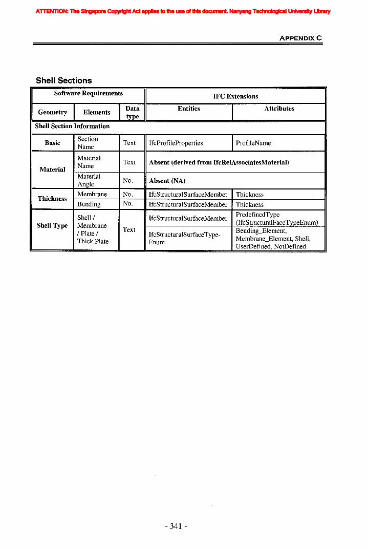
Shell Sections
ApPENDIXC
Software Requirements IFC Extensions
Data Entities I AttributesGeometry Elementsttpe
Shell Section Information
BasicSection
Text IfcProfileProperties IProfileNameName
MaterialText Absent (derived from IfcRelAssociatesMaterial)
Material Name
MaterialNo. Absent (NA)Angle
Membrane No. IfcStructuralSurfaceMember ThicknessThickness
Bending No. IfcStructuralSurfaceMember Thickness
IfcStructuralSurfaceMemberPredefinedTypeShell /(IfcStructuralFaceTypeEnum)Shell Type Membrane
Text Bending_Element,/ Plate / IfcStructuralSurfaceType-Membrane_Element, Shell,Thick Plate EnumUserDefined, NotDefined
- 341 -
ATTENTION: The Singapore Copyright Act applies to the use of this document. Nanyang Technological University Library

Table C.S Structural Responses
ApPENDIXC
Software Requirements IFC Extensions
Others ElementsData Entities Attributestype
Structural Responses IfcStructuralAnalysisModel HasResults(IfcStructuralResultGroup)
IfcRelAssignsToGroup RelatingGroup(IfcStructuraIResultGroup)
IfcRelAssignsToGroup RelatedObjects(IfcStructuralReaction)
Joint Reactions IfcStructuralReaction AppliedLoad(IfcStructuraILoad)
Joint name Text IfcStructuralConnectionGioballd(IfcGloballyUniqueId)
Load caseText IfcStructuralLoadGroup
Gioballdname (IfcGloballyUniqueId)
v..lFI/ F2/ F3 No. IfcStructuralLoadSingleForce Force XfY/Z
~v..l MI/M21M3 No. IfcStructuralLoadSingleForce Moment XfY/Z=QCo. IfcStructuralReaction AppliedLoadv..l Joint Displacement~ (IfcStructuralLoad)~..... Gioballd= Joint Text IfcStructuralConnection'S (IfcGloballyUniqueId)~
Load caseText IfcStructuralLoadGroup
Gioballdname (IfcGloballyUniqueId)
UI/U2/U3 No. IfcStructuralLoadDisplacementDisplacement XfYIZ(IfcLengthMeasure)RotationalDisplacemnt
RI/ R2/ R3 No. IfcStructuralLoadDisplacement RXlRYIRZ(IfcPlaneAngleMeasure)
Frame Element IfcStructuralReaction AppliedLoadForces (IfcStructuraILoad)
Frame Text IfcStructuralMemberGioballd(IfcGloballyUniqueId)
IfcStructuralResultGroupResultForLoadGroup
r:I.l Load case (IfcStructuralLoadGroup)~r:I.l Text= name GioballdQ IfcStructuralLoadGroupCo. (IfcGloballyUniqueId)v..l~
~Station No. IfcStructuralLinearActionVarying
VaryingAppliedLoadLocation~ (IfcShapeAspect)aC':S SubsequentAppliedLoadsJ-l IfcStructuralLinearActionVarying~
PN2/V3 No. (IfcStructuraILoad)IfcStructuralLoadSingleForce Force XIY/Z
IfcStructuralLinearActionVaryingAppliedSubsequentLoads
T 1M2/M3 No. (IfcStructuraILoad)IfcStrcuturalLoadSingleForce MomentXfY/Z
- 342-
ATTENTION: The Singapore Copyright Act applies to the use of this document. Nanyang Technological University Library
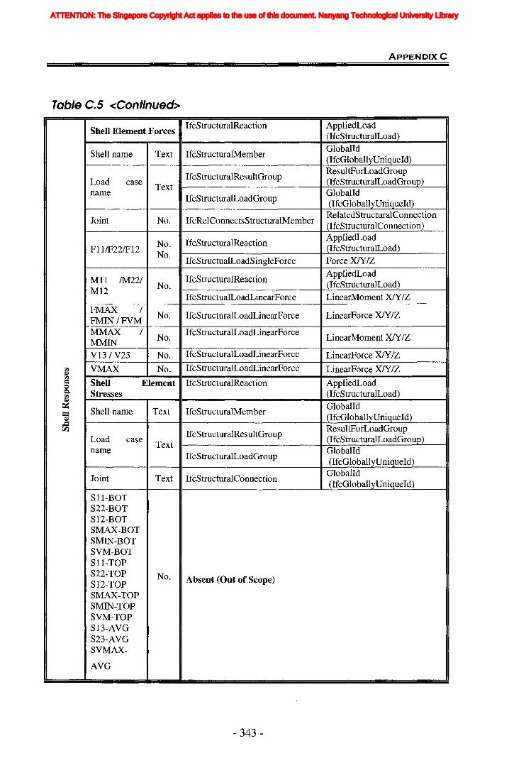
Table C.5 <Continued>
ApPENDIXC
Shell Element ForcesIfcStructuralReaction AppliedLoad
(lfcStructuraILoad)
Shell name Text IfcStructuralMemberGioballd(IfcGloballyUniqueId)
IfcStructuralResultGroupResultForLoadGroup
Load caseText
(IfcStructuraILoadGroup)name
IfcStructuralLoadGroupGioballd(IfcGloballyUniqueld)
Joint No. IfcRelConnectsStructuralMemberRelatedStructuralConnection(IfcStructuralConnection)
No. IfcStructuralReactionAppliedLoad
FIIIF221F12 (IfcStructuralLoad)No.
IfcStructualLoadSingleForce ForceXN/Z
MIl fM221 IfcStructuralReactionAppliedLoad
M12No. (IfcStructuraILoad)
IfcStructualLoadLinearForce LinearMoment XlYIZFMAX 1
No. IfcStructuralLoadLinearForce LinearForce XN/ZFMIN/FVMMMAX 1
No.IfcStructuralLoadLinearForce
LinearMoment XlYIZMMINV13 1V23 No. IfcStructuralLoadLinearForce LinearForce XIYIZ
rI.) VMAX No. IfcStructuralLoadLinearForce LinearForce XNIZQ,,)rI.)
= Shell Element IfcStructuralReaction AppliedLoad0c. Stresses (IfcStructuraILoad)rI.)Q,,)
~Shell name Text IfcStructuralMember
Gioballd- (IfcGloballyUniqueId)1Z..=ResultForLoadGrouprJ'l
IfcStructuralResultGroupLoad case
Text(lfcStructuraILoadGroup)
nameIfcStructuralLoadGroup
Gioballd(IfcGloballyUniqueId)
Joint Text IfcStructuralConnectionGioballd(IfcGloballyUniqueld)
Sll-BOTS22-BOTS12-BOTSMAX-BOTSMIN-BOTSVM-BOTSll-TOPS22-TOP No. Absent (Out of Scope)S12-TOPSMAX-TOPSMIN-TOPSVM-TOPS13-AVGS23-AVGSVMAX-
AVG
- 343 -
ATTENTION: The Singapore Copyright Act applies to the use of this document. Nanyang Technological University Library
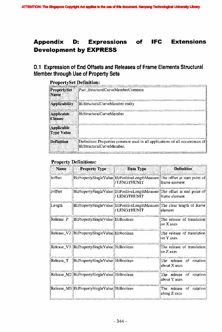
Appendix D: ExpressionsDevelopment by EXPRESS
of IFe Extensions
0.1 Expression of End Offsets and Releases of Frame Elements StructuralMember through Use of Property Sets
£giC;~! Itr>~h'l1 {"'1tllr~lll ;urVe~lVl(~mIDerentity
Properties common used in all applications of all occurrences
p~~P~J;!y ..~.efi~ition~.:r__~__1
ilIoffset 1< IIfcPropertySingleValuellIfcPositiveLengthMeasurei!The offset at start point o~1
HI 11/ LENGTHUNIT IIframe element II
II~~~~~:~~~III d 11/ LENGTHUNIT Ilframe element 1IIL;;;;;;;;;;;;;;:;:;;;;;:;:;;;;;;;:;:;:;:;:;;;:;;;~ ~;:;;;:;;;:;;;;;;;;;;;;;;;;;;;:;;;;;:;;;;;;;;;;;;;;;;;:;:;;;;;;;:;;;;;;;;:;;;:;:;;;;;:;;;;;:;::1 L:;;;:;:;:;;;;;;;;;:;;;:;;;:;;;;;:;;;;;;;;;;;:;;;;;:;:;;;;;:;;;;;;;:;:;;;;;;;:;;;:;;;:;;;;;:;;;;;;;;;;;;;:::1 ~;;;;:;;;;;;;;;;;;;;;;;:;;;;~;:;;;;;;;;;;;;;;;;;;;;:;:;:;;;:;:;:;;;;;:;;;;;;;:;;;;;;;;;;;;;:;;;;;;;;;;;::11'!Length ,!IfcPropertySingleValueIIIfcPositiveLengthMeasure!iThe clear length of framellIII 11/ LENGTHUNIT IIelement l!Ib;;;;;;;;;;;;;;;;;;;;;;;;;:;;;;;;;;;:;;;;;;;;;:;;;;; ~;;:;;;;;;;;;;;;;;;;;;;;;;;;;;;:;:;;:;;;;;;;;;;;;;;;;;;;;;;;;;;;;;;;;;;;;;:;;;;;;;;;;;;;;:;;;;;;;;;;1 ~;;;;;;;;;;;;;;;;;;;;;;;;;;;;;;;;;;;;;:;;;;;;;;;;;;:;;:;::;;;:;;:;;;;;;;;;;;;::;;;;;;;;;;;;;;;;;:;;;;;;;;;;;;;:1 L;;;;;;;:;;;;;;;;;;;;;;;;;;;;;;;;;;;;;;;;;;;;;;;;;;;;;;;;;;;;;;;;;;;;;;;;;;;;;;;;;;;;;;;;;;;;;;;;;;;;;;;;;;;;J I
IIRelease_P IIIfcPropertySingleValuellIfcBoolean liThe release of translationll
Il~~=~~J~~1nRelease_V2 iIIfcPropertySingleValuellIfcBoolean liThe release of translationll
iEJ IllRelease_T ilIfcPropertySingleValuellIfcBoolean liThe release of rotationlli! q q H b X i!11 11 i! ila out axes i!
I~;;;;;;;;;;,;;;;;;:;;;;;;:;;:;;;;;;;:;;;;;;;:::;;;;;:4 ~;;;;;;;;;;;;:::;;;;;,;;;;:;;;;;;;:;;;:;;;;;;;;;;;;;:;;;;;;;;;;;;;;:;;;;;;;;;;;;;;;;;;:;;;:;;;;;;;;;~ ~;;;;;;;;;;:;;:;;;;;;;;;;;;;;;;;;:;;;;;;;;;;;;;;;;;;;;;;;;;;;;,;;;;;;;;;:;;;;;;;;;;;:;;;;;;;;;;;;;;;;;;;;;;;;::1 L;;;;;;:;;;;;;;;;;:;:;;;;;;;:;;;;;;;:;;:;;;;;;;;:;;;:;;::,;;;;;;;;:;;;;;;;:;;;;;;;;;;;;;;;;;:;;;:;;;;;;;;;;;JI
IIRelease_M21IIfcPropertySingleValuellIfcBoolean !IThe release of rotation!IPI P Habout Y axes 11
'l;;;;;;;;;;;;;;;;;;;;;;;;;;;;;;;;;;;;;;;;;;;;;;;;;;j L;;;;;;;;;;;;;;;;;;;;;;;;;;;;;;;;;;;;;;;;;;;;;;;;;;;;;;;;;;;;;;;;;;;;;;;;;;;;:::;;;;;;;;;;;;;;;:::1 L;;;;;;;;;;;;;;;;;;;;;;;;;;;;;;;;;;;;;;;;;;;;;;;;;;;;;;;;;;;;;;;;;;;;;;;;;;;;;;;;;;;;;;;;;;;;;;;;;;;;;;;;::1 L;;;;;;;;;;;;;;;;;;;;;;;;;;;;;;;;;;;;;;;;;;;;;;;;;;;;;;;;;;;;;;;;;;;;;;;;;;;;;;;;;;;;;;;;;;;;;;;;;;;;;;;;:::11
llRelease_M3lIfcPropertySingleValuel!IfcBoolean liThe release of rotationll
Lj~~JJ
- 344-
ATTENTION: The Singapore Copyright Act applies to the use of this document. Nanyang Technological University Library

ApPENDlxD
0.2 Expression of Restraints of Joint through Use of Property SetsPiUIJl:t-t '-Set Definition:.~
Iij~
.:-1'
Properties common needed to the definition of all occurrences )f:-I'
Property Definitions:
IIRestraintsU2 lIIfcPropertySingleValue IIIfcBoolean liThe restraints along Y axes III~;;;;;;;;;;;;;;;;;;;;;;;;;;;;;;;;;;;;;;;;;;;;;;;;;;;;;;;;;;:1 ~;;;;;;;;;;;;;;;;;;;;;;;;,:;;;;;;;;;;;;;;;;;;;;;;;;;;;;;;;;;;;;;;;;;;;;;;;;;;;;;;;;;;;;;;;;;;;;;;;;;;;;:1 b;;;;;;;;;;;;;;;;;;;;;;;;;;;;;;;;;;;;;;;;;;;;;;;;;;;;;;;;;;;;;;! ~;;;;;;;;;;;;;;;;;;;;;;;;;;;;;;;;;;;;;;;;;;;;;;;;;;;;;;;;;;;;;;;;;;;;;;;;;;;;;;;;;;;;;;;;;;;;;;;;;;;;;;;;;;;;;;;;;;;;;;;;;;;;;;;! I
IlRestraintsU3 llIfcPropertySingleValue IIIfcBoolean liThe restraints along Z axes IIIL;;;;;;;;;;;;;;;;;;;;;;;;;;;;;;;;;;;;;;;;;;;;;;;;;;;;;;::J !;;;;;;;;;;;;;;;;;;;;;;;;;;;;;;;;;;;;;;;;;;;;;;;;;;;;;;;;;;;;;;;;;;;;;;;;;;;;;;;;;;;;;;;;;;;;;;;;;;;;;;:::1 ~;;;;;;;;;;;;;;;;;;;;;;;;;;;;;;;;;;;;;;;;;;;;;;;;;;;;;;;;;;;;;;;;;::1 L;;;;;;;;;;;;;;;;;;;;;;;;;;;;;;;;;;;;;;;;;;;;;;;;;;;;;;;;;;;;;;;;;;;;;;;;;;;;;;;;;;;;;;;;;;;;;;;;;;;;;;;;;;;;;;;;;;;;;;;;;;;;;;;;;JI'IRestraintsRl l.IIfcPropertySingleValue IIIfcBoolean liThe restraints of rotation aboutll
IL====:1L~~b:~1IiRestraintsR2 IIIfcPropertySingleValue IIIfcBoolean liThe restraints of rotation aboutll
:=J ~
- 345-
ATTENTION: The Singapore Copyright Act applies to the use of this document. Nanyang Technological University Library
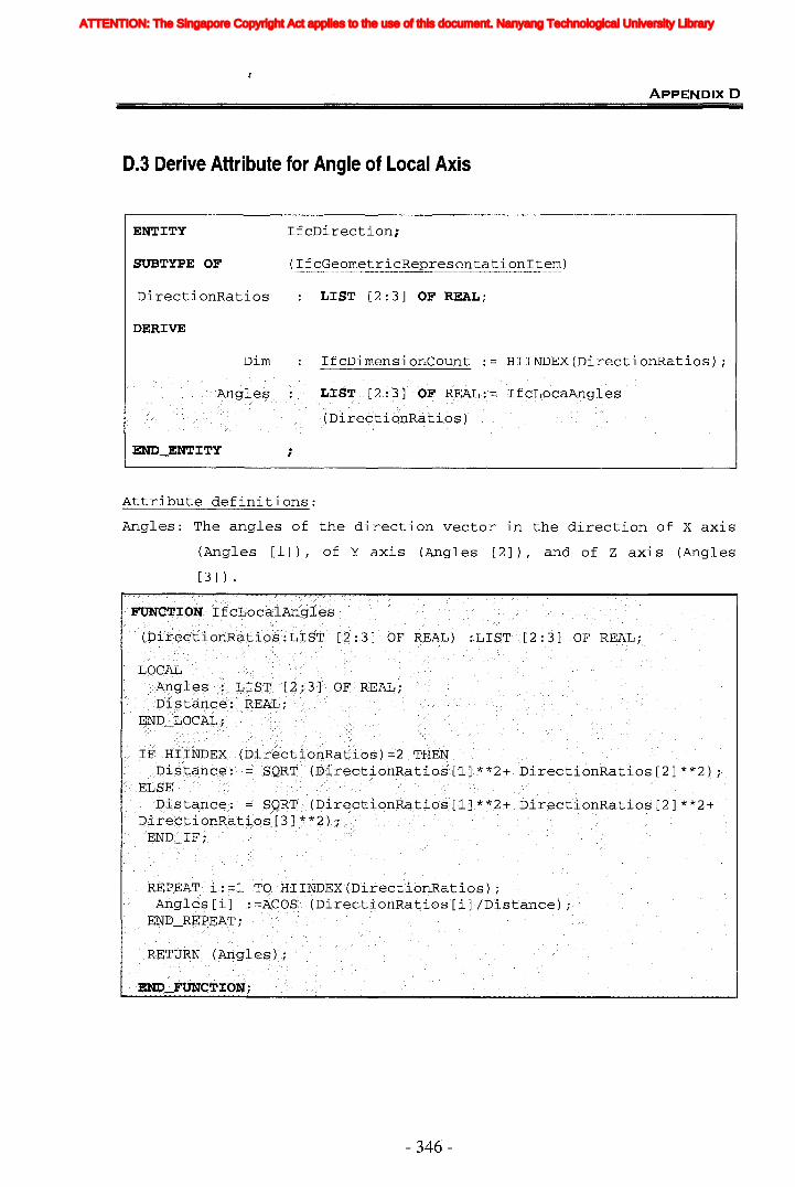
ApPENDlxD
D.3 Derive Attribute for Angle of Local Axis
ENTITY IfcDirection;
SUBTYPE OF (IfcGeometricRepresentationItem)
DirectionRatios LIST [2:3] OF REAL;
DERIVE
Dim IfcDimensionCount HIINDEX(DirectionRatios) ;
Attribute definitions:
Angles: The angles of the direction vector in the direction of X axis
(Angles [1]), of Y axis (Angles [2]), and of Z axis (Angles
[3] ) .
- 346-
ATTENTION: The Singapore Copyright Act applies to the use of this document. Nanyang Technological University Library
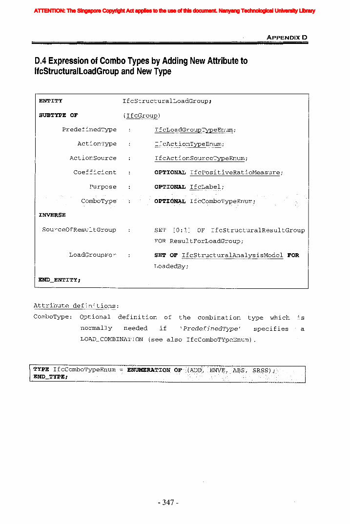
ApPENDlxD
0.4 Expression of Combo Types by Adding New Attribute toIfcStructuralLoadGroup and New Type
ENTITY IfcStructuralLoadGroup;
SUBTYPE OF (IfcGroup)
PredefinedType IfcLoadGroupTypeEnumi
ActionType IfcActionTypeEnumi
ActionSource IfcActionSourceTypeEnumi
Coefficient OPTiONAL IfcPositiveRatioMeasurei
Purpose OPTiONAL IfcLabel;
iNVERSE
SourceOfResultGroup
LoadGroupFor
SET [0: 1] OF IfcStructuralResul tGroup
FOR ResultForLoadGrouPi
SET OF IfcStructuralAnalysisModel FOR
LoadedBy;
Attribute definitions:
ComboType: Optional definition of the combination type which is
normally needed if \ PredefinedType' specifies a
LOAD_COMBINATION (see also IfcComboTYpeEnum) .
- 347-
ATTENTION: The Singapore Copyright Act applies to the use of this document. Nanyang Technological University Library
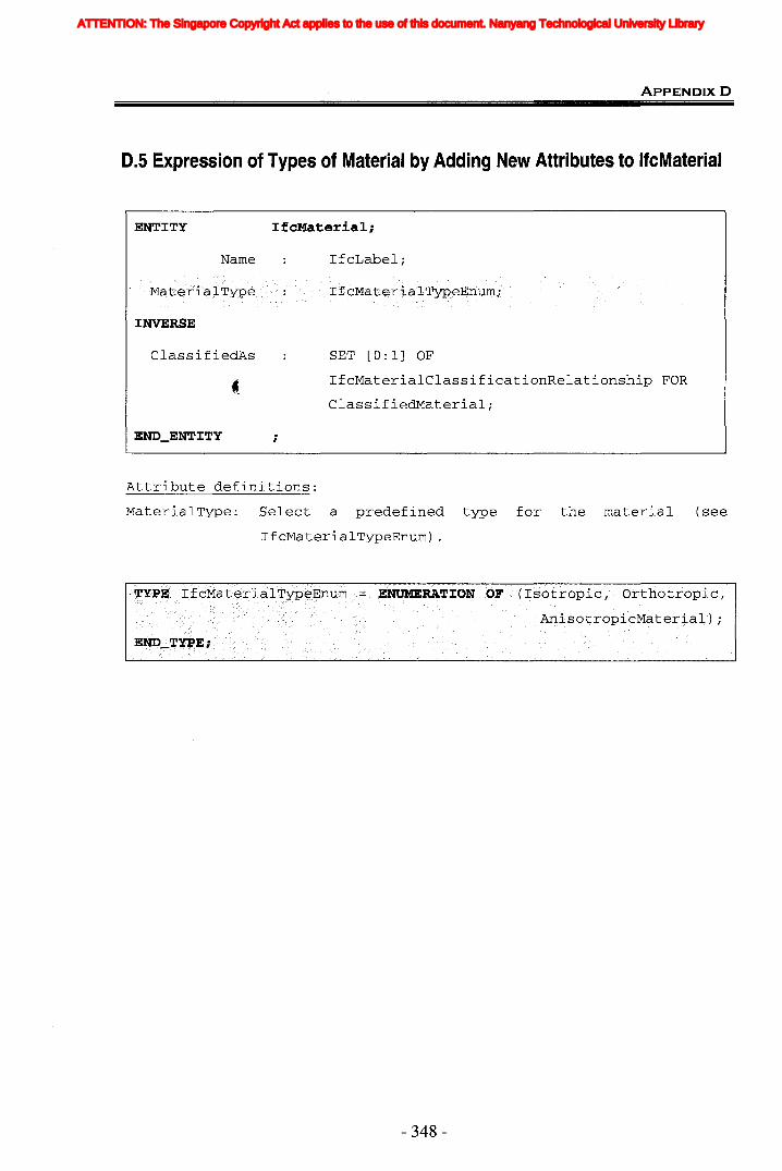
ApPENDIXD
0.5 Expression of Types of Material by Adding New Attributes to IfcMaterial
ENTITY IfcMaterial;
Name IfcLabel;
INVERSE
ClassifiedAs
;
SET [0:1] OF
IfcMaterialClassificationRelationship FOR
ClassifiedMaterial;
Attribute definitions:
MaterialType: Select a predefined type for the material (see
IfcMaterialTypeEnum) .
- 348-
ATTENTION: The Singapore Copyright Act applies to the use of this document. Nanyang Technological University Library
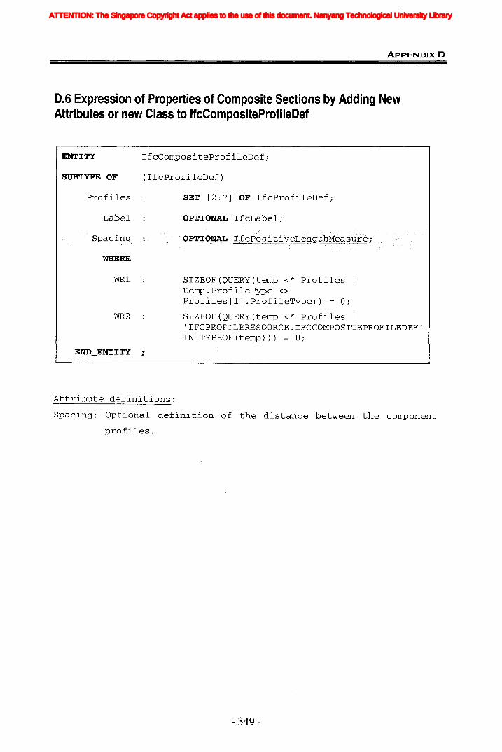
ApPENDIX D
0.6 Expression of Properties of Composite Sections by Adding NewAttributes or new Class to IfcCompositeProfileOef
ENTITY IfcCompositeProfileDef;
SUBTYPE OF (IfcProfileDef)
Profiles SET [2:?] OF IfcProfileDef;
Label OPTIONAL IfcLabel;
WHERE
WR1
WR2
SIZEOF(QUERY(temp <* Profiles Itemp.ProfileType <>
Profiles [1] .ProfileType)) = 0;
SIZEOF(QUERY(temp <* Profiles I'IFCPROFILERESOURCE.IFCCOMPOSITEPROFILEDEF'IN TYPEOF(temp))) = 0;
Attribute definitions:
Spacing: Optional definition of the distance between the component
profiles.
- 349-
ATTENTION: The Singapore Copyright Act applies to the use of this document. Nanyang Technological University Library
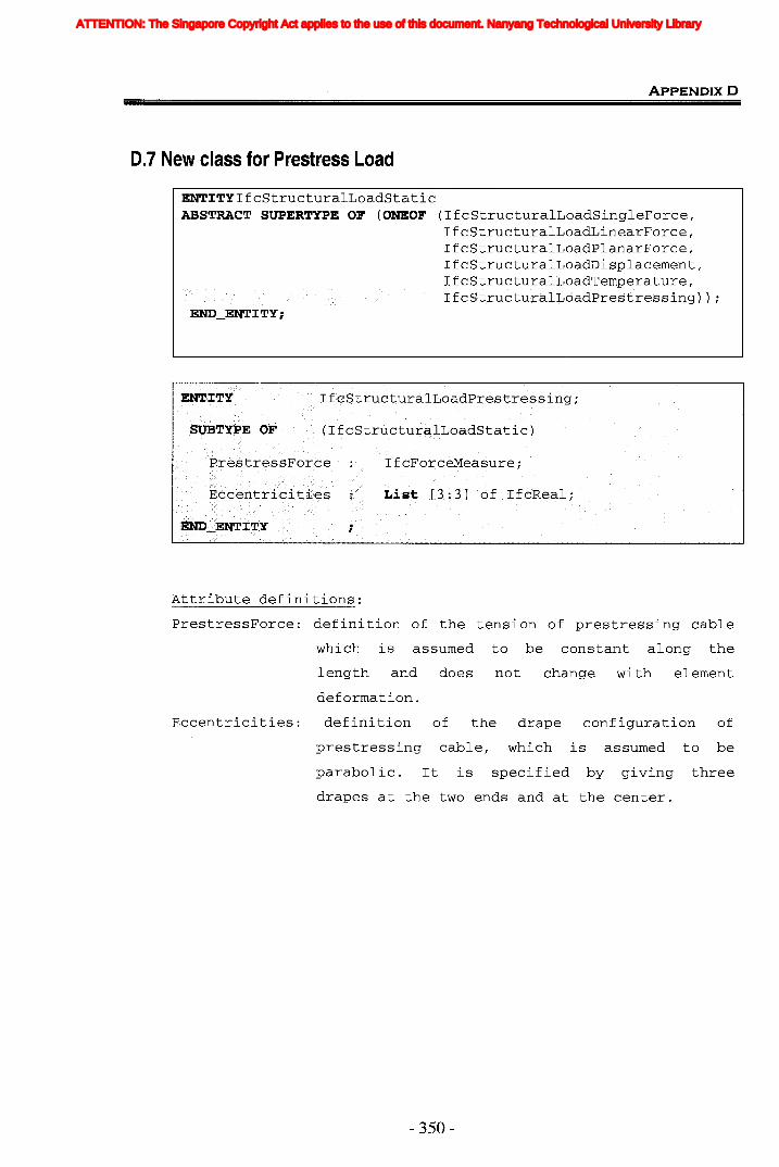
ApPENDIXD
0.7 New class for Prestress Load
ENTITYIfcStructuralLoadStaticABSTRACT SUPERTYPE OF (ONEOF (IfcStructuralLoadSingleForce,
IfcStructuralLoadLinearForce,IfcStructuralLoadPlanarForce,IfcStructuralLoadDisplacement,
Attribute definitions:
PrestressForce: definition of the tension of prestressing cable
which is assumed to be constant along the
length and does not
deformation.
change wi th element
Eccentricities: definition of the drape configuration of
prestressing cable, which is assumed to be
parabolic. It is specified by giving three
drapes at the two ends and at the center.
- 350-
ATTENTION: The Singapore Copyright Act applies to the use of this document. Nanyang Technological University Library
Copyright © 2022 FDOKUMEN