IEEE PSRC Report on Global Industry Experiences With System Integrity Protection Schemes (SIPS)
15
> REPLACE THIS LINE WITH YOUR PAPER IDENTIFICATION NUMBER (DOUBLE-CLICK HERE TO EDIT) < 1 Abstract—This paper is a summary of the IEEE Power System Relaying Committee report C4 [1] on System Integrity Protection Schemes (SIPS) survey. SIPS role is to counteract system instability, maintaining overall system connectivity, and/or to avoid serious equipment damage during major system events. The survey describes industry experiences with this category of protection schemes applied to protect the integrity of the power system. It is designed to provide guidance for SIPS users and implementers based on surveyed operating practices and lessons learned. The survey includes a global participation through the comprehensive effort of IEEE and CIGRE. Index Terms— System Integrity Protection Schemes (SIPS), Blackout Prevention, Protective Relaying, Wide Area Disturbances I. INTRODUCTION The electric power grid is the “pivot point” that balances generation and load. Maintaining the integrity of this pivot point is imperative for the effective operation of interconnected power systems. As such, the balance of power is only as reliable as the weakest element in the system. System-wide disturbances in power systems are a growing issue for the power system industry [2], [3], [4], [5], [6]. When a major disturbance occurs, protection and control actions are required to stop power system degradation, restore the system to a normal state, and minimize the impact of the disturbance [7], [8]. Control center operators must deal with a very complex situation and rely on heuristic solutions and policies. Local protection systems arrest the propagation of the fast- developing emergencies through automatic actions and are applied to address equipment specific or local system problems. Local protection systems are not intended for arresting large-scale power system problems, which may be caused by system disturbances. The trend in power system planning is to develop tight operating margins, with less redundancy. At the same time, addition of renewable energy resources, interchange increases across large areas, and introduction of fast reactive control devices make the power system more complex to operate. Manuscript received January 5, 2010 Vahid Madani is with Pacific Gas and Electric Co. (PG&E), 1919 Webster Street, Oakland, CA 94612, USA (phone: 510-874-2300; e-mail: vxm6@PG&E.com ). Damir Novosel is with the Technology Division at Quanta, 4020 Westchase Boulevard, Suite 300, Raleigh, NC 27607, USA (e-mail: dnovosel@quanta- technology.com ) Stan Horowitz is an independent consultant, Columbus, OH 43222, USA (e-mail: [email protected] ) Mark Adamiak is with General Electric Co. (GE), 530 Swedesford Rd, Wayne, PA 19087, USA (e-mail: [email protected]) Javier Amantegui is with Iberdrola of Spain, Avda. San Adrian, 48 48003 Bilbao (e-mail: [email protected] ) Daniel Karlsson is with Gothia Power, Aschebersgaten 46, 411 33 Goteborg, Sweden (e-mail: [email protected] ) Shinichi Imai is with Tokyo Electric Power Company (TEPCO), 460 Mogusa, Hino-shi, Tokyo191-8507, Japan (e-mail: [email protected] ) Alex Apostolov is with Omicron Electronics, 2950 Bentley Avenue, Unit 4 Los Angeles, CA 90064, USA (e-mail: [email protected] ) The fundamental changes in the design and operation of the electric power system require that system-wide protection solutions be integrated as part of the overall solutions to prevent disturbance propagation. As a result, automated schemes have been designed to detect one or more predetermined system conditions that would have a high probability of causing undesired stress on the power system. Examples of large blackouts in the past decade have shown that the risk of large blackouts (product of blackout probability and the associated cost) is no longer acceptable and can lead to very large and unexpected social and financial consequences. Reduction of the risk of large system-wide disturbances and blackouts requires that system protection function be approached with the assistance of modern technologies in support of preserving system integrity under adverse conditions. These schemes, defined as system integrity protection schemes (SIPS), are installed to protect the integrity of the power system or strategic portions thereof, as opposed to conventional protection systems that are dedicated to a specific power system element. The SIPS encompasses Special Protection System (SPS), Remedial Action Schemes (RAS) as well as other system integrity schemes such as Underfrequency (UF), Undervoltage (UV), Out-of-Step (OOS), etc. These schemes provide reasonable countermeasures to slow and/or stop cascading outages caused by extreme contingencies. Advanced detection and control strategies through the concept of SIPS offer a cohesive management of the disturbances. With the increased availability of advanced computer, communication, and measurement technologies, more "intelligent" equipment can be used at the local level to improve the overall response. Traditional dependant contingency / event based systems could be enhanced to include power system response based algorithms with proper local supervisions for security. In August of 1996, a seminal article [10] was published as a result of the activity of the joint Working Group of IEEE and CIGRE, the purpose of which was to investigate the special protection system (SPS) then in existence worldwide and to report about various aspects of their designs, IEEE PSRC Report on Global Industry Experiences with System Integrity Protection Schemes (SIPS) Vahid Madani (Fellow), Damir Novosel (Fellow), Stan Horowitz (Life Fellow), Mark Adamiak (Fellow) Javier Amantegui, Daniel Karlsson (Senior Member), Shinichi Imai (Member); Alexander Apostolov (Fellow)
-
Upload
independent -
Category
Documents
-
view
7 -
download
0
Transcript of IEEE PSRC Report on Global Industry Experiences With System Integrity Protection Schemes (SIPS)
> REPLACE THIS LINE WITH YOUR PAPER IDENTIFICATION NUMBER (DOUBLE-CLICK HERE TO EDIT) <
1
Abstract—This paper is a summary of the IEEE Power System Relaying Committee report C4 [1] on System Integrity Protection
Schemes (SIPS) survey. SIPS role is to counteract system instability, maintaining overall system connectivity, and/or to avoid serious equipment damage during major system events. The survey describes industry experiences with this category of protection schemes applied to protect the integrity of the power system. It is designed to provide guidance for SIPS users and implementers based on surveyed operating practices and lessons learned. The survey includes a global participation through the comprehensive effort of IEEE and CIGRE.
Index Terms— System Integrity Protection Schemes (SIPS), Blackout Prevention, Protective Relaying, Wide Area Disturbances
I. INTRODUCTION The electric power grid is the “pivot point” that
balances generation and load. Maintaining the integrity of this pivot point is imperative for the effective operation of interconnected power systems. As such, the balance of power is only as reliable as the weakest element in the system. System-wide disturbances in power systems are a growing issue for the power system industry [2], [3], [4], [5], [6]. When a major disturbance occurs, protection and control actions are required to stop power system degradation, restore the system to a normal state, and minimize the impact of the disturbance [7], [8]. Control center operators must deal with a very complex situation and rely on heuristic solutions and policies. Local protection systems arrest the propagation of the fast-developing emergencies through automatic actions and are applied to address equipment specific or local system problems. Local protection systems are not intended for arresting large-scale power system problems, which may be caused by system disturbances.
The trend in power system planning is to develop tight operating margins, with less redundancy. At the same time, addition of renewable energy resources, interchange increases across large areas, and introduction of fast reactive control devices make the power system more complex to operate.
Manuscript received January 5, 2010 Vahid Madani is with Pacific Gas and Electric Co. (PG&E), 1919 Webster
Street, Oakland, CA 94612, USA (phone: 510-874-2300; e-mail: vxm6@PG&E.com).
Damir Novosel is with the Technology Division at Quanta, 4020 Westchase Boulevard, Suite 300, Raleigh, NC 27607, USA (e-mail: [email protected])
Stan Horowitz is an independent consultant, Columbus, OH 43222, USA (e-mail: [email protected])
Mark Adamiak is with General Electric Co. (GE), 530 Swedesford Rd, Wayne, PA 19087, USA (e-mail: [email protected])
Javier Amantegui is with Iberdrola of Spain, Avda. San Adrian, 48 48003 Bilbao (e-mail: [email protected])
Daniel Karlsson is with Gothia Power, Aschebersgaten 46, 411 33 Goteborg, Sweden (e-mail: [email protected])
Shinichi Imai is with Tokyo Electric Power Company (TEPCO), 460 Mogusa, Hino-shi, Tokyo191-8507, Japan (e-mail: [email protected])
Alex Apostolov is with Omicron Electronics, 2950 Bentley Avenue, Unit 4 Los Angeles, CA 90064, USA (e-mail: [email protected])
The fundamental changes in the design and operation of the electric power system require that system-wide protection solutions be integrated as part of the overall solutions to prevent disturbance propagation. As a result, automated schemes have been designed to detect one or more predetermined system conditions that would have a high probability of causing undesired stress on the power system.
Examples of large blackouts in the past decade have shown that the risk of large blackouts (product of blackout probability and the associated cost) is no longer acceptable and can lead to very large and unexpected social and financial consequences. Reduction of the risk of large system-wide disturbances and blackouts requires that system protection function be approached with the assistance of modern technologies in support of preserving system integrity under adverse conditions.
These schemes, defined as system integrity protection schemes (SIPS), are installed to protect the integrity of the power system or strategic portions thereof, as opposed to conventional protection systems that are dedicated to a specific power system element. The SIPS encompasses Special Protection System (SPS), Remedial Action Schemes (RAS) as well as other system integrity schemes such as Underfrequency (UF), Undervoltage (UV), Out-of-Step (OOS), etc. These schemes provide reasonable countermeasures to slow and/or stop cascading outages caused by extreme contingencies.
Advanced detection and control strategies through the concept of SIPS offer a cohesive management of the disturbances. With the increased availability of advanced computer, communication, and measurement technologies, more "intelligent" equipment can be used at the local level to improve the overall response. Traditional dependant contingency / event based systems could be enhanced to include power system response based algorithms with proper local supervisions for security.
In August of 1996, a seminal article [10] was published as a result of the activity of the joint Working Group of IEEE and CIGRE, the purpose of which was to investigate the special protection system (SPS) then in existence worldwide and to report about various aspects of their designs,
IEEE PSRC Report on Global Industry Experiences with System Integrity Protection Schemes (SIPS)
Vahid Madani (Fellow), Damir Novosel (Fellow), Stan Horowitz (Life Fellow), Mark Adamiak (Fellow)
Javier Amantegui, Daniel Karlsson (Senior Member), Shinichi Imai (Member); Alexander Apostolov (Fellow)
> REPLACE THIS LINE WITH YOUR PAPER IDENTIFICATION NUMBER (DOUBLE-CLICK HERE TO EDIT) <
2
functional specifications, reliability, overall implementation and life cycle cost and operating experience. The report encompassed over 100 schemes from all over the world and provided a wealth of information on the direction industry was taking in coping with ever-larger disturbances. The report also highlighted that IEEE and CIGRE were not the only groups of professional organizations that had shown concerns for the reliability of the SPS, and that several other organizations including Instrument Society of America (ISA) and International Electrotechnical Commission (IEC) were actively involved in establishing standards for the future development of the devices manufactured to support system integrity type protection.
The results of the 1996 survey indicated that there was considerable interest in developing such SPS. In fact, the survey indicated that such protection was widespread and no longer should be considered “special”. The acronym is now more properly termed System Integrity Protection Scheme (SIPS) or Remedial Action Scheme (RAS).
In 2005, the System Protection Subcommittee of the IEEE Power System Relaying Committee (PSRC) started an initiative to update the industry experiences on SIPS by creating and widely disseminating a new survey to attract as wide a response from the industry worldwide.
II. SURVEY APPROACH The survey is intended to compile industry
experiences with a category of protection schemes designed to protect the integrity of the power system; system stability, maintaining overall system connectivity, and/or to avoid serious equipment damage during major events. The survey is designed to provide guidance for future system implementers based on what exists today as well as operating practices and lessons learned. Our industry has long recognized system vulnerabilities, and is energized to promote grid reliability with SIPS being a key element. The responses to this survey will assist the industry in driving towards a more robust grid design.
The Power System Relaying Committee (PSRC) working group (WG) members requested that the survey questionnaire be expanded to include a global participation and suggested a comprehensive effort of IEEE and CIGRE representation to cover a worldwide base of responses. The survey draft was presented at IEEE informational meetings, conferences, and the CIGRE summer 2006 meeting to collect additional input on the form and to inform interested participants of the developments underway, and to request participation once the survey was released. Survey participants have access to the tabulated results of the responses and a copy of the collaborative report.
Since the survey participants are international, the topographical structure of the power industry varies from one system to the next. For example, in some cases, the entire country is operated under a national power grid. In other cases, only the Grid Operators have participated on behalf of the entire grid. There are also many responses in a bundled or aggregate form since responses are representing a regional grid. Therefore, the total number of responses is not as
meaningful as the total number of schemes reported, types of applications, operational experiences, and the technologies deployed. Care has been exercised not to have duplicate data entered.
The conclusion is that for the most part these schemes are accepted worldwide, are used in a variety of SIPS from manually operated system to very advanced and high speed schemes, all have a high degree of overall reliability, and good operational experiences. Many of the SIPS have annually or bi-annual operational history which assists in validity of the data. Several examples of more complex schemes have been included by the survey participants as part of the report [1], which also emphasizes the wide acceptance of the SIPS.
A. Material Supplied to the Survey Participants In addition to the questionnaire, the participants received supplementary material, the SIPS or RAS Application Definitions, a short review of methods to balance the operation of the power system and the main factors influencing the type of SIPS applied [1]. This material was provided to assist the respondents with the selection of the most appropriate types of SIPS actions, and to achieve consistency when tabulating the results.
B. Survey Data Validity of Survey Data - This survey was sent to
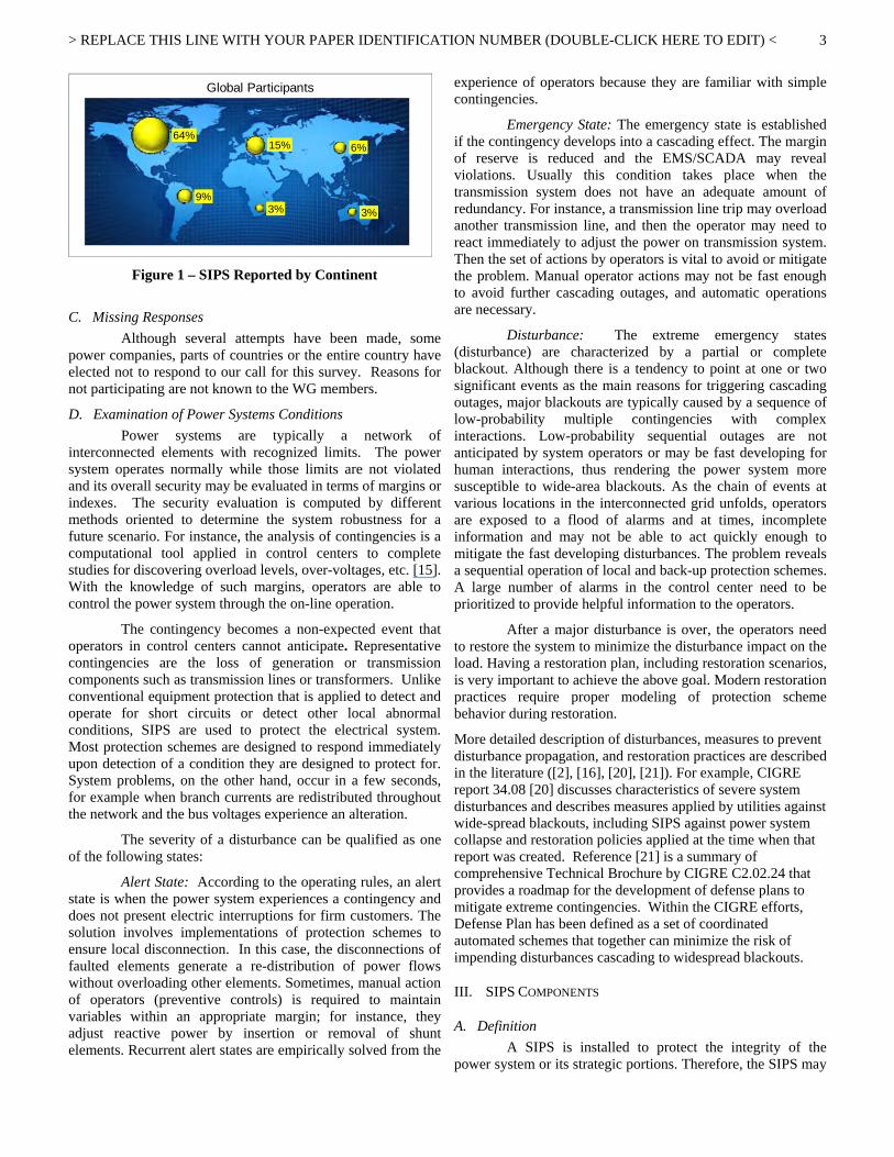
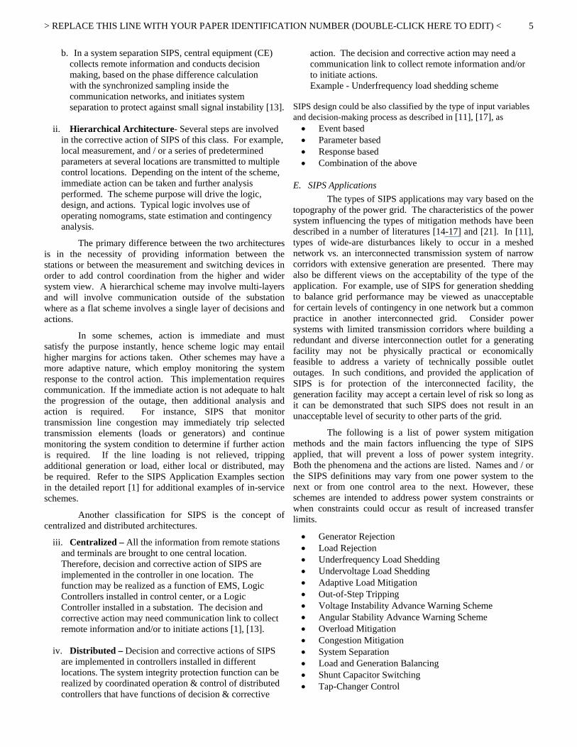
power companies, grid operators, and Independent System Operators worldwide. The representatives of more than 100 individual power companies and bundled power systems have been tabulated. Results are presented in graphical format with a summary interpretation. The responses are from a representative cross-section of utilities in terms of type of utility, size of a power company, municipalities, national grids, and provinces. The respondents also cover a broad geographical and Regional Council diversity within the North American Electric Reliability Corporation (NERC), as well as a significant number of CIGRE participants from different countries with completely different grid topographies, Figure 1.
The survey responses show great consistency reflecting common practices across all segments of the industry. The survey has two complementary parts, namely operational experiences and design practices. The two parts in the survey complement each other well with the information received from the industry. The operational experiences section demonstrates the performance of the existing schemes, including discrete elements, the telecommunication system availability and associated maintenance for telecommunication dependant schemes, the operational performance and overall throughput timing for systems that have stringent performance requirements. The Engineering, Design, and Implementation section of the survey responses demonstrate how the SIPS have become an integral part of the technological advancements in power system manufacturing of multifunction protective devices, as well as the integration of advanced functions that at one time, would have been performed by discrete components. The survey results also highlight the need for better system monitoring, advanced tools, and advanced applications.
> REPLACE THIS LINE WITH YOUR PAPER IDENTIFICATION NUMBER (DOUBLE-CLICK HERE TO EDIT) <
3
64%
9%
15%
3%
6%
3%
Global Participants
Figure 1 – SIPS Reported by Continent
C. Missing Responses Although several attempts have been made, some
power companies, parts of countries or the entire country have elected not to respond to our call for this survey. Reasons for not participating are not known to the WG members.
D. Examination of Power Systems Conditions Power systems are typically a network of
interconnected elements with recognized limits. The power system operates normally while those limits are not violated and its overall security may be evaluated in terms of margins or indexes. The security evaluation is computed by different methods oriented to determine the system robustness for a future scenario. For instance, the analysis of contingencies is a computational tool applied in control centers to complete studies for discovering overload levels, over-voltages, etc. [15]. With the knowledge of such margins, operators are able to control the power system through the on-line operation.
The contingency becomes a non-expected event that operators in control centers cannot anticipate. Representative contingencies are the loss of generation or transmission components such as transmission lines or transformers. Unlike conventional equipment protection that is applied to detect and operate for short circuits or detect other local abnormal conditions, SIPS are used to protect the electrical system. Most protection schemes are designed to respond immediately upon detection of a condition they are designed to protect for. System problems, on the other hand, occur in a few seconds, for example when branch currents are redistributed throughout the network and the bus voltages experience an alteration.
The severity of a disturbance can be qualified as one of the following states:
Alert State: According to the operating rules, an alert state is when the power system experiences a contingency and does not present electric interruptions for firm customers. The solution involves implementations of protection schemes to ensure local disconnection. In this case, the disconnections of faulted elements generate a re-distribution of power flows without overloading other elements. Sometimes, manual action of operators (preventive controls) is required to maintain variables within an appropriate margin; for instance, they adjust reactive power by insertion or removal of shunt elements. Recurrent alert states are empirically solved from the
experience of operators because they are familiar with simple contingencies.
Emergency State: The emergency state is established if the contingency develops into a cascading effect. The margin of reserve is reduced and the EMS/SCADA may reveal violations. Usually this condition takes place when the transmission system does not have an adequate amount of redundancy. For instance, a transmission line trip may overload another transmission line, and then the operator may need to react immediately to adjust the power on transmission system. Then the set of actions by operators is vital to avoid or mitigate the problem. Manual operator actions may not be fast enough to avoid further cascading outages, and automatic operations are necessary.
Disturbance: The extreme emergency states (disturbance) are characterized by a partial or complete blackout. Although there is a tendency to point at one or two significant events as the main reasons for triggering cascading outages, major blackouts are typically caused by a sequence of low-probability multiple contingencies with complex interactions. Low-probability sequential outages are not anticipated by system operators or may be fast developing for human interactions, thus rendering the power system more susceptible to wide-area blackouts. As the chain of events at various locations in the interconnected grid unfolds, operators are exposed to a flood of alarms and at times, incomplete information and may not be able to act quickly enough to mitigate the fast developing disturbances. The problem reveals a sequential operation of local and back-up protection schemes. A large number of alarms in the control center need to be prioritized to provide helpful information to the operators.
After a major disturbance is over, the operators need to restore the system to minimize the disturbance impact on the load. Having a restoration plan, including restoration scenarios, is very important to achieve the above goal. Modern restoration practices require proper modeling of protection scheme behavior during restoration.
More detailed description of disturbances, measures to prevent disturbance propagation, and restoration practices are described in the literature ([2], [16], [20], [21]). For example, CIGRE report 34.08 [20] discusses characteristics of severe system disturbances and describes measures applied by utilities against wide-spread blackouts, including SIPS against power system collapse and restoration policies applied at the time when that report was created. Reference [21] is a summary of comprehensive Technical Brochure by CIGRE C2.02.24 that provides a roadmap for the development of defense plans to mitigate extreme contingencies. Within the CIGRE efforts, Defense Plan has been defined as a set of coordinated automated schemes that together can minimize the risk of impending disturbances cascading to widespread blackouts.
III. SIPS COMPONENTS
A. Definition A SIPS is installed to protect the integrity of the
power system or its strategic portions. Therefore, the SIPS may

> REPLACE THIS LINE WITH YOUR PAPER IDENTIFICATION NUMBER (DOUBLE-CLICK HERE TO EDIT) <
4
require multiple detection and actuation devices spread over a wide area and utilize communication facilities.
Within North America, NERC defines SPS as an automatic protection system designed to detect abnormal or predetermined system conditions, and take corrective actions other than and/or in addition to the isolation of faulted components to maintain system reliability. Such action may include changes in demand, generation (MW and Mvar), or system configuration to maintain system stability, acceptable voltage, or power flows. A NERC defined SPS does not include (a) underfrequency or undervoltage load shedding or (b) fault conditions that must be isolated or (c) out-of-step relaying (not designed as an integral part of an SPS).
The SIPS encompasses SPS, Remedial Action Schemes (RAS), as well as additional schemes such as underfrequency (UF), undervoltage (UV), out-of-step (OOS), etc. These additional schemes are included in the scope of our interest since they are excluded from the conventional North American definition of SPS and RAS.
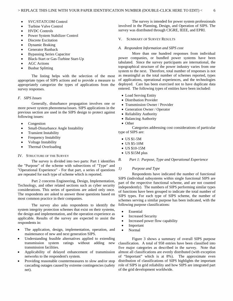
A conventional protection scheme is dedicated to a specific piece of equipment (line, transformer, generator, bus bar, etc.), whereas a SIPS is applied to the overall power system or a strategic part of it. To do so, the SIPS may require multiple detection and actuation devices and communication facilities. The scheme architecture can be described by the physical location of the sensing, decision making, and control devices that make up the scheme and the extent of impact the SIPS has on the electrical system.
SIPS
Local(Distribution
System)
Local(Transmission
System)Subsystem System Wide
Figure 2 - SIPS Model [10]
B. SIPS Architecture: The SIPS Model (Figure 2) explains the high level
layout and configuration of the scheme, the overall system complexity, and the potential system/scheme interactions.
The scheme architecture can be described by the physical location of the sensing, decision making, and control devices that make up the scheme and the extent of impact the SIPS has on the electrical system [17].
i. Local a. Distribution – For this type of SIPS, the architecture is
simple. The equipment often have very limited or dedicated functions. All sensing, decision-making and control devices are typically located within one distribution substation. Operation of this type of SIPS generally affects only a very limited portion of the
distribution system such as a radial feeder or small network.
b. Transmission – In this type of SIPS, all sensing,
decision-making and control devices are typically located within one transmission substation. Operation of this type of SIPS generally affects only a single small power company, or portion of a larger utility, with limited impact on neighboring interconnected systems. This category includes SIPS with impact on generating facilities.
ii. Subsystem - SIPS of this type are more complex and
involve sensing of multiple power system parameters and states. Information can be collected both locally and from remote locations. Decision-making and logic functions are performed at one location. Telecommunications facilities are generally needed both to collect information and to initiate remote corrective actions. The operation of SIPS of this type has a significant impact on an entire large utility or balancing authority area consisting of more than one utility, transmission system owner or generating facility.
iii. System wide - SIPS of this type are the most complex
and involve multiple levels of arming and decision making and communications. These types of schemes collect local and telemetry data from multiple locations and can initiate multi-level corrective actions consistent with real-time power system requirements. These schemes typically have multi-level logic for different types and layers of power system contingencies or outage scenarios. Operation of a SIPS of this type has a significant impact on an entire interconnected system or a major portion thereof, comprising multiple balancing authority areas, possibly including international impacts.
C. SIPS Design Considerations: Failure of the SIPS to operate when required, or its
undesired or unintentional operation will have adverse impact on the power system. Therefore, design of the SIPS may involve redundancy or some backup functions, and depending on the operational security requirements may involve some form of voting, or vetoing [12].
D. SIPS Classification Classification defines the scheme function in terms of
purposes and operating times.
i. Flat Architecture- In this classification, the measurement and operating elements of the SIPS are typically in the same location. The decision and corrective action may need a communication link to collect remote information and/or to initiate actions. Examples include:
a. In underfrequency load shedding scheme, the
frequency is determined at a distribution station and the pre-selected circuit breakers are tripped.
> REPLACE THIS LINE WITH YOUR PAPER IDENTIFICATION NUMBER (DOUBLE-CLICK HERE TO EDIT) <
5
b. In a system separation SIPS, central equipment (CE) collects remote information and conducts decision making, based on the phase difference calculation with the synchronized sampling inside the communication networks, and initiates system separation to protect against small signal instability [13].
ii. Hierarchical Architecture- Several steps are involved
in the corrective action of SIPS of this class. For example, local measurement, and / or a series of predetermined parameters at several locations are transmitted to multiple control locations. Depending on the intent of the scheme, immediate action can be taken and further analysis performed. The scheme purpose will drive the logic, design, and actions. Typical logic involves use of operating nomograms, state estimation and contingency analysis.
The primary difference between the two architectures is in the necessity of providing information between the stations or between the measurement and switching devices in order to add control coordination from the higher and wider system view. A hierarchical scheme may involve multi-layers and will involve communication outside of the substation where as a flat scheme involves a single layer of decisions and actions.
In some schemes, action is immediate and must satisfy the purpose instantly, hence scheme logic may entail higher margins for actions taken. Other schemes may have a more adaptive nature, which employ monitoring the system response to the control action. This implementation requires communication. If the immediate action is not adequate to halt the progression of the outage, then additional analysis and action is required. For instance, SIPS that monitor transmission line congestion may immediately trip selected transmission elements (loads or generators) and continue monitoring the system condition to determine if further action is required. If the line loading is not relieved, tripping additional generation or load, either local or distributed, may be required. Refer to the SIPS Application Examples section in the detailed report [1] for additional examples of in-service schemes.
Another classification for SIPS is the concept of centralized and distributed architectures.
iii. Centralized – All the information from remote stations and terminals are brought to one central location. Therefore, decision and corrective action of SIPS are implemented in the controller in one location. The function may be realized as a function of EMS, Logic Controllers installed in control center, or a Logic Controller installed in a substation. The decision and corrective action may need communication link to collect remote information and/or to initiate actions [1], [13].
iv. Distributed – Decision and corrective actions of SIPS
are implemented in controllers installed in different locations. The system integrity protection function can be realized by coordinated operation & control of distributed controllers that have functions of decision & corrective
action. The decision and corrective action may need a communication link to collect remote information and/or to initiate actions. Example - Underfrequency load shedding scheme
SIPS design could be also classified by the type of input variables and decision-making process as described in [11], [17], as • Event based • Parameter based • Response based • Combination of the above
E. SIPS Applications The types of SIPS applications may vary based on the
topography of the power grid. The characteristics of the power system influencing the types of mitigation methods have been described in a number of literatures [14-17] and [21]. In [11], types of wide-are disturbances likely to occur in a meshed network vs. an interconnected transmission system of narrow corridors with extensive generation are presented. There may also be different views on the acceptability of the type of the application. For example, use of SIPS for generation shedding to balance grid performance may be viewed as unacceptable for certain levels of contingency in one network but a common practice in another interconnected grid. Consider power systems with limited transmission corridors where building a redundant and diverse interconnection outlet for a generating facility may not be physically practical or economically feasible to address a variety of technically possible outlet outages. In such conditions, and provided the application of SIPS is for protection of the interconnected facility, the generation facility may accept a certain level of risk so long as it can be demonstrated that such SIPS does not result in an unacceptable level of security to other parts of the grid.
The following is a list of power system mitigation methods and the main factors influencing the type of SIPS applied, that will prevent a loss of power system integrity. Both the phenomena and the actions are listed. Names and / or the SIPS definitions may vary from one power system to the next or from one control area to the next. However, these schemes are intended to address power system constraints or when constraints could occur as result of increased transfer limits.
• Generator Rejection • Load Rejection • Underfrequency Load Shedding • Undervoltage Load Shedding • Adaptive Load Mitigation • Out-of-Step Tripping • Voltage Instability Advance Warning Scheme • Angular Stability Advance Warning Scheme • Overload Mitigation • Congestion Mitigation • System Separation • Load and Generation Balancing • Shunt Capacitor Switching • Tap-Changer Control
> REPLACE THIS LINE WITH YOUR PAPER IDENTIFICATION NUMBER (DOUBLE-CLICK HERE TO EDIT) <
6
• SVC/STATCOM Control • Turbine Valve Control • HVDC Controls • Power System Stabilizer Control • Discrete Excitation • Dynamic Braking • Generator Runback • Bypassing Series Capacitor • Black-Start or Gas-Turbine Start-Up • AGC Actions • Busbar Splitting
The listing helps with the selection of the most
appropriate types of SIPS actions and to provide a measure to appropriately categorize the types of applications from the survey responses.
F. SIPS Issues Generally, disturbance propagation involves one or
more power system phenomena/issues. SIPS applications in the previous section are used in the SIPS design to protect against following issues:
• Congestion • Small-Disturbance Angle Instability • Transient Instability • Frequency Instability • Voltage Instability • Thermal Overloading
IV. STRUCTURE OF THE SURVEY The survey is divided into two parts: Part 1 identifies
the "Purpose" of the scheme with subsections of "Type" and "Operational Experience" - For that part, a series of questions are repeated for each type of scheme which is reported.
Part 2 concerns Engineering, Design, Implementation, Technology, and other related sections such as cyber security considerations. This series of questions are asked only once. The respondents are asked to answer those questions based on most common practice in their companies.
The survey also asks respondents to identify the system integrity protection schemes that exist on their systems, the design and implementation, and the operation experience as applicable. Results of the survey are expected to assist the respondents in:
• The application, design, implementation, operation, and maintenance of new and next generation SIPS.
• Understanding feasible alternatives applied to extending transmission system ratings without adding new transmission facilities.
• Applicability of delayed enhancement of transmission networks to the respondent's system.
• Providing reasonable countermeasures to slow and/or stop cascading outages caused by extreme contingencies (safety net).
The survey is intended for power system professionals involved in the Planning, Design, and Operation of SIPS. The survey was distributed through CIGRE, IEEE, and EPRI.
V. SUMMARY OF SURVEY RESULTS
A. Respondent Information and SIPS cost More than one hundred responses from individual
power companies, or bundled power systems have been tabulated. Since the survey participants are international, the topographical structure of the power industry varies from one system to the next. Therefore, total number of responses is not as meaningful as the total number of schemes reported, types of applications, operational experiences, and the technologies deployed. Care has been exercised not to have duplicate data entered. The following types of entities have been included:
• Load Serving Entity • Distribution Provider • Transmission Owner / Provider • Generation Owner / Operator • Reliability Authority • Balancing Authority • Other
Categories addressing cost considerations of particular type of SIPS are:
• US $1-5M • US $5-10M • US $10-15M • US $15M plus
B. Part 1: Purpose, Type and Operational Experience
1) Purpose and Type Respondents have indicated the number of functional
SIPS (individual subsystems within single functional SIPS are part of the respective functional scheme, and are not counted independently). The numbers of SIPS performing similar types of functions have been grouped to indicate the total number of SIPS types. For each type of SIPS scheme, the number of schemes serving a similar purpose has been indicated, with the following purpose classifications:
• Essential • Increased Security • Increased power flow capability • Important • Normal
Figure 3 shows a summary of overall SIPS purpose
classification. A total of 958 entries have been classified into five major categories as described in the survey. Note that almost all classifications are evenly distributed (with exception of “Important” which is at 8%). The approximate even distribution of classifications of SIPS highlights the important role of SIPS in grid reliability and how SIPS are integrated part of the grid development worldwide.

> REPLACE THIS LINE WITH YOUR PAPER IDENTIFICATION NUMBER (DOUBLE-CLICK HERE TO EDIT) <
7
Figure 3 - SIPS Classification
It is clear from Figure 3 that the application of SIPS has become a component of a comprehensive total protection philosophy. The fact that 22% of the entries are applications to address “normal” system conditions demonstrates that SIPS are no longer applied solely for system security purposes. In fact, close examination of Figure 3 reveals SIPS applications can be viewed as two major categories:
a) Normal Conditions (49% with three components, 19% Increased Power Flow, 8% Important, plus 22% Normal) which in effect are system improvements considered part of normal conditions.
b) System Security (51% with two components, 22% Essential plus 29% for Increased Security) which at one time was the primary intent of SIPS.
Figure 4 shows the intent of the various types of SIPS. The information in Figure 4 correlates with the classifications in Figure 3, demonstrating that worldwide SIPS are integrated components of various aspects of grid operation. Close review of Figure 3 reveals that about 63% of the SIPS are applied for “System Security” (category 2 description associated with Figure 3) which is composed of voltage instability (25%), transient instability (21%), and frequency instability (17%). The remaining 37% of the schemes are for “Normal” operating conditions composed of thermal overload (16%), Small disturbance angular instability (11%), and congestion management (10%).
Figure 4 - SIPS Purpose
Table 1 shows the SIPS corrective actions in groups or categories. For example, Load Shedding category includes several types of measures involving rapid separation of load from the grid to maintain system integrity – Note that the “Load Shedding” category in Table 1 is a high speed automated system. The survey questioner explicitly highlighted that the manual load shedding is not part of the questions. The italic sequence numbers in Table 1 correspond to the survey section describing the corrective or protective action the respective scheme is designed to perform.
Table 1 – SIPS Categories by Type of Corrective Actions and the Percentage of Applications
Table 1 also shows the percentages for each type of corrective measure the tabulated based on the responses received. From the 298 entries, only (8% or 24 schemes) are underfrequency load shedding, highlighting the fact that the survey responses are mainly focused on the SIPS with hierarchical structure.
Figures 5a and 5b show the types of corrective actions based on the categories listed in Table 1 in percentage and total number of schemes respectively. The fact that a good number of schemes apply to generator-turbines (21%) mirrors the results of the 1996 IEEE/CIGRE survey (21.6%), [10].
Figure 5a – Percentage of SIPS Corrective Actions Based
on Categories Identified in Table 1
Load Shedding Generation Control - Slow Speed
ii. Load Rejection – (10%) i. Generator Rejection – (8%) iii. Under-Frequency Load Shedding – (8%)
xviii. Power System Stabilizer Control – (3%)
iv. Under-Voltage Load Shedding – (6%)
xix. Discrete Excitation – (1%)
v. Adaptive Load Mitigation – (2%)
xxi. Generator Runback – (3%)
ix. Overload Mitigation – (7%) xxiv. AGC Actions – (4%) System Stability Controls - Slow Speed vi. Out-of-Step Tripping – (7%) xiv. Tap-Changer Control –
(2%) vii. Voltage Instability Advance Warning – (2%)
xvi. Turbine Valve Control – (1%)
viii. Angular Stability Advance Warning – (1%)
xxiii. Black-Start or Gas-Turbine Start-Up – (1%)
xi. System Separation – (7%) xx. Dynamic Braking – (1%) Congestion Mitigation
x. Congestion Mitigation – (3%)
Controls - High Speed Reactive Voltage Compensation
xii. Load and Generation Balancing – (3%)
xxii. Bypassing Series Capacitor – (2%)
xxv. Busbar Splitting – (2%)
xiii. Shunt Capacitor Switching – (5%)
xv. SVC/STATCOM Control – (4%)
Others
xvii. HVDC Controls – (3%) xxivi. Other, please specify – (5%)

> REPLACE THIS LINE WITH YOUR PAPER IDENTIFICATION NUMBER (DOUBLE-CLICK HERE TO EDIT) <
8
Figure 5b – Number of SIPS Corrective Actions Based on
Categories Identified in Table 1
On the other hand, the percentage of system stability applications has increased from 11.8% (system separation 6.3% + out of step tripping 2.7% + dynamic braking 1.8%) in the 1996 report to 18% in this survey. Also, several new application categories have been added in recent years highlighting that protection philosophy has now been extended to include the total electric power system operating as a unified entity.
2) SIPS Performance SIPS applications by nature raise an issue concerning
dependability and security. A failure to operate when required does not alleviate the problem. Such in-action can result in an increase in system stress - very possibly leading to a total blackout. On the other hand, incorrect operation will remove system elements when system integrity does not require it possibly increasing the system stress.
Figure 6 is a plot of the functional performance of SIPS showing that 66% of the respondents have experienced a performance of 99% or better reflecting the dependability. For the purpose of this report, the performance indicators are not affected as a result of a few local schemes, such as underfrequency load shedding.
Figure 6 - SIPS Performance
Since SIPS in many cases are communication-dependant schemes, it is important to evaluate the performance of the communications equipment associated with these schemes.
Figure 7 shows performance of communication based SIPS with 65% of the respondents indicating performance of 99% or better. Note, some schemes are not communication based (25%) and none of the respondents have observed communication performance of the 80% or below.
Figure 7 – Telecommunication Performance of SIPS
Figure 8 shows number of successful operations for the five classifications of SIPS described earlier (Essential, Increase Security, Increased Power Flow Capability, Important, and Normal). Based on the responses, 39% of the schemes operate once a year and 47% of the schemes have never operated (zero was not indicated amongst the choices). The infrequent operational experience of these schemes highlights the importance of testing, verification of set points, and routine verification of coordination of the schemes with both conventional protection as well as other SIPS in the area.
Figure 8 – Number of Successful Operations
A good majority of the respondents noted that the criterion used in the design is a combination of purpose of the schemes and also based on the measures set forth within the reliability coordinators in the area where asset owner operates the systems. For example, hardware and telecommunication aspects of the design may need to conform to a regional reliability group.

> REPLACE THIS LINE WITH YOUR PAPER IDENTIFICATION NUMBER (DOUBLE-CLICK HERE TO EDIT) <
9
C. Part 2: Engineering, Design, and Implementation Part 2 of this survey describes the main
methodologies adopted in the scheme design in terms of preliminary studies, technology assessment, design standards, redundancy etc. Design issues were considered next. In general, the overall design can be broken down into the following components:
• System Study • Solution Development • Design and Implementation • Commissioning / Periodic Testing • Training & Documentation
In this section, the specific responses and comments are listed next to the selections in parenthesis.
1) System Study In order to design a wide-area monitoring and
prevention scheme, accurate system studies need to be completed to identify the ensemble of contingency scenarios and / or the type of a response based system, to define the parameters required for proper implementation. Some of the critical items include:
• Understanding the requirements and the intent of the application
• Types of studies to be performed – Planning and Operating studies, followed by on-going system studies including protection coordination studies
• Evaluating multiple solutions – Studying alternatives and
• performing contingency analysis • On-going dialog with all entities involved – Internal
and external (Regional). • Identifying monitoring signals with corresponding
locations and set points (e.g. overload conditions, undervoltage, underfrequency, synchronized phasor measurement).
• Arming conditions and levels – Determining whether the scheme arming should be power system condition based or outage/contingency based
• Contingency identification • Identifying islanding points if applicable • System restoration process; Cold Load Pickup
considerations. • Intelligent dispatch • Reliability and dependability levels – Redundancy,
Voting, Fail safe, etc. System studies identify limitations or restrictions.
The limitations may be thermal, voltage, or angular instability related limits wherein the latter items are of significantly more concern than thermal capacity limits. It should be noted, however, that relaxing non-thermal limits in a cost-effective fashion can be very challenging in a deregulated environment. Finally, all the above criteria need to be evaluated within the range of existing reliability council standards.
Survey Responses to System Study Related Questions:
o System studies performed prior to deploying the SIPS. To properly apply a SIPS, extensive studies are performed to provide a thorough understanding of the performance of the power system under various credible contingencies, and to determine the required corrective action to mitigate any severe consequences of those contingencies that could lead to system collapse or damage. These studies require modeling the system in sufficient detail to accurately simulate the actual responses to the contingencies.
Planning criteria - Survey respondents have described their planning criteria, which is a key element in identifying the level of performance required of their SIPS • seasonal performance variations (2) • single contingency (6) • double contingency (10) • single contingency followed by breaker failure
(5) • extreme contingencies (7) • other (9), Study includes impact of breaker failure
protection
Types of planning studies • steady state (12) • dynamic (4) • transient stability (11) • other (9), Study includes transient simulations for
faults
Real-time operational studies (12)
Protection and control coordination studies - Respondents reported on whether they have attempt to coordinate SIPS with conventional protection schemes: • Yes (23) • No (5) • Other (4), Comments explaining the levels of
studies and types: Simple SIPS - applications and
coordination impact is minimal. Coordination studies are performed only
for transformer overload mitigation. Perform coordination studies for certain
types of schemes, for example essential and important.
Coordination with other Protection and Control systems (29) responses have been received with following breakdown based on the respondents applications: • Coordinated with other SIPS (7) • Coordinated with local protection (11) • Coordinated between themselves (i.e., UVLS vs.
SIPS) (12)
Some respondents have indicated that their applications in some cases involve primary and back-up (as opposed to Primary 1, Primary 2, or Set “A” /

> REPLACE THIS LINE WITH YOUR PAPER IDENTIFICATION NUMBER (DOUBLE-CLICK HERE TO EDIT) <
10
Set B” type of applications). When designed as Primary / Backup, there is coordination between the two systems. Others have responded that coordination studies are done at the planning stages with all core teams involved. In other cases, a Regional Committee verifies coordination amongst different schemes to avoid cascading events.
o The survey asked what types of technologies were used in the SIPS
• Electromechanical (1) • Solid State (1) • Microprocessor (13) • Custom designed product (2) • Other (8) – The majority of schemes applied in
recent years, are numerically based systems. Some have indicated that they have many schemes that involve a combination of solid state, microprocessor, and tone communication – Other schemes have evolved over time and they include a combination of all of the above.
• PMU (2) – The PMU based schemes are simple applications of PMU systems such as Blackstart, or confirmation of two systems measurements in a redundant system applied to very large generation sources. Respondents have designed the systems to be available for more adaptive systems (response based) as more experiences are gained.
• Combination of above (13) • Time synchronization techniques (3) • Future trends or functions that should be
considered (1) • Rationale for combining different vintage
hardware System expanded (3) Obsolescence (blank – No responses) Combination of above two (15)
o Are there specific standards used in the design and application of?
• Yes, as it pertains to consistency in application philosophy (12) Use devices of different vendors as part of
the redundancy (2)
• No (14), with following reasons: Planning and operational aspects of different
schemes require different hardware (1) Different SIPS have been deployed over
many years and technology has changed (4) Application specific – each situation is
unique and no common concept or standard exists (2)
Other (5)
2) Hardware Description and Outage Detection The primary data used in a SIPS are line flows and
line outages. Newer schemes may consider the collection of
synchrophasor data, which involves not only the synchronized measurements themselves but also the time stamps associated with the measurements.
Line Outage detection can take several forms – depending on the level of security required in the scheme. In the simple case, monitoring of the breaker auxiliary contacts can be used. It should be noted, however, that this mechanism could be insecure from two different vantage points. First of all, the breaker auxiliary switch mechanism can fail – especially during routine breaker testing yielding incorrect outage information. Secondly, coupling of the breaker auxiliary contact wiring from other control signals in a cableway can result in transients that “appear” to look like a breaker open signal. These types of transients can be detected through the use of input-circuit debounce. The coupling transients, however, can contain enough energy to last for over 20ms thereby adding significant delay to the SIPS scheme.
A more secure mechanism for outage detection can be implemented by using a combination of information – specifically by implementing the logic that includes breaker is Open AND the current on the line is Zero. Most digital relays today can perform a Zero-current check in ½ of a cycle thereby resulting in faster and more secure outage detection. Local practice, such as the use of a Line Maintenance switch, also needs to be incorporated in the outage detection logic. Other implementations may involve a confirmation of under power condition from remote terminal for added security. Note that when under power is used, the “outage detection” logic design may also need to address loss of potential conditions.
When speed of detection is paramount, a third mechanism can be employed which is the monitoring of the breaker trip signals as wired from the protective relays. By tapping into the trip buses of the breakers, typically as much as 40ms can be saved in outage detection time. As tripping can sometimes occur on a single pole basis, the detection logic needs to be able to differentiate between a single pole trip and a 3 pole trip and to act according to the needs of the scheme. Note that, based on the scheme requirements, not only would the primary relay trips be monitored but also the Breaker Failure trip outputs.
In general, the function of outage detection should be implemented through the use of “protection class” hardware, that is, hardware that is designed for the substation environment. Typical environmental requirements include an extended temperature range (-20 to +55°C), the ability to tolerate 95% non-condensing humidity, the ability to withstand high common mode voltages across all terminals, and the ability to withstand fast and oscillatory electrical transients. In addition, the detection device must be able to quickly perform the logic required to confirm a line outage per the criteria stated above.
It is important that events throughout the SIPS be available and time-coordinated so that a post-mortem of an SIPS operation can be analyzed. Most IEDs today have the ability to time stamp events based on Universal Time Coordinated (UTC), or Coordinated Universal Time, through an IRIG-B input as typically provided by the Global
> REPLACE THIS LINE WITH YOUR PAPER IDENTIFICATION NUMBER (DOUBLE-CLICK HERE TO EDIT) <
11
Positioning System (GPS). Time stamping to the nearest millisecond is the minimum time accuracy requirement. Many IEDs, when they read the IRIG-B clock signal, will internally maintain time accuracy to the nearest microsecond – which is required for synchrophasor measurements.
Survey Responses to Hardware Description and Outage Detection:
o Outage detection method • Breaker auxiliary contacts (3) • Breaker status and undercurrent (4) • Voltage (1) • Both voltage and current (2) • Trip output from protective relays (5) • SCADA based architecture?
No (13) Yes (4)
• Open-ended line detection (1) • Manual opening (1) • Other (11), Respondents have provided more
detailed description, for example different schemes have deployed combination of breaker aux. contact and current / voltage supervision. Also, feature on “provisions for breaker maintenance” is built-in to the scheme.
o Does the scheme use programmable logic controllers (PLC)?
• No (15) • Yes (14)
Central controller (8) If redundant PLCs, are they in one
location: • Yes (14) • No (6)
How many redundant PLCs? • One – (8) • Two – (9) • More – (1)
Triple redundant modular (TMR) controller?
• Yes (2) • No (5)
3) Scheme Architecture Once the design and application planning aspects of
the SIPS have been defined, many questions arise regarding the implementation such as:
• Identification of the functional and technical requirements (evaluation of monitoring, isolation of transmission equipment, breaker failure application, redundancy, etc.)
• Selection of the technology to meet the functional requirements of the SIPS technically and economically, such as high speed secure communication between the SIPS devices and programmable solutions to protect the system against severe contingencies
• Identification of the areas that may need new technology developments
• System diagnostics. • Flexibility/Upgradeability to meet the future
expansions or requirements of designed SPS • Description of scheme operation and well prepared
Maintenance plans / Intelligent or Automatic Maintenance Testing
• Communication system design and failure detection systems. For example, routing of primary system communication failure on the alternate communication medium when dual schemes are applied.
• Simplicity of the implemented solution over the life cycle of the project and as new operators, maintenance specialists, and engineers take responsibility for expansion or operation.
• Cost effectiveness for implementation. • Provisions for alternate location for manual arming • Breaker failure operation and automatic restoration –
Should breaker failure be incorporated as part of the design and whether automatic restoration should be considered for parts of the scheme operation.
Given the defined contingencies, a method of conveying the actions for a given contingency is required. Another key consideration is the availability aspect of the overall system. As a SIPS is typically a system stabilizing scheme, failure to operate can result in the collapse of a section of the power system. To achieve high availability, most SIPS are implemented in a redundant manner, which is, redundant measurement equipment, redundant communications, redundant controllers, and redundant mitigation. Higher availability may also be achieved by a duplicate system. There are differences between a Redundant systems and a duplicate system.
Redundant – There are 2 systems (A and B) and there are no credible common mode failures between systems. No single point of failure that can impact both of redundant systems A and B.
Dual or Duplicate – There are credible common mode failures relative to redundant scheme – example, communication route may be same, or both systems pickup same auxiliary isolation devices, or common breaker trip coil (absence of breaker failure scheme).
Having redundancy results in the fact that multiple
data sources are fed to multiple controllers – all making decisions. Given that one of the data sources is corrupt, an incorrect decision can be made. To address this issue, functions such as input data conditioning/evaluation, voting, and vetoing can be used.
Input data conditioning involves the process of comparing data from the multiple data sources and checking the inputs for consistency. Consistency algorithms can be created based on expected values, values from other ends of the line, and value tracking. At a minimum, the system operator

> REPLACE THIS LINE WITH YOUR PAPER IDENTIFICATION NUMBER (DOUBLE-CLICK HERE TO EDIT) <
12
can be alarmed during a data consistency failure. At a maximum, the consistency algorithm has to decide if the SIPS will be allowed to operate.
When there are multiple controllers in the SIPS, it is possible that different decisions may have been made by different controllers. There are two strategies for dealing with the multiple-decision issue:
1. Voting – the mitigation device, upon receiving multiple commands, can choose to Vote on the received commands. Typically a 2 out of 3 scheme is used but other combinations are possible
2. Veto – in the case where there are only two controllers an incorrect decision can have disastrous consequences, the one controller can, if it disagrees with the decision, “veto” the decision of the first controller
Most SIPS today are event bases, that is, the system reacts in a pre-programmed manner upon the detection of pre-determined operation criteria. While this technique is effective, it is not adaptive to changing system conditions. As SIPS controllers evolve, they will be able to migrate to a more response-based approach, that is, the system will dynamically determine the best course of action based upon evolving system conditions.
Survey Responses to Hardware Description and Outage Detection:
o Objective: decision making Predetermined, based on off-line simulation (17) Response-based, using fast system assessment
techniques (4) Intelligent system with self-reconfiguration
capability (3) o Redundancy needs/implementation - Both
telecommunication and hardware Completely redundant (14) Partially redundant (8)
• Reasons for parts that aren’t redundant o Not possible (2) o Too costly – blank o No impact on reliability (1) o Other (1), No comment
provided Dual – completely duplicate (1) Dual – partially duplicate (2) Describe criteria for determining redundancy (No
comments provided in this section) o Criteria for consideration of redundancy
Interconnection between different system (owners) requirements (5)
Interconnection between different countries’ requirements – blank
Regulatory, or International Oversight Compliance
• NERC and/or Regional Council (10) • UCTE (1) • ESCJ (1) • Other (7)
o Does the scheme use voting? No (25) Yes (5)
• 2 out of 2 w/maintenance and fail-safe mode (1) – In this type of scheme, there are only two systems (not 3 systems) and during maintenance, one system would operate independent of the permissive from the second systems. Likewise, if one system does not detect or activate, the remaining system will operate independently after a set time.
• 2 out of 3 (1) • 3 out of 4 (blank) • Other (4), includes schemes that have out-
of-step protection complementing the RAS. o Is the scheme:
Response based event control (1) Condition based (13) Both (10) Other (4), combination of response based and
condition based o Does the scheme initiate breaker failure?
Yes (15) No (10) • If no, how is failed breaker handled? • Failed breaker condition not possible (1) • Scheme does not address breaker failure
(10) o Performance requirements:
Throughput timing: entire scheme • Below 50 ms (2) • Below 60 ms (0) • Below 70 ms (2) • Below 80 ms (1) • Below 90 ms (1) • Below 100 ms (3) • Below 110 ms (blank) • Between 110 – 150 ms (2) • Between 150 – 200 ms (7) • Greater than 200 ms (11) • Not time sensitive (blank)
Comments provided in this section reflect that ing timing is a direct function of scheme purpose and “type” as described in the survey. For Type I - below 50ms; Type II - below 100ms; Type IV - varies from 5 to 30 seconds
Throughput timing of the controller • Below 30 ms (11) • Below 50 ms (4) • Below 75 ms (blank) • Below 100 ms (4) • Greater than 100 ms (3)
4) Data acquisition, System Restoration and related tools As application of wide area monitoring often involves
extreme contingencies, such schemes are not expected to
> REPLACE THIS LINE WITH YOUR PAPER IDENTIFICATION NUMBER (DOUBLE-CLICK HERE TO EDIT) <
13
operate frequently. Therefore, significant importance should be placed on effective and fast power system restoration after major disturbances. Power system restoration needs to be executed with well-defined procedures that require overall coordination within the restoring area, as well as with the neighboring electrical networks. In general, the operated breakers should be blocked from automatic reclose. Intelligent restoration recommendations and mechanisms should be provided to the operating personnel as the generation, frequency and/or voltage recover.
Survey Responses to Data Acquisition, Restoration, and Measurement Methodology:
o Measured Quantities Voltage
• Polarity sensitive (17) • Not polarity sensitive (3)
Current • Polarity sensitive (14) • Not polarity sensitive (8)
Power output of generators • Percentage sensitivity (3) • Time delay to calculate (2) • Range (3) • Delta f / delta t (1) • Other (4), Conductor Temperature, wind
speed, outdoor temprature o Time synchronization requirements
Accuracy (9) Specified synchronization requirement (blank) Other (8)
o Use of SMART SIPS / Intelligent SIPS Does the SIPS automatically adjust
• Load (4) • Generation (3) • Both (8)
Does the SIPS include on-line power system assessment?
• Optimal power flow (2) • Transient stability assessment (3) • Voltage stability assessment (2) • Other (7), See next section on State
Estimator Are State Estimator values interlinked with the
scheme? • Yes (5) • No (14)
o Does activation of the scheme block automatic reclosing? Yes (11) No (11) Not applicable (5)
o Does the scheme activation block any operator initiated SCADA restoration?
Yes (5) No (22) Not Applicable (3)
o Restoration Issues and Planned Mechanisms Restoration part of the design of the scheme (3)
Restoration facilitated by scheme data (blank) Restoration facilitated by EMS data only (blank) Restoration handled by operating and dispatching
instructions only (9) Performed through EMS and instructions (2) Other (1), No comment is provided
VI. SYSTEM APPLICATIONS As part of responses received, a series of application
examples were provided by the respondents describing specific applications and levels of complexity associated with different schemes. Examples are described in the report [1].
VII. CONCLUSIONS In August 1996 issue of IEEE Transactions on Power
Systems, an article [10] was published as a result of a joint CIGRE/IEEE study titled “Industry Experience with Special Protection Schemes”. The article attracted a great deal of attention, as wide-area protection and system integrity protection systems were only beginning to make inroads into utility practices. The geographical coverage of the report spanned the globe, the number of reported special protection schemes was 111, and the range of issues reported was wide (e.g. functional breakdown, design considerations, cost and reliability, testing). The complexity of the system integrity protection schemes has greatly increased since the time of the first report, and IEEE PES Power System Relaying Committee undertook an effort in 2005 to collect and update the information from around the globe with collaborations from CIGRE and EPRI.
This new survey corroborates the findings in the earlier report and has identified many new areas where SIPS are applied. The survey provides valuable information to the industry practitioners and researchers alike about the trends and experiences in system integrity protection schemes. It answers many questions about current industry practices, regional differences in system protection philosophy and experience with such designs. The detailed survey result analysis report describes some of the critical design considerations and applications of latest technology for SIPS. The report highlights differences between a duplicate and redundant system. Several examples of more complex applications have been provided. The report also covers many of the industry practices and approaches to using new technologies for monitoring, communication and control in a never ending quest to further reduce the risk of large power system blackouts.
ACKNOWLEDGMENT This paper is based on the report created by IEEE Power System Relaying Committee working group C4 and is available at http://www.pes-psrc.org. The survey content and the supporting information such as definition of the various types of schemes are a collective effort of many industry members from IEEE PSRC, CIGRE, and EPRI. The authors acknowledge contributions by the Working Group members that have made this paper possible.

> REPLACE THIS LINE WITH YOUR PAPER IDENTIFICATION NUMBER (DOUBLE-CLICK HERE TO EDIT) <
14
IEEE: Vahid Madani (chair), Miroslav Begovic (vice-chair), Mark Adamiak, Ram Adapa, Frankie Au-Yeung, George Bartok, Gustavo Brunello, DAC-phuoc Bui, TW Cease, Guy Colaron, Jaime De La Ree, David Elizondo, Jean-Marie Gagnon; Charlie Henville, Yi Hu, Stan Horowitz, Shinichi Imai, Bogdan Kasztenny, Ken Martin, Victor Ortiz Muro, Damir Novosel, Arun Phadke, Jonathan Sykes, Eric Udren, Alfredo Vaccaro, Solveig Ward, Rich Young, Pei Zhang; CIGRE: Richard J Adams, Javier Amantegui, Santiago López Barba, John Fitch, Satyajit Ganguly; Fernando González Giorgio Giannuzzi, Stig Holst, Hideyuki Kameda; Daniel Karlsson, Dong Kim, Volker Leitloff, Jorge Miguel Ordacgi F.Andre dos Santos, Walter Sattinger, Tevik Sezi, Akira Takeuchi. The authors are also grateful to the survey respondents that have taken time to thoroughly participate and where appropriate offer insightful notes to help clarify their responses and to make sure the survey content is accurate. The detailed report could not be compiled without due diligence and participation of hundreds of individuals and companies that have participated in the survey.
REFERENCES [1] Global Industry Experiences with System Integrity
Protection Schemes (SIPS), IEEE Power System Relaying Committee, 2009 Report [on-line at www.pes-psrc.org] .
[2] Wide Area Protection and Emergency Control”, Working Group C-6, System Protection Subcommittee, IEEE Power System Relaying Committee, January 2003.
[3] FERC, U.S./Canada Power Outage Task Force, “Initial Blackout Timeline,” Press Release, September 12, 2003, www.ferc.gov.
[4] S.H. Horowitz and A.G. Phadke, ”Boosting Immunity to Blackouts,” Power & Energy Magazine, September/October 2003.,
[5] D. Novosel, M. Begovic, V. Madani, “Shedding Lights on Blackouts”, IEEE Power and Energy Magazine, January/February 2004
[6] I. Dobson, J. Chen, J. Thorp, B. Carreras, D. Newman, “Examining Criticality of Blackouts in Power System Models with Cascading Outages”, Proc. 35th International Conference on System Science, Hawaii, January 2002.
[7] M. Begovic, V. Madani, and D. Novosel, “System Integrity Protection Systems,” IREP Symposium for Bulk Power Systems Dynamics and Control VII, Charleston, Georgia, August 2007.
[8] V. Madani, and D. Novosel, “Getting a Grip on the Grid”, IEEE Spectrum, December 2005.
[9] WECC, Coordinated Off-Nominal Frequency Load Shedding and Restoration Plan, 1997 and 2004.
[10] P. Anderson and B.K. LeReverend, “Industry Experience with Special Protection Schemes”, IEEE/CIGRE Special Report, IEEE Transactions on Power Systems, Vol. 11, No. 3, Aug. 1996, pp. 1166-1179.
[11] V. Madani, and D. Novosel, M. Begovic, M. Adamiak, “Application Considerations in System Integrity Protection Schemes (SIPS)”, GE Magazine, May 2008
[12] V. Madani, E. Taylor, D. Erwin, A. Meklin, M. Adamiak, “High-Speed Control Scheme to Prevent Instability of A Large Multi-Unit Power Plant”, Western Protective Relay Conference, October 2006.
[13] Y. Ohura, et al, “A Predictive Out-Of-Step Protection System Based on Observation Of the Phase Difference Between Substations”, IEEE Transactions on Power Delivery, Vol.5, No.4, November 1990.
[14] T. Ohno, et al ‘Islanding Protection System Based on Synchronized Phasor Measurements and its Operational Experiences’, IEEE PES General Meeting 2008.
[15] S. Imai, “Undervoltage Load Shedding Improving Security as Reasonable Measure for Extreme Contingencies”, IEEE PES General Meeting 2005.
[16] D. Karlsson, et al., “System Protection schemes in Power Networks”, CIGRE WG38.02.19, June 2001.
[17] S. Horowitz, D. Novosel, V. Madani, and M. Adamiak, “System-Wide Protection,” IEEE Power and Energy Magazine, September/October 2008.
[18] IEEE Special Stability Controls Working Group, Annotated Bibliography on Power System Stability Controls: 1986-1994, IEEE Trans. on Power Systems, Vol. 11, No. 2, pp. 794-800, August 1996.
[19] WECC Voltage Stability Methodology – 1998 and 2004. [20] CIGRE 34.08, “Isolation and Restoration Policies against
System Collapse”, June 2001. [21] J.M. Gagnon, “Defense Plan against Extreme
Contingencies,” CIGRE WG C2.02.24, ELECTRA, pp 46-61, April 2007.
Vahid Madani is the chief architect and master developer of standards in protection & control, integration, and substation modernization at Pacific Gas and Electric Co. (PG&E). He has a MS Degree in Power Systems, is a Tau Beta Pi member, and a registered Electrical Engineer with more than 25 years of academic and utility experience, and is the recipient of many distinguished citations for innovations and leadership. For a decade, he served as Chair of the Western Electricity Coordinating Council (WECC) RAS Reliability Subcommittee and received the best Chair Person award for his leadership. Mr. Madani Chairs multiple committees at IEEE, is a member of CIGRE Study Committees B and C, and Chairs the Performance Standards Task Team within the North American Synchrophasor Initiative (NASPI). Mr. Madani is the author of more than 75 publications, and is the co-editor of multiple professional journals. Damir Novosel is President of Technology Division at Quanta. Dr. Novosel received his PhD Degree in Electrical Engineering from Mississippi State University in 1991. Damir has over 27 years of experience working with electric utilities and vendors. He holds 16 US and international patents and has published over 100 articles in Refereed Journals and Conference Proceedings mainly in the areas of power system automation, protection and design. Dr. Novosel is Vice President of the IEEE PES Technical Council and had also served as the Power System Subcommittee Chair of the IEEE PSRC. Stan Horowitz is a consultant, author and lecturer. He joined American Electric Power Service Corp. (then American Gas
> REPLACE THIS LINE WITH YOUR PAPER IDENTIFICATION NUMBER (DOUBLE-CLICK HERE TO EDIT) <
15
and Electric) in 1950 and retired in 1989, having served as head of the System Protection Section, Assistant Head of the Electrical Engineering Division and Consulting Electrical Engineer. Stan has co-authored the textbook Power System Relaying and edited the IEEE Press books Protective Relaying for Power System, Volumes 1 and 2. Mr. Horowitz is a Life Fellow of the IEEE, has served as chairman of the PSRC from1975-1978 and as the chairman of CIGRE Study Committee 34, Protection and Control from 1980-1986. Stan is the recipient of the 2009 IEEE PES Lifetime Achievement Award. Mr. Horowitz was elected to the National Academy of Engineering in 1995 and was editor-in-chief of the IEEE PES magazine, Computer Applications in Power from 1996-2002. Mark Adamiak is the Director of Advanced Technologies for GE Multilin and is responsible for identifying and developing new technology for GE’s protection and control business. Mark received his Bachelor of Science and Master of Engineering degrees from Cornell University in Electrical Engineering and an MS-EE degree from the Polytechnic Institute of New York. Mark started his career with American Electric Power (AEP) in the System Protection and Control section where his assignments included R&D in Digital Protection and Control, fault analysis, and Power Line Carrier. In 1990, Mark joined General Electric where his activities have ranged from advanced development, product planning, application engineering, and system integration. Mr. Adamiak is involved in the development of the IEC61850 communication protocol for power system communication - a NIST Smart Grid protocol. Mark is a Fellow of the IEEE, past Chairman of the IEEE Relay Communication Sub Committee, and the US Regular Member for the CIGRE Protection & Control study committee. Mark is a registered Professional Engineer in the State of Ohio and the recipient of the 2008 GE Edison Award. Javier Amantegui is Manager of the Protection and Technical Assistance Department in Distribution at Iberdrola, Spain. Dr. Amantegui has more than 30 years in protection and control and customer technical assistance at Iberdrola. In addition, he is leading several internal projects in the area of Quality of Supply, Reactive Power Program and Substation Standardization. His main areas of interest are Substation Standardization, Automation Systems using IEC 61850 with multivendor solutions, and studying the interaction and islanding detection of the recently installed 1,800 MW of photovoltaic power generation in DG related activities. Dr. Amantegui is Chairman of CIGRE SC B5 “Protection and Automation”. He has been collaborating with CIGRE since year 1987 in areas of Protection and Power Quality. Between years 1994 to 1998 he was member of CIGRE SC 36 “Electromagnetic Compatibility”. In 1999 he become member of SC B5 and in 2002 he became the convener of AG B53 on ”Monitoring, Recording ,Metering and Overall Power System Protection”. He has also collaborated with IEC and CENELEC and has published more that 30 papers.
Dr Amantegui graduated as an Electrical Engineer from the University of the Basque Country. In 2008, he received the PhD in Electrical Engineering for his thesis “System Integrity Protection Schemes based in Local Measurements”. Daniel Karlsson is a principal engineer at Gothia Power. He received his Ph. D in Electrical Engineering from Chalmers University in Sweden 1992. Between 1985 and April 1999 he worked as an analysis engineer at the Power System Analysis Group within the Operation Department of the Sydkraft utility. From 1994 until he left Sydkraft in 1999 he was appointed Power System Expert and promoted Chief Engineer. Most recently Dr. Karlsson holds a position as Application Senior Specialist at ABB Automation Technology Products. His work has been in the protection and power system analysis area and the research has been on voltage stability and collapse phenomena with emphasis on the influence of loads, on-load tap-changers and generator reactive power limitations. His work has comprised theoretical investigations at academic level, as well as extensive field measurements in power systems. Through the years he has been active in several Cigré and IEEE working groups. Dr. Karlsson is a member of Cigré and a senior member of IEEE. He serves as a reader at Chalmers University of Technology and he has supervised a number of diploma-workers and Ph. D students at Swedish universities. Shinichi Imai is Manager of world-wide benchmarking and project manager of Protection and Control of the future in power network division of Tokyo Electric Power Company (TEPCO) Japan. Mr. Imai joined TEPCO after he earned his Master degree from the Osaka University in 1989. His special fields of interest include power system protection, power system stability and Special Protection System. Mr. Imai has been actively involved in IEEE PSRC, PSDP and Cigre working groups. He is member of IEEE and IEEJ (The Institute of Electrical Engineers of Japan). Mr. Imai is registered professional engineer of state of California.. Alexander Apostolov received a MS degree in Electrical Engineering, MS in Applied Mathematics and Ph.D. from the Technical University in Sofia, Bulgaria. He has more than thirty years experience in the field of electric power systems protection, control and communications.. Dr. Apostolov is Principal Engineer at OMICRON electronics in Los Angeles, CA. He is an IEEE Fellow and Member of the Power Systems Relaying Committee and Substations C0 Subcommittee. He is the past Chairman of the Relay Communications Subcommittee, serves on several IEEE PES Working Groups and is Chairman of Working Group D21: Investigate Supporting of IEC Standard for Distance Relay Characteristics. He is member of IEC TC57 and TC95 working groups and Convener of CIGRE WG B5.27 and member of several other CIGRE B5 working groups. He is Chairman of the Technical Publications Subcommittee of the UCA International Users Group. He holds four patents and has authored and presented more than 300 technical papers. He is also Editor-in-Chief of the PAC World magazine.


![[] IEEE 1120-2004 - IEEE Guide for the Planning, D(Book Fi org)](https://static.fdokumen.com/doc/165x107/63150fb6511772fe45103298/-ieee-1120-2004-ieee-guide-for-the-planning-dbook-fi-org.jpg)