ICS Regent+Plus® - Literature Library | Rockwell Automation ...
19
ICS Regent+Plus ® PD - 7035 Industrial Control Services 1 Multiplexed I/O Modules (T7491) Issue 1, March, 06 Multiplexed I/O modules provide two RS-422 serial port interfaces between the Regent system and ICS’s remote multiplexed I/O Unit (MIU) equipment, providing an economical interface to digital inputs and outputs. MIU equipment is often used for matrix and mimic displays in safety and fire and gas systems or low cost, remote simplex input and outputs. Features • Occupies one slot in the I/O chassis. • Two isolated RS-422 serial ports for remote multiplexed I/O. • Supports up to 512 digital inputs and 256 digital outputs of remote MIU equipment. • Individual front panel indicators on each module show module active and fault status; and transmit, receive and fault status for each port. • Serial ports can be used in simplex or duplex modes (with 2oo2 testing in dual mode). • 1000 volt minimum electrical isolation between serial ports and between serial and logic circuits. • TÜV certified, Risk Class 5, non-interfering. Multiplexed I/O modules support multi-drop connection to remote MIU equipment up to 4000 feet (1220 meters) away at 19200 baud. The two serial ports of the Mux I/O module can be configured for simplex or duplex mode. In duplex mode, 2oo2 voting is performed on the I/O data.
-
Upload
khangminh22 -
Category
Documents
-
view
1 -
download
0
Transcript of ICS Regent+Plus® - Literature Library | Rockwell Automation ...

ICS Regent+Plus® PD-7035
Industrial Control Services 1
Multiplexed I/O Modules
(T7491)
Issue 1, March, 06
Multiplexed I/O modules provide two RS-422 serial port interfaces between the Regent system and ICS’s remote multiplexed I/O Unit (MIU) equipment, providing an economical interface to digital inputs and outputs. MIU equipment is often used for matrix and mimic displays in safety and fire and gas systems or low cost, remote simplex input and outputs.
Features
• Occupies one slot in the I/O chassis.
• Two isolated RS-422 serial ports for remote multiplexed I/O.
• Supports up to 512 digital inputs and 256 digital outputs of remote MIU equipment.
· Individual front panel indicators on each module show module active and fault status; and transmit, receive and fault status for each port.
• Serial ports can be used in simplex or duplex modes (with 2oo2 testing in dual mode).
· 1000 volt minimum electrical isolation between serial ports and between serial and logic circuits.
· TÜV certified, Risk Class 5, non-interfering.
Multiplexed I/O modules support multi-drop connection to remote MIU equipment up to 4000 feet (1220 meters) away at 19200 baud. The two serial ports of the Mux I/O module can be configured for simplex or duplex mode. In duplex mode, 2oo2 voting is performed on the I/O data.
Multiplexed I/O Module (T7491)
2 Industrial Control Services
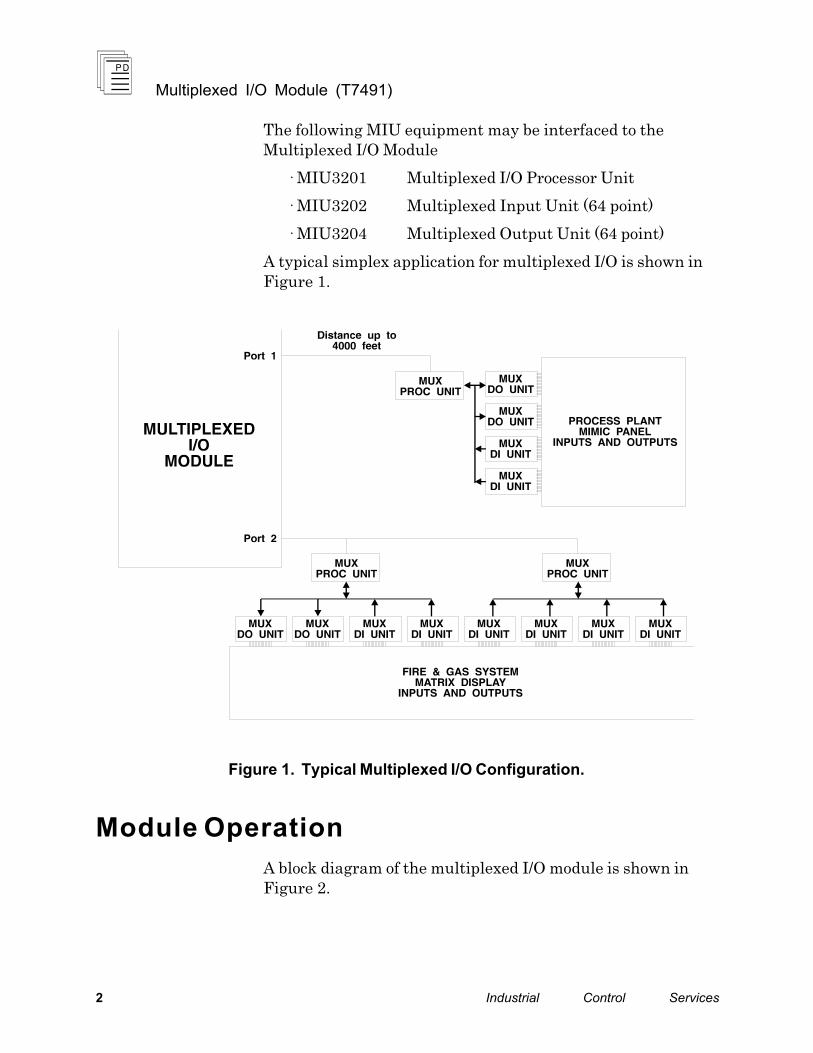
The following MIU equipment may be interfaced to the Multiplexed I/O Module
· MIU3201 Multiplexed I/O Processor Unit
· MIU3202 Multiplexed Input Unit (64 point)
· MIU3204 Multiplexed Output Unit (64 point)
A typical simplex application for multiplexed I/O is shown in Figure 1.
Figure 1. Typical Multiplexed I/O Configuration.
Module Operation
A block diagram of the multiplexed I/O module is shown in Figure 2.
Multiplexed I/O Module (T7491)
P D - 7 0 3 5 M a r - 0 6 3
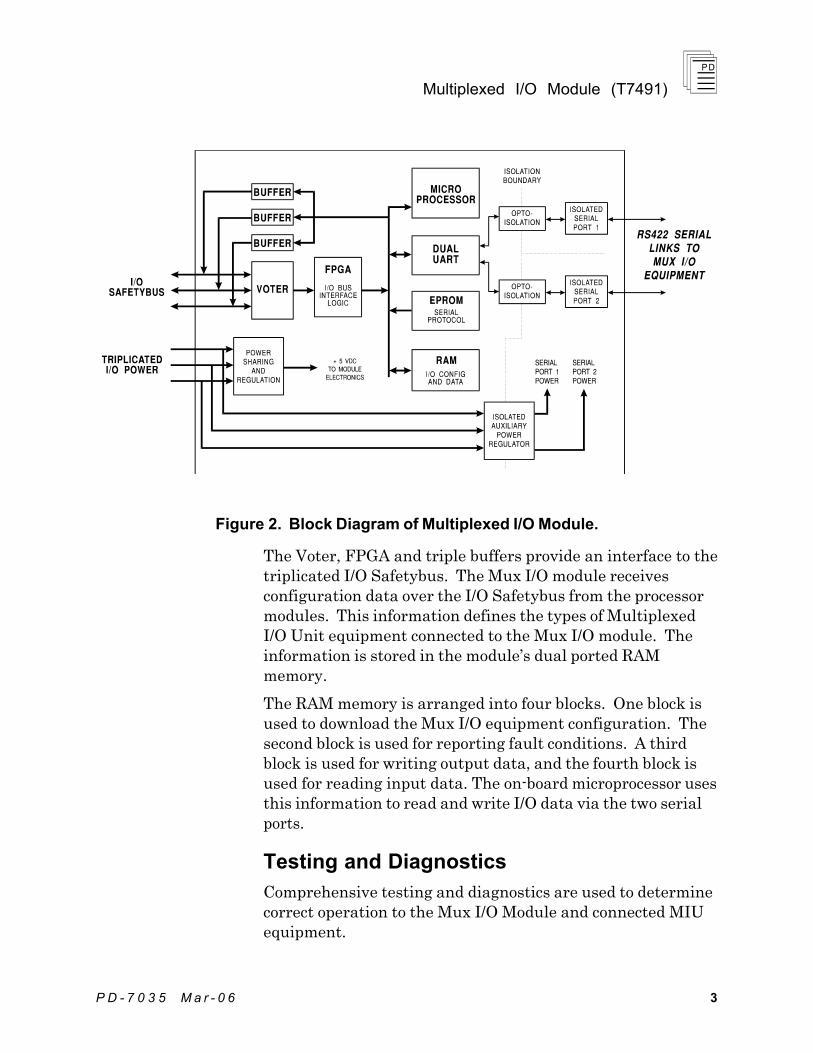
Figure 2. Block Diagram of Multiplexed I/O Module.
The Voter, FPGA and triple buffers provide an interface to the triplicated I/O Safetybus. The Mux I/O module receives configuration data over the I/O Safetybus from the processor modules. This information defines the types of Multiplexed I/O Unit equipment connected to the Mux I/O module. The information is stored in the module’s dual ported RAM memory.
The RAM memory is arranged into four blocks. One block is used to download the Mux I/O equipment configuration. The second block is used for reporting fault conditions. A third block is used for writing output data, and the fourth block is used for reading input data. The on-board microprocessor uses this information to read and write I/O data via the two serial ports.
Testing and Diagnostics
Comprehensive testing and diagnostics are used to determine correct operation to the Mux I/O Module and connected MIU equipment.

Multiplexed I/O Module (T7491)
4 Industrial Control Services
Standard Module Testing
Each module’s voter circuits are periodically tested by the processor modules. Discrepant data are sent through one of three legs of the I/O Safetybus to determine whether the module’s voter is able to outvote the incorrect data. A failure to return the correct majority-voted result to the processors produces an I/O module error indication at the processor modules and a module fault indication at the I/O module.
Each type of module has a unique identification code that is read by the controller. This code lets the controller know which type of module is installed in each I/O chassis slot and how to address that module and its points specifically. If a module is removed, or is replaced with a module of a different type, the processor modules will indicate I/O module errors.
Loopback logic tests periodically write data to the module and then read it back to determine whether the module’s I/O bus interface logic is functioning correctly.
Multiplexed I/O Module Testing
Additional tests are periodically performed to verify the correct operations of the microprocessor, ROM, RAM and serial interface to the remote MIU equipment. Detected failures are reported back to the processor modules as either fatal or non-fatal errors.
Fatal Errors
Fatal errors are reported when the diagnostics detect a failure in the module’s electronics. For example, failures in the microprocessor, RAM, or ROM are considered fatal errors. A fatal error will result in a module fault indication.
Non-Fatal Errors
Non-fatal errors are reported when failures occur in communications to the connected MIU equipment. These failures would represent problems with the serial communications cables, or the connected MIU processor. These types of failures are indicated on the face of the module as a Port fault.

Multiplexed I/O Module (T7491)
P D - 7 0 3 5 M a r - 0 6 5
Front Panel Indicators
Figure 3 shows the physical features of the Mux I/O module. The front panel of the module contains active, and fault status indicators for the module as well as transmit, receive, and communications fault status indicators for each port.

Multiplexed I/O Module (T7491)
6 Industrial Control Services
Figure 3. Multiplexed I/O Module.
Multiplexed I/O Module (T7491)
P D - 7 0 3 5 M a r - 0 6 7
Active and Fault Status Indicators
These green and red LEDs indicate the overall health of the MUX I/O module. During normal operation the green ACTIVE indicator flashes at the controller's scan rate. If a fatal module fault is detected the red FAULT indicator switches on and the green indicator switches off. Refer to page 4 for descriptions of fatal module faults.
Port Status Indicators
Both of the multiplexed I/O module’s ports have transmit, receive and communications fault status indicators.
The green TX and RX indicators turn on and off reflecting normal transmission and reception of communications data.
The communications fault indicator is normally off. When a non-fatal communications fault occurs, the red LED switches on. Refer to page 4 for descriptions of non-fatal faults.
Application
Simplex Configuration
Most often the Mux I/O module is used in simplex configuration. In this configuration, each of the two serial ports are used to individually connect to MIU equipment. The module uses the downloaded configuration information to read inputs and write outputs for each serial port.
Dual Configurations
To protect against communications failures related to the serial cables, the module can be configured for duplex operation. When configured this way, the Mux I/O module communicates to the connected equipment by reading from and writing to both communications ports. Each port is cabled to the same MIU processors.
The Mux I/O module reads inputs from each port and stores the information in separate areas in RAM. The RAM data is 2oo2 voted, so that when both data areas agree, the input data is updated for the Regent processor modules.

Multiplexed I/O Module (T7491)
8 Industrial Control Services
When output data changes state, the Mux I/O module writes the output data to both ports. At the MIU processor, the output data is 2oo2 voted, so that when the data agrees, the outputs are updated.
When input data disagrees, the Mux I/O module reads the input data three more times. If the disagreement persists, a failure is reported.
Serial Port Cable Connections
The serial communications cables are connected to the connector terminals located on the rear of the I/O chassis slot where the module is installed. Figure 4 illustrates the proper connections for the serial ports.

Multiplexed I/O Module (T7491)
P D - 7 0 3 5 M a r - 0 6 9
Figure 4. MUX I/O Module Serial Cable Connections.
Keying
The I/O chassis can be physically keyed to prevent accidental damage caused by inserting a module into a slot wired for a
Multiplexed I/O Module (T7491)
1 0 Industrial Control Services
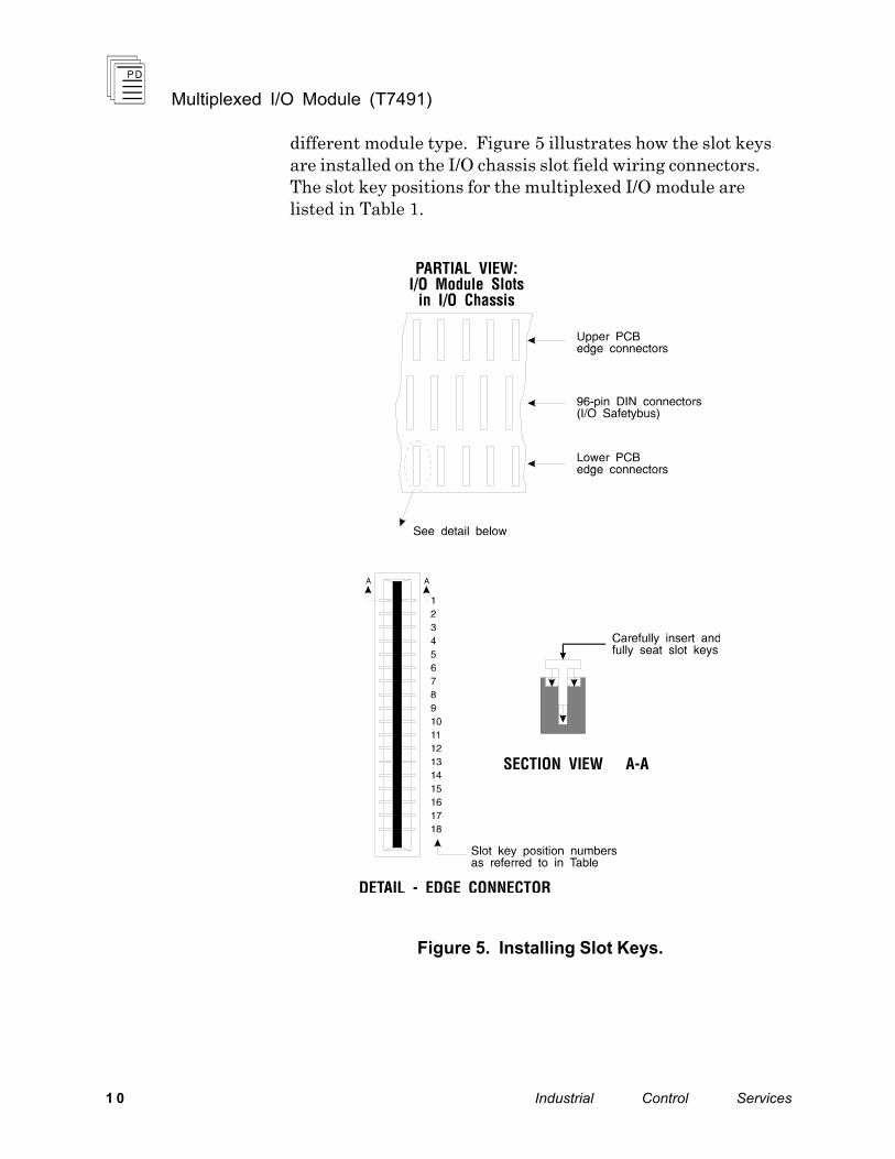
different module type. Figure 5 illustrates how the slot keys are installed on the I/O chassis slot field wiring connectors. The slot key positions for the multiplexed I/O module are listed in Table 1.
Figure 5. Installing Slot Keys.
Multiplexed I/O Module (T7491)
P D - 7 0 3 5 M a r - 0 6 11
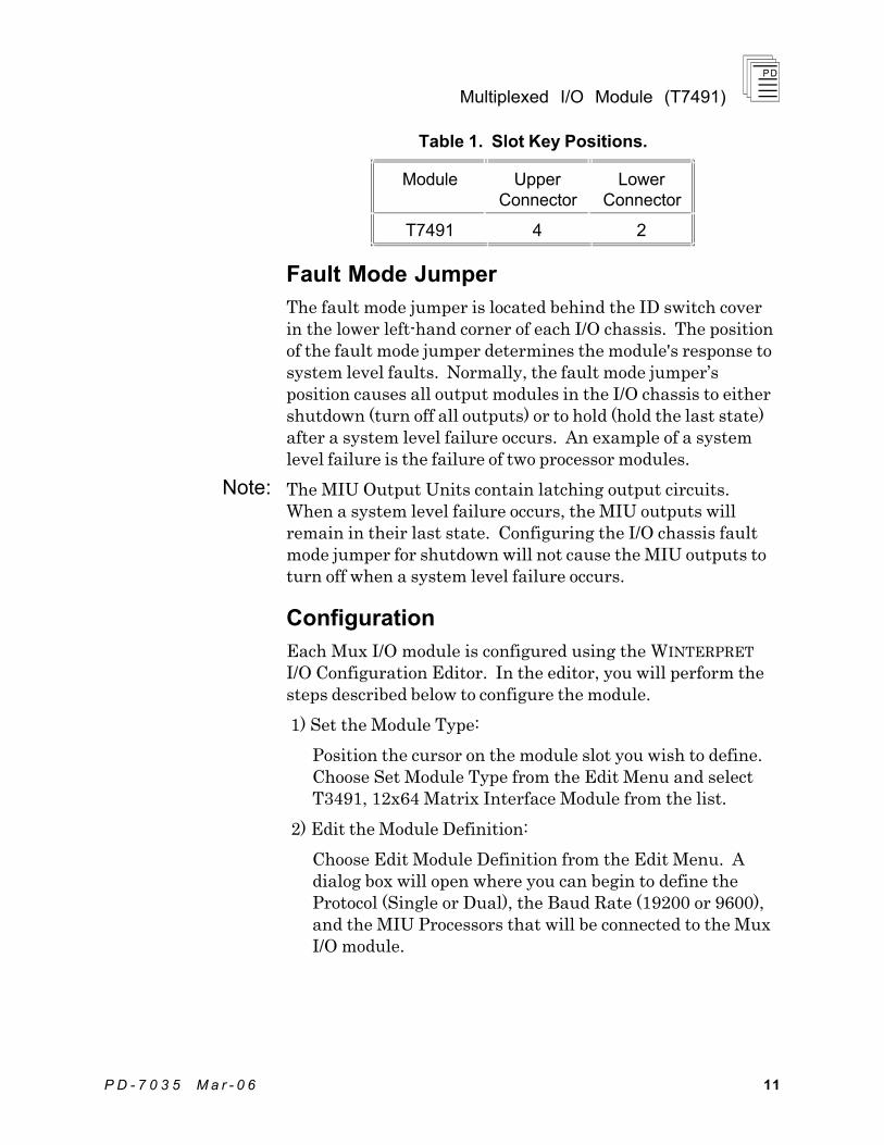
Table 1. Slot Key Positions.
Module Upper Connector
Lower Connector
T7491 4 2
Fault Mode Jumper
The fault mode jumper is located behind the ID switch cover in the lower left-hand corner of each I/O chassis. The position of the fault mode jumper determines the module's response to system level faults. Normally, the fault mode jumper’s position causes all output modules in the I/O chassis to either shutdown (turn off all outputs) or to hold (hold the last state) after a system level failure occurs. An example of a system level failure is the failure of two processor modules.
The MIU Output Units contain latching output circuits. When a system level failure occurs, the MIU outputs will remain in their last state. Configuring the I/O chassis fault mode jumper for shutdown will not cause the MIU outputs to turn off when a system level failure occurs.
Configuration
Each Mux I/O module is configured using the WINTERPRET I/O Configuration Editor. In the editor, you will perform the steps described below to configure the module.
1) Set the Module Type:
Position the cursor on the module slot you wish to define. Choose Set Module Type from the Edit Menu and select T3491, 12x64 Matrix Interface Module from the list.
2) Edit the Module Definition:
Choose Edit Module Definition from the Edit Menu. A dialog box will open where you can begin to define the Protocol (Single or Dual), the Baud Rate (19200 or 9600), and the MIU Processors that will be connected to the Mux I/O module.
Note:
Multiplexed I/O Module (T7491)
1 2 Industrial Control Services
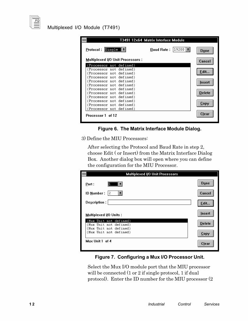
Figure 6. The Matrix Interface Module Dialog.
3) Define the MIU Processors:
After selecting the Protocol and Baud Rate in step 2, choose Edit ( or Insert) from the Matrix Interface Dialog Box. Another dialog box will open where you can define the configuration for the MIU Processor.
Figure 7. Configuring a Mux I/O Processor Unit.
Select the Mux I/O module port that the MIU processor will be connected (1 or 2 if single protocol, 1 if dual protocol). Enter the ID number for the MIU processor (2
Multiplexed I/O Module (T7491)
P D - 7 0 3 5 M a r - 0 6 13
through 15). You may also enter a description to annotate the MIU processor definition.
Each MIU processor has an ID number that must be unique from other processors connected to the same Mux I/O module. This number should match the ID number set by links on the MIU processor unit. Refer to the product description for the MIU Processor for details on link settings.
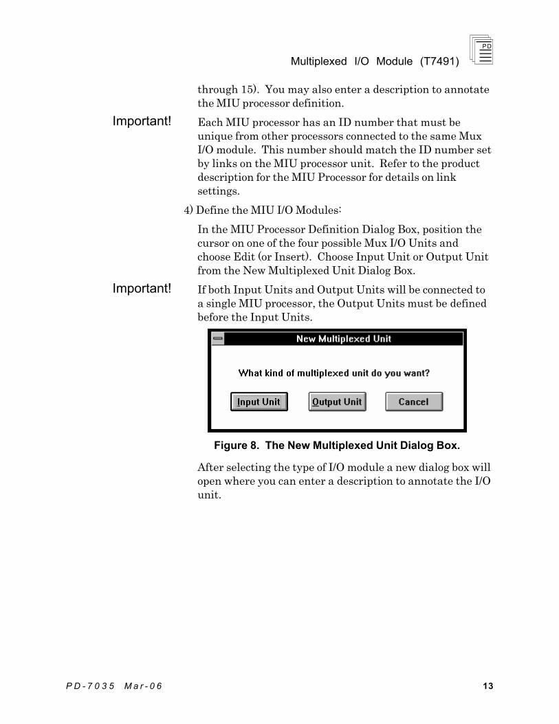
4) Define the MIU I/O Modules:
In the MIU Processor Definition Dialog Box, position the cursor on one of the four possible Mux I/O Units and choose Edit (or Insert). Choose Input Unit or Output Unit from the New Multiplexed Unit Dialog Box.
If both Input Units and Output Units will be connected to a single MIU processor, the Output Units must be defined before the Input Units.
Figure 8. The New Multiplexed Unit Dialog Box.
After selecting the type of I/O module a new dialog box will open where you can enter a description to annotate the I/O unit.
Important!
Important!
Multiplexed I/O Module (T7491)
1 4 Industrial Control Services
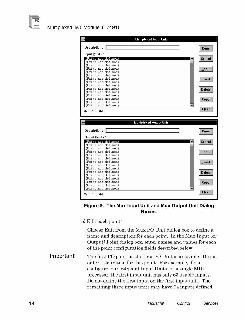
Figure 9. The Mux Input Unit and Mux Output Unit Dialog Boxes.
5) Edit each point:
Choose Edit from the Mux I/O Unit dialog box to define a name and description for each point. In the Mux Input (or Output) Point dialog box, enter names and values for each of the point configuration fields described below.
The first I/O point on the first I/O Unit is unusable. Do not enter a definition for this point. For example, if you configure four, 64-point Input Units for a single MIU processor, the first input unit has only 63 usable inputs. Do not define the first input on the first input unit. The remaining three input units may have 64 inputs defined.
Important!
Multiplexed I/O Module (T7491)
P D - 7 0 3 5 M a r - 0 6 15
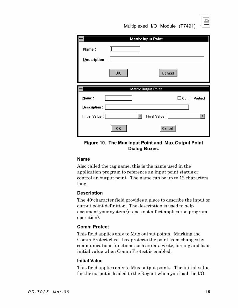
Figure 10. The Mux Input Point and Mux Output Point Dialog Boxes.
Name
Also called the tag name, this is the name used in the application program to reference an input point status or control an output point. The name can be up to 12 characters long.
Description
The 40-character field provides a place to describe the input or output point definition. The description is used to help document your system (it does not affect application program operation).
Comm Protect
This field applies only to Mux output points. Marking the Comm Protect check box protects the point from changes by communications functions such as data write, forcing and load initial value when Comm Protect is enabled.
Initial Value
This field applies only to Mux output points. The initial value for the output is loaded to the Regent when you load the I/O
Multiplexed I/O Module (T7491)
1 6 Industrial Control Services
configuration and also when you load the application program that controls the output.
Final Value
This field applies only to Mux output points. The final value for the output is loaded to the Regent when the application program that controls the output is deleted. Unless special circumstances exist, you should always choose Off, so that the output is turned off when you delete the application program that controls the output. If you do not enter a final value, the output will remain in its last state when you delete the application that controls it.
Programming
Mux input points are used in application programs just like any other simplex input. Contacts in ladder logic can be used to examine the on or off status of the inputs.
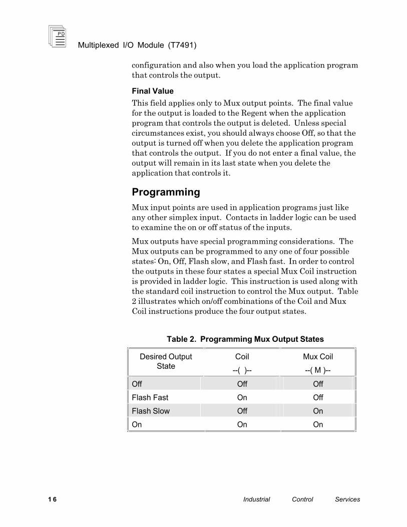
Mux outputs have special programming considerations. The Mux outputs can be programmed to any one of four possible states: On, Off, Flash slow, and Flash fast. In order to control the outputs in these four states a special Mux Coil instruction is provided in ladder logic. This instruction is used along with the standard coil instruction to control the Mux output. Table 2 illustrates which on/off combinations of the Coil and Mux Coil instructions produce the four output states.
Table 2. Programming Mux Output States
Desired Output State
Coil
--( )--
Mux Coil
--( M )--
Off Off Off
Flash Fast On Off
Flash Slow Off On
On On On
Multiplexed I/O Module (T7491)
P D - 7 0 3 5 M a r - 0 6 17
Maintenance
No periodic maintenance or calibration is required for the multiplexed I/O module. There are no user replaceable parts inside the module.
Troubleshooting
Most problems with the Mux I/O equipment relates to improper configuration. For correct operation you should carefully check the protocol configuration (single vs. dual) and the MIU processor addresses. Verify the configuration information with the link settings for the MIU processors.
Also you should carefully check the serial cable connections. The Mux I/O module labels the serial cable connections with ‘A’ and ‘B’ designations although the MIU processors refer to the connections as ‘+’ and ‘-’. The serial cable connection diagram in Figure 4 properly illustrates the relationship between these signal references.
Safety Considerations
The Multiplexed I/O module is TÜV certified as non-interfering and may be used for non-safety critical inputs and outputs.
While the use of dual protocol configurations for 2oo2 voting provides greater security for the communications link, it is not sufficient to meet the requirements for Risk Class 5 safety critical inputs and outputs. In applications of Mux I/O equipment for maintenance override of safety critical inputs, redundant Mux I/O Modules and MIU equipment is recommended.
For additional safety considerations, please refer to the Safety Considerations section of the Regent User’s Guide.
Multiplexed I/O Module (T7491)
1 8 Industrial Control Services
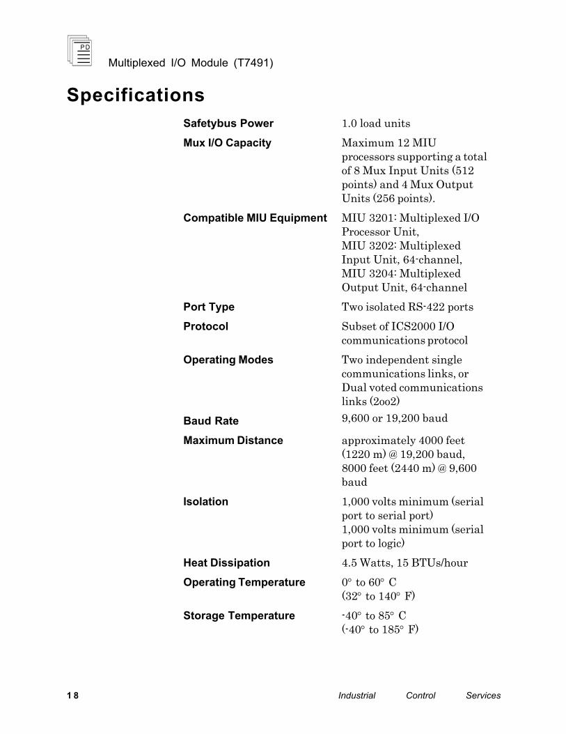
Specifications
Safetybus Power 1.0 load units
Mux I/O Capacity Maximum 12 MIU processors supporting a total of 8 Mux Input Units (512 points) and 4 Mux Output Units (256 points).
Compatible MIU Equipment MIU 3201: Multiplexed I/O Processor Unit, MIU 3202: Multiplexed Input Unit, 64-channel, MIU 3204: Multiplexed Output Unit, 64-channel
Port Type Two isolated RS-422 ports
Protocol Subset of ICS2000 I/O communications protocol
Operating Modes Two independent single communications links, or Dual voted communications links (2oo2)
Baud Rate 9,600 or 19,200 baud
Maximum Distance approximately 4000 feet (1220 m) @ 19,200 baud, 8000 feet (2440 m) @ 9,600 baud
Isolation 1,000 volts minimum (serial port to serial port) 1,000 volts minimum (serial port to logic)
Heat Dissipation 4.5 Watts, 15 BTUs/hour
Operating Temperature 0° to 60° C (32° to 140° F)
Storage Temperature -40° to 85° C (-40° to 185° F)

Multiplexed I/O Module (T7491)
P D - 7 0 3 5 M a r - 0 6 19
Operating Humidity 0 to 95% relative humidity, non-condensing
Vibration
10 to 55 Hz:
±0.15mm
Shock
Operating:
15 g, ½ sine wave, 11 msec
Electromagnetic Interference
• IEC 801 Part 2 - Electrostatic Discharges
• IEC 801 Part 3 - Radiated Electromagnetic Fields
• IEC 801 Part 4 - Transients and Bursts
• ANSI/IEEE C37.90 - Surge Withstand Capability
Level 3: Contact discharge of 6 kV
Level 3: 10 V/M, 27 MHz - 500 MHz
Level 4: 2 kV, 2.5 kHz for t = 60 seconds
2.5 kV damped 1 MHz sine wave
4 kV bi-directional impulse, 10 nsec rise time, fast transient
Safety Certified to DIN V VDE 0801 for Risk Class 5, non-interfering. Also designed to meet UL 508 and CSA 22.2, No. 142-M1981
Dimensions Height: Width: Depth:
12.6" (320 mm) 1.27" (32 mm) 10.12" (257 mm)
Weight 3.0 lbs (1.4 kg)