~ICROPR~ctSS.O~CONTROLLED PR06RAn~ABlE BY
109
~ICROPR~ctSS.O~ CONTROLLED PR06RAn~ABlE AunIO SYSTE" BY A '1'tl~siS SuBMITTED TP T~~ DEPARTMEN'1'P~~LECTRiCAL ANb ELECTRONIC ENGtNt~RINO IN PARTIAL FULFiLMENT O~ TUE REQutR~M~NTS ~OR TUE DEGREE O~ MASTER. OF SCIENCE IN ENGIN6ERING (EL~CTRICAL & ELECTRONIC) DEPARTMENT OF ~LBOTRICAL AND ELECtRONIC ENGIN!BRtNG BANGLADESH UNIVERsIty OF ENGINEERING AND TECHNOLOGY nHAKA. BANGLADESH. 1111111111111111111111111111111111 #62085# i
-
Upload
khangminh22 -
Category
Documents
-
view
2 -
download
0
Transcript of ~ICROPR~ctSS.O~CONTROLLED PR06RAn~ABlE BY

~ICROPR~ctSS.O~CONTROLLED PR06RAn~ABlEAunIO SYSTE"
BY
A '1'tl~siS
SuBMITTED TP T~~ DEPARTMEN'1'P~~LECTRiCAL ANbELECTRONIC ENGtNt~RINO IN PARTIAL FULFiLMENT O~
TUE REQutR~M~NTS ~OR TUE DEGREE O~ MASTER.OF SCIENCE IN ENGIN6ERING (EL~CTRICAL & ELECTRONIC)
DEPARTMENT OF ~LBOTRICAL AND ELECtRONIC ENGIN!BRtNGBANGLADESH UNIVERsIty OF ENGINEERING AND TECHNOLOGY
nHAKA. BANGLADESH.1111111111111111111111111111111111
#62085# i

Trw, .u. to c.eJLU..6y that: th.u. WM//. nM beeVl dOYle by me and UItM Ylot beeYl ./>ubmUti1-ii ~ewheJt.e 60JL the awevul 06 aVly dll.gll.i1-it
01(. dhnp.eoma. Oll. 60ll. pupUp.ttUon.
•
CoulUeJt,6-i!]ited by tff(2. Sflr-irJt.v,u,M.
r.. ,,~~\}v~)
...;...~y~ ~! .; f • ~ ' ;. i ;. •• ~'ilOR, SYEV MAHBUBUR RAHMANI
,; ; • ,: •• i • ,; ••••• ;. ~ .; •••••••••
(A~OULLAH FARuQUE I

Accepted as satisfactory for partial fulfilment of the requirementsfor the degree of M. Sc. Engineering in Electrical and ElectronicEngineering.
EXAMINERS
1.
2.
3.
4.
DHAKAAUGUST. 1984
•••••••••••••••••••••••• 0.(Dr. Syed.Mahbubur Rahman)
Supervisor
...{i4..t!. .(Il'il/.n,(Dr. .Shamsuddin -Ahmed)
Member
...~r~tf:~~"'.~V.l:C.(Dr. A.K.M. Mahfuzur Rahman Khan)
Member
(Dr. A. R. Khan)External Examiner
"The author expresses his indebtedness and deep sense of Jratitude
to Dr. Syed Mahbubur Rahma~, Assistant Professor of Electrical andElectronic Engineering Department, Bangladesh University of Engineeringand Technology, Dhaka; for his continuous guidance, valuable suggestions.constant encouragement and help alZ along the course of this worK.
The author wishes to express his sincere gratitude and greatindebtedness to Prof. A. M. Patwari, Vice-Chancellor, BangladeshUniversity of Engineering and Technology, for his constant advice andencouragement during this worK.
The author expresses his greatfulness and thanks to Prof.Shamsuddin Ahmed, Head of the Department of Electrical and ElectronicEngineering, who was kind enough to provide all the facilities of theDepartment for this work.
The author wishes to give wholehearted thanks to MI'.MUkhtarAhmed, Assistant architect, Engineering and Planning ConsuZtants Limited,Dhaka,'Bangladesh for his helpful assistance in printing this thesis.
The author wishes to thank the staff of Electronics Laboratory ofthe Department of Electrical and Electronic Engineering, for theirco-operation and help during this lJork.
'IlS.
.\

ABSTRACT
Recently microprocessor s are used in a wide range
of applications, such as Process Control Systems, Conmunica-
tion SYstems, Digital Instruments and Consumer Products. This
work deals with the application of microprocessors in audio
system~'A microprocessors controlled programmable audio system•has been develibjld,which is able to generate and compas<e the
tones of different musica~ instruments. This thesis describes
the comp~te hard-ware and soft-ware design of a microprocessor
controlled musical instrument. A conventional musical key-boardI
has been interfaced with a microprocessor for real time ibpera-Itions. A soft-ware program has been developed to store or record I
Ia song in the memory (RAM) of the system for auto-play operation.:
This work is intended for musioian's and composers of contempo-
rary mUsic who are inter~sted in the application of mieroprocesso~
technology to the arts.
-.
. -~.<-",': ..,
''-1

CHAPTER I
CHAPTER II
2.12.2
CHAPTER III
3.13.2
CHAPTER IV
CHAPTER V.
CONTENTS
INTRODUCTION
CH.ARACTERISTlCS OF MUSICAL. TONES
Parameters of l1)usical tones
Scales of musical instruments
INTRODUCTION' TO MICROPROCESSOR
Description of 8085 microprocessor
Description of 8155 RAM-.and. IlO~ports.
KEY-BOARD INTERFACING ANDHARD-WARE DESIGN
SOFT-WARE PROGRAM DEVELOPMENT
Page
1-1
2-1
2'-2
3'.1
3,.4
4 .. 1
Soft-ware program development formusical tone generation
5.1. lREFR sub;-program
5.1.2 ACTKC.. sub-program
5.1.3 INACT .s.ubzprogram
5.1.4 KEYP sub-program
5.1.5 FRKC sub-program
5.1.6 STOP sub-pl:ogra1"
5.1.7 SEND sub-program
Soft-ware program developme'nt for Recording.
5.2.1 STRK sub-program
5.2.2 APLAY sub-program
Soft-ware program ,development for display.monitoring and controlling,
5.1
5.2
5.3
5.3.1
5.3.2
KBGRAPH
sub-program
sub-program
5., 1
5.'5
5-,8
5-11
5-11
5-145-145-17
5-215-215-22
5-245-245-26

CHAPTER VI
6.1
6.2
CHAPTER VII
i.l7.27.37.4
CHAPTER VIII
ANALOG PROCESSING CIRCUIT
Generation. of actual wave shapes ofdifferent instruments
Audio amplifier and tone control circuit
OPERA TING -INSTRUCTIONS
Manual play
Recording
Auto-play
Specification of the developed microprocessorcontrolled musical instrument
CONCLUSIONS
6--1
6-2
7-17-27-2
7-3
8-+
RE[o'ERENCES
APPEN J)IX A
Complete soft-ware program
APPENDIX
I.
II.
III .
B
8085 instruction set summary byfunctional _grouping
Functional- description of 8155 chip
Functional description of STK~437 chip
•
I-
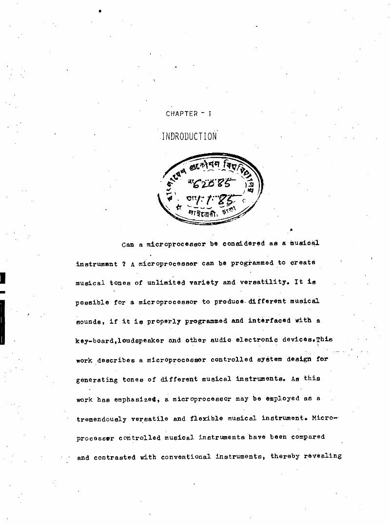
CHAPTER - I
I NDRODUCTI ON
•Can a microprocessor be considered as a music~
instrumant ? A microprocessor can be programmed to create
musical tones of unlimited variety and versatility. It is
possible for a microprocessor to produce. different musicBl
sounds, if it is properly programmed and interfaced with a
key-board,loudspeaker and other audio electronic devices.This
work describes a microprocesscr controlled system design for
generating tones of different musical instruments. As this
work has emphasizea, a microprocessor may be employed as a
tremendously versatile and flexible musical instrument. Micro-
processor controlled musical instruments have been compared
and contrasted with conventional instruments, thereby revealing

•-
1-2
some of their special aspects and distinctions. The intro-
duction of microprocessor musio has opened evenues of erea-
tive possibilities that music composers have never befOre
seen. A microprocess controlled musical instrument oan oom-
pose or synthesize any possible combination ef,musical tones.
their pitches may be set to any arbitrary value with tramen-
dous precision.
This work describes the complete software and hard-
ware design of a practical microprocessor controlled musical
inatrument. we have also developed such a system in our labora-
tory using Intel 8085 microprocessor. Our system has been inter-
faced with a conventional musical key-board fOr real time op~ra-
ti.onlike an Organ. Our system is able to generate t!>nes of
organ, viOlin, nute I fantasy and horn. It is also able to can-
pose any combination of these five musical .instruments. The key-
board can be selected to any desired octav of the above mentio-
ned five instruments. Our musical instrument is able to stor'e a
song played on any above mentioned five instruments in its RAM.
The stored song can also be replayed on any of the five instru-
ments. This recording and play back system is a unique feature
••

1-,3
of our microprocessor controlled musical instrument compared
to a conventional musical instrument. which needs .a cassette
recorded to store a song. By changing software one can easily
add or change any desired feature in our develope d system which
is another distinct advantage over any conventional musical
instrumen ts.
A block diagram of our microprocessor controlled
musical system is shown in figur'e 1.1. Here a conventional musi-
cal key board has been interfaced for real time operation i.e.
play on key-board and listen to speaker without any time delay.
The key-board is. the input to the microprocessOr. ROM has been
used to store the' software progrlllllmedeveloped tor our system.
RAM has been used to record a song. ~ song is recorded in the
RAM in coded form. The key-board. software programme inside the
ROM and the programmable 14-Bit binary counter (8155) work toga-
ther to generate a desired tone. which is the processed by an
analog processing circuit to .give the actual wa.ve shape of a
particular musical instrument. The audio amplifisr has been
used to amplify the output of the analog processing circuit to
drive the speaker. The detailed descriptions of the hardwkre and
software of the above mentioned musical system are given in the
following chapters.

~
~~ ~ ~
~~~<:>41~S~'<I>J~<Y"
K<:;~~"'<;)~~
~
~~'I: \--v\j
~\!)-~ ~.
(;jS ...,'S~
':'<: '-l <:J
~ ~.~ Cl ~~~'->
'l:~~IJ)
~~~~
h. \!.!.
"l~~ ~~ ~
W~'"'i~~<:>K ..,.0() " ~
:a.- -- ~~
~ ~i2'<:
~ (f;~~~
"l:((
~
,,<'(jCl--.j
ftltgCJ~~
••.•.......:
~l(
~ ~~....~ 't~ Cl~ \")

CHAPTER - I I
CHARACTERISTICS OF MUSICAL TONES
2.1 PARAMETERS OF MUSICAL TONES
The basic parameters of musical tones are frequenct
(pitch), intensity (loudness), overtones or harmonics content,
vibrato and tremolo.
Frequency and pitch are distinguished in that the
former is a physical concept, whereas the later is 8 subjective
experience. The unit of frequency is hertz, whereas the unit Of
pitch is mel. A 1 KHZ sin wave tone, 40 dB above a listener's
threshold of hearing, produces a pitch of 1000 mels. The pitch
of any sound that is judged by the listeners to be n times that
of a 1 mel tone is denoted as n mels.

2-2
Inensity and loudne"s are distinguished in that the'
former is a physical concept, whereas the later is a sub-
jective experience intensity denotes ths strength or ampli-
tude of a sound wave, loudness is a measure of the sensiti-
vity of human hearing to the strength of a sound wave" The
strength of a sound ••ave is measured in microbar uni'ts.Loud-
ness is measured in sone Or phon units.
Vibrato denotes the frequency modulation of a tcne at a•rate of approximately 7 Hz. Tremolo denotes the amplitude modu-
lation of a tone at a rate of approximately 7 Hz.
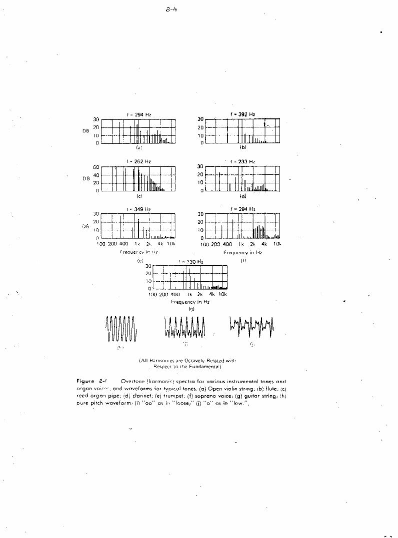
A musical tone has overtones or harmonics. Overtone
(harmonics) spectra for various instrumental tones and Organ
voices are shown in figure 2.1.
2.2 SCALES OF MUSICAL INSTRUMENTS
Key board music is generally restricted to the 12-note
tempered scale. The tempered scale divides the octave into 12
intervals ••hose pitch ratios are exactly equal. Since the octave

interval ratio is 2:1, the pitch interval ratio is twelfth
root.of 2. Figure 2.2 shows the pitch ratios of the equally
tempered scale. Table 2.3 lists the frequencies of the tem-
pered scale. which is used in the great majority Of organs.
Different musical instruments have different range of fre-
quencies in audio frequency' spectrum. Figure 2.4 shows the
range of frequencies for various musical instruments.
Interval pitch ratio
Prime 1
semitone 21/12c 1.059463
Whole step 22/12 ;, 1.1221162
Minor third 23/12 c 1.189207
Major third 24/12 = ,1.259921perfect fo'urth ;/12 = 1.334840Tritone 26/12 •• 1.44214
perfect fifth 27/12c 1.498307
MinOr sixth 28/12= 1.597401
Major sixth 29/12 = 1.681793
Minor seventh 110/12 = 1.781797
Major seventh 211/12 = 1.887749
Octave 2
Fig.2.2 pitch ratio in tempered scale.
/
2-4
Ibl
f-392Hz
- e-- -~"
-II.
302010o
f""233Hl3°~H20 ~~~
10 -- , ~' , ,-0_, .
Idl
f = 294 HI30
DR20
10(1
I,d
f '" 262 HzGO
DB 4020
0(c)
DB ~[L:""'"Ijo810 r.'~._... !---, .. -~- i I, J__,.."~_I,lL , '
100200400 1k 2~ 4k 10k 1002{J0 400 Ik 2k 4f 1m
Frequency in Hl
(~~ " ~30 Hz (ll30211
10o100 200 400 lk 2k 4k 10k
Frequency in Hz(g)
~;,
(All Harmorlll::S are Octavely Related wilh8esnci.:! ,0 Ih,! Fundamental)
Figure 2-1 Overtone- (harmonic) spectra lor various instrumental tones andorgan vo,:-r,c. ond woveform~ tor tyoical tones. (0) Open violin string; Ib) flute; (e)reed organ pipe; (d) darinet; (e) trumpet; (f) soprano voice; (g) guitar string; rh)pI)fe pilch w(lveform: (il "00" as ill "kose;" (j) "0" as in "low.".

2.-'.1
D
/6 ~:32 7C;654,
13() S!
26, 62. -i523 2S 1/
'046 5(' /2093 e<:.':'186 :j.8372 C26?,~4 G~
20 GC<, ! ,2C8241648:3296365926:3 18.51
2637025274 ~
1054808
G"259651.9,
10383207654 i 5 3.":230 S.166! 2.233122 .::..:.6644 87132897a
173234656930
, 38.59277 18554 36108,73217.46434 9286984
F
21.8343.6587.31
114.61349.2369846
1~96.912793825581 65
! I 157,30
A
27.505500110.00220.0044000880.00
1760 003520 007040 00
14080.00
18 3~36 "II7342
1468329366.•~?7 33
-1174662349 32ar,9A 64939727
r••23.1246259250
185.00369.99739.991479,982959.95591990118,3981
A"291458.27
116.5423308466.16932,.33
1864.653729 ..317458 (,;:'14917,?3
19 4~i3~89-n '78
I 55 5I=i:3 t I 1,3622 2~
1244 ~)i248901,4971t[)3~hJ5'6.0rl
G245049009800
196.CX:392 ,00783.9'.1
1567.983135.966276.9~12541 86
8308761 74
1234724694493 88gff7- 771975.'533951 067902 13
15004,26
cccc= 16.35 Hz is lhe lowesl nole of 3£ It pilChCCC = 32 70 Hz IS lhe lowest note 01 16 fi DilchCC = 65 41 Hz IS lhe lowest note 01 811 pilChC = 26: 62 Hz IS the populorly termed micXjle C of Ihf' keyboard
TABLE: 2-3 FI?EQUH'iCIES OF THE -fTMP£RflJ SCAI.L
\.; I
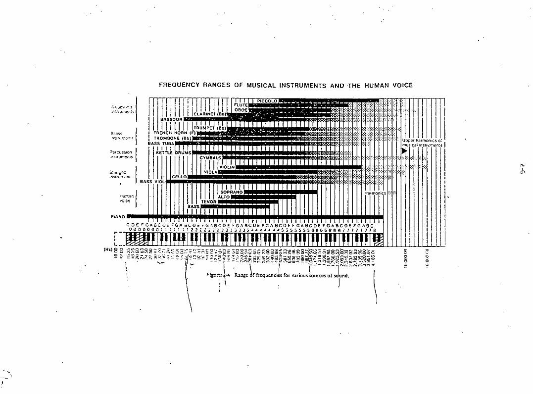
FREQUENCY RANGES OF MUSICAL INSTRUMENTS AND .THE HUMAN VOICE
'",0'
'.:.1: ..
g gg ~
I ill: ....\ ..... ijrrrmInti .•.......II iii i
I'
iKt:.... I. .. ~:J;:Jelharmon,c. c'
uSIc.al,mSln:~;n': I• , • , .? '
Harmonic:; 1::;1:::
';::1:::1=:: t::f:::t:::t:::1:::t::. 1:.:1:-,
;~.!••tlnJljri\I .••lirl'.V'...tk'••'"..It~~tJJJll~~~j::::;:;.':.:.:::BASS VIOL-,
i I I I iii iii Iii i j iii I I I i I f j'i .••••••••••• , • I I ,., '" I ..
C DE F G l, BC 0 E ;; G A 8e 0 2 ;-G.; e C 0 E ;-G A 9.C 0 E F G A BC 0 E F G A BC 0 E F GAB C 0 E F G AB Co 0 0 0 0 \) 0 ; 1 : 1 : 1 1 2 2 2 2 ;;: :12 3 3 J ) J 3 3 .: 4. 4: 4 4 4 4: 5 :; 5 5 5 5 5 6 6 6 6 6' 6 6 7 7 7 7 7 7 7 8
HuO".,n I''':.,cr;
PiANO
:.'!..iC".,,~:!.:"l':.':u:!~er.:~.
""50 In••llu~("~:~
=>e'CUSS10" I.,"\<;lrum,!,;,:~,
S'/I!1f;'!' ••."\<;I!I,;II.
,.-,,L. __
(H;t) 0 Q ••-:••"\0 ""'00 - C - =' ..-: ,:;-':;l,-~--(':- -:: c,_ -M - -:;, ....•••.~...::~ noo:e.nM(O<.OClO ~O(O - -(oOM:gNNMUOI'--o •..• .:"'::-;u :e .••..lt.!': -;: '.'. ,~:,.; '': ;:;.,..,...,. ..,.:-:.:;;: -:I";o=:l;:; ..:lee:::,:,..: '':-'':' ~.-:;, O:l'i"MN"" ,=,0 ""'"••"'lU)•••••C!010"" :-:Oa:JClOq 0
o~. ='=~;;::~:~~:;:.:~~'ff'?~~:::~'~~P~?~~'~~-~R~~~~~.~~~gg~~~8~~~~~~~@~fJR?B~~~\ 1- \, \ ! (.:--.:.:r"'N";rin,-i-i
''"''1' ~='-~.'_.'-"'.t\
,-,

CHAPTER - III
INTRODUCTION TO MICROPROCESSOR
3.1. DESCRIPTION OF 8085 MICROPROCESSOR
we have developed the microprocessor controlled musical
instrument by ueing Intel 8085 microprocessor and peripherals.
A brief description of 8085 microprocessor is given below.
The 8085 is an 8-bit general purpose microprocessor,which
is capable of accessing up to 64K bytes of memory. The 8085 CPU, .
functional bock diagram is shown in figure 3.1. The 8085trans~:
fers data On an 8-bit, bidirectional 3-etate bus (ADO_7) which
is time-multiplexed 80 as to also transmit the eight lower-order
address bits. A additional eight lines (Ae-15) expand the 8085
system memory addressing capability of 16 bits, thereby allowing
..,

3-2
64 K bytes of memory to be accessed directly by the CPU. The
8085 has eight addressable 8-bi t registers. six of 'them can
be used either as 8-bit registers or as 16-bit register pairs.
The accumulator (ACC or A register) is an eight-bit register.
The programme counter (PC) always points to the memory loca-
tion of the next instruction to be executed. It contains a
16-bit address. The stack pointer (sP) is a special data poin~
ter that always points to the stack top (next available stack
address). It is an indivisible 16-bit register. The" flag register
v: ~6ntains five one-bit Jlags,' each of which records processo(£),
~atus information and may also control processOr operation.
A microprocessor needs to be interfaced to memories for
programme and data storage and to input/output devices fOr the
purpose of com",unicating, with environment (which consists of men
and machine). Our system has got RAM and ROM arrangements fOr
its memory operation and 'keyboard, T.V. nionitor"cassette ~ecor-
der and printer interfacing capabilities for its input/output
operation.

3-3
<>,l, .• I>,.• """I.£tD~U "us
Lt- --- ,
I ID•••'1•.•.•
~OO"Ull ,US
• ''1 c---;;;'1110. "IG.
0 "'1 '0;." "Hi,. "'1 , ,,,Ilill. ""
n"(,I';Ol",1(1II ".,".oon ••.••COUHY!II
..,''''CII(''I''''IIIII)II';I\[''['''I''
AOOIIIUtATCH ""TL___
IHnllUCUOtf.. O£COOUI,.,
MACH''''.CYCli .
lltCOO1HQ
.1"t4~~~~~
''''T ''''UIIINALQA, •••eln ~--'---'---------------":==:=J-.---.--- '---1-- '-~~.:INS IIUC"
1I1ClnU It, III ,I
"I i iI "
! ['
r..''''''. I..~I""V I',i
, I'i 'J
)1J Ii
II:!_ ••......_-
o•••r•.I •••I.H' •• ~~~ )u,n" .•,
'lAO ••,, ".HOI'S
AlllnH •• nlC••oalC .~..
' •••••UIW
tl"'HQ "NO COHTIIOL
".-~ .
_.{ ....•""':f\~ _OIolD
FIG,3.1 8085 CPU FUNCTIONAL DIAGRAM
2!H; •. 8~TAllC
""
10/;.4------
•
•0-----w~------
Run
PO~TC,PC" '.
I,-v,;c I,~V'
--.v,sIOVI
FIG, .3,2 BLOCK DIAGRAM OF 8155

3-4
,
3.2. DESCRIPTION OF 8155 RAM 'AND I/O PORTS
The 8155 RAM chip has three I/O ports apart from 256
bytas of RAM. Two of these are 8-bit ports and are referred
to as PA and PB. The third one" the PC port, is Of 6-bits.
The ports can be 'individually addressed, ,when the chip is
selected and IO/M line is high, using the least significant
3 bits of the address sent out by the 8085 to the 8155. A block
diagram of the 8155 ohip'is given in figUre 3.2. we ha~e used
these I/O ports fOr interfacing OUr mUsical key-board with the'
microprocessor. At the time of system initialization, the three'
ports may be suitably programmed using the bits of a command
status register (CSR). The CSR is an internal 8-bit register
in the,8155. The 6 least significant bits Of this register can
be suitably set Or reset to programme the three ports.
The 8155 has a 14-bit programmable counter/timer to
provide either a square or terminal count pulse for the CPU, ,
system depending on timer mOde. The timer is a 14-bit down coun-
ter which counts the input pulses. we have used this programma- '
ble counter to get the desired frequency correspond ing to a
particular key of the musical key-board. The input of this

3-5
counter is the clock output of 8085 microprocessor, the out-
put of the counter is the square wave of desired frequency.
The output frequency depends upon the content Of the OOUNT
LENGTH REGISTER. To programme the timer, the COUNT LENGTH REGIS-
TER is loaded first, one byte at a time, by selecting the timer \
addresses.

CH/IPTER - IV
KEYBOARD IN1'ERFACING AND HARDWARE utSIGN
-f:we have int,faced a convenH6lul1 liil18illti3.It., bo~a to
the microprocessor through the input/output port. or &15~~#~~t/output ohip. OUr klly bOard has 37 il1diYiduai Iteta. we hilY~ jil;j4~d
these keys by using a 8 by 5 matrix. Figure 4.1 shows th~fi~numbers and oorresponding key Code. Table 4.aS~O.8 t~. ~~y9~~<~
-->-- E\nnections to form 8 by 5 matrix. Th'Blin~~-(~.tlttl\l;h!l~) li."f~ )
been connected to the input port A or the 8155 Ohlp 8#d t~i ,
(scan lines) lines have been connected to the outili,itPl1d 11lit
the 8155 chip. Figure 4., ,shows the oonnections ot 5 liti,~~d
8 lines frOm the keyboard to the mioroprocess9r output/inpqt
ports. The tivelines trom the keyboard have been conl\~pt8~
through open collector inverters to avoid the ShOrt bit~~~~f
/"."
(Q,)
\

kE( TIjI3L,£ +-.7JA r1 [\>
C3of-- k~yN()T£c;.-:z. 112 82
crt- # A~ro tit .c,# ff
C2. .ll,2. E.2. ' F•.81
If,G,
F.1'- (/' J.t{:
F,D1 £,
c.'#' ffJ # j't"F: Gn A.
F" CTo Ao Bo C1
OCTAV£~
c! lire
Co :D. £0
'~OHE.
- - - - '. - - - , - -rl /;1 ~2 +3 ~y '6 Lt6 4-7 8fJ 81 gz. 83 8'1 g) &'6
~ .~ ~
::):, <--..~ '" ~' "' Q3' 0\-,\;)' <i' G\ \D' 0{ ."" ~ -;:;
~ ~«) «) S ~ '" ~
<'l C'J "- "- i;:, "~
~~ ~
N) "- '-0
~ ;t ~ ~ ~ ~ ~ ~ ~ ~ ~ ~'V '0 '0 'J '0 '-J
,
- ,-- - -- _~Lr--- r- '-- - ~~ '-- - --~ ~ &;\ ~ ~ «\' ~ ~
---..~ ~ l;)' ~ 0
~ ~ ~~
h::' ~ ~ ~~
«) «), «) Ii) N) «)
~
t'l N <'l <'l '- ~
~ ~C\l
~ " " "- ;;, C<t '-~
~~ ~
~ ~ ~ ~~ li-..
~'- ~ I;;
~'-.::.;J --0 '-> '0 '-J 'J ~ ~ ~ ~ ~~ v v '=' '-J '-J
- ~aJ8 1j9 ~A @8 !be 0]) mE @F Iff II 12 13 Iy 1;;- /6 /7- ..<0 .2..1 ,22 23 2'1 2;;-f£ - - . -
KJ;.yCeD.
kEy.COD,
FIG Lt.t. KEy POSlrlO!'/, kEy co.lJ£ ANDK£l rh3L£. .DAr4•
I-''.
-' ,

f(£ TUR.N LiNE
4-3
kE,YS CcJ;YN£CT~TCJq.c ilf£,t<;,
1---->""'- 2, 2..1,I, I~ 2..3-2 ----->-> y~2.3, g, 11,30-3 -----'"-> r, 2G, 5, /&')32-.y ----'):..:'),2.8,6> .:2.0, 3y5---'---"'-)- II, 3/~c; 22., 366-----')~/y)3~ 1"/ 24....31:;-----''>''-/6) 35"~/2.) 25"g ------:~,.. /')) /3/ 2T
FIe;..1.,2 KEy CONNECTIONS TO FORM 8 By6 Nt17Ji.'Ix,
TO ,up INPUTP~RT4 {8 RE.TClRN UN/:j
+5V~
~ ~\C(<' Ik ....:::, ~~~ Z(50
\I) .3Q..
~~ 't~.Q S--
/3
2
8
12
-.....,\\

two keys are pressed simul t••neoullly. 8 resistors have bei!i\
connected bet.een the 8 linestrom the keyboard to tb~ +5
volt. So normally the logic level Of these light line~ ~rii
high i.e. logic "1". At the output pOrt B of 8155 ".5 H~
order , .-----:-:--, ,at a 'verY high\
frequency as shown in ~ab1e 4.4~'\ .;:~~-:;--.'
P:BilSd Al'l LIl;lE NO. PB4 FB FB ~U.,1::..:l.. '. 2- --- . __._~ .•.....
1 () 0 0 0 1
2 0 0 0 1 b
3 0 0 1 0 0
4 0 i 0 0 Q
5 1 0 0 0 0
Table 4~4port
5-bit d••t••B of 8155.
10rlllat at tli.e O\itpiit
Simultaneously the microproceseor moniters the 8 inpti~ i~fteB
(Return lines) at port A of.8155. If a key is pressed Bn,d
if the corresPonding scan lines is high Ii logio low is Qbtai~
ned at the corresponding input return lines. SO.by 8eD~g a
5 bit data to the scan lines aDdsimultaneousit monite~',l..i\g
the 8-bitreturn lines, the mioroprocessor is ••bie t~in48n.
tify and code a olosed key torm t!ie scan lilies data il.il4 rlltijr~

lines data by using software program~e. The key ceae ~~.~ 8~
bit binary number. The' leastllignificant biU Nlpre~1iiit~liI,.
coded form of the 8-bit binary d4ta obtained from t~~ t~tprn
lines. A software counter has been used to code th. 8~bit ~at~
obtaine d from the return lines into a 3-bit bii1ary liUil\1:l11r~T~i!
5 mo~t significant bits bf the ket code represent the ije~
lines data in decoded for~. The 8-bit data format Ofa kilt il!:i!le
is shown in figure 4.5.
Scan lines datain decoaed torm
doded form Of ~~turn", ; '; . ". -.'liM8 datil"
Figure 4., 8-bit data fOrmat ot ii.\taT ood••
generate the key code has been de~cribed in ohapter 5!

cH ..\PTER - v
SOFTWARE PROGRAMME DEVELOPMENT
5.1. SOFT-wAREPROGRAMMEDEVELOPMEN~FORMUSICAL.TONEGEN~~AtION;
we have developed a software programme to geli~ratit",itt.rep.t
musical tones using Intel 8085' microprocessor and a 06nv~~tio~~i
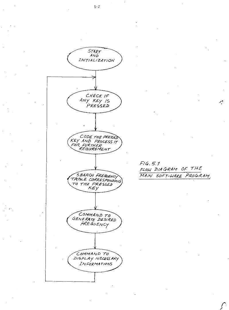
keyboard interfac.ed "ith the microprocessor. A flow dia~rQiii "f tl11.1!1
software programme i$ shown in fig.5.1. To perform the operat~oli~
. These sub-programs are called. by the main progr8ill (MAINP) :l.p liyo1~o
Order. The nameo ot these sUb-programs ;re REFRj INACl', AC?'J(C.~1il~,rJfF,RKC,STOP, KB and STIMIil,The functions of these aUb"prog:riUllliar~
described below, The, different variable namee ueed in theil,s sub-
7 programs are given in Table 5. 2 wi til their functional deeot'1.pt,,"O!li!.
Many memory locations are used for the aifferent variabl~B ueed tndifferent .sub-programs. The memory allocation of difterept 1I.rill~1!t
/
5-2
ST-1RrAND
1N!TlALirAnON
CHECK IFIINy I<£y IS
PRESS£:D
COD£T/I£ PKESS£KEy ANI) PROCESS ITFo/( FURT/lER,
REG,U/I?EI'1ENT
Cat1,.",AIyD TO.b/SPLA'j NECCf;SAi<yI IV t=oIiMtfT/ONS
FIr;. 5.1,cLON ])fAa-RAM OF (HEM,f//Y SoFT-UI1RE. PRoc;./(A!'1.
(',/

5-3TABLE 5.2
NAMES OF,VARIABLES AND THEIR FUNCTIOi,tL DESCRIPTION:- ,"';
~- -'
N,.1'lE
YJAINPREFRINACT :
ACl'KCK:'"'vp~-~l"IU<CS:rOP
KB :
N .r.",B
ACr.fK
COM :
INATB
INTBE
U3'I'NPRGNT
i'!l'AB:
DESCRIPrIONS:Main program which calls different sub-programs.Refresh sub-program, which is used to generate the key code.Inactive Key check sub-program.Active key check sub-program.Key on process sub-program.Fresh Key check sub-program.Stop sub-program which is used to stop the tone generationwhen a key is released.Key-toard sub-program which is used to control some opera-tions directly from the microprocessor key-bo~ and alsoused to display some infor~ations for the users.Store time sub-program, which is used to store the timeduration of a pressed Key in a memory Iocation for recor-ding operation.Name t'able for new pressed keys. A table which contain amaximum of four key codes.Name of the memory location to store the code of-the activekey.Name of the 8-bit memory location, which represents thestatus indicator for different operations.Inactive table, which contains the key code of inactivekeys.Memory location, which represents the end of the inac'tivekey table. 'Memory location to store the ectave number.Memory location to store the number corresponding toprolonged time for sustained operation.Memory location, which contains the first address ofmemory table of a recorded song.
".CNTRL Low-order counter to store the tim,
for're90rding operation. of a pressed key
Contd •••
,

5-4
N,J';L DESCRIP'l'IONS
CN~RH High-order counter to store the time of a pressed keyfor recording operation.'
DBCNTDebounce counter to store the number for debouncingoperation.
PKEY : Memory location to store the key code of the 'key onprocess.
FRQTB : Frequency table which contains the number correspondingto e,achkey of the zero octave. '.
Nfrl'AB
NJ'1ATB
NJ'1TIlP
Name table, which contains the names of a recorded song.
Name address table, wh~ch contains the starting addressof a name in the name table.
Name table pointer, which contains the serial number ofa name.
.,,
PTAB : Memory location, which contains the starting address ofthe play table for auto-play operation •
"
". '".
.,
,

are shown in figure 5.3. A system status Iindicatbrs byhI ..'
COM is used to flag the current state of the different opera~
tions. The bit assignment of COM tor differentopero,tiorii!lis
shown in figure 5.4.
Li~~8ystem uses a conventional musical key-boatdi~hioh
consists of 37 individual keys. If a key illpressed the nlillrOpri;l"
cessor generates a tone corresponding to that key. Xt t~o OrmOI'll
keys are pressed Bimultaneouely the soft-ware progrlim peI'lllitilthe..: -- .._;- .. ~-:,;,:,;,,;:,.--:-_~
. ----.microprocessor to generate tones corresponding to the ~t ket
pressed. we define the state of a key in five possible ways irl811~- ' , ---,"---
tive key, active key, key on process, tresh key and the n9rm~
open key. A key passes through a series Of etate~ till it ism~de&.
ready to @ prooeBeed for tone generation. A key stilt'll~iiigrf;l!i!
is shOwn in t'igtite 5.5.
This Bub-program sends the.5-bit decoded data ~6 tb~..,-.
scan linos and monitors the 8-bit data from the r.t~rh linns to-=::-~..----_-"# - ,- - -. ,
code a pressed key. The code ot B pressed key is Bt~red i~ N[~~
in sequence. NTAB refers to the first address Of a 5••by~e m~m~rylocation as shown in figure 5.3. The first foul'bytes are used

:>-6
F05 ,.7-{.:
F8 '11-1)-
Flll-1 -1c-P8 rJJ -' 7F
F8)1.:5- !?S
__f'_l__~_ASPJ)
Lis -r 'p.R.CrR
lll/itJ PI?(j
INS T.{) P.R.1t~
TA,?~A1PAl .
.':/I!
.J, r'
'"
F'6~S-;=gtJ6Pf5?!'1 v'PS<;IJf5
rgfit.:>,-=f5'llc;=f?>D-DF6'.p£ - ;::8>1',c:
F8'/~/=8'/2..;=$'/3
Ff?/IjFf?,;S-
/=8/(;;=&'17
Fft/g-- F82.F
/=8(;3F6"b'~-,c:g'':::JPUb'FtS 70- ;::8'"7-/
,c8'12.-/-i?13
F f? r"t
-Ni18
ACrJ<COM
/N-11J;J
/IV"-I3E/IVS"-/\(PJ<:,""-/VT),4 T113
evT~L0\1 or/? Ifel<.E-/\(
:lJI3CNT. P,k..Ey2E.-I<,6
;:::'R.&'T!3
iVM"-I3P
N.<tT~13
~FF -~PTA-8
N/<t";T8
PNT/~
W C!/<..1\ -1
IN SST
t; It;. 573. A/ENJJRj' ~LLOD1 r; o/ys ;CO/< THE
V-fR/ /I /3LE~ ~S£J) ~N rij.E, SY~:!~1

.1>.
]JeDNLSTtJP"
------- 4Lt~oPJe.1J-ro£'roRF •. 1
E.D STOP ~ / .. -. ~._,
I}rf $-r0P" 0!?£CtJRP£[) .= /
he;. 5:/;.. 31T J<£P.R.E.5bffA 7"1ON oj: eat.(
~7 J).{, ])5 PI( .J:>:3 .1>•. .»,
.~f" ,'"-
SuSTAINfNIvlE Dl
L.
FI4'-.5.5,e,Ey sm/£
.D.//J C!rR.AJ1-------
F/<.E.SIJ1<£)1
NO,R.MI1L-1:£1 0;:
NOr P,R,.E.SSEj)
K.£,Y
1<.£( ON
?R.(XESS
. ACT!V£kEy

5-8
to store the ke.y code •.The last byte contains (FF; which 1ndi••---' \....../
cates the end of table. The REFR sub-prOgram has been 4sed to
store a maximum Of ~ key codes in NTAB, when the.keys are pr.~
ssed simultaneously. The flow chart Of REFR sUb-program ~~
shown in figure 5.6.",.. tv l. \." -5.i.2. ACTKC SUB-PROGHAM
.-/ACTKC is the active key cheCk eUb-progr/lM, whioh i~U~~d
to cbeck if there is any active key. Active key ~.hote~ tbelast key prOBsed beside the inl\OHve keys. It two iiI.' Itlllt~ ltll;ti!
are pressed simultaneously the.last key is the active kOy. Tb,remaining pressed keys are termed as inactive keys. lnac~ive
key codes
the first
J-are store} in .a table nallled/" ",",' . .
" "'.'address of a\:-bY~~ memory.•••.... j."
as INA'l'B.INATB reters to rg.V~-- ,-~.; '. - ~ " .
location as shoym in ti/tUtef8'01'>
5,3. The first 4 bytes are used to store .the key COdeii ot ~il-'..
active keys, the last byte contains FF, which indicates the end
of the table. The key c.odeof an active key is stored in itleillot1
location named ACTK. This sUbprogram also initialises the value
Of prolong counter (PRCNT). This counter is used to obtain the
sustained operation of a tone i.e. a tone is sUstained for a.
while after the key is relaased. The content of PRCNT determines
the time of the sustained operation. The flow chart of AC~~C suh-
program is shown in figure 5.7.

~j-9
5E:r IN/7/-4L I<t'wORSOINLINE IYUM/3£j(: 8,p1l,INI7I-1LIZE.D IYr-1B .4D~I?E.SS
I?EFI<Z5E, NE-Xr Row NO.(Ror/JT£ LEFlj
SC/JNN~ L
Y£.5 -rHE R.OWS«OI-l!J
5 EtyZJ THE OU No.T~ OU"TPur POt<:T
I3RINr.. TI+E COLUMNol<I(E7'U~N LINE e.tJN-rcNTS~
CI<EN=O
RE,cR,3ENCODE
NE.;o;T KEf
pc;.. 5"'6.R£ FR, FLOW CHART
NO
I
I
STORE: "THe KEy' 111/TII$NEXT NrA!3J LOcATioN
13-r ek.e N ..-" (3' ,1.3 ....,.. CKEN
NO

NO
5-10
IS /T IN TIfENTAI3
NO
..570 R E. .4C-TIV£ I<Et
:DELeTE /tCT/VEl<Ey
COMMA-ND Ttl STO~IIYIT/~Lli!E PRClVr
ACTI(I
PEL-ErE. ROI1NT-+i3

.~ouncing. A memory location DBCNT (Debounce counter) o~nt~nB tho.~-
::> -II
5.1.3. INACT SUB-PROGRAM
INACT is the inactive key check sub-program, which is;::--
use;;check if there is any inactive key in inactive key tsole
(INATB). This sub-program also compares the key codes Of inac-
tive key table (INATB) and new key table (NTAB). If a s~e key
code is f.ound in the both table, then thi~ sub-program deletes
the key code from NTAB.If a key code is found in inactive key
table but not found in NTAB, then this sub-program deletes the
key code from inactive key table (INATB). Because the key corres-
ponding to this key code has already been released, so we do not, ~ --
require it any more. The flow chart of this SUb-program is shown
in figure 5.8. ,'1 .1-" 'V",'"-- "--0 "..~ c~ . .
5.l.l KE~ \SUB-PROGR~
'-...-."KEYF is the key on process eheck sub-program, which lsused
key On process is star ad in memory location PKEt. This eUb,.pri)gt'llii!
..\<l-.c--?checksa key on process i.e.'a p!,essed key 20 timos to retlilcede.••:,.;..;v , (,f. ..\.. - ".'w.
'J \~
number 20. This number can be changed it desired. Bt 1~croaDin~
this number debouncing effect cen be reduced mOre; After c~sery!~g<::. - ~ ..
. "20 ti~e_~this sub-program calls another sub-program named' SEND}'
"_ ../

jN;fcl
D';:LErE~Ro/l1NrA8
5-12
/ty,4C TI VE I<£yCHCCI< OrvACT)
5ET IN4-CTIVE I<Ey Tl1l3LE;Aj)j),R.ES5 .
IN,4c2
J.5 TfiEINAC7IVE ,(£ye/vD
NO
I5 TilEIN.fe-71 vI: ICEy
IN N-rAI3
NO
J)ELET£ FR.OMIN,fC7IVe K.Ey
T~I3LE

!YO
5-13
!<Ey ONPI<oa ~Self ):.ck.
(/<£yP)
NOYES
!Yo
5Tol!.E I<E-y,1cr,<:: ----? INlle nvt=. KEy
K£y ON P/(OCF-sS -? ftc- TK.UJ/v(H ,ftv lJ TO SCN})
/(EYPlDE.'--ETE qyON ~/?OCL5S ' '.
------------_._----

JinitialiSif the value
5-1+ (('
-" .-_. -.;'- .......•....•.. / .:'\ .'. '.'which allowB the 14-bit programmage/counter (8155) to give nece-~----;-~--::-:~ -~~"-
Bsary tones correspon~ing to the pressed key. This sUb-protra~
also calls another sub-program n8ll1e~~ which !ltaras t~e pt" •••
ssed key codes for recording purpose. The fiow chart Of t11;1;8 sub••
program is shown in figure 5.9.
5.1.5. FHKC SU1H'1l0GRAM,
FIlj(Cis the fr!lehkey check sub-program. whioi! olililcks if
there is any fresh key. A fresh key is the key which is just pre",
ssed. This sub-program keeps the code of the key just pr!lseed in
the PKEY memory location for further processing. The flow-chart
of this sub-program is shown in figure 5-10. This sub-prOgram also~ '
of/DBCNT ito zero'if a fresh key is detected.'''-- ~\\~"~,(G;-
5.1.6. STOP SUB.PROGRAM
This sub-program is used to stop the 14-bit programmable
counter (8155) when a key is released by comparing the stop bit of
the system status indicator (COM). The COM is a 8-bitmemo1'j loca•.
tion for diffefent system status indications. This Bub-program
also checks the sustained bit Of COM to perform sustainedetop
operation. The flow chart fOr this sub-program is shown in figure
'''~1.
'--,:i
( ~,'. .-

NO
5-15
k.EEP /tVro THE !<£yON PR.OCES5 ,
.DELETE FRO"1 Nr-4?3
.I

~-16
NO
"'05TPi
STOPC. 0 tJ N T L/<..{g-{~:J
,
IVO
Fie; 5:/1. FLOAJ CHAR.T FoR STOP StJI3-PRoGR./I"1

5-17
5.1.7. sEND SUB-PllOGllAM
This sub-program compares the content of ACTKi.e. the
code of a pressed ke/to the contents of a key table nlllliedKEY~B!
to get the key position number within an~av~ and ~c~av_e nUlll.,
-ber from amongst the ~ Octave of the keyboard. The KEYTBcOi1Sillts-..-;;:----- ---~--
of 37 data word corresponding to the 37 keys of the musical key
board. This 37 keys represents the ~ Octave with 12 keys in each
Octave. The key position and Octave arrangements are shown in Fig.
4.1. The high order byte of the data-ward of KEYTBrepreeentll the
key code, the 4 least significant bits of the low Order byte repre-
sente the key position number i.e. 1st key, 2nd key e1;<:.~Hh:4l
an Octave, the 4 most significant bits of the low order ~yte i~
the Octave number in which the key is placed on the keyboard. 'rhili
program also searches a frequency table named FllQTto get a data
used to edoul,.te the required nUmberwhich is to be lOeitled- til
the l4-bit counter (8155) to obtUiJ. the toneB of deli:l.f~4 tr4,qj.t~~i.)h".'. .,'
,
~he frequency table (FllQT) contains 12 data -words correB-
ponding to 12 keys in the highest (zero) Octave. The frequency table
is shown in figure 5.12. The number in the frequency table repreeents

. .
5 -/8
I J<EY TI/ f!>'L; KEy FRQ.r Uti/PUT ;:R£qU£.NcyNOr£S T-113 L-£ J),lJT "1
fiN /;/I'?,f COUN!E~i CoD£-/'
1
20/9 c3 (i~g71f /£,1!Y1;t
.:2'1/1 83 rJ rl !SEll IS-. flot;
8{,12 41 YJrj9l11 Ii/ 91T
.23 !3 A2- (it? 19/1 Ii; . tJt1cY. -...,.-
'6511; c;# r;JIA9/f /3 .2fl'j:2-
. .._--------_._-_.f--.---- -
22/5 L7z. prj J33Jf 12.5''1/-_ ..
g-rl{; ;:;.# py1 (3E/f II. g:3>i:2-
-
5!./ /7- Fz. y1yj CA 1/ //./51
.20/ g £2- ~~..1)51f /r). Sir&-
8313 Dr pyj £211 'J. '156
IliA ..1)2- pi EF// '1'3;1
'3'21(3 c# y1r;J ,cJ)/f g. 'f f?:62.
;::/c:;.. 5./2 ~/<.E6(uENcy TA /.3L,c,'~---_.-"_r'.----.._---.-----l
.:: .
-,

5-19
the data which is to be sent to the ~imer to get the required
tone frequency within the highest (ze~o)Ootave. 1he'~oO~$Barl
data for the key in the same position in another O(\taT~ !iiln bl!
calculated using the formule :-
d = d .2nn 0
Where, d = the data fora key in the zero Octave (fromo
frequency table)
n = Octave number.
Octave number can be selected from the microprocessor kily-board
(between 0-5) and is stored in the memory location named INSTN.
The content of INSTN represents a number in reference to ~ero
Octave. So if a key is pressed from amongst the key in the 2nd
octave of the key""board.,then its data can be calculated f~om the
following equation :-
d 1+3= d 2 li:3
o
where 1 = selected Octave number
The general form of ,the formula i8 given below-,
•

5-20
5£NJ)
TI1;<E TilL I/C71V£
1:..£ Y COJ£
FIN.£) 77fE K£y ?os/71<w'AN LJ OCr/?- V£ }'/UM I!>C/?CoR.~£SPdNIJ/;\Icr ro piEAcT/V£ ~£y COllE FkOff
1<£ TA-13
FIN£) THE D,1rA ROMTHE. FR£OIo6/Vey TJ/0LE(Ff<. Q..r) FoR. TH £ ?~o'
OC-r.l9-vE
C1LCu.r//r£ T/fE. NUN/3I!:,I(I<£&I/I/<.£fl T6 LoAd) T/fEUvNT£r<. Pol< TilE SpEC/rIC-K£'{ IN r#£ 4-/l£N OC.r-I",,"U5/NCr OC.T~VENO. AN/) TII£S£l-£<!. Te () cJCrA vE MtI'tI3E~
( /NSTN
SEND TH e c.4LCU/..;,q TE/Jf7'1W/c. -'0 "THE COI/Iyre;<.To 00T;1I;\1 ~Esu//UtJ TONE
R.ET
FICi.5./.3. FLOW' CIlt1RT FOI( SEND ..sUI!>-PRoc;.PAM

5-21
Where, m = ,Octave number within the keyboard obtained from the
KEYTB (Lies between 0 and 3).
So after getting the key code, the key position within
an octave and the octave number can be found from 'the KEYTB and
the corresponding data to be loaded into the counter can be found
from FRQT. The musical key board can be tuned to any desired fre-
9uency range by ,changing the 12 data-words of the frequency table
(FRqT). The flow chart for the SEND sub-program is shown in figure
5.2. SOFTWARE PROGRAM DEVELOPMENT FOR RECORDING
The developed microprocessOr controlled musical system is
able to record a song in its RAM and is also able to replay the .
recorded song. A Bong is recorded with a song nt:llilesupplied \it..
the users. A maximum of 5 songs can be reoorded with their njWia!h
This system permits maximum8 characters for a song name. To per-.
for",the record and auto-play operaHon three sub-programs nliilled
STRK, APLAY an[1 STIME are used. The functions of these flllb-pr6--
grams are described bolo'll.
5.2.1. STRK SVB-PROGRAM
STRK sub-program is the store key sub-program which stores

5-U
the key codes of the pressed keys sequentially in a memory
location, whose starting address is given by the content of
MTAB. The time duration of a pressed key is also stored in the
subsequent memory location by using a sub-program named STIME
(STORE TIME). One byte of memory is Use'd to store a key COde
and the next twobytes are used to etore the counter valU8(CNT~i
cNTRH) which repreeents the time dUration or a preo~ed ~~Y.CNTRL is the low-order counter and CNTRH is the high order c6un~
ter. Tho flow chart of tho STRK sub-~rogram is shown in tigure
5-14. The last byte of a recorded song is 'FF' indicating the ertd
of the song.
5.2,2. APLAY sUB-PROGRAM
APLAY sub-program is the autoplay sub-program which is
used to playa recorded song. At first this program takes a key
code from the memory location of a recorded song. and then callsI
the SEND sub-program to get the tones corresponding to the key
code. The time interval between two pressed keys is compensated
by delay loop. The flow chant of APLAY sub-program is shown in
figure 5.15.
•

5-23
ye5
~ TO!?£. M'-T/< geT/VIi/(I:y) j S TOR.£CV..jL(/E~ INIT/IjLIi!£G(JUNf~f(
(J ()1'1f't/IN ZJ Td1/-0 TrJ-Pt-/l-1
FIe; /5. /5" A PL.IJ ):"1.,.01.1
CIfItRT

below.
5-24
5.3. SOFT-WARE PROGRAM DEVELOPMENT FOR DISPLAY, MONITORING
AND CONTROLLING.
A soft-ware program has been developed to display necessary
informations fOr the user, to monitor different operation modes
and to control different operations from the microProcessor key--:\ 'board. To perform these operation two sub-programs named'KB;and
"-._-
GRAPH are used. The descriptions of these sub-programs are given.
/'-- /'15.3.1. KB SUB-PROGRAM
Th~ sub-program is used to perform some operations directly
from the microprocessor keyboard and to display some necessary
informatiOns for the users. Octave number can be selected by pre-(-~~ . ~
ssin~ _the\desi)t0-5 of the keY-boar~ this is done by putting the. '-
pressed number to the INSTN memory location. The selected Octave
number is also displayed. Immediate stop operation is perfo~ed
by pressing the character 'I' of the keyboard. When 'I' is Pressed
this sub-program sets the corresponding bit of COM to tero for
immediate stop. The WOrd IMMEDIATE is also displayed wh\lli'II itJI
pressed. The s~stained stop operation is done by pressing tq\l ~~~-
racter 's' of the keyboard. when'S' is pressed the correspoliding
bit of COM is set to '1' fOr sustained stop operation and aleothe
word SUSTAINED is displayed on the screen. There are two modes of

• 5-25
- operations for the musica~ keyboard, one in Monophonic mode
and the another is x-phonic mode. Monophonic mode represents
the generation of musica~ tone corresponding to a sing~~ pre~
ssed key. X-phonic mode represents the operation of musical .
tones corresponding to mu~ tip~e pres@od keys sim~ taneotiEily.
Monophonic mode can be se~ected by pressing the character 'M' ~.
of keyboard. when 'M' is pressed the word M-PHO~IC is diep~aY~~
on the sereenby this sub-program. X-phonic mode can be se~ec-
ted by pressing the character 'X' of the ksyboard. When X is•
pressed this sub-program puts ~FF at the first memory~oca-
tion of INATB and also disp~ays the word X-PHONIC on the screen.I
In X-phonic mode there is no inactive key, a~ of the keys pr~~
ssed simultaneous~y are treated is active keys. The record.m.de
can be selected by pressing character 'R' is pressed the word
RECORD-MODE and SONG-NAME are disp~ayed on the screen. A song
name Of maximum 8-character shou~d be given by the users, which
is stored and diBP~ayed by the name read (NREARD) and name store. \
(NSTOR) sub-programs. Auto-p~ay operation is perfo~ed by pre-
ssing the character '.A'of the key-board. When' A' is pressed
and main program calls the APLAY sub-program to perform auto
play operation. The song name which is to be p~ayed shou~d be

I '
.'
0-26
given by the user. This sub-program compares the supplied name
to the previously recorded song name by using a match sub-pro-
gram (MATCH) and if the same song name is found from the pre-
viously recorded song names, this sub-program allows auto play
operation. If no name is found from the previously recorded song
name -to match with the name supplied for auto play operation,
then a message NO NAME is display by this subprogram. The flow
chart of KB sub-program is shown in .:'N:gure5.16.
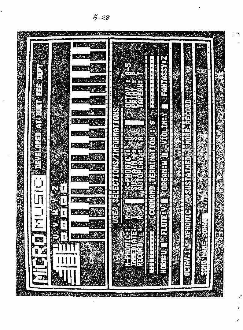
5.32 GRAPH SUB-PROGRAM
This sub program is used to generate a graphic represeh-
tation of the developed microprocessOr controlled musical ins~ru-':'-"()'-' ,. __ / t8 A picture of..the graphic diaplayis shown in
. r-_
fig{ 5.l?)~ii:LB~...-""'='.•.:_: , ..•.......:'--
sub-program is alao Used to displaY necessary 1nfot'lllat19!1i!lfOJ.'.1;1111
users on the screen.
~he comple te software program for the developed micro-
processOr controllefrmusicalsystem is given in the APpendix A.

K8(I<ty 13011R.J) )
U5 £5R., SPt.-£.c 11 oNC.H15c.-<-
I /V ,p U T 1<.£')'"/3()/fR}) COJ)E
/
/

CHAPTER - VI
ANALOG PROCESSING CIRCUIT
6.1. GENERATION OF ACTU AI.WAVE SHAPES OF DIFFERENT INSTRUKENTS
we have observed the actual frequencies and wave shapes of
different conventional musical instruments on CRO screen in the
laboretory. In our system the actual wave shapes for the five
instrument,s have been generated experimentally by adding different
harmonics. For this purpose we have designed an analog processing
circuit. The input to .this circuit is the square wave output Of
the 14-bit programmable counter (8155) and the output is the desi-
red, wave shape. The output of the 14-bit programmable counter(8155)
has been treated as the fundamental frequency and this fundamental
frequency has been divided bY'a binary ,counter (SN74l91) to get
necessary harmonics. Operational ampliiiershave been use4 to add
the harmonics. Finally R-C filters have been employed 'for necessary
wave shaping. The complete circUit diagram of the analog processing
\" -"-,.- '

6-2
circuit is given in figure 6.1. Here an open collector he~
inverter has been used to select anyone of the five instru-
ment.s Or any combination emong them. A logic "1" to the
input of the hex-inverter disablee an inetrument,whereas a
zero to the input of the inverter enables an instrument. The.
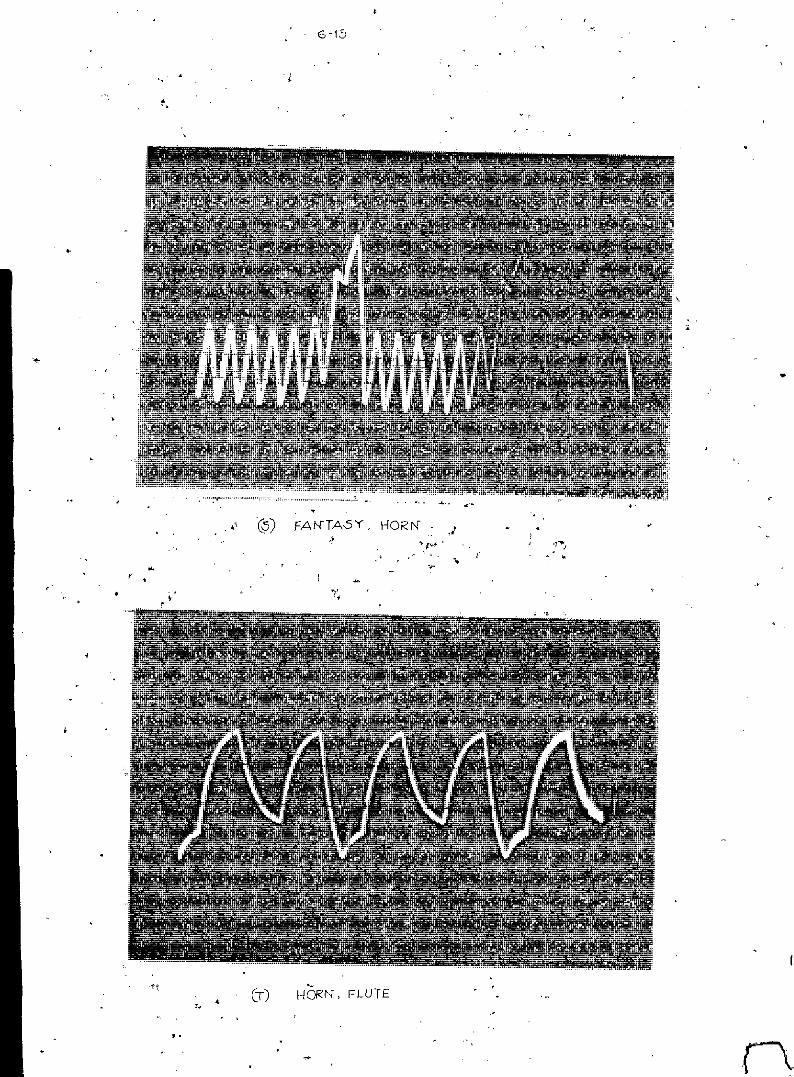
wave shapes of different organs obtained from the CRe screen.
are shown in figure 6.2. The organ tone ie obtained by adding
the. A and D output of the counter. The flute tone is obtained
from C output of the counter. The fantasy. tone is obtained
from the A output of the counter. The violin tone is obtained
by adding the clock input and D output of the counter. The horn
tone is obtained by adding B, C and D output of the counter. wehave used Op-amplifier. to add the harmonics, for each instru- ...
ment. Finally .the output of the five op-amplifiers have been.
mixed by a mixer amplifier. The output of the mixer emplifier
has been connected to the input of a audio power amplifier.
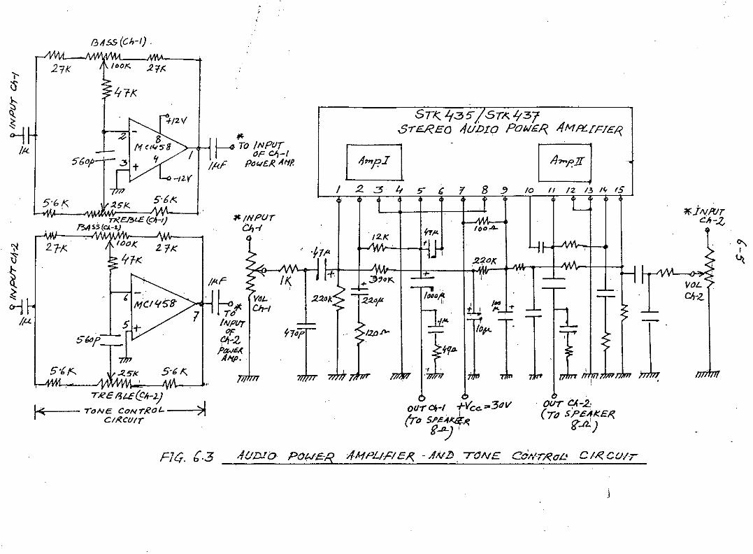
6.2. AUDIO AMPLIFISR AND TONE CONTROL CIRCUIT
It is necessary to amplify the output signal of the analog
proceseing circuit to drive the speaker. This has been done by
using STK435 I.C. ,power amplifier. STK 435 is a stereo power(

'",C.<
t Ot/rPur(ToT71E"'W)fO,4"'pt/I'/~
4-1f<
=
SELECTION SWITC/fE5pOR :P1p.cER£IVT
IN5TRtlMENT.5
-'"-
/r1.",
Yi"1("-,,~
4-7'*--viy~,
4-10-<:
>'5'"
FLUTE otrrNT
,---L ./ftFT~
- o."
ORtrl1N OUTPUT
-1MT
-'~T'/~F
-/ /-<"-
T
/01(
10k.
101;
.Z!:
~ '" .
It~tlll " _01~~"JllU+ ' ;Dt7~T
TO .1<;0 /IVPvr •
g
(
100);
f/2y
lOOk
1001<
(001;
2
10k;
101(
101(
(01<;
101(
/01(
10k,
10
IO/(
I ,111I !i I! 1
i I.i I
-t-'Jv
FIt:;. 6.f AIV"ILOt;: PROC£SSfNt;:-CZR.CUlT ])II'1GR"IM
II---+--LOAl) 13
~~A~'"~iBI.z"-~CLtJ<I("IJ 16
14'111'{1'Ur~ C~is])it~""'.b
II! II II . II ,
--'-o - -+5V 1-5v
SIGNALltv
(FR,.OM TilETIME/? OurOF 8155 C/fIP)
. ---lv.161 ce
.Ot

6-4
amplifier, which gives an output power of 7 watts/channel into.~
8 ohms load. we have used a tone control circuit by using op-
~plifier, which provides bass and treble controls. The tone
control stageonormally has a unity gain when the control poten-
tiometers are centered. However, this gain is adjustable. with
respect to frequency, if the control potentiometers are not cen~
teredo The output of the tone control stage direcUy drives the.
main power amplifier. The complete circuit diagram of the. tone
control stage and audio power amplifier is shown in figure 6.3.
/3"55 (C!,-I) .
."\I
~
1f.j II/fflrCIr-.z.
I-1'7
l(JoA-
.220';tot;
1o,,"
'I 1--1" J J4..- IT
,l+r~.J:,
STI( 't::35/Srl\. '137S-rE.REQ -1UDIO POWER. AM~fF7£1?,
j ~mp.I l I 4~p'ff II 2..3 If !> C 'I 8 3 10 II /2 13 Iv f5
~/NP(/r~-{
4\'L... TO IN pOrI • OF OJ-IIA;: PdW£.1<A'ff.
5'b!':.
lOOK ••Z~ - IU
Itl/(
I~Il<r II(
~'I't ~I ' I .2:10XZ 1.2:10/'
INf'1/'f£ii 1'
701A~ ..5-& /(, I .
I.
fry-x
~fil<W~---..
. n?CI3<E (C~-I)f3;/ 5S (CJ.-L)
5601
21K Ij\ IDCI< .2'{,:
5-t t<-
27-,K.
5'61:'
'l--ISII~
~II<.
':lV
.~
~~
l,u
IRe f.3U(CIr-2.)I<: TONE CONTR.Ol..---)\
CIR.CI/IToo-r CIt-I +Vce.""3~w(To S.l'£"~
~~'
. ou-r /:( -.2"(TO SPeAKER,
fS.d.)
F'/" /' 7'IL{. 0'':;> AU.Dfb POW£'- -4MPL;HE.R. - AN,!) TONE CdNT.RI7L' C 1.~C(Nr

,.' .:.;'. ". ,r,.., ;: '- . ,-,FIGi 6,2 WA'JE'SHAPES 'Of 'DIFF-E-REN,T,C;;INSTRUME'NT'S
.;¥~.'
;..,,
.I,' ,.
';.
... ;:"
','
,.:
"-". ~:.l..'
, .. 'j
:',.
•• V r'
t:.
.•..- l., •./>,.-"
;
,-
.}.
.~
.,,' \
-~~-,_!~-.-_._~---._~-----_.
-,1 :
, "
','
, , '
VIOLIN:," ,
..-'!'
..~

6-,
(c) FLUTf
•
CD) FANTA-5Y

6-8
(E-j ORGAN, FLUTE E' HORN
(F) ORGAN, FAI'fTA3Y, VIOLIN, HORN

'.." , '.
,.
'r.
.,
'\. ,.-','
'. '...' .~
.... '"
.. ,.'
."':-
.'
, ,
. ,
, ' .
.,",:
;.;..~'.
..•.
' ...,~
! .,
.' .. '
Q_I). FANTASY, VIOLIN" ,HORN"
"
:,'-

"
. ;~.,'
"
;i
,',
..-
, ..., '
, ~~'::
;'
"6-'10
, .,",," .
.'~
1- "
",.. 'j.
, , ,
" ,,,
,,' ,
,
.,'.,.
..
~..~(1) ,< ,H.ORN-, v IO,L1e!
,"
..
r:
".•..
" , )
~.:..,{o ,'t
• ,i ';.,
""
," .
.J
,.
~:.~',.
'.;:.
"
:<.-"
,";
':,
" .. '.;
"
'-."
. -'."
;"1
'~ ,.
,, ;
r ""
.~~.
"
..
/:.
t.
"
, ~,'
, .~.
"
"
'.

6-11
(i<) ORGAi'f, FLUTE, VIOLIN, HORN t' FAN TA,sy
(L) ORGAN", FLUTE, VIOLIN e' HORN

(1) FANrA-sy,HORN"
(ii) FLUT£, FAIiTA&Y, HORN", VIOLIN

6-13
(0) ORGAN, FLUTE
(p) ORGAN", FAtHA5Y, VIOLIN, HORN

(Q) ORGAN .• FLUTE, FAN TA5Y, HORN
~3 FLUTE, FANTASY, VIOll!, ,HORt{
•
." c•.- ~~(3) FA l'HA5Y, HORN" •-'-, '> f~!' .•~
~",.
.,
•
I-lORN, FLUTE
.,

CHAPTeR - V I I
OPERATING INSTRUCTIONS
The users should know some necessary instructions and
informations to play the developed' musical instrument. These
instructions and informations are given below. User's opera-
ting informs tiona are .also available on the display screen.
7.1. MANUAL PLAY
1~ Press the character 'I' of key board for imme-
diate. stop operation OR the character '$' for
sustained stop operation.
2. Select the desired Octave by pressing the digit
0-5 of the key bOard.
3. Press the character 'M' of the key board for.mono-
phonic operatio~ OR the character 'X' fOr x-phonic
operation.
4. select any instrument among the five - ORGAN, FLUTE,

7.2 RECORDING
7.5. AUTOPLAY
FANTASY, VIOLIN, HORN by pressing the corres-
ponding key on the musical key board. Any com-
bination can be selected by pressing correspon-
ding keys simultaneously.
1. Press 'R' of key-board to set the instrume'nt
in recording mode.
2.,Give a song name of maximum8character long
using the key board.
3. Press 'CR' of key board.
4. Now, start recording.
5. Recording mode ca,~be terminated by p'tesei~!t
(SilU'T) (~)/(t) when desired.
1',Press 'A' of keyboard to set tho inffltrume~tt~
autoplay mOd.e.
2. Give anyone of the song name amo~~ the req~r~
ded song by using the keyboard.

7-3
3. Press 'CR' of keyboard to start auto-playing.
4. stop auto-playing by pressing~HIFTI ill (S) ~
7.4. gpECIFI CATIONS OF THE DEVELOPED MICROPROCESSOR CONTROLLED
NtilIIbthi.jjif'''O ctaves
~lIlitbor 0 f. \teys
Pt'9set sounds
..
..
6
37 keys
5 sounds. 1
and Horn. or any combinatiOn Of
them.
• ~,
audio power amplifier.
Memory play function
Built in stereo ..
'Manual MemOry, storage Capacity.:.
Max. 5 llongs.
• Autoplay.
• Maximum output power of 7 w per
channel.
• Bass and Treble controls.

.[r'_1 ,'., .,."
. "".
•CHAPTER--V I I I
CONCLUSrDN
A practrcal- microprocessor controlled musical instrument
ha.s been-con.structed ...in ..our_.laboratory by using Intel 8085 micro-
processor. The..comple.te. hard-ware and software design for thie
musical instrument has been described in the previous chapters.
This instrument can be compared with conventional musical instru-
ments such as flute, violin, organ etc. It has got s_omedistillC-
tions and additional facilities over the conventional musical
instruments. The developed musical instrument is able to generate
tones of organ, flute, fantasy, violin and horn Or tones of any.
coinposi tion of the-se -five instruments. Because the .developed
musical system is controlled by soft-ware program, one can easily
chang" any parBlf;eter of this system as desired. 'fhe developed
musical instrument is able to record a song in its RAM,which is

~"\,,;
.I
a distinct advantage over the conventional musical instrmnent.
The recorded song can also be replayed when desired. The maxi-
mummemory capacity of this system is- five songs with the:Lr
-names.- The-mamor~ycspacity can be extended by introducing addi-- --'_._--~_._--- -- ~.
tional_RA}Lchips. The_developed musical system will be he.lpful
fOrmusi.ci-ans. and comp-osers of contemporary music who are in-
terested in the application of microprocessor technology to the
arts. This system can be further developed by introducing addi-
tional hard-ware and soft-ware. The developed system has got
tremendous -nexibility over any conventional musical system
because it is programmable.

REFERENCES
1. Bateman,.l'/ayne, "Introduc_tion to computer--Music",
Wi1.ey- In te_rsc Lenc_e_-_pub1.iCati.on,
John l'/11.ey and Sons, Inc., New-York, U.S.A.
2. Eargle, John, "Sound Recording", published -by
Von Nostrand Reinhold Company, New -York, U.S.A.
3. Ry-erson, Michael, "Acoustic trciub1.e shooting 0 f
audio system", Reston Publishing Company, Inc.,
Virginia, U.S.A.
4. Herrick, Clyde N., "Electronic Troubleshoo-ting",
Reston Publishing Company, INC, Virginia, U.S.A.
5. Intel Mcs.;.-8o/85 ,'amily User's Manual, -O-ctober
1979, published by Intel Corporation.

, ",,'
~'.
APPENDIX A
COMPLETE SOFT-WARE PROGRAM FORTHE DEVELOPED MUSICAL SYSTEM

ASSM 1800
lAA0F8312JF818F812F813F814F815F816FB17F810F800F806F807F812J8F80CF80DF80E
A-I
COMPLE1E 50FT- WARE PROGRAM
13020 KB EQU lAA0H0040 NMTBP EQU I2JF830H0060 FRQTB EQU I2JF818H00813 CNTRL EQU I2JF812H01130 CNTRH EQU I2JF813H131213CKEN EQU 0F814H0140 DBCNT EQU I2JF815H13160 PKEY EQU 0F816H0180 ZERO EQU 0F817H0200 MTRB EQU 0F810H0220 NTAB EQU 0F800H0240 ACTK EQU 0F806H0260 COM EQU 0F807H0280 INRTB EQU 0F808H0300 INTBE EQU I2JF80CH03213 INSTN EQU 0F80DH0340 PRCNT EQU I2JF80EH
18013 3E10 13360 INIT MVI A, 10H .1802 3207F8 0380 STA COM1812153El2Jl 04130 MVI A,011807 320DF8 13420 STA INSTN1801'4lli8F8 0440 LXI D,FRQTB180D 11341A 04613 "LXI D,FRQT1810 CD8AIA 04813 CALL MOVN1813 3E02 0500 MVI A,21815 D3C0 0520 OUT 0C0H
".1817 3EFF 13540 MVI A,0FFH1819 32121CF8 0560 STA INTBE181C 3C 0580 INR AlBiD 3206F8 0600 STA ACTK1820 3230FB 0620 STA NMTBP

/\_.[>
1823 CD3E18 0640 MAINP CALL REFR MAIN PROGRAM
1826 CD8C18 '2)660 CALL INACT1829 CDBF18 0680 CALL ACTKC182C CDF318 0700 CALL KEYP182F CD4919 0720 CALL FRKC1832 CD6B19 0740 CALL STOP1835 CDA01A 0760 CALL KB1838 CD81211A 0780 CALL STIME183B C32-31B 121800 JMP MAINP183E C5 0820 REFR PUSH B REFR SUB-PROGRAM
183F E5 121840 PUSH H1840 D5 0860 PUSH D1841 I2IE8Ql 0880 MVI C,80H1843 210'21F8 0900 LXI H,NTAB1846 1604 0920 MVI D,41848 79 0940 REFR2 MOV A,C1849 07 0960 RLC184A 4F 0980 MOV C,A184B FE20 1000 CPI 20H184D CA7618 1020 JZ REFR11850 79 1040 MOV A,C1851 D3C2 1060 OUT 0C2H1853 3E00 1.080 MVI A,01855 3214FB 1100 STA CKEN1858 DBCl 11'20 IN 0C1H185A 2D7D18 1140 REFR3 CALL ENCDlB5D D24318 1160 JNC REFR21860 5F i::'80 MOV E,A1851 .3q14FB 1200 LDA CKEN1<::'.64!3lC 122121 ADD B'i [-:.(;5 l+7 '.240 t1DV B, A:'861'03C ~.260 INR ,'i.',E',57 32~4F8 1280 5TA CKEN18GA 7'=< 13121:2lMOV A,C1.,3GB 07 i 2:;20 G::LC1.8(;C l,.?7 13 ..•.0 .~l_C18E.=' ~~! i.360 r-,! ,......
;..•.._' ...••
::. E.):::=.E ~3(J 138121 8;~1~ . :3l.sC~ 7-; 14,ZliZrt10 "i.) iYj ~ A187e .-, ...,. 1420 INX hc.... ..:.....
1871 -;.•I:: 1440 ?'f;::"v; h ,~;:.,1872 15 i.460 DC~ :,:.1873 C25P:' t.... :. .:~,::?0 JNZ RCFR?1876 3EFF 1...5,t(~ ~C:Fru :-r. t..,,' : ?"~:i l2if='F:-.;187B 77 ~.5;::Z. ..<:.u IV' A. -,187'3 D1 i:5,~.(! ;: C:.•:-.187A E: 1550 ~:-;::' ,_.
187B .- , 158i2l POP 7~L." ..:.

187C!.B7D187F1880:881:iB8218841885:S8E.1887188A188B1a8Cl8eD188E1891189218941897189A1B9D18A01BA2lBA3l8A4lBA7lBASl8AAl8ABl8AC1BAF18B0l8B118B2lBB318B518B5l8B718B818B9iSBA18BD18BE18BF18C2,-8C4l8CS18CE.18C7leCA18CD
CSFEFF373FeBI2IGFF0437IFDA841837C9E5D52108FS7EFEFFCAAF1S1100FBCDB218DAA71B3E0lZ'7723C391181B3E\Z!01223C39118D1E1C91AFEFF373FC8BEC2B2j.e37C'33A05F8FE00S805E5210E.F81100F8CDB21B
1600152016401650168017001720174017E.0178018001018201840186'"188019001.92019401960:9802000202020402050208021002120214'212160218022002220224022602280230121232023402360238024002420244024E.024B02512102520254tZ!2561Z!25802E.1Zl1l!
A-3
RETEN CD cpr =:F-=-;.:STC:MCRZMVI B,IZlFFH
DEC: INR E:STCRARJC DEClSTCRET
INACT PUSH H INACTIVEPUSH DLXI H,INATB
I ~":~C2 ~O\) A,; MC p :: en=:= ~-:,..! Z SAVr;:LX I D~ NT;:-;BCAi....L TABc:_TC INAC:lMVT A,0MOV M,AINX HJ;vjP INAC2
I:-';AC1 DCX Dt~VI A,'"STAX :JINX HJMP INAC2
SAVE POP DPOP HRET
TABS LDAX DC;::tI 0;::"FHSTCC!"1CRZCMP MINX DJNZ TABSSTCRET
ACTKC '_DA ACTf{. ACTIVECPI 0RZP'JSH DPUSI-' '.-4:""XI H,CJCTKLXI D,NTABCALL TABS
KEY &lJB- PROGRAM
kEY 5UB- PROGRAM

18D0 DAEC18 2620 .~ACTr<'l".j!:.."
18D3 CD5AIA 26413 CALL STRK18D6 3E00 2660 MVI A,G'J18D8 32Q\6F8 2680 STA ACTK180B 3A07F8 271210 L.DA COM18DE F601 2720 ORI 118E0 3207F8 2740 STA COM18E3 21FF00 2760 LXI H,0FFH18E6 220EF8 2780 SHLD PRCNT18E9 El 2800 POP H18EA Dl 2820 POP D18EB C9 2840 RETIBEC lB 2860 ACTKl DCX ")
18ED 3E130 2880 MVI A,12118EF 12 2900 S~AX D18F0 El 2920 POP H18Fl Dl 2940 POP r.~.1~F2 C9 2960 RETlBF3 3A16FB 2980 KEYP LDA PKEY I<iEY ON" PROCESS .sUEJ- PROGRAM
18F6 FE,z,0 300121 cpr IIIIBFB C8 3020 RZIBF9 D5 3040 PUSH D18FA E5 312160 PUSH H18FB 2116F8 3080 LXI H,PKEV18FE 11130F8 3100 LXI D,NTAB1901 CDB218 312121 CALL TABS19134 D24119 3140 JNC KEYPl191217IB 316121 DCX D1908 3E130 3180 MVI A,I2I190A 12 3200 STAX D190B 3A15F8 3220 LOA DBCNT190E 3C 3240 INR A190F 3215F8 3260 8TA DBCNT1912 FEFF 3280 CPI 0FFH1914 D24619 3300 JNC KEVP31917 CD5AIA 3320 CALL S:rRK191A 3E00 3340 MVr A,0191C 3217FB 3360 STA ZERO191F 2117F8 3380 LX~ H,.ZERO1922 1108F8 3400 LXI D, INATB1925 CDB218 3420 CALL TABS1928 D231Z119 3440 JNC KEVP2192B 18 3460 DCX D192C 3A13E.F8 3480 LDA ACTK:t 92F 12 35013 STAX D19;30 3A1E.PB 3520 KEVP2 LDA PK:O:V1933 3206F8 3540 BTA ACTK.,193E.CD9.S19 35E.0 CALL SEND1939 3A07F8 3580 ~DA COM193C E6FE 3600 ANI 0FEH193E 3207FB 3620 STA COM
~.-,

1941 3E0iZl 3640 KEYD1 MVI 8,01943 3216F8 3660 STA PKEY1946 E1 3680 KEYP3 POP H1947 D1 3700 POP D1948 C9 3720 RET1949 E5 3740 FRKC PUSH H FRE5H KEY 3lJB-PROEJRAM
194A 2100F8 3760 LXI H,NTAB194D 3EFF 3780 FRKC1 MVI A,0FFH194F BE 3800 CMP M1950 CA6919 3820 .JZFRKC21953 3E00 3840 MVI A, ill1955 BE 3860 CMP M1956 23 3880 INX H1957 CA4D19 3900 JZ FRf<Cl195A 2B 3920 DCX H195B 7E 3940 MOV R,M195C 3216F8 3960 STA PKEY195F 3E0Q1 3980 MVI A,01951 77 401210 MOV M,A1962 3215F8 4020 STA :)BCNT1955 23 4040 INX H1966 C34D19 4060 JMP FRKC11969 E1 4080 FR:"~C2 POP H1'36AC9 4100 RET196B 3A07F8 4120 STOP LDA COM STOP QUB- PROGRAM
196E IF 4140 RAR196F DQI 4160 RNC1970 E608 4180 ANI 81972 CA81i9 4200 JZ STP11975 E5 4220 PUSH H1976 2A0EF8 4240 LHLD PRCNT1979 2B 4260 DCX H197A 220EF8 4280 SHLD PRCNT197D 7C 4300 MOV A,H197E B5 4320 ORA L197F £1 4340 POP H1980 C0 4360 RNZ1981 3£82 4380 STP1 MVI A,82H1983 D3C0 4400 OUT 0C0H1'385 3A07F8 4420 LDA COM1988 E6FE 4440 ANI 0FEH198A 3207F8 4460 STR COM198D 3£20 4480 MVI A,20Hi98F 3279ES 4500 STA 0E979H1992 327AE9 4520 STA 0E97AH1995 C9 4540 RET1996 E5 4560 SEND PUSH H SEND SUB- pROGRAM .'}.
'-997C5 4580 PUSH B1998 3A07F8 4600 LDA COM199B E6FE 4620 ANI 0FEH

A-6
199D 32"'7F8 4640 STACOM19A'" CDDA19 466'" CALL STAB19A3 2B 468'" DCX H19A4 7E 47"''''MOV A,M19A5 47 472'" MOV B,A19A6 E6"'F 4740 ANI 0FH19A8 87 476'" ADD A19A9 2118F8 4780 LXI H,FRQTB19AC 85 480'" ADD L19AD 6F 4820 MOV L,A19AE D2B219 484'" JNC SENDl19B1 24 4860 INR H19B2 4E 4880 SENDl MOV C,M19B3 23 4900 INX H19B4 66 4920 MOV H,M19B5 69 4940 MOV L,C19B6 78 4960 MOV A,B19B7 E6F0 4980 ANI 0F0H19B9 0F 5000 RRC19BA 0F 5020 RRC19BB 0F 5040 RRC19BC "'F 5"'6'" RRC19BD 4F 5080 MOV C,A19BE 3A0DF8 5100 'LDA INSTN19C1 81 5120 ADD C19C2 4F 5140 MOV C,A19C3 Q1D 5160 AGAIN OCR C19C4 CACB19 5180 JZ SEND219C7 29 5200 DAD H19CB C3C319 5220 ,JIYIPAGAIN19CB 7D 5240 SEND2 MOV A,L19CC D3C4 5260 OUT 0C4H19CE 7C 5280 MOV A,H19CF F640 5300 ORI 40H19D1 D3C5 5320 OUT 0C5H1903 3EC2 5340 MVI A,IZIC2H19D5 D3C0 5360 OUT 0C"'H19D7 C1 5380 POP B19D8 El 5400 POP H19D9 C9 5420 RET19DA 21EA19 544'" STAB LXI H,KEYTB19DD 31'1061='85460 LDA ACTK19E'" CD401A 5480 CALL DPK19E3 23 5500 STABl INX H19E4 BE 5520 CMP M19E5 C8 554'" RZ19E6 23 5560 INX H19E7 C3E319 5580 JMP STABl19EA 1025 5600 KEYTB OW 2510H19EC 1124 5620 DW 2411H19EE 1286 5640 DW 8612H

A-(
19FIZI 1323 566121 DW 2313H'19F2 1485 568121 DW B514H19F4 1522 57121121DW 2215H19F6 1684 572121 DW 8416H19F8 1721- 5740 DW 2117H19FA 1820 576121 DW 21Z118H19FC 1983 5780 DW 8319H19FE 1A17 581210 DW 171AH1A1211211B82 582121 DW 821BH :~.1AIZI22016 584121 DW 16212\H1A04 2115 586121 DW 1521HlAIZI62281 588121 OW 8122H1A08 2314 59121121DW 1423HlAIZIA 2480 5920 OW 81Z124H1A0C 2513 594121 DW 1325H1AIZIE2647 5960 OW 4726H1Al1212712 598121 DW 1'227HlA12 2811 6121121121DW 1128HlA14 2946 61212121DW 4629HlA16 2A11Z1 61214121OW 11212AHlA18 2B45 61216121DW 452BH1A1A 31Z11Z1F 6080 OW IZIF31Z1HlA1C 310E 610121 DW 0E31H1A1E 3244 612121 DW 4432H1A 2121330D 614121 DW 0D33H '.:'lA22 3443 616121 OW 43341-'11"124350C 6180 D'N IZIC35H1A26 3542 621210 DI.,J 4236H1A28 370E: 6220 DW lZIB37HlA2A 38121A 6240 DW 0A38H1A2C 3941 6260 D~~4139HlA2E 3A09 628121 DW 1Z193AH1A 31213B40 631210 D'N 403BHlA32 4008 6320 D~J 0841ZlH1A34 87121121. 634121 FRQT DW 0087HlA36 8E00 636121 0(,,' 008EH1A38 970121 638121 DW 01Z197H1A3A A000 640121 DW 00AIZIH.1A3C A91Z11Z1 642121 DW 01Z1A9H1A3E B31Z11Z1 644121 DW 0121B3H1A 4121BEIZI0 646121 DW I2II21BEH1A42 CA01Z1 6480 OW 0IZ1CAH.1A44 D501Z1 65121121DW 121121D5H1A46 E200 6520 DW 00E2H1A48 EF00 654121 DW 1Z10EFHlA4A FDIZIIZI 656121 DW 00FDHlA4C FF 658121 DB IZIFFH1A4D F5 66121121DPK PUSH P TlA4E E5 6620 PUSH H1A4F C5 6640 PUSH B
(, '
I\;
" ~';-',

A-S
lA5121 2179E9 556121 LXI H,0E'379HlA53 CD8902 668121 CALL _289HlA55 Cl 671210 POP B11'157 El 572121 POP HlA58 Fl 574121 POP PlA~9 C9 676121 RETlA5A 3A07F8 578121 STRK LDA COl<: STORE I<EY 5UB- PROGRAMlA5D E61214 681210 ANI 4lA5F C8 5820 RZlA6121 E5 6840 PUSH HlA51 2Al121F8 686121 Li-lLD MTABlA64 3AI2I6F8 688121 LDA ACTKlA67 77 69121121MOV M,A11'168 23 6920 INX H11'169 31'112F8 694121 LDA CNTRLlA6C 77 695121 MOV M,AlA50 23 698121 INX HlA6E 3A13F8 712100 LDA CNTRHlA71 77 712120 MOV-M,A11'17223 704121 INX HlA73 36FF 7060 MVI M,0FFHlA75 221121F8 7080 SHLD MTABlA7B 2100121121 711210 LXI H,12IlA7B 2212F8 7120 SHLD CNTRLlA7E El 7140 POP H c~,-,
• - 'OJ _
lA7F C9 7160 RET11'180 E5 7180 STIME PUSH H STORE TIME -SUB- PR06RAII1lA81 2A12F8 7200 L.HLD CNTRLlA84 23 722121 INX HlA85 2212FB 7240 SHLD CNTR!-lA88 El 726121 POP HlA89 C9 728121 RETlA8A lA 73121121MOVN LOAX DlA8B FEFF 732121 cpr I2IFFHlA8D C8 7340 RZlA8E 77 735121 MOV M,AlA8F 23 7380 INX HlA9121 13 74121121INX 0lA91 C38A1A 7420 JMP MOVN
. -
,-

A-9
1E;0!Z1:A3A.-.0;::- •...•-.,.c-JHI
F87D;=-.:) 7 RF875F8741995FB66F864!-"831l1F831r- e. J. QIF87'"F"372027A:=S0E,F8"'?;:-31.;)8F80C
F5Ql3l.A;:'.10J.HH3
:'AAF
:~AEI4-;. ::'437lH8~
lACQ;tAC2~l.f~C3
:'.AC61 AC:2.1 !=leA1;:~c. ~::1:ACC
1.AD4tAD""?
C))7DFBI=DEB i qDe;FE3iZ!D8,-:=E36D2CB:AEG0F3:;:: 0D F 02-21C4EE~_lC4:i..ACD8A1A-3A0DFB
~7, .C90F03:~ 4121 J.
:-=F,-c:::: -'.-.=(...,..)
2:5B1C47CD02iF=:D\2+DA::.~1CJ.
1ZI1Zt20QllZl4000E,(ll'2108001012)012001 'till:;"1600180020002201212400260'212800300i2J320,Zo340036100380'21400iZl4200440046Q1048005001215201~54012)560058006000620'216400GtS006800700072007400760078008000820.2)840086012188009121009;~00"9400960098121
INIT EQU 1800HMOVN EQU 1AB'AHsr;:p EQU 25A7HI~,jSTD EQU 0FB7DHAUTOC EQLi QlF87AHASPD EQU 0F875HINSTS EQU 0F874HSEND EQU 1996HNMATB EQU QlF86tSHPTAB EQU 0F8tS4HNMTBP EQU 0F830HNMTAB EQU 0F831HMTAB EQU 0F810HPN-'-R EQU 0F870HWORKA EQU 0F872HSCRN EQU 27AHACTK EQU 0F806HCOM EGU 0F807HINATB EG'U 0F808HINTBE EQU 0F80CHINSTN EQU I2IF80DHCOMSR C:QU 0F503HKB CALL INSTD KB
CALL KEYBRNCcpr 30HRCCPI 36HJNC KB1ANI I2IFHSTA INSTN
OCT LXI H,0EEC4HLXI D,OCTAVCAl..L MOVNLDA INSTNORr 30HMOV M,ARET
OCTAV DW 030FHDW \ZI1i4HDW 2Elf,HDE: \ZIFFHf{Bl PUSH HPUSH BLXI H,COMTB;'o10VB,ACALL COMSRJC :=-OUNDPOP B
.s\JB - PROGRAM
,
•••

lAD8lAD9lADAlRDBlADD1.ADFlAE0lAE2lAE4:tAE6iRE';>1t:lEAiAEB1REEi~lEFlAFl1AF4lAF7lAF9lAFClAFF1902IB051B051B091 BillA
130E:,~-i0r:B11i B1,31B15
lB17.~B:1.A~,B1C::E:1F:-"322J, I:c~5lB2e.1B2':)1B2A,":.,B2B
11331
::'335
~~c-..:'-C'3E9DBFlE61Zo7CB3E4121D3FlDBF0CD2BF637C'3CDDB1RD13FE24C2151B3A07FBE6FA3207FBCDC31B11QlA1BcoeRl!'!13CDBA:AC910QlC0:19FF212'20202021lJFt="
C93A07FBF6103207F821D9££112B1BCD8A1AC1E1cs1315:31.4-01'?'30E05'Z:4FF3R07F8E5EF3207FB
10121011212010401060108011l2lQl11201140116011801200122012401260128013001320134131360138014001420,.4401461314801511101.52III
15401560158016001620164iZl1660168121170017213174017612117801.812101820184121186018801'3001920194019601980
A-l0
POP HRET
FOUND PCHLKCALL IN 0F1H
ANI 7RZMVI A,40HOUT iZlF1HIN iZlF0HCALL I2IF62BH5TCRET
~{EYB CALL KCALLRNCCPI 24HJNZ l-<EYB1
SPLRY LDA COMANI 0FAH5TA COM
"LAY CALL MODELXI D,PLCALL MoVNINX DCALL MOVNRET
PL DW 0C1iZlHDW 1901HDB 0FFH
SP DW 2020HDW 2iZl20HD'-J 0FF20H
KEYB1 5TCRET
SUSTN LDA COM -oRI 10H5TA COMLXI H,0EED9HLXI D,PROL
MOVET CALL MOVNSAVE POP B
POP HRET
PROL DW 1513HDW 14~3HDW 0901HDW 050EHDW 0FF04H
IMMD LDA COMANI 0EFH5TA COM

lB3D1840lB4318461848lB4R],B4ClB4ElB51Z11B521B55185E.1859lB5C.1B5ElB611B52lB651B67lS6A1B60lB6FtB721874lB7E.1878lB7'3iB7CiB7E1881:B2.41B87lB8A1B8D1 B9rZ'lB93iB95189BlB9AlB9D1BA0lBA3i'BAS1:9A91E~AClBAF1882lBB51BB7l.BBSi
21D9EE11461BC3251B09121DlZI00504lZ19011405FF3EFF32lZ1CFB3C320BFB21CEEE360011721B
C3251B3EFF3208FB21CEEE3618C35E1B10080F0E0903FF3A3JZlF8C"ErZJ5CAA91BC0801CCA2B1BC;)FB1CC0731DC02E1D2A10FB36FF3AJZl7F8:""604321l17f3CDC31B21EAEEllBA1BC3251BCDEF1C2184EFl1B51BC-3251B0615iZIC0CFF
2lZl0020202040206020802100212021402160218022002220224022602280230023202340236121238024002420.24402460248025002520254025602580260026202640266026802700272027402761212780280028202B402860288029002920294029602980
A-11
LXI H,lZlEED9HLXI D,IMJMP MOVET
1M OW 0009HDW 0500HOW 0904HOW 1401HDW 0FF05H
MPHON MVI A,0FFHSTA INTBEINR ASTA INATBLXI H,0EECEHMVI M,00H
MPH1 LXI O,MPINX HJMP MOVET
XPHON MVI A,lZIFFHSTA INATBLXI H,0EECEHMVI M,,18HJMP MPH1
MP OW 0810HOW 0E0FHOW 0309HDB 0FFH
RECRD LOA NMTBPCPI 5JZ REClCALL NREADJZ SAVECALL NSTORCALL NMDSPCALL APSTRLHLD MTABMvr M,0FFH
NONMR LDA COMORr 4STA.COMCALL MODELXI H,0EEEAHLXI D,RECJMP MOVET
RECl CALL USRCLLXI H,0EF84HLXI D,FULLJMP MOVET
FULL DW 1506HDW 0C0CHDB 0FFH
/

13BA 1205lBBC 030F12;8E 1204lBC0 2020lBC2 FFlBC3 21E5EE':'BCE.11CD1B1BC9 CD8A1AlBee C9lBCD 0D0F:BCF !ll4051BDl 2EFFlBD3 D51BD4 CD801ClBD7 CA3C1ClBDA CD521DiBDD D2471C1BE0 2264F8lBE3 7E1BE4 "'EFFiBEE. CA331C18E9 3E60.,BEB 3278E91BEE 23lBEF 23lBF0 231BF1 7E1BF2 FEFFlBF4 CA331ClBF7 FE00lBF9.CA401ClBFC E5lBFD CDDBIAlC00 E1iC01 D2091C1C04 FE24lC06 CA33:i.ClC0S' 7ElC0A 320E,F8lC0D CD9619lC1ill 23lei! E5iC12 2A75F8lei5 44iC1E. 4DlCl7 E1lClB 5ElC19 23ielA 56lClB 2B
30003021213040306030803100312031403160318032003220324032603280330033203341213360338034003420344034603480350035203540356035803600362036403660368037003720374037603780380038203840386038803'3003'320394039603980
A-12
REC DW 0512HDW 0F03HDW 0412HDW 2020HDB 0FFH
MODE LXI H,0EEE5HLXI D,MOCALL MOVNRET
:vIODW 0F0DHDW 0504HDW 0FF2EH.
APLAY PUSH D AUTO pLAY SUB-PROGRAM
CALL NREADJZ NILCALL MATCH~TNC NFND
NONA1 SHLD PTABMOV A,Mcpr 0FFHJZ APLA4MVI A,60HSTA 0E978HINX HINX HINX H
APLAl MOV A,MCPI 0FFHJZ APLA4CPI 0JZ NOKEYPUSH HCALL KCALLPOP HJNC APLA3CPI 24HJZ APLA4
APLA3 MOV A,MSTA ACTKCALL SEND
APLA2 INX HPUSH HLHLD ASPDMOV B,HMOV C,LPOP H
DELY2 MOV E,MINX HMOV D,MDCX H
•

/\"l,j
lC1C lB~C1D 713lC1E B2lC1F C22D1ClC22 lZlBlC23 78lC24 BllC25 C21B1ClC28 23lC29 23lC2A C3Fl1B1C2D CD7AF81;::30 C31C1ClC33 3E82:;.C:.35 D.3C0lC37 3E20.:.:.::;33 327-9E9lC3C ;)1iC3D Cl1C3E EliC3F C9lC412i3ES2lC42 D3CQIlC4~ C31QllCL:>+7 2184EFlC/~A 11531C1C4D CDBA1A1C50 C33C1C':'C530E0F1C55 2121121E1C57 010DlC59 05FFlC5.B 41lC5C D313lC5E 521C5F 791B:i.~61 531 C;E,2 :;.71 B1.C64 49:CE.5 351BlCG7 4D1C58 5l2'1B1e6A,581C58 651B:;"C5D 47~.C5E 951B1C70 481C71 BAlDlC73 51211C74 86F8
40004020404040604080410041204140416041804212104220424042604280430043204340436043804400442044404460.44804500452045404560458046004620464046604680470047204740476047804800It-B2048404860488049004920494049604980
DELY1 DCX DMOV A,EORA DJNZ CHKEYDCX BMOV A,BORA CJNZ ::lELY2INX HINX HJMP APLA1
CHKEY CALL AUTOCJMP DELYl
APLA4 MVI A,B2HOUT 0C0H;'v1VI A't20HSTA 0E978H
NIL POP DPOP BPOP HRET
NOKEY MVI A,82HOUT 0C0HJMP APLA2
NFND LXI H,0EF84HLXI D,NTFCALL MOVNJMP NIL
NTF DW 0FI2IEHDW I2IE20HDW 0D01HDl-J 0FF05H
COMTB DB 41HDW APLAYDB 52HDW RECRDDB 53HDW SUSTNDB 49HDW IMMDDB 4DH.DW MPHONDB 58HDW XPHONDB 47HDW NONMRDB 48HDW NONMADB 50HDW 0F886H

lC76 541C77 83F8lC73 43lC7A 911DlC7C 4ClC7D 77F13lC7F FFlC80 E5lC8! 2184EF1C134 22FEFFlCe? 21101DlCBA CD7AQi2lC8D EllC8E E5:C8F 21C7401C92 CDF6Q10.1C95 FE241C97 C2B31C:cC9A 21C740lC9;) 36FFlC9F CDEF1ClCA2 21C740lCA5. 7ElCAG 227Q1F8lCA9 23lCAA FE212llCAC CAA51CiCRF FEFFiCBl EliCB2 C91C83 FE0DlC85 C2C01ClCB8 3EDll'lCBA CDE100ICBD C39DIC1CC0 FE08:1.. CC2 C2D4 1ClCC5 3EC7iCC7 .BDlcca CA921Ci.o:;CB 2BlCCC 0612lB1CCE SDIZI301lCD1 C3921CiCD4 FE20lCD6 DA921ClC:D9 FE5B
.1CDB D2921CleDE 47lCDF E6BF
500050205040506050805100512051405160518052005220524052605280530053205340536053B0540054205440546051'+80550055205540556055B0560056205640566056805700572057405760578058005B2058405B6Ql58B05900592059405961359813
A-14
DB 54HDW QlF883HDB 43HDW CLEARDB 4CHDW QlFB77HDB 0FFH
NREAD PUSH H NAME READ 5UB-PR06RAM
LXI H,0EFB4HSHLD IZlFFFEHLXI H,SNGNMCALL SCRNPOP H
READ PUSH HLXI H,40C7H
NEXT CALL 0F6HCPI 24HJNZ CRLXI H,40C7H
READl MVI M,0FFHCALL USRCLLXI H,40C7H
READ2 MOV A,MSHLD PNTRINX Hcpr 20HJZ READ2CPI 0FFHPOP H.RET
CR CPI 0DHJNZ DELMVI A,fllD0H
.CALL 0E1HJMP READ!
DEL CPI 8JNZ CHARMVI A,0C7HCMP LJZ r..!EXTDCX H
BSPA MVI 8,8CALL 103H._TMP NEXT
CHAR CPI 20HJC NEXTcpr 5BHJNC NEXTMOV B,AANI 0BFH
r,"

lCEl 77 5000 MOV M"AlCE2 CD0301 5020 CALL 103HlCE5 3ECF 5040 MVI H,CClCFHlCE7 BD 5050 CMP LleES CACCle 608O .JZ BSPA::'CEB 23 E.10CClINX HiCEC C3921C 612!Zt JMP NEXT:CEF 2182EF 5140 USRCL LXI H,0EF82HlCF2 3EBE 616O MVI A,0BEH1CF4 CDE100 5180 CALL 0.E1HlCF7 C9 62OO RETlCFB F~ 6220 NSTOR PUSH H NAME STORE 5UB- PROGRAM--'lCF9 D5 624O PUSH DlCFA C5 5260 PUSH BlCFB 2A71l:F8 6280 L..HLDPNTRlCFE EB 630O XCHG:'...CFF CD1BID 632.0 CALL SETHL::'D~2 CD8A1A 6340 CALL MOVN1DI2I5 3E63 6360 MVI A,63HlD07 CDE10/Z1 638O CALL 0E1H1DI2lA36FF 6400 MVI M,0FFH~_D~:= Cl 6420 POP BlD~D D1 644O POP D1D0E El 6460 POP H:DlZ\FC9 6480 RET1DllZ' 5.34F 651Zl0SNGNM DW 4F53H1.D12 4E47 6520 DW 474EH1~}:4 204E 6540 DW 4E20H~:J16 414D 6560 DW 4D41H.-. :':''i:;. 8 452E 6580 DW 2E45H1.D1A 0D 6600 DB 0DHlD1B 3A31ZlF8 6620 SETHL LDA NMTBPIDlE 3C 6640 INR A101F 3230F8 6661Zl 8TA NMTBP:D22 2131F8 668121INCNM LXI H,NMTAB:'. .025 1211IZ:A01Zl 57121121INCHL LXI B,0AI'-1~D28 3D 6720 INCHl DCR A~=~29 C8 5740 RZlD2A 1Z:'3 5760 DAD BiD2B C328:i.D 6780 ~TMP INCHllD2E E5 6800 ADSTR PUSH Hi ~)E:!=' D5 5820 PUSH D1D30 2A~.iZ'F.9 6840 LHLD MTAB:':'':=>2::3 23 686iZ' INX H:"034 2210F8 6880 SHLD MTABl037 E:B 590O XCHG:'D3B SD7D;.::> 6'320 CALL INHL2::...~~2;3 73 6940 MOV M,ElD3C 23 6960 INX HlD3D 7-::;' 6980 MOV M,D~.

lD3E D1 7000 POP 01D3F E1 7020 POP H104121C9 7040 RET1D41 3A72F8 7060 NXTA LDA WORKAlD44 3C 7080 INR AlD45 3272F8 7100 STA WORKA~D48 FE05 7120 CPI 5-lD4A 37 7140 STClD4B 3F 7150 CMC1D4C CB 718121 RZ1D40 CD221D 721210 CALL INCNMlD51Z1 "7"7 7220 STC~,lD5:;' C'') 7240 RET1D52 3E00 726121MATCH MVI A,01D54 3272F8 7280 STA WORKA1D57 CD411D 731210MATC1 CALL NXTAiD5A D0 7321Zt RNCID5B EB 7340 XCHGl..D5C 2A7121FB 7360 LHLD PNTRlD5F QlE0B 7380 :"IVI C,81D51 CD5301 7400 CALL 0153H1D64 C2571D 7420 JNZ MATCl10G7 3A72F8 7440 LDA WORKA
-lDGA CD80iD 74613 CALL INH3.1.:D5D 7E 748121 MOV A,MlD6E 23 7500 INX HiD5F 66 752121 MOV H,M1D70 5F 7540 MOV L,A1:>7,_37 7560 STClD72 C9 75813 RETiD73 2144EE 7G00 NMDSP LXI H,0EE44H KAME DISPLAY SUB - P Rffi RAM1D76 :'..131F8 7620 LXI D,NMTAB1:>79 CDBA1A 7640 CALL MOVNlD7C C9 766121 RET:;j7D 3A30F8 7680 INHL2 LDA NMTBPlD80 2166FB 770121INH3 LXI H.NMATBlD83 3D 7720 INH2 OCR AlD84 CB 7740 RZ~ T"'~OC:- ~7 7760 INX H.L .l,..,: •...J...J c~
lD86 23 778121 INX H~,D87 C.3831D 7800 JMP INH2lD8R D5 7820 NONMA PUSH DlD8B 210044 7840 LXI H,4400HiDBE C3E01B 7860 JMP NONAl-1'10-- 2144EE 788121CLEAR LXI H.I2IEE44HJ...Li ..•••.\.
1;:)943E7B 79121121MVI A,7BH:~D96 CDE10lll 7920 CALL -0E1H:D99 3E00 7940 MVI A, 12110SB 3231Z1F8 796121 STA NMTBPlD9E ~. 7980 POP B'••..•. .1.

lDSF EllDAI2IC9,
A-17
801211ZlPOP H8020 RET
lDRi 3EC'3 804121MNIT MVI A,0C9HlDA3 327DF8 8060 8TA 0F67DHlDAG 3EC9 8080 MVI A,0C'3H:DA8 327AF8 8100 8TA 0FB7AH~,DAB 3277F8 8120 8TA QlF877HlDAE 3280F8 8140 5TA 0F880HlDBl 3283FB 8160 STA QlF883HlDB4 3286F8 8180 8TA 13F886HlDB7 210041 820121INITl LXI H,4100HibBA 2210F8 8220 SHLD MTABlDBD CDA725 8240 CALL GRP~_;)CIb21801210 82613 LXI H,80HlDC3 2275F8 8280 SHLD ASPDlDC6 CDDliD 8300 CALL INDPlDC9 3E0ill 832121 MVI A, 121lDCB 3274FB 8340 8TA IN8TSiDCE C30018 8360. JMP INITlDDi CDB4iA 83B0 INDP CALL OCT1:;D4 CDF41A 84013 CALL SPLAY1007 CODE1D 84213 CALL SMPHlDDA CDE31D 8440 CALL SSUSTlDDD C9 8460 RET.~DDE E5 8480 8MPH PUSH H10DF C5 8500 PUSH BlDE0 C3501B 8520 JMP MPHONlDE3 E5 8540 SSUST PUSH HlDE4 ~= 8560 PUSH B'....•..J
lDE5 C3171B 8580 JMP SU8TN

A-18PROGRAM r=OR GRAPHIC prSPLAY_
ASSM 25R7
25A7 061F25A9 CD030125AC CDD12525AF CDE52525B2 COEE2525B5 COFC2525B8 11002025BB 017FEB25BE 2140E825C1 COA9F225C4 21C0EB25c7 11402325CA 01FFEO25CO COA9F22500 C92501 2100E82504 05EA2506 7025b7 2325D8 7025D9 2B25DA l140002500 19250E 7C250F FEF025E1 DAD62525E4 C925E5 213EE825E8 06D525EA COD52525ED C925EE 2100E825F1 36FA25F3 16F325F5 2325F6 CD2C2525F9 36F525FB C925FC 21C0EF25FF 36EB2601 CDF3252504 36D72506 2181EE2609 CD1F26260C 2101EF250F CD1F252512 2181EB
00201211214121121050121121800112112112112001400161210180020121022012124002600280030003200340133600381210400042004400460048005000520054005500580060006200640065006800700072007400750078008000820138400860088121090009200940
GRP MVI B,lFH GRAPH -SUB-PROGRAM
CALL 103HCALL VLDLCALL VLDRCALL FRSTLCALL HLOLXI 0,2000HLXI B,0EB7FHLXI H,I2IE840HCALL 0F2A9HLXI H,0EBC0HLXI "D,2340HLXI B,0EDFFHCALL 0F2A9HRET
VLDL LXI H,0E81210HMVI B,0EAH
VLOl MOV M,BINX HMOV M,BDCX HLXI 0,4121""DAD 0MOV A,HCPI 0F0HJC VLOlRET
VLDR LXI H,0E83EHMVI B,0D5HCALL VLDlRET
FRSTL LXI H,0E800HFRST2 MVI M,0FAHFRST1 MVr D,I2IF3HFRST3 INX HCALL MOVDMVI M,0F5HRET
HLO LXI H,0EFC0H;.IV!M,0EBHCALL FRST1MVI M,0D7H
LSTM2 LXI H,0EE81HCALL STLN
LSTMl LXI H,0EF01~~CALL STLN
LSTM4 LXI H,0EBBIH

A19
2615 36CE 0960 MVI M,0CEH2617 CD2126 0980 CALL STLN1261A 36CD 1000 MVI M,0CDH-261C 2101EE 1020 LSTM3 LXI H,0EE01H261F 36EE 1040 STLN MVI M,0EEH2621 16CC 106O STLN1 MVI D,0CCH2623 23 1080 INX H2624 1E3C 1100 MVI E,3CH2526 CD2E25 1120 CALL MOVDl2629 35DD 1140 MVI M,0DDH252B C9 1160 RET262C 1E3E 1180 MOVD MVI E,3EH252E 72 120O MOVDl MOV M,D262F 23 1220 INX H2530 1D 1240 DCR E2631 C8 1260 RZ2532 C32E26 128O JMP MOVD1
.

A-2U()A-rA FOR Gr""::APH Pf-.-D6K'AM
DUMP 2(21ill0 233FEA EA 85 82 87 84 81 8C B3 85 8C 89 Bl~BC B9 80BE BF 8E 8E 8F BE BE Be 8C 8E BF 8C 8D BA 80 8080 80 BillBill80 80 B0 80 8(218(2180 8(2180 80 8(218080 80 80 B0 80 80 80 B0 80 B0 80 80 80 80 D5 D5EA EA 95 94 95 95 95 80 80 95 8D 98 '35 B0 95 80AA 9B 8A AA BF AA AB £1382 AA AA BF AE AA 80 0405 16 05 0C 0F 10 05~04 80 01 14 80 02 15 05 1480 05 05 05 80 04 05 10 14 B0 80 80 oS080 D5 D5EA ER 94 80 94 94 90 8C 98 94 80 A4 90 8C 98 80AC BC AC BC 8C 9C AC 8C 8C AC BC 8C 9C A8 80 8080 80 80 80 80 80 80 80 80 80 80 80 80 80 80 8081380 80 B0 80 80 80 80 80 80 81380 80 80 D5 D5EA FA-B0 B0 B0 B0 B0 B0 80 B0 B0 B0 B0 B0 B0 B0B0 B0 B0 BillB0 B0 B0 B0 B0 80 B0 B0 B0 B0 B0 B0B0 B0 B0 B0 80 B0 £10B0 80 B0 80 80 B0 B0 B0 80B0 B0 B0 B0 80 B0 B0 B0 B0 B0 B(lIB0 80 B0 F5 D5EA EA 80 80 80 84 BA BE 8C 8D B5 A8 A8 8ll!15 8080 16 80 80 17 80 80 19 B(lI80 lA 80 80 80 80 8080 80 80 80 80 80 80 80 80 80 80 80 B0 80 80 8080 80 80 80 80 80 80 80 80 80 80 80 8ill80 D5 D5EA EA 80 83 83 83 AA £18B3 B7 35 B3 A2 C5 CC CAC5 CC CA C5 CC CA C5 CC CA C5 CC CA 80 80 80 812)80 80 80 80 80 80 80 80 80 80 80 8e. 80 80 80 8080 8080 80 80 80 80 80 80 B0 80 80 80 80 D5 D5EA E:AB4 8C 8C BC AA AE BC 9D 95 8C B8 Dl F3 E3D3 F3 E3 D3 F3 E3 D3 F3 E3 D3 F3 E3 C3 C3 C3 C3C3 C3 C3 C3 C3 C3 C3 C3 C3 C3 C3 C3 C3 C3 C3 --?'--~C3 C3 C3 C3 C3 C3 C3 C3 C3 C3 C3 C3 C3 C3 D7 D5EA EA 83 83 83 B3 AA BB B3 87 95 B3 A2 D5 C0 35SF 80 95 BF B0 95 8F B0 D5 C0 95 SF 80 95 SF 80D5 C0 95 8F Bill95 BF 8ill95 BF 80 05 C0 95 8F .'3095 BF B0 D5 C0 95 BF 80 95 BF 80 95 BF 80 D5 D5EA EA B0 B0 BillBillBill80 80 Bill80 B0 B0 D5 C0 958F B0 95 BF 80 95 BF 80 D5 C0 95 ElF80 95 SF BillD5 C0 95 SF'"80 95 SF 80 95 8F'"80 D5 C0 95 BF 8095 SF 80 D5 C0 95 BF 80 95 BF 80 95 BF 80 D5 D5EA EA 80 80 80 80 80 B0 80 B0 80 80 BiltD5 C0 95BF B0 95 BF B0 95 BF 80 D5 C0 95 SF 80 95 BF 8005 C0 95 SF 80 95 BF 80 95 8F 80 05 Cilt95 BF 3095 SF 80 D5 C0 '35BF 80 95 BF B0 35 BF 80 D5 D5EA EA C0 C0 C0 C0 C0 C0 C0 C0 C0 CIllC0 05 C0 C0EA C0 C0 EA C0 C0 EA C0 05 C0 C0 EA e0 C0 EA CIll05 C0 C0 EA CiltC0 EA C0 C0 EA CIlt05 CiltC0 EA CillC0 EA C0 05 C0 C0 EA C0 C0 EA C0 C0 EA C0 D5 D5EA EA C0 C0 C0 C0 C0 ClltC0 C0 C0 C0 C0 D5 C0 C0EA CIltC0 EA C0 C0 EA C0 D5 C0 C0 EA C0 CIllEA eli.'D5 C0 C0 EA C0 C0 EA C0 CIltEA C0 D5 C0 C0 EA C0CIltEA C0 D5 C0 C0 EA C0 C0 EA C0 C0 EA CiltD5 D5EA EB C3 C3 C3 C3 C3 C3 C3 C3 C3 C3 C3 D7 C3 C3

A-21
EB C3 C3 EB C3 C3 EB C3 D7 C3 C3 EB C3 C3 EB C307 C3 C3 EB C3 C3 EB C3 C3 EB C3 D7 C3 C3 EB C3C3 EBC3 D7 C3 C3 EB C3 C3 EB C3 C3 EB C3 D7 D5
DUMP 2340 257FEA EA 20 2121212120 20 212120 20 20 20 20 20 20 2020 20 15 13 05 ..~ 20 13 05 0C 05 03 14 12190F 0ELC.
13 2F 09 0E 05 0F 12 0D 01 14 09 0F 0E 13 20 2020 20 20 20 20 20 20 20 20 20 20 20 20 20 D5 D5EA EA 20 20 20 20 20 20 20 20 20 20 20 20 20 20212120 2D 2D 2D 2D 2D 2D 2D 2D 2D 2D 2D 2D 2D 2D2D 2D 2D 2D 2D 2D 2D 2D 2D 2D 2D 2D 2D 2D 21212020 20 20 20 20 20 20 20 20 20 20 212120 20 D5 D5EA EA 20 20 20 20 21210D 2D 10 08 0F 0E 09 03 203A 20 20 0D 20 20 20 FF 212120 18 2D 10 08 0F 0E09 03 21213A 20 20 18 20 20 20 FF 20 20 20 0F 0314 01 15 20 3A 20 30 2D 35 20 20 212120 20 D5 D5EA EA 20 20 212120 20 09 0D \ZlD1215121409 121114 053A 20 20 09 20 20 20 FF 20 20 13 15 . .., 14 01 1219L~
I2IE20 20 3A 20 20 13 2121212120 FF 212120 212110 1209 0E 14 20 3A 2121 10 20 20 20 20 20 20 2121D5 D5EA EA 20 20 20 20 20 .~05 03 0F 12 04 20 20 20L~
3A 20 20 12 20 20 20 FF 20 20 01 15 14 0F 10 0C01 19 20 3A 20 20 01 20 20 20 FF 20 20 20 14 01.10 05 12 17 3A 20 14 20 20 20 20 20 20 20 D5 D5EA EA 20 20 20 2D 2D 2D 2D 2D 2D 2D 2D 20 2D 2D2D 2D 2D 2D 2D 2D .20 2D 2D 2D 2D 2D 2D 2D 2D 2D2D 20 2D 2D 2D 20 2D 2D 2D 2D 2D 2D_2D 2D 2D 2D2D 2D 2D 2D 2D 2D 2D 2D 2D 2D 2D 20 20 20 D5 D5EA EA 20 20 20 2A 2A 2A 2A 2A 21'12A 2A 2A 2A 2A2~ ;;:1lI 20 20 03 0F QlD IllD0.1 0E 04 20 14 05 1..... 0Dc.09 0E 01 14 09 I2IF0E 20 3A 20 24 20 2~ 20 2A 2A2A 2A 2A 21'12A 2A 2A 2A 21'121'12A 20 20 2flJ D5 D5EA EA 20 20 20 2D 2D 2D 2D 2D 2D 2D 2D 2D 2D 2D2D 2D 2D 2D 2D 2D 2D 2D 2D 2D 2D 2D 2D 2D 2D '~n~,.2D 2D 2D 2D 2D 2D 2D 2D 2D 2D 20 2D 2D 2D ~- 2Dc.iJ2D 2D. 20 2D 2D 2D 2D 2D 2D 2D 2D 20 20 20 D5 D5EA EA 20 20 20 08 0F 12 0E 3A 15 20 FF 20 20 ill€.iZlC15 14 05 3A 15 20 FF 20 20 0F 12 07 01 illE3A17 20 FF 20 20 15 09 0F 0C 09 0E 3A ~9 20 FF 2020 05 01 0E 14 01 13 13 19 3A 1A 20 20 20 D5 D5
APPENDIX B
I. 8085 INSTRUCTION SET SUMMARY BY FUNCTIONAL GROUPlNG(FROM INTEL USER'S MANUAL)
II, FUNCTIONAL DESCRIPTION OF 8155 CHIP(FROM INTEL USER'S MANUAL)
III, FUNCTIONAL DESCRIPTION OF STK-437 I,C, CHIPI .
(FROM SANYO USER'S MANUAL)
, .

B-1
8085A INSTRUCTION SET SUMMARY BY FUNCTIONAL GROUPINGTable 6.1
hlllllcll •••'(dlllt 1~,Il.t1i•• t.,. IIIM:ntm•••l. _ an.,.,Il" 'r ., -'I '. ., ., ., 'I "P Mlltmlnll lhu,I,Hall .r '. '. •• ., ., " ., .,.MOYE,'LOAD; AND ITO"E/IIOY,\',2 •••••••",",'" "''Villil , I • • • I I I •• " C.II 011 ,. •• , , , ~.U .MOYM,r M.", "tilll' .t''"'''''''''' , , , , • I 0 I •• t,/IIZ "II .n no "'0 , , , ..,MOY •.• M••• "'''"OIl It '''"''
, I , , , , , , •• " Call Gn "0111'''' , , • S.I~• yt ,-. --M," ''"''''fill ••.••II'' , , ,:.0 , • , , , •• 'M C.II ••• ""nYI , , • S.UMVIM Ill ••• '111""';1" ,",mory , , I I , , , , •• m Cill Onpa,il, .WlII , 1.14qUI Lotd ;1fI'"dilh ''till'! , , , , , , , , .-. '"' Clll'on , •• i" 0'" , S.u- "11'" C RETURNL~IQ Lo.d lmmH'''' •.••• '11 • .-, ". Ihrll'II , , , , 1.1.Pi"OII
" 1I""n'" uny , , , , 5.'.L~l" lIulmm"'". ""'" I-l ONe Itt'Y'1IOflIlO(III, , , , -' ~ tl',tI, /II" L •• "'""IIl''' tnO , , , ; "I$1'Alii II'"'' '""I,", , , , , , , , •• 'HZ "'l ••n all"ct "" , , , , , '.l~nAX 0 'IOrt A indiml , , , -, , , , ':8" •• """11 OfII'''';liw , , , , , , i.l.LO"' •• Ltd A InfINct. I , , , I , , ., •• lillI/ill on minl/l , , , , , , , ~.l.-Ul/l,.ICO Ltllll A lflltl'tcl , • , I , , , l-5 ••• "" ••<nun parity ." •• -, , , - , , , , '1<ITO It ••• i\'lml , , , , , , ,
" .,. l'l'lyl" on-PIf;ly 0lI' I , , , , • '-UL.A tlh' A dl'.cf , , , I I , , .,RESTART'IHlO' SIal'" • L lI.rat • , , , , , , .-.
lHlD L,"".t~- , , I , , B '" A",." • • • ,- ~,", ,ll'ClfD hell." •• J) a.l. II & L I , I , , , , " INI'U1/OUTPUT
I'll'f/llill " IllIIyl , ' ~,1'ITACK 01'. OUT 0""111 !.If.,'UIH II 'VlIlIt ••••tlT'tiP I' • • •• ~INCnEM(NL'NO O[C(I[MINT
ten 1I11C' 'If'" ,,,,,.ml"'"'''''' , , • , • , U'USH 0 "",lln';lllI "" 0 I • ,.. Otll , 01'1:'""'''"''1'1111 , , , , , , H11",,11:' 1""M IIfC,••m•••' ••••ma'w , , , , , , , U''UIH" PIIJ1l rttI"., 'ai. " • I , S.IS DtA at 0"••""••, ••••'n~" , , , , , '-1~ Itill ••.
lIUI-' Inc"lllt •••ll ~ I: , , , , , , ••'US" 1'$Yf~""'h A 1IIf..'11tI , , r.a ''''lllttlIIIllIdlimo Inclf,n •••, 0 r. r • , "'0' ~ 'tp 'llill" ',h I I ~-1' •••• 1I111t .111111:'ifill" I"u,.", ••, " ~ 1 ". '0' 0 '" '••••'" hi, o'a ,- -, -. l.U ,,,,,1'1<1. '(.ofl-IlK.
'0' H 'up 1.11f hi, H' • , aUI D'U_"1 as c , ,,~, S,ISLO"IlK. ocx 0 Dec""""1 a A t ,
' 5"'0' PlW 'ap A til" ~I•••• S.I~ Dell II Oec",",,"1 I( A l ,
H1111II". .0.
kfHl fuh.,." I~ al I ~.1& ADU, Ad~ """,., In A , , C • ,,~1t"•. "aL.AOe, A~" "'1'110"110A , , c- O I-IIfItL "IL1"I •• p-oin1ll' I , ',II ...,~""'LXI S' LodimlllotClia"Illd • , ., -AOUM All" ••••••••••, 'n A 5.' .,allllt!A{lC-at A~d ••"""'" ,. A i,.'Plk 51 1l't"1ft'OIlI,,,,,t,lIiIItlf , , ., II •••II,r ••,y
DtllU Decltflllf'll n"t , -, , U AD' A,td ''''m''''.""" A , "pai"lt!Ar.1 ,,~ •• ,,""'",,'4'" 1</A -, -, "JUMI' "'''''<>I'y,., h1m~ 11l1li;'"",il.a,,-' , , , , , ~-l) "AO II A,ldII>C'uHkt , , , "JC ""mil en ••• " , I , n n ," DAOa "'~~Do\fl~I("i " , C "IIIC ./tomp'"' "a elf', , I • , n ." IIAtl U, AoI.tH'" 11',111\ l n , , , ••Jl }ymp •• 'If' , , I • , ~,l' [lAO S" A"~ 1101.1I"""'.' I" , .0
'"' Ju""_111 'lfl • • , • , n 0\ I'-1]
" Ju"'lllll,"i,iw , , • , , '.1] SUItRACT1M Jum, ••• """111 , I I • , '"
Stili I So"",,,,,, '"'"'''' , •• "'" Jump on "'''l ••••• , , , , , l.n "",n A1'0- ""mll,en 114ril'l1Nl. I , , , , .11
~111, St.tm.u,,,,,,, ••, ••,,••• , -, "A •••11,~""' •••'till " A l '" "~I" I • , , , ,..folln" ~,"It., ••., ""', ••,'" " > -(II••••'" ,.,,",11tALL$1111t.l S"II,,'" ""''''''''; II" ••• "CALL WI' ••11(011.;1••••-' , , ~-I] A ••"II ,."",,,.,ce elll ""c.,, , • .1< ~III :;, •• ,11 •• , .", ••••••• ~,.
"'" C.t' a••"'fll" , , .1< f",.••"
'''" mnomonlCS copyugtlled' Inlel COlpo,alioll 1916.---._- _ .._-.- ... - ------------- .- ..... ----- ---- --_.~_. -- ._--

B-2.
SOSSA INSTRUCTION SET SUMMARY (Cont'd)
Table 6.1IniUuniOfl e.d. til
1"" •.,<\;011 c:.~,m'MMm.ni< On.,i"",o " '. '. '. " '. " '. ..~ MMm,"i. o••<",li," " " '. '. " '. " '. ••so' $ub"KI,,,,,,,,dlll' H. '" ~bll\t It ,.ghl
, , ."II.,," " ••••1" lIe"o'" ." ~."!fIt Itlt lhro,,~ , "J
lOGICALU"Y
ANA, AM "QUlI' ••,Ih A,., "" AOIl" It 'it'll Ihr.u,1I '"
'"A, r "I", .•• nA,,~,""' '" t"'~•••11'"
ll~'" , 011 ,.~,,, •• ",'h It , ~1IlS!'HIAlS
eM' , e"'''11''' "'1'1'" ••••th A, .. ~.1'
,., '.m,'"""nl A , , , , S.lI
,utA M And '''P1no'f •••.•," A r. I ~,10 nr. Sfl ""Y, , I ,. S,II
~I'" III (.(1" ••.., Dill m'mD'. , ~ 10 'M~ ClIft•• I.",,"! ca", , , I , ."••,u, A
CO, 11•• ;",01 ""IU"" , , , , ".OIl •••.M OR ••••• ""' •. ""Ill A " ."elII'M to,na." ,n.""" •.•.," .•.
CONTROL, '"'" A,,~ "••",.dl'" •••111It " '" " I ".bl, InlinUPlI I I I .-It.., E.(I,,">1I OR ""","dlO,t ~.IO '" !l,,11I1o1"''''''0. , , I '"
•• ,," It "" tt •.•••• ,,;" •• , , ,'"
eo, OR"."",d,." ""III A. ." ,,' Ihll, , , .01
C .~ e"",.", ".•m.d,1l1 S. \I
••.,,~ ANEW BOBSA INSTRUCTIONS
ROTATE ". lind lnll"v~l Mnk, 1.11
'" IIgl'" AI,'I ~." 51' S.l lnlll1vPI Mnk, '"
NOHS: I. oes g, $51: 8 000, COOl, D OlD, tOIl, H 100, l 101, M"ng,y lID, '" I II.t T.••g PQnibl. ~y~11 I;,nll. (511 JI il\d;UI. InWvCI;Q'I tytl.1 ~'I'.nd.nl gn CQndil;Qn 11111•
•All mn.emonics copy,lol'lted.' Inlel Corpofilion 197e"

B-3
inter8155/8156/8155-2/8156-2
2048 BIT STATIC MOS RAM WITH I/O PORTS AND TIMER
.• 256 Word x aBita• Single +5V Power .Supply• Complelely Sialic Operallon•• Inlernal Address. Latch• 2 Programmable a Bit I/O Porls
-III 1 Programmable 6-BIt I/O Port• Programmable 14-BIt Binary Counter/
Timern Compallble with 8085A and 8088 CPU
III Muiliplexed Address and .Dala BusIl! 40 Pin DIP
The-S155-and-S9"T5e-are RAM" and-liD chips lo-be ulled in lhe BOSSA and. BOBB microprocessor systems. "TheRAM portion Is designed wilh.2048-ale.lic,cella organizod as 256)( 8. They ha..••e 8 maximum access time of 400"ns10permit ule wilh no walt Itales In 8085A'CPU~Tne e-rS5:2"and:8T56-:2"have msximum.8cceSS"Umea 01330 n$ lor usewil h_1h e~80B SA. 2-8 nd _ttl a_I UIl-8 pe e d~5 -M Hz -8088 'CP U.
The 110 perHaMconelata ollhree general purpoie I/O poria. One or the three porls can be programmed 10 be alatuspln',lhue-allowing the other two porfs"10 operate in hendshak" mods.
A.14.bil programmable.counter Ilimer la jalao included on chip .to provide either a square weve or terminal count pulsefor Ihe CPU aV.lem depending on.timer mode. .
PIN CONFIGURATION BLOCK DIAGRAM
"'. " '""', ." 'PCJ•.
TIMER IN " -"'. 101M
GI"O~T A
Il.ESET "'. 'Ao'l". ", All" I 1'~6 III ,'miitlfmil ", STATIC101M ", "M
GEi Ofll CEO ", • I"OAT a
• plio. ,'"' ",115!11 '"'R '156 ",ALE " 1155.2/ ", 'n-
GAO, '156-2 ", pO~T CWk-AO, " ", p(.o.~
AO, .•. -''', nUll 'IMOI
AO. " •••AO, '! ",
11"'IIlC~M~ ~'" ,....AO, " ",AO, ", fiM[lI"r),i'H vu IOV)"AO, " ",'n ". ••• 8155/8155 .••• CE. IH561!'5f1 .••• CE
r\
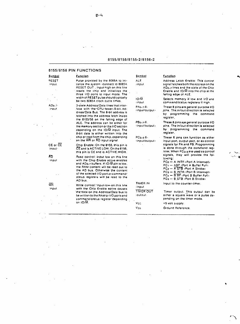
B-4
8155/8156/8155-218156-2
•••
Timer output. This output can beeither a square 'wave or 8 pulse de.pending on the timer mode.
+5 volt supply.
Ground Reference.
~Address lalch Enable: This contro!signal latches both the eddress on theADo_11ines and the slate of.the ChipEnable and to/~ into the chip at thelalling edge of ALE.
Selects memory if low end I/O andcommand/slatus registers il high.
These B pins are general purpose 1/0~pins. The.in/oul.direction is selecledby progremming the commandregisler.
These_8_pins.e~_general purpose I/Opins. The In/out'direction Is selectedby programming the commandregister.
These 6 plna can luncllon as eitherinput pori, O~lput PO{t, or, as controlsignals lor PA and pe. ProgrammingLs done through the commt.nd reg-isler, When PCo-~ are used es controlsignals, Ihey will provide the fol-lowing;PCo - A INTR IPori A Interrupl)PC, - ABF fPort A Buller FulllPC2 - A'5'i'"e I Port A Strobe IPC3 - B INTR rPort. B Interrupt)PC4 - !fN I POri B Bulrer Full IPC~ - 8.STB ,Port B Strobel
Input to lhe counter-limer.
~ymbot
ALE.input.
VeeVss
TIMER IN,input'
TIMER OUT,output
PCO-S,6,r input/oulput'
101M,input
PAO_7,B,
,input/outPut,
.PBO-7IB'inpuVoUlput,
Pulse provided by the B08SA to ini-tialize the system 'connect to BOSSAREseT OUT. Il"\pul high on this lineresets the Chip and initializes Ihethree I/O ports to input mode. Thewidth 01 RESET pulse should typicallybe two B08SA clock cycle times.
3-sillte Address/Oala lines Ihat inter.face wilh; the-CPU -lower ••8-biL Ad-dress/Data Bus. The a.bit address islatched inlo Ihe address latch insideIhe 8155/56 on Ihe lalling edge ofALE. The address can be either lorIhe memory section or Ihe 1/0 sectiondepending on Ihe 101M input. TheB-bit dala is either written into theChip or read from lhechip, depending([:In the WA or AD ir:pul signal
Chip Enable: On the 8155, this pin isCE and is ACTIVE LOW. On the 8156.this pin is CE and is ACTIVE. HIGH.
Read control: Input Iowan this linewith the Chip Enable active enablesand ADo_7 buffers. II [DIM pin is low.the RAM content will be read out 10
the AD bus. Otherwise the content01 the selected. I/O por.l.or ..commandlstalus registers will be read to the'AD bus.
Write control:-'Inpublow~on __this linewith the Chip Enable llclive causes-the-data-on-Ihe Address/Data bus 10be wrillen 10 the RAM or I/O ports andcommand/slatus- regis ler-de pendingon 10iM".
WRinput
RDInput
CE or CEinput.
8155/8156 PIN FUNCTIONS
Sy1!l2.o1RESpInput
•

8-5
8155/8156/8155-2/8156-2
DESCRIPTIONThe 8155/8156 contains the following,, 2k Bit Sialic RAM organized as 256 )( 8• Two a-bit I/O ports (PA &. PS) andone6-bit I/O.port(PC\• 14.bit timer-counter
The lO/M (lO/Memory Selecl) pin selecls either the riveregisters (Command, Status, PAo_T, PBO_T, PCO-5l orthe memory (RAMfporlion. (See Figure 1.)The 8-bit address on the Address/Dala lines, Chip Enable'input CE or CE, I!nd loiM are all latched on-chip al thetailing edge of-ALE._(See_Figure 2.)
TlMHIMoor
IIIIIIIIIIIL _
IIII,.IIIIII_________J
a 11\~51
.,
".
AOOAESS DATA ••.•AlIO
HOlE: fOR DETAILED TIMING INFORMATION, SEE FIGUfl[ 12 AND A.C. CHARACTERISTICS.
•••.• 1..1155/815& On.Bo.rd Memory Read/Write Cy'cle

B-\;
8155/8156/8155-2/8156-2
-~. O. IN"""J 1. ovtl'l,"
PROGRAMMING OF_THE-COMMAND REGISTERThe comma nd-reglsler--consisls-ol_ eight-Jalches._Fourbils 10-3, define the_mode-of "the-ports,-two_biIS. 14.5)enable- or- disable-the-lnlerrupl-lrom.porl_C when it aclsas control por't, and the lasllwo bits \6-7\ are lor the limer.the command register,'conlents can be altered at anytime by using the I/O address XXXXXOOO during a WRITEoperation with the Chip Enable active and 10m. 1. Themeaning 01 eaCh bit of the command byte is defined In-Figllre-3. The contents of the command register maynever be'read.
~.1:1 00' "1' ,
OIJl~1I toe.-. ~ _11. AL' II ---- OI •••• Ll)! l. IO••••lH
L _INjIt,BU.1'011lY A } •'lfnll"VI'T 1 • (NAOll
L ._. 1"''''IlLI "OAf. o. OISAIlUINT(I'A~T
roo' NO' _ 00 IWOT"'HCf C;OVHn~
I, OI'E~••"ONDI • 'ITOI'_ NOf'I' TI"'EII HAl HOTITVIHO;
ITOI' c;oVNflHGI' hIE T,•••tll rl: J IIUN',lIHQ
I 10. nOl' AFf(~ fC _ITO' r"''''lorAHl'I'LTu,nll.eo"''''''HO-i AFH~ I'1\UIHT TCII RI"CHIO lM)'
IF "IIlEA M.UNOT""IlTEDrI II. IUllf - ~o••o MODf""'0 tNT U"fOTHANDITAIlT t••••••fOlun" A'UIl
I ~O"O'NGII' T!MEIlII HOT'RUENnv
I ;~:~l~I~~t~~~ ~N~U~~:~"STAIUr -1••••••EO'••T(~:r MUll '"UINT TCL 1.IlEACHEO.
Flg~re 3. Co:mmand Regllter Bit Aulgnmenl
-READ ING-TH E.~STA.TUscRE GISTERThe status register consists 01seven latChes, 'one lor eachbit; six.(O-51 tor the slatus ollhe paris and one (6) for th,status 01 the timer.
.The status of the timer and the 1/0 secllon can be polleCiby reading the Slat us RegIster (Address XXXXXOOOI.Status word format i. shown in Figure 4, Nole that youmay never write to Ihe stalus register elnce the commandregister shares the same 1/0 address and the commandregister Is selected when.ll; write to that addr~S$ls issued.
".
'OfIITA IHTlIlIlUl'T IIItOVUf
P'Ol''' •• 'V"EIl 'vun •• "!t"''VTIOUfl'VTl
P'ORT, INTtlllllurT IIEoutn
I'OIlT' 'U'FlIII 'VLlIt"' ••."flM'UTlOuflVTI
-------- •• rollT IlINTlIIIII"T U••••UD
---------. ""'1Il IHf(III1UI'T /THISIttII LATCHED"IOH WHENUIl"'IN"~ COUNTIt
-IlE ••CHED,•••"IO 'I IIun TO~ow l'I'OH IlEADtHO0' TWI;CISIlfeHnElI AND'.HAflOWAIlE"unl.
Figure 4, SllIluI Regl.t., Blf Aul9nmlllnt

8155/8156/8155-2/8156-2
Flgure_5. 110 pori and Tlm.r Addreulng Scheme
'Igure 6.8155/8156 Port-Func,lIons-
"
0,,\:::)
II11II11
,I
1'1 • 1 '01'1OUTpUTMOO!• 0 rOIll I,""UT fIoIOO(
on
"HIII~'ON! 'IT or I'OI'IT'"01ll1'01"ITe
NO'U,lH OUnUTMOO( }III S,"'PU ''''PUT ,,"UlT'PlUl.ll'I121 STI'lOIEOlNp\,/t CONTIIOl11("'01'011T_ llolf;l'll' 1K!)..gl' IC! "'CTIV(I"ll'OlIIt-"'OOIlUI Ul!CTEO'.WIIITf I'OI'IT' "0'''''11' ,¥fIl,.",. !CEACTIV(l. l'ORT "'001'1($$SfUCT(DI
•. Don't C... _ _ _• 1I0"dnrtu •••"tlt>'lIu'''''tClt>,CE' I el~5 ,,,C!"C ~,~~ ." ••'O,M.""O'Qotr
'0 .tlfCI ,,,. 'PP'''P''''. r'O'l1t'
Figure 6 ShOws how I/O PORTS A and Bare strucluredwithin~lhe 8155 and 6156:
110AOOFlES5' I
"d .•.•SELECTION i•• •• " " •• " ----j
:I' , , , 0 0 0 1"le,•.~1CO"'''''''C! SI,luS A'9'"'', . " '. • 0 0 , C••ne'.l P,,'''Olf I 0 PO" .•• i
l • • • 0 , 0 Cen".~! PU'1)05" I 0 ,".:1"a i• • • • • 0 , , "0>1 C - 01'".'" ""'5'0.'" C' J' C"~"'"'!• • • • • , , , l<.••••O'C1l'•• 0'15 (II T,m", C,l"'" I
l-~ ~.
• • • , , , M"l" to tI,,. r! t,n .•••' CIl"nl .,,~:' t"I' Io! T,,,,,,, ~O<I••" - - ,
CONTROL INPUT MODE OUTPUT MODEBF Low Low
INTR Low High_STB -Input Control Input Control
INPUT/OUTPUT SECTIONThe i/o section of the 8155/81 56consists of live registers:l$ee. Figure 5.1• Command/StatuI Regilier (CIS) - Both regislel10 are
•• signed Ihe address XXXXXOOO. The CIS oddrsss-.- '-S8 rvu-the-d !J.I-pu 'POIle ;---
When the CIS regiliers are selected during .WAITE''opo,.lIoo, a command I, wrillen InlO tho command-rogilier. The con lent. of Ii'll.register Ir, not acce,eiblethrough the pin •.When the CIS (XXXXXOOOIis selected during a READoperation, the .talus information of the 110 ports andthe IImor become. avallabl.e on the ADo_tHnes,
• PA Rtgilltr - This register can be programmed 10beeither input or'output potts depending on the statuI 01the contenls of the CIS Aegister. Also depending onthe command, this port can operate In either the basicmode or Iha .Irobed mode ISee timing diagram l, TheI/O pin. DSsigned.ln relation 10 thi, regisier are PAO-7.The address oHhl. register I, XXXXXOO1.
• PB Regl.t., - This register funClions the same as PARegister.The I/O pins assigned are PBo-1.The addressalii'll, rogialer I. XXXXX010,
• PCA.gl.ler- This register has the address XXXXX011-and-conlalna-0nly-6-bl ta":-The-6-bll s-can-be--program~med to be elltler input port', output porta or as controltlgnala"for-PA-and-PB- by-properly. prog ramming theAP2and A03 bUa of Ihe.C/S regisler.When PCO-Ii la uaed aa--a-contr.ol-port.3-bhs-aro_••• Igned for Port A and 3 lor Port B. Ttle 'Iral bit Is aninterrupi thai ttlo--8155 senda-out. Ttle second Is anoutpul"",ignaHndlcaling-wheltler_',lhe buffer la lull or,mply. and ttle ttllrd I. an Input pin 10accept a strobelor Itle atrobed Input mode. l$ee Table 1.1
'Ml,n-the"C' port Is programmed 10either ALT3 or ALT.,tt'II control'algnall for PAand PBare initialized as lollow.:

B-8
8155/8156/8155-2/8156-2
TABLE 1. TABLE OF~PORT CONTAOl ASSIGNMENT.
PI" ALT 1 -ALT 2 .ALl 3 . ALT ••PCO Input Port Output Pori A INTR IPori A InterruptI A tNTR IPort A InterruPtiPC! 'Input PorI Output Po'r! - -A-,SF l-Porl~A-BullerJull! A SF IPori A Buller Full IPC2 Inpul"Porl Output Pori A S~ (POri A Slrobel A ~-IPort A StrobelPC3 Input Port Output Pori Output PorI e INTR IPori e Interrupt Ipce -Input Port- _ Output 'Port Output Port B SF ,Port B-Buffer Full tPCS Inpul Port Output Pori Output Pori -B-rn~(Port"B-Slrobel
Figure 7. Eumple: Command Reohl.r'" 00'11001
'OAll INP'
'0 Ion Iln '~J'VT
__TO 101le 1II1T.INI'UT
OVUUT 'OIlT A
A IHTA ISIC~ALI DATA .(CIIV(OI
A " ISIO~ALI OATil III!AOYI
•••ITS lAC. ~OWL. OA TA IIIfC( IV(OI
Inl IlOAO"OIlT I LAtC'11
I U ISIO~"'lS6V"(l'IIS 'ULLI
I I~TIII ISfG~"lS !lV"( 1\II.(AOY FOil Il(AOING,
IIUItIN
Nole in. the diagram that when the I/O POr.t1 are pro-grammed to be Oulpul pOrls, Ihe conlents 01 Ihe outpulporls'can still be read by a READ operation when appro.prielely addressed.
The outputs of the 8155/8156 are "gWen-free" meaningthai you can write a"," 10a bit position thai was previ.ously "1" and the level at the output pin will not change.Note also Ihat t'he oulpul latch Is cleared when Ihe porienters the inpul mode. The output latch cannot be loadedby writing to the port lithe pori i. in the input mode. Ther~sult is thllt ellch Umea port mode Is changed from Input-.to output, the output pins will go low. When the 8155/56is RESET, the output latches are all cteared and a1l3portsenter the input mOde:When in~the_ALT.1 'or'ALr2'mOdes, the bits-o'-PORT.C.are structured like the-diagram:-above-in-the'simple input,or output mode, respeclively,
Reading Irom an input port with nothing connected to the.pins will provide unpredictable results.
Figure 7"shows how the 8155/8156 I/O porlS might beconfigured in a~,typlca':MCS-a5 system,

5-9
8155/8156/8155-2/8156-2
Figure 10. Alymmetric.l Squ.r ••Wne Output fI •• ultlng.Irom Counl 01 flJ
Note that while the counler Is counting, you may load 11
new count and mode Into the CQunt length registers.Bilfore-lhe- new count and mode will be used--by thecounter, you!!!.!:!!! Issue a START command. to lhecounter, This applies even though you may only want 10Change_thecount and-use the previous mode, .
In case 01 an odd.numbered count, the first half-cy'cleof the squarewave output, which Is high. is one countlonger than the second (low) half:cycle, ,as ~hown inFigure 10,
NOll': If you started with an odd count and you read lhecount length register before the third count pulse OCcurs.YOuwill not be able to discern whether one or two COunl$has occurred, RegardleSi of this, the 8155/56 alwayscounts oul Ihe righl number of pulses In generating IheTIMER OUT waveforms. .
1, Stop the count
2. Read in the 16.bil value Irom the cOunt length registers
3. Aeset the upper two mode bits
4, Resel the carry and rotate right one position 811-'6bitsthrough carry
5. If carry is set, add 112of the lull original count, V2 lull'count - 1 illull count Is oddl. ' .
Tho Counter In the a, 5S is nol initialized to any parllc~larmode or count when hardware RESETOCCurs,but RESETdoes stop the counling,-Therelore, counting cannot beginlollowing RESET until a START command is i5'ued viathe CIS register:
Pleas. note that the limer circuit on the 8155/8156 Chip15 designed to be a square.wave timer, not an e..••ent-counler ..To ,aChieve this, it counts down by twos twiceIn completing one cycle. Thus, Its registers do nol con •.'Iain-values directly representing the number of TIMER INpulse. received. You cannot load an Initial value 011 intoIhe count regisler and cause Ihe timer to operate. as ItstermInal Count value is 10 (binary) or 2 (decimall. IForthe_detection of single pulses, it ia suggested that one01 the hardware interrupt-pins on .the 808SA be used.lAfter Ihe timer has started counting down. the valuesresiding In the count registers can be used to calCulatethe actual number of TIMER IN pulses required to.com.plele the Iimer cycle II desired. To obtain the remainingcount, perlorm the 101l0wingoperations' In order:
•
•2
2
u
u-----------
,
,•
•
MSB OF CNT LENGTH
•LSB OF C~T LENGTH
•
•
o NOP - 00 nol affect counter operation,
1 STOP - NOP If timer has not started;alop counting il the timer is running.
o STOP AFTER TC - Stop immediatelyalter present TC Is reached (NOP if timerhas-not starled).
START - Load mode and CNT lengthand slarl immediately after loading IIItimer_is not presently running l. If timerIs running, start the new mode and CNTlenglh Immediately aller prescnt TC Isreached.
,
,••
TlMER'MODE
2. CONT'NUOUIIOVAAI"A'll
1. 'INaLI.•. _ 'ULII ON-
TfI'lMINAL COUNT
1 •• CONTINUOUS. roUts .
oo
'~\lr._ •• -Tlm.r Mod.,81ls6-7 (TM2 end TM1) of command regisler contentsart used to ,tart and stop lhe counter, There are four~m.nd. to choose from:
TM2 TMI
TIMER SECTIONThe timer Is. '.-blt down""Counle,'thatcounla the TIMERIN pulses and provide. either a .quare wave or pulsewhl!ln-termlnat-count-(TC)-Is-reached~ .
The.tlmer.has the 1/0 addrOil XXXXX100for the lawarderbyte 01 the regIster and the 1I0-addreu-XXXXX101~lorlhe'tllgh-order byte 01 the register. (See Flgure-5).To program the timer, the COlJNT"lENGTft:-REa-ilIceded -firat, one bylo at a time. by selecllng the limeraddreu81. Bite 0.13 01 the nigh order Count regIster will.pecUy the length of the nut count and bits 14-15 of thehigh. order _register will specify the timer. output mode(leo Figure 8). The value loaded Into the count lengthregIsler can hIve any value from 2H through 3FFH In81\.-0=13.
'-- ~-'llIur.' '.-Tlmer-form.L
ThereBre four modes to choose from: M2 and M1 definelhe tlme(mode, as shown in Figure 9,

B-l0.',~
'" ;.
,., .t-~....",:',., . .:.'~i.';'.~....- --.._----
•ABSOLUTE MAXIMUM RATINGS / Ta=25°C STK.433 STK.435 STK-437 STK.439 STK.441
Maximum Supply Volt<Jge Vee max 32 39 50 56 63 V(pin 7 t04 or 121
Operating Case Temperature TC 90 90 90 85 85 °c
Slor~ge Temperature T"9 ~ .~ ~ ..• -30 to +100 °c
Allowable Load Shoni ng ,,' ..• ~ ~ ...• 2 $ecTime (in appollltt:d cundition)
RECOMMENDED OPERATION CONDITION / Tag25°C•
STK-433 STK.435 STK.437 STK.439 STK.441,
Supply Vollage Vee 23 27 33 39 44 VLoad Resistance i'lL ..• ...• ...• ..• 8 n. .
OPEI'lATION CHARACTERISTICS / Ta=25°C, recommended condition, Pgg600n, VG-40dB .
STK.433 STK.435 STK.437 STK.439 STK-441 unit ,•
Ouiescent Current iceD recomrne,lued ..• ~ ..• ...• 120 mAmaxVee
1---Features• <:JIMST,2 Channel, by 1 Pow.r Supply• Small shock noise becaUie of direct coupllng
emitter feed backed• AF outPut power STK-433: 5Wmin., STK-435:7Wmin., STK-437: lOW min., STK.439: 15Wmin" STK-411: 20Wmin.
•%max
20 Wmin' 'I
0.3
25V
C'I
C5C6
:-~. ;j]K.: ;isK'Cl J6V
C? IOV
C3 16V
Output Power Po THD=I%, 5 7 10 15l=lkHz
Distortion THO Po=O.lW, 0.5 0.5 0.2 0.2t=1kHz
Fre4UeQCY: Po=O.IW ...• ...• ...• ....Response
APPLICATION: AF Power Amp.
STK 4j3.435.437.439.441