HDFC Life/CA/2021-22/27 Listing Department Listing ... - NSE
Upload
khangminh22Category
view
3download
0
ICC-ES Evaluation Reports are not to be construed as representing aesthetics or any other attributes not specifically addressed, nor are they to be construed as an endorsement of the subject of the report or a recommendation for its use. There is no warranty by ICC Evaluation Service, LLC, express or implied, as to any finding or other matter in this report, or as to any product covered by the report.
Copyright © 2022 ICC Evaluation Service, LLC. All rights reserved. Page 1 of 37
ICC-ES Listing Report ELC-3814 Reissued May 2022
This listing is subject to renewal May 2023.
www.icc-es.org | (800) 423-6587 | (562) 699-0543 A Subsidiary of the International Code Council ®
CSI: DIVISION: 03 00 00—CONCRETE Section: 03 16 00—Concrete Anchors
DIVISION: 05 00 00—METALS Section: 05 05 19—Post-Installed Concrete Anchors
Product Certification System: The ICC-ES product-certification system includes evaluating reports of tests of standard manufactured product, prepared by accredited testing laboratories and provided by the listee, to verify compliance with applicable codes and standards. The system also involves factory inspections, and assessment and surveillance of the listee’s quality system.
Product: Hilti HIT-RE 500 V3 Adhesive Anchor System in Cracked and Uncracked Concrete.
Listee: HILTI, INC. Compliance with the following standards:
Annex D, Anchorage of CSA A23.3-14, Design of Concrete Structures, CSA Group. Compliance with the following codes:
Hilti HIT-RE 500 V3 adhesive anchor system in cracked and uncracked concrete, as described in this listing report, are in conformance with CSA A23.3-14, Annex D, as referenced in the applicable section of the following code editions: National Building Code of Canada® 2015 and 2010
Applicable Section: Division B, Part 4, Section 4.3.3. Description of adhesive anchor system:
The Hilti HIT-RE 500 V3 Adhesive is an injectable two-component epoxy adhesive. The two components combine and react when dispensed through a static mixing nozzle attached to the manifold. Hilti HIT-RE 500 V3 is available in 11.1-ounce (330 mL), 16.9-ounce (500 mL), and 47.3-ounce (1400 mL) foil packs. The manifold attached to each foil pack is stamped with the adhesive expiration date. The shelf life, as indicated by the expiration date, applies to an unopened foil pack stored in a dry, dark environment and in accordance with Figure 2. Hole Cleaning Equipment:
Standard hole cleaning equipment, comprised of steel wire brushes and air nozzles, is described in Figure 2 of this listing report The Hilti Safe-Set™ with Hilti HIT-RE 500 V3 consists of one of the following:
• For the anchor elements, threaded steel rods, steel reinforcing bars for use as anchorsand Hilti HIS-N and HIS-RS inserts, the Hilti TE-CD or TE-YD hollow carbide drill bit with a carbide drilling head conforming to ANSI B212.15 must be used. Used in conjunction with a Hilti vacuum with a minimum value for the maximum volumetric flow rate of 129 CFM (61 l/s), the Hilti TE-CD or TE-YD drill bit will remove the drilling dust, automatically cleaning the hole.
• For the anchor elements, threaded steel rods, steel reinforcing bars for use as anchorsand Hilti HIS-N and HIS-RS inserts, the Hilti Safe-Set™ with TE-YRT roughening tool with a carbide roughening head is used for hole preparation in conjunction with holes core drilled with a diamond core bit as illustrated in Figure 4.
Hilti HIT-RE 500 V3 must be dispensed with manual or electric dispensers provided by Hilti.

ELC-3814 | Most Widely Accepted and Trusted Page 2 of 37
HILTI HIT-RE 500 V3 FOIL PACK AND MIXING NOZZLE
ANCHORING ELEMENTS
HILTI DISPENSER
HILTI TE-CD OR TE-YD HOLLOW CARBIDE DRILL BIT
HILTI TE-YRT ROUGHENING TOOL
FIGURE 1—HILTI HIT-RE 500 V3 ANCHORING SYSTEM
Identification: 1. The Hilti HIT-RE 500 V3 anchors are identified by packaging labeled with the manufacturer’s name
(Hilti Corp.) and address, product name, lot number, expiration date, and listing number (ELC-3814), and the ICC-ES listing mark. Threaded rods, nuts, washers, cap screws, and deformed reinforcing bars are standard elements and must conform to applicable national or specifications as set forth in Tables 3-6 of this listing report or equivalent.
2. The report holder’s contact information is the following: HILTI, INC. 7250 DALLAS PARKWAY, SUITE 1000 PLANO, TEXAS 75024 (800) 879-8000 www.us.hilti.com [email protected]
Installation: 1. The installation parameters are illustrated in Figure 3. Installation must be in accordance with CSA
A23.3-14 D.10 and D.10.2, as applicable. Anchor locations must comply with this listing report and the plans and specifications approved by the code official. Installation of the Hilti HIT-RE 500 V3 Adhesive Anchor Systems must conform to the manufacturer’s printed installation instructions (MPII) included in each unit package as provided in Figure 2 of this report. The MPII contains additional requirements for combinations of drill hole depth, diameter, drill bit type, and dispensing tools. Hilti HIT-RE 500 V3 adhesive anchors may be used to resist tension and shear forces in floor, wall, and overhead installations only if installation is into concrete with a temperature between 23°F and 104°F (-5°C and 40°C) for threaded rods, rebar, and Hilti HIS-(R)N inserts. Overhead installations for hole diameters larger than 7/16-inch or 10mm require the use of piston plugs (HIT-SZ, -IP) during injection to the back of the hole. 7/16-inch or 10mm diameter holes may be injected directly to the back of the hole with the use of extension tubing on the end of the nozzle. The anchor must be supported until fully cured (i.e., with Hilti HIT-OHW wedges, or other suitable means). Where temporary restraint devices are used, their use shall not result in impairment of the anchor shear resistance. Installations in concrete temperatures below 41°F (5°C) require the adhesive to be conditioned to a minimum temperature of 41°F (5°C). Installation of anchors in horizontal or upwardly inclined orientations to resist sustained tension loads shall be performed by personnel certified by an applicable certification program in accordance with CSA A23.3-14 D.10.2.2 or D.10.2.3, as applicable.

ELC-3814 | Most Widely Accepted and Trusted Page 3 of 37
FIGURE 2—MANUFACTURER’S PRINTED INSTALLATION INSTRUCTIONS (MPII)

ELC-3814 | Most Widely Accepted and Trusted Page 4 of 37
FIGURE 2—MANUFACTURER’S PRINTED INSTALLATION INSTRUCTIONS (MPII) (Continued)
h

ELC-3814 | Most Widely Accepted and Trusted Page 5 of 37
FIGURE 2—MANUFACTURER’S PRINTED INSTALLATION INSTRUCTIONS (MPII) (Continued)

ELC-3814 | Most Widely Accepted and Trusted Page 6 of 37
FIGURE 2—MANUFACTURER’S PRINTED INSTALLATION INSTRUCTIONS (MPII) (Continued)
ELC-3814 | Most Widely Accepted and Trusted Page 7 of 37
FIGURE 2—MANUFACTURER’S PRINTED INSTALLATION INSTRUCTIONS (MPII) (Continued)

ELC-3814 | Most Widely Accepted and Trusted Page 8 of 37
FIGURE 2—MANUFACTURER’S PRINTED INSTALLATION INSTRUCTIONS (MPII) (Continued)

ELC-3814 | Most Widely Accepted and Trusted Page 9 of 37
FIGURE 2—MANUFACTURER’S PRINTED INSTALLATION INSTRUCTIONS (MPII) (Continued)

ELC-3814 | Most Widely Accepted and Trusted Page 10 of 37
FIGURE 2—MANUFACTURER’S PRINTED INSTALLATION INSTRUCTIONS (MPII)

ELC-3814 | Most Widely Accepted and Trusted Page 11 of 37
Anchor setting information: DEFORMED REINFORCMENT
THREADED ROD
HILTI HIS-N AND HIS-RN THREADED INSERTS
FIGURE 3—INSTALLATION PARAMETERS FOR POST-INSTALLED ADHESIVE ANCHORS
h h
h
ELC-3814 | Most Widely Accepted and Trusted Page 12 of 37
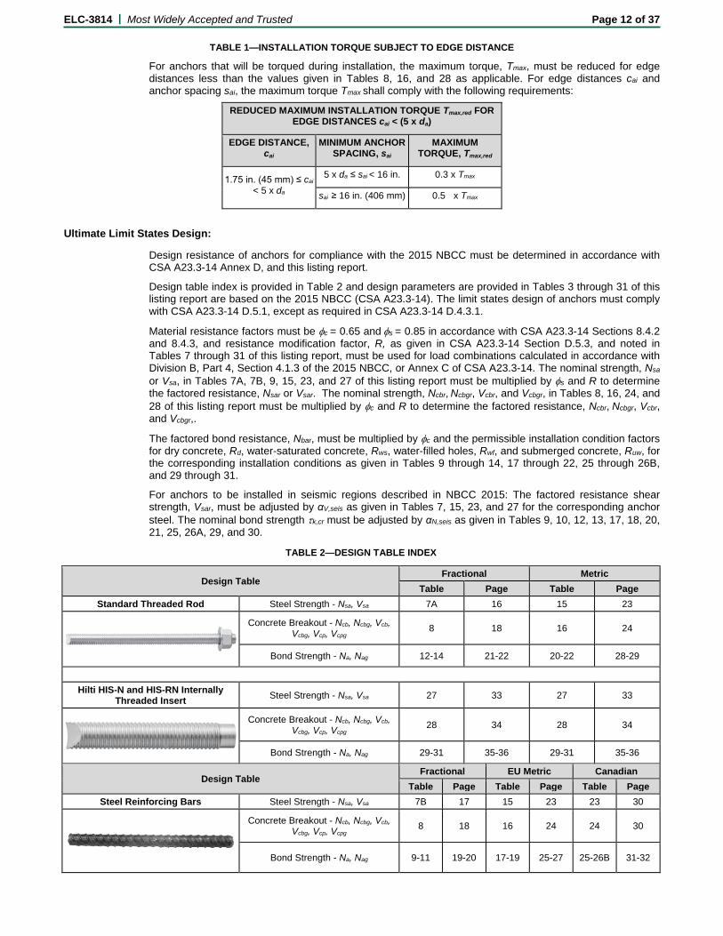
TABLE 1—INSTALLATION TORQUE SUBJECT TO EDGE DISTANCE
For anchors that will be torqued during installation, the maximum torque, Tmax, must be reduced for edge distances less than the values given in Tables 8, 16, and 28 as applicable. For edge distances cai and anchor spacing sai, the maximum torque Tmax shall comply with the following requirements:
REDUCED MAXIMUM INSTALLATION TORQUE Tmax,red FOR EDGE DISTANCES cai < (5 x da)
EDGE DISTANCE, cai
MINIMUM ANCHOR SPACING, sai
MAXIMUM TORQUE, Tmax,red
1.75 in. (45 mm) ≤ cai < 5 x da
5 x da ≤ sai < 16 in. 0.3 x Tmax
sai ≥ 16 in. (406 mm) 0.5 x Tmax
Ultimate Limit States Design:
Design resistance of anchors for compliance with the 2015 NBCC must be determined in accordance with CSA A23.3-14 Annex D, and this listing report.
Design table index is provided in Table 2 and design parameters are provided in Tables 3 through 31 of this listing report are based on the 2015 NBCC (CSA A23.3-14). The limit states design of anchors must comply with CSA A23.3-14 D.5.1, except as required in CSA A23.3-14 D.4.3.1.
Material resistance factors must be φc = 0.65 and φs = 0.85 in accordance with CSA A23.3-14 Sections 8.4.2 and 8.4.3, and resistance modification factor, R, as given in CSA A23.3-14 Section D.5.3, and noted in Tables 7 through 31 of this listing report, must be used for load combinations calculated in accordance with Division B, Part 4, Section 4.1.3 of the 2015 NBCC, or Annex C of CSA A23.3-14. The nominal strength, Nsa or Vsa, in Tables 7A, 7B, 9, 15, 23, and 27 of this listing report must be multiplied by φs and R to determine the factored resistance, Nsar or Vsar. The nominal strength, Ncbr, Ncbgr, Vcbr, and Vcbgr, in Tables 8, 16, 24, and 28 of this listing report must be multiplied by φc and R to determine the factored resistance, Ncbr, Ncbgr, Vcbr, and Vcbgr,.
The factored bond resistance, Nbar, must be multiplied by φc and the permissible installation condition factors for dry concrete, Rd, water-saturated concrete, Rws, water-filled holes, Rwf, and submerged concrete, Ruw, for the corresponding installation conditions as given in Tables 9 through 14, 17 through 22, 25 through 26B, and 29 through 31.
For anchors to be installed in seismic regions described in NBCC 2015: The factored resistance shear strength, Vsar, must be adjusted by αV,seis as given in Tables 7, 15, 23, and 27 for the corresponding anchor steel. The nominal bond strength τk,cr must be adjusted by αN,seis as given in Tables 9, 10, 12, 13, 17, 18, 20, 21, 25, 26A, 29, and 30.
TABLE 2—DESIGN TABLE INDEX
Design Table Fractional Metric
Table Page Table Page Standard Threaded Rod Steel Strength - Nsa, Vsa 7A 16 15 23
Concrete Breakout - Ncb, Ncbg, Vcb, Vcbg, Vcp, Vcpg 8 18 16 24
Bond Strength - Na, Nag 12-14 21-22 20-22 28-29
Hilti HIS-N and HIS-RN Internally
Threaded Insert Steel Strength - Nsa, Vsa 27 33 27 33
Concrete Breakout - Ncb, Ncbg, Vcb, Vcbg, Vcp, Vcpg 28 34 28 34
Bond Strength - Na, Nag 29-31 35-36 29-31 35-36
Design Table Fractional EU Metric Canadian
Table Page Table Page Table Page Steel Reinforcing Bars Steel Strength - Nsa, Vsa 7B 17 15 23 23 30
Concrete Breakout - Ncb, Ncbg, Vcb, Vcbg, Vcp, Vcpg 8 18 16 24 24 30
Bond Strength - Na, Nag 9-11 19-20 17-19 25-27 25-26B 31-32

ELC-3814 | Most Widely Accepted and Trusted Page 13 of 37
FIGURE 4—FLOWCHART FOR THE ESTABLISHMENT OF DESIGN BOND STRENGTH

ELC-3814 | Most Widely Accepted and Trusted Page 14 of 37
TABLE 3—SPECIFICATIONS AND PHYSICAL PROPERTIES OF COMMON CARBON AND STAINLESS STEEL THREADED ROD MATERIALS1
THREADED ROD SPECIFICATION
Minimum specified ultimate
strength, futa
Minimum specified
yield strength 0.2 percent offset, fya
futa/fya
Elongation, min.
percent7
Reduction of Area,
min. percent
Specification for nuts8
CAR
BON
STE
EL
ASTM A1932 Grade B7 ≤ 21/2 in. (≤ 64 mm) MPa 862 724 1.19 16 50 ASTM A563 Grade DH
ASTM F568M3 Class 5.8 M5 (1/4 in.) to M24 (1 in.) (equivalent to ISO 898-1)
MPa 500 400 1.25 10 35 ASTM A563 Grade DH9 DIN 934 (8-A2K)
ASTM F1554, Grade 367 MPa 400 248 1.61 23 40 ASTM A194 or ASTM A563
ASTM F1554, Grade 557 MPa 517 379 1.36 21 30 ASTM A194 or ASTM A563
ASTM F1554, Grade 1057 MPa 862 724 1.19 15 45 ASTM A194 or ASTM A563
ISO 898-14 Class 5.8 MPa 500 400 1.25 22 - DIN 934 Grade 6
ISO 898-14 Class 8.8 MPa 800 640 1.25 12 52 DIN 934 Grade 8
STAI
NLE
SS S
TEEL
ASTM F5935 CW1 (316) 1/4-in. to 5/8-in. MPa 689 448 1.54 20 - ASTM F594
ASTM F5935 CW2 (316) 3/4-in. to 11/2-in. MPa 586 310 1.89 25 - ASTM F594
ASTM A193 Grade 8(M), Class 12 - 1 ¼-in. MPa 517 207 2.50 30 50 ASTM F594
ISO 3506-16 A4-70 M8 – M24 MPa 700 450 1.56 40 - ISO 4032
ISO 3506-16 A4-50 M27 – M30 MPa 500 210 2.38 40 - ISO 4032
1 Hilti HIT-RE 500 V3 adhesive may be used in conjunction with all grades of continuously threaded carbon or stainless steel rod (all-thread) that comply with the code reference standards and that have thread characteristics comparable with ANSI B1.1 UNC Coarse Thread Series or ANSI B1.13M M Profile Metric Thread Series. Values for threaded rod types and associated nuts supplied by Hilti are provided here.
2 Standard Specification for Alloy-Steel and Stainless Steel Bolting Materials for High-Temperature Service 3 Standard Specification for Carbon and Alloy Steel Externally Threaded Metric Fasteners 4 Mechanical properties of fasteners made of carbon steel and alloy steel – Part 1: Bolts, screws and studs 5 Standard Steel Specification for Stainless Steel Bolts, Hex Cap Screws, and Studs 6 Mechanical properties of corrosion-resistant stainless steel fasteners – Part 1: Bolts, screws and studs 7 Based on 2-in. (50 mm) gauge length except for A193, which are based on a gauge length of 4d and ISO 898, which is based on 5d. 8 Nuts of other grades and styles having specified proof load stresses greater than the specified grade and style are also suitable. Nuts must have specified proof
load stresses equal to or greater than the minimum tensile strength of the specified threaded rod. 9 Nuts for fractional rods.
TABLE 4—SPECIFICATIONS AND PHYSICAL PROPERTIES OF COMMON STEEL REINFORCING BARS
REINFORCING BAR SPECIFICATION
Minimum specified ultimate strength, futa
Minimum specified yield strength, fya
ASTM A6151 Gr. 60 MPa 620 414
ASTM A6151 Gr. 40 MPa 414 276
ASTM A7062 Gr. 60 MPa 550 414
DIN 4883 BSt 500 MPa 550 500
CAN/CSA-G30.184 Gr. 400 MPa 540 400 1 Standard Specification for Deformed and Plain Carbon Steel Bars for Concrete Reinforcement 2 Standard Specification for Low Alloy Steel Deformed and Plain Bars for Concrete Reinforcement 3 Reinforcing steel; reinforcing steel bars; dimensions and masses 4 Billet-Steel Bars for Concrete Reinforcement

ELC-3814 | Most Widely Accepted and Trusted Page 15 of 37
TABLE 5—SPECIFICATIONS AND PHYSICAL PROPERTIES OF FRACTIONAL AND METRIC HIS-N AND HIS-RN INSERTS
HILTI HIS-N AND HIS-RN INSERTS
Minimum specified ultimate strength, futa Minimum specified yield strength, fya
Carbon Steel DIN EN 10277-3 11SMnPb30+c or DIN 1561 9SMnPb28K
MPa 490 390
Stainless Steel EN 10088-3 X5CrNiMo 17-12-2 MPa 700 350
TABLE 6—SPECIFICATIONS AND PHYSICAL PROPERTIES OF COMMON BOLTS, CAP
SCREWS AND STUDS FOR USE WITH HIS-N AND HIS-RN INSERTS1,2
BOLT, CAP SCREW OR STUD SPECIFICATION
Minimum specified ultimate
strength futa
Minimum specified
yield strength 0.2 percent
offset fya
futa/fya Elongation,
min. Reduction
of Area, min.
Specification for nuts6
ASTM A193 Grade B7 MPa 862 724 1.119 16 50 ASTM A563 Grade DH
SAE J4293 Grade 5 MPa 828 634 1.30 14 35 SAE J995
ASTM A3254 1/2 to 1-in. MPa 828 634 1.30 14 35 A563 C, C3, D, DH, DH3 Heavy Hex
ASTM A1935 Grade B8M (AISI 316) for use with HIS-RN MPa 759 655 1.16 15 45 ASTM F5947
Alloy Group 1, 2 or 3
ASTM A1935 Grade B8T (AISI 321) for use with HIS-RN MPa 862 690 1.25 12 35 ASTM F5947
Alloy Group 1, 2 or 3
1 Minimum Grade 5 bolts, cap screws or studs must be used with carbon steel HIS inserts. 2 Only stainless steel bolts, cap screws or studs must be used with HIS-RN inserts. 3 Mechanical and Material Requirements for Externally Threaded Fasteners 4 Standard Specification for Structural Bolts, Steel, Heat Treated, 120/105 ksi Minimum Tensile Strength 5 Standard Specification for Alloy-Steel and Stainless Steel Bolting Materials for High-Temperature Service 6 Nuts must have specified minimum proof load stress equal to or greater than the specified minimum full-size tensile strength of the specified stud. 7 Nuts for stainless steel studs must be of the same alloy group as the specified bolt, cap screw, or stud.

ELC-3814 | Most Widely Accepted and Trusted Page 16 of 37
Fractional Threaded Rod Steel Strength
TABLE 7A—STEEL DESIGN INFORMATION FOR FRACTIONAL THREADED ROD
DESIGN INFORMATION Symbol Units Nominal rod diameter (in.)1
3/8 1/2 5/8 3/4 7/8 1 11/4
Rod O.D. d in. 0.375 0.5 0.625 0.75 0.875 1 1.25 (mm) (9.5) (12.7) (15.9) (19.1) (22.2) (25.4) (31.8)
Rod effective cross-sectional area Ase in.2 0.0775 0.1419 0.2260 0.3345 0.4617 0.6057 0.9691
(mm2) (50) (92) (146) (216) (298) (391) (625)
ISO
898
-1
Cla
ss 5
.8 Nominal strength as governed by steel
strength Nsa kN 25.0 45.8 72.9 107.9 148.9 195.3 312.5
Vsa kN 15.0 27.5 43.7 64.7 89.3 117.2 187.5 Reduction for seismic shear αV,seis - 1.0 Resistance modification factor for tension3 R - 0.70 Resistance modification factor for shear3 R - 0.65
ASTM
A19
3 B7
Nominal strength as governed by steel strength
Nsa kN 43.1 78.9 125.7 186.0 256.7 336.8 538.8
Vsa kN 25.9 47.3 75.4 111.6 154.0 202.1 323.3 Reduction for seismic shear αV,seis - 1.0 Resistance modification factor for tension2 R - 0.80 Resistance modification factor for shear2 R - 0.75
ASTM
F15
54
Gr.
36
Nominal strength as governed by steel strength
Nsa kN - 36.6 58.3 86.3 119.1 156.3 250.0
Vsa kN - 22.0 35.0 51.8 71.5 93.8 150.0 Reduction factor, seismic shear αv,seis - 0.60 Resistance modification factor for tension2 R - 0.80 Resistance modification factor for shear2 R - 0.75
ASTM
F15
54
Gr.
55
Nominal strength as governed by steel strength
Nsa kN - 47.4 75.4 111.6 154.0 202.1 323.3 Vsa kN - 28.4 45.2 67.0 92.4 121.3 194.0
Reduction factor, seismic shear αv,seis - 1.0 Resistance modification factor for tension2 R - 0.80 Resistance modification factor for shear2 R - 0.75
ASTM
F15
54
Gr.
105
Nominal strength as governed by steel strength
Nsa kN - 78.9 125.7 186.0 256.7 336.8 538.8
Vsa kN - 47.3 75.4 111.6 154.0 202.1 323.3 Reduction factor, seismic shear αv,seis - 1.0 Resistance modification factor for tension2 R - 0.80 Resistance modification factor for shear2 R - 0.75
ASTM
F59
3, C
W
Stai
nles
s
Nominal strength as governed by steel strength
Nsa kN 34.5 63.1 100.5 126.5 174.6 229.0 -
Vsa kN 20.7 37.9 60.3 75.9 104.7 137.4 -
Reduction factor, seismic shear αv,seis - 0.8 -
Resistance modification factor for tension3 R - 0.70 -
Resistance modification factor for shear3 R - 0.65 -
ASTM
A19
3, G
r. 8(
M),
Cla
ss 1
St
ainl
ess
Nominal strength as governed by steel strength
Nsa kN - 245.7
Vsa kN - 147.4
Reduction factor, seismic shear αv,seis - - 0.8
Resistance modification factor for tension2 R - - 0.80
Resistance modification factor for shear2 R - - 0.75
For SI: 1 inch = 25.4 mm, 1 lbf = 4.448 N. For pound-inch units: 1 mm = 0.03937 inches, 1 N = 0.2248 lbf 1 Values provided for common material types based on specified strengths and calculated in accordance with CSA A23.3-14 Eq. D.2 and Eq. D.3. 2 The tabulated value of the material resistance factors φc and φs, and resistance modification factor, R, applies when the load combinations of Division B, Part 4, Section 4.1.3 of the 2015 NBCC or Annex C of CSA A23.3-14 are used. Values correspond to ductile steel elements. 3 The tabulated value of material resistance factors φc and φs, and resistance modification factor, R, applies when the load combinations of Division B, Part 4, Section 4.1.3 of the 2015 NBCC or Annex C of CSA A23.3-14 are used. Values correspond to brittle steel elements.
ELC-3814 | Most Widely Accepted and Trusted Page 17 of 37
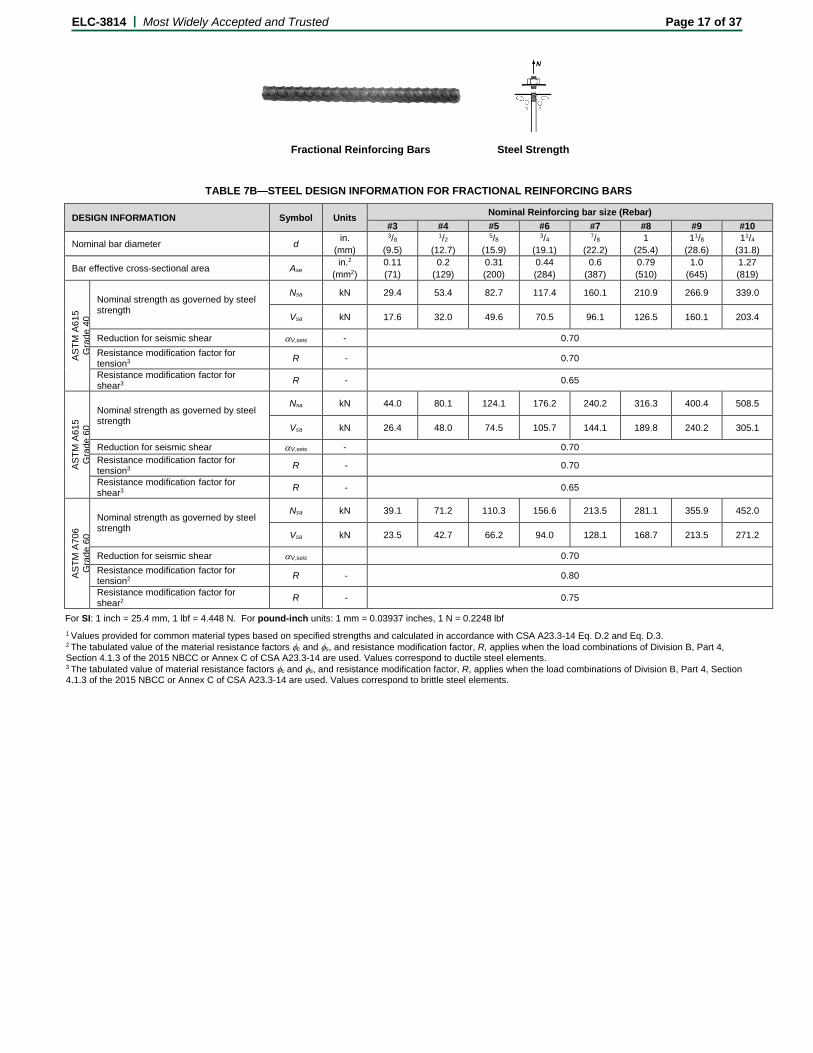
Fractional Reinforcing Bars Steel Strength
TABLE 7B—STEEL DESIGN INFORMATION FOR FRACTIONAL REINFORCING BARS
DESIGN INFORMATION Symbol Units Nominal Reinforcing bar size (Rebar) #3 #4 #5 #6 #7 #8 #9 #10
Nominal bar diameter d in. 3/8 1/2 5/8 3/4 7/8 1 11/8 11/4 (mm) (9.5) (12.7) (15.9) (19.1) (22.2) (25.4) (28.6) (31.8)
Bar effective cross-sectional area Ase in.2 0.11 0.2 0.31 0.44 0.6 0.79 1.0 1.27
(mm2) (71) (129) (200) (284) (387) (510) (645) (819)
ASTM
A61
5
Gra
de 4
0
Nominal strength as governed by steel strength
Nsa kN 29.4 53.4 82.7 117.4 160.1 210.9 266.9 339.0
Vsa kN 17.6 32.0 49.6 70.5 96.1 126.5 160.1 203.4
Reduction for seismic shear αV,seis - 0.70 Resistance modification factor for tension3 R - 0.70
Resistance modification factor for shear3 R - 0.65
ASTM
A61
5 G
rade
60
Nominal strength as governed by steel strength
Nsa kN 44.0 80.1 124.1 176.2 240.2 316.3 400.4 508.5
Vsa kN 26.4 48.0 74.5 105.7 144.1 189.8 240.2 305.1
Reduction for seismic shear αV,seis - 0.70 Resistance modification factor for tension3 R - 0.70
Resistance modification factor for shear3 R - 0.65
ASTM
A70
6 G
rade
60
Nominal strength as governed by steel strength
Nsa kN 39.1 71.2 110.3 156.6 213.5 281.1 355.9 452.0
Vsa kN 23.5 42.7 66.2 94.0 128.1 168.7 213.5 271.2
Reduction for seismic shear αV,seis 0.70 Resistance modification factor for tension2 R - 0.80
Resistance modification factor for shear2 R - 0.75
For SI: 1 inch = 25.4 mm, 1 lbf = 4.448 N. For pound-inch units: 1 mm = 0.03937 inches, 1 N = 0.2248 lbf 1 Values provided for common material types based on specified strengths and calculated in accordance with CSA A23.3-14 Eq. D.2 and Eq. D.3. 2 The tabulated value of the material resistance factors φc and φs, and resistance modification factor, R, applies when the load combinations of Division B, Part 4, Section 4.1.3 of the 2015 NBCC or Annex C of CSA A23.3-14 are used. Values correspond to ductile steel elements. 3 The tabulated value of material resistance factors φc and φs, and resistance modification factor, R, applies when the load combinations of Division B, Part 4, Section 4.1.3 of the 2015 NBCC or Annex C of CSA A23.3-14 are used. Values correspond to brittle steel elements.

ELC-3814 | Most Widely Accepted and Trusted Page 18 of 37
Fractional Threaded Rod and
Reinforcing Bars Concrete Breakout Strength Carbide Bit or
Hilti Hollow Carbide Bit Diamond Core Bit +
Roughening Tool, or Diamond Core Bit
TABLE 8—CONCRETE BREAKOUT DESIGN INFORMATION FOR FRACTIONAL THREADED ROD AND REINFORCING BARS ALL DRILLING METHODS1
DESIGN INFORMATION Symbol Units
Nominal rod diameter (in.) / Reinforcing bar size 3/8 or
#3 1/2 #4 5/8 #5 3/4 #6 7/8 #7 1 or
#8 #9 11/4 or
#10 Effectiveness factor for cracked concrete kc,cr
SI 7 (in-lb) (17)
Effectiveness factor for uncracked concrete
kc,uncr
SI 10
(in-lb) (24)
Minimum Embedment hef,min
mm 60 70 60 79 76 89 76 89 85 102 114 127
(in.) (23/8) (23/4) (23/8) (31/8) (3) (31/2) (3) (31/2) (33/8) (4) (41/2) (5)
Maximum Embedment hef,max
mm 191 254 254 318 318 381 381 445 445 508 572 635 (in.) (71/2) (10) (10) (121/2) (121/2) (15) (15) (171/2) (171/2) (20) (221/2) (25)
Min. anchor spacing3 smin mm 48 64 64 79 79 95 95 111 111 127 143 159 (in.) (17/8) (21/2) (21/2) (31/8) (31/8) (33/4) (33/4) (43/8) (43/8) (5) (55/8) (61/4)
Min. edge distance3 cmin - 5d; or see Table 1 of this report for design with reduced minimum edge distances
Minimum concrete thickness hmin
mm hef + 30 hef + 2d0
(3)
(in.) (hef + 11/4) Critical edge distance – splitting (for uncracked concrete)
cac - 2hef
Resistance modification factor for tension, concrete failure modes, Condition B2
R - 1.00
Resistance modification factor for shear, concrete failure modes, Condition B2
R - 1.00
For SI: 1 inch ≡ 25.4 mm, 1 lbf = 4.448 N, 1 psi = 0.006897 MPa. For pound-inch units: 1 mm = 0.03937 inches, 1 N = 0.2248 lbf, 1 MPa = 145.0 psi 1 Additional setting information is described in Figure 2, Manufacturers Printed Installation Instructions (MPII). 2 Condition A requires supplemental reinforcement, while Condition B applies where supplemental reinforcement is not provided or where pullout or pryout governs, as set forth in CSA A23.3-14 D.5. The tabulated value of the material resistance factors φc and φs, and resistance modification factor, R, applies when the load combinations of Division B, Part 4, Section 4.1.3 of the 2015 NBCC or Annex C of CSA A23.3-14 are used. 3 d0 = hole diameter.

ELC-3814 | Most Widely Accepted and Trusted Page 19 of 37
Fractional Reinforcing Bars Bond Strength Carbide Bit or Hilti Hollow Carbide Bit
TABLE 9—BOND STRENGTH DESIGN INFORMATION FOR FRACTIONAL REINFORCING BARS IN HOLES DRILLED WITH A HAMMER DRILL AND CARBIDE BIT (OR HILTI HOLLOW CARBIDE DRILL BIT)1
DESIGN INFORMATION Symbol Units Nominal reinforcing bar size
#3 #4 #5 #6 #7 #8 #9 #10
Minimum Embedment hef,min mm 60 60 76 76 85 102 114 127 (in.) (23/8) (23/8) (3) (3) (33/8) (4) (41/2) (5)
Maximum Embedment hef,max mm 191 254 318 381 445 508 572 635 (in.) (71/2) (10) (121/2) (15) (171/2) (20) (221/2) (25)
Dry
con
cret
e an
d W
ater
Sat
urat
ed
Con
cret
e Tem
pera
ture
ra
nge
A2 Characteristic bond strength in cracked concrete τk,cr MPa 9.3 9.4 9.6 9.7 9.7 9.8 9.6 9.3
Characteristic bond strength in uncracked concrete τk,uncr MPa 12.2 12.0 11.9 11.7 11.5 11.3 11.2 11.0
Tem
pera
ture
ra
nge
B2 Characteristic bond strength in cracked concrete τk,cr MPa 6.4 6.5 6.6 6.7 6.7 6.8 6.6 6.4
Characteristic bond strength in uncracked concrete τk,uncr MPa 8.4 8.3 8.2 8.1 7.9 7.8 7.7 7.6
Anchor Category - - 1 1 1 1 1 1 1 1 Resistance modification factor Rd, Rws - 1.00 1.00 1.00 1.00 1.00 1.00 1.00 1.00
Wat
er-fi
lled
hole
Tem
pera
ture
ra
nge
A2 Characteristic bond strength in cracked concrete τk,cr MPa 6.9 6.9 7.2 7.3 7.4 7.5 7.4 7.2
Characteristic bond strength in uncracked concrete τk,uncr MPa 9.0 8.9 8.9 8.8 8.7 8.7 8.6 8.6
Tem
pera
ture
ra
nge
B2 Characteristic bond strength in cracked concrete τk,cr MPa 4.7 4.8 5.0 5.0 5.1 5.2 5.1 5.0
Characteristic bond strength in uncracked concrete τk,uncr MPa 6.2 6.1 6.1 6.1 6.0 6.0 5.9 5.9
Anchor Category - - 3 3 3 3 3 3 3 3 Resistance modification factor Rwf - 0.75 0.75 0.75 0.75 0.75 0.75 0.75 0.75
Subm
erge
d co
ncre
te
Tem
pera
ture
ra
nge
A2 Characteristic bond strength in cracked concrete τk,cr MPa 5.9 6.1 6.3 6.5 6.6 6.9 6.7 6.8
Characteristic bond strength in uncracked concrete τk,uncr MPa 7.9 7.8 7.9 7.9 7.9 7.9 7.8 8.0
Tem
pera
ture
ra
nge
B2 Characteristic bond strength in cracked concrete τk,cr MPa 4.1 4.2 4.4 4.5 4.6 4.7 4.6 4.7
Characteristic bond strength in uncracked concrete τk,uncr MPa 5.4 5.4 5.4 5.4 5.4 5.5 5.4 5.5
Anchor Category - - 3 3 3 3 3 3 3 3 Resistance modification factor Ruw - 0.75 0.75 0.75 0.75 0.75 0.75 0.75 0.75
Reduction for seismic tension αN,seis - 0.9 0.9 0.9 0.9 0.9 0.9 0.9 0.9
For SI: 1 inch ≡ 25.4 mm, 1 lbf = 4.448 N, 1 psi = 0.006897 MPa. For pound-inch units: 1 mm = 0.03937 inches, 1 N = 0.2248 lbf, 1 MPa = 145.0 psi
1 Bond strength values correspond to concrete compressive strength f′c = 17.2 MPa (2,500 psi). For concrete compressive strength, f’c, between 17.2 MPa (2,500 psi) and 55.2 MPa (8,000 psi), the tabulated characteristic bond strength may be increased by a factor of:: (f’c / 17.2)0.25 for uncracked concrete [For pound-inch (f’c / 2,500)0.25] and (f’c / 17.2)0.15 for cracked concrete [For pound-inch: (f’c / 2,500)0.15]. 2 Temperature range A: Maximum short term temperature = 55°C (130°F), Maximum long term temperature = 43°C (110°F). Temperature range B: Maximum short term temperature = 80°C (176°F), Maximum long term temperature = 43°C (110°F). Short term elevated concrete temperatures are those that occur over brief intervals, e.g., as a result of diurnal cycling. Long term concrete temperatures are roughly constant over significant periods of time.

ELC-3814 | Most Widely Accepted and Trusted Page 20 of 37
+
Fractional Reinforcing Bars Bond Strength Diamond Core Bit +
Roughening Tool TABLE 10—BOND STRENGTH DESIGN INFORMATION FOR FRACTIONAL REINFORCING BARS IN HOLES CORE DRILLED WITH A
DIAMOND CORE BIT AND ROUGHENED WITH A HILTI ROUGHENING TOOL1
DESIGN INFORMATION Symbol Units Nominal reinforcing bar size
#5 #6 #7 #8 #9
Minimum Embedment hef,min mm 76 76 85 102 115 (in.) (3) (3) (33/8) (4) (4½)
Maximum Embedment hef,max mm 318 286 445 508 573 (in.) (12½) (11 ¼) (17½) (20) (22½)
Dry
and
wat
er s
atur
ated
co
ncre
te
Temperature range A2
Characteristic bond strength in cracked concrete τk,cr MPa 6.7 6.8 6.8 6.9 6.7
Characteristic bond strength in uncracked concrete τk,uncr MPa 11.9 11.7 11.5 11.3 11.2
Temperature range B2
Characteristic bond strength in cracked concrete τk,cr MPa 4.6 4.7 4.7 4.8 4.6
Characteristic bond strength in uncracked concrete τk,uncr MPa 8.2 8.1 7.9 7.8 7.7
Anchor Category - - 1 1 1 1 1 Resistance modification factor Rd, Rws - 1.00 1.00 1.00 1.00 1.00
Reduction for seismic tension αN,seis - 0.9 0.9 0.9 0.9 0.9
For SI: 1 inch ≡ 25.4 mm, 1 lbf = 4.448 N, 1 psi = 0.006897 MPa. For pound-inch units: 1 mm = 0.03937 inches, 1 N = 0.2248 lbf, 1 MPa = 145.0 psi 1 Bond strength values correspond to concrete compressive strength f′c = 17.2 MPa (2,500 psi). 2 Temperature range A: Maximum short term temperature = 55°C (130°F), Maximum long term temperature = 43°C (110°F). 3 Temperature range B: Maximum short term temperature = 80°C (176°F), Maximum long term temperature = 43°C (110°F). Short term elevated concrete temperatures are those that occur over brief intervals, e.g., as a result of diurnal cycling. Long term concrete temperatures are roughly constant over significant periods of time.
Fractional Reinforcing Bars Bond Strength Diamond Core Bit
TABLE 11—BOND STRENGTH DESIGN INFORMATION FOR FRACTIONAL REINFORCING BARS IN HOLES CORE DRILLED WITH A DIAMOND CORE BIT1
DESIGN INFORMATION Symbol Units Nominal reinforcing bar size
#3 #4 #5 #6 #7 #8 #9 #10
Minimum Embedment hef,min mm 60 60 76 76 85 102 114 127 (in.) (23/8) (23/8) (3) (3) (33/8) (4) (41/2) (5)
Maximum Embedment hef,max mm 191 254 318 381 445 508 572 635 (in.) (71/2) (10) (121/2) (15) (171/2) (20) (221/2) (25)
Dry
and
wat
er
satu
rate
d co
ncre
te
Temperature range A2
Characteristic bond strength in uncracked concrete τk,uncr MPa 8.0 8.0 8.0 8.0 8.0 8.0 8.0 8.0
Temperature range B2
Characteristic bond strength in uncracked concrete τk,uncr MPa 5.5 5.5 5.5 5.5 5.5 5.5 5.5 5.5
Anchor Category - - 2 2 3 3 3 3 3 3 Resistance modification factor Rd, Rws - 0.85 0.85 0.75 0.75 0.75 0.75 0.75 0.75
For SI: 1 inch ≡ 25.4 mm, 1 lbf = 4.448 N, 1 psi = 0.006897 MPa. For pound-inch units: 1 mm = 0.03937 inches, 1 N = 0.2248 lbf, 1 MPa = 145.0 psi 1 Bond strength values correspond to concrete compressive strength f′c = 17.2 MPa (2,500 psi). For concrete compressive strength, f’c, between 17.2 MPa (2,500 psi) and 55.2 MPa (8,000 psi), the tabulated characteristic bond strength may be increased by a factor of:: (f’c / 17.2)0.25 for uncracked concrete [For pound-inch (f’c / 2,500)0.25]. 4 Temperature range A: Maximum short term temperature = 55°C (130°F), Maximum long term temperature = 43°C (110°F). Temperature range B: Maximum short term temperature = 80°C (176°F), Maximum long term temperature = 43°C (110°F) Short term elevated concrete temperatures are those that occur over brief intervals, e.g., as a result of diurnal cycling. Long term concrete temperatures are roughly constant over significant periods of time.

ELC-3814 | Most Widely Accepted and Trusted Page 21 of 37
Fractional Threaded Rod Bond Strength Carbide Bit or Hilti Hollow Carbide Bit
TABLE 12—BOND STRENGTH DESIGN INFORMATION FOR FRACTIONAL THREADED ROD IN HOLES DRILLED WITH A HAMMER DRILL AND CARBIDE BIT (OR HILTI HOLLOW CARBIDE DRILL BIT)1
DESIGN INFORMATION Symbol Units Nominal rod diameter (in.) 3/8 1/2 5/8 3/4 7/8 1 11/4
Minimum Embedment hef,min mm 60 70 79 89 89 102 127
(in.) (23/8) (23/4) (31/8) (31/2) (31/2) (4) (5)
Maximum Embedment hef,max mm 191 254 318 381 445 508 635
(in.) (71/2) (10) (121/2) (15) (171/2) (20) (25)
Dry
con
cret
e an
d W
ater
Sa
tura
ted
Con
cret
e
Tem
pera
ture
ra
nge
A2 Characteristic bond strength in cracked concrete τκ,cr MPa 8.8 8.7 8.7 8.6 8.6 8.5 8.1
Characteristic bond strength in uncracked concrete τκ,uncr MPa 16.4 15.8 15.3 14.7 14.1 13.5 12.4
Tem
pera
ture
ra
nge
B2 Characteristic bond strength in cracked concrete τκ,cr MPa 6.1 6.0 6.0 5.9 5.9 5.9 5.6
Characteristic bond strength in uncracked concrete τκ,uncr MPa 11.3 10.9 10.5 10.1 9.7 9.3 8.5
Anchor Category - - 1 1 1 1 1 1 1
Resistance modification factor Rd, Rws - 1.00 1.00 1.00 1.00 1.00 1.00 1.00
Wat
er-fi
lled
hole
Tem
pera
ture
ra
nge
A2 Characteristic bond strength in cracked concrete τκ,cr MPa 6.5 6.5 6.5 6.5 6.5 6.5 6.4
Characteristic bond strength in uncracked concrete τκ,uncr MPa 12.1 11.7 11.4 11.0 10.7 10.4 9.7
Tem
pera
ture
ra
nge
B2 Characteristic bond strength in cracked concrete τκ,cr MPa 4.5 4.5 4.5 4.5 4.5 4.5 4.4
Characteristic bond strength in uncracked concrete τκ,uncr MPa 8.4 8.1 7.9 7.6 7.4 7.1 6.7
Anchor Category - - 3 3 3 3 3 3 3
Resistance modification factor Rwf - 0.75 0.75 0.75 0.75 0.75 0.75 0.75
Subm
erge
d co
ncre
te
Tem
pera
ture
ra
nge
A2 Characteristic bond strength in cracked concrete τκ,cr MPa 5.7 5.7 5.8 5.8 5.9 5.9 5.9
Characteristic bond strength in uncracked concrete τκ,uncr MPa 10.6 10.3 10.1 9.9 9.6 9.4 9.0
Tem
pera
ture
ra
nge
B2 Characteristic bond strength in cracked concrete τκ,cr MPa 3.9 3.9 4.0 4.0 4.0 4.1 4.1
Characteristic bond strength in uncracked concrete τκ,uncr MPa 7.3 7.1 7.0 6.8 6.6 6.5 6.2
Anchor Category - - 3 3 3 3 3 3 3
Resistance modification factor Ruw - 0.75 0.75 0.75 0.75 0.75 0.75 0.75
Reduction for seismic tension αN,seis - 0.92 0.93 0.95 1 1 1 1
For SI: 1 inch ≡ 25.4 mm, 1 lbf = 4.448 N, 1 psi = 0.006897 MPa. For pound-inch units: 1 mm = 0.03937 inches, 1 N = 0.2248 lbf, 1 MPa = 145.0 psi 1 Bond strength values correspond to concrete compressive strength f′c = 17.2 MPa (2,500 psi). For concrete compressive strength, f’c, between 17.2 MPa (2,500 psi) and 55.2 MPa (8,000 psi), the tabulated characteristic bond strength may be increased by a factor of:: (f’c / 17.2)0.25 for uncracked concrete [For pound-inch (f’c / 2,500)0.25] and (f’c / 17.2)0.15 for cracked concrete [For pound-inch: (f’c / 2,500)0.15]. 2 Temperature range A: Maximum short term temperature = 55°C (130°F), Maximum long term temperature = 43°C (110°F). Temperature range B: Maximum short term temperature = 80°C (176°F), Maximum long term temperature = 43°C (110°F). Short term elevated concrete temperatures are those that occur over brief intervals, e.g., as a result of diurnal cycling. Long term concrete temperatures are roughly constant over significant periods of time.

ELC-3814 | Most Widely Accepted and Trusted Page 22 of 37
+
Fractional Threaded Rod Bond Strength Diamond Core Bit +
Roughening Tool
TABLE 13—BOND STRENGTH DESIGN INFORMATION FOR U.S. CUSTOMARY UNIT THREADED RODS IN HOLES CORE DRILLED WITH A DIAMOND CORE BIT AND ROUGHENED WITH A HILTI ROUGHENING TOOL1
DESIGN INFORMATION Symbol Units Nominal rod diameter (in.)
5/8 ¾ 7/8 1 1¼
Minimum Embedment hef,min mm 79 89 89 102 127 (in.) (31/8) (31/2) (3½) (4) (5)
Maximum Embedment hef,max mm 318 286 445 508 635 (in.) (12½) (11¼) (17½) (20) (25)
Dry
and
wat
er s
atur
ated
con
cret
e
Temperature range A2
Characteristic bond strength in cracked concrete τk,cr MPa 6.1 6.0 6.0 6.0 5.7
Characteristic bond strength in uncracked concrete τk,uncr MPa 15.3 14.7 14.1 13.5 12.4
Temperature range B2
Characteristic bond strength in cracked concrete τk,cr MPa 4.2 4.2 4.2 4.1 3.9
Characteristic bond strength in uncracked concrete τk,uncr (MPa) (10.5) (10.1) (9.7) (9.3) (8.5)
Anchor Category - - 1 1 1 1 1
Resistance modification factor Rd, Rws - 1.00 1.00 1.00 1.00 1.00
Reduction for seismic tension αN,seis - 0.95 1 1 1 1
For SI: 1 inch ≡ 25.4 mm, 1 lbf = 4.448 N, 1 psi = 0.006897 MPa. For pound-inch units: 1 mm = 0.03937 inches, 1 N = 0.2248 lbf, 1 MPa = 145.0 psi 1 Bond strength values correspond to concrete compressive strength f′c = 17.2 MPa (2,500 psi). 2 Temperature range A: Maximum short term temperature = 55°C (130°F), Maximum long term temperature = 43°C (110°F). Temperature range B: Maximum short term temperature = 80°C (176°F), Maximum long term temperature = 43°C (110°F).
Short term elevated concrete temperatures are those that occur over brief intervals, e.g., as a result of diurnal cycling. Long term concrete temperatures are roughly constant over significant periods of time.
Fractional Threaded Rod Bond Strength Diamond Core Bit
TABLE 14—BOND STRENGTH DESIGN INFORMATION FOR FRACTIONAL THREADED RODS IN HOLES CORE DRILLED WITH A DIAMOND CORE BIT1
DESIGN INFORMATION Symbol Units Nominal rod diameter (in.)
3/8 ½ 5/8 ¾ 7/8 1 1 ¼
Minimum Embedment hef,min mm 60 70 79 89 89 102 127 (in.) (23/8) (23/4) (31/8) (31/2) (31/2) (4) (5)
Maximum Embedment hef,max mm 191 254 318 381 445 508 635 (in.) (71/2) (10) (121/2) (15) (171/2) (20) (25)
Dry
con
cret
e an
d W
ater
sat
urat
ed
conc
rete
Temperature range A2
Characteristic bond strength in uncracked concrete
τk,uncr MPa 10.7 10.7 10.7 10.7 10.7 10.7 10.7
Temperature range B2
Characteristic bond strength in uncracked concrete
τk,uncr MPa 7.4 7.4 7.4 7.4 7.4 7.4 7.4
Anchor Category - - 2 2 3 3 3 3 3 Resistance modification factor Rd, Rws - 0.85 0.85 0.75 0.75 0.75 0.75 0.75
For SI: 1 inch ≡ 25.4 mm, 1 lbf = 4.448 N, 1 psi = 0.006897 MPa. For pound-inch units: 1 mm = 0.03937 inches, 1 N = 0.2248 lbf, 1 MPa = 145.0 psi 1 Bond strength values correspond to concrete compressive strength f′c = 17.2 MPa (2,500 psi). For concrete compressive strength, f’c, between 17.2 MPa (2,500 psi) and 55.2 MPa (8,000 psi), the tabulated characteristic bond strength may be increased by a factor of:: (f’c / 17.2)0.25 for uncracked concrete [For pound-inch (f’c / 2,500)0.25]. 5 Temperature range A: Maximum short term temperature = 55°C (130°F), Maximum long term temperature = 43°C (110°F). Temperature range B: Maximum short term temperature = 80°C (176°F), Maximum long term temperature = 43°C (110°F). Short term elevated concrete temperatures are those that occur over brief intervals, e.g., as a result of diurnal cycling. Long term concrete temperatures are roughly constant over significant periods of time.

ELC-3814 | Most Widely Accepted and Trusted Page 23 of 37
Metric Threaded Rod and EU Metric Reinforcing Bars Steel Strength
TABLE 15—STEEL DESIGN INFORMATION FOR METRIC THREADED ROD AND EU METRIC REINFORCING BARS
DESIGN INFORMATION Symbol Units Nominal rod diameter (mm)1
8 10 12 16 20 24 27 30
Rod Outside Diameter d mm 8 10 12 16 20 24 27 30 (in.) (0.31) (0.39) (0.47) (0.63) (0.79) (0.94) (1.06) (1.18)
Rod effective cross-sectional area Ase mm2 36.6 58.0 84.3 157 245 353 459 561 (in.2) (0.057) (0.090) (0.131) (0.243) (0.380) (0.547) (0.711) (0.870)
ISO
898
-1
Cla
ss 5
.8
Nominal strength as governed by steel strength
Nsa kN 18.3 29.0 42.0 78.5 122.5 176.5 229.5 280.5
Vsa kN 11.0 14.5 25.5 47.0 73.5 106.0 137.5 168.5
Reduction for seismic shear αV,seis - 1.00
Resistance modification factor for tension3 R - 0.70
Resistance modification factor for shear3 R - 0.65
ISO
898
-1
Cla
ss 8
.8
Nominal strength as governed by steel strength
Nsa kN 29.3 46.5 67.5 125.5 196.0 282.5 367.0 449.0
Vsa kN 17.6 23.0 40.5 75.5 117.5 169.5 220.5 269.5
Reduction for seismic shear αV,seis - 1.00
Resistance modification factor for tension3 R - 0.70
Resistance modification factor for shear3 R - 0.65
ISO
350
6-1
Cla
ss
A4 S
tain
less
3
Nominal strength as governed by steel strength
Nsa kN 25.6 40.6 59.0 109.9 171.5 247.1 229.5 280.5
Vsa kN 15.4 20.3 35.4 65.9 102.9 148.3 137.7 168.3
Reduction for seismic shear αV,seis - 0.80
Resistance modification factor for tension3 R - 0.70
Resistance modification factor for shear3 R - 0.65
DESIGN INFORMATION Symbol Units Nominal reinforcing bar diameter (mm) 10 12 14 16 20 25 28 30 32
Nominal bar diameter d mm 10.0 12.0 14.0 16.0 20.0 25.0 28.0 30.0 32.0 (in.) (0.394) (0.472) (0.551) (0.630) (0.787) (0.984) (1.102) (1.224) (1.260)
Bar effective cross-sectional area Ase mm2 78.5 113.1 153.9 201.1 314.2 490.9 615.8 706.9 804.2
(in.2) (0.122) (0.175) (0.239) (0.312) (0.487) (0.761) (0.954) (1.096) (1.247)
DIN
488
BSt
550
/500
Nominal strength as governed by steel strength
Nsa kN 43.0 62.0 84.5 110.5 173.0 270.0 338.5 388.8 442.5
Vsa kN 26.0 37.5 51.0 66.5 103.0 162.0 203.0 233.3 265.5
Reduction for seismic shear αV,seis - 0.70
Resistance modification factor for tension3 R - 0.70
Resistance modification factor for shear3 R - 0.65
1 Values provided for common bar material types based on specified strengths and calculated in accordance with CSA A23.3-14 Eq. D.2 and Eq. D.3. 2 The tabulated value of material resistance factors φc and φs, and resistance modification factor, R, applies when the load combinations of Division B, Part 4, Section 4.1.3 of the 2015 NBCC or Annex C of CSA A23.3-14 are used. Values correspond to brittle steel elements. 3 A4-70 Stainless (M8- M24); A4-502 Stainless (M27- M30)

ELC-3814 | Most Widely Accepted and Trusted Page 24 of 37
Metric Threaded Rod and EU Metric Reinforcing Bars Concrete Breakout Strength
Carbide Bit or Hilti Hollow Carbide Bit
Diamond Core Bit + Roughening Tool, or
Diamond Core Bit
TABLE 16—CONCRETE BREAKOUT DESIGN INFORMATION FOR METRIC THREADED ROD AND EU METRIC REINFORCING BARS
ALL DRILLING METHODS1
DESIGN INFORMATION Symbol Units Nominal rod diameter (mm)
8 10 12 16 20 24 27 30
Minimum Embedment hef,min mm 60 60 70 80 90 100 110 120 (in.) (2.4) (2.4) (2.8) (3.1) (3.5) (3.9) (4.3) (4.7)
Maximum Embedment hef,max mm 160 200 240 320 400 480 540 600 (in.) (6.3) (7.9) (9.4) (12.6) (15.7) (18.9) (21.4) (23.7)
Min. anchor spacing3 smin mm 40 50 60 80 100 120 135 150 (in.) (1.6) (2.0) (2.4) (3.2) (3.9) (4.7) (5.3) (5.9)
Min. edge distance3 cmin - 5d; or see Table 1 of this report for design with reduced minimum edge distances
Minimum concrete thickness hmin
mm hef + 30 hef + 2do
(4)
(in.) (hef + 11/4)
DESIGN INFORMATION Symbol Units Nominal reinforcing bar diameter (mm)
10 12 14 16 20 25 28 30 32
Minimum Embedment hef,min mm 60 70 80 80 90 100 112 120 128 (in.) (2.4) (2.8) (3.1) (3.1) (3.5) (3.9) (4.4) (4.7) (5.0)
Maximum Embedment hef,max mm 200 240 280 320 400 500 560 600 640 (in.) (7.9) (9.4) (11.0) (12.6) (15.7) (19.7) (22.0) (23.7) (25.2)
Min. anchor spacing3 smin mm 50 60 70 80 100 125 140 150 160 (in.) (2.0) (2.4) (2.8) (3.2) (3.9) (4.9) (5.5) (5.9) (6.3)
Min. edge distance3 cmin - 5d; or see Table 1 of this report for design with reduced minimum edge distances
Minimum concrete thickness hmin
mm hef + 30 hef + 2do
(4)
(in.) (hef + 11/4) Critical edge distance – splitting (for uncracked concrete)
cac - 2hef
Effectiveness factor for cracked concrete kc,cr
SI 7.1 (in-lb) (17)
Effectiveness factor for uncracked concrete kc,uncr
SI 10 (in-lb) (24)
Resistance modification factor for tension, concrete failure modes, Condition B2
R - 1.00
Resistance modification factor for shear, concrete failure modes, Condition B2
R - 1.00
For SI: 1 inch ≡ 25.4 mm, 1 lbf = 4.448 N, 1 psi = 0.006897 MPa. For pound-inch units: 1 mm = 0.03937 inches, 1 N = 0.2248 lbf, 1 MPa = 145.0 psi 1 Additional setting information is described in Figure 2, Manufacturers Printed Installation Instructions (MPII). 2 Condition A requires supplemental reinforcement, while Condition B applies where supplemental reinforcement is not provided or where pullout or pryout governs, as set forth in CSA A23.3-14 D.5. The tabulated value of the material resistance factors φc and φs, and resistance modification factor, R, applies when the load combinations of Division B, Part 4, Section 4.1.3 of the 2015 NBCC or Annex C of CSA A23.3-14 are used. 3 d0 = hole diameter.

ELC-3814 | Most Widely Accepted and Trusted Page 25 of 37
EU Metric Reinforcing Bars Bond Strength Carbide Bit or Hilti Hollow Carbide Bit
TABLE 17—BOND STRENGTH DESIGN INFORMATION FOR EU METRIC REINFORCING BARS
IN HOLES DRILLED WITH A HAMMER DRILL AND CARBIDE BIT (OR HILTI HOLLOW CARBIDE DRILL BIT)1
DESIGN INFORMATION Symbol Units Nominal reinforcing bar diameter (mm)
10 12 14 16 20 25 28 30 32
Minimum Embedment hef,min mm 60 70 80 80 90 100 112 120 128
(in.) (2.4) (2.8) (3.1) (3.1) (3.5) (3.9) (4.4) (4.7) (5.0)
Maximum Embedment hef,max mm 200 240 280 320 400 500 560 600 640
(in.) (7.9) (9.4) (11.0) (12.6) (15.7) (19.7) (22.0) (23.7) (25.2)
Dry
con
cret
e an
d W
ater
sat
urat
ed c
oncr
ete Temperature
range A2
Characteristic bond strength in cracked concrete
τk,cr MPa 9.3 9.4 9.5 9.6 9.7 9.8 9.7 9.5 9.3
Characteristic bond strength in uncracked concrete
τk,uncr MPa 12.2 12.1 12.0 11.8 11.6 11.4 11.2 11.1 11.0
Temperature range B2
Characteristic bond strength in cracked concrete
τk,cr MPa 6.4 6.5 6.5 6.6 6.7 6.8 6.7 6.5 6.4
Characteristic bond strength in uncracked concrete
τk,uncr MPa 8.4 8.3 8.3 8.2 8.0 7.8 7.7 7.7 7.6
Anchor Category - - 1 1 1 1 1 1 1 1 1
Resistance modification factor Rd, Rws - 1.00 1.00 1.00 1.00 1.00 1.00 1.00 1.00 1.00
Wat
er-fi
lled
hole
Temperature range A2
Characteristic bond strength in cracked concrete
τk,cr MPa 6.9 6.9 7.0 7.2 7.4 7.4 7.4 7.4 7.2
Characteristic bond strength in uncracked concrete
τk,uncr MPa 9.0 8.9 8.9 8.9 8.8 8.7 8.6 8.6 8.6
Temperature range B2
Characteristic bond strength in cracked concrete
τk,cr MPa 4.7 4.8 4.8 5.0 5.1 5.1 5.1 5.1 5.0
Characteristic bond strength in uncracked concrete
τk,uncr MPa 6.2 6.2 6.1 6.1 6.1 6.0 5.9 5.9 5.9
Anchor Category - - 3 3 3 3 3 3 3 3 3
Resistance modification factor Rwf - 0.75 0.75 0.75 0.75 0.75 0.75 0.75 0.75 0.75
Subm
erge
d co
ncre
te
Temperature range A2
Characteristic bond strength in cracked concrete
τk,cr MPa 6.0 6.1 6.2 6.3 6.6 6.8 6.8 6.8 6.8
Characteristic bond strength in uncracked concrete
τk,uncr MPa 7.9 7.8 7.8 7.8 7.9 7.8 7.9 8.0 8.0
Temperature range B2
Characteristic bond strength in cracked concrete
τk,cr MPa 4.2 4.2 4.3 4.4 4.6 4.7 4.7 4.7 4.7
Characteristic bond strength in uncracked concrete
τk,uncr MPa 5.4 5.4 5.4 5.4 5.4 5.4 5.4 5.5 5.5
Anchor Category - - 3 3 3 3 3 3 3 3 3
Resistance modification factor Ruw - 0.75 0.75 0.75 0.75 0.75 0.75 0.75 0.75 0.75
Reduction for seismic tension αN,seis - 0.9 0.9 0.9 0.9 0.9 0.9 0.9 0.9 0.9
For SI: 1 inch ≡ 25.4 mm, 1 lbf = 4.448 N, 1 psi = 0.006897 MPa. For pound-inch units: 1 mm = 0.03937 inches, 1 N = 0.2248 lbf, 1 MPa = 145.0 psi 1 Bond strength values correspond to concrete compressive strength f′c = 17.2 MPa (2,500 psi). For concrete compressive strength, f’c, between 17.2 MPa (2,500 psi) and 55.2 MPa (8,000 psi), the tabulated characteristic bond strength may be increased by a factor of:: (f’c / 17.2)0.25 for uncracked concrete [For pound-inch (f’c / 2,500)0.25] and (f’c / 17.2)0.15 for cracked concrete [For pound-inch: (f’c / 2,500)0.15]. 2 Temperature range A: Maximum short term temperature = 55°C (130°F), Maximum long term temperature = 43°C (110°F). Temperature range B: Maximum short term temperature = 80°C (176°F), Maximum long term temperature = 43°C (110°F). Short term elevated concrete temperatures are those that occur over brief intervals, e.g., as a result of diurnal cycling. Long term concrete temperatures are roughly constant over significant periods of time.

ELC-3814 | Most Widely Accepted and Trusted Page 26 of 37
+
EU Metric Reinforcing Bars Bond Strength Diamond Core Bit +
Roughening Tool
TABLE 18—BOND STRENGTH DESIGN INFORMATION FOR EU METRIC REINFORCING BARS IN HOLES CORE DRILLED WITH A DIAMOND CORE BIT AND ROUGHENED WITH A HILTI ROUGHENING TOOL1
DESIGN INFORMATION Symbol Units Nominal reinforcing bar diameter (mm)
14 16 20 25 28
Minimum Embedment hef,min mm 80 80 90 100 112 (in.) (3.1) (3.1) (3.5) (3.9) (4.4)
Maximum Embedment hef,max mm 280 320 400 500 560 (in.) (11.0) (12.6) (15.7) (19.7) (22.0)
Dry
and
wat
er s
atur
ated
con
cret
e
Temperature range A2
Characteristic bond strength in cracked concrete
τk,cr MPa 6.7 6.7 6.8 6.9 6.8
Characteristic bond strength in uncracked concrete
τk,uncr MPa 12.0 11.8 11.6 11.4 11.2
Temperature range B2
Characteristic bond strength in cracked concrete
τk,cr MPa 4.6 4.6 4.7 4.8 4.7
Characteristic bond strength in uncracked concrete
τk,uncr MPa 8.3 8.2 8.0 7.8 7.7
Anchor Category - - 1 1 1 1 1 Resistance modification factor Rd, Rws - 1.00 1.00 1.00 1.00 1.00
Reduction for seismic tension αN,seis - 0.9 0.9 0.9 0.9 0.9
For SI: 1 inch ≡ 25.4 mm, 1 lbf = 4.448 N, 1 psi = 0.006897 MPa. For pound-inch units: 1 mm = 0.03937 inches, 1 N = 0.2248 lbf, 1 MPa = 145.0 psi 1 Bond strength values correspond to concrete compressive strength f′c = 17.2 MPa (2,500 psi). 2 Temperature range A: Maximum short term temperature = 55°C (130°F), Maximum long term temperature = 43°C (110°F). Temperature range B: Maximum short term temperature = 80°C (176°F), Maximum long term temperature = 43°C (110°F). Short term elevated concrete temperatures are those that occur over brief intervals, e.g., as a result of diurnal cycling. Long term concrete temperatures are roughly constant over significant periods of time.

ELC-3814 | Most Widely Accepted and Trusted Page 27 of 37
EU Metric Reinforcing Bars Bond Strength Diamond Core Bit
TABLE 19—BOND STRENGTH DESIGN INFORMATION FOR EU METRIC REINFORCING BARS IN HOLES CORE DRILLED WITH A DIAMOND CORE BIT1
DESIGN INFORMATION Symbol Units Nominal reinforcing bar diameter (mm)
10 12 14 16 20 25 28 30 32
Minimum Embedment hef,min mm 60 70 80 80 90 100 112 120 128
(in.) (2.4) (2.8) (3.1) (3.1) (3.5) (3.9) (4.4) (4.7) (5.0)
Maximum Embedment hef,max mm 200 240 280 320 400 500 560 600 640
(in.) (7.9) (9.4) (11.0) (12.6) (15.7) (19.7) (22.0) (23.7) (25.2)
Dry
and
Wat
er S
atur
ated
co
ncre
te
Temperature range A2
Characteristic bond strength in uncracked concrete
τk,uncr MPa 8.0 8.0 8.0 8.0 8.0 8.0 8.0 8.0 8.0
Temperature range B2
Characteristic bond strength in uncracked concrete
τk,uncr MPa 5.5 5.5 5.5 5.5 5.5 5.5 5.5 5.5 5.5
Anchor Category - 2 2 2 3 3 3 3 3 3
Resistance modification factor Rd, Rws 0.85 0.85 0.85 0.75 0.75 0.75 0.75 0.75 0.75
For SI: 1 inch ≡ 25.4 mm, 1 lbf = 4.448 N, 1 psi = 0.006897 MPa. For pound-inch units: 1 mm = 0.03937 inches, 1 N = 0.2248 lbf, 1 MPa = 145.0 psi 1 Bond strength values correspond to concrete compressive strength f′c = 17.2 MPa (2,500 psi). For concrete compressive strength, f’c, between 17.2 MPa (2,500 psi) and 55.2 MPa (8,000 psi), the tabulated characteristic bond strength may be increased by a factor of:: (f’c / 17.2)0.25 for uncracked concrete [For pound-inch (f’c / 2,500)0.25]. 2 Temperature range A: Maximum short term temperature = 55°C (130°F), Maximum long term temperature = 43°C (110°F). Temperature range B: Maximum short term temperature = 80°C (176°F), Maximum long term temperature = 43°C (110°F). Short term elevated concrete temperatures are those that occur over brief intervals, e.g., as a result of diurnal cycling. Long term concrete temperatures are roughly constant over significant periods of time.

ELC-3814 | Most Widely Accepted and Trusted Page 28 of 37
Metric Threaded Rod Bond Strength Carbide Bit or Hilti Hollow Carbide Bit
TABLE 20—BOND STRENGTH DESIGN INFORMATION FOR METRIC THREADED RODS IN HOLES DRILLED WITH A HAMMER DRILL AND CARBIDE BIT (OR HILTI HOLLOW CARBIDE DRILL BIT)1
DESIGN INFORMATION Symbol Units Nominal rod diameter (mm) 8 10 12 16 20 24 27 30
Minimum Embedment hef,min mm 60 60 70 80 90 100 110 120 (in.) (2.4) (2.4) (2.8) (3.1) (3.5) (3.9) (4.3) (4.7)
Maximum Embedment hef,max mm 160 200 240 320 400 480 540 600 (in.) (6.3) (7.9) (9.4) (12.6) (15.7) (18.9) (21.4) (23.7)
Dry
and
Wat
er S
atur
ated
Con
cret
e
Tem
pera
ture
ra
nge
A2
Characteristic bond strength in cracked concrete
τk,cr MPa 8.8 8.8 8.8 8.7 8.6 8.5 8.5 8.4
Characteristic bond strength in uncracked concrete
τk,uncr MPa 16.7 16.3 16.0 15.2 14.5 13.8 13.2 12.7
Tem
pera
ture
ra
nge
B2
Characteristic bond strength in cracked concrete
τk,cr MPa 6.1 6.1 6.0 6.0 5.9 5.9 5.9 5.8
Characteristic bond strength in uncracked concrete
τk,uncr MPa 11.5 11.3 11.0 10.5 10.0 9.5 9.1 8.7
Anchor Category - - 1 1 1 1 1 1 1 1 Resistance modification factor Rd, Rws - 1.00 1.00 1.00 1.00 1.00 1.00 1.00 1.00
Wat
er-fi
lled
hole
Tem
pera
ture
ra
nge
A2
Characteristic bond strength in cracked concrete
τk,cr MPa 6.5 6.5 6.5 6.5 6.5 6.5 6.5 6.5
Characteristic bond strength in uncracked concrete
τk,uncr MPa 12.3 12.1 11.8 11.4 11.0 10.5 10.2 9.8
Tem
pera
ture
ra
nge
B2
Characteristic bond strength in cracked concrete
τk,cr MPa 4.5 4.5 4.5 4.5 4.5 4.5 4.5 4.5
Characteristic bond strength in uncracked concrete
τk,uncr MPa 8.5 8.3 8.2 7.9 7.6 7.2 7.0 6.8
Anchor Category - - 3 3 3 3 3 3 3 3 Resistance modification factor Rwf - 0.75 0.75 0.75 0.75 0.75 0.75 0.75 0.75
Subm
erge
d co
ncre
te
Tem
pera
ture
ra
nge
A2
Characteristic bond strength in cracked concrete
τk,cr MPa 5.7 5.7 5.7 5.7 5.8 5.9 6.0 6.0
Characteristic bond strength in uncracked concrete
τk,uncr MPa 10.7 10.5 10.4 10.1 9.8 9.5 9.3 9.1
Tem
pera
ture
ra
nge
B2
Characteristic bond strength in cracked concrete
τk,cr MPa 3.9 3.9 3.9 4.0 4.0 4.1 4.1 4.2
Characteristic bond strength in uncracked concrete
τk,uncr MPa 7.4 7.3 7.2 7.0 6.8 6.6 6.4 6.3
Anchor Category - - 3 3 3 3 3 3 3 3 Resistance modification factor Ruw - 0.75 0.75 0.75 0.75 0.75 0.75 0.75 0.75
Reduction for seismic tension αN,seis - 1 0.92 0.93 0.95 1 1 1 1
For SI: 1 inch ≡ 25.4 mm, 1 lbf = 4.448 N, 1 psi = 0.006897 MPa. For pound-inch units: 1 mm = 0.03937 inches, 1 N = 0.2248 lbf, 1 MPa = 145.0 psi 1 Bond strength values correspond to concrete compressive strength f′c = 17.2 MPa (2,500 psi). For concrete compressive strength, f’c, between 17.2 MPa (2,500 psi) and 55.2 MPa (8,000 psi), the tabulated characteristic bond strength may be increased by a factor of:: (f’c / 17.2)0.25 for uncracked concrete [For pound-inch (f’c / 2,500)0.25] and (f’c / 17.2)0.15 for cracked concrete [For pound-inch: (f’c / 2,500)0.15]. 2 Temperature range A: Maximum short term temperature = 55°C (130°F), Maximum long term temperature = 43°C (110°F). Temperature range B: Maximum short term temperature = 80°C (176°F), Maximum long term temperature = 43°C (110°F). Short term elevated concrete temperatures are those that occur over brief intervals, e.g., as a result of diurnal cycling. Long term concrete temperatures are roughly constant over significant periods of time.

ELC-3814 | Most Widely Accepted and Trusted Page 29 of 37
+
Metric Threaded Rod Bond Strength Diamond Core Bit + Roughening Tool
TABLE 21—BOND STRENGTH DESIGN INFORMATION FOR METRIC THREADED RODS IN HOLES CORE DRILLED WITH A DIAMOND
CORE BIT AND ROUGHENED WITH A HILTI ROUGHENING TOOL1
DESIGN INFORMATION Symbol Units Nominal rod diameter (mm) 16 20 24 27 30
Minimum Embedment hef,min mm 80 90 100 110 120 (in.) (3.1) (3.5) (3.9) (4.3) (4.7)
Maximum Embedment hef,max mm 320 400 480 540 600 (in.) (12.6) (15.7) (18.9) (21.4) (23.7)
Dry
and
wat
er s
atur
ated
con
cret
e
Temperature range A2
Characteristic bond strength in cracked concrete
τk,cr MPa 6.1 6.0 6.0 6.0 5.9
Characteristic bond strength in uncracked concrete
τk,uncr MPa 15.2 14.5 13.8 13.2 12.7
Temperature range B2
Characteristic bond strength in cracked concrete
τk,cr MPa 4.2 4.2 4.2 4.2 4.1
Characteristic bond strength in uncracked concrete
τk,uncr MPa 10.5 10.0 9.5 9.1 8.7
Anchor Category - - 1 1 1 1 1 Resistance modification factor Rd, Rws - 1.00 1.00 1.00 1.00 1.00
Reduction for seismic tension αΝ,seis - 0.95 1 1 1 1
For SI: 1 inch ≡ 25.4 mm, 1 lbf = 4.448 N, 1 psi = 0.006897 MPa. For pound-inch units: 1 mm = 0.03937 inches, 1 N = 0.2248 lbf, 1 MPa = 145.0 psi 1 Bond strength values correspond to concrete compressive strength f′c = 17.2 MPa (2,500 psi). 2 Temperature range A: Maximum short term temperature = 55°C (130°F), Maximum long term temperature = 43°C (110°F). Temperature range B: Maximum short term temperature = 80°C (176°F), Maximum long term temperature = 43°C (110°F). Short term elevated concrete temperatures are those that occur over brief intervals, e.g., as a result of diurnal cycling. Long term concrete temperatures are roughly constant over significant periods of time.
Metric Threaded Rod Bond Strength Diamond Core Bit
TABLE 22—BOND STRENGTH DESIGN INFORMATION FOR METRIC THREADED RODS IN HOLES CORE DRILLED WITH A DIAMOND CORE BIT1
DESIGN INFORMATION Symbol Units Nominal rod diameter (mm) 8 10 12 16 20 24 27 30
Minimum Embedment hef,min mm 60 60 70 80 90 100 110 120 (in.) (2.4) (2.4) (2.8) (3.1) (3.5) (3.9) (4.3) (4.7)
Maximum Embedment hef,max mm 160 200 240 320 400 480 540 600 (in.) (6.3) (7.9) (9.4) (12.6) (15.7) (18.9) (21.4) (23.7)
Dry
con
cret
e an
d W
ater
sat
urat
ed
conc
rete
Temperature range A2
Characteristic bond strength in uncracked concrete
τk,uncr MPa 10.7 10.7 10.7 10.7 10.7 10.7 10.7 10.7
Temperature range B2
Characteristic bond strength in uncracked concrete
τk,uncr MPa 7.4 7.4 7.4 7.4 7.4 7.4 7.4 7.4
Anchor Category - - 2 2 2 3 3 3 3 3 Resistance modification factor Rd, Rws - 0.85 0.85 0.85 0.75 0.75 0.75 0.75 0.75
For SI: 1 inch ≡ 25.4 mm, 1 lbf = 4.448 N, 1 psi = 0.006897 MPa. For pound-inch units: 1 mm = 0.03937 inches, 1 N = 0.2248 lbf, 1 MPa = 145.0 psi 1 Bond strength values correspond to concrete compressive strength f′c = 17.2 MPa (2,500 psi). For concrete compressive strength, f’c, between 17.2 MPa (2,500 psi) and 55.2 MPa (8,000 psi), the tabulated characteristic bond strength may be increased by a factor of:: (f’c / 17.2)0.25 for uncracked concrete [For pound-inch (f’c / 2,500)0.25]. 2 Temperature range A: Maximum short term temperature = 55°C (130°F), Maximum long term temperature = 43°C (110°F). Temperature range B: Maximum short term temperature = 80°C (176°F), Maximum long term temperature = 43°C (110°F). Short term elevated concrete temperatures are those that occur over brief intervals, e.g., as a result of diurnal cycling. Long term concrete temperatures are roughly constant over significant periods of time.

ELC-3814 | Most Widely Accepted and Trusted Page 30 of 37
Canadian Reinforcing Bars Steel Strength
TABLE 23—STEEL DESIGN INFORMATION FOR CANADIAN METRIC REINFORCING BARS1
DESIGN INFORMATION Symbol Units Nominal reinforcing bar size
10 M 15 M 20 M 25 M 30 M
Nominal bar diameter d mm 11.3 16.0 19.5 25.2 29.9 (in.) (0.445) (0.630) (0.768) (0.992) (1.177)
Bar effective cross-sectional area Ase mm2 100.3 201.1 298.6 498.8 702.2 (in.2) (0.155) (0.312) (0.463) (0.773) (1.088)
CSA
G30
Nominal strength as governed by steel strength
Nsa kN 54.0 108.5 161.5 270.0 380.0
Vsa kN 32.5 65.0 97.0 161.5 227.5
Reduction for seismic shear αV,seis - 0.70 Resistance modification factor for tension3
R - 0.70
Resistance modification factor for shear3
R - 0.65
For SI: 1 inch ≡ 25.4 mm, 1 lbf = 4.448 N, 1 psi = 0.006897 MPa. For pound-inch units: 1 mm = 0.03937 inches, 1 N = 0.2248 lbf, 1 MPa = 145.0 psi 1 Values provided for common bar material types based on specified strengths and calculated in accordance with CSA A23.3-14 Eq. D.2 and Eq. D.3. 2 The tabulated value of material resistance factors φc and φs, and resistance modification factor, R, applies when the load combinations of Division B, Part 4, Section
4.1.3 of the 2015 NBCC or Annex C of CSA A23.3-14 are used. Values correspond to brittle steel elements.
Canadian Reinforcing Bars Concrete Breakout Strength Carbide Bit or
Hilti Hollow Carbide Bit or Diamond Core Bit
TABLE 24—CONCRETE BREAKOUT DESIGN INFORMATION FOR CANADIAN METRIC REINFORCING BARS IN HOLES DRILLED WITH A HAMMER DRILL AND CARBIDE BIT (OR HILTI HOLLOW CARBIDE DRILL BIT), OR DIAMOND CORE BIT1
DESIGN INFORMATION Symbol Units Nonminal reinforcing bar size
10 M 15 M 20 M 25 M 30 M
Effectiveness factor for cracked concrete kc,cr SI 7.1
(in-lb) (17)
Effectiveness factor for uncracked concrete kc,uncr SI 10
(in-lb) (24)
Minimum Embedment hef,min mm 60 80 90 101 120 (in.) (2.4) (3.1) (3.5) (4.0) (4.7)
Maximum Embedment hef,max mm 226 320 390 504 598 (in.) (8.9) (12.6) (15.4) (19.8) (23.5)
Min. bar spacing3 smin mm 57 80 98 126 150 (in.) (2.2) (3.1) (3.8) (5.0) (5.9)
Min. edge distance3 cmin mm 5d; or see Table 1 of this report for design with reduced minimum edge
distances (in.)
Minimum concrete thickness hmin mm hef + 30
hef + 2do(3)
(in.) (hef + 11/4) Critical edge distance – splitting (for uncracked concrete) cac - 2hef
Resistance modification factor for tension, concrete failure modes, Condition B2 R - 1.00
Resistance modification factor for shear, concrete failure modes, Condition B2 R - 1.00
For SI: 1 inch ≡ 25.4 mm, 1 lbf = 4.448 N, 1 psi = 0.006897 MPa. 1 Additional setting information is described in Figure 2, Manufacturers Printed Installation Instructions (MPII). 2 Condition A requires supplemental reinforcement, while Condition B applies where supplemental reinforcement is not provided or where pullout or pryout governs,
as set forth in CSA A23.3-14 D.5. The tabulated value of the material resistance factors φc and φs, and resistance modification factor, R, applies when the load combinations of Division B, Part 4, Section 4.1.3 of the 2015 NBCC or Annex C of CSA A23.3-14 are used.
3 d0 = hole diameter.
ELC-3814 | Most Widely Accepted and Trusted Page 31 of 37
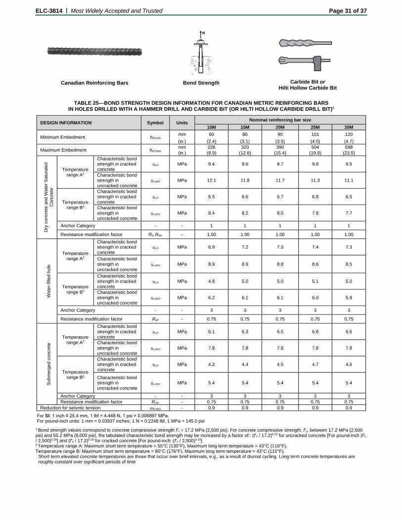
Canadian Reinforcing Bars Bond Strength Carbide Bit or Hilti Hollow Carbide Bit
TABLE 25—BOND STRENGTH DESIGN INFORMATION FOR CANADIAN METRIC REINFORCING BARS
IN HOLES DRILLED WITH A HAMMER DRILL AND CARBIDE BIT (OR HILTI HOLLOW CARBIDE DRILL BIT)1
DESIGN INFORMATION Symbol Units Nominal reinforcing bar size 10M 15M 20M 25M 30M
Minimum Embedment hef,min mm 60 80 90 101 120 (in.) (2.4) (3.1) (3.5) (4.0) (4.7)
Maximum Embedment hef,max mm 226 320 390 504 598 (in.) (8.9) (12.6) (15.4) (19.8) (23.5)
Dry
con
cret
e an
d W
ater
Sat
urat
ed
Con
cret
e
Temperature range A2
Characteristic bond strength in cracked concrete
τk,cr MPa 9.4 9.6 9.7 9.8 9.5
Characteristic bond strength in uncracked concrete
τk,uncr MPa 12.1 11.8 11.7 11.3 11.1
Temperature range B2
Characteristic bond strength in cracked concrete
τk,cr MPa 6.5 6.6 6.7 6.8 6.5
Characteristic bond strength in uncracked concrete
τk,uncr MPa 8.4 8.2 8.0 7.8 7.7
Anchor Category - - 1 1 1 1 1
Resistance modification factor Rd, Rws - 1.00 1.00 1.00 1.00 1.00
Wat
er-fi
lled
hole
Temperature range A2
Characteristic bond strength in cracked concrete
τk,cr MPa 6.9 7.2 7.3 7.4 7.3
Characteristic bond strength in uncracked concrete
τk,uncr MPa 8.9 8.9 8.8 8.6 8.5
Temperature range B2
Characteristic bond strength in cracked concrete
τk,cr MPa 4.8 5.0 5.0 5.1 5.0
Characteristic bond strength in uncracked concrete
τk,uncr MPa 6.2 6.1 6.1 6.0 5.9
Anchor Category - - 3 3 3 3 3
Resistance modification factor Rwf - 0.75 0.75 0.75 0.75 0.75
Subm
erge
d co
ncre
te
Temperature range A2
Characteristic bond strength in cracked concrete
τk,cr MPa 6.1 6.3 6.5 6.8 6.6
Characteristic bond strength in uncracked concrete
τk,uncr MPa 7.8 7.8 7.8 7.8 7.8
Temperature range B2
Characteristic bond strength in cracked concrete
τk,cr MPa 4.2 4.4 4.5 4.7 4.6
Characteristic bond strength in uncracked concrete
τk,uncr MPa 5.4 5.4 5.4 5.4 5.4
Anchor Category - - 3 3 3 3 3 Resistance modification factor Ruw - 0.75 0.75 0.75 0.75 0.75
Reduction for seismic tension αN,seis - 0.9 0.9 0.9 0.9 0.9
For SI: 1 inch ≡ 25.4 mm, 1 lbf = 4.448 N, 1 psi = 0.006897 MPa. For pound-inch units: 1 mm = 0.03937 inches, 1 N = 0.2248 lbf, 1 MPa = 145.0 psi
1 Bond strength values correspond to concrete compressive strength f′c = 17.2 MPa (2,500 psi). For concrete compressive strength, f’c, between 17.2 MPa (2,500 psi) and 55.2 MPa (8,000 psi), the tabulated characteristic bond strength may be increased by a factor of:: (f’c / 17.2)0.25 for uncracked concrete [For pound-inch (f’c / 2,500)0.25] and (f’c / 17.2)0.15 for cracked concrete [For pound-inch: (f’c / 2,500)0.15]. 2 Temperature range A: Maximum short term temperature = 55°C (130°F), Maximum long term temperature = 43°C (110°F). Temperature range B: Maximum short term temperature = 80°C (176°F), Maximum long term temperature = 43°C (110°F).
Short term elevated concrete temperatures are those that occur over brief intervals, e.g., as a result of diurnal cycling. Long term concrete temperatures are roughly constant over significant periods of time
ELC-3814 | Most Widely Accepted and Trusted Page 32 of 37
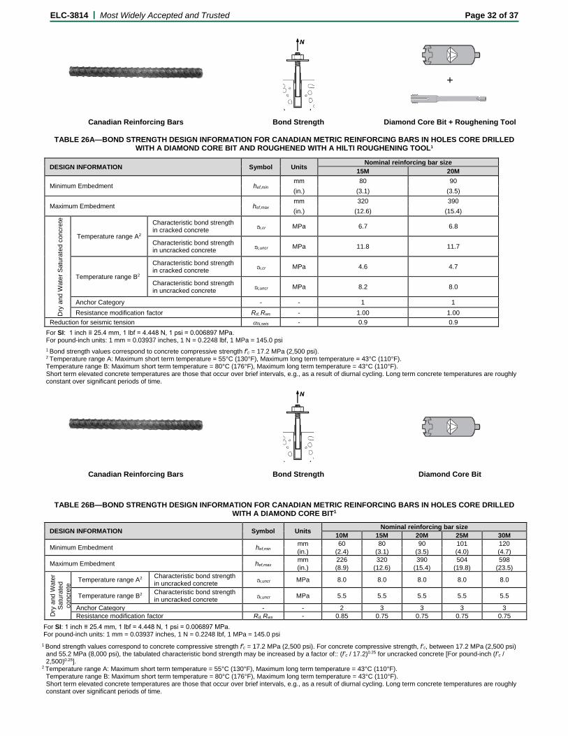
+
Canadian Reinforcing Bars Bond Strength Diamond Core Bit + Roughening Tool
TABLE 26A—BOND STRENGTH DESIGN INFORMATION FOR CANADIAN METRIC REINFORCING BARS IN HOLES CORE DRILLED WITH A DIAMOND CORE BIT AND ROUGHENED WITH A HILTI ROUGHENING TOOL1
DESIGN INFORMATION Symbol Units Nominal reinforcing bar size 15M 20M
Minimum Embedment hef,min mm 80 90 (in.) (3.1) (3.5)
Maximum Embedment hef,max mm 320 390 (in.) (12.6) (15.4)
Dry
and
Wat
er S
atur
ated
con
cret
e
Temperature range A2
Characteristic bond strength in cracked concrete τk,cr MPa 6.7 6.8
Characteristic bond strength in uncracked concrete τk,uncr MPa 11.8 11.7
Temperature range B2
Characteristic bond strength in cracked concrete τk,cr MPa 4.6 4.7
Characteristic bond strength in uncracked concrete τk,uncr MPa 8.2 8.0
Anchor Category - - 1 1 Resistance modification factor Rd, Rws - 1.00 1.00
Reduction for seismic tension αN,seis - 0.9 0.9 For SI: 1 inch ≡ 25.4 mm, 1 lbf = 4.448 N, 1 psi = 0.006897 MPa. For pound-inch units: 1 mm = 0.03937 inches, 1 N = 0.2248 lbf, 1 MPa = 145.0 psi 1 Bond strength values correspond to concrete compressive strength f′c = 17.2 MPa (2,500 psi). 2 Temperature range A: Maximum short term temperature = 55°C (130°F), Maximum long term temperature = 43°C (110°F). Temperature range B: Maximum short term temperature = 80°C (176°F), Maximum long term temperature = 43°C (110°F). Short term elevated concrete temperatures are those that occur over brief intervals, e.g., as a result of diurnal cycling. Long term concrete temperatures are roughly constant over significant periods of time.
Canadian Reinforcing Bars Bond Strength Diamond Core Bit
TABLE 26B—BOND STRENGTH DESIGN INFORMATION FOR CANADIAN METRIC REINFORCING BARS IN HOLES CORE DRILLED
WITH A DIAMOND CORE BIT1
DESIGN INFORMATION Symbol Units Nominal reinforcing bar size 10M 15M 20M 25M 30M
Minimum Embedment hef,min mm 60 80 90 101 120 (in.) (2.4) (3.1) (3.5) (4.0) (4.7)
Maximum Embedment hef,max mm 226 320 390 504 598 (in.) (8.9) (12.6) (15.4) (19.8) (23.5)
Dry
and
Wat
er
Satu
rate
d co
ncre
te Temperature range A2 Characteristic bond strength in uncracked concrete τk,uncr MPa 8.0 8.0 8.0 8.0 8.0
Temperature range B2 Characteristic bond strength in uncracked concrete τk,uncr MPa 5.5 5.5 5.5 5.5 5.5
Anchor Category - - 2 3 3 3 3 Resistance modification factor Rd, Rws - 0.85 0.75 0.75 0.75 0.75
For SI: 1 inch ≡ 25.4 mm, 1 lbf = 4.448 N, 1 psi = 0.006897 MPa. For pound-inch units: 1 mm = 0.03937 inches, 1 N = 0.2248 lbf, 1 MPa = 145.0 psi
1 Bond strength values correspond to concrete compressive strength f′c = 17.2 MPa (2,500 psi). For concrete compressive strength, f’c, between 17.2 MPa (2,500 psi) and 55.2 MPa (8,000 psi), the tabulated characteristic bond strength may be increased by a factor of:: (f’c / 17.2)0.25 for uncracked concrete [For pound-inch (f’c / 2,500)0.25].
2 Temperature range A: Maximum short term temperature = 55°C (130°F), Maximum long term temperature = 43°C (110°F). Temperature range B: Maximum short term temperature = 80°C (176°F), Maximum long term temperature = 43°C (110°F). Short term elevated concrete temperatures are those that occur over brief intervals, e.g., as a result of diurnal cycling. Long term concrete temperatures are roughly constant over significant periods of time.
ELC-3814 | Most Widely Accepted and Trusted Page 33 of 37
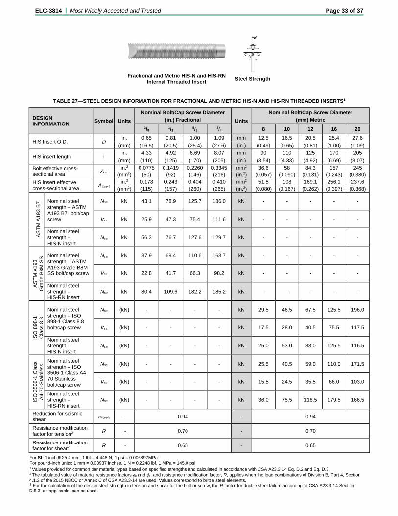
Fractional and Metric HIS-N and HIS-RN Internal Threaded Insert Steel Strength
TABLE 27—STEEL DESIGN INFORMATION FOR FRACTIONAL AND METRIC HIS-N AND HIS-RN THREADED INSERTS1
DESIGN INFORMATION Symbol Units
Nominal Bolt/Cap Screw Diameter (in.) Fractional Units
Nominal Bolt/Cap Screw Diameter (mm) Metric
3/8 1/2 5/8 3/4 8 10 12 16 20
HIS Insert O.D. D in. 0.65 0.81 1.00 1.09 mm 12.5 16.5 20.5 25.4 27.6
(mm) (16.5) (20.5) (25.4) (27.6) (in.) (0.49) (0.65) (0.81) (1.00) (1.09)
HIS insert length l in. 4.33 4.92 6.69 8.07 mm 90 110 125 170 205
(mm) (110) (125) (170) (205) (in.) (3.54) (4.33) (4.92) (6.69) (8.07) Bolt effective cross-sectional area Ase
in.2 0.0775 0.1419 0.2260 0.3345 mm2 36.6 58 84.3 157 245 (mm2) (50) (92) (146) (216) (in.2) (0.057) (0.090) (0.131) (0.243) (0.380)
HIS insert effective cross-sectional area Ainsert
in.2 0.178 0.243 0.404 0.410 mm2 51.5 108 169.1 256.1 237.6 (mm2) (115) (157) (260) (265) (in.2) (0.080) (0.167) (0.262) (0.397) (0.368)
ASTM
A19
3 B7
Nominal steel strength – ASTM A193 B73 bolt/cap screw
Nsa kN 43.1 78.9 125.7 186.0 kN - - - - -
Vsa kN 25.9 47.3 75.4 111.6 kN - - - - -
Nominal steel strength – HIS-N insert
Nsa kN 56.3 76.7 127.6 129.7 kN - - - - -
ASTM
A19
3
Gra
de B
8M S
S Nominal steel strength – ASTM A193 Grade B8M SS bolt/cap screw
Nsa kN 37.9 69.4 110.6 163.7 kN - - - - -
Vsa kN 22.8 41.7 66.3 98.2 kN - - - - -
Nominal steel strength – HIS-RN insert
Nsa kN 80.4 109.6 182.2 185.2 kN - - - - -
ISO
898
-1
Cla
ss 8
.8
Nominal steel strength – ISO 898-1 Class 8.8 bolt/cap screw
Nsa (kN) - - - - kN 29.5 46.5 67.5 125.5 196.0
Vsa (kN) - - - - kN 17.5 28.0 40.5 75.5 117.5
Nominal steel strength – HIS-N insert
Nsa (kN) - - - - kN 25.0 53.0 83.0 125.5 116.5
ISO
350
6-1
Cla
ss
A4-7
0 St
ainl
ess
Nominal steel strength – ISO 3506-1 Class A4-70 Stainless bolt/cap screw
Nsa (kN) - - - - kN 25.5 40.5 59.0 110.0 171.5
Vsa (kN) - - - - kN 15.5 24.5 35.5 66.0 103.0
Nominal steel strength – HIS-RN insert
Nsa (kN) - - - - kN 36.0 75.5 118.5 179.5 166.5
Reduction for seismic shear αV,seis - 0.94 - 0.94
Resistance modification factor for tension2 R - 0.70 - 0.70
Resistance modification factor for shear2 R - 0.65 - 0.65
For SI: 1 inch ≡ 25.4 mm, 1 lbf = 4.448 N, 1 psi = 0.006897MPa. For pound-inch units: 1 mm = 0.03937 inches, 1 N = 0.2248 lbf, 1 MPa = 145.0 psi 1 Values provided for common bar material types based on specified strengths and calculated in accordance with CSA A23.3-14 Eq. D.2 and Eq. D.3. 2 The tabulated value of material resistance factors φc and φs, and resistance modification factor, R, applies when the load combinations of Division B, Part 4, Section 4.1.3 of the 2015 NBCC or Annex C of CSA A23.3-14 are used. Values correspond to brittle steel elements. 3 For the calculation of the design steel strength in tension and shear for the bolt or screw, the R factor for ductile steel failure according to CSA A23.3-14 Section D.5.3, as applicable, can be used.

ELC-3814 | Most Widely Accepted and Trusted Page 34 of 37
Fractional and Metric HIS-N and HIS-RN Internal Threaded Insert
Concrete Breakout Strength Carbide Bit or Hilti Hollow Carbide Bit
TABLE 28—CONCRETE BREAKOUT DESIGN INFORMATION FOR FRACTIONAL AND METRIC HILTI HIS-N AND HIS-RN INSERTS IN HOLES DRILLED WITH A HAMMER DRILL AND CARBIDE BIT (OR HILTI HOLLOW CARBIDE DRILL BIT)1
DESIGN INFORMATION Symbol Units
Nominal Bolt/Cap Screw Diameter (in.) Fractional Units
Nominal Bolt/Cap Screw Diameter (mm) Metric
3/8 1/2 5/8 3/4 8 10 12 16 20
Effectiveness factor for cracked concrete kc,cr
in-lb 17 SI 7.1
(SI) (7.1) (in-lb) (17)
Effectiveness factor for uncracked concrete kc,uncr
in-lb 24 SI 10
(SI) (10) (in-lb) (24)
Effective embedment depth hef
in. 43/8 5 63/4 81/8 mm 90 110 125 170 205
(mm) (110) (125) (170) (205) (in.) (3.5) (4.3) (4.9) (6.7) (8.1)
Min. anchor spacing3 smin in. 31/4 4 5 51/2 mm 63 83 102 127 140
(mm) (83) (102) (127) (140) (in.) (2.5) (3.25) (4.0) (5.0) (5.5)
Min. edge distance3 cmin in. 31/4 4 5 51/2 mm 63 83 102 127 140
(mm) (83) (102) (127) (140) (in.) (2.5) (3.25) (4.0) (5.0) (5.5)
Minimum concrete thickness hmin
in. 5.9 6.7 9.1 10.6 mm 120 150 170 230 270
(mm) (150) (170) (230) (270) (in.) (4.7) (5.9) (6.7) (9.1) (10.6) Critical edge distance – splitting (for uncracked concrete)
cac - 2hef - 2hef
Resistance modification factor for tension, concrete failure modes, Condition B2
R - 1.00 - 1.00
Resistance modification factor for shear, concrete failure modes, Condition B2
R - 1.00 - 1.00
For SI: 1 inch ≡ 25.4 mm, 1 lbf = 4.448 N, 1 psi = 0.006897MPa. For pound-inch units: 1 mm = 0.03937 inches, 1 N = 0.2248 lbf, 1 MPa = 145.0 psi 1 Additional setting information is described in Figure 2, Manufacturers Printed Installation Instructions (MPII). 2 Condition A requires supplemental reinforcement, while Condition B applies where supplemental reinforcement is not provided or where pullout or pryout governs, as set forth in CSA A23.3-14 D.5. The tabulated value of the material resistance factors φc and φs, and resistance modification factor, R, applies when the load combinations of Division B, Part 4, Section 4.1.3 of the 2015 NBCC or Annex C of CSA A23.3-14 are used.

ELC-3814 | Most Widely Accepted and Trusted Page 35 of 37
Fractional and Metric HIS-N and HIS-RN Internal Threaded Insert Bond Strength
Carbide Bit or Hilti Hollow Carbide Bit
TABLE 29—BOND STRENGTH DESIGN INFORMATION FOR FRACTIONAL AND METRIC HILTI HIS-N AND HIS-RN INSERTS IN HOLES DRILLED WITH A HAMMER DRILL AND CARBIDE BIT (OR HILTI HOLLOW CARBIDE DRILL BIT)1
DESIGN INFORMATION Symbol Units Nominal bolt/cap screw diameter
(in.) Units Nominal bolt/cap screw diameter (mm)
3/8 1/2 5/8 3/4 8 10 12 16 20
Embedment hef in. 43/8 5 63/4 81/8 mm 90 110 125 170 205
(mm) (110) (125) (170) (205) (in.) (3.5) (4.3) (4.9) (6.7) (8.1)
Dry
con
cret
e an
d W
ater
sat
urat
ed c
oncr
ete
Tem
pera
ture
rang
e A2
Characteristic bond strength in cracked concrete
τk,cr MPa 7.4 7.4 7.4 7.4 MPa 7.4 7.4 7.4 7.4 7.4
Characteristic bond strength in uncracked concrete
τk,uncr MPa 12.3 12.3 12.3 12.3 MPa 12.3 12.3 12.3 12.3 12.3
Tem
pera
ture
ra
nge
B2
Characteristic bond strength in cracked concrete
τk,cr MPa 5.1 5.1 5.1 5.1 MPa 5.1 5.1 5.1 5.1 5.1
Characteristic bond strength in uncracked concrete
τk,uncr MPa 8.5 8.5 8.5 8.5 MPa 8.5 8.5 8.5 8.5 8.5
Anchor Category - - 1 1 1 1 - 1 1 1 1 1 Resistance modification factor Rd, Rws - 1.00 1.00 1.00 1.00 - 1.00 1.00 1.00 1.00 1.00
Wat
er-fi
lled
hole
Tem
pera
ture
ra
nge
A2
Characteristic bond strength in cracked concrete
τk,cr MPa 5.5 5.5 5.6 5.7 MPa 5.5 5.5 5.6 5.7 5.7
Characteristic bond strength in uncracked concrete
τk,uncr MPa 9.1 9.2 9.3 9.5 MPa 9.1 9.2 9.3 9.5 9.5
Tem
pera
ture
ra
nge
B2
Characteristic bond strength in cracked concrete
τk,cr MPa 3.8 3.8 3.8 3.9 MPa 3.8 3.8 3.8 3.9 3.9
Characteristic bond strength in uncracked concrete
τk,uncr MPa 6.3 6.4 6.4 6.5 MPa 6.3 6.4 6.4 6.5 6.6
Anchor Category - - 3 3 3 3 - 3 3 3 3 3 Resistance modification factor Rwf - 0.75 0.75 0.75 0.75 - 0.75 0.75 0.75 0.75 0.75
Subm
erge
d co
ncre
te
Tem
pera
ture
ra
nge
A2
Characteristic bond strength in cracked concrete
τk,cr MPa 4.9 5.0 5.1 5.2 MPa 4.8 4.9 5.0 5.1 5.2
Characteristic bond strength in uncracked concrete
τk,uncr MPa 8.2 8.4 8.6 8.7 MPa 8.0 8.2 8.4 8.6 8.7
Tem
pera
ture
ra
nge
B2
Characteristic bond strength in cracked concrete
τk,cr MPa 3.4 3.4 3.5 3.6 MPa 3.3 3.4 3.4 3.5 3.6
Characteristic bond strength in uncracked concrete
τk,uncr MPa 5.6 5.8 5.9 6.0 MPa 5.5 5.6 5.8 5.9 6.0
Anchor Category - - 3 3 3 3 - 3 3 3 3 3 Resistance modification factor Ruw - 0.75 0.75 0.75 0.75 - 0.75 0.75 0.75 0.75 0.75
Reduction for seismic tension αN,seis - 1 1 1 1 - 1 1 1 1 1
For SI: 1 inch ≡ 25.4 mm, 1 lbf = 4.448 N, 1 psi = 0.006897 MPa. For pound-inch units: 1 mm = 0.03937 inches, 1 N = 0.2248 lbf, 1 MPa = 145.0 psi 1 Bond strength values correspond to concrete compressive strength f′c = 17.2 MPa (2,500 psi). For concrete compressive strength, f’c, between 17.2 MPa (2,500
psi) and 55.2 MPa (8,000 psi), the tabulated characteristic bond strength may be increased by a factor of:: (f’c / 17.2)0.25 for uncracked concrete [For pound-inch (f’c / 2,500)0.25] and (f’c / 17.2)0.15 for cracked concrete [For pound-inch: (f’c / 2,500)0.15].
2 Temperature range A: Maximum short term temperature = 55°C (130°F), Maximum long term temperature = 43°C (110°F). Temperature range B: Maximum short term temperature = 80°C (176°F), Maximum long term temperature = 43°C (110°F). Short term elevated concrete temperatures are those that occur over brief intervals, e.g., as a result of diurnal cycling. Long term concrete temperatures are roughly constant over significant periods of time.

ELC-3814 | Most Widely Accepted and Trusted Page 36 of 37
+
Fractional and Metric HIS-N and HIS-RN
Internal Threaded Insert Bond Strength Diamond Core Bit + Roughening Tool
TABLE 30—BOND STRENGTH DESIGN INFORMATION FOR FRACTIONAL AND METRIC HILTI HIS-N AND HIS-RN INSERTS IN HOLES CORE DRILLED WITH A DIAMOND CORE BIT AND ROUGHENED
WITH A HILTI ROUGHENING TOOL1
DESIGN INFORMATION Symbol Units Nominal bolt/cap screw
diameter (in.) Units Nominal bolt/cap screw
diameter (mm) 1/2 5/8 3/4 12 16 20
Embedment hef in. 5 6¾ 81/8 mm 125 170 205
(mm) (125) (170) (205) (in.) (4.9) (6.7) (8.1)
Dry
con
cret
e an
d W
ater
Sat
urat
ed
Con
cret
e
Temperature range A2
Characteristic bond strength in cracked concrete
τk,cr MPa 5.2 5.2 5.2 MPa 5.2 5.2 5.2
Characteristic bond strength in uncracked concrete
τk,uncr MPa 12.3 12.3 12.3 MPa 12.3 12.3 12.3
Temperature range B2
Characteristic bond strength in cracked concrete
τk,cr MPa 3.6 3.6 3.6 MPa 3.6 3.6 3.6
Characteristic bond strength in uncracked concrete
τk,uncr MPa 8.5 8.5 8.5 MPa 8.5 8.5 8.5
Anchor Category - - 1 1 1 - 1 1 1 Resistance modification factor Rd, Rws - 1.00 1.00 1.00 - 1.00 1.00 1.00
Reduction for seismic tension αN,seis - 1 1 1 - 1 1 1
For SI: 1 inch ≡ 25.4 mm, 1 lbf = 4.448 N, 1 psi = 0.006897 MPa. For pound-inch units: 1 mm = 0.03937 inches, 1 N = 0.2248 lbf, 1 MPa = 145.0 psi 1 Bond strength values correspond to concrete compressive strength f′c = 17.2 MPa (2,500 psi). 2 Temperature range A: Maximum short term temperature = 55°C (130°F), Maximum long term temperature = 43°C (110°F). Temperature range B: Maximum short term temperature = 80°C (176°F), Maximum long term temperature = 43°C (110°F). Short term elevated concrete temperatures are those that occur over brief intervals, e.g., as a result of diurnal cycling. Long term concrete temperatures are roughly constant over significant periods of time.
Fractional and Metric HIS-N and HIS-RN Internal Threaded Insert Bond Strength Diamond Core Bit
TABLE 31—BOND STRENGTH DESIGN INFORMATION FOR FRACTIONAL AND METRIC HILTI HIS-N AND HIS-RN INSERTS IN HOLES CORE DRILLED WITH A DIAMOND CORE BIT1
DESIGN INFORMATION Symbol Units Nominal bolt/cap screw
diameter (in.) Units Nominal bolt/cap screw diameter (mm)
3/8 1/2 5/8 3/4 8 10 12 16 20
Embedment hef in. 43/8 5 63/4 81/8 mm 90 110 125 170 205
(mm) (110) (125) (170) (205) (in.) (3.5) (4.3) (4.9) (6.7) (8.1)
Dry
con
cret
e an
d W
ater
Sa
tura
ted
Con
cret
e Temperature range A2
Characteristic bond strength in uncracked concrete
τk,uncr MPa 8.3 8.3 8.3 8.3 MPa 8.3 8.3 8.3 8.3 8.3
Temperature range B2
Characteristic bond strength in uncracked concrete
τk,uncr MPa 5.7 5.7 5.7 5.7 MPa 5.7 5.7 5.7 5.7 5.7
Anchor Category - - 3 3 3 3 - 2 3 3 3 3
Resistance modification factor Rd, Rws - 0.75 0.75 0.75 0.75 - 0.85 0.75 0.75 0.75 0.75
For SI: 1 inch ≡ 25.4 mm, 1 lbf = 4.448 N, 1 psi = 0.006897 MPa. For pound-inch units: 1 mm = 0.03937 inches, 1 N = 0.2248 lbf, 1 MPa = 145.0 psi
1 Bond strength values correspond to concrete compressive strength f′c = 17.2 MPa (2,500 psi). For concrete compressive strength, f’c, between 17.2 MPa (2,500 psi) and 55.2 MPa (8,000 psi), the tabulated characteristic bond strength may be increased by a factor of:: (f’c / 17.2)0.25 for uncracked concrete [For pound-inch (f’c / 2,500)0.25].
2 Temperature range A: Maximum short term temperature = 55°C (130°F), Maximum long term temperature = 43°C (110°F). Temperature range B: Maximum short term temperature = 80°C (176°F), Maximum long term temperature = 43°C (110°F). Short term elevated concrete temperatures are those that occur over brief intervals, e.g., as a result of diurnal cycling. Long term concrete temperatures are roughly constant over significant periods of time.

ELC-3814 | Most Widely Accepted and Trusted Page 37 of 37
Conditions of listing:
1. The listing report addresses only conformance with the standards and code sections noted above.
2. Approval of the product’s use is the sole responsibility of the local code official.
3. The listing report applies only to the materials tested and as submitted for review by ICC-ES.
4. Anchor sizes, dimensions, minimum embedment depths and other installation parameters are as set forth in this listing report.
5. Anchors must be limited to use in cracked and uncracked normal-weight concrete and lightweight concrete having a specified compressive strength, f'c, of 17.2 MPa (2,500 psi) to 58.6 MPa (8,500 psi).
6. The values of f'c, used for calculation purposes must not exceed 55 MPa. 7. Limit states design values must be established in accordance with this listing report. 8. The use of fatigue or shock loading for these anchors under such conditions is beyond the scope of this
listing report. 9. Anchors may be used to resist short-term loading due to wind or seismic forces in locations designed
according to NBCC 2015. 10. Where not otherwise prohibited in the code as referenced in CSA A23.3-14, Hilti HIT-RE 500 V3
Adhesive Anchor System are permitted for use with fire-resistance-rated construction provided that at least one of the following conditions is fulfilled: a. Anchors are used to resist wind or seismic forces only.
b. Anchors that support a fire-resistance-rated envelope or a fire-resistance-rated membrane are protected by approved fire-resistance-rated materials, or have been evaluated for resistance to fire exposure in accordance with recognized standards.
c. Anchors are used to support nonstructural elements.
11. Use of zinc-coated carbon steel anchors is limited to dry, interior locations. 12. Use of anchors made of stainless steel as specified in this report are permitted for exterior exposure
and damp environments. 13. Steel anchoring materials in contact with preservative-treated wood and fire-retardant-treated wood
must be of zinc-coated carbon steel or stainless steel. The minimum coating weights for zinc-coated steel must comply with ASTM A153.
14. Installation of anchors in horizontal or upwardly inclined orientations to resist sustained tension loads shall be performed by personnel certified by an applicable certification program, and the certification shall include written and performance tests in accordance with the ACI/CRSI Adhesive Anchor Installer Certification program, or equivalent in accordance with CSA A23.3-14 D.10.2.3. The installation shall be continuously inspected during installation by an inspector specially approved for that purpose. The special inspector shall furnish a report to the licensed design professional and building official that the work covered by the report has been performed and that the materials used and the installation procedures used conform with the approved contract documents and the MPII in accordance with CSA A23.3-14 D.10.2.4.
15. Anchors shall not be used for applications where the concrete temperature can rise from 40°F (5°C) or less to 80°F (27°C) or higher within a 12-hour period. Such applications may include but are not limited to anchorage of building facade systems and other applications subject to direct sun exposure.
16. Anchors may be used to resist tension and shear forces in floor, wall, and overhead installations only if installation is into concrete with a temperature between -5°C and 40°C (23°F and 104°F) for threaded rods, rebar, and Hilti HIS-(R)N inserts. Overhead installations for hole diameters larger than 7/16-inch or 10mm require the use of piston plugs (HIT-SZ, -IP) during injection to the back of the hole. 7/16-inch diameter holes may be injected directly to the back of the hole with the use of extension tubing on the end of the nozzle. The anchor or post-installed reinforcing bars must be supported until fully cured (i.e., with Hilti HIT-OHW wedges, or other suitable means). Where temporary restraint devices are used, their use shall not result in impairment of the anchor shear resistance. Installation in concrete temperature below 5°C (41°F) requires the adhesive to be conditioned to a minimum temperature of 5°C (32°F).
Copyright © 2022 FDOKUMEN