HySpeed HSD130 Remote High Frequency (RHF) Instruction ...
233
Remote High Frequency (RHF) Instruction Manual 805510 – Revision 1 HySpeed ® Plasma HSD130 ™
-
Upload
khangminh22 -
Category
Documents
-
view
0 -
download
0
Transcript of HySpeed HSD130 Remote High Frequency (RHF) Instruction ...

Remote High Frequency (RHF)Instruction Manual
805510 – Revision 1
HySpeed ® Plasma HSD130™

Register your new Hypertherm system
Register your product online at www.hypertherm.com/registration for easier technical and warranty support. You can also receive updates on new Hypertherm products and a free gift as a token of our appreciation.
For your records
Serial number: _______________________________________
Purchase date: _______________________________________
Distributor: _______________________________________
_________________________________________________
_________________________________________________
Maintenance notes:
_____________________________________________________
_____________________________________________________
_____________________________________________________
_____________________________________________________
_____________________________________________________
_____________________________________________________

HySpeed HSD130Remote High Frequency (RHF)
Instruction Manual
(P/N 805510)
Revision 1 – April, 2011
© Copyright 2011 Hypertherm, Inc.All Rights Reserved
Hypertherm, HySpeed, and HSD130 are trademarks of Hypertherm, Inc. and may be registered in the United States and/or other countries
Hypertherm, Inc.Hanover, NH USA
www.hypertherm.com

Hypertherm, Inc.Etna Road, P.O. Box 5010Hanover, NH 03755 USA603-643-3441 Tel (Main Office)603-643-5352 Fax (All Departments)[email protected] (Main Office Email)800-643-9878 Tel (Technical Service)[email protected] (Technical Service Email)800-737-2978 Tel (Customer Service)[email protected] (Customer Service Email)
Hypertherm Automation5 Technology Drive, Suite 300West Lebanon, NH 03784 USA603-298-7970 Tel 603-298-7977 Fax
Hypertherm Plasmatechnik GmbHTechnologiepark HanauRodenbacher Chaussee 6 D-63457 Hanau-Wolfgang, Deutschland49 6181 58 2100 Tel49 6181 58 2134 Fax49 6181 58 2123 (Technical Service)
Hypertherm (S) Pte Ltd.82 Genting LaneMedia CentreAnnexe Block #A01-01Singapore 349567, Republic of Singapore65 6841 2489 Tel65 6841 2490 Fax 65 6841 2489 (Technical Service)
Hypertherm (Shanghai) Trading Co., Ltd.Unit A, 5th Floor, Careri Building432 West Huai Hai RoadShanghai, 200052PR China86-21 5258 3330/1 Tel86-21 5258 3332 Fax
Hypertherm Europe B.V.Vaartveld 94704 SE Roosendaal, Nederland31 165 596907 Tel31 165 596901 Fax31 165 596908 Tel (Marketing)31 165 596900 Tel (Technical Service)00 800 4973 7843 Tel (Technical Service)
Hypertherm Japan Ltd.Level 9, Edobori Center Building2-1-1 Edobori, Nishi-kuOsaka 550-0002 Japan81 6 6225 1183 Tel81 6 6225 1184 Fax
Hypertherm Brasil Ltda.Avenida Doutor Renato de Andrade Maia 350Parque Renato MaiaCEP 07114-000Guarulhos, SP Brasil55 11 2409 2636 Tel55 11 2408 0462 Fax
Hypertherm México, S.A. de C.V.Avenida Toluca No. 444, Anexo 1,Colonia Olivar de los PadresDelegación Álvaro ObregónMéxico, D.F. C.P. 0178052 55 5681 8109 Tel52 55 5683 2127 Fax
Hypertherm Korea Branch#3904 Centum Leaders Mark B/D,1514 Woo-dong, Haeundae-gu, BusanKorea, 612-88982 51 747 0358 Tel82 51 701 0358 Fax
03/08/11

Compliance Information EMC-1
7/10
ELECTROMAGNETIC COMPATIBILITY (EMC)
IntroductionHypertherm’s CE-marked equipment is built in compliance with standard EN60974-10. The equipment should be installed and used in accordance with the information below to achieve electromagnetic compatibility.
The limits required by EN60974-10 may not be adequate to completely eliminate interference when the affected equipment is in close proximity or has a high degree of sensitivity. In such cases it may be necessary to use other measures to further reduce interference.
This cutting equipment is designed for use only in an industrial environment.
Installation and useThe user is responsible for installing and using the plasma equipment according to the manufacturer’s instructions.
If electromagnetic disturbances are detected then it shall be the responsibility of the user to resolve the situation with the technical assistance of the manufacturer. In some cases this remedial action may be as simple as earthing the cutting circuit, see Earthing of the work piece. In other cases, it could involve constructing an electromagnetic screen enclosing the power source and the work complete with associated input filters. In all cases, electromagnetic disturbances must be reduced to the point where they are no longer troublesome.
Assessment of areaBefore installing the equipment, the user shall make an assessment of potential electromagnetic problems in the surrounding area. The following shall be taken into account:
a. Other supply cables, control cables, signaling and telephone cables; above, below and adjacent to the cutting equipment.
b. Radio and television transmitters and receivers.
c. Computer and other control equipment.
d. Safety critical equipment, for example guarding of industrial equipment.
e. Health of the people around, for example the use of pacemakers and hearing aids.
f. Equipment used for calibration or measurement.
g. Immunity of other equipment in the environment. User shall ensure that other equipment being used in the environment is compatible. This may require additional protection measures.
h. Time of day that cutting or other activities are to be carried out.
The size of the surrounding area to be considered will depend on the structure of the building and other activities that are taking place. The surrounding area may extend beyond the boundaries of the premises.
Methods of reducing emissionsMains supplyCutting equipment must be connected to the mains supply according to the manufacturer’s recommendations. If interference occurs, it may be necessary to take additional precautions such as filtering of the mains supply.

EMC-2 Compliance Information
7/10
ELECTROMAGNETIC COMPATIBILITY
Consideration should be given to shielding the supply cable of permanently installed cutting equipment, in metallic conduit or equivalent. Shielding should be electrically continuous throughout its length. The shielding should be connected to the cutting mains supply so that good electrical contact is maintained between the conduit and the cutting power source enclosure.
Maintenance of cutting equipmentThe cutting equipment must be routinely maintained according to the manufacturer’s recommendations. All access and service doors and covers should be closed and properly fastened when the cutting equipment is in operation. The cutting equipment should not be modified in any way, except as set forth in and in accordance with the manufacturer’s written instructions. For example, the spark gaps of arc striking and stabilizing devices should be adjusted and maintained according to the manufacturer’s recommendations.
Cutting cablesThe cutting cables should be kept as short as possible and should be positioned close together, running at or close to the floor level.
Equipotential bondingBonding of all metallic components in the cutting installation and adjacent to it should be considered.
However, metallic components bonded to the workpiece will increase the risk that the operator could receive a shock by touching these metallic components and the electrode (nozzle for laser heads) at the same time.
The operator should be insulated from all such bonded metallic components.
Earthing of the workpieceWhere the workpiece is not bonded to earth for electrical safety, nor connected to earth because of its size and position, for example, ship’s hull or building steel work, a connection bonding the workpiece to earth may reduce emissions in some, but not all instances. Care should be taken to prevent the earthing of the workpiece increasing the risk of injury to users, or damage to other electrical equipment. Where necessary, the connection of the workpiece to earth should be made by a direct connection to the workpiece, but in some countries where direct connection is not permitted, the bonding should be achieved by suitable capacitances selected according to national regulations.
Note: The cutting circuit may or may not be earthed for safety reasons. Changing the earthing arrangements should only be authorized by a person who is competent to assess whether the changes will in crease the risk of injury, for example, by allowing parallel cutting current return paths which may damage the earth circuits of other equipment. Further guidance is provided inIEC 60974-9, Arc Welding Equip ment, Part 9: Installation and Use.
Screening and shieldingSelective screening and shielding of other cables and equipment in the surrounding area may alleviate problems of interference. Screening of the entire plasma cutting installation may be considered for special applications.

Compliance Information W-1
9/10
AttentionGenuine Hypertherm parts are the factory-recommended replacement parts for your Hypertherm system. Any damage or injury caused by the use of other than genuine Hypertherm parts may not be covered by the Hypertherm warranty, and will constitute misuse of the Hypertherm Product.
You are solely responsible for the safe use of the Product. Hypertherm does not and cannot make any guarantee or warranty regarding the safe use of the product in your environment.
GeneralHypertherm, Inc. warrants that its Products shall be free from defects in materials and workmanship for the specific periods of time set forth herein and as follows: if Hypertherm is notified of a defect (i) with respect to the power supply within a period of two (2) years from the date of its delivery to you, with the exception of Powermax brand power supplies, which shall be within a period of three (3) years from the date of delivery to you, and (ii) with respect to the torch and leads within a period of one (1) year from its date of delivery to you, and with respect to torch lifter assemblies within a period of one (1) year from its date of delivery to you, and with respect to laser heads within a period of one (1) year from its date of delivery to you, and with respect to Automation products one (1) year from its date of delivery to you, with the exception of the EDGE Pro CNC and ArcGlide THC, which shall be within a period of two (2) years from the date of delivery to you.
This warranty shall not apply to any Powermax brand power supplies that have been used with phase converters. In addition, Hypertherm does not warranty systems that have been damaged as a result of poor power quality, whether from phase converters or incoming line power. This warranty shall not apply to any Product which has been incorrectly installed, modified, or otherwise damaged.
Hypertherm provides repair, replacement or adjustment of the Product as the sole and exclusive remedy, if and only if the warranty set forth herein properly is invoked and applies. Hypertherm, at its sole option, shall repair, replace, or adjust, free of charge, any defective Products covered by this warranty which shall be returned with Hypertherm’s prior authorization (which shall not be unreasonably withheld), properly packed, to Hypertherm’s place of business in Hanover, New Hampshire, or to an authorized Hypertherm repair facility, all costs, insurance and freight pre paid by the customer. Hypertherm shall not be liable for any repairs, replacement, or adjustments of Products covered by this warranty, except those made pursuant to this paragraph and with Hypertherm’s prior written consent.
The warranty set forth above is exclusive and is in lieu of all other warranties, express, implied, statutory, or otherwise with respect to the Products or as to the results which may be obtained therefrom, and all implied warranties or conditions of quality or of merchantability or fitness for a particular purpose or against infringement. The foregoing shall constitute the sole and exclusive remedy for any breach by Hypertherm of its warranty.
Distributors/OEMs may offer different or additional warranties, but Distributors/OEMs are not authorized to give any additional warranty protection to you or make any representation to you purporting to be binding upon Hypertherm.
WARRANTY

EMC-2 Compliance Information
7/10
ELECTROMAGNETIC COMPATIBILITY
Consideration should be given to shielding the supply cable of permanently installed cutting equipment, in metallic conduit or equivalent. Shielding should be electrically continuous throughout its length. The shielding should be connected to the cutting mains supply so that good electrical contact is maintained between the conduit and the cutting power source enclosure.
Maintenance of cutting equipmentThe cutting equipment must be routinely maintained according to the manufacturer’s recommendations. All access and service doors and covers should be closed and properly fastened when the cutting equipment is in operation. The cutting equipment should not be modified in any way, except as set forth in and in accordance with the manufacturer’s written instructions. For example, the spark gaps of arc striking and stabilizing devices should be adjusted and maintained according to the manufacturer’s recommendations.
Cutting cablesThe cutting cables should be kept as short as possible and should be positioned close together, running at or close to the floor level.
Equipotential bondingBonding of all metallic components in the cutting installation and adjacent to it should be considered.
However, metallic components bonded to the workpiece will increase the risk that the operator could receive a shock by touching these metallic components and the electrode (nozzle for laser heads) at the same time.
The operator should be insulated from all such bonded metallic components.
Earthing of the workpieceWhere the workpiece is not bonded to earth for electrical safety, nor connected to earth because of its size and position, for example, ship’s hull or building steel work, a connection bonding the workpiece to earth may reduce emissions in some, but not all instances. Care should be taken to prevent the earthing of the workpiece increasing the risk of injury to users, or damage to other electrical equipment. Where necessary, the connection of the workpiece to earth should be made by a direct connection to the workpiece, but in some countries where direct connection is not permitted, the bonding should be achieved by suitable capacitances selected according to national regulations.
Note: The cutting circuit may or may not be earthed for safety reasons. Changing the earthing arrangements should only be authorized by a person who is competent to assess whether the changes will in crease the risk of injury, for example, by allowing parallel cutting current return paths which may damage the earth circuits of other equipment. Further guidance is provided inIEC 60974-9, Arc Welding Equip ment, Part 9: Installation and Use.
Screening and shieldingSelective screening and shielding of other cables and equipment in the surrounding area may alleviate problems of interference. Screening of the entire plasma cutting installation may be considered for special applications.

Table of ConTenTs
HySpeed HSD130 RHF Instruction Manual i
Electromagnetic compatibility (EMC) .............................................................................................................................................EMC-1Warranty.....................................................................................................................................................................................................W-1
section 1 safeTy ................................................................................................................................................................1-1Recognize safety information ..................................................................................................................................................................1-2Follow safety instructions .........................................................................................................................................................................1-2Electrical hazards .......................................................................................................................................................................................1-2Electric shock can kill ................................................................................................................................................................................1-3Cutting can cause fire or explosion .......................................................................................................................................................1-4Toxic fumes can cause injury or death ..................................................................................................................................................1-5Grounding safety........................................................................................................................................................................................1-6Static electricity can damage circuit boards .......................................................................................................................................1-6Compressed gas equipment safety .......................................................................................................................................................1-6Gas cylinders can explode if damaged .................................................................................................................................................1-6A plasma arc can cause injury and burns .............................................................................................................................................1-7Arc rays can burn eyes and skin .............................................................................................................................................................1-7Pacemaker and hearing aid operation ..................................................................................................................................................1-8Noise can damage hearing ......................................................................................................................................................................1-8A plasma arc can damage frozen pipes ...............................................................................................................................................1-8Dry dust collection information ...............................................................................................................................................................1-9Laser radiation .........................................................................................................................................................................................1-10Symbols and marks ................................................................................................................................................................................1-11Additional safety information ................................................................................................................................................................1-11Warning labels .........................................................................................................................................................................................1-12
section 1a séCuriTé ...................................................................................................................................................... 1a-1Identifier les consignes de sécurité .................................................................................................................................................... 1a-2Suivre les instructions de sécurité ...................................................................................................................................................... 1a-2Risques électriques ................................................................................................................................................................................ 1a-2Les chocs électriques peuvent être fatals ......................................................................................................................................... 1a-3Le coupage peut provoquer un incendie ou une explosion .......................................................................................................... 1a-4Les vapeurs toxiques peuvent provoquer des blessures ou la mort ........................................................................................... 1a-5Mise à la masse et à la terre ................................................................................................................................................................. 1a-6L’électricité statique peut endommager les cartes de circuits imprimés ................................................................................... 1a-6Sécurité des bouteilles de gaz comprimé ......................................................................................................................................... 1a-6Les bouteilles de gaz comprimé peuvent exploser en cas de dommages ................................................................................ 1a-6L’arc plasma peut provoquer des blessures ou des brûlures ....................................................................................................... 1a-7Les rayons de l’arc peuvent brûler les yeux et la peau ................................................................................................................... 1a-7Pacemakers et prothèses auditives .................................................................................................................................................... 1a-8Le bruit peut provoquer des problèmes auditifs .............................................................................................................................. 1a-8Un arc plasma peut endommager les tuyaux gelés ........................................................................................................................ 1a-8Information sur le dépoussièrage ........................................................................................................................................................ 1a-9Radiation au laser .................................................................................................................................................................................1a-10Symboles et marquage ........................................................................................................................................................................1a-11Étiquettes de sécurité ..........................................................................................................................................................................1a-12

Table of ConTenTs
ii HySpeed HSD130 RHF Instruction Manual
section 1b seguridad .................................................................................................................................................. 1b-1Reconocimiento de información de seguridad ................................................................................................................................ 1b-2Cumplimiento de instrucciones de seguridad.................................................................................................................................. 1b-2Riesgos de electrocución ..................................................................................................................................................................... 1b-2Las descargas eléctricas pueden matar ............................................................................................................................................ 1b-3Los cortes pueden producir incendios o explosiones .................................................................................................................... 1b-4Los vapores tóxicos pueden producir lesiones o la muerte .......................................................................................................... 1b-5Seguridad de toma a tierra ................................................................................................................................................................... 1b-6La electricidad estática puede dañar las placas de circuitos ....................................................................................................... 1b-6Seguridad de equipos de gas comprimido ...................................................................................................................................... 1b-6Los cilindros de gas pueden explotar si están dañados ................................................................................................................ 1b-6El arco de plasma puede producir lesiones y quemaduras .......................................................................................................... 1b-7Los rayos del arco pueden quemar los ojos y la piel ...................................................................................................................... 1b-7Funcionamiento de marcapasos y audífonos ................................................................................................................................... 1b-8Los ruidos pueden dañar la audición ................................................................................................................................................. 1b-8El arco de plasma puede dañar las tuberías congeladas .............................................................................................................. 1b-8Información acerca de la recolección de polvo seco ..................................................................................................................... 1b-9Radiación láser ......................................................................................................................................................................................1b-10Símbolos y marcas ...............................................................................................................................................................................1b-11Etiquetas de advertencia .....................................................................................................................................................................1b-12
section 2 speCifiCaTions..............................................................................................................................................2-1 System description ....................................................................................................................................................................................2-2
General ..............................................................................................................................................................................................2-2Power supply ...................................................................................................................................................................................2-2Ignition console ................................................................................................................................................................................2-2Fuel-gas console .............................................................................................................................................................................2-2Off-valve ............................................................................................................................................................................................2-2Torch ..................................................................................................................................................................................................2-2System diagram 1 — without a fuel gas console .....................................................................................................................2-3System diagram 2 — with a fuel-gas console ..........................................................................................................................2-4
Specifications .............................................................................................................................................................................................2-5System gas requirements ..............................................................................................................................................................2-5Noise levels .......................................................................................................................................................................................2-6Power supply ....................................................................................................................................................................................2-7Fuel gas console — 078201 ........................................................................................................................................................2-8Ignition console — 078172 ..........................................................................................................................................................2-9Standard off-valve — 229105 ...................................................................................................................................................2-10Fuel-gas off-valve — 229130 ....................................................................................................................................................2-11Torch – 228144 ...........................................................................................................................................................................2-12
section 3 insTallaTion ...................................................................................................................................................3-1 Upon receipt ...............................................................................................................................................................................................3-3Claims ...........................................................................................................................................................................................................3-3Installation requirements...........................................................................................................................................................................3-3Placement of system components .........................................................................................................................................................3-3
Torque specifications .....................................................................................................................................................................3-3

Table of ConTenTs
HySpeed HSD130 RHF Instruction Manual iii
Installation requirements – standard system .....................................................................................................................................3-4System components .......................................................................................................................................................................3-5Cables and hoses ...........................................................................................................................................................................3-5Customer-supplied power cable .................................................................................................................................................3-5Supply gas hoses ............................................................................................................................................................................3-5
Installation requirements — system with optional fuel gas console ...............................................................................................3-6System components .......................................................................................................................................................................3-7Cables and hoses ...........................................................................................................................................................................3-7Customer-supplied power cable .................................................................................................................................................3-7Supply gas hoses ............................................................................................................................................................................3-7
System integration diagram .....................................................................................................................................................................3-8Components .....................................................................................................................................................................................3-9
Recommended grounding and shielding practices ........................................................................................................................3-10Introduction ..............................................................................................................................................................................................3-10
Types of grounding ......................................................................................................................................................................3-10Steps to take .................................................................................................................................................................................3-11Grounding diagram ......................................................................................................................................................................3-14
Placement of the power supply ...........................................................................................................................................................3-15Install the ignition console .....................................................................................................................................................................3-16Install the off-valve ..................................................................................................................................................................................3-18Torch mounting and alignment ............................................................................................................................................................3-19
Mounting the torch .......................................................................................................................................................................3-19Torch alignment ............................................................................................................................................................................3-19Torch lifter requirement ...............................................................................................................................................................3-19
Install the fuel-gas console (optional component) ..........................................................................................................................3-20Cable and hose assembly from power supply to off-valve............................................................................................................3-21
Power supply to off-valve connections ...................................................................................................................................3-22Fuel-gas console to off-valve connections .......................................................................................................................................3-23Fuel-gas console to power supply connections ..............................................................................................................................3-24Power supply to ignition console leads .............................................................................................................................................3-26
Ignition console power cable .....................................................................................................................................................3-28Ignition console coolant hoses ..................................................................................................................................................3-29
Torch lead assembly ..............................................................................................................................................................................3-30Connect the torch to the torch lead assembly ......................................................................................................................3-31
Work lead .................................................................................................................................................................................................3-34Arc voltage connection ..........................................................................................................................................................................3-35Power supply to CNC interface cable ...............................................................................................................................................3-36
Notes to CNC interface cable run list .....................................................................................................................................3-37Examples of output circuits ........................................................................................................................................................3-38Examples of input circuits ...........................................................................................................................................................3-40
Power requirements ...............................................................................................................................................................................3-41General ...........................................................................................................................................................................................3-41Line disconnect switch ...............................................................................................................................................................3-42Power cable ...................................................................................................................................................................................3-42
Connect the power .................................................................................................................................................................................3-43Torch coolant requirements ..................................................................................................................................................................3-44

Table of ConTenTs
iv HySpeed HSD130 RHF Instruction Manual
Premixed coolant for standard operating temperatures ......................................................................................................3-44Custom coolant mix for cold operating temperatures ..........................................................................................................3-45Custom coolant mix hot operating temperatures ..................................................................................................................3-46Water purity requirements ..........................................................................................................................................................3-46
Fill the power supply with coolant .......................................................................................................................................................3-47Gas requirements ...................................................................................................................................................................................3-48
Setting the supply regulators .....................................................................................................................................................3-48Gas regulators ..............................................................................................................................................................................3-49
Supply gas plumbing .............................................................................................................................................................................3-50Connect the supply gases ....................................................................................................................................................................3-51
Standard system ...........................................................................................................................................................................3-51Fuel-gas system ............................................................................................................................................................................3-51
Supply gas hoses ...................................................................................................................................................................................3-52
section 4 operaTion ........................................................................................................................................................4-1 Controls and indicators ............................................................................................................................................................................4-2
Main power switch .........................................................................................................................................................................4-2Daily start-up ...............................................................................................................................................................................................4-3
Check torch ......................................................................................................................................................................................4-3System operation .......................................................................................................................................................................................4-4
Amps display ....................................................................................................................................................................................4-4Fuel-gas console operation .....................................................................................................................................................................4-5Consumable selection ..............................................................................................................................................................................4-6
Mild steel ...........................................................................................................................................................................................4-6Stainless steel ..................................................................................................................................................................................4-6Aluminum ...........................................................................................................................................................................................4-7
IInstall and Inspect consumables ...........................................................................................................................................................4-8Torch maintenance .................................................................................................................................................................................4-10
Torch connections ........................................................................................................................................................................4-10Replace torch water tube ......................................................................................................................................................................4-11Common cutting faults ..........................................................................................................................................................................4-12How to optimize cut quality ..................................................................................................................................................................4-13
Tips for table and torch ...............................................................................................................................................................4-13Plasma set-up tips........................................................................................................................................................................4-13Maximize the life of consumable parts .....................................................................................................................................4-13Additional factors of cut quality .................................................................................................................................................4-14Additional improvements ............................................................................................................................................................4-15
Estimated kerf width compensation ...................................................................................................................................................4-16Cut charts .................................................................................................................................................................................................4-18
section 5 mainTenanCe ..................................................................................................................................................5-1Introduction .................................................................................................................................................................................................5-3Routine maintenance.................................................................................................................................................................................5-3System description ....................................................................................................................................................................................5-4
Control and signal cables ..............................................................................................................................................................5-4Sequence of operation .............................................................................................................................................................................5-5Gas system purge cycle ...........................................................................................................................................................................5-6

Table of ConTenTs
HySpeed HSD130 RHF Instruction Manual v
Gas system valve usage ...........................................................................................................................................................................5-6Systems without a fuel-gas console ...........................................................................................................................................5-6Systems with a fuel-gas console .................................................................................................................................................5-7
PCB block diagram ...................................................................................................................................................................................5-8Error codes ..................................................................................................................................................................................................5-9
Error code troubleshooting – Error codes 000 to 024 .......................................................................................................5-10Error code troubleshooting – Error codes 026 to 042 .......................................................................................................5-11Error code troubleshooting – Error codes 043 to 047 .......................................................................................................5-12Error code troubleshooting – Error codes 050 to 063 .......................................................................................................5-13Error code troubleshooting – Error codes 065 to 075 .......................................................................................................5-14Error code troubleshooting – Error codes 093 to 103 .......................................................................................................5-15Error code troubleshooting – Error codes 195 to 116 .......................................................................................................5-16Error code troubleshooting – Error codes 134 to 157 .......................................................................................................5-17
Power supply states ...............................................................................................................................................................................5-18Plasma system operation with pump timeout ...................................................................................................................................5-19CNC operation with pump timeout .....................................................................................................................................................5-20Initial checks .............................................................................................................................................................................................5-21Automated diagnostic tests ..................................................................................................................................................................5-22Power measurement ..............................................................................................................................................................................5-23Power supply coolant system servicing .............................................................................................................................................5-24
Draining the coolant system. ......................................................................................................................................................5-24Coolant system filter replacement ......................................................................................................................................................5-25Air filter replacement ..............................................................................................................................................................................5-26Coolant flow test procedure .................................................................................................................................................................5-27
Testing the flow switch ...............................................................................................................................................................5-28Gas leak test procedure ........................................................................................................................................................................5-29PCB4: Power supply control board ...................................................................................................................................................5-30PCB3: Power supply power distribution board ...............................................................................................................................5-31PCB2: Start circuit .................................................................................................................................................................................5-32
Operation .......................................................................................................................................................................................5-32Start-circuit functional schematic .............................................................................................................................................5-32Start-circuit troubleshooting ......................................................................................................................................................5-32Pilot arc current levels .................................................................................................................................................................5-34
PCB2: Fuel-gas console control board .............................................................................................................................................5-35PCB1: Fuel-gas console power distribution board ........................................................................................................................5-36PCB3: Fuel-gas console AC valve-driver board .............................................................................................................................5-37Chopper tests ..........................................................................................................................................................................................5-38Phase-loss detection test .....................................................................................................................................................................5-42Torch lead test .........................................................................................................................................................................................5-44Preventive maintenance .........................................................................................................................................................................5-45
section 6 parTs lisT ........................................................................................................................................................6-1Power supply ..............................................................................................................................................................................................6-2RHF Ignition console ................................................................................................................................................................................6-8Fuel-gas console ........................................................................................................................................................................................6-9Off-valve (standard) ................................................................................................................................................................................6-10
Table of ConTenTs
vi HySpeed HSD130 RHF Instruction Manual
Off-valve (fuel-gas) .................................................................................................................................................................................6-10HySpeed torch ........................................................................................................................................................................................6-11
Torch assembly .............................................................................................................................................................................6-11Torch leads ....................................................................................................................................................................................6-11
Mild steel consumable parts kit ...........................................................................................................................................................6-12Stainless steel / Aluminum consumable parts kit ............................................................................................................................6-13Recommended spare parts ..................................................................................................................................................................6-14
section 7 Wiring diagrams .........................................................................................................................................7-1Introduction .................................................................................................................................................................................................7-1Wiring diagrams .........................................................................................................................................................................................7-5
appendix a HyperTHerm TorCH CoolanT safeTy daTa.............................................................................. a-1 Section 1 Chemical Product and Company Identification ..........................................................................................................a-2Section 2 Information on Ingredients ...............................................................................................................................................a-2Section 3 Hazards Identification .......................................................................................................................................................a-2Section 4 First Aid Measures ............................................................................................................................................................a-3Section 5 Fire Fighting Measures .....................................................................................................................................................a-3Section 6 Accidental Release Measures ........................................................................................................................................a-3Section 7 Handling and Storage ......................................................................................................................................................a-3Section 8 Exposure Controls / Personal Protection ....................................................................................................................a-4Section 9 Physical and Chemical Properties .................................................................................................................................a-4Section 10 Stability and Reactivity .....................................................................................................................................................a-4Section 11 Toxicological Information .................................................................................................................................................a-4Section 12 Ecological Information ......................................................................................................................................................a-5Section 13 Disposal Considerations .................................................................................................................................................a-5Section 14 Transport Information .......................................................................................................................................................a-5Section 15 Regulatory Information .....................................................................................................................................................a-5Section 16 Other Information ..............................................................................................................................................................a-5

Hypertherm 1-1
03/10
Section 1
SAFETY
In this section:
Recognizesafetyinformation..................................................................................................................................................................1-2Followsafetyinstructions.........................................................................................................................................................................1-2Electricalhazards.......................................................................................................................................................................................1-2Electricshockcankill................................................................................................................................................................................1-3Cuttingcancausefireorexplosion.......................................................................................................................................................1-4Toxicfumescancauseinjuryordeath..................................................................................................................................................1-5Groundingsafety........................................................................................................................................................................................1-6Staticelectricitycandamagecircuitboards.......................................................................................................................................1-6Compressedgasequipmentsafety.......................................................................................................................................................1-6Gascylinderscanexplodeifdamaged.................................................................................................................................................1-6Aplasmaarccancauseinjuryandburns.............................................................................................................................................1-7Arcrayscanburneyesandskin.............................................................................................................................................................1-7Pacemakerandhearingaidoperation..................................................................................................................................................1-8Noisecandamagehearing......................................................................................................................................................................1-8Aplasmaarccandamagefrozenpipes...............................................................................................................................................1-8Drydustcollectioninformation...............................................................................................................................................................1-9Laserradiation.........................................................................................................................................................................................1-10Symbolsandmarks................................................................................................................................................................................1-11Additionalsafetyinformation................................................................................................................................................................1-11Warninglabels.........................................................................................................................................................................................1-12

1-2 Hypertherm
SAFETY
03/10
RECOGNIZE SAFETY INFORMATION
Thesymbolsshowninthissectionareusedtoidentifypotentialhazards.Whenyouseeasafetysymbolinthismanualoronyourmachine,understandthepotentialforpersonalinjury,andfollowtherelatedinstructionstoavoidthehazard.
FOLLOW SAFETY INSTRUCTIONS
Readcarefullyallsafetymessagesinthismanualandsafetylabelsonyourmachine.• Keepthesafetylabelsonyourmachineingood
condition.Replacemissingordamagedlabelsimmediately.
• Learnhowtooperatethemachineandhowtousethe controlsproperly.Donotletanyoneoperateitwithoutinstruction.
• Keepyourmachineinproperworkingcondition.Unauthorizedmodificationstothemachinemayaffectsafetyandmachineservicelife.
DANGER WARNING CAUTIONHyperthermusesAmericanNationalStandardsInstituteguidelinesforsafetysignalwordsandsymbols.AsignalwordDANGERorWARNINGisusedwithasafetysymbol.DANGERidentifiesthemostserioushazards.
• DANGERandWARNINGsafetylabelsarelocatedonyourmachinenearspecifichazards.
• DANGERsafetymessagesprecederelatedinstructionsinthemanualthatwillresultinseriousinjuryordeathifnotfollowedcorrectly.
• WARNINGsafetymessagesprecederelatedinstructionsinthismanualthatmayresultininjuryor deathifnotfollowedcorrectly.
• CAUTIONsafetymessagesprecederelatedinstructionsinthismanualthatmayresultinminor injuryordamagetoequipmentifnotfollowed correctly.
ELECTRICAL HAZARDS• Onlytrainedandauthorizedpersonnelmayopenthis
equipment.
• Iftheequipmentispermanentlyconnected,turnitoff,andlockout/tagoutpowerbeforetheenclosureisopened.
• Ifpowerissuppliedtotheequipmentwithacord,unplugtheunitbeforetheenclosureisopened.
• Lockabledisconnectsorlockableplugcoversmustbeprovidedbyothers.
• Wait5minutesafterremovalofpowerbeforeenteringtheenclosuretoallowstoredenergytodischarge.
• Iftheequipmentmusthavepowerwhentheenclosureisopenforservicing,arcflashexplosionhazardsmayexist.FollowALLlocalrequirements(NFPA70EintheUSA)forsafeworkpracticesandforPersonalProtectiveEquipmentwhenservicingenergizedequipment.
• Theenclosureshallbeclosedandtheproperearthgroundcontinuitytotheenclosureverifiedpriortooperatingtheequipmentaftermoving,opening,orservicing.
• Alwaysfollowtheseinstructionsfordisconnectingpowerbeforeinspectingorchangingtorchconsumableparts.

Hypertherm 1-3
SAFETY
03/10
Touchingliveelectricalpartscancauseafatalshockorsevereburn.• Operatingtheplasmasystemcompletesanelectrical
circuitbetweenthetorchandtheworkpiece.Theworkpieceandanythingtouchingtheworkpiecearepartoftheelectricalcircuit.
• Nevertouchthetorchbody,workpieceorthewater ina watertablewhentheplasmasystemis operating.
Electric shock prevention
All Hypertherm plasma systems use high voltage in the cutting process (200 to 400 VDC are common). Take the following precautions when operating this system:
• Wearinsulatedglovesandboots,andkeepyourbodyandclothingdry.
• Donotstand,sitorlieon–ortouch–anywetsurfacewhenusingtheplasmasystem.
• Insulateyourselffromworkandgroundusingdryinsulatingmatsorcoversbigenoughtopreventanyphysicalcontactwiththeworkorground.Ifyoumustworkinornearadamparea,useextremecaution.
• Provideadisconnectswitchclosetothepowersupplywithproperlysizedfuses.Thisswitchallowstheoperatortoturnoffthepowersupplyquicklyinan emergencysituation.
• Whenusingawatertable,besurethatitiscorrectlyconnectedtoearthground.
ELECTRIC SHOCK CAN KILL
• Installandgroundthisequipmentaccordingtotheinstructionmanualandinaccordancewithnationalandlocalcodes.
• Inspecttheinputpowercordfrequentlyfordamageorcrackingofthecover.Replaceadamagedpowercordimmediately.Bare wiring can kill.
• Inspectandreplaceanywornordamagedtorchleads.• Donotpickuptheworkpiece,includingthewaste
cutoff,whileyoucut.Leavetheworkpieceinplaceorontheworkbenchwiththeworkcableattachedduringthecuttingprocess.
• Beforechecking,cleaningorchangingtorchparts,disconnectthemainpowerorunplugthepowersupply.
• Neverbypassorshortcutthesafetyinterlocks.• Beforeremovinganypowersupplyorsystem
enclosurecover,disconnectelectricalinputpower.Wait5minutesafterdisconnectingthemainpowerto allowcapacitorstodischarge.
• Neveroperatetheplasmasystemunlessthepowersupplycoversareinplace.Exposedpowersupplyconnectionspresentasevereelectricalhazard.
• Whenmakinginputconnections,attachpropergroundingconductorfirst.
• EachHyperthermplasmasystemisdesignedtobeusedonlywithspecificHyperthermtorches.Donotsubstituteothertorcheswhichcouldoverheatandpresentasafetyhazard.

1-4 Hypertherm
SAFETY
03/10
Fire prevention• Besuretheareaissafebeforedoinganycutting.
Keepafireextinguishernearby.• Removeallflammableswithin35feet(10m)ofthe
cuttingarea.• Quenchhotmetalorallowittocoolbeforehandling
orbeforelettingittouchcombustiblematerials.• Nevercutcontainerswithpotentiallyflammable
materialsinside–theymustbeemptiedandproperly cleanedfirst.
• Ventilatepotentiallyflammableatmospheresbefore cutting.
• Whencuttingwithoxygenastheplasmagas,anexhaustventilationsystemisrequired.
Explosion prevention• Donotusetheplasmasystemifexplosivedustor
vaporsmaybepresent.• Donotcutpressurizedcylinders,pipes,orany
closed container.• Donotcutcontainersthathaveheldcombustible
materials.
CUTTING CAN CAUSE FIRE OR EXPLOSION
WARNING ExplosionHazard
Argon-HydrogenandMethane
Hydrogenandmethaneareflammablegasesthatpresentanexplosionhazard.Keepflamesawayfromcylindersandhosesthatcontainmethaneorhydrogenmixtures.Keepflamesandsparksawayfromthetorchwhenusingmethaneorargon-hydrogenplasma.
WARNING ExplosionHazard
UnderwaterCuttingwithFuelGases
• Donotcutaluminumunderwaterorwithwatertouchingtheundersideofthealuminum.
• Cuttingaluminumunderwaterorwiththewatertouchingtheundersideofthealuminumcanresultinanexplosiveconditionthatcandetonateduringplasmacuttingoperations.
WARNING HydrogenDetonationwith
AluminumCutting
• Donotcutunderwaterwithfuelgasescontaininghydrogen.
• Cuttingunderwaterwithfuelgasescontaininghydrogencanresultinanexplosiveconditionthatcandetonateduringplasmacuttingoperations.

Hypertherm 1-5
SAFETY
03/10
Theplasmaarcbyitselfistheheatsourceusedforcutting.Accordingly,althoughtheplasmaarchasnotbeenidentifiedasasourceoftoxicfumes,thematerialbeingcutcanbeasourceoftoxicfumesorgasesthatdepleteoxygen.
Fumesproducedvarydependingonthemetalthatiscut.Metalsthatmayreleasetoxicfumesinclude,butare notlimitedto,stainlesssteel,carbonsteel,zinc(galvanized),andcopper.
Insomecases,themetalmaybecoatedwithasubstancethatcouldreleasetoxicfumes.Toxiccoatings include,butarenotlimitedto,lead(insomepaints),cadmium(in somepaintsandfillers),andberyllium.
Gasesproducedbyplasmacuttingvarybasedonthematerialtobecutandthemethodofcutting,butmayincludeozone,oxidesofnitrogen,hexavalentchromium,hydrogen,andothersubstancesifsucharecontainedin orreleasedbythematerialbeingcut.
Cautionshouldbetakentominimizeexposuretofumesproducedbyanyindustrialprocess.Dependinguponthechemicalcompositionandconcentrationofthefumes(aswellasotherfactors,suchasventilation),theremaybeariskofphysicalillness,suchasbirthdefectsorcancer.
Itistheresponsibilityoftheequipmentandsiteownerto testtheairqualityintheareawheretheequipmentisusedandtoensurethattheairqualityintheworkplacemeetsalllocalandnationalstandardsand regulations.
Theairqualitylevelinanyrelevantworkplacedependsonsite-specificvariablessuchas:• Tabledesign(wet,dry,underwater).• Materialcomposition,surfacefinish,andcomposition
ofcoatings.• Volumeofmaterialremoved.• Durationofcuttingorgouging.
TOXIC FUMES CAN CAUSE INJURY OR DEATH
• Size,airvolume,ventilationandfiltrationofthework area.
• Personalprotectiveequipment.• Numberofweldingandcuttingsystemsinoperation.• Othersiteprocessesthatmayproducefumes.
Iftheworkplacemustconformtonationalorlocalregulations,onlymonitoringortestingdoneatthesitecandeterminewhetherthesiteisaboveorbelowallowablelevels.
Toreducetheriskofexposuretofumes:• Removeallcoatingsandsolventsfromthemetal
beforecutting.• Uselocalexhaustventilationtoremovefumesfrom
the air.• Donotinhalefumes.Wearanair-suppliedrespirator
whencuttinganymetalcoatedwith,containing,orsuspectedtocontaintoxicelements.
• Assurethatthoseusingweldingorcuttingequipment,aswellasair-suppliedrespirationdevices,arequalifiedandtrainedintheproperuseofsuchequipment.
• Nevercutcontainerswithpotentiallytoxicmaterialsinside.Emptyandproperlycleanthecontainerfirst.
• Monitorortesttheairqualityatthesiteasneeded.• Consultwithalocalexperttoimplementasiteplan
to ensuresafeairquality.

1-6 Hypertherm
SAFETY
03/10
• Neverlubricatecylindervalvesorregulatorswithoilor grease.
• Useonlycorrectgascylinders,regulators,hosesandfittingsdesignedforthespecificapplication.
• Maintainallcompressedgasequipmentandassociatedpartsingoodcondition.
• Labelandcolor-codeallgashosestoidentifythetypeofgasineachhose.Consultapplicablenationalandlocalcodes.
GAS CYLINDERS CAN EXPLODE IF DAMAGED
COMPRESSED GAS EQUIPMENT SAFETY
Gascylinderscontaingasunderhighpressure.If damaged,acylindercanexplode.
• Handleandusecompressedgascylindersinaccordancewithapplicablenationalandlocalcodes.
• Neveruseacylinderthatisnotuprightandsecuredin place.
• Keeptheprotectivecapinplaceovervalveexceptwhenthecylinderisinuseorconnectedforuse.
• Neverallowelectricalcontactbetweentheplasmaarcandacylinder.
• Neverexposecylinderstoexcessiveheat,sparks,slagoropenflame.
• Neveruseahammer,wrenchorothertooltoopenastuckcylindervalve.
Work cable Attachtheworkcablesecurelytotheworkpieceortheworktablewithgoodmetal-to-metalcontact.Donotconnectittothepiecethatwillfallawaywhenthecutiscomplete.
Work table Connecttheworktabletoanearthground,inaccordancewithappropriatenationalandlocalelectricalcodes.
Input power
• Besuretoconnectthepowercordgroundwiretothegroundinthedisconnectbox.
• Ifinstallationoftheplasmasysteminvolvesconnectingthepowercordtothepowersupply,besuretoconnectthepowercordgroundwireproperly.
• Placethepowercord’sgroundwireonthestudfirst,thenplaceanyothergroundwiresontopofthepowercordground.Fastentheretainingnuttightly.
• Tightenallelectricalconnectionstoavoidexcessiveheating.
GROUNDING SAFETY
STATIC ELECTRICITY CAN DAMAGE CIRCUIT BOARDS
Useproperprecautionswhenhandlingprintedcircuitboards:• StorePCboardsinanti-staticcontainers.• WearagroundedwriststrapwhenhandlingPC boards.

Hypertherm 1-7
SAFETY
03/10
Eye protection Plasmaarcraysproduceintensevisibleandinvisible(ultravioletandinfrared)raysthatcanburn eyesandskin.• Useeyeprotectioninaccordancewithapplicablenationalandlocalcodes.• Weareyeprotection(safetyglassesorgoggleswithsideshields,andaweldinghelmet)withappropriate
lens shadingtoprotectyoureyesfromthearc’sultravioletandinfraredrays.
Skin protection Wearprotectiveclothingtoprotectagainstburnscausedbyultravioletlight,sparks,andhot metal.• Gauntletgloves,safetyshoesandhat.• Flame-retardantclothingtocoverallexposedareas.• Cufflesstrouserstoprevententryofsparksandslag.• Removeanycombustibles,suchasabutanelighterormatches,fromyourpocketsbeforecutting.
Cutting area Preparethecuttingareatoreducereflectionandtransmissionofultravioletlight:• Paintwallsandothersurfaceswithdarkcolorstoreducereflection.• Useprotectivescreensorbarrierstoprotectothersfromflashandglare.• Warnothersnottowatchthearc.Useplacardsor signs.
ARC RAYS CAN BURN EYES AND SKIN
Arc current (amps)
Minimum protective shade number
(ANSI Z49.1:2005)
Suggested shade number for comfort (ANSI Z49.1:2005)
OSHA 29CFR 1910.133(a)(5)
Europe EN168:2002
Lessthan40A 5 5 8 9
41to60A 6 6 8 9
61to80A 8 8 8 9
81to125A 8 9 8 9
126to150A 8 9 8 10
151to175A 8 9 8 11
176to250A 8 9 8 12
251to300A 8 9 8 13
301to400A 9 12 9 13
401to800A 10 14 10
Instant-on torchesPlasmaarccomesonimmediatelywhenthetorchswitchisactivated.
A PLASMA ARC CAN CAUSE INJURY AND BURNS
Theplasmaarcwillcutquicklythroughglovesand skin.• Keepawayfromthetorchtip.• Donotholdmetalnearthecuttingpath.• Neverpointthetorchtowardyourselforothers.

1-8 Hypertherm
SAFETY
03/10
NOISE CAN DAMAGE HEARING
Pacemakerandhearingaidoperationcanbeaffectedbymagneticfieldsfromhighcurrents.
Pacemakerandhearingaidwearersshouldconsultadoctorbeforegoingnearanyplasmaarccuttingandgougingoperations.
Toreducemagneticfieldhazards:
• Keepboththeworkcableandthetorchleadtooneside,awayfromyourbody.
• Routethetorchleadsascloseaspossibletothework cable.
PACEMAKER AND HEARING AID OPERATION
Cuttingwithaplasmaarccanexceedacceptablenoiselevelsasdefinedbylocalcodesinmanyapplications.Prolongedexposuretoexcessivenoisecandamagehearing.Alwayswearproperearprotectionwhencuttingorgouging,unlesssoundpressurelevelmeasurementstakenattheinstalledsitehaveverifiedpersonalhearingprotectionisnotnecessaryperrelevantinternational,regional,andlocalcodes.
Significantnoisereductioncanbeobtainedbyaddingsimpleengineeringcontrolstocuttingtablessuchasbarriersorcurtainspositionedbetweentheplasmaarcandtheworkstation;and/orlocatingtheworkstationawayfromtheplasmaarc.Implementadministrativecontrolsintheworkplacetorestrictaccess,limitoperatorexposuretime,screenoffnoisyworkingareasand/ortakemeasurestoreducereverberationinworkingareasbyputtingupnoiseabsorbers.
Useearprotectorsifthenoiseisdisruptiveorifthereisariskofhearingdamageafterallotherengineeringandadministrativecontrolshavebeenimplemented.Ifhearingprotectionisrequired,wearonlyapprovedpersonalprotectivedevicessuchasearmuffsorearplugswithanoisereductionratingappropriateforthesituation.Warnothersintheareaofpossiblenoisehazards.Inaddition,earprotectioncanpreventhotsplatterfromenteringtheear.
Frozenpipesmaybedamagedorcanburstifyouattempttothawthemwithaplasmatorch.
A PLASMA ARC CAN DAMAGE FROZEN PIPES
• Donotwrapordrapethetorchleadorworkcablearoundyourbody.
• Keepasfarawayfromthepowersupplyaspossible.

Hypertherm 1-9
SAFETY
03/10
SAFETY
03/10
Atsomesites,drydustcanrepresentapotentialexplosionhazard.
TheU.S.NationalFireProtectionAssociation’s2007editionofNFPAstandard68,“ExplosionProtectionbyDeflagrationVenting,”providesrequirementsforthedesign,location,installation,maintenance,anduseofdevicesandsystemstoventcombustiongasesandpressuresafteranydeflagrationevent.Consultwiththemanufacturerorinstallerofanydrydustcollectionsystemforapplicablerequirementsbeforeyouinstallanewdrydustcollectionsystemormakesignificantchangesintheprocessormaterialsusedwithanexistingdrydustcollectionsystem.
Consultyourlocal“AuthorityHavingJurisdiction”(AHJ)todeterminewhetheranyeditionofNFPA68hasbeen“adoptedbyreference”inyourlocalbuildingcodes.
RefertoNFPA68fordefinitionsandexplanationsofregulatorytermssuchasdeflagration,AHJ,adoptedbyreference,theKstvalue,deflagrationindex,andotherterms.
Note1–Hypertherm’sinterpretationofthesenewrequirementsisthatunlessasite-specificevaluationhasbeencompletedtodeterminethatalldustgeneratedisnotcombustible,the2007editionofNFPA68requirestheuseofexplosionventsdesignedtotheworst-caseKstvalue(seeannexF)thatcouldbegeneratedfromdustsothattheexplosionventsizeandtypecanbedesigned.NFPA68doesnotspecificallyidentifyplasmacuttingorotherthermalcuttingprocessesasrequiringdeflagrationventingsystems,butitdoesapplythesenewrequirementstoalldrydustcollectionsystems.
Note2–UsersofHyperthermmanualsshouldconsultandcomplywithallapplicablefederal,state,andlocallawsandregulations.Hyperthermdoesnot,bythepublicationofanyHyperthermmanual,intendtourgeactionthatisnotincompliancewithallapplicableregulationsandstandards,andthismanualmayneverbeconstruedasdoingso.
DRY DUST COLLECTION INFORMATION

1-10 Hypertherm
SAFETY
03/10
Additionallasersafetyinstructions:
• Consultwithanexpertonlocallaserregulations.Lasersafetytrainingmayberequired.
• Donotallowuntrainedpersonstooperatethelaser.Laserscanbedangerousinthehandsofuntrainedusers.
• Donotlookintothelaserapertureorbeamatanytime.
• Positionthelaserasinstructedtoavoidunintentionaleyecontact.
• Donotusethelaseronreflectiveworkpieces.• Donotuseopticaltoolstovieworreflectthelaser
beam.• Donotdisassembleorremovethelaseroraperture
cover.
SAFETY
03/10
LASER RADIATION
Exposure to the laser output can result in serious eye injury. Avoid direct eye exposure.
Foryourconvenienceandsafety,onHyperthermproductsthatusealaser,oneofthefollowinglaserradiationlabelshasbeenappliedontheproductnearwherethelaserbeamexitstheenclosure.Themaximumoutput(mV),wavelengthemitted(nM)and,ifappropriate,thepulsedurationisalsoprovided.
• Modifyingthelaserorproductinanywaycanincreasetheriskoflaserradiation.
• Useofadjustmentsorperformanceofproceduresotherthanthosespecifiedinthismanualmayresultinhazardouslaserradiationexposure.
• Donotoperateinexplosiveatmospheres,suchasinthepresenceofflammableliquids,gases,ordust.
• Useonlylaserpartsandaccessoriesthatarerecommendedorprovidedbythemanufacturerforyourmodel.
• RepairsandservicingMUSTbeperformedbyqualifiedpersonnel.
• Donotremoveordefacethelasersafetylabel.

Hypertherm 1-11
SAFETY
03/10
SYMBOLS AND MARKSYourHyperthermproductmayhaveoneormoreofthefollowingmarkingsonornearthedataplate.Duetodifferencesandconflictsinnationalregulations,notallmarksareappliedtoeveryversionofaproduct.
S mark symbolTheSmarksymbolindicatesthatthepowersupplyandtorcharesuitableforoperationscarriedoutinenvi-ronmentswithincreasedhazardofelectricalshockperIEC60974-1.
CSA markHyperthermproductswithaCSAmarkmeettheUnitedStatesandCanadianregulationsforproductsafety.Theproductswereevaluated,tested,andcertifiedbyCSA-International.Alternativelytheproductmayhavea markbyoneoftheotherNationallyRecognizedTestingLaboratories(NRTL)accreditedinboththeUnitedStatesandCanada,suchasUnderwritersLaboratories,Incorporated(UL)orTÜV.
CE markingTheCEmarkingsignifiesthemanufacturer’sdeclarationofconformitytoapplicableEuropeandirectivesand standards.OnlythoseversionsofHyperthermproductswithaCEmarkinglocatedonornearthedata platehavebeentestedforcompliancewiththeEuropeanLowVoltageDirectiveandtheEuropeanElectromagneticCompatibility(EMC)Directive.EMCfiltersneededtocomplywiththeEuropeanEMCDirectiveareincorporatedwithinversionsoftheproductwithaCEmarking.
GOST-R markCEversionsofHyperthermproductsthatincludeaGOST-Rmarkofconformitymeettheproductsafetyand EMCrequirementsforexporttotheRussianFederation.
c-Tick markCEversionsofHyperthermproductswithac-TickmarkcomplywiththeEMCregulationsrequiredforsalein AustraliaandNewZealand.
CCC markTheChinaCompulsoryCertification(CCC)markindicatesthattheproducthasbeentestedandfoundcompliantwithproductsafetyregulationsrequiredforsaleinChina.
1. ANSIStandardZ49.1,Safety in Welding and Cutting, AmericanWeldingSociety,550LeJeuneRoadP.O.Box351020,Miami,FL33135
2. ANSIStandardZ49.2,Fire Prevention in the Use of Cutting and Welding Processes, AmericanNationalStandardsInstitute1430Broadway,NewYork,NY10018
3. ANSIStandardZ87.1,Safe Practices for Occupation and Educational Eye and Face Protection, AmericanNationalStandardsInstitute,1430Broadway,NewYork,NY10018
4. AWSF4.1,Recommended Safe Practices for the Preparation for Welding and Cutting of Containers and Piping That Have Held Hazardous Substances, AmericanWeldingSociety550LeJeuneRoad,P.O.Box351040,Miami,FL33135
5. AWSF5.2,Recommended Safe Practices for Plasma Arc Cutting, AmericanWeldingSociety550LeJeuneRoad,P.O.Box351040,Miami,FL33135
6. CGAPamphletP-1,Safe Handling of Compressed Gases in Cylinders, CompressedGasAssociation1235JeffersonDavisHighway,Arlington,VA22202
7. CSAStandardW117.2,Code for Safety in Welding and Cutting, CanadianStandardsAssociationStandardSales178RexdaleBoulevard,Rexdale,OntarioM9W1R3,Canada
8. NFPAStandard51B,Cutting and Welding Processes,NationalFireProtectionAssociation470AtlanticAvenue,Boston,MA02210
9. NFPAStandard70–1978,National Electrical Code, NationalFireProtectionAssociation,470AtlanticAvenue,Boston,MA02210
10. OSHA,Safety and Health Standards, 29FR1910U.S.GovernmentPrintingOffice,Washington,D.C.20402
11. AWSSafetyandHealthFactSheets,AmericanWeldingSociety550LeJeuneRoad,P.O.Box351040,Miami,FL33135www.aws.org/technical/facts/
ADDITIONAL SAFETY INFORMATION

1-12 Hypertherm
SAFETY
03/10
WARNING LABELSThiswarninglabelisaffixedtosomepowersupplies.Itisimportantthattheoperatorandmaintenancetechnicianunderstandtheintentofthesewarningsymbolsasdescribed.
Read and follow these instructions, employer safetypractices, and material safety data sheets. Refer to ANS Z49.1, “Safety in Welding, Cutting and Allied Processes” from American Welding Society (http://www.aws.org) and OSHA Safety and Health Standards, 29 CFR 1910 (http://www.osha.gov).
WARNING
1. Cutting sparks can cause explosion or fire.1.1 Do not cut near flammables.1.2 Have a fire extinguisher nearby and ready to use.1.3 Do not use a drum or other closed container as a cutting table.
2. Plasma arc can injure and burn; point the nozzle away from yourself. Arc starts instantly when triggered. 2.1 Turn off power before disassembling torch.2.2 Do not grip the workpiece near the cutting path.2.3 Wear complete body protection.
3. Hazardous voltage. Risk of electric shock or burn.3.1 Wear insulating gloves. Replace gloves when wet or damaged.3.2 Protect from shock by insulating yourself from work and ground.3.3 Disconnect power before servicing. Do not touch live parts.
4. Plasma fumes can be hazardous.4.1 Do not inhale fumes. 4.2 Use forced ventilation or local exhaust to remove the fumes.4.3 Do not operate in closed spaces. Remove fumes with ventilation.
6. Become trained. Only qualified personnel should operate this equipment. Use torches specified in the manual. Keep non-qualified personnel and children away.
5. Arc rays can burn eyes and injure skin.5.1 Wear correct and appropriate protective equipment to protect head, eyes, ears, hands, and body. Button shirt collar. Protect ears from noise. Use welding helmet with the correct shade of filter.
7. Do not remove, destroy, or cover this label. Replace if it is missing, damaged, or worn (PN 110584 Rev C).
Plasma cutting can be injurious to operator and persons in the work area. Consult manual before operating. Failure to follow all these safety instructions can result in death.
AVERTISSEMENTLe coupage plasma peut être préjudiciable pour l’opérateur et les personnes qui se trouvent sur les lieux de travail. Consulter le manuel avant de faire fonctionner. Le non respect des ces instructions de sécurité peut entraîner la mort.
1. Les étincelles de coupage peuvent provoquer une explosion ou un incendie.1.1 Ne pas couper près des matières inflammables. 1.2 Un extincteur doit être à proximité et prêt à être utilisé.1.3 Ne pas utiliser un fût ou un autre contenant fermé comme table de coupage.
2. L’arc plasma peut blesser et brûler; éloigner la buse de soi. Il s’allume instantanément quand on l’amorce; 2.1 Couper l’alimentation avant de démonter la torche. 2.2 Ne pas saisir la pièce à couper de la trajectoire de coupage. 2.3 Se protéger entièrement le corps.
3. Tension dangereuse. Risque de choc électrique ou de brûlure. 3.1 Porter des gants isolants. Remplacer les gants quand ils sont humides ou endommagés. 3.2 Se protéger contre les chocs en s’isolant de la pièce et de la terre. 3.3 Couper l’alimentation avant l’entretien. Ne pas toucher les pièces sous tension.
4. Les fumées plasma peuvent être dangereuses. 4.1 Ne pas inhaler les fumées 4.2 Utiliser une ventilation forcée ou un extracteur local pour dissiper les fumées. 4.3 Ne pas couper dans des espaces clos. Chasser les fumées par ventilation.
5. Les rayons d’arc peuvent brûler les yeux et blesser la peau. 5.1 Porter un bon équipement de protection pour se protéger la tête, les yeux, les oreilles, les mains et le corps. Boutonner le col de la chemise. Protéger les oreilles contre le bruit. Utiliser un masque de soudeur avec un filtre de nuance appropriée.
6. Suivre une formation. Seul le personnel qualifié a le droit de faire fonctionner cet équipement. Utiliser exclusivement les torches indiquées dans le manual. Le personnel non qualifié et les enfants doivent se tenir à l’écart.7. Ne pas enlever, détruire ni couvrir cette étiquette. La remplacer si elle est absente, endommagée ou usée (PN 110584 Rev C).

Hypertherm 1-13
SAFETY
03/10
WARNING LABELSThiswarninglabelisaffixedtosomepowersupplies.Itisimportantthattheoperatorandmaintenancetechnicianunderstandtheintentofthesewarningsymbolsasdescribed.Thenumberedtextcorrespondstothenumberedboxesonthelabel.
1. Cuttingsparkscancauseexplosionorfire.
1.1 Donotcutnearflammables.
1.2 Haveafireextinguishernearbyandreadytouse.
1.3 Donotuseadrumorotherclosedcontainerasacuttingtable.
2. Plasmaarccaninjureandburn;pointthenozzleawayfromyourself.Arcstartsinstantlywhentriggered.
2.1 Turnoffpowerbeforedisassemblingtorch.
2.2 Donotgriptheworkpiecenearthecuttingpath.
2.3 Wearcompletebodyprotection.
3. Hazardousvoltage.Riskofelectricshockorburn.
3.1 Wearinsulatinggloves.Replacegloveswhenwetordamaged.
3.2 Protectfromshockbyinsulatingyourselffromworkandground.
3.3 Disconnectpowerbeforeservicing.Do nottouchliveparts.
4. Plasmafumescanbehazardous.
4.1Donotinhalefumes.
4.2 Useforcedventilationorlocalexhausttoremovethefumes.
4.3 Donotoperateinclosedspaces.Removefumeswithventilation.
5. Arcrayscanburneyesandinjureskin.
5.1 Wearcorrectandappropriateprotectiveequipmenttoprotecthead,eyes,ears,hands,andbody.Buttonshirtcollar.Protectearsfromnoise.Useweldinghelmetwiththecorrectshadeoffilter.
6. Becometrained.Onlyqualifiedpersonnelshouldoperatethisequipment.Usetorchesspecifiedinthemanual.Keepnon-qualifiedpersonnelandchildrenaway.
7. Donotremove,destroy,orcoverthislabel.Replaceifitismissing,damaged,orworn.

1-14 Hypertherm
SAFETY
03/10

Hypertherm 1a-1
03/10
Section 1a
SÉCURITÉ
Sommaire de cette section :
Identifierlesconsignesdesécurité.......................................................................................................................................................1-2Suivrelesinstructionsdesécurité.........................................................................................................................................................1-2Risquesélectriques...................................................................................................................................................................................1-2Leschocsélectriquespeuventêtrefatals............................................................................................................................................1-3Lecoupagepeutprovoquerunincendieouuneexplosion.............................................................................................................1-4Lesvapeurstoxiquespeuventprovoquerdesblessuresoulamort..............................................................................................1-5Miseàlamasseetàlaterre....................................................................................................................................................................1-6L’électricitéstatiquepeutendommagerlescartesdecircuitsimprimés......................................................................................1-6Sécuritédesbouteillesdegazcomprimé............................................................................................................................................1-6Lesbouteillesdegazcomprimépeuventexploserencasdedommages...................................................................................1-6L’arcplasmapeutprovoquerdesblessuresoudesbrûlures..........................................................................................................1-7Lesrayonsdel’arcpeuventbrûlerlesyeuxetlapeau......................................................................................................................1-7Pacemakersetprothèsesauditives.......................................................................................................................................................1-8Lebruitpeutprovoquerdesproblèmesauditifs.................................................................................................................................1-8Unarcplasmapeutendommagerlestuyauxgelés...........................................................................................................................1-8Informationsurledépoussièrage...........................................................................................................................................................1-9Radiationaulaser................................................................................................................................................................................... 1-10Symbolesetmarquage..........................................................................................................................................................................1-11Étiquettesdesécurité............................................................................................................................................................................1-12

1a-2 Hypertherm
SÉCURITÉ
03/10
IDENTIFIERLESCONSIGNESDESÉCURITÉ
Lessymbolesindiquésdanscettesectionsontutiliséspouridentifierlesrisqueséventuels.Sivoustrouvezunsymboledesécurité,quecesoitdanscemanuelousurl’équipement,soyezconscientdesrisquesdeblessuresetsuivezlesinstructionscorrespondantesafind’évitercesrisques.
SUIVRELESINSTRUCTIONSDESÉCURITÉ
Lireattentivementtouteslesconsignesdesécuritédansleprésentmanueletsurlesétiquettesdesécuritésetrouvantsurl’équipement.• Lesétiquettesdesécuritésurl’équipementdoivent
resterlisibles.Remplacerimmédiatementlesétiquettesmanquantesouabîmées.
• Ilestimportantd’apprendreàfairefonctionnerl’équipementetàutilisercorrectementlescommandes.Nelaisserpersonneutiliserl’équipementsansconnaîtresonfonctionnement.
• Garderl’équipementenbonétat.Desmodificationsnonautoriséessurl’équipementpeuvententraînerdesproblèmesdesécuritéetraccourcirladuréedevieutiledel’équipement.
DANGER AVERTISSEMENT ATTENTIONHyperthermadopteleslignesdirectricesdel’AmericanNationalStandardsInstituterelativementauxtermesetauxsymbolesdelasignalisationdesécurité.LessignauxDANGERouAVERTISSEMENTsontutilisésavecunsymboledesécurité.DANGERcorrespondauxrisqueslesplussérieux.
• LesétiquettesdesécuritéDANGERetAVERTISSEMENTsontplacéessurl’équipementpoursituercertainsdangersspécifiques.
• LesmessagesdesécuritéDANGERprécèdentlesdirectivescorrespondantesdanslemanuelqui,si ellesnesontpassuiviesscrupuleusement,entraînentdesblessuresgraves,voiremortelles.
• Lesmessagesd’AVERTISSEMENTprécèdentlesinstructionsd’utilisationprésentéesdanscemanuelqui,siellesnesontpassuiviesscrupuleusement,peuvententraînerdesblessuresgraves,voiremortelles.
• LesmessagesdesécuritéATTENTIONprécèdentlesdirectivesassociéesdanslemanuelqui,siellesnesontpassuiviesscrupuleusement,peuvententraînerdesblessuresmineuresouendommagerl’équipement.
RISQUESÉLECTRIQUES• Seullepersonnelforméetautorisépeutouvrircet
équipement.
• Sil’équipementestbranchéenpermanence,mettez-lehorstension,puiscoupezl’alimentationavantd’ouvrirle boîtier.
• Sil’équipementestmissoustensionàl’aided’uncordon,débranchez-leavantd’ouvrirleboîtier.
• Dansuncasautre,desraccordsoudescapotsd’obturateursverrouillablesdoiventêtrefournis.
• Attendreensuite5 minutesaprèslacoupuredel’alimentationélectriqueavantl’ouvertureducapotpour quel’énergiestockéesedécharge.
• Sil’équipementdoitêtresoustensionlorsquelecapotestouvertpourl’entretien,lecoupd’arcpeutse produire.RespecterTOUTESlesexigenceslocales(NFPA70EauxÉtats-Unis)relativesauxpratiquesdetravailsécuritairesetàl’équipementdeprotectionindividuellelorsdel’entretiendel’équipementélectrique.
• Vérifierqueleboîtierestbienferméetquelamiseà laterreestbieneffectuéeavantdefairefonctionnerl’équipementaprèsl’avoirdéplacé,ouvertouaprèsavoireffectuéunentretien.
• Toujourssuivrecesinstructionsconcernantledébranchementdelasourcedecourantavantd’inspecterouderemplacerdesconsommablesdelatorche.

Hypertherm 1a-3
SÉCURITÉ
03/10
Lecontactaveclespiècesélectriquessoustensionpeutentraîneruneélectrocutionoudebrûluresgraves,voirelamort.• L’utilisationd’unsystèmeplasmacomplèteuncircuit
électriqueentrelatorcheetlapièceàcouper.La pièceainsiquetoutautreélémentlatouchantfont partieducircuitélectrique.
• Nejamaistoucherlecorpsdelatorche,lapièceà couperoul’eaudelatableàeaulorsquelesystèmeplasmafonctionne.
Préventiondeschocsélectriques
TouslessystèmesplasmaHyperthermfonctionnentàhautetensionpourlecoupage(souventde200à400 Vc.c.).Prendrelesprécautionssuivanteslorsdel’utilisationdu système :
• Porterdesbottesetdesgantsisolantsetgarderle corpsetlesvêtementsausec.
• Nepassetenir,s’asseoirousecouchersurunesurfacemouillée,nilatoucherpendantl’utilisationdu systèmeplasma.
• S’isolerdelasurfacedetravailetdusolenutilisantdestapisisolantsoudescouverturesassezgrandespourévitertoutcontactphysiqueaveclematérieldetravailoulesol.S’ils’avèrenécessairedetravaillerdansouprèsd’unendroithumide,procéderavecextrêmeprudence.
• Installerunsectionneuravecfusiblesappropriés,à proximitédelasourcedecourant.Cesectionneurpermetàl’opérateurd’éteindrerapidementlasourcedecourantencasd’urgence.
• Encasd’utilisationd’unetableàeau,s’assurerquecettedernièreestcorrectementmiseàlaterre.
LESCHOCSÉLECTRIQUESPEUVENTÊTREFATALS
• Installeretmettreàlaterrel’équipementselonlesinstructionsduprésentmanueletconformémentaux codeslocauxetnationaux.
• Inspecterfréquemmentlecordondepuissanced’entréepourvérifierqu’iln’estpasendommagénifendu.Remplacerimmédiatementuncordond’alimentationendommagé.Uncâbledénudépeut causerlamort.
• Inspecteretremplacerlescâblesdelatorchequisont usésouendommagés.
• Nepassaisirlapièceàcouper,nilesdébrislorsducoupage.Laisserlapièceàcouperenplaceousurla tabledetravailetlecâblederetourconnectélorsducoupage.
• Avantdevérifier,denettoyerouderemplacerlespiècesdelatorche,couperl’alimentationoudébrancherlasourcedecourant.
• Nejamaiscontourneroucourt-circuiterlesverrousde sécurité.
• Avantd’enleverlecapotdusystèmeoudelasourcedecourant,couperlapuissanced’entréeélectrique.Attendreensuite5 minutespourqueles condensateurssedéchargent.
• Nejamaisfairefonctionnerlesystèmeplasmasansquelescapotsdelasourcedecourantnesoientenplace.Lesraccordsexposésdelasourcedecourantsontextrêmementdangereux.
• Lorsdel’installationdesconnexions,attachertoutd’abordlaprisedeterreappropriée.
• ChaquesystèmeplasmaHyperthermestconçupourêtreutiliséuniquementavecdestorchesHyperthermspécifiques.Nepasutiliserdestorchesinappropriéesquipourraientsurchaufferetprésenterdesrisquespourlasécurité.

1a-4 Hypertherm
SÉCURITÉ
03/10
Préventiondesincendies• Avantdecommencer,vérifierquelazonedecoupage
neprésenteaucundanger.Conserverunextincteurà proximité.
• Éloignertoutematièreinflammableàunedistanced’aumoins10 mdupostedecoupage.
• Tremperlemétalchaudoulelaisserrefroidiravantde lemanipulerouavantdelemettreencontactavec desmatériauxcombustibles.
• Nejamaiscouperdesrécipientspouvantcontenirdesmatièresinflammablesavantdelesavoirvidéset nettoyéscorrectement.
• Aérertouteatmosphèrepotentiellementinflammableavantdecommencerlecoupage.
• Lorsdel’utilisationd’oxygènecommegazplasma,unsystèmedeventilationparextractionestnécessaire.
Préventiondesexplosions• Nepasutiliserlesystèmeplasmaenprésence
possibledepoussièreoudevapeurs.• Nepascouperdebouteilles,detuyauxouautres
récipientsfermésetpressurisés.• Nepascouperderécipientsquiontserviàcontenir
desmatièrescombustibles.
LECOUPAGEPEUTPROVOQUERUNINCENDIEOUUNEEXPLOSION
AVERTISSEMENTRisqued’explosion
Argon-hydrogèneetméthane
L’hydrogèneetleméthanesontdesgazinflammableset potentiellementexplosifs.Conserveràl’écartdetouteflammelesbouteillesettuyauxcontenantdesmélangesà based’hydrogèneoudeméthane.Maintenirtouteflammeetétincelleàl’écartdelatorchelorsdel’utilisationd’unplasmad’argon-hydrogèneoudeméthane.
AVERTISSEMENTRisqued’explosion
Sousl’eaulorsducoupageavecgazcombustibles
• Nepascouperl’aluminiumsousl’eauoulorsquecelle-citouchelapartieinférieuredelapièced’aluminium.
• Lecoupagedel’aluminiumsousl’eau,oul’eauquitouchelapartieinférieuredelapièced’aluminiumpeutrassemblerlesconditionspropicesàuneexplosioncausantunedétonationlorsducoupageplasma.
AVERTISSEMENTDétonationdel’hydrogène
lorsducoupagedel’aluminium
• Nepascouperlapiècesousl’eauavecdesgazcombustiblescontenantdel’hydrogène.
• Celapeutentraîneruneexplosionsuivied’unedétonationlorsducoupageplasma.

Hypertherm 1a-5
SÉCURITÉ
03/10
L’arcplasmaconstituelasourcedechaleurutiliséepourlecoupage.Parconséquent,bienquel’arcplasman’aitpasétéreconnucommeunesourcedevapeurstoxiques,lematériaucoupépeutêtreunesourcedevapeursoudegaztoxiquesquiépuisentl’oxygène.
Lesvapeursproduitesvarientselonlemétalcoupé.Lesmétauxquipeuventdégagerdesvapeurstoxiquescomprennent,entreautres,l’acierinoxydable,l’acierau carbone,lezinc(galvanisé)etlecuivre.
Danscertainscas,lemétalpeutêtrerevêtud’unesubstancesusceptiblededégagerdesvapeurstoxiques.Lesrevêtementstoxiquescomprennententreautres,leplomb(danscertainespeintures),lecadmium(danscertainespeinturesetenduits)etlebéryllium.
Lesgazproduitsparlecoupageplasmavarientselonlematériauàcouperetlaméthodedecoupage,maisilspeuventcomprendrel’ozone,lesoxydesd’azote,le chromehexavalent,l’hydrogèneetautressubstancesprésentesdanslematériaucoupéouenémanent.
Certainesprécautionss’imposentpourréduireauminimuml’expositionauxvapeursproduitespartoutprocessusindustriel.Selonlacompositionchimiqueetlaconcentrationdesvapeurs(ainsiqued’autresfacteurscommelaventilation),celles-cirisquentdecauserunemaladiephysique,commedesdéficiencesdenaissanceoulecancer.
Ilincombeaupropriétairedumatérieletdusitedevérifierlaqualitédel’airdanslesecteuroùlematérielestutiliséetdes’assurerquelaqualitédel’airsurleslieuxdetravailrépondauxnormesetréglementationslocalesetnationales.
Leniveaudequalitédel’airdanstoutlieudetravaildépenddesvariablespropresausitecomme :• Typedetable(humide,sèche,sousl’eau).• Compositiondumatériau,finidelasurfaceet
compositiondesrevêtements.• Volumedematériauenlevé.• Duréeducoupageoudugougeage.
LESVAPEURSTOXIQUESPEUVENTPROVOQUERDESBLESSURESOULAMORT
• Dimensions,volumed’air,ventilationetfiltrationdelazonedetravail.
• Équipementdeprotectionindividuelle.• Nombredesystèmesdesoudageetdecoupage
en fonctionnement.• Autresprocédésdusitequipeuventproduire
des vapeurs.
Sileslieuxdetravaildoiventêtreconformesauxréglementationsnationalesoulocales,seulslescontrôlesoulesessaiseffectuésausitepeuventdéterminersicelui-cisesitueau-dessusouau-dessousdesniveauxadmissibles.
Pourréduirelerisqued’expositionauxvapeurs :• Éliminertoutrevêtementetsolvantdumétalavant
le coupage.• Utiliserlaventilationparextractionlocalepouréliminer
lesvapeursdel’air.• Nepasinhalerlesvapeurs.Porterunrespirateur
à adductiond’airlorsducoupagedesmétauxrevêtusd’élémentstoxiquesouquiencontiennentousontsusceptiblesd’encontenir.
• S’assurerquelespersonnesquiutilisentunéquipementdesoudageoudecoupageainsiquelesdispositifsderespirationparadductiond’airsontqualifiéesetforméespourutiliseradéquatementcetéquipement.
• Nejamaiscouperlescontenantsdanslesquelsilpeutyavoirdesmatériauxtoxiques.Enpremierlieu,videret nettoyercorrectementlecontenant.
• Contrôlerouéprouverlaqualitédel’airdusiteaubesoin.
• Consulterunexpertlocalpourmettreenœuvreunplandusiteafind’assurerlaqualitédel’air.

1a-6 Hypertherm
SÉCURITÉ
03/10
• Nejamaislubrifierlesrobinetsdesbouteillesoulesrégulateursavecdel’huileoudelagraisse.
• Utiliseruniquementlesbouteilles,régulateurs,tuyauxetaccessoiresappropriésetconçuspourchaqueapplicationspécifique.
• Entretenirl’équipementetlespiècesd’équipementà gazcompriméafindelesgarderenbonétat.
• Étiqueteretcoderavecdescouleurstouslestuyauxdegazafind’identifierletypedegazcontenudanschaquetuyau.Consulterlescodeslocauxou nationauxenvigueur.
LESBOUTEILLESDEGAZCOMPRIMÉPEUVENTEXPLOSERENCASDEDOMMAGES
SÉCURITÉDESBOUTEILLESDEGAZCOMPRIMÉ
Lesbouteillesdegazcontiennentdugazàhautepression.Siunebouteilleestendommagée,ellepeutexploser.
• Manipuleretutiliserlesbouteillesdegazcompriméconformémentauxcodeslocauxounationaux.
• Nejamaisutiliserunebouteillequin’estpasplacéeàlaverticaleetbienassujettie.
• Lecapuchondeprotectiondoitêtreplacésurlerobinetsaufsilabouteilleestencoursd’utilisationou connectéepourutilisation.
• Éviteràtoutprixlecontactélectriqueentrel’arcplasmaetunebouteille.
• Nejamaisexposerdesbouteillesàunechaleurexcessive,auxétincelles,auxscoriesouauxflammesnues.
• Nejamaisutiliserdesmarteaux,desclésoud’autresoutilspourdébloquerlerobinetdesbouteilles.
Câblederetour Bienfixerlecâblederetour(oudemasse)àlapièceàcouperouàlatabledetravaildefaçonàassurerunboncontactmétalàmétal.Nepasfixerlecâblederetouràlapartiedelapiècequidoitsedétacher.
Tabledetravail Raccorderlatabledetravailàlaterre,conformémentauxcodesdesécuritélocauxou nationauxappropriés.
Puissanced’entrée
• S’assurerquelefildeterreducordond’alimentationestconnectéàlaterredanslecoffretdusectionneur.
• S’ilestnécessairedebrancherlecordond’alimentationàlasourcedecourantlorsdel’installationdusystème,vérifierquelefildeterreestcorrectementbranché.
• Placertoutd’abordlefildeterreducordond’alimentationsurleplotdemiseàlaterre,puisplacerlesautresfilsdeterrepar-dessus.Bienserrerl’écrouderetenue.
• Vérifierquetouteslesconnexionssontbienserréespouréviterunesurchauffe.
MISEÀLAMASSEETÀLATERRE
L’ÉLECTRICITÉSTATIQUEPEUTENDOMMAGERLESCARTESDECIRCUITSIMPRIMÉSLesprécautionsquis’imposentdoiventêtrerespectéeslorsdelamanipulationdescircuitsimprimés:• Lescartesdecircuitsimprimésdoiventêtrerangéesdansdescontenantsantistatiques.• L’utilisateurdoitporterunbraceletantistatiquelorsdelamanipulationdescartesdecircuitsimprimés.

Hypertherm 1a-7
SÉCURITÉ
03/10
Protectiondesyeux Lesrayonsdel’arcplasmaproduisentdepuissantsrayonsvisiblesetinvisibles(ultravioletsetinfrarouges)quipeuventbrûlerlesyeuxetlapeau.• Utiliserdeslunettesdesécuritéconformémentauxcodeslocauxounationauxenvigueur.• Porterdeslunettesdeprotection(deslunettesoumasquemunid’écranslatérauxetunmasquedesoudure)
avecdesverresteintésappropriéspourprotégerlesyeuxdesrayonsultravioletsetinfrarougesdel’arc.
Protectiondelapeau Porterdesvêtementsdesécuritépourseprotégercontrelesbrûluresquepeuventcauserlesrayonsultraviolets,lesétincellesetlemétalbrûlant :• Gantsàcrispin,chaussuresetcasquedesécurité.• Vêtementsignifugescouvranttouteslespartiesexposéesducorps.• Pantalonsansreverspouréviterquedesétincellesoudesscoriespuissents’yloger.• Avantlecoupage,retirerdesespochestoutobjetcombustiblecommelesbriquetsaubutaneoulesallumettes.
Zonedecoupage Préparerlazonedecoupageafinderéduirelaréverbérationetlatransmissiondelalumièreultraviolette :• Peindrelesmursetautressurfacesd’unecouleursombrepourréduirelaréflexiondelalumière.• Utiliserdesécransetautresdispositifsdeprotectionafindeprotégerlesautrespersonnesdelalumière
etdela réverbération.• Prévenirlesautrespersonnesdenepasregarderl’arc.Utiliserdesaffichesoudespanneaux.
LESRAYONSDEL’ARCPEUVENTBRÛLERLESYEUXETLAPEAU
Courantdel’arc(A)
Indicedeprotectionminimum
(ANSI Z49.1:2005)
Indicedeprotectionsuggérépour
assurerleconfort(ANSIZ49.1:2005)
OSHA29CFR1910.133(a)(5)
EuropeEN168:2002
Moinsde40 A 5 5 8 941à60 A 6 6 8 961à80 A 8 8 8 9
81à125 A 8 9 8 9126à150 A 8 9 8 10151à175 A 8 9 8 11176à250 A 8 9 8 12251à300 A 8 9 8 13301à400 A 9 12 9 13401à800 A 10 14 10
TorchesàallumageinstantanéL’arcplasmas’allumeimmédiatementaprèsquela torcheestactivée.
L’ARCPLASMAPEUTPROVOQUERDESBLESSURESOUDESBRÛLURES
L’arcplasmacoupefacilementlesgantsetlapeau.• Resteréloignédel’extrémitédelatorche.• Nepastenirdemétalprèsdelatrajectoiredecoupe.• Nejamaispointerlatorcheverssoioud’autrespersonnes.

1a-8 Hypertherm
SÉCURITÉ
03/10
LEBRUITPEUTPROVOQUERDESPROBLÈMESAUDITIFS
Leschampsmagnétiquesproduitsparlescourantsà hautetensionpeuventaffecterlefonctionnementdes prothèsesauditivesetdespacemakers.
Lespersonnesportantcetyped’appareildoiventconsulterunmédecinavantdes’approcherd’unlieuoù s’effectuelecoupageoulegougeaged’arcplasma.
Pourréduirelesrisquesassociésauxchampsmagnétiques :
• Garderloindesoietdumêmecôtéducorpslecâblederetouretlefaisceaudetorche.
PACEMAKERSETPROTHÈSESAUDITIVES
Lecoupageavecl’arcplasmapeutdépasserlesniveauxdebruitsacceptablesconformémentauxcodeslocauxrelatifsàdenombreusesapplications.Uneexpositionprolongéeàunbruitexcessifpeutprovoquerdesproblèmesauditifs.Toujoursporterundispositifdeprotectionantibruitadéquatlorsducoupageoudugougeage,saufsilesmesuresdeniveaudebruitsprisessurlesited’installationcertifientquelesprothèsesauditivesnesontpasnécessaires,tellesquespécifiéesparlescodesinternationaux,régionauxetlocaux.
Lesbruitspeuventêtreconsidérablementréduitsenajoutantdesimplesdispositifsdesécuritéintégrésauxtablesdecoupe,tellesquedesbarrièresoudesrideauxplacésentrel’arcplasmaetlepostedetravail;et/ouenéloignantlepostedetravaildel’arcplasma.Mettresurpieddesmesuresadministrativessurlesitedetravailafindelimiterl’accèsetladuréed’exposition
de l’opérateur,délimiterleszonesbruyantesàl’aided’uneparoiet/ouinstaurerdesmesurespréventivesvisantàréduirelaréverbérationsurlelieudetravailen installantdesdispositifsantibruits.
Utiliserdesprotecteursd’oreillesilebruitesttoujoursdérangeantousidesproblèmesauditifspeuventsurveniraprèsl’installationdesdispositifsdesécuritéintégrésetl’instaurationdesmesurespréventives.Si desprotecteursd’oreilless’avèrentêtrenécessaires,porteruniquementdesarticlesdeprotectionpersonnelleapprouvés,telsquedesoreillèresoudesbouchonsd’oreilleavecuncoefficientderéductiondebruitsappropriépourlasituationsurlelieudetravail.Prévenirlespersonnesauxalentoursdesrisquesencourusencasd’expositionaubruit.Enoutre,la protectiondesoreillessertégalementdemunitioncontrelesprojectionschaudes.
Tenterdedégelerlestuyauxgelésavecunetorcheplasmapeutlesendommageroulesfaireéclater.
UNARCPLASMAPEUTENDOMMAGERLESTUYAUXGELÉS
• Fairepasserlefaisceaudetorcheleplusprèspossibleducâblederetour.
• Nepass’enroulerlefaisceaudetorcheoulecâblede retourautourducorps.
• Setenirleplusloinpossibledelasourcedecourant.

Hypertherm 1a-9
SÉCURITÉ
03/10
Àcertainsendroits,lapoussièrepeutreprésenterun risqued’explosionpotentiel.
LanormeNFPA 68delaNationalFireProtectionAssociationdesÉ.-U.(édition 2007)«ExplosionProtectionbyDeflagrationVenting»établitlesexigencesrelativesàlaconception,àl’emplacement,à l’installation,àl’entretienetàl’utilisationdedispositifsetdesystèmespourévacueràl’airlibrelesgazdecombustionetlespressionsaprèsunedéflagration.Communiqueraveclefabricantouavecl’installateurde toutsystèmededépoussiérageafindeconnaîtreles exigencesapplicablesavantd’installeruntelsystèmeneufoud’apporterdesmodificationsimportantesauxprocédésouauxmatériauxutilisésparunsystèmede dépoussiérageexistant.
Consultezl’autoritécompétentelocalepourdéterminersiuneéditiondelaNFPA 68aétéadoptéeenréférencedansvoscodesdubâtimentlocaux.
VoirledocumentNFPA 68pourobtenirdesdéfinitionsetdesexplicationsdestermesréglementairestelsque« déflagration,autoritécompétente,adoptéenréférence,indiceKst,indicededéflagration »etautrestermes.
Note 1–L’interprétationd’Hyperthermdecesnouvellesexigencesestque,saufévaluationparticulièredusite,pourdéterminerquetoutelapoussièreproduiten’estpascombustible,l’édition 2007delaNFPA 68exigel’utilisationd’éventsd’explosionconçuspourl’indice Kstdanslepiredescas(voirannexe F)quipourraitprovenirdelapoussièredesortequel’onpuisseconcevoirladimensionetletyped’éventd’explosion.LaNFPA 68nestipulepasparticulièrementleprocédédecoupageplasmaoud’autresprocédésdecoupagethermique,maiselleprescritcesnouveauxrèglementsàtouslessystèmesdedépoussiérage.
Note 2–Lesutilisateursdesmanuelsd’Hyperthermdoiventconsultertouslesrèglementsetloisfédérauxetlocauxapplicablesets’yconformer.Hyperthermn’apasl’intention,enpubliantunmanueld’Hypertherm,dedemanderdesmesuresquinesontpasconformesauxrèglementsetnormesapplicablesetcemanuelnepeutjamaisêtreinterprétédanscesens.
INFORMATIONSURLEDÉPOUSSIÈRAGE

1a-10 Hypertherm
SÉCURITÉ
03/10
Autresconsignesdesécuritérelativesaulaser :
• Consulterunexpertlocalpourlesréglementationslocalessurlelaser.Uneformationsurlasécuritérelativeaulaserpeutêtrenécessaire.
• Nepasautoriserlepersonnelnonforméàfairefonctionnerlelaser.Ilpeuts’avérerdangereuxpource personnel.
• Nejamaisregarderl’intérieuroulefaisceaudulaser.• Positionnerlelaserselonlesinstructionsafind’éviter
unéventuelcontactaveclesyeux.• Nepasutiliserlelasersurdespiècesàcouper
réflectives.• Nepasutiliserdesoutilsoptiquespourvisualiser
le faisceaudulaser.• Nepasdémonterouretirerlelaserousoncapot.
RADIATIONAULASER
L’expositionàunesortielaserpeutprovoquerdesproblèmesvisuelsgraves.Éviteruncontactdirectaveclesyeux.
Pourvotreaisanceetvotresécurité,l’unedesétiquettesderadiationaulasersuivantesaétéinstalléesurlesproduitsHyperthermprèsdelasortiedufaisceaulaserduboîtier.Ontégalementétéfournieslasortiemaximale(mV),lalongueurd’ondeémise(nM)etaubesoin,laduréed’impulsion.
• Toutemodificationdulaserouduproduitpeutaccroîtrelerisquederadiationaulaser.
• L’utilisationdesréglagesoulesuividesprocéduresautresquecellesspécifiéesdanscemanuelpeutentraînerunrisquederadiationaulaser.
• Nepasfairefonctionnerl’appareilenprésenced’explosifstelsquedesliquidesetdesgazinflammablesoulapoussière.
• Utiliseruniquementlespiècesetaccessoireslaserrecommandésoufournisparlefabricantpourvotremodèle.
• Lestravauxderéparationetd’entretienDOIVENTêtre effectuésparunpersonnelqualifié.
• Nepasretireroudétruirel’étiquettedesécuritédu laser.

Hypertherm 1a-11
SÉCURITÉ
03/10
SYMBOLESETMARQUAGEVotreproduitHyperthermpeutcomporteruneouplusieursdesmarquessuivantessursaplaquesignalétiqueouà proximité.Enraisondesdifférendsetdesconflitsrelatifsauxrèglementsnationaux,touteslesmarquesnesontpas appliquéesàchaqueversiond’unproduit.
Symboledemarque SLesymboledemarque Sindiquequelasourcedecourantetlatorcheconviennentpourlestravauxeffectués danslesmilieuxàrisqueaccrudechocélectriqueselonl’IEC60974-1.
MarqueCSALesproduitsHyperthermportantlamarqueCSAsontconformesauxréglementationsdesÉtats-UnisetduCanadapourlasécuritédesproduits.Lesproduitsontétéévalués,testésetcertifiésparCSA-International.Leproduitpeutautrementporterlamarqued’autreslaboratoiresd’essaisreconnusàl’échellenationale(NRTL)agréésàlafoisauxÉtats-UnisetauCanada,parexemple :UnderwritersLaboratories,Incorporated(UL)ouTÜV.
MarqueCELemarquageCEsignifie :déclarationdeconformitédufabricantauxdirectivesetnormeseuropéennesapplicables.SeuleslesversionsdesproduitsHyperthermportantlamarqueCEsituéesurouàproximitédelaplaquesignalétiqueontététestéespourconformitéàladirectiveeuropéenne« bassetension »etladirectiveeuropéenne« compatibilitéélectromagnétique »(CEM).LesfiltresCEMdevantêtreenconformitéavecla directiveeuropéenneCEMsontintégrésdanslesproduitsportantlamarqueCE.
MarqueGOST-RLesversionsCEdesproduitsHyperthermquiportentlamarquedeconformitéGOST-RrépondentauxexigencesdesécuritéduproduitetdeCEMenvuedel’exportationàlaFédérationrusse.
Marquec-TickLesversionsCEdesproduitsHyperthermportantlamarquec-TicksontconformesauxrèglementsCEMprescritspourlaventeenAustralieetenNouvelle-Zélande.
MarqueCCCLamarquedecertificationobligatoireenChine(CCC)indiquequeleproduitaétémisàl’essaietdéclaréconformeauxrèglementsdesécuritéduproduitprescritspourlaventeenChine.

1a-12 Hypertherm
SÉCURITÉ
03/10
ÉTIQUETTESDESÉCURTITÉCetteétiquetteestaffichéesurcertainessourcesdecourant.Ilestimportantquel’opérateuretletechniciend’entretiencomprennentlasignificationdessymbolesdesécurité.
Read and follow these instructions, employer safetypractices, and material safety data sheets. Refer to ANS Z49.1, “Safety in Welding, Cutting and Allied Processes” from American Welding Society (http://www.aws.org) and OSHA Safety and Health Standards, 29 CFR 1910 (http://www.osha.gov).
WARNING
1. Cutting sparks can cause explosion or fire.1.1 Do not cut near flammables.1.2 Have a fire extinguisher nearby and ready to use.1.3 Do not use a drum or other closed container as a cutting table.
2. Plasma arc can injure and burn; point the nozzle away from yourself. Arc starts instantly when triggered. 2.1 Turn off power before disassembling torch.2.2 Do not grip the workpiece near the cutting path.2.3 Wear complete body protection.
3. Hazardous voltage. Risk of electric shock or burn.3.1 Wear insulating gloves. Replace gloves when wet or damaged.3.2 Protect from shock by insulating yourself from work and ground.3.3 Disconnect power before servicing. Do not touch live parts.
4. Plasma fumes can be hazardous.4.1 Do not inhale fumes. 4.2 Use forced ventilation or local exhaust to remove the fumes.4.3 Do not operate in closed spaces. Remove fumes with ventilation.
6. Become trained. Only qualified personnel should operate this equipment. Use torches specified in the manual. Keep non-qualified personnel and children away.
5. Arc rays can burn eyes and injure skin.5.1 Wear correct and appropriate protective equipment to protect head, eyes, ears, hands, and body. Button shirt collar. Protect ears from noise. Use welding helmet with the correct shade of filter.
7. Do not remove, destroy, or cover this label. Replace if it is missing, damaged, or worn (PN 110584 Rev C).
Plasma cutting can be injurious to operator and persons in the work area. Consult manual before operating. Failure to follow all these safety instructions can result in death.
AVERTISSEMENTLe coupage plasma peut être préjudiciable pour l’opérateur et les personnes qui se trouvent sur les lieux de travail. Consulter le manuel avant de faire fonctionner. Le non respect des ces instructions de sécurité peut entraîner la mort.
1. Les étincelles de coupage peuvent provoquer une explosion ou un incendie.1.1 Ne pas couper près des matières inflammables. 1.2 Un extincteur doit être à proximité et prêt à être utilisé.1.3 Ne pas utiliser un fût ou un autre contenant fermé comme table de coupage.
2. L’arc plasma peut blesser et brûler; éloigner la buse de soi. Il s’allume instantanément quand on l’amorce; 2.1 Couper l’alimentation avant de démonter la torche. 2.2 Ne pas saisir la pièce à couper de la trajectoire de coupage. 2.3 Se protéger entièrement le corps.
3. Tension dangereuse. Risque de choc électrique ou de brûlure. 3.1 Porter des gants isolants. Remplacer les gants quand ils sont humides ou endommagés. 3.2 Se protéger contre les chocs en s’isolant de la pièce et de la terre. 3.3 Couper l’alimentation avant l’entretien. Ne pas toucher les pièces sous tension.
4. Les fumées plasma peuvent être dangereuses. 4.1 Ne pas inhaler les fumées 4.2 Utiliser une ventilation forcée ou un extracteur local pour dissiper les fumées. 4.3 Ne pas couper dans des espaces clos. Chasser les fumées par ventilation.
5. Les rayons d’arc peuvent brûler les yeux et blesser la peau. 5.1 Porter un bon équipement de protection pour se protéger la tête, les yeux, les oreilles, les mains et le corps. Boutonner le col de la chemise. Protéger les oreilles contre le bruit. Utiliser un masque de soudeur avec un filtre de nuance appropriée.
6. Suivre une formation. Seul le personnel qualifié a le droit de faire fonctionner cet équipement. Utiliser exclusivement les torches indiquées dans le manual. Le personnel non qualifié et les enfants doivent se tenir à l’écart.7. Ne pas enlever, détruire ni couvrir cette étiquette. La remplacer si elle est absente, endommagée ou usée (PN 110584 Rev C).

Hypertherm 1a-13
SÉCURITÉ
03/10
ÉTIQUETTEDESÉCURITÉCetteétiquetteestaffichéesurcertainessourcesdecourant.Ilestimportantquel’opérateuretletechniciend’entretiencomprennentlasignificationdessymbolesdesécurité.Lesnumérosdelalistecorrespondentauxnumérosdesimages.
1. Lesétincellesdecoupagepeuventprovoqueruneexplosionouunincendie.
1.1 Nepascouperprèsdesmatièresinflammables.
1.2 Unextincteurdoitsetrouversurleslieuxetêtreprêtàêtreutilisé.
1.3 Nepasutiliserunfûtouunautrecontenantfermécommetabledecoupe.
2. L’arcplasmapeutblesseretbrûler;ne jamaispointerlabuseverssoi.L’arc s’amorceinstantanémentquandon appuiesurlagâchette.
2.1 Couperl’alimentationavantdedémonterlatorche.
2.2 Nepassaisirlapièceàcouperprèsde latrajectoiredecoupage.
2.3 Seprotégerentièrementlecorps.3. Tensiondangereuse.Risquedechoc
électriqueoudebrûlure.3.1 Porterdesgantsisolants.Remplacerles
gantss’ilssonthumidesouendommagés.3.2 Seprotégercontreleschocsens’isolant
delapièceetdelaterre.3.3 Couperl’alimentationavantdeprocéder
àl’entretien.Nepastoucherlespiècessoustension.
4. Lesfuméesduplasmapeuventêtredangereuses.
4.1 Nepasinhalerlesfumées.4.2 Utiliseruneventilationforcéeoupar
extractionlocalepouréliminerlesfumées.4.3 Nepasutiliserdansdesespacesclos.
Éliminerlesfuméesaveclaventilation.5. Lesrayonsd’arcpeuventbrûlerlesyeux
etblesserlapeau.5.1 Porterunbonéquipementdeprotection
pourseprotégerlatête,lesyeux,lesoreilles,lesmainsetlecorps.Boutonnerlecoldelachemise.Protégerlesoreillescontrelebruit.Utiliserlemasquedesoudageaveclefiltreayantlebonindicedeprotection.
6. Suivreuneformation.Seullepersonnelqualifiédoitfairefonctionnercetéquipement.Utiliserlestorchesprescritesdanslemanuel.Tenirlepersonnelnonqualifiéetlesenfantsàl’écart.
7. Nepasenlever,détruireoucouvrircetteétiquette.Laremplacersielleest manquante,endommagéeouusée.

1a-14 Hypertherm
SÉCURITÉ
03/10

Hypertherm 1b-1
03/10
Sección 1b
SEGURIDAD
En esta sección:
Reconocimientodeinformacióndeseguridad...................................................................................................................................1-2Cumplimientodeinstruccionesdeseguridad.....................................................................................................................................1-2Riesgosdeelectrocución........................................................................................................................................................................1-2Lasdescargaseléctricaspuedenmatar...............................................................................................................................................1-3Loscortespuedenproducirincendiosoexplosiones.......................................................................................................................1-4Losvaporestóxicospuedenproducirlesionesolamuerte.............................................................................................................1-5Seguridaddetomaatierra......................................................................................................................................................................1-6Laelectricidadestáticapuededañarlasplacasdecircuitos..........................................................................................................1-6Seguridaddeequiposdegascomprimido.........................................................................................................................................1-6Loscilindrosdegaspuedenexplotarsiestándañados..................................................................................................................1-6Elarcodeplasmapuedeproducirlesionesyquemaduras.............................................................................................................1-7Losrayosdelarcopuedenquemarlosojosylapiel.........................................................................................................................1-7Funcionamientodemarcapasosyaudífonos......................................................................................................................................1-8Losruidospuedendañarlaaudición....................................................................................................................................................1-8Elarcodeplasmapuededañarlastuberíascongeladas.................................................................................................................1-8Informaciónacercadelarecoleccióndepolvoseco........................................................................................................................1-9Radiaciónláser........................................................................................................................................................................................ 1-10Símbolosymarcas.................................................................................................................................................................................1-11Etiquetasdeadvertencia.......................................................................................................................................................................1-12

1b-2 Hypertherm
SEGURIDAD
03/10
RECONOCIMIENTO DE INFORMACIÓN DE SEGURIDAD
Lossímbolosincluidosenestasecciónseusanparaidentificarposiblespeligros.Cuandoveaunsímbolodeseguridadenestemanualoenlamáquina,debetomarconcienciadelriesgodelesionespersonalesyseguirlasinstruccionesrelacionadasparaevitareseriesgo.
CUMPLIMIENTO DE INSTRUCCIONES DE SEGURIDAD
Leacuidadosamentetodoslosmensajesdeseguridaddeestemanualytodaslasetiquetasdeseguridaddelamáquina.• Mantengalasetiquetasdeseguridaddelamáquina
enbuenestado.Repongadeinmediatolasetiquetasdañadasofaltantes.
• Aprendaaoperarlamáquinayusarloscontrolesdemaneraadecuada.Nopermitaquenadielaoperesinlasinstruccionescorrespondientes.
• Asegúresedequelamáquinaestéenbuenascondicionesoperativas.Lasmodificacionesnoautorizadaspuedenafectarlaseguridadylavidaútildelamáquina.
RIESGOS DE ELECTROCUCIÓN• Sóloelpersonalcapacitadoyautorizadopuedeabrir
esteequipo.
• Sielequipoestáconectadoenformapermanente,apágueloeimplementeuncierre“conllaveyetiqueta”delaenergíaantesdeabrirelarmazón.
• Sielsuministrodeenergíaserealizaatravésdeuncable,desenchufelaunidadantesdeabrirelarmazón.
• Otraspersonasdeberánsuministrarlascubiertasparaenchufesbloqueablesyloselementosdedesconexiónbloqueables.
• Espere5minutosluegodecortarlaenergíayantesdeingresarenelarmazón,afindepermitirquelaenergíaalmacenadasedescargue.
• Sinosepuedecortarelsuministrodeenergíadelequipomientrasseabreelarmazónpararealizarreparaciones,esposiblequeseproduzcanpeligrosdeexplosióndearcoeléctrico.SigaTODOSlosrequisitoslocales(NFPA70EenlosEE.UU.)enrelaciónconlaspracticasdetrabajoseguroyconelequipodeprotecciónpersonalalrealizarreparacionesenequiposenergizados.
• Elarmazóndebepermanecercerradoysedebeverificarquelacontinuidadatierrafísicaalarmazónsealaadecuadaantesdeoperarelequipoyluegodemoverlo,abrirloorealizarlereparaciones.
• Siempresigaestasinstruccionesparadesconectarlaenergíaantesdeinspeccionarocambiarlaspiezasconsumiblesdelaantorcha.
PELIGRO ADVERTENCIA PRECAUCIÓNHyperthermutilizalaspautasdelAmericanNationalStandardsInstituteenrelaciónconlossímbolosylaspalabrasdeavisodeseguridad.Juntoalossímbolosdeseguridad,aparecenpalabrasdeavisocomoPELIGROoADVERTENCIA.LapalabraPELIGROidentificaalosriesgosmásgraves.
• LasetiquetasdeseguridaddePELIGROy ADVERTENCIAestáncolocadascercadelos riesgosespecíficosquepresentalamáquina.
• LosmensajesdeseguridaddePELIGROaparecenenestemanualantesdelasinstruccionesrelacionadasaprocesosquepuedenproducirlesionesolamuertesinosesiguencorrectamente.
• LosmensajesdeseguridaddeADVERTENCIAaparecenenestemanualantesdelasinstruccionesrelacionadasaprocesosquepuedenproducirlesionesolamuertesinosesiguencorrectamente.
• LosmensajesdeseguridaddePRECAUCIÓNaparecenenestemanualantesdelasinstruccionesrelacionadasaprocesosquepuedenproducirlesionesmenoresodañosenlosequipossinose siguencorrectamente.

Hypertherm 1b-3
SEGURIDAD
03/10
Elcontactoconpiezaseléctricasconcorrientepuedecausarunadescargamortaloquemadurasgraves.• Cuandoelsistemadeplasmaestáenfuncionamiento,
secompletauncircuitoeléctricoentrelaantorchaylapiezaacortar.Lapiezaacortarycualquierobjetoquelaestétocandopasanaformarpartedeestecircuito.
• Nuncatoqueelcuerpodeantorcha,lapiezaacortarnielaguadelamesadeaguacuandoelsistemadeplasmaestéenfuncionamiento.
Prevención de descargas eléctricas
Todos los sistemas de plasma Hypertherm usan voltajes altos en el proceso de corte (suelen ser de 200 a 400 VCD). Tome las siguientes precauciones al operar el sistema:
• Usebotasyguantesaislados,ymantengasucuerpoy suvestimentasecos.
• Asegúresedequeningunapartedesucuerpoestéen contactoconunasuperficiemojadamientrasusaelsistemadeplasma.
• Aíslesedelapiezadetrabajoylatierraconunaalfombraocubiertaaislantedetamañosuficienteparaprevenircualquiercontactofísicoconlapiezadetrabajoolatierra.Tengamuchaprecauciónsiellugardetrabajoolosalrededoresestánhúmedos.
• Instaleuninterruptordedesconexiónconfusiblesde tamañoapropiadocercadelafuentedeenergía.Esteinterruptorpermitiráaloperadorcortarlafuentedeenergíarápidamenteanteunaemergencia.
• Alusarunamesadeagua,asegúresedequeestébienpuestaatierra.
LAS DESCARGAS ELÉCTRICAS PUEDEN MATAR
• Instaleypongaatierraelequiporespetandoelmanualdeinstruccionesyloscódigosnacionalesylocales.
• Inspeccioneconfrecuenciaelcabledepotenciadealimentaciónparadetectardañosorajadurasenlacubierta.Reemplaceloscablesdañadosdeinmediato.Los cables pelados pueden ser mortales.
• Inspeccionelasmanguerasdelaantorchayreemplacelasqueesténdañadas.
• Nolevantelapiezaacortarnilosresiduosdecortedurantelatarea.Dejelapiezaacortarensulugaroenlamesadetrabajoconelcabledetrabajocolocadoduranteelprocesodecorte.
• Antesdecontrolar,limpiaroreemplazarpiezasdelaantorcha,desconectelaalimentaciónprincipalo desenchufelafuentedeenergía.
• Nuncaanulenipuenteelosbloqueosdeseguridad.• Antesdequitarlelacubiertaaunafuentedeenergía
orecintodelsistema,desconectelapotenciade alimentacióneléctrica.Espere5minutosantesde desconectarlaalimentaciónprincipal,parapermitirladescargadeloscondensadores.
• Nuncaopereelsistemadeplasmasinlascubiertasdelafuentedeenergíaensulugar.Silasconexionesdelafuentedeenergíaestánexpuestas,presentanun altoriesgodeelectrocución.
• Alhacerlasconexionesdeentrada,unaprimeroel conductordepuestaatierracorrespondiente.
• CadasistemadeplasmaHyperthermestádiseñadoparausarseúnicamenteconantorchasHyperthermespecíficas.Noutiliceotrasantorchas,yaquepodríansobrecalentarseypresentarunriesgoparala seguridad.

1b-4 Hypertherm
SEGURIDAD
03/10
Prevención de incendios• Compruebelaseguridaddellugarantesderealizar
cortes.Tengadisponibleunextintordeincendioscercadellugar.
• Mantengatodaslassustanciasinflamablesa10 mde distanciadeláreadecorte.
• Templeodejeenfriarelmetalcalienteantesdemanipularlooqueentreencontactoconmaterialescombustibles.
• Nuncacorteenvasesquecontenganmaterialespotencialmenteinflamables;primerodebenvaciarsey limpiarsebien.
• Ventilelasatmósferasquepuedanserinflamablesantesderealizarcortes.
• Alcortarconoxígenocomogasplasma,esobligatorioelusodeunsistemadeventilacióndeescape.
Prevención de explosiones• Nouseelsistemadeplasmasipuedehaberpolvo
o vaporesexplosivos.• Nocortecilindrospresurizados,tuberíasnienvases
cerrados.• Nocorteenvasesqueteníanmaterialescombustibles.
LOS CORTES PUEDEN PRODUCIR INCENDIOS O EXPLOSIONES
ADVERTENCIA Peligrodeexplosión
Argón-hidrógenoymetano
Elhidrógenoyelmetanosongasesinflamablesquepresentanunriesgodeexplosión.Mantengalasllamasalejadasdeloscilindrosylasmanguerasconmetanoo mezclasdehidrógeno.Evitequelasllamasylaschispasseacerquenalaantorchacuandouseplasmademetanooargón-hidrógeno.
ADVERTENCIA Peligrodeexplosión
Cortesbajoelaguacongasescombustibles
• Nocortealuminiobajoelaguaocuandoelaguaestéencontactoconlaparteinferiordelaluminio.
• Cortaraluminiobajoelaguaocuandoelaguaestéencontactoconlaparteinferiordelaluminiopuedeprovocarunasituaciónexplosivaquepodríadetonarsedurantelasoperacionesdecorteporplasma.
ADVERTENCIA Explosióndehidrógeno
alcortaraluminio
• Norealicecortesbajoelaguacongasescombustiblesquecontenganhidrógeno.
• Realizarcortesbajoelaguacongasescombustiblesquecontienenhidrógenopuedeprovocarunasituaciónexplosivaquepodríadetonarseduranteoperacionesde corteporplasma.

Hypertherm 1b-5
SEGURIDAD
03/10
Elarcodeplasmaeslafuentedecalorusadaparaelcorte.Porlotanto,aunqueelarcodeplasmamismonoseafuentedevaporestóxicos,elmaterialquesecortapuedeproducirestosvaporesogasesqueagotanel oxígeno.
Losvaporesproducidosvaríansegúnelmetalquesecorte.Algunosdelosmetalesquepuedenproducirvaporestóxicosson,entreotros,elaceroinoxidable,el aceroalcarbono,elzinc(galvanizado)yelcobre.
Enalgunoscasos,elmetalpuedeestarrecubiertoporunasustanciaquepodríaproducirvaporestóxicos.Los revestimientostóxicosincluyen,entreotros,el plomo(dealgunaspinturas),elcadmio(dealgunaspinturasy tapaporos)yelberilio.
Losgasesproducidosporelcorteporplasmavaríansegúnelmaterialyelmétododecorte,peropuedenincluirozono,óxidosdenitrógeno,cromohexavalente,hidrógenoyotrassustanciascontenidasoliberadaspor elmaterialdecorte.
Sedebentomarprecaucionesparaminimizarlaexposiciónalosvaporesproducidosencualquierprocesoindustrial.Segúnlacomposiciónquímicaylaconcentracióndelosvapores(juntoconotrosfactores,comolaventilación),puedehaberriesgodecontraerenfermedadesfísicas,comodefectoscongénitosocáncer.
Elpropietariodelequipoylasinstalacionesdebeanalizarlacalidaddelairedellugardondeseusael equipo,paraasegurarsedequecumplacontodaslas normasyreglamentacioneslocalesynacionales.
Lacalidaddelairedecualquierlugardetrabajodependedevariablesespecíficasdellugar,como:• Diseñodelamesa(conagua,enseco,bajoelagua).• Composicióndelmaterial,acabadodelasuperficie
y composicióndelosrevestimientos.• Volumendematerialdescartado.• Duracióndelcorteoranurado.
LOS VAPORES TÓXICOS PUEDEN PRODUCIR LESIONES O LA MUERTE
• Tamaño,volumendeaire,ventilaciónyfiltracióndel áreadetrabajo.
• Equiposdeprotecciónpersonal.• Cantidaddesistemasdesoldaduraycorteen
funcionamiento.• Otrosprocesosdellugarquepuedenproducir
vapores.
Siellugardetrabajodebecumplirconreglamentacionesnacionalesolocales,sóloloscontrolesopruebasrealizadosenellugarpuedendeterminarsilosnivelesse encuentrandentrodelopermitido.
Parareducirelriesgodeexposiciónavapores:• Quitetodoslosrevestimientosysolventesdelmetal
antesdecortar.• Uselaventilacióndeescapelocalparaeliminarlos
vaporesdelaire.• Noinhalelosvapores.Useunrespiradorconsuministro
deairealcortarmetalesquecontienenopuedencontenerelementostóxicos,oestánrecubiertosconestoselementos.
• Asegúresedequelaspersonasqueusenequiposdesoldaduraocorte,yrespiradoresconsuministrodeaireesténcalificadasycapacitadasenelusoadecuadodeestosequipos.
• Nuncacorteenvasesquecontenganmaterialespotencialmentetóxicos.Vacíeylimpiebienelenvaseantesdecortarlo.
• Realicecontrolesopruebasdelacalidaddelairedellugar,segúnseanecesario.
• Consulteaunexpertolocalsobrelaimplementacióndeunplanparaasegurarsedequelacalidaddelaireseasegura.

1b-6 Hypertherm
SEGURIDAD
03/10
• Nuncalubriquelosreguladoresolasválvulasde cilindrosconaceiteograsa.
• Useúnicamenteloscilindrosdegas,losreguladores,lasmanguerasylosaccesoriosdiseñadosespecíficamenteparaesaaplicación.
• Mantengatodoslosequiposdegascomprimidoylaspiezasrelacionadasenbuenestado.
• Etiqueteeidentifiqueconcolorestodaslasmanguerasdegas,parasabereltipodegasquetransportacadamanguera.Consulteloscódigosnacionalesylocalescorrespondientes.
LOS CILINDROS DE GAS PUEDEN EXPLOTAR SI ESTÁN DAÑADOS
SEGURIDAD DE EQUIPOS DE GAS COMPRIMIDO
Loscilindrosdegastienengasbajoaltapresión.Sisedañan,puedenexplotar.
• Loscilindrosdegascomprimidodebenmanipularseyusarserespetandoloscódigosnacionalesylocales.
• Useúnicamentecilindrosqueesténenposiciónverticalybiensujetosensulugar.
• Mantengalatapaprotectoracolocadaenlaválvula,amenosqueelcilindroestéconectadooenuso.
• Nuncapermitaquehayacontactoeléctricoentreelarcodeplasmayuncilindro.
• Nuncaexpongaloscilindrosalcalorexcesivo,laschispas,laescorianilallamadirecta.
• Nuncauseunmartillo,llaveniotraherramientaparaabrirunaválvuladecilindroatascada.
Cable de trabajo Sujeteelcabledetrabajofirmementealapiezaacortarolamesadetrabajo,estableciendounbuencontactometalconmetal.Noloconectealapiezaquesecaerácuandosetermineelcorte.
Mesa de trabajo Pongaatierralamesadetrabajo,encumplimientoconloscódigoseléctricoslocalesy nacionales.
Potencia de alimentación (entrada)
• Asegúresedeconectarelconductordepuestaatierradelcabledealimentaciónconlapuestaatierradelacajadedesconexión.
• Silainstalacióndelsistemadeplasmaimplicala conexióndelcabledealimentaciónalafuentede energía,asegúresedeconectaradecuadamenteelconductordepuestaatierradelcabledealimentación.
• Coloqueelconductordepuestaatierradelcablede alimentaciónenelborneantesquelosdemás;los otrosconductoresdepuestaatierradebenirencimadelconductordelcabledealimentación.Ajustebienlatuercaderetención.
• Ajustetodaslasconexioneseléctricasparaevitarel calentamientoexcesivo.
SEGURIDAD DE TOMA A TIERRA
LA ELECTRICIDAD ESTÁTICA PUEDE DAÑAR LAS PLACAS DE CIRCUITOSTomelasprecaucionesnecesariasparamanipularplacasdecircuitoimpreso:• GuardelasplacasdePCenrecipientesantiestáticos.• UseunacintademuñecapuestaatierraparamanipularlasplacasdePC.

Hypertherm 1b-7
SEGURIDAD
03/10
Protección ocular Elarcodeplasmaproducerayosvisibleseinvisibles(ultravioletaseinfrarrojos)quepuedenquemarlosojosylapiel.• Uselaprotecciónocularqueexigenloscódigosnacionalesylocales.• Laslentesdelaprotecciónocular(anteojosogafasdeseguridadconprotecciónlateral,ycaretadesoldador)
debencontarconelsombreadoadecuadoparaprotegerlosojosdelosrayosultravioletaseinfrarrojosdelarco.
Protección cutánea Usevestimentadeprotecciónparaevitarlasquemadurasproducidasporlaluzultravioleta,laschispasyelmetalcaliente.• Guantesdeseguridad,calzadodeseguridadycasco.• Vestimentaignífugaparacubrirtodaslasáreasexpuestas.• Pantalonessindobladillo,paraevitarelingresodechispasyescoria.• Antesdelcorte,sáquesedelosbolsillostodomaterialcombustible,comolosencendedoresconbutanoolosfósforos.
Área de corte Prepareeláreadecorteparareducirelreflejoylaemisióndeluzultravioleta:• Pintelasparedesyotrassuperficiesdecoloresoscuros,parareducirelreflejo.• Usepantallasobarrerasprotectoraspararesguardaralosdemásdelcentelleoyelresplandor.• Adviertaalasdemáspersonasquenodebenmirarelarco.Coloquecartelesoanuncios.
LOS RAYOS DEL ARCO PUEDEN QUEMAR LOS OJOS Y LA PIEL
Corriente del arco
(amperios)
Número mínimo de sombra de
protección (ANSI Z49.1:2005)
Número de sombra sugerido para confort (ANSI Z49.1:2005)
OSHA 29CFR 1910.133(a)(5)
Europa EN168:2002
Inferiora40A 5 5 8 941a60A 6 6 8 961a80A 8 8 8 9
81a125A 8 9 8 9
126a150A 8 9 8 10151a175A 8 9 8 11176a250A 8 9 8 12251a300A 8 9 8 13301a400A 9 12 9 13401a800A 10 14 10
Antorchas de encendido inmediatoElarcodeplasmaseenciendedeinmediatoalactivarelinterruptordelaantorcha.
EL ARCO DE PLASMA PUEDE PRODUCIR LESIONES Y QUEMADURAS
Elarcodeplasmapuedecortarlosguantesylapielrápidamente.• Eviteelcontactoconlapuntadelaantorcha.• Nopongapiezasdemetalcercadelarutadecorte.• Nuncaapuntelaantorchaendirecciónausted
oaotraspersonas.

1b-8 Hypertherm
SEGURIDAD
03/10
LOS RUIDOS PUEDEN DAÑAR LA AUDICIÓN
Elfuncionamientodemarcapasosyaudífonospuedeverseafectadoporloscamposmagnéticosdelasaltascorrientes.
Laspersonasqueusanmarcapasosoaudífonosdebenconsultaraunmédicoantesdeacercarseaunaoperacióndecorteoranuradoporarcodeplasma.
Parareducirelriesgoquepresentanloscamposmagnéticos:
• Mantengaelcabledetrabajoylosconductosdeantorchaauncostado,alejadosdelcuerpo.
FUNCIONAMIENTO DE MARCAPASOS Y AUDÍFONOS
Realizarcortesconunarcodeplasmapuedesuperarlosnivelesderuidoaceptables,segúnsedefinenenloscódigoslocalesenmuchasaplicaciones.Laexposiciónprolongadaaruidosexcesivospuededañarlaaudición.Siempreuseunaprotecciónapropiadaparalosoídosalrealizarcortesoranurados,amenosquesehayaverificadoque,enfuncióndelasmedicionesdelosnivelesdepresióndesonidotomadasenelsitioinstalado,noseanecesarioutilizarprotecciónauditivapersonal,deacuerdoconloscódigosinternacionales,regionalesylocalescorrespondientes.
Sepuedeobtenerunareducciónsignificativadelosruidosmediantelaincorporacióndecontrolesdeingenieríasimplesalasmesasdecorte,comobarrerasocortinasubicadasentreelarcodeplasmaylaestacióndetrabajo;además,sepuedeubicarla estacióndetrabajoenunlugaralejadodel arcode plasma.Sedebenimplementarcontroles
administrativosenellugardetrabajopararestringirel acceso,limitareltiempodeexposicióndeloperador,cubriráreasdetrabajoruidosasotomarlasmedidasnecesariasparareducirlareverberaciónenáreasdetrabajoalcolocarmecanismosdeabsorciónderuidos.
Sedebeutilizarunaprotecciónauditivasielruidoesperjudicialosiexisteelriesgodequeseproduzcandañosalaaudiciónunavezimplementadostodoslosdemáscontrolesadministrativosydeingeniería.Siesnecesarioutilizarunaprotecciónauditiva,utilicesólolosdispositivosdeprotecciónpersonalaprobados,comoprotectoresparalasorejasotaponesparalosoídosconunacalificacióndereducciónderuidosadecuadaparalasituación.Adviertaalasdemáspersonasquetrabajaneneláreasobrelosposiblesriesgosquepresentanlosruidos.Además,laprotecciónparalosoídospuedeevitarquesalpicadurascalientesingresenenlaoreja.
Lastuberíaspuedendañarseoreventarsiseintentadescongelarlasconunaantorchadeplasma.
EL ARCO DE PLASMA PUEDE DAÑAR LAS TUBERÍAS CONGELADAS
• Hagapasarlasmanguerasdelaantorchalomáscercaposibledelcabledetrabajo.
• Noseenrosqueniapoyelosconductosdeantorchanielcabledetrabajoenelcuerpo.
• Manténgaselomásalejadodelafuentedeenergíacomoseaposible.

Hypertherm 1b-9
SEGURIDAD
03/10
Enalgunossitios,elpolvosecopuedepresentarunposibleriesgodeexplosión.
Laedición2007delanorma68NFPAdelaU.S.NationalFireProtectionAssociation,“ExplosionProtectionbyDeflagrationVenting”(Proteccióncontraexplosionesmedianteventilaciónencasodedeflagración)proporcionalosrequisitosparaeldiseño,laubicación,lainstalación,elmantenimientoyelusode dispositivosysistemasparaventilarpresionesygasesdecombustióndespuésdeuneventode deflagración.Consultealfabricanteoinstaladorde sistemasderecoleccióndepolvosecoacercadelosrequisitosaplicablesantesdeinstalarunnuevosistemaderecoleccióndepolvosecooderealizarcambiossignificativosenlosmaterialesoprocesosutilizadosconunsistemaderecoleccióndepolvosecoexistente.
Consultela“Autoridadconjurisdicción”(AHJ,AuthorityHavingJurisdiction)paradeterminarsilaedicióndelanorma68delaNFPAseha“adoptadoporreferencia”enloscódigosdeconstrucciónlocales.
ConsultelanormaNFPA68paraconocerlasdefinicionesyexplicacionesdelostérminosaprobadoscomodeflagración,AHJ,adoptadoporreferencia,valorKst,índicededeflagraciónyotrostérminos.
Nota1–LainterpretaciónporpartedeHyperthermdeestosnuevosrequisitosimplicaque,amenosquesehayarealizadounaevaluaciónespecíficadellugarparadeterminarqueelpolvogeneradonoescombustible,laedición2007deNFPA68requiereelusodeventilacionesdeexplosióndiseñadasparaelpeorvalorKst(consulteelanexoF)quesepodríageneraracausadelpolvo,demaneraquesepuedandiseñareltipoyeltamañodeventilacióndeexplosión.LanormaNFPA68noidentificaespecíficamentequeelcorteporplasmaniotrosprocesosdecortetérmicorequieransistemasdeventilaciónencasodedeflagración;sinembargo,sí aplicaestosnuevosrequisitosatodoslossistemasderecoleccióndepolvoseco.
Nota2–LosusuariosdelosmanualesdeHyperthermdebenconsultarycumplirtodaslasregulacionesy leyesfederales,estatalesylocalescorrespondientes.Mediantelapublicacióndesusmanuales,Hyperthermnopretendeinstarlaimplementacióndeaccionesquenocumplenlosestándaresylasregulacionesaplicables;asimismo,nosedebeinterpretarqueestemanualpersiguedichofin.
INFORMACIÓN ACERCA DE LA RECOLECCIÓN DE POLVO SECO

1b-10 Hypertherm
SEGURIDAD
03/10
Instruccionesdeseguridadadicionalessobrelautilizacióndeproductosconláser:
• Consulteaunexpertoparaconocerlasregulacioneslocalessobrelautilizacióndeláser.Esposiblequeseexijaunacapacitacióndeseguridadparaelusodeláser.
• Nopermitaqueelpersonalnocapacitadoopereelláser.Elláserpuedeserpeligrososiesutilizadoporpersonalnocapacitado.
• Nomireelhazolaaperturadelláserenningúnmomento.
• Ubiqueellásercomoseindica,afindeevitarcontactoocularnodeseado.
• Noutiliceelláserenpiezasacortarreflectantes.• Noutiliceherramientasópticasparavisualizar
oreflectarelhazdelláser.• Nodesarmeniextraigaellásernilacubierta
deapertura.
RADIACIÓN LÁSER
La exposición a la salida del láser puede provocar graves daños oculares. Evite la exposición ocular directa.
Parasuconvenienciayseguridad,entodoslosproductosHyperthermqueusanunláser,sehaaplicadounadelassiguientesetiquetasderadiaciónláserenelproducto,cercadelugardondeelhazlásersaledelbastidor.Tambiénseproporcionanlosvaloresdesalidamáxima(mV),lalongituddeondaemitida(nM)y,sicorresponde,laduracióndepulso.
• Lasmodificacionesrealizadasalláseroalproductopuedenaumentarelriesgodequeseproduzcaradiaciónláser.
• Elusodeajustesolaimplementacióndeprocedimientosquenoseanaquellosespecificadosenestemanualpuedenprovocarunaexposiciónpeligrosaalaradiaciónláser.
• Noopereelproductoenatmósferasexplosivas,comoenpresenciadepolvo,gasesolíquidosinflamables.
• Sóloutilicelosaccesoriosylaspiezasdelláserqueelfabricantesuministraorecomiendaparasumodelo.
• LasreparacionesyelmantenimientoSEDEBENllevaracaboporpersonalcalificado.
• Noextraiganimutilelaetiquetadeseguridaddelláser.

Hypertherm 1b-11
SEGURIDAD
03/10
SÍMBOLOS Y MARCASSuproductoHyperthermpuedeconteneralgunadelassiguientesmarcasenlaplacadedatosocercadeella.Debidoalasdiferenciasylosconflictosconlasregulacionesnacionales,notodaslasmarcasseaplicanatodaslasversionesdeunproducto.
Marca símbolo SLamarcasímboloSindicaquelafuentedeenergíaylaantorchasonaptasparaoperacionesllevadasacaboenentornosenlosqueexisteunaltopeligrodedescargaseléctricas,deacuerdoconlanormaIEC60974-1.
Marca CSALosproductosdeHyperthermquetienenlamarcaCSAcumplenconlosreglamentosdeseguridaddelosproductosdelosEstadosUnidosyCanadá.Estosproductoshansidoevaluados,probadosycertificadosporCSA-International.Demaneraalternativa,esposiblequeelproductotengaunamarcacolocadaporotroLaboratoriodepruebasreconocidoanivelnacional(NRTL,porsussiglaseninglés)autorizadoenlosEstadosUnidosyenCanadá,porejemplo,UnderwritersLaboratories,Incorporated(UL)oTÜV.
Marca CELamarcaCEindicaladeclaracióndecumplimientodelfabricanteconlasnormasylasdirectivaseuropeasaplicables.SóloseconsideraránprobadasparacumplimientoconlasDirectivaseuropeasdebajatensiónyconlasDirectivaseuropeasdecompatibilidadelectromagnética(EMC)aquellasversionesdelosproductosHyperthermquetenganlamarcaCEcolocadasobrelaplacadedatosocercadeésta.AquellosfiltrosdeEMCquedebancumplirconlasDirectivaseuropeasdeEMCsehanincorporadoalasversionesdelosproductosconlamarcaCE.
Marca GOST-RLasversionesCEdelosproductosdeHyperthermqueincluyenunamarcadeconformidadGOST-Rcumplenlosrequisitosdecompatibilidadelectromagnética(EMC)ydeseguridaddelproductoparaexportaciónalaFederaciónRusa.
Marca c-TickLasversionesCEdelosproductosdeHyperthermqueincluyenunamarcac-TickcumplenlasregulacionesdeEMCparalaventadelproductoenAustraliayNuevaZelanda.
Marca CCCLamarcaChinaCompulsoryCertification(CCC)indicaquesehaevaluadoelproductoyqueestecumplelasregulacionesdeseguridaddelproductorequeridasparasuventaenChina.

1b-12 Hypertherm
SEGURIDAD
03/10
ETIQUETAS DE ADVERTENCIAEstaetiquetadeadvertenciasecolocaenciertasfuentesdeenergía.Esimportantequeeloperadoryeltécnicodemantenimientoentiendanlasideasquetransmitenestossímbolosdeadvertencia.
Read and follow these instructions, employer safetypractices, and material safety data sheets. Refer to ANS Z49.1, “Safety in Welding, Cutting and Allied Processes” from American Welding Society (http://www.aws.org) and OSHA Safety and Health Standards, 29 CFR 1910 (http://www.osha.gov).
WARNING
1. Cutting sparks can cause explosion or fire.1.1 Do not cut near flammables.1.2 Have a fire extinguisher nearby and ready to use.1.3 Do not use a drum or other closed container as a cutting table.
2. Plasma arc can injure and burn; point the nozzle away from yourself. Arc starts instantly when triggered. 2.1 Turn off power before disassembling torch.2.2 Do not grip the workpiece near the cutting path.2.3 Wear complete body protection.
3. Hazardous voltage. Risk of electric shock or burn.3.1 Wear insulating gloves. Replace gloves when wet or damaged.3.2 Protect from shock by insulating yourself from work and ground.3.3 Disconnect power before servicing. Do not touch live parts.
4. Plasma fumes can be hazardous.4.1 Do not inhale fumes. 4.2 Use forced ventilation or local exhaust to remove the fumes.4.3 Do not operate in closed spaces. Remove fumes with ventilation.
6. Become trained. Only qualified personnel should operate this equipment. Use torches specified in the manual. Keep non-qualified personnel and children away.
5. Arc rays can burn eyes and injure skin.5.1 Wear correct and appropriate protective equipment to protect head, eyes, ears, hands, and body. Button shirt collar. Protect ears from noise. Use welding helmet with the correct shade of filter.
7. Do not remove, destroy, or cover this label. Replace if it is missing, damaged, or worn (PN 110584 Rev C).
Plasma cutting can be injurious to operator and persons in the work area. Consult manual before operating. Failure to follow all these safety instructions can result in death.
AVERTISSEMENTLe coupage plasma peut être préjudiciable pour l’opérateur et les personnes qui se trouvent sur les lieux de travail. Consulter le manuel avant de faire fonctionner. Le non respect des ces instructions de sécurité peut entraîner la mort.
1. Les étincelles de coupage peuvent provoquer une explosion ou un incendie.1.1 Ne pas couper près des matières inflammables. 1.2 Un extincteur doit être à proximité et prêt à être utilisé.1.3 Ne pas utiliser un fût ou un autre contenant fermé comme table de coupage.
2. L’arc plasma peut blesser et brûler; éloigner la buse de soi. Il s’allume instantanément quand on l’amorce; 2.1 Couper l’alimentation avant de démonter la torche. 2.2 Ne pas saisir la pièce à couper de la trajectoire de coupage. 2.3 Se protéger entièrement le corps.
3. Tension dangereuse. Risque de choc électrique ou de brûlure. 3.1 Porter des gants isolants. Remplacer les gants quand ils sont humides ou endommagés. 3.2 Se protéger contre les chocs en s’isolant de la pièce et de la terre. 3.3 Couper l’alimentation avant l’entretien. Ne pas toucher les pièces sous tension.
4. Les fumées plasma peuvent être dangereuses. 4.1 Ne pas inhaler les fumées 4.2 Utiliser une ventilation forcée ou un extracteur local pour dissiper les fumées. 4.3 Ne pas couper dans des espaces clos. Chasser les fumées par ventilation.
5. Les rayons d’arc peuvent brûler les yeux et blesser la peau. 5.1 Porter un bon équipement de protection pour se protéger la tête, les yeux, les oreilles, les mains et le corps. Boutonner le col de la chemise. Protéger les oreilles contre le bruit. Utiliser un masque de soudeur avec un filtre de nuance appropriée.
6. Suivre une formation. Seul le personnel qualifié a le droit de faire fonctionner cet équipement. Utiliser exclusivement les torches indiquées dans le manual. Le personnel non qualifié et les enfants doivent se tenir à l’écart.7. Ne pas enlever, détruire ni couvrir cette étiquette. La remplacer si elle est absente, endommagée ou usée (PN 110584 Rev C).

Hypertherm 1b-13
SEGURIDAD
03/10
ETIQUETAS DE ADVERTENCIAEstaetiquetadeadvertenciasecolocaenciertasfuentesdeenergía.Esimportantequeeloperadoryeltécnicodemantenimientoentiendanlasideasquetransmitenestossímbolosdeadvertencia.Lostextosnumeradoscorrespondenaloscuadrosnumeradosdelaetiqueta.
1. Laschispasdecortepuedenproducirexplosionesoincendios.
1.1 Nocortecercadesustanciasinflamables.1.2 Tengadisponibleunextintordeincendios
cercadellugarylistoparausar.1.3 Nousetamboresniotrosenvases
cerradoscomomesadecorte.2. Elarcodeplasmapuedeproducir
lesionesyquemaduras;mantengala boquillaalejadadelcuerpo.Elarcoarrancainstantáneamentealapretarel gatillo.
2.1 Cortelafuentedeenergíaantesde desarmarlaantorcha.
2.2 Noagarrelapiezaacortarcercadelarutadecorte.
2.3 Useproteccióncorporalcompleta.3. Voltajepeligroso.Riesgodedescargas
oquemaduraseléctricas.3.1 Useguantesaislantes.Reemplácelos
cuandoesténhúmedosodañados.3.2 Protéjasedelasdescargasaislándose
delapiezadetrabajoylatierra.3.3 Desconectelacorrienteantesderealizar
reparaciones.Notoquelaspiezasconcorriente.
4. Losvaporesdeplasmapuedenserpeligrosos.
4.1 Noinhalelosvapores.4.2 Useventilaciónforzadaolaventilación
deescapelocalparaeliminarlosvapores.4.3 Noopereelsistemaenespacios
cerrados.Eliminelosvaporesconventilación.
5. Losrayosdelarcopuedenquemarlos ojosylesionarlapiel.
5.1 Useelequipodeproteccióncorrectoyadecuadoparaprotegerlacabeza,losojos,losoídos,lasmanosyelcuerpo.Abrócheseelcuellodelacamisa.Protéjaselosoídosdelruido.Useunacaretadesoldadorconelsombreadoo filtroadecuado.
6. Capacítese.Sólopersonalcalificadodebeoperaresteequipo.Uselasantorchasespecificadasenelmanual.Mantengaalpersonalnocalificadoyalosniñosalejadosdeláreadetrabajo.
7. Noquite,destruya,nicubraestaetiqueta.Reemplácelasifaltaosiestádañadao gastada.

1b-14 Hypertherm
SEGURIDAD
03/10

HySpeed HSD130 RHF Instruction Manual 2-1
Section 2
SPECIFICATIONS
In this section:
System description ....................................................................................................................................................................................2-2General...............................................................................................................................................................................................2-2Power supply ...................................................................................................................................................................................2-2Ignition console ................................................................................................................................................................................2-2Fuel-gas console ..............................................................................................................................................................................2-2Off-valve .............................................................................................................................................................................................2-2Torch ...................................................................................................................................................................................................2-2System diagram 1 — without a fuel-gas console ......................................................................................................................2-3System diagram 2 — with a fuel-gas console ............................................................................................................................2-4
Specifications..............................................................................................................................................................................................2-5System gas requirements ..............................................................................................................................................................2-5Noise levels .......................................................................................................................................................................................2-6Power supply.....................................................................................................................................................................................2-7Fuel-gas console — 078201..........................................................................................................................................................2-8Ignition console — 078172.............................................................................................................................................................2-9Standard off-valve — 229105 .....................................................................................................................................................2-10Fuel-gas off-valve — 229130 ......................................................................................................................................................2-11Torch – 228144.............................................................................................................................................................................2-12

System description
General
The HySpeed HSD130 plasma system is designed to cut a wide range of thicknesses of mild steel, stainless steeland aluminum.
Power supply
The power supply is a 130-amp, 150-VDC constant-current supply. It contains the circuitry to ignite a torch plus a heatexchanger and a pump to cool the torch. The power supply has a discrete machine interface to provide communicationwith a CNC controller.
Ignition console
The ignition console uses a spark-gap assembly. The ignition console converts 120 VAC control voltage from thepower supply into high-frequency and high-voltage pulses (9-10 kV) to break over the torch electrode-nozzle gap.The high-voltage, high-frequency signal is coupled to the pilot arc lead.
Fuel-gas console (optional, see system diagram 2)
The fuel-gas console manages the selection and flow rate of incoming fuel-gases. The fuel-gas console includes aregulator, solenoid valves, check valves and a pressure transducer. The fuel-gas console also houses a relay PC boardand a control PC board.
Off-valve
The off-valve consists of 3 solenoid valves, a manifold block and a wiring harness with connector. The assemblyinterfaces with the power supply.
Torch
The torch can cut 12 mm mild steel at up to 2032 mm/min (1/2 inch at up to 80 ipm). The recommended productioncutting capability of the torch is 16 mm (5/8 inch). Maximum pierce capability is 25 mm (1 inch) for mild steel and19 mm (3/4 inch) for stainless steel and aluminum. The maximum severance capability is 38 mm (1.5 inch) for mild steeland 25 mm (1 inch) for stainless steel and aluminum.
SPECIFICATIONS
2-2 HySpeed HSD130 RHF Instruction Manual

SPECIFICATIONS
HySpeed HSD130 RHF Instruction Manual 2-3
CNC
System diagram 1 – without a fuel-gas console

SPECIFICATIONS
2-4 HySpeed HSD130 RHF Instruction Manual
SPECIFICATIONS
System diagram 2 – with a fuel-gas console
CNC

SPECIFICATIONS
HySpeed HSD130 RHF Instruction Manual 2-5
Gas quality and pressure requirements
Quality Pressure +/- 10% Flow rate
O2 Oxygen 99.5% pure 793 kPa / 7.93 bar 4250 l/h 150 scfh Clean, dry, oil-free 115 psi
N2 Nitrogen* 99.99% pure 793 kPa / 7.93 bar 8500 l/h 300 scfhClean, dry, oil-free 115 psi
Air Clean, dry, oil-free 655 kPa / 6.55 bar 8500 l/h 300 scfh95 psi
H35 Argon-hydrogen* 99.995% pure 793 kPa / 7.93 bar 4250 l/h 150 scfh(H35 = 65% Argon, 35% Hydrogen) 115 psi
F5 Nitrogen-hydrogen* 99.98% pure 793 kPa / 7.93 bar 4250 l/h 150 scfh(F5 = 95% Nitrogen, 5% Hydrogen) 115 psi
Mild steel Stainless steel Aluminum
Gas types Plasma Shield Plasma Shield Plasma Shield
Cutting 45 A Air Air Air / N2 / F5 Air / N2 Air Air
Cutting 50 A O2 Air N/A N/A N/A N/A
Cutting 130 A O2 / Air Air Air / N2 / H35 Air / N2 Air / H35 Air / N2
Specifications
System gas requirements
* These gases are only needed for systems with a fuel-gas console.

SPECIFICATIONS
2-6 HySpeed HSD130 RHF Instruction Manual
Noise levels
Measurements were made in a Hypertherm engineering laboratory, with other equipment operating nearby, inaccordance with Hypertherm instruction ESI-034. These measurements only provide a general indication of the noiseproduced by the plasma system. Sound measurements should be taken after installation to determine the specificnoise levels at the site. Measurements were taken at distances of 1 m, 2 m, 3 m, and 5 m (straight-line distance)from the center of the arc. An operator standing at the CNC controller would be approximately 1 m from the arc. Allmeasurements were made with a Bruel & Kjaer sound meter mounted on a tripod at a height of 336.55 mm (13.25 inch)above the center of the arc.
Distance from the centerof the arc Ambient room noise
Process 1H35/N2 130 Amps
Process 2Air/Air 130 Amps
1 m (3.3 ft) 80-84 dB 104-106 dB 106-108 dB
2 m (6.6 ft) 80-84 dB 97-99 dB 99-100 dB
3 m (9.9 ft) 80-84 dB 94-96 dB 96-97 dB
5 m (16.5 ft) 80-84 dB 93-97 dB 94-96 dB

SpecificationS
HySpeed HSD130 RHF Instruction Manual 2-7
power supply
286.3 kg 631 lb
1073.2 mm42.25”
1117.6 mm 44.0”
571.5 mm 22.5”
GeneralMaximum OCV (U0) 311 VDCMaximum output current (I2) 130 AmpsOutput voltage (U2) 50 – 150 VDCDuty cycle rating (X) 100% @ 19.5 kw, 40° C (104° F)Ambient temperature/Duty cycle Power supplies will operate between -10° C and +40° C (+14° and 104° F)Power factor(cosϕ) 0.91 @ 130 ADC outputCooling Forced air (Class F)Insulation Class H
part number
ac Voltage (U1) phase frequency
(Hz) amperage (i1) Regulatoryapproval
power kW (+/- 10%)(U1 x i1 x 1.73)
078515 200/208 3 50/60 62/60 CSA 21.5078516 220 3 50/60 56 CSA 21.5078517 240 3 60 52 CSA 21.5078518 380 3 *50/60 33 CCC 21.5078519 400 3 50/60 32 CE/GOST-R 21.5078520 440 3 50/60 28 CSA 21.5078521 480 3 60 26 CSA 21.5078522 600 3 60 21 CSA 21.5
* 380 V CCC regulatory approval is for 50 Hz operation only.

SPECIFICATIONS
2-8 HySpeed HSD130 RHF Instruction Manual
Fuel-gas console (optional) – 078201
• The fuel-gas console is mounted on the top of the power supply. Allow 1m (3 ft) on all sides of the console forservicing and ventilation.
• The maximum lead length, from the fuel-gas console to the off-valve, is 45.7 m (150 ft).
172.7 mm6.8"
13.15 kg29.0 lb
508 mm20"
457.2 mm18"
279.4 mm11"
304.8 mm12"

SPECIFICATIONS
HySpeed HSD130 RHF Instruction Manual 2-9
Ignition console – 078172
• The ignition console should be mounted on the cutting table’s bridge. See Installation section for details.
• Maximum lead length from the ignition console to the torch lifter station is 15 m (50 ft). Allow room to removethe top for servicing.
• The ignition console may be mounted horizontally or vertically.
9.1 kg20 lb
283 mm11.125"219 mm
8.625"
194 mm7.625"
152 mm6"
216 mm8.5"

SPECIFICATIONS
2-10 HySpeed HSD130 RHF Instruction Manual
Standard off-valve – 229105
• Maximum cable length from the off-valve to the torch lifter is 1.8 m (6 ft).
• Mount the off-valve assembly on the torch carriage on large tables. On small tables it can be mounted on abracket just above the bridge.
• The vent hole on the side of the manifold must be kept clear at all times.
A
A
A - A
70 mm2.75"
139.7 mm5.5"
54.4 mm2.14"
5.16 mm0.203"
130.8 mm5.15"
109.7 mm4.32"
19 mm0.75"
1.30 kg2.87 lb
Vent hole

SPECIFICATIONS
HySpeed HSD130 RHF Instruction Manual 2-11
Fuel-gas off-valve – 229130
• Maximum cable length from the off-valve to the torch lifter is 1.8 m (6 ft).
• Mount the off-valve assembly on the torch carriage on large tables. On small tables it can be mounted on abracket just above the bridge.
• The vent hole on the side of the manifold must be kept clear at all times.
A
A
A - A
70 mm2.75"
139.7 mm5.5"
54.4 mm2.14"
5.16 mm0.203"
130.8 mm5.15"
109.7 mm4.32"
19 mm0.75"
1.44 kg3.18 lb
Vent hole

SPECIFICATIONS
2-12 HySpeed HSD130 RHF Instruction Manual
Torch – 228144 (includes mounting sleeve and consumables)
• The outside diameter of the torch mounting sleeve is 45 mm (1.75 inch).
1.8 m6'
0.93 kg2.05 lb
229 mm9.0"
62 mm2.43"
116 mm4.55"
45 mm1.75"
35°345 mm13.57"

HySpeed HSD130 RHF Instruction Manual 3-1
Section 3
INSTALLATION
In this section:
Upon receipt ................................................................................................................................................................................................3-3Claims ...........................................................................................................................................................................................................3-3Installation requirements...........................................................................................................................................................................3-3Placement of system components .........................................................................................................................................................3-3
Torque specifications ......................................................................................................................................................................3-3Installation requirements – standard system.....................................................................................................................................3-4
System components........................................................................................................................................................................3-5Cables and hoses ............................................................................................................................................................................3-5Customer-supplied power cable ..................................................................................................................................................3-5Supply gas hoses ............................................................................................................................................................................3-5
Installation requirements — system with optional fuel gas console.................................................................................................3-6System components........................................................................................................................................................................3-7Cables and hoses ............................................................................................................................................................................3-7Customer-supplied power cable ..................................................................................................................................................3-7Supply gas hoses.............................................................................................................................................................................3-7
Recommended grounding and shielding practices............................................................................................................................3-8Introduction..................................................................................................................................................................................................3-8
Types of grounding ..........................................................................................................................................................................3-8Steps to take.....................................................................................................................................................................................3-9Grounding diagram.......................................................................................................................................................................3-12
Placement of the power supply ............................................................................................................................................................3-13Install the ignition console .....................................................................................................................................................................3-14Install the off-valve ...................................................................................................................................................................................3-16Torch mounting and alignment ..............................................................................................................................................................3-17
Mounting the torch ........................................................................................................................................................................3-17Torch alignment ..............................................................................................................................................................................3-17Torch lifter requirement.................................................................................................................................................................3-17
Install the fuel-gas console (optional component) ...........................................................................................................................3-18Cable and hose assembly from power supply to off-valve.............................................................................................................3-19
Power supply to off-valve connections.....................................................................................................................................3-20Fuel-gas console to off-valve connections.........................................................................................................................................3-21Fuel-gas console to power supply connections ...............................................................................................................................3-22Power supply to ignition console leads ..............................................................................................................................................3-24

INSTALLATION
3-2 HySpeed HSD130 RHF Instruction Manual
Ignition console power cable......................................................................................................................................................3-26Ignition console coolant hoses...................................................................................................................................................3-27
Torch lead assembly................................................................................................................................................................................3-28Connect the torch to the torch lead assembly .......................................................................................................................3-29
Work lead...................................................................................................................................................................................................3-32Arc voltage connection...........................................................................................................................................................................3-33Power supply to CNC interface cable ................................................................................................................................................3-34
Notes to CNC interface cable run list ......................................................................................................................................3-35Examples of output circuits.........................................................................................................................................................3-36Examples of input circuits............................................................................................................................................................3-37
Power requirements ................................................................................................................................................................................3-38General ............................................................................................................................................................................................3-38Line disconnect switch ................................................................................................................................................................3-38Power cable....................................................................................................................................................................................3-38
Connect the power..................................................................................................................................................................................3-39Torch coolant requirements ...................................................................................................................................................................3-40
Water purity requirements...........................................................................................................................................................3-40Fill the power supply with coolant........................................................................................................................................................3-41Gas requirements ....................................................................................................................................................................................3-42
Setting the supply regulators......................................................................................................................................................3-42Gas regulators ...............................................................................................................................................................................3-43
Supply gas plumbing ..............................................................................................................................................................................3-44Connect the supply gases.....................................................................................................................................................................3-45
Standard system............................................................................................................................................................................3-45Fuel-gas system.............................................................................................................................................................................3-45
Supply gas hoses ....................................................................................................................................................................................3-46

INSTALLATION
HySpeed HSD130 RHF Instruction Manual 3-3
Upon receipt• Verify that all system components on your order have been received. Contact your supplier if any items
are missing.
• Inspect the system components for any physical damage that may have occurred during shipping. If there isevidence of damage, refer to Claims. All communications regarding claims must include the model number andserial number located on the back of the power supply.
ClaimsClaims for damage during shipment – If your unit was damaged during shipment, you must file a claim with thecarrier. Hypertherm will furnish you with a copy of the bill of lading upon request. If you need additional assistance, callCustomer Service listed in the front of this manual, or your authorized Hypertherm distributor.
Claims for defective or missing merchandise – If any of the merchandise is defective or missing, contact yoursupplier. If you need additional assistance, call Customer Service listed in the front of this manual, or your authorizedHypertherm distributor.
Installation requirementsAll installation and service of the electrical and plumbing systems must conform to national or localelectrical and plumbing codes. This work should be performed only by qualified, licensed personnel.
Direct any technical questions to the nearest Hypertherm Technical Service Department listed in the front of this manual,or your authorized Hypertherm distributor.
Placement of system components• Place all system components in position prior to making electrical, gas and interface connections. Use the
diagrams in this section for component placement guidelines.
• Ground all system components to earth. See Recommended grounding and shielding practices in this sectionfor details.
• To prevent leaks in the system, tighten all gas and water connections as shown below:
Torque specifications
Gas or waterhose size kgf-cm lbf-in lbf-ft
Up to 10 mm (3/8") 8.6-9.8 75-85 6.25-7
12 mm (1/2") 41.5-55 360-480 30-40

4
3
2
Installation requirements – standard system
System diagram 2 – without a fuel gas console
CNC
A
B
C
1
5
6
7
INSTALLATION
3-4 HySpeed HSD130 RHF Instruction Manual
D
1011
8
9

System components
Power supply
Ignition console
Off-valve assembly
Torch
Cables and hoses
Cable and hose assembly from power supply to off-valve
Pilot arc lead
Negative lead
Ignition console control cable
Ignition console coolant hoses
Torch lead assembly
Work lead
Power supply to CNC interface cable
Customer-supplied power cable
Main power cable
Supply gas hoses
Air
Oxygen11
10
9
8
7
6
5
4
3
2
1
D
C
B
A
INSTALLATION
HySpeed HSD130 RHF Instruction Manual 3-5

INSTALLATION
3-6 HySpeed HSD130 RHF Instruction Manual
CNC
A
B
C
1
2
3
45
6 7
D
System diagram 2 – with a fuel gas console
8
1aa
1b
1c
1d
1e
9
Installation requirements – system with optional fuel gas console
1f
E
1011
1212
13

INSTALLATION
HySpeed HSD130 RHF Instruction Manual 3-7
System components
Power supply
Ignition console
Off-valve assembly
Torch
Fuel-gas console
Cables and hoses
Cable and hose assembly from the power supply to the off-valve
Cable and hose assembly from the fuel gas console to the off-valve
Gas power cable
Gas control cable
Cut gas 1 hose
Cut gas 2 hose
Air hose from power supply air filter to the fuel-gas console
Pilot arc lead
Negative lead
Ignition console power cable
Ignition console coolant hoses
Torch lead assembly
Work lead
Power supply to CNC interface cable
Customer-supplied power cable
Main power cable
Supply gas hoses
Air
Oxygen
F5 or H35
Nitrogen13
12
11
10
9
8
7
6
5
4
3
2
1f
1e
1d
1c
1b
1aa
1
E
D
C
B
A

INSTALLATION
3-8 HySpeed HSD130 RHF Instruction Manual
Recommended grounding and shielding practices
IntroductionThis document describes the grounding and shielding necessary to protect a plasma cutting system installation againstradio frequency interference (RFI) and electromagnetic interference (EMI) noise. It addresses the 3 grounding systemsdescribed below. There is diagram on page 5 for reference.
Note: These procedures and practices are not known to succeed in every case to eliminate RFI/EMInoise issues. The practices listed here have been used on many installations with excellentresults, and we recommend that these practices be a routine part of the installation process. Theactual methods used to implement these practices may vary from system to system, but shouldremain as consistent as possible across the product line.
Types of grounding
A. The safety (PE) or service ground. This is the grounding system that applies to the incoming line voltage. It preventsa shock hazard to any personnel from any of the equipment, or the work table. It includes the service ground cominginto the plasma power supply and other systems such as the CNC controller and the motor drivers, as well as thesupplemental ground rod connected to the work table. In the plasma circuits, the ground is carried from the plasmapower supply chassis to the chassis of each separate console through the interconnecting cables.
B. The DC power or cutting current ground. This is the grounding system that completes the path of the cutting currentfrom the torch back to the power supply. It requires that the positive lead from the power supply be firmly connectedto the work table ground bus with a properly sized cable. It also requires that the slats, on which the workpiece rests,make good contact with the table and the workpiece.
C. RFI and EMI grounding and shielding. This is the grounding system that limits the amount of electrical “noise”emitted by the plasma and motor drive systems. It also limits the amount of noise that is received by the CNC andother control and measurement circuits. This grounding/shielding process is the main target of this document.
DANGERELECTRIC SHOCK CAN KILL
Disconnect electrical power before performing any maintenance. All workrequiring the removal of the power supply cover must be performed by aqualified technician.
See Section 1 of the plasma system instruction manual for more safetyprecautions.

INSTALLATION
HySpeed HSD130 RHF Instruction Manual 3-9
Steps to take
1. Unless noted, use only 6 AWG (16 mm2) welding cable (Hypertherm part no. 047040) for the EMI ground cablesshown on the diagram (blue).
2. The cutting table is used for the common, or star, EMI ground point and should have threaded studs welded to thetable with a copper bus bar mounted on them. A separate bus bar should be mounted on the gantry as close toeach drive motor as possible. If there are drive motors at each end of the gantry, run a separate EMI ground cablefrom the far drive motor to the gantry bus bar. The gantry bus bar should have a separate, heavy EMI ground cable(4 AWG part no. 047031) to the table bus bar. The EMI ground cables for the torch lifter and the RHF consolemust each run separately to the table ground bus.
3. A ground rod that meets all applicable local and national electrical codes must be installed within 6 m (20 feet) ofthe table. This is a PE ground and should be connected to the ground bus on the cutting table with 6 AWGgreen/yellow grounding cable (Hypertherm part number 047121) or equivalent. All PE grounds are shown on thediagram in green.
4. For the most effective shielding, use the Hypertherm CNC interface cables for I/O signals, serial communicationsignals, power supply-to-power supply multi-drop connections, and interconnections between all parts of theHypertherm system.
5. All hardware used in the ground system must be brass or copper. The only exception is that the studs welded to thetable for mounting the ground bus can be steel. Under no circumstances should aluminum or steel hardware beused.
6. AC power, PE, and service grounds must be connected to all equipment according to local and national codes.
7. * The positive, negative, and pilot arc leads should be bundled together for as long a distance as possible. The torchlead, work lead, and the pilot arc (nozzle) leads may only be run parallel to other wires or cables if they areseparated by at least 150 mm (6 in.). If possible, run power and signal cables in separate cable tracks.
8. * The ignition console should be mounted as close as possible to the torch, and must have a separate ground cableto the bus bar on the cutting table.
9. Each Hypertherm component, as well as any other CNC or motor-drive cabinet or enclosure, must have a separateground cable to the common (star) point on the table. This includes the ignition console, even if it is bolted to thepower supply or to the cutting machine.
10. The metal braided shield on the torch leads must be connected firmly to the ignition console and to the torch. Itmust be electrically insulated from any metal and from any contact with the floor or building.
11. The torch holder and the torch breakaway mechanism – the part mounted to the lifter, not the part mounted onthe torch – must be connected to the stationary part of the lifter with copper braid at least 12.7 mm (1/2 in.) wide.A separate cable must run from the lifter to the bus bar on the gantry. The valve assembly should also have aseparate ground connection to the gantry bus bar.
* Applies to systems that use a remote high frequency (RHF) console

INSTALLATION
3-10 HySpeed HSD130 RHF Instruction Manual
12. If the gantry runs on rails that are not welded to the table, then the rails need to be connected with a ground cablefrom each end of both rails to the table. These need not go to the common (star) point, but could take the shortestpath to the table.
13. If the OEM is installing a voltage divider to process arc voltage for use in the control system, the voltage dividerboard should be mounted as close as possible to the point where the arc voltage is sampled. One acceptablelocation is inside the plasma power supply. If the Hypertherm voltage divider board is used, the output signal isisolated from all other circuits. The processed signal should be run in twisted, shielded cable (Belden type 1800For equivalent). The cable used must have a braided shield, not a foil shield. The shield should be connected to thechassis of the power supply and left unconnected at the other end.
14. All other signals (analog, digital, serial, encoder) should run in twisted pairs inside a shielded cable. Connectors onthese cables should have a metal housing and the shield, not the drain, should be connected to the metal housingof the connectors at each end of the cable. Never run the shield or the drain through the connector on any of thepins.
Example of a good cutting table ground bus. The picture above shows the connection from thegantry ground bus, the connection from the ground rod, the power supply positive lead, the RHFconsole*, the CNC enclosure, the torch holder, and the power supply chassis.
* Applies to systems that use a remote high frequency (RHF) console
Gantry
Ground rod
Powersupply
lead (+)
Remotehigh frequency(RHF) console
CNC enclosure
Torch holder
Power supplychassis

INSTALLATION
HySpeed HSD130 RHF Instruction Manual 3-11
Example of a good gantry ground bus. It is bolted to the gantry, close to the motor. All of the individualground cables from the components mounted on the gantry go to the bus except those from the RHFconsole* and the torch holder. A single heavy cable then goes from the gantry ground bus to theground bus bolted to the table.
* Applies to systems that use a remote high frequency (RHF) console
Componentground cables
Cable to groundbus on the
cutting table
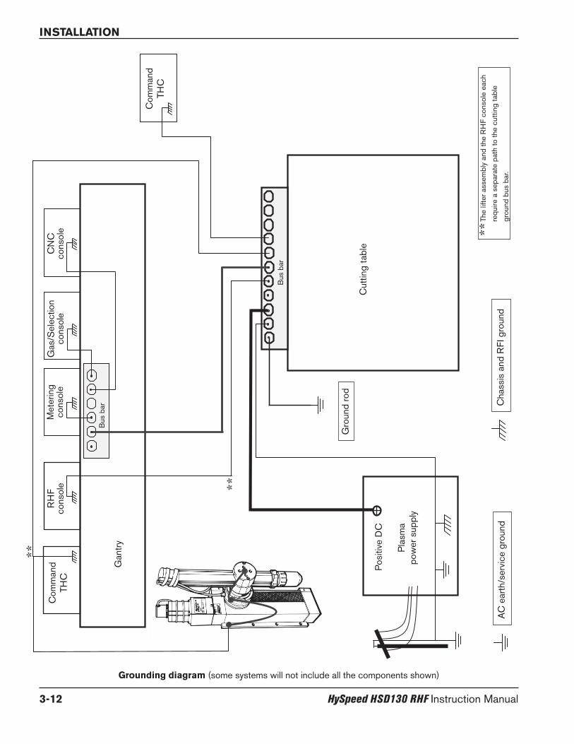
INSTALLATION
3-12 HySpeed HSD130 RHF Instruction Manual
**
**
**
AC
ear
th/s
ervi
ce g
roun
d
Gro
und
rod
Cha
ssis
and
RFI
gro
und
The
lifte
r ass
embl
y an
d th
e R
HF
cons
ole
each
requ
ire a
sep
arat
e pa
th to
the
cutti
ng ta
ble
grou
nd b
us b
ar.
Cut
ting
tabl
e
Pla
sma
pow
er s
uppl
y
Pos
itive
DC
Com
man
dTH
C
Bus
bar
Bus
bar
Com
man
dTH
CR
HF
cons
ole
Met
erin
gco
nsol
eG
as/S
elec
tion
cons
ole
CN
Cco
nsol
e
Grounding diagram (some systems will not include all the components shown)
Gan
try

INSTALLATION
HySpeed HSD130 RHF Instruction Manual 3-13
Placement of the power supplyA
The power supply can be moved by forklift but the forks must be long enough to extend the entire length of the base.Take care when lifting so that the underside of the power supply is not damaged.
• Place the power supply in an area that is free of excessive moisture, has proper ventilation, and is relativelyclean. Allow 1 m (3 ft) on all sides of the power supply for ventilation and servicing.
• Cooling air is drawn in through the front panel and is exhausted through the rear of the unit by a cooling fan.Do not place any filter device over the air intake locations, which reduces cooling efficiency and VOIDSTHE WARRANTY.
• Do not place the power supply on an incline greater than 10° to prevent it from toppling.
DANGERELECTRICAL SHOCK CAN KILL
Remove all electrical connections to power supply before moving or positioning.Transporting the unit can cause personal injury and equipment damage.

INSTALLATION
3-14 HySpeed HSD130 RHF Instruction Manual
Install the ignition console
• Mount the ignition console on the gantry (bridge).
• Allow room to remove the top for servicing.
B
7 mm .028"
(4 places)
32 mm1.25"
32 mm1.25"
184 mm7.25"
279 mm11.00"
248 mm9.75"
216 mm8.50"
Note: verify the hose orientation before running the coolant hoses. The fittings are different on the ignitionconsole end and the power supply end of each hose. The label marked IGN CSL on the end of eachhose indicates that it is the end that is connected to the ignition console.

INSTALLATION
HySpeed HSD130 RHF Instruction Manual 3-15
Horizontal RHF mounting
Vertical RHF mounting
Ignition console grounding

INSTALLATION
3-16 HySpeed HSD130 RHF Instruction Manual
Install the off-valve (standard and fuel-gas)
• Mount the off-valve assembly near the torch lifter. The maximum length of the gas hoses between the off-valveassembly and the torch is 1.8 m (6 ft).
C
Off-valve grounding
54.4 mm2.14"
5.16 mm0.203"
130.8 mm5.15"
Vent hole:Keep clear at all times

INSTALLATION
HySpeed HSD130 RHF Instruction Manual 3-17
Torch mounting and alignmentD
Mounting the torch
Torch alignment
To align the torch at right angles to the workpiece, use a square. See figure above.
See also Install consumables in Section 4 to install consumables in the torch.
Torch lifter requirement
The system requires a high-quality, motorized torch lifter with sufficient travel to cover all cutting thickness requirements.The lifter must provide 203 mm (8 in.) of vertical travel. The unit should have the capability of maintaining a constantspeed of up to 5080 mm/min (200 ipm) with positive braking. A unit which drifts through the stop point is notacceptable.
Installation
1. Install the torch (with torch leadsattached) in the torch mounting bracket.
2. Position the torch below the mountingbracket, so that the bracket is around thelower portion of the torch sleeve but nottouching the torch body.
3. Tighten the securing screws.
Note: The bracket should be as low on thetorch sleeve as possible to minimize vibrationat the tip of the torch.
Lower torch sleeve
Torch mountingbracket(customer-supplied)
Upper torch sleeve

INSTALLATION
3-18 HySpeed HSD130 RHF Instruction Manual
Install the fuel gas console (optional component)
• The fuel gas console is mounted on the top of the power supply. Allow 1 m (3 ft) on all sides of the console forservicing and ventilation.
• The maximum lead length, from the fuel gas console to the off-valve, is 15 m (50 ft).
E

INSTALLATION
HySpeed HSD130 RHF Instruction Manual 3-19
Power supply to off-valve cable
Off-valve solenoid cable
4
8
1
7
32
5 6
9 10 11
141312
AC
B
End B End A ( male/pins)
Cable and hose assembly from power supply to off-valve1
Cable signal list – power supply to off-valve cable
Power supply end Off-valve end
Pin # Description Pin #
1 120 Vac Hot – Shield 1
2 120 Vac Return – Shield 2
3 120 Vac Hot – Plasma preflow 3
4 120 Vac Return – Plasma preflow 4
5 120 Vac Hot – Plasma cutflow 5
6 120 Vac Return – Plasma cutflow 6
7 120 Vac Hot – Plasma vent 7
8 120 Vac Return – Vent 8
9 Ground 9
Cable signal list – off-valve solenoid cable to off-valve cable
Function End B Color End A
Shield A Blue 1C Blue 2
Plasma P Red/Black 3Preflow P Red 4
Plasma P Red/Black 5Cutflow C Red 6
Vent V Red/Black 7V Red 8
Not used 9Not used 10
Ground Ground Green/Yellow 11Ground 12Ground 13Ground 14
Part no. Length
228053 7.5 m (25 ft)228054 15 m (50 ft)
To power supply To off-valve solenoid cable
Male/Pins Female/Sockets

1X3
Power supply to off-valve connections
INSTALLATION
3-20 HySpeed HSD130 RHF Instruction Manual
OptionalFuel-gas off-valveconnections
1

Fuel gas console to off-valve connections1aa
The cable and hoseare bundled together
Part no. Length
228148 7.5 m (25 ft)228149 15 m (50 ft)
INSTALLATION
HySpeed HSD130 RHF Instruction Manual 3-21

INSTALLATION
3-22 HySpeed HSD130 RHF Instruction Manual
– Fuel gas console to power supply connectionsBefore connections from the power supply to the fuel-gas console are made, the standard air hose must be removedfrom the power supply.
1. Remove and discard the standard air hose.
2. The air hose for the power supply to the fuel-gas console connection is supplied with the fuel-gas console. Connectthe hose (024819) from the air filter on the power supply to the air inlet on the fuel-gas console.
1f1b
Remove thestandardair hose
Install thefuel-gasair hose
The air supplyline must beconnectedhere

INSTALLATION
HySpeed HSD130 RHF Instruction Manual 3-23
Part no. Description Length
078203 Fuel-gas console lead set024819 Hose (black): CG1 1 m (3 ft)024820 Hose (blue): CG2 1 m (3 ft)123844 Cable: CAN Communication (3x2 to 1x2) 1.5 m (5 ft)123684 Cable: Power (3x1 to 1x1) 1.5 m (5 ft)024819 Hose: power supply air filter to fuel-gas console 1 m (3 ft)

Part no. Length
123932 7.5 m (25 ft)123933 15 m (50 ft)123934 23 m (75 ft)123935 30.5 m (100 ft)123936 38 m (125 ft)
Part no. Length
123926 7.5 m (25 ft)123927 15 m (50 ft)123928 23 m (75 ft)123929 30.5 m (100 ft)123930 38 m (125 ft)
INSTALLATION
3-24 HySpeed HSD130 RHF Instruction Manual
Power supply to ignition console leads
Pilot arc lead2
Negative lead3
Pilot arclead

INSTALLATION
HySpeed HSD130 RHF Instruction Manual 3-25
Negativelead
Pilot arc lead
Negative lead
Pilot arc lead
Negative lead

INSTALLATION
3-26 HySpeed HSD130 RHF Instruction Manual
Ignition console power cable4
CABLE SIGNAL LIST – power supply to ignition console
Power supply end Ignition console end
Pin # I/O Description Pin #
1 120Vac Hot 1
2 120Vac Return 2
3 Ground 3
4 Not connected 4
Part no. Length
123421 7.5 m (25 ft)123424 15 m (50 ft)123425 23 m (75 ft)123426 30.5 m (100 ft)123938 38 m (125 ft)

INSTALLATION
HySpeed HSD130 RHF Instruction Manual 3-27
Ignition console coolant hoses5
Red
Red
Part no. Length
228157 7.5 m (25 ft)228158 15 m (50 ft)228159 23 m (75 ft)228160 30.5 m (100 ft)228161 38 m (125 ft)
Green
Note: verify the hose orientation before running the coolant hoses. The fittings are different on the ignitionconsole end and the power supply end of each hose. The label marked IGN CSL on the end of eachhose indicates that it is the end that is connected to the ignition console.

INSTALLATION
3-28 HySpeed HSD130 RHF Instruction Manual
Torch lead assembly6
Part no. Length
228050 7.5 m (25 ft)228051 15 m (50 ft)

INSTALLATION
HySpeed HSD130 RHF Instruction Manual 3-29
Connect the torch to the torch lead assembly
1. Route the leads through the cable track on the table. Leave 2 meters (6.5 ft.) of the leads loose at the torch end toinstall the torch.
2. Hold the torch in place and remove the mounting sleeve from the torch assembly.
3. Push back the braided cover and slide the sleeve back over the leads. Align the torch connections with the hoses inthe lead assembly. The hoses must not twist, and they are taped together to help prevent twisting.
4. Connect the coolant hoses to the torch. Red connects to red. Use 2 wrenches to tighten gas and coolant fittings.
Braided cover
Sleeve

INSTALLATION
3-30 HySpeed HSD130 RHF Instruction Manual
5. Connect the shield gas hose.
6. Connect the plasma gas hose. This connection has left-hand threads.
7. Connect the pilot arc lead.
Note: Be careful not to damage or remove the small slotted metal band at the end of the pilot arc cable
7a. Pull the sleeve back until the connector is exposed.
7b. Screw the connector onto the pilot arc connection from the torch. Tighten by hand until it is firmly seated.

INSTALLATION
HySpeed HSD130 RHF Instruction Manual 3-31
7c. Slide the sleeve forward until it clicks into place.
8. Slide the torch sleeve over the connections and screw it onto the torch body.
9. Slide the braided cover up to the torch sleeve. Push the brass collar into the torch sleeve. It is a snug fit. Make surethe plasma and shield hoses are routed through the hole in the braided cover.

INSTALLATION
3-32 HySpeed HSD130 RHF Instruction Manual
Work lead7
To work table
Lower frame of work table (typical)
Work table Power supply
Part no. Length
123662 7.5 m (25 ft)123663 15 m (50 ft)

INSTALLATION
HySpeed HSD130 RHF Instruction Manual 3-33
Arc voltage connectionIf a torch height control is installed, and undivided arc voltage (0 to 311 VDC) is needed, it can be accessed by makingthe connections shown in the figure on this page. The cables in the figure terminate at a voltage divider (supplied by thetorch height control manufacturer).
(+)
(—)

INSTALLATION
3-34 HySpeed HSD130 RHF Instruction Manual
Wire Input/ Input/color Pin no. Output Signal name Function Output Notes
Black 1 Input None Not used OutputRed 20 Input None Not used Output
Black 2 Output None Not used InputGreen 21 Output None Not used Input
Black 3 None Not usedBlue 22 None Not used
Black 4 Output Motion E (-) Notifies the CNC that an arc transfer has occurred and to begin Input 2Yellow 23 Output Motion C (+) machine motion once the CNC’s pierce delay has timed out. Input
Black 5 Output None Not used Input 2Brown 24 Output None Not used Input
Black 6 Output Rampdown error E (-) Notifies the CNC that a rampdown error has occurred Input 2Orange 25 Output Rampdown error C (+)
Red 7 Output None Not used Input 2White 26 Output None Not used
Red 8 Output None Not used Input 2Green 27 Output None Not used Input
Red 9 Output None Not used Input 2Blue 28 Output None Not used Input
Red 10 Output None Not used Input 2Yellow 29 Output None Not used Input
Red 11 None Not usedBrown 30 None Not used
Red 12 Input Corner - CNC Notifies the plasma system that a corner is approaching and to Output 1Orange 31 Input Corner + reduce cut current (Cut current is CNC selectable or defaults to 75%. Output
of cut current)
Green 13 Input Pierce - CNC Notifies the plasma system to maintain the shield preflow until Output 1White 32 Input Pierce + the CNC releases the signal.
Green 14 Input Hold - Not required without Command THC. Command THC requires signal Output 1Blue 33 Input Hold + to preflow gases during IHS.
Green 15 Input Start - CNC initiates the plasma arc. Output 1Yellow 34 Input Start + Output
Green 16 None Not usedBrown 35 None Not used
Green 17 None Not usedOrange 36 Power ground Ground
White 18 Power ground GroundBlack 37 CNC +24 VDC Available 24 VDC (200 milliamps maximum) See notes 3
19 CNC + 24 VDC Not connected
Power supply to CNC interface cable8
Power supply CNC
Part no. Length
123022 7.5 m (25 ft)123023 15 m (50 ft)

INSTALLATION
HySpeed HSD130 RHF Instruction Manual 3-35
Notes to CNC interface cable run list
Note 1. Inputs are relay coils. They require 24 VDC at 8.3 mA, or dry-contact closure.
Note 2. Outputs are optically isolated, open-collector, transistors. The maximum rating is 24 VDC at 10 mA.
Note 3. CNC +24 VDC provides 24 VDC at 200 mA maximum. A jumper is required on J300 to use 24 V power.
Caution: The CNC cable must be constructed using cable with 360 degree shielding andmetal housing connectors at each end. The shielding must be terminated tothe metal housings at each end to ensure proper grounding and to provide thebest shielding.

INSTALLATION
3-36 HySpeed HSD130 RHF Instruction Manual
Examples of output circuits
1. Logic interface, active-high
2. Logic interface, active-low
3. Relay interface
4. Do not use this configuration. Warranty will be void.
High-impedance (≤10mA)
10K(optional)
CNC/PLC
5VDC-24VDC
CHSD
E
+
-
HSDC
E
+
-
5VDC-24VDC
High-impedance (≤10mA)
CNC/PLC
10K(optional)
CNC/PLC
CNC +24V+24VDC CNC +24V
HSDC
E
+
-
Powerground
External relay 24VDC low-power coil ≤10mA or ≥2400ohm
High-current contact closure inputs (AC or DC)
°t
Any voltage
VOIDSWARRANTY
HSD
Install a
Jumper
108056 J300
C
E
+
-
To 1x4

INSTALLATION
HySpeed HSD130 RHF Instruction Manual 3-37
Examples of input circuits
Output fromCNC/PLC
External relay(AC or DC)
1. Relay interface
+24 VDC
HSD
Powerground
2. Optocoupler interface
CNC/PLC
+24 VDC
HSD
Powerground
Transistor-outputoptocoupler
24VDC
CNC/PLC +24 VDC
HSD
Powerground Power
groundActive-high drive
3. Amplified-output interface
Note: The external relay's life may be improved by adding ametallized-polyester capacitor (0.022µF 100V or higher) inparallel with the relay contacts.
°t
°t
°t

INSTALLATION
3-38 HySpeed HSD130 RHF Instruction Manual
Line disconnect switch
The line disconnect switch serves as the supply-voltage disconnecting (isolating) device. Installthis switch near the power supply for easy access by the operator.
Installation must be performed by a licensed electrician and according to applicable nationaland local codes.
The switch should:
• isolate the electrical equipment and disconnect all live conductors from the supplyvoltage when in the “OFF” position
• have one “OFF” and one “ON” position clearly marked with “O” (OFF) and “l” (ON)• have an external operating handle capable of being locked in the “OFF” position• contain a power-operated mechanism that serves as an emergency stop• have slow-blow fuses installed for the proper breaking capacity (see table above).
Power cable
Cable sizes vary based on the distance of the receptacle from the main box. Use a 4-conductor Type SO input powercable with a conductor temperature rating of 60° C (140° F). Installation must be performed by a licensed electrician.
9
Power requirements
General
All switches, slow-blow fuses and power cables are customer-supplied and must bechosen as outlined by applicable national and local electrical-codes. Installation must beperformed by a licensed electrician. Use a separate primary-line disconnect switch forthe power supply.
FU
SE
SWITCH BOX
Note: Cable AWG recommendations taken from table 310-16 of the National Electric Code handbook (USA).
Recommended cable sizefor 15 m (50 feet)
Input Rated input current Recommended maximum lengthvoltage Phase @ 19.5 kW output slow-blow fuse size Rated for 60° C
200/208 VAC 3 62/58 amps 85 amps 30 mm2 (3 AWG)
220 VAC 3 56 amps 80 amps 30 mm2 (3 AWG)
240 VAC 3 52 amps 65 amps 26 mm2 (4 AWG)
400 VAC 3 32 amps 40 amps 10 mm2 (8 AWG)
440 VAC 3 28 amps 35 amps 8 mm2 (8 AWG)
480 VAC 3 26 amps 35 amps 8 mm2 (8 AWG)
600 VAC 3 21 amps 30 amps 6 mm2 (10 AWG)

INSTALLATION
HySpeed HSD130 RHF Instruction Manual 3-39
Connect the power
1. Insert the power cable through the strain relief at the rear of the power supply.
2. Connect the ground lead (PE) to the ground terminal as shown below.
3. Connect the power leads to the terminals as shown below.
4. Check that the line disconnect switch is in the OFF position and remains in the OFF position for theremainder of the installation of the system.
5. Connect the power cord leads to the line disconnect switch, following national and local electrical codes.
Linedisconnect
switch Powercable
L1
GND
North American wire colorsU = BlackV = WhiteW = Red(PE) Earth ground = Green/Yellow
European wire colorsU = BlackV = BlueW = Brown(PE) Earth ground = Green/Yellow
L2
L3
L1
GND
L2
L3
Non-CE power supply CE power supply
L1 = White
L2 = Red
L3 = Black
GND = Green
DANGERELECTRICAL SHOCK CAN KILL
The line disconnect switch must be in the OFF position before making the power cable connections.In the U.S., use a “lock-out/tag-out” procedure until installation is complete. In other countries,follow appropriate national and local safety procedures.

INSTALLATION
3-40 HySpeed HSD130 RHF Instruction Manual
Torch coolant requirementsThe power supply is shipped without any coolant in the tank. Hypertherm recommends a mixture of 30% propyleneglycol, 69.9% deionized water, and 0.1% benzotriazole. This mixture resists freezing to -12° C (+10° F) and contains acorrosion inhibitor to protect copper surfaces in the coolant loop. This mixture is available in 1-gallon (3.8 liter)containers by ordering 028872. 100% propylene glycol is available by ordering 028873.
Caution: For operating temperatures colder than the temperature stated above, thepercentage of propylene glycol must be increased. Failure to do so could result ina cracked torch head, hoses or other damage to the torch coolant system due tofreezing.
See Material Safety Data Sheets Appendix to determine if a stronger propylene glycol:purified water solution is neededfor your particular application.
Observe the warning and cautions below. Refer to the Material Safety Data Sheets Appendix for data on safety,handling and storage of propylene glycol and benzotriazole.
Caution: Always use propylene glycol in the coolant mixture. Do not use automotiveanti-freeze in place of propylene glycol. Antifreeze contains corrosioninhibitors that will damage the torch coolant system.
Always use purified water in the coolant mixture in order to prevent damage tothe pump and corrosion in the torch coolant system.
Water purity requirements
It is critical to maintain a low level of calcium carbonate in the coolant to avoid reduced performance of the torch orcooling system.
DANGERCOOLANT CAN BE IRRITATING TO SKIN AND EYES AND
HARMFUL OR FATAL IF SWALLOWED
Propylene glycol and benzotriazole are irritating to skin and eyes, and harmful or fatal if swallowed.Upon contact, flush skin or eyes with water. If swallowed, induce vomiting and call a physicianimmediately.

INSTALLATION
HySpeed HSD130 RHF Instruction Manual 3-41
Fill the power supply with coolantThe system will take 11.4 – 15.1 liters (3 to 4 gallons) of coolant depending on the length of the torch leads andwhether the system has a local or remote ignition console.
3. The level of coolant in the tank will have dropped. Add coolant until the tank is full and replace the filler cap.
1. Add coolant until the tank is full.
2. Press and hold the Amps knob on the power supply control panel and turn ON the power to the power supply. Thisallows the user to override the 5-second pump time-out and fill the torch leads with coolant for the first time.Release the amps knob after 60 seconds. If the coolant flow switch is satisfied, the pump will continue to run andyou are done. If the pump turns off, turn OFF the power to the power supply and repeat the process.
Power switch Amps knob

INSTALLATION
3-42 HySpeed HSD130 RHF Instruction Manual
Gas requirementsThe customer must furnish all gases and gas-supply regulators for the system. Use high-quality, 2-stage pressureregulators located within 3 m (10 ft) of the power supply or optional fuel-gas console. See Gas regulators in this sectionfor recommendations. See Section 2 for gas and flow specifications.
Caution: Gas supply pressures not within the specifications in Section 2 can cause poorcut quality, poor consumable life, and operational problems.
If the purity level of the gas is too low, or if there are leaks in the supply hoses orconnections,
• Cut speeds can decrease• Cut quality can deteriorate• Cutting thickness capability can decrease• Parts life can shorten
Setting the supply regulators
1. Make sure the power is OFF. Set the oxygen regulator pressure to 8.3 bar (120 psi). Set the air regulator pressure to7.2 bar (95 psi). If an optional fuel-gas console is being used, set H35, F5, and N2 pressures to 8.3 bar (120 psi).
2. Turn ON the power.
3. After the purge cycle stops, move the selection switch to the SET position.
4. Adjust all regulators while gas is flowing. Return to the supply regulators and adjust them to match the values instep 1.
5. Move the selection switch back to the RUN position (center).

INSTALLATION
HySpeed HSD130 RHF Instruction Manual 3-43
Gas regulators
Low-quality gas regulators do not provide consistent supply pressures and can result in poor cut quality and systemoperation problems. Use high-quality, 1-stage, gas regulators to maintain consistent gas supply pressure, if using liquidcryogenic or bulk storage. Use high-quality, 2-stage, gas regulators to maintain consistent gas supply pressure fromhigh-pressure gas cylinders.
The high-quality gas regulators listed below are available from Hypertherm and meet U.S. Compressed Gas Association(CGA) specifications. In other countries, select gas regulators that conform to national and local codes.
PartNumber Description Qty.
128544 Kit: Oxygen, 2-stage * 1128545 Kit: Inert Gas, 2-stage 1128546 Kit: Hydrogen (H5, H35 and methane) 2-stage 1128547 Kit: Air, 2-stage 1128548 Kit: 1-stage (for use with cryogenic liquid nitrogen or oxygen) 1022037 Oxygen, 2-stage 1022038 Inert gas, 2-stage 1022039 Hydrogen/methane, 2-stage 3022040 Air, 2-stage 1022041 Line regulator, 1-stage 1
* Kits include appropriate fittings
2-stage regulator Single-stage regulator
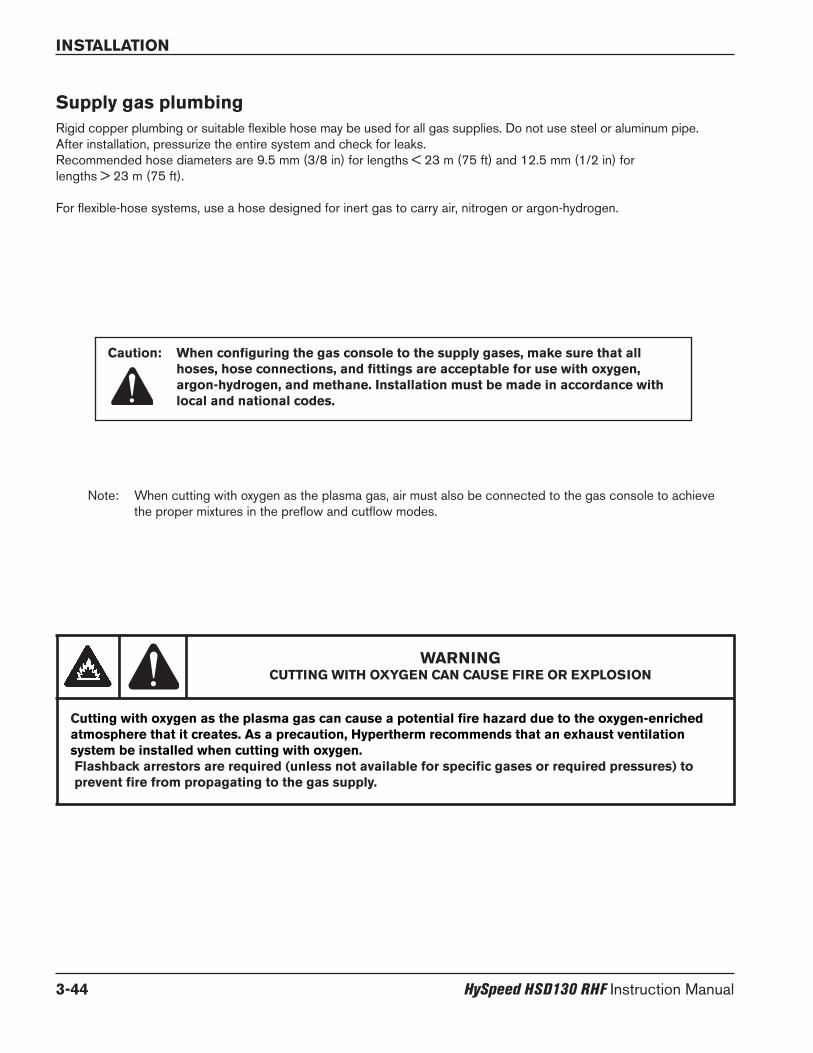
INSTALLATION
3-44 HySpeed HSD130 RHF Instruction Manual
Supply gas plumbingRigid copper plumbing or suitable flexible hose may be used for all gas supplies. Do not use steel or aluminum pipe.After installation, pressurize the entire system and check for leaks.Recommended hose diameters are 9.5 mm (3/8 in) for lengths < 23 m (75 ft) and 12.5 mm (1/2 in) for lengths > 23 m (75 ft).
For flexible-hose systems, use a hose designed for inert gas to carry air, nitrogen or argon-hydrogen.
Caution: When configuring the gas console to the supply gases, make sure that allhoses, hose connections, and fittings are acceptable for use with oxygen,argon-hydrogen, and methane. Installation must be made in accordance withlocal and national codes.
Note: When cutting with oxygen as the plasma gas, air must also be connected to the gas console to achievethe proper mixtures in the preflow and cutflow modes.
WARNINGCUTTING WITH OXYGEN CAN CAUSE FIRE OR EXPLOSION
Cutting with oxygen as the plasma gas can cause a potential fire hazard due to the oxygen-enrichedatmosphere that it creates. As a precaution, Hypertherm recommends that an exhaust ventilationsystem be installed when cutting with oxygen.Flashback arrestors are required (unless not available for specific gases or required pressures) toprevent fire from propagating to the gas supply.

INSTALLATION
HySpeed HSD130 RHF Instruction Manual 3-45
Connect the supply gases
Standard system
Connect the supply gases to the power supply.
Fuel-gas system
Connect the supply gases to the gas console. Torch leads must be purged between gas changes.
Fitting Size
H35 / F5 9/16 – 18 LH,(fuel gas)”B”
N2 5/8 – 18, RH, internal(inert gas) “B”
O2 9/16 – 18, RH (oxygen) “B”
Air 9/16 – 18, JIC, #6

INSTALLATION
3-46 HySpeed HSD130 RHF Instruction Manual
Supply gas hoses
Air hose10
Oxygen hose11
Part no. Length
024659 7.5 m (25 ft)024660 15 m (50 ft)
Nitrogen hose13
F5 or H35 hose12
Part no. Length
024205 7.5 m (25 ft)024155 15 m (50 ft)
Part no. Length
024384 7.5 m (25 ft)024656 15 m (50 ft)
Part no. Length
024134 7.5 m (25 ft)024112 15 m (50 ft)

HySpeed HSD130 RHF Instruction Manual 4-1
Section 4
OPERATION
In this section:
Controls and indicators.............................................................................................................................................................................4-2Main power switch ..........................................................................................................................................................................4-2
Daily start-up................................................................................................................................................................................................4-3Check torch.......................................................................................................................................................................................4-3
System operation........................................................................................................................................................................................4-4Amps display.....................................................................................................................................................................................4-4
Fuel-gas console operation......................................................................................................................................................................4-5Consumable selection...............................................................................................................................................................................4-6
Mild steel............................................................................................................................................................................................4-6Stainless steel...................................................................................................................................................................................4-6Aluminum............................................................................................................................................................................................4-7
Install consumables....................................................................................................................................................................................4-8Cut charts.....................................................................................................................................................................................................4-9
Estimated kerf width compensation ............................................................................................................................................4-9Changing consumable parts .................................................................................................................................................................4-23
Remove consumables ..................................................................................................................................................................4-23Inspect consumables....................................................................................................................................................................4-24Inspect torch...................................................................................................................................................................................4-25Inspect electrode pit depth.........................................................................................................................................................4-26
Replace torch water tube.......................................................................................................................................................................4-27Common cutting faults ...........................................................................................................................................................................4-28How to optimize cut quality ...................................................................................................................................................................4-29
Tips for table and torch ................................................................................................................................................................4-29Plasma set-up tips.........................................................................................................................................................................4-29Maximize the life of consumable parts......................................................................................................................................4-29Additional factors of cut quality..................................................................................................................................................4-30Additional improvements .............................................................................................................................................................4-31

OPERATION
4-2 HySpeed HSD130 RHF Instruction Manual
Controls and indicators
Main power switch
The switch illuminates when it is in the ON position.
On position (I)AC power is sent to the control transformer, to turn ON the power supply.
Off position (O)AC power is cut off to the control transformer, to turn OFF the power supply.

Daily start-upPrior to start-up, ensure that your cutting environment and that your clothing meet the safety requirements outlined in theSafety section of this manual.
Check the torch
1. Turn OFF the main disconnect switch to the power supply.
2. Remove the consumables from the torch and check for worn or damaged parts. Always place the consumableson a clean, dry, oil-free surface after removing. Dirty consumables can cause the torch to malfunction.
• Refer to Changing consumable parts later in this section for details and for consumable inspection tables.
• Refer to Consumable selection to choose the correct consumables for your cutting needs.
3. Replace consumables. Refer to Changing consumable parts later in this section for details.
4. Ensure that the torch is perpendicular to the workpiece.
TorchCurrent ringElectrodeSwirl ringNozzle
OPERATION
HySpeed HSD130 RHF Instruction Manual 4-3
Shield Retaining cap
WARNING
Before operating this system, you must read the Safety section thoroughly! Turn OFF the powersupply’s main disconnect switch before proceeding with the following steps.

OPERATION
4-4 HySpeed HSD130 RHF Instruction Manual
1. Turn ON the power with the selection switch in the RUN position.
2. Set the current using the AMPS knob.
3. Choose a process using the process selection knob.
4. Move the selection switch to the SET position.
5. Set the PLASMA and SHIELD gas pressures using the data in the cut chart for the desired process. Pull the knobtowards you to unlock it and set the pressure. Push the knob towards the power supply until it clicks to lock it.
Note: when the selection switch is in the set position, the amps display shows the incoming shield supplypressure.
6. Move the selection switch to the RUN position.
Amps display
• When the selection switch is in the run position, the display shows the current set point.
• During a cut the display shows the actual cutting current.
• Push the amps knob during a cut to display the output voltage of the power supply.
Ampsknob
Process selectionknob
Plasma setknob
Selectionswitch
Shield setknob
System operation
Ampsdisplay

OPERATION
HySpeed HSD130 RHF Instruction Manual 4-5
Fuel-gas console operation
Note: The plasma set knob on the fuel-gas console is used when an H35 or F5 process is selected. Theplasma set knob on the power supply is used (as described on the previous page) when an O2, Air, or N2process has been selected.
1. Turn ON the power with the selection switch in the RUN position.
2. Move the selection switch on the power supply to SET and choose the current using the AMPS knob.
3. Choose a process using the process selection knob on the fuel gas console.
4. Set the PLASMA gas pressure on the fuel gas console (H35/F5).
5. Set the SHIELD gas pressure on the power supply using the data in the cut chart for the desired process.
6. Move the selection switch on the power supply to the RUN position.
Plasma setknob
Process selectionknob

OPERATION
4-6 HySpeed HSD130 RHF Instruction Manual
Consumable selection
Mild steel
130 A (Air)
Shield Nozzle Swirl ring Electrode
220532
Stainless steel
Retaining cap
50 A (O2)
45 A (Air)
220525 220529 220528220578
220536 220492 220488 220487220578
220532 220530 220529 220528220578
220491 220489 220488 220487220578
130 A (O2)
220532 220525 220529 220528220578
220536 220492 220488 220487220578
45 A (Air)
130 A (Air)
45 A (N2 and F5/N2)
220532 220525 220529 220528220534
130 A (H35)
220536 220535 220529 020415220534
Shield Nozzle Swirl ring ElectrodeRetaining cap
130 A (N2)
220536 220535 220488 020415220578

OPERATION
HySpeed HSD130 RHF Instruction Manual 4-7
220532 220525 220529 220528220578
220536 220492 220488 220487220578
45 A (Air)
130 A (Air)
Aluminum
130 A (H35)
220536 220535 220529 020415220534
Shield Nozzle Swirl ring ElectrodeRetaining cap

OPERATION
4-8 HySpeed HSD130 RHF Instruction Manual
Install consumables
Apply a thin film of silicone grease on all o-rings.
Do not overtighten parts! Only tighten until mating parts are seated.
Use compressed air to clean out the inside of the torch every time consumablesare changed.
Clean the nozzlemating surface with acotton swab and wateror 3% hydrogenperoxide.
Tool part number027102
Install the electrode Install the swirl ring Install the nozzle andswirl ring
Install the retaining cap Install the shield

OPERATION
HySpeed HSD130 RHF Instruction Manual 4-9
Cut chartsThe following Cut charts show the consumable parts, cutting speed, and the gas and torch settings required for eachprocess.
The numbers shown in the Cut charts are recommended to provide high-quality cuts with minimal dross. Because ofdifferences between installations and material composition, adjustments may be required to obtain desired results.
Material thickness (inches)
Mild steel 0.06 0.135 0.25 0.375 0.5 0.75 1130 O2/Air 0.061 0.07 0.078 0.088 0.092 0.121130 Air/Air 0.053 0.062 0.074 0.082 0.107 0.12850 O2/Air 0.041 0.046 0.05845 Air/Air 0.032 0.050 0.056
Stainless steel130 Air/Air 0.065 0.076 0.084 0.109130 N2/N2 0.065 0.065 0.100 0.139130 H35/N2 0.113 0.109 0.102 0.11645 Air/Air 0.032 0.044 0.05045 N2/N2 0.021 0.026 0.02645 F5/N2 0.024 0.025 0.032
Aluminum130 Air/Air 0.082 0.076 0.085 0.106 0.111130 H35/N2 0.088 0.086 0.079 0.04645 Air/Air 0.046 0.047 0.048
Estimated kerf width compensation
Material thickness (mm)
Mild steel 1.524 3.429 6.350 9.525 12.70 19.05 25.40130 O2/Air 1.549 1.778 1.981 2.235 2.336 3.073130 Air/Air 1.346 1.574 1.879 2.082 2.717 3.25150 O2/Air 1.041 1.168 1.47345 Air/Air 0.812 1.270 1.422
Stainless steel130 Air/Air 1.651 1.930 2.133 2.768130 N2/N2 1.651 1.651 2.540 3.530130 H35/N2 2.870 2.768 2.590 2.94645 Air/Air 0.812 1.117 1.27045 N2/N2 0.533 0.660 0.66045 F5/N2 0.609 0.635 0.812
Aluminum130 Air/Air 2.082 1.930 2.159 2.692 2.819130 H35/N2 2.235 2.184 2.006 1.16845 Air/Air 1.168 1.193 1.219

OPERATION
4-10 HySpeed HSD130 RHF Instruction Manual
Mild steelAir Plasma / Air Shield
45 A Cutting
Flow Rates – lpm/scfh
AirPreflow 113 / 240Cutflow 122 / 258
220532 220525 220529 220528220578220490 (no IHS tab)
Metric
Plasma Shield Plasma Shield mm Volts mm factor % seconds0.5 104 3.0 200 0.00.8 106 3.0 200 0.01.0 107 3.0 200 0.1
1.2 108 3.6 200 0.1
1.5 109 3.6 200 0.2
2.0 110 3.6 200 0.2
2.5 110 4.0 200 0.2
3.0 110 4.0 200 0.34.0 113 4.6 200 0.46.0 115 5.0 200 0.5
English
Plasma Shield Plasma Shield in Volts in factor % seconds
.018 104 0.120 200 0.0
.024 105 0.120 200 0.0
.030 106 0.120 200 0.0
.036 107 0.120 200 0.1
.048 108 0.140 200 0.1
.060 109 0.140 200 0.2
.075 110 0.140 200 0.2
.105 110 0.160 200 0.2
.135 110 0.160 200 0.3
3/16 113 0.180 200 0.4
1/4 116 0.200 200 0.5
SelectGases
SetCutflow
MaterialThickness
ArcVoltage
Torch-to-WorkDistance Cutting Speed
mm mm/m
Air
Air Air
SelectGases
Air
in
.060
.060
.070
Initial Pierce HeightPierce Delay
Time
SetCutflow
MaterialThickness
ArcVoltage
Torch-to-WorkDistance Cutting Speed Initial Pierce Height
Pierce Delay Time
2.3
90
70
60
170
ipm.060
.060
.080
360
345
335
315
285
255
235
2.0
.070
.070
.080
1950
.090
.100
1.5
1.5
1.5
1.8
1.8
1.8
2.0
15752.5
8930
8400
7750
7250
6500
5800
4700
3300
57 50
57 50

OPERATION
HySpeed HSD130 RHF Instruction Manual 4-11
Mild steelO2 Plasma / Air Shield
50 A Cutting
Flow Rates – lpm/scfh
O2 AirPreflow 0 / 0 69 / 146Cutflow 29 / 62 73 / 155
220532 220530 220529 220528
Metric
Plasma Shield Plasma Shield mm Volts mm factor % seconds0.5 98 3.0 200 0.00.8 98 3.0 200 0.01.0 98 3.0 200 0.1
1.2 98 3.0 200 0.1
1.5 98 3.0 200 0.1
2.0 98 3.0 200 0.1
2.5 100 3.6 200 0.2
3.0 102 3.6 200 0.34.0 104 4.0 200 0.46.0 108 5.0 200 0.5
English
Plasma Shield Plasma Shield in Volts in factor % seconds
.018 98 0.120 200 0.0
.024 98 0.120 200 0.0
.030 98 0.120 200 0.0
.036 98 0.120 200 0.1
.048 98 0.120 200 0.1
.060 98 0.120 200 0.1
.075 98 0.120 200 0.1
.105 100 0.140 200 0.2
.135 103 0.140 200 0.3
3/16 106 0.180 200 0.4
1/4 108 0.200 200 0.5
72 36
85
65
240
220
160
130
290
280
270
260
3650
2800
1750
300
6600
6150
5400
4300
.090
.100
1.5
1.5
1.5
1.5
1.5
1.5
1.8
1.8
.060
.060
.070
.070
O2 Air
.060
.060
.060
.060
.060
MaterialThickness
Pierce Delay Time
in ipm
ArcVoltage
Torch-to-WorkDistance Initial Pierce Height
O2 Air
SelectGases
SetCutflow
72 36
Initial Pierce HeightPierce Delay
TimeSelectGases
SetCutflow
MaterialThickness
ArcVoltage
mm mm/m
Cutting Speed
Torch-to-WorkDistance Cutting Speed
2.0
2.5
7550
7050
6775
220578220490 (no IHS tab)

OPERATION
4-12 HySpeed HSD130 RHF Instruction Manual
Mild steelAir Plasma / Air Shield
130 A Cutting
220536 220492 220488 220487
Metric
Plasma Shield Plasma Shield mm Volts mm factor % seconds3 136 6.2 200 0.14 13 6.2 200 0.26 138 7.2 200 0.3
10 142 8.2 200 0.5
12 144 8.2 200 0.5
15 150 9.2 200 0.8
20 153 10.5 230 1.2
25 16332 170
English
Plasma Shield Plasma Shield in Volts in factor % seconds
0.1350 136 .240 200 0.1
0.1875 136 .240 200 0.2
0.2500 138 .280 200 0.3
0.3750 142 .320 200 0.5
0.5000 144 .320 200 0.5
0.6250 150 .360 200 0.8
0.7500 153 .420 230 1.2
1 163
1-1/4 170Edge Start
Edge Start
72 35
72 35
4.6
4.6
5.1
15
.180
.180
2050
1450
810
410
6000
4930
3850
2450
.200
220
160
150
100
75
50
35
10
Initial Pierce Height
SelectGases
SetCutflow Initial Pierce Height
250
3.1
3.1
3.6
4.1
4.1
Cutting Speed
.120
.120
.140
.160
.160
.180
Pierce Delay Time
mm mm/m
Air Air
MaterialThickness
ArcVoltage
Torch-to-WorkDistance Cutting Speed
4.6
Pierce Delay Time
in ipm
Air Air
SelectGases
SetCutflow
MaterialThickness
ArcVoltage
Torch-to-WorkDistance
Flow Rates – lpm/scfh
AirPreflow 67 / 142Cutflow 132 / 280
220578220490 (no IHS tab)

OPERATION
HySpeed HSD130 RHF Instruction Manual 4-13
Mild steelO2 Plasma / Air Shield
130 A Cutting
220491 220489 220488 220487
Metric
Plasma Shield Plasma Shield mm Volts mm factor % seconds3 128 5 200 0.14 129 5.6 200 0.26 130 5.6 200 0.3
10 134 6 200 0.3
12 136 6 200 0.5
15 141 7.6 200 0.7
20 142 7.6 200 1
25 152 8 200 1.532 155
38 160
English
Plasma Shield Plasma Shield in Volts in factor % seconds
0.1350 128 0.2 200 0.1
0.1875 129 0.22 200 0.2
0.2500 130 0.22 200 0.3
0.3750 134 0.24 200 0.3
0.5000 136 0.24 200 0.5
0.6250 141 0.3 200 0.7
0.7500 142 0.3 200 1
1 152 0.32 200 1.5
1-1/4 155
1-1/2 160Edge Start
Edge Start
65
65
48
43
48
43
4.0
4.5
4.5
3.0
3.0
3.8
3.8
12
6500
5420
4000
2650
2200
1650
1130
675
480
.180
240
190
150
110
80
60
50
25
20
.150
.150
.160
.180
.110
.110
.120
.120
AirO2
Initial Pierce HeightPierce Delay
TimeSelectGases
SetCutflow
305
2.5
2.8
2.8
mm mm/m
MaterialThickness
ArcVoltage
Torch-to-WorkDistance Cutting Speed
Initial Pierce HeightPierce Delay
TimeSelectGases
SetCutflow
MaterialThickness
ArcVoltage
in ipm
Torch-to-WorkDistance Cutting Speed
O2 Air
.100
Flow Rates – lpm/scfh
O2 AirPreflow 0 / 0 90 / 190Cutflow 48 / 102 92 / 195
220578220490 (no IHS tab)

OPERATION
4-14 HySpeed HSD130 RHF Instruction Manual
Stainless steelAir Plasma / Air Shield
45 A Cutting
220532 220525 220529 220528
Metric
Plasma Shield Plasma Shield mm Volts mm factor % seconds0.5 102 3.0 200 0.00.8 104 3.0 200 0.01.0 105 3.0 200 0.1
1.2 108 3.6 200 0.1
1.5 109 3.6 200 0.2
2.0 110 3.6 200 0.2
2.5 113 4.0 200 0.2
3.0 117 4.0 200 0.34.0 120 4.6 200 0.46.0 122 5.0 200 0.5
English
Plasma Shield Plasma Shield in Volts in factor % seconds
.018 102 0.120 200 0.0
.024 103 0.120 200 0.0
.030 104 0.120 200 0.0
.036 105 0.120 200 0.1
.048 108 0.140 200 0.1
.060 109 0.140 200 0.2
.075 110 0.140 200 0.2
.105 113 0.160 200 0.2
.135 117 0.160 200 0.3
3/16 120 0.180 200 0.4
1/4 122 0.200 200 0.5
62 73
62 73
.080
.090
.100
.070
.070
.070
.080
.060
.060
.060
.060
3000
2250
1500
1050
5600
5100
4500
3650
2.0
2.0
2.3
2.5
1.5
1.8
1.8
1.8
SetCutflow Initial Pierce Height
1.5
1.5
6800
6100
Initial Pierce HeightPierce Delay
TimeTorch-to-Work
Distance Cutting Speed
270
260
245
230
200
Pierce Delay Time
mm mm/m
Air Air
MaterialThickness
ArcVoltage
Torch-to-WorkDistance Cutting Speed
SelectGases
SelectGases
SetCutflow
MaterialThickness
ArcVoltage
in ipm
Air Air 175
150
110
70
50
40
Flow Rates – lpm/scfh
AirPreflow 149 / 315Cutflow 161 / 342
220578220490 (no IHS tab)

OPERATION
HySpeed HSD130 RHF Instruction Manual 4-15
Stainless steelN2 Plasma / N2 Shield
45 A Cutting
220532 220525 220529 220528
Metric
Plasma Shield Plasma Shield mm Volts mm factor % seconds0.5 106 3.0 200 0.00.8 107 3.0 200 0.01.0 107 3.0 200 0.1
1.2 109 3.6 200 0.1
1.5 112 3.6 200 0.2
2.0 114 3.6 200 0.2
2.5 118 4.0 200 0.2
3.0 119 4.0 200 0.34.0 121 4.6 200 0.46.0 126 5.0 200 0.5
English
Plasma Shield Plasma Shield in Volts in factor % seconds
.018 106 0.120 200 0.0
.024 106 0.120 200 0.0
.030 107 0.120 200 0.0
.036 107 0.120 200 0.1
.048 109 0.140 200 0.1
.060 112 0.140 200 0.2
.075 114 0.140 200 0.2
.105 118 0.160 200 0.2
.135 119 0.160 200 0.3
3/16 121 0.180 200 0.4
1/4 126 0.200 200 0.5
25
2573
60
40
.060
.060
.060
.060
.070
.070
.070
.080
180
160
120
75
1125
280
Cutting Speed
210
2.5
7000
6500
5850
5350
4600
3950
3300
2450
1700
1.8
2.0
2.0
2.3
SelectGases
SetCutflow
MaterialThickness
1.5
N2N2
1.5
1.5
1.8
1.8
Pierce Delay Time
mm mm/m
ArcVoltage
Torch-to-WorkDistance Cutting Speed Initial Pierce Height
Initial Pierce HeightPierce Delay
Time
in ipm
Torch-to-WorkDistance
N2
270
260
240
N2
SetCutflow
MaterialThickness
ArcVoltage
SelectGases
.080
.090
.100
73
Flow Rates – lpm/scfh
N2
Preflow 74 / 157Cutflow 91 / 192
220534220533 (no IHS tab)

OPERATION
4-16 HySpeed HSD130 RHF Instruction Manual
Stainless steelF5 Plasma / N2 Shield
45 A Cutting
220532 220525 220529 220528
Metric
Plasma Shield Plasma Shield mm Volts mm factor % seconds0.5 122 4.6 200 0.00.8 124 4.6 200 0.01.0 125 4.6 200 0.1
1.2 128 5.0 200 0.1
1.5 129 5.0 200 0.2
2.0 132 5.6 200 0.2
2.5 137 6.0 200 0.2
3.0 138 6.0 200 0.34.0 140 6.6 200 0.46.0 148 7.2 200 0.6
English
Plasma Shield Plasma Shield in Volts in factor % seconds
.018 122 0.180 200 0.0
.024 123 0.180 200 0.0
.030 124 0.180 200 0.0
.036 125 0.180 200 0.1
.048 128 0.200 200 0.1
.060 129 0.200 200 0.2
.075 132 0.220 200 0.2
.105 137 0.240 200 0.2
.135 138 0.240 200 0.3
3/16 140 0.260 200 0.4
1/4 148 0.280 200 0.6
82 82
.130
.140
.120
80
45
.090
.090
.090
.090
260
.100
.110
.120
2350
1325
280
270
3.3
3.6
7000
6500
5875
5360
4650
3200
2975
2740
SelectGases
SetCutflow
2.3
2.3
MaterialThickness
ArcVoltage
Torch-to-WorkDistance
82 82
3.0
Initial Pierce HeightPierce Delay
Time
Initial Pierce HeightPierce Delay
TimeCutting Speed
mm mm/m
F5 N2
2.3
2.5
2.5
2.8
3.0
in ipm
F5
SelectGases
SetCutflow
MaterialThickness
ArcVoltage
Torch-to-WorkDistance Cutting Speed
N2
240
180
130
115
100
.100 210
Flow Rates – lpm/scfh
F5 N2
Preflow 0 / 0 162 / 344Cutflow 32 / 67 147 / 311
220534220533 (no IHS tab)

OPERATION
HySpeed HSD130 RHF Instruction Manual 4-17
Stainless steelAir Plasma / Air Shield
130 A Cutting
220536 220492 220488 220487
Metric
Plasma Shield Plasma Shield mm Volts mm factor % seconds6 143 7.2 200 0.3
10 148 8.2 200 0.512 148 8.2 200 0.8
15 15820 160
English
Plasma Shield Plasma Shield in Volts in factor % seconds
1/4 143 .280 200 0.3
3/8 148 .320 200 0.5
1/2 148 .320 200 0.8
5/8 158
3/4 160Edge Start
Edge Start
72 35
72 35
20
.140
.160
.160
.180
.180
100
70
50
30
1700
1380
900
430
Air Air
AirAir
3.6
4.1
4.1
4.6
Initial Pierce HeightPierce Delay
Time
in ipm
mm mm/m
SelectGases
SetCutflow
MaterialThickness
ArcVoltage
Torch-to-WorkDistance Cutting Speed
4.6
2600
Torch-to-WorkDistance Cutting Speed Initial Pierce Height
Pierce Delay Time
SelectGases
SetCutflow
MaterialThickness
ArcVoltage
Flow Rates – lpm/scfh
AirPreflow 67 / 142Cutflow 132 / 280
220578220490 (no IHS tab)

OPERATION
4-18 HySpeed HSD130 RHF Instruction Manual
Stainless steelN2 Plasma / N2 Shield
130 A Cutting
220536 220535 220488 020415
Metric
Plasma Shield Plasma Shield mm Volts mm factor % seconds6 130 6.0 200 0.3
10 132 7.2 200 0.512 141 7.2 200 0.8
15 14420 153
English
Plasma Shield Plasma Shield in Volts in factor % seconds
1/4 130 .240 200 0.3
3/8 132 .280 200 0.5
1/2 141 .280 200 0.8
5/8 144
3/4 153Edge Start
Edge Start
.140
.150
.170
700
300
90
70
Torch-to-WorkDistance Cutting Speed
MaterialThickness
ArcVoltage
Torch-to-WorkDistance
Pierce Delay Time
3.0
3.6
3.6
3.8
4.3
2340
N2 N2
SelectGases
SetCutflow
46 71
Pierce Delay Time
mm mm/m
Initial Pierce Height
Initial Pierce Height
Cutting Speed
1640
1080
N2 N2
MaterialThickness
ArcVoltage
SelectGases
SetCutflow
46 71
in ipm
35
25
15
.120
.140
Flow Rates – lpm/scfh
N2
Preflow 165 / 350Cutflow 173 / 366
220578220490 (no IHS tab)

OPERATION
HySpeed HSD130 RHF Instruction Manual 4-19
Stainless steelH35 Plasma / N2 Shield
130 A Cutting
220536 220535 220529 020415
Metric
Plasma Shield Plasma Shield mm Volts mm factor % seconds10 150 7.8 170 0.312 154 7.8 170 0.515 157 7.8 170 0.8
20 162 7.8 170 1.3
25 167
English
Plasma Shield Plasma Shield in Volts in factor % seconds
3/8 150 .310 170 0.3
1/2 154 .310 170 0.5
5/8 157 .310 170 0.8
3/4 162 .310 170 1.3
1 167 Edge Start
Edge Start
70 75
10.180
.180
.180
.180
.180
Initial Pierce HeightPierce Delay
Time
Initial Pierce HeightTorch-to-Work
Distance Cutting SpeedPierce Delay
Time
580
360
260
4.6
SelectGases
SetCutflow
H35
ArcVoltage
SelectGases
SetCutflow
MaterialThickness
N2
70 75
MaterialThickness
ArcVoltage
Torch-to-WorkDistance Cutting Speed
mm mm/m
H35 N2
4.6
4.6
4.6
4.6
980
820
in40ipm
30
20
15
Flow Rates – lpm/scfh
H35 N2
Preflow 0 / 0 164 / 348Cutflow 61 / 130 141 / 298
220534220533 (no IHS tab)

OPERATION
4-20 HySpeed HSD130 RHF Instruction Manual
AluminumAir Plasma / Air Shield
45 A Cutting
220532 220525 220529 220528
Metric
Plasma Shield Plasma Shield mm Volts mm factor % seconds0.5 113 3.0 200 0.00.8 116 3.0 200 0.11.0 117 3.6 200 0.1
1.2 118 3.6 200 0.2
1.5 119 3.6 200 0.2
2.0 120 4.0 200 0.2
2.5 120 4.0 200 0.3
3.0 121 4.0 200 0.34.0 122 4.6 200 0.46.0 130 5.0 200 0.5
English
Plasma Shield Plasma Shield in Volts in factor % seconds0.016 113 0.120 200 0.0
0.020 114 0.120 200 0.0
0.025 115 0.120 200 0.00.032 116 0.120 200 0.1
0.040 117 0.140 200 0.1
0.051 118 0.140 200 0.2
0.064 119 0.140 200 0.2
0.081 120 0.160 200 0.2
0.102 120 0.160 200 0.3
1/8 121 0.160 200 0.33/16 122 0.180 200 0.41/4 130 0.200 200 0.5
62 73
62 73
.090
.100 40
65
.060
.060
.060
.060
.070
.070
.070
.080
.080
150
110
90.080
270
250
220
185
1950
1150
310
300
5000
3950
2950
2400
7600
6900
6350
5800
2.0
2.0
2.3
2.5
SetCutflow
SelectGases
Torch-to-WorkDistance Cutting Speed
1.5
1.5
1.8
1.8
1.8
2.0
Pierce Delay Time
mm mm/m
Air Air
MaterialThickness
ArcVoltage
Torch-to-WorkDistance Cutting Speed Initial Pierce Height
Pierce Delay Time
in ipm
SelectGases
SetCutflow
MaterialThickness
ArcVoltage Initial Pierce Height
Air Air
290
Flow Rates – lpm/scfh
AirPreflow 149 / 315Cutflow 161 / 342
220578220490 (no IHS tab)

OPERATION
HySpeed HSD130 RHF Instruction Manual 4-21
AluminumAir Plasma / Air Shield
130 A Cutting
220536 220492 220488 220487
Metric
Plasma Shield Plasma Shield mm Volts mm factor % seconds6 147 5.6 200 0.2
10 148 6.1 200 0.3
12 152 6.1 200 0.5
15 162 6.6 200 0.8
20 166 7.8 220 1.3
25 173
English
Plasma Shield Plasma Shield in Volts in factor % seconds1/4 147 .220 200 0.2
3/8 148 .240 200 0.3
1/2 152 .240 200 0.5
5/8 162 .260 200 0.8
3/4 166 .310 220 1.3
1 173 Edge Start
Edge Start
72 35
72 35
1050
1225
1465
2370
30
20
525
725
90
60
45
40
2.8
3.0
3.0
3.3
3.6
4.1
.110
Pierce Delay Time
mm mm/m
Cutting Speed Initial Pierce HeightTorch-to-Work
Distance
Initial Pierce Height
SelectGases
SetCutflow
MaterialThickness
ArcVoltage
Pierce Delay Time
SelectGases
SetCutflow
MaterialThickness
ArcVoltage
in ipm
Torch-to-WorkDistance Cutting Speed
.120
.120
.130
.140
.160
AirAir
AirAir
Flow Rates – lpm/scfh
AirPreflow 67 / 142Cutflow 132 / 280
220578220490 (no IHS tab)

OPERATION
4-22 HySpeed HSD130 RHF Instruction Manual
AluminumH35 Plasma / N2 Shield
130 A Cutting
220536 220535 220529 020415
Metric
Plasma Shield Plasma Shield mm Volts mm factor % seconds10 150 7.8 170 0.3
12 151 7.8 170 0.5
15 152 7.8 170 0.8
20 155 7.8 170 1.3
25 158
English
Plasma Shield Plasma Shield in Volts in factor % seconds3/8 150 .310 170 0.3
1/2 151 .310 170 0.5
5/8 152 .310 170 0.8
3/4 155 .310 170 1.3
1 158 Edge Start
Edge Start
40
20
1615
1455
1305
940
540
70 75
4.6
4.6
4.6
4.6
4.6
.180
.180
.180
N2H35
N2H35
Initial Pierce HeightPierce Delay
Time
in ipm
.180
.180
65
55
50
mm mm/m
SelectGases
SetCutflow
MaterialThickness
ArcVoltage
Torch-to-WorkDistance Cutting Speed
70 75
Torch-to-WorkDistance Cutting Speed Initial Pierce Height
Pierce Delay Time
SelectGases
SetCutflow
MaterialThickness
ArcVoltage
Flow Rates – lpm/scfh
H35 N2
Preflow 0 / 0 164 / 348Cutflow 61 / 130 141 / 298
220534220533 (no IHS tab)

OPERATION
HySpeed HSD130 RHF Instruction Manual 4-23
Changing consumable parts
Remove consumables
Check the consumable parts daily for wear before cutting. Before removing consumables, bring the torch to the edge ofthe cutting table, with the torch lifter raised to its highest point to prevent the consumables from dropping into the waterof the water table.
Turn OFF all power to the system.
Remove the retainingcap and shield
Remove the nozzleand swirl ring
Remove theelectrode
Remove theswirl ring
Tool part number027102
WARNING
Always disconnect power to the power supply before inspecting or changing torch consumable parts.Coolant will flow from the torch if there is power to the system.
Use gloves when removing consumables. The torch might be hot.

OPERATION
4-24 HySpeed HSD130 RHF Instruction Manual
Inspect consumables
Part Check for ActionCap
Nozzle
Swirl ring
Electrode
Center surface Wear
O-rings 1. Damage Replace electrode*
2. Lubricant Apply a thin film of silicone lubricant if dry
*Note: Always replace the nozzle and electrode as a set.
Damage Replace swirl ring
Dirt or debris Clean and check for damage, and replace swirl ring if damaged
Gas holes Blocked holes Replace swirl ring
O-rings 1. Damage Replace swirl ring
2. Lubricant Apply a thin film of silicone lubricant if dry
Center hole 1. Must be round Replace nozzle if hole is no longer round*
2. Signs of arcing Replace nozzle*
O-rings 1. Damage Replace nozzle*
2. Lubricant Apply a thin film of silicone lubricant if dry
Erosion or missing material Replace nozzle*
Blocked gas holes Replace nozzle*
Erosion, missing material Replace cap
Cracks Replace cap
Burn marks Replace cap
See Inspect electrode pit depth later inthis section

OPERATION
HySpeed HSD130 RHF Instruction Manual 4-25
All surfaces Dirt or debris Clean surfaces
Erosion, missing material Replace torch
Cracks Replace torch
Internal burn or arcing marks Replace torch
Nozzle seating surface 1. Dirt or debris Clean (use compressed air to remove debris)
2. Pitted or missing material Replace torch
Threads Wear or damage Replace torch
External o-rings 1. Damage Replace o-ring
2. Lubricant Apply a thin film of silicone lubricant if dry
Water tube* 1. Pitted or missing material Replace water tube*
*Note: See Replace torch water tube later in this section.
Inspect Check for Action
Inspect torch
Watertube
Nozzleseatingsurface
Externalo-rings

OPERATION
4-26 HySpeed HSD130 RHF Instruction Manual
Part Check for Action
10
0
20
40
30
40
2 3
1
80
60
70
50
90
Inspect electrode pit depth
Electrode
Center surface Wear Replace electrode if pit is deeper than 1 mm (0.040 in.)*
*Note: Always replace the nozzle and electrode as a set.
Electrode pit depth gauge (004630)

OPERATION
HySpeed HSD130 RHF Instruction Manual 4-27
Replace torch water tube
Turn OFF all power to the system.
Remove consumables from torch. See Remove consumables in this section.
Remove water tube Install new water tube Replace consumables.See Install consumablesin this section.
Note: The water tube may seem loose when correctly inserted, but any side-to-side looseness will disappearafter the electrode is installed.
WARNING
Always disconnect power to the power supply before inspecting or changing torch consumable parts.Coolant will flow from the torch if there is power to the system.
Use gloves when removing consumables. The torch might be hot.

OPERATION
4-28 HySpeed HSD130 RHF Instruction Manual
Common cutting faults
• Torch pilot arc will initiate, but will not transfer. Causes can be:
1. Work cable connection on the cutting table is not making good contact.
2. Malfunction in the system. See Section 5..
3. Torch-to-work distance is too high.
• The workpiece is not totally penetrated, and there is excessive sparking on top of the workpiece. Causes can be:
1. Current is set too low (check Cut chart information).
2. Cut speed is too high (check Cut chart information).
3. Torch parts are worn (see Changing consumable parts).
4. Metal being cut is too thick.
• Dross forms on the bottom of the cut. Causes can be:
1. Cutting speed is not correct (check Cut chart information).
2. Arc current is set too low (check Cut chart information).
3. Torch parts are worn (see Changing consumable parts).
• Cut angle is not square. Causes can be:
1. Wrong direction of machine travel.High-quality side is on the right with respect to the forward motion of the torch.
2. Torch-to-work distance is not correct (check Cut chart information).
3. Cutting speed is not correct (check Cut chart information).
4. Arc current is not correct (check Cut chart information).
5. Damaged consumable parts (see Changing consumable parts ).
• Short consumable life. Causes can be:
1. Arc current, arc voltage, travel speed, motion delay, gas flow rates, or initial torch height not set as specifiedin the Cut charts.
2. Attempting to cut highly magnetic metal plate, such as armor plate with a high nickel content, will shortenconsumable life. Long consumable life is difficult to achieve when cutting plate that is magnetized orbecomes magnetized easily.
3. Beginning or ending the cut off the plate surface. To achieve consumable long life, all cuts must beginand end on the plate surface.

OperatiOn
HySpeed HSD130 RHF Instruction Manual 4-29
How to optimize cut quality
The following tips and procedures will help produce square, straight, smooth and dross-free cuts.
Tips for table and torch
• Use a square to align the torch at right angles to the workpiece.
• The torch may travel more smoothly if you clean, check and “tune” the rails and drive system on the cutting table.Unsteady machine motion can cause a regular, wavy pattern on the cut surface.
• The torch must not touch the workpiece during cutting. Contact can damage the shield and nozzle, and affectthe cut surface.
Plasma set-up tips
Follow carefully each step in the Daily start-up procedure described earlier in this section.
Purge the gas lines before cutting.
Maximize the life of consumable parts
Hypertherm’s LongLife® process automatically “ramps up” the gas and current flows at the start and ramps them downat the end of each cut, to minimize erosion of the electrode’s center surface. The LongLife process also requires thatcuts start and stop on the workpiece.
• The torch should never fire into the air.
– Starting the cut at the edge of the workpiece is acceptable, as long as the arc is not fired in the air.
– To start with a pierce, use a pierce height that is 1.5 to 2 times the torch-to-work distance. See Cut charts.
• Each cut should end with the arc still attached to the workpiece, to avoid arc blow-outs (ramp-down errors).
– When cutting drop parts (small parts that drop down after being cut from the workpiece), check that the arcstays attached to the edge of the workpiece, for proper ramp-down.
• If arc blow-outs occur, try one or more of the following:
– Reduce the cutting speed during the final part of the cut.
– Stop the arc before the part is completely cut, to allow completion of the cut during the ramp-down.
– Program the path of the torch into the scrap area for ramp-down.
Note: Use a “chain cut” if possible, so the path of the torch can lead directly from one cut part intothe next, without stopping and starting the arc. However, do not allow the path to lead off theworkpiece and back on, and remember that a chain cut of long duration will cause electrodewear.
Note: It may be difficult to achieve the full benefits of the LongLife process in some conditions.

OperatiOn
4-30 HySpeed HSD130 RHF Instruction Manual
Additional factors of cut quality
Cut angle
A cut part whose 4 sides average less than 4° of cut angle is considered acceptable.
Note: The squarest cut angle will be on the right side with respect to the forward motion of the torch.
Note: To determine whether a cut-angle problem is being caused by the plasma system or the drivesystem, make a test cut and measure the angle of each side. Next, rotate the torch 90° in itsholder and repeat the process. If the angles are the same in both tests, the problem is in thedrive system.
If a cut-angle problem persists after “mechanical causes” have been eliminated (see Tips for table and torch, previouspage), check the torch-to-work distance, especially if cut angles are all positive or all negative.
• A positive cut angle results when more material is re moved from the top of the cut than from the bottom.
• A negative cut angle results when more material is removed from the bottom of the cut.
Cause
The torch is too low.
The torch is too high.
Square cut
\
Solution
Increase arc voltage to raise the torch.
Decrease arc voltage to lower the torch.Positive cut angle
Negative cut angle
Problem
Dross
Low-speed dross forms when the torch’s cutting speed is too slow and the arc shoots ahead. It forms as a heavy,bubbly deposit at the bottom of the cut and can be removed easily. Increase the speed to reduce the dross.
High-speed dross forms when the cutting speed is too fast and the arc lags behind. It forms as a thin, linear bead ofsolid metal attached very close to the cut. It is welded to the bottom of the cut and is difficult to remove. To reducehigh-speed dross:
• Decrease the cutting speed.
• Decrease arc voltage, to decrease the torch-to-work distance.
• Increase O2 in the shield gas to increase the range of dross-free cutting speeds. (Only HyDefinition andHT4400 systems can accommodate mixed-gas shield gases.)
Notes: Dross is more likely to form on warm or hot metal than on cool metal. For example, the first cutin a series of cuts will likely produce the least dross. As the workpiece heats up, more drossmay form on subsequent cuts.
Dross is more likely to form on mild steel than on stainless steel or aluminum.
Worn or damaged consumables may produce intermittent dross.

OperatiOn
HySpeed HSD130 RHF Instruction Manual 4-31
Straightness of the cut surface
A typical plasma cut surface is slightly concave.
The cut surface may become more concave, or convex. Correct torch height is required to keep the cutsurface acceptably close to straight.
A strongly concave cut surface occurs when the torch-to-work distance is too low. Increase the arc voltageto increase the torch-to-work distance and straighten the cut surface.
A convex cut surface occurs when the torch-to-work distance is too great or the cutting current is too high.First, reduce the arc voltage, then reduce the cutting current. If there is overlap between different cuttingcurrents for that thickness, try the consumables designed for the lower current.
Additional improvements
Some of these improvements involve trade-offs, as described.
Smoothness of cut surface (surface finish)
• (HyDefinition and HT4400 only) On mild steel, a higher concentration of N2 in the O2-N2 shield mixture mayproduce a smoother cut surface. Trade-off: This may produce more dross.
• (HyDefinition and HT4400 only) On mild steel, a higher concentration of O2 in the O2-N2 shield mixture mayincrease the cutting speed and produce less dross. Trade-off: This may produce a rougher cut surface.
Piercing
The pierce delay must be sufficiently long that the arc can pierce the material before the torch moves, but not so longthat the arc “wanders” while trying to find the edge of a large hole.
When piercing maximum thicknesses, the ring of dross that forms during the pierce may become high enough to contactthe torch when the torch begins to move after the pierce is complete.
• A “flying pierce,” which makes the pierce while the torch is moving, may eliminate the torch vibration that followscontact between the torch and the ring of dross.
• In some Hypertherm systems, the shield gas pressure automatically increases during pierce delay.
• If the above steps do not solve the problem, increasing the setting of the shield gas pressure may help blow themolten metal away during piercing.Trade-off: This may reduce starting reliability.
How to increase cutting speed
• Decrease the torch-to-work distance. Trade-off: This will increase the negative cut angle
Note: The torch must not touch the workpiece while piercing or cutting.

OperatiOn
4-32 HySpeed HSD130 RHF Instruction Manual

HySpeed HSD130 RHF Instruction Manual 5-1
Section 5
MAINTENANCE
In this section:
Introduction..................................................................................................................................................................................................5-2Routine maintenance .................................................................................................................................................................................5-2System description ....................................................................................................................................................................................5-3
Control and signal cables ..............................................................................................................................................................5-3Sequence of operation..............................................................................................................................................................................5-4PCB block diagram....................................................................................................................................................................................5-5Error codes ..................................................................................................................................................................................................5-6
Error code troubleshooting – 1 of 8 ............................................................................................................................................5-7Error code troubleshooting – 2 of 8............................................................................................................................................5-8Error code troubleshooting – 3 of 8............................................................................................................................................5-9Error code troubleshooting – 4 of 8 .........................................................................................................................................5-10Error code troubleshooting – 5 of 8 .........................................................................................................................................5-11Error code troubleshooting – 6 of 8 .........................................................................................................................................5-12Error code troubleshooting – 7 of 8 .........................................................................................................................................5-13Error code troubleshooting – 8 of 8 .........................................................................................................................................5-14
Power supply states................................................................................................................................................................................5-15Plasma system operation with pump timeout....................................................................................................................................5-16CNC operation with pump timeout......................................................................................................................................................5-17Initial checks..............................................................................................................................................................................................5-18Automated diagnostic tests...................................................................................................................................................................5-19Power measurement ...............................................................................................................................................................................5-20Power supply coolant system servicing..............................................................................................................................................5-21
Draining the coolant system. ......................................................................................................................................................5-21Coolant system filter replacement .......................................................................................................................................................5-22Air filter replacement ...............................................................................................................................................................................5-23Coolant flow test procedure..................................................................................................................................................................5-24
Testing the flow switch.................................................................................................................................................................5-25Gas leak test procedure.........................................................................................................................................................................5-26PCB4: Power supply control board ....................................................................................................................................................5-27PCB3: Power supply power distribution board................................................................................................................................5-28PCB2: Start circuit..................................................................................................................................................................................5-29
Operation ........................................................................................................................................................................................5-29Start-circuit functional schematic ..............................................................................................................................................5-29Start-circuit troubleshooting .......................................................................................................................................................5-29Pilot arc current levels ..................................................................................................................................................................5-31
PCB2: Fuel-gas console control board..............................................................................................................................................5-32PCB1: Fuel-gas console power distribution board .........................................................................................................................5-33PCB3: Fuel-gas console AC valve-driver board...............................................................................................................................5-34Chopper tests...........................................................................................................................................................................................5-35Phase-loss detection test ......................................................................................................................................................................5-38Torch lead test ..........................................................................................................................................................................................5-40Preventive maintenance..........................................................................................................................................................................5-41

MAINTENANCE
5-2 HySpeed HSD130 RHF Instruction Manual
IntroductionHypertherm assumes that the service personnel that troubleshoots and tests the plasma systems arehigh-level electronic service technicians who have worked with high-voltage electro-mechanical systems.Knowledge of final isolation troubleshooting techniques is also assumed.
In addition to being technically qualified, maintenance personnel must perform all testing with safety inmind. Refer to the Safety section for operating precautions and warning formats.
Routine maintenanceFor a complete list of routine maintenance recommendations, see the Preventative Maintenance Schedule, located atthe end of this section. Contact the Technical Services department listed at the front of this manual with any questionsregarding the maintenance schedule or procedures.
WARNINGShock Hazard
Use extreme caution when working near the chopper components. The large blue capacitors store highvoltage. Even if the power is off, dangerous voltages exist at the capacitor terminals, on the choppers,and the heatsinks. Discharging any capacitor with a screwdriver or other implement may result in anexplosion, property damage, or personal injury. Wait at least 5 minutes after turning off the powersupply before touching the chopper or the capacitors.

MAINTENANCE
HySpeed HSD130 RHF Instruction Manual 5-3
System description
Control and signal cables
Power cable:Provides 120 VAC tothe ignition console.
Digital signal cable:Provides signals between thepower supply and the off-valve
for a fuel-gas system.
Power cable:Provides 120 VAC to
the off-valve.
Digital signal cable:Provides signals between the
power supply and the off-valve.
CAN Bus signal cable:Provides process and status
signals between the power supplyand the fuel-gas Console.
Power cable:Provides 120 VAC tothe fuel-gas console.

MAINTENANCE
5-4 HySpeed HSD130 RHF Instruction Manual
Sequence of operation1. Power-up – The system verifies that all of these signals are off at power-up
Coolant flow offChopper current offTransfer offPhase Loss offChopper 1 over-temp offMagnetics over-temp offCoolant over-temp offPlasma start off
2. Purge – Air or O2 gas flows through torch for 24 secondsCoolant flow onContactor closes and the chopper performs a chopper test and a current sensor testPlasma start offContactor opens when the purge cycle endsGas pressure OK
3. IdleGas pressure OKCoolant flow on Chopper current offLine voltage OK
4. Preflow – Gas flows for 1.25 seconds
5. Pilot arc – Current flows between electrode and nozzleChopper, main contactor, and pilot arc relay are onHigh frequency presentChopper current sensor = pilot arc current
6. Transfer – Pilot arc current sensed on the worklead
7. Ramp-up – Chopper current increases to set-point and the gas switches to cutflowCoolant flow onGas pressure OKPhase loss onLine voltage OK
8. Steady state – normal operating parametersCoolant flow onGas pressure OKPhase loss onChopper over-temp offMagnetics over-temp offCoolant over-temp off
9. Ramp-down – Current and gas flow decrease after plasma start has been removedCutflow gas off
10. Auto Off – 10-second postflowMain contactor offChopper off

MAINTENANCE
HySpeed HSD130 RHF Instruction Manual 5-5
PCB block diagram
Co
mm
and
TH
Cco
ntr
ol m
od
ule
PC
B (
op
tio
nal
)
CN
C in
terfa
ce c
able
CN
C c
on
tro
ller
Po
wer
su
pp
ly
Co
ntr
ol b
oar
d (
PC
B4)
Cho
pper
cur
rent
Dut
y cy
cle
CA
N b
us
Out
put
cont
rol
sign
als
Tran
sfer
PH
C in
terf
ace
bo
ard
(o
pti
on
al)
Pla
sma
inte
rface
cab
le
Mac
hine
inte
rface
cab
leA
rc v
olta
ge
Wor
k
Ch
op
per
(C
H1)
Torc
h
Cho
pper
tem
pera
ture
sens
or
Pha
se lo
ssP
ow
er d
istr
ibu
tio
n b
oar
d(P
CB
3)
DC
pow
er fo
r PC
Bs
and
sens
ors
AC
pow
er fo
r sol
enoi
ds,
mot
ors,
fans
, rel
ays,
and
cont
acto
rs
Pilo
t arc
ena
ble
AC
pow
er
PA
co
ntr
olle
r (P
CB
2)
RH
F c
on
sole
Hig
h-f
req
uen
cyb
oar
d (
PC
B9)
AC
pow
er to
hig
h-vo
ltage
tran
sfor
mer
Fu
el-g
as c
on
sole
Co
ntr
ol b
oar
d (
PC
B2)
DC
pow
erVa
lve
cont
rol
sign
als
AC
pow
er
Po
wer
dis
trib
uti
on
bo
ard
(P
CB
1)V
alve
dri
ver
bo
ard
(PC
B3)
AC
pow
er
I/O
bo
ard
(PC
B2)

MAINTENANCE
5-6 HySpeed HSD130 RHF Instruction Manual
Error codesSet the selection switch on the power supply to ERROR. The power supply states are shown in the 3-digit LED displayon the power supply. The state ID numbers are 2 digits with a dash in front of them and error codes have 3 digits. Whenthe selection switch is set to ERROR, the state ID number will be displayed for 2 seconds. An error code number willthen be displayed for 2 seconds. The display will continue to cycle through both numbers until the selection switch ismoved.
3-digit display

MAINTENANCE
HySpeed HSD130 RHF Instruction Manual 5-7
Error code troubleshooting (1 of 8)
Error codenumber Name Description Corrective action
000 No error System is ready to run. None needed.
012fuel-gasconsole
only
Test inprogress
One of the gas tests isrunning.
The test will run for about 3 minutes.
014fuel-gasconsole
only
Plasma-gaschannelfailure
A gas leak of more than0.7 bar (10 psi) in theplasma gas channel.
Check the plasma gas lines for leaks.
015fuel-gasconsole
only
Preflow-gaschannelfailure
A gas leak of more than0.7 bar (10 psi) in thepreflow gas channel.
Check the preflow gas lines for leaks.
016fuel-gasconsole
only
Shield-gaschannelfailure
A gas leak of more than0.7 bar (10 psi) in theshield gas channel.
Check the shield gas lines for leaks.
017fuel-gasconsole
only
Fuel-gaschannelfailure
A gas leak of more than0.7 bar (10 psi) in theplasma gas channel.
Check the fuel plasma line for leaks.
020 No pilot arcNo current detected fromchopper at ignition andbefore 1-sec timeout.
1. Verify that the consumable parts are in good condition.2. Verify proper pre-flow and cut-flow settings.3. Fuel-gas only: Perform leak test.4. Verify spark across spark gap.5. Inspect CON1 for excessive wear.6. Perform torch lead test (see Maintenance section).7. Perform start circuit test (see Maintenance section).8. Perform chopper test (see Maintenance section).
021No arctransfer
No current detected onwork lead 500 milli-seconds after pilot arccurrent was established.
1. Verify proper pierce height.2. Verify proper gas settings.3. Inspect work lead for damage or loose connections.4. Verify the condition of the current transfer sensor on the
I/O PCB.
024 Lost currentLost current from chopperafter transfer.
1. Verify that the consumable parts are in good condition.2. Verify proper gas settings.3. Verify pierce delay time.4. Verify that the arc did not lose contact with plate while
cutting (hole cutting, scrap cutting, etc).5. Perform chopper test (see Maintenance section).

MAINTENANCE
5-8 HySpeed HSD130 RHF Instruction Manual
Error code troubleshooting (2 of 8)
Error codenumber Name Description Corrective action
026 Lost transferAfter transfer lost thetransfer signal. The signalis < 3.5 amps.
1. Verify that the consumable parts are in good condition.2. Verify proper gas settings.3. Verify pierce delay time.4. Verify that the arc did not lose contact with plate while
cutting (hole cutting, scrap cutting, etc).5. Inspect work lead for damage or loose connections.6. Try connecting work lead directly to the plate.7. Perform chopper test (see Maintenance section).
027 Lost phasePhase imbalance tochopper after contactorengaged or while cutting.
1. Verify phase-to-phase voltage to power supply.2. Disconnect power to power supply, remove cover on
contactor, and inspect contacts for excessive wear.3. Inspect the power cord, contactor, and input to chopper for
loose connections.4. Inspect the phase-loss fuses on the power distribution
board (PCB3). Replace board if fuses are blown.5. Perform phase-loss test (see Maintenance section).
031 Start lossStart signal was receivedand then lost before an arcwas established.
1. If a mechanical relay is being used to provide the HSD witha start signal, this relay is either bouncing when activated orthe contacts are faulty. Replace the relay.
2. Inspect interface cable for damage; faulty crimps, or poorelectrical connections.
3. If interface cable is good and a relay is not driving the startinput, the CNC is dropping the start signal before a steadystate arc has been established.
032 Hold timeoutHold signal was active forlonger than 60 seconds.
1. Check the interface cable for damage. The hold wires maybe short-circuiting inside.
2. The CNC is maintaining this input, it could be waiting for anIHS complete input from another torch.
3. If CNC interface cable is good and it is a one-torch system,change PCB4.
035Low preflow
pressure
Preflow gas pressureunder lower limit of0.4 bar (5 psi).
1. Put the selection switch in the SET position. The 3-digit LEDshows the preflow supply pressure. The pressure readingshould be between 6.2 bar and 8.3 bar (90 psi and 120 psi).
2. Verify that the Burkart valve is functioning properly.
042Nitrogen gaspurge error
Low or no nitrogenpressure during purge.Purge occurs whenswitching from a fuel gasprocess to an oxygen or airprocess.
1.Verify that the nitrogen supply is turned on, and inspect gassupply pressure and volume of gas remaining in supply tanks.
2. Verify that the gas regulator is set to 7.2 bar (105 psi). SeeSetting the supply regulators (Installation section).

MAINTENANCE
HySpeed HSD130 RHF Instruction Manual 5-9
Error code troubleshooting (3 of 8)
Error codenumber Name Description Corrective action
043High preflow
pressure
Gas pressure is above theupper limit of 6.8 bar (99 psi)
1. Verify gas supply pressure settings.2. Verify gas regulator settings on gas console with cut chart.3. See Setting the supply regulators (Installation section).4. Solenoid at off-valve is not opening. Verify power to valves,
disconnect plasma and shield hoses exiting off-valve. Ifpressures decrease, a valve is not functioning or no powerto the valve.
044Low plasmagas pressure
Gas pressure is below thelower limit of 3.5 bar (50 psi)
1. Inspect gas supply pressure and volume of gas remaining insupply tanks.
2. Verify gas regulator settings on the front panel of the powersupply with cut chart.
3. See Setting the supply regulators (Installation section).4. Fuel-gas only – Perform leak test procedure
(Maintenance section).
045High plasmagas pressure
Gas pressure above theupper limit of 6.8 bar(99 psi)
1. Verify gas supply pressure settings.2. Verify plasma gas regulator settings on the front panel of the
power supply with cut chart.3. See Setting the supply regulators (Installation section).4. Solenoid at off-valve is not opening. Verify power to valves,
disconnect plasma and shield hoses exiting off-valve. Ifpressures decrease, a valve is not functioning or no powerto the valve.
046Low linevoltage
Line voltage is close to orbelow the lower limit of102 VAC (120 VAC–15%). The normal lowerlimit for operation is 108VAC (120 VAC –10%).
1. Verify input-line voltage. Voltage needs to be within 10 % ofnominal (120 VAC).
2. Verify fuses on PCB3.3. Verify 120 VAC voltage on plug J3.4, pins 3 and 4 on
PCB3.4. If AC voltage on J3.4, pins 3 and 4, is greater than
108 VAC, replace PCB3.
047High linevoltage
Line voltage is close to orabove the upper limit of138 VAC (120 VAC+15%). The normal upperlimit for operation is 132VAC (120 VAC +10%).
1. Verify input-line voltage. Voltage needs to be within 10 % ofnominal (120 VAC).
2. Verify fuses on PCB3.3. Verify 120 VAC voltage on plug J3.4, pins 3 and 4 on
PCB3.4. If AC voltage on J3.4, pins 3 and 4, is less than
132 VAC, replace PCB3.

MAINTENANCE
5-10 HySpeed HSD130 RHF Instruction Manual
Error code troubleshooting (4 of 8)
Error codenumber Name Description Corrective action
050Start signal is
on atpower-up
Plasma start signal input isactive during power-up ofthe power supply.
1. Stop or clear the cutting program. The plasma start signalto the plasma was not dropped after the last cut.
2. Verify that the CNC interface cable is not damaged.3. Remove CNC interface cable from PCB4 and look for an
open circuit between pins 15 and 34.4. If the circuit is closed either the CNC is issuing a plasma
start or the CNC interface cable is damaged.5. If circuit is open, and D44 is illuminated with the CNC
Interface cable removed from PCB4, replace PCB4.
053Low shieldpressure
Shield pressure is belowlower limit of 0.14 bar(2 psi).
1. Verify gas supply pressure and that a sufficient volume ofgas remains in your supply.
2. Verify gas regulator settings on the front panel with cutchart.
3. See Setting the supply regulators (Installation section).4. Fuel-gas only – Perform leak test procedure
(Maintenance section).
054High shieldpressure
Shield gas pressure isabove upper limit of6.8 bar (99 psi).
1. Verify gas supply regulator settings. See Setting thesupply regulators (Installation section).
2. Verify pressure settings on the front panel with cut chart.3. Solenoid at off-valve is not opening. Verify power to valves,
disconnect plasma and shield hoses exiting off-valve. Ifpressures decrease, a valve is not functioning or no powerto the valve.
061No plasmagas type
Plasma gas has not beenselected.
1. If you have a base system (no fuel-gas console), replacethe control board (PCB4)
2. If the system has a fuel gas console, replace the fuel-gasconsole control board (PCB2)
062No shield gas
typeShield gas has not beenselected.
1. If you have a base system (no fuel-gas console), replacethe control board (PCB4)
2. If the system has a fuel gas console, replace the fuel-gasconsole control board (PCB2)
063Low preflowinlet pressure
Inlet pressure is < 4.1 bar(60 psi).
1. Verify Air or nitrogen gas supply pressure and that asufficient volume of gas remains in your supply.
2. Verify that the Burkart valve is functioning properly.3. Put the selection switch in the SET position. The 3-digit
LED shows the supply pressure. The pressure readingshould be between 6.2 bar and 8.3 bar(90 psi and 120 psi).
1

MAINTENANCE
HySpeed HSD130 RHF Instruction Manual 5-11
Error code troubleshooting (5 of 8)
Error codenumber Name Description Corrective action
065Chopper over
temp
The chopper hasoverheated. Thetemperature is > 85° C(185° F).
1. Verify that both chopper fans are operating properly.Spinning fan blades should be difficult to see.
2. Blow dust out of the system, especially from fans and thechopper’s heat sink.
3. Verify that the voltage on the back side of J3.19, pins 1and 2 on PCB3, is less than or equal to 2.9 VDC.
4. If the voltage is low, verify correct wiring between choppertemp sensor and J3.19 pins 1 and 2.
5. If wiring is good and over temp error does not clear after30 minutes, replace chopper.
6. If voltage is higher than 2.9 VDC and over temp LED doesnot clear after 30 minutes, replace PCB3.
067Magneticsover temp
The power transformer orinductors have overheated.The temperature is > 150° C (302° F).
1. Verify that the large fan is operating properly. Spinning fanblades should be difficult to see.
2. Blow dust out of system, especially from fans and largepower transformer.
3. Verify that the voltage on the back side of J3.20 pins 3 and4, is equal to or less than 3.2 VDC.
4. If voltage is low, inspect wiring between the transformer'stemp sensor and J3.20 pins 3 and 4. Look for shortcircuits to wires or ground.
5. If wiring is good, the transformer has overheated.6. If voltage is higher than 3.2 V and over temp error does not
clear after 30 minutes, replace PCB3.
071Coolant over
temp
Torch coolant hasoverheated. Thetemperature is > 70° C(158° F).
1. Verify that all fans in the coolant heat exchanger arerunning.
2. Blow dust out of the system, especially from the heatexchanger.
3. Verify that the voltage on the back side of J3.20 pins 1 and2, is equal to or lower than 2.8 VDC.
4. If voltage is low, inspect wiring between coolant sensorand J3.20, pins 1 and 2, for short circuits to wires orground.
5. If wiring is good, the coolant has overheated; let systemstand for 30 minutes to cool.
6. If voltage is higher than 2.8 VDC and the over temp errordoes not clear after 30 minutes, replace the temperatureswitch.
075Low current
on CS2
A Current < 10 Amps hasbeen detected on chopperchannel 2 by currentsensor 2 during thechopper test at power-up.
1. Measure voltage across the current sensor (CS2).a) Red to black = +15 VDC, green to black = -15 VDC,
white to black = 0 VDC at idle and varies with currentoutput (4 VDC = 100 amps).
b) If possible, take a voltage reading on current sensorwhile trying to cut. Ratio is 4 VDC = 100 amps.
c) If the current sensor voltage is approximately 6.4 VDCor greater at idle, replace the current sensor.

MAINTENANCE
5-12 HySpeed HSD130 RHF Instruction Manual
Error code troubleshooting (6 of 8)
Error codenumber Name Description Corrective action
093No coolant
flow
Coolant flow signal waslost or was never satisfied.Coolant flow is < 2 lpm(0.6 gpm)
1. If this is a new system, follow start procedure.2. Verify that the coolant filter is in good condition.3. Perform coolant flow test procedure (Maintenance
section).4. Verify that the CNC drives the plasma start signal for at
least 10 seconds to allow the timed-out pump to turn onagain.
098Phase-loss at
power-up
Voltage detected on thephase-loss circuit duringthe chopper test at power-up.
1. Verify phase-to-phase voltage to the power supply.2. Verify that the fuses on PCB3 (F5, F6, and F7) are good.3. Verify the voltage from F5 to F6, F5 to F7, and F6 to F7. All
3 readings should be about 311 VAC. If the voltagereadings are correct, U5 should be active and J8, pins 1and 2 should be closed. If these conditions are not met,replace PCB3.
099Chopper over
temp atpower-up
Chopper is indicating anover temp at power-up.
1. Verify that the temperature sensor for the chopper has notbeen jumped out or the wires to the temp switch shortedout in the harness.
2. If no jumper is present, the chopper is overheated andneeds time to cool to 83° C (181.4° F).
101Magnetics
over temp atpower-up
The main transformer orinductors are indicating anover temp at power-up.
1. Verify that the transformer temperature sensor for thechopper has not been jumped out or the wires to thetemperature sensor are not shorted out in the harness.
2. If not, the main transformer is overheated and needs timeto cool to 150° C (302° F).
102Output
current atpower-up
Chopper current signalfrom CS1 is active(greater than 5 amps) atpower-up.
1. Verify proper electrical connections to chopper currentsensor (CS1) and to J4.2 on PCB4.
2. Verify that the contactor is not stuck in the closed (on)position.
103High current
on CS1
A Current > 35 Amps hasbeen detected on chopperchannel “A” bycurrent sensor 1 duringthe chopper test atpower-up.
1. Verify that there is not a short circuit between the negativelead and the work lead.
2. Measure voltage across the current sensor (CS1)a) Red to black = +15 VDC, green to black = –15 VDC,
white to black = 0 VDC at idle and varies with currentoutput (4 VDC = 100 amps).
b) If possible, take a voltage reading on current sensorwhile trying to cut. Ratio is 4 VDC = 100 amps.
c) If the current sensor voltage is approximately 6.4 VDCor greater at idle, replace the current sensor.

MAINTENANCE
HySpeed HSD130 RHF Instruction Manual 5-13
Error code troubleshooting (7 of 8)
Error codenumber Name Description Corrective action
105Low current
on CS1
A Current < 10 Amps hasbeen detected on chopperchannel 1 by current sensor 1 duringthe chopper test atpower-up.
1. Measure voltage across the current sensor (CS1).a) Red to black = +15 VDC, green to black = -15 VDC,
white to black = 0 VDC at idle and varies with currentoutput (4 VDC = 100 amps).
b) If possible, take a voltage reading on current sensorwhile trying to cut. Ratio is 4 VDC = 100 amps.
c) If the current sensor voltage is approximately 6.4 VDCor greater at idle, replace the current sensor.
107High current
on CS2
A Current > 35 Amps hasbeen detected on channel2 by current sensor 2during the chopper test atpower-up.
1. Verify that there is not a short circuit between the negativelead and the work lead.
2. Measure voltage across the current sensor (CS2).a) Red to black = +15 VDC, green to black = -15 VDC,
white to black = 0 VDC at idle and varies with currentoutput (4 VDC = 100 amps).
b) If possible, take a voltage reading on current sensorwhile trying to cut. Ratio is 4 VDC = 100 amps.
c) If the current sensor voltage is approximately 6.4 VDCor greater at idle, replace the current sensor.
108Transfer atpower-up
The system has detectedcurrent on the work lead >3.5 amps during power-up.
1. Disconnect J6.6 on the I/O PCB (PCB6). If the problem isresolved, replace PCB6.
109Coolant flowat power-up
Coolant flow is > 2 lpm(0.6 gpm) when the pumpis off.
1. The coolant flow sensor was bypassed or the flow switchis faulty. Replace the flow switch.
111Coolant over
temp atpower-up
Coolant is indicating anover temp at power-up.
1. Verify that the coolant temperature sensor has not beenjumped out or the wires to the sensor are not shorted outin the harness.
2. If not, the coolant temperature is over the set point andneeds time to cool to 70° C (158° F).
116Watchdoginterlock
An error occurred with theCAN communicationsystem.
1. Verify that the power supply to gas console control cable isnot damaged and is properly connected to PCB4 and tothe back of the gas console.
2. Verify that the power supply to gas console power cable isnot damaged and is properly connected inside the powersupply and to the back of the gas console.
3. Use the CAN bus tester to verify CAN buscommunications.

MAINTENANCE
5-14 HySpeed HSD130 RHF Instruction Manual
Error code troubleshooting (8 of 8)
Error codenumber Name Description Corrective action
134Chopper
overcurrent
Chopper channel 1 currentfeedback has exceeded90 amps.
1. Verify that the wiring between CS1 and PCB4 is correctand not damaged.
2. Measure voltage across the current sensor.a) Red to black = +15 VDC, green to black = -15 VDC,
white to black = 0 VDC at idle and varies with currentoutput (4 VDC = 100 amps).
b) If possible, take a voltage reading on the currentsensor while trying to cut. Ratio is 4 VDC = 100 amps.
c) If the current sensor voltage is approximately 6.4 VDCor greater at idle, replace the current sensor.
139Purge
time-outerror
The purge cycle did notcomplete within 3 minutes.
This is a warning for a possible gas restriction in the leads.Verify that there are no restrictions in the plasma and shieldhoses.
151Software
failure
The software has detectedan incorrect state orcondition.
1. Replace the power supply control board (PCB4).
152Internal flash
error
Communication problem to the flash chip on the power supply controlboard.
1. Replace the power supply control board (PCB4).
153PS EEPROM
error
EEPROM memory onpower supply controlboard is not working.
1. Replace the power supply control board (PCB4).
154Chopper
overcurrent
Chopper channel 2 currentfeedback has exceeded90 amps.
1. Verify that the wiring between CS2 and PCB4 is correctand not damaged.
2. Measure voltage across the current sensor.a) Red to black = +15 VDC, green to black = -15 VDC,
white to black = 0 VDC at idle and varies with currentoutput (4 VDC = 100 amps).
b) If possible, take a voltage reading on the currentsensor while trying to cut. Ratio is 4 VDC = 100 amps.
c) If the current sensor voltage is approximately 6.4 VDCor greater at idle, replace the current sensor.
157Output
current atpower-up
Chopper current signalfrom CS2 is active(greater than 5 amps) atpower-up.
1. Verify proper electrical connections to chopper currentsensor (CS1) and to J4.2 on PCB4.
2. Verify proper electrical connections to chopper currentsensor (CS2) and to J4.2 on PCB4.

MAINTENANCE
HySpeed HSD130 RHF Instruction Manual 5-15
Power supply statesSet the selection switch on the power supply to ERROR. The power supply states are shown in the 3-digit LED displayon the power supply. The state ID numbers are 2 digits with a dash in front of them and error codes are 3 digits. Whenthe selection switch is set to ERROR, the state ID number will be displayed for 2 seconds. An error code number willthen be displayed for 2 seconds. The display will continue to cycle through both numbers until the selection switch ismoved.
State ID Name
-00 Idle
-02 Purge
-03 Idle 2
-04 Preflow
-05 Pilot arc
-06 Transfer
-07 Ramp-up
-08 Steady state
-09 Ramp-down
-10 Final ramp-down
-11 Auto off
-12 Test cutflow
-14 Shutdown
-15 Reset
-16 Maintenance
-22 Manual pump control
-26 System test state
3-digit display

MAINTENANCE
5-16 HySpeed HSD130 RHF Instruction Manual
HSDpower supply
power-up
Internal hold signal off.Fire the torch
and begin cutting.
Gas preflowcomplete
Internal hold signal on.If the pump has timed out,
turn on the pump.
Coolant flowerror code 093
< 45 seconds > 45 seconds
Plasma system operation with pump timeout

MAINTENANCE
HySpeed HSD130 RHF Instruction Manual 5-17
Are all torchesin position to cut?
CNC operation with pump timeout

MAINTENANCE
5-18 HySpeed HSD130 RHF Instruction Manual
Initial checksBefore troubleshooting, do a visual check that proper voltages are present at the power source, transformers and powerdistribution board.
1. Disconnect line power by turning OFF the main disconnect switch.
2. Remove the power supply’s top panel and 2 side panels.
3. Inspect interior of power supply for discoloration on PC boards, or other apparent damage. If a component or moduleis obviously defective, remove and replace it before doing any testing. Refer to the Parts List section to identify partsand part numbers.
4. If no damage is apparent, connect power to the power supply, and turn the main disconnect switch ON.
5. Measure the voltage between the W, V and U terminals of TB1 located on the right side of the power supply. SeePower measurement later in this section. Also refer to the wiring diagram in Section 7, if required. The voltagebetween any 2 of the 3 terminals should be equal to the supply voltage. If there is a problem at this point, disconnectmain power and check connections, power cable, and fuses at line disconnect switch. Repair or replace anydefective component.
DANGER
SHOCK HAZARD: Always use extreme caution when servicing a power supply when it is plugged in andthe covers are removed. Dangerous voltages exist within the power supply which could cause injury ordeath.

MAINTENANCE
HySpeed HSD130 RHF Instruction Manual 5-19
Automated diagnostic testsMove the process selection knob on the power supply to the TEST position while the machine is idle and the system willrun the following tests automatically:
1. The system tests the chopper. The Amps display will show the open circuit voltage (OCV). A normal reading isapproximately 300 VDC.
2. The plasma select valve (SV1) turns on for 3 seconds.
3. The shield off-valve (SV2) turns on for 3 seconds.
4. The preflow off-valve (SV3) turns on for 3 seconds.
5. The plasma off-valve (SV4) turns on for 3 seconds.
6. The vent off-valve (SV5) turns on for 3 seconds.
7. (Fuel Gas Console Only) The off-valve closes and the inlet valves open until the system is pressurized, and thenthey close. The system should maintain pressure. If a leak is detected, the HSD130 will display an error code. Put thetoggle switch in the Error position to monitor for errors.
8. (Fuel Gas Console Only) The inlet valve closes and the off-valve opens until the pressure in the system is releasedand then it closes. The system looks for an increase in pressure. The test ensures that the valves are closing properlyand are not allowing gas to leak through. Put the toggle switch in the Error position to monitor for errors.
The following error codes may be seen during automated tests 7 and 8:
Error 012 – Test in progress – Wait for test completion.
Error 014 – Test failed – Plasma gas channel
Error 015 – Test failed – Preflow gas channel
Error 016 – Test failed – Shield channel
Note: When the process selection knob is in the TEST position the display will alternate between “-26” (testposition) and “012” (test in progress). If the error code changes from “012” to “000”, the systempassed all tests.

MAINTENANCE
5-20 HySpeed HSD130 RHF Instruction Manual
Power measurement
Note: Check lines in the following order:U to VU to WV to WCheck each line to ground. If one line
is 10% or higher than the other two, put thatleg on U.
U
V
W
Ground
U
V
W
Ground
DANGER
There is line voltage at the contactor when the line disconnect switch is ON, even if the the circuitbreaker on the power supply is OFF. Use extreme caution when measuring primary power in theseareas. Voltages present at the terminal block and contactors can cause injury or death.

MAINTENANCE
HySpeed HSD130 RHF Instruction Manual 5-21
2. Locate the coolant drain valve and use a 20 liter (5 gallon) container to catch the coolant. Coolant will flow as soonas the drain is opened. Close the drain valve when the coolant stops flowing. Always dispose of coolant according tolocal and national codes.
Power supply coolant system servicing
Draining the coolant system
1. Turn OFF the power, and remove the right-side panel from the power supply.

MAINTENANCE
5-22 HySpeed HSD130 RHF Instruction Manual
2 3 4 5
Coolant system filter replacement1. Make sure that the coolant has been drained and then turn OFF all power to the system.
2. Remove housing.
3. Remove and discard the filter element.
4. Install the new filter element 027664.
5. Re-install housing.
6. Refill the power supply with coolant.
Caution: Coolant will flow from the filter when its housing is removed.Drain coolant before replacing the filter.

MAINTENANCE
HySpeed HSD130 RHF Instruction Manual 5-23
Air filter element replacement
A
B
C
1. Disconnect the electrical power and the gas supply.Remove the filter bowl and the old filter element.
a. Pull down and hold the black release tab. (If you do not see the tab,check the back of the filter bowl.)
b. Rotate the filter bowl in either direction until it releases.
c. Pull the filter bowl down to remove it. The bowl has an o-ringaround the top. Do not discard the o-ring. If the o-ring needs to bereplaced, use part number 011105.
A
B
C
Re-install the filter bowl.
a. Hold down the black tab and slide the filter bowl overthe new filter element.
b. Align the marks on filter bowl and the filter body.
c. Rotate the filter bowl until it locks in place.
Use a screwdriver to remove the filter element from the filterhousing. Then install the new filter element.
Note: Do not allow the filter element to turn when loosening thescrew.

MAINTENANCE
5-24 HySpeed HSD130 RHF Instruction Manual
1. Turn OFF the power, and remove the right-side panel from the power supply.
Coolant flow test procedureThe control board (PCB4) receives a contact closure signal from the flow switch when the flow rate is 2.3 lpm (0.6 gpm)or greater. Normal flow is 4.5 lpm (1.2 gpm), but this will vary depending on lead lengths and whether the power is50 Hz or 60 Hz. PCB4 will allow the system to operate if the coolant flow is 2.3 lpm (0.6 gpm) or greater. If the systemshows a coolant flow error (093) the system will need to be turned OFF and then ON again and the following testneeds to be performed to determine if the problem is coolant flow or the flow switch.
2. Remove the return hose at the top of the coolant tank. Apply gentle pressure to the hose while pulling back on thecollar of the elbow fitting. This will release the coolant hose. No tools required. Put the end of the return hose into a20 liter (5 gallon) container.

MAINTENANCE
HySpeed HSD130 RHF Instruction Manual 5-25
3. Turn ON the power and have another person push and hold the current knob, to override the flow time-out error.Allow the coolant to flow for 45 seconds, and turn OFF the power.
4. Measure the amount of coolant in the container. It should be about 4 liters (1 gallon). If there is less than 3 liters(3/4 gallon) there may be a restriction in the coolant system or a problem with the pump.
5. If the flow is 2.3 lpm (0.6 gpm) or higher, check the flow switch for contact closure at J11 (blue and white wires). Thewires should be shorted. The LED lamp on the flow switch should be illuminated when the pump is running and theflow is > 2.3 lpm (0.6 gpm).
Testing the flow switch
6. Reconnect the return hose to the coolant tank and turn ON the power. Have another person push and hold thecurrent knob to override the flow time-out error.
7. If the LED lamp on the flow switch is illuminated, D67 on the control board (PCB4) should also be illuminated.
041938
D67
LED lamp

MAINTENANCE
5-26 HySpeed HSD130 RHF Instruction Manual
Gas leak test procedure (standard system)The fuel-gas system has 2 automated leak test modes. See Automated diagnostic tests in this section.
Leak test for a standard system (no fuel-gas console)
1. Turn ON the power to the system.
2. After the initial gas purge, move the process selection switch to SET.
3. Adjust the air supply regulator to 5.5 bar (80 psi).
4. Adjust the O2 supply regulator to 5.5 bar (80 psi).
5. Move the process selection switch to RUN.
6. Disconnect the off-valve cable (1x3)from the rear panel of the power supply.
7. Move the process selection switch to SET.
8. Turn off the oxygen and the air at the supply.
9. Monitor the plasma pressure and the shield pressure displays for 10 minutes. The pressure should not decreasemore than 0.7 bar (10 psi) in 10 minutes.
10. When the test is complete, reconnect the 1x3 cable, move the process selection switch to RUN, and reset theincoming gas supply pressures.
1X3

MAINTENANCE
HySpeed HSD130 RHF Instruction Manual 5-27
PCB4: Power supply control board
041938
Control PCB4 firmware list
Item Part number
U53 081118 EVENU54 081118 ODD
PCB4 LED list
LED Description Color LED Description Color
D44 Plasma start input Green D59 Hold output GreenD45 Corner current input Green D60 Pilot arc enable output GreenD47 + 5 VDC Green D61 High-frequency enable GreenD48 Coolant temperature Green D62 Pump enable GreenD49 Hold ignition input Green D63 Contactor enable GreenD50 + 3.3 VDC Green D64 SVA drive GreenD51 Pierce complete input Green D65 CAN transmit GreenD52 Chopper temperature Green D66 CAN receive GreenD53 Magnetics temperature Green D67 Flow switch GreenD54 Chopper temperature 2 Green D68 Work lead (transfer) GreenD55 Magnetics temperature 2 Green D69 Phase loss GreenD57 Motion output Green D70 Overpressure (not used) GreenD58 Ramp-down error output Green

MAINTENANCE
5-28 HySpeed HSD130 RHF Instruction Manual
PCB3: Power supply power distribution board
A
041
935
PCB3 LED list
LED Output Color LED Output Color
D1 120 VAC Green D15 Main contactor RedD6 Vent solenoid (SV5) Red D21 24 VAC GreenD7 Plasma cutflow solenoid (SV4) Red D48 240 VAC GreenD8 Plasma preflow solenoid (SV3) Red D52 + 24 VDC RedD9 Shield off-valve solenoid (SV2) Red D54 Pump on GreenD10 Plasma select solenoid (SV1) Red D55 + 5 VDC RedD11 Shield select solenoid (SV0) Red D56 – 15 VDC RedD12 Power switch closed Green D57 + 15 VDC RedD14 High-voltage transformer Red
Note: FH1, FH2, and FH3 are 6 Amp slow-blow fusesFH5, FH6, and FH7 are 3 Amp fast-blow fuses

MAINTENANCE
HySpeed HSD130 RHF Instruction Manual 5-29
Start circuit functional schematic
Start-circuit troubleshooting
Power supplycontrol board
PCB2: Start-circuit
Operation
The start circuit is a high-speed switch that quickly transfers the pilot arc current from the pilot arc lead to the work lead.The start circuit performs 2 functions:
1. It allows the initial pilot arc current to flow through the pilot arc lead quickly, with little impedance.
2. After initial pilot arc current is established, the start circuit introduces resistance to the pilot arc lead to aid intransferring the arc to the workpiece. See schematic below.
DANGER
SHOCK HAZARD: Always use extreme caution when servicing a power supply when it is plugged in andthe covers are removed. Dangerous voltages exist within the power supply which could cause injury ordeath.

D4 should always be illuminated.
D5 illuminates as soon as the torch fires and will extinguish as soon as the arctransfers to the workpiece. If arc transfer is immediate, the LED may notilluminate.
If there is no arc at the torch or if the arc will not transfer:
1. Turn OFF all power to the system.
2. Remove wires from J4 ( TO WORK) and J3 (TO NOZZLE) studs on theboard.
3. Verify a resistance of 2 Ω between J4 and J7. If the resistance value is notcorrect, replace PCB2.Note: Resistance value may slowly increase to the correct value due to the
capacitance in the circuit.
4. Verify a resistance of 4 Ω across R7 and R6.
• The work lead should not have any cuts or breaks. verify a resistance of 1Ω or less. The work lead connectionto the cutting table should be clean and have good contact to the table.
• Verify that D4 is illuminated. If it is not illuminated the board may need to be replaced or the board may not bereceiving power.
• Fire the torch in the air and verify that D5 is illuminated. If it is not illuminated, but a pilot arc is established,PCB2 may need to be replaced.
5. Place a 10 AWG (6 mm2) jumper across J3 and J4. Perform a test cut. The nozzle will wear out after just a fewstarts. If the arc transfers, replace PCB2.
MAINTENANCE
5-30 HySpeed HSD130 RHF Instruction Manual
TO WORK
TO NOZZLEJ3
J4
2Ω
4Ω
R7
R6
PCB2

MAINTENANCE
HySpeed HSD130 RHF Instruction Manual 5-31
Pilot arc current levels
The pilot arc current level will change depending on the chosen process and arc current level. See table below.
Plasma gas 45 Amps 50 Amps 130 Amps
O2 30 20 30
N2 30 20 35
H35 30 20 35
F5 30 20 35
Air 30 20 35
Pilot arc current
Transfer current
Transfer is determined by CS1 on PCB6. Transfer occurs when current on the work lead is > 3.5 Amps.

MAINTENANCE
5-32 HySpeed HSD130 RHF Instruction Manual
PCB2: Fuel-gas console control board
Gas console control board LED list
LED Signal name Color
D1 + 5 VDC GreenD2 + 3.3 VDC GreenD7 CAN transmit GreenD8 CAN receive Green

MAINTENANCE
HySpeed HSD130 RHF Instruction Manual 5-33
041805
PCB1: Fuel-gas console power distribution board
Gas console power distribution board LED list
LED Signal name Color
D1 120 VAC GreenD7 + 5 VDC RedD9 + 24 VDC Red
5 Ampslow-blow
fuse

PCB3: Fuel-gas console AC valve-driver board
Gas console AC valve driver board LED listLED Signal name Color
D1 SV0 RedD2 SV1 RedD3 SV2 RedD4 SV3 RedD5 SV4 RedD6 SV5 RedD7 SV6 RedD8 SV7 RedD9 SV8 RedD10 SV9 Red
MAINTENANCE
5-34 HySpeed HSD130 RHF Instruction Manual
0419
62
5 Ampslow-blow
fuse

MAINTENANCE
HySpeed HSD130 RHF Instruction Manual 5-35
Chopper tests
Test 1 – automatic chopper and current sensor tests during power-up
Turn ON the system. When the preflow starts, the contactor will close and the system will automatically test the chopperand current sensors. The system closes the contactor and turns chopper channel 1 on at 90% duty cycle. The chopperwill charge the surge capacitor on the I/O board (PCB 6). The current that charges the capacitor should be between10 amps and 35 amps. Error code 105 will show in the AMPS display if the current is < 10 amps or there is nofeedback on current sensor 1 (CS1). Error code 103 will show in the AMPS display if the current is > 35 amps.
If Channel 1 passes the test, the system will repeat the test for channel 2 and current sensor 2. Error code 075 willshow in the AMPS display if the current is < 10 amps. Error code 107 will show in the AMPS display if the current is> 35 amps.
Place the toggle switch in the ERROR position if the system completes the power-up sequence. If the system shows astatus of -03 the test has passed. The chopper and current sensors are OK.
Troubleshooting low-current error codes 75 and 105
1. Verify that the current sensor (CS1 or CS2) and the cables are not damaged.
2. Exchange CS1 and CS2 to see if the error code switches channels. Replace the faulty sensor if the channelswitches.
3. Measure the resistance between J6.2 and J6.3 on PCB6 with a meter. The value should be increasing as thecapacitor charges. Replace PCB6 if a constant value is seen.
4. Check for loose wires or opens from chopper to PCB6.
5. Check for 220 VAC to 1A, 1B, and 1C on the chopper when the contactor closes.
WARNING
SHOCK HAZARD: Use extreme care when working near the chopper modules. Each large electrolyticcapacitor (blue-cased cylinder) stores large amounts of energy in the form of electric voltage. Even ifthe power is off, dangerous voltages exist at the capacitor terminals, on the chopper, and the diodeheatsinks. Never discharge any capacitor with a screwdriver or other implement … explosion, propertydamage and/or personal injury will result.

MAINTENANCE
5-36 HySpeed HSD130 RHF Instruction Manual
Troubleshooting high-current error codes 103 and 107
1. Verify that the current sensor (CS1 or CS2) and the cables are not damaged.
2. Exchange CS1 and CS2 to see if error the code switches channels. Replace the faulty sensor if the channelswitches.
3. Look at the surge capacitor to ensure that it is not short circuited. Replace PCB6 if it is open.
4. Check for short circuits from work to negative. Resistance should be about 100K ohm from negative to work.Resistance will vary if you have a voltage divider for a height control system.
Power supplyselection knob
Fuel-gas console selection knob
Test 2 – using the TEST position on the process selection knob.
1. Turn the process selection knob to TEST.
2. The contactor will close and the open circuit voltage (OCV) for the chopper will show in the AMPS display.
3. The OCV is 311 VDC. The AMPS display will show approximately 280 VDC for OCV based on where themeasurement is taken.
Note: At any time while the system is cutting you can push in on AMPS knob to display the actual voltagewhile cutting. The refresh rate is slow but you can compare the value to the height control set point.

MAINTENANCE
HySpeed HSD130 RHF Instruction Manual 5-37
Test 3 – using a meter to measure open circuit voltage (OCV)
J6.3(WORK)
J6.2(NEGATIVE)
1. It is best to use clip-on test leads to keep your hands and the meter outside the power supply. Connect the meter toJ6.3 (WORK) and J6.2 (NEGATIVE) on the I/O board (PCB 6).
2. Turn ON the system.
3. The automatic chopper test will begin when the purge cycle starts. You will hear the main contactor close and 0 to5 seconds later the meter should show 311 VDC. This is the OCV for channel 1. The voltage will start to decrease to0 VDC and will then spike back up to 311 VDC again. The second reading represents the OCV for channel 2.
DANGER
SHOCK HAZARD: The system will close the contactor and feed voltage to the I/O board (PCB6) withno input from the technician. Lethal voltages greater than 300 VDC will be present at times duringpower-up.

MAINTENANCE
5-38 HySpeed HSD130 RHF Instruction Manual
Phase-loss detection test1. Turn OFF all power to the system and remove the cover from CON1. On non-CE units the contactor is located on
the back of the power supply. On CE units the contactor is located inside the power supply on the left side.
2. Inspect the condition of the 3 contacts for excessive wear. If one or more of the contacts are worn excessively,replace CON1 and restart the system. If the error remains, perform the following steps.
3. Test the fuses F5, F6, and F7 on the power distribution board (PCB3). If any of the fuses are blown, replace PCB3.
041
935
OK Excessive wear
Non-CE power supply CE power supply
CON1

MAINTENANCE
HySpeed HSD130 RHF Instruction Manual 5-39
4. Remove J3.8 from PCB3 and place a jumper wire between pins 1 and 2 on the cable connector.
a. Make a test cut. If the phase-loss error continues, verify wiring between the connectors J3.8 on PCB3 andJ4.301 on the power supply control board (PCB4) by verifying the continuity between
– J3.8 pin1 to J4.301 pin13
– J3.8 pin2 to J4.301 pin14.
b. If the wiring is OK, replace PCB4. If any wiring is damaged, repair or replace damaged wires.
c. If the phase-loss error goes away while the jumper is on J3.8, make another cut and measure the phase-to-phase voltage across the fuses F5, F6, and F7. The voltage should be 220 VAC +/–15%. If one of the3 voltage readings is less than 187 VAC, check the contacts to the contactor, and check for loose connectionsbetween the power cord, contactor, power transformer, and the chopper.
041938
041
935
Power distribution board (PCB3)
Power supply control board (PCB4)

MAINTENANCE
5-40 HySpeed HSD130 RHF Instruction Manual
Torch lead test1. Turn OFF all power to the system.
2. Locate the pilot arc controller.
TO WORK
TO NOZZLEJ3
J4
TO WORK
TO NOZZLEJ3
J4
3. Install a temporary jumper wire between J4 (work) and J3 (nozzle) on the start circuit PCB1.
4. Measure the ohm value between the nozzle and the plate. The reading should be < 3 ohms. A measurement > 3 ohms indicates a faulty connection between the torch and ignition console, or between the ignition console andthe power supply.
5. Verify that the pilot arc wire on the torch lead is not damaged. If it is damaged, replace the lead. If it is not damaged,replace the torch head.
DANGER
SHOCK HAZARD: Always use extremecaution when servicing a power supply when it is plugged in andthe covers are removed. Dangerous voltages exist within the power supply which could cause injuryor death.

MAINTENANCE
HySpeed HSD130 RHF Instruction Manual 5-41
Preventive maintenance
Introduction
Deteriorating consumable parts life is one of the first indications that something is wrong with a plasma system.Reduced parts life increases operating costs in two ways: the operator must use more electrodes and nozzles to cut thesame amount of metal, and the work of cutting must stop more often to change consumables.
Proper maintenance often eliminates the problems that shorten the life of consumable parts. Since labor and overheadcan account for 80% of the cost of cutting, improved productivity can reduce cutting costs dramatically.
Preventive maintenance protocol
The following protocol covers the basic elements of all Hypertherm HySpeed plasma systems.
If inspection suggests that a component is worn and might require replacement, and you would like confirmation of yourdecision, please contact Hypertherm's Technical Service department.
The power supply
DANGERELECTRIC SHOCK CAN KILL
Turn off all electrical power before removing the power supply cover and set theline disconnect switch to OFF. In the U.S., use a ìlock-o ut and tag-out” procedureuntil the service or maintenance is complete. In other countries, follow appropriatelocal or national safety procedures.
1. With power to the power supply turned off, remove all side panels. Use compressed air to blow out any accumulationof dust and particulates.
2. Inspect wiring harnesses and connections for wear, damage or loose connections. If you see any discoloration thatmight indicate overheating, contact Hypertherm Technical Service.
3. Inspect the main contactor for excessive pitting on the contacts, characterized by a blackened, rough surface on anyof the contacts. If this condition exists, replacement is recommended.

MAINTENANCE
5-42 HySpeed HSD130 RHF Instruction Manual
Cooling system
4. Inspect the coolant-circulating system’s filter element at the rear of the power supply. If the filter is a brownish color,replace it. Consult the Parts List in this manual for part numbers.
5. Perform a coolant flow test as described in this manual, then check for coolant leaks. Primary locations to inspectare these:
A. The back of the power supply;
B. At the ignition console; and
C. At the torch main body.
Also, check the coolant tank for dirt and particulates. Verify that proper Hypertherm coolant is being used. ProperHypertherm coolant (028872) is a red liquid.
Torch main body
6. Verify that the water tube is straight and has no pitting on the end.
7. Clean all threads on the front end of the torch head with hydrogen peroxide and a cotton swab, pipe cleaner orclean cloth. Do not use alcohol. Damage to the threads usually results from not cleaning the torch and retaining capthreads properly, so that dirt and particulates accumulate in the threads.
8. Inspect the torch insulator for cracks. Replace the torch if you find cracks.
9. Inspect all o-rings on the torch body and consumables. Make sure that the correct amount of lubricant, a thin film, isapplied to these o-rings. Too much lubricant may obstruct gas flows.
10. Check that the retaining or shield cap is tightened securely to the torch main body.
11. Inspect all hose fittings at the rear of the torch for wear. Damage to the fitting threads may indicate thatovertightening has occurred.
12. Check that all connections between the torch and torch leads are tight, but do not overtighten. See torque specs inthe Installation section of this manual.
When removing consumables, always place them on a clean, dry, oil-free surface, since dirty consumables may causethe torch to malfunction.
Gas flows
13. Check each gas line from the gas supply, as follows:
A. Remove and plug the inlet gas fitting at the gas console.
B. Pressurize the O2 gas line to 8.3 bar (120 psi) and the air gas line to 7.2 bar (105 psi).
C. Close the gas supply valve at the source. Watch for a pressure drop. If the gas supply line is a hose, there maybe a 0.3 to 0.5 bar (5 to 7 psi) drop due to hose-stretch.
D. Repeat for each line from a gas supply source. If any pressure continues to drop, find the leak within the system.

MAINTENANCE
HySpeed HSD130 RHF Instruction Manual 5-43
14. If the gas line pressures hold steady, perform a system gas leak test as specified in this manual.
15. Check for hose restrictions, as follows:
A. Check all hoses to verify that they have no kinks or sharp bends, which can restrict gas flow.
B. If the cutting table uses a power track system to support leads from the power supply to the gas console ortorch, check the position of the leads in the power track to ensure the leads do not twist or kink, causing apossible restriction.
Cable connections
16. All cables should be checked for chafing or unusual wear. If the outside insulation has been cut or otherwisedamaged, replace the cable.
Ignition console
17. Open the cover and use compressed air to blow out any accumulation of dust and particulates. If moisture is present,dry the inside of the console with a cloth and try to identify the source of the moisture.
18. Inspect the spark gap assembly. Ensure that the wiring connections to the spark gap assembly are secure.
19. Inspect the torch leads. Ensure that they are fastened tightly to the outside of the ignition console.
System grounding
20. Verify that all components of the system are individually grounded to a driven earth ground, as described in theInstallation and Grounding sections of this manual.
A. All metal enclosures, such as the power supply, ignition console and gas console, should be connectedindividually to a ground point. These connections should be made with 10 mm2 (#8 AWG) wire (USA), orequivalent-size wire.
21. Check the work lead (+) connection, particularly where the work lead (+) connects to the cutting table. This mustbe a good, clean connection because a poor connection may cause arc-transfer problems.
22. Complete the Preventive Maintenance worksheet on the next page, for future reference.

5-44 HySpeed HSD130 RHF Instruction Manual
Preventive Maintenance Master Schedule
Daily:
• Verify proper inlet gas pressure.
• Verify proper gas flow settings. – Mandatory at every consumable change.
• Inspect torch and replace consumables as needed.
Weekly:
Week Jan Feb March April May June July Aug Sept Oct Nov Dec
1
2
3
4
5
Bi-Annually:
Year 1st Service 2nd Service
• Clean power supply with dry, oil free compressed air or vacuum.
• Verify cooling fans are working properly.
• Clean torch threads and current ring.
• Verify proper coolant level.
Annually:
Year
• Replace service parts per the Service Part Replacement Schedule.
• Replace service parts per the Service Part Replacement Schedule.
MAINTENANCE

MAINTENANCE
HySpeed HSD130 RHF Instruction Manual 5-45
Gas flows (cont.)�P �NP 14. Perform gas leak test
A. Oxygen pressure drop at ____________psi in 10 minutes ( ____________ bar)
B. Air pressure drop at ____________psi in 10 minutes ( ____________ bar)
�P �NP 15. Inspect for hose restrictions�P �NP A. Off-valve to torch body�P �NP B. Gas console to Off-valve�P �NP C. Hoses in power track
Cable connections�P �NP 16. Inspect cables
�P �NP A. Height control�P �NP B. Control cable from off-valve to
power supply�P �NP C. From ignition console and gas
console to power supply
Ignition console�P �NP 17. Inspect for moisture, dust and
particulates�P �NP 18. Inspect spark gap subassembly�P �NP 19. Inspect torch leads
System grounding�P �NP 20. Inspect for proper system
component grounding�P �NP 21. Inspect connection from cutting
table to workpiece (+) lead
Power supply�P �NP 1. Inspect for particulates and blow out�P �NP 2. Inspect wiring harnesses�P �NP 3. Inspect main contactor
Coolant system�P �NP 4. Inspect filter element�P �NP 5. Perform coolant flow test
A. Coolant flow checked at _________gallons per minute ( _________ l/min)
Torch main body�P �NP 6. Inspect water tube�P �NP 7. Clean threads on torch front end�P �NP 8. Inspect Vespel torch insulator�P �NP 9. Inspect torch and consumable o-rings�P �NP 10. Verify proper fit of retaining or shield cap�P �NP 11. Inspect hose fittings�P �NP 12. Inspect torch-to-torch-lead connections
Gas flows�P �NP 13. Inspect plumbing from gas supply
�P �NP A. Oxygen�P �NP B. Nitrogen�P �NP C. Air�P �NP D. Nitrogen-Hydrogen�P �NP E. Argon-Hydrogen�P �NP F. Inspect compressed air filter system
Preventive Maintenance Protocol Checklist
Customer:Location:Contact:Date:
Hypertherm system:System serial #:
System arc hours: (if equipped with an hour meter)
Comments P – Performed NP – Not present on system
Preventive maintenance performed by: Date:
General comments and recommendations:

MAINTENANCE
5-46 HySpeed HSD130 RHF Instruction Manual
Timeline Component Part Number QuantityCoolant Filter Element 027664 1Coolant Solution 70/30 028872 4Coolant Filter Element 027664 1Coolant Solution 70/30 028872 4Main Contactor 003139 1Torch Main Body 220474 1Air filter 011093 1Coolant Filter Element 027664 1Coolant Solution 70/30 028872 4Coolant Filter Element 027664 1Coolant Solution 70/30 028872 4Main Contactor 003139 1Torch Main Body 220474 1Air filter 011093 1Coolant Pump 229126 1Torch leads System Dependent 1Coolant Filter Element 027664 1Coolant Solution 70/30 028872 4
3 Years or 1800 arc hrs. Coolant Filter Element 027664 1Coolant Solution 70/30 028872 4Main Contactor 003139 1Torch Main Body 220474 1Air filter 011093 1Off-valve Assembly System Dependent 1Cooling Fan 127039 System DependentCooling Fan 027079 1Coolant Filter Element 027664 1Coolant Solution 70/30 028872 4Coolant Filter Element 027664 1Coolant Solution 70/30 028872 4Main Contactor 003139 1Torch Main Body 220474 1Air filter 011093 1Coolant Pump 229126 1Torch Leads System Dependent 1Coolant Pump Motor 128385 1Coolant Filter Element 027664 1Coolant Solution 70/30 028872 4Coolant Filter Element 027664 1Coolant Solution 70/30 028872 4Main Contactor 003139 1Torch Main Body 220474 1Air filter 011093 1High Voltage Transformer 129854 1Power Distribution Board 041935 1Pilot Arc Lead System Dependent 1Gas Leads System Dependent 1Coolant Filter Element 027664 1Coolant Solution 70/30 028872 4Coolant Filter Element 027664 1Coolant Solution 70/30 028872 4Main Contactor 003139 1Torch Main Body 220474 1Air filter 011093 1Coolant Pump 229126 1Torch Leads System Dependent 1Off-valve Assembly System Dependent 1Cooling Fan 6" 127039 System DependentCooling Fan 10" 027079 1
6.5 Years or 3900 arc hrs. Repeat schedule starting at 6 months or 300 arc hrs.
6 months or 300 arc hrs.
1 Year or 600 arc hrs.
1.5 Years or 900 arc hrs.
2 Years or 1200 arc hrs.
2.5 Years or 1500 arc hrs.
4.5 Years or 2700 arc hrs.
5 Years or 3000 arc hrs.
5.5 Years or 3300 arc hrs.
3.5 Years or 2100 arc hrs.
4 Years or 2400 arc hrs.
6.0 Years or 3600 arc hrs.
HSD130 Service Parts Replacement Schedule
Annual Kit228167

HySpeed HSD130 RHF Instruction Manual 6-1
Section 6
PARTS LIST
In this section:
Power supply ...............................................................................................................................................................................................6-2RHF Ignition console ................................................................................................................................................................................6-8Fuel-gas console ........................................................................................................................................................................................6-9Off-valve (standard).................................................................................................................................................................................6-10Off-valve (fuel-gas)...................................................................................................................................................................................6-10HySpeed torch .........................................................................................................................................................................................6-11
Torch assembly ..............................................................................................................................................................................6-11Torch leads......................................................................................................................................................................................6-11
Mild steel consumable parts kit ............................................................................................................................................................6-12Stainless steel / Aluminum consumable parts kit.............................................................................................................................6-13Recommended spare parts ...................................................................................................................................................................6-14

Parts List
6-2 HySpeed HSD130 RHF Instruction Manual
Power supply
1
3
2
4
5
Part item number Description Qty.
1 078515 HySpeed (HSD) Plasma power supply: 200/208 volt 078516 HySpeed (HSD) Plasma power supply: 220 volt 078517 HySpeed (HSD) Plasma power supply: 240 volt 078518 HySpeed (HSD) Plasma power supply: 380 volt 078519 HySpeed (HSD) Plasma power supply: 400 volt 078520 HySpeed (HSD) Plasma power supply: 440 volt 078521 HySpeed (HSD) Plasma power supply: 480 volt 078522 HySpeed (HSD) Plasma power supply: 600 volt 2 075241 Sheet metal screw 1 3 027967 Handle 2 4 005262 Power switch: green illuminated 1 5 108590 knob 2 108591 Knob cover 2

PARTS LIST
HySpeed HSD130 RHF Instruction Manual 6-3
Power supply
PartItem number Description Qty.
1 001963 Cover: power supply 12 001965 Cover: LHF rear box 13 001964 Enclosure: LHF rear box 14 001960 Panel: power supply rear 15 001966 Enclosure: power supply PCB 16 001962 Panel: power supply left side 17 001810 Base: power supply 18 001957 Panel: power supply front 19 001958 Panel: fan cover 1
10 001961 Panel: power supply right side 1
13
4
5
6
7
9 8
10
2

PARTS LIST
6-4 HySpeed HSD130 RHF Instruction Manual
Power supply
PartItem number Description Designator Qty.
1 027634 Filter assembly 1027664 Filter element 1
2 127014 Cap: coolant reservoir 13 229107 Chopper assembly CH1 14 127039 6" fan :230 CFM, 115 VAC 50-60 HZ 25 027079 10" fan :450-550 CFM, 120 VAC 50-60 HZ 16 109638* EMI filter (not shown) 1
*400 volt power supplies
1
5
4
23
6

PARTS LIST
HySpeed HSD130 RHF Instruction Manual 6-5
Power supply
PartItem number Description Designator Qty.
1 041932 PCB: I/O PCB6 12 229106 Pilot arc start circuit assembly PCB2 13 109004 Current sensor: hall 100 amp, 4 volt CS1, CS2 24 014310 Inductor: 65A 1Mh L1/L2 25 014283 Main transformer: 200V, 50-60 Hz T1 1
014284 Main transformer: 220V, 50 Hz T1 1014282 Main transformer: 240V, 60 Hz T1 1014303 Main transformer: 380V, 50-60 Hz T1 1014283 Main transformer: 400V, 50-60 Hz T1 1014284 Main transformer: 440V, 50 Hz T1 1014282 Main transformer: 480V, 60 Hz T1 1014281 Main transformer: 600V, 60 Hz T1 1
3
4
5
1 2

A
PARTS LIST
6-6 HySpeed HSD130 RHF Instruction Manual
PartItem number Description Designator Qty.
1 041935 Power distribution PCB PCB3 12 229102 Gas manifold 13 109393 Temperature switch 14 006046 Solenoid valve CLT SOL 15 229119 Flow switch FLS 16 027978 Heat exchanger assembly 17 127039* 6" fan :230 CFM, 115 VAC 50-60 HZ 18 128385 Motor assembly: 1/3HP 240 V 50-60 HZ 19 229126 Pump 1
10 008709** Fuse: 20 amp, 500 volt F1, F2 2008551*** Fuse: 7.5 amp, 600 volt F1, F2 2
*200, 220, 380, 400 and 440, volt power supplies
**200, 220 and 240 volt power supplies
***380, 400, 440, 480 and 600 volt power supplies
Power supply
1
3
4
5
67
8910
2

PARTS LIST
HySpeed HSD130 RHF Instruction Manual 6-7
Power supply
PartItem number Description Designator Qty.
1 041938 Control PCB PCB4 12 011101 Regulator 23 006075 Check valve 14 129786 Control transformer: 200 V power supply T2 1
229117 Control transformer: 220 V power supply T2 1129966 Control transformer: 240 V power supply T2 1229094 Control transformer: 380 V power supply T2 1129787 Control transformer: 400 V power supply T2 1229013 Control transformer: 440 V power supply T2 1129967 Control transformer: 480 V power supply T2 1129989 Control transformer: 600 V power supply T2 1
5 011093 Filter element 1011105 O-ring: filter bowl 1
2
4
3
1
5

PARTS LIST
6-8 HySpeed HSD130 RHF Instruction Manual
RHF Ignition console
PartItem Number Description Designator Qty.
1 078172 Ignition Console2 129831 Coil assembly T2 13 041817 HFHV Ignition PCB 14 129854 Transformer T1 1
1
2
3
4

PARTS LIST
HySpeed HSD130 RHF Instruction Manual 6-9
3
6
4
Fuel-gas console
PartItem number Description Designator Qty.
1 078201 Fuel-gas console 1001970 Cover: fuel-gas console 1001971 Front panel: fuel-gas console 1
2 041805 Power distribution PCB PCB1 13 006135 Solenoid valve SV0 and SV7 24 006075 Check valve 15 006109 Solenoid valve SV1-SV5 5
006112 Replacement solenoid coil 56 041971 Control PCB PCB2 17 041962 Valve driver PCB PCB3 18 108590 knob 2
108591 Knob cover 2
1
5
7
2
8

PARTS LIST
6-10 HySpeed HSD130 RHF Instruction Manual
Off-valve (standard)
PartItem number Description Designator Qty.
229105 Off valve assembly (includes cable) 11 006135 Solenoid valve SV2 12 006109 Solenoid valve SV3-SV5 3
006112 Replacement solenoid coil 33 123870 Off-valve cable 1
Off-valve (fuel-gas)
PartItem number Description Designator Qty.
229130 Off valve assembly 11 006135 Solenoid valve SV2 12 006109 Solenoid valve SV3-SV6 4
006112 Replacement solenoid coil 43 123870 Off-valve cable 14 123912 Off-valve cable (fuel-gas) 1
3
4
21
321

PARTS LIST
HySpeed HSD130 RHF Instruction Manual 6-11
HySpeed torch
PartItem number Description
1 228144 HSD machine torch assembly2 220521 Water tube3 220474 Torch main body4 220473 Torch mounting sleeve
Torch leads
Partnumber Description
228050 7.5 m (25 ft)228051 15 m (50 ft)
Torch assembly1
3 42

PARTS LIST
6-12 HySpeed HSD130 RHF Instruction Manual
Mild steel consumable parts kit – 228146
Note: See Consumable selection or Cut charts for specific applications
Partnumber Description Qty.
004630 Electrode gauge assembly 1044026 O-ring: 1.239" X .070" 2027055 Lubricant: silicone 1/4-oz tube 2027102 Tool: electrode removal / replacement 1220487 Electrode 3220488 Swirl ring 1220489 Nozzle 3220490 Retaining cap 1220491 Shield 1220492 Nozzle 3220525 Nozzle 2220528 Electrode 2220529 Swirl ring 1220530 Nozzle 2220532 Shield 1220578 Retaining cap with IHS tab 1220340 Water tube with o-ring 1

PARTS LIST
HySpeed HSD130 RHF Instruction Manual 6-13
Stainless steel / Aluminum consumable parts kit – 228156
Note: See Consumable selection or Cut charts for specific applications
Partnumber Description Qty.
044026 O-ring: 1.239" X .070" 2027055 Lubricant: silicone 1/4-oz tube 2027102 Tool: electrode removal / replacement 1020415 Electrode 3220488 Swirl ring 1220490 Retaining cap: clockwise 1220491 Shield 1220492 Nozzle 2220525 Nozzle 2220528 Electrode 2220529 Swirl ring 1220532 Shield 1220533 Retaining cap: counter-clockwise 1220534 Retaining cap: counter-clockwise with IHS tab 1220535 Nozzle 3220536 Shield 1220578 Retaining cap: clockwise with IHS tab 1220340 Water tube with o-ring 1

PARTS LIST
6-14 HySpeed HSD130 RHF Instruction Manual
Recommended spare partsPower supply
Partnumber Description Designator Qty.
005262 Power switch: green illuminated 1011093 Filter element 1229107 Chopper assembly CH1 1127039 6" fan :230 CFM, 115 VAC 50-60 HZ 1027079 10" fan :450-550 CFM, 120 VAC 50-60 HZ 1041932 PCB: I/O PCB6 1229106 Pilot arc start circuit assembly PCB2 1109004 Current sensor: hall 100 amp, 4 volt CS1, CS2 1008709* Fuse: 20 amp, 500 volt F1, F2 2008551** Fuse: 7.5 amp, 600 volt F1, F2 2041935 Power distribution PCB PCB3 1041938 Control PCB PCB4 1229119 Flow switch FLS 1006075 Check valve 1006046 Solenoid valve CLT SOL 1229126 Coolant pump 1128385 Kit: motor, 1/3HP 240 V 50-60 HZ 1
*200, 220 and 240 volt power supplies**380, 400, 440, 480 and 600 volt power supplies
Fuel-gas console (optional)
Partnumber Description Designator Qty.
041805 Power distribution PCB PCB1 1041962 Valve driver PCB PCB3 1041971 Control PCB PCB2 1006135 Solenoid valve SV0 and SV7 1006109 Solenoid valve SV1-SV5 2
Off-valve (standard)
Partnumber Description Designator Qty.
006135 Solenoid valve SV2 1006109 Solenoid valve SV3-SV5 1
Off-valve (fuel-gas)
Partnumber Description Designator Qty.
006135 Solenoid valve SV2 1006109 Solenoid valve SV3-SV5 1

PARTS LIST
HySpeed HSD130 RHF Instruction Manual 6-15
Ignition console
Partnumber Description Designator Qty.
041817 HFHV Ignition PCB PCB9 1129854 Transformer T1 1

Parts List
6-16 HySpeed HSD130 RHF Instruction Manual

HySpeed HSD130 RHF Instruction Manual 7-1
Section 7
WIRING DIAGRAMS
IntroductionThis section contains the wiring diagrams for the system. When tracing a signal path or referencing with the Parts List orTroubleshooting sections, please be aware of the following format to assist you in understanding the wiring diagrams'organization:
• Sheet numbers are located in the lower right-hand corner.• Page-to-page referencing is done in the following manner:
C SHEET4-D3
CSHEET4-D3
Destination and Source Coordinates refer to letters A-D on the Y-axis of each sheet and numbers 1-4 on the X-axisof each sheet. Lining up the coordinates will bring you to the source or destination blocks (similar to a road map).
Wiring diagram symbolsWiring diagram symbols and their identification precede the system wiring diagrams in this section.
Source Connection Source Reference Block Destination Sheet # DestinationCoordinates
Source Sheet # Source Coordinates Source Reference Block DestinationCoordinates

7-2H
ySpeed H
SD
13
0 R
HF
Instruction Manual
WIR
ING
DIA
GR
AM
S
Battery
Cap, polarized
Cap, non-polarized
Cap, feed-thru
Circuit breaker
Coax shield
Current Sensor
Current sensor
Diode
Door interlock
Fan
Feedthru LC
Filter, AC
DC supply
Fuse
Ground Clamp
Ground, Chassis
Ground, Earth
IGBT
Inductor
LED
Lamp
Pin
Socket
Plug
PNP Transistor
Potentiometer
Push Button,Normally Closed
MOV
Push Button,Normally Open
Receptacle
Relay, Coil
Relay, Normally Closed
Relay, Normally Open
Relay, Solid State, AC
Relay, Solid State, DC
Relay, Solid State, Dry
SCR
Shield
Shunt
Spark Gap
Resistor

HyS
peed H
SD
13
0 R
HF
Instruction Manual
7-3
Switch, Level,Normally Closed
Time Delay Closed,NO/Off
Transformer
Electrode
Torch Symbols
Nozzle
Shield
Torch
Transformer, Air Core
Transformer Coil
Valve, Solenoid
Voltage Source
Zener Diode
VAC Source
Triac
Switch, Pressure,Normally Closed
Switch, Pressure,Normally Open
Switch, 1 Pole, 1 Throw
Switch, 1 Pole, 2 Throw
Switch, 1 Pole, 1 Throw,Center Off
Switch, Temperature,Normally Closed
Switch, Temperature,Normally Open
Time Delay Closed,NC/Off
Time Delay Open,NO/Off
Time Delay Open,NC/On
Terminal Block
Torch, HyDefinition™
WIR
ING
DIA
GR
AM
S
Switch, Flow

Wiring Diagrams
7-4 HySpeed HSD130 RHF Instruction Manual

7-5
C
C
C
C
C
C
4 3 2 1
1
A
4 3 2
A
B
C
D
B
C
D
3 PhasePowerw/ Ground
Shielded Torch Leads
Valve Assy
Torch 220474
InterfaceCNC
(Customer Supplied)
200-208V/50-60240V/60
400V/50-60
Workpiece
Plasma
229105
480V/60078198
078195
078197
078200600V/60
Shield
LifterTorch
(Optional Unit)
Atm Vent
Gas/Valve Cable
Positive Lead
72"
123022
123662
228050
228053
Machine Interface I/O Cable
078194
440V/50-60078199
380V/50-60 078196
078201
Fuel GasConsole
Optional
N2 Air F5 H35 O2
Plasma Cutflow
Plasma Preflow
Shield
Shielded Torch & Gas Leads 228067
123
925
123
84
4
024
820
024
819
FGS & Leads078203
Optional Fuel Gas/Valve Cable 228148
Fuel Gas
Valve Assy229130
OptionalFuel Gas
220V/50-60 078204
RHFOptional
078172
123670
123666
028440
123662Negative Lead
Nozzle Lead
Cooling Return LeadCooling Supply Lead
HF/PS Cable
THESE ITEMS ARE REQUIRED WHEN A RHF IS USED
200-208V/50-60240V/60
400V/50-60
480V/60078520
078517
078519
078522600V/60
078515
440V/50-60078521
380V/50-60 078518
220V/50-60 078516
WHEN A LHF IS USED SHIELDED TORCH LEADS CONNECT DIRECTLY TO POWER SUPPLY
HSD130 PACDry Cutting System
LHF
HSD130 PACDry Cutting System
RHF
SHEET 1 OF 15
013363ELECTRICAL SCHEMATIC: HSD130A POWER SUPPLY
C

7-6
TB1WVUPE
L3L2L1PE
INPUT POWERFROM FACILITY
L3L2L1
C4B4A4
V W
RE
D/B
LKR
ED
5-A2M
1920
CON1
4-D4N
BLK
L3
BLK
L2
A4
A3A2A1B4
B3B2B1C4
C3
C2C1
0
0
0
0
0
0
1A
1B
1C
5-A2A
T1SHOWN WIRED FOR 480VSEE PAGES 8 AND 9 FOROTHER CONFIGURATIONS
1A
1B
1C
J1.4J1.2
BLK
SH
LDR
ED
J2
RE
D/B
LKR
ED
J4
CH1
1 2 31 32 4 5 6
4-C1E
CH1 +
J3
6-C1C
WH
T
RE
DG
RN
BLK
CONTROLTRANSFORMER
21
T2
YE
L 24
VAC
RE
D 1
20VA
CO
RN
24
0VA
C
J1
BLK
RE
D
CHOPPER SA229101 4 2 13
T1
SH
LD
BLK
CH1-CS2
7-A3I
4-D4B
1C1B1A
6-B1D
BLK
BLK
F1 F2
CH1-L2L1
BLK
J2
4
GR
NR
ED
WH
T
1 32
7-A3H
3-C3G
3-D1L
BLK
RE
D123
5-C4F
J1.1
J1
RE
D
CH1-L1
CH1-CS1L2
2 1W
HT
BLU
J5
5-B2K
T3
5-B2J
J4
T2
1 2W
HT
BLU
120V
HO
T12
0V R
TN
DU
TY C
YCLE
+5V
DU
TY C
YCLE
+5V
300Vdc
SH
IELD
(PWM Drv A)
(PWM Drv C)
CH1-
CH1-
A
B
1234
SHEET
SHEET
SHEET
SHEET
SHEET
SHEET
SHEET
SHEET
SHEET
SHEET
SHEET
SHEETSHEET
SHEET
C
C
C
C
C
C C C
1
A
B
C
D
4 3 2 1
A
B
C
D
4 3 2
SHEET 2 OF 15
013363ELECTRICAL SCHEMATIC: HSD130A POWER SUPPLY
C

7-7
SHEET
SHEET
R1 C1
21
J6.6
3
REDBLK
R5
+
C3 R6
C4 R7
C2
(-)NEGATIVE
(+)POSITIVE
J4 J3
BLK
BLK
PCB2START CIRCUIT SA
229106
21
3
4-C1P
RED
RED/BLK
J2.5J5
I/OSURGE INJECTION
J2.6 J6
21
6-B1 QB
LKR
ED
BLU
6-C1R
PA
.22UF 10K
.022UF 10K
.22UF100K
10K350UF
R4 10
J3
J1
J2
041932
YE
L/B
LK
YE
L
ENABLE
R2R310K10K
J5
J4
2-C1L
2-D1 G
CS1
D5
5-D1X
13-C2AJ
13-D2AI
120V RTN
120V HOT
PCB6
+ 24V
SHEET
SHEET
SHEET
SHEET
SHEET
SHEET
C
1
A
B
C
D
4 3 2 1
A
B
C
D
4 3 2
SHEET 3 OF 15
013363ELECTRICAL SCHEMATIC: HSD130A POWER SUPPLY
C

7-8
SHEET
1718
16
1415
13
910
87
56
4
12
321
11
3 65421
1
456
23
6
3
54
21
J11 J3.11
J1 J3.1
J3.4 J4
ORN 240VAC
RED 120VAC
YEL 24VAC
J17
J9
041935POWER DISTRIBUTION
PCB3
1 2 21J12 J13
120VAC HOT
120VAC RTN
24VAC
120VAC
240VAC
123456
240VAC HOT
240VAC RTN
12
J8 J3.8
PHASE LOSS OUTPUT
1A
1B
1C
J3.17
65
34
2
J14
1
J73 4 1 2
J3.12 J3.13 J3.7
J3.14
+5V
-15V
+5V COM+15V+/-15V COM
+24V+24V COM
24VA
C H
OT
24VA
C R
TN
CO
M24
0VA
C
–
BU
S V
OLT
AG
E O
UTP
UT
24VA
C
+–
PU
MP
MO
TOR
+ CO
M
PU
MP
MO
TOR
CN
TRL
RE
MO
TE O
N/O
FF
SIG
NA
L
2-A3 N
BLK
WH
T1 2
1 2
WH
TB
LU
WH
TB
LU
RED
WHT
6-C1V
BLUWHT
RED/BLKRED/BLK
REDRED
567
FAN
BLK
WHT
RE
D
RE
D/B
LK
BLUWHT
7-D4 SBLUWHT
RED
BLKYEL
2-C2 B
BLK
BLK
BLK
RED/BLK
2-D2E
RED
RED/BLK
RED
3-A2P
RED/BLK
RED
221 1BLK
WHT
CLT SOL
J7
J8
K1
K2
F3
F1
F4F2
RED/BLK
RED
8
FAN 2 CLT
F5
F6
F7
D3 120VAC
D26 Pump motor signal
D12 24VAC
D32 -15V
D23 240VAC
D31 +5V
D25 +24V
D33 +15V
78
PHASE LOSS INPUT
FAN 1
1234
RE
DR
ED
/BLK
7-A2Y
6-D1T
FAN 1 CLT
CHP CHPFAN 2
10-B4AC
CABLE: 123925
1X1
240V
AC
HO
TA
C1
AC
2
K3
+
U5
CHOPPERPOWER
START CIRCUITPOWER
–
D35 Remote
+24
V
TE
ST
CO
NN
EC
TOR
CO
M21
J16
11A
2A 2
SW1
GR
N
WH
TB
LK
1 1
J12
2 2
GR
N/Y
EL
LIN
E V
OLT
AG
E O
UTP
UT
WH
TB
LU
J3.2
1 2
CO
M
SIG
NA
L
J2
7-A2U
BLK
BLU
WH
TJ3.16
6-C1 AB
RED/BLK
REDPUMP MTRFAN 50HZ ONLY
FLOWSWITCHDC POWER
SHEET
SHEET
SHEET
SHEET
SHEET
SHEET
SHEET
SHEET
SHEET
SHEET
C
A
B
C
4 3 2
D
4 3 2
1
A
B
C
1
D
SHEET 4 OF 15
013363ELECTRICAL SCHEMATIC: HSD130A POWER SUPPLY
C

7-9
SHEET
SHEET
321
J18 J3.18
J3.3
J321 3 4 5 6 1110987 12
87
J3.6
56
4
23
1
J6
1211109
D11 SV0-SHIELD SELECT
120V
AC
RTN
SV
3S
V4
SV
5
6-D4 AA
POWER DISTRIBUTIONPCB3
041935
13141516
171513 14 16 18
J5J3.5
1234
+
+
HV XFMRD14 HV XFMR
D15 CONTACTORCONTACTOR
WHT
WHTBLU
BLU
BUS VOLTAGE INPUT
VBGND
D10 SV1-PLASMA SELECT
D9 SV2-SHIELD OFFVALVE
D8 SV3-PLASMA PREFLOW
D7 SV4-PLASMA CUTFLOW
D6 SV5-Atm
SV +5V
SVGND
SV
2
SV
1
HF
XFM
R
CO
NTA
CTO
R
J3.20
1
CO
OLA
NT
TEM
P S
EN
SO
R +
(A +
5V)
J201132 4 5 6 97 8 10 12 13 14
IND
UC
TOR
TE
MP
SE
NS
OR
2A
-
IND
UC
TOR
TE
MP
SE
NS
OR
1B
+
TRA
NS
FOR
ME
R T
EM
P S
EN
SO
R -
TRA
NS
FOR
ME
R T
EM
P S
EN
SO
R +
CO
OLA
NT
TEM
P S
EN
SO
R -
6
910
87
REDBLK
3
54
21 CHOPPER TEMP SENSOR 1A+ (A +5V)
J3.19 J19
A +5V
CHOPPER TEMP
123
J21 J3.21
CHOPPER TEMP SENSOR 1A-
CHOPPER TEMP SENSOR 1B-
CHOPPER TEMP SENSOR 2A-
CHOPPER TEMP SENSOR 2B-
CHOPPER TEMP SENSOR 1B+
CHOPPER TEMP SENSOR 2A+
CHOPPER TEMP SENSOR 2B+
IND
UC
TOR
TE
MP
SE
NS
OR
1A
+IN
DU
CTO
R T
EM
P S
EN
SO
R 1
A -
IND
UC
TOR
TE
MP
SE
NS
OR
1B
-
IND
UC
TOR
TE
MP
SE
NS
OR
2B
+IN
DU
CTO
R T
EM
P S
EN
SO
R 2
B -
IND
UC
TOR
TE
MP
SE
NS
OR
2A
+
4567
COOLANT TEMP
MAGNETICS TEMPCHOPPER TEMP 2
MAGNETICS TEMP 2COM
6-D1 AK
2-B2 F
2-D
3M
RE
DR
ED
/BLK
RE
D/B
LK
RE
D
SV
1
8 109764 53
1X3
1 2
52 3 41 6 87 9 10 11 12 13 1414131211
RE
D
2-D
3A
BLK
BLU
2-D
1J
WH
TB
LU
2-B
1K
WH
T
BLU
WH
T
RE
D/B
LK
RE
D/B
LKR
ED
/BLK
RE
D/B
LKR
ED
RE
D
RE
DR
ED
RE
D/B
LKR
ED
RE
D/B
LKR
ED
RE
D/B
LKR
ED
RE
D/B
LKR
ED
GR
N/Y
EL
GR
N/Y
EL
GR
N/Y
EL
GR
N/Y
EL
GR
N/Y
EL
GR
N/Y
EL
SV5
SV4
SV3
SV2
229105
RE
DR
ED
/BLK
13-D
3A
H
1 21 2
J10
VIO
WHT
VIOVIO
BLU
VIOVIO
YEL
YEL/BLK
3-D1X
7-A2Z
CABLE: 123885
1 2
1211
6-D1 W
Shield
Preflow
Plasma
VentCABLE: 123877
OFF-VALVE 229105
SHEET
SHEET
SHEET
SH
EE
T
SH
EE
T
SH
EE
T
SH
EE
T
SH
EE
T
SHEET
A
B
C
4 3 2
D
4 3 2
1
A
B
C
1
D
SHEET 5 OF 15
013363ELECTRICAL SCHEMATIC: HSD130A POWER SUPPLY
C

7-10
J303
10
89
2
5
76
4SOLENOID VALVE 13
J4.305
SOLENOID VALVE 01
J305 POWER SUPPLY CONTROL041938
PCB4
3-B2R
WHT
WHTBLU
BLU
WHTBLU 4-A2T
11121314
SOLENOID VALVE 3
5-D4 AA
1 20 2 21 3 22 4 23 5 24 6 25 7 26 8 27 9 2810 2911 3012 351634153314321331 183617 1937
MO
TIO
N-E
MO
TIO
N-C
RD
ER
R-E
RD
ER
R-C
CO
RN
ER
CU
RR
EN
T –
CO
RN
ER
CU
RR
EN
T +
PIE
RC
E –
PIE
RC
E +
HO
LD –
HO
LD +
STA
RT
–S
TAR
T +
CN
C +
24V
PW
R G
ND
CNC INTERFACE
1615
1314
1
7
10
1211
98
4
65
32
J4.301J301
+24VCONTACTOR
PUMP
+12V
PHASE LOSS
SOLENOID VALVE 5
21J300
+24
VC
NC
+24
V
HF
FLOWSWITCH
WORK LEAD
OVERPRESSURE
PWM DRV D
+24V
141312
1011
9
BLKRED
PWM DRV B
PWM DRV A
+5V
RED
78
6
45
3
SHIELDBLK
J4.302J302
12
REDBLK
2-D2C
PA-E
SVA
PWM DRV C
1615
SOLENOID VALVE 2
SOLENOID VALVE 4
+5VD48 COOLANT TEMP
D52 CHOPPER TEMP
D54 CHOPPER TEMP 2
D53 MAGNETICS TEMP
D68 WORK LEAD
D69 PHASE LOSS
D67 FLOWSWITCH
D55 MAGNETICS TEMP 2
D58 RD ERROR
D57 MOTION
D70 OVERPRESSURE
D61 HF
D49 HOLD IGNITION INPUT
D51 CNC PIERCE COMPLETE INPUT
D62 PUMP
D44 PLASMA START INPUT
D45 CNC CORNER CURRENT INPUT
D64 SVA
D63 CONTACTOR
D59 HOLD OUTPUT
D60 PILOT ARC
2-D2D
3-A4Q
WHTBLU
RED
5-D4W
BLKBLU FLS
12
12
J11.3
4-D1V
VAREDBLKCLEAR
CABLE: 123885
WHTBLU 5-D4AK
12
1 2J13
1 2
4-A3AB
BLU
WH
T
1 20 2 21 3 22 4 23 5 24 6 25 7 26 8 27 9 2810 2911 3012 351634153314321331 183617 1937
123887
1X4
A
4 3
B
2 1
A
B
C
D
4 3
C
2 1
D
SHEET
SHEET
SHEET
SHEET
SHEET
SHEET
SHEET
SHEET
SHEET
SHEET
SHEET 6 OF 15
013363ELECTRICAL SCHEMATIC: HSD130A POWER SUPPLY
C

7-11
SH
EE
T
SH
EE
T
SH
EE
T
SH
EE
T
SH
EE
T
041938POWER SUPPLY CONTROL
PCB4
1413121110
89
7
56
4
23
1
J104
2
54
6
87
1
3
J4.100 J100
3 8 94 52 761J103J101
1 2
4-D4 S
BLUWHT
BLUWHT
REDBLKYEL
+24VPWR GND
+5VGND+15V
-15VCOM
TMSTRST\TDICOM+5V
TDO
TCK
EMU0EMU1
JTAG
1
7
98
COM
4
65SPICLK
32
FLASHCS\J105
SD CARD
CA
N G
ND
CA
N +
24V
CA
NH
CA
NL
121
0
CABLE: 123886
J4.101
RE
D
11-B4 AG
BLK
RE
DB
LK
SH
IELD
151413121110
SPISIMO
+3.3V
SPISOMI
FLASHCD\FLASHWP\
MFG TEST
RX-
TX-RX+
76
45
3TX+
COMJ106
12
81J200
2 3 4 5 6 7 9 1110 12 13 14 15 16
CH
OP
PE
R S
EN
SO
R A
+15
V
CH
OP
PE
R S
EN
SO
R B
CH
OP
PE
R S
EN
SO
R C
-15V
CH
OP
PE
R S
EN
SO
R D
CO
M
CO
OLA
NT
TEM
P
LIN
E V
OLT
AG
E IN
PU
T
J2011 2 43 5
BU
S V
OLT
AG
E IN
PU
T
6 7 8 9
+15
V
PR
ES
S A
CO
M
J2021 2 3
J203
2
J204
3
1CO
M
PR
ES
S B
+15
V
CO
M
PRESS C
+15V
COM
TP3 TP1 TP12 TP8 TP13 TP5
TP11 TP7
TP6
1/3
1/2 1/2 1/2 1/2 1 1
1/3
1/3
10 1211
CH
OP
PE
R T
EM
PM
AG
NE
TIC
S T
EM
PC
HO
PP
ER
TE
MP
2M
AG
NE
TIC
S T
EM
P 2
CO
M
A +
5V
4 1 32 4
4
J4.200 J4.201 J4.202 J4.203
2-C
1H
2-B
1I
GR
NR
ED
WH
TB
LK
RE
DG
RN
WH
TB
LK
WH
TB
LUW
HT
BLU
4-A
2U
4-A
2Y
VIO
VIO
BLU
VIO
VIO
VIO
WH
T
5-D
1Z
P1-YELLOW P2-BLUE
P3-GREEN
J4.204
CABLE: 123878 CABLE: 123878
CABLE: 123878
1
1X2
RED
BLKREDBLK
SHIELDSHIELD
BLKREDBLK
RED
CABLE: 123844 62738495
C C
C
A
B
C
4 3 2
D
4 3 2
1
A
B
C
1
D
SHEET
SHEET
SHEET 7 OF 15
013363ELECTRICAL SCHEMATIC: HSD130A POWER SUPPLY
C

7-12
FROM FACILITYINPUT POWER
L3L2L1
PE
L1L2L3
TB1
VWPE
U
A4
CON1
B4C4
V W
A1
T1
0C3
C20C1
B20B1
C4
0B4
0B3
1C
1AA40A3
A2 1B
T2
GR
Y
WH
T
WIRED FOR 480V 60HZ
C4B4A4
CON1
TB1
EMI FILTER L2L3
PE
L1L2L3
V
L1
W
WVU
L1L2
B2
T1
B1
C2
C3
C4
C10
0
0
A2
B4A1
B3
A3
1C0
01B
0A4 1A
WIRED FOR 400V 50-60HZ
INPUT POWERFROM FACILITY
PEL3
C4B4A4
CON1
TB1
PE
L2L3
V
L1
W
WVU
L1L2
B2
T1
B1
C2C3C4
C10
0
0
A2
B4A1
B3
A3
1C0
01B
0A4 1A
WIRED FOR 240V 60HZ
INPUT POWERFROM FACILITY
PEL3
WIRED FOR 200-208V 50-60HZ
L2 B4
CON1
L3 C4
TB1
VWPE
U
L1
WV
A4
L1
L3PE
L2
B4 1C
C2C10
T1
B10
C3C4
0
B2B30
A30A2A10
1B
A4 1A
FROM FACILITYINPUT POWER
F1 F2
WH
T
BLU
T2
F1 F2
WH
T
BLK
T2
F1 F2
T2
BLK
WH
T
F1 F2
014282
109638
014282
014283
4
1
32
12
43
12
43
1
432
4 3
A
2 1
A
B
C
D
4 3 2 1
B
C
DT1 T1
T1T1
SHEET 8 OF 15
013363ELECTRICAL SCHEMATIC: HSD130A POWER SUPPLY
C

7-13
C1
T1
0
WIRED FOR 600V 60HZ
PEW
UV
TB1
CON1
L3
L1L2
C1
A1B1
V W
INPUT POWERFROM FACILITY
L2L3
L1
PE
1B0
B1
1C
A10
1A
GR
Y
WH
T
T2
F1 F2014281
T2
WH
T
GR
Y
F1
L3 C4
F2
CON1
TB1
V
PEW
L1L2
U
INPUT POWERFROM FACILITY
WIRED FOR 440V 50-60HZ
A4B4
WV
L2L1
L3PE
L1
WH
T
T2
BLK
F1
TB1
L2L3
L1
WPE
VU
F20
C1
T1
1C
A1B1C1
CON1
WV
B10
1B
A10
1A
014303
INPUT POWERFROM FACILITY
WIRED FOR 380V 50HZPE
L2L3
B3
0C1T1
C4
C2
C30
B10B2 014284
A2
B40
A101C
A30A4
1B
1A
T2
BLK
WH
T
F1 F2
C10
C4C3C2
0
T1
UVWPE
TB1
WIRED FOR 220V 50-60HZ
L1
L3
L1L2
V
CON1
C4
A4B4
W
FROM FACILITYINPUT POWER
PE
L2L3
014284
B3
B1B2
0
0
A1B4
A20
1C
1B
A4A30
1A
234
11
34
2
234
1
234
1
A
B
C
4 3 2
D
4 3 2
1
A
B
C
1
D
T1
T1
T1
T1
SHEET 9 OF 15
013363ELECTRICAL SCHEMATIC: HSD130A POWER SUPPLY
C

7-14
1718
16
1415
13
910
87
56
4
12
321
11
J1 J1.1
4 3 2 1GAS CLS PWR
041805POWER DISTRIBUTION
PCB1
120VAC HOT
120VAC RTN
32
J2
1
65
34
2
J3
1
J1.2
J1.3
120V HOT
+5V COM
120V RTN
+5V
+24V+24V COM
10-B4 AD
11-D4 AF
RE
DR
ED
/BLK
RED/BLKRED
BLUWHT
BLU
WHTRED/BLK
12-D3AE
RED
F1
D4 120VAC
D12 +24V
D8 +5V87
10-D4 AD
GAS CONSOLE
4-A1 AC
3X1
CABLE: 123925
DC POWERGAS CONSOLE
AC VALVEDRIVER POWER
BLK
WH
TG
RN
SHEET
SHEET
SHEET
SHEET
SHEET
C
A
B
C
4 3 2
D
4 3 2
1
A
B
C
1
D
SHEET 10 OF 15
013363ELECTRICAL SCHEMATIC: HSD130A POWER SUPPLY
C

7-15
1413
910
87
56
4
12
321
11
J6
041971GAS CSL CONT
PCB2
65
34
2
J1
1
J2.1
+5V
10-C4 AF
BLUWHT +24V COM
+24V
5
76
2
43
1
J7
WHTBLU
+5V COM
78
TX +
RS-422
CANH
CAN GND
CAN PWR
CAN A
JTAG
TMSTRST\
TDI+5V COM
+5V
TDO
TCK
EMU0
EMU1
RX +
3
6
87
54
J2.2 J2
21
9
CANL
CABLE: 123692
BLK
BLK
RED
RED
SHIELD
6
987
3
54
21
CABLE: 1238443X2
7-A4 AG
BLKBLK
RED
RED
SHIELD
TX -
RX -
8 1
S2
MFG TEST
J8
PR
ES
S A
+24
V
CO
M
1 32 4
J2.8
P1-YELLOW
CABLE: 123878
SHEET
SHEET
C
A
B
C
4 3 2
D
4 3 2
1
A
B
C
1
D
SHEET 11 OF 15
013363ELECTRICAL SCHEMATIC: HSD130A POWER SUPPLY
C

7-16
041971GAS CSL CONT
PCB2
J2.5J5
24
2625
232221
17
201918
1516
14
10
131211
89
7
3
654
12
J3.4 J4
SV3 RTN
120V HOT
SV4 RTN120V HOT120V HOT
SV7 N2-Air Select
SV6 RTNSV5 RTN
SV9 Spare
SV8 RTN
SV7 RTNSV8 Spare
SV9 RTN
SV6 F5-H35 Select
120V HOT120V RTN2
1
J1J3.1
120V HOT
SV0 RTNSV5 O2 Inlet2
SV1 RTN
SV1 N2 Purge
SV4 O2 InletSV2 RTN
SV0 Air Inlet
SV2 F5 InletSV3 H35 Inlet
AC VALVE DRIVER041962
PCB3
24232221
17
201918
1516
14
10
131211
89
7
3
654
12
J3
26COND RIBBON
3
J3.310-C1 AE
7
2
RED/BLKRED Air Inlet
43
REDRED/BLK
N2 Purge
78
65
REDRED/BLK
RED H35 Inlet
RED/BLKF5 Inlet
1615
1112
109
REDRED/BLK
CABLE: 228148
RED/BLKRED
RED
N2-Air Select
O2 Inlet2
RED/BLKO2 Inlet
RED/BLK1
RED/BLK5RED/BLK3RED/BLK1RED/BLK9RED 6RED 4RED 2RED/BLK11RED 8
RED/BLKRED
10
RED/BLK15RED 12RED
RED 16
+5V
COM
CABLE: 123903
5
9876
2
43
111213
10
14
1615
181920
17
212223
2526
24
1COM
+5V
SOLENOID VALVE 1
SOLENOID VALVE 9
SOLENOID VALVE 8
SOLENOID VALVE 7
SOLENOID VALVE 4
SOLENOID VALVE 6
SOLENOID VALVE 5
SOLENOID VALVE 3
SOLENOID VALVE 2
SOLENOID VALVE 0
D9 SV8
D10 SV9
D3 SV2
D4 SV3
D5 SV4
D6 SV5
D7 SV6
D8 SV7
D1 SV0
D2 SV1
SV0
SV1
SV2
SV3
SV4
SV5
SV7
34
12
3X3BLKRED
F5-H35 SelectSV6
34
12
RED/BLKRED
SHIELDCLEAR
SHEET
C C
A
B
C
4 3 2
D
4 3 2
1
A
B
C
1
D
SHEET 12 OF 15
013363ELECTRICAL SCHEMATIC: HSD130A POWER SUPPLY
C

7-17
SHEET
SHEET
COIL PRIMARY 1
COIL PRIMARY 2
COIL SECONDARY IN
1093445kV
J2
5kV
SG2
109344SG1
J1
009975
J3
1400pF 20kV
1400pF 20kV
1400pF 20kV
009975C5
C4009975
C3
J6
129150
T1
0.22uF 1kVDC
0.22uF 1kVDCJ4
TORCH
C1
009224
009224
C2
BLOCKCATHODE
PILOT ARC
J5
009793
CONNECTIONNOZZLE
T2
COILSECONDARY
OUT
3-C1AJ
5-A2 AH
RE
D/B
LKR
ED
109636 FLTR
3-D1AI
J7
HFHV IGN041817
CABLE: 123670
34
12
1X5
RHF
34
12
5-A2 AH
PCB9
C
A
B
C
4 3 2
D
4 3 2
1
A
B
C
1
D
SHEET
SHEET
SHEET 13 OF 15
013363ELECTRICAL SCHEMATIC: HSD130A POWER SUPPLY
C

7-18
C
A
4
B
3
C
D
4 3
2 1
A
B
2 1
C
D
F1
F1CV1Shield OffvalveSV2
Preflow OffvalveSV3
Plasma OffvalveSV4
VentSV5
O2Inlet2SV5
F5-H35SV6
N2-AirSelect SV7
Plasma Fuel
VA
PR2
PR1 Shield
Plasma Preflow Plasma
Shield
4'
10'-75'
6'
AuxilliaryGasConsole
PowerSupply
Off Valve SA
Torch
Customer SuppliedGas Regulators
Atm
Atm
OxidizerO2
FuelH35
Fuel F5
InertN2
OxidizerAir
O2InletSV4
H35InletSV3
F5InletSV2
N2PurgeSV1
AirInletSV0
Plasma SelectSV1
P1
P2
P3
Plasma Cutflow
PR1
P1
Auxilliary Off Valve SA (shown)229130Standard Off Valve SA (not shown)229105
Gas 1
(Oxygen Supply)
Gas 2
(Air Supply)
Gas 3
(Fuel Supply)
SV6 not used on 229105
SHEET 14 OF 15
013363ELECTRICAL SCHEMATIC: HSD130A POWER SUPPLY
C

7-19
C
A
B
C
D
4 3 2 1
A
B
C
D
4 3 2 1
HEAT EXCHANGER
RESERVOIR
PUMP SHUT OFF VALVE
CHECK VALVE
FILTER
THERMISTOR
FLOW SWITCH
TORCH
MANIFOLD
SHEET 15 OF 15
013363ELECTRICAL SCHEMATIC: HSD130A POWER SUPPLY
C

4/06/07
Hypertherm Plasma systems a-1
Appendix A
HYPERTHERM TORCH COOLANT SAFETY DATA
In this section:
Section 1 Chemical Product and Company Identification .........................................................................................................a-2Section 2 Information on Ingredients ..............................................................................................................................................a-2Section 3 Hazards Identification.......................................................................................................................................................a-2Section 4 First Aid Measures ............................................................................................................................................................a-3Section 5 Fire Fighting Measures ....................................................................................................................................................a-3Section 6 Accidental Release Measures........................................................................................................................................a-3Section 7 Handling and Storage......................................................................................................................................................a-3Section 8 Exposure Controls / Personal Protection ....................................................................................................................a-4Section 9 Physical and Chemical Properties ................................................................................................................................a-4Section 10 Stability and Reactivity.....................................................................................................................................................a-4Section 11 Toxicological Information .................................................................................................................................................a-4Section 12 Ecological Information......................................................................................................................................................a-5Section 13 Disposal Considerations .................................................................................................................................................a-5Section 14 Transport Information........................................................................................................................................................a-5Section 15 Regulatory Information .....................................................................................................................................................a-5Section 16 Other Information ..............................................................................................................................................................a-5

9/2/04
a-2 Hypertherm Plasma systems
MATERIAL SAFETY DATA SHEET
SECTION 1 – CHEMICAL PRODUCT AND COMPANY IDENTIFICATION
SECTION 2 – COMPOSITION / INFORMATION ON INGREDIENTS
SECTION 3 – HAZARDS IDENTIFICATION
PRODUCT NAME Hypertherm Torch Coolant
ISSUE DATE 03-10-2005
EMERGENCY TELEPHONE NUMBERS
DISTRIBUTOR: Hypertherm, Inc.Etna RoadHanover, N.H. 03755
Transportation: (800) 424-9300 *Product Information: (603) 643-3441
Hazardous EXPOSURE LIMITSComponent CAS No. % by wt. OSHA PEL ACGIH TLV R Phrases
Benzotriazole
Propylene Glycol
95-14-7 <1,0 N.E. N.E. R22,36/37/38
57-55-6 <50,0 N.E. N.E. R36/37/38
EmergencyOverview
Causes eye irritation.May be harmful if swallowed.May cause skin irritation
Potential Health Effects
Ingestion ................................................
Inhalation ..............................................
eye contact ............................................
skin contact ..........................................
Oral LD 50 (rat) as reported for 100% Benzotriazole is 560 mg./Kg.
Mists are harmful.
Causes eye irritation.
Can cause skin irritaion.
Latest Revision 09-02-2004Date

9/2/04
Hypertherm Plasma systems a-3
SECTION 4 – FIRST AID MEASURES
MSDS Page 2 of 4Product Hypertherm Torch Coolant CODE
Ingestion Never give anything by mouth to an unconscious person. Give several glasses of water. Ifvomiting is not spontaneous, induce vomiting. Keep airway clear. Get medical attention.
If affected, remove from exposure. Restore breathing. Keep warm and quiet. Get medicalattention.
Immediately flush eye with cool running water. Remove contact lenses if applicable. Continueflushing with water for at least 15 minutes. Get immediate medical attention.
Wash with soap and water. If irritation develops or persists, get medical attention.
Inhalation
Eye Contact
Skin Contact
Treatment based on judgment of the physician in response to reactions of the patient.Note to Physician
SECTION 5 – FIRE FIGHTING MEASURES
SECTION 6 – ACCIDENTAL RELEASE MEASURES
SECTION 7 – HANDLING AND STORAGE
Flash Point / Method None to boiling. Flammablelimits
Not Established
Extinguishing media Product is an aqueous solution. Use Carbon Dioxide, Dry Chemical, Foam.
Full protective equipment including self-contained breathing apparatus shouldbe used. During emergency conditions overexposure to decompositionproducts may cause a health hazard. Symptoms may not be immediatelyapparent. Get medical attention.
Water base solution.
special fire fightingprocedures
Fire and explosion hazards
Response tospills
Small spills: Mop up residues and place in a covered waste disposal container.Large spills: Dike or dam spill. Pump to containers or soak up on inert absorbent. Place incovered waste dissposal container.
Handlingprecautions
Keep container in upright position. Avoid breathing or creating airborne mists. Avoid contactwith skin eyes, and clothing. Avoid inhalation of vapor or mists. DO NOT TAKEINTERNALLY. Clean up spills immediately.
Storageprecautions
Store in a cool dry place. Keep from freezing. Keep containers tightly closed when not in use.

9/2/04
a-4 Hypertherm Plasma systems
SECTION 8 – EXPOSURE CONTROLS / PERSONAL PROTECTION
SECTION 9 – PHYSICAL AND CHEMICAL PROPERTIES
SECTION 10 – STABILITY AND REACTIVITY
SECTION 11 – TOXICOLOGICAL INFORMATION
Hygienic practices
Engineering controls
Normal procedures for good hygiene.
Good general ventilation. Eye wash station in immediate area of use.M.E.L./O.E.S Nil. U.K HSE EH:40 Not listed
Personal protective equipmentX Respirator
X goggles / face shieldAPRON
X GlovesBoots
If exposed to mists.Recommended
Recommended; PVC, Neoprene or Nitrile acceptable
Appearance Clear Pink/Red Liquid Boiling point 100EC
None freezing point Not established
5,5-7,0 vapor pressure Not applicable
1,0 vapor density Not applicable
Complete evaporation rate Not determined
ODORpH of ConcentrateSpecific gravitysolubility in water
Chemical StabilityNone
None Known
BY FIRE: Carbon Dioxide, Carbon Monoxide Nitrogen Oxides
Will not occur X May occur
Not applicable
Incompatibility
Conditions to avoid
Hazardous products ofdecomposition
PolymerizationConditions to avoid
Stable UnstableX
CarcinogenicityTHIS PRODUCT CONTAINS A KNOWN OR SUSPECTED CARCINOGEN
X THIS PRODUCT DOES NOT CONTAIN ANY KNOWN OR ANTICIPATED CARCINOGENS ACCORDINGTO THE CRITERIA OF THE NTP ANNUAL REPORT ON CARCINOGENS AND OSHA 29 CFR 1910, Z
Other effectsAcuteChronic
Not determinedNot determined
MSDS Page 3 of 4Product Hypertherm Torch Coolant CODE

9/2/04
Hypertherm Plasma systems a-5
Yes NoX CODE 2 – HDPE
SECTION 12 – ECOLOGICAL INFORMATION
SECTION 13 – DISPOSAL CONSIDERATIONS
SECTION 14 – TRANSPORT INFORMATION
SECTION 15 – REGULATORY INFORMATION
SECTION 16 – OTHER INFORMATION
Biodegradability
Information contained in this MSDS refers only to the specific material designated and does not relate to any process or useinvolving other materials. This information is based on data believed to be reliable, and the Product is intended to be used in amanner that is customary and reasonably foreseeable. Since actual use and handling are beyond our control, no warranty, express orimplied, is made and no liability is assumed by Hypertherm, Inc., in connection with the use of this information.
Considered biodegradable Not biodegradable
Waste disposal method
RCRA ClassificationRecycle container
Waste material must be disposed of in accordance with national/locallegislative requirements.
DOT Classification Hazardous Not Hazardous X
NFPA Classification1 BLUE Health hazard0 RED Flammability0 YELLOW reactivity— WHITE Special hazard
REGULATORY STATUS: Benzotriazole1. Labeling Information2. R Phrases3.4. EI NECS No.5. EC annex 1 Classification6. German WGK
Not established
As reported for 100% Benzotriazole: Bluegill Sunfish (96 hr. Tlm):28mg/l; Minnow(96hr. Tlm):28mg/l; Trout (96 hr. LC 50): 39mg/l; Algae(96hr. EC 50): 15.4mg/l;Daphina magna (48 hr. LC 50): 141.6mg/l
Non Hazardous
Ecotoxicity
BOD / COD Value
Not applicableDescription
S Phrases
IrritantR 36/37/38, 22
Not listedNil.—
S 24/25, 26
MSDS Page 4 of 4Product Hypertherm Torch Coolant CODE

-70
-60
-50
-40
-30
-20
-10
0
10
20
30
40
0 10 20 30 40 50 60
Tem
per
atu
re, °
C
% of Propylene Glycol
9/2/04
a-6 Hypertherm Plasma systems
Freezing Point of Propylene Glycol Solution