
Ecological treatment of waste products from zinc hydrometallurgy
Upload
khangminh22Category
view
0download
0
HydrometallurgySuresh Bhargava, Mark Pownceby and Rahul Ram
www.mdpi.com/journal/metals
Edited by
Printed Edition of the Special Issue Published in Metals
metals

Hydrometallurgy Special Issue Editors Suresh Bhargava Mark Pownceby Rahul Ram MDPI • Basel • Beijing • Wuhan • Barcelona • Belgrade

Special Issue Editors Suresh Bhargava Mark Pownceby RMIT University CSIRO Mineral Resources Australia Australia Rahul Ram RMIT University Australia Editorial Office MDPI AG St. Alban-Anlage 66 Basel, Switzerland This edition is a reprint of the Special Issue published online in the open access journal Metals (ISSN 2075-4701) from 2015–2016 (available at: http://www.mdpi.com/journal/metals/special_issues/hydrometallurgy). For citation purposes, cite each article independently as indicated on the article page online and as indicated below: Author 1; Author 2. Article title. Journal Name Year, Article number, page range. First Edition 2017 ISBN 978-3-03842-464-2 (Pbk) ISBN 978-3-03842-465-9 (PDF)
Articles in this volume are Open Access and distributed under the Creative Commons Attribution license (CC BY), which allows users to download, copy and build upon published articles even for commercial purposes, as long as the author and publisher are properly credited, which ensures maximum dissemination and a wider impact of our publications. The book taken as a whole is © 2017 MDPI, Basel, Switzerland, distributed under the terms and conditions of the Creative Commons license CC BY-NC-ND (http://creativecommons.org/licenses/by-nc-nd/4.0/).

iii
Table of Contents About the Special Issue Editors ................................................................................................................... vii
Preface to “Hydrometallurgy” ..................................................................................................................... ix
Hsin-Hsiung Huang
The Eh-pH Diagram and Its Advances Reprinted from: Metals 2016, 6(1), 23; doi: 3390/met6010023 .................................................................. 1
Jordan Rutledge and Corby G. Anderson
Tannins in Mineral Processing and Extractive Metallurgy Reprinted from: Metals 2015, 5(3), 1520–1542; doi: 10.3390/met5031520 ............................................... 31
Divyamaan Wadnerkar, Vishnu K. Pareek and Ranjeet P. Utikar
CFD Modelling of Flow and Solids Distribution in Carbon-in-Leach Tanks Reprinted from: Metals 2015, 5(4), 1997–2020; doi: 10.3390/met5041997 ............................................... 51
Talitha C. Santini, Martin V. Fey and Robert J. Gilkes
Experimental Simulation of Long Term Weathering in Alkaline Bauxite Residue Tailings Reprinted from: Metals 2015, 5(3), 1241–1261; doi: 10.3390/met5031241 ............................................... 71
Riadh Slimi and Christian Girard
“High-Throughput” Evaluation of Polymer-Supported Triazolic Appendages for Metallic Cations Extraction Reprinted from: Metals 2015, 5(1), 418–427; doi: 10.3390/met5010418 ................................................... 89
Xianwen Zeng, Lijing Niu, Laizhou Song, Xiuli Wang, Xuanming Shiand Jiayun Yan
Effect of Polymer Addition on the Structure and Hydrogen Evolution Reaction Property of Nanoflower-Like Molybdenum Disulfide Reprinted from: Metals 2015, 5(4), 1829–1844; doi: 10.3390/met5041829 ............................................... 98
Shirin R. King, Juliette Massicot and Andrew M. McDonagh
A Straightforward Route to Tetrachloroauric Acid from Gold Metal and Molecular Chlorine for Nanoparticle Synthesis Reprinted from: Metals 2015, 5(3), 1454–1461; doi: 10.3390/met5031454 ............................................... 111
Laura Castro, María Luisa Blázquez, Felisa González, Jesús Ángel Muñoz and Antonio Ballester
Exploring the Possibilities of Biological Fabrication of Gold Nanostructures Using Orange Peel Extract Reprinted from: Metals 2015, 5(3), 1609–1619; doi: 10.3390/met5031609 ............................................... 118
Yu-Ling Wei, Yu-Shun Wang and Chia-Hung Liu
Preparation of Potassium Ferrate from Spent Steel Pickling Liquid Reprinted from: Metals 2015, 5(4), 1770–1787; doi: 10.3390/met5041770 ............................................... 127

iv
Ho-Sung Yoon, Chul-Joo Kim, Kyung Woo Chung, Sanghee Jeon, Ilhwan Park, Kyoungkeun Yoo and Manis Kumar Jha The Effect of Grinding and Roasting Conditions on the Selective Leaching of Nd and Dy from NdFeB Magnet Scraps Reprinted from: Metals 2015, 5(3), 1306–1314; doi: 10.3390/met5031306 ............................................... 142
Rafael M. Santos, Aldo Van Audenaerde, Yi Wai Chiang, Remus I. Iacobescu, Pol Knops and Tom Van Gerven
Nickel Extraction from Olivine: Effect of Carbonation Pre-Treatment Reprinted from: Metals 2015, 5(3), 1620–1644; doi: 10.3390/met5031620 ............................................... 150
Hwanju Jo, Ho Young Jo, Sunwon Rha and Pyeong-Koo Lee
Direct Aqueous Mineral Carbonation of Waste Slate Using Ammonium Salt Solutions Reprinted from: Metals 2015, 5(4), 2413–2427; doi: 10.3390/met5042413 ............................................... 172
Yubiao Li, Gujie Qian, Jun Li and Andrea R. Gerson
Chalcopyrite Dissolution at 650 mV and 750 mV in the Presence of Pyrite Reprinted from: Metals 2015, 5(3), 1566–1579; doi: 10.3390/met5031566 ............................................... 184
Katsutoshi Inoue, Manju Gurung, Ying Xiong, Hidetaka Kawakita, Keisuke Ohto and Shafiq Alam
Hydrometallurgical Recovery of Precious Metals and Removal of Hazardous Metals Using Persimmon Tannin and Persimmon Wastes Reprinted from: Metals 2015, 5(4), 1921–1956; doi: 10.3390/met5041921 ............................................... 195
Karin Karlfeldt Fedje, Oskar Modin and Ann-Margret Strömvall
Copper Recovery from Polluted Soils Using Acidic Washing and Bioelectrochemical Systems Reprinted from: Metals 2015, 5(3), 1328–1348; doi: 10.3390/met5031328 ............................................... 228
Yuri Sueoka, Masayuki Sakakibara and Koichiro Sera
Heavy Metal Behavior in Lichen-Mine Waste Interactions at an Abandoned Mine Site in Southwest Japan Reprinted from: Metals 2015, 5(3), 1591–1608; doi: 10.3390/met5031591 ............................................... 245
Kwangheon Park, Wonyoung Jung and Jihye Park
Decontamination of Uranium-Contaminated Soil Sand Using Supercritical CO2 with a TBP–HNO3 Complex Reprinted from: Metals 2015, 5(4), 1788–1798; doi: 10.3390/met5041788 ............................................... 260
Sang-hun Lee, Ohhyeok Kwon, Kyoungkeun Yoo and Richard Diaz Alorro
Removal of Zn from Contaminated Sediment by FeCl3 in HCl Solution Reprinted from: Metals 2015, 5(4), 1812–1820; doi: 10.3390/met5041812 ............................................... 270
Alessio Siciliano
Use of Nanoscale Zero-Valent Iron (NZVI) Particles for Chemical Denitrification under Different Operating Conditions Reprinted from: Metals 2015, 5(3), 1507–1519; doi: 10.3390/met5031507 ............................................... 278
Ana Paula Paiva, Mário E. Martins and Osvaldo Ortet
Palladium(II) Recovery from Hydrochloric Acid Solutions by N,N′-Dimethyl-N,N′-Dibutylthiodiglycolamide Reprinted from: Metals 2015, 5(4), 2303–2315; doi: 10.3390/met5042303 ............................................... 289

v
Diankun Lu, Yongfeng Chang, Wei Wang, Feng Xie, Edouard Asselin and David Dreisinger
Copper and Cyanide Extraction with Emulsion Liquid Membrane with LIX 7950 as the Mobile Carrier: Part 1, Emulsion Stability Reprinted from: Metals 2015, 5(4), 2034–2047; doi: 10.3390/met5042034 ............................................... 300
Shotaro Saito, Osamu Ohno, Shukuro Igarashi, Takeshi Kato and Hitoshi Yamaguchi
Separation and Recycling for Rare Earth Elements by Homogeneous Liquid-Liquid Extraction (HoLLE) Using a pH-Responsive Fluorine-Based Surfactant Reprinted from: Metals 2015, 5(3), 1543–1552; doi: 10.3390/met5031543 ............................................... 312


vii
About the Special Issue Editors Suresh Bhargava is a world-renowned interdisciplinary scientist who has achieved excellence in five disciplines and is recognized for delivering research that underpins significant industrial applications. He has published over 400 journal articles and 200 industrial reports. His research has been cited over 9,000 times. Out of his seven patents, five have gone to industries or licensed to commercialization. He has been quoted as being among the top 1% world scientists in the resource sector. As a passionate supporter of technological science and engineering for innovation, he provides consultancy and advisory services to many government and industrial bodies around the world, including BHP Billiton, Alcoa World Alumina, Rio Tinto and Mobil Exxon. Fellow of six Academies around the world, Professor Bhargava was awarded many prestigious national and international awards including the 2016 Khwarizmi International Award (KIA), the 2015
CHEMECA Medal, Indian National Science Academy’s P. C. Ray Chair (distinguished lecture series 2014), the RMIT University Vice Chancellor’s Research Excellence Award (2006 and 2014), the Applied Research award (2013), and the R. K. Murphy Medal (2008) by the Royal Australian Chemical Institute. Most recently, he was decorated with the title of Distinguished Professor at RMIT University.
Mark Pownceby is a Principal Research Scientist at CSIRO Mineral Resources, Melbourne Australia. An Earth Scientist by training, he spent 3 years as a visiting scientist at the Bayerisches Geoinstitut (Bayreuth, Germany) developing experimental techniques for measuring fundamental thermodynamic properties of alloys and oxides before joining CSIRO in 1992 as a process mineralogist. He has >25 years research experience in process mineralogy where his activities span a range of disciplines including: uranium ore characterization and hydrometallurgy, solid state chemistry and mineralogy, experimental phase equilibria, advanced resource characterization and processing of iron ore and heavy mineral sands. He has considerable expertise in minerals and materials characterization specializing in the application of electron probe microanalysis to ores and processed products and in using
in-situ x-ray diffraction techniques for monitoring and quantifying mineralogical changes during processing. Mark is currently an Adjunct Professor at both RMIT and Swinburne Universities, Australia.
Rahul Ram is currently a Post-doctoral research fellow at RMIT University, Melbourne Australia. He received an APAI scholarship from BHP Billiton to conduct his PhD in 2013 on processing of uranium ores at RMIT University for which he received the Dr. Megan Clark Excellence Award. Following this, he worked as a Process Advisor with Rio Tinto G&I before returning to RMIT University as a key member of the ARC Linkage between Rio Tinto, Murdoch Uni, CSIRO and RMIT. He then received the URC fellowship award as a visiting research fellow at the University of Cape Town, South Africa before returning to RMIT. His research expertise includes hydrometallurgy, electrochemistry,
geochemistry, materials synthesis and characterization, process modeling and sustainability design; with significant experience in both fundamental and applied research across various industries. He is currently the assistant editor of Hydrometallurgy, the premier journal in the field.

viii
metals
Editorial
Hydrometallurgy
Suresh K. Bhargava 1,*, Mark I. Pownceby 2,* and Rahul Ram 1,*1 Centre of Advanced Materials & Industrial Chemistry, School of Applied Sciences, RMIT University,
GPO Box 2476, Melbourne, VIC 3000, Australia2 CSIRO Mineral Resources, Private Bag 10, Clayton South, VIC 3169, Australia* Correspondence: [email protected] (S.K.B.); [email protected] (M.I.P.);
[email protected] (R.R.)
Received: 18 May 2016; Accepted: 18 May 2016; Published: 23 May 2016
Hydrometallurgy, which involves the use of aqueous solutions for the recovery of metals from ores,concentrates, and recycled or residual material, plays an integral role in the multi-billion dollar mineralsprocessing industry. It involves either the selective separation of various metals in solution on thebasis of thermodynamic preferences, or the recovery of metals from solution through electro-chemicalreductive processes or through crystallisation of salts. There are numerous hydrometallurgical processtechnologies used for recovering metals, such as: agglomeration; leaching; solvent extraction/ionexchange; metal recovery; and remediation of tailings/waste. Hydrometallurgical processes areintegral across various stages in a typical mining recovery and mineral processing circuits be it in situleaching (where solution is pumped through rock matrices); heap leaching (of the ROM or crushedore); tank/autoclave leaching (of the concentrate/matte obtained from floatation); electro-refining(of the blister product from smelting routes); and the treatment of waste tailings/slags from theaforementioned processes. Modern hydrometallurgical routes to extract metals from their ores are facedwith a number of issues related to both the chemistry, geology and engineering aspects of the processesinvolved. These issues include declining ore grade, variations in mineralogy across the deposits andgeo-metallurgical locations of the ore site; which would influence the hydrometallurgical route chosen.The development of technologies to improve energy efficiency, water/resources consumption andwaste remediation (particularly acid-rock drainage) across the circuit is also an important factor to beconsidered. Therefore, there is an ongoing development of novel solutions to these existing problemsat both fundamental scales and pilot plant scales in order to implement environmentally sustainablepractices in the recovery of valuable metals.
The Present Issue
We are delighted to be the Guest Editors for this Special Issue of Hydrometallurgy published inthe journal Metals. With a total of 22 papers covering both fundamental and applied research, thisissue covers all aspects of hydrometallurgy from comprehensive review articles [1,2], theoreticalmodelling [3] and experimental simulations [4], surface studies of dissolution mechanisms andkinetics [5], pre-treatment by roasting [6] or carbonation [7] to enhance recovery, aqueouscarbonation as a means of CO2 sequestration [8], biological systems [9–11], solvent and liquid-liquidextraction [12–14], nanoparticle preparation [15,16] and the development of novel and/orenvironmentally sustainable methods for the treatment of wastes and effluents for the recoveryof valuable metals and products [17–22]. The number and of quality of submissions makes this SpecialIssue of Metals the most successful to date. As Guest Editors, we would especially like to thankDr. Jane Zhang, Managing Editor for her support and active role in the publication. We are alsoextremely grateful to the entire staff of the Metals Editorial Office, who productively collaboratedon this endeavour. Furthermore, we would like to thank all of the contributing authors for theirexcellent work.
Metals 2016, 6, 122 ix www.mdpi.com/journal/metals

Metals 2016, 6, 122
References
1. Huang, H.-H. The Eh-pH Diagram and Its Advances. Metals 2016, 6, 23. [CrossRef]2. Rutledge, J.; Anderson, C.G. Tannins in Mineral Processing and Extractive Metallurgy. Metals 2015, 5,
1520–1542. [CrossRef]3. Wadnerkar, D.; Pareek, V.K.; Utikar, R.P. CFD Modelling of Flow and Solids Distribution in Carbon-in-Leach
Tanks. Metals 2015, 5, 1997–2020. [CrossRef]4. Santini, T.C.; Fey, M.V.; Gilkes, R.J. Experimental Simulation of Long Term Weathering in Alkaline Bauxite
Residue Tailings. Metals 2015, 5, 1241–1261. [CrossRef]5. Li, Y.; Qian, G.; Li, J.; Gerson, A.R. Chalcopyrite Dissolution at 650 mV and 750 mV in the Presence of Pyrite.
Metals 2015, 5, 1566–1579. [CrossRef]6. Yoon, H.-S.; Kim, C.-J.; Chung, K.W.; Jeon, S.J.; Park, I.; Yoo, K.; Jha, K. The Effect of Grinding and Roasting
Conditions on the Selective Leaching of Nd and Dy from NdFeB Magnet Scraps. Metals 2015, 5, 1306–1314.[CrossRef]
7. Santos, R.M.; Van Audenaerde, A.; Chiang, Y.W.; Iacobescu, R.I.; Knops, P.; Van Gerven, T. Nickel Extractionfrom Olivine: Effect of Carbonation Pre-Treatment. Metals 2015, 5, 1620–1644. [CrossRef]
8. Jo, H.; Jo, H.Y.; Rha, S.; Lee, P.-K. Direct Aqueous Mineral Carbonation of Waste Slate Using Ammonium SaltSolutions. Metals 2015, 5, 2413–2427. [CrossRef]
9. Fedje, K.K.; Modin, O.; Strömvall, A.-M. Copper Recovery from Polluted Soils Using Acidic Washing andBioelectrochemical Systems. Metals 2015, 5, 1328–1348. [CrossRef]
10. Sueoka, Y.; Sakakibara, M.; Sera, K. Heavy Metal Behaviour in Lichen-Mine Waste Interactions at anAbandoned Mine Site in Southwest Japan. Metals 2015, 5, 1591–1608. [CrossRef]
11. Castro, L.; Blázquez, M.L.; González, F.; Munoz, J.A.; Ballester, A. Exploring the Possibilities of BiologicalFabrication of Gold Nanostructures Using Orange Peel Extract. Metals 2015, 5, 1609–1619. [CrossRef]
12. Paiva, A.P.; Martins, M.E.; Ortet, O. Palladium(II) Recovery from Hydrochloric Acid Solutions byN,N’-Dimethyl-N,N’-Dibutylthiodiglycolamide. Metals 2015, 5, 2303–2315. [CrossRef]
13. Lu, D.; Chang, Y.; Wang, W.; Xie, F.; Asselin, E.; Dreisinger, D. Copper and Cyanide Extraction with EmulsionLiquid Membrane with LIX 7950 as the Mobile Carier: Part 1, Emulsion Stability. Metals 2015, 5, 2034–2047.[CrossRef]
14. Saito, S.; Ohno, O.; Igarashi, S.; Kato, T.; Yamaguchi, H. Separation and Recycling for Rare Earth Elements byHomogeneous Liquid-Liquid Extraction (HoLLE) Using a pH-Responsive Fluorine-Based Surfactant. Metals2015, 5, 1543–1552. [CrossRef]
15. Zeng, X.; Niu, L.; Song, L.; Wang, X.; Shi, X.; Yan, J. Effect of Polymer Addition on the Structure and HydrogenEvolution Reaction Property of Nanoflower-Like Molybdenum Disulfide. Metals 2015, 5, 1829–1844.[CrossRef]
16. King, S.R.; Massicot, J.; McDonagh, A.M. A Straightforward Route to Tetrachlorauric Acid from Gold Metaland Molecular Chlorine for Nanoparticle Synthesis. Metals 2015, 5, 1454–1461. [CrossRef]
17. Inoue, K.; Gurung, M.; Xiong, Y.; Kawakita, H.; Ohto, K.; Alam, S. Hydrometallurgical Recovery of PreciousMetals and Removal of Hazardous Metals Using Persimmon Tannin and Persimmon Wastes. Metals 2015, 5,1921–1956. [CrossRef]
18. Park, K.; Jung, W.; Park, J. Decontamination of Uranium-Contaminated Sand and Soil Using SupercriticalCO2 with a TBP-HNO3 Complex. Metals 2015, 5, 1788–1798. [CrossRef]
19. Slimi, R.; Girard, C. “High-Throughput” Evaluation of Polymer-Supported Triazolic Appendages for MetallicCations Extraction. Metals 2015, 5, 418–427. [CrossRef]
20. Lee, S.-H.; Kwon, O.; Yoo, K.; Alorro, R.D. Removal of Zn from Contaminated Sediment by FeCl3 in HClSolution. Metals 2015, 5, 1812–1820. [CrossRef]
x

Metals 2016, 6, 122
21. Wei, Y.-L.; Wang, Y.-S.; Liu, C.-H. Preparation of Potassium Ferrate from Spent Steel Pickling Liquid. Metals2015, 5, 1770–1787. [CrossRef]
22. Siciliano, A. Use of Nanoscale Zero-Valent Iron (NZVI) particles for Chemical Dentrification under DifferentOperating Conditions. Metals 2015, 5, 1507–1519. [CrossRef]
© 2016 by the authors. Licensee MDPI, Basel, Switzerland. This article is an open accessarticle distributed under the terms and conditions of the Creative Commons Attribution(CC BY) license (http://creativecommons.org/licenses/by/4.0/).
xi


metals
Article
The Eh-pH Diagram and Its Advances
Hsin-Hsiung Huang
Metallurgical and Materials Engineering, Montana Tech, Butte, MT 59701, USA; [email protected];Tel.: +1-406-496-4139; Fax: +1-406-496-4664
Academic Editors: Suresh Bhargava, Mark Pownceby and Rahul RamReceived: 29 July 2015; Accepted: 28 December 2015; Published: 14 January 2016
Abstract: Since Pourbaix presented Eh versus pH diagrams in his “Atlas of Electrochemical Equilibriain Aqueous Solution”, diagrams have become extremely popular and are now used in almostevery scientific area related to aqueous chemistry. Due to advances in personal computers, suchdiagrams can now show effects not only of Eh and pH, but also of variables, including ligand(s),temperature and pressure. Examples from various fields are illustrated in this paper. Examplesinclude geochemical formation, corrosion and passivation, precipitation and adsorption for watertreatment and leaching and metal recovery for hydrometallurgy. Two basic methods were developedto construct an Eh-pH diagram concerning the ligand component(s). The first method calculatesand draws a line between two adjacent species based on their given activities. The second methodperforms equilibrium calculations over an array of points (500 ˆ 800 or higher are preferred), eachrepresenting one Eh and one pH value for the whole system, then combines areas of each dominantspecies for the diagram. These two methods may produce different diagrams. The fundamentaltheories, illustrated results, comparison and required conditions behind these two methods arepresented and discussed in this paper. The Gibbs phase rule equation for an Eh-pH diagram wasderived and verified from actual plots. Besides indicating the stability area of water, an Eh-pHdiagram normally shows only half of an overall reaction. However, merging two or more relateddiagrams together reveals more clearly the possibility of the reactions involved. For instance, leachingof Au with cyanide followed by cementing Au with Zn (Merrill-Crowe process) can be illustratedby combining Au-CN and Zn-CN diagrams together. A second example of the galvanic conversionof chalcopyrite can be explained by merging S, Fe–S and Cu–Fe–S diagrams. The calculation ofan Eh-pH diagram can be extended easily into another dimension, such as the concentration ofa given ligand, temperature or showing the solubility of stable solids. A personal computer is capableof drawing the diagram by utilizing a 3D program, such as ParaView, or VisIt, or MATLAB. Two 3Dwireframe volume plots of a Uranium-carbonate system from Garrels and Christ were used to verifythe Eh-pH calculation and the presentation from ParaView. Although a two-dimensional drawingis still much clearer to read, a 3D graph can allow one to visualize an entire system by executingrotation, clipping, slicing and making a movie.
Keywords: Pourbaix diagram; Eh-pH diagram; Eh-pH applications; ligand component; equilibriumline; mass balance point; Gibbs phase rule; 3D Eh-pH diagrams; ParaView; VisIt; MATLAB
1. Introduction
All Eh-pH diagrams are constructed under the assumption that the system is in equilibrium withwater or rather with water’s three essential components, H(+1), O(´2) and e(´1); the oxidation statesare presented using Arabic numbers with a + or a ´ sign. The diagrams are divided into areas, eachof which represents a locally-predominant species. Eh represents the oxidation-reduction potentialbased on the standard hydrogen potential (SHE), while pH represents the activity of the hydrogen ion(H+, also known as a proton). An Eh-pH diagram can describe not only the effects of potential and pH,
Metals 2016, 6, 23 1 www.mdpi.com/journal/metals

Metals 2016, 6, 23
but also of complexes, temperature and pressures. By convention, Eh-pH diagrams always show thethermodynamically-stable area of water by two dashed diagonal lines.
Two typical Eh-pH diagrams, both based on thermodynamic data from the NBS database [1], arepresented. Figure 1 shows an Eh-pH diagram for one component (excluding three essential H(+1),O(´2) and e(´1) components) of metal, in this case manganese, Mn, while Figure 2 is that of anothercomponent of mineral acid phosphorus, P. Both diagrams show that oxidized species reside in highEh areas, while reduced species are in low Eh areas. The metal diagram starts, at the left edge, frommetal ions (Mn2+) at low pH, which progressively react with OH´ as pH increases to produce metalhydroxides (Mn(OH)2) or oxides. The diagram for the mineral acid starts, again from the left, withacid (H3PO4) and progressively deprotonates due to reactions with OH´ to finally produce phosphateion (PO4
3´) at high pH. Figure 1 also illustrates the tendencies to transition between species.
Figure 1. Eh-pH diagram of a Mn–water system. Dissolved manganese concentration, [Mn] = 0.001 M.
Figure 2. Eh pH diagram of a P-water system. Dissolved phosphorus species, [P] = 0.001 M.
2

Metals 2016, 6, 23
Scope of the Paper
This paper illustrates some ways to improve a basic Eh-pH diagram for better visualization ofspecies and stability regions. The demonstrated methods are all calculated and constructed withan ordinary PC, without a high-end graphics card, using Windows 7 or a higher version. All diagramscan be obtained in a short time. The fundamentals underlying the calculations are briefly describedand/or available in the literature and listed as references. Discussions include:
1. Examples of applications: geochemical formation, corrosion and passivation, leaching and metalrecovery, water treatment precipitation and adsorption.
2. Development of equilibrium line and mass balance point methods to handle ligand component(s):the theory, illustration and result comparison are presented; both methods satisfy the Gibbs phaserule derived for the Eh-pH diagram.
3. Examples by merging two or more diagrams for better illustration of the overall reactions involvedin a process.
4. Demonstrations using a third party program to produce 3D diagrams with the addition of a thirdaxis. The axis can represent the solubility of stable solids, ligand concentration or temperature.Two 3D wireframe volume plots of the Uranium-carbonate system based on a classic Garrels andChrist [2] work were used to verify the Eh-pH calculation and the presentation from ParaView.
This paper is not intended to discuss the following topics in detail:
1. Comparison among existent computer programs listed from the literature that directly orindirectly construct an Eh-pH diagram.
2. Effects from temperature, pressure, ionic strength and surface complexation foraqueous chemistry.
3. The algorithm and flow sheet to construct the diagram used by the author: they are available andreferenced elsewhere; no source codes of the programs are presented.
4. Comparison or comments on third party 3D programs used by the author.
Note: The diagrams shown in this paper are solely for illustration. Unless specified, all wereconstructed at a temperature of 25 ˝C and zero ionic strength. The molarity is used for a dissolvedspecies as [species], and Σcomponent is used to represent the sum of all mass from one component.Various thermodynamic databases were used as was convenient. Except as noted for 3D plots, alldiagrams were constructed by STABCAL [3] running on the Windows operating system using win8.164 bit, Pentium i7, 4.3 GHz with 16 GB RAM hardware, and 1680 ˆ 1050 resolution monitor.
2. Crucial Developments of the Eh-pH Diagram
Chapter 2 of the Pourbaix Atlas [4] presented the method of calculation and the procedure ofthe construction of an Eh-pH diagram. The process was relatively simple since only one componentwas considered.
Garrels and Christ [2] dedicated a full chapter to the Eh-pH diagrams. Several diagrams relatedto geochemical systems were not only presented, but also explained. They laid out a procedure toconstruct the diagrams when ligand(s) were involved, such as illustrated in the Fe–S and Cu–Fe–Ssystems. They also presented two 3D wireframe volume diagrams for the Eh-pH-CO2 system, whichwill be discussed later in this paper.
A crucial development in constructing an Eh-pH diagram was in deciding how to handle a systemwhen a ligand component was involved. Two completely different approaches were evolved.
2.1. Development of the Equilibrium Line Method
The equilibrium line method was originally used by Pourbaix for simple metal-hydroxide systems.Each line equation is derived from an electrochemical and/or acid-base reaction between species.
3

Metals 2016, 6, 23
Garrels and Christ used Fe–S as an example to show that the same procedure presented byPourbaix could be applied to a multicomponent system. Basically, it involved two separate steps:domain areas of ligand S were first constructed, then all Fe species (including Fe–S complexes) weredistributed in each isolated area of the ligand species. Huang and Cuentas [5] presented a computeralgorithm to construct this type of diagram using an early personal computer.
2.2. Development of the Mass Balance Point Method
Forssberg et al. [6] constructed several Eh-pH diagrams related to chalcopyrite, CuFeS2, byperforming equilibrium calculations for the whole system at once at each given Eh and pH. By doingso, the Cu:Fe:S ratio could be strictly maintained to 1:1:2 at all points. They used the SOLGASWATERprogram developed by Eriksson [7] to perform the calculation. This point-by-point mass balancemethod identifies the predominant species at each given point of Eh and pH. Points of the same specieswere combined into an area for the final diagram. The SOLGASWATER program used free energyminimization, which is commonly used for equilibrium calculation. Woods et al. [8] also presenteddiagrams for the Cu–S system using SOLGASWATER.
The mass balance method can also be computed considering the law of mass action(Huang et al. [9]). This approach simultaneously solves all equations, equilibria and mass balances, ateach given point of Eh and pH. As with the free energy minimization method, the final diagram has tobe plotted by grouping calculated results together. presented later, was reconstructed using the law ofmass action for Cu–S and matched with from Woods et al. [8].
Besides matching the mass input, these diagrams reveal the presence of multiple solids asrestricted only by the Gibbs phase rule. The key to the success of using the point-by-point method,however, is the resolution of the grids used in the calculation. Except for 3D diagrams, all mass balancediagrams in this paper were constructed using grids of at least 400 ˆ 800.
3. Applications for the Diagrams
Eh-pH diagrams are widely used in many areas where an aqueous system is affected byoxidation-reduction and/or acid-base reactions, ligand complexation, temperature or pressure.The following three examples are presented to illustrate these effects.
3.1. Geochemical Formation
Copper porphyry ore deposits occur throughout the world and are very important sources ofcopper, silver and gold. These deposits initially consist of disseminated sulfide minerals in a rockmatrix, but near-surface weathering oxidizes the sulfides and leaches dissolved metals from theresidual mass. These leached metals in solution percolate downward and are often reprecipitated inan enrichment zone overlying unreacted sulfide protore. The near-surface weathered, oxidized portionof the deposit corresponds to the oxidizing region of an Eh-pH diagram, while the non-oxidizingreduced enrichment zone corresponds to the reducing diagram region. Figure 3 is a geologic sketch ofan idealized porphyry deposit versus the depth from the surface, while Figure 4 is a copper Eh-pHdiagram in which iron, sulfur and carbonate, besides copper, are considered in the calculations.The minerals predicted in the diagram, solely from thermodynamic considerations, correspondextremely well with minerals observed in these deposits and with the relationships between theseminerals. In the oxidized and weathered zone, the original copper and iron sulfides are not stable,while copper carbonates (antlerite, malachite, azurite) and oxides (tenorite, cuprite) form instead.In the enrichment zone, the copper-only sulfides covellite (CuS) and chalcocite (Cu2S) are dominant,with native copper seen to occur in both oxidized and enriched zones.
4

Metals 2016, 6, 23
Figure 3. Illustrated copper ore deposit for comparison to the Eh-pH diagram to the right(Dudas et al. [10]).
Figure 4. Eh-pH diagram Cu–CO2–Fe–S in water. pCO2 = 0.1 atm, [S] = 0.01 M, [Fe] = [Cu] = 0.001 M.Species were taken from the LLnL database [11].
Another geochemical example is the Eh-pH diagram modeling metamorphic conditions. In orderto show the effect of high pressure, a database such as SUPCRT (Johnson et al. [12]) is required. See thereference from Kontny et al. [13] for a Fe–S diagram at 300 ˝C and 1500 bars pressure or Huang [14] formore calculations and examples using SUPCRT-related databases.
5

Metals 2016, 6, 23
3.2. Corrosion and Passivation
Metallic corrosions are widespread problems of great importance in virtually all physicalstructures. Corrosion chiefly occurs when metal electrochemical dissolution is favored. One way toprotect the metal from corrosion is to form a passivated layer, which may simply be a metal oxide. Somemetal oxides, such as PbO, exhibit relatively high solubility and provide little corrosion protection.
The distribution-pH diagram (Figure 5) shows the concentrations of dissolved Pb species, as wellas the solubility of PbO, versus pH. Formation of metal-carbonate, as shown in the Eh-pH diagramof Figure 6, offers a wider passivation region. Both diagrams were constructed using the LLnL [11]database. Pourbaix in his lectures [15] presented a similar case for using CO2 to passivate Zn metal.
Figure 5. Solubility of PbO (shaded) versus pH. PbO does not provide good corrosion protection, evenat elevated pHs.
Figure 6. Eh-pH of the PbCO3–water system. [Pb] = 1 ˆ 10´6 and [CO3] = 0.001 M. Pb carbonatephases do provide corrosion resistance.
6

Metals 2016, 6, 23
3.3. Water Treatment and Adsorption
Water discharge standards almost always include concentration limits for the acid, base andheavy metals. When feasible, precipitation of a solid, followed by a liquid-solid separation is usuallythe preferred means of achieving these limits, but often, stringent standards are difficult, if notimpossible, to comply with by this means. Adsorption onto metal oxides/hydroxides sometimesprovides an alternative means of removing these metals from the discharge solution. The adsorption ofarsenic (As) by ferrihydrite is demonstrated in Figure 7 using data from Nishimura et al. [16]. For thisparticular experiment, the initial conditions were ΣAs = 37.5 mg/L with a Fe/As mole ratio of 10.The source of ferric iron was dissolved Fe2(SO4)3:5H2O.
The species considered and their thermodynamic values were also taken from the LLnLdatabase [11]. The equilibrium calculation included adsorption using a surface complexation model.Potentially adsorbed species onto ferrihydrite are three arsenates, one arsenite, two sulfates, hydrogenion and hydroxide. Their equilibrium constants, logKads
int, were obtained from Dzombak andMorel [17]. In order to better fit the experimental data, some modifying changes were made:
1. Type 2 site density for ferrihydrite was changed from 0.2 to 0.3 mole As/mole Fe dueto co-precipitation,
2. The logK1int for adsorbed species ”FeH2AsO4 was changed from 29.31 to 31.67,
3. The adsorbed species ”FeAsO42´ and its logK3
int = 21.404 were added and4. Solid scorodite (FeAsO4:2H2O) and its ΔG0
25C = ´297.5 kcal/mole were included with theLLnL dbase.
Figure 7 is the resulting distribution-pH diagram, of the same type as Figure 5, for arsenateAs(V). The adsorption model nicely matches the experimental data, demonstrating effectively whatthe arsenic removal should be. The adsorption of arsenite As(III), while not shown, also matches theexperimental data. Figure 8 is presented to illustrate the Eh-pH diagram for the As–Fe–S–water systemconstructed using the mass-balanced (600 ˆ 800 grids) method. The areas in light blue show solidsand adsorbed species to a dissolved concentration less than 0.1 ppm.
Figure 7. Distribution of As(V) vs. pH diagram when Fe/As = 10. Asterisks are experimentally-observedvalues. Drinking water standard from EPA (2001).
7

Metals 2016, 6, 23
Figure 8. Eh-pH of As–Fe–S water where the mole ratio of Fe/As = 10. The colored area indicates lessthan 0.1 ppm concentration of As by adsorption.
3.4. Hydrometallurgical Leaching and Metal Recovery
Three applications for hydrometallurgy are presented in more detail later in the section titled“Enhancing the Eh-pH Diagrams by Merging Two or More Diagrams”. These are:
1. Cyanidation of Au and cementation with Zn Metal,2. Cementation of copper with elemental Fe, and3. Galvanic conversion of chalcopyrite with Cu metal with two construction methods for Eh-pH
diagrams to handle ligand components.
4. Descriptions and Comparison between These Two Crucial Methods
4.1. Equilibrium Equations for Eh-pH Diagrams
The chemical equation between Species A and B in the water system, with or without electroninvolvement, can be expressed as:
aA ` cC Ø bB ` dD ` hH+ ` wH2O p`ne´q (1)
Species C and D are ligand and complexes produced with ligand. The stoichiometric coefficientof a species is taken as positive if it is on the right-hand side of the equation, and vice versa. Species H+,H2O and e´ may not always be on the right-had side of the equation. Because so many equations andspecies are involved while performing equilibrium calculations for an Eh-pH diagram, it is easier touse the free energy of formation of each involved species, ΔGi
0, then to calculate the free energy ofreaction as,
ΔGrex “ÿ
pυi ˆ ΔGi0q (2)
where υi represents the stoichiometric coefficient of species i.Depending on whether or not the reaction involves an electron and/or hydrogen ion, the
equations are:The Nernst equation for oxidation-reduction reaction with or without acid-base:
8

Metals 2016, 6, 23
Eh “ Eh0 ` lnp10qRTpn ˆ Fq ˆ
«log
˜tBub tDud
tAua tCuc
¸´ hpH
ff(3)
where Eh0 “ ΔGrexpn ˆ Fq , where R is the universal gas constant, 8.314472(15) J/(K¨ mol); T is in kelvins; F is
the Faraday constant 96,485.3399(24) J/(V¨ equivalent); and {A} and the others species are defined as theactivities of Species A. The activities of solid and liquid are normally assumed to be one; gas is takenas the atmosphere (atm). The activity of an aqueous solution is the multiplication of the concentrationin mol/L, symbolized as [A], with its activity coefficient. The coefficient can be computed from oneof the appropriate models. Without having the acid-base, the “hpH” term in the equation will bedropped out.
The equilibrium equation for acid-base reaction without redox reaction:
pH “ 1h
ˆ«
log
˜tBub tDud
tAua tCuc
¸` ΔGrex
lnp10q ˆ RT
ff(4)
The equation for reaction involves neither an electron nor a hydrogen ion:
log Q ´ log K “ log
˜tBub tDud
tAua tCuc
¸` ΔGrex
lnp10q ˆ RT(5)
Species A will be favored if logQ ´ logK is positive, and vice versa.As mentioned earlier, two different approaches may be used to construct an Eh-pH diagram.
One is to calculate equilibrium equations between pairs of species and to construct the diagramby plotting the resulting equilibrium lines. The other is to perform equilibrium calculations fromall involved species at each point in a grid, then selecting the predominant species at each point.Regardless of which method is used, these equilibrium equations have to be satisfied.
4.2. Line Method Using Equilibrium Concentration [5]
The diagram is constructed by computing the equilibrium between two adjacent species fromtheir activities. The concentration or activity of aqueous species has to be given. Figure 9 showsthe Eh-pH diagram for Cu at three different concentrations. The case where a ligand componentis also involved is demonstrated in Figure 10, for the Cu–S–water system using [S] = 0.001 and[Cu] = 0.001 mol/L. The areas of predominance for the various ligand S species (labeled in lightblue) were first constructed. The distribution of Cu species, including Cu–S complexes, in each Sdomain (such as the area of H2S shaded with light blue) was then constructed. The final diagram ofCu species was determined by combining all of the areas from S ligands. It should be noted that thetotal concentration of ΣS may change depending on whether or not Cu is complexed with S. When Cuspecies are not complexed with S, ΣS would be 0.001 mol/L, as described. However, when Cu speciesare complexed with S, as in the formation of CuS, ΣS will be the molar sum of the S concentration plusthe CuS concentration, which will be equal to 0.002 mol/L. In such a case, the mass of total S may notbe constant, as originally assigned.
9

Metals 2016, 6, 23
Figure 9. Eh-pH of Cu-water constructed by the line method where three concentrations in log scaleare plotted. Data taken from NBS [1].
Figure 10. Eh-pH of Cu(main)–S (ligand). The line method plots the ligand first, shown in blue color.The distribution of Cu species for each domain of S is then determined.
4.3. Point-by-Point Method Using Mass Balance [9,18]
In this method, mass balances are considered and calculated with all of the equilibria from all ofthe components at once from every point of the grid. Unlike the line method where the concentration oractivity of aqueous species is specified, this method requires knowing the total mass of each component.The calculation requires not only satisfying all equilibrium equations, but also matching all of the massbalances. The results are sorted out in order to plot the diagram for each specific component. This type
10

Metals 2016, 6, 23
of diagram is particularly important for Eh-pH diagrams, which include solids with composition ratiosthat are close to mineral formation ratios (such as 3:1:4 mole ratios for enargite Cu3AsS4)
Mass inputs, including masses of ligands, are crucial for determining critical areas of thesediagrams. Figures 11 and 12 illustrate this for the Cu–S–water system (data from NBS [1]). Figure 11shows the case where S is stoichiometrically slightly less than copper, i.e., ΣCu = 0.001 andΣS = 0.0009 M, while Figure 12 shows the case where S is slightly in excess. The higher mass ofS leads to a larger area of predominance for CuS.
Figure 11. Mass-balanced Eh-pH diagram for the Cu–S–water system with copper slightly in excess.ΣCu = 0.001 M and ΣS = 0.0009 M.
Figure 12. Mass-balanced Eh-pH diagram for the Cu–S–water system with copper slightly in deficit.ΣCu = 0.001 M and ΣS = 0.0011 M.
11

Metals 2016, 6, 23
4.4. Differences and Comparison between the Methods
Different results of the two methods can be seen by comparing diagrams constructed within theCu–S system, with sulfate species not shown due to unfavorable kinetics (Woods et al. [8]). Figure 13was constructed by the equilibrium line method where [Cu] = 0.118 and [S] = 0.059, and Figure 14 wasconstructed by the mass-balanced point method where ΣCu = 0.118 and ΣS = 0.059. Free energy datawere taken from Woods et al. [8]. Crucial differences can be seen in the general area of Cu–S solids.As can be seen from Figure 13, even though the concentration ratio of Cu/S is specified as two to one,CuS, not Cu2S, is the predominant species.
The mass-balanced point calculation involved points on a 400 ˆ 800 grid to a precisionof 1 ˆ 10´10, but took less than three minutes for a PC from creating a worksheet for input to plottingthe final diagram.
Figure 13. Eh-pH diagram for the Cu–S–water system constructed by the equilibrium line method.
Figure 14. Eh-pH diagram for the Cu–S–water system constructed by the mass-balance point-by-pointmethod. This diagram matches Figure 5 of Wood et al. [8].
12

Metals 2016, 6, 23
The equilibrium line method was favored in the past due to its relative ease of construction.When diagrams were constructed using manual calculation (as by Pourbaix), the equilibrium linemethod was the only practical approach. As greater computational power became available, themass-balanced point-by-point method came into favor. The following list includes some areas wherethe mass balance method should be considered over the line method.
1. When the exact composition of the system is needed: Examples include leaching and flotationstudies. See Huang and Young [18] for more examples. The Eh-pH diagram of enargite (Cu3FeS4)(Figure 15) was constructed using data collected by Gow [19].
2. When a system is required to specify total concentration, not equilibrium concentrationnor activity.
3. When the adsorption by solids, such as ferrihydrite, is considered (refer to Figure 8).4. When multiple phases of a solid need to be shown: Figure 16 was constructed by showing the
coexistence of schwertmannite with various forms of jarosites in Berkeley pit water. Water sampleswere taken and analyzed from 1987 to 2012 by the Montana Bureau of Mines and Geology [20],and the thermodynamic data for the solids species were regression estimated by Srivastave [21].
5. A diagram will most likely be mass balanced if a speciation program, such as PHREEQC(USGS) [22], was used to construct it. Results from the program were collected manually orelectronically, then combined into an Eh-pH diagram.
Figure 15. Mass balanced Eh-pH diagram for the enargite Cu3AsS4 system. The mass ratio is 0.75:0.25:1for Cu, As and S. The diagram shows only the copper species in acid solution.
13

Metals 2016, 6, 23
Figure 16. Mass balanced Eh-pH diagram for the Fe–K–S system at 7 ˝C. This diagram shows thecoexistence among schwertmannite, K-jarosite and KH-jarosite. * represents the data analyzed fromthe sampled water.
Both methods, however, can produce identical diagrams under the following conditions:
1. A one-component system, such as Figure 1 for Mn and Figure 2 for P,2. The concentration of ligand component(s) is much greater than the main component, such as
metal corrosion by sea water, and3. Gas is the only ligand, such as the Fe–CO2(g) system.
4.5. Gibbs Phase Rule Applied to an Eh-pH Diagram
An Eh-pH diagram constructed using either method must follow the Gibbs phase rule.The original phase rule equation, P + F = C + 2, was developed for considerations of temperature andpressure. It can be refined for use in constructing an Eh-pH diagram by implementing some conceptsand restrictions.
Mass-balanced method: This method calculates equilibrium from all components at once.The variables are as follows:
1. P is the total number of phases = 1 (liquid water) + 1 (gas if considered) + N (maximum numberof solids/liquids),
2. F is the degree of freedom on the diagram, which is two for an open area, one on a boundary lineand zero on a triple point,
3. C is the total number of components = 3 + EC (extra components). Three components are essentialfor Eh-pH calculation in an aqueous system. These are H(+1), O(´2) and e(´1). The extracomponents include the main component to be plotted, as well as all ligands.
4. The term of +2 is for temperature and pressure variables. Since both are considered to be constant,+2 will be dropped off. If any system involved a gaseous species, +1 should be used, but it will becanceled out with one extra gaseous phase to the equation.
The phase rule equation for an Eh-pH diagram, best expressed as the maximum number of solidsplus liquids excluding the liquid phase of water, thus becomes:
14

Metals 2016, 6, 23
Nmaxsolid “ C ´ F ´ 1 (6)
Example 1, Cu and S two-component system: The incorporation of the rule is illustrated inFigure 17, in which all solids containing Cu, as well as S components are presented. Since the methodcomputes equilibria from all components involved at once, C = 3 + 2 and Nmaxsolid = 5 – F – 1 or 4 – F.
1a. In an open area of the diagram where F = 2, Nmaxsolid will be equal to two. The co-existence oftwo solids can be seen in many places on the diagram,
1b. On a boundary line where F = 1, Nmaxsolid becomes three. For instance, while each of the lightblue areas contains two solids, the line between them represents the presence of three: CuO, Cu2Sand Cu1.96S,
1c. On a triple point where three lines meet, F = 0, Nmaxsolid = 4. At the point labeled A, forinstance, even though four areas meet, only three solids are coexistent at the point: CuO, Cu1.75Sand Cu1.96S.
Example 2, Pb-S-KEX (potassium ethyl xanthate) three-component system: Pb-S-KEX was alsoused to illustrate the phase rule. Figure 18 was constructed using data taken from Pritzker andYoon [23]. The plot illustrates a small, but intricate area, Eh from ´0.5 to ´0.3 and pH from 10 to13, with a resolution of 600 ˆ 800. A small pink area shows three stable solids: PbS, Pb and PbX2.This number agrees with the phase rule equation for the Eh-pH diagram of Nmaxsolid = 5 – F, where Fis equal to two, being inside an open area. There are four solids (PbS, Pb, PbX2 and Pb(OH)2) along theline between this pink area and the area right above it. The Nmaxsolid for all three corners of this areawas no greater than five, as described by the rule.
Figure 17. Mass-balanced Eh-pH diagram of the Cu–S–water system to illustrate the phase rule. This isa zoomed-in detail from Figure 14; stable solids include elemental S from the S component. ΣCu = 0.118and ΣS = 0.059 M.
15

Metals 2016, 6, 23
Figure 18. Mass-balanced Eh-pH diagram of the Pb–S–potassium ethyl xanthate (KEX) water system.ΣPb = ΣS = 0.45 and ΣX = 0.0001 M. This zoomed-in detail has a resolution of 600 ˆ 800 to verify theGibbs phase rule.
Equilibrium line method: Since this method works on one component at a time,Nmaxsolid = 4 – F – 1 = 3 – F. Referring to Figure 13, in any open area of the diagram, Nmaxsolid = 1,which means only one solid is allowed. On any boundary line, Nmaxsolid = 2, as shown by the linebetween CuO and CuS. If a triple point is formed, Nmaxsolid will be equal to three.
5. Enhancing the Eh-pH Plot by Merging Two or More Diagrams
Most Eh-pH diagrams indicate the stability of water by two dashed lines: this is a typical exampleof merging two diagrams together. Other examples include showing several solubilities of solid species(see Figure 9), showing dissolved species in areas dominated by solids and showing ligands in additionto the main component (see Figure 10).
An Eh-pH diagram, including the examples listed above, often shows only half of a reaction.To illustrate the whole process, merging another relevant diagram may be necessary. The combineddiagram can be re-plotted or overlaid by a graphics program, such as MS PowerPoint. It is stronglysuggested to use different colors for each merged diagram.
5.1. Cyanidation of Gold and Cementation with Zn Metal
The combination of a Au–CN diagram with a Zn–CN diagram is shown as Figure 19. The up-arrowindicates leaching of Au using CN as the complexing ligand and O2 as the oxidant. The down-arrowindicates the cementation of Au replaced by Zn metal.
5.2. Cementation of Copper with Metallic Iron
Figure 20 shows the combination of a Cu–water diagram and a Fe-water diagram and illustratescementation of copper by iron metal. Additionally, the diagram shows other reactions of interest, suchas those that represent wasteful consumption of iron metal by reactions involving Fe3+, O2(g) andH+(a). Although not part of the diagram calculations, the rest potential between the Cu2+/Cu–Fe2+/Feelectrodes is also shown.
16

Metals 2016, 6, 23
Figure 19. Combined Au–CN and Zn–CN Eh-pH diagrams would show leaching and cementation forthe gold cyanidation process.
Figure 20. Combined Cu and Fe Eh-pH diagrams would show that reactions occur during coppercementation using metallic iron.
5.3. Galvanic Conversion of Chalcopyrite with Copper Metal [24]
When in contact with Cu metal, chalcopyrite reacts cathodically in an effect known asgalvanic conversion:
10CuFeS2 pchalcopyriteq ` 24H+ ` 8e´ “ 2Cu5FeS4 ` 8Fe2+ ` 12H2S (7)
2Cu5FeS4 pborniteq ` 6H+ ` 2e´ “ 5Cu2S ` 2Fe2+ ` 3H2S (8)
17

Metals 2016, 6, 23
An anodic reaction takes place on the metallic copper as:
2Cu ` H2S “ Cu2S ` 2H+ ` 2e´ (9)
A schematic diagram for all these reactions is shown as Figure 21. In order to present all of thespecies involved, three Eh-pH diagrams are superimposed and shown as Figure 22.
1. The three diagrams used are: S species in cyan, Fe and Fe–S in red and Cu–Fe–S in black.2. Areas of predominance are shown as: chalcopyrite in yellow, bornite in gray, chalcocite in light
blue and metallic copper in orange.3. The down-arrow indicates where galvanic conversion occurs down from chalcopyrite to bornite
and, finally, to Cu2S. The up-arrow indicates where the anodic reaction occurs up from metalliccopper to Cu2S.
4. The diagram indicates that both cathodic and anodic reactions lead to the formation of Cu2S, andother final species match what Hiskey and Wadsworth [24] described.
Figure 21. Schematic diagram of reactions occurring upon galvanic conversion of chalcopyrite withmetallic copper [24].
Figure 22. Combination of three Eh-pH diagrams showing the galvanic conversion reactions ofchalcopyrite with metallic copper.
18

Metals 2016, 6, 23
6. Third Dimension to an Eh-pH Diagram
Even more information may be shown by adding a third dimension to a base Eh-pH diagram.The third dimension can be the simple solubility of solid or an independent variable, such astemperature or ligand concentration. First, the data needed for a 3D Eh-pH diagram must be calculated.Thereafter, 3D programs for PC, such as ParaView [25], VisIt [26] or MATLAB [27], combine all ofthe data into a single diagram. These programs can also provide other functions, such as animatedrotation, clipping and slicing. This section presents some 3D examples by considering extension ofthe Eh-pH diagram into a third dimension. Data creation and setup input files for a 3D program arebriefly presented. Three areas are illustrated:
1. Eh-pH along with the solubility of stable solids; two example diagrams are illustrated: passivationof lead (Figure 6) and adsorption of As(III) and As(V) onto ferrihydrite (Figure 8).
2. Eh-pH with an extra axis for ligand CO2: two wireframe volume diagrams of Eh-pH-CO2 takenfrom Garrels and Christ [2] are used for verifying the results; these two are:
(a) Figure 7.32b: in order to match the given ΣCO2 for the third axis, the mass balance methodhas to be used; the output of 3D and discussion for this case are presented in more detail.
(b) Figure 7.32a: since the third axis is given as the pressure of CO2(g), the equilibrium linemethod can be applied; the time required for the Eh-pH calculation was much less.
3. Presentation of a system in which two or more solid phases, such as CuS and Cu2S, can coexist.
6.1. Eh-pH with Solubility
Including the solubility of solids in an Eh-pH diagram can give a much clearer view of whatcan happen to the solid. The following two diagrams constructed by MATLAB extend the 2D Eh-pHdiagrams presented earlier. In order for MATLAB to plot 3D solubility diagrams, the Eh-pH programneeds to create two files: the (name).m file contains instructions to be executed by MATLAB, andthe data file contains solubility from each Eh and pH from the grid. A MATLAB plot can show thematching contour (iso-solubility) lines below the 3D feature.
Figure 23 is an extension of Figure 6, showing the solubility of Pb(II) as the third dimension.The red areas indicate conditions where corrosion can be expected to occur. The gulch area in yellowindicates conditions where Pb(II) is passivated by CO2.
Figure 23. The Eh-pH plus solubility diagram for Pb–CO3–water. The yellow gulch area in the middleis where Pb(II) is likely passivated by CO3.
19

Metals 2016, 6, 23
Figure 24 illustrates the same system as Figure 8, which showed where As(V) and (III) canbe adsorbed upon the formation of ferrihydrite. The solubility diagram shows where the lowestconcentrations of As(V) and (III) can be achieved. The deep blue area at the low Eh of the diagram iswhere arsenic metal becomes stable and immunized from corrosion.
0
5
10
15-1
-0.5
00.5
1
-10
-8
-6
-4
-2
Eh(Volts)
log(0.1ppmAs)=-5.8746
pH
As,
log(
mol
/L)
-7.5
-7
-6.5
-6
-5.5
-5
-4.5
-4
-3.5
Figure 24. The Eh-pH plus solubility diagram for As–Fe–water. The valley area on the left is where thegreatest adsorption of arsenic can occur.
6.2. 3D Eh-pH, Uranium with ΣCO2: Using the Mass-Balance Point Method
Example system: Figure 7.23b from Garrels and Christ [2] is one of the earliest three-dimensionaldiagrams for the U–CO2–water system. It is an Eh-pH diagram with the concentration of CO2 usedfor the third dimension. See the duplicated plot from Figure 25. In it, each predominant species isenclosed by the faces of adjacent species. A semi-transparency presentation can be a more advancedgraphical method, but it had not been developed at the time. A comparison to the Garrels andChrist plot was generated, considering the same species and their ΔG0s (Free energy of formation).Other considerations required are:
1. One species in one volume: Since total carbonate is given, assuming total CO2 means allcarbonates, including dissolved, solids and complexes with U, the mass-balanced method forEh-pH diagram is used. However, to match the Garrels and Christ plot, only one single solid ineach volume was selected, with no regions of mixed solids allowed.
2. One missing species: One species on the Garrels and Christ diagram, indicated by a red letter A inFigure 25, seems to have been mislabeled as UO2(CO3)4´. Judging from its high pH and carbonatelocation, and being sandwiched between U(IV) and U(VI), the species UO2(CO3)3
5´ [28] seemsto be a good fit. Figure 26 is the regenerated 2D Eh-pH diagram using logΣCO2 = ´1 M.
20

Metals 2016, 6, 23
Figure 25. 3D diagram after Garrels and Christ. Label A is where the questionable species is located.
Figure 26. The Eh-pH diagram of U with logΣCO2 = ´1. The inclusion of UO2(CO3)35´ clarifies
a region that Garrels and Christ might have misrepresented.
21

Metals 2016, 6, 23
Example diagrams and conditions: Figures 27–32 are three-dimensional diagrams created usingParaView (Version 4.3.1) based on the data generated by the STABCAL program. Although thecomplete ParaView diagram allows such functions as continuous rotation, clipping and slicing, thesestatic diagrams demonstrate the range of features that can be achieved. A color map (bar), shown inFigure 27, indicates that the names of the species should be added at least once to one of the figures.Computational conditional limits include:
‚ Ranges: Eh = ´1 to 0.8, pH = 0 to 14 and logΣCO2 = ´6 to ´1,‚ Grid point: 250 ˆ 250 ˆ 250,‚ Computer: 64 bit, 3.40 GHz, 16 G of RAM,‚ Program algorithm: mass balance point method using mass action law,‚ Accuracy (sum of squared residual) <1 ˆ 10´8 and‚ Time to complete the calculation: 1:36:25 (h:mm:ss) from i7 PC or 2:00:51 from i5; contrary to
using the line method, shown later, which took less than 30 s.
In order for ParaView to plot a 3D diagram, the Eh-pH program needs to create a (name).vtkfile [29] that specifies the type of grid, the values of all X, Y and Z coordinates followed by all of thepoint data that indicate which species are to be plotted for each point on all three axes.
Figure 27. Eh-pH-logΣCO2 of uranium where the species are shown by colors. A color bar is insertedto show the corresponding species.
22

Metals 2016, 6, 23
Figure 28. The transparent view of the 3D plot. Each colored area is labeled with the name of the species.
Figure 29. The clip plot shows only regions below the constraint of Eh ´0.1 V.
23

Metals 2016, 6, 23
Figure 30. The clip plot shows species below the plane of theoretic water stability between H2O andH2(g). Compare to the lower dashed water line in Figure 26 or the lower plane where no species wereshown in Figure 25.
Figure 31. 3D plot that shows the boundaries (contour) between species.
24

Metals 2016, 6, 23
Figure 32. Semi-transparent plot that shows the stability region of UO2(CO3)2(H2O)22´ species.
A three-dimensional plot has the great advantage of being able to show the effects of multiplevariables at once. Tools, such as rotate, slice and clip, can easily identify areas of particularinterest. For a complicated system, however, a three-dimensional image may not be as clear asa two-dimensional drawing due to the memory and screen resolution imposed by an ordinary PC. It istherefore wise to choose or combine the use of 2D and 3D to have the best presentation.
A simple way to turn a set of line-drawn diagrams into a three-dimensional object is to arrangesix two-dimensional surface plots (two from each of Eh-pH, Eh-ligand and pH-ligand) into a cube.It may be necessary to reverse the x- or y-axis direction for this purpose. Simple plastic cubes, intendedfor use with photographs, are readily available. See Figure 33, where the section on the left (three plotscombined) is the top-front view and the section on the right is the bottom-rear view. The two sectionsare jointed along the Eh axis, at pH = 14 and log ΣCO3 = ´1 M. Rotating the right sections to the leftwill make a complete cube. To show the continuity between plots, species UO2 was purposely coloredin light blue.
Figure 33. Combination of six surface plots of the U Eh-pH-logΣCO2 system to form a cube.
25

Metals 2016, 6, 23
6.3. 3D Eh-pH, Uranium with Pressure CO2(g): Using the Equilibrium Line Method
This example used Figure 7.32a from Garrels and Christ for U with the CO2 system. Since theextra axis is the pressure of CO2(g), the equilibrium line method was used. The Eh-pH program tookless than 30 s to create necessary data for making the (name).vtk file for ParaView. Without havingto repeat the same features presented earlier, only the semi-transparent surfaces and the boundariesbetween species are shown on Figures 34 and 35 respectively. These two plots agree with the originaldiagram presented by Garrels and Christ.
Figure 34. Eh-pH-logpCO2(g) of uranium where the species are shown by colors. This diagram matchesFigure 7.32a of Garrels and Christ.
Figure 35. 3D plot that shows the boundaries (contour) between species. This diagram used data fromthe line method where logpCO2(g) was given.
26

Metals 2016, 6, 23
6.4. How to Show Two or More Solids in One Area
ParaView is capable of showing areas occupied by more than one solid phase. As with single solidregions, multi-phase areas are also colored and shown on the color map. Using the same conditionsas for Figures 11 and 12, Figures 36 and 37 are plotted by ParaView indicating four two-solid phases.The areas occupied by CuS plus Cu2S are indicated in red and pointed to by an arrow.
Figure 36. ParaView of Cu–S–water, where ΣCu = 0.001 and ΣS = 0.0009 M. See the 2D plot of Figure 11for a comparison.
Figure 37. ParaView of Cu–S–water, where ΣCu = 0.001 and ΣS = 0.0011 M. See the 2D plot of Figure 12for a comparison.
27

Metals 2016, 6, 23
7. Summary
An Eh-pH diagram, commonly known as a Pourbaix diagram, is an effective way of presentingthe effects from oxidation-reduction potential, acid and base, complexing ligands, temperature andpressure for an aqueous system. It can be used in many scientific fields, including hydro- andelectro-metallurgy, geo and solution chemistry and corrosion science. Diagrams describing naturalcopper deposits, lead corrosion prevention and arsenic adsorption by ferrihydrite and leaching andmetal recovery were illustrated. The fundamental principles behind the diagram were briefly described.
To handle ligand components for these diagrams, two separate methods developed over time,the line of equilibrium concentration and the point of complete mass balances, were described andillustrated. Both satisfy the Gibbs phase rule in their own way of calculation. The comparison andapplications from these two methods are mentioned and illustrated.
Many advances of the Eh-pH diagrams are presented. These are:Merging diagrams: Most of the Eh-pH diagrams describe only half of the reactions. Merging
several same-sized Eh-pH diagrams together can better illustrate the overall system. Examples includecyanidation of Au plus cementation with Zn metal, cementation of Cu with metallic Fe and galvanicconversion of chalcopyrite with metallic Cu.
Creating 3D diagrams: Expanding the Eh-pH program to create data from an extra axis isrelatively simple. However, a more professional third party 3D program is the best choice fordrawing the final diagram. The author has tested ParaView, VisIt and MATLAB for 3D Eh-pHdiagrams. Most of these programs can perform animations, such as rotation, clipping and slicing.The diagram can be semi-transparent or show the boundary for better illustration. The followingexamples are demonstrated:
1. An Eh-pH diagram that shows solubility. Examples include: lead corrosion prevention withCO2 and concentrations of arsenic adsorption by ferrihydrite; MATLAB was used for morecolorful pictures.
2. An Eh-pH with an independent variable; diagrams created by ParaView were illustrated for itsfunctionality, and example are:
The mass balance point method for the Uranium system where the extra axis is log(ΣCO3);The equilibrium line method for the Uranium system where the third axis is logp(CO2(g));The Cu–S system for showing the coexistence of two or more solids in one volume.
When a 3D picture becomes too complex to label all of the species involved, two-variable diagrams(Eh-pH, Eh-ligand, Eh-temperature or pH-ligand) can be presented side-by-side for clarity.
Acknowledgments: The author would like to thank Dave Tahija, Hecla Greens Creek Mining, for editing thismanuscript and Chen-Luh Lin, Metallurgical Engineering University of Utah, for introducing the use of ParaView.Thanks to colleagues in the Department of Metallurgical and Materials Engineering at Montana Tech for theirsupport, in particular Courtney A. Young, Chairman of the Department, for introducing the mass balance methodand encouragement for continuing development of the STABCAL program, and to Steve McGrath for his valuablediscussion on the 3D Uranium-carbonate diagrams from Garrels and Christ.
Conflicts of Interest: The author declares no conflict of interest.
References
1. Wagman, D.D.; Evans, W.H.; Parker, V.B.; Schumm, R.H.; Halow, I.; Bailey, S.M.; Churney, K.L.; Nuttall, R.L.The NBS tables of chemical thermodynamic properties. J. Phys. Chem. Ref. Data 1982. [CrossRef]
2. Garrels, R.M.; Christ, C.L. Eh-pH. In Solutions, Minerals, and Equilibria; Freeman, Cooper & Company:New York, NY, USA, 1975; Chapter 7; pp. 172–277.
3. STABCAL, version 2015; Stability Calculation for Aqueous and Nonaqueous System; Montana Tech: Butte,MT, USA, 2015.
4. Pourbaix, M. Atlas of Electrochemical Equilibria in Aqueous Solution, 1st ed.; Pergamon Press: Bristol, UK, 1966.
28

Metals 2016, 6, 23
5. Huang, H.H.; Cuentas, L. Construction of Eh-pH and Other Stability Diagrams of Uranium ina Multicomponent system with a Microcomputer—I. Domains of Predominance Diagram. Can. Metall. Q.1989, 28, 225–234. [CrossRef]
6. Forssberg, E.; Antti, B.-M.; Palsson, B. Computer-assisted Calculations of thermodynamic equilibria inthe Chalcopyrite-ethyl xanthate system. In Reagents in the Minerals Industry; Jones, M.J., Oblatt, R., Eds.;The Institution of Mining and Metallurgy: London, UK, 1984; pp. 251–264.
7. Eriksson, G.A. An algorithm for the computation of aqueous multicomponent, multiphase equilibria.Anal. Chim. Acta 1979, 112, 375–383. [CrossRef]
8. Woods, R.; Yoon, R.H.; Young, C.A. Eh-pH diagrams for stable and metastable phases in copper-sulfur-watersystem. Int. J. Miner. Process. 1987, 20, 109–120. [CrossRef]
9. Huang, H.H.; Twidwell, L.G.; Young, C.A. Speciation for aqueous system—An equilibrium calculationapproach. In Computational Analysis in Hydrometallurgy—35th Annual Hydrometallurgy Meeting; Dixon, D.G.,Dry, M.J., Eds.; CIM: Calgary, AB, Canada, 2005; pp. 295–310.
10. Dudas, L.; Maass, H.; Bhappu, R. Role of mineralogy in heap and in situ leaching of copper ores. In SolutionMining Symposium; AIME: New York, NY, USA, 1974; pp. 193–201.
11. LLnL database, version V8.R6.230; Lawrence Livermore National Laboratory: Livermore, CA, USA, 2010.12. Johnson, J.; Oelkers, E.H.; Helgeson, H.C. SUPCRT92: A software package for calculating the Standard molal
thermodynamic properties of mineral, gases, aqueous species, and reactions from 1 to 5000 bar and 0 to1000 ˝C. Comput. Geosci. 1992, 18, 899–947. The database for the program has be updated as slop98.datfrom Geopig group. Available online: https://www.asu.edu/sites/default/files/slop98.dat (accessed on4 July 2006). [CrossRef]
13. Kontny, A.; Friedrich, A.; Behr, H.J.; de Wall, H.; Horn, E.E. Formation of ore minerals in metamorphic rocksof the German continental deep drilling site (KTB). J. Geophys. Res. 1997, 102, 18323–18336. [CrossRef]
14. Huang, H.H. The Application of Revised HKF Model for Thermodynamically Describing Elevated Pressureand Temperature processes such as Treatment of Gold Bearing Materials in Autoclaves. In Hydrometallurgy2008—Proceedings of the Sixth International Sixth International Symposium; Young, C.A., Taylor, P.R.,Anderson, C.G., Choi, Y., Eds.; Society for Mining, Metallurgy, and Exploration (SME): Littleton, CO,USA, 2008; pp. 1066–1077.
15. Pourbaix, M. Lectures on Electrochemical Corrosion; Plenum Press: New York, NY, USA, 1973; pp. 143–144.16. Wang, Q.; Nishimura, T.; Umetsu, Y. Oxidative Precipitation for Arsenic Removal in Effluent Treatment.
In SME Minor Elements 2000 Processing and Environmental Aspects of As, Sb, Se, Te and Bi; Young, C.A., Ed.;SME: Littleton, CO, USA, 2000; pp. 39–52.
17. Dzombak, D.A.; Morel, F.M.M. Surface Complexation Modeling: Hydrous Ferric Oxide; John Wiley & Sons:New York, NY, USA, 1990.
18. Huang, H.H.; Young, C.A. Mass-Balanced Calculations of Eh-pH diagrams using STABCAL. In Mineral andMetal Processing IV; Woods, R., Ed.; Electrochemical Society: Pennington, NJ, USA, 1996; pp. 227–233.
19. Gow, R.N.V. Spectroelectrochemistry and Modelling of Enargite (Cu3AsS4) Reactivity under AtmosphericConditions. Ph.D. Thesis, The University of Montana, Butte, MT, USA, June 2015.
20. Duaime, T.E.; Tucci, N.J. Butte Mine Flooding Operable Unit: Water-Level Monitoring and Water-QualitySampling 2011. Available online: http://www.pitwatch.org/download/mbmgannual/BMF-2011.pdf(accessed on 25 Marth 2014).
21. Srivastave, R. Estimation and Thermodynamic Modeling of Solid Iron Species in the Berkeley Pit water.M.Sc. Thesis, The University of Montana, Butte, MT, USA, June 2015.
22. Parkhust, D.L.; Appelo, C.A.A. PHREEQC Computer Program for Speciation, Batch-Reaction,One-Dimensional Transport, and Inverse Geochemical Calculations version 3.3.3. Available online:http://wwwbrr.cr.usgs.gov/projects/GWC_coupled/phreeqc/ (accessed on 13 March 2014).
23. Pritzker, M.D.; Yoon, R.H. Thermodynamic Calculations on Sulfide Flotation System: I. Galena-EthylXanthate System in the Absence of Metastable Species. Int. J. Miner. Process. 1984, 12, 95–125. [CrossRef]
24. Hiskey, J.B.; Wadsworth, M.E. Galvanic Conversion of Chalcopyrite. Metall. Trans. B 1975, 6, 183–190.[CrossRef]
25. ParaView version 4.3.1 64-bit. Available online: http://www.paraview.org/download/ (accessed on11 February 2015).
29

Metals 2016, 6, 23
26. VisIt 2015 Version 2.4.2. Available online: https://wci.llnl.gov/simulation/computer-codes/visit/ (accessedon 23 April 2012).
27. MATLAB, Version R2013a; Mathworks Computer program: Natick, MA, USA, 2013.28. Grossmann, K.; Arnold, T.; Lkeda-Ohno, A.; Steudtner, R.; Geipel, G.; Bernhard, G. Fluorescence properties of
a uranyl(V)-carbonate species [U(V)O2(CO3)3]5´ at low temperature. Spectrochim. Acta A 2009, 72, 449–453.[CrossRef] [PubMed]
29. VTK Format. The VTK User’s Guide, Version 4.2, Kitware. 2010. Available online: http://www.vtk.org/wp-content/uploads/2015/04/file-formats.pdf (accessed on 19 February 2015).
© 2016 by the author. Licensee MDPI, Basel, Switzerland. This article is an open accessarticle distributed under the terms and conditions of the Creative Commons Attribution(CC BY) license (http://creativecommons.org/licenses/by/4.0/).
30

metals
Review
Tannins in Mineral Processing andExtractive Metallurgy
Jordan Rutledge and Corby G. Anderson *
Kroll Institute for Extractive Metallurgy, Colorado School of Mines, Golden, CO 80401, USA; [email protected]* Author to whom correspondence should be addressed; [email protected]; Tel.: +1-303-273-3580;
Fax: +1-303-273-3795.
Academic Editor: Suresh BhargavaReceived: 28 July 2015; Accepted: 21 August 2015; Published: 27 August 2015
Abstract: This study provides an up to date review of tannins, specifically quebracho, in mineralprocessing and metallurgical processes. Quebracho is a highly useful reagent in many flotationapplications, acting as both a depressant and a dispersant. Three different types of quebracho arementioned in this study; quebracho “S” or Tupasol ATO, quebracho “O” or Tupafin ATO, andquebracho “A” or Silvafloc. It should be noted that literature often refers simply to “quebracho”without distinguishing a specific type. Quebracho is most commonly used in industry as a methodto separate fluorite from calcite, which is traditionally quite challenging as both minerals share acommon ion—calcium. Other applications for quebracho in flotation with calcite minerals as themain gangue source include barite and scheelite. In sulfide systems, quebracho is a key reagentin differential flotation of copper, lead, zinc circuits. The use of quebracho in the precipitationof germanium from zinc ores and for the recovery of ultrafine gold is also detailed in this work.This analysis explores the wide range of uses and methodology of quebracho in the extractivemetallurgy field and expands on previous research by Iskra and Kitchener at Imperial Collegeentitled, “Quebracho in Mineral Processing”.
Keywords: quebracho; tannin; flotation; fluorite; germanium; precipitation; Tupasol
1. Introduction
Tannins are organic, wood derived compounds that have many industrial applications includingleather production, chemical and petroleum processes, and froth flotation. The most commonly usedform of tannins comes from two types of trees that grow in southeastern South America. Figure 1displays one of the species of quebracho trees native to Argentina.
This valuable material, quebracho, is extracted from the inner core of the tree, or the heartwood.The heartwood is chipped, heated to around 230 ◦F under pressure and evaporated under a vacuum.This produces Tupafin ATO, the most basic form of quebracho, which is soluble in warm water.If treated with the addition of sodium bisulfate the compound becomes Tupasol ATO, quebracho thatis soluble at all ranges of pH and temperatures. Silvafloc is a quebracho with added amine groups [2].There are two chemically distinct tannin groups: hydrolysable and condensed. Quebracho is a memberof the condensed tannin group and will not break down to form other compounds in when acids, alkalior enzymes are introduced [3]. Chemically, quebracho is made up of carbon, oxygen, and hydrogenatoms. The quebracho compounds are made up of phenol and carboxylic groups. When ionized, thesegroups provide the adsorption onto cationic surfaces and with the addition of hydrogen bonding, themineral surfaces become hydrophilic [2]. Quebracho adsorption occurs in a variety of ways includinghydrogen bonding, complex formation between OH groups and cations, charge neutralization withOH- meets a positively charged surface, and from electrostatic attraction between negatively chargedquebracho micelles and positively charged mineral surfaces [3].
Metals 2015, 5, 1520–1542 31 www.mdpi.com/journal/metals

Metals 2015, 5, 1520–1542
Figure 1. A cut from the Quebracho Colorado tree displays the deep red-brown heartwood [1].
2. Flotation
2.1. Jamesonite
The use of tannins for the polymetallic ore containing tin, antimony lead, and zinc was studied atthe Changpo flotation plant in China. The optimum flotation conditions for jamesonite (Pb4FeSb6S14)were at a pH below 8.5 with addition of lime. In these conditions it is problematic to depress sulfidesincluding marmatitie, arsenopyrite, pyrite, and pyrrhotite. Five different types of tannins were used todetermine the depressing affect—larch, bayberry, valonia, acacia mangium, and emblic.
Lab scale bulk flotation tests were carried out to recover the antimony, lead, and zinc into asingle concentrate. The concentrate was reground and floated with lime, sodium cyanide, zinc sulfate,and tannins. All tannin varieties produced positive results on jamesonite flotation except bayberry.Larch and emblic are condensed tannins with flavonoids and were the most effective as opposedto the hydrolysable tannins that contained carboxyl and hydroxyl groups like the bayberry tannin.In addition to this factor, tannins with more total color correlated to more quinines and thus betterselectivity. The presence of larch tannins in the lab flotation circuit improved the grade significantlyfrom 18.5% to 23.5%, while the recovery remained constant at 86%.
X-ray diffraction was used to compare the patterns between concentrates with and without thelarch tannin; these are shown in Figure 2. The intensity of the peaks was compared to determine thedepressing effect of tannin on each mineral. Calcite and quartz were the most strongly depressed,followed by pyrite, marcasite, sphalerite, pyrrhotite and arsenopyrite. However, the jamesoniteintensity was greatly increased with the addition of tannins—thus, tannins have no depressing affect.
In addition to lab scale work, an industrial test was also completed at the Changpo plant. Thecircuit had a capacity of 2000 t/day and contained a rougher cell, eight cleaner cells, and four scavengercells. The larch tannins were added to the second, fourth, and sixth cleaner cells. The results werepositive for the two-month trial with an increase in antimony grade from 13.1% to 17.6% and increasein lead grade from 14.8% to 19.9% while the recoveries of both remained constant.
32

Metals 2015, 5, 1520–1542
Figure 2. X-Ray diffraction peaks show the quebracho effect on the concentrates [4].
The results of this study indicate that the use of tannins, particularly larch tannin, which iscondensed and has a higher content of tannin species, helps to depress minerals to aid the flotation ofJamesonite [4].
2.2. Strontium
Historically, the main application for strontium was in the production of cathode ray tubes forcolor televisions; however, these televisions are becoming obsolete and other applications such asferric magnets, zinc reduction, specialty alloys and fireworks now take up the majority of the market.The most common sources of strontium are celestite (SrSO4) and strontianite (SrCO3).
There are several common methods for the recovery of strontium. The first involves the blackash method whereby finely ground celestite is combined with coal and heated to 1100 ◦C to reducethe strontium sulfate into a soluble strontium sulfide. Strontium carbonate is precipitated out as afinal product by passing soda ash through the sulfide solution. The soda ash method involves treatingground celestite with soda ash and steam for several hours. Strontium carbonate is formed and sodiumsulfate goes into solution [5].
The main setback in the production of a strontium concentrate is the separation of the calcareousgangue, primarily calcite, from the celestite mineral as both minerals are similar in physical andchemical properties. Flotation proves to be a viable method with the addition of quebracho as a meansto depress calcite.
In the flotation studies done by F. Hernainz Bermudez de Castro and M. Calero de Hoces,quebracho was used as a key reagent in addition to sodium silicate and sodium oleate. Sodium silicate,an inorganic modifier, was compared with the organic quebracho reagent to depress the calcite. Bothof these depressants act by decreasing the adsorption of the collector, sodium oleate, on the calcitesurface. In addition to these reagents, pine oil was used as a frother, with hydrochloric acid andsodium hydroxide used as pH modifiers. The study indicated that quebracho did have a depressingeffect on the calcite; however, it also depressed the celestite and resulting in poor selectivity. For agiven concentration of collector this affect was largely independent of pH. However, concentrationof collector changed the outcome drastically. With an increase in concentration of sodium oleate, thedepression action of quebracho was significantly lowered. Thus, the interaction of both the collector
33

Metals 2015, 5, 1520–1542
and the depressor is an important factor to watch. A competition between the two reagents occurs forthe adsorption on the calcite surface [6]. While the quebracho was not a selective reagent under theseconditions, further work should be done possibly with combining depressors, to fully understand thelimitations of quebracho.
2.3. Rare Earth Oxides
A study on the Mt. Weld deposit in Western Australia looked into the recovery of rare earthoxides from limonitic siltstone ore rich in both iron and calcium. Two different upgrading methodswere tested, one, which focused on multiple flotation, stages following fine grinding with a P80 of110 μm. Sodium silicate was used for desliming, with sodium sulfide, starch and fatty acid usedin the rougher and scavenger cells. Quebracho was utilized in the cleaners to depress any iron andcalcium minerals remaining in the rougher concentrate While the results displayed the upgradingwas substantial with a grade of 49.5% in 16 percent of the total weight, a large portion of hematiteand calcium oxide remained in the final concentrate. The study concluded that optimizing grindingconditions and modifying the depressant usage in the cleaners would be needed [7].
2.4. Scheelite
The separation of scheelite (CaWO4) from calcite (CaCO3) proves to be quite difficult giventhe physical and chemical similarities that both minerals share—including hardness, solubility, andspecific gravity [8]. Thus, flotation was researched as a means for the selective recovery of scheelite. Aninvestigation was conducted by the U.S. Bureau of Mines to determine a procedure to efficiently floatcalcareous scheelite ores. The ores had varying assays of scheelite ranging from 0.16 to 0.54 weightpercent and from 24.3 to 32.0 weight percent calcite. All of the experiments consisted of three separateflotation phases. A traditional reagent scheme of fatty acid collectors, sodium silicate as a depressantand sodium carbonate for pH control was used in the addition to quebracho. First, the sulfide mineralsin the ore were floated off prior to scheelite flotation—modified dixanthogen and cresylic acid had thehighest recoveries of sulfides while pulling almost no scheelite. The pulp was then conditioned withsodium carbonate, quebracho, and trisodium phosphate to depress the gangue minerals and finally arougher and one cleaner produced the final scheelite concentrate. Alternatives for quebracho such aslignin sulfonate salts, sodium cyanide, and other tannin extracts were tested yet quebracho remainedthe most effective for calcite depression. The Table 1 shows the optimal reagent additions from thebatch tests.
Table 1. Depressant Dosing Amounts [9].
Reagent Amount (Pounds per Ton)
Linoleic-oleic acid 1.2Sodium silicate 3
Sodium carbonate 4Quebracho 1–2 *
* The amount of quebracho needed was directly related to the amount of calcite in the ore.
The preliminary work studied many factors of flotation including water purity, pulp density,temperature, and reagents. A more detailed study was completed on the factors that were considered“critical in achieving optimal results.” These factors were found to be the role of quebracho as adepressant and the control of iron. The role of quebracho in the flotation of scheelite was critical.While the recovery is only slightly affected by the amount of quebracho in the system, the gradeis significantly improved with the addition of quebracho. Quebracho has a marked effect on theselectivity of the collector and allows the scheelite to be preferentially chosen over the calcite duringflotation. It was shown that a deficiency in quebracho was met with a much lower grade concentrate,while excess quebracho had little effect.
34

Metals 2015, 5, 1520–1542
It was shown that the order in which the reagents were added for conditioning and theconditioning time were important variables. While the reagents can be added simultaneously, thequebracho should be added before the collector to allow the scheelite surfaces to become preferentialto the calcite surfaces. Quebracho primarily influences the grade of the concentrate. This was also thecase with the conditioning time, as seen in Table 2. A marked difference in grade and an insignificantdifference in recovery were seen by changing time. The optimum time for conditioning was 3 to 5 minfor the quebracho followed by a 5 to 10 min conditioning with the collector. The reason for declininggrade with increasing time was explained that as time went on the quebracho film was removed fromthe calcite surfaces [9].
Table 2. Conditioning Time Data [9].
Quebracho Conditioning Time(minutes)
Collector Conditioning Time(minutes)
% WO3 in Concentrate
3 3 6.63 5 8.93 10 7.73 20 2.25 3 6.110 3 2.120 3 1.2
The work done by the Imperial College suggests some further interpretations of the 1964 Bureauof Mines study. The primary advantage of using the sodium carbonate in addition to controlling thepH is to limit the amount of soluble calcium and magnesium ions within the system. When excess ionsexist within the system, the quebracho is more likely to bind to the scheelite surfaces and displace thefatty acid collector [3].
In another study done at the Istanbul Technical University, multiple modifiers were used inaddition to the oleoyl sarcosine collector including quebracho, oxine, and alkyl oxine. Zeta potentialmeasurements were taken over a range of modifier concentrations to display electrokinetic data. Forquebracho alone, in concentrations from 10 ppm to 150 ppm, the zeta potential for scheelite was morenegative than that of calcite, which indicates the scheelite would be depressed. In higher concentrationsabove 150 ppm, the zeta potentials were comparable, consequently no selectivity would occur.However, when conditioning with alkyl oxine was done prior to adding quebracho, the zeta potentialof calcite surfaces was greater than that of the scheelite surfaces—providing selective depression.Competitive adsorption occurs on the scheelite surfaces between alkyl oxine and quebracho; alkyloxine is chemically adsorbed onto the surface and decreased the negative charge on the surface. Thezeta potentials of scheelite and calcite were significantly different enough to feasibly separate viaflotation. Both the recovery and grade with the oxines were higher than without [8].
2.5. Fluorite
Although fluorite is often regarded as a gangue mineral for metals production, high-grade fluoritehas value in a variety of markets. The most notable use for fluorite ore is in the production ofhydrofluoric acid used for the majority of fluorine compounds. It is also used in uranium production,aluminum production and as a flux. Figure 3 displays the relative amounts of fluorspar used indifferent applications over time.
35

Metals 2015, 5, 1520–1542
0
200,000
400,000
600,000
800,000
1,000,000
1,200,000
1,400,000
1975 1980 1985 1990 1995 2000
Met
ric to
nsEnd Uses of Fluorspar
Hydrofluoric acid Metallurgical Open-hearth furnaceBasic oxygen furnace Electric arc furnace Other
Figure 3. United States Geological Survey data showing the uses of fluorspar over the last few decadesis illustrated [10].
The traditional means to recover fluorspar involved utilizing ores that did not contain significantamounts calcium carbonate. Means to separate fluorite from silica were well established; however upuntil the 1940s, calcareous deposits were untreatable. Cullen and Lavers revealed a new method forfluorite flotation in 1936. Anderson, Stengl, and Trewartha set out to produce a high quality fluoriteconcentrate (no less than 97% CaF2) from calcareous type deposits. The process involved grindingthe material to around 150 microns, floating at a pH of 8 with fatty acid collectors and quebracho todepress the calcite and other gangue [11]. Currently, quebracho and tannin extracts are the depressantof choice for generating high purity acid-grade fluorite concentrates.
The positive advantage of adding quebracho into the flotation circuit was seen in the study doneby Clemmer and Anderson. The head assay of zinc and lead flotation tailings was 0.13% Pb, 0.45%Zn, 26.92% CaF2, and 42.98% CaCO3. The material was ground to below 100 mesh and treated witholeic acid and quebracho in a cell. The final concentrate assayed at 99% CaF2, 0.03% Pb, and 0.05%Zn [12]. With an enrichment ratio of 3.68, it is a very formidable process and proves to be viable for theproduction of fluorite in multiple applications.
The basic principle behind the success of quebracho in the fluorspar flotation circuit lies in the factthat it depresses the calcite, silicates, and metal sulfides much stronger than the fluorite. With respect tocalcite, it is particularly challenging to separate from fluorite because both minerals have Ca2+ cationsin lattice. When quebracho is adsorbed, the surface becomes hydrophilic. Many attempts to describeand characterize the selective nature of quebracho have been undertaken. One of the primary insightsinvolved the depression variance between tannin derivatives. It is clear through many studies thatthe condensed tannins, like that of quebracho, are far more selective than the hydrolysable tanninslike that of tannic acid. The hydrolysable tannins have a greater depression affect to a disadvantagecompared to the condensed tannins; the depression on the hydrolysable tannins is too strong and thusprovides a less selective depression [3].
The method of bonding also affects the behavior of tannins within a system. Plaskin and Shraderhad several insights on how tannins interacted with the surfaces of minerals being floated with oleic
36

Metals 2015, 5, 1520–1542
acid. They determined the tannins to be semi-colloidal with hydrogen bonding being present. Tanninscarry a negative surface charge due to the phenolic-OH groups present. Tannins thus react with thesurfaces of minerals via chemisorption. This reaction isn’t exclusive to the mineral surface itself butalso interacts with the collector being used. The electrokinetic potential of the mineral is slightlynegative with the addition of small amounts of tannin. This negative surface charge repels anioniccollectors causing depression, but attracts cationic collectors [3].
The use of quebracho in a circuit relies heavily on the other reagents in the flotation scheme andtheir concentrations. In general, fatty acid collectors are used exclusively in fluorspar flotation withquebracho. Common collectors include oleic acid, sulphated soap, spermol, and oleate. The generalrange for collector addition is around 200–500 grams per ton while the tannins are similar at around100–500 grams per ton. The Imperial College study determined that both the quebracho and thecollector compete for adsorption on the surfaces of calcite and fluorite. Adsorption was observedfor all scenarios of calcite and fluorite in the presence of quebracho and oleate. When only oleatewas present in the system, fluorite adsorbed almost double the amount than the calcite. Adding onlyquebracho, the adsorption levels onto the calcite and the fluorite were very similar. Thus, it was shownthat both the oleate and the quebracho played a significant role in the depression of calcite. With calciteholding less oleate than fluorite and quebracho adsorbing similarly onto both minerals, the fluoritefloats and the calcite is depressed. In this manner, the order of conditioning is important. It was foundthat when the quebracho was added before the oleate, a greater depression of calcite took place andwhen the oleate was added prior to the quebracho, an increase in calcite flotation was observed [3].
The effect of pH on the flotation of fluorite with quebracho has been studied quite thoroughly.In practical applications, the pH ranges from 8 to 9.5. This accounts for multiple factors of adsorptionof the quebracho and the oleate, the acid consumption, and practical recovery and grade balances.The Imperial College study indicated that quebracho remains a depressant up until a pH of around 10.The optimal adsorption pH for quebracho on fluorite surface is around 7, while the dissolution of calciterequires the pH be at or above 8 [3]. The work done by Clarence Thom suggests that pre-conditioningthe ore at a pH less alkaline than that of optimal flotation levels improves the separation. Thom hadoptimum recovery when the quebracho conditioning was carried out at a lower pH (ideally below 8)before soda ash and oleic acid were added [13]. While the pH of the cell has been studied extensively,temperature could be a new parameter of interest.
Another aspect that has been studied with regards to fluorite flotation is the effect of soluble ionswithin the system—specifically calcium ions. As both fluorite and calcite are marginally soluble, it canbe concluded that a small amount of calcium ions will be present in the aqueous solution. The ImperialCollege work acknowledged that adding different concentrations of calcium ions into the solution,by means of calcium chloride, affected the flotation. At concentrations greater than 10−4 M calciumions, the fluorite was severely depressed, keeping all other factors constant. However, when theconcentration of calcium is slightly lower, on the order of 10−5 M, the calcite is heavily depressed,while the fluorite floats. In industry, it is common practice to use softened water to avoid the negativeaffect of dissolved calcium ions on the flotation of fluorite [3].
In the patent from Allen and Allen, the generation of acid grade fluorspar, 97% CaF2 or greater,was investigated. The main research done involved the addition of ferrous sulfate salts and the effect ofquebracho in the circuit. It was shown that a crude fluorspar ore assaying at 87.23% CaF2, 4.68% SiO2,and 4.66% CaCO3 was significantly upgraded to 97.48% CaF2 with a recovery of 91 percent. In thisexample, the material was crushed and fed to a wet ball mill unit running at 70 percent solids where0.275 pounds of ferrous sulfate was added. The material was reduced to 89% passing 200 mesh, wasflocculated, thickened and transferred to a conditioning tank. Reagents on the amounts of 2.2 poundsper ton of stearic fatty acid, 3.3 pounds per ton Acintol FA2 tall oil fatty acid, and 0.97 pounds ofsodium carbonate were added to the conditioning cell at 207 ◦F for 20 min. Quebracho was added atthe conditioner tank discharge at 0.18 pounds per ton of crude ore in addition to 3.67 pounds per ton ofsodium silicate. This was fed to the first flotation cells, which produced a heavily mineralized fluorspar
37

Metals 2015, 5, 1520–1542
froth while maintaining the pH between 8 and 9. Quebracho was further used in the subsequent twocleaning stages at 0.37 pounds per ton. From this study, it was concluded that the addition of solubleferrous sulfate salts (on the order of 0.2 to 0.8 pounds per ton) in combination with quebracho aidedin depressing gangue minerals present including silica and calcium carbonate, whilst improving theflotation of fluorite.
Allen and Allen also delved into the effect of different types of fatty acids. Fatty acids are the mostcommon type of collectors for fluorite flotation. This study suggested that the use of saturated fattyacids was critical in the reagent scheme. They argued that using high concentrations of the traditionalunsaturated fatty acid collectors, like oleic acid and tall oil acids, was not the best practice. Instead, itwas recommended having a collector composition between 30 and 60 percent saturated fatty acids.The saturated fatty acids were preferably to have between 12 and 18 carbon atoms like those of stearicacid, lauric acid, and palmitic acid. Increased recoveries of fluorite were seen with the use of saturatedfatty acids.
Allen and Allen also discovered that the use of guar within the system in addition to the reagentsdiscussed above helped to further improve the flotation of fluorite. It was shown that when guarwas added to the pulp the gangue minerals including barium sulfate, pyrite, and clay slimes weresignificantly depressed. It was suggested that the guar be introduced into the circuit in the mill or theconditioner when the ferrous sulfate and depressants are added [14].
While fluorite flotation is conventionally carried out in a standard bank of cells with multiplestages comprised of roughers, scavengers and cleaners, column flotation also proves to be a successfulmethod. The Fish Creek fluorite processing plant in Eureka County Nevada proved column flotationto be superior due to increased recovery [15]. The work done by the Gujarat Mineral DevelopmentCorporation in Kadipani proved column flotation to be more advantageous than that of the traditionalroute. The original processing circuit consisted of a rougher, scavenger and six stages of cleaningwhile the modified column flotation eliminated four of these stages. The differences between columnand conventional flotation can be seen in Table 3. The findings of this study showed that the use oftannins in a column flotation scheme as opposed to a traditional flotation circuit improved the overallseparation of fluorite from the gangue consisting of CaCO3, SiO2, and P2O5 [16].
Specific column flotation parameters were researched in fluorite flotation on an ore from theNossa Senhora do Carmo Mining Company. The work focused on using a short column, described asthe collection zone being 8 m tall, with a negative bias regime. Negative bias is obtained by havinga smaller tailing output flow than the feed input flow. The cell was kept at 30% solids with a pHof 10 and sodium silicate, cornstarch, quebracho, and tall oil were added in sequence during theconditioning stage. The study concluded that increased recoveries were observed in this environmentdue to the negative bias allowing loaded air bubbles to more readily rise to create froth. While thisscheme created a good environment for the recovery of fluorite, it should be used as a rougher as thegrade of the concentrate is fairly low [17].
A very common issue regarding flotation as a means of separation involves slime coatings.The heterocoagulation of a fluorite and gangue minerals was observed for a feed fluorite ore of theMinera de las Cuevas concentration plant in Mexico. The work focused on the flotation circuit witholeic acid as a collector and quebracho as a depressant with the addition of CMC and water glassas dispersants. SEM (scanning electron microscope) was used to observe the slime coatings of thegangue minerals, calcium carbonate and quartz, on the fluorite surface. It was found that strongheterocoagulation occurred around pH 9, which is close to general operating parameters for pH in afluorite flotation circuit. The study suggested that this phenomenon may be due to strong electricaldouble layer attraction yet weak double layer repulsion between the gangue particles and the fluoriteparticles at these conditions. The addition of the dispersants CMC and water glass improved theflotation circuit by reducing the slime coatings; an increased recovery of fluorite from 72% to 78.5%was seen with the grade remaining continuous at 98% [18].
38

Metals 2015, 5, 1520–1542
Table 3. Kadipani Flotation Data [16].
Feed Assay %
Sample CaF2 CaCO3 SiO2 P2O5
1 65.84 5.62 16.68 3.142 74.51 5.10 10.82 2.163 78.8 4.36 10.60 1.884 84.69 4.67 4.57 1.785 89.42 4.23 2.56 0.896 90.58 2.43 3.00 1.20
Concentrate Assay, % Conventional Flotation Concentrate Assay, % Column Flotation
Sample CaF2 CaCO3 SiO2 P2O5 CaF2 CaCO3 SiO2 P2O5
1 76.80 5.62 6.73 2.40 82.80 5.12 3.70 3.202 80.86 6.60 6.16 2.13 88.82 4.86 1.47 1.413 80.01 2.40 9.80 2.01 92.56 1.65 1.53 1.354 88.77 4.64 4.57 1.78 91.80 3.40 1.06 1.075 91.75 3.31 1.64 0.72 95.21 1.59 0.60 0.186 92.10 3.61 1.95 0.68 94.35 2.12 1.07 0.58
The stability of the feed into a flotation circuit is a critical parameter to control, particularly asit affects the grades and recoveries of the valuable mineral in question. The work done by Schubert,Baldauf, Kramer, and Schoenherr on the development of fluorite flotation examined the effects ofchanging feed in high calcareous ores with the addition of quebracho, sodium hexametaphosphate,and oleoyl sarcosine. Oleoyl sarcosine with around 20% oleic acid was favored over the traditionalcollector containing 60%–70% oleic acid. The calcium carbonate content in the ores tested rangedfrom 7 percent to 45 percent while the fluorite ranged from 29 to 52 percent. As noted previously,the most important parameter to control was the concentrations of the reagents; specifically theamount of quebracho added. This study illustrated that quebracho had two major effects: when at lowconcentrations, depression is the primary rule and at higher concentrations the flotation of fluoritebecomes activated. It was also explained that quebracho acts as a dispersant in the system particularlyat high concentrations. The most favorable recoveries occurred in the pH range from 8–9 and in highlyflocculated systems with a particle size from 0.04 to 0.16 mm [19].
2.6. Sulfides: Copper-Lead-Zinc-Nickel Ores
To effectively separate polymetallic sulfide ores, depressants including lime, sulfites and cyanidein conjunction with xanthate collectors are traditionally used. Quebracho proves to be a promisingalternative to these depressants and is favored for operating conditions, as the tannins are completelynon-toxic and work at moderate pH levels [3]. The order of depression by quebracho is shown belowfor sulfides:
pyrite > pyrrhotite > sphalerite > copper sulfides [2] (1)
Imperial College provided a comprehensive study on the effects of quebracho as a depressant forsulfides. The depressant action of quebracho was found to be a function of the –OH group content [3].Before this study, the quebracho form most commonly used for sulfides was Tupasol ATO; however,Tupafin ATO proved to be the most effective quebracho depressant form.
The primary aim in nearly all sulfide separation includes removing the pyrite content from therest of the valuable sulfides. An important distinction of the form of pyrite was taken into account.As pyrite experiences high surface oxidation, both non-oxidized and oxidized pyrites were tested.In the presence of xanthate, the non-oxidized pyrite was sufficiently depressed by all three forms ofquebracho. In the case of the oxidized pyrite, it is clear that quebracho is less effective for depression.Figures 4 and 5 display the differences in depression that quebracho has on non-oxidized and oxidizedpyrite. Most notably the range of pH that the pyrite is depressed is much smaller in the case of
39
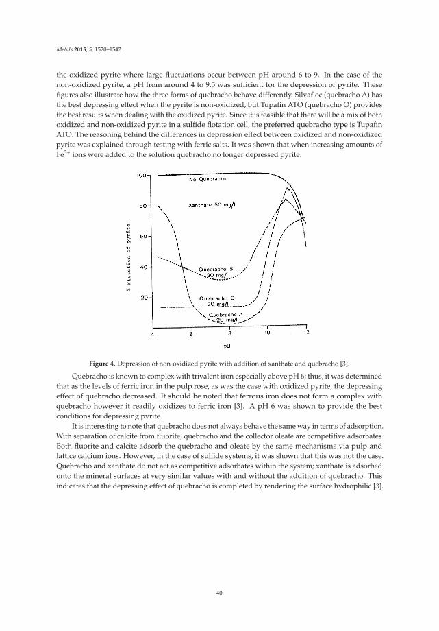
Metals 2015, 5, 1520–1542
the oxidized pyrite where large fluctuations occur between pH around 6 to 9. In the case of thenon-oxidized pyrite, a pH from around 4 to 9.5 was sufficient for the depression of pyrite. Thesefigures also illustrate how the three forms of quebracho behave differently. Silvafloc (quebracho A) hasthe best depressing effect when the pyrite is non-oxidized, but Tupafin ATO (quebracho O) providesthe best results when dealing with the oxidized pyrite. Since it is feasible that there will be a mix of bothoxidized and non-oxidized pyrite in a sulfide flotation cell, the preferred quebracho type is TupafinATO. The reasoning behind the differences in depression effect between oxidized and non-oxidizedpyrite was explained through testing with ferric salts. It was shown that when increasing amounts ofFe3+ ions were added to the solution quebracho no longer depressed pyrite.
Figure 4. Depression of non-oxidized pyrite with addition of xanthate and quebracho [3].
Quebracho is known to complex with trivalent iron especially above pH 6; thus, it was determinedthat as the levels of ferric iron in the pulp rose, as was the case with oxidized pyrite, the depressingeffect of quebracho decreased. It should be noted that ferrous iron does not form a complex withquebracho however it readily oxidizes to ferric iron [3]. A pH 6 was shown to provide the bestconditions for depressing pyrite.
It is interesting to note that quebracho does not always behave the same way in terms of adsorption.With separation of calcite from fluorite, quebracho and the collector oleate are competitive adsorbates.Both fluorite and calcite adsorb the quebracho and oleate by the same mechanisms via pulp andlattice calcium ions. However, in the case of sulfide systems, it was shown that this was not the case.Quebracho and xanthate do not act as competitive adsorbates within the system; xanthate is adsorbedonto the mineral surfaces at very similar values with and without the addition of quebracho. Thisindicates that the depressing effect of quebracho is completed by rendering the surface hydrophilic [3].
40

Metals 2015, 5, 1520–1542
Figure 5. Depression of oxidized pyrite with addition of xanthate and quebracho [3].
Laboratory and pilot plant testing was done on the Cayeli-Riz massive sulfide deposit in Turkeyto compare two different depressant systems. The deposit has two ores; the yellow ore is mostly copperwith fine-grained pyrite while the black ore contains both copper and zinc that is finely disseminated.Both ores are very high in pyrite and thus required a specific depressant system that would depressthe gangue sulfides without depressing the valuable sulfides. The copper rougher flotation was takenout at a pH of 10.5–11.5, the copper cleaning at a lower pH 4.5–5.5, and the zinc flotation was at a highpH above 11.5. The first depressant system used a 1:1 mixture of cyanide and thiourea at 120 g/t in thecopper rougher to depress zinc and lime was used to depress the pyrite at 8000 g/t with controlledaddition of SO2. The second system used the same additions of lime and SO2 in addition to 2H-BC,which is a mixture of quebracho and dextrin-maleic acid. The new addition of 2H-BC was successfulat depressing the ultrafine pyrite and increased both the grade and recovery of the copper and zincconcentrates by several percentage points [20].
A recent study taken out by the National University of San Juan in Argentina set out to provethat tannins and quebracho are a cleaner alternative to the conventional flotation reagents used incopper sulfide flotation. The work specifically set out to show that the Cu/Fe ratio could be improvedby depressing pyrite with the organic depressant. Hallimond tube flotation tests were taken out onboth pure pyrite and pure chalcopyrite minerals. The pyrite was floated at a pH 8 and showed gooddepression (around 40% pyrite depressed) with increasing tannin concentration up to around 0.25g/L where it leveled off. The effect of pH on the recovery of pyrite was shown to favor in the alkalineand acidic range where only 5%–10% pyrite was recovered with a mixture of tannins and lime. It wasalso illustrated that the presence of Ca2+ ions (in the form of lime) improved the depression effectof the tannins on the pyrite system. Similar tests were carried out in the Hallimond tube for purechalcopyrite. The recovery of pyrite and chalcopyrite with and without the addition of tannin is shownin Figure 6 [21].
Figure 6 clearly illustrates that the use of tannins have a marked depression effect on pyrite whilehaving little influence on chalcopyrite recovery. Flotation work was carried out in a Denver cell wherethe pH was set constant at 10 with the addition of lime and a varying amount of tannins between 0 and600 g/t. With increasing tannin addition, the pyrite was drastically reduced in the concentrate with thebest results at 600 g/t. These tests concluded that the addition of tannins in the system significantly
41

Metals 2015, 5, 1520–1542
increased the grade of the copper while only sacrificing 1 percent of recovery of copper due to thedepression of pyrite [21].
Figure 6. The effect of tannins on pure chalcopyrite and pyrite Hallimond tube flotation [21].
A United States patent titled “Separation of Polymetallic Sulphides by Froth Flotation” by SrdjanBulatovic and Robert S. Salter investigates the use of quebracho as a depressant in complex sulfideores. Bulatovic and Salter’s work focuses on comparing a newly invented depressant mixture tothe traditional depressant system on several polymetallic sulfides. The new depressant is made bydissolving quebracho into solution with either dextrin or guar gum. This mixture undergoes a secondreaction with a lignin sulphonate to make a water-soluble polymer. The polymer is then partiallymonomerized by at least one of the following reagents: alkali metal cyanide, alkaline earth metalcyanide, metal sulfate, and/or a sulfite. For the experimental trials, the lignin sulphonate polymersLS7 and LS8 are used; LS7 is the compound that is reacted with sodium cyanide while LS8 is thecompound that has been reacted with zinc sulfate/sodium cyanide complex.
The first set of experiments focused on the clean separation of copper and zinc from a massivesulfide deposit in Canada. The Cu–Zn ore contains valuable amounts of silver and the primary gangueminerals are quartz, pyrite and pyrrhotite. Four sets of experiments were conducted on two ore types,high and low copper, to compare the effects of the LS8 depressant versus sodium cyanide on therecovery and grade of the concentrates. The first set of experiments was laboratory scale while thesecond set was tested on a full-scale commercial plant. The LS8 depressant was added during thegrinding process and in the copper cleaner flotation circuit, with a total of 170 g/t added. In the labscale trials, the LS8 depressant made large improvements over the sodium cyanide on the rejection ofzinc and iron sulfides from the copper concentrate by several percentage points. The sequential zincconcentrate grade and recovery was also improved with the addition of LS8. In the plant trails, similarresults were obtained whereby the zinc recovery in the copper circuit was reduced, copper concentrategrade was increased, and zinc recovery in the zinc circuit was improved.
The second segment of laboratory experiments was conducted on two different massive sulfideores containing mostly copper and nickel. The first ore, from British Columbia, contained copperand nickel as well as significant amounts of platinum and palladium. The comparison tests betweenthe LS8 depressant and sodium cyanide proved that the LS8 reagent had a positive effect on thecircuits. With the use of LS8 the copper was recovered to a higher degree in the copper flotation circuit,while the nickel was effectively depressed. The nickel recovery in the nickel circuit was increasedand overall, the platinum and palladium recovery was improved. The second ore, from Northern
42

Metals 2015, 5, 1520–1542
Ontario, also showed improved results with the use of LS8. Most significantly, the nickel recovery inthe nickel cleaner concentrate was increased by more than 50 percent. These examples prove that theLS8 depressant is highly effective for depressing nickel in the flotation of copper-nickel ores.
The third installment of experiments involved a massive sulfide with mostly lead and zinc withlarge amounts of pyrite. Lime was compared to the LS7 depressant in laboratory testing. LS7 wasadded during the grinding stage at 250 g/t while the lime was added in the lead circuit at 750 g/t andthe zinc circuit at 3500 g/t. The recovery of lead in the lead concentrate remained the same, whilethe grade improved over 30 percent with the addition of LS7. Zinc grade and recovery in the zincconcentrate was also improved with the use of LS7. In plant operations, testing was done to comparethe addition of 300 g/t of LS7 to no addition of LS7. By using the LS7 reagent, grade of the leadconcentrate was increased with no recovery loss.
The work done by Bulatovic and Salter proved that the invention of a new series of quebrachocontaining depressants greatly improved the differential flotation of polymetallic sulfides in contrastto traditional reagent schemes [22].
3. Precipitation
Germanium
Germanium is primarily consumed as a vital element for the production of semiconductors forelectronics use. It is most closely associated with the elements C, Zn, Si, Cu, Fe, Ag, and Sn. Argyrodite,germanite, canfieldite, and renierite germanium containing minerals; however, these minerals do notform specific ore deposits. Thus, the majority of germanium is sourced from trace and minor amountsfound in coal, iron ore, and Cu–Pb–Zn sulfide deposits [23]. Sphalerite ores with low amounts ofiron prove to be the most important source of germanium containing a few hundred ppm that iscontained within the lattice of the zinc sulfide [24]. As a minor element in zinc ores, the challengecomes in finding a way to selectively remove the germanium from the rest of the residual metalsand compounds.
There are a variety of different methods that germanium is recovered from zinc circuits.While germanium can be collected pyrometallurgically, the concerns of volatile germanium oxidesand sulfides prove hydrometallurgical methods to be the most viable route. There are two mainmethods to recover germanium hydrometallurgically; the first is by precipitation with tannins and thesecond is solvent extraction (generally used for higher concentrations of germanium in solution) [25].Tech Cominco’s process uses the latter. A substantial circuit is used whereby the zinc concentrate iscalcined by two Lurgi Fluo-solid roasters and a suspension roaster. Zinc oxide is the product of thisprocess, with the sulfides being taken off as gas oxides. ZnO from the roasting process is sent througha ball mill, cyclones, and electrostatic precipitators prior to being sent to the leaching plant. Leachingtanks contain the calcined zinc material at a pH from 1.7 to 3.5. The residue from the leaching is leachedone more time with sulfuric acid to take the germanium and indium into solution. The germanium isrecovered and concentrated by selective solvent extraction [26]. Another zinc operation in Russia, theJoint Stock Company Chelyabinsk Electrolytic Zinc Plant, also possesses germanium as a byproduct.This plant utilizes fluidized bed reactors to roast the sulfides and convert them to oxides that areleached. The underflow from the leaching process is dried and sent to another processing facility torecover the germanium from the residue [27].
The recovery of germanium from Cu–Pb–Zn ore was studied at the Cinkur Zinc Plant in Kayseri,Turkey. This plant produces zinc electrolytically and requires that the leach solution be refined toremove impurity metals like Ge, Cd, Ni, Co, and Cu before electrolysis occurs. Figure 7 shows theoperating flow sheet.
43

Metals 2015, 5, 1520–1542
Figure 7. Flow sheet of the Cinkur plant in Turkey [25].
Precipitation was used to hydrometallurgically recover these metals in solution. First, the cobaltand nickel were precipitated using CuSO4·5H2O and As2O3 and zinc powder. The second precipitationutilized CuSO4·5H2O, Sb2O3 and zinc to remove the cadmium from solution. These precipitated cakesolutions provide the largest source of germanium at the plant with a concentration of over 700 ppm.The cake was leached with sulfuric acid and the leach solution treated with tannins to precipitateout germanium. Two different leaching schemes were created; one for selective leaching and one forcollective leaching. The selective leaching found optimum operating conditions with a temperaturefrom 40–60 ◦C, 100 grams per liter sulfuric acid, 30 min leach time, a solid to liquid ratio of 1/4, andno air pumping. It was found that 78% of the germanium was recovered under these conditions.With regards to the collective leaching approach a temperature of 85 ◦C, 150 grams per liter sulfuricacid, 1 h of leach time, and a solid to liquids ratio of 1/8 with air pumping was advantageous.The collective leaching method resulted in 92.7% germanium recovery although the solution hadsignificant amounts of Cu, Zn, Ni, Co, and Cd. The tannin precipitation study indicated that 94% ofthe germanium could be selectively recovered from leach solution [25]. The primary reaction for theprecipitation of germanium with tannins is shown below:
Ge4+ + O2 + H6T → GeO2·H6T (2)
where T is tannic acid (C14H10O9) [25]. The study suggested that a more effective germaniumprecipitation from the zinc electrolytic solution could be done with tannins rather than the copper andzinc additives mentioned above.
44

Metals 2015, 5, 1520–1542
Precipitation methods as sulfides, hydroxides, or with tannic acid are a viable option for obtaininggermanium hydrometallurgically. The role of tannins in the precipitation of germanium from zincproduction has been given more weight in recent years. Tannins work my forming chelates thatcomplex with metal ions in solution. Optimization of tannins use is of great interest as the reagents areexpensive. A study to understand the behavior of tannins chelation was done on the Chinese YunnanChihong Zinc and Germanium plant, the largest germanium producer in the world. The experimentwas two-stage with the first part looking into the binding of tannins to metal ions individually andsecond, the effect of binding in a polymetallic system. It was shown through the experiments thatthe metals with higher valences (like that of germanium and ferric iron) had the best binding abilitywith tannins. This is explained by the electrostatic attraction that favors ions with larger valence.Figures 8 and 9 show the binding ability, noted as the precipitation yield for metals in both a singlemetal solution and a polymetallic solution. The conditions for complexation were a stirring rate of10 rps, temperature of 373 K, and a duration of 500 s [28].
Figure 8. Binding ability of various metals in a single metal solution with tannins [28].
The complexation reaction of metals with tannins is described as follows:
Ge4+ + 2HT → (GeT)2+ + 2H+ (3)
where T is tannins (H2(GeO2C76H52O46·nH2O) [29].Additional research was also done to determine if adding tannins in stages produced different
results than adding tannins in one step. In the study the same amount of tannins was introduced,50 g, divided equally among the number of stages to the 1 L leach solution. It was shown that yieldincreased dramatically with additional stages. The single step tannin addition resulted in a percentyield of 85.2 and steadily increased each time as stages were added to the five stage addition that had ayield of 99.8 percent. A possible explanation for this behavior is diffusion; with the single step addition,diffusion had a shorter time to react with more difficulty. In addition, the tannins concentration mayaffect the binding ability of metal ions [28].
45
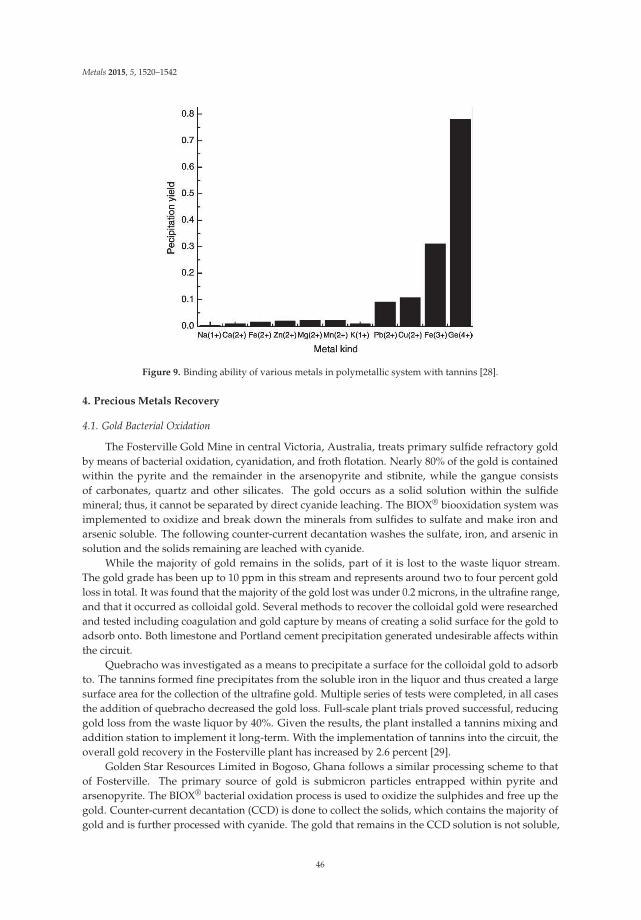
Metals 2015, 5, 1520–1542
Figure 9. Binding ability of various metals in polymetallic system with tannins [28].
4. Precious Metals Recovery
4.1. Gold Bacterial Oxidation
The Fosterville Gold Mine in central Victoria, Australia, treats primary sulfide refractory goldby means of bacterial oxidation, cyanidation, and froth flotation. Nearly 80% of the gold is containedwithin the pyrite and the remainder in the arsenopyrite and stibnite, while the gangue consistsof carbonates, quartz and other silicates. The gold occurs as a solid solution within the sulfidemineral; thus, it cannot be separated by direct cyanide leaching. The BIOX® biooxidation system wasimplemented to oxidize and break down the minerals from sulfides to sulfate and make iron andarsenic soluble. The following counter-current decantation washes the sulfate, iron, and arsenic insolution and the solids remaining are leached with cyanide.
While the majority of gold remains in the solids, part of it is lost to the waste liquor stream.The gold grade has been up to 10 ppm in this stream and represents around two to four percent goldloss in total. It was found that the majority of the gold lost was under 0.2 microns, in the ultrafine range,and that it occurred as colloidal gold. Several methods to recover the colloidal gold were researchedand tested including coagulation and gold capture by means of creating a solid surface for the gold toadsorb onto. Both limestone and Portland cement precipitation generated undesirable affects withinthe circuit.
Quebracho was investigated as a means to precipitate a surface for the colloidal gold to adsorbto. The tannins formed fine precipitates from the soluble iron in the liquor and thus created a largesurface area for the collection of the ultrafine gold. Multiple series of tests were completed, in all casesthe addition of quebracho decreased the gold loss. Full-scale plant trials proved successful, reducinggold loss from the waste liquor by 40%. Given the results, the plant installed a tannins mixing andaddition station to implement it long-term. With the implementation of tannins into the circuit, theoverall gold recovery in the Fosterville plant has increased by 2.6 percent [29].
Golden Star Resources Limited in Bogoso, Ghana follows a similar processing scheme to thatof Fosterville. The primary source of gold is submicron particles entrapped within pyrite andarsenopyrite. The BIOX® bacterial oxidation process is used to oxidize the sulphides and free up thegold. Counter-current decantation (CCD) is done to collect the solids, which contains the majority ofgold and is further processed with cyanide. The gold that remains in the CCD solution is not soluble,
46

Metals 2015, 5, 1520–1542
but colloidal gold. The Golden Star plant saw 0.57 g/L gold go to tailings with the CCD solution.Quebracho tannin supplied by Nowata Mining Chemical Manufacture and Supply was tested.
Varied concentrations, between 0.05 g/L and 1 g/L, of quebracho tannin were prepared at 10percent strength and were tested at a laboratory scale. Total suspended solids (TSS) and reductionin gold loss were the two main end goals of the study. It was found that the quebracho tannin wasoptimum at a level of 0.05 g/L where there was a 21.25% reduction in the TSS and a 45.79% gold lossreduction. These results warranted the industrial scale test, which resulted in 53.51% reduction in TSSand an additional recovery of 0.13 grams of gold per tonne of ore [30].
4.2. Tannin Gel Adsorption
The use of tannins to create a gel adsorbent to recover precious metals from aqueous solutionshas been studied by several groups. One of the first to study adsorption behavior with tannin gelswas Takeshi Ogata and Yoshio Nakano from the Tokyo Institute of Technology. Their work focused onthe synthesization of a tannin gel derived from wattle tannin for the application of recovering goldfrom electronic waste as an alternative to other hydrometallurgical operations like solvent extractionand ion exchange. Ogata and Nakano developed a method to immobilize the tannin particles, whichare naturally soluble in water. The tannin powder was dissolved into a sodium hydroxide solutionbefore adding formaldehyde to act as a cross-linking agent. The solution was allowed to gelatinizefor 12 h at an elevated temperature of 353 K. The tannin gel was then crushed to 125–250 micronparticles. The particles were added to a gold solution containing 100 ppm gold prepared fromhydrogen tetrachloroaurate tetrahydrate. With varying pH, different chlorogold complexes werecreated. In the pH range from 2–3.8 the predominant complex was AuCl4−. Between pH 2–3.8, therewas no dependence on initial pH for the recovery of gold. This was interpreted by Ogata and Nakanoto be explained by the conversion of chlorogold complexes. It was shown that the adsorption rate ofgold increased with increasing temperature. Additional tests were completed with 5 mg of tanningel in 100 ppm gold solution to obtain the maximum adsorption capacity of the gold onto the gel.An extremely high value of 8000 mg of gold per 1 g of tannin gel was found for the adsorption capacity.Through XRD and FT-IR spectra research, it was shown that the hydroxyl groups on the tannin gelparticles were oxidized to carbonyl groups during the adsorption testing. Trivalent gold in solution isreduced to elemental gold on the surface of the tannin gel particles [31].
Work done by a group at Saga University in Japan and Memorial University of Newfoundland inCanada expanded on the initial study done by Ogata and Nakano. This collaborative study focusedon the use of tannin gel to selectively recover precious metals from a polymetallic acidic leach solutionof circuit boards from spent mobile phones. The tannin gel was prepared to the procedure specified byOgata and Nakano. Persimmon tannin was used to create the original tannin gel. This was furtherprocessed to create a chloromethylated persimmon tannin, which was treated to obtain the final tanningel with bisthiourea functional groups. This tannin gel was labeled BTU-PT. It was shown that theadsorption behavior varied for different metal ions. Precious metals in the hydrochloric acid solution,particularly gold and palladium, had a drastically higher percent adsorption onto the tannin gelthan the base metals like copper, iron, zinc and nickel. Maximum adsorption capacities of the tanningel were found to be 5.18 mol kg−1 for Au(III) ions, 1.80 mol kg−1 for Pd(II) ions, 0.67 mol kg−1
for Pt(IV) ions. The mechanism behind the adsorption was studied with FT-IR technology. It wasfound that ion exchange, electrostatic interactions, and thiocarbonyl coordination were all mechanismsof adsorption for precious metals on the BTU-PT gel. It was shown the that tannin gel could besuccessfully regenerated for up to 5 cycles of use. Finally, an industrial study was done using actualcircuit board leach liquor and as indicated in the initial laboratory work, the BTU-PT tannin gel actedas a successful adsorbent for precious metals while not taking up base metals in solution [32].
Work done by Yurtsever and Sengil at Sakarya University in Turkey explored the use of a valoniatannin gel for the removal of silver ions from solution. The valonia tannin was sources from a Turkishleather company and the gel was prepared similarly to Ogata and Nakano’s procedure. It was shown
47
Metals 2015, 5, 1520–1542
in the study that the major factors influencing the adsorption of silver ions onto the tannin gel weresolution pH, temperature of solution, and concentration of silver ions, and contact time. The peak ofadsorption was seen at a pH 5. As temperature increased, from 20 to 90 degrees Celsius, the amount ofsilver ions adsorbed onto the tannin gel decreased. In addition, the more silver ions initially in thesystem lead to a higher amount of adsorption [33].
5. Pressure Leaching
Zinc and Nickel
In the 1960s, Gordon Sherritt Mines Limited filed a number of patents for the extraction of zincfrom iron containing sulfide ores. In this process, elevated temperature and pressure with the additionof oxygen and sulfuric acid, leached zinc. Up until the 1970s, the pressure leaching of zinc complexeswas done below the melting point of sulfur at around 120 ◦C to avoid the formation of elementalsulfur at higher temperatures. However, it was found that if the temperature was increased, a moreadvantageous rate of reaction occurred. With the formation of elemental sulfur at temperatures above120 ◦C, the zinc sulfide particles were wetted by the molten sulfur and thus were not available forleaching. To provide the best kinetics and complete extraction of zinc, an additive was needed toprevent the unreacted zinc sulfide particles from being occluded by the molten sulfur. The additivesfound to be beneficial were those tannin compounds like quebracho, lignins, and lignosulphonates.The amount of additives needed was found to be around 0.1–0.3 g per liter. In a series of tests conductedat 150 ◦C, it was proven that the additives significantly improved the extraction of zinc. By adding0.1 g per liter calcine lignosulphonate and 0.2 g per liter quebracho, the zinc extraction was increasedfrom 54.4% to 90.0% in one test and 63.3% to 97.8% in another. The use of additives such as quebrachogreatly increased the metal recovery in the elevated temperature leaching and became part of thecommercialized Sherritt Zinc Pressure Leach Process [34].
Similar work investigating the effects of these additives was done on other sulfide systems. LibinTong and David Dreisinger conducted research at the University of British Columbia on pentlandite,nickeliferous pyrrhotite, pyrrhotite, and chalcopyrite. Studies were conducted on the work of adhesionwhich is the work required to separate liquid sulfur from the mineral surface. This is expressed by theDupre equation:
Wa = γMA + γSA − γMS = −ΔGW/α (4)
where Wa is the work of adhesion, γ are interfacial tension, ΔGw is the surface free energy and α is thesurface area of the mineral.
It was shown that in three different systems, pentlandite, nickeliferous pyrrhotite, and pyrrhotitethat the work of adhesion was significantly lowered with the addition of quebracho, lignosulphonate,and humic acid. This implies that the additives should be good dispersing agents of the moltensulfur [35].
6. Conclusions
This study has explored the role of tannins in extractive metallurgy, specifically flotation andprecipitation. Quebracho has proved to be an efficient depressant in many flotation systems, bothsulfidic and calcareous, improving the overall selectivity of the collectors. Quebracho has also shownto aid in the precipitation of metals from solution including that of germanium and gold. While it isknown that quebracho can be used for many different flotation and precipitation applications, thefundamentals of how quebracho functions requires additional investigation.
Acknowledgments: This work was funded by the Silvateam through collaboration with the Colorado Schoolof Mines Kroll Institute for Extractive Metallurgy in the George S. Ansell Department of Metallurgical andMaterials Engineering.
Author Contributions: Jordan Rutledge and Corby Anderson researched, wrote and revised this review paper asrequested by and on behalf of Silvateam, the project sponsor.
48
Metals 2015, 5, 1520–1542
Conflicts of Interest: The authors declare no conflict of interest.
References
1. Quebracho Colorado tree. Photograph. Britannica Online for Kids. Available online: http://kids.britannica.com/comptons/art-173288 (accessed on 1 July 2015).
2. Leja, J. Surface Chemistry of Froth Flotation; Plenum Press: New York, NY, USA, 1982.3. Iskra, J.; Fleming, M.G.; Kitchener, J.A. Quebracho in Mineral Processing; Imperial College London: London,
UK, 1980.4. Chen, J.; Li, Y.; Long, Q.; Wei, Z.; Chen, Y. Improving the selective flotation of jamesonite using tannin extract.
Int. J. Miner. Process. 2011, 100, 54–56. [CrossRef]5. Ober, J. Strontium; US Geological Survey-Minerals Information: Reston, VI, USA, 1996.6. De Castro, F.H.B.; de Hoces, M.C. Influence of quebracho and sodium silicate on flotation of celestite and
calcite with sodium oleate. Int. J. Miner. Process. 1993, 37, 283–298. [CrossRef]7. Guy, P.; Bruckard, W.; Vaisey, M. Beneficiation of Mt Weld Rare Earth Oxides by Gravity Concentration,
Flotation and Magnetic Separation. In Proceedings of the Seventh Mill Operators’ Conference, Kalgoorlie,WA, Australia, 12–14 October 2000.
8. Ozcan, O.; Bulutcu, A. Electrokinetic, infrared and flotation studies of scheelite and calcite with oxine, alkyloxine, oleoyl sarcosine and quebracho. Int. J. Miner. Process. 1993, 39, 275–290. [CrossRef]
9. Dean, K.C.; Schack, C.H. Flotation of Calcareous Scheelite Ores; US Bureau of Mines: Washington, DC,USA, 1963.
10. Kelly, T.D.; Matos, G.R. 2005 Fluorspar statistics, Historical statistics for mineral and material commoditiesin the United States: US Geological Survey Data Series 140. US Geological Survey. Available online:http://pubs.usgs.gov/ds/2005/140/ (accessed on 1 July 2015).
11. Mahoning Mining Company. Method of Concentrating Fluorspar Ores. US 2263552, 1941.12. Mahoning Mining Company. Method of Concentrating Fluorspar Ores. US 2168762, 1938.13. Thom, C. Method of Concentrating Fluorspar Ores. US 3207304, 1962.14. Allied Chemical Corporation. Beneficiation of Fluorspar Ores. US 3536193, 1970.15. McKay, J.; Foot, D., Jr.; Shirts, M. Parameters Affecting Column Flotation of Fluorite. In Proceedings of SME
Annual Meeting, Denver, CO, USA, 24–27 February 1987.16. Raju, G.; Prabhakar, S. Beneficiation of fluorspar by column flotation. Miner. Metall. Process. 2000, 17,
167–172.17. Aliaga, W.; Sampaio, C.; Brum, I.; Ferreira, K.; Batistella, M. Flotation of high-grade fluorite in a short column
under negative bias regime. Miner. Eng. 2006, 19, 1393–1396. [CrossRef]18. Song, S.; Lopez-Valdivieso, A.; Martinez-Martinez, C.; Torres-Armenta, R. Improving fluorite flotation from
ores by dispersion processing. Miner. Eng. 2006, 19, 912–917. [CrossRef]19. Schubert, H.; Baldauf, H.; Kramer, W.; Schoenherr, J. Further development of fluorite flotation from ores
containing higher calcite contents with oleoylsarcosine as collector. Int. J. Miner. Process. 1990, 30, 185–193.[CrossRef]
20. Bulatovic, S.; Wyslouzil, D. Selection and evaluation of different depressants systems for flotation of complexsulphide ores. Miner. Eng. 1995, 8, 63–76. [CrossRef]
21. Sarquís, P.; Menéndez-Aguado, J.; Mahamud, M.; Dzioba, R. Tannins: The organic depressants alternative inselective flotation of sulfides. J. Clean. Prod. 2014, 84, 723–726. [CrossRef]
22. Falconbridge Limited. Separation of Polymetallic Sulphides by Froth Flotation. US 2952329, 1990.23. Höll, R.; Kling, M.; Schroll, E. Metallogenesis of germanium—A review. Ore Geol. Rev. 2007, 30, 145–180.
[CrossRef]24. Krebs, R.E. The History and Use of Our Earth’s Chemical Elements; Greenwood: Westport, CT, USA, 1998.25. Kul, M.; Topkaya, Y. Recovery of germanium and other valuable metals from zinc plant residues.
Hydrometallurgy 2008, 92, 87–94. [CrossRef]26. MetSoc of CIM. Welcome! MetSoc of CIM | Metallurgy & Materials Home. Available online: http://www.
metsoc.org/virtualtour/processes/zinc-lead/oxide.asp (accessed on 18 May 2015).27. Moskalyk, R.R. Review of germanium processing worldwide. Miner. Eng. 2004, 17, 393–402. [CrossRef]
49

Metals 2015, 5, 1520–1542
28. Liang, D.; Wang, J.; Wang, Y.; Wang, F.; Jiang, J. Behavior of tannins in germanium recovery by tannin process.Hydrometallurgy 2008, 93, 140–142. [CrossRef]
29. Symes, R. Recovery of Colloidal Gold from Oxidised Concentrate Wash Liquor. In Proceedings of the TenthMill Operators’ Conference, Adelaide, SA, Australia, 12–14 October 2009.
30. Buah, W.K.; Asamoah, R.K.; Boadi, I. Effects of Quebracho Tannin on Recovery of Colloidal Gold fromBioleached Wash Liquor. Ghana Min. J. 2015, 15, 44–49.
31. Ogata, T.; Nakano, Y. Mechanisms of gold recovery from aqueous solutions using a novel tannin geladsorbent synthesized from natural condensed tannin. Water Res. 2005, 39, 4281–4286. [CrossRef] [PubMed]
32. Gurung, M.; Adhikari, B.B.; Kawakita, H.; Ohto, K.; Inoue, K.; Alam, S. Selective Recovery of Precious Metalsfrom Acidic Leach Liquor of Circuit Boards of Spent Mobile Phones Using Chemically Modified PersimmonTannin Gel. Ind. Eng. Chem. Res. 2012, 51, 11901–11913. [CrossRef]
33. Yurtsever, M.; Sengil, A. Adsorption and desorption behavior of silver ions onto valonia tannin resin.Trans. Nonferrous Met. Soc. China 2012, 22, 2846–2854. [CrossRef]
34. Gordon Sherritt Mines Limited. Recovery of Zinc from Zinc Sulphides by Direct Pressure Leaching.US 3867268, 1975.
35. Tong, L.; Dreisinger, D. Interfacial properties of liquid sulfur in the pressure leaching of nickel concentrate.Miner. Eng. 2009, 22, 456–461. [CrossRef]
© 2015 by the authors. Licensee MDPI, Basel, Switzerland. This article is an open accessarticle distributed under the terms and conditions of the Creative Commons Attribution(CC BY) license (http://creativecommons.org/licenses/by/4.0/).
50

metals
Article
CFD Modelling of Flow and Solids Distribution inCarbon-in-Leach Tanks
Divyamaan Wadnerkar, Vishnu K. Pareek and Ranjeet P. Utikar *
Department of Chemical Engineering, Curtin University, Perth, WA 6102, Australia;[email protected] (D.W.); [email protected] (V.K.P.)* Author to whom correspondence should be addressed; [email protected]; Tel.: +61-8-9266-9837;
Fax: +61-8-9266-2681.
Academic Editors: Suresh Bhargava, Mark Pownceby and Rahul RamReceived: 29 July 2015; Accepted: 23 October 2015; Published: 28 October 2015
Abstract: The Carbon-in-Leach (CIL) circuit plays an important role in the economics of a goldrefinery. The circuit uses multiphase stirred tanks in series, in which problems such as dead zones,short-circuiting, and presence of unsuspended solids are detrimental to its efficiency. Therefore, thehydrodynamics of such a system is critical for improving the performance. The hydrodynamics ofstirred tanks can be resolved using computational fluid dynamics (CFD). While the flow generated bythe impellers in the CIL tanks is complex and modelling it in the presence of high solid concentrationis challenging, advances in CFD models, such as turbulence and particle-fluid interactions, havemade modelling of such flows feasible. In the present study, the hydrodynamics of CIL tanks wasinvestigated by modelling it using CFD. The models used in the simulations were validated usingexperimental data at high solid loading of 40 wt. % in a lab scale tank. The models were further usedfor examining the flow generated by pitched blade turbine and HA-715 Mixtec impellers in lab scaleCIL tanks with 50 wt. % solids. The effect of design and operating parameters such as off-bottomclearance, impeller separation, impeller speed, scale-up, and multiple-impeller configuration onflow field and solid concentrations profiles was examined. For a given impeller speed, better solidssuspension is observed with dual impeller and triple impeller configurations. The results presentedin the paper are useful for understanding the hydrodynamics and influence of design and operatingparameters on industrial CIL tanks.
Keywords: CIL tanks; CFD; hydrodynamics; HA-715 impeller; impeller configuration; design
1. Introduction
Carbon-in-Leach (CIL) circuit is a process that concentrates gold from 2.5 to 3.5 g/t in ore to10,000 to 15,000 g/t on carbon. It is a process of continuous leaching of gold from ore to liquid andcounter-current adsorption of gold from liquid to carbon particles in a series of tanks. The tanksused in the CIL circuit are continuously stirred tanks and contain high concentration of ores. Efficientoperation of CIL tanks requires suspension of the ore particles in the leaching solution and hence, toprovide maximum contact between ore and leaching solution. However, problems such as settledsolids and presence of dead zones are detrimental to the efficiency, and could be identified and solvedby understanding the flow field and solid distribution in the system. Furthermore, reducing the energyconsumption to achieve a higher contact is always desired and can be achieved by proper design andoptimization while investigating the hydrodynamics.
While, some information on the hydrodynamics such as residence time distribution (RTD) can beobtained from experiments using tracer studies; detailed quantitative measurement of the flow fieldinside the CIL tank is challenging. In such a scenario, computational fluid dynamics (CFD) can proveto be an inexpensive and viable solution. With the availability of improved models for turbulence,
Metals 2015, 5, 1997–2020 51 www.mdpi.com/journal/metals

Metals 2015, 5, 1997–2020
interphase drag force, particle-particle interaction models, etc. and advances in computational speeds,resolving the complex multiphase flows phenomenon is possible using CFD.
In the present work, models for simulating high solid loading stirred tanks are validated withexperimental data. The flow field generated by a pitched blade turbine and a HA-715 impeller iscompared. The effect of design parameters such as off-bottom clearance, impeller separation, impellerspeed, scale-up, and multiple-impeller configuration is examined by modelling the flow and estimatingthe suspension quality for each case.
2. Literature Review
Carbon-in-leach tanks are high solid loading stirred tanks of large diameter (~10–15 m) withsolid concentration of up to 50% by weight (~28% by volume). Such a high concentration rendersopacity to the system which makes its hydrodynamic investigation challenging even at a small scale.With the advent of radioactive experimental techniques such as Computer Aided Radioactive ParticleTracking (CARPT), Positron Emission Particle Tracking (PEPT), etc., reliable quantitative data can beobtained [1–3]. The data can now be used to validate the computational models for the high solidloading regimes in turbulent flows and further advance the design and optimization of CIL tanks.
While simulating high solid concentration (20% by volume) stirred tanks, Altway et al. [4] foundmajor discrepancy while validating the solid concentration profile using data from Yamazaki et al. [2].Micale et al. [5] used Multiple Reference Frame (MRF) and Sliding Grid (SG) approach to study the clearliquid layer and the suspension height for dense solid-liquid systems. In their simulations, the powernumbers were 2.98, 2.74, and 2.68 for N = 5, 6.33 and 8 RPS respectively (particle loading of 9.6% v/v),which were significantly smaller than the experimental values of 4.59, 4.37, and 4.23. They attributedthe imperfection in the solid suspension prediction to second order effects (particle drag modificationsdue to liquid turbulence, presence of other particles, particle-particle direct interactions, etc.) thatwere neglected in the study. Ochieng and Lewis [6], Fradette, et al. [7], Ochieng and Onyango [8],Kasat, et al. [9], Fletcher and Brown [10], Tamburini, et al. [11–13], conducted simulations for volumefractions below 20%, and validated using non-local properties like cloud height, suspension quality,etc. In another similar study, Gohel, et al. [14] used qualitative and quantitative data for cloud height tovalidate the simulation of high concentration solids suspension in stirred tanks. In these studies, whilethe parameters, for example cloud height, were accurately predicted, the errors in the predictionsof local hydrodynamics were not verified in the absence of data. In the direction of resolving thelocal hydrodynamics of the stirred tanks, Liu and Barigou [15] used local velocity field and solidsconcentration data for model validation and found that even though a good agreement in the axialconcentration profile was observed, the local concentration predictions could still be very poor andcould vary from experiments by several folds. The inaccuracy was attributed to inadequate models forparticle sedimentation, lift-off, and particle-particle interaction in their CFD model. They suggestedincorporating particle-particle interaction in the solids pressure term given by Gidaspow [16], butdid not use it in their models due to convergence problems. The highest solid loading for which thesimulation results in stirred tanks are reported is 20% (by volume), and the simulations are not able topredict the local concentration due to limitations of models [4,5].
In the CIL tanks, Dagadu, et al. [17] used a radioactive tracer to investigate the RTD inthe CIL tanks and developed a model to predict it. While the results provided an overview ofcomplexity of the system and suggested the presence of stagnant and active volumes, the detailssuch as solid accumulation, dead-zones, uniformity, etc. are still unknown. To address these issues,Dagadu et al. [18,19] investigated the mixing in the CIL tanks by conducting CFD simulations anddrawing inferences based on the flow field and eddy viscosity. In both of these instances, neither therelationship of the flow field or turbulent viscosity with the solid distribution is quantified, nor thesolid distribution in the tanks are presented. While validation with experimental data is missing, thescope of both studies is limited to evaluating the ability of the models for predicting the qualitative flowbehavior in such systems. Drawing conclusions for critical design and operating parameters requires
52

Metals 2015, 5, 1997–2020
comprehensive validation of models and controlled investigation of influence of these parameters onthe flow field and solid distribution.
The current study focuses on the extensive validation of local solid concentration distributionin high solid loading stirred tanks. The shortcomings of previous investigations are addressed byusing the appropriate constitutive models for turbulence, drag, particle-particle interactions, etc. Thevalidated model is then used for investigation of critical parameters in the CIL tanks.
3. Model Description
3.1. Governing Equations
The hydrodynamic simulations are conducted using Eulerian-Eulerian multiphase model. In thismodel, each phase is treated as an interpenetrating continuum represented by a volume fraction ateach point of the system. Reynolds averaged mass and momentum balance equations are solved foreach phase. The governing equations are:
Continuity equation:∂
∂t
(αqρq
)+∇.
(αqρquq
)= 0 (1)
Momentum equation:
∂
∂t
(αqρq
→u q
)+∇.
(αqρq
→u q
→u q
)= −αq∇p +∇.
=τq + αqρq
→g +
→F td,q,vm,li f t +
→F 12 (2)
The rotation of impeller can be simulated using sliding grid approach (SG) or Multiple ReferenceFrame (MRF). While MRF provides reasonably accurate steady state solution, SG is found to be moreaccurate compared to MRF approach [20,21]. Therefore, SG will be used in the paper to simulate theimpeller rotation.
Turbulence is not resolved in the RANS simulations and therefore, it needs to be modelled.Standard k-ε is the most commonly used model in the RANS simulations of stirred tanks [4,9,21–25].However, it finds limitation in modelling anisotropic turbulence in the impeller discharge region andunder-predicts turbulent kinetic energy in flow impingement region. RSM model predicts the Reynoldsstresses by explicitly solving their governing equations. Hence, it resolves the anisotropic turbulenceand results in improved predictions of turbulence in such regions [26]. Large eddy simulation (LES)also resolves the larger anisotropic turbulence scales while requiring simulation of complete domainwith fine mesh, which is computationally expensive [27]. For the same scale, the computationalrequirement using LES can be 100 times higher than that for RSM simulation. Therefore, in this paper,RSM model is used for modelling turbulence.
The equations of Reynolds Stress Model (RSM) model for turbulence are given below.
∂∂t
⟨u′
i u′j
⟩+∇.
(→u qu′
i u′j
)= ∇.
(Cs
k⟨
u′i u′
j
⟩ε ∇
⟨u′
i u′j
⟩)− C1
εk
(⟨u′
i u′j
⟩− (2/3)δijk
)− C2
(Pij − (2/3)δijP − Sij
)− (2/3)δijε
(3)
∂
∂t
(ρqε)+∇.
(ρq
→u qε
)= ∇.
(Cε
ρkε
⟨u′
i u′i⟩∇ε
)+
ε
k
(C1εGk,q − C2ερmε
)(4)
where Cs, C1, C2, C1ε, C1ε, and C2ε are constants. And, Pij = −⟨u′i u
′k⟩∇.uj −
⟨u′
ju′k
⟩∇.ui; P = 1
2 Pii;
ρq =N∑
i=1αiρi;
→u q =
N∑
i=1αiρi
→u i
N∑
i=1αiρi
.
Eddy viscosity is computed from
μt,q = ρqCμk2
ε(5)
53

Metals 2015, 5, 1997–2020
Evaluation of generation of turbulent kinetic energy is consistent with Boussinesq hypothesis andis computed as
Gk,q = μt,q
(∇→
u q +∇→u
Tq
): ∇→
u q (6)
The equation of conservation of granular temperature is given as:
32
[∂
∂t(αsρsΘs) +∇.
(αsρs
→u sΘs
)]= −
(ps
=I +∇.
=τs
): ∇→
u s +∇.(kΘs∇Θs)− γΘs +ϕls (7)
where −(
ps=I +∇.
=τs
): ∇→
u q is the generation of energy by the solid stress tensor, ∇.(kΘs∇Θs) is the
diffusion of energy, γΘs is the collisional dissipation of energy and ϕls is the energy exchange betweenfluid and solid phase.
Table 1. Constitutive equations.
Description Equations
Liquid-phase stress tensor=τq = αqμq
(∇→
u q +∇→u
Tq
)+ αq
(λq − 2
3μq
)∇→
u q=I
Solid-phase stress tensor=τs = αsμs
(∇→
u s +∇→u
Ts
)+ αs
(λs − 2
3 μs
)∇→
u s=I
Solid shear viscosity μs = μs,col + μs,kin + μs, f r
Collisional viscosity μs,col =45αsρsdsgo,ss(1 + ess)
(Θsπ
)0.5αs
Kinetic viscosity μs,kin = αsρsds6(3−ess)
[1 + 2
5 (1 + ess)(3ess − 1)αsgo,ss
]Frictional viscosity μs, f r =
ps sin ϕ
2√
I2D
Solids pressure ps = αsρsΘs + 2ρs(1 + ess)α2s go,ssΘs
Radial distribution function go,ss =
[1 −
(αs
αs,max
)1/3]−1
Diffusion coefficient of granular temperature kΘs =15αsρsds
√Θsπ
4(41−33η)
⎡⎣ 1 + 12
5 η2(4η− 3)αsgo,ss
+ 1615π (41 − 33η)ηαsgo,ss
⎤⎦
where η = 0.5(1 + ess)
Collision dissipation energy γΘs =12(1−e2
ss)go,ss
ds√π
ρsα2s Θ3/2
s
The stress-strain tensor in the momentum transfer equation is due to viscosity and Reynoldsstresses that include the effect of turbulent fluctuations. Boussinesq’s eddy viscosity hypothesis isused for the closure of momentum transfer equation. The particle-particle interaction is modelledusing kinetic theory of granular flow by assuming that its behavior similar to dense gas. Similar tothe thermodynamic temperature of gases, the granular temperature is used to model the fluctuatingvelocity of particles [16]. The constitutive equations for momentum equation are given in Table 1.
3.2. Turbulent Dispersion Force
Turbulent fluctuations result in dispersion of phases from high volume fraction regions to lowvolume fraction regions. The turbulent dispersion force is significant when the size of turbulent eddiesis larger than the particle size [9]. The effect of turbulence dispersion force on the hydrodynamicsin CIL tanks, is incorporated using the Burns, et al. [28] model. The model equations for turbulencedispersion force are given below:
→F td,q = CTDkpq
Dt,q
σpq
(∇αp
αp− ∇αq
αq
)(8)
54

Metals 2015, 5, 1997–2020
3.3. Interphase Drag Force
Interphase drag is the resultant force experienced by the particle in the direction of relativemotion due to a moving fluid. Since, the solids and liquid phases are treated as inter-penetrating, aninter-phase momentum exchange term is required. The interphase exchange force is calculated usingthe following expression given by Syamlal et al. [29]:
Fd =3αlαsρlCDRe
4dpV3r
(→u l −→
u s
)(9)
where, Vr = 0.5(
A − 0.06Re +√(0.06Re)2 + 0.12Re(2A − B) + (A)2
); A = α5.14
g ; B = 0.8α2.28g , for
αg ≤ 0.85; B = α3.65g , for αg > 0.85.
The drag coefficient is calculated using an expression that has a form derived by Dalla Valle andKenning [30]:
CD =
(0.63 +
4.8√Re/Vr
)2(10)
4. Methodology and Boundary Conditions
4.1. Vessel Geometry
In this paper, a flat bottomed cylindrical tank was simulated (see Figure 1). The shaft of theimpeller was concentric with the axis of the tank. A Mixtec HA-715 was used as impeller for CILtanks, but for validation 45◦ six-bladed pitched blade turbine pumping downwards (PBTD) impellerwas employed. For validation, vessel geometry dimensions, material properties, etc. were takenfrom paper of Guida et al. [3]. The dimensions of tank and impeller are given in Table 2. The fluidand particle properties used in the simulation are also tabulated in the same table. Conditionssuch as solid concentrations, impeller speed, and the Reynolds number in the tank are tabulated inTable 3. Simulations were carried out at just suspension speed for each case, which was determinedby Guida et al. [3] following Zwietering [31] criterion. According to this criterion, no particle shouldremain stationary on the base of the vessel for longer than 1–2 s.
Table 2. Dimensions of domain and properties of materials used in this study.
Tank (m) PBTD (m) HA-715
T 0.288, 10 D T/2 D T/2, T/3H T Bl 0.055 Dshaft 0.01152W T/10 Bw 0.041 - -
CiT/2, T/3, T/4,
T/6, T/8Dshaft 0.01 - -Dhub 0.034 - -
Table 3. Conditions in stirred tanks used for simulations.
Name of Case X (wt. %)N = Njs
(RPM)ρl (kg/m3) μl (Pa·s)
ρp
(kg/m3)dp (mm)
PBTD-Validation 40 589.8 1150 0.001 2585 3CIL tanks
(Lab Scale) 50 200–700 1000 0.001 2550 0.075
CIL tanks(Full Scale) 50 22.15 1000 0.001 2550 0.075
55

Metals 2015, 5, 1997–2020
Figure 1. Computational domain, grid distribution, and schematic of the stirred tank.
4.2. Numerical Simulations
The stirred tank for validation consists of six PBT blades and four baffles and that of CIL tanksconsists of three HA-715 blades and three baffles. In all the cases studied in the paper, simulation ofthe full tank is conducted. For the case of PBTD, the moving zone with dimensions r = 0.06 m and0.036 < z < 0.137 is created (where z is the axial distance from the bottom). For the case of HA-715, themoving zone of height T/10 and r = 3T/4 is created, with top and bottom surfaces equidistant fromthe center of impeller. The impeller rod outside this zone is considered as a moving wall. Impellersused in all the cases simulated in the study are operated in the down-pumping mode. The top of thetank is open, so it is defined as a wall of zero shear. The solids in the tank are assumed to be settledin the beginning of simulations. Therefore, a solid volume fraction of 0.6 is patched in the stirredtank up to a height such that the volume averaged solid concentration is the same as the uniformlydistributed solids specified in Table 3. For modelling the turbulence, a RSM turbulence model is used.The standard model parameters are Cμ: 0.09, Cs: 0.22, C1: 1.8, C2: 0.6, C1ε: 1.44, C2ε: 1.92, σk: 1.0 andσε: 1.3. In the present work, SIMPLE scheme is used for Pressure-Velocity coupling along with thestandard pressure interpolation scheme. To avoid any numerical diffusion and unphysical oscillations,a third order Quadratic Upstream Interpolation for Convective Kinetics (QUICK) discretization schemeis used for momentum, volume fraction, turbulent kinetic energy, and turbulent dissipation rates.The convergence of the simulation is verified by monitoring residual values as well as additionalparameters namely turbulence dissipation over the volume, turbulence dissipation at the surface rightbelow impeller and torque on the shaft. Once the residuals and additional parameters are constant,a simulation is deemed to be converged. For all the cases presented in the paper, a time-step of 0.001 sis less than the time which the impeller needs to sweep by a single computational cell (one cell timestep ~0.003 s). One cell time step is considered appropriate for the CFD simulations in stirred tanks [12].But using a time-step of 0.001 s resulted in divergence in the initial time-steps. Therefore, the time-stepsize initially used in the simulations is 0.0001s, which is gradually increased to 0.001 s. For the fullscale geometry, the one cell time step increased due to the reduction in the impeller speed. Therefore,the maximum time-step used for full-scale simulation is 0.01 s (one cell time step ~0.025 s). The results
56

Metals 2015, 5, 1997–2020
of lab scale simulations approached transient steady values after 12 s. Therefore, the data used forresults and discussion is time averaged for the last 3 s. For full scale simulations, the time taken forreaching the transient steady value is 900 s, and the data is time-averaged for 300 s. The numericalsolution of the system is obtained by using the commercial CFD solver ANSYS FLUENT 15.0 using48 cores of Magnus with Cray XC40, Intel Xeon E5-2690V3 “Haswell” processors running at 2.6 GHzsystem at Pawsey supercomputing center. Each time step takes an average of 20 s of the wall clocktime which reduces after approaching convergence when residuals reach at 10−5.
The finite volume method solves the partial differential equations in a spatially discretizeddomain. The discretization should be fine enough to resolve the physics while not incurring excesscomputational power. For the purpose, a grid independency test is conducted initially on the singlephase flow and is presented. The models used in the paper are validated with the experimental resultsat 40 wt. % solid loading stirred tank published by Guida et al. [3]. The validated model is used foranalyzing the flow field generated by HA-715 impeller and assessing its efficacy compared to thePBTD. The influence of different impeller speeds, impeller off-bottom clearance and impeller diameteron the solid suspension, homogeneity and power consumption are examined. The appropriate stirredtank design parameters are used for scale-up and simulations and are conducted to gain an insighton the flow developed. Flow generated by single and multiple impeller systems in the full-scale CILtanks is also investigated.
5. Results and Discussion
5.1. Grid Independency and Validation
For testing the grid-independency, the experimental values for axial, tangential, and radialvelocities at impeller discharge plane for single phase flow were compared with the simulation resultsusing computational grids with 32,000 (coarse), 140,000 (medium) and 900,000 (fine) cells (see Figure 2).The results using mesh with 32,000 cells are accurate at z = 0.2 H plane. The predictions improve slightlywhile using 140,000 cells, and beyond that the improvement is marginal. Furthermore, the power forthe stirred tanks is calculated by integrating the turbulence dissipation rate over the volume. For thecoarse, medium, and fine meshes, the values of power number are 1.34, 1.53, and 1.57, respectively,which re-emphasizes that a mesh of 140,000 cells is suitable for simulation and further refinement willonly lead to marginal improvement at significant computational cost. Therefore, the mesh with 140,000cells is used for the rest of the simulations in the study. For the full scale geometry, the computationalgrid of 140,000, 900,000, and 3,000,000 cells are investigated based on the same parameters. The valuesof power number obtained for the three cases are 1.27, 1.49, and 1.55, respectively. Mixing time isanother parameter that is sensitive to the number of computational cells in the domain. For the fullscale tank, the mixing time for the three cases are 75 s, 113 s, and 111 s respectively to achieve 99%homogeneity. It is evident from the analysis that the results of 900,000 cells and 3,000,000 cells aresimilar. Therefore, the grid of 900,000 cells was selected for the simulation of full scale CIL tanks.
The models used in the study are validated by comparing the flow field generated by PBTD andthe concentration profiles obtained at 40 wt. % solid loading. The axial, tangential, and radial velocityplots describe the flow generated by the PBTD. The PBTD pumps the fluid downwards leading tohighly negative axial velocities at the impeller plane. The jet leaving the impeller flows down to thebottom of the stirred tank, is then redirected towards the periphery and circulates back to the topalong the walls. Due to such motion, a flow loop is formed near the impeller. It results in decreasingaxial velocity when moving radially outwards in impeller plane that eventually increases due tothe upwards flow near the walls. A 45◦ inclination of the impeller blade imparts momentum in thetangential direction resulting in moderate values of tangential velocity. Due to the downward flowdeveloped by a PBTD, the magnitude of the radial component of velocity is the lowest. The maximumvalues of radial, tangential, and axial velocity in the impeller plane are 0.1 Utip, 0.28 Utip, and 0.45 Utip
respectively. Both radial and tangential components gain value with the increase in radius as the
57

Metals 2015, 5, 1997–2020
velocity increases radially along the impeller blades. The maximum value is attained by both of thesecomponents close to the impeller tip after which a sudden decline is observed due to no momentumsource in the absence of impeller. These characteristics are well represented in the velocity profilesshown in Figure 2.
r/R, [-]0.0 0.5 1.0
U/U
tip,
[-]
-0.6
0.0
0.6
Experiment32000 Cells140000 Cells900000 Cells
(a)
Figure 2. Comparison of dimensionless axial (green), radial (black) and tangential (red) velocity at z =0.2H plane for computational grid with different resolution.
The average axial concentration profile is compared with the experimental data of Guida et al. [3]in Figure 3a. In some cases, the average axial concentration does not provide the information forlocal variation of concentration. Therefore, radial concentration profiles at different heights are alsocompared with the experiments. As is evident from Figure 3, the results obtained are in agreementwith the experimental data. As the impeller speed used is the speed of just suspension, the solidconcentration near the bottom of the tank is only double the average concentration. The jet from thePBTD moves downwards and strikes the bottom around the r/R = 0.5. Therefore, the concentration atthis location is low. However, the solid is accumulated at the bottom center and the bottom corner ofthe tanks due to low velocity fields in both of these regions. Near 0.29 Z, the low concentration in theloop of the eye formed by the jet circular loop is also well predicted by the simulations. With increasingheight, the axial velocity near the wall and impeller diminish and therefore, the concentration profilealso becomes inverted with low concentration near the periphery and impeller rod. This shape ofconcentration profile is maintained till the top of the stirred tank with the magnitude of concentrationdecreasing with height.
The validity of the CFD simulations is further tested by comparing the results of cloud height instirred tanks. For quantifying the cloud height, Hicks et al. [32] conducted experiments and reportedthe values at various suspension speeds, D/T, power, torque, and suspension ratios. Bittorf andKresta [33] developed a model for predicting the cloud height based on the analysis of liquid jetvelocity and just suspension speed. Due to inherent complexity due to several variables such as solidconcentration, suspension speed, particle diameter, D/T ratio, C/T ratio, experimental errors, etc.,error in the predictions lie in the range of ±16%. Therefore, the simulations are conducted using10.6% solid concentration (by weight) at Njs with D/T of 0.5 and C/T of 0.25. These results werecompared with the experimental results of Hicks et al. [32]. The cloud height obtained from CFDsimulations is 0.93 compared to the experimental value of 0.94. For the solid concentration of 20%and 40%, the cloud height calculated from CFD simulation is 0.935 and 0.942 respectively. This aligns
58

Metals 2015, 5, 1997–2020
with the observation by Hicks et al. [32] that the cloud height remains nearly constant between solidconcentration of 10% and 40%. It is evident that the models used in the simulations are able to predictthe local hydrodynamics for high solid loading stirred tank systems accurately and can be used forinvestigating hydrodynamics in CIL tanks.
Cz/Cav, [-]
0.00 0.75 1.50 2.25 3.00
z/H
, [-]
0.00
0.25
0.50
0.75
1.00(a)
Experiment Simulation
3
6
3
6
0.0 0.50
3
6
0.0 0.5 1.0
r/R, [-]
C r/C
av, [
-]
z = 0.86 Z z = 0.71 Z
z = 0.14 Zz = 0.29 Z
z = 0.43 Zz = 0.57 Z
(b)
Figure 3. (a) Averaged axial concentration profiles and (b) radial concentration profiles plotted atdifferent heights in stirred tanks with 40 wt. % solid loading using PBTD.
5.2. Flow Field
The simulations of lab scale stirred tank with PBTD and HA-715 were conducted to compare thehydrodynamics in both the cases. Only for these set of simulations, four baffles were employed for theHA-715 case, which is equal to that of PBTD cases. The flow field generated by both axial impellersviz. PBTD and HA-715 are shown in Figure 4. The asymmetry seen in the case of HA-715 impellers isdue to the use of three impeller blades which cannot simultaneously appear in the mid-baffle plane.Both of these impellers generate strong axial flow with similar flow field profile. Similar to the flowgenerated by PBDT, the jet originates from the impeller blades for HA-715 impeller and strikes thebottom of the tank. Such a motion is effective for the suspension of ore particles at the bottom ofthe tank. After hitting the bottom, the fluid changes direction and moves upwards along the wallof the stirred tank. This results in higher axial velocities near the bottom-wall region of the stirredtanks, where both radial and tangential velocities diminish. The value of axial velocity near the wallgradually diminishes with the ascent due to the counter effect of gravity. The height to which axialvelocity remains significant is proportional to the magnitude of velocity at the bottom, which exertsforce against gravity. Such a behavior is also evident from Figure 4. It can be observed from contoursthat for the same impeller rotation speed, the flow generated by PBTD is dominant compared to thatgenerated by HA-715. However, the flow generated at a particular impeller rotation speed is not thesole criterion for determining the efficacy of impellers. Rather than the impeller speed, the powerconsumed is a more reasonable criterion, where the desired flow needs to be generated by supplying aspecific amount of power. While the power consumed for the PBTD case is 20.79 W, its value for theHA-715 case at 300 RPM is only 3.25 W. Therefore, the power used in HA-715 was increased to 12.89 Wby doubling the impeller speed. This change resulted in a flow field that is far more effective than thatgenerated by the PBTD, while using 60% of the power. The efficiency of mixing for both the casesis quantified by determining the mixing time using an 8% solute patched at the top of stirred tank.The value of mixing time for PBTD is 4.2 s, while the same for HA-715 at 660 RPM is 2.9 s. Therefore,for the given power consumption, HA-715 shows better mixing characteristics than PBTD.
59
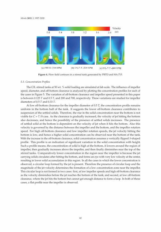
Metals 2015, 5, 1997–2020
Figure 4. Flow field contours in a stirred tank generated by PBTD and HA-715.
5.3. Concentration Profiles
The CIL stirred tanks at 50 wt. % solid loading are simulated at lab scale. The influence of impellerspeed, diameter, and off-bottom clearance is analyzed by plotting the concentration profiles for each ofthe cases in Figure 5. The variation of off-bottom clearance and impeller speed presented in this paperis between 0.125 T and 0.5 T, and 200 and 700, respectively. These variations are studied for impellerdiameters of 0.5 T and 0.33 T.
At low off-bottom clearance for the impeller diameter of 0.5 T, the concentration profile remainsuniform in the bottom half of the tank. It suggests the lower off-bottom clearance contributes tosuspension of the settled solids. Therefore, the rise in the solid concentration near the bottom is notvisible for C = T/8 case. As the clearance is gradually increased, the velocity of jet hitting the bottomalso decreases, and hence the possibility of the presence of settled solids increases. The presenceof settled solid at the bottom is dependent on the velocity of jet when it hits the bottom. Also thisvelocity is governed by the distance between the impeller and the bottom, and the impeller rotationspeed. For high off-bottom clearance and low impeller rotation speeds, the jet velocity hitting thebottom is low, and hence a higher solid concentration can be observed near the bottom of the tank.With the increase in the off-bottom clearance, solid concentration assumes a vertically flipped S-shapedprofile. This profile is an indication of significant variation in the solid concentration with height.Such a profile means, the concentration of solid is high at the bottom, it lowers around the region ofimpeller, then gradually increases above the impeller, and then finally diminishes near the top of thestirred tanks. Comparatively lower concentration in the region near the impeller is because the jetcarrying solids circulates after hitting the bottom, and forms an eye with very low velocity at the center,resulting in lower solid accumulation in this region. In all the cases in which the lower concentration isobserved, a circular loop formed by the jet is present. Therefore the presence of circular loop and themagnitude of the jet velocity determines the formation of a low concentration zone near the impeller.This circular loop is not formed in two cases: first, at low impeller speeds and high off-bottom clearanceas the velocity diminishes before the jet reaches the bottom of the tank; and second, at low off-bottomclearance, where the jet hits the bottom but cannot get enough distance to form a loop. In both of thesecases, a flat profile near the impeller is observed.
60

Metals 2015, 5, 1997–2020
Cz/Cav
0.60 1.00 1.40
z/H
0.3
0.7
Cz/Cav
0.60 1.00
z/H
0.3
0.7
Cz/Cav
0.60 1.00
z/H
0.3
0.7
Cz/Cav
0.60 1.00
z/H
0.3
0.7
Cz/Cav
0.6 1.0
z/H
0.00
0.25
0.50
0.75
1.00C = T/2 C = T/3 C = T/4 C = T/6 C = T/8
200 RPM 300 RPM 400 RPM 500 RPM 600 RPM 700 RPM
(a)
Cz/Cav
0.60 1.00 1.40
z/H
0.3
0.7
Cz/Cav
0.60 1.00
z/H
0.3
0.7
Cz/Cav
0.60 1.00
z/H
0.3
0.7
Cz/Cav
0.60 1.00
z/H
0.3
0.7
Cz/Cav
0.6 1.0
z/H
0.00
0.25
0.50
0.75
1.00C = T/2 C = T/3 C = T/4 C = T/6 C = T/8
200 RPM 300 RPM 400 RPM 500 RPM 600 RPM 700 RPM
(b)
Figure 5. Axial concentration profiles at different stirrer speeds and off-bottom clearance for impellerto tank diameter ratio of (a) 0.5 and (b) 0.33.
When the impeller diameter is decreased to 0.33 T, the flipped S-shaped concentration profile isnot dominant. On the contrary, the concentration is high near the bottom, which decreases to averageconcentration while reaching the height of the impeller, and then gradually decreases when reachingnear the top. Clearly, the conditions for strong circular loop formed in the 0.5 T case is not met in the0.33 T case. With the decrease in the impeller diameter and similar rotation velocity, the impeller tipspeed is reduced and therefore, the velocity magnitude of the jet is not sufficient to form a circular loopof solids. Therefore, the profiles for all the cases are almost identical, with strong influence of impellerspeed. At low impeller speeds, a high accumulation of solids at the bottom and low concentrationat the top is observed. At high impeller speeds, the concentration values showed less variation withheight. However, the influence of off-bottom clearance on the accumulation of solid near the bottomremained the same as in the case of 0.5 T. A low off-bottom clearance is found beneficial to suspendthe settled solids.
61

Metals 2015, 5, 1997–2020
5.4. Suspension Quality and Power Consumption
The suspension quality and power consumption are the two important parameters for determiningthe efficiency of a stirred tank. A high homogeneity (high suspension quality) achieved at a low powerconsumption is the objective of design and optimization. Suspension quality in a stirred tank can bedefined in two different ways: first, by defining the variation between the minimum and maximumconcentration [34] and second, by determining the homogeneity by variation in local concentrationcompared to the average concentration [35]. Mathematical representation of both these methods isgiven in equations below:
ΔCmax =Cmax − Cmin
Caverage× 100 (11)
Hsusp = 1 −√√√√ 1
n
n
∑i=1
(Ci
Caverage− 1)2
(12)
The results obtained from both of these equations are plotted in Figure 6. While the results fromthe Hsusp equation suggest that the homogeneity increases with the increase in impeller speed andreaches a plateau value, the results of the ΔCmax equation appear quite erratic. Such an observationis a result of error in the Cmin or Cmax values due to local errors during computation. Therefore, aconclusion cannot be drawn from these plots with confidence. Hsusp provides insight with respect tothe homogeneity prevailing in the stirred tanks.
For the case of Di/T = 0.5, the homogeneity is low at low impeller speeds, which improves withincreasing impeller speed and reaches a plateau. However, for an impeller off-bottom clearance ofT/3, the homogeneity decreases at very high velocity because of the generation of a dominant flippedS-shaped concentration profile (see Figure 5a). For a clearance higher than T/3 or lower than T/3,the flipped S-shaped profile is not dominant and therefore, the decrease in homogeneity at very highimpeller speed is also not observed. The highest deviation in the homogeneity occurs due to thesuspended solids at the bottom. Decreasing the off-bottom clearance allows the high velocity jet toforce the solids to suspend. Therefore, at off-bottom clearance of T/8, the homogeneity improves atlower impeller speed compared to other cases.
The results of cases Di/T = 0.33 are far different from those of Di/T = 0.5. In these cases, theimprovement in the homogeneity is not significant with the increase in the impeller rotation speed.Exceptions are the case of off-bottom clearance of T/4, T/6, and T/8, where the homogeneity crosses0.9 beyond the impeller rotation speed of 600, 500, and 500 RPM respectively. This suggests that thehigher off-bottom clearance and low impeller speeds result in dead zones in the stirred tank, hencereducing the homogeneity. When the velocities in the lower part of the tank are sufficiently high, thesolids suspend and a higher value of homogeneity is achieved.
For a particular impeller speed, the power consumption in a stirred tank system is proportionalto D5
i . Therefore, the power consumption for an impeller diameter of Di/T = 0.5 is higher than thatof Di/T = 0.33 at a given RPM (see Figure 6). For an impeller rotation speed of 700 RPM, the powerconsumption for cases of Di/T = 0.33 is less than 9 W. The impellers with Di/T = 0.5 can operateonly up to 400 RPM using this power, and beyond 400 RPM, these impellers will require additionalpower. However, at the same time, homogeneity higher than a value of 0.9 can only be achievedfor an impeller rotation speed above 400 RPM using this impeller diameter, while the same can beachieved using an impeller diameter of Di/T = 0.33 and clearance of T/6 or T/8 using 70% of thepower requirement at 600 RPM. Therefore, Di/T = 0.33 is more efficient than Di/T = 0.5 for obtaininghigh suspension quality for a given power consumption. The power consumption also varies with theoff-bottom clearance [36]. The closer the impeller is to the bottom of the tank, the higher the turbulenceand power dissipation. Although only minor, the power consumption of T/8 off-bottom clearance ismore than that of T/6. Therefore out of all the cases discussed, the impeller diameter of Di/T = 0.33
62

Metals 2015, 5, 1997–2020
with clearance of T/6 and impeller rotation speed of 600 RPM is appropriate for efficiently suspendinghigh concentration of solids in a stirred tank using an HA-715 impeller.
Impeller Rotation Speed, [RPM]
0 200 400 600 800
C max
, [-]
50
150
250
Impeller Rotation Speed, [RPM]
0 200 400 600 800
C max
, [-]
50
150
250
(a) (b)
C= T/2 C = T/3 C = T/4 C = T/6 C = T/8
Impeller Rotation Speed, [RPM]
0 200 400 600 800su
sp, [
-]0.8
0.9
1.0
Impeller Rotation Speed, [RPM]
0 200 400 600 800
susp
, [-]
0.8
0.9
1.0
Impeller Rotation Speed, [RPM]
0 200 400 600 800
Pow
er, [
Wat
t]
0
5
10
Impeller Rotation Speed, [RPM]
0 200 400 600 800
Pow
er, [
Wat
t]
0
50
100
Figure 6. Suspension quality and power consumption plotted at different stirrer speeds and off-bottomclearance for impeller to tank diameter ratio of (a) 0.5 and (b) 0.33.
5.5. Scale-Up
Different scale-up criteria are available based on attaining homogeneity or complete suspensioncondition in the stirred tanks [37–40]. Buurman et al. [37] suggested a scaling up rule of Njs ∝ D−0.666
for the complete suspension in stirred tanks assuming the turbulence to be isentropic. Barresi andBaldi [40] suggested that Njs ∝ D−0.666 is strictly valid in a homogeneous isotropic turbulent fieldand devised a new rule of Njs ∝ D−0.666 by applying the turbulence theory to the solids distribution.Magelli et al. [38] investigated the solids distribution in high aspect ratio stirred tanks under batch andsemibatch conditions and found that a constant ND0.93 was more appropriate. Montante et al. [39]analyzed the scale-up criteria for stirred tanks based on the dependency of minimum impeller speedas a function of impeller diameter and the dependency of settling velocity on the λ/dP, and backed thescale-up criterion of a constant ND0.93. Montante et al. [41] further investigated the role of turbulence onthe particle settling and suspension in scaled-up vessels, and arrived at the conclusion that intermediateturbulent fluctuation maintains the vertical solid concentration. Therefore, a value intermediate ofconstant tip speed Njs ∝ D−1) and constant power per unit volume (Njs ∝ D−0.666), i.e., N ∝ D−0.93 isappropriate for scaling-up. Based on this criterion, an impeller velocity of 22.15 RPM used for a stirredtank with T = 10 m.
The axial concentration profiles in laboratory scale and full scale stirred tanks are shown inFigure 7. The homogeneity in solid concentration observed in the laboratory scale stirred tankat 600 RPM is not extrapolated to the full scale stirred tank at 22.15 RPM. The presence of lowconcentration on the top can be explained by the very low velocity field present in the top part of
63

Metals 2015, 5, 1997–2020
the full scale tank (see Figure 8). The velocity imparted by the impeller is observed to be localized inthe lower part of the stirred tank and has apparently no influence on the top. Therefore, the velocityvectors between the middle and top of the impeller are nearly invisible showing low velocity zones.The average value of turbulent kinetic energy in the lower half of the tank is 0.033 m2/s2, whichreduces to 0.0008 m2/s2 in the lower half of the tank. Without sufficient kinetic energy in the flow fieldin this zone, the settling of solids is evident. As a result, the solid concentration drops sharply to zeroafter 8.5 m in the full scale tank. Due to the same low velocity field in the middle to top zone of thestirred tank, the remaining solid stays suspended in the bottom half of the stirred tank.
From the above discussion it is clear that the power provided in the lower half of the stirred tankis sufficient to suspend the solids. However, due to the absence of a power source in the upper half,maintaining the homogeneity in the stirred tank is not possible. Therefore, a multiple impeller systemis desired to achieve homogeneity.
Cz/Cav, [-]
0.00 0.75 1.50
z/H
, [-]
0.00
0.25
0.50
0.75
1.00Lab Scale Full Scale
Figure 7. Axial concentration profiles for lab scale (T = 0.288 m) and full scale (T = 10 m) stirred tankswith C = T/6 and Di = T/3.
Figure 8. Velocity vectors on baffle-impeller blade plane in a full scale stirred tank.
64

Metals 2015, 5, 1997–2020
5.6. Multiple-Impeller Systems
As the homogeneity was not achieved with the single impeller and additional power for solidsuspension near the top is required, more impellers are required to be installed in the full scale CILtanks. Therefore, three configurations in multi-impeller CIL systems were investigated, the details ofwhich are given in Table 4.
Table 4. Details of impeller configuration in multi-impeller CIL tanks.
Variable Twin-CT6 Twin-CT3 Triple-CT4
Off-bottom clearance, Ci T/6 T/3 T/4Distance between
impellers, CiD2T/3 T/3 T/4
The solid concentration contours on the baffle-impeller plane in the full-scale CIL tanks for singleimpeller and multi-impeller cases are given in Figure 9. The inhomogeneity in the single and Twin-CT6cases are evident from the contour plot. A continuous gradient is observed from bottom-to-top inthese two cases. This gradient can be categorized into three zones of very low, medium, and highsolid concentration. The use of a second impeller in the Twin-CTby6 case forms a jet that draws thelow concentration liquid from the top and circulates the high concentration fluid along the peripheryof the tank. Such a flow is favorable for increasing the suspension quality near the top of the CILtanks, as a result of which the extent of the low concentration zone is reduced. The zone of high solidconcentration is the largest for the single impeller system (extends to z = 0.6 T), which is reduced byusing a second impeller which disperses the high solid concentration present near the middle of theCIL tanks (extends to z = 0.5 T). However, the limited range of the jet formed by this impeller does notsignificantly affect the high concentration zone which still extends to half of the tank. Nonetheless, theuse of a second impeller is partially effective in improving the homogeneity.
Figure 9. Concentration profiles in baffle-impeller plane for (a) Single impeller; (b) Twin-CT6; (c)Twin-CT3 and (d) Triple-CT4.
65

Metals 2015, 5, 1997–2020
While, the presence of impeller near the gradient at the top was found beneficial, a similarapproach near the interface between medium and low concentration zones can be applied. Therefore,Twin-CT3 and Triple-CT4 cases were investigated specifically targeting at the interface of the gradientsbetween the zones. The strategy appears to be beneficial as the interface between the medium and highconcentration zone disappears and an intermediate concentration is observed to be prevalent in themajority of tank. The average concentration values of intermediate concentration zones for Twin-CT3and Triple-CT4 cases are 0.32 and 0.31, respectively. The increased distance from the top in Twin-CT3case results in the weakening of drawing forces at the interface of low and medium concentrationzones. Therefore, compared to Twin-CT6 case, the low concentration zone in Twin-CT3 case hasextended to single impeller value of 0.9 T. This value again increases to 0.95 T for Triple-CT4 case,where the distance of impeller from the interface of low and medium concentration zones is reduced.The concentration profiles indicate accumulation of solid particles at the bottom center of the CIL foroff-bottom clearance of T/6 and T/4, which is not present in the off-bottom clearance of T/3. A closerscrutiny of the flow near the bottom of the CIL tanks indicate that the secondary loops play a vital rolein the suspension of solid particles at the bottom center of the tank. Ibrahim and Nienow [42] made asimilar observation while investigating the solid suspension using different impellers and Newtonianfluids with different viscosities. For T/3 clearance, the secondary loop formed near the bottom isstrong which results in the values of axial velocity required for solid suspension at the bottom. For allother cases, the secondary loop is not strong and the values of axial velocity also approach zero. Thisresults in accumulation of solids near the bottom center.
Twin-CT3 case and Triple-CT6 case present feasible configurations for achieving homogeneityin CIL tanks. Comparison of the suspension quality and power requirement may provide furtherinformation on the efficiency of these two cases. In the case of Twin-CT3, the combination of lowerintermediate concentration and extended low concentration zone results in a low suspension qualityof 0.72, nearly the same of 0.78 for the Triple-CT6 case. The power requirements for single impeller,Twin-CT3 case and Triple-CT4 cases are 6.5 kW, 12 kW, and 18 kW, respectively. Therefore, the increasedhomogeneity is achieved at the expense of 6 kW of power per additional impeller.
6. Conclusions
CFD was used to simulate the high solid loading carbon-in-leach tanks. The averaged and localconcentration profiles in high solid loading systems were validated with the available experimentaldata. The validated models were used to simulate the lab scale and full scale CIL tanks. The influenceof design and operating parameters such as off-bottom clearance, impeller diameter, and impellerrotation speed were investigated. Several impeller configurations in the full scale CIL tanks forattaining homogeneity in the CIL tanks were also assessed. The conclusions deduced from the studyare as follows:
1. The Euler-Euler simulation approach with KTGF, Syamlal drag model, RSM turbulence modeland turbulent dispersion force model appropriately predict the local hydrodynamics in highsolid loading stirred tank systems.
2. For a given power consumption, the flow generated by the HA-715 impeller is more dominantthan the PBTD.
3. The low off-bottom clearance is favorable in achieving homogeneity at low impeller speed for labscale CIL tanks.
4. For scale-up, multiple impeller systems are necessary for providing kinetic energy in the upperhalf of the CIL tanks.
5. While a low off-bottom clearance is suitable for solid suspension, solids can however accumulateat the bottom center in full scale CIL tanks due to weak secondary loops.
66

Metals 2015, 5, 1997–2020
6. The dual impeller configuration with T/3 clearance and triple impeller configuration with T/4clearance minimize the problems encountered in the CIL tanks. Additional impellers requireapproximately 6 kW of extra power in CIL tanks.
The insight of the prevailing hydrodynamics in the CIL tanks in this study was useful for theconclusions drawn for its design. The models can be further applied to other industrial high solidloading stirred tank systems to investigate the optimal design and operating parameters.
Acknowledgments: This work was supported by resources provided by the Pawsey Supercomputing Centrewith funding from the Australian Government and the Government of Western Australia.
Author Contributions: D.W. and R.P.U. conceived and designed the CFD simulations. D.W. conducted simulationand acquired data. D.W., R.P.U. and V.K.P. analyzed and interpreted the data. D.W. drafted the manuscript andR.P.U. critically revised it.
Conflicts of Interest: The authors declare no conflict of interest.
Nomenclature
Bl blade length, mBw blade width, mCi impeller clearance, mCiD impeller-impeller distance, mC concentration in volume percent, (-)Cav average concentration in volume percent, (-)CD drag coefficient, (-)CDo particle drag coefficient in still fluidCH cloud height, mD or Di impeller diameter, mDshaft shaft diameter, mDhub hub diameter, mdP particle diameter, m→F td force due to turbulent dissipation, kg·m/s2
→F q external force, kg·m/s2
→F lift lift force, kg·m/s2
→F vm virtual mass force, kg·m/s2
→F 12 interphase interaction force, kg·m/s2
g acceleration due to gravity, m/s2
Gk production of turbulence kinetic energy, kg·m2/s2
H tank height, m=I unit stress tensor, Pa
k turbulence kinetic energy per unit mass, m2/s2
M torque, N·mN impeller speed, 1/minNjs speed of just suspension, 1/minNRe Reynolds number, (-)NP power number, (-)NQ pumping number, (-)p pressure and is shared by both the phases, PaP power delivered to the fluid, WT tank diameter, m→u velocity vector, m/s→u dr drift velocity, m/s
67

Metals 2015, 5, 1997–2020
Utip Impeller tip velocity, m/sGreek Letters
α volume fractionγ shear rate, 1/sε turbulence dissipation rate, m2/s3
εb bulk turbulence dissipation rate, m2/s3
λ Kolmogorov length scale, mμ shear viscosity, Pa·sμt turbulent viscosity, m2/sρ density kg/m3
σ Prandtl numbersσsl dispersion Prandtl numberτ shear stress, Pa=τ stress tensor, Paθm mixing time, sυ bulk viscositySubscripts1 or l continuous or primary phase2 or s dispersed or secondary phasem mixture propertiesz axial point
References
1. Barigou, M. Particle tracking in opaque mixing systems: An overview of the capabilities of PET and PEPT.Chem. Eng. Res. Des. 2004, 82, 1258–1267. [CrossRef]
2. Stevenson, R.; Harrison, S.T.L.; Mantle, M.D.; Sederman, A.J.; Moraczewski, T.L.; Johns, M.L. Analysis ofpartial suspension in stirred mixing cells using both MRI and ERT. Chem. Eng. Sci. 2010, 65, 1385–1393.[CrossRef]
3. Guida, A.; Nienow, A.W.; Barigou, M. PEPT measurements of solid-liquid flow field and spatial phasedistribution in concentrated monodisperse stirred suspensions. Chem. Eng. Sci. 2010, 65, 1905–1914.[CrossRef]
4. Altway, A.; Setyawan, H.; Winardi, S. Effect of particle size on simulation of three-dimensional soliddispersion in stirred tank. Chem. Eng. Res. Des. 2001, 79, 1011–1016. [CrossRef]
5. Micale, G.; Grisafi, F.; Rizzuti, L.; Brucato, A. CFD simulation of particle suspension height in stirred vessels.Chem. Eng. Res. Des. 2004, 82, 1204–1213. [CrossRef]
6. Ochieng, A.; Lewis, A.E. Nickel solids concentration distribution in a stirred tank. Miner. Eng. 2006, 19,180–189. [CrossRef]
7. Fradette, L.; Tanguy, P.A.; Bertrand, F.; Thibault, F.; Ritz, J.-B.; Giraud, E. CFD phenomenological model ofsolid-liquid mixing in stirred vessels. Comput. Chem. Eng. 2007, 31, 334–345. [CrossRef]
8. Ochieng, A.; Onyango, M.S. Drag models, solids concentration and velocity distribution in a stirred tank.Powder Technol. 2008, 181, 1–8. [CrossRef]
9. Kasat, G.R.; Khopkar, A.R.; Ranade, V.V.; Pandit, A.B. CFD simulation of liquid-phase mixing in solid-liquidstirred reactor. Chem. Eng. Sci. 2008, 63, 3877–3885. [CrossRef]
10. Fletcher, D.F.; Brown, G.J. Numerical simulation of solid suspension via mechanical agitation: Effect of themodelling approach, turbulence model and hindered settling drag law. Int. J. Comput. Fluid Dyn. 2009, 23,173–187. [CrossRef]
11. Tamburini, A.; Cipollina, A.; Micale, G.; Ciofalo, M.; Brucato, A. Dense solid-liquid off-bottom suspensiondynamics: Simulation and experiment. Chem. Eng. Res. Des. 2009, 87, 587–597. [CrossRef]
12. Tamburini, A.; Cipollina, A.; Micale, G.; Brucato, A.; Ciofalo, M. CFD simulations of dense solid-liquidsuspensions in baffled stirred tanks: Prediction of suspension curves. Chem. Eng. J. 2011, 178, 324–341.[CrossRef]
68
Metals 2015, 5, 1997–2020
13. Tamburini, A.; Cipollina, A.; Micale, G.; Brucato, A.; Ciofalo, M. CFD simulations of dense solid-liquidsuspensions in baffled stirred tanks: Prediction of the minimum impeller speed for complete suspension.Chem. Eng. J. 2012, 193–194, 234–255. [CrossRef]
14. Gohel, S.; Joshi, S.; Azhar, M.; Horner, M.; Padron, G. CFD modeling of solid suspension in a stirred tank:Effect of drag models and turbulent dispersion on cloud height. Int. J. Chem. Eng. 2012. [CrossRef]
15. Liu, L.; Barigou, M. Numerical modelling of velocity field and phase distribution in dense monodispersesolid-liquid suspensions under different regimes of agitation: CFD and PEPT experiments. Chem. Eng. Sci.2013, 101, 837–850. [CrossRef]
16. Gidaspow, D. Multiphase Flow and Fluidization: Continuum and Kinetic Theory Descriptions; Academic Press:San Diego, CA, USA, 1994.
17. Dagadu, C.P.K.; Akaho, E.H.K.; Danso, K.A.; Stegowski, Z.; Furman, L. Radiotracer investigation in goldleaching tanks. Appl. Radiat. Isot. 2012, 70, 156–161. [CrossRef] [PubMed]
18. Dagadu, C.P.K.; Stegowski, Z.; Furman, L.; Akaho, E.H.K.; Danso, K.A. Determination of flow structure in agold leaching tank by CFD simulation. J. Appl. Math. Phys. 2014, 2, 510–519. [CrossRef]
19. Dagadu, C.P.K.; Stegowski, Z.; Sogbey, B.J.A.Y.; Adzaklo, S.Y. Mixing analysis in a stirred tank usingcomputational fluid dynamics. J. Appl. Math. Phys. 2015, 3, 637–642. [CrossRef]
20. Aubin, J.; Fletcher, D.F.; Xuereb, C. Modeling turbulent flow in stirred tanks with CFD: The influence ofthe modeling approach, turbulence model and numerical scheme. Exp. Therm. Fluid Sci. 2004, 28, 431–445.[CrossRef]
21. Montante, G.; Magelli, F. Modelling of solids distribution in stirred tanks: Analysis of simulation strategiesand comparison with experimental data. Int. J. Comput. Fluid Dyn. 2005, 19, 253–262. [CrossRef]
22. Fan, L.; Mao, Z.; Wang, Y. Numerical simulation of turbulent solid-liquid two-phase flow and orientation ofslender particles in a stirred tank. Chem. Eng. Sci. 2005, 60, 7045–7056. [CrossRef]
23. Khopkar, A.R.; Kasat, G.R.; Pandit, A.B.; Ranade, V.V. Computational fluid dynamics simulation of the solidsuspension in a stirred slurry reactor. Ind. Eng. Chem. Res. 2006, 45, 4416–4428. [CrossRef]
24. Ljungqvist, M.; Rasmuson, A. Numerical simulation of the two-phase flow in an axially stirred vessel. Chem.Eng. Res. Des. 2001, 79, 533–546. [CrossRef]
25. Micale, G.; Montante, G.; Grisafi, F.; Brucato, A.; Godfrey, J. CFD simulation of particle distribution in stirredvessels. Chem. Eng. Res. Des. 2000, 78, 435–444. [CrossRef]
26. Murthy, B.N.; Joshi, J.B. Assessment of standard k-ε, RSM and LES turbulence models in a baffled stirredvessel agitated by various impeller designs. Chem. Eng. Sci. 2008, 63, 5468–5495. [CrossRef]
27. Derksen, J.; Akker, V.D.; Harry, E.A. Large eddy simulations on the flow driven by a rushton turbine. AlChEJ. 1999, 45, 209–221. [CrossRef]
28. Burns, A.D.; Frank, T.; Hamill, I.; Shi, J.-M. The favre averaged drag model for turbulent dispersion ineulerian multi-phase flows. In Proceedings of the 5th International Conference on Multiphase Flow, ICMF,Yokohama, Japan, 30 May–4 June 2004. Paper No. 392.
29. Syamlal, M.; Rogers, W.; O’Brien, T.J. Mfix Documentation: Theory Guide. Available online: https://mfix.netl.doe.gov/documentation/Theory.pdf (accessed on 26 October 2015).
30. Del Valle, V.H.; Kenning, D.B.R. Subcooled flow boiling at high heat flux. Int. J. Heat Mass Transfer 1985, 28,1907–1920. [CrossRef]
31. Zwietering, T.N. Suspending of solid particles in liquid by agitators. Chem. Eng. Sci. 1958, 8, 244–253.[CrossRef]
32. Hicks, M.T.; Myers, K.J.; Bakker, A. Cloud height in solids suspension agitation. Chem. Eng. Commun. 1997,160, 137–155. [CrossRef]
33. Bittorf, K.J.; Kresta, S.M. Prediction of cloud height for solid suspensions in stirred tanks. Chem. Eng. Res.Des. 2003, 81, 568–577. [CrossRef]
34. Zhao, H.-L.; Lv, C.; Liu, Y.; Zhang, T.-A. Process optimization of seed precipitation tank with multipleimpellers using computational fluid dynamics. JOM 2015, 67, 1451–1458. [CrossRef]
35. Tamburini, A.; Cipollina, A.; Micale, G.; Brucato, A.; Ciofalo, M. CFD simulations of dense solid-liquidsuspensions in baffled stirred tanks: Prediction of solid particle distribution. Chem. Eng. J. 2013, 223, 875–890.[CrossRef]
36. Armenante, P.M.; Mazzarotta, B.; Chang, G.-M. Power consumption in stirred tanks provided with multiplepitched-blade turbines. Ind. Eng. Chem. Res. 1999, 38, 2809–2816. [CrossRef]
69

Metals 2015, 5, 1997–2020
37. Buurman, C.; Resoort, G.; Plaschkes, A. Scaling-up rules for solids suspension in stirred vessels.Chem. Eng. Sci. 1986, 41, 2865–2871. [CrossRef]
38. Magelli, F.; Fajner, D.; Nocentini, M.; Pasquali, G. Solid distribution in vessels stirred with multiple impellers.Chem. Eng. Sci. 1990, 45, 615–625. [CrossRef]
39. Montante, G.; Pinelli, D.; Magelli, F. Scale-up criteria for the solids distribution in slurry reactors stirred withmultiple impellers. Chem. Eng. Sci. 2003, 58, 5363–5372. [CrossRef]
40. Barresi, A.; Baldi, G. Solid dispersion in an agitated vessel. Chem. Eng. Sci. 1987, 42, 2949–2956. [CrossRef]41. Montante, G.; Bourne, J.R.; Magelli, F. Scale-up of solids distribution in slurry, stirred vessels based on
turbulence intermittency. Ind. Eng. Chem. Res. 2008, 47, 3438–3443. [CrossRef]42. Ibrahim, S.; Nienow, A.W. Comparing impeller performance for solid-suspension in the transitional flow
regime with newtonian fluids. Chem. Eng. Res. Des. 1999, 77, 721–727. [CrossRef]
© 2015 by the authors. Licensee MDPI, Basel, Switzerland. This article is an open accessarticle distributed under the terms and conditions of the Creative Commons Attribution(CC BY) license (http://creativecommons.org/licenses/by/4.0/).
70

metals
Article
Experimental Simulation of Long Term Weathering inAlkaline Bauxite Residue Tailings
Talitha C. Santini 1,2,3,*, Martin V. Fey 4 and Robert J. Gilkes 3
1 School of Geography, Planning, and Environmental Management, the University of Queensland, Brisbane,QLD 4072, Australia
2 Centre for Mined Land Rehabilitation, the University of Queensland, Brisbane, QLD 4072, Australia3 School of Earth and Environment, University of Western Australia, 35 Stirling Highway, Crawley, WA 6009,
Australia; [email protected] Department of Plant Production and Soil Science, University of Pretoria, Private Bag X20, Hatfield,
Pretoria 0002, South Africa; [email protected]* Author to whom correspondence should be addressed; [email protected]; Tel.: +61-7-3346-1647;
Fax: +61-7-3365-6899.
Academic Editor: Suresh BhargavaReceived: 18 June 2015; Accepted: 7 July 2015; Published: 14 July 2015
Abstract: Bauxite residue is an alkaline, saline tailings material generated as a byproduct of theBayer process used for alumina refining. Developing effective plans for the long term managementof potential environmental impacts associated with storage of these tailings is dependent onunderstanding how the chemical and mineralogical properties of the tailings will change duringweathering and transformation into a soil-like material. Hydrothermal treatment of bauxiteresidue was used to compress geological weathering timescales and examine potential mineraltransformations during weathering. Gibbsite was rapidly converted to boehmite; this transformationwas examined with in situ synchrotron XRD. Goethite, hematite, and calcite all precipitated overlonger weathering timeframes, while tricalcium aluminate dissolved. pH, total alkalinity, and salinity(electrical conductivity) all decreased during weathering despite these experiments being performedunder “closed” conditions (i.e., no leaching). This indicates the potential for auto-attenuation ofthe high alkalinity and salinity that presents challenges for long term environmental management,and suggests that management requirements will decrease during weathering as a result of thesemineral transformations.
Keywords: weathering; pressure vessels; in situ XRD; bauxite residue; reaction kinetics
1. Introduction
1.1. Tailings as a Soil Parent Material
Tailings are the residual mixture of solids and liquids remaining after extraction of a mineralor energy resource from its ore. Around 7 Gt of tailings are produced worldwide each year, withalmost half of this total derived from copper extraction alone [1]. Tailings have typically been treatedsolely as waste materials; however, tailings are increasingly being recognized as substrates for soildevelopment [2–4]. The annual mass of tailings produced globally is approximately one-third of themass of soil lost through erosion globally [1,5]. Understanding how tailings materials weather intosoils over extended timescales is therefore important not only for managing long term environmentalimpacts associated with tailings (e.g., acid mine drainage), but also for predicting future ecosystemproperties and land use capabilities given the substantial and growing contribution of tailings to parentmaterial inputs for global soil development.
Metals 2015, 5, 1241–1261 71 www.mdpi.com/journal/metals

Metals 2015, 5, 1241–1261
Bauxite residue is an alkaline, saline-sodic byproduct of the Bayer process for alumina refining.Most economic reserves of bauxite worldwide are hosted in deeply weathered lateritic deposits [6], andthe bauxite residues produced during the Bayer process contain a characteristic mineral assemblagedominated by weathering-resistant minerals, such as quartz (SiO2), goethite (FeOOH), hematite(Fe2O3), anatase (TiO2) and rutile (TiO2). Precipitates formed during the Bayer process, such asthe desilication products sodalite (Na8(AlSiO4)6Cl2) and cancrinite (Na6Ca2(AlSiO4)6(CO3)2), calcite(CaCO3), tricalcium aluminate (Ca3Al2(OH)12), and perovskite (CaTiO3), also report to the residuefraction during processing, as well as minor amounts of undigested aluminium oxides (gibbsite(Al(OH)3) and boehmite (AlOOH)). Each year, 120 Mt of bauxite residue are produced globally,adding to the 3 Gt already stored in tailings facilities [7]. After deposition in tailings storage facilities,management tasks include collection and treatment of alkaline, saline leachates, and rehabilitation ofthe bauxite residue surface. Rehabilitation aims to stabilize the surface and improve visual amenity byestablishing a vegetation cover. Insofar as the objective of rehabilitation is to establish a vegetationcover, rehabilitation strategies aim to accelerate pedogenesis (soil formation) in bauxite residue andenhance natural mechanisms of alkalinity and salinity attenuation such as precipitation, dissolution,and leaching. The weathering trajectory of bauxite residue, therefore, needs to be determined in orderto identify any attenuation mechanisms that can be targeted by applied treatments. Furthermore,an understanding of the potential weathering trajectories of bauxite residue may aid in minimizingamounts and types of applied treatments. Refinery scale Bayer processing commenced in 1894, whichgives 120 years exposure to weathering in the very oldest residue deposits [7]. The longest weatheringtimeframe for bauxite residue reported in studies to date was 40 years under a tropical climate inGuyana, in which dissolution of sodalite and calcite were observed [3]. This reflects the fact thatweathering of primary minerals, an essential part of soil formation, can be a slow process in the fieldwhich is partially constrained by reaction kinetics. Limited evidence of mineral weathering has alsobeen reported in other studies of soil development in bauxite residue [8,9]. Laboratory simulationof weathering is therefore essential in order to understand how this material behaves over longerweathering timescales and ensure that management strategies are effectively designed to minimizeadverse environmental impacts over the long term.
1.2. Laboratory Simulation of Weathering
Compressing the geological timescales over which mineral weathering occurs requiresmanipulation of environmental conditions to accelerate reaction rates. Increasing temperature and/orpressure can accelerate attainment of chemical equilibrium according to the modified ArrheniusEquation (Equation (1)):
K = A (exp (−(Ea + PΔV)/RT)) (1)
where K is reaction rate (s−1; for a first-order reaction), A is the pre-exponential factor (s−1; for afirst-order reaction), Ea is activation energy (J·mol−1), P is partial pressure of reactant (mol·cm−3),ΔV is activation volume (cm3·mol−1), R is the universal gas constant (8.314 J·mol−1·K−1) and T istemperature (◦K).
Soxhlet extractors have been used to simulate weathering for a variety of geologicalmaterials [10–14]; however, the very fine texture of bauxite residue (median particle diameter 130 μmfor bauxite residue used in this study; [15]) inhibited leaching. Furthermore, the Soxhlet extractionprocedure is slow and labour intensive when conducting experiments at multiple temperatures toinvestigate reaction kinetics. Pressure vessels (also known as pressure bombs, Teflon bombs, Parrbombs) have been used to accelerate reactions and rapidly bring materials to chemical equilibrium,because they apply both elevated temperatures and pressures to the material under investigation.Their previous use in weathering studies has mostly concerned the alteration of single minerals duringpedogenesis [16–18]. Reaction kinetics can be derived from these experiments and extrapolated topredict reaction rates under field conditions [17,19]. The drawback of pressure vessels compared toSoxhlet extractors for weathering simulations is that they do not allow for the effect of leaching, being
72

Metals 2015, 5, 1241–1261
a “closed” system. Allowing reaction products to accumulate may create a local equilibrium whichslows further reactions. Different equilibrium states could therefore be identified for the same materialunder various leaching conditions. Bauxite residue has a very low hydraulic conductivity [20], whichlimits leaching; and under low leaching rates, equilibration with pore water may proceed to chemicalequilibrium. The use of pressure vessels to predict the long term equilibrium composition of bauxiteresidue may therefore be a reasonable representation of reactions that occur under field conditions.
The aims of this study were to: (a) analyse the chemical and mineralogical composition of bauxiteresidue over time under simulated weathering conditions in pressure vessels; (b) extrapolate resultsfrom the pressure vessel studies to temperatures and pressures typical of field conditions in bauxiteresidue deposit areas (tailings storage facilities); and (c) determine whether pressure vessels provide asuitable method for rapidly determining potential weathering trajectories of bauxite residue underfield conditions. Under hydrothermal conditions, we expected to observe some conversion of mineralphases that are commonly associated with Bayer process conditions, such as conversion of gibbsite toboehmite [21], goethite to hematite [22], tricalcium aluminate to calcite [23], and quartz to desilicationproducts [24]. Dissolution of sodalite and calcite has been observed during weathering under leachingconditions [3,25,26]. However, dissolution of these minerals was not expected within this experimentbecause no leaching was possible.
2. Experimental Section
2.1. Study Design
This study used pressure vessels to elevate temperature and pressure in order to rapidly determinethe likely weathering trajectory of bauxite residue. Two types of pressure vessels were used: PTFE-linedstainless steel pressure vessels; and fused silica capillaries, sealed and pressurized with N2 toavoid boiling. These vessels were used in two experiments to provide complementary information.The stainless steel pressure vessels allowed sampling and analysis of both solid and liquid phases, butrequired 90 min to reach the required temperature in an oven. This limited temporal resolution, andcomplete transformation of some minerals (e.g., gibbsite to boehmite) was observed between the initial(t = 0) and second (t = 90 min) sampling times. Use of the fused silica capillary reaction vessels at theAustralian Synchrotron Powder Diffraction beamline 10BM1 resolved this problem, as they heatedquickly (less than 40 s in our experiment) and full X-ray diffraction (XRD) patterns can be collected insitu on a rapid basis (20 s in this experiment) with the Mythen detector array. Results are unreplicated;that is, only one sample was analysed for each time and temperature combination. This is common inmineral dissolution and precipitation studies where reaction rates are studied in response to variables,such as temperature or pH [17,22,27–34] to derive reaction kinetics. A single time and temperaturecombination in the pressure vessel experiments (100 ◦C, 909 h) was conducted in triplicate to estimatevariability; this approach has also been used elsewhere [35].
2.2. Bauxite Residue Sample
Bauxite residue was sourced from Alcoa of Australia Limited’s Kwinana refinery. Iron oxides(goethite and hematite) were the major mineral phases present, with smaller amounts of quartz,and calcite and sodalite formed during the Bayer process (Table 1). In 1:1 bauxite residue to watersuspensions, initial pH was 13.07, electrical conductivity (EC) was 15.52 dS·m−1, and total alkalinity(TA) was 7.35 g/L CaCO3.
2.3. Stainless Steel Pressure Vessel Experiment
Five hydrothermal treatment temperatures (100, 140, 165, 200 and 235 ◦C) were employed inorder to extract kinetic data for observed reactions. Subsamples (4 g) of bauxite residue were addedto 5 mL of ultrapure deionised water to create bauxite residue slurries inside 25 cm3 internal volumePTFE-lined stainless steel pressure vessels (Parr Instrument Company, Moline, IL, USA) and heated
73

Metals 2015, 5, 1241–1261
to the designated temperature in a rotating oven. One vessel was removed after 1.5, 3.75, 21, 28, and48 h and allowed to cool to room temperature. Additional samples of the 100 ◦C treatment were alsocollected at 170, 336 and 909 h. Slurry samples were taken from each vessel after cooling (<2 h).
Table 1. Mineral concentrations in bauxite residue prior to hydrothermal treatment, as determined byquantitative mineral analysis by Rietveld refinement of an X-ray diffraction pattern.
Mineral Formula Concentration (% Weight) a
Goethite FeOOH 41Hematite Fe2O3 11
Calcite CaCO3 11Quartz SiO2 9.4
Boehmite AlOOH 8.4Muscovite KAl2Si3AlO10(OH)2 8.4Gibbsite Al(OH)3 3.4Sodalite Na8(AlSiO4)6Cl2 2.8Anatase TiO2 1.7Ilmenite FeTiO3 1.7
Tricalcium aluminate Ca3Al2(OH)12 0.4Amorphous/unidentified - 0.8
a X-ray diffraction analysis was performed as described for hydrothermally-treated samples in Section 2.4. usingRietveld refinement implemented in TOPAS-Academic (v. 4.1; [36] Coelho Software, Brisbane, Australia) withoutrunning in sequential refinement mode.
Cooled slurries were centrifuged at 3000 rpm for 5 min to separate liquid and solid phases.Supernatants were immediately filtered through a 0.2 μm cellulose acetate filter and analysed for pH,EC, and total alkalinity by titration with 0.1 M HCl to endpoints pH 8.5 and 4.5 [37]. Subsamples ofsupernatants were diluted 1:10, acidified with HCl to pH < 2 and stored at 4 ◦C prior to analysis byInductively Coupled Plasma Optical Emission Spectrometry (ICP-OES; Optima 5300DV, PerkinElmer,Waltham, MA, USA) to determine Al, Ca, Fe, K, Na, Si, and Ti concentrations.
Treated solids were shaken with acetone in an end-over-end shaker for 90 min and thencentrifuged at 3000 rpm for 5 min. The supernatant was decanted and the solids allowed to dryat ambient laboratory temperature for 48 h. Dried solids were hand ground with an agate mortar andpestle and then packed into 0.3 mm internal diameter glass capillaries for XRD analysis (wavelength0.8271 Å, collection time 5 min) at the Powder Diffraction beamline (10BM1) at the AustralianSynchrotron, Victoria, Australia. Peak locations and areas for selected minerals were then calculatedusing Traces [38]. Anatase, which is naturally present in the bauxite residue, was used as an internalstandard for the purpose of comparing peak areas of selected minerals between XRD patterns. Anatasehas been found to be only sparingly soluble in the presence of Bayer liquor at 90 ◦C under ambientpressure [39].
2.4. Fused Silica Capillary Pressure Vessel Experiment
In situ XRD experiments were conducted at the Australian Synchrotron’s beamline 10BM1, withslurries heated in Norby cells [40], consisting of fused silica capillaries (internal diameter: 0.8 mm; wallthickness: 0.1 mm, typical working volume: 0.02 mL) heated with a hot air blower, continuously rotatedthrough 270◦ along the longitudinal axis of the capillary, and held under N2 pressure during heatingto various temperatures (140–170 ◦C) to avoid boiling. The N2 regulator could not provide sufficientpressure to avoid boiling above 170 ◦C. Slurries were prepared <2 h before analysis at the same bauxiteresidue: Deionised water ratio as in the stainless steel pressure vessel experiments (44% wt solids).Diamond powder was added to the dry bauxite residue at 5% wt (2.2% wt in slurries) as an internalstandard for the purposes of quantitative phase analysis by Rietveld refinement. Diamond wasselected for its low reactivity under the experimental conditions, and for its few diffraction peakswithin the 2θ angular range of interest, which minimizes overlaps with other phases. Diffraction
74

Metals 2015, 5, 1241–1261
patterns were collected continuously every twenty seconds using the Mythen microstrip detector,capable of collecting 80◦ 2θ simultaneously, to allow calculation of mineral transformation kinetics.XRD patterns were collected first at ambient temperature with the required N2 pressure applied,during heating, and for the duration of the experiment. Operating temperature was reached in 20–40 s.Run times varied between 1.5 h and 4 h, depending on factors such as loss of synchrotron beam,capillary failure, and observed reaction rates.
To quantify changes in mineral concentrations and amorphous content during this experiment,quantitative mineral analysis of X-ray diffractograms was conducted using TOPAS-Academic(v. 4.1; [36] Coelho Software, Brisbane, Australia) for Rietveld refinement. Compared with the peak areabased data analysis approach, Rietveld refinement removes the potential for errors from peak overlaps,reports mineral concentrations on an absolute rather than relative scale, and allows quantificationof amorphous content. Data were analysed using a sequential refinement approach, which usedthe refined (output) mineral concentrations for dataset x as the input mineral concentrations for theRietveld refinement of dataset x + 1, where x is any dataset in the collected sequence of XRD patternsfor bauxite residue at a particular temperature. Reported mineral concentrations (on a percent weightbasis) were corrected for amorphous content (including X-ray amorphous solids, fused silica capillary,and water in the slurry) using the diamond internal standard and Equations (2) and (3):
Absi = (wiSTDtrue)/(STDmeas) (2)
wamorph = 1 − (n
∑i=1
Absi) (3)
where Absi is the absolute weight fraction of phase i, wi is the weight fraction of phase i determinedby Rietveld refinement, STDtrue is the known weight fraction of the diamond standard, STDmeas is thecalculated weight fraction of the diamond standard by Rietveld refinement and wamorph is the totalabsolute weight fraction of amorphous and unidentified phases.
2.5. Reaction Kinetics Calculations
An extent of reaction parameter, α, was calculated from either peak areas (stainless steel pressurevessel experiment) or mineral concentrations (fused silica capillary experiment), where It was theobserved peak area or mineral concentration at a sampling time, t, and Imax was the maximum peakarea or mineral concentration attained (Equation (4)):
α = (It)/(Imax) (4)
Kinetic data was then extracted using an approach identical to that detailed by Murray et al. [22].The Sharp-Hancock equation (Equation (5); [41]), a linearised version of the Avrami-Erofe’ev Equation(Equation (6); [42–45]), was used to calculate kinetic parameters n (reaction order) and k (reaction rate)by plotting ln(−ln(1 − α)) against ln(t) and fitting a least-squares linear equation.
ln(−ln(1 − α)) = n ln(t − t0) + n ln(k) (5)
α = 1 − exp(−k (t − t0))n (6)
Nucleation time (t0) was assumed to be zero as no new minerals were formed and growth sitestherefore existed for all phases. Values for ln(k) were then plotted against 1/T in an Arrhenius plot todetermine activation energy, Ea, and the pre-exponential factor, A.
75

Metals 2015, 5, 1241–1261
3. Results and Discussion
3.1. Supernatant Chemistry
Decreases in pH, EC, and total alkalinity (TA) were observed over time in bauxite residue in the200 ◦C and 235 ◦C treatments (Figure 1), indicating a potential for “auto-attenuation” of alkalinityand salinity within the bauxite residue. This is in sharp contrast with the weathering trajectories oftailings derived from sulfidic ores, in which initially low pH and high salinity are exacerbated duringweathering due to oxidation of residual iron sulfides [2,4]. Some increases in EC and TA were observedin 100 ◦C and 135 ◦C treatments whereas EC and TA initially increased and then sharply decreased inthe 165 ◦C, 200 ◦C, and 235 ◦C treatments. This suggests that the lower temperature hydrothermaltreatments progress along the same reaction trajectory as the higher temperature treatments, withslower reaction rates in the lower temperature treatments.
Figure 1. pH, EC, and total alkalinity (TA) of supernatants from bauxite residue during pressure vesseltreatments at various temperatures. Dashed lines indicate t = 0 values. Note that treatment time (X axis)is graphed on a logarithmic scale. Error bars indicate 95% confidence interval for the mean of the100 ◦C treatment at 909 h.
Supernatant concentrations of Al, K, Na, and S all decreased over time to below initialconcentrations in the 200 and 235 ◦C treatments, suggesting removal from solution by mineralprecipitation. Concentrations of Al, Na, and S increased and then decreased to concentrations slightlyabove or below initial concentrations in the 165 ◦C treatment. This suggests that similar reactions areresponsible for observed changes in concentrations of Al, Na, and S at temperatures from 165 to 235 ◦C,and that reaction rates decrease with decreasing temperature. At 100 and 130 ◦C, Al, K, Na, and Sconcentrations increased and remained above initial concentrations during hydrothermal treatment;this suggests that precipitation reactions occur very slowly or do not occur at all at lower temperatures.Silicon concentrations in the supernatant increased over time in all but the 235 ◦C treatment. This couldbe a result of dissolution of reactive Si (from muscovite or finely divided quartz), with precipitation ofsodalite or cancrinite only occurring to an appreciable extent at 235 ◦C. Iron concentrations in solutionremained near or below the detection limit for all treatment temperatures except 235 ◦C (Figure 2).
76

Metals 2015, 5, 1241–1261
The assumption of anatase insolubility was supported by ICP-OES data, which indicated that little Tiwas released to solution, except at 235 ◦C. Titanium and iron concentrations increased simultaneouslyand were present in solution at an approximate Fe:Ti molar ratio of 8:1, which is inconsistent withilmenite dissolution and rather may indicate dissolution of a minor titanium-substituted iron oxidephase, such as titanohematite. Ca concentrations were below detection limits (0.35 mg/L) in all samplesand are therefore not shown in Figure 2.
Figure 2. Concentrations of selected elements (mg or g·L−1) in supernatant from bauxite residue aftertreatment in pressure vessels. Dashed lines indicate concentrations at t = 0. Where no dashed line isvisible, concentrations at t = 0 were below detection limits. Note that treatment time (X axis) is graphedon a logarithmic scale. Error bars indicate 95% confidence interval for the mean of the 100 ◦C treatmentat 909 h.
3.2. Solids Mineralogy
The rapid collection of XRD patterns from the bauxite residue slurry in fused silica capillaryreaction vessels allowed construction of time sequence graphs which illustrate the temperaturedependent transformation of gibbsite to boehmite over short timescales (Figures 3–6). Gibbsiteand boehmite dynamics reflect a dissolution-precipitation mechanism based on observed rates oftransformation in Figures 3–6, and previous studies of hydrothermal conversion [46,47]. This wouldaid in lowering pH, EC, and TA by diluting the supernatant (Equation (7)). No Al would be released tothe supernatant, although some Al initially present in solution may also be precipitated as boehmite.
Al(OH)3(s) → AlOOH(s) + H2O(l) (7)
77

Metals 2015, 5, 1241–1261
The gibbsite to boehmite reaction could only be observed by in situ synchrotron XRD becausethe transformation time (<50 min at 165–170 ◦C) was faster than the required time for the stainlesssteel pressure vessels to heat to temperature. The gibbsite to boehmite transformation is knownto occur above 100 ◦C [22]. Transformation of gibbsite to boehmite was very slow at temperatures≤150 ◦C in this study and increased markedly above this temperature. Elevated pressure slows thetransformation, because the sum of the molar volumes of the products is greater than that of thereactants (Equation (7)). At lower temperatures, the inhibitory effect of elevated pressure is likely tohave slowed the transformation; however, this effect appeared to have less influence on reaction ratesat higher temperatures. A similar conclusion was drawn by Mehta and Kalsotra [48], who observedconversion of gibbsite to boehmite under hydrothermal conditions only at temperatures ≥190 ◦C.Higher alumina to caustic ratios (A/C; Al2O3:Na2O ratio (g/L) in the supernatant) also raise theminimum transformation temperature [49,50]; the alumina:caustic ratio was consistently below 0.5 inthis experiment and was therefore unlikely to have inhibited transformation of gibbsite to boehmite.
Goethite precipitated to a minor extent at 170 ◦C (Figure 6). Anatase concentrations appearedstable according to quantitative mineral analysis graphs (Figures 3–6), which supports interpretationsbased on Ti concentrations in the supernatants (Figure 2). Amorphous content was stable during thetransformation of gibbsite to boehmite; given that calculated amorphous content includes contributionsfrom water in the slurry, amorphous content was expected to increase as a result of the water releasedduring this transformation. The water released during transformation of gibbsite (present in thebauxite residue slurry at approximately 2% wt) to boehmite may have been insufficient to increase theamorphous content detectable within the error of the Rietveld-based quantification approach. Thequality of the diffractograms was compromised by the short collection time; this hindered accuratequantification of gibbsite concentrations below 0.5% wt, and quantification of tricalcium aluminate andilmenite concentrations. Diffractogram quality may also have been too poor to detect small changesin amorphous content of the solid phase. Longer collection times (1–2 min) are required for complexmineral assemblages if quantification of minor phases, or small changes in concentration of majorphases are of interest.
Figure 3. Concentration of crystalline and amorphous phases in bauxite residue slurry in capillaryreaction vessels as a function of treatment time at 140 ◦C, as determined by Rietveld-based quantitativemineral analysis of X-ray diffractograms. Note that amorphous content is plotted on the secondaryY axis and represents contributions from X-ray amorphous minerals in bauxite residue, water in theslurry, and the fused silica capillary.
78

Metals 2015, 5, 1241–1261
Figure 4. Concentration of crystalline and amorphous phases in bauxite residue slurry in capillaryreaction vessels as a function of treatment time at 150 ◦C, as determined by Rietveld-based quantitativemineral analysis of X-ray diffractograms. Note that amorphous content is plotted on the secondaryY axis and represents contributions from X-ray amorphous minerals in bauxite residue, water in theslurry, and the fused silica capillary. Gaps in data from 100–110, and 160–180 min were caused by beamloss at the synchrotron. Heating of the slurry continued during beam loss.
Figure 5. Concentration of crystalline and amorphous phases in bauxite residue slurry in capillaryreaction vessels as a function of treatment time at 165 ◦C, as determined by Rietveld-based quantitativemineral analysis of X-ray diffractograms. Note that amorphous content is plotted on the secondaryY axis and represents contributions from X-ray amorphous minerals in bauxite residue, water in theslurry, and the fused silica capillary.
79

Metals 2015, 5, 1241–1261
Figure 6. Concentration of crystalline and amorphous phases in bauxite residue slurry in capillaryreaction vessels as a function of treatment time at 170 ◦C, as determined by Rietveld-based quantitativemineral analysis of X-ray diffractograms. Note that amorphous content is plotted on the secondaryY axis and represents contributions from X-ray amorphous minerals in bauxite residue, water in theslurry, and the fused silica capillary.
During extended hydrothermal treatment in stainless steel pressure vessels, boehmite, goethite,hematite, and calcite appeared to precipitate (Figure 7; Table 2), along with minor precipitation ofsodalite; whereas gibbsite and tricalcium aluminate dissolved (Figure 7). As discussed above, gibbsiteis likely converted to boehmite during hydrothermal treatment. Although conversion of goethiteto hematite has been observed under Bayer process conditions [22], goethite dissolution was notobserved during this experiment, perhaps due to the inhibitory effect of anatase [22]. The precipitationof both goethite and hematite was likely limited by low dissolved Fe concentrations. Fe(OH)4
−(aq) is
thermodynamically predicted to be the dominant form of dissolved iron at pH values observed inthese experiments, and goethite and hematite precipitation would therefore have a minimal effectupon pH, EC, and TA (Equations (8) and (9)) even if precipitation occurred to a greater extent:
Fe(OH)4−
(aq) → FeOOH(s) + H2O(l) + OH−(aq) (8)
2Fe(OH)4−
(aq) + 2H+(aq) → Fe2O3(s) + 5H2O(l) (9)
Tricalcium aluminate dissolved more slowly than gibbsite and the majority of Al and Ca suppliedto solution from dissolution of both minerals is likely to have been precipitated as boehmite and calcitegiven that Al and Ca concentrations did not increase substantially during dissolution (Equation (10);Figure 2). This conclusion is consistent with the conversion mechanisms described elsewhere [23,46,47].
Ca3Al2(OH)12(s) + 3CO32−
(aq) → 3CaCO3(s) + 2AlOOH(s) + 10OH−(aq) (10)
Calcite and sodalite precipitation were not observed in the fused silica capillary experiments;changes in calcite:anatase ratio in Table 2 indicate that this is a slower reaction and smaller in magnitudethan the boehmite precipitation reaction. Precipitation of calcite may have only occurred to a minorextent during the fused silica capillary experiments, and therefore may not have been detected.A similar explanation may account for the observations of goethite and hematite precipitation in thelonger term stainless steel pressure vessel experiment. Both minerals precipitated more slowly and toa lesser extent than boehmite (Table 2), and precipitation may therefore not have been detectable overtimescales of 150–250 min at temperatures of 140–165 ◦C.
80

Metals 2015, 5, 1241–1261
Figure 7. X-ray diffraction patterns from bauxite residue before and after hydrothermal treatment. Treatmenttime and temperature are indicated for each pattern. Peaks between 7.5◦–35◦ 2θ are labeled with d-spacings(Å) and abbreviations for minerals as follows: M—muscovite; S—sodalite; B—boehmite; T—tricalciumaluminate; Go—goethite; Gi—gibbsite; Q—quartz; C—calcite; H—hematite; At—natase; I—ilmenite.
Muscovite appeared to dissolve at 165–170 ◦C in the fused silica capillary experiments but wasstable in the stainless steel pressure vessel experiments. As the only K-bearing mineral in bauxiteresidue, muscovite behaviour could be expected to mirror supernatant K concentrations (Figure 2),dissolving at temperatures ≤165 ◦C and precipitating at temperatures ≥200 ◦C. This is not fullysupported by the XRD data from the fused silica capillary or the stainless steel pressure vesselexperiments. All XRD patterns were collected from powders or slurries that were rotated duringcollection of XRD patterns; preferred orientation is therefore unlikely to cause changes in peak areasbetween patterns. Muscovite has been observed to dissolve under alkaline conditions [28,31], althoughdissolution rates decrease as aqueous Al and Si concentrations increase [32]. The minor dissolutionobserved in fused silica capillary experiments at 165–170 ◦C may be due to decreases in aqueous Al insupernatant solution at temperatures ≥165 ◦C (Figure 2). It is unclear why muscovite dissolution wasnot observed by ex situ XRD of hydrothermally treated solids.
Table 2. Percentage change in mineral:anatase ratio during hydrothermal treatment of bauxite residue,relative to untreated bauxite residue. Ratio was calculated from primary peak areas of each mineralfrom synchrotron XRD scans. Mineral names are abbreviated as follows: Gi—gibbsite; T—tricalciumaluminate; B—boehmite; C—calcite; Go—goethite; H—hematite; S—sodalite. Mineral:anatase ratios ofmuscovite, anatase, and quartz did not indicate dissolution or precipitation in response to temperatureor treatment time.
Temperature (◦C) Treatment Time (h)Mineral
Gi T B C Go H S
100 1.5 54 41 82 30 47 15 47100 21 47 24 102 43 48 29 62100 48 46 −2 153 44 52 30 64100 336 43 −2 313 88 107 89 106
165 1.5 −100 −14 300 53 71 55 68165 21 −100 −100 468 95 119 109 118165 48 −100 −100 584 106 138 117 190
235 1.5 −100 −35 348 85 99 90 123235 3.75 −100 −100 526 88 114 119 150235 21 −100 −100 587 94 141 177 294235 48 −100 −100 643 111 156 198 389
81

Metals 2015, 5, 1241–1261
3.3. Reaction Kinetics
Peak areas of minerals in XRD patterns of residues from the 100, 165, and 235 ◦C treatments inthe stainless steel pressure vessel experiment (Table 2) were used to calculate extents of reaction (α)and kinetic parameters (Equations (4)–(6)). The rapid dissolution of gibbsite and tricalcium aluminateprecluded calculation of reaction kinetics for these phases from the stainless steel pressure vesselexperiment data. Fused silica capillary reaction vessel data were used for the calculation of gibbsitereaction kinetics, at hydrothermal treatment temperatures of 140, 150, 165, and 170 ◦C, using absolutemineral concentration as calculated by Rietveld refinement of XRD patterns rather than peak areaof minerals relative to the internal standard. The quality of the XRD patterns from the fused silicacapillary experiment was insufficient to allow accurate quantification of tricalcium aluminate andreaction kinetics were therefore not calculated for this mineral.
Sharp-Hancock analysis of mineral transformations within these experiments indicated that theplots of ln(−ln(1 − α)) against ln(t) were well described by linear functions because r2 values weregenerally >0.80 (Table 3), except for goethite at 100 ◦C. This indicates that a single reaction mechanismdominated over the course of the dissolution or precipitation reactions for most minerals. The n valuesof 0.8–1.2 observed for gibbsite dissolution (Table 4) are consistent with first-order reaction kinetics(n = 1). Contracting area kinetics, with an n value of 1.04, and contracting volume kinetics, with an nvalue of 1.08, would also be feasible explanations for the observed n values and are consistent with thetransformation of gibbsite to boehmite as a dissolution-precipitation mechanism [46,47].
Table 3. Coefficients of determination (r2) for Sharp-Hancock lines of best fit (ln(−ln(1 − α)) vs. ln(t))to mineral transformations in bauxite residue. Mineral names are abbreviated as follows: Gi—gibbsite;B—boehmite; C—calcite; Go—goethite; H—hematite; S—sodalite.
Temperature (◦C) Gi Temperature (◦C) B C Go H S
140 0.90 100 0.86 0.84 0.64 0.91 0.91150 0.98 165 0.94 0.99 0.99 0.99 0.92165 0.94 235 0.86 1.00 1.00 1.00 0.97170 0.99
Table 4. Reaction orders (n) derived from Sharp-Hancock lines of best fit (ln(−ln(1 − α)) vs. ln(t)) tomineral transformations in bauxite residue. Mineral names are abbreviated as follows: Gi—gibbsite;B—boehmite; C—calcite; Go—goethite; H—hematite; S—sodalite.
Temperature (◦C) Gi Temperature (◦C) B C Go H S
140 0.804 100 0.289 0.281 0.200 0.363 0.162150 1.072 165 0.357 0.441 0.361 0.301 0.331165 0.991 235 0.403 0.096 0.314 0.499 0.508170 1.185
The Ea value calculated from this study (Table 5) match well with values from Mehta andKalsotra’sstudy [48] of boehmite precipitation under hydrothermal, alkaline conditions for boehmite(Ea 69.63–73.46 kJ·mol−1). Under alkaline, heated (60–85 ◦C) conditions, at ambient pressure, theEa for gibbsite dissolution is 107 kJ·mol−1 [51]. This is lower than the value observed in this study(Table 5), which suggests that pressure inhibited the gibbsite-boehmite transformation [21] The Ea
value determined from this study for sodalite precipitation (Table 5) was much higher than thatdetermined in other studies for first-order reaction kinetics involving precipitation from solution(38.2–48.4 kJ·mol−1; [52,53]). This suggests that sodalite is not directly precipitated from solution,but that precipitation is reliant upon the dissolution or transformation of another mineral. A similarelevation in activation energy for cancrinite precipitation under Bayer conditions was observed whencancrinite formed from sodalite rather than directly precipitating from solution [54]. Muscovite orquartz could be sources of reactive silica for sodalite precipitation; however, neither were observed to
82

Metals 2015, 5, 1241–1261
dissolve to an appreciable extent within this study. No values for activation energies of precipitationof calcite, goethite, or hematite under similar reaction conditions were available in the literature.
The low values of n returned from Sharp-Hancock analysis (0.10 < n < 0.85) for minerals otherthan gibbsite suggest that precipitation of minerals proceeded via three-dimensional (3D) diffusioncontrolled reaction mechanisms (Table 3), because these reactions occur with an ideal n value of0.57 [55]. However, the activation energies calculated from Arrhenius plots of ln(k) against 1/T rangedfrom 76–131 kJ·mol−1 (Table 5). These activation energies are far higher than expected for diffusioncontrolled reactions (generally <21 kJ·mol−1; [56]), and therefore suggest that precipitation reactionswere in fact surface controlled.
Table 5. Activation energies (Ea; kJ·mol−1), pre-exponential (“frequency”) factors (A; s−1), and reactionrates at 165 ◦C (k; s−1) calculated from Arrhenius plots for mineral transformations in bauxite residue.Mineral names are abbreviated as follows: Gi—gibbsite; B—boehmite; C—calcite; Go—goethite;H—hematite; S—sodalite.
Parameter Gi B C Go H S
Ea 190.79 88.03 99.58 75.54 75.71 131.15ln A 49.00 12.80 18.45 9.79 8.38 21.07
log(k), 165 ◦C −1.47 −4.94 −3.86 −4.76 −5.39 −6.50
In an attempt to distinguish which kinetic models best describe observed behaviour, lines werefitted to the reaction data for [ln(1 − α)] against t, which should result in a straight line with gradient kif the reaction is controlled by first-order kinetics, and [1 − (1 − α)1/3]2 against t, which should resultin a straight line with gradient k if the reaction is controlled by 3D diffusion [55]. Gibbsite data was alsofitted to [1 − (1 − α)1/2] against t, which should result in a straight line with gradient k if the reactionproceeds at a decelerating rate proportional to remaining mineral surface area (contracting area),and [1 − (1 − α)1/3] against t, which should result in a straight line with gradient k if the reactionproceeds at a decelerating rate proportional to remaining mineral volume (contracting volume).Coefficient of determination values (r2) were used to compare the linear fits achieved by each model.Fits achieved were similar, although r2 values for first-order reaction models were generally betterthan r2 values for 3D diffusion models for precipitating minerals (Table 6). The gibbsite dissolutionrate appears to be constant at 140 and 150 ◦C (Figures 3 and 4), but appears to decelerate at 165 and170 ◦C (Figures 5 and 6). However, the first-order, contracting area, and contracting volume models fitgibbsite dissolution at 150 and 170 ◦C equally well (Table 6). Overall, the fits to first-order, contractingarea, and contracting volume models for gibbsite dissolution were almost identical, which does notallow the most appropriate model amongst these three to be identified.
Reaction half lives (time required for half of the reactant(s) in a chemical reaction to be consumed),as predicted by the Avrami-Erofe’ev Equation and using the values of n expected for first-order surfacecontrolled and 3D diffusion controlled reactions, were compared with observed reaction half lives,calculated by interpolation of Sharp-Hancock lines of best fit. Precipitation reaction half lives werepredicted far more accurately by the first-order surface control model (Table 7). This information,combined with the high activation energies which are inconsistent with the 3D diffusion mechanism,suggests that the rates of these precipitation reactions were controlled by first-order surface kinetics.It also seems unlikely that 3D diffusion would control reaction rates in a continuously stirred system.However, there was more than an order of magnitude difference between observed and predictedreaction half lives for boehmite, goethite, muscovite, and sodalite using first-order kinetics, whichsuggests that first-order kinetics do not accurately model reaction kinetics in all cases.
83

Metals 2015, 5, 1241–1261
Table 6. Coefficient of determination (r2) values for least square lines fitted to mineral precipitation ordissolution data under a first-order surface control kinetic model (FO), 3D diffusion control kineticmodel (3D), contracting area model (CA), and contracting volume model (CV). Mineral names areabbreviated as follows: Gi—gibbsite; B—boehmite; C—calcite; Go—goethite; H—hematite; S—sodalite.
Mineral Kinetic ModelTemperature (◦C)
100 165 235
B FO 0.985 0.998 0.7853D 0.999 0.989 0.813
C FO 0.995 0.989 0.9383D 0.996 0.994 0.944
Go FO 0.994 0.985 0.9883D 0.991 0.996 0.992
H FO 0.992 0.819 0.9943D 0.995 0.854 0.999
S FO 0.963 0.993 0.9993D 0.989 0.962 0.998
Mineral Kinetic ModelTemperature (◦C)
140 150 165 170
Gi FO 0.907 0.987 0.948 0.9763D 0.890 0.954 0.937 0.916CA 0.907 0.986 0.939 0.986CV 0.907 0.987 0.943 0.984
Table 7. Reaction half lives (t1/2) as calculated by interpolation of Sharp-Hancock lines of best fit toobserved data (OB) and the Avrami-Erofe’ev equation predicted for first-order surface control (FO)and 3D diffusion control (3D) for mineral transformations in bauxite residue. Mineral names areabbreviated as follows: Gi—gibbsite; B—boehmite; C—calcite; Go—goethite; H—hematite; S—sodalite.
Temperature Kinetic Model Gi B C Go H S
165◦C (h)OB 0.0061 2 2 2 17 83FO 0.0057 16.78 1.40 11 47 5953D 0.0570 67870 869 32412 416986 35509858
25 ◦C (years) FO 32098 164 61 21 94 1513193
Using the kinetic data presented in Tables 4 and 5, and assuming that reactions are controlledby a first-order surface mechanism (i.e., n = 1), reaction rates were extrapolated to determine reactionhalf lives at field conditions (1 atm pressure, 25 ◦C). Calcite, boehmite, goethite and hematite reachtheir reaction half lives within two centuries; however, gibbsite and sodalite take substantially longerto reach their half lives. Boehmite precipitation was predicted to occur more rapidly than gibbsitedissolution at field conditions, which indicates that gibbsite dissolution would control the gibbsite toboehmite transformation. Although auto-attenuation of residue alkalinity and salinity under closedsystem conditions is theoretically possible, it would take millions of years under field conditionsif controlled by these mineral reactions. No mineral transformations or reactions were observedduring simulated weathering that would be potentially deleterious to rehabilitation and long termenvironmental management, although the slow dissolution of calcite and sodalite (which precipitatedto a minor extent under closed system conditions) during rainfall leaching would contribute to themaintenance of high alkalinity and salinity in bauxite residue pore water and leachates. Given themineral transformations observed here, the soil forming from bauxite residue is likely to have similarmineralogical properties to deeply weathered soils characteristic of tropical environments, such asNitisols and Ferralsols [57], owing to the dominance of iron oxides and absence of high-activity clayminerals. These soils are not alkaline or saline so substantial leaching of residue would be requiredto remove soluble salts, especially sodium which remains in pore water at substantial concentrations(≥1.5 g·L−1) even at the highest treatment temperature.
84

Metals 2015, 5, 1241–1261
The reactions observed in this experiment may not occur under field conditions. Non-linearityin the response of activation energies and reaction rates to temperature and pressure can occur dueto different reaction mechanisms being favoured [56], which hinders the use of observed activationenergies and rates to predict behaviour outside the observed range. Diffusion does not appear to bea significant rate limiting process in the observed reactions, but is dependent on pressure, and thedirection of this dependence (and thus the effect of pressure on reaction rates according to Equation (1))cannot be predicted without determining activation volumes of the reactions. The effect of pressure onreaction rates is considered to be small relative to temperature for pressures found in the Earth’s crust(1–10,000 kbar) [56], and is, therefore, unlikely to cause substantial variation between observed andpredicted reaction half lives within this study. However, the effect of temperature on activation energies,rates, and reaction mechanisms could result in a different suite of reactions occurring in bauxite residuewithin storage areas under ambient temperature and pressure compared to those observed at elevatedtemperatures and pressures. Results from this study illustrate a potential weathering trajectory forbauxite residue; but this would need to be validated against observations of mineral transformationsin the long term for field weathered bauxite residues to confirm that the predicted reactions occur inthe field. Further, trace element speciation and mobility, which were beyond the scope of this study,also merit evaluation under both simulated laboratory weathering and field weathering scenarios toensure that the weathering reactions observed here do not result in pulses of elements, such as As, Se,Mo, and V, being released.
4. Conclusions
Hydrothermal treatment of bauxite residue slurry resulted in a decrease in pH, EC, and totalalkalinity, as well as decreases in concentrations of Al, K, Na, and S, in the liquid component of theslurry; these decreases were inversely related to treatment temperature and time. Conversion ofgibbsite to boehmite, and the dilution from water released to solution during this reaction, appearedto be the main mechanism responsible for decreases in pH, EC, TA, and element concentrations.Dissolution and precipitation kinetics were adequately described by first-order kinetics. Extrapolationof reaction rates and activation energies from hydrothermal conditions imposed in this studyto standard temperature and pressure indicated that calcite, goethite, hematite, and boehmiteprecipitation could be expected to occur within a few centuries; but that dissolution of gibbsite andprecipitation of sodalite would take substantially longer. Auto-attenuation of alkalinity and salinityin bauxite residue under closed conditions is theoretically possible according to the reaction kineticsdetermined in this study, although it would occur over lengthy timescales. Based on the observedmineral transformations, soil developing from bauxite residue is likely to have characteristics associatedwith Nitisols or Ferralsols. Extrapolation of reaction kinetics observed under hydrothermal conditionsto standard temperatures and pressures may be invalid because of different reaction mechanisms beingfavoured at different temperatures and pressures. Temperature is likely to be more important thanpressure in this regard. Validation of observed mineral behaviour in this study against field weatheredresidues is required to determine if mineral transformations observed under hydrothermal conditionsprovide an accurate representation of weathering reactions under field conditions.
Acknowledgments: The authors thank Stephen Leavy, Tina Matheson, and Alan Jones (Alcoa of AustraliaLimited) for assistance with the stainless steel reaction vessel experiment; Michael Smirk (University of WesternAustralia) and Bree Morgan (Monash University) for assistance with the fused silica capillary reaction vesselexperiment; and Ian Madsen (CSIRO) and Matthew Rowles (Curtin University) for assistance with Rietveldrefinement of X-ray diffractograms. Part of this research was undertaken on the Powder Diffraction beamline(10BM1) at the Australian Synchrotron, Victoria, Australia, and the authors would like to thank Kia Wallwork forassistance with the fused silica capillary reaction vessel experiment. This research was supported by an AustralianPostgraduate Award, and funding from the Minerals and Energy Research Institute of Western Australia, Alcoa ofAustralia Ltd., and BHP Billiton Worsley Alumina Pty Ltd.
Author Contributions: T.S. and M.F. conceived the experiments; T.S. designed experiments with contributionsfrom M.F. and R.G.; T.S. performed experiments, data analysis and interpretation, and wrote the paper.
85

Metals 2015, 5, 1241–1261
Conflicts of Interest: The authors declare no conflict of interest. This study was supported by funding from Alcoaof Australia Ltd. and BHP Billiton Worsley Alumina Ltd.; however, funders had no role in the design of the studyor interpretation of results.
References
1. Mudd, G.M.; Boger, D.V. The ever growing case for paste and thickened tailings—Towards more sustainablemine waste management. J. Aust. Inst. Min. Metall. 2013, 2, 56–59.
2. Uzarowicz, L.; Skiba, A. Technogenic soils developed on mine spoils containing iron sulphides: Mineraltransformations as an indicator of pedogenesis. Geoderma 2011, 163, 95–108. [CrossRef]
3. Santini, T.C.; Fey, M.V. Spontaneous vegetation encroachment upon bauxite residue (red mud) as anindication and facilitator of in situ remediation processes. Environ. Sci. Technol. 2013, 47, 12089–12096.[CrossRef] [PubMed]
4. Hayes, S.M.; Root, R.A.; Perdrial, N.; Maier, R.M.; Chorover, J. Surficial weathering of iron sulfide minetailings under semi-arid climate. Geochim. Cosmochim. Acta 2014, 141, 240–257. [CrossRef] [PubMed]
5. Wilkinson, B.H.; McElroy, B.J. The impact of humans on continental erosion and sedimentation. Geol. Soc.Am. Bull. 2007, 119, 140–156. [CrossRef]
6. Bardossy, G.; Aleva, G.J.J. Lateritic Bauxites; Elsevier: Amsterdam, The Netherlands, 1990.7. Power, G.; Grafe, M.; Klauber, C. Bauxite residue issues: I. Current management, disposal and storage
practices. Hydrometallurgy 2011, 108, 33–45. [CrossRef]8. Santini, T.C.; Fey, M.V. Fly ash as a permeable cap for tailings management: Pedogenesis in bauxite residue
tailings. J. Soils Sediments 2015, 15, 552–564. [CrossRef]9. Santini, T.C.; Fey, M.V. Assessment of Technosol formation and in situ remediation in capped alkaline tailings.
Catena 2015. in review.10. Henin, S.; Pedro, G. The laboratory weathering of rocks. In Experimental Pedology; Hallsworth, E.G.,
Crawford, D.V., Eds.; Butterworths: London, UK, 1965; pp. 15–22.11. Williams, C.; Yaalon, D.H. An experimental investigation of reddening in dune sand. Geoderma 1977, 17,
181–191. [CrossRef]12. Singleton, G.A.; Lavkulich, L.M. Adaptation of the Soxhlet extractor for pedologic studies. Soil Sci. Soc. Am.
J. 1978, 42, 984–986. [CrossRef]13. Sullivan, P.J.; Sobek, A.A. Laboratory weathering studies of coal refuse. Environ. Geochem. Health 1982, 4,
9–16. [CrossRef]14. Hodson, M.E. Experimental evidence for mobility of Zr and other trace elements in soils. Geochim. Cosmochim.
Acta 2002, 66, 819–828. [CrossRef]15. Taylor, S.; Pearson, N. Properties of Bayer Process Solids from Alcoa WA Refineries and Their Component Minerals;
Alcoa of Australia Ltd.: Perth, Australia, 2001; p. 86.16. Hurst, V.J.; Kunkle, A.C. Dehydroxlyation, rehydroxylation, and stability of kaolinite. Clays Clay Miner. 1985,
33, 1–14. [CrossRef]17. Imasuen, O.I.; Tazaki, K.; Fyfe, W.S.; Kohyama, N. Experimental transformation of kaolinite to smectite. Appl.
Clay Sci. 1989, 4, 27–41. [CrossRef]18. Mosser-Ruck, R.; Cathelineau, M. Experimental transformation of Na, Ca smectite under basic conditions at
150 ◦C. Appl. Clay Sci. 2004, 26, 259–273. [CrossRef]19. Su, C.; Harsh, J.B. Dissolution of allophane as a thermodynamically unstable solid in the presence of boehmite
at elevated temperatures and equilibrium vapor pressures. Soil Sci. 1998, 163, 299–312. [CrossRef]20. Nikraz, H.R.; Bodley, A.J.; Cooling, D.J.; Kong, P.Y.L.; Soomro, M. Comparison of physical properties between
treated and untreated bauxite residue mud. J. Mater. Civ. Eng. 2007, 19, 2–9. [CrossRef]21. Wefers, K.; Misra, C. Oxides and Hydroxides of Aluminium; Alcoa Technical Paper No. 19 (revised); Aluminium
Company of America: Pittsburgh, PA, USA, 1987; p. 92.22. Murray, J.; Kirwan, L.; Loan, M.; Hodnett, B.K. In situ synchrotron diffraction study of the hydrothermal
transformation of goethite to hematite in sodium aluminate solutions. Hydrometallurgy 2009, 95, 239–246.[CrossRef]
23. Whittington, B.I. The chemistry of CaO and Ca(OH)2 relating to the Bayer process. Hydrometallurgy 1996, 43,13–35. [CrossRef]
86
Metals 2015, 5, 1241–1261
24. Smith, P. The processing of high silica bauxites—Review of existing and potential processes. Hydrometallurgy2009, 98, 162–176. [CrossRef]
25. Thompson, T.L.; Hossner, L.R.; Wilding, L.P. Micromorphology of calcium carbonate in bauxite processingwaste. Geoderma 1991, 48, 31–42. [CrossRef]
26. Menzies, N.W.; Fulton, I.M.; Kopittke, R.A.; Kopittke, P.M. Fresh water leaching of alkaline bauxite residueafter sea water neutralization. J. Environ. Qual. 2009, 38, 2050–2057. [CrossRef] [PubMed]
27. Hawkins, D.B.; Roy, R. Experimental hydrothermal studies on rock alteration and clay mineral formation.Geochim. Cosmochim. Acta 1963, 27, 1047–1054. [CrossRef]
28. Knauss, K.G.; Wolery, T.J. Muscovite dissolution kinetics as a function of pH and time at 70 ◦C. Geochim.Cosmochim. Acta 1989, 53, 1493–1501. [CrossRef]
29. Huang, W.L. Stability and kinetics of kaolinite to boehmite conversion under hydrothermal conditions.Chem. Geol. 1993, 105, 197–214. [CrossRef]
30. Frogner, P.; Schweda, P. Hornblende dissolution kinetics at 25 ◦C. Chem. Geol. 1998, 151, 169–179. [CrossRef]31. Kuwahara, Y. In situ observations of muscovite dissolution under alkaline conditions at 25–50 ◦C by AFM
with an air/fluid heater system. Am. Mineral. 2008, 93, 1028–1033. [CrossRef]32. Oelkers, E.H.; Schott, J.; Gauthier, J.M.; Herrero-Roncal, T. An experimental study of the dissolution
mechanism and rates of muscovite. Geochim. Cosmochim. Acta 2008, 72, 4948–4961. [CrossRef]33. Gudbrandsson, S.; Wolff-Boenisch, D.; Gislason, S.R.; Oelkers, E.H. An experimental study of crystalline
basalt dissolution from 2 ≤ pH ≤ 11 and temperatures from 5 to 75 ◦C. Geochim. Cosmochim. Acta 2011, 75,5496–5509. [CrossRef]
34. Saldi, G.D.; Schott, J.; Pokrovsky, O.S.; Gautier, Q.; Oelkers, E.H. An experimental study of magnesiteprecipitation rates at neutral to alkaline conditions and 100–200 ◦C as a function of pH, aqueous solutioncomposition and chemical affinity. Geochim. Cosmochim. Acta 2012, 83, 93–109. [CrossRef]
35. Heimann, R.B.; Vandergraaf, T.T. Cubic zirconia as a candidate waste form for actinides: Dissolution studies.J. Mater. Sci. Lett. 1988, 7, 583–586. [CrossRef]
36. Coelho, A. TOPAS-Academic v 4.1, Coelho Software: Brisbane, Australia, 2007.37. Vogel, A.I. A Textbook of Quantitative Inorganic Analysis; Longman Group: New York, NY, USA, 1978; p. 925.38. GBC Scientific Equipment Pty. Ltd. Traces: X-ray Diffraction Screen Processing Software and Accessories, v 6.7.20,
GBC Scientific Equipment: Hampshire, NH, USA, 2006.39. Chester, R.; Jones, F.; Loan, M.; Oliviera, A.; Richmond, W.R. The dissolution behaviour of titanium oxide
phases in synthetic Bayer liquors at 90 ◦C. Hydrometallurgy 2009, 96, 215–222. [CrossRef]40. Norby, P. Hydrothermal conversion of zeolites: An in situ synchrotron X-ray powder diffraction study. J. Am.
Chem. Soc. 1997, 119, 5215–5221. [CrossRef]41. Sharp, J.H.; Hancock, J.D. Method of comparing solid state kinetic data and its application to the
decomposition of kaolinite, brucite, and BaCO3. J. Am. Ceram. Soc. 1972, 55, 74–77.42. Avrami, M. Kinetics of phase change. I. General theory. J. Chem. Phys. 1939, 7, 1103–1113. [CrossRef]43. Avrami, M. Kinetics of phase change. II. Transformation-time relations for random distribution of nuclei.
J. Chem. Phys. 1940, 8, 212–225. [CrossRef]44. Avrami, M. Granulation, phase change, and microstructure kinetics of phase change. III. J. Chem. Phys. 1941,
9, 177–185. [CrossRef]45. Erofe’ev, B.V. Generalised equation of chemical kinetics and its application in reactions involving solids.
C. R. (Dokl.) Acad. Sci. URSS 1946, 52, 511–514.46. Tsuchida, T. Hydrothermal synthesis of submicrometer crystals of boehmite. J. Eur. Ceram. Soc. 2000, 20,
1759–1764. [CrossRef]47. Gong, X.; Nie, Z.; Qian, M.; Liu, J.; Pederson, L.A.; Hobbs, D.T.; McDuffle, N.G. Gibbsite to boehmite
transformation in strongly caustic and nitrate environments. Ind. Eng. Chem. Res. 2003, 42, 2163–2170.[CrossRef]
48. Mehta, S.K.; Kalsotra, A. Kinetics and hydrothermal transformation of gibbsite. J. Ther. Anal. Calorim. 1991,367, 267–275. [CrossRef]
49. Dash, B.; Tripathy, B.C.; Bhattacharya, I.N.; Das, S.C.; Mishra, C.R.; Pani, B.S. Effect of temperature andalumina/caustic ratio on precipitation of boehmite in synthetic sodium aluminate liquor. Hydrometallurgy2007, 88, 121–126. [CrossRef]
87

Metals 2015, 5, 1241–1261
50. Dash, B.; Tripathy, B.C.; Bhattacharya, I.N.; Das, S.C.; Mishra, C.R.; Mishra, B.K. Precipitation of boehmite insodium aluminate liquor. Hydrometallurgy 2009, 95, 297–301. [CrossRef]
51. Grenman, H.; Salmi, T.; Murzin, D.Y.; Addai-Mensah, J. The dissolution kinetics of gibbsite in sodiumhydroxide at ambient pressure. Ind. Eng. Chem. Res. 2010, 49, 2600–2607. [CrossRef]
52. Adamson, A.N.; Bloore, E.J.; Carr, A.R. Extractive Metallurgy of Aluminium—Volume 1; Interscience: New York,NY, USA, 1963; pp. 23–58.
53. Cresswell, P.J. Factors affecting desilication of Bayer process liquors. In Proceedings of the Chemeca 84:The 12th Australian Chemical Engineering Conference, Melbourne, Australia, 26–29 August 1984.
54. Barnes, M.C.; Addai-Mensah, J.; Gerson, A. A methodology for quantifying sodalite and cancrinite phasemixtures and the kinetics of the sodalite to cancrinite phase transformation. Microporous Mesoporous Mater.1999, 31, 303–319. [CrossRef]
55. Francis, R.J.; O’Brien, S.; Fogg, A.M.; Halasyamani, P.S.; O’Hare, D.; Loiseau, T.; Ferey, G. Time-resolved in situenergy and angular dispersive X-ray diffraction studies of the formation of the microporous gallophosphateULM-5 under hydrothermal conditions. J. Am. Chem. Soc. 1999, 121, 1002–1015. [CrossRef]
56. Lasaga, A.C. Kinetic Theory in the Earth Sciences; Princeton University Press: Princeton, NJ, USA, 1998.57. IUSS Working Group WRB. World Reference Base for Soil Resources 2014; World Soil Resources Reports No.
106; Food and Agriculture Organisation of the United Nations: Rome, Italy, 2014.
© 2015 by the authors. Licensee MDPI, Basel, Switzerland. This article is an open accessarticle distributed under the terms and conditions of the Creative Commons Attribution(CC BY) license (http://creativecommons.org/licenses/by/4.0/).
88

metals
Article
“High-Throughput” Evaluation of Polymer-SupportedTriazolic Appendages for Metallic Cations Extraction
Riadh Slimi and Christian Girard *
Unité de Technologies Chimique et Biologiques pour la Santé (UTCBS), UMR 8258 CNRS, U 1022 Inserm, EcoleNationale Supérieure de Chimie de Paris (Chimie ParisTech)/PSL Research University, 11 rue Pierre et MarieCurie, 75005 Paris, France; [email protected]* Author to whom correspondence should be addressed; [email protected];
Tel.: +33-144-276-748; Fax: +33-144-276-496.
Academic Editor: Hugo F. LopezReceived: 25 February 2015; Accepted: 7 March 2015; Published: 12 March 2015
Abstract: The aim of this work was to find and use a low-cost high-throughput method for a quickprimary evaluation of several metal extraction by substituted piperazines appendages as chelatantsgrafted onto Merrifield polymer using click-chemistry by the copper (I)-catalyzed Huisgen’s reaction(CuAAC) The polymers were tested for their efficiency to remove various metal ions from neutralaqueous solutions (13 cations studied: Li+, Na+, K+, Mn2+, Fe3+, Co2+, Ni2+, Cu2+, Cd2+, Ba2+, Ce3+,Hg+ and Pb2+) using the simple conductimetric measurement method. The polymers were found toextract all metals with low efficiencies ≤40%), except for Fe3+ and Hg+, and sometimes Pb2+. Somepolymers exhibited a selectively for K+, Cd2+ and Ba2+, with good efficiencies. The values obtainedhere using less polymer, and a faster method, are in fair correspondence (average difference ±16%)with another published evaluation by atomic absorption spectroscopy (AAS).
Keywords: polymer functionalization; click chemistry; CuAAC; complexants; metallic cations;complexation; depollution; catalysis
1. Introduction
Water pollution by metallic ions and other pollutants is becoming an increasing concern nowadays.This modification of the water, in all his reservoirs, is mainly due to Human activities with uncontrolledrejects of such pollutants. The pollution has a strong impact onto the global ecosystem as well asdrinkable water sources. There is thus a strong need for methods to analyze traces and to remove thepollutants from water. Usual methods for removing metallic salts from water range from distillationto the use of engineered materials such as zeolites, polymers, membranes, etc. The long time knownion-exchange resins can be used for this purpose [1–3]. Usually, the polymers are engineered is sucha way that their nature can be hydrophilic [4–7] or phobic [8,9], to meet the requirements for theiruse [10–14]. Many polymers have been designed in order to include chelatants to fix metal ions to beused in applications such as purification, depollution or catalysis [15–20].
Due to our interest into metal chelation, supported catalysis and Huisgen’s reaction, we becameinterested into the preparation of polymers based on this approach [21–23]. We thus started to use the“click-chemistry” concept for polymer functionalization and especially copper (I)-catalyzed Huisgen’scycloaddition (“copper (I)-catalyzed azide/alkyne cycloaddition” or CuAAC) [24–29]. The use ofCuAAC has the advantage to give a quick access of controlled substitutions onto the polymer bythe use of its azided version and alkynes with various substituents [30–35]. This CuAAC is linkingthe azided polymer and the substituents bearing alkyne by forming the 1,4-triazole linkage. All theintroduced substituents and the triazole can be implicated into chelation through a “triazole design”,or a “pendant design”, or both parts implicated into an “integrated design”. The chelation can be a
Metals 2015, 5, 418–427 89 www.mdpi.com/journal/metals

Metals 2015, 5, 418–427
mono- or multi-dentate mode due to the vicinity of other chelating entities and the flexible structure ofthe polymer chains. (Figure 1) [34,35].
Figure 1. Functionalization of azido-Merrifield polymer by complexing appendages usingcopper (I)-catalyzed azide/alkyne cycloaddition (CuAAC) for a 1,2,3-triazole linkages and possiblechelation modes.
The goal of this work was to try to find a faster method, using less polymer, for the evaluationof several metal cations complexation evaluation. We present in this communication the use of theless sensitive conductimetric method for the study of piperazine-triazole-substituted poly(styrenes).The polymers were tested for their ability to extract metal cations salts (Li+, Na+, K+, Mn2+, Fe3+, Co2+,Ni2+, Cu2+, Cd2+, Ba2+, Ce3+, Hg+ and Pb2+) from neutral aqueous solutions. The results were foundto be fair enough to be used for a primary evaluation at a “high-throughput” level when compared toour previous atomic absorption spectroscopy measurements (within ±16% average difference) [36].
2. Experimental Section
2.1. N-Substituted Piperazine Propargylcarbamates and Polymers
Poly(azidomethylstyrene) was prepared from Merrifield polymer as already reported.N'-propargylcarbamates of N-substituted piperazine, and the corresponding polymers containingtriazole-linked piperazines preparations were described in a another publication as depicted inFigure 2 [36,37]. Typical procedures are indicated below.
Figure 2. Synthesis of the polymers by CuAAC procedure.
90

Metals 2015, 5, 418–427
2.1.1. General Procedure for the Synthesis of Propargylcarbamates Derivatives of Piperazines 2a–2g
To a solution of the required N-substituted piperazine 1a to 1g (12.0 mmol) in acetonitrile (45 mL)was added Na2CO3 (1.27 g, 12.0 mmol, 1 eq.). Propargyl chloroformate (1.42 g, 1.17 mL, 12.0 mmol, 1eq.) was then added dropwise. The reaction mixture was stirred for 48 h at room temperature andthen filtered and evaporated under vacuum. The resulting carbamates 2a–2g were sufficiently pure tobe used without further purification.
2.1.2. General procedure for the Synthesis of Polymers 3a–3g
Coupling reactions onto the polymer using CuAAC were conducted accordingly to the generalprocedure indicated below in round bottom flasks equipped with a reflux condenser. To a suspensionof 3.00 g of azidomethyl polystyrene A (1.82 mmol N3 g−1, 5.46 mmol N3) in THF (60 mL) wasadded 6.30 mmol (1.15 eq.) of the alkyne (2a–2g), 9.00 mL of triethylamine (6.75 g, 66,7 mmol,12.2 eq.) and 2.40 mg of copper (I) iodide (12.6 μmol, 4 mol%). The suspension was slowly stirredat room temperature 72 h. After this time, the complete disappearance of the IR band of the azideof the polymer A (2103 cm−1) was observed. The resulting polymer was filtered on sintered glassand washed sequentially with CH2Cl2, pyridine, and MeOH (60 mL each), the sequential washingsbeing repeated two other times. The resulting polymers 3a–3g were finally dried overnight in anoven at 50 ◦C.
2.2. Conductimetric Quick Primary Evaluation of Metals Complexation
2.2.1. Extraction
Neutral aqueous solutions of metal salts were prepared with 50 mg of LiCl (1.179 mmol),NaCl (0.856 mmol), KCl (0.671 mmol), MnCl2·4H2O (0.253 mmol), Fe(NO3)3·9H2O (0.124 mmol),CoCl2·6H2O (0.210 mmol), NiCl2·6H2O (0.210 mmol), CuCl2·2H2O (0.293 mmol), CdCl2·H2O (0.248mmol), BaCl2·2H2O (0.205 mmol), CeCl3·7H2O (0.134 mmol), HgNO3 (0.190 mmol) and Pb(NO3)2
(0.151 mmol) in 1 L of distilled water.Aliquots of the each polymers (100 mg; 3a: 0.137 mmol, 3b: 0.134 mmol, 3c: 0.121 mmol, 3d: 0.126
mmol, 3e: 0.126 mmol, 3f: 0.117 mmol and 3g: 0.123 mmol piperazine) were incubated in triplicatewith 20 mL (50 mg L−1, equals to 1 mg of salt) of each metal ion solution (23.6 μmol Li+, 17.1 μmolNa+, 13.4 μmol K+, 5.05 μmol Mn2+, 2.47 μmol Fe3+, 4.20 μmol Co2+, 4.21 μmol Ni2+, 5.87 μmol Cu2+,4.97 μmol Cd2+, 4.09 μmol Ba2+, 2.68 μmol Ce3+, 3.81 μmol Hg+ and 3.02 μmol Pb2+) at 25 ◦C for 24 h.The suspension was then filtrated on filter paper, which was previously washed with distilled wateruntil no difference in conductimetry was observed between the washes and water.
2.2.2. Conductimetric Measurements
Evaluation of the chelated metal was done by conductimetric measurements on a benchConductivity/TDS/◦C Meter CO 3000 L, pHenomenal® by VWR (Paris, France) on the filtrate bycomparison with the conduction of the initial solution of the metal salt. The results, average of threeexperiments, were expressed as percentages of extraction of the metal (Figure 3 (below) and Figure 4,Section 3.2).
91

Metals 2015, 5, 418–427
Figure 3. Extraction efficiencies of metal cations by the triazolic piperazine polymers 3a–3g (cationsextracted at levels ≥50% are indicated).
3. Results and Discussion
3.1. Polymers Preparation
The polymers needed for this study have been prepared elsewhere [36]. They wereeasily accessible, in different substitution motifs, using poly(azidomethylstyrene) (1) and variousN-substituted-piperazine-N'-propargylcarbamates (2a–2g). A CuAAC procedure afforded aquantitative reaction to form the triazole linkage onto the polymers 3a–3g (Figure 2, Section 2.1) [36,37].
3.2. Extraction Results
After 24 h incubation on a 100 mg scale of the polymers in 20 mL of 50 mg L−1 solutions of the salts(1 mg of salt, see Section 2.2.1 for details), the percentages of extraction for each metal were calculatedby conductimetric differences between the initial and final solutions, each experiment having beencarried out in triplicate. The results for each polymer as a function of the metallic cations are presentedin Figure 3 (Section 2.2.2).
When looking at the whole results, we can observe than most of the cations were poorly extracted,at 30% or below, but exceptions. Since the polymeric structure differs only by the R substituent onthe nitrogen (Figure 2, Section 2.1), an analysis has been done to understand the influence of thesubstituent’s nature on the extraction.
In the alkyl series, polymer 3a, R = Me, was a very good extractant for Fe3+ (81% ± 1%) and Hg+
(85% ± 1%), less for Pb2+ (37.5% ± 0.3%), and not very good for other metals (≤30%). When changingR for Et, in polymer 3b, the same extractive properties were found, only at a little lower level, for Fe3+
(77.35% ± 0.05%) and Hg+ (77.5% ± 0.3%), less for Pb2+ (34% ± 2%), the other metals being around orbelow 30%, as for the previous one.
When entering the aryl series, an obvious decrease in the extraction potentials was observed,alongside some other interesting behaviors. For the uncited cations in the following paragraph, theywere extracted ≤30%. For R = 4-methoxyphenyl in 3c, Fe3+ (60% ± 7%) and Hg+ (46% ± 4%) wereless extracted. However, Pb2+ (51% ± 3%) was better extracted. By replacing the phenyl group by anitrogen containing aromatic one, like in the 2-pyrimidyl (3d), Fe3+ (59.4% ± 0.2%) was extracted at thesame level, lower than the alkyl family (3a, 3b). Hg+ (61.25% ± 0.05%) was a little less extracted than
92

Metals 2015, 5, 418–427
by N-alkyl substituted polymers 3a and 3b but better than the 4-methoxyphenyl polymer 3c. In thecase of polymer 3d, Pb2+ (18% ± 1%) extraction dropped, but K+ (34% ± 3%) uptake increased. It isinteresting to point out that some metals were not at all extracted by 3d: Li+, Na+, Mn2+, Co2+, Cu2+
and Cd2+. When the substituent borne by the nitrogen was 2-pyridyl (3e), the extraction level droppedfor Fe3+ (43% ± 2%), but stayed similar for Hg+ (59.19% ± 0.04%) and Pb2+ (22% ± 1%). Interestingly,another metal was extracted, Ba2+ (51% ± 4%), while Ni2+ and Ce3+ were not extracted.
By changing the nature of the substituent by introducing a carbamate function in 3f
(R = C(O)OCH2Ph), the polymer became less selective. This polymer (3f) still extracted Fe3+
(72% ± 1%), but at the same level as the N-alkyl substituted ones (3a, 3b), it extracted Pb2+ (46% ± 1%)at the level of the 4-methoxyphenyl polymer 3c, and stayed in the same range as the previous one forHg+ (58% ± 2%) and Ba2+ (41% ± 1%). Furthermore, the polymer 3f was a good extractant for K+
(67% ± 5%) and Cd2+ (60.3% ± 0.1%).Finally, when the piperazine nitrogen onto the polymer was an amide of 2-furoic acid (3g),
The extraction behavior came back to the triade Fe3+ (41% ± 4%), Hg+ (56.23% ± 0.04%), and Pb2+
(34% ± 2%). The levels were similar as the ones of 3e. Once again some cations were not extracted likeLi+, Na+, and Cu2+.
From this first analysis, based only on the difference of the R group, it seems that the presenceof an alkyl substituent (3a, R = Me, 3b, R = Et) is giving the best extraction levels for Fe3+ and Hg+,probably due to the increased electronegativity of the amine. Inductive and steric hindrance effectscan explain the differences between 3a and 3b. The introduction of a 2-methoxyphenyl group on thenitrogen (3c) changes it to an aniline, less basic, which is extracting less Fe3+ and Hg+. However, thepresence of the methoxy group in ortho position seems to help in Pb2+ extraction. It is possible that thisoxygenated group is implicated into the chelation of this metal. Replacement of this aromatic by a2-pyrimidyl (3d) and 2-pyridyl (3e), less and more basic respectively when compared one to the other,still gives polymers capable of extracting Fe3+ and Hg+, with similar levels as 3c. Special features ofthese polymers are higher extraction of K+ for 3d and Ba2+ for 3e, as well as exclusion of some cations:Li+, Na+, Mn2+, Co2+, Cu2+ and Cd2+ for 3d, and Ni2+ and Ce3+ for 3e.
The electronegativities and chelating capabilities of these amino-R groups are however difficultto put in relation with their extracting properties. The most puzzling effect is the presence of abenzylcarbamate onto the nitrogen of the polymer (3f). This group is totally modifying the propertiesof the polymer. In this case, more metallic ions are extracted, with the classical Fe3+ and Hg+. Thisincludes K+, Cd2+, Ba2+, and Pb2+. This may suggest another chelation mode introduced by thepresence of the carbamate. Finally, the presence of a derivative of furoic acid as an amide on thenitrogen (3g) do not seems to helps since extraction levels are going down with extraction of the usualFe3+, Hg+, and Pb2+, and exclusion of Li+, Na+, Cu2+.
The electronegativities of the substituted nitrogen of the piperazine can in part explain someof the relative extraction efficiencies. However, it is difficult to draw a clear conclusion. We havealso tried to rationalize the interactions between the polymers and the metal ions based on theirelectropositivities, ionic radii and water solvatation. Once again, no clear link can be drawn aboutthe extraction efficiencies based on the metal cation properties. The only difference that can explain,once again in part, the preference of the polymers for Fe3+ and Hg+, and in some cases Pb2+, is thecounter-ion of the salt used for the study. All metallic salts were chlorides except for Fe3+, Hg+, andPb2+, which were used as their nitrates.
The final analysis we have tried to make is to try to find out the chelation mode from thepiperazine-triazole in relation with the metal cations. For the best extraction results, over 40%, it wasnot possible to make a clear discrimination between the three modes (pendant, triazole and integrated).The ratios piperazine-triazole:metal cation varied from 13:1 (3f and K+, 67% ± 5%) to 118:1 (3e andFe3+, 43% ± 2%), since the chelating moieties were in large excess. This cannot gives a clear hit on thechelation mode, which can be of polydentate type or simply a statistical repartition on the chelationsites, without knowledge of the chelation type.
93

Metals 2015, 5, 418–427
All the results and analyses cannot clearly identify the discrete complexation behavior of themetal by the polymers at the solid/liquid interface. However, we were able to obtain better resultsthan with our first series of triazolic polymers based on propargyl amides and propiolic anilides ontopoly(styrene) [38].
Figure 4 presents our results by cation absorption to help to find the best extractant. By drawing acut-off for selection at 40% extraction level, it is clear that none of the polymers is very efficient for theremoval of Li+, Na+, K+, Co2+, Ni2+, Cu2+ and Ce3+. For K+, polymer 3f is the best with 3.51 mg K+ g−1.
• In the case of Fe3+, as said before, all polymers are complexing this ion. The best results are1.12 mg Fe3+ g−1 3a, 1.07 mg Fe3+ g−1 3b and 1.00 mg Fe3+ g−1 3f; followed by 0.83 mg Fe3+ g−1
3c and 0.82 mg Fe3+ g−1 3d, while 3e and 3g were borderline.• Cd2+ and Ba2+ are more efficiently removed by 3f (3.37 mg Cd2+ g−1, 2.31 mg Ba2+ g−1) and 3e
(2.87 mg Ba2+ g−1).• For Hg+, as for Fe3+, all polymers can be used. In order, by sorption capacities, are 3a
(6.49 mg Hg+ g−1), 3b (5.92 mg Hg+ g−1), 3d (4.68 mg Hg+ g−1), 3e (4.52 mg Hg+ g−1), 3f
(4.43 mg Hg+ g−1), 3g (4.30 mg Hg+ g−1) and 3c (3.51 mg Hg+ g−1).• Finally, in the case of Pb2+, polymers 3c (3.19 mg Pb2+ g−1) and 3f (2.88 mg Pb2+ g−1) are the
more efficient.
Figure 4. Extraction efficiencies of metal cations by the triazolic piperazine polymers 3a–3g (polymersextracting at levels ≥50% are indicated).
4. Conclusions
In this work, we studied chemical grafting of piperazine chelating units onto commercialpoly[styrene] (Merrifield resin) using CuAAC procedure between the azided polymer and selectedpiperazine-N-propargylcarbamates. The synthesized polymers were characterized by FTIR. They werethen tested for their efficiency to extract metallic ions from aqueous solution (Li+, Na+, K+, Mn2+, Fe3+,Co2+, Ni2+, Cu2+, Cd2+, Ba2+, Ce3+, Hg+ and Pb2+). All polymers were found to extract most of theions at low level (≤40%), with the exception of Fe3+, Hg+ and Pb2+. Some polymers showed selectivityfor K+, Cd2+ and Ba2+. Extraction efficiencies reached up 85%, with the highest sorption capacity at6.49 mg Hg+ g−1 of polymer (3a).
The conductimetric method used, even having a less precise reputation, was good enough tohave a quick evaluation of several cations removal. This method has been selected both for its lowercost in appartatus when compared to AAS and ICP methods. It is also faster and easier to do the
94

Metals 2015, 5, 418–427
measurements in order to speed up the process to find the best and highly selective extractant for arange of engineered polymers.
Even if no clear interpretation can be done with the results for the interfacial chelation process,the good extraction properties encourage us to continue polymers modifications using CuAAC inorder to find new polymeric complexants for depollution and catalytic applications. Further studieswill be reported in due course.
Acknowledgments: This project was financed by Tunisian 05/UR/12-05 and French UMR 8258 CNRS/U1022INSERM grants. R. S. is grateful to the Tunisian Ministry of Research and Education for fellowship.
Author Contributions: This is a part of the Ph.D. thesis of R. Slimi under the supervision of C. Girard. Experimentswere conducted by R. Slimi. R. Slimi and C. Girard analyzed the data.
Conflicts of Interest: The authors declare no conflict of interest.
References
1. Rifi, E.H.; Leroy, M.J.F.; Brunette, J.P.; Schloesser-Becker, C. Extraction of copper, cadmium and related metalswith poly(sodium acrylate–acrylic acid) hydrogels. Solvent Extr. Ion Exch. 1994, 12, 1003–1119. [CrossRef]
2. Hodgkin, J.H.; Eibi, R. Gold extraction with poly(diallylamine) resins. React. Polym. Ion Exch. Sorb. 1988, 9,285–291. [CrossRef]
3. Rivas, B.L.; Klahenhoff, D.; Perich, I.M. Kinetics of uranium sorption from acidic sulphate solutions ontocrosslinked polyethyleneimine based resins. 10. Polym. Bull. 1990, 23, 219–223. [CrossRef]
4. Anspach, W.M.; Marinsky, J.A. Complexing of nickel(II) and cobalt(II) by a polymethacrylic acid gel and itslinear polyelectrolyte analog. J. Phys. Chem. 1975, 79, 433–439. [CrossRef]
5. Nichide, H.; Oki, N.; Suchida, E.T. Complexation of poly(acrylic acid)s with uranyl ion. Eur. Polym. J. 1982,18, 799–802. [CrossRef]
6. Pollack, G.H. Water, energy and life: Fresh views from the water’s edge. Int. J. Des. Nat. Ecodyn. 2010, 5,27–29. [CrossRef]
7. Rifi, E.H.; Rastegar, F.; Brunette, J.P. Uptake of cesium, strontium and europium by a poly(sodiumacrylate-acrylic acid) hydrogel. Talanta 1995, 42, 811–816. [CrossRef] [PubMed]
8. Wang, X.; Weiss, R.A. A facile method for preparing sticky, hydrophobic polymer surfaces. Langmuir 2012,28, 3298–3305. [CrossRef] [PubMed]
9. Loret, J.F.; Brunette, J.P.; Leroy, J.F.M.; Candau, S.G.; Prevost, M. Liquid-lipophilic gel extraction of preciousmetals. Solv. Extr. Ion Exch. 1988, 6, 585–603. [CrossRef]
10. Nghiem, L.D.; Mornane, P.; Potter, I.D.; Pereira, J.M.; Cattrall, R.W.; Kolev, S.D. Extraction and transport ofmetal ions and small organic compounds using polymer inclusion membranes (PIMs). J. Membr. Sci. 2006,281, 7–41. [CrossRef]
11. Peterson, J.; Nghiem, L.D. Selective extraction of cadmium by polymer inclusion membranes containingPVC and Aliquat 336: Role base polymer and extractant. Int. J. Environ. Technol. Manag. 2010, 12, 359–368.[CrossRef]
12. Kebiche Senhadji, O.; Sahi, S.; Kahloul, N.; Tingry, S.; BenAmor, M.; Seta, P. Extraction du Cr(VI) parmembrane polymère à inclusion. Sci. Technol. A 2008, 27, 43–50.
13. Guibaud, G.; Baudu, M.; Dollet, P.; Condat, M.L.; Dagot, C. Role of extracellular polymers in cadmiumadsorption by activated sludges. Environ. Technol. 1999, 20, 1045–1054. [CrossRef]
14. Upitis, A.; Peterson, J.; Lukey, C.; Nghiem, L.D. Metallic ion extraction using polymer inclusion membranes(PIMs): optimising physical strength and extraction rate. Desalin. Water Treat. 2009, 6, 41–47. [CrossRef]
15. Zotti, G.; Zecchin, S.; Schiavon, G.; Berlin, A.; Penso, M. Ionochromic and potentiometric propertiesof the novel polyconjugated polymer from anodic coupling of 5,5'-Bis(3,4-(ethylenedioxy)thien-2-Yl)-2,2'-Bipyridine. Chem. Mater. 1999, 11, 3342–3351. [CrossRef]
16. Brembilla, A.; Cuny, J.; Roizard, D.; Lochon, P. Un nouveau polymère catalyseur bifonctionnel: Le polyvinyl-5(6)benzimidazoleméthanethiol Synthèse et catalyse de l'hydrolyse de l'acétate de p-nitrophényle. Eur. Polym.J. 1983, 19, 729–735. [CrossRef]
95

Metals 2015, 5, 418–427
17. Rhazi, M.; Desbrières, J.; Tolaimate, A.; Rinaudo, M.; Vottero, P.; Alagui, A.; El Meray, M. Influence of thenature of the metal ions on the complexation with chitosan: Application to the treatment of liquid waste.Eur. Polym. J. 2002, 38, 1523–1530. [CrossRef]
18. Kozlowski, C.; Walkowiak, W. Applicability of liquid membranes in chromium(VI) transport with amines asion carriers. J. Membr. Sci. 2005, 266, 143–150. [CrossRef]
19. Kozlowski, C.; Apostoluk, W.; Walkowiak, W.; Kita, A. Removal of Cr(VI), Zn(II) and Cd(II) ions by transportacross polymer inclusion membranes with basic ion carriers. Physicochem. Probl. Min. Process. 2002, 36,115–122.
20. Toy, P.H.; Janda, K.D. Soluble polymer-supported organic synthesis. Acc. Chem. Res. 2000, 33, 546–554.[CrossRef] [PubMed]
21. Girard, C.; Önen, E.; Aufort, M.; Beauvière, S.; Samson, E.; Herscovici, J. Reusable polymer-supported catalystfor the [3+2] Huisgen cycloaddition in automation protocols. Org. Lett. 2006, 8, 1689–1692. [CrossRef][PubMed]
22. Jlalia, I.; Meganem, F.; Herscovici, J.; Girard, C. “Flash” solvent-free synthesis of triazoles using a supportedcatalyst. Molecules 2009, 14, 528–539. [CrossRef] [PubMed]
23. Jlalia, I.; Beauvineau, C.; Beauvière, S.; Önen, E.; Aufort, M.; Beauvineau, A.; Khaba, E.; Herscovici, J.;Meganem, F.; Girard, C. Automated synthesis of a 96 product-sized library of triazole derivatives using asolid phase supported copper catalyst. Molecules 2010, 15, 3087–3120. [CrossRef] [PubMed]
24. Li, C.; Finn, M.G. Click chemistry in materials synthesis. II. Acid-swellable crosslinked polymers madeby copper-catalyzed azide–alkyne cycloaddition. J. Polym. Sci. Part A: Polym. Chem. 2006, 44, 5513–5518.[CrossRef]
25. Tasdelen, M.A.; Yilmaz, G.; Iskin, B.; Yagci, Y. Photoinduced free radical promoted copper(I)-catalyzed clickchemistry for macromolecular syntheses. Macromolecules 2011, 45, 56–61. [CrossRef]
26. Liu, Y.; Díaz, D.D.; Accurso, A.A.; Sharpless, K.B.; Fokin, V.V.; Finn, M.G. Click chemistry in materialssynthesis. III. Metal-adhesive polymers from Cu(I)-catalyzed azide–alkyne cycloaddition. J. Polym. Sci. PartA 2007, 45, 5182–5189. [CrossRef]
27. Dag, A.; Durmaz, H.; Demir, E.; Hizal, G.; Tunca, U. Heterograft copolymers via double click reactions usingone-pot technique. J. Polym. Sci. Part A: Polym. Chem. 2008, 46, 6969–6977. [CrossRef]
28. Opsteen, J.A.; Brinkhuis, R.P.; Teeuwen, R.L.M.; Lowik, D.W.P.M.; van Hest, J.C.M. “Clickable”polymersomes. Chem. Commun. 2007, 3136–3138. [CrossRef]
29. Riva, R.; Schmeits, S.; Jérôme, C.; Jérôme, R.; Lecomte, P. Combination of ring-opening polymerization and“click chemistry”: Toward functionalization and grafting of poly(ε-caprolactone). Macromolecules 2007, 40,796–803. [CrossRef]
30. Löber, S.; Rodriguez-Loaiza, P.; Gmeiner, P. Click linker: Efficient and high-yielding synthesis of a newfamily of SPOS resins by 1,3-dipolar cycloaddition. Org. Lett. 2003, 5, 1753–1755. [CrossRef] [PubMed]
31. Iskin, B.; Yilmaz, G.; Yagci, Y. ABC type miktoarm star copolymers through combination of controlledpolymerization techniques with thiol-ene and azide-alkyne click reactions. J. Polym. Sci. Part A: Polym. Chem.2011, 49, 2417–2422. [CrossRef]
32. Xue, X.; Zhu, J.; Zhang, Z.; Cheng, Z.; Tu, Y.; Zhu, X. Synthesis and characterization ofazobenzene-functionalized poly(styrene)-b-poly(vinyl acetate) via the combination of RAFT and “click”chemistry. Polymer 2010, 51, 3083–3090. [CrossRef]
33. Shin, J.-A.; Lim, Y.-G.; Lee, K.-H. Synthesis of polymers including both triazole and tetrazole by click reaction.Bull. Korean Chem. Soc. 2011, 32, 547–552. [CrossRef]
34. Struthers, H.; Mindt, T.L.; Schibli, R. Metal chelating systems synthesized using the copper(I) catalyzedazide-alkyne cycloaddition. Dalton Trans. 2010, 39, 675–696. [CrossRef] [PubMed]
35. Urankar, D.; Pinter, B.; Pevec, A.; De Proft, F.; Turel, I.; Košmrlj, J. Click-triazole N2 coordination totransition-metal ions is assisted by a pendant pyridine substituent. Inorg. Chem. 2010, 49, 4820–4829.[CrossRef]
36. Slimi, R.; Ben Othman, R.; Sleimi, N.; Ouerghui, A.; Girard, C. Polystyrene-supported triazolic substitutedpiperazines for metal ions extraction. React. Funct. Polym. 2015. submitted.
96

Metals 2015, 5, 418–427
37. Arseniyadis, S.; Wagner, A.; Mioskowski, C. A straightforward preparation of amino-polystyrene resin fromMerrifield resin. Tetrahedron Lett. 2002, 43, 9717–9719. [CrossRef]
38. Ouerghui, A.; Elamari, H.; Ghammouri, S.; Slimi, R.; Meganem, F.; Girard, C. Polystyrene-supported triazolesfor metal ions extraction: Synthesis and evaluation. React. Funct. Polym. 2014, 74, 37–45. [CrossRef]
© 2015 by the authors. Licensee MDPI, Basel, Switzerland. This article is an open accessarticle distributed under the terms and conditions of the Creative Commons Attribution(CC BY) license (http://creativecommons.org/licenses/by/4.0/).
97

metals
Article
Effect of Polymer Addition on the Structure andHydrogen Evolution Reaction Property ofNanoflower-Like Molybdenum Disulfide
Xianwen Zeng, Lijing Niu, Laizhou Song *, Xiuli Wang, Xuanming Shi and Jiayun Yan
College of Environmental and Chemical Engineering, Yanshan University, Qinhuangdao 066004, China;[email protected] (X.Z.); [email protected] (L.N.); [email protected] (X.W.);[email protected] (X.S.); [email protected] (J.Y.)* Author to whom correspondence should be addressed; [email protected]; Tel./Fax: +86-335-8061569.
Academic Editors: Suresh Bhargava, Mark Pownceby and Rahul RamReceived: 8 September 2015; Accepted: 25 September 2015; Published: 9 October 2015
Abstract: Nano-structured molybdenum disulfide (MoS2) catalysts have been extensively developedfor the hydrogen evolution reaction (HER). Herein, a novel hydrothermal intercalation approachis employed to fabricate nanoflower-like 2H–MoS2 with the incorporation of three polymers,polyvinylpyrrolidone (PVP), polyvinyl alcohol (PVA), and polyethylenimine (PEI). The as-preparedMoS2 specimens were characterized by techniques of scanning electron microscope (SEM),transmission electron microscopy (TEM), X-ray diffraction (XRD), together with Raman and Fouriertransform infrared spectroscopy (FTIR). The HER properties of these lamellar nanoflower-likecomposites were evaluated using electrochemical tests of linear sweep voltammetry (LSV) andelectrochemical impedance spectroscopy (EIS). The existent polymer enlarges the interlayer spacingof the lamellar MoS2, and reduces its stacked thickness. The lamellar MoS2 samples exhibit apromoting activity in HER at low additions of these three polymers (0.04 g/g MoS2 for PVA and PEI,and 0.08 g/g MoS2 for PVP). This can be attributed to the fact that the expanded interlayer of MoS2
can offer abundant exposed active sites for HER. Conversely, high additions of the polymers exertan obvious interference in the HER activity of the lamellar MoS2. Compared with the samples ofMoS2/PVP–0.08 and MoS2/PEI–0.04, the MoS2/PVA–0.04 composite exhibits excellent activity inHER, in terms of higher current density and lower onset potential.
Keywords: nanoflower-like molybdenum disulfide; hydrogen evolution reaction; polymerintercalation; electrochemical test
1. Introduction
Hydrogen as an ideal, clean and efficient secondary energy resource serves as one of the mostcompetent candidates for replacing petroleum fuels for the future. The electrolysis of water is the mostmature and promising method for the production of hydrogen [1,2]. Thus, a variety of nonmetal andmetal materials such as carbides [3,4], and Pt-group alloys [5,6] employed as catalysts for the hydrogenevolution reduction (HER) have been extensively explored. Up to date, it has been difficult to pushthe industrial applications of them because of the poor activities in HER or high costs. Comparedwith the above-mentioned materials, chalcogenides [7–9], particularly, molybdenum disulfide (MoS2),possess the merits of acceptable cost, acidic stability, easy fabrication, and a higher electrocatalyticproperty [10,11]. The suitability of MoS2 as an excellent catalyst for HER, is mainly due to the catalyticactivity at the edge of this lamellar crystal [7,12,13]. It has been proved by theoretical and experimentalstudies that the active sites of 2H-MoS2 for HER locate the (010) and (100) planes with the existence ofunsaturated molybdenum and sulfur atoms, while the (002) basal plane is inactive [7,12,14].
Metals 2015, 5, 1829–1844 98 www.mdpi.com/journal/metals

Metals 2015, 5, 1829–1844
In general, there are three pathways to obtain MoS2 catalyst with an effective activity in HER.They are briefly described as follows: (1) increase in the intrinsic activity of active sites, for instance,Ni, B, and Fe metals have been incorporated to improve the catalytic activity of MoS2 [15,16]; (2)improvement in the electrical contact between the catalytic sites, such that graphite [17], mesoporouscarbon [18], and reduced graphene oxide [19,20] have been employed to improve electrical conductivity;(3) enhancement in the number of active sites, thus the decrease in crystal size and stacked thicknesshave been taken into account. It is well known that the HER activity of MoS2 decreases with the increaseof stacked thickness, because of the Van der Waals force interactions within its interlayer [21–23].Therefore, most studies in the electrocatalytic enhancements of MoS2 have focused on improving thedensity of the active sites and reducing the stacked thickness. Based on this consideration, the chemicalexfoliation process [24] and the low pressure chemical vapor deposition method [25] were employedfor the fabrications of exfoliated 1T–MoS2 and monolayer MoS2. In view of the enhancement in theHER of nano-structured MoS2, various intercalation techniques have been employed to extend theinterlayer space and to increase the active sites of MoS2 specimens. Compared with intercalations ofgraphene oxide and some other materials, the process of polymer intercalation can be easily performed.To the best of our knowledge, however, as for the improvement in HER of MoS2-based catalyst,insufficient efforts for the intercalation of polymers have been devoted to the increase in the exposedunsaturated edge sites and the reduction in the stacked thickness. Thus, the enhancement in HER ofMoS2 catalyst merits extensive exploration.
The aim of this study is to reveal the effects of intercalated polymers on the structure,density of active edge sites, and HER activity of nanoflower-like MoS2. Thus, three polymers, i.e.,polyvinylpyrrolidone (PVP), polyvinyl alcohol (PVA), and polyethylenimine (PEI) were added tothe aqueous solutions employed for the fabrication of nanoflower-like MoS2 via a solvothermalsynthesis approach. Herein, the prepared MoS2 specimens were characterized using scanning electronmicroscope (SEM), transmission electron microscopy (TEM), X-ray diffraction (XRD), as well as Ramanand Fourier transform infrared spectroscopy (FTIR). The electrocatalytic performances in HER oftheses lamellar catalysts were evaluated by the techniques of linear sweep voltammetry (LSV) andelectrochemical impedance spectroscopy (EIS). This work sheds insight into the enhancement in HERof the MoS2-based material.
2. Material and Methods
2.1. Material
Analytical grade reagents of ammonium molybdate tetrahydrate ((NH4)6Mo7O24·4H2O, AHM,99 wt. %), thiourea (CH4N2S, 99 wt. %), polyvinyl alcohol (PVA, average molecular weight of 77087.5,93 wt. %), polyethylenimine (PEI, average molecular weight of 600, 99 wt. %), polyvinylpyrrolidone(PVP, average molecular weight of 10,000, 95 wt. %), and sulfuric acid (H2SO4, 98 wt. %) werepurchased from Jingchun Scientific Co. Ltd. (Shanghai, China). The 5 wt. % of Nafion solution wasprovided by Alfa Aesar Chemicals Co. Ltd. (Shanghai, China). The above mentioned reagents wereused as received and without further purification.
2.2. Synthesis of Nanoflower-Like MoS2
The preparation process of nanoflower-like MoS2 was as follows: 1.41 g of AHM and 0.26 g ofthiourea were dissolved in 20 mL of distilled water, and the mixed solution was stirred to form ahomogeneous solution. Then, a certain amount of polymer (PVA in the range of 0.04–0.4 g/g MoS2,PVP in the range of 0.08–2.0 g/g MoS2, PEI in the range of 0.04–0.4 g/g MoS2) was added to themixed solution. This solution was stirred for another 30 min at room temperature to guarantee thehomogeneity of the solution. Afterward, the mixed solution was transferred to a 25 mL Teflon-linedstainless steel autoclave placed in an electric cooker (WRN-010, Eurasian, Tianjin, China). Thenthe temperature of this mixed solution was increased to 200 ◦C and maintained for 24 h. When
99

Metals 2015, 5, 1829–1844
the temperature of the solution naturally cooled from 200 ◦C to room temperature, the solutionwas centrifuged and then washed with distilled water and ethanol to remove residual reactants.Finally, the obtained powders were dried at 60 ◦C under a vacuum atmosphere. With the additionof PVA, PVP, and PEI, the prepared samples were described as MoS2/(PVA)–X, MoS2/(PVP)–X andMoS2/(PEI)–X (Table 1), respectively; where X denotes the concentration of polymer (g/g MoS2) in thesolution. Without the presence of polymer, the pure MoS2 was fabricated by a similar process to thatmentioned above.
Table 1. Additions of reagents for MoS2/polymers catalysts with the hydrothermal synthesis process.Polyvinyl alcohol (PVA), polyvinylpyrrolidone (PVP), polyethylenimine (PEI), Thiourea, ammoniummolybdate tetrahydrate (AHM) and H2O are listed.
SamplePVA (g/g
MoS2)PVP (g/g
MoS2)PEI (g/gMoS2)
Thiourea (g) AHM (g) H2O (mL)
Pure MoS2 – – – 0.26 1.41 20MoS2/PVA–0.04 0.04 – – 0.26 1.41 20MoS2/PVA–0.2 0.2 – – 0.26 1.41 20MoS2/PVA–0.4 0.4 – – 0.26 1.41 20MoS2/PVP–0.08 – 0.08 – 0.26 1.41 20MoS2/PVP–0.4 – 0.4 – 0.26 1.41 20MoS2/PVP–2.0 – 2.0 – 0.26 1.41 20MoS2/PEI–0.04 – – 0.04 0.26 1.41 20MoS2/PEI–0.2 – – 0.2 0.26 1.41 20MoS2/PEI–0.4 – – 0.4 0.26 1.41 20
2.3. Characterization
An X-ray diffractometer (XRD, Smartlab, Tokyo, Japan) with a Cu Kα radiation (λ = 1.5418 Å) wasemployed to investigate the structures of the prepared catalysts. Raman spectroscopy was conductedusing a Raman Microscope (E55+FRA106, Bruker, Karlsruhe, Germany) with an excitation wavelengthof 514.5 nm. The morphology analysis was performed using a scanning electron microscope (SEM,S-4800, Hitachi, Tokyo, Japan) with an accelerating voltage of 5 kV. Transmission electron microscopy(TEM) and high resolution TEM (HRTEM) images were performed with a microscope (JEM-2010, JEOL,Tokyo, Japan) at a voltage of 200 kV. A Nicolet iS5 Fourier transform infrared spectrometer (ThermoFisher Scientific, Madison, WI, USA) was adopted to determine the FTIR spectra of the specimens with16 scans at a resolution of 4 cm−1 interval.
2.4. Fabrication of the Electrodes
The fabrication process of the tested electrode was described as follows. First, 5 mg of pureMoS2 or MoS2/polymer powder and 30 μL of Nafion solution (5 wt. %) were dispersed in 1 mL ofethanol-water solution at room temperature (the volume ratio between absolute ethanol and distilledwater is 1:3). Then the mixed solution was dispersed for 1 h using an ultrasonic cleaner (YJ5120-10,Kun Shan Ultrasonic Instruments Co. Ltd., Kunshan, China). Second, 5 μL of the dispersed solutionwas dropped onto the surface of a glassy carbon electrode (GCE) with a diameter of 3 mm (AidaHengsheng Technology Co. Ltd., Tianjin, China). Finally, the modified GCE with a powder loadingof 0.34 mg/cm2 was dried at room temperature for 24 h. The obtained electrodes were denoted asMoS2/PVA–X, MoS2/PVP–X and MoS2/PEI–X (Table 1), where X denotes the different addition ofPVA, PVP, and PEI. The pure MoS2 electrode was fabricated exactly as the above process, except forpure MoS2 powder applied to replace the MoS2/polymer powder.
2.5. Electrochemical Measurements
All the electrochemical measurements were performed in a 0.5 mol·L−1 H2SO4 solution at 298 Kunder atmospheric pressure, using an electrochemical workstation (CHI 650C, Chenhua Co. Ltd.,
100

Metals 2015, 5, 1829–1844
Shanghai, China). A three stand electrode cell was employed, where the fabricated electrode mentionedabove, Ag/AgCl, and Pt wire were employed as working electrode, reference electrode, and auxiliaryelectrode. Before the tests, all the electrolytes were deaerated by purging with pure N2 gas for 40 minbefore the tests.
Linear sweep voltammetry (LSV) was conducted between −0.25 and 0.1 V at 2 mV·s−1.Electrochemical impedance spectroscopy (EIS) was measured at a cathode overpotential of 200 mV;the employed amplitude of the sinusoidal signal was 5 mV. All EIS tests were always carried outfrom high frequency to low frequency, and the frequency ranged from 105 to 10−2 Hz. During thetest, all potentials were collected versus the Ag/AgCl electrode. Then the potentials (versus Ag/AgCl)were calibrated to a reversible hydrogen electrode (RHE) as follows: ERHE = EAg/AgCl + 0.059pH +0.209 V. All the measurements were performed in triplicate to guarantee the reproducibility of theexperimental data.
3. Results and Discussions
3.1. Characterization of Nanoflower-Like MoS2
3.1.1. X-Ray Diffraction (XRD) Spectra
The XRD patterns of the prepared MoS2-based nanoflower-like samples are presented in Figure 1.For the purpose of comparison, the standard pattern of the pristine 2H-MoS2 (JCPDS No. 37-1492)is also displayed within Figure 1. Three peaks appearing at 2θ = 15.0◦, 33.8◦, and 57.1◦ correspondto the (002), (100), and (110) planes of the pristine 2H–MoS2, respectively. It is noteworthy that,compared to that of pure MoS2, the locations of the composites corresponding to the (002) peaks shiftto lower angles. The diffraction peaks of composites centered at around 2θ = 12.5◦ correspond to theinterspacing (d) of 7.08 Å obtained via the Bragg equation. Herein, the interspacing thicknesses of thethree MoS2 composite specimens are identical, which may be due to the low additions of PVA, PVP,and PEI. The interspacing of 7.08 Å for MoS2/polymer composites is much larger than that of the pureMoS2 (5.9 Å), indicating the expansion of lattice and the intercalation of polymers [26,27]. In addition,the weak characteristic of these three peaks for the prepared samples is validated, suggesting theirpoor crystallizations. Meanwhile, with a decrease in concentrations of polymers, the shapes of thesereflection peaks become sharper, suggesting enhancement of crystallinities. It is noteworthy that thedecline of the (002) diffraction peak indicates a low stacking height [28], which is effective for offeringmore active sites and lower intrinsic resistance for HER [21].
Figure 1. X-ray diffraction (XRD spectra of the as-prepared MoS2-based nanoflower-like catalysts:(a) MoS2/polyvinyl alcohol (PVA) composite; (b) MoS2/polyvinylpyrrolidone (PVP) composite;(c) MoS2/polyethylenimine (PEI) composite.
101
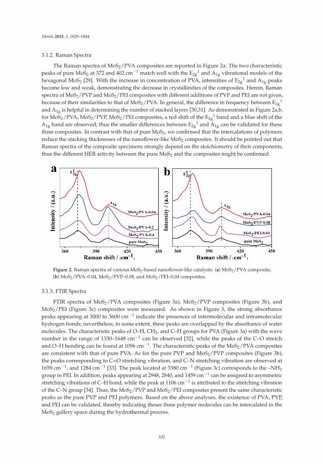
Metals 2015, 5, 1829–1844
3.1.2. Raman Spectra
The Raman spectra of MoS2/PVA composites are reported in Figure 2a. The two characteristicpeaks of pure MoS2 at 372 and 402 cm−1 match well with the E2g
1 and A1g vibrational models of thehexagonal MoS2 [29]. With the increase in concentration of PVA, intensities of E2g
1 and A1g peaksbecome low and weak, demonstrating the decrease in crystallinities of the composites. Herein, Ramanspectra of MoS2/PVP and MoS2/PEI composites with different additions of PVP and PEI are not given,because of their similarities to that of MoS2/PVA. In general, the difference in frequency between E2g
1
and A1g is helpful in determining the number of stacked layers [30,31]. As demonstrated in Figure 2a,b,for MoS2/PVA, MoS2/PVP, MoS2/PEI composites, a red shift of the E2g
1 band and a blue shift of theA1g band are observed; thus the smaller differences between E2g
1 and A1g can be validated for thesethree composites. In contrast with that of pure MoS2, we confirmed that the intercalations of polymersreduce the stacking thicknesses of the nanoflower-like MoS2 composites. It should be pointed out thatRaman spectra of the composite specimens strongly depend on the stoichiometry of their components,thus the different HER activity between the pure MoS2 and the composites might be confirmed.
Figure 2. Raman spectra of various MoS2-based nanoflower-like catalysts: (a) MoS2/PVA composite;(b) MoS2/PVA–0.04, MoS2/PVP–0.08, and MoS2/PEI–0.04 composites.
3.1.3. FTIR Spectra
FTIR spectra of MoS2/PVA composites (Figure 3a), MoS2/PVP composites (Figure 3b), andMoS2/PEI (Figure 3c) composites were measured. As shown in Figure 3, the strong absorbancepeaks appearing at 3000 to 3600 cm−1 indicate the presences of intermolecular and intramolecularhydrogen bonds; nevertheless, to some extent, these peaks are overlapped by the absorbance of watermolecules. The characteristic peaks of O–H, CH2, and C–H groups for PVA (Figure 3a) with the wavenumber in the range of 1330–1648 cm−1 can be observed [32], while the peaks of the C–O stretchand O–H bending can be found at 1096 cm−1. The characteristic peaks of the MoS2/PVA compositesare consistent with that of pure PVA. As for the pure PVP and MoS2/PVP composites (Figure 3b),the peaks corresponding to C=O stretching vibration, and C–N stretching vibration are observed at1659 cm−1, and 1284 cm−1 [33]. The peak located at 3380 cm−1 (Figure 3c) corresponds to the –NH2
group in PEI. In addition, peaks appearing at 2948, 2840, and 1459 cm−1 can be assigned to asymmetricstretching vibrations of C–H bond, while the peak at 1106 cm−1 is attributed to the stretching vibrationof the C–N group [34]. Thus, the MoS2/PVP and MoS2/PEI composites present the same characteristicpeaks as the pure PVP and PEI polymers. Based on the above analyses, the existence of PVA, PVP,and PEI can be validated, thereby indicating theses three polymer molecules can be intercalated in theMoS2 gallery space during the hydrothermal process.
102

Metals 2015, 5, 1829–1844
Figure 3. Raman and Fourier transform infrared spectroscopy (FTIR) spectra of (a) MoS2/PVA–0.04composite; (b) MoS2/PVP–0.08 composite; (c) MoS2/PEI–0.04 composite.
3.1.4. SEM Morphologies
The morphologies of the pure MoS2 and the synthesized MoS2/PVA composites are illustrated inFigure 4. All samples are assembled by the lamellar nanoflower-like MoS2 with diverse lateral sizesranging from 100 to 400 nm. With the increase in PVA addition (Figure 4b–d), large nano-size flowerswith vague edges can be found, suggesting insufficient crystallization of these composites, consistentwith the results of XRD. It should be noted that a similar tendency in the presence of PVP and PEIcan also be confirmed (Figure 5). Among the MoS2/polymer composite samples, the MoS2/PVA–0.4,MoS2/PVP–2.0 and MoS2/PEI–0.4 samples exhibit remarkable aggregations (Figures 4d and 5c,f),which may be attributed to the excessive adsorption of polymers at the surface and edge sites of theMoS2 composites. In addition, with the decrease in polymer addition, the edges of MoS2 composites(Figures 4b and 5a,d) can be easily observed, thereby indicating the high crystallinity of the samples.Therefore, a nanoflower-like MoS2 sample with a high crystallinity and small particle size can beobtained with low additions of polymers (0.04 g/g MoS2 for PVA and PEI, and 0.08 g/g MoS2 for PVP).
Figure 4. Scanning electron microscope (SEM) images of (a) pure MoS2; (b) MoS2/PVA–0.04 composite;(c) MoS2/PVA–0.08 composite; and (d) MoS2/PVA–0.4 composite.
103

Metals 2015, 5, 1829–1844
Figure 5. SEM images (a–f) of the MoS2/polymer composites synthesized at various concentrations,where a–f represent MoS2/PVP–0.08, MoS2/PVP–0.4, MoS2/PVP–2.0, MoS2/PEI–0.04, MoS2/PEI–0.2,and MoS2/PEI–0.4 composites.
3.1.5. TEM
To further elucidate the morphologies of the obtained composites, transmission electronmicroscopy (TEM) and high-resolution TEM (HRTEM) measurements were performed. From thefabricated composites, MoS2/PVA–0.04, MoS2/PVP–0.08, and MoS2/PEI–0.04 three samples wereselected for the tests. Also, the pure MoS2 sample was analyzed for comparison. As displayed inFigure 6, these samples with a diameter of about 100 nm are assembled by lamellar MoS2 powders.Nano-size flowers with a thickness of 2–5 nm can be observed, which are notably thinner than that ofthe pure MoS2 (~10 nm). The lattice inter spaces of 7.08 Å for MoS2/PVA–0.04, MoS2/PVP–0.08 andMoS2/PEI–0.04 composites are much larger than that of pure MoS2 (5.9 Å), which is also consistentwith the results of XRD. This may be attributed to the intercalations of polymers, and the interactionsbetween the oxygen-containing functional groups of the polymers and the MoS2 precursors [19]. Thus,the polymers intercalated into the MoS2 interlayer can afford a number of exposed edges for HER.
Figure 6. Transmission electron microscopy (TEM) (a–d) and high resolution transmission electronmicroscopy (HR-TEM) (e–h) of the various samples, represented for pure MoS2, MoS2/PVA–0.04,MoS2/PVP–0.08, and MoS2/PEI–0.04 composites.
104

Metals 2015, 5, 1829–1844
3.2. HER Activity of the Nanoflower-Like MoS2/Polymer
3.2.1. Linear Sweep Voltammetry (LSV)
To evaluate the catalytic activity in HER of the MoS2/polymer composite, LSV measurementswere performed in 0.5 mol·L−1 H2SO4 solution with a scanning rate of 2 mV·s−1 at room temperature.Cathodic polarization curves (Figure 7a) and corresponding Tafel plots (Figure 7d) of MoS2/PVA–0.04,MoS2/PVA–0.08, MoS2/PVA–0.4 were obtained. In comparison with the pure MoS2 sample, it canbe observed that all the MoS2/PVA composites present much lower onset overpotentials (η); amongthem, the MoS2/PVA–0.04 sample exhibits the lowest value of η (~40 mV), suggesting the excellentHER activity. The onset potentials for other MoS2/PVA composites are in the range of 180–250 mV,these values are still lower than that of the pure MoS2 (300 mV). As shown in Figure 7a, comparedwith other specimens, the MoS2/PVA–0.04 sample exhibits the largest cathodic current density of20 mA·cm−2 at (η = 250 mV), which is 80 times that of the pure MoS2 (0.25 mA·cm−2). Similarly, theenhancements in HER for MoS2/PVP and MoS2/PEI composites can also be validated (Figure 7b,c).The current densities of MoS2/PVP–0.08 and MoS2/PEI–0.04 (η = 250 mV) are 9.04 mA·cm−2 and9.60 mA·cm−2, respectively; which are 36-fold and 38-fold levels higher than that of the pure MoS2.
Figure 7. Polarization curves (a–c) and corresponding Tafel plots (d–f) of the MoS2/PVA, MoS2/PVP,MoS2/PEI composites.
It is well known that the smaller the Tafel slope of the sample, the higher the HER activity [35,36]will be. The Tafel plots (Figure 7d–f) fit the following Tafel equation:
η = b × log j + a (1)
where, η (mV) is the overpotential, and j (mA·cm−2) is the current density. The values of Tafel slope are~173, ~113, ~46, and ~39 mV·dec−1 for MoS2, MoS2/PVA–0.4, MoS2/PVA–0.2, and MoS2/PVA–0.04,which are very consistent with published reports [37,38]. Among the samples, MoS2/PVA–0.04with the smallest Tafel slope exhibits the highest HER activity. The small Tafel plot compares tothat of the other reported polymer [39]. Although Tafel slopes of MoS2/PVA–0.2, MoS2/PVA–0.4samples are larger than that of MoS2/PVA–0.04, their HER activities are still higher than that of
105

Metals 2015, 5, 1829–1844
the pure MoS2 because of their smaller Tafel slopes. Similarly, the same can be concluded forMoS2/PVP and MoS2/PEI composites. Among these two kinds of composite, the MoS2/PVP–0.08 andMoS2/PEI–0.04 samples possess notable HER activities due to smaller Tafel slopes than those of othercorresponding samples (Figure 7e,f). However, these two composites for HER activity are inferior tothe MoS2/PVA–0.04 sample.
Based on the above mentioned results, we realize that all the prepared composites present quitedifferent HER activities due to the effects of different concentrations of polymers. Considering thefeasibilities of intercalation polymers in the interlayer of MoS2 catalysts and excessive adsorption ofthem on the surface and edge sites of MoS2, the HER activities of these three kinds of compositesare reduced with increase in the additions of the polymers. Thus, the enhancement in HER fornanoflower-like MoS2 can be achieved by adjusting the polymer addition.
3.2.2. Electrochemical Impedance Spectroscopy (EIS)
The kinetics of MoS2/polymer composites in HER can be further illustrated by EIS, and theresults are reported in Figure 8. The EIS data were fitted using a modified Randles equivalent circuitshown in Scheme 1. The values of the circuit elements obtained by fitting the experimental results areshown in Table 2. Herein, a constant phase element (CPE) was adopted to model the electrical doublelayer of the electrode/electrolyte interface. The necessity of CPE in place of pure capacitance is due tothe dispersed distribution of Nyquist diagrams in the high frequency domain [40]. The double layercapacitance (Cdl) and exchange current density (i0) of the electrode were estimated using Equations (2)and (3) [41]:
Cdl = Y0 × (R−1s + R−1
ct )n−1
(2)
i0 =RT
nFRct(3)
where, Y0 (mS·s·cm−2) regarded as a capacity parameter, is the CPE coefficient; the dimensionlessCPE exponent (n) is related to the constant phase angle. Rs (Ω·cm2), and Rct (Ω·cm2) are the solutionresistance, and the charge transfer resistance, respectively.
Figure 8. Nyquist plots of MoS2-based nanoflower-like composite catalysts: (a) MoS2/PVA composite;(b) MoS2/PVP composite; (c) MoS2/PEI composite.
As indicated by Figure 8 and Table 2, compared with that of the MoS2 pure sample, theNyquist plots reveal a decrease in charge transfer resistance (Rct) (from 7.55 kΩ·cm2 to 0.84 kΩ·cm2),demonstrating the excellent conductivity of the composites (Table 2). Rct of MoS2/polymer compositesfollow the sequence of MoS2/PVA < MoS2/PEI < MoS2/PVP. Rct of the MoS2/PVA–0.04 is smallerthan that of other specimens, suggesting a faster charge transfer of this composite. The doublelayer capacitance (Cdl) is calculated to evaluate the exposed active surface area of the electrode.As shown in Table 2, MoS2/PVA–0.04 exhibits the largest Cdl compared to the other ones. Furthermore,MoS2/PVA–0.04 exhibits a significant exchange current density (i0) of 5.89 × 10⁻⁵ mA·cm−2, which is2–11 times larger than that of the other composites. The large i0 further confirms the excellent activity
106

Metals 2015, 5, 1829–1844
for HER catalysis. Thus, among the composite samples, the MoS2/PVA–0.04 composite with the lowestRct, highest Cdl and i0 provides sufficient active sites, and thereby guarantees excellent HER activity.
Rs
Rct
CPE
Scheme 1. Randles electrical equivalent circuit compatible with the Nyquist diagrams shown inFigure 8. Rs, Rct and CPE are the solution resistance, the charge transfer resistance, and a constantphase element, respectively.
Table 2. Analyzed parameters of electrochemical impedance spectroscopy (EIS) spectra for the composites.
Sample Rs/(Ω·cm2) Rct/(kΩ·cm2) Y0/(mS·s·cm−2) n Cdl/(mF·cm−2) i0/(×10−5mA·cm−2)
MoS2 6.13 7.55 0.16 0.67 0.29 0.50MoS2/PVA–0.04 4.87 0.84 1.00 0.52 2.13 5.89MoS2/PVA–0.2 5.24 1.96 0.25 0.72 0.64 1.82MoS2/PVA–0.4 5.86 6.05 0.19 0.79 0.39 0.54MoS2/PVP–0.08 5.72 2.62 0.27 0.71 0.85 1.38MoS2/PVP–0.4 6.54 3.04 0.20 0.87 0.40 0.97MoS2/PVP–2.0 7.58 6.23 0.02 0.81 0.34 0.51MoS2/PEI–0.04 6.22 1.45 0.30 0.83 0.87 2.14MoS2/PEI–0.2 6.45 2.47 0.21 0.66 0.62 1.58MoS2/PEI–0.4 5.71 6.18 0.20 0.80 0.37 0.52
Y0 regarded as a capacity parameter, is the CPE coefficient. the dimensionless CPE exponent (n) is related to theconstant phase angle. Rs and Rct are the solution resistance and the charge transfer resistance. The double layercapacitance (Cdl) and exchange current density (i0) are listed in the table.
3.3. Stability
In addition to the HER activity, stability plays a crucial role in the potential application for aMoS2-based catalyst. In order to reveal the stability of this catalyst in acidic solution, a long-termcycling test for the MoS2/PVA–0.04 composite was conducted. This test was performed with thepotential ranging from −0.25 to 0.1 V (vs. RHE) at a scan rate of 20 mV·s−1. It can be observed that thecurrent density of the composite (Figure 9) shows a slight decrease (less than 4%) after 1000 CV cycles.Thus, the MoS2/PVA–0.04 composite exhibits excellent durability in the HER process.
Figure 9. Stability test for the MoS2/PVA–0.04 composite. RHE = reversible hydrogen electrode.
107

Metals 2015, 5, 1829–1844
4. Conclusions
In this study, three kinds of MoS2/polymer composites were fabricated by a facile hydrothermalmethod. The effects of three polymers PVA, PVP, and PEI on the stacking height and the quantityof exposed active sites of the nanoflower-like MoS2 were evaluated. The intercalated or adsorbedpolymers provide carbonyl and hydroxyl functional groups for attachment of the MoS2 precursor,and enlarge the interlayer spacing of MoS2 particles. The expanded interlayers of nanoflower-likeMoS2 catalysts lead to the enhancement in active sites, resulting in a high electrocatalytic activityfor HER. Of all the composites, the MoS2/PVA–0.04 composite exhibits the best HER activity, dueto a small overpotential (~40 mV), a large cathodic current (20 mA·cm−2), and a small Tafel slope(~39 mV·dec−1).
Acknowledgments: This work was supported by the Scientific Research Foundation of the Hebei HigherEducation Institutions of China (Grant No. ZD2015120). Herein, we are also very grateful to the editors and thereviewers for giving the valuable and instructive comments.
Author Contributions: Laizhou Song designed the study. Xianwen Zeng, Lijing Niu, Xiuli Wang, XuanmingShi and Jiayun Yan performed the experiments. Xianwen Zeng, Lijing Niu and Laizhou Song wrote the paper.Xianwen Zeng, Lijing Niu, and Laizhou Song reviewed and edited the manuscript. All authors read and approvedthe manuscript.
Conflicts of Interest: The author declares no conflict of interest.
References
1. Mallouk, T.E. Water electrolysis: Divide and conquer. Nat. Chem. 2013, 5, 362–363. [CrossRef] [PubMed]2. Raimondi, F.; Scherer, G.G.; Kötz, R.; Wokaun, A. Nanoparticles in energy technology: Examples from
electrochemistry and catalysis. Angew. Chem. Int. Ed. 2005, 44, 2190–2209. [CrossRef] [PubMed]3. Liu, Y.; Kelly, T.G.; Chen, J.G.G.; Mustain, W.E. Metal carbides as alternative electrocatalyst supports.
ACS Catal. 2013, 3, 1184–1194. [CrossRef] [PubMed]4. Hinnemann, B.; Moses, P.G.; Bonde, J.; Jørgensen, K.P.; Nielsen, J.H.; Honch, S.; Chorkendorff, I.; Nørskov, J.K.
Biornimetic hydrogen evolution: MoS2 nanoparticles as catalyst for hydrogen evolution. J. Am. Chem. Soc.2005, 127, 5308–5309. [CrossRef] [PubMed]
5. Dresselhaus, M.S.; Thomas, I.L. Alternative energy technologies. Nature 2001, 414, 332–337. [CrossRef][PubMed]
6. Antolini, E. Palladium in fuel cell catalysis. Energy Environ. Sci. 2009, 2, 915–931. [CrossRef]7. Tang, H.; Dou, K.P.; Kaun, C.-C.; Kuang, Q.; Yang, S.H. MoSe2 nanosheets and their graphene hybrids:
Synthesis, characterization and hydrogen evolution reaction studies. J. Mater. Chem. A 2014, 2, 360–364.[CrossRef]
8. Chen, Z.B.; Cummins, D.; Reinecke, B.N.; Clark, E.; Sunkara, M.K.; Jaramillo, T.F. Core-shell MoO3–MoS2
nanowires for hydrogen evolution: A functional design for electrocatalytic materials. Nano Lett. 2011, 11,4168–4175. [CrossRef] [PubMed]
9. Cheng, L.; Huang, W.J.; Gong, Q.F.; Liu, C.H.; Liu, Z.; Li, Y.G.; Dai, H.J. Ultrathin WS2 nanoflakes as ahigh-performance electrocatalyst for the hydrogen evolution reaction. Angew. Chem. Int. Ed. 2014, 53,7860–7863. [CrossRef] [PubMed]
10. Vrubel, H.; Merki, D.; Hu, X. Hydrogen evolution catalyzed by MoS3 and MoS2 particles. Energy Environ.Sci. 2012, 5, 6136–6144. [CrossRef]
11. Karunadasa, H.I.; Montalvo, E.; Sun, Y.; Majda, M.; Long, J.R.; Chang, C.J. A molecular MoS2 edge site mimicfor catalytic hydrogen generation. Science 2012, 335, 698–702. [CrossRef] [PubMed]
12. Jaramillo, T.F.; Jørgensen, K.P.; Bonde, J.; Nielsen, J.H.; Horch, S.; Chorkendorff, I. Identification of activeedge sites for electrochemical H2 evolution from MoS2 nanocatalysts. Science 2007, 317, 100–102. [CrossRef][PubMed]
13. Bonde, J.; Moses, P.G.; Jaramillo, T.F.; Nørskov, J.K.; Chorkendorff, I. Hydrogen evolution on nano-particulatetransition metal sulfides. Faraday Discuss. 2009, 140, 219–231. [CrossRef]
108

Metals 2015, 5, 1829–1844
14. Liu, N.; Yang, L.C.; Wang, S.N.; Zhong, Z.W.; He, S.N.; Yang, X.Y.; Gao, Q.S.; Tang, Y. Ultrathin MoS2
nanosheets growing within an in-situ-formed template as efficient electrocatalysts for hydrogen evolution.J. Power Sources 2015, 275, 588–594. [CrossRef]
15. Zhou, T.; Yin, H.; Liu, Y.; Chai, Y.; Zhang, J.; Liu, C. Synthesis, characterization and HDS activity ofcarbon-containing Ni–Mo sulfide nano-spheres. Catal. Lett. 2010, 134, 343–350. [CrossRef]
16. Merki, D.; Vrubel, H.; Rovelli, L.; Fierro, S.; Hu, X. Fe, Co, and Ni ions promote the catalytic activity ofamorphous molybdenum sulfide films for hydrogen evolution. Chem. Sci. 2012, 3, 2515–2525. [CrossRef]
17. Jaramillo, T.F.; Bonde, J.; Zhang, J.; Ooi, B.-L.; Andersson, K.; Ulstrup, J.; Chorkendorff, I. Hydrogen evolutionon supported incomplete cubane-type [Mo3S4]4+ electrocatalysts. J. Phys. Chem. C 2008, 112, 17492–17498.[CrossRef]
18. Bian, X.J.; Zhu, J.; Liao, L.; Scanlon, M.D.; Ge, P.Y.; Ji, C.; Girault, H.H.; Liu, B.H. Nanocomposite of MoS2 onordered mesoporous carbon nanospheres: A highly active catalyst for electrochemical hydrogen evolution.Electrochem. Commun. 2012, 22, 128–132. [CrossRef]
19. Zheng, X.L.; Xu, J.B.; Yan, K.Y.; Wang, H.; Wang, Z.L.; Yang, S.H. Space-confined growth of MoS2 nanosheetswithin graphite: The layered hybrid of MoS2 and graphene as an active catalyst for hydrogen evolutionreaction. Chem. Mater. 2014, 26, 2344–2353. [CrossRef]
20. Li, Y.G.; Wang, H.L.; Xie, L.M.; Liang, Y.Y.; Hong, G.S.; Dai, H.J. MoS2 nanoparticles grown on graphene:An advanced catalyst for the hydrogen evolution reaction. J. Am. Chem. Soc. 2011, 133, 7296–7299. [CrossRef][PubMed]
21. Wang, D.Z.; Pan, Z.; Wu, Z.Z.; Wang, Z.P.; Liu, Z.H. Hydrothermal synthesis of MoS2 nanoflowers as highlyefficient hydrogen evolution reaction catalysts. J. Power Sources 2014, 264, 229–234. [CrossRef]
22. Kong, D.S.; Wang, H.T.; Cha, J.J.; Pasta, M.; Koski, K.J.; Yao, J.; Cui, Y. Synthesis of MoS2 and MoSe2 filmswith vertically aligned layers. Nano Lett. 2013, 13, 1341–1347. [CrossRef] [PubMed]
23. Tsai, C.; Pedersen, F.A.; Nørskov, J.K. Tuning the MoS2 edge-site activity for hydrogen evolution via supportinteractions. Nano Lett. 2014, 14, 1381–1387. [CrossRef] [PubMed]
24. Lukowski, M.A.; Daniel, A.S.; Meng, F.; Forticaux, A.; Li, L.S.; Jin, S. Enhanced hydrogen evolution catalysisfrom chemically exfoliated metallic MoS2 nanosheets. J. Am. Chem. Soc. 2013, 135, 10274–10277. [CrossRef][PubMed]
25. Shi, J.P.; Ma, D.L.; Han, G.-F.; Zhang, Y.; Ji, Q.Q.; Gao, T.; Sun, J.Y.; Song, X.J.; Li, C.; Zhang, Y.S.; et al.Controllable growth and transfer of monolayer MoS2 on Au foils and its potential application in hydrogenevolution reaction. ACS Nano 2014, 8, 10196–10204. [CrossRef] [PubMed]
26. Bissessur, R.; Gallant, D.; Brüning, R. Novel nanocomposite material consisting of poly[oxymethylene-(oxyethylene)] and molybdenum disulfide. Mater. Chem. Phys. 2003, 82, 316–320. [CrossRef]
27. Lin, B.-Z.; Ding, C.; Xu, B.-H.; Chen, Z.-J.; Chen, Y.-L. Preparation and characterization ofpolythiophene/molybdenum disulfide intercalation material. Mater. Res. Bull. 2009, 44, 719–723. [CrossRef]
28. Wu, Z.Z.; Fang, B.Z.; Wang, Z.P.; Wang, C.L.; Liu, Z.H.; Liu, F.Y.; Wang, W.; Alfantazi, A.; Wang, D.Z.;Wilkinson, D.P. MoS2 nanosheets: A designed structure with high active site density for the hydrogenevolution reaction. ACS Catal. 2013, 3, 2101–2107. [CrossRef]
29. Wang, H.T.; Lu, Z.Y.; Xu, S.C.; Kong, D.S.; Cha, J.J.; Zheng, G.Y.; Hsu, P.-C.; Yan, K.; Bradshaw, D.; Prinz, F.B.;et al. Electrochemical tuning of vertically aligned MoS2 nanofilms and its application in improving hydrogenevolution reaction. Proc. Natl. Acad. Sci. USA 2013, 110, 19701–19706. [CrossRef] [PubMed]
30. Lee, C.G.; Yan, H.G.; Brus, L.E.; Heinz, T.F.; Hone, J.; Ryu, S. Anomalous lattice vibrations of single andfew-layer MoS2. ACS Nano 2010, 4, 2695–2700. [CrossRef] [PubMed]
31. Yu, Y.F.; Huang, S.Y.; Li, Y.P.; Steinmann, S.N.; Yang, W.T.; Cao, L.Y. Layer-dependent electrocatalysis ofMoS2 for hydrogen evolution. Nano Lett. 2014, 14, 553–558. [CrossRef] [PubMed]
32. Peresin, M.S.; Vesterinen, A.-H.; Habibi, Y.; Johansson, L.-S.; Pawlak, J.J.; Nevzorov, A.A.;Rojas, O.J. Crosslinked PVA nanofibers reinforced with cellulose nanocrystals: Water interactions andthermomechanical properties. J. Appl. Polym. Sci. 2014. [CrossRef]
33. Prasanth, S.; Irshad, P.; Raj, D.R.; Vineeshkumar, T.V.; Philip, R.; Sudarsanakumar, C. Nonlinear opticalproperty and fluorescence quenching behavior of PVP capped ZnS nanoparticles co-doped with Mn2+ andSm3+. J. Lumin. 2015, 166, 167–175. [CrossRef]
109

Metals 2015, 5, 1829–1844
34. Popescu, L.M.; Piticescu, R.M.; Petriceanu, M.; Ottaviani, M.F.; Cangiotti, M.; Vasile, E.; Dîrtu, M.M.; Wolff, M.;Garcia, Y.; Schinteie, G.; et al. Hydrothermal synthesis of nanostructured hybrids based on iron oxide andbranched PEI polymers. Influence of high pressure on structure and morphology. Mater. Chem. Phys. 2015,161, 84–95. [CrossRef]
35. Merki, D.; Hu, X. Recent developments of molybdenum and tungsten sulfides as hydrogen evolutioncatalysts. Energy Environ. Sci. 2011, 4, 3878–3888. [CrossRef]
36. Chang, Y.-H.; Nikam, R.D.; Lin, C.-T.; Huang, J.-K.; Tseng, C.-C.; Hsu, C.-L.; Cheng, C.-C.; Su, C.-Y.; Li, L.-J.;Chua, D.H.C. Enhanced electrocatalytic activity of MoSx on TCNQ-treated electrode for hydrogen evolutionreaction. ACS Appl. Mater. Interfaces 2014, 6, 17679–17685. [CrossRef] [PubMed]
37. Xie, J.F.; Zhang, J.J.; Li, S.; Grote, F.; Zhang, X.D.; Zhang, H.; Wang, R.X.; Lei, Y.; Pan, B.C.; Xie, Y. Controllabledisorder engineering in oxygen-incorporated MoS2 ultrathin nanosheets for efficient hydrogen evolution.J. Am. Chem. Soc. 2013, 135, 17881–17888. [CrossRef] [PubMed]
38. Voiry, D.; Salehi, M.; Silva, R.; Fujita, T.; Chen, M.W.; Asefa, T.; Shenoy, V.B.; Eda, G.; Chhowalla, M.Conducting MoS2 nanosheets as catalysts for hydrogen evolution reaction. Nano Lett. 2013, 13, 6222–6227.[CrossRef] [PubMed]
39. Youssef, L.; Alain, D.; Jean-Claude, M. Electrocatalytic hydrogen evolution from molybdenumsulfide-polymer composite films on carbon electrodes. ACS Appl. Mater. Interfaces 2015, 7, 15866–15875.
40. Heli, H.; Sattarahmady, N.; Jabbari, A.; Moosavi-Movahedi, A.A.; Hakimelahi, G.H.; Tsai, F.-Y. Adsorptionof human serum albumin onto glassy carbon surface—Applied to albumin-modified electrode: Mode ofprotein-ligand interactions. J. Electroanal. Chem. 2007, 610, 67–74. [CrossRef]
41. Alcaide, F.; Brillas, E.; Cabot, P.-L. EIS analysis of hydroperoxide ion generation in an uncatalyzedoxygen-diffusion cathode. J. Electroanal. Chem. 2003, 547, 61–73. [CrossRef]
© 2015 by the authors. Licensee MDPI, Basel, Switzerland. This article is an open accessarticle distributed under the terms and conditions of the Creative Commons Attribution(CC BY) license (http://creativecommons.org/licenses/by/4.0/).
110

metals
Article
A Straightforward Route to Tetrachloroauric Acidfrom Gold Metal and Molecular Chlorine forNanoparticle Synthesis
Shirin R. King, Juliette Massicot and Andrew M. McDonagh *
School of Mathematical and Physical Sciences, University of Technology Sydney, 15 Broadway,Ultimo NSW 2007, Australia; [email protected] (S.R.K.); [email protected] (J.M.)* Author to whom correspondence should be addressed; [email protected];
Tel.: +61-2-9514-1035 (ext. 1035).
Academic Editor: Suresh BhargavaReceived: 5 June 2015; Accepted: 12 August 2015; Published: 18 August 2015
Abstract: Aqueous solutions of tetrachloroauric acid of high purity and stability were synthesisedusing the known reaction of gold metal with chlorine gas. The straightforward procedure developedhere allows the resulting solution to be used directly for gold nanoparticle synthesis. The procedureinvolves bubbling chlorine gas through pure water containing a pellet of gold. The reaction isquantitative and progressed at a satisfactory rate at 50 ◦C. The gold(III) chloride solutions producedby this method show no evidence of returning to metallic gold over at least twelve months. Thisprocedure also provides a straightforward method to determine the concentration of the resultingsolution using the initial mass of gold and volume of water.
Keywords: gold chloride; HAuCl4; chlorine; gold nanoparticles
1. Introduction
Research involving gold nanoparticles has increased significantly over the last two decades,creating with it the need for high purity gold chloride (generally in the form of tetrachloroauric acid)as a starting material for the nanoparticle synthesis. Many synthetic methods utilize aqueous solutionsof gold(III) chloride for this purpose. Although gold chloride can be purchased from commercialsuppliers, we have found that this can increase laboratory costs significantly, especially when largerquantities of gold nanoparticles are being prepared. Furthermore, solutions of gold(III) chloride can bequite unstable, rapidly returning to metallic gold unless kept under appropriate conditions (e.g., pH <4 with excess chloride ions) [1]. Here we report a straightforward method to produce highly stableaqueous solutions of gold(III) chloride using gold metal and molecular chlorine as starting materials.The method can be scaled from the millilitre scale to litre scale and requires no expensive reagents.
2Au0(s) + 3Cl2 (g) + 2HCl (aq) → 2HAuIIICl4 (aq) (1)
The reaction of metallic gold with chlorine is shown in Equation (1). This chemistry was appliedto industrial processes as early as the 19th century to dissolve gold from gold-bearing ores [2–4], andalthough chlorination was quickly replaced by cyanidation in the gold mining industry, researchinto the use of halogens, in particular chlorine, bromine and iodine, has made a resurgence in recentdecades due to environmental concerns associated with cyanide use [5,6]. A number of the industrialprocedures for ore extraction use chlorine gas injected into the reaction chamber or alternatively water
Metals 2015, 5, 1454–1461 111 www.mdpi.com/journal/metals

Metals 2015, 5, 1454–1461
that contains dissolved chlorine gas [7], while other methods employ the reaction between sodiumhypochlorite, hydrochloric acid and sodium chloride (Equation (2)) to generate chlorine gas in situ [8,9].
NaOCl (aq) + 2HCl (aq) + NaCl (aq) → 2NaCl (aq) + Cl2 (g) + H2O (l) (2)
Of course, aqua regia (formed from nitric and hydrochloric acids) has been used for centuries todissolve gold and form gold(III) chloride, but this process requires cumbersome workup procedures(such as boiling down and repeated hydrochloric acid dilution/concentration cycles to removenitric acid).
Thus, the method that we report here offers several advantages over the above-mentionedprocedures. Importantly, we show that the known reaction of gold with chlorine can be used in astraightforward method to produce high purity and highly stable gold(III) chloride solutions that canbe used directly (without further workup procedures) for gold nanoparticle synthesis. In comparisonto solutions prepared from commercially available gold(III) chloride, this method offers a significantreduction in expense, ease of concentration determination and is scalable.
2. Experimental Section
2.1. General
Gold pellets (99.99%, ~250–360 mg, AGS Metals, Sydney, Australia), hydrochloric acid (36%; RCILabscan, Pathumwan Bangkok, Thailand), potassium permanganate (BDH) and sodium thiosulfatepentahydrate (Ajax Chemicals, Sydney, Australia) were all used as received. Ultrapure Milli-Q water(Sartorius, Dandenong South, Australia; 18.2 MΩ cm) was used as the reaction solvent. UV-visiblespectra were recorded using an Agilent Technologies Cary 60 UV-Visible spectrophotometer (MulgraveVictoria, Australia) with 0.1 M aqueous HCl as the solvent. Inductively coupled plasma massspectrometry was performed with an Agilent Technologies 7500cx series ICP-MS (Mulgrave Victoria,Australia) with sample introduction via a micromist concentric nebuliser (Glass expansion) and a Scotttype double pass spray chamber cooled to 2 ◦C. The sample solution and the spray chamber wastewere carried with the aid of a peristaltic pump. ICP-MS extraction lens conditions were selected tomaximise the sensitivity of a 1% HNO3:HCl solution containing 1 ng/mL of Li, Co, Y, Ce and Tl. Goldand manganese stock solutions were obtained from Choice Analytical (Thornleigh, Australia). Baselinenitric acid (HNO3) was purchased from Seastar Chemicals Inc. (Sidney, BC, Canada). Calibrationstandards were prepared in 1% nitric acid. Oleylamine-stabilised gold nanoparticles were preparedby the literature method [10]. The concentration of chlorine in solution was measured using theiodometric titration method [11].
2.2. Synthesis of Tetrachloroauric Acid (HAuCl4)
A laboratory-scale reaction apparatus was assembled as shown in Figure 1. Hydrochloric acid(14 mL, 36%, 0.16 mol) was placed in a pressure-equalizing dropping funnel, and slowly addeddrop-wise to a side-arm flask containing potassium permanganate (3.0 g, 19 mmol). The resultingchlorine gas (see Equation (3)) was passed into a two-neck round-bottom flask containing 100 mLMilli-Q water and one pellet of gold (~250–360 mg). Undissolved/unreacted chlorine gas was bubbledthrough a solution of sodium thiosulfate (1.1 g, 7.0 mmol) in 50 mL of water. The reaction mixture wasstirred at the selected temperature (25–70 ◦C) until all of the gold dissolved. The resulting solutionof tetrachloroauric acid can be used without further treatment. UV-Vis (λmax, nm [ε, 104 M−1·cm−1]):226 (3.5), 313 (0.54).
112

Metals 2015, 5, 1454–1461
Figure 1. Apparatus for the synthesis of aqueous tetrachloroauric acid.
2KMnO4 (s) + 16HCl (aq) → 5Cl2 (g) + 2KCl (aq) + 2MnCl2 (aq) + 8H2O (l) (3)
2.3. Measurement of Reaction Times
The rate at which gold dissolved was measured by weighing the gold pellet at regular intervals.The pellet was removed from the reaction vessel using a clean glass spoon, rinsed with acetone andallowed to completely dry, and then weighed before returning to the reaction mixture. For experimentsusing flattened gold pellets, the pellets were placed between layers of cotton fabric or sheets ofpolycarbonate and mechanically pressed to a thickness of ~1 mm.
2.4. Synthesis of Citrate-Stabilised Gold Nanoparticles
The citrate method was used to synthesise aqueous gold nanoparticles from the tetrachloroauricacid synthesised as above. All glassware was cleaned with aqua regia, then rinsed and steeped inMilli-Q water prior to use. Aqueous tetrachloroauric acid (6.85 mL, 14.6 mM) was added to a 100 mLvolumetric flask and diluted with Milli-Q water to make a 1.00 mM solution. The contents of thevolumetric flask were poured into a 250 mL conical flask containing a magnetic stirrer bar, and heatedto 90 ◦C. While stirring vigorously, a freshly prepared solution of tri-sodium citrate (114 mg, 10.0 mL,38.8 mM) in Milli-Q water was quickly added to the conical flask. The solution was heated for a further15 min, allowing it to turn a deep burgundy colour, indicating the presence of small gold nanoparticles.
3. Results and Discussion
The oxidation of gold metal to form aqueous solutions of gold(III) chloride was reliably andreproducibly achieved through introduction of chlorine gas to water containing the gold metal. Thereaction is quantitative and no manganese-containing by-products (which may have arisen from thechlorine production process) were detected (see Table S1). Thus, the concentration of the gold(III)chloride solutions can be reasonably accurately calculated from the mass of the gold metal and thefinal volume of water.
The UV-visible spectrum of the resultant gold(III) chloride solution is shown in Figure 2 anddisplays the expected peaks for a solution at pH 1.05. The absorption bands at 313 and 226 nm areassigned to ligand-to-metal charge transfer [12,13]. It is important to note that the UV-visible spectrum
113

Metals 2015, 5, 1454–1461
is highly dependent on pH [14]. Therefore, accurate determination of concentrations of aqueousgold(III) chloride solutions using UV-visible spectroscopy requires an accurate determination of pH(and of course knowledge of the molar absorptivity at that particular pH).
Figure 2. UV-Vis spectrum of HAuCl4 in 0.1 M aqueous HCl.
At room temperature, the reaction proceeded at a moderate rate and the rate of reaction couldbe significantly increased by increasing the reaction temperature (Figure 3). The rate at 50 ◦C wassignificantly greater than that at room temperature and although the rate at 70 ◦C was greater thanthat at 50 ◦C, it was only marginally so. We attribute this to the reduction in solubility of chlorine gasat elevated temperatures [15].
Figure 3. Reaction times at different temperatures, expressed as the percentage remaining of the initialmass of gold as a function of time: (i) 281 mg pellet at room temperature; (ii) 268 mg pellet at 50 ◦C;(iii) 319 mg pellet at 60 ◦C; (iv) 357 mg pellet at 70 ◦C. Note: pellets were used as-received from thesupplier hence the range of masses used.
The effect of surface area of the gold pellet is also an important factor influencing reactiontimes. The data shown in Figure 3 were obtained using reasonably spherical (as purchased) goldpellets. Mechanical flattening of the gold pellets to thicknesses <1 mm resulted in significantly shorterreaction times whereby the flattened pellets dissolved in ~12 h at 50 ◦C (ca. 35 h for spherical pellets).However, care needs to be taken to prevent any metallic contamination of the gold during the flattening
114

Metals 2015, 5, 1454–1461
process. This may be accomplished by placing the gold between layers of cotton fabric or sheets ofpolycarbonate prior to the mechanical flattening process.
Figure 4. Photographs of gold(III) chloride solutions prepared by: (a) chlorine gas method; and (b) sodiumhypochlorite/hydrochloric acid method (where precipitation occurred ~2 weeks post-synthesis).
The aqueous gold(III) chloride produced by this method is quite stable; no metallic goldprecipitation was evident within at least twelve months of synthesis and the UV-visible spectrawere invariant over this time (Figure S1). The stabilisation of the gold chloride was achieved withoutthe addition of a source of excess chloride ions, such as sodium chloride, which would have made thegold chloride unusable for some nanoparticle synthesis methods due to the extreme sensitivity of manygold nanoparticles to ionic impurities [16]. The dissolved chlorine concentration of a three monthold solution kept in a tightly stoppered flask was measured by iodometric titration to be 8.9 × 10⁻³
M. This concentration is somewhat lower than the chlorine saturation concentration of 0.08 M at 20◦C [15] and comparable to previous reports of gold chloride solutions with dissolved chlorine [17–19].The solution pH was 1.6–1.8, where molecular chlorine is expected to be the predominant species [17],and well within the pH range required for gold chloride stability (<pH 4) [1]. Furthermore, theas-prepared gold(III) chloride solution can be directly freeze-dried to produce solid gold(III) chloride(note: the powder is highly hygroscopic, and must therefore be stored under strictly anhydrousconditions). In contrast, gold(III) chloride solutions prepared using sodium hypochlorite as oxidantfollowed by purification by extraction into diethyl ether, solvent removal and redissolving in purewater or dilute aqueous HCl were found to be significantly less stable over time (see Figure 4).
To test the suitability of the gold(III) chloride solutions for direct use in nanoparticle synthesis,citrate-stabilised aqueous gold nanoparticles were synthesised, which are known to be extremelysensitive to ionic impurities. The formation of the nanoparticles progressed as described in previousliterature [20], and remained in a stable colloidal suspension, confirming the high purity of the gold(III)chloride solutions produced by the chlorine gas method. We also used the gold chloride solutionas starting material to prepare organic-soluble oleylamine-stabilised gold nanoparticles [10]. Thissynthesis also proceeded as described in the literature method to yield stable nanoparticles. Scanningelectron microscope images and UV-visible spectra of the particles are shown in the SupplementaryInformation (Figures S2–S4).
4. Conclusions
Aqueous solutions of gold(III) chloride of high purity and stability can be reliably synthesisedfrom gold metal and molecular chlorine via a straightforward procedure. The reaction was foundto proceed at a satisfactory rate at 50 ◦C, and progressed at a faster rate when the gold pellets wereflattened compared to the as-purchased spherical beads.
115
Metals 2015, 5, 1454–1461
Gold(III) chloride solutions prepared by this method did not precipitate any metallic gold withinat least twelve months of synthesis. ICP-MS analysis confirmed the absence of any manganesecontamination that may have arisen from the chlorine production process, and the purity of the goldchloride solution was further demonstrated through its direct use in the synthesis of stable aqueouscitrate-stabilised as well as oleylamine-stabilised gold nanoparticles. The use of gold metal as thestarting material allows for accurate determination of the final gold(III) chloride concentration fromthe mass of gold and the volume of water.
Acknowledgments: We acknowledge Mr. Alexander Angeloski and Mr. Sanket Aggarwal for laboratory assistance.
Author Contributions: Shirin R. King: sample preparation, data analysis and writing the manuscript. JulietteMassicot: development of the process and data analysis. Andrew M. McDonagh: supervision of the first andsecond authors and writing the manuscript.
Conflicts of Interest: The authors declare no conflict of interest.
References
1. Nam, K.S.; Jung, B.H.; An, J.W.; Ha, T.J.; Tran, T.; Kim, M.J. Use of Chloride-Hypochlorite Leachants toRecover Gold from Tailing. Int. J. Miner. Process. 2008, 86, 131–140. [CrossRef]
2. Mellor, J.W. A Comprehensive Treatise on Inorganic and Theoretical Chemistry, 2nd ed.; Longmans, Green and Co.Ltd.: London, UK, 1928; Volume 3, pp. 491–618.
3. Konyratbekova, S.S.; Baikonurova, A.; Akcil, A. Non-cyanide Leaching Processes in Gold Hydrometallurgyand Iodine-Iodide Applications: A Review. Miner. Process. Extr. Metall.: Int. J. 2014, 36, 198–212. [CrossRef]
4. French, A. Process of Obtaining Gold, Silver and Copper from Ores. U.S. Pat. Off. US490193, 17 January 1893.5. La Brooy, S.R.; Linge, H.G.; Walker, G.S. Review of Gold Extraction from Ores. Miner. Eng. 1994, 7, 1213–1241.
[CrossRef]6. Syed, S. Recovery of Gold from Secondary Sources—A Review. Hydrometallurgy 2012, 115–116, 30–51.
[CrossRef]7. Kallmes, J. Improvement in Treating Gold and Silver Ores. U.S. Pat. Off. US138500, 6 May 1873.8. Puvvada, G.V.K.; Murthy, D.S.R. Selective Precious Metals Leaching from a Chalcopyrite Concentrate Using
Chloride/Hypochlorite Media. Hydrometallurgy 2000, 58, 185–191. [CrossRef]9. Simpson, C.H. Chlorination Process for Removing Precious Metals from Ore. U.S. Pat. Off. US4439235,
27 March 1984.10. Choi, H.; Chen, W.T.; Kamat, P.V. Know Thy Nano Neighbor. Plasmonic versus Electron Charging Effects of
Metal Nanoparticles in Dye-Sensitized Solar Cells. ACS Nano 2012, 6, 4418–4427. [CrossRef] [PubMed]11. Skoog, D.A.; West, D.M.; Holler, F.J. Fundamentals of Analytical Chemistry, 6th ed.; Saunders College Publishing:
Sydney, Australia, 1992; pp. 373–374.12. Carlin, R.L. Transition Metal Chemistry; Marcel Dekker, Inc.: New York, NY, USA, 1965; Volume 1, pp. 245–253.13. Gangopadhayay, A.K.; Chakravorty, A. Charge Transfer Spectra of some Gold(III) Complexes. J. Chem. Phys.
1961, 35, 2206–2209. [CrossRef]14. Peck, J.A.; Tait, C.D.; Swanson, B.I.; Brown, G.E., Jr. Speciation of Aqueous Gold(III) Chlorides from
Ultraviolet/Visible Absorption and Raman/Resonance Raman Spectroscopies. Geochim. Cosmochim. Acta1991, 55, 671–676. [CrossRef]
15. Alkan, M.; Oktay, M.; Kocakerim, M.M.; Copur, M. Solubility of Chlorine in Aqueous Hydrochloric AcidSolutions. J. Hazard. Mater. 2005, 119, 13–18. [CrossRef] [PubMed]
16. Turkevich, J. Colloidal Gold. Part II Colour, Coagulation, Adhesion, Alloying and Catalytic Properties.Gold Bull. 1985, 18, 125–131. [CrossRef]
17. Vinals, J.; Nunez, C.; Herroros, O. Kinetics of the Aqueous Chlorination of Gold in Suspended Particles.Hydrometallurgy 1995, 38, 125–147. [CrossRef]
18. Diaz, M.A.; Kelsall, G.H.; Welham, N.J. Electrowinning Coupled to Gold Leaching by ElectrogeneratedChlorine: I. Au(III)–Au(I)/Au Kinetics in Aqueous Cl2/Cl− Electrolytes. J. Electroanal. Chem. 1993, 361,25–38. [CrossRef]
116

Metals 2015, 5, 1454–1461
19. Sun, T.M.; Yen, W.T. Kinetics of Gold Chloride Adsorption onto Activated Carbon. Miner. Eng. 1993, 6, 17–29.[CrossRef]
20. Frens, G. Controlled Nucleation for the Regulation of the Particle Size in Monodisperse Gold Suspensions.Nat. Phys. Sci. 1973, 241, 20–22. [CrossRef]
© 2015 by the authors. Licensee MDPI, Basel, Switzerland. This article is an open accessarticle distributed under the terms and conditions of the Creative Commons Attribution(CC BY) license (http://creativecommons.org/licenses/by/4.0/).
117

metals
Article
Exploring the Possibilities of Biological Fabrication ofGold Nanostructures Using Orange Peel Extract
Laura Castro, María Luisa Blázquez *, Felisa González, Jesús Ángel Muñoz and Antonio Ballester
Department of Materials Science and Metallurgical Engineering, Complutense University of Madrid,Madrid 28040, Spain; [email protected] (L.C.); [email protected] (F.G.); [email protected] (J.A.M.);[email protected] (A.B.)* Author to whom correspondence should be addressed; [email protected]; Tel.: +34-91-394-4335;
Fax: +34-91-394-4357.
Academic Editors: Suresh Bhargava and Rahul RamReceived: 22 July 2015; Accepted: 6 September 2015; Published: 11 September 2015
Abstract: Development of nanotechnology requires a constant innovation and improvement in manymaterials. The exploration of natural resources is a promising eco-friendly alternative for physicaland chemical methods. In the present work, colloidal gold nanostructures were prepared usingorange peel extract as a stabilizing and reducing agent. The initial pH value of the solution and theconcentration of the gold precursor had an effect on the formation and morphology of nanoparticles.The method developed is environmentally friendly and allows control of nanoparticles. By controllingthe pH and, especially, the gold concentration, we are able to synthesize crystalline gold nanowiresusing orange peel extract in the absence of a surfactant or polymer to direct nanoparticle growth, andwithout external seeding. UV-VIS spectroscopy, transmission electron microscopy (TEM), and X-raydiffraction (XRD) were used to characterize the nanoparticles obtained by biosynthesis.
Keywords: biosynthesis; nanoparticles; gold; nanowires; orange peel extract
1. Introduction
Nanostructured materials have received considerable attention due to their unique physicaland chemical properties and their potential application [1–3]. The synthesis of nanoparticles with acontrolled shape and size is one of the most promising research areas. The excellent properties of somematerials strongly depend on crystallographic and morphological characteristics [4]. It is well-knownthat triangular nanoparticles of gold exhibit two characteristic absorption bands referred to as thetransverse (out of plane) and longitudinal (in plane) surface plasmon resonance bands. The ability totune the optical properties of the gold nanotriangles can be very useful in applications such as cancercell hyperthermia [5] and architectural optical coatings [6]. One-dimensional nanostructures have alsounusual anisotropic properties. For example, if metal nanoparticles are smaller than approximatelytens of nanometers, electrons should be confined along the diameter of long metallic nanowires.Metallic nanowires are useful to connect different components in nanodevices. Metal nanorods andnanowires are able to absorb and scatter light along the long and the short axis because they havetwo plasmon bands [7]. These structures have been used as components in flexible electronics [8] andbiological or gas sensing applications [9].
Synthesis of metal nanoparticles via chemical and physical methods has been employedin nanotechnology due to their affordability and ease of modulation in functional behavior ofnanostructures [10–12]. However, toxic effects of various chemicals and organic solvents used inphysical and chemical methods have promoted an increasing interest in biomass as a biosyntheticmachinery for the production of metal nanoparticles [13–16]. Biosynthesis of gold nanoparticles hasbeen reported using bacteria [17], yeasts [18], actinomycetes [19], fungi [20], and plants [21]. Although
Metals 2015, 5, 1609–1619 118 www.mdpi.com/journal/metals

Metals 2015, 5, 1609–1619
biological methods are regarded as safe, cost-effective, sustainable, and clean processes, they also havesome drawbacks in culturing microbes and using biomasses, which are time-consuming and difficultin providing better control over size distribution, shape, and crystallinity [22]. These are the problemsthat have plagued the biological synthesis approaches.
The use of plants in the recovery of noble metals from ore mines and runoffs is known asphytomining. Compared to the conventional chemical methods, phytomining is a cost-effective,environmentally compatible method [23]. The use of plants and its by-products as sustainableand renewable resources in the synthesis of nanoparticles is more advantageous over prokaryoticmicrobes, which need expensive methodologies for maintaining microbial cultures and downstreamprocessing [21,24].
Another dimension was added to the “green chemistry” approach for pure metal synthesis withthe use of plant broths. Synthesis of noble metal nanoparticles using plant extracts is very cost effective,and therefore can be used as an economic and valuable alternative for the large-scale fabrication ofmetal nanoparticles. Extracts from plants may act both as reducing and capping agents in nanoparticlesynthesis. The bioreduction of metal nanoparticles by combinations of biomolecules found in plantextracts (enzymes, proteins, amino acids, vitamins, polysaccharides, and organic acids, such as citrates)is environmentally benign, despite of its chemical complexity [25,26].
In this work, biosynthesis of gold nanostructures has been investigated using aqueouschloroaurate ions and orange peel extract as a clean technology to recover gold from dilute solutions.Orange peel is a residue obtained after juice extraction in the food industry. Waste orange peel iscomposed of sugars, cellulose, hemicelullose, pectin and D-limonene [27]. The morphology of thenanoparticles produced could be controlled by varying the initial pH value and the concentration ofgold ions in the reaction medium. Triangular nanoplates and nanorods were obtained at low pH andnanospheres at high pH values. Additionally, gold nanowires were produced by increasing the goldion concentration.
2. Materials and Methods
2.1. Materials
All chemical reagents including chloroauric acid (HAuCl4), sodium hydroxide flakes, andhydrochloric acid (37%) were obtained from Panreac (Barcelona, Spain).
2.2. Synthesis of Gold Nanoparticles
The experimental method consists of mixing aqueous solution of metallic precursor with orangepeel extract (9:1) and stirring the mixture. The orange peel extract was previously prepared by boilingthe dried orange peel in deionized water. Then, the extract was obtained by filtration using 0.2 μmnylon membrane filters from Whatman (Dassel, Germany). The initial pH of orange peel extract was5.0. Chloroauric acid (HAuCl4) was used as precursor. Gold nanoparticles were synthesized at roomtemperature. The influence of solution pH (2, 4, 7, and 9) was investigated in 100 mg/L (0.5 mM Au3+)of metal precursor aqueous solutions. The pH was adjusted by addition of NaOH solution and HClin Au solutions. The effect of precursor concentration to obtain gold nanowires was tested by using100 mg/L (0.5 mM Au3+), 250 mg/L (1.25 mM Au3+) and 500 mg/L Au3+ (2.5 mM Au3+).
2.3. UV-VIS Absorbance Spectroscopy Studies
The UV-VIS spectra of samples at different pH values were analyzed using a Libra S11 singlebeam spectrophotometer (Cambridge, UK) operated at a resolution of 5 nm with quartz cells. Blanksof each sample set were prepared with deionized water.
119

Metals 2015, 5, 1609–1619
2.4. TEM Measurements
The shape of the nanoparticles was observed by transmission electron microscopy (TEM). Samplesof the biosynthesized gold nanoparticles were prepared by placing drops of the product solutiononto carbon-coated copper grids and allowing the solvent to evaporate. TEM measurements wereperformed on a JEOL model JEM-2100 instrument (Tokyo, Japan) operated at an accelerating voltageof 200 kV.
2.5. X-ray Diffraction Analysis
The measurements were carried out by powder X-ray diffraction (XRD) on a Philips X’pert-MPDequipment (El Dorado County, CA, USA) with a Cu anode operating at a wavelength of 1.5406 Å asthe radiance source. Samples were placed on off-axis quartz plates (18 mm diameter × 0.5 mm DPcavity). The scanning range was from 10◦ to 60◦ 2θ with an angular interval of 0.05◦ and 4 s countingtime. The crystalline phases were identified using standard cards from the International Centre forDiffraction Data (ICDD, Newtown Square, PA, USA) Powder Diffraction File database.
3. Results
The present work was focused on the development of a biosynthetic method to control theproduction of gold nanostructures using green chemistry. For that, authors propose an efficientexploitation of wastes from food industry production. The color of gold solutions changed from paleyellow to dark blue or pink in 30 min (Figure 1). This change would be an indication of gold reductionby orange peel extract and the formation of nanoparticles. Orange peel extract contains organic acids,amino acids, and proteins, as well as the important presence of saccharides, which provides reductionpower for the nanostructures’ preparation. In order to complete the study, an attempt to develop abiosynthetic method for the production of gold nanowires using green chemistry was carried out.
0
0,2
0,4
0,6
0,8
1
1,2
1,4
450 500 550 600 650 700 750
Abso
rban
ce/ u
.a.
Wavelength/ nm
pH 2
pH 4
pH 7
pH 9
a b c d
Figure 1. UV-VIS spectra of gold nanoparticles using 100 mg/L HAuCl4 prepared at different initialpH values: pH 2, 4, 7, and 9. The inset shows the solutions corresponding to these spectra: (a) pH 2;(b) pH 4; (c) pH 7; and (d) pH 9.
120

Metals 2015, 5, 1609–1619
3.1. Biosynthesis of Gold Nanoparticles: Influence of pH
3.1.1. UV-VIS Spectral Study
It is well known that the differences in UV-VIS absorption spectra and color of solution couldbe dependent on different surrounding mediums and size, shape, and crystallinity of the metalnanoparticles. The color of chloroaurate solutions changed to pink or blue depending on the pH tested,indicating a change in metal oxidation and the formation of gold nanoparticles. As shown in the insetin Figure 1, the color of the colloidal gold solutions is a function of pH.
In all cases, a surface plasmon resonance (SPR) band absorption peak appears centered atapproximately 540 nm, which is characteristic of gold nanoparticles. At a longer wavelength, asecond band related to aggregates of spherical nanoparticles [28] or anisotropic nanostructures [29] ispresent in solutions at pH 2 and 4.
Triangular nanoparticles, nanorods, and nanowires of gold display two distinct SPR bandsreferred to as transverse and longitudinal electron oscillations. The transverse SPR band coincideswith the longitudinal SPR band of spherical gold nanoparticles. However, the longitudinal oscillationis very sensitive to the nanoparticle shape. In consequence, slight deviations from spherical shapecan lead to dramatic color changes. The longitudinal SPR band is a strong function of the edge lengthof the triangles [5]. Gold nanorods and nanowires exhibit both a band corresponding to the shortaxis and another one corresponding to the long axis at a longer wavelength. At pH 2, the absorbancecurve is practically flat in the range of 500–825 nm and the intensity is lower than at pH 4. In addition,this spectrum corresponds to the blue sample. In this case, the two peaks of the SPR bands cannotbe clearly observed due to the overlap of the longitudinal absorption of the nanorods with differentaspect ratios at relevant wavelengths [30].
At pH 7 and 9, the spectra exhibit a unique resonance wavelength at approximately 540 nmassociated to the formation of the nanospheres since all their electronic oscillations are equivalent.The band at pH 9, however, is broader indicating the polydispersity of size.
3.1.2. Characterization of Gold Nanoparticles
The morphology of the gold nanoparticles was observed by transmission electron microscopy.Figure 2 shows representative TEM images of the nanoparticles synthesized using orange peel extractat different pH values. TEM observations revealed that gold nanoparticles formed at acidic mediumwere mainly triangular, polygonal and rod-shaped nanoparticles (Figure 2a,b). The edge length ofthe rods can reach 120 nm at pH 2. When the pH was increased to 4, the size of the nanoparticlesdecreased and the length of the triangles’ edge and the rods was ~40 nm.
An increase of initial solution pH favored the formation of nanospheres. At pH 7 and 9, sphericalnanoparticles were formed (Figure 2c,d). The analysis showed that the average diameter of thenanospheres obtained at pH 7 was about 20 nm. At pH 9, there were nanoparticles with a diameter of25 nm and smaller nanoparticles of 10 nm of diameter.
EDS microanalysis and XRD of the gold nanoparticles showed that the sample was essentiallymetallic gold (Figure 3). Elemental gold peaks were found in the EDS study to confirm the nature ofthe metallic nanoparticles (Figure 3a). The structural properties of gold nanoparticles were confirmedusing XRD technique. XRD pattern showed that diffraction peaks corresponded to the diffractionplanes (111), (200), (220), (311) and (220) of face-centered cubic gold (Figure 3b).
121

Metals 2015, 5, 1609–1619
a b
c d
Figure 2. TEM images of gold nanoparticles using 100 mg/L HAuCl4 prepared at different initial pHvalues: (a) pH 2; (b) pH 4; (c) pH 7; and (d) pH 9.
keV Position [°2Theta] (Copper (Cu))
10 20 30 40 50 60 70 80
0
100
200 1331108790101
(111)
(200)
(220) (311)
(222)
200
100
010 20 30 40
Position[º2Theta] (Copper(Cu))50 60 70 80
a b
Figure 3. (a) EDS spectrum and (b) XRD pattern of gold nanoparticles.
3.2. Biosynthesis of Gold Nanowires: Influence of Gold Ion Concentration
It is already known that hydroxide ions play a key role in the production of nanowires. In spitethat the capping agent was available, competition between the biomolecules of the biomass andhydroxide ions for gold ions favored the aggregation of nanoparticles due to the lower ability ofbiomolecules to stabilize the nuclei formed. In turn, nanoparticle aggregation led to the formation ofnanowires. This process could be favored not only in the presence of hydroxide ions but also withincreasing gold ion concentration. Hence, gold nanowires production was investigated by increasingthe concentration of HAuCl4 at high pH value (pH 10).
TEM images of the samples evidenced that gold concentration has an enormous influence inthe shape and size of the gold nanoparticles synthesized using orange peel extract. As it is shownin Figure 4a, spherical nanoparticles were obtained at 100 mg/L. There were some particles with anaverage size of 42 nm and other very tiny nanoparticles of 5 nm. When the initial concentration ofgold precursor was 250 mg/L, triangular and polygonal nanoparticles were obtained and their edgescan reach up to 110 nm, and were surrounded by spherical nanoparticles with 20 nm of diameter(Figure 4b). When the gold precursor concentration was increased to 500 mg/L, nanowires with an
122

Metals 2015, 5, 1609–1619
average diameter of 30 nm were formed (Figure 4c). Figure 4d shows the fine nanostructure of onesection of the gold nanowires depicted in Figure 4c.
At the lowest initial gold concentration, the amount of capping agent was enough to stabilize thefirst particles formed in solution.
a b
c d
Figure 4. Effect of gold ions concentration. TEM images of gold nanoparticles obtained at pH 10 usingdifferent HAuCl4 concentrations: (a) 100; (b) 250; and (c) 500 mg/L; (d) detail of nanostructure of thegold nanowires.
Increasing concentration, gold nanoparticles size increased since they were not thermodynamicallystable and stuck together. At the highest concentration, gold nanowires were produced. The formationof these nanowires can be related to the Ostwald ripening effect. In Ostwald ripening, smaller particlesdissolve preferentially with subsequent crystallization onto larger particles, which involves nucleationand growth processes of larger particles from smaller ones.
4. Discussion
The green synthesis of silver and platinum nanoparticles using orange peel extract havebeen previously reported [31]. It is found that the pH value influences the morphologies of thenanostructures. The results indicated that the properties of silver and platinum nanoparticles dependstrongly on their morphologies and sizes. In general, silver nanospheres with lower diameter possesthe higher antimicrobial activity. However, silver nanowires are useful to connect different componentsin nanodevices. Small and spherical platinum nanoparticles exhibited better catalytic properties.
The biosynthesis of nanoparticles with a controlled shape and size is one of the most promisingresearch areas. Gold nanoparticles are interesting due to their applications in optoelectronic, electronic,and magnetic devices, and because of their use as catalysts and sensors. One- and two-dimensionalnanostructures for noble metals are especially attractive.
The initial pH value of the aqueous HAuCl4 solutions for different sets of samples was studied inthe synthesis of gold nanoparticles using orange peel extract. At high pH values, are spherical andmonodispersed gold nanoparticles were obtained. These nanoparticles could be used in non-toxiccarriers for drug and gene delivery applications. With these systems, the gold core imparts stability
123

Metals 2015, 5, 1609–1619
to the assembly, while the monolayer allows tuning of surface properties such as charge andhydrophobicity. An additional attractive feature of these nanoparticles is their interaction with thiols,providing an effective and selective means of controlled intracellular release [32].
The synthesis of gold nanotriangles under acidic conditions could be produced by slow reductionand crystallization. This leads to the formation of stable multiply twinned particles which evolve intogold nanotriangles due to the shape-directing effect of the constituents of the orange peel. Moreover,the difference in the growth rates of the various crystallographic planes could lead to the changesin the morphology of the nanoparticles. It can also be observed the hexagonal shapes, truncatedtriangles or icosahedral shapes. These structures with unique and highly anisotropic planer shapesmight find application in photonics, optoelectronics, and optical sensing. Applications in cancercell hyperthermia, but also the effect of different organic solvent vapors like methanol, benzene andacetone on the conductivity of tamarind leaf extract reduced gold nanotriangles, among others, havebeen investigated [33].
Gold nanorods and nanowires have usually been synthesized by electrochemical reduction withcetyltrimethylammonium bromide (CTAB) and by seed-mediated growth method using a surfactanttemplate. The synthesis of gold nanowires using biological resources has hardly ever been reported.Recently, networked nanowires were synthesized with an extract of Rhodopseudomonas capsulatamodulating the concentration of HAuCl4 [34] and gold nanowires were also obtained using sugar beetpulp by changing the pH and the gold concentration [30]. Reduction with orange peel extract is amethod to produce nanowires in the absence of surfactant or polymer to control nanoparticles growthand without externally added seed crystallites. As mentioned previously, gold is a face centeredcubic metal and its surface energies associated with different crystallographic planes are usuallydifferent. The free energies decrease in the order γ{111} > γ{100} > γ{110}, because of the package andthe distinct surface atoms density. Surfactants and capping agents can usually cap planes with {100}growth, which might lead to anisotropic growth of gold nanoparticles through {111} planes [35].The effect of the hydroxyl ions in the shape and size of the gold nanoparticles using biomass has beenpreviously reported by our group and the results showed that nanowires are produced in alkalinesolutions [30]. The explanation for this probably involves Ostwald ripening and the capping action ofthe biomolecules. The biomolecules of the orange peel extract were insufficient to stabilize completelygold nuclei. The first gold nanoparticles formed were thermodynamically unstable due to their smallsize and the insufficient amount of capping agent. The uncovered face of gold nanoparticles couldorientate against each other through dipole-dipole interaction of biomolecules and the intermolecularhydrogen bounding interaction of biomolecules and hydroxide ions could act as possible driving forcesfor the formation of 1D assembly. In addition, the surface energy of larger particles is lower than thatof smaller ones [36]. The nanoparticles grew and joined together because of their Brownian motion inthe solution, forming wire-like structures. The end of these nanorods may be bounded by {111} facetswhose interaction with OH− and with biomolecules is very weak and, thus, reactive to the new atomsformed [37]. The weak complexing agent allows the deposition of newly reduced gold atoms and theysinter together and form larger agglomerates of gold (nanowires).
5. Conclusions
Reduction of tetrachloroaurate with orange peel extract is a simple, conducted at roomtemperature, efficient, and a clean method to synthesize gold nanostructures from dilutehydrometallurgical solutions. Advantages over other biological methods include the reuse of industrywastes, easy handling and scalability. In addition, one- and two-dimensional nanostructures for noblemetals are especially attractive.
The key points for nanowires production are: competition between hydroxide ion andbiomolecules for gold ions, shortage of biomolecules to cap the nanoparticles and preferentialadsorption of AuCl4− on the gold nanoparticles surface.
124

Metals 2015, 5, 1609–1619
Acknowledgments: The authors are grateful for the financial support given by the Spanish Ministry of Economyand Competitiveness to fund this work. We acknowledge Juan Luis Bardonado from the Electronic MicroscopyCentre of UCM for their technical assistance.
Author Contributions: L. Castro mainly performed the present study and wrote the paper. M.L. Blázquez, F.González, J.A. Muñoz and A. Ballester provided advice and recommendations on the research and polishingof the paper.
Conflicts of Interest: The authors declare no conflict of interest.
References
1. Gao, S.; Li, W.; Cao, R. Palladium-pyridyl catalytic films: A highly active and recyclable catalyst forhydrogenation of styrene under mild conditions. J. Colloid Interface Sci. 2015, 441, 85–89. [CrossRef][PubMed]
2. Moghadam, A.H.; Dashtizad, V.; Kaflou, A.; Yoozbashizadeh, H.; Ashiri, R. Development of a nanostructuredZr3Co intermetallic getter powder with enhanced pumping characteristics. Intermetallics 2015, 57, 51–59.[CrossRef]
3. Jin, Y.; Jia, M. Design and synthesis of nanostructured graphene-SnO2-polyaniline ternary composite andtheir excellent supercapacitor performance. Colloids Surf. A Physicochem. Eng. Asp. 2015, 464, 17–25.[CrossRef]
4. Liz-Marzán, L.M. Nanometals: Formation and color. Mater. Today 2004, 7, 26–31. [CrossRef]5. Chandran, S.P.; Chaudhary, M.; Pasricha, R.; Ahmad, A.; Sastry, M. Synthesis of Gold Nanotriangles and
Silver Nanoparticles Using Aloevera Plant Extract. Biotechnol. Prog. 2006, 22, 577–583. [CrossRef] [PubMed]6. Shankar, S.S.; Rai, A.; Ahmad, A.; Sastry, M. Controlling the Optical Properties of Lemongrass Extract
Synthesized Gold Nanotriangles and Potential Application in Infrared-Absorbing Optical Coatings.Chem. Mater. 2005, 17, 566–572. [CrossRef]
7. Murphy, C.J.; Gole, A.M.; Hunyadi, S.E.; Orendorff, C.J. One-Dimensional Colloidal Gold and SilverNanostructures. Inorg. Chem. 2006, 45, 7544–7554. [CrossRef] [PubMed]
8. Vuillaume, D. Molecular-scale electronics. Comptes Rendus Phys. 2008, 9, 78–94. [CrossRef]9. Jo, S.Y.; Kang, B.R.; Kim, J.T.; Ra, H.W.; Im, Y.H. The synthesis of single PdAu bimetallic nanowire: Feasibility
study for hydrogen sensing. Nanotechnology 2010. [CrossRef] [PubMed]10. Mikkelsen, K.; Cassidy, B.; Hofstetter, N.; Bergquist, L.; Taylor, A.; Rider, D.A. Block Copolymer Templated
Synthesis of Core-Shell PtAu Bimetallic Nanocatalysts for the Methanol Oxidation Reaction. Chem. Mater.2014, 26, 6928–6940. [CrossRef]
11. Xiao, A.; Zhou, S.; Zuo, C.; Zhuan, Y.; Ding, X. Electrodeposited porous metal oxide films with interconnectednanoparticles applied as anode of lithium ion battery. Mater. Res. Bull. 2014, 60, 864–867. [CrossRef]
12. Biswas, A.; Bayer, I.S.; Biris, A.S.; Wang, T.; Dervishi, E.; Faupel, F. Advances in top-down and bottom-upsurface nanofabrication: Techniques, applications & future prospects. Adv. Colloid Interface Sci. 2012, 170,2–27. [PubMed]
13. Castro, L.; Blázquez, M.L.; González, F.; Muñoz, J.A.; Ballester, A. Extracellular biosynthesis of goldnanoparticles using sugar beet pulp. Chem. Eng. J. 2010, 164, 92–97. [CrossRef]
14. Castro, L.; Blazquez, M.L.; Munoz, J.A.; Gonzalez, F.; Ballester, A. Biological synthesis of metallicnanoparticles using algae. IET Nanobiotechnol. 2013, 7, 109–116. [CrossRef] [PubMed]
15. Syed, A.; Saraswati, S.; Kundu, G.C.; Ahmad, A. Biological synthesis of silver nanoparticles using the fungusHumicola sp. and evaluation of their cytoxicity using normal and cancer cell lines. Spectrochim. Acta A Mol.Biomol. Spectrosc. 2013, 114C, 144–147. [CrossRef] [PubMed]
16. Husseiny, M.I.; El-Aziz, M.A.; Badr, Y.; Mahmoud, M.A. Biosynthesis of gold nanoparticles usingPseudomonas aeruginosa. Spectrochim. Acta A Mol. Biomol. Spectrosc. 2007, 67, 1003–1006. [CrossRef][PubMed]
17. Rösken, L.; Körsten, S.; Fischer, C.; Schönleber, A.; van Smaalen, S.; Geimer, S.; Wehner, S. Time-dependentgrowth of crystalline Au0-nanoparticles in cyanobacteria as self-reproducing bioreactors: 1. Anabaena sp.J. Nanopart. Res. 2014, 16, 1–14. [CrossRef]
18. Agnihotri, M.; Joshi, S.; Kumar, A.R.; Zinjarde, S.; Kulkarni, S. Biosynthesis of gold nanoparticles by thetropical marine yeast Yarrowia lipolytica NCIM 3589. Mater. Lett. 2009, 63, 1231–1234. [CrossRef]
125

Metals 2015, 5, 1609–1619
19. Bansal, V.; Bharde, A.; Ramanathan, R.; Bhargava, S.K. Inorganic materials using “unusual” microorganisms.Adv. Colloid Interface Sci. 2012, 179–182, 150–168. [CrossRef] [PubMed]
20. Gade, A.; Ingle, A.; Whiteley, C.; Rai, M. Mycogenic metal nanoparticles: Progress and applications.Biotechnol. Lett. 2010, 32, 593–600. [CrossRef] [PubMed]
21. Iravani, S. Green synthesis of metal nanoparticles using plants. Green Chem. 2011, 13, 2638–2650. [CrossRef]22. Grzelczak, M.; Perez-Juste, J.; Mulvaney, P.; Liz-Marzan, L.M. Shape control in gold nanoparticle synthesis.
Chem. Soc. Rev. 2008, 37, 1783–1791. [CrossRef] [PubMed]23. Narayanan, K.B.; Sakthivel, N. Green synthesis of biogenic metal nanoparticles by terrestrial and aquatic
phototrophic and heterotrophic eukaryotes and biocompatible agents. Adv. Colloid Interface Sci. 2011, 169,59–79. [CrossRef] [PubMed]
24. Zheng, B.; Kong, T.; Jing, X.; Odoom-Wubah, T.; Li, X.; Sun, D.; Lu, F.; Zheng, Y.; Huang, J.; Li, Q.Plant-mediated synthesis of platinum nanoparticles and its bioreductive mechanism. J. Colloid Interface Sci.2013, 396, 138–145. [CrossRef] [PubMed]
25. Gericke, M.; Pinches, A. Biological synthesis of metal nanoparticles. Hydrometallurgy 2006, 83, 132–140.[CrossRef]
26. Duran, N.; Marcato, P.D.; Duran, M.; Yadav, A.; Gade, A.; Rai, M. Mechanistic aspects in the biogenicsynthesis of extracellular metal nanoparticles by peptides, bacteria, fungi, and plants. Appl. Microbiol.Biotechnol. 2011, 90, 1609–1624. [CrossRef] [PubMed]
27. Balu, A.M.; Budarin, V.; Shuttleworth, P.S.; Pfaltzgraff, L.A.; Waldron, K.; Luque, R.; Clark, J.H. Valorisationof orange peel residues: Waste to biochemicals and nanoporous materials. ChemSusChem 2012, 5, 1694–1697.[CrossRef] [PubMed]
28. Schwartzberg, A.M.; Grant, C.D.; van Buuren, T.; Zhang, J.Z. Reduction of HAuCl4 by Na2S Revisited: TheCase for Au Nanoparticle Aggregates and Against Au2S/Au Core/Shell Particles. J. Phys. Chem. C 2007, 111,8892–8901. [CrossRef]
29. Kelly, K.L.; Coronado, E.; Zhao, L.L.; Schatz, G.C. The Optical Properties of Metal Nanoparticles:The Influence of Size, Shape, and Dielectric Environment. J. Phys. Chem. B 2002, 107, 668–677. [CrossRef]
30. Castro, L.; Blázquez, M.L.; Muñoz, J.A.; González, F.; García-Balboa, C.; Ballester, A. Biosynthesis of goldnanowires using sugar beet pulp. Process Biochem. 2011, 46, 1076–1082. [CrossRef]
31. Castro, L.; Blázquez, M.L.; González, F.; Muñoz, J.Á.; Ballester, A. Biosynthesis of silver and platinumnanoparticles using orange peel extract: Characterisation and applications. IET Nanobiotechnol. 2015.[CrossRef]
32. Ghosh, P.; Han, G.; De, M.; Kim, C.K.; Rotello, V.M. Gold nanoparticles in delivery applications. Adv. DrugDeliv. Rev. 2008, 60, 1307–1315. [CrossRef] [PubMed]
33. Ankamwar, B.; Chaudhary, M.; Sastry, M. Gold Nanotriangles Biologically Synthesized using Tamarind LeafExtract and Potential Application in Vapor Sensing. Synth. React. Inorg. Met.-Org. Nano-Met. Chem. 2005, 35,19–26. [CrossRef]
34. He, S.; Zhang, Y.; Guo, Z.; Gu, N. Biological synthesis of gold nanowires using extract of Rhodopseudomonascapsulata. Biotechnol. Prog. 2008, 24, 476–480. [CrossRef] [PubMed]
35. Lin, X.; Wu, M.; Wu, D.; Kuga, S.; Endo, T.; Huang, Y. Platinum nanoparticles using wood nanomaterials:Eco-friendly synthesis, shape control and catalytic activity for p-nitrophenol reduction. Green Chem. 2011, 13,283–287. [CrossRef]
36. Wang, Y.; Chen, L.Q.; Li, Y.F.; Zhao, X.J.; Peng, L.; Huang, C.Z. A one-pot strategy for biomimetic synthesisand self-assembly of gold nanoparticles. Nanotechnology 2010. [CrossRef] [PubMed]
37. Johnson, C.J.; Dujardin, E.; Davis, S.A.; Murphy, C.J.; Mann, S. Growth and form of gold nanorods preparedby seed-mediated, surfactant-directed synthesis. J. Mater. Chem. 2002, 12, 1765–1770. [CrossRef]
© 2015 by the authors. Licensee MDPI, Basel, Switzerland. This article is an open accessarticle distributed under the terms and conditions of the Creative Commons Attribution(CC BY) license (http://creativecommons.org/licenses/by/4.0/).
126

metals
Article
Preparation of Potassium Ferrate from Spent SteelPickling Liquid
Yu-Ling Wei *, Yu-Shun Wang and Chia-Hung Liu
Department of Environmental Science and Engineering, Tunghai University, Taichung 40704, Taiwan;[email protected] (Y.-S.W.); [email protected] (C.-H.L.)* Author to whom correspondence should be addressed; [email protected]; Tel.: +886-4-2359-1368;
Fax: +886-4-2359-6858.
Academic Editors: Suresh Bhargava and Rahul RamReceived: 31 July 2015; Accepted: 18 September 2015; Published: 24 September 2015
Abstract: Potassium ferrate (K2FeO4) is a multi-functional green reagent for water treatment withconsiderable combined effectiveness in oxidization, disinfection, coagulation, sterilization, adsorption,and deodorization, producing environment friendly Fe(III) end-products during the reactions. Thisstudy uses a simple method to lower Fe(VI) preparation cost by recycling iron from a spent steelpickling liquid as an iron source for preparing potassium ferrate with a wet oxidation method. Therecycled iron is in powder form of ferrous (93%) and ferric chlorides (7%), as determined by X-rayAbsorption Near Edge Spectrum (XANES) simulation. The synthesis method involves three steps,namely, oxidation of ferrous/ferric ions to form ferrate with NaOCl under alkaline conditions,substitution of sodium with potassium to form potassium ferrate, and continuously washingimpurities with various organic solvents off the in-house ferrate. Characterization of the in-houseproduct with various instruments, such as scanning electron microscopy (SEM), ultraviolet-visible(UV-Vis), X-ray diffraction (XRD), and X-ray absorption spectroscopy (XAS), proves that productquality and purity are comparative to a commercialized one. Methylene blue (MB) de-colorizationtests with in-house potassium ferrate shows that, within 30 min, almost all MB molecules arede-colorized at a Fe/carbon mole ratio of 2/1.
Keywords: potassium ferrate; wet oxidation method; steel pickling liquid; ferrous chloride; ferricchloride; Fe k-edge XAS
1. Introduction
1.1. Environmental Application of Potassium Ferrate
Potassium ferrate (K2FeO4) is a potent oxidant. Under acidic and alkaline conditions, its respectivereduction potentials are 2.20 and 0.700 V, being a potential for replacing traditional oxidants, such asozone, hypochlorite, permanganate, and others [1]; their respective half-cell reduction potentials inacidic conditions are 2.08, 1.48, and 1.69 V, respectively [2], all less than Fe(VI). Potassium ferrate, otherthan acting as a powerful oxidant, can be an inorganic coagulant when chemically reduced to Fe(OH)3;it can effectively remove suspended solids, heavy metals, and a variety of contaminants in water [3–7].Further, using traditional oxidants to treat pollutants/contaminants usually can result in a noteworthytoxic byproduct problem, such as tri-halo-methane and bromates [8]. In contrast, potassium ferrate, asa water treatment agent, is reduced to environment friendly Fe(OH)3 [3,9–13]. Prior to the chlorinationprocess for drinking water, using Fe(VI) as a pre-treatment agent can effectively reduce the formationof hazardous by-products [14,15].
Despite the advantages Fe(VI) can provide, it is expensive for using it to treat pollutants andcontaminants. Synthesizing Fe(VI) by using spent steel pickling liquid as an iron source can achieve a
Metals 2015, 5, 1770–1787 127 www.mdpi.com/journal/metals

Metals 2015, 5, 1770–1787
dual-win benefit by not only reducing the cost of Fe-source raw chemicals for Fe(VI) synthesis but alsorecycling spent steel pickling liquid for sustainable spirits. Currently, the annual output rate of spentsteel pickling liquid is approximately 150,000 tons in Taiwan [16], and it is considered hazardous dueto its high content of various toxic metals that may be a constraint on preparation of Fe(VI) from thepickling liquid.
1.2. Source of Spent Pickling Liquid
Spent pickling liquid is unwantedly produced by the steel industry. Products like steel plates,pipes, and coils always require cleaning with acid to remove their surface impurities before beingsubjected to further processing. The impurities include black surfaces, iron oxides, and othercontaminants. Hydrochloric acid is usually used as the pickling acid for carbon steel products due toits relatively lower price, lower acid consumption rate, and providing a faster pickling process, despiteits shortcomings of a larger volatilization rate [17,18].
If spent pickling liquid is treated as waste water, toxic metal present in it is generally removedthrough different approaches, such as precipitation method, ion exchange, and others. Among them,precipitation as hydroxide is the most often used technology. Although the technology is technicallysimple, its neutralization step requires a large amount of alkaline- or alkaline earth-based chemicals,and it would be much more praised if spent steel pickling liquid can be recycled.
When hydrochloric acid is used as pickling agent, most iron in spent steel pickling liquid wouldbe present in a form of ferrous chloride through the following chemical reaction [17]:
FeO + 2HCl → FeCl2 + H2O (1)
1.3. Fe(VI) Preparation with Wet Oxidation Method
Oxidants used for Fe(VI) preparation in previous studies include hypochlorite, Cl2, and ozone [19].Among them, ozone is the most powerful [19]. However, this study uses hypochlorite due to its relativeease in laboratory handling. Yet, in our further study, utilization of ozone for Fe(VI) preparation fromspent pickling liquid is worthy of study. Theoretically, with the use of hypochlorite, Fe(III) can beoxidized to Na2FeO4 in strong basic solution. After adding saturated KOH solution to replace thesodium of Na2FeO4, potassium ferrate precipitate can then be formed, separated, washed with organicsolvents, and de-watered. Below are the associated chemical reactions [20].
Fe3+ + 3OH− → Fe(OH)3 (2)
2Fe(OH)3 + 3NaClO + 4NaOH → 2Na2FeO4 + 3NaCl + 5H2O (3)
Na2FeO4 + 2KOH → K2FeO4 + 2NaOH (4)
Both the purity and yield of potassium ferrate is affected by the types of oxidants and ironprecursors used for its preparation. In general, the use of hypochlorite (OCl−) can lead to more yieldand higher purity, as compared to that using chlorine. As to iron source, ferric nitrate Fe(NO3)3·9H2Ois more expensive than ferric chloride, which can result in a more rapid synthesis rate and more yieldthan ferric chloride. As this study intends to recover the spent steel pickling liquid as raw material forpotassium ferrate synthesis, there will be no other choice in the aspect of the identity of iron source.
One more thing that needs consideration is what kinds of organic solvents ought to be used forwashing crude product potassium ferrate. Organic solvents can barely dissolve potassium ferrate, andtheir function is to remove the impurities, such as moisture content, KNO3, KCl, KOH, and others.
During the purification step, n-pentane or benzene was used to replace the moisture content incrude potassium ferrate. Methanol or ethanol was employed to dissolve hydroxides, chlorides, nitratesand other impurities. Diethyl ether could speed up the drying process of crude product. The use of
128

Metals 2015, 5, 1770–1787
inert solvents to remove moisture from crude products is critical. Otherwise, ferrate will be readilyreduced to Fe(OH)3, losing its purity grade [21].
For this study, n-pentane, rather than benzene, was used due to its lower toxicity and cheaper price.The prices for n-pentane and benzene are 80.6 and 96.1 US dollar L−1, respectively. The disadvantageof using n-pentane is its lower boiling point (36.1 ◦C) compared to benzene (80.1 ◦C); this fact impliesa greater loss of n-pentane if a pilot-scale or full-scale device is to be set up for this purification process,unless it is a closed process. Methanol was chosen, instead of ethanol, because of its cheaper price andgreater effectiveness in removing hydroxides, chlorides, nitrates and other impurities [21]. The priceratio of methanol to ethanol is approximately 1/4 and their respective boiling points are 64.7 and78.4 ◦C. Diethyl ether will be used to speed up de-moisture rate of crude product.
1.4. Stability of Fe(VI)
Fe(VI) is very unstable, readily snatching three electrons from neighboring water and beingreduced to a more stable form, Fe(III). Solid-phase hexavalent iron is more stable than aqueous iron.It can be stored with negligible reduction reaction for a long time when it is stored in such a way thatkeeps off the contact of moisture and atmospheric air [22]. When exposed to moisture and atmosphere,it readily reacts with water forming Fe(OH)3, oxygen, and potassium hydroxide. The reductionproceeds as follows [22]:
4K2FeO4 + 10H2O → 4Fe(OH)3 + 3O2 (g) + 8KOH (5)
1.5. Quantification of Fe(VI)
A few methods can be used for quantitative determination of Fe(VI); they include electrochemical,volumetric, and various spectrophotometric methods [23,24]. Among them, UV-Vis spectral methodoffers simple steps, rapid experimental work, and accurate outcome [24]. Therefore, this study choosesto use UV-Vis spectral method for determining Fe (VI) concentration and purity. It is briefly describedas follows.
Determination of Fe(VI) concentration in water with UV-Vis absorbance is based on Beer’s law.Fe(VI) ions in water appears dark purple with an absorbance maximum peak at 505 nm, and its molarabsorbance coefficient (ε) was determined to be 1070 M−1 cm−1 [23]; accordingly, the concentration ofFe(VI) can be calculated using the following equation:
ε = A/BC (6)
where the notation “ε” equals 1070 M−1 cm−1 (molar absorbance coefficient), “A” is UV-Vis absorbanceby sample, “B” represents Fe(VI) concentration (M) in the examined sample, and “C” is light path (cm)of the quartz cell used in this study.
For determining Fe(VI) purity of the in-house ferrate prepared in the present study, a properamount of the product was dissolved in 0.100-L de-ionized water, centrifuged for 10 min at 4000 roundsper minute (centrifuge, Allegra 21/R, Beckman Coulter, Brea, CA, USA), and the top clear solution wasmeasured with a UV-Vis spectrometer (UV-2450, Shimadzu Corporation, Tokyo, Japan). In addition,purity of the product in weight percentage can be calculated using the equation below. It has to benoted that molecular weight of K2FeO4 is 198.04 g mole−1:
K2FeO4 purity =A
1070× 0.1 × 198.04
weight of sample× 100% (7)
129

Metals 2015, 5, 1770–1787
2. Materials and Methods
2.1. Materials
The spent steel pickling liquid was provided by a local steel plant that uses hydrochloric acidto clean its carbon steel surface. It contains 133 g L−1 Fe ions and 351 g L−1 Cl−, respectively.The chemicals used in this study are summarized in Table 1.
Table 1. Chemicals used in this study.
Chemical Purity Producer
Fe(NO3)3·9H2O 98%–101% (reagent grade) JT Baker, Center Valley, PA, USAn-C5H12 99% (reagent grade) Merck, Darmstadt, GermanyC2H5OH 96% (reagent grade) Merck, Germany.(C2H5)2O 99.5% (reagent grade) Merck, Germany
FeCl2·4H2O 98% (reagent grade) Sigma-Aldrich, St. Louis, MO,USA
FeCl3·6H2O 97% (reagent grade) Sigma-Aldrich, USAKOH 85% (reagent grade) Sigma-Aldrich, USA
NaOH 99% (reagent grade) Sigma-Aldrich, USANaOCl solution 6%–14% (reagent grade) Sigma-Aldrich, USA
K2FeO4 purity ≥ 90% Sigma-Aldrich, USAMB 100% Sigma-Aldrich, USA
2.2. Synthesis Flowchart for K2FeO4
Because the spent pickling liquid used here is very rich in Fe and Cl ions, 133 g L−1 and 351 g L−1,respectively, a simple drying process on a 85 ◦C hot plate can readily vaporize its water content. Thesolid derived from spent pickling liquid contains FeCl2·4H2O as the major iron species representingapproximately 93%, balanced by 7% FeCl3·6H2O on mole basis. The iron speciation was determined byFe k-edge X-ray absorption near edge spectrum (XANES) simulation, and the details will be describedbelow in Section 2.4.
K2FeO4 was synthesized using the derived solid as a raw material and the synthesis flowchart isdepicted in Figure 1. Briefly, first, 20 g NaOH and 30 mL 6%–14% NaOCl were mixed for one hour at astirring speed of 800 rpm, and un-dissolved NaOH solid was filtered off and the filtrate was retainedand mixed/reacted (stirring at 800 rpm) for 150 min with 2 g of the derived solid. Second, after thecentrifuging and solid/liquid separation, liquid solution was mixed with 20 mL saturated KOH, stirredat 800 rpm for 20 min, centrifuged, and solid/liquid separated. The resulting solid material was addedinto 10 mL 6.0 M KOH. Third, after a centrifuging process at 3500 rpm for 10 min and solid/liquidseparation, the liquid portion was added into an icy-cold 20 mL saturated KOH. Finally, this mixturewas filtrated and the resulting crude potassium ferrate was subjected to consecutive washing usingeach of 0.5 mL n-pentane, methyl alcohol, and ethyl ether in approximately 2 min. The solid on filterpaper was then dried in a vacuum oven (VO-2000, Pan-Chum Co., Taipei, Taiwan) under a pressure <30 mm Hg at room temperature for one hour to produce dry, purified K2FeO4 product.
2.3. Crystalline Phase Study with XRD
X-ray diffractometer (XRD, D8 Advance, Bruker AXS, Karlsruhe, Germany) using a copper targetwas operated at a voltage of 30 kV and a current of 20 mA. X-ray wavelength generated is 1.54056 Å.Sample scanning angle (2θ) is 20◦–80◦ with a scanning rate of 3 deg min−1. Diffraction patternswere identified by comparing them with the database compiled by The Joint Committee on PowderDiffraction Standards (JCPDS).
130

Metals 2015, 5, 1770–1787
Figure 1. Flowchart for synthesizing in-house potassium ferrate.
131

Metals 2015, 5, 1770–1787
2.4. Molecular Study of Potassium Ferrates
X-ray absorption spectroscopy is a non-destructive physical method. Generally, an X-rayabsorption spectroscopy (XAS) spectrum can be divided into two parts. The first part is X-rayAbsorption Near Edge Spectrum (XANES) for probing electronic properties of target atoms, such asoxidation state and electron occupancy of its d-orbitals. The second part is Extended X-ray AbsorptionFine Structure (EXAFS) that can be Fourier transformed and simulated to reveal the knowledge of localgeometry of coordination atoms, such as atomic type, coordination number (N), interatomic distance(R), and disorder level of coordination atoms (σ2).
XAS spectra were recorded on the 16A and Wiggler C (BL-17C) beamlines of National SynchrotronRadiation Center, Hsinchu, Taiwan. During the recording period, its electron storage ring energywas 1.5 GeV, current was 300 mA, and its energy range was 2–14.2 keV. The k-edge edge jump of ironis at 7.112 keV. XAS data analysis was carried out using WinXAS 3.1 software [25] ([email protected],Thorsten Ressler, Hamburg, Germany). The software can be used to simulate a sample XANESspectrum by linearly combining various standard spectra to quantify component species, based onthe least-squares principle from the fingerprints in their XANES spectra [25]. For each standardcompound used, two parameters, energy correction and partial mole fraction, are determined. At endof the refining process, standards with a negative mole fraction and/or unreasonable energy shiftindicate their absence from the sample [25]. In the present study, XANES spectra from reagent gradeFeCl2·4H2O and FeCl3·6H2O were recorded and used as standards to simulate the experimentalspectrum from dry solid derived from spent pickling liquid.
3. Results and Discussion
3.1. Characteristics of Spent Steel Pickling Liquid
3.1.1. pH and Density of Pickling Liquid
Hydrochloric acid was employed by the steel plant for pickling its steel product. The spentpickling liquid has a pH of <1 and a density of 1.40 kg L−3. The high density is due to its large contentsof Fe and Cl.
3.1.2. Composition of Spent Steel Pickling Liquid
Table 2 shows that the pickling liquid contains many kinds of toxic metals with their concentrationsbeing considerably higher than wastewater legal thresholds. The toxic metals include Cr, Bi, Tl, Cd,Co, Cu, Ni, Pb, and Zn. Fe and Cl are the most abundant components, with Mn and Ca (respectively,1.386 and 1.551 g L−1) being the second most abundant elements. Generally, when Fe content insteel pickling liquid reaches 70–100 g L−1, the liquid is disqualified for further pickling process inthe steel industry [17]. The spent pickling liquid (Table 2) has apparently been over-used with an Fecontent of 133 g L−1. Because the sum of Fe and Cl, 485 g L−1, accounts for one third of the weightof 1.0 L pickling liquid (i.e., 1.4 kg), only a small amount of heat is required for vaporizing its liquidcomponents, including water and HCl. The pickling liquid was dried on a 85 ◦C hot plate. Please notethat, practically, the HCl can be recovered with a cooling system if desired, but such recovery is not theobjective of the present study, rather, at present we are more focusing on investigating the technicalfeasibility of using the recovered solid iron chloride(s) as a raw material for preparing potassiumferrate. In contrast, direct use of the pickling liquid in potassium ferrate synthesis would alter therequired pH value of the solution containing 20 g NaOH and 30 mL NaOCl, as depicted in Figure 1.
132

Metals 2015, 5, 1770–1787
Table 2. Chemical compositions of spent steel pickling liquid.
Compositional Element Content (mg L−1) Spike Recovery d (%)
Cr a 3.63 ± 0.23 (24 ± 1.2)Bi a 46.48 ± 0.95 (31 ± 4)Ag a 6.86 ± 0.07 (25 ± 3.6)Al a 6.73 ± 0.04 (76 ± 2)Tl a 60.15 ± 0.13 (52 ± 3.1)Ca b 1552 ± 0.3 (97 ± 2.5)Cd a 3.08 ± 0.02 (30 ± 2.4)Co a 5.10 ± 0.036 (31 ± 2.5)Cu a 39.15 ± 0.085 (78 ± 1.4)Fe b 133,000 ± 2160 (89 ± 1.2)K a 7.69 ± 0.00 (111 ± 3.7)
Mg a 65.28 ± 0.07 (56 ± 2.6)Mn a 1387 ± 1 (73 ± 0.2)Na b 256.3 ± 1.4 (87 ± 4)Ni a 19.72 ± 0.10 (30 ± 4.1)Pb a 15.08 ± 0.60 (23 ± 2.6)Zn b 188.6 ± 2.1 (91 ± 2.5)Cl c 351,500 ± 3100 (88 ± 3.3)
a using an inductively coupled plasma atomic emission spectrometer (ICP-AES, Profile plus, Teledyne LeemanLabs, Hudson, NH, USA) to measure metal concentrations after microwave-assisted digestion; b using a flameatomic absorption spectrophotometer (FAAS, Z-6100, Hitachi, Tokyo, Japan) to measure metal concentrations aftermicrowave-assisted digestion; c the total amount Cl ion was measured with an ion chromatographer (IC, DX-100,Dionex, Thermal Fisher Scientific, Sunnyvale, CA, USA); d the steps are described as follows. First, the picklingliquid was digested with a microwave digester (MWS-4, Berghof Laborprodukte GmbH, Eningen Germany) at 180◦C; metallic ion concentration in the digest was approximately measured with ICP/atomic emission spectrometer orflame atomic absorption spectrometer. Then, exactly 0.5 to 5 times the amount of the approximate ion concentrationswere added to the spent steel pickling liquid and ionic concentrations were re-measured after the same digestionprocess, providing data for the calculation of spike recovery.
3.1.3. Fe Speciation in Solid Raw Material Recycled
As shown in Figure 2, based on XANES simulation, Fe species in the solid raw material recycledby drying the spent steel pickling liquid can be well simulated by approximately summing 93 mol.% ferrous chloride and 7% ferric chloride. The simulative spectrum (dotted curve) and experimentalXANES (solid curve) are almost completely overlapped.
As reported in literature, iron sources used in wet oxidation process to synthesize hexavalentiron are mainly ferric chloride and ferric nitrate. Among them, ferric nitrate is preferred due toits characteristics of quick dissolution, rapid chemical reaction with sodium hypochlorite to formhexavalent iron. Oxidation rate of ferric chloride by sodium hypochlorite is relatively slow becausechloride ions released by ferric chloride will slow down the rate of sodium hypochlorite dissociation,thus prolonging Fe(VI) synthesis time [12]. However, ferric chloride costs much less than ferricnitrate. Using reagent grade as an example, price ratio among these iron compounds (per unit iron)is approximately 1.0 (ferric chloride):1.25 (ferrous chloride):2.5 (ferric nitrate). It is noteworthy thatreagent grade FeCl2·4H2O sells at approximately 120 US dollars kg−1 in Taiwan.
A comparison among various studies in K2FeO4 synthesis is presented in Table 3. Included in itare types of raw material (iron source), Fe(VI) product purity, and Fe(VI) yield. The yield is calculatedbased on the following equation.
133
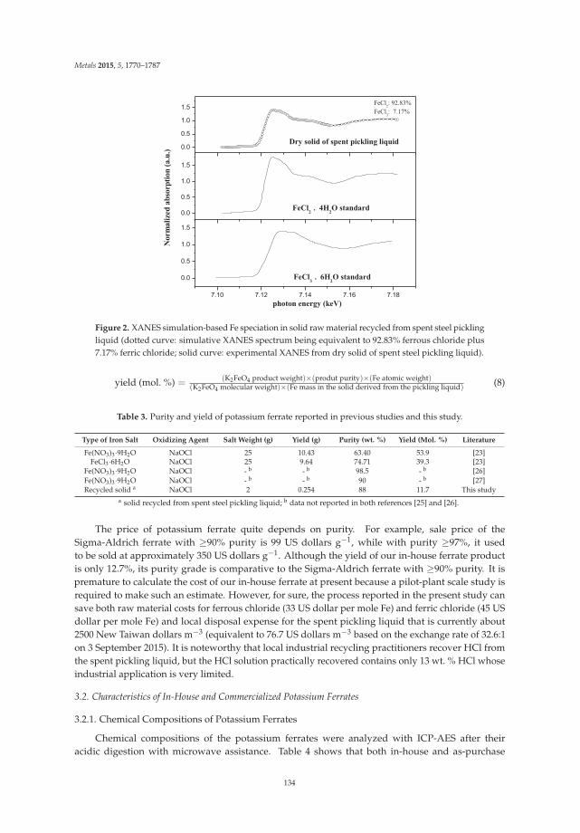
Metals 2015, 5, 1770–1787
0.0
0.5
1.0
1.5
0.0
0.5
1.0
1.5
7.10 7.12 7.14 7.16 7.18
0.0
0.5
1.0
1.5
photon energy (keV)
Dry solid of spent pickling liquid
FeCl2: 92.83%
FeCl3: 7.17%
Nor
mal
ized
abs
orpt
ion
(a.u
.)
FeCl2
4H2O standard
FeCl3
6H2O standard
Figure 2. XANES simulation-based Fe speciation in solid raw material recycled from spent steel picklingliquid (dotted curve: simulative XANES spectrum being equivalent to 92.83% ferrous chloride plus7.17% ferric chloride; solid curve: experimental XANES from dry solid of spent steel pickling liquid).
yield (mol. %) = (K2FeO4 product weight)×(produt purity)×(Fe atomic weight)(K2FeO4 molecular weight)×(Fe mass in the solid derived from the pickling liquid) (8)
Table 3. Purity and yield of potassium ferrate reported in previous studies and this study.
Type of Iron Salt Oxidizing Agent Salt Weight (g) Yield (g) Purity (wt. %) Yield (Mol. %) Literature
Fe(NO3)3·9H2O NaOCl 25 10.43 63.40 53.9 [23]FeCl3·6H2O NaOCl 25 9.64 74.71 39.3 [23]
Fe(NO3)3·9H2O NaOCl - b - b 98.5 - b [26]Fe(NO3)3·9H2O NaOCl - b - b 90 - b [27]Recycled solid a NaOCl 2 0.254 88 11.7 This study
a solid recycled from spent steel pickling liquid; b data not reported in both references [25] and [26].
The price of potassium ferrate quite depends on purity. For example, sale price of theSigma-Aldrich ferrate with ≥90% purity is 99 US dollars g−1, while with purity ≥97%, it usedto be sold at approximately 350 US dollars g−1. Although the yield of our in-house ferrate productis only 12.7%, its purity grade is comparative to the Sigma-Aldrich ferrate with ≥90% purity. It ispremature to calculate the cost of our in-house ferrate at present because a pilot-plant scale study isrequired to make such an estimate. However, for sure, the process reported in the present study cansave both raw material costs for ferrous chloride (33 US dollar per mole Fe) and ferric chloride (45 USdollar per mole Fe) and local disposal expense for the spent pickling liquid that is currently about2500 New Taiwan dollars m−3 (equivalent to 76.7 US dollars m−3 based on the exchange rate of 32.6:1on 3 September 2015). It is noteworthy that local industrial recycling practitioners recover HCl fromthe spent pickling liquid, but the HCl solution practically recovered contains only 13 wt. % HCl whoseindustrial application is very limited.
3.2. Characteristics of In-House and Commercialized Potassium Ferrates
3.2.1. Chemical Compositions of Potassium Ferrates
Chemical compositions of the potassium ferrates were analyzed with ICP-AES after theiracidic digestion with microwave assistance. Table 4 shows that both in-house and as-purchase
134

Metals 2015, 5, 1770–1787
Sigma-Aldrich potassium ferrates are of high purity with only negligible impurities. Compared withthe commercialized one, the in-house product is no less in purity. Most non-iron metals originallypresent in the pickling liquid have been either washed or precipitated off during the synthesis process.
Figure 3 depicts Fe k-edge XANES spectra from in-house (top) and as-purchase Sigma-Aldrich(bottom) potassium ferrates. The height (or area) of pre-edge peak at 7.115 keV is proportional to theratio Fe(VI)/total Fe. This figure provides evidence that both ferrates are almost identical in pre-edgepeak height, implying that they are of similar purity.
Table 4. Chemical compositions of Sigma-Aldrich and in-house potassium ferrates by weight.
Sigma-Aldrich K2FeO4 Standard In-House K2FeO4 (This Study)
Composition wt. Percentage (%) Recovery (%) wt. Percentage (%) Recovery (%)
Cr a 0.11 ± 0 (51 ± 2.5) 0.01 ± 0.0002 (60 ± 2.8)Bi a 0.11 ± 0.0344 (61 ± 1.6) 0.06 ± 0.000196 (51 ± 1.8)Al a 0.01 ± 0.0006 (75 ± 2.6) 0.02 ± 0.00098 (71 ± 2.8)Ba a 0.00 ± 0 (82 ± 2.2) 0.01 ± 0 (88 ± 2.1)Ca a 0.00 ± 0.0004 (73 ± 1.4) 0.02 ± 0.0002 (70 ± 2.6)Fe a 24.99 ± 0.899 (84 ± 2.7) 23.75 ± 0.214 (85 ± 2.1)K a 37.77 ± 0.746 (96 ± 2.5) 38.69 ± 0.697 (94 ± 2.8)Li a 0.20 ± 0.0008 (69 ± 2.3) 0.59 ± 0.00982 (58 ± 1.8)
Mn a 0.07 ± 0.002 (80 ± 2.6) 0.10 ± 0.00039 (79 ± 3.1)Na a 0.01 ± 0.0002 (79 ± 1.5) 0.01 ± 0.00039 (77 ± 1.8)Ni a 0.15 ± 0.0656 (69 ± 3.1) 0.04 ± 0.009627 (71 ± 3.0)
a analyzed with ICP-AES after microwave-assisted acidic digestion (n = 2).
0.0
0.2
0.4
0.6
0.8
1.0
1.2
1.4
7.10 7.12 7.14 7.16 7.18
0.0
0.2
0.4
0.6
0.8
1.0
1.2
1.4
Norm
alize
d ab
sorp
tion
(a.u
.)
K2FeO
4(this study)
photon energy (keV)
K2FeO
4 standard
Figure 3. Comparison of Fe k-edge XANES of in-house K2FeO4 and Sigma-Aldrich K2FeO4 standard.
135

Metals 2015, 5, 1770–1787
3.2.2. UV-Vis Absorption Spectra
Previous literature found that hexavalent iron compounds show a maximum absorbance atwavelength 505 nm [3] and two respective minimum absorbance peaks at 390 nm and 675 nm [15]on UV-Vis spectrum. Figure 4 indicates no difference in UV-Vis absorbance spectrum between ourin-house potassium ferrate product and the commercial ferrate that was used as a reference compoundin this study.
300 400 500 600 700
0.0
0.5
1.0
1.5 ferrate(VI) (this study) ferrate(VI) standard
abso
rban
ce
wavelength (nm)
Figure 4. UV-Vis absorbance spectra of in-house and Sigma-Aldrich potassium ferrates at aconcentration of 2.88 × 10⁻⁴ M.
3.2.3. SEM-EDX Results from Potassium Ferrates
Figures 5 and 6 depict the mapping results from an environmental scanning electron microscope(ESEM-EDX, FEI Quanta 400 F, Hillsboro, OR, USA) spectra of commercialized and in-house potassiumferrates, respectively. Despite the presence of some impurities, such as Pb, Ca, Si, Al, Mg, Na, andCl, these two ferrate samples are almost identical in EDX spectrum except that Cl peak of in-houseproduct is slightly stronger. Thus, these two ferrates are considered to be not much different in quality.
Figure 5. SEM/EDX results from as-purchase potassium ferrate.
136

Metals 2015, 5, 1770–1787
Figure 6. SEM/EDX results from in-house potassium ferrate.
3.2.4. Crystalline Phases of Potassium Ferrates
Figure 7 indicates that XRD patterns of both in-house and commercialized potassium ferrate areconsistent with the main patterns belonging to K2FeO4 according to The Joint Committee on PowderDiffraction Standards (JCPDS) 25-0652 data file. XRD patterns also indicate that K2O and FeO(OH) arepresent as the main impurity in the in-house ferrate product.
0
200
400
600
800
1000
20 25 30 35 40 45
0
200
400
600
800
1000
0 10 20 30 40 50 60 70 80 90
0
200
400
600
800
1000
0 10 20 30 40 50 60 70 80 90
0
200
400
600
800
1000
BB
C
C
BB
B
BAA
AAA
A
A
AAA
A
inte
nsity
A
A
A
A
A:K2FeO
4B:FeO(OH)C:K
2O
AA
AA
AAA
AA
A
A
A
A
2 theta
A
A
A
AA
AA:K
2FeO
4
A
AA
A
2theta
AA
AA
A
A
A
AA
A
AA:K
2FeO
4
A
AA
AA
AA
A
A
A
A:K2FeO
4
Figure 7. XRD patterns of in-house (top) and as-purchase (bottom) potassium ferrates.
137

Metals 2015, 5, 1770–1787
3.2.5. Test of Fe(VI) Stabilization during Storage
Moisture content was recognized to readily reduce Fe(VI) to Fe(III). Thus dry environment isbeneficial for Fe(VI) storage. To test storage stability of in-house Fe(VI) product, two identical partsof it were respectively stored in an electronic dryer box (relative humidity: 35%–40%) and in theatmosphere (relative humidity: 67%–70%) for 32 h, and a small amount of each part was retrievedperiodically in every 2–3 h interval for analyzing its Fe(VI) purity. The results are presented in Figure 8.
Figure 8 indicates that for a 32 h storage time, only 1.2% chemical reduction occurred to in-housepotassium ferrate when stored under 35%–40% relative humidity (RH), while, if stored under theatmosphere of 67%–70% RH, Fe(VI) reduction rate to Fe(III) was 14.5%. Previous study elsewhere hasobserved an increase in Fe(VI) reduction with increasing RH at room temperature [28]. At a lowerhumidity (55%–70% RH), Fe(VI) decay was slow, while the decay rate was considerably enhanced athigher humidity such as 90%–95% RH [28]. Formation of KHCO3 at higher RH was suggested to be animportant reason for the enhanced Fe(VI) decay rate [28].
-2 0 2 4 6 8 10 12 14 16 18 20 22 24 26 28 30 32 34
0.4
0.5
0.6
0.7
0.8
0.9
1.0
in dry box (humidity: 35~40 % RH) in air (humidity: 67~70 % RH)
C/C
0
time (hr)
Figure 8. Storage stability of in-house potassium ferrate under different relative humidities.
3.3. Stepwise Loss of Iron in Fe(VI) Synthesis Flowchart
To know which step(s) have lost a large amount of iron for future studies to improve the yield ofin-house potassium ferrate, this study performed quantitative analysis of iron in the solid and liquidphases after each solid/liquid separation step of Fe(VI) synthesis. Fe analysis was carried out with theFAAS after microwave-assisted acidic digestion. Table 5 shows that iron was gradually lost along withthe synthesis steps. Among them, the centrifugation and filtration steps affect potassium ferrate yieldthe most. Ideally, if these ion losses can be reduced, yield of potassium ferrate will be improved.
Table 5. Fe loss during wet synthesis of in-house potassium ferrate.
Synthesis Step b Fe Loss a (%)
Discarded solid (A) 54.8Discarded solid (B) 26.5
Discarded liquid (C) 1.49Discarded solid (D) 8.25Discarded liquid (E) 0.55
a Fe loss =(Fe in discarded solid or liquid)
total Fe used for synthesis ; b please refer to Figure 1.
138
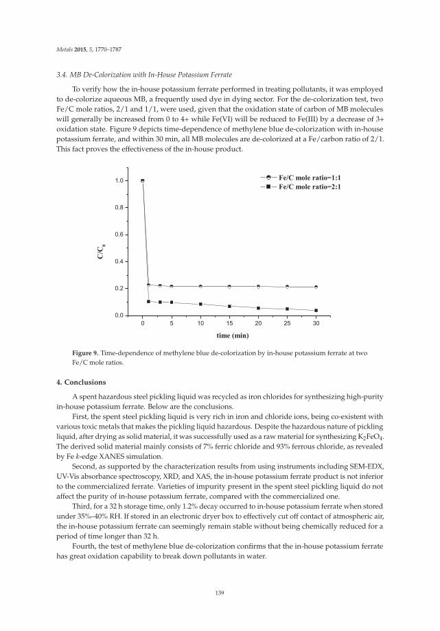
Metals 2015, 5, 1770–1787
3.4. MB De-Colorization with In-House Potassium Ferrate
To verify how the in-house potassium ferrate performed in treating pollutants, it was employedto de-colorize aqueous MB, a frequently used dye in dying sector. For the de-colorization test, twoFe/C mole ratios, 2/1 and 1/1, were used, given that the oxidation state of carbon of MB moleculeswill generally be increased from 0 to 4+ while Fe(VI) will be reduced to Fe(III) by a decrease of 3+oxidation state. Figure 9 depicts time-dependence of methylene blue de-colorization with in-housepotassium ferrate, and within 30 min, all MB molecules are de-colorized at a Fe/carbon ratio of 2/1.This fact proves the effectiveness of the in-house product.
0 5 10 15 20 25 30
0.0
0.2
0.4
0.6
0.8
1.0 Fe/C mole ratio=1:1 Fe/C mole ratio=2:1
C/C
0
time (min)
Figure 9. Time-dependence of methylene blue de-colorization by in-house potassium ferrate at twoFe/C mole ratios.
4. Conclusions
A spent hazardous steel pickling liquid was recycled as iron chlorides for synthesizing high-purityin-house potassium ferrate. Below are the conclusions.
First, the spent steel pickling liquid is very rich in iron and chloride ions, being co-existent withvarious toxic metals that makes the pickling liquid hazardous. Despite the hazardous nature of picklingliquid, after drying as solid material, it was successfully used as a raw material for synthesizing K2FeO4.The derived solid material mainly consists of 7% ferric chloride and 93% ferrous chloride, as revealedby Fe k-edge XANES simulation.
Second, as supported by the characterization results from using instruments including SEM-EDX,UV-Vis absorbance spectroscopy, XRD, and XAS, the in-house potassium ferrate product is not inferiorto the commercialized ferrate. Varieties of impurity present in the spent steel pickling liquid do notaffect the purity of in-house potassium ferrate, compared with the commercialized one.
Third, for a 32 h storage time, only 1.2% decay occurred to in-house potassium ferrate when storedunder 35%–40% RH. If stored in an electronic dryer box to effectively cut off contact of atmospheric air,the in-house potassium ferrate can seemingly remain stable without being chemically reduced for aperiod of time longer than 32 h.
Fourth, the test of methylene blue de-colorization confirms that the in-house potassium ferratehas great oxidation capability to break down pollutants in water.
139

Metals 2015, 5, 1770–1787
Finally, for future study, industrial grade chemicals will be used to replace the reagent-gradechemicals for the synthesis of in-house potassium ferrate.
Acknowledgments: This work was sponsored by the Taiwan Ministry of Science and Technology (NSC-102-2221-E-029-001). Fe k-edge XAS was recorded on beamlines 17C and 16A of NSRRC, Taiwan.
Author Contributions: Wang and Liu worked together in laboratory under Wei’s advice for the project. They alsodid some literature review. Wei was the principal investigator of the project sponsored by the Taiwan Ministry ofScience and Technology and this paper was written by Wei after discussion with Wang and Liu.
Conflicts of Interest: The authors declare no conflict of interest.
References
1. Audette, R.J.; Quail, J.W.; Smith, P.J. Ferrate(VI) ion, a novel oxidizing agent. Tetrahedron Lett. 1971, 3, 279–282.[CrossRef]
2. Yoon, J.; Lee, Y.; Cho, M.; Kim, J.Y. Chemistry of ferrate (Fe(IV)) in aqueous solution and its application asa green chemistry. J. Ind. Eng. Chem. 2004, 10, 161–171.
3. Jiang, J.Q.; Lloyd, B. Progress in the development and use of ferrate(VI) salt as an oxidant and coagulant forwater and wastewater treatment. Water Res. 2002, 36, 1397–1408. [CrossRef]
4. Jiang, J.Q. The role of ferrate(VI) in the remediation of emerging micro pollutants: A review. Desalin.Water Treat. 2015, 55, 828–835. [CrossRef]
5. Sharma, V.K.; Zboril, R.; Varma, R.S. Ferrates: Greener Oxidants with Multimodal Action in Water TreatmentTechnologies. Acc. Chem. Res. 2015, 48, 182–191. [CrossRef] [PubMed]
6. Kim, C.; Panditi, V.R.; Gardinali, P.R.; Varma, R.S.; Kim, H.; Sharma, V.K. Ferrate promoted oxidativecleavage of sulfonamides: Kinetics and product formation under acidic conditions. Chem. Eng. J. 2015, 279,307–316. [CrossRef]
7. Yates, B.J.; Zboril, R.; Sharma, V.K. Engineering aspects of ferrate in water and wastewater treatment—Areview. J. Environ. Sci. Heal. A 2014, 49, 1603–1614. [CrossRef] [PubMed]
8. Gombos, E. Ferrate treatment for inactivation of bacterial community in municipal secondary effluent.Bioresour. Technol. 2012, 107, 116–121. [CrossRef] [PubMed]
9. Prucek, R.; Tucek, J.; Kolar k J.; Huškováa, I.; Filip, J.; Varma, R.S.; Sharma, V.K.; Zboril, R.Ferrate(VI)-Prompted removal of metals in aqueous media: Mechanistic delineation of enhanced efficiencyvia metal entrenchment in magnetic oxides. Environ. Sci. Technl. 2015, 49, 2319–2327. [CrossRef] [PubMed]
10. Gombos, E.; Barkacs, K.; Felfoldi, T.; Vertes, C.; Mako, M.; Palko, G.; Záray, G. Removal of organic matters inwastewater treatment by ferrate(VI) technology. Microchem. J. 2013, 107, 115–120. [CrossRef]
11. Sharma, V.K. Oxidation of inorganic contaminants by ferrates (VI, V, and IV) kinetics and mechanisms:A review. J. Environ. Manag. 2011, 92, 1051–1073. [CrossRef] [PubMed]
12. Jiang, J.Q.; Lloyd, B. Preliminary study of ciprofloxacin (cip) removal by potassium ferrate(VI). Sep. Purif.Technol. 2013, 88, 95–98. [CrossRef]
13. Li, C.; Lib, X.Z.; Grahamc, N.; Gaoa, N.Y. The aqueous degradation of bisphenol A and steroid estrogens byferrate. Water Res. 2008, 42, 109–120. [CrossRef] [PubMed]
14. Yang, X.; Guo, W.; Zhang, X.; Chen, F.; Wei, T. Formation of disinfection by-products after pre-oxidation withchlorine dioxide or ferrate. Water Res. 2013, 47, 5856–5864. [CrossRef] [PubMed]
15. Al-Abdulya, A.; Sharma, V.K. Oxidation of benzothiophene, dibenzothiophene, and methyl-dibenzothiopheneby ferrate(VI). J. Hazard. Mater. 2015, 279, 296–301. [CrossRef] [PubMed]
16. Environmental Protection Administration, R.O.C. Available online: http://www.epa.gov.tw/ (accessed on21 September 2015).
17. Agrawal, A.; Sahu, K.K. An overview of the recovery of acid from spent acidic solutions from steel andelectroplating industries. J. Hazard. Mater. 2009, 171, 61–75. [CrossRef] [PubMed]
18. Rögener, F.; Buchloh, D.; Reichardt, T.; Schmidt, J.; Knaup, F. Total regeneration of mixed pickling acids fromstainless steel production. Stahl und Eisen. 2009, 10, 69–73.
19. Perfiliev, Y.D.; Benko, E.M.; Pankratov, D.A.; Sharma, V.K.; Dedushenko, S.K. Formation of iron(VI) inozonalysis of iron(III) in alkaline solution. Inorg. Chim. Acta 2007, 360, 2789–2791. [CrossRef]
140

Metals 2015, 5, 1770–1787
20. Thompson, J.E.; Ockerman, L.T.; Schreyer, J.M. Preparation and purification of potassium ferrate(VI). J. Am.Chem. Soc. 1951, 73, 1379–1381. [CrossRef]
21. Delaude, L.; Laszlo, P. A Novel Oxidizing Reagent Based on Potassium Ferrate(VI). J. Org. Chem. 1996, 61,6360–6370. [CrossRef] [PubMed]
22. Sharma, V.K. Potassium ferrate(VI): An environmentally friendly oxidant. Adv. Environ. Res. 2002, 6, 143–156.[CrossRef]
23. Licht, S.; Naschitz, V.; Halperin, L.; Halperin, N.; Lin, L.; Chen, J.J.; Ghosh, S.; Liu, B. Analysis of ferrate(VI)compounds and super-iron Fe(VI) battery cathodes: FTIR, ICP, titrimetric, XRD, UV-VIS, and electrochemicalcharacterization. J. Power Sources 2001, 101, 167–176. [CrossRef]
24. Luo, Z.; Strouse, M.; Jiang, J.Q.; Sharma, V.K. Methodologies for the analytical determination of ferrate(VI):A Review. J. Environ. Sci. Heal. A 2011, 46, 453–460. [CrossRef] [PubMed]
25. Ressler, T. WinXAS: A program for X-ray absorption spectroscopy data analysis under MS-Windows.J. Synchrotron Radiat. 1998, 5, 118–122. [CrossRef] [PubMed]
26. Wang, L.W.; Liu, S.Q.; Zhang, X.Y. Preparation and application of sustained release microcapsules ofpotassium ferrate(VI) for dinitro butyl phenol (DNBP) wastewater treatment. J. Hazard. Mater. 2009, 169,448–453. [CrossRef] [PubMed]
27. Yuan, B.L.; Li, X.Z.; Graham, N. Reaction pathways of dimethyl phthalate degradation in TiO2–UV–O2 andTiO2–UV–Fe(VI) systems. Chemosphere 2008, 72, 197–204. [CrossRef] [PubMed]
28. Machala, L.; Zboril, R.; Sharma, V.K.; Filip, J.; Jancil, D.; Homonnay, Z. Transformation of solid potassiumferrate(VI) (K2FeO4): Mechanism and kinetic effect of air humidity. Eur. J. Inorg. Chem. 2009, 8, 1060–1067.[CrossRef]
© 2015 by the authors. Licensee MDPI, Basel, Switzerland. This article is an open accessarticle distributed under the terms and conditions of the Creative Commons Attribution(CC BY) license (http://creativecommons.org/licenses/by/4.0/).
141

metals
Article
The Effect of Grinding and Roasting Conditions onthe Selective Leaching of Nd and Dy from NdFeBMagnet Scraps
Ho-Sung Yoon 1, Chul-Joo Kim 1, Kyung Woo Chung 1, Sanghee Jeon 2, Ilhwan Park 2,
Kyoungkeun Yoo 2,* and Manis Kumar Jha 3
1 Minerals Resource Research Division, Korea Institute of Geoscienece & Mineral Resources (KIGAM),Daejeon 305-350, Korea; [email protected] (H.-S.Y.); [email protected] (C.-J.K.);[email protected] (K.W.C.)
2 Department of Energy & Resources Engineering, Korea Maritime and Ocean University (KMOU), Busan606-791, Korea; [email protected] (S.J.); [email protected] (I.P.)
3 Metal Extraction & Forming Division, CSIR-National Metallurgical Laboratory, Jamshedpur 831007, India;[email protected]
* Author to whom correspondence should be addressed; [email protected]; Tel.: +82-51-410-4686;Fax: +82-51-403-4680.
Academic Editor: Suresh BhargavaReceived: 7 June 2015; Accepted: 14 July 2015; Published: 17 July 2015
Abstract: The pretreatment processes consisting of grinding followed by roasting were investigatedto improve the selective leaching of Nd and Dy from neodymium-iron-boron (NdFeB) magnet scraps.The peaks of Nd(OH)3 and Fe were observed in XRD results after grinding with NaOH as the amountof water addition increased to 5 cm3. These results indicate that the components of Nd and Fe inNdFeB magnet could be changed successfully into Nd(OH)3 and Fe, respectively. In the roasting testsusing the ground product, with increasing roasting temperature to 500 ◦C, the peaks of Nd(OH)3 andFe disappeared while those of Nd2O3 and Fe2O3 were shown. The peaks of NdFeO3 in the sampleroasted at 600 ◦C were observed in the XRD pattern. Consequently, 94.2%, 93.1%, 1.0% of Nd, Dy, Fewere leached at 400 rpm and 90 ◦C in 1 kmol·m−3 acetic acid solution with 1% pulp density usinga sample prepared under the following conditions: 15 in stoichiometric molar ratio of NaOH:Nd,550 rpm in rotational grinding speed, 5 cm3 in water addition, 30 min in grinding time, 400 ◦C and2 h in roasting temperature and time. The results indicate that the selective leaching of Nd and Dyfrom NdFeB magnet could be achieved successfully by grinding and then roasting treatments.
Keywords: NdFeB magnet scraps; selective leaching; acetic acid leaching; roasting; planetaryball milling
1. Introduction
Neodymium-iron-boron (NdFeB) magnets were developed in the early 1980s due to the importantdiscovery that modifying Nd2Fe17 produces the ternary compound Nd2Fe14B [1,2]. The NdFeBmagnets could substitute samarium-cobalt magnets because neodymium is more abundant thansamarium and the use of iron as transition metal is lower-cost than that of cobalt [1]. The NdFeBmagnets have been widely used in various applications such as motors for hard disk and hybridelectric vehicle and magnetic generators for magnetic resonance imaging (MRI) [3–5]. Since most Ndis imported into Korea, there is an increasing demand for recycling process of waste NdFeB magnets.
It has been well known that Nd could be obtained from NdFeB magnet scraps by sulfuric acidleaching followed by precipitation of Nd salts [6–8]. Because this method dissolves iron as well asneodymium, there are disadvantages such as high consumption of sulfuric acid and large amount
Metals 2015, 5, 1306–1314 142 www.mdpi.com/journal/metals
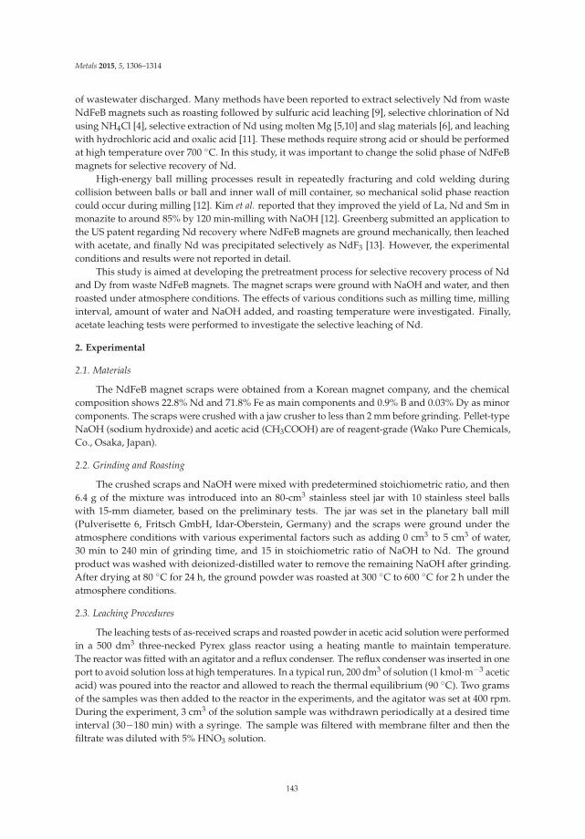
Metals 2015, 5, 1306–1314
of wastewater discharged. Many methods have been reported to extract selectively Nd from wasteNdFeB magnets such as roasting followed by sulfuric acid leaching [9], selective chlorination of Ndusing NH4Cl [4], selective extraction of Nd using molten Mg [5,10] and slag materials [6], and leachingwith hydrochloric acid and oxalic acid [11]. These methods require strong acid or should be performedat high temperature over 700 ◦C. In this study, it was important to change the solid phase of NdFeBmagnets for selective recovery of Nd.
High-energy ball milling processes result in repeatedly fracturing and cold welding duringcollision between balls or ball and inner wall of mill container, so mechanical solid phase reactioncould occur during milling [12]. Kim et al. reported that they improved the yield of La, Nd and Sm inmonazite to around 85% by 120 min-milling with NaOH [12]. Greenberg submitted an application tothe US patent regarding Nd recovery where NdFeB magnets are ground mechanically, then leachedwith acetate, and finally Nd was precipitated selectively as NdF3 [13]. However, the experimentalconditions and results were not reported in detail.
This study is aimed at developing the pretreatment process for selective recovery process of Ndand Dy from waste NdFeB magnets. The magnet scraps were ground with NaOH and water, and thenroasted under atmosphere conditions. The effects of various conditions such as milling time, millinginterval, amount of water and NaOH added, and roasting temperature were investigated. Finally,acetate leaching tests were performed to investigate the selective leaching of Nd.
2. Experimental
2.1. Materials
The NdFeB magnet scraps were obtained from a Korean magnet company, and the chemicalcomposition shows 22.8% Nd and 71.8% Fe as main components and 0.9% B and 0.03% Dy as minorcomponents. The scraps were crushed with a jaw crusher to less than 2 mm before grinding. Pellet-typeNaOH (sodium hydroxide) and acetic acid (CH3COOH) are of reagent-grade (Wako Pure Chemicals,Co., Osaka, Japan).
2.2. Grinding and Roasting
The crushed scraps and NaOH were mixed with predetermined stoichiometric ratio, and then6.4 g of the mixture was introduced into an 80-cm3 stainless steel jar with 10 stainless steel ballswith 15-mm diameter, based on the preliminary tests. The jar was set in the planetary ball mill(Pulverisette 6, Fritsch GmbH, Idar-Oberstein, Germany) and the scraps were ground under theatmosphere conditions with various experimental factors such as adding 0 cm3 to 5 cm3 of water,30 min to 240 min of grinding time, and 15 in stoichiometric ratio of NaOH to Nd. The groundproduct was washed with deionized-distilled water to remove the remaining NaOH after grinding.After drying at 80 ◦C for 24 h, the ground powder was roasted at 300 ◦C to 600 ◦C for 2 h under theatmosphere conditions.
2.3. Leaching Procedures
The leaching tests of as-received scraps and roasted powder in acetic acid solution were performedin a 500 dm3 three-necked Pyrex glass reactor using a heating mantle to maintain temperature.The reactor was fitted with an agitator and a reflux condenser. The reflux condenser was inserted in oneport to avoid solution loss at high temperatures. In a typical run, 200 dm3 of solution (1 kmol·m−3 aceticacid) was poured into the reactor and allowed to reach the thermal equilibrium (90 ◦C). Two gramsof the samples was then added to the reactor in the experiments, and the agitator was set at 400 rpm.During the experiment, 3 cm3 of the solution sample was withdrawn periodically at a desired timeinterval (30−180 min) with a syringe. The sample was filtered with membrane filter and then thefiltrate was diluted with 5% HNO3 solution.
143

Metals 2015, 5, 1306–1314
2.4. Analytical Methods
The concentrations of Nd, Fe, and Dy were measured by an inductively coupled plasma-atomicemission spectrometry (ICP-AES, OPTIMA 8300DV; PerkinElmer Inc., Waltham, MA, USA).The samples were also characterized by X-ray Diffraction (Smartlab, Rigaku Co., Tokyo, Japan) with Cutarget under the following conditions: 30 kV, 200 mA, 20–80◦/2θ in angle range, step scanning methods.
3. Results and Discussion
In this study, the pretreatment process consists of grinding and roasting for selective leaching ofNd and Dy from the magnet leaving Fe component as leach residue. The Fe component should beoxidized to ferric ion (Fe3+), since the solubility products (Ksp) of Fe(OH)3 and Fe(OH)2 are 10−36.51
and 10−14.18, respectively, using standard Gibbs free energy data in Table 1 [14], which means thatthe solubility of ferric ion (Fe3+) is much lower than that of ferrous ion (Fe2+). The roasting tests wereperformed to oxidize the Fe, but, since Kim et al. reported that the magnet scraps were not oxidizedsufficiently at less than 500 ◦C [15], the grinding tests were conducted to increase the specific surfacearea of magnet powder and change the solid phase before roasting.
Table 1. Standard Gibbs free energies of species at 25 ◦C [14].
Species Fe2+ Fe3+ Fe(OH)2 Fe(OH)3 OH−
ΔG0 (kJ/mol) −91.2 −16.7 −486.6 −696.6 −157.293
The NdFeB magnet scraps were ground with 0 to 5 cm3 under the following conditions: 15 instoichiometric molar ratio of NaOH:Nd, 550 rpm in rotational speed, 30 min in grinding time. Figure 1shows the effect of water addition on the formation of Nd(OH)3 during grinding. When samples wereground without water, XRD peaks show little difference from the as-received sample, while the peaksof Fe and Nd(OH)3 arose as the amount of water addition increased. It has been found that Nd couldbe oxidized with H2O as the following equation.
2Nd + 6H2O = 2Nd(OH)3 + 3H2 (1)
The standard reduction potentials of Nd (Nd3+ + 3e = Nd) and water (2H2O + 2e = H2 + 2OH−) are−2.32 V [16] and −0.83 V [17], respectively, and because the standard electrode potential of Equation(1) is calculated to be 1.49 V, the reaction must be spontaneous. Therefore, 5 cm3-water addition couldaccelerate the formation of Nd(OH)3 as shown in Figure 1. However, iron could not be oxidized bywater addition, so iron peaks were observed by adding 3 cm3 or 5 cm3 water. These results indicatethat Nd and Fe of Nd2Fe14B was changed successfully into Nd(OH)3 and Fe, respectively.
Greenburg proposed the recycling process of NdFeB magnet scraps [13], where Nd was selectivelyleached after grinding with NaOH. Figure 2 shows XRD patterns of products ground for 30 min and240 min. However, the intensity of the Fe peak decreased with increasing the grinding time, sinceFe remained after 240 min grinding and Fe could be dissolved by acetic acid leaching; therefore, it isdifficult to expect selective leaching of Nd. Furthermore, in the preliminary experiments with 30 instoichiometric molar ratio, the peaks of Fe were observed (data not shown).
144

Metals 2015, 5, 1306–1314
Figure 1. XRD patterns of ground products with water addition (Grinding conditions: 15 instoichiometric molar ratio, 550 rpm in rotational speed, 30 min in grinding time).
Figure 2. XRD patterns of ground products with grinding time (Grinding conditions: 15 instoichiometric molar ratio, 550 rpm in rotational speed, 5 cm3 in water addition).
Therefore, in this study, the magnet scraps were roasted after grinding to oxidize Fe for improvingselective leaching efficiency. The ground products were prepared under the conditions such as 15 instoichiometric molar ratio, 550 rpm in rotational speed, 30 min in total grinding time, and 5 cm3 in
145

Metals 2015, 5, 1306–1314
water addition, and then was roasted at 300 ◦C to 600 ◦C for 2 h. As shown in Figure 3, the peaks ofFe2O3 and Nd2O3 as well as Nd(OH)3 and Fe were shown after roasting at 300 ◦C. After roasting at400 ◦C and 500 ◦C, the peaks of Nd(OH)3 and Fe disappeared, and only peaks of Fe2O3 and Nd2O3
were observed. The peaks of NdFeO3 emerged after roasting at 600 ◦C, and the reaction was given asthe following equation [9].
2Nd + 6H2O = 2Nd(OH)3 + 3H2 (2)
These results indicate that iron could be oxidized at 400 ◦C and 500 ◦C, and the components ofNd and Fe were changed into NdFeO3 at 600 ◦C.
The selective leaching with acetic acid was tested using the roasted product. Figure 4 shows theleaching efficiencies of Nd, Fe, and Dy using product ground under the following conditions: 15 instoichiometric molar ratio, 550 rpm in rotational speed, 5 cm3 in water addition, 30 min in grindingtime and roasted at 400 ◦C. The leaching efficiencies of Nd and Dy increased rapidly to more than 90%and remained almost constant after 60 min, and that of Fe remained at less than 1.5%, which indicatesthat Nd and Dy were selectively leached from scraps. Therefore, the leaching efficiencies measuredat 60 min were used for further discussion.
Figure 3. XRD patterns of roasted sample with temperature (Grinding conditions: 15 in stoichiometricmolar ratio, 550 rpm in rotational speed, 5 cm3 in water addition, 30 min in grinding time).
Figure 5 shows the effect of roasting temperature on the leaching efficiencies of Nd, Fe and Dy.The samples were prepared under the grinding conditions: 550 rpm in rotational speed, 5 cm3 in wateraddition, 30 min in grinding time and 15 in stoichiometric ratio, and then were leached under theconditions: 1% in pulp density, 1 kmol·m−3 in acetic acid, 400 rpm in agitation speed, and 90 ◦C intemperature. The leaching efficiencies of Nd and Dy decreased rapidly with increasing temperaturefrom 500 ◦C to 600 ◦C, and that of Fe decreased and then increased gradually with increasing roasting
146

Metals 2015, 5, 1306–1314
temperature. The decrease in leaching efficiencies of Nd and Dy would be formation of NdFeO3 shownin Equation (2).
Figure 4. Leaching efficiencies of Nd, Fe, Dy with leaching time (Grinding conditions: 15 instoichiometric molar ratio, 550 rpm in rotational speed, 5 cm3 in water addition, 30 min in grindingtime, roasting condition; 2 h at 400 ◦C, leaching conditions: 400 rpm, 1 kmol·m−3 acetic acid, 90 ◦C).
Figure 5. The effect of roasting temperature on the leaching efficiency (Grinding conditions: 550 rpmin rotational speed, 5 cm3 in water addition, 30 min in grinding time, 15 in stoichiometric molar ratio).
Figure 6. The comparison of leaching efficiencies using samples as as-received, only roasted, androasted after being ground.
147
Metals 2015, 5, 1306–1314
Figure 6 shows the comparison of leaching efficiencies using samples such as “as-received”,“roasting only”, which was roasted at 400 ◦C for 2 h using “as-received” sample, and “roasting aftergrinding”, which was prepared under the grinding conditions: 15 in stoichiometric molar ratio, 550 rpmin rotational speed, 5 cm3 in water addition, 30 min in grinding time and roasting conditions: 400 ◦C intemperature and 2 h in roasting time. The leaching efficiency of Fe is calculated to be more than 40% inthe cases of “as-received” and “only roasting” samples, and the results indicate that Nd and Dy werenot leached selectively from the scraps. The dissolution of Fe would result from insufficient oxidationof Fe as reported by Kim et al. [15] However, 30-min grinding with NaOH changes the components ofNd and Fe into Nd(OH)3 and Fe, respectively, which could oxidize Fe easily during roasting. Finally,more than 90% of Nd and Dy could be leached but the leaching efficiency of Fe was 1% at 60 minleaching time, which indicates that selective leaching of Nd and Dy could be achieved by roastingafter grinding but not by only roasting or by only grinding. The leaching efficiencies of Nd and Dyincreased to 94.2% and 93.1%, respectively, with increasing time to 180 min. These results indicate thatthe selective leaching of Nd and Dy was achieved successfully.
4. Conclusions
The pretreatment methods consisting of grinding and roasting for the selective leaching of Nd andDy from NdFeB magnet scraps was investigated for recycling of waste NdFeB magnet. The magnetscraps were ground with NaOH and water, and then roasted under the atmosphere condition todecrease the leaching efficiency of Fe and to accelerate the selectivity of Nd and Dy leaching.
The peaks of Nd(OH)3 and Fe were shown by increasing the amount of water addition in thegrinding test. When the ground products were roasted at 400 ◦C and 500 ◦C, the peaks of Nd(OH)3
and Fe disappeared while those of Nd2O3 and Fe2O3 were observed in the XRD results. Consequently,94.2%, 93.1%, 1.0% of Nd, Dy, Fe were leached, respectively, under the following conditions: 15 instoichiometric molar ratio, 550 rpm in rotational grinding speed, 5 cm3 in water addition, 30 min ingrinding time, 400 ◦C and 2 h in roasting temperature and time, 90 ◦C in leaching time, 1 kmol·m−3
in acetic acid concentration, 400 rpm in leaching agitation speed, 1% in leaching pulp density, and180 min in leaching time.
Acknowledgments: The authors express appreciation for support of “R&D Center for Valuable Recycling”(Global-Top R&BD Program) funded by Korea Ministry of Environment (Project No. GT-11-C-01-100-0).
Author Contributions: Yoon and Yoo wrote the paper and contributed to all activities. Kim and Chung performedcrushing and roasting samples. Jeon and Park conducted grinding and leaching tests and analyses. Jha contributedto interpretation and discussion of the experimental results.
Conflicts of Interest: The authors declare no conflict of interest.
References
1. Campbell, P. Permanent Magnet Materials and Their Application; Cambridge University Press: New York, NY,USA; Melbourne, Australia, 1994; pp. 45–51.
2. Gupta, C.K.; Krishnamurthy, N. Extractive Metallurgy of Rare Earths; CRC Press: Boca Raton, FL, USA; London,UK; New York, NY, USA, 2005; pp. 396–411.
3. Lee, K.; Yoo, K.; Yoon, H.S.; Kim, C.J.; Chung, K.W. Demagnetization followed by remagnetization of wasteNdFeB magnet for reuse. Geosystem Eng. 2013, 16, 286–288. [CrossRef]
4. Itoh, M.; Miura, K.; Machida, K. Novel rare earth recovery process on Nd-Fe-B magnet scrap by selectivechlorination using NH4Cl. J. Alloys Compd. 2009, 477, 484–487. [CrossRef]
5. Okabe, T.H.; Takeda, O.; Fukuda, K.; Umetsu, Y. Direct extraction and recovery of neodymium metal frommagnet scrap. Mater. Trans. 2003, 44, 798–801. [CrossRef]
6. Saito, T.; Sato, H.; Ozawa, S.; Yu, J.; Motegi, T. The extraction of Nd from waste Nd-Fe-B alloys by the glassslag method. J. Alloys Compd. 2003, 353, 189–193. [CrossRef]
7. Lee, C.H.; Chen, Y.J.; Liao, C.H.; Popuri, S.R.; Tsai, S.L. Selective leaching process for neodymium recoveryfrom scrap Nd-Fe-B magnet. Metall. Mater. Trans. A 2013, 44, 5825–5833. [CrossRef]
148

Metals 2015, 5, 1306–1314
8. Binnemans, K.; Jones, P.T.; Blanpain, B.; Gerven, T.V.; Yang, Y.; Walton, A.; Buchert, M. Recycling of rareearths: A critical review. J. Clean. Prod. 2013, 51, 1–22. [CrossRef]
9. Lee, J.C.; Kim, W.B.; Jeong, J.; Yoon, I.J. Extraction of neodymium from Nd-Fe-B magnet scraps by sulfuricacid. Korean J. Met. Mater. 1998, 36, 967–972.
10. Xu, Y.; Chumbley, L.S.; Laabs, F.C. Liquid metal extraction of Nd from NdFeB magnet scrap. J. Mater. Res.2000, 15, 2296–2304. [CrossRef]
11. Itakura, T.; Sasai, R.; Itoh, H. Resource recovery from Nd-Fe-B sintered magnet by hydrothermal treatment.J. Alloys Compd. 2006, 408–412, 1382–1385. [CrossRef]
12. Kim, W.; Bae, I.; Chae, S.; Shin, H. Mechanochemical decomposition of monazite to assist the extraction ofrare earth elements. J. Alloys Compd. 2009, 486, 610–614. [CrossRef]
13. Greenberg, B. Neodymium Recovery Process. U.S. Patent 5,362,459, 8 November 1994.14. Bard, A.J.; Parsons, R.; Jordan, J. Standard Potentials in Aqueous Solution; Marcel Dekker, Inc.: New York, NY,
USA; Basel, Switzerland, 1985; pp. 51, 392–394.15. Kim, C.J.; Yoon, H.S.; Chung, K.W. The Leaching of Nd Using Dipping Method. KR Patent 10-1147643,
4 May 2012.16. Dean, J.A. Lange’s Handbook of Chemistry; McGraw-Hill, Inc.: New York, NY, USA, 1992; pp. 8–130.17. Brett, C.M.A.; Brett, A.M.O. Electrochemistry, Principles, Methods, and Applications; Oxford University Press
Inc.: New York, NY, USA, 2004; p. 418.
© 2015 by the authors. Licensee MDPI, Basel, Switzerland. This article is an open accessarticle distributed under the terms and conditions of the Creative Commons Attribution(CC BY) license (http://creativecommons.org/licenses/by/4.0/).
149

metals
Article
Nickel Extraction from Olivine: Effect ofCarbonation Pre-Treatment †
Rafael M. Santos 1,2,*, Aldo Van Audenaerde 2, Yi Wai Chiang 3, Remus I. Iacobescu 4,
Pol Knops 5 and Tom Van Gerven 2
1 School of Applied Chemical and Environmental Sciences, Sheridan Institute of Technology, Brampton,ON L6Y 5H9, Canada
2 Department of Chemical Engineering, KU Leuven, Leuven 3001, Belgium;[email protected] (A.V.A.); [email protected] (T.V.G.)
3 School of Engineering, University of Guelph, Guelph, ON N1G 2W1, Canada; [email protected] Department of Materials Engineering, KU Leuven, Leuven 3001, Belgium;
[email protected] Innovation Concepts B.V., Twello 7391MG, The Netherlands; [email protected]* Author to whom correspondence should be addressed; [email protected];
Tel.: +1-905-459-7533 (ext. 5723); Fax: +1-905-874-4321.† Contents of this paper also appear in the MetSoc of CIM Proceedings of the 7th International
Symposium—Hydrometallurgy 2014, Volume II, pp. 755–767.
Academic Editors: Suresh Bhargava and Rahul RamReceived: 19 August 2015; Accepted: 6 September 2015; Published: 11 September 2015
Abstract: In this work, we explore a novel mineral processing approach using carbon dioxide topromote mineral alterations that lead to improved extractability of nickel from olivine ((Mg,Fe)2SiO4).The precept is that by altering the morphology and the mineralogy of the ore via mineral carbonation,the comminution requirements and the acid consumption during hydrometallurgical processing canbe reduced. Furthermore, carbonation pre-treatment can lead to mineral liberation and concentrationof metals in physically separable phases. In a first processing step, olivine is fully carbonated at highCO2 partial pressures (35 bar) and optimal temperature (200 ◦C) with the addition of pH bufferingagents. This leads to a powdery product containing high carbonate content. The main products ofthe carbonation reaction include quasi-amorphous colloidal silica, chromium-rich metallic particles,and ferro-magnesite ((Mg1−x,Fex)CO3). Carbonated olivine was subsequently leached using anarray of inorganic and organic acids to test their leaching efficiency. Compared to leaching fromuntreated olivine, the percentage of nickel extracted from carbonated olivine by acid leaching wassignificantly increased. It is anticipated that the mineral carbonation pre-treatment approach mayalso be applicable to other ultrabasic and lateritic ores.
Keywords: nickel; olivine; mineral carbonation; leaching; ferro-magnesite; colloidal silica
1. Introduction
In the last few decades, traditional nickel resources have become scarcer because of rampingglobal production and growing demand [1]. Nickel is more abundantly present in the Earth’s crustthan copper and lead, but the availability of high-grade ores is rather limited [2]. The current strongdemand for nickel is expected to carry into the future, and the scarcity of high-grade recoverable oreswill inevitably call for the exploitation of low-grade ores as a source for nickel. Therefore, increasinglymore research is underway investigating the feasibility of recovering nickel from low-grade ores [3–5].Magnesium-iron silicates, minerals that are widely distributed on the Earth’s crust and that containrelatively dilute, yet considerable amounts, of nickel arise as one possible, yet challenging, opportunity.
Metals 2015, 5, 1620–1644 150 www.mdpi.com/journal/metals

Metals 2015, 5, 1620–1644
The main objective of this study was to investigate the possibility of processing olivine((Mg,Fe)2SiO4) for the production of nickel. Olivine is solid-solution of iron- and magnesium-silicatescontaining relatively small amounts of nickel and chromium, and is the precursor of weathered lateriticores. Olivine (also known as dunite, an ore containing at least 90% olivine [6]) is abundantly presentin the Earth’s upper mantle [7], and intrudes in some locations into the Earth’s crust, most notablyin the Fjordane Complex of Norway, which contains the largest ore body (approx. two billion metrictons) under commercial exploitation [6]. The use of olivine as a nickel source could, thus, possiblysolve the scarcity problem of high-grade ores. Due to its small nickel content, conventional extractionand recovery methods (e.g., high pressure acid leaching, agitation leaching or heap leaching [3])are not viable, as reagent and processing costs become too high [8]. In this work a novel approachwas investigated, whereby the mineral is first carbonated in a pre-treatment step before the nickelis extracted by leaching. Carbonation may allow for an easier recovery due to a better accessibilityof the nickel during leaching as a result of morphological and mineralogical changes. Recently,considerable research has focused on the carbonation of olivine and other alkaline silicates as an optionfor sustainable carbon dioxide sequestration [9,10]. In the present work, however, CO2 is utilizedprimarily as a processing agent; such an approach can be termed “carbon utilization” (more specificallyturning CO2 from a waste into an acid).
Nickel is able to replace magnesium in olivine’s magnesium silicate matrix forming amagnesium-nickel silicate (Mg,Ni)2SiO4 called liebenbergite or nickel-olivine. This replacementis possible due to certain similarities of nickel and magnesium in the silicate structure. Their ionicradii are similar (Mg = 0.66 Å; Ni = 0.69 Å), their valences are the same (Mg2+, Ni2+), and they bothbelong to the same orthorhombic system [11]. The amount of nickel in olivine is variable and dependson the ore’s origin, varying between <0.1 and 0.5 wt. % Ni [12]. These concentrations are rather lowcompared to the grade of nickel deposits presently used in industrial processes, which ranges from0.7 to 2.7 wt. % Ni [11].
Olivine is highly susceptible to weathering processes and alterations by hydrothermal fluids.These alteration reactions involve hydration, silicification, oxidation, and carbonation; commonalteration products are serpentine, chlorite, amphibole, carbonates, iron oxides, and talc [11]. The factthat olivine is highly susceptible to weathering also makes it suitable for intensified carbonation.Due to this suitability and its high abundance, olivine has been the subject of intensive research forcarbon dioxide sequestration using mineral carbonation, whereby the formation of stable magnesiumcarbonates act as carbon sinks [13–17].
Carbonating olivine converts the silicates (mainly forsterite (Mg2SiO4) and fayalite (Fe2SiO4) [6])into carbonates and silica. This reaction is exothermic and is, thus, thermodynamically favored. Thereaction mechanism contains three main steps: the dissolution of CO2 in the aqueous solution toform carbonic acid; the dissolution of magnesium in the aqueous solution, and the precipitation ofmagnesium carbonate. The overall reaction schemes for carbonation of forsterite and fayalite are givenin Equations (1) and (2):
Mg2SiO4 + 2CO2 � 2MgCO3 + SiO2 + 89kJ
mol CO2(1)
Fe2SiO4 + 2CO2 � 2FeCO3 + SiO2 + 79kJ
mol CO2(2)
The formed magnesite (MgCO3) and siderite (FeCO3), as well as the residual silica (SiO2), arethermodynamically stable products that are environmentally friendly. These reaction products can,thus, be readily disposed of in the environment or reutilized as commercial products.
151

Metals 2015, 5, 1620–1644
The focus of this work was to investigate the leaching behavior of carbonated olivine. Whencarbonated olivine is leached, the acid will have to dissolve a carbonate structure instead of a silicatestructure. These reactions can be seen in Equations (3) and (4):
MgCO3 + 2H+ � Mg2+ + CO2(g) + H2O (3)
MgCO3 + 2H+ � Mg2+ + CO2(g) + H2O (4)
Through these alterations of the olivine mineral, which may increase specific surface area, nickelmight become more accessible to leaching. Secondly, the C–O (360 kJ/mol) bonds are weaker than theirSi–O (466 kJ/mol) counterparts [18], which can lead to an easier leaching of the carbonated olivinecompared to natural olivine.
This paper reports the results of a series of tests that aimed to: (i) find the optimal carbonationconditions that maximize the desired mineral and morphological alterations; (ii) characterize thecarbonated products with a focus on the fate of nickel; (iii) compare the leaching performance ofan array of organic and inorganic acids, and assess the efficiency and extent of nickel extractionfrom carbonated olivine compared to natural olivine; and (iv) provide the proof-of-concept of usingcarbonation as a pre-treatment step for nickel recovery from low-grade silicate ores and elucidatedirections for future research.
2. Experimental Section
2.1. Olivine Characterization
Olivine was supplied by Eurogrit B.V. (a subsidiary of Sibelco, Antwerp, Belgium) and originatedfrom Åheim, Norway. The material obtained, classified as GL30, had the following properties describedby the supplier: sub-angular to angular shape, pale green color, hardness of 6.5 to 7 Mohs, specificdensity of 3.25 kg/dm3, and a grain size between 0.063 and 0.125 mm. The olivine was milled beforeany further use to increase the reactivity of the material to carbonation and leaching by increasingthe specific surface area. The milling was performed using a centrifugal mill (Retsch ZM100, Haan,Germany) operated at 1400 rpm with an 80 μm sieve mesh. After milling, a total of 86 vol. % of thematerial had a particle size below 80 μm, and the average mean diameter D{4,3}, determined by LaserDiffraction Analysis (LDA, Malvern Mastersizer 3000, Worcestershire, UK), was equal to 34.8 μm.The particle size distribution is shown in Figure S1. The morphology of the particles was imaged byScanning Electron Microscopy (SEM, Philips XL30 FEG, Eindhoven, The Netherlands), and is shownin Figure S2. For SEM analysis, particles were gold-coated and mounted on conductive carbon tape.
The material was extensively analyzed to obtain the chemical and mineralogical composition.Table 1 presents the elemental composition results obtained by digestion followed byInductively-Coupled Plasma Mass Spectrometry (ICP-MS, Thermo Electron X Series, Waltham, MA,USA) analysis; Co, Mg, Mn, and Si content were determined by Wavelength Dispersive X-rayFluorescence (XRF, Panalytical PW2400, Almelo, The Netherlands).
The mineralogy of the fresh olivine was analyzed by powder X-ray Diffraction (XRD, PhilipsPW1830, Almelo, The Netherlands) with quantification by Rietveld refinement; the diffractogramis shown in Figure 1. As can be expected, the material contains mostly forsterite (84.5 wt. %; infact ferroan-forsterite, which is forsterite with iron substitution) as well as a smaller amount offayalite (2.5 wt. %). Other minor components present include some hydrated silicates (clinochlore((Mg,Fe2+)5Al(Si3Al)O10(OH)8, 2.1 wt. %), lizardite (Mg3Si2O5(OH)4, 2.7 wt. %), talc (Mg3Si4O10(OH)2,0.5 wt. %), and tirodite (Na(Na,Mn2+)(Mg4,Fe2+)Si8O22(OH)2, 3.1 wt. %)), carbonates (magnesiancalcite (Ca0.85Mg0.15CO3, 1.0 wt. %), and magnesite (MgCO3, 0.2 wt. %)), magnesium (hydr)oxides(periclase (MgO, 0.1 wt. %), and brucite (Mg(OH)2, 0.7 wt. %)), chromite (FeCr2O4, 1.1 wt. %) andquartz (SiO2, 0.2 wt. %).
152

Metals 2015, 5, 1620–1644
Table 1. Elemental composition of fresh olivine, in decreasing order, determined by ICP-MS (Al, Ca, Cr,Fe, Ni) and XRF * (Co, Mg, Mn, Si).
Element Mass %
Mg 27.2Si 20.7Fe 3.7Ni 0.27Cr 0.24Al 0.17Ca 0.17Mn 0.09Co 0.02
* XRF was used for Si and Mg analysis as it is a more accurate method for determination of these elements. Datafor Co and Mn is not available by ICP-MS, so XRF data is presented; it should be noted that due to their lowconcentration, these data are to be considered semi-quantitative.
Figure 1. XRD diffractograms of fresh olivine, fully carbonated olivine and fully carbonated olivineafter leaching in 1.28 N H2SO4 for 24 h; major mineral peaks are indicated: F = ferroan-forsterite((Mg,Fe)2SiO4); M = magnesite/ferro-magnesite ((Mg1−x,Fex)CO3); A = quasi-amorphous phase.
The olivine was also analyzed with a Jeol Hyperprobe JXA-8530F Field Emission Gun ElectronProbe Micro-Analyzer (FEG EPMA, Akishima, Japan), equipped with five wavelength dispersive
153

Metals 2015, 5, 1620–1644
spectrometers, to map the concentration of each element within the particles. The EPMA was capableof detecting elements down to a concentration of 100 ppm and map them down to a spatial resolutionof 0.1 μm. A small representative surface area (80 × 100 μm) of a polished sample (pelletized andembedded in resin) was fully mapped to give the distribution of elements in the material. The EPMAwas operated at 15 kV, a probe current of 100 nA, and dwell time of 30 ms per 0.3 × 0.3 μm pixel. Bothpeak and background were measured under these conditions. Nickel was found to be dispersed in thematerial, as can be seen in Figure 2. This would indicate that it replaces magnesium in the magnesiumsilicate structure to form a magnesium-nickel silicate ((Mg,Ni)2SiO4). There are also small particlesthat are highly concentrated (shown as white) in nickel, chromium and iron. Figure S3 shows theelemental distribution of other elements (Al, C, Ca, Co, Cr, Fe, Mg, Mn, Si). Figure S4 helps to visualizethat nickel-rich regions exist; in some, nickel is associated with iron (cyan color in composite map),and in some nickel is not associated with iron nor chromium (green color in composite map). In thecase of chromium, it is present mainly in select regions, and those regions are highly concentrated iniron as well (suggestive of chromite), but not in nickel.
Figure 2. Fresh olivine backscattered scanning electron image (top) and EPMA mapping of nickelconcentrations (bottom); concentration scale is relative to max/min levels.
2.2. Carbonation
Carbonation experiments were conducted in a Büchi Ecoclave continuously-stirred tankreactor (CSTR, Uster, Switzerland). The reactor has a volume of 1.1 liters and is capable ofwithstanding pressures up to 60 bar and temperatures up to 250 ◦C. Carbon dioxide gas (99.5%purity) was continuously injected from a compressed cylinder. It should be noted that for industrialimplementation, gases with lower CO2 purity (e.g., combustion flue gases) may be used for mineralcarbonation so long as the desired CO2 partial pressure is met by gas compression. All experimentsin this study were conducted with 35 bar CO2 partial pressure; steam made up the balance pressureup to 55 bar total, depending on the temperature. The reactor was equipped with a Rushton turbine
154

Metals 2015, 5, 1620–1644
stirrer and a baffle to ensure adequate mixing of the reactor contents; 1000 rpm stirring rate was used.The liquid volume in the reactor was kept constant at 800 mL.
The experimental parameters varied are detailed in Table 2; these were temperature, solids loading,residence time, and additive concentrations. Increasing the temperature influences the equilibriumconstants. An increase in the dissociation constants of carbonic acid leads to a decrease in pH (higheracidity) and an increase in both bicarbonate and carbonate ion concentrations; this enhances thedissolution of magnesium as well as the precipitation of magnesium carbonate (under suitable pH, i.e.,not excessively acidic). These effects are counteracted by an increase of Henry’s constant, which leadsto a lower solubility of CO2 in the solution. Lastly, a decrease of the solubility product of magnesiumcarbonate stimulates its precipitation. These opposing effects indicate that an optimal temperatureexists. Increasing the solids loading in the reaction process has been reported to increase the extentof carbonation due to an increase in particle-particle collisions that remove passivating layers andincrease the surface area available for carbonation [19]. The use of additives aims at enhancing thedissolution of magnesium, the dissociation of carbonic acid, and/or the precipitation of magnesiumcarbonate. Sodium chloride (NaCl) and sodium bicarbonate (NaHCO3) were tested as carbonationenhancing additives as suggested by Chen et al. [20].
After completion, the reacted slurry content was filtered to recover the liquid and solid portions;solids were dried at 105 ◦C for 24 h. Most experiments were conducted in duplicate, and data presentedare average values.
Table 2. Parameter values used in the carbonation experiments.
Parameters Tested Values
Temperature 150–185–200 ◦CSolids loading 50–100–200 g/800 mLResidence time 4–24–48–72 h
NaCl concentration 0–1–2 MNaHCO3 concentration 0–0.64–2.5 M
2.3. Leaching
Leaching experiments were conducted by atmospheric agitation methodology. A certain amountof olivine (typically two grams), either fresh or carbonated, was added to plastic flasks together with100 mL of a solution containing various concentrations of a certain acid. The flasks were shaken at25 ◦C for the desired reaction time (typically 24 h). When finished, solids and liquids were separatedusing a centrifuge. The supernatant liquids and the dried solids were further analyzed. Leachingexperiments were conducted in duplicate, and data presented are average values. A low leachingtemperature was used as this study’s main aim was to investigate mineralogical effects on chemicalequilibrium rather than leaching kinetics. Low temperature leaching (i.e., ambient) is typical in heapleaching operations [3].
For the leaching with inorganic acids, sulfuric acid (H2SO4), nitric acid (HNO3) and hydrochloricacid (HCl) were chosen. A preliminary test was performed using a large variety of organic acids: citricacid (HOC(COOH)(CH2COOH)2), oxalic acid (HOOCCOOH), succinic acid (HOOC(CH2)2COOH),lactic acid (CH3CH(OH)COOH), acetic acid (CH3COOH), formic acid (HCOOH) and butyric acid(C3H7COOH). These organic acids were chosen as they are reportedly produced by microorganismsutilized in bioleaching of silicate minerals [21,22]. Based on preliminary experimental results (Figure S5)the three most promising organic acids, citric acid, formic acid, and lactic acid were selected for furtheruse in the experiments discussed hereon.
2.4. Analytical Methods
The concentrations of soluble elements in aqueous solutions were determined by ICP-MS. Themineralogical, morphological, and microstructural properties of carbonated solids were characterized
155

Metals 2015, 5, 1620–1644
by XRD, SEM, nitrogen adsorption (BET, Micromeritics TriStar 3000, Norcross, GA, USA), LDA, andEPMA. The CO2 uptake of the carbonated solids was determined by thermogravimetric analysis (TGA,TA Instruments Q500, New Castle, DE, USA), conducted in duplicate. The weight loss between 250 and900 ◦C was attributed to the decomposition of carbonates (XRD results suggest minimal formation ofhydration products that could interfere in this range, and there is good agreement between quantitativeXRD and TGA determination of magnesite content (Figure S6)). The maximal theoretical CO2 uptake(MCO2,max) of natural olivine, 0.521 g, CO2/g, olivine, was estimated based on its magnesium and ironcontent. Extent of carbonation (ξ) is expressed as the percentage ratio of actual to maximal uptakevalues: ξ = MCO2,actual/MCO2,max.
3. Results and Discussion
3.1. Influence of Carbonation Parameters
The dependencies of the temperature, residence time, solids loading, and NaCl and NaHCO3
concentrations on the carbonation extent are given in Figure 3.The influence of the reactor temperature on the carbonation is shown in Figure 3a. The extent
of carbonation increases with increasing temperature between 150 ◦C and 200 ◦C, both for 4 h and24 h residence times. This is due to the increase in both acid dissociation constants of carbonic acid,which contributes to magnesium silicate dissolution, as well as the decrease in the solubility productof magnesium carbonate, which promotes magnesium carbonate precipitation. These two effects aremutually beneficial, since as more magnesium precipitates as carbonate, more magnesium can leachfrom the silicate, propagating the reaction. Increasing the temperature also increases Henry’s constantfor the dissolution of CO2 in the water, which can have a negative impact on the carbonation [20], butthis was not observed here. O’Connor et al. [23] found that these counteracting temperature effects leadto an optimal olivine carbonation temperature of 185 ◦C. In our experiments, no maximum was reachedbetween 150 ◦C and 200 ◦C. The difference in results can be explained because O’Connor et al. [23] useother parameter values in their experiments; most importantly, they operated at CO2 pressures of 150bar, whereas our experiments operated at 35 bar. At higher CO2 pressure, the solubility limit of CO2
will be reached at a lower temperature.The extent of carbonation increases linearly with an increase in residence time, as can be seen
in Figure 3b. There seems to be an initially fast carbonation rate due to parts of the olivine that aremore easily carbonated (fines, particle surfaces, and more reactive minerals (e.g., periclase, brucite)),after which the carbonation continues linearly with time. Due to this linear increase with time, there iseither no limitation by the formation of a passivating layer, or the passivating layer is broken downsufficiently by particle collisions. This was confirmed by SEM analysis of partially carbonated olivine.Figure S7 shows that the residual silica and precipitated magnesite form separate particles, rather thanforming a passivating layer around unreacted olivine. More discussion on this is presented in theSection 3.2. The residence times used in this study are relatively long, which was necessary because ofthe relatively low CO2 partial pressure utilized (35 bar), as restricted by the reactor’s pressure rating.Higher CO2 partial pressures should accelerate the processes, from the order of days to the order ofhours, as indicated by other studies conducted at higher pressures (e.g., 139 atm [14]) and modelingwork [13].
As can be seen from Figure 3c, increasing the solids loading greatly enhances carbonation. A solidsloading increase from 50 g (5.9 wt. %) to 200 g (20 wt. %) almost doubles the carbonation extent for boththe 24 h and 72 h experiments at 200 ◦C with the addition of 1 M NaCl. These results confirm previousresults from Béarat et al. [19] who also noticed a substantial increase in carbonation, proportional to(wt. %)1/3, when increasing the solids loading from 5 to 20 wt. %. The higher amount of solids inthe reactor will lead to more collisions of the olivine particles, promoting the removal of passivatinglayers and the breakage of unreacted particles. Julcour et al. [16] emphasized the importance of
156

Metals 2015, 5, 1620–1644
attrition/exfoliation, conducting olivine carbonation reactor in a stirred bead mill and achieving 80%conversion in 24 h at 180 ◦C, 800 rpm and 20 bar CO2.
Figure 3. Influence of carbonation process parameters (temperature (a); residence time (b); solidsloading (c); NaCl concentration (d); and NaHCO3 concentration (e)) on extent of olivine carbonation;Table S1 provides detailed data values and statistics on replicates.
The addition of NaCl does not seem to enhance the extent of carbonation. As can be seen inFigure 3d, using one or two molar solutions of NaCl has a very limited impact on the extent ofcarbonation. O’Connor et al. [23] proposed the addition of both 1 M NaCl and 0.64 M NaHCO3,although they also remarked that the addition of sodium bicarbonate has a much larger impact thansodium chloride on the carbonation extent. It can be concluded that, in view of minimizing processingcost or complexity, NaCl addition can be omitted. However, ionic strength can play a role in surfacecharges and particle aggregation, and should, thus, be investigated in view of product properties suchas particle size distribution, specific surface area, and mineral separation. An economical source ofsaline solution, if desired, would be seawater.
The addition of NaHCO3, on the other hand, has a substantial impact on the carbonation reaction.As can be seen from Figure 3e, the extent of carbonation is highest when 0.64 M of NaHCO3 is added.The substantial impact of NaHCO3 on the carbonation is due to its dissolution into Na+ and HCO3
−
ions. Chen et al. [20] state that adding sodium bicarbonate reduces the concentration of magnesiumions required to exceed the solubility product for magnesium carbonate and, thus, promotes theprecipitation of magnesite. They explain that this is because in solutions with a large amount ofNaHCO3, the concentration of CO3
2− is inversely proportional to CO2 pressure and proportional tothe square of the concentration of NaHCO3. A reversal of this effect occurs at higher concentrationsof NaHCO3 possibly because the solution pH increases excessively, slowing the dissolution of thesilicate minerals.
157

Metals 2015, 5, 1620–1644
3.2. Characterization of Fully-Carbonated Olivine
Full conversion (0.515 g, CO2/g, olivine = 99.0% ± 3.9%) of olivine was achieved by carbonatingit for 72 h at 200 ◦C and 35 bar CO2 partial pressure with the addition of 1 M NaCl and using a solidsloading of 200 g/800 mL. This fully carbonated olivine was the only carbonated material used in theacid leaching experiments presented in Section 3.3. The chemical and mineralogical compositions aswell as the microstructural characteristics of the carbonated olivine are very important for interpretationof the leaching results.
The chemical composition of the fully carbonated olivine was determined by digestion followedby ICP-MS (for Al, Ca, Cr, Fe, and Ni) and by XRF (for Co, Mg, Mn, and Si). The obtained results,in decreasing order, were: 18.1 wt. % Mg; 13.8 wt. % Si; 2.5 wt. % Fe; 0.19 wt. % Ni; 0.17 wt. % Cr;0.13 wt. % Ca; 0.11 wt. % Al; 0.06 wt. % Mn; 0.01 wt. % Co. The respective weight percentages arelower compared to fresh olivine (Table 1) due to the conversion of magnesium silicate to magnesiumcarbonate; the addition of CO2 increases the total mass of the olivine by roughly 50%, thus reducingthe elemental concentrations.
The mineralogy of the fully-carbonated olivine was analyzed using XRD; the diffractogram isshown in Figure 1. The magnesium silicate (ferroan-forsterite) that was predominant in fresh olivine(84.5 wt. %) is now converted nearly completely (0.5 wt. % remaining) to magnesium carbonate(magnesite (MgCO3), 87.0 wt. %). Periclase and brucite are absent, since they easily carbonate andare also converted to magnesite. The various other minerals that were found in fresh olivine are stillpresent in the carbonated olivine, as they either did not react during carbonation or were formed ashydrated by-products of the reaction: clinochlore (3.7 wt. %), talc (3.1 wt. %), lizardite (2.3 wt. %),tirodite (1.4 wt. %), fayalite (0.9 wt. %), quartz (0.9 wt. %), magnesian calcite (0.3 wt. %), andchromite (0.2 wt. %). Hydrated silicates are known to require dehydroxylation to enable acceleratedcarbonation [24], and fayalite is known to require elevated pressures to convert into siderite [25].
The particle size distribution of the fully-carbonated olivine can be seen in Figure 4. The averageparticle size is considerably lower after carbonation as 90 vol. % of the carbonated olivine has a particlesize below 42 μm. The BET specific surface area increased from 0.49 m2/g to 16.1 m2/g. This confirmsthat carbonation can act as a substitute to more intense comminution of fresh olivine. Two distinctivepeaks can clearly be identified in the particle size distribution, with one peak around 5 μm and onepeak around 30 μm. The SEM and EDX analyses presented in Figure 5 provide insight into theiroccurrence. The carbonated olivine consists of small particles that are clusters of small spheres, andlarger crystalline particles. The small particles are analyzed to be silica (SiO2) rich (Figure 5c), whereasthe crystalline particles are primarily magnesium carbonate (MgCO3), seemingly in solid-solutionwith iron carbonate (FeCO3) (Figure 5b). The appearance of clustered silica particles is likely due tothe aggregation of smaller polymerized silica particles. Surface silica will polymerize setting free awater molecule. The polymerized silica will break off from the surface of the olivine particle formingsmall silica particles free in solution. These small particles can either grow by further condensation orby aggregating together forming the clusters that are shown in Figure 5c. This reaction mechanismwas proposed for the preparation of silica from olivine by Lieftink and Geus [26] and was confirmedby Lazaro et al. [27].
The fully carbonated olivine was analyzed using EPMA to map the concentration of each elementwithin the particles. The concentrations of chromium, iron, magnesium and nickel are shown inFigure 6. Chromium is concentrated in iron-rich particles, in agreement with chromite composition.Iron distribution largely coincides with that of magnesium, confirming the solid-solution carbonateformation ((Mg1−x,Fex)CO3). Nickel appears to be more dispersed throughout the material, althoughthe outline of the carbonate particles can be seen in its map, which would suggest a preference forthe carbonate phase. Highly concentrated nickel is also found in a few small particles and the fewchromium-rich particles.
158

Metals 2015, 5, 1620–1644
Figure 4. Particle size distribution of fully carbonated olivine, determined by LDA.
Figure 5. SEM and EDX analyses of individual fully carbonated olivine particles: (a) fully carbonatedolivine at low magnification; (b) ferro-magnesite crystal; (c) colloidal silica cluster. Note that Au and Csignals are also attributable to gold coating and carbon tape.
159

Metals 2015, 5, 1620–1644
Figure 6. Backscattered scanning electron image and elemental concentration mapping (carbon,chromium, magnesium, iron and nickel) of fully carbonated olivine, captured by EPMA; concentrationscale is relative to max/min levels; color gradient in Mg map is due to curvature artifact that occurs atthese relatively low magnifications.
Additional elemental distributions are mapped in Figure 7 and Figure S8, taken at slightly lowermagnification of another area of the embedded sample. In Figure 7 it is seen that silicon is present inregions poor in magnesium and iron, which supports the EDX results (Figure 5) in that silicon formsdistinct particles separate from the carbonate phase. The few calcium-rich particles have magnesium,silicon, and aluminum co-present (Figure 7), and low levels of carbon (Figure S8), which could indicatea calcium-magnesium-aluminum silicate originally present in the olivine or formed during the reaction.A possible natural analogue would be alumoåkermanite ((Ca,Na)2(Al,Mg,Fe2+)(Si2O7)) [28].
160

Metals 2015, 5, 1620–1644
Figure 7. Backscattered scanning electron image and elemental concentration mapping (silicon, iron,magnesium, calcium and aluminum) of fully carbonated olivine, captured by EPMA; color scaleindicates max/min levels.
Spot EPMA analysis on certain regions of the polished sample is shown in Figure 8, with theirchemical compositions given in Table 3. The four analyzed spot areas are very distinctive. Area 001 isa chromium- and iron-concentrated chromite particle. Area 002 contains mainly a combinationof magnesium and silicon, meaning it is a rare grain of unreacted ferroan-forsterite. Area 003contains magnesium, iron and carbon, indicative of ferro-magnesite ((Mg1−x,Fex)CO3). Area 004is a polymerized silica cluster, as it contains high concentrations of silicon, low concentrations ofmagnesium and carbon that originates from the embedding resin that penetrates the gaps between
161

Metals 2015, 5, 1620–1644
the small agglomerated silica particles. These results reaffirm the EDX analysis presented in Figure 5,indicating that carbonate and silica phases (as well as unreacted mineral grains) form distinct particlesin the product powder. This means that these particles may be separable by physical means, in view ofproducing high-value product streams.
Figure 8. Backscattered scanning electron image of fully carbonated olivine and EPMA scanning ofselected areas; mounted sample was coated with platinum and palladium for the analysis.
Table 3. Chemical composition (%), determined by EPMA, of spot areas in Figure 8; carbon as elementalC and other elements as oxides.
Chemical Formula 001 002 003 004
C 0.5 1.2 19.8 37.7MgO 4.8 35.3 68.6 2.6SiO2 0 57.6 0 59.8
Al2O3 3.3 0 0 0Cr2O3 55.5 5.8 0 0Fe2O3 35.9 0 11.6 0
162

Metals 2015, 5, 1620–1644
3.3. Acid Leaching of Fresh and Carbonated Olivine
3.3.1. Inorganic Acids
Limited research mentions the acid leaching of nickel from olivine. Our own experiments havetwo main objectives. The first objective is to look at the leaching behavior of various inorganicand organic acids for olivine. The second objective is to investigate the impact of carbonation as apre-treatment step to leaching.
The metal extractions for the leaching from fresh and carbonated olivine with the three inorganicacids tested can be seen in Figure 9. Sanemasa et al. [29] found that there is no preferential leachingof the silicate structure in olivine of one metal over the other. Our results, both for fresh as well ascarbonated olivine, confirm these findings: for each acid, at the various concentrations, there is nopreferential leaching of magnesium, iron or nickel. In all cases, chromium leaching was minimal,which confirms that it is located in different particles than the ones containing nickel, and that thosechromium-containing particles do not undergo dissolution during leaching, while the ones containingnickel do.
Terry et al. [30] noted that olivine dissolves congruently, meaning a complete breakdown ofthe silicate structure to give, percentage-wise, the same amount of silica and metal cation leached.The leaching results for fresh olivine in Figure 9 do not entirely confirm these findings. It seems thatless silica is solubilized than would be expected based on a congruent dissolution. This indicates thatdissolved silica will precipitate, possibly by forming a silica gel. Notably, the results for carbonatedolivine (Figure 9b,d,f) show substantially less leaching of silica compared to fresh olivine. This occursbecause the metal silicates in the fresh olivine are transformed to metal carbonates in carbonated olivine.Carbon dioxide will now be released instead of silica during the acid leaching. The polymerized silicain the carbonated olivine does not significantly partake in the dissolution reactions of the acid attack.
Increasing the acid concentration enhances the leaching of most elements. The leaching of Mg, Feand Ni from fresh olivine increased from below 10% at 0.02 N to above 60% at 2.56 N for all inorganicacids tested. This impact was even more apparent for the leaching of carbonated olivine with HCland HNO3, where Mg, Fe, and Ni extractions increased from below 10% at 0.02 N to nearly 100% at2.56 N. Most notably, the leaching of nickel from carbonated olivine is substantially better than fromfresh olivine when using hydrochloric and nitric acids. A concentration of 2.56 N of either acid leaches,respectively, 100% and 91% of nickel from carbonated olivine. For fresh olivine these values are only66% and 64%, respectively.
In terms of the differences between the three acids, all three inorganic acids show similar leachingbehavior of fresh olivine for the same acid normalities. Between 60% and 70% of Mg, Fe and Niis leached with 2.56 N of either HCl, H2SO4 or HNO3. At intermediate normalities, sulfuric acidperformed better; Sanemasa et al. [29] explain that sulfate is better at stabilizing the metal cationsthan the chloride anions. For carbonated olivine, however, there is a clear and opposite distinctionbetween the leaching behaviors of nitric and hydrochloric acid compared to sulfuric acid. H2SO4
leaches substantially less Mg, Fe and Ni than HCl and HNO3. Whereas H2SO4 leaches only about 30%Mg, Fe and Ni at 2.56 N, for HCl and HNO3 this is equal to about 90% to 100%. Additional leachingtests, discussed later on, were performed to investigate this phenomenon.
163

Metals 2015, 5, 1620–1644
Figure 9. Leaching extent from fresh (a,c,e) and carbonated (b,d,f) olivine with hydrochloric (a,b),sulfuric (c,d) and nitric (e,f) acids; Tables S2 and S3 provide statistical data on replicates.
The leaching enhancement ratio of nickel from carbonated olivine compared to fresh olivine can beseen in Table 4; the enhancement ratio (ϕ) is calculated as the percent of nickel leached from carbonatedolivine (χNi,carb) over the percent of nickel leached from fresh olivine (χNi,fresh): ϕ = χNi,carb/χNi,fresh.For HCl and HNO3, the leaching ratio increases with increasing acid concentration, peaking at 0.64 N,where carbonated olivine leaches, respectively, 1.77 and 1.72 times better than fresh olivine. The slightdecrease at even higher concentrations can be attributed to the fact that the leaching of carbonatedolivine is approaching completion, while fresh olivine still benefits significantly from higher acidconcentrations (Figure 9). For H2SO4, the leaching of carbonated olivine compared to fresh olivinefollows the opposite path, decreasing with increasing acid concentrations. This indicates that theinhibiting effect of H2SO4 is dependent on the sulfate ion concentration. The leaching ratio for H2SO4
reaches a minimum at 0.32 N with only 0.42 times the percentage of nickel extracted from carbonatedolivine compared to fresh olivine.
164

Metals 2015, 5, 1620–1644
Table 4. Nickel leaching enhancement ratios of carbonated olivine over fresh olivine for inorganic andorganic acids.
Leaching Ratio ϕ
(Carbonated/Fresh)HCl HNO3 H2SO4
Leaching Ratio ϕ
(Carbonated/Fresh)Lactic Citric Formic
0.02 N 0.99 0.85 1.11 0.25 N 1.01 1.15 0.460.04 N 0.93 0.92 0.92 0.5 N 1.18 1.25 0.460.08 N 1.23 1.01 0.72 1.0 N 1.38 1.16 0.470.16 N 1.20 1.22 0.52 2.0 N 1.48 1.00 0.570.32 N 1.47 1.65 0.42 4.0 N * 1.35 - 0.680.64 N 1.77 1.72 0.471.28 N 1.58 1.62 0.452.56 N 1.52 1.43 0.49
* exceeds citric acid solubility.
3.3.2. Organic Acids
The metal extractions from fresh and carbonated olivine by the three organic acids tested areshown in Figure 10. Some similar conclusions can be drawn as for inorganic acids. There is alsoessentially no preferential dissolution of Mg, Fe and Ni both from fresh and carbonated olivine.Although there is also less silica in solution as would be expected based on a congruent dissolutionof the fresh olivine silicate structure, this difference is less than for inorganic acids. Silica is, thus,less prone to precipitation in the presence of organic acids, but is equally insoluble when alreadyprecipitated as colloidal silica in the case of carbonated olivine.
The leaching enhancement ratio for lactic acid increases with increasing acid concentrations,reaching a maximum of 1.48 at 2 N (Table 4). Contrary to lactic and formic acids, leaching with citricacid remains constant (for fresh olivine), or decreases slightly (for carbonated olivine) with increasingacid concentration (Figure 10). The enhancement ratio remains above one up to 1 N, with a maximumof 1.25 at 0.5 N (Table 4). Citrate ions act as chelating agents and will form strong metal-ligandcomplexes that enhance leaching. It appears that due to these highly soluble complexes, citric acidalready reaches its maximum leaching potential at low concentrations. Tzeferis et al. [31] also foundthat increasing the citric acid concentration from 0.5 M to 1.5 M did not increase the nickel or ironextraction from nickeliferous ores at low pulp densities. At higher pulp densities, the percentages ofnickel and iron leached at 0.5 M were substantially lower than for low pulp densities, and they didincrease when the citric acid concentration was increased to 1.5 M. This confirms the idea that citricacid has an intrinsic maximum for the leaching of metals or specific ores, which, once reached, will notincrease further when increasing the citric acid concentration.
Comparing the leaching results from fresh olivine with carbonated olivine, it can be seen thatthere is also a large discrepancy among the organic acids (Table 4). Nickel leaching by citric and lacticacids is enhanced when olivine is carbonated (i.e., enhancement ratios > 1). Leaching by formic acid,however, just like with sulfuric acid, experiences a considerable decrease (–32% to –54%) in nickelextraction from carbonated olivine compared to fresh olivine.
165

Metals 2015, 5, 1620–1644
Figure 10. Leaching extent from fresh (a,c,e) and carbonated (b,d,f) olivine with formic (a,b), citric(c,d), and lactic (e,f) acids; Tables S4 and S5 provides statistical data on replicates.
3.3.3. Sulfuric Acid Leaching Investigation
Aforementioned results for fresh olivine show a limited leaching of nickel, magnesium and iron(the cationic components of ferroan-forsterite) with H2SO4 compared to HCl and HNO3. Terry et al. [30]noted that sulfate ions form stronger metal cation-acid anion complexes than chloride ions, whichwould lead to an increased reactivity with sulfuric acid. For carbonated olivine, however, this iscompletely reversed and thus does not follow the existing theory. One possibility is that the sulfateions form insoluble compounds with the components of carbonated olivine (carbonate and silicaphases), passivating the particles. To test this hypothesis, leaching tests were conducted using sulfuricacid and mineral mixtures. The mineral mixtures consisted of one or more of the following components:pure magnesite (MgCO3), pure fumed (amorphous) silica (SiO2), fresh olivine and fully carbonatedolivine. If the carbonation products (magnesite and silica) had unexpected behavior in contact withsulfuric acid, these tests would help uncover these effects. Since the pure phases did not contain nickelor iron, leaching data for magnesium was collected.
Figure 11 presents the data on magnesium leaching from the pure components (Figure 11a) andfrom the mineral mixtures (Figure 11c). Figure 11a presents the raw leaching data (expressed as g,Mg/100 mL) and the data expressed as a percentage of the theoretical maximum leaching extent (based
166

Metals 2015, 5, 1620–1644
on Mg content in the mineral: 0.577 g, Mg/100 mL for pure MgCO3, 0.543 g, Mg/100 mL for fresholivine, and 0.362 g, Mg/100 mL for fully carbonated olivine). It is found that pure MgCO3 leachescompletely in 1.28 N H2SO4, so there is no negative effect of sulfate anions, and no precipitation ofinsoluble compound. In the case of olivine, leaching is much more extensive in the case of fresh olivine(77%) compared to fully carbonated olivine (20%). This confirms the effects seen in previous results(Figure 9). Figure 11b presents kinetic data on the leaching of fresh and fully carbonated olivine by1.28 N H2SO4. Leaching of the latter is slower and stalls after two hours, while leaching of the formercontinuously increases over time, although it is also relatively slow (leaching after 2 h is less than athird that after 24 h).
Figure 11c presents the leaching results of four mineral mixtures. For each mixture, data ispresented in raw format (g, Mg/100 mL) and as a percentage of the theoretical maximum leachingbased on the mixture’s composition and the leaching results obtained for the singular components(Figure 11a). The first mixture contains only the pure minerals, and shows that SiO2 does not preventleaching of MgCO3, as the leaching extent reaches 97% of the predicted value (i.e., within experimentaluncertainty). The second mixture shows that MgCO3 does not alter the leaching of fresh olivine, as theleaching extent is equal to the predicted value; hence, no insoluble precipitate forms. Likewise, thethird mixture shows that SiO2 does not alter the leaching of fresh olivine (the value greater than 100%is within experimental uncertainty); again, no insoluble precipitate forms. Finally, the last mixtureshows that carbonated olivine still leaches poorly and that leaching of MgCO3 is not affected by thepresence of carbonated olivine, since the leaching extent is approximately equal to the calculatedprediction (97%). This last mixture result shows that no component of carbonated olivine prevents theleaching of pure MgCO3, although the ferro-magnesite present in carbonated olivine is affected.
To better understand what happens with the sulfuric acid-leached carbonated olivine, the leachingresidue was characterized by XRD, and results are shown in Figure 1. The diffraction pattern of theleaching residue is very similar to that of the pre-leaching fully carbonated olivine. No additionalpeaks form after leaching, which indicates that no crystalline precipitates form. Additionally, allsignificant peaks present in the pre-leaching mineral (attributable to magnesite) are still present afterleaching, meaning that magnesite leaching is not extensive, as the magnesium leaching data indicated(Figure 11a). The main difference seen between the two diffractograms is that the leached residuehas a larger “bump”, which is attributable to a quasi-amorphous phase. Since this bump is near thetheoretical location for crystalline silica (i.e., quartz), it is possible to infer that it represents the colloidalsilica content of the material (and hence is also present in the pre-leached mineral). The reason whythe bump grows after leaching, is that the crystalline content is reduced, due to partial dissolution ofmagnesite. These XRD results suggest that no precipitate forms after leaching, either crystalline orquasi-amorphous in nature.
Based on leaching and XRD results, it appears that the only explanation for the poor leachingresults of fully carbonated olivine in sulfuric acid is that the magnesite present in carbonated olivine isa solid-solution of MgCO3 and FeCO3. Since pure MgCO3 leaches adequately in sulfuric acid, andamorphous silica does not affect leaching, it could be that the iron content of the ferro-magnesite helpsto passivate the mineral particles after an initial limited leaching extent. Further research is needed tocharacterize this mechanism.
167
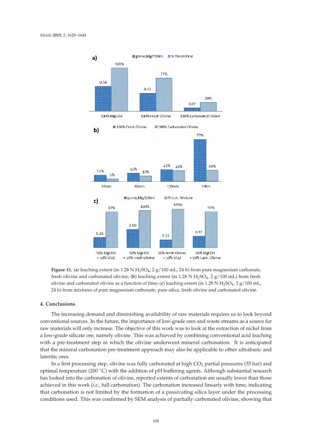
Metals 2015, 5, 1620–1644
Figure 11. (a) leaching extent (in 1.28 N H2SO4, 2 g/100 mL, 24 h) from pure magnesium carbonate,fresh olivine and carbonated olivine; (b) leaching extent (in 1.28 N H2SO4, 2 g/100 mL) from fresholivine and carbonated olivine as a function of time; (c) leaching extent (in 1.28 N H2SO4, 2 g/100 mL,24 h) from mixtures of pure magnesium carbonate, pure silica, fresh olivine and carbonated olivine.
4. Conclusions
The increasing demand and diminishing availability of raw materials requires us to look beyondconventional sources. In the future, the importance of low-grade ores and waste streams as a source forraw materials will only increase. The objective of this work was to look at the extraction of nickel froma low-grade silicate ore, namely olivine. This was achieved by combining conventional acid leachingwith a pre-treatment step in which the olivine underwent mineral carbonation. It is anticipatedthat the mineral carbonation pre-treatment approach may also be applicable to other ultrabasic andlateritic ores.
In a first processing step, olivine was fully carbonated at high CO2 partial pressures (35 bar) andoptimal temperature (200 ◦C) with the addition of pH buffering agents. Although substantial researchhas looked into the carbonation of olivine, reported extents of carbonation are usually lower than thoseachieved in this work (i.e., full carbonation). The carbonation increased linearly with time, indicatingthat carbonation is not limited by the formation of a passivating silica layer under the processingconditions used. This was confirmed by SEM analysis of partially carbonated olivine, showing that
168

Metals 2015, 5, 1620–1644
after carbonation distinct crystalline magnesium carbonate particles and clusters of nano-silica areformed. High solids loading and mixing rate appear to enhance the carbonation reaction substantiallydue to the olivine particles being eroded by increased particle collisions. Using electron probe microanalysis it was possible to map the distribution of both major (C, Mg, Si) and minor (Al, Ca, Cr, Fe,Ni) elemental components in this material. The main products of the carbonation reaction includedquasi-amorphous colloidal silica, chromium-rich metallic particles, and ferro-magnesite.
The second stage of this work looked at the extraction of nickel and other metals by leachingfresh as well as carbonated olivine with an array of inorganic and organic acids to test their leachingefficiency. Compared to leaching from untreated olivine, the percentage of nickel extracted fromcarbonated olivine by acid leaching was significantly increased. For example, using 2.6 N HCl andHNO3, 100% and 91% of nickel was respectively leached from carbonated olivine. This compares toonly 66% and 64% nickel leached from untreated olivine using the same acids. Similar trends wereobserved with the organic acids used, where the leaching enhancement reached a factor of 1.25 using0.5 N citric acid, and a factor of 1.48 using 2 N lactic acid. It was found that two acids, sulfuric andformic, are unsuitable for leaching of carbonated olivine.
Looking at future developments, it should be pointed out that in the present work the metalextraction was performed after carbonation. Selective metal recovery of the olivine during carbonationmight substantially enhance the leaching and reduce extractant consumption. During carbonation, themetals dissolve due to the acidic aqueous solution as a result of carbonic acid formation. The residualsolids could then be separated at high temperatures and pressures prior to exiting the reactor, producinga purified silica stream and a concentrated metal liquor or metal precipitate. Another option is toseparate the final products (i.e., silica-rich clusters, carbonate crystals, and metallic particles) priorto leaching, and leach only the metal-rich fraction; this may reduce the amount of sequestered CO2
liberation. Lastly, re-use of any CO2 released during acidification can contribute to lowering processingcosts associated with CO2 concentration from industrial emission sources. These processes are presentlyin development using the proprietary reactor technology of Innovation Concepts B.V. called the “CO2
Energy Reactor” [13]. This reactor makes use of a Gravity Pressure Vessel (GPV) that supportshydrostatically built supercritical pressures, runs in autothermal regime by recycling the exothermiccarbonation heat, and operates under turbulent three-phase plug flow configuration. This reactor isexpected to allow faster carbonation conversion and more economical processing.
Acknowledgments: The KU Leuven Industrial Research Fund (IOF) is gratefully acknowledged for fundingthe Knowledge Platform on Sustainable Materialization of Residues from Thermal Processes into Products(SMaRT-Pro2) in which this work was performed. Rafael Santos is thankful for the PGS-D support from theNatural Sciences and Engineering Research Council of Canada (NSERC), and for postdoctoral financial support(PDM) from the KU Leuven Special Research Fund (BOF). The EPMA work was made possible due to the supportof the Hercules Foundation (project ZW09-09). The KU Leuven Department of Earth and Environmental Sciencesis acknowledged for the use of XRD and LDA equipment.
Author Contributions: Rafael M. Santos conceptualized and managed the research, co-supervised the Masterstudent, characterized materials and samples, and co-wrote the paper. Aldo Van Audenaerde performedexperiments, analyzed the data and co-wrote the paper. Yi Wai Chiang co-supervised the Master student,performed BET analyses and co-wrote the paper. Remus I. Iacobescu performed EPMA analyses and co-wrote thepaper. Pol Knops conceptualized the research and provided industrial advice. Tom Van Gerven supervised thepersonnel, provided funding and managed the laboratory facilities.
Conflicts of Interest: The authors declare no conflict of interest.
References
1. Goldie, R.J. The shortage of nickel. Prospectors & Developers Association of Canada 2004 Convention.Available online: http://www.webcitation.org/query?url=http%3A%2F%2Fwww.pdac.ca%2Fdocs%2Fdefault-source%2Fpublications---papers-presentations---conventions%2Ftechprgm-goldie.pdf%3Fsfvrsn%3D4&date=2015-07-26 (accessed on 26 July 2015).
2. Kerfoot, D.G.E. Nickel. In Ullmann’s Encyclopedia of Industrial Chemistry; Wiley-VCH Verlag GmbH & Co.KGaA: Weinheim, Germany, 2012; Volume 27, pp. 37–101.
169

Metals 2015, 5, 1620–1644
3. McDonald, R.G.; Whittington, B.I. Atmospheric acid leaching of nickel laterites review—Part I: sulphuricacid technologies. Hydrometallurgy 2008, 91, 35–55. [CrossRef]
4. Zhai, Y.-C.; Mu, W.-N.; Liu, Y.; Xu, Q. A green process for recovering nickel from nickeliferous laterite ores.Trans. Nonferrous Metals Soc. China 2010, 20, s65–s70. [CrossRef]
5. Chen, N.; Cao, Z.-F.; Zhong, H.; Fan, F.; Qiu, P.; Wang, M.-M. A novel approach for recovery of nickel andiron from nickel laterite ore. Metall. Res. Technol. 2015, 112, 306. [CrossRef]
6. Harben, P.W.; Smith, C., Jr. Olivine. In Industrial Minerals & Rocks: Commodities, Markets, and Uses, 7th ed.;Kogel, J.E., Trivedi, N.C., Barker, J.M., Krukowski, S.T., Eds.; Society for Mining, Metallurgy and Exploration,Inc.: Littleton, CO, USA, 2006; pp. 679–684.
7. Smyth, J.R.; Frost, D.J.; Nestola, F.; Holl, C.M.; Bromiley, G. Olivine hydration in the deep upper mantle:Effects of temperature and silica activity. Geophys. Res. Lett. 2006. [CrossRef]
8. Agatzini-Leonardou, S.; Dimaki, D. Heap Leaching of Poor Nickel Laterites by Sulphuric Acid at AmbientTemperature. In Hydrometallurgy ’94; Springer: Dordrecht, The Netherlands, 1994; pp. 193–208.
9. Bodor, M.; Santos, R.M.; van Gerven, T.; Vlad, M. Recent developments and perspectives on the treatment ofindustrial wastes by mineral carbonation—A review. Cent. Eur. J. Eng. 2013, 3, 566–584. [CrossRef]
10. Sanna, A.; Hall, M.R.; Maroto-Valer, M. Post-processing pathways in carbon capture and storage by mineralcarbonation (CCSM) towards the introduction of carbon neutral materials. Energy Environ. Sci. 2012, 5,7781–7796. [CrossRef]
11. Ahmad, W. Nickel laterites—Fundamentals of chemistry, mineralogy, weathering processes, formation, andexploration. VALE Inco-VITSL. Available online: http://www.scribd.com/doc/83755762/Nickel-Laterites-Vale-Inco-Oct-2008 (accessed on 7 July 2012).
12. Thompson, J.F.H.; Barnes, S.J.; Dyke, J.M. The distribution of nickel and iron between olivine and magmaticsulfides in some natural assemblages. Can. Miner. 1984, 22, 55–66.
13. Santos, R.M.; Verbeeck, W.; Knops, P.; Rijnsburger, K.; Pontikes, Y.; van Gerven, T. Integrated mineralcarbonation reactor technology for sustainable carbon dioxide sequestration: “CO2 energy reactor”. EnergyProc. 2013, 37, 5884–5891. [CrossRef]
14. Gadikota, G.; Matter, J.; Kelemen, P.; Park, A.-H.A. Chemical and morphological changes during olivinecarbonation for CO2 storage in the presence of NaCl and NaHCO3. Phys. Chem. Chem. Phys. 2014, 16,4679–4693. [CrossRef] [PubMed]
15. Gadikota, G.; Swanson, E.J.; Zhao, H.; Park, A.-H.A. Experimental design and data analysis for accurateestimation of reaction kinetics and conversion for carbon mineralization. Ind. Eng. Chem. Res. 2014, 53,6664–6676. [CrossRef]
16. Julcour, C.; Bourgeois, F.; Bonfils, B.; Benhamed, I.; Guyot, F.; Bodénan, F.; Petiot, C.; Gaucher, É.C.Development of an attrition-leaching hybrid process for direct aqueous mineral carbonation. Chem. Eng. J.2015, 262, 716–726. [CrossRef]
17. Rigopoulos, I.; Petallidou, K.C.; Vasiliades, M.A.; Delimitis, A.; Ioannou, I.; Efstathiou, A.M.; Kyratsi, T.Carbon dioxide storage in olivine basalts: Effect of ball milling process. Powder Technol. 2015, 273, 220–229.[CrossRef]
18. Oxtoby, D.W.; Freeman, W.A.; Block, T.F. Chemistry: Science of Change, 4th ed.; Brooks/Cole: Belmont, NY,USA, 2002.
19. Béarat, H.; McKelvy, M.J.; Chizmeshya, A.V.G.; Gormley, D.; Nunez, R.; Carpenter, R.W.; Squires, K.;Wolf, G.H. Carbon sequestration via aqueous olivine mineral carbonation: Role of passivating layer formation.Environ. Sci. Technol. 2006, 40, 4802–4808. [CrossRef] [PubMed]
20. Chen, Z.-Y.; O’Connor, W.K.; Gerdemann, S.J. Chemistry of aqueous mineral carbonation for carbonsequestration and explanation of experimental results. Environ. Prog. 2006, 25, 161–166. [CrossRef]
21. De Windt, L.; Devillers, P. Modeling the degradation of Portland cement pastes by biogenic organic acids.Cem. Concr. Res. 2010, 40, 1165–1174. [CrossRef]
22. Chiang, Y.W.; Santos, R.M.; van Audenaerde, A.; Monballiu, A.; van Gerven, T.; Meesschaert, B.Chemoorganotrophic Bioleaching of Olivine for Nickel Recovery. Minerals 2014, 4, 553–564. [CrossRef]
170
Metals 2015, 5, 1620–1644
23. O’Connor, W.K.; Dahlin, D.C.; Rush, G.E.; Gerdemann, S.J.; Penner, L.R.; Nilsen, D.N. Aqueousmineral carbonation—Mineral availability, pretreatment, reaction parametrics, and process studies.National Energy Technology Laboratory, US DOE. Available online: http://www.webcitation.org/query?url=https%3A%2F%2Fwww.netl.doe.gov%2FFile%2520Library%2FResearch%2FCoal%2FNETLAlbanyAqueousMineralCarbonation.pdf&date=2015-07-26 (accessed on 26 July 2015).
24. Larachi, F.; Daldoul, I.; Beaudoin, G. Fixation of CO2 by chrysotile in low-pressure dry and moist carbonation:Ex-situ and in-situ characterizations. Geochim. Cosmochim. Acta 2010, 74, 3051–3075. [CrossRef]
25. Qafoku, O.; Kovarik, L.; Kukkadapu, R.K.; Ilton, E.S.; Arey, B.W.; Tucek, J.; Felmy, A.R. Fayalite dissolutionand siderite formation in water-saturated supercritical CO2. Chem. Geol. 2012, 332–333, 124–135. [CrossRef]
26. Lieftink, D.J.; Geus, J.W. The preparation of silica from the olivine process and its possible use as a catalystsupport. J. Geochem. Explor. 1998, 62, 1–3. [CrossRef]
27. Lazaro, A.; Brouwers, H.J.H.; Quercia, G.; Geus, J.W. The properties of amorphous nano-silica synthesizedby the dissolution of olivine. Chem. Eng. J. 2012, 211–212, 112–121. [CrossRef]
28. Wiedenmann, D.; Zaitsev, A.N.; Britvin, S.N.; Krivovichev, S.V.; Keller, J. Alumoåkermanite,(Ca,Na)2(Al,Mg,Fe2+)(Si2O7), a new mineral from the active carbonatite-nephelinite-phonolite volcanoOldoinyo Lengai, northern Tanzania. Miner. Mag. 2009, 73, 373–384. [CrossRef]
29. Sanemasa, I.; Yoshida, M.; Ozawa, T. The dissolution of olivine in aqueous solution of inorganic acids.Bull. Chem. Soc. Jpn. 1972, 45, 1741–1746. [CrossRef]
30. Terry, B. The acid decomposition of silicate minerals part I. Reactivities and modes of dissolution of silicates.Hydrometallurgy 1983, 10, 135–150. [CrossRef]
31. Tzeferis, P.G.; Agatzini-Leonardou, S. Leaching of nickel and iron from Greek non-sulphide nickeliferousores by organic acids. Hydrometallurgy 1994, 36, 345–360. [CrossRef]
© 2015 by the authors. Licensee MDPI, Basel, Switzerland. This article is an open accessarticle distributed under the terms and conditions of the Creative Commons Attribution(CC BY) license (http://creativecommons.org/licenses/by/4.0/).
171

metals
Article
Direct Aqueous Mineral Carbonation of Waste SlateUsing Ammonium Salt Solutions
Hwanju Jo 1, Ho Young Jo 2,*, Sunwon Rha 2 and Pyeong-Koo Lee 1
1 Korea Institute of Geoscience and Mineral Resources, Daejeon 34132, Korea; [email protected] (H.J.);[email protected] (P.-K.L.)
2 Department of Earth and Environmental Sciences, Korea University, Seoul 02841, Korea;[email protected]
* Author to whom correspondence should be addressed; [email protected]; Tel.: +82-2-3290-3179;+82-2-3290-3189.
Academic Editors: Suresh Bhargava, Mark Pownceby and Rahul RamReceived: 18 October 2015; Accepted: 15 December 2015; Published: 18 December 2015
Abstract: The carbonation of asbestos-containing waste slate using a direct aqueousmineral carbonation method was evaluated. Leaching and carbonation tests were conducted onasbestos-containing waste slate using ammonium salt (CH3COONH4, NH4NO3, and NH4HSO4)solutions at various concentrations. The CH3COONH4 solution had the highest Ca-leaching efficiency(17%–35%) and the NH4HSO4 solution had the highest Mg-leaching efficiency (7%–24%) at varioussolid dosages and solvent concentrations. The CaCO3 content of the reacted materials based onthermogravimetric analysis (TGA) was approximately 10%–17% higher than that of the as-receivedmaterial for the 1 M CH3COONH4 and the 1 M NH4HSO4 solutions. The carbonates were precipitatedon the surface of chrysotile, which was contained in the waste slate reacted with CO2. These resultsimply that CO2 can be sequestered by a direct aqueous mineral carbonation using waste slate.
Keywords: CO2 sequestration; mineral carbonation; waste slate; ammonium salts; asbestos
1. Introduction
CO2 mineral carbonation is a method to permanently sequester CO2 as a form of carbonateminerals with or without aqueous phase. For the CO2 mineral carbonation process with aqueousphase, CO2 is reacted with raw materials containing alkaline earth metals (mostly Ca and Mg) inaqueous solutions (i.e., direct aqueous mineral carbonation) or is reacted with alkaline earth metalsleached from raw materials in aqueous solutions (i.e., indirect aqueous mineral carbonation) to formcarbonate minerals [1,2].
The mineral carbonation to sequester CO2 has been extensively studied due to its followingadvantages: (1) non-requirement for any underground geological storage sites; (2) permanent CO2
sequestration without long-term monitoring; (3) potential immobilization of toxic elements containedin raw materials; and (4) beneficial use of produced carbonates. However, the major challenge of themineral carbonation method is to enhance the leaching capacity of alkaline earth metals from rawmaterials, which is a main factor affecting rate and degree of mineral carbonation [3,4]. The leachingprocesses of alkaline earth metals from raw materials are generally expensive due to the need forincreasing temperature and pressure, acid or base solutions, and grinding raw materials.
Previous researches regarding aqueous mineral carbonation have mainly focused on enhancingthe leaching efficiency of alkaline earth metals by pre-treating raw materials before carbonationprocesses [4–8]. Natural alkaline materials and alkaline industrial wastes have been extensivelyevaluated for the mineral carbonation, e.g., [8–19]. Natural alkaline materials are relatively abundantcompared with alkaline industrial wastes but their use requires pretreatment to enhance the leaching
Metals 2015, 5, 2413–2427 172 www.mdpi.com/journal/metals

Metals 2015, 5, 2413–2427
of the alkaline earth metal due to their strong chemical stability. Even if industrial wastes have morelimited availability, the alkaline earth metals can be relatively easily leached from the alkaline industrialbyproducts because of their chemical instability [20].
Asbestos-containing waste slate is one of the potential alkaline industrial wastes to sequester CO2
due to its high content of Ca and Mg. Asbestos-containing waste slate is mostly comprised of cement,which is a Ca source, and chrysotile, which is an Mg source. Chrysotile, which is considered as acarcinogenic material, is the fibrous magnesium silicate mineral (Mg3(Si2O5)(OH)4) in the serpentinegroup. Asbestos-containing slate was used as a roofing material in South Korea during 1960 and 1970sdue to its high insulating capacity, but subsequently has not been legally allowed for use due to thetoxicity of chrysotile, which is a form of asbestos. Currently, the asbestos containing waste slate ismostly disposed of in government certified landfills without reuse in South Korea.
Due to the health risks such as asbestosis, lung cancer, and mesothelioma, a number of studiessuggested safe disposal schemes of asbestos containing materials. Most treatment methods ofasbestos-containing materials focused on morphological alteration of asbestos using chemical andthermal treatment. Chemical treatment methods of asbestos-containing material using oxalic acid [21],Na-oxalate and Na-acetate [22], sulfuric acid [23], and hydrogen peroxide [24] could alter significantlyasbestos material. Thermal treatment methods of asbestos using microwave [25–27] and microwaveair plasma [28] could also alter effectively asbestos to non-hazardous form. However, thermaltreatment requires vast amount of energy. Gualtieri and Tartaglia [29] reported that temperaturehigher than 1000 ◦C is required to entire transformation of asbestos to non-hazardous silicate glassphase. Yoshikawa et al. [27] also showed that asbestos was completely transformed to non-hazardousform at the temperature >1000 ◦C with microwave treatment.
The main objective of this study was to evaluate the feasibility of CO2 sequestration usingwaste slate by a direct aqueous mineral carbonation. Ammonium salt (CH3COONH4, NH4Cl,NH4NO3, and NH4HSO4) solutions were used as solvents for a direct aqueous mineral carbonation ofasbestos-containing waste slate. The leaching and carbonation behaviors of asbestos-containing wasteslate were investigated at room temperature and atmospheric pressure conditions. For the carbonationtests, CO2 was injected into the mixture of waste slate and ammonium salt solution. Morphologicalalteration of asbestos-containing waste slate after carbonation was also evaluated.
2. Experimental Section
2.1. Materials
Waste roofing slate panels were collected from an abandoned house in South Korea. The wasteslate was broken using a hand hammer to get particle size less than 0.425 mm. The slate particles wereused in the leaching and carbonation tests. CH3COONH4, NH4NO3, and NH4HSO4 (Sigma-AldrichCo., St. Louis, Mo, USA) solutions were used as solvents. Deionized (DI) water was used to preparethe ammonium salt solutions.
2.2. Leaching Tests
The leaching test was performed with various slate solid dosages ranging between 20 and 150 g/Lin a 50 mL polypropylene copolymer centrifuge tube using an ammonium salt solution for four hours.1–10 g of oven-dried slate was added into a 50 mL polypropylene copolymer centrifuge tube with 1, 2,and 4 M solutions. The mixture was shaken at room temperature and atmospheric pressure usinga water bath shaker and the pH and electrical conductivity (EC) were then measured. The mixturewas centrifuged at 5000 rpm for 30 min (VS-550i, Vision Scientific CO., Daejeon, Korea) and was thenfiltered using a 0.2 μm filter (ADVANTEC®, Advantec MFS, Inc. Tokyo, Japan). All of the leachingtests were conducted a single time.
173

Metals 2015, 5, 2413–2427
2.3. Carbonation Tests
For the carbonation test, the waste slate and 1 M CH3COONH4 solution or 1 M NH4HSO4
solution at various solid dosages ranged from 20 to 150 g/L were mixed thoroughly for four hoursin a 500 mL Elrenmeyer flask (Dongsung Scientific, Busan, Korea). The initial pH of the mixturesof the waste slate and 1 M CH3COONH4 solution or 1 M NH4HSO4 solution were about 9.4 and9.2, respectively. A 15 vol. % CO2 gas mixture with 85 vol. % N2 was then injected at a flow rateof 200 mL/min into the slurry of waste slate and 1 M CH3COONH4 solution or 1 M NH4HSO4
solution at various solid dosages in the 500 mL Erlenmeyer flask. The 15 vol. % CO2 gas mixture waschosen because the flue gas from coal fired power plants in South Korea generally contains 15 vol. %CO2. During the carbonation tests, the slurry was mixed using a magnetic stirrer at a stirring rate ofapproximately 300 rpm. The procedure of the carbonation test used in this study is similar to that usedin Jo et al. [8]. The carbonation test was performed at a room temperature and atmospheric pressure.The CO2 injection was stopped at a pH of around 7.5 for preventing CaCO3 dissolution [30]. All of thecarbonation tests were conducted a single time.
2.4. Chemical Analysis and Material Characterization
The cation concentrations of filtrates from the leaching and carbonation tests were analyzed byinductivity coupled plasma-atomic emission spectroscopy (ICP-AES, OPTIMA 3000XL, Perkin Elmer,Wellesley, MA, USA). The elemental composition of the as-received material was determined by usingmicrowave digestion. 0.5 g of the waste slate raw material with 10 mL of HNO3 was digested usingmicrowave digestion for 10 min at 175 ◦C and the leachate was then analyzed by ICP-AES (PerkinElmer, Wellesley, MA, USA).
An X-ray diffractometer (Xpert MPD, Phillips, Almelo, The Netherlands) and a field emissionscanning electron microscope (FE-SEM: S-4300, Hitachi, Tokyo, Japan) equipped with energy dispersiveX-ray spectroscopy (EDX: Ex-20, Horiba, Kyoto, Japan) were used to characterize the as-received andreacted materials. The thermogravimetric analysis (TGA) (SDTG-60H, Shimadzu Corp., Kyoto, Japan)was performed on the reactant and products to determine the calcium carbonate (CaCO3) content.
3. Results and Discussion
3.1. Raw Material
The as-received waste slate contained mainly Ca (25.2%). (Table 1). Table 1 shows selectedelemental composition determined by using microwave digestion. The as-received waste slate mainlyconsists of calcite, chrysotile, and Ca-Mg-Al silicates (Figure 1). The CaCO3 content of the waste slatedetermined using the results of TGA [8], as shown in Figure 2 was approximately 29.8%. The CaCO3
may have been formed by natural carbonation because the slate had been exposed to atmosphere fora very long period of more than 20 years. It is well known that cement based materials exposed toatmosphere can absorb CO2 during the service life [31].
Table 1. Chemical and mineralogical characteristics of as-received waste slate sample.
MaterialsComposition (wt. %)
Minerals (XRD)Ca Mg Al Fe Si
Waste slate 25.2 2.2 1.4 1.3 1.4 Calcite, Chrysotile, andCa-Mg-Al-Si-oxide minerals
174

Metals 2015, 5, 2413–2427
10 20 30 40 50 60
0
100
200
300
400
500
Inte
nsity
(cou
nt/s)
2 theta (degree)
CalciteChrysotileCa-Mg-Al-Si-O
Figure 1. X-ray diffraction (XRD) patterns of as-received waste slate.
Figure 2. Thermogravimetric analysis (TGA) results of as-received waste slate. “H2O”, “C–S–H”,and “CaCO3” indicate the mass change occurred by the decomposition of H2O, C–S–H, andCaCO3, respectively.
3.2. Leaching Behaviors
The Ca- and Mg-leaching efficiencies after leaching tests as a function of solid dosage (20, 50, 100,150, and 200 g/L) and solvent concentration (1, 2, and 4 M) are shown in Figures 3 and 4. The leachingefficiency was determined by following equation:
Metal leaching efficiency(%) =MMe-leached(g)
Mt(g)× CMeo(%)× 100 (1)
where MMe-leached is the mass (g) of the metal in the leachate obtained after the leaching test, Mt isthe total mass (g) of the material used in the leaching test, CMeO is the metal content of the materialdetermined by the total elemental analysis.
175

Metals 2015, 5, 2413–2427
0
5
10
15
20
25
30
35
40
CH3COONH4NH4NO3NH4HSO4
0 50 100 150 200 250
Ca
leac
hing
eff
icie
ncy
(%)
Solid dosage (g/L)
1 M
(a)
0
5
10
15
20
25
30
35
40
CH3COONH4NH4NO3NH4HSO4
0 50 100 150 200 250
Mg
leac
hing
eff
icie
ncy
(%)
Solid dosage (g/L)
1 M
(b)
Figure 3. Ca and Mg-leaching efficiencies as a function of the solid dosage with the 1.0 M ammoniumsolution for waste slate samples.
10
15
20
25
30
35
40
CH3COONH4NH4NO3
NH4HSO4
0 1 2 3 4 5
Ca
leac
hing
effi
cien
cy (%
)
Solvent concentration (M)
20 g/L
(a)
10
15
20
25
30
35
40
CH3COONH4NH4NO3
NH4HSO4
0 1 2 3 4 5
Mg
leac
hing
effi
cien
cy (%
)
Solvent concentration (M)
20 g/L
(b)
Figure 4. Ca and Mg-leaching efficiencies as a function of solvent concentration at the solid dosageof 20 g/L for waste slate samples.
For all solvent conditions, the metal leaching efficiencies were decreased when the solid dosageincreased from 20 to 200 g/L (Figures 3 and 4). Among the 1 M ammonium salts solutions, theCH3COONH4 and NH4NO3 solutions had higher Ca-leaching efficiencies than did the NH4HSO4
solution, regardless of solid dosage. Jo et al. [8] reported that 1 M NH4NO3 and CH3COONH4 solutionscould effectively dissolve Ca ions from waste cement. The NH4HSO4 solution may have had a lowerCa-leaching efficiency than the NH4NO3 and CH3COONH4 solutions due to the lower Ca selectivityor the precipitation of gypsum (CaSO4) during the leaching step (Figure 5). In contrast, the NH4HSO4
solution had the highest Mg-leaching efficiency among all the solvents. Wang and Maroto-Valer [6]reported that 1.4 M NH4HSO4 solution leached 100% of Mg and 98% of Fe, but only 13.6% of Si, fromserpentine at 100 ◦C. However, the lower Mg-leaching efficiency (<24%) obtained in this study was
176

Metals 2015, 5, 2413–2427
probably due to the lower temperature and solvent concentration. Nevertheless, Mg ions were leacheddominantly from waste slate in the NH4HSO4 solution.
10 20 30 40 50 60
Rel
ativ
e In
tens
ity (c
ount
/s)
2 theta (degree)
20 g/L
50 g/L
100 g/L
150 g/L
ChrysotileQuartz
Calcite
Unreacted
(a) 123
1
1 1 1 1 1 12 23 3
10 20 30 40 50 60
Rela
tive
Inte
nsity
(cou
nt/s
)
2 theta (degree)
GypsumCalcite(b)
20 g/L
50 g/L
100 g/L
150 g/L
Unreacted
Chrysotile
1
11
1 1 1 1 1
23
2 22
2 2 23
3
Figure 5. X-ray diffraction (XRD) patterns of as-received waste slate (Unreacted) and reacted wasteslate samples obtained from leaching tests using the (a) 1 M CH3COONH4 and (b) 1 M NH4HSO4
solutions at various solid dosages (20, 50, 100, and 150 g/L).
For the 20 g/L of the solid dosage, the CH3COONH4 and NH4NO3 solutions had relativelyhigh Ca-leaching efficiencies (~37%) at high solvent concentrations (>2 M) (Figure 4). However,the CH3COONH4 and NH4NO3 solutions had a slightly lower Ca-leaching efficiency (34%) at lowsolvent concentration (1 M). The NH4HSO4 solution had the lowest Ca-leaching efficiency at allsolvent concentrations. On the contrary, the NH4HSO4 solution had the highest Mg-leaching efficiency(18%–20%) at all solvent concentrations. The Mg-leaching efficiencies of both CH3COONH4 andNH4NO3 solutions were lower than that of the NH4HSO4 solution but increased with increasing thesolvent concentration. The Mg-leaching efficiency of NH4HSO4 was slightly affected by the solventconcentration, suggesting that the CH3COONH4 and NH4HSO4 solutions were the most efficientsolvents for Ca and Mg leaching from waste slate, respectively.
The XRD patterns on the unreacted and reacted waste samples are shown in Figure 5. For the 1 MCH3COONH4 solution, the chrysotile peak intensity was slightly decreased, regardless of the soliddosage (Figure 5). Even though Ca ions were dissolved into the leachate, the calcite peak intensitybarely changed after the leaching tests, possibly indicating that Ca-silicates in the waste slate was amain Ca source in the slurry. The quartz peak identified after the leaching tests was further possibleevidence for the dissolution of Ca-silicates.
For the 1 M NH4HSO4 solution, gypsum (CaSO4·2H2O) was identified at all solid dosages,suggesting that gypsum was precipitated during the leaching process. The gypsum peak intensity washigher at the solid dosage of 50 g/L and decreased with increasing the solid dosage. The calcite peakintensity also barely changed after the leaching test using the 1 M NH4HSO4 solution. In addition,the chrysotile peak was still observed after the leaching tests. The Mg-leaching efficiency (~20%) alsoconfirmed that chrysotile, which was an Mg source, was not fully decomposed after the leaching testsusing the CH3COONH4, NH4NO3, and NH4HSO4 solutions.
3.3. Carbonation Behaviors
The carbonation tests were carried out on suspensions from the leaching test using 1 MCH3COONH4 and 1 M NH4HSO4 solutions. The 1 M CH3COONH4 and NH4HSO4 solutions wereselected due to their high metal leaching efficiency and selectivity in the leaching test. The 1 MCH3COONH4 solution had a high Ca-leaching efficiency and Ca selectivity and the 1 M solutionNH4HSO4 showed high Mg-leaching efficiency and Mg selectivity (Figures 3 and 4).
The cation concentrations of filtrates obtained from the leaching and carbonation tests areshown in Table 2. After the leaching tests, the pH of mixtures using 1 M CH3COONH4 and 1 M
177

Metals 2015, 5, 2413–2427
NH4HSO4 solutions ranged between 9.0 and 9.8, which was suitable for mineral carbonation. For theCH3COONH4 solution, the Ca concentration decreased significantly after carbonation test due to theprecipitation of CaCO3. For the NH4HSO4 solution, however, the Ca concentration was not greatlychanged after the carbonation test. In contrast, the Mg concentration increased after the carbonationtest for both CH3COONH4 and NH4HSO4 solutions, probably because Mg ions were released fromthe solid phase during the CO2 injection. Dissolution of Mg ion is favorable at pH < 8.0 [32]. TheMg ion might dissolve further during carbonation because CO2 injection was stopped when pHof the suspension reached about 7.5. The Si concentration decreased after the carbonation for bothCH3COONH4 and NH4HSO4 solution, probably due to the precipitation of SiO2 from dissolvedCa-Mg-Al-Si-O complex during the CO2 injection.
Table 2. Results of chemical analysis for filtrates obtained from leaching and carbonation tests.
SolventSolid dosage
(g/L)
pH Cation Concentration (mg/L)
LeachingCa Mg Fe Si
Leaching Carbonation Leaching Carbonation Leaching Carbonation Leaching Carbonation
1 M CH3COONH4
20 9.0 1707.2 375.2 51.3 136.8 0.1 0.9 44.3 21.650 9.4 3533.2 652.3 77.5 345.9 0.2 0.6 41.3 32.1100 9.7 6002.2 1955.0 91.9 784.1 0.2 0.5 39.9 24.7150 9.8 7429.2 2597.0 87.4 1200 0.7 0.4 37.0 30.2
1 M NH4HSO4
20 9.0 778.1 709.9 100.9 154.4 1.0 0.6 40.5 16.450 9.2 822.9 797.5 210.3 342.7 0.1 0.4 50.3 24.0100 9.7 755.9 751.9 263.3 824.1 0.4 1.2 52.5 16.1150 9.8 655.1 852.7 214.3 1234 0.3 0.5 48.9 26.3
The carbonation efficiency was determined using the Ca concentration of the filtrates obtainedfrom the leaching and carbonation tests using the following equation:
Ca carbonation efficiency (%) =MCa-leached(g)− MCa-carbonation(g)
Mt(g)× CCa(%)100
× 100(%) (2)
where MCa-leached is the mass (g) of Ca in the filtrate obtained from the leaching test, Mcarbonation isthe mass (g) of Ca in the filtrate obtained from the carbonation test, Mt is the total mass (g) of thewaste slate used in the tests, and CCa is the calcium content (%) of the waste slate determined by totalelemental analysis (Table 1).
The carbonation efficiency is shown in Figure 6. The 1 M CH3COONH4 solution had a higherCa carbonation efficiency than the 1 M NH4HSO4 solution, regardless of the solid dosage. The Cacarbonation efficiencies for both 1 M CH3COONH4 and 1 M NH4HSO4 solutions decreased as thesolid dosage increased, which was comparable to the Ca-leaching efficiency.
0
10
20
30
40
50
60
70
CH3COONH4
NH4HSO4
0 50 100 150 200
Ca
carb
onat
ion
effi
cien
cy (%
)
Solid dosage (g/L)
1 M
Figure 6. Ca carbonation efficiencies as a function of the solid dosage with the 1.0 M CH3COONH4
and 1.0 M NH4HSO4 solutions for waste slate samples.
178

Metals 2015, 5, 2413–2427
3.4. Characteristics of Reacted Asbestos-Containing Waste Slate
The CaCO3 content of the reacted materials determined using results of TGA is shown in Figure 7.The CaCO3 content of the reacted material was approximately 10%–17% higher than that of theas-received material, except for the 1 M NH4HSO4 solution, at a solid dosage of 100 g/L. These resultssuggest that a maximum CO2 sequestration capacity of ~0.048 kg CO2/kg waste slate was obtainedat a solid dosage of 20 g/L using the 1 M CH3COONH4 solution. The CaCO3 content of the reactedmaterial was slightly decreased with increasing the solid dosage from 20 to 150 g/L, except the soliddosage of 100 g/L, with the 1 M NH4HSO4 solution. The CaCO3 content in the 1 M CH3COONH4
solution was approximately 10% higher than that in the 1 M NH4HSO4 solution. On the other hand,the carbonation efficiency in the 1 M CH3COONH4 solution based on Ca concentrations in the filtratewas approximately 20% higher than that in the 1 M NH4HSO4 solution. These results suggest that Caions obtained during the leaching process and Ca ions obtained by dissolving further from waste slatemight be precipitated during the CO2 injection.
0
10
20
30
40
50
60
70
CH3COONH 4
NH4HSO4
0 50 100 150 200
CaC
O3
cont
ent o
f re
acte
d w
aste
sla
te (
%)
Solid dosage (g/L)
1 M
CaCO 3 content of unreacted waste slate
Figure 7. CaCO3 content of reacted waste slate samples determined using TGA as a function of thesolid dosage with the 1.0 M CH3COONH4 and NH4HSO4 solutions.
After the carbonation tests using 1 M CH3COONH4 and 1 M NH4HSO4 solutions, the calcite peakintensity increased at all the solid dosages (Figure 8). For both 1 M CH3COONH4 and 1 M NH4HSO4
solutions, a chrysotile peak was still observed in the reacted materials after the carbonation tests. Forthe 1 M CH3COONH4 and 1 M NH4HSO4 solutions, almost similar XRD results were obtained, exceptfor the formation of gypsum (CaSO4·2H2O) for the 1 M NH4HSO4 solution (Figure 8).
The images of SEM analysis on the as-received and reacted materials obtained after thecarbonation tests using 1 M CH3COONH4 and 1 M NH4HSO4 solutions are shown in Figures 9and 10, respectively. No carbonates were observed on the surface of needle-like chrysotile in theas-received waste slate, as shown in Figure 9a, even though carbonates were formed by naturalcarbonation due to the long atmospheric exposure of the slate panels. In addition, the SEM imagesconfirmed that the chrysotile originally contained in the waste slate was not fully decomposed afterthe carbonation tests.
179

Metals 2015, 5, 2413–2427
10 20 30 40 50 60
Rel
ativ
e In
tens
ity (c
ount
/s)
2 theta (degree)
20 g/L
50 g/L
100 g/L
150 g/L
ChrysotileCa-Mg-Al-Si-O
Calcite
Unreacted
(a) 123
1
1 1 1 1 1 12 231
10 20 30 40 50 60
Rela
tive
Inte
nsity
(cou
nt/s
)
2 theta (degree)
Gypsum
Calcite(b)Chrysotile
20 g/L
50 g/L
100 g/L
150 g/L
Unreacted
123
1
3
332 1 1 1 1 1 13 3
Figure 8. X-ray diffraction (XRD) patterns of unreacted waste slate (Unreacted) and reacted waste slatesamples obtained from carbonation tests using (a) 1 M CH3COONH4 and (b) 1 M NH4HSO4 solutionsat various solid dosages (20, 50, 100, and 150 g/L).
Mg ions from chrysotile can be dissolved at high pressure (>3 MPa) and temperature (>600 ◦C)conditions or moderate temperature (>70 ◦C) with very strong acid solutions (e.g., hydrochloric acid,oxalic acid, and sulfuric acid), e.g., [33,34]. However, cubic calcite was precipitated on the surface ofneedle-like chrysotile at all solid dosages for both 1 M CH3COONH4 and 1 M NH4HSO4 solutionsafter the carbonation tests (Figures 9 and 10). Health impact of asbestos is mainly caused by itsneedle-like morphological characteristics. The mobility of needle-like chrysotile coated by carbonatesmight be decreased, which probably mitigated the chrysotile’s toxicity by changing its morphology.The carbonates also changed chemical composition of asbestos surface. Aust et al. [35] reported that theasbestos toxicity is strongly related to surface chemical composition of respirable elongated mineralparticles (e.g., Fe associated with the fibers). The carbonates coated chrysotile may inhibit the Fe-relatedreaction between chrysotile and biological molecules [35]. These results suggest that the aqueousmineral carbonation of asbestos-containing waste slate may reduce toxicity of asbestos.
Figure 9. Scanning electron microscope (SEM) images of (a) unreacted waste slate and reacted wasteslate samples obtained from carbonation tests using the 1 M CH3COONH4 solution at solid dosages of(b) 20 g/L, (c) 50 g/L, (d) 100 g/L, and (e) 150 g/L.
180
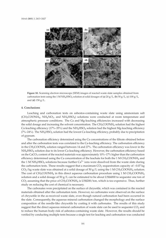
Metals 2015, 5, 2413–2427
Figure 10. Scanning electron microscope (SEM) images of reacted waste slate samples obtained fromcarbonation tests using the 1 M NH4HSO4 solution at solid dosages of (a) 20 g/L, (b) 50 g/L, (c) 100 g/L,and (d) 150 g/L.
4. Conclusions
Leaching and carbonation tests on asbestos-containing waste slate using ammonium salt(CH3COONH4, NH4NO3, and NH4HSO4) solutions were conducted at room temperature andatmospheric pressure conditions. The Ca and Mg-leaching efficiencies increased with decreasingthe solid dosage and increasing the solvent concentration. The CH3COONH4 solution had the highestCa-leaching efficiency (17%–35%) and the NH4HSO4 solution had the highest Mg-leaching efficiency(7%–24%). The NH4HSO4 solution had the lowest Ca-leaching efficiency, probably due to precipitationof gypsum.
The carbonation efficiency determined using the Ca concentrations of the filtrate obtained beforeand after the carbonation tests was correlated to the Ca-leaching efficiency. The carbonation efficiencyin the CH3COONH4 solution ranged between 14 and 27%. The carbonation efficiency was lower in theNH4HSO4 solution due to its lower Ca-leaching efficiency. However, the carbonation efficiency basedon the CaCO3 content of the reacted materials was approximately 10%–17% higher than the carbonationefficiency determined using the Ca concentration of the leachate for both the 1 M CH3COONH4 andthe 1 M NH4HSO4 solutions because further Ca2+ ions were dissolved from the waste slate duringthe carbonation tests. These results suggest that a maximum CO2 sequestration capacity of ~0.07 kgCO2/kg waste slate was obtained at a solid dosage of 50 g/L using the 1 M CH3COONH4 solution.The cost of CH3COONH4 in this direct aqueous carbonation procedure using 1 M CH3COONH4
solution and a solid dosage of 50 g/L can be estimated to be about US$4000 to sequester one ton ofCO2 assuming that the price of CH3COONH4 is US$200/ton, which is too expensive. Thus, furtherstudy on reducing the cost of chemical is necessary.
The carbonates were precipitated on the surface of chrysotile, which was contained in the reactedmaterials obtained after the carbonation tests. However, no carbonates were observed on the surfaceof chrysotile in the as-received waste slate, even though natural carbonation had been occurred inthe slate. Consequently, the aqueous mineral carbonation changed the morphology and the surfacecomposition of the needle-like chrysotile by coating it with carbonates. The results of this studysuggest that the direct aqueous mineral carbonation of waste slate can be used to sequester CO2 andto reduce the human body risk of asbestos-containing waste slate. However, the results should beverified by conducting multiple tests because a single test for leaching and carbonation was conducted
181

Metals 2015, 5, 2413–2427
in this study. In addition, further studies are necessary to investigate the human body risk of thesolid particles obtained after the carbonation tests and the potential effectiveness of more appropriateconditions to further mitigate the toxicity of asbestos-containing waste slate.
Acknowledgments: This research was supported by the Basic Research Project (Study on the mineral carbonationof the alkaline industrial products, GP2015-009) of the Korea Institute of Geoscience and Mineral Resources(KIGAM) funded by the Ministry of Science, ICT and Future Planning and also supported by the Basic ScienceResearch Program through the National Research Foundation of Korea (NRF) funded by the Ministry of Education(2012R1A1B3002473).
Author Contributions: Ho Young Jo designed and managed the research and co-wrote and edited the paper.Hwanju Jo characterized the materials, interpreted the data, and co-wrote the paper. Sunnwon Rha conductedleaching and carbonation tests and characterized the materials. Pyeong-Koo Lee conceptualized the experimentand analyzed interpreted the data.
Conflicts of Interest: The authors declare no conflict of interest.
References
1. Lackner, K.S.; Wendt, C.H.; Butt, D.P.; Joyce, B.L.; Sharp, D.H. Carbon dioxide disposal in carbonate minerals.Energy 1995, 20, 1153–1170. [CrossRef]
2. Sipilä, J.; Teir, S.; Zevenhoven, R. Carbon dioxide sequestration by mineral carbonation: Literature review update2005–2007; Report VT; Abo Akademi University: Turku, Finland, 2008.
3. Intergovernmental Panel on Climate Change. Climate change 2007: Mitigation of climate change:Contribution of working group III to the fourth assessment report of the intergovernmental panel onclimate change. Cambridge University Press: Cambridge, NY, USA, 2007.
4. Jo, H.; Jo, H.Y.; Jang, Y.N. Effect of leaching solutions on carbonation of cementitious materials in aqueoussolutions. Environ. Technol. 2012, 33, 1391–1401. [CrossRef] [PubMed]
5. Kodama, S.; Nishimoto, T.; Yamamoto, N.; Yogo, K.; Yamada, K. Development of a new pH-swing CO2
mineralization process with a recyclable reaction solution. Energy 2008, 33, 776–784. [CrossRef]6. Wang, X.; Maroto-Valer, M.M. Dissolution of serpentine using recyclable ammonium salts for CO2 mineral
carbonation. Fuel 90, 1229–1237. [CrossRef]7. Eloneva, S.; Said, A.; Fogelholm, C.J.; Zevenhoven, R. Preliminary assessment of a method utilizing carbon
dioxide and steelmaking slags to produce precipitated calcium carbonate. Appl. Energy 2012, 90, 329–334.[CrossRef]
8. Jo, H.; Park, S.H.; Jang, Y.N.; Chae, S.C.; Lee, P.K.; Jo, H.Y. Metal leaching and indirect mineral carbonation ofwaste cement material using ammonium salt solutions. Chem. Eng. J. 2012, 254, 313–323. [CrossRef]
9. Park, A.H.A.; Fan, L.S. CO2 mineral sequestration: Physically activated dissolution of serpentine and pHswing process. Chem. Eng. Sci. 2004, 59, 5241–5247. [CrossRef]
10. Huijgen, W.J.J.; Witkamp, G.J.; Comans, R.N.J. Mineral CO2 sequestration by steel slag carbonation. Environ.Sci. Technol. 2005, 39, 9676–9682. [CrossRef] [PubMed]
11. Katsuyama, Y.; Yamasaki, A.; Iizuka, A.; Fujii, M.; Kumagai, K.; Yanagisawa, Y. Development of a process forproducing high-purity calcium carbonate (CaCO3) from waste cement using pressurized CO2. Environ. Prog.2005, 24, 162–170. [CrossRef]
12. Baciocchi, R.; Polettini, A.; Pomi, R.; Prigiobbe, V.; Zedwitz, V.N.V.; Steinfeld, A. CO2 sequestration by directgas-solid carbonation of air pollution control (APC) residues. Energy Fuels 2006, 20, 1933–1940. [CrossRef]
13. Teir, S.; Kuusik, R.; Fogelholm, C.J.; Zevenhoven, R. Production of magnesium carbonates from serpentinitefor long-term storage of CO2. Int. J. Miner. Process. 2007, 85, 1–15. [CrossRef]
14. Bonenfant, D.; Kharoune, L.; Sauve, S.; Hausler, R.; Niquette, P.; Mimeault, M.; Kharoune, M. CO2
Sequestration potential of steel slags at ambient pressure and temperature. Ind. Eng. Chem. Res. 2008, 47,7610–7616. [CrossRef]
15. Huntzinger, D.N.; Gierke, J.S.; Sutter, L.L.; Kawatra, S.K.; Eisele, T.C. Mineral carbonation for carbonsequestration in cement kiln dust from waste piles. J. Hazard. Mater. 2009, 168, 31–37. [CrossRef] [PubMed]
16. Baciocchi, R.; Costa, G.; Bartolomeo, E.D.; Polettini, A.; Pomi, R. Carbonation of stainless steel slag as aprocess for CO2 storage and slag valorization. Waste Biomass Valorization 2010, 1, 467–477. [CrossRef]
182

Metals 2015, 5, 2413–2427
17. Kashef-Haghighi, S.; Ghoshal, S. CO2 Sequestration in concrete through accelerated carbonation curing in aflow-through reactor. Ind. Eng. Chem. Res. 2010, 49, 1143–1149. [CrossRef]
18. Wang, X.; Maroto-Valer, M.M. Integration of CO2 capture and mineral carbonation by using recyclableammonium salts. ChemSusChem 4, 1291–1300. [CrossRef] [PubMed]
19. Baciocchi, R.; Costa, G.; Gianfilippo, M.D.; Polettini, A.; Pomi, R.; Stramazzo, A. Thin-film versus slurry-phasecarbonation of steel slag: CO2 uptake and effects on mineralogy. J. Hazard. Mater. 2015, 283, 302–313.[CrossRef] [PubMed]
20. Kirchofer, A.; Becker, A.; Brandt, A.; Wilcox, J. CO2 mitigation potential of mineral carbonation withindustrial alkalinity sources in the United States. Environ. Sci. Technol., 2013, 47, 7548–7554.
21. Jang, Y.N.; Chae, S.C.; Lee, M.K.; Won, H.I.; Ryu, K.W. Method of removing asbestos from asbestos-containingmaterials by 99% through low temperature heat treatment. US9079055, 14 July 2014.
22. Gadikota, G.; Natali, C.; Boschi, C.; Park, A.H.A. Morphological changes during enhanced carbonation ofasbestos containing material and its comparison to magnesium silicate minerals. J. Hazard. Mater. 2014, 264,42–52. [CrossRef] [PubMed]
23. Nam, S.N.; Jeong, S.; Lim, H. Thermochemical destruction of asbestos-containing roofing slate and thefeasibility of using recycled waste sulfuric acid. J. Hazard. Mater. 2014, 265, 151–157. [CrossRef] [PubMed]
24. Pacella, A.; Fantauzzi, M.; Turci, F.; Cremisini, C.; Montereali, M.R.; Nardi, E.; Atzei, D.; Rossi, A.;Andreozzi, G.B. Surface alteration mechanism and topochemistry of iron in tremolite asbestos: A steptoward understanding the potential hazard of amphibole asbestos. Chem. Geol. 2015, 405, 28–38. [CrossRef]
25. Leonelli, C.; Veronesi, P.; Boccaccini, D.N.; Rivasi, M.R.; Barbieri, L.; Andreola, F.; Lancellotti, I.; Rabitti, D.;Pellacani, G.C. Microwave thermal inertisation of asbestos containing waste and its recycling in traditionalceramics. J. Hazard. Mater. 2006, 135, 149–155. [CrossRef] [PubMed]
26. Horikoshi, S.; Sumi, T.; Ito, S.; Dillert, R.; Kashimura, K.; Yoshikawa, N.; Sato, M.; Shinohara, N.Microwave-driven asbestos treatment and its scale-up for use after natural disasters. Environ. Sci. Technol.2014, 48, 6882–6890. [CrossRef] [PubMed]
27. Yoshikawa, N.; Kashimura, K.; Hashiguchi, M.; Sato, M.; Horikoshi, S.; Mitani, T.; Shinohara, N.Detoxification mechanism of asbestos materials by microwave treatment. J. Hazard. Mater. 2015, 284,201–206. [CrossRef] [PubMed]
28. Averroes, A.; Sekiguchi, H.; Sakamoto, K. Treatment of airborne asbestos and asbestos-like microfiberparticles using atmospheric microwave air plasma. J. Hazard. Mater. 2011, 195, 405–413. [CrossRef] [PubMed]
29. Gualtieri, A.F.; Tartaglia, A. Thermal decomposition of asbestos and recycling in traditional ceramics. J. Eur.Ceram. Soc. 2000, 20, 1409–1418. [CrossRef]
30. Stumm, W.; Morgan, J.J. Aquatic chemistry: Chemical equilibria and rates in natural water, 3rded.Wiley-Interscience publications: New York, NY, USA, 1996.
31. Pade, C.; Guimaraes, M. The CO2 uptake of concrete in a 100 year perspective. Cem. Concr. Res. 2007, 37,1348–1356. [CrossRef]
32. Back, M.; Kuehn, M.; Stanjek, H.; Peiffer, S. Reactivity of alkaline lignite fly ashes towards CO2 in water.Environ. Sci. Technol. 2008, 42, 4520–4526. [CrossRef] [PubMed]
33. Lee, M.G.; Ryu, K.W.; Jang, Y.N.; Kim, W.; Bang, J.H. Effect of oxalic acid on heat pretreatment for serpentinecarbonation. Mater. Trans. 2011, 52, 235–238. [CrossRef]
34. Ryu, K.W.; Jang, Y.N.; Lee, M.G. Enhancement of chrysotile carbonation in alkali solution. Mater. Trans. 2012,53, 1349–1352. [CrossRef]
35. Aust, A.E.; Cook, P.M.; Dodson, R.F. Morphological and chemical mechanisms of elongated mineral particletoxicities. J. Toxic. Environ. Health Part 2011, 14, 40–75. [CrossRef] [PubMed]
© 2015 by the authors. Licensee MDPI, Basel, Switzerland. This article is an open accessarticle distributed under the terms and conditions of the Creative Commons Attribution(CC BY) license (http://creativecommons.org/licenses/by/4.0/).
183

metals
Article
Chalcopyrite Dissolution at 650 mV and 750 mV inthe Presence of Pyrite
Yubiao Li 1,2,*, Gujie Qian 2, Jun Li 2 and Andrea R. Gerson 2,3,*
1 School of Resources and Environmental Engineering, Wuhan University of Technology, Wuhan 430070,Hubei, China
2 Minerals and Materials Science & Technology, Mawson Institute, University of South Australia, MawsonLakes, SA 5095, Australia; [email protected] (G.Q.); [email protected] (J.L.)
3 Blue Minerals Consultancy, 13 Mill Terrace, Middleton, SA 5213, Australia* Authors to whom correspondence should be addressed; [email protected] (Y.L.);
[email protected] (A.R.G.); Tel.: +86-18702778563 (Y.L.); +61-4-22112516 (A.R.G.);Fax: +86-27-87882128 (Y.L.); +61-8-83025545 (A.R.G.).
Academic Editor: Suresh BhargavaReceived: 6 August 2015; Accepted: 25 August 2015; Published: 28 August 2015
Abstract: The dissolution of chalcopyrite in association with pyrite in mine waste results in the severeenvironmental issue of acid and metalliferous drainage (AMD). To better understand chalcopyritedissolution, and the impact of chalcopyrite’s galvanic interaction with pyrite, chalcopyrite dissolutionhas been examined at 75 ◦C, pH 1.0, in the presence of quartz (as an inert mineral) and pyrite.The presence of pyrite increased the chalcopyrite dissolution rate by more than five times at Ehof 650 mV (SHE) (Cu recovery 2.5 cf. 12% over 132 days) due to galvanic interaction betweenchalcopyrite and pyrite. Dissolution of Cu and Fe was stoichiometric and no pyrite dissolved.Although the chalcopyrite dissolution rate at 750 mV (SHE) was approximately four-fold greater (Curecovery of 45% within 132 days) as compared to at 650 mV in the presence of pyrite, the galvanicinteraction between chalcopyrite and pyrite was negligible. Approximately all of the sulfur fromthe leached chalcopyrite was converted to S0 at 750 mV, regardless of the presence of pyrite. At thisEh approximately 60% of the sulfur associated with pyrite dissolution was oxidised to S0 and theremaining 40% was released in soluble forms, e.g., SO4
2−.
Keywords: chalcopyrite; pyrite; galvanic interaction; dissolution
1. Introduction
Chalcopyrite (CuFeS2) is the most abundant copper containing mineral on the planet, accountingfor approximately 70% of the total copper resources [1]. Although copper is predominantly extractedusing pyrometallurgical processing, much attention has recently been paid to the development of aneffective hydrometallurgical extraction methodology [2–8] due to the potential for improved economicsand reduced environmental impact, especially for ore of low copper grade.
The most common reaction (Equation (1)) used to describe [4,6,9–11] chalcopyrite dissolution isits oxidation by Fe3+.
CuFeS2(s) + 4Fe3+→Cu2+ + 5Fe2+ + 2S0 (1)
Equation (1) can be considered to be the sum of anodic and cathodic half-cell reactions as shown inEquations (2) and (3) [12–15].
Anodic half-cell reaction: CuFeS2(s)→Cu2+ + Fe2+ + 2S0(s) + 4e− (2)
Metals 2015, 5, 1566–1579 184 www.mdpi.com/journal/metals

Metals 2015, 5, 1566–1579
Cathodic half-cell reaction: 4Fe3+ + 4e−→4Fe2+ (3)
Chalcopyrite is frequently associated with pyrite (FeS2), the predominant contributor to the seriousenvironmental issue of acid and metalliferous drainage (AMD). However, to date the role ofchalcopyrite in AMD is not well understood. In the absence of pyrite, both anodic and cathodicreactions occur on the chalcopyrite surface. The slow dissolution rate has been proposed to be dueto a slow cathodic half-cell reaction on the chalcopyrite surface [11,16]. In the presence of pyrite, thecathodic half-cell reaction occurs on the pyrite surface as the rest potential of pyrite is greater (660 mVSHE) than that of chalcopyrite (560 mV SHE), forming a galvanic cell with electron transfer from thelower rest potential material (anode) to the material with the greater rest potential (cathode) material [3].It has been reported that when chalcopyrite is in intimate contact with pyrite, the dissolution rate ofchalcopyrite is increased significantly as compared chalcopyrite in isolation [11,14,17,18]. On the otherhand, the dissolution rate of chalcopyrite is significantly decreased in the presence of sulfide mineralswith lower rest potential such as sphalerite and galena [10].
Li et al. [19] have investigated the effect of Eh on chalcopyrite dissolution and found that thechalcopyrite dissolution rate at 750 mV is significantly greater than that at 650 mV. Further study hasshown that the chacopyrite dissolution rate at 650 mV is increased in the presence of added solubleiron [20]. However, the effect of pyrite at these two Eh conditions (i.e., 650 and 750 mV SHE) is not yetwell understood. Hence, better understanding of chalcopyrite dissolution behaviour, in the presenceof pyrite as a function Eh is of geochemical and industrial importance for minimising AMD andoptimising Cu extraction during hydrometallurgical processing, respectively [21–23].
2. Experimental Section
2.1. Mineral Characterisation
The chalcopyrite sample used in this study was from Sonora, Mexico. The pyrite originated fromHuanzala, Peru and was purchased from Ward’s Scientific. Quartz, added as an inert material in thisstudy, originated from Bolivia, NSW, Australia and was purchased from Geo Discoveries (Gosford,NSW, Australia). A chunk of each mineral, i.e., chalcopyrite, pyrite and quartz, was crushed andsubsequently rod milled to obtain a size fraction of 38–75 μm via wet sieving. The resulting sample wasthen sonicated to remove clinging fines, and dried at 70 ◦C in an oven purged with N2. These sampleswere then placed into a plastic tube which was sealed after being filled with N2 gas to minimise surfaceoxidation by air. All the samples were stored in a freezer prior to use. BET analysis (University ofSouth Australia, Adelaide, Australia) indicated a surface area of 0.24 ± 0.04 m2·g−1 for chalcopyriteand 0.39 ± 0.04 m2·g−1 for pyrite. As quartz was not dissolved in the dissolution experiment, the BETwas not performed.
X-ray powder diffraction Rietveld analysis (University of South Australia, Adelaide, Australia)indicated that the chalcopyrite sample contained 92 wt. % chalcopyrite, 2 wt. % quartz, 1 wt. % pyrite,1 wt. % sphalerite and another 4 wt. % amorphous (or unidentified) component(s). This is consistentwith the ICP-AES measurement (Table 1) suggesting a stoichiometry of 95.9 wt. % Cu0.96Fe0.99S2.00 [24].A stoichiometry for the pyrite samples of 94.3 wt. % Fe1.91S2.00 was also indicated (Table 1). This isin agreement with Rietveld XRD analysis of the pyrite which indicated the only phase present to bepyrite with approximately 4 wt. % amorphous. SiO2, was determined to be of more than 99 wt. %purity by XRD analysis.
Table 1. Elemental composition of chalcopyrite and pyrite samples.
Element (wt. %) S Cu Fe Si Ca Bi Zn Pb As Al Co K Mg
Chalcopyrite 34.1 32.5 29.3 0.9 0.8 0.3 0.5 0.3 0.06 0.04 0.1 0.02 0.02Pyrite 51.5 0.01 42.8 - 0.01 - 0.01 0.004 0.003 0.01 - 0.006 -
Note: “-” less than detection limit (Si, Mg 0.003 wt. %, Bi, Co 0.001 wt. %).
185

Metals 2015, 5, 1566–1579
2.2. Dissolution Conditions
Glass vessels (1.2 L) and dissolution cells (PTFE, 60 mL) were used for the flow-through dissolutionexperiments. The 5-port lid of the glass vessel provided access to the dissolution liquor and was usedto house a thermometer, Teflon impeller, high temperature Eh probe, hydrogen peroxide (H2O2) inletand a reflux condenser. The four blade Teflon impeller was driven by a digitally controlled stirrerwith a constant agitation speed of 500 rpm. Heating was provided by a thermostatically controlledsilicone oil bath. In addition to the glass vessels, a peristaltic pump (20 rpm·min−1) was used to recyclethe dissolution solution between each vessel and the PTFE cell (60 mL) through connecting tubes.The PTFE cells were hosted and heated in an adjacent oven to the oil bath. Both the reaction vesselsand the PTFE cells were maintained at 75 ◦C.
A total 10 g of sample (38 < x < 75 μm) was placed into the bottom of the flow-through cell. Forthe reference experiment 4 g of chalcopyrite and 6 g of quartz were mixed uniformly. In another cell4 g of chalcopyrite and 6 g of pyrite were mixed uniformly to investigate chalcopyrite dissolutionin the presence of pyrite. A solution flow rate of 8 L·d−1 was used. The leach liquor was controlledto have Eh of either 650 or 750 mV (SHE) to within ±10 mV, using 7.5 wt. % H2O2 solution, and anauto titrator (EUTECH pH 200 series (Thermo Scientific, Singapore) with a Master Flex pump (JohnMorris Scientific, Chatswood, Australia). The leach solution pH was checked during sampling andmaintained at pH 1.0 by addition of 5 M sulfuric acid.
In order to better understand the surface S species on the leached chalcopyrite polishedchalcopyrite and pyrite samples (8 × 8 × 5 mm, using 600 then 1200 grit silicon carbide paper) wereused. The presence of pyrite in the dissolved residue containing the mixture of pyrite and chalcopyritewould perturb the interpretation of S species upon chalcopyrite surface. The reference experimentused one chalcopyrite slab and the chalcopyrite-pyrite galvanic couples was examined using onechalcopyrite and one pyrite slab tied together using cable ties. In both cases these samples were leachedin 750 mV leach liquor at 75 ◦C and pH 1.0. The leach system that was used is described in [25] and inboth instances a stirring speed of 500 rpm was applied. It has been shown that approximately 30% Cuwas leached from powdered (38–75 μm) chalcopyrite at 30 h upon being subjected to this degree ofagitation. Hence, it is reasonable to suggest that surface species differences due to galvanic interactionwould be apparent after 30 h.
2.3. Bulk and Surface Analyses
During the dissolution process, 10 mL of the reaction solution was sampled periodically andfiltered using a 0.22 μm membrane. The liquor was analysed for soluble Fe, Cu and S analysis usinginductively coupled plasma—atomic emission spectroscopy (ICP-AES) by Analytical Chemistry Sectorat Rio Tinto Technology and Innovation in Bundoora, Australia. Experimental uncertainty of theICP-AES measurements was estimated to be around 1%. The reaction solution in the glass vessel wasreplenished upon each sampling with a fresh 10 mL of lixiviant to maintain the original volume.
At the end of each experiment, a portion of the leached residue was rinsed three times usingpH 1.0 perchloric acid to remove any surface adsorbed species from the lixiviant. These solids wereimmediately frozen using liquid N2 to minimise post-dissolution oxidation. These frozen sampleswere subsequently used for surface-sensitive X-ray photoelectron spectroscopy (XPS) analysis. Theremaining solids were washed with distilled water and dried in the oven at 35 ◦C for XRD andSEM analysis.
A SEM (Phillips XL30 field emission SEM, Adelaide Microscopy, Adelaide, Australia) equippedwith energy dispersive spectrometers (EDS) was employed to record images, using both backscattered(BSE) and secondary electron (SE) modes, and elemental quantification. XRD measurements, onselected residues, were measured using a Bruker D4 ENDEAVOR (University of Adelaide, Adelaide,Australia) with Co Kα1 = 1.78897 Å at 35 kV and 40 mA. A computer program DIFFRA.EVA (Version3.0.0.9) from Bruker in conjunction with the crystallography open database (REV 30738 2011.11.2)was applied to identify mineral phases while quantitative phase analysis of the XRD data was
186

Metals 2015, 5, 1566–1579
performed using the Rietveld method with the aid of DIFFRAC.SUIT TOPAS (Version 4.2, Bruker,Melbourne, Australia).
The XPS instrument used was a Kratos Axis Ultra instrument (University of South Australia,Adelaide, Australia). The X-ray source was a monochromatic aluminium cathode running at 225 Wwith a characteristic energy of 1486.6 eV. Pass energies of 160 and 20 eV were used for survey andhigh-resolution scans, respectively. The charge neutraliser was utilised to compensate for surface staticcharging resulting from electron emission. The area of analysis (Iris aperture) was a 0.3 × 0.7 mmslot; the analysis depth was less than 15 nm. The analysis vacuum was 4 × 10⁻⁹ Torr. To minimisethe sublimation of elemental sulfur (S0), the samples were sample stage was cooled using liquid N2
(150 K). Details of the XPS data analysis methodology are described in [24].
3. Results
3.1. Dissolution
Figure 1a indicates no significant difference in the extracted Cu concentrations in the presence ofquartz or pyrite within 132 days, the duration of the experiment, when Eh was controlled at 750 mV.Within the initial 40 days, the Cu extracted at 750 mV increased in a manner similar to that at 650 mV inthe presence of pyrite; approximately 6% of the Cu was extracted during this stage. Subsequently, theconcentration of the Cu in the 750 mV leach liquor increased significantly, considerably more than thatin the 650 mV leach liquor, regardless of the presence of quartz or pyrite. Approximately 45% of theCu was released within 132 days when the Eh was 750 mV. In contrast, the Cu concentration increasedslowly from 40 days (approximately 6%) within 132 days (approximately 12% Cu) for the dissolutionat 650 mV in the presence of pyrite. When chalcopyrite was dissolved at 650 mV in the presence ofquartz, less than 2.5% Cu was released within 132 days, indicating that the presence of pyrite resultedin a significantly increase in Cu dissolution rate at 650 mV, due most likely to the galvanic interactionbetween chalcopyrite and pyrite.
Figure 1. Leach data resulting from the flow-through experiments conducted at 75 ◦C, pH 1.0, 650mV and 750 mV: (a) Cu concentration and % extraction versus time; (b) Cu concentration againstFe concentration.
The Cu: Fe ratio was slightly greater than 1 when chalcopyrite was dissolved with quartzat 750 mV (Figure 1b). This ratio increased gradually, but was still close to 1, in the later dissolutionstage when both Cu and Fe concentrations increased, indicating Cu to Fe stoichiometric dissolution ofchalcopyrite. In contrast, when chalcopyrite was dissolved at 750 mV in the presence of pyrite, theCu to Fe ratio was slightly less than 1 from the beginning of dissolution, and continued to decreaseto approximately 0.8 at the end of the experiment (i.e., 132 days), indicating the dissolution of Fefrom pyrite. However, the Cu to Fe ratio in the leach liquor was approximately 1 during the entire
187

Metals 2015, 5, 1566–1579
experiment duration when Eh was controlled at 650 mV, regardless of the presence of quartz or pyrite,indicating stoichiometric Cu–Fe dissolution of chalcopyrite.
3.2. XRD and SEM Analyses
Figure 2 shows the XRD patterns collected from the leach residues subjected to 750 mV, 75 ◦Cand pH 1.0. Quantitative Rietveld analysis indicated a leach residue phase composition of 71 wt. %quartz, 19 wt. % chalcopyrite and 10 wt. % S0 for the chalcopyrite-quartz leach system (Figure 2a) and47 wt. % pyrite, 25 wt. % chalcopyrite and 28 wt. % S0 for the chalcopyrite-pyrite system (Figure 2b).No other phases were identified. XRD patterns collected from the leach residues at 650 mV are notshown as most of the residues were almost identical to the feed (less than 12% of the chalcopyrite wasdissolved, Figure 1a).
Figure 2. XRD patterns from the chalcopyrite leach residue subjected to 750 mV, 75 ◦C and pH 1.0: (a)chalcopyrite and quartz; (b) chalcopyrite and pyrite.
If the quantity of quartz (6 g) in the residues from the chalcopyrite-quartz system is assumed tobe unchanged 1.607 g chalcopyrite and 0.845 g of S0 are calculated to be present in the leach residue(Table 2). This weight of S0 converts into 2.423 g of leached chalcopyrite. Hence, the total weight ofchalcopyrite (remaining and dissolved) was 4.03 g which is nearly identical to that added initially(4 g). This suggests that approximately all of the sulfur from the chalcopyrite was oxidised to S0, oralternatiely that no SO4
2− was produced during chalcopyrite dissolution controlled at 750 mV, pH 1.0and 75 ◦C (in the presence of inert quartz).
Table 2. Initial and final weights of mineral phases for the flow-through leach experiments. It isassumed that no quartz dissolution occurs.
Remaining(Dissolved) Quartz
Remaining (Dissolved)Chalcopyrite
Remaining(Dissolved) Pyrite
S0 Formed
4 g chalcopyrite+ 6 g quartz 6 (0) g 1.607 (2.423) g N.A. 0.845 g
4 g chalcopyrite+ 6 g pyrite N.A. 1.607 (2.423) g 3.021 (2.979) g 1.800 g
As shown in Figure 1a, Cu was dissolved in a similar manner in the presence of either quartz orpyrite at 750 mV, indicating an identical (within experimental error) quantity of chalcopyrite remainingin these two residues, i.e., 1.607 g (equating to 25 wt. % of the leach residue in the presence of pyrite).Hence, the remaining total residue, and the amounts of pyrite and S0 formed are calculated to be6.428 g, 3.021 g and 1.800 g, respectively. If it is assumed that the leached chalcopyrite (i.e., 2.423 g)produces 0.845 g of S0 in the chalcopyrite-pyrite system, 0.955 g of S0 must result from pyrite oxidation.
188

Metals 2015, 5, 1566–1579
This suggests that approximately 60% S (corresponding to 1.791 g of pyrite) of the leached pyrite(2.979 g) was oxidised to S0 while 40% S (corresponding to 1.188 g of pyrite) from the pyrite wasoxidised to soluble sulfur species, e.g., SO4
2−.Figure 3 shows SEM images, using two imaging modes, SE and BSE (e.g., Figure 3a,b) of the leach
residues collected at 750 mV, 75 ◦C and pH 1.0. As indicated in Figure 3b, a portion of the chalcopyriteparticles in the chalcopyrite-quartz leach system were oxidised to S0, with the chalcopyrite particlesbeing surrounded/armoured by S0 (Figure 3c). In addition some chalcopyrite particles appearedunoxidised, presenting a smooth surface (Figure 3a,b).
Figure 3. SEM images of leach residues collected at the end of the experiment, 132 days, (750 mV,75 ◦C and pH 1.0 shown in Figure 1): (a) full view of chalcopyrite dissolved with quartz (SE image);(b) full view of chalcopyrite dissolved with quartz (BSE image); (c) selected area from (a); (d) full viewof chalcopyrite dissolved with pyrite (SE image); (e) selected area from (d); (f) selected area from (e).Cp—chalcopyrite, S0—elemental sulfur, SiO2—quartz, Py—pyrite.
In contrast, when pyrite was present, the morphology of the oxidised chalcopyrite wassignificantly changed from that with in the chalcopyrite-quartz system. Figure 3d shows that bothchalcopyrite and pyrite were present in the residue and Figure 3e indicates that the chalcopyrite surfacewas S0-free. In addition, Figure 3e,f suggest that chalcopyrite dissolution behaviour may be differenton different crystal faces. However, the interpretation of these images in terms of leach behaviour isnot yet clear and will form a next step in our study.
3.3. XPS Analyses
XPS has been employed in order to understand the evolution of the uppermost surface species.As the presence of pyrite in the dissolved residue may convolute the interpretation of XPS S 2p specieson the chalcopyrite surface, chalcopyrite slab surfaces leached in the glass vessel (instead of particlesin the flow-through cell) were used.
Figure 4a shows that a significant amount of S0 and Sn2− (polysulfide) formed on the leached
chalcopyrite surface in galvanic interaction with pyrite, as compared to that leached in isolation(Figure 4b). Figure 4c provides the difference spectra of Figure 4a minus Figure 4b. Figure 4d providesthe fitting of the S 2p spectrum shown in Figure 4a. The presence of SO4
2− on the chalcopyritesurface leached in isolation (Figure 4b) might be due to the slow leach rate. As water was used as thelubricating agent during the polishing process, the chalcopryite surface may react with water to form
189

Metals 2015, 5, 1566–1579
SO42−. But when chalcopyrite was contacting with pyrite, the increased leach would be expected to
result in complete dissolution of SO42− (Figure 4a).
(a)–(c) (d)
Figure 4. S 2p spectra collected from the chalcopyrite slabs dissolved at 750 mV, 75 ◦C and pH 1.0 for30 h: (a) chalcopyrite from galvanic cell; (b) chalcopyrite only; (c) (a) minus (b); (d) fitting of (a).
Table 3 provides the quantification of S species on the surfaces of the chalcopyrite slabs. Both Sn2−
and S0 are present in relatively greater quantities (as % of total S) where pyrite was in contact withthe chalcopyrite as compared to the chalcopyrite only system, indicating enhanced sulfur oxidationoccurred on the chalcopyrite slab surface involved in the galvanic cell.
However, these observations are apparently inconsistent with the dissolution data provided inFigure 1a which shows no enhancement in the Cu extraction rate in the galvanic chalcopyrite-pyritesystem at 750 mV. In the flow-through dissolution experiment considerably greater Fe2+ is releasedfrom the chalcoyrite powder particles, as compared to the system used to leach the slab samples.This will be rapidly oxidised to Fe3+ which will dominate the subsequent dissolution (Equation (1))at 750 mV. It is also worth considering that the absolute amount of surface S is not known. Hencealthough the relative amounts of oxidised S species (as % S) are greater on the chalcopyrite surfacesin contract with pyrite (Table 3), the total S on these surfaces may actually be smaller as compared tothose in contact with quartz. If this is the case so the absolute concentrations of the oxidised S speciesmay also be smaller.
Table 3. S species (% S) on the leached chalcopyrite slab surfaces (30 h).
S Species Binding Energy (eV) FWHM * (eV) Chalcopyrite OnlyChalcopyrite
(Galvanic Cell)
Surface S2− 160.6–160.8 0.5–0.6 3 0Bulk S2− 161.1 0.5–0.6 51 49
S22− 161.8–162.2 0.6–0.7 5 7
Sn2− 162.8–163.4 1.2–1.5 22 28
S0 163.9–164.3 1.2–1.5 2 13SO4
2− 168.7–169.1 1.2–1.5 14 0Energy loss 164.8–165.2 1.8–2.0 3 3
* FWHM—full width at half maximum. For the estimation of FWHM values refer to [24,26].
No significant difference was observed between the O 1s spectra collected from chalcopyriteslab surface with and without pyrite present. Only chemisorbed H2O and electrical isolated H2Owere observed in the O 1s spectra collected at these two surfaces, with no O2− or OH−/SO observed(Figure 5).
190

Metals 2015, 5, 1566–1579
Figure 5. Fitted O 1s spectrum collected from the chalcopyrite slab in contact with pyrite (galvanic cell)leached at 750 mV, 75 ◦C and pH 1.0 for 30 h.
The strongest peak in the Fe 2p3/2 XPS spectra is observed at around 708 eV and another weakpeak was also observed at 710–712 eV. This indicates that Fe(III)–S was the major Fe containing specieswith a component of Fe–O/OH also present [3,26–31] (Figure 6a). The Cu 2p spectrum (Figure 6b)shows that the oxidation stat of Cu in/on chalcopyrite was +1 [32–35].
Figure 6. XPS spectra collected from the chalcopyrite surface in contact with pyrite (galvanic cell)leached for 30 h at 750 mV, 75 ◦C and pH 1.0: (a) Fe 2p; (b) Cu 2p.
4. Discussion
Equation (1) indicates that chalcopyrite can be oxidised by Fe3+ to produce S0. As indicated by thePourbaix diagram of the CuFeS2–H2O system [36], pH less than 4 and Eh greater than 580 mV (SHE) isrequired for effective Cu extraction from chalcopyrite. A greater Cu dissolution rate was observedat greater Eh (750 cf. 650 mV, Figure 1a), in accord with our previous chalcopyrite batch dissolutionstudy [19].
The total Cu extracted from chalcopyrite at 650 mV increased significantly across the 132 daysexperimental duration when pyrite, as compared to quartz, was present (Figure 1a, 12% cf. 2.5%). Basedon the ICP results (Figure 1a), the average Cu dissolution rate across 132 days at 650 mV is calculated tobe 3.36 × 10⁻⁶ M·d−1 in the absence of pyrite and 1.86 × 10⁻⁵ M·d−1 when pyrite is present, indicating
191

Metals 2015, 5, 1566–1579
a fivefold increase of the Cu dissolution rate due to galvanic interaction. The mean chalcopyritedissolution rate across 132 days at 750 mV is approximately four times greater than that at 650 mVin the presence of pyrite, i.e., 7.11 × 10⁻⁵ M·d−1 and 7.35 ×10⁻⁵ M·d−1 for the chalcopyrite-quartzand chalcopyrite-pyrite systems respectively. This suggests that Eh plays a vital role in chalcopyritedissolution rate-control. The similar Cu dissolution rates at 750 mV, in the presence and absence ofpyrite, indicate that the galvanic interaction between chalcopyrite and pyrite is negligible.
Our findings are consistent with those of Tshilombo [37] who, using electrochemical techniques,reported that pyrite did not dissolve significantly at low solution potentials and under these conditionsthe leach rate of chalcopyrite was enhanced due to the presence of the cathodic sites on pyrite, i.e.,increased cathodic surface area. However, at greater solution potentials the galvanic interactionstopped and pyrite oxidation was apparent at redox potentials above 700 mV (SHE) [37].When Fe2+
is released from chalcopyrite or pyrite particles into solution, Fe3+ is available as the Eh is controlledand a portion of Fe2+ is oxidised rapidly by the addition of H2O2. The reduction of Fe3+ occurs onthe pyrite surface in preference to the chalcopyrite surface when pyrite is present and contactingwith chalcopyrite. However, when the solution Eh (e.g., 750 mV) is greater than the rest potential ofpyrite, the reduction of Fe3+ on both pyrite and chalcopyrite is possible, resulting in the dissolutionfrom both chalcopyrite and pyrite as indicated by Figure 1b. Therefore at 750 mV leaching of bothchalcopyrite and pyrite is likely to take place. The dissolution of pyrite therefore increases the Feconcentration, resulting in a decreased Cu to Fe ratio as shown in Figure 1b. However, stoichiometricCu to Fe dissolution of chalcopyrite at 650 mV is expected (Figure 1b), regardless of the presence ofpyrite, as this Eh is less than the rest potential of pyrite but greater than that of chalcopyrite [38] andlittle dissolution of pyrite occurs.
These findings are of significance in providing better understanding of the factors affectingdissolution rate of mixed chalcopyrite and pyrite systems in AMD systems within the most oftenobserved Eh range of 500–800 mV (SHE) [39–41]. In particular the findings suggest that metalliferousCu-containing drainage may be of importance in this Eh range and that acidic drainage from pyritedissolution may be partially inhibited if the Eh remains below pyrite’s rest potential. In addition, thisstudy also reveals that the galvanic effect between chalcopyrite and pyrite (or other sulfides) in thehydrometallurgical processing of chalcopyrite can be managed via controlling the solution Eh.
5. Conclusions
Chalcopyrite leaching has been conducted at 75 ◦C and pH 1.0. At Eh of 650 mV, the presenceof pyrite, as compared to the same amount of the inert mineral of quartz, increases chalcopyritedissolution rate by more than five times due to the effective galvanic interaction between chalcopyriteand pyrite. In addition, chalcopyrite leaching of Cu and Fe was found to be stoichiometric suggestinginsignificant pyrite dissolution.
The dissolution rate at 650 mV is significantly less than that at 750 mV, regardless of the presenceof pyrite or quartz. At 750 mV the galvanic effect derived from pyrite is negligible as this Eh is greaterthan the rest potentials of both chalcopyrite and pyrite so that both minerals dissolve.
XRD and SEM results indicate that almost 100% S of the dissolved chalcopyrite is oxidised to S0,regardless of the presence of pyrite (at 750 mV). When pyrite contacts with chalcopyrite at 750 mV,around 60% of the S due to pyrite leaching is oxidised to S0 and the remaining 40% is released assoluble species, e.g., SO4
2−. Therefore, a reasonable Eh should be selected if galvanic interaction isexpected in chalcopyrite dissolution.
Acknowledgments: Financial support from Rio Tinto and Australian Research Council via the ARC-LinkageProject “Solution and surface speciation evolution during chalcopyrite leaching” (LP110200326) isgratefully acknowledged.
Author Contributions: Yubiao Li and Andrea Gerson wrote the paper and contributed to all the activities relatedto this paper. Gujie Qian cooperated in conducting the dissolution experiment and data analysis. Jun Li designedthe dissolution experiment and contributed to all the discussion.
192

Metals 2015, 5, 1566–1579
Conflicts of Interest: The authors declare no conflict of interest.
References
1. Córdoba, E.M.; Muñoz, J.A.; Blázquez, M.L.; González, F.; Ballester, A. Leaching of chalcopyrite with ferricion. Part I: General aspects. Hydrometallurgy 2008, 93, 81–87. [CrossRef]
2. Córdoba, E.M.; Muñoz, J.A.; Blázquez, M.L.; González, F.; Ballester, A. Leaching of chalcopyrite with ferricion. Part III: Effect of redox potential on the silver-catalyzed process. Hydrometallurgy 2008, 93, 97–105.[CrossRef]
3. Li, Y.; Kawashima, N.; Li, J.; Chandra, A.P.; Gerson, A.R. A review of the structure, and fundamentalmechanisms and kinetics of the leaching of chalcopyrite. Adv. Colloid Interface Sci. 2013, 197–198, 1–32.[CrossRef] [PubMed]
4. Watling, H.R. Chalcopyrite hydrometallurgy at atmospheric pressure: 1. Review of acidic sulfate,sulfate-chloride and sulfate-nitrate process options. Hydrometallurgy 2013, 140, 163–180. [CrossRef]
5. Munoz-Castillo, B.P. Reaction Mechanisms in the Acid Ferric-Sulfate Leaching of Chalcopyrite. Ph.D. Thesis,University of Utah, Salt Lake City, UT, USA, 1977.
6. Hirato, T.; Majima, H.; Awakura, Y. The leaching of chalcopyrite with ferric sulfate. Metall. Mater. Trans. B1987, 18, 489–496. [CrossRef]
7. Klauber, C. A critical review of the surface chemistry of acidic ferric sulphate dissolution of chalcopyritewith regards to hindered dissolution. Int. J. Miner. Process. 2008, 86, 1–17. [CrossRef]
8. Watling, H.R. The bioleaching of sulphide minerals with emphasis on copper sulphides—A review.Hydrometallurgy 2006, 84, 81–108. [CrossRef]
9. Hiroyoshi, N.; Miki, H.; Hirajima, T.; Tsunekawa, M. Enhancement of chalcopyrite leaching by ferrous ionsin acidic ferric sulfate solutions. Hydrometallurgy 2001, 60, 185–197. [CrossRef]
10. Dutrizac, J.E. Elemental sulphur formation during the ferric sulphate leaching of chalcopyrite. Can. Metall.Quart. 1989, 28, 337–344. [CrossRef]
11. Dixon, D.G.; Mayne, D.D.; Baxter, K.G. Galvanox (TM)—A novel galvanically-assisted atmospheric leachingtechnology for copper concentrates. Can. Metall. Quart. 2008, 47, 327–336. [CrossRef]
12. Liu, Q.; Li, H.; Zhou, L. Galvanic interactions between metal sulfide minerals in a flowing system:Implications for mines environmental restoration. Appl. Geochem. 2008, 23, 2316–2323. [CrossRef]
13. Koleini, S.M.J.; Jafarian, M.; Abdollahy, M.; Aghazadeh, V. Galvanic leaching of chalcopyrite in atmosphericpressure and sulfate media: Kinetic and surface studies. Ind. Eng. Chem. Res. 2010, 49, 5997–6002. [CrossRef]
14. Koleini, S.M.J.; Aghazadeh, V.; Sandström, A. Acidic sulphate leaching of chalcopyrite concentrates inpresence of pyrite. Miner. Eng. 2011, 24, 381–386. [CrossRef]
15. Misra, M.; Fuerstenau, M.C. Chalcopyrite leaching at moderate temperature and ambient pressure in thepresence of nanosize silica. Miner. Eng. 2005, 18, 293–297. [CrossRef]
16. Tshilombo, A.F.; Petersen, J.; Dixon, D.G. The influence of applied potentials and temperature on theelectrochemical response of chalcopyrite during bacterial leaching. Miner. Eng. 2002, 15, 809–813. [CrossRef]
17. Berry, V.K.; Murr, L.E.; Hiskey, J.B. Galvanic interaction between chalcopyrite and pyrite during bacterialleaching of low-grade waste. Hydrometallurgy 1978, 3, 309–326. [CrossRef]
18. Mehta, A.P.; Murr, L.E. Kinetic study of sulfide leaching by galvanic interaction between chalcopyrite, pyrite,and sphalerite in the presence of T. ferrooxidans (30 ◦C) and a thermophilic microorganism (55 ◦C). Biotechnol.Bioeng. 1982, 24, 919–940. [CrossRef] [PubMed]
19. Li, Y.; Qian, G.; Li, J.; Gerson, A. The rate controlling parameters in the hydrometallurgical leaching ofchalcopyrite. In Proceedings of ALTA 2014 Nickel-Cobalt-Copper Sessions, Perth, Australia, 24–31 May 2014;pp. 399–410.
20. Li, Y.; Qian, G.; Li, J.; Gerson, A.R. Kinetics and roles of solution and surface species of chalcopyritedissolution at 650 mV. Geochim. Cosmochim. Acta 2015, 161, 188–202. [CrossRef]
21. Li, J.; Kawashima, N.; Kaplun, K.; Absolon, V.J.; Gerson, A.R. Chalcopyrite leaching: The rate controllingfactors. Geochim. Cosmochim. Acta 2010, 74, 2881–2893. [CrossRef]
22. Kaplun, K.; Li, J.; Kawashima, N.; Gerson, A.R. Cu and Fe chalcopyrite leach activation energies and theeffect of added Fe3+. Geochim. Cosmochim. Acta 2011, 75, 5865–5878. [CrossRef]
193

Metals 2015, 5, 1566–1579
23. Kimball, B.E.; Rimstidt, J.D.; Brantley, S.L. Chalcopyrite dissolution rate laws. Appl. Geochem. 2010, 25,972–983. [CrossRef]
24. Li, Y.; Chandra, A.P.; Gerson, A.R. Scanning photoelectron microscopy studies of freshly fracturedchalcopyrite exposed to O2 and H2O. Geochim. Cosmochim. Acta 2014, 133, 372–386. [CrossRef]
25. Qian, G.; Li, J.; Li, Y.; Gerson, A.R. Probing the effect of aqueous impurities on the leaching of chalcopyriteunder controlled conditions. Hydrometallurgy 2014, 149, 195–209. [CrossRef]
26. Acres, R.G.; Harmer, S.L.; Beattie, D.A. Synchrotron XPS, NEXAFS, and ToF-SIMS studies of solution exposedchalcopyrite and heterogeneous chalcopyrite with pyrite. Miner. Eng. 2010, 23, 928–936. [CrossRef]
27. Buckley, A.N.; Woods, R. An X-ray photoelectron spectroscopic study of the oxidation of chalcopyrite. Aust.J. Chem. 1984, 37, 2403–2413. [CrossRef]
28. Smart, R.S.C. Surface layers in base metal sulphide flotation. Miner. Eng. 1991, 4, 891–909. [CrossRef]29. Fairthorne, G.; Fornasiero, D.; Ralston, J. Effect of oxidation on the collectorless flotation of chalcopyrite. Int.
J. Miner. Process. 1997, 49, 31–48. [CrossRef]30. Brion, D. Photoelectron spectroscopic study of the surface degradation of pyrite (FeS2), chalcopyrite (CuFeS2),
sphalerite (ZnS), and galena (PbS) in air and water. Appl. Surf. Sci. 1980, 5, 133–152. [CrossRef]31. Acres, R.G.; Harmer, S.L.; Shui, H.W.; Chen, C.H.; Beattie, D.A. Synchrotron scanning photoemission
microscopy of homogeneous and heterogeneous metal sulfide minerals. J. Synchrotron Radiat. 2011, 18,649–657. [CrossRef] [PubMed]
32. Yin, Q.; Kelsall, G.H.; Vaughan, D.J.; England, K.E.R. Atmospheric and electrochemical oxidation of thesurface of chalcopyrite (CuFeS2). Geochim. Cosmochim. Acta 1995, 59, 1091–1100. [CrossRef]
33. Harmer, S.L.; Pratt, A.R.; Nesbitt, H.W.; Fleet, M.E. Reconstruction of fracture surfaces on bornite. Can.Mineral. 2005, 43, 1619–1630. [CrossRef]
34. Pearce, C.I.; Pattrick, R.A.D.; Vaughan, D.J.; Henderson, C.M.B.; van der Laan, G. Copper oxidation state inchalcopyrite: Mixed Cu d9 and d10 characteristics. Geochim. Cosmochim. Acta 2006, 70, 4635–4642. [CrossRef]
35. Klauber, C.; Parker, A.; van Bronswijk, W.; Watling, H. Sulphur speciation of leached chalcopyrite surfaces asdetermined by X-ray photoelectron spectroscopy. Int. J. Miner. Process. 2001, 62, 65–94. [CrossRef]
36. Garrels, R.M.; Christ, C.L. Solutions, Minerals, and Equilibria; Harper & Row: New York, NY, USA, 1965.37. Tshilombo, A.F. Mechanism and Kinetics of Chalcopyrite Passivation and Depassivation during Ferric and
Microbial Leaching. Ph.D. Thesis, University of Brithish Columbia, Vancouver, BC, Canada, December 2004.38. Payant, R.; Rosenblum, F.; Nesset, J.E.; Finch, J.A. The self-heating of sulfides: Galvanic effects. Miner. Eng.
2012, 26, 57–63. [CrossRef]39. Costa, M.; Martins, M.; Jesus, C.; Duarte, J. Treatment of acid mine drainage by sulphate-reducing bacteria
using low cost matrices. Water Air Soil Pollut. 2008, 189, 149–162. [CrossRef]40. Borkowski, A.; Parafiniuk, J.; Wolicka, D.; Kowalczyk, P. Geomicrobiology of acid mine drainage in the
weathering zone of pyrite-bearing schists in the rudawy janowickie mountains (Poland). Geol. Q. 2013, 57,601–612. [CrossRef]
41. Azzali, E.; Marescotti, P.; Frau, F.; Dinelli, E.; Carbone, C.; Capitani, G.; Lucchetti, G. Mineralogical andchemical variations of ochreous precipitates from acid sulphate waters (asw) at the Rosia Montana goldmine (Romania). Environ. Earth Sci. 2014, 72, 3567–3584. [CrossRef]
© 2015 by the authors. Licensee MDPI, Basel, Switzerland. This article is an open accessarticle distributed under the terms and conditions of the Creative Commons Attribution(CC BY) license (http://creativecommons.org/licenses/by/4.0/).
194

metals
Review
Hydrometallurgical Recovery of Precious Metals andRemoval of Hazardous Metals Using PersimmonTannin and Persimmon Wastes
Katsutoshi Inoue 1,*, Manju Gurung 1, Ying Xiong 1, Hidetaka Kawakita 1,†, Keisuke Ohto 1,† and
Shafiq Alam 2,†
1 Department of Applied Chemistry, Faculty of Science & Engineering, Saga University, Honjo-Machi 1,Saga 840-8502, Japan; [email protected] (M.G.); [email protected] (Y.X.);[email protected] (H.K.); [email protected] (K.O.)
2 Department of Chemical and Biological Engineering, College of Engineering, University of Saskatchewan,57 Campus Drive, Saskatoon, SK S7N 5A9, Canada; [email protected]
* Author to whom correspondence should be addressed; [email protected]; Tel.: +81-90-5290-7575;Fax: +81-952-288548.
† These authors contributed equally to this work.
Academic Editors: Suresh Bhargava, Mark Pownceby and Rahul RamReceived: 3 June 2015; Accepted: 29 September 2015; Published: 23 October 2015
Abstract: Novel and environmentally benign adsorbents were prepared via a simple sulfuric acidtreatment process using the wastes of astringent persimmon, a type of biomass waste, along withpersimmon tannin extract which is currently employed for the tanning of leather and as naturaldyes and paints. The effectiveness of these new biosorbents was exemplified with regards tohydrometallurgical and environmental engineering applications for the adsorptive removal ofuranium and thorium from rare earths, cesium from other alkaline metals such as sodium, hexa-valentchromium from zinc as well as adsorptive recovery of gold from chloride media. Furthermore,reductive coagulation of gold from chloride media for the direct recovery of metallic gold andadsorptive recovery of palladium and platinum using chemically modified persimmon tannin extractwere studied.
Keywords: adsorption; precious metals; radioactive elements; chromium(VI); persimmon tannin;biomass wastes
1. Introduction
Within the last decades, increasing attention has been paid towards energy savinghydrometallurgical processes for the recovery of valuable metals and the removal of hazardousmaterials. In hydrometallurgical processing, a leach liquor is subjected to metal separation andpurification, which includes solvent extraction, ion exchange, precipitation, membrane filtration, andso forth. However, all the aforementioned methods suffer from significant disadvantages, whichinclude incomplete metal recovery, high capital costs, high reagent and/or energy requirements andgeneration of toxic sludge or other waste products that demand additional disposal considerations,hence increasing the overall cost. Due to their high efficiency, flexibility, applicability over a widerange of metal concentration, and simple sludge free operation for the effective recovery of analyte,adsorption techniques demonstrate great promise for the recovery of metal values from aquaticenvironment. From the technical and economical points of view, in recent years, much attention hasbeen focused on low cost adsorbents prepared from various biomass wastes as they are relativelyinexpensive, environmentally benign, biodegradable and renewable. In such biomass wastes, thechemical components which exhibit effective adsorption behaviors include several polysaccharides
Metals 2015, 5, 1921–1956 195 www.mdpi.com/journal/metals

Metals 2015, 5, 1921–1956
such as pectic acid, alginic acid, chitin and cellulose, polyphenol compounds such as lignin andtannin, and proteins. Additionally, such adsorption behaviors of the original components can besignificantly enhanced using simple chemical treatments or chemical modification processes. Forexample, although the adsorption of chitin for metal ions is poor, that of chitosan which can beproduced by simple hydration reaction using concentrated sodium hydroxide solution is attractiveparticularly with regards to hydrometallurgical processing [1]. Furthermore, although cellulose itselfexhibits negligible adsorption for nearly all metal ions, it exhibits extraordinary high and selectiveadsorption for gold as a consequence of a simple concentrated sulfuric acid treatment [2].
Concerning tannin compounds, it is well known that they possess ion exchange and complexationcharacteristics towards metal ions; that is, the potential of tannin rich biomass materials for the recoveryof heavy and precious metals has been reported by some authors [3,4].
Persimmon is a popular fruit in East Asian countries such as China, Korea and Japan. Thereare two kinds of persimmon fruits, sweet persimmon and astringent persimmon, which differ bytheir content of water soluble persimmon tannin. Although the former can be eaten, as they aresimilar to apples, the latter are rich in the water soluble persimmon tannin which generates avery astringent taste and, are thus unsuitable for direct consumption. However, such astringentpersimmon can be edible by peeling and drying in the open air for a few weeks during the winterwherein the water soluble persimmon tannin is transformed by a spontaneous condensation reactioninto water insoluble polymerized tannin and its astringent taste is diminished. Here, persimmontannin is a kind of polyphenol compound possessing a complicated chemical structure as shown inScheme 1 containing large amounts of catechol and pyrogallol functional groups [5]. Persimmonextract, the juice of astringent persimmon, contains large quantities of persimmon tannin and hasbeen traditionally employed in various applications as natural paints, dyes, tanning agent for leathertanning, a coagulating agent for proteins, etc. During the preparation of dried persimmon fruitsand astringent persimmon extract, large quantities of peels and juice residue, or biomass wastes,are generated. These wastes still contain large amounts of persimmon tannin. In our recent works,several novel types of environmentally benign adsorption gels were prepared from the powder ofthe astringent persimmon juice and also from the above-mentioned persimmon wastes as potentialagents for the recovery of valuable metals and the removal of hazardous metals. In the presentpaper, these works are summarized and briefly reviewed from the viewpoints of hydrometallurgy andenvironmental engineering.
196

Metals 2015, 5, 1921–1956
ROH O
OH
OH O
OH
OH O
OH
O
OH
OH
OH
CO
OH
OH
OH
O
OH
OH
OH
CO
OH
OH
O
OH
OH
C
OOH
OH
OH
ROH
OH
OH O
OH
OH O
OH
OH
OH
OH
OH
O
OH
OH
OH
CO
OH
OH
OH
OH
OH
OH
m
Scheme 1. Schematic structure of persimmon tannin where m stands for the number of the unit.
2. Adsorptive Removal of Uranium and Thorium
After the oil crisis in the 1970s, the recovery of uranium from sea water received a considerableamount of attention in Japan. From such interest, Sakaguchi and Nakajima found that some tannincompounds such as Chinese gallotannin (tannic acid) immobilized on cellulosic matrices such ascellulose powder are effective for the recovery of uranium from sea water [3]. They further discoveredthat persimmon extract exhibits an extremely high affinity for uranium, and subsequently prepared anadsorption gel for the recovery of uranium by crosslinking it using glutaraldehyde [6]. They attemptedto employ this gel not only for the recovery of uranium from sea water but also for the removal oftrace amounts of uranium from uranium milling wastewater. Environmental pollution by radioactiveelements such as uranium and thorium is not limited to uranium mines and nuclear facilities. Rareearth ores, monazite, bastnaesite and xenotime, contain some quantities of these elements, which areremoved in the mineral dressing stage at mine sites. However, unfavorable treatment and managementof tailings of these ores may bring about serious environmental contamination. For instance, in theearly 1980s a serious environmental pollution problem took place at a rare earth plant at Ipoh, Malaysia.As seen from this case, selective removal of uranium and thorium from rare earths has been requiredin order to avoid such environmental problems.
197

Metals 2015, 5, 1921–1956
From such a viewpoint, studies were conducted on the selective removal of uranium(VI) andthorium(IV) from lutetium(III) (the heaviest rare earth exhibiting similar chemical behaviors with theseactinide elements) using three kinds of adsorbents [7,8]. These are as follows: (1) A persimmon peel gel(PP gel) prepared from persimmon peel waste generated in the production of dried persimmon fruits byboiling in concentrated sulfuric acid for the dehydration condensation reaction for crosslinking betweenpolyphenols and polysaccharides such as cellulose; (2) a gallic acid resin prepared by interacting gallicacid with a commercially available weak base anion exchange resin (DIAION WA30, MitsubishiChemical Corp., Tokyo, Japan); and (3) a kakishibu resin, which was prepared by impregnatingpersimmon extract (kakishibu) into a high porous resin without any functional groups (DIAION HP 20,Mitsubishi Chemical Corp., Tokyo, Japan), kindly donated by Tomiyama Corp., Kyoto, Japan.
pH1 3 5 7 9
% A
dsor
ptio
n
0
20
40
60
80
100
gallic acid resinkakishibu resinPP gel
Figure 1. Percentage adsorption of uranium(VI) at varying equilibrium pH on PP gel, gallic acid resinand kakishibu resin.
Figure 1 shows the pH dependency of % adsorption of uranium(VI) on the PP gel, the gallicacid resin and the kakishibu resin for comparison. For all adsorbents, the adsorption increases withincreasing pH, indicating that adsorption takes place according to a cation exchange mechanismwith the phenolic hydroxyl groups of the persimmon tannin releasing hydrogen ions as suggestedby Sakaguchi and Nakajima [6] (a similar adsorption mechanism will be discussed in Section 4(chromium(VI) adsorption) by the reaction equation shown in Scheme 2b) wherein nearly quantitativeadsorption is achieved at pH values greater than 4.5. The adsorption on the PP gel appears to be nearlyequal to that on the gallic acid resin and higher than that of the kakishibu resin. On the other hand, theadsorption behavior for thorium(IV) was found to be nearly equal for all of the three adsorbents whilethe adsorption of lutetium(III) on the PP gel was found to be higher than that on other two adsorbents.
Figure 2 shows the comparison of the % adsorption of uranium(VI), thorium(IV) and lutetium(III)on the PP gel to compare the order of selectivity among these three metal ions. As seen from thisfigure, it is as follows: Th(IV) > U(VI) > Lu(III). That is, uranium(VI) and thorium(IV) are selectivelyadsorbed on the gel over lutetium(III), supporting the feasibility of selective adsorptive removal of theradioactive elements, uranium(VI) and thorium(IV), contained in rare earth ores using this gel.
198

Metals 2015, 5, 1921–1956
pH1 2 3 4 5 6 7 8 9
% A
dsor
ptio
n
0
20
40
60
80
100
UO22+
Th4+
Lu3+
Figure 2. Percentage Adsorption of uranium(VI), thorium(IV) and lutetium(III) at varying equilibriumpH on PP gel [8] (with permission for reuse from TMS).
From the study of the adsorption isotherms of uranium(VI), thorium(IV) and lutetium(III) onthe PP gel, it was found that the adsorption appears to exhibit the Langmuir type adsorption; i.e.,it increases with increasing metal concentration and tends to approach constant values correspondingto each metal ion, from which maximum adsorption capacities were evaluated for uranium(VI),thorium(IV) and lutetium(III) as follows, respectively: 1.29, 0.49 and 0.28 mol·kg−1-dry gel.In contrast to the selectivity order, uranium(VI) is much more greatly adsorbed than thorium(IV)and lutetium(III). Compared with the adsorption capacities of commercially available chelating resins,that of uranium(VI) on the PP gel is very high as in the case of the persimmon tannin gel reported bySakaguchi and Nakajima [6].
Based on experimental results of the above-mentioned batch wise adsorption tests, mutualseparation between uranium(VI) and lutetium(III) was tested using a small glass column packed withPP gel and model solution containing 0.21 mmol·dm−3 uranium(VI) and 0.29 mmol·dm−3 lutetium(III)at pH = 3.81.
Figure 3 shows the breakthrough profiles of these two metal ions; i.e., a plot of the relativeconcentration of these ions in the effluent (their outlet concentrations) compared with their feedconcentrations against contact time after the initiation of the flow. As seen from this figure,breakthrough of lutetium(III) began at the contact time before 10 h just after the initiation of thefeed while that of uranium(VI) began at 20 h, suggesting that the mutual separation of uranium(VI)from lutetium(III) can be successfully achieved using the column packed with the PP gel.
Figure 4, on the other hand, shows the elution profiles for these two metal ions from the columnafter eluting the loaded column with a 1 mol·dm−3 hydrochloric acid solution. As seen from thisfigure, uranium(VI) was eluted at a concentration greater than 25 times that of the feed solutionfor the breakthrough test, though a small amount of lutetium(III) coexisted as a contaminant in theeluted solution.
Further, from the results of the cycle test, it was apparent that repeating the adsorption ofuranium(VI) followed by elution did not compromise the adsorption capacity of the PP gel foruranium(VI) even after 10 cycles, further supporting its feasibility for practical application.
199

Metals 2015, 5, 1921–1956
0
0 .2
0 .4
0 .6
0 .8
1
1 .2
0 5 0 100 150
Lu(III)
Out
let
conc
entr
atio
n /
Feed
co
ncen
trat
ion
Time / h
U(VI)
Figure 3. Breakthrough profile of uranium(VI) and lutetium(III) from the column packed withpersimmon peel (PP) gel.
0
1 0
2 0
3 0
0 2 4 6 8 1 0
U(VI)
Elut
ed m
etal
con
cent
ratio
n
/ Fe
ed c
once
ntra
tion
Time / h
Lu(III)
Figure 4. Elution profiles of uranium(VI) and lutetium(III) from the PP gel packed column afterbreakthrough using 1 mol·dm−3 hydrochloric acid solution.
3. Adsorptive Removal of Cesium
Cesium (137Cs) is one of the fission products of nuclear fuels contained in radioactive wastes.Due to its long half life (30 years) and bio-toxicity, its separation and removal from aquaticenvironments has always attracted special attention, and this has become much more importantin recent days after the nuclear plant accident at Fukushima, Japan.
Studies on the removal of cesium(I) ion from aqueous solution have been focused largely onadsorption and ion-exchange methods [9–12]. Natural and synthetic zeolites, clay minerals andsynthetic organic or inorganic ion-exchangers have been employed for large scale separation of137Cs from low and intermediate-level radioactive waste effluents or contaminated water [9,10,13,14].However, the majority of these materials appear to be uneconomical as a consequence of their highoperational cost and poor performance. It has been reported that the phenolic resins such as Duolite
200

Metals 2015, 5, 1921–1956
S-30 (phenolic), and Duolite CS-100 (phenolic-carboxylic), can selectively remove cesium(I) fromalkaline solutions [15,16]. The phenolic OH groups are, however, ionizable and only effectiveat high pH. Because of their comparatively lower pKa versus the monohydroxy phenols, thepolyhydroxyphenols are ionizable and can function as metal chelators at relatively lower pH than themonohydroxyphenols. Based on such findings, we anticipated that bioadsorbents having polyphenolicmoieties would exhibit adsorption selectivity towards cesium(I) ions at approximately neutral pH.From this perspective, our focus was towards developing highly effective adsorption materials forcesium(I) removal using a persimmon extract rich in persimmon tannin [17,18]. That is, the adsorbentin the present case, which is abbreviated as CPT (cross-linked persimmon tannin) gel hereafter, wasprepared from commercially available dried persimmon tannin extract powder (Persimmon-KakiTechnology Development Co. Ltd., Jincheng, China) also by means of crosslinking in boilingconcentrated in sulfuric acid at 100 ◦C.
Figure 5 shows the effect of initial pH on the adsorption behavior of CPT gel towards cesium(I)and sodium(I) ions. It is clear from this figure that the adsorption of these metal ions is also greatlyaffected by pH similar to the adsorption of uranium(VI), thorium(IV) and lutetium(III) as describedin the preceding section. Although cesium(I) is negligibly adsorbed on this adsorbent in acidicregion, its adsorption increases with increasing pH, achieving near quantitative removal at pH higherthan 4.5 with moderate adsorption of sodium(I) ion (around 40%), which supports the applicability ofthis adsorbent for the selective removal of cesium(I) at around neutral pH.
0
20
40
60
80
100
0 1 2 3 4 5 6 7
% A
dsor
ptio
n
pHi
Cs
Na
Figure 5. Percentage adsorption of cesium(I) and sodium(I) ions on crosslinked persimmon tannin(CPT) gel at varying initial pH [17] (with permission for reuse from Elsevier B.V.).
Figure 6 shows the isotherm plots for the adsorption of cesium(I) (plot of amount of adsorption(q) vs. equilibrium concentration (Ce)) as well as sodium(I) on CPT gel. The plots indicate the typicalLangmuir’s monolayer type of adsorption. From the Langmuir plot using these data, the maximumadsorption capacities for cesium(I) and sodium(I) on this adsorbent were evaluated as 1.33 and0.45 mol·kg−1, respectively.
201
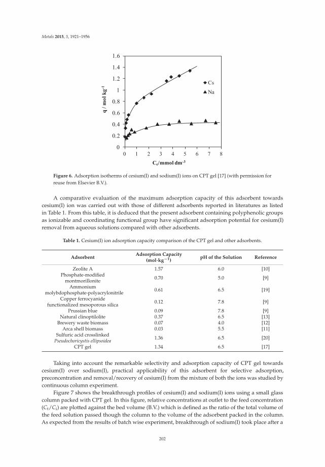
Metals 2015, 5, 1921–1956
0
0.2
0.4
0.6
0.8
1
1.2
1.4
1.6
0 1 2 3 4 5 6 7 8
q / m
ol k
g-1
Ce/mmol dm-3
Cs
Na
Figure 6. Adsorption isotherms of cesium(I) and sodium(I) ions on CPT gel [17] (with permission forreuse from Elsevier B.V.).
A comparative evaluation of the maximum adsorption capacity of this adsorbent towardscesium(I) ion was carried out with those of different adsorbents reported in literatures as listedin Table 1. From this table, it is deduced that the present adsorbent containing polyphenolic groupsas ionizable and coordinating functional group have significant adsorption potential for cesium(I)removal from aqueous solutions compared with other adsorbents.
Table 1. Cesium(I) ion adsorption capacity comparison of the CPT gel and other adsorbents.
AdsorbentAdsorption Capacity
(mol·kg−1)pH of the Solution Reference
Zeolite A 1.57 6.0 [10]Phosphate-modified
montmorillonite 0.70 5.0 [9]
Ammoniummolybdophosphate-polyacrylonitrile 0.61 6.5 [19]
Copper ferrocyanidefunctionalized mesoporous silica 0.12 7.8 [9]
Prussian blue 0.09 7.8 [9]Natural clinoptilolite 0.37 6.5 [13]
Brewery waste biomass 0.07 4.0 [12]Arca shell biomass 0.03 5.5 [11]
Sulfuric acid crosslinkedPseudochoricystis ellipsoidea 1.36 6.5 [20]
CPT gel 1.34 6.5 [17]
Taking into account the remarkable selectivity and adsorption capacity of CPT gel towardscesium(I) over sodium(I), practical applicability of this adsorbent for selective adsorption,preconcentration and removal/recovery of cesium(I) from the mixture of both the ions was studied bycontinuous column experiment.
Figure 7 shows the breakthrough profiles of cesium(I) and sodium(I) ions using a small glasscolumn packed with CPT gel. In this figure, relative concentrations at outlet to the feed concentration(Ct/Ci) are plotted against the bed volume (B.V.) which is defined as the ratio of the total volume ofthe feed solution passed though the column to the volume of the adsorbent packed in the column.As expected from the results of batch wise experiment, breakthrough of sodium(I) took place after a
202
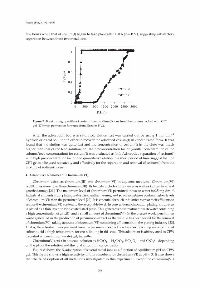
Metals 2015, 5, 1921–1956
few hours while that of cesium(I) began to take place after 100 h (996 B.V.), suggesting satisfactoryseparation between these two metal ions.
0
0.2
0.4
0.6
0.8
1
0 500 1000 1500 2000 2500 3000
Ct/C
i(-)
B.V. (-)
Cs+
Na+
Figure 7. Breakthrough profiles of cesium(I) and sodium(I) ions from the column packed with CPTgel [17] (with permission for reuse from Elsevier B.V.).
After the adsorption bed was saturated, elution test was carried out by using 1 mol·dm−3
hydrochloric acid solution in order to recover the adsorbed cesium(I) in concentrated form. It wasfound that the elution was quite fast and the concentration of cesium(I) in the elute was muchhigher than that of the feed solution, i.e., the preconcentration factor (=outlet concentration of thecolumn/feed concentration) for cesium(I) was evaluated as 140. Adsorptive separation of cesium(I)with high preconcentration factor and quantitative elution in a short period of time suggest that theCPT gel can be used repeatedly and effectively for the separation and removal of cesium(I) from themixture of sodium(I) ions.
4. Adsorptive Removal of Chromium(VI)
Chromium exists as chromium(III) and chromium(VI) in aqueous medium. Chromium(VI)is 500 times more toxic than chromium(III). Its toxicity includes lung cancer as well as kidney, liver andgastric damage [21]. The maximum level of chromium(VI) permitted in waste water is 0.5 mg·dm−3.Industrial effluents from plating industries, leather tanning and so on sometimes contain higher levelsof chromium(VI) than the permitted level [22]. It is essential for such industries to treat their effluents toreduce the chromium(VI) content to the acceptable level. In conventional chromium plating, chromiumis plated as a thin layer on zinc-coated steel plate. This generates post treatment wastewater containinga high concentration of zinc(II) and a small amount of chromium(VI). In the present work, persimmonwaste generated in the production of persimmon extract as the residue has been tested for the removalof chromium(VI), taking account of chromium(VI)-containing effluents from the plating industry [23].That is, the adsorbent was prepared from the persimmon extract residue also by boiling in concentratedsulfuric acid at high temperature for cross-linking in this case. This adsorbent is abbreviated as CPW(crosslinked persimmon waste) gel, hereafter.
Chromium(VI) exist in aqueous solution as HCrO4−, H2CrO4, HCr2O7
− and CrO42− depending
on the pH of the solution and the total chromium concentration.Figure 8 shows the % adsorption of several metal ions as a function of equilibrium pH on CPW
gel. This figure shows a high selectivity of this adsorbent for chromium(VI) at pH < 3. It also showsthat the % adsorption of all metal ions investigated in this experiment, except for chromium(VI),
203

Metals 2015, 5, 1921–1956
was found to increase with increasing pH in the pH range of 1–5 whereas opposite behavior wasobserved for chromium(VI). That is, the % adsorption of chromium(VI) increased with increasing pHin the pH range of 1–3 and then decreased with further increases in pH. This contrasting behavior forchromium(VI) adsorption compared to the other metal ions can be attributed to a different adsorptionmechanism shown in Scheme 2 [4]. As stated earlier, Cr(VI) exists in aqueous medium as HCrO4
−,H2CrO4, HCr2O7
− and CrO42−, among which the HCrO4
− is the dominant species up to pH 5 [24].Scheme 2a shows the adsorption mechanism of the oxo anionic form of chromium(VI) on CPW gel
from an acidic solution in terms of an esterification reaction, which suggests that a high concentrationof H+ ion enhances chromium(VI) adsorption whereas a high concentration of OH− ion suppresseschromium(VI) adsorption, thus accounting for the decrease in the % adsorption of chromium(VI)with increasing the pH of the solution at pH higher than 3. The reason for decreasing % adsorptionwith decreasing pH of the solution at pH less than 3 is due to the reduction of chromium(VI) tochromium(III) in acidic solution as will be discussed later.
On the other hand, the adsorption of other metal ions, except for chromium(VI), which existas cationic species in aqueous solution, are adsorbed on CPW gel according to a cation exchangemechanism as shown in Scheme 2b, which accounts for the increase in the % adsorption with increasingpH of the solution.
Figure 8. Effect of equilibrium pH on the adsorption of different metal ions on CPW gel [23] (withpermission for reuse from Elsevier B.V.).
OH
OHCr
O
O-O
HO O
OCr
OH2O OH-+ +
H++
O (a) Esterification reaction
OH
OH
O
OM(n-2)+Mn+ 2H+++
(b) Cation exchange reaction
Scheme 2. The binding mechanism of (a) chromium(VI) and (b) other metals to the hydroxyl groups ofcatechol units on the cross-linked persimmon gel.
204

Metals 2015, 5, 1921–1956
Batch wise kinetic experiments were carried out in order to elucidate the equilibrium time andmechanism of the adsorption reaction of Cr(VI).
The time variation of % adsorption of total chromium at varying pH is shown in Figure 9, whichreveals that the chromium adsorption monotonously increases with increasing contact time untilreaching constant values corresponding to pH values, except for the case at pH = 1. On the other hand,at pH = 1, after the adsorption rapidly increases at the initial stage similar to the cases at other pHvalues, it slightly decreases and tends to approach a constant value. This phenomenon was observedalso in the adsorption on the crosslinked grape waste gel and it was concluded to be attributed to theadsorption coupled reduction mechanism of chromium(VI) to chromium(III) which is not adsorbed atlow pH as seen from Figure 8 [25].
Figure 9. Effect of contact time on the adsorption of total chromium on cross-linked persimmon waste(CPW) gel from chromium(VI) solution at different pH values [23] (with permission for reuse fromElsevier B.V.).
In order to elucidate the actual mechanism of chromium(VI) adsorption by CPW gel, the rateof change of both chromium(VI) and chromium(III) concentrations in solution were measured atpH = 1 as shown in Figure 10. The result shows that chromium(VI) ions were completely removedfrom the aqueous solution at this pH and chromium(III) ions were generated which were not presentin the original solution. This result demonstrates that there is not only an adsorption mechanismof chromium(VI) but also a reduction mechanism taking place in this pH range. That is, the oxoanionic species of chromium(VI) that is adsorbed on the adsorbent by the esterification reaction asdescribed earlier is reduced to chromium(III) by the electron rich polyphenolic aromatic ring thatsupplies electrons for the reduction reaction as described by the following reactions:
CrO42− + 8H+ + 3e− → Cr3+ + 4H2O (1)
After reduction, the adsorbed chromium is released into the aqueous solution in the form ofchromium(III) ions, thus increasing the concentration of chromium(III) in the solution with contact time.
Isotherm studies were carried out to investigate the effect of metal concentration on the adsorptionof chromium(VI) on the CPW gel. Figure 11 shows the experimental isotherm plots for chromium(VI)adsorption by the CPW gel at different pH values ranging from 1 up to 4. From the result in this
205

Metals 2015, 5, 1921–1956
figure, the adsorption of chromium(VI) at all the pH values tested appears to take place accordingto the Langmuir model, that is, the amount of adsorption increases with increasing chromium(VI)concentration at low concentration while it tends to approach constant values corresponding to eachpH at high concentration in the aqueous solution.
Figure 10. Time variation of the concentrations of chromium(VI) and chromium(III) as well as totalchromium in the aqueous solution at pH = 1 during adsorption [23] (with permission for reuse fromElsevier B.V.).
Figure 11. Adsorption isotherms of chromium(VI) on CPW gel [23] (with permission for reuse fromElsevier B.V.). � pH 1, Δ pH 2, � pH 3, ♦ pH 4.
From the Langmuir plots of these experimental results, the maximum adsorption capacities ofchromium(VI) on the CPW gel were evaluated as 7.18, 6.11, 2.38 and 1.96 mol·kg−1 at pH = 1, 2, 3 and 4,respectively. This result demonstrates the increasing maximum adsorption capacity with decreasingpH, indicating that chromium(VI) removal by the CPW gel is greatly influenced by hydrogen ion.
Table 2 shows the maximum adsorption capacities reported for various adsorbents for comparison,which shows that the polyphenol-containing adsorbents such as mimosa tannin (condensed tannin) [4]
206

Metals 2015, 5, 1921–1956
and persimmon tannin [26] have higher adsorption capacities than other biomasses adsorbents suchas grape gel [25], chitosan [27,28] and sugarcane bagasse [29]. It is noteworthy that the CPW gelcontaining polyphenol groups investigated in this study has the highest adsorption capacity amongthese, and it is also much higher than those of other tannin-containing gels.
Table 2. The maximum adsorption capacity for chromium ion(VI) for different adsorbents.
Adsorbent pH Temperature [K]Maximum AdsorptionCapacity (mol kg−1)
Reference
Mimoza tannin 2.0 303 5.52 [4]Persimmon tannin 3.0 303 5.27 [26]
Quaternary chitosan 4.5 298 0.58 [27]Sugarcane bagasse 3.0 298 1.97 [29]Ocimun americanum 1.5 300 1.60 [30]
Crosslinked grape gel 4 303 1.91 [25]Carbonized wheat straw 2 303 1.67 [31]Carbonized barley straw 3 303 1.68 [31]
CPW gel 1 303 7.18 [23]
Similar to the cases of other metals, mutual separation of chromium(VI) from other metalssuch as zinc(II), for example, was tested on the basis of the results of the batch wise experimentsmentioned earlier.
Figure 12. Breakthrough profiles of various chromium and zinc species from the column packed withCPW gel at pH = 1.0 [23] (with permission for reuse from Elsevier B.V.). �: Total Cr Δ: Cr(III) �: Cr(VI)♦: Zn(II).
Figures 12 and 13 show the breakthrough profiles of zinc(II), total chromium and chromium(VI)at pH = 1 and 4, respectively, for a column packed with the CPW gel using an initial feed solutioncontaining 0.5 mmol·dm−3 chromium(VI) and 5 mmol·dm−3 zinc(II). From these figures, it is seen thatbreakthrough of zinc(II) took place just after the initiation of the feed whereas that of chromium(VI)occurred later, suggesting that mutual separation between zinc(II) and chromium(VI) is feasible usingthe CPW gel. The breakthrough of zinc(II) ion just after the start of feeding is due to the non-adsorbingnature of this ion at this pH on the CPW gel. Although some amount of total chromium was found tohave leaked from the column from the start of the feeding at pH = 1, no chromium(VI) was detectedin the outlet solution; i.e., the total chromium detected in the outlet solution is concluded to be
207

Metals 2015, 5, 1921–1956
chromium(III) reduced from chromium(VI) in the feed solution by the aid of the CPW gel as describedearlier. Consequently, it is apparent that small or trace amounts of chromium(VI) can be completelyremoved from an excess concentration of zinc(II) by using the column packed with the CPW gel,indicating that it can be applicable for the treatment of effluent generating from chromium platingindustries which contain high concentration of zinc(II) but low concentration of chromium(VI).
Figure 13. Breakthrough profiles of various chromium and zinc species from the column packed withCPW gel at pH = 4.0 [23] (with permission for reuse from Elsevier B.V.). �: Total Cr Δ: Cr(III) �: Cr(VI)♦: Zn(II).
5. Recovery of Gold from Acidic Chloride Media by Means of Coagulation Using PersimmonTannin Extract Liquor
Nowadays, precious metals such as gold, silver and platinum group metals (PGM) are in extensiveuse not only as traditional jewelry materials but also as useful components in a variety of well-knownadvanced applications such as electric and electronic devices, catalysts, and medical instruments.Since these metals are limited resources existing only in small amounts on the earth, they shouldbe effectively recovered from various wastes for recycling and reuse purposes. From an economicalpoint of view, the recovery process should be such that the precious metals are highly selectivelyseparated from base metals such as iron, copper, and zinc which often coexist with the precious metalsin disproportionate amounts.
Due to the high price of precious metals, they have been recovered from various wastes formany years. According to the classical refining method of precious metals, feed materials includingvarious wastes are leached using aqua regia, where gold, platinum and palladium are dissolvedleaving other precious metals like silver as well as base metals in leach residue. From the leach liquor,gold is recovered at first as gold sponge by means of the reduction using various reducing agentslike ferrous sulfate, followed by the recovery of platinum and palladium using ammonium chloride.However, because such conventional methods are tedious and require a significant amount of energyas well as long processing times, it is currently being replaced by new methods which involve thecomplete dissolution of feed materials using chlorine containing hydrochloric acid except for silver,followed by solvent extraction and ion exchange or distillation for selective separation into high purityof each precious metal. In this dissolution process, chlorine is dissociated into hydrochloric acidand hypochlorous acid which functions as oxidation agent and is converted into hydrochloric acid.Consequently, the mutual separation among precious metals by means of solvent extraction and ionexchange is carried out from hydrochloric acid. Solvent extraction reagents as well as diluents and ion
208

Metals 2015, 5, 1921–1956
exchange resins, synthetic organic materials, are not environmentally benign taking account of theirdissolution in water and the treatments after their use. On such viewpoints, we attempted to employpersimmon tannin extract (kakishibu), a natural material, as a coagulating agent for the refining ofgold while, as mentioned earlier, persimmon tannin extract has been employed as a coagulating agentfor proteins for a long time [32]. In the present work, persimmon tannin extract liquid was kindlydonated by Tomiyama Corp., Kyoto, Japan, and employed by diluting with water into 10 (V/V) %aqueous solution.
As shown in Figure 14, the minor addition of the persimmon tannin extract into hydrochloric acidsolution containing gold(III) ions caused an observable color change of the solution, which graduallybecame turbid. In the course of time, such dark turbid materials were coagulated and sank down onthe bottom of vessel. After the filtration of the coagulated materials, the filter cake was observed byusing an optical microscope and by means of X-ray diffraction (XRD) analysis.
Gold(III) solution Addition of small volume of
persimmon extract solution Generation of turbid materials Formation of precipitate
Figure 14. Change in the hydrochloric acid solution containing small amount of gold(III) after theaddition of trace volume of persimmon extract liquid [32] (with permission for reuse from The Societyof Chemical Engineers of Japan).
Figure 15. Image of the filter cake of the precipitate generated by the addition of persimmon extractliquor into the gold(III) solution observed by optical microscope (×800).
Figure 15 shows the image of the filter cake observed by an optical microscope. Aggregates ofbrilliant yellow fine particles are observed in the filter cake.
From the observation by the X-ray diffraction pattern of the filter cake, 4 sharp peaks wereconfirmed at 2θ = 38.2, 44.4, 64.6 and 77.5 degree, surely suggesting the existence of metallic gold.
From these observations, it can be concluded that gold(III) ion was reduced into elemental gold(gold(0)) and coagulated into the aggregates by the aid of persimmon tannin extract.
Similar coagulation tests were carried out for hydrochloric acid solutions containing other metalions. Figure 16 shows the plots of % recovery as coagulated precipitates against hydrochloric acid
209

Metals 2015, 5, 1921–1956
concentration for the individual solutions of platinum(IV), palladium(II), copper(II), zinc(II), andiron(III) as well as gold(III).
Figure 16. Percentage recovery of various metal ions by means of coagulation using persimmon extractliquor from varying concentration (mol·dm−3) of hydrochloric acid solution [32] (with permission forreuse from The Society of Chemical Engineers of Japan).
As seen from this figure, the recovery of other metal ions is negligible, suggesting that only goldis much selectively recovered by this method using persimmon tannin extract. The high selectivityto gold is attributable to the higher oxidation reduction potential (ORP) of gold(III) ion than othermetal ions.
The reduction of gold(III) ions to metallic gold (gold(0)) is inferred to take place according to thefollowing reactions where P stands for the polymer matrices of persimmon tannin.
P PhH2O
AuCl4 + 4 H+ + 3 e Au0 + 4 HCl
OH P Ph O + H+ + e
Figure 17 shows the time variation of the % recovery of gold from 0.1 mol·dm−3 hydrochloricacid solution at varying temperatures. As seen from this figure, although it takes very long time toreach the quantitative recovery at 293 and 303 K, such kinetic behavior of the gold recovery can bemuch improved by elevating temperature.
210

Metals 2015, 5, 1921–1956
Figure 17. Percentage recovery of gold(III) by means of coagulation using persimmon extract liquorfrom 0.1 mol·dm−3 hydrochloric acid solution at varying temperatures [32] (with permission for reusefrom The Society of Chemical Engineers of Japan).
6. Adsorptive Recovery of Gold from Acidic Chloride Media Using Gels of Dried PersimmonTannin Extract and Waste of Persimmon Peel
As mentioned in the preceding section, the liquid of persimmon tannin extract exhibits a strongreduction behavior for gold. On the basis of such observation, we carried out the adsorptive recoveryof gold using a CPT gel [33] which was employed for the adsorptive removal of cesium(I) as describedin the former section and also using the gel prepared from persimmon peel waste generated in theproduction of dried persimmon fruit still containing large quantities of persimmon tannin [34].
Figures 18 and 19 show the % adsorption of gold(III), platinum(IV) and palladium(II) as well assome base metals such as copper(II) from varying concentration of hydrochloric acid solution on CPTgel and crude persimmon tannin extract (PT) powder for comparison, respectively.
0
20
40
60
80
100
0 1 2 3 4 5 6
HCl concentration/mol dm-3
% A
dsor
ptio
n
Au(III)
Pd(II)
Pt(IV)
Zn(II)
Ni(II)
Fe(III)
Cu(II)
Figure 18. Percentage adsorption of various metal ions on CPT gel as a function of concentration ofhydrochloric acid [33] (with permission for reuse from Elsevier B.V.).
211

Metals 2015, 5, 1921–1956
Quantitative adsorption of gold(III) was achieved on CPT gel over the whole concentration rangeof hydrochloric acid while the adsorption of gold(III) on crude PT powder decreased significantly inhigher acid concentration regions (greater than 3.0 mol·dm−3). Although both adsorbents exhibitedabout 10%–20% adsorption for platinum(IV) and palladium(II), the adsorption of base metals waspractically negligible under the present experimental conditions. The remarkably high selectivity ofCPT gel for gold(III) over base metals as well as platinum(IV) and palladium(II) in a wide concentrationrange of hydrochloric acid is immensely useful for selective and quantitative recovery of gold(III) fromacidic chloride media.
0
20
40
60
80
100
0 1 2 3 4 5 6
HCl concentration/mol dm-3
% A
dsor
ptio
n
Au(III)
Pd(II)
Pt(IV)
Zn(II)
Ni(II)
Fe(III)
Cu(II)
Figure 19. Percentage adsorption of various metal ions on crude PT powder as a function ofconcentration of hydrochloric acid [33] (with permission for reuse from Elsevier B.V.).
Figure 20 shows the adsorption isotherms of gold(III) on CPT gel and crude PT powder. As seenfrom this figure, it is clear that the amount of gold(III) adsorption on both adsorbents increasedwith increasing metal concentration of the test solution and tended to approach the constant value.That is, the gold(III) adsorption capacity of both adsorbents tended to approach a constant value ataround 4.5 mol·kg−1. Interestingly, as can be seen in this figure, gold(III) adsorption capacity of bothadsorbents again increased, after tending to approach the constant value, with further increase ingold(III) concentration in the test solution, resulting a typical BET type adsorption isotherm based onmultilayer adsorption model. Consequently, the gold uptake capacity of CPT gel reached as high as7.7 mol·kg−1 (=1.52 kg-gold·kg−1-dry adsorbent) and that of crude PT powder reached 5.8 mol·kg−1
(=1.14 kg-gold·kg−1-dry adsorbent), respectively, suggesting that greater quantities of gold(III) relativeto the dry weight of these adsorbents were adsorbed. From this result, it is clear that CPT gel is moreeffective than the crude PT powder for uptake of gold(III) from hydrochloric acid solutions. The higheruptake of CPT gel than crude PT powder towards gold(III) may be attributable to the improvementof structure or surface morphology of the polymer matrices of the gel through crosslinking relatedto the adsorption coupled reduction mechanism. That is, it was found in our previous work thatpolysaccharides such as cellulose which have no functional groups for binding metal ions exhibit veryhigh affinity only for gold to give rise to metallic gold particles by special reduction reaction after thecrosslinking using concentrated sulfuric acid [2]. In the case of CPT gel, in addition to the reductiveadsorption of persimmon tannin itself, the crosslinked polysaccharides coexisting in CPT gel mayexhibit the additional reductive adsorption for gold(III).
212

Metals 2015, 5, 1921–1956
0
2
4
6
8
0 5 10 15Ce/mmol dm-3
q (m
ol/k
g)
CPT gelcrude PT powder
Figure 20. Adsorption isotherms of gold(III) on CPT gel and crude persimmon extract tannin(PT) powder from 0.1 mol·dm−3 hydrochloric acid solution [33] (with permission for reuse fromElsevier B.V.).
Figure 21. FT-IR spectra of CPT gel before and after the adsorption of gold(III) [33] (with permissionfor reuse from Elsevier B.V.).
The above-mentioned mechanism of adsorption of gold(III) followed by reduction to elementalgold was supported by the observation of FT-IR spectra before and after the adsorption of Au(III) onCPT gel and crude PT powder as presented in Figures 21 and 22, respectively. In the FT-IR spectrumafter gold adsorption, the intensity of the band at 1709 cm−1 assigned for quinine type C=O stretchingwas increased. It is interesting to note that the band at 1185 cm−1 attributable to C=C–O asymmetricalstretching was also increased in intensity. These results support the fact that oxidation of phenolichydroxyl groups has actually taken place as mentioned earlier during the adsorption of gold(III) onphenol-rich tannin matrix.
213
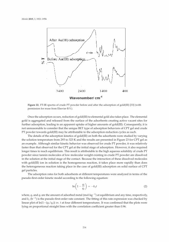
Metals 2015, 5, 1921–1956
Figure 22. FT-IR spectra of crude PT powder before and after the adsorption of gold(III) [33] (withpermission for reuse from Elsevier B.V.).
Once the adsorption occurs, reduction of gold(III) to elemental gold also takes place. The elementalgold is aggregated and released from the surface of the adsorbents creating active vacant sites forfurther adsorption, leading to an apparent uptake of higher amounts of gold(III). Consequently, it isnot unreasonable to consider that the unique BET type of adsorption behaviors of CPT gel and crudePT powder towards gold(III) may be attributable to the adsorption-reduction cycles as such.
The details of the adsorption kinetics of gold(III) on both the adsorbents were studied by varyingthe solution temperature from 293 to 323 K and the results are presented in Figure 23 for CPT gel asan example. Although similar kinetic behavior was observed for crude PT powder, it was relativelyfaster than that observed for the CPT gel at the initial stage of adsorption. However, it also requiredlonger times to reach equilibrium. This result is attributable to the high aqueous solubility of crude PTpowder since tannin molecules of low molecular weight existing in crude PT powder are dissolvedin the solution at the initial stage of the contact. Because the interaction of these dissolved moleculeswith gold(III) ion in solution is the homogeneous reaction, it takes place more rapidly than doesthe heterogeneous reaction taking place in the case of gold(III) adsorption on solid surface of CPTgel particles.
The adsorption rates for both adsorbents at different temperatures were analyzed in terms of thepseudo-first-order kinetic model according to the following equation:
ln(
1 − qt
qe
)= −k1t (2)
where, qe and qt are the amount of adsorbed metal (mol·kg−1) at equilibrium and any time, respectively,and k1 (h−1) is the pseudo-first-order rate constant. The fitting of this rate expression was checked bylinear plot of ln{1−(qt/qe)} vs. t at four different temperatures. It was confirmed that the plots werelying on proportional straight lines with the correlation coefficient greater than 0.96.
214

Metals 2015, 5, 1921–1956
0
1
2
3
0 20 40Time (h)
q (m
ol/k
g)
293 K303 K313 K323 K
Figure 23. Time variation of the adsorption of gold(III) on CPT gel at different temperatures [33] (withpermission for reuse from Elsevier B.V.).
The relationships between the evaluated pseudo-first-order rate constant and temperature wererearranged according to the Arrehnius equation as shown below:
k1 = A e−Ea/RT (3)
where k1 is rate constant, Ea is activation energy, T is absolute temperature, A is Arrehenius constantand R is gas constant.
The results are shown in Figure 24 for CPT gel as an example. From the slopes of the straight linein this figure, the apparent activation energy, Ea, was evaluated as 73 kJ/mol for CPT gel. Similarly,that for crude PT powder was evaluated as 54 kJ/mol.
Similar experimental work was carried out using the adsorption gel prepared by the same methodfrom persimmon peel waste generated in the production of dried persimmon fruit [34]. Such wastestill contains large quantities of persimmon tannin. This gel is abbreviated as PP (persimmon peel)gel, hereafter. Figure 25 shows % adsorption of various metal ions including precious metals such asgold(III), platinum(IV) and palladium(II) as well as base metals such as copper(II) and iron(III) on PPgel from varying concentration of hydrochloric acid containing individual metal ions. Similar to theadsorption on CPT gel, selective adsorption nearly only to gold(III) was observed also in this case.
-3.5
-3
-2.5
-2
-1.5
-1
-0.5
0
3 3.1 3.2 3.3 3.4 3.5
ln k
1/T*1000 (K-1)
Figure 24. Arrhenius plots for the pseudo-first-order rate constants for CPT gel where the straight lineis expressed by the linear equation, Y = −8.57x + 26.7, with the correlation factor (R2) = 0.9671 [33](with permission for reuse from Elsevier B.V.).
215

Metals 2015, 5, 1921–1956
Figure 25. Percentage adsorption of some metal ions on PP gel from varying concentration (mol·dm−3)of hydrochloric acid [34] (with permission for reuse from Elsevier B.V.).
Figure 26 shows the adsorption isotherm of gold(III) on PP gel from 1 mol·dm−3 hydrochloricacid solution as well as those on the adsorption gels prepared from peels of lemon and grape by thesame method for comparison.
Similar to the case of CPT gel, typical BET type adsorption isotherms based on multilayeradsorption model were also observed for these adsorption gels. Extraordinary high amounts of gold(III)adsorption are noteworthy on the adsorbents of PP gel and lemon gel in particular; i.e., the maximumadsorption amount observed for PP gel is as high as around 9 mol·kg−1 (=1.77 kg-gold·kg−1-dryadsorbent), suggesting that considerably greater quantity of gold(III) was adsorbed also on this gelrelative to the dry weight of the adsorbent.
Also in this case, it was confirmed by XRD analysis that the adsorbed gold(III) existed as metallicgold on the adsorbent similar to the case of CPT gel. Figure 27 shows the image of the filter cakeobserved by optical microscope, after the adsorption of gold(III) on PP gel followed by filtration. It isevident from this figure that the brilliant gold particles surely exist in the filter cake separated from thegel particles.
0
4
8
12
16
0 23 46 69 92Ce / mmol dm-3
Q /
mm
olg-1
persimmonlemongrape
Figure 26. Adsorption isotherms of gold(III) from 1 mol·dm−3 hydrochloric acid solution on theadsorption gels prepared from peels of persimmon, lemon and grape treated in boiling concentratedsulfuric acid [34] (with permission for reuse from Elsevier B.V.).
216

Metals 2015, 5, 1921–1956
Figure 27. Image of filter cake after the adsorption of gold(III) on PP gel observed by an opticalmicroscope. Brilliant yellow is the particle of metallic gold while black materials are particles of PP gel.
It may be inferred that the surfaces of CPT and PP gels as well as PT powder function as catalystsfor the reductive adsorption reaction of gold(III) as follows: (1) adsorption of gold(III) ion on the surface;(2) reduction of gold(III) ion into metallic gold (gold(0)); (3) release of nanoparticles of metallic goldfrom the surface and (4) formation of aggregates of nanoparticles of metallic gold. The extraordinaryhigh selectivity and high adsorption capacity for gold(III) may be attributable to this mechanism.In the step (1), the adsorption takes place by the interaction of anionic tetrachloro-complex of gold(III),AuCl4−, with phenolic hydroxyl groups of persimmon tannin molecules, which is followed by thereduction of the step (2). Here, the phenolic hydroxyl groups are oxidized into quinone groups, whichare again converted into phenolic hydroxyl groups by the aid of hydrogen ions and again take placethe adsorption followed by the reduction reaction. Consequently, such reductive adsorption takesplace only under acidic conditions.
7. Chemical Modification of Persimmon Tannin Extract and Persimmon Waste and theAdsorption Behaviors of the Modified Gels
Although, as mentioned earlier, CPT and PP gels were found to exhibit extraordinary highselectivity for gold(III), we further attempted to enhance the affinity also for platinum(IV) andpalladium [35–40]. It is easy to chemically modify persimmon tannin extract and persimmon wasteincluding persimmon peel by immobilizing a variety of functional groups which exhibit specialaffinities for some metal ions onto their surface similar to other biomass wastes [41,42]. In our researchworks, persimmon waste was chemically modified by immobilizing functional group of dimethylamine(DMA) to prepare the adsorption gel functioning as a typical weak base type of anion exchange materialand investigated its adsorption behavior for some precious and base metals from hydrochloric acidsolutions [35,36]. Further, a variety of adsorption gels were prepared from persimmon tannin extractpowder by the chemical modifications immobilizing other functional groups such as tertiary aminewhere the immobilized tertiary amine groups function as quaternary ammonium compounds (QA) [37],a typical strong base, as well as tetraethylenepentamine (TEPA) [38], glycidyltrimethyl ammonium(GTA), aminoguanidine (AG) [40], and bisthiourea (BTU) [41]. These are abbreviated as DMA-PW geland QAPT, BTU-PT, AG-PT, TEPA-PT and GTA-PT gels, respectively, hereafter.
DMA-PW gel was prepared according to Scheme 3. Powder of PW, the same feed materialemployed for the adsorptive removal of chromium(VI) mentioned earlier, was interacted withpara- formaldehyde, 1,4-dioxane, acetic acid, phosphoric acid and hydrochloric acid to preparethe chloromethylated intermediate product. Here, the polymer matrices of PT are not onlychloromethylated but also crosslinked by the aid of paraformaldehyde under acidic condition. It was
217

Metals 2015, 5, 1921–1956
then interacted with dimethylamine to prepare the final product. The abundance of dimethylaminegroups in the DMA-PW gel thus prepared was evaluated as 2.09 mol·kg−1 dry gel.
Scheme 3. Synthetic route of dimethylamine modified persimmon waste (DMA-PW) gel.
Figure 28 shows % adsorption of various metal ions on DMA-PW gel from varying concentrationof hydrochloric acid solution. Although only gold(III) is selectively adsorbed on CPT and PP gels toany considerable extent as mentioned earlier, adsorption is observed not only for gold(III) but alsofor platinum(IV) and palladium(II) while no affinity was observed for base metals such as copper(II),iron(III), nickel(II), and zinc(II) in the case of DMA-PW. This result indicates that the precious metals canbe selectively recovered from any other coexisting base metal ions in hydrochloric acid medium usingthe DMA-PW gel. Additionally, the % adsorption of the precious metals decreased with increasinghydrochloric acid concentration though nearly quantitative adsorption was observed for gold(III) overthe whole concentration region of hydrochloric acid similar to the cases of CPT and PP gels.
0 1 2 3 4
0
20
40
60
80
100
Au(III) Pt(IV) Pd(II) Fe(III) Cu(II) Ni (II) Zn(II)
%
A
[HCl] / M
Figure 28. Percentage adsorption of various metal ions on DMA-PW gel from varying concentration(mol·dm−3) of hydrochloric acid solution [36] (with permission for reuse from Elsevier B.V.).
In acidic chloride media, tertiary amine group of DMA-PW gel is protonated as follows:
RN(CH3)2 + HCl ↔ RNH+(CH3)2Cl− (4)
218

Metals 2015, 5, 1921–1956
The protonated DMA-PW gel is interacted with anionic chloride complexes of gold(III),palladium(II) and platinum(IV), AuCl4−, PtCl62− and PdCl42−, to form ion pair complexes on the gelsurface as follows.
RNH+(CH3)2Cl− + AuCl4− ↔ [RNH+(CH3)2]AuCl4− + Cl− (5)
2RNH+(CH3)2Cl− + PtCl62− ↔ [RNH+(CH3)2]2 PtCl62− + 2Cl− (6)
2RNH+(CH3)2Cl− + PdCl42− ↔ [RNH+(CH3)2]2 PdCl42− + 2Cl− (7)
The decrease in the amount of adsorption of these metal ions with increasing hydrochloric acidconcentration as shown in Figure 28 can be reasonably interpreted by the above-described adsorptionreaction equations. However, the adsorbed gold(III) ion is further reduced by the aid of the functionalgroups of polyphenols of persimmon tannin into metallic gold similar to the cases of CPT and PP gels.
Figure 29 shows the time variations of amount of the adsorption of gold(III) on CPW and DMA-PWgels for comparison, which clearly indicates that equilibrium is attained within 5 h in the case ofDMA-PW whereas it takes much longer in the case of the CPW gel; that is, as a consequence of thechemical modification immobilizing the dimethylamine functional groups, the adsorption kinetics ofgold(III) was significantly enhanced by the interactions between the protonated amine groups andanionic chloro-complex of gold(III).
0 20 40 60 80
0.0
0.5
1.0
1.5
2.0
2.5
q / m
ol/k
g
Time / h
Figure 29. Time variation of the amount of gold(III) on CPW ( )gel and DMA-PW (�)gel from0.1 mol· dm−3 hydrochloric acid solution [36] (with permission for reuse from Elsevier B.V.).
From the studies of adsorption isotherms of gold(III), platinum(IV) and palladium(II) on DMA-PWgel, it was found that all of these are satisfactorily fitted with the Langmuir’s adsorption isothermand the maximum adsorption capacities were evaluated as 5.63, 0.26 and 0.42 mol·kg−1, respectively,while that of gold(III) on CPW gel was evaluated as 4.94 mol·kg−1. Compared with the adsorptionof platinum(IV) and palladium(II), the extraordinary higher adsorption capacities of gold(III) arenoteworthy, which is attributable to the reduction of the adsorbed gold(III) ion into metallic gold(gold(0)) by the polyphenolic functional groups of persimmon tannin as mentioned earlier. In addition,the adsorption capacity of gold(III) itself is also enhanced by this chemical modification.
219

Metals 2015, 5, 1921–1956
On the basis of the above-mentioned results of the batch wise experimental works, an adsorptiontests was conducted for the recovery of precious metals from actual industrial effluent sample, whichis an acidic chloride solution dissolving various metal scraps generated in a precious metals industry.Since the CPW gel has exhibited high selectivity and capacity only for gold, while the DMA-PW hasexhibited a high selectivity for palladium and platinum, the flow experiment was conducted using acolumn packed with PW gel at first for the separation of gold(III) from platinum(IV) and palladium(II),connected in series with the second column packed with DMA-PW gel for recovering platinum(IV)and palladium(II). Here, the acid concentration was around 1 mol·dm−3 and the concentrations ofprecious metals and some base metals in the actual test solution were as follows (in mg·dm−3): Cu 3360,Zn 1040, Fe 760, Au 100, Pd 6.3, and Pt 4.1.
Figures 30a and 31a show the breakthrough profiles from the first column packed with theCPW gel and from the second column packed with DMA-PW gel, respectively. As seen from thesefigures, gold(III) is selectively separated from platinum(IV), palladium(II) and base metals at the firstcolumn while platinum(IV) and palladium(II) are separated from all base metals at the second column.All precious metals adsorbed in these columns were effectively eluted using a mixture of 0.1 mol·dm−3
thiourea in 1 mol·dm−3 hydrochloric acid solution as shown in Figures 30b and 31b. The % recovery ofgold(III), platinum(IV) and palladium(II) were 94.2%, 92.9% and 96.1%, respectively. Almost completerecovery of the loaded precious metal ions including the metallic gold from the loaded gel using acidicthiourea solution verifies the easy regeneration of the gel for repeated use. These findings are highlyencouraging in terms of consistent recovery of precious metals from actual complex mixtures.
0 1000 2000 3000 40000.0
0.2
0.4
0.6
0.8
1.0
Au(III) Pd(II) Pt(IV) Cu(II) Zn(II) Fe(III)
Ce
/ Ci
Bed Volume
0 4 8 12 16 20 24 28 320.0
0.5
1.0
1.5
2.0
2.5
3.0
3.5(b)
Ce
/ Ci
Time (h)
(a)
Figure 30. (a) Breakthrough profiles of various metal ions contained in the sample solution of theactual effluent of the precious metals industry from the first column column packed with CPW gel;(b) Elution profiles of various metal ions from the first column using aqueous mixture of 0.1 mol·dm−3
thiourea in 1 mol·dm−3 hydrochloric acid solution [36] (with permission for reuse from Elsevier B.V.).
The chemical structures of QAPT, BTU-PT, AG-PT, TEPA-PT and GTA-PT gels are shown inScheme 4.
220

Metals 2015, 5, 1921–1956
0 3 6 9 12 15
0
3
6
9
12 Pd(II) Pt(IV) Cu(II) Zn(II) Fe(III)
Time (h)
Ce
/ Ci
Ce
/ Ci
Bed Volume
(a)
0 500 1000 1500 2000 2500 30000.0
0.2
0.4
0.6
0.8
1.0
(b)
Figure 31. (a) Breakthrough profiles of various metal ions from the second column packed withDMA-PW gel; (b) Elution profiles of various metal ions from the second column using aqueous mixtureof 0.1 mol·dm−3 thiourea in 1 mol·dm−3 hydrochloric acid solution [36] (with permission for reusefrom Elsevier B.V.).
Scheme 4. Chemical structures of the gels prepared from persimmon tannin extract powder viachemical modification immobilizing functional groups of quaternary ammonium (QA), bisthiourea(BTU), aminoguanidine (AG), tetraethylenepentamine (TEPA) and glycidyltrimethyl ammonium (GTA)where P stands for persimmon tannin moiety.
Figure 32 shows the % adsorption of various metal ions at varying concentrations of hydrochloricacid on these chemically modified gels for comparison. As seen from this figure, although platinum(IV),
221

Metals 2015, 5, 1921–1956
palladium(II) and gold(III) in particular are adsorbed on all of these modified gels, only negligibleadsorption takes place for the base metals. Among these gels, it is noticeable that QAPT gel exhibitspreferable adsorption behavior compared with other modified gels not only for gold(III) but also forplatinum(IV) and palladium(II) over the relatively wide concentration range of hydrochloric acid. Thatis, the adsorption of gold(III) on QAPT gel is nearly quantitative over the whole concentration region ofhydrochloric acid. Additionally, nearly quantitative adsorption of palladium(II) and platinum(IV) wasachieved in the low concentration range (0.1–1.5 mol·dm−3) of hydrochloric acid. From the comparisonof this figure with Figure 28, it is evident that the adsorption of palladium(II) and platinum(IV) onQAPT gel is much higher than that on DMA-PW gel. Both of tertiary amine functional groups ofDMA-PW gel protonated in acidic solutions and quaternary ammonium functional groups of QAPTcontaining positive charges regardless of pH interact with negatively charged chloro-complexes ofprecious metals by electrostatic interactions. However, because the basicity of QAPT gel is strongerthan that of MDA-PW gel, the interaction by the former is stronger than that by the latter. Furthermore,because precious metals such as gold(III), platinum(IV) and palladium(II) give rise to much morestable chloro-complexes with chloride ion, much more negatively charged complexes, than base metalssuch as iron(III), zinc(II) and copper(II), these precious metals are much more preferentially adsorbedon these modified gels, which may be inferred to be the origin of the high selectivity to precious metalsover base metals.
Figure 32. Percentage adsorption of various metal ions on some chemically modified PT gel from varyingconcentration of hydrochloric acid. � Au(III), � Pd(II), � Pt(IV), | Cu(II), × Zn(II), Δ Ni(II), * Fe(III).
222

Metals 2015, 5, 1921–1956
The results acquired from the adsorption isotherm studies of gold(III), palladium(II), andplatinum(IV) on these modified gels suggested that they were adequately fitted with the Langmuirtype adsorption isotherms. The maximum adsorption capacities of these precious metals on thesemodified gels as well as the DMA-PW gel evaluated according to the Langmuir’s equation are listed inTable 3 together with those on other adsorbents for comparison.
Table 3. The maximum adsorption capacities of gold(III), platinum(IV) and palladium(II) onvarious adsorbents.
Adsorbent
Maximum AdsorptionCapacity (mol·kg−1)
HCl Concentration(mol·dm−3) or pH Reference
Au(III) Pt(IV) Pd(II)
Persimmon extract tannin (PT) powder 5.89 - - 0.1 [33]Crosslinked persimmon tannin (CPT) 7.7 - - 0.1 [33]Crosslinked persimmon waste (CPW) 4.95 - - 0.1 [35,36]Dimethylamine modified persimmon
waste (DMA-PW) 5.63 0.28 0.42 0.1 [35,36]
Quaternary ammonium modifiedpersimmon tannin (QAPT) 4.16 0.52 0.84 0.1 [37]
Tetraethylenepentamine- modifiedpersimmon tannin (TEPA-PT) 5.93 1.48 1.76 0.1 [38]
Glycidyltrimethyl ammonium chloridemodified persimmon tannin (GTA-PT) 3.30 1.00 1.67 0.1 [39]
Aminoguanidine modified persimmontannin (AG-PT) 8.90 1.00 2.00 0.1 [40]
Bisthiourea modified persimmontannin (BTU-PT) 5.22 0.70 1.72 0.1 [41]
Quaternary ammonium modifiedmicroalgal residue 1.33 2.95 0.1 [43]
Crosslinked microalgal residue 3.25 0.15 0.25 0.1 [44]Crosslinked chitosan 1.6 2.1 0.01 [1]
Collagen fiber immobilizedbayberry tannin 0.495 0.80 pH = 5.6 [45]
Lysine modified cross-linked chitosan 0.35 0.66 1.03pH = 1 for Pt;pH = 2 for Pd,
and Au[46]
Glycine modified cross-linked chitosan 0.86 0.62 1.13 pH = 2 [47]PEI-modified
corynebacterium glutamicum 1.66 0.1 [48]
Ethylenediamine modifiedchitosan nanoparticle 0.87 1.30 pH = 2 [49]
Thiourea-modifiedchitosan microsphere 0.66 1.06 pH = 2 [50]
Duolite GT-73 0.58 0.26 pH = 2 [51]Polyallylamine modifiedEscherichia coli biomass 2.50 pH = 3 [52]
Dimethylamine modified waste paper 4.60 0.90 2.10 1 [42]
Among these modified persimmon tannin gels, the high adsorption capacities of TEPA-PT,GTA-PT, AG-PT and BTU-PT not only for gold(III) but also for platinum(IV) and palladium(II) arenoteworthy though the concentration range of hydrochloric acid effective for the high adsorption islimited. Also for these modified persimmon tannin gels, the exceptionally high adsorption capacitiesfor gold(III) are attributable to the combination of adsorption and reduction into metallic gold particlesby the aid of polyphenolic groups of persimmon tannin, which was confirmed by the observationsusing optical microscope and XRD.
The adsorption kinetics of gold(III), palladium(II) and platinum(IV) on the QAPT gel were studiedin detail and compared with that of gold(III) on crude PT powder. It was observed that equilibriumwas attained within 2 h for palladium(II) and platinum(IV) for the adsorption on QAPT gel, whereas itwas attained within 6 h for gold(III) adsorption. On the other hand, the crude PT powder requires 24 hto reach equilibrium of gold(III) adsorption under the same condition. The rapid kinetics of gold (III)adsorption with the QAPT gel is attributable to the effect of abundant quaternary ammonium groups,
223

Metals 2015, 5, 1921–1956
which concentrate the reactant species, AuCl4−, on the gel surface by anion exchange adsorption,enhancing the reduction rate of gold(III).
8. Conclusions
Persimmon tannin extract rich in polyphenol compounds has been traditionally employed forvarious purposes such as tanning of leather, natural dyes and paints as well as coagulating agentsfor proteins in East Asian countries. By effectively using special characteristics of persimmon tanninextract and persimmon wastes which have not been utilized to date, new separation technologies weredeveloped using adsorption gel prepared from these feed materials by a simple treatment in boilingsulfuric acid in the authors’ previous research works. These are as follows.
(1) Adsorptive separation of trace concentration of uranium(VI) and thorium(III) from rare earths(III),which can be expected to be used for resolving the environmental problems of rare earth mines.
(2) Adsorptive removal of cesium(I) from other alkaline metals such as sodium, which can beexpected to be useful for the remediation of water resources or wetlands that have been pollutedby the accidents of atomic energy facilities or atomic energy wastes.
(3) Adsorptive removal of chromium(VI) from other metal ions such as zinc(II), which can beexpected to be useful for the treatment of spent chromium plating solutions.
(4) Highly selective adsorptive recovery of gold(III) from acidic chloride media in the form of fineparticles of metallic gold in which gold(III) ions are reduced to metallic gold by the catalyticreduction mechanism functioned by hydroxyl groups contained in these gels.
Additionally, such reduction reaction for gold(III) was also observed in the precipitation usingpersimmon extract liquid itself as a coagulating agent. These interesting behaviors exhibited bypersimmon extract and persimmon wastes can be expected to be effectively used for the recovery ofgold from various waste including e-wastes.
Furthermore, it was also found that these persimmon tannin extracts and persimmon wastescan be easily chemically modified by immobilizing a variety of functional groups such as quaternaryammonium compounds to improve the adsorption behaviors for platinum(IV) and palladium(II).
Acknowledgments: The authors are greatly indebted for the financial support for the study of cesium(I) removalby Grant-in-Aid for Challenging Exploratory Research by Japan Society for the Promotion of Science (JSPS), forthat of gold recovery by the Industrial Technology Research Grant Program in 2006 by the New Energy and theIndustrial Technology Development Organization (NEDO), Japan, and for those of the recovery of chromium(VI)and precious metals by the Grant-in-Aid for Scientific Research about Establishing a Sound Material-Cycle Societyby the Ministry of Environment of Japanese Government. We are also indebted to Hiroshi Murakami, KumikoKajiyama, Rie Yamauchi and Hisashi Nakagawa for their experimental works.
Author Contributions: Manju Gurung contributed to the works related to Sections 3, 6 and 7. Ying Xiongcontributed to the works related to Sections 6 and 7. All of other authors contributed equally to this work.
Conflicts of Interest: The authors declare no conflict of interest.
References
1. Inoue, K.; Baba, Y.; Yoshizuka, K. Adsorption of metal ions on chitosan and crosslinked copper(II)-complexedchitosan. Bull. Chem. Soc. Jpn. 1993, 66, 2915–2921. [CrossRef]
2. Pangeni, B.; Paudyal, H.; Abe, M.; Inoue, K.; Kawakita, H.; Ohto, K.; Adhikari, B.B.; Alam, S. Selectiverecovery of gold using some cross-linked polysaccharide gels. Green Chem. 2012, 14, 1917–1927. [CrossRef]
3. Sakaguchi, T.; Nakajima, A. Recovery of uranium from seawater by immobilized tannin. Sep. Sci. Technol.1987, 22, 1609–1623. [CrossRef]
4. Nakano, Y.; Takeshita, K.; Tsutsumi, T. Adsorption mechanism of hexavalent chromium by redox withincondensed-tannin gel. Water Res. 2001, 35, 496–500. [CrossRef]
5. Matsuo, T.; Ito, S. The chemical structure of Kaki-tannin from immature fruit of the persimmon (Diospyroskaki L.). Agric. Biol. Chem. 1978, 42, 1637–1643. [CrossRef]
224

Metals 2015, 5, 1921–1956
6. Sakaguchi, T.; Nakajima, A. Accumulation of uranium by immobilized persimmon tannin. Sep. Sci. Technol.1994, 29, 205–221. [CrossRef]
7. Inoue, K.; Kawakita, H.; Ohto, K.; Oshima, T.; Murakami, H. Adsorptive removal of uranium and thoriumwith a crosslinked persimmon peel gel. J. Radioanal. Nucl. Chem. 2006, 267, 435–442. [CrossRef]
8. Inoue, K.; Alam, S. Refining and mutual separation of rare earths using biomass wastes. JOM 2013, 65,1341–1347. [CrossRef]
9. Sangvanich, T.; Sukwarotwat, V.; Wiacek, R.J.; Grudzien, R.M.; Fryxell, G.E.; Addleman, R.S.; Timchalk, C.;Yantasee, W. Selective capture of cesium and thallium from natural waters and simulated wastes with copperferrocyanide functionalized mesoporous silica. J. Hazard. Mater. 2010, 182, 225–231. [CrossRef] [PubMed]
10. El-Kamash, A.M. Evaluation of zeolite A for the sorptive removal of Cs+ and Sr2+ ions from aqueoussolutions using batch and fixed bed column operations. J. Hazard. Mater. 2008, 151, 432–445. [CrossRef][PubMed]
11. Dahiya, S.; Tripathi, R.M.; Hedge, A.G. Biosorption of heavy metals and radionuclide from aqueous solutionsby pre-treated arca shell biomass. J. Hazard. Mater. 2008, 150, 376–386. [CrossRef] [PubMed]
12. Chen, C.; Wang, J. Removal of Pb2+, Ag+, Cs+, and Sr2+ from aqueous solution by brewery’s waste biomass.J. Hazard. Mater. 2008, 151, 65–70. [CrossRef] [PubMed]
13. Smiciklas, I.; Dimovic, S.; Plecaš, I. Removal of Cs+, Sr2+ and Co2+ from aqueous solutions by adsorption onnatural clinoptilolite. Appl. Clay Sci. 2007, 35, 139–144. [CrossRef]
14. Bhattacharyya, K.G.; Gupta, S.S. Adsorption of a few heavy metals on natural and modified kaolinite andmontmorillonite: A review. Adv. Colloid Interface Sci. 2008, 140, 114–131. [CrossRef] [PubMed]
15. Samanta, S.K.; Ramaswamy, M. Studies on cesium uptake by phenolic resins. Sep. Sci. Technol. 1992, 27,255–267. [CrossRef]
16. Dumont, N.; Favre-Réguillon, A.; Dunjic, B.; Lemaire, M. Extraction of cesium from an alkaline leachingsolution of spent catalysts using an ion-exchange column. Sep. Sci. Technol. 1996, 31, 1001–1010. [CrossRef]
17. Gurung, M.; Adhikari, B.B.; Alam, S.; Kawakita, H.; Ohto, K.; Inoue, K.; Harada, H. Adsorptive removal ofCs(I) from aqueous solution using polyphenols enriched biomass-based adsorbents. Chem. Eng. J. 2013, 231,113–120. [CrossRef]
18. Pangeni, B.; Paudyal, H.; Inoue, K.; Ohto, K.; Kawakita, H.; Alam, S. Preparation of natural cation exchangerfrom persimmon waste and its application for the removal of cesium from water. Chem. Eng. J. 2014, 242,109–116. [CrossRef]
19. Park, Y.; Lee, Y.-C.; Shin, W.S.; Choi, S.-J. Removal of cobalt, strontium and cesium from radioactive laundrywastewater by ammonium molybdophosphate-polyacrylonitrile (AMP-PAN). Chem. Eng. J. 2010, 162,685–695. [CrossRef]
20. Inoue, K.; Gurung, M.; Adhikari, B.B.; Alam, S.; Kawakita, H.; Ohto, K.; Murata, M.; Atsumi, K. Adsorptiveremoval of cesium using bio-fuel extraction microalgal waste. J. Hazard. Mater. 2014, 271, 196–201. [CrossRef][PubMed]
21. Mohan, D.; Singh, K.P.; Singh, V.K. Removal of hexavalent chromium from aqueous solution using low-costactivated carbons derived from agricultural waste materials and activated carbon fabric cloth. Ind. Eng.Chem. Res. 2005, 44, 1027–1042. [CrossRef]
22. Tarley, C.R.T.; Arruda, M.A.Z. Biosorption of heavy metals using rice milling by-products. Characterizationand application for removal of metals from aqueous effluents. Chemosphere 2004, 54, 987–995. [CrossRef][PubMed]
23. Inoue, K.; Paudyal, H.; Nakagawa, H.; Kawakita, H.; Ohto, K. Selective adsorption of chromium(VI) fromzinc(II) and other metal ions using persimmon waste gel. Hydrometallurgy 2010, 104, 123–128. [CrossRef]
24. Park, D.; Yun, Y.S.; Lee, H.; Park, J.M. Advanced kinetic model of the Cr(VI) removal by biomaterials atvarious pHs and temperatures. Bioresour. Technol. 2008, 99, 1141–1147. [CrossRef] [PubMed]
25. Chand, R.; Narimura, K.; Kawakita, H.; Ohto, K.; Watari, T.; Inoue, K. Grape waste as a biosorbent forremoving Cr(VI) from aqueous solution. J. Hazard. Mater. 2009, 163, 245–250. [CrossRef] [PubMed]
26. Nakajima, A.; Baba, Y. Mechanism of hexavalent chromium adsorption by persimmon tannin gel. Water Res.2004, 38, 2859–2864. [CrossRef] [PubMed]
27. Spinelli, V.A.; Lalanjeira, M.C.M.; Favere, V.T. Preparation and characterization of quaternary chitosan salt:Adsorption equilibrium of chromium(VI) ion. React. Funct. Polym. 2004, 61, 347–352. [CrossRef]
225

Metals 2015, 5, 1921–1956
28. Tan, T.; He, X.; Du, W. Adsorption behavior of metal ions on imprinted chitosan resin. J. Chem. Technol.Biotechnol. 2001, 76, 191–195.
29. Wartelle, L.H.; Marshall, W.E. Chromate ion adsorption by agricultural by-products modified withdimethyloldihydroxyethylene urea and choline chloride. Water Res. 2005, 39, 2869–2871. [CrossRef][PubMed]
30. Levankumar, L.; Muthukumaran, V.; Gobinath, M.B. Batch adsorption and kinetics of chromium(VI) removalfrom aqueous solutions by Ocimum americanum L. seed pods. J. Hazard. Mater. 2009, 161, 709–713. [CrossRef][PubMed]
31. Chand, R.; Watari, T.; Inoue, K.; Torikai, T.; Yada, M. Evaluation of wheat straw and barley straw carbon forCr(VI) adsorption. Sep. Purif. Technol. 2009, 65, 331–336. [CrossRef]
32. Kawakita, H.; Ohto, K.; Harada, H.; Inoue, K.; Parajuli, D.; Yamauchi, R. Recovery of gold by means ofaggregation and precipitation using astringent persimmon extract. Kagaku Kogaku Ronbunshu 2008, 34,230–233. [CrossRef]
33. Gurung, M.; Adhikari, B.B.; Kawakita, H.; Ohto, K.; Inoue, K.; Alam, S. Recovery of Au(III) by using lowcost adsorbent prepared from persimmon tannin extract. Chem. Eng. J. 2011, 174, 556–563. [CrossRef]
34. Parajuli, D.; Kawakita, H.; Inoue, K.; Ohto, K.; Kajiyama, K. Persimmon peel gel for the selective recovery ofgold. Hydrometallurgy 2007, 87, 133–139. [CrossRef]
35. Xiong, Y.; Adhikari, C.R.; Kawakita, H.; Ohto, K.; Harada, H.; Inoue, K. Recovery of precious metals byselective adsorption on dimethylamine-modified persimmon peel. Waste Biomass Valoriz. 2010, 1, 339–345.[CrossRef]
36. Xiong, Y.; Adhikari, C.R.; Kawakita, H.; Ohto, K.; Inoue, K.; Harada, H. Selective recovery of precious metalsby persimmon waste chemically modified with dimethylamine. Bioresour. Technol. 2009, 100, 4083–4089.[CrossRef] [PubMed]
37. Gurung, M.; Adhikari, B.B.; Khunathai, K.; Kawakita, H.; Ohto, K.; Harada, H.; Inoue, K. Quaternary aminemodified persimmon tannin gel: An efficient adsorbent for the recovery of precious metals from hydrochloricacid media. Sep. Sci. Technol. 2011, 46, 2250–2259. [CrossRef]
38. Gurung, M.; Adhikari, B.B.; Alam, S.; Kawakita, H.; Ohto, K.; Inoue, K. Persimmon tannin-based newsorption material for resource recycling and recovery of precious metals. Chem. Eng. J. 2013, 228, 405–414.[CrossRef]
39. Gurung, M.; Adhikari, B.B.; Inoue, K.; Kawakita, H.; Ohto, K.; Alam, S. Adsorptive recovery of palladiumand platinum from acidic chloride media using chemically modified persimmon tannin. In Proceedings ofTMS 2016, Nashville, TN, USA, 14–18 February 2016. Submitted.
40. Gurung, M.; Adhikari, B.B.; Morisada, S.; Kawakita, H.; Ohto, K.; Inoue, K.; Alam, S. N-aminoguanidinemodified persimmon tannin: A new sustainable material for selective adsorption, preconcentration andrecovery of precious metals from acidic chloride solution. Bioresour. Technol. 2013, 129, 108–117. [CrossRef][PubMed]
41. Gurung, M.; Adhikari, B.B.; Kawakita, H.; Ohto, K.; Inoue, K.; Alam, S. Selective recovery of precious metalsfrom acidic leach liquor of circuit boards of spent mobile phones using chemically modified persimmontannin gel. Ind. Eng. Chem. Res. 2012, 51, 11901–11913. [CrossRef]
42. Adhikari, C.R.; Parajuli, D.; Kawakita, H.; Inoue, K.; Ohto, K.; Harada, H. Dimethylamine-modified wastepaper for the recovery of precious metals. Environ. Sci. Technol. 2008, 42, 5486–5491. [CrossRef] [PubMed]
43. Khunathai, K.; Inoue, K.; Ohto, K.; Kawakita, H.; Kurata, M.; Atsumi, K.; Fukuda, H.; Alam, S. Adsorptiverecovery of palladium(II) and platinum(IV) on the chemically modified-microalgal residue. Solvent Extr.Ion Exch. 2013, 31, 320–334. [CrossRef]
44. Khunathai, K.; Xiong, Y.; Biswas, B.K.; Adhikari, B.B.; Kawakita, H.; Ohto, K.; Inoue, K.; Kato, H.; Kurata, M.;Atsumi, K. Selective recovery of gold by simultaneous adsorption-reduction using microalgal residuesgenerated from biofuel conversion processes. J. Chem. Technol. Biotechnol. 2012, 87, 393–401. [CrossRef]
45. Wang, R.; Liao, X.; Shi, B. Adsorption behaviors of Pt(IV) and Pd(II) on collagen fiber immobilized bayberrytannin. Ind. Eng. Chem. Res. 2005, 44, 4221–4226. [CrossRef]
46. Fujiwara, K.; Ramesh, A.; Maki, T.; Hasegawa, H.; Ueda, K. Adsorption of platinum(IV), palladium(II) andgold(III) from aqueous solutions on L-lysine modified crosslinked chitosan resin. J. Hazard. Mater. 2007, 146,39–50. [CrossRef] [PubMed]
226

Metals 2015, 5, 1921–1956
47. Ramesh, A.; Hasegawa, H.; Sugimoto, W.; Maki, T.; Ueda, K. Adsorption of gold(III), platinum(IV) andpalladium(II) onto glycine modified crosslinked chitosan resin. Bioresour. Technol. 2008, 99, 3801–3809.[CrossRef] [PubMed]
48. Won, S.W.; Park, J.; Mao, J.; Yun, Y.-S. Utilization of PEI-modified Corneybacterium glutamikum biomass forthe recovery of Pd(II) in hydrochloric solution. Bioresour. Technol. 2011, 102, 3888–3893. [CrossRef] [PubMed]
49. Zhou, L.; Xu, J.; Liang, X.; Liu, Z. Adsorption of platinum(IV) and palladium(II) from aqueous solutions bymagnetic crosslinking chitosan nanoparticles modified with ethylenediamine. J. Hazard. Mater. 2010, 182,518–524. [CrossRef] [PubMed]
50. Zhou, L.; Liu, J.; Liu, Z. Adsorption of platinum(IV) and palladium(II) from aqueous solution bythiourea-modified chitosan microspheres. J. Hazard. Mater. 2009, 172, 439–446. [CrossRef] [PubMed]
51. Iglesias, M.; Antico, E.; Salvado, V. Recovery of palladium(II) and gold(III) from diluted liquors using theresin Duolite GT-73. Anal. Chim. Acta 1999, 381, 61–67. [CrossRef]
52. Park, J.; Won, S.W.; Mao, J.; Kwak, I.S.; Yun, Y.-S. Recovery of Pd(II) from hydrochloric solution usingpolyallylamine hydrochloride-modified Escherichida coli biomass. J. Hazard. Mater. 2010, 181, 794–800.[CrossRef] [PubMed]
© 2015 by the authors. Licensee MDPI, Basel, Switzerland. This article is an open accessarticle distributed under the terms and conditions of the Creative Commons Attribution(CC BY) license (http://creativecommons.org/licenses/by/4.0/).
227

metals
Article
Copper Recovery from Polluted Soils Using AcidicWashing and Bioelectrochemical Systems
Karin Karlfeldt Fedje 1,2,*, Oskar Modin 1 and Ann-Margret Strömvall 1
1 Water Environment Technology, Department of Civil and Environmental Engineering, Chalmers Universityof Technology, Gothenburg SE-412 96, Sweden; [email protected] (O.M.);[email protected] (A.-M.S.)
2 Recycling and Waste Management, Renova AB, Box 156, Gothenburg SE-401 22, Sweden* Author to whom correspondence should be addressed; [email protected]; Tel.: +46-31-772-21-49;
Fax: +46-31-772-56-95.
Academic Editor: Suresh BhargavaReceived: 1 July 2015; Accepted: 14 July 2015; Published: 23 July 2015
Abstract: Excavation followed by landfilling is the most common method for treating soilscontaminated by metals. However, as this solution is not sustainable, alternative techniques arerequired. Chemical soil washing is one such alternative. The aim of this experimental lab-scale studyis to develop a remediation and metal recovery method for Cu contaminated sites. The method isbased on the washing of soil or ash (combusted soil/bark) with acidic waste liquids followed byelectrolytic Cu recovery by means of bioelectrochemical systems (BES). The results demonstrate thata one- or two-step acidic leaching process followed by water washing removes >80 wt. % of theCu. Copper with 99.7–99.9 wt. % purity was recovered from the acidic leachates using BES. In allexperiments, electrical power was generated during the reduction of Cu. This clearly indicates thatCu can also be recovered from dilute solutions. Additionally, the method has the potential to washco-pollutants such as polycyclic aromatic hydrocarbons (PAHs) and oxy-PAHs.
Keywords: soil washing; Cu; PAH; soil remediation; metal recovery; microbial fuel cell
1. Introduction
Excavation followed by landfilling is the most common method for treating soils contaminatedby metals. However, landfilling is not a sustainable management option, as many landfills will closein the coming decades, while new ones are not opened at the same rate. Consequently, alternativetreatment methods are necessary. One interesting method is soil washing, which can be divided intophysical and chemical washing, although a combination of both is often used. Physical soil washingusually aims at enriching most of the pollutants into a specific soil fraction, see e.g., [1], while chemicalsoil washing aims to wash out the pollutants. There is thorough lab-scale research on chemical soilwashing using a variety of leaching agents, including inorganic acids, bio surfactants and complexingagents such as EDTA or its derivates [2–8]. Apart from cases where water was used as the leachingagent, not many pilot scale experiments have been conducted [9]. A reason might be that when virginchemicals are used, recirculation or reuse of the leaching agents is essential in order to ensure anefficient and economically viable process. There are examples of recycling and reuse of the commonlyused leaching agent EDTA [10,11]. However, as EDTA is non-biodegradable, it is important to ensurethat any remaining EDTA does not lead to problems with the solid residues. From that perspective, anacid might be a better option. Probably the best alternative would be a waste liquid for leaching asthe need for recycling is lower making the proposed method simpler and potentially less expensive.Acidic wastewater from a flue gas cleaning process has been shown to effectively (>70%) leach copper(Cu) from contaminated soils [12].
Metals 2015, 5, 1328–1348 228 www.mdpi.com/journal/metals

Metals 2015, 5, 1328–1348
In many cases, metal-contaminated sites also contain organic pollutants; especially those at whichwood preservation took place using both metal-containing and creosote-based preservers. Creosotecontains high concentrations of polycyclic aromatic hydrocarbons (PAHs) that are known to be toxic,mutagenic and carcinogenic. In contaminated sites, the PAHs are degraded to oxygenated PAHs(oxy-PAHs) through chemical oxidation [13], photo oxidation [14] or biological transformation [15].The oxy-PAHs are of great interest because they are persistent, highly toxic to both humans andthe environment and more water-soluble than their corresponding PAHs [16]. When investigatingtreatment methods for metal-contaminated soils, it is therefore necessary to study the fate oforganic pollutants.
An aspect that has not received much attention is the potential to recover the valuable metalsreleased through soil washing processes. Conventionally, Cu is recovered from concentrated liquids(>35 g Cu/L) using large-scale energy-demanding electrolysis [17]. An interesting alternative, whichwould reduce the amount of electrical energy required during electrolysis, is the use of microbialbioelectrochemical systems (BES) [18]. In BES, microorganisms oxidize the organic compounds presentin e.g., wastewater and use the anode as an electron acceptor, thereby transforming the chemicalenergy in the organic compounds into electrical energy. Recent studies on diluted Cu solutions(~1 g/L) demonstrate that the energy consumption is significantly lower with BES compared totraditional electrolysis [19–21]. At certain cathode potentials, electrical energy could even be extractedfrom the system together with the Cu. As in conventional electrolysis, it is possible to selectivelyreduce individual metals from a mixture by varying the cathode potential in the system. Modinand co-workers found that high purity Cu (99.9%) could be recovered from a simulated ash leachatecontaining a mixture of Cu, Cd, Pb and Zn ions (1 g/L) without energy input. In addition, high purityZn (>99.9%) was recovered from the mixture, although Cd and Pb needed further purification [22].
The aim of this experimental lab-scale study is to develop a remediation and metal recoverymethod for Cu contaminated sites. The method is based on soil washing using acidic waste liquidsand BES to recover Cu. In addition, as contaminated areas often contain both metals and organicpollutants, the behavior of PAHs and oxy-PAHs during the recovery process is studied and evaluated.
2. Experimental Section
In this work, the term “soil” is defined as “the entire mantle of unconsolidated material, whateverits nature or origin”, first formulated by G.P. Merrill in his book “Rocks, rock-weathering and soils”published in 1897 and used by other research groups.
2.1. Soil Samples
Soil samples with different characteristics from two sites, Köpmannebro (A) in western Swedenand Björkhult (B) in eastern Sweden, were used in this study. Both sites are highly contaminated withCu and were previously used for wood preservation by means of CuSO4 according to the Boucheriemethod. Based on results from chemical analyses in earlier studies on the two sites, representativesamples were collected from hotspots with a high metal content. Sample A1 is a bark sample from adepth of 5–80 cm and A2 is a soil sample from the same spot but from a depth of 120–150 cm. SampleB1 is bark from a depth of 5–20 cm and B2 is a soil sample from the same spot at a depth of 40–60 cm.All samples are mixtures of several sub-samples taken from the bark and the soil, respectively.
Pre-Treatment of the Soil Samples
All samples were gently dried at 80 ◦C until constant weight (i.e., 100% dry solids (DS)). The A1and B1 samples (i.e., bark) were cut into smaller pieces using an automatic mixer and thereafter mostparts of each sample were separately incinerated to ash, while the remaining bark samples were storedfor analysis. The incineration processes were performed in two ways. The bark was either incineratedin batches in a laboratory oven at 850 ◦C for 5 h or in a real full-scale plant (Type-D 200 using the BSIncinerator System) normally employed for the incineration and destruction of e.g., animal cadavers
229

Metals 2015, 5, 1328–1348
and hospital waste. The bark was continuously incinerated at 830 ◦C. This temperature was chosento theoretically prevent vaporization of Cu compounds, thus enriching them in the collected bottomash. Bark sample A1 was incinerated by both methods and the resulting ash (A1a) was a mixture(50/50%) of the two ashes i.e., A1alab incinerated in the lab and A1aincin incinerated in the real boiler.This mixture was used in the present study. The B1 bark was only incinerated in the laboratory oven,resulting in ash sample B1a. All samples were stored in airtight containers until use.
2.2. Leaching Experiments
Highly acidic wastewater (pH around 0) produced in the wet flue gas cleaning processduring full-scale incineration of municipal solid and industrial waste was used as a leaching agent.Consequently, the wastewater contained metal ions and chlorides from the flue gases. The compositionof ions in the process water varies in accordance with incineration conditions and the kind of wasteused, but is dominated by Cl−. Representative concentrations of the most common ions are presentedin Table S1. Today, acidic water is purified of toxic metal ions and small particles by means ofprecipitation. Thereafter, the sludge is landfilled, while the clean water is released to the recipient.
2.2.1. Optimizing Leaching Experiments
The influence of the parameters leaching time, liquid-to-solid (L/S) ratio and number of acidicleaching steps was studied to optimize the Cu leaching process. The optimization experiments werecarried out on samples A1a and A2. The latter was also tested using significantly longer leaching timesof 18 and 24 h. The original bark samples were not leached directly, as previous research revealed agreater leaching efficiency from the corresponding ashes as well as a higher Cu concentration in thefinal leachates [12]. In each experiment, 0.5–5 g of ash or soil (100% DS) was leached in airtight plasticcontainers using the acidic process wastewater at L/S ratios of 2, 5 or 10. The leaching times variedbetween 15 and 90 min, and a reciprocal shaker (SM 25, Edmund Bühler GmbH, Hechingen, Germany)was used at 140 rpm to ensure continuous agitation. After leaching, the solid-liquid-mixture wascentrifuged for 15 min at 3000 G (gravity). The supernatant was transferred to a new airtight containerbefore being stored at 4 ◦C until analysis. The solid residues were either leached in an additional stepfollowed by 15 min of centrifugation at 3000 G, or washed immediately for 5 min with continuousshaking using ultrapure water (18.2 MΩ/cm2) in L/S ratios of 2 calculated on the basis of the originalsample amount. In the initial ash leaching experiments, i.e., one acidic leaching step, an L/S of 5 wasused for washing. Finally, the sample-water mixture was centrifuged for 15 min at 3000 G and thesolid residues were dried and stored in airtight containers. The leachates were also filtrated beforeanalysis using acid resistant filters with pore size 1.6 μm. All soil samples were studied in triplicate,while the ash samples were generally investigated in duplicate due to shortage of ash.
Larger scale batch leaching experiments were performed based on the parameters identified inthe optimization experiments. In the batch leaching experiments, 20–30 g (100% DS) of each sample,i.e., ash (A1a, B1a) and soil (A2, B2), was used.
2.2.2. SS-EN-12457-3 Leaching Tests
The potential natural leaching from the original samples as well as from selected soil and ashresidues was studied using a downscaled and somewhat modified SS-EN-12457-3 leaching testprocedure, i.e., L/S = 2 for 6 h and L/S = 8 for 18 h [23]. Depending on the amounts available,between 1 and 30 g was used in each experiment. The samples were continuously shaken duringleaching in a reciprocal shaker (SM 25, Edmund Bühler GmbH) and then centrifuged to separate theleachates from the solids. The leachates were filtered using acid resistant filters with pore sizes varyingfrom 1–6 μm and stored at 4 ◦C for further analyses.
230

Metals 2015, 5, 1328–1348
2.3. Bioelectrochemical Experiments
The bioelectrochemical reactor consisted of cylindrical anode (2 cm diameter, 6 cm length) andcathode (2 cm diameter, 3 cm length) compartments separated by a 3.1 cm2 anion exchange membrane(AMI-7001, Membranes International Inc., Ringwood, NJ, USA). The anode was a 5 × 2 × 0.2 cm3
carbon felt (TMIL, Tsukuba, Japan) and the cathode a 5 cm long, 0.81 mm diameter titanium wire(Sigma Aldrich). A nutrient medium containing 500 mg/L glucose, 114 mg/L NH4Cl, 20 mg/LK2HPO4 and 5.6 g/L NaHCO3 was circulated through the anode compartment from a 1 L glass bottle.At the start of the experiment, the anode was inoculated with sludge from an anaerobic digester. Thecathode compartment was fed with either leachate A1a or a salt solution containing 2925 mg/L NaCl,1179 mg/L CuSO4·5H2O and 1 mL/L 2 M HCl.
The bioelectrochemical reactor was operated for five weeks. During the first four weeks, thereactor was acclimatized with a Cu-containing salt solution in the cathode compartment. In Week 5,Cu recovery from real leachates (A1a) was investigated.
2.4. Leaching and Degradation of PAHs
The A2 soil sample was used for the leaching and degradation test of PAHs and oxy-PAHs. Anundried soil sample (~2 kg) was mixed in a mortar, and bigger pieces of bark were retained, butinorganic parts such as stones were excluded. The soil sample was thereafter mixed with ~500 mLultrapure water for 24 h to form a homogeneous soil/water slurry sample. To ensure a sufficientlyhigh PAH content, the soil sample was spiked with additional PAHs. A sub-sample of 800 g was mixedwith 1 mL of PAH-mix 3 (Supelco in 50:50 CH2Cl2:CH3OH, Sigma-Aldrich) containing 18 specificPAHs, each with a concentration ranging from 100 to 1000 μg/mL, together with 2 mL MeOH toenable good mixing and prevent the PAHs from adsorbing to the glass surfaces of the containers. Thesample was then stirred for 2 h. Thereafter, the PAH spiked sample was stored in a dark glass bottlein a refrigerator (+4 ◦C) for eight months. A portion of this sample was sent for external analysis ofmetals, minerals, PAHs, oxy-PAHs, organic (loss of ignition) and water content. Two other ~200 gportions were leached for 30 min with continuous stirring and L/S = 10 using the acidic process wateras described above. The filtrates from the two samples were mixed and sent for US EPA PAH-16and oxy-PAH-9 analysis after filtration through 0.6 μm glass-fiber filters, while the samples for metalanalysis were filtered through a 0.45 μm cellulose acetate filter. It should be noted that these soilsamples were not centrifuged and not washed with ultrapure water before chemical analysis.
2.5. Analytical Methods
The total metal content of the original and selected leached bark, soil and ash samples wasanalyzed using either ASTM D3683, i.e., leaching in closed Teflon bottles heated in a microwave ovenusing 7 M HCl (A1a and B1a; As, Cd, Cu, Co, Hg, Ni, Pb, Sb, S, Se, Sn and Zn), HNO3/H2O2 (A1,A2, B1, B2; As, Cd, Cu, Co, Hg, Ni, Pb, B, S, Sb, Se and Zn) (not Sb in A1 and B1) or ASTM D3682i.e., melting in lithium tetra borate followed by dissolution in diluted HCl (Al, Ca, Fe, K, Mg, Na, P,Si, Ti, Ba, Be, Cr, Mn, Mo Nb, Sc, Sr, V, W, Y and Zr). The solutions from the total digestion wereanalyzed using ICP-MS (inductively coupled plasma mass spectrometry) or ICP-AES (inductivelycoupled plasma atomic emission spectrometry).
The Cu concentration in the leachates obtained from the optimized Cu leaching experimentswas analyzed semi-quantitatively using an ATI UNICAM spectrophotometer with a D2/tungstenlamp. The leachates obtained from the batch leaching experiments (based on the optimized leachingparameters and larger sample volumes) and the acidic process water were analyzed for metals (Al, As,Ba, Be, Pb, Cd, Co, Cu, Cr, Li, Mn, Mo, Ni, Se, Ag, Sr, V and Zn) by means of ICP-MS. The sameanalytical method was also employed for the BES experiment liquids (As, Pb, Cd, Co, Cu, Cr, Ni, Vand Zn). Ion chromatography (Dionex ICS-900, Thermo Scientific) was applied to analyze the K+,Mg2+, Na+, NH4
+, Ca2+, Cl−, NO2−, NO3
−, PO43− and SO4
2− concentrations in the acidic process
231

Metals 2015, 5, 1328–1348
water. The pH was measured in some of the original samples (pH(H2O)) using a Metrohm SM 702pH meter. At the end of each leaching experiment, the pH was controlled to be <2 using litmuspaper. To measure the influence of the various parameters on metal leaching to guarantee an accurateevaluation, analysis of variance (ANOVA) was conducted [24]. The organic content in the anodecompartment of the BES was analyzed by means of a total organic carbon analyzer (TOC-V, Shimadzu,Japan). Cell potentials were logged using a data logger (USB-6008, National Instruments, USA). Theamount of Cu recovered on the cathode was quantified by dissolving it in 10 mL HNO3 (50%) andmeasuring the Cu2+ concentration using ICP-AES. The PAHs and oxy-PAHs were solvent extractedand analyzed with GC-MS by a commercial laboratory (ALS, Luleå, Sweden).
3. Results and Discussion
3.1. Characterization of Original Samples
Total Amounts
The total amounts of selected major and minor elements in the original samples (A1, A1aoven,A1aincin, A2, B1, B1a and B2) are presented in Table 1. For comparison purposes, the Swedish genericguideline values for sensitive and less sensitive land use are also provided [25]. Copper greatly exceedsthe guidelines in all samples, while the other elements, with the exception of Ba and Zn, are below therecommended values.
The incineration temperature was chosen so as to avoid vaporization of Cu compounds asdiscussed above. If no Cu vaporization took place, the amount of Cu/mass unit in the collected bottomash would have been about 10 and 3 times higher in A1aoven and in B1a, respectively, compared to theoriginal bark samples. The reason for the higher ash fraction in sample B1, i.e., lower Cu content/massunit, is most likely due to the non-volatile soil particles present in the bark fraction, which was notthe case in the bark from site A (Figure 1). Sample A1aincin, i.e., the bark sample incinerated in areal incineration plant, resulted in less bottom ash compared to the other samples because of thecontinuous gas flow during the incineration procedure. In this study no fly ash was collected, in whichthe volatilized metal compounds are captured. However, in a real incineration situation the fly ash iscollected in the flue gas cleaning system and thus interesting metals can also be recovered from thatash fraction, although this was not studied here.
(a) (b)
Figure 1. Bark samples from (a) site A (Köpmannebro); and (b) site B (Österbybruk).
The concentrations of carcinogenic PAHs have previously been analyzed in selected spots in sitesA and B [26,27]. The PAH pollution was heterogeneous at both sites. The highest presence of PAHat site A, 2.3 and 2.1 mg/kg, could be referred to two specific places; where a fire had taken placeand where a small turpentine factory was previously located. At site B the highest contamination,
232

Metals 2015, 5, 1328–1348
12 mg/kg, could not be related to any specific activity but in several places where soil samples weretaken, an ash like material was present, indicating that a fire could have occurred.
Table 1. Average total amounts of selected major (oxide minerals) and minor elements in the originalsoil samples (A1, A1aoven, A1aincin, A2, B1, B1a and B2). The Swedish generic guidelines values forsensitive (KM) and less sensitive (MKM) land use are also shown. All amounts are shown in mg/kgDS. Measurement uncertainties vary between 20% and 25%.
Element A1 (bark)A1aoven
(Bark Ash)A1aincin
(Bark Ash)A2
(Soil)B1
(Bark)B1a (Bark
Ash)B2
(Soil)
SensitiveLand Use a
(KM)
LessSensitive
Land Use a
(MKM)
pH(H2O) 4.9 b 12.1 b – c 5.5 – – 5.2
wt. % DS
SiO2 1.9 54 8.4 68 26 57 76 * d *Al2O3 0.7 10 4.6 12 5.3 11 13 * *CaO 0.8 4.5 26 1.8 0.5 1.3 0.8 * *
Fe2O3 0.5 4.0 1.8 2.5 2.0 4.4 1.1 * *K2O 0.1 2.7 6.9 2.4 1.6 3.5 4.2 * *MgO 0.06 0.7 1.7 0.6 0.1 0.2 0.1 * *MnO 0.01 0.07 0.01 0.04 0.01 0.03 0.02 * *Na2O 0.08 2.0 7.3 2.6 1.0 2.5 2.7 * *P2O5 0.1 0.6 29 0.04 0.2 0.4 0.01 * *TiO2 0.02 0.4 0.9 0.5 0.2 0.2 0.2 * *
mg/kg DS
As 2.0 11 <3 0.6 7.8 22 0.3 10 25Ba 110 930 e 430 500 620 230 860 200 300Be 0.1 1.5 <0.5 1.4 0.7 1.5 1.9 * *Cd 0.3 1.3 0.1 0.01 0.1 0.3 0.03 0.5 15Co 1.2 7.5 2.3 2.2 0.9 2.2 0.3 15 35Cr 3.9 50 71 42 9.0 24 25 80 150Cu 11,000 130,000 19,000 1100 15,000 110,000 720 80 200Hg 0.1 <0.01 <0.01 <0.04 0.4 <0.01 0.1 0.25 2.5Mo 0.2 2.4 3.1 0.3 0.3 1.4 0.2 40 100Nb 0.4 8.8 5.4 9.0 7.0 6.4 5.9 * *Ni 3.5 27 21 3.1 2.6 7.9 0.3 40 120Pb 31 360 61 7.9 39 150 3.2 50 400S 570 4900 2700 76 510 2400 <50 * *
Sb – 6.7 8.9 0.2 – 16 0.1 12 30Sc 0.6 5.9 <1 7.7 1.2 2.9 1.9 * *Sn – 19 33 – – 19 – * *Sr 30 230 130 190 95 260 200 * *V 6.7 38 12 44 7.0 15 9.7 100 200W 0.6 <50 <50 1.2 0.6 <50 0.7 * *Y 2.3 19 2.9 17 6.9 8.0 5.4 * *
Zn 44 260 1500 14 36 160 3.5 250 500Zr 5.7 150 13 230 42 95 113 * *a [25]; b [12]; c not analyzed; d * no guideline values exist; e Italic font; above the Swedish guidelines for less sensitiveland use.
3.2. Optimization of Leaching Parameters
3.2.1. Ash
In theory, a low L/S-ratio is required in order to obtain the most concentrated leachates possible.Initially, L/S = 2 was used for leaching the ash samples but the ratio turned out to be too low as more orless all the leaching agent was absorbed by the solids, making further leaching impossible. ThereforeL/S ratios of 5 or 10 were used for further experiments. The L/S-ratio is more important than theleaching time (Figure 2). The Cu leaching was about twice as high when using L/S = 10 compared toL/S = 5, irrespective of leaching time. This is also confirmed by the ANOVA analysis, where the L/Sratio parameter was p < 0.05 (Table S2).
233

Metals 2015, 5, 1328–1348
0
20
40
60
80
100
120
L/S 530min
L/S 560min
L/S 590min
L/S 1030min
L/S 1060min
L/S 1090min
gCu
/kgash
Figure 2. Cu leached from the bark-ash sample A1 with a variation in leaching time (30–90 min) andL/S-ratios (5 and 10). The columns show the average of three replicate tests. The error bars show themaximum and minimum values.
Although Cu release is very efficient when using an L/S ratio of 10, between 1 and 3 wt. % of theCu initially present in the ash was released in the water washing step following the acidic leaching.This indicates that Cu leaching from the ash residue would exceed the legal limit for depositing it intolandfills for hazardous materials (100 mg Cu/kg dry ash), despite the fact that leaching procedures arenot totally comparable [28]. Consequently, several leaching steps are required to achieve an acceptablelevel of Cu leaching and thus a two-step leaching procedure was tested. As expected, most Cu leachingoccurred in the first step; on average about 70 wt. % of the Cu, irrespective of leaching time (Figure 3).There was no statistically significant effect of time on Cu leaching (Table S3).
0
20
40
60
80
100
120
15+15min 30+15min 30+30min
gCu
/kgash
Step 2
Step 1
Figure 3. Cu leached from the bark-ash sample A1a using two-step leaching with different leachingtimes at an L/S ratio of 10. The columns show the average of duplicate tests. The error bars show themaximum and minimum values.
After two 30 min leaching steps and L/S = 10, the Cu release from the ash residue duringthe water washing step was <100 mg Cu/kg dry ash and thus meets the limit for depositing itinto a hazardous waste landfill [28]. Therefore, these leaching parameters were chosen for furtherinvestigation, including batch leaching using a larger sample volume.
234

Metals 2015, 5, 1328–1348
3.2.2. Soil
For the soil the L/S ratio was also found to be the most important leaching parameter and anL/S = 10 yielded the most efficient Cu leaching irrespective of time (Figure 4 and Table S4). Previousstudies have indicated that longer leaching times, i.e., several hours, can increase metal leaching fromsoils [29,30]. In the present study, the concentration of most metals detected in the leachates (>1 mg/L)after 18 and 24 h was similar to those after shorter periods (Ba, Cu, Mn, Pb and Zn). However, theAl concentration in the leachates was almost twice as high after several hours compared to 30 minleaching. This indicates that the soil matrix to some extent dissolves after several hours leaching, asanorthite was found to be one of the major minerals in soil from site A [12]. In addition, a tendencytowards the opposite trend, i.e., lower concentrations in leachates with longer leaching times, wasfound for Zn and Pb, indicating precipitation of solid compounds or that the metal ions are adsorbed toactive sites in the soil matrix. The latter is most likely in the present case, an effect also demonstrated byothers [31,32]. Consequently, the soil can act as a cleaning agent for Zn and Pb ions in the process water.
0
2
4
6
8
10
12
14
L/S 230min
L/S 260min
L/S 290min
L/S 530min
L/S 560min
L/S 590min
L/S 1030min
L/S 1060min
L/S 1090min
gCu
/kgsoil
Figure 4. Cu leached from the A2 soil sample at varying leaching times (30–90 min) and L/S-ratios (2,5 and 10). The columns show the average of three replicate tests. The error bars show the maximumand minimum values.
After one leaching step, <100 mg Cu/kg of dry soil was released in the following washing step,indicating that the soil residues can be deposited in a landfill for hazardous waste after Cu recovery.Consequently, a one-step leaching process with a leaching time of 30 min and an L/S-ratio of 10 wasused for the subsequent experiments.
It should be noted that both bark and soil samples were highly heterogeneous. The concentrationof Cu differed between locations at the sites and could also differ between subsamples of the collectedsamples. Therefore, the leached amounts are not directly comparable to the original concentrationsshown in Table 1.
3.3. Batch Leaching
Batch leaching experiments were carried out on samples A1a, A2, B1a and B2, in two 30 min stepswith an L/S = 10. The concentrations of selected elements in the respective leachates are presented inTable 2. It should be noted that the concentrations include the total Cu present in the leachates, i.e.,Cu originally present in the process water, is included (Table S1). Al, Pb and Zn were the only othermeasured elements present in significant amounts.
235

Metals 2015, 5, 1328–1348
Table 2. Concentrations of selected major and minor elements in the final leachates from the ashsamples A1a and B1a and from the soil samples A2 and B2. All amounts are in mg/L. Uncertaintiesin the analyses vary between 25% and 35%. Beryllium, Tl, U and Ag were detected in concentrationsof <0.1 mg/L in all leachates.
ElementA1a (Bark Ash) a B1a (Bark Ash) a A2 (Soil) a B2 (Soil) a
Step 1 b Step 2 c Step 1 b Step 2 c Step 1 b Step 1 b
mg/L
Al 820 340 96 52 150 560As 0.7 0.3 2.5 0.4 0.2 0.2Ba 5.2 2.1 1.3 1.5 2.0 1.7Pb 21 12 11 11 11 9.3Cd 0.3 0.3 0.3 0.3 0.3 0.3Co 0.1 <0.1 <0.1 <0.1 <0.1 <0.1Cu 3400 2400 8400 1500 120 140Cr 0.8 0.2 0.1 0.1 0.1 0.1Li 0.6 0.08 0.06 0.04 0.06 0.0
Mn 20 5.0 6.9 4.5 4.9 5.4Mo 0.2 <0.1 <0.1 <0.1 <0.1 <0.1Ni 6.6 2.5 9.4 0.7 0.1 0.1Se 0.1 <0.1 <0.1 <0.1 0.1 <0.1Sr 13 2.2 4.3 1.1 0.7 0.6V 0.7 0.1 0.5 <0.1 0.2 0.1
Zn 430 90 70 60 60 50a L/S = 10; b 30 min; c 30 min.
Cu leaching from B1a ash was significantly higher in the first compared to the second leachingstep, while Cu leaching from A1a ash was more evenly distributed between the two steps; 85/15% and60/40%, respectively (Table 2 and Figure 5a). This is probably due to the higher initial Cu content atsite B but the properties of the original bark and the corresponding ash effect, for instance how stronglyCu is bound into the ash matrix, also play a role. It is noticeable that the A1a leaching fraction forthe two steps is more evenly distributed in the batch leaching compared to the previous experimentson smaller amounts (Figures 3 and 5). This is probably due to less efficient contact between liquidand solid in larger sample volumes. Although only about 1% of the total Cu for both ashes wasleached during the washing steps, it corresponds to >100 mg Cu/kg dry ash (940 mg Cu/kg and820 mg Cu/kg dry ash for ash A1a and B1a, respectively). Consequently, leaching and washing areless effective when larger amounts of ash and process water are used. The reasons for this could beinefficient mixing or that Cu ions are temporarily adsorbed into the pore water of the particles duringcentrifugation and released in the following washing step instead of during leaching. In the soils,about 5% of the leached Cu was released in the washing step for both samples (Figure 5b), whichcorresponds to <100 mg Cu/kg dry soil, i.e., below the legal limit.
As the batch leachates from A1a were more complex than those from B1a due to higherconcentrations of most elements, the former were chosen for the electrolysis experiments.
236

Metals 2015, 5, 1328–1348
0
20
40
60
80
100
A1a B1a
wash
step 2
step 1gCu
/kgash
0
500
1000
1500
A2 B2
wash
step 1
mgCu
/kgsoil
a)
b)
Figure 5. Amounts of Cu leached in steps 1 and 2, each 30 min, L/S = 10, followed by a washing stepfor (a) the A1a and B1a ashes; and (b) the A2 and B2 soils. The amounts are shown in (a) g Cu/kg dryash; and (b) mg Cu/kg dry soil. Uncertainties in the analyses vary between 25% and 35%.
3.4. Cu Recovery Using BES
The BES was operated as a microbial fuel cell with either a 100 Ω (Ohm) or 1000 Ω resistorconnected between the anode and cathode. This means that current flowed spontaneously in the reactorand no electrical energy input was needed to drive Cu reduction. After four weeks of acclimatizationwith a copper-containing salt solution as a catholyte, four experimental runs were carried out onreal leachates. The anode of the microbial fuel cell contained 132–158 mg C/L of glucose during theexperimental runs, thus the anode performance was not limited by substrate availability. Instead, theaim was to investigate the purity of the recovered Cu in the microbial fuel cell and the efficiency of Cuextraction from the A1a leachates.
A summary of the results obtained with the microbial fuel cell is presented in Table 3. In additionto Cu, As, Pb, Cd, Co, Cr, Ni, V and Zn were analyzed in the leachate. Cu made up approximately90% of the total metal content, Zn accounted for 9.4% and Pb for 0.4%. The other metals werepresent in much lower concentrations. In the metal deposits recovered from the cathode, Cu made up99.7%–99.9% of the total metal content, Zn 0.1%–0.3% and Pb 0.01%–0.03% except in Run 4 when itconstituted 0.2%. This demonstrates that Cu can be selectively extracted from the leachate with onlyminor contamination from other metals. It is unlikely that Zn will be spontaneously reduced on thecathode in a microbial fuel cell and its presence is likely due to salt deposits or small drops of catholyteremaining on the cathode when it was removed for sampling.
Operation of the microbial fuel cells at lower resistance led to a higher current and more rapidreduction of Cu. At 100 Ω, the maximum current was 141.3 A/m3 (catholyte volume) and at 1000 Ω37.5 A/m3. The currents correspond to Cu recovery rates of 167.5 and 14.0 g Cu/m3/h, respectively, at100% cathode efficiency. Based on the charge transfer in the microbial fuel cell, the theoretical amountof Cu reduction can be calculated for each run and compared to the actual removal of Cu from thecatholyte as well as the amount recovered on the cathode surface (Table 3). Of the Cu removed from
237
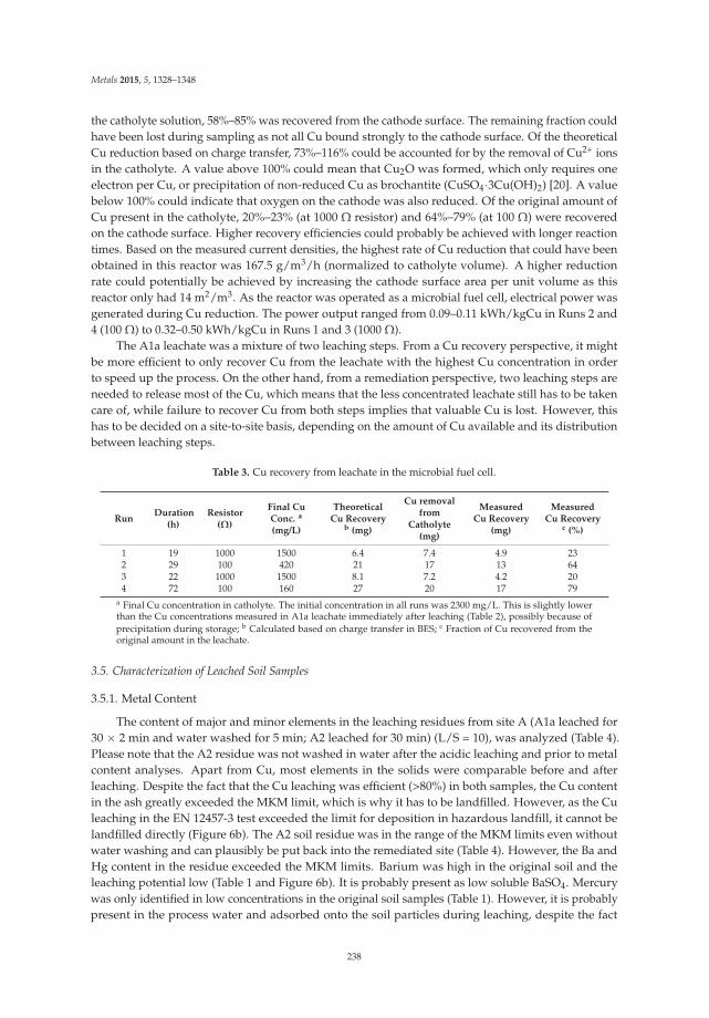
Metals 2015, 5, 1328–1348
the catholyte solution, 58%–85% was recovered from the cathode surface. The remaining fraction couldhave been lost during sampling as not all Cu bound strongly to the cathode surface. Of the theoreticalCu reduction based on charge transfer, 73%–116% could be accounted for by the removal of Cu2+ ionsin the catholyte. A value above 100% could mean that Cu2O was formed, which only requires oneelectron per Cu, or precipitation of non-reduced Cu as brochantite (CuSO4·3Cu(OH)2) [20]. A valuebelow 100% could indicate that oxygen on the cathode was also reduced. Of the original amount ofCu present in the catholyte, 20%–23% (at 1000 Ω resistor) and 64%–79% (at 100 Ω) were recoveredon the cathode surface. Higher recovery efficiencies could probably be achieved with longer reactiontimes. Based on the measured current densities, the highest rate of Cu reduction that could have beenobtained in this reactor was 167.5 g/m3/h (normalized to catholyte volume). A higher reductionrate could potentially be achieved by increasing the cathode surface area per unit volume as thisreactor only had 14 m2/m3. As the reactor was operated as a microbial fuel cell, electrical power wasgenerated during Cu reduction. The power output ranged from 0.09–0.11 kWh/kgCu in Runs 2 and4 (100 Ω) to 0.32–0.50 kWh/kgCu in Runs 1 and 3 (1000 Ω).
The A1a leachate was a mixture of two leaching steps. From a Cu recovery perspective, it mightbe more efficient to only recover Cu from the leachate with the highest Cu concentration in orderto speed up the process. On the other hand, from a remediation perspective, two leaching steps areneeded to release most of the Cu, which means that the less concentrated leachate still has to be takencare of, while failure to recover Cu from both steps implies that valuable Cu is lost. However, thishas to be decided on a site-to-site basis, depending on the amount of Cu available and its distributionbetween leaching steps.
Table 3. Cu recovery from leachate in the microbial fuel cell.
RunDuration
(h)Resistor
(Ω)
Final CuConc. a
(mg/L)
TheoreticalCu Recovery
b (mg)
Cu removalfrom
Catholyte(mg)
MeasuredCu Recovery
(mg)
MeasuredCu Recovery
c (%)
1 19 1000 1500 6.4 7.4 4.9 232 29 100 420 21 17 13 643 22 1000 1500 8.1 7.2 4.2 204 72 100 160 27 20 17 79
a Final Cu concentration in catholyte. The initial concentration in all runs was 2300 mg/L. This is slightly lowerthan the Cu concentrations measured in A1a leachate immediately after leaching (Table 2), possibly because ofprecipitation during storage; b Calculated based on charge transfer in BES; c Fraction of Cu recovered from theoriginal amount in the leachate.
3.5. Characterization of Leached Soil Samples
3.5.1. Metal Content
The content of major and minor elements in the leaching residues from site A (A1a leached for30 × 2 min and water washed for 5 min; A2 leached for 30 min) (L/S = 10), was analyzed (Table 4).Please note that the A2 residue was not washed in water after the acidic leaching and prior to metalcontent analyses. Apart from Cu, most elements in the solids were comparable before and afterleaching. Despite the fact that the Cu leaching was efficient (>80%) in both samples, the Cu contentin the ash greatly exceeded the MKM limit, which is why it has to be landfilled. However, as the Culeaching in the EN 12457-3 test exceeded the limit for deposition in hazardous landfill, it cannot belandfilled directly (Figure 6b). The A2 soil residue was in the range of the MKM limits even withoutwater washing and can plausibly be put back into the remediated site (Table 4). However, the Ba andHg content in the residue exceeded the MKM limits. Barium was high in the original soil and theleaching potential low (Table 1 and Figure 6b). It is probably present as low soluble BaSO4. Mercurywas only identified in low concentrations in the original soil samples (Table 1). However, it is probablypresent in the process water and adsorbed onto the soil particles during leaching, despite the fact
238

Metals 2015, 5, 1328–1348
that the pH is acidic. Less than 0.5 mg·Hg/L in the process water can account for this phenomenonand as process water is a waste product from flue gas cleaning after waste incineration, it possiblycontains such concentrations. If using this kind of leaching agent for soil remediation, it will probablyrequire purification from Hg before utilization. Nevertheless, no water washing steps were used here;by using washing, the Hg content in the residues might fall below the MKM limit.
1.E 03
1.E 02
1.E 01
1.E+00
1.E+01
1.E+02
1.E+03
1.E+04
As Ba Cd Cr Cu Mo Ni Pb Se Zn
mg/kg
dryash
A1a 30+30 min A1a 30+30 min, no washA1a 30 min B1a 30+30 minB1a 30 min Non hazardous wasteHazardous waste
1.E 03
1.E 02
1.E 01
1.E+00
1.E+01
1.E+02
1.E+03
As Ba Cd Cr Cu Mo Ni Pb Se Zn
mg/kg
drysoil
A2 30 min A2 24hA2 untreated B2 30 minB2 untreated Non hazardous wasteHazardous waste
a)
b)
Figure 6. Metal release in the EN-12457-3 leaching test compared to the limit values for acceptance innon-hazardous and hazardous waste landfills: (a) treated ash samples A1a and B1a; and (b) originaland treated soil samples A2 and B2.
The soil matrixes were stable against leaching; <5 wt. % was dissolved during leaching, whilethe ashes were dissolved to a greater extent. About 10 wt. % of the B1a sample was dissolved afterleaching in two steps compared to 50 wt. % of the A1a sample. This difference is probably due to thepresence of soil particles in the B1 sample as discussed above (Section 3.1).
3.5.2. Metal Leaching
With the exception of Cu, the leaching of all elements in the original and leached soil samplesA2 and B2 was below the limits for acceptance on landfills for non-hazardous waste (Figure 6). Mostelements (As, Ba, Cd, Cr, Mo and Se) also met the requirements for acceptance in an inert landfill.However, the leaching of Ba, Cd, Cr, Cu, Ni and Zn was higher from the leached soil compared to theoriginal sample, which is most probably due to the fact that previously encapsulated metal compoundsare released when the soil matrix is affected by the acid. Consequently, in this particular case, soilwashing to minimize the risk of leaching is not beneficial and the total amount of a specific elementis not correlated with the risk of leaching. This was also seen for the ash samples where all elementsexcept Cu and Zn were below the non-hazardous waste limit (As, Ba, Cr and Mo were also belowthe inert waste limits), irrespective of the higher initial total amounts. There is no general trend as towhether a two-step acid leaching process reduces metal leaching to a greater extent in a subsequentEN-test than a one-step leaching procedure. However, water washing after leaching seems to decreasemetal release during the EN-test, even if the washing period is as short as 5 min. This is probably
239

Metals 2015, 5, 1328–1348
caused by metal ions that were easily adsorbed to the ash particles being released to the first water incontact with these solids. The results also indicate that a higher L/S-ratio during the water washingstep might further decrease leaching in the EN-test.
Table 4. Total amounts of selected major (calculated as oxides) and minor elements in the A1a (barkash) and A2 (soil) residues after leaching experiments. Please note that the A2 residue was not washedin water after the acidic leaching. Uncertainties in the analyses vary between 20% and 25%.
Element A1a Bark Ash Residue A2 Soil Residue
wt. % DS
SiO2 54 71Al2O3 12 11CaO 1.0 1.9
Fe2O3 5.6 2.2K2O 4.6 2.4MgO 0.8 0.5MnO <0.1 <0.1Na2O 1.8 2.6P2O5 1.1 <0.1TiO2 8.1 0.6
mg/kg DS
As <6 0.8Ba 2200 450Be 1.9 1.3Cd 0.7 0.1Co 7.2 1.7Cr 220 20Cu 10,000 210Hg 68 3.6Mo 4.2 0.4Nb 34 8.5Ni 66 3.9Pb 370 8.4S 900 220
Sb 64 2.7Sc 7.2 7.5Sn 180 2.5Sr 82 180V 37 41W <50 1.1Y 10 14
Zn 1000 28Zr 140 220
3.5.3. PAHs and Oxy-PAHs Content
The concentration of each specific PAH in the spiked soil varied from 0.25 mg/kg (DS) to4.4 mg/kg (DS) in the unleached sample. In this sample the low-molecular weight PAH-L, i.e.,the sum of naphthalene, acenapthylene and acenapthene, was 10 mg/kg (DS), the mean-molecularweight PAH-M, i.e., the sum of fluorene, phenanthrene, anthracene, fluoranthene and pyrene,was 2.0 mg/kg (DS) and the high-molecular weight PAH-H, i.e., the sum of benz[a]anthracene,chrysene, benzo[b]fluoranthene, benzo[k]fluoranthene, benzo[a]pyrene, dibenz[ah]anthracene,benzo[ghi]perylene and indeno[123cd]pyrene, was 2.8 mg/kg (DS), see Figure 7. These concentrationsare in the ranges of the generic Swedish guideline values for sensitive and less sensitive land use [33].Two of the nine oxy-PAHs analyzed were also identified in this unleached sample: 9-fluorenone0.14 mg/kg (DS), a degradation product of fluorene, and 9,10-anthraquinone 0.15 mg/kg (DS), a
240

Metals 2015, 5, 1328–1348
degradation product of anthracene, indicating that PAH oxidation may occur during storage of thespiked soil sample. This could occur, e.g., because of aerobic bacterial degradation [15] or biocatalyticactivity of fungi in the soil [16]. However, it cannot be ruled out that oxy-PAHs were alreadypresent in the original samples. The calculated ratios of the sum of oxy-PAH-9/PAH-16 are 0.04,for 9-fluorenone/fluorene 0.2 and for 9,10-anthraquinone/anthracene 0.6. These ratios are much lowerthan reported from other sites contaminated by PAHs [16,34].
After acidic washing, the concentration of each specific PAH in the treated soil was lower andvaried from 0.19 to 2.5 mg/kg (DS). These concentrations are below the guideline value for less sensitiveland use, but not low enough to qualify for sensitive land use [33]. For PAH-L, the concentrations were1.6 times lower, for PAH-M 1.3 and PAH-L 1.2 times lower, compared to the concentrations before soilwashing. In the resulting leachate, the concentration of each specific PAH varied from 0.17 to 16 μg/L.From calculations of the relative compositions of the PAHs in the soil before and after acidic washing,and in the acidic leachates, no signs of PAH degradation or volatilization could be found. If degradationhad occurred, the most volatile and water-soluble PAH-L would disappear first causing a decreasein HMW/LMW PAH ratios [35,36]. None of the oxy-PAHs were found after leaching, neither in theresidual soil nor in the leachate, indicating that acidic leaching may accelerate the degradation ofoxy-PAHs. This may be caused by enhanced leaching of the oxy-PAHs into the water phase, i.e., moreexposed for degradation, caused by weathering and degradation of the soil matrix under the strongacidic washing.
0
5
10
15
20
25
30
0
2
4
6
8
10
12
PAHs L PAHs M PAHs H oxy PAH 9
g/L
mg/kg
drysoil
Before soil washing
After soil washing
Acidic leachate
Figure 7. Concentrations of PAHs and oxy-PAHs analyzed in the A1 spiked soil sample before andafter acidic washing (mg/kg), and the concentrations in the corresponding acidic leachate (μg/L).
In the leachate water, relatively more water soluble PAH-L occurred, indicating that the transportof the most water soluble PAHs into the acidic water was high. However, this transport to the waterphase is expected to be very low and should not be pH dependent, but may follow the humic andfulvic acids released from the soil during mixing with acidic water. In a recent study of the distributionof organic pollutants in dissolved, colloidal and particulate form, relatively high PAH-L concentrationswere detected in both the dissolved and the colloidal phases [37]. The results also suggested thatdissolved organic carbon (DOC) colloids were carriers of pollutants in the colloidal phase [37,38]. PAHsare also assumed to be sorbed to Fe minerals such as goethite [39]. Iron was released during the acidicleaching (Tables 1 and 4) and in a previous study on site A, Fe minerals were identified in original soilsamples but not in the acid leached residues [12]. Organic matter is known to be sorbed to iron oxidesin soils [40], and therefore it is expected that the dissolution of iron oxide enhance the solubilization ofDOC, and therefore could explain why PAHs are solubilized. The release of Fe minerals followed byan enhanced release of DOC can thus be important factors in the PAH leaching under strong acidicconditions. The leaching and degradation of PAHs in soils from contaminated sites may be improvedby addition of a strong oxidant to achieve a Fenton-like oxidation [41], electrochemical degradation [42]
241
Metals 2015, 5, 1328–1348
or by a combination of the two techniques [43]. The addition of a strong oxidant could also affectthe Cu leachability, which is something that should be studied further if this technique is used toremove PAHs.
4. Conclusions
In this study, a lab-scale method to release and recover Cu from contaminated soils has beendeveloped and discussed. Acidic wastewater was used as a leaching agent. In a one- or two-step(depending on soil material) acidic leaching process followed by a water washing step, >80 wt. % ofthe Cu was leached. Although the Cu leaching efficiency was high, none of the samples are below theguidelines for less sensitive land use (MKM) or the limit values for acceptance in non-hazardous andhazardous waste landfills. Consequently, improvement of the final washing step is needed. Copper(99.7–99.9 wt. % purity) was recovered from the acidic leachates of one of the samples (A1a) usinga BES operated as a microbial fuel cell. Electric power was generated, while Cu was reduced andrecovered on the cathode surface. Although microbial fuel cells have been previously operated withCu-containing catholytes, this was the first study to demonstrate recovery of high purity Cu fromreal soil leachate. According to predictions, there are about 30 tons of Cu in site A. Based on theresults of this lab scale study, about 20 tons could potentially be recovered, corresponding to a valueof approximately one million SEK (~100,000 euro). A limitation of the proposed method in full scaleis the supply of acidic wastewater. Some pre-treatment is necessary in order to reduce the quantityof soil for washing. For example, physical soil washing, e.g., sieving, can concentrate the pollutedmaterial into smaller particle sizes, which efficiently reduces the amounts that require acidic washing.This study also revealed that acidic water is a good leaching agent for all PAHs; especially those withlow-molecular weight. There are also indications that oxy-PAHs are fully degraded by acidic soilwashing. PAH leaching mechanisms are not fully understood and the soil washing method needs tobe further developed to increase efficiency.
Acknowledgments: This work was funded by Renova (a Swedish waste and recycling management company),FORMAS (the Swedish Research Council for Environment, Agricultural Sciences and Spatial Planning), the RoyalSociety for the Arts and Sciences in Gothenburg (KVVS) and the European Commission’s career integration grant(project: Bioanode). The authors also wish to express their gratitude to Anna Eriksson, Per Johansson, OlivierLavergne and Mona Pålsson for their assistance with the laboratory work.
Author Contributions: K.K.F., O.M. and A.M.S. together conceived and designed the experiments; performed theexperiments; analyzed the data; and wrote the paper. K.K.F. coordinated the work.
Conflicts of Interest: The authors declare no conflict of interest.
References
1. Sierra, C.; Menendez-Aguadoa, J.M.; Afifb, E.; Carreroc, M.; Gallegoa, J.R. Feasibility study on the use of soilwashing to remediate the As-Hg contamination at an ancient mining and metallurgy area. J. Hazard. Mater.2011, 196, 93–100. [CrossRef] [PubMed]
2. Bisone, S.; Blais, J.; Drogui, P.; Mercier, G. Toxic metal removal from polluted soil by acid extraction. Water AirSoil Pollut. 2012, 223, 3739–3755. [CrossRef]
3. Moon, D.H.; Lee, J.R.; Wazne, M.; Park, J.H. Assessment of soil washing for Zn in contaminated soils usingvarious washing solutions. J. Ind. Eng. Chem. 2012, 18, 822–825. [CrossRef]
4. Sierra, C.; Martínez-Blanco, D.; Blanco, J.A.; Gallego, J.R. Optimization of the concentration operation viamagnetic separation: A case study for soil washing. Chemosphere 2014, 107, 290–296. [CrossRef] [PubMed]
5. Sierra, C.; Martínez, J.; Menéndez-Aguado, J.M.; Afif, E.; Gallego, J.R. High intensity magnetic separationfor the clean-up of a site polluted by lead metallurgy. J. Hazard. Mater. 2013, 248–249, 194–201. [CrossRef][PubMed]
6. Ghosh, M.; Singh, S.P. A review on phytoremediation of heavy metals and utilization of its byproducts.Ecol. Environ. Res. 2005, 3, 1–18. [CrossRef]
242

Metals 2015, 5, 1328–1348
7. Camenzuli, D.; Gore, D.B.; Stark, S.C. Immobilisation of metals in contaminated landfill material usingorthophosphate and silica amendments: A pilot study. Int. J. Environ. Pollut. Remediat. 2015, 3, 27–32.[CrossRef]
8. Chigbo, C.; Batty, L. Chelate-assisted phytoremediation of Cu-pyrene-contaminated soil using Z. Mays.Water Air Soil Pollut. 2015, 226. [CrossRef]
9. Travar, I.; Kihl, A.; Kumpiene, J. The release of As, Cr and Cu from contaminated soil stabilized with apcresidues under landfill conditions. J. Environ. Manag. 2015, 151, 1–10. [CrossRef] [PubMed]
10. Voglar, D.; Lestan, D. Chelant soil-washing technology for metal-contaminated soil. Environ. Technol. 2014,35, 1389–1400. [CrossRef] [PubMed]
11. Pociecha, M.; Lestan, D. Washing of metal contaminated soil with edta and process water recyling.J. Hazard. Mater. 2012, 235–236, 384–387. [CrossRef] [PubMed]
12. Karlfeldt Fedje, K.; Yillin, L.; Strömvall, A.M. Remediation of metal polluted hotspot areas through enhancedsoil washing—Evaluation of leaching methods. J. Environ. Manag. 2013, 128, 489–496.
13. Achugasim, O.; Ojinnaka, C.; Osuji, L. Assessment of ability of three chemcial oxidants to removehydrocarbons from soils polluted by bonny light crude oil. Eur. Chem. Bull. 2013, 2, 226–230.
14. Xu, C.B.; Dong, D.B.; Meng, X.L.; Su, X.; Zheng, X.; Li, Y.Y. Photolysis of polycyclic aromatic hydrocarbonson soil surfaces under uv irradiation. J. Environ. Sci. China 2013, 25, 569–575. [CrossRef]
15. Baboshin, M.A.; Golovleva, L.A. Aerobic bacterial degradation of polycyclic aromatic hydrocarbons (PAHs)and its kinetic aspects. Microbiology 2012, 81, 639–650. [CrossRef]
16. Lundstedt, S.; White, P.A.; Lemieux, C.L.; Lynes, K.D.; Lambert, L.B.; Oberg, L.; Haglund, P.;Tysklind, M. Sources, fate, and toxic hazards of oxygenated polycyclic aromatic hydrocarbons (PAHs)at PAH-contaminated sites. Ambio 2007, 36, 475–485. [CrossRef]
17. Jenkins, J.; Dodge, P.; Morenci, A. Solvent Extraction Transfer of Cu from Leach Solution to Electrolyte; Pergamon:New York, NY, USA, 2002; pp. 307–325.
18. Nancharaiah, Y.V.; Venkata Mohan, S.; Lens, P.N. Metals removal and recovery in bioelectrochemical systems:A review. Bioresour. Technol. 2015. [CrossRef] [PubMed]
19. Modin, O.; Fedje, K.K. Combined Wastewater Treatment and Recovery of Copper from Ash Leachate.In Proceedings of the IWA World Water Congress & Exhibition, Busan, Korea, 16–31 September 2012.
20. Tao, H.C.; Liang, M.; Li, W.; Zhang, L.J.; Ni, J.R.; Wu, W.M. Removal of copper from aqueous solution byelectrodeposition in cathode chamber of microbial fuel cell. J. Hazard. Mater. 2011, 189, 186–192. [CrossRef][PubMed]
21. Ter Heijne, A.; Liu, F.; Weijden, R.V.D.; Weijma, J.; Buisman, C.J.N.; Hamelers, H.V.M. Copper recoverycombined with electricity production in a microbial fuel cell. Environ. Sci. Technol. 2010, 44, 4376–4381.[CrossRef] [PubMed]
22. Modin, O.; Wang, X.; Wu, X.; Rauch, S.; Fedje, K.K. Bioelectrochemical recovery of Cu, Pb, Cd, and Zn fromdilute solutions. J. Hazard. Mater. 2012, 235–236, 291–297. [CrossRef] [PubMed]
23. Swedish Standard Institute. SS-EN-12457-3 characterization of waste—Leaching—Compliance test forleaching of granular waste materials and sludges. In Part 3: Two Stage Batch Test at a Liquid to Solid Ratio of2 L/kg and 8 L/kg for Materials with High Soild Content and with Particle Size Below 4 mm (witout or with SizeReduction); Swedish Standard Institute: Stockholm, Sweden, 2003.
24. Mongomery, D.C. Design and Analysis of Experiments, 7th ed.; John Wiley & Sons Pte Led (Asia): Hongkong,China, 2009.
25. SEPA. Riktvärden för Förorenad Mark Modellbeskrivning och Vägledning Rapport 5976 (Guidelines for ContaminatedSoil Model Description and Guidance Report 5976); SEPA: Stockholm, Sweden, 2009.
26. Springfors, A. Kartläggning av Föroreningssituationen i Mark, Grundvatten och Sediment, Förenklad Riskbedömning,Översiktlig Åtgärdsutredning Samt Riskbedömning för Föreslagna Efterbehandlingsåtgärder för Långön, Köpmannebo;ÅF-IPK AB: Göteborg, Sweden, 2001.
27. Florell, S.E.; Stubdrup, O.P.; Arnér, M. Rapport, Televerket Björkhult, Huvudstudie (Report, Televerket Björkhult);WSP: Linköping, Sweden, 2008.
28. Naturvårdsverkets föreskrifter om deponering, kriterier och förfaranden för mottagning av avfall vidanläggningar för deponering av avfall. Available online: http://www.naturvardsverket.se/Stod-i-miljoarbetet/Rattsinformation/Foreskrifter-allmanna-rad/NFS/2004/NFS-200410---Mottagning-av-avfall-for-deponering/ (accessed on 17 July 2015).
243
Metals 2015, 5, 1328–1348
29. Yip, T.C.M.; Tsang, D.C.W.; Ng, K.T.W.; Lo, I.M.C. Empirical modeling of heavy metal extraction by eddsfrom singel-metal and mulit-metal contaminated soils. Chemosphere 2008, 74, 301–307. [CrossRef] [PubMed]
30. Udovic, M.; Lestan, D. Edta and hcl leaching of calcareous and acidic soils polluted with potentially toxicmetals: Remediation efficiency and soil impact. Chemosphere 2012, 88, 718–724. [CrossRef] [PubMed]
31. Karlfeldt, K.; Steenari, B.M. Assessment of metal mobility in msw incineration ashes using water as thereagent. Fuel 2007, 86, 1983–1993. [CrossRef]
32. Kalmykova, Y.; Strömvall, A.M.; Steenari, B.M. Alternative materials for removal of heavy metals andpetroleum hydrocarbons from contaminated leachates. Environ. Technol. 2008, 29, 111–122. [CrossRef][PubMed]
33. Swedish Environmental Protection Agency. Generic Guideline Values for Contaminated Soils. Availbleonline: http://www.swedishepa.se/en/In-English/Start/Operations-with-impact-on-the-environment/Remediation-of-contaminated-areas/Classification-and-risk-assessment/Generic-guideline-values-for-contaminated-soils/ (accessed on 29 May 2012).
34. Bandowe, B.A.M.; Wilcke, W. Analysis of polycyclic aromatic hydrocarbons and their oxygen-containingderivatives and metabolites in soils. J. Environ. Qual. 2010, 39, 1349–1358. [CrossRef] [PubMed]
35. Jonsson, S.; Persson, Y.; Frankki, S.; van Bavel, B.; Lundstedt, S.; Haglund, P.; Tysklind, M. Degradationof polycyclic aromatic hydrocarbons (PAHs) in contaminated soils by Fenton’s reagent: A multivariateevaluation of the importance of soil characteristics and pah properties. J. Hazard. Mater. 2007, 149, 86–96.[CrossRef] [PubMed]
36. Mao, D.; Lookman, R.; Van de Weghe, H.; Weltens, R.; Vanermen, G.; De Brucker, N.; Diels, L. CombiningHPLC-GCXGC, GCXGC/TOF-MS, and selected ecotoxicity assays for detailed monitoring of petroleumhydrocarbon degradation in soil and leaching water. Environ. Sci. Technol. 2009, 43, 7651–7657. [CrossRef][PubMed]
37. Kalmykova, Y.; Bjoerklund, K.; Stroemvall, A.-M.; Blom, L. Partitioning of polycyclic aromatic hydrocarbons,alkylphenols, bisphenol A and phthalates in landfill leachates and stormwater. Water Res. 2013, 47, 1317–1328.[CrossRef] [PubMed]
38. Nielsen, K.; Kalmykova, Y.; Strömvall, A.M.; Baun, A.; Eriksson, E. Particle phase distribution of polycyclicaromatic hydrocarbons in stormwater—Using humic acid and iron nano-sized colloids as test particles. Sci.Total Environ. 2015, 532, 103–111. [CrossRef] [PubMed]
39. Tunega, D.; Gerzabek, M.H.; Haberhauer, G.; Totsche, K.U.; Lischka, H. Model study on sorption of polycyclicaromatic hydrocarbons to goethite. J. Colloid Interface Sci. 2009, 330, 244–249. [CrossRef] [PubMed]
40. Oren, A.; Chefetz, B. Successive sorption-desorption cycles of dissolved organic matter in mineral soilmatrices. Geoderma 2012, 189–190, 108–115. [CrossRef]
41. Yap, L.C.; Gan, S.; Ng, H.K. Fenton based remediation of polycyclic aromatic hydrocarbons-contaminatedsoils. Chemosphere 2011, 83, 1414–1430. [CrossRef] [PubMed]
42. Tran, L.H.; Drogui, P.; Mercier, G.; Blais, J.F. Electrochemcial degradation of polycyclic aromatic hydrocarbonsin creostoe solution using ruthenium oxid on titanium expanded mesh anod. J. Hazard. Mater. 2009, 164,1118–1129. [CrossRef] [PubMed]
43. Zheng, X.J.; Blais, J.F.; Mercier, G.; Bergeron, M.; Drogui, P. PAH removal from spiked municipal wastewatersewage sludge using biological, chemical and electrochemical treatments. Chemosphere 2007, 68, 1143–1152.[CrossRef] [PubMed]
© 2015 by the authors. Licensee MDPI, Basel, Switzerland. This article is an open accessarticle distributed under the terms and conditions of the Creative Commons Attribution(CC BY) license (http://creativecommons.org/licenses/by/4.0/).
244

metals
Article
Heavy Metal Behavior in Lichen-Mine WasteInteractions at an Abandoned Mine Site inSouthwest Japan
Yuri Sueoka 1,*, Masayuki Sakakibara 1 and Koichiro Sera 2
1 Graduate School of Science and Engineering, Ehime University, Bunkyo-cho 2-5, Matsuyama,Ehime 790-8577, Japan; [email protected]
2 Cyclotron Research Center, Iwate Medical University, Tomegamori 348-58, Takizawa, Iwate 020-0603, Japan;[email protected]
* Author to whom correspondence should be addressed; [email protected]; Tel.: +81-89-927-9649;Fax: +81-89-927-9640.
Academic Editor: Suresh BhargavaReceived: 13 July 2015; Accepted: 28 August 2015; Published: 2 September 2015
Abstract: The lichen, Stereocaulon exutum Nylander, occurring in a contaminated abandoned minesite was investigated to clarify (1) the behavior of heavy metals and As during the slag weatheringprocesses mediated by the lichen; and (2) the distribution of these elements in the lichen thallus on slag.The heavy metals and As in the slag are dissolved from their original phases during the weatheringprocess by lichen substances (organic acids) and hypha penetration, in addition to non-biologicalweathering. The dissolved elements are absorbed into the lichen thallus. Some of these dissolvedelements are distributed in the cells of the hyphae. The others are distributed on the surface of thehyphae as formless particles and show lateral distribution inside the cortex of the thallus. The Cu andZn concentrations in the thalli are positively correlated with the concentrations in the correspondingsubstrata and a positive intercept in the regression curve obtained using a linear function. Thesechemical characteristics make this lichen a good biomarker for Cu and Zn contamination of thesubstrata of the lichen. Therefore, the present study supposes that Stereocaulon exutum has a possiblepractical application in biomonitoring or risk assessment of heavy metal pollution at abandonedmine sites.
Keywords: Stereocaulon exutum; biomarker; smelting slag; weathering
1. Introduction
Lichen covers more than 6% of the land surface of the earth [1]. Lichen is found in variousareas, including extreme environments such as tropical forests, deserts, alpine regions, polar regions,and urban areas, and even in highly polluted areas [2,3]. Therefore, as organisms that indicate theenvironmental conditions of their habitats, lichens could have broad utility as bioindicators andbiomarkers throughout the world.
The interactions of lichens with their substrata have been investigated. In addition to abioticweathering, the weathering of rocks is accelerated by lichens [4–6]. Biological weathering by lichensoccurs through two main processes [7,8]. One is a chemical process involving lichen substancescalled lichen acids. Lichen acids are organic acids that affect the chemical decomposition of minerals.The other is a physical process of penetration and expansion of lichen hyphae. The mechanicalfragmentation by hyphae increases the surface area of the rocks and minerals and accelerates thechemical decomposition.
Lichens have been well studied as a biomonitoring tool for air pollution [9–13]. The lichens absorbmineral nutrients and trace elements, including metals from dry and wet atmospheric deposition,
Metals 2015, 5, 1591–1608 245 www.mdpi.com/journal/metals

Metals 2015, 5, 1591–1608
due to the lack of a protective cuticle and a vascular root system [14,15]. Therefore, some lichens aresensitive to airborne pollutants [16]. Some characteristics of lichens that could be used as bioindicatorsand biomarkers for heavy metal pollution of their substrata have been revealed in recent studies.Several lichens absorb and/or accumulate heavy metals from the substrata [17,18]. Osyczka and Rola(2013) found that the relationships between the Zn and Cd contents in Cladonia rei Schaer. thalli andin the host substrate through specific non-linear regression models could be described by a powerfunction [19].
However, the interactions between lichens and the corresponding substrata have not beendiscussed comprehensively in relation to the behavior of heavy metals during the weathering processand the heavy metal concentrations. Thus, there is insufficient information on the availability of lichensas bioindicators or biomarkers for heavy metal pollution of their substrata. Therefore, this study hasclarified (1) the behavior of Cu, Zn, As, and Pb during the slag weathering processes mediated byStereocaulon exutum Nyl., and (2) the distribution of these elements in S. exutum thalli growing on slag.Finally, the present study evaluated the possible practical application of the lichen for environmentalmonitoring in terms of heavy metal and As pollution.
2. Materials and Methods
2.1. Study Area
This study was conducted at an abandoned mine site in Eastern Okayama, Southwest Japan, atan altitude of approximately 250 m above sea level (Figure 1). The site is located in the temperate zonewith an average annual temperature of 14.1 ◦C (the seasonal averages are 2.8 ◦C in January and 25.8 ◦Cin July) and a total annual precipitation of 1200 mm (the seasonal totals were 22.0 mm in January and299 mm in August) in 2014 [20].
Figure 1. A location map of study area (indicated by a black dot).
Mainly Cu had been smelted at the abandoned mine site more than 50 years ago. The hostrocks for the ore deposits are mainly rhyolite, andesite, sandstone, mudstone, and phreatomagmaticbreccia [21]. These host rocks contain pyrite and chalcopyrite with quartz and calcite veins.
The surface of the waste dump consists primarily of tailings composed of phreatomagmaticbreccia and rhyolite, and fractured slag overlies solidified, coherent slag [21]. The tailing and fracturedslag have been kept on-site, in part, by wooden boards. However, these boards are now decaying andare no longer effective [21].
The soil and the stream water that flows through the waste dump are contaminated by Zn and/orAs because the slag and tailings leach from the waste dump and accumulate on erosion control dams
246

Metals 2015, 5, 1591–1608
and sandbanks. The pH of the stream is nearly neutral (7.2–7.8), but the water contains Zn and As inexcess of the environmental water quality standards determined by the Ministry of Health, Labor andWelfare, Japan [22,23]. The soil in the waste dump also contains As in excess of Japan’s environmentalquality standards set by the Ministry of the Environment [22,23].
The slag is one of the potential pollutants in this area and contains high levels of heavy metals [21].S. exutum can grow even on the slag, and it could affect the slag weathering. Therefore, this fruticoselichen was chosen as the object of this study.
2.2. Sampling Methods
The 18 lichens, 12 slags, seven tailings, and four rocks were randomly sampled from the slag andtailing dump, outcrops, and sandbanks at the abandoned mine site from 21 April 2011 to 28 September2013. The lichen samples were taken with the corresponding substrata and packed into plastic bagsthat have a zipper. The slag, tailing, and rock samples were packed into plastic bags or put into cartons.The lichen samples for SEM-EDS analysis were stored in cool and dark place. The lichen samples forPIXE analysis were stored in a desiccator after cleaning by hyper-pure water.
2.3. Analytical Methods
The lichens were identified by morphological and biochemical classification using color reactionswith the following three solutions: 10% aqueous potassium hydroxide [KOH], saturated aqueouscalcium hypochlorite [Ca(OCl)2], and 5% alcoholic p-phenylenediamine solutions.
Rocks and slag were sampled at random, and their structures were observed using a scanningelectron microscope (SEM). Then, the substrata were investigated by X-ray powder diffraction (XRD)analysis, and a scanning electron microscope equipped with an energy-dispersive X-ray spectrometer(SEM-EDS) was used to identify the primary and subsidiary phases and to clarify the behavior ofheavy metals and As during the slag weathering process.
Eight pulverized slags and four pulverized rocks were analyzed by XRD to identify their mineralcomponents. XRD analyses were performed on an Ultima IV (Rigaku, Tokyo, Japan) spectrometerhoused at Ehime University (Ehime, Japan) using Cu Kα (λ = 1.54056 Å) radiation. The diffractionpatterns for non-constant azimuth analysis were collected using an accelerating voltage of 40 kV,a specimen current of 40 mA, an analytical speed of 2◦/min, and an analytical range of 5◦–70◦.
To investigate the distribution of potentially toxic elements in the slag, the slag and lichen sampleswere imaged and analyzed by SEM-EDS on a JSM-6510LV (JEOL, Tokyo, Japan) and X-Max 50 (OxfordInstruments, Tokyo, Japan) detector with INCA software (Oxford Instruments, Tokyo, Japan) at EhimeUniversity. The slag samples were embedded in resin and prepared as polished thin sections that werethen carbon-coated. The glass-phase content in the slag was estimated by counting the intersectionpoints of a 200 μm mesh overlaid on back-scattered electron images. The SEM was operated withan accelerating voltage of 15 kV and a beam current of 0.8 nA. A counting time of 50 s was used forquantitative analysis, and count times of >1 h were required for element mapping. Enstatite (MgSiO3),K-feldspar (KAlSi3O8), and anorthite (CaAl2Si2O8) (Japan Electron Optics Laboratory Mineral StandardSamples for Electron Probe Micro Analyzer, Tokyo, Japan) were analyzed to confirm the analyticalprecision and accuracy. The following standards were used: NaAlSi2O6 for Na, Mg2SiO4 for Mg, Al2O3
for Al, CaSiO3 for Si, FeS2 for S, KBr for K, Ti for Ti, Cr for Cr, Mn for Mn, FeS2 for Fe in matte drops,Fe2O3 for Fe in magnetite, Fe2SiO4 for Fe in fayalite and glass, Co for Co, Cu for Cu, ZnO-glass for Zn,InAs for As, Ag for Ag, and Sn for Sn. The Co standard was also used to optimize the quantification ofthe analyses. The L characteristic X-ray lines were used for the Cu, Zn, As, Ag, and Sn quantification,and the K lines were used for other elements.
The heavy metal concentrations of the substrata, including seven slags, eight tailings, and sevenhost rocks, were determined by energy dispersive X-ray fluorescence (ED-XRF) spectrometry using anEpsilon5 instrument (PANalytical, Almelo, The Netherlands) at Ehime University. Pressed powderpellet samples were used for the XRF analysis. The samples were powdered to a grain size of <1 μm in a
247

Metals 2015, 5, 1591–1608
tungsten carbide vibrating sample mill (Sample Mill model TI-100, HEIKO, Tokyo, Japan) and an agatemortar at Ehime University. C13H14O6 was used as a binder (20 wt. % in the pressed powder pellets)and homogenized with the powdered samples by shaking for 1 h. The XRF analyses were conducted atan excitation voltage of 100 kV. The following standards were used as secondary targets for irradiationwith the relevant excited X-rays for the individual elements: Al for Na and Mg; Ti for Al–Sc; Ge forTi–Ga; Mo for Ge–Y, Tl–Ra, and Ac–U; and Al2O3 for other elements, including lanthanides. TheX-ray source was a Gd anode. A counting time of 300 s was repeated three times on a Ge detector foreach secondary target, and elemental concentrations were determined by the fundamental parametermethod. Geological standards, including JSd-1, JSd-2, JSd-3, JSl-1, Jlk-1, and JMn-1 (Geological Surveyof Japan Referenced Materials) [24,25], were analyzed to confirm the analytical precision (relativestandard deviations are 1.86% Fe2O3, 11.3% Cu, 3.09% Zn, 10.9% As, 45.5% Sn, and 53.2% Pb).
The heavy metal concentrations of the lichens were determined by particle-induced X-ray emission(PIXE) performed at the Nishina Memorial Cyclotron Center established by the Japan RadioisotopeAssociation. The analytical conditions followed Sera et al. (1992) [26]. A small cyclotron providesa 2.9 MeV-proton beam on the target after passing through a beam collimator of graphite. Themaximum beam intensity on the target is approximately 40 nA for a beam spot diameter of 2 mm and80 nA for a diameter of 6 mm. Elements from Na to U are detected by two ORTEC Si (Li) detectors.The elements heavier than Ca are detected by the first detector, which has a 0.025 mm-thick Be windowand a 6 mm active diameter, with X-rays with an energy resolution of 154 eV at 5.9 keV and a 300-to 500-μm-thick Mylar absorber inserted between the target and the detector. The other low atomicnumber elements are detected by the second detector, which has a 0.008 mm Be window and a 4 mmactive diameter, a resolution of 157 eV, and a small graphite aperture without an absorber. The upper1–5 mm portion of the lichen thallus was cut out from the substrata to remove the effects of the trappedsubstratum fragments by the hypha structure and rinsed with ultrapure water. The rinsed sampleswere dried at 80 ◦C for 24 h in an oven. The dried samples (30 mg) were digested with 1 mL of HNO3
and heated in a microwave (150 W). The analytical accuracy and precision of the analyses were verifiedusing the NIES CRM No. 1 environmental sample.
2.4. Statistical Methods
The distributional normality of the Cu, Zn, As, and Pb concentrations in S. exutum and thecorresponding substrata was verified by the Shapiro-Wilk normality test. The correlation of the scatterplots was verified by Spearman’s rank-correlation coefficient. All statistical analyses were performedwith EZR (Saitama Medical Center, Jichi Medical University, Saitama, Japan), a graphical user interfacefor R (The R Foundation for Statistical Computing, Vienna, Austria). More precisely, it is a modifiedversion of R Commander designed to add statistical functions frequently used in biostatistics [27].
3. Results
3.1. Microstructure of the Hyphae of Stereocaulon exutum Thallus and the Effects of the Lichen onSlag Weathering
The hyphae of the thallus form loosely-complicated structures and adhere to each other near theinterface with the slag. The hyphae that compose the medulla of the thallus form lines in the directionof growth. Hyphae that compose the cortex of the upper thallus form complicated structures, andthese different hyphae partially adhere to each other.
Stereocaulon exutum has both physical and chemical effects on the slag during the weatheringprocess. The surface of the weathered slag under the lichen is penetrated and fractured by the lichenhyphae during the physical process (Figure 2a–c). The hyphae penetrate and expand into the crack ofthe slag and along the mineral interfaces. Etch-pits occur on the weathered willemite and matte dropsunder the lichen during the chemical process (Figure 2e).
248

Metals 2015, 5, 1591–1608
Figure 2. Back-scattered electron images of (a) lichen-slag interface; (b) slag fragments caught byhyphae structure; (c) hyphae penetrating crack of slag; (e) etch-pits of pseudomorph of willemite;and (d) a secondary electron image of slag fragments caught by hyphae structure. W-Wi: weatheredwillemite; Wi: willemite; Fa: fayalite.
Figure 3. Back-scattered electron images of thallus containing fragments. Distances from substrataincrease from (a) to (d) every 2 mm. (a) is the section where 100 μm high from slag; (b) and (c) are thesection of thallus; (d) is the section of apothecium. The broken lines indicate thallus-resin interfaces.Wi: willemite; Fa: fayalite; Qtz: quartz; Fld: feldspar.
The slag fragments in the thallus show differences in the distance from the substrata. The lowerportion of the thallus contains fragments of the fractured slag (Figure 2b,d). The amounts of the slagfragments in the upper portion (more than 1 mm from the substratum) are less comparable with theportion near the interface between the lichen and the slag. The fragments trapped in the upper portionconsist of mainly quartz and plagioclase (Figure 3).
3.2. Heavy Metal Distribution in the Weathered Slag
The slag is composed mainly of willemite, fayalite, and/or magnetite with a silicate glassy matrixand contains matte drops, which are Cu-, Zn-, Pb-metals, -alloys, and -sulfides. Willemite is themain host of Zn, and fayalite is the main host of Fe. Matte drops are the main hosts of heavy metals,S, and As.
249
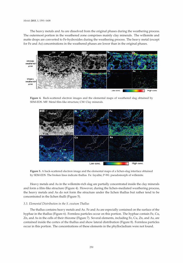
Metals 2015, 5, 1591–1608
The heavy metals and As are dissolved from the original phases during the weathering process.The outermost portion in the weathered zone comprises mainly clay minerals. The willemite andmatte drops are converted to Fe-hydroxides during the weathering process. The heavy metal (exceptfor Fe and As) concentrations in the weathered phases are lower than in the original phases.
Figure 4. Back-scattered electron images and the elemental maps of weathered slag obtained bySEM-EDS. MF: Metal film-like structure; CM: Clay minerals.
Figure 5. A back-scattered electron image and the elemental maps of a lichen-slag interface obtainedby SEM-EDS. The broken lines indicate thallus. Fa: fayalite; P-Wi: pseudomorph of willemite.
Heavy metals and As in the willemite-rich slag are partially concentrated inside the clay mineralsand form a film-like structure (Figure 4). However, during the lichen-mediated weathering process,the heavy metals and As do not form the structure under the lichen thallus but rather tend to beconcentrated in the lichen thalli (Figure 5).
3.3. Elemental Distribution in the S. exutum Thallus
The thallus contains heavy metals and As. Fe and As are especially contained on the surface of thehyphae in the thallus (Figure 6). Formless particles occur on this portion. The hyphae contain Fe, Cu,Zn, and As in the cells of their rhizome (Figure 7). Several elements, including Fe, Cu, Zn, and As, arecontained inside the cortex of the thallus and show lateral distribution (Figure 8). Formless particlesoccur in this portion. The concentrations of these elements in the phyllocladium were not found.
250

Metals 2015, 5, 1591–1608
Figure 6. Back-scattered electron images and the elemental maps of hyphae inside the cortex of thethallus. The white box in BSE2 indicates the area of BSE3 and the mapping analysis area.
Figure 7. A back-scattered electron image and the elemental maps of the lichen hyphae.
Figure 8. A back-scattered electron image and the elemental maps of the lichen thallus.
251

Metals 2015, 5, 1591–1608
3.4. Heavy Metals and As Concentrations of Lichens and the Corresponding Substrata
The heavy metal and As concentrations of Stereocaulon exutum on slag and rocks, including tailings,gravel, and the host rock, are 33.6–1250 mg/kg-DW Zn, 6.51–923 mg/kg-DW Cu, 12.0–147 mg/kg-DWPb, and ND-438 mg/kg-DW As. The heavy metal and As concentrations of the substrata are asfollows: slag contains 20.6%–3.27%-DW Zn, 1.62%–0.66%-DW Cu, ND–758 mg/kg-DW Pb, and31.3–561 mg/kg-DW As; the tailings contain 640–101 mg/kg-DW Zn, 154–34.2 mg/kg-DW Cu,12.7–1280 mg/kg-DW Pb, and ND–23.0 mg/kg-DW As; the outcrop rocks contain 79.1–1940 mg/kg-DWZn, 96.6–461 mg/kg-DW Cu, 8.08–97.1 mg/kg-DW Pb, and 1.12–490 mg/kg-DW As.
On determination of the correlations between heavy metal concentrations in lichens and thecorresponding substrata, the distributional normality was verified by the Shapiro-Wilk normality test(Table 1). As no significant normal distribution of the scattered plots was shown in correspondingconcentrations of Cu, Zn, As, and Pb in the lichen and the corresponding substrata (Table 1, Figure 9),the correlation was verified by Spearman’s rank-correlation coefficient. The results of the test showthat the Cu and Zn concentrations in S. exutum thalli exhibit positive correlations with those in thecorresponding substrata under the 5% significance level but not As and Pb concentrations (Table 2,Figure 10). The formulas of the regression curves have positive X-intercepts (Figure 10).
Table 1. p-values of heavy metal concentrations in lichens and the corresponding substrata obtained byShapiro-Wilk normality test.
Elementsp-Values
S. exutum Substrata
Cu 1.23 × 10⁻³ 8.26 × 10⁻⁵
Zn 3.48 × 10⁻⁵ 4.39 × 10⁻⁶
As 1.16 × 10⁻² 0.109Pb 0.207 2.07 × 10⁻⁵
log.Cu 0.888 4.31 × 10⁻³
log.Zn 5.52 × 10⁻³ 8.17 × 10⁻⁴
log.As 1.92 × 10⁻³ 0.437log.Pb 2.24 × 10⁻⁴ 0.802
Table 2. Spearman’s correlation rho and p-values of the scattered plots of Cu, Zn, As, and Pbconcentrations in the lichens and the corresponding substrata. n = 18.
Elements rs p-Values
Cu 0.618 7.43 × 10⁻³
Zn 0.829 1.28 × 10⁻⁵
As 0.421 0.119Pb 0.336 0.188
252

Metals 2015, 5, 1591–1608
Figure 9. QQ plots of heavy metal concentrations of lichens and the corresponding substrata and thelogarithmic data. The p-values were obtained by Shapiro-Wilk normality test. n = 18.
Figure 10. Scatter diagrams show Cu and Zn concentration of S. exutum and the correspondingsubstrata with linear functions after logarithmic transformation. Note: significance level = 5%.n = sample number.
253

Metals 2015, 5, 1591–1608
4. Discussion
4.1. Effects of S. exutum on Heavy Metals and As Behavior in the Slag Weathering Process
In addition to abiological weathering, Stereocaulon exutum affects and accelerates the weatheringof the original phases, and the effect can be attributed to both physical and chemical processes.The physical effects are caused by hyphal penetration and expansion, and the chemical effects arecaused by lichen substances.
Fragmentation and disaggregation of the lithic surface below the lichens have been well knownand investigated in previous studies [4,5]. Various types of rocks, including calcareous rock, siliceousrock, and sedimentary rock, can be weathered physically by the hyphal penetration [7,8,28–31].The slag that is composed of mainly silicate phases is also fractured by the hyphae even in thecoherent portion.
The fragments of the substrata of lichens are incorporated into the thallus and coated byextracellular polymers and secondary minerals [4,5]. The fragments of the weathered slag are observedmainly in the lower 1–5 mm portion of the thallus, closer to the substratum. However, the trappedfragments in the upper than 5 mm portion of the thallus consist of mainly quartz and feldspar. Theseresults indicate that the fragments are not transported to the upper portion of the thallus. Thus,the origin of the fragments trapped in the upper thallus could not be the substrata but atmosphericdeposition. The trapped slag fragments consist of the Fe hydroxides containing Zn as weatheredsecondary minerals. However, no extracellular polymers were found in this study.
In addition to penetration of hyphae, substrata are mechanically disrupted by expansion,contraction, freezing, and thawing of the lichen thallus [5]. The hyphae penetrate into cracks ofthe willemite and matte drops in the slag and along the interface of these phases. The lichen thallushas an abundant water storage capacity [32]. Therefore, the slag is physically disaggregated throughwetting and drying of the hyphae, and chemical weathering could be accelerated by the water supply.
Lichens affect not only physical weathering but also chemical weathering mostly by lichencompounds [6]. The main chemical dissolution processes of minerals by lichens are generated byrespiratory CO2, the excretion of oxalic acid, and the chemical action of lichen compounds [33].Mineral etching is a frequent feature of weathering at the rock-lichen interface [6]. The etch-pits inthe weathered willemite and matte drops are evidence of the chemical weathering of these phases inthis study. The excretion of various organic compounds can effectively dissolve the original phasesand chelate metallic cations [4–6]. Several lichen compounds such as depsides and depsidones areslightly soluble and have the ability to chelate in conjunction with the presence of polar groupssuch as OH, CHO, and COOH [34]. Although the dissolution and decomposition of rock-formingminerals by lichen acids has been demonstrated in laboratory experiments [35,36], the dissolution anddecomposition processes have not been conclusively proven in previous field studies [37,38].
S. exutum contains the depsidone (lobaric acid) in the thallus and could affect the dissolutionand decomposition of slag phases. Although the present study also provides no scientific evidence toclarify the processes, the results show the evidence of heavy metal and As dissolution from the originalphases by acids. Willemite and matte drops, which are the main hosts of heavy metals and As, aretransformed to Fe hydroxide during the weathering process. The heavy metal and As concentrationsof weathered phases in the weathered portion of the slag are lower than the heavy metal and Asconcentrations in the unweathered portion [21]. The lower heavy metal and As concentrations in theweathered phases and the occurrence of etch-pits in the pseudomorphs of willemite and matte dropsin only the lichen-mediated weathered portion are evidence of the effect of lichens on decomposing ofslag phases and dissolving of heavy metals from the original phases. Although this study could notclarify whether the S. exutum or other microbes are mostly effective in dissolving and decomposingslag phases by excretion of acids, the results indicate the lichen affects biochemical weathering ofsmelting slag in terms of heavy metal and As dissolution from the original phases for the first time.
254

Metals 2015, 5, 1591–1608
4.2. The Accumulation and the Behavior of Heavy Metals in the Lichen Thallus
The heavy metal uptake ability and the accumulation capacity of lichens has been welldemonstrated in various previous studies [19,39]. Several lichens, such as Cladonia spp. and Stereocaulonspp. that grow near Cu smelters and Cu-polluted sites contain high levels of heavy metals [40–42]. S.exutum growing on the tailing and slag dump at this study site also contains high concentrations of Cu,Zn, As, and Pb.
The heavy metals accumulated by S. exutum through the slag weathering process are containedin the lichen thallus. The kinetics and thermodynamics of ion exchange, such as binding constantsand charge balances, have been well demonstrated in previous studies [43]. Cation uptake occursextracellularly in lichens [44]. Nieboer and Richardson (1980) supposed that the affinity of ions for theexchange sites varies in an order corresponding to monovalent Class A < divalent Class A < borderlinedivalent < divalent Class B [45]. They categorized ions as follows: Class A ions are composed ofalkaline metals, alkaline-earth metals, Al, Y, lanthanoid, and actinoid; borderline ions are composed ofSc, Ti, V, Cr, Mn, Fe, Co, Ni, Cu2+, Zn, Ga, As, Cd, In, Sn, Sb, and Pb2+; and Class B ions are composedof Cu1+, Rh, Pd, Ag, Ir, Pt, Au, Hg, Tl, Pb4+, and Bi [45]. The distribution of the cations has beenestimated as follows four fractions into an intercellular and surface fraction, ion exchange site fraction,intracellular fraction, and residual fraction [46].
The SEM observations and elemental mapping analysis of the lichen thalli clarified at least twodistributions of the absorbed elements in this study. Some of the elements are distributed throughoutcells or the exchange sites of the cell wall of the hyphae in the thallus and show no trend. The othersare distributed on the surface of the hyphae as unformed materials and show lateral distributioninside the cortex. As the elements do not concentrate in the phyllocladium, the fungal componentpositively absorbs the elements rather than the algal partner. Although this study could not clarifythe form of the ions that are absorbed in the lichen thallus, the elements in the cell may indicate theresults of absorption of the ions into the cytoplasm from external solutions or through positively andnegatively charged anionic binding sites. The distribution of Fe and As on the surface of the hyphae asunformed materials could show the results of elemental precipitation or making compounds duringthe evaporation of external solutions. The elements in the external solutions may be affected by lichensubstances during the processes of precipitation and chemical combination. As the carboxyl groupcan easily form complexes with Cu and Zn [47], these ions could make some compounds with lichensubstances or some enzymes that are excreted by S. exutum. While the Cu and Zn could be affected bythe lichen substances, Fe and As could be affected by inorganic precipitation and adsorption. The Feand As in the thallus tend to be more concentrated on the surface of the hyphae of the thallus asformless particles in the study samples. As arsenic is easily adsorbed by Fe hydroxides [48], it ispossible that the As and Fe absorbed by lichens may deposit on the surface of the hypha structureas Fe hydroxides.
The SEM observations and PIXE analysis indicate that the upper thallus contains heavy metalsand As not as slag fragments but rather as ions and/or compounds. The hyphae of S. exutum arecomposed of filamentous fungi with a diameter of generally 1–10 μm. The filamentous fungi ofascomycete commonly have a septum with a stoma in the hyphae, and protoplasmic streaming occursbetween the cells of the fungi [49,50]. Therefore, the dissolved elements from the weathered slagphases are taken into the cells of the lichen thallus and are transported to the upper portion.
While biominerals such as moolooite found by Purvis (1984) have not been found in this study [51],formless particles rich in Fe and As have been found on the surface of the hyphae in the thallus.In addition, Fe, Cu, Zn, and As are distributed throughout the cells of the hyphae. These resultssupport the possibility of different mechanisms of Fe and As absorption and accumulation by lichens,compared with previous studies.
255

Metals 2015, 5, 1591–1608
4.3. The Correlation of Cu and Zn Concentrations in the Lichen and Substrata
The relationship of heavy metal concentrations between lichens and the corresponding substratahas been demonstrated in previous studies [19,41]. Copper concentrations of Cladonia subconistea andC. humilis growing on Cu-hyperaccumulator moss Scopelophila cataractae at a Cu-polluted site are muchhigher than the copper concentrations of control samples growing on soil [41]. Osyczka and Rola(2013) [19] demonstrated the relationship of Zn and Cd concentrations between C. rei thalli and thehost substrata using specific non-linear regression models described by a power function. In this study,the concentrations of Cu and Zn in lichens after logarithmic transformation show a positive correlationwith their concentrations in the corresponding substrata that are obtained by linear regression modelsdescribed by a linear function as well as the result of Osyczka and Rola (2013) [19], while the lichenspecies and the type of their substrata are different. The regression model clarified an impressive abilityof S. exutum to accumulate Cu and Zn because the model showed the positive intercept. Furthermore,the relationship between the concentrations in the lichen thalli and the corresponding substrata showsno peak in the scatter diagram, which also supports the characterization of S. exutum as a Cu andZn accumulator.
The dominant source of heavy metals should be estimated on the discussion of the relationshipsof the heavy metal content between lichens and the corresponding substrata. The fragments of theweathered slag have not been transported to the upper portion, and the analyzed portion is the portionhigher than 1–5 mm from the substratum. Although the fragments that are contained in the analyzedportion are composed of mainly quartz and feldspar as material from atmospheric depositions, theCu and Zn concentrations of the lichen show a positive correlation with the concentrations of theircorresponding substrata. Therefore, the Cu and Zn concentrations in the lichen reflect the Cu andZn contents absorbed by the lichen from the corresponding substratum and not the fragments of thesubstratum. Accordingly, the S. exutum appears to absorb mainly the heavy metals from the substratabelow the lichen thallus at the study site.
5. Conclusions
Stereocaulon exutum affects slag weathering in biological processes by lichen substances (organicacids) and hyphae penetration and could accelerate non-biological weathering. Heavy metal and Asin the slag are dissolved from the silicate, sulfide, and metal phases during the weathering process.The heavy metals form metal film-like structures in the non-lichen-mediated weathering portion ofthe slag but not in the lichen-mediated weathered portion. The elements are absorbed into the lichenand contained within the thallus. Some of the elements are distributed in the cells of the hyphae. Theothers are distributed on the surface of the hyphae as formless particles and show lateral distributioninside the cortex of the thallus.
S. exutum shows other interesting results related to the chemical properties. The Cu and Znconcentrations in the thalli are positively correlated with the concentrations in the correspondingsubstrata and the positive intercept of the regression curve obtained by a linear function.These chemical characteristics make this lichen a good biomarker for Cu and Zn contaminationof the substrata of the lichen, making lichen-solid interactions very important and interesting to thefield of environmental studies. Therefore, the present study supposes that S. exutum has a possiblepractical application to biomonitoring or risk assessment of heavy metal pollution at abandonedmine sites.
Acknowledgments: We are grateful to A. Kawamata (Ehime prefectural science museum, Japan) for help withidentifications of lichens. The authors are grateful to H. Ohfuji (Ehime University, Japan) for help with analysis bySEM-EDS. We thank H. Akamatsu (Ehime University, Japan) for help with making thin sections. We thank the twoanonymous referees for their perceptive comments and recommendations. This study was partially supported byJSPS KAKENHI Grant Number 15J04570 and grant from Fukada Geological Institute (Fukada Grant-in-Aid, 2013).
256

Metals 2015, 5, 1591–1608
Author Contributions: Y. Sueoka mainly performed the present study and wrote the paper. M. Sakakibaraprovided advice and recommendations on analytical methods and polishing of the paper. K. Sera performed thePIXE analysis.
Conflicts of Interest: The authors declare no conflict of interest.
References
1. Purvis, O.W. Chapter Three: Lichens and industrial pollution. In Ecology of Industrial Pollution; Batty, L.C.,Hallberg, K.B., Eds.; Cambridge University Press: Cambridge, UK, 2010; pp. 41–69.
2. Edwards, H.G.M.; Moody, C.D.; Villar, S.E.J.; Wynn-Williams, D.D. Raman spectroscopic detection of keybiomarkers of cyanobacteria and lichen symbiosis in extreme Antarctic habitats: Evaluation for Mars Landermissions. Icarus 2005, 174, 560–571. [CrossRef]
3. Backor, M.; Loppi, S. Interactions of lichens with heavy metals. Biol. Plant. 2009, 53, 214–222. [CrossRef]4. Adamo, P.; Violante, P. Weathering of rocks and neogenesis of minerals associated with lichen activity.
Appl. Clay Sci. 2000, 16, 229–256. [CrossRef]5. Chen, J.; Blume, H.P.; Beyer, L. Weathering of rocks induced by lichen colonization—A review. Catena 2000,
39, 121–146. [CrossRef]6. Wilson, M.J.; Jones, D. Lichen weathering of minerals: Implications for pedogenesis. Geol. Soc. Lond. Spec.
Publ. 2012, 11, 5–12. [CrossRef]7. Banfield, J.F.; Baker, W.W.; Welch, S.A.; Taunton, A. Biological impact on mineral dissolution: Application of
the lichen model to understanding mineral weathering in the rhizosphere. Proc. Natl. Acad. Sci. USA 1999,96, 3404–3411. [CrossRef] [PubMed]
8. Favero-Longo, S.E.; Gazzano, C.; Girlanda, M.; Castelli, D.; Tretiach, M.; Baiocchi, C.; Piervittori, R. Physicaland chemical deterioration of silicate and carbonate rocks by meristematic microcolonial fungi and endolothiclichens (Chaetothyriomycetidae). Geomicrobiol. J. 2011, 28, 732–744. [CrossRef]
9. Conti, M.E.; Cecchetti, G. Biological monitoring: Lichens as bioindicators of air pollution assessment—Areview. Environ. Pollut. 2001, 114, 471–492. [CrossRef]
10. Golubev, A.V.; Golubeva, V.N.; Krylov, N.G.; Kuznetsova, V.F.; Mavrin, S.V.; Aleinikov, A.Y.; Hoppes, W.G.;Surano, K.A. On monitoring anthropogenic airborne uranium concentrations and 235U/238U isotopic ratioby Lichen—Bio-indicator technique. J. Environ. Radioact. 2005, 84, 333–342. [CrossRef] [PubMed]
11. Ohmura, Y.; Kawachi, M.; Ohtara, K.; Sugiyama, K. Long-term monitoring of Parmotrema tinctrumandqualitative changes of air pollution in Shimizu Ward, Shizuoka City, Japan. J. Jpn. Soc. Atmos. Environ. 2008,43, 47–54.
12. Pinho, P.; Augusto, S.; Martins-Loução, M.A.; Pereira, M.J.; Soarea, A.; Máguas, C.; Branquinho, C. Causes ofchange in nitrophytic and oligotrophic lichen species in a Mediterranean climate: Impact of land cover andatmospheric pollutants. Environ. Pollut. 2008, 154, 380–389. [CrossRef] [PubMed]
13. Guidotti, M.; Stella, D.; Dominici, C.; Blasi, G.; Owczarek, M.; Vitali, M.; Protano, C. Monitoring oftraffic-related pollution in a province of central Italy with translocated lichen Pseudovernia furfuracea. Bulll.Environ. Contam. Toxicol. 2009, 83, 852–858. [CrossRef] [PubMed]
14. Ceburnis, D.; Steinnes, E. Conifer needles as biomonitors of atmospheric heavy metal deposition:Comparison with mosses and precipitation, role of the canopy. Atmos. Environ. 2000, 34, 4265–4271.[CrossRef]
15. Loppi, S.; Pirintsos, S.A. Epiphytic lichens as sentinels for heavy metal pollution at forest ecosystems(central Italy). Environ. Pollut. 2003, 121, 327–332. [CrossRef]
16. Nash, T.H. Sensitivity of lichens to sulfur dioxide. Am. Biol. Lichenol. Soc. 2012, 76, 333–339.17. Purvis, O.W.; Pawlik-Skowronska, B.; Cressey, G.; Jones, G.C.; Kearsley, A.; Spratt, J. Mineral phases and
element composition of the copper hyperaccumulator lichens Lecanora polytropa. Mineral. Mag. 2008, 72,607–616. [CrossRef]
18. Purvis, O.W.; Bennett, J.P.; Spratt, J. Copper localization, elemental content, and thallus colour in the copperhyperaccumulator lichen Lecanora. sierrae from California. Lichenologist 2011, 43, 165–173. [CrossRef]
19. Osyczka, P.; Rola, K. Response of the lichen Cladonia. rei Schaer. To strong heavy metal contamination of thesubstrate. Environ. Sci. Pollut. Res. Int. 2013, 20, 5076–5084. [CrossRef] [PubMed]
257

Metals 2015, 5, 1591–1608
20. Homepage of the Japan Meteorological Agency. Available online: http://www.data.jma.go.jp/gmd/risk/obsdl/index.php (accessed on 30 July 2015).
21. Sueoka, Y.; Sakakibara, M. Primary phases and natural weathering of smelting slag at an abandoned minesite in southwest Japan. Minerals 2013, 3, 412–426. [CrossRef]
22. Homepage of the Ministry of the environment, Japan. Available online: https://www.env.go.jp/kijun/dojou.html (accessed on 31 August 2015).
23. Sakakibara, M.; Ohmori, Y.; Ha, N.T.H.; Sano, S.; Sera, K. Phytoremediation of heavy metal-contaminatedwater and sediment by Eleocharis. acicularis. Clean Soil Air Water 2011, 39, 735–741. [CrossRef]
24. Imai, N.; Terashima, S.; Itoh, S.; Ando, A. Compilation of analytical data on nine GSJ geochemical referencesamples, “Sedimentary Rock Series”. Geostand. Newsl. 1996, 20, 165–216. [CrossRef]
25. Imai, N.; Terashima, S.; Itoh, S.; Ando, A. Compilation of analytical data for five GSJ geochemical referencesamples: The “Instrumental Analysis Series”. Geostand. Newsl. 1998, 23, 223–250. [CrossRef]
26. Sera, K.; Yanagisawa, T.; Tsunoda, H.; Futatsugawa, S.; Hatakeyama, S.; Saitoh, S.; Suzuki, S.; Orihara, H.Bio-PIXE at the Takizawa Facility (Bio-PIXE with a baby cyclotron). Int. J. PIXE 1992, 2, 325–330. [CrossRef]
27. Kanda, Y. Investigation of the freely available easy-to-use software “EZR” for medical statistics. Bone MarrowTransplant. 2013, 48, 452–458. [CrossRef] [PubMed]
28. Friedmann, E.I. Endolithic microorganisms in the Antarctic cold desert. Science 1982, 215, 1045–1053.[CrossRef] [PubMed]
29. Sanders, W.B.; Ascaso, C.; Wierzchos, J. Physical interactions of two rhizomorph-forming lichens with theirrock substrate. Bot. Acta 1994, 107, 432–439. [CrossRef]
30. Wierzchos, J.; Ascaso, C. Application of back-scattered electron imaging to the study of the lichen-rockinterface. J. Microsc. 1994, 175, 54–59. [CrossRef]
31. Wierzchos, J.; Ascaso, C. Morphological and chemical features of bioweathered granitic biotite induced bylichen activity. Clays Clay Miner. 1996, 44, 652–657. [CrossRef]
32. Creveld, M.C. Epilithic Lichen Communities in the Alpine Zone of Southern Norway; J. Gantner Verlag KG: Vaduz,Liechtenstein, 1981; pp. 48–55.
33. Syers, J.K.; Iskandar, I.K. Pedogenetic significance of lichens. In The Lichens; Ahmadjian, V., Hale, M.E., Eds.;Academic Press: New York, NY, USA, 1973; pp. 225–248.
34. Iskandar, I.K.; Syers, J.K. Solubility of lichen compounds in water: Pedogenetic implications. Lichenologist1971, 5, 45–50. [CrossRef]
35. Iskandar, I.K.; Syers, J.K. Metal-complex formation by lichen compounds. J. Soil Sci. 1972, 23, 255–265.[CrossRef]
36. Ascaso, C.; Galvan, J. Studies on the pedogenetic action of lichen acids. Pedobiologia 1976, 16, 321–331.37. Jones, D.; Wilson, M.J. Chemical activity of lichens on mineral surfaces—A review. Int. Biodeterior. 1985, 21,
99–104.38. Wilson, M.J. Interactions between lichens and rocks. Cryptogam. Bot. 1995, 5, 299–305.39. Goyal, R.; Seaward, M.R. Metal uptake in terricolous lichens: Metal localization within the thallus. New
Phytol. 1981, 89, 631–645. [CrossRef]40. Nieboer, E.; Ahmed, H.M.; Puckett, K.J.; Richardson, D.H.S. Heavy metal content of lichens in relation to
distance from a nickel smelter in Sudbury, Ontario. Lichenologist 1972, 5, 292–304. [CrossRef]41. Nakajima, H.; Fujimoto, K.; Yoshitani, A.; Yamamoto, Y.; Sakurai, H.; Itoh, K. Effect of copper stress on
cup lichens Cladonia. humilis and C. subconistea growing on copper-hyperaccumulating moss Scopelophila.cataractae. Ecotoxicol. Environ. Saf. 2012, 84, 341–346. [CrossRef] [PubMed]
42. Nakajima, H.; Yamamoto, Y.; Yoshitani, A.; Itoh, K. Effect of metal stress on photosynthetic pigments in theCu-hyperaccumulating lichens Cladonia. humilis and Stereocaulon. japonicum growing in Cu-polluted sites inJapan. Ecotoxicol. Environ. Saf. 2013, 97, 154–159. [CrossRef] [PubMed]
43. Nieboer, E.; Richardoson, D.H.S. Lichens as monitors of atmospheric depositions. In Atmospheric Pollutantsin Natural Waters; Eisenreich, S.J., Ed.; Ann Arbor Science Publisher: Ann Arbor, MI, USA, 1981; pp. 339–388.
44. Nieboer, E.; Richardoson, D.H.S.; Tomassini, F.D. Mineral uptake and release by lichens: An review. Bryologist1978, 81, 226–246. [CrossRef]
45. Nieboer, E.; Richardoson, D.H.S. The replacement of the nondescript term “heavy metals” by a biologicallyand chemically significant classification of mental ions. Environ. Pollut. 1980, 1, 3–26. [CrossRef]
258

Metals 2015, 5, 1591–1608
46. Brown, D.H.; Beckett, R.P. Uptake and effect of cations on lichen metabolism. Lichenologist 1984, 16, 173–188.[CrossRef]
47. Shimada, T.; Shimizu, T.; Uehara, N. Aggregation property of thermo-sensitive copolymers having polyaminogroups and carboxyl groups. Bunseki Kagaku 2002, 51, 689–695. [CrossRef]
48. Sato, T.; Fukushi, K.; Yonada, T. Environmental behavior and management of hazardous inorganic anions innature. J. MMIJ 2007, 123, 132–144. [CrossRef]
49. Yaguchi, T. Classification and examination of fungi. Jpn. J. Food Microbiol. 2010, 27, 47–55. [CrossRef]50. Fahselt, D.; Madazia, S. Scanning electron microscopy of invasive fungi in lichens. Bryologist 2012, 104, 24–39.
[CrossRef]51. Purvis, O.W. The occurrence of copper oxalate in lichens grown on copper sulphide-bearing rocks in
Scandinavia. Lichenologist 1984, 16, 197–204. [CrossRef]
© 2015 by the authors. Licensee MDPI, Basel, Switzerland. This article is an open accessarticle distributed under the terms and conditions of the Creative Commons Attribution(CC BY) license (http://creativecommons.org/licenses/by/4.0/).
259

metals
Article
Decontamination of Uranium-ContaminatedSoil Sand Using Supercritical CO2 witha TBP–HNO3 Complex
Kwangheon Park *, Wonyoung Jung and Jihye Park
Department of Nuclear Engineering, Kyung Hee University, Yongin 446-701, Korea;[email protected] (W.J.); [email protected] (J.P.)* Author to whom correspondence should be addressed; [email protected]; Tel.: +82-31-201-2917;
Fax: +82-31-202-2410.
Academic Editors: Suresh Bhargava and Rahul RamReceived: 31 July 2015; Accepted: 18 September 2015; Published: 25 September 2015
Abstract: An environmentally friendly decontamination process for uranium-contaminated soil sandis proposed. The process uses supercritical CO2 as the cleaning solvent and a TBP–HNO3 complex asthe reagent. Four types of samples (sea sand and coarse, medium, and fine soil sand) were artificiallycontaminated with uranium. The effects of the amount of the reagent, sand type, and elapsed timeafter the preparation of the samples on decontamination were examined. The extraction ratios ofuranium in all of the four types of sand samples were very high when the time that elapsed afterpreparation was less than a few days. The extraction ratio of uranium decreased in the soil sand witha higher surface area as the elapsed time increased, indicating the possible formation of chemisorbeduranium on the surface of the samples. The solvent of supercritical CO2 seemed to be very effectivein the decontamination of soil sand. However, the extraction of chemisorbed uranium in soil sandmay need additional processes, such as the application of mechanical vibration and the addition ofbond-breaking reagents.
Keywords: supercritical CO2; decontamination; uranium; soil sand; TBP–HNO3 complex
1. Introduction
Nuclear energy is environmentally friendly because of its high energy density, with no release ofgreenhouse gases. However, nuclear energy by fission generates radioactive fission products, such asCs-137, Xe-133, I-131, and Sr-90. Worldwide, there have been two major nuclear accidents: Chernobylin 1986 and Fukushima in 2011. These major nuclear accidents showed that radioactive products thatleak from a plant could contaminate the soil in a large area near the nuclear power plant [1,2]. Soil canalso be contaminated by natural radioactive isotopes, such as uranium. Uranium-contaminated soilis common around uranium production, ore, and nuclear fuel production facilities. The pollution ofthese sites by radioactive isotopes is directly harmful to human health and disrupts soil functions thatsupport terrestrial ecosystems [3]. Cleaning the soil contaminated by radioactive materials requireshuge efforts, as the amount of soil needed for decontamination is generally immense due to the largecontaminated area that has to be cleaned. Moreover, a large amount of secondary aqueous wasteis generated during decontamination, and this waste has to be decontaminated again later. Hence,conventional soil-cleaning methods do not seem to be effective for cleaning soil because they generatesecondary wastes [4,5].
Metals 2015, 5, 1788–1798 260 www.mdpi.com/journal/metals

Metals 2015, 5, 1788–1798
Plutonium uranium redox extraction (PUREX), a solvent-extraction process, can be used for theextraction of uranium and plutonium from spent nuclear fuels [6]. Tributylphosphate (TBP) is a keyextractant for uranium and plutonium in the PUREX process, and it dissolves well in organic solvents,such as kerosene. According to a recent report, TBP dissolved easily in supercritical carbon dioxide(CO2) [7]. Supercritical CO2 has good qualities as a solvent, combining the high solubility of a liquidwith the fast reaction speed of a gas. CO2 has great potential as a supercritical solvent because itbecomes supercritical relatively easily at 31 ◦C and 73.8 bar. It is easy to recycle CO2 because the phase,in addition to the temperature, can be easily controlled by a depressurization/compression process [8].CO2 is a nonpolar organic solvent, which shows low solubility in polar substances, such as inorganicmatter, and in ionic substances, such as metal ions. To develop an effective uranium decontaminationprocess using supercritical CO2, an extraction reagent (e.g., TBP) that combines with uranium metalmust be used [9]. TBP and nitric acid form a complex that dissolves well in supercritical CO2 [10]. Atechnology to directly reprocess spent fuels using a TBP-nitric acid compound has been proposed [11],and a reprocessing method based on CO2, referred to as Super-Direx, has been developed. Thepotential of supercritical CO2 technology in the extraction of actinide-based metal ions has also beenstudied [12,13].
In this study, an environmentally friendly decontamination method to clean uranium-contaminated soil is proposed. The method uses a complex of TBP and nitric acid as the extractingagent in supercritical CO2. CO2, the solvent in the cleaning process, can be easily recycled by changingits pressure. In addition, the TBP and nitric acid are reusable after the removal of the uranium fromthe TBP-nitric acid complex using conventional technology applied in the PUREX process. Hence, nosecondary waste is generated. The experimental decontamination method is explained, and the resultsare discussed to the conclusion to see the feasibility of the supercritical CO2 decontamination method.
2. Experiments
2.1. Preparation of the Reagent for Extraction and the Extraction Conditions
Uranium dioxide in its solid state can be dissolved directly in supercritical CO2 with a TBP–HNO3
complex [14–16]. To prepare the reagent (i.e., TBP–HNO3 complex) for extraction, anhydrous TBPand 70% HNO3 were fully mixed in a 1:1 ratio in a beaker using a rotating magnetic stirring bar. Themixture was then separated by centrifuging for 40 min. The ratio of HNO3:TBP:H2O in the TBP–HNO3
complex obtained after separation was 1:1.8:0.4 [13]. The solubility of the TBP–HNO3 and TBP–U–NO3
complexes in the supercritical CO2 was observed through a view cell. The solubility of TBP–HNO3
was measured at 40–60 ◦C, and the solubility of TBP–U–NO3 was determined at 50 ◦C, as illustrated inFigure 1 [13]. As shown in the figure, these complexes can form a single phase with supercritical CO2
in a wide range of concentrations. At 50 ◦C, both complexes fully dissolved in supercritical CO2 whenthe applied pressure was higher than 17 MPa. In this study, the following conditions were used for theextraction of uranium from contaminated soil sand: a pressure of 20 MPa and temperature of 40 ◦C.
261

Metals 2015, 5, 1788–1798
Figure 1. Solubility curves for the transition pressures from two-phase to single-phaseTBP·(UO2)0.5·NO3 and TBP·(HNO3)1.8·(H2O)0.6 in supercritical CO2 [13].
2.2. Specimen Preparation
Soil is made up of many components, such as minerals, organic matter, gases, liquids, andcountless organisms [17]. In this study, we focused only on the effect of the soil grains (i.e., sand).Two types of sand were prepared: sea sand and soil sand collected from a hill in the campus of KyungHee University (located south of Seoul, Korea). The sea sand was pure grade and purchased fromJUNSEI Chemical Co., Tokyo, Japan. The soil sand for the experiment was collected at a depth of 50 cmfrom the ground surface. The soil was immersed in a 30% peroxide solution for about 3 h to removeorganic matter. The soil was then cleaned in 6 M nitric acid for 3 h to remove metallic impurities onthe surface. After rinsing the soil in hot water (about 80 ◦C), it was dried in a vacuum glass containerfor one week. The dried soil was then screened to obtain soil sand. The soil sand was grouped intofour sizes according to the diameter of the grains: larger than 1, 0.5–1.0, 0.2–0.5, and less than 0.2 mm.Particles in the sand larger than 1 mm were not considered. In the experiments, the sand was classifiedas follows: (1) sea sand (0.5–1.0 mm); (2) coarse soil sand (0.5–1.0 mm); (3) medium soil sand (0.2–0.5mm); and (4) fine soil sand (less than 0.2 mm). The details of the soil sample preparation have beendescribed previously [4].
A nitric acid solution containing uranium was prepared by dissolving a small amount of uraniumoxide in the solution. The sand samples (50 μg-U per 1 g of sample) were placed in beakers containingthe solution. The beaker was then placed in an ultrasonic cleaner for 1 h to evenly mix the uranium ionsin the sand. The beakers containing the sand and solution were placed in a vacuum oven and dried at90 ◦C for about 24 h. After full evaporation of the solution, the dried sand was mixed again with aspatula to ensure that the uranium was uniformly distributed in the sand. The sand samples artificiallycontaminated by uranium are shown in Figure 2. In each experiment, 1 g of the contaminated sandspecimen was used.
262

Metals 2015, 5, 1788–1798
Figure 2. Sand samples artificially contaminated with uranium. (a) Sea sand; (b) coarse soil sand; (c)medium soil sand; and (d) fine soil sand.
2.3. Experimental Process
The experimental setup for the uranium extraction from sand using supercritical CO2 is shownin Figure 3. The experimental apparatus was composed of a syringe pump, mixing cell, and reactioncell. The mixing cell contained a magnetic bar, which mixed both the TBP–HNO3 complex and theCO2 inside. The reaction cell was a stainless tube, inside which the contaminated sand sample waslocated. The syringe pump supplied CO2 at a pressure of 20 MPa from the tank to the system. TheCO2 was pumped into the mixing cell and combined with the TBP–HNO3 complex inside the cell for30 min. The mixture was then transferred to the reaction cell containing the sand sample. Uraniumwas extracted from the sand sample in the reaction cell. This dynamic extraction process lasted formore than 30 min. The flow rate of the CO2 from the syringe pump was about 3 mL (liquid CO2)per min. The reacted TBP–HNO3 complex that dissolved in the CO2 was collected in a beaker afterdepressurization outside the system. Both the mixing cell and the reaction cell were inside a water bath(i.e., a reaction zone), the temperature of which was maintained at 40 ◦C. The effects of each of threevariables on the extraction of uranium were determined: the amount of the reagent, sand type (or size),and duration of the postcontamination period (one hour, one day, one week, one month, three months,and four years). Table 1 shows the experimental conditions in the uranium-extraction experiments.
Figure 3. Experiment setup and the reaction zone for uranium extraction from the contaminated sand:(1) CO2 cylinder; (2) syringe pump; (3) mixing cell; (4) preheating cell; (5) specimen; (6) mixer; (7)thermostat; and (8) collector.
263

Metals 2015, 5, 1788–1798
Table 1. Conditions for the extraction experiments.
Variables Specimen Description
Amount of the reagent used Sea sand 0.1–15 mL
Sand size (or type) Sea sand 1.0 mm (reagent amount: 0.5 mL)
Soil sand Coarse (0.5–1.0 mm), medium (0.2–0.5 mm),fine (less than 0.2 mm) (reagent amount: 0.5 mL)
Elapsed time after samplepreparation Sea sand 1 h, 1 day, 1 week, 1 month, 4 years
(reagent amount: 0.5 mL)
2.4. Analysis of the Extracted Fraction of Uranium
The extracted fraction of uranium from the sand samples was obtained by comparing the amountof uranium in the sample before and after the experiment using microwave digestion and InductivelyCoupled Plasma (ICP) measurements. After the experiment, 1 g of each sand sample was placed ina Teflon XP-1500 container (MARS5 Digestion Microwave System, CEM Co., Matthews, NC, USA)with 20 mL of 35% nitric acid. A reference specimen (i.e., a sample not exposed to the cleaningprocess) containing the same amount of nitric acid was placed in another XP-1500 container. Bothcontainers were heated slowly by microwaves from room temperature to 180 ◦C for 15 min. Themaximum pressure inside the XP-1500 container was set as 2 MPa. The temperature was maintainedat 180 ◦C for another 15 min. After cooling the containers, the nitric acid was extracted from eachcontainer, and the amount of uranium in each solution was analyzed using ICP (Leeman Labs, Lowell,MA, USA). The fraction of uranium extracted after the experiment was obtained by comparing theuranium concentration between the two nitric acids. The extracted fraction of uranium or the extractionratio, f U), was estimated as:
fU =Cbef − Caft
Cbef(1)
where Cbef and Caft are the concentration of uranium in the solution before and after theexperiment, respectively.
The concentration measured from the ICP analysis is known to have an uncertainty of 5%–10%.Based on this uncertainty, the uncertainty of the extraction ratio may be 5%–20%.
3. Results and Discussion
3.1. The Effect of the Amount of Extraction Regent Used
Sea sand was used in these experiments, and the amount of the extraction reagent used was0.1–15 mL. Figure 4 shows the results. The extraction ratio of uranium increased with the amount ofextraction reagent used. The extraction ratio of uranium exceeded 90% when the amount of reagentwas 0.4 mL or higher. As the weight of the sample was 1 g in the experiment, the total amount ofuranium in the reaction cell was about 50 μg. The extraction reaction of the uranium by the reagent,the TBP–HNO3 complex, can be expressed as follows:
UO2 + 2TBP · (HNO3)2 = UO2 (NO3)2 · TBP2 +23
NO +43
H2O +43
HNO3 (2)
264
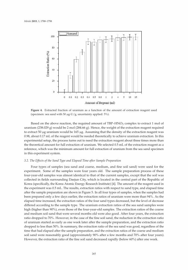
Metals 2015, 5, 1788–1798
Figure 4. Extracted fraction of uranium as a function of the amount of extraction reagent used(specimen: sea sand with 50 μg-U/g, uncertainty applied: 5%).
Based on the above reaction, the required amount of TBP–HNO3 complex to extract 1 mol ofuranium (238.029 g) would be 2 mol (284.66 g). Hence, the weight of the extraction reagent requiredto extract 50 μg uranium would be 165 μg. Assuming that the density of the extraction reagent was0.98, about 0.17 mL of the reagent would be needed theoretically to achieve uranium extraction. In thisexperimental setup, the process turns out to need the extraction reagent about three times more thanthe theoretical amount for full extraction of uranium. We selected 0.5 mL of the extraction reagent as areference, which was the minimum amount for full extraction of uranium from the sea sand specimenin this experiment system.
3.2. The Effects of the Sand Type and Elapsed Time after Sample Preparation
Four types of samples (sea sand and coarse, medium, and fine soil sand) were used for theexperiment. Some of the samples were four years old. The sample preparation process of thesefour-year-old samples was almost identical to that of the current samples, except that the soil wascollected in fields surrounding Daejun City, which is located in the central part of the Republic ofKorea (specifically, the Korea Atomic Energy Research Institute) [4]. The amount of the reagent used inthe experiment was 0.5 mL. The results, extraction ratios with respect to sand type, and elapsed timeafter the sample preparation are shown in Figure 5. In all four types of samples, when the samples hadbeen prepared only a few days earlier, the extraction ratios of uranium were more than 94%. As theelapsed time increased, the extraction ratios of the four sand types decreased, but the level of decreasediffered according to the sample type. The uranium extraction ratios of the sea sand samples werehigh (higher than 90%), even those of the four-year-old samples. The extraction ratios of the coarseand medium soil sand that were several months old were also good. After four years, the extractionratio dropped to 70%. However, in the case of the fine soil sand, the reduction in the extraction ratioof uranium started as early as one week later after the sample preparation, and the extraction ratiodropped to less than 50%. In summary, the extraction ratio of the sea sand was good, regardless of thetime that had elapsed after the sample preparation, and the extraction ratios of the coarse and mediumsoil sand were reasonably good (approximately 90% after a few months and 70% after four years).However, the extraction ratio of the fine soil sand decreased rapidly (below 60%) after one week.
265

Metals 2015, 5, 1788–1798
Figure 5. Extracted ratio changes according to soil type and the elapsed time after sample preparation(uncertainty applied: 5%).
In the present study, the reduction in the extraction ratio of uranium ions in the soil sand may haveoriginated from two mechanisms: the trapping of uranium ions in cracks and pores and chemisorptionof uranium ions on the surface. The microstructures of the sea sand and soil sand were observed bySEM (Figure 6) (Stereoscan 440, Leica, Cambridge, UK). The surface of the sea sand was relativelysmooth and glassy, whereas that of the soil sand was rough and contained cracks and small pores.If uranium ions are adsorbed to the surfaces inside cracks or pores, they may not be easy to remove orextract. In the case of chemisorption, the extraction of uranium may also be difficult. Chemically puresea sand is mainly silica, which rarely reacts chemically with uranium ions. An SEM-EDX analysisof the sand indicated the existence of various impurities, including Fe, Mg, K, and Al (Figure 7).These impurities may take different structures on the surface, and they can provide sites for chemicalreactions with uranium ions. Initially, uranium ions in soil are mainly physically adsorbed on thesurface of the soil. Over time, the uranium ions and impurities on the surface of the soil start tochemically react with each other (chemisorption). Once the uranium ions are chemically bonded withthe impurities on the soil surface, it becomes more difficult to extract uranium from the surface, and astronger extraction process is required.
The results shown in Figure 5 indicate that the extraction ratios of all the four types of soil sandwere very high when the elapsed time was less than one day. Based on these results, it seems moredifficult to extract chemisorbed uranium ions on the surface than trapped uranium ions in cracksand pores. Supercritical CO2 has a very good ability to penetrate solid gaps, such as cracks and openpores. Although soil sand has a large surface area, with cracks and pores, supercritical CO2 can carrythe extraction reagent to cracks and pores by penetrating fine gaps in the sample. However, as timeprogresses, physically adsorbed uranium ions transform to a chemically bonded state, with impuritieson the surface. Once uranium ions enter a chemisorbed state, they are not easy to extract. Some soil,such as fine soil sand, which has a greater higher surface area, has more chemical bonding sites foruranium ions. In such soil samples, the extraction ratio decreases with the elapsed time since thepreparation of the samples. The extraction of chemisorbed uranium may require mechanical energy,such as ultrasonic vibrations, and additional chemical reagents that prevent chemical bonding.
266

Metals 2015, 5, 1788–1798
Figure 6. SEM images of the four types of soil samples before the cleaning process (four-year-oldsamples). (a) Sea sand; (b) coarse soil sand; (c) medium soil sand; (d) fine soil sand.
Figure 7. EDX analyses of the sea sand and fine soil sand before the cleaning process (four-year-oldsamples). (a) Sea sand and (b) fine soil sand.
4. Conclusions
Sand fractions sorted from soil contaminated with uranium were cleaned by supercritical CO2
with a TBP–HNO3 complex. Four types of sand (sea sand, and coarse, medium, and fine soil sand)were used, and experiments were performed to examine the effects of the amount of reagent, sandtype, and elapsed time after sample preparation on the uranium extraction.
267

Metals 2015, 5, 1788–1798
In this experimental setup, about three times more extraction reagent was needed than thetheoretical amount for full extraction of uranium from the sea sand specimens. Only if the elapsed timeafter the sample preparation was less than a day were the extraction ratios of uranium very high in allthe four types of sand. This indicates that supercritical CO2 can easily pump the extraction reagent intocracks and pores by penetrating through the fine gaps in the sample. Over time, physically adsorbeduranium ions transform to a chemically bonded state, with impurities on the surface. Once uraniumions enter a chemisorbed state, they are not easy to extract. Thus, the extraction ratio of the fine soilsand, which has the largest surface area of the samples, decreased the most in the present study as theelapsed time since the sample preparation increased.
The process suggested in this study is environmentally friendly. CO2, the solvent in the cleaningprocess, can be easily recycled, and TBP and nitric acid can be reused. Thus, no secondary wasteis generated during the uranium-decontamination process. The solvent of supercritical CO2 seemsvery effective in the decontamination of soil. However, the extraction of chemisorbed uranium in soilmay require additional processes, such as the application of mechanical vibration and the addition ofbond-breaking reagents.
Acknowledgments: This research was supported by a grant from the National Research Foundation of Korea(NRF), funded by the Korean government (MSIP: Ministry of Science, ICT and Future planning). The projectnumber is 2012M2B2B1055502.
Author Contributions: Kwangheon Park interpreted the results and drafted the paper. Wonyoung Jung built theexperimental setup, prepared the specimens and produced the results. Jihye Park analyzed the specimens.
Conflicts of Interest: The authors declare no conflict of interest.
References
1. Steinhauser, G.; Brandl, A.; Johnson, T.E. Comparison of the Chernobyl and Fukushima Nuclear Accidents:A review of the environmental impacts. Sci. Total Environ. 2014, 470–471, 800–817. [CrossRef] [PubMed]
2. Calmon, P.; Gonze, M.A.; Mourlon, C. Modeling the Early-Phase Redistribution of Radiocesium Falloutsin an Evergreen Coniferous Forest after Chernobyl and Fukushima Accidents. Sci. Total Environ. 2015, 529,30–39. [CrossRef] [PubMed]
3. Certini, G.; Scalenghe, R.; Woods, W.I. The Impact of Warfare on the Soil Environment. Earth Sci. Rev. 2013,127, 1–15. [CrossRef]
4. Park, K.; Lee, J.; Sung, J. Metal Extraction from the Artificially Contaminated Soil Using Supercritical CO2
with Mixed Ligands. Chemosphere 2013, 91, 616–622. [CrossRef] [PubMed]5. Park, K.; Jinhyun, S.; Koh, M.; Kim, H.; Kim, H. Decontamination of Radioactive Contaminants Using Liquid
and Supercritical CO2. In Radioactive Waste; Rahman, R.A., Ed.; InTech: Rijeka, Croatia, 2012; pp. 219–238.6. Benedict, M.; Pigford, T.H.; Levi, H.W. Nuclear Chemical Engineering, 2nd ed.; McGraw-Hill Book Company:
New York, NY, USA, 1981.7. Lin, Y.; Smart, N.G.; Wai, C.M. Supercritical Fluid Extraction of Uranium and Thorium from Nitric Acid
Solutions with Organophosphorus Reagents. Environ. Sci. Technol. 1995, 29, 2706–2708. [CrossRef] [PubMed]8. McHardy, J.; Sawan, S.P. Supercritical Fluid Cleaning: Fundamentals, Technology and Applications; Noyes:
Westwood, NJ, USA, 1998.9. Park, K.H.; Kim, H.W.; Kim, H.D.; Koh, M.S.; Ryu, J.D.; Kim, Y.E.; Lee, B.S.; Park, H.T. Application of CO2
Technology in Nuclear Decontamination. Han’guk Pyomyon Konghak Hoechi 2001, 34, 62–67.10. Carrott, M.J.; Waller, B.E.; Smart, N.G.; Wai, C.M. High solubility of UO2(NO3)2·2TBP complex in supercritical
CO2. Chem. Commun. 1998. [CrossRef]11. Shimada, T.; Ogumo, S.; Ishihara, N.; Kosaka, Y.; Mori, Y. A Study on the Technique of Spent Fuel
Reprocessing with Supercritical Fluid Direct Extraction Method (super-DIREX method). J. Nucl. Sci. Technol.2002, 39, 757–760. [CrossRef]
12. Erkey, C. Supercritical Carbon Dioxide Extraction of Metals from Aqueous Solutions: A Review. J. Supercrit.Fluids 2000, 17, 259–287. [CrossRef]
13. Enokida, Y.; Yamamoto, I. Vapor-liquid Equilibrium of UO2(NO3)2·2TBP and Supercritical Carbon DioxideMixture. J. Nucl. Sci. Technol. 2002, 9, 270–273. [CrossRef]
268

Metals 2015, 5, 1788–1798
14. Tamika, O.; Meguro, Y.; Enokida, Y.; Yamamoto, I.; Yoshida, Z. Dissolution Behavior of Uranium Oxideswith Supercritical CO2 Using HNO3–TBP Complex as a Reactant. J. Nucl. Sci. Technol. 2001, 38, 1097–1102.[CrossRef]
15. Meguro, Y.; Iso, S.; Yoshida, Z.; Tomioka, O.; Enokida, Y.; Yamamoto, I. Decontamination of uranium Oxidesfrom Solid Wastes by Supercritical CO2 Fluid Leaching Method Using HNO3–TBP Complex as a Reactant.J. Supercrit. Fluids 2004, 31, 141–147. [CrossRef]
16. Sawada, K.; Uruga, K.; Koyama, T.; Shimada, T.; Mori, Y.; Enokida, Y.; Yamanoto, I. Stoichiometric relationfor Extraction of Uranium from UO2 Powder Using TBP Complex with HNO3 and H2O in Supercritical CO2.J. Nucl. Sci. Technol. 2005, 42, 301–304. [CrossRef]
17. Buol, S.W.; Southard, R.J.; Graham, R.C.; McDaniel, P.A. Soil Genesis and Classification, 6th ed.; Wiley-Blackwell:Hoboken, NJ, USA, 2011.
© 2015 by the authors. Licensee MDPI, Basel, Switzerland. This article is an open accessarticle distributed under the terms and conditions of the Creative Commons Attribution(CC BY) license (http://creativecommons.org/licenses/by/4.0/).
269

metals
Article
Removal of Zn from Contaminated Sediment byFeCl3 in HCl Solution
Sang-hun Lee 1, Ohhyeok Kwon 2, Kyoungkeun Yoo 2,* and Richard Diaz Alorro 3
1 Gas & Mining Plant Division, Samsung Construction & Technology, Seoul 137-956, Korea;[email protected]
2 Department of Energy & Resources Engineering, Korea Maritime and Ocean University (KMOU),Busan 606-791, Korea; [email protected]
3 Department of Mining Engineering and Metallurgical Engineering, Western Australian School of Mines,Curtin University, Kalgoorlie, WA 6430, Australia; [email protected]
* Author to whom correspondence should be addressed; [email protected]; Tel.: +82-51-410-4686;Fax: +82-51-403-4680.
Academic Editors: Suresh Bhargava, Mark Pownceby and Rahul RamReceived: 28 July 2015; Accepted: 5 October 2015; Published: 8 October 2015
Abstract: Harbor sediments contaminated with ZnS concentrate were treated by ferric chloride inHCl solution to remove Zn. The sediments were evaluated using Tessier’s sequential extractionmethod to determine the different metal phase associations of Zn. Leaching tests were performedto investigate the effects of experimental factors, such as agitation speed, ferric ion concentration,temperature, and pulp density, on the removal of Zn. The sequential extraction procedure revealedthat about 17.7% of Zn in the sediment was associated with soluble carbonate and oxide phases.The results of the leaching tests indicated that higher ferric concentration and temperature increasedthe leaching efficiencies significantly, while the agitation speed has a negligible effect on the removalof Zn. The removal ratio increased to more than 99% within 120 min of treatment at 1 kmol·m−3 HClsolution with 1 kmol·m−3 Fe3+, 10% pulp density, and 400 rpm at 90 ◦C. The dissolution kineticsof Zn were discussed by comparing the two shrinking core models. It was determined that thekinetic data followed the diffusion controlled model well compared to the surface chemical reactionmodel. The activation energies were calculated to be 76.9 kJ/mol, 69.6 kJ/mol, and 58.5 kJ/molfor 0.25 kmol·m−3, 0.5 kmol·m−3, and 1 kmol·m−3 Fe3+, respectively.
Keywords: harbor sediments; ferric chloride; zinc sulfide; metal contamination
1. Introduction
Operational or incidental spillage of materials during unloading activities of metal concentrateshas caused contamination problems in some harbor areas in Korea. This has led to increasing concernsregarding metal-contaminated soils and sediments and their impacts on the environment. Varioustreatment methods have been proposed for remediating contaminated sites, such as gravity separation,phytoremediation, thermal processing, solidification/stabilization, electrokinetic remediation, andsoil washing [1,2]. Gravity separation techniques have been considered to be cost-effective andenvironmentally friendly primarily because of the chemical-free process, but their effectivenessand applicability are rather difficult in the treatment of fine concentrates with particle sizes lessthan 75 μm [2]. Since fine particles have high specific surface area, chemical treatment methods suchas leaching generally are more suitable than physical treatment processes.
Zinc sulfide (sphalerite, ZnS) concentrates are normally subjected to roasting as a pre-treatmentmethod before leaching to enhance the dissolution of Zn. After leaching, the released Zn ions arerecovered as metallic zinc in the electrowinning process [3]. The emission of SO2 during roasting is
Metals 2015, 5, 1812–1820 270 www.mdpi.com/journal/metals
Metals 2015, 5, 1812–1820
a serious environmental problem and is governed by strict environmental regulations. Due to this,the hydrometallurgical route has gained recognition as an alternative process to recover Zn fromconcentrates [3]. The leaching of sphalerite has been investigated using various leaching media, suchas ferric sulphate and chloride with hydrogen peroxide or oxygen [3], ferric sulphate [4], hydrochloricacid with ferric chloride [5], and sulfuric acid with nitric acid [6]. These studies suggested the use ofeither ferric ions, H2O2, O2, or HNO3 for ZnS oxidation using mineral grade sphalerite or concentrates.Only a few studies on the hydrometallurgical removal of Zn from ZnS-contaminated sediments withferric ions are available in literature.
Harbor sediments contaminated with ZnS are exposed to natural environmental conditions andmay undergo weathering over time and may change to a different chemical form. Metals accumulatein sediments from both natural and anthropogenic sources, thus making it difficult to identify anddetermine their origin. It is therefore important to evaluate the individual fractions of the metals notonly to understand their actual and potential environmental effects but also to aid in the process design.However, metal concentrations in contaminated sediments are usually below the detection limit ofthe X-ray diffractometer (XRD), making their measurements difficult. To overcome this limitation,sequential extraction methods can be used [7,8]. One of the most widely used methods is the Tessiersequential extraction method which consists of five extraction steps: “bound to exchangeable”, “boundto carbonate”, “bound to oxide”, “bound to sulfide or organic matter”, and residue. A study conductedby Park et al. on the leaching of heavy metals (Cu, Zn, Pb) from contaminated soil using citric acidrevealed that the metals in carbonate and oxide phases are easy to dissolve [2].
In the present study, the sediments contaminated with ZnS concentrate were evaluated usingTessier’s sequential extraction method. Ferric chloride leaching tests were performed to investigate theeffects of leaching factors such as agitation speed, ferric chloride concentration, temperature, and pulpdensity on Zn removal. The dissolution kinetics were discussed and interpreted by comparing the twoshrinking core models.
2. Experiments
2.1. Materials
Sediments contaminated with ZnS were collected from a harbor site that has been used for theunloading of Zn concentrate. The samples were washed three times with distilled water and thendried overnight at 105 ◦C. The particle size distribution of the sediment as shown in Figure 1 revealsthat 48.5% of the sample has a particle size <75 μm. This size fraction was used in the leachingtests. The zinc content of the sample was determined to be 5287 mg/kg by aqua-regia digestion.All chemicals used in this study were of reagent grade.
2.2. Leaching Procedures and Analytical Methods
The leaching tests were performed in a 500 dm3 three-necked Pyrex glass reactor using a heatingmantle to maintain the desired temperature to within ±2 ◦C. This reactor was fitted with a stirrerand a reflux condenser to prevent solution loss at high temperatures. Leach solutions were preparedwith FeCl3 concentrations of between 0.25 kmol·m−3 and 1 kmol·m−3 in 1 kmol·m−3 HCl solution.For every batch of leaching test, 200 cm3 of leach solution was introduced into the reactor. Once thesolution reached thermal equilibrium (40–90 ◦C), 20–60 g of the fine sediment powder was added andagitated at 200−600 rpm. During these tests, a 2 cm3 aliquot solution was withdrawn periodically overthe desired time interval (5–240 min) for analysis.
271

Metals 2015, 5, 1812–1820
Figure 1. Particle size distribution of the contaminated sediment.
The sequential extraction method used in this study was originally developed by Tessier et al.(1979) [7] and later modified by Li et al. (1995) [8]. The extraction method used 1 g of dried sample andwas performed under the following conditions and reagents: (1) 8 cm3 of 1 kmol·m−3 MgCl2 (adjustedto pH 7) for 1 h at room temperature in the shaking bath; (2) 8 cm3 of 1 kmol·m−3 CH3COONa (adjustedto pH 5) for 5 h at room temperature in the shaking bath; (3) 20 cm3 of 0.4 kmol·m−3 NH2OH·HCl(in 25% CH3COOH) for 6 h at 96 ◦C in a heating block; (4) 3 cm3 of 0.02 kmol·m−3 HNO3 and 5 cm3
of 30% H2O2 (adjusted to pH 2) for 2 h at 85 ◦C in a heating block, followed by 3 cm3 of 30% H2O2
(adjusted to pH 2) for 3 h at 85 ◦C in a heating block, and, finally, 5 cm3 of 3.2 kmol·m−3 CH3COONH4
(in 20% HNO3) and about 4 cm3 deionized water for 30 min at room temperature in the shakingbath; (5) 20 cm3 of aqua regia for 20 min. All solid/liquid separations were done by centrifugationfor 30 min at 10,000 rpm (1065× g), designated amounts of supernatant were taken and then dilutedwith 5% HNO3 solution. The concentration of Zn was determined with AA-7000 atomic absorptionspectrophotometer (Shimadzu Scientific Instrument, Ltd., Kyoto, Japan).
3. Results and Discussion
Zinc concentrate is usually imported to Korea in the form of ZnS (sphalerite) and due tooperational or incidental spillage during unloading, this concentrate has become the source of Zncontamination in harbor sediments. The chemical association of Zn in this sediment was examinedusing Tessier’s sequential extraction method to understand its characteristics, through which it wasfound that 7.9% and 9.8% of the Zn was in the “bound to carbonate” and “bound to oxide” phases,respectively. The rest of the Zn content was found to be associated with the “bound to sulfide” phase.This result indicates that 17.7% of Zn is bound to the weathered forms, such as carbonates and oxides,which can be dissolved easily in HCl solution.
Leaching tests using the contaminated sediments were carried out at agitation speeds in the rangeof 200–600 rpm to examine the effect of liquid film boundary diffusion surrounding the solid particleson the leaching efficiency at the following conditions: 1 kmol·m−3 HCl with 1 kmol·m−3 Fe3+, 10%pulp density, and 50 ◦C. Figure 2 shows that the leaching efficiencies of Zn are independent of theagitation speeds. Therefore, in all subsequent leaching tests, a working agitation speed of 400 rpmwas selected to ensure effective particle suspension in the solution. It was also observed that theleaching efficiency of Zn increased rapidly to more than 20% within 5 min and then gradually increasedafterwards. This can be attributed to the initial dissolution of Zn present in the “bound to carbonate”and “bound to oxide” phases.
272

Metals 2015, 5, 1812–1820
Figure 2. The effects of agitation speed on the leaching efficiency of Zn at 1 kmol·m−3 HCl with1 kmol·m−3 Fe3+, 10% pulp density, and 50 ◦C.
Figure 3 shows the effect of Fe3+ concentration on the dissolution of Zn from the contaminatedsediment at 1 kmol·m−3 HCl solution, 10% pulp density, 0.25–1 kmol·m−3 Fe3+, 50 ◦C, and 400 rpm.The leaching efficiencies of Zn increased gradually with leaching time and improved significantly withhigher Fe3+ concentrations. A ferric ion was used as an oxidant in this study, and the oxidation of ZnSwas promoted by the ferric ion according to the following equation [9]:
ZnS + 2FeCl3 = ZnCl2 + 2FeCl2 + S0 (1)
The sediments contain 5287 mg/kg of Zn, which is equivalent to 8 mol·m−3 in a 10% pulp densitysolution. However, although 250 mol·m−3 Fe3+ is already almost 15 times more than the stoichiometricrequirement of 16 mol·m−3 Fe3+ to oxidize 8 mol·m−3 of ZnS, the leaching efficiency of Zn wasonly 41.4% at 240 min as shown in Figure 3.
Figure 4 shows the effect of temperature on the leaching efficiency of Zn at 1 kmol·m−3 HClsolution, 10% pulp density, 1 kmol·m−3 Fe3+, 40–90 ◦C, and 400 rpm. Higher temperatures yield higherZn leaching efficiency and it increased to more than 99% within 120 min and 180 min at 90 ◦C and 80 ◦C,respectively. These results also show that the Zn content decreased to less than 200 mg/kg, which isthe environmental standard for Zn in Korea, and indicate that Zn could be removed successfully. Theeffect of pulp density on the leaching of Zn from the sediments was investigated under the followingconditions: 1 kmol·m−3 HCl, 1 kmol·m−3 Fe3+, 10%–30% pulp density, 50 ◦C temperature, and 400 rpmagitation speed, but the results showed no apparent differences in leaching efficiency (data not shown).
Figure 3. The effects of Fe3+ concentration on the leaching efficiency of Zn at 1 kmol·m−3 HCl, 10%pulp density, 50 ◦C, and 400 rpm.
273

Metals 2015, 5, 1812–1820
Studies on the dissolution kinetics of ZnS were reported previously and investigations werecarried out using pure sphalerite crystals [9,10], low-grade calcareous sphalerite [11], and ZnSconcentrate [4,5]. Activation energy values were calculated using the shrinking core model andthe Dickson and Heal model [4,5,9–11] and were determined to be 27.5 kJ/mol in sulfuric acid [4]and 42–49.2 kJ/mol in hydrochloric acid [5,9–11], respectively. The shrinking core model could beexpressed by [5,12]:
1 − (1 − x)13 = krt (2)
1 − (23)x − (1 − x)
23 = kdt (3)
Equation (2) represents the shrinking core model based on surface chemical reaction(reaction-controlled model), while Equation 3 is based on diffusion reaction (diffusion-controlledmodel). The value for x in the equations represents the fraction reacted and is obtained from theleaching efficiencies, while kr and kd are rate constants.
Figure 4. The effects of temperature on the leaching efficiency of Zn at 1 kmol·m−3 HCl with1 kmol·m−3 Fe3+, 10% pulp density, and 400 rpm.
The leaching efficiency of Zn increased to more than 90% at 80 ◦C and 90 ◦C within 120 min, so theleaching data within 60 min were fitted to the models as shown in Figure 5 (reaction-controlledmodel) and Figure 6 (diffusion-controlled model), respectively. Based on the calculations, thecorrelation coefficients (R2) for the diffusion-controlled model are higher compared to that of thereaction-controlled model. Previous studies on ZnS leaching with FeCl3 reported that the leachingbehavior of Zn followed the reaction-controlled model [5,9,10] while others proposed that the reactionwas controlled by both the reaction- and diffusion-controlled model [4,11]. In the current study, thekinetic model parameters indicated that the diffusion-controlled model is more suitable to explainthe kinetic behavior of Zn removal. This result can be attributed to the low Zn content of the testsample (about 0.5%) as compared to the 48%–67% Zn contents of the samples used in previousstudies [4,5,9–11].
Rate constants for different temperatures were calculated from Figure 6, and the Arrhenius plotsof lnK vs. T−1 for leaching data are shown in Figure 7. From the Arrhenius plots, the activationenergies of 76.9 kJ/mol, 69.6 kJ/mol, and 58.5 kJ/mol were calculated for the sphalerite dissolution in0.25 kmol·m−3, 0.5 kmol·m−3, and 1 kmol·m−3 Fe3+, respectively. The results indicate that the reactionis controlled by the diffusion of Fe3+ ions.
This study confirmed that the removal of Zn could be achieved by ferric chloride leaching in HClsolution, and the Zn content decreased to less than 200 mg/kg, satisfying the Korean environmentalstandard. During leaching, ferrous (Fe2+) ion is generated and the Fe2+ ion could be oxidized
274

Metals 2015, 5, 1812–1820
electrochemically or biologically into Fe3+, which can be reused as an oxidant in the process. Furtherstudy will be required to optimize the re-oxidation.
(a) (b)
(c)
Figure 5. Plot of 1 − (1 − x)1/3 vs. T for different temperatures ([Fe3+]: (a) 1.0 M; (b) 0.5 M; (c) 0.25 M;10% pulp density; 400 rpm agitation speed).
(a) (b)
(c)
Figure 6. Plot of 1 − 2/3x − (1 − x)2/3 vs. T for different temperatures ([Fe3+]: (a) 1.0 M; (b) 0.5 M;(c) 0.25 M; 10% pulp density; 400 rpm agitation speed).
275

Metals 2015, 5, 1812–1820
Figure 7. Arrhenius plots. (1 kmol m−3 HCl; 0.25 kmol m−3–1 kmol m−3 Fe3+; 400 rpm agitationspeed; 10% pulp density; 40 ◦C–90 ◦C temperature).
4. Conclusions
The leaching behavior of Zn from sediment contaminated with ZnS concentrate using Fe3+ ionsin HCl solution was investigated. The chemical associations of Zn in the sediment were also evaluatedusing Tessier’s sequential extraction method. By fitting the leaching data to two shrinking core models,the following conclusions were made:
1. The removal of Zn was achieved by ferric chloride leaching in HCl solution. The removalratio increased to more than 99% within 120 min under the following leaching conditions;1 kmol·m−3 Fe3+; 1 kmol·m−3 HCl; 400 rpm agitation speed; 90 ◦C leaching temperature;10% pulp density. More importantly, the results obtained meet the Korean environmentalstandards for Zn of 200 mg/kg.
2. About 17.7% of Zn in the sediment was associated with the soluble carbonate and oxide phasesas determined by the sequential extraction procedure. The leaching efficiency of Zn increasedquite rapidly in the first 5 min and then gradually in the succeeding treatment time. The rapidincrease can be attributed to the dissolution of Zn in carbonate and oxide fractions. These resultsconfirm the importance of evaluating the different metal phase associations through sequentialextraction to understand the leaching behavior.
3. The kinetic data indicated that the leaching behavior followed the diffusion-controlled modelwell rather than the surface chemical reaction model. As ferric ion concentration increases, thecalculated activation energy decreases. The results also suggest that higher ferric ion concentrationand temperature could enhance the leaching efficiency of Zn.
Acknowledgments: The authors express appreciation for the support of the “Leaders Industry-UniversityCooperation” Project, funded by the Ministry of Education, Science & Technology (MEST) and the NationalResearch Foundation of Korea (NRF).
Author Contributions: Lee and Yoo wrote the paper and contributed to all activities. Kwon conducted leachingtests and analyses. Alorro contributed to interpretation and discussion of the kinetics data.
Conflicts of Interest: The authors declare no conflict of interest.
References
1. Furukawa, M.; Tokunaga, S. Extraction of heavy metals from a contaminated soil using citrate enhancingextraction by pH control and ultrasound application. J. Environ. Sci. Health 2004, 39, 627–638. [CrossRef]
2. Park, H.; Jung, K.; Alorro, R.D.; Yoo, K. Leaching behavior of copper, zinc and lead from contaminated soilwith citric acid. Mater. Trans. 2013, 54, 1220–1223. [CrossRef]
276

Metals 2015, 5, 1812–1820
3. Santos, S.M.C.; Machado, R.M.; Correia, M.J.N.; Reis, M.T.A.; Ismael, M.R.C.; Carvalho, J.M.R. Ferricsulhate/chloride leaching of zinc and minor elements from a sphalerite concentrate. Miner. Eng. 2010, 23,606–615. [CrossRef]
4. Souza, A.D.; Pina, P.S.; Leão, V.A.; Silva, C.A.; Siqueira, P.F. The leaching kinetics of a zinc sulphideconcentrate in acid ferric sulphate. Hydrometallurgy 2007, 89, 72–81. [CrossRef]
5. Aydogan, S.; Aras, A.; Canbazoglu, M. Dissolution kinetics of sphalerite in acidic ferric chloride leaching.Chem. Eng. J. 2005, 114, 67–72.
6. Peng, P.; Xie, H.; Lu, L. Leaching of a sphalerite concentrate with H2SO4–HNO3 solutions in the presence ofC2Cl4. Hydrometallurgy 2005, 80, 265–271. [CrossRef]
7. Tessier, A.; Campbell, P.G.C.; Bisson, M. Sequential extraction procedure for the speciation of particulatetrace metals. Anal. Chem. 1979, 51, 844–850. [CrossRef]
8. Li, X.; Coles, B.J.; Ramsey, M.H.; Thornton, I. Sequential extraction of soils for multielement analysis byICP-AES. Chem. Geol. 1995, 124, 109–123. [CrossRef]
9. Dutrizac, J.E.; Macdonald, R.J.C. The dissolution of sphalerite in ferric chloride solutions. Metall. Trans. B1978, 9B, 543–551. [CrossRef]
10. Al-Harahsheh, M.; Kingman, S. The influence of microwaves on the leaching of sphalerite in ferric chloride.Chem. Eng. Prog. 2008, 47, 1246–1251. [CrossRef]
11. Dehghan, R.; Noaparast, M.; Kolahdoozan, M. Leaching and kinetic modelling of low-grade calcareoussphalerite in acidic ferric chloride solution. Hydrometallurgy 2009, 96, 275–282. [CrossRef]
12. Levenspiel, O. Chemical Reaction Engineering; John Wiley & Sons: New York, NY, USA, 1999; pp. 566–588.
© 2015 by the authors. Licensee MDPI, Basel, Switzerland. This article is an open accessarticle distributed under the terms and conditions of the Creative Commons Attribution(CC BY) license (http://creativecommons.org/licenses/by/4.0/).
277

metals
Article
Use of Nanoscale Zero-Valent Iron (NZVI) Particlesfor Chemical Denitrification under DifferentOperating Conditions
Alessio Siciliano
Department of Environmental and Chemical Engineering, University of Calabria, P. Bucci, 87036 Arcavacata diRende (CS), Italy, [email protected]; Tel./Fax: +39-09-84496537
Academic Editor: Suresh BhargavaReceived: 9 July 2015; Accepted: 18 August 2015; Published: 21 August 2015
Abstract: The nitrate pollution of waters and groundwaters is an important environmental andhealth concern. An interesting method to remove the oxidized forms of nitrogen from waters andwastewaters is chemical denitrification by means of metallic iron (Fe0). Particularly advantageousis the use of nanoscopic zero-valent iron particles due to the elevated surface area, which allowsreaching extremely high reaction rates. In the present paper, the efficiency of nitrate reductionby means of nanoscopic Fe0 has been investigated under several operating conditions. The ironnanoparticles were synthesized by the chemical reduction of ferric ions with sodium borohydride.The effects of Fe0 dosage, initial N–NO3
− concentration and pH on chemical denitrification wereidentified. In particular, the results of the tests carried out showed that it is possible to reach analmost complete nitrate reduction in treating solutions with a nitrate nitrogen concentration higherthan 50 mg/L. Moreover, the process performance was satisfactory also under uncontrolled pH.By means of the trends detected during the experiments, the kinetic-type reaction was identified.Furthermore, a relation between the kinetic constant and the process parameters was defined.
Keywords: denitrification; kinetic analysis; nanoscopic iron; nitrate
1. Introduction
Nitrate pollution is a serious environmental problem, because it causes eutrophication phenomenaand may lead to diseases when drinking water sources are contaminated. The sources of nitrogencompounds include nitrogenous fertilizers, animal manure, municipal and industrial wastewaters.Many physicochemical and biological processes, such as ion exchange, reverse osmosis and biologicaldenitrification, have been used to remove nitrate from waters and wastewaters. However, ion exchangeand reverse osmosis may be expensive, because they require frequent regeneration of the media andgenerate secondary waste [1]. Biological denitrification, the most widely-used method, producesexcessive biomass and soluble microbial products that require further expensive treatment for usein drinking water supplies. Moreover, the microbial processes are generally slow and sometimesincomplete compared to chemical processes [1]. The N–NO3
− chemical reduction to ammonia bymeans of microscopic zero-valent iron has been widely studied, because this metal is abundant,inexpensive and readily available and because its reduction process requires little maintenance [1–12].The performance of Fe0 treatment is dependent on the pH value in the aqueous system. Generally,rapid reduction of nitrate by Fe0 occurred at pH ≤ 4, which is probably related to the enhancediron corrosion in acid solution. Under environmental conditions, the iron corrosion products, suchas iron oxides, oxide hydroxides or salts, which are usually coated on the Fe0 surface, could slowdown the nitrate reduction reaction. Thus, the process requires acidic conditions to achieve the bestperformances. Several compounds, such as H2SO4, HCl, acetic acid and buffered agents, were used
Metals 2015, 5, 1507–1519 278 www.mdpi.com/journal/metals

Metals 2015, 5, 1507–1519
to speed up the rate of nitrate removal [3]. However, these methods are not convenient in practicalapplications, because the costs are significantly increased and because the release into waters ofundesired compounds, such as sulfate, chloride etc., occurs. Moreover, in the nitrate removal byFe0, a high transfer into the solution of soluble iron generally occurs. Therefore, in order to recoverythese ions, further treatment is generally needed. In some works, the efficiency of the treatment wasimproved by the addition to the solution of a sufficient amount of Fe2+, because, in this way, it ispossible to locally transform the corrosion products into reactive compounds, so as to facilitate nitratereduction [4]. Furthermore, in the presence of Fe2+, dissolved oxygen does not seem to interferewith rapid nitrate reduction by Fe0 [4]. The adaptation of nano-scale zero-valent iron (NZVI) forthe decontamination of water and wastewaters has several advantages compared to micro-scale ZVI.Reducing the particle size of granular Fe0 materials (mm) to 10–100 nm, it increases the surface areaand, thus, the reaction rates. Moreover, the nano-Fe0 can be applied in the treatment process in slurryform, which facilitates the contact with the contaminant. These factors allow operating with lowerdosages and obtaining a high and stable reactivity. Furthermore, the recovery of NZVI particlesafter the treatment could be easy accomplished. In fact, it is a common behavior that nanoparticleswould aggregate in clusters in aqueous solution unless they are dispersed by a surfactant. Therefore,synthesized nanoscale iron particles can be easily separated from liquid by filtration or other physicalseparation processes [5]. In the present paper, the results of an experimental activity conducted toinvestigate the efficiency of nanoscale zero-valent iron (NZVI) particles for chemical denitrification ofnitrate nitrogen in aqueous solutions, under different operating conditions, are reported. Nanosizediron was synthesized by chemical reduction of ferric ions with sodium borohydride. Several batchexperiments were carried out to evaluate the influence of nitrate concentrations, iron amounts and pHon the process performance. In particular, contrary to the common zero-valent iron applications, theapplicability of NZVI particles without pH setting was also verified. Furthermore, a detailed analysiswas conducted to identify the type of reaction kinetics.
2. Experimental Section
2.1. Preparation of Nanosized Iron
In this study nanosized iron was synthesized by chemical reduction of ferric ions with sodiumborohydride [1,5] according to the following reaction:
4Fe3+ + 3BH4− + 9H2O → 4Fe0 + 3H2BO3
− + 12H+ + 6H2 (1)
In a typical synthesis procedure, 33.77 g of FeCl3·6H2O were dissolved in 250 mL of bi-distilledwater (0.5 M of Fe3+). The resulting solution was transferred to a glass beaker of 500-mL capacity.Then, 9.45 g of NaBH4 powder were dissolved in 250 mL bi-distilled water (1 M of B5−), and this wasadded incrementally to the FeCl3·6H2O solution by means of a peristaltic pump with a flowrate ofabout 10 mL/min. The mixture was mechanically stirred at 250 rpm during the NaBH4 feeding. Themixing was stopped 15 min after the entire sodium borohydride solution was added. No surfactantwas added to keep the iron particles dispersed. The mixture was centrifuged for 30 min at 4000 rpm,and the recovered solid was washed twice with bi-distilled water. The prepared wet NZVI was usedimmediately for batch experiments.
2.2. Nitrate Reduction by NZVI
The experiments were carried out in order to investigate the influence of NVZI, nitrateconcentrations and pH on process performance. A total of 36 tests were conducted using wetiron amounts of 1 g/L, 2 g/L, 3 g/L and 5 g/L for the treatment of solutions with initial nitrateconcentrations (Ni) of about 50 mgN/L, 70 mgN/L and 95 mgN/L, at conditions of pH 3, 5 anduncontrolled. Batch tests for nitrate reduction were conducted in 0.5-L glass beakers. The reactor wasfilled with 300 mL of nitrate standard solutions (prepared using KNO3 salt), then wet NZVI particles
279

Metals 2015, 5, 1507–1519
were added to the reaction solution. The dispersion was continuously mixed with a mechanical stirrerat 350 rpm for 60 min. During the tests conducted with the pH setting, HCl (1 N) was added to holdthe established pH value. The reactions were conducted at atmospheric conditions at a temperature ofabout 20 ◦C. No attempts were made to exclude oxygen during the experiments. Samples of 5 mL wereperiodically taken and immediately analyzed, after a filtration at 0.45 μm, with respect to nitrogencompounds (N–NO3
−, N–NO2− and N–NH4
+) and dissolved iron ions.
2.3. Analytical Methods and Presentation of Results
The BET surface area of nanoparticles was determined by Micromeritics (Thermo Sorptomatic1990, Waltham, MA, USA). XRD (Philips PW 1710, Amsterdam, The Netherlands) was used tocharacterize the iron corrosion products. During the nitrate removal tests, temperature, pH anddissolved oxygen were measured by a multiparametric analyzer (Hanna HI 98196, Padova, Italy);N–NO3
−, N–NO2−, N–NH4
+ and iron ions by colorimetric methods using a UV spectrophotometer(Thermo Genesys10uv, Waltham, MA, USA) [13]. Each measurement was carried out three times,and the mean value was considered. The results of the efficiencies reported were representative ofthe actual removal or production of the compounds. Thus, the values were not affected by dilutionbecause of reactant additions in the various processes.
3. Results and Discussion
3.1. Nitrate Abatement by Fe0 Nanoparticles
The iron particles synthesized in this study were determined to have a specific surface area of39.36 m2/g, in line with the values reported in the literature [1,5]. The results of the experimentsconducted by means of the prepared nanoparticles are reported in Table 1 and Figures 1–4. For eachpH condition, growing nitrate reductions in response to the increase of Fe0 mass were detected.In particular, in treating solutions with an initial N–NO3
− concentration of about 50 mg/L, at pH = 3and with the lower amount of nanoparticles, an abatement close to 56% was obtained, reaching aresidual concentration of about 23 mg/L (Figure 1a). This yield rapidly increased up to an almostcomplete nitrate abatement using a concentration of nanoparticles equal to 2 g/L. (Figure 1a).
Smaller performances were obtained in the tests conducted with higher nitrate concentrations(Table 1). Indeed, the curves plotted in Figure 1b,c show slower decreasing trends in the tests carriedout with solutions characterized by initial concentrations of 70 mg/L and 95 mg/L. This is alsonoticeable from the specific reaction rates (k) identified by interpolating the experimental results (seeSection 3.2). By comparing the k values for the two last sets of tests (Table 1), just a moderate reductionwas observed. Only with the greatest Fe0 quantity a notable gap between the kinetic constant values(k) was detected (Table 1). Anyhow, using the Fe0 amount of 1 g/L, the efficiencies were around 32%and 36% in treating 70 mg/L and 95 mg/L respectively; then they progressively increased, reaching acomplete nitrate removal with the highest nanoparticles dosage (Table 1, Figure 1b,c).
These results, taking into account the amounts of nitrate and iron used for the experiments, areconsistent with those detected by Yang [5], confirming the reduction power of nanoscopic Fe0 alsoin treating highly concentrated solutions. Moreover, our tests showed only slight reductions of theprocess performance with increasing the pH to five (Table 1, Figure 2).
In particular, the yields obtained during the tests conducted with the lower nitrate concentrationwere analogous to that obtained at pH = 3. Indeed, although a general reduction occurred in responseto pH increase, the reactions rates were such that they ensured particularly high abatements in treatingsolutions with 50 mg/L of nitrate nitrogen (Figure 2a). Furthermore, compared to those observed atpH = 3, even higher abatements were detected with the initial nitrate amount of 70 mg/L (Table 1,Figure 2b). Instead, during the set of experiments carried out with 95 mg/L, lower performances weredetected using Fe0 amounts of 3 g/L and 5 g/L. In fact, yields higher than 90% were obtained at pH = 3,while a maximum yield of about 70% was observed at pH = 5, reaching a final concentration of about
280

Metals 2015, 5, 1507–1519
20 mg/L (Figure 2c). Thus, the above results indicate that, by increasing the process pH up to five, onlya meaningful abatement reduction occurred for the highest nitrate concentrations tested in this study.In the experiments conducted without pH control, the initial value was about 5.9, 5.6 and 5.4 for thesolutions with 50, 70 and 95 mg/L, respectively. The above initial pH values rapidly increased duringthe process up to reaching in a few minutes values higher than nine (Figure 3). However, remarkablenitrate reductions were also observed with these process conditions (Table 1). In particular, with thelower nitrate concentration, the yields increased from 42% to about 98% in response to iron dosageenhancement from 1 g/L–5 g/L (Table 1, Figure 4a). Maximum abatements around 87% and 63%,reaching residual concentration of about 9 mg/L and 35 mg/L, were obtained in treating solutionscharacterized with nitrate amount of 70 mg/L and 95 mg/L, respectively (Figure 4b,c).
Table 1. Nitrate abatement, nitrate removed, ammonium produced, dissolved iron and the specificreaction rate (k) detected for each test.
pH Ni mg/L Fe0 g/LN–NO3
−Abatement (%)
N–NO3−
Removed (mg/L)N–NH4
+
Produced (mg/L)Fe2+ mg/L k min−1
3
50
1 56.1 28.2 27.6 198 0.0132 99.9 49.2 47.8 491 0.0913 99.9 49.6 46.3 705 0.1855 99.9 50.8 48.5 1408 0.282
70
1 36.2 26.9 24.4 197 0.0082 74.3 52.9 49.3 605 0.0253 84.4 59.2 58.5 803 0.0345 99.9 71.7 70.2 1530 0.135
95
1 32.1 31.2 31.0 198 0.0062 60.2 58.6 57.6 491 0.0193 92.4 89.6 88.3 705 0.0295 99.9 98.5 97.3 1408 0.075
5
50
1 52.0 24.6 23.0 48 0.0152 97.1 48.3 47.6 230 0.0543 99.9 51.0 48.1 350 0.1095 99.9 52.2 48.3 1200 0.209
70
1 38.3 26.3 23.0 96 0.0082 83.0 56.4 55.1 232 0.0293 99.9 65.3 62.4 235 0.0735 99.9 69.4 69.1 530 0.084
95
1 28.4 27.5 26.7 32 0.0042 61.0 57.9 56.5 126 0.0143 69.2 66.4 64.6 168 0.0195 73.1 71.2 70.1 370 0.029
uncontrolled
50
1 42.3 20.3 16.0 4.0 0.0102 77.1 37.3 33.1 4.2 0.0213 80.0 39.2 34.1 4.6 0.0225 98.0 44.6 40.5 6.0 0.060
70
1 32.4 22.0 16.4 5.0 0.0072 59.2 42.9 30.1 6.3 0.0153 60.5 44.1 34.6 7.0 0.0165 87.1 59.2 41.5 6.8 0.034
95
1 29.5 28.7 20.7 4.0 0.0052 45.2 44.0 30.8 5.4 0.0103 47.4 46.3 40.3 5.7 0.0105 63.0 61.7 43.0 5.7 0.015
281

Metals 2015, 5, 1507–1519
0
10
20
30
40
50
60
0 5 10 15 20 25 30 35 40 45 50 55 60
N-N
O3- (
mg/
L)
t (min)
Fe=1g/L k=0.013 min^-1 R^2=0.87
Fe=2g/L k=0.091 min^-1 R^2=0.83
Fe=3 g/L k=0.185 min^-1 R^2=0.87
Fe=5 g/L k=0.282 min^-1 R^2=0.75
0
10
20
30
40
50
60
70
80
0 5 10 15 20 25 30 35 40 45 50 55 60
N-N
O3- (
mg/
L)
t (min)
Fe=1 g/L k=0.008 min^-1 R^2=0.84Fe=2 g/L k=0.025 min^-1 R^2=0.96Fe=3 g/L k=0.034 min^-1 R^2=0.94Fe=5 g/L k=0.135 min^-1 R^2=0.80
(a) (b)
0
20
40
60
80
100
120
0 5 10 15 20 25 30 35 40 45 50 55 60
N-N
O3- (
mg/
L)
t (min)
Fe=1 g/L k=0.006 min^-1 R^2=0.79
Fe=2 g/L k=0.019 min^-1 R^2=0.81
Fe=3 g/L k=0.029 min^-1 R2=0.99
Fe=5 g/L k=0.075 min^-1 R^2=0.97
(c)
Figure 1. Trends of nitrate concentrations detected during the tests conducted at pH = 3:(a) Ni = 50 mg/L; (b) 70 mg/L; (c) 95 mg/L.
0
10
20
30
40
50
60
0 10 20 30 40 50 60
N-N
O3- (
mg/
L)
t (min)
Fe=1 g/L k=0.015 min^-1 R^2=0.83
Fe=2 g/L k=0.054 min^-1 R^2=0.98
Fe=3 g/L k=0.109 min^-1 R^2=0.97
Fe=5 g/L k=0.209 min^-1 R^2=0.74
(a) (b)
0
20
40
60
80
100
120
0 10 20 30 40 50 60
N-N
O3-
(mg/
L)
t (min)
Fe=1 g/L k=0.004 min^-1 R^2=0.88Fe=2 g/L k=0.014 min^-1 R^2=0.96Fe=3 g/L k=0.019 min^-1 R^2=0.95Fe=5 g/L k=0.029 min^-1 R^2=0.89
(c)
Figure 2. Trends of nitrate concentrations detected during the tests conducted at pH = 5:(a) Ni = 50 mg/L; (b) 70 mg/L; (c) 95 mg/L.
282

Metals 2015, 5, 1507–1519
0
1
2
3
4
5
6
7
8
9
10
0 10 20 30 40 50 60
pH
t (min)
Figure 3. pH trend during the test conducted with Fe0 = 3 g/L, Ni = 50 mg/L and uncontrolled pH.
0
10
20
30
40
50
60
0 10 20 30 40 50 60
N-N
O3- (
mg/
L)
t (min)
Fe=1 g/L k=0.01 min^-1 R^2=0.83
Fe=2 g/L k=0.021 min^-1 k^2=0.84
Fe=3 g/L k=0.022 min^-1 R^2=0.89
Fe=5 g/L k=0.06 min^-1 R^2=0.98
0
10
20
30
40
50
60
70
80
0 10 20 30 40 50 60
N-N
O3- (
mg/
L)
t (min)
Fe=1 g/L k=0.007 min^-1 R^2=0.91Fe=2 g/L k=0.015 min^-1 R^2=0.88Fe=3 g/L k=0.016 min^-1 R^2=0.98Fe=5 g/L k=0.034 min^-1 R^2=0.86
(a) (b)
0
20
40
60
80
100
120
0 10 20 30 40 50 60
N-N
O3- (
mg/
L)
t (min)
Fe=1 g/L k=0.005 min^-1 R^2=0.95Fe=2 g/L k=0.01 min^-1 R^2=0.97Fe=3 g/L k=0.01 min^-1 R^2=0.91Fe=5 g/L k=0.015 min^-1 R^2=0.89
(c)
Figure 4. Trends of nitrate concentrations detected during the tests conducted at uncontrolled pH:(a) Ni = 50 mg/L; (b) 70 mg/L; (c) 95 mg/L.
These yields are significantly higher than those reported in other works in which a remarkable lossin process efficiency at a pH value higher than four was observed [5,14]. This is generally attributed tothe formation, with the pH increase, of protective layers at the surface of nanosized ZVI that reducethe reactive sites for chemical reduction of nitrate [5]. To increase the process performance under
283

Metals 2015, 5, 1507–1519
uncontrolled pH, some works have tested Fe/Cu bimetallic nanoscopic materials [1,15]. In this way,however, a transfer in the solution of Cu ions could occur, which can form stable complexes that aredifficult to remove, with the ammonia nitrogen [16] produced during the nitrate reduction.
+ Fe0 o Lepidocrocite
+ o o o o o o
Figure 5. XRD of iron corrosion product after the tests conducted with Fe0 = 3 g/L, Ni = 50 mg/Land pH = 3.
Our results, instead, are in agreement with Cheng et al. [17], who stated that also iron corrosionproducts may be responsible for appreciable nitrate reduction. In fact, as shown in Figure 4, in ourtests the N–NO3
− abatement proceeds beyond the time required to reach pH 9 (Figure 3) and, thus,over the corrosion products’ formation. Moreover, from the XRD analysis of iron particles recoveredafter the treatment, appreciable differences between the spectra obtained in the tests carried out at acidconditions and those under uncontrolled pH do not appear (Figures 5 and 6). In fact, in both cases, itseems that the main iron corrosion product could be lepidocrocite (γ-FeOOH) [4]. These statementssuggest that the prevailing amount of iron corrosion products is generated during the first minutes oftreatment. Lepidocrocite could be initially-formed by O2 because our tests have been conducted inaerobic environment. Indeed, other works detected, in similar process conditions, mainly lepidocrociteinstead of magnetite (Fe3O4) or maghemite (γ-Fe3O4) [4]. On the contrary, Fe3O4 and γ-Fe3O4 arecommonly observed in experiments conducted in controlled anoxic conditions [4].
The high yields of our treatment could be also attributed to the strong mixing rate that alloweddisaggregation of the nanoparticle clusters, enhancing the mass transport of nitrate to the iron surface.Moreover, our tests being conducted under atmospheric conditions, the observed results do not showa meaningful dependence of nitrate reduction from dissolved oxygen. These statements are consistentwith the founding of other works conducted both with microscopic and nanoscopic iron particles [5,17].The experiments of the present study confirmed that the ammonium nitrogen was the major productof nitrate reduction (Table 1). In particular, very low differences between the removed nitrate amountsand the produced ammonia were detected during the experiments conducted at pH values of threeand five. The nitrite amounts were always negligible; thus, it is presumable that a slight amount ofnitrogen gas has been generated in each test. Lower concentrations of ammonium were detected byperforming the process under uncontrolled pH (Table 1). This suggests that part of the producedammonia has been stripped due to the rapid pH increase beyond nine during the treatment [1]. WithoutpH control, as expected, also restricted iron ions in the treated solutions were monitored (Table 1).These concentrations were much less than those detected during the other tests, in which the acidconditions promote the iron dissolution. The lower iron and ammonium ions that remain in solutions
284

Metals 2015, 5, 1507–1519
in the tests conducted in uncontrolled conditions, are clearly a positive aspect. Anyhow, the residualN–NH4
+ makes it necessary to forecast further adequate treatments for its removal. A suitable andprofitable technology may be the struvite precipitation process using low expensive reagents that wasdeveloped by the author [18,19].
+ Fe0 o Lepidocrocite
+ o o o o o o
Figure 6. XRD of iron corrosion product after the tests conducted with Fe0 = 3 g/L, Ni = 50 mg/L anduncontrolled pH.
3.2. Kinetic Analysis
The results discussed above show how the nitrate reduction through nanoscopic iron is affectedby many factors. In order to analyze the influence of these factors, a kinetic analysis of the N–NO3
−
decreasing trends was conducted, which were monitored during the experimental tests. For eachoperating conditions tested, the N–NO3
− removal exhibits typical trends of first order kinetics(Figures 1, 2 and 4). Thus, the reduction rate for nitrate can be expressed with the following equation:
rN =dNdt
= −k · N (2)
where N is the nitrate concentration and k is the specific reaction rate (first order kinetic constant). Bysolving the above equation, the following behavior for nitrate concentrations as a function of time canbe easily obtained:
N = Ni · e−k·t (3)
By means of the previous equations, it is possible to accurately simulate the results of theinvestigation carried out. Indeed, the remarkable agreement between the experimental results andtheoretical predictions (Figures 1, 2 and 4) is a good validation of the proposed kinetic model, which,furthermore, is consistent with the statements of other authors [1,5,20]. The abatement curves generallyshowed faster decreasing trends with the Fe0 amount enhancement and decreasing reaction ratesin response to the growth of initial nitrate concentration and the process pH. However, the kineticconstants did not follow a linear relationship in response to the operating parameters’ change. In fact,a concomitant effect of these parameters occurred. By carefully analyzing the detected values of thekinetic constant, it was possible to identify, for the operating conditions tested in this study, a close
285

Metals 2015, 5, 1507–1519
dependence of the k constant on the ratio between the iron amount and the square of initial nitrateconcentration (IN = Fe/Ni
2) (Figure 7). In particular, the following function type was identified:
k = α · INβ (4)
where the values of α and β change in response of process pH. The overall reaction rate can beexpressed by means of the following relation of the process parameters:
rN = −α(pH)
[FeNi
2
]β(pH)
N (5)
The curves reported in Figure 7 show that, for a given pH, the kinetic constants detected in thevarious tests follow the same function of the IN ratio. Thus, at constant pH, this ratio can be consideredthe main parameter affecting the process rate. Other works, instead, identified the Fe/Ni ratio as thefactor governing the process [5]. Our results clearly underline a greater effect of the nitrate amount tobe removed on the reaction rate. From the trends reported in Figure 7, it can be noticed that the kineticparameters are just lower in the tests conducted at pH 5 with respect to those at pH 3, while higherreductions of k values were observed by performing the experiments without pH control. Anyhow, asdiscussed above, also under uncontrolled pH, the process evolved with reaction rates and was able toensure satisfactory yields in a reaction time of 60 min.
Figure 7. Trends of the k constant vs. the Fe/Ni2 ratio.
4. Conclusions
The experiments conducted for this work allowed investigating the effects of operating conditionson nitrate reduction in wastewaters by means of nanoscopic zero-valent iron particles. In particular,the results of the tests carried out showed how the efficiency of the treatment is positively affectedby the pH reduction. However, lower increases in process performance were detected by reducingthe pH from five to three. Moreover, satisfactory yields were obtained also under uncontrolled pH.In fact, abatements up to 98%, 87% and 63% were reached in 60 min during the treatment of solutionscharacterized by initial nitrate nitrogen concentrations of 50 mg/L, 70 mg/L and 95 mg/L, respectively.
286

Metals 2015, 5, 1507–1519
The increase of Fe0 dosage clearly produces an enhancement of the nitrate abatement, while theinitial N–NO3
− amount of wastewaters negatively affected the reduction process. This statement wasverified also by the kinetic analysis of trends detected during the conducted experiments. In fact, a firstorder kinetic-type reaction was identified for each operating condition tested, and the kinetic constant,for a given process pH, resulted in a positive function of the Fe/Ni
2 ratio. The identification of theoverall expression of the reaction rate could help to plan treatments for chemical denitrification ofwastewaters. The results of the experiments proved, furthermore, that the nitrate reduction efficientlyevolved also in aerobic conditions and that the ammonia nitrogen is the main process product. Theresidual N–NH4
+ amount resulted in being lower in the tests conducted without pH control. In factthe basic conditions that were rapidly reached during the reactions cause ammonia stripping and theprecipitation of iron corrosion compounds. The good efficiencies and the low residual ammonium andiron ions make the process under uncontrolled pH preferable. Indeed, in this way, the treatment iseasier to manage and less expensive, avoiding the addition of acid. The costs of the process could befurther reduced by exploiting unconventional sources, such as iron-rich clay minerals [21,22], for thenanoparticles’ generation. Anyhow further experiments are necessary to verify the applicability of theprocess under field conditions.
Acknowledgments: The author thanks Mr. Giuseppe Bevilacqua for the technical support.
Conflicts of Interest: The authors declare no conflicts of interest
References
1. Hwang, Y.H.; Kim, D.G.; Shin, H.S. Mechanism study of nitrate reduction by nano zero valent iron.J. Hazard. Mater. 2011, 185, 1513–1521. [CrossRef] [PubMed]
2. Noubactep, C.; Caré, S. On nanoscale metallic iron for groundwater remediation. J. Hazard. Mater. 2010, 182,923–927. [CrossRef] [PubMed]
3. Ruangchainikom, C.; Liao, C.H.; Anotai, J.; Lee, M.T. Effects of water characteristics on nitrate reduction bythe Fe0/CO2 process. Chemosphere 2006, 63, 335–343. [CrossRef] [PubMed]
4. Huang, Y.H.; Zhang, T.C. Effects of dissolved oxygen on formation of corrosion products and concomitantoxygen and nitrate reduction in zero-valent iron systems with or without aqueous Fe2+. Water Res. 2005, 39,1751–1760. [CrossRef] [PubMed]
5. Yang, G.C.C.; Lee, H.L. Chemical reduction of nitrate by nanosized iron: Kinetics and Pathways. Water Res.2005, 39, 884–894. [CrossRef] [PubMed]
6. Bhatnagar, A.; Sillanpää, M. A review of emerging adsorbents for nitrate removal from water. Chem. Eng. J.2011, 168, 493–504. [CrossRef]
7. Hansen, H.C.B.; Guldberg, S.; Erbs, M.; Koch, C.B. Kinetics of nitrate reduction by green rusts—Effects ofinterlayer anion and Fe(II):Fe(III) ratio. Appl. Clay Sci. 2001, 18, 81–91. [CrossRef]
8. Huang, C.P.; Wang, H.W.; Chiu, P.C. Nitrate reduction by metallic iron. Water Res. 1998, 32, 2257–2264.[CrossRef]
9. Huang, Y.H.; Zhang, T.C. Effects of low pH on nitrate reduction by iron powder. Water Res. 2004, 38,2631–2642. [CrossRef] [PubMed]
10. Rodríguez-Maroto, J.M.; García-Herruzo, F.; García-Rubio, A.; Gómez-Lahoz, C.; Vereda-Alonso, C. Kineticsof the chemical reduction of nitrate by zero-valent iron. Chemosphere 2009, 74, 804–809. [CrossRef] [PubMed]
11. Luo, H.; Jin, S.; Fallgren, P.H.; Colberg, P.J.S.; Johnson, P.A. Prevention of iron passivation and enhancementof nitrate reduction by electron supplementation. Chem. Eng. J. 2010, 160, 185–189. [CrossRef]
12. Tsai, Y.J.; Chou, F.C.; Cheng, T.C. Coupled acidification and ultrasound with iron enhances nitrate reduction.J. Hazard. Mater. 2009, 163, 743–747. [CrossRef] [PubMed]
13. American Public Health Association. Standard Methods for the Examination of Water and Wastewater, 20th ed.;APHA: Washington DC, USA, 1998.
14. Kassaee, M.Z.; Motamedi, E.; Mikhak, A.; Rahnemaie, R. Nitrate removal from water using iron nanoparticlesproduced by arc discharge vs. Reduction. Chem. Eng. J. 2011, 166, 490–495. [CrossRef]
287

Metals 2015, 5, 1507–1519
15. Liou, Y.H.; Lo, S.L.; Lin, C.J.; Kuan, W.H.; Weng, S.C. Chemical reduction of an unbuffered nitrate solutionusing catalyzed and uncatalyzed nanoscale iron particles. J. Hazard. Mater. 2005, 127, 102–110. [CrossRef][PubMed]
16. De Rosa, S.; Siciliano, A. A catalytic oxidation process of olive oil mill wastewaters using hydrogen peroxideand copper. Desalination Water Treat. 2010, 23, 187–193. [CrossRef]
17. Cheng, F.; Muftikian, R.; Fernando, Q.; Korte, N. Reduction of nitrate to ammonia by zero-valent iron.Chemosphere 1997, 35, 2689–2695. [CrossRef]
18. Siciliano, A.; de Rosa, S. Recovery of ammonia in digestates of calf manure through a struvite precipitationprocess using unconventional reagents. Environ. Technol. 2014, 35, 841–850. [CrossRef] [PubMed]
19. Siciliano, A.; Ruggiero, C.; de Rosa, S. A new integrated treatment for the reduction of organic and nitrogenloads in methanogenic landfill leachates. Process Saf. Environ. Prot. 2013, 91, 311–320. [CrossRef]
20. Choe, S.; Liljestrand, H.M.; Khim, J. Nitrate reduction by zero-valent iron under different pH regimes.Appl. Geochem. 2004, 19, 335–342. [CrossRef]
21. Stucki, J.W.; Su, K.; Pentrakova, L.; Pentrak, M. Methods for handling redox-sensitive smectite dispersions.Clay Miner. 2014, 49, 359–377. [CrossRef]
22. Pentrak, M.; Pentrakova, L.; Stucki, J.W. Iron and manganese reduction-oxidation. In Methods inBiogeochemistry of Wetlands; DeLaune, R.D., Reddy, K.R., Richardson, C.J., Megonigal, J.P., Eds.; Soil ScienceSociety of America: Madison, WI, USA, 2013; pp. 701–721.
© 2015 by the author. Licensee MDPI, Basel, Switzerland. This article is an open accessarticle distributed under the terms and conditions of the Creative Commons Attribution(CC BY) license (http://creativecommons.org/licenses/by/4.0/).
288

metals
Article
Palladium(II) Recovery fromHydrochloric Acid Solutions byN,N′-Dimethyl-N,N′-Dibutylthiodiglycolamide
Ana Paula Paiva 1,*, Mário E. Martins 1,† and Osvaldo Ortet 1,2,†
1 Centro de Química e Bioquímica, Faculdade de Ciências, Universidade de Lisboa, Lisboa 1749-016, Portugal;[email protected] (M.E.M.); [email protected] (O.O.)
2 Departamento de Ciência e Tecnologia, Universidade de Cabo Verde, 379C, Praia 279, Santiago Island,Cape Verde
* Author to whom correspondence should be addressed; [email protected]; Tel.: +351-217-500-953;Fax: +351-217-500-088.
† These authors contributed equally to this work.
Academic Editors: Suresh Bhargava, Mark Pownceby and Rahul RamReceived: 27 October 2015; Accepted: 30 November 2015; Published: 8 December 2015
Abstract: N,N′-dimethyl-N,N′-dibutylthiodiglycolamide (DMDBTDGA) has been synthesized,characterized, and is investigated in this work as a potential liquid-liquid extractant for palladium(II),platinum(IV), and rhodium(III) from hydrochloric acid solutions. Pd(II) is the only ion which isefficiently removed by DMDBTDGA in toluene from 1.5 M to 4.5 M HCl, but it is not extractedfrom 7.5 M HCl. Pd(II) stripping is quantitatively achieved by an acidic thiourea solution. Pd(II)extraction kinetics are highly favored (2–5 min). Distribution data points to a DMDBTDGA:Pd(II)species with a 1:1 molar ratio. Pd(II) can selectively be recovered by DMDBTDGA from 4.0 M HClcomplex mixtures containing equivalent concentrations of Pt(IV) and Rh(III). When five-fold Fe(III)and Al(III) concentrations are present, only Pt(IV) in the presence of Fe(III), and Fe(III) itself, areextensively co-extracted together with Pd(II). However, Fe(III) can easily be eliminated through anintermediate scrubbing step with water.
Keywords: Palladium(II); hydrochloric acid; liquid-liquid extraction; thiodiglycolamide derivative
1. Introduction
Platinum, palladium, and rhodium, three elements included in the class of the platinum-groupmetals (PGMs), are rather scarce in the earth, with their core mineral resources concentrated in SouthAfrica and Russia [1]. The preservation of day-to-day life in the Western world would be threatenedif the supply of PGMs was to rely on their mines only, since PGMs are currently used in severaltechnological applications, and with a tendency for further development. The exclusive catalyticproperties of PGMs place these elements in the forefront of the fabrication of automobile catalysts (todrop the harmful emissions of the motor engines) and also in the chemical industry [2]. Therefore,recycling practices are nowadays determinant for balancing the overall supply of PGMs worldwide [3].
Spent automobile catalytic converters are the main secondary source of PGMs recycled by themetallurgical industry, through the use of pyro and/or hydrometallurgical methods [4]. The directhydrometallurgical leaching of PGMs from spent catalysts involves hydrochloric acid alone, or withdifferent oxidizing agents [5], with the liquid-liquid extraction (solvent extraction, SX) [6] and theion exchange [7] techniques being the most common approaches to separate, concentrate, and purifysolutions containing PGMs. The composition of the leaching media coming from the treatment ofsecondary sources is rather different from the original leaching solutions of the PGMs mines [6];
Metals 2015, 5, 2303-2315 289 www.mdpi.com/journal/metals

Metals 2015, 5, 2303-2315
therefore, SX research for improving the performance of well-known and/or commercial extractants [8,9] or for developing new molecules [10,11] to process the typical leaching media of secondary rawmaterials is currently very active.
Within the novel molecules created to improve the selective and efficient recovery of PGMs fromchloride solutions, various sorts of amide derivatives deserve a special mention. For the recoveryof platinum(IV), several malonamides, e.g., [11,12], and thiodiglycolamides [10,13] have proventheir adequacy; sulfide-containing monoamides [14], thiodiglycolamides [15,16], thioamides [17],and a dithiodiglycolamide [18] have also been proposed for palladium(II) extraction. Recently,amide-containing tertiary amine compounds have been reported as suitable for rhodium(III)recovery [19].
Following the promising results found for N,N′-dimethyl-N,N′-dicyclohexylthiodiglycolamide(DMDCHTDGA) toward Pd(II) extraction [13,20,21], this article reports some preliminaryresearch regarding the synthesis and use of another member of the same family,N,N′-dimethyl-N,N′-dibutylthiodiglycolamide (DMDBTDGA), as a SX agent for Pd(II) (Figure 1).This work is an attempt to better understand the role played by different alkyl substituents (butylvs. cyclohexyl) when N,N′-thiodiglycolamide derivatives are used as Pd(II) extractants, in additionto the methyl groups placed at the nitrogen atoms. Accordingly, a step-by-step comparison of theperformances of DMDBTDGA and DMDCHTDGA is carried out, highlighting the similarities andmain differences observed. Generally, it can be considered that the replacement of the cyclohexylgroups of DMDCHTDGA by the butyl substituents in DMDBTDGA worsens the ability of this lattercompound to efficiently and selectively recover Pd(II) when compared with the performance shownby DMDCHTDGA [13,20]. Accordingly, a tentative rationalization of the potential main factorscontributing to the differences found between DMDBTDGA and DMDCHTDGA in Pd(II) extraction ispresented and discussed.
CH3
N
O
S
O
N
CH3
CH3CH3
Figure 1. Structure of N,N′-dimethyl-N,N′-dibutylthiodiglycolamide (DMDBTDGA).
2. Experimental Section
2.1. Synthesis and Characterization
The FTIR spectrum was recorded in a Satellite Mattson spectrophotometer (Thermo Mattson,Madison, WI, USA) sing NaCl cells. The 1H and 13C NMR spectra (400 MHz for 1H and 100 MHzfor 13C nuclei) were acquired on a Bruker Avance 400 (Bruker Corporation, Billerica, MA, USA)using deuterated chloroform (Sigma-Aldrich, St Louis, MO, USA, 99.8%) as solvent. For the GC-MSanalysis an Agilent 6890 gas chromatograph (Agilent Technologies, Santa Clara, CA, USA), equippedwith a non-polar capillary column Hewlett-Packard HP5-MS (Hewlett-Packard, Palo Alto, CA, USA)and coupled to a mass spectrometer Agilent 5973 (electronic impact of 70 eV, Agilent Technologies),was used. The temperature program consisted of an initial heating at 50 ◦C for 1 min, a raise of15 ◦C/min until 180 ◦C, and another sequential increase of 25 ◦C/min until 280 ◦C, remaining at thislatter temperature for 3 min. The temperature of the injector was fixed at 280 ◦C. The preparationof the samples was accomplished by dilution of a small portion of the compound in 200 μL ofdichloromethane, and encapsulating the solution in a small vial prior to its analysis.
The synthesis of N,N′-dimethyl-N,N′-dibutylthiodiglycolamide (DMDBTDGA) was carried outsimilarly to the one previously reported for N,N′-dimethyl-N,N′-dicyclohexylthiodiglycolamide(DMDCHTDGA) [13]. A yellowish viscous residue was obtained, with a global yield of 41%.
290

Metals 2015, 5, 2303-2315
FTIR (NaCl cells, cm−1): 1643 (C=O).1H NMR (CDCl3, δ in ppm): 3.47–3.50 (4H, multiplet, CH2–S), 3.28–3.38 (4H, multiplet, N–CH2),
3.03 (3H, singlet, N–CH3), 2.92 (3H, singlet, N–CH3), 1.47–1.61 (4H, multiplet, N–CH2–CH2), 1.26–1.36(4H, sextuplet, CH3–CH2), 0.90–0.96 (6H, multiplet, CH3–CH2).
13C NMR (CDCl3, δ in ppm): 13.83 (CH3–CH2), 19.94, 19.97 (CH3–CH2), 29.27, 30.60(CH3–CH2–CH2), 33.53, 33.64, 34.09, 34.25 (CH2–S), 33.65, 35.71 (N–CH3), 47.87, 50.33 (N–CH2),168.42 (C=O).
GC-MS: retention time = 13.70 min, 91% abundance; m/z = 288 (molecular ion, [M]+), 114 (basepeak, [CH3(CH2)3NCH3CO]+), 87 [CH3(CH2)3NCH3 + H]+ and 57 ([CH3(CH2)3]+).
2.2. Solvent Extraction Experiments
Feed aqueous phases containing about 9.4 × 10⁻⁴ M Pd(II), 5.1 × 10⁻⁴ M Pt(IV), or 9.7 × 10⁻⁴
M Rh(III) (about 100 mg·L−1 each) were prepared from atomic absorption spectroscopy standards(1003 ± 4 mg·L−1 Pd(II) in 5% HCl, 1000 ± 4 mg·L−1 Pt(IV) in 5% HCl, 1001 ± 6 mg·L−1 Rh(III)in 5% HCl, all provided by Fluka, a subsidiary company of Sigma-Aldrich), in the requiredvolumes of hydrochloric acid (~37%, p.a., Fisher Chemicals, Fisher Scientific Unipessoal, Lisboa,Portugal). Organic phases with 0.02 M DMDBTDGA were settled in toluene (Sigma-Aldrich, ≥99.3%).For the determination of the stoichiometry of the DMDBTDGA:Pd(II) species, organic phases withDMDBTDGA concentrations varying between 1.6 × 10⁻³ to 2.0 × 10⁻² M were considered. A 0.1 Mthiourea solution (99%, Sigma-Aldrich) in 1.0 M HCl (~37%, p.a., Fisher Chemicals) was systematicallyused as Pd(II) stripping media [13,17].
For the selectivity experiments, 4.0 M HCl solutions containing 9.4 × 10⁻⁴ M Pd(II) and 5.1 × 10⁻⁴
M Pt(IV) were prepared, as well as similar ones with the additional presence of 9.7 × 10⁻⁴ M Rh(III)(about 100 mg·L−1 of each metal ion). Quaternary and five-metal ion solutions were further arranged,containing the three PGMs with 9.0 × 10⁻³ M Fe(III) (prepared from iron(III) chloride hexahydrate,99%, Riedel-de Haën, a subsidiary company of Sigma-Aldrich) and/or 1.9 × 10⁻² M Al(III) (preparedfrom aluminum(III) chloride, >98%, Merck, Merck & Co., Inc., Kenilworth, NJ, USA). The Fe(III) andAl(III) contents in the aqueous solutions were of about 500 mg·L−1.
Extraction and stripping experiments were generally performed by stirring equal volumes ofaqueous and organic phases (A/O = 1) at room temperature (25 ± 2 ◦C) and adopting a rotation speedbetween 900 and 1000 rpm. The preliminary experiments carried out to evaluate the extraction affinityof DMDBTDGA toward Pd(II), Pt(IV) and Rh(III) in different HCl concentrations were performedconsidering a contact time of 30 min. After the investigation of the kinetics associated with Pd(II)extraction, the adopted agitation time for the subsequent experiments was 5 min. The period ofshaking time considered for the stripping assays was always 30 min.
After separation of the two phases, the aqueous and organic extracts were always filtrated tominimize mutual entrainments. In the selectivity experiments, the assays including the presence ofFe(III) involved an additional scrubbing step of the loaded organic phase with distilled water.
The determination of the metal contents in single ion aqueous phases, before and after extraction,was performed by flame atomic absorption spectrophotometry (AAS, novAA 350, Analytik Jena, Jena,Germany). For the analysis of the multi-metallic aqueous solutions, inductively coupled plasma-atomicemission spectrometry (ICP-AES, model Ultima from Horiba Jobin-Yvon S.A.S., Longjumeau, France)was used instead. Metal ion concentrations in organic phases were calculated by mass balance. At leasttwo replicates were considered for all the experiments, and the analysis of the aqueous solutionsbefore and after extraction was systematically made in triplicate. The uncertainties determined for theextraction and stripping results are in the range of ±5% to ±8%.
291
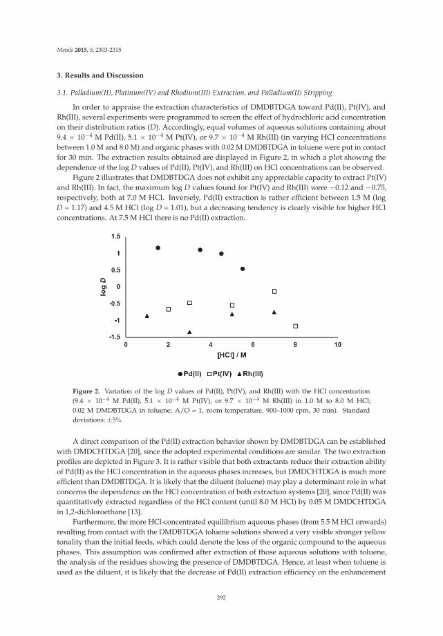
Metals 2015, 5, 2303-2315
3. Results and Discussion
3.1. Palladium(II), Platinum(IV) and Rhodium(III) Extraction, and Palladium(II) Stripping
In order to appraise the extraction characteristics of DMDBTDGA toward Pd(II), Pt(IV), andRh(III), several experiments were programmed to screen the effect of hydrochloric acid concentrationon their distribution ratios (D). Accordingly, equal volumes of aqueous solutions containing about9.4 × 10−4 M Pd(II), 5.1 × 10⁻⁴ M Pt(IV), or 9.7 × 10⁻⁴ M Rh(III) (in varying HCl concentrationsbetween 1.0 M and 8.0 M) and organic phases with 0.02 M DMDBTDGA in toluene were put in contactfor 30 min. The extraction results obtained are displayed in Figure 2, in which a plot showing thedependence of the log D values of Pd(II), Pt(IV), and Rh(III) on HCl concentrations can be observed.
Figure 2 illustrates that DMDBTDGA does not exhibit any appreciable capacity to extract Pt(IV)and Rh(III). In fact, the maximum log D values found for Pt(IV) and Rh(III) were −0.12 and −0.75,respectively, both at 7.0 M HCl. Inversely, Pd(II) extraction is rather efficient between 1.5 M (logD = 1.17) and 4.5 M HCl (log D = 1.01), but a decreasing tendency is clearly visible for higher HClconcentrations. At 7.5 M HCl there is no Pd(II) extraction.
Figure 2. Variation of the log D values of Pd(II), Pt(IV), and Rh(III) with the HCl concentration(9.4 × 10⁻⁴ M Pd(II), 5.1 × 10⁻⁴ M Pt(IV), or 9.7 × 10⁻⁴ M Rh(III) in 1.0 M to 8.0 M HCl;0.02 M DMDBTDGA in toluene; A/O = 1, room temperature, 900–1000 rpm, 30 min). Standarddeviations: ±5%.
A direct comparison of the Pd(II) extraction behavior shown by DMDBTDGA can be establishedwith DMDCHTDGA [20], since the adopted experimental conditions are similar. The two extractionprofiles are depicted in Figure 3. It is rather visible that both extractants reduce their extraction abilityof Pd(II) as the HCl concentration in the aqueous phases increases, but DMDCHTDGA is much moreefficient than DMDBTDGA. It is likely that the diluent (toluene) may play a determinant role in whatconcerns the dependence on the HCl concentration of both extraction systems [20], since Pd(II) wasquantitatively extracted regardless of the HCl content (until 8.0 M HCl) by 0.05 M DMDCHTDGAin 1,2-dichloroethane [13].
Furthermore, the more HCl-concentrated equilibrium aqueous phases (from 5.5 M HCl onwards)resulting from contact with the DMDBTDGA toluene solutions showed a very visible stronger yellowtonality than the initial feeds, which could denote the loss of the organic compound to the aqueousphases. This assumption was confirmed after extraction of those aqueous solutions with toluene,the analysis of the residues showing the presence of DMDBTDGA. Hence, at least when toluene isused as the diluent, it is likely that the decrease of Pd(II) extraction efficiency on the enhancement
292
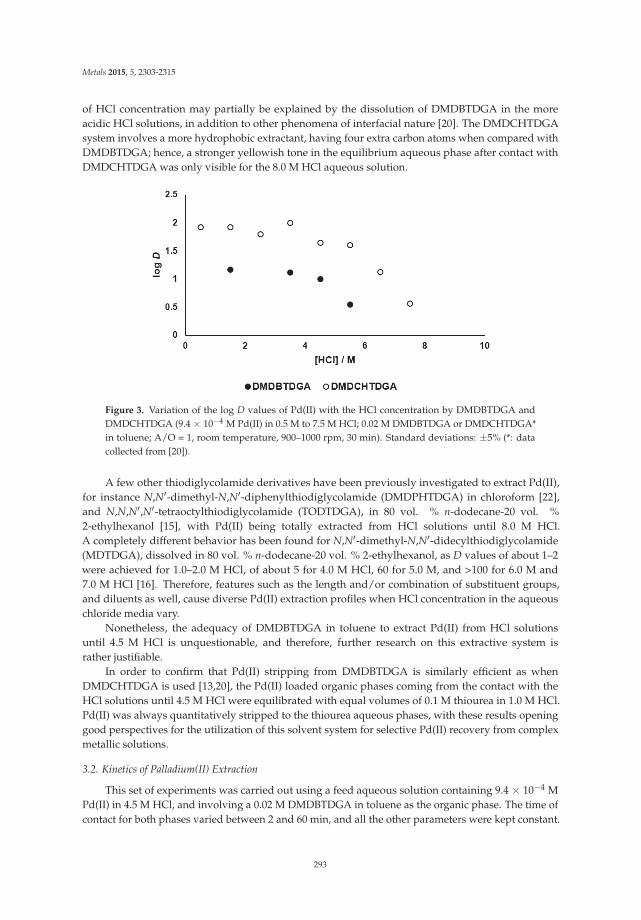
Metals 2015, 5, 2303-2315
of HCl concentration may partially be explained by the dissolution of DMDBTDGA in the moreacidic HCl solutions, in addition to other phenomena of interfacial nature [20]. The DMDCHTDGAsystem involves a more hydrophobic extractant, having four extra carbon atoms when compared withDMDBTDGA; hence, a stronger yellowish tone in the equilibrium aqueous phase after contact withDMDCHTDGA was only visible for the 8.0 M HCl aqueous solution.
Figure 3. Variation of the log D values of Pd(II) with the HCl concentration by DMDBTDGA andDMDCHTDGA (9.4 × 10⁻⁴ M Pd(II) in 0.5 M to 7.5 M HCl; 0.02 M DMDBTDGA or DMDCHTDGA*in toluene; A/O = 1, room temperature, 900–1000 rpm, 30 min). Standard deviations: ±5% (*: datacollected from [20]).
A few other thiodiglycolamide derivatives have been previously investigated to extract Pd(II),for instance N,N′-dimethyl-N,N′-diphenylthiodiglycolamide (DMDPHTDGA) in chloroform [22],and N,N,N′,N′-tetraoctylthiodiglycolamide (TODTDGA), in 80 vol. % n-dodecane-20 vol. %2-ethylhexanol [15], with Pd(II) being totally extracted from HCl solutions until 8.0 M HCl.A completely different behavior has been found for N,N′-dimethyl-N,N′-didecylthiodiglycolamide(MDTDGA), dissolved in 80 vol. % n-dodecane-20 vol. % 2-ethylhexanol, as D values of about 1–2were achieved for 1.0–2.0 M HCl, of about 5 for 4.0 M HCl, 60 for 5.0 M, and >100 for 6.0 M and7.0 M HCl [16]. Therefore, features such as the length and/or combination of substituent groups,and diluents as well, cause diverse Pd(II) extraction profiles when HCl concentration in the aqueouschloride media vary.
Nonetheless, the adequacy of DMDBTDGA in toluene to extract Pd(II) from HCl solutionsuntil 4.5 M HCl is unquestionable, and therefore, further research on this extractive system israther justifiable.
In order to confirm that Pd(II) stripping from DMDBTDGA is similarly efficient as whenDMDCHTDGA is used [13,20], the Pd(II) loaded organic phases coming from the contact with theHCl solutions until 4.5 M HCl were equilibrated with equal volumes of 0.1 M thiourea in 1.0 M HCl.Pd(II) was always quantitatively stripped to the thiourea aqueous phases, with these results openinggood perspectives for the utilization of this solvent system for selective Pd(II) recovery from complexmetallic solutions.
3.2. Kinetics of Palladium(II) Extraction
This set of experiments was carried out using a feed aqueous solution containing 9.4 × 10⁻⁴ MPd(II) in 4.5 M HCl, and involving a 0.02 M DMDBTDGA in toluene as the organic phase. The time ofcontact for both phases varied between 2 and 60 min, and all the other parameters were kept constant.
293

Metals 2015, 5, 2303-2315
It was found that the extraction kinetics for these systems is very favorable, as can be seen inFigure 4a 2 min contact results in the highest log D value obtained, with an apparent tendency todecrease for longer contact periods. A higher uncertainty of the results (±8%) may partially justifythis unexpected trend. However, the pattern achieved also suggests the possible occurrence of a morecomplex phenomenon: if the direct kinetic constant is larger than the one corresponding to the forwardextraction reaction, this means that Pd(II) would be extensively extracted at very short times, and aftera few minutes, when the forward reaction takes place, D values would decrease until equilibrium isreached. Further investigation is obviously needed to support such an assumption.
Figure 4. Variation of the log D values of Pd(II) with the contact time (9.4 × 10⁻⁴ M Pd(II) in 4.5 M HCl;0.02 M DMDBTDGA in toluene; A/O = 1, room temperature, 900–1000 rpm). Standard deviations: ±8%.
Nevertheless, the period of time necessary for DMDBTDGA to efficiently extract Pd(II) is quiteshort, being in general agreement with the ones previously reported for other thiodiglycolamidederivatives, e.g., less than 5 min for DMDPHTDGA [22], 10 min for MDTDGA [16], and 15 min forboth TODTDGA [15] and DMDCHTDGA [20].
Accordingly, a contact time of 5 min was adopted for all the subsequent experimentswith DMDBTDGA.
3.3. Effect of DMDBTDGA Concentration on Palladium(II) Extraction
The evaluation of the effect of the extractant concentration on the D values of Pd(II) providesinformation about the stoichiometry of the extractant:Pd(II) species, contributing to the establishmentof the Pd(II) extraction reactions. These sets of experiments were carried out under the usual extractionconditions and involved a 9.4 × 10⁻⁴ M Pd(II) in 4.5 M HCl aqueous solution, which was contactedwith DMDBTDGA organic phases with concentrations varying between 1.6 × 10⁻³ to 2.0 × 10⁻² M.
The log-log plot between the Pd(II) D values and the initial DMDBTDGA concentrations indicatesa slope value of about 1.2, as shown in Figure 5. However, as the DMDBTDGA concentrations arenot in a sufficiently large excess when compared with that of Pd(II), the DMDBTDGA-Pd(II) speciesconcentrations cannot be neglected or, in other words, the initial DMDBTDGA concentration shouldnot be considered as similar to the DMDBTDGA concentrations at equilibrium. Accordingly, aniterative method previously developed in our group to overcome these situations was applied [23].
In this method, calculations for the free extractant concentrations are carried out uponconsideration of different stoichiometric molar ratios between the extractant and the metal ion. Whenplotting the log-log plots involving the equilibrium ligand concentrations, the coincidence betweenthe slope value obtained and the estimated one is sought [23]. For the DMDBTDGA system, slopeswere coincident for a 1.10 value (Figure 5). Hence, this result suggests that species having a 1:1DMDBTDGA:Pd(II) stoichiometry should exist in the organic solutions.
294

Metals 2015, 5, 2303-2315
Figure 5. Dependence of the Pd(II) log D values on the log of the initial and equilibrium DMDBTDGAconcentrations (9.4 × 10⁻⁴ M Pd(II) in 4.5 M HCl; 1.6 × 10⁻³ to 2.0 × 10⁻² M DMDBTDGA in toluene;A/O = 1, room temperature, 900–1000 rpm). Standard deviations: ±5%.
Knowing that the predominant Pd(II) species for 1 M and higher HCl concentrations is[PdCl4]2− [24–26], the general data on the Pd(II) extraction reactions involving different amine andamide derivatives indicates the occurrence of two different mechanisms: the direct extraction of[PdCl4]2− by a positively charged extractant, resulting in an outer-sphere electrostatic attraction,and/or the replacement of chloride anions from the complexation sphere of [PdCl4]2− by ligandmolecules, due to the liability nature of this chlorocomplex, giving rise to inner-sphere complexes inthe organic phase [24]. Previous studies with other thiodiglycolamide derivatives, e.g., MDTDGA [16]and TODTDGA [15], point to inner-sphere complexation reactions when Pd(II) is extracted from3.0 M HCl (in spite of their completely different profile when the influence of HCl in the feed aqueoussolution is taken into account) whereas the metal ion seems to be extracted by a mixing of outer-sphereion pairs and inner-sphere complexation by DMDPHTDGA [22].
Further research is needed to determine how is Pd(II) extracted by DMDBTDGA from 4.5 M HCl,although the fast extraction rate of the metal ion in this system may eventually suggest the existenceof ion-pair extraction reactions [22,27]. Assuming this is the case, a proposal for the Pd(II) speciesextracted by DMDBTDGA would be the outer-sphere electrostatic attraction between the [PdCl4]2−
species and the protonated extractant on its two amide sites, in a similar scheme as the one suggestedfor the DMDCHTDGA-Pt(IV) species [13].
3.4. Selectivity for Palladium(II) Extraction
The selectivity shown for Pd(II) extraction by DMDBTDGA is a relevant key point whoseevaluation is rather pertinent. On one hand, the separation of Pd(II) from the other two PGMs can beenvisaged; subsequently, its isolation from base metals such as Al(III) and Fe(III), often appearing inthe leaching solutions of end-of-life anthropogenic sources, is again interesting. Therefore, focusingon the use of HCl media with a more practical interest, 4.0 M HCl solutions with two—Pd(II) andPt(IV)—and three PGMs—Pd(II), Pt(IV) and Rh(III)—were considered, all with concentrations ofabout 100 mg·L−1.
The overall data obtained for the DMDBTDGA extractive performance toward the three PGMsare illustrated in Table 1, shown by the separation factors (SF) of Pd(II) in relation to each of the othermetal ions (calculated as SF = DPd/Dmetal). Hence, the higher the SF, the more selective for Pd(II)recovery DMDBTDGA is. As similar tests were previously carried out with DMDCHTDGA [20], theresults obtained with this compound are also included in Table 1 for a direct comparison.
295

Metals 2015, 5, 2303-2315
Table 1. Selectivity of DMDBTDGA for extraction of two and three PGM solutions (solutions 1and 2, respectively), evaluated through the correspondent separation factor values (SF). Standarddeviations: ±5%.
[HCl] = 4 MSolution 1 Solution 2
Pt(IV) Pt(IV) Rh(III)
DMDBTDGA 261 356 ~2880DMDCHTDGA * 354 289 ~2000
* Data collected from [20].
For the binary aqueous media—solution 1—it can be observed that the SFPd/Pt achieved forDMDBTDGA is good, and a similar situation is extended for the three PGMs solution. Rh(III) ispractically not extracted. The selective performance shown by DMDBTDGA for Pd(II) recovery whenPt(IV), and Pt(IV) and Rh(III), are present in the 4.0 M HCl solution is comparable to the data previouslyfound for DMDCHTDGA [20]. Pd(II) was efficiently stripped by 0.1 M thiourea in 1.0 M HCl fromthe DMDBTDGA loaded organic phases—84 to 86 mg·L−1—with a maximum Pt(IV) contaminationof 7 mg·L−1.
Other experiments were subsequently carried out involving four metals in the feed aqueousphases, namely the three PGMs with either 500 mg·L−1 Al(III) (solution 3) or Fe(III) (solution 4), andfinally five-metal aqueous solutions were also considered, containing the three PGMs, Al(III) andFe(III) (solution 5), all with similar concentrations as described above. The overall results are depictedin Table 2.
Table 2. Selectivity of DMDBTDGA for extraction of three PGMs with Al(III) or Fe(III) (solutions3 and 4, respectively) and three PGMs with Al(III) and Fe(III) (solution 5), evaluated through thecorrespondent SF values. Standard deviations: ±5%.
[HCl] = 4 MSolution 3 Solution 4 Solution 5
Pt(IV) Rh(III) Al(III) Pt(IV) Rh(III) Fe(III) Pt(IV) Rh(III) Al(III) Fe(III)
DMDBTDGA 271 759 673 5 66 26 5 126 169 26DMDCHTDGA * 314 ~2180 ~7300 20 996 30 32 ~1650 ~2260 38
* Data collected from [20].
In the presence of Al(III), the SFPd/Pt by DMDBTDGA is comparable to the ones previouslyachieved, whereas Rh(III) is more extracted than before. Al(III) is not extracted extensively. As expected,due to what previously occurred with DMDCHTDGA [20], Fe(III) is widely extracted by DMDBTDGA,and Pt(IV) withdrawal markedly increases as well. In spite of that, the Pd(II) distribution ratio is high(D = 20). The general selective behavior toward Pd(II) found earlier for DMDCHTDGA [20] is betterthan that determined for DMDBTDGA.
The results displayed in Table 2 for the extraction of the five-metal aqueous phase (solution 5)show that Rh(III) and Al(III) are now generally more extracted by DMDBTDGA, whereas the SF valuesfor the pairs Pd/Pt and Pd/Fe are the same as those obtained for solution 4. The D value for Pd(II)was about 11. These overall results are worse than the ones achieved for DMDCHTDGA [20], alsoincluded in Table 2.
Although extensively extracted, Fe(III) can efficiently be scrubbed from the loaded organic mediawith water [20]. Hence, focusing on the treatment of solution 5, 90% of Fe(III) from the loaded organicphase transferred to water, accompanied by a maximum of 2 mg·L−1 Pd(II). Pd(II) was efficientlystripped by 0.1 M thiourea in 1.0 M HCl from the loaded organic phase—86 mg·L−1—with residualcontaminations of Pt(IV) and Fe(III) less than 1 mg·L−1. Neither water nor the thiourea solution wereable to remove the Pt(IV) content from the loaded DMDBTDGA solution. An efficient stripping agentto recover Pt(IV) has not still been found to date, but its discovery would be crucial to take profit of theextensive co-extraction of Pt(IV) with Pd(II), as the two PGMs could be further separated by selective
296

Metals 2015, 5, 2303-2315
stripping [13]. The extraction of Pt(IV) together with Pd(II) was not so effective when DMDCHTDGAwas used, as can be seen in Table 2 [20].
In summary, the selectivity patterns observed for DMDBTDGA toward Pd(II) are relatively good;among the metal ions tested, only Pt(IV) in the presence of Fe(III), and Fe(III) itself, are extensivelyextracted together with Pd(II). Fe(III) is easily removed through an intermediate scrubbing step withwater. Nevertheless, the selective behavior for Pd(II) recovery shown by the other thiodiglycolamidederivative previously investigated—DMDCHTDGA [20]—is generally much better than that ofDMDBTDGA, particularly if Al(III) and Fe(III), and not only Pt(IV) and Rh(III), are present in thefeed 4.0 M HCl aqueous phase. These selectivity differences can be rationalized by resorting to therole the substituent groups in the thiodiglycolamide skeleton are likely to play; the butyl groups areapparently too short to favor a more specific selectivity trend, and probably to avoid significant lossesof the extractant to the more acidic HCl phases as well. The cyclohexyl substituents, on the other hand,proved to be more adequate to achieve better extraction efficiency and selectivity profiles for Pd(II)recovery by DMDCHTDGA [20].
The evaluation of the performance shown by MDTDGA toward Pd(II) extraction has already beencarried out [16], but under quite different experimental conditions than those adopted in this work.A direct comparison between the extraction systems involving DMDBTDGA and DMDCHTDGA withMDTDGA is not possible at present, but the screening of the extraction behavior for Pd(II) depictedby a similar thiodiglycolamide derivative with octyl or decyl groups, in addition to the two methylsubstituents, would surely be worthwhile.
4. Conclusions
N,N′-dimethyl-N,N′-dibutylthiodiglycolamide (DMDBTDGA) has been synthesized to test itspractical usefulness as a SX reagent to recover PGMs from concentrated HCl media. DMDBTDGA intoluene is efficient for Pd(II) extraction until 4.5 M HCl, with a gradual decrease afterwards. Pd(II)in the loaded organic phases is quantitatively stripped by a 0.1 M thiourea in 1 M HCl solution.The extraction kinetics are very favorable (5 min maximum), and the distribution data points out to anextractant: Pd(II) ratio of 1:1.
Pd(II) is selectively recovered from 4.0 M HCl solutions containing the three PGMs under study.However, the selectivity patterns become worse when excess concentrations of Al(III) and Fe(III)co-exist in the HCl solution: Pd(II) distribution ratios are not critically affected, but Pt(IV) is muchmore extracted than before, together with Fe(III). The Fe(III) interference can nonetheless be eliminatedby an intermediate scrubbing step of the loaded organic phases with water. Al(III), one of the maincontaminants in real leaching solutions of the hydrometallurgical treatment of secondary raw materials,is not extensively extracted.
The selectivity figures obtained for DMDBTDGA, although reasonable, are poorer than thoseachieved for DMDCHTDGA [20], another thiodiglycolamide derivative tested under similar conditions.
Acknowledgments: The financial support for the investigation reported in this article has been kindly providedby Portuguese national funds through “FCT—Fundação para a Ciência e a Tecnologia” (Lisbon, Portugal) underthe projects with references UID/MULTI/00612/2013 and PTDC/QUI-QUI/109970/2009, including the PhDgrant offered to Osvaldo Ortet (SFRH/BD/78289/2011). The GC-MS analysis performed by José Manuel Nogueiraand collaborators is gratefully acknowledged.
Author Contributions: Mário E. Martins and Osvaldo Ortet carried out the synthesis and characterizationof DMDBTDGA, as well as the SX experiments. Ana Paula Paiva supervised all the research and wrotethe manuscript.
Conflicts of Interest: The authors declare no conflict of interest.
297

Metals 2015, 5, 2303-2315
References
1. Report on Critical Raw Materials for the EU—European Commission, May 2014. Available online:http://www.google.pt/url?sa=t&rct=j&q=&esrc=s&source=web&cd=1&cad=rja&uact=8&ved=0CB4QFjAAahUKEwj0q5HDpdHIAhVCURoKHZwgCBQ&url=http%3A%2F%2Fec.europa.eu%2FDocsRoom%2Fdocuments%2F10010%2Fattachments%2F1%2Ftranslations%2Fen%2Frenditions%2Fnative&usg=AFQjCNEF6SkHHErPeB2gXS_dxBBFtlw_7A&sig2=qkh5AeKsO4cyRpuIZtVrWQ (accessedon 20 October 2015).
2. Johnson Matthey, Precious Metals Management. Available online: http://www.platinum.matthey.com/about-pgm/applications (accessed on 20 October 2015).
3. Hagelüken, C. Recycling the platinum group metals: A European perspective. Platinum Met. Rev. 2012, 56,29–35. [CrossRef]
4. Crundwell, F.K.; Moats, M.S.; Ramachandran, V.; Robinson, T.G.; Davenport, W.G. Extractive Metallurgy ofNickel, Cobalt and Platinum-Group Metals, 1st ed.; Elsevier: Amsterdam, The Netherlands, 2011; pp. 537–549.
5. Nogueira, C.A.; Paiva, A.P.; Oliveira, P.C.; Costa, M.C.; Costa, A.M.R. Oxidative leaching process with cupricion in hydrochloric acid media for recovery of Pd and Rh from spent catalytic converters. J. Hazard. Mater.2014, 278, 82–90. [CrossRef] [PubMed]
6. Cox, M. Solvent extraction in hydrometallurgy. In Solvent Extraction Principles and Practice, 2nd ed.;Rydberg, J., Cox, M., Musikas, C., Choppin, G.R., Eds.; Marcel Dekker: New York, NY, USA, 2004;pp. 455–505.
7. Nikoloski, A.N.; Ang, K.-L. Review of the application of ion exchange resins for the recovery ofplatinum-group metals from hydrochloric acid solutions. Miner. Process. Extr. Metall. Rev. 2014, 35,369–389. [CrossRef]
8. Lee, J.Y.; Raju, B.; Kumar, B.N.; Kumar, J.R.; Park, H.K.; Reddy, B.R. Solvent extraction separation andrecovery of palladium and platinum from chloride leach liquors of spent automobile catalyst. Sep. Purif.Technol. 2010, 73, 213–218. [CrossRef]
9. Reddy, B.R.; Raju, B.; Lee, J.Y.; Park, H.K. Process for the separation and recovery of palladium and platinumfrom spent automobile catalyst leach liquor using LIX 84I and Alamine 336. J. Hazard. Mater. 2010, 180,253–258. [CrossRef] [PubMed]
10. Narita, H.; Tanaka, M.; Morisaku, K.; Tamura, K. Extraction of platinum(IV) in hydrochloric acid solutionusing diglycolamide and thiodiglycolamide. Solvent Extr. Res. Dev. Jpn. 2006, 13, 101–106.
11. Costa, M.C.; Assunção, A.; Costa, A.M.R.; Nogueira, C.; Paiva, A.P. Liquid-liquid extraction of platinumfrom chloride media by N,N′-dimethyl-N,N′-dicyclohexyltetradecylmalonamide. Solvent Extr. Ion Exch. 2013,31, 12–23. [CrossRef]
12. Malik, P.; Paiva, A.P. Solvent extraction studies for platinum recovery from chloride media by a N,N′-tetrasubstituted malonamide derivative. Solvent Extr. Ion Exch. 2009, 27, 36–49. [CrossRef]
13. Paiva, A.P.; Carvalho, G.I.; Costa, M.C.; Costa, A.M.R.; Nogueira, C. Recovery of platinum and palladiumfrom chloride solutions by a thiodiglycolamide derivative. Solvent Extr. Ion Exch. 2014, 32, 78–94. [CrossRef]
14. Narita, H.; Morisaku, K.; Tamura, K.; Tanaka, M.; Shiwaku, H.; Okamoto, Y.; Suzuki, S.; Yaita, T. Extractionproperties of palladium(II) in HCl solution with sulfide containing monoamide compounds. Ind. Eng.Chem. Res. 2014, 53, 3636–3640. [CrossRef]
15. Narita, H.; Tanaka, M.; Morisaku, K. Palladium extraction with N,N,N′,N′-tetra-n-octyl-thiodiglycolamide.Miner. Eng. 2008, 21, 483–488. [CrossRef]
16. Huang, Y.; Li, N.; Li, Y.; Wu, J.; Li, S.; Chen, S.; Zhu, L. Extraction of precious metals with a new amideextractant. Adv. Mater. Res. 2014, 878, 399–405. [CrossRef]
17. Ortet, O.; Paiva, A.P. Development of tertiary thioamide derivatives to recover palladium(II) from simulatedcomplex chloride solutions. Hydrometallurgy 2015, 151, 33–41. [CrossRef]
18. Das, A.; Ruhela, R.; Singh, A.K.; Hubli, R.C. Evaluation of novel ligand dithiodiglycolamide (DTDGA) forseparation and recovery of palladium from simulated spent catalyst dissolver solution. Sep. Purif. Technol.2014, 125, 151–155. [CrossRef]
19. Narita, H.; Morisaku, K.; Tanaka, M. Highly efficient extraction of rhodium(III) from hydrochloric acidsolution with amide-containing tertiary amine compounds. Solvent Extr. Ion Exch. 2015, 33, 407–417.[CrossRef]
298

Metals 2015, 5, 2303-2315
20. Ortet, O.; Paiva, A.P. Liquid-liquid extraction of palladium(II) from chloride media by N,N′-dimethyl-N,N′-dicyclohexylthiodiglycolamide. Sep. Purif. Technol. 2015, 156, 363–368. [CrossRef]
21. Paiva, A.P.; Carvalho, G.I.; Costa, M.C.; Costa, A.M.R.; Nogueira, C.A. Recovery of Palladium(II) from aSpent Automobile Catalyst Leaching Solution. In Proceedings of the 3rd International Conference on Wastes:Solutions, Treatments and Opportunities, Viana do Castelo, Portugal, 14–16 September 2015; Vilarinho, C.,Castro, F., Carvalho, J., Russo, M., Araújo, J., Eds.; CVR (Centro para a Valorização de Resíduos): Guimarães,Portugal, 2015; pp. 61–63.
22. Narita, H.; Tanaka, M.; Morisaku, K. Extraction Properties of Platinum Group Metals with DiamideCompounds. In Proceedings of the 17th International Solvent Extraction Conference (ISEC 2005),Beijing, China, 19–23 September 2005; Conference Proceeding Editorial Department: Beijing, China, 2005;pp. 227–232.
23. Ribeiro, L.C.; Santos, M.S.; Paiva, A.P. Apparent molar volumes of N,N-disubstituted monoamides:A convenient tool to interpret iron(III) extraction profiles from hydrochloric acid solutions. Solvent Extr.Ion Exch. 2013, 31, 281–296. [CrossRef]
24. Cleare, M.J.; Charlesworth, P.; Bryson, D.J. Solvent extraction in platinum group metal processing. J. Chem.Technol. Biotechnol. 1979, 29, 210–224. [CrossRef]
25. Levitin, G.; Schmuckler, G. Solvent extraction of rhodium chloride from aqueous solutions and its separationfrom palladium and platinum. React. Funct. Polym. 2003, 54, 149–154. [CrossRef]
26. Bernardis, F.L.; Grant, R.A.; Sherrington, D.C. A review of methods of separation of the platinum-groupmetals through their chloro-complexes. React. Funct. Polym. 2005, 65, 205–217. [CrossRef]
27. Preston, J.S.; du Preez, A.C. Solvent extraction of platinum-group metals from hydrochloric acid solutions bydialkyl sulphoxides. Solvent Extr. Ion Exch. 2002, 20, 359–374. [CrossRef]
© 2015 by the authors. Licensee MDPI, Basel, Switzerland. This article is an open accessarticle distributed under the terms and conditions of the Creative Commons Attribution(CC BY) license (http://creativecommons.org/licenses/by/4.0/).
299

metals
Article
Copper and Cyanide Extraction with Emulsion LiquidMembrane with LIX 7950 as the Mobile Carrier: Part 1,Emulsion Stability
Diankun Lu 1, Yongfeng Chang 1, Wei Wang 1, Feng Xie 1,*, Edouard Asselin 2 and
David Dreisinger 2
1 School of Material and Metallurgical Engineering, Northeaestern University, 3-11 Wenhua Road, Shenyang110819, China; [email protected] (D.L.); [email protected] (Y.C.);[email protected] (W.W.)
2 Department of Materials Engineering, University of British Columbia, 309-6350 Stores Road, Vancouver, BCV6T 1Z4, Canada; [email protected] (E.A.); [email protected] (D.D.)
* Author to whom correspondence should be addressed; [email protected]; Tel.: +86-24-8367-2298;Fax: +86-24-8368-7750.
Academic Editors: Suresh Bhargava, Mark Pownceby and Rahul RamReceived: 19 August 2015; Accepted: 14 October 2015; Published: 4 November 2015
Abstract: The potential use of emulsion liquid membranes (ELMs) with LIX 7950 as the mobile carrierto remove heavy metals from waste cyanide solutions has been proposed. Relatively stable ELMswith reasonable leakage and swelling can be formed under suitable mixing time and speed duringemulsification. The concentration of LIX 7950 and Span 80 in the membrane phase, KOH in theinternal phase and the volume ratio of membrane to internal phases are also critical to ELM formation.The efficiency of copper and cyanide removal from dilute cyanide solution by ELMs is related to ELMstability to some extent. More than 90% copper and cyanide can be removed from dilute cyanidesolutions by ELMs formed under suitable experimental conditions.
Keywords: emulsion liquid membrane; LIX 7950; stability; copper cyanides
1. Introduction
Waste cyanide solutions are generated industrially on a large scale in gold and silver extractionfrom ores, electroplating, coal cooking and organic chemical formulation. Heavy metals such ascopper zinc and iron may also occur in these solutions, e.g., those waste effluents arising from thegold cyanidation process [1]. Due to the highly toxicity of cyanide and heavy metals to humans andaquatic organisms, strict environmental regulations on the management of waste cyanide solutionshave been established. Environmental constraints controlling the discharge of cyanide from goldplants are being tightened by local governments worldwide [2,3]. A considerable number of methodshave been developed for recovering valuable metals and cyanide from waste cyanide solutions.Acidification, volatilization, and recovery (AVR) and some modifications have been long practiced insome gold operations, but the high consumption and cost of reagents has significantly limited theirapplication [4–6]. The indirect recovery of metals and cyanide by activated carbon and ion-exchangeresin has been proposed. However, the low adsorption capability of carbon and the high cost of resinhave severely hampered their wide application in practice [7–10]. The use of solvent extraction processto recover copper from cyanide solution has been suggested. The extraction and stripping of metalcyanide complexes is believed to occur via an ion-exchange mechanism [11–15]. These investigationsprove that copper can be effectively extracted from alkaline cyanide solutions by proposed solventextraction systems.
Metals 2015, 5, 2034–2047 300 www.mdpi.com/journal/metals

Metals 2015, 5, 2034–2047
Extraction processes using emulsion liquid membrane (ELM) have also received significantattention due to their potential application in treating industrial liquid wastes [16–20]. Use of ELMsfor hydrometallurgical recovery of heavy metals from waste industrial solutions has been reportedby many investigators and some processes have been successfully commercialized to remove variousmetals from wastewater in industry [21–27]. The potential use of liquid membranes to extract preciousmetals from alkaline cyanide solutions was also proposed [28–32]. In ELM processes, simultaneouspurification/concentration of the target solute can be realized through combining extraction andstripping into one stage, which results in the high interfacial area for mass transfer, the ability toremove/concentrate selectively or collectively, and the requirement of only small quantities of organicsolvent. It is believed that the large specific interfacial area associated with ELMs result in higherpermeation rates and the transport is governed by kinetic rather than equilibrium parameters whichmay enable the achievement of higher metal concentrations in fewer separation stages than solventextraction [33–35]. Consequently, there is a substantial saving in the volume of mixers and settlers forextraction and stripping which are generally carried out in conventional solvent extraction circuits.However, although the technology has been successfully practiced for removing some heavy metalsfrom waste solutions, its operating efficiency is highly dependent on the emulsion instability whichcommonly includes membrane leakage, coalescence, and emulsion swelling. In order to obtainrelatively stable emulsion liquid membranes, its formulation design including selection of carrier, stripagent, surfactant, diluents, and preparation method is critical [36].
The process of recovering copper and cyanide from waste alkaline cyanide solutions throughELMs using the guanidine extractant LIX 7950 as the mobile carrier has been suggested in this research.The factors which may potentially influence the stability of ELMs and the removal of copper andcyanide by ELMs including membrane formula, mixing speed, and phase ratio (volume ratio ofmembrane to internal phases) have been examined with the purpose to determine the feasibility ofextracting copper and cyanide from waste cyanide solutions by ELMs.
2. Experimental Section
2.1. Materials
LIX 7950, a trialkylguanidine extractant, was used as supplied by the manufacturer (Cognis,Mississauga, ON, Canada). The non-ionic surfactant commercially known as Span 80 (SinopharmChemical Reagent, Shanghai, China) was used for stabilizing the emulsion. The diluent was acommercial kerosene which was a complex mixture of aliphatic origin containing about 15%–20%w/w aromatics. A small amount of liquid paraffin was used as the additive to facilitate formationof ELMs. Some 1-dodecanol was added as the modifier to facilitate; dissolution of LIX 7950 in thediluent. Synthetic copper cyanide solutions were made up from CuCN and NaCN. All chemicals wereof reagent grade and doubly distilled water was used throughout.
2.2. Procedure
To prepare ELMs, designated volume of LIX 7950, 1-dodecanol, Span 80, liquid paraffin,and kerosene were emulsified in a 250 mL beaker through a mechanical mixer with an overheaddisk-propeller. A portion of KOH solution used as the internal stripping solution was added dropwiseto the stirred membrane solution till obtaining the desired volume ratio of internal to membranephases. The mixed solution was stirred continuously to obtain stable ELMs.
For stability and extraction tests, designated volume of ELMs prepared through the describedprocedure was added to a 500 mL beaker filled with the feed solution (100 mL). Mixing was providedwith a mechanical stirrer with four Teflon-coated turbine-type impellers. All tests were conducted atthe indoor temperature of 20 ± 1 ◦C (except defined otherwise). After the desired extraction time, theemulsions were separated from the mixture through a 125 mL separator and the obtained aqueoussolution was filtrated with Whatman No. 3 filter paper to remove any entrained organic before analysis.
301

Metals 2015, 5, 2034–2047
The emulsions were recovered and subsequently broken into its constituent organic and aqueousphases through a high speed centrifuge. Samples of organic phase were filtered with 1 PS PhaseSeparation paper and samples of aqueous phase were filtered with Whatman No. 3 filter paper toremove any entrained organic phase before analysis.
2.3. Analysis and Calculation
The solution pH was measured with a pH meter using a combined glass electrode. Metals inaqueous samples were analyzed by atomic absorption spectrophotometry (AAS) and Ion coupledPlasma (ICP-MS, PerkinElmer, Shanghai, China) and their content in the organic phase was calculatedby mass balance. Total cyanide content in the aqueous solution was determined by the standarddistillation method [37]. The morphology of ELMs is determined by a metallographic microscope. Todetermine the leakage of ELMs, a portion of the feed solution (without K+) was mixed with equalvolume of ELMs with K+ in the internal stripping solution; after mixing for the designated time,ELMs were separated from the external aqueous phase (the raffinate) and was further de-emulsifiedthoroughly through heating and centrifuge. The volume of the raffinate, the membrane phase and theinternal phase and the concentration of tracer K+ in each aqueous phase were measured. The apparentleakage (breakage) of ELMs is calculated by the following equation:
δ =CKR × VR
CKi × Vi× 100% (1)
where
δ: the apparent leakage (breakage) of ELMs, %;CKR: the molar concentration of K+ in the raffinate, mol/L;CKi: the molar concentration of K+ in the initial internal phase, mol/L;VR: the volume of the raffinate, L;Vi: the volume of the initial internal phase, L;
The apparent swelling of ELMs is simply defined as following:
η =V ′
E/VR − VE/Vf
VE/Vf× 100% (2)
where
VE: the apparent volume of emulsions before contacting the feed, L;V ′
E: the apparent volume of emulsions after extraction, L;Vf: the initial volume of feed, L;
The removal (or extraction) of the target species from feed by ELMs is calculated through thefollowing equation:
E =Cf × Vf − CR × VR
Cf × Vf× 100% (3)
where
E: the removal (or extraction) of the target species from the feed solution by ELMs, %;Cf: the molar concentration of the target species in the feed, mol/L;CR: the molar concentration of the target species in the raffinate, mol/L;
302

Metals 2015, 5, 2034–2047
3. Results and Discussion
3.1. Influence of Mixing for ELM Formation
In order to ensure a potential transport of copper cyanides through ELMs, a relatively stable ELMwith reasonable leakage and swelling has to be constructed. Preliminary investigations indicated theinput energy for the preparation emulsions played an important role in forming such meta-stableELMs. When the stirring speed of the mixer is fixed at 4500 RPM, images of ELMs formed underdifferent emulsification time are shown in Figure 1. At the emulsification time of 5 min, the formedELMs have a relatively large size. They tend to decrease with increasing stirring time, resulting in moreuniform droplets of ELMs, e.g., more uniform ELMs are produced after 15 min of stirring than 5 min ofstirring. However, when the emulsification time exceeds 25 min, more ELMs start to distort to connectwith others to form a semi-continuous phase. It is believed that small droplet tends to have betterbreaking resistant and rapid extraction, but will be very difficult to de-emulsify by mechanical methods.In addition, too many of them are packed into each organic globule and, consequently, the liquidmembrane becomes too thin and ruptures easily. However, large droplets may cause poor stabilityand extraction efficiency due to the low surface-to-volume ratio. Thus, emulsions with the dropletdiameter in the range 0.3–10 μm (preferably 0.8–3 μm) have been suggested considering reasonableELM stability [16,18].
(a)
2μm 2μm
(c)
2μm
(b)
2μm
(d)
2μm
2μm
(c) (d)
2μm
Figure 1. Photographic of ELM droplets formed under different stirring times. (Membrane phase: 6%v/v LIX 7950, 2% v/v 1-dodecanol, 5% v/v Span 80, 1% v/v paraffin, balanced with kerosene; Internalstripping solution: 0.1 mol/L KOH; Volume ratio of the membrane phase to the internal phase: 1:1;Mixing speed: 4500 RPM; Mixing time: (a) 5 min; (b) 15 min; (c) 25 min; (d) 35 min).
The effect of emulsification time on ELM stability and removal of copper and cyanide fromthe external solution by ELMs is shown in Figure 2. Under the experimental conditions, a highleakage (>40%) was observed when the emulsification time is 5 min. This is probably because theshort stirring time for emulsification results in relatively large but unstable ELM droplets which tendto break up easily when contacting with the external solution. Accordingly, a negative value forELM swelling (data not shown in Figure 2) was obtained at emulsification time of 5 min due to highbreakage of ELMs (partial internal solution has released to the external phase). The ELM leakage
303
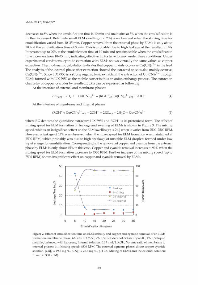
Metals 2015, 5, 2034–2047
decreases to 8% when the emulsification time is 10 min and maintains at 5% when the emulsification isfurther increased. Relatively small ELM swelling (η < 2%) was observed when the stirring time foremulsification varied from 10–35 min. Copper removal from the external phase by ELMs is only about50% at the emulsification time of 5 min. This is probably due to high leakage of the resulted ELMs.It increases up to 90% at the emulsification time of 10 min and remains stable when the emulsificationtime increases from 10–35 min, indicating effective ELMs have formed under these conditions. Underexperimental conditions, cyanide extraction with ELMs shows virtually the same values as copperextraction. Thermodynamic calculation indicates that copper mainly occurs as Cu(CN)3
2− in the feed.The analysis of the internal phase after extraction showed the extracted species also mainly occur asCu(CN)3
2−. Since LIX 7950 is a strong organic basic extractant, the extraction of Cu(CN)32− through
ELMs formed with LIX 7950 as the mobile carrier is thus an anion exchange process. The extractionchemistry of copper cyanides by resulted ELMs can be expressed as following:
At the interface of external and membrane phases:
2RGorg + 2H2O + Cu(CN) 32− = (RGH+)2 Cu(CN)3
2−org + 2OH− (4)
At the interface of membrane and internal phases:
(RGH+)2 Cu(CN)32−
org + 2OH− = 2RGorg + 2H2O + Cu(CN)32− (5)
where RG denotes the guanidine extractant LIX 7950 and RGH+ is its protonized form. The effect ofmixing speed for ELM formation on leakage and swelling of ELMs is shown in Figure 3. The mixingspeed exhibits an insignificant effect on the ELM swelling (η < 2%) when it varies from 2500–7500 RPM.However, a leakage of 12% was observed when the mixer speed for ELM formation was maintained at2500 RPM, which probably was due to high breakage of unstable ELM droplets formed under lowinput energy for emulsification. Correspondingly, the removal of copper and cyanide from the externalphase by ELMs is only about 45% in this case. Copper and cyanide removal increases to 90% when themixing speed for ELM formation increases to 3500 RPM. Further increase of the mixing speed (up to7500 RPM) shows insignificant effect on copper and cyanide removal by ELMs.
0
20
40
60
80
100
Figure 2. Effect of emulsification time on ELM stability and copper and cyanide removal. (For ELMsformation, membrane phase: 6% v/v LIX 7950, 2% v/v 1-dodecanol, 5% v/v Span 80, 1% v/v liquidparaffin, balanced with kerosene; Internal solution: 0.05 mol/L KOH; Volume ratio of membrane tointernal phases: 1:1; Mixing speed: 4500 RPM. The external aqueous phase: dilute copper cyanidesolution, [Cu]T = 19.3 mg/L, [CN]T = 23.6 mg/L, pH 9.5. Mixing of ELMs and the external solution:15 min at 300 RPM).
304

Metals 2015, 5, 2034–2047
0
20
40
60
80
100
Figure 3. Effect of emulsification speed on ELM stability and copper and cyanide removal. (For ELMsformation, membrane phase: 6% v/v LIX 7950, 2% v/v 1-dodecanol, 5% v/v Span 80, 1% v/v liquidparaffin, balanced with kerosene; Internal phase: 0.05 mol/L KOH; Volume ratio of membrane tointernal phases: 1:1; Mixing time: 15 min. The external aqueous phase: dilute copper cyanide solution,[Cu]T = 19.3 mg/L, [CN]T = 23.6 mg/L, pH 9.5. Mixing of ELMs and the external phase: 15 minat 300 RPM).
3.2. Influence of KOH in the Internal Phase
The mobile carrier LIX 7950, a tri-alkylguanidine, is a strong organic base having an intermediatebasicity between that of primary amines and quaternary ammonium salts (pKa is approximately 12).It is capable of being protonated to form a guanidinium cation at the operating pH of cyanidation(usually 10–11). This guanidinium cation can form an ion-pair with metal cyanides such as Cu(CN)3
2−,resulting in metal extraction from the cyanide solution. By increasing the basicity of the aqueous phase,the guanidinium cation is converted to the neutral guanidine functionality. The neutral guanidinefunctionality no longer forms an ion-pair with metal cyanides, causing metal cyanides to be strippedfrom the organic phase [13]. Therefore, in order to extract metal cyanide species from alkalinecyanide solutions, the ideal internal phase of ELMs would be a solution with pH higher than 12.ELM leakage and swelling with different KOH concentration in the internal solution are shown inFigure 4. Insignificant emulsion swelling (η < 1%) was observed when KOH concentration in theinternal phase varied from 0.05–1 mol/L, indicating the increase of ionic strength in the internal phaseexhibits an insignificant effect on the change of volume ratio of ELMs to the external aqueous solutionunder experimental conditions. However, the ELM leakage increases significantly when the KOHconcentration in the internal phase is higher than 0.25 mol/L. It was believed that high concentrationof KOH might significantly increase the osmotic pressure difference between internal and externalphases and thus result in emulsion leaking. It was also reported that the potential reaction betweenKOH and the surfactant Span 80 might result in reduced properties of the surfactant and consequentlylead to an emulsion destabilization [36]. The removal of copper and cyanide from the external solutionby ELMs exhibits insignificant change when KOH concentration varies from 0.05–0.5 mol/L (Figure 4),indicating 0.05 mol/L KOH in the internal phase is good enough for stripping copper cyanides fromthe membrane phase under experimental conditions. High KOH concentration (>0.5 mol/L) in the
305

Metals 2015, 5, 2034–2047
internal phase results in a slight decrease of copper and cyanide removal probably due to increasingbreakage of ELMs.
0
20
40
60
80
100
Figure 4. Effect of KOH on ELM stability and copper and cyanide removal. (For ELMs formation,membrane phase: 6% v/v LIX 7950, 2% v/v 1-dodecanol, 5% v/v Span 80, 1% v/v liquid paraffin,balanced with kerosene; Volume ratio of membrane to internal phases: 1:1; Mixing for emulsification:15 min at 4500 RPM. The external aqueous phase: dilute copper cyanide solution, [Cu]T = 19.3 mg/L,[CN]T = 23.6 mg/L, pH 9.5. Mixing of ELMs and the external phase: 15 min at 300 RPM).
3.3. Influence of Extractant and Surfactant
A great number of studies indicated that both extractant and surfactant played important roles inthe ELM formation [16,36]. The mobile carrier, LIX 7950, acts as a “shuttle” to carry the target speciesthrough ELMs in this case. Effects of concentration of LIX 7950 and Span 80 in the membrane phase onELM stability and copper and cyanide removal are shown in Figures 5 and 6, respectively. Under theexperimental conditions, both ELM leakage and swelling slightly decrease when the concentrationof LIX 7950 in the membrane phase increases from 1% v/v–6% v/v. Both ELM leakage and swellingare lower than 2% when LIX 7950 concentration varies from 6% v/v–10% v/v. Correspondingly, theremoval of copper and cyanide from the external phase with ELMs increases with an increase of LIX7950 concentration when it varies from 1% v/v–6% v/v. Further increase of LIX 7950 concentrationexhibits an insignificant effect on copper and cyanide removal from the external phase by ELMs.A number of studies has given evidence that both extractant and surfactant concentration wouldpotentially affect the emulsion stability. On one hand, increasing extractant concentration in themembrane phase may potentially facilitate the transport of target species from the external phase tothe membrane phase. On the other hand, a high content of extractant in the membrane phase mayresult in increased viscosity which may affect the dispersion behavior of ELMs and cause a decline ininterfacial area, and, consequently, lead to a slow extraction rate of target species. Besides, using lessextractant is always preferred in practice from an economic point view since, in most cases, extractantis usually the most expensive agent among membrane components [36].
306

Metals 2015, 5, 2034–2047
0
20
40
60
80
100
Figure 5. Effect of LIX 7950 concentration on ELM stability and copper and cyanide removal. (For ELMsformation, membrane phase: 2% v/v 1-dodecanol, 5% v/v Span 80, 1% v/v liquid paraffin, balancedwith kerosene; Internal phase: 0.05 mol/L KOH solution. Volume ratio of the membrane phase to theinternal phase: 1:1; Mixing for emulsification: 15 min at 4500 RPM. The external aqueous phase: dilutecopper cyanide solution, [Cu]T = 19.3 mg/L , [CN]T = 23.6 mg/L, pH 9.5. Mixing of ELMs and theexternal phase: 15 min at 300 RPM).
For the surfactant (Span 80) aspect, under the experimental conditions, high ELM leakage wasobserved when the content of Span 80 in the membrane phase was low, e.g., more than 20% of leakagewith 3% v/v Span 80. Accordingly, ELM swelling exhibits little change when the Span 80 concentrationvaries from 1% v/v–9% v/v. Test results indicate that stable ELMs can be only formed when theconcentration of Span 80 is higher than 5% under the experimental conditions. The removal of copperand cyanide from the external phase with ELMs is relatively low (only 55%) when the concentration ofSpan 80 in the membrane phase is 3% v/v. Copper and cyanide removal increases to about 91% whenthe content of Span 80 in the membrane phase is 4% v/v and remains stable when it varies from 4%v/v–6% v/v. Further increase of Span 80 in the membrane phase leads to a decrease of copper andcyanide extraction. Many studies propose that surfactant can reduce the interfacial tension between oiland water by adsorbing at the liquid–liquid interface; thus, maintaining the emulsion stability and thetransport of target species through the membrane [16,34–36]. However, it should be noted that, at ahigh concentration, surfactant may form emulsions that are stable with a higher emulsion viscosity.Consequently, decreasing copper and cyanide extraction with ELMs was observed at a high content ofSpan 80 in the membrane phase.
307

Metals 2015, 5, 2034–2047
0
20
40
60
80
100
Figure 6. Effect of Span 80 concentration on ELM stability and copper and cyanide removal. (For ELMsformation, membrane phase: 2% v/v 1-dodecanol, 1% v/v liquid paraffin, balanced with kerosene;Internal phase: 0.05 mol/L KOH solution. Volume ratio of the membrane phase to the internal phase:1:1; Mixing for emulsification: 15 min at 4500 RPM. The external aqueous phase: dilute copper cyanidesolution, [Cu]T = 19.3 mg/L, [CN]T = 23.6 mg/L, pH 9.5. Mixing of ELMs and the external phase:15 min at 300 RPM).
3.4. Influence of Volume Ratio of Membrane to Internal Phases
The influence of volume ratio of membrane phase to internal phase (Vm/Vint) on ELM stabilitywas also examined (Table 1). It was found that at low Vm/Vint, ELMs exhibited higher leakage, forexample, a leakage of 12.5% when Vm/Vint was maintained at 1:3. Relatively lower leakage wasobserved when Vm/Vint varied from 2:1 to 1:2. The swelling of ELMs was also insignificant in thisrange of Vm/Vint. These results are generally in accordance with the literature. It was believed thatincreasing the volume of internal solution made ELMs unstable due to an increase of the size ofinternal droplets, resulting in decreasing interfacial contact area between the emulsion and the externalphase. Other authors reported that the thickness of film in droplets thinned off when the volume of thestripping phase increased [34,36]. For higher Vint/Vm, the volume of membrane phase is not enoughfor enclosing all the stripping solution, thus resulting in higher leakage [36]. ELM leakage and swellingsignificantly increased with increasing Vm/Vint when it was higher than 3:1. Though, usually lowerVint/Vm leads to a thicker and more stable membrane phase, it was found that too high Vm/Vint alsoresulted in unstable ELMs (high leakage and swelling). Wang and Zhang [38] reported that Vint/Vm
might affect the surfactant concentration at the interface of membrane/aqueous phases and in thebulk membrane phase, and the entrainment and osmotic swelling might increase decreasing Vint/Vm,which resulted in unstable ELMs. Correspondingly, when Vint/Vm varies from 1:2 to 1:1, more than90% of copper and cyanide removal with ELMs was achieved and lower copper and cyanide removalwas observed at both higher and lower Vint/Vm.
308

Metals 2015, 5, 2034–2047
Table 1. Effect of volume ratio of membrane to internal phases on ELM stability and copper andcyanide removal. (For ELMs formation, membrane phase: 2% v/v 1-dodecanol, 1% v/v liquid paraffin,balanced with kerosene; Internal phase: 0.05 mol/L KOH solution. Mixing for emulsification: 15min at 4500 RPM. The external aqueous phase: dilute copper cyanide solution, [Cu]T = 19.3 mg/L,[CN]T = 23.6 mg/L, pH 9.5. Mixing of ELMs and the external phase: 15 min at 300 RPM).
Vm/V int Leakage, % Swelling, % Cuext, mg/L CNext, mg/LCu
Removal, %CN
Removal, %
1:3 12.5 1 4.3 5.1 78.0 78.21:2 2.5 2 0.9 1.2 95.5 94.91:1 3 2 1.7 2.2 91.0 90.82:1 4 8 10.8 13.0 44.3 45.03:1 15 10 11.7 13.9 39.3 41.24:1 18 12 11.3 13.3 41.3 43.85:1 28 18 10.8 13.2 44.0 44.0
4. Conclusions
The use of emulsion liquid membranes with LIX 7950 as the mobile carrier to recover metals andcyanide from waste cyanide solutions has been proposed. The concentration of LIX 7950 and Span 80in the membrane phase, KOH in the internal phase, volume ratio of internal to membrane phases, andmixing during emulsification are critical factors for forming stable ELMs. Relatively stable ELMs withreasonable leakage and swelling can be formed under suitable formulas of membrane components.The extraction of copper and cyanide can be usually obtained when ELMs with relatively low leakageand swelling are formed. However, excessive Span 80 in the membrane phase may result in low copperand cyanide removal from dilute cyanide solutions with ELMs.
Acknowledgments: The authors thank Yan Fu for his generous help on the project. The project was financiallysupported by Fundamental Research Funds for Central Universities of China (No. N130202001).
Author Contributions: Dianku Lu wrote and edited the manuscript. Yongfeng Chang and Wei Wang helped withemulsion liquid membrane preparation and data collection. Feng Xie supervised experimental work and dataanalysis. Edouard Asselin and David Dreisinger helped with data analysis and interpretation.
Conflicts of Interest: The authors declare no conflict of interest.
References
1. Marsden, J.; House, I. Chemistry of Gold Extraction, 2nd ed.; Society for Mining, Metallurgy, and Exploration:Englewood, CO, USA, 2006; pp. 15–45.
2. DeVries, F. Brief overview of the Baia Mare Dam Breach. In Cyanide: Social, Industrial and Economic Aspects;Young, A.A., Twidwell, L.G., Anderson, C.G., Eds.; TMS: Warrendale, PA, USA, 2001; pp. 11–14.
3. Fleming, C.A. Cyanide Recovery. In Advances in Gold Ore Processing; Adams, M.D., Ed.; Elsevier: Amsterdam,The Netherlands, 2005; pp. 703–727.
4. Jay, W.H. Copper Cyanide Recovery System. In Cyanide: Social, Industrial and Economic Aspects; Young, A.A.,Twidwell, L.G., Anderson, C.G., Eds.; TMS: Warrendale, PA, USA, 2001; pp. 317–340.
5. Botz, M.M.; Mudder, T.I.; Akcil, A.U. Cyanide Treatment: Physical, Chemical and Biological Process.In Advances in Gold Ore Processing; Adams, M.D., Ed.; Elsevier: Amsterdam, The Netherlands, 2005;pp. 672–702.
6. Barter, J.; Lane, G.; Mitchell, D.; Kelson, R.; Dunne, R.; Trang, C.; Dreisinger, D. Cyanide Management bySART. In Cyanide: Social, Industrial and Economic Aspects; Young, A.A., Twidwell, L.G., Anderson, C.G., Eds.;TMS: Warrendale, PA, USA, 2001; pp. 549–562.
7. Adams, M.D. Removal of cyanide from solution using activated carbon. Miner. Eng. 1994, 7, 1165–1177.[CrossRef]
8. Goldblatt, E. Recovery of cyanide from waste cyanide solution by ion exchange. Ind. Eng. Chem. 1956, 48,2107–2114. [CrossRef]
309

Metals 2015, 5, 2034–2047
9. Le Vier, K.M.; Fitzpatrick, T.A.; Brunk, K.A.; Ellett, W.N. AuGMENT Technologies: An update. In Proceedingsof the Randol Gold Forum, Monterey, CA, USA, 18–21 May 1997; pp. 135–137.
10. Leão, V.A.; Ciminelli, V.S.T.; Costa, R.S. Cyanide recycling using strong-base ion exchange resins. JOM 1998,50, 66–69. [CrossRef]
11. Davis, M.R.; MacKenzie, M.W.; Sole, K.C.; Virnig, M.J. A proposed solvent extraction route for thetreatment of copper cyanide solutions produced in leaching of gold ores. In Proceedings of the AltaCopper Hydrometallurgy Forum, Brisbane, Australia, 20–21 October 1998; pp. 42–56.
12. Xie, F.; Dreisinger, D. Copper solvent extraction from waster cyanide solution by a solvent mixture of aquaternary amine and nonylphenol. In Proceedings of the ISEC 2008, Tucson, AZ, USA, 15–19 September2008; Moyer, B.A., Ed.; CIM: Tuscon, AZ, USA, 2008; pp. 107–112.
13. Xie, F.; Dreisinger, D. Recovery of copper cyanide from waste cyanide solution by LIX 7950. Miner. Eng.2009, 22, 190–195. [CrossRef]
14. Riveros, P.A. Studies on the solvent extraction of gold from cyanide media. Hydrometallurgy 1990, 24, 135–156.[CrossRef]
15. Flynn, C.M.; Sandra, L.M. Cyanide Chemistry—Precious Metals Processing and Waste Treatment; InformationCircular (United States Bureau of Mines) 9429; United States Department of Interior: Washington, DC, USA,1995; pp. 1–28.
16. Bodzek, M. Membrane Technologies for the Removal of Micropollutants in Water Treatment. In Advancesin Membrane Technologies for Water Treatment: Materials, Processes and Applications; Basile, A., Cassano, A.,Rastogi, N.K., Eds.; Elsevier: Cambridge, UK, 2015; pp. 465–517.
17. Li, N.N.; Chan, R.P.; Naden, D.; Lai, R.W.M. Liquid membrane processes for copper extraction.Hydrometallurgy 1983, 9, 277–305. [CrossRef]
18. Li, Q.M.; Liu, Q.; Wei, X. Separation study of mercury through an emulsion liquid membrane. Talanta 1996,43, 1837–1842. [CrossRef]
19. Kumbasar, R. Selective extraction of cobalt from strong acidic solutions containing cobalt and nickel throughemulsion liquid membrane using TIOA as carrier. J. Ind. Eng. Chem. 2012, 18, 2076–2082. [CrossRef]
20. Pabby, A.K.; Sastre, A.M. State-of-the-art review on hollow fibre contactor technology and membrane-basedextraction processes. J. Membr. Sci. 2013, 430, 263–303. [CrossRef]
21. García, M.G.; Acosta, A.O.; Marchese, J. Emulsion liquid membrane pertraction of Cr(III) from aqueoussolutions using PC-88A as carrier. Desalination 2013, 318, 88–96. [CrossRef]
22. Martin, T.P.; Davies, G.A. The extraction of copper from dilute aqueous solutions using a liquid membraneprocess. Hydrometallurgy 1977, 2, 315–334. [CrossRef]
23. Kitagawa, T.; Nishikawa, Y.; Frankenfeld, J.; Li, N.N. Waste water treatment by liquid membrane process.Environ. Sci. Technol. 1977, 11, 602–605. [CrossRef]
24. Chakraborty, M.; Bhattacharya, C.; Datta, S. Emulsion Liquid Membranes: Definitions and Classification,Theories, Module Design, Applications New Directions and Perspectives. In Liquid Membranes: Principlesand Applications in Chemical Separations and Wastewater Treatment; Kislik, V.S., Ed.; Elsevier: Amsterdam, TheNetherlands, 2010; pp. 141–199.
25. Marr, R.J.; Draxler, J. Emulsion Liquid Membrane Application. In Membrane Handbook; Ho, W.S., Sirkar, K.K.,Eds.; Chapman & Hall: New York, NY, USA, 1992; pp. 701–717.
26. Chiha, M.; Hamdaoui, O.; Ahmedchekkat, F.; Petrier, C. Study on ultrasonically assisted emulsification andrecovery of copper(II) from wastewater using an emulsion liquid membrane process. Ultrason. Sonochem.2010, 17, 318–325. [CrossRef] [PubMed]
27. Kumbasar, R.A. Selective separation of chromium(VI) from acidic solutions containing various metal ionsthrough emulsion liquid membrane using trioctylamine as extractant. Sep. Purif. Technol. 2008, 64, 56–62.[CrossRef]
28. Aydiner, C.; Kobya, M.; Demirbas, E. Cyanide ions transport from aqueous solutions by using quaternaryammonium salts through bulk liquid membranes. Desalination 2005, 180, 139–150. [CrossRef]
29. Alguacil, F.J.; Alonso, M.; Sastre, A.M. Facilitated supported liquid membrane transport of gold(I) andgold(III) using Cyanex 921. J. Membr. Sci. 2005, 252, 237–244. [CrossRef]
30. Alguacil, F.J.; Alonso, M. Transport of Au(CN)2− across a supported liquid membrane using mixtures of
amine Primene JMT and phosphine oxide Cyanex 923. Hydrometallurgy 2004, 74, 157–163. [CrossRef]
310
Metals 2015, 5, 2034–2047
31. Pabby, A.K.; Haddad, R.; Alguacil, F.J.; Sastre, A.M. Improved kinetics-based gold cyanide extraction withmixture of LIX79 + TOPO utilizing hollow fiber membrane contactors. Chem. Eng. J. 2004, 100, 11–22.
32. Kumar, A.; Haddad, R.; Benzal, G.; Ninou, R.; Sastre, A.M. Use of modified membrane carrier system forrecovery of gold cyanide from alkaline cyanide media using hollow fiber supported liquid membranes:Feasibility studies and mass transfer modeling. J. Membr. Sci. 2000, 174, 17–30. [CrossRef]
33. León, G.; Guzmán, M.A. Kinetic study of the effect of carrier and stripping agent concentrations on thefacilitated transport of cobalt through bulk liquid membranes. Desalination 2005, 184, 79–87. [CrossRef]
34. Uddin, M.S.; Kathiresan, M. Extraction of metal ions by emulsion liquid membrane using bi-functionalsurfactant: Equilibrium and kinetic studies. Sep. Purif. Technol. 2000, 19, 3–9. [CrossRef]
35. Singh, R.; Mehta, R.R.; Kumar, V. Simultaneous removal of copper, nickel and zinc metal ions using bulkliquid membrane system. Desalination 2011, 272, 170–173. [CrossRef]
36. Ahmada, A.L.; Kusumastuti, A.; Dereka, C.J.C.; Ooi, B.S. Emulsion liquid membrane for heavy metalremoval: An overview on emulsion stabilization and destabilization. Chem. Eng. J. 2011, 171, 870–882.[CrossRef]
37. ASTM. Standard Test Methods for Cyanides in Water. In D2036-09, Annual Book of ASTM Standards 2015;ASTM International: West Conshohocken, PA, USA, 2015; pp. 1–20.
38. Wan, Y.; Zhang, X. Swelling determination of W/O/W emulsion liquid membranes. J. Membr. Sci. 2002, 196,185–201. [CrossRef]
© 2015 by the authors. Licensee MDPI, Basel, Switzerland. This article is an open accessarticle distributed under the terms and conditions of the Creative Commons Attribution(CC BY) license (http://creativecommons.org/licenses/by/4.0/).
311

metals
Article
Separation and Recycling for Rare Earth Elements byHomogeneous Liquid-Liquid Extraction (HoLLE)Using a pH-Responsive Fluorine-Based Surfactant
Shotaro Saito 1, Osamu Ohno 1, Shukuro Igarashi 1,*, Takeshi Kato 2 and Hitoshi Yamaguchi 3
1 Department of Biomolecular Functional Engineering, College of Engineering, Ibaraki University,4-12-1 Nakanarusawa-cho, Hitachi, Ibaraki 316-8511, Japan; [email protected] (S.S.);[email protected] (O.O.)
2 Industrial Technology Institute of Ibaraki Prefecture, 3781-1 Nagaoka, Ibaraki-machi, Ibaraki-gun,Ibaraki 311-3195, Japan; [email protected]
3 Research Center for Strategic Materials, National Institute for Material Science, 1-2-1 Sengen, Tsukuba,Ibaraki 305-0047, Japan; [email protected]
* Author to whom correspondence should be addressed; [email protected];Tel.: +81-294-38-5059; Fax: +81-294-38-5078.
Academic Editor: Suresh BhargavaReceived: 27 July 2015; Accepted: 25 August 2015; Published: 27 August 2015
Abstract: A selective separation and recycling system for metal ions was developed by homogeneousliquid-liquid extraction (HoLLE) using a fluorosurfactant. Sixty-two different elemental ions (e.g.,Ag, Al, As, Au, B, Ba, Be, Bi, Ca, Cd, Ce, Co, Cr, Cu, Dy, Er, Eu, Fe, Ga, Gd, Ge, Hf, Hg, Ho, In, Ir,La, Lu, Mg, Mn, Mo, Nb, Nd, Ni, Os, P, Pb, Pd, Pr, Pt, Re, Rh, Ru, Sb, Sc, Se, Si, Sm, Sn, Sr, Ta, Tb,Te, Ti, Tl, Tm, V, W, Y, Yb, Zn, and Zr) were examined. By changing pH from a neutral or alkalinesolution (pH ≥ 6.5) to that of an acidic solution (pH < 4.0), gallium, zirconium, palladium, silver,platinum, and rare earth elements were extracted at >90% efficiency into a sedimented Zonyl FSA®
(CF3(CF2)n(CH2)2S(CH2)2COOH, n = 6–8) liquid phase. Moreover, all rare earth elements wereobtained with superior extraction and stripping percentages. In the recycling of rare earth elements,the sedimented phase was maintained using a filter along with a mixed solution of THF and 1 Msodium hydroxide aqueous solution. The Zonyl FSA® was filtrated and the rare earth elementswere recovered on the filter as a hydroxide. Furthermore, the filtrated Zonyl FSA was reusable byconditioning the subject pH.
Keywords: homogeneous liquid-liquid extraction; HoLLE; phase separation phenomenon;fluorosurfactant; ion association; rare earth elements; separation and recycling; hydrometallurgy
1. Introduction
Many kinds of rare earth elements such as neodymium, europium, and gadolinium have beenrecently used in the development of new materials. However, the production of scandium, yttrium,and lanthanoids, collectively referred to as rare earth elements, is not yet widespread across theworld. Hence, the potential production of these materials via waste recycling processes has becomeincreasingly important; however, the costs and efficiencies of these recycling processes pose inherentproblems. The mutual metal separation method is generally classified into wet and dry methods.Here, the wet method has been employed for reasons such as separation accuracy and energy savings.This typical method utilizes a solvent extraction process which uses solvents that are immiscible witheach other. In addition to this process, various separating agents and methods for metal separationhave also been recently developed. These include solvent extraction using ionic liquids [1,2], phaseseparation extraction using stimuli-responsive polymers [3–6], and solid-phase extraction using the
Metals 2015, 5, 1543–1552 312 www.mdpi.com/journal/metals

Metals 2015, 5, 1543–1552
adsorption effect of biological materials [7–9]. Among these, it is especially noteworthy that in 1988,Igarashi and Yotsuyanagi discovered the pH-dependent phase separation phenomenon, resultingfrom the addition of acid to a perfluorooctanoic acid (PFOA) aqueous solution containing traceamounts of acetone [10]. An oily, small secondary phase is resultantly produced, with the targetsubstance ultimately being extracted from therein. Furthermore, the formation of a stable liquid phasewhich consists of PFOA− and quaternary salt (Q+ such as tetrabutylammonium ion (TBA+)) wassubsequently reported in the following year (1989) [11,12]. The produced liquid phase is stable inwater and air; hence, it is known to be the same type as the early ionic liquid reported in 1992 [13]because the liquid is produced at room temperature by ionic associations of the subject cationic andanionic organic compounds (e.g., melting point; −2.3 ◦C in PFOA−/TBA+ [14]). This formationreaction of an ionic liquid is applied at the same time as the homogeneous liquid-liquid extractionmethod (HoLLE, type I in Figure 1). Many research papers have been published from the viewpointof microextraction methods for trace components [15–20]. Hence, HoLLE, a separation method thatuses these characteristics effectively, was conceived. In HoLLE, because an aqueous phase and anorganic phase are in a homogeneous state at the starting point of extraction, a mechanically vigorousagitation for increasing the contact interface between the aqueous and organic phases in the solventextraction process is not necessary. This separation method is the extraction to the water-immisciblesedimented phase for the target substance by providing stimuli such as changes in pH, temperature,and light. Some separation and concentration methods for metal chelates using surfactants such asPFOA and slight amounts of water-miscible organic solvents (such as acetone, tetrahydrofuran, etc.)have been reported [15–17,19]. In addition, a concentration method for rare earth elements usingphosphoric acid and di(2-ethylhexyl)ester (D2EHPA) as an extracting agent in PFOA−/TBA+ has alsobeen reported [21].
Figure 1. Scheme of homogeneous liquid-liquid extraction method (HoLLE).
In this study, Zonyl FSA®, which is an alternative substance of PFOA−, was used as aphase separation agent in HoLLE. Zonyl FSA® is a 3-[2-(perfluoroalkyl)ethylthio]propanoic acid(CF3(CF2)n(CH2)2S(CH2)2COOH, n = 6–8), with an acid dissociation constant (pKa) of approximately 6 [22].Therefore, this compound displays weak acidity because a spacer of some methylene groups isintroduced between the fluorocarbon chain and the hydrophilic group, as compared to the stronglyacidic PFOA. Applications of the separation and concentration of chlorophyll-a [22], silver complex [23],
313

Metals 2015, 5, 1543–1552
copper complex [24], indium complexes [25], and aluminum/titanium with 1,10-phenanthrolinecomplexes [26] have been reported by HoLLE using this phase-separating agent.
In this paper, the extraction for 62 kinds of elements were examined and a high-efficiencyseparation and recycling system of rare earth elements using Zonyl FSA® as a phase-separatingagent based on HoLLE, without the use of a chelating reagent, is described.
2. Experimental Section
2.1. Reagents
Zonyl FSA® was purchased from DuPont (Wilmington, DE, USA). Sixty-two types of elementalions (Ag, Al, As, Au, B, Ba, Be, Bi, Ca, Cd, Ce, Co, Cr, Cu, Dy, Er, Eu, Fe, Ga, Gd, Ge, Hf, Hg, Ho, In, Ir,La, Lu, Mg, Mn, Mo, Nb, Nd, Ni, Os, P, Pb, Pd, Pr, Pt, Re, Rh, Ru, Sb, Sc, Se, Si, Sm, Sn, Sr, Ta, Tb, Te, Ti,Tl, Tm, V, W, Y, Yb, Zn, and Zr) were selected and their predetermined concentrations were preparedby diluting 1000-ppm standard solutions (received from Kanto Chemicals, Tokyo, Japan) with distilledwater. Concretely, Ag(I), Al(III), Ba(II), Be(II), Bi(III), Ca(II), Cd(II), Ce(III), Co(II), Cr(VI), Cu(II), Dy(III),Er(III), Eu(III), Fe(II), Ga(III), Gd(III), Hg(II), Ho(III), In(III), La(III), Lu(III), Mg(II), Mn(II), Nd(III),Ni(II), Pb(II), Pd(II), Pr(III), Sc(III), Se(IV), Sm(III), Sr(II), Tb(III), Tl(I), Tm(III), V(V), Y(III), Yb(III),Zn(II), and Zr(IV) were 0.01−1 M of nitric acid aqueous solution. As(III), Au(III), Ir(IV), Mo(VI),Os(IV), Pt(II), Rh(III), Ru(III), Sb(III), Sn(II), and Te(IV) were 0.4−6 M of hydrochloric acid aqueoussolution. Hf(IV), Nb(V), and Ta(V) were 1–3 M of hydrofluoric acid aqueous solution. Ge(IV) and Si(IV)were 0.2–0.4 M potassium hydroxide solution. Ti(IV) was 2 M sulfuric acid aqueous solution. Each ofB(III), P(V), Re(VII), and W(VI) were aqueous solution of oxo acid salts containing some ammoniumion. All element solutions were diluted with distilled water to 100 fold. Tetrahydrofuran (THF), aceticacid, sodium acetate, sodium hydroxide, acetone, and all other reagents used were of commerciallyavailable analytical grade unless otherwise specified. The utilized filter (for all cases) was a MerckMillipore hydrophilic PTFE filter JAWP02500 (Omnipore, pore size: 1.0 μm, Billerica, MA, USA).
2.2. Apparatuses
The following apparatuses were used: pH meter = Model F-51, manufactured by Horiba Ltd.(Kyoto, Japan); centrifugal separator = Model LC-100, manufactured by TOMY SEIKO Co., Ltd. (Tokyo,Japan); vacuum pump = Model MDA-015, manufactured by ULVAC (Kanagawa, Japan); ICP opticalemission spectrometer = Model iCAP6300, manufactured by Thermo Fisher Scientific (Waltham,MA, USA).
2.3. Experimental Procedure
2.3.1. Extraction Characteristics of Elements by HoLLE with Zonyl FSA®
The following were added into a glass vial: 0.5 mL of elemental mixed solution (each elementconcentration: 10 ppm), 1.0 mL of THF, and 1.0 mL of Zonyl FSA®. Next, 7.5 mL of acetic acid/sodiumacetate buffer solution (pH = 4) were added to bring the total mixture volume up to 10 mL. The mixturewas then centrifuged for 10 min at 2000 rpm to separate the sedimented (Zonyl FSA®) phase andthe supernatant (aqueous) phase. Each rendered post-centrifugal phase volume was Vaq. = 9.95 mLand VZonyl FSA(r) = 50 μL. The concentration of elemental ions in the aqueous phase was determinedby ICP-OES.
The extraction percentage (E %) of elemental ions was calculated as
E % = 100 (1 − Caq./CTotal) (1)
314

Metals 2015, 5, 1543–1552
where CTotal and Caq. represent the total concentration of the added element and the concentrationof the element in the aqueous phase after separation, respectively. Of note, the error range of eachelement’s extraction percentage is ±5% or less.
2.3.2. The Recovery of Elements from the Zonyl FSA® Phase and the Redissolution of the ZonylFSA® Phase
A water-immiscible Zonyl FSA® phase has retained the state of a stable liquid phase in theaqueous solution, and the elemental ions were recovered by filtration. In the recovery of targets, rareearth elements (Sc, Y, and lanthanoids) were well extracted by the experiment described in Section 2.3.1,and they were thus selected as targets. A Zonyl FSA® phase (approximately 50 μL) was produced afterrare earth elemental extraction, which held on the hydrophilic PTFE filter. Water-immiscible ZonylFSA® was filtered by adding 1 mL of sodium hydroxide and THF solution, which were mixed at avolume ratio of 1:1. The elements were trapped on the filter as hydroxides, the recovery percentage ofelemental ions in the filtrate phase was determined by ICP-OES. Furthermore, the rare earth elementswere recycled again by the same procedure outlined in Section 2.3.1 using the filtrated Zonyl FSA®.
3. Results and Discussion
3.1. The Extraction of THF within the Phase Separation Phenomenon
As solubilizing agents for Zonyl FSA®, acetone and THF are examined. THF was selected from theviewpoint of its concentration time and operability, because it was already reported that the sedimentedvolume and its associated viscosity increase in the case of using acetone [22]. The relationshipof the volume percentage of THF in the sedimented volume showed linear behavior in the rangeof 10–35 vol. % for the THF volumes shown in Figure 2 below. In the case of below 10 vol. % THF, theZonyl FSA® phase precipitated fine solid particles. Moreover, Zonyl FSA® did not form a sedimentedphase in the case of THF exceeding 50 vol. %. Therefore, THF volume in this system was ultimatelydeemed appropriate for 10 vol. %.
Figure 2. Relationship between the volume percentage of THF and the volume of sedimented phase.(Zonyl FSA®) = 10 vol. %; pH = 4.
3.2. Screening of Elements
The experimental procedure was performed according to Section 2.3.1. The percentage of extractedelement ions in the sedimented phase is shown in Figure 3. Here, some element ions in the samplesolution are estimated to exist as different type species such as a free metal ion, an anion complex suchas gold chloride complex or platinum chloride complex, and an oxo anion species such as boric acidor phosphoric acid. Gallium, zirconium, palladium, silver, platinum, and rare earth elements (exceptfor praseodymium) were obtained with a high extraction percentage; however, gold, indium, and
315

Metals 2015, 5, 1543–1552
germanium were obtained with a very low extraction percentage. With respect to rare earth elements,most rare earth elements are stable in the trivalent state, and they do not produce a hydroxide unlessthe pH range is of weak basicity to neutrality, e.g., since the solubility product constant (Ksp) oflanthanum is 1.0 × 10⁻¹⁹ [27], it does not precipitate as a hydroxide during the extraction procedure(pH = 4.0). On the other hand, only cerium was obtained with a notably low extraction percentage.This is because cerium is thought to exist in trivalent and tetravalent states in an aqueous solution witha pH of approximately 4. Based on this reason, tetravalent cerium is precipitated as a hydroxide inan acidic condition and, thus, is still susceptible to hydrolysis [28,29]. Therefore, the extraction intothe sedimented Zonyl FSA® phase can present inherent challenges because of the fact that tetravalentcerium has usually already hydrolyzed at the time of extraction in a pH equal to 4.
Be B62% 76%Mg Al Si P26% 57% 0% *Ca Sc Ti V Cr Mn Fe Co Ni Cu Zn Ga Ge As Se0% 97% 41% 34% 87% 47% 100% 52% 42% 62% 57% 100% 21% * *Sr Y Zr Nb Mo Ru Rh Pd Ag Cd In Sn Sb Te
30% 94% 100% 51% 38% 74% 0% 95% 96% 62% 0% * 0% 69%Ba Hf Ta W Re Os Ir Pt Au Hg Tl Pb Bi
43% 21% 62% 44% 52% 70% 61% 97% 0% * * 57% 51%
La Ce Pr Nd Sm Eu Gd Tb Dy Ho Er Tm Yb Lu97% 49% 100% 85% 96% 97% 94% 88% 95% 95% 95% 94% 94% 94%
Hs Mt Ds RgSg Bh
Tc
PuNp
H
Li
Na
K
Rb
Cs
Fr Ra Rf Db
La-Lu
Ac-Lr
Lanthanoid
Cn
Po At Rn
XeI
C F Ne
Br Kr
ArClS
He
LrNoMdFm
ON
EsCfBkCmAmActinoid
Pm
UPaThAc
E 25% 25% E 50% 50% E 85%
85% E M*
error not experiment
Figure 3. Summary of the extraction percentages for elemental ions with Zonyl FSA®.
3.3. Stripping of Rare Earth Elements
The extraction behavior of elements into the Zonyl FSA® liquid phase was examined by focusingon rare earth elements. Filtration operation by the filter was evaluated for the sedimented phasecontaining rare earth elements. The sedimented phase was held/maintained by a microsyringe ona Teflon filter (Pore size: 1 μm). The rare earth elements were collected on the filters as hydroxidesby a 1:1 mixed solvent of 1 mL THF and 1 M sodium hydroxide aqueous solution, whereas the ZonylFSA® was dissolved in the procedure. That rare earth elements had been stripped was confirmed bymeasuring Zonyl FSA® aqueous solution that was dissolved and filtrated using ICP-OES (Table 1).
Table 1. Stripping percentages of rare earth elements from the Zonyl FSA® phase.
Metal Sc Y La Ce Pr Nd Sm Eu Gd Tb Dy Ho Er Tm Yb Lu
Recovery % 81 92 88 90 91 88 91 92 92 91 92 92 84 92 92 92
316

Metals 2015, 5, 1543–1552
3.4. Reuse of Spent Zonyl FSA®
The subject rare earth elements could be separated from the sedimented Zonyl FSA® phase byfiltration, and the sedimented liquid phase similar to what existed before extraction was formed byadding a buffer solution (pH = 4) in the filtrate containing the Zonyl FSA®. Based on this phenomenon,the stripping experiments for rare earth elements were performed again using the spent Zonyl FSA®.The related findings are shown below in Table 2. Part of the heavy elements has a higher extractionpercentage in the second extraction compared to the first extraction. Because part of the Zonyl FSAwas lost during the recycling procedure, the component balance was changed in each fluorinatedcarbon chain number (6–8) of Zonyl FSA®. Thereby, the extraction selectivity for heavy elements wasrelatively increased. Zonyl FSA® was found to be reusable for the extraction and stripping of rareearth elements.
Table 2. Comparison of extraction percentages in first and second extraction times.
Metal Sc Y La Ce Pr Nd Sm Eu Gd Tb Dy Ho Er Tm Yb Lu
1st Extraction % 97 94 97 49 100 85 96 97 94 88 95 95 95 94 94 942nd Extraction % 80 100 93 53 100 84 100 100 100 94 100 100 94 100 100 100
3.5. Overview of Separation and Recycling System of Rare Earth Elements Using Zonyl FSA®
Extracting rare earth elements by Zonyl FSA® is a plausible recovery technique using a simplefiltration operation, and the spent Zonyl FSA® can be reused. Therefore, a separation and recyclingsystem for rare earth elements using Zonyl FSA® was constructed, with the subject scheme shownbelow in Figure 4. In this system, the Zonyl FSA® and THF were added to metal solutions containingrare earth elements (depicted in the figure), with the solution resultantly forming a homogeneousstate by gentle shaking. In addition, a weak acid buffer solution is introduced into the solution toextract the rare earth elements, and the Zonyl FSA® is subsequently aggregated by centrifugation for aperiod. The sedimented Zonyl FSA® phase is ultimately retained on the filter. Then, only Zonyl FSA®
is filtrated and the rare earth elements are recovered on the filter as hydroxides. In contrast, ZonylFSA® solution is obtained as a filtrate to around a neutral pH (pH ≥ 6.5). Accordingly, it is capableas a second recycling product to be used again for separation and recovery, as demonstrated belowin the figure.
Figure 4. Separation and recycling system for rare earth elements using Zonyl FSA®. REE: rare earthelements; Mx: coexistent metals.
317

Metals 2015, 5, 1543–1552
4. Conclusions
A homogeneous liquid-liquid extraction method (HoLLE) for metal elements using a ZonylFSA® fluorosurfactant instead of a chelating agent was proposed. As a result, metal elements such aspalladium, platinum, and rare earth elements were extracted at a very high percentage. This method ishighly capable of extracting and stripping (with high efficiency) rare earth elements by HoLLE viathe use of Zonyl FSA®. This method is expected to be a preprocessing technique for separating andrecycling rare earth elements in electrical appliance components. Moreover, the developed process iscapable of both the recycling of rare earth elements and the reuse of Zonyl FSA® as an extraction agent.
Acknowledgments: The authors thank Toshinori Fukazawa for assistance with the screening experiment ofmetals. This work was supported by JSPS KAKENHI Grant Numbers 15H02847. The authors would like to thankEnago (www.enago.jp) for the English language review.
Author Contributions: S.S. and S.I. conceived the experiments, and wrote the paper; S.S. designed experimentswith contributions from S.I., O.O., T.K. and H.Y.; H.Y. was measured of metals by ICP-OES; S.S. performedexperiments and interpretation.
Conflicts of Interest: The authors declare no conflict of interest.
References
1. Yang, J.; Kubota, F.; Baba, Y.; Kamiya, N.; Goto, M. One step effective separation of platinum and palladiumin an acidic chloride solution by using undiluted ionic liquids. Solvent Extr. Res. Dev. Jpn. 2014, 21, 129–135.[CrossRef]
2. Yang, J.; Kubota, F.; Baba, Y.; Kamiya, N.; Goto, M. Separation of precious metals by using undiluted ionicliquids. Solvent Extr. Res. Dev. Jpn. 2014, 21, 89–94. [CrossRef]
3. Saitoh, T.; Sugiura, Y.; Asano, K.; Hiraide, M. Chitosan-conjugated thermos-responsive polymer for the rapidremoval of phenol in water. React. Funct. Polym. 2009, 69, 792–796. [CrossRef]
4. Kato, T.; Igarashi, S.; Ohno, O.; Watanabe, Y.; Murakami, K.; Takemori, T.; Yamaguchi, H.; Ando, R. Separationand recovery properties of rare earth elements using a pH-sensitive polymer having benzoic acid substituentgroup. Bunseki Kagaku 2012, 61, 235–242. [CrossRef]
5. Igarashi, S.; Saito, S.; Kato, T.; Okano, G.; Yamaguchi, H. Development of separation and recovery system ofgold and rare earth elements using stimuli-responsive polymers—G-MOVE system and La-VEBA system.J. Surf. Finish. Soc. Jpn. 2012, 63, 630–632. [CrossRef]
6. Saito, S.; Igarashi, S.; Yamaguchi, H. Selective collection characteristics and separation/recovery method ofgold(III), silver(I) and platinum(II) with pH-sensitive polymer under addition of L-ascorbic acid. BunsekiKagaku 2014, 63, 791–795. [CrossRef]
7. Inoue, K.; Ohto, K.; Yoshizuka, K.; Shinbaru, R.; Baba, Y.; Kina, K. Adsorption behavior of metal ions onsome carboxymethylated chitosans. Bunseki Kagaku 1993, 42, 725–731. [CrossRef]
8. Parajuli, D.; Kawakita, H.; Inoue, K.; Ohto, K.; Kajiyam, K. Persimmon peel gel for the selective recovery ofgold. Hydrometallurgy 2007, 87, 133–139. [CrossRef]
9. Gurung, M.; Adhikari, B.B.; Kawakita, H.; Ohto, K.; Inoue, K. Recovery of Au(III) by using low cost adsorbentprepared from persimmon tannin extract. Chem. Eng. J. 2011, 174, 556–563. [CrossRef]
10. Igarashi, S.; Yotsuyanagi, T. A novel homogeneous liquid-liquid Extraction by pH dependent phaseseparation with fluorocarbon ionic surfactant. In Proceedings of the Symposium on Solvent Extraction 1988,Tokyo, Japan, 5–7 December 1988; pp. 175–180.
11. Igarashi, S.; Yotsuyanagi, T. Temperature dependent phase transformation in the homogeneous liquid-liquidextraction with fluorocarbon surfactant. In Proceedings of the Symposium on Solvent Extraction 1989,Sendai, Japan, 9–11 November 1989; pp. 51–54.
12. Igarashi, S.; Yotsuyanagi, T. New homogeneous liquid-liquid extraction by phase separation andtransformation with fluorocarbon surfactant and quaternary ammonium salt. In Solvent extraction 1990,Proceedings of the International Solvent Extraction Conference (ISEC ’90), Kyoto, Japan, 16–21 July 1992;Sekine, T., Ed.; Elsevier: New York, NY, USA, 1992; pp. 1725–1730.
13. Wilkes, J.S.; Zaworotko, M.J. Air and water stable 1-ethyl-3-methylimidazolium based ionic liquids. J. Chem.Soc. Chem. Commun. 1992, 13, 965–967. [CrossRef]
318

Metals 2015, 5, 1543–1552
14. Yamaguchi, H. Did the study of ionic liquids begin from analytical chemistry? Bunseki 2007, 11, 608–609.15. Igarashi, S.; Yotsuyanagi, T. Homogeneous liquid-liquid extraction by pH dependent phase separation
with a fluorocarbon ionic surfactant and its application to the preconcentration of porphyrin compounds.Mikrochimica Acta 1992, 106, 37–44. [CrossRef]
16. Oshite, S.; Igarashi, S. Homogeneous liquid-liquid extraction using perfluorooctanesulfonic acid and calciumand its application to the separation and recovery vitamin B12. J. Chem. Technol. Biotechnol. 1999, 74,1183–1187. [CrossRef]
17. Oshite, S.; Furukawa, M.; Igarashi, S. Homogeneous liquid-liquid extraction method for the selectivespectrofluorimetric determination of trace amoutns of tryptophan. Analyst 2001, 126, 703–706. [CrossRef][PubMed]
18. Takahashi, A.; Ueki, Y.; Igarashi, S. Highly efficient homogeneous liquid-liquid extraction of rare earth metalions from perfluorocarboxylate surfactant solutions using ion-pair phase separation systems. Solvent Extr.Res. Dev. Jpn. 2001, 8, 235–240.
19. Hoogerstraete, T.V.; Ohghena, B.; Binnemans, K. Homogeneous liquid-liquid extraction of rare earths withthe betaine-batainium bis(trifluoromethylsulfonyl)imide ionic liquid system. Int. J. Mol. Sci. 2013, 14,21353–21377. [CrossRef] [PubMed]
20. Takagai, Y.; Igarashi, S. Homogeneous liquid-liquid extraction method as simple and powerfulpreconcentration for capillary gas chromatography and capillary electrophoresis. Am. Lab. 2002, 34, 29–30.
21. Fuchimukai, J.; Yamaguchi, H.; Meguro, Y.; Kubota, T.; Igarashi, S. Highly efficient homogeneousliquid-liquid extraction of lanthanoid ions in a strong acidic solution. Solvent Extr. Res. Dev. Jpn. 2006, 13,139–146.
22. Sudo, T.; Igarashi, S. Homogeneous liquid-liquid extraction method for spectrofluorimetric determination ofchlorophyll a. Talanta 1996, 43, 233–237. [CrossRef]
23. Ghiasvand, A.R.; Moradi, F.; Sharghi, H.; Hasaninejad, A.R. Determination of silver(I) byelectrothermal-AAS in a microdroplet formed from a homogeneous liquid-liquid extraction system usingtetraspirocyclohexylcalix[4]pyrroles. Anal. Sci. 2005, 21, 387–390. [CrossRef] [PubMed]
24. Ghiasvand, A.R.; Shadabi, S.; Kakanejadifard, A.; Khajehkoolaki, A. Synthesis of a new α-dioxime derivativeand its application for selective homogeneous liquid-liquid extraction of Cu(II) into a microdroplet followedby direct GFAAS determination. Bull. Korean Chem. Soc. 2005, 26, 781–785.
25. Kato, T.; Igarashi, S.; Ishiwatari, Y.; Furukawa, M.; Yamaguchi, H. Separation and concentration of indiumfrom a liquid crystal display via homogeneous liquid-liquid extraction. Hydrometallurgy 2013, 137, 148–155.[CrossRef]
26. Yamaguchi, H.; Itoh, S.; Igarashi, S.; Kobayashi, T. Homogeneous liquid-liquid extraction ofmetal-1,10-phenanthoroline chelates in a weak acidic solution. Bunseki Kagaku 2005, 54, 227–230. [CrossRef]
27. Sinha, S.P. Complexes of the Rare Earths; Pergamon Press Ltd.: Oxford, UK, 1966; p. 26.28. Suzuki, Y. Kidorui no Hanashi [The Story of Rare Earth Elements]; Shokabo Publishing Co., Ltd.: Chiyoda, Japan,
1998; pp. 66–72.29. Burgess, J. Metal Ions in Solution; Ellis Horwood Ltd.: New York, NY, USA, 1978; pp. 266–267.
© 2015 by the authors. Licensee MDPI, Basel, Switzerland. This article is an open accessarticle distributed under the terms and conditions of the Creative Commons Attribution(CC BY) license (http://creativecommons.org/licenses/by/4.0/).
319


MDPI AG
St. Alban-Anlage 66
4052 Basel, Switzerland
Tel. +41 61 683 77 34
Fax +41 61 302 89 18
http://www.mdpi.com
Metals Editorial Office
E-mail: [email protected]
http://www.mdpi.com/journal/metals


MDPI AG St. Alban-Anlage 66 4052 Basel Switzerland
Tel: +41 61 683 77 34 Fax: +41 61 302 89 18
www.mdpi.com ISBN 978-3-03842-465-9
Copyright © 2022 FDOKUMEN