Hybrid TOA–AOA Location Positioning Techniques in GSM Networks
28
Wireless Pers Commun (2010) 54:321–348 DOI 10.1007/s11277-009-9728-x Hybrid TOA–AOA Location Positioning Techniques in GSM Networks Nikos Deligiannis · Spiros Louvros Published online: 12 May 2009 © Springer Science+Business Media, LLC. 2009 Abstract Positioning algorithms and their implementation in mobile networks are being investigated in the literature due to their importance in location services. Nowadays, the need for superior accuracy has cast attention to hybrid positioning techniques. In this paper, we introduce a novel algorithm for the identification of NLOS propagation using both angle and time estimates, which leads to enhanced versions of the Time of Arrivals and Angle of Arrivals positioning methods. Furthermore, a novel GSM procedure for the implementation of the latter techniques is proposed. In contrast to specified network-based GSM solutions (U-TDOA), the proposed requires minimum modifications in the GSM Phase 2+ infrastruc- ture and protocol stack, and therefore increases the upgrade flexibility and minimizes the implementation cost. The proposed GSM positioning procedure has been experimentally validated using a GSM emulator and the modified signalling messages given by a measure- ment tool of the emulator are exhibited. Finally, the enhanced cost functions are experi- mentally evaluated using several GSM-like, high-capacity simulation environments and the results have shown significant reduction of the location error compared to the conventional techniques. Keywords Time of arrivals · Angle of arrivals · Hybrid techniques · GSM procedure · Paging signalling · Access delay N. Deligiannis Department of Electronics & Informatics (ETRO)-Interdisciplinary Institute for Broadband Technology (IBBT), Vrije Universiteit Brussel (VUB), Pleinlaan 2, B-1050 Brussels, Belgium e-mail: [email protected] S. Louvros (B ) Department of Telecommunication Systems & Networks, Technological Educational Institute of Mesologgi, Nafpactos, Hellas, Greece e-mail: [email protected] 123
Transcript of Hybrid TOA–AOA Location Positioning Techniques in GSM Networks
Wireless Pers Commun (2010) 54:321–348DOI 10.1007/s11277-009-9728-x
Hybrid TOA–AOA Location Positioning Techniquesin GSM Networks
Nikos Deligiannis · Spiros Louvros
Published online: 12 May 2009© Springer Science+Business Media, LLC. 2009
Abstract Positioning algorithms and their implementation in mobile networks are beinginvestigated in the literature due to their importance in location services. Nowadays, the needfor superior accuracy has cast attention to hybrid positioning techniques. In this paper, weintroduce a novel algorithm for the identification of NLOS propagation using both angleand time estimates, which leads to enhanced versions of the Time of Arrivals and Angle ofArrivals positioning methods. Furthermore, a novel GSM procedure for the implementationof the latter techniques is proposed. In contrast to specified network-based GSM solutions(U-TDOA), the proposed requires minimum modifications in the GSM Phase 2+ infrastruc-ture and protocol stack, and therefore increases the upgrade flexibility and minimizes theimplementation cost. The proposed GSM positioning procedure has been experimentallyvalidated using a GSM emulator and the modified signalling messages given by a measure-ment tool of the emulator are exhibited. Finally, the enhanced cost functions are experi-mentally evaluated using several GSM-like, high-capacity simulation environments and theresults have shown significant reduction of the location error compared to the conventionaltechniques.
Keywords Time of arrivals · Angle of arrivals · Hybrid techniques · GSM procedure ·Paging signalling · Access delay
N. DeligiannisDepartment of Electronics & Informatics (ETRO)-Interdisciplinary Institute for Broadband Technology(IBBT), Vrije Universiteit Brussel (VUB), Pleinlaan 2, B-1050 Brussels, Belgiume-mail: [email protected]
S. Louvros (B)Department of Telecommunication Systems & Networks, Technological Educational Instituteof Mesologgi, Nafpactos, Hellas, Greecee-mail: [email protected]
123
322 N. Deligiannis, S. Louvros
1 Introduction
Positioning algorithms are of great importance in mobile cellular telecommunications asmeans of providing LoCation Services (LCS), mainly, in areas with high concentration ofsubscribers. These services support applications which make use of the knowledge of theposition of the mobile station and can be classified into Commercial LCS, Internal LCS,Emergency LCS and Lawful Intercept LCS. Solutions for implementing a mobile locationpositioning system are classified into handset-based and network-based positioning. Theformer techniques require the legacy handsets to be redesigned in order to meet new require-ments, while the latter necessitate adjustments only in the base stations (BS) or the switchingcenters.
Global System for Mobile communications (GSM) networks, with an approximate numberof 1.5 billion subscribers, are attractive platforms for emerging location aware applications.Although Wideband Code Division Multiple Access (WCDMA) is growing and lately theLTE enhancement is appearing in the 3rd Generation Partnership Project (3GPP) specifica-tions for 3,5G networks, GSM is still vital from the coverage, the capacity and the servicespoint of view. The importance of developing an accurate positioning technique based onGSM technology is emphasized by the coverage possibilities that the GSM cells still offer inan heterogeneous cellular environment. Combined network strategies, from a planning anddimensioning point of view for GSM/GPRS and WCDMA, aims at providing efficient radioresource utilization for the operator and a seamless service experience for the subscriber.WCDMA and GSM are to be seen as complementary systems, where GSM contributes witha well built-out coverage and WCDMA adds new services and higher bit-rates at mostly hot-spot areas. Inter-working between these systems enables subscribers with Inter-Radio AccessTechnology (Inter-RAT) capable terminals to reach WCDMA services on WCDMA whileusing GSM as a fallback access technology outside WCDMA coverage. In most countriesnowadays the pure WCDMA geographical coverage solution is still not feasible due to costinvestments and deployment. In these cases, the GSM network is providing an underlay fullgeographical coverage solution while the WCDMA is mostly a high capacity and servicesnetwork in an overlay hot-spot coverage solution. Therefore, from the location position-ing point of view a GSM-based solution is essential since in most of the cases the handsetresides on GSM cellular coverage. Moreover, GSM phones have constant connectivity andare usually at hand and powered on.
In the GSM-EDGE Radio Access Network (GERAN), Cell Identification (CID) [1],Enhanced Observed Time Difference (E-OTD) [2], Uplink Time Difference of Arrivals(U-TDOA) [3] and Assisted Global Positioning System (A-GPS) [4], are specified to performlocation estimation of the mobile station (MS). The CID method determines the position of thesubscriber using the coverage information of the serving BS. This knowledge can be obtainedby paging, location update or location area (LA) update. The CID’s accuracy depends onthe cell size. For pico and micro solutions (indoor or in-building coverage) where the cellsize is considered to be very restricted (100–300 m) the CID’s accuracy is satisfactory. Yet,in macrocells which have a cell coverage of 1–35 km the CID does not contribute anymoreto accurate location positioning. It is possible to improve CID’s accuracy by utilising theTiming Advance parameter (TA), especially in macrocells, but still the granularity of theTA parameter is 554 m. Although CID shows poor accuracy in cells served by omnidirec-tional antennas, it can have reasonable performance in sectored cells. U-TDOA estimatesthe position of a mobile station by measuring the time difference of arrivals between thesignal received at the serving BS and the same transmission received at other surround-ing BSs. By using at least three BSs to resolve ambiguities, the MS’s position is given by
123
Hybrid TOA–AOA Location Positioning Techniques in GSM Networks 323
the intersection of hyperbolas. Precise synchronization of BSs is required in this technique.E-OTD is the handset-based alternative to U-TDOA based on the OTD feature already existingin GSM. An substitute method which measures the TDOAs from several BSs and then solvesthe optimization problem through a cooperative stochastic algorithm was recently presentedin [5]. The basic idea of A-GPS is to establish a GPS reference network whose receivershave clear views of the sky and that can operate continuously. This reference network is alsoconnected with the GSM infrastructure, continuously monitors several parameters such assatellite visibility, Doppler, clock correction, etc. At the request from the MS, the assistancedata from the reference network is transmitted to the handset to increase the performance ofthe GPS sensor.
E-OTD and A-GPS are included in handset-based positioning requiring modifications inthe legacy GSM handsets. On the contrary, network-based technologies involve changes onlyin the infrastructure of the network. In general, network-based techniques are preferable dueto their fair implementation complexity, the limited cost and the satisfactory performance.Typical representatives are Time of Arrivals (TOA) [6–10], which rely on calculating accu-rate time estimates at several BSs and Angle of Arrivals (AOA) [11] in which BS antennaarrays are required to measure the angle of the received signal. Though not yet establishedin GSM networks, research is ongoing for smart BS antennas which can provide preciseangle estimates in mobile cellular networks [12]. In recent years, the trend for exploitingthe benefits of both TOA and AOA techniques simultaneously, has cast attention to hybridsolutions [13–18].
In this work, we revise the mathematical rudiments of both TOA and AOA techniquesand we introduce a novel algorithm which makes use of TOA and AOA estimates, sup-ported by data regarding the BSs’ environments, to identify the degree of non-line-of-sight(NLOS) propagation at each measurement. Thereafter, appropriate weights, related to thedegree of NLOS degradation at each BS, are incorporated in the typical TOA and AOA costfunctions resulting to improved positioning accuracy. Moreover, we introduce a novel GSMprocedure to obtain accurate time and angle estimates from three BSs and transfer them tothe network for positioning processing under TOA, AOA or the proposed Enhanced-TOA(E-TOA), Enhanced-AOA (E-AOA) techniques. Time measurements are carried from theBS to the network using the existing GSM parameter called Access Delay while AOA mea-surements are transmitted using a modified Measurement Report message. The proposedprocedure is liberated from the U-TDOA drawbacks including BSs’ synchronization, hea-rability and capacity loss. Furthermore, it is entirely compatible with the Phase 2+ GSMinfrastructure and requires minimum modifications in the existing networks. Since it is anetwork-based technique, it works with legacy handsets and can be easily implemented inthe software releases of the switches and loaded as a simple change delivery on the GSMnodes. The feasibility of the proposed procedure has been investigated using a GSM networkemulator provided by Teledrom/Ericsson and the required modifications in the legacy sig-nalling messages are given. Regarding the validation of the proposed E-TOA and E-AOAalgorithms, we conduct experiments using several GSM-like, high-capacity simulation envi-ronments. Following the latest achievements in GSM cell planning for high capacity, theoptimized macro/micro-cellular coverage scenario is considered in the simulation environ-ments. For the propagation of wideband radio channels, a 2-D ray-trace model combinedwith a well-established probabilistic model have been employed. All the results indicate thesuperior positioning accuracy of the proposed hybrid TOA–AOA techniques compared tothe corresponding conventional ones.
The remainder of this paper is organised as follows. Section 2 summarises the mathe-matical background of TOA and AOA techniques and reports the corresponding enhanced
123
324 N. Deligiannis, S. Louvros
algorithms. The proposed GSM procedure for the implementation of conventional/hybridTOA and AOA techniques, as well as the required modifications in the existing signallingmessages as provided by a GSM software emulation are presented in Sect. 3. The validationof the proposed hybrid techniques in several simulation environments exhibiting a variety ofNLOS and multipath degradation is provided in Sect. 4. Finally, Sect. 5 draws the conclusionsof this work.
2 Proposed Hybrid Positioning Techniques
Various wireless location positioning techniques, which have been extensively investigatedin the literature, can be classified into time- or angle-based. Both categories have their ownadvantages and limitations, and therefore it is reasonable to consider hybrid approaches tointegrate the merits of both techniques. In [14], a technique which combines TDOA mea-surements from several BSs with the AOA at the serving BS has been proposed for WCDMAsystems. To overcome the drawbacks of the Taylor series approach, this scheme uses a least-square (LS) estimator, initially proposed in [19]. Furthermore, Thomas et al. [17] proposed apositioning technique for UMTS networks, which processes TDOA estimates with the AOAat the serving BS using a Kalman filter (KF) tracking state. In contrast to [14,17], in [18]all AOA data along with TDOA information from all BSs are processed centrally using theextended Kalman filter (EKF) to determine the handset’s position in ultra wideband (UWB)systems. Towards a simple approach, Chen et al. [13] introduced an algorithm which selectsthe best position outcome from TOA, AOA, and hybrid TOA/AOA by comparing the distanceof each estimated position with their mean.
To mitigate the NLOS location error in mobile communications several techniques havebeen proposed in the literature. Initially, a polynomial fitting was applied to all range mea-sured data for variance calculation and data smoothing [20]. It was noticed that the standarddeviation of the range measurements is much higher for NLOS than for LOS propagation.However, since a block of measured data is not always available, real time positioning may notbe possible. Towards more realistic solutions, biased versions of the KF have been proposedto reduce the impact of NLOS propagation [21,22]. Nonetheless, to obtain fair location accu-racy, a rule-determined coefficient for the measurement noise covariance matrix is required.For positioning in UMTS networks, a modified Kalman algorithm with NLOS bias estima-tion was introduced in [23]. Regarding the mitigation of the location error due to NLOSpropagation in the AOA positioning technique, Xiong [24] presented a selective algorithmwhich excludes the NLOS signals during the position estimation. The selective criterion usedwas the root mean square of the angular errors.
Based on our recent findings [15], in this section we propose the combined use of TOAand AOA estimates, measured at three BSs, supported by some minimal information aboutthe neighborhood environment of each BS to determine the NLOS BSs in a GSM network.Thereafter, appropriate weights associated to the degree of LOS degradation at each BS areincorporated in the typical TOA and AOA cost functions.
2.1 Enhanced Time of Arrivals Technique
Revisiting the fundamentals of the TOA technique, the location of the Mobile Station (MS)derives from measuring the time needed for a signal to travel from a number of BSs to theMS. The equation d = c × t provides the distance between MS and BS. Geometrically, the
123
Hybrid TOA–AOA Location Positioning Techniques in GSM Networks 325
MS lies on a circle centred at the BS’s location and radius distance d . By using at least threeBSs, the position of the MS is given by the intersection point of the three circles. Quite a fewmethods have been proposed as solutions to obtain the time estimates including phase esti-mation, pulse transmission, burst transmission, signalling and spread spectrum techniques.In the first technique, phase detectors are employed in the BSs and synchronization of theBSs used for positioning is required. In pulse transmission and spread spectrum systems, thetime estimates are computed by implementing correlation techniques [10].
Due to measurement errors in time estimates the circles do not intersect at a single point.In that case, location algorithms have been introduced in the literature to resolve the prob-lem [19]. Moreover TOA method suffers from NLOS propagation. In this case, the signaldoes not travel directly from the MS to the BS but it reaches the latter through reflectionsor diffractions on buildings, cars, obstacles, etc. Therefore, Turin et al. [10] modified thelocation algorithm taking into consideration that in NLOS propagation the measured dis-tance dBSi = c × tBSi is greater than the true one c × (tBSi − �t)—where �t is the NLOSpropagation error, and thus the possible MS’s location lies inside the circle centred in BS’sposition. For the three BSs TOA technique, the intersection of the three circles provides anarea where the MS can possibly lie. The location estimate is calculated using a non-linearleast square solution. According to this, for each BS used in location process, the followingfunction is formed [10]:
gi (x, y) = cτBSi −√
(x − xBSi )2 + (y − yBSi )
2, (1)
where (xBSi , yBSi ) are the coordinates of the BSi . Then, the feasible area, here denoted byE, can be appointed by the following inequality:
E = {(x, y)|gi (x, y) ≥ 0,∀i = 1, . . . NBS}. (2)
Combining (2) with (1) leads to:
E = {(x, y)|(x − xBSi )2 − (y − yBSi )
2 ≤ (c × tBSi )2,∀i = 1, . . . NBS}, (3)
where NBS is the number of the BSs. Then, the following cost function can be derived:
GTOA(x, y) =NBS∑
i=1
a2i g2
i (x, y), (4)
where αi are weights reflecting the signal strength as received at the BSi , (i = 1...NBS). Ifno information about signal strength is available or not taken into account, it is possible toset αi = 1, ∀i = 1...NBS . The location estimate is finally given by the couple (x, y) thatminimizes the cost function inside the feasible region.
To improve the accuracy of the TOA’s cost function (4), in environments where NLOSpropagation is frequent we present a novel method which enables the network to identifythe NLOS BSs To implement the proposed method, the network requires (a) antenna arraysinstalled in the BSs in order to measure the angle of the received signal, and (b) a Geograph-ical Interface System (GIS) available to the network operator in order to derive informationabout the surroundings of each BS involved in the positioning estimation of the mobile termi-nal. Hence, the network can apply the Sentinel Function (SF) [16], denoted by ϕ(θ), whichis defined as the Euclidean distance between a BS and the nearest obstacle found along theazimuth direction identified by angle θ of the received signal. Note that, the network canderive ϕ(θ) from a GIS system by sampling the surrounding environment with a certain stepsize ε ∈ [0, γ ], where γ is the angle spread of the BS’s antenna. The more complex the
123
326 N. Deligiannis, S. Louvros
clutter in the BS neighborhood is, the smaller the sampling step required. Even in demandingsurroundings, however, a small amount of memory is needed to store the samples. For theangle (direction) of an incoming signal, the distance between the BS and the MS (provided bythe TOA measurement) is compared with the first obstacle’s distance at the same direction.If ϕ(θ) − c × tBSi ≥ 0 then the MS is considered in LOS with the BSi . On the contrary,if ϕ(θ) − c × tBSi < 0 then the MS is considered in NLOS with the BSi . Additionally, thenetwork is able to determine the degree of NLOS propagation in each NLOS BS, denoted byBSNLOS . This is done by comparing the absolute differences |c × tBSNLOS
i− ϕBSNLOS
i(θ)| of
the NLOS BSs. We notice that, the absolute difference |c × tBSNLOSi
− ϕBSNLOSi
(θ)| expressesthe covered distance by the reflected signal before the final reflection above the obstacle,which will direct the signal to the BSNLOS
i . The greater this absolute difference is, the longerthe distance the reflected signal has covered due to NLOS propagation. These reflectionscause the erroneous increment in TOA or in other words, they increase the deviation betweenthe estimated, dBSi = c × tBSi and the true distance between the MS and the BSNLOS
i .Thereafter, in order to reduce the affect of NLOS erroneous measurements, we pro-
pose the inclusion of appropriate weights, denoted by i , ∀i = 1...NBS , in the TOAcost function (4). In this work, we suggest that i = 1 is assigned to the LOS BSs whilethe value of the i coefficients for the NLOS BSs are reduced by an order of magnitudeproportionally to the value of the absolute difference |c × tBSNLOS
i− ϕBSNLOS
i(θ)|. To set
an example, in case one BS is in NLOS then we set i = 10−1. In case two BSs are inNLOS and |c × tBSNLOS
1− ϕBSNLOS
1(θ)| < |c × tBSNLOS
2− ϕBSNLOS
2(θ)| then we set 1 = 10−1
and 2 = 10−2. Finally, if all three BSs are in NLOS and |c × tBSNLOS1
− ϕBSNLOS1
(θ)| <
|c × tBSNLOS2
− ϕBSNLOS2
(θ)| < |c × tBSNLOS3
− ϕBSNLOS3
(θ)| then the values of the coefficients
are set as 1 = 10−1, 2 = 10−2 and 3 = 10−3, respectively. Notice that, these values havebeen chosen by the authors since they have shown the minimum location error in severalexperiments. However, the employ of alternative coefficient’s values and/or ways to mitigatethe NLOS error, remain to be investigated. In this direction, our forthcoming work is tar-geting more accurate and sophisticated solutions regarding the coefficient’s tuning based onscattering principles and probabilistic models. After the introduction of the i coefficientsthe TOA cost function is reformed as follows:
G ET O A(x, y) =NBS∑
i=1
i a2i g2
i (x, y). (5)
2.2 Enhanced Angle of Arrivals Technique
In the AOA technique [11], the angles of arrivals of a signal from the MS at a pair -or more-BSs are measured by using antenna arrays (or adaptive antennas). The position of the MS isdefined by the intersection of at least two directional lines of bearing. Location errors occurin AOA technique by reason of NLOS propagation and multipath. Due to NLOS propagationthe reflected signal received at BS antenna array has different AOA than the direction of theMS. Moreover, even in LOS propagation, multipath which means scattered signals near andaround the BS would still alter the measured AOA. Because of measuring limitations of thedevices, the higher the distance between MS and BS, the more the precision of the methoddecreases. In proportion to the TOA technique the location positioning using the AOA tech-nique implements the minimization of a cost function [15]. As the MS’s location lies on abeeline determined by the AOA of the signal received at the BS and BS’s coordinates (Fig. 2),the following function is assumed:
123
Hybrid TOA–AOA Location Positioning Techniques in GSM Networks 327
fi (x, y) = (y − yBSi ) − tan φi · (x − xBSi ) (6)
where φi is the angle of arrival of the signal received at the BSi from the MS. The coordinatesof the MS are those that minimize the following cost function:
FAOA(x, y) =NBS∑
i=1
a2i f 2
i (x, y), (7)
Following the algorithm discussed in Sect. 2.1, the network can determine the NLOS BSsas well as the degree of measurement degradation due to NLOS propagation. Similarly toSect. 2.1, the AOA location error due to NLOS propagation can de reduced by the use ofappropriate AOA coefficients li . The role and the demands of these coefficients are approxi-mately the same with the corresponding in the enhanced TOA technique. Correspondingly toE-TOA, the implementation of AOA LOS coefficients require the formation of the SentinelFunction φ(θ). However, on the contrary to E-TOA, li coefficients are used to remove thecontribution of the NLOS BSs in the E-AOA cost function. Therefore their value is binary(0 or 1):
• In case that all three BSs are in LOS with the MS then we set li = 1, ∀i = 1 = ...NBS .An exception may be if the AOA received at a BS is φ = π/2. Since tan φ = ∞ we setl = 0 to remove the ambiguity.
• When one BS is in NLOS with the MS then we set l = 0 and the cost function estimatesthe position by the minimization of the remaining directional lines. In that case, theNLOS propagation error is removed and assuming an environment without scattering,the location error drops to zero.
• When two BSs are in NLOS with the MS we set l = 0 for the BS which corresponds tothe greatest absolute difference |c × tBSNLOS
i− ϕBSNLOS
i(θ)|. This is why, the greater this
absolute difference is, the more the number of the reflections undertaken by the signal.In general, an increase in the reflections’ number causes greater error in the measuredAOA.
• Similarly, when all three BSs are in NLOS, the algorithm picks out the BS which corre-sponds to the greatest |c × tBSNLOS
i− ϕBSNLOS
i(θ)| absolute difference.
Finally, incorporating the NLOS coefficients in (7), the coordinates of the MS are pro-vided by the minimization of the following cost function:
FEAOA(x, y) =NBS∑
i=1
li a2i f 2
i (x, y) (8)
3 Proposed Network-Based GSM Positioning Technique
To date GSM uplink time-based positioning technology i.e. U-TDOA, faces several problems.When the MS is very close to the serving BS the hearability of the MS degrades severely.Furthermore, the network can exhibit capacity loss due to handovers to sub-optimal BSs. Anadditional restriction is the need for strict synchronization of the BSs which is not straightfor-ward in a GSM network [4,25]. Finally, in rural environments where cell site spacing is verylarge and geometries are limited by constrained network coverage (e.g. very rural highways,mountainous areas, etc.), the hyperbolic approach of U-TDOA is deficient.
123
328 N. Deligiannis, S. Louvros
In this section, we present a novel network-based procedure for the implementation of(Enhanced-)TOA and (Enhanced-)AOA positioning techniques in the legacy GSM Phase2+ infrastructure and protocol stack. Specifically, the proposed procedure allows the GSMnetwork to obtain accurate time and angle measurements from several BSs using the Pagingsignalling and transfer them to a central node for processing. An essential requirement ofthe proposed procedure is that the target handset remains in idle mode. When in busy mode,the target MS can be located using U-TDOA which uses forced handovers to sub-optimalBSs but then, apart from the inherent disadvantages of U-TDOA it is no longer possible totransfer angle estimates without severe modifications in the network. What is more, forcedhandovers result in degradation of the call quality and reduction of the network’s capacity.Thus, special care has been taken for a viable solution requiring the least modifications in thecurrent network signalling. In fact, the proposed can be easily implemented in an existingGSM network as a change delivery update to the networks nodes.
3.1 GSM Architecture for Positioning Support
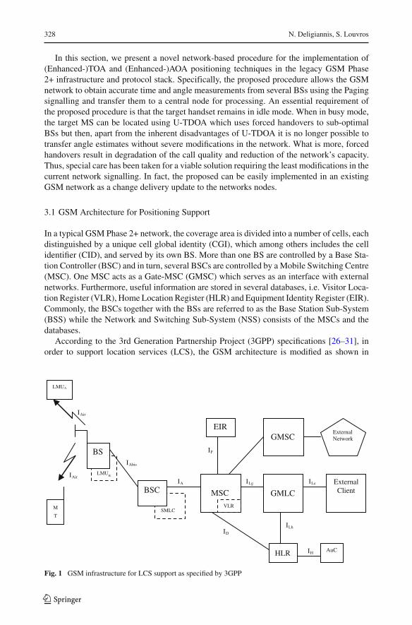
In a typical GSM Phase 2+ network, the coverage area is divided into a number of cells, eachdistinguished by a unique cell global identity (CGI), which among others includes the cellidentifier (CID), and served by its own BS. More than one BS are controlled by a Base Sta-tion Controller (BSC) and in turn, several BSCs are controlled by a Mobile Switching Centre(MSC). One MSC acts as a Gate-MSC (GMSC) which serves as an interface with externalnetworks. Furthermore, useful information are stored in several databases, i.e. Visitor Loca-tion Register (VLR), Home Location Register (HLR) and Equipment Identity Register (EIR).Commonly, the BSCs together with the BSs are referred to as the Base Station Sub-System(BSS) while the Network and Switching Sub-System (NSS) consists of the MSCs and thedatabases.
According to the 3rd Generation Partnership Project (3GPP) specifications [26–31], inorder to support location services (LCS), the GSM architecture is modified as shown in
IAir
IA ILe
IH
IAbis
IAir
ILh ID
ILg
LMUB
BS
SMLC
BSC MSC
VLR
GMLC
HLR AuC
EIR GMSC
External Client
IF
External Network
LMUA
M
T
Fig. 1 GSM infrastructure for LCS support as specified by 3GPP
123
Hybrid TOA–AOA Location Positioning Techniques in GSM Networks 329
Fig. 1. The External LCS Client is an entity setting a request for location informationon a specific MS. The Gateway Mobile Location Centre (GMLC) is the first node anexternal LCS client accesses in the network. The GMLC may request routing informa-tion from the HLR via the Lh interface. After performing registration authorization, itsends positioning requests to and receives final location estimates from the GMSC viathe Lg interface. The Service Mobile Location Centre (SMLC) which is responsible forthe calculation of the final position estimate is an update of the BSC. The SMLC con-trols a number of Location Measurements Units (LMU) for the collection of the radiointerface measurements to locate the MS subscriber in the area it serves. The estimatedposition of the subscriber is sent back to the corresponding MSC/VLR. An LMU can bedefined either as type A which is accessed over the normal GSM air interface or typeB which is accessed over the Abis interface. The MSC contains functionality responsi-ble for MS subscription authorization and managing call-related and non-call related posi-tioning requests of GSM LCS. The MSC is accessible to the GMLC via the Lg interfaceand the SMLC via the Ls interface. The HLR contains LCS subscription data and routinginformation.
3.2 Proposed GSM Procedure for the Implementation of Hybrid TOA–AOA Techniques
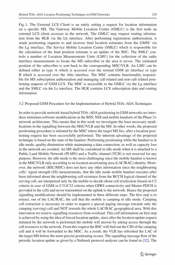
In order to provide network-based hybrid TOA–AOA positioning in GSM networks we intro-duce minimum software modifications in the BSS, NSS and mobile handsets of the Phase 2+network architecture. This means that in this work we investigate the least necessary modi-fications in the signalling between the MSC/VLR and the MS. In other words, the proposedpositioning procedure is initiated by the MSC where the target MS lies, after a location posi-tioning request has been successfully performed. The inherent advantage of the proposedtechnique is based on the state of the handset. Performing positioning while the handset is inidle mode, quality diminution while maintaining a data connection, as well as capacity lossin the network are avoided. An MS shall be considered in idle mode when it is attached to aPublic Land Mobile Network (PLMN) and a Traffic channel (TCH) is not reserved for anypurpose. However, the idle mode is the most challenging since the mobile handset is knownin the MSC/VLR only according to its location area/routing area (LAC/RAC) identity. More-over, the network (BSC/MSC) does not have any other information since the neighbouringcells’ signal strength (SS) measurements, that the idle mode mobile handset executes afterbeen informed about the neighbouring cell existence from the BCCH logical channel of theserving cell, are interpreted only by the mobile to decide about cell reselection (based on C2criteria in case of GSM or C31/C32 criteria when GPRS connectivity and Master PDCH isprovided in the cell) and never transmitted on the uplink to the network. Hence the proposedsignalling modifications should be implemented in three different steps. The first step is toextract, out of the LAC/RAC, the cell that the mobile is camping in idle mode. Campingcell extraction is necessary in order to request a special paging message towards only thecamping (serving) cell and NOT towards the whole LAC/RAC geographical area. With thisinnovation we reserve signalling resources from overload. This cell information on first stepis achieved by using the idea of forced location update, since after the location update requestinitiated by the network is performed the mobile will answer by asking access through thecell resources to the network. From this request the BSC will find out the CID of the campingcell and it will be forwarded to the MSC. As a result, the VLR has refreshed the LAC ofthe target MS before the more precise positioning occurs. The signalling message flow of theperiodic location update as given by a Nethawk protocol analyser can be found in [32]. The
123
330 N. Deligiannis, S. Louvros
VLR MSC BSC BS3 MS
IC cell info
Page MT
UDT Locate
Subscriber Command
Paging Command
Paging Request (PCH)
Channel Request (RACH)
Channel Required
Channel Activation
Channel Activation ACK.
Immediate Assignment Command Immediate Assignment (AGCH)
Paging Response (SDCCH) Paging Response Establish Indication
Measurements request
UA (SDCCH)
Measurements results
Channel Activation (SDCCH TS in BS2)
Channel Activation ACK.
Immediate Assignment Command
RF release (SDCCH TS in BS1)
RF release Acknowledgment
Single Paging Command
Single Paging Request (PCH)
Channel Request (RACH)
Channel Required
Channel Activation
Channel Activation Ack.
Immediate Assignment Command Immediate Assignment (AGCH)
Single Paging Response (SDCCH) SAMB
UA (SDCCH)
Single Paging Response Establish indication
Measurements req (SDCCH)
Meas. res. (SDCCH)
Paging signaling from BS1
Measurement acquisition
Forced cell reselection to
BS2
Single Paging
signaling from BS2
Imm. Assign. Cmd (AGCH)
AOA measurement results
BS2 BS1
Fig. 2 Signalling Message Flow of the proposed GSM procedure which enables the implementation of hybridTOA–AOA positioning in GSM Networks
123
Hybrid TOA–AOA Location Positioning Techniques in GSM Networks 331
MS
Single Paging Command Single Paging Request (PCH)
Channel Request (RACH) Channel Required
Channel Activation
Channel Activation Ack.
Immediate Assignment Cmd Immediate Assignment (AGCH)
UA (SDCCH)
Single Paging Response (SDCCH) SAMB
Single Paging Response
RF Channel release
RF Channel release Ack.
MSCVLR
Channel Activation Ack.
Channel Activation (SDCCH TS in BS3)
(E-)TOA or (E-) AOA positioning
algorithm runs
Forced cell reselection to
BS3
Single Paging
signaling from BS2
Imm. Assign. Cmd (AGCH)
AOA measurement results
Immediate Assignment Command
RF release (SDCCH TS in BS2)
RF release Acknowledgment
UDT Locate
Subscriber Response
BSC BS3 BS2
Fig. 2 continued
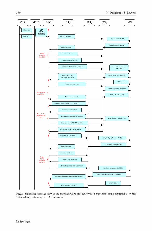
second step is to force the mobile to send the idle mode measurements up to the network forfurther interpretations by the MSC locating. The third step is to force the mobile to reselectthe two strongest neighbouring cells, based on the forced received measurements of SS on theuplink from step two. This is novel since by having the mobile reselecting totally three cellsand by performing three forced paging messages, the triangulation process is enabled. Theanalytical signalling message flow of the proposed positioning procedure is demonstrated inFig. 2.
In more details, immediately after the forced periodic location update (named as firststep above), a paging signalling procedure follows in order to obtain the time estimate fromthe serving BS. The time measurement is similar to the computation of Timing Advancebut in our approach, the fact that the MS is in idle mode allows for the BS to measurethe propagation delay between the Paging channel (PCH) and the Random Access channel(RACH) using existing conventional techniques [33–37]. In this point it has to be clari-fied that the mobile gets a RACH channel from a BCCH multiframe after more than oneattempt, depending on the traffic load and the cell parameters. The network defines themaximum number of re-attempts to get access through the RACH channel based on a param-eter (in Ericsson networks it is called MAXRET). This procedure poses a time offset inthe time estimation, however in our case it has been supposed that the MAXRET param-eter has been set into the minimum value meaning that after a first access attempt failurethe forced paging procedure is restarted. Hence this time offset is kept very low, mini-mum affecting the overall time estimation. For larger MAXRET values, a probabilistic study
123
332 N. Deligiannis, S. Louvros
of the influence of the cellular traffic load to the accuracy of the obtained time estimatecould be further investigated. The obtained round trip time estimate is divided by two andconveyed (using the Access Delay parameter) to the BSC via the Channel Request mes-sage. In addition, a BS equipped with antenna arrays can measure the angle of the receivedsignal.
Thereafter, the algorithm searches for the best three Base Stations (BSs) (one is the camp-ing cell and two others from the best SS cells received in the uplink measurement report)to force coordination with the MS. In case of Idle Mode condition, the MS keeps for itselfmeasurements about the received signal power from the nearest and the 6 adjacent BSs.In order to acquire the measurements from the MS a Link Access Protocol on D-channel(LAPD) Measurement Request message is introduced. The message is transmitted to theMS from the serving BS through the established Stand-alone Dedicated Control channel(SDCCH). The MS responds through the SDCCH and the measurement report is forwardedto the BSC through LAPD DCM Layer 3 Measurement Results (IDhex = 36) message. Noticethat, the serving BS includes the AOA measurements in the previous message. Out of the6 BSs listed, BSC chooses those two corresponding to the greater signal power under thecondition to be controlled by itself. As a result, additional signalling through the MSC isavoided.
Moreover, to obtain the time estimate and the AOA measurements from the other two BSsa novel proposed LAPD Paging Command message is introduced. The proposed signallingresembles to paging signalling but with a change: The proposed single paging message con-tains the Cell Global Identity (CGI) and the Temporary Mobile Subscriber Identity (TMSI)of the MS (meaning that it will be transmitted downlink only by one cell), while the normalpaging signal contains the total cells belonging to the LAC and the TMSI. By using thismessage, a paging signalling is exchanged between just one BS and the target MS, whilea common paging signal is forwarded from all BSs of a LAC to the target MS. Hence,useless signalling overhead is avoided. After the BSC’s decision, the MS is sequentiallycoordinated to each of the two selected BSs by using a novel Forced Cell Reselection (FCR)signalling procedure. The BSC activates a new SDCCH to the second BS, forces the MS tocoordinate with the new SDCCH channel (through the first BS) and deactivates the previ-ous. Then, the BSC/BS2 sends a Single Paging Request message to the MS through PagingChannel (PCH) and the MS transmits a Channel Request message through the RACH. Whenthe paging signalling from BS2 is terminated, the BSC obtains the AOA measurementsusing the novel BTSM AOA Measurements Results message. Then it activates a SDCCHin BS3, forces the MS to coordinate with this (through BS2) and releases the previousSDCCH channel in BS2. Again, the single paging procedure through BS3 takes place theAOA measurements are obtained and the SDCCH is released. Note that, in this work weconsider the use of three BSs in the positioning process. For NBS > 3, the above signallingis extended similarly. An important advantage of the proposed FCR procedure is that it ini-tiates forced coordination from the Abis Interface and thus, enables the network to resolvethe synchronization and hearability issues that state-of-the-art U-TDOA technique suffersfrom.
Finally, the required data (time and angle measurements) has been obtained by the BSCwhich incorporates a SMLC and the position estimation of the MS using the proposed costfunctions (Sects. 2.1 and 2.2) takes place. Note that to employ the proposed cost functions, theBSC/SMLC stores GIS data for each BSs that controls. The estimated subscriber’s positionis sent to the network via the Locate Subscriber Response message which is transmitted fromthe BSC to the MSC.
123
Hybrid TOA–AOA Location Positioning Techniques in GSM Networks 333
MSCBSC/SMLC
BS1
BS2MS
A Interface
Abis Interface
Abis Interface
Abis Interface
EmuSeqTool
EmuSliTool
AXE dump
Related tools
ComponentLibrary
VirtualAXE
Configuration File(config.exe)
SEAConfiguration
Wizard
BS3
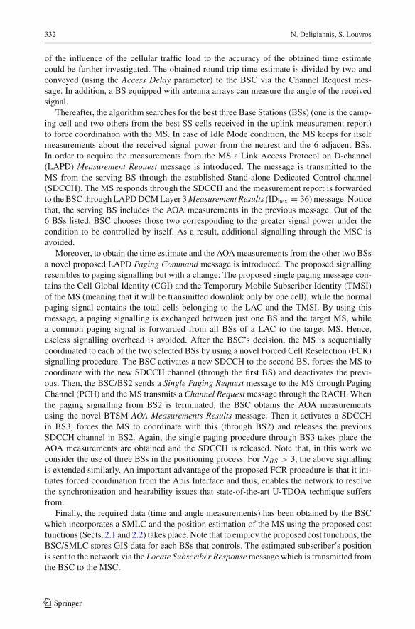
Fig. 3 Experimental emulation setup for the proposed GSM positioning procedure
3.3 Required Modifications in the Existing Signalling Messages
To validate the feasibility and the applicability of the proposed GSM positioning proce-dure a GSM AXE emulation has been performed, as shown in Fig. 3. The employed emu-lator, known as Simulated Test Environment (STE) was provided by Ericsson. A normaltest case should be performed in a real test bed environment including all the networknodes (MSC, BSC, BTS, MS) based on the AXE Ericsson architectures. However, per-forming these activities in a simulated environment reduces the hours per test case andimproves the flexibility of controlling the case and measuring the signalling flow. In par-ticular, the AXE Emulation enables the user to build or adapt an AXE node (or a networkof nodes) using computer simulation—without using the real Signalling Transfer points(STP) unless it is absolutely necessary. The SEA block control centre of STE offers thepossibility to create and use several functional nodes with the appropriate operating soft-ware and functionalities, as it is the case for MSC, BSC and BTS. Currently, SEA is avail-able in three versions where APZ Emulator (1st Generation) and APZ 212xx Emulator(2nd Generation) have been the first steps towards a complete 3rd Generation AXE emu-lation which was our test case software version. Towards realistic precision, the 3rd Gen-eration AXE emulator uses a real software backup copy of an AXE switch node, calleddump file. This file is loaded in the server in which the emulator is running. This dumpfile is redesigned using Ericsson specific software development language and incorporates
123
334 N. Deligiannis, S. Louvros
the proposed signalling messages. Also, in order to emulate the functionalities and thePSTN/PLMN traffic of a user equipment (UE), an EmuSliTool has been used. An addi-tional tool called EmuSeqTool, is employed to read the signalling messages created inthe interfaces among the nodes. Below, we provide the context of the modified messagesas given by the emulator, followed by a brief explanation for each message. To improvetheir presentation the modified messages are mapped into the well known format of Net-hawk. The interested reader can find the context of the remainder unmodified messages in[32,38,39].
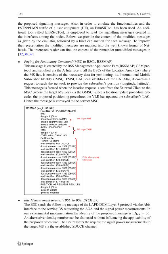
• Paging for Positioning Command (MSC to BSCs, BSSMAP)This message is created by the BSS Management Application Part (BSSMAP) GSM pro-tocol and supplied via the A Interface to all the BSCs of the Location Area (LA) wherethe MS lies. It consists of the necessary data for positioning, i.e. International MobileSubscriber Identity (IMSI), TMSI, LAC, cell identities of the LA. Also, it contains arequest towards the network to provide the subscriber’s position (longitude, latitude).This message is formed when the location request is sent from the External Client to theMSC (where the target MS lies) via the GMSC. Since a location update procedure pre-cedes the proposed positioning procedure, the VLR has updated the subscriber’s LAC.Hence the message is conveyed to the correct MSC.
BSSMAP (length: 52, 34h) PAGING FOR POSITIONING Info IMSI -length: 8 (08h) -identity contains an IMSI -mobile country code: 202 -mobile network code: 01 -MSIN: 0000000002 TMSI -length: 4 (04h) -TMSI value: CA2A0100h Cell Identifier - length: 29 (1Dh) -cell identified with LAC+CI -location area code: 1369 (0559h) -cell identifier: 171 (00ABh) -location area code: 1369 (0559h) -cell identifier: 172 (00ACh) -location area code: 1369 (0559h) -cell identifier: 173 (00ADh) -location area code: 1369 (0559h) -cell identifier: 174 (00AEh) -location area code: 1369 (0559h) -cell identifier: 175 (00AFh) -location area code: 1369 (0559h) -cell identifier: 176 (0060h) -location area code: 1369 (0559h) -cell identifier: 177 (0061h) POSITIONING REQUEST RESULTS -length: 2 (02h) -provide latitude
-provide longitude
MS target IMSI
MS target TMSI
Cells where paging takes place
• Idle Measurement Request (BSC to BS1, BTSM L3)The BSC sends the following message of the LAPD DCM Layer 3 protocol via the Abisinterface to the serving BS requesting the AOA and the signal power measurements. Inour experimental implementation the identity of the proposed message is IDhex = 35.An alternative identity number can be also used without influencing the applicability ofthe proposed procedure. The BS transfers the request for signal power measurements tothe target MS via the established SDCCH channel.
123
Hybrid TOA–AOA Location Positioning Techniques in GSM Networks 335
IDLE_MEAS_REQ (DCh) T=0 Channel Nr. -SDCCH/8 subchannel 6 -timeslot: 1 Idle_Meas_Req Nr -value: 10 (0ah) Uplink Measurements -length: 1 (1h) -provide meas. AOA Downlink Measurements -serving cell rxlev_full -serving cell rxlev_sub -number of neigh cells meas request: 6 -rxlev[1] -neighbor BA index[1] -BSIC[1] -rxlev[2] -neighbor BA index[2] -BSIC[2] -rxlev[3] -neighbor BA index[3] -BSIC[3] -rxlev[4] -neighbor BA index[4] -BSIC[4] -rxlev[5] -neighbor BA index[5] -BSIC[5] -rxlev[6] -neighbor BA index[6] -BSIC[6]
SDCCH between BS
and MS
AOA measurements
request
Power Level Measurements
request
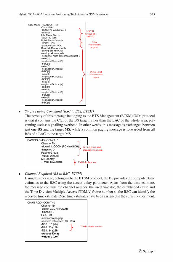
• Single Paging Command (BSC to BS2, BTSM)The novelty of this message belonging to the BTS Management (BTSM) GSM protocolis that it contains the CGI of the BS target rather than the LAC of the whole area, pre-venting useless signalling overhead. In other words, this message is exchanged betweenjust one BS and the target MS, while a common paging message is forwarded from allBSs of a LAC to the target MS.
PAGING CMD (CCh) T=0 Channel Nr -downlink CCCH (PCH+AGCH) -timeslot: 0 Paging Group -value: 2 (02h) MT identity -TMSI: CA2A0100 TMSI declaration
Paging group and channel declaration
• Channel Required (BS to BSC, BTSM)Using this message, belonging to the BTSM protocol, the BS provides the computed timeestimates to the BSC using the access delay parameter. Apart from the time estimate,the message contains the channel number, the used timeslot, the established cause andthe Time Division Multiple Access (TDMA) frame number so the BSC can identify thereceived time estimate. Zero time estimates have been assigned in the current experiment.
CHAN RQD (CCh) T=0 Channel Nr -uplink CCCH (RACH) -timeslot: 0 Req. Ref -answer to paging -random reference: 25 (19h) -N32: 10 (ah) -N26: 23 (17h) -N51: 34 (22h) -Access Delay -value: 0 (00h)
TDMA frame number
123
336 N. Deligiannis, S. Louvros
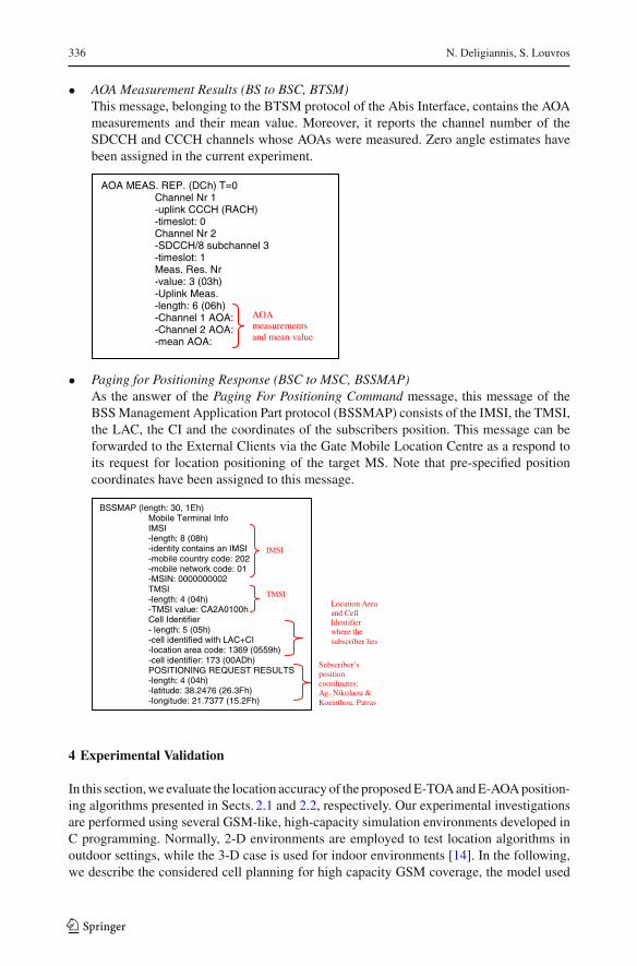
• AOA Measurement Results (BS to BSC, BTSM)This message, belonging to the BTSM protocol of the Abis Interface, contains the AOAmeasurements and their mean value. Moreover, it reports the channel number of theSDCCH and CCCH channels whose AOAs were measured. Zero angle estimates havebeen assigned in the current experiment.
AOA MEAS. REP. (DCh) T=0 Channel Nr 1 -uplink CCCH (RACH) -timeslot: 0 Channel Nr 2 -SDCCH/8 subchannel 3 -timeslot: 1 Meas. Res. Nr -value: 3 (03h) -Uplink Meas. -length: 6 (06h) -Channel 1 AOA: -Channel 2 AOA: -mean AOA:
AOA measurements and mean value
• Paging for Positioning Response (BSC to MSC, BSSMAP)As the answer of the Paging For Positioning Command message, this message of theBSS Management Application Part protocol (BSSMAP) consists of the IMSI, the TMSI,the LAC, the CI and the coordinates of the subscribers position. This message can beforwarded to the External Clients via the Gate Mobile Location Centre as a respond toits request for location positioning of the target MS. Note that pre-specified positioncoordinates have been assigned to this message.
IMSI
TMSI Location Area and Cell Identifier where the subscriber lies
Subscriber’s position coordinates: Ag. Nikolaou & Korinthou, Patras
BSSMAP (length: 30, 1Eh) Mobile Terminal Info IMSI -length: 8 (08h) -identity contains an IMSI -mobile country code: 202 -mobile network code: 01 -MSIN: 0000000002 TMSI -length: 4 (04h) -TMSI value: CA2A0100h Cell Identifier - length: 5 (05h) -cell identified with LAC+CI -location area code: 1369 (0559h) -cell identifier: 173 (00ADh) POSITIONING REQUEST RESULTS -length: 4 (04h) -latitude: 38.2476 (26.3Fh)
-longitude: 21.7377 (15.2Fh)
4 Experimental Validation
In this section, we evaluate the location accuracy of the proposed E-TOA and E-AOA position-ing algorithms presented in Sects. 2.1 and 2.2, respectively. Our experimental investigationsare performed using several GSM-like, high-capacity simulation environments developed inC programming. Normally, 2-D environments are employed to test location algorithms inoutdoor settings, while the 3-D case is used for indoor environments [14]. In the following,we describe the considered cell planning for high capacity GSM coverage, the model used
123
Hybrid TOA–AOA Location Positioning Techniques in GSM Networks 337
to capture the electromagnetic propagation and the experimental environments. Last, wereport the location positioning performance of the proposed compared to the conventionalpositioning techniques.
4.1 Simulation Environments
We begin by referring to the considered GSM cell planning. Nominal cell planning, usedin the early years of the GSM 2G network planning, considers the coverage of a specificgeographical area using several clearly separated layers, i.e. picocell, microcell, and mac-rocell planning. After the introduction of the 2.5G phase in the network, the sensitivity ofthe network in the radio propagation environment and the demand for capacity forced theplanners to incorporate many classical microcells, i.e. antenna height from 4 to 10 m, in citycenters and also semi-urban and rural areas e.g. train stations, shopping malls, industrialareas, etc. However, the problem raised was the increase in the interference level which influ-enced the user throughputs and affected the service QoS. As a result, the combined optimizedmacro/micro-cellular coverage has recently emerged [40,41]. According to this planning, thebuilding heights and the average user densities in the considered area are taken into account.The planners choose the highest buildings in the area and they place on roof-top antennaswith classical macrocell characteristics. Thereafter, some of the macrocell characteristics aremodified in order to achieve restricted microcell coverage. This is performed by appropri-ately fixing the antenna’s tilt to be down-tilted towards the buildings and the surroundedroads. Abiding by this state-of-the-art cell planning, in the following simulations, we con-sider antennas in high heights i.e. roof-top level, but with restricted coverage and increasedcapacity, achieved by high down-tilts and many TRXs per cell.
Since in the considered GSM cell planning the BS antennas are mounted at a level higherthan the surrounding scatterers, the received signal at the BS results mainly from the scatteringprocess at the vicinity of handset. In this case, a popular model for the reception at the BS isthat effective scatterers are evenly spaced on a circular ring about the handset [42,43]. Mea-surements given in [44,45] conclude that the angle-of-arrival is stationary Gaussian withangle spreads of approximately φn ≤ 5◦. Similarly, for wideband radio channels, measure-ments centered at 1,800 MHz (GSM DCS-1800 band) confirm that most of the received signalenergy is concentrated in a small region φn ≤ 5◦ in rural, semi-urban and urban environments[44].
In complete accordance to these findings [42–46] and state-of-the-art work on locationpositioning [5,13,14,18,24], we model the reception at the BS using the Gaussian station-ary uncorrelated scattering model. Specifically, the electromagnetic field is modeled to afirst-order ray trace contribution and the signal reaches the BS directly (LOS propagation)or through reflections or diffractions on the buildings’ walls (NLOS propagation). The TOAestimate at the BS is given by a halved Gaussian distribution with a mean tBSi calculatedby the tBSi = dBSi /c equation and a standard deviation σtBSi
= tn × tBSi . Furthermore, theAOA estimates are given by a Gaussian distribution with a mean calculated by the followingformula:
ϕi = tan−1 y − yBSi
x − xBSi
, (9)
where (xBSi , yBSi ) are the coordinates of the BSi , ∀i = 1...3 and (x, y) are the coordi-nates of the MS (LOS propagation) or the coordinates of the point where the final reflectionoccurred. Notice that, in contrast to AOA measurements, the TOA bias needs to be alwaysadditive and positive. This is the reason why the halved Gaussian distribution is employed to
123
338 N. Deligiannis, S. Louvros
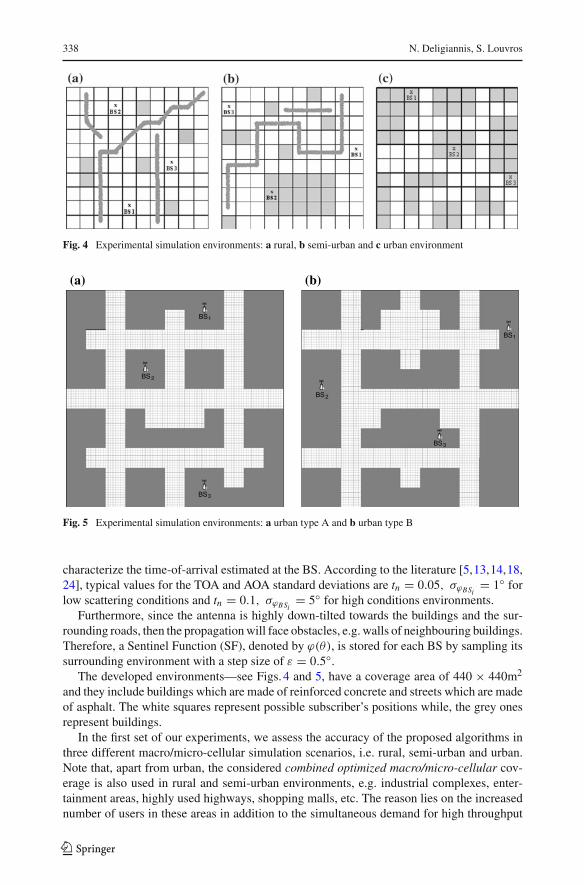
Fig. 4 Experimental simulation environments: a rural, b semi-urban and c urban environment
BS3
BS2
BS1
BS3
BS2
BS1
(a) (b)
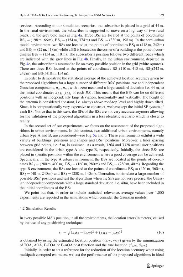
Fig. 5 Experimental simulation environments: a urban type A and b urban type B
characterize the time-of-arrival estimated at the BS. According to the literature [5,13,14,18,24], typical values for the TOA and AOA standard deviations are tn = 0.05, σϕBSi
= 1◦ forlow scattering conditions and tn = 0.1, σϕBSi
= 5◦ for high conditions environments.Furthermore, since the antenna is highly down-tilted towards the buildings and the sur-
rounding roads, then the propagation will face obstacles, e.g. walls of neighbouring buildings.Therefore, a Sentinel Function (SF), denoted by ϕ(θ), is stored for each BS by sampling itssurrounding environment with a step size of ε = 0.5◦.
The developed environments—see Figs. 4 and 5, have a coverage area of 440 × 440m2
and they include buildings which are made of reinforced concrete and streets which are madeof asphalt. The white squares represent possible subscriber’s positions while, the grey onesrepresent buildings.
In the first set of our experiments, we assess the accuracy of the proposed algorithms inthree different macro/micro-cellular simulation scenarios, i.e. rural, semi-urban and urban.Note that, apart from urban, the considered combined optimized macro/micro-cellular cov-erage is also used in rural and semi-urban environments, e.g. industrial complexes, enter-tainment areas, highly used highways, shopping malls, etc. The reason lies on the increasednumber of users in these areas in addition to the simultaneous demand for high throughput
123
Hybrid TOA–AOA Location Positioning Techniques in GSM Networks 339
services. According to our simulation scenarios, the subscriber is placed in a grid of 44 m.In the rural environment, the subscriber is suggested to move on a highway or two ruralroads, i.e. the grey bold lines in Fig. 4a. Three BSs are located at the points of coordinatesBS1 = (198 m, 66 m), BS2 = (154 m, 374 m) and BS3 = (330 m, 198 m). In the semi-urbanmodel environment two BSs are located at the points of coordinates BS1 = (418 m, 242 m)and BS3 = (22 m, 418 m) while a BS is located on the corner of a building at the point of coor-dinates BS2 = (154 m, 110 m). The subscriber’s position follows two different roads whichare indicated with the grey lines in Fig. 4b. Finally, in the urban environment, depicted inFig. 4c, the subscriber is assumed to lie on every possible position in the grid (white squares).There are three BSs located at the points of coordinates BS1(110 m, 418 m), BS2(242 m,242 m) and BS3(418 m, 154 m).
In order to demonstrate the statistical average of the achieved location accuracy given bythe proposed algorithms for a large number of different BSs’ positions, we add independentGaussian components, nxi , nyi , with a zero mean and a large standard deviation i.e. 44 m, tothe initial coordinates xBSi , yBSi of each BSi . This means that the BSs can lie on differentpositions with an independently large deviation, horizontally and vertically. The height ofthe antenna is considered constant, i.e. always above roof-top level and highly down tilted.Since, it is computationally very expensive to construct, we have kept the initial SF system ofeach BS. Notice that in this case, the SFs of the BSs are not very accurate anymore allowingfor the validation of the proposed algorithms in a less idealistic scenario which is closer toreality.
In the second set of our experiments, we focus on the assessment of the proposed algo-rithms in urban environments. In this context, two additional urban environments, namelyurban type A and B, are considered—see Fig. 5a and b. These environments exhibit a widevariety of buildings’ positions and shapes and BSs’ positions. Moreover, a finer spacingbetween grid points, i.e. 5 m, is assumed. As a result, 3264 and 3328 actual user positionsare considered in the urban type A and type B, respectively. Initially, the three BSs areplaced in specific positions within the environment where a good coverage can be achieved.Specifically, in the type A urban environment, the BSs are located at the points of coordi-nates BS1 = (280 m, 400 m), BS2 = (160 m, 280 m) and BS3 = (280 m, 40 m). Regarding thetype B environment, the BSs are located at the points of coordinates BS1 = (420 m, 360 m),BS2 = (40 m, 240 m) and BS3 = (280 m, 140 m). Thereafter, to simulate a large number ofpossible BSs’ positions and test the algorithms when the SFs are not very precise, the Gauss-ian independent components with a large standard deviation, i.e. 40m, have been included inthe initial coordinates of the BSs.
We point out that, in order to include statistical relevance, average values over 1,000experiments are reported in the simulations which consider the Gaussian models.
4.2 Simulation Results
In every possible MS’s position, in all the environments, the location error (in meters) causedby the use of any positioning technique:
εr =√
(xM S − xM S)2 + (yM S − yM S)2 (10)
is obtained by using the estimated location position (xM S, yM S) given by the minimizationof TOA, AOA, E-TOA or E-AOA cost function and the true location (xM S, yM S).
Initially, in order to set a reference for the reduction of the location accuracy when usingmultipath corrupted estimates, we test the performance of the proposed algorithms in ideal
123
340 N. Deligiannis, S. Louvros
0 5 10 15 20 250
50
100
150
200
250
300
350
400
Position Nr.
Loc
atio
n E
rror
(m
)Rural Environment
TOAE-TOAAOAE-AOA
(a)
0
20
40
60
80
100
120
140
160
180
200
TOA E-TOA AOA E-AOA
Loc
atio
n E
rror
(m
)
Rural Environment
Three BSs in LOS Two BSs in LOS One BS in LOS In all Positions
(b)
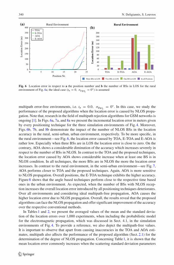
Fig. 6 Location error in respect to a the position number and b the number of BSs in LOS for the ruralenvironment of Fig. 4a; the ideal case (tn = 0, σϕBSi
= 0◦) is assumed
multipath error-free environments, i.e. tn = 0.0, σφBSi= 0◦. In this case, we study the
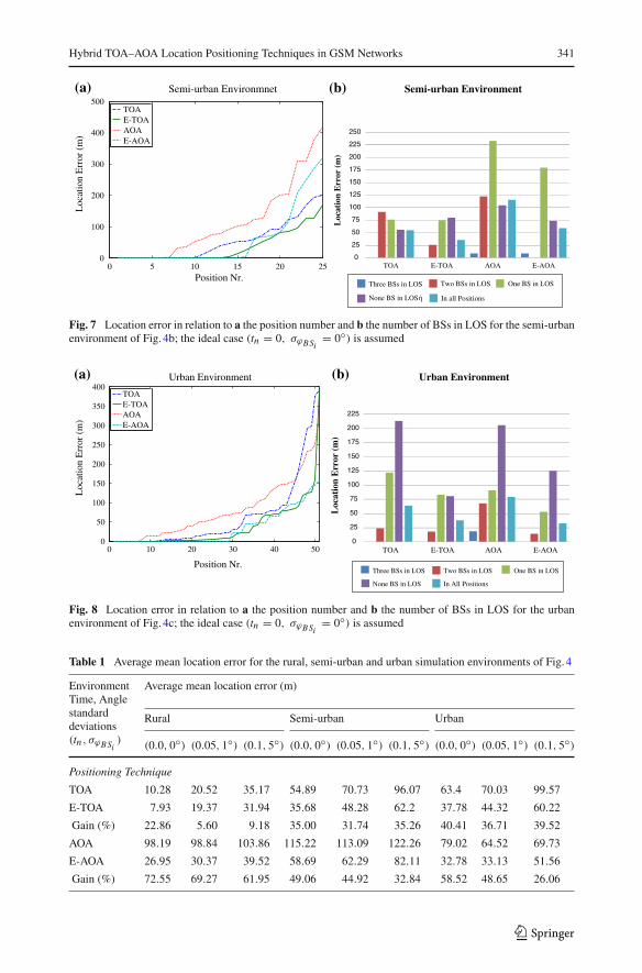
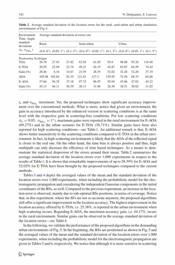
performance of the proposed algorithms when the location error is caused by NLOS propa-gation. Note that, research in the field of multipath rejection algorithms for GSM networks isongoing [1]. In Figs. 6a, 7a, and 8a we present the incremental location error in meters givenby every positioning technique for the three simulation environments of Fig. 4. Moreover,Figs. 6b, 7b, and 8b demonstrate the impact of the number of NLOS BSs in the locationaccuracy in the rural, semi-urban, urban environment, respectively. To be more specific, inthe rural environment—see Fig. 6, the location error caused by TOA, E-TOA and E-AOA israther low. Especially when three BSs are in LOS the location error is close to zero. On thecontrary, AOA shows a considerable diminution of the accuracy which increases severely inrespect to the number of BSs in NLOS. In contrast to the TOA and the proposed techniques,the location error caused by AOA shows considerable increase when at least one BS is inNLOS condition. In all techniques, the more BSs are in NLOS the more the location errorincreases. In contrast to the rural environment, in the semi-urban environment—see Fig. 7,AOA performs closer to TOA and the proposed techniques. Again, AOA is more sensitiveto NLOS propagation. Overall positions, the E-TOA technique exhibits the higher accuracy.Figure 8 shows that the angle based techniques perform close to the respective time basedones in the urban environment. As expected, when the number of BSs with NLOS recep-tion increases the overall location error introduced by all positioning techniques deteriorates.Over all environments and considering ideal multipath-free propagation, AOA causes thehigher location error due to NLOS propagation. Overall, the results reveal that the proposedalgorithms can face the NLOS propagation and offer significant improvement of the accuracyover the respective conventional methods.
In Tables 1 and 2, we present the averaged values of the mean and the standard devia-tion of the location errors over 1,000 experiments, when including the probabilistic modelfor the electromagnetic propagation, which was discussed in Sect. 4.1, in the simulationenvironments of Fig. 4. To provide a reference, we also depict the multipath-free values.It is important to observe that apart from causing inaccuracies in the TOA and AOA esti-mates, multipath also affects the performance of the proposed algorithm (Sect. 2.1) for thedetermination of the degree of NLOS propagation. Concerning Table 1, it is shown that themean location error commonly increases when the scattering standard deviation parameters
123
Hybrid TOA–AOA Location Positioning Techniques in GSM Networks 341
0 5 10 15 20 250
100
200
300
400
500
Position Nr.
Loc
atio
n E
rror
(m
)Semi-urban Environmnet
TOAE-TOAAOAE-AOA
(a)
0
25
50
75
100
125
150
175
200
225
250
TOA E-TOA AOA E-AOA
Loc
atio
n E
rror
(m
)
Semi-urban Environment
Three BSs in LOS Two BSs in LOS One BS in LOS
None BS in LOS In all Positions
(b)
Fig. 7 Location error in relation to a the position number and b the number of BSs in LOS for the semi-urbanenvironment of Fig. 4b; the ideal case (tn = 0, σϕBSi
= 0◦) is assumed
0 10 20 30 40 500
50
100
150
200
250
300
350
400
Position Nr.
Loc
atio
n E
rror
(m
)
Urban Environment
TOAE-TOAAOAE-AOA
(a)
0
25
50
75
100
125
150
175
200
225
TOA E-TOA AOA E-AOA
Loc
atio
n E
rror
(m
)
Urban Environment
Three BSs in LOS Two BSs in LOS One BS in LOS
None BS in LOS In All Positions
(b)
Fig. 8 Location error in relation to a the position number and b the number of BSs in LOS for the urbanenvironment of Fig. 4c; the ideal case (tn = 0, σϕBSi
= 0◦) is assumed
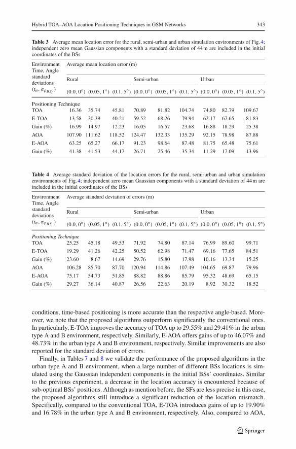
Table 1 Average mean location error for the rural, semi-urban and urban simulation environments of Fig. 4
EnvironmentTime, Anglestandarddeviations(tn , σϕBSi
)
Average mean location error (m)
Rural Semi-urban Urban
(0.0, 0◦) (0.05, 1◦) (0.1, 5◦) (0.0, 0◦) (0.05, 1◦) (0.1, 5◦) (0.0, 0◦) (0.05, 1◦) (0.1, 5◦)
Positioning Technique
TOA 10.28 20.52 35.17 54.89 70.73 96.07 63.4 70.03 99.57
E-TOA 7.93 19.37 31.94 35.68 48.28 62.2 37.78 44.32 60.22
Gain (%) 22.86 5.60 9.18 35.00 31.74 35.26 40.41 36.71 39.52
AOA 98.19 98.84 103.86 115.22 113.09 122.26 79.02 64.52 69.73
E-AOA 26.95 30.37 39.52 58.69 62.29 82.11 32.78 33.13 51.56
Gain (%) 72.55 69.27 61.95 49.06 44.92 32.84 58.52 48.65 26.06
123
342 N. Deligiannis, S. Louvros
Table 2 Average standard deviation of the location errors for the rural, semi-urban and urban simulationenvironments of Fig. 4
EnvironmentTime, Anglestandarddeviations(tn , σϕBSi
)
Average standard deviation of errors (m)
Rural Semi-urban Urban
(0.0, 0◦) (0.05, 1◦) (0.1, 5◦) (0.0, 0◦) (0.05, 1◦) (0.1, 5◦) (0.0, 0◦) (0.05, 1◦) (0.1, 5◦)
Positioning TechniqueTOA 28.78 27.43 27.82 63.05 61.85 95.6 96.08 95.26 118.48
E-TOA 20.59 25.69 23.74 49.21 44.19 45.87 65.07 64.59 74.42
Gain (%) 28.46 6.34 14.67 21.95 28.55 52.02 32.28 32.20 37.19
AOA 105.08 104.64 83.35 121.81 127.2 129.95 74.58 68.33 64.86
E-AOA 57.66 56.39 37.18 97.32 86.55 95.04 45.86 47.82 44.22
Gain (%) 45.13 46.11 58.39 20.11 31.96 26.30 38.51 30.02 31.82
tn and σφBSiincrement. Yet, the proposed techniques show significant accuracy improve-
ment over the conventional methods. What is more, notice that given an environment, thegain in accuracy introduced by the enhanced version in scattering conditions is at the samelevel with the respective gain in scattering-free conditions. For low scattering conditions(tn = 0.05, σφBSi
= 1◦), maximum gains were reported in the rural environment for E-AOA(69.27%) and in the urban scenario for E-TOA (36.71%). Similar gains have been alsoreported for high scattering conditions—see Table 1. An additional remark is that, E-AOAshows better insensitivity to the scattering conditions compared to E-TOA in the urban envi-ronment. In fact, in high scattering environments is likely that the AOA of the reflected signalis closer to the real one. On the other hand, the time bias is always positive and thus, highmultipath can only decrease the efficiency of time based techniques. As a means to dem-onstrate the statistical dispersion of the errors around their mean, Table 2 summarizes theaverage standard deviation of the location errors over 1,000 experiments in respect to theresults of Table 1. It is shown that remarkable improvements of up to 58.39% for E-AOA and52.02% for E-TOA have been brought by the proposed techniques compared to the currentmethods.
Tables 3 and 4 depict the averaged values of the mean and the standard deviation of thelocation errors over 1,000 experiments, when including the probabilistic model for the elec-tromagnetic propagation and considering the independent Gaussian components in the initialcoordinates of the BSs, as well. Compared to the previous experiment, an increase in the loca-tion error is observed, mainly due to sub-optimal BSs positions, in terms of coverage. Noticethat, in this experiment, where the SFs are not so accurate anymore, the proposed algorithmsstill offer a significant improvement in the location accuracy. The highest improvement in thelocation accuracy offered by E-TOA, i.e. 25.38%, is reported in the urban environment whenhigh scattering occurs. Regarding E-AOA, the maximum accuracy gain, i.e. 44.17%, incursin the rural environment. Similar gains can be observed in the average standard deviation ofthe location errors—see Table 4.
In the following, we validate the performance of the proposed algorithms in the demandingurban environments of Fig. 5. In the beginning, the BSs are positioned as shown in Fig. 5 andthe averaged values of the mean and the standard deviation of the location errors over 1,000experiments, when including the probabilistic model for the electromagnetic propagation aregiven in Tables 5 and 6, respectively. We notice that although it is more sensitive in scattering
123
Hybrid TOA–AOA Location Positioning Techniques in GSM Networks 343
Table 3 Average mean location error for the rural, semi-urban and urban simulation environments of Fig. 4;independent zero mean Gaussian components with a standard deviation of 44 m are included in the initialcoordinates of the BSs
EnvironmentTime, Anglestandarddeviations(tn , σϕBSi
)
Average mean location error (m)
Rural Semi-urban Urban
(0.0, 0◦) (0.05, 1◦) (0.1, 5◦) (0.0, 0◦) (0.05, 1◦) (0.1, 5◦) (0.0, 0◦) (0.05, 1◦) (0.1, 5◦)
Positioning TechniqueTOA 16.36 35.74 45.81 70.89 81.82 104.74 74.80 82.79 109.67
E-TOA 13.58 30.39 40.21 59.52 68.26 79.94 62.17 67.65 81.83
Gain (%) 16.99 14.97 12.23 16.05 16.57 23.68 16.88 18.29 25.38
AOA 107.90 111.62 118.52 124.47 132.33 135.29 92.15 78.98 87.88
E-AOA 63.25 65.27 66.17 91.23 98.64 87.48 81.75 65.48 75.61
Gain (%) 41.38 41.53 44.17 26.71 25.46 35.34 11.29 17.09 13.96
Table 4 Average standard deviation of the location errors for the rural, semi-urban and urban simulationenvironments of Fig. 4; independent zero mean Gaussian components with a standard deviation of 44 m areincluded in the initial coordinates of the BSs
EnvironmentTime, Anglestandarddeviations(tn , σϕBSi
)
Average standard deviation of errors (m)
Rural Semi-urban Urban
(0.0, 0◦) (0.05, 1◦) (0.1, 5◦) (0.0, 0◦) (0.05, 1◦) (0.1, 5◦) (0.0, 0◦) (0.05, 1◦) (0.1, 5◦)
Positioning TechniqueTOA 25.25 45.18 49.53 71.92 74.80 87.14 76.99 89.60 99.71
E-TOA 19.29 41.26 42.25 50.52 62.98 71.47 69.16 77.65 84.51
Gain (%) 23.60 8.67 14.69 29.76 15.80 17.98 10.16 13.34 15.25
AOA 106.28 85.70 87.70 120.94 114.86 107.49 104.65 69.87 79.96
E-AOA 75.17 54.73 51.85 88.82 88.86 85.79 95.32 48.69 65.15
Gain (%) 29.27 36.14 40.87 26.56 22.63 20.19 8.92 30.32 18.52
conditions, time-based positioning is more accurate than the respective angle-based. More-over, we note that the proposed algorithms outperform significantly the conventional ones.In particularly, E-TOA improves the accuracy of TOA up to 29.55% and 29.41% in the urbantype A and B environment, respectively. Similarly, E-AOA offers gains of up to 46.07% and48.73% in the urban type A and B environment, respectively. Similar improvements are alsoreported for the standard deviation of errors.
Finally, in Tables 7 and 8 we validate the performance of the proposed algorithms in theurban type A and B environment, when a large number of different BSs locations is sim-ulated using the Gaussian independent components in the initial BSs’ coordinates. Similarto the previous experiment, a decrease in the location accuracy is encountered because ofsub-optimal BSs’ positions. Although as mention before, the SFs are less precise in this case,the proposed algorithms still introduce a significant reduction of the location mismatch.Specifically, compared to the conventional TOA, E-TOA introduces gains of up to 19.90%and 16.78% in the urban type A and B environment, respectively. Also, compared to AOA,
123
344 N. Deligiannis, S. Louvros
Table 5 Average mean location error for the urban type A and type B simulation environments of Fig. 5
EnvironmentTime, Anglestandard devia-tions(tn , σϕBSi
)
Average mean location error (m)
Urban type A Urban type B
(0.0, 0◦) (0.05, 1◦) (0.1, 5◦) (0.0, 0◦) (0.05, 1◦) (0.1, 5◦)
Positioning TechniqueTOA 56.51 66.23 81.21 36.51 49.70 60.50
E-TOA 39.82 51.37 71.27 25.77 40.07 49.36
Gain (%) 29.55 22.44 12.24 29.41 19.37 18.41
AOA 104.18 109.19 114.08 80.79 81.02 81.45
E-AOA 56.71 58.89 63.99 41.43 54.74 59.15
Gain (%) 45.57 46.07 43.91 48.73 32.43 27.38
Table 6 Average standard deviation of the location errors for the urban type A and type B simulation envi-ronments of Fig. 5
EnvironmentTime, Anglestandard devia-tions(tn , σϕBSi
)
Average standard deviation of errors (m)
Urban type A Urban type B
(0.0, 0◦) (0.05, 1◦) (0.1, 5◦) (0.0, 0◦) (0.05, 1◦) (0.1, 5◦)
Positioning TechniqueTOA 57.91 58.21 67.92 34.31 34.03 34.92
E-TOA 45.33 48.71 61.66 29.55 30.56 31.66
Gain (%) 21.73 16.32 9.20 13.86 10.19 9.34
AOA 65.95 64.06 67.41 56.13 49.67 54.42
E-AOA 58.11 52.12 55.47 48.34 39.84 45.61
Gain (%) 11.89 18.64 17.72 13.87 19.79 16.20
E-AOA is more precise up to 31.24% and 28.95% in the urban type A and B environment,respectively. As expected, similar gains are observed in the standard deviation of the errors.
Overall experiments, the proposed enhancements always outperform the respective con-ventional ones. In relation with the proposed GSM procedure which is shown that can be easilyimplemented in the existing GSM infrastructure—see Sect. 3.3, the proposed approaches canbecome a competitive solution for GSM positioning.
5 Conclusions and Future Directions
In this paper, we have introduced a novel GSM procedure enabling the network nodes toobtain and transfer accurate time and angle estimates from three BSs. Neither TOA nor AOAhave been specified for GERAN, as far. Yet, the proposed procedure, which is based on thecurrent GSM Phase 2+ infrastructure and protocol stack, is fully compatible with the 3GPPtechnical specifications for GSM location services. The proposed procedure is validated usinga GSM emulator and the results corroborate that minimum modifications in existing signal-ling messages are required, making the procedure easily implemented as a simple software
123

Hybrid TOA–AOA Location Positioning Techniques in GSM Networks 345
Table 7 Average mean location error for the urban type A and type B simulation environments of Fig. 5;independent zero mean Gaussian components with a standard deviation of 40 m are included in the initialcoordinates of the BSs
EnvironmentTime, Anglestandard devia-tions(tn , σϕBSi
)
Average mean location error (m)
Urban type A Urban type B
(0.0, 0◦) (0.05, 1◦) (0.1, 5◦) (0.0, 0◦) (0.05, 1◦) (0.1, 5◦)
Positioning TechniqueTOA 63.46 74.43 92.77 45.47 65.75 72.00
E-TOA 50.83 64.49 77.59 37.97 54.84 59.92
Gain (%) 19.90 13.35 16.36 16.50 16.59 16.78
AOA 107.47 107.49 114.78 83.61 84.94 88.51
E-AOA 73.89 74.03 80.20 59.40 71.29 73.38
Gain (%) 31.24 31.13 30.12 28.95 16.07 17.10
Table 8 Average standard deviation of the location errors for the urban type A and type B simulation environ-ments of Fig. 5; independent zero mean Gaussian components with a standard deviation of 40 m are includedin the initial coordinates of the BSs
EnvironmentTime, Anglestandard devia-tions(tn , σϕBSi
)
Average standard deviation of errors (m)
Urban type A Urban type B
(0.0, 0◦) (0.05, 1◦) (0.1, 5◦) (0.0, 0◦) (0.05, 1◦) (0.1, 5◦)
Positioning TechniqueTOA 59.93 63.93 85.70 58.73 59.98 66.87
E-TOA 50.59 52.21 65.89 44.45 48.69 51.28
Gain (%) 15.58 18.32 23.12 24.30 18.82 23.31
AOA 94.11 96.05 98.11 73.33 74.65 73.61
E-AOA 68.96 69.32 75.06 50.87 64.23 62.12
Gain (%) 26.72 27.83 23.49 30.63 13.96 15.61
patch delivery in any GSM node. It is important to point out that the proposed resolves thehearability and synchronisation drawbacks caused by the state-of-the-art U-TDOA using thenovel FCR algorithm. Also it operates in the idle mode and thus no capacity loss is witnessed.Furthermore, we have introduced a novel algorithm for the identification of the degree ofNLOS reception combining angle and time estimates with some minimal information aboutthe surroundings of a BS, which leads to enhanced versions of the TOA and AOA positioningmethods. The proposed enhanced techniques have been evaluated using several simulationsenvironments with a variety of NLOS propagation and scattering conditions. The resultsindicate the remarkable accuracy improvement offered by the proposed compared to therespective conventional techniques.
Based on this paper, numerous directions for future work can be followed. Of particularinterest is the extension of the proposed GSM positioning procedure to incorporate morethan three BSs. Though it will improve the accuracy, a high number of paging signallinginitiations can cause delays which introduce error, especially for high speed subscribers.The compromise between the number of BSs involved in the positioning and the acquired
123
346 N. Deligiannis, S. Louvros
accuracy remains to be investigated. Possible extensions can incorporate additional featuresof the GSM network, such as the slow frequency hopping. Each GSM logical channel maytransmit successive SDCCH bursts on a different frequency channel according to an allocationscheme. The diversity effect can benefit the proposed procedure, particularly in the presenceof multipath. Moreover, a deterministic propagation model can be employed to assess thelocation accuracy of the proposed positioning techniques. According to these models, theelectromagnetic field is given by the vector sum of several ray contributions. Similar to [16],the AOA and TOA for each ray can be measured, weighted by an appropriate coefficient,and used in the total cost function, resulting in improved location performance. However, theimplementation of such an approach without severe modifications in the current network’sinfrastructure is a rather intricate issue. Finally, as above mentioned, future work might headtowards the improvement of the weight coefficients in the enhanced proposed model basedon scattering principles and probabilistic models.
Acknowledgments The authors gratefully acknowledge many valuable discussions with Prof. Adrian Mun-teanu and Prof. Peter Schelkens in this work. Furthermore, the authors would like to thank the anonymousreviewers whose meticulous comments vastly improved the quality and the presentation of this paper.
References
1. Drane, C., Macnaughtan, M., & Scott, C. (1998). Positioning GSM telephones. IEEE CommunicationsMagazine, 36(4), 46–54.
2. 3GPP TS 25.305. (March, 2002). Stage 2 functional specification of UE positioning.3. 3GPP TR 45.811. (June, 2002). Feasibility study on Uplink TDOA in GSM and GPRS.4. Zhao, Y. (2002). Standardization of mobile phone positioning for 3G systems. IEEE Communications
Magazine, 40(7), 108–116.5. Azaro, R., Donelli, M., Benedetti, M., Rocca, P., & Massa, A. (2008). A GSM signals-based positioning
technique for mobile applications. Microwave and Optical Technology Letters, 50(8), 2128–2130.6. Caffery, J. J., & Stuber, G. L. (1998). Overview of radiolocation in CDMA cellular systems. IEEE Com-
munications Magazine, 36(4), 38–45.7. Fang, B. T. (1990). Simple solutions for hyperbolic and related position fixes. IEEE Transactions on
Aerospace and Electronic Systems, 26(5), 748–753.8. Feuerstein, M., & Pratt, T. (1989). A local area position location system. In International conference on
mobile radio and personal communications, 11–14 December 1989 (pp. 79–83).9. Foy, W. (1976). Position-location solutions by taylor series estimation. IEEE Transactions on Aerospace
and Electronic Systems, 12(2), 187–194.10. Turin, G., Jewell, W., & Johnston, T. (1972). Simulation of urban vehicle-monitoring systems. IEEE
Transactions on Vehicular Technology, VT-21(1), 9–16.11. Sakagami, S., Ayoama, S., Kuboi, K., Shirota, S., & Akeyama, A. (1992). Vehicle position estimates
by multibeam antennas in multipath environments. IEEE Transactions on Vehicular Technology, 41(1),63–68.
12. Blanz, J. J., Papathanassiou, A., Haardt, M., Furió, I., & Baier, P. W. (2000). Smart antennas for combinedDOA and joint channel estimation in time-slotted CDMA mobile radio systems with joint detection. IEEETransactions on Vehicular Technology, 49(2), 293–306.
13. Chen, T. Y., Chiu, C. C., & Tu, T. C. (2003). Mixing and combining with AOA and TOA for the enhancedacurracy of mobile location. In IEE 5th European personal mobile communications conference, 22–25April 2003 (pp. 276–280).
14. Cong, L., & Zhuang, W. (2002). Hybrid TDOA/AOA mobile user location for wideband CDMA cellularsystems. IEEE Transactions on Wireless Communications, 1(3), 439–447.
15. Deligiannis, N., Louvros, S., & Kotsopoulos, S. (2007). Optimizing location positioning using hybridTOA–AOA techniques in mobile cellular networks. In ACM international conference on mobile multi-media communications, MobiMedia, 27–29 August 2007 (Vol. 329, pp. 1–7).
16. Porretta, M., Nepa, P., Manara, G., Giannetti, F., Dohler, M., Allen, B., & Aghvami, A. H. (2004). A novelsingle base station location technique for microcellular wireless networks: Description and validation bya deterministic propagation model. IEEE Transactions on Vehicular Technology, 53(5), 1502–1514.
123
Hybrid TOA–AOA Location Positioning Techniques in GSM Networks 347
17. Thomas, N. J., Cruickshank, D. G. M., & Laurenson, D. I. (2001). Performance of a TDOA-AOA hybridmobile location system. In IEE international conference on 3G mobile communications, 26–28 March2001 (pp. 216–220).
18. Wann, C.-D., Yeh, Y.-J., & Hsueh, C.-S. (2006). Hybrid TDOA/AOA indoor positioning and tracking usingextended Kalman filters. In IEEE Vehicular Technology Conference, VTC 2006, Melbourne, Australia,7–10 May 2006 (Vol. 3, pp. 1058–1062).
19. Chan, Y. T., & Ho, K. C. (1994). A simple and efficient estimator for hyperbolic location. IEEE Transac-tions on Signal Processing, 42, 1905–1915.
20. Wylie, M. P., & Holtzman, J. (1996). The non-line of sight problem in mobile location estimation. IEEEinternational conference on universal personal communications (ICUPC 1996), September 1996 (Vol.2, pp. 827–831).
21. Le, B. L., Ahmed, K., & Tsuji, H. (2003). Mobile location estimator with NLOS mitigation using Kalmanfiltering. IEEE wireless communications and networking conference (WCNC 2003), March 2003 (Vol. 3,pp. 16–20).
22. Thomas, N. J., Cruickshank, D. G. M., & Laurenson, D. I. (2000). A robust location estimator architec-ture with biased Kalman filtering of TOA data for wireless systems. In IEEE international symposium onspread-spectrum techniques and applications, September 2000 (Vol. 1, pp. 296–300).
23. Najar, M., Vidal, J. (2003). Kalman tracking for mobile location in NLOS situations. In IEEE interna-tional symposium on Personal, Indoor and Mobile Radio Communications (PIMRC 2003), September2000 (Vol. 3, pp. 2203–2207).
24. Xiong, L. (1998). A selective model to suppress NLOS signals in angle-of-arrival (AOA) location estima-tion. In IEEE international symposium on Personal, Indoor and Mobile Radio Communications (PIMRC2003), 8–11 September 1998 (Vol. 1, pp. 461–465).
25. Dropping, B. (2005). Changes in base station backhaul drive new synchronization solutions. RF DesignMagazine, 48–56.
26. 3GPP TS 02.71 v7.3.0. (March, 2001). Digital cellular telecommunications system (Phase 2+), LocationServices (LCS), Service description, Stage 1.
27. 3GPP TS 03.71 v7.11.0. (May, 2004). Digital cellular telecommunications system (Phase 2+), LocationServices (LCS), Functional Description.
28. 3GPP TS 04.31 v8.17.0. (January, 2005). Digital cellular telecommunications system (Phase 2+); Loca-tion Services (LCS); Mobile Station (MS)—Serving Mobile Location Center (SMLC); Radio ResourceLCS Protocol (RRLP).
29. 3GPP TS 04.71 v8.4.0. (July, 2002). Digital cellular telecommunications system (Phase 2+); Mobile radiointerface layer 3 Location Services (LCS) specification.
30. 3GPP TS 08.31 v8.1.1. (May, 2002). Digital cellular telecommunications system (Phase 2+); LocationServices (LCS); Serving Mobile Location Center (SMLC)—Serving Mobile Location Center (SMLC);SMLC Peer Protocol (SMLCPP).
31. 3GPP TS 09.31 v8.7.1. (May, 2004). Digital cellular telecommunications system (Phase 2+); LocationServices (LCS); Base Station System Application Part LCS Extension (BSSAP-LE).
32. NokiaTelecommunicationsOy1198. GSM 900/1800 BSS signaling training document.33. Caffery, J. J., & Stuber, G. L. (1994). Vehicle location and tracking for IVHS in CDMA microcells. In
IEEE international symposium on Personal, Indoor and Mobile Radio Communications, PIMRC, 18–23September 1994 (Vol. 4, pp. 1227–1231).
34. Goud, P., Sesay, A., & Fattouche, M. (1991). A spread spectrum radiolocation technique and its applicationto cellular radio. In IEEE Pacific rim conference on communications, computers and signal processing,9–10 May 1991 (Vol. 2, pp. 661–664).
35. Holmes, J. (1982). Coherent spread spectrum systems. Wiley.36. Knapp, C., & Carter, G. (1976). The generalized correlation method for estimation of time delay. IEEE
Transactions on Acoustics, Speech and Signal Processing, ASSP-24(4), 320–327.37. Ziemer, R., & Peterson, R. (1985). Digital communications and spread spectrum systems. Macmillan.38. Heine, G., (1998). GSM networks: Protocols, terminology and implementation. Artech House Publishers.39. Mouly, M., & Paulet, M.-B. (1992). The GSM system for mobile communications. Palaiseau, France.40. Flemming Hermann, P. (2007). Examining telia-sonera Denmark’s microcellular approach to solving
specific special coverage projects for 2G/2.5G environments. In International conference on in-building& enhanced coverage solutions, May 2007.
41. Wisely, D. (2007). BT convergence case study: Effectively deploying cellular/short range converged solu-tion for advanced multimedia services. In International conference on in-building & enhanced coveragesolutions, May 2007.
42. Jakes, W. C. (1994). Microwave mobile Communications. New York: IEEE Press.
123
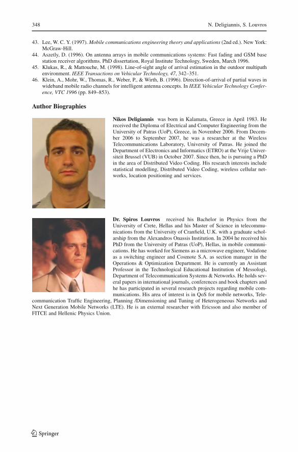
348 N. Deligiannis, S. Louvros
43. Lee, W. C. Y. (1997). Mobile communications engineering theory and applications (2nd ed.). New York:McGraw-Hill.
44. Aszetly, D. (1996). On antenna arrays in mobile communications systems: Fast fading and GSM basestation receiver algorithms. PhD dissertation, Royal Institute Technology, Sweden, March 1996.
45. Klukas, R., & Mattouche, M. (1998). Line-of-sight angle of arrival estimation in the outdoor multipathenvironment. IEEE Transactions on Vehicular Technology, 47, 342–351.
46. Klein, A., Mohr, W., Thomas, R., Weber, P., & Wirth, B. (1996). Direction-of-arrival of partial waves inwideband mobile radio channels for intelligent antenna concepts. In IEEE Vehicular Technology Confer-ence, VTC 1996 (pp. 849–853).
Author Biographies
Nikos Deligiannis was born in Kalamata, Greece in April 1983. Hereceived the Diploma of Electrical and Computer Engineering from theUniversity of Patras (UoP), Greece, in November 2006. From Decem-ber 2006 to September 2007, he was a researcher at the WirelessTelecommunications Laboratory, University of Patras. He joined theDepartment of Electronics and Informatics (ETRO) at the Vrije Univer-siteit Brussel (VUB) in October 2007. Since then, he is pursuing a PhDin the area of Distributed Video Coding. His research interests includestatistical modelling, Distributed Video Coding, wireless cellular net-works, location positioning and services.
Dr. Spiros Louvros received his Bachelor in Physics from theUniversity of Crete, Hellas and his Master of Science in telecommu-nications from the University of Cranfield, U.K. with a graduate schol-arship from the Alexandros Onassis Institution. In 2004 he received hisPhD from the University of Patras (UoP), Hellas, in mobile communi-cations. He has worked for Siemens as a microwave engineer, Vodafoneas a switching engineer and Cosmote S.A. as section manager in theOperations & Optimization Department. He is currently an AssistantProfessor in the Technological Educational Institution of Messologi,Department of Telecommunication Systems & Networks. He holds sev-eral papers in international journals, conferences and book chapters andhe has participated in several research projects regarding mobile com-munications. His area of interest is in QoS for mobile networks, Tele-
communication Traffic Engineering, Planning /Dimensioning and Tuning of Heterogeneous Networks andNext Generation Mobile Networks (LTE). He is an external researcher with Ericsson and also member ofFITCE and Hellenic Physics Union.
123