hvac - North Orange County Community College District
138
FULLERTON COLLEGE NORTH ORANGE COUNTY COMMUNITY COLLEGE DISTRICT DIVISION 23 06/2020 SECTION DESCRIPTION 23 0500 COMMON WORK RESULTS FOR HVAC 23 0511 SUPPLEMENTARY HVAC REQUIREMENTS 23 0512 HVAC PRODUCT SUBSTITUTIONS 23 0513 COMMON MOTOR REQUIREMENTS FOR HVAC EQUIPMENT 23 0514 EARTHWORK FOR MECHANICAL SYSTEMS 23 0515 ACCESS DOORS AND PANELS 23 0519 METERS AND GAGES 23 0520 VARIABLE FREQUENCY DRIVES AND MOTORS 23 0523 GENERAL DUTY VALVES FOR HVAC PIPING 23 0529 SUPPORTS AND ANCHORS 23 0548 VIBRATION CONTROL FOR HVAC 23 0553 HVAC IDENTIFICATION 23 0593 TESTING, ADJUSTING, AND BALANCING 23 0900 INSTRUMENTATION AND CONTROL FOR HVAC
-
Upload
khangminh22 -
Category
Documents
-
view
1 -
download
0
Transcript of hvac - North Orange County Community College District

FULLERTON COLLEGE NORTH ORANGE COUNTY COMMUNITY COLLEGE DISTRICT
DIVISION 23 06/2020
SECTION DESCRIPTION
23 0500 COMMON WORK RESULTS FOR HVAC 23 0511 SUPPLEMENTARY HVAC REQUIREMENTS 23 0512 HVAC PRODUCT SUBSTITUTIONS 23 0513 COMMON MOTOR REQUIREMENTS FOR HVAC EQUIPMENT 23 0514 EARTHWORK FOR MECHANICAL SYSTEMS 23 0515 ACCESS DOORS AND PANELS 23 0519 METERS AND GAGES 23 0520 VARIABLE FREQUENCY DRIVES AND MOTORS 23 0523 GENERAL DUTY VALVES FOR HVAC PIPING 23 0529 SUPPORTS AND ANCHORS 23 0548 VIBRATION CONTROL FOR HVAC 23 0553 HVAC IDENTIFICATION 23 0593 TESTING, ADJUSTING, AND BALANCING 23 0900 INSTRUMENTATION AND CONTROL FOR HVAC


NOCCCD – FULLERTON COLLEGE DIVISION 23 - HVAC
COMMON WORK RESULTS FOR HVAC 23 0500 - 1
SECTION 23 0500
COMMON WORK RESULTS FOR HVAC
PART 1 - GENERAL
1.01 RELATED DOCUMENTS
A. Drawings and general provisions of Contract, including General and Supplementary Conditions and Project specification Sections, apply to this and the other sections of Division 23.
B. This Division is an integrated whole comprising interrelated and interdependent Section
and shall be considered in its entirety in determining requirements of the Work.
C. Refer to other sections of this Division for additional requirements or information regarding the subjects of this Section.
1.02 SECTION INCLUDES
A. This Section includes general administrative and procedural requirements for HVAC
installations. The following administrative and procedural requirements are included in this Section to expand the requirements specified in Division 01: 1. Submittals. 2. Coordination drawings. 3. Record documents. 4. Maintenance manuals. 5. Rough-ins. 6. Mechanical installations. 7. Cutting and patching.
1.03 SUBMITTALS
A. General: Follow the procedures specified in Division 01.
B. HVAC submittals shall include shop drawings, product data, and samples per
requirements of each section of specification
C. HVAC Submittals and Product Data: Assemble “submittals” and “product data” into tabbed brochures according to main areas of work i.e. (HVAC); Temperature Control; Testing, Adjusting, and Balancing. 1. Assemble each brochure with tabbed separators for each Specification Section
where products are noted to be submitted, with separate tabs for each product listed.
2. Temperature "control shop drawings" may be submitted separately after preparations for review.
3. For items such as valves, hangers and accessories, indicate specific items and where they are to be used.
4. Contractor need only to submit for review those items specified to be submitted, unless requested by the Architect for special review.
D. All submittals shall be submitted in hard copy, electronic submittals are not acceptable.

NOCCCD – FULLERTON COLLEGE DIVISION 23 - HVAC
COMMON WORK RESULTS FOR HVAC 23 0500 - 2
E. Increase the number of HVAC related submittals including; shop drawings, product data, and samples submitted to allow for required distribution by one additional copy, which will be retained by the Mechanical Consulting Engineer.
F. Submit for review, only the specific items required in this Section or other Sections of
Division 23.
G. Additional submittals shall include, but not limited: 1. Air balance reports and equipment data record drawings. 2. Certification of completion of testing. 3. Certification of completion of operation instructions. 4. Operating instruction brochure. 5. Maintenance instruction brochures. 6. Equipment guarantees. 7. 1/4" = 1'-0" or larger scale layouts of "Equivalent" equipment or "Or Approved
Equal" equipment. 8. Coordination Drawings, where requested or required.
H. Submittal materials will be reviewed for substantial conformity with the intent of the
contract plans and specifications only. Such review does not indicate approval of dimensions, quantities, coordination with other trades, or work methods of the contractor, which are indicated thereon.
I. Additional copies may be required by individual sections of these specifications.
1.04 COORDINATION
A. The Contractor shall be totally responsible for coordinating the layout of all building
elements to avoid conflict of the work of the structural, mechanical, electrical systems, and architectural features of the building.
B. The cost of any extra work of any kind caused by a conflict due to this lack of
coordination shall be borne by the Contractor.
1.05 COORDINATION OF DRAWINGS
A. Prepare coordination drawings in accordance with requirements of Project Specification to a scale of 1/4" = 1'-0" or larger; detailing major elements, components, required clearances, and systems of HVAC equipment and materials in relationship with other systems, installations, and building components. Indicate locations where space is limited for installation and access and where sequencing and coordination of the installations are of importance to the efficient flow of the Work, including but not necessarily limited to the following: 1. Indicate the proposed locations of piping, ductwork, equipment, and materials.
Include the following: a. Clearances for servicing and maintaining equipment, including tube removal,
filter removal, and space for equipment disassembly required for periodic maintenance.
b. Equipment for connections and support details.
2. Prepare reflected ceiling plans to coordinate and integrate installations with other systems and components, such as, air outlets and inlets, light fixtures, communication systems components, sprinklers, and other ceiling-mounted items.

NOCCCD – FULLERTON COLLEGE DIVISION 23 - HVAC
COMMON WORK RESULTS FOR HVAC 23 0500 - 3
B. Submittal of "Or Equal" substitutions of equipment will not be reviewed unless accompanied by coordination drawings.
1.06 RECORD DOCUMENTS
A. Prepare record documents in accordance with the requirements of project
specification. In addition to the requirements of project specification, indicate the following installed conditions: 1. Record drawings of all installed as specified in Division 01 the locations and
invert elevations of underground installations.
1.07 MAINTENANCE MANUALS
A. Prepare maintenance manuals in accordance with Project Specifications and Division 23 Section "Supplementary HVAC Requirements.”
1.08 DELIVERY, STORAGE, AND HANDLING
A. Deliver products to the project properly identified with names, model numbers, types,
grades, compliance labels, mill certification, and other information needed for identification.
B. Provide for the safety and good condition of all materials and equipment until final acceptance by the owner. Protect all materials and equipment from any damage due to any cause what so ever. Provide adequate and proper storage facility during the progress of the work. Replace all damaged and defective work, material, or equipment, piping, ductwork, accessories, etc. from dirt, dust, and debris prior to and during installation of the work.
1.09 EQUIVALENT EQUIPMENT
A. In these specification and drawings, whenever more than one (1) manufacturer’s
product is specified, the manufacturer specified on the drawings and the first named product in these specifications is the basis of design and the use of alternate-named manufacturer’s product or substitutes may require modification in the design work and agency approvals. If such alternatives or substitutions are proposed by the contractor, contractor shall adhere to the following requirements: 1. Contractor shall clearly identify all proposed alternatives or substitutions in the
submittal package. 2. The Contractor shall assume all costs required to make all necessary revisions
and modifications of the contract documents resulting from the substitution or selection of an alternate manufacturer’s product, including all professional fees and the cost of DSA approval.
3. The Contractor shall assume all costs required for any additional modification to building structure, electrical and all other related construction costs resulting from the substitution or selection of an alternate manufacturer’s product
B. These specifications and/or drawings, names and specifies certain equipment in detail
which are the basis of design and are explained in paragraph 1.09, A. above. It also names alternate equipment by manufacturer, which is not considered to be a "substitution".
C. Submit equivalent equipment to the Architect for review per the requirements of
Division 01, and Section "Common Work Results for HVAC."

NOCCCD – FULLERTON COLLEGE DIVISION 23 - HVAC
COMMON WORK RESULTS FOR HVAC 23 0500 - 4
D. Equipment of Manufacturers named in Division 23 will be considered equivalent to that specified in detail and/or named on the drawings if: 1. Submit all required documentation and calculations to establish equivalency of
the proposed equipment and/or material to that specified in detail on the drawings.
2. The proposed equipment is of equivalent quality, capacity. 3. Equipment is as fully equipped, fits the space allotted, and has physical
configuration and weight similar to the equipment specified in detail.
E. A complete lay out of an equipment room or area must be submitted for equivalent equipment. Notice space limitations. Layouts to include plans and section views at a scale of not less than 1/4" = 1 ft.
F. The Architect shall determine the acceptability of "Equivalent Equipment."
PART 2 - PRODUCTS (Not Applicable)
PART 3 - EXECUTION
3.01 ROUGH-IN
A. Verify final locations for rough-ins with field measurements and with the requirements
of the actual equipment to be connected.
3.02 MECHANICAL INSTALLATIONS
A. General: Sequence, coordinate, and integrate the various elements of HVAC systems, materials, and equipment. Comply with the following requirements: 1. Coordinate HVAC systems, equipment, and materials installation with other
building components. 2. Verify all dimensions by field measurements. 3. Arrange for chases, slots, and openings in other building components during
progress of construction, to allow for HVAC installations. 4. Coordinate the installation of required supporting devices and sleeves to be set
in poured-in-place concrete and other structural components, as they are constructed.
5. Sequence, coordinate, and integrate installations of HVAC materials and equipment for efficient flow of the Work. Give particular attention to large equipment requiring positioning prior to closing in the building.
6. Where mounting heights are not detailed or dimensioned, install systems, materials, and equipment to provide the maximum headroom possible as required by California Building Code.
7. Coordinate connection of HVAC system with exterior underground and overhead utilities and services. Comply with requirements of governing regulations, franchised service companies, and controlling agencies. Provide required connection for each service.
8. Install systems, materials, and equipment to conform with approved submittal data, including coordination drawings, to greatest extent possible. Conform to arrangements indicated by the Contract Documents, recognizing that portions of the Work are shown only in diagrammatic form. Where coordination requirements conflict with individual system requirements, refer conflict to the Architect prior to commencement of installation.
9. Install systems, materials, and equipment level and plumb, parallel and perpendicular to other building systems and components.

NOCCCD – FULLERTON COLLEGE DIVISION 23 - HVAC
COMMON WORK RESULTS FOR HVAC 23 0500 - 5
10. Install all HVAC equipment to facilitate servicing, maintenance, and repair or replacement of equipment components in full compliance with California Building Code and the equipment manufacturer's recommendations. If the drawings or the manufacturer does not provide a specific space requirement for servicing equipment, provide as a minimum, horizontal distance of 36" from face of equipment to opposite vertical surface.
11. Install access panels or doors for all equipment and components which require access for adjustment and maintenance, where units are concealed behind finished surfaces.
12. Install systems, materials, and equipment giving right-of-way priority to systems required to be installed at a specified slope.
13. Any equipment located above a ceiling that has any component, which is serviceable shall be installed within 12" of the top of the ceiling.
3.03 CUTTING AND PATCHING
A. General: Perform cutting and patching in accordance with project specification. In
addition to the requirements specified in project specification, the following requirements apply: 1. Protection of Installed Work: During cutting and patching operations, protect
adjacent installations.
B. Perform cutting, fitting, and patching of HVAC equipment and materials required to: 1. Uncover Work to provide for installation of ill-timed Work. 2. Remove and replace defective work. 3. Remove and replace Work not conforming to requirements of the Contract
Documents. 4. Remove samples of installed Work as specified for testing. 5. Install equipment and materials in existing structures. 6. Upon written instructions from the Architect, uncover and restore Work to provide
for Architect/Engineer observation of concealed Work.
C. Cut, remove and legally dispose of selected HVAC equipment, components, and materials as indicated, including but not limited to removal of HVAC piping, refrigerant lines, heating units, and other HVAC items made obsolete by the new Work.
D. Protect the structure, furnishings, finishes, and adjacent materials not indicated or
scheduled to be removed
E. Provide and maintain temporary partitions or dust barriers adequate to prevent the spread of dust and dirt to adjacent areas. 1. Patch existing finished surfaces and building components using experienced
installers and new materials matching existing materials. For installer’s qualifications refer to the materials and methods required for the surface and building components being patched.
END OF SECTION 23 0500

NOCCCD – FULLERTON COLLEGE DIVISION 23 - HVAC
COMMON WORK RESULTS FOR HVAC 23 0500 - 6

NOCCCD – FULLERTON COLLEGE DIVISION 23 - HVAC
SUPPLEMENTARY HVAC REQUIREMENTS 23 0511-1
SECTION 23 0511
SUPPLEMENTARY HVAC REQUIREMENTS
PART 1 - GENERAL
1.01 SECTION INCLUDES
A. This Section specifies supplementary requirements for HVAC installations and includes requirements common to more than one section of Division 23. It expands and supplements the requirements specified in Section 230500 "Common Work Results for HVAC."
1.02 DESCRIPTION
A. Provide a complete and operable installation, including all labor, supervision, materials,
equipment, tools, apparatus, transportation, warehousing, rigging, scaffolding and other equipment and services necessary to accomplish the work in accordance with the intent and meaning of these drawings and specifications.
1.03 COORDINATION
A. Coordination of the work is the responsibility of the Contractor.
B. Contractor shall designate an individual competent and versed in the HVAC trades to
coordinate the HVAC work with the work of other trades.
1.04 DEFINITIONS (AS USED ON DIVISION 23 DRAWINGS AND HEREIN)
A. "Provide" means furnish, install and connect unless otherwise described in specific instances.
B. "Piping" means pipes, fittings, valves and all like pipe accessories connected thereto.
C. "Ductwork" means ducts, plenums, compartments, or casings including the building
structure, which are used to convey or contain air.
D. "Extend", "Submit", "Repair" and similar words mean that the Contractor (or his designated subcontractor) shall accomplish the action described.
E. "Codes" or "Code" means all codes, laws, statutes, rules, regulations, ordinances,
orders, decrees, and other requirements of all legally constituted authorities and public utility franchise holders having jurisdiction.
F. "Products", "Materials" and "Equipment" are used interchangeably and mean materials,
fixtures, equipment, accessories, etc.
G. "Utility Areas" are defined as mechanical, electrical, janitorial, and similar rooms or spaces which are normally used or occupied only by custodial or maintenance personnel. "Public Areas" are defined as the rooms or spaces, which are not included in the utility areas definition.
H. "Building Boundary" includes concrete walkways immediately adjacent to the building structure.

NOCCCD – FULLERTON COLLEGE DIVISION 23 - HVAC
SUPPLEMENTARY HVAC REQUIREMENTS 23 0511-2
I. "Below Grade" means buried in the ground.
J. "Substantial Completion" means all components of all systems are functioning but lacking in final adjustment.
K. Pressure rating specified (such as for valves and the like) means design working
pressure for and with references to the fluid, which the device will serve.
1.05 RELATED WORK
A. Coordination: Refer to Architectural, HVAC, Plumbing, Civil, Structural, and Electrical Drawings for the construction details and coordinate the work of this Division with that of other Divisions. Order the work of this Division so that progress will harmonize with that of other Divisions and all work will proceed expeditiously. The work of this Division shall include direct responsibility for the correct placing and connection of HVAC work in relation to the work of other Divisions.
B. Examine other Divisions for work related to the Work of this Division, especially Divisions
22 and 26.
1.06 EXISTING CONDITIONS
A. Visit the site prior to bidding and investigate the existing conditions, which affect or will be affected by the work of this Division. Become thoroughly familiar with the working conditions and take into account any special or unusual features peculiar to this job. By the act of submitting a Bid, the Contractor will be deemed to have complied with the foregoing, to have accepted such conditions, and to have made allowance therefore in preparing his Bid.
B. The locations of existing concealed utility lines are shown in accordance with reference
data received by the Architect. The Architect does not guarantee the accuracy of such data. The points of connection are therefore approximate and the Bidder shall include adequate funds in his Bid to cover costs of connection regardless of their exact location.
C. Exercise extreme caution during trenching operations. Repair the damage caused by
such operations to existing utility lines at no cost to the Owner, whether the lines are shown on drawings or not.
1.07 DRAWINGS AND SPECIFICATIONS
A. These drawings and specification do not include necessary components for construction
safety.
B. All provisions shall be deemed mandatory except as expressly indicated as optional by the word "may" or "option".
C. Except where dimensioned, the drawings relating to this division are a diagrammatic
presentation of the design concept, which indicates the general area where piping and ductwork is to be run. The drawings do not necessarily indicate any and all offsets and configurations required for coordination with other trades. The contractor is responsible for the correct placing of his work, and the proper location and connection of his work in relation to the work or other trades.

NOCCCD – FULLERTON COLLEGE DIVISION 23 - HVAC
SUPPLEMENTARY HVAC REQUIREMENTS 23 0511-3
1.08 PERMITS AND INSPECTIONS
A. Obtain, schedule and pay for permits, licenses, approvals, tests, and inspections required by legally constituted authorities and public utility franchise holders having jurisdiction over the work.
B. Afford the Architect's representative every facility for evaluating the skill and competence
of the mechanics and to examine the materials. Concealed work shall be reopened when so directed during his periodic visits.
1.09 CODES AND REGULATIONS
A. By submitting a Bid, Contractor is deemed to represent himself as competent to
accomplish the work of this Division in conformance with applicable Codes. In case of conflict between the Contract Documents and Code requirements, the Codes shall take precedence. Should such conflicts appear, cease work on the parts of the contract affected and immediately notify the Architect in writing. It shall be the Contractor's responsibility to correct, at no cost to the Owner, any work he executes in violation of Code requirements. Specific references to codes elsewhere in this Division are either to aid the Contractor in locating applicable information or to deny him permission to use options, which are permitted by Codes.
B. Applicable Codes: Current edition unless otherwise noted.
1. All local codes; city and/or county as applicable. 2. OSHA requirements 3. California Building Code 4. California Code of Regulations (CCR) Titles (as applicable) 5. Fire Marshal Regulations 6. State, County, City Health Department Ordinances and Regulations 7. Regulations of all other authorities having jurisdiction. 8. California Mechanical Code. 9. California Plumbing Code. 10. California Fire Code.
C. Where conflict or variation exists amongst Codes, the most stringent shall govern.
1.10 RECORD AND DOCUMENTATION
A. Accumulate the following and deliver to the Owner's representative prior to final
acceptance of the work. 1. Record (As-Built) Drawings:
a. Maintain in good order in the field office a complete set of prints for all work being done under Division 23. Update the drawings daily with neat and legible annotations in red ink showing the work as actually installed.
b. The actual size, location and elevation of all buried lines, valve boxes, manholes, monuments, and stubouts shall be accurately located and dimensioned from building walls or other permanent landmarks.
c. Furnish the original marked up AS-Built drawings and an electronic copy in AutoCAD-14 format.
2. Operation and Maintenance Manual: Furnish an operation and maintenance manual covering the stipulated HVACsystems and equipment. Seven copies of the manual, bond in hardback binders or an approved equivalent shall be provided to the Architect.

NOCCCD – FULLERTON COLLEGE DIVISION 23 - HVAC
SUPPLEMENTARY HVAC REQUIREMENTS 23 0511-4
3. Furnish one complete manual prior to the time that system or equipment tests are performed.
4. Furnish the remaining manuals before the contract is completed. 5. The following identification shall be inscribed on the cover:
OPERATION AND MAINTENANCE MANUAL
PROJECT TITLE . . . . . . . . . .
CONTRACTOR NAME & CONTACT INFORMATION
6. Provide a table of contents. a. Insert tab sheets to identify discrete subjects. b. Instruction sheets shall be legible and easily understood, with large sheets
of drawings folded in. c. The manual shall be complete in all respects for all materials, piping,
valves, devices and equipment, controls, accessories and appurtenances stipulated. Include as a minimum the following: 1) Updated approved materials lists, shop drawings and catalog
information of all items of HVAC system equipment. 2) System layout showing piping, valves and controls. 3) Wiring and control diagrams with data to explain detailed operation
and control of each component. 4) A control sequence describing start-up, operation and shutdown. 5) Detailed description of the function of each principal component of
the system. 6) Procedure for starting. 7) Procedure for operating. 8) Shut-down instructions. 9) Installation instructions. 10) Adjustments, maintenance and overhaul instructions. 11) Lubrication schedule including type, grade, temperature range and
frequency. 12) Safety precautions, diagrams and illustrations. 13) Test procedures. 14) Performance data. 15) Parts lists, with manufacturer's names and catalog numbers. 16) Preventive maintenance schedule. 17) Service organization with name, address and telephone number. 18) Valve identification chart and schedule. 19) ASME certificates. 20) Air balance report. 21) Hydronic balance report.
B. Standards Compliance: Where equipment or materials are specified to conform to
requirements of standards of recognized technical or industrial organizations such as American National Standards Institute (ANSI) American Society for Mechanical Engineers (ASME) American Society of Heating, Refrigeration and Air Conditioning Engineers (ASHRAE), American Society for Testing Materials (ASTM), Underwriters Laboratories (UL), American Gas Association (AGA), American Refrigeration Institute (ARI), or National Electrical Manufacturer's Association (NEMA), that use a label or published listing as a method of indicating compliance, proof of such conformance shall be submitted and approved. The label or listing of the specified organization will be acceptable evidence.

NOCCCD – FULLERTON COLLEGE DIVISION 23 - HVAC
SUPPLEMENTARY HVAC REQUIREMENTS 23 0511-5
C. Certificates of Conformance or Compliance: Submit original and not pre-printed certifications. Do not make statements in the certifications that could be interpreted to imply that the product does not meet all requirements.
D. Certified Test Reports: Certified Test Reports are reports of tests conducted on
previously manufactured materials or equipment identical to that proposed for use. Before delivery of materials and equipment, submit certified copies of test reports specified in the individual sections.
E. Factory Tests: Factory tests are tests, which are required to be performed on the actual
materials or equipment, proposed for use. Submit results of the tests in accordance with the requirements for laboratory test results of this Contract.
F. Permits and Certificates of Inspection: Furnish the originals.
G. Testing procedures and test results required in this and other sections. Furnish 2 copies.
H. Other data required by other sections of this Division. Furnish 2 copies.
1.11 CONSTRUCTION COST BREAKDOWN
A. Prepare and submit for review a construction cost breakdown for the major subdivisions
of the HVAC work in accordance with General and Supplemental Conditions and Project Specification.
B. Subdivide each item on the breakdown into two headings: labor and materials. Include
overhead and profit in each entry.
C. Submit one copy of the breakdown directly to the Engineer and the remaining copies sent through regular channels.
1.12 TOOLS
A. Provide all special tools needed for proper operation and routine adjustment and
maintenance of systems and equipment. Deliver tools to Owner's representative and request a receipt for same.
1.13 WARRANTIES
A. Refer to Project Specification for procedures and submittal requirements for warranties.
Refer to individual equipment specifications for warranty requirements.
B. Where periods more than one year are specified in the specifications, such longer periods shall govern. However, when any component fails at any time during this period, the warranty period for such component and all other components, which are inactive because of, said failure shall be suspended. The warranty period for such components shall resume to run for the remaining portion of the warranty period when failed component is completely repaired and in operation; however, in no case shall the resumed portion of the warranty period be less than 3 months in duration.
NOCCCD – FULLERTON COLLEGE DIVISION 23 - HVAC
SUPPLEMENTARY HVAC REQUIREMENTS 23 0511-6
C. Neither payment for work, nor total or partial occupancy of work by the Owner, within or prior to the warranty period specified, shall be construed as acceptance of faulty work or shall condone any negligence or omission of Contractor in doing the work.
D. Compile and assemble the warranties specified in Division 23, into a separated set of
vinyl covered, three ring binders, tabulated and indexed for easy reference.
E. Provide complete warranty information for each item to include product or equipment to include date of beginning of warranty or bond; duration of warranty or bond; and names and addresses, and telephone numbers and procedures for filing a claim and obtaining warranty services.
1.14 SEISMIC RESTRAINT
A. Provide seismic restraint for HVAC equipment, piping, and ductwork.
B. Contractor shall submit certification of suitability of seismic restraint methods signed by
Licensed Structural Engineer registered in State of California.
C. Contractor may refer to details applicable in the SMACNA, "GUIDELINES FOR SEISMIC RESTRAINT OF HVAC SYSTEMS", using the 'g' forces for "other buildings" classification CCR Title 24 all such details shall be DSA approved. Deliver a copy of these Guidelines to the Owner's Resident Inspector.
1.15 SYSTEM OPERATIONAL TESTS
A. The Contractor shall inform the Owner one week prior to start of testing in order that the
Owner's representative may be present.
B. After balancing and prior to final inspection, the contractor shall operate all systems continuously trouble free and stable for a minimum period of fourteen (14) consecutive days including Saturday and Sunday. Each day shall be a minimum of an 8-hour day. Should a problem arise, the fourteen (14) day period shall be restarted and repeated until successfully operated for full 14 days. A written report certified by the Owner's representative shall indicate the successful completion of a stable and trouble free 14- day period.
PART 2 - PRODUCTS
2.01 MATERIALS AND EQUIPMENT
A. Standard Products: Materials and equipment shall be essentially the standard cataloged
products of manufacturers regularly engaged in production of such materials or equipment and shall be their latest standard designs that comply with the specification requirements.
B. Materials and equipment shall duplicate items that have been in satisfactory commercial
or industrial use at least two years prior to bid opening, unless more stringent requirements are specified. Where two or more units of the same type of equipment are required, these units shall be products of a single manufacturer. The components thereof, however, are not required to be exclusively of the same manufacturer.

NOCCCD – FULLERTON COLLEGE DIVISION 23 - HVAC
SUPPLEMENTARY HVAC REQUIREMENTS 23 0511-7
C. Each major component of equipment shall have manufacturer's name, address, model, and serial number on a nameplate securely affixed in a conspicuous place. The nameplate of the distributing agent will not be acceptable.
D. In these specification and drawings, whenever more than one (1) manufacturer’s product
is specified, the manufacturer specified on the drawings and the first named product in these specifications is the basis of design and the use of alternate-named manufacturer’s product or substitutes shall comply with the requirements of Section 23 0500.
2.02 PRODUCT LISTING
A. When two or more items of same material or equipment are required (pipe and fittings,
pumps, valves, air conditioning units, etc.) they shall be of the same manufacturer. Product manufacturer uniformity does not apply to raw materials, bulk materials, sheet metal, wire, steel bar stock, welding rods, solder, fasteners, and similar items used in Work, except as otherwise indicated.
2.03 NAMEPLATE DATA
A. Provide permanent operational data nameplate on each item of power operated
HVACequipment, indicating manufacturer, product name, model name, serial number, capacity, operating and power characteristics, labels of tested compliances, and similar essential data. Locate nameplates in an accessible location.
2.04 SUBSTITUTIONS
A. General: Submittals of "Substitutions" shall be in accordance with requirements of
Division 01.
B. By proposing a substitution, it is deemed that the Contractor shall bear the cost of any and all design and construction changes (whether architectural, structural, electrical, HVAC and Plumbing) necessary to accommodate the substitution, if said substitution is accepted.
C. Specific: Refer to Specification Sections 230500 & 230512 for additional requirements.
2.05 SUBMITTALS
A. General: Make submittals in accordance with requirements of Division 01.
B. Specific: Refer to Specification Sections 230500 for additional requirements.
PART 3 - EXECUTION
3.01 WORKMANSHIP AND INSTALLATION METHODS
A. Workmanship shall be in the best standard practice of the trade.
B. Install equipment in accordance with the manufacturer's instructions and
recommendations unless otherwise noted or specified.

NOCCCD – FULLERTON COLLEGE DIVISION 23 - HVAC
SUPPLEMENTARY HVAC REQUIREMENTS 23 0511-8
3.02 TESTS
A. General: 1. Demonstrate that all components of the work of this Division have been provided
and that they operate in accordance with the Contract Documents. 2. Provide instruments and personnel for tests and demonstrations. Submit signed
test results.
B. Specific: Refer to the other sections of this Division for test requirements.
3.03 DELIVERY, HANDLING, STORAGE OF MATERIALS AND PROTECTION OF WORK
A. Protect materials against dirt, water, chemical and mechanical damages both while in storage and during construction.
B. Cover materials in such a manner that no finished surfaces will be damaged, marred or
splattered with plaster or paint, and all moving parts will be kept clean and dry.
C. Replace or refinish any damaged materials including fronts of control panels, ductwork fittings, and shop-fabricated ductwork.
D. Air distribution systems shall be aggressively protected from dust during the
construction process to ensure that no contamination of the duct system occurs.
E. The use of permanently installed AHUs and associated air distribution systems for temporary heating and cooling during construction is prohibited.
F. Keep cabinets and other openings closed to prevent entry of foreign matter.
G. Specific: Refer to other sections of this Division for additional requirements.
3.04 PROJECT CONDITIONS
A. Check and coordinate for clearance, accessibility and placement of equipment either by
going through openings provided or by placing equipment during construction. Ordering of equipment to be shipped disassembled, or disassembly of equipment at Project Site and reassembly of equipment to accomplish this requirement shall be executed without additional cost. Where provided openings are inadequate to accommodate equipment, provide new openings and restoration of same, all at no additional cost. Obtain written approval for new openings before proceeding.
B. Verify location of all equipment within finished spaces with the Architectural Drawings. In
the event that HVAC Drawings do not indicate exact locations, or are in conflict with the Architectural Drawings, obtain information regarding proper locations. Installation of work without proper instruction under such circumstances will result in relocation of work, when directed, without additional cost.

NOCCCD – FULLERTON COLLEGE DIVISION 23 - HVAC
SUPPLEMENTARY HVAC REQUIREMENTS 23 0511-9
3.05 INSTRUCTION TO OWNER PERSONNEL
A. Contractor shall furnish, without additional expense to the Owner, the services of competent instructors who will give full instruction to the designated personnel in the adjustment, operation, and maintenance, including pertinent safety requirements, of the equipment or system specified. Each instructor shall be thoroughly familiar with all parts of the installation and shall be trained in operating theory as well as practical operation and maintenance of work. Instruction shall be given at the Owner's convenience. The number of man-days (eight-hours) of instruction furnished shall be as specified in other sections. When more than four man-days of instruction are specified, approximately half of the time shall be used for classroom instruction. All other time shall be used for instruction with the equipment or system. When significant changes or modifications are made under the terms of the contract, provide additional instructions to acquaint the operating personnel with the changes or modifications.
B. Contractor shall videotape, both visual and audio, instruction to Owner's personnel on
the maintenance and operation of the HVACsystems.
C. Submit certification, signed by Owner's agent that instructions have been completed and the videotape has been reviewed and delivered to the Owner.
D. Printed operating instructions and a copy of wiring diagrams are to be mounted in all
equipment areas, framed and behind glass or encased in plastic. Printed operating instructions shall include steps for starting up and securing equipment. As a precedent to final acceptance four (4) copies of instructions are to be submitted to the Architect for review. Contractor shall turn over to Owner in a neat brochure form, equipment guarantee and maintenance instructions.
3.06 CLEANING
A. Cleaning shall be done as the work proceeds. Periodically remove waste and debris to
keep the site as clean as is practical.
B. Refer the Division 01 for general requirements for cleaning.
C. Leave exposed parts of the HVAC work in a neat, clean and usable condition, with painted surfaces unblemished and plated metal surfaces polished.
D. Thoroughly clean all materials, equipment and appliances. Clean and prepare all
surfaces to be painted. Clean the entire premises of unused materials, debris, spots and marks to the satisfaction of the Architect.
E. Remove, thoroughly clean and replace all strainers and automatic valves after the
system has been put in operation until system is clear of all foreign matter and repeat this operation after ten (10) days and again after the system has been in operation thirty (30) days. Submit certification that this operation has been completed.

NOCCCD – FULLERTON COLLEGE DIVISION 23 - HVAC
SUPPLEMENTARY HVAC REQUIREMENTS 23 0511-10
3.07 SAFETY REQUIREMENTS
A. Enclose and guard belts, pulleys, chains, gears, couplings, projecting setscrews, keys, and other rotating parts in accordance with OSHA requirements. Insulate, guard, and cover any high-temperature equipment and piping so located as to endanger personnel or create a fire hazard.
END OF SECTION 23 0511

NOCCCD – FULLERTON COLLEGE DIVISION 23 - HVAC
HVAC PRODUCT SUBSTITUTIONS 23 0512 - 1
SECTION 23 0512
HVAC PRODUCT SUBSTITUTIONS
PART 1 - GENERAL
1.01 SECTION INCLUDES
A. This Section specifies administrative and procedural requirements for handling requests made after award of the Contract for substitutions of products specified in Division 23.
1.02 RELATED SECTIONS
A. Procedure for Contractor's construction Schedule and the Schedule of Submittals are
included under Division 01.
B. Standards: Refer to Division 01 for applicability of industry standards to products specified.
C. Procedural requirements governing the Contractor's selection of products and product options are included under Division 01.
D. Refer to Division 01 for Products and Substitutions.
E. Refer to Sections 230500 and 230511 for additional requirements.
1.03 DEFINITIONS
A. "Products" is defined to include purchased items for incorporation into the work, regardless of whether specifically purchased for project or taken from Contractor's stock of previously purchased products. "Materials" is defined as products which must be substantially cut, shaped, worked, mixed, finished, refined or otherwise fabricated, processed, installed or applied to form units of work.
B. "Equipment" is defined as products with operational parts, regardless of whether motorized or manually operated, and particularly including products with service connections (wiring, piping, etc.). Definitions in this paragraph are not intended to negate the meaning of other terms used in contract documents, including "specialties", "systems", "structure", "finishes", "accessories", "furnishings", "special construction", and similar terms, which are self-explanatory and have recognized meanings in the construction industry.
1.04 SUBSTITUTIONS
A. The requirements for substitutions do not apply to specified Contractor options on
products and construction methods. Revisions to contract documents, where requested by Owner, Architect or Engineer, are "changes" not "substitutions". Substitutions requested during bidding period, which have been accepted prior to Contract Date, are included in contract document and are not subject to requirements for substitutions as specified herein. Contractor's determination of and compliance with governing regulations and orders issued by governing authorities do not constitute "substitutions"; and do not constitute a basis for change orders, except as provided for in contract documents.

NOCCCD – FULLERTON COLLEGE DIVISION 23 - HVAC
HVAC PRODUCT SUBSTITUTIONS 23 0512 - 2
Otherwise, contractor's requests of changes in products, materials and methods of construction required by contract documents are considered requests for "substitutions", and are subject to requirements hereof.
B. Conditions: The Contractor's substitution request will be received and considered by the Architect when one or more of the following conditions are satisfied, as determined by the Architect; otherwise requests will be returned without action except to record noncompliance with these requirements. 1. Extensive revisions to Contract Documents are not required. 2. Proposed changes are in keeping with the general intent of Contract Documents. 3. The request is directly related to an "or approved equal" clause or similar
language in the Contract Documents. 4. All costs required to make all necessary revisions and modifications to the
contract documents resulting from the substitution, including but not limited to, all professional fees and the cost of approval from jurisdiction(s) having authority including Division of the State Architect “DSA” will be the Contractor’s responsibility.
5. All costs required to make all necessary revisions and modifications to the building structure, electrical and all other related construction costs resulting from the substitution, including but not limited to, material, products, equipment, testing, and inspection will bethe Contractor’s responsibility.
6. The specified product or method of construction cannot receive necessary approval by a governing authority, and the requested substitution can be approved.
7. Contractor will coordinate the installation of the accepted substitute, making such changes as may be required for the work to be complete in all respects.
8. Contractor certifies that the substitution is not heavier than the specified item and does not necessitate any structural and electrical redesign; will fit within the room or area designed for the specified item; and will not exceed any maximum dimensions specified or shown on the original contract Documents. All roof mounted equipment must be less than or equal to the maximum height dimension from the finished roof as shown on the drawings.
9. Contractor represents that he has personally investigated the proposed substitute product and determined that it is equal or superior in all respects to that specified.
10. Contractor represents that he will provide the same warranty for the substitution that he would for that specified.
1.05 SUBMITTALS
A. Requests for Substitutions: Any request for substitution shall follow the guidelines of
Substitution Requirements in Division 01, Section 230500 and 230511.
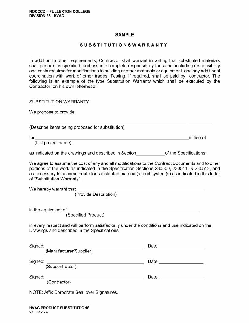
B. Substitution Warranty: All submittals of Request for Substitutions under the General and Supplementary Conditions of this Section shall be accompanied by a completely executed (filled out) and signed, Substitution Warranty in the form entitled "Substitution Warranty", bound herein. Substitutions will not be accepted without the Substitution Warranty. In addition to other requirements, Contractor shall warrant in writing on his own letterhead that substituted materials shall perform as specified, and assume complete responsibility for same, including responsibility and costs required for modifications to building or other materials or equipment, and any additional coordination with work of other trades. Testing, if required, shall be paid by Contractor.

NOCCCD – FULLERTON COLLEGE DIVISION 23 - HVAC
HVAC PRODUCT SUBSTITUTIONS 23 0512 - 3
C. Responsibility of Contractor: The contractor shall be solely and directly responsible for fitting accepted substitute material and equipment into the available space in a manner acceptable to the Architect, and for the proper operation of the substituted equipment with all other equipment with which it may be associated. The Contractor shall bear all costs of meeting the above requirements for presenting a proposed substitution, and if the substitution is accepted, he must bear all costs involved.
D. Submit the following as part of the Request for Substitutions: 1. Data showing proposed equipment is "equal" to that specified and is fully
equipped, fits the space allotted and has physical configuration and weight similar to the equipment specified in detail.
2. A complete layout, where applicable, of equipment room or area must be submitted for equipment proposed in "Request for Substitution". Submittal shall conform to requirements of Division 01 and Section 230500 "Common Work Results For HVAC" as it applies to "Coordination Drawings."
3. Seismic Restraint: Where seismic restraint is required for products or equipment as specified, methods of seismic restraint signed by licensed Structural Engineer registered in the State of California, shall be submitted for review to the Division of the State Architect.
1.06 ARCHITECT'S ACTION
A. The Architect may request additional information or documentation necessary for
evaluation of the request. Requests, by the Architect, for additional information or documentation will be in accordance with Division 01 requirements. The Architect will notify the Contractor of acceptance or rejection of the proposed substitution. If a decision on use of a proposed substitute cannot be made or obtained within the time allocated, Contractor shall use the “Bases of Design” product specified by name in the contract documents. Acceptance will be in the form of a Change Order.
PART 2 - PRODUCTS
2.01 SUBSTITUTIONS
A. Substitutions shall conform to the product requirements for the specified products or
equipment.
PART 3 - EXECUTION (Not Applicable.)
END OF SECTION 23 0512
NOCCCD – FULLERTON COLLEGE DIVISION 23 - HVAC
HVAC PRODUCT SUBSTITUTIONS 23 0512 - 4
SAMPLE
S U B S T I T U T I O N S W A R R A N T Y
In addition to other requirements, Contractor shall warrant in writing that substituted materials shall perform as specified, and assume complete responsibility for same, including responsibility and costs required for modifications to building or other materials or equipment, and any additional coordination with work of other trades. Testing, if required, shall be paid by contractor. The following is an example of the type Substitution Warranty which shall be executed by the Contractor, on his own letterhead:
SUBSTITUTION WARRANTY
We propose to provide
(Describe items being proposed for substitution)
for in lieu of (List project name)
as indicated on the drawings and described in Section of the Specifications.
We agree to assume the cost of any and all modifications to the Contract Documents and to other portions of the work as indicated in the Specification Sections 230500, 230511, & 230512, and as necessary to accommodate for substituted material(s) and system(s) as indicated in this letter of “Substitution Warranty”.
We hereby warrant that
(Provide Description)
is the equivalent of (Specified Product)
in every respect and will perform satisfactorily under the conditions and use indicated on the Drawings and described in the Specifications.
Signed: (Manufacturer/Supplier)
Signed:
(Subcontractor)
Signed: (Contractor)
NOTE: Affix Corporate Seal over Signatures.
Date:
Date:
Date:

NOCCCD – FULLERTON COLLEGE DIVISION 23 - HVAC
COMMON MOTOR REQUIREMENTS FOR HVAC EQUIPMENT 23 0513-1
SECTION 23 0513
COMMON MOTOR REQUIREMENTS FOR HVAC EQUIPMENT
PART 1 - GENERAL
1.01 SECTION INCLUDES
A. This Section specifies the basic requirements for electrical components, which are an integral part of packaged HVAC equipment. These components include, but are not limited to factory-installed motors, starters, and disconnect switches furnished as an integral part of packaged HVACequipment.
B. Specific electrical requirements (i.e. horsepower and electrical characteristics) for
HVAC equipment are scheduled on Drawings.
C. All motors, power driven equipment and automatic control equipment, except motor starters as hereinafter set forth required and connected with the work of this section of the specifications are to be furnished and installed under Division 23.
D. Control low (24V) and control line (120V) voltage wiring, conduit and related switches
and relays required for the automatic control and/or interlock of motors and equipment includes final connection, are to be furnished and installed under Division 23. Materials and installation to conform to Class 1 or 2, CAC Title 24, Article E725, and as restricted under Division 26 of these specifications.
E. Power wiring, conduit, outlets, disconnect switches, motor starters and motor-rated
contactors, and making of final connections, except as hereinafter specified, are to be furnished and installed under the Division 26 of these Specification.
F. All power supply wiring for providing a power source to control dampers, control valves,
VAV boxes, control transformers, etc., shall be furnished and installed under Division 23.
G. Identify circuits and equipment as outlined in the Electrical Sections of these
Specifications.
H. Coordinate requirements for underground conduit only between buildings for control interlocks shown on the drawings. This conduit to be furnished and installed under Division 26 of these Specifications.
I. Space provisions have been made on electrical panels for control power source.
1.02 RELATED SECTIONS
A. Separate electrical components and materials required for field installation and
electrical connections are specified in Division 26.
B. This section applies to all Division 23 sections specifying packaged HVAC equipment.

NOCCCD – FULLERTON COLLEGE DIVISION 23 - HVAC
COMMON MOTOR REQUIREMENTS FOR HVAC EQUIPMENT 23 0513-2
1.03 REFERENCES
A. Conform to all AFBMA, IEEE, NEMA, NFPA, and California Title 24 standards, codes, and regulations.
B. NEMA Standards MG 1: Motors and Generators.
C. NEMA Standards ICS 2: Industrial Control Devices, Controllers, and Assemblies.
D. NEMA Standard 250: Enclosures for Electrical Equipment.
E. NEMA Standard KS 1: Enclosed Switches.
F. Comply with National Electrical Code (NFPA 70).
G. AFBMA 9 - Load Ratings and Fatigue Life for Ball Bearings.
H. AFBMA 11 - Load Ratings and Fatigue Life for Roller Bearings.
I. IEEE 112 - Test Procedure for Polyphase Induction Motors and Generators
1.04 SUBMITTALS
A. No separate submittal is required. Submit product data for motors, starters, and other electrical components with submittal data required for the equipment for which it serves, as required by the individual equipment specification sections.
1.05 QUALITY ASSURANCE
A. Manufacturer Qualifications: Experienced in manufacturing the products specified in
this Section with minimum five years documented product development, testing, and manufacturing experience.
B. Electrical components and materials shall be UL labeled.
PART 2 - PRODUCTS
2.01 MOTORS
A. Provide all motors necessary for equipment under the HVAC Work. See Electrical Drawings for voltage and phase of electrical services.
B. The following are basis requirements for simple or common motors. For special
motors, more detailed and specific requirements are specified in the individual equipment specifications. 1. Torque characteristics shall be sufficient to satisfactorily accelerate the driven
loads. 2. Motor sizes shall be large enough so that the driven load will not require the
motor to operate in the service factor range. 3. 2-speed motors shall have 2 separate windings on poly-phase motors. 4. Temperature Rating: As a minimum motors shall be rated for 40 degree C
environment with maximum 50 degree C temperature rise for continuous duty at full load (Class A Insulation).
5. Starting capability: Frequency of starts as indicated by automatic control system, and not less than 5 evenly time spaced starts per hour for manually controlled motors.

NOCCCD – FULLERTON COLLEGE DIVISION 23 - HVAC
COMMON MOTOR REQUIREMENTS FOR HVAC EQUIPMENT 23 0513-3
6. Service Factor: 1.23 for poly-phase motors and 1.35 for single-phase motors. 7. Motor construction: NEMA Standard MG 1, general purpose, continuous duty,
Deign "B", except "C" where required for high starting torque. a. Frames: NEMA Standard No. 48 or 54; use driven equipment
manufacturer's standards to suit specific application. b. Bearings:
1) Ball or roller bearings with inner and outer shaft seals. 2) Re-greasable bearings, except permanently sealed where motor is
normally inaccessible for regular maintenance. 3) Bearings designed to resist thrust loading where belt drives or other
drives produce lateral or axial thrust in motor. 4) Bearings for fractional horsepower, light duty motors, sleeve type
bearings are permitted.
c. Enclosure Type: 1) Open drip-proof motors for indoor use where satisfactorily housed or
remotely located during operation. 2) Guarded drip-proof motors where exposed to contact by employees
or building occupants. 3) Weather protected Type I for outdoor use, Type II where not housed
(Epoxy encapsulated or TEFC). d. Overload protection: Polyphase built-in thermal overload protection and,
where indicated, internal sensing device suitable for signaling and stopping motor at starter. Single phase, provide thermal overload protection.
e. Noise rating: "Quiet". f. Efficiencies shall be guaranteed minimum values in accordance with the
following tabulation. Efficiencies shall be established in accordance with NEMA Test Standards MG1-12.53A using IEEE Test Procedure 112, Method B:
HP EFFICIENCY 1 - 2 81.5 3 – 5 86.5 7-1/2 - 10 90.6 15 - 30 92.0
g. Nameplate: Indicate the full identification of manufacturer, ratings,
characteristics, construction, special features and similar information. h. Provide all motors with junction boxes or terminals boxes and provide
adjustable slide rails for all motors with belt drives. i. Motors rated 1 HP and larger shall have shaft, bearings and etc. capable of
operating with multiple grooved sheaves and two or more belts. j. V Type Belt Drives: Drives requiring not more than 2 belts; variable pitch
type; size for mid-point of operating range. Drives requiring 3 or more belts; nonadjustable constant speed type. Provide belts in matched sets.
2.02 MOTOR STARTERS
A. Unless provided as part of packaged HVAC equipment or otherwise indicated, starters
for motors will be provided under Division 26. Provide to Division 26 the data necessary for motor starter heater sizing for all motors.
NOCCCD – FULLERTON COLLEGE DIVISION 23 - HVAC
COMMON MOTOR REQUIREMENTS FOR HVAC EQUIPMENT 23 0513-4
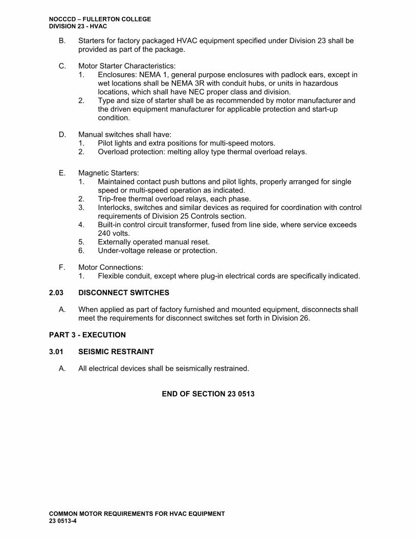
B. Starters for factory packaged HVAC equipment specified under Division 23 shall be provided as part of the package.
C. Motor Starter Characteristics:
1. Enclosures: NEMA 1, general purpose enclosures with padlock ears, except in wet locations shall be NEMA 3R with conduit hubs, or units in hazardous locations, which shall have NEC proper class and division.
2. Type and size of starter shall be as recommended by motor manufacturer and the driven equipment manufacturer for applicable protection and start-up condition.
D. Manual switches shall have:
1. Pilot lights and extra positions for multi-speed motors. 2. Overload protection: melting alloy type thermal overload relays.
E. Magnetic Starters:
1. Maintained contact push buttons and pilot lights, properly arranged for single speed or multi-speed operation as indicated.
2. Trip-free thermal overload relays, each phase. 3. Interlocks, switches and similar devices as required for coordination with control
requirements of Division 25 Controls section. 4. Built-in control circuit transformer, fused from line side, where service exceeds
240 volts. 5. Externally operated manual reset. 6. Under-voltage release or protection.
F. Motor Connections:
1. Flexible conduit, except where plug-in electrical cords are specifically indicated.
2.03 DISCONNECT SWITCHES
A. When applied as part of factory furnished and mounted equipment, disconnects shall meet the requirements for disconnect switches set forth in Division 26.
PART 3 - EXECUTION
3.01 SEISMIC RESTRAINT
A. All electrical devices shall be seismically restrained.
END OF SECTION 23 0513
NOCCCD – FULLERTON COLLEGE DIVISION 23 - HVAC
EARTHWORK FOR MECHANICAL SYSTEMS 23 0514 - 1
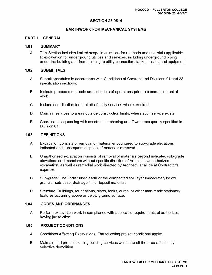
SECTION 23 0514
EARTHWORK FOR MECHANICAL SYSTEMS
PART 1 – GENERAL
1.01 SUMMARY
A. This Section includes limited scope instructions for methods and materials applicable to excavation for underground utilities and services, including underground piping under the building and from building to utility connection, tanks, basins, and equipment.
1.02 SUBMITTALS
A. Submit schedules in accordance with Conditions of Contract and Divisions 01 and 23
specification sections.
B. Indicate proposed methods and schedule of operations prior to commencement of work.
C. Include coordination for shut off of utility services where required.
D. Maintain services to areas outside construction limits, where such service exists.
E. Coordinate sequencing with construction phasing and Owner occupancy specified in
Division 01.
1.03 DEFINITIONS
A. Excavation consists of removal of material encountered to sub-grade elevations indicated and subsequent disposal of materials removed.
B. Unauthorized excavation consists of removal of materials beyond indicated sub-grade
elevations or dimensions without specific direction of Architect. Unauthorized excavation, as well as remedial work directed by Architect, shall be at Contractor's expense.
C. Sub-grade: The undisturbed earth or the compacted soil layer immediately below
granular sub-base, drainage fill, or topsoil materials.
D. Structure: Buildings, foundations, slabs, tanks, curbs, or other man-made stationary features occurring above or below ground surface.
1.04 CODES AND ORDINANCES
A. Perform excavation work in compliance with applicable requirements of authorities
having jurisdiction.
1.05 PROJECT CONDITIONS
A. Conditions Affecting Excavations: The following project conditions apply:
B. Maintain and protect existing building services which transit the area affected by selective demolition.

NOCCCD – FULLERTON COLLEGE DIVISION 23 - HVAC
EARTHWORK FOR MECHANICAL SYSTEMS 23 0514 - 2
C. Protect structures, utilities, sidewalks, pavements, and other facilities from damage caused by settlement, lateral movement, undermining, washout, and other hazards created by excavation operations.
D. Site Information: Subsurface conditions were investigated during the design of the
Project. Reports of these investigations are available for information only; data in the reports are not intended as representations or warranties of accuracy or continuity of conditions. The Owner will not be responsible for interpretations or conclusions drawn from this information.
E. Existing Utilities: Locate existing underground utilities in excavation areas. If utilities
are indicated to remain, support and protect services during excavation operations. Remove existing underground utilities indicated to be removed.
F. Should uncharted, or incorrectly charted, piping or other utilities be encountered during
excavation, consult utility owner immediately for directions. Cooperate with Owner and utility companies in keeping respective services and facilities in operation. Repair damaged utilities to satisfaction of utility owner.
G. Use of Explosives: Use of explosives is not permitted.
1.06 SEQUENCE AND SCHEDULING
A. Coordinate the shut off and disconnection of utility services with Owner and utility
company.
B. Provide minimum of 48-hour notice to Architect prior to utility interruption.
PART 2 – PRODUCTS
2.01 MATERIALS
A. Select Bedding Sand: Dry river bed sand free of any debris or organic matter.
B. Mastic Coatings: "Henry's" oil base roof mastic or approved equal.
C. Polyethylene sheeting not less than 8 mils thick.
PART 3 – EXECUTION
3.01 EXAMINATION
A. Examine areas where earthwork is to occur. Determine extent of work and effect on existing conditions to remain. Advise Architect of any conditions that might create extensive alteration beyond indicated scope.
B. Clearances: Take special notice and maintain the required horizontal and vertical
depth clearances from structural footings for utility trenches running parallel to footings. Do not violate the area of the footing bearing prism. In the event of conflict (i.e., the utility cannot be relocated or its depth changed), proceed as directed by the Architect. Lower structural footings to maintain proper clearances for underground utilities trenching without additional cost to Owner.

NOCCCD – FULLERTON COLLEGE DIVISION 23 - HVAC
EARTHWORK FOR MECHANICAL SYSTEMS 23 0514 - 3
3.02 EXCAVATION
A. Slope sides of excavations to comply with local codes and ordinances. Shore and brace as required for stability of excavation.
B. Shoring and Bracing: Establish requirements for trench shoring and bracing to comply
with local codes and authorities. Maintain shoring and bracing in excavations regardless of time period excavations will be open. 1. Remove shoring and bracing when no longer required. Where sheeting is
allowed to remain, cut top of sheeting at an elevation of 30 inches below finished grade elevation.
C. Install sediment and erosion control measures in accordance with local codes and
ordinances.
3.03 DEWATERING
A. Dewatering: Prevent surface water and subsurface or ground water from flowing into excavations and from flooding project site and surrounding area. 1. Do not allow water to accumulate in excavations. Remove water to prevent
softening of bearing materials. Provide and maintain dewatering system components necessary to convey water away from excavations.
2. Establish and maintain temporary drainage ditches and other diversions outside excavation limits to convey surface water to collecting or run-off areas. Do not use trench excavations as temporary drainage ditches.
3.04 MATERIAL STORAGE
A. Material Storage: Stockpile satisfactory excavated materials where directed, until
required for backfill or fill. Place, grade, and shape stockpiles for proper drainage. 1. Locate and retain soil materials away from edge of excavations. Do not store
within drip-line of trees indicated to remain. 2. Remove and legally dispose of excess excavated materials and materials not
acceptable for use as backfill or fill.
3.05 TRENCHING
A. Do all necessary trenching, excavation, shoring and backfilling required for the proper laying of the pipe lines.
B. Pipe Trench Dimensions: The following requirements are considered minimal unless
otherwise indicated, in order to provide adequate pipe clearances and bedding. Provide trenches wider than the specified minimum where required to properly install the particular type of piping. In the event utility company regulations, code requirements, or the pipe manufacturer's recommendations differ from these provisions, the most restrictive requirements shall take precedence:
1. Pipe Burial Depths: a. Sewer & Drainage: 24"(a) + pipe O.D.(b) + 3" bed of sand b. Gas: 30" + pipe O.D. + 4" bed of sand c. Water (Domestic)
PVC: 30" + pipe O.D. + 4" bed of sand All other: 24" (30" at planters) + pipe O.D. + 4" bed of sand
d. Pre-insulated Piping 36" + jacket O.D. + 4" bed

NOCCCD – FULLERTON COLLEGE DIVISION 23 - HVAC
EARTHWORK FOR MECHANICAL SYSTEMS 23 0514 - 4
Notes: Finish grade to top of pipe, typical. O.D.: Outside dimension.
2. Trench Widths:
a. Sewer & Drainage: 12" + pipe O.D. for 4" to 18" diameter pipe b. Gas: 8" + pipe O.D. c. Water (Domestic) 8" + pipe O.D. d. Water (Fire) e. Pre-insulated Pipe 8" + jacket O.D.
C. Where rock is encountered, carry excavation below required elevation and backfill with
a layer of select bedding sand prior to installation of pipe. Provide a minimum of 6 inches of stone or gravel cushion between rock bearing surface and pipe.
D. Excavate trenches for piping and equipment with bottoms of trench to accurate
elevations for support of pipe and equipment on undisturbed soil.
E. Do not install copper piping or metal gas piping in a common trench with other dissimilar metal piping or conduit; separate a minimum of 4 feet when running parallel to such piping or conduit.
F. Separate multiple parallel lines of piping in a common trench a minimum of 12 inches,
both horizontally and vertically, between individual pipes.
G. Install domestic water piping, running parallel in a common trench with sewer or drainage lines, on a solid shelf 12 inches above the sewer or drainage piping.
H. Do not run electrical power and communications conduit in a common trench with
sewer, drainage, water or gas piping.
I. Provide and install a bare 14 gauge copper "tracer" wire, continuous for entire length, for all underground non-metallic piping. Secure to piping at alternate joints, at each fitting and at each valve. Locate "Tracer" wire along side of pipe, but not under pipe.
J. Install thrust blocks in all pressurized lines. Install thrust blocks in accordance with
pipe manufacturer’s recommendations.
3.06 EXCAVATION FOR UNDERGROUND CLARIFIERS AND STRUCTURES
A. Excavation for Underground Tanks, Basins, and Mechanical Structures: conform to elevations and dimensions shown within a tolerance of plus or minus 0.10 foot; plus a sufficient distance to permit placing and removal of concrete formwork, installation of services, other construction, and for inspection.
B. Excavate, by hand, areas within drip-line of large trees. Protect the root system from
damage and dry-out. Maintain moist conditions for root system and cover exposed roots with burlap. Paint root cuts of 1 inch in diameter larger with emulsified asphalt tree paint.
C. Take care not to disturb bottom of excavation. Excavate by hand to final grade just
before concrete reinforcement is placed.

NOCCCD – FULLERTON COLLEGE DIVISION 23 - HVAC
EARTHWORK FOR MECHANICAL SYSTEMS 23 0514 - 5
3.07 BACKFILLING AND FILLING
A. Backfilling and Filling: Place soil materials in layers to required sub-grade elevations for each area classification listed below, using materials specified in Part 2 of this Section.
B. Bedding: Lay and bed pipe in compacted select dry river-bed bedding sand, thickness
as specified herein and backfill with the same sand material to a height of one foot above the top of pipe. 1. Sewer drain lines except as hereinafter specified may be bedded in the native soil
provided it is rock free and sandy. Dig out under bell portions of the piping for uniform bearing.
2. Under walks and pavements, use a combination of sub-base materials and excavated or borrowed materials.
3. Under building slabs, set piping on a 6-inch bed of dry river-bed sand and backfilled to 12" of finish grade with dry river-bed sand. Remainder of backfill to be approved backfill material.
4. Under piping and equipment, use sub-base materials where required over rock bearing surface and for correction of unauthorized excavation.
5. For piping less than 30 inches below surface of roadways, provide 4-inch-thick concrete base slab support. After installation and testing of piping, provide a 4- inch thick concrete encasement (sides and top) prior to backfilling and placement of roadway sub-base.
6. Other areas use excavated or borrowed materials.
C. Backfill excavations as promptly as work permits, but not until completion of the following: 1. Do not backfill until installation has been approved and as-built drawings are up
to date. 2. Inspection, testing, approval, and locations of underground utilities have been
recorded. 3. Removal of concrete formwork. 4. Removal of shoring and bracing, and backfilling of voids. 5. Removal of trash and debris.
D. Placement and Compaction: Place backfill and fill materials in layers of not more than
8 inches in loose depth for material compacted by heavy equipment, and not more than 4 inches in loose depth for material compacted by hand-operated tampers.
E. Before compaction, moisten or aerate each layer as necessary to provide optimum
moisture content. Compact each layer to required percentage as specified in Division 02. Do not place backfill or fill material on surfaces that are muddy, frozen, or contain frost or ice.
F. Place backfill and fill materials evenly adjacent to structures, piping, and equipment to
required elevations. Prevent displacement of piping and equipment by carrying material uniformly around them to approximately same elevation in each lift.
G. Cold Weather Protection: Protect excavation bottoms against freezing when
atmospheric temperature is less than 35 deg. F.

NOCCCD – FULLERTON COLLEGE DIVISION 23 - HVAC
EARTHWORK FOR MECHANICAL SYSTEMS 23 0514 - 6
H. Unauthorized excavation: 1. Under footings, foundation bases, or retaining walls, fill unauthorized excavation
by extending indicated bottom elevation of footing or base to excavation bottom, without altering required top elevation. Lean concrete fill may be used to bring elevations to proper position, when acceptable to Architect.
2. In locations other than those above, backfill and compact unauthorized excavations as specified for authorized excavations of same classification, unless otherwise directed by Architect.
3.08 SUBSIDENCE
A. Subsidence: Where subsidence occurs at mechanical installation excavations during the period 12 months after Substantial Completion, remove surface treatment (i.e., pavement, lawn, or other finish), add backfill material, compact to specified conditions, and replace surface treatment. Restore appearance, quality, and condition of surface or finish to match adjacent areas.
3.09 CORROSION PROTECTION
A. All below ground metallic fittings, valves, flanges, bolts, pipes (which are not factory coated with a bituminous material) shall be protected against corrosion as follows:
1. All metallic components as described above shall receive a heavy coating of "Henry's" oil base roof mastic or approved equal.
2. After mastic coating is completed and inspected, wrap entire metallic component with a minimum of 8 mil polyethylene wrap overlapped 50% of the circumference and extended beyond ends of component as required for polyethylene to be secured to piping. The overlap seam shall be located to avoid backfill material from entering the encapsulated area. The ends and seam of the polyethylene material shall be secured to the piping and sealed with 3M Scotch/Wrap N. 50, 10 mil., 2" wide, printed, pipe wrap sealing tape.
3. The mastic coating shall be inspected and approved prior to the finish application of the polyethylene material, which shall also be inspected.
END OF SECTION 23 0514

NOCCCD – FULLERTON COLLEGE DIVISION 23 - HVAC
23 0515-2
SECTION 23 0515
ACCESS DOORS AND PANELS
PART 1 - GENERAL
1.01 SECTION INCLUDES
A. This Section includes limited scope of general construction materials and methods for access doors and panels in walls and ceilings for access to HVAC materials.
B. Requirements of access doors are outlined in Division 01.
C. Access doors and panels are required for all HVAC equipment requiring maintenance, inspection, adjustment, monitoring, etc… which are installed in inaccessible areas such as behind walls, above ceiling, under floor, etc…
1.02 SUBMITTALS
A. Product Data: Submit manufacturer's technical product data, including installation
instructions for each type of access door or panel.
1.03 QUALITY ASSURANCE
A. Manufacturer's Qualifications: Firms regularly engaged in manufacture of types and sizes required, whose products have been in satisfactory use in similar service for not less than 5 years.
B. Installer Qualifications: Engage an experienced Installer for the installation of access panels and doors.
PART 2 - PRODUCTS
2.01 MANUFACTURERS
A. Available Manufacturers: Subject to compliance with requirements, manufacturers
offering products which may be incorporated in the Work include, but are not limited to, the following: 1. Elmdor / Stoneman. 2. Jay R. Smith Mfg. Co. 3. Milcor Inc.
2.02 ACCESS DOORS
A. Steel Access Doors and Frames: Factory-fabricated and assembled units, complete with
attachment devices and fasteners ready for installation. Joints and seams shall be continuously welded steel, with welds ground smooth and flush with adjacent surfaces.
B. Frames: 16-gage steel, with a 1-inch-wide exposed perimeter flange for units installed in unit masonry, pre-cast, or cast-in-place concrete, ceramic tile, or wood paneling. 1. For installation in masonry, concrete, ceramic tile, or wood paneling: 1 inch-
wide-exposed perimeter flange and adjustable metal masonry anchors. 2. For gypsum wallboard or plaster: perforated flanges with wallboard bead. 3. For full-bed plaster applications: galvanized expanded metal lath and exposed
casing bead, welded to perimeter frame.
ACCESS DOORS AND PANELS

NOCCCD – FULLERTON COLLEGE DIVISION 23 - HVAC
23 0515-1
C. Flush Panel Doors: 14-gage sheet steel, with concealed spring hinges or concealed
continuous piano hinge set to open 175 degrees; factory-applied prime paint. 1. Fire-Rated Units: Insulated flush panel doors, with continuous piano hinge and
self-closing mechanism.
D. Locking Devices: Flush, screwdriver-operated cam locks.
PART 3 - EXECUTION
3.01 EXAMINATION
A. Examine areas and conditions under which access door and panel products are to be installed. Do not proceed with work until unsatisfactory conditions have been in manner acceptable to Installer.
3.02 APPLICATION
A. Nonrated Walls and Ceilings: Prime coat finish door and frame, Allen key latch face of
wall type; Smith 4760, Elmdor / Stoneman DW Series.
B. Fire Rated Walls and Ceilings: "B" Labeled U.L. 1-1/2 hours, prime coat finish door and frame, flush keyed cylinder lock; Milcor.
C. Tile Walls: Cover and frame 18-8 satin stainless steel, face-of-wall type, vandal resistant screws; J. R. Smith 4762, Elmdor / Stoneman DW Series
3.03 INSTALLATION OF ACCESS DOORS
A. Set frames accurately in position and securely attached to supports, with face panels
plumb and level in relation to adjacent finish surfaces.
B. Adjust hardware and panels after installation for proper operation.
3.04 COORDINATION
A. General: Coordinate locations of ceilings access doors with lights, air outlets, speakers, etc. Submit drawings showing relative locations of doors to other ceiling items for acceptance by the Architect prior to installation. Transparencies of floor plans and/or reflected ceiling plans will be available from the Architect for this purpose.
B. Location: Doors may be located to serve more than one item where feasible, providing they are approved as specified. Sizes suitable for purpose intended, with 12" x 12" minimum.
C. Access doors and panels not required in accessible ceiling systems where direct access to HVAC items is possible.
END OF SECTION 23 0515
ACCESS DOORS AND PANELS

NOCCCD – FULLERTON COLLEGE DIVISION 23 - HVAC
METERS AND GAGES 23 0519-1
SECTION 23 0519
METERS AND GAGES
PART 1 - GENERAL
1.01 SECTION INCLUDES
A. This Section includes the following types of meters and gages: 1. Liquid-in-glass thermometers. 2. Thermo-wells. 3. Dial-type pressure gages. 4. Gage attachments. 5. Test plugs. 6. Test-plug kits. 7. Sight flow indicators. 8. Orifice flow-meters. 9. Pitot-tube flow-meters. 10. Turbine flow-meters. 11. Venturi flow-meters. 12. Vortex-shedding flow-meters. 13. Impeller-turbine, thermal-energy meters. 14. Ultrasonic, thermal-energy meters.
B. Meters and gages furnished as part of factory fabricated equipment are specified as
part of equipment assembly in other Division 23 Sections.
1.02 SUBMITTALS
A. General: Submit the following in accordance with conditions of Contract and Division 01 Specification Sections and Section 230500 "Common Work Results for HVAC.” 1. Product data for each type of meter and gage. Include scale range, ratings.
Submit meter and gage schedule showing manufacturer's figure number, scale range, location, and accessories for each meter and gage.
2. Maintenance data for each type of meter and gage for inclusion in Operating and Maintenance Manuals specified in Division 01 and Division 23 Section "Common Work Results for HVAC.”
1.03 QUALITY ASSURANCE
A. ASME and ISA Compliance: Comply with applicable portions of ASME and Instrument
Society of America (ISA) standards pertaining to construction and installation of meters and gages.
PART 2 - PRODUCTS
2.01 LIQUID-IN-GLASS THERMOMETERS
A. Metal-Case, Industrial-Style, Liquid-in-Glass Thermometers:
1. Manufacturers: Subject to compliance with requirements, provide products by one of the following: a. Flo Fab Inc. b. Miljoco Corporation.

NOCCCD – FULLERTON COLLEGE DIVISION 23 - HVAC
METERS AND GAGES 23 0519-2
c. Palmer Wahl Instrumentation Group. d. Tel-Tru Manufacturing Company. e. Trerice, H. O. Co. f. Weiss Instruments, Inc. g. Winters Instruments - U.S.
2. Standard: ASME B40.200. 3. Case: Cast aluminum; 7-inch nominal size unless otherwise indicated. 4. Case Form: Adjustable angle unless otherwise indicated. 5. Tube: Glass with magnifying lens and blue organic liquid. 6. Tube Background: Nonreflective aluminum with permanently etched scale
markings graduated in deg F. 7. Window: Glass. 8. Stem: Aluminum and of length to suit installation.
a. Design for Air-Duct Installation: With ventilated shroud. b. Design for Thermowell Installation: Bare stem.
9. Connector: 1-1/4 inches, with ASME B1.1 screw threads. 10. Accuracy: Plus or minus 1 percent of scale range or one scale division, to a
maximum of 1.5 percent of scale range.
2.02 DUCT-THERMOMETER MOUNTING BRACKETS
A. Description: Flanged bracket with screw holes, for attachment to air duct and made to hold thermometer stem.
2.03 THERMO-WELLS
A. Thermo-wells:
1. Standard: ASME B40.200. 2. Description: Pressure-tight, socket-type fitting made for insertion into piping tee
fitting. 3. Material for Use with Copper Tubing: CNR. 4. Material for Use with Steel Piping: CRES. 5. Type: Stepped shank unless straight or tapered shank is indicated. 6. External Threads: NPS 1/2, NPS 3/4, or NPS 1, ASME B1.20.1 pipe threads. 7. Internal Threads: 1/2, 3/4, and 1 inch, with ASME B1.1 screw threads. 8. Bore: Diameter required to match thermometer bulb or stem. 9. Insertion Length: Length required to match thermometer bulb or stem. 10. Lagging Extension: Include on thermo-wells for insulated piping and tubing. 11. Bushings: For converting size of thermowell's internal screw thread to size of
thermometer connection.
B. Heat-Transfer Medium: Mixture of graphite and glycerin.
2.04 PRESSURE GAGES
A. Direct-Mounted, Metal-Case, Dial-Type Pressure Gages:
1. Manufacturers: Subject to compliance with requirements, provide products by one of the following: a. AMETEK, Inc.; U.S. Gauge. b. Ashcroft Inc. c. Ernst Flow Industries. d. Flo Fab Inc. e. Marsh Bellofram.

NOCCCD – FULLERTON COLLEGE DIVISION 23 - HVAC
METERS AND GAGES 23 0519-3
f. Miljoco Corporation. g. Noshok. h. Palmer Wahl Instrumentation Group. i. REOTEMP Instrument Corporation. j. Tel-Tru Manufacturing Company. k. Trerice, H. O. Co. l. Watts Regulator Co.; a div. of Watts Water Technologies, Inc. m. Weiss Instruments, Inc. n. WIKA Instrument Corporation - USA. o. Winters Instruments - U.S.
2. Standard: ASME B40.100. 3. Case: Sealed type(s); cast aluminum or drawn steel; 6-inch nominal diameter. 4. Pressure-Element Assembly: Bourdon tube unless otherwise indicated. 5. Pressure Connection: Brass, with NPS 1/4 or NPS 1/2, ASME B1.20.1 pipe
threads and bottom-outlet type unless back-outlet type is indicated. 6. Movement: Mechanical, with link to pressure element and connection to pointer. 7. Dial: Nonreflective aluminum with permanently etched scale markings graduated
in psi. 8. Pointer: Dark-colored metal. 9. Window: Glass. 10. Ring: Stainless steel. 11. Accuracy: Grade A, plus or minus 1 percent of middle half of scale range.
2.05 GAGE ATTACHMENTS
A. Snubbers: ASME B40.100, brass; with NPS 1/4 or NPS 1/2, ASME B1.20.1 pipe
threads and piston-type surge-dampening device. Include extension for use on insulated piping.
B. Siphons: Loop-shaped section of stainless-steel pipe with NPS 1/4 or NPS 1/2 pipe
threads.
C. Valves: Brass or stainless-steel needle, with NPS 1/4 or NPS 1/2, ASME B1.20.1 pipe threads.
2.06 TEST PLUGS
A. Manufacturers: Subject to compliance with requirements, provide products by one of
the following: 1. Flow Design, Inc. 2. Miljoco Corporation. 3. National Meter, Inc. 4. Peterson Equipment Co., Inc. 5. Sisco Manufacturing Company, Inc. 6. Trerice, H. O. Co. 7. Watts Regulator Co.; a div. of Watts Water Technologies, Inc. 8. Weiss Instruments, Inc.
B. Description: Test-station fitting made for insertion into piping tee fitting.
C. Body: Brass or stainless steel with core inserts and gasketed and threaded cap.
Include extended stem on units to be installed in insulated piping.
D. Thread Size: NPS 1/4 or NPS 1/2, ASME B1.20.1 pipe thread.

NOCCCD – FULLERTON COLLEGE DIVISION 23 - HVAC
METERS AND GAGES 23 0519-4
E. Minimum Pressure and Temperature Rating: 500 psig at 200 deg F.
F. Core Inserts: EPDM self-sealing rubber.
2.07 TEST-PLUG KITS
A. Manufacturers: Subject to compliance with requirements, provide products by one of the following: 1. Flow Design, Inc. 2. Miljoco Corporation. 3. National Meter, Inc. 4. Peterson Equipment Co., Inc. 5. Sisco Manufacturing Company, Inc. 6. Trerice, H. O. Co. 7. Watts Regulator Co.; a div. of Watts Water Technologies, Inc. 8. Weiss Instruments, Inc.
2.08 SIGHT FLOW INDICATORS
A. Manufacturers: Subject to compliance with requirements, provide products by one of
the following: 1. Archon Industries, Inc. 2. Dwyer Instruments, Inc. 3. Emerson Process Management; Brooks Instrument. 4. Ernst Co., John C., Inc. 5. Ernst Flow Industries. 6. KOBOLD Instruments, Inc. - USA; KOBOLD Messring GmbH. 7. OPW Engineered Systems; a Dover company. 8. Penberthy; A Brand of Tyco Valves & Controls - Prophetstown.
B. Description: Piping inline-installation device for visual verification of flow.
C. Construction: Bronze or stainless-steel body, with sight glass and ball, flapper, or
paddle wheel indicator, and threaded or flanged ends.
D. Minimum Pressure Rating: 150 psig.
E. Minimum Temperature Rating: 200 deg F.
F. End Connections for NPS 2 and Smaller: Threaded.
G. End Connections for NPS 2-1/2 and Larger: Flanged
2.09 FLOW-METERS
A. Orifice Flow-meters: 1. Manufacturers: Subject to compliance with requirements, provide products by
one of the following: a. ABB; Instrumentation and Analytical. b. Bell & Gossett; ITT Industries. c. Meriam Process Technologies. d. Preso Meters; a division of Racine Federated Inc. e. S. A. Armstrong Limited; Armstrong Pumps Inc.

NOCCCD – FULLERTON COLLEGE DIVISION 23 - HVAC
METERS AND GAGES 23 0519-5
2. Description: Flow-meter with sensor, hoses or tubing, fittings, valves, indicator, and conversion chart.
3. Flow Range: Sensor and indicator shall cover operating range of equipment or system served.
4. Sensor: Wafer-orifice-type, calibrated, flow-measuring element; for installation between pipe flanges. a. Design: Differential-pressure-type measurement for water. b. Construction: Cast-iron body, brass valves with integral check valves and
caps, and calibrated nameplate. c. Minimum Pressure Rating: 300 psig. d. Minimum Temperature Rating: 250 deg F.
5. Permanent Indicators: Meter suitable for wall or bracket mounting, calibrated for connected sensor and having 6-inch- diameter, or equivalent, dial with fittings and copper tubing for connecting to sensor. a. Scale: Gallons per minute. b. Accuracy: Plus or minus 1 percent between 20 and 80 percent of scale
range. 6. Portable Indicators: Hand-held, differential-pressure type, calibrated for
connected sensor and having two 12-foot hoses, with carrying case. a. Scale: Gallons per minute. b. Accuracy: Plus or minus 2 percent between 20 and 80 percent of scale
range. 7. Display: Shows rate of flow, with register to indicate total volume in gallons. 8. Conversion Chart: Flow rate data compatible with sensor and indicator. 9. Operating Instructions: Include complete instructions with each flow-meter.
B. Pitot-Tube Flow-meters:
1. Manufacturers: Subject to compliance with requirements, provide products by one of the following: a. ABB; Instrumentation and Analytical. b. Emerson Process Management; Rosemount. c. Meriam Process Technologies. d. Preso Meters; a division of Racine Federated Inc. e. TACO Incorporated. f. Veris Industries, Inc.
2. Description: Flow-meter with sensor and indicator. 3. Flow Range: Sensor and indicator shall cover operating range of equipment or
system served. 4. Sensor: Insertion type; for inserting probe into piping and measuring flow directly
in gallons per minute. a. Design: Differential-pressure-type measurement for water. b. Construction: Stainless-steel probe of length to span inside of pipe, with
integral transmitter and direct-reading scale. c. Minimum Pressure Rating: 150 psig. d. Minimum Temperature Rating: 250 deg F.
5. Indicator: Hand-held meter; either an integral part of sensor or a separate meter. 6. Integral Transformer: For low-voltage power connection. 7. Accuracy: Plus or minus 3 percent. 8. Display: Shows rate of flow, with register to indicate total volume in gallons. 9. Operating Instructions: Include complete instructions with each flow-meter.

NOCCCD – FULLERTON COLLEGE DIVISION 23 - HVAC
METERS AND GAGES 23 0519-6
C. Turbine Flow-meters:
1. Manufacturers: Subject to compliance with requirements, provide products by one of the following: a. ONICON Incorporated. (Campus Standard) b. ABB; Instrumentation and Analytical. c. Data Industrial Corp. d. EMCO Flow Systems; a division of Spirax Sarco, Inc. e. ERDCO Engineering Corp. f. Hoffer Flow Controls, Inc. g. Liquid Controls; a unit of IDEX Corporation. h. McCrometer, Inc. i. Midwest Instruments & Controls Corp. j. SeaMetrics, Inc. k. Sponsler, Inc.; a unit of IDEX Corporation.
2. Description: Flow-meter with sensor and indicator. 3. Flow Range: Sensor and indicator shall cover operating range of equipment or
system served. 4. Sensor: Impeller turbine; for inserting into pipe fitting or for installing in piping and
measuring flow directly in gallons per minute. a. Design: Device or pipe fitting with inline turbine and integral direct-reading
scale for water. b. Construction: Bronze or stainless-steel body, with plastic turbine or impeller. c. Minimum Pressure Rating: 150 psig. d. Minimum Temperature Rating: 180 deg F.
5. Indicator: Hand-held meter; either an integral part of sensor or a separate meter. 6. Accuracy: Plus or minus 1-1/2 percent. 7. Display: Shows rate of flow, with register to indicate total volume in gallons. 8. Operating Instructions: Include complete instructions with each flow-meter.
D. Venturi Flow-meters:
1. Manufacturers: Subject to compliance with requirements, provide products by
one of the following: a. ABB; Instrumentation and Analytical. b. Gerand Engineering Co. c. Hyspan Precision Products, Inc. d. Preso Meters; a division of Racine Federated Inc. e. S. A. Armstrong Limited; Armstrong Pumps Inc. f. Victaulic Company.
2. Description: Flow-meter with calibrated flow-measuring element, hoses or tubing, fittings, valves, indicator, and conversion chart.
3. Flow Range: Sensor and indicator shall cover operating range of equipment or system served.
4. Sensor: Venturi-type, calibrated, flow-measuring element; for installation in piping. a. Design: Differential-pressure-type measurement for water. b. Construction: Bronze, brass, or factory-primed steel, with brass fittings and
attached tag with flow conversion data. c. Minimum Pressure Rating: 250 psig. d. Minimum Temperature Rating: 250 deg F. e. End Connections for NPS 2 and Smaller: Threaded. f. End Connections for NPS 2-1/2 and Larger: Flanged or welded.

NOCCCD – FULLERTON COLLEGE DIVISION 23 - HVAC
METERS AND GAGES 23 0519-7
g. Flow Range: Flow-measuring element and flow-meter shall cover operating range of equipment or system served.
5. Permanent Indicators: Meter suitable for wall or bracket mounting, calibrated for connected flow-meter element, and having 6-inch- diameter, or equivalent, dial with fittings and copper tubing for connecting to flow-meter element. a. Scale: Gallons per minute. b. Accuracy: Plus or minus 1 percent between 20 and 80 percent of scale
range. 6. Portable Indicators: Hand-held, differential-pressure type, calibrated for
connected flow-meter element and having two 12-foot hoses, with carrying case. a. Scale: Gallons per minute. b. Accuracy: Plus or minus 2 percent between 20 and 80 percent of scale
range. 7. Display: Shows rate of flow, with register to indicate total volume in gallons. 8. Conversion Chart: Flow rate data compatible with sensor. 9. Operating Instructions: Include complete instructions with each flow-meter.
E. Vortex-Shedding Flow-meters:
1. Manufacturers: Subject to compliance with requirements, provide products by
one of the following: a. ABB; Instrumentation and Analytical. b. Eastech Flow Controls. c. EMCO Flow Systems; a division of Spirax Sarco, Inc. d. Emerson Process Management; Rosemount. e. Endress+Hauser. f. ISTEC Corporation.
2. Description: Flow-meter with sensor and indicator. 3. Flow Range: Sensor and indicator shall cover operating range of equipment or
system served. 4. Sensor: Inline type; for installing between pipe flanges and measuring flow
directly in gallons per minute. a. Design: Flow obstruction device, vortex-measurement type for liquids. b. Construction: Stainless-steel body, with integral transmitter and directreading
scale. c. Minimum Pressure Rating: 1000 psig. d. Minimum Temperature Rating: 500 deg F. e. Integral Transformer: For low-voltage power operation.
5. Indicator: Hand-held meter; either an integral part of sensor or a separate meter. 6. Accuracy: Plus or minus 0.25 percent for liquids and 0.75 percent for gases. 7. Display: Shows rate of flow, with register to indicate total volume in gallons. 8. Operating Instructions: Include complete instructions with each flow-meter.
2.10 THERMAL-ENERGY METERS
A. Impeller-Turbine, Thermal-Energy Meters:
1. Manufacturers: Subject to compliance with requirements, provide products by one of the following: a. ONICON Incorporated. (Campus Standard) b. Data Industrial Corp. c. Hoffer Flow Controls, Inc. d. ISTEC Corporation.
2. Description: System with strainer, flow sensor, temperature sensors, transmitter, indicator, and connecting wiring.

NOCCCD – FULLERTON COLLEGE DIVISION 23 - HVAC
METERS AND GAGES 23 0519-8
3. Flow Sensor: Impeller turbine with corrosion-resistant-metal body and transmitter; for installing in piping. a. Design: Total thermal-energy measurement. b. Minimum Pressure Rating: 150 psig. c. Minimum Temperature Range: 40 to 250 deg F.
4. Temperature Sensors: Insertion-type transducer. 5. Indicator: Solid-state, integrating-type meter with integral battery pack; for wall
mounting. a. Data Output: Six-digit electromechanical counter with readout in kilowatts per
hour or British thermal units. b. Battery Pack: Five-year lithium battery.
6. Accuracy: Plus or minus 1 percent. 7. Display: Visually indicates total fluid volume in gallons and thermal-energy flow in
kilowatts per hour or British thermal units. 8. Strainer: Full size of main line piping. 9. Operating Instructions: Include complete instructions with each thermalenergy
meter system.
B. B. Ultrasonic Thermal-Energy Meters:
1. Manufacturers: Subject to compliance with requirements, provide products by one of the following: a. ONICON Incorporated. (Campus Standard) b. EMCO Flow Systems; a division of Spirax Sarco, Inc. c. Siemens Energy & Automation, Inc.
2. Description: Meter with flow sensor, temperature sensors, transmitter, indicator, and connecting wiring. All devices shall be rated for the temperature and pressure application for which it is to be used.
3. Flow Sensor: Transit-time ultrasonic type with transmitter. 4. Temperature Sensors: Insertion-type or strap-on transducer. 5. Indicator: Solid-state, integrating-type meter with integral battery pack.
a. Data Output: Six-digit electromechanical counter with readout in kilowatts per hour or British thermal units.
b. Battery Pack: Five-year lithium battery. 6. Accuracy: Plus or minus 1 percent. 7. Display: Visually indicates total fluid volume in gallons and thermal-energy flow in
kilowatts per hour or British thermal units. 8. Operating Instructions: Include complete instructions with each thermalenergy
meter system.
2.11 MANUFACTURERS
A. Manufacturers: Subject to compliance with requirements, provide products by one of the following: 1. Liquid-In-Glass Thermometers:
a. Marsh Bellofram Group of Companies b. Marshalltown Instruments, Inc. c. Trerice (H.O.) Co. d. Weiss Instruments, Inc. e. Weksler Instruments Corp. f. Palmer Wahl Instrumentation Group.
2. Thermometer Wells: a. Marshalltown Instruments, Inc. b. Trerice (H.O.) Co.

NOCCCD – FULLERTON COLLEGE DIVISION 23 - HVAC
METERS AND GAGES 23 0519-9
c. Weiss Instruments, Inc. d. Weksler Instruments Corp. e. Palmer Wahl Instrumentation Group.
3. Pressure Gages: a. Ametek, U.S. Gauge Div. b. Ashcroft Dresser Industries Instrument Div. c. Marsh Bellofram Group of Companies d. Marshalltown Instruments, Inc. e. Palmer Wahl Instrumentation Group. f. Trerice (H.O.) Co. g. Weiss Instruments, Inc. h. Weksler Instruments Corp. i. WIKA Instruments Corp.
4. Pressure Gage Accessories: a. Ametek, U.S. Gauge Div. b. Ashcroft Dresser Industries Instrument Div. c. Marsh Bellofram Group of Companies d. Marshalltown Instruments, Inc. e. Palmer Wahl Instrumentation Group. f. Trerice (H.O.) Co. g. Weiss Instruments, Inc. h. Weksler Instruments Corp. i. WIKA Instruments Corp.
5. Water Orifice-Type Measurement System: a. Armstrong Pumps, Inc. b. Bell & Gossett, ITT. Fluid Handling Div.
6. Calibrated Balance Valves a. Armstrong Pumps, Inc. b. Bell and Gossett, ITT, Fluid Handling Div.
7. Venturi-Type Flow Measurement System a. Armstrong Pumps, Inc. b. Barco Div., Marison Industries c. Gerand Engineering Co.
8. Test Plugs a. MG Piping Products Co. b. Peterson Equipment Co., Inc. c. Sisco, A Spedco, Inc. Co. d. Trerice (H.O.) Co. e. Watts Regulator Co.
2.12 THERMOMETERS, GENERAL
A. Accuracy: Plus or minus 1 percent of range span or plus or minus one scale division to
maximum of 1.5 percent of range span.
B. Scale range: Temperature ranges for services listed as follows: 1. Domestic Hot Water: 30 to 240 deg F. with 2-degree scale divisions. 2. Domestic Cold Water: 0 to 100 deg F. with 2-degree scale divisions. 3. Heating Water: 30 to 300 deg F. with 2-degree scale divisions. 4. Condenser Water: 0 to 160 deg F. with 2-degree scale divisions. 5. Chilled Water: 0 to 100 deg F. with 2-degree scale divisions. 6. Steam and Condensate: 50 to 400 deg F. with 2-degree scale divisions.

NOCCCD – FULLERTON COLLEGE DIVISION 23 - HVAC
METERS AND GAGES 23 0519-10
2.13 LIQUID-IN-GLASS THERMOMETERS
A. Case: Die cast, aluminum finished, in baked epoxy enamel, glass front, spring secured, 9 inches long.
B. Adjustable Joint: Finished to match case, 180-degree adjustment in vertical plane,
360-degree adjustment in horizontal plane, with locking device.
C. Tube: Red reading, mercury filled, magnifying lens.
D. Scale: Satin-faced, non-reflective aluminum, with permanently etched markings.
E. Stem: Copper-plated steel, aluminum or brass, for separable socket, length to suit installation.
2.14 THERMOMETER WELLS
A. Thermometer Wells: Stainless steel, pressure rated to match piping system design
pressure; with 2-inch extension for insulated piping and threaded cap nut with chain permanently fastened to well and cap.
2.15 PRESSURE GAGES
A. Type: General use, ASME B40.1, Grade A, phosphor bronze bourdon-tube type,
bottom connection.
B. Case: Drawn steel or brass, glass lens, 4-1/2-inches diameter.
C. Connector: Brass, 1/4-inch NPS.
D. Scale: White coated aluminum, with permanently etched markings.
E. Accuracy: Plus or minus 1 percent of range span.
F. Range: Conform to the following: 1. Vacuum: 30" & 0-15 PSI compound range; 1" and 1/2 PSI graduations. 2. Chilled and heating water systems, except as otherwise indicated: 0-100 PSI
range, 1 PSI graduations. 3. Heating water systems, except as otherwise indicated: 0-160 PSI range, 1 PSI
graduations. 4. Condenser water system, except as otherwise indicated: (0-15); (0-30) PSI
range, (1/4 PSI); (1/2 PSI) graduations. 5. High temperature water system: 0-300 PSI range, 2 PSI graduations.
2.16 PRESSURE GAGE ACCESSORIES
A. Syphon: 1/4-inch NPS straight coil constructed of brass tubing with threads on each
end.
B. Snubber: 1/4-inch NPS brass bushing with corrosion-resistant porous metal disc. Disc material shall be suitable for fluid served and rated pressure.
2.17 FLOW METERS, GENERAL
A. Flow rate of elements and meters shall be same as connected equipment or system.

NOCCCD – FULLERTON COLLEGE DIVISION 23 - HVAC
METERS AND GAGES 23 0519-11
2.18 WAFER ORIFICE TYPE FLOW ELEMENTS
A. Type: Differential-pressure wafer type orifice insert flow elements designed for installation between pipe flanges.
B. Construction: Cast-iron body, brass valves with integral check readout valves and
caps, and calibrated nameplate. Elements pressure rated for 300 PSIG and 250 degrees F.
2.19 CALIBRATED BALANCE VALVE
A. Type: Differential-pressure, ball type, adjustable orifice designed for installation in
piping.
B. Construction: Bronze body/brass ball construction with glass and carbon filled TFE seal rings, screwed connections with integral check readout valves and caps and calibrated nameplate and memory stop and drain connection. Elements pressure rated for 300 PSIG and 250 degrees F.
2.20 VENTURI-TYPE FLOW ELEMENTS
A. Type: Differential-pressure venturi type, designed for installation in piping.
B. Construction: Bronze or cadmium-plated steel with brass fittings and attached tag with
flow conversion data. Ends shall be threaded for 2 inches and smaller elements and flanged or welded for 2-1/2 inches and larger elements.
2.21 PITOT TUBE-TYPE FLOW ELEMENTS
A. Type: Differential-pressure Pitot-tube type design with probe for insertion into piping.
B. Construction: Stainless steel probe of length to span inside of pipe, with brass fittings
and attached tag with flow conversion data. Elements shall be pressure rated for 150 PSIG and 250 degrees F. (120 Degrees C).
2.22 METERS
A. Portable Meters: Differential-pressure gage and two 12-foot hoses in carrying case
with handle.
B. Scale: In inches of water unless otherwise indicated.
C. Accuracy: Plus or minus 2 percent between 20 to 80 percent of range.
D. Each meter shall be complete with operating instructions.
2.23 TEST PLUGS
A. Test Plugs shall be nickel-plated brass body, with 1/2-inch NPS fitting and 2 self- sealing valve-type core inserts, suitable for inserting a 1/8-inch O.D. probe assembly from a dial-type thermometer or pressure gage. Test plug shall have gasketed and threaded cap with retention chain and body of length to extend beyond insulation. Pressure rating shall be 500 PSIG.

NOCCCD – FULLERTON COLLEGE DIVISION 23 - HVAC
METERS AND GAGES 23 0519-12
B. Core Material: conform to the following for fluids and temperature range: 1. Air, Water, Oil, and Gas, 20 to 200 degrees F: Neoprene.
C. Test Kit: Provide test kit consisting of 1 pressure gage, gage adapter with probe, 2
bimetal dial thermometers, and carrying case.
D. Ranges of pressure gage and thermometers shall be approximately 2 times system operating conditions.
PART 3 - EXECUTION
3.01 INSTALLATION
A. All gauges and thermostats shall be installed such that they could be easily replaced
without any damage to pipe insulation.
B. Install thermo-wells with socket extending to center of pipe and in vertical position in piping tees.
C. Install thermo-wells of sizes required to match thermometer connectors. Include
bushings if required to match sizes.
D. Install thermo-wells with extension on insulated piping.
E. Fill thermo-wells with heat-transfer medium.
F. Install direct-mounted thermometers in thermo-wells and adjust vertical and tilted positions.
G. Install remote-mounted thermometer bulbs in thermo-wells and install cases on panels;
connect cases with tubing and support tubing to prevent kinks. Use minimum tubing length.
H. Install duct-thermometer mounting brackets in walls of ducts. Attach to duct with
screws.
I. Install direct-mounted pressure gages in piping tees with pressure gage located on pipe at the most readable position.
J. Install remote-mounted pressure gages on panel.
K. Install valve and snubber in piping for each pressure gage for fluids (except steam).
L. Install valve and syphon fitting in piping for each pressure gage for steam.
M. Install test plugs in piping tees.
N. Install flow indicators in piping systems in accessible positions for easy viewing.
O. Assemble and install connections, tubing, and accessories between flowmeasuring
elements and flow-meters according to manufacturer's written instructions.
P. Install flow-meter elements in accessible positions in piping systems.
Q. Install wafer-orifice flow-meter elements between pipe flanges.

NOCCCD – FULLERTON COLLEGE DIVISION 23 - HVAC
METERS AND GAGES 23 0519-13
R. Install differential-pressure-type flow-meter elements, with at least minimum straight lengths of pipe, upstream and downstream from element according to manufacturer's written instructions.
S. Install permanent indicators on walls or brackets in accessible and readable positions.
T. Install connection fittings in accessible locations for attachment to portable indicators.
U. Mount thermal-energy meters on wall if accessible; if not, provide brackets to support
meters.
V. Install thermometers in the following locations: 1. Inlet and outlet of each hydronic zone.
2. Inlet and outlet of each hydronic boiler.
3. Two inlets and two outlets of each chiller.
4. Inlet and outlet of each hydronic coil in air-handling units.
5. Two inlets and two outlets of each hydronic heat exchanger.
6. Inlet and outlet of each thermal-storage tank.
7. Outside-, return-, supply-, and mixed-air ducts.
W. Install pressure gages in the following locations: 1. Discharge of each pressure-reducing valve.
2. Inlet and outlet of each chiller chilled-water and condenser-water connection.
3. Suction and discharge of each pump.
3.02 CONNECTIONS
A. Install meters and gages adjacent to machines and equipment to allow service and maintenance of meters, gages, machines, and equipment.
B. Connect flow-meter-system elements to meters.
C. Connect flow-meter transmitters to meters.
D. Connect thermal-energy meter transmitters to meters.
3.03 ADJUSTING
A. After installation, calibrate meters according to manufacturer's written instructions.
B. Adjust faces of meters and gages to proper angle for best visibility.
3.04 THERMOMETER SCHEDULE
A. A. Thermometers at inlet and outlet of each hydronic zone shall be the following:
1. Industrial-style, liquid-in-glass type. 2. Test plug with EPDM self-sealing rubber inserts.
B. Thermometers at inlets and outlets of each chiller shall be the following:
1. Industrial-style, liquid-in-glass type. 2. Test plug with EPDM self-sealing rubber inserts.

NOCCCD – FULLERTON COLLEGE DIVISION 23 - HVAC
METERS AND GAGES 23 0519-14
C. Thermometers at inlet and outlet of each hydronic coil in air-handling units and built-up central systems shall be the following: 1. Industrial-style, liquid-in-glass type. 2. Test plug with EPDM self-sealing rubber inserts.
D. Thermometers at inlets and outlets of each hydronic heat exchanger shall be the
following: 1. Industrial-style, liquid-in-glass type. 2. Test plug with EPDM self-sealing rubber inserts.
E. Thermometers at outside, return, supply, and mixed-air ducts shall be the following:
1. Industrial-style, liquid-in-glass type.
F. Thermometer stems shall be of length to match thermo-well insertion length.
3.05 THERMOMETER SCALE-RANGE SCHEDULE
A. Scale Range for Chilled-Water Piping: 0 to 100 deg. F.
B. Scale Range for Condenser-Water Piping: 0 to 150 deg. F.
C. Scale Range for Heating, Hot-Water Piping: 0 to 250 deg. F.
D. Scale Range for Air Ducts: Minus 40 to plus 110 deg. F.
3.06 PRESSURE-GAGE SCHEDULE
A. Pressure gages at discharge of each pressure-reducing valve shall be the following: 1. Sealed, direct-mounted, metal case. 2. Test plug with EPDM self-sealing rubber inserts.
B. Pressure gages at inlet and outlet of each chiller chilled-water and condenserwater
connection shall be the following: 1. Sealed, direct-mounted, metal case. 2. Test plug with EPDM self-sealing rubber inserts.
C. Pressure gages at suction and discharge of each pump shall be the following:
1. Sealed, direct-mounted, metal case. 2. Test plug with EPDM self-sealing rubber inserts.
3.07 PRESSURE-GAGE SCALE-RANGE SCHEDULE
A. Scale Range for Chilled-Water Piping: 0 to 100 psi.
B. Scale Range for Condenser-Water Piping: 0 to 100 psi.
C. Scale Range for Heating, Hot-Water Piping: 0 to 160 psi.
3.08 FLOW-METER SCHEDULE
A. Flow-meters for Chilled-Water Piping: Turbine type.
B. Flow-meters for Condenser-Water Piping: Turbine type.
C. Flow-meters for Heating, Hot-Water Piping: Turbine type.

NOCCCD – FULLERTON COLLEGE DIVISION 23 - HVAC
METERS AND GAGES 23 0519-15
D. Flow-meters for Heating, High Temperature Hot-Water Piping: Vortex or Ultrasonic type.
3.09 THERMAL-ENERGY METER SCHEDULE
A. Thermal-Energy Meters for Chilled-Water Piping: Ultrasonic type.
B. Thermal-Energy Meters for Condenser-Water Piping: Ultrasonic type.
C. Thermal-Energy Meters for Heating, Hot-Water Piping: Ultrasonic type.
D. Thermal-Energy Meters for Heating, High Temperature Hot-Water Piping: Vortex or
Ultrasonic type.
END OF SECTION 23 0519


NOCCCD – FULLERTON COLLEGE DIVISION 23 - HVAC
VARIABLE FREQUENCY DRIVES AND MOTORS 23 0520- 1
SECTION 23 0520
VARIABLE FREQUENCY DRIVES AND MOTORS
PART 1 – GENERAL
1.01 DESCRIPTION
A. This specification is to cover a complete Variable Frequency motor Drive (VFD) consisting of a pulse width modulated (PWM) inverter designed for use on a standard NEMA Design B induction motor.
B. The drive manufacturer shall supply the drive and all necessary controls as herein
specified. The manufacturer shall have been engaged in the production of this type of equipment for a minimum of twenty years. All VFDs installed on this project shall be from the same manufacturer.
1.02 QUALITY ASSURANCE
A. Referenced Standards:
1. Institute of Electrical and Electronic Engineers (IEEE) a. Standard 519-2014, IEEE Guide for Harmonic Content and Control.
2. Underwriters laboratories a. UL508C
3. National Electrical Manufacturer’s Association (NEMA) a. ICS 7.0, AC Adjustable Speed Drives
4. IEC 16800 Parts 1 and 2
B. Manufacturers: Manufacturer shall have been engaged in the production of this type of equipment for a minimum of ten years. The following manufacturer’s products are approved, subject to the requirements of this engineering specification. Naming of manufacturers does not imply that their standard construction is acceptable nor does it imply that their products are automatically approved. A manufacturer who is not the basis of design is required to submit proposed equipment along with a comparison letter addressing every item in the specification and stating compliance with the specifications.
C. Basis of Design: ABB (Asea Brown Bovery-VDA) ACH550 with E-Clipse Bypass is the
Campus Standard. 1. It is required that the Variable Frequency Drives be supplied by the local
manufacturer’s representative who has expertise in the HVAC systems and controls and who shall provide and coordinate start-up and any future service.
2. The VFD manufacturer shall have been engaged in the production of this type of equipment for a minimum of ten years. Variable Frequency Drives must be manufactured in the USA.
3. Alternate manufacturer’s requests must be submitted in writing at least 10 working days prior to bid. Approval does not relieve supplier of specification requirements.
4. VFDs that are manufactured by a third party and “brand labeled” shall not be acceptable.
5. Or approved equal.

NOCCCD – FULLERTON COLLEGE DIVISION 23 - HVAC
VARIABLE FREQUENCY DRIVES AND MOTORS 23 0520 - 2
D. Failure analysis: VFD manufacturer shall have an analysis laboratory to evaluate the failure of any component. The failure analysis lab shall allow the manufacturer to perform complete electrical testing, x-ray of components, and de-cap or delaminate of components and analyze failures within the components.
E. Qualifications:
1. VFDs and options shall be UL listed as a complete assembly. VFDs that require the customer to supply external fuses for the VFD to be UL listed are not acceptable. VFDs with requiring additional branch circuit protection are not acceptable. The base VFD shall be UL listed for 100 KAIC without the need for input fusing.
2. CE Mark – The VFD shall conform to the European Union Electro-Magnetic Compatibility directive, a requirement for CE marking. The VFD shall meet product standard EN 61800-3 for the First Environment restricted level.
1.03 SUBMITTALS
A. Submittals shall include the following information:
1. Outline dimensions, conduit entry locations and weight. 2. Customer connection and power wiring diagrams. 3. Complete technical product description include a complete list of options
provided. Any portions of the specifications not complied with must be clearly indicated or the supplier and contractor shall be liable to provide all components required to meet the specification.
4. Compliance to IEEE 519 – harmonic analysis for particular jobsite including total harmonic voltage distortion and total harmonic current distortion (TDD). a. The VFD manufacturer shall provide calculations; specific to the installation,
showing total harmonic voltage distortion is less than 5%. Input filters shall be sized and provided as required by the VFD manufacturer to ensure compliance with the IEEE electrical system standard 519. All VFDs shall include a minimum of 5% equivalent impedance reactors, no exceptions.
PART 2 – PRODUCTS
2.01 VARIABLE FREQUENCY DRIVES (VFD)
A. The VFD package as specified herein shall be enclosed in a UL Listed Type enclosure,
(NEMA rated enclosures are not acceptable) completely assembled and tested by the manufacturer in an ISO9001 facility. The VFD tolerated voltage window shall allow the VFD to operate from a line of +30% nominal, and -35% nominal Voltage as a minimum. 1. Environmental operating conditions: 0 – 400C continuous. Altitude 0 to 3300
feet above sea level, up to 95% humidity, non-condensing. All circuit boards shall have conformal coating.
2. Enclosure shall be rated UL type 1 and shall be UL listed as a plenum rated VFD.
B. All VFDs shall have the following features: 1. All VFDs shall have the same customer interface, including digital display, and
keypad, regardless of horsepower rating. The keypad shall be removable, capable of remote mounting and allow for uploading and downloading of parameter settings as an aid for start-up of multiple VFDs.
2. The keypad shall include Hand-Off-Auto selections and manual speed control. There shall be fault reset and “Help” buttons on the keypad. The Help button shall include “on-line” assistance for programming and troubleshooting.
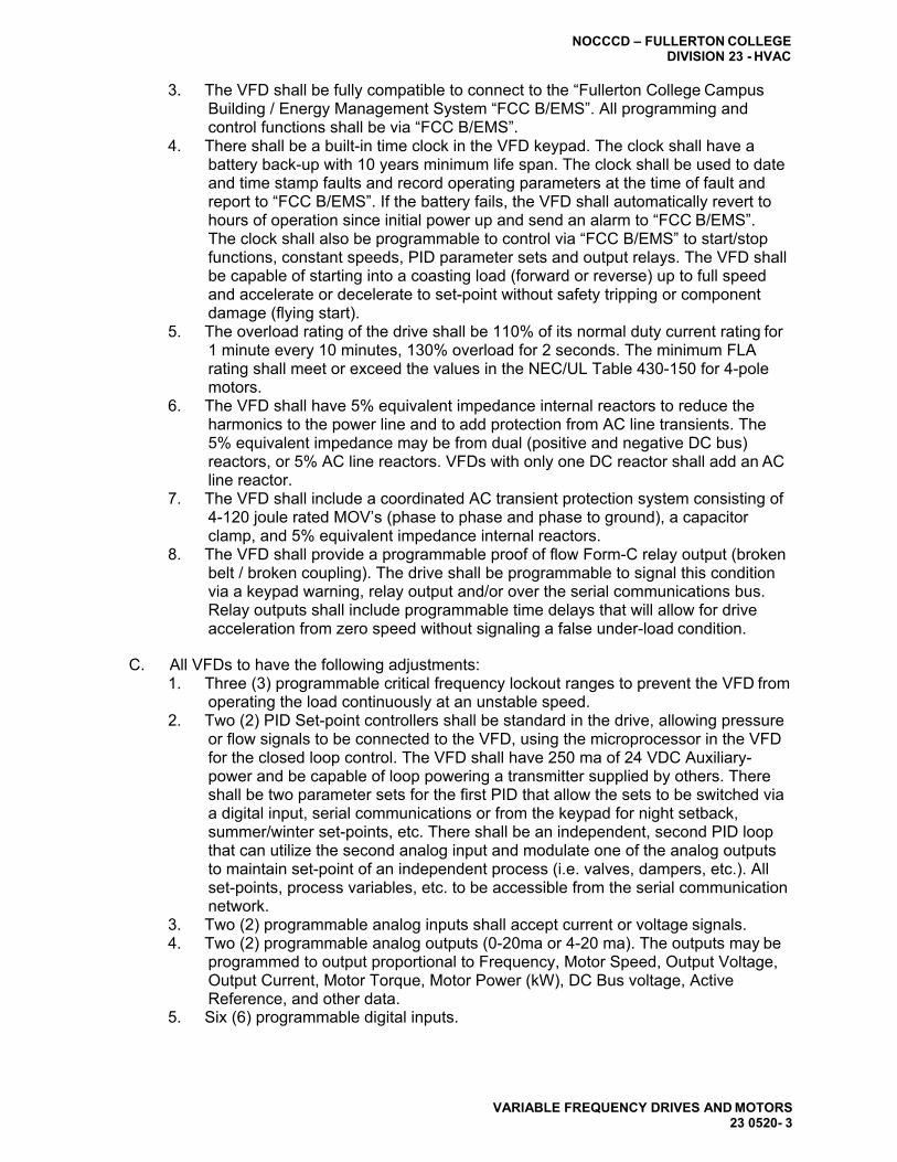
NOCCCD – FULLERTON COLLEGE DIVISION 23 - HVAC
VARIABLE FREQUENCY DRIVES AND MOTORS 23 0520- 3
3. The VFD shall be fully compatible to connect to the “Fullerton College Campus Building / Energy Management System “FCC B/EMS”. All programming and control functions shall be via “FCC B/EMS”.
4. There shall be a built-in time clock in the VFD keypad. The clock shall have a battery back-up with 10 years minimum life span. The clock shall be used to date and time stamp faults and record operating parameters at the time of fault and report to “FCC B/EMS”. If the battery fails, the VFD shall automatically revert to hours of operation since initial power up and send an alarm to “FCC B/EMS”. The clock shall also be programmable to control via “FCC B/EMS” to start/stop functions, constant speeds, PID parameter sets and output relays. The VFD shall be capable of starting into a coasting load (forward or reverse) up to full speed and accelerate or decelerate to set-point without safety tripping or component damage (flying start).
5. The overload rating of the drive shall be 110% of its normal duty current rating for 1 minute every 10 minutes, 130% overload for 2 seconds. The minimum FLA rating shall meet or exceed the values in the NEC/UL Table 430-150 for 4-pole motors.
6. The VFD shall have 5% equivalent impedance internal reactors to reduce the harmonics to the power line and to add protection from AC line transients. The 5% equivalent impedance may be from dual (positive and negative DC bus) reactors, or 5% AC line reactors. VFDs with only one DC reactor shall add an AC line reactor.
7. The VFD shall include a coordinated AC transient protection system consisting of 4-120 joule rated MOV’s (phase to phase and phase to ground), a capacitor clamp, and 5% equivalent impedance internal reactors.
8. The VFD shall provide a programmable proof of flow Form-C relay output (broken belt / broken coupling). The drive shall be programmable to signal this condition via a keypad warning, relay output and/or over the serial communications bus. Relay outputs shall include programmable time delays that will allow for drive acceleration from zero speed without signaling a false under-load condition.
C. All VFDs to have the following adjustments:
1. Three (3) programmable critical frequency lockout ranges to prevent the VFD from operating the load continuously at an unstable speed.
2. Two (2) PID Set-point controllers shall be standard in the drive, allowing pressure or flow signals to be connected to the VFD, using the microprocessor in the VFD for the closed loop control. The VFD shall have 250 ma of 24 VDC Auxiliary- power and be capable of loop powering a transmitter supplied by others. There shall be two parameter sets for the first PID that allow the sets to be switched via a digital input, serial communications or from the keypad for night setback, summer/winter set-points, etc. There shall be an independent, second PID loop that can utilize the second analog input and modulate one of the analog outputs to maintain set-point of an independent process (i.e. valves, dampers, etc.). All set-points, process variables, etc. to be accessible from the serial communication network.
3. Two (2) programmable analog inputs shall accept current or voltage signals. 4. Two (2) programmable analog outputs (0-20ma or 4-20 ma). The outputs may be
programmed to output proportional to Frequency, Motor Speed, Output Voltage, Output Current, Motor Torque, Motor Power (kW), DC Bus voltage, Active Reference, and other data.
5. Six (6) programmable digital inputs.

NOCCCD – FULLERTON COLLEGE DIVISION 23 - HVAC
VARIABLE FREQUENCY DRIVES AND MOTORS 23 0520 - 4
6. Three (3) programmable digital Form-C relay outputs. The relays shall include programmable on and off delay times and adjustable hysteresis. The relays shall be rated for maximum switching current 8 amps at 24 VDC and 0.4 A at 250 VAC; Maximum voltage 300 VDC and 250 VAC; continuous current rating 2 amps RMS. Outputs shall be true Form-C type contacts; open collector outputs are not acceptable.
7. Run permissive circuit - There shall be a run permissive circuit for damper or valve control. Regardless of the source of a run command (keypad, time-clock control, or serial communications) the VFD shall provide a dry contact closure that will signal the damper to open (VFD motor does not operate). When the damper is fully open, a normally open dry contact (end-switch) shall close. The closed end- switch is wired to a VFD digital input and allows motor operation. Two separate safety interlock inputs shall be provided. When either safety is opened, the motor shall be commanded to coast to stop, and the damper shall be commanded to close.
8. Two independently adjustable Accel and Decel ramps with 1 – 1800 seconds adjustable time ramps.
9. The VFD shall include a motor flux optimization circuit that will automatically reduce applied motor voltage to the motor to optimize energy consumption and audible motor noise.
10. The VFD shall include a carrier frequency control circuit that reduces the carrier frequency based on actual VFD temperature that allows higher carrier frequency without de-rating the VFD or operating at high carrier frequency only at low speeds.
11. The VFD shall include password protection against parameter changes.
D. The Keypad shall include a backlit LCD display. The display shall be in complete English words for programming and fault diagnostics (LED and alpha-numeric codes are not acceptable). All VFD faults shall be displayed in English words.
E. All applicable operating values shall be capable of being displayed in engineering (user)
units. A minimum of three operating values from the list below shall be capable of being displayed at all times. The display shall be in complete English words (alpha- numeric codes are not acceptable): 1. Output Frequency 2. Motor Speed (RPM, %, or Engineering units) 3. Motor Current 4. Drive Temperature 5. DC Bus Voltage 6. Output Voltage
F. The VFD shall include a fireman’s override input. Upon receipt of a contact closure
from the fireman’s control station, the VFD shall operate in one of two modes: 1) Operate at a programmed predetermined fixed speed or operate in a specific fireman’s override PID algorithm that automatically adjusts motor speed based on override set point and feedback . The mode shall override all other inputs (analog/digital, serial communication, and all keypad commands), except customer defined safety run interlock, and force the motor to run in one of the two modes above. “Override Mode” shall be displayed on the keypad. Upon removal of the override signal, the VFD shall resume normal operation.

NOCCCD – FULLERTON COLLEGE DIVISION 23 - HVAC
VARIABLE FREQUENCY DRIVES AND MOTORS 23 0520- 5
G. Serial Communications 1. The VFD shall have an RS-485 port as standard. The standard protocols shall be
Modbus, BACnet, Johnson Controls N2 bus, and Siemens Building Technologies FLN. Each individual drive shall have the protocol in the base VFD. The use of third party gateways and multiplexers is not acceptable. All protocols shall be “certified” by the governing authority (i.e. BTL Listing for BACnet). Use of non- certified protocols is not allowed.
2. The BACnet connection shall be an RS485, MS/TP interface operating at 9.6, 19.2, 38.4, or 76.8 Kbps. The connection shall be tested by the BACnet Testing Labs (BTL) and be BTL Listed. The BACnet interface shall conform to the BACnet standard device type of an Applications Specific Controller (B-ASC). The interface shall support all BIBBs defined by the BACnet standard profile for a B- ASC including, but not limited to: a. Data Sharing – Read Property – B. b. Data Sharing – Write Property – B. c. Device Management – Dynamic Device Binding (Who-Is; I-AM). d. Device Management – Dynamic Object Binding (Who-Has; I-Have). e. Device Management – Communication Control – B.
3. Serial communication capabilities shall include, but not be limited to; run-stop control, speed set adjustment, proportional/integral/derivative PID control adjustments, current limit, Accel / Decel time adjustments, and lock and unlock the keypad. The drive shall have the capability of allowing the DDC to monitor feedback such as process variable feedback, output speed / frequency, current (in amps), % torque, power (kW), kilowatt hours (resettable), operating hours (resettable), and drive temperature. The DDC shall also be capable of monitoring the VFD relay output status, digital input status, and all analog input and analog output values. All diagnostic warning and fault information shall be transmitted over the serial communications bus. Remote VFD fault reset shall be possible.
H. EMI / RFI filters. All VFDs shall include EMI/RFI filters. The VFD shall comply with
standard EN 61800-3 for the First Environment, restricted level with up to 100’ of motor cables. No Exceptions. Certified test lab test reports shall be provided with the submittals.
I. All VFDs through 60HP shall be protected from input and output power miss-wiring.
The VFD shall sense this condition and display an alarm on the keypad. The VFD shall not be damaged by this condition.
J. OPTIONAL FEATURES – Optional features to be furnished and mounted by the drive
manufacturer. All optional features shall be UL Listed by the drive manufacturer as a complete assembly and carry a UL508 label. The bypass enclosure door and VFD enclosure must be interlocked such that input power is turned off before either enclosure can be opened. The VFD and Bypass as a package shall have a UL listed short circuit rating of 100,000 amps and shall be indicated on the data label. 1. A complete factory wired and tested bypass system consisting of an output
contactor and bypass contactor, service (isolation) switch and VFD input fuses are required. Bypass designs, which have no VFD only fuses, or that incorporate fuses common to both the VFD and the bypass will not be accepted
2. Door interlocked pad-lockable circuit breaker that will disconnect all input power from the drive and all internally mounted options.
K. The following operators shall be provided:
1. Bypass-Hand-Off-Auto. 2. Drive mode selector and light.

NOCCCD – FULLERTON COLLEGE DIVISION 23 - HVAC
VARIABLE FREQUENCY DRIVES AND MOTORS 23 0520 - 6
3. Bypass mode selector and light. 4. Bypass fault reset. 5. Bypass LDC display, 2 lines, for programming and status / fault / warning
indications. 6. Motor protection from single phase power conditions- The Bypass system must
be able to detect a single phase input power condition while running in bypass, disengage the motor in a controlled fashion, and give a single phase input power indication. Bypass systems not incorporating single phase protection in Bypass mode are not acceptable.
7. The system (VFD and Bypass) tolerated voltage window shall allow the system to operate from a line of +30%, -35% nominal Voltage as a minimum. The system shall incorporate circuitry that will allow the drive or bypass contactor to remain “sealed in” over this voltage tolerance at a minimum.
8. The Bypass system shall NOT depend on the VFD for bypass operation. The bypass shall be completely functional in both Hand and Automatic modes even if the VFD has been removed from the enclosure for repair / replacement.
9. Serial communications – the bypass and VFD shall be capable of being monitored and or controlled via serial communications. Provide communications protocols for ModBus; Johnson Controls N2; Siemens Building Technologies FLN (P1) and BACnet in the bypass controller.
10. BACnet Serial communication bypass capabilities shall include, but not be limited to; bypass run-stop control; the ability to force the unit to bypass; and the ability to lock and unlock the keypad. The bypass shall have the capability of allowing the DDC to monitor feedback such as, bypass current (in amps), bypass kilowatt hours (resettable), bypass operating hours (resettable), and bypass logic board temperature. The DDC shall also be capable of monitoring the bypass relays output status, and all digital input status. All bypass diagnostic warning and fault information shall be transmitted over the serial communications bus. Remote bypass fault reset shall be possible. The following additional bypass status indications and settings shall be transmitted over the serial communications bus – keypad “Hand” or “Auto” selected, and bypass selected. The DDC system shall also be able to monitor if the motor is running under load in both VFD and bypass (proof of flow) in the VFD mode over serial communications or Form-C relay output. A minimum of 40 field parameters shall be capable of being monitored in the bypass mode.
11. Run permissive circuit - there shall be a run permissive circuit for damper or valve control. Regardless of the source of a run command (keypad, time-clock control, or serial communications) the VFD and bypass shall provide a dry contact closure that will signal the damper to open (VFD motor does not operate). When the damper is fully open, a normally open dry contact (end-switch) shall close. The closed end-switch is wired to a VFD system input and allows motor operation. Two separate safety interlock inputs shall be provided. When either safety is opened, the motor shall be commanded to coast to stop, and the damper shall be commanded to close.
12. The bypass control shall monitor the status of the VFD and bypass contactors and indicate when there is a welded contactor contact or open contactor coil. This failed contactor operation shall be indicated on the Bypass LCD display as well as over the serial communications protocol.
13. The bypass control shall include a programmable time delay for bypass start and keypad indication that this time delay is in process. This will allow VAV boxes to be driven open before the motor operates at full speed in the bypass mode. The time delay shall be field programmable from 0 – 120 seconds.

NOCCCD – FULLERTON COLLEGE DIVISION 23 - HVAC
VARIABLE FREQUENCY DRIVES AND MOTORS 23 0520- 7
14. The bypass control shall be programmable for manual or automatic transfer to bypass. The user shall be able to select via keypad programming which drive faults will generate an automatic transfer to bypass and which faults require a manual transfer to bypass.
15. There shall be an adjustable motor current sensing circuit for the bypass and VFD mode to provide proof of flow indication. The condition shall be indicated on the keypad display, transmitted over the building automation protocol and on a relay output contact closure.
16. The bypass controller shall have six programmable digital inputs, and five programmable Form-C relay outputs.
17. The relay outputs from the bypass shall programmable for any of the following indications. a. System started. b. System running. c. Bypass override enabled. d. Drive fault. e. Bypass fault. f. Bypass H-O-A position. g. Motor proof of flow (broken belt). h. Overload. i. Bypass selected. j. Bypass run.
18. System started (damper opening) a. Bypass alarm. b. Over temperature.
19. The digital inputs for the system shall accept 24VAC or 24VDC. The bypass shall incorporate internally sourced power supply and not require an external control power source. The bypass power board shall supply 250 ma of 24 VDC for use by others to power external devices.
20. Customer Interlock Terminal Strip – provide a separate terminal strip for connection of freeze, fire, smoke contacts, and external start command. All external safety interlocks shall remain fully functional whether the system is in VFD or Bypass mode. The remote start/stop contact shall operate in VFD and bypass modes. The terminal strip shall allow for independent connection of up to four (4) unique safety inputs.
21. The user shall be able to select the text to be displayed on the keypad when the safety opens. Example text display indications include “Fire-stat”, “Freeze-stat”, “Over pressure” and “Low pressure”. The user shall also be able to determine which of the four (4) safety contacts is open over the serial communications connection.
22. Class 10, 20, or 30 (selectable) electronic motor overload-protection shall be included.
2.02 MOTORS
A. Motors shall be NEMA TEFC; T-FRAME mounted on an adjustable steel base.
B. Motors shall be tested to IEEE standard 112 test method B and rated per NEMA MG1,
Part 31 “Inverter Fed Motors”.
C. Motors shall be specifically designed to meet or exceed all (EPAct) requirements for energy efficiency and include Class ‘F’ insulation.
D. Motors shall be as manufactured by Baldor or approved equal.

NOCCCD – FULLERTON COLLEGE DIVISION 23 - HVAC
VARIABLE FREQUENCY DRIVES AND MOTORS 23 0520 - 8
E. Motor shall have factory installed Aegis bearing protection rings.
F. Motors shall meet the electrical characteristics as specified for Voltage, RPM, and efficiencies.
G. Motors shall be designed to be installed at any distance from their respective variable
frequency drives
H. Warranty on motors: Warranty shall be 24 months from the date of certified start-up, not to exceed 30 months from the date of manufacturer. The warranty shall include all parts, labor, travel time and expenses.
I. Installation of motors: Installation should be done in accordance with the
manufacturer’s recommendations and per NEC and all local codes.
PART 3 – EXECUTION
3.01 HARMONIC LINE DISTORTION
A. Compliance of system to IEEE 519-2014 1. The VFD manufacturer shall, at the request of the engineer, provide
computerized calculation, specific to this installation, showing total harmonic voltage distortion (THD) per IEEE std. 519-1992. Guide for Harmonic Control and Reactive Compensation for Static Power Converters. The acceptance of this calculation must be completed prior to VFD installation.
2. If the voltage THD exceeds 5%, the VFD manufacturer is to recommend the additional equipment required to reduce the THD to an acceptable level.
3.02 UNACCEPTABLE FEATURES
A. The following design and/or construction features will not be acceptable for use on this
particular project: 1. Drive efficiencies of less than 97% at full rating are not acceptable. 2. Phase Control Rectifiers (Thyristors) or other such devices causing line notching
are not acceptable. 3. 6-step output is not acceptable. 4. Drives that do not have adjustable carrier frequencies. 5. Function and/or fault indications which are in code or require reference to an
operating manual or any method not using direct reading English words are not acceptable.
3.03 EXTRA MATERIALS
A. Spare Parts: The VFD and bypasses shall be furnished with one spare set of all fuses
for each size and type of fuse.
3.04 INSTALLATION
A. Installation shall be the responsibility of the mechanical contractor. The contractor shall install the drive in accordance with the requirements of the VFD manufacturer’s installation manual.

NOCCCD – FULLERTON COLLEGE DIVISION 23 - HVAC
VARIABLE FREQUENCY DRIVES AND MOTORS 23 0520- 9
3.05 START-UP
A. Certified factory start-up shall be provided for each drive by a factory certified service center. A certified start-up form shall be filled out for each drive with a copy provided to the owner, and a copy kept on file at the manufacturer.
3.06 PRODUCT SUPPORT
A. Factory trained application engineering and service personnel that are thoroughly
familiar with the VFD products offered shall be locally available at both the specifying and installation locations. A toll free 24/365 technical support line shall be available.
B. A computer based training CD or 8-hour professionally generated video (VCR format)
shall be provided to the owner at the time of project closeout. The training shall include installation, programming and operation of the VFD, bypass and serial communication.
3.07 WARRANTIES
A. Warranty shall be 24 months from the date of certified start-up, not to exceed 30
months from the date of shipment. The warranty shall include all parts, labor, travel time and expenses.
END OF SECTION 23 0520

NOCCCD – FULLERTON COLLEGE DIVISION 23 - HVAC
VARIABLE FREQUENCY DRIVES AND MOTORS 23 0520 - 10

NOCCCD – FULLERTON COLLEGE DIVISION 23 – HVAC
GENERAL DUTY VALVES FOR HVAC PIPING 23 0523 - 1
SECTION 23 0523
GENERAL DUTY VALVES FOR HVAC PIPING
PART 1 – GENERAL
1.01 SUMMARY
A. This Section includes general duty valves common to most mechanical piping systems.
B. Special purpose valves are specified in individual piping system specifications.
1.02 RELATED SECTIONS
A. Division 23 Section "HVAC Identification" for valve tags and charts.
1.03 SUBMITTALS
A. General: Submit the following in accordance with Conditions of Contract, Division 01 Specification Sections, and Section 23 0500 "Common Work Results for HVAC."
B. Product data, including body material, valve design, pressure and temperature
classification, end connection details, seating materials, trim material and arrangement, dimensions and required clearances, and installation instructions.
C. Provide valve schedule showing manufacturer's figure numbers and sizes.
1.04 QUALITY ASSURANCE
A. Single Source Responsibility: Comply with the requirements specified in Division 01
Section "Materials and Equipment," under "Source Limitations."
B. American Society of Mechanical Engineers (ASME) Compliance: Comply with ASME B31.9 for building services piping and ASME B31.1 for power piping.
C. Manufacturer’s Standardization Society (MSS) of the Valve and Fittings Industry
Compliance: Comply with the various MSS Standard Practices referenced.
1.05 DELIVERY, STORAGE, AND HANDLING
A. Preparation for Transport: Prepare valves for shipping as follows:
B. Ensure valves are dry and internally protected against rust and corrosion.
C. Protect valve ends against damage to threads, flange faces, and weld-end preps.
D. Set valves in best position for handling. Set globe and gate valves closed to prevent ratting; set ball and plug valves open to minimize exposure of functional surfaces; and block swing check valves in either closed or open position.
E. Storage: Use the following precautions during storage:

NOCCCD – FULLERTON COLLEGE DIVISION 23 - HVAC
GENERAL DUTY VALVES FOR HVAC PIPING 23 0523 - 2
F. Do not remove valve end protectors unless necessary for inspection; then reinstall for storage.
G. Protect valves from weather. Store valves indoor. Maintain valve temperature higher
than the ambient dew point temperature. If outdoor storage is necessary, support valves off the ground or pavement in watertight enclosures.
PART 2 – PRODUCTS
2.01 MANUFACTURERS
A. Manufacturer: Subject to compliance with requirements, provide products from one of
the manufacturers listed in valve schedule.
2.02 VALVE FEATURES, GENERAL
A. Valve Design: Rising stem or rising outside screw and yoke stems. 1. Non-rising stem valves may be used where headroom prevents full extension of
rising stems.
B. Pressure and Temperature Ratings: As scheduled and required to suit system pressures and temperatures.
C. Sizes: Same size as upstream pipe, unless otherwise indicated.
D. Operators: Provide the following special operator features:
1. Hand wheels, fastened to valve stem, for valves other than quarter turn. 2. Lever handles, on quarter-turn valves 6-inches and smaller, except for plug
valves. Provide plug valves with square heads; provide one wrench for every 10 plug valves.
3. Chain-wheel operators, for valves 2-1/2 inch and larger, install 72 inches or higher above finished floor elevation. Extend chains to an elevation of 5'-0" above finished floor elevation.
4. Provide gear drive operators, on quarter-turn valves 8-inch and larger.
E. End Connections: As indicated in the valve specifications. 1. Threads: Comply with ANSI B1.20.1. 2. Flanges: Comply with ANSI B16.1 for cast-iron, ANSI B16.5 for steel, and ANSI
B16.24 for bronze valves. 3. Solder-Joint: Comply with ANSI B16.18.
a. Caution: Where soldered end connections are used, use solder having a melting point below 840 deg. F for gate, globe, and check valves; below 421 deg. F for ball valves.
2.03 GATE VALVES
A. Gate Valves, 2-Inch and Smaller: MSS SP-80; Class 150, body and union bonnet of
ASTM B62 cast bronze; with threaded or solder ends, solid disc, copper-silicon alloy stem, brass packing gland, "Teflon" impregnated packing, and malleable iron hand wheel. Do not use solder end valves for hot water heating or steam piping applications.
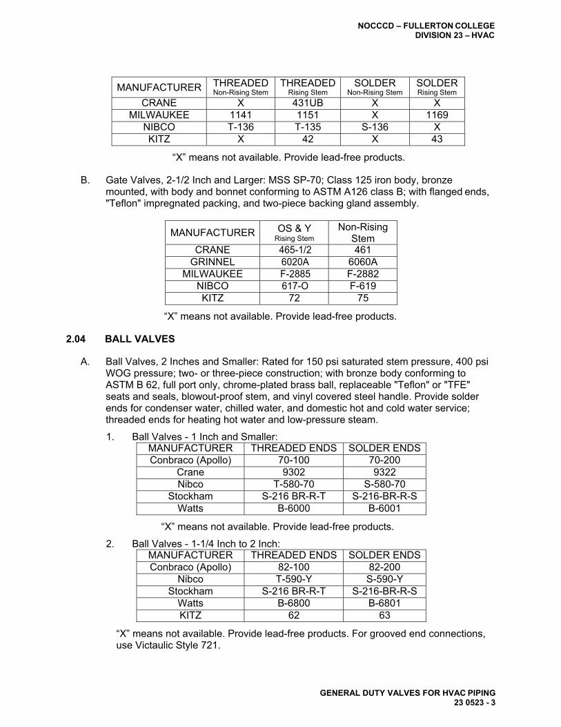
NOCCCD – FULLERTON COLLEGE DIVISION 23 – HVAC
GENERAL DUTY VALVES FOR HVAC PIPING 23 0523 - 3
MANUFACTURER THREADED Non-Rising Stem
THREADED Rising Stem
SOLDER Non-Rising Stem
SOLDER Rising Stem
CRANE X 431UB X X MILWAUKEE 1141 1151 X 1169
NIBCO T-136 T-135 S-136 X KITZ X 42 X 43
“X” means not available. Provide lead-free products.
B. Gate Valves, 2-1/2 Inch and Larger: MSS SP-70; Class 125 iron body, bronze mounted, with body and bonnet conforming to ASTM A126 class B; with flanged ends, "Teflon" impregnated packing, and two-piece backing gland assembly.
MANUFACTURER OS & Y Rising Stem
Non-Rising Stem
CRANE 465-1/2 461 GRINNEL 6020A 6060A
MILWAUKEE F-2885 F-2882 NIBCO 617-O F-619 KITZ 72 75
“X” means not available. Provide lead-free products.
2.04 BALL VALVES
A. Ball Valves, 2 Inches and Smaller: Rated for 150 psi saturated stem pressure, 400 psi WOG pressure; two- or three-piece construction; with bronze body conforming to ASTM B 62, full port only, chrome-plated brass ball, replaceable "Teflon" or "TFE" seats and seals, blowout-proof stem, and vinyl covered steel handle. Provide solder ends for condenser water, chilled water, and domestic hot and cold water service; threaded ends for heating hot water and low-pressure steam.
1. Ball Valves - 1 Inch and Smaller: MANUFACTURER THREADED ENDS SOLDER ENDS Conbraco (Apollo) 70-100 70-200
Crane 9302 9322 Nibco T-580-70 S-580-70
Stockham S-216 BR-R-T S-216-BR-R-S Watts B-6000 B-6001
“X” means not available. Provide lead-free products.
2. Ball Valves - 1-1/4 Inch to 2 Inch: MANUFACTURER THREADED ENDS SOLDER ENDS Conbraco (Apollo) 82-100 82-200
Nibco T-590-Y S-590-Y Stockham S-216 BR-R-T S-216-BR-R-S
Watts B-6800 B-6801 KITZ 62 63
“X” means not available. Provide lead-free products. For grooved end connections, use Victaulic Style 721.

NOCCCD – FULLERTON COLLEGE DIVISION 23 - HVAC
GENERAL DUTY VALVES FOR HVAC PIPING 23 0523 - 4
2.05 PLUG VALVES
A. Plug Valves, 2-Inch and Smaller: Rated at 150 psi WOG; bronze body, with straightaway pattern, square head, and threaded ends. 1. Lunkenheimer: 454 or equal. 2. Homestead: 611 (Semi Steel Body) or equal.
B. Plug Valves, 2-1/2 Inch and Larger: MSS SP-78; rated at 175 psi WOG; lubricated
plug type, with semi steel body, single gland, wrench operated and flanged ends. 1. Powell: 2201 or equal. 2. Homestead: 605 or equal.
2.06 GLOBE VALVES
A. Globe Valves, 2-Inch and Smaller: MSS SP-80; Class 125; body and screwed bonnet
of ASTM B 62 cast bronze; with threaded or solder ends, brass or replaceable composition disc, copper-silicon alloy stem, brass packing gland, "Teflon" impregnated packing, and malleable iron hand wheel. Provide Class 150 valves meeting the above where system pressure requires.
CLASS 125
MANUFACTURER CLASS 125 THREADED
CLASS 150 SOLDER
THREADED
Crane 1 1310 17TF Milwaukee 502 1502 590
Nibco T-211-B T-211-Y
S-211-B S-211-Y
T-235-Y
KITZ 11 12 10
“X” means not available. Provide Lead-free products.
B. Globe Valves, 2-1/2-Inch and Larger: MSS SP-85; Class 125 iron body and bolted bonnet conforming to ASTM A 126, Class B; with outside screw and yoke, bronze mounted, flanged ends, and "Teflon" impregnated packing, and two-piece backing gland assembly.
MANUFACTURER STRAIGHT
BODY ANGLE BODY
Crane 351 353 Milwaukee F2981 F2986
Nibco F-718-B F-818-B KITZ 76 X
“X” means not available. Provide Lead-free products.
2.07 BUTTERFLY VALVES
A. General - Where butterfly valves are used as shutoff for termination, or equipment removal or repair, select ductile iron lug type valves, bi-directional, dead-end service rated to the full working pressure of the valve. Select wafer type valves for other applications. Provide gear operators on butterfly valves 8" and larger. Valve bodies to have extended necks to provide for 2-1/4" insulation as needed. Butterfly valves 12 inch and smaller rated to 200 psi, 14 inch and larger 150 psi.

NOCCCD – FULLERTON COLLEGE DIVISION 23 – HVAC
GENERAL DUTY VALVES FOR HVAC PIPING 23 0523 - 5
Butterfly Valves 2-1/2 Inches and Larger: The following are model numbers for wafer-type, with nickel-plated ductile-iron disc:
MANUFACTURER LEVER GEAR
Crane 12 12 Nibco WD-20103 WD-20105
Milwakee MW-222E MW-322E KITZ DJ Series DJ Series
“X” means not available. Provide Lead-free products. Grooved Ends: Victaulic Series 300 and 704.
The following are model numbers for lug-type, with nickel-plated ductile-iron disc:
MANUFACTURER LEVER GEAR
Crane 14 14 Nibco LD-20103 LD-20105
Milwaukee ML-222E ML-322E KITZ DJ Series DJ Series
Grooved Ends: Victaulic Series 300 and 704.Provide lead-free products.
The following are model numbers for wafer-type, with aluminum-bronze disc:
MANUFACTURER LEVER GEAR Crane 42 42 Nibco WD-20003 WD-20005
Milwaukee CW-223E CW-323E KITZ DJ Series DJ Series
Grooved Ends: Victaulic Series 300A, 700A, and 703A.Provide lead-free products.
The following are model numbers for lug-type, with aluminum-bronze disc:
MANUFACTURER LEVER GEAR Center Line Series LT Series LT
Crane 44 44 Nibco LD-20003 LD-20005
Milwaukee CL-223E CL-323E KITZ DJ Series DJ Series
Grooved Ends: Victaulic Series 300A, 700A, and 703A.Provide lead-free products.
2.08 CHECK VALVES
A. Swing Check Valves, 2-Inch and Smaller: MSS SP-80; Class 125, cast-bronze body and cap conforming to ASTM B 62; with horizontal swing, Y-pattern, and bronze disc; and having threaded or solder ends. Provide valves capable of being reground while the valve remains in the line. Provide Class 150 valves meeting the above specifications, with threaded end connections, where system pressure requires or where Class 125 valves are not available.

NOCCCD – FULLERTON COLLEGE DIVISION 23 - HVAC
GENERAL DUTY VALVES FOR HVAC PIPING 23 0523 - 6
MANUFACTURER
CLASS 125 THREADED
ENDS
CLASS 125 SOLDER
ENDS
CLASS 125 THREADED
ENDS Crane 37 1342 137
Milwaukee 509 1509 510 Nibco T-413 S-413 T-433 KITZ 22 23 29
“X” means not available. Provide lead-free products. For grooved connections, use Victaulic Series 712.
B. Swing Check Valves, 2-1/2 Inch and Larger: MSS SP-71; Class 125 (Class 175 FM
approved for fire protection piping systems), cast iron body and bolted cap conforming to ASTM A 126, Class B; horizontal wing, and bronze disc or cast-iron disc with bronze disc ring; and flanged ends. Provide valves capable of being refitted while the valve remains in the line.
MANUFACTURER CLASS 125 CLASS 175
Crane 373 X Milwaukee F2974 X
Nibco F-918 X KITZ 78 X
“X” means not available. Provide lead-free products. For grooved connections, use Victaulic Series 712.
C. Lift Check Valves, 2-Inch and Smaller: Class 125; cast-bronze body and cap
conforming to ASTM B 62; horizontal or angle pattern, lift-type valve, with stainless steel spring, bronze disc holder with renewable "Teflon" disc, and threaded ends. Provide valves capable of being refitted and ground while the valve remains in the line.
MANUFACTURER HORIZONTAL ANGLE
Jenkins 655-A X Lunkenheimer 233 X
“X” means not available. Provide lead-free products.
PART 3 – EXECUTION
3.01 EXAMINATION
A. Examine valve interior through the end ports for cleanliness, freedom from foreign matter, and corrosion. Remove special packing materials, such as blocks used to prevent disc movement during shipping and handling.
B. Actuate valve through an open-close and close-open cycle. Examine functionally
significant features, such as guides and seats made accessible by such actuation. Following examination, return the valve closure member to the shipping position.
C. Examine threads on both the valve and the mating pipe for form (i.e., out-of-round or
local indentation) and cleanliness.

NOCCCD – FULLERTON COLLEGE DIVISION 23 – HVAC
GENERAL DUTY VALVES FOR HVAC PIPING 23 0523 - 7
D. Examine mating flange faces for conditions that might cause leakage. Check bolting for proper size, length, and material. Check gasket material for proper size, material composition suitable for service, and freedom from defects and damage.
E. Prior to valve installation, examine the piping for cleanliness, freedom from foreign
materials, and proper alignment.
3.02 VALVE ENDS SELECTION
A. Select valves with the following ends or types of pipe/tube connections: 1. Copper Tube Size, 2-Inch and Smaller: Solder ends, except provide threaded
ends for heating hot water and low-pressure steam service. 2. Steel Pipe Sizes, 2-Inch and Smaller: threaded or grooved end. 3. Steel Pipe Sizes 2-1/2 Inch and Larger: grooved end or flanged.
3.03 VALVE INSTALLATIONS
A. General Application: Refer to piping system specification sections for specific valve
applications and arrangements. Use gate, ball, and butterfly valves for shut-off duty. Use globe, plug, and ball valves for throttling duty.
B. Locate valves for easy access and provide separate support where necessary. Where
concealed, install behind access panel with valve located for complete accessibility for servicing.
C. Install valves and unions for each fixture and item of equipment. Arrange valves to
allow equipment removal without system shutdown. Unions are not required on flanged devices.
D. Install valves in horizontal piping with stem at or above the center of the pipe.
E. Install valves in a position to allow full stem movement.
F. Installation of Check Valves: Install for proper direction of flow as follows:
1. Swing Check Valves: Horizontal position with hinge pin level. 2. Lift Check Valve: With stem upright and plumb.
G. Where shut-off valves are installed in a confined space such as in a wall or furring,
install ball valves with operating handle parallel with face of wall.
H. Where valves are located in walls, do not install more than 6'-0" from finished floor. Where valves are located above ceiling, install valve centered on access point and not greater than 24" above access point.
3.04 SOLDER CONNECTIONS
A. Cut tube square and to exact lengths.
B. Clean end of tube to depth of valve socket with steel wool, sand cloth, or a steel wire
brush to a bright finish. Clean valve socket in same manner.

NOCCCD – FULLERTON COLLEGE DIVISION 23 - HVAC
GENERAL DUTY VALVES FOR HVAC PIPING 23 0523 - 8
C. Apply proper soldering flux in an even coat to inside of valve socket and outside of tube.
D. Open gate and glove valves to full open position.
E. Remove the cap and disc holder of swing check valves having composition discs.
F. Insert tube into valve socket, making sure the end rests against the shoulder inside
valve. Rotate tube or valve slightly to ensure even distribution of the flux.
G. Apply heat evenly to outside of valve around joint until solder will melt upon contact. Feed solder until it completely fills the joint around tube. Avoid hot spots or overheating valve. Once the solder starts cooling, remove excess amounts around the joint with a cloth or brush.
H. Use 95-5 tin/antimony ‘lead-free’ solder for all solder joints unless indicated otherwise.
3.05 THREADED CONNECTIONS
A. Note the internal length of threads in valve ends, and proximity of valve internal seat or
wall, to determine how far pipe should be threaded into valve.
B. Align threads at point of assembly.
C. Apply appropriate tape or thread compound to the external pipe threads (except where dry seal threading is specified).
D. Assemble joint, wrench tight. Wrench on valve shall be on the valve end into which the
pipe is being threaded.
3.06 FLANGED CONNECTIONS
A. Align flange surfaces parallel.
B. Assemble joints by sequencing bolt tightening to make initial contact of flanges and gaskets as flat and parallel as possible. Use suitable lubricants on bolt threads. Tighten bolts gradually and uniformly with a torque wrench.
3.07 FIELD QUALITY CONTROL
A. Tests: After piping systems have been tested and put into service, but before final
adjusting and balancing, inspect valves for leaks. Adjust or replace packing to stop leaks; replace valves if leak persists.
3.08 ADJUSTING AND CLEANING
A. Cleaning: Clean mill scale, grease, and protective coatings from exterior of valves and
prepare valves to receive finish painting or insulation.

NOCCCD – FULLERTON COLLEGE DIVISION 23 – HVAC
GENERAL DUTY VALVES FOR HVAC PIPING 23 0523 - 9
3.09 VALVE PRESSURE/TEMPERATURE CLASSIFICATION SCHEDULES
A. Below schedules are for standard installation conditions. Variations or special valves and/or conditions set forth in other Division 23 Sections shall take precedence.
1. VALVES, 2-INCH AND SMALLER SERVICE GATE GLOBE BALL CHECK
Chilled Water 125 125 150 125 Domestic HW &
CW 125 125 150 125
Heating Hot Water 150 150 150 150
2. VALVES, 2-1/2 INCH AND LARGER SERVICE GATE GLOBE BUTTERFLY CHECK
Chilled Water 125 125 200 125 Domestic HW &
CW 125 125 200 125
Heating Hot Water 125 125 200 125
3.10 VALVE ON INSULATED PIPING
A. Where piping is insulated, valves shall be equipped with 2” extended handles of non- thermal conductive material. Also provide a protective sleeve that allows operation of the valve without breaking the vapor seal or disturbing the insulation. Supply with memory stops, which are fully adjustable after insulation is applied.
END OF SECTION 23 0523


NOCCCD – FULLERTON COLLEGE DIVISION 23 - HVAC
SUPPORTS AND ANCHORS 23 0529-1
SECTION 23 0529
SUPPORTS AND ANCHORS
PART 1 - GENERAL
1.01 SECTION INCLUDES
A. Extent of supports and anchors required by this section is indicated on drawings or in other Division 23 Sections and include the following: 1. Horizontal-Piping Hangers and Supports; 2. Vertical-Piping Clamps; 3. Hanger-Rod Attachments; 4. Building Attachments; 5. Saddles and Shields; 6. Miscellaneous Materials; 7. Anchors; 8. Equipment Supports.
1.02 RELATED SECTIONS
A. This section is part of each Division 23 Section making reference to or requiring
supports and anchors specified herein.
B. Supports and anchors furnished as part of factory-fabricated equipment are specified as part of equipment assembly in other Division 23 Sections.
1.03 QUALITY ASSURANCE
A. Codes and Standards:
1. Code Compliance: Comply with applicable mechanical codes pertaining to product materials and installation of supports and anchors.
2. UL and FM Compliance: Provide products which are UL-listed and FM approved.
3. MSS Standard Compliance: a. Provide pipe hangers and supports of which materials, design, and
manufacturer comply with MSS SP-58. b. Select and apply pipe hangers and supports, complying with MSS SP-69. c. Fabricate and install pipe hangers and supports, complying with MSS SP-89. d. Terminology used in this section is defined in MSS SP-90.
1.04 SUBMITTALS
A. Product Data: Submit manufacturer's technical product data, including installation
instructions for each type of support and anchor.
PART 2 - PRODUCTS
2.01 MANUFACTURED UNITS
A. Hangers and support components shall be factory fabricated of materials, design, and manufacturer complying with MSS SP-58.

NOCCCD – FULLERTON COLLEGE DIVISION 23 - HVAC
SUPPORTS AND ANCHORS 23 0529-2
1. Components shall have galvanized coatings where installed for piping and equipment that will not have field-applied finish.
2. Pipe attachments shall have nonmetallic coating for electrolytic protection where attachments are in direct contact with copper tubing.
B. Thermal Hanger Shield Inserts: 100 PSI average compressive strength, waterproofed
calcium silicate, encased with a sheet metal shield. Insert and shield shall cover entire circumference of the pipe and shall be of length indicated by manufacturer for pipe size and thickness of insulation.
2.02 HORIZONTAL PIPING HANGERS AND SUPPORTS
A. General: Except as otherwise indicated, provide factory fabricated horizontal-piping
hangers and supports complying with MSS SP-58, of one of the following MSS types listed, selected by Installer to suit horizontal-piping systems, in accordance with MSS SP-69 and manufacturer's published product information. Use only one type by one manufacturer for each piping service. Select size of hangers and supports to exactly fit pipe size for bare piping, and to exactly fit around piping insulation with saddle or shield for insulated piping. Provide copper-plated hangers and supports for copper-piping systems. 1. Adjustable Steel Clevis Hangers: MSS Type 1. 2. Adjustable Swivel Pipe Rings: MSS Type 6.
2.03 VERTICAL PIPING CLAMPS
A. General: Except as otherwise indicated, provide factory fabricated vertical-piping
clamps complying with MSS SP-58, of one of the following types listed, selected by Installer to suit vertical piping systems, in accordance with MSS SP-69 and manufacturer's published product information. Select size of vertical piping clamps to exactly fit pipe size of bare pipe. Provide copper-plated clamps for copper-piping systems.
B. Two-Bolt Riser Clamps: MSS Type 8.
2.04 HANGER ROD AND BUILDING ATTACHMENTS
A. General Hanger Rod Attachment: Refer to structural drawings for requirements of
hanger rod and building attachments. If a specific attachment that is required is not detailed on the structural drawings, one of the following attachments may be submitted for review by the structural engineer prior to installation. Except as otherwise indicated, provide factory fabricated hanger-rod attachments complying with MSS SP- 58, of one of the following MSS types listed, selected by Installer to suit horizontal- piping hangers and building attachments, in accordance with MSS SP-69 and manufacturer's published product information. Use only one type by one manufacturer for each piping service. Select size of hanger-rod attachment to suit hanger rods. Provide copper-plated hanger-rod attachments for copper-piping systems.
B. General Building Attachment: Except as otherwise indicated, provide factory fabricated building attachments complying with MSS SP-58, of one of the following MSS types listed, selected by Installer to suit building substrate conditions, in accordance with MSS SP-69 and manufacturer's published product information. Select size of building attachments to suit hanger rods. Provide copper-plated building attachments for copper-piping systems.

NOCCCD – FULLERTON COLLEGE DIVISION 23 - HVAC
SUPPORTS AND ANCHORS 23 0529-3
1. Concrete Inserts: MSS Type 18. 2. Center Beam Clamps: MSS Type 21. 3. Steel Beam Clamps W/Eye Nut: MS Type 28. 4. Linked Steel Clamps W/Eye Nut: MSS Type 29. 5. Malleable Beam Clamps: MSS Type 30. 6. Steel Brackets: One of the following for indicated loading: 7. Light Duty: MSS Type 31.
2.05 SADDLES AND SHIELDS
A. General: Except as otherwise indicated, provide saddles or shields under piping
hangers and supports, factory-fabricated, for all insulated piping. Size saddles and shields for exact fit to mate with pipe insulation.
B. Protection Shields: MSS Type 40; provide high density insert of same thickness of
insulation.
2.06 MANUFACTURERS OF HANGERS AND SUPPORTS
A. Manufacturers: Subject to compliance with requirements, provide hangers and supports of one of the following: 1. B-Line Systems, Inc. 2. Tolco, Inc. 3. Elcen Metal Products Co. 4. Fee & Mason Mfg. Co.; Div. Figgie International. 5. ITT Grinnel Corp.
2.07 MISCELLANEOUS MATERIALS
A. Steel Plates, Shapes and Bars: ASTM A36.
B. Cement Grout: Portland cement (ASTM C150, Type I or Type III) and clean uniformly
graded, natural sand (ASTM C 404, Size No. 2). Mix at a ratio of 1.0 part cement to 3.0 parts sand, by volume, with minimum amount of water required for placement and hydration.
C. Pipe Alignment Guides: Factory fabricated, of cast semisteel or heavy fabricated steel,
consisting of bolted two-section outer cylinder and base with two-section guiding spider that bolts tightly to pipe. Length of guides shall be as recommended by manufacturer to allow indicated travel.
D. Pipe Roll Stand: Factory fabricated cast iron stand, size as required, with insulation
installed on piping.
2.08 ISOLATORS
A. Isolators: Provide factory-fabricated isolators of size required.
B. Spring Isolators: Refer to Section 23 0548 "Vibration Control for HVAC.”
C. Manufacturers: Semco "Trisolator" or Potter-Roemer PR-ISO.

NOCCCD – FULLERTON COLLEGE DIVISION 23 - HVAC
SUPPORTS AND ANCHORS 23 0529-4
PART 3 - EXECUTION
3.01 INSPECTION
A. Examine substrates and conditions under which supports and anchors are to be installed. Do not proceed with installation until unsatisfactory conditions have been corrected.
3.02 PREPARATION
A. Proceed with installation of hangers, supports and anchors only after required building
structural work has been completed in areas where the work is to be installed. Correct inadequacies including (but not limited to) proper placement of inserts, anchors and other building structural attachment.
B. Prior to installation of hangers, supports, anchors and associated work, installer shall
meet at project site with Contractor, installer of each component of associated work, inspection and testing agency representatives (if any), installers of other work requiring coordination with work of this section and Architect/Engineer for purpose of reviewing material selections and procedures to be followed in performing the work in compliance with requirements specified.
3.03 INSTALLATION OF BUILDING ATTACHMENTS
A. Install building attachments at required locations within concrete or on structural steel
for proper piping support. Space attachments within maximum piping span length indicated in MSS SP-69. Install additional building attachments where support is required for additional concentrated loads, including valves, flanges, guides, strainers, expansion joints, and at changes in direction of piping. Install concrete inserts before concrete is placed; fasten insert securely to forms. Where concrete with compressive strength less than 2500 psi is indicated, install reinforcing bars through openings at top of inserts.
3.04 INSTALLATION OF HANGERS AND SUPPORTS
A. General: Install hangers, supports, clamps and attachments to support piping properly
from building structure; comply with MSS SP-69. Arrange for grouping of parallel runs of horizontal piping to be supported together on trapeze type hangers where possible. Install supports with maximum spacings complying with MSS SP-69. Where piping of various sizes is to be supported together by trapeze hangers, space hangers for smallest pipe size or install intermediate supports for smaller diameter pipe. Do not use wire or perforated metal to support piping, and do not support piping from other piping.
B. Install hangers and supports complete with necessary inserts, bolts, rods, nuts,
washers and other accessories. Except as otherwise indicated for exposed continuous pipe runs, install hangers and supports of same type and type as installed for adjacent similar piping.
C. Prevent electrolysis in support of copper tubing by use of hangers and supports which
are copper plated, or by other recognized industry methods.
D. Provisions of Movement: Install hangers and supports to allow controlled movement of piping systems and to permit freedom of movement between pipe anchors.

NOCCCD – FULLERTON COLLEGE DIVISION 23 - HVAC
SUPPORTS AND ANCHORS 23 0529-5
E. Load Distribution: Install hangers and supports so that piping live and dead loading
and stresses from movement will not be transmitted to connected equipment.
F. Pipe Slopes: Install hangers and supports to provide required pipe slopes, and so that maximum pipe deflections allowed by ANSI B31 Pressure Piping Codes are not exceeded.
G. Bare Piping: Install isolators for all bare domestic water and bare hydronic piping.
H. Insulated Piping: Comply with the following installation requirements.
1. Clamps: Attach clamps, including spacers (if any), to piping with clamps projecting through insulation; do not exceed pipe stresses allowed by ANSI B31.
2. Shields: Where low-compressive-strength insulation or vapor barriers are indicated on cold or chilled water piping, install coated protective shields. Provide rigid insulation reinforcement at shields.
I. Hangers and supports to be capable to resist the minimum seismic forces indicated in
drawings.
3.05 EQUIPMENT SUPPORTS
A. Concrete housekeeping bases will be provided as work of Division 03.
B. Furnish to Contractor, scaled layouts of all required bases, with dimensions of bases, and location to column center lines. Furnish templates, anchor bolts, and accessories, necessary for base construction.
3.06 ADJUSTING AND CLEANING
A. Hanger Adjustment: Adjust hangers so as to distribute loads equally on attachments.
B. Support Adjustment: Provide grout under supports so as to bring piping and
equipment to proper level and elevations.
C. Cleaning: Clean factory-finished surfaces. Repair any marred or scratched surfaces with manufacturer's touch-up paint.
D. Touch-Up Painting: Immediately after erection of anchors and supports, clean field
welds and abraded areas of shop paint and paint exposed areas with same material as used for shop painting to comply with SSPC-PA-1 requirements for touch-up of field- painted surfaces. 1. Apply by brush or spray to provide a minimum dry film thickness of 2.0 mils.
E. For galvanized surfaces clean welds bolted connections and abraded areas and apply
galvanizing repair paint to comply with ASTM A 780.
END OF SECTION 23 0529


NOCCCD – FULLERTON COLLEGE DIVISION 23 - HVAC
VIBRATION CONTROL FOR HVAC 23 0548 - 1
SECTION 23 0548
VIBRATION CONTROL FOR HVAC
PART 1 - GENERAL
1.01 DESIGN REQUIREMENTS
A. It is the intent of this Specification to provide the necessary design for the avoidance of excessive noise or vibration in the building due to the operation of machinery or equipment, or due to interconnected piping, ductwork, or conduit. Also is the intent of this Specification to provide the necessary design to seismically restraint piping, ductwork and equipment per the applicable codes against seismic forces in any direction. 1. All isolators shall:
a. Be provided by a single manufacturer. b. Be designed or treated for resistance to corrosion. Structural steel bases
shall be cleaned of welding slag and coated with an SCAQMD compliant primer.
c. Be selected to perform their function without undue stress or overloading. All isolators shall have a method for leveling and have a 1/4" thick ribbed neoprene acoustical pad under the spring baseplate.
d. Be installed in a manner to prevent the transmission of vibration to the structure. No rigid connections between rotating or oscillating equipment or piping and the building will be permitted.
e. Be designed to be non-resonant with equipment forcing frequencies or support structure natural frequencies.
2. Anchor floor mounted isolated equipment to concrete housekeeping pads of sufficient size to accommodate the anchorage of seismic restraints. Housekeeping pads shall be anchored to the structure as specified by the Structural Engineer of Record.
3. Each fan and motor assembly shall be supported on a single structural steel frame. Flexible duct connections shall be provided at inlet and discharge ducts.
4. Where called for in the specifications or on the drawings, all structural steel bases, including concrete pouring form bases, shall be designed and fabricated by the isolation manufacturer. Isolation manufacturer shall be a licensed fabricator for the City of Los Angeles, California.
5. Unless otherwise indicated, all equipment mounted on vibration bases shall have a minimum operating clearance of 1" between structural steel base and floor or support base beneath. The minimum operating clearance between concrete inertia bases and housekeeping pads shall be 1 inch. Check clearance space after installation to ensure that no debris has been left to possibly short circuit isolation bases.
6. Where necessary due to height limitations, provide height saving brackets. 7. Design isolators for positive anchorage against uplift and overturning.
1.02 MANUFACTURERS
A. Acceptable Isolation Manufacturer:
1. M. W. Sausse' & Co., Inc. (Vibrex) 2. Mason Industries, Inc 3. Or Approved Equal.

NOCCCD – FULLERTON COLLEGE DIVISION 23 - HVAC
VIBRATION CONTROL FOR HVAC 23 0548 - 2
B. Purchased and/or fabricated equipment must be designed and manufactured with provision for positive anchorage against seismic forces.
C. Seismic restraints for pipes and ducts shall be as per the SMACNA Guidelines for
seismic Restraint of Mechanical Systems and shall be approved by DSA.
D. Seismic restraints for equipment and piping shall be designed to meet the criteria of the current California Code of Regulations.
E. The manufacturer of Vibration Isolation and Seismic Control Equipment shall have the
following responsibilities: 1. Determine adequate vibration isolation and seismic restraint sizes and locations. 2. Provide piping and equipment isolation systems and seismic restraints as
scheduled and/or specified. 3. Provide installation instructions and drawings to assure proper installation and
performance.
1.03 SUBMITTALS
A. Make Submittals in Accordance with: 1. Contract General Provisions – Division 01. 2. Mechanical General Provisions - Sections 230500 and 230511.
B. Submit Shop Drawings and Manufacturer's Literature
1. Specific vibration isolators and seismic restraints to be utilized showing compliance with the specifications.
2. Isolation frame construction for each machine including dimensions, structural member sizes, support points and restraint locations and details.
3. Methods for isolation and restraint of suspended piping, ductwork, and equipment.
4. Methods for guides and isolation of piping risers. 5. Seismic restraint calculations signed and stamped by an engineer licensed in the
State of California and experienced in the design of isolation and seismic restraint for flexibly mounted equipment.
PART 2 - PRODUCTS
2.01 VIBRATION ISOLATOR TYPES
A. "RMS" shall be a laterally stable un-housed spring isolator. Spring, top plate, and
baseplate assembly shall be welded. Mounting shall comply with all requirements stated in paragraph above.
B. "RMSG" shall be the same as "RMS" above, but shall include height saving brackets for
attachment to the equipment frame or isolation base.
C. "RMSP-EQ" shall be the same as "RMS" above except that the spring shall be enclosed in a welded steel cylinder with uplift restraints for horizontal and vertical seismic control.

NOCCCD – FULLERTON COLLEGE DIVISION 23 - HVAC
VIBRATION CONTROL FOR HVAC 23 0548 - 3
D. "RMLS-EQ" shall be the same as "RMS" above, and shall be equipped with a steel housing designed for seismic restraint and with vertical limit stops to prevent the equipment changing from its loaded height should it be necessary to remove a portion of its weight. This housing may also be used as rigid blocking during rigging so that the installed height and the operating height of the isolated equipment remain the same. O.S.H.P.D. pre-approval # OPA-0029.
E. "RMLS-SB" shall be a steel frame constructed of structural wide flange members unless
shown otherwise and shall be rectangular in shape. The depths of the steel members shall not be less than one tenth (1/10) of the longest span between base supports or designed for a maximum beam deflection of .005". If the latter method is used, submittals shall include calculations showing the necessary moment of inertia. All steel members shall be coped and fitted, or constructed using the overlap insert method to assure a structural strength that is greater than the individual member strength. The steel frame is placed directly on top of the RMLS-EQ type isolators. O.S.H.P.D. Pre-approved isolator/seismic restraints.
F. "RMU-EQ-SH": shall be an individual semi-housed steel spring isolator complete with
vertical motion limit stops incorporating seismic restraints, leveling, and ribbed neoprene pad bonded to the base-plate. O.S.H.P.D. pre-approval # OPA-0098.
G. "AS" shall be air spring isolators and shall incorporate the following:
1. A complete vibration isolation system consisting of a minimum of three air springs and a total of three height sensing valves. If there are two or more air springs per location, they shall be connected to the outlet of the height control valve in parallel. An associated interconnecting air supply system is required which is not included in this work.
2. The air spring shall operate at its normal operating height and the maximum pressure shall not exceed the manufacturer's recommended rating of 100 PSI. The system shall maintain an elevation of +/- 1/8", once adjusted.
3. The type air spring to be utilized shall be based upon the required natural frequency as indicated in the schedule. In order to avoid instability, auxiliary height saving brackets, housings, etc. may be utilized, subject to approval.
H. "RP-EQ" shall be a rubber pad type elastomer mounting, consisting of a steel bearing
plate with 1/4" thick neoprene ribbed acoustical pad. Maximum loading shall be 60 PSI. Proper anchorage for seismic loads shall be indicated on drawings.
I. FUD-EQ shall be rubber-in-shear isolators incorporating mounting bolts for bolting to
equipment base, a bottom steel plate for bolting isolator to sub base or structure, and built in seismic restraints.
J. "RMXA" shall be a rectangular steel housing that shall be bolted to the overhead
structure and designed to allow up to 30 degrees rod misalignment. Hanger shall consist of a steel spring located in a molded neoprene retaining cup with hanger rod bushing.
K. "PRMXA" - Same as type "RMXA" with the addition of a steel load transfer plate so that
the equipment or piping operating height is the same as the installed height.
L. "HXA" -Same as type "RMXA" with the addition of a neoprene element in series to isolate the upper connection.

NOCCCD – FULLERTON COLLEGE DIVISION 23 - HVAC
VIBRATION CONTROL FOR HVAC 23 0548 - 4
M. "PHXA" - Same as type "HXA" with the addition of a steel load transfer plate so that the equipment or piping operating height is the same as the installed height.
N. "HSS" - shall be a 'rubber in shear' isolator element contained within a rectangular steel
housing.
2.02 RAIL AND BASE TYPES
A. "RMR" spring rail isolator. Rails shall have springs of proper size and constant, installed between a continuous structural steel channel (upper member) and a continuous flat steel plate (bottom member) in such manner, quantity, and location that efficient uniform deflection and loading to the structure is assured. Rails shall be furnished with Vibrex hold down stabilizers to restrict excessive amplitudes. Cross bracing must be used when necessary for seismic stability.
B. "RMB" shall be the same as "RMR" above except that it shall be designed as an integral
fan and motor base with an adjustable motor slide base.
C. "RMSR" shall be a set of wide flange structural steel rails supplied with height saving brackets to reduce the mounting height of the equipment. The maximum allowable deflection of any point on the loaded frame relative to the unloaded frame shall be 0.005". A wide flange section depth greater than 1/10 the supporting span between isolators will be accepted as satisfying the deflection requirement.
D. "RMSB" shall be a steel frame constructed of structural wide flange members unless
shown otherwise and shall be rectangular in shape. The depths of the steel members shall not be less than one tenth (1/10) of the longest span between base supports or designed for a maximum beam deflection of .005". If the latter method is used, submittals shall include calculations showing the necessary moment of inertia. All steel members shall be coped and fitted, or constructed using the overlap insert method to assure a structural strength that is greater than the individual member strength. Adjustable motor slide bases shall be included when required for centrifugal fan applications. The steel bases shall have an operating clearance of one (1") inch above the supporting structure. Where bases are used to mount pumps, the bases shall be large enough to support the pipe elbows if required.
E. "RMSBI" shall be a steel frame inertia base with all welded members and constructed of
structural channel shapes. The base shall be designed for a thickness or inertia mass to equipment weight ratio as shown on the schedule with a minimum thickness of six (6") inches. The bases shall include a template and anchor bolts to anchor the equipment. Inertia bases shall have 1/2" (#4) rebar spaced a maximum of 12" on centers in each direction and located 1-1/2" from the bottom of the base. Adjustable motor slide bases shall be included when required for centrifugal fan applications. Bases shall be supplied with height saving brackets to reduce the mounting height of the equipment.
F. “RMUAB-EQ” shall be a steel frame made of structural angle with type “RMU-EQ-SH”
O.S.H.P.D. pre-approved combination isolator/restraints.

NOCCCD – FULLERTON COLLEGE DIVISION 23 - HVAC
VIBRATION CONTROL FOR HVAC 23 0548 - 5
G. "RMLSR" shall be a set of multiple wide flange structural steel rails supplied with type RMLS-EQ vibration isolator/seismic restraints and height saving brackets to reduce the mounting height of the equipment. The maximum allowable deflection of any point on the loaded frame relative to the unloaded frame shall be 0.005". A wide flange section depth greater than 1/10 the supporting span between isolators will be accepted as satisfying the deflection requirement.
H. Type "RMLSB" shall be a steel frame constructed of structural wide flange members
unless shown otherwise and shall be rectangular in shape. The depths of the steel members shall not be less than one tenth (1/10) of the longest span between base supports or designed for a maximum beam deflection of .005". If the latter method is used, submittals shall include calculations showing the necessary moment of inertia. All steel members shall be coped and fitted, or constructed using the overlap insert method to assure a structural strength that is greater than the individual member strength. Frame shall be supplied complete with height saving brackets and type RMLS-EQ, O.S.H.P.D. pre-approved isolator/seismic restraints. 1. Type RMLS-SB is the same as type “RMLSB” but rather than utilizing height saving
brackets the steel frame is placed directly on top of the RMLS-EQ type isolators.
2.03 CURB TYPES
A. Type "VIC-EQ-SS" shall be a factory fabricated combination roof mounting curb and vibration isolation base for rooftop package units over 25 tons. The curb assembly shall be designed so that it can be re-roofed without disturbing the HVAC equipment. Curbs must be designed so that roofing material cannot cover access to isolators. The vibration isolation portion of the assembly shall be constructed of structural steel and designed to mate with the bottom of the rooftop unit. System shall include factory fabricated duct supports and any required bracing welded in place. The sheet metal weather proofing curb portion shall be supplied complete with a wood-nailerstrip to facilitate flashing by the roofing contractor. Internal vibration isolator/seismic restraints shall be OSHPD pre-approved number OPA-0029 as manufactured by MW Sausse’ & company, inc. Required anchorage calculations shall be supplied with submittal package. When required, curb shall include an optional acoustical package for sound reduction.
B. Type "VIC-EQ" shall be a factory fabricated combination roof mounting curb and vibration
isolation base for rooftop package units up to 20 tons. Steel members and cross bracing shall all be welded. The assembly shall be shipped and installed in one piece complete with curb, weather-seal, removable OSHPD pre-approved isolator/restraints #OPA-0098, exterior accessible leveling device, and minimum 14 gage galvanized steel top section to match the unit. Curb shall be fabricated of minimum 12 gage galvanized steel designed to carry the seismic loads to the supporting structure. System shall include factory fabricated duct supports welded in place as well as insulated panels when required. Required anchorage and lower curb structural calculations shall be supplied with submittal package. When required, curb shall include an optional acoustical package for sound reduction. Curb shall be manufactured to match roof slope if specified in drawings.

NOCCCD – FULLERTON COLLEGE DIVISION 23 - HVAC
VIBRATION CONTROL FOR HVAC 23 0548 - 6
2.04 SEISMIC RESTRAINTS
A. Shall be capable of safely accepting external forces as specified in the applicable codes without failure. Restraints shall maintain equipment, duct, and piping in a captive position during an earthquake. Restraints shall not short circuit vibration isolation systems or transmit objectionable vibration or noise under normal operating conditions. Seismic restraints shall be provided on all equipment as scheduled on the drawings. Submit calculations by a Licensed Structural Engineer Registered in State of California to verify snubber capacities.
B. Type "3500" seismic restraint shall be constructed of steel plate, concentric steel pipes,
and structural members in an all welded assembly. All contact points shall be cushioned with minimum 1/4" thick resilient pad. Restraints shall be O.S.H.P.D pre-approved type OPA-0029.
C. Type "3200" seismic restraint shall be all directional type with interlocking steel members
constructed of structural angle and A-36 threaded rod. All contact points shall be cushioned with minimum 1/4" thick resilient pad or bushing.
D. Type "CR" seismic restraints shall be constructed of 7x19 strand galvanized aircraft
cable. Cable assembly shall come complete with minimum (2) "U" bolt clamps per end and thimbles to protect cable from chafing. Allowed loads shall be the cable breaking strength with a safety factor of three. Actual loads shall be calculated with the worst case of all load applied to one cable and anchor pattern. Cable shall be installed with 1/4" slack to prevent the transmission of vibration to the structure.
PART 3 - EXECUTION
3.01 GENERAL
A. Install in accordance with manufacturer's written instructions. Vibration isolators must not
be installed in a manner that will result in piping stress or misalignment.
B. The structural steel or concrete inertia base shall be placed in position and supported temporarily by blocks or shims, as appropriate, prior to the installation of the equipment or isolators. The isolators shall be installed without raising the equipment and frame assembly.
C. After the entire installation is complete and under full operational load, the isolator shall
be adjusted so that the load is transferred from the blocks or shims to the isolator. When all isolators are properly adjusted, the blocks or shims shall be barely free and shall be removed.
D. Once the equipment is in operation, install and anchor the seismic restraints with proper
operating clearances as indicated on drawings.
E. HVAC equipment shall be isolated from the building structure by vibration isolators as scheduled on the drawings.
F. All piping 1 1/4" and over located in mechanical equipment rooms, and for a minimum of
fifty (50) feet or 100 pipe diameters whichever is greater, from connection to vibrating mechanical or electrical equipment, shall be isolated from the building structure by means of vibration isolators as identified above.

NOCCCD – FULLERTON COLLEGE DIVISION 23 - HVAC
VIBRATION CONTROL FOR HVAC 23 0548 - 7
G. All HVAC piping and vertical risers shall be isolated from the building structure by means of vibration isolators and guides.
H. All piping and ductwork to be isolated shall freely pass through walls and floors without
contact. Penetration points shall be sleeved or otherwise formed to allow passage of piping or ductwork and maintain adequate clearance (Minimum of 2 inches all around) around the outside surfaces. Any materials used to fill the clearance space shall be permanently flexible so that vibration will not pass through it.
I. No rigid connections between equipment and building structure, including electrical
conduit and refrigerant lines, shall be made that degrades the vibration isolation system herein specified. Inform other following trades, such as plastering, or electrical, to avoid any contact which would short-circuit the vibration isolation.
J. Bring to the Architect's attention prior to installation any conflicts with other trades which
will result in unavoidable rigid contact with equipment or piping as described herein, due to inadequate space or other unforeseen conditions. Corrective work necessitated by conflicts after installation shall be at the contractor's expense.
K. Bring to the Architect's attention any discrepancies between the specifications and field
conditions or changes required due to specific equipment selection, prior to installation. Corrective work necessitated by discrepancies after installation shall be at the contractor's expense.
L. Obtain inspection and approval of any isolation installation to be covered or enclosed,
prior to such closure.
M. Thrust restraints shall consist of spring hangers with the same deflection as specified for the spring mountings. Thrust restraints shall be attached to the fan at the centerline of air discharge opening.
N. Correct, at no additional cost, all installations that are deemed defective in workmanship
or materials.
3.02 PIPING ISOLATORS
A. All piping except fire standpipe systems are included under this section.
B. Isolate piping within 50 feet of rotating equipment and pressure reducing stations.
C. The isolators shall be installed with the isolator hanger box attached to, or hung as close as possible to, approved locations on the supporting structure.
D. The isolators shall be suspended from substantial structural members, not from slab
diaphragm unless specifically permitted.
E. Hanger rods shall be aligned to clear the hanger box.
F. Horizontal floor supported piping shall be isolated by type "RMLS-EQ", with a minimum static deflection of 1.0 inch or the same deflection as isolated equipment to which pipe is connected, whichever is greater.
NOCCCD – FULLERTON COLLEGE DIVISION 23 - HVAC
VIBRATION CONTROL FOR HVAC 23 0548 - 8
G. Vertical riser pipe support and restraint system shall consist of type "RMS" springs and type "PG-EQ" guides. Install vertical riser guides so that clearances are maintained around concentric pipes in the guides. Install vertical restraints on the floor location as shown on drawings.
H. Pipe anchors, where required, shall utilize resilient pipe anchors, type "RPA" or
equivalent, to avoid direct contact of piping with building.
I. Pipe Extension and Alignment connectors: Provide connectors at pump suction and discharge, riser take offs, cooling and heating coils, and elsewhere as required to accommodate thermal expansion and misalignment.
J. Seismic restraint spacing shall be in accordance with applicable codes.
3.03 INSPECTION
A. On completion of installation of all vibration isolation and seismic control devices herein
specified, the local representative of the isolation materials manufacturer shall inspect the completed system and report in writing any installation error, improperly selected isolation devices, or other faults in the system that could affect the performance of the system. The contractor shall submit a report to the Architect, including the above report with consequent steps taken to properly complete the isolation work.
END OF SECTION 23 0548

NOCCCD – FULLERTON COLLEGE DIVISION 23 – HVAC
HVAC IDENTIFICATION 23 0553-1
SECTION 23 0553
HVAC IDENTIFICATION
PART 1 - GENERAL
1.01 SECTION INCLUDES
A. Extent of HVAC identification work required by this section is indicated on drawings or specified in other Division 23 Sections, and includes the following: 1. Painted Identification Materials; 2. Plastic Pipe Markers; 3. Plastic Tape; 4. Underground-Type Plastic Line Marker; 5. Plastic Duct Markers; 6. Valve Tags; 7. Diagram and Schedule Frames; 8. Engraved Plastic-Laminate Signs; 9. Plastic Equipment Markers; 10. Plasticized Tags.
1.02 RELATED SECTIONS
A. This section is part of each Division 23 Section making reference to identification devices
specified herein.
B. HVAC identification furnished as part of factory fabricated equipment is specified as part of equipment assembly in other Division 23 Sections.
C. Refer to Division 26 Sections for identification requirements of electrical work; not work
of this section.
1.03 SUBMITTALS
A. Product Data: Submit manufacturer's technical product data and installation instructions for each identification material and device required.
B. Samples: Submit samples of each color, lettering style and other graphic representation
required for each identification material or system.
C. Schedules and Diagrams: 1. Submit valve schedule for each piping system, typewritten and reproduced on 8-
1/2"x11" bond paper. Tabulate valve number, piping system, system abbreviation (as shown on tag), location of valve (room or space), and variations for identification (if any). Mark valves which are intended for emergency shut-off and similar special uses, by special "flags", in margin of schedule.
2. Submit temperature control diagrams and Sequence of Operation on bond paper suitable for framing.
D. Maintenance Data: Include product data and schedules in maintenance manuals; in
accordance with requirements of Division 01 and Division 23 Section 230511 "Supplementary HVAC Requirements.”

NOCCCD – FULLERTON COLLEGE DIVISION 23 - HVAC
HVAC IDENTIFICATION 23 0553-2
1.04 QUALITY ASSURANCE
A. Codes and Standards: 1. ANSI Standards: Comply with ANSI A13.1 for lettering size, length of color field,
colors, and viewing angles of identification devices. 2. No adhesive type identification markers will be accepted. All markers and tags
shall be permanently attached to pipe, etc. 3. All identification markers installed exterior of buildings shall be ultra-violet
resistant.
PART 2 - PRODUCTS
2.01 ACCEPTABLE MANUFACTURERS
A. Manufacturer: Subject to compliance with requirements, provide HVAC identification materials of one of the following: 1. Seton Name Plate Corp. 2. Allen Systems, Inc. 3. Brady (W.H.) Co.; Signmark Div. 4. Industrial Safety Supply Co., Inc.
2.02 HVAC IDENTIFICATION MATERIALS
A. General: Provide manufacturer's standard products of categories and types required for
each application as referenced in other Division 23 Sections. Where more than single type is specified for application, selections is Installer’s option, but provide single selection for each product category.
2.03 PLASTIC PIPE MARKERS
A. Snap-On Type: Provide manufacturer's standard pre-printed, semi-rigid snap-on, color-
coded pipe markers, complying with ANSI A13.1.
B. Insulation: Furnish 1" thick molded fiberglass insulation with jacket for each plastic pipe marker to be installed on uninsulated pipes subject to fluid temperatures of 125oF. (52oC) or greater. Cut length to extend 2" beyond each end of plastic pipe marker.
C. Small Pipes: For external diameters less than 6" (including insulation if any), provide full-
band pipe markers, extending 360 degrees around pipe at each location, fastened by one of the following methods: 1. Snap-on application of pre-tensioned semi-rigid plastic pipe marker. 2. Laminated or bonded application of pipe marker to pipe (or insulation). 3. Taped to pipe (or insulation) with color-coded plastic adhesive tape, not less than
3/4" wide; full circle at both ends of pipe marker, tape lapped 1-1/2".
D. Large Pipes: For external diameters of 6" and larger (including insulation if any), provide either full-band or strip-type pipe markers, but not narrower than 3 times letter height (and of required length), fastened by one of the following methods: 1. Laminated or bonded application of pipe marker to pipe (or insulation). 2. Taped to pipe (or insulation) with color-coded plastic adhesive tape, not less than
1-1/2" wide; full circle at both ends of pipe marker, taped lapped 3". 3. Strapped-to-pipe (or insulation) application of semi-rigid type, with manufacturer's
standard stainless steel bands.

NOCCCD – FULLERTON COLLEGE DIVISION 23 – HVAC
HVAC IDENTIFICATION 23 0553-3
E. Lettering: Manufacturer's standard pre-printed nomenclature which best describes piping system in each instance, as selected by Architect/Engineer in cases of variance with names as shown or specified. 1. Arrows: Print each pipe marker with arrows indicating direction of flow, either
integrally with piping system service lettering (to accommodate both directions), or as a separate unit of plastic.
2.04 PLASTIC TAPE
A. General: Provide manufacturer's standard color-coded pressure-sensitive (self-
adhesive) vinyl tape, not less than 3 mils thick.
B. Width: Provide 1-1/2" wide tape markers on pipes with outside diameters (including insulation, if any) of less than 6", 2-1/2" wide tape for larger pipes.
C. Color: Comply with ANSI A13.1, except where another color selection is indicated.
2.05 UNDERGROUND TYPE PLASTIC LINE MARKER
A. General: Manufacturer's standard permanent, bright-colored, continuous-printed plastic
tape, intended for direct-burial service; not less than 6" wide x 4 mils thick. Provide tape with printing which most accurately indicates the type of service of buried pipe. 1. Provide multi-ply tape consisting of solid aluminum foil core between 2-layers of
plastic tape.
2.06 VALVE TAGS
A. Brass Valve Tags: Provide 19-gage polished brass valve tags with stamped-engraved piping system abbreviation in 1/4" high letters and sequenced valve numbers 1/2" high, and with 5/32" hole for fastener. 1. Provide 1-1/2" diameter tags, except as otherwise indicated. 2. Fill tag engraving with black enamel.
B. Valve Tag Fasteners: Provide manufacturer's standard solid brass chain (wire link or
beaded type), or solid brass S-hooks of the sizes required for proper attachment of tags to valves, and manufactured specifically for that purpose.
C. Access panel markers: Provide manufacturer's standard solid brass chain (wire link or
beaded type), or solid brass S-hooks of the sizes required for proper attachment of tags to valves, and manufactured specifically for that purpose.
D. Access Panel Markers: Provide manufacturer's standard 1/16" thick engraved plastic
laminate access panel markers, with abbreviations and numbers corresponding to concealed valve. Include 1/8" center hole to allow attachment.
2.07 DIAGRAM AND SCHEDULE FRAMES
A. General: For each page of schedule and/or diagrams, provide glazed display frame, with
screws for removable mounting on masonry walls. Provide frames of finished hardwood or extruded aluminum, with SSB-grade sheet glass.

NOCCCD – FULLERTON COLLEGE DIVISION 23 - HVAC
HVAC IDENTIFICATION 23 0553-4
2.08 ENGRAVED PLASTIC LAMINATE SIGNS
A. General: Provide engraving stock melamine plastic laminate, complying with FS L-P- 387, in the sizes and thicknesses indicated, engraved with engraver's standard letter style of the sizes and wording indicated, white with black core (letter color) except as otherwise indicated, punched for mechanical fastening except where adhesive mounting is necessary because of substrate.
B. Thickness: 1/16" for units up to 20 sq. in. or 8" length; 1/8" for larger units.
C. Fasteners: Self-tapping stainless steel screws, except contact-type permanent adhesive
where screws cannot or should not penetrate the substrate.
2.09 LETTERING AND GRAPHICS
A. General: Coordinate names, abbreviations and other designations used in HVAC identification work, with corresponding designations shown, specified or scheduled. Provide numbers, lettering and wording as indicated, as recommended by manufacturers or as required for proper identification and operation/maintenance of HVAC systems and equipment. 1. Multiple Systems: Where multiple systems of same generic name are shown and
specified, provide identification which indicates individual system number as well as service (as examples; Boiler No. 3, Air Supply No. 1H, Standpipe F12).
2.10 EQUIPMENT MARKERS
A. Equipment Nameplates: Metal, with data engraved or stamped, for permanent
attachment on equipment. 1. Data:
a. Manufacturer, product name, model number, and serial number. b. Capacity, operating and power characteristics, and essential data. c. Labels of tested compliances.
2. Location: Accessible and visible. 3. Fasteners: As required to mount on equipment.
B. Equipment Markers: Engraved, color-coded laminated plastic. Include contact-type,
permanent adhesive. 1. Terminology: Match schedules as closely as possible. 2. Data. 3. Name and plan number.
a. Equipment service. b. Design capacity. c. Other design parameters such as pressure drop, entering and leaving
conditions, and speed. 4. Size: 2-1/2 by 4 inches for control devices, dampers, and valves; 4-1/2 by 6
inches for equipment.
C. Equipment Signs: ASTM D 709, Type I, cellulose, paper-base, phenolic-resin-laminate engraving stock; Grade ES-2, black surface, black phenolic core, with white melamine sub-core, unless otherwise indicated. Fabricate in sizes required for message. Provide holes for mechanical fastening. 1. Data: Instructions for operation of equipment and for safety procedures. 2. Engraving: Manufacturer's standard letter style, of sizes and with terms to match
equipment identification.

NOCCCD – FULLERTON COLLEGE DIVISION 23 – HVAC
HVAC IDENTIFICATION 23 0553-5
3. Retain and edit subparagraph above or first subparagraph below. 4. Thickness: 1/16 inch for units up to 20 sq. in. or 8 inches in length, and 1/8 inch
for larger units. 5. Fasteners: Self-tapping, stainless-steel screws or contact-type, permanent
adhesive.
D. Access Panel and Door Markers: 1/16-inch thick, engraved laminated plastic, with abbreviated terms and numbers corresponding to identification. Provide 1/8-inch center hole for attachment. 1. Fasteners: Self-tapping, stainless-steel screws or contact-type, permanent
adhesive.
2.11 PLASTIC DUCT MARKERS
A. Engraved, color-coded laminated plastic. Include direction and quantity of airflow and duct service (such as supply, return, and exhaust). Include contact-type, permanent adhesive.
PART 3 - EXECUTION
3.01 GENERAL INSTALLATION REQUIREMENTS
A. Coordination: Where identification is to be applied to surfaces which require insulation,
painting or other covering or finishes, including valve tags in finished mechanical spaces, install identification after completion of covering and painting. Install identification prior to installation of acoustical ceilings and similar removable concealment.
3.02 PIPING SYSTEM IDENTIFICATION
A. General: Install pipe markers of one of the following types on each system indicated to
receive identification, and include arrows to show normal direction of flow: 1. Plastic pipe markers, with application system as indicated under "Materials" in
this section. Install on pipe insulation segment where required for hot-non- insulated pipes.
B. Locate pipe markers as follows wherever piping is exposed to view in occupied spaces,
machine rooms, accessible maintenance spaces (shafts, tunnels, plenums) and exterior non-concealed locations. 1. Near each valve and control device. 2. Near each branch; mark each pipe at branch, where there could be question of
flow pattern. 3. Near locations where pipes pass through walls, floors ceilings, or enter non-
accessible enclosures. 4. At access doors, manholes similar access points which permit view of concealed
piping. 5. Near major equipment items and other points of origination and termination. 6. Spaced intermediately at maximum spacing of 50' along each piping run, except
reduce spacing to 25' in congested areas of piping and equipment. 7. On piping above removable acoustical ceilings, except omit intermediately
spaced markers.

NOCCCD – FULLERTON COLLEGE DIVISION 23 - HVAC
HVAC IDENTIFICATION 23 0553-6
3.03 UNDERGROUND PIPING IDENTIFICATION
A. General: During back-filling/top-soiling of each exterior underground piping systems, except sanitary sewer and storm drainage install continuous underground-type plastic line marker, located directly over buried line at 6" to 8" below finished grade. Where multiple small lines are buried in common trench and do not exceed overall width of 16", install single line marker.
3.04 VALVE IDENTIFICATION
A. General: Provide valve tag on every valve, cock and control device in each piping
system; exclude check valves, valves within factory-fabricated equipment units. List each tagged valve on valve schedule for each piping system.
B. Mount valve schedule frames and schedules in machine rooms where indicated or, if not
otherwise indicated, where directed by Architect/Engineer.
3.05 HVAC EQUIPMENT IDENTIFICATION
A. General: Install engraved plastic laminate sign or plastic equipment marker on or near each major item of HVAC equipment and each operational device, as specified herein if not otherwise specified for each item or device. Provide signs for the following general categories of equipment and operational devices: 1. Fuel-burning units including boilers, furnaces, heaters. 2. Pumps, compressors, chillers, condensers and similar motor-driven units. 3. Fans and blowers. 4. Packaged HVAC central-station or zone-type units. 5. Split air conditioner indoor and outdoor units 6. Single Duct terminal units and all equipment in ceiling space. 7. (In addition to the equipment tag, install an identification tag for VAV units in
locations approved by architect to indicate where each unit is installed above the ceiling. Coordinate the Installation location, type, size and color of this tag with the architect.)
B. Lettering Size: Minimum 1/4" high lettering for name of unit where viewing distance is
less than 2'-0", 1/2" high for distances up to 6'-0", and proportionately larger lettering for greater distances. Provide secondary lettering of 2/3 to 3/4 of size of the principal lettering.
C. Test of Signs: In addition to name of identified unit, provide lettering to distinguish
between multiple units, inform operator of operational requirements, indicate safety and emergency precautions, and warn of hazards and improper operations.
3.06 ADJUSTING AND CLEANING
A. Adjusting: Relocate any HVAC identification device which has become visually blocked
by work of this division or other divisions.
B. Cleaning: Clean face of identification devices, and glass frames of valve charts.
END OF SECTION 23 0553

NOCCCD – FULLERTON COLLEGE DIVISION 23 - HVAC
TESTING, ADJUSTING, AND BALANCING 23 0593 - 1
SECTION 23 0593
TESTING, ADJUSTING, AND BALANCING
PART 1 – GENERAL
1.01 RELATED DOCUMENTS
A. Drawings and general provisions of the Contract, including General and Supplementary Conditions and Division 01 Specification Sections, apply to this Section.
1.02 SUMMARY
A. This Section includes testing, adjusting, and balancing HVAC systems to produce design objectives and measurement and reporting of sound and vibration levels, including the following: 1. Balancing airflow and water flow within distribution systems, including sub-mains,
branches, and terminals, to indicated quantities according to specified tolerances.
2. Test, adjust and balance hydronic system based on the requirements of the existing variable flow chilled and heating water systems.
3. Adjusting total HVAC systems to provide indicated quantities. 4. Measuring electrical performance of HVAC equipment. 5. Setting quantitative performance of HVAC equipment. 6. Verifying that automatic control devices are functioning properly. 7. Reporting results of the activities and procedures specified in this Section.
B. Related Sections include the following:
1. Testing and adjusting requirements unique to particular systems and equipment are included in the Sections that specify those systems and equipment.
2. Field quality-control testing to verify that workmanship quality for system and equipment installation is specified in system and equipment Sections.
1.03 DEFINITIONS
A. Adjust: To regulate fluid flow rate and air patterns at the terminal equipment, such as to reduce fan speed or adjust a damper.
B. Balance: To proportion flows within the distribution system, including sub-mains,
branches, and terminals, according to design quantities.
C. Draft: A current of air, when referring to localized effect caused by one or more factors of high air velocity, low ambient temperature, or direction of airflow, whereby more heat is withdrawn from a person's skin than is normally dissipated.
D. Procedure: An approach to and execution of a sequence of work operations to yield
repeatable results.
E. Report Forms: Test data sheets for recording test data in logical order.
F. Static Head: The pressure due to the weight of the fluid above the point of measurement. In a closed system, static head is equal on both sides of the pump.

NOCCCD – FULLERTON COLLEGE DIVISION 23 - HVAC
TESTING, ADJUSTING, AND BALANCING 23 0593 - 2
G. Suction Head: The height of fluid surface above the centerline of the pump on the suction side.
H. System Effect: A phenomenon that can create undesired or unpredicted conditions
that cause reduced capacities in all or part of a system.
I. System Effect Factors: Allowances used to calculate a reduction of the performance ratings of a fan when installed under conditions different from those presented when the fan was performance tested.
J. Terminal: A point where the controlled medium, such as fluid or energy, enters or
leaves the distribution system.
K. Test: A procedure to determine quantitative performance of a system or equipment.
L. Testing, Adjusting, and Balancing Agent: The entity responsible for performing and reporting the testing, adjusting, and balancing procedures.
M. AABC: Associated Air Balance Council.
N. T&B: Testing, Adjusting, and Balancing.
O. T&B Agency: An independent entity certified by AABC to perform testing and
balancing work.
P. TBE: AABC certified test and balance engineer.
Q. TBT: AABC certified test and balance technician.
R. HVAC: Heating, ventilating, and air conditioning.
S. BAS: Building automation systems.
T. Contract documents: the mechanical drawings and test and balance specification.
U. NC: Noise Criteria.
V. RC: Room Criteria.
W. SMACNA: Sheet Metal and Air Conditioning Contractors' National Association.
1.04 SUBMITTALS
A. Qualification Data: Within 30 days of Contractor's Notice to Proceed, submit documentation T&B of AABC certification of T&B agency and personnel, including a sample copy of the AABC "National Performance Guaranty." If not submitted within the timeframe specified, the engineer has the right to choose an AABC agency at the Contractor’s expense.
B. Strategies and Procedures Plan: Within 60 days of Contractor's Notice to Proceed,
submit T&B strategies and step-by-step procedures as specified in "Preparation" Article. Include a complete set of report forms intended for use on this Project.

NOCCCD – FULLERTON COLLEGE DIVISION 23 - HVAC
TESTING, ADJUSTING, AND BALANCING 23 0593 - 3
C. System Readiness Checklists: Within 60 days of Contractor's Notice to Proceed, submit system readiness checklists as specified in "Preparation" Article to be used and filled out by systems Installers verifying that systems are ready for T&B.
D. Examination Report: Within 60 days of Contractor's Notice to Proceed, provide a
summary report of the examination review required in Part 3 “Examination”, if issues are discovered that may preclude the proper testing and balancing of the systems.
E. Certified T&B reports: Within 14 days of completion of balancing work, submit AABC-
Certified T&B report. 1. Submit one copy of the final T&B Report directly to the design professional of
record. Provide five additional copies to the contractor.
F. Warranty: Submit 6 copies of special warranty specified in the "Warranty" Article below.
G. Provide a summary of any discrepancies found in the system, by Air balance contractor
to each system as described hereafter. Include a complete list of deficiencies and problems found in system being tested and balanced. Add this report to final submittal package.
1.05 QUALITY ASSURANCE
A. T&B Agency Qualifications: Engage a T&B entity certified by AABC.
1. T&B Field Supervisor: Employee of the T&B Agency who is certified by AABC. 2. T&B Technician: Employee of the T&B Agency and who is certified by AABC as
a TBT.
B. Testing, Adjusting, and Balancing Conference: Meet with the Owner's and the Architect's representatives on approval of the testing, adjusting, and balancing strategies and procedures plan to develop a mutual understanding of the details. Ensure the participation of testing, adjusting, and balancing team members, equipment manufacturers' authorized service representatives, HVAC controls Installer, and other support personnel. Provide 7 days' advance notice of scheduled meeting time and location. 1. Agenda Items: Include at least the following:
a. Submittal distribution requirements. b. Contract Documents examination report. c. Testing, adjusting, and balancing plan. d. Work schedule and Project site access requirements. e. Systems readiness checklists. f. Coordination and cooperation of trades and subcontractors. g. Coordination of documentation and communication flow.
C. Certification of Testing, Adjusting, and Balancing Reports: Certify the testing,
adjusting, and balancing field data reports. This certification includes the following: 1. Review field data reports to validate accuracy of data and to prepare certified
testing, adjusting, and balancing reports. 2. Certify that the testing, adjusting, and balancing team complied with the
approved testing, adjusting, and balancing plan and the procedures specified and referenced in this Specification.
D. Testing, Adjusting, and Balancing Reports: Use standard forms from AABC "National
Standards for Testing, Adjusting, and Balancing."

NOCCCD – FULLERTON COLLEGE DIVISION 23 - HVAC
TESTING, ADJUSTING, AND BALANCING 23 0593 - 4
E. Instrumentation Type, Quantity, and Accuracy: As described in AABC national standards.
F. Instrumentation Calibration: Calibrate instruments at least every 6 months or more
frequently if required by the instrument manufacturer.
1.06 PROJECT CONDITIONS
A. Full Owner Occupancy: Owner will occupy the site and existing building during entire T&B period. Cooperate with Owner during T&B operations to minimize conflicts with Owner's operations.
B. Partial Owner Occupancy: Owner may occupy completed areas of building before
Substantial Completion. Cooperate with Owner during T&B operations to minimize conflicts with Owner's operations.
1.07 COORDINATION
A. Coordinate the effort of this section with the Owner’s Commissioning Agent, also
known as Commissioning Agent for all LEED v4 for BD+C: Schools requirements of this section 14 working days after the award of contract.
B. Coordinate the efforts of factory-authorized service representatives for systems and
equipment, HVAC controls installers, and other mechanics to operate HVAC systems and equipment to support and assist testing, adjusting, and balancing activities.
C. Notice: Provide 7 days advance notice for each test. Include scheduled test dates and
times.
D. Perform testing, adjusting, and balancing after leakage and pressure tests on air and water distribution systems have been satisfactorily completed.
E. Review Division 23 contract documents to assure that the design has considered all
required components necessary for a complete and successful testing, adjusting and balancing of the system as described hereafter. Prepare a report for this examination of contract documents and propose any additional components required to complete the scope of work this section no later than 45 days after the award of the contract.
1.08 WARRANTY
A. General Warranty: The national project performance guarantee specified in this Article
shall not deprive the Owner of other rights the Owner may have under other provisions of the Contract Documents and shall be in addition to, and run concurrent with, other warranties made by the Contractor under requirements of the Contract Documents.
B. National Project Performance Guarantee: Provide a guarantee on AABC "National
Standards" forms stating that AABC will assist in completing the requirements of the Contract Documents if the testing, adjusting, and balancing Agent fails to comply with the Contract Documents. Guarantee includes the following provisions: 1. The certified Agent has tested and balanced systems according to the Contract
Documents. 2. Systems are balanced to optimum performance capabilities within design and
installation limits.

NOCCCD – FULLERTON COLLEGE DIVISION 23 - HVAC
TESTING, ADJUSTING, AND BALANCING 23 0593 - 5
PART 2 – PRODUCTS (Not Applicable)
PART 3 – EXECUTION
3.01 EXAMINATION
A. Examine Contract Documents to become familiar with project requirements and to discover conditions in systems' designs that may preclude proper testing, adjusting, and balancing of systems and equipment. 1. Contract Documents are defined in the General and Supplementary Conditions
of the Contract.
B. Examine systems for installed balancing devices, such as test ports, gage cocks, thermometer wells, flow-control devices, balancing valves and fittings, and manual volume dampers. 1. Verify that quantities and locations of these balancing devices are accessible and
appropriate for effective balancing and for efficient system and equipment operation. Note the locations of devices that are not accessible for testing and balancing.
C. Examine approved submittal data of HVAC systems and equipment.
D. Examine project record documents described in Division 01 Section "Project Record
Documents.
E. Examine ceiling plenums and under-floor air plenums used for supply, return, or relief air to verify that are properly separated from adjacent areas. Verify that penetrations in plenum walls are sealed and fire-stopped if required.
F. Examine HVAC equipment and verify that bearings are greased, belts are aligned and
tight, clean permanent filters are installed, and equipment with functioning controls is ready for operation.
G. Examine Architect's and Engineer's design data, including HVAC system descriptions,
statements of design assumptions for environmental conditions and systems' output, and statements of philosophies and assumptions about HVAC system and equipment controls.
H. Examine equipment performance data, including fan and pump curves. Relate
performance data to project conditions and requirements, including system effects that can create undesired or unpredicted conditions that cause reduced capacities in all or part of a system. Calculate system effect factors to reduce the performance ratings of HVAC equipment when installed under conditions different from those presented when the equipment was performance tested at the factory. To calculate system effects for air systems, use tables and charts found in AMCA 201, "Fans and Systems," Sections 7 through 10; or in SMACNA "HVAC Systems--Duct Design," Sections 5 and 6. Compare this data with the design data and installed conditions.
I. Examine system and equipment installations to verify that they are complete and that
testing, cleaning, adjusting, and commissioning specified in individual Specification Sections have been performed.
J. Examine system and equipment test reports.

NOCCCD – FULLERTON COLLEGE DIVISION 23 - HVAC
TESTING, ADJUSTING, AND BALANCING 23 0593 - 6
K. Examine HVAC system and equipment installations to verify that indicated balancing devices, such as test ports, gage cocks, thermometer wells, flow-control devices, balancing valves and fittings, and manual volume dampers, are properly installed, and their locations are accessible and appropriate for effective balancing and for efficient system and equipment operation.
L. Examine systems for functional deficiencies that cannot be corrected by adjusting and
balancing.
M. Examine air-handling equipment to ensure clean filters have been installed, bearings are greased, belts are aligned and tight, and equipment with functioning controls is ready for operation.
N. Examine terminal units, such as variable-air-volume boxes, and verify that they are
accessible and their controls are connected, configured by the controls contractor, and functioning.
O. Examine strainers to verify that mechanical contractor has replaced startup screens
with permanent screens and that all strainers have been cleaned.
P. Examine heat-transfer coils for correct piping connections and for clean and straight fins.
Q. Examine air vents to verify that mechanical contractor has removed all air from all
hydronic systems.
R. Examine equipment for installation and for properly operating safety interlocks and controls.
S. Prior to examination of the vibration isolation system, verify that all system and
equipment installations are complete and that testing, adjusting, and balancing specified in the contract documents have been performed.
T. Examine all vibration Isolation system. All vibration isolated equipment and piping must
be inspected and examined before startup and shall include the following: 1. Verify that all isolators are installed in accordance with manufacturer’s
recommendations. 2. Verify that piping, duct, and conduit penetrations through mechanical equipment
room envelope are sealed, and if required, rigid contact with building structure does not exist.
3. Steel isolation bases must be inspected for cracked welds, excessive bending or twisting of steel members.
4. Concrete isolation bases must be examined for cracked concrete. Isolator retainer brackets must be checked for looseness. The concrete base must be flat and true in plane.
5. Elastomer isolators must be examined for cracks in the rubber and for loose bonds between the rubber and steel plates or other steel components. Adequate clearance must be provided between bolts and the side of the bolt holes to prevent short circuiting.
6. Steel spring isolators must be examined for loose or missing bolts, nuts or lock washers. Check for spring overloading or under-loading, completely collapsed spring coils, and cocked springs. Note if rubber or glass fiber pad between the bottom plate of the steel spring and the concrete slab or supporting structure is present.

NOCCCD – FULLERTON COLLEGE DIVISION 23 - HVAC
TESTING, ADJUSTING, AND BALANCING 23 0593 - 7
7. Housed steel springs must be examined for proper centering of the springs, clearance between the cast housing and rubber snubber, and the steel spring for tilted or cocked springs.
8. When the specifications require that the isolators be bolted to the concrete slab or other supporting structure, the bolts may be isolated by means of rubber bushings and rubber washers.
9. Inspect isolators with restraint devices to make sure that all shims have been removed and supportive nuts have been properly adjusted to allow for free floating of the isolated system.
10. Seismic restraints shall not prevent the proper functioning of vibration isolation system.
11. Pneumatic isolators must be inspected for overload or under-load by checking the air pressure gauge against manufacturer's submittals or catalog. The pneumatic isolator system should include the isolator, strainer, oil separator, height regulator, and air pressure gauge. Inspect the vicinity of the isolator. Note if the isolator is exposed to damage from vehicle or other traffic.
12. Carefully inspect the space under all isolated bases to assure that these spaces are clean and free of debris to prevent short-circuiting.
13. Check to ensure that all shipping bolts associated with spring isolators have been removed.
14. Inspect all flexible piping, hoses, and expansion joints as to type, length and location as called for by the specifications. Examine flexible hose for excessive elongation.
15. Inspect all electrical and control connections to ensure that they do not restrain the movement of the vibration isolated equipment.
16. Inspect all fabric connections between fans and ductwork to ensure that a fabric "bellows" exists when the fans are operating.
17. Each piece of vibration isolated machinery must be free of any structural tie or rigid connection that may "short circuit" the isolation system. All limit stops, shipping bolts, and leveling bolts on all isolators must be inspected to ensure that they are not "short circuiting" the isolation system.
18. Hanger isolators should be free of misalignment and over / under-loading. Under no circumstances the isolator rod should be allowed to make rigid contact with the hanger housing.
19. Report deficiencies as discovered to the appropriate parties.
U. Examine automatic temperature system components to verify the following: 1. Dampers, valves, and other controlled devices operate by the intended controller. 2. Dampers and valves are in the position indicated by the controller. 3. Integrity of valves and dampers for free and full operation and for tightness of
fully closed and fully open positions. This includes dampers in multi-zone units, mixing boxes, and variable-air-volume terminals.
4. Automatic modulating and shutoff valves, including 2-way valves, are properly connected.
5. Thermostats are located to avoid adverse effects of sunlight, drafts, and cold walls.
6. Sensors are located to sense only the intended conditions. 7. Sequence of operation for control modes is according to the Contract
Documents. 8. Controller set points are set at design values. Observe and record system
reactions to changes in conditions. Record default set points if different from design values.
9. Interlocked systems are operating. 10. Changeover from heating to cooling mode occurs according to design values.

NOCCCD – FULLERTON COLLEGE DIVISION 23 - HVAC
TESTING, ADJUSTING, AND BALANCING 23 0593 - 8
V. Report deficiencies discovered before and during performance of testing, adjusting, and balancing procedures.
3.02 PREPARATION
A. Prepare a testing, adjusting, and balancing plan that includes strategies and step-by-
step procedures that includes the following: 1. Equipment and systems to be tested. 2. Strategies and step-by-step procedures for balancing the systems. 3. Instrumentation to be used. 4. Sample forms with specific identification for all equipment.
B. Prepare system-readiness checklists, as described in the "AABC National Standards
for Total System Balance," for use by systems installers in verifying system readiness for T&B. These shall include, at a minimum, the following: 1. Airside:
a. Ductwork is complete with terminals installed. b. Volume, smoke and fire dampers are open and functional. c. Clean filters are installed. d. Fans are operating, free of vibration, and rotating in correct direction. e. Variable-frequency controllers' start-up is complete and safeties are verified. f. Automatic temperature-control systems are operational. g. Ceilings are installed. h. Windows and doors are installed. i. Suitable access to balancing devices and equipment is provided.
2. General a. Permanent electrical power wiring is complete. b. Equipment and duct access doors are securely closed.
3.03 GENERAL TESTING AND BALANCING PROCEDURES
A. Perform testing and balancing procedures on each system according to the procedures
contained in AABC's "National Standards for Total System Balance" and in this Section.
B. Cut insulation, ducts, pipes, and equipment cabinets for installation of test probes to
the minimum extent necessary for T&B procedures.
C. Mark equipment and balancing devices, including damper-control positions, valve position indicators, fan-speed-control levers, and similar controls and devices, with paint or other suitable, permanent identification material to show final settings.
D. Take and report testing and balancing measurements in inch-pound (IP) units.
3.04 GENERAL PROCEDURES FOR BALANCING AIR SYSTEMS
A. Prepare test reports for both fans and outlets. Obtain approved submittals and
recommended testing procedures. Crosscheck the summation of required outlet volumes with required fan volumes.
B. Prepare single-line schematic diagram of systems "as-built" for the purpose of
identifying HVAC components.
C. For variable-air-volume systems, develop a plan to simulate diversity.

NOCCCD – FULLERTON COLLEGE DIVISION 23 - HVAC
TESTING, ADJUSTING, AND BALANCING 23 0593 - 9
D. Determine the best locations in main and branch ducts for accurate duct-airflow measurements.
E. Locate start-stop and disconnect switches, electrical interlocks, and motor starters.
F. Verify that motor starters are equipped with properly sized thermal protection.
G. Check condensate drains for proper connections and functioning.
H. Check for proper sealing of air-handling-unit components.
I. Check the airflow patterns from the outside-air louvers and dampers and the return-
and exhaust-air dampers, through the supply-fan discharge and mixing dampers.
J. Check dampers for proper position to achieve desired airflow path.
K. Check for airflow blockages.
3.05 PROCEDURES FOR CONSTANT VOLUME AIR SYSTEMS
A. Adjust fans to deliver total indicated airflows within the maximum allowable fan speed listed by fan manufacturer. 1. Measure total airflow.
a. Set outside air, return air and relief air dampers for proper position that simulates minimum outdoor air conditions.
b. Where duct conditions allow, measure airflow by Pitot-tube traverse. If necessary, perform multiple Pitot-tube traverses to obtain total airflow.
c. Where duct conditions are not suitable for Pitot-tube traverse measurements, a coil traverse may be acceptable.
d. If a reliable Pitot-tube traverse or coil traverse is not possible, measure airflow at terminals and calculate the total airflow.
2. Measure fan static pressures as follows: a. Measure static pressure directly at the fan outlet or through the flexible
connection. b. Measure static pressure directly at the fan inlet or through the flexible
connection. c. Measure static pressure across each component that makes up the air-
handling system. d. Report any artificial loading of filters at the time static pressures are
measured. 3. Do not make fan-speed adjustments that result in motor overload. Consult
equipment manufacturers about fan-speed safety factors. Modulate dampers and measure fan-motor amperage to ensure that no overload will occur. Measure amperage in full-cooling, full-heating, economizer, and any other operating mode to determine the maximum required brake horsepower.
B. Adjust volume dampers for main duct, sub-main ducts, and major branch ducts to
indicated airflows. 1. Measure airflow of sub-main and branch ducts. 2. Adjust sub-main and branch duct volume dampers for specified airflow. 3. Re-measure each sub-main and branch duct after all have been adjusted.
C. Adjust air inlets and outlets for each space to indicated airflows.
1. Set airflow patterns of adjustable outlets for proper distribution without drafts.

NOCCCD – FULLERTON COLLEGE DIVISION 23 - HVAC
TESTING, ADJUSTING, AND BALANCING 23 0593 - 10
2. Measure airflow at all inlets and outlets. 3. Adjust each inlet and outlet for specified airflow. 4. Re-measure each inlet and outlet after all have been adjusted.
D. Verify final system conditions.
1. Re-measure and confirm minimum outdoor air, return and relief airflows are within design. Readjust to design if necessary.
2. Re-measure and confirm total airflow is within design. 3. Re-measure all final-fan operating data, RPM, Volts, Amps, static profile. 4. Mark all final settings. 5. Test system in economizer mode. Verify proper operation and adjust, if
necessary. 6. Measure and record all operating data. 7. Record final fan-performance data.
3.06 TEMPERATURE TESTING
A. During testing, adjusting, and balancing, report need for adjustment in temperature
regulation within the automatic temperature-control system.
B. Measure indoor wet- and dry-bulb temperatures every other hour for a period of 2 successive 8-hour days, in each separately controlled zone, to prove correctness of final temperature settings. Measure when the building or zone is occupied.
C. Measure outside-air, wet- and dry-bulb temperatures.
3.07 PROCEDURES FOR VIBRATION MEASUREMENTS
A. Perform vibration measurements when other building and outdoor vibration sources
are at a minimum level and will not influence measurements of equipment being tested. 1. Turn off equipment in the building that might interfere with testing. 2. Restrict people from occupying areas where human activity may affect accuracy
of measurements. 3. Note all exterior vibration sources; i.e. trains, roadway traffic, adjacent
construction activities, etc.
B. Attach and secure the vibration transducer in accordance with the latest edition of the AABCS&V Procedural Standards for Measurement of Sound and Vibration.
C. Measure and record, on all pumps and fans over 3 hp, and all chillers and compressors
over 5hp, at discrete frequencies or in 1/3 octave bands as follows: 1. Discrete vibration levels from 1 to 200 Hz in 1 Hz increments, or 2. In each 1/3 octave band from 12.5 Hz to 100 Hz.
D. Measure and record equipment vibration, bearing vibration, equipment base vibration,
and on building structure adjacent to equipment. Record velocity and displacement readings in the radial vertical, radial horizontal and axial planes, where measurements can be performed safely. 1. Fans and HVAC Equipment with Fans:
a. Fan Bearing: Drive end and opposite end. b. Motor Bearing: Drive and opposite end. c. Equipment Base: Top and side, within 6” of each isolator. d. Building: Floor adjacent to fan/motor, within 6” of each isolator.

NOCCCD – FULLERTON COLLEGE DIVISION 23 - HVAC
TESTING, ADJUSTING, AND BALANCING 23 0593 - 11
E. Vibration Measurement Reports: 1. Date and time of test 2. Equipment designation, location, equipment speed, motor speed and motor
horsepower. 3. Measured acceleration (in units of g’s, inches/sec²), and measured velocity (in
units of inches/sec) and measured displacement (in units of inches).
3.08 PROCEDURES FOR SOUND LEVEL MEASUREMENTS
A. Close windows and doors to the space.
B. Perform measurements when the space is not occupied, or when the occupant noise levels from other spaces in the building and outside are at a minimum, or do not affect sound readings.
C. Clear the space of temporary sound sources so unrelated disturbances will not be
measured. Turn off all sound sources (personal computers, printers, fax machines, etc) in the space that may affect sound readings.
D. Position testing personnel during measurements to achieve a direct line-of-sight
between the sound source and the sound-level meter.
E. Take sound measurements at a height approximately 48 inches above the floor and at least 36inches from a wall, column, or any other large surface capable of altering the measurements.
F. Take sound measurements in dB (linear or flat), with the slow time constant, in the
octave bands from 31.5 to 8000 Hz.
G. Take sound measurements with the HVAC systems off to establish the background levels and take sound measurements with the HVAC systems operating. Calculate the difference between measurements. Apply a correction factor depending on the difference and adjust measurements.
H. Perform sound testing in all occupied space horizontally and vertically adjacent to all
mechanical equipment rooms and all mechanical chases.
I. Perform sound testing at 10% of locations on the project for each type of the following spaces. For each space type tested, select a measurement location that has the greatest anticipated sound level. If testing multiple locations for each space type, select at least one location that is near and at least one location that is remote from the predominant sound source. 1. Private office. 2. Open office area. 3. Conference room. 4. Auditorium/large meeting room/lecture hall. 5. Classroom/training room. 6. Patient room/exam room. 7. Sound or vibration sensitive laboratory. 8. Hotel room/apartment. 9. Library open space. 10. Public areas (such as, lobbies, hallways, break rooms). 11. Perform sound testing in all spaces with a design criterion of NC or RC 25 or
less.

NOCCCD – FULLERTON COLLEGE DIVISION 23 - HVAC
TESTING, ADJUSTING, AND BALANCING 23 0593 - 12
J. Sound Measurement Reports: Record sound measurements on appropriate test forms, indicating the decibel levels measured in for both “background” and “HVAC system operating" readings. Record each tested location on a separate NC or RC chart. Record the following on the forms. 1. Date and time of test. 2. Equipment operational parameters – speed / frequency at time of measurements. 3. Indoor measurements - space location within building including floor level and
room /space number. 4. Outdoor measurements – location identifier such as location relative to
equipment, building, or property line. 5. Indicate where measurements meet or exceed design criteria.
3.09 CONTROL VERIFICATION
A. In conjunction with system balancing perform the following:
1. Work with the temperature control contractor to ensure the system is operating within the design limitations, and gain a mutual understanding of intended control performance.
2. Confirm that the sequences of operation are in compliance with the approved drawings. Note air pressures and device positions and correlate with airflow and water-flow measurements. Note the speed of response to input changes.
3. Verify that controllers are calibrated and function as intended. 4. Verify that controller set-points are as specified. 5. Verify operation of limiting controllers (i.e., high- and low-temperature
controllers). 6. Verify the operation of lockout or interlock systems. 7. Verify the operation of all valve and damper actuators. 8. Verify that all controlled devices are properly installed and connected to the
correct controller. 9. Verify that all controlled devices travel freely and are in the position indicated by
the controller: open, closed, or modulating. 10. Verify the location and installation of all sensors to ensure they will sense only
the intended temperatures, humidity, or pressures. Note conditions that would adversely affect control functions.
11. Record controller settings and note variances between set points and actual measurements.
12. Confirm interaction of electrically operated switch transducers. 13. Verify main control supply-air pressure and observe compressor and dryer
operations. 14. Record voltages of power supply and controller output. Determine if the system
operates on a grounded or non-grounded power supply. 15. Note operation of electric actuators using spring return for proper fail-safe
operations.
B. Reporting 1. The report shall include a summary of verifications performed, remaining
deficiencies, and any variations from specified conditions.
3.10 TOLERANCES
A. Set HVAC system airflow and water flow rates within the following tolerances: 1. Supply, Return, and Exhaust Fans: Minus 5 to plus 5 percent. 2. Fresh air intake: 0 to plus 5%. 3. Air Outlets and Inlets: Minus 10 to plus 10 percent.

NOCCCD – FULLERTON COLLEGE DIVISION 23 - HVAC
TESTING, ADJUSTING, AND BALANCING 23 0593 - 13
B. Maintaining pressure relationships as designed shall have priority over the tolerances specified above.
3.11 REPORTING
A. Initial Construction-Phase Report: Based on examination of the Contract Documents
as specified in "Examination" Article above, prepare a report on the adequacy of design for systems' balancing devices. Recommend changes and additions to systems' balancing devices to facilitate proper performance measuring and balancing. Recommend changes and additions to HVAC systems and general construction to allow access for performance measuring and balancing devices.
B. Status Reports: As Work progresses, prepare reports to describe completed
procedures, procedures in progress, and scheduled procedures. Include a list of deficiencies and problems found in systems being tested and balanced. Prepare a separate report for each system and each building floor for systems serving multiple floors.
3.12 FINAL REPORT
A. General: Computer printout in letter-quality font, on standard bond paper, in a fine
quality 3-ring binder, tabulated and divided into sections by tested and balanced systems.
B. The final report for sound and vibration measurement shall be in accordance with the
requirements of the current edition of the AABC Procedural Standards for Measurement of Sound and Vibration.
C. Include a certification sheet in front of binder signed and sealed by the certified testing
and balancing engineer. 1. Include a list of the instruments used for procedures, along with proof of
calibration.
D. Final Report Contents: In addition to the certified field report data, include the following: 1. Fan curves. 2. Manufacturers' test data. 3. Field test reports prepared by system and equipment installers. 4. Other information relative to equipment performance, but do not include
approved Shop Drawings and Product Data.
E. General Report Data: In addition to the form titles and entries, include the following data in the final report, as applicable: 1. Title page. 2. Name and address of testing, adjusting, and balancing Agent. 3. Project name. 4. Project location. 5. Architect's name and address. 6. Engineer's name and address. 7. Contractor's name and address and field technician responsible for the project. 8. Report date. 9. Signature of testing, adjusting, and balancing Agent who certifies the report. 10. Summary of contents, including the following: 11. Design versus final performance.

NOCCCD – FULLERTON COLLEGE DIVISION 23 - HVAC
TESTING, ADJUSTING, AND BALANCING 23 0593 - 14
12. Notable characteristics of systems. 13. Description of system operation sequence if it varies from the Contract
Documents. 14. Nomenclature sheets for each item of equipment. 15. Data for terminal units, including manufacturer, type size, and fittings. 16. Notes to explain why certain final data in the body of reports vary from design
values. 17. Test conditions for fans and pump performance forms, including the following:
a. Settings for outside-, return-, and exhaust-air dampers. b. Conditions of filters. c. Fan drive settings, including settings and percentage of maximum pitch
diameter. d. Inlet vane settings for Variable-Air-Volume systems. e. Settings for supply-air, static-pressure controller. f. Other system operating conditions that affect performance.
F. System Diagrams: Include schematic layouts of air systems. Present with single-line
diagrams and include the following: 1. Quantities of outside, supply, return, and exhaust airflows. 2. Duct, outlet, and inlet sizes.
G. Fan Test Reports: For supply, return, and exhaust fans, include the following:
1. Fan Data: Include the following: a. System identification. b. Location. c. Make and type. d. Model number and size. e. Manufacturer's serial number. f. Arrangement and class. g. Sheave make, size in inches, and bore. h. Sheave dimensions, center-to-center and amount of adjustments in inches.
2. Motor Data: Include the following: a. Make and frame type and size. b. Horsepower and RPM. c. Volts, Phase, and Hertz. d. Full-load amperage and service factor. e. Sheave make, size in inches, and bore. f. Sheave dimensions, center-to-center and amount of adjustments in inches. g. Number of belts, make, and size.
3. Test Data: Include design and actual values for the following: a. Total airflow rate in CFM. b. Total system static pressure in inches W.G. c. Fan RPM. d. Discharge static pressure in inches W.G. e. Suction static pressure in inches W.G.
H. Round and Rectangular Duct Traverse Reports: Include a diagram with a grid
representing the duct cross-section and record the following: 1. Report Data: Include the following:
a. System and air-handling unit number. b. Location and zone. c. Traverse air temperature in deg F. d. Duct static pressure in inches W.G. e. Duct size in inches.

NOCCCD – FULLERTON COLLEGE DIVISION 23 - HVAC
TESTING, ADJUSTING, AND BALANCING 23 0593 - 15
f. Duct area in Sq. Ft. g. Design airflow rate in CFM. h. Design velocity in FPM. i. Actual airflow rate in CFM. j. Actual average velocity in FPM. k. Barometric pressure in PSIG.
I. Instrument Calibration Reports: For instrument calibration, include the following:
1. Report Data: Include the following: a. Instrument type and make. b. Serial number. c. Application. d. Dates of use. e. Dates of calibration.
3.13 ADDITIONAL TESTS
A. Within 90 days of completing testing, adjusting, and balancing. Perform additional
testing and balancing to verify that balanced conditions are being maintained throughout and to correct unusual conditions.
B. Seasonal Periods: If initial testing, adjusting, and balancing procedures were not
performed during near-peak summer and winter conditions, perform additional inspections, testing, and adjusting during near-peak summer and winter conditions.
C. Duct Leakage Testing:
1. Perform duct pressure/leakage testing on newly constructed ductwork. 2. Verify that proper test methods are used and that leakage rates are within
specified tolerances per Section 23 3113. 3. Report any deficiencies observed.
END OF SECTION 23 0593


NOCCCD – FULLERTON COLLEGE DIVISION 23 - HVAC
INSTRUMENTATION AND CONTROL FOR HVAC 23 0900 - 1
SECTION 23 0900
INSTRUMENTATION AND CONTROL FOR HVAC
PART 1 – GENERAL
1.01 SCOPE OF WORK
A. Scope of Work: 1. The installing contractor shall furnish and install a fully integrated building
automation system, incorporating JCI Facility Explorer series direct digital control (DDC) for energy management equipment monitoring and control, and subsystems with open communications capabilities.
2. All materials and equipment used shall be standard components, regularly manufactured for this and/or other systems and not custom designed especially for this project. All systems and components shall have been thoroughly tested and proven in actual use for at least five years. Wireless controllers and control devices shall not be acceptable.
3. Installing contractor shall be responsible for all BMS and Temperature Control wiring for a complete and operable system. All wiring shall be done in accordance with all local and national codes.
1.02 RELATED DOCUMENTS
A. Drawings and general provisions of the Contract, including General and
Supplementary Conditions and Division 01 Specification Sections, apply to this Section.
B. This Section includes control equipment for HVAC systems and components, including
control components for terminal heating and cooling units not supplied with factory- wired controls.
C. Related Sections include the following:
1. Section 230519 "Meters and Gages" for measuring equipment that relates to this Section.
2. Section 230593 "Testing, Adjusting, and Balancing" 3. Section 230800 "Commissioning of HVAC" 4. Section 260500 "Basic Materials and Methods" 5. Section 261100 "Conduits and Raceways" 6. Section 230901 “Sequence of Operations”
D. Products furnished but installed under the provisions of other sections include the
following: 1. Control valves 2. Flow meters 3. Flow switches
E. Pressure and/or temperature sensor wells & sockets.

NOCCCD – FULLERTON COLLEGE DIVISION 23 - HVAC
INSTRUMENTATION AND CONTROL FOR HVAC 23 0900 - 2
F. Communications with Third Party Equipment: 1. Provide BACnet interface for any additional integral control systems provided
under this section to be integrated into the Direct Digital Control System described in this section.
2. Provide technical assistance and technical field labor during engineering, startup and commissioning phases for the points included in the Sequence of Operation.
1.03 DEFINITIONS
A. BMS: Building Management System.
B. BACnet:Building Automation Controls Network; A control network technology platform
for designing and implementing interoperable control devices and networks.
C. CPT: Control Power Transformer.
D. DDC: Direct Digital Control.
E. EMI: Electromagnetic Interference.
F. I/O: Input/Output.
G. ISP: Internet Service Provider.
H. MS/TP: Master Slave/Token Passing.
I. PC: Personal Computer.
J. PID: Proportional Integral Derivative.
K. RFI: Radio-Frequency Interference.
L. RTD: Resistance Temperature Detector.
M. VFD: Variable-Frequency Drive motor controller.
1.04 SYSTEM PERFORMANCE
A. Comply with the following performance requirements: 1. Graphic Display: Display graphic with minimum twenty (20) dynamic points with
current data within fifteen (15) seconds. 2. Graphic Refresh: Update graphic with minimum twenty (20) dynamic points with
current data within ten (10) seconds. 3. Object Command: Reaction time of less than two (2) seconds between operator
command of a binary object and device reaction. 4. Object Scan: Transmit change of state and change of analog values to control
units or workstation within six seconds. 5. Alarm Response Time: Annunciate alarm at workstation within forty five (45)
seconds. Multiple workstations must receive alarms within five seconds of each other.

NOCCCD – FULLERTON COLLEGE DIVISION 23 - HVAC
INSTRUMENTATION AND CONTROL FOR HVAC 23 0900 - 3
6. Program Execution Frequency: Run capability of applications as often as five (5) seconds, but selected consistent with mechanical process under control.
7. Performance: Programmable controllers shall execute DDC PID control loops, and scan and update process values and outputs at least once per second.
8. Reporting Accuracy: The system shall report all values with an end-to-end accuracy as listed or better than those listed in the following table:
9. Stability of Control. Control loops shall maintain measured variable at set-point
within the tolerances listed in Table 1.
TABLE 1: CONTROL STABILITY AND ACCURACY
Controlled Variable Control Accuracy Range of Medium
Air Pressure 0.2" W.C. 0.01" W.C
0-6" W.C. -0.1 to 0.1" W.C.
Airflow 10% of full scale
Temperature 0.5ºC [1.0ºF]
Humidity 5% RH
Fluid Pressure 1.5 psi 1-150 psi
" differential" 1.0" W.C. 0-50" W.C.
Measured Variable
Reported Accuracy
Space Temperature ±5ºF
Ducted Air ±5ºF Outside Air 0ºF
Dew-point ±5ºF
Water Temperature ±1ºF
Delta-T ±0.25ºF Relative Humidity ±2% RH
Water Flow ±2% of full scale
Airflow (terminal) ±10% of full scale (see Note 1)
Airflow (measuring stations) ±5% of full scale Air Pressure (ducts) ±0.1" W.C.
Air Pressure (space) ±0.01" W.C.
Water Pressure ±2% of full scale (see Note 2)
Electrical (A, V, W, Power factor) 5% of reading (see Note 3) Carbon Monoxide (CO) ±5% of reading
Carbon Dioxide (CO2) ±50 PPM
Note 1: 10%-100% of scale
Note 2: For both absolute and differential pressure
Note 3: Not including utility-supplied meters

NOCCCD – FULLERTON COLLEGE DIVISION 23 - HVAC
INSTRUMENTATION AND CONTROL FOR HVAC 23 0900 - 4
1.05 SEQUENCE OF OPERATION
A. Comply with sequence as indicated in Specification Section 23 0901.
1.06 SUBMITTALS
A. Product Data: Include manufacturer's technical literature for each control device. Indicate dimensions, capacities, performance characteristics, electrical characteristics, finishes for materials, and installation and startup instructions for each type of product indicated. Comply with submittal requirements listed in Division 01 Specification Sections. 1. DDC System Hardware: Bill of materials of equipment indicating quantity,
manufacturer, and model number. Include technical data for operator workstation equipment, interface equipment, control units, transducers/transmitters, sensors, actuators, valves, relays/switches, control panels, and operator interface equipment.
2. Control System Software: Include technical data for operating system software, operator interface, color graphics, and other third-party applications.
3. Controlled Systems: Instrumentation list with element name, type of device, manufacturer, model number, and product data. Include written description of sequence of operation including schematic diagram.
B. Shop Drawings: Detail equipment assemblies and indicate dimensions, loads (Panel
Full Load Amps), components, and location and size of each field connection. Comply with submittal requirements listed in Division 01 Specification Sections. 1. Bill of materials of equipment indicating quantity, manufacturer, and model
number. 2. General arrangement diagrams: Indicating locations of control panels and power
supplies for coordination with Electrical. 3. Wiring Diagrams: Power, signal, and control wiring, including control system
architecture/riser diagram. 4. Details of control panels, including controls, instruments, wire duct, wiring and
labeling. 5. Written description of sequence of operation as outlined in detail in Specification
Section 23 0901. 6. Schedule of valves including flow characteristics. 7. DDC System Hardware:
a. Wiring diagrams for control units with termination numbers. b. Schematic diagrams for control, communication, and power wiring, showing
trunk data conductors and wiring between operator workstation and control unit locations.
C. Controlled Systems:
1. Schematic diagrams of each controlled system with control points labeled and control elements graphically shown, with wiring. a. Schematic diagrams showing wiring of all field installed instrumentation. b. Detailed written description of sequence of operation including schematic
diagram. c. Points lists can be included with schematic control diagrams.
1.07 CLOSEOUT SUBMITTALS

NOCCCD – FULLERTON COLLEGE DIVISION 23 - HVAC
INSTRUMENTATION AND CONTROL FOR HVAC 23 0900 - 5
A. Operation and Maintenance Data: For HVAC instrumentation and control system to include in emergency, operation, and maintenance manuals. In addition to items specified in Division 01 "Closeout Submittals," include the following: 1. Index sheet, listing contents in alphabetical order or control panel sequencing. 2. Manufacturer’s equipment parts list of all functional components of the system,
CD/DVD ROM disk or flash memory card/stick of system schematics, including wiring diagrams and Bill of Materials.
3. Sequence of operation as outlined in detail in Specification Section 23 0901. 4. As-Built interconnection wiring diagrams. 5. Manufacturer’s descriptive literature, operating instruction, and maintenance and
repair data, if available from BMS system manufacturer. 6. Backbone cable schematic showing remote electronic panel location, and all
backbone data. 7. List of connected data points, including panels to which they are connected and
input device.
B. Software and Firmware Operational Documentation: Include the following: 1. Software operating manuals. 2. Program Software Backup: On digital media or storage device, complete with
data files. 3. Device address list. 4. Printout of software application and graphic screens. 5. Software license required by and installed for DDC workstations and control
systems.
1.08 QUALITY ASSURANCE
A. Service Provider and Manufacturer Qualifications 1. Service Provider shall have an established a 10 year working relationship with
evidence of successful prior performance with the Control System Manufacturer and Supplier.
2. Or, Service Provider shall have successfully completed Control System Manufacturer’s control system training. Upon request, Installer shall present record of completed training including course outlines for the approval of the Engineer.
B. Electrical Components, Devices, and Accessories: Listed and labeled as defined in
NFPA 70, Article 100, by a testing agency acceptable to authorities having jurisdiction, and marked for intended use.
C. Comply with ASHRAE 135(BACnet) for DDC system components.
D. Materials and equipment shall be the catalogued products of manufacturers regularly
engaged in production and installation of automatic temperature control systems and shall be manufacturer’s latest standard design that complies with the specification requirements.
E. All BMS peer-to-peer network controllers, central system controllers, floor level
controllers and local user displays shall be UL Listed under Standard UL 916, category PAZX.

NOCCCD – FULLERTON COLLEGE DIVISION 23 - HVAC
INSTRUMENTATION AND CONTROL FOR HVAC 23 0900 - 6
F. All electronic equipment shall conform to the requirements of FCC Regulation, Part 15, Governing Radio Frequency Electromagnetic Interference and be so labeled.
1.09 SYSTEM PERFORMANCE
A. Performance Standards. System shall conform to the following minimum standards
over network connections. Systems shall be tested using manufacturer’s recommended hardware and software for operator workstation (server and browser for web-based systems). 1. Graphic Display. A graphic with twenty (20) dynamic points shall display with
current data within ten (10) seconds. 2. Graphic Refresh. A graphic with twenty (20) dynamic points shall update with
current data within eight (8) seconds and shall automatically refresh every fifteen (15) seconds.
3. Configuration and Tuning Screens. Screens used for configuring, calibrating, or tuning points, PID loops, and similar control logic shall automatically refresh within six (6) seconds.
4. Object Command. Devices shall react to command of a binary object within two (2) seconds. Devices shall begin reacting to command of an analog object within 2 sec.
5. Alarm Response Time. An object that goes into alarm shall be annunciated at the workstation within forty five (45) seconds.
6. Program Execution Frequency. Custom and standard applications shall be capable of running as often as once every five (5) seconds. Select execution times consistent with the mechanical process under control.
7. Performance. Programmable controllers shall be able to completely execute DDC PID control loops at a frequency adjustable down to once per sec. Select execution times consistent with the mechanical process under control.
8. Multiple-Alarm Annunciation. Each workstation on the network shall receive alarms within five (5) seconds of other workstations.
9. Reporting Accuracy. System shall report values with minimum end-to-end accuracy listed in Table 1.
10. Control Stability and Accuracy. Control loops shall maintain measured variable at set-point within tolerances listed in Table 2.
TABLE-1 Reporting Accuracy
MEASURED VARIABLE REPORTED ACCURACY Space Temperature ±0.5ºF Ducted Air ±0.5ºF Outside Air ±1.0ºF Dew Point ±1.5ºF Water Temperature ±0.5ºF Delta-T ±0.25ºF Relative Humidity ±2% RH Water Flow ±2% of full scale Airflow (terminal) ±10% of full scale (see Note 1) Airflow (measuring stations) ±5% of full scale Airflow (pressurized spaces) ±2% of full scale Air Pressure (ducts) ±0.1 in. W.C.

NOCCCD – FULLERTON COLLEGE DIVISION 23 - HVAC
INSTRUMENTATION AND CONTROL FOR HVAC 23 0900 - 7
Air Pressure (space) ±0.01 in. W.C. Water Pressure ±2% of full scale (see Note 2) Electrical ±1% of reading (see Note 3) Carbon Monoxide (CO) ±5% of reading Carbon Dioxide (CO2) ±50 PPM Note 1: 10%–100% of scale Note 2: For both absolute and differential pressure Note 3: Not including utility-supplied meters
TABLE-2 Control Stability and Accuracy
1.10 CODES AND STANDARDS
A. Work, materials, and equipment shall comply with the most restrictive of local, state, and federal authorities' codes and ordinances or these plans and specifications. As a minimum, the installation shall comply with the current editions in effect thirty (30) days prior to the receipt of bids of the following codes: 1. National Electric Code (NEC) 2. International Mechanical Code (IMC) 3. ANSI/ASHRAE Standard 135, BACnet - A Data Communication Protocol for
Building Automation and Control Systems.
1.11 WARRANTY
A. Provide all services, materials and equipment necessary for the successfully operation of the BACnet BAS system for a period of one year after beneficial use.
B. Provide all services, materials and equipment necessary for the successfully operation
of the control valves and control damper operators for a period of five years after beneficial use.
C. The adjustment, required testing, and repair of the system includes all computer
equipment, transmission equipment and all sensors and control devices.
D. The on-line support services shall allow the local BAS subcontractor to monitor and control the facility’s building automation system. This remote connection to the facility
CONTROLLED VARIABLE CONTROLLED ACCURACY RANGE OF MEDIUM
Air Pressure ±0.2” W.C. ±0.01” W.C.
0–6” W.C. -0.1” to 1” W.C.
Airflow ±10% of full scale
Space Temperature ±1.5ºF
Duct Temperature ±1.5ºF
Humidity ±5% RH
Fluid Pressure ±1.5 PSI ±1.0 in. W.C.
1–150 PSI 0–50” W.C. differential

NOCCCD – FULLERTON COLLEGE DIVISION 23 - HVAC
INSTRUMENTATION AND CONTROL FOR HVAC 23 0900 - 8
shall be within four (4) hours of the time that the problem is reported. This coverage shall be extended to include normal business hours, after business hours, weekends and holidays.
E. If the problem cannot be resolved with on-line support services, the BAS contractor
shall dispatch the appropriate personnel to the job site to resolve the problem within twenty four (24) hours of the time that the problem is reported.
1.12 DELIVERY, STORAGE, AND HANDLING
A. Factory-Mounted Components: Where control devices specified in this Section are
indicated to be factory mounted on equipment, arrange for shipping of control devices to equipment manufacturer.
B. System Software: Update to latest version of software at Project completion.
1.13 COORDINATION
A. Coordinate location of thermostats, humidi-stats, and other exposed control sensors
with plans and room details before installation.
B. Coordinate supply of conditioned electrical branch circuits for control units and operator workstation.
C. Coordinate locations and mounting of control panels and low voltage power supplies.
D. Coordinate locations, mounting, and electrical power for VFD’s.
PART 2 – PRODUCTS
2.01 CONTROL SYSTEM
A. Provide a complete and operable and fully functional system based on the
requirements of this specification and control drawings to completely implement the sequence of operation as outlined in section 23 0993.
B. Available Manufacturers: Subject to compliance with requirements, manufacturers
offering products that may be incorporated into the Work include manufacturer listed.
C. Manufacturer: 1. Johnson Controls Inc. FX Series Only.
a. Building / Supervisor Controller : FX-80 Jace b. AHU Central Plants: FX-PCG x621 FX-PCA x611, with DIS 1710 c. Variable Air Volume Boxes: FX-PCV-1630
D. Control system shall consist of sensors, indicators, actuators, final control elements,
interface equipment, other apparatus, accessories, and software connected to distributed controllers operating in multiuser, multitasking environment on token- passing network and programmed to control mechanical systems. An operator workstation permits interface with the network via dynamic color graphics with each

NOCCCD – FULLERTON COLLEGE DIVISION 23 - HVAC
INSTRUMENTATION AND CONTROL FOR HVAC 23 0900 - 9
mechanical system, building floor plan, and control device depicted by point-and-click graphics.
2.02 MATERIALS
A. All products used in this project installation shall be new, currently under manufacture,
and shall be applied in similar installations for a minimum of two years. This installation shall not be used as a test site for any new products unless explicitly approved by the Owner’s Representative in writing. Spare parts shall be available for at least five years after completion of this contract.
2.03 COMMUNICATION
A. All control products provided for this project shall comprise a BACnet internetwork.
Communication involving control components (i.e., all types of controllers and Operator Workstations) shall conform to ANSI/ASHRAE Standard 135-2004, BACnet.
B. Each BACnet device shall operate on the BACnet Data Link/Physical layer protocol
specified for that device as defined in this section.
C. The Campus IT Department shall provide all required communication switches for the internetwork. No Contractor switches are allowed.
D. All controllers shall have a communication port for connections with the Operator
Workstations using the BACnet Data Link/ Physical layer protocol.
E. Communication services over the internetwork shall result in operator interface and value passing that is transparent to the internetwork architecture as follows:
F. Connection of an Operator Workstation device to any one controller on the
internetwork will not be allowed. Contractor will be given access to the Jace / FX80 Supervisory Controller via LAN port2. At the time of integration to the FX Server, Contractor will be issued a a temporary VPN Access for the duration of the project.
G. All database values (e.g., objects, software variables, custom program variables) of
any one controller shall be readable by any other controller on the internetwork. This value passing shall be automatically performed by a controller when a reference to an object name not located in that controller is entered into the controller's database. An operator/installer shall not be required to set up any communication services to perform internetwork value passing.
H. The time clocks in all controllers shall be automatically synchronized daily. An operator
change to the time clock in any controller shall be automatically broadcast to all controllers on the network.
I. The network shall have the following minimum capacity for future expansion:
J. Each Building Controller shall have routing capacity for 99 controllers.
K. The Building Controller network shall have capacity for 1000 Building Controllers.

NOCCCD – FULLERTON COLLEGE DIVISION 23 - HVAC
INSTRUMENTATION AND CONTROL FOR HVAC 23 0900 - 10
L. The system shall have an overall capacity for 12,500 Building Controller, Advanced Application Controller, and Application Specific Controller input/output objects.
2.04 DDC EQUIPMENT
A. Operator Workstation: Operator workstation will be provided by Fullerton College ACT
Department, located at the HVAC Shop / Offices. No remote workstation allowed.
B. Operating System: 1. Operating System: Furnish a concurrent multi tasking operating system. The
operating system also shall support the use of other common software applications that operate under Microsoft Windows. Examples include Microsoft Excel, Microsoft Word, and Microsoft Access. Acceptable operating system is Windows 10 Professional with high-speed Internet access.
2. System Graphics: The operator workstation software shall be a graphical user interface (GUI). The system shall allow display of up to 10 dynamic and animated graphic screens at once for comparison and monitoring of system status. Provide a method for the operator to easily move between graphic displays and change the size and location of graphic displays on the screen. The system graphics shall be able to be modified while on-line. An operator with the proper password level shall be able to add, delete, or change dynamic objects on a graphic. Dynamic objects shall include analog and binary values, dynamic text, static text, and animation files. Graphics shall have the ability to show animation by shifting image files based on the status of the object.
3. Custom Graphics: Custom graphic files shall be created with the use of a graphics generation package furnished with the system. The graphics generation package shall be a graphically based system that uses the mouse to create and modify graphics. The graphics generation package also shall provide the capability of capturing or converting graphics from other programs such as Visio, Gravit IO or AutoCAD.
4. Graphics Library: Furnish a complete library of standard HVAC equipment graphics such as chillers, boilers, air handlers, terminals, fan coils, and unit ventilators. This library also shall include standard symbols for other equipment including fans, pumps, coils, valves, piping, dampers, and ductwork. The library shall be furnished in a file format compatible with the graphics generation package program. Graphics shall be created by drag-and-drop selection of graphic symbols and drag-and-link with BACnet objects with dynamic and interactive display fields.
5. Multilingual: Software shall be supported in the following languages English, Spanish, French, German, and Chinese.
6. Dynamic Data Exchange (DDE): Software shall support dynamic data sharing with other Windows-based programs for third party add-on functionality e.g. preventative maintenance, tenant billing, etc.
C. System Applications: Each workstation shall provide operator interface and off line
storage of system information. Provide the following applications at each workstation: 1. System Database Save and Restore: Each workstation shall store on the hard
disk a copy of the current database of each Building Controller. This database shall be updated whenever an operator initiates a save command.

NOCCCD – FULLERTON COLLEGE DIVISION 23 - HVAC
INSTRUMENTATION AND CONTROL FOR HVAC 23 0900 - 11
2. Manual Database Save and Restore: A system operator with the proper password clearance shall be able to save the database from any system panel. The operator shall be able to clear a panel database via the network and may initiate a download of a specified database to any panel in the system from the network.
3. System Configuration: The workstation software shall provide a method of configuring the system. This shall allow for future system changes or additions by users under proper password protection.
4. On-Line Help: Provide a context-sensitive, on-line help system to assist the operator in operating and editing the system. On- line help shall be available for all applications and shall provide the relevant data for that particular screen. Additional help information shall be available through the use of hypertext.
5. Security: Each operator shall be required to log on to the system with a user name and password in order to view, edit, add, or delete data. System security shall be selectable for each operator. The system supervisor shall have the ability to set passwords and security levels for all other operators. Each operator password shall be able to restrict the functions accessible to viewing and/or changing each system application.
6. System Diagnostics: The system shall automatically monitor the operation of all workstations, printers, network connections, building management panels, and controllers.
7. Alarm Processing: Any object in the system shall be configurable to alarm in and out of normal state. The operator shall be able to configure the alarm limits, alarm limit differentials, states, and reactions for each object in the system.
8. Alarm Messages: Alarm messages shall use the English language descriptor for the object in alarm, in such a way that the operator will be able to recognize the source, location, and nature of the alarm without relying upon acronyms or other mnemonics.
9. Alarm Reactions: The operator shall be able to determine (by object) what if any actions are to be taken during an alarm. Actions shall include logging, printing, starting programs, displaying messages, dialing out to remote stations, paging, providing audible annunciation.
10. Trend Logs: The operator shall be able to define a custom trend log for any data object in the system. This definition shall include change-of-value digital, change-of-value analog, time interval, start time, and stop time. Trend data shall be sampled and stored on the Building Controller panel, and be achievable on the hard disk and be retrievable for use in spreadsheets and standard database programs.
11. Alarm and Event Log: The operator shall be able to view all system alarms and change of states from any location in the system. Events shall be listed chronologically. An operator with the proper security level may acknowledge and clear alarms.
12. Object and Property Status and Control: Provide a method for the operator to view, and edit if applicable, the status of any object and property in the system. The status shall be available by menu, on graphics, or through custom programs.
13. Clock Synchronization: The real-time clocks in all building control panels and workstations shall be using the BACnet Time Synchronization service. The system also shall be able to automatically synchronize all system clocks daily from any operator-designated device in the system. The system shall automatically adjust for daylight savings and standard time, if applicable.
NOCCCD – FULLERTON COLLEGE DIVISION 23 - HVAC
INSTRUMENTATION AND CONTROL FOR HVAC 23 0900 - 12
D. Diagnostic Terminal Unit (Laptop): Portable laptop, PC-based microcomputer terminal capable of accessing system data by connecting to system network with minimum configuration as follows: 1. System: With one integrated USB 2.0 port, integrated Ethernet, integrated audio,
bios, and hardware monitoring. 2. Processor: Intel Core i7 3. Random-Access Memory: 4 GB. 4. Graphics: HD compatible 5. Monitor: Minimum 15 inches, LCD color. 6. Keyboard: QWERTY 105 keys in ergonomic shape. 7. Hard-Disk Drive: Minimum 320 GB. 8. DVD-ROM Read/Write Drive 9. Pointing Device: Touch pad or other internal device. 10. Operating System: Microsoft Windows 10 Professional with high-speed Internet
access.
E. Diagnostic Terminal Unit (Tablet): Portable tablet, wireless based microcomputer capable of accessing system data wirelessly by connecting to system network with minimum configuration as follows: 1. System: Mobile or remote keyboard docking station with built-in rechargeable
battery. 2. Processor: Intel Atom (1.50GHz) 512KB. 3. Wireless: Wireless 802.11a/b/g/n and BlueTooth 4.0. 4. Random-Access Memory: 2 GB SDRAM. 5. Graphics: Intel Graphics Media Accelerator. 6. Display: 10.1” (1280x800) Wide Viewing Angle LED. 7. Mobile Broadband: Wireless Mini Card. 8. Solid State Drive: Minimum 64 GB. 9. Drive: DVD Drive. 10. Pointing Device: Touch pad & pen input device. 11. Webcam: Dual Webcams with Digital Microphone, 1.2MP Front / 5.0MP Rear. 12. Operating System: Microsoft Windows 10 Professional with high-speed Internet
access
F. Report Management: 1. The following reporting capability shall be provided at the operator workstation.
a. Reporting: 1) Internal reports built into operator workstation software 2) External reporting via ODBC
b. Internal Reports: 1) User definable query reports (support advanced multiple-property,
multiple-object). 2) Reports shall be scheduled for automatic generation by schedule or
event. 3) Manual execution to printing/file. 4) Ability to save report in system report folder. 5) Query controller hierarchy. 6) Report to multiple destinations:
i. Email ii. Print iii. File (text, CSV, xml)
NOCCCD – FULLERTON COLLEGE DIVISION 23 - HVAC
INSTRUMENTATION AND CONTROL FOR HVAC 23 0900 - 13
iv. Terminal c. Enterprise Interface
1) ODBC driver supporting common SQL statements (select, update, insert, where, order by, group by, etc.)
2) Allow integration to Enterprise software 3) Shall be capable of being used with third party software that
supports ODBC connection such as: Microsoft Access, Excel, Crystal Reports, etc.
4) All queries shall be real time into live controller network. 5) Shall be able to both read and write using SQL.
G. Internet Connection: The owner shall furnish appropriate static IP addresses as
required for the system and connection to the Internet via high-speed cable modem, ADSL, ISDN, T1 or through the facility ISP. The owner shall pay for all monthly Internet access fees and connection charges.
H. Web Browser Interface:
1. The system shall be capable of supporting an unlimited number of clients using a standard Web browser such as Internet Explorer™ 9.
2. The Web browser software shall run on any operating system and system configuration that is supported by the Web browser. Systems that require specific machine requirements in terms of processor speed, memory, etc., in order to allow the Web browser to function with the BAS, shall not be acceptable.
3. The Web browser shall provide the same view of the system, in terms of graphics, schedules, calendars, logs, etc., and provide the same interface methodology as is provided by the Graphical User Interface. Systems that require different views or that require different means of interacting with objects such as schedules, or logs, shall not be permitted.
4. The Web browser client shall support at a minimum, the following functions: 5. User log-on identification and password shall be required. If an unauthorized user
attempts access, a blank web page shall be displayed. Security using Java authentication and encryption techniques to prevent unauthorized access shall be implemented.
6. Graphical screens developed for the GUI shall be the same screens used for the Web browser client. Any animated graphical objects supported by the GUI shall be supported by the Web browser interface.
7. HTML editing of the Web page shall be allowed if the user desires a specific look or format.
8. Storage of the graphical screens shall be in the Server, without requiring any graphics to be stored on the client machine.
9. Real-time values displayed on a Web page shall update automatically without requiring a manual “refresh” of the Web page.
10. Users shall have administrator-defined access privileges. Depending on the access privileges assigned, the user shall be able to perform the following:
11. Modify common application objects, such as schedules, calendars, and set points in a graphical manner.
12. Holidays shall be set by using a graphical calendar, without requiring any keyboard entry from the operator.
13. Commands to start and stop binary objects shall be done by right-clicking the selected object and selecting the appropriate command from the pop-up menu. No entry of text shall be required.

NOCCCD – FULLERTON COLLEGE DIVISION 23 - HVAC
INSTRUMENTATION AND CONTROL FOR HVAC 23 0900 - 14
14. The system shall provide the capability to specify a user’s (as determined by the log-on user identification) home page. Provide the ability to limit a specific user to just their defined home page. From the home page, links to other views, or pages in the system shall be possible, if allowed by the system administrator.
15. Graphic screens on the Web Browser client shall support hypertext links to other locations on the Internet or on Intranet sites, by specifying the Uniform Resource Locator (URL) for the desired link.
I. Sustainability Dashboard (Web Based Dashboard):
1. Upon implementation of Power Monitoring by Campus, Provide a web accessible graphical interface to the system with a summary of the facilities sustainability metrics to include: a. Total facility energy consumption by month, this year and last year. b. Current facility electrical demand. c. Electrical demand trend over the last forty eight (48) hours d. Total facility gas consumption by month, this year and last year. e. Monthly water consumption totals for each meter listed in the point
schedule. f. The facility’s total energy consumption quotient (MMBTU’s / Sq. Ft. / year)
calculated for the most recent twelve (12) months. g. The design team’s baseline for energy consumption for the facility by month
(furnished by the design team). This should be displayed along with the actual consumption in a bar or line graph format to clearly show how the facility is doing versus design.
h. Energy Star Rating for the facility. i. Equivalent Carbon Emissions for the facilities total energy consumption
over the last 12 months versus the design-teams’ baseline. j. The ASHRAE Building EQ Operational Rating (calculated from the real time
energy consumption index for the previous twelve (12) months) and the design team furnished Building EQ Asset rating.
J. Server Functions and Hardware:
1. A central server shall be provided. The server shall support all Network Area Controllers connected to the customer’s network whether local or remote.
2. Local connections shall be via an Ethernet LAN. Remote connections can be via ISDN, ADSL or T1 connection.
3. The server shall provide scheduling for all Area Controllers and their underlying field control devices.
4. The server shall implement the BACnet Command Prioritization scheme (16 levels) for safe and effective contention resolution of all commands issued to Network Area Controllers. Systems not employing this prioritization shall not be accepted.
5. The server shall provide central management of alarm data for all Network Area controllers supported by the server inclusive of the following: a. View and acknowledge alarms. b. View and edit comments on acknowledged alarms.
6. Server Hardware Requirements: The server hardware platform shall have the following requirements: a. Processor: Minimum quad core processor or multiple dual core processor. b. Random-Access Memory: 8 GB minimum. c. Hard-Disk Drive: Minimum 320 GB.

NOCCCD – FULLERTON COLLEGE DIVISION 23 - HVAC
INSTRUMENTATION AND CONTROL FOR HVAC 23 0900 - 15
d. NIC: Minimum 2 10/100 Network Cards. e. Video Card & rack mounted. f. Operating System: Latest Edition of Microsoft Windows Server.
K. Controller Software:
1. Furnish the following applications software for building and energy management. All software applications shall reside and operate in the system controllers. Editing of applications shall occur at the operator workstation
2. System Security: a. User access shall be secured using individual security passwords and user
names. b. Passwords shall restrict the user to the site, objects, applications, and
system functions as assigned by the system manager. c. User Log On/Log Off attempts shall be recorded.
3. Scheduling: Provide the capability to schedule each object or group of objects in the system. Each schedule shall consist of the following: a. Provide an event scheduling system that allows the operator to specify a
single event, multiple day event and/or recurring events. The event schedule specifies both the on/off times and the date in a calendar planning format similar to Microsoft Outlook®.
b. Calendar Schedules: Provide the capability for the operator to define up to 99 special schedules. These schedules may be placed on the scheduling calendar and will be repeated each year. The operator shall be able to define the length of each calendar period.
4. Alarm Reporting: The operator shall be able to determine the action to be taken in the event of an alarm. Alarms shall be routed to the appropriate workstations based on time and other conditions.
5. Remote Communication: The system shall have the ability to send text messages to cell phones and email messages in the event of an alarm using SMTP protocol.
6. Maintenance Management: The system shall monitor equipment status and generate maintenance messages based upon user-designated run-time, starts, and/or calendar date limits.
7. Sequencing: Provide application software to properly sequence the start and stop of chillers, boilers, and pumps to minimize energy usage in the facility.
8. PID Control: A PID (proportional-integral-derivative) algorithm with direct or reverse action and anti-windup shall be supplied. The algorithm shall calculate a time-varying analog value that is used to position an output or stage a series of outputs. The controlled variable, set-point, and PID gains shall be user- selectable.
9. Staggered Start: This application shall prevent all controlled equipment from simultaneously restarting after a power outage.
10. Energy Calculations: Provide software to allow instantaneous power (e.g., kW) or flow rates (e.g., L/s [GPM]) to be accumulated and converted to energy usage data. Provide an algorithm that calculates a sliding-window kW demand value.
11. Anti-Short Cycling: All binary output objects shall be protected from short cycling. This feature shall allow minimum on-time and off-time to be selected.
12. On/Off Control with Differential: Provide an algorithm that allows a binary output to be cycled based on a controlled variable and set-point. The algorithm shall be direct-acting or reverse-acting, and incorporate an adjustable differential.

NOCCCD – FULLERTON COLLEGE DIVISION 23 - HVAC
INSTRUMENTATION AND CONTROL FOR HVAC 23 0900 - 16
13. Run-time Totalization: Provide software to totalize run-times for all binary input objects. A high run-time alarm shall be assigned, if required, by the operator.
L. General Building Controllers:
1. Provide an adequate number of BACnet® Building Controllers to achieve the performance specified in the Part 1 Article on “System Performance.” Each of these panels shall meet the following requirements. Additionally, provide Building Controllers where shown on the drawings.
2. The Energy Management and Control System shall be comprised of one or more independent, standalone, microprocessor-based Building Controllers to manage the global strategies described in the System Software section. a. The Building / Supervisory Controller shall have sufficient memory to
support its operating system, database, and programming requirements. b. Data shall be shared between networked Building Controllers. c. The operating system of the Building / Supervisory Controller shall manage
the input and output communication signals to allow distributed controllers to share real and virtual object information, and allow central monitoring and alarms.
d. Controllers that perform scheduling shall have a battery or super-cap backed up real-time clock.
3. Communications: a. Each Building / Supervisory Controller shall support direct Ethernet. The
Building / Supervisory Controller shall be connected to the BACnet network using the ISO 8802-3 (Ethernet) Data Link/ Physical layer protocol, or BACnet IP (Annex J).
b. Each Building / Supervisory Controller with a communications card shall perform BACnet routing if connected to a network of Custom Application and Application Specific Controllers.
c. The controller shall provide a service communication port using BACnet Data Link/ Physical layer protocol Peer to Peer for connection to a hand- held workstation/ and/or modem.
d. The Building / Supervisory Controller secondary communication network shall support BACnet MS/TP.
4. Environment: Controller hardware shall be suitable for the anticipated ambient conditions. a. Controllers used outdoors and/or in wet ambient conditions shall be
mounted within ventilated waterproof enclosures Nema 3R or greater, and shall be rated for operation at 32°F to 110°F and 10 to 90% RH.
b. Controllers used in conditioned space shall be mounted in dust proof enclosures, and shall be rated for operation at 32°F to 120°F (0°C to 50°C).
5. Building Controllers shall be fully peer to peer. 6. Serviceability: Provide diagnostic LEDs for power, communication, and
processor. All wiring connections shall be made to field- removable, modular terminal strips — or to a termination card connected by a ribbon cable.
7. Memory: The Building Controller shall have as a minimum standard SRAM of 256 KB, standard DRAM of 1MB and standard non-volatile 1 MB of flash memory in lieu of EPROM. Memory shall be user extendible through RAM chip sockets and SIMMs for future memory expansion.
8. Immunity to power and noise: Controller shall be able to operate at 90% to 110% of nominal voltage rating and shall perform an orderly shutdown below 80% nominal voltage. The Building Controller shall maintain all database information

NOCCCD – FULLERTON COLLEGE DIVISION 23 - HVAC
INSTRUMENTATION AND CONTROL FOR HVAC 23 0900 - 17
including BIOS and programming information in the event of a power loss for at least 72 hours. Operation shall be protected against electrical noise of 5 to 120 Hz and from keyed radios up to 5 W at 3 ft. (1 m).
9. Inputs/Outputs: a. Inputs: Controller input/output board shall support dry contact, 0-5 VDC
and 0-10 VDC- voltage, 4-20 mA- current and thermistor-resistive signal types on an individual basis for connecting any status or sensing device. Analog resolution shall be minimum 10-bit A to D.
b. Outputs: Controller input/output board shall support plug-and-play I/O modules.
M. Advance Application Controllers:
1. General: Provide an adequate number of BACnet® Advanced Application Controllers to achieve the performance specified in the Part 1 Article on “System Performance.” Each of these panels shall meet the following requirements: a. The Advanced Application Controller shall have sufficient memory to
support its operating system, database, and programming requirements. b. Advanced Application Controllers shall be fully peer to peer. c. The operating system of the Controller shall manage the input and output
communication signals to allow distributed controllers to share real and virtual object information, and allow central monitoring and alarms.
d. Both firmware and controller database shall be loadable over the network. 2. Communication:
a. Each Advanced Application Controller shall reside on a BACnet network using the MS/TP.
b. The controller shall provide a service communication port using BACnet Data Link/ Physical layer protocol for connection to portable operator’s workstation and allow access to the entire network.
3. Environment: Controller hardware shall be suitable for the anticipated ambient conditions. a. Controllers used outdoors and/or in wet ambient conditions shall be
mounted within ventilated waterproof enclosures Nema 3R or greater, and shall be rated for operation at 32°F to 110°F.
b. Controllers used in conditioned space shall be mounted in dust proof enclosures, and shall be rated for operation at 32°F to 120°F (0°C to 50°C).
4. Serviceability: Provide diagnostic LEDs for power, communication, and processor. All wiring connections shall be made to field-removable, modular terminal strips — or to a termination card connected by a ribbon cable.
5. Memory: The Advanced Application Controller shall be non-volatile FLASH memory.
6. Immunity to power and noise: Controller shall be able to operate at 90% to 110% of nominal voltage rating and shall perform an orderly shutdown below 80% nominal voltage. Operation shall be protected against electrical noise of 5 to120 Hz and from keyed radios up to 5 W at 3 ft. (1 m).
N. Application Specific Controllers:
1. General: Provide BACnet® Application Specific Controllers (ASCs) as required to execute the sequence of operations. ASC’s are microprocessor-based DDC controllers which through hardware or firmware design are able to control a wide variety of equipment. They shall be fully user-configurable.

NOCCCD – FULLERTON COLLEGE DIVISION 23 - HVAC
INSTRUMENTATION AND CONTROL FOR HVAC 23 0900 - 18
a. Each ASC shall be capable of standalone operation and shall continue to provide control functions without being connected to the network.
b. Each ASC will contain sufficient I/O capacity to control the target system. Multiple controlled units on one controller is not allowed.
c. Both firmware and controller database shall be loadable over the network d. ASC’s shall come with an integrated housing to allow for easy mounting
and protection of the circuit board. Only wiring terminals shall be exposed. 2. Communication:
a. The controller shall reside on a BACnet network using the MS/TP Data Link/ Physical layer protocol.
b. Each controller shall have a BACnet Data Link/ Physical layer compatible connection for a laptop computer or a portable operator's tool. This connection shall be extended to a space temperature sensor port where shown and allow access to the entire network.
3. Environment: The hardware shall be suitable for the anticipated ambient conditions. a. Controllers used outdoors and/or in wet ambient conditions shall be
mounted within ventilated waterproof enclosures with Nema 3R rating or greater and shall be rated for operation at -40°F to 150°F and/or suitably installed in a heated or fan cooled enclosure.
b. Controllers used in conditioned space shall be mounted in dust proof enclosures, and shall be rated for operation at 32°F to 120°F (0°C to 50°C).
4. Serviceability: Provide diagnostic LEDs for power, communication, and processor. All wiring connections shall be made to field-removable, modular terminal strips.
5. Memory: The Application Specific Controller shall use non-volatile memory and maintain all BIOS and programming information in the event of a power loss.
6. Immunity to power and noise: ASC shall be able to operate at 90% to 110% of nominal voltage rating and shall perform an orderly shutdown below 80%. Operation shall be protected against electrical noise of 5-120 Hz and from keyed radios up to 5 W at 3 ft. (1 m).
7. Transformer: Power supply for the ASC must be rated at minimum of 125% of ASC power consumption, and shall be fused or current limiting type.
8. Input/Output: ASC shall support as a minimum, directly connected, a combination of analog outputs and binary outputs and universal software selectable analog or digital inputs. ASC inputs shall support 0-10 VDC-voltage, 4-20mA-current, thermistor-resistance and dry contacts. ASC outputs shall support 0-10 VDC-voltage, digital Triac rated at 0.5 amps at 24 VAC.
O. I/O Interface:
1. Hardwired inputs and output points may be wired into the system through Building, Advanced Application, or Application Specific Controllers.
2. Digital inputs shall allow the monitoring of ON/OFF signals from remote devices. The digital inputs shall provide a current of at least 12 mA to be compatible with commonly available control devices, and shall be protected against the effects of contact bounce and noise. Digital inputs shall sense “dry contact” closure without external power (other than that provided by the controller) being applied.
3. Pulse Accumulation Inputs: Accept 0-200 Hz and 0-2000 Hz. 4. Analog inputs shall allow the monitoring of 0-5 VDC, 0-10 VDC-voltage, 4-20 mA-
current, or thermistors. Analog inputs shall be compatible, and be field configurable to commonly available sensing devices.

NOCCCD – FULLERTON COLLEGE DIVISION 23 - HVAC
INSTRUMENTATION AND CONTROL FOR HVAC 23 0900 - 19
5. Digital outputs shall provide for ON/OFF operation. Outputs shall be selectable for either normally open or normally closed operation.
6. Analog outputs shall provide a modulating signal for the control of end devices. Outputs shall provide a 0 to 10 VDC signal as required to provide proper control of the output device. Analog outputs shall not exhibit a drift of greater than 0.4% of range per year.
7. Tri-State Outputs: Provide tri-state outputs (two coordinated binary outputs) for control of three-point floating type electronic actuators without feedback. Use of three-point floating devices shall be limited to zone control and terminal unit control applications (VAV terminal units, duct mounted heating coils, zone dampers, radiation, etc.)
8. System Object Capacity. The system size shall be expandable to at least twice the number of input/output objects required for this project. Additional controllers (along with associated devices and wiring) shall be all that is necessary to achieve this capacity requirement. The Operator Workstations installed for this project shall not require any hardware additions or software revisions in order to expand the system.
P. Power Supplies: Transformers with Class 2 current-limiting type or over-current
protection; limit connected loads to 80 percent of rated capacity. DC power supply shall match output current and voltage requirements and be full-wave rectifier type with the following:
1. Output ripple of 5.0 mV maximum peak to peak. 2. Built-in over-current protection with auto reset.
2.05 ELECTRONIC SENSORS
A. Description: Vibration and corrosion resistant; for wall, immersion, or duct mounting as
required.
B. Thermistor Temperature Sensors and Transmitters: 1. Available Manufacturers:
a. BAPI. HVAC b. Kele. c. Veris Industries. d. JCI.
2. Accuracy: Plus or minus 0.36 deg F at calibration point. 3. Wire: Twisted, shielded-pair cable. 4. Insertion Elements in Ducts: Single point, 4 to 18 inches long; use where not
affected by temperature stratification or where ducts are smaller than 9 Sq. Ft.. 5. Averaging Elements in Ducts: 8 to 24 Ft long flexible 18 to 36 inches long rigid;
use where prone to temperature stratification or where ducts are larger than 10 Sq. Ft.
6. Insertion Elements for Liquids: Stainless-steel socket with minimum insertion length of 2-1/2 inches.
7. Room Sensor: JCI NSB8 Series Zone Sensors a. Built-in 1k ohm Nickel at 77 deg F. Thermistor. b. Plastic housing. c. Programmable (optional) d. PIR Occupancy sensor as required.

NOCCCD – FULLERTON COLLEGE DIVISION 23 - HVAC
INSTRUMENTATION AND CONTROL FOR HVAC 23 0900 - 20
e. Occupancy override: Push button as required. f. LCD display. g. Built-in humidity sensor as required. h. Screw-type terminal connectors, or phone jack. i. Color: White.
8. Outside-Air Sensors: Watertight inlet fitting, shielded from direct sunlight.
C. RTD and Transmitters: 1. Available Manufacturers:
a. BAPI. HVAC b. Kele. c. Veris Industries. d. JCI.
2. Room Sensor Accuracy: Plus or minus 0.8 percent of span. 3. Duct, Average, Immersion & Outside Air Sensor Accuracy: Plus or minus 0.1
percent of span. 4. Wire: Twisted, shielded-pair cable. One cable per device. No multiple sensors
on a multi-conductor cable is allowed. 5. Insertion Elements in Ducts: Single point, 8 inches long; use where not affected
by temperature stratification or where ducts are smaller than 9 Sq. Ft.. 6. Averaging Elements in Ducts: 12 or 24 inch long copper coil; use where prone to
temperature stratification or where ducts are larger than 9 Sq. Ft.; length as required.
7. Insertion Elements for Liquids: Stainless steel well with minimum insertion length of 5-1/2 inches.
8. Outside-Air Sensors: Watertight inlet fitting, shielded from direct sunlight. 9. Room Sensor Cover Construction: Manufacturer's standard locking covers.
a. Insulating Bases: For sensors located on exterior walls. b. Sensor with LCD display tamper-proof lockable push buttons.
D. Humidity Sensors: Bulk polymer sensor element.
1. Available Manufacturers: a. BAPI. HVAC b. Kele. c. Veris Industries.
2. Accuracy: Plus or minus 2 percent relative humidity (10% to 90% RH). 3. Room Sensor Range: 0 to 95 percent relative humidity, non-condensing. 4. Duct Sensor: 0 to 99 percent, non-condensing. 5. Outside-Air Sensor: 0 to 100 percent relative humidity range with mounting
enclosure, suitable for operation at outdoor temperatures of minus 4 to 140 deg F 6. Duct and Sensors: With element guard and mounting plate, range of 0 to 100
percent relative humidity.
E. Pressure Transmitters/Transducers: 1. Available Manufacturers:
a. Veris Industries. 2. Air Differential Pressure Transmitter: Non-directional or bidirectional sensor with
range for expected input, and temperature compensated. 3. Accuracy: 1 percent of range with adjustable zero & span. 4. Output: 4 to 20 mA. 5. Building Static-Pressure Range: 0- to 0.25-inch WG.

NOCCCD – FULLERTON COLLEGE DIVISION 23 - HVAC
INSTRUMENTATION AND CONTROL FOR HVAC 23 0900 - 21
6. Duct Static-Pressure Range: 0- to 5-inch WG. 7. Water Pressure Transducers: Stainless-steel diaphragm construction, suitable
for service; minimum 150-psig operating pressure; linear output 4 to 20 mA. 8. Water Differential-Pressure Transducers: Stainless-steel diaphragm
construction, suitable for service; minimum 150-psig operating pressure and tested to 300-psig; linear output 4 to 20 mA.
9. Differential-Pressure Switch (Air or Water): Snap acting, with pilot-duty rating and with suitable scale range and differential.
10. Pressure Transmitters: Direct acting for gas, liquid, or steam service; range suitable for system; linear output 4 to 20 mA.
F. Room Static Pressure Sensor:
1. Stainless steel wall plate. 2. Wall mounted to standard electrical box. 3. 100 micron stainless steel breather vent.
2.06 STATUS SENSORS
A. Available Manufacturers:
1. Veris Industries H600 for run status only. 2. Veris Industries H930 for start/stop control and run status. 3. Veris Industries H221 for current draw.
B. Current Transducer: Current-sensing fixed or split-core transducer with loop powered
4-20mA output, adjustable amperage range.
C. Power Monitor: 3-phase type with disconnect/shorting switch assembly, listed voltage and current transformers, with pulse kilowatt hour output and 4- to 20-mA kW output.
D. Current Switches: Self-powered, solid-state with adjustable trip current, selected to
match current and system output requirements.
E. Electronic Valve/Damper Position Indicator: Visual scale indicating percent of travel and 2- to 10-V dc, feedback signal.
F. Damper Position Indicator: Encapsulated mercury switch with SPDT contacts.
G. Water-Flow Switches: Bellows-actuated snap-acting type with pilot-duty rating,
stainless-steel paddle, with appropriate range and differential adjustment, in NEMA 250, Type 1 or Type 3R enclosure depending on location.
2.07 GAS DETECTION EQUIPMENT
A. Available Manufacturers:
1. Thermal Gas
B. Carbon Monoxide Detectors: Single or multichannel, dual-level detectors using solid- state plug-in sensors with a 3-year minimum life; suitable over a temperature range of 32 to 104 deg F.; with 2-stage alarming contacts and a measurement range between 0 and 200 PPM. Transmitter sensor outputs: 4- to 20-mA output; for wall or duct mounting.

NOCCCD – FULLERTON COLLEGE DIVISION 23 - HVAC
INSTRUMENTATION AND CONTROL FOR HVAC 23 0900 - 22
C. Carbon Dioxide Sensor and Transmitter: Single detectors using solid-state infrared sensors; suitable over a temperature range of 32 to 122 deg F. and accuracy of plus or minus 75 PPM, measurement range between 0 and 2000 PPM with continuous or average reading, 4- to 20-mA or 0-10 VDC output; for wall or duct mounting.
D. Oxygen Sensor and Transmitter: Single detectors using solid-state sensing; suitable
over a temperature range of 40 to 104 deg F. and accuracy of plus or minus 1 percent, with a range of 0 to 25 percent oxygen, 4- to 20-mA or 0-10 VDC output; for wall mounting.
E. Occupancy Sensor: Passive infrared, with time delay, daylight sensor lockout,
sensitivity control, and 180-degree field of view with vertical sensing adjustment; for flush mounting.
2.08 AIRFLOW MEASURING STATIONS
A. Duct Airflow Station: Combination of air straightener and multiport, self-averaging
pitot-tube station or thermal dispersion airflow temperature measurement device technology. 1. Available Manufacturers:
a. Ebtron, Inc.
B. Casing: Galvanized-steel frame for pitot-tube station.
C. Flow Straightener: Aluminum honeycomb, 3/4-inch parallel cell, 3 inches deep.
D. Thermal dispersion airflow station: Aluminum alloy multi-point thermal sensing probes with mounting brackets, suitable over a temperature range of minus 20 to 160 deg F and a velocity range between 0 to 5000 FPM.
2.09 THERMOSTATS
A. Available Manufacturers:
1. Honeywell International Inc.; Home & Building Control. 2. Venstar 3. Viconics Electronics, Inc.
B. Combination Thermostat and Fan Switches: Line-voltage thermostat with push-button
or lever-operated fan switch. 1. Label switches "FAN ON-OFF," "FAN HIGH-LOW-OFF," "FAN HIGH-MED-LOW-
OFF". 2. Mount on single electric switch box.
C. Electric, solid-state, microcomputer-based room thermostat with remote sensor.
1. Automatic switching from heating to cooling. 2. Preferential rate control to minimize overshoot and deviation from set point. 3. Set up for four separate temperatures per day. 4. Instant override of set point for continuous or timed period from 1 hour to 31
days. 5. Short-cycle protection.

NOCCCD – FULLERTON COLLEGE DIVISION 23 - HVAC
INSTRUMENTATION AND CONTROL FOR HVAC 23 0900 - 23
6. Programming can be based on weekday, Saturday, and Sunday every day of week.
7. Selection features include degree F. or degree C display, 12- or 24-hour clock, keyboard disable, remote sensor, and fan on-auto.
8. Battery replacement without program loss. 9. Thermostat display features include the following:
a. Time of day. b. Actual room temperature. c. Programmed temperature. d. Programmed time. e. Duration of timed override. f. Day of week. g. System mode indications include “Cooling”, "Heating," "Off," "Fan Auto,"
and "Fan On."
D. Low-Voltage, On-Off Thermostats: 24-V, bimetal-operated, with adjustable or fixed anticipation heater, concealed set-point adjustment, 40 to 90 deg F. set-point range, and 2 deg F. maximum differential.
E. Line-Voltage, On-Off Thermostats: Bimetal-actuated, open contact or bellows-
actuated, enclosed, snap-switch or equivalent solid-state type, with heat anticipator; listed for electrical rating; with concealed set-point adjustment, 55 to 85 deg F. setpoint range, and 2 deg F. maximum differential. 1. Electric Heating Thermostats: Equip with off position on dial wired to break
ungrounded conductors. 2. Selector Switch: Integral, manual on-off-auto.
F. Remote-Bulb Thermostats: On-off or modulating type, liquid filled to compensate for
changes in ambient temperature; with copper capillary and bulb, unless otherwise indicated. 1. Bulbs in water lines with separate wells of same material as bulb. 2. Bulbs in air ducts with flanges and shields. 3. Averaging Elements: Copper tubing with either single- or multiple-unit elements,
extended to cover full width of duct or unit; adequately supported. 4. Scale settings and differential settings are clearly visible and adjustable from
front of instrument. 5. On-Off Thermostat: With precision snap switches and with electrical ratings
required by application. 6. Modulating Thermostats: Construct so complete potentiometer coil and wiper
assembly is removable for inspection or replacement without disturbing calibration of instrument.
G. Fire-Protection Thermostats: Listed and labeled by an NRTL acceptable to authorities
having jurisdiction; with fixed or adjustable settings to operate at not less than 75 deg F. above normal maximum operating temperature, and the following: 1. Reset: Manual. 2. Reset: Automatic, with control circuit arranged to require manual reset at central
control panel; with pilot light and reset switch on panel labeled to indicate operation.

NOCCCD – FULLERTON COLLEGE DIVISION 23 - HVAC
INSTRUMENTATION AND CONTROL FOR HVAC 23 0900 - 24
H. Immersion Thermostat: Remote-bulb or bimetal rod-and-tube type, proportioning action with adjustable throttling range and adjustable set point.
I. Electric, Low-Limit Duct Thermostat: Snap-acting, single-pole, single-throw, manual
reset switch that trips if temperature is equal to or below set point. 1. Bulb Length: Minimum 20 feet. 2. Quantity: One thermostat for every 20 Sq. Ft. of coil surface.
J. Electric, High-Limit Duct Thermostat: Snap-acting, single-pole, single-throw, manual
reset switch that trips if temperature is equal to or above set point. 1. Bulb Length: Minimum 20 feet. 2. Quantity: One thermostat for every 20 Sq. Ft. of coil surface.
2.10 HUMIDISTATS
A. Available Manufacturers:
1. Barber-Colman (HC-201).
B. Duct-Mounting Humidi-stats: Electric insertion, 2-position type with adjustable setpoint, humidity sensing range from 0 to 100 percent relative humidity, non-condensing, and single- or double-pole contacts.
2.11 ACTUATORS
A. Electronic Actuators:
1. Available Manufacturers: a. Belimo Air Controls (USA), Inc. for flow control valves and dampers. b. Bray Controls, A Division of Bray International, Inc. for isolation valves.
2. Valves: Size for torque required for valve close off at maximum pump differential pressure.
3. Dampers: Size for running torque calculated as follows: a. Parallel-Blade Damper with Edge Seals: 7 Inch-Lb/Sq. Ft. of damper. b. Opposed-Blade Damper with Edge Seals: 5 Inch-Lb/Sq. Ft. of damper. c. Parallel-Blade Damper without Edge Seals: 4 Inch-Lb/Sq. Ft of damper. d. Opposed-Blade Damper without Edge Seals: 3 Inch-Lb/Sq. Ft. of damper.
4. Coupling: V-bolt and V-shaped, toothed cradle. 5. Fail-Safe Operation: Mechanical, spring-return mechanism. Provide external
manual override on non-spring-return actuators. 6. Power Requirements (Two-Position Spring Return): 24 or 120-V ac. 7. Power Requirements (Modulating): Maximum 10 VA at 24-V ac or 8 W at 24-V
dc. 8. Proportional Signal: 2- to 10-V dc or 4 to 20 mA, and 2- to 10-V dc position
feedback signal as an option. 9. Run Time: 90 to 120 seconds.
2.12 CONTROL VALVES
A. Available Manufacturers:
1. Belimo Air Controls (USA), Inc.

NOCCCD – FULLERTON COLLEGE DIVISION 23 - HVAC
INSTRUMENTATION AND CONTROL FOR HVAC 23 0900 - 25
B. Control Valves: Factory fabricated, of type, body material, and pressure class based on maximum pressure and temperature rating of piping system, unless otherwise indicated.
C. Hydronic system characterized control valves (CCV) shall have the following
characteristics: 1. NPS 2 and Smaller: Forged brass or bronze body, stainless steel ball, blow-out
resistant stem, dual seal packing design, reinforced PTFE seats, flow characterizing disc and screwed ends.
2. NPS 2-1/2 to 3”: ANSI Class 125 iron body, stainless steel ball and blow-out resistant stem, dual seal packing design, flanged ends, and renewable PTFE seat and disc.
3. Flow Characteristics: Two-way valves shall have equal percentage characteristics; three-way valves shall have linear characteristics.
4. Close-Off Pressure Rating: Combination of actuator and trim shall provide minimum close-off pressure of 200 PSI for 1/2”-2” sizes and 100 PSI for 2”-3” sizes.
5. Maximum Differential Pressure Across Valve (Range): 30 PSID.
D. Hydronic system pressure independent characterized control valves (PICCV) shall have the following characteristics: 1. NPS 2 and Smaller: Two-way forged brass or bronze body, Stainless Steel ball
and stem, characterizing disc and screwed ends. 2. Internal Construction: Reinforced PTFE seats, lubricated packing, synthetic
diaphragm, stainless steel, brass, or thermoplastic regulator components, and stainless steel spring
3. Flow Rates: 0.5 to 100 Gallons Per Minute. 4. Flow Characteristics: Two-way valves shall have equal percentage
characteristics. 5. Close-Off Pressure Rating: 200 PSI. 6. Maximum Differential Pressure Across Valve (Range): 5 to 50 PSID.
E. Hydronic system pressure independent globe control valves (PICV) shall have the
following characteristics: 1. Two-way globe style with integrated differential pressure control regulator for
pressure control across control valve orifice. 2. NPS 2 and Smaller: Two-way brass or bronze body with union ends. 3. 2-1/2” to 10”: Two-way ANSI Class 150 brass, bronze or iron body with flanged-
end connections. 4. Operating Pressure Ranges: a.
½” to 1-1/4”: 3 to 60 PSI. b. 1-1/2 to 2”: 4-60 PSI. c. 2-1/2” to 10”: 4-60 PSI.
5. Internal Construction: Regulator with EPDM diaphragm, stainless steel spring and pressure control disc, and brass pressure control seat with EPDM.
6. Flow Rates: 0.5 to 1235 Gallons Per Minute. 7. Flow Characteristics: Two-way valves shall have linear flow characteristics when
installed with a proportional actuator. 8. Close-Off (Differential) Pressure Rating: 90 PSI.
F. Hydronic system globe valves shall have the following characteristics:

NOCCCD – FULLERTON COLLEGE DIVISION 23 - HVAC
INSTRUMENTATION AND CONTROL FOR HVAC 23 0900 - 26
1. 2” and Smaller: ANSI Class 250 bronze body, stainless steel stem, brass plug, bronze seat, a TFE packing, and female threaded ends.
2. 2-1/2” and Larger: ANSI Class 125 or 250 cast iron body, stainless steel stem, bronze plug, bronze seat, a TFE V-ring packing, and flanged end connections..
3. Flow Characteristics: Two-way valves shall have equal percentage characteristics; three-way valves shall have linear characteristics.
4. Close-Off (Differential) Pressure Rating: ½” – 2” 35 PSID, 21/2” – 6” 25 PSID or 50 PSID.
G. Butterfly Valves: 150 PSIG maximum pressure differential, ASTM A 126 cast-iron or
ASTM A 536 ductile-iron body and bonnet, extended neck, stainless-steel stem, field- replaceable EPDM or Buna N sleeve and stem seals. 1. Body Style: One-piece Lug. 2. Disc Type: Type 304 stainless steel 3. Body Pressure: 250 PSI.
2.13 CONTROL CABLE
A. Electronic and fiber-optic cables for control wiring are specified in Section 271000
"Electronic Network Systems Infrastructure."
PART 3 – EXECUTION
3.01 EXAMINATION
A. Verify that power is available to control units and operator workstation.
B. Verify that duct, pipe, and equipment-mounted devices are installed before proceeding with installation.
3.02 PROTECTION
A. Provide protection against damage to work and material caused by Contractor’s work
or employees. All damages incurred will be assessed as outlined in Division 01.
B. Protect material not immediately installed. Close open ends of work with temporary covers or plugs during storage and construction to prevent entry of foreign objects.
3.03 INSTALLATION
A. Install software in control units and operator workstation(s). Implement all features of
programs to specified requirements and as appropriate to sequence of operation.
B. Connect and configure equipment and software to achieve sequence of operation specified.
C. Verify location of thermostats, humidi-stats, and other exposed control sensors with
Drawings and room details before installation. Install devices 48 inches above the floor.
D. Install averaging elements in ducts and plenums in crossing or zigzag pattern.

NOCCCD – FULLERTON COLLEGE DIVISION 23 - HVAC
INSTRUMENTATION AND CONTROL FOR HVAC 23 0900 - 27
E. Install guards on thermostats or lock room sensor LCD display with buttons in the following locations: 1. Entrances. 2. Public areas. 3. Where indicated.
F. Install automatic dampers according to Section 233300 "Ductwork Accessories."
G. Install damper motors on outside of duct in warm areas, not in locations exposed to
outdoor temperatures, unless it’s rated for outdoor use.
H. Install labels and nameplates to identify control components according to Section 230553 "HVAC Identification."
I. Install hydronic instrument wells, valves, and other accessories according to Section
232113 "Hydronic Piping."
J. Install duct volume-control dampers according to Section 233113 "Metal Ductwork".
K. Install electronic and fiber-optic cables according to Section 271000 "Electronic Network Systems Infrastructure."
3.04 COORDINATION
A. Submittals: See Division 01.
B. Test and Balance:
1. Provide a single set of necessary tools to interface with control system for testing and balancing.
2. Provide support for the Test and Balance Contractor to use system interface tools.
3. Provide a qualified technician to assist with testing and balancing the first four (4) terminal units.
4. At completion of test and balance, Test and Balance Contractor shall return tools undamaged and in working condition.
C. Life Safety: 1. Fire and smoke damper actuators required provided under Section 233300
“Ductwork Accessories” Damper control provided under Division 26.
D. Other Control Systems: Integrate and coordinate with control devices and systems furnished or installed by others as follows: 1. Communication media and equipment shall be provided as specified in Divisions
26, 27 & 28. 2. Each supplier of a control system shall configure, program, start and test their
system or products to meet the Sequence of Operation. See specification section 23 0901.
3. Resolve incompatibility issues with other control systems or products as required to meet the Sequence of Operation. See specification section 23 0901.
4. Integrate control products as describe within the Contract Documents.

NOCCCD – FULLERTON COLLEGE DIVISION 23 - HVAC
INSTRUMENTATION AND CONTROL FOR HVAC 23 0900 - 28
3.05 ELECTRICAL WIRING AND CONNECTION INSTALLATION
A. Install raceways, boxes, and cabinets according to Section 260500 "Basic Electrical Materials And Methods" and Section 260543 "Underground Ducts And Raceways For Electrical Systems."
B. Install building wire and cable according to Section 260530 "Conduit And Wire."
C. Install signal and communication cable according to Section 271000 "Electrical
Network Systems Infrastructure." 1. Conceal cable, except in mechanical rooms and areas where other conduit and
piping are exposed. 2. Install exposed cable in raceway where subject to mechanical damage and at
levels below 10ft in mechanical, electrical, or service rooms 3. Install UL listed plenum rated cable where exposed in attics or plenums. 4. Use structural members to support or anchor plenum cables without raceway.
Do not use ductwork, electrical raceways, piping, ceiling suspension systems or other sharp surfaces to support or anchor cables.
5. Install concealed cable in raceway. 6. Secure raceways with raceway clamps fastened to structure and spaced
according to code requirements. Raceways and pull boxes shall not be hung on or attached to ductwork, electrical raceways, piping, or ceiling suspension system.
7. Bundle and harness multi-conductor instrument cable in place of single cables where several cables follow a common path.
8. Fasten flexible conductors, bridging cabinets and doors, along hinge side; protect against abrasion. Tie and support conductors.
9. Make wiring splices using crimp type connectors only (3M UR2 and UY2). Provide means of protecting the wire/cable jacket from wear when penetrating the junction box with chase nipple, plastic grommet or clamp style connector.
10. Provide 300 VAC or greater rated wire entering motor control sensors, combination motor starters, etc.
11. Number-code or color-code conductors for future identification and service of control system, except local individual room control cables.
12. Install wire and cable with sufficient slack and flexible connections to allow for vibration of piping and equipment.
13. Use nylon crimp connectors for terminations and splices (3M UR2 and UY2). Wire nuts are not permitted.
D. Install sensors according to manufacturer’s recommendations.
1. Mount sensors rigidly and adequately for operating environment. 2. Air seal wires attached to sensors in their raceways or in the wall to prevent
sensor reading from being affected by air transmitted from other areas. 3. Install sensors with averaging tubing in a serpentine manner vertically across
airflow cross-section using capillary clips for support.
E. Connect manual-reset limit controls independent of manual-control switch positions. Automatic duct heater resets may be connected in interlock circuit of power controllers.
F. Connect hand-off-auto selector switches to override automatic interlock controls when
switch is in hand position.

NOCCCD – FULLERTON COLLEGE DIVISION 23 - HVAC
INSTRUMENTATION AND CONTROL FOR HVAC 23 0900 - 29
3.06 IDENTIFICATION AND LABELING
A. Label wiring, cabling, and pneumatic tubing. 1. Wires and cables – Label to consist of “Point Name” and “I/O Point”. Ie (AI # #,
BI # #, AO # #, BO # #) printed on heat shrink labels, on each end within 2 inches of termination.
2. Tubing – Number or a descriptive identifier within 2 inches of termination.
B. Label control panels with minimum ½ inch letters on laminated plastic nameplates. 1. Label each control component and plug-in components such that the label
remains stationary during component replacement.
C. Warning Labels 1. Affix permanent warning labels to motor starter and control panels that are
connected to multiple power sources utilizing separate disconnects. 2. Warning labels shall read as follows: CAUTION - THIS EQUIPMENT MAY BE
CONNECTED TO MULTIPLE POWER SOURCES.
3.07 FIELD QUALITY CONTROL
A. Manufacturer's Field Service: Engage a factory-authorized service representative to inspect, test, and adjust field-assembled components and equipment installation, including connections.
B. Perform the following field tests and inspections and prepare test reports:
1. Operational Test: After electrical circuitry has been energized, start units to confirm proper unit operation. Remove and replace malfunctioning units and retest.
2. Test and adjust controls and safeties. 3. Test calibration of electronic controllers by disconnecting input sensors and
stimulating operation with compatible signal generator. 4. Test each point through its full operating range to verify that safety and operating
control set points are as required. 5. Test each control loop to verify stable mode of operation and compliance with
sequence of operation. Adjust PID actions. 6. Test each system for compliance with sequence of operation. See specification
section 23 0901. 7. Test software and hardware interlocks.
C. DDC Verification:
1. Verify that instruments are installed before calibration, testing, and loop or leak checks.
2. Check instruments for proper location and accessibility. 3. Check instrument installation for direction of flow, elevation, orientation, insertion
depth, and other applicable considerations. 4. Check flow instruments. Inspect tag number and line and bore size, and verify
that inlet side is identified and that meters are installed correctly. 5. Check pressure instruments, piping slope, installation of valve manifold, and self-
contained pressure regulators. 6. Check temperature instruments and material and length of sensing elements. 7. Check control valves. Verify that they are in correct direction.

NOCCCD – FULLERTON COLLEGE DIVISION 23 - HVAC
INSTRUMENTATION AND CONTROL FOR HVAC 23 0900 - 30
8. Check dampers. Verify proper blade alignment, either parallel or opposed, has been provided.
9. Check DDC system as follows: a. Verify that DDC controller power supply is from emergency power supply, if
applicable. b. Verify that wires at control panels are tagged with their service designation
and approved tagging system. c. Verify that spare I/O capacity has been provided. d. Verify that DDC controllers are protected from power supply surges.
D. Replace damaged or malfunctioning controls and equipment and repeat testing
procedures.
3.08 ADJUSTING
A. Calibrating and Adjusting: 1. Calibrate instruments which require field calibration. 2. Make three-point calibration test for both linearity and accuracy for each analog
instrument. 3. Calibrate equipment and procedures using manufacturer's written
recommendations and instruction manuals. Use test equipment with accuracy at least double that of instrument being calibrated.
4. Control System Inputs and Outputs: a. Check analog inputs at 0, 50, and 100 percent of span. b. Check analog outputs using Milli-ampere / digital meter at 0, 50, and 100
percent output. c. Check digital inputs using jumper wire. d. Check digital outputs using ohmmeter to test for contact making or
breaking. e. Check resistance temperature inputs at 0, 50, and 100 percent of span
using a precision-resistant source. 5. Flow:
a. Set differential pressure flow transmitters for 0 and 100 percent values with 3-point calibration accomplished at 50, 90, and 100 percent of span.
b. Manually operate flow switches to verify that they make or break contact. 6. Pressure:
a. Calibrate pressure transmitters at 0, 50, and 100 percent of span. b. Calibrate pressure switches to make or break contacts, with adjustable
differential set at minimum. 7. Temperature:
a. Calibrate resistance temperature transmitters at 0, 50, and 100 percent of span using a precision-resistance source.
b. Calibrate temperature switches to make or break contacts. 8. Control Valve and Dampers:
a. Stroke and adjust control valves and dampers that are 2 positions, following the manufacturer's recommended procedure, so that valve or damper is 100 percent open and closed.
b. Stroke and adjust control valves and dampers that are proportional, following manufacturer's recommended procedure, so that valve and damper is 0, 50, and 100 percent closed.
9. Provide diagnostic and test instruments for calibration and adjustment of system.

NOCCCD – FULLERTON COLLEGE DIVISION 23 - HVAC
INSTRUMENTATION AND CONTROL FOR HVAC 23 0900 - 31
10. Provide written description of procedures and equipment for calibrating each type of instrument. Submit procedures review and approval before initiating start-up procedures.
B. Adjust initial temperature and humidity set-points.
3.09 TRAINING
A. Engage a factory-authorized service representative to train Owner's maintenance
personnel to adjust, operate, and maintain HVAC instrumentation and controls. Refer to Division 01.
B. Training shall enable staff to accomplish the following objectives:
1. Proficiently operate system. 2. Understand control system architecture and configuration. 3. Understand DDC system components. 4. Understand system operation, including DDC system control and optimizing
routines (algorithms). 5. Operate workstation and peripherals 6. Log on and off system 7. Access graphics, point reports, and logs 8. Adjust and change system set-points, time schedules, and holiday schedules 9. Recognize common HVAC system malfunctions by observing system graphics,
trend graphs, and other system tools 10. Understand system drawings and Operation and Maintenance manual 11. Understand job layout and location of control components 12. Access data from DDC controllers 13. Operate portable operator's terminals 14. Create and change system graphics 15. Create, delete, and modify alarms, including configuring alarm reactions 16. Create, delete, and modify point trend logs (graphs) and multi-point trend graphs 17. Configure and run reports 18. Add, remove, and modify system's physical points 19. Create, modify, and delete application programming 20. Add operator interface stations 21. Add a new controller to system 22. Download firmware and advanced applications programming to a controller 23. Configure and calibrate I/O points 24. Maintain software and prepare backups 25. Interface with job-specific, third-party operator software 26. Add new users and understand password security procedures
C. Divide presentation of objectives into three sessions (1-13, 14-23, and 24-26).
Participants will attend one or more of sessions, depending on knowledge level required. 1. Day-to-day Operators (objectives 1-13) 2. Advanced Operators (objectives 1-13 and 14-23) 3. System Managers and Administrators (objectives 1-13 and 24-26)
END OF SECTION 23 0900

NOCCCD – FULLERTON COLLEGE DIVISION 23 - HVAC
INSTRUMENTATION AND CONTROL FOR HVAC 23 0900 - 32