Multidimensional tomographic imaging using volume holography
Upload
uninsubriaCategory
view
3download
0
Bondani et al. Vol. 20, No. 1 /January 2003 /J. Opt. Soc. Am. B 1
Holography by nondegenerate � (2) interactions
Maria Bondani, Alessia Allevi, and Alessandra Andreoni
Dipartimento di Scienze Chimiche, Fisiche e Matematiche, Universita degli Studi dell’Insubria, and IstitutoNazionale di Fisica della Materia, Unita di Como, via Valleggio, 11, 22100 Como, Italy
Received February 6, 2002; revised manuscript received July 24, 2002
We consider noncollinear interaction among three amplitude-modulated plane waves in a uniaxial crystal un-der type I phase-matching conditions. If one among the interacting fields can be taken as undepleted duringthe interaction, the remaining two fields are holographic replicas of each other: the undepleted field acts asthe reference field in holography. We develop a general method to calculate the holographic wave front gen-erated by a nonplane object wave front and a plane reference wave front. We present experiments in which aholographic image of an object consisting of a pointlike light source is obtained by choosing the object- andreference-field frequencies among �1 , �2 , and �3 (with �3 � �1 � �2) in any of the possible combinations.© 2003 Optical Society of America
OCIS codes: 190.0190, 190.2620, 190.5040, 090.0090.
1. INTRODUCTIONThe links among the phases of optical fields that arecoupled to each other by a medium nonlinearity have re-ceived continuous attention since the early 1960s,1 whenexperiments of nonlinear optics became feasible. But thestrongest interest was on optical phase conjugation,2 somuch so that the majority of research on coherence innonlinear optics concerned four-wave interactions at de-generacy, where the occurrence of optical phase conjuga-tion is rather obvious, whereas wave-front manipulationsother than phase reversal were never studied in � (3) me-dia to our knowledge.3–6 As to � (2) media, the possibilityof generating phase-conjugate fields with ultrashort re-sponse times by frequency-degenerate downconversionwas discovered early and used to correct moderate phasedistortions in powerful laser beams.7–10 With the adventof more efficient nonlinear crystals, wave-front reversalwith 100% conversion could be achieved in the picosecondregime.11 Our group has demonstrated coherence effectsinherent to 2� ↔ �, � interactions and found a numberof useful applications, such as the detection of coherentfields superimposed on strong random-phase fields at thesame frequency,12–14 and the possibility of generating ho-lographic images in real time15–19 with applications to op-tical computing.20,21 In this paper we generalize the ho-lographic properties of all three-wave mixing interactionsthat occur in type I phase matching and in frequency non-degenerate conditions. In particular, we determine therules for wave-front transformations and perform a fullset of experiments to prove the theoretical results.
2. THEORYWe consider a type I interaction among three amplitude-modulated plane-waves, E1(r, t) and E2(r, t) with ordi-nary polarization and E3(r, t) with extraordinary polar-ization, in a � (2) nonlinear uniaxial crystal, e.g.,�-BaB2O4 (BBO). As depicted in Fig. 1, the wavespropagate in the ( y, z) plane at different angles, �1 , �2 ,
0740-3224/2003/010001-13$15.00
and �3 , to direction z, which is perpendicular to the crys-tal entrance face. Note that the extraordinarily polar-ized field, E3 , is not transverse. With reference to thefigure, we can write the fields interacting at position r� (x, y, z) in any plane at fixed x, say, x � 0, as follows:
E1�r, t � �x
2��2�0�1
n1a1�r�exp�i�k1 cos �1z
� k1 sin �1y � �1t �� � c.c.� ,
E2�r, t � �x
2��2�0�2
n2a2�r�exp�i�k2 cos �2z
� k2 sin �2y � �2t �� � c.c.� ,
E3�r, t � �1
2��2�0�3
n3 ya3y�r�
� za3z�r��exp�i�k3 cos �3z
� k3 sin �3y � �3t �� � c.c.� , (1)
in which �0 is the vacuum impedance and aj(r)� �aj(r)�expi�j(r)� are the complex envelopes of the in-teracting fields with wave vectors kj � nj� j /c and fre-quencies �1 , �2 , and �3 (nj are the corresponding in-dexes of refraction). For frequencies satisfying energyconservation (�3 � �1 � �2), the classical Maxwellequations describing the noncollinear interaction in Fig. 1provide a set of equations for the complex amplitudesa1(r), a2(r), a3y(r), and a3z(r) that we solved in phasematching (k3 � k1 � k2) by imposing boundary condi-tions that mimic those of holography.19 In particular, wehave taken only two nonvanishing fields entering thecrystal at z � 0, one of which, according to the parametric
© 2003 Optical Society of America

2 J. Opt. Soc. Am. B/Vol. 20, No. 1 /January 2003 Bondani et al.
approximation, is assumed to travel with a constant en-velope during the interaction (undepleted reference field),and the other is emitted/diffused by the object. Threedifferent choices of boundary conditions are of relevance:
(1) Sum-frequency generation (SFG) is
a1�0 � 0, a2�z � � a2�0 �, a3�0 � � 0, (2)
where field 1 is taken as the object field, field 2 is the ref-erence field (with constant envelope), and field 3 is thegenerated field.(2) Difference-frequency generation (DFG, object field athigh frequency, �3) is
a1�0 � � 0, a2�z � � a2�0 �, a3�0 � 0, (3)
with field 3 is the object field, field 2 is the reference field,and field 1 is the generated field.(3) Difference-frequency generation (DFG, object field atlow frequency, �1) is
a1�0 � 0, a2�0 � � 0, a3�z � � a3�0 �, (4)
with field 1 as the object field, field 3 as the referencefield, and field 2 as the generated field.
Since our system of equations does not change upon in-terchanging fields 1 and 2,19 the boundary conditionsabove exhaust all cases in which the generated field pro-vides a holographic image of the object:
(1a) SFG with field 1 taken is the reference and field 2 isthe object field.(2a) DFG (object field at high frequency, �3) with field 1 isthe reference and field 2 is the generated field.(3a) DFG with the object field at low frequency �2 (in-stead of �1) with field 3 is the reference and field 1 is thegenerated field.
In case 1, for the amplitude of the holographic field gen-erated at the sum frequency �3 , we found
Fig. 1. Noncollinear three-wave interaction in a type I uniaxialcrystal: (x, y, z), laboratory reference frame with the (x, y)plane parallel to the crystal entrance face; �, tuning angle.
a3y,3z� y, z � �g�,�
ga1�0 �sin� g�a2�0 ��
sin��1 � �3��cos �3
� cos �1�y � �sin �3 � sin �1�z��� exp� i��2�0 � �
�
2 � � , (5)
where the (real) coupling constants g� and g� are
g�,� � d�,��2�1�2�3�03
n1n2n3, (6)
with the definitions22
d� � d22 cos�� � �3� � d31 sin�� � �3�,
d� � d22 sin�� � �3� � d31 cos�� � �3�, (7)
g � �g�2 � g�
2 . (8)
By use of Eq. (1), the holographic field can be written as
E3� y, z, t �
�1
2�2�0�3
n3
yg� � z, g�
ga1�0 �
� sin� g�a2�0 ��
cos�3 � �1
2
� sin�3 � �1
2y
� cos�3 � �1
2z � � exp� i��2�0 � �
�
2 � �� exp�i�k3 cos �3z � k3 sin �3y � �3t �� � c.c.,
(9)
and, by defining the unit vector w � (yg�� zg�)/�g�
2 � g�2 � (yg� � zg�)/g, as
E3� y, z, t � �w
2��2�0�3
n3a3� y, z �exp�i�k3 cos �3z
� k3 sin �3y � �3t �� � c.c.� , (10)
in which
a3� y, z � � a1�0 �sin� g�a2�0 ��
cos�3 � �1
2
� sin�3 � �1
2y
� cos�3 � �1
2z � � exp� i��2�0 � �
�
2 � � .
(11)

Bondani et al. Vol. 20, No. 1 /January 2003 /J. Opt. Soc. Am. B 3
From the expression in Eq. (11), we see that the ampli-tude of the holographic field, a3( y, z), at any position in-side the crystal is directly proportional to the amplitudeof the object field, a1(0), at the entrance of the crystalthrough a complex function of the position along the zaxis (see Fig. 1), that is, field E3(z, t) generated at thesum frequency indeed reconstructs a holographic image ofthe object emitting field 1 at �1 .15,16,23,24 Moreover, sincethe proportionality in Eq. (11) is direct, the holographicimage of a real object is virtual and vice versa.24
In case 2 of DFG, the solution to the system for theholographic-field amplitude19 is
a1� y, z � �geff
ga3�0 �sin� g�a2�0 ��
cos�3 � �1
2
� sin�3 � �1
2y
� cos�3 � �1
2z � � exp� i���2�0 � �
�
2 � � ,
(12)
where geff � (d22 cos ��d31 sin �) (�1 �2�3�03/n1n2n3),
1/2
and hence
E1� y, z, t � �x
2 ��2�0�1
n1
geff
ga3�0 �
� sin� g�a2�0 ��
cos�3 � �1
2
� sin�3 � �1
2y
� cos�3 � �1
2z � � exp� i���2�0 � �
�
2 � �� exp�i�k1 cos �1z � k1 sin �1y
� �1t �� � c.c.� . (13)
As in the previous case, the holographic-field amplitudein Eq. (12) is directly proportional to the amplitude of theobject field at the entrance of the crystal. Thus this typeof difference-frequency generation also produces a virtualholographic image of a real object and vice versa.
In case 3 of DFG, the expression for the holographicfield amplitude is
a2� y, z � � a1*�0 �sinh� geff�a3�0 ��
cos�1 � �2
2
� sin�1 � �2
2y
� cos�1 � �2
2z � � exp� i��3�0 � �
�
2 � � ,
(14)
from which
E2� y, z, t � �x
2 ��2�0�2
n2a1*�0 �
� sinh� geff�a3�0 ��
cos�1 � �2
2
� sin�1 � �2
2y
� cos�1 � �2
2z � � exp� i��3�0 � �
�
2 � �� exp�i�k2 cos �2z � k2 sin �2y
� �2gt �� � c.c.� . (15)
At variance with the previous situations, Eq. (14) showsthat the holographic field amplitude a2( y, z) is propor-tional to the complex-conjugate amplitude, a1*(0), of theobject field. Thus this difference-frequency generationproduces a holographic field that reconstructs an image ofthe same nature as that of the object (real from real andvirtual from virtual).24 This has the obvious advantageof making it straightforward to detect the holographic im-age of a real object as well as to use this image for furtheroptical transformations.
We analyze the space-dependent phases of the fields ob-tained above to determine how a wave front of the objectfield transforms into the wave front of the correspondingholographic field in each of the cases examined. If we de-fine the space-dependent phases � j(r) of the fieldsEj(r, t) so that Ej(r, t) � Ej , t) � Ejj(r, 0)exp�i �j(r)� � jt�� and take into account the phase-matching rela-tion k3 � k1 � k2 , for the holographic field in Eq. (10)generated at the sum frequency, with the help of Eq. (11),we find
�case 1 � �3�r� � �1�0 � � �2�0 � ��
2� k3 • r
� ��r� � �2�r� ��
2, (16)
and for the two DFG fields in Eq. (13) and in Eq. (15),

4 J. Opt. Soc. Am. B/Vol. 20, No. 1 /January 2003 Bondani et al.
�case 2 � �1�r� � ��2�0 � � �3�0 � ��
2� k1 • r
� �3�r� � �2�r� ��
2, (17)
�case 3 � �2�r� � ��1�0 � � �3�0 � ��
2� k2 • r
� �3�r� � �1�r� ��
2. (18)
Cases (1a), (2a), and (3a) are as the previous ones uponexchanging fields 1 and 2.
Equations (16)–(18) can be used to describe the case ofnon-plane-wave fronts by taking the unit vectors kj ateach point r on a wave front parallel to its propagationdirection at that point and � j � � j(r). We assume asknown the constant-phase surfaces (wave fronts) of thetwo fields in the right-hand sides of each of these equa-tions, i.e., object and reference fields, and use the equa-tions to determine the shape of the wave front of the thirdfield(s). We perform this analysis by choosing the fre-quencies of the two fields entering the crystal among fun-damental, second, and third harmonics of any laser, as�1 � �, �2 � 2�, and �3 � 3�. Moreover, we considerobject fields with spherical wave fronts and referencefields represented by plane waves. If we disregard thevalues of the space-dependent phases at r � 0 as well asthe constant phase shift �/2 in Eqs. (16)–(18), we can putthe origin of our reference frame at the center of thespherical object wave front in all cases, draw the wavefronts of the object and reference fields crossing at an ar-bitrary point P � r, and take the phase values on thesetwo wave fronts as those appearing in the last member ofeach equation. The first members of the equations pro-vide the phase values of the holographic field generated atthe same point P in each of the cases. The equationsthemselves and the phase-matching relation will allow usto identify other points (Q, Q� in the following) in whichthe holographic field has the same phase value as in Pand hence to infer the shape of the holographic wave frontthrough P.
In case 1, the object and reference wave fronts crossingat point P, W1 and W2 , respectively, in Fig. 2(a) havephase values �1(P) � �k1R, where R � OP and �2(P)� �k2OH, and the phase at any point Q� is �3(Q�)� �k3(Q�) • r(Q�). Under our simplifying assump-tions, Eq. (16) gives �3(P) � �1(P) � �2(P) � �k1R� k2OH. It is not difficult to translate the general con-dition, �3(Q�) � �3(P), for a point Q� to belong to the ho-lographic wave front W3 through P, into a condition thatallows us to find the entire wave front W3 . In fact, theobvious observation that r(Q�) � OQ�k1(Q�) [see Fig.2(a)] and the phase-matching relation yield �3(Q�)� �OQ�k3 ( Q�) • k1 ( Q� ) � �OQ��k1 � k2 cos �1 (Q�)� �2��, which upon substitution into the condition ofabove leads to �k1 � k2 cos�1(Q�)��2��OQ� � k1R� k2OH, from which k1(R � OQ�) � k2�OQ� cos�1(Q�)� �2� � OH�; that is, k1Q�V� � k2KH. Note that Q�V�is the radial distance of Q� from the object wave front,
and KH is its distance from the reference wave front asmeasured in the direction of the reference-field wave vec-tor. If, as in Fig. 2(a), we take r(Q) � OQk2 , that is, wechoose a point Q at which the three wave vectors are par-allel to each other, we find k1QV � k2QH. When the ob-ject wave front that is actually upconverted to frequency�3 is a small region of the spherical wave front W1 , the
Fig. 2. Wave fronts, Wi (i � 1, 2, 3, dotted curves), generated bythree-wave interactions in response to a plane and a spherical in-put wave fronts (solid curves); ki are unit vectors parallel to thecorresponding wave vectors. (a) The object, W1 , and reference,W2 , wave fronts are at � and 2�, respectively, and the SFG wavefront is W3 (case 1). (b) The inputs are W3 at 3� and W2 at 2�,and the DFG wave front is W1 (case 2). In Fig. 2(c) the inputsare W1 at � and W3 at 3�, and the DFG wave front is W2 (case 3).

Bondani et al. Vol. 20, No. 1 /January 2003 /J. Opt. Soc. Am. B 5
corresponding wave front W3 can be approximated by asphere whose radius is greater than that of W1 by a factorabout equal to VH/QH � (k1 � k2)/k1 . Since we havechosen �1 � �, �2 � 2�, this is a factor of �3. The ho-lographic image at �3 � 3� of the point object emittingW1 is thus formed at triple distance from the crystal.For an extended object, the holographic image would becorrespondingly elongated, though maintaining the sametransverse dimension as that of the object. Since the ho-lographic wave front W3 reconstructing each point of theimage has radius of curvature roughly equal to 3 timesthat of W1 but wavelength equal to 1/3 that of the objectfield, the resolution of the image is equal to that of the ob-ject, which is relevant for the applications. In case (1a),the longitudinal magnification factor between holographicimage and object would be (k1 � k2)/k2 � 3/2, and theresolution would still be the same.
In case 2 the object and reference wave fronts crossingat point P, W3 , and W2 , respectively, in Fig. 2(b), havephase values �3(P) � �k3(P)R and �2(P) � �k2OH,and Eq. (17) gives �1(P) � �3(P) � �2(P) � �k3(P)R� k2OH, and, at any point Q�, �1(Q�) � �k1(Q�)• r(Q�). The phase matching at point P allows us to re-write k3(P)R � k2OH as k1(P) • k3(P)R. Since thiscase is opposite to case 1, in that the object and the holo-graphic fields simply exchanged their roles, it is not sur-prising that the condition for a point Q� with r(Q�)� OQ�k3(Q�) to belong to the holographic wave front W1through P, that is, �1(Q�) � �1(P), turns out to be�k3(Q�) � k2 cos�3(Q�) � �2��OQ� � k3(P)R � k2OH. Ifwe assume k3(Q�) � k3(P) � k3 , we find k3Q�V�� k2KH, which is a scaling law analogous to that foundin the previous case linking the distances of points of thegenerated wave front to the object and reference wavefronts. As expected, when �2 � �3(Q�) � 0, that is, forpoint Q� in Fig. 2(a), we get k3Q�W � k2Q�H. Due toour choice of frequencies, the generated wave front W1has triple curvature as compared with the object wavefront W3 , as if it were emitted by a virtual point sourcelocated at O�, a position at �1/3 the distance of O fromthe crystal. In case 2a, O� would be at �2/3 the distanceof O from the crystal. As above, the spot size in thetransverse plane is conserved.
In case 3, the object and reference wave fronts crossingat points P, W1 , and W3 , respectively, in Fig. 2(c), havephase values �1(P) � �k1R and �3(P) � �k3(P)OH.Under our simplifying assumptions, Eq. (18) gives �2(P)� �3(P) � �1(P) � �k3(P)OH � k1R, and, at anypoint Q�, �2(Q�) � �k2(Q�) • r(Q�). For a point Q�at position r(Q�) � OQ�k1(Q�), we can write �2(Q�)� �OQ�k2 ( Q� ) • k1 ( Q� ) � �OQ��k3 ( Q� )cos�1(Q�)� �3� � k1�, and, by equating to �2(P), as the conditionfor Q� to belong to W2 , we find k1Q�V� � k3KH, ifk3(Q�) � k3(P) � k3 . In particular, at point Q in Fig.2(c), where the three wave vectors are parallel to eachother and r(Q) � OQk3 , we have k1QV � k3QH.Again a small-aperture spherical object wave front W1 ofradius R, at �, is converted into a spherical wave frontW2 , at 2�, whose radius is �R(k3 � k1)/k1 . The realDFG holographic image reconstructed by W2 is then lo-cated at a distance from the nonlinear crystal that is
about twice that of the point source emitting W1 . Itwould be the opposite in case 3a. Once more, since ra-dius of curvature and frequency scale by the same factor,objects and holographic images are spots of the same(transversal) sizes.
Note that the previous discussion holds for small-aperture wave fronts, so that the interacting fields arenearly phase matched across the entire crystal, and theangular dependence, in magnitude, of the wave vector ofthe extraordinarily polarized field, is negligible. Theproperties of the wave fronts generated by the different� (2) interactions that we have found separately for thecases above can be summarized in a single one. Equa-tions (16)–(18) are equivalent to fixing the Q�V�/KHlength ratios to the values k2 /k1 in case 1, k1 /k2 in case1a, k2 /k3 in case 2, k1 /k3 in case 2a, k3 /k1 in case 3, andk3 /k2 in case 3a. Note that in all cases, Q�V�/KH isequal to the ratio of the magnitudes of the reference wavevector to that of the object wave vector, i.e., Q�V�/KH� kref /kobj . In a system of polar coordinates in whichthe origin O is the center of the spherical object wavefront Wobj and the polar axis � is parallel to the referencewave vector kref , the points of the wave front W�(2) gener-ated by any of the six possible � (2) interactions and cross-ing Wobj , and Wref , at point P obey the following rule:Their radial distances to Wobj and those to Wref , mea-sured along �, are in the constant ratio kref /kobj .
In some cases, it is possible to carry out an analyticaldemonstration of the properties discussed above. Onecase of interest is that of a Gaussian object field propagat-ing from a given minimum waist w0 , entering the crystalat normal incidence and interacting collinearly with aplane reference field. The situation, discussed in Appen-dix A, shows that the generated holographic field is alsoGaussian and reconstructs an image having the samewaist as the object and is located at the position predictedby the previous discussion. The result of Appendix A isbe used to analyze the experimental data presented in thefollowing section.
3. EXPERIMENTAL RESULTS ANDDISCUSSIONThe fundamental and the frequency-doubled and -tripledoutputs of a Q-switched amplified Nd:YAG laser (modelQuanta-Ray GCR-4, Spectra-Physics, Inc., MountainView, Calif.) were sent to a prism to be separated in angle.Then each of the beams was space filtered and shapedinto a collimated one of suitable diameter. To obtain thepolarizations indicated in Fig. 1, in which the ( y, z) planeis horizontal, the polarization of the beam at 2� had to berotated by �/2. The nonlinear crystal was a BBO cut at22.8 deg with nominal 5 mm � 5 mm cross section and2-mm thickness (Fujian Castech Crystals, Inc., Fuzhou,China). In each experiment the beam playing the role ofthe reference beam was enlarged by a telescope formed bytwo lenses of focal lengths �20 mm and �150 mm so as towidely illuminate the BBO crystal. The crystal cross sec-tion (slant for achieving noncollinear type I phase match-ing; see Fig. 1) constituted the effective pupil of the entireoptical system, thus contributing to determining the effec-tive dimension of the object (see below and Appendix B).

6 J. Opt. Soc. Am. B/Vol. 20, No. 1 /January 2003 Bondani et al.
Except in one experiment performed in case 3a, the objectwas the focal spot of a 2-mm-diameter beam through aspherical lens, �1 in the following, with focal length f1� 100 mm. A CCD camera (model PE2015, Pulnix Eu-rope, Basingstoke, UK) was used to detect the holo-graphic images. Typical energies of the pulses used inthe experiments were tens of millijoules for the pulses atthe fundamental frequency, a few millijoules for those at2 �, and tenths of millijoules for those at 3 �, independentof the roles played, object, or reference.
The setup for the experiment in case 1 is sketched inFig. 3(a). The telescope was set on the beam at 2�, andlens �1 forming the object O was on the beam at �. Sinceaccording to Eq. (11) the field generated by the crystalBBO at 3� reconstructs a virtual image O�, a lens �2 inFig. 3(a)] was used to obtain a real image O� onto the
Fig. 3. Setup for selected experiments of � (2) interactions in aBBO crystal in which lens �1 ( f1 � 100 mm) forms the pointlikeobject source O, the telescope (7.5�, see text) enlarges the refer-ence beam, and O� is the holographic image reconstructed by theinteraction. The interacting-beam wavelengths are as indi-cated. Wavefronts W1,2,3 , object and reference (solid curves),generated (dotted curve); CCD, camera. (a) Setup for the ex-periment in case 1 in which the virtual image O� is transformedinto the real image O� by lens �2 ( f2 � 460 mm). (b) Setup forthe experiment in case 2a, in which the virtual image O� istransformed into the real image O� by lens �2 ( f2 � 250 mm).(c) Setup for the experiment in case 3.
CCD sensor. For the experiment in case 1a, lens �1forming O was set on the beam at 2�, and the telescopewas inserted onto the beam at �.
Figure 3(b) shows the setup for the experiment in case2a, in which the reference beam, enlarged by the tele-scope, was the one at �, and the object O was the focalspot of lens �1 on the beam at 3�.
Figure 3(c) shows the setup for the experiment in case3 in which the reference beam, enlarged by the telescope,was the one at 3�, and the object O was the focal spot oflens �1 on the beam at �. In this case, as expected fromthe result in Eq. (14), the image O� is real and hence di-rectly detectable by the CCD.
As mentioned above, the effective dimensions of the ob-ject must be calculated by taking into account the BBO ef-fective aperture, which operates slightly different cuts ineach of our experimental setups. As an average value,we take L2 � 2.5 mm � 2.5 mm for the area of the effec-tive crystal aperture. By using Eq. (B8), which gives arelation between the waist w0 of the pointlike source inthe focal plane of lens �1 and the waist w0� of the objectfiltered by the crystal aperture, we can write
w0� ��4dO2
kj2
1
w02� 1 �
4dO2
kj2
1
w04�
��2
�
dO2
L2, (19)
where kj is the wave vector relative to the object and dO isthe distance between the focal plane of lens �1 and thecrystal (see Fig. 3). Equation (19) allows us to determinethe correct dimensions of the object that must be com-pared with the dimensions of the holographic image. Tomake the comparison clearer, for each experimental situ-ation, we perform a Gaussian fit of the measured inten-sity map by using the following fitting function:
G�x, y � � A exp���x � x0�2 � � y � y0�2
w2 � . (20)
The dimensions of all the spots will be given in terms ofw.
In the experiment in case 1, the pointlike object O hada minimum waist w0 � 34 �m, being formed by focusinga 2-mm-diameter beam at � through the spherical lens�1 , and was located at a distance dO � 28 cm from BBO.According to Eq. (19), the waist seen through the BBO isw0� � 75 �m. Since the virtual holographic image O�was expected at triple distance (dO� � 3dO ; see Fig.3(a)], in order to obtain the real image O� with 1:1 mag-nification, lens �2 ( f2 � 460 mm) was put at a distancel � 8 cm( � 2 f2 � dO�) from BBO. The image O� wasdetected on focus when the CCD was located at a distancex � 95 cm from �2 , which is very similar to the value of2 f2( � 92 cm). This image is displayed as an intensitymap in Fig. 4 (upper panel) together with its Gaussian fit(lower panel). It is a well-shaped round spot with w0,exp�� 79 �m, thus virtually equal to the object O seenthrough the BBO.
In case 1a, since the beam at 2� had the same diameteras the one at �, the object, which was located at a distancedO � 26 cm from BBO, should have had half-minimumwaist as compared with the previous case, i.e., w0

Bondani et al. Vol. 20, No. 1 /January 2003 /J. Opt. Soc. Am. B 7
� 17 �m, and the spot seen through the BBO shouldhave waist w0� � 36 �m. According to our theory, thevirtual image O� at 3� was expected at dO� � 3/2dO . Toobtain the real image O� with 1:1 magnification, we thusput lens �2 , with focal length f2 � 220 mm in this case, ata distance l � 5 cm( � 2 f2 � dO�) from the crystal BBO.The image O�, detected on focus at x � 44 cm from �2 ,which actually matches the values of 2 f2 , was again afairly round spot, with w0,exp� � 77 �m, that is, muchlarger than that of the object. This enlargement intransversal size could originate from some curvature ofthe reference wave front.15,16 However, a demonstrationof the good flatness of this wave front at � in case 1a isthat the image O� forms exactly at the expected position:dO� � 2 f2 � l � 39 cm � 3/2dO . We rather attributethe greater diameter of O� as compared with O to thenon-Gaussian profile of the beam at 2�. Though spacefiltered, our object beam could easily have a diffractionangle above the diffraction limit and produce a focal spotthrough lens �1 much bigger than the ideal one. It isworth noting, at this point, that our predictions as to theshapes of the generated-field wave fronts strictly hold forflat reference wave fronts and spherical object wavefronts, i.e., point like sources as the objects at any of thefrequencies. The failure of the latter hypothesis due tothe non-Gaussian profile of the beam impinging onto lens
Fig. 4. Upper panel: image O� detected by the CCD camera incase 1 [see the setup in Fig. 3(a)]. Lower panel: Gaussian fit ofimage O�.
�1 is not detrimental to the quality of the experimentalresults. It simply means that our object may not be apointlike source at the diffraction limit of which, however,to prove our theory, we only need to know the distance,dO , from the nonlinear crystal. When a non-Gaussianobject beam is used, neither the distance dO� from thenonlinear crystal at which the holographic image O� isexperimentally obtained nor the identity in transversalsize of O� and O are affected. This has already beendemonstrated in experiments performed in case 1 at fre-quency degeneracy.17,21 On the contrary, any curvatureof the reference wave front would result in a change in thedistance dO� as well as in the transversal size.15,16 In ourexperiments, the best-shaped beam is that at the funda-mental frequency, whereas the beams at 2� and 3�present phase distortions. Since these are rather local-ized, we can reasonably expect that, whichever beam isused as the reference beam, the O�-to-BBO distances areexperimentally found as expected. On the other hand,we must be aware that, when we use either the beam at2� or that at 3� to form the light spot serving as the ob-ject, the actual size of O is likely to be bigger than thatobtained with a diffraction-limited beam. Since in ourexperiments both the second- and third-harmonic beamshave 2-mm diameters when impinging on the object-forming lens, �1 , with focal length 100 mm, we can evalu-
Fig. 5. Upper panel: image O� detected by the CCD camera incase 2a [see the setup in Fig. 3(b)]. Lower panel: Gaussian fitof image O�.

8 J. Opt. Soc. Am. B/Vol. 20, No. 1 /January 2003 Bondani et al.
ate the transverse sizes of our objects to be �17 �m for Oat 2� and �11 �m for O at 3�.
For the experiments of DFG holograms in which O is alight spot at 3�, Fig. 5 shows the image O� obtained incase 2a, in which the beam at � provides the plane refer-ence wave front W1 [see Fig. 3(b)]. In this experiment, Owas located at a distance dO � 33 cm from BBO, and,since the virtual holographic image O� was expected atdO� � 2/3dO , lens �2 ( f2 � 250 mm) was put at a dis-tance l � 28 cm (�2 f2 � dO�) from BBO in order to ob-tain the real image O� with 1:1 magnification. This im-age, shown in Fig. 5 (upper panel), was detected on focuswhen the CCD was located at a distance x � 50.5 cmfrom �2 , which is very similar to the value of2 f2(� 50 cm). The waist of the detected O� is w0,exp�� 57 �m, obtained from the Gaussian fit shown in Fig. 5(lower panel), to be compared with the w0� � 29 �m waistof O seen through the BBO in the ideal case of a Gaussianbeam profile.
In case 2, in which non-diffraction-limited beams wereused both to form the object at 3� and to obtain the ref-erence wave front at 2�, we still found the holographicimage at � at the expected longitudinal position (dO�� dO/3), namely, dO� � 14 cm for dO � 42 cm, but with
a transversal size of w0,exp� � 74 �m to be compared withthe w0� � 35 �m of an object O obtained with a Gaussianbeam and seen through the BBO. In this case, lens
Fig. 6. Upper panel: image O� detected by the CCD camera incase 3 [see the setup in Fig. 3(c)]. Lower panel: Gaussian fit ofimage O�.
�2( f2 � 200 mm) forming the 1:1 real image O� was putat l � 26 cm( � 2 f2 � dO�) from BBO, and O� was on fo-cus at x � 40 cm from �2 .
For the experiments of DFG holograms in which thereference beam is at 3�, Fig. 6 (upper panel) shows thereal image O� obtained in case 3, in which the object is apointlike source at � [see Fig. 3(c)]. The image O� at 2�was located at dO� � 80 cm, which is exactly twice thedistance from BBO at which the object was positioned inthis experiment (dO � 40 cm). Moreover, the image O�displayed by the CCD has a waist (taken from the Gauss-ian fit shown in Fig. 6 (lower panel)) of w0,exp� � 101 �mversus a waist of w0� � 102 �m of object O seen throughthe BBO, which shows that, in the experiment performedin case 3, we were able to obtain a holographic replica ofthe object preserving the transverse dimensions, althoughthe holographic image is not perfectly round. Note thatwe could observe the same property in the only other case,case 1, in which O was formed by the beam at � throughlens �1 , which was never changed throughout the experi-ments described to this point. This fact strengthens ouropinion that the bigger transverse dimensions we re-ported for the holographic images in the other experi-ments (object not at �) actually arise from an underesti-mation of the focal spot sizes obtainable with the beamsat 2� and at 3�. For this reason, when we made an ex-periment in case 3a, with the object beam at 2�, we de-cided to use a �1 lens of longer focal length, f1� 250 mm, to form an object O with a bigger beam waist(w0 � 84 �m if produced by a diffraction-limited beam).For such an object located at dO � 68 cm, we detected thereal holographic image O� at � on focus when the CCDcamera was positioned at distance dO� � 34 cm fromBBO, which perfectly agrees with our expectation, dO�� dO/2. More important, the transversal size of O� was
Fig. 7. (a) Upper panel: object O seen by the CCD through theBBO in case 2a. Lower panel: Gaussian fit of the object in case2a. (b) Upper panel: image O� detected by the CCD camera incase 2a. Lower panel: Gaussian fit of image O�.
Bondani et al. Vol. 20, No. 1 /January 2003 /J. Opt. Soc. Am. B 9
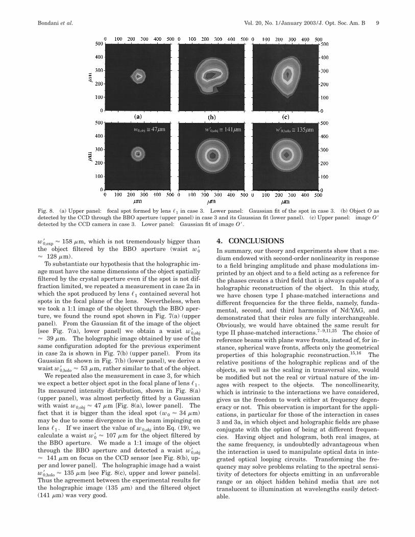
Fig. 8. (a) Upper panel: focal spot formed by lens �1 in case 3. Lower panel: Gaussian fit of the spot in case 3. (b) Object O asdetected by the CCD through the BBO aperture (upper panel) in case 3 and its Gaussian fit (lower panel). (c) Upper panel: image O�detected by the CCD camera in case 3. Lower panel: Gaussian fit of image O�.
w0,exp� � 158 �m, which is not tremendously bigger thanthe object filtered by the BBO aperture (waist w0�� 128 �m).
To substantiate our hypothesis that the holographic im-age must have the same dimensions of the object spatiallyfiltered by the crystal aperture even if the spot is not dif-fraction limited, we repeated a measurement in case 2a inwhich the spot produced by lens �1 contained several hotspots in the focal plane of the lens. Nevertheless, whenwe took a 1:1 image of the object through the BBO aper-ture, we found the round spot shown in Fig. 7(a) (upperpanel). From the Gaussian fit of the image of the object[see Fig. 7(a), lower panel] we obtain a waist w0,obj�� 39 �m. The holographic image obtained by use of thesame configuration adopted for the previous experimentin case 2a is shown in Fig. 7(b) (upper panel). From itsGaussian fit shown in Fig. 7(b) (lower panel), we derive awaist w0,holo� � 53 �m, rather similar to that of the object.
We repeated also the measurement in case 3, for whichwe expect a better object spot in the focal plane of lens �1 .Its measured intensity distribution, shown in Fig. 8(a)(upper panel), was almost perfectly fitted by a Gaussianwith waist w0,obj � 47 �m [Fig. 8(a), lower panel]. Thefact that it is bigger than the ideal spot (w0 � 34 �m)may be due to some divergence in the beam impinging onlens �1 . If we insert the value of w0,obj into Eq. (19), wecalculate a waist w0� � 107 �m for the object filtered bythe BBO aperture. We made a 1:1 image of the objectthrough the BBO aperture and detected a waist w0,obj�� 141 �m on focus on the CCD sensor [see Fig. 8(b), up-per and lower panel]. The holographic image had a waistw0,holo� � 135 �m [see Fig. 8(c), upper and lower panels].Thus the agreement between the experimental results forthe holographic image (135 �m) and the filtered object(141 �m) was very good.
4. CONCLUSIONSIn summary, our theory and experiments show that a me-dium endowed with second-order nonlinearity in responseto a field bringing amplitude and phase modulations im-printed by an object and to a field acting as a reference forthe phases creates a third field that is always capable of aholographic reconstruction of the object. In this study,we have chosen type I phase-matched interactions anddifferent frequencies for the three fields, namely, funda-mental, second, and third harmonics of Nd:YAG, anddemonstrated that their roles are fully interchangeable.Obviously, we would have obtained the same result fortype II phase-matched interactions.7–9,11,25 The choice ofreference beams with plane wave fronts, instead of, for in-stance, spherical wave fronts, affects only the geometricalproperties of this holographic reconstruction.15,16 Therelative positions of the holographic replicas and of theobjects, as well as the scaling in transversal size, wouldbe modified but not the real or virtual nature of the im-ages with respect to the objects. The noncollinearity,which is intrinsic to the interactions we have considered,gives us the freedom to work either at frequency degen-eracy or not. This observation is important for the appli-cations, in particular for those of the interaction in cases3 and 3a, in which object and holographic fields are phaseconjugate with the option of being at different frequen-cies. Having object and hologram, both real images, atthe same frequency, is undoubtedly advantageous whenthe interaction is used to manipulate optical data in inte-grated optical looping circuits. Transforming the fre-quency may solve problems relating to the spectral sensi-tivity of detectors for objects emitting in an unfavorablerange or an object hidden behind media that are nottranslucent to illumination at wavelengths easily detect-able.

10 J. Opt. Soc. Am. B/Vol. 20, No. 1 /January 2003 Bondani et al.
APPENDIX AWe analytically demonstrate that the three-wave interac-tion transforms an ‘‘object’’ consisting of a Gaussian fielddistribution into a ‘‘holographic image’’ located at the dis-tance predicted by the theory and endowed with a Gauss-ian profile having the same transversal size as the object.As an example, we consider the interaction described incase 3 (difference-frequency generation with object fieldat �1 and reference field at �3 providing the real holo-graphic image at �2). Furthermore, we suppose a collin-ear interaction along the z axis orthogonal to the crystalface, which is supposed to have infinite cross dimensions.
The object is the focal spot of a converging lens charac-terized by the following Gaussian distribution on plane(xO , yO , zO) (see Fig. 9):
a1�xO , yO , zO� � A1 exp� �xO
2 � yO2
w1,02 � , (A1)
where w1,0 is the ‘‘object’’ beam waist. Since the fieldpropagates along z according to the paraxial Helmholtzequation, if plane (xC , yC , zC) represents the crystal en-trance face, the field entering the crystal is given by
E1�xC , yC , zC , t �
�x
2 A1
w1,0
w1�zC � zO�exp��
xC2 � yC
2
w12�zC � zO�
�� exp� �i�k1z � k1
xC2 � yC
2
2R1�zC � zO�
� tan�1� zC � zO
z1,0� � �1t� � � c.c.
�x
2��2�0�1
n1a1�xC , yC , zC�
� exp�i�k1z � �1t �� � c.c.� , (A2)
with
a1�xC , yC , zC�
Fig. 9. Reference frames for the propagation of a Gaussianbeam from the focal spot [plane (xO , yO , zO)] to the crystal en-trance and exit planes [planes (xC , yC , zC) and (xf , yf , zf), re-spectively].
�A1
�2�0�1
n1
w1,0
w1�zC � zO�exp��
xC2 � yC
2
w12�zC � zO�
�� exp��ik1
xC2 � yC
2
2R1�zC � zO�� i tan�1� zC � zO
z1,0� � ,
(A3)where z1,0 � k1w1,0
2 /2 is the Rayleigh range, w1(zC� zO) is the beam waist, and R1(zC � zO) is the wave-front radius of curvature at the crystal entrance. The fol-lowing relations hold:
w12�zC � zO� � w1,0
2 �1 � � zC � zO
z1,0� 2� , (A4)
R1�zC � zO� � �zC � zO��1 � � z1,0
zC � zO� 2� .
(A5)If we suppose that the exit face of the crystal coincideswith the plane (xf , yf , zf), by using Eq. (14), we canwrite the amplitude of the holographic field at �2 on theoutput face of the crystal as
a2�xf , yf , zf� � a1*�xC , yC , zC�
� sinh geff�a3�xC , yC , zC��Z�
� exp� i��3�0 � ��
2 � � , (A6)
with Z � zf � zC as the crystal depth. Since the inter-action is collinear, for each set of input coordinates on thecrystal plane, we have xf � xC , yf � yC , and zf � zC� Z. By using Eqs. (A3), (A6), and (1), the field at �2can be written as
E2�xf , yf , zf , t �
�x
2��2�0�2
n2a2�xf , yf , zf�
� exp��ik2�zf � zC� � �2t�� � c.c.��
x
2��2n1
�1n2A1
w1,0
w1�zC � zO�
� exp��xf
2 � yf2
w12�zC � zO�
�exp� ik2
k1
k2
xf2 � yf
2
2R1�zC � zO�
� i�
2�sinh geff�a3�xC , yC , zC��Z�exp� i��3�0 �
��
2 �exp�i�k2Z � �2t ��� � c.c.�
x
2 � A�Z �exp��xf
2 � yf2
w22�zf�
�exp� ik2
xf2 � yf
2
2R2�zf�
� i tan�1� zf
z2,0� �exp�i�k2Z � �2t �� � c.c.� ,
(A7)
Bondani et al. Vol. 20, No. 1 /January 2003 /J. Opt. Soc. Am. B 11
where the approximation tan�1(zC � zO)/z1,0� � �/2 inthe second line of the equation is consistent with the con-dition (zC � zO) � z1,0 . In the last line of Eq. (A7), wehave evidenced the Gaussian profile of the holographicfield at �2 by defining
w2�zf� � w1�zC � zO� (A8)
as the waist of the beam and
R2�zf� �k2
k1R1�zC � zO� (A9)
as its radius of curvature at zf . Moreover, we have in-terpreted �/2 as tan�1(zf /z2,0), which is correct if zf� z2,0 ; A(Z) is a complex factor containing quantitiesthat are constant for a crystal of given depth Z. We canthus regard the field in Eq. (A7) as originating from a cer-tain minimum waist, say w2,0 , located at a distance zffrom the exit face of the crystal, and find the relationslinking w2,0 to w1,0 , and (zC � zO) to zf . In fact, being(zC � zO) � z1,0 and zf � z2,0 , we can expand Eqs. (A4)and (A5) written for both object and holographic fields asfollows:
w1�zC � zO� � w1,0�1 � � zC � zO
z1,0� 2
� w1,0�1 � � 2�zC � zO�
k1w1,02 � 2
�2�zC � zO�
k1w1,0,
w2�zf� � w2,0�1 � � zf
z2,0� 2
� w2,0�1 � � 2zf
k2w2,02 � 2
�2zf
k2w2,0, (A10)
R1�zC � zO� � �zC � zO��1 � � z1,0
zC � zO� 2� � �zC � zO�,
R2�zf� � zf�1 � � z2,0
zf� 2� � zf . (A11)
By inserting Eq. (A10) in Eq. (A8) and Eq. (A11) in Eq.(A9), we finally get the relations
w2,0
w1,0� 1,
zf
zC � zO� �
k2
k1. (A12)
That is, the holographic image has the same transversaldimension as the object, and its position scales with re-spect to that of the object as the ratio of the wave vectorsas seen in Section 2.
APPENDIX BIf the crystal entrance face is not an infinite plane, it af-fects the dimensions of a Gaussian beam impinging on it,and the modifications introduced can be described withinthe Fresnel diffraction theory. We take the field at thecrystal surface to be that in Eq. (A2) and describe thepresence of the crystal as a rectangular aperture withunit transmittance in the plane (xC , yC , zC) (see Fig. 9):
T�xC , yC , zC� � rect� xC
L � rect� yC
L � . (B1)
The effective field entering the crystal is thus given by
U�xC , yC , zC� � E�xC , yC , zC�T�xC , yC , zC�(B2)
where E(xC , yC , zC) is the space-dependent part of thefield in Eq. (A2). We now want to find the equivalentfield distribution U0 on plane (xO , yO , zO) that, by un-dergoing diffraction, would give rise to fieldU(xC , yC , zC):
U�xC , yC , zC�
�exp��ikzC�
i�zCexp��i
k
2CC�xC
2 � yC2 ��
� � U0�xO , yO , zO�exp��ik
2zC�xO
2
� yO2 ��exp� i
2�
�zC�xCxO � yCyO��dxOdyO , (B3)
where we put for simplicity zO � 0 and omit the index 1.To obtain U0(xO , yO , zO), we invert the previous rela-tion, insert Eq. (A2), and find
U0�xO , yO , zO�
� i�zC exp�ikzC�exp� ik
2zC�xO
2 � yO2 ��
� ���
��
U�xC , yC , zC�exp� ik
2zC�xC
2
� yC2 ��exp��i
2�
�zC�xCxO � yCyO��dxCdyC
� i�zCAw0
w�zC�exp� i
k
2zC�xO
2 � yO2 ��exp� i tan � 1� zC
z0� �
� ���
��
exp� �� 1
w2�zC�� i
k
2 � 1
R�zC��
1
zC� � �xC
2
� yC2 �� T�xC , yC , zC�
� exp��i2�
�zC�xCxO � yCyO��dxCdyC . (B4)
12 J. Opt. Soc. Am. B/Vol. 20, No. 1 /January 2003 Bondani et al.
In order to obtain an analytical expression for the integralin Eq. (B4), we approximate the rectangular transparencyT(xC , yC , zC) with a Gaussian transparency subtendingthe same area, that is,
T�xC , yC , zC� � exp���
L2 �xC2 � yC
2 �� . (B5)
Equation (B4) then gives
U0�xO , yO , zO�
� i�zCAw0
w�zC�exp� i
k
2zC�xO
2 � yO2 ��exp� i tan � 1� zC
z0� �
��
1
w2�zC�� i
k
2 � 1
R�zC��
1
zC� �
�
L2
� exp� ��2
�2zC2
�xC2 � yC
2 �
1
w2�zC�� i
k
2 � 1
R�zC��
1
zC� �
�
L2� .
(B6)
By noting that in all cases of experimental interestR(zC) � zC [see Eq. (A11)] and zC � z0 , Eq. (B6) simpli-fies to
U0�xO , yO , zO�
� i�zCA1
w0
w�ZC�
�
1
w2�zC��
�
L2
exp� ik
2zC�xO
2
� yO2 ��exp� i
�
2 � exp���xC
2 � yC2 �
w0�2 � , (B7)
where the waist w0� of the Gaussian beam can be linked tothe minimum waist w0 (size of the pointlike source) by us-ing Eq. (A4):
w0� � ��2zC2
�2 � 1
w2�zC��
�
L2���4zC
2
k2
1
w02� 1 �
4zC2
k2
1
w04�
��2
�
zC2
L2. (B8)
Note that in the limiting case of very large crystal aper-ture, L → �, the waist is not modified, w0� � w0 ,whereas in the case of very small crystal aperture L→ 0, the waist reaches the diffraction-limit value w0�� (�/L)zC .
ACKNOWLEDGMENTSThe authors are very grateful to E. Puddu (Como) for hisprecious experimental collaboration during the revisionphase of the manuscript.
REFERENCES1. J. A. Armstrong, N. Bloembergen, J. Ducuing, and P. S. Per-
shan, ‘‘Interactions between light waves in a nonlinear di-electric,’’ Phys. Rev. 127, 1918–1939 (1962).
2. D. M. Pepper and A. Yariv, ‘‘Optical phase conjugation usingthree-wave and four-wave mixing via elastic photon scatter-ing in transparent media,’’ in Optical Phase Conjugation, R.A. Fisher, ed. (Academic, New York, 1983), p. 23.
3. D. M. Pepper, D. Fekete, and A. Yariv, ‘‘Observation of am-plified phase-conjugate reflection and optical parametric os-cillation by degenerate four-wave mixing in a transparentmedium,’’ Appl. Phys. Lett. 33, 41–44 (1978).
4. M. P. Bogdanov, S. A. Dimakov, A. V. Gorlanov, D. A. Gory-achkin, A. M. Grigor’ev, V. M. Irtuganov, V. P. Kalinin, S. I.Kliment’ev, I. M. Kozlovskaya, I. B. Orlova, V. E. Sherstobi-tov, and V. Yu. Venediktov, ‘‘Correction of segmented mirroraberrations by phase conjugation and dynamic holography,’’Opt. Commun. 129, 405–413 (1996).
5. G. Klose and A. Siahmakoun, ‘‘External mode locking withfeedback from a self-pumped phase-conjugator BaTiO3crystal,’’ Opt. Eng. 35, 2983–2988 (1996).
6. P. C. Sun, K. Oba, Y. T. Mazurenko, and S. Y. Fainman,‘‘Space-time processing with photorefractive volume holog-raphy,’’ Proc. IEEE 87, 2086–2097 (1999).
7. P. V. Avizonis, F. A. Hopf, W. D. Bomberger, S. F. Jacobs, A.Tomita, and K. H. Womack, ‘‘Optical phase conjugation in alithium formate crystal,’’ Appl. Phys. Lett. 31, 435–437(1977).
8. S. N. Shostko, Ya. G. Podoba, Yu. A. Ananiev, B. D. Volosov,and A. M. Gorlanov, ‘‘On one possibility of the compensationof optical inhomogeneities in laser devices (in Russian),’’Pis’ma Zh. Tekh. Fiz. 5, 29–31 (1979).
9. A. M. Gorlanov, N. I. Grishmanova, N. A. Sventsitskaya,and V. D. Solov’yov, ‘‘Angular characteristics of radiationfrom neodymium laser with wavefront conjugation underthree-wave parametric interaction (in Russian),’’ Kvant.Elektron. (Moscow) 5, 415–417 (1982).
10. B. Zel’dovich, ‘‘Wave front conjugation by three-wave mix-ing,’’ in Wave Front Conjugation (Science, Moscow, 1985), p.194.
11. L. Lefort and A. Barthelemy, ‘‘Revisiting optical phase con-jugation by difference-frequency generation,’’ Opt. Lett. 21,848–850 (1996).
12. A. Andreoni, M. Bondani, M. A. C. Potenza, and F. Villani,‘‘Phase selection of image-bearing field components by fre-quency up-conversion in nonlinear crystals,’’ J. NonlinearOpt. Phys. Mater. 8, 55–77 (1999).
13. A. Andreoni, M. Bondani, M. A. C. Potenza, and F. Villani,‘‘Relevance of temporal coherence in the second-harmoniccross-correlation measurement of a multiply scattered laserpulse,’’ Eur. Phys. J. D 8, 111–116 (2000).
14. A. Andreoni, M. Bondani, M. A. C. Potenza, and F. Villani,‘‘‘‘Viewing’’ objects hidden in highly scattering media bycross-correlating the Fourier-transform of the image withthe incident field in a second-order nonlinear crystal,’’ Opt.Commun. 174, 487–497 (2000).
15. Yu. N. Denisyuk, A. Andreoni, and M. A. C. Potenza, ‘‘Holo-graphic properties of the effect of second-order harmoniccross-correlation of optical wavefields,’’ Opt. Mem. NeuralNetw. 8, 123–137 (1999).
16. A. Andreoni, M. Bondani, Yu. N. Denisyuk, and M. A. C. Po-tenza, ‘‘Holographic properties of the second-harmonic crosscorrelation of object and reference optical wave fields,’’ J.Opt. Soc. Am. B 17, 966–972 (2000).
17. Yu. N. Denisyuk, A. Andreoni, M. Bondani, and M. A. C. Po-tenza, ‘‘Real-time holograms by second-harmonic cross cor-relation of object and reference optical wave fields,’’ Opt.Lett. 25, 890–892 (2000).
18. Yu. N. Denisyuk, A. Andreoni, M. Bondani, and M. A. C. Po-tenza, ‘‘The formation of the holographic image of a diffus-ing object in the second-harmonic light generated by a non-linear material,’’ Opt. Spectrosc. (Russia) 89, 113–120(2000).
19. M. Bondani and A. Andreoni, ‘‘Holographic nature of three-wave mixing,’’ Phys. Rev. A 66, 033805 (2002).

Bondani et al. Vol. 20, No. 1 /January 2003 /J. Opt. Soc. Am. B 13
20. A. Andreoni, M. Bondani, and M. A. C. Potenza, ‘‘Combina-tional tasks performed by second harmonic generated holo-grams,’’ Opt. Lett. 25, 1570–1572 (2000).
21. A. Andreoni, M. Bondani, Yu. N. Denisyuk, M. A. C. Po-tenza, and E. Puddu, ‘‘Boolean algebra operations per-formed on optical bits by the generation of holographicfields through second-order nonlinear interactions,’’ Rev.Sci. Instrum. 72, 2525–2531 (2001).
22. V. G. Dmitriev, G. G. Gurzadyan, and D. N. Nikogosyan,
Handbook of Nonlinear Optical Crystals (Springer, NewYork, 1997).
23. D. Gabor, ‘‘Microscopy by reconstructed wavefronts,’’ Proc.R. Soc. London, Ser. A 197, 454–463 (1949).
24. J. W. Goodman, Introduction to Fourier Optics (McGraw-Hill, New York, 1988), Chap. 8.
25. M. R. Fewings and A. L. Gaeta, ‘‘Compensation of pulse dis-tortions by phase conjugation via difference-frequency gen-eration,’’ J. Opt. Soc. Am. B 17, 1522–1525 (2000).
Copyright © 2022 FDOKUMEN